loosely woven fabric model with viscoelastic crimped fibres for ballistic impact simulations
TRANSCRIPT
INTERNATIONAL JOURNAL FOR NUMERICAL METHODS IN ENGINEERINGInt. J. Numer. Meth. Engng 2004; 61:1565–1583Published online in Wiley InterScience (www.interscience.wiley.com). DOI: 10.1002/nme.1113
Loosely woven fabric model with viscoelastic crimped fibresfor ballistic impact simulations
Ivelin Ivanov1,§ and Ala Tabiei2,∗ ,†,‡
1Department of Engineering Mechanics, University of Rousse, Rousse 7017, Bulgaria2The Center of Excellence in DYNA3D Analysis, Department of Aerospace Engineering and
Engineering Mechanics, University of Cincinnati, OH 45221-0070, U.S.A.
SUMMARY
A computational micro-mechanical material model of loosely woven fabric for non-linear finite elementimpact simulations is presented in this work. The model is a mechanism incorporating the crimping ofthe fibres as well as the trellizing. The equilibrium of the mechanism allows the straightening of the fibresdepending on the fibre tension. The contact force at the fibre crossover point determines the rotational frictiondissipating a part of the impact energy. The stress–strain relationship is viscoelastic based on a three-elementmodel. The failure of the fibres is strain rate dependent. The model is implemented as user defined subroutinein the transient finite element code LS-DYNA. The ballistic impact simulations with the model are in goodagreement with the experimental results. Copyright � 2004 John Wiley & Sons, Ltd.
KEY WORDS: computational micro-mechanical material model; flexible woven fabric; ballistic impactsimulations; non-linear explicit finite element analysis
INTRODUCTION
Looselyn woven fabrics of high modulus fibres such as Kevlar�, Spectra�, Aramid, Nylon, etc. canwithstand large transverse deflection and absorb high impact energy. They are widely used as ballisticprotective structural elements, which have high strength and flexibility. These two properties arevery important for ballistic protective structures. Woven fabrics can be used in structures subjectedto transverse loading such as automotive inflated airbags and human body armors subjected toprojectile impact. Another application of the high modulus flexible fabrics is the protective jackets
∗Correspondence to: Ala Tabiei, The Center of Excellence in DYNA3D Analysis, Department of AerospaceEngineering and Engineering Mechanics, University of Cincinnati, OH 45221-0070, U.S.A.
†E-mail: [email protected]‡Associate Professor and Director, author to whom correspondence should be addressed§Former Graduate Research Assistant, Currently Assistant Professor
Contract/grant sponsor: Ohio Supercomputer Centre
Received 22 November 2002Revised 9 January 2004
Copyright � 2004 John Wiley & Sons, Ltd. Accepted 5 March 2004
1566 I. IVANOV AND A. TABIEI
in airplane jet engines. These jackets are placed around the jet engines in order to contain any brokenblades from penetrating the engine casing and the fuselage.
The modelling of the flexible fabric behaviour under membrane and transverse loading is a chal-lenging task. The difficulty comes from the architecture of the loosely woven fabrics. The undulationof the yarns allows their straightening that causes more flexibility and redistribution of the strainenergy between the yarns. The shearing of the fabrics resembles a trellis mechanism with big reori-entation of the yarns. The rotation of the yarns is accompanied with rotational friction that dissipatesa part of the impact energy, which could be significant. The yarns of the loose fabrics are free torotate but up to some locking angle. If the deflection of the fabric under impact is severe, the rotatingyarns reach the locking angle between them and the fabric is packed in a block that has the highestarea density. A transverse interaction of the yarns occurs in that case. The high modulus fibres arepolymeric materials possessing viscoelastic properties. This is very important for the ballistic impactsimulations because the fibre rupture is strain rate dependent and this will determine the ballisticlimit of the fabric. All those elements of fabric behaviour are difficult to be modelled and in the mostof the fabric models some of them are missing.
In earlier models of Vinson et al. [1] and Taylor et al. [2], the fabric is modelled as conical isotropicshells for ballistic impact analysis. As a result of the assumption of isotropic material, the modelsthey presented are not able to distinguish the membrane directions and consequently the behaviourof the material is the same in all directions, which is not observed in experimental results. Cunniff[3] discussed the system effects that occur during the ballistic impact of woven fabric materials.A conceptual framework relating single yarn impact mechanisms to fabric impact mechanisms isdeveloped. Analytical models of Walker [4] and Gu [5] aimed to determine the ballistic limits offabrics are based on that conceptual framework. The crimping of the yarns, however, is missing inboth models.
The most of the models of flexible fabric materials presented in the literature use the pin-joinedmechanism modelled by bar elements. Ting et al. [6] and Shim et al. [7] modelled the fabric materialas an orthogonal grid of pin-joined bar elements. In such models the transverse pressure loading dueto the contact between protective structures and the impactor cannot be captured properly. The finiteelement mesh has to be in the scale of the fabric structure in order to capture the contact surfacecorrectly. This presents some difficulties in the general use of such models. The friction and thelocking angle are absent in most of these models. 1-D viscoelastic material model is incorporatedin the model of Shim et al. [7]. The authors used some increase of the ultimate strain in order toimplement the crimping flexibility in the model and noted the importance of this to impact simulationsof fabrics.
Roylance et al. [8] applied finite difference method at crossover points of the fabric yarns tosimulate ballistic impacts. Artificial buck up springs in transverse direction play significant role inthe ballistic limit determination. Johnson et al. [9] modelled the fabric by both pin-joined membersand thin membrane shells. Bi-linear stress–strain relationship is assumed for the bar elements inorder to simulate the crimping of the yarns. Shell elements provided the contact surface in the modeland shear stiffness.
Lim et al. [10] modelled a fabric armor of Twaron� fibres in DYNA3D finite element code. Theyused a standard isotropic strain-rate dependent elastic–plastic model to incorporate the strain-ratedependency of Twaron� fibres determined in experiments [11]. However, the isotropic propertiesof the material cause spherical shape of deflected fabric under ballistic impact instead of pyramidalgeometry. The straightening of the crimped yarns is missing but the strain-rate dependent rapture ofthe yarns appears to be important for ballistic limit prediction.
Copyright � 2004 John Wiley & Sons, Ltd. Int. J. Numer. Meth. Engng 2004; 61:1565–1583
WOVEN FABRIC MODEL WITH VISCOELASTIC CRIMPED FIBRES 1567
warp yarn
fill yarn
t
s
w
S
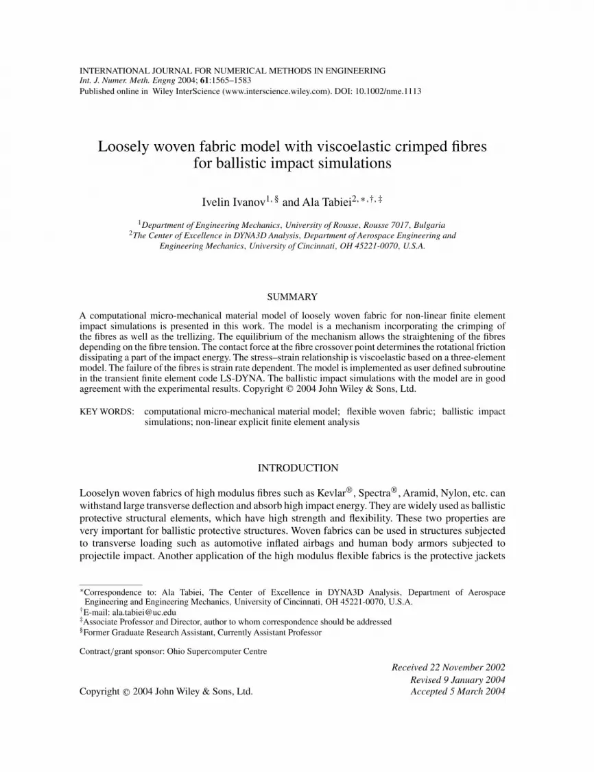
Figure 1. Representative volume cell (RVC) of the model.
Cheeseman et al. [12] did very good review of the factors determining the ballistic performanceof the fabrics. The straitening of the crimped yarns, the trellising of the yarns, and the strain-ratedependent behaviour and rapture of the yarns are emphasized as the basic mechanisms determiningthe straining of the yarns, which is the main energy absorption phenomenon in ballistic impacts offabric targets. The trellising of the yarns appears naturally in the models with pin-joined bar elements,but the crimping of the yarns is difficult to be represented.
A micro-mechanical model of woven fabrics can account for the crimping of the yarns as well as fortheir trellising with reorientation of the yarns and their locking. Therefore it was decided to developa model of loosely woven fabric materials that can simulate a trellis mechanism of crimped yarns,based on the micro-mechanics. The model is accomplished with friction of the rotating yarns and 1-Dviscoelastic stress–strain relationship with strain rate dependent failure criteria. Impact and ballisticproblems can be simulated successfully by means of finite element codes for dynamic non-linearproblems with explicit time integration scheme. Such codes are heavily used in many industries asthey provide a powerful tool and cost effective process for simulation-based designs. The developedcomputational material model is implemented in the nonlinear dynamic explicit finite element codeLS-DYNA as a user defined material model that is compatible with the shell element formulation.Shell elements are better structural elements for contact problems and transverse pressure loadingin the finite element method. In what follows, a description of the model and its implementation ispresented.
THE REPRESENTATIVE VOLUME CELL OF THE MODEL
The representative volume technique, vastly used in the micro-mechanical models, is utilized here-after. A current deformed state of the fabric is considered. The representative volume cell (RVC)of the loosely woven fabric material model is extracted from the deformed pattern of the material.The RVC consists of an undulated fill yarn crossed over an undulated warp yarn (see Figure 1). Theparameters of the RVC are: the yarn span, s, the fabric thickness, t , the yarn width, w, and the yarncross-sectional area, S. The complex geometry of the yarns is simplified and they are representedas a pin-joint mechanism of straight viscoelastic bars connected at the middle crossover point by arigid link (see Figure 2). The end nodes of the yarns are always in the plane of the shell element xy.
Copyright � 2004 John Wiley & Sons, Ltd. Int. J. Numer. Meth. Engng 2004; 61:1565–1583
1568 I. IVANOV AND A. TABIEI
fill yarn
warp yarn
θfqf
θwqw
x
y
z
t/2
rigid link
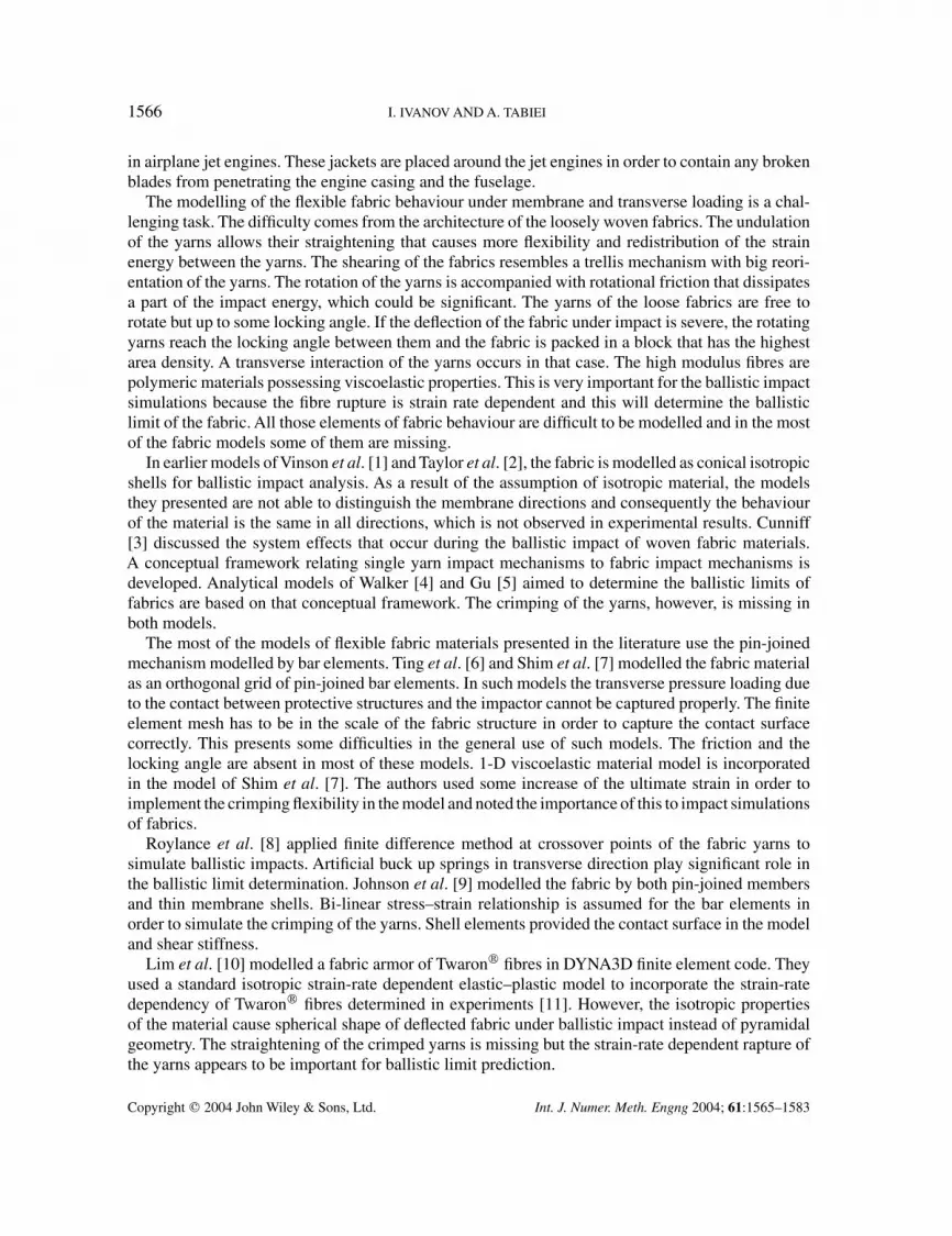
Figure 2. Pin-joint bar mechanism.
The distance between the central nodes of the yarns in z-direction is provided by the rigid link oflength t/2, which is always normal to the xy-plane, and their z-co-ordinates depend on the equilib-rium of the stretching forces in the yarns. The pin-joints have axes always parallel to the xy-planeand perpendicular to the bars. The mechanism allows the in-plane rotation of the yarns about therigid link as a trellis mechanism and the straightening of the zig–zag undulated yarns depending ontheir tension. The deformation of the yarns as a result of the contact between the yarns is neglected.The in-plane orientation of the yarns is determined by the unit vectors, q’s, or the braid angles, �’s,measured with respect to the axis x of the RVC co-ordinate system. The subscript f denotes the fillyarn and the subscript w denotes the warp yarn.
In explicit finite element codes as LS-DYNA, the material model have to determine the stressresponse of the material to the strain increment obtained at each time step of the explicit timeintegration. Assuming that the RVC co-ordinate system is the shell element local co-ordinate system,the stress response of the woven fabric RVC to the strain increment passed to the model in the RVCco-ordinate system has to be developed by the micro-mechanical approach.
IN-PLANE YARN ROTATION AND STRAIN TRANSFORMATION
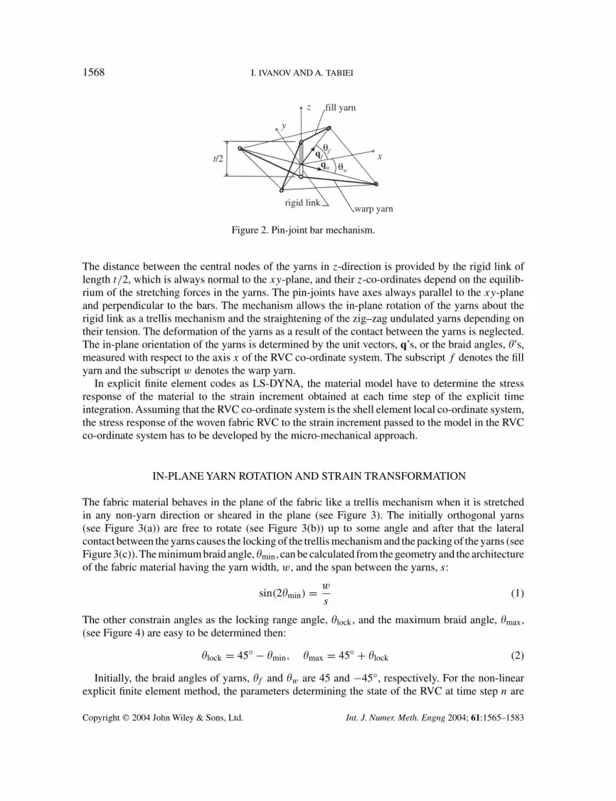
The fabric material behaves in the plane of the fabric like a trellis mechanism when it is stretchedin any non-yarn direction or sheared in the plane (see Figure 3). The initially orthogonal yarns(see Figure 3(a)) are free to rotate (see Figure 3(b)) up to some angle and after that the lateralcontact between the yarns causes the locking of the trellis mechanism and the packing of the yarns (seeFigure 3(c)). The minimum braid angle, �min, can be calculated from the geometry and the architectureof the fabric material having the yarn width, w, and the span between the yarns, s:
sin(2�min) = w
s(1)
The other constrain angles as the locking range angle, �lock, and the maximum braid angle, �max,(see Figure 4) are easy to be determined then:
�lock = 45◦ − �min, �max = 45◦ + �lock (2)
Initially, the braid angles of yarns, �f and �w are 45 and −45◦, respectively. For the non-linearexplicit finite element method, the parameters determining the state of the RVC at time step n are
Copyright � 2004 John Wiley & Sons, Ltd. Int. J. Numer. Meth. Engng 2004; 61:1565–1583

WOVEN FABRIC MODEL WITH VISCOELASTIC CRIMPED FIBRES 1569
θ
θ
45°
45°
w s
(a)
(c)
(b)
θmin
θmin
s
w
Figure 3. Plain woven fabric as trellis mechanism: (a) initial state; (b) slightly stretched in biasdirection; and (c) stretched to locking.
qw
qf
x
yfill yarn
warp yarn
RVC
θmin
θlock
θlock
θf
θw
45o
θmax
locking area
Figure 4. Locking angles.
kept as history variables. The new parameters of the RVC at time step n + 1 are the aim of ourconsideration. The in-plane positions of the yarns at time step n are determined by the vectors:
q(n)f = [cos �(n)
f sin �(n)f ]T, q(n)
w = [cos �(n)w sin �(n)
w ]T (3)
The new position of the yarns at time step n + 1 can be obtained by using the deformation gradient2-D tensor, F, to rotate the unit vectors:
q(n+1)f = F(n)q(n)
f , q(n+1)w = F(n)q(n)
w (4)
Copyright � 2004 John Wiley & Sons, Ltd. Int. J. Numer. Meth. Engng 2004; 61:1565–1583
1570 I. IVANOV AND A. TABIEI
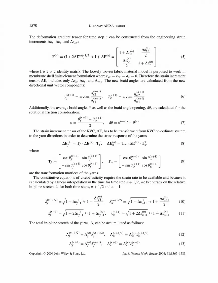
The deformation gradient tensor for time step n can be constructed from the engineering strainincrements ��x , ��y , and ��xy :
F(n) = (I + 2�E(n))1/2 ≈ I + �E(n) =
1 + ��(n)
x
��(n)xy
2��(n)
xy
21 + ��(n)
y
(5)
where I is 2 × 2 identity matrix. The loosely woven fabric material model is purposed to work inmembrane shell finite element formulation where �yz = �zx = �z = 0. Therefore the strain incrementtensor, �E, includes only ��x , ��y , and ��xy . The new braid angles are calculated from the newdirectional unit vector components:
�(n+1)f = arctan
q(n+1)f 2
q(n+1)f 1
, �(n+1)w = arctan
q(n+1)w2
q(n+1)w1
(6)
Additionally, the average braid angle, �, as well as the braid angle opening, d�, are calculated for therotational friction consideration:
� = �(n+1)f − �(n+1)
w
2, d� = �(n+1) − �(n) (7)
The strain increment tensor of the RVC, �E, has to be transformed from RVC co-ordinate systemto the yarn directions in order to determine the stress response of the yarns
�E(n)f = Tf · �E(n) · TT
f , �E(n)w = Tw · �E(n) · TT
w (8)
where
Tf = cos �(n+1)
f sin �(n+1)f
− sin �(n+1)f cos �(n+1)
f
, Tw =
[cos �(n+1)
w sin �(n+1)w
− sin �(n+1)w cos �(n+1)
w
](9)
are the transformation matrices of the yarns.The constitutive equations of viscoelasticity require the strain rate to be available and because it
is calculated by a linear interpolation in the time for time step n + 1/2, we keep track on the relativein-plane stretch, �, for both time steps, n + 1/2 and n + 1:
�(n+1/2)f =
√1 + ��(n)
f 11 ≈ 1 + ��(n)f 11
2, �(n+1/2)
w =√
1 + ��(n)w11 ≈ 1 + ��(n)
w11
2(10)
�(n+1)f =
√1 + 2��(n)
f 11 ≈ 1 + ��(nt)f 11 , �(n+1)
w =√
1 + 2��(n)w11 ≈ 1 + ��(n)
w11 (11)
The total in-plane stretch of the yarns, �, can be accumulated as follows:
�(n+1/2)f = �(n)
f �(n+1/2)f , �(n+1/2)
w = �(n)w �(n+1/2)
w (12)
�(n+1)f = �(n)
f �(n+1)f , �(n+1)
w = �(n)w �(n+1)
w (13)
Copyright � 2004 John Wiley & Sons, Ltd. Int. J. Numer. Meth. Engng 2004; 61:1565–1583

WOVEN FABRIC MODEL WITH VISCOELASTIC CRIMPED FIBRES 1571
σ, ε σ, εσ , εb b
σ , εa a
Ka
µb
Kb
Figure 5. Three-element viscoelasticity model.
VISCOELASTICITY MODEL
The viscoelasticity exists as a property of all materials but it is significant at room temperature forpolymeric materials mainly. The creep and the stress relaxation are the results of the viscoelas-tic behaviour of materials. For impact simulations, we do not need the long-term effects of theviscoelasticity, so that the material behaviour can be simply described by a combination of oneMaxwell element without the dashpot and one Kelvin–Voigt element. The 1-D model of viscoelas-ticity is given in Figure 5. The differential equation of viscoelasticity can be derived from the modelequilibrium in the form
(Ka + Kb)� + �b�̇ = KaKb� + �bKa �̇ (14)
For the incremental formulation of the problem, we can estimate the stress rate and the strain rateat time step n + 1/2 as follows:
�̇(n+1/2) = ��(n)
�t (n), �̇(1+1/2) = ��(n)
�t (n)(15)
Then Equation (14) can be written in incremental form for the time step n + 1/2:
(Ka + Kb)
(�(n) + ��(n)
2
)+ �b
��(n)
�t (n)= KaKb
(�(n) + ��(n)
2
)+ �bKa
��(n)
�t (h)(16)
We can determine the stress increment from the last equation
��(n) = 2[KaKb�(n) − (Ka + Kb)�(n)] + Ka(Kb + 2(�b/�t (n)))��(n)
(Ka + Kb) + 2(�b/�t (n))(17)
Another simplified form is the equation
��(n) = 2(E1�(n) − �(n)) + (E1 + Ka�(n))��(n)
1 + �(n)(18)
where E1/(EaEb) is the static Young’s modulus in fibre direction of the yarns and
�(n) = 2 �b
�t (n)(Ka + Kb)
Copyright � 2004 John Wiley & Sons, Ltd. Int. J. Numer. Meth. Engng 2004; 61:1565–1583
1572 I. IVANOV AND A. TABIEI
s( +1/2)n
/2f s( +1/2)n
/2f
s( +1/2)n
/2w s( +1/2)n
/2w
hf(n) (n)+ /2δ
hw(n) (n)−δ /2
Pf Pf
Pw Pw
Nf Nf
Nw Nw
Ff Ff
2Ff
Fw Fw
2Fw
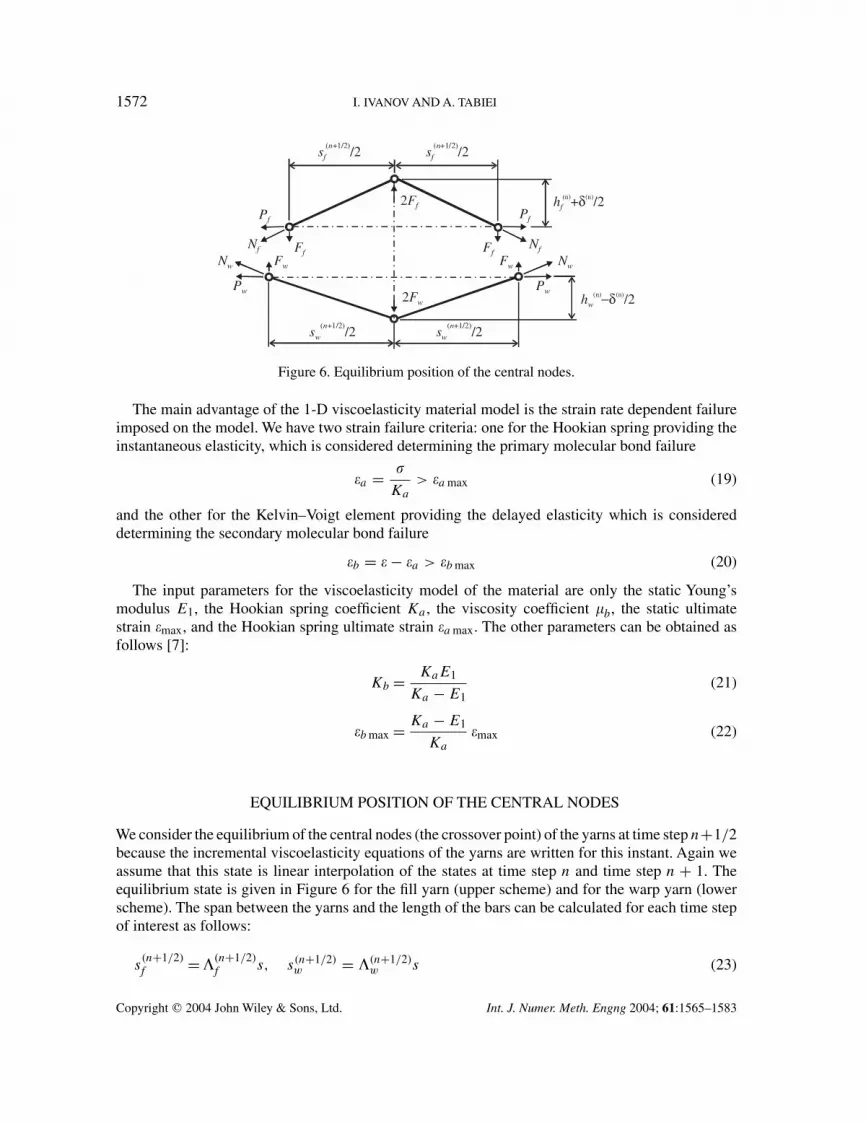
Figure 6. Equilibrium position of the central nodes.
The main advantage of the 1-D viscoelasticity material model is the strain rate dependent failureimposed on the model. We have two strain failure criteria: one for the Hookian spring providing theinstantaneous elasticity, which is considered determining the primary molecular bond failure
�a = �
Ka
> �a max (19)
and the other for the Kelvin–Voigt element providing the delayed elasticity which is considereddetermining the secondary molecular bond failure
�b = � − �a > �b max (20)
The input parameters for the viscoelasticity model of the material are only the static Young’smodulus E1, the Hookian spring coefficient Ka , the viscosity coefficient �b, the static ultimatestrain �max, and the Hookian spring ultimate strain �a max. The other parameters can be obtained asfollows [7]:
Kb = KaE1
Ka − E1(21)
�b max = Ka − E1
Ka
�max (22)
EQUILIBRIUM POSITION OF THE CENTRAL NODES
We consider the equilibrium of the central nodes (the crossover point) of the yarns at time step n+1/2because the incremental viscoelasticity equations of the yarns are written for this instant. Again weassume that this state is linear interpolation of the states at time step n and time step n + 1. Theequilibrium state is given in Figure 6 for the fill yarn (upper scheme) and for the warp yarn (lowerscheme). The span between the yarns and the length of the bars can be calculated for each time stepof interest as follows:
s(n+1/2)f = �(n+1/2)
f s, s(n+1/2)w = �(n+1/2)
w s (23)
Copyright � 2004 John Wiley & Sons, Ltd. Int. J. Numer. Meth. Engng 2004; 61:1565–1583

WOVEN FABRIC MODEL WITH VISCOELASTIC CRIMPED FIBRES 1573
s(n+1)f = �(n+1)
f s, s(n+1)w = �(n+1)
w s (24)
L(n+1/2)f =
√√√√√s
(n+1/2)f
2
2
+(
h(n)f + �(n)
2
)2
, L(n+1/2)w =
√√√√(s(n+1/2)w
2
)2
+(
h(n)w − �(n)
2
)2
(25)
L(n+1)f =
√√√√(s(n+1)f
2
)2
+ (h(n)f + �(n))2, L(n+1)
w =√√√√(s
(n+1)w
2
)2
+ (h(n)w − �(n))2 (26)
The vertical components of the yarn forces can be determined as follows:
Ff = h(n)f − (�(n)/2)
L(n+1/2)f
Nf = h(n)f − (�(n)/2)
L(n+1/2)f
(�(n)f + ��(n)
f
2
)S (27)
Fw = h(n)w − (�(n)/2)
L(n+1/2)w
Nw = h(n)w − (�(n)/2)
L(n+1/2)w
(�(n)
w + ��(n)w
2
)S (28)
where S is the cross-sectional area of the yarns. The equilibrium of the mechanism is reached when
2Ff = 2Fw (29)
Developing Equation (29) by plugging in Equations (25) and (17) written for the fill and the warpyarns, we get the following simplified equation:(
h(n)f + d�(n)
2
)(A
(n)f + K(n)��(n)
f )L(n+1/2)f =
(h(n)
w − d�(n)
2
)(A(n)
w + K(n)��(n)w )L(n+1/2)
w (30)
where
A(n)f = 2�(n)
f
�b
�t (n)+ KaKb�
(n)f , A(n)
w = 2�(n)w
�b
�t (n)+ KaKb�
(n)w (31)
K(n) = Ka
(Kb
2+ �b
�t (n)
)(32)
The strain increments of the yarns are determined by the expressions:
��(n)f = L
(n+1)f − L
(n)f
L, ��(n)
w = L(n+1)w − L
(n)w
L(33)
where L is the initial length of the bars calculated by the formula:
L =√( s
2
)2 +(
t
4
)2
(34)
Copyright � 2004 John Wiley & Sons, Ltd. Int. J. Numer. Meth. Engng 2004; 61:1565–1583

1574 I. IVANOV AND A. TABIEI
Substituting the yarn strain increments, Equation (33), in Equation (30) and plugging Equations (26)in, we can get the final equation after some small simplifications:
(�(n) + 2h
(n)f
)√(�(n) − 2h
(n)w
)2 +(s(n+1/2)w
)2
×A
(n)f L + K
√√√√(�(n) + h
(n)f
)2 +(
s(n+1)f
2
)2
− L(n)f
+ (�(n) − 2h(n)w )
√(�(n) + 2h
(n)f
)2 +(s(n+1/2)f
)2
×A(n)
w L + K
√√√√(�(n) − h
(n)w
)2 +(
s(n+1)w
2
)2
− L(n)w
= 0 (35)
Equation (35) can be solved numerically for �(n) by means of the Newton–Raphson method.The vertical position change of the central nodes is constrained in order to avoid the snap-through
behaviour of the mechanism, −t/4 � �(n) � t/4. In this way, the buckling of the yarns in compressionis represented by the structural buckling of the membrane shell element model. The vertical positionsof the central nodes, initially set to h
(0)f = h
(0)w = t/4, are finally updated:
h(n+1)f = h
(n)f + �(n), h(n+1)
w = h(n)w − �(n) (36)
STRESS CALCULATION
The actual lengths of the bars at time step n + 1 are calculated using Equations (26). Then the strainincrements in the yarns are calculated by means of Equations (33) and the strain in the yarns can beupdated:
�(n+1)f = �(n)
f + ��(n)f , �(n+1)
w = �(n)w + ��(n)
w (37)
Applying Equation (18) for the fill and the warp yarns, we obtain the stress increments in the yarns,��f and ��w,. The stress in the yarns is updated for the next time step:
�(n+1)f = �(n)
f + ��(n)f , �(n+1)
w = �(n)w + ��(n)
w (38)
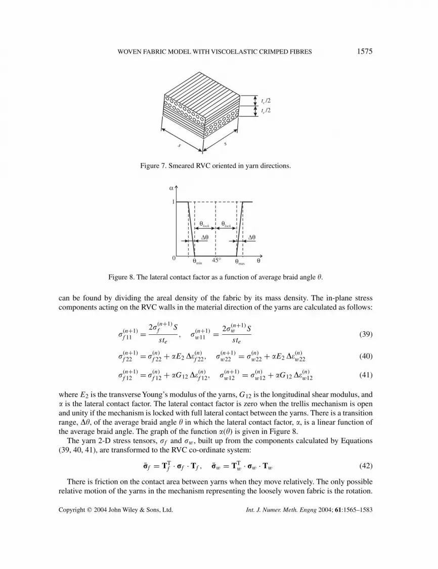
We can imagine that the RVC is smeared to the parallelepiped shown in Figure 7 in order totransform the stress acting on the yarn cross-section to the stress acting on the element wall. Thethickness of the membrane shell element used should be equal to the effective thickness, te, that
Copyright � 2004 John Wiley & Sons, Ltd. Int. J. Numer. Meth. Engng 2004; 61:1565–1583
WOVEN FABRIC MODEL WITH VISCOELASTIC CRIMPED FIBRES 1575
s s
te /2
te /2
Figure 7. Smeared RVC oriented in yarn directions.
θ
1
0 45° θmaxθ
α
min
∆θ∆θ
θlockθlock
Figure 8. The lateral contact factor as a function of average braid angle �.
can be found by dividing the areal density of the fabric by its mass density. The in-plane stresscomponents acting on the RVC walls in the material direction of the yarns are calculated as follows:
�(n+1)f 11 = 2�(n+1)
f S
ste, �(n+1)
w11 = 2�(n+1)w S
ste(39)
�(n+1)f 22 = �(n)
f 22 + �E2 ��(n)f 22, �(n+1)
w22 = �(n)w22 + �E2 ��(n)
w22 (40)
�(n+1)f 12 = �(n)
f 12 + �G12 ��(n)f 12, �(n+1)
w12 = �(n)w12 + �G12 ��(n)
w12 (41)
where E2 is the transverseYoung’s modulus of the yarns, G12 is the longitudinal shear modulus, and� is the lateral contact factor. The lateral contact factor is zero when the trellis mechanism is openand unity if the mechanism is locked with full lateral contact between the yarns. There is a transitionrange, ��, of the average braid angle � in which the lateral contact factor, �, is a linear function ofthe average braid angle. The graph of the function �(�) is given in Figure 8.
The yarn 2-D stress tensors, �f and �w, built up from the components calculated by Equations(39, 40, 41), are transformed to the RVC co-ordinate system:
�̄f = TTf · �f · Tf , �̄w = TT
w · �w · Tw (42)
There is friction on the contact area between yarns when they move relatively. The only possiblerelative motion of the yarns in the mechanism representing the loosely woven fabric is the rotation.
Copyright � 2004 John Wiley & Sons, Ltd. Int. J. Numer. Meth. Engng 2004; 61:1565–1583
1576 I. IVANOV AND A. TABIEI
x
y
M
w
s
TTy
Tx
T T
T
θ
θ
dθ
dθ
A , Iw
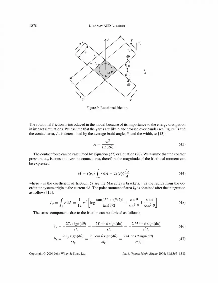
Figure 9. Rotational friction.
The rotational friction is introduced in the model because of its importance to the energy dissipationin impact simulations. We assume that the yarns are like plane crossed over bands (see Figure 9) andthe contact area, A, is determined by the average braid angle, �, and the width, w [13]:
A = w2
sin(2�)(43)
The contact force can be calculated by Equation (27) or Equation (28). We assume that the contactpressure, �c, is constant over the contact area, therefore the magnitude of the frictional moment canbe expressed:
M = 〈�c〉∫
A
r dA = 2〈Ff 〉Iw
A(44)
where is the coefficient of friction, 〈 〉 are the Macauley’s brackets, r is the radius from the co-ordinate system origin to the current dA. The polar moment of area Iw is obtained after the integrationas follows [13]:
Iw =∫
A
r dA = 1
12w3[
logtan(45◦ + (�/2))
tan(�/2)+ cos �
sin2 �+ sin �
cos2 �
](45)
The stress components due to the friction can be derived as follows:
�̂x = −2Tx sign(d�)
ste= −2T sin � sign(d�)
ste= −2 M sin � sign(d�)
s2te(46)
�̂y = 2Ty sign(d�)
ste= 2T cos � sign(d�)
ste= 2M cos � sign(d�)
s2te(47)
Copyright � 2004 John Wiley & Sons, Ltd. Int. J. Numer. Meth. Engng 2004; 61:1565–1583
WOVEN FABRIC MODEL WITH VISCOELASTIC CRIMPED FIBRES 1577
Then the final stress response of the model can be compiled from the yarn and the frictionalstresses in RVC co-ordinate system as follows:
�x = �̄f xx + �̄wxx
2+ �̂x, �y = �̄fyy + �̄wyy
2+ �̂y, �xy = �̄f xy + �̄wxy
2(48)
The membrane shell element formulation does not have resistance against the warping of quad finiteelements and this could cause some instability in 3-D finite element models. This could be avoidedby introducing transverse shear stiffness and calculating the transverse shear stresses in the shellelement formulation.
NUMERICAL RESULTS
The developed micro-mechanical model of loosely woven fabric is implemented in LS-DYNA ex-plicit finite element code as a user-defined subroutine for user-defined material. The simulationsof ballistic impact problems show the capability of the model. In order to validate the developedmaterial model, we want to compare the result of simulations to the parameters measured in ballisticexperiments.
The measurements in ballistic experiments are not easy and reliable. In the most of the experiments,the residual velocity of the projectile after the perforation of the target is measured only. Starrattet al. [14] announced results of continuously measured bullet displacements during the impact on afabric target of Kevlar� 129. The Enhanced Laser Velocity System used for the measurement is welldescribed in Reference [15]. Two experiments of 8-ply Kevlar� 129 target hit by 2.8 g blunt bulletare chosen for comparison. In the first example, the initial velocity of the projectile is 267 m/s andno perforation or any damage of any ply of the fabric target occurred. In the second example, theinitial velocity of the projectile is 428 m/s and full perforation of the target happened.
A quarter of the target is modelled by eight layers of shell elements in the finite element simulations.The mesh is refined in the area of the impact. A quarter of the bullet is modelled as a rigid body.The target is clamped at two opposite edges and simply supported over a rigid frame at the other twoedges. Details of the support and size of the target are described in Reference [14].
We do not have experimental data for the viscoelastic properties of the 840 denier Kevlar� 129fibres and we basically accepted the data used in Reference [7] for Twaron� fibres of aramid, becausethey look similar with the same ultimate strain �max = 3.3%. The parameters of the viscoelasticitymodel accepted for the simulations are as follows:
E1 = 96 GPa, Ka = 2E1 = 192 GPa, �b = 35 MPa, �max = 3.3%, �a max = 2.7%
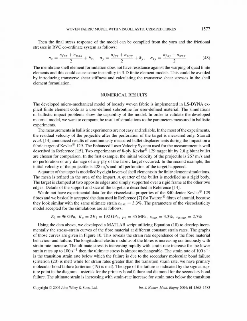
Using the data above, we developed a MATLAB script utilizing Equation (18) to develop incre-mentally the stress–strain curves of the fibre material at different constant strain rates. The graphsof those curves are given in Figure 10. This reveals the strain rate dependence of the fibre materialbehaviour and failure. The longitudinal elastic modulus of the fibres is increasing continuously withstrain-rate increase. The ultimate stress is increasing rapidly with strain-rate increase for the lowerstrain rates up to 100 s−1 then the ultimate stress is almost unchangeable. The strain rate of 100 s−1
is the transition strain rate below which the failure is due to the secondary molecular bond failure(criterion (20) is met) while for strain rates greater than the transition strain rate, we have primarymolecular bond failure (criterion (19) is met). The type of the failure is indicated by the sign at rup-ture point in the diagram—asterisk for the primary bond failure and diamond for the secondary bondfailure. The ultimate strain is increasing with strain-rate increase for strain rates below the transition
Copyright � 2004 John Wiley & Sons, Ltd. Int. J. Numer. Meth. Engng 2004; 61:1565–1583
1578 I. IVANOV AND A. TABIEI
0 0.005 0.01 0.015 0.02 0.025 0.03 0.035 0.04 0.045 0.050
1000
2000
3000
4000
5000
6000
Strain
0.001 s-1
10 s-130 s-1
50 s-1
150 s-1200 s-1300 s-1
70 s-1
100 s-1
500 s-1
Str
ess,
MP
a
Figure 10. Stress–strain curves of viscoelastic fibre material at different strain rates.
strain rate and it is decreasing with strain-rate increase for strain rates above the transition strain rate.This behaviour of the ultimate strain is similar to what we have in experiments of polymeric materialsbut how accurately this simple model represents the strain-rate dependent failure of Kevlar� 129we do not know exactly. The high strain-rate tests are still a problem as well as the modelling ofstrain-rate dependent behaviour of materials. The other elastic parameters of the fibre material areaccepted as follows: E2 = 7.4 GPa, G12 = 2.5 GPa.
The fabric of 840 denier Kevlar� 129 has areal density of 204 g/m2 and count 11 yarns/cm. Themass density of Kevlar� 129 is 1440 kg/m3. Some parameters of the woven fabric model are easyto be calculated from the data above as the cross-sectional area of the yarns, S = 6.48 × 10⁻² mm2,and the span between the yarns, s = 0.909 mm. The remaining parameters of the model are assumedfrom some geometrical considerations. They are as follows: �lock = 35◦, �� = 3◦, w = 0.32 mm, = 0.11. Many simulations using different values for the parameters above show that the sensitivityof the projectile displacement and velocity history to them is very small.
The most important parameter in the simulations, as Shim et al. [7] noticed, is the undulation of theyarns expressed by the thickness, t , in the model. The target deflection history as well as the projectilevelocity history strongly depends on the crimp of the yarns. Trying to match the experimental data
Copyright � 2004 John Wiley & Sons, Ltd. Int. J. Numer. Meth. Engng 2004; 61:1565–1583
WOVEN FABRIC MODEL WITH VISCOELASTIC CRIMPED FIBRES 1579
0 50 100 150 2000
5
10
15
20
25
Exper. 267 m/s Simul. 267 m/sExper. 428 m/s Simul. 428 m/s
Dis
plac
emen
t [m
m]
Time [µs]
Figure 11. Displacement history of the projectile.
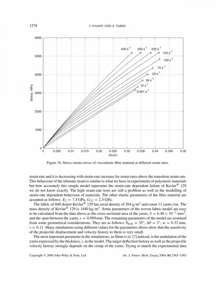
we assumed t = 0.820 mm. In our case perhaps, the assumed thickness incorporates not only thecrimping of the yarns but also the slippage of the fabric in the fixture at the clamped ends that we donot know.
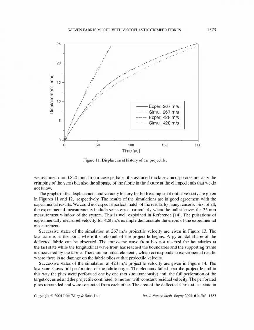
The graphs of the displacement and velocity history for both examples of initial velocity are givenin Figures 11 and 12, respectively. The results of the simulations are in good agreement with theexperimental results. We could not expect a perfect match of the results by many reasons. First of all,the experimental measurements include some error particularly when the bullet leaves the 25 mmmeasurement window of the system. This is well explained in Reference [14]. The pulsations ofexperimentally measured velocity for 428 m/s example demonstrate the errors of the experimentalmeasurement.
Successive states of the simulation at 267 m/s projectile velocity are given in Figure 13. Thelast state is at the point where the rebound of the projectile begins. A pyramidal shape of thedeflected fabric can be observed. The transverse wave front has not reached the boundaries atthe last state while the longitudinal wave front has reached the boundaries and the supporting frameis uncovered by the fabric. There are no failed elements, which corresponds to experimental resultswhere there is no damage on the fabric plies at that projectile velocity.
Successive states of the simulation at 428 m/s projectile velocity are given in Figure 14. Thelast state shows full perforation of the fabric target. The elements failed near the projectile and inthis way the plies were perforated one by one (not simultaneously) until the full perforation of thetarget occurred and the projectile continued its motion with constant residual velocity. The perforatedplies rebounded and were separated from each other. The area of the deflected fabric at last state in
Copyright � 2004 John Wiley & Sons, Ltd. Int. J. Numer. Meth. Engng 2004; 61:1565–1583
1580 I. IVANOV AND A. TABIEI
0 50 100 150 2000
100
200
300
400
500
Vel
ocity
[m
/s]
Time [µs]
Exper. 267 m/sSimul. 267 m/sExper. 428 m/sSimul. 428 m/s
Figure 12. Velocity history of the projectile.
Figure 14 is quite smaller compared with the deflected area at the last state in Figure 13. Thelongitudinal wave front has not reached the boundaries at the last state depicted in Figure 14.
The pictures of the simulations at both projectile velocities look very realistic and qualitatively wecould estimate them as in good agreement with the experimental results. In the numerical simulations,we are not able to present all phenomena of the ballistic impact. The contact force developed duringimpact events is different in the simulations compared with the experimental one because the contactarea is of the order of the microstructure of the fabric, i.e. of the size of the representative volumecell. In the real experiment, the projectile displaces the fibres in the yarns as well as the yarns inthe fabric crushing the fibres. This causes ramp increase of the contact force. The ‘wedge through’phenomenon does not appear in the simulations. The contact algorithm produces suddenly a contactforce based on penalty formulation. The shell elements are not transversely deformable and theyhave finite size and mass which causes sudden increase of nodal inertia forces. This difference inthe contact force development between the experiment and the simulation is obvious in the velocityhistory graphs.
In the present model, the slippage of the yarns at crossover points is missing and only the rotationalfriction is accounted for. The rotational friction will appear when we have 2-D membrane tension ofthe shell elements with in-plane distortion. An inspection of the elements in the simulations showsthat 2-D membrane tension occurs in the elements of the deflected area and the higher distortionappears in the elements out of the principle yarns, which are assumed to have significant energydissipated by the rotational friction. This energy loss however is difficult to be estimated becausewe have friction between the plies as well as between the projectile and the plies. Some small mass
Copyright � 2004 John Wiley & Sons, Ltd. Int. J. Numer. Meth. Engng 2004; 61:1565–1583

WOVEN FABRIC MODEL WITH VISCOELASTIC CRIMPED FIBRES 1581
Figure 13. Successive states of impact simulation at projectile velocity of 267 m/s.
damping of the fabric material is included in the simulations in order to present the effect of airresistance and to remove some low frequency oscillations. In this situation, it is difficult to extractthe rotational friction energy losses from the energy balance of the simulations.
Copyright � 2004 John Wiley & Sons, Ltd. Int. J. Numer. Meth. Engng 2004; 61:1565–1583

1582 I. IVANOV AND A. TABIEI
Figure 14. Successive states of impact simulation at projectile velocity of 428 m/s.
Copyright � 2004 John Wiley & Sons, Ltd. Int. J. Numer. Meth. Engng 2004; 61:1565–1583
WOVEN FABRIC MODEL WITH VISCOELASTIC CRIMPED FIBRES 1583
CONCLUSION
The developed micro-mechanical material model of loosely plain-woven fabrics can simulate almostthoroughly the behaviour of the fabric materials under impact. It can simulate the scissoring of theyarns due to the yarn rotations and the straightening of the crimped yarns. The fabric material isviscoelastic with strain rate dependence of the failure. The latter is very important for the impactsimulations with moderate and high velocity because the ballistic limit of fabric material is verydifferent then. The comparison between the experimental results and the results of the simulationsshows good agreement. The model has the capability to be used in finite element simulations fordesign of protective structures.
ACKNOWLEDGEMENT
Computing support was provided by the Ohio Supercomputer Center. Their support is gratefully acknowl-edged.
REFERENCES
1. Vinson JR, Zukas JA. On the ballistic impact of textile armor. Journal of Applied Mechanics 1975; 6:263–268.2. Taylor WJ Jr., Vinson JR. Modeling ballistic impact into flexible materials. AIAA Journal 1990; 28:2098–2103.3. Cunniff PM. An analysis of the system effect in woven fabrics under ballistic impact. Textile Research 1992; 62:
495–509.4. Walker JD. Constitutive model for fabrics with explicit static solution and ballistic limit. Proceedings of the 18th
International Symposium on Ballistics, San Antonio, Texas, November 15–19, 1999.5. Gu B. Analytical modeling for the ballistic perforation of planar plain-woven fabric target by projectile. Composites:
Part B 2003; 34:361–371.6. Ting J, Roylance D, Chi CH, Chitrangad B. Numerical modeling of fabric panel response to ballistic impact.
Proceedings of the 25th International SAMPE Technical Conference, Philadelphia, Pennsylvania, October 26–28,1993.
7. Shim VPW, Tan VBC, Tay TE. Modeling deformation and damage characteristics of woven fabric under smallprojectile impact. International Journal of Impact Engineering 1995; 16:585–605.
8. Roylance D, Hammas P, Ting J, Chi H, Scott B. Numerical modeling of fabric impact, ASME high strain rate effectson polymer. Metal and Ceramic Matrix Composites and Other Advanced Materials 1995; 48:155–160
9. Johnson GR, Beissel SR, Cunniff PM. A computational model for fabric subjected to ballistic impact. Proceedingsof the 18th International Symposium on Ballistics, San Antonio, Texas, November 15–19, 1999.
10. Lim CT, Shim VPW, Ng YH. Finite-element modeling of the ballistic impact of fabric armor. International Journalof Impact Engineering 2003; 28:13–31.
11. Shim VPW, Lim CT, Foo KJ. Dynamic mechanical properties of fabric armour. International Journal of ImpactEngineering 2001; 25:1–15.
12. Cheeseman BA, Bogetti TA. Ballistic impact into fabric and compliant composite laminates. Composite Structures2003; 61:161–173.
13. Page J, Wang J. Prediction of shear force and an analysis of yarn slippage for a plain-weave carbon fabric in a biasextension state. Composites Science and Technology 2000; 60:977–986.
14. Starratt D, Pageau G, Vaziri R, Poursartip A. An instrumented experimental study of the ballistic impact responseof Kevlar� fabric. Proceedings of the 18th International Symposium on Ballistics, San Antonio, Texas, November15–19, 1999.
15. Starratt D, Sanders T, Cepus E, Poursartip A, Vaziri R. An efficient method for continuous measurement of projectilemotion in ballistic impact experiments. International Journal of Impact Engineering 2000; 24:155–170.
Copyright � 2004 John Wiley & Sons, Ltd. Int. J. Numer. Meth. Engng 2004; 61:1565–1583