long-pulse neutron instrumentation workshop
TRANSCRIPT

STS04-41-TR0002, R00
Long-Pulse Neutron Instrumentation Workshop,
August 26-28, 2009
Report
August 23, 2010


This report was prepared as an account of work sponsored by an agency of the United States government. Neither the United States government nor any agency thereof, nor any of their employees, makes any warranty, express or implied, or assumes any legal liability or responsibility for the accuracy, completeness, or usefulness of any information, apparatus, product, or process disclosed, or represents that its use would not infringe privately owned rights. Reference herein to any specific commercial product, process, or service by trade name, trademark, manufacturer, or otherwise, does not necessarily constitute or imply its endorsement, recommendation, or favoring by the United States government or any agency thereof. The views and opinions of authors expressed herein do not necessarily state or reflect those of the United States government or any agency thereof.

STS04-41-TR0002, R00
Long-Pulse Neutron Instrumentation Workshop, August 26-28, 2009
Report
R. K. Crawford (editor), M. Arai, C. Carlile, L. Chapon, G. Granroth, S. Langridge, K. Lefmann, F. Mezei, M. Monkenbusch, G. Muhrer, A. Wiedenmann
Rev. 00 - August 2010
Prepared by OAK RIDGE NATIONAL LABORATORY
P.O. Box 2008 Oak Ridge, Tennessee 37831-6285
managed by UT-Battelle, LLC
for the U.S. DEPARTMENT OF ENERGY under contract DE-AC05-00OR22

STS04-41-TR0002, R00

STS04-41-TR0002, R00
CONTENTS
Figures.............................................................................................................................................v Tables ............................................................................................................................................ vi List of Acronyms......................................................................................................................... vii Preface........................................................................................................................................... ix
1.0 Introduction...........................................................................................................................1 1.1 Background and Philosophy ......................................................................................1 1.2 Workshop Goals...........................................................................................................1 1.3 Workshop Plan.............................................................................................................2 1.4 Introductory Presentations .........................................................................................3
1.4.1 Status of current long-pulse projects .............................................................3 1.4.2 Summary of recent long-pulse workshops.....................................................4 1.4.3 Lessons learned from recently completed facilities ......................................7 1.4.4 Basics of instrumentation for long-pulse sources..........................................9
1.5 References...................................................................................................................10
2.0 Diffraction ...........................................................................................................................12
3.0 Small Angle Neutron Scattering .......................................................................................13 3.1 Geometry ...................................................................................................................13 3.2 Resolution and proton pulse length..........................................................................13 3.3 Moderator...................................................................................................................14 3.4 Small sample SANS ...................................................................................................14 3.5 Focusing ......................................................................................................................14 3.6 Polarization.................................................................................................................15 3.7 Detectors .....................................................................................................................15 3.8 Double crystal TOF USANS .....................................................................................15 3.9 SESANS/SERGIS.......................................................................................................16 3.10 Kinetics from SANS...................................................................................................16 3.11 Design process ............................................................................................................16 3.12 Simulations .................................................................................................................16 3.13 Conclusion: “Work horse” and Flag-ship SANS ....................................................18 3.14 References...................................................................................................................18
4.0 Reflectometry ......................................................................................................................19 4.1 Scientific Drivers........................................................................................................19
4.1.1 Weaker effects ................................................................................................19 4.1.2 Smaller samples..............................................................................................19 4.1.3 Smaller lateral length-scales .........................................................................19 4.1.4 Kinetics ...........................................................................................................19 4.1.5 Excitations ......................................................................................................19
4.2 Potential Instrument Layouts ...................................................................................20 4.3 Challenges...................................................................................................................21
iii

STS04-41-TR0002, R00
4.4 Summary.....................................................................................................................21 4.5 References...................................................................................................................22
5.0 Larmor Devices and Spin-Echo.........................................................................................23 5.1 Introduction................................................................................................................23 5.2 High resolution...........................................................................................................24 5.3 TOF gain factors ........................................................................................................24 5.4 Distance from source .................................................................................................24 5.5 Source parameters .....................................................................................................25 5.6 Conclusion ..................................................................................................................26 5.7 References...................................................................................................................26
6.0 TOF Spectroscopy...............................................................................................................28 6.1 Introduction................................................................................................................28 6.2 Flagship instrument – cold neutron chopper spectrometer...................................28 6.3 Fine energy resolution spectrometer........................................................................29 6.4 Thermal spectrometer ...............................................................................................29 6.5 EV uses of neutron beams .........................................................................................30
6.5.1 Spectrometer ..................................................................................................30 6.5.2 Irradiation ......................................................................................................30
6.6 Other ideas..................................................................................................................30 6.6.1 Phase space transformation bunching .........................................................30 6.6.2 Inelastic reflectometry...................................................................................31
6.7 Technology development ...........................................................................................31 6.7.1 Detectors .........................................................................................................31 6.7.2 Wide angle polarization analyzers ...............................................................31 6.7.3 Fermi choppers ..............................................................................................31 6.7.4 Analysis software development.....................................................................32
6.8 References...................................................................................................................32
7.0 Sources .................................................................................................................................33 7.1 Introduction................................................................................................................33 7.2 Desired bandwidth .....................................................................................................33 7.3 Metric ..........................................................................................................................33 7.4 Bright spot on moderator..........................................................................................34 7.5 Viewed surface ...........................................................................................................35 7.6 Proton pulse length ....................................................................................................35 7.7 Ideas/recommendations.............................................................................................35 7.8 References...................................................................................................................37
8.0 Summary of workshop .......................................................................................................38
Appendix – Workshop Participants ...........................................................................................39
iv

STS04-41-TR0002, R00
FIGURES Figure Page
1.1 Simulation of measured Bragg Peaks from C-60 ...................................................................6 1.2 Examples of powder and single crystal diffraction data on WISH .................................................7 1.3 Multi-Ei measurement from a single crystal of CuGeO3 ........................................................9 3.1 Simulations of count rate for 10 nm spheres for SANS instruments of different lengths and
beam cross sections ..............................................................................................................17 3.2 Simulations [2] of resolution LPSS-SANS with L1=L2 =10 m and 2 m respectively with a
sample position at 18 m from source ....................................................................................17
v
STS04-41-TR0002, R00
vi
TABLES Table Page
1.1 Long-pulse instrument simulations...................................................................................4 1.2 Instruments considered at Rencurel and Ven ...................................................................4 3.1 “Work horse” and Flagship SANS .................................................................................18 7.1 Desired bandwidths for the individual instrument working groups ...............................33 7.2 Metrics proposed by the individual working groups ......................................................34

STS04-41-TR0002, R00
LIST OF ACRONYMS AND ABBREVIATIONS 4SEASONS Chopper spectrometer at J-PARC CCD Charge Coupled Device CRISP Reflectometer at ISIS-TS1 DMA Backscattering spectrometer at J-PARC ESS European Spallation Source ESSS Team proposing Lund, Sweden, as the site for the ESS ESS-Bilbao Team proposing Bilbao, Spain, as the site for the ESS FRM II Reactor-based neutron scattering facility in Germany Fz. Jülich Forschungszentrum Jülich (research center in Germany) GEM Diffractometer at ISIS-TS1 GINSE Grazing Incidence Neutron Spin Echo GKSS Research center in Germany HRPD Diffractometer at J-PARC HZB Helmholz Zentrum Berlin (research center in Germany) IDOM Company with headquarters in Bilbao, Spain IFE Institute for Energy Technology (Norway) ILL Institute Laue-Langevin (reactor-based neutron scattering facility in
France) IN5 Chopper spectrometer at ILL IN6 Chopper spectrometer at ILL IN11 NSE instrument at ILL IN15 NSE instrument at ILL INTER Reflectometer at ISIS-TS2 IPCF-CNR Institute for Physical-Chemical Processes – National Research Council
(Italy) ISIS pulsed spallation neutron source facility in Great Britain J-NSE NSE instrument at JRR-3 J-PARC pulsed spallation neutron source facility in Japan JRR-3 Reactor-based neutron scattering facility in Japan LANL Los Alamos National Laboratory LANSCE Los Alamos Neutron Science Center (at LANL) LET Chopper spectrometer at ISIS-TS2 LOQ SANS instrument at ISIS-TS1 LPSS Long Pulse Spallation Source Lujan Center Short pulse spallation source at LANL Mari Chopper spectrometer at ISIS-TS1 MIEZE Modulation of Intensity by Zero Effort NIMROD Diffractometer at ISIS-TS2 NISP Neutron Instrument Simulation Package (Monte Carlo software package
for simulation of neutron scattering instruments) NMI3 Integrated Infrastructure Initiative for Neutron Scattering and Muon
Spectroscopy (European initiative) NSE Neutron Spin-Echo
vii
STS04-41-TR0002, R00
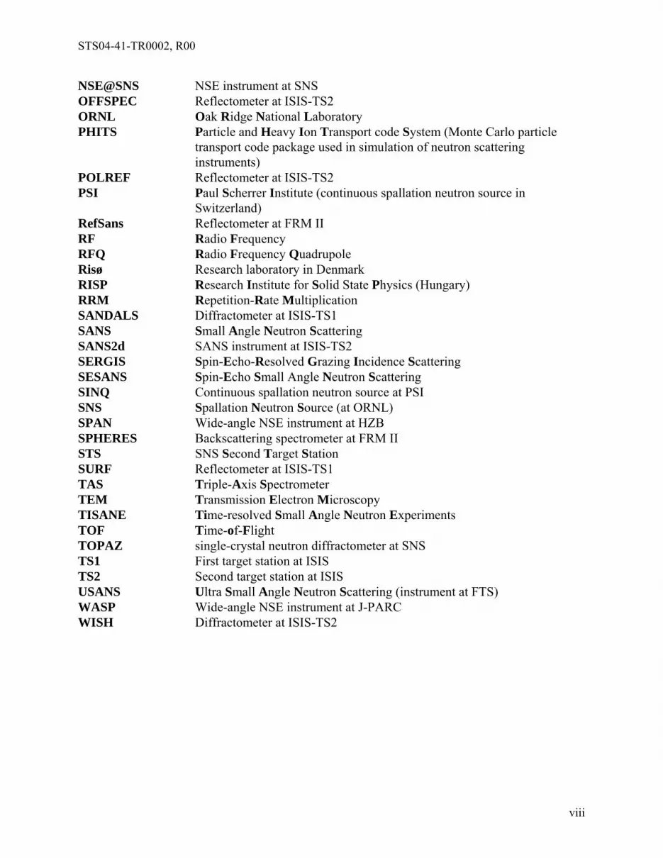
NSE@SNS NSE instrument at SNS OFFSPEC Reflectometer at ISIS-TS2 ORNL Oak Ridge National Laboratory PHITS Particle and Heavy Ion Transport code System (Monte Carlo particle
transport code package used in simulation of neutron scattering instruments)
POLREF Reflectometer at ISIS-TS2 PSI Paul Scherrer Institute (continuous spallation neutron source in
Switzerland) RefSans Reflectometer at FRM II RF Radio Frequency RFQ Radio Frequency Quadrupole Risø Research laboratory in Denmark RISP Research Institute for Solid State Physics (Hungary) RRM Repetition-Rate Multiplication SANDALS Diffractometer at ISIS-TS1 SANS Small Angle Neutron Scattering SANS2d SANS instrument at ISIS-TS2 SERGIS Spin-Echo-Resolved Grazing Incidence Scattering SESANS Spin-Echo Small Angle Neutron Scattering SINQ Continuous spallation neutron source at PSI SNS Spallation Neutron Source (at ORNL) SPAN Wide-angle NSE instrument at HZB SPHERES Backscattering spectrometer at FRM II STS SNS Second Target Station SURF Reflectometer at ISIS-TS1 TAS Triple-Axis Spectrometer TEM Transmission Electron Microscopy TISANE Time-resolved Small Angle Neutron Experiments TOF Time-of-Flight TOPAZ single-crystal neutron diffractometer at SNS TS1 First target station at ISIS TS2 Second target station at ISIS USANS Ultra Small Angle Neutron Scattering (instrument at FTS) WASP Wide-angle NSE instrument at J-PARC WISH Diffractometer at ISIS-TS2
viii

STS04-41-TR0002, R00
ix
PREFACE
This document provides the record of the joint European-US Long-Pulse Neutron Instrumentation Workshop held at Frascati, August 26-28, 2009. It includes a distillation of the introductory presentations and the full reports from the various working group breakout sessions that comprised the bulk of the workshop. As such, this report should be viewed as a set of notes resulting from the workshop, with some results remaining very sketchy because of the lack of time for further exploration at the workshop. Only minimal further refinements of these notes have been made for this report.
The workshop was successful in meeting its goal of assessing concepts for a number of neutron beam instruments that might be appropriate for the SNS Second Target Station and/or the ESS, and in defining the next steps for more detailed instrument optimization and evaluation of the performances anticipated from these instruments. Part of the credit for this goes to the chairs of the working groups who guided the discussions and prepared the final reports. Many thanks are also due Robert McGreevy and Carla Andreani, who dealt with many of the arrangements and administrative details for the workshop. However, the bulk of the credit goes to the workshop participants, who represented many different points of view and participated in insightful discussions, leading to a new appreciation of some aspects of the instrumentation and some novel instrumentation ideas. The workshop could not have been a success without these efforts.
RKC – November 2009

STS04-41-TR0002, R00
Long-Pulse Neutron Instrumentation Workshop, Frascati, Aug. 26-28, 2009
1.0 INTRODUCTION
1.1 Background and Philosophy
The European neutron community is currently working to develop plans for the ESS, a 5 MW long-pulse spallation neutron source[1], and the SNS in the US is currently developing plans for a second target station (STS) operating in the long-pulse mode at ~1 MW[2]. This workshop represents an effort by the US and European communities to pool resources to develop a better understanding of what might be possible with neutron beam instrumentation optimized for operation at such high-power long-pulse spallation neutron sources.
Since both the ESS and the STS are in the early conceptual design stage, there is currently considerable freedom to tailor the neutronic performance of each of these sources by varying the target-moderator-reflector geometries and materials to optimize the performance of the neutron beam instrumentation to meet the scientific goals (likely somewhat different at each facility). It has been demonstrated that such neutronic optimization can lead to large gains provided it is appropriately matched to the requirements of the associated instrumentation (a striking example is the Second Target Station at the ISIS facility in the UK[3]). Therefore, it is timely to carry out a systematic process of instrument optimization to define the source performance parameters best suited for particular instrumentation, so this information can be fed back into the source design process.
Advances beyond the capabilities of current sources and instrumentation generally bring with them improvements in some combination of the following four areas:
Smaller samples (access to new materials existing only in small quantities)
Faster measurements (kinetic processes, non-equilibrium systems, parametric processes)
Larger length scales (biology, soft-matter chemistry, aggregation, self-assembly, vortex lattices)
Longer time scales (big floppy systems)
The goal of this workshop was to systematically look at how far each measurement technique can be pushed at the currently planned long-pulse sources, with emphasis on these four broad areas. This workshop built on earlier work at the recent long-pulse instrumentation workshops in Europe (Rencurel, France in 2006[4] and Ven, Sweden in 2008[5]) and the STS instrumentation workshop in the US (Oak Ridge in 2007[6]).
1.2 Workshop Goals
Specific goals were:
1. Systematically extend the understanding of the strengths and weaknesses of various types of long-pulse-source instrumentation optimized to address differing types of scientific problems, and how far this instrumentation at the proposed new sources could surpass
1

STS04-41-TR0002, R00
current capabilities. Take advantage of the large body of instrumentation expertise that will be present at the workshop to develop instrument concepts thought to be appropriate to the specified scientific problems, and at least to specify in some detail the simulation(s) required to evaluate and/or optimize these concepts.
2. Develop innovative new instrumentation approaches to address some of the weaknesses found in conventional instrumentation approaches.
3. Utilize the instrument optimization process to identify source modifications and/or new component development that would significantly enhance the instrument performance.
4. Develop plans for longer-term coordination of activities to further extend these systematic studies, including provisions for carrying out the simulations suggested by, but not carried out at, this workshop , and provisions for developing the analysis software that may be required to extract the information of interest from the simulated data.
1.3 Workshop Plan
The workshop was held August 26-28 at the Villa Mondragone in Frascati, Italy. It started with a short plenary session addressing workshop organization and goals, providing short summaries of the Rencurel, SNS, and VEN workshops, and a few lessons learned from recently constructed facilities (these presentations are summarized in Section 1.4).
Most of the workshop was devoted to working groups, broken out along the lines of particular types of instrumentation. The success of the workshop was dependent on having a strong leader for each of these working groups to ensure the work proceeded efficiently to meet the workshop goals. These working group topics were:
Diffraction and imaging, including single-crystal diffraction; powder, total scattering, liquids diffraction; engineering diffraction; and imaging
SANS and USANS
Reflectometry
Larmor techniques including spin-echo
TOF spectroscopy
Sources
Relevant reading material was made available to workshop participants prior to and during the workshop. There was also one short plenary session to report working group status during the course of the workshop, and a longer plenary session to close out the workshop with reports of working group results and discussion of future plans. Working group leaders provided written reports of the results of their working group discussions, and these are contained in Chapters 2-7 below.
2

STS04-41-TR0002, R00
1.4 Introductory Presentations 1.4.1 Status of current long-pulse projects
ESS (reported by Colin Carlile)
The ESS project as it currently stands is a project to design and build a 5 MW long-pulse spallation neutron source and associated instrumentation. A reference design based on the earlier extensive planning for a more elaborate (short-pulse plus long-pulse) version[1] is based on using pulses directly from a linac operating at 16.7 Hz and producing 2 ms long proton pulses.
The ESS has recently been the subject of a site competition among three groups, and very recently the decision has been made in favor of the group proposing Lund, Sweden as the site. That group is now proceeding to gather agreements from partnering countries and beginning to revisit the optimization of the source parameters, the facility design, and the neutron scattering instrumentation for this facility, via an international consortium of expertise.
STS (reported by Kent Crawford)
The SNS has always included in its plans the possibility of adding a second target station as an upgrade. Recent studies directed toward a second target station (STS) commenced in 2006 with a series of workshops. These workshops indicated that the focus of the STS should be on production of intense beams of cold neutrons. Obtaining the most intense cold beams requires near-complete thermalization of the neutrons in a cold moderator leading to relatively long thermalization times (long pulses), and this in turn led to the consideration of a long-proton-pulse source. A “white paper”[2] was produced in 2007 indicating a possible concept for the STS and the level of performance of different types of instruments that could be expected with this concept under conditions of short proton pulses and long proton pulses. The assessment indicated that for many of the instruments the long-pulse mode gave similar or better performance than the short-pulse mode, particularly because somewhat more power can be supplied in the long-proton-pulse mode than in the short-pulse mode. The technical risks of long-pulse operation appeared to be lower as well. For these reasons, the STS project has focused on long-pulse operation.
Based on the white paper and other documents, SNS received Critical Decision Zero (CD-0) approval for the STS project in January, 2009, and from that point forward has been working on further exploring all the options for the STS and more fully developing the facility concept. At the current level of concept development, the STS would be a 20 Hz, ~1 MW source (upgradeable to somewhat higher power) operating in pulse-stealing mode to utilize every third pulse from the 60 Hz linac. Proton pulses would be ~1 ms long and the neutrons would be produced in either a flowing mercury target (similar to the first SNS target station) or in a rotating solid target (a concept currently under study). The moderators most studied so far are large parahydrogen moderators, but other options are being considered to provide different capabilities for at least some beamlines.
Under an optimistic scenario, the STS could be completed in 2019.
3
STS04-41-TR0002, R00
1.4.2 Summary of recent long-pulse workshops
Rencurel and Ven (reported by Kim Lefmann)
A workshop was held at Rencurel, France in September, 2006 to take a detailed look at instrumentation for the ESS long-pulse target station. This workshop placed heavy emphasis on instrument simulation, with 10 instrument experts and 10 simulators attending, and resulted in a general journal article[4] and an article on a cold neutron chopper spectrometer[7].
The workshop held at Ven, Sweden in October, 2008 was a continuation of the work begun at Rencurel. There were 12 simulators and 19 instrument experts at this workshop. There has not yet been a published report from this workshop.
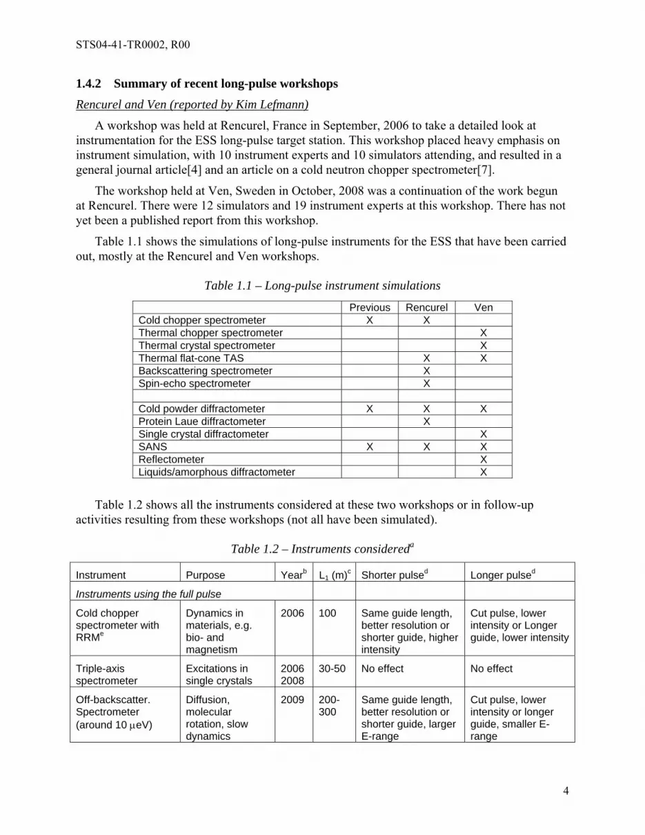
Table 1.1 shows the simulations of long-pulse instruments for the ESS that have been carried out, mostly at the Rencurel and Ven workshops.
Table 1.1 – Long-pulse instrument simulations
Previous Rencurel Ven Cold chopper spectrometer X X Thermal chopper spectrometer X Thermal crystal spectrometer X Thermal flat-cone TAS X X Backscattering spectrometer X Spin-echo spectrometer X Cold powder diffractometer X X X Protein Laue diffractometer X Single crystal diffractometer X SANS X X X Reflectometer X Liquids/amorphous diffractometer X
Table 1.2 shows all the instruments considered at these two workshops or in follow-up activities resulting from these workshops (not all have been simulated).
Table 1.2 – Instruments considereda
Instrument Purpose Yearb L1 (m)c Shorter pulsed Longer pulsed
Instruments using the full pulse
Cold chopper spectrometer with RRMe
Dynamics in materials, e.g. bio- and magnetism
2006 100 Same guide length, better resolution or shorter guide, higher intensity
Cut pulse, lower intensity or Longer guide, lower intensity
Triple-axis spectrometer
Excitations in single crystals
2006 2008
30-50 No effect No effect
Off-backscatter. Spectrometer (around 10 eV)
Diffusion, molecular rotation, slow dynamics
2009 200-300
Same guide length, better resolution or shorter guide, larger E-range
Cut pulse, lower intensity or longer guide, smaller E-range
4

STS04-41-TR0002, R00
Hybrid thermal spectrometer
Excitations in single crystals
2008 50 No effect Slight intensity loss
SANS, small sample Biological structures
2008 40 No effect (better resolution)
No effect
SANS, workhorse Macromolecular and biological structures
2008 20 No effect (better resolution)
No effect
Spin-echo SANS Micrometer-size structures
2006 40 No effect (better resolution)
No effect
Spin-echo spectrometer
Very slow dynamics
2006 40 No effect (better resolution)
Longer guide, smaller wavelength band
Inverted geometry thermal spectrometer
Excitations in single crystals
2006 100 Better resolution Worse resolution
Liquids reflectometer Surface layers, biophysics
2008 40 No effect (better resolution)
Longer guide, smaller wavelength band
Single crystal diffractometer, low resolution (full pulse) or medium resolution (shape pulse)
Small crystals, extreme environments, dynamic studies
2008 30 Low-res mode:: better resolution same flux Medium-res mode: same resolution, more flux
Both modes: longer instrument, same resolution, less flux
Instruments using a chopped pulse
Backscattering spectrometer (below 1 eV
Diffusion, molecular rotation, slow motion
2006 180 Higher intensity, same resolution
Lower intensity, same resolution
Thermal chopper spectrometer with RRMe
Magnetic excitations, lattice dynamics
2008 80 Higher intensity, fewer repetitions, slight advantage
Lower intensity, more repetitions, slight disadvantage
Single crystal diffractometer, large flux, RRMe
Protein crystallography
2006 70 Higher intensity, smaller wavelength band, advantage (< 1 s huge advantage)
Lower intensity, unchanged wavelength band, disadvantage
“Hard surface” reflectometer
Multilayers, nanotechnology
2008 40-80 Higher intensity, same resolution
Lower intensity, same resolution
“Cold” powder diffractometer
Crystal structure, magnetism
2005 2008
200 Higher intensity, same resolution
Lower intensity, same resolution
Disordered materials diffractometer
2008 NOT on ESS
5
STS04-41-TR0002, R00
a Assessments based on ESS parameters, 5 MW, 2 ms pulse, 16.67 Hz b Year the assessment/simulation was done c Source-sample distance d Compared to ESS 2 ms pulse length e RRM = Repetition-Rate Multiplication
Examples shown included: 1) highlights of ongoing work to determine which type of thermal spectrometer will work best on a long pulse; 2) some details of work completed on a cold chopper spectrometer [7]; 3) a diffractometer for small crystals; 4) new ideas for SANS and reflectometers; and 5) a cold powder diffractometer.
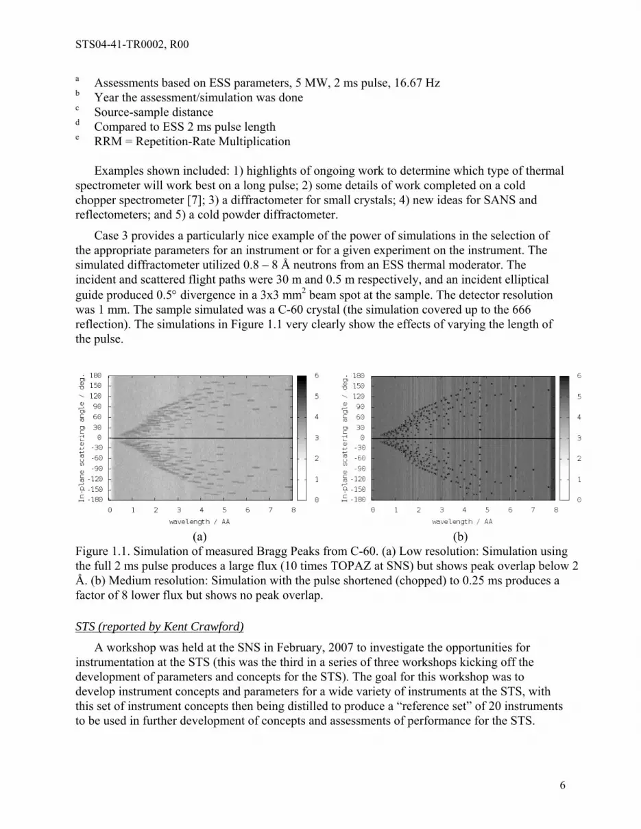
Case 3 provides a particularly nice example of the power of simulations in the selection of the appropriate parameters for an instrument or for a given experiment on the instrument. The simulated diffractometer utilized 0.8 – 8 Å neutrons from an ESS thermal moderator. The incident and scattered flight paths were 30 m and 0.5 m respectively, and an incident elliptical guide produced 0.5 divergence in a 3x3 mm2 beam spot at the sample. The detector resolution was 1 mm. The sample simulated was a C-60 crystal (the simulation covered up to the 666 reflection). The simulations in Figure 1.1 very clearly show the effects of varying the length of the pulse.
(a) (b)
Figure 1.1. Simulation of measured Bragg Peaks from C-60. (a) Low resolution: Simulation using the full 2 ms pulse produces a large flux (10 times TOPAZ at SNS) but shows peak overlap below 2 Å. (b) Medium resolution: Simulation with the pulse shortened (chopped) to 0.25 ms produces a factor of 8 lower flux but shows no peak overlap.
STS (reported by Kent Crawford)
A workshop was held at the SNS in February, 2007 to investigate the opportunities for instrumentation at the STS (this was the third in a series of three workshops kicking off the development of parameters and concepts for the STS). The goal for this workshop was to develop instrument concepts and parameters for a wide variety of instruments at the STS, with this set of instrument concepts then being distilled to produce a “reference set” of 20 instruments to be used in further development of concepts and assessments of performance for the STS.
6

STS04-41-TR0002, R00
The workshop had ~70 international attendees representing a broad range of disciplines, and produced concepts for 41 instruments. These instrument concepts and rough estimates of instrument performance were documented in a workshop report[6]. This workshop was not focused on instrument simulation, and no simulations were produced. Further refinements and performance assessments of the concepts chosen for the STS reference set of instruments can be found in reference [2]. 1.4.3 Lessons learned from recently completed facilities
ISIS-TS2 (reported by Sean Langridge)
The ISIS second target station (ISIS-TS2) produced first beams in August 2008. This target station operates in “pulse-stealing” mode, taking one pulse in five from the 50 Hz accelerator production. This 10 Hz operation for TS2 gives a 100 ms frame with 48 kW on the target. The target-moderator-reflector design is optimized for cold neutron production. Phase-1 included 7 instruments. INTER is a reflectometer emphasizing study of the air-water interface, and having more than 10 times the flux of the reflectometer SURF on TS1. Another reflectometer, OFFSPEC, includes spin-echo capabilities for studying in-plane structures. A third reflectometer, POLREF, uses polarised neutrons to study the inter and intra-layer magnetic ordering in thin films and surfaces, and has more than 10 times the flux of CRISP at TS1. All of these reflectometers view a grooved solid methane moderator. Another instrument for study of large-scale structures is SANS2d with more than 20-30 times the flux of LOQ at TS1. The WISH long-wavelength diffractometer for magnetic and large d-spacing systems has 20 times the peak flux of GEM at TS1 with the same divergence. It also has a wide angular detector coverage with no gaps. Figure 1.2 shows examples of WISH data for powder diffraction and for single crystal diffraction, projected onto the detector array in each case.
Figure 1.2. Examples of powder and single crystal diffraction data on WISH. Data are projected onto the detector array locus in each case.
Another diffractometer is NIMROD which is optimized for the study of near and intermediate range order. It provides more flux, wider Q-range and better resolution than SANDALS at TS1. The low energy transfer spectrometer LET is intended to provide high incident flux at low energies, and has a wide angular detector array with no gaps in coverage. It is designed to be
7

STS04-41-TR0002, R00
able to operate in a RRM mode to make measurements with multiple incident energies in a single frame.
The high level of performance of these instruments at the relatively low power TS2 arises from extensive optimization of the geometry and materials of the target-moderator-reflector system to match the needs of the individual instruments, coupled with the use of advanced neutron optics, chopper systems, and detectors. The relatively low power of this target station has made it possible to use solid methane as a moderator material, and this has significantly enhanced performance.
Other lessons learned include the importance of science driven designs with strong community involvement, the advantage of international partnerships, the need for a holistic design-delivery-operation model for instrument design and construction, and the importance of integrated instrument spaces (villages) grouping instruments addressing similar science or having other similar needs. Having available state-of-the-art computing capabilities is extremely important for simulation, instrument control, and for data reduction and analysis.
SNS (reported by Kent Crawford)
Neutron beams at SNS were first produced in April, 2006. The facility has been in routine operation for some time and is currently operating at power levels of ~850 kW. The accelerator system is designed for 60 Hz short-pulse operation at up to 1.4 MW. SNS currently has 7 instruments operating in user mode with several hundred users per year. Six more instruments are commissioning with beam and another six are under construction.
One of the lessons learned is the extent to which the choice of target material can drive the mechanical design requirements for the instruments (e.g., seismic constraints, shielding flammability). Another lesson is that the design developed at SNS for neutron beam shutters works extremely well for reproducible alignment of the guide through the shutter when the shutter is in the open position. Some of the SNS instruments utilize pits in the target building floor to allow the instrument detector array to extend vertically, and such pits are much easier to install when the building is being built rather than later.
Some of the things that worked very well include the ramp-up in power of the accelerator and the performance of the mercury target and the moderators which is consistent with the design analyses. The event-mode data acquisition system works well, and provides significant advantages for most instruments. Newly-designed and fabricated vertical-axis T0 choppers provide a very large background reduction for direct geometry instruments. A wide variety of guide and bender designs are in operation on the various instruments, and these perform in good agreement with the simulations. SNS has developed two different types of scintillation detectors, and these are well adapted to the needs of a number of the diffraction instruments. SNS adopted a policy on the allowable levels of magnetic fringe fields in the facility, and instruments have been designed to adhere to this policy. This is working well.
J-PARC (reported by Masatoshi Arai)
The neutron scattering facility at J-PARC produced its first beams in May 2008. It has been operating at low power (~20 kW) due to an RFQ problem, but expects to ramp up to 100 kW in November 2009. Design parameters for the accelerator system are 3 GeV, 25 Hz, 1 MW, double
8

STS04-41-TR0002, R00
bunched with 100 ns bunches 700 ns apart (i.e., short-pulse). Fifteen instruments have been funded, and several of them are already operational. One of these is the 100-m long high-resolution powder diffractometer (HRPD) which has a measured resolution of d/d ~0.035%. Another is the Fermi chopper spectrometer (4SEASONS), which has demonstrated some very nice multiple-Ei measurement (a form of RRM) results with inelastic scattering data from a single crystal sample of CuGeO3 collected concurrently at four different incident energies. This approach allows one to see the broad features over an extended range and also to “zoom in” on some of the details with higher resolution, all in a single data set as indicated in the Figure 1.3. (See also the subsequently published paper by Nakamura, et al. [8])
Ei = 150.7 meV Ei = 45.4 meV Ei = 21.5 meV Ei = 12.6 meV
Figure 1.3. Multi-Ei measurement from a single crystal of CuGeO3 (5.5 hours at 16 kW). Another instrument with RRM capability is the backscattering spectrometer (DMA), which uses a pulse-shaping chopper to achieve 1 eV resolution, and can collect data from several openings from this chopper for each source pulse (i.e., in a single 40 ms time frame between pulses from the moderator).
Lessons learned include the very good agreement between the calculated source performance (intensity and pulse width) and that measured. Similar good agreement is found for instrument performance. As indicated above, the implementations of RRM have been very successful. Event recording of the data has been found to be very useful. The coupled moderator is very popular, and is even preferred by many of the high resolution instruments. Pulse-shaping disk choppers are indispensible, as are high quality guides. 1.4.4 Basics of instrumentation for long-pulse sources
Presentation by Feri Mezei
This presentation emphasized that the optimization of instrumentation and facility parameters should be treated with a holistic approach, but that there are limitations on how far it is practical to vary some of the source parameters. As an example, the previously established parameters for an ESS long-pulse source were 5 MW at 16.7 Hz, with a 2 ms proton pulse. However, some of the instruments would perform better if the pulse were shorter, and some would perform better if the repetition rate were lower. If the 5 MW power could be achieved with a 1 ms pulse at 5 Hz, this would result in improvements to a number of instruments. However, the first case requires 150 MW peak power and 300 kJ/pulse, which is challenging but doable. The second case
9

STS04-41-TR0002, R00
requires 1000 MW peak power and 1000 kJ/pulse, which is beyond the state of the art. Other alternatives can be found which might be better for the instruments, but would be prohibitively expensive. Thus, the source characteristics should be optimized to meet the instrument requirements to the extent practical, but there are limits to how much the source characteristics can be adjusted. The main challenges to the accelerator technology ranked from most difficult to least difficult are peak power, energy per pulse, and average power.
In order to make the most of the opportunities provided within the limitations of the accelerator systems, many of the instrument designs need to be rethought so they are not just carbon copies either of short-pulse instruments or of steady-state instruments. One of the issues is that the optimum pulsing rate is very different for different types of instruments. For SANS the optimum rate might be ~ 20 Hz, while for direct-geometry TOF spectrometers the optimum rate might be ~ 300 Hz. One can bridge this gap by operating the accelerator at the lower frequency and implementing RRM [9, 10] to effectively increase the pulsing frequency for those instruments benefitting from a higher frequency. (Note that the multiple-Ei measurement scheme discussed in the J-PARC part of section 1.4.3 above does effectively the same thing, but with a simplified chopper scheme adequate for shorter neutron wavelengths.) As discussed above, we are already seeing first examples of the performance enhancement resulting from RRM (in the broadest sense) at a low-repetition-rate source in the early data from some of the instruments at J-PARC.
Another other key feature of instrumentation at long pulse sources is the general capability of pulse shaping, which can be achieved by adequate chopper systems [9]. This allows us to bridge the large differences in incoming wavelength resolution requirements by the different instruments. Paradoxically, long pulses with state-of-the-art pulse shaping choppers offer better resolution capabilities for thermal and cold neutrons than customary at short pulses. An additional new feature is, that the combination of long pulses and pulse shaping opens up the opportunity to vary the resolution on the same instruments in order to optimize the balance between resolution and beam intensity for each experiment. It is one of the current challenges in instrument design considerations to evaluate quantitatively the benefits of this new flexibility.
1.5 References
[1] The ESS Project: Vol. I, European Source of Science; Vol. II, New Science and Technology for the 21st Century; Vol. III, Technical Report; Vol. IV, Instruments and User Support. Available at http://neutron.neutron-eu.net/n_documentation/n_reports/ n_ess_reports_and_more/102.; see also http://essi.neutron-eu.net/essi
[2] Conceptual design study for a second target station for the Spallation Neutron Source, http://neutrons.ornl.gov/pubs/SNS_STS_report_public.pdf
[3] http://TS-2.isis.rl.ac.uk/
[4] H. Schober, E. Farhi, F. Mezei, P. Allenspach, K. Andersen, P.M. Bentley, P. Christiansen, B. Cubitt, R.K. Heenan, J. Kulda, P. Langan, K. Lefmann, K. Lieutenant, M. Monkenbusch, P. Willendrup, J. Šaroun, P. Tindemans, G. Zsigmond, “Tailored instrumentation for long-pulse neutron spallation sources”, Nucl. Instr. Meth. A 589, 34-46 (2008).
[5] http://www.essworkshop.org/index.php?title=Main_Page
10

STS04-41-TR0002, R00
[6] SNS Second Target Station Instrumentation Workshop, SNS 107000000-TR0007-R00, February 19-21, 2007.
[7] K. Lefmann, H. Schober, and F. Mezei, Meas. Sci. Technol. 19, 034025 (2008)
[8] M. Nakamura, R. Kajimoto, Y. Inamura, F. Mizuno, M. Fujita, T. Yokoo, and M. Arai, “First Demonstration of Novel Method for Inelastic Neutron Scattering Measurement Utilizing Multiple Incident Energies”, J. Phys. Soc. Japan 78, 093002 (2009).
[9] F. Mezei, M. Russina, “Multiplexing chopper systems for pulsed neutron source instruments”, in: I.S. Anderson, B. Guerard (Eds.) Advances in Neutron Scattering Instrumentation, Proceedings of SPIE 4785 (2002) 24-33.
[10] M. Russina and F. Mezei, “First implementation of Repetition Rate Multiplication in neutron spectroscopy”, Nucl. Instr. Meth. A 604, 624 (2009)
11

STS04-41-TR0002, R00
2.0 DIFFRACTION -WORKING GROUP REPORT
[Report Not Available]
12

STS04-41-TR0002, R00
3.0 SMALL ANGLE NEUTRON SCATTERING - WORKING GROUP REPORT
Chair: Albrecht Wiedenmann Other Participants: Heinrich Frielinghaus, Janos Füzi, Richard Heenan, Alan Hurd, Ken
Littrell, Antonio Pietropolo, Aurel Radulescu, Lazlo Rosta, Jun-ichi Suzuki, Roberto Triolo
3.1 Geometry
SANS needs to offer a large dynamic range in Q from some 10-4 A-1 to about 1 A-1. Flexibility of both collimation (L1) and detector position (at L2 from the sample) is key to optimize conditions to suit particular experiments.
Many SANS instruments are designed for samples up to say ~A2=25 mm in diameter, which requires for “optimal SANS” (L1=L2, A1 = 2A2) an input guide dimension A1=50 x 50 mm and typical lengths L1 and L2 of the order of 20 m.
It has been observed that the typical sample size hardly exceeds 10 mm which allows to scale down the SANS instrument accordingly: This allows to keep the same divergence and flux at the sample while the range of wavelengths from one pulse is increased. Though for very long guides a large size can have an advantage due to a reduced number of reflections, an over large guide on a pulsed source can be a route for unwanted backgrounds. If the maximum sample size is set at 10 mm then guides of 20 mm become optimal and the maximum length of L1 and L2 is reduced to 10 m. With the initial flight path L0= 8 m across the shielding and inserts (such as polarisers and lenses) a large wavelength band between typically 2 and 11 A can be used in one pulse leading to the same resolution and flux characteristics as the “workhorse SANS ” with a total length of 36 m discussed in [1].
Note also the minimum Q achieved in reality is always worse than theory or most simulations will predict due to parasitic scatter from apertures and detector effects, so beam lines should be “over specified” in this regard. The Q resolution at smallest Q is often also of questionable usefulness!
Long pulse SANS will very likely need a “bender” to remove a direct view of the target and cut out neutrons below ~ 1.5 – 2 Å which will possibly otherwise contribute to backgrounds by “moderating” within the shielding. Experience at SNS and J-PARC should be included.
3.2 Resolution and proton pulse length
A long pulse source that has the same time average flux as the ILL will make significant gains for SANS if a broad range of wavelengths can be used. With only a narrow band of wavelengths it will simply replicate what can already be done. Q resolution is important for SANS experiments where bumps, wiggles and inflexions can appear almost anywhere in Q. These details can provide vital clues to differentiate one structural model from another in sets of data that are otherwise almost identical in say the Guinier region.
13
STS04-41-TR0002, R00
In previous workshops a ~2 ms proton pulse at 16.66 Hz was taken as “given”. The opportunity to input to discuss other pulse lengths and repetition rates would be welcome. To build a strong, ground-breaking pulsed source SANS beam it is important to have acceptable resolution over as broad a range of wavelengths as possible, extending down to the peak in flux at 3 – 4 Å. A pulse length of 1 ms rather than 2 ms will give more scope to do this with shorter, less expensive, beam lines with larger band widths and hence wider simultaneous Q range. For longer beam lines the effects may be less noticeable.
Simulations of resolution functions for different instrument parameters have been initiated taking into account different pulse lengths, repetition rates and moderator shapes.
3.3 Moderator
The metric to be maximised is perhaps the integral of flux perÅ n from say 2 to 12 Å, where n is to be determined, but n ~ 2 – 4 is likely relevant, and may not make any difference. A moderator time constant τ of 0.5 ms will likely be more acceptable than say 1msec, though this needs some simulations and is obviously also coupled to the issue of the proton pulse length.
The guide has still to be well coupled to a moderator, which suggests an optimisation including a moderator with a “groove” or “hot spot”.
A “grooved” or other “high flux spot” moderator with one dimension of order 20-40 mm will likely be best matched to the relatively small cross section bender and guide.
3.4 Small sample SANS
“Small sample SANS” down to 2-3 mm can be done on a normal beam line by reducing A1 and A2 as far as the incident neutron flux is sufficient. However gains in Q range can be made with a suitably high resolution detector (pixel size ≤ A2 ). This might warrant a separate beam line, especially if the very best in Q resolution is desired on a long-pulse source (long L0).
A beam focussed at a small, 2-3 mm sample by a lens will increase flux (easily by factors ~5), but for only short L2 due to beam divergence after the sample. Much smaller samples, as for example, “micro-fluidic” channels, which have been examined by X-rays will be considerably more challenging. Slit shaped beams and adsorbing masks deposited between channels on a chip might help. Simulations/calculations are required here.
A multi-beam setup has been discussed where many individual beams separated by several degrees are focussed onto the sample with recording of the SANS signal in individual detectors. In order to take advantage from the large wavelength band in the pulsed beam broad band focussing mirrors are required which are presently not available.
3.5 Focusing
Magnetic sextupole lenses, developed in Japan, require 99.9% polarisation (see below). Fully polychromatic magnetic lenses for TOF are complex, expensive and thus far have high stray fields. A simpler method of three lenses with pi flippers has been shown to work for a ~ 2 -3 Å wavelength range. ZOOM at ISIS TS-2 proposes “fast apertures” to re-collimate the optics during pulses so that un-focussed short wavelength neutrons still have reasonable collimation
14
STS04-41-TR0002, R00
and count rates (to gain higher Q values). Such devices could also be used to move the source pinhole position towards or away from the lens during pulses to aid focussing.
Focussing at the detector gives smaller Q, but with large samples required for optimal count rates. Moving the sample closer to the detector gives a compromise, with reduced Q range for smaller samples. Note that only the longest wavelengths need be fully focussed, shorter wavelengths may be partially focussed. Fast apertures will be needed to re-collimate during pulses.
Focussing to 2 -3 mm at the sample will be helpful for “small” samples, especially for biology.
Ideally, focussing should be added as an immediately available option on a normal SANS beam line. Clever engineering is needed to move the sample position and the detector vacuum tanks quite large distances (e.g. see ZOOM proposal).
R. Gähler has proposed spinning in a non-linear way, large, one dimensional MgF2 lenses as a method to focus say 10-20 Å during a TOF pulse.
3.6 Polarisation
An incident polarised beam, with possibly a 3He analyser cell in the scattered beam after the sample will be essential for magnetism experiments. A combination of mirror in transmission (for short wavelengths) and transmission polariser (for long wavelengths) can give ~ 95% polarisation over a broad band max/min ~10, though there are some issues with critical reflection from the silicon mirror substrate.
A fixed field quadrupole magnet, though more expensive, can give 99.9% polarisation needed for magnetic lenses.
3.7 Detectors
Both small sample and focusing SANS beam lines require high count rate neutron detectors (e.g. 1 MHz per pixel) of ~ 2 mm or better pixel size respectively. Development of such devices, to be economic over say initially 200 x 200 mm is a necessity (and later perhaps to 1m x 1m areas.)
CCD and image plate devices do not yet have enough dynamic range or read out for TOF ! Scintillators plus phototube have good dynamic range but are only available for small areas.
3.8 Double crystal TOF USANS
Such an instrument is being developed, slowly, at SNS, and has potential science areas particularly in geology, materials, soft matter and metallurgy. A Bonse-Hart type instrument with channel cut crystals will need a special beamline and cannot be included in standard pin-hole SANS.
15

STS04-41-TR0002, R00
3.9 SESANS/SERGIS
Larmor encoding techniques present much potential for new science on 100 nm to 100 micron size range, and are being explored at ISIS/Delft and in USA. Real space data provides a complementary view especially for the details of large particle interaction potentials (relevant for directed assembly etc). A compact SERGIS device “added in” to a conventional polarised incident beam SANS line, would complement the dynamical range of the instrument using the same sample set-up.
3.10 Kinetics from SANS
The stroboscopic TISANE method using a fast chopper allows periodic processes in the sub-millisecond time range to be examined. Whenever the scattering system responds to a periodic perturbing field this modulation technique can close the time gap between Mössbauer and inelastic neutron scattering techniques (10-6-10-12 s) and static measurements.
Developments should be followed and consideration given as to the merits of TISANE on a pulsed source. In any case if a 5MW source matches the ILL spectrum then results will be equally good. Simulations are needed here.
Stop-flow and frame by frame “event mode” recorded data on a time scale of seconds are taken as “normal features” of pulsed source SANS. Long pulses will obviously limit time resolution within pulses (where cyclic sample perturbations may be asynchronous with neutron pulses to scan the full Q range).
3.11 Design process
Though teams of scientists and design engineers may be collaborating a single point of contact on both sides should be the channel for all decisions on a day to day basis. It is useful to deal with the “whole beam line layout” as early as possible, detailing cable routes, sample services, electronics racks and modes of safe operation for installation of sample environment, additional polariser/filters etc.
3.12 Simulations
We still need to compare results of different simulation programs. Japanese PHITS as well as Phil Seeger’s NISP can to some extent include backgrounds and parasitic scatter. PHITS will be useful for lenses. (Japanese visitors to ISIS will shortly start a knowledge transfer process for PHITS.)
Figure 3.1 shows a simulation [2]of the count-rate in a 1 m 1 m detector for spherical particles of 10 nm size for SANS instruments of different total lengths and different beam cross sections (but with the same divergence). The accessible Q range of the short instrument 6/5/5 is by one order larger than for the long 6/15/15 instrument while the resolution is still sufficient to reproduce the characteristic intensity oscillations. A “Debye Scherrer” sample, with a list of delta functions at discreet Q values was used for simulations to fit and then evaluate the resolution. Figure 3.2 shows that ΔQ/Q of about 4% can be achieved with a 8/10/10 instrument with little influence of the pulse length.
16

STS04-41-TR0002, R00
10-4
10-3
10-2
10-1
100
10-4
10-3
10-2
10-1
100
101
102
103
104
spheres of 100 nm diameter
Co
unt r
ate
[n/s
]
Q [Å-1
]
6+ 2+ 2 m, 4x 4 mm2
6+ 5+ 5 m, 10x10 mm2
6+15+15 m, 30x30 mm2
19+ 2+ 2 m, 30x30 mm2
Figure 3.1: Simulations [2] of count rate for 10 nm spheres for SANS instruments of different lengths and beam cross sections.
Figure 3.2: Simulations [2] of resolution LPSS-SANS with L1=L2 =10 m and 2 m respectively with a sample position at 18 m from source.
17

STS04-41-TR0002, R00
3.13 Conclusion: “Work horse” and Flagship SANS.
The large demand in the SANS area justifies both a long and short SANS version at a long-pulse source. An early decision about the number of SANS instruments to be built would be favourable since it would allow to optimise better the instrument design. For a single “flag-ship” instrument the trade-off between intensity, resolution and Q range would lead to the following characteristics:
Table 3.1 – “Work horse”and Flagship SANS
Parameter or Feature Value
Maximum sample size 11 cm2
Guide cross section: 22 cm2
Maximum lengths L1, L2: 10 m
Beam-bender to avoid direct view
Wavelength band 1.5 - 15Å
Detector Size Spatial resolution Count rate capability/per pixel
1 m2
2 mm 1 MHz
Pulse length & frequency 1.5 ms, 16 Hz
Focussing to sample by refractive lenses (small volumes) or to detector (extended Q range)
Polarised beam from broad band super-mirrors 0.5 -1 m
Polarisation analysis by 3He filters
Micro-second dynamics using TISANE with multi-slit double chopper
3.14 References
[1] H. Schober, et al., Nucl. Instr. and Meth. A (2008), doi:10.1016/j.nima.2008.01.102
[2] K. Lieutenant : private communication
18

STS04-41-TR0002, R00
4.0 REFLECTOMETRY - WORKING GROUP REPORT
Chair: Sean Langridge Other Participants: Rob Dalgliesh, Mike Fitzsimmons, Reinhard Kampmann, Roger Pynn
4.1 Scientific Drivers
The scientific drivers for the application of reflectometry to nanoscience are well established. To look beyond the instrumentation that currently exists at spallation sources around the world it is important to take a science driven approach to their specification and implementation. Based on current experience and scientific trends it suggests that to increase our current and near-term capabilities we will need to address the following scientific and technical issues:
4.1.1 Weaker effects
There is a clear need to study weaker effects/interactions within nanoscale systems. For magnetic systems pushing the sensitivity below 1emu cm-3 will give access to such problems as interfacial “non-magnetic oxides” and push towards pure spin current effects to match the impressive advances in spintronics. Structurally the ability to observe smaller changes in scattering length density (contrast) would be beneficial especially when combined with parametric studies.
4.1.2 Smaller Samples
The past two decades has seen phenomenal development in nanofabrication and lithography. New instruments must have the ability to look at samples which are smaller than 1cm2. This will then push towards and complement techniques such as TEM, x-ray probes etc. It would also match onto realistic sample areas for complex materials or large area lithographically designed structures such as can be provided by the nanoscience centres that are often co-located with neutron/photon facilities. This need may also be driven by sample environment requirements for extreme conditions.
4.1.3 Smaller lateral length-scales
The technologically relevant in-plane length-scale varies from ~1 nm up to microns. New instrumentation should address this range.
4.1.4 Kinetics
Access to processes with sub-second time-scales should be accessible with millisecond resolution available for stroboscopic measurements.
4.1.5 Excitations
A capability to measure surface, interfacial magnon and phonon excitations would be a step change in our understanding and complement light scattering studies etc.
19

STS04-41-TR0002, R00
4.2 Potential Instrument Layouts
For our discussions we considered 2 beamline options: a 30-40 m option and a 60 m option with tuneable resolution. Both instruments view a bright moderator. Whilst a high power target naturally leads to a large incident neutron flux this clearly has to be balanced against potential resolution restrictions. The 30-40 m option provides a high intensity, medium resolution instrument contrasted by a tuneable 60 m instrument. An often overlooked outcome of longer instruments is the potential for reduced instrumental backgrounds, pulse shaping, beam multiplexing and additional space for advanced beam polarisation, focussing schemes and possible sidestations.
Our initial layout criteria were based on:
16.67 Hz 2 ms target
Moderate resolution (Q/Q ~ 5%)
Out of line of sight to minimise background
Switchable polarised-unpolarised beam options
A performance metric of Integrated flux 4
As has been found previously[1-4] , our discussions focussed around a 30-40 m instrument producing a ~6-8 Å wavelength band. Initial Monte Carlo simulations comparing the reflectivity from an ESS moderator for the two prototype instruments suggest that the long pulse offers over an order of magnitude increase in flux with relaxed resolution compared to a short pulse instrument. However, it is important to note that experimental studies at the Lujan Centre[5] operating with a pulse duration of 250 ns and 625 s show the expected flux gains but with an acceptable degradation in resolution. If required, this resolution can be partially recovered in the 60 m instrument at the expense of bandwidth. This bandwidth can be recovered via frame multiplication but at a flux cost.
The ability to vary the characteristics of a longer (60 m) instrument is very appealing and merits further consideration. Obviously, this flexibility carries with it a financial and flux overhead.
Spin labelling instrumentation was also discussed. The consensus was that given the worldwide developments it would be prudent to observe how these techniques develop before opting for a design strategy for a long pulse target station.
Any prioritisation from our original discussion evidently depends on the potential need for high resolution measurements. For many problems, relaxed resolution is desirable (liquid surfaces for example) whilst for others, higher resolution is required (complex multilayer structures for example). What is a common requirement is the need to access a large range of reciprocal space. This requires a high incident flux, minimised systematic errors and a low instrumental background. Reflectivities of 10-8 and a momentum transfer of ~0.5 Å-1 would be a reasonable objective.
It is noteworthy that the discussion did not have time to pursue the very likely gains from such developments as multiplexing, multiple incident beams, recombination of polarised beams etc.
20

STS04-41-TR0002, R00
4.3 Challenges
Much of the discussion centered on the challenges to be addressed in producing such an instrument suite. Even with the impressive developments worldwide there is still considerable scope for improvement. An approximate prioritised list would include:
Detectors: Current detector technology is already limiting data acquisition given the needs for large count rates, high spatial resolution and large dynamic range.
Focussing: large gains ( 25) can be achieved from neutron focussing on the instrument particularly for the case of pure specular scattering focussing in both directions. This has not currently been fully exploited. The effect of the optics induced beam structure must also be considered.
Data quality: To access the weak phenomena requires data of a high statistical quality. Minimisation of the systematic errors of the instrument (e.g. polarising efficiency) is essential. Also applicable to Analysis.
Analysis: There still remains considerable scope for progress on the reduction, visualisation, analysis and theoretical interpretation of reflectometry data. The validity and applicability of theoretical techniques is still an active area of research.
Simulation: To access reflectivities of 10-8 requires an improvement in our ability to simulate the full instrument performance. Current MC techniques give a good overview of performance but do not capture the backgrounds and inhomogeneities that are central to the actual performance of the instrument. Equally, a detailed study is required to reconcile the apparent loss in Q-resolution from simulation which is not mirrored in the experimental data currently available.
Magnetic Environment: a clean environment to allow complex magnetic field sample environment and to reduce depolarization effects.
Each of these issues raised has potential for significant impact on the instrument performance.
4.4 Summary
The working group have identified 2 reflectometer layouts for further consideration on a high power long pulse target station: a high intensity, medium resolution instrument complemented by a controllable instrument taking advantage of pulse shaping and frame multiplication. The high intensity instrument on a 2 ms, low frequency source offers a significant increase in performance over existing instrumentation for medium resolution experiments. Whilst the second offers customized performance taking full advantage of novel developments in neutron transport and polarisation. Several development requirements are identified to deliver instrumentation capable of measuring reflectivities of 10-8 from 1 cm2 samples.
21

STS04-41-TR0002, R00
4.5 References
[1] H. Schober et al. NIM A 589 (2008) 34–46
[2] J.R.P. Webster et al. ESS Venn Meeting
[3] M.R. Fitzsimmons NIM A 383 ( 1996) 549
[4] H. Fritzsche and K. Lieutenant J. Neutron Research, (2003) 11, 61
[5] M.R. Fitzsimmons et al. “Test of the long pulse spallation source concept at the Lujan Center” (2003)
22
STS04-41-TR0002, R00
5.0 LARMOR DEVICES AND SPIN ECHO - WORKING GROUP REPORT
Chair: Michael Monkenbusch Other Participants: Ken Andersen, Rob Dalgleish, Georg Ehlers, Bela Farago, Janos Fuzi,
Alexander Ioffe, Gyorgy Kali, Feri Mezei
5.1 Introduction
In this chapter we discuss the impact of Larmor techniques on the instrumentation of a future long-pulse spallation source. As it turns out the focus here will be on high resolution spectroscopy. A number of other ingenious and useful Larmor techniques have been identified as add-ons for SANS instruments and reflectometers. The following techniques have been considered:
1. High resolution NSE spectroscopy (using precession magnets) [1]
2. Wide angle NSE spectroscopy (using precession magnets) [2]
3. Resonance NSE, MIEZE etc. (using zero field and RF-flippers) [3]
4. New approaches, like NSE with time varying flippers [4]
5. High resolution SANS with NSE (SESANS) [5]
6. Grazing incidence: SERGIS, GINSE [6]
7. 3D polarimetry (in combination with NSE ) [7]
8. Beam modulators (Drabkin filters, choppers)
As genuine full instruments at a new long-pulse spallation source only the first two items have the potential to become state-of-the-art workhorses for the community. Among the others, 5 and 6 are well developed methods that we would recommend as (optional) add-ons for the corresponding basic instruments, i.e. SESANS[5] for SANS and SERGIS[6] as SESANS on a polarized reflectometer as it is already realized at OFFSPEC[8] at ISIS-TS2.
Points 6 (GINSE = spectroscopic NSE at grazing incidence) and 3 polarimetry are to be considered as options for the spectroscopic NSE 1, 2. Items 4 and 8 are still experimental so in the near future they will not justify the assignment of a high intensity beamport, except for temporary use for development at a general purpose test beamline.
Finally 3 (resonance NSE) is identified as a method that offers unique possibilities if installed on a three axis type spectrometer in order to measure the widths of dispersion surfaces[9] or for ultrahigh resolution diffraction[10]. Resonance NSE for spectroscopy and MIEZE are due to the technical limitation imposed by the RF-flippers and the non-availability of correction elements to enable larger beam divergence and high resolution –to our opinion—not in a state to serve as competitive ultra-high resolution spectroscopic instruments.
23

STS04-41-TR0002, R00
Therefore we focus the further considerations on the instruments of the first type, analog to (IN11, IN15[11], J-NSE[12], NSE@SNS[13], ….) and to those of the second type (SPAN[2], WASP[14]). There are several properties and conditions that are common to these instruments.
5.2 High resolution
The primary resolution parameter is the maximum Fourier-time, t, that can be measured. It is completely decoupled from any time structure of the neutron pulse and depends solely on the shaping and control of the instruments magnetic fields. For a given magnetic field integral along the neutron flight path from, e.g. sample to analyzer (pi to pi/2 –flipper), J = Bdl, the Fourier-time is t = J3 with ≈ 0.2 nsT-1m-1Å-3. Since the state-of-the art magnets and auxiliary elements allow for J ≈ 1 Tm, the only efficient way to reach Fourier-times in the several 100 ns to s region is the use of (very) long wavelength neutrons. For example, a wavelength of 16 Å would be required to obtain t = 0.8 s with J = 1 Tm. This observation leads to the first request on the moderator type and layout. Also the next property will add input to the moderator design.
5.3 TOF gain factors
All reactor based instruments accept a wavelength band of 10-15% of the incoming neutrons, which is well adapted to most of the soft-matter-problems. The envisaged proton pulse length of the source is 2 ms. We assume that the resulting effective neutron pulse length is in the range of 3 ms. Thus the wavelength uncertainty of intensity reaching the detector with distance L from the moderator is at any time given by 410-7 m2s-1 t/L. For an instrument with detector distance L = 50 m this yields = 0.24 Å which corresponds to 10% width at = 2.4 Å becoming worse for shorter wavelength, however, much better for longer ones, i.e. 2% at 12 Å.
Since intensity is one of the most important limitation factors for all present NSE spectrometers –in view of the above mentioned “natural” wavelength spreads— the best choice is to refrain from any (intensity eating) pulse shaping and restrict the chopper system to frame selection only.
The wavelength range covered by one frame between chopper pulses is again independent of wavelength and is 410-7 m2s-1 (1/f)/L. With a repetition frequency f = 16.66 Hz we obtain 5 Å at a detector distance of L = 50 m.
The gain factors g due to the pulsed operation compared to a continuous source of the same average flux may be computed by a naively unbiased comparison of the same sequence of experiments done at a continuous source with wavelength width W = and the pulse source: g = ln[(+/2)/(-/2)]/W with W = 0.1, 5 Å and a central wavelength we get = 5 (g = 11),= 10 (g = 5),= 16 (g = 3). However, the experiment at the pulsed source imposes the same counting times for all partial experiments, which in many cases would be conducted with different, optimized times at a continuous source. Thus the above gain factors are upper limits.
5.4 Distance from source
If a sector of 12 is available at a beamline this would imply a lateral space of 8-10 m for an instrument with L = 50 m. For a generic IN11 type instrument which is designed without
24

STS04-41-TR0002, R00
restrictions to space, however, with scattering angle limited to one side one would like to have a 0.5 m for shielding and >1.5 m distance of the beam axis and the inner shielding wall. At the scattering side the secondary arm should be able to swing to 90 or more, a total length of 5 m plus 0.5 m for shielding then implies a total width of 7.5 m at the sample distance. In the above example 9 m would be available, but the described scenario is not symmetric with respect to the beam. In the latter case 4.5 m would be available also on the scattering arm side whereas 5.5 m would be desirable. Detailed design has to show how much deviation from symmetry may be available and how the extraction of two beams from one beam port can be made compatible with these conditions. Shorter distances down to L = 30 m can certainly be realized – in particular if asymmetric configurations are allowed. They would yield wider frame width (8 Å) but may already require compromises with respect to the magnetic design due to arm length restriction.
For a wide angle instrument of the SPAN type one may consider the WASP design [14] as a reference. The diameter of this instrument is ~7 m if analyzers, detector and detector shielding is included with some space on both for shielding and bypass a minimum of L = 50 m results.
A large distance (even beyond 50 m) has additional advantage that the background is low and direct sight to the moderator may be easily avoided by curved (pre-polarizing) guides. For NSE instruments it is also of genuine importance to have a clean magnetic environment with field variation of less than some mGauss during a scan. On the other hand the instruments themselves generate magnetic fields that contribute to fraction of a Gauss outside the own sector for a compensated IN11 type instruments and of several Gauss for a WASP type instrument. A large L helps to cope with the magnetic interference problem by increasing the distance between instruments. It also yields enough space to install a magnetic shielding if required.
5.5 Source parameters
Source parameters and moderators that meet the requirements of the instruments described above are discussed here.
The pulse length of 2 ms is compatible with the majority of applications for the NSE spectrometers. In particular high intensity in terms of number of neutrons in the pulse is the most important criterion. On the other hand there is no special advantage to have long pulses. Some experimental problems that need better Q-resolution (e.g. samples with sharp structures in S(Q) like oriented lamellar microemulsions) and would benefit from the lower wavelength spread due to shorter pulses.
The envisaged repetition rate of 16.66 Hz for ESS is acceptable but going to a somewhat lower frequency (10 Hz) would still increase the overall performance of the NSE instruments, provided that the average power stays unchanged.
Since the challenge for NSE spectroscopy specifically lies in the ultra high resolution sector it is essential to have high neutron flux at long wavelengths up to 20 Å or more. This requires in any case a cold coupled moderator. In addition, optimization for the best available long wavelength neutron flux is requested. In the course of such an optimization – for NSE instruments – it is acceptable that the pulse length is increased by an extended moderation time.
25

STS04-41-TR0002, R00
5.6 Conclusion
As flagship instruments from the Larmor/Spin-echo class a high intensity, high resolution IN11 type spectrometer and/or a wide angle NSE spectrometer of the SPAN/WASP type are recommended. If there is room to modify the accelerator parameters, a slight reduction of repetition frequency (without reduction of average power) would be beneficial. The pulse width of 2 ms is acceptable but if technology allows shorter pulses could improve experiments on samples with sharp structures in S(Q). But, intensity – particularly at long wavelengths – is of paramount importance even if it is achieved by measures that extend the neutron pulse width.
5.7 References
[1] F. Mezei, editor. Neutron Spin Echo. Number 128 in Lecture Notes in Physics Vol. 128. Springer, Berlin, Heidelberg, New York, (1980).
[2] C. Pappas, G. Kali, T. Krist, P. Boni, and F. Mezei., Wide angle NSE: the multidetector spectrometer SPAN at BENSC. Physica B 283, 365–371 (2000).
[3] R. Golub and R. Gahler. A neutron resonance spin-echo spectrometer for quasi-elastic and inelastic-scattering. Physics Letters A 123, 43–48 (1987); R. Gahler, R. Golub, and T. Keller. Neutron resonance spin-echo - a new tool for high-resolution spectroscopy. Physica B 180, 899–902 (1992); P. Hank, W. Besenbock, R. Gahler, and M. Koppe. Zero-field neutron spin echo techniques for incoherent scattering. Physica B 234, 1130–1132 (1997).
[4] A. Ioffe, A new neutron spin-echo technique with time-gradient magnetic fields. Nucl. Inst. Meth. A 586, 31–35 (2008).
[5] M.T. Rekveldt, J. Plomp, W.G. Bouwman, W.H. Kraan, S. Grigoriev, and M. Blaauw. Spin-echo small angle neutron scattering in Delft. Rev. Sci. Inst. 76, 033901 (2005).
[6] J. Major, H. Dosch, G.P. Felcher, K. Habicht, T. Keller, S.G.E. te Velthuis, A. Vorobiev, M. Wahl, Combining of neutron spin echo and reflectivity: a new technique for probing surface and interface order. Physica B 336, 8–15 (2003).
[7] C. Pappas, E. Lelievre-Berna, P. Bentley, E. Bourgeat-Lami, E. Moskvin, M. Thomas, S. Grigoriev, V. Dyadkin. Polarimetric neutron spin echo: Feasibility and first results. Nucl. Inst. Meth. A 592, 420– 427 (2008).
[8] J. Plomp, V.O. de Haan, R.M. Dalgliesh, S. Langridge, A.A. van Well, Neutron spin-echo labelling at OffSpec, an ISIS second target station project. Thin Solid Films 515, 5732-5735 (2007).
[9] K. Habicht, T. Keller, and R. Golub. The resolution function in neutron spin-echo spectroscopy with three-axis spectrometers. J. Appl. Cryst. 36, 1307–1318 (2003); S.P. Bayrakci, T. Keller, K. Habicht, and B. Keimer. Spin-wave lifetimes throughout the Brillouin zone. Science 312, 1926–1929 (2006).
[10] M. Jernenkov, H. Lauter, V. Lauter-Pasyuk, B. Toperverg, S. Klimko, and R. Gahler. Angular encoding with Larmor precession. Physica B 357, 94–97 (2005).
[11] P. Schleger, B. Alefeld, J.F. Barthelemy, G. Ehlers, B. Farago, P. Giraud, C. Hayes, A. Kollmar, C. Lartigue, F. Mezei, and D. Richter. The long-wavelength neutron spin-echo spectrometer IN15 at the Institut Laue-Langevin. Physica B 241, 164–165 (1997);
26

STS04-41-TR0002, R00
B. Farago. Recent neutron spin-echo developments at the ILL (IN11 and IN15). Physica B 268, 270–276 (1999).
[12] M. Monkenbusch, R. Schatzler, and D. Richter. The Julich neutron spin-echo spectrometer - Design and performance. Nucl. Inst. Meth. A 399, 301–323 (1997).
[13] Ohl M, Monkenbusch M, Richter D, Pappas C, Lieutenant K, Krist T, Zsigmond G, Mezei F. The high-resolution neutron spin-echo spectrometer for the SNS with tau 1 mu s Physica B 350, 147-150 (2004).
[14] R. Holzel, P.M. Bentley. P. Fouquet, Instrument design and optimization using genetic algorithms. Rev. Sci. Inst. 77, 105107 (2006).
27

STS04-41-TR0002, R00
6.0 TOF SPECTROSCOPY – WORKING GROUP REPORT
Chair: Garrett Granroth Other Participants: Carla Andreani, Masa Arai, Giuseppe Gorini, Fanni Juranyi, Kim
Lefmann, Margarita Russina, Helmut Schober, Uwe Stuhr, Joachim Wuttke
6.1 Introduction
The Spectroscopy group was charged with looking at spectrometers that would work well at a long pulsed source. Therefore, unless otherwise noted, all instrument descriptions assume a long pulsed source. Three previous meetings discussed spectrometers on long pulsed sources: The ESS instrumentation workshop at Rencurel, the one at Ven, and the SNS second target station instrumentation workshop. The present discussions built upon the previous work to further optimize these concepts. For the most part this working group agrees with the conclusions of these workshops. Therefore we have added relevant comments on those concepts where needed. This report summarizes the discussions and presents the relevant comments of this working group.
6.2 Flagship instrument – cold neutron chopper spectrometer
At the Rencurel workshop a Cold Neutron Chopper Spectrometer was studied in detail [1] following design principles pioneered at Los Alamos since the late 1990’s; specifically RRM combined, for optimal efficiency, with large source to sample distance in order to keep the wavelength band covered by the RRM pulses relatively small. This instrument was shown to perform approximately 80 times faster than IN5. Part of the gain (10x) is assumed to come from the RRM [2,3] mode of operation and the other part( 8x) comes from optimization of instrument components; i.e. new guide. A similar instrument with similar gains was also put forward at the instrumentation workshop for the SNS second target station.[4] The present working group is impressed with this instrument and feels that it will enable vast amounts of new science. The current working group has some further comments on this spectrometer. First, this instrument should be designed to perform well in the thermal range. Second the possibility of large Q and fine energy resolution was discussed. Specifically it was noted that the high flux obtained on this instrument can be sacrificed by fine chopping to allow 50 μeV energy resolution at a Q of 4 Å-1. This would require a 5 μs pulse emanating from the chopper system, phased for 10 meV, and would be observed in a detector at 140o. Even with such severe chopping of the beam, the flux from the source is so great that this instrument would run as fast as many currently productive cold chopper spectrometers, albeit with finer energy resolution. These resolution and Q range values are particularly useful for studies of slow dynamics in large molecules such as some Fullerene systems. Third, the working group identified polarization as a key feature of the next generation of these spectrometers. The incident beam polarizer could be either 3He, a polarizing supermirror, or polarizing guide. A wide angle 3He analyzer is envisioned for the polarization analysis. Some worries on the availability of 3He are discussed in a later section and thus a wide angle polarizer may be a research project.
28

STS04-41-TR0002, R00
6.3 Fine energy resolution spectrometer
This working group also expects the fine energy resolution spectrometer, as initially proposed at Rencurel, to be a high performing instrument. Again a similar instrument was proposed at the SNS second target station workshop. The additional discussion in the present workshop centered on optimizing this instrument through maximal use of RRM. Two types of RRM were considered; 1) multiple instances of a single wavelength from a single source pulse, 2) a single instance of multiple wavelengths from a single source pulse. A creative chopper cascade that allowed the use of both types of RRM might produce a more optimized instrument. The working group identified that further study including instrument simulation is required to optimize this instrument concept.
6.4 Thermal spectrometer
Thermal spectrometers are very scientifically productive and at least one must be considered for every new source. There are two types of thermal spectrometers that may be optimal for a long pulse source; a chopper spectrometer (very similar to the cold instrument) and a traditional triple axis spectrometer. The basic question is does the chopper spectrometer with RRM allow for faster experiments than the triple axis that uses a given wavelength for the full duration of the source pulse. The answer to this question is non-trivial because it is experiment dependent. Therefore simulations for a large set of samples are required to provide an answer. A subset of these simulations was started at the Ven workshop. However a larger set of samples is probably required. The fact that so many simulations are required may indicate that one of these instrument types is not necessarily superior to other. A likely solution is that both should be built.
The working group notes that the triple axis is the considered spectrometer type that benefits the most from a longer pulse, assuming the integrated number of neutrons over the pulse is greater than a shorter pulse. The chopper spectrometer benefits from the largest peak flux, assuming that the pulse is long enough to allow the pulse shaping chopper system to deliver the different pulse lengths needed to optimally trade resolution for intensity. The efficiency of a pulse shaping chopper cascade falls off if the pulse width is shorter than 1 ms. Another advantage of a triple axis for a thermal spectrometer is that polarized operation is straight forward.
A time of flight instrument with a monochromator for focusing was also considered. However this instrument type does not take advantage of RRM or a single wavelength emitted over the whole duration of the source pulse. A comparison to IN6 was performed and it was determined that this loss of repetition rate, even when time focusing is employed, means that this type of instrument on the long pulsed source would operate ~ 3 slower. As with the chopper spectrometer, this type of instrument benefits from the greatest peak flux, assuming one can tailor the pulse shape to provide the necessary resolution.
29

STS04-41-TR0002, R00
6.5 EV uses of neutron beams 6.5.1 Spectrometer
Several approaches to an eV spectrometer were discussed. Pulse shaping for this style of instrument is very difficult because most materials are relatively transparent to neutrons at this energy. Therefore we think the optimum source and instrument type is an inverse geometry machine on a short pulse source. At the SNS, an instrument for this kind of science should be located on the first target station. However the situation is Europe is not so clear. Since no next generation short pulse is currently envisioned, the working group discussed some of the possible directions that need to be pursued in order to design an eV spectrometer for a long pulse source.
The working group was particularly intrigued by the recent work of Stock et al.[5] where 0.5 to 100 eV operation was realized on the Mari spectrometer at ISIS. Such experiments suggest that a direct geometry eV spectrometer is possible. However a Fermi chopper design, that will provide the desired resolution for an eV spectrometer, does not exist. The Fermi chopper design used in the Mari experiment has slats that individually absorb less than 10% of the neutrons in the eV range. The resolution characteristics of this chopper were designed under the assumption that the blade transmission was < 110-2. Therefore the fact that this chopper works means a complicated collective absorption involving multiple slits in the chopper is in play. Designing a chopper around this fact is necessary for a direct geometry instrument to be optimized.
Another possibility is a resonance absorption spectrometer. Such an instrument would use a resonance to provide monochromation, and a series of foils with different resonances for an analyzer. Gammas from the foils could be used for detection. Nevertheless to realize such an instrument significant development is required to both determine feasibility and realize the necessary components. 7.5.2 Irradiation
Though not spectroscopy, it was mentioned in the working group that a port for keV to MeV irradiation would be highly used and beneficial especially for the semiconductor industry.
6.6 Other ideas 6.6.1 Phase space transformation bunching
Phase space transformation has been shown[6] to work effectively for backscattering spectrometers at reactors. Simply moving an instrument like SPHERES to a long pulse source would provide a 3 increase in measurement speed since the phase space transformation chopper would be blocking the beam when the source is not producing neutrons and thus not throwing away useable neutrons. The increase gained from this exercise suggests that several of the instrument types may consider such a device as a part to increase performance.
An instrument that uses a monochromator to focus a beam after a rotating crystal bunches neutrons in time in exchange for added divergence was discussed. This concept requires a double monochromator of complex shape to focus the beam back on the sample. Nevertheless there is a possible gain of ~ 3 for a single wavelength. However this gain may be negated by
30

STS04-41-TR0002, R00
the reflectivity of the monochromator crystals and the required multiple bounces. A study needs to be performed to see if this concept is promising. 6.6.2 Inelastic reflectometry
The working group, briefly discussed inelastic reflectometery. It was noted that the chopper systems in the RefSans[7] setup would allow for direct geometry spectroscopy. Nevertheless studies to verify that a significant flux of neutrons can be provided on the sample in such a setup need to be performed.
6.7 Technology development
The working group identified several major areas of technology that will enable the next generation of instruments to be built at these long pulsed sources. 6.7.1 Detectors
For the past three to four decades, 3He detectors have been ideal for spectroscopy. The working group would like to employ detectors using this technology. However demands for 3He make its availability in the future less than clear. Therefore alternative detector systems with similar performance characteristics should be developed. The most promising technologies (BF3 detectors, or scintillator detectors) are at best half as efficient and are not currently produced in large scale.
Assuming gas detectors are available, detectors with a uniform cross section are desired. For cylindrical tubes and cold neutrons, a dominant term in the instrument resolution is the change in flight path due to different position around the radius where the neutron enters the tube. This effect can be reduced by using squashed tubes. But these tubes are not available with the position sensitivity. A combined squashed tube with position sensitivity should be developed. 6.7.2 Wide-angle polarization analyzers
The working group assumes 3He will be available for wide angle polarizing analyzers. The working group feels that this is a relatively safe assumption as very little 3He is required for this application. However should this not be the case, other options should be pursued. In contrast to the detector case, there is no alternative technology close enough to realization to bear comment. Also wide angle polarization analysis in the thermal energy range is another development effort. 6.7.3 Fermi choppers
Fermi choppers have an advantage over disc choppers in that they can transmit much wider beams and still have ~10 μs pulses. Nevertheless they tend to be optimized for relatively narrow energy bands. Developments to make shorter tighter slit packages would allow sharp timing for a broader range of wavelengths especially for colder neutrons where their paths in the chopper frame have a significant curvature. Furthermore the magic chopper[8] that is under development, should be completed to make RRM more effective for Fermi choppers. Finally as was mentioned in the eV spectroscopy section, if direct geometry eV spectroscopy is to be optimized a specific Fermi chopper for this application should be developed.
31

STS04-41-TR0002, R00
6.7.4 Analysis software development
As much of the gain in the long pulse instrument concepts discussed at this workshop comes from utilization of RRM, maximizing the number of pulses means maximizing the gain. However if the pulses are very closely spaced, then significant frame overlap can occur. Traditionally frame overlap was considered as something to be minimized, pushed into a region of the experiment where the scattering intensity is low, or the resultant data should be ignored. Current proposals to maximize the usefulness of RRM take a different approach. They allow for significant overlap and rely on post processing to deconvolve the signal from the overlapping data. A successful example of this deconvolution is given in the work of Russina and Mezei.[3] However there is no agreement as to the universal applicability of such analysis. The concern is that in systems where the signal is already difficult to deconvolute from other background processes, i.e. magnetic excitations from a phonon background, additional pulses make the analysis even more difficult. An additional concern is that the increases in uncertainty arising from multiple subtractions will require longer measurement times that will negate the benefit of the additional pulses. These issues will only be resolved through a detailed study of simulations and tests and through the development of new analysis software to facilitate this deconvolution.
6.8 References
[1] H. Schober , Nucl. Inst. Meth. A 589, 34-46 (2008).
[2] F. Mezei, J. Neutron Res. 6, 3-32 (1997).
[3] M. Russina, F. Mezei, Nucl. Inst. Meth A 604, 624-631 (2009).
[4] R. K. Crawford et al., Report from SNS Second Target Station Instrumentation Workshop, Feb. 20–22, 2007, SNS Report SNS107000000-TR0007-R01 (2009).
[5] C. Stock et al.arXiv:0907.1945 (2009).
[6] J. Wuttke, http://www.jcns.info/jcns_spheres .
[7] R. Kampmann et al. Physica B 385–386, 1161-1163 (2006).
[8] M. Nakamura et al. J. Neutron Res. 15, 31-37 (2007).
32

STS04-41-TR0002, R00
7.0 SOURCES – WORKING GROUP REPORT
Chair: Guenter Muhrer Other Participants: Alberto Fernandez, Franz Gallmeier, Jose Maria Gomez, Fujio Maekawa,
Francois Plewinski, Iñigo Sard, Michael Wohlmuther
7.1 Introduction
Members from the target development groups at ESS-Bilbao, ESSS, J-PARC, SNS and LANSCE were invited to the Long-Pulse Instrumentation Workshop to interact with the instrument designers from the various different instrumentation groups, to learn and understand their needs and requirements and to develop a principle concept that would satisfy these requirements. Based on this task the source group interacted with the small angle scattering group (SANS), the reflectometry group, the spin-echo group, the spectroscopy group and the diffraction group.
7.2 Desired bandwidth
In Table 7.1 the bandwidths desired by the individual instrument working groups are presented.
Table 7.1 – Desired bandwidths for the individual instrument working groups
Instrument group Desired bandwidth [Å] Small angle neutron scattering 1.5 – 20 Reflectometry 3 – 15(20) Spin-Echo 4 – 20 Spectroscopy 1 – 10 Nuclear (classical) diffraction 0.5 (0.2) – 4 Magnetic diffraction 1 - 10
It can be said in general that all groups, with the exception of nuclear diffraction, desire a bandwidth between a few Å and few tens of Å. This bandwidth is commonly served best by a cold or by a bi-spectral (thermal/cold) moderator, whereas the bandwidth for nuclear diffraction would call for a thermal moderator.
7.3 Metric
While the bandwidth is a good first indication which moderator would serve specific instruments best, it is absolutely essential that, for the purpose of optimization, metrics are defined for every individual working group. While it is understood that these metrics will evolve with the maturity of the design of the instruments to be built at the SNS second target station and the European Spallation Neutron Source, Table 7.2 shows the metrics as proposed by the individual working groups at this workshop.
33

STS04-41-TR0002, R00
Table 7.2 – Metrics proposed by the individual working groups
Instrument group Flux metric Shape metric
Small angle neutron scattering
A
A
dIF20
5.1
32)(max N/A
Reflectometry
A
A
dIF)20(15
3
4)(max N/A
Spin-Echo
A
A
dIF20
4
32)(max N/A
Spectroscopy
A
A
dPF10
1
0)(max
A
A
dd
dPF10
1
)(min
Nuclear (classical) diffraction
A
A
dPF4
)2.0(5.0
0)(max
A
A
dd
dPF4
)2.0(5.0
)(min
Magnetic diffraction
A
A
dPF10
1
0)(max
A
A
dd
dPF10
1
)(min
Here IF( is defined as the pulse-integrated flux and PF() is the pulse-peak flux for a particular wavelength This table shows that there are two different types of instruments in regard to the source characteristics on a long-pulse source. SANS, reflectometry and spin-echo instruments are within limits insensitive to the broadening of the neutron pulse due to the millisecond scale of the incident proton pulse and the moderator storage time, which will be of the order of half a millisecond for a coupled system. Where exactly this limit is, will have to be determined through further interaction between these groups and the source teams as the designs for the proposed long-pulse sources will evolve. In contrast to these instrument groups, spectroscopy and diffraction (nuclear and magnetic) are very concerned about the resolution of the neutron pulses. However these instruments will define their resolution by using chopper systems. For that reason these instruments are primarily interested in the peak flux as a function of wavelength and not the integrated flux. It was also mentioned by the working groups for spectroscopy and diffraction that they would desire a constant peak flux throughout their bandwidths. This is stated in Table 2 under column “shape metric” in a more mathematical form. Based on these metrics, conventional target moderator design suggests, that SANS, reflectometry and spin-echo will be served best by a cold moderator. Spectroscopy and magnetic diffraction would benefit from a bi-spectral moderator and nuclear diffraction should be served by a thermal moderator.
7.4 Bright spot on the moderator
All instrument working groups agreed on a bright spot on the moderator being desirable, however the size of this spot various from 22 cm2 to 66 cm2 and needs to be determined through an optimization process and through continuous communication between the instrument
34

STS04-41-TR0002, R00
working groups, the instrument simulation group and the source developers. The instrument simulation group educated us with the fact that any neutron guide system will preferentially transmit neutrons from the center of the viewed moderator area, and filter out neutrons from the periphery of the viewed area.
In some traditional moderator concepts, the desired bright spot was introduced by a groove on the viewed surface of the moderator of the size of the desired bright spot or by a series of small grooves[1-3]. In both cases the size of the grooves will have to be determined through an optimization process. Alternatively, in the case of instruments that are using only neutrons with a wave length of several Ångstrom and more, the moderator can be equipped by teeth or veins on the inside of the moderator, which are made of materials of a very low absorption cross-section as well as a very high packing fraction making these materials transparent at cryogenic temperatures. In addition this will enhance the structural stability of the moderator vessel over the grooved moderator and therefore allow one to reduce the thickness of the moderator walls.
7.5 Viewed surface
With the exception of the SANS working group all groups have indicated that, despite the fact that they all would prefer a small bright spot on the moderator surface, they all would like to view a fairly large surface of the moderator (~1212 cm2).
7.6 Proton pulse length
It was stated in general that all working groups would prefer a proton pulse that is as short as reasonable achievable. While most working groups would find already a 1ms proton pulse instead of a 2 ms one satisfying, classical nuclear diffraction would like to use a proton pulse even shorter than 1 ms. Currently it is assumed that a 2 ms proton pulse, with an energy density of 300 KJ/pulse at 16.67 Hz (equivalent to 5 MW), can be safely handled by a liquid metal target and a rotating solid target. However in the light of the request of the instrument working groups one should investigate whether the length of the proton beam can be shortened and if so, what would be the limit.
7.7 Ideas/recommendations
The target/moderator/reflector arrangement for a long-pulse spallation source will be a hybrid of conventional steady-state sources (research reactors, PSI-SINQ) and traditional short-pulse spallation sources (ISIS, SNS, J-PARC, Lujan-Center).
At short-pulse spallation sources, the moderators are placed close to small-volume high-brilliance fast neutron production zones (targets) that are viewed by beam tubes. A short moderation and thermalization time is critical to the degree that neutron absorbers are being used as poison and decoupling materials to remove neutron in the tail of the neutron emission time distributions and to arrive at sharp pulses.
In contrast, a steady-state source typically consists of a still small-volume neutron production zone surrounded by a large-volume ambient moderator (beryllium, heavy-water). The small-volume neutron production zone allows for high leakage rate into the moderator. A high brilliance is less of importance. Neutrons are extracted by beam tubes penetrating into the moderator viewing the high-flux zones that are established at some distance from the neutron
35

STS04-41-TR0002, R00
production zone. Confined volumes of cold and also hot moderators are introduced into the large ambient moderator to shift the neutron energy distribution to lower or higher energies. These confined volumes are viewed by dedicated beam tubes.
A long-pulse neutron source will have features of both of these concepts. Long-pulse sources aim at proton pulse lengths of 0.5-2 ms. Ideally the time-structure of the neutron pulses follow the proton pulse shape but this requires moderation and thermalization times well below the proton pulse length. Only hydrogenous materials are able to achieve this requirement. In addition, this requirement pushes moderators to be placed right next to the target zone. In this respect short-pulse and long-pulse sources will conceptually look much alike using hydrogenous moderators close at a target. Different to a short-pulse source and more alike to a continuous source, the moderator avoids decoupler and poisoning materials to achieve highest intensity neutron output.
As cold moderator materials come into mind para-hydrogen, ortho-hydrogen or a mix of both, solid methane, solid mesithylene, ammonia with reservation. The solid materials are known to suffer from radiation damage and will require frequent annealing cycles to prevent spontaneous energy release by recombination of metastable radiolysis products. Their use seems to be feasible only at beam powers of 0.5 MW and below. Bi-spectral moderators are requested from several instruments, which could be realized by several approaches: composite ambient cold and ambient moderator sandwich, cold and ambient moderators side by side with neutron mirror support combining the cold and thermal neutron beams into beamlines, or intermediate temperature moderators like liquid methane.
Premoderators can reduce the energy deposition in the cryogenic moderator materials and also enhance the flux intensity by trapping the thermalized neutrons in the cold moderator area. Again materials with a high hydrogen density are requested. Light water is in use for this purpose at most spallation sources. Alternative materials may be liquid methane or mesityelene or metal hydrides.
As a reflector material around moderator and premoderators beryllium is used at most spallation sources and also at some research reactors. At the spallation sources, the reflector’s main task is to keep scattering neutrons leaking from the moderator assembly back into the moderator but may also aid some in the moderation process. Heavier materials may be of advantage because they may have better backscattering qualities.
Also a matter of debate is the choice of the target. At ESS and SNS both liquid metal targets (as realized at J-PARC and SNS) or solid rotating wheel targets are in discussion. Both target types have almost equivalent neutron production performance as shown in simulations at SNS (liquid mercury vs. solid tungsten). The choice of target concepts is more a matter of practicability (heat removal, servicing, lifetime, safety).
The many choices of moderator, premoderator and reflector materials can serve tailoring a target station to instruments. The instrument suite at SNS and ESS may differ significantly with ESS designing on a green field for all types of instruments, while the SNS building a second target station complementary to the first short-pulse station.
Based on the interactions with the instrument working groups the source working group was contemplating about conceptual design options. Based on traditional knowledge of source development, the source group envisions a flat target (solid or liquid) with two large volume
36
STS04-41-TR0002, R00
moderators, one above and one below the target. One is envisioned to be a cylindrical hydrogen moderator, with water pre-moderators and possibly with a groove/vein that is filled with beryllium at one of several neutron extraction ports. This moderator would serve the SANS, reflectometry and the spin-echo instruments.
For the second moderator we envisioned a composite moderator. One option would be to have a cuboidal water moderator and a cuboidal hydrogen moderator back to back both of them thin enough so that one could see the spectrum of the secondary moderator through the primary moderator. In this case the spectroscopy instruments would view this moderator through the hydrogen surface and the diffraction instruments would view the moderator through the water surface. Another option would be to have a cylindrical hydrogen moderator with a cylindrical water moderator inside the hydrogen moderator. Depending on the needs of the instruments the center lines of these two cylinders could be the same or offset. However this level of detail will have to be determined through an optimization study.
This concept does a priori not have any foreseeable showstoppers. However because of its conservative approach it has a large potential of improvements. In order to be able to incorporate later design improvements it is recommended that the new facilities are built as flexible as reasonable achievable. In particular great attention should be paid to how fast/easy individual components of the target moderator reflector system can be replaced and updated. The benefit will be fast implementation of improvements to the target moderator system, but will also quick recovery in case of unexpected/premature failure of the target system.
7.8 References
[1] J. M. Carpenter et al., “The IPNS Grooved, Solid Methane Moderator.” 8th Meeting of the International Collaboration on Advanced Neutron Sources (ICANS-VIII), Rutherford Laboratory, UK, July 8-12 1985.Rutherford Appleton Laboratory report RAL-85-110, pp. 311-318 (1985).
[2] S. Ansell et al., “Improved Performance from the TS2 Decoupled Moderator.” 17th Meeting of the International Collaboration on Advanced Neutron Sources (ICANS-XVII), Santa Fe, USA, April 25-29, 2005. Los Alamos National Laboratory Report LA-UR-06-3904, pp. 660-668 (2006).
[3] P. Ageron. Nucl. Inst. Meth. A 284 197-199 (1989).
37

STS04-41-TR0002, R00
8.0 WORKSHOP SUMMARY A summary of the workshop can be found at: Notiziario Neutroni e Luce di Sincrotrone, Vol. 15, n. 1, pp 32-35 (2010).
38

STS04-41-TR0002, R00
39
APPENDIX – WORKSHOP PARTICIPANTS
Participant Institution Participant Institution Andersen, Ken ILL Oyón, Cristina ESS-Bilbao Andreani, Carla Univ. Rome Pietropaolo, Antonino Univ. Milan Arai, Masa J-PARC Plewinski, Francois ESSS Carlile, Colin ESSS Pynn, Roger Univ. Indiana Chapon, Laurent ISIS Radulescu, Aurel Fz. Jülich Crawford, Kent ORNL Ricci, Maria Antonietta Univ. Rome Dalgliesh, Rob ISIS Robertson, Lee ORNL Ehlers, Georg ORNL Rodriguez-Carvajal, Juan ILL Farago, Bela ILL Rosta, Laszlo RISP Farhi, Emmanuel ILL Russina, Margarita HZB Fernandez, Alberto IDOM Salvato, Gabriele IPCF-CNR Fitzsimmons, Mike LANL Sard, Iñigo IDOM Frielinghaus, Henrich Fz. Jülich Schober, Helmut ILL Fuzi, Janos RISP Steuwer, Axel ESSS Gallmeier, Franz ORNL Stoica, Alexandru ORNL Gomez, Jose Maria ESS-Bilbao Stuhr, Uwe PSI Gorini, Giuseppe Univ. Milan Suzuki, Junichi J-PARC Granroth, Garrett ORNL Triolo, Roberto Univ. Palermo Harrison, Andrew ILL Vettier, Christian ESSS Heenan, Richard ISIS Wiedenmann, Albrecht ILL Hurd, Alan LANL Willendrup, Peter Risø Ioffe, Alexander Fz. Juelich Wohlmuther, Michael PSI Juranyi, Fanni PSI Wuttke, Joachim Fz. Jülich Kali, Gyorgy RISP Kampmann, Reinhard GKSS Knudsen, Erik Risø Langridge, Sean ISIS Lefmann, Kim U. Copenhagen Lehmann, Eberhard PSI Lieutenant, Klaus IFE Littrell, Ken ORNL Maekawa, Fujio J-PARC McGreevy, Robert ISIS Mezei, Feri LANL Monkenbusch, Michael Fz. Jülich Muhrer, Guenter LANL