llillli - university of south wales
TRANSCRIPT

University of South Wales
llillli2064748
Bound by Abbey Bookbinding Co.,
CardiffTel: (0222) 395882 Fax: (0222) 223345
COMPUTER AIDED DESIGN OF PROTECTION SYSTEMS FOR ELECTRICAL DRIVES
by
lan Dunn, B.A., M.IEE., C.Eng.
A dissertation submitted to the University of Glamorgan in support of an
application for the Degree of Doctor of Philosophy in Electrical Engineering.
This research project was carried out on a part time basis at the University of
Glamorgan and in collaboration with British Steel pic, January, 1994.

This thesis is dedicated to the memory
of my late mother, whose unfaltering
support was the principal factor which
enabled me to complete this work.
ABSTRACT
The contents of this thesis describe the results of an investigation into the means
by which computer aided design (CAD) may be applied to the protection systems of
electrical drives, removing much of the repetitive procedures presently used in
determining relay settings. To further this aim, a series of algorithms have been
devised which allow exploitation of the concept. The areas chosen for
demonstration are, direct-on-line started induction motors and transformer fed
variable speed drives. In both cases "standard settings' cannot be implemented as
the field of application varies enormously.
The text discusses an algorithm which utilises several databases containing
motor, fuse and cable parameters. Chapter three uses a program derived from this
algorithm which allows data to be extracted from the databases and manipulated
in order to determine the optimum circuit components.
Subsequent chapters examine the implementation of two types of motor protection
relay and discusses the algorithms used in modelling them. The text is supported
by applications which demonstrate the effectiveness of the derived programs.
Chapter six discusses in depth the application of overcurrent relays for the
protection of transformers used on variable speed drive installations. The
possibility of using overcurrent elements in two or three phases is examined
together with the attendant difficulties which may arise. The algorithms are
further expanded to incorporate applications which involve the protection of
multi-transformer installations supplied from a common point.

Declaration
I declare that this thesis has not been, nor is currently being, submitted for the
award of any other degree or similar qualification.
Signed

Acknowledgements
I would like to express my thanks and appreciation to my mentor, Dr. M.G. Jayne
whose valued guidance and encouragement has greatly contributed to the
completion of this work. In addition I would like to express my gratitude to Mr.
Denis Pope of British Steel pic, for providing technical support and also to all those
individuals at GEC-Alsthom and P&B Golds Ltd who provided assistance and
permission to reproduce photographs of their devices.
Finally I would like to thank Mr. Terrence Craven who assisted me with the
diagrams, tables and flowcharts and Mrs. Susan Thomas who typed the contents of
this thesis under difficult circumstances.
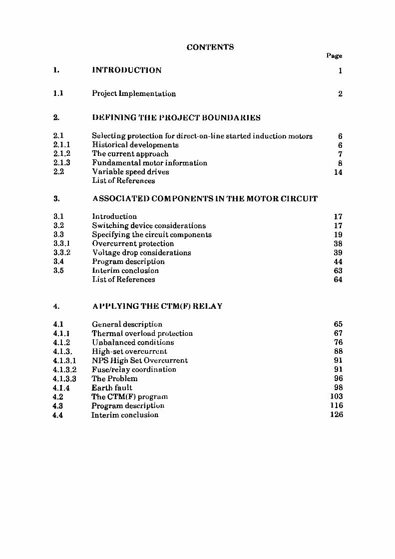
CONTENTSPage
1. INTRODUCTION 1
1.1 Project Implementation 2
2. DEFINING THE PROJECT BOUNDARIES
2.1 Selecting protection for direct-on-line started induction motors 62.1.1 Historical developments 62.1.2 The current approach 72.1.3 Fundamental motor information 8 2.2 Variable speed drives 14
List of References
3. ASSOCIATED COMPONENTS IN THE MOTOR CIRCUIT
3.1 Introduction 173.2 Switching device considerations 173.3 Specifying the circuit components 193.3.1 Overcurrent protection 383.3.2 Voltage drop considerations 393.4 Program description 443.5 Interim conclusion 63
List of References 64
4. APPLYING THE CTM(F) RELAY
4.1 General description 654.1.1 Thermal overload protection 674.1.2 Unbalanced conditions 764.1.3. High-set overcurrent 884.1.3.1 NFS High Set Overcurrent 914.1.3.2 Fuse/relay coordination 914.1.3.3 The Problem 964.1.4 Earth fault 984.2 The CTM(F) program 1034.3 Program description 1164.4 Interim conclusion 126
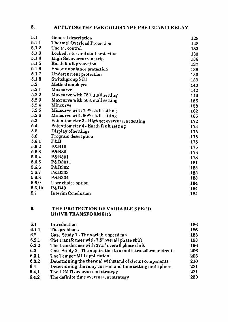
5. APPLYING THE P&B GOLDS TYPE PBSJ 3E5 Nil KELAY
5.1 General description 1285.1.1 Thermal Overload Protection 1285.1.2 The t6x control 1335.1.3 Locked rotor and stall protection 1335.1.4 High Set overcurrent trip 1365.1.5 Earth fault protection 1375.1.6 Phase unbalance protection 1385.1.7 Undercurrent protection 1395.1.8 Switchgroup SG1 1395.2 Method employed 1405.2.1 Maxcurve 1425.2.2 Maxcurve with 75% stall setting 1495.2.3 Maxcurve with 50% stall setting 1565.2.4 Mincurve 1585.2.5 Mincurve with 75% stall setting 1625.2.6 Mincurve with 50% stall setting 1655.3 Potentiometer 3 - High set overcurrent setting 1725.4 Potentiometer 4 - Earth fault setting 1735.5 Display of settings 1755.6 Program description 1755.6.1 P&B 1755.6.2 P&B10 1755.6.3 P&B30 1785.6.4 P&B301 1785.6.5 P&B3011 1815.6.6 P&B302 1835.6.7 P&B303 1835.6.8 P&B304 1835.6.9 User choice option 1845.6.10 P&B40 1845.7 Interim Conclusion 184
6. THE PROTECTION OK VARIABLE SPEED DRIVE TRANSFORMERS
6.1 Introduction 1866.1.1 The problems 1866.2 Case Study 1 - The variable speed fan 1886.2.1 The transformer with 7.5° overall phase shift 1936.2.2 The transformer with 37.5° overall phase shift 1966.3 Case Study 2 - The application to a multi-transformer circuit 2066.3.1 The Temper Mill application 2066.3.2 Determining the thermal withstand of circuit components 2106.4 Determining the relay current and time setting multipliers 2216.4.1 The JDMTL overcurrent strategy 2216.4.2 The definite time overcurrent strategy 230
6.5 Instantaneous overcurrent elements 2336.5.1 IDMTL - Standard inverse characterstic 2336.5.2 Instantaneous overcurrent setting associated with the DTL
strategy 234 6.6 Earth fault 2356.6.1 The IDMTL strategy 2366.6.2 The DTL strategy 2386.7 Program description for transformer protection on variable
speed drive installations 2396.7.1 Protsel - Project Control Routine 2426.7.2 TX - Program Control routine 2426.7.3 TX10 Voltage Selection menu 2426.7.4 TX20 Transformer data displays 2456.7.5 TX30 Circuit constraints 2456.7.6 TX40 System definition 2506.7.7 TX50 Switching device and clearing time routine 2506.7.8 TX60 Current transformer selection 2526.7.9 TX70 Displays fuse catalogue 2556.7.10 TX80 Displays fuse data 2556.7.11 TX90 Displays cable catalogue 2576.7.12 TX100 Cable rating calculations 2606.7.13 TX110 Displays cable data 2616.7.14 TX120 Fault current calculations 2616.7.15 TRIG Calculates sine and Cosine of angles 2636.7.16 TX1201 Fault current calculation data input 2636.7.17 TX1202 Transformer winding fault current distribution 2636.7.18 TX130 Assigns constants to selected relay characteristics 2646.7.19 Inverse time characteristics 2646.7.20 Definite time lag characteristics 2686.7.21 TX150-152 User option settling data input 2686.7.22 TX160-162 Circuit withstand and constraints IDMTL calculation 2726.7.23 TX 170-172 Circuit withstand and constraints DTL calculation 2726.7.24 TX180 and TX190 DTL and IDMTL calculation routines 2736.7.25 TX210 Settings display 2736.7.26 TX310 Fault current withstand and constraints menu 2736.7.27 TX320 and TX330 Fault current listings 2766.7.28 TX340 Withstand/relay operating times - min source impedance 2766.7.29 TX350 Withstand/relay operating times - max source impedance 2766.7.30 TX360 Constraints/Relay operating times 2816.8 Interim Conclusion 281
7. CONCLUSION 284
7.1 Future Enhancements 285

Bibliography 287
Appendices
Appendix 1 Appendix 2
Appendix 3 Appendix 4 Appendix 5
Appendix 6 Appendix 7 Appendix 8 Appendix 9 Appendix 10
Determining the motor withstand characteristicsPrediction of motor acceleration times for directlycoupled motor/drive unitsHarmonics in the supply voltageEffects of unbalanced supply voltageDetermination of terminal fault currents for typicaltransformer sizesDetermination of zero sequence impedance of a cableTypical electric motor informationTypical fuse characteristicsMotor protection relay thermal characteristicsCurrent transformers
288
292300304
317345352358361370
List of Illustrations
Fig. 1.1 Main selection menu 4Fig. 1.2 Trotsel'program flowchart 5
Fig. 3.1 Main selection menu 20Fig. 3.2 Motor type display listing 22Fig. 3.3 415V 4 pole Motor rating display 23Fig. 3.4 75kW Motor data display 24Fig. 3.5 Typical systems condition display for 1500kVA transformer 26Fig. 3.6 Fuse type listing 29Fig. 3.7 Fuse rating listing 30Fig. 3.8 Cable type listing 31Fig. 3.9 Cable limitation display for 75kW Motor fed from an 800kVA
transformer 42 Fig. 3.10 Cable limitation display for 75kW Motor fed from an 1500kVA
transformer 43 Fig. 3.11 Circuit voltage conditions and acceleration time display 45 Fig. 3.12 Protection relay menu 46 Fig. 3.13 Motor protection relay selection - flowchart 48 Fig. 3.14 Display motor types - flowchart 49 Fig. 3.15 Display motor ratings - flowchart 50 Fig. 3.16 Display motor data - flowchart 52 Fig. 3.17 Routine for entering unclassified motor data - flowchart 53 Fig. 3.18 Determine system conditions - flowchart 54 Fig. 3.19 Selects routine according to voltage - flowchart 56 Fig. 3.20 Display fuse ratings - flowchart 58 Fig. 3.21 Displays listing of all cable types for selection -flowchart 59 Fig. 3.22 Calculates cable parameters from selected cable CSA's and
length - flowchart 61 Table 3.1 Fuse rating/5 second disconnecting current 28 Table 3.2 Minimum CSA of protective conductors/5 sec disconnecting
current 35
Fig. 4.1 Comparison between actual and desired characteristic 68Fig. 4.2(a) Block diagram of CTM relay components 77Fig. 4.2(b) Block diagram of CTMF relay components 77Fig. 4.3(a) Single-phase circuit for three-phase star-connected motor 86Fig. 4.3(b) Equivalent circuit for loss of phase on a three phase star
connected motor 86 Fig. 4.4(a) Single phase circuit for three phase delta-connected motor 86 Fig. 4.4(b) Equivalent circuit for loss of one supply phase on a
three-phase delta-connected motor 86 Fig. 4.5 Fuse/Thermal/Motor/Acceleration time coordination graph Fig. 4.6(a) Wiring connections for relay with internal star connection 101 Fig. 4.6(b) Wiring connections for relay with external star connection 101 Fig. 4.7 Relay type option menu - display 104 Fig. 4.8 Current transformer data requirement - display 106 Fig. 4.9 Thermal strategy option menu - display 107
Fig. 4.10 Operating times and margins for CTM4-02 relay - display 108 Fig. 4.11 Thermal/Motor/Acceleration time coordination graph for
CTM4-06 110 Fig. 4.12 Operating times and margins for CTM4-31 relay - display 111 Fig. 4.13 Thermal/Motor/Acceleration time coordination graph for
CTM4-31 112 Fig. 4.14 Operating times and margins for CTM4-06 relay - display 113 Fig. 4.15 Thermal/Motor/Acceleration time coordination graph for
CTM4-06 114 Fig. 4.16 User selected characteristic menu - display 115 Fig. 4.17 Relay settings-display 117 Fig. 4.18 CTM (F) Solution flowchart 118 Fig. 4.19 CTM (F) Control routine - flowchart 120 Fig. 4.20 CTM60, User characteristic menu-flowchart 122 Fig. 4.21 CTM70, Inequality tests - flowchart 124 Fig. 4.22 CTM80, Relay operating time margins - flowchart 125
Table 4.1 Typical correlation of relay and motor types 66 Table 4.2 Time inequality checks 89
Fig. 5.1 The P&B Microgolds relay 129 Fig. 5.2 Key to P&B Microgolds relay controls 131 Fig. 5.3 Typical Hot and Cold thermal characteristics including
75% and 50% stall functions 134 Fig. 5.4 Typical relay faceplate 'set up' arrangement 141 Fig. 5.5 Thermal strategy option menu 143 Fig. 5.6 Operating times and margins for 'MAXCURVE' with full
thermal characteristic and a tex setting of 17 seconds 148 Fig. 5.7 Operating times and margins for 'MAXCURVE' with 75% step
in the thermal characteristic and a tex setting of 17 seconds 150 Fig. 5.8 Operating times and margins for 'MAXCURVE' with 50% step
in the thermal characteristic and a tex setting of 17 seconds 151 Fig. 5.9 Motor withstand and relay thermal characteristic with a
tgx setting of 17 seconds. Graph includes 75% and 50% stepsin the relay characteristic. 152
Fig. 5.10 Operating times and margins for 'MAXCURVE' with 75% stepin the thermal characteristic and a t6x setting of 22.5 seconds 154
Fig. 5.11 Operating times and margins for 'MAXCURVE' with 50% stepin the thermal characteristic and a tex setting of 22.5 seconds 155
Fig. 5.12 Motor withstand and relay thermal characteristic with atex setting of 22.5 seconds. Graph shows 75% and 50% stepsin the relay characteristic. 157
Fig. 5.13 Operating times and margins for 'MAXCURVE' with50% step in the thermal characteristic and a tex setting of34 seconds. 159
Fig. 5.14 Motor withstand and relay thermal characteristic with a texsetting of 34 seconds. Graph shows 50% step in the relaycharacteristic. 160
Fig. 5.15 Operating times and margins for 'MINCURVE 1 with fullthermal characteristic and a tex setting of 7 seconds. 163
Fig. 5.16 Motor withstand and relay thermal characteristic witha tex setting of 7 seconds. Graph shows the full characteristic. 164
Fig. 5.17 Operating times and margins for 'MINCURVE 1 with a 75% stepin the thermal characteristic and a tex setting of 9.5 seconds. 166
Fig. 5.18 Motor withstand and relay thermal characteristic with a texsetting of 9.5 seconds and a 75% step in the relay characteristic. 167
Fig. 5.19 Operating times and margins for 'MINCURVE 1 with a 50%step in the thermal characteristic and a tex setting of 14 seconds. 168
Fig. 5.20 Motor withstand and relay thermal characteristic with a texsetting of 14 seconds and a 50% step in the relay characteristic. 169
Fig. 5.21 Typical relay setting display. 176 Fig. 5.22 P&B Control routine - flowchart. 177 Fig. 5.23 Calculate time settings - flowchart. 179 Fig. 5.24 Calculate t6x for'MAXCURVE1 -flowchart. 180 Fig. 5.25 Calculate and display operating times - flowchart. 182
Fig. 6.1 General arrangement of synchronous motor poweredvariable speed fan. 189
Fig. 6.2 Current distribution in transformer windings for phase-phasefault on secondary terminals - delta/delta winding arrangement. 197
Fig. 6.3 Current distribution in transformer windings for phase-phasefault on secondary terminals - delta/star winding arrangement. 197
Fig. 6.4 Coil temper mill transformer supplies diagram. 207 Fig. 6.5 Current distribution in transformer windings for 3-phase
and phase-phase faults - delta/delta winding arrangement. 214 Fig. 6.6 Current distribution in transformer windings for 3-phase and
phase-phase faults - delta/star winding arrangement. 215 Fig. 6.7 Fault currents observed at the relays for phase-phase
and 3-phase fault conditions on each transformer. 216 Fig. 6.8 Protsel - Main system program. 243 Fig. 6.9 Variable speed drive transformer protection. 244 Fig. 6.10 Voltage selection menu - display. 246 Fig. 6.11 Voltage selection menu - flowchart. 247 Fig. 6.12 TX20 - Record transformer data. 248 Fig. 6.13 Transformer data input display. 249 Fig. 6.14 System source conditions. 251 Fig. 6.15 Switching device and protection operating times. 253 Fig. 6.16 Current transformer data. 254 Fig. 6.17 Fuse catalogue. 256 Fig. 6.18 Fuse rating summary. 258 Fig. 6.19 Cable catalogue. 259 Fig. 6.20 Cable limitation display for a typical installation. 262 Fig. 6.21 Relay characteristic and element selection display. 265 Fig. 6.22 Definite time lag strategy flowchart. 269 Fig. 6.23 'User Choice' flowchart 270 Fig. 6.24 Typical settings display. 274 Fig. 6.25 'User Choice'menu. 275
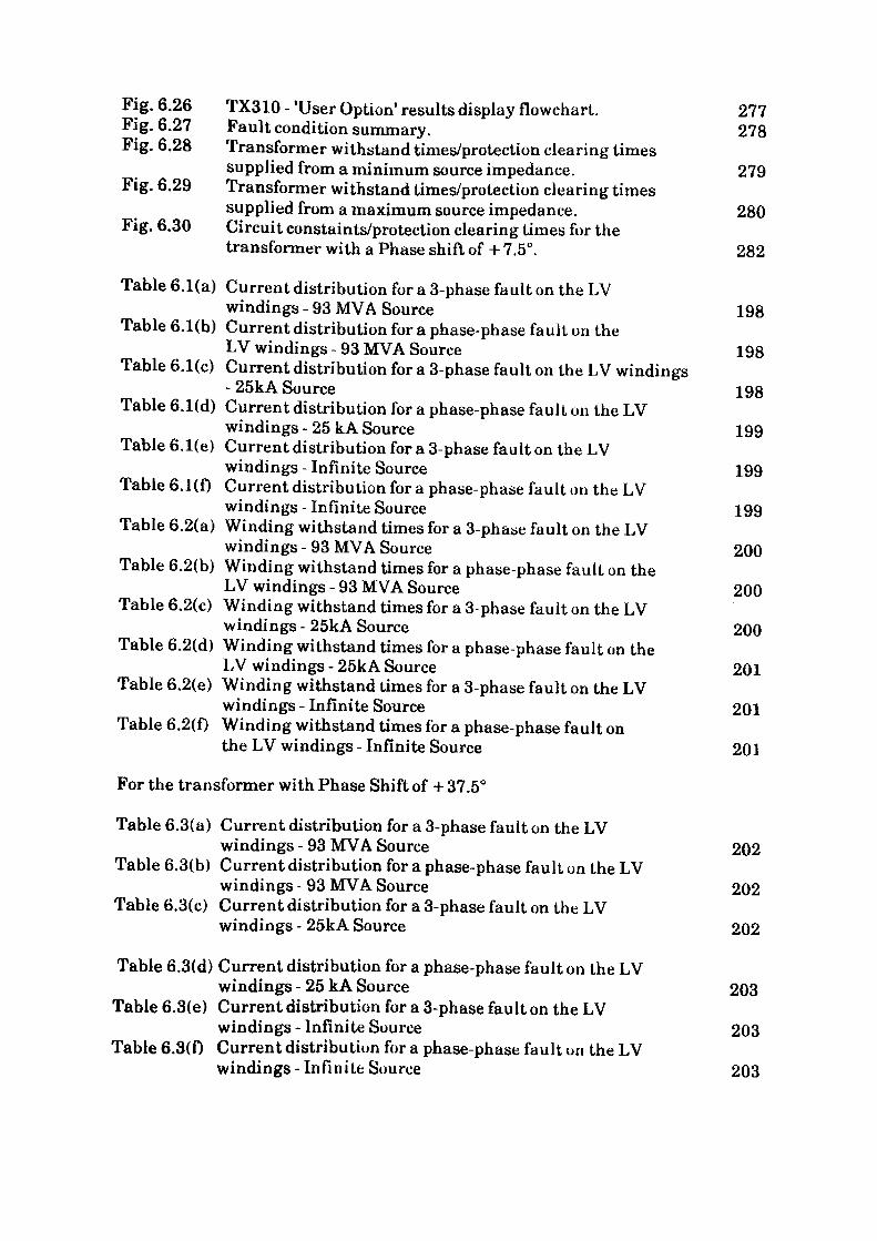
Fig. 6.26 TX310-'User Option1 results display flowchart. 277 Fig. 6.27 Fault condition summary. 278 Fig. 6.28 Transformer withstand times/protection clearing times
supplied from a minimum source impedance. 279 Fig. 6.29 Transformer withstand times/protection clearing times
supplied from a maximum source impedance. 280 Fig. 6.30 Circuit constaints/protection clearing times for the
transformer with a Phase shift of + 7.5°. 282
Table 6.1(a) Current distribution for a 3-phase fault on the LVwindings - 93 MVA Source 198
Table 6.1(b) Current distribution for a phase-phase fault on theLV windings - 93 MVA Source 198
Table 6.1(c) Current distribution for a 3-phase fault on the LV windings- 25kA Source 198
Table 6.1(d) Current distribution for a phase-phase fault on the LVwindings - 25 kA Source 199
Table 6.1(e) Current distribution for a 3-phase fault on the LVwindings - Infinite Source 199
Table 6.1(f) Current distribution for a phase-phase fault on the LVwindings - Infinite Source 199
Table 6.2(a) Winding withstand times for a 3-phase fault on the LVwindings - 93 MVA Source 200
Table 6.2(b) Winding withstand times for a phase-phase fault on theLV windings - 93 MVA Source 200
Table 6.2(c) Winding withstand times for a 3-phase fault on the LVwindings - 25kA Source 200
Table 6.2(d) Winding withstand times for a phase-phase fault on theLV windings - 25kA Source 201
Table 6.2(e) Winding withstand times for a 3-phase fault on the LVwindings - Infinite Source 201
Table 6.2(f) Winding withstand times for a phase-phase fault onthe LV windings - Infinite Source 201
For the transformer with Phase Shift of +37.5°
Table 6.3(a) Current distribution for a 3-phase fault on the LVwindings - 93 MVA Source 202
Table 6.3(b) Current distribution for a phase-phase fault on the LVwindings - 93 MVA Source 202
Table 6.3(c) Current distribution for a 3-phase fault on the LVwindings - 25kA Source 202
Table 6.3(d) Current distribution for a phase-phase fault on the LVwindings - 25 kA Source 203
Table 6.3(e) Current distribution for a 3-phase fault on the LVwindings-Infinite Source 203
Table 6.3(f) Current distribution for a phase-phase fault on the LVwindings - Infinite Source 203
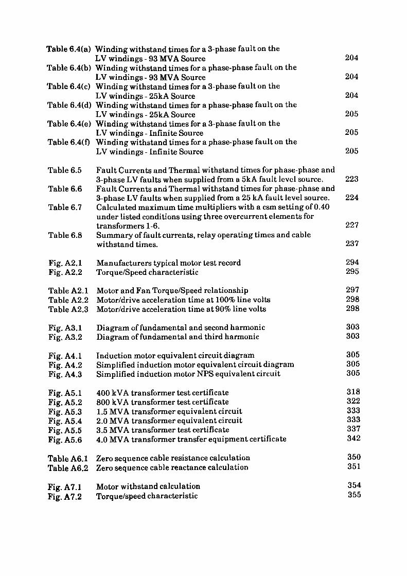
Table 6.4(a) Winding withstand times for a 3-phase fault on theLV windings - 93 MVA Source 204
Table 6.4(b) Winding withstand times for a phase-phase fault on theLV windings - 93 MVA Source 204
Table 6.4(c) Winding withstand times for a 3-phase fault on theLV windings - 25kA Source 204
Table 6.4(d) Winding withstand times for a phase-phase fault on theLV windings - 25kA Source 205
Table 6.4(e) Winding withstand times for a 3-phase fault on theLV windings - Infinite Source 205
Table 6.4(f) Winding withstand times for a phase-phase fault on theLV windings - Infinite Source 205
Table 6.5 Fault Currents and Thermal withstand times for phase-phase and3-phase LV faults when supplied from a 5kA fault level source. 223
Table 6.6 Fault Currents and Thermal withstand times for phase-phase and3-phase LV faults when supplied from a 25 kA fault level source. 224
Table 6.7 Calculated maximum time multipliers with a csm setting of 0.40 under listed conditions using three overcurrent elements for transformers 1-6. 227
Table 6.8 Summary of fault currents, relay operating times and cablewithstand times. 237
Fig. A2.1 Manufacturers typical motor test record 294 Fig. A2.2 Torque/Speed characteristic 295
Table A2.1 Motor and Fan Torque/Speed relationship 297Table A2.2 Motor/drive acceleration time at 100% line volts 298Table A2.3 Motor/drive acceleration time at 90% line volts 298
Fig. A3.1 Diagram of fundamental and second harmonic 303 Fig. A3.2 Diagram of fundamental and third harmonic 303
Fig. A4.1 Induction motor equivalent circuit diagram 305Fig. A4.2 Simplified induction motor equivalent circuit diagram 305Fig. A4.3 Simplified induction motor NFS equivalent circuit 305
Fig. A5.1 400 kVA transformer test certificate 318Fig. A5.2 800 kVA transformer test certificate 322Fig. A5.3 1.5 MVA transformer equivalent circuit 333Fig. A5.4 2.0 MVA transformer equivalent circuit 333Fig. A5.5 3.5 MVA transformer test certificate 337Fig. A5.6 4.0 MVA transformer transfer equipment certificate 342
Table A6.1 Zero sequence cable resistance calculation 350 Table A6.2 Zero sequence cable reactance calculation 351
Fig. A7.1 Motor withstand calculation 354 Fig. A7.2 Torque/speed characteristic 355

Fig. A7.3 Equivalent circuit phase values 356Fig. A7.4 Manufacturers typical motor test record 357
Table A7.1 Information requirements for electric motors 353
Fig. A8.1 Typical Fuse Time/Current characteristics 359Fig. A8.2 Typical Fuse Cut-off current characteristics 360
Table A8.1 Typical Fuse I2t characteristics 360
Fig. A10.1 Current transformer equivalent current 373Fig. A10.2 Current transformer vector diagram 373
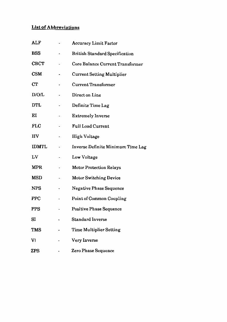
List of Abbreviations
ALF
BSS
CBCT
CSM
CT
D/O/L
DTL
El
FLC
HV
IDMTL
LV
MPR
MSB
NFS
PPC
PPS
SI
TMS
VI
ZPS
Accuracy Limit Factor
British Standard Specification
Core Balance Current Transformer
Current Setting Multiplier
Current Transformer
Direct on Line
Definite Time Lag
Extremely Inverse
Full Load Current
High Voltage
Inverse Definite Minimum Time Lag
Low Voltage
Motor Protection Relays
Motor Switching Device
Negative Phase Sequence
Point of Common Coupling
Positive Phase Sequence
Standard Inverse
Time Multiplier Setting
Very Inverse
Zero Phase Sequence
CHAPTER 1
1. INTRODUCTION
The core of this project originated in the design philosophy of the first generation
of electronic motor protection relays (MPR). Advances in the design of these
devices have resulted from the introduction of digital electronic techniques which
enable the relays to provide previously unheard of applications. The selection is
usually carried out by means of miniature slide switches which select the desired
functions and characteristic from a library of inbuilt features that the devices now
possess. On some of the latest devices, multifunction selection is achieved by
sequential operation of push buttons mounted on the relay faceplate. Such is the
complexity of the available options that in the opinion of the author a need exists
for a document which sets out a practical approach to the application of protection
relays for direct-on-line (D/O/L) started induction motors in a general industrial
environment. To achieve this objective in full would indeed be extremely difficult
and would require a vast expenditure in man-hours to complete the task. The
difficulty lies in the potential field to be explored which is extensive and
increasing rapidly with the advent of modern microprocessor based relaying
equipment. Hence, to provide 'proof of concept' the field has been limited to
achievable proportions, these limits being set out in Chapter 2.
A further problem which can prove extremely time consuming arises from the
protection requirements associated with equipment supplying large variable
speed motors. A typical arrangement for this type of equipment comprises a main
step-down transformer with two secondary windings phase displaced to provide
twelve pulse converter operation. The difficulties encountered with this type of
installation can be readily appreciated as the motors are often not operated at
their continuous rating but are driven into the overload state as part of their
designed operating mode. By careful consideration of the operating parameters, it
may be possible to select protection relay characteristics and settings which will
bring about substantial cost savings by minimising the switchgear and cabling
requirements. A method is suggested which demonstrates the potential of this
approach.
For both D/O/L started and variable speed motors, problems will inevitably arise if
an attempt is made to incorporate late design changes into the project. In the case
of D/O/L started drives the change may involve a larger motor coupled with
different acceleration parameters. The general dearth of information available
coupled with a reluctance by manufacturers to provide customers with the
required machine specifications can make the life of the protection engineer very
difficult. Similar problems may be encountered with variable speed machines
where the ratings, vector grouping and impedance of the transformers are not
generally known until late in the project and even then are likely to further
change. Theoretically a "design freeze" should eliminate the problem but
countless projects have proved the contrary to be the case. To this end the work
undertaken in the research project reported may point the way ahead because the
effect of any changes can be rapidly incorporated and assessed thus enabling the
earliest possible placement of orders to proceed. As a guide typical delivery times
range from twelve weeks for relaying equipment to twenty four weeks for
switchgear.
1.1 Project Implementation
The research project undertaken may sensibly be separated into two parts. The
first part is mainly concerned with the application of motor protection relays to
direct-on-line started induction motors, whilst the latter part deals with the
protection requirements applicable to transformer fed variable speed drives. Both

parts of the project utilise a computer based solution based on a suite of novel
algorithms developed in a modular format. The resulting programs are presented
sequentially taking the user through a series of logical steps until a suitable
solution is arrived at. To implement the solutions to the problems outlined in the
project and detailed later, a database of subject matter has been established using
standard DBASE in + software running on a personal computer. The benefits of
using this software accrue from the inbuilt programming language which enables
specific programs to be written to manipulate the stored data. Each section of the
work contains general details of the individual programs which are used to
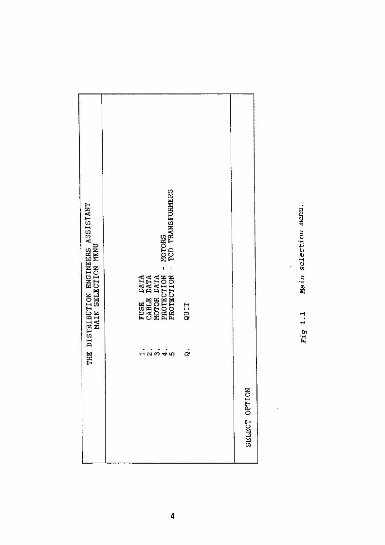
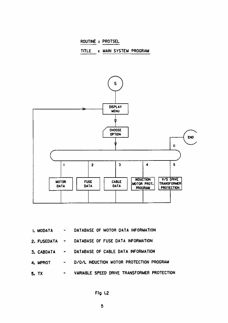
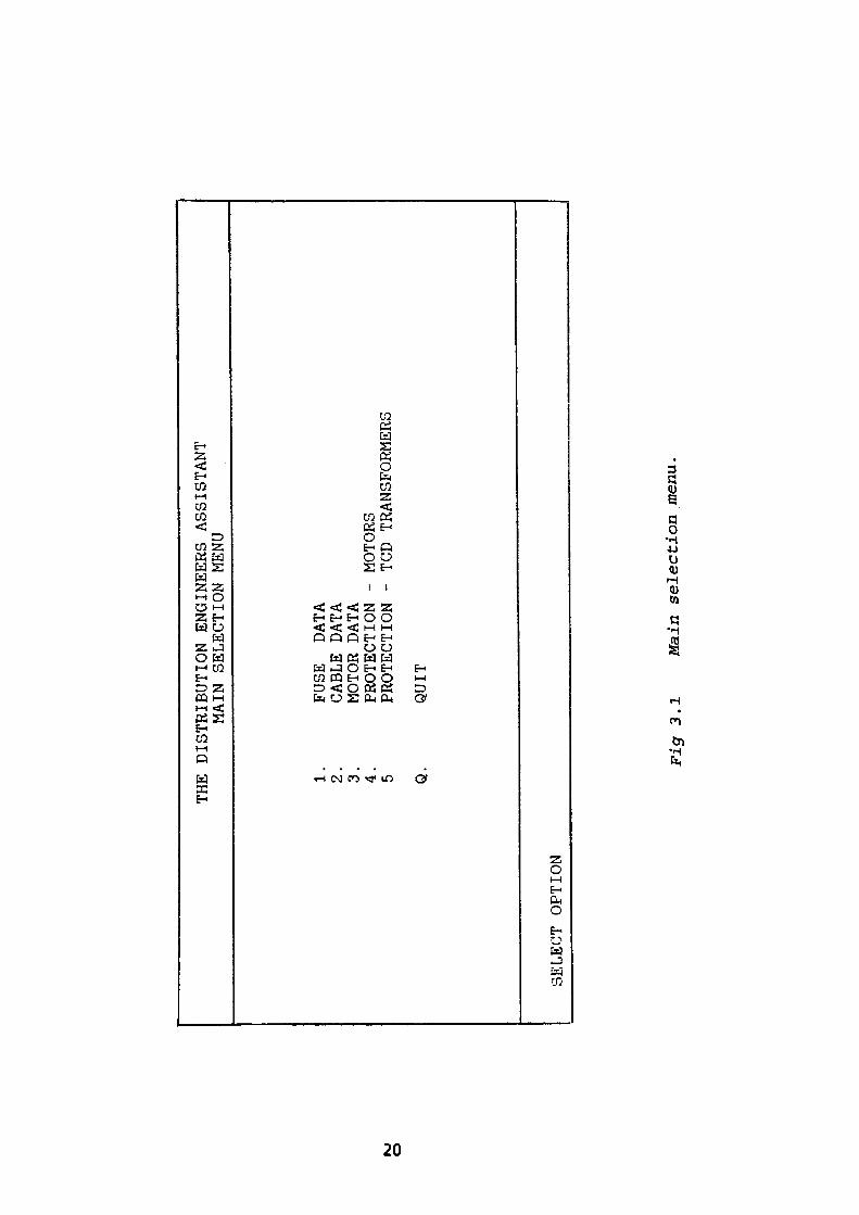
determine the appropriate solution. The entire suite of programs is controlled by a
master program called TROTSEL1 from which the user is able to select five
distinct options from a menu. A copy of the menu display is shown in Fig. 1.1. It
can be seen that options 1-3 allow the user to access the motor, fuse and cable
databases whilst options 4 and 5 involve the heart of this project. A flowchart of
the 'PROTSEL1 program is shown in Fig. 1.2.
THE DISTRIBUTION ENGINEERS ASSISTANT
MAIN SELECTION MENU
1.
FUSE
DATA
2.
CABLE DATA
3.
MOTOR DATA
4.
PROTECTION
5 PROTECTION
Q.
QUIT
MOTORS
TCD TRANSFORMERS
SELECT OPTION
Figr 1.1
Main selection menu.
ROUTINE i PROTSEL
TITLE s MAIN SYSTEM PROGRAM
1. MODATA
2. FUSEDATA
3. CABDATA
A. MPROT
5. TX
DATABASE OF MOTOR DATA INFORMATION
DATABASE OF FUSE DATA INFORMATION
DATABASE OF CABLE DATA INFORMATION
D/O/L INDUCTION MOTOR PROTECTION PROGRAM
VARIABLE SPEED DRIVE TRANSFORMER PROTECTION
Fig 1.2
5
CHAPTER2
2. DEFINING THE PROJECT BOUNDARIES
2.1 Selecting Protection for Direct-on-Line Started Induction Motors
Many papers* 1 - 2 '31 have been produced on this subject, generally by manufacturers
or those parties who have a vested interest in extolling the virtues of a particular
product, with the specific intention of increasing sales. Any inherent deficiencies
which the device may exhibit are of course suppressed. It is with this background
in mind that an attempt has been made to research, analyse and document both
relay information and application techniques from a variety of sources and
opinions which are relevant to a large cross section of the protection devices
available today. Using the knowledge acquired from this research it has been
found feasible to produce a novel algorithm which when applied to the problem,
will produce the satisfactory selection of relay characteristics when required,
together with the appropriate settings. The algorithm has been enhanced such
that the system studied comprises cable, motor and where applicable, fusegear.
2.1.1 Historical Developments
Prior to the introduction of the electronic MPR, the protection function was
carried out using electro-mechanical relays equipped with a thermal element.
The thermal element comprised a small heating element supplied with a replica
current proportional to the current taken by the motor. The heating element was
located adjacent to a bimetallic coil. The coil was rigidly attached at the outside
point to the relay case whilst it's centre was connected to a rotating shaft on which
a moving contact was mounted. Excessive current drawn by the motor resulted in
the shaft being rotated sufficiently to allow the moving contact to complete a trip
circuit and disconnect the machine. The heating elements were usually applied to
all three phases and mechanically coupled to a common shaft. The use of three
phases allowed the variation in heat output to be used as a measure of phase
current unbalance. The resultant movement of the bi-metallic coil caused by this
differential heating effect being conveyed via mechanical linkages to effect
tripping. The design was usually complemented with an additional unheated
bimetallic coil whose function was to compensate for the ambient air temperature
within the case. This was the general arrangement followed by MPR
manufacturers for decades, the main variation being found in the quality of the
mechanical implementation.
2.1.2 The Current Approach
With current technology it is possible to provide a high degree of protection for
virtually any motor performing any duty under any particular set of conditions,
provided the conditions and constraints are accurately specified and that
sufficient funds are available to provide devices capable of sensing the imposed
limitations. Clearly there is an economic constraint which suggests that the
fitting of a sophisticated protection relay to a small low voltage machine would
appear to be unrealistic although undoubtedly beneficial to the life expectancy of
the motor. The essence of the problem is one of insurance, the engineer may
choose cheap protection providing minimal coverage or alternatively more
expensive protection for greater security. The solution may well result from a
combination of both. There are also circumstances where minimal protection may
be deemed desirable, such as the case where an unplanned shutdown of a motor for
any reason other than a short circuit may have catastrophic results on the
industrial process, certainly far in excess of the price of a new motor. For some
situations, the sacrifice of a motor and the resulting loss of production may be
tolerable, but for others, the solution may require built in redundancy in the form
of duplicate or triplicate motors performing the vital function in order that the
failure of one machine would not adversely affect the process. Such is the nature
of the exercise that these often intangible factors must all be considered when
assessing the protection requirements for any particular installation.
2.1.3 Fundamental Motor Information
As a precursor to writing a motor protection relay program it is sensible to
consider some of the more fundamental aspects of the nature of the machines
which are to be protected. The "Specification of General Requirements for
Rotating Electrical Machines" is defined in British Standard (B.S.) 4999(4) and
provides a wealth of information for consideration. Part 30 of this document
relates to the "Duty and Rating" of machines. Clearly if a machine is used
intermittently or for short periods of time, it may be run at a higher power output
level than a motor which has a continuous running duty, provided adequate
cooling periods follow the running mode. BS 4999 Part 30 lists and defines eight
independent duty types which are designated from SI to S8 inclusive. It is the SI
or continuous running duty which this project considers, as it is the most common
type found in industrial applications. A further essential requirement is to
consider the temperature excursions to which the machine may be subjected. BS
4999 Part 32 defines the limits of temperature rise for all insulation classes in
order to prevent premature failure of the windings. The document also includes
methods of temperature measurement and extrapolation techniques for predicting
final machine temperatures. Both Parts 30 and 32 of BS 4999 are considered as
essential reading.
If a load increase is envisaged for a particular machine it is sensible to perform a
few preliminary calculations to predict the final winding temperature increase
8
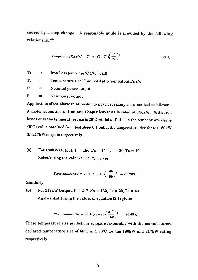
caused by a step change. A reasonable guide is provided by the following relationship.(5)
(T2-Tn —):V Pn I
TemperatureRistCC) - Tl + (T2-T\)\ — f (2.1)
TI = Iron Loss temp rise °C (No Load)
T2 = Temperature rise °C on Load at power output Pn kWPn = Nominal power output
P = New power output
Application of the above relationship to a typical example is described as follows:A motor submitted to Iron and Copper loss tests is rated at 150kW. With ironlosses only the temperature rise is 20°C whilst at full load the temperature rise is49°C (value obtained from test sheet). Predict the temperature rise for (a) 180kW(b) 217kW outputs respectively.
(a) For 180kW Output, P = 180, Pn = 150, Tl = 20, T2 = 49 Substituting the values in eq (2.1) gives:
/ISO \9 Temperature Rise - 20 + (49-20)1 —— Y =61,76°C
Similarly
(b) For 217kW Output, P = 217, Pn = 150, Tl = 20, T2 = 49
Again substituting the values in equation (2.1) gives:
/217\2Temperature Rise - 20 + (49-20) —— ) = 80.69°Cv 150 /
These temperature rise predictions compare favourably with the manufacturers declared temperature rise of 60°C and 80°C for the 180kW and 217kW rating
respectively.
If such output increases were to be contemplated it should be noted that the 'hot1
thermal withstand characteristic of the motor, which is the curve relating the
sustained motor overload current to its allowable duration, would be reduced.
This reduced withstand time must be reflected in the 'hot' thermal withstand
characteristic of the protection relay if protection is to be maintained. The 'cold' or
starting characteristic would of course remain unchanged for both motor and
relay.
Improvements in motor insulating materials have resulted in the widespread
adoption of class F insulation to supersede the older class B insulated machines.
This change of insulation class allows a typical increase of 20°C on the previous
maximum running temperature, enabling induction motors of a given frame size
and configuration to produce increased output at the shaft. Utilisation of this
temperature increase results in the motor exhibiting the reduced thermal
withstand ability referred to above, particularly under locked rotor conditions.
Hence a more discerning analysis of both machine and protective device would be
deemed appropriate.
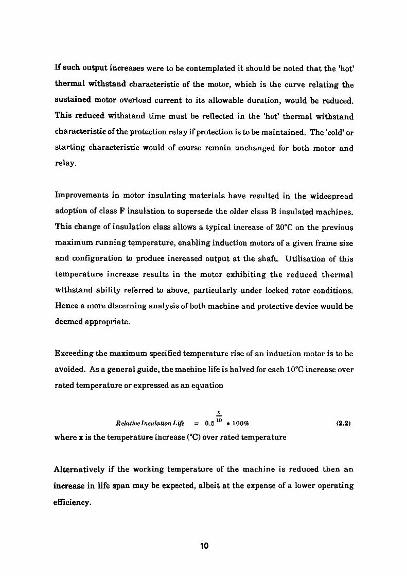
Exceeding the maximum specified temperature rise of an induction motor is to be
avoided. As a general guide, the machine life is halved for each 10°C increase over
rated temperature or expressed as an equation
Relative Insulation Life - 0.5 10 • 100% (2.2)
where x is the temperature increase (°C) over rated temperature
Alternatively if the working temperature of the machine is reduced then an
increase in life span may be expected, albeit at the expense of a lower operating
efficiency.
10
The thermal withstand capabilities of a machine may be represented by means of a single time constant exponential curve, which models the hot and cold characteristics of the insulation. Appendix 1 contains a derivation of these
characteristics which can be used to provide suitable thermal modelling of a motor.
The method of protection adopted by the relay manufacturer is intended to provide a device with operating characteristics which comply with the desired withstand characteristics laid down in BS 142<6) . Two models are referred to in this document. The first, a general curve, models both hot and cold characteristics
using a single time - constant exponential curve; whilst the second suggested arrangement uses an adiabatic relationship. It is the characteristic defined in the former case which is utilised by the two relays examined in this investigation. The link between motor and device model can clearly be seen.
Some machine manufacturers provide customers with composite withstand characteristics. These characteristics provide a more accurate assessment of the thermal withstand capability of the machine by using the exponential approach in the overload region (1 - 2£ x flc) whilst an adiabatic arrangement is used to represent the high current, low speed/locked rotor zone. Clearly this is a more realistic representation for machines which are fitted with internal cooling fans driven from the shaft. In such cases satisfying the locked rotor condition will
usually result in a generous protective margin in the overload region. It is
however, essential to clu:ek and confirm that such margins exist.
Before considering the type of protection to be employed, the engineer must determine whether sufficient supply capacity is available to allow the machine to start in the first place. Indeed, regulation in the motor supply may reduce the starting torque to a level insufficient for the machine to break away. Bearing in
11
mind that torque is proportional to Applied Voltage2 , then 80% applied voltage
results in 64% starting torque. The magnitude of the supply "voltage dip" may
well cause distress to other circuits supplied from the same busbar, and will
probably prove to be the limiting factor especially in the case of 415V machines,
where the busbar will usually supply lighting and voltage sensitive solid
state/computer type loads. To quantify a potential problem it is expedient to carry
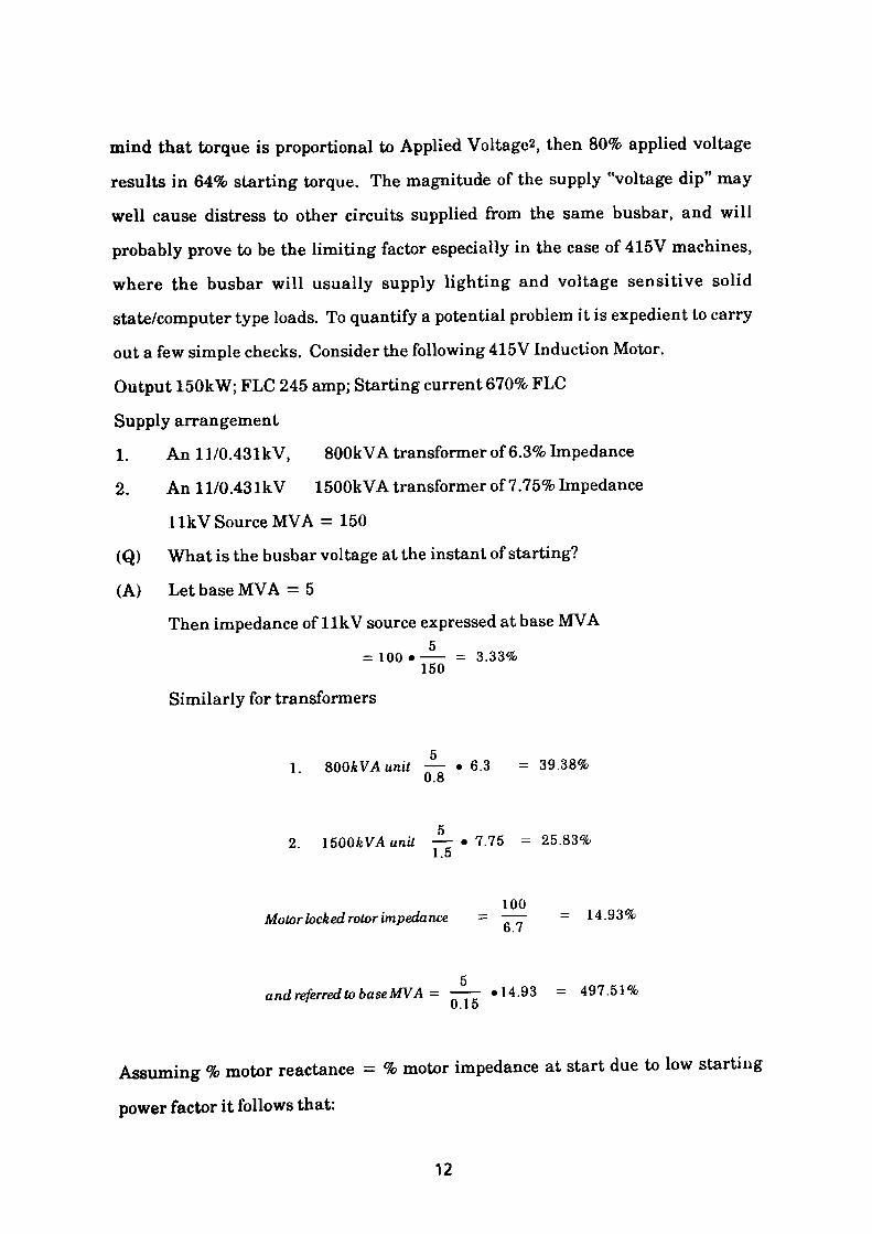
out a few simple checks. Consider the following 415V Induction Motor.
Output 150kW; FLC 245 amp; Starting current 670% FLC
Supply arrangement
1. An ll/0.431kV, 800kVA transformer of 6.3% Impedance
2. Anll/0.431kV 1500kVA transformer of 7.75% Impedance
1 Ik V Source MVA = 150
(Q) What is the busbar voltage at the instant of starting?
(A) Let base MVA = 5
Then impedance of llkV source expressed at base MVA5
= 100 •—— = 3.33% 150
Similarly for transformers
51. &QQkVAunit — • 6.3 = 39.38%
0.8
52. \5QQkVA unit —— • 7.75 = 25.83%
1.5
100Motor locked rotor impedance = —— = 14.93%
6.7
5and referred to base MVA- —— -14.93 = 497.51%
U. 10
Assuming % motor reactance = % motor impedance at start due to low starting
power factor it follows that:
12
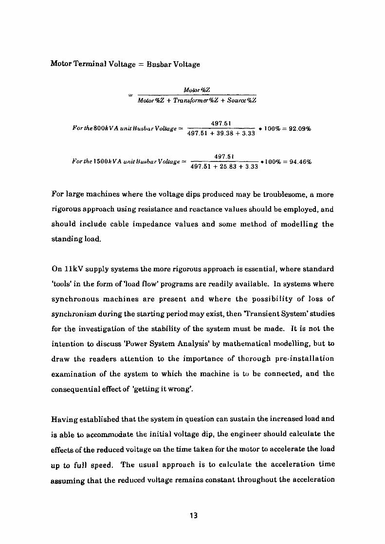
Motor Terminal Voltage = Busbar Voltage
Motor %ZMotor %Z + Trunsformer%Z + Source %Z
497.51For tke&QQkVA unit BusbarVoltage^ ————————————— . 100% = 92.09%
497.51 + 39.38 + 3.33
497.S1ForthelSQQkVA unittiuabarVoUage^ —————————————— -100% = 94.46%497.51 +25.83 + 3.33
For large machines where the voltage dips produced may be troublesome, a more
rigorous approach using resistance and reactance values should be employed, and
should include cable impedance values and some method of modelling the
standing load.
On llkV supply systems the more rigorous approach is essential, where standard
'tools' in the form of 'load flow' programs are readily available. In systems where
synchronous machines are present and where the possibility of loss of
synchronism during the starting period may exist, then Transient System* studies
for the investigation of the stability of the system must be made. It is not the
intention to discuss Tower System Analysis' by mathematical modelling, but to
draw the readers attention to the importance of thorough pre-installation
examination of the system to which the machine is to be connected, and the
consequential effect of 'getting it wrong'.
Having established that the system in question can sustain the increased load and
is able to accommodate the initial voltage dip, the engineer should calculate the
effects of the reduced voltage on the time taken for the motor to accelerate the load
up to full speed. The usual approach is to calculate the acceleration time
assuming that the reduced voltage remains constant throughout the acceleration
13
period, then to recalculate the acceleration time assuming the presence of 100%
voltage at all times. A further calculation for the overvoltage condition should
also be carried out if possible. The three values thus calculated represent the
maximum, minimum and nominal values of acceleration time and are used as
constraints when determining the upper and lower limits of the protection relay
thermal withstand characteristic. A method suitable for determining the
acceleration times is described in Appendix 2.
2.2 Variable Speed Drives
The use of solid state devices and drives in industrial installations is becoming
increasingly prevalent. One of the many applications to be found is in the role of
starting and speed control of induction motors. The control being achieved by
either varying the output voltage magnitude, the frequency or both. The former
case is generally used in "Soft Start1 units where an increasing voltage ramp is
applied to the motor to accelerate it up to speed. The unit usually incorporates a
current limiting feature and some form of motor protection. Where speed control
of the machine is considered, a far more sophisticated arrangement is required
which will produce the required output voltage and frequency. The topology of the
converter equipment varies considerably but will ultimately be dictated by the
economics of producing adequate supplies at the correct voltage level, ac or dc, to
satisfy the load requirements. Most modern variable speed drives are invariably
supplied from ac sources. Here again some form of motor protection is a built in
feature of the equipment.
The vast majority of such devices are to be found on 415V systems where solid
state control devices capable of handling such voltage levels are readily available.
Where larger drives are required they may be supplied from more substantial
sources at higher voltage levels, step down transformers being utilised to reduce
14

the supply voltage to the required working voltage level. Whilst this is the arrangement usually encountered, variable frequency equipment at both 3.3kV and llkV does exist and may prove useful where variable speed modifications are envisaged on an existing machine. The by product of using such devices may be observed by monitoring the busbar voltage which can be seen to contain an increased harmonic content. Guidance for the maximum permissible distortion values may be gleaned from "The Electricity Council Engineering Recommendation G5/3 - Limits for Harmonics in the United Kingdom Electricity Supply System'.'7'
A direct effect of harmonic content in the supply voltage waveform may be seen in Appendix 3 which discusses the implications of waveforms containing harmonics.
Similar detrimental effects to the life span of a machine are caused by the application of unbalanced voltages to three phase induction motors. Such effects may be caused by motors being supplied from busbars containing heavy single phase loads, transformer tap changer damage, or in an extreme case, open-circuits in a supply phase. Appendix 4 examines some of the undesirable effects and why they should be avoided.
15
References
1. Advanced Motor Protection using microcomputers by Joe Brandolino, Multilin Inc, Markham, Ontario, Canada.
2. Guide for the choice of protective relays - CEE.
3. Protective relays application guide published by GEC Measurements.
4. BS 4999 - The Specification of General Requirements for Rotating Electrical Machines.
5. Electro-Magnetic Machines by Langlois Berthelot.
6. BS 142 Electrical Protective Relays.
7. The Electricity Council Engineering Recommendation G5/3 - Limits for Harmonics in the United Kingdom Electricity Supply System.
16
CHAPTER3
3. ASSOCIATED COMPONENTS IN THE MOTOR CIRCUIT
3.1 Introduction
When considering the application of protection systems to induction motors it
should be emphasised that the relaying equipment must protect the entire circuit
comprising of the motor, associated mains cabling, terminal boxes, isolators,
switchgear and any other component which may be subjected to the through fault
current. In the case where a motor is supplied via a circuit breaker then all
components must be fully rated to withstand the forces and heating effects which
are imposed by the fault current during the fault detection period and the
subsequent opening time of the device.
3.2 Switching Device Considerations
When the switching device used is a contactor the stresses imposed during fault
conditions are far in excess of the switching capabilities of the device. The
solution is of course found in the use of fuses which contain no moving parts and
are thus capable of extremely fast operation at high fault levels, such that the
magnitude of the potential fault current is limited and the associated energy
dissipated at the fault location, is restricted to a low level. The benefit of using
such devices results in cable and associated components of much reduced current
rating because they are only required to withstand the thermal effects associated
with the normal current demanded by the motor and the maximum 'let thro 1
energy of the fuse. In such cases the motor, cabling, isolator and switching device
is protected against overloads by the thermal protection relay, whilst the fuses
provide the short circuit protection. When considering protection of 415V motors,
17
the resulting installation is required to conform with the 16th edition of the BEE
Wiring Regulations' !) . This requires particular note to be taken of Regulation
435-01-01 which states:
"The characteristics of each device for overload current protection and for fault
current protection shall be co-ordinated so that the energy let through by the fault
current device, does not exceed that which can be withstood without damage by
the overload protective device".
Note: For circuits incorporating motor starters, Regulation 435-01-01 does not
preclude the type of coordination described in BS 4941.
Unfortunately BS 4941 allows 3 types of co-ordination: "a", "b" and "c" of which
only type "c" ensures that the overload relay is not damaged by short circuit
current. The relevance of the above quotation emphasises that in circuits where
potentially high fault currents are available, the short circuit fuse protection must
be capable of providing type 'c1 protection. Standards however are subject to
change, the frequency of change now being greater than that experienced
previously as authorities strive to produce harmonised documents which will be
valid throughout the EEC. A new International Standard IEC 947-4(2) was
published in 1990 to replace IEC 158<3) and EEC 292-l (4) (equivalent to BS 4941)<5) .
As the document will no doubt become a British Standard (BSS) eventually, due
note should be taken of the revised categories which are now reduced to two, types
1 and 2. The type 1 category allows damage to the starter whilst the type 2 does
not. This latter category is far more onerous as it is essential for manufacturers to
subject the various combinations of equipment to type tests at official testing
stations (ASTA<6>, KEMA17), etc). The object of the tests being to establish that
cut-off current and 'let thro' energy are below the limits that the thermal overload
device and contactor can withstand without damage.
18
Great care should be taken in HV installations where it is intended that the short-
circuit duty is to be controlled by the rupturing of a fuse element. It is imperative
to ensure that the switching device remains closed for currents in excess of its
switching capability until sufficient time has elapsed to allow the fault current to
be removed. The potential danger of this problem is highlighted in an example
cited in Chapter 4, section 4.1.3.3.
Where circuits are controlled by fully rated circuit breakers, due attention must
be paid to the rated burden of the current transformers (CT) in order to prevent
the short time withstand capabilities of the protective relay being exceeded. This
is particularly important when considering HV motors where CT ratios are
relatively low and potential fault current is high. Additional short time
limitations may also be imposed on the CT's themselves in cases where wound
primary windings are being used to overcome low CT ratios. It is in this area of
high powered machines utilising motor protection relays, whose measuring
current is derived from current transformers, that this project is directed. The
remainder of this chapter will discuss the steps in the design of typical direct on
line started motor installations and attempt to reduce the process to a series of
linked steps which may be coded in a program and presented in modular form as
an aid to circuit design. The major design stages dealt with are motor, cable and
where appropriate fuse selection. A typical example is used in the next section to
illustrate the procedure adopted.
3.3 Specifying the Circuit Components
The program for the selection of motor protection relays is chosen by selecting
option 4 from the main system menu. A copy of the menu display is illustrated in
Fig. 3.1. On selection the screen is cleared and replaced by a list of available
motor types indexed in an ascending voltage order with the least number of poles
19
THE DISTRIBUTION ENGINEERS ASSISTANT
MAIN SELECTION MENU
ISJO
1. 2. 3. 4.
5 Q.
FUSE
DATA
CABLE DATA
MOTOR DATA
PROTECTION
PROTECTION
QUIT
MOTORS
TCD TRANSFORMERS
SELECT OPTION
Fig 3.
1 Main se
lect
ion
menu
.
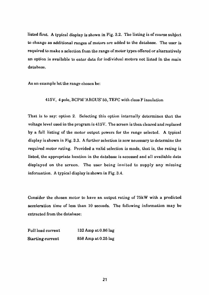
listed first. A typical display is shown in Fig. 3.2. The listing is of course subject
to change as additional ranges of motors are added to the database. The user is
required to make a selection from the range of motor types offered or alternatively
an option is available to enter data for individual motors not listed in the main
database.
As an example let the range chosen be:
415V, 4 pole, BCPM 'ARGUS' 55, TEFC with class F insulation
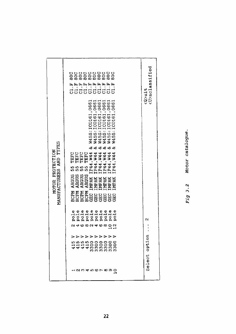
That is to say: option 2. Selecting this option internally determines that the
voltage level used in the program is 415V. The screen is then cleared and replaced
by a full listing of the motor output powers for the range selected. A typical
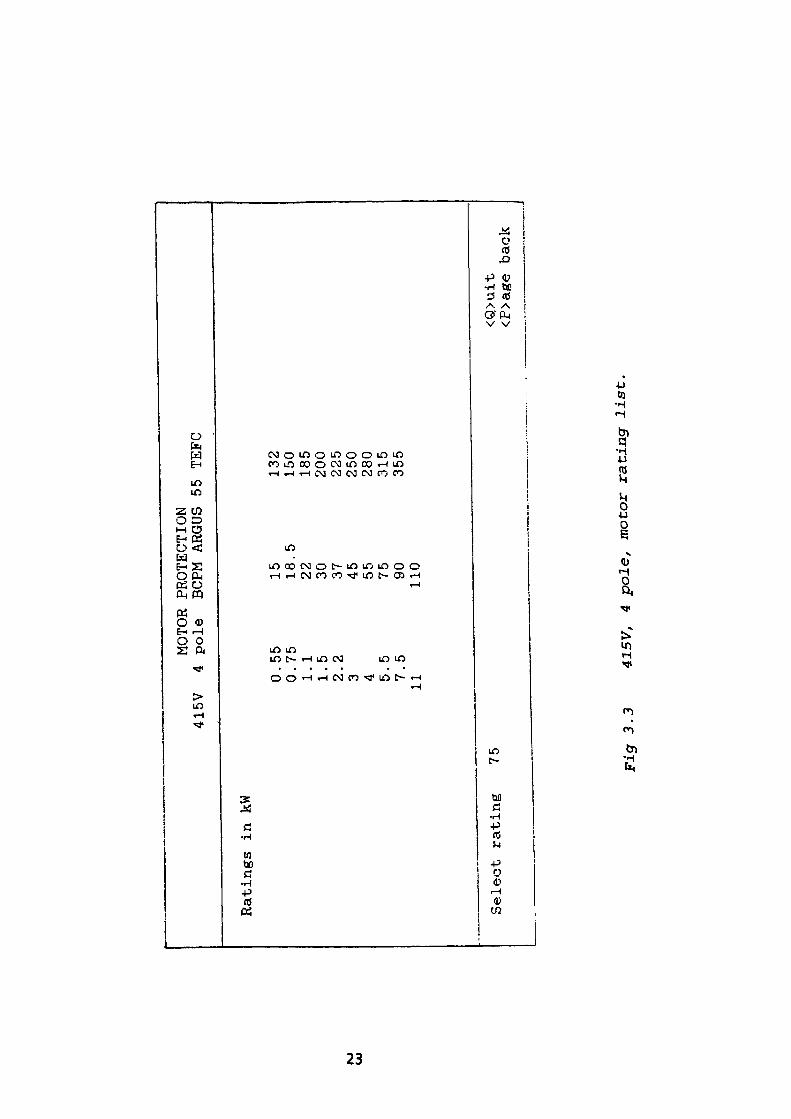
display is shown in Fig. 3.3. A further selection is now necessary to determine the
required motor rating. Provided a valid selection is made, that is, the rating is
listed, the appropriate location in the database is accessed and all available data
displayed on the screen. The user being invited to supply any missing
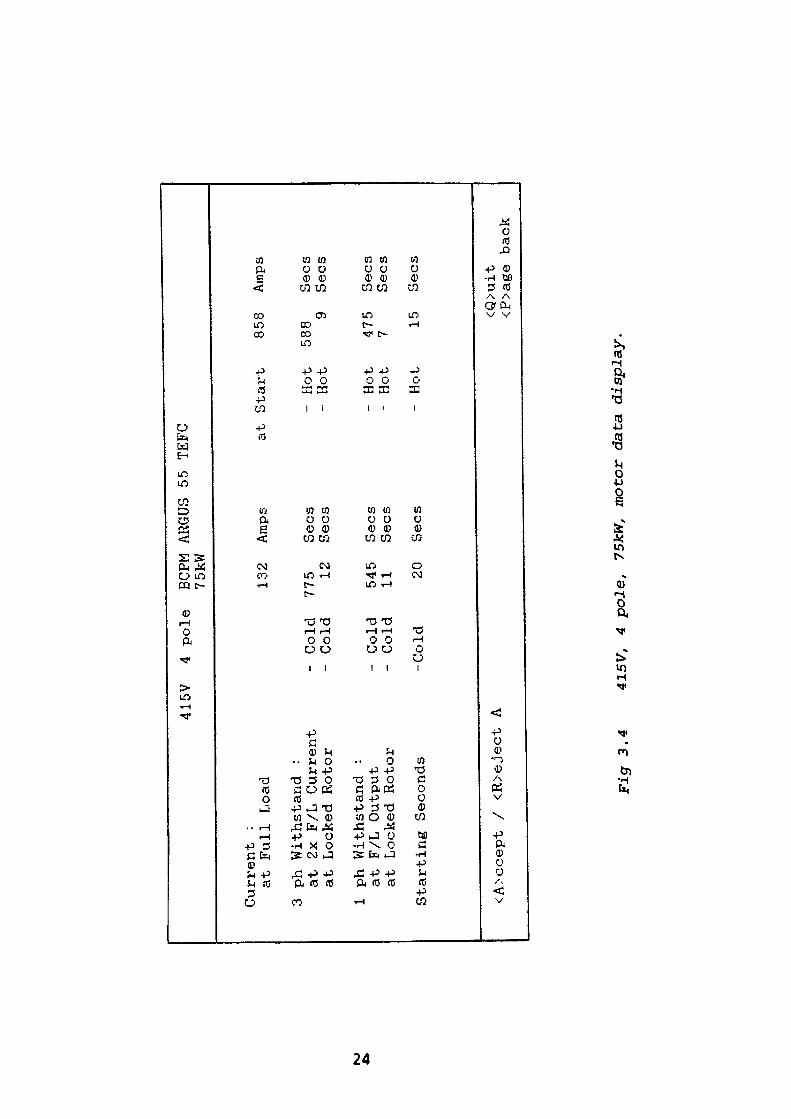
information. A typical display is shown in Fig. 3.4.
Consider the chosen motor to have an output rating of 75kW with a predicted
acceleration time of less than 10 seconds. The following information may be
extracted from the database:
Full load current 132 Amp at 0.86 lag
Starting current 858 Amp at 0.25 lag
21
NJ
MOTOR PROTECTION
MANUFACTURERS AND TYPES
1 415
V 2
415 V
3 415
V4
415
V5
3300 V
6 3300 V
7 3300 V
8 3300 V
9 3300 V
10
3300 V
Select option
2 4 6 8 2 4 6 810 12 . .
.
pole
pole
pole
pole
pole
pole
pole
pole
pole
pole
2
BCPM ARGUS 55
BCPM ARGUS 55
BCPM ARGUS 55
BCPM ARGUS 55
GEC
GEC
GEC
GEC
GEC
GEC
IMPAK
IMPAK
IMPAK
IMPAK
IMPAK
IMPAK
IP44
IP44
IP44
IP44
IP44
IP44
TEFC
TEFC
TEFC
TEFC
,W44
,W44
,W44
,W44
,W44
,W44
& W45S:
& W45S:
& W45S:
& W45S:
& W45S:
&. W45S:
IC0161
IC0161
IC0161
IC0161
IC0161
IC0161
,0661
,0661
,0661
,0661
,0661
,0661
Cl.F
Cl.F
Cl.F
Cl.F
Cl.F
Cl.F
Cl.F
Cl.F
Cl.F
Cl.F
80C
80C
80C
80C
80C
80C
80C
80C
80C
80C
<Q>uit
<U>nclassified
Fig
3.2
M
otor
cat
alog
ue.
NJ
UJ
415V
Ratings in kW
0 0 1 1 2 3 4 5 711
Select rating
75
MOTOR
4 pole
.55
.75
.1 .5 .2 .5 .5
PROTECTION
BCPM ARGUS
15 18.5
22 30 37 45 55 75 90 110
55 TEFC
132
150
185
200
225
250
280
315
355
<Q>uit
<P>age back
Fig 3.3
415V,
4 pole,
motor rating list.
NJ
415V
Current
: at Full Load
3 ph Withstand
: at 2x F/L Current
at Locked Rotor
1 ph Withstand
: at F/L Output
at Locked Rotor
Starting Seconds
<A>ccept /
<R>eject A
4 pole
BCPM
75kW
132
- Cold
775
- Cold
12
- Cold
545
- Cold
11
-Cold
20
ARGUS 55 TEFC
Amps
at Start
Sees
- Hot
Sees
- Hot
Sees
- Hot
Sees
- Hot
Sees
- Hot
858
Amps
588
Sees
9 Sees
475
Sees
7 Sees
15
Sees
<Q>uit
<P>age back
Fig 3.4
415V,
4 pole,
75kW,
motor data display.
Representing these two conditions by single phase equivalent impedances gives:
1. for running condition
V 415 1 Z = - = —r- • ———————-——— = 1.5610 + J0.9263Q1 V3 132 Cos" 1 0.86
2. for starting condition
V 415 1Z = — = -7- . ——————————— = 0.0698 + J0.2704Q1 V3 858 Cos' 1 0.25
The values determined above are of course calculated within the program but are
included to illustrate the strategy employed within the overall algorithm.
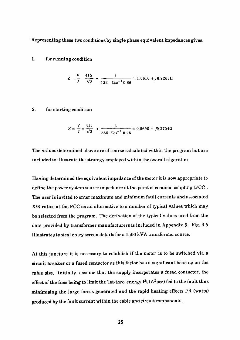
Having determined the equivalent impedance of the motor it is now appropriate to
define the power system source impedance at the point of common coupling (PCC).
The user is invited to enter maximum and minimum fault currents and associated
X/R ratios at the PCC as an alternative to a number of typical values which may
be selected from the program. The derivation of the typical values used from the
data provided by transformer manufacturers is included in Appendix 5. Fig. 3.5
illustrates typical entry screen details for a 1500 kVA transformer source.
At this juncture it is necessary to establish if the motor is to be switched via a
circuit breaker or a fused contactor as this factor has a significant bearing on the
cable size. Initially, assume that the supply incorporates a fused contactor, the
effect of the fuse being to limit the 'let-thro' energy I2t (A2 sec) fed to the fault thus
minimising the large forces generated and the rapid heating effects PR (watts)
produced by the fault current within the cable and circuit components.
25
415V
4 pole
BCPM ARGUS 55 TEFC
SYSTEM CONDITIONS
Circuit controlled by circuit bz
-eak
er
Select typical value option number
Minimum 3ph fault current at source
Maximum 3ph fault current at source
Minimum Earth fault current at source
Maximum Earth fault current at
source
TYPICAL VALUES
N 4 Amps
23730
47460
30531
61062
X/R
5.522
5.522
3.291
3.291
<1>
3.3/ 0.431 kV
YYOD1
400 kVA
<2>
3.3/ 0.431 kV
YYOD1
800 kVA
<3>
ll.O/ 0.431 kV
YYOD1
800
kVA
<4>
ll.O/ 0.431 kV
YYOD1
1500 kVA
<5>
ll.O/ 0.431 kV
YYO.D1
2000 kVA
<A>ccept /
<R>eject A
<Q>uit
<P>age back
Fig 3.5
Switching device and source data display for iBOOkVA
transformer.
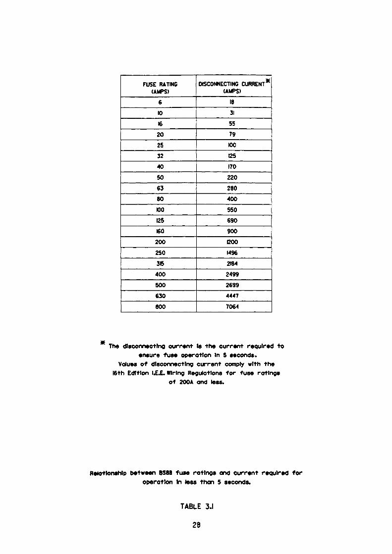
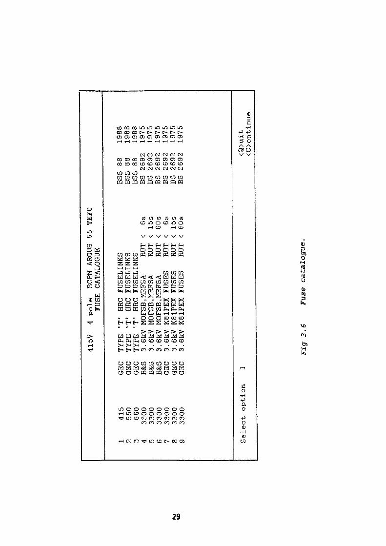
If the fuse links used are GEC TYPE T HRC type then reference to the
manufacturers data indicates that the optimum size fuselink for this duty is 250A,
For this fuselink the total let thro energy is 550 x 103 A2 sec and, by inspection of
table 3.1, the minimum fault disconnecting current required to ensure fuse
operation in less than 5 seconds is found to be 1496A.
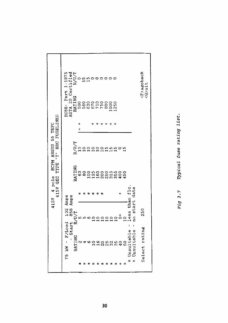
Typical displays of fuse selection information presented by the program are shown
in Figs. 3.6 and 3.7. It can be seen that all unsuitable fuse ratings are marked
with an asterisk. The option thus being to select any fuse equal to or larger than
250A. As an example, consider the fuse rating chosen to be 250A.
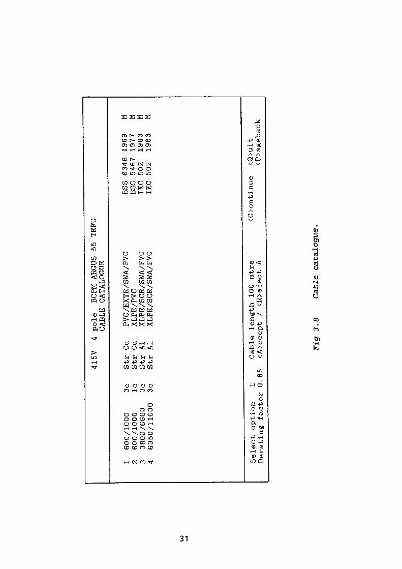
In this example the cable selection procedure is accomplished by choosing a cable
type from a displayed list, a typical display is as shown in Fig. 3.8. The cable
selected is option 1. The cable defined by this option is:
600/1000V grade, 3 core, PVC insulated, extruded bedding, single wire armour
and an oversheath of PVC. The conductor being of stranded copper construction
and generally complying with BS 634618).
The user is required to enter the route length of the cable run and the cable
derating factor in order to select cables of adequate current rating for
examination.
For example consider the cable length selected to be 100 metres with a derating
factor of 0.85.
To ensure the satisfactory operation in service and protection of the cable the
following series of checks are necessary.
27
FUSE RATING (AMPS)
6
10
16
20
25
32
40
50
63
80
100
125
160
200
250
315
400
500
630
600
DISCONNECTING CURRENT* (AMPS)
18
31
55
79
100
125
170
220
280
400
550
690
900
1200
1496
2184
2499
2699
4447
7064
The disconnecting current Is the current required toensure fuse operation In 5 seconds.
Values of disconnecting current comply with the16th Edition LEJL Wiring Regulations for fuse ratings
of 200A and less.
Relationship between BS88 fuse ratings and current required for operation In lees than 5 seconds.
TABLE 3.1
28
V£>
415V
1 415
2 550
3 660
4 3300
5 3300
6 3300
7 3300
8 3300
9 3300
Select option
GEC
GEC
GEC
B&S
B&S
B&S
GEC
GEC
GEC 1
4 pole
BCPM ARGUS
FUSE CATALOGUE
TYPE 'T
1 HRC
TYPE 'T'
HRC
TYPE 'T'
HRC
3. 3. 3. 3. 3. 3.
6kV
6kV
6kV
6kV
6kV
6kV
MOFSB ,
MOFSB,
MOFSB ,
K81PEX
K81PEX
K81PEX
55 TEFC
FUSELINKS
FUSELINKS
FUSELINKS
MRFSA
MRFSA
MRFSA
FUSES
FUSES
FUSES
RUT
RUT
RUT
RUT
RUT
RUT
< 6s
< 15s
< 60s
< 6s
< 15s
< 60s
BSS 88
BSS 88
BSS
88BS BS BS BS BS BS
2692
2692
2692
2692
2692
2692
1988
1988
1988
1975
1975
1975
1975
1975
1975
<Q>uit
<C>ontinue
Fig
3.6
F
use
cata
logu
e.
Ul
o
75 kW -
415V
4 415V
F/Load
132
Amps
- Start
858
Amps
RATING
R/U/T
* * * * * * * * * + **
2 4 610 16 20 25 32 35 40 50
5 5 5 10 10 10 10 10 10 0 +
10
* * * * * * +
pole
BCPM
GEC TYPE
'ARGUS 55 TEFC
T' HRC FUSEL INKS BS
88:
Part.
1:1975
ASTA 20 Certified
RATING
63 80100
125
160
200
250
315
355
400
450
R/U/T
RATING
10 10 10 10 10 10 15 15 15 0 15Unsuitable -
less than flc.
+ +
500
560
630
+ 670
+ 710
+ 750
+ 800
+ 1000
+ 1250
R/U/T
0 15 15 0 0 0 0 0 0
Sel
ect
rati
ng
250
<F>a
geba
ck
<Q>u
it
Fig
3.7
T
ypic
al
fuse
ra
tin
g l
ist.
UJ
1 600/1000
3c
2 600/1000
Ic
3 3800/6600
3c
4 6350/11000
3c
Select option
1 Derating factor 0.
415V
4 pole
BCPM ARGUS 55
CABLE CATALOGUE
Str Cu
PVC/EXTR/SWA/PVC
Str Cu
XLPE/PVC
Str Al
XLPE/SCR/SWA/PVC
Str Al
XLPE/SCR/SWA/PVC
Cable length 100
mtrs
85
<A>ccept /
<R>eject A
TEFC
BSS
6346 1969
M ESS 5467 1977
M IEC
502
1983
M IEC
502
1983
M
<Oontinue
<Q>uit
<P>ageback
Fig
3.8
C
able
cat
alog
ue.
To comply with IEE Regulation 433 - 02 - 01 which states:
IB < In < Iz
where IB = Design current of the circuit, that is a Motor full load current of 132A
In = The nominal current setting of the protective device which in this
case is a 250 Amp fuselink.
Iz = The current carrying capacity of the conductors.
It should be noted that where the fuse is not the only protective device in the
circuit, that is to say: it is augmented by a motor protection relay; then Iz need
only be greater than or equal to the relay setting.
Referring to Fig. 3.9 it can be seen that:
(a) Provided the cable is buried a cross-sectional area (CSA) of 35mm2 provides
an adequate current rating.
(b) Where the cable route is partly buried and partly in air, a CSA of 50mm2 is
satisfactory.
(c) A cable with a CSA of 70mm2 provides an adequate current rating for
routes comprising of portions laid in the ground, air and in duct.
Hence, provided the conductor current carrying capacity, Iz, satisfies the
appropriate condition a, b or c and is greater than or equal to the motor flc, then
the conductor current rating will be adequate providing the proposed relay
overload operating point does not exceed 1.45 x Iz. The factor, 1.45, is included
because the current causing effective operation of the protective device should not
exceed 1.45 x Iz to comply with regulation 433-02-01. This condition is satisfied
when BS 88 or BS1361 fuses are used.
32
Compliance with IEE Regulation 434-03-03 which states:
Where a protective device is provided for fault current protection only, the
clearance time of the device under both short-circuit and earth fault conditions
shall not result in the admissible limiting temperature of any live conductor being
exceeded.
The time t, in which a given fault current will raise the live conductors from the
highest permissible temperature in normal duty to the limiting temperature, can,
as an approximation be calculated from the formula stated in
Regulation 434-03-03 as:
(3.1)
where: t = duration in seconds
8 = nominal CSA of the conductor in mm2
I = Short circuit current in amps
k = 115 for copper conductors insulated with PVC
When applying fuse links to protect a 415V motor, one should be aware of the
limitations imposed by the earth fault loop impedance for compliance with
regulation 543-01-03 which states:
The CSA, where calculated, shall not be less than the value determined by the
following formula or shall be obtained by reference to BS 7454.
S = ——— mm (3.2) k
where: S is the nominal CSA of the conductor in
33
I is the value in amperes of the fault current for a fault of negligible
impedance which can flow through the associated protective
device, where due account is taken of the current limiting effect of
the circuit impedances and the limiting capability (I2t) of that
protective device.
t is the operating time of the disconnecting device in seconds
corresponding to the fault current I amperes.
k is the factor taking account of resistivity, temperature coefficient
and heat capacity of the conductor material, and the appropriate
initial and final temperatures.
Additionaly it should be noted that the maximum disconnecting time for TN-S
systems is stated as 5 seconds in regulation 413-02-13.
It can be seen that caution must be exercised particularly when considering large
415V motors supplied via long cable lengths which rely on fuselinks for
disconnection of earth fault conditions.
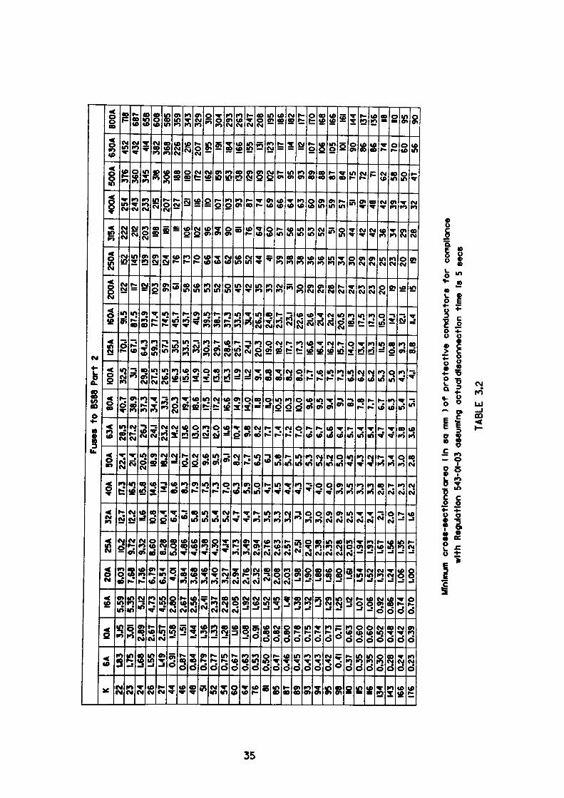
The minimum fault current required to rupture any fuse link complying with
BS 88: Part 2 may be determined by reference to table 3.2 which specifies the
minimum CSA of protective conductor which satisfies Regulation 543-01-03
assuming a maximum disconnection time of 5 seconds.
Consider a 250A fuselink used in conjunction with a PVC/SWA/PVC cable, the
appropriate k factor for steel wire being 51. Referring table 3.2 it can be seen that
at the intersection of the row containing the k factor of 51 and the 250A fuse link
column lies a value of 66 which represents the minimum size of protective
conductor (mm2) satisfying Regulation 543-01-03.
34
ui
Fuse
s to
BS8
8 Po
rt 2
K 22 23 24 26 27 44 46 48 51 52 54 60 64 76 81 85 87 89 93 94 95 98 HO 15 •6 134
143
166
176
6A L83
1.75
L68
L55
L49
0.91
0.87
0.84
0.79
0.77
0.75
0.67
0.63
0.53
0.50
0.47
0.46
0.45
0.43
0.43
0.42 0.4
10.
370.
350.
350.
300.
280.
240.
23
KM 3.5
3.01
2.89
2.67
2.57 1.5
81.5
11.4
41.3
61.3
31.2
81.1
61.0
80.9
10.
860.
820.
800.
780.
750.
740.
73 0.71
0.63
0.60
0.60
0.52
0.48
0.42
0.39
I6A 5.59
5.35 5J2
4.73
4.55
2.80
2.67
2.56 2.4
12.
372.
282.
05 1.92
1.62
1.52
1.45
1.41
1.38
1.32 1.31
1.29
1.25
U2 L07
1.06
0.92
0.86
0.74
0.70
20A
8.03
7.68
7.36
6.79
6.54 4.0
13.
843.
683.
463.
403.
272.
942.
762.
32 2.18
2.08
2.03 L9
81.9
01.8
81.8
61.8
01.6
11.5
41.5
21.3
21.2
41.0
61.0
0
25A
10.2
9.72
9.32
8.60
8.28
5.08
4.86
4.66
4.38
4.30 4.1
43.
733.
492.
942.
762.
632.
57 2.51
2.40 2.38
2.35
2.28
2.03 1.9
41.9
31.6
71.5
61.3
51.2
7
32A
12.7
12.2 H.6
10.8
10.4 6.4 6.1 5.8
5.5
5.4
5.2
4.7
4.4
3.7
3.5
3.3
3.2 3J 3.0
3.0
2.9
2.9
2.5
2.4
2.4 2.1 2.0 1.7 1.6
40A
17.3
16.5
15.8
14.6 14.1
8.6
8.3 7.9
7.5
7.3
7.0
6.3
5.9
5.0 4.7
4.5
4.4
4.3 4.1 4.0
4.0
3.9
3.5
3.3
3.3
2.6
2.7
2.3
2.2
50A
22.4 21.4
20.5 18.9
18.2 n.2 K).7
10.2 9.6
9.5 9.1 8.2
7.7
6.5 6.1 5.8
5.7
5.5
5.3
5.2
5.2
5.0
4.5
4.3
4.2
3.7
3.4
3.0
2.8
63A
28.5
27.2 26.1
24.1
23.2 14.2
13.6
13.0
12.3
12.0 11.6
10.4 9.8
8.2
7.7
7.4 7.2
7.0
6.7
6.7
6.6
6.4 5.7
5.4 5.4
4.7
4.4
3.8
3.6
80A
40.7
38.9
37.3
34.4 33.1
20.3 19.4
18.6
17.5
17.2
16.6
14.9
14.0 n.8 H.O 10.5
10.3
10.0 9.6
9.5
9.4 9J 8.1 7.8 7.7
6.7
6.3
5.4 5.1
IOOA
32.5 31.
129
.827
.526
.516
.315
.614
.914
.013
.813
.3 IL9
11.2
9.4
8.8
8.4
8.2
8.0
7.7 7.6
7.5
7.3
6.5
6.2
6.2
5.3
5.0
4.3 4.1
I25A
70.1
67.1
64.3
59.3 57.1
35.1
33.5 32.1
30.3
29.7
28.6
25.7 24.1
20.3
19.0
18.2
17.7
17.3
16.6
16.4
16.2
15.7
14.0
13.4
13.3 11.5
10.8 9.3
8.8
I60A 9.5
87.5
83.9
77.4
74.5
45.7
43.7 41.9
39.5
38.7
37.3
33.5 31.4
26.5
24.8
23.7
23.1
22.6 21.6
21.4
21.2
20.5 18.3
17.5
17.3
15.0 14.1
12.1
1.4
200A 12
2 117 112 103 99 61 58 56 53 52 50 45 42 35 33 32 31 30 29 29 28 27 24 23 23 20 19 16 15
250A 15
214
513
912
912
4 76 73 70 66 64 62 56 52 44 41 39 38 38 36 36 35 34 30 29 29 25 23 20 19
36A
222 212
203 188 181 in
106
102 96 94 90 81 76 64 60 57 56 55 53 52 51 50 44 42 42 36 34 29 28
400A 254
243
233 215
207 127 121 116 110 107
103 93 87 74 69 66 64 63 60 59 59 57 51 49 48 42 39 34 32
500A 376
360
345 318
306 188
180
172
162
159
153
138
129
109
102 97 95 93 89 88 87 84 75 72 71 62 58 50 47
630A 452
432 414
382
368
226 216
207 195 191 184
166
155 131 123 117 114 112 107
106^
105 101 90 86 86 74 70 60 56
800A 71
868
765
860
858
535
934
332
9 310
304
293
263
247
208 195
186
182
177
170
166
166 161 144
137
136 118 no 95 90
Min
imum
cr
oss
-sec
tio
nal
are
a (I
n s
a m
m )o
f p
rote
ctiv
e co
nduc
tors
fo
r co
mpl
ianc
e w
ith R
egul
atio
n 54
3-01
-03
assu
min
g ac
tual
dis
conn
ectio
n tim
e Is
5 s
ees
TAB
LE
3.2
Transposing the formula above gives:
Sk'• vZand substituting values for S, k and t gives
66*51/ = ——-.—— = l5Q5Amp V 5
Reference to Fig. 3.9 provides confirmation of this value of current.
A full listing of the 5 second disconnecting currents for all BS 88: Part 2 fuses are
included in Table 3.1.
Using the disconnecting current of 1505A determined above and examining the
smallest of the 3 cable CSA's previously considered in item 1, that is to say CSA's
of 35mm2, 50mm2 and 70mm2 where k = 115 we bee that by using the equation
given in eq (3.1).
Transposing the formula gives t = I —
/2
/35 »115 \and by substitution of values t = I ———— ) = 7.15
V 1505 /sees
From which it can be seen that the main conductors satisfy the 5 second fuse
disconnection criteria. Whilst this is true for PVC cables used in conjunction with
fuses complying with BS 88 Part 2, caution should be exercised when using a cable
with a k factor less than that used in this example.
36

Consider the CSA of the armouring for the same cable. Reference to
manufacturers data shows that the allowable armour fault current to earth for a
duration of 1 second is 3300A.
Sk Substituting in I — I —r
S.513300 = —T— Vl
3300 9from whichCSA S - ——— - 64.7 mm
51
Using this calculated armour CSA value for an earth fault of 5 seconds duration
shows that the armour rating is marginal for use with this fuse size.Sk
By substituting in I — —j- it can be seen that:
64.7 «51/= ——-.——= 1475 Amp V5
In addition it should be noted that manufacturers data has been used in this
calculation which will generally have a larger CSA than that called for in
BS 6346.
Clearly for circuits which cannot satisfy the 5 second disconnecting time, reliance
must be placed on an earth fault detecting device to provide disconnecting times of
shorter duration.
37
3.3.1 Overcurrent Protection
Compliance with EEE Regulation 552-01-02 which states:
'Every electric motor greater than 0.37kW shall be provided with control
equipment incorporating a means of protection against an overload of the motor'.
This regulation is usually satisfied by incorporating a fuselink as previously
discussed in conjunction with contactor controlled circuits or alternatively an
overcurrent protective relay element where circuit breakers are used.
Compliance with ZEE Regulation 434-03-03 which states:
"Where a protective device is provided for fault current protection only, the
clearance time of the device under both short-circuit and earth fault conditions
shall not result in the admissable limiting temperature of any line conductor
being exceeded.
In this case consideration should be given to the case where an excess of current
causes the fuse link to rupture in a very short time of less than 10 msecs. Under
these conditions manufacturers data indicates the maximum energy let thro I2t
value is 550 x 103 A2s which must be compared with the cable withstand value.
Transposing the formula in Regulation 434-03-03 shows that;
CSA S = V — mm 2 k 2
from which the minimum CSA for PVC insulated cables with copper conductors is:
,550 «10 3 , V ————= 6.45mm1152
38
This confirms that the cable CSA's previously considered on current ratings are
adequately protected under short-circuit conditions by the 250 Amp fuselink.
3.3.2 Voltage Drop Considerations
Compliance with IEE regulation 525-01-02 which states that:
The requirements of regulation 525-01-02 are deemed to be satisfied for a supply
given in accordance with the Electricity Supply Regulations 1988 (as amended) if
the voltage drop between the origin of the installation (usually the supply
terminals) and the fixed current - using equipment does not exceed 4% of the
nominal voltage of the supply.
Referring to the 415V, 4 pole, 75kW motor previously discussed, we will examine
the voltage drop in the 70mm2 cable for the run condition to determine compliance
with regulation 525-01-02.
Total Impedance = Z cable + Z motor run
(0.0321 + j 0.00079)* + (1.561 + j 0.9263)
1.5931 + j 0.9342
1.8468 Z30.4°Q
""manufacturers data
V 415 Z 0 Current = — =
Z V3 «1.8468 Z 30.4°
= 129.74 Z -30.4° A
Voltage drop in cable = IZ = 129.74 Z - 30.4° • [0.0321 + j 0.0079]
39
= 4.29^-16.56° V
V3«4.29 Z - 16.56'Voltage drop = ———— ———— «100 415 Z. 0
= 1.79% which is satisfactory
Similar calculations carried out on the 50mm2 cable indicate a voltage drop of 2.53% whilst for the 35mm2 cable it is 3.37% which may be marginal.
In this case the 70mm2 cable is selected as it satisfies Regulation 522-01-02 and all previously considered regulations.
If it is assumed that the circuit is supplied from an 800kVA transformer source, then referring to Appendix 5 suggests a typical source impedance for a single transformer would be:
0.003161 + j 0.0132189 (I
Hence the reference voltage of a fictitious generator of equivalent source impedance would be:
I x Z source + (415/V3 + JO)
= 129.74 Z -30.4° . 1 source + (415A/3 + j 0)
= 1.76 Z 46.16° + (415/V3 + j 0)
= 1.2213 + jl.2719 + 415/V3 + JO
= 240.8216 + jl.2719
Now consider the circuit under starting conditions where:
Total Impedance: = Source impedance + cable impedance + motor start
impedance
Source = 0.003161+ j 0.0132189 Q
40
Cable = 0.0321 + j 0.0079 Q
Motor (start) = 0.0698 + j 0.2704 Q
then total impedance = 0.10506 + j 0.29152 Q
The resulting starting current would be given by:
240.8216 + jl.2719 Starting Current = ——————————
B 0.10506+./0.29152
- 240.825 Z 0.303° 0.30987 Z 70.18°
= 777.2 Z -69.88° A
Similarly, the voltage at the terminal box of the motor would be given by:
Voltage at motor = IZ
= 777.2 Z-69.88°. (0.0698+ 0.2704)
= 217.04 Volts
Va«2i7Hence % motor volts at start - ———— . 100 - 90.58%
415
The MPROT program is arranged so that checks are conducted in a logical
sequence. Those cables which fail to satisfy the various regulations are 'flagged'
accordingly, whilst the motor terminal voltage values for both the 'Run' and 'Start'
conditions are displayed.
Fig. 3.9 displays the predicted start and run motor terminal voltages for each
cable CSA in the range when attempting to supply the 75kW motor from an
SOOkVA source. Similarly Fig. 3.10 displays the predicted values when supplied
from a 1500kVA source.
41
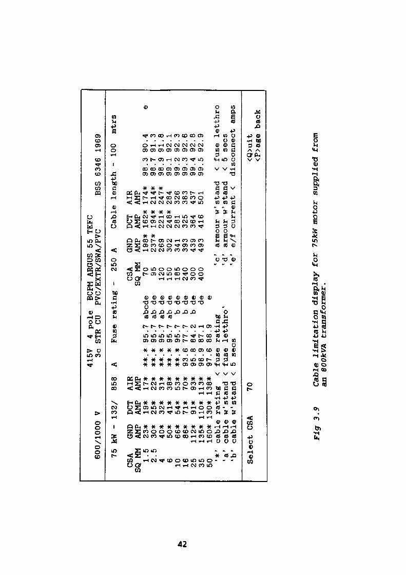
to
600/1000
75
CSA
SQ MM
1.5
2.5
4 6 10 16 25 35 50 *>
'a'
'b'
kW -
GND
AMP
23*
30*
40*
50*
66*
86*
112*
135*
160*
cable
cable
cabl
e
V 132/
858
DCT
AIR
AMP
AMP
19*
17*
25*
22*
32*
31*
41*
38*
54*
53*
71*
70*
91*
93*
110* 113*
130* 138*
rating
<w' stand
<w" stand <
415V
3c
A **.*
**.*
**. *
**.*
**.*
93.6
95.8
96.9
97.6
fuse
fuse
4 po
le
SIR
CUBCPM ARGUS 55 TEFC
PVC/EXTR/SWA/PVC
Fuse rating
95.7 abode
95.7 ab
95.7 ab
95.7 ab
95.7
b77.7
b84.2
b87.1
88.9
rating
letthro'
de de de de de de dee
5 sees
- 250
CSA
SQ MM
70 95120
150
185
240
300
400
'c'
'd'
'e'
A GND
AMP
198*
237*
269
302
341
393
439
493
BSS
6346 1969
Cable length -
DCT
AIR
AMP
AMP
162*
194*
221*
248*
281
325
364
416
armour w'
armour w'
e/f
174*
214*
247*
284
326
383
437
501
stand
stan
dcurrent
<
98.
98.
98.
99.
99.
99.
99.
99. < <
100
mtrs
3 90.4
e7
91.3
9 91.8
1 92.1
2 92.3
3 92.6
4 92.8
5 92.9
fuse letthro
5 sees
disconnect amps
Select CSA
70<Q>uit
<P>age ba
ck
Fig 3.9
Cabl
e li
mita
tion
display
for
75kW
mot
or supplied from
an BOOkVA transformer.
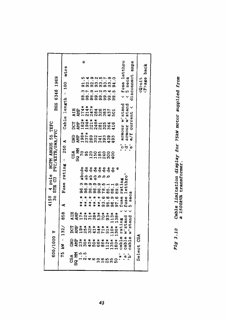
Ul
600/1000 V
75
CSA
SQ MM
1.5
2.5
4 610 16 25 35 50«*
'a'
'b'
kW -
132/
858
GND
DCT
AIR
AMP
AMP AMP
23*
19*
17*
30*
25*
22*
40*
32*
31*
50*
41*
38*
66*
54*
53*
86*
71*
70*
112*
91*
93*
135* 110* 113*
160* 130* 138*
cable
rating
<cable
w1 stand <
cable
w' stand
<
415V
3c
A **.*
**.*
**.*
**. *
**.*
93.6
95.8
96.9
97.6
fuse
fuse
4 pole
SIR
CUBCPM ARGUS 55 TEFC
PVC/EXTR/SWA/PVC
Fuse rating
96.9 abode
96.9 ab
96.9 ab
96.9 ab
96.9
b78.5
b85.1
b88.1
89.9
rating
letthro
de
de de de de de dee
- 250
A
CSA
GND
SQ MM
AMP
70 95120
150
185
240
300
400
198*
237*
269
302
341
393
439
493
Cable
DCT
AMP
162*
194*
221*
248*
281
325
364
416
'c'
armour w'
' 'd'
armour w'
5 sees
'e'
e/f
BSS
6346 1969
length -
AIR
AMP
174*
214*
247*
284
326
383
437
501
stand
stand
current
<
98.
98.
98.
99.
99.
99.
99.
99.
100
mtrs
3 91.5
7 92.4
9 92.9
1 93.2
2 93.5
3 93.7
4 93.9
5 94.0
e
< fuse letthro
<5
sees
disconnect
Select CSA
<Q>uit
<P>age
amps
back
Fig
3.1
0 C
able
lim
itati
on d
ispl
ay f
or
75kW
mot
or s
uppl
ied
from
a
ISO
OkV
A tr
ansf
orm
er.
Although all the relevant circuit parameters have now been specified, there still
remains the final requirement of acceleration or run-up-time of the installation.
The user is presented with a screen displaying the calculated minimum
percentage voltage of 90.6%V at the motor terminal for which the appropriate
acceleration time must be supplied. Similar inputs are required for terminal
voltages of 100% and 105%v or whatever overvoltage may be envisaged. A
suitable method of calculating acceleration times is contained in Appendix 2. A
typical screen display of this section of the program is shown in Fig. 3.11.
Fig. 3.12 depicts the subsequent screen display which follows and allows the user
to select the motor protection relay of choice.
3.4 Program Description
The purpose of this program is to examine a series of data libraries from which a
motor, cable, and if required a fuse of adequate rating may be selected.
This objective is achieved by executing a series of linked modules each of which
has a unique function. The first modules access a database from which a motor of
desired rating is selected. Subsequent modules* enable the selection of the most
suitable fuse size to be determined. Further modules provide a choice of cable type
and predict the most appropriate conductor CSA. All data determined and
collated in the program is used by the protection relay programs detailed in later
chapters.
A detailed description of the function of individual modules follows:
44
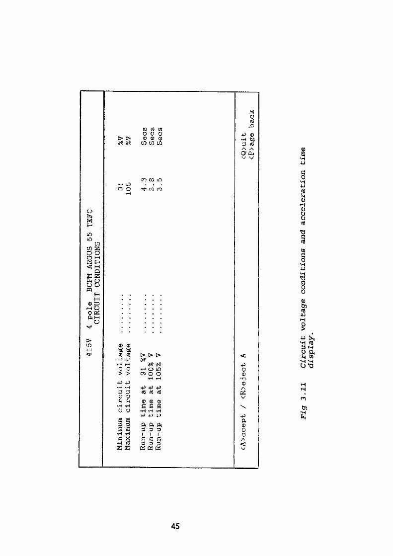
415V
4 pole
BCPM ARGUS 55 TEFC
CIRCUIT CONDITIONS
Minimum circuit voltage
Maximum circuit voltage
Run-up time at
91 %V
Run-up time at 100% V
Run-up time at 105% V
91105 4.3
3.8
3.5
%V
%V Sees
Sees
Sees
in
<A>ccept /
<R>eject A
<Q>uit
<P>age back
Fig
3.1
1 C
ircu
it v
olta
ge c
ondi
tion
s an
d ac
cele
rati
on
time
disp
lay.
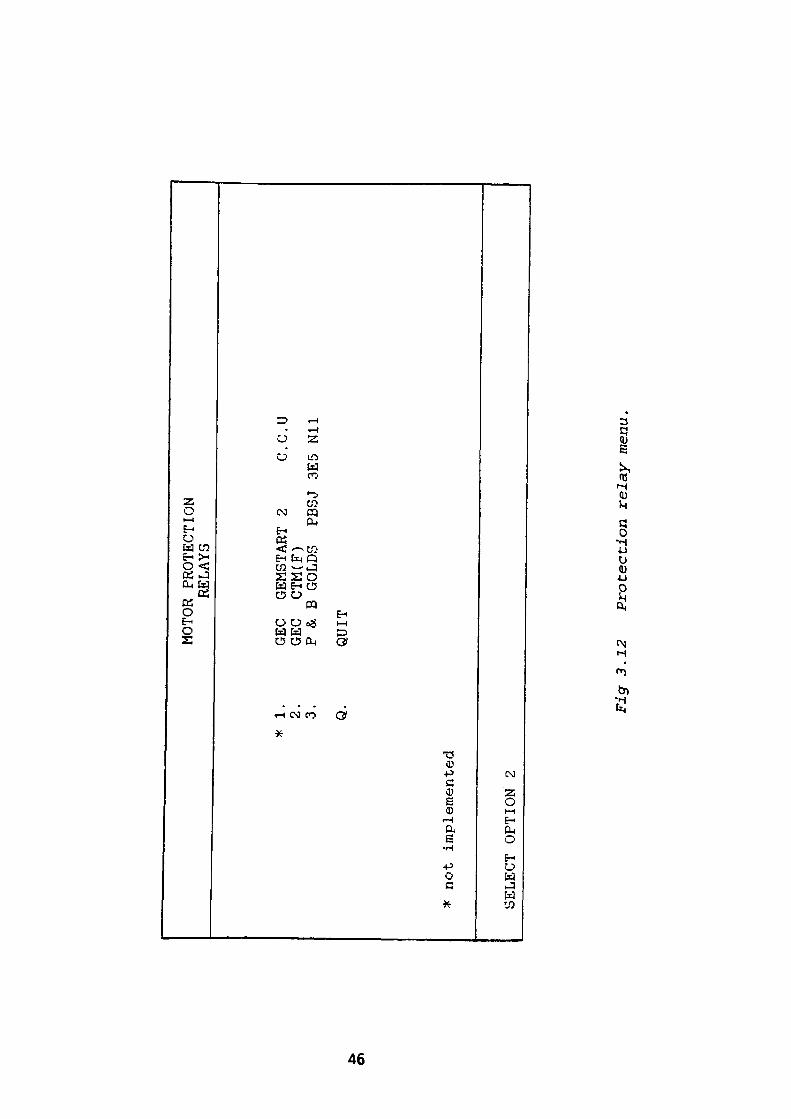
MOTOR PROTECTION
RELAYS
* 1. 2. 3. Q.
GEC
GEMSTART 2
C.C.U
GEC
CTM(F)
P & B
GOLDS
PBSJ 3E5
Nil
QUIT
* not implemented
SELECT OPTION 2
Fig 3.12
Protection relay menu.
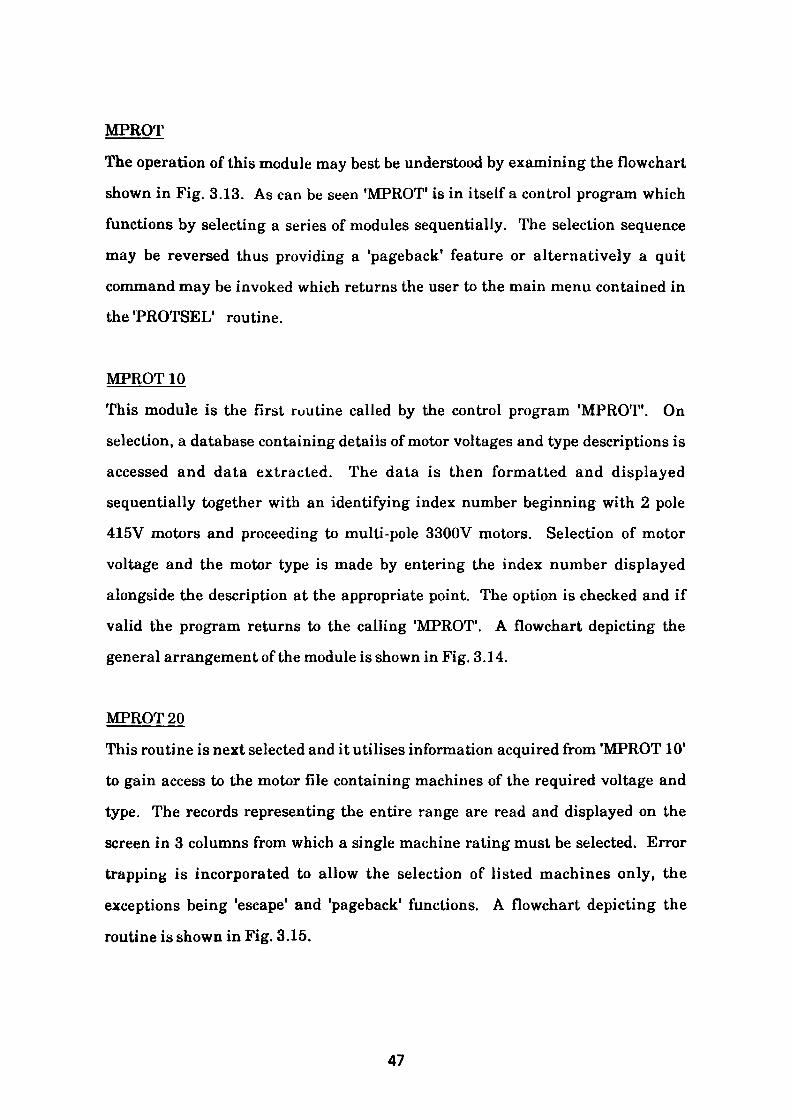
MPROT
The operation of this module may best be understood by examining the flowchart
shown in Fig. 3.13. As can be seen 'MPROT' is in itself a control program which
functions by selecting a series of modules sequentially. The selection sequence
may be reversed thus providing a 'pageback' feature or alternatively a quit
command may be invoked which returns the user to the main menu contained in
the'PROTSEL' routine.
MPROT 10
This module is the first routine called by the control program 'MPROT1 . On
selection, a database containing details of motor voltages and type descriptions is
accessed and data extracted. The data is then formatted and displayed
sequentially together with an identifying index number beginning with 2 pole
415V motors and proceeding to multi-pole 3300V motors. Selection of motor
voltage and the motor type is made by entering the index number displayed
alongside the description at the appropriate point. The option is checked and if
valid the program returns to the calling 'MPROT'. A flowchart depicting the
general arrangement of the module is shown in Fig. 3.14.
MPROT20
This routine is next selected and it utilises information acquired from 'MPROT 10'
to gain access to the motor file containing machines of the required voltage and
type. The records representing the entire range are read and displayed on the
screen in 3 columns from which a single machine rating must be selected. Error
trapping is incorporated to allow the selection of listed machines only, the
exceptions being 'escape' and 'pageback' functions. A flowchart depicting the
routine is shown in Fig. 3.15.
47
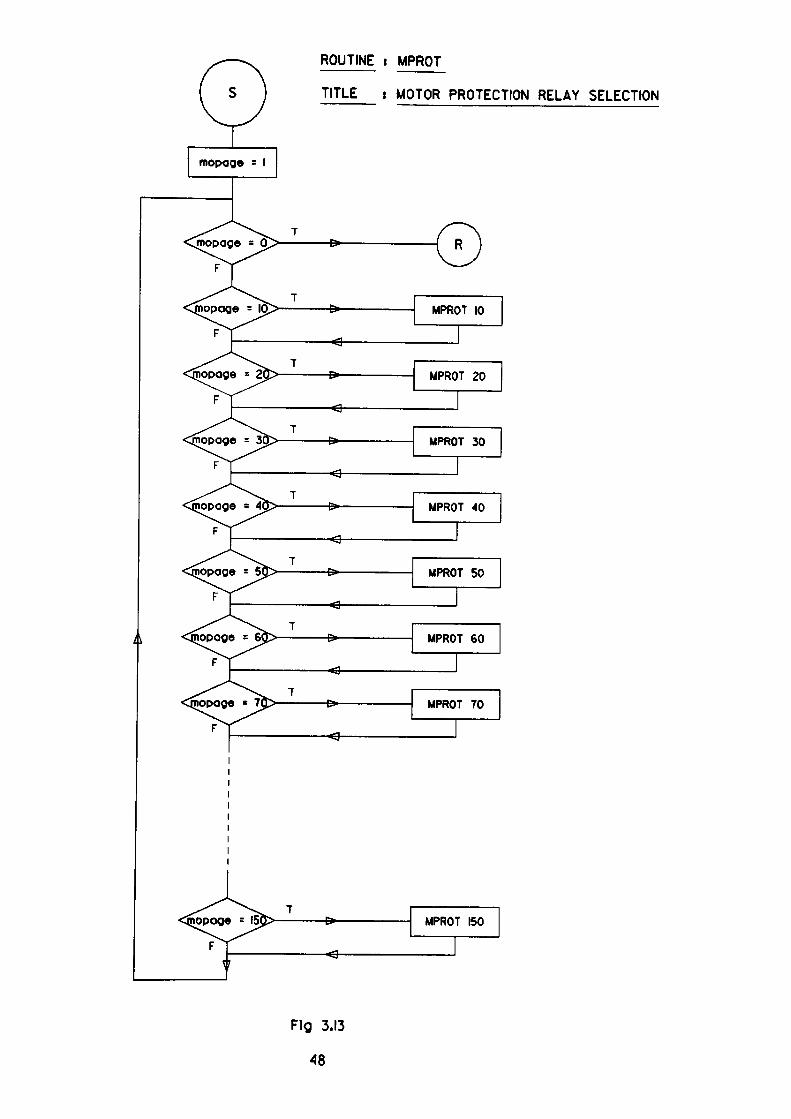
ROUTINE i MPROT
TITLE i MOTOR PROTECTION RELAY SELECTION
Fig 3.13
48

ROUTINE i MPROT 10
TITLE 5 DISPLAY OF MOTOR TYPES
READ MOTOR LIBRARY
DISPLAY
SELECT OPTION
FFg 3.14
49
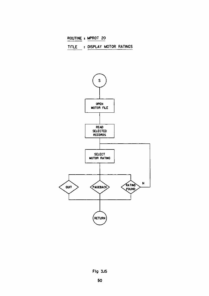
ROUTINE : MPROT 20
TITLE : DISPLAY MOTOR RATINGS
OPEN MOTOR FILE
READ SELECTED RECORDS
SELECT MOTOR RATING
Fig 3.15
50
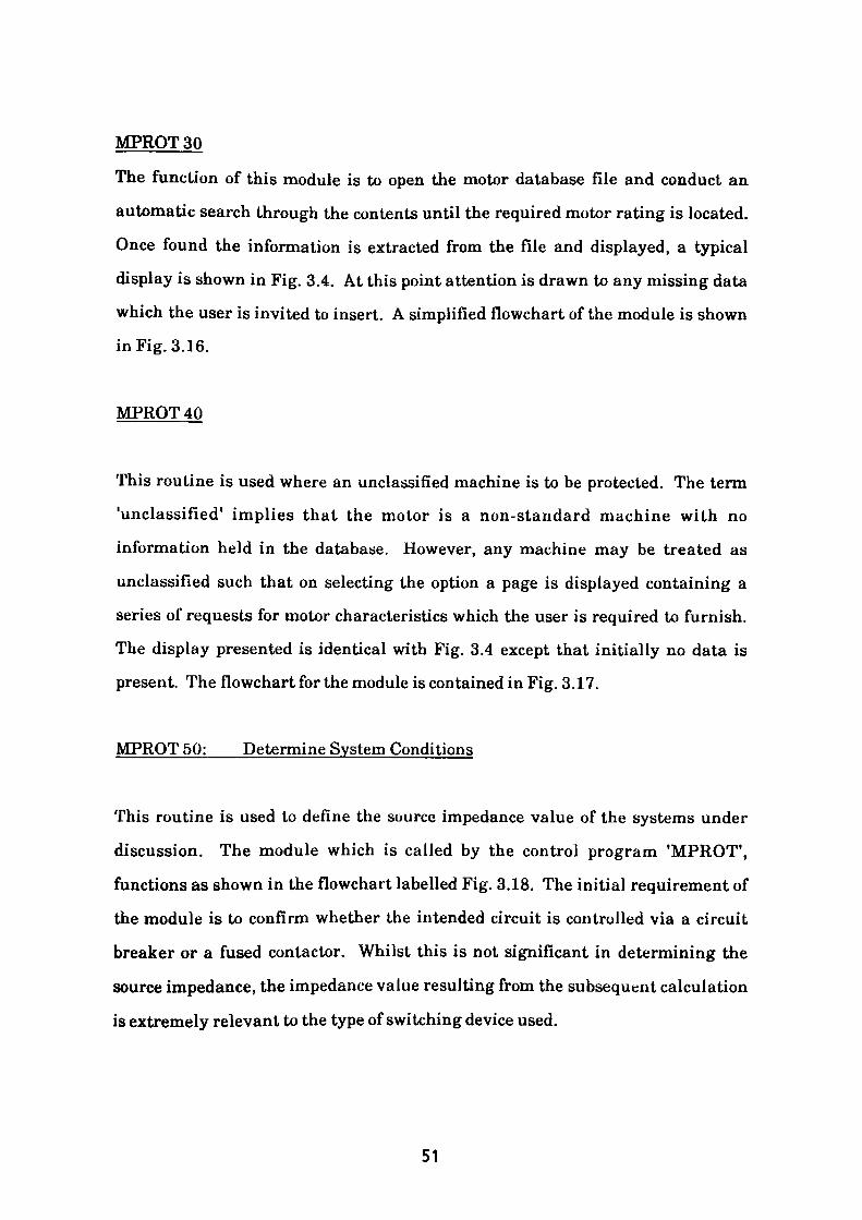
MPROT 30
The function of this module is to open the motor database file and conduct an
automatic search through the contents until the required motor rating is located.
Once found the information is extracted from the file and displayed, a typical
display is shown in Fig. 3.4. At this point attention is drawn to any missing data
which the user is invited to insert. A simplified flowchart of the module is shown
in Fig. 3.16.
MPROT 40
This routine is used where an unclassified machine is to be protected. The term
'unclassified* implies that the motor is a non-standard machine with no
information held in the database. However, any machine may be treated as
unclassified such that on selecting the option a page is displayed containing a
series of requests for motor characteristics which the user is required to furnish.
The display presented is identical with Fig. 3.4 except that initially no data is
present. The flowchart for the module is contained in Fig. 3.17.
MPROT 50: Determine System Conditions
This routine is used to define the source impedance value of the systems under
discussion. The module which is called by the control program 'MPROT 1 ,
functions as shown in the flowchart labelled Fig. 3.18. The initial requirement of
the module is to confirm whether the intended circuit is controlled via a circuit
breaker or a fused contactor. Whilst this is not significant in determining the
source impedance, the impedance value resulting from the subsequent calculation
is extremely relevant to the type of switching device used.
51
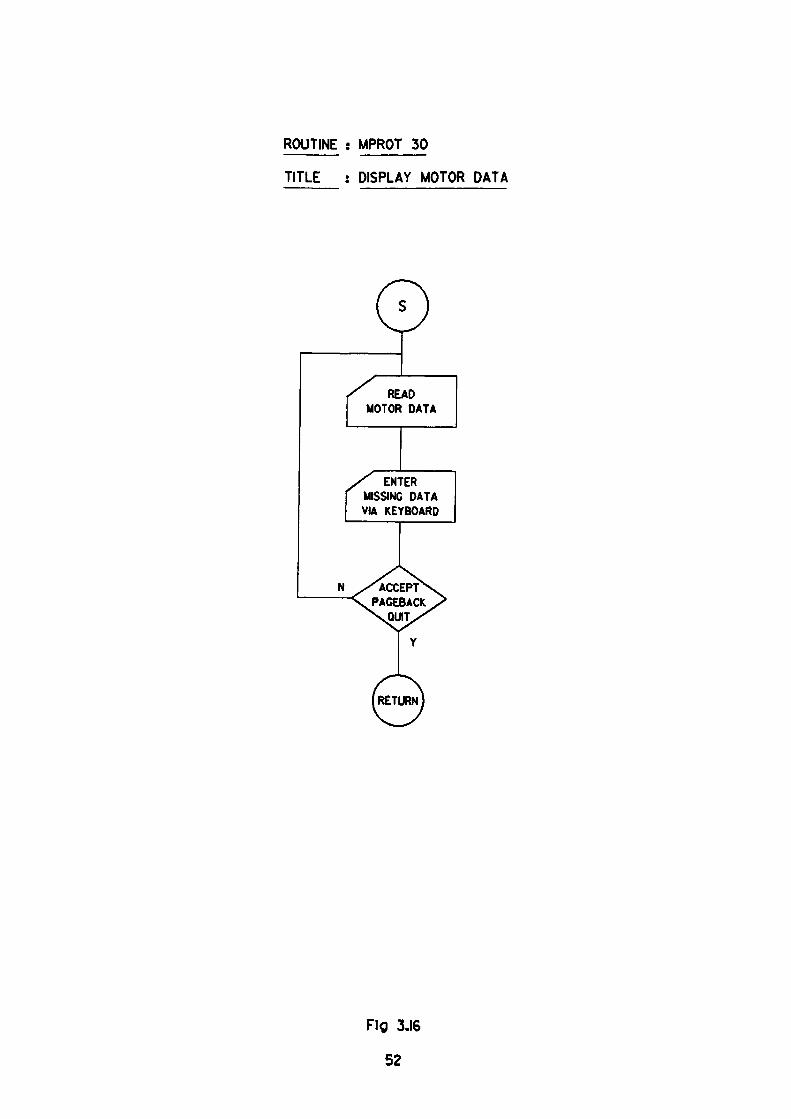
ROUTINE : MPROT 30
TITLE : DISPLAY MOTOR DATA
: ENTER
ISSINC DATA & KEYBOARD
Fig 3.16
52
ROUTINE « MPROT 40
TITLE ; DATA INPUT FOR•UNCLASSIFIED' MOTORS
ENTER ALL DATA VIA KEYBOARD
Fig 3.17
53
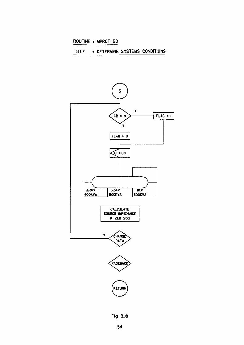
ROUTINE : MPROT 50
TITLE : DETERMINE SYSTEMS CONDITIONS
CALCULATESOURCE lyPEDANCE
& ZER SOQ
Ffg 3.18
54
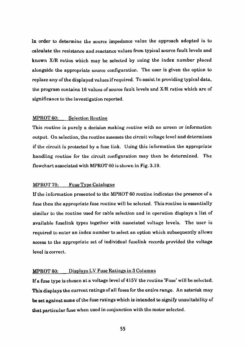
In order to determine the source impedance value the approach adopted is to
calculate the resistance and reactance values from typical source fault levels and
known X/R ratios which may be selected by using the index number placed
alongside the appropriate source configuration. The user is given the option to
replace any of the displayed values if required. To assist in providing typical data,
the program contains 16 values of source fault levels and X/R ratios which are of
significance to the investigation reported.
MPROT 60: Selection Routine
This routine is purely a decision making routine with no screen or information
output. On selection, the routine assesses the circuit voltage level and determines
if the circuit is protected by a fuse link. Using this information the appropriate
handling routine for the circuit configuration may then be determined. The
flowchart associated with MPROT 60 is shown in Fig. 3.19.
MFROT 70: Fuse Type Catalogue
If the information presented to the MPROT 60 routine indicates the presence of a
fuse then the appropriate fuse routine will be selected. This routine is essentially
similar to the routine used for cable selection and in operation displays a list of
available fuselink types together with associated voltage levels. The user is
required to enter an index number to select an option which subsequently allows
access to the appropriate set of individual fuselink records provided the voltage
level is correct.
MPROT 80: Displays LV Fuse Ratings in 3 Columns
If a fuse type is chosen at a voltage level of 415V the routine 'Fuse' will be selected.
This displays the current ratings of all fuses for the entire range. An asterisk may
be set against some of the fuse ratings which is intended to signify unsuitability of
that particular fuse when used in conjunction with the motor selected.
55
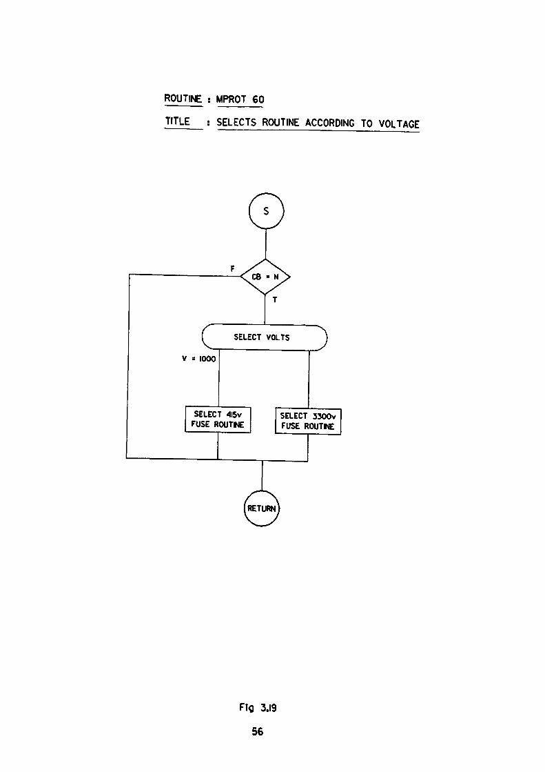
ROUTINE s MPROT 60
TITLE : SELECTS ROUTINE ACCORDING TO VOLTAGE
c SELECT VOLTS
V s 1000
SELECT 4l5v FUSE ROUTINE
SELECT 3300v FUSE ROUTINE
Fig 3.19
56

Hence: Motor Starting Current > fuse pulse rating for starting duration of T
sees.
The flowchart associated with this module is shown in Fig. 3.20
MPROT 90 - displays HV fuse ratings in 1 column
MPROT100 - displays HV fuse ratings in 2 columns
MPROT 110: Displays Cable Catalogue
This module is selected by one of two proceeding modules either MPROT 60 or
MPROT 80,90,100 depending on whether the switching device is a fused contactor
or a fully rated circuit breaker.
The operation of this module is as shown in the flowchart depicted in Fig. 3.21.
The routine uses the same technique as was used in previous data extraction
routines. A file containing records of cable types is opened and from each record
data is extracted from selected fields, some of which is displayed on the screen
together with an identifying index number. The cable type is selected by entering
the index number displayed alongside the desired option.
This action isolates the required record and enables further data to be extracted
from the individual cable records held in the CA1 database. To complete the cable
specification it is necessary to provide details of the installed cable length together
with an appropriate thermal derating factor for the intended installation
environment.
The module incorporates various checks, one of which ensures that the cable
option selected has the correct voltage rating. The usual 'pageback' and 'quit'
options are also included.
57
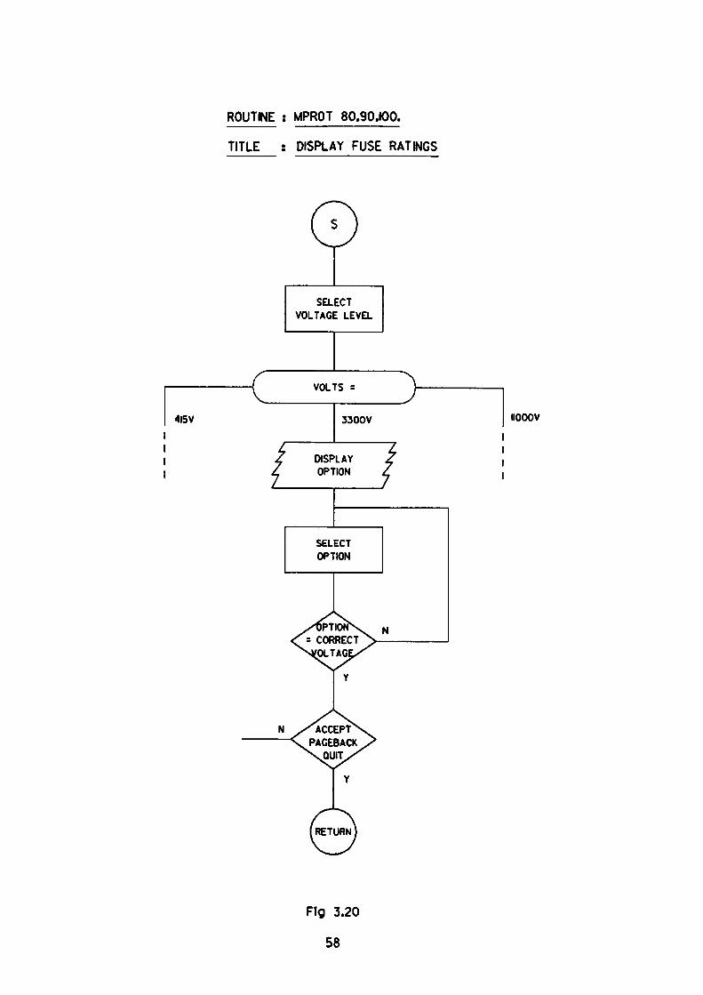
ROUTINE ; MPROT 80.90,100.
TITLE : DISPLAY FUSE RATINGS
415V
SELECT VOLTAGE LEVEL
IIOOOV
Fig 3.20
58
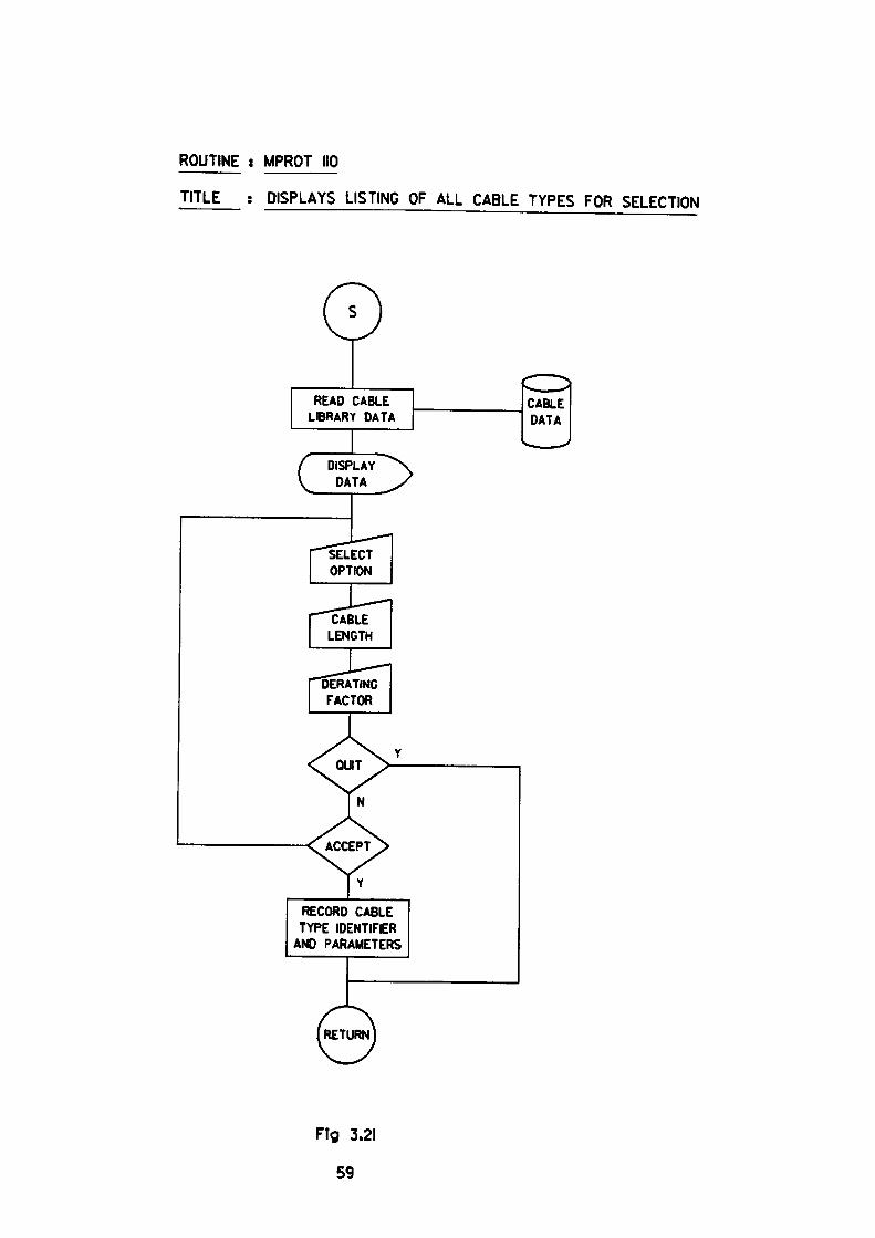
ROUTINE i MPROT IIP
TITLE : DISPLAYS LISTING OF ALL CABLE TYPES FOR SELECTION
READ CABLE LIBRARY DATA
RECORD CABLETYPE IDENTIFER
AND PARAMETERS
CABLE DATA
Fig 3.21
59
MPRQT 120: Calculates Currents and Conditions
In this routine much of the data acquired in previous modules is used in
computations. The routine begins by opening and clearing the workfile prior to
accepting fresh data. A second file containing the required cable data records is
opened and the first record extracted. The standard current ratings are modified
by the derating factor ready for storage in the workfile. Additionally the cable
positive and zero sequence impedance values for the specified length are
calculated and used in conjunction with the maximum source impedance value to
determine the following computations.
1. Percentage voltage drop in the cable at the motor FLC.
2. The fictitious generator voltage for supplying power through the source
impedance to the circuit busbar which is held at nominal voltage when the
motor is drawing FLC.
3. The voltage at the motor terminals when drawing starting current.
When fuselinks are used additional checks are conducted to determine if:
4. The derated cable rating > fuselink rating.
A flowchart indicating the general arrangement is shown in Fig. 3.22
60
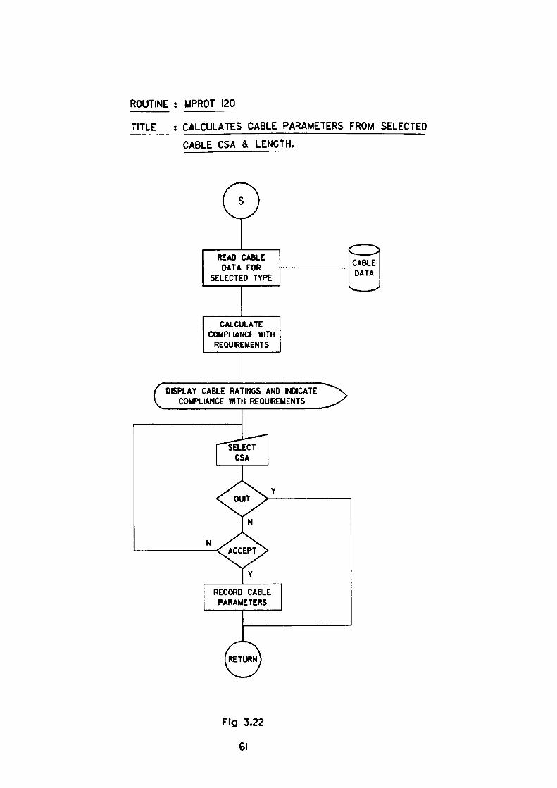
ROUTINE : MPROTJ20
TITLE ; CALCULATES CABLE PARAMETERS FROM SELECTED
CABLE CSA & LENGTH.
READ CABLEDATA FOR
SELECTED TYPE
CABLE DATA
CALCULATECOMPLIANCE WITH
REQUIREMENTS
DISPLAY CABLE RATINGS AND INDICATE COMPLIANCE WITH REQUIREMENTS
RECORD CABLE PARAMETERS
Fig 3.22
61

MPRQT 130:Displavs Cable Ratings
The function of this routine is to display a complete cable listing for all CSA's
together with their current ratings for operation in Air, Ground and Duct
environments. The ratings are all modified in accordance with the declared
derating factor. A series of symbols are assigned to each conductor CSA to draw
attention to any limitations.
The limitations listed are as follows:
For Fused Circuits
* Cable rating
a Cable withstand energy
b Cable withstand time
c Armour withstand energy
d Armour withstand time
e Earth fault current
< Fuse rating
< Fuse 'let thro1 energy
> Fuse disconnecting time
< Fuse 'let thro' energy
> Fuse disconnecting time
< Disconnecting current
For Unfused Circuits
* Cable rating
a Cable withstand current
b Armour withstand current
< Full load current
< Fault current (200mSec)
< Fault current (200mSec)
The routine is purely for display and uses data previously calculated in the
MPROT120 routine.
In the case of HV contactors, it is important to check that at the maximum
breaking current of the device;
62

Cable withstand time > Fuse disconnecting time
MPROT140
The function of this routine is to obtain data for use in later modules. This routine
requests the user to enter the run-up time of the motor-drive unit when supplied
at:
(a) Minimum circuit voltage
(b) Nominal circuit voltage
(c) Maximum circuit voltage
The minimum circuit voltage is calculated in previous routines but alternative
values may be substituted if required.
MPROT 150
This routine displays a menu which lists the protection relay options available for
application in the circuit now specified, the routine offers the usual alternative
functions which allow the user to 'Quit' or Tageback1 if required.
3.5 Interim Conclusion
In this section of the work, the readers attention is drawn to the need for providing
coordination between the circuit components. Whilst the limits of the project
ensure that coordination can be achieved downstream of the switching device, it is
essential to ensure that where fusegear is used, coordination between the fuses
and the switching device is also maintained.
63
Section 3.3 highlights the requirement to provide databases containing
information on cables, motors and fuses. Close scrutiny is required, however, as
the quantity of potential information that is available would provide a basis for
several projects. It should be noted at this juncture, that whilst the subject area
may be vast, the acquisition of some data, particularly for motors, may prove
difficult. This is due to a reluctance by certain manufacturers to release actual
data without monetary recompense. Hence, to provide 'Proof of Concept1 , the
range of information contained in the database has been deliberately curtailed.
List of References
1. IEE Wiring Regulations - 16th Edition.
2. IEC 947 - Low voltage switchgear and control gear. Part 4: Contactors
and motor starters. Section 1: Electromechanical contactors
and motor starters.
3. IEC 158 - Low voltage controlgear.
4. IEC 292 - Low voltage motor starters
5. BS 4941 - Specification for motor starters for voltages up to and
including 1000V ac. and 1200V dc.
6. ASTA - Formerly 'Association of Short-Circuit Testing Authorities'
now 'ASTA Certification Services'.
7. KEMA - N.V. tot Keuring van Elektrotechanische Materialen,
Arnhem.
8. BS6346 - Specification for PVC-insulated cables for electricity supply.
9. BS 88 - Cartridge fuses for voltages up to and including 1000V ac. and
1500V dc.
64
CHAPTER4
Applying the GEC-ALSTHOM TYPE CTM MOTOR PROTECTION RELAY
4.1 General Description
The motor protection relay under consideration in this chapter is the type
CTM/CTMF produced by GEC-ALSTHOM Ltd. The relay which is electronic in
nature uses analogue techniques in its operation. The use of the relay is now in
decline as more modern equipment offering improved features and flexibility are
readily available. Although dated it is well established in service and still
currently available from the manufacturer.
The relay may be mounted on the switchgear or alternatively on a relay panel at a
remote location. In operation, it is required to model temperature excursions of
the motor under overload and if required, under phase unbalance conditions using
current supplied from current transformers, CT's, of suitable ratio. The CT
output, which is proportional to the motor supply current and hence to its heating,
is processed into its symmetrical component form and used to determine the
necessary action to be taken. In addition, where currents of short-circuit
magnitude are detected, the relay may be required to initiate immediate isolation,
if appropriate.
The CTM/CTMF relay is offered in six distinct forms comprising various
combinations of Thermal, Phase Unbalance, Instantaneous Overcurrent and
Earth Fault functions, some of the instantaneous elements being available with
definite time delays. The definite time delay functions are used in conjunction
with switching devices which are not fully fault rated and require the use of series
power fuses. Table 4.1 gives the standard range of available options together with
a selection of typical applications. For certain applications, it was found that none
of the available thermal characteristics offered were able to satisfy the circuit
65
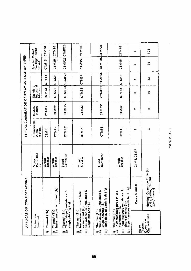
o\
o\
AP
PLI
CA
TIO
N C
ON
SID
ER
ATI
ON
S
Pro
tect
ion
Pro
vide
d
i) Th
erm
al (
Th)
i) Th
erm
al (
Th)
ii)
Inst
anta
neou
s ea
rth f
ault
(I0)
i)
Ther
mal
(T
h)
ii)
Tim
e de
laye
d, u
nbal
ance
&
sing
le p
hasi
ng (
Ij)
i) Th
erm
al (
Th)
ii)
Inst
anta
neou
s th
ree
phas
e ov
ercu
rren
t (I
i)
Hi)
Inst
anta
neou
s un
bala
nce
&
sing
le p
hasi
ng (
I2)
i) Th
erm
al (
Th)
ii)
Tim
e de
laye
d, u
nbal
ance
&
sing
le p
hasi
ng (
It)
iii)
Tim
e de
laye
d ea
rth f
ault
(I0)
i) Th
erm
al (
Th)
ii)
Inst
anta
neou
s th
ree
phas
e ov
ercu
rren
t (I
i)
iii)
Inst
anta
neou
s un
bala
nce
& si
ngle
pha
sing
(Ij)
iv)
-Inst
anta
neou
s ea
rth f
ault
(I0)
Rel
ay
Ther
mal
O
pera
tion
Cha
ract
eris
tic
Cur
ve N
umbe
r
Mot
or
Con
trolle
d by C
ircui
t B
reak
er
Circ
uit
Bre
aker
Fuse
d C
onta
ctor
Circ
uit
Bre
aker
Fuse
d C
onta
ctor
Circ
uit
Bre
aker
CT
M&
CT
MF
Nom
inal
Ope
ratio
n Ti
me
(s)
at 5
x S
etti.
ng C
urre
nt
('Col
d' c
urve
s)
TYP
ICA
L C
OR
RE
LATI
ON
OF
REL
AY A
ND
MO
TOR
TYP
ES
Sub
mer
sibl
e P
ump
Mot
ors
CTM
11
CTM
21
CTM
F21
CTM
31
CTM
F31
CTM
41 1 4
C.M
.R.
Mot
ors
CTM
12
CTM
22
CTM
F22
CTM
32
CTM
F32
CTM
42 2 8
Sta
ndar
d In
dust
rial
Mot
ors
CTM
13
CTM
23
CTM
F23
CTM
33
CTM
F33
CTM
43
3 16
CTM
14
CTM
24
CTM
F24
CTM
34
CTM
F34
CTM
44
4 32
Spe
cial
Mot
ors
For
Hig
h In
ertia
D
rives
CTM
15
CTM
25
CTM
F25
CTM
35
CTM
F35
CTM
45
5 64
CTM
16
CTM
26
CTM
F26
CTM
36
CTM
F36
CTM
46
6
128
Tabl
e 4.
1
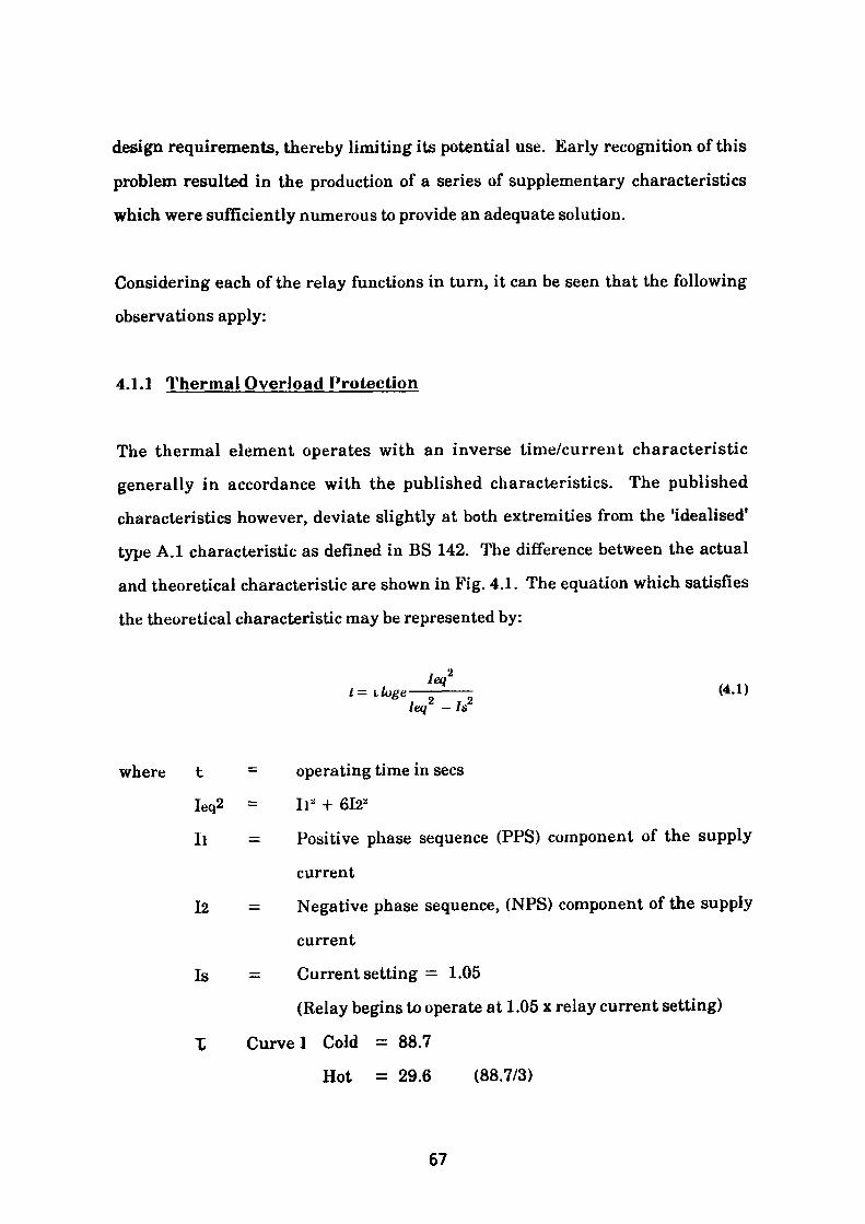
design requirements, thereby limiting its potential use. Early recognition of this
problem resulted in the production of a series of supplementary characteristics
which were sufficiently numerous to provide an adequate solution.
Considering each of the relay functions in turn, it can be seen that the following
observations apply:
4.1.1 Thermal Overload Protection
The thermal element operates with an inverse time/current characteristic
generally in accordance with the published characteristics. The published
characteristics however, deviate slightly at both extremities from the "idealised*
type A.I characteristic as defined in BS 142. The difference between the actual
and theoretical characteristic are shown in Fig. 4.1. The equation which satisfies
the theoretical characteristic may be represented by:
leq 1tillage——-——- (4.1)
left - Is2
where t = operating time in sees
Ieq2 = II* + 612*
11 = Positive phase sequence (PPS) component of the supply
current
12 = Negative phase sequence, (NPS) component of the supply
current
Is = Current setting = 1.05
(Relay begins to operate at 1.05 x relay current setting)
T Curve 1 Cold = 88.7
Hot = 29.6 (88.7/3)
67
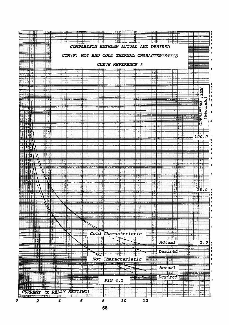
if::::: res : 1 r *
J-t ,4-j- -— .
Ill I^ P
Hif ***
Hit!
1 s; i !!| £" g :: |: t:
CORA
0
«m JfS B?f ZS
4- .--a j_ ;_ -^ _^_L
£:& H^: =£5 ;
+. |iLf i4-j_ J— j-J. .
i-^gg— t *£Et tacf 1*3 :
S- • '
fapajSPp' s ll:St±ffiB
a I IL ill
ilrfliSflSl
|p|g
^il1 i i 1 :
t:::i ::i^±:^i: t '"^ 'ii i" "^
1 f •• "H" T1" 1 r^"
:::: jrpp for : it ~
...i -.. . .... •ttt'
ENT (x Rl
2
T+*-r
V' 'tV:
•f-n—
TJrj
: #T
Tt*^-
11 j ; ^
=^
JL/
4
C1
t . .•<
— r
^— _I_L
f- -H-1
f-i-*-
-i —— f-
\Y
C
Ttfl
-i-t-H i
ill-r+4-
i ' I '
^
i —
•N:
SI~"T
:QP T;
fffr-
^A-
N
<3T— -[
fPJ
J
*7t
s~— 1_3
ZTj
6
LRJ
f03
T--
N
NiS
rscr J
c
s^,
)"•
2W
LNZ
C
"t ' !
< ——
ol
*^ Ho
Bl
-> c
7U1
Sr d
t
£e
-T —
3n :oj2V3
Ch
C2J
FJ
1 >8
TTTT
i/EJ
iD
^ J
-.44-c
i |
ax; i "»
ar
:G
—— u
T7[T
- —
2W
Tl
1E1
4-(—— H
•H""1
•ac
J— <S
H ——
ac
4.
i
A(
4E
ran
•te•*•»
te
*^
1
K
rnRMi
ieEi
-frf
4-H-f- — pf-
•rj[>>.^SL,
ri*>s
3
-r^
7Aj
IL
UC1
St
st
—
& ,
C
E
:ic
1 K^
ic
^^s«
mHA
3
v
^S
V
1
—-, — r " — r
D j
RA
• • M— r-f4-
• t
2
__i_.
DE
cr
L-i— -)-
• • i ' ;
-+4-14-
tt . i
] — t-
-i ——— L
trjt
i!!.
— IT
trrV SJ
ER
i4i
•pr-1 —
i '
Tl —
il
A~rr
D
A
D
RE
IS
I i i i
"ill
•rH-'
; 1
fr-1ct
es
ct
ss
i-•I—1-
D
TJ
— rn.
—— hi-
ua
ir
ua
zr
CS
-^-^— K
TrrtJ
1p=T
ed
1
ed
— P-
•HT'
-H--*-
1
',
——— L
— *4-
———
^-*-
«-*.
1C
J
^llilliljjIilHillllltll^iir oRDuriM; TIME 1 1 H ! HHHtllll IIIIHI litii 1 tl
H f '
0.
1 1 I 1
1.
^0t)§(U CO*—.
0
b
0
The NFS multiplying factor of 6 provides a weighted allowance for the heating
effect of this current. An earlier electro-mechanical relay, the type CMM offered
by the same manufacturer incorporated a multiplying factor of 3. More recently,
the latest model, the type MCHN, provides a range of selectable factors from 3 to
10.
Inspection of the standard characteristics associated with Table 4.1 indicates that
for a given multiple of current (x relay setting) the thermal trip time varies in the
ratio 2:1 between each set of characteristics.
That is to say, at 5 x current (x relay setting) for characteristic 6, the thermal
tripping time from the cold state is 128 sees. For characteristic 5 it is 64 sees,
characteristic 4,32 sees and so on to characteristic 1.
Associated with each cold characteristic is a hot characteristic whose purpose is to
thermally protect the motor when it has reached its running temperature. The
ratio of the tripping times on the cold characteristic to the tripping times on the
hot characteristic for any multiple of current ( x relay setting) are constant and in
the proportion 3:1.
In addition to the six standard characteristics, five further supplementary
characteristics are available. These characteristics are arranged to fit midway
between each of the six standard characteristics thus making a total of eleven
thermal characteristics with cold:hot tripping times in the proportion 3:1. The
supplementary curves may be identified by a 2 digit reference number the first
number being 0, that is 00,01,02,03 and 04.
To increase the versatility of the relay a further set of eleven characteristics are
available with identical cold characteristics but with cold:hot tripping times
modified to the proportion 1.5:1. These prove particularly suitable for modern
69
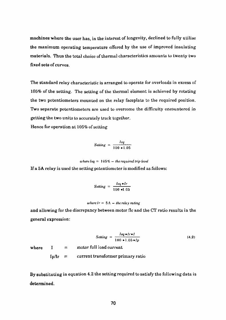
machines where the user has, in the interest of longevity, declined to fully utilise
the maximum operating temperature offered by the use of improved insulating
materials. Thus the total choice of thermal characteristics amounts to twenty two
fixed sets of curves.
The standard relay characteristic is arranged to operate for overloads in excess of
105% of the setting. The setting of the thermal element is achieved by rotating
the two potentiometers mounted on the relay faceplate to the required position.
Two separate potentiometers are used to overcome the difficulty encountered in
getting the two units to accurately track together.
Hence for operation at 105% of setting
lea Setting -
100 •l.OS
whereleq — 105% — the required trip level
If a 5A relay is used the setting potentiometer is modified as follows:
lea • Ir Setting =
100 «1.05
where Ir= 5 A — the relay rating
and allowing for the discrepancy between motor flc and the CT ratio results in the
general expression:
lea »Ir»ISetting - ————————— (4.2) 100.1.05 «/p
where I = motor full load current
Ip/Ir = current transformer primary ratio
By substituting in equation 4.2 the setting required to satisfy the following data is
determined.
70
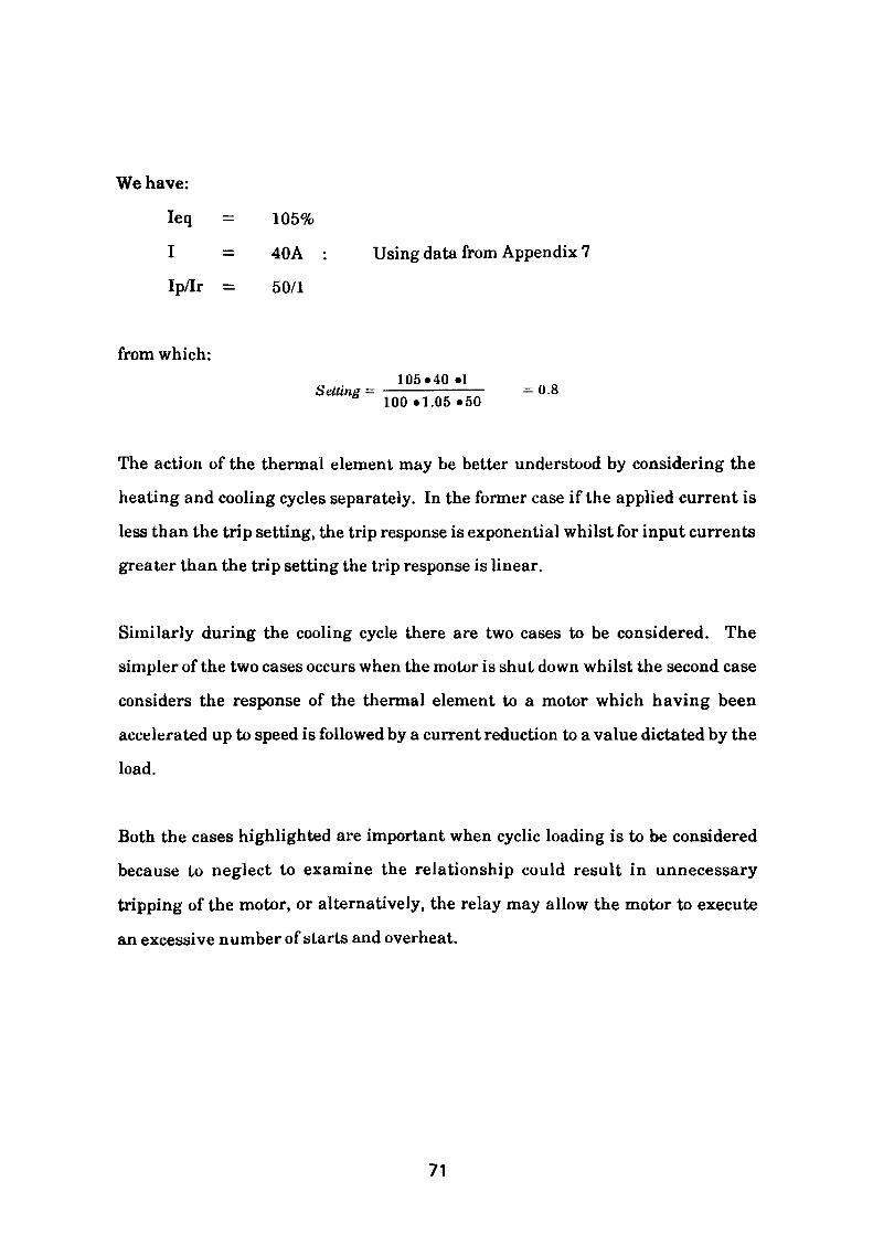
We have:
leq = 105%
I = 40A : Using data from Appendix 7
Ip/Ir = 50/1
from which:105*40 •!Setting = ———————— =0.8
100»1.05«50
The action of the thermal element may be better understood by considering the
heating and cooling cycles separately. In the former case if the applied current is
less than the trip setting, the trip response is exponential whilst for input currents
greater than the trip setting the trip response is linear.
Similarly during the cooling cycle there are two cases to be considered. The
simpler of the two cases occurs when the motor is shut down whilst the second case
considers the response of the thermal element to a motor which having been
accelerated up to speed is followed by a current reduction to a value dictated by the
load.
Both the cases highlighted are important when cyclic loading is to be considered
because to neglect to examine the relationship could result in unnecessary
tripping of the motor, or alternatively, the relay may allow the motor to execute
an excessive number of starts and overheat.
71
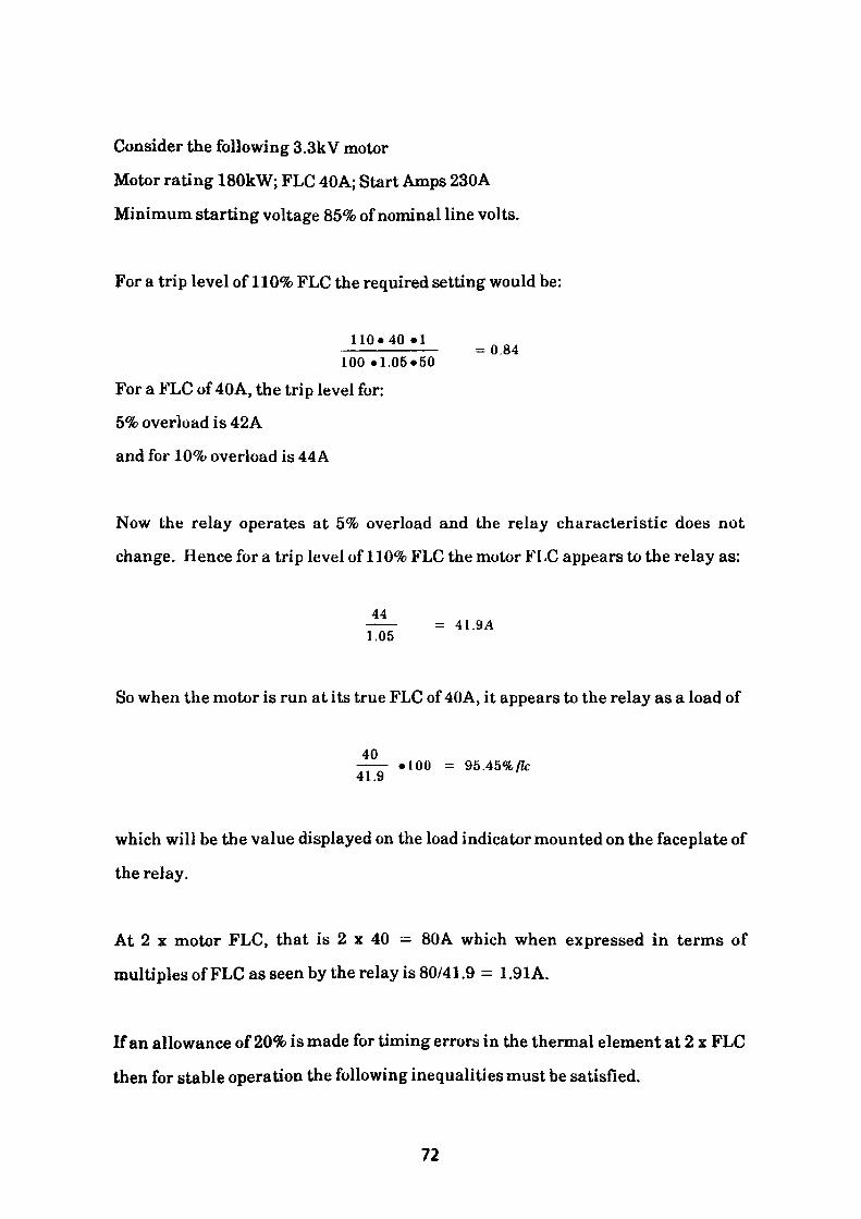
Consider the following 3.3kV motor
Motor rating 180kW; FLC 40A; Start Amps 230A
Minimum starting voltage 85% of nominal line volts.
For a trip level of 110% FLC the required setting would be:
110*40 •!= 0.84
100 •1.05*50 For a FLC of 40A, the trip level for:
5% overload is 42A
and for 10% overload is 44A
Now the relay operates at 5% overload and the relay characteristic does not
change. Hence for a trip level of 110% FLC the motor FLC appears to the relay as:
44= 41.9A
1.05
So when the motor is run at its true FLC of 40A, it appears to the relay as a load of
40• 100 = 95.45%/Zc
41.9
which will be the value displayed on the load indicator mounted on the faceplate of
the relay.
At 2 x motor FLC, that is 2 x 40 = 80A which when expressed in terms of
multiples of FLC as seen by the relay is 80/41.9 = 1.91A.
If an allowance of 20% is made for timing errors in the thermal element at 2 x FLC
then for stable operation the following inequalities must be satisfied.
72
1.2 x Relay Thermal Curve (Cold) at 1.91 FLC < Motor Withstand (Cold) at 2 x
FLC (that is < 770 sees)
and
1.2 x Relay Thermal Curve (Hot) at 1.91 FLC < Motor Withstand (Hot) at 2 x
FLC (that is < 600 sees)
For the starting condition three cases should be considered
1. Starting with full line voltage available
2. Starting with reduced line voltage typically 85% x nominal voltage
3. Starting with raised line voltage typically 105% nominal voltage
The starting current at full line voltage stated in terms of multiples of relay FLC
is:
23041.9
The manufacturers state that the maximum error of the thermal element at 5 x
FLC is ± 10% hence this value will be included in the following inequalities
which are to be satisfied.
1.1 x Relay Thermal Curve (Cold) at 5.49 x FLC < Motor Withstand (Cold) when
stalled (that is < 23 sees)
and
1.1 x Relay Thermal Curve (Hot) at 5.49 x FLC < Motor Withstand (Hot) when
stalled (that is < 15 sees)
Similarly when starting with a line voltage reduced to 85% the starting current
stated in terms of multiples of relay FLC will be reduced to:
73
° 85 - 23° = 4.67 A 41.9
Due to the lower stall current the withstand time for the motor is increased. The increase is considered to be adiabatic resulting in the following revised withstand times at this reduced current level.
/i 2 *R .Ti = 72* • « .T2 (4.3)
where
11 = Stall current with 100% line voltage applied
Ti = Motor Withstand time with 100% line voltage applied12 = Stall current with 85% line voltage applied
Ta = Motor Withstand time with 85% line voltage appliedR = Motor equivalent resistance at standstill
By substituting the respective values in equation (4.3), the following is obtained.
1. Revised cold withstand time with 85% line voltage applied
402 »R«23 = (0.85«40) 2 ««
23from which T2 = —————— = 31.83 sees 0.85*0.85
2. Revised hot withstand time with 85% line voltage applied
402 »««15 = (0.85*40) 2 «« »
15from which Tz = ————— =20.76 sees 0.85.0.85
The inequalities to be satisfied then become:
74
1.1 x Relay Thermal Curve (Cold) at 4.67 FLC < Motor Withstand (Cold) when
stalled (that is < 31.83 sees)
1.1 x Relay Thermal Curve (Hot) at 4.67 x FLC < Motor Withstand (Hot) when
stalled (that is < 20.76 sees)
A similar exercise is conducted for the case where excess voltage is applied to the
machine. This case would arise if the machine was the first to be started after a
shutdown or maintenance period when busbar volts tend to be higher than
nominal.
From the information calculated so far it is possible to determine a thermal curve
which will satisfy the set of inequalities. Such a characteristic is given by the
curve shown in reference 3, which yields the following results:
1.2 x Relay Thermal Curve (Cold) at 1.91 x FLC < Motor Withstand (Cold) at 2 x
FLC 184.6 sees < 770 sees
1.2 x Relay Thermal Curve (Hot) at 1.91 x FLC < Motor Withstand (Hot) at 2 x
FLC 61 sees < 600 sees
1.1 x Relay Thermal curve (Cold) at 5.49 x FLC < Motor Withstand (Cold) when
stalled 14.2 sees < 23 sees
1.1 x Relay Thermal Curve (Hot) at 5.49 x FLC < Motor Withstand (Hot) when
stalled 4.7 sees < 15 sees
1.1 x Relay Thermal Curve (Cold) at 4.67 x FLC < Motor Withstand (Cold) when
stalled at 85% Volt 19.9 sees < 31.8 sees
1.1 x Relay Thermal Curve (Hot) at 4.67 x FLC < Motor Withstand (Hot) when
stalled at 85% Volt 6.6 sees < 20.8 sees
1.1 x Relay Thermal Curve (Cold) at 5.76 x flc < Motor Withstand (Cold) when
stalled at 110% Volt 19.0 sees
75
1.1 x Relay Thermal curve (Hot) at 5.76 x flc < Motor Withstand (Hot) when
stalled at 110% Volt < 12.4 sees
These inequalities, when satisfied, provide thermal protection of the motor for all
balanced overloads up to and including the locked rotor or stall condition.
However, when other constraints such as negative phase sequence components
and run-up time considerations are examined the characteristic may prove
unsuitable as can be seen by exploring further considerations in the next section.
4.1.2 Unbalanced Conditions
When unbalanced supply voltages are presented to the motor, the effects are
generally as described in Appendix 3. The cause of the unbalance may be external
in the form of unbalanced phase voltages and supply harmonics or alternatively
the motor itself may be the source of the problem. During unbalanced conditions
the magnitude of the negative phase sequence component, NFS, of the current
assumes great importance as at running speed the frequency of the NFS current in
the rotor is almost twice the supply frequency. At this frequency the ratio of the
rotor ac resistance to the virtual dc resistance presented to the positive phase
sequence, PPS, currents is in the range 3-8 times from which it can be readily
understood that the I2R heating effects will limit the power that can be extracted
from the rotor if temperature limits are not to be exceeded.
In order to provide adequate thermal protection it is necessary for the relay to
detect and quantify the magnitude of the NFS current supplied to the motor, and if
appropriate, produce a tripping signal or alternatively accelerate the tripping
time if a preset threshold level is exceeded. The operation of the NFS element may
be seen by examining Figs. 4.2a and 4.2b. Fig. 4.2a depicts a block diagram of
76
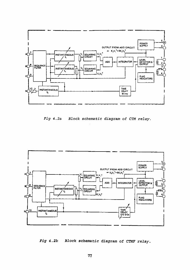
OUTPUT FROM ADD CIRCUIT
a 2
Fig 4.2a Block schematic diagram of CTM relay.
OUTPUT FROM ADD CIRCUIT = K2V,'+6KzV
Fig 4.2b Block schematic diagram of CTMF relay.
77
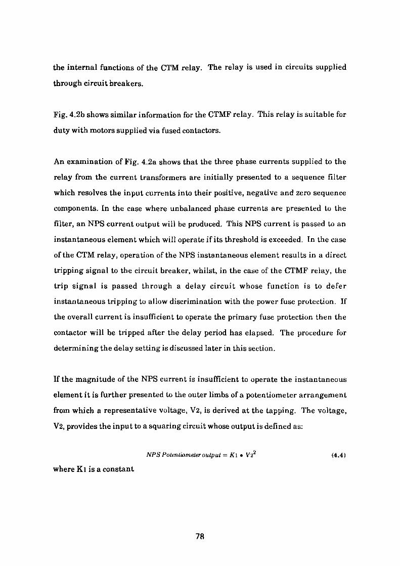
the internal functions of the CTM relay. The relay is used in circuits supplied
through circuit breakers.
Fig. 4.2b shows similar information for the CTMF relay. This relay is suitable for
duty with motors supplied via fused contactors.
An examination of Fig. 4.2a shows that the three phase currents supplied to the
relay from the current transformers are initially presented to a sequence filter
which resolves the input currents into their positive, negative and zero sequence
components. In the case where unbalanced phase currents are presented to the
filter, an NFS current output will be produced. This NFS current is passed to an
instantaneous element which will operate if its threshold is exceeded. In the case
of the CTM relay, operation of the NFS instantaneous element results in a direct
tripping signal to the circuit breaker, whilst, in the case of the CTMF relay, the
trip signal is passed through a delay circuit whose function is to defer
instantaneous tripping to allow discrimination with the power fuse protection. If
the overall current is insufficient to operate the primary fuse protection then the
contactor will be tripped after the delay period has elapsed. The procedure for
determining the delay setting is discussed later in this section.
If the magnitude of the NFS current is insufficient to operate the instantaneous
element it is further presented to the outer limbs of a potentiometer arrangement
from which a representative voltage, V2, is derived at the tapping. The voltage,
V2, provides the input to a squaring circuit whose output is defined as:
NFS Potentiometer output - Kl • V22 (4.4)
where Kl is a constant
78
Similar processing is applied to the positive phase sequence (PPS) component of
current from which a representative output voltage is obtained. The value of
which is defined by:
PPS Potentiometer output - Kl • Vl2 (4.5)
where Kl is a constant
Both values are presented to an adder circuit which applies selective amplification
to the value representing the NFS component, such that the output of the adder
circuit is represented by:
Composite output voltage = Kl • Vl2 + &K\ • V22 (4.6)
This composite voltage is applied to an integrator circuit which produces an output voltage which rises exponentially from zero to 105% of the relay setting
current and linearly for multiples of current above this value.
As stated previously, the relay is designed to operate when the applied current leq
exceeds 105% of the setting value. leq is defined as:
Ieq = V(/12 + A/22 ) (4.7)
where II = Positive-phase-sequence component of the current
12 = Negative-phase-sequence component of the current
k = 6, a weighting factor applied to the negative-phase-sequence
component.
79
It follows that for a motor running at full load with a protective overload relay
setting of 105%, the relay will tolerate without operating an NFS current up to a
level determined as follows:
Operating Level 105%, that is 1.05 x FLC/i = FLC = 1
Then substituting in equation (4.7) gives:
1.05 = \/(l + 6/22 )
1.1025 = 1 + 6/22
V(l. 1025-1) ft- _________ =0.13076
That is, there will be no trip operation at full load output with less than a 13.07%
negative phase sequence current component (excluding relay tolerances).
The potential user of this relay should be aware that if the relay is set to operate at
a value greater than 5% overload then the NFS current tolerated, will also
increase.
Consider the following example:
Desired operating level is 110% - to achieve this the setting must be raised to
110/105 = 1.048, so that to the relay, the motor appears to be running at 1/1.048
= 0.954 of the relay setting.
That is a 110% overload produces tripping at 0.954 x 1.1 = 1.05 FLC
Substituting II = 0.945 in the equation (4.7) gives:
1.05 = V( 0.9542 +6/a2
1.1025 = 0.911 +6/22
80
V(l.1025-0.911)—————————— = 0.1786
This means no operation at full load output will occur with less than a 17.86%
negative phase sequence current component (excluding relay tolerances).
Consider two extreme cases of loss of a supply phase to a 3.3kV, 3ph, 180kW
motor (similar to that detailed in Appendix 7).
Case (1) At full load output
Case (2) At standstill
In the case of a star connected motor, Fig. 4.3a and Fig. 4.3b show that the loss of a
phase results in two windings being connected in series across the remaining two
supply phases. The star arrangement is the connection generally found on HV
motors for which this application is intended.
Case (1)
Under normal conditions180
Output power I phase = —— =60 kWiJ
3300 and voltage/phase —-.— — 1905V
To maintain output with the loss of one phase.
180 Theoutput/phase must rise to —— kW = 90kW
£i
3 = - • Normal condition
£t
81
The new value of current will therefore be equal to 3/2 x Original value of current.
(In practice both power factor and rotational speed will change).
Additionally, with the single phase configuration, the phase voltage reduces to
3300/2 = 1650 volts which implies a further increase in current to sustain
constant output2 3
Therefore new value of current = —j- • (— •Original Current) — V3 • Original CurrentA/ O £t
Resolving the unbalanced current into its symmetrical components gives
lal = i (la + hlb + h2Ic )
Ia2 = 4 (la + h2Ib + h Ic ) (4.8)
lao = | (la + Ib + Ic )
where la = V3.Iflc ; Ib = -VS.Ific ; Ic = 0
Substituting for la, Ib and Ic in equation (4.8) gives:lal - i(^3I + M-N/3/) + 0)
lal = i(V3/_ +A2 (-V3/_ ) + 0) (4.9)flC flC
lao = i(v3/fl + (-V3/,. ) + 0)
From the above set of equations it can be seen that lao = 0. This means no zero
sequence components of current are present.
Simplifying equation (4.9) for lal, gives:
= i(V3//7c+ (-i--f^)(-v'3//7c ))
82
sVs
V/3 1 lal = T //fc~'/ 2 V
From which it can be seen that the magnitude of lal — Iflc
Similarly it can be shown that the magnitude of Ia2 = Iflc
Hence for this condition the operating time may be determined by calculating leq
using equation (4.7) and applying either value to the relay characteristic
leg =
leq =
leg = V?«7 for 105% trip level
For 110% trip level leq is modified as follows:.
leq = V(( —— -)/i + 6(1052 , 1052
l\02
, 105leq = V7.——
110
Considering the second case where the motor is supplied from only two phases
whilst in the standstill or locked rotor condition:
Then for normal 3 phase operation
kVA supplied in standstill condition = V3«Vl- «ILK
83
Equivalent phase impedance for this condition = Zph = VL /(V3 • ILR) Q
Under single phase conditions the arrangement reduces to two windings in series
supplied with line volts, hence single phase locked rotor current reduces to:
Vl7(2VL / (V3 • ILR )) = V3 . ILK/ 2 Amps
Resolving this single phase value of current into its symmetrical phase sequence
components gives:
lal =v/3«//r
0)
lao =
V3 __ N/3*//r
+ (-\/3«//r
0) 4.10
where la
Simplifying for lal, gives:
. lut . lutV3 • —— ; Ib - V3 • —— ; Ic - 0
2 2
/a]
V/3«//r
r _i/al — — ton —r- Amps 2 V3 ^
Similarly it can be shown that the magnitude ofla'2 in — A nips
84
Substituting these values in the characteristic equation gives
leq = V(/l2 + 6/22)
llr o Ilr
105 V?»//rF or \\Q% trip level lea - —— •———
110 2
The derived values of symmetrical phase sequence current components are lower
than would be experienced in practice. Under no-load conditions a three-phase
motor when subjected to a loss of a phase would experience a current increase of
V3 times the no load current. In the practical case, where the motor would be
loaded prior to the single phase fault occurring, the expected current increase to
sustain the load under single phase conditions would be in excess of V3 times the
loaded current value. Under full load conditions the anticipated single phase
current increase would be of the order of 2-2^ times flc providing sufficient torque
is available to sustain the load(1). The logic used in this analysis requires the
motor manufacturer to provide maximum withstand times for the single phase
condition occurring during the fully loaded run condition and also for the stalled
condition which may arise due to a locked rotor. In both run cases the analysis
assumes a current increase of V3 times flc whilst the latter case assumes a value
of V3/2 times locked rotor current. Both cases when satisfied will provide an
effective margin of safety.
In the case of a delta wound machine running under normal healthy conditions
the phase current is given by:
phase current = line current /V3
Referring to Figs. 4.4a and 4.4b it can be seen that with the loss of one supply
phase the circuit effectively consists of a single winding in parallel with the other
85
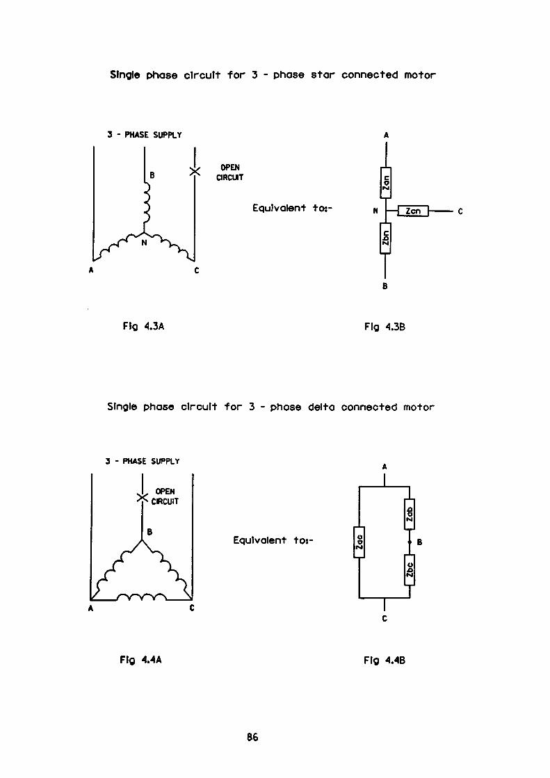
Single phase circuit for 3 - phase star connected motor
3 - PHASE SUPPLY
OPEN CIRCUIT
Equivalent to:-
Flg 4.3A Fig 4.3B
Single phase circuit for 3 - phase delta connected motor
3 - PHASE SUPPLY
OPEN CRCUIT
Equivalent to:-
Flg 4.4A Fig 4.4B
86
two windings arranged in series. To maintain full load output the line current in
the two sound phases must rise by a factor of V3. Under this arrangement the
single winding across the supply will dissipate four times more power than that
dissipated in the other two windings. The heating effect will be substantial as 2/3
of the overall current will be passed through the single winding. The value of this
current will be:2
>-«V3«/Zc > 1.15/ZctJ
This phase current value of 1.15 flc is twice the phase current experienced under
normal healthy three-phase supply operation. It can be resolved into symmetrical
components of positive and negative phase sequence component currents of
magnitude:
1 2—r- »V3» - • flc = 0.667 flc\r o tj
Both these values are 115% greater than the phase current experienced under
healthy three phase operation and will lead to rapid heating of the windings.
Similarly in the case of a single phase locked rotor condition, the current
measured by the protective device, the line current, will be identical to the line
current for a star connected machine under single phase conditions. The internal
current distribution however again will allow two thirds of the line current to pass
through one of the windings which in the case of a delta wound machine is
identical to the current observed under 3-phase locked rotor conditions. This
condition is of course remedied by detecting and magnifying the negative phase
sequence component of the line current in order to accelerate tripping in
accordance with the chosen thermal characteristic.
87
From the above discussion it is therefore evident that it is now possible to provide
additional inequalities such that when satisfied they provide thermal protection
against the unbalanced condition. The conditions may be described as follows.
Minimum NFS current content determined from the trip setting < Maximum
continuous NFS current content allowable for the motor
As it is difficult to obtain a continuous thermal withstand characteristic
containing a declared NFS content for any motor, it is prudent to examine and
check the constraints at the two locations already considered, that is single phase
at full load and single phase for the stall condition. A summary of the checks
carried out are listed in table 4.2.
4.1.3 High Set Overcurrents
Reference to Fig. 4.2A shows that the CTM relay can be fitted with two
instantaneous elements, one which is sensitive to positive-phase-sequence
overcurrents, the other, to negative-phase-sequence overcurrents. The usual
approach adopted when setting the PPS element is to aim for an operating
threshold at:
1.25 x CT Secondary steady state current (4.11)
The setting arrived at should be sufficient to ensure that mal-operation due to
assymetry on starting does not occur. Assymetry on starting will of course occur,
due to the three phase motor being energised by simultaneous closure of contacts
in each phase. The closure of each phase taking place at a different point on the
voltage waveform. The effect of this assymetry will produce unequal currents of
large magnitude in each phase of the motor supply. The magnitude of these
88
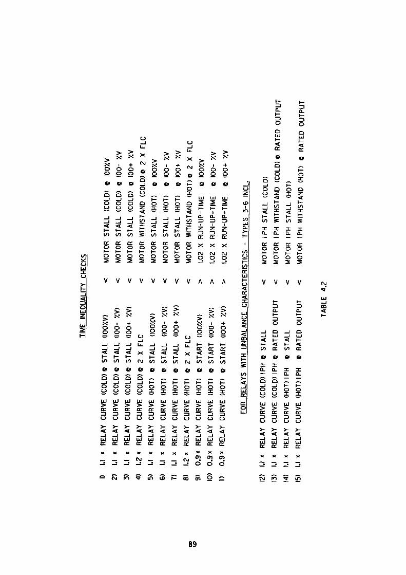
TIM
E IN
EQUA
LITY
CH
ECKS
1) 1.1
x
REL
AY
CURV
E (C
OLD
) Q
STAL
L (IO
OXV
)2)
1.1
x
RELA
Y CU
RVE
(CO
LD) e
ST
ALL
(100
- XV
)3)
1.1
x
RELA
Y CU
RVE
(CO
LD)
6 ST
ALL
(100
+ XV
)4)
1.2
x
RELA
Y CU
RVE
(CO
LD)
C 2
X FL
C5)
1.1
x
RELA
Y CU
RVE
(HO
T)
C ST
ALL
(IOO
XV)
6)
U
x RE
LAY
CURV
E (H
OT)
6
STAL
L (1
00-
XV)
7)
1.1
x RE
LAY
CURV
E (H
OT)
e
STAL
L (1
00+
XV)
8)
1.2 x
R
ELAY
CU
RVE
(HO
T)
e 2
X FL
C9)
0.
9 x
RELA
Y CU
RVE
(HO
T)
6 ST
ART
(IOO
XV)
10)
0.9
x RE
LAY
CURV
E (H
OT)
e
STAR
T (1
00-
XV)
11)
0.9
x RE
LAY
CURV
E (H
OT)
0
STAR
T (1
00+
XV)
MOT
OR
STAL
L (C
OLD
) C
IOOX
V M
OTOR
ST
ALL
(CO
LD)
0 10
0- X
V M
OTOR
ST
ALL
(CO
LD)
0 10
0+
XV
MOT
OR
WIT
HSTA
ND
(CO
LD)
0 2
X FL
C M
OTOR
ST
ALL
(HO
T)
e IO
OXV
MOT
OR
STAL
L (H
OT)
O
100-
XV
M
OTOR
ST
ALL
(HO
T)
@ 10
0+
XV
MOT
OR
WIT
HSTA
ND (
HOT)
0
2 X
FLC
1.02
X
RU
N-U
P-TI
ME
O IO
OXV
1.02
X
RU
N-U
P-TI
ME
e 10
0-
XV
1.02
X
RU
N-U
P-TI
ME
6 10
0+
XV
FOR
RELA
YS
WIT
H UN
BALA
NCE
CHAR
ACTE
RIST
ICS
- TY
PES
3-6
INCL
.
12)
U x
RE
LAY
CURV
E (C
OLD
)IPH
Q
STAL
L <
13)
U x
RE
LAY
CURV
E (C
OLD
)IPH
c
RATE
D O
UTPU
T <
14)
I.I
x R
ELA
Y
CU
RVE
(H
OT)
IP
H
C
STA
LL
<15
) U
x
RELA
Y CU
RVE
(HO
T)IP
H
0 RA
TED
OUT
PUT
<
MOT
OR
IPH
STA
LL
(CO
LD)
MOT
OR
IPH
WIT
HSTA
ND
(CO
LD)
C RA
TED
OUT
PUT
MOT
OR
IPH
STA
LL
(HO
T)M
OTOR
IP
H
WIT
HSTA
ND
(HO
T)
0 RA
TED
OUT
PUT
TABL
E 4.
2
currents being determined by the point of closure on the waveform and the
transient reactance of the machine.
Early electro-mechanical type relays utilised instantaneous attracted armature
elements for detecting overcurrents. These elements produced perfectly
satisfactory results when used with 'old* style induction motors which contained
large amounts of iron in the frame but resulted in mal-operation when used with
modern small frame machines. Tests conducted on a modern small frame
induction motor using a high speed recorder showed the problem to be caused by
peak currents with a magnitude approaching twenty times full load current. The
small time constant associated with these currents resulted in their rapid decay.
The solution adopted by certain manufacturers was to 'slug1 the operation of the
instantaneous overcurrent element for the first few cycles of operation. This was
usually achieved by attaching a sealed dashpot containing silicon fluid or liquid of
a similar viscosity arranged to delay closure of the element armature. Modern
relays including the CTM incorporate a built in delay of 80 msecs to overcome the
problem. It should be noted that the CTM relay is used in conjunction with fully
rated circuit breakers and that fault clearance time is additive to the 80 msecs
relay operating time. In the case of a modern vacuum circuit breaker the clearing
time will be less than 50 msecs whereas clearing time in an old oil-circuit breaker
may stretch to 150 msec or greater. This may be of critical importance when
contemplating the installation of minimum size cabling.
It can be seen that the PPS overcurrent element offers no protection for any motor
overloads up to and including the stall condition. Its sole response is to detect
abnormal conditions outside the envelope encountered during the starting and
acceleration states.
90
4.1.3.1 NFS High Set Overcurrent
The negative phase sequence element also incorporates a time delay such that the
nominal operating time of 80 msecs is sufficient to overcome most assymetry
encountered on starting.
The recommended setting for the element is:
< 0.4 x Positive phase sequence element setting (4.12)
This value is one half of the 3 phase steady state starting current and is equal to
the maximum NFS current found in the single phase stall condition. The lowest
setting possible should be used consistent with stable operation of the element.
Caution should be exercised as if the setting chosen is too low, mal-operation of the
element may occur resulting in unecessary tripping of the motor. The cause of
such tripping may not be immediately obvious and could result in unnecessary
delay before resetting takes place.
4.1.3.2 Fuse/Relay Co-ordination
Fig. 4.2B, the block schematic diagram for the CTMF relay shows that there is no
PPS high set overcurrent element installed in this unit. Instead, the fault current
detection and isolation function is carried out by inline power fuses. The inline
power fuses are mandatory due to the inability of the motor switching device,
MSD, to interrupt the high levels of current found under fault conditions. It is of
course essential to establish that the clearing time of the fuse is substantially less
than the opening time of the MSD, otherwise the MSD will attempt to break the
fault current. Most manufacturers of power fuses for motor applications provide
information to deduce optimum fuse size for given values of motor starting
91
current, duration and starting frequency. In practice, however, the usual
approach is to establish the largest size fuse that offers complete protection for the
MSD and equip all circuits alike. On the debit side this action may result in using
minimum sized cables which are larger than required but is offset by requiring
only one size of fuse to be retained for emergencies.
It can be seen that the CTMF relay is equipped with a high set NFS element which
trips the MSD following a time lag which is adjustable between 0.5 - 3.0 sees. The
adjustment being to allow discrimination between the MSD and the inline power
fuses. The usual procedure adopted to determine the delay setting may be
observed in the following example.
Consider a circuit with the following specification
Relay
Power Fuse
Rating
Max' pre arc I2t
Max'Total I2t
Motor switching device
Current rating
Max1 interrupting capacity
Short time rating
Opening time
GEC type CTMF Motor Protection Relay
equipped with thermal characteristic
reference 3 with a thermal setting of 105%.
The relay is supplied from 40/1 ratio current
transformers.
GEC3.3kV, typeKSIPE
250 Amp
235 xlO3 Amp2 sees
1400 x 103 Amp2 sees
Alien West type CV432H-GAT, 3.3kV
Vacuum Contactor
350 Amp
4400 Amp
20kAfor0.1sec
90-120msec
92
Motor GEC 180kW, 3.3kV, 50Hz 'Impak1 type CACA
induction motor as specified in appendix 7
driving a pump with a 2 sec acceleration time.
It can be seen from Fig. 4.5 that for potential fault currents in excess of 6kA, the
pre-arcing time of the 250A fuse is of the order of 10-20 msecs. It is at this point
that the peak value of current is experienced before the onset of the arcing period
and subsequent current decay.
In this particular case, assuming a potential fault current of lOkA, the fuse cut-off
current is limited to 15kA peak (see Appendix 8).
Using the fuse data specified and the knowledge that the motor full load current is
40A, the minimum sized cable may be determined as follows:
Cable type: PVC insulated, steel wire armoured, pvc oversheath with stranded
copper conductors.
Minimum size on current consideration alone 16mm2 (Generally the minimum
size available in the cable manufacturers industrial range - current rating 79 -
94A).
Maximum current withstand for 1 sec = 1732A (assuming fully loaded at start).
Maximum I2t withstand = 3 x 10⁶ Amp2 sees which is greater than the maximum
let thro1 , Ft, value for the fuse of 1.4 x 10⁶ Amp2 sees. Provided the cable length is
not excessive and voltage drop is within prescribed limits then this cable will be
satisfactory. Caution must be exercised when dealing with paper insulated cables
as it is important to calculate the peak current withstand capability of the cable
from the manufacturers supplied data. Failure to do so may cause peak fuse let
thro* current to exceed the capabilities of the paper insulation resulting in possible
damage by "tearing" or "bursting" of the papers. Referring to the contactor
specification, the shortest opening time is quoted as 90 msecs.
93
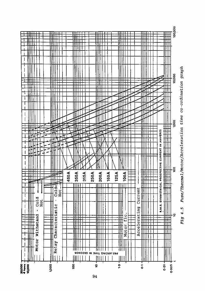
o6 o inO
O§
Ol
0)n>
n>
Irt O
0)
Srt M. O 3rrh>.
CD
8oM.aQJ(T M.O3
I
PRE-ARCING TIME IN SECONDS
O. O
' ? 2to0)
2S ma nr-•o aO in•o m3mOC a a mZ
TOma
n n
(T H-
ncI-!
(D 3 rr
O '<TO •l-h H O
Oo
_4 _L roro o> o01 o o
ro GJ 01 -*o en
CO Jkcn en o o
JM£
o. oo
o o. o o
o o "o • o o
\X
aracteristic
Co
rr O
rr,CO rr. Pi . 3 . O..
nO CL
Allowing a 20% margin indicates that for an operating time of 90/1.2 = 75 msecs,
the prospective RMS symmetrical current is 4kA which is less than the contactor
breaking capability of 4.4kA. Where larger prospective fault currents are
available the fuse clearance time becomes shorter thus ensuring a larger
discrimination time with the contactor.
Extending the logic to larger fuse sizes suggests that the 315A fuse should not be
used as it does not provide complete discrimination with the contactor. More
modern contactors exhibit much improved capabilities and may be obtained with
maximum interrupting capabilities extending to 12kA. Typical general purpose
contactors of around 6-8kA interrupting capacity are readily available.
All fuse sizes greater than 250A can be used with the contactor under discussion
but a zone of uncertainty now appears to exist where pre-arcing time exceeds
contactor opening time. It should be noted however that the opening time quoted
only occurs after trip initiation. This may result from:
1. Operation of the main fuses removing power from the control transformer
from which the contactor holding coil supplies may be derived. The fault
may however be an earth fault affecting only one phase which could leave
the control transformer output unaffected.
2. If the control transformer remains energised then the striker pins
contained within the body of the main fuses will on operation activate micro
switches via a common tripping bar and remove power from the contactor
holding coil.
3. Operation of the high set 12 NFS element or the lo, ZPS element.
Examination of case (1) indicates an inconsistent method of tripping. The
resulting trip time being a function of the type of fault.
95
In case (2) the action of ejecting a striker pin through the end cap to operate micro-
switches via a mechanical linkage takes a finite time. This time is of course
additive to the contactor opening time but may be modified by the action of case
(1).
Case (3) refers to the NFS and ZPS sensing elements which could operate
providing the current values presented exceed the operating threshold of the
elements. It should be noted that both of these elements operate into a delay
circuit prior to tripping, the minimum delay being 500 msecs. Hence tripping
from these elements will only take place at low fault current levels where the
fusing time exceeds the operating time of these elements.
The recommended approach to setting the l2/lo time delay is to establish the
clearance time of the fuse at the maximum breaking capacity of the contactor.
The l2/Io time delay is then set to 120% of this value which is adequate to cover
fuse operating time tolerances as it is in addition to the contactor opening time.
The total clearance time of the fuse is difficult to predict as the arcing period
during the fusing cycle will vary with circuit power factor, voltage level, fault
level, electrical angle at which arcing commences and several other less important
factors. However, provided voltage levels are within limits, the arcing time only
becomes a significant proportion of the total time at high fault currents where the
pre-arc times are very short. Using this technique the entire range of fuses up to
the maximum available size of 450A may be accommodated provided the thermal
rating of the contactor is not exceeded during the duration of the fault.
4.1.3.3 The Problem
Herein lies the problem as seen by the author of this thesis. There can be no
guarantee that the contactor will remain closed during the period when fault
current is present when used in conjunction with fuses which have a rating
96

greater than 250A. As previously stated the supply for the contactor holding coil
is derived from a control transformer whose primary is connected to the circuit
side of the main fuses and as such may be subject to severe voltage depressions
prior to fuse clearance. It should be noted that contactors are required to remain
closed during voltage depressions down to 70% of nominal voltage levels.
Examination of test reports indicate that many will remain closed down to 40% of
this value, but this figure may prove optimistic as there will be a force present
tending to open the contactor when heavy fault currents are flowing. The
contactor holding coil is usually controlled by a pilot relay which also has the
function of removing the holding coil supply for voltage excursions to less than
70% of nominal voltage. Such is the sensitivity and response of these relays to
short duration voltage dips that they may cause the contactor to open prematurely
whilst carrying current in excess of its rated breaking capacity. This is a potential
hazard which could conceivably arise when large fuse sizes are utilised.
One solution to the problem would be to supply all contactor holding coils and pilot
relays from a source not affected by the fault such as a dc battery system. This
solution whilst feasible calls for a battery installation which is capable of
sustaining a large standing load - clearly not a cost effective option. A more
realistic approach would be to utilise latched contactors. Whilst a battery supply
is still necessary it is now only required to provide a short impulse to close the
contactor until the mechanism latches and retains it. Similarly a short low power
impulse is required to trip it. Both these requirements can easily be met from the
closing/tripping battery which is necessary to operate the circuit breakers which
provide the incoming supply to the switchboard. Many other solutions exist but
the cost will depend on whether the closing/tripping supplies provided for the
incoming circuit breakers can be utilised.
97
Technology will solve the problem in due course as earlier comments imply. The
interrupting capacity of the contactors are constantly being improved allowing
discrimination to be obtained with maximum sized fuses. Extreme caution should
be exercised as a large variation in interrupting capabilities for both new and
previously installed equipment does exist.
4.1.4 Earth Fault
There are two earth fault options catered for in the CTM relay series. The first as
fitted to the CTM relay, utilises a type CAG 11 instantaneous attracted armature
measuring element set to operate after a delay of 80 msecs when its value exceeds
a nominal operating threshold of either 10% or 20% of relay rating as specified by
the purchaser. This element is supplied with zero sequence current derived from
the input sequence filter as shown in Fig. 4.2a. The unit fitted to the CTMF relay
is identical in all respects save the inclusion of a variable time delay feature which
inhibits the output of the element until the delay has elapsed. This relay is
illustrated in Fig. 4.2b.
The second option as fitted to the CTMC variant utilises a core balance current
transformer (CBCT) in addition to the line current transformers (CT). This
configuration is well suited to systems where available earth fault current is low.
Due to only one CBCT being required the operating threshold may be set low as
'spill' current is not a problem as is the case with three residually connected CT's.
In addition the accuracy of the operating setting is good, as magnetising current is
only required for one CT. Despite the stated attraction the relay is seldom
encountered and will not be further considered.
The normal residually connected earth fault arrangement requires the addition of
a stabilising resistor in series with the zero-sequence sensing element. The
98
purpose of the resistor is to allow the element to remain stable during the starting
period when heavy current is drawn. Assymetry during this period may cause
saturation or partial saturation of a CT resulting in an imbalance or 'spill1 current
to flow in the CT neutral conductor.
The usual method of calculating the value of the stabilising resistor is to assume
the worst case where one CT is completely saturated whilst the other two
transform perfectly.
Consider an example using the previously mentioned 3.3kV 180kW motor with
the following basic characteristics:
Full Load Current 40A
Starting Current 230A
Current Transformer Ratio 40/1A
Then CT output at start 230/40 = 5.75A
The CT output from each phase is supplied initially to a sequence filter mounted
in the relay. The general arrangement of the connections is shown in Fig. 4.2a
and 4.2b. Under normal conditions of transformation only 'spill' current passes
through the neutral conductor to the instantaneous lo element and stabilising
resistor RV6. However when considering the unbalanced case of one CT being
saturated, the current supplied to it is the vector sum of the output from the two
sound phase CT's. Hence the voltage generated across the phase containing the
saturated CT may be determined as follows.
V = IS(RCT + NRL + 0.6/In2) (4.13)
99
where RCT = Resistance of saturated CT = 2Q
RL = Resistance of Lead = 0.1Q
In = Relay Rating = 1A
IS = Starting Current (CT Output = 5.75A
0.6 = Relay Burden/Phase = 0.6 VA
N = 1 For 4 wire CT connection (star point formed at CT's)
N = 2 For 6 wire CT connection (star point formed at relay
panel)
let N = 1
At this point it should be noted that the relay may be supplied with either internal or external star point phase connections. Figs. 4.6a and 4.6b are included to illustrate the difference.
Substituting these values in equation (4.13) gives:
V = 5.75(2 + 0.1 + 0.6/1) = 15.53V
which is the voltage impressed across the lo element and the stabilising resistor. The instantaneous lo element used is a type GAG 11 attracted armature unit designed to operate at 0.2 x In. Test results^2) obtained from the manufacturer show that for a 1A rated relay with the armature open the following characteristics apply.
a.c. Resistance of CAG 11 element = 5.8 Q = RZS
Inductive Reactance of GAG 11 element = 13.4 Q = Xzs
and for a 5A rated relay
a.c. Resistance of CAG 11 element = 0.8 Q = RZS Inductive reactance of CAG 11 element = 0.8 Q = XZS
100
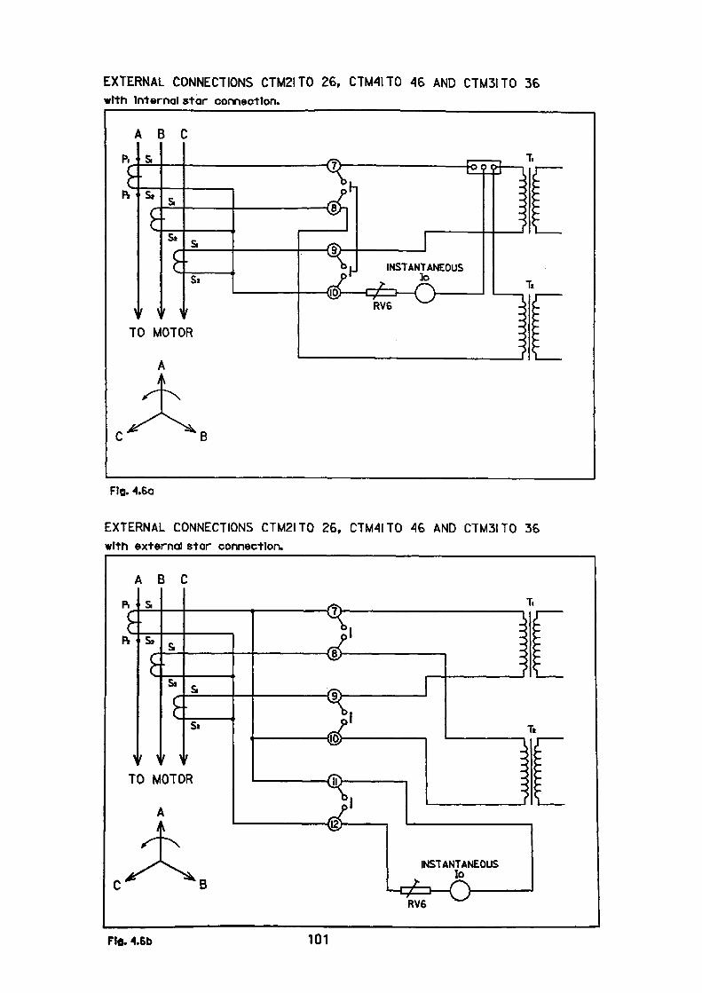
EXTERNAL CONNECTIONS CTM2ITO 26, CTM4ITO 46 AND CTM3ITO 36 with Internal star connection.
ABC
^' u
TO MOTOR
Fig. 4.6a
EXTERNAL CONNECTIONS CTM2ITO 26, CTM4I TO 46 AND CTM3ITO 36 with external star connection.
ABC
\}•k
^T
s
s»{•
' ^ 0 M
/i
s,
Si
^f ) OTC
i
/
s
s»
r
IR
———— (
———— <
———— (
———— I
——————— (
B
Ftfl. 4. 101
INSTANTANEOUS lo
RV6
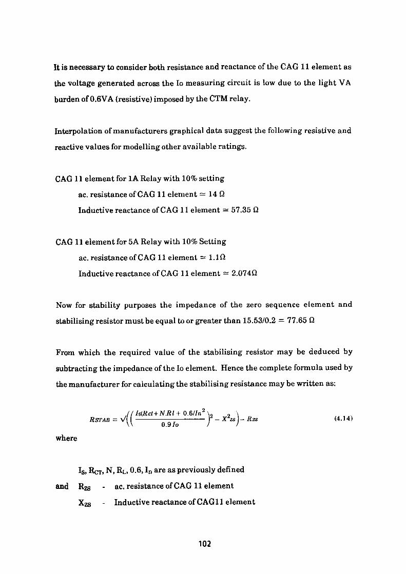
It is necessary to consider both resistance and reactance of the GAG 11 element as
the voltage generated across the Io measuring circuit is low due to the light VA
burden of 0.6VA (resistive) imposed by the CTM relay.
Interpolation of manufacturers graphical data suggest the following resistive and
reactive values for modelling other available ratings.
CAG 11 element for 1A Relay with 10% setting
ac. resistance of CAG 11 element = 14 Q
Inductive reactance of CAG 11 element = 57.35 Q
CAG 11 element for 5A Relay with 10% Setting
ac. resistance of CAG 11 element =1.10
Inductive reactance of CAG 11 element = 2.074Q
Now for stability purposes the impedance of the zero sequence element and
stabilising resistor must be equal to or greater than 15.53/0.2 = 77.65 Q
From which the required value of the stabilising resistor may be deduced by
subtracting the impedance of the Io element. Hence the complete formula used by
the manufacturer for calculating the stabilising resistance may be written as:
/ /Is(Rct + N.RI + 0.6//n 2 ... „ .RSTAB = VU ———^To—— } - X2s] ~ Rzs (4 '
where
Is, RCT, N, RL, 0.6, In are as previously defined
and RZS - ac. resistance of CAG 11 element
- Inductive reactance of CAG 11 element
102
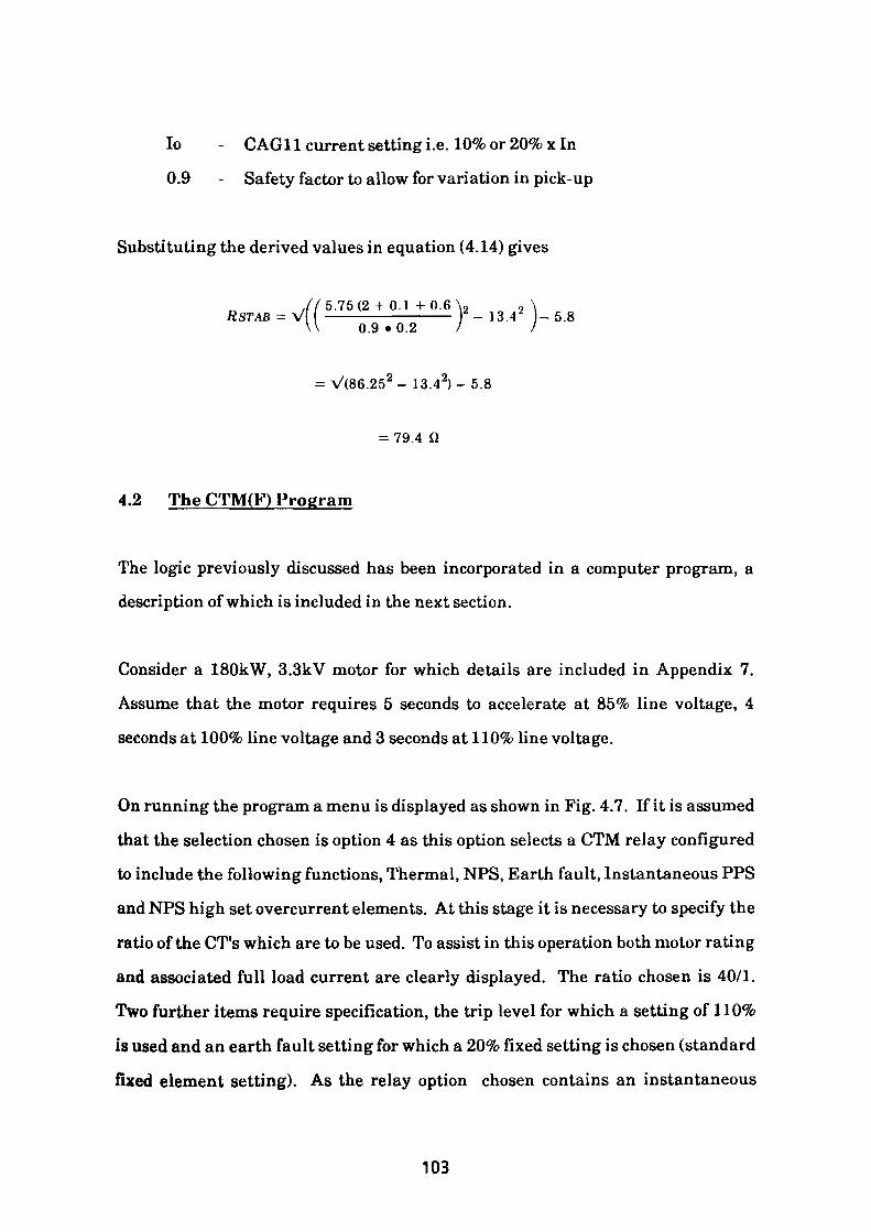
lo - CAG11 current setting i.e. 10% or 20% x In
0.9 - Safety factor to allow for variation in pick-up
Substituting the derived values in equation (4.14) gives
,//5.75(2 -I- 0.1 + 0.6\ 2 2 \ RSTAB = V ——————————— 2 - 13.4 2 - 5.8 \\ 0.9 • 0.2 / /
= V(86.25 2 -13.42)-5.8
= 79.4 Q
4.2 The CTM(F) Program
The logic previously discussed has been incorporated in a computer program, a
description of which is included in the next section.
Consider a 180kW, 3.3kV motor for which details are included in Appendix 7.
Assume that the motor requires 5 seconds to accelerate at 85% line voltage, 4
seconds at 100% line voltage and 3 seconds at 110% line voltage.
On running the program a menu is displayed as shown in Fig. 4.7. If it is assumed
that the selection chosen is option 4 as this option selects a CTM relay configured
to include the following functions, Thermal, NFS, Earth fault, Instantaneous PPS
and NPS high set overcurrent elements. At this stage it is necessary to specify the
ratio of the CT's which are to be used. To assist in this operation both motor rating
and associated full load current are clearly displayed. The ratio chosen is 40/1.
Two further items require specification, the trip level for which a setting of 110%
is used and an earth fault setting for which a 20% fixed setting is chosen (standard
fixed element setting). As the relay option chosen contains an instantaneous
103
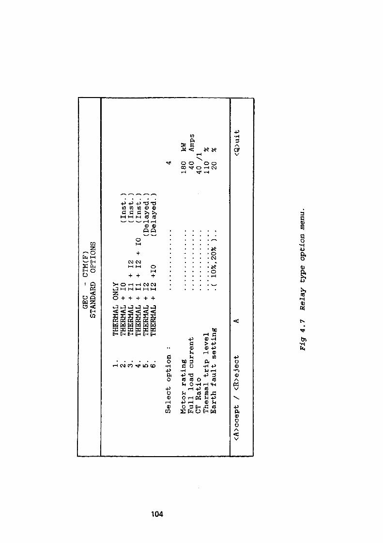
GEC
- CTM(F)
STANDARD
OPTIONS
1.
THERMAL ONLY
2.
THERMAL +
10
(lust. )
3.
THERMAL +11+12
(Inst.)
4.
THERMAL +
11 +
12 +
10
(Inst.)
5.
THERMAL +
12
(Delay
ed.)
6.
THERMA
L +
12 +10
(Delayed
.)
Sele
ct op
tion
:
..............
Motor rating
..............
Full
lo
ad current
CT Ratio
..............
Thermal
trip
le
vel
..............
Earth fault setting
.( 10
%, 20% )..
<A>ccept /
<R>eject
A
4
180
kW
40
Amps
40 /I
110
%20
% <Q>uit
Fig
4,7
R
elay
typ
e op
tion
men
u.
earth fault element it is necessary to provide further information to enable the
program to determine the value of the appropriate stabilising resistance. Fig. 4.8
displays the information required. On satisfying the requirements a further menu
is displayed which lists the available characteristic solution strategies. This
menu is shown in Fig. 4.9, the options available are discussed below.
Option 1 'MAXCURVE1 3/1 Cold/Hot ratio using standard characteristic.
The 'Maxcurve' option selects the relay characteristic which is closest to the motor
thermal withstand characteristic. As all the constraints previously listed in the
text cannot be satisfied, the option fails.
Option 2 'MAXCURVE' 3/1 Cold/Hot ratio using non-standard characteristic.
This option is similar to option 1 except that all constraints to be satisfied are now
applied to the range of optional non-standard relay thermal characteristics, these
are 00,01,02,03 and 04 which can be seen in appendix 7. In this case the option
enables all conditions to be satisfied by characteristic 02. A table of relay
operating times compared against motor withstand times under defined
conditions is then displayed on the screen to allow the user to assess the protective
margin available. A copy of the screen display is shown in Fig. 4.10 and is
followed by Fig. 4.11 which shows a graphical representation of relay
characteristic and the constraints which are accommodated.
Option 3 'MAXCURVE' 1.5/1 Cold/Hot Ratio using non-standard characteristic.
This option again uses the same technique as in the two previous cases except that
the set of constraints are now applied to the series of supplementary
characteristics defined as 11, 05, 21, 06, 31, 07,41, 08, 51, 09 and 61. In this case
the conditions are all satisfied by curve 31, the calculated values being shown in
Fig. 4.12 whilst Fig. 4.13 provides a graphical representation.
105
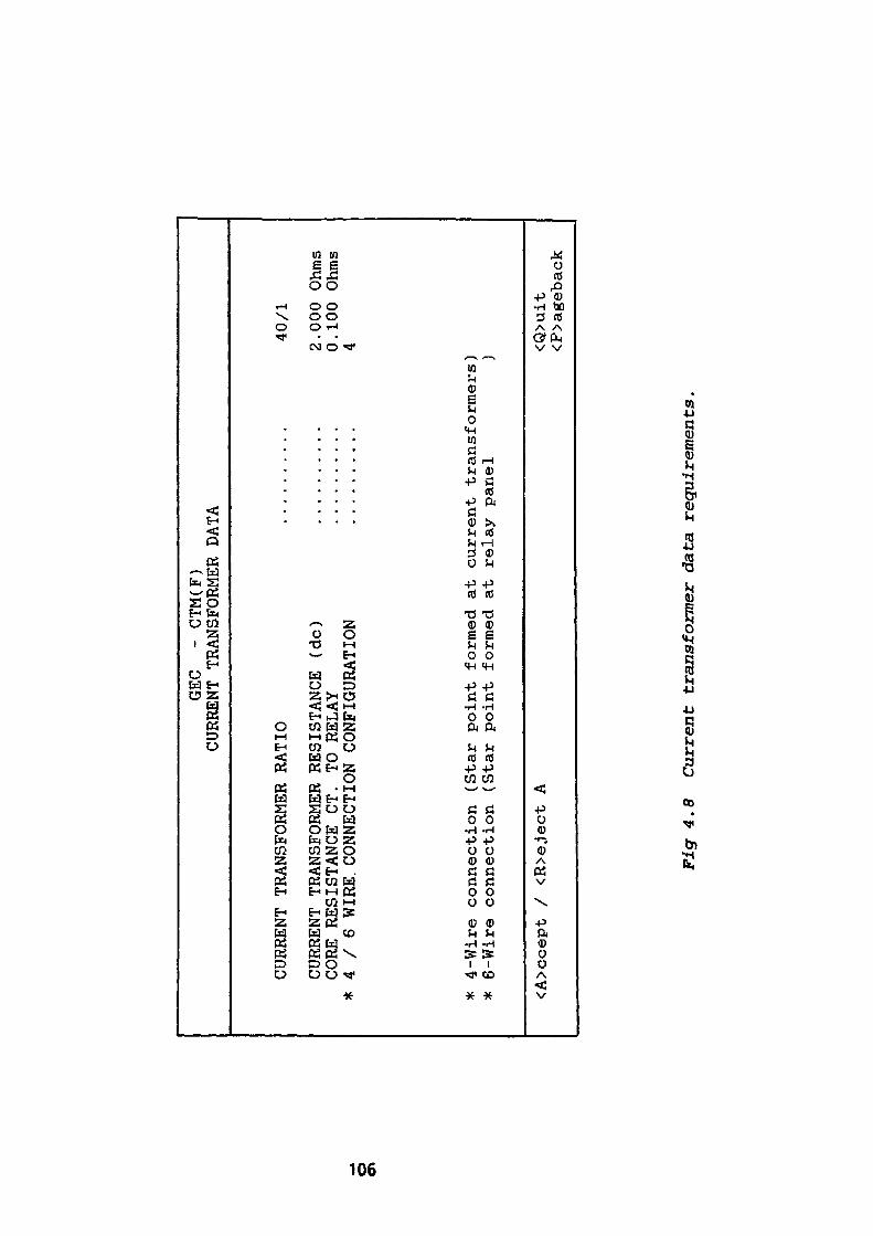
GEC
- CTM(F)
CURRENT TRANSFORMER DATA
CURRENT TRANSFORMER RATIO
..........
CURRENT TRANSFORMER RESISTANCE (dc)
..........
CORE RESISTANCE CT.
TO RELAY
......
....
* 4
/ 6
WIRE. CONNECTION CONFIGURATION
..........
* 4-Wire connection (Star
point formed at current transformers
* 6-Wire connection (Star
point formed at relay panel
<A>ccept /
<R>eject A
40/1
2.000
Ohms
0 . 100 Ohms
4 ) ) <Q>uit
<P>ageback
Fig 4.8
Current transformer da
ta requirements.
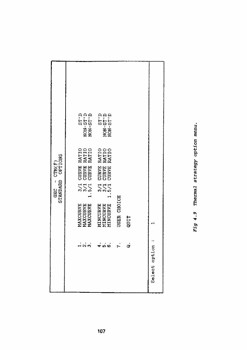
GEC
- CT
M(F)
STANDARD
OPTIONS
1.
2.
3. 4.
5.
6. 7. Q.
Select option
:
MAXCURVE
MAXCURVE
MAXCURVE
1 .
MINCURVE
MINCURVE
MINCURVE
1 .
USER CHOICE
QUIT
1
3/1
CURVE RATIO
3/1
CURVE RATIO
5/1
CURVE RATIO
3/1
CURVE RATIO
3/1
CURVE RATIO
5/1
CURVE RATIO
ST'D
NON-ST'D
NON-ST'D
ST'D
NON-ST'D
NON-ST'D
Fig
4.9
Th
erm
al st
rate
gy
opti
on m
enu.
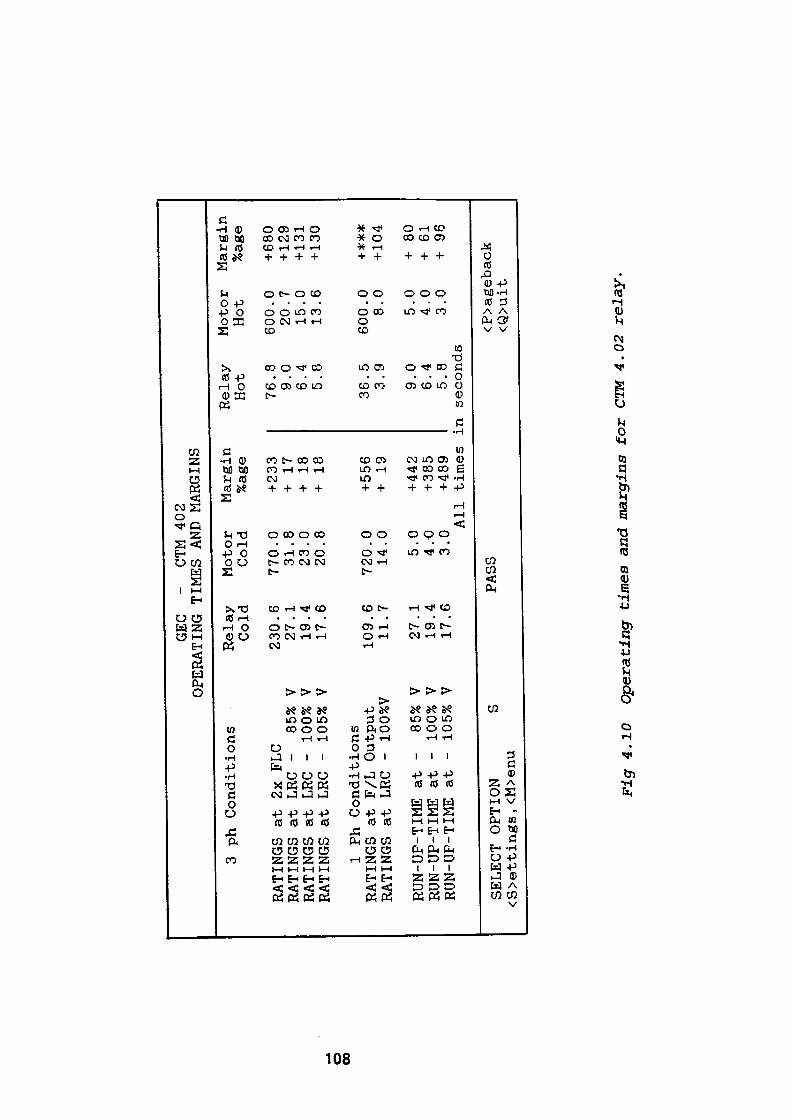
o 00
GEC
- CTM 402
OPERATING TIMES AND MARGINS
3 ph Conditions
RATINGS at 2x
RATINGS at LRC
RATINGS at LRC
RATINGS at LRC
FLC
- 85%
- 100%
- 105%
V V V
1 Ph Conditions
RATINGS at F/L Output
RATINGS at LRC
- 100%V
RUN-UP-TIME at
RUN-UP-TIME at
RUN-UP-TIME at
- 85%
- 100%
- 105%
V V V
Relay
Cold
230 27
19
17 109 11 27
19
17
.6
.1
.4
.6 .6
.7 .1
.4
.6
SELECT OPTION
S <S>ettings , <M>enu
Motor
Margin
Relay
Cold
%age
Hot
770 31
23
20
720 14
5 4 3
PASS
.0
.8
.0
.8 .0
.0 .0
.0
.0 Al
l
+ 233
+ 17
+ 18
+ 18
+ 556
+ 19
+ 442
+ 385
+489
times
i
76 9 6 5
36 3
.8
.0
.4
.8 .5
.9
9.0
6.4
5.8
n seconds
Motor
Hot
600.0
20.7
15.0
13.6
600.0
8.0
5.0
4.0
3.0
Margin
%age
+680
+ 129
+ 131
+ 130
+###
+ 104
+ 80
+ 61
+ 96
<P>ageback
<Q>uit
Fig
4.1
0 O
pera
ting
tim
es a
nd m
argi
ns f
or
CTM
4.0
2 re
lay.
Option 4 'MINCURVE'
3/1 Cold/Hot Ratio using standard characteristics.
The 'Mincurve* option selects the relay characteristic which is furthest from the
motor thermal withstand characteristic yet allows sufficient time to enable the
motor to accelerate up to running speed. As in option 1 the strategy fails as none
of the standard characteristics satisfy the imposed constraints.
Option 5 'MINCURVE 1
3/1 Cold/Hot Ratio using non-standard characteristic
This option uses the same approach as in option 4 albeit applied to the range of
characteristics listed in option 2. In this case the fastest operating characteristic
to satisfy the imposed conditions is found to be 02. This is of course identical with
the result obtained in option 2 which indicates that the only characteristic with a
3/1 Cold/Hot Ratio which can satisfy the constraints is curve 02 - see Figs 4.10 and
4.11.
Option 6 'MINCURVE 1
1.5/1 Cold/Hot Ratio using non standard characteristic.
The method used to locate the solution is identical with that used in options 4 and
5 except that it is applied to the set of characteristics listed in option 3. Curve 06
provides a solution by satisfying all the constraints. The associated data and
graphical representation is shown in Figs. 4.14 and 4.15.
Option 7 'User Option'
Presents the user with a list of all available relay thermal characteristics from
which one can be selected. The screen display listing these characteristics is
shown in Fig. 4.16. The characteristic which is chosen is then subjected to a series
of constraint tests followed by a display of the calculated values. In the case where
109
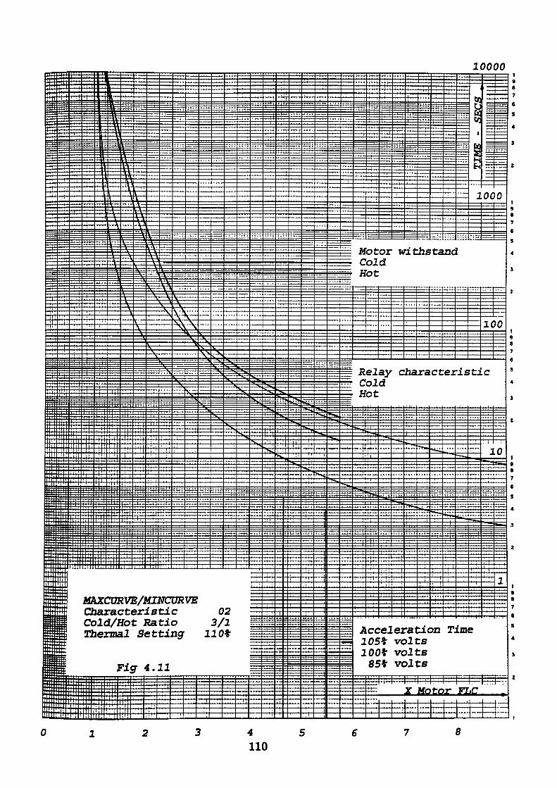
10000Frp
c= =
TT T
frr 4
r Mi
g
!{===
* r*" i —
: — -*-
^ira i *1 1 1ft=ttJ35
gig
i*;|At
a• rv 3 t*tD n
*TT
4
;+~+Tt
ti«^=
^
41LUi
F
•V
\
1 1 1i_ii
^p
r ——
^P
H<Vi
< i • '
Ac
^
i j •
*v ~Sr
H 35 HS iiS rid: 5rr — — — — —— f
IXOZRVE/MI-NeORVE jaracteristic 02 aid/Hot Katio 3/1 jennal Setting 110*
Flff 4.11
pi4^
-H-l -Ht
"^
=;
S
-
¥*
S."
— r
•>^—
——
"****
^
—4
-T4
!s>*
*
^
,
M C H
12 C H
, ,
ot ol ot
el ol ot
TT=i •
j^
-4-4
or d
ayd
joi
W
C
it
ha
T-^-
rr
hs
ra
it:
ta
ct
"~~.
==
-*-
•i-M —
xia
er
=^
.,
!
•is
•^^.
=rS~
Hi
rf!s ^
i
•ta
i~^ i'if
•r ' ;• i J ii
i i. : '_[
:•• r:^ = T- ——
oc
1C
c
1^ N_
25
0
)0
0s^
B>«
7
Acceleration Time 105* volts 100* volts
85* volts
2 we tc!£_ n£
7
5
4
3
2
t9 8 7 6
S
4
3
Z
19 8 7 6
S
4
3
Z
19 B 7 6
S
4
3
2
1
a7
5
4
I
4110
8
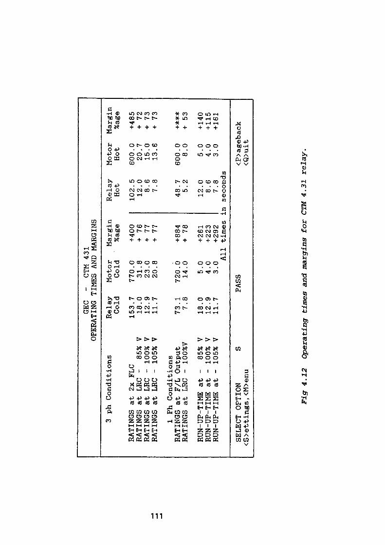
GEC
- CTM 431
OPERATING TIMES AND MARGINS
3 ph Conditions
RATINGS at 2x
RATINGS at LRC
RATINGS at
LRC
RATINGS at LRC
FLC
- 85%
- 100%
- 105%
V V V
1 Ph Conditions
RATINGS at F/L Output
RATINGS at
LRC
- 100%V
RUN-UP-TIME at
RUN-UP-TIME at
RUN-UP-TIME at
- 85%
- 100%
- 105%
V V V
Relay
Cold
153.
18.
12.
11.
73. 7. 18.
12.
11.
7 0 9 7 1 8 0 9 7
SELECT OPTION
S <S>ettings, <M>enu
Motor
Margin
Relay
Cold
%age
Hot
770.
31.
23.
20.
720.
14. 5.
4.
3.
PASS
0 8 0 8 0 0 0 0 0 All
+400
+
76
+ 77
+ 77
+884
+
78
+261
+ 22
3 +292
times
]
102.
12
. 8.
7.
48. 5.
5 0 6 8 7 2
12.0
8.6
7.8
.n seconds
Motor
Hot
600.
0 20.7
15.0
13.6
600.
0 8.
0
5.0
4.0
3.0
Marg
in
%age
+485
+ 72
+ 73
+ 73
+**#
+ 53
+ 140
+ 115
+161
<P>ageback
<Q>uit
Fig 4.12
Operating
times and margins
for
CTM
4.31 relay.
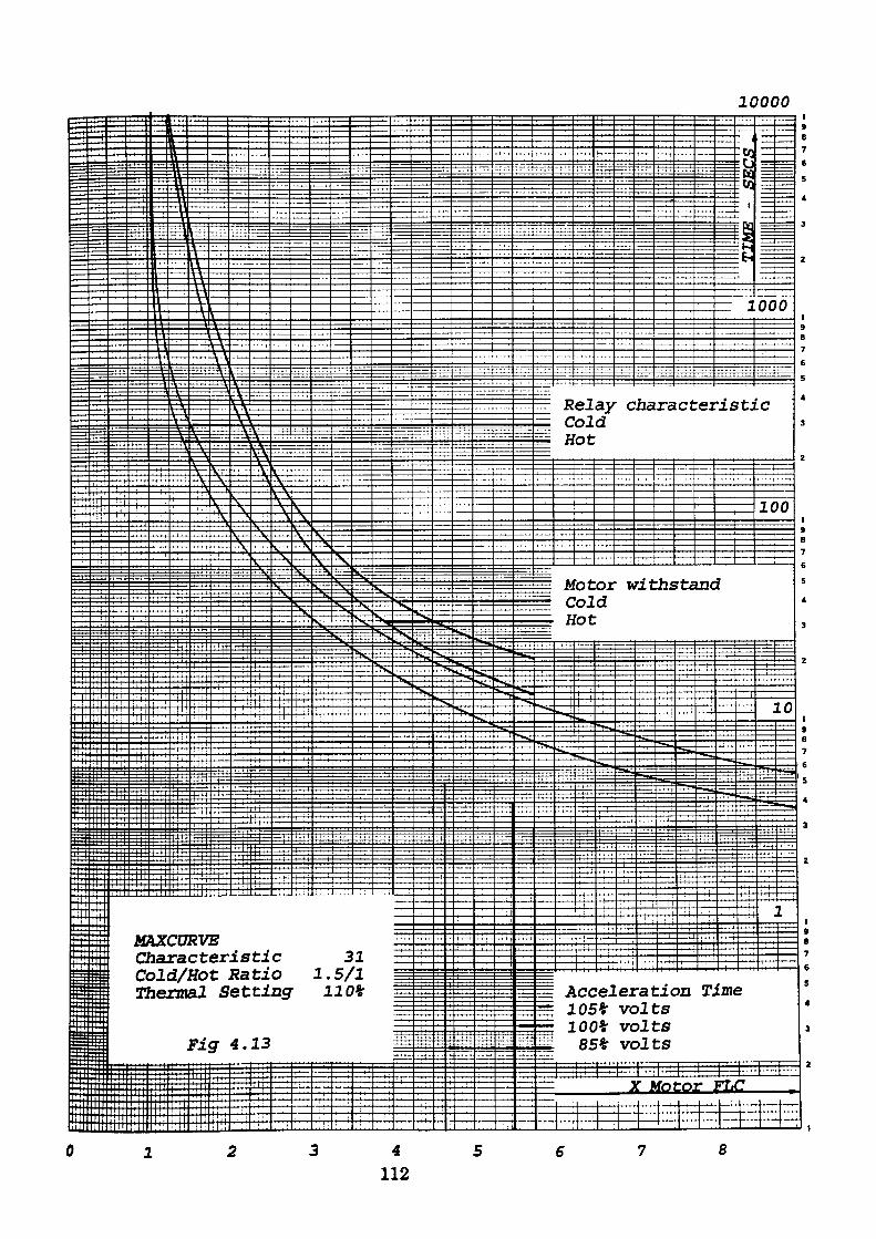
10000
4112
8
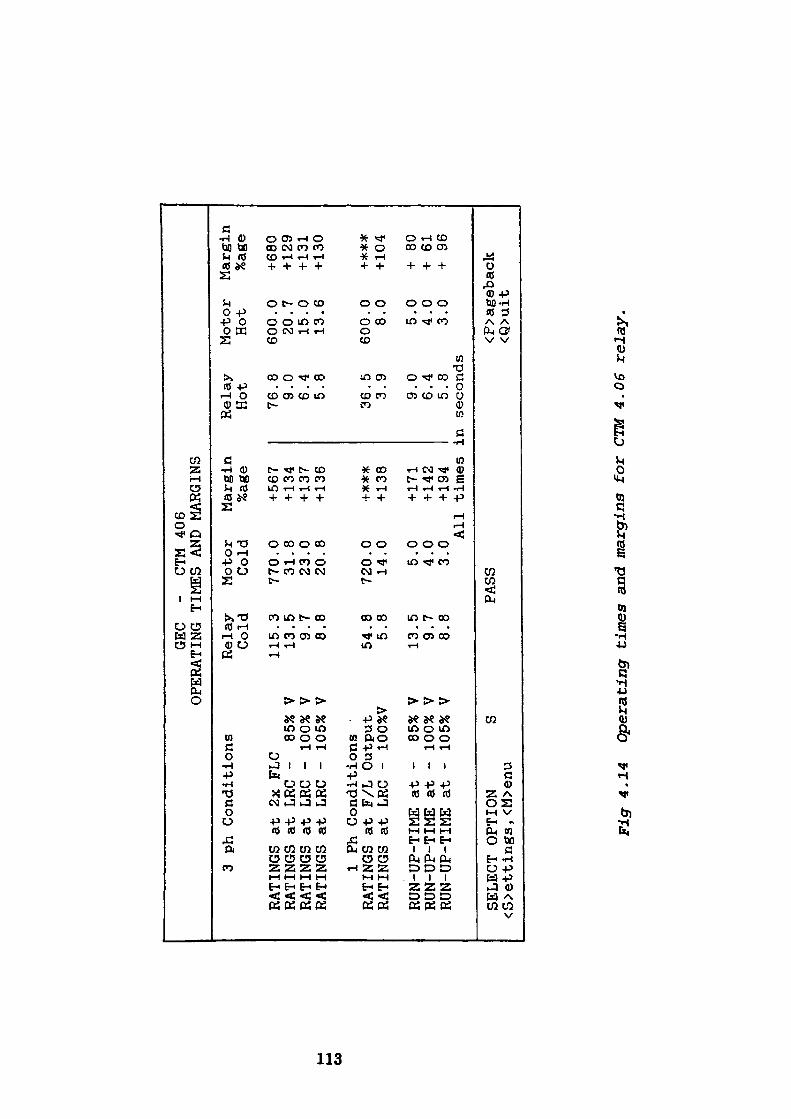
CO
GEC
- CTM 406
OPERATING TIMES AND MARGINS
3 ph
Conditions
RATINGS at 2x
RATINGS at LRC
RATINGS at LRC
RATINGS at LRC
FLC
- 85% V
- 100% V
- 105% V
1 Ph Conditions
RATINGS at F/L Output
RATINGS at LRC -
100%V
RUN-UP-TIME at
RUN-UP-TIME at
RUN-UP-TIME at
- 85% V
- 100% V
- 105% V
Relay
Cold
115.
13. 9.
8. 54. 5.
13. 9.
8.
3 5 7 8 8 8 5 7 8
SELECT OPTION
S <S>ettings, <M>enu
Motor
Margin
Relay
Cold
%age
Hot
770 31
23
20 720 14
5 4 3
PASS
.0
.8
.0
.8 .0
.0 .0
.0
.0 All
+ 567
+ 134
+ 137
+136
f***
+ 138
+ 171
+ 142
+ 194
times
:
76. 9.
6.
5. 36. 3.
8 0 4 8 5 9
9.0
6.4
5.8
.n seconds
Motor
Hot
600 20
15
13
600 8 5 4 3
.0
.7
.0
.6 .0
.0 .0
.0
.0
Margin
%age
+680
+ 129
+ 131
+ 130
+#**
+ 104
+ 80
+ 61
+ 96
<P>ageback
<Q>uit
Fig 4.
14
Oper
atin
g ti
mes and ma
rgin
s for CTM 4.06
relay.
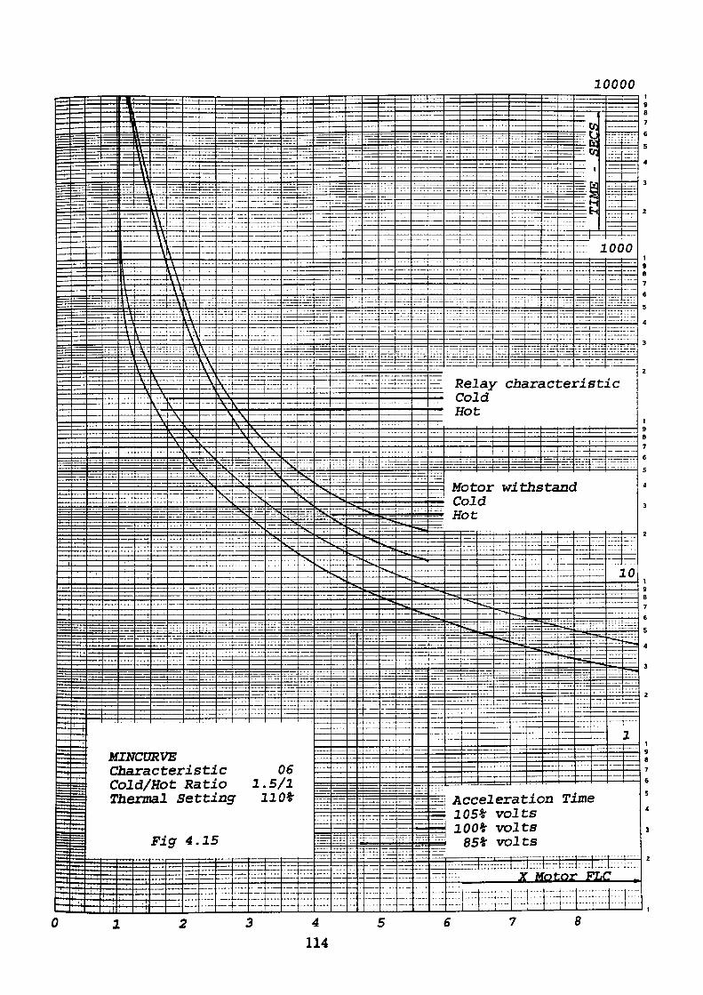
10000
Belay characterise!c ColdHot
Motor withColdHot
Cold/Hot Ratio 1.5/1 Setting 110*
Fig 4.15
Acceleration 105* volts 100* volts 85* volts
FLC
4
114
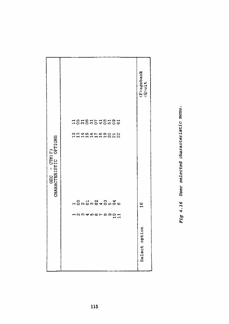
1 2 3 4 5 6 7 8 910 11
Select option
1 00 2 01 3 02 4 03 5 04 6 16
GEC
- CTM(F)
CHARACTERISTIC
OPTIONS 12 13 14 15 16 17 18 19 20 21 22
11 05 21 06 31 07 41 08 51 09 61
<P>ageback
<Q>uit
Fig 4.
16
User se
lect
ed characteristic m
enu.
an inequality is not satisfied the value displayed is supplemented by a symbol and
a legend indicating the failure condition.
Option 8 'QUIT1
returns the program to an earlier stage where an alternative relay type may be
chosen.
Following the successful selection of a thermal characteristic and the subsequent
examination of displayed operating times, the user may return to the strategy
option menu shown in Fig. 4.7 to examine further possibilities by depressing the
'M' key. This selection also enables the CT ratio and thermal setting to be altered
if required. Alternatively the required relay settings may be displayed by
selecting the 'S' key. The 'S' key initially displays a table which contains the
required settings and where applicable ohmic values for the stabilising resistor.
Fig. 4.17 is a replica of the screen display produced. As in option 8, operation of
the 'Q' key returns the program to an earlier stage which allows the selection of an
alternative relay.
4.3 The CTM(F) Program Description
The program is again constructed in a modular form, each module being selected
sequentially using an address supplied by the routine currently in use. A
flowchart outlining the logic of the program is shown in Fig. 4.18.
On selecting the CTM/CTMF option from the relay menu the program is directed
to the CTM routine, a description of which follows:
116
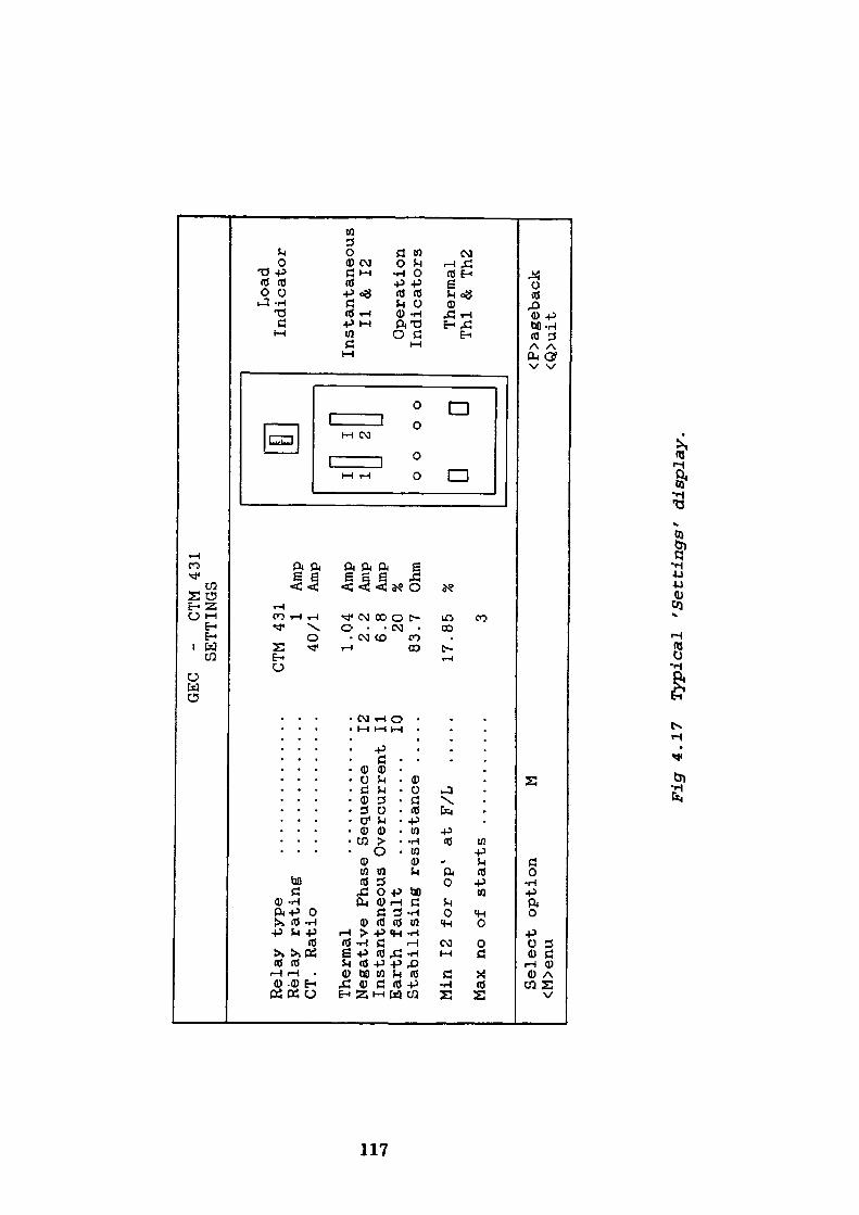
GEC
- CTM 431
SETTINGS
Relay type
..............
CTM 431
Relay rating
..............
1 Amp
CT.
Ratio
..............
40/1
Amp
Thermal
..............
1.04
Amp
Negative Phase Sequence
12
2.2
Amp
Instantaneous Overcurrent 11
6.8
Amp
Earth fault
..........
10
20
%Stabilising resistance .....
83.7
Ohm
Min 12 for op'
at F/L
.....
17.85
%
Max no of starts ...........
3
Select option
M
<M>enu
T 1 0 DJ c
Fl T 2 r- )o D
Load
Indicator
Instantaneous
11 & 12
Operation
Indicators
Thermal
Thl
& Th2
<P>ageback
<Q>uit
Fig
4.1
7 T
ypic
al
'Set
tin
gs'
d
isp
lay.
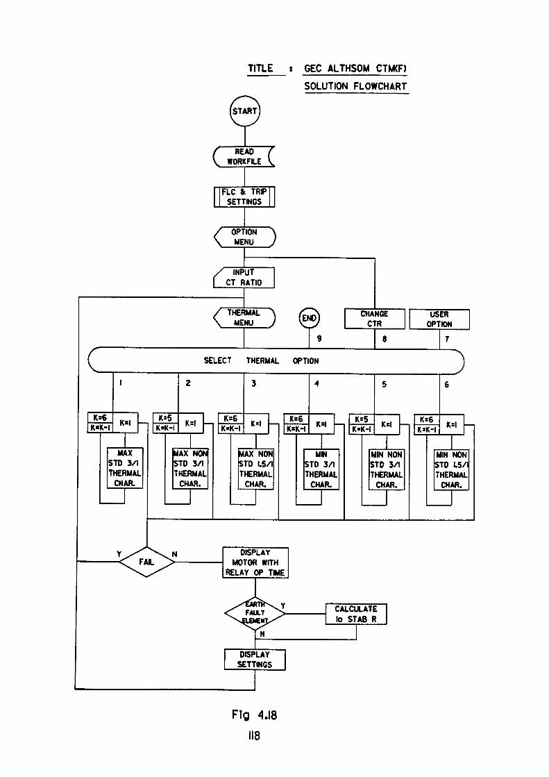
TITLE GEC ALTHSOM CTM(F)
SOLUTION FLOWCHART
/ READ ( \ WORKFILE V
FLC & TRIP SETTINGS
/ OPTION A \ MENU J
/ INPUT | CT RATIO
/ THERMAL A /l^S C \ MENU J *W
1 9
C SELECT THERMAL OPTION
1 2
K=6 K_, K=5 K=6K»K-I K-K-I K«K-I
3 4
K-l KS€ 1C- KSK=K-I K«t
MAX MAX NON MAX NON MM STD 3/1 STD 3/1 STD 1.5/1 STD 3/1 THERMAL THERMAL THERMAL THERMAL CHAR. CHAR. CHAR. CHAR.
Y X^^\N I—————— <T FAIL ^> ——————— MO ^^^^^ RELt
<
MSPLAY TOR WITH Y OP TIME
USJ^ CALCULfLEItHV^" '° ^^*
INDISPLAY SETTINGS
MANGE USER CTR OPTION
S 7
)5 6
5 K-l K=6 K-l[-1 * ' K*K-I *"'
MIN NON MIN NON STD 3/1 STD 1.5/1 THERMAL THERMAL CHAR. CHAR.
ATE B R
Fig 4.18 118
CTM
This routine is the control module for the CTM relay selection program and is the
module which allows the individual sections of the program to be sequentially
accessed. Selecting this option directs the flow of all data previously established
in the MPROT routines through the following appropriate CTM modules. A
generalised flowchart of the CTM module is shown in Fig. 4.19. The first module
selected by this routine is CTM10.
CTM10
The function of the routine is to display the initial program menu from which one
of six options may be chosen. The options presented enable the type, function and
number of relay elements to be selected. The menu display is shown in Fig. 4.7.
CTM30
A further menu containing 8 options is presented in this routine. The options
displayed allow the user to specify the approach used by the program in the
selection of the thermal characteristics required. The menu display is shown in
Fig. 4.9.
CTM40
In this routine data is aligned to variables based on the selections made in earlier
routines. The data is used in subsequent routines to identify the characteristic
previously chosen.
CTM50
In this module the characteristic is identified and labelled accordingly based on
the previously supplied information. The routine calls a subroutine labelled
CTM501 whose function is to select the characteristic type previously determined
and to apply a series of inequality tests which compare motor withstand times
119
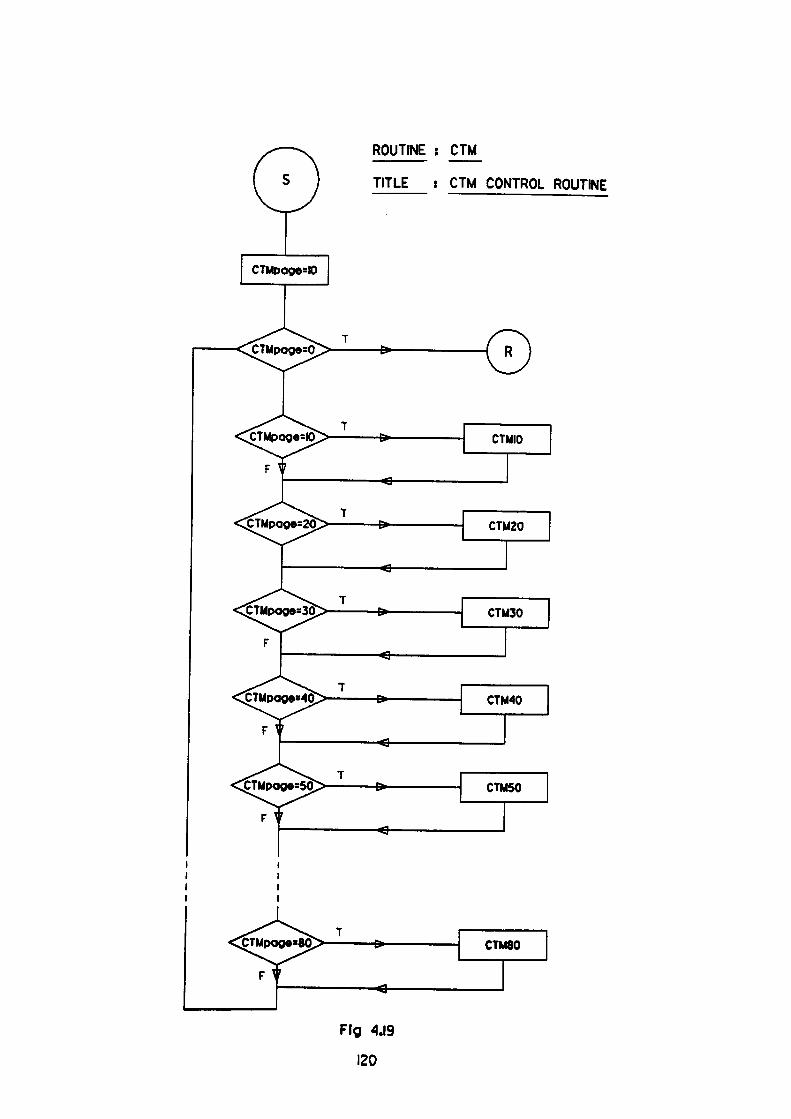
ROUTINE : CTM
TITLE : CTM CONTROL ROUTINE
"CTMpage=Ox
5TMpoge=20:
Fig
120
with predicted relay operating times. The operating time of the relay for each
particular current condition being determined in a routine labelled CTM5011. In
general a set of characteristics comprise either 5 or 6 individual characteristics
each of which must be tested until a satisfactory match is found. The
characteristics may be checked by examining the lowest characteristic first and
incrementing the curves or alternatively commencing with the maximum
operating characteristic and decrementing the curves until a satisfactory solution
is encountered. The result may either:
1. Fail to satisfy the set of inequalities
2. Detect a maximum characteristic which satisfies the set of inequalities
3. Detect a minimum characteristic which satisfies the set of inequalities
CTM5011
This module uses the Neville-Aitken interpolation method to model the relay
thermal operating characteristics such that for any given current input value the
routine provides an operating time as output.
CTM60
This routine is used to display the 'User Characteristic1 menu. A small database
file CTM1 is opened from which a series of characteristic multipliers and
associated reference names are extracted and displayed in sequential form. The
user is required to select the appropriate curve for comparison against the motor
and associated circuit constraints. A flowchart of the routine is shown in Fig. 4.20.
CTM70
This routine is used to evaluate the operating times for the series of conditions
detailed in table 4.2 when applied to the characteristics selected in the previous
routine. The routine records the conditions where the relay operating time
121
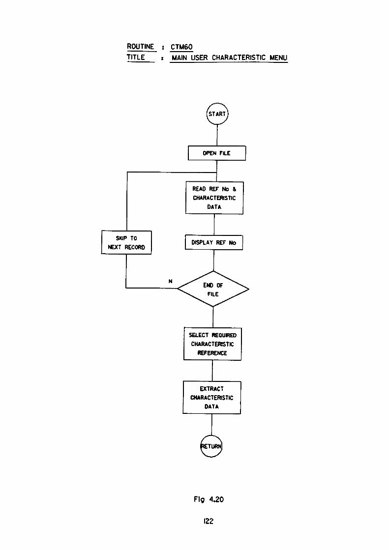
ROUTINE : CTM60TITLE : MAIN USER CHARACTERISTIC MENU
OPEN FILE
READ REF No &
CHARACTERISTIC
DATA
SKIP TO
NEXT RECORD
N
SELECT REQUIRED CHARACTERISTIC
REFERENCE
EXTRACT CHARACTERISTIC
DATA
Fig 4.20
122
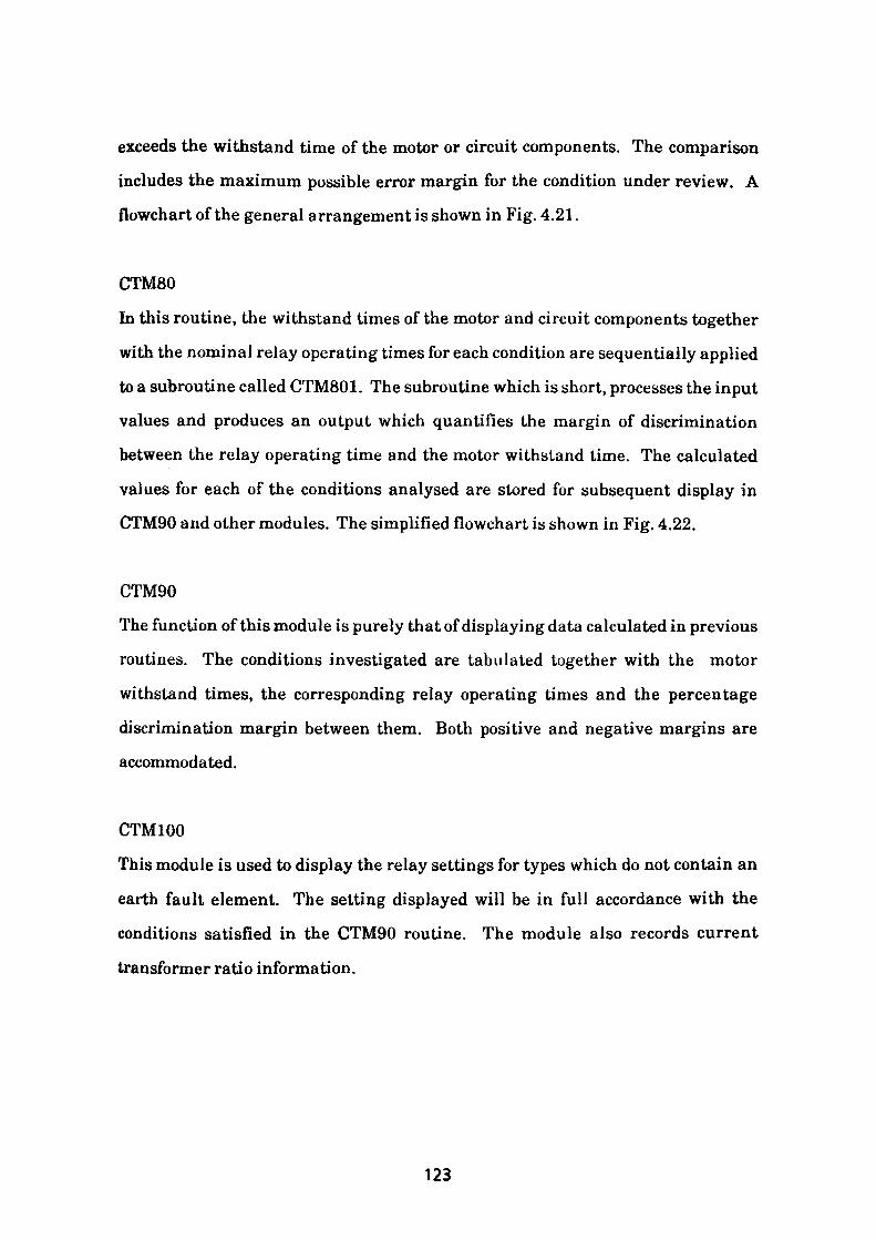
exceeds the withstand time of the motor or circuit components. The comparison
includes the maximum possible error margin for the condition under review. A
flowchart of the general arrangement is shown in Fig. 4.21.
CTM80
In this routine, the withstand times of the motor and circuit components together
with the nominal relay operating times for each condition are sequentially applied
to a subroutine called CTM801. The subroutine which is short, processes the input
values and produces an output which quantifies the margin of discrimination
between the relay operating time and the motor withstand time. The calculated
values for each of the conditions analysed are stored for subsequent display in
CTM90 and other modules. The simplified flowchart is shown in Fig. 4.22.
CTM90
The function of this module is purely that of displaying data calculated in previous
routines. The conditions investigated are tabulated together with the motor
withstand times, the corresponding relay operating times and the percentage
discrimination margin between them. Both positive and negative margins are
accommodated.
CTM100
This module is used to display the relay settings for types which do not contain an
earth fault element. The setting displayed will be in full accordance with the
conditions satisfied in the CTM90 routine. The module also records current
transformer ratio information.
123
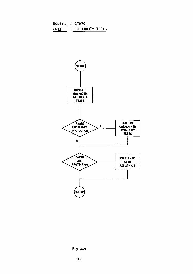
ROUTINE ; CTM70
TITLE : INEQUALITY TESTS
CONDUCTBALANCEDINEOAULITY
TESTS
CONDUCTUNBALANCEDINEOAULITYTESTS
PHASE UNBALANCE PROTECTION
EARTHFAULT
PROTECTION
CALCULATESTAB
RESISTANCE
Flfl 4.21
124
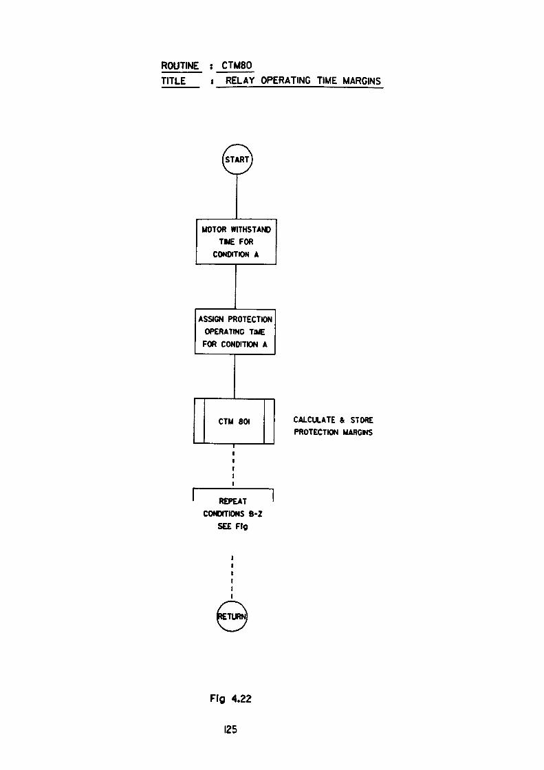
ROUTINE : CTM80
TITLE RELAY OPERATING TIME MARGINS
MOTOR WITHSTAND
TIME FOR
CONDITION A
ASSIGN PROTECTION
OPERATING TIME
FOR CONDITION A
CTM 801 CALCULATE & STORE
PROTECTION MARGMS
REPEAT
CONDITIONS B-2
SEE Fig
Fig 4.22
125
CTM110
This routine is called when earth fault protection is required. To function the
algorithm requires further specific circuit parameters to complete the calculation.
The additional parameters required are:
1. Current transformer dc resistance
2. Lead resistance
3. Location of star point
4. Operating level of element (10% or 20%)
Utilising the additional data, the routine calculates the value of the series
stabilising resistor using the method outlined in the text. A screen display for the
example discussed is shown in Fig. 4.5. It should be noted that the increased
stabilising resistor value is due to the program taking account of the line voltage
supplying the motor being 110% greater than nominal.2B
CTM120
The routine is used purely for the display of final settings for relays which include
the earth fault element and associated stabilising resistor. The routine is very
similar to CTM100.
4.4 Interim Conclusion
The contents of Chapter 4 discuss the major elements which must be considered by
the protection engineer when applying a CTM(F) protection relay to a motor
circuit. The novel approach using standard desktop PC programs, ensures that
the relay operating times are accurately quantified to ensure maximum
utilisation of the relay. The resultant settings when determined take full account
of the declared maximum and minimum tolerances.
126
The most obvious benefit which arises from using the program is the ease with
which a suitable thermal characteristic or range of characteristics can be selected,
thus enabling the optimum relay to be requisitioned. Further benefits accrue
from the comprehensive set of checks which are applied each time the program is
run. This factor ensures consistency and eliminates the possibility of error or the
taking of short cuts, thus providing a sound engineering basis for the resulting
characteristic choice and applied settings.
References
1. Correspondence with J. Middlemiss, Peebles Electric Ltd
2. Correspondence with A. Marshall, GEC Alsthom
GEC Alsthom Publication No. R-5171
GEC Alsthom Publication No. R-5738
Protection of Industrial Power Systems by T. Davies
Power System protection Volume 3 - Electricity Council
Protective Relay Application Guide - GEC Measurements
127
CHAPTERS
APPLYING THE P&B GOLDS TYPE PBSJ 3E5 Nl 1
MOTOK PROTECTION RELAY
5.1 INTRODUCTION
The purpose of this section is to introduce a more modern motor protection relay,
(MPR), and to highlight its increased versatility resulting from enhanced
features. The MPR referred to is the P&B Golds type PBSJ 3E5 Nil which is
illustrated in Fig. 5.1. It is a medium priced digital electronic device which is
capable of operating from current transformers producing either a 1A or 5A
secondary output at their nominal ratio. An auxiliary voltage supply of 80-265V
ac or dc is necessary to power the device.
The main functions offered by the relay are:
1. Thermal overload protection
2. Locked Rotor and stall protection
3. Earth fault protection
4. Phase unbalance protection
5. Undercurrent protection
These functions will be discussed in the following sections
6.1.1 Thermal Overload Protection
The thermal element settings are applied to the relay by operation of the selection
button Rl on the relay faceplate. The locations of the selection button Rl together
128
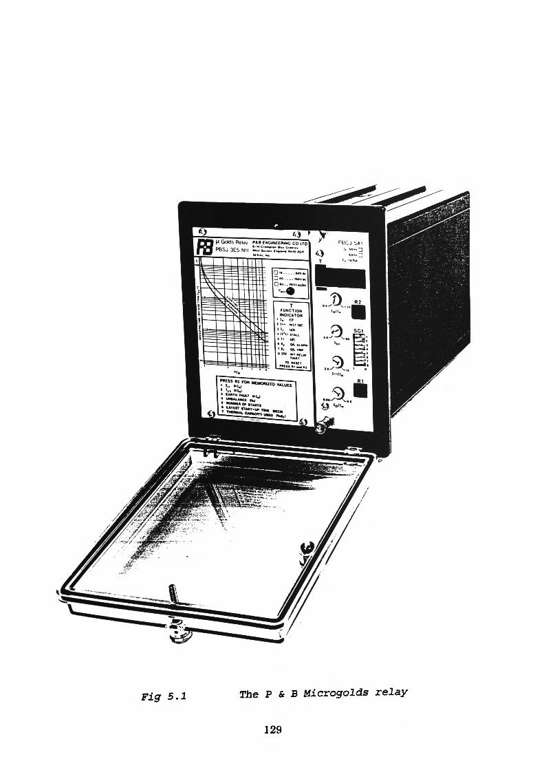
M Golds Relay PU C«GINCC»IMG coiro
Figr 5.1 The P & B Microgolds relay
129
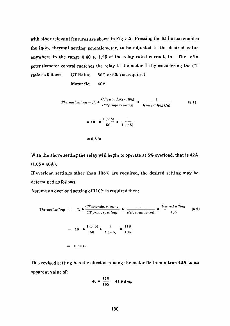
with other relevant features are shown in Fig. 5.2. Pressing the Rl button enables
the Iq/In, thermal setting potentiometer, to be adjusted to the desired value
anywhere in the range 0.40 to 1.25 of the relay rated current, In. The Iq/In
potentiometer control matches the relay to the motor flc by considering the CT
ratio as follows: CT Ratio: 50/1 or 50/5 as required
Motor flc: 40A
CT seconda ry ra ting 1Thermal setting = flc • ———————————— • ————————— (5.1)CT primary rating Relay rating (In)
1 (or5) 1 - 4050 1 (o»-5)
-O.&ln
With the above setting the relay will begin to operate at 5% overload, that is 42A
(1.05«40A).
If overload settings other than 105% are required, the desired setting may be
determined as follows.
Assume an overload setting of 110% is required then:
('T secuiulary rating \ Desired settingThermal setting = flc •——————i———2- • ———————————• ————————- (5.2)CT primary rating Relay rating (in) 105
1 (or 5) 1 110= 40 • ———— • ———— • ——50 1 (or 5) 105
= 0.84 In
This revised setting has the effect of raising the motor flc from a true 40A to an
apparent value of:no
40 • —— - 41.9 Amp 105 ^
130
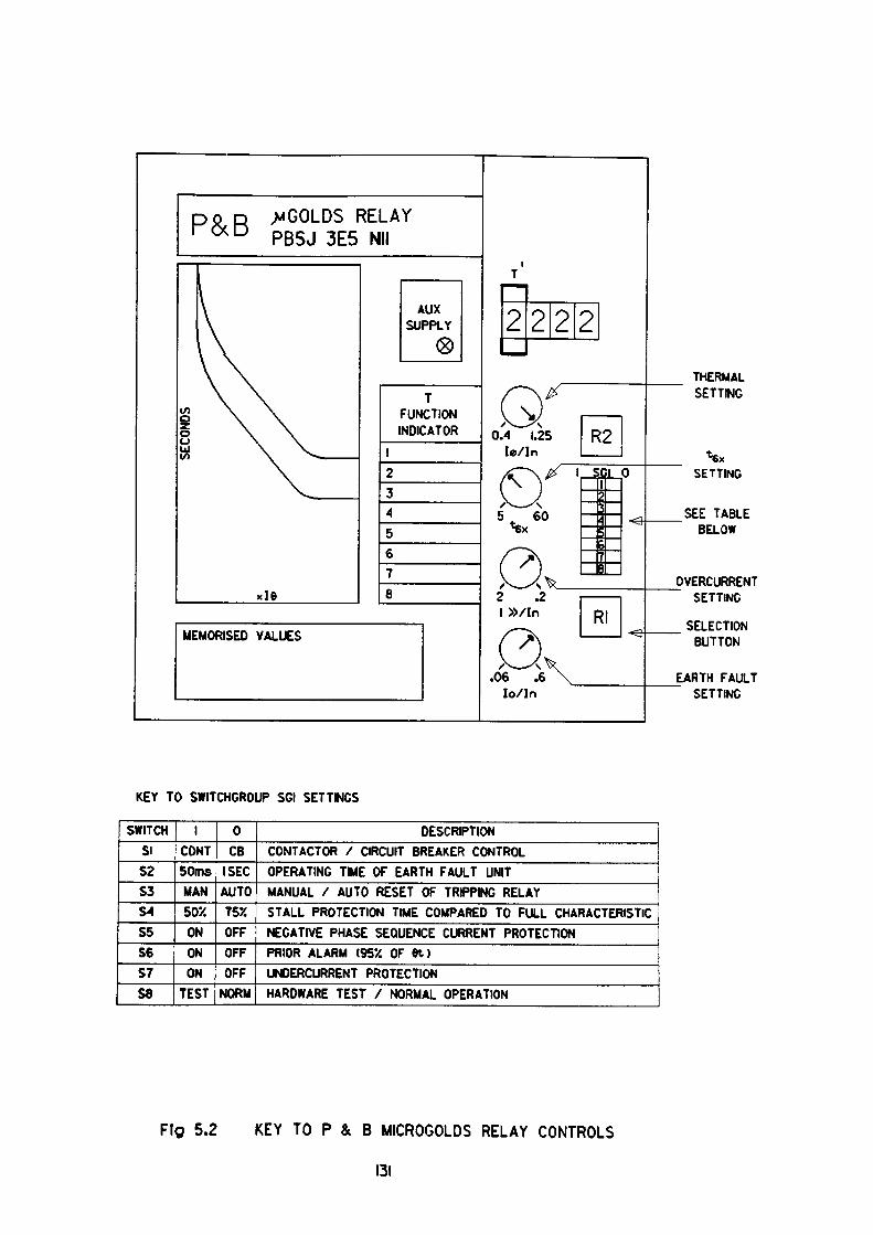
^GOLDS RELAY PB5J 3E5 Nil
MEMORISED VALUES
TFUNCTION INDICATOR
2 2 2 2THERMAL SETTING
SETTING
SEE TABLE BELOW
>VERCURRENT SETTING
SELECTION BUTTON
EARTH FAULT SETTING
KEY TO SWITCHGROUP SGI SETTINGS
SWITCHSI
S2S3S4
S5S6srS8
1CONT50msMAN
50XONONON
TEST
0CB
ISECAUTO
T55C
OFFOFFOFF
NORM
DESCRIPTIONCONTACTOR / CIRCUIT BREAKER CONTROLOPERATING TIME OF EARTH FAULT UNITMANUAL / AUTO RESET OF TRIPPING RELAYSTALL PROTECTION TIME COMPARED TO FULL CHARACTERISTICNEGATIVE PHASE SEQUENCE CURRENT PROTECTIONPRIOR ALARM (952 OF ft)UNDERCURRENT PROTECTIONHARDWARE TEST / NORMAL OPERATION
Fig 5.2 KEY TO P & B MICROGOLDS RELAY CONTROLS
131

A further 5% increase on this load causes the thermal unit to become active and if
sustained eventually to cause tripping.
By accommodating differing values of overload setting, it can be observed that
adjustment of the thermal setting controls the pick up point on the horizontal
current axis. (Fig. 5.3). This factor should be borne in mind when adjusting the
other controls.
It should be noted that if the setting arrived at lies between 0.9 -1.1 • relay rating
then the operating setting will have an accuracy within ± 1% of the calculated
characteristic. Outside these limits setting errors may be up to ± 5% of the
calculated values.
The characteristic of the thermal unit fully accords with the characteristics
detailed in B.S. 142: Section 2.3, Appendices A and B. The operating time of the
element, subject to setting errors, may be accurately determined by the equation.
t ., = 32.a.log ( ——— I sees — for the starting or cold condition (5.3)e \ p — s '
( p - Q.bdL) \ and t, — 32.a.log I —— - — - —— j sees — for the running or hot condition
e \ — '
where:
p is a multiple of motor flc (p.u. value)
s is the desired overload setting (p.u. value)
a is the setting of the tex control (referred to later)
A derivation of the above characteristics is included in Appendix 9.
132
5.1.2 The tfi* Control
A typical thermal characteristic is shown in Fig. 5.3. The characteristic may be
adjusted vertically in order to increase or decrease its operating time for any given
multiple of relay rated current. The adjustment is affected by using the tex control
potentiometer, the location of which is shown in Fig. 5.2. The tex setting is the
elapsed time required to trip the relay from the cold state at 6 times motor flc and
may be adjusted within the range 5-60 seconds in 0.5 second increments. It is
important to note that the tex setting always refers to the operating time at six
times flc which implies that the motor withstand time for start or stall current for
other conditions must be modified to take this into account. The setting so
determined must also take into account the relay errors, relay overshoot time,
gwitchgear clearance time, consider the effects of starting at other than nominal
voltage and any other relevant ordinates on the operating characteristic. The
adjustment is made by again pressing the selection button Rl on the relay
faceplate to select the second option. The exact setting is determined by observing
the value on the digital display as the t6x potentiometer is adjusted. Thus, it can
be seen that the t&x potentiometer effectively controls movement of the vertical or
time axis by moving both the Cold and Hot characteristics up or down as dictated
by the setting.
5.1.3 Locked Kotor and Stall Protection
The relay operating time may be modified by introducing a step in the characteristic at the twice times flc ordinate. The effect of the modification is to
reduce the operating time of the thermal element by a selectable factor of 0.75 or
0.5 for all values of current in excess of twice times flc. The chosen factor is
selected by means of a miniature rocker switch located in the switchgroup SG1 on
the faceplate of the relay. The location of the switchgroup is shown in Fig. 5.2.
133
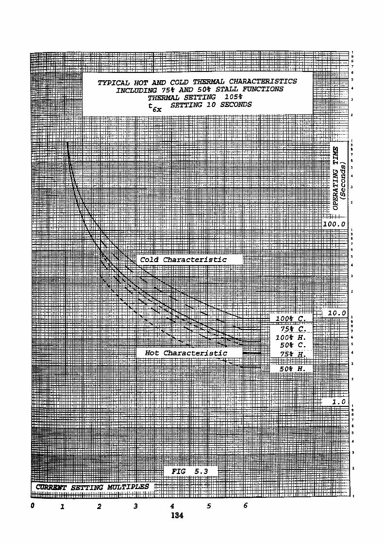
TYPICAL HOT AND COLD THERMAL CHARACTERISTICS INCLUDING 75* AND 50% STALL FUNCTIONS
THERMAL SETTING 105*t, SETTING 10 SECONDS oX
Cold Characteristic
Hot Characteristic
CURRENT SETTING MULTIPLESiiiiiiiiiiini
4134
6
This inbuilt thermal characteristic modification, the stall function, is activated by
supplying auxiliary power to a pair of designated terminals on the rear of the
relay.
Activation of the stall function allows an increased tex value to be selected whilst
still permitting full thermal protection of the motor to be achieved. As a direct
consequence of raising the tex setting, the relay operating times for motor
overloads of magnitude less than twice times flc will be increased. This increased
operating time can prove beneficial by allowing greater use to be made of the
thermal withstand of the motor in this region. Such a condition could arise in the
case of a stone crusher or similar machine where frequent overload excursions are
experienced when particularly hard stone is encountered. This method of solution
is discussed in Section 5.2.1.
Alternatively, where the accelerating time of the motor is short in relation to the
maximum allowable acceleration period, the stepped characteristic may be
adjusted to satisfy the motor acceleration period yet will still enable greater use to
be made of the overload capability of the motor up to twice times flc. This
technique is further discussed in Section 5.2.4.
Where acceleration periods in excess of locked rotor withstand time are
encountered, it may be possible to arrange for the stepless characteristic to satisfy
the motor overload requirements up to twice times flc whilst still allowing
sufficient time to accelerate the motor. On completion of the acceleration period
the stall function may be activated to allow total thermal protection of the motor
to be maintained. The signal required to introduce the step in the
characterteristic may be produced by various sources such as timers, current
sensing elements, or external devices such as speed sensing switches on the motor
itself.
135
It can be readily understood that this protective approach must be supplemented
by additional protective relays to ensure prompt disconnection should the motor
fail to rotate.
5.1.4 High-Set QvercurrentTrip
The relay incorporates an instantaneous high-set overcurrent feature which may
be enabled or disabled as required. If the motor is supplied through a fully rated
circuit breaker and cabling, the element should be set to the active mode to detect
and initate the clearance of a short-circuit as quickly as possible. Alternatively if
the circuit is supplied by fused contactor, the element should be disabled to allow
the fuses to clear the fault whilst the contactor remains closed. The contactor
may, of course, fail to stay closed for reasons discussed in 4.1.3.2.
In order to enable or disable the element, a rocker switch in the faceplate mounted
switchgroup SGl must be moved to the required position. The location of the
switch is shown in Fig. 5.2. If the active mode is selected a setting must be applied
to the element within the range 2.0-12.0 • In. In order to apply a setting to the
element, the function selection button Rl is operated until the appropriate
selection is made. Selection is signified by the function identifier '3' being
displayed on the faceplate panel. The actual setting is applied by adjusting the
faceplate mounted overcurrent setting potentiometer and observing the setting on
the faceplate digital display. As a general rule and to avoid mal-operation, a high
set instantaneous overcurrent element must be set at a value which exceeds the
starting current and any assymetry in the current wave form likely to be
encountered immediately after switch closure. This relay, however, incorporates
a novel form of overcurrent element which doubles its setting during the starting
period. In addition to detecting short-circuits, at all times this useful feature can
also be used to detect a locked rotor condition occurring during the running mode.
136
This high-set over-current function is of course, not available when contactor
control is utilised.
5.1.5 Earth Fault Protection
The relay incorporates an element whose function is to detect the presence of earth
fault currents in the motor circuit. The earth fault current may be detected using
either a core balance CT or alternatively, a residually connected CT arrangement.
The operating setting of the element is not fixed but may be adjusted within the
range 0.06-0.6 • In. To assign an E/F setting to the relay the procedure requires
the function selection button Rl to be pressed until the function identifier '4' is
displayed on the faceplate panel. This allows the earth fault setting potentiometer
to be rotated to the desired setting. The setting point may be accurately
determined by observing the setting value on the faceplate digital display. The
earth fault element is not instantaneous but incorporates a fixed time delay prior
to operating. Two time delays are possible, a 50 millisecond delay and a 1 second
delay. The 50 millisecond delay is used when the circuit is supplied via a fully
rated circuit breaker. This delay is of sufficient duration to prevent maloperation
caused by assymetry on starting or operation by system borne transients. The one
second delay time is selected for contactor circuit duty and is used to delay the
tripping signal thereby allowing heavy current faults to be cleared by the main
power fuses. The chosen time delay is selected by means of the S2 rocker switch in
the switchgroup SG1 on the faceplate of the relay. It should be noted that if the
MSD is a fused contactor the SI rocker switch in the switchgroup SG1 would be set
for contactor control. This action blocks the operation of the instantaneous
overcurrent elements and additionally inhibits the operation of the earth fault
element for fault currents in excess of four times flc.
137
5.1.6 Phase Unbalance Protection
The relay is equipped with a network which extracts the negative phase sequence
component from an unbalanced 3 phase supply. The magnitude of the current is
used to initiate disconnection in accordance with an inverse characteristic
satisfying the equation
3910 Asecs of the form ——— (5.5)
5-! Bc -l
where 1% is the NPS current expressed as a percentage of the maximum phase
current being monitored. Hence in the case of a total loss of one phase of the
supply to a motor, the current will rise to a value greater than V3 times its former
value to sustain output power (refer to section 4.1.2). Resolving the assymetrical
phase currents into their symmetrical phase components shows that the
maximum magnitude of NPS current is 1/V3 times the current in the sound phase
(equation 4.9).1
Hence maximum NPS component of current — —j- • 100 — 57.74% ofsound phase current
Substituting the max value in equation 5.1 gives
3910— = 1.44 secs
(57.74)1S5-1
Thus rapid isolation of the machine is guaranteed for this condition at all values of
current in excess of 0.25 • fie.
The phase unbalance function, may be set to the active mode or inhibited as
required. To ensure the function is active, the rocker switch S5 in the switchgroup
SGl shown in Fig. 5.2 must be set to the 'ON' position.
138
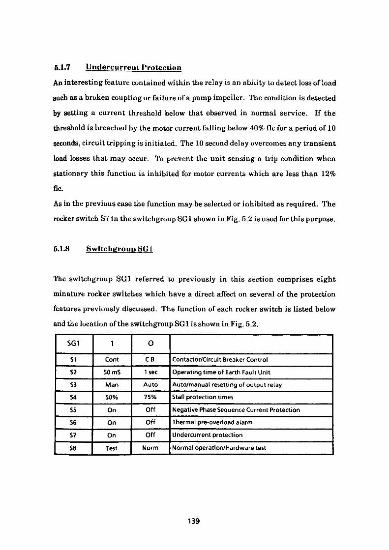
5.1.7 Undercurrent Protection
An interesting feature contained within the relay is an ability to detect loss of load
such as a broken coupling or failure of a pump impeller. The condition is detected
by setting a current threshold below that observed in normal service. If the
threshold is breached by the motor current falling below 40% flc for a period of 10
seconds, circuit tripping is initiated. The 10 second delay overcomes any transient
load losses that may occur. To prevent the unit sensing a trip condition when
stationary this function is inhibited for motor currents which are less than 12%
flc.
As in the previous case the function may be selected or inhibited as required. The
rocker switch S7 in the switchgroup SG1 shown in Fig. 5.2 is used for this purpose.
5.1.8 Switchgroup SG1
The switchgroup SGl referred to previously in this section comprises eight
minature rocker switches which have a direct affect on several of the protection
features previously discussed. The function of each rocker switch is listed below
and the location of the switchgroup SGl is shown in Fig. 5.2.
SG1
S1
S2
S3
S4
S5
S6
S7
S8
1
Cont
50 mS
Man
50%
On
On
On
Test
O
C.B.
1sec
Auto
75%
Off
Off
Off
Norm
Contactor/Circuit Breaker Control
Operating time of Earth Fault Unit
Auto/manual resetting of output relay
Stall protection times
Negative Phase Sequence Current Protection
Thermal pre-overload alarm
Undercurrent protection
Normal operation/Hardware test
139
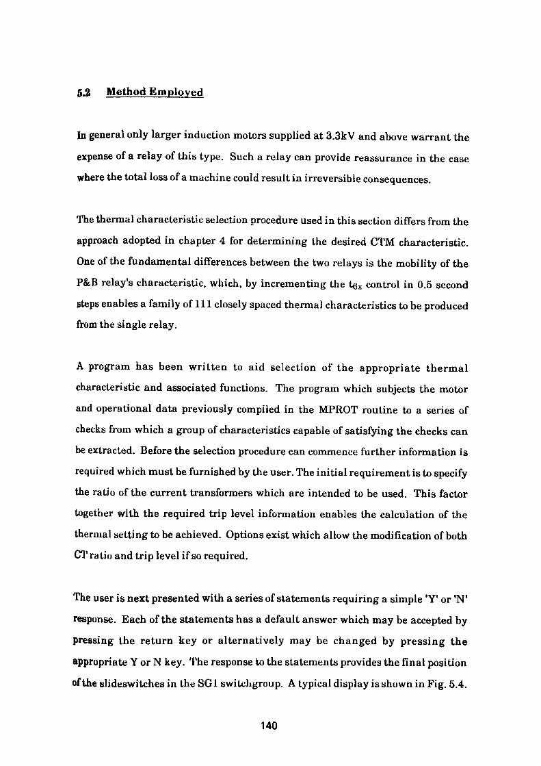
5.2 Method Employed
In general only larger induction motors supplied at 3.3kV and above warrant the
expense of a relay of this type. Such a relay can provide reassurance in the case where the total loss of a machine could result in irreversible consequences.
The thermal characteristic selection procedure used in this section differs from the
approach adopted in chapter 4 for determining the desired CTM characteristic. One of the fundamental differences between the two relays is the mobility of the
P&B relay's characteristic, which, by incrementing the tex control in 0.5 second
steps enables a family of 111 closely spaced thermal characteristics to be produced from the single relay.
A program has been written to aid selection of the appropriate thermal characteristic and associated functions. The program which subjects the motor
and operational data previously compiled in the MPROT routine to a series of checks from which a group of characteristics capable of satisfying the checks can be extracted. Before the selection procedure can commence further information is required which must be furnished by the user. The initial requirement is to specify the ratio of the current transformers which are intended to be used. This factor together with the required trip level information enables the calculation of the thermal setting to be achieved. Options exist which allow the modification of both
CT ratio and trip level if so required.
The user is next presented with a series of statements requiring a simple 'Y' or *N'
response. Each of the statements has a default answer which may be accepted by
pressing the return key or alternatively may be changed by pressing the
appropriate Y or N key. The response to the statements provides the final position
of the slideswitches in the SG1 switchgroup. A typical display is shown in Fig. 5.4.
140
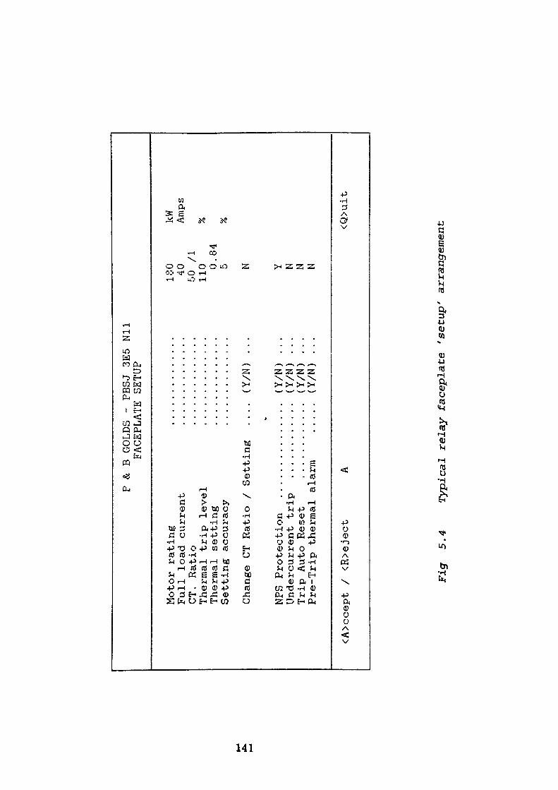
P &.
B GO
LDS
- PB
SJ 3E
5 Ni
l FA
CEPL
ATE
SETUP
Motor
rating
..........
Full load cu
rren
t ..........
CT.
Ratio
..........
Thermal
trip le
vel
..........
Thermal
sett
ing
..........
Setting
accuracy
..........
Change CT Ra
tio
/ Se
ttin
g .... (Y/N)
NFS
Protec
tion
....
....
....
...
(Y/N)
Undercurrent
tr
ip
............ (Y
/N)
Trip Auto Re
set
............ (Y
/N)
Pre-Trip th
erma
l alar
m .....
(Y/N)
180 40 50 /I
110 0.
84
N Y N N N
kW
Amps
<A>ccept /
<R>eject
<Q>uit
Fig
5.4
Typi
cal
relay faceplate 's
etup
' arrangement
Following the satisfactory input of data, the screen display is replaced by the
option menu shown in Fig. 5.5. The menu provides seven options for determining
the tex thermal setting assigned to potentiometer 2. The application method
employed to find a suitable setting may be divided into two broad strategies
namely 'MAXCURVE' and 'M1NCURVE 1 . To illustrate the approach a typical
180kW induction motor supplied from a 3300V, 3ph, 50Hz unearthed supply will
be considered, details of which are contained in Appendix 7.
5.2.1 Maxcurve
The object of the 'MAXCURVE1 technique, initially without the stall feature
connected, is to raise the relay thermal characteristics as close as possible to the
motor Hot and Cold withstand characteristics taking due account of the setting
tolerances. The tex control always refers to the relay setting at 6 x flc which
means that the actual stall current value and its associated Hot and Cold
withstand times must be referred to this datum.
As stated earlier, potentiometer 1 must be set to accommodate the full load
current of the motor, the current transformers selected and the trip level required.
Using the motor data recorded in Appendix 7 it can be seen that the full load and
starting currents are 40 Amp and 230 Amp. The maximum stalling times for the
machine being 15 and 23 seconds measured from the hot and cold state
respectively. As the stall withstand time of the motor is short and the heat
radiating area small, the heating of the winding is considered an adiabatic process
with the value Ft a constant.
142
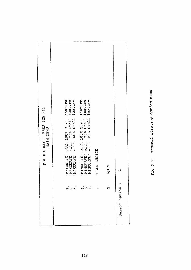
P & B
GOLDS -
PBSJ 3E5
Nil
WAIN MENU
CO
1 2 3. 4. 5. 6.
'MAXCURVE' with 100% Stall
feature
'MAXCURVE' with
75%
Stall
feature
'MAXCURVE
1 with
50%
Stall
feature
'MINCURVE' with 100% Stall
feature
'MINCURVE' with
75%
Stall
feature
'MINCURVE' with
50%
Stall
feature
'USER
CHOICE'
Q.QUIT
Select option
Fig
5.5
Thermal
strategy option menu
If the required trip level is 110% flc the equivalent motor current is 40 x 1.1 = 44
Amps. Hence, as the relay is designed to operate at 105% of setting, the pseudo flc
to achieve tripping of the machine will be 44/1.05 — 41.905 Amp. This pseudo flc
will require a potentiometer setting of:
41.905 41.905————— - ———— = 0.8381 • In Amp (5.6)CT Ratio 50
The nearest setting value being 0.84 which will operate at a nominal trip level of
50*0.84—————— • 105%= 110.25%/Zc or 44.1 Amp (5.7)
40
Effectively this raises the motor flc to a revised flc value of 44.1/1.05 = 42 Amp.
The setting 0.84 • In, being less than 0.9 • In, is subject to a ± 5% setting
tolerance of 0.798 - 0.882 • In, Substituting these thermal hounds into equation
5.2 we have:
lu flc* Relay rating Desired trip lendThermal Setting — - 0.798 = —————-———- • —————-—— (5.8)In CT Ratio 105
0.798 «50»105 From which potential trip level for true flc — ————————— =104.7%
40
0.882 »50 *105Similarly for upper bound ——————————— —115.5%40
Using equation 5.3, the operating time of the relay from the cold state is given by:
/ (Start current //Zc)2 \ ic = 32 • / • log ( —————————-——————————- \ (5.9)V (Start current/flc)- (Actual trip levetf '
144
Now for relay operation, actual trip level is 105% • relay setting subject to setting
errors.
Hence for revised flc of 42 Amp
lower tripping bound = 99.75%
upper tripping bound = 110.25%
Substituting values in equation 5.9 gives:/ (230/42.0)2 \
23 - 32* t • log ( ——————-—————- v (230/42.0) - 1.1025 2 '
and re-arranging23 t = ————————-———-——————- = 17.37 Sees (5.10)
32*/og <!(5.482 /(5.482-1.10252))
As the tgx setting is subject to increments of ± 0.5 second the value above must be
reduced accordingly. Hence t6x setting becomes 17.0 sees.
The minimum starting voltage must also be considered as during this mode the
motor draws a reduced starting current because I is proportional to V. In the
example considered the minimum voltage is declared as 85% of nominal line volts,
consequently the starting current will be reduced proportionately to 0.85 • 230 =
195.5 Amp. At this reduced current value, the associated motor withstand time
increases adiabatically to 23/0.85 2 = 31.83 seconds.
Hence te* setting calculated for the reduced voltage condition becomes:
23/0.852t = ———————————————-————————-——————— = 17.23 Sees
32 • log ((195.5/42.Or/<(195.5/42.Or - 1.1025^))e
Similarly for the overvoltage condition where the current rises to 1.05 • 230 =
241.5 Amps. In this case the starting/run current ratio becomes 241.5/42.0 =
145
5.75. If this ratio exceeds a multiple of 6, the inverse thermal characteristic of the
relay changes to that of a constant time characteristic.
For the overvoltage condition the tex setting becomes
23/1.05 2t - ——————————————————————— = 17.40 Sees 32 • log (5.752 /(5.75 - 1.10252 ))
Clearly the lowest value of the tex must be used to cover the declared voltage
depression on starting. Hence tex setting is 17.0 seconds.
Similarly motor operation from the hot state must be considered together with the
attendant reduction in withstand times. To accommodate these reduced values,
the relay cold characteristic is modified and represented in accordance with
equation 5.4.
(Start current/ flc)'2 - QMloadcurrenl/ftcf————————— ; ——————————(Start current/ flc) 2- (Actual trip level)1
Substituting gives:/ (230/42.0)"- 0.5(40/42.0)' \15 =M*t •log ( ————————-———————~) v i9^n/A9 rn z _ (\ m9.Kr /
/ (230/42.0) 2- 0.5(40/42.0)2
(230/42. 0) -U.1025)
and rearranging15 / _ ————————— ———————— ———— —————— --17.93 sees
329hg ((5.48'J -0.5(0.952r)/(5.482- 1.1025F
Similarly for the reduced starting voltage condition
= 17.74 sees15/0.852
6)1 32 • log ((230«0.85/42.0)2 - 0.5 (40/42.0)2)/((230«0.85/42.0)2 - 1.10252 )
and the overvoltage condition15/1.05 2
= 17.98 sees& 32 • log (((230«1.05/42.0)2 -0.5(40/42.0)2)/((230»1.05/42.0)2 - 1.10252 ))
146
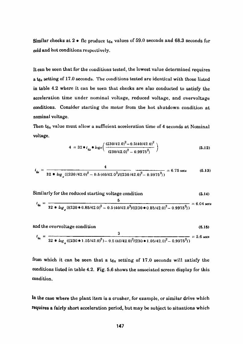
Similar checks at 2 • flc produce t6x values of 59.0 seconds and 68.3 seconds for
cold and hot conditions respectively.
It can be seen that for the conditions tested, the lowest value determined requires
a tgx setting of 17.0 seconds. The conditions tested are identical with those listed
in table 4.2 where it can be seen that checks are also conducted to satisfy the
acceleration time under nominal voltage, reduced voltage, and overvoltage
conditions. Consider starting the motor from the hot shutdown condition at
nominal voltage.
Then tex value must allow a sufficient acceleration time of 4 seconds at Nominal
voltage./ (230/42.0)2 -0.5(40/42.0)2 \4 =32»< •**«(———————-——————— (5.12)
01 \ i9.nn/A.9. nf — QQcn^\ >
= 6.75 sees (5.13)61 32 • log (((230/42.0)2 - 0.5 (40/42.02V((230/42.0)2- 0.9975 2))
Similarly for the reduced starting voltage condition (5.14)5 i = ——————————————————————————————————————————————_ - 6.04 sacs
32 • log (((230 • 0.85/42.0)- 0.5 (40/42.02)/((230 *0.85/42.0)2 - 0.9975 2))
and the overvoltage condition (5.15)3
= 5.6 seesfa 32 • fog e (((230«1.05/42.0)2 )- 0.5 (40/42.0)2/(230*1.05/42.0)2 -0.99752))
from which it can be seen that a tex setting of 17.0 seconds will satisfy the
conditions listed in table 4.2. Fig. 5.6 shows the associated screen display for this
condition.
In the case where the plant item is a crusher, for example, or similar drive which
requires a fairly short acceleration period, but may be subject to situations which
147
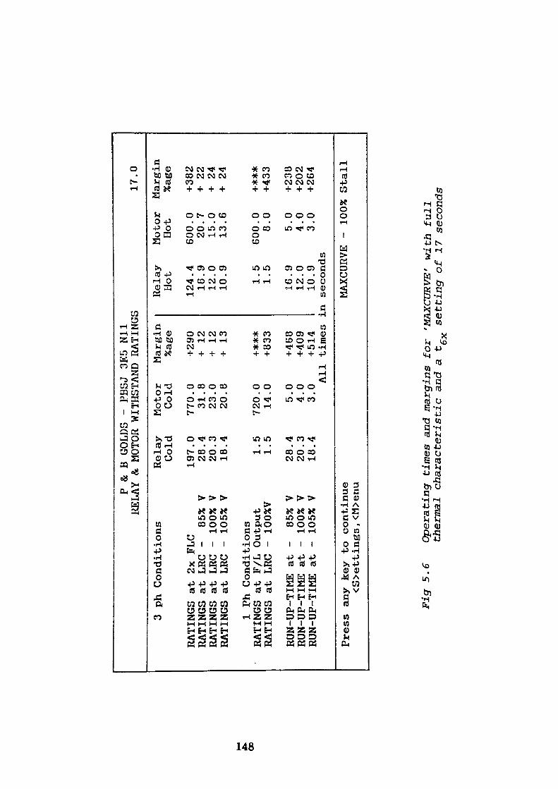
*». OD
P & B
GOLDS - PBSJ 3E5
Nil
RELAY & MOTOR WITHSTAND RATINGS
3 ph C
onditions
RATINGS at 2x FLC
RATINGS at LRC
- 85
% V
RATINGS at LR
C -
100%
V
RATINGS at
LRC
- 105% V
1 Ph Conditions
RATINGS at F/L Output
RATINGS at
LRC
- 100%V
RUN-UP-TIME at
RUN-UP-TIME at
RUN-UP-TIME at
- 85%
V -
100%
V
- 10
5% V
Rela
y Cold
197 28
20
18 1 1
28
20
18
.0
.4
.3
.4 .5
.5 .4
.3
.4
Motor
Margin
Cold
%age
770 31
23
20
720 14 5 4 3
.0
.8
.0
.8 .0
.0 .0
.0
.0 Al
l
Press any
key to continue
<S>ettings, <M
>enu
+290
+
12
+ 12
+
13
+*##
+833
+468
+409
+514
time
s ]
Relay
Hot
124 16
12
10
1 1
.4
.9
.0
.9 .5
.5
16.9
12.0
10.9
Ln se
cond
s
17.0
Motor
Margin
Hot
%age
600 20
15
13
600 8 5 4 3
MAXCURVE -
.0
.7
.0
.6 .0
.0 .0
.0
.0 100%
+382
+ 22
+
24
+ 24
+***
+433
+238
+202
+264
Stall
Figr
5.6
O
pera
ting
ti
mes
and
mar
gins
for
'MAX
CURV
E'
wit
h f
ull
ther
mal
ch
ara
cter
isti
c an
d a
t se
ttin
g o
f 17
sec
onds
will stall the drive and produce locked rotor conditions, then it is sensible to trip
the motor as quickly as possible to avoid unnecessary overheating.
If the motor switching device (MSD) controlling the circuit is a fused contactor, the
protection characteristic may be improved by invoking the inbuilt stall feature of
the relay. The feature, when activated, introduces a step in the chosen
characteristic for all multiples of motor flc greater than 2. The step displaces the
characteristic such that the operating time is reduced to 75% or 50% of the
original characteristic. The portion of the characteristic up to twice times flc
remains unaffected and is available to accommodate modest overloads of medium
duration such as may be produced by large stones in a crusher which do not result
in jamming the machine. Fig. 5.7 and 5.8 depicts the screen display associated
with a tex value of 17.0 seconds with the 75% and 50% step functions active. Fig.
5.9 clearly shows the protective envelope of the full characteristic and the
improvement effected by using the stall feature.
Where the circuit is supplied through a fully rated circuit breaker, the relay will
have the instantaneous overcurrent device set to the active state. This feature
may be used to further supplement the stall characteristic of the thermal element.
5.2.2 Maxcurve with 75% Stall Setting
In section 5.2.1, reference is made to the case of a stone crushing machine which is
subject to occasional locked rotor conditions. In the normal overload range where
magnitudes of current up to twice times flc are experienced but are of a duration
which exceeds the thermal characteristic tripping time then the previous strategy
will fail. It is usually found possible to further increase the tex setting by taking
advantage of the 75% stall function. Using this feature the tex setting can be used
149
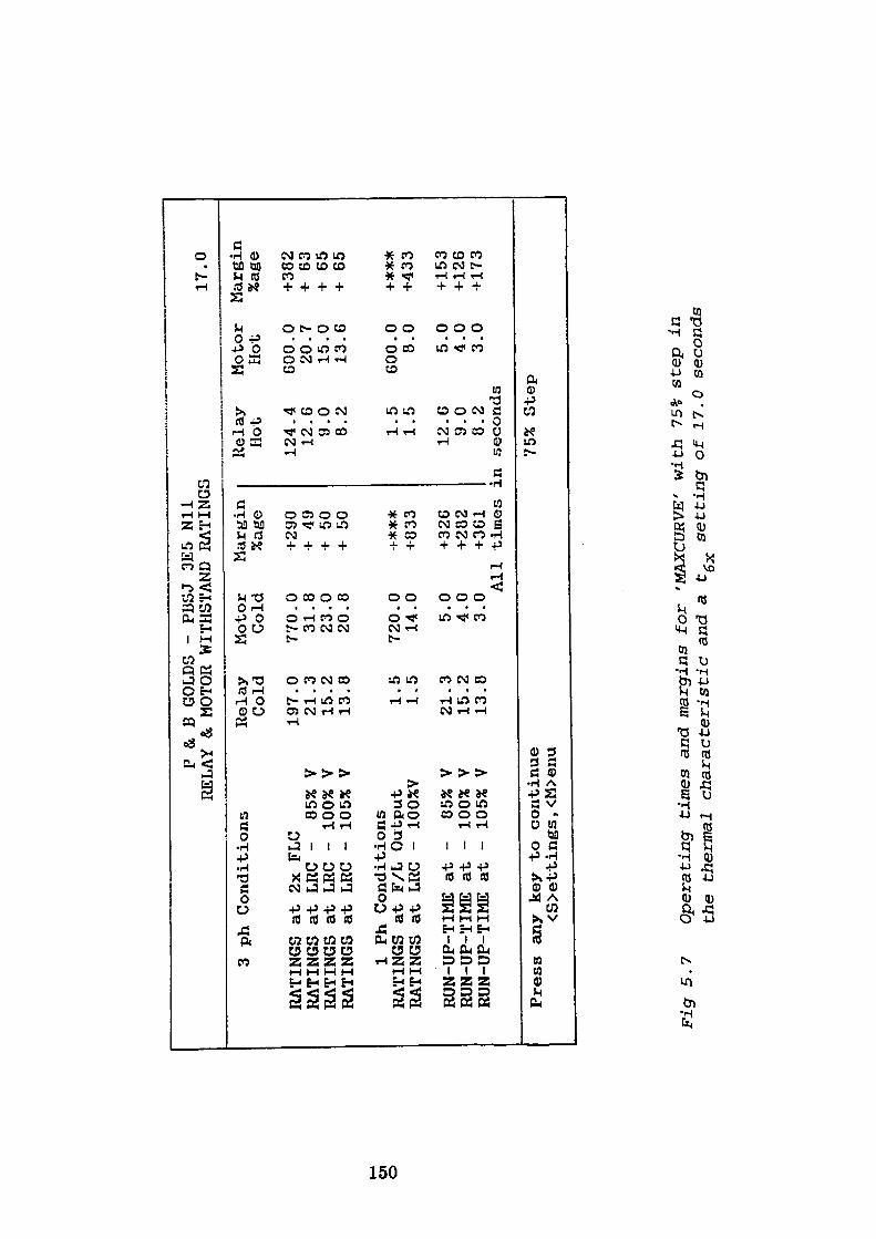
en o
P & B
GOLDS
- PI3SJ
3E5
Nil
RELAY & MOTOR
WITHSTAND
RATINGS
3 ph Conditions
RATINGS at 2x
RATINGS
at LRC
RATINGS at LRC
RATINGS
at LRCFL
C - 85%
V -
100% V
- 105% V
1 Ph Conditions
RATINGS
at F/L
Output
RATINGS
at LRC
- 100%V
RUN-UP-TIME
at
RUN-UP-TIME
at
RUN-UP-TIME
at
- 05%
V -
100% V
- 105% V
Relay
Cold
197.
21.
15.
13. 1.
1.
21.
15.
13.
0 3 2 8 5 5 3 2 8
Motor
Margin
Cold
%age
770 31
23
20 720 14 5 4 3
.0
.8
.0
.8 .0
.0 .0
.0
.0 Al
l
Press
any
key
to continue
<S>ettings, <M>enu
+290
+ 49
+ 50
+ 50
-!-***
-1833
+326
+282
+361
times
:
Relay
Hot
124 12 9 8 1 1
.4
.6
.0
.2 .5
.5
12.6
9.0
8.2
.n seconds
75%
Step
Motor
Hot
GOO.
20.
15.
13.
GOO.
8. 5.
4.
3.
0 7 0 G 0 0 0 0 0
17.0
Margin
%age
+382
+ 63
+ 65
+ 65
+***
+433
+153
+126
+ 173
Fig 5.7
Operating times and margins for 'MAXCURVE' with 75%
step in
the
thermal
characteristic and a
tgx
setting of 17.0
seconds
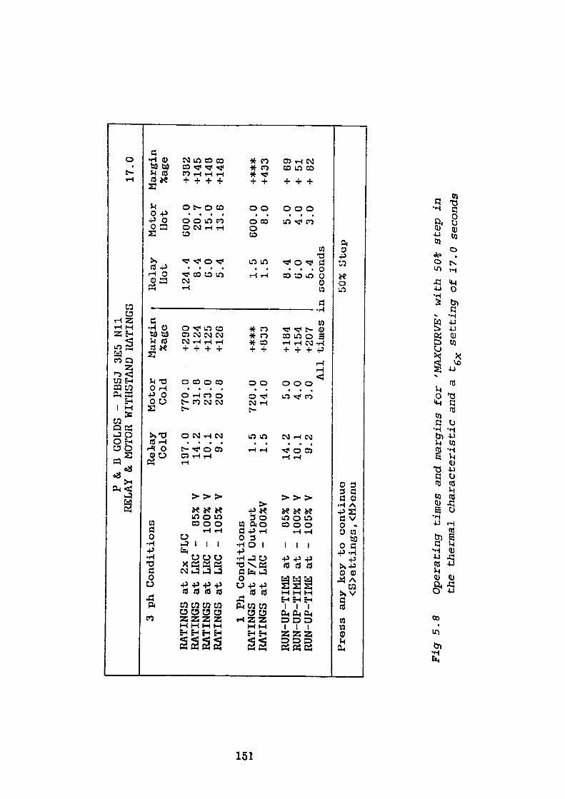
en
P & D
GOLDS
- PBSJ 3E5
Nil
RELAY & MOTOR WITHSTAND RATINGS
3 ph Conditions
RATINGS at 2x FLC
RATINGS at LRC
- 85%
V RATINGS at LRC
- 100% V
RATINGS at LRC
- 105% V
1 Ph Conditions
RATINGS at F/L
Output
RATINGS at LRC
- 100%V
RUN-UP-TIME at -
85%
V RUN-UP-TIME at -
100% V
RUN-UP-TIME at -
105% V
Press
any key
to continue
<S>ettingG, <M>enu
Relay
Cold
197.0
14.2
10.1
9.2
1.5
1.5
14.2
10.1
9.2
Motor
Margin
Cold
%age
770.0
31.8
23.0
20.8
720.0
14.0 5.0
4.0
3.0 All
+290
-M24
+125
+126
-i-***
-1833
+ 184
+154
+207
times
3
Relay
Hot
124.4
8.4
G.O
5.4
1.5
1.5
8.4
G.O
5.4
in seconds
50%
Step
Motor
Hot
GOO.O
20.7
15.0
13.6
600.0
8.0
5.0
4.0
3.0
17.0
Margin
%age
+382
+145
+148
+148
+***
+433
+ 69
+ 51
+ 82
Fig
5.8
O
pera
ting
tim
es a
nd m
argi
ns f
or
'MAX
CURV
E'
wit
h 50
* st
ep i
n
the
ther
mal
ch
ara
cter
isti
c an
d a
t,
sett
ing o
f 17
.0 s
econ
ds
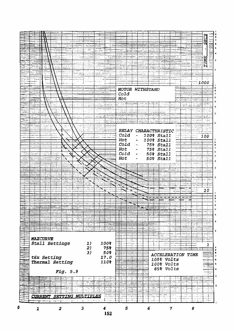
MOTOR WITHSTAND Cold
RELAY" CHARACTERISTIC Cold • Hot Cold -Hot Cold •
lOOt Stall 100* Stall 75% Stall 75t Stall 50t Stall 50t Stall
Stall Settings
ACCELERATIONt6x SettingSetting 105t Volts
lOOt Volts85t VoltsFig. 5.9
4152
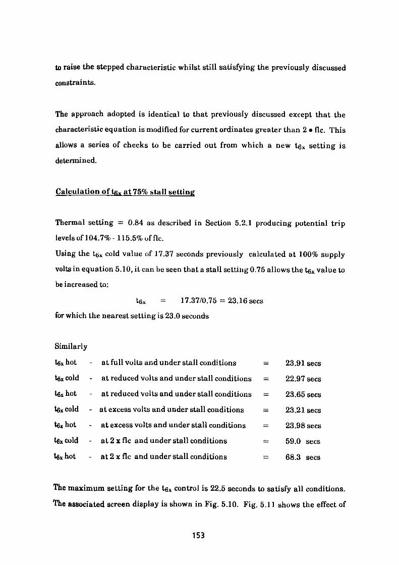
to raise the stepped characteristic whilst still satisfying the previously discussed
constraints.
The approach adopted is identical to that previously discussed except that the
characteristic equation is modified for current ordinates greater than 2 • flc. This
allows a series of checks to be carried out from which a new IQX setting is
determined.
Calculation of Uj x at 75% stall setting
Thermal setting = 0.84 as described in Section 5.2.1 producing potential trip
levels of 104.7%-115.5% of flc.
Using the t&x cold value of 17.37 seconds previously calculated at 100% supply
volts in equation 5.10, it can be seen that a stall setting 0.75 allows the tgx value to
be increased to:
l6x = 17.37/0.75 = 23. 16 sees
for which the nearest setting is 23.0 seconds
Similarly
tax hot - at full volts and under stall conditions — 23.91 sees
tax cold - at reduced volts and under stall conditions = 22.97 sees
tax hot - at reduced volts and under stall conditions = 23.65 sees
tex cold - at excess volts and under stall conditions = 23.21 sees
tax hot - at excess volts and under stall conditions = 23.98 sees
tax cold - at 2 x flc and under stall conditions — 59.0 sees
tax hot - at 2 x flc and under stall conditions = 68.3 sees
The maximum setting for the tex control is 22.5 seconds to satisfy all conditions.
The associated screen display is shown in Fig. 5.10. Fig. 5.11 shows the effect of
153
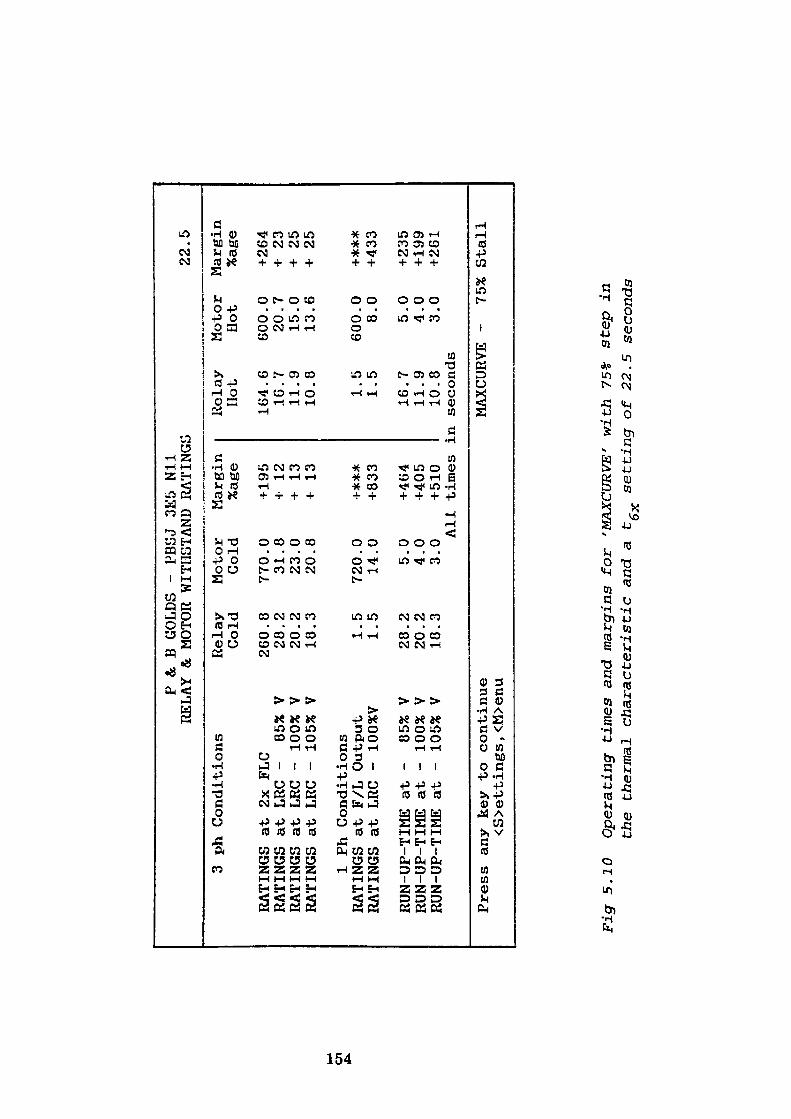
P & B
GOLDS
- PBSJ 3E5
Nil
RELAY & MOT
OR WITHSTAND
RATINGS
3 ph Co
nditions
RATINGS
RATINGS
RATINGS
RATINGS
at 2x FLC
at LRC
- 85%
V at LRC
- 100%
V
at LRC
- 105% V
1 Ph Conditio
ns
RATINGS
at F/L
Output
RATINGS
at LRC
- 100%
Y
RUN-UP-TIME
at -
85%
V RUN-UP-TIME
at -
100%
V
RUN-UP-TIME
at -
105%
V
Relay
Cold
2GO.
28.
20.
18. 1.
1.
28.
20.
18.
8 2 2 3 5 5 2 2 3
Motor
Margin
Cold
%age
770 31
23
20
720 14 5 4 3
.0
.8
.0
.8 .0
.0 .0
.0
.0 Al
l
Press
any
key
to continue
<S>ettings
, <M>enu
+ 195
+ 12
+ 13
+
13
+***
-•83
3
+464
+405
+510
times
i
Relay
Hot
164 16
11
10 1 1
.6
.7
.9
.8 .5 .5
16.7
11.9
10.8
in se
cond
s
22.5
Motor
Marg
in
Hot
%age
600.
20.
15.
13.
600.
8. 5.
4.
3.
MAXC
URVE -
0 7 0 6 0 0 0 0 0 75%
+264
+ 23
+ 25
+ 25
+***
+433
+235
+199
+261
Stal
l
Fig
5,10
Operating
time
s and ma
rgin
s fo
r 'MAXCURVE' wi
th 75*
step
in
the
ther
mal
characteristic a
nd a
t,
sett
ing
of 22
.5 se
cond
s
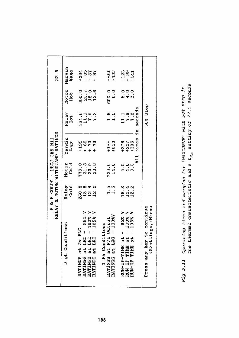
en Oi
P & B GOLDS - PBSJ 3E
5 Nil
RELAY & MOTOR WITHSTAND RATINGS
3 ph Conditions
RATINGS at 2x FLC
RATINGS at LR
C -
85%
V RATINGS at LRC
- 100% V
RATINGS at LRC
- 105% V
1 Ph Conditions
RATINGS at F/L Output
RATINGS at LRC -
100%V
RUN-UP-TIME at -
85%
V RUN-UP-TIME at -
100% V
RUN-UP-TIME at -
105% V
Press an
y key to continue
<S>ettings, <M>enu
Relay
Cold
260.
18.
13.
12. 1.
1.
18.
13.
12.
8 8 4 2 5 5 8 4 2
Motor
Margin
Cold
%age
770 31
23
20
720 14 5 4 3
.0
.8
.0
.8 .0
.0 .0
.0
.0 Al
l
+195
+ 69
+ 70
+ 70
+*#*
1833
+ 276
+237
+ 30
6 times
j
Relay
Llot
164 11 7 7 1 1
.6
.1
.9
.2 .5
.5
11.1
7.9
7.2
Ln seconds
50%
Step
Motor
Hot
600 20
15
13
600 8 5 4 3
.0
.7
.0
.6 .0
.0 .0
.0
.0
22.5
Margin
%age
+264
+ 85
+ 87
+ 87
+***
+433
+123
+ 99
+141
Fig
5.1
1 O
pera
ting
ti
mes
and
mar
gins
fo
r 'M
AXCU
RVE'
w
ith
50%
st
ep i
n
the
ther
mal
ch
ara
cter
isti
c an
d a
tgx
sett
ing o
f 22
,5
seco
nds
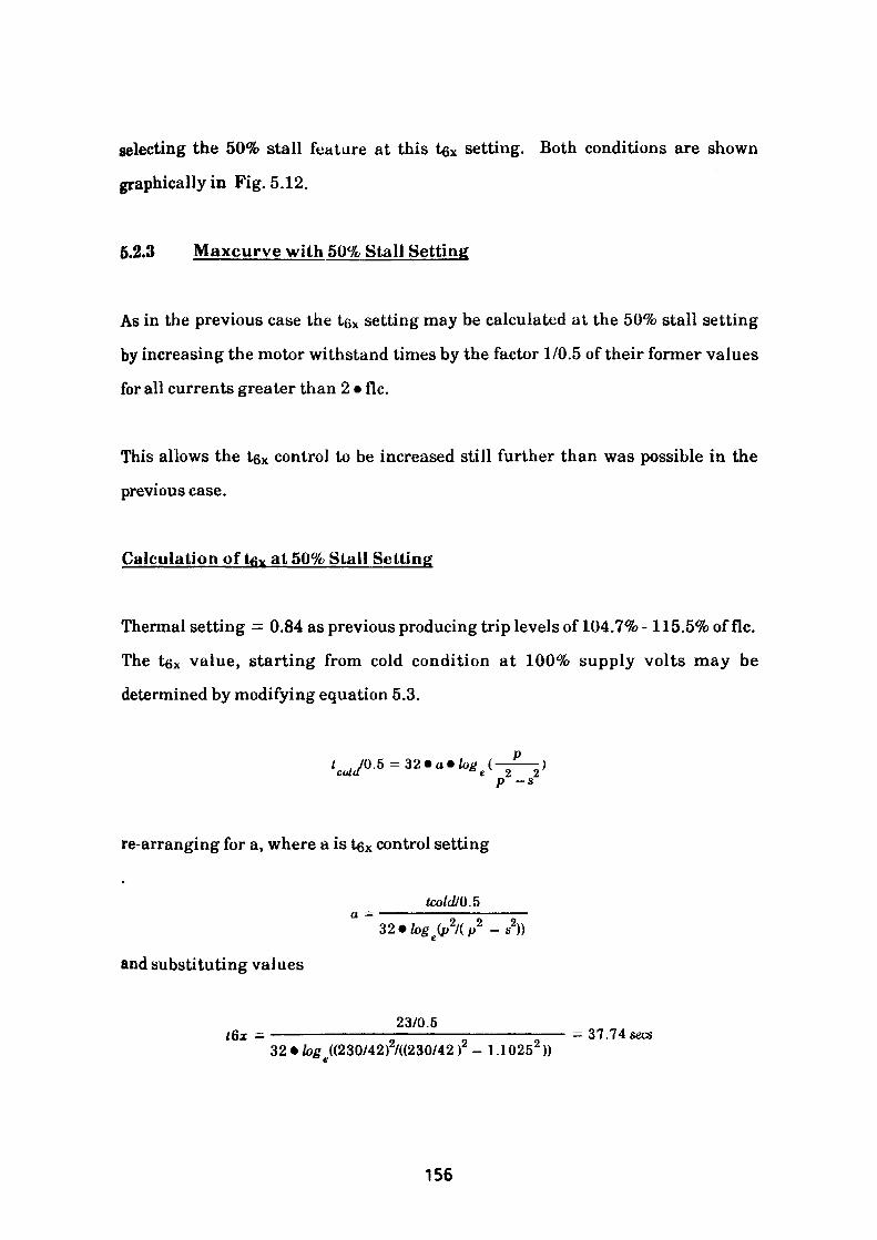
selecting the 50% stall feature at this t$x setting. Both conditions are shown
graphically in Fig. 5.12.
5.2.3 Maxcurve with 50% Stall Setting
As in the previous case the tg* setting may be calculated at the 50% stall setting
by increasing the motor withstand times by the factor 1/0.5 of their former values
for all currents greater than 2 • flc.
This allows the tex control to be increased still further than was possible in the
previous case.
Calculation of tax at 50% Stall Setting
Thermal setting = 0.84 as previous producing trip levels of 104.7% -115.5% of flc.
The tgx value, starting from cold condition at 100% supply volts may be
determined by modifying equation 5.3.
t . JO.5 = 32 • a • log (—-—) cultl ° e 2 2P ~*
re-arranging for a, where a is tex control setting
-s2))
and substituting values
23/0.5 t6x = ——————————-——————-——————-—— - 37.74 tea329log ((230/42r/((230/42 r - 1.1025 2 ))
156
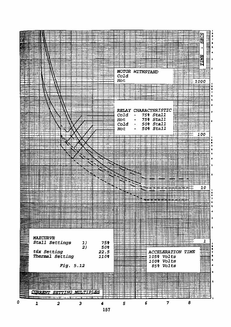
MOTOR WITHSTANDColdHot
RELAY CHARACTERISTIC Cold - 75* Stall Hot - 75* Stall Cold - 50* Stall Hot - 50* Stall
MAXCURVEStall Settings 1)
2)t6x Setting Thermal Setting
ACCELERATION TIME 105* Volts 100* Volts 85* VoltsFig. 5.12
MULTIPLES
157
Alternatively, using the t6* cold value of 17.37 seconds previously calculated for
the cold condition in equation 5.10 gives
t6x = 17.37/0.5 = 34.74 sees
Selecting the closest setting the value reduces to 34.5 sec
Similarly
tfix hot - at full volts and under stall conditions = 35. 86 sees
texcold - at reduced volts and under stall conditions = 34.46 sees
tex hot - at reduced volts and under stall conditions = 35.47 sees
tex cold - at excess volts and under stall conditions = 34.81 sees
tfix hot - at excess volts and under stall conditions = 35.96 sees
- at 2 xflc under stall conditions = 59.0 sees
- at 2 x flc under stall conditions = 35.96 sees
from which the maximum setting for the tgx control is 34.0 sec to cover all conditions.
As in the previous case the tex setting value is used to calculate the relay
operating times which are displayed together with the associated motor withstand
times and error margins. Figs. 5.13 and 5.14 depict the display and graphical
representation for this condition.
5.2.4 M incurve
When using the 'MINCUKVE 1 technique (initially without the stall feature) the
procedure adopted is to reduce the t6x setting until the relay hot characteristic
approaches the limits set by the acceleration times of the motor under nominal,
158
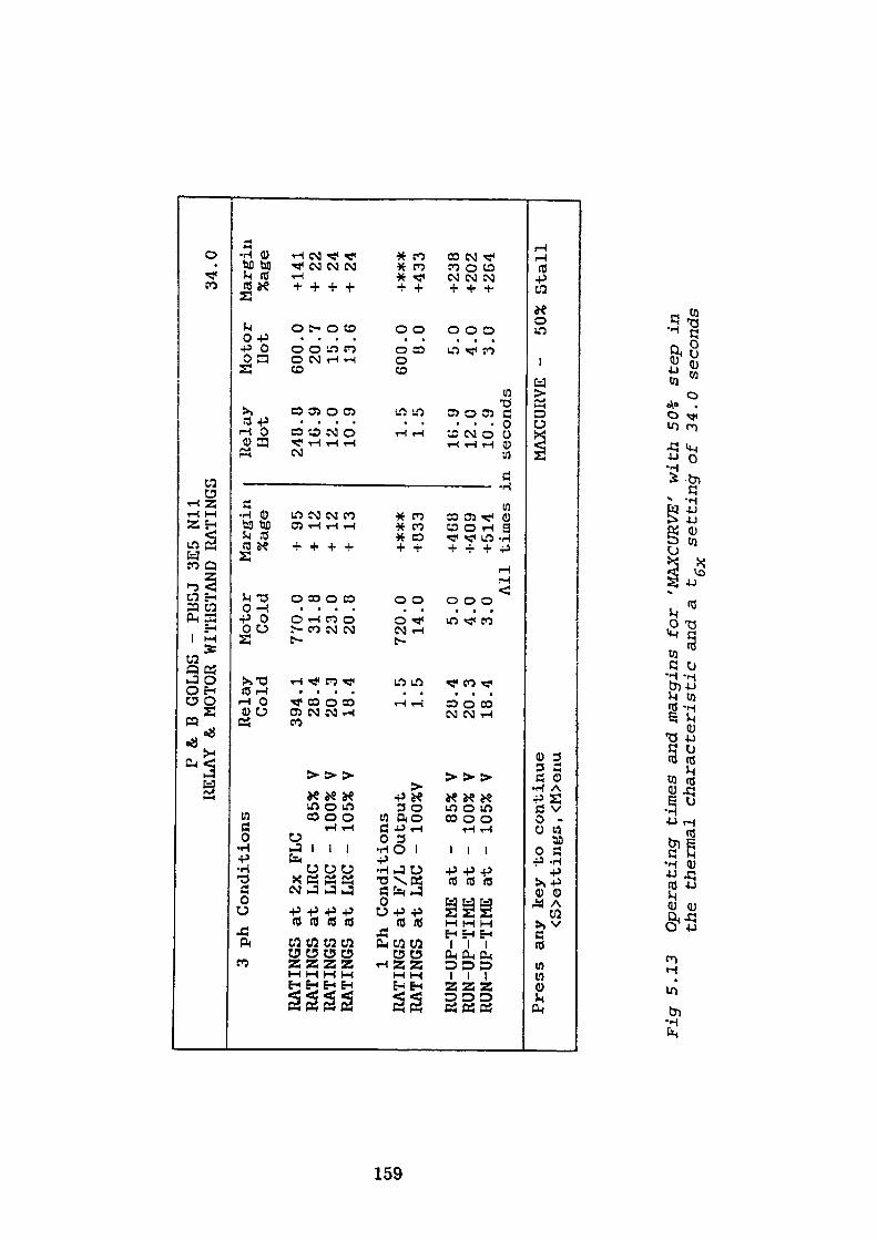
en
CD
P & B
GOLDS
- PLJSJ
3E5
Nil
RELAY & MOTOR WITHSTAND RATINGS
3 ph Conditions
RATINGS
at 2x FLC
RATINGS
at LRC
- 85%
RATINGS at LRC
- 100%
RATINGS
at LRC
- 105%
V V V
1 Ph Conditions
RATINGS
at F/L
Output
RATINGS at LRC
- 100%V
RUN-UP-TIME
at
RUN-UP-TIME
at
RUN-UP-TIME
at
- 85%
- 100%
- 105%
V V V
Relay
Cold
394 28
20
18 1 1
28
20
18
.1
.4
.3
.4 .5
.5 .4
.3
.4
Motor
Margin
Cold
%age
770 31
23
20
720 14 5 4 3
.0
.8
.0
.8 .0
.0 .0
.0
.0 Al
l
Press
any
key
to continue
<S>ettings, <M>enu
+ 95
+ 12
+ 12
+ 13
+***
•1833
+4G«
-1-409
-1-514
times
j
Relay
Hot
248.
16.
12.
10. 1.
1.
8 9 0 9 5 5
16.9
12.0
10.9
in seconds
MAXCURYE
34.0
Motor
Margin
Hot
%age
600.0
20.7
15.0
13.6
600.0
8.0
5.0
4.0
3.0
- 50%
+ 141
+ 22
+ 24
•I 24
+*#*
+433
+238
+202
+264
Stall
Fig
5.1
3 O
pera
ting
- ti
mes
and
mar
gins
for
'MAX
CURV
E'
wit
h 50
£ st
ep i
n
the
ther
mal
ch
ara
cter
isti
c an
d a
t~
sett
ing o
f 34
.0
seco
nds
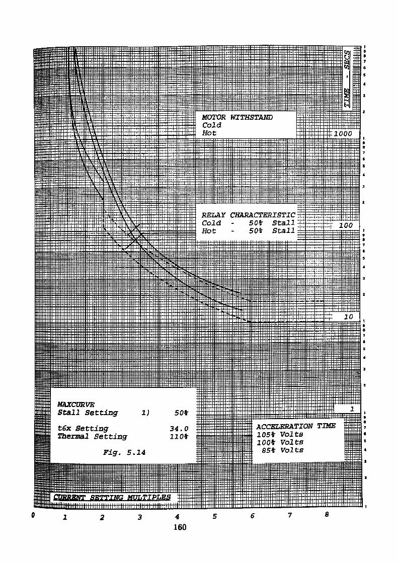
MOTOR WITHSTANDColdHot
RELAY CHARACTERISTIC Cold - 50% Stall Hot - 50% Stall
MAXCURVE Stall Setting
ACCELERATION TIME 105* Volts 100* Volts
85* Volts
t6x Setting Thermal Setting
34.0 110*
Fig-. 5.14
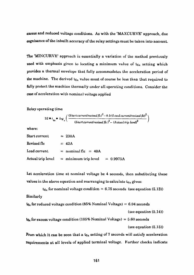
excess and reduced voltage conditions. As with the 'MAXCURVE' approach, due
cognisance of the inbuilt accuracy of the relay settings must be taken into account.
The 'MINCURVE 1 approach is essentially a variation of the method previously
used with emphasis given to locating a minimum value of t6x setting which
provides a thermal envelope that fully accommodates the acceleration period of
the machine. The derived tex value must of course be less than that required to
fully protect the machine thermally under all operating conditions. Consider the
case of acceleration with nominal voltage applied
Relay operating time/ (Start current/revised fk) — 0.5 (Loadcurrent!revised flc)
32 • /. • .bet a \ 2 2(S tart current!revised flc) — (Actual trip level)
where:
Start current = 230A
Revised flc = 42A
Load current = nominal flc = 40A
Actual trip level = minimum trip level = 0.9975A
Let acceleration time at nominal voltage be 4 seconds, then substituting these
values in the above equation and rearranging to calculate LB X gives:
tgx for nominal voltage condition = 6.75 seconds (see equation (5.13))
Similarly
tfix for reduced voltage condition (85% Nominal Voltage) = 6.04 seconds
(see equation (5.14))
tex for excess voltage condition (105% Nominal Voltage) = 5.60 seconds
(see equation (5.15))
From which it can be seen that a tex setting of 7 seconds will satisfy acceleration
requirements at all levels of applied terminal voltage. Further checks indicate
161
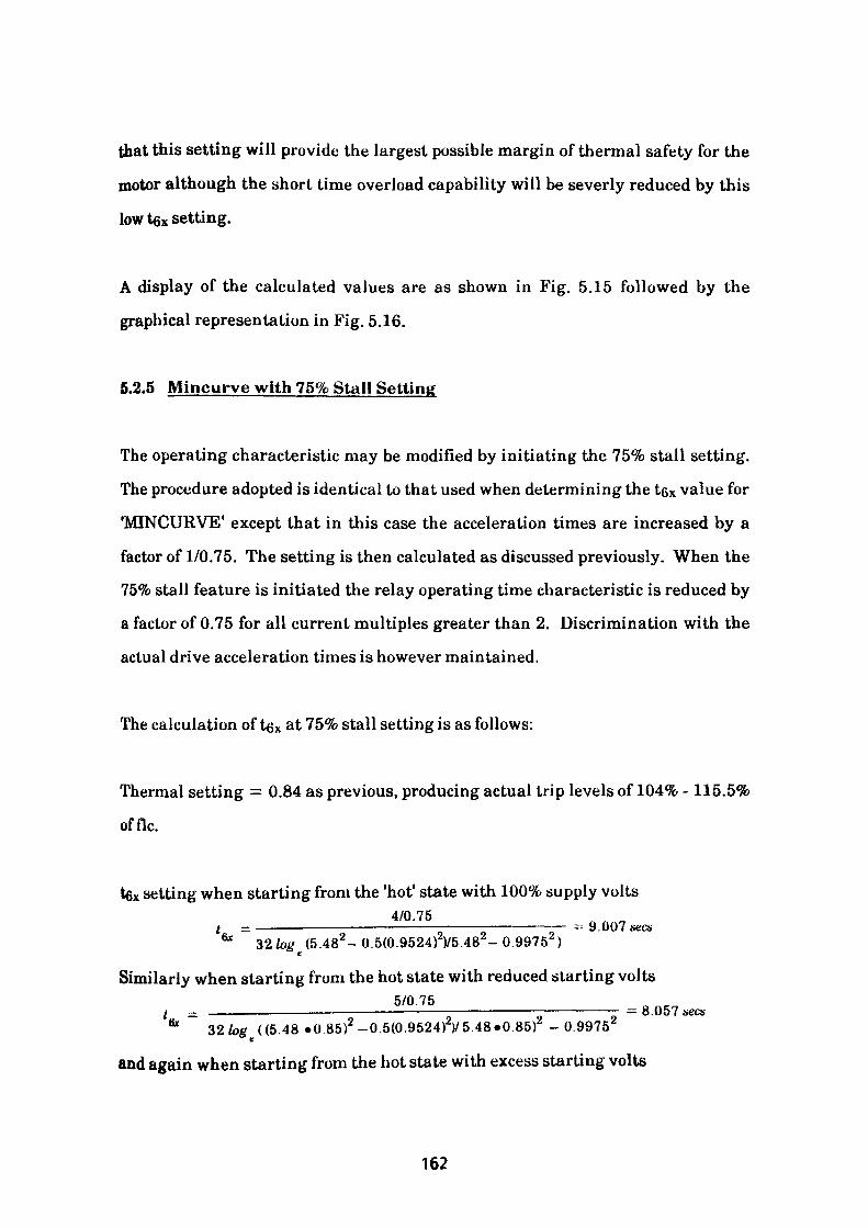
that this setting will provide the largest possible margin of thermal safety for the
motor although the short time overload capability will be severly reduced by this
low tex setting.
A display of the calculated values are as shown in Fig. 5.15 followed by the
graphical representation in Fig. 5.16.
5.2.5 Mincurve with 75% Stall Setting
The operating characteristic may be modified by initiating the 75% stall setting.
The procedure adopted is identical to that used when determining the t6x value for
'MINCURVE' except that in this case the acceleration times are increased by a
factor of 1/0.75. The setting is then calculated as discussed previously. When the
75% stall feature is initiated the relay operating time characteristic is reduced by
a factor of 0.75 for all current multiples greater than 2. Discrimination with the
actual drive acceleration times is however maintained.
The calculation of tex at 75% stall setting is as follows:
Thermal setting = 0.84 as previous, producing actual trip levels of 104% -115.5%
offlc.
tex setting when starting from the 'hot' state with 100% supply volts4/0.75 t - _————————————————————————————— = 9.007 sees
61 32/og (5.482-0.5(0.9524)2V5.48 -099752 )
Similarly when starting from the hot state with reduced starting volts5/0.75 crj / - —————————————-————————-————————-——————-= 8.057
32log ((548 •0.85)-0.5(0.9524)1/5.48.0.85r - 0.9975^0 *
and again when starting from the hot state with excess starting volts
162
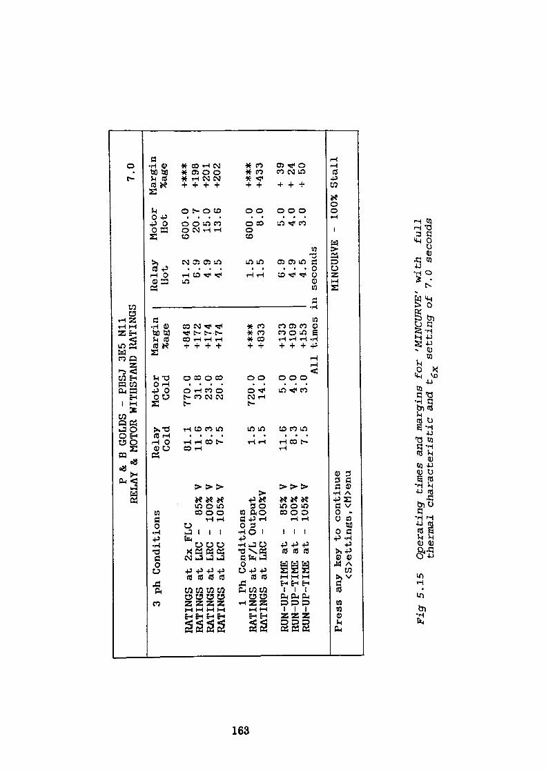
CO
P & B
GOLDS
- PBSJ 3E5
Nil
RELAY & MOTOR WITHSTAND RATINGS
3 ph Conditions
RATINGS
at 2x FLC
RATINGS
at LRC
- 85%
V RATINGS
at LRC
- 100% V
RATINGS
at LRC
- 105% V
1 Ph Conditions
RATINGS
at F/L
Output
RATINGS
at LRC
- 100%V
RON-UP-TIME
at
RUN-UP-TIME
at
RUN-UP-TIME
at
- 85%
V -
100% V
- 105% V
Relay
Cold
81
11 8 7 1 1 11 8 7
.1
.6
.3
.5 .5
.5 .6
.3
.5
Motor
Margin
Cold
%age
770 31
23
20 720 14
5 4 3
.0
.8
.0
.8 .0
.0 .0
.0
.0 Al
l
Press
any
key
to continue
<S>ettings, <M>enu
+848
-1172
+174
+174
+***
+833
+133
+ 109
+ 153
times
j
Relay
Hot
51. 6.
4.
4. 1.
1.
2 9 9 5 5 5
6.9
4.9
4.5
in seconds
7.0
Motor
Margin
Hot
%age
600 20
15
13 600 8 5 4 3
MINCUR
VE -
.0
.7
.0
.6 .0
.0 .0
.0
.0 100%
+***
+198
+201
+202
•f***
+433
+ 39
+ 24
+ 50
Stall
Figr 5.15
Operating
times
and margins
for
'MINCURVE' with
full
thermal
characteristic a
nd t-
setting
of 7.0
seconds
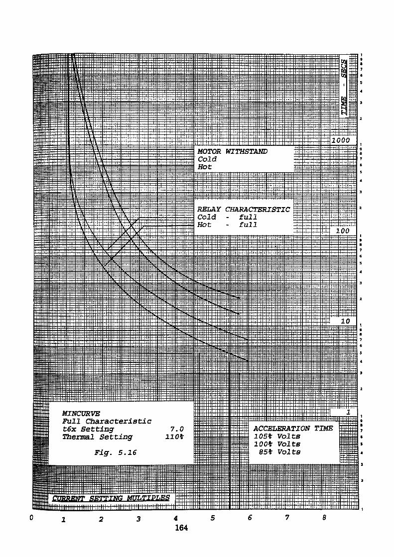
MOTOR WITHSTANDColdHot
RELAYColdHot
CHARACTERISTIC- full- full
MINCURVEFull Characteristic t6x Setting Thermal Setting
ACCELERATION TIME 105% Volts 100% Volts
85% VoltsFig. 5.16
CURRENT SETTING MULTIPLES
8
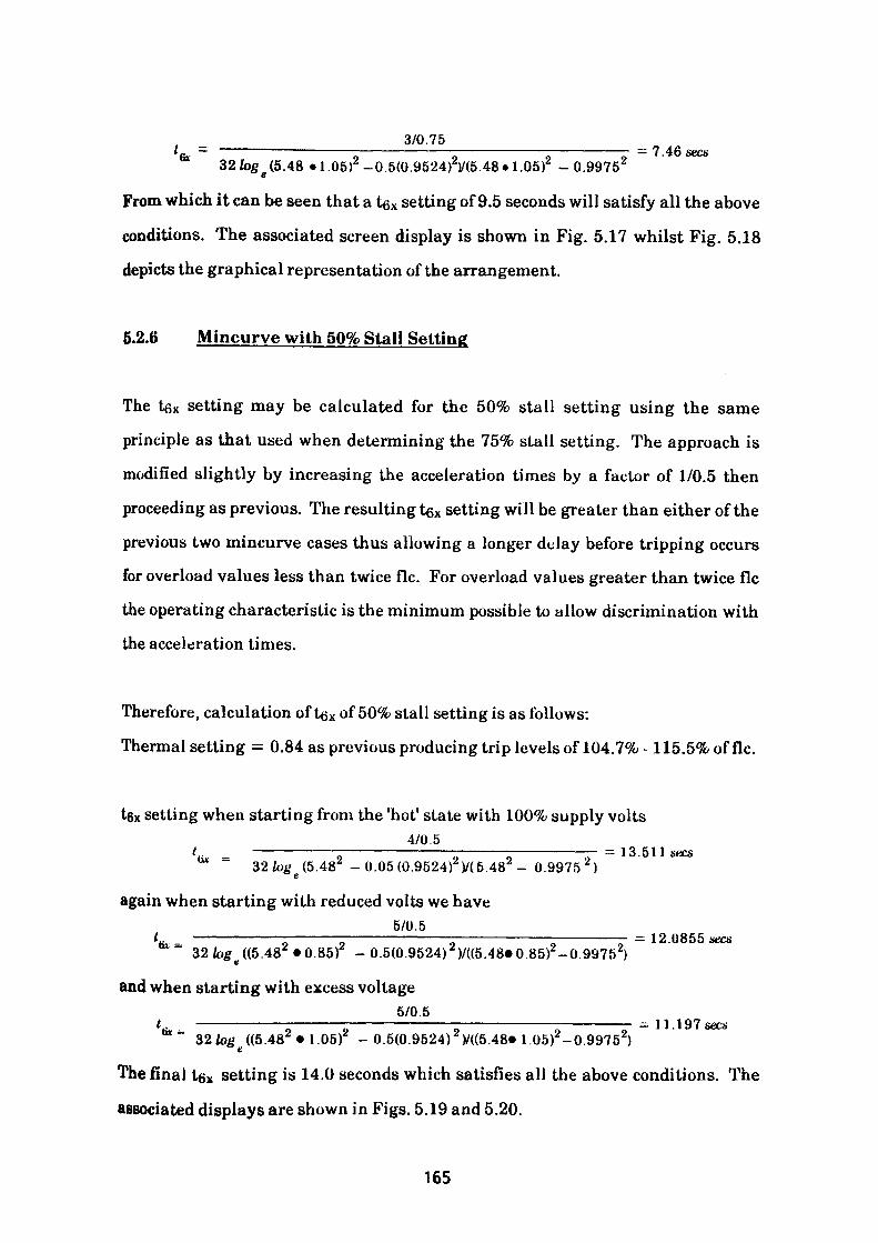
3/0.75— 7 46 sees
32fog e (5.48 «1.05)2 -0.5(0.9524)2)/(5.48«1.05)2 - 0.9975 2
From which it can be seen that a tex setting of 9.5 seconds will satisfy all the above
conditions. The associated screen display is shown in Fig. 5.17 whilst Fig. 5.18
depicts the graphical representation of the arrangement.
5.2.6 Mincurve with 50% Stall Setting
The tex setting may be calculated for the 50% stall setting using the same
principle as that used when determining the 75% stall setting. The approach is
modified slightly by increasing the acceleration times by a factor of 1/0.5 then
proceeding as previous. The resulting tex setting will be greater than either of the
previous two mincurve cases thus allowing a longer delay before tripping occurs
for overload values less than twice flc. For overload values greater than twice flc
the operating characteristic is the minimum possible to allow discrimination with
the acceleration times.
Therefore, calculation of tex of 50% stall setting is as follows:
Thermal setting = 0.84 as previous producing trip levels of 104.7% - 115.5% of flc.
tex setting when starting from the 'hot1 state with 100% supply volts4/0.5/ _ ———————— - ——————————— - ———— - ———————— = 13. 511 sees
~ 32/0^(5.48^ -0.05(0.9524rV(5.48 - 0.9975 2 )
again when starting with reduced volts we have5/0.5 t _ ————————————— - —————————————————————————— = 12. 0855 sees
32log ((5.482 *0.85)2 - 0.5(0.9524) 2 )/((5.48»0.85)2 -0.99752)
and when starting with excess voltage5/0.5
,32/otf ((5.482 *1.05r - 0.5(0.9524) Z V((5.48« 1.05) -0.99752)
= 11. 197 sets
The final tgx setting is 14.0 seconds which satisfies all the above conditions. The
associated displays are shown in Figs. 5.19 and 5.20.
165
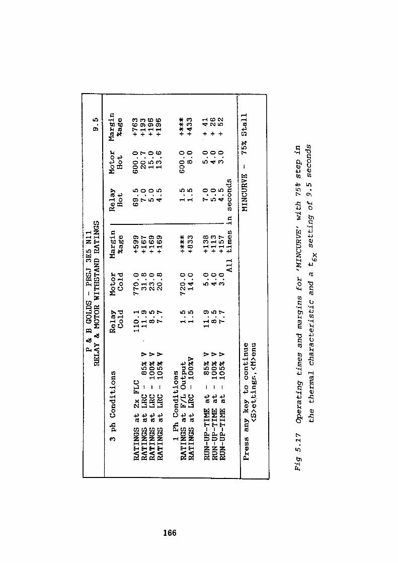
OS o>
P & B
GOLDS
- PBSJ 3E5
Nil
RELAY & MOTOR WITHSTAND RATINGS
3 ph Conditions
RATINGS
at 2x FLC
RATINGS
at LRC
- 85%
VRATINGS
at LRC
- 100% V
RATINGS
at LRC
- 105% V
1 Ph Co
ndit
ions
RATINGS
at F/L Output
RATINGS
at LRC
- 100%V
RUN-UP-TIME
at -
85%
VRUN-UP-TIME
at -
100% V
RUN-UP-TIME
at -
105% V
Press
any
key
to continue
<S>ettingr.
, <M>enu
Relay
Cold
110.1
11.9 8.5
7.7
1.5
1.5
11.9 8.5
7.7
Motor
Margin
Cold
%age
770.0
31.8
23.0
20.8
720.0
14.0 5.0
4.0
3.0All
+599
+167
+169
+169
+***
+833
+ 138
+113
+ 157
Relay
Hot
69.5 7.0
5.0
4.5
1.5
1.5
7.0
5.0
4.5
times
in seconds
MINCURVE
9.5
Motor
Margin
Hot
%age
600.0
20.7
15.0
13.6
600.0
8.0
5.0
4.0
3.0
- 75%
+763
+193
+196
+196
+***
+433
+ 41
+ 26
+ 52
Stall
Fig
5.1
7 O
pera
ting
tim
es a
nd m
argi
ns f
or
'MIN
CURV
E'
wit
h 75
% s
tep
in
th
e th
erm
al
chara
cter
isti
c an
d a
t-
sett
ing o
f 9.
5 se
cond
so
X
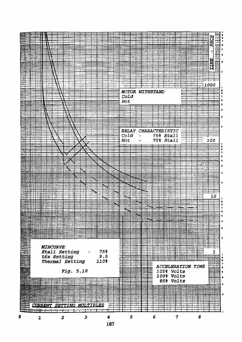
MOTOR WITHSTANDColdHot
RELAYColdHot
CHARACTERISTIC 75* Stall 75* Stall
MINCURVE Stall Setting t6x Setting Thermal Setting
ACCELERATION TIME 105% Volts 100* Volts
85* Volts
Fig. 5.18
CURRENT SETTING MULTIPLES
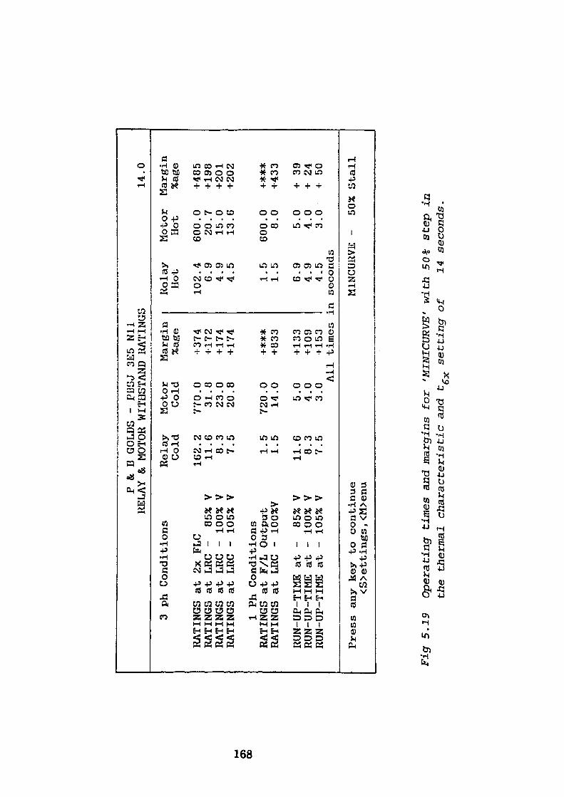
P &
B GO
LDS
- PJ
USJ
3E5
Nil
RELA
Y & MO
TOR
WITHSTAND
RATINGS
3 ph
Conditions
RATI
NGS
RATI
NGS
RATI
NGS
RATI
NGS
at 2x FLC
at LR
C -
85%
Vat
LR
C -
100%
V
at LR
C -
105% V
Rela
y Cold
162. 11. 8. 7.
2 6 3 5
Motor
Marg
in
Cold
%age
770
.31
.23
.20
.
0 8 0 8
-137
4+1
72+ 17
4+1
74
1 Ph
Conditio
nsRATINGS
RATI
NGS
at F/
L Output
at LR
C -
100%
V
RUN-UP-TIME
at -
85%
VRUN-UP-TIME
at -
100%
V
RUN-UP-TIME
at -
105%
V
1. 1.
11. 8. 7.
5 5 6 3 5
720. 14. 5. 4. 3.
0 0 0 0 0 All
Press
any
key
to continue
<S>e
ttings, <M
>enu
+***
+833
+ 133
+109
+153
Relay
Hot
102 G 4 4 1 1 G 4 4
.4 .9 .9 .5 .5 . 5 .9 .9 .5
14.0
Motor
Margin
Hot
%age
600 20 15 13
GOO 8 5 4 3
.0 .7 .0 .6 .0 .0 .0 .0 .0
+485
+198
+201
+202
+***
+433
+ 39
+ 24
+ 50
time
s in seconds
MINC
URVE
-
50%
Stal
l
Fig
5.1
9 O
pera
ting
tim
es a
nd m
argi
ns f
or
'MIN
ICU
RVE'
w
ith
50%
st
ep i
n
the
ther
mal
ch
ara
cter
isti
c an
d tg
se
ttin
g- o
f 14
se
cond
s.
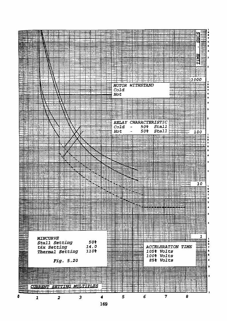
MOTOR WITHSTANDColdHot
RELAY CHARACTERISTIC Cold - 50% Stall Hot - 50% Stall
MINCURVEStall Setting 50% t6x Setting 14.0 Thermal Setting 110%
ACCELERATION TIME 105% Volts 100% Volts 85% VoltsFig. 5.20
MULTIPLES
8
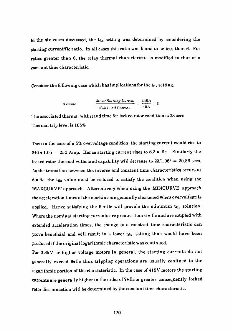
In the six cases discussed, the tex setting was determined by considering the
starting current/flc ratio. In all cases this ratio was found to be less than 6. For
ratios greater than 6, the relay thermal characteristic is modified to that of a
constant time characteristic.
Consider the following case which has implications for the te\ setting.
Motor Starting Current 24()A Assume —————————————— — ——— = 6bf all Load Current 40A
The associated thermal withstand time for locked rotor condition is 23 sees
Thermal trip level is 105%
Then in the case of a 5% overvoltage condition, the starting current would rise to
240 • 1.05 = 252 Amp. Hence starting current rises to 6.3 • flc. Similarly the
locked rotor thermal withstand capability will decrease to 23/1.052 = 20.86 sees.
As the transition between the inverse and constant time characteristics occurs at
6 • flc, the tex value must be reduced to satisfy the condition when using the
'MAXCURVE' approach. Alternatively when using the 'MINCURVE' approach
the acceleration times of the machine are generally shortened when overvoltage is
applied. Hence satisfying the 6 • flc will provide the minimum t6x solution.
Where the nominal starting currents are greater than 6 • flc and are coupled with
extended acceleration times, the change to a constant time characteristic can
prove beneficial and will result in a lower tex setting than would have been
produced if the original logarithmic characteristic was continued.
For 3.3kV or higher voltage motors in general, the starting currents do not
generally exceed 6*flc thus tripping operations are usually confined to the
logarithmic portion of the characteristic. In the case of 415V motors the starting
currents are generally higher in the order of 7* flc or greater, consequently locked
rotor disconnection will be determined by the constant time characteristic.
170
In the case where the acceleration time exceeds the maximum thermal withstand
time of the machine, tripping during the acceleration period would inevitably
occur if a correctly determined characteristic was used.
A solution may be arrived at by setting the acceleration times to a low value then
using the "MAXCURVE 1 approach to determine the tgx setting with the 50% and
75% stall features selected.
If the true acceleration times are restored, the 'USER CHOICE* option can be
invoked to produce a table of results from which it can be clearly seen if either of
the two t6x values (previously obtained with 50% and 75% stall feature selected)
when used with the full 100% stepless characteristic can accommodate the
extended acceleration period. If either setting proves suitable the relay can be
arranged so that starting occurs with a stepless characteristic using the selected
tgx setting. An external speed switch or similar device is used to switch and seal
the selected step in the characteristic by detecting the end of the acceleration
period.
The danger associated with this technique arises if the motor fails to rotate at all,
as under this circumstance thermal protection of the machine will not be provided.
The time to trip will be a function of the full 100% stepless characteristic at the
chosen tex setting which will be in excess of the locked rotor thermal withstand
capability of the machine.
The technique has not been specifically incorporated into the program as the
approach is essentially flawed. It has however, been included in the text as it
could well prove useful when supplemented by additional protective relays.
171
5.3 Potentiometer 3 - High Set Overcurrent Setting
By examining the data read from the workfile the program is able to determine
the generic type of motor switching device used for controlling the circuit. Either
it is a fully rated circuit breaker or alternatively a fuse protected contactor. In the
latter case the fuse must provide short circuit protection for the contactor, cable,
motor terminal box and motor by high speed operation on heavy short circuit
overcurrents and earth faults. In order to avoid possible damage to the contactor
it is essential that switch SI in the SG1 switchgroup is set for contactor operation.
In this mode the instantaneous overcurrent element is inhibited so preventing the
contactor opening for current values in excess of its designed interupting limit.
When the circuit is switched by a fully rated circuit breaker the switch Si in the
SGl switchgroup is set for circuit breaker operation. In this mode, settings in the
range 2.0-12.0 • In may be assigned. It should be noted that during the starting
phase the setting value is doubled. This useful feature enables a setting value
lower than flc to be used. Hence this element can be used to detect and disconnect
the supply for overcurrents between the setting and the equivalent motor flc.
Such an overcurrent may result from a motor in a locked rotor condition.
For the case under consideration the operating level of the element in the run
state, should in order to provide an instantaneous stall feature, be set to operate
at:Starting currentat 85%V • accuracy factor—————————
which is the CT secondary current observed with 85% line voltage applied to the
motor.085* 230* 0.95 _ ——————————— = 3 71 Amp 50 v
172

and in order to avoid nuisance tripping on starting must be:
Starting current at 1 Q5%V • overreach factor* accuracy factorC.T. Ratio
1 U5» 230* 1.05* 1.05 ——————————————— = 5.33 Amp 50
Under starting conditions the instantaneous overcurrent element is doubled,
hence to satisfy the overvoltage condition, the setting must be:
5.33 > ——— = 2.7 Amp£t
and < 3.7 Amp to ensure operation of the instantaneous element under locked
rotor conditions in the run mode.
5.4 Potentiometer 4 - Karth Fault Setting
The function of this element is to detect the presence of an earth fault on the motor
circuit. To obtain operation, the magnitude of the earth fault current must be
greater than the operating threshold of the element as determined by the earth
fault setting potentiometer.
The setting should satisfy the following conditions.
1. There must be sufficient current to operate the element at the setting
applied.
2. The operating setting must discriminate with any upstream protection.
3. For fully rated circuit breaker operation, the 50 millisecond time setting
should be used to isolate the faulted circuit as quickly as possible.
173

4. The faulted circuit must be isolated before thermal damage can occur in
potential earth fault paths such as cable armouring.
5. For contactor operation the function of the earth fault element may be
inhibited at all settings if the magnitude of the earth fault current is in
excess of four times flc. This implies that clearance must result from fault
recognition by other means. These are:
1. Upstream protection
2. Main power fuses
3. Thermal protection
4. NFS/Phase unbalance protection
It can be seen that items 3 & 4 will be used to clear faults of medium magnitude
whilst item 2, the main power fuse will remove heavy earth fault currents. If the
power fuse is large, discrimination may be lost causing the upstream protection to
operate.
Where the earth fault current is of low magnitude and above the operating
threshold of the earth fault setting, the operating time of the element introduces
either a 50 millisecond or a 1 second delay prior to operating. Where the potential
earth fault current approaches the capability of the switching device, it is
essential to select the 1 second delay to prevent the contactor opening on receipt of
a trip signal from the relay. The trip signal may conceivably be initiated by a high
resistance earth fault which subsequently develops into an earth fault of greater
magnitude than the clearing capability of the switching device. Any attempt to
clear the fault by means of the switching device may result in severe damage. In
such circumstances, it is prudent to ensure that the fuse selected is capable of
disrupting the fault current in less than 1 second.
174
To ensure decisive operation, it is essential to ensure that the earth fault setting,
typically 20% flc, is from a source which will provide a minimum of twice times the
current required to operate the element.
5.5 Display of Settings
A screen display is available following a MAXCURVE or MINCURVE calculation
which when selected, summarises the potentiometer setting values and SG1
switchgroup positions for the relay faceplate. A typical display is shown in Fig.
5.21.
5.6 Program Description
5.6.1 P&B
This routine is the main control element of the P&B relay setting program. The
start of the program is used as a set-up routine where all variables used
throughout the program are declared and assigned initial values.
The main body of the routine is in the form of a loop which is directed to the first
module P&B10. Subsequent routines P&B20, P&B30 are called in sequence until
the final routine P&.B40 is accessed. On completion of this routine the program is
rerouted to P&B20 from which it is possible to exit the program. A flowchart for
this routine is shown in Fig 5.22.
5.6.2 I'&BIO
The P&B10 module comprises two parts. The first part produces a display of
questions which are relevant to the setting of the relay faceplate switches and
175
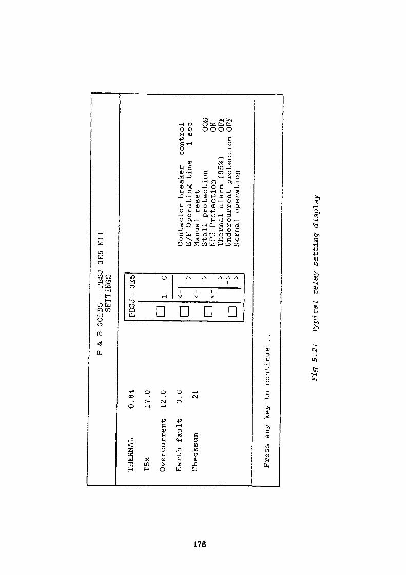
OS
P &.
B GOLDS
- PBSJ 3E5
Nil
SETTINGS
THERMAL
0.84
T6x
17.0
Overcurrent
12.0
Earth
fault
0.6
Checksum
21
PBSJ-
3E5
n a a
1 0 ->
Contactor
breaker
control
E/F
Operating
time
1 sec
Manual reset
Stall
protection
OOS
NPS
Protection
ON
Thermal
alarm
(95%)
OFF
Undercurrent protection OFF
Normal operation
Press
any
key
to continue.
. .
Fig
5.21
Typical
relay
setting display
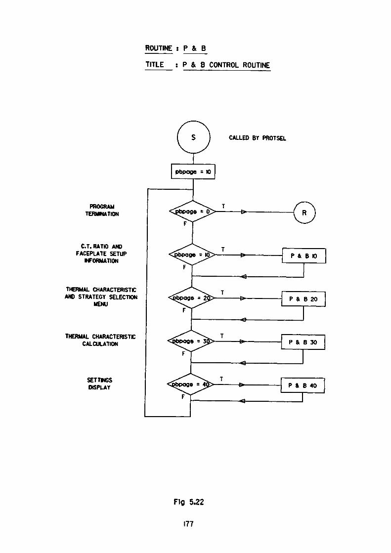
ROUTINE : P & B
TITLE : P & B CONTROL ROUTINE
PROGRAM TERMINATION
C.T. RATIO ANDFACEPLATE SETUP
INFORMATION
THERMAL CHARACTERISTCAND STRATEGY SELECTION
MENU
THERMAL CHARACTERISTIC CALCULATION
SETTMCS DISPLAY
CALLED BY PROTSEL
pbpoga = K)
Fig 5.22
177
potentiometers. The latter part of the routine which forms the major portion is
used to acquire and process the data for use in subsequent modules. Beside
faceplate setup data the routine produces a setting for potentiometer 1 based on
the desired trip level.
5.6.3 P&B30
This module forms a major routine in the program. It is used to determine the t6x
setting for potentiometer 2 in accordance with the option chosen in P&B20. The
flowchart for this module is shown in Fig. 5.23. It can be seen that when accessed
the routine calculates the t«x value which will satisfy the 2 • flc condition for both
hot and cold characteristics. The remaining tex calculations which determine the
tfix setting are performed in a series of subroutines which are controlled by the
P&B30 routine. The subroutine selected is determined by the option chosen in
P&B20. Hence the function of the module is mainly that of control rather than
calculation.
5.6.4 F&B301
If option 1 - 'MAXCURVE' with full characteristic, is selected from the menu
displayed by the P&B20 module, the information passed to the P&B30 module
enables the selection of subroutine P&B301 to be executed. A flowchart of the
P&B301 routine is shown in Fig. 5.24.
In this routine values are assigned to selected variables which represent current
values indicative of the condition under examination. The variables are directed
to a subroutine, temax, which processes the information and returns the
maximum tex value which will satisfy the condition whilst taking full account of
the various tolerances. Further sets of data are processed in the same way, an
178
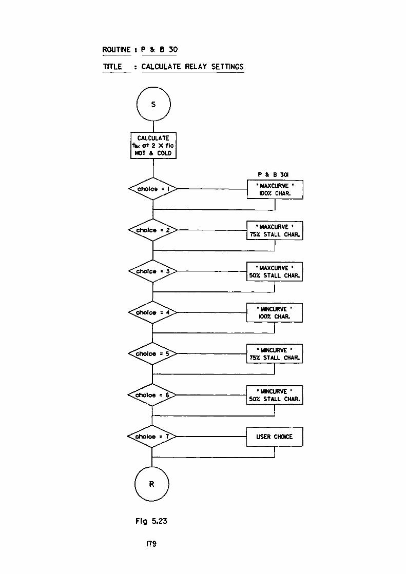
ROUTINE ; P & B 30
TITLE : CALCULATE RELAY SETTINGS
CALCULATE Ike at 2 X f Ic
HOT & COLD
choice = l
^choice =
P & B 301
•MAXCURVE 'max, CHAR.
•MAXCURVE • 75X STALL CHAR.
choice•MAXCURVE '
50% STALL CHAR.
^choice =
.. choice =
•MINCURVE ' IOOX CHAR.
•MINCURVE ' 75X STALL CHAR.
.choice =
jsholce
•MINCURVE ' 50% STALL CHAR.
USER CHOICE
Flfl 5.23
179
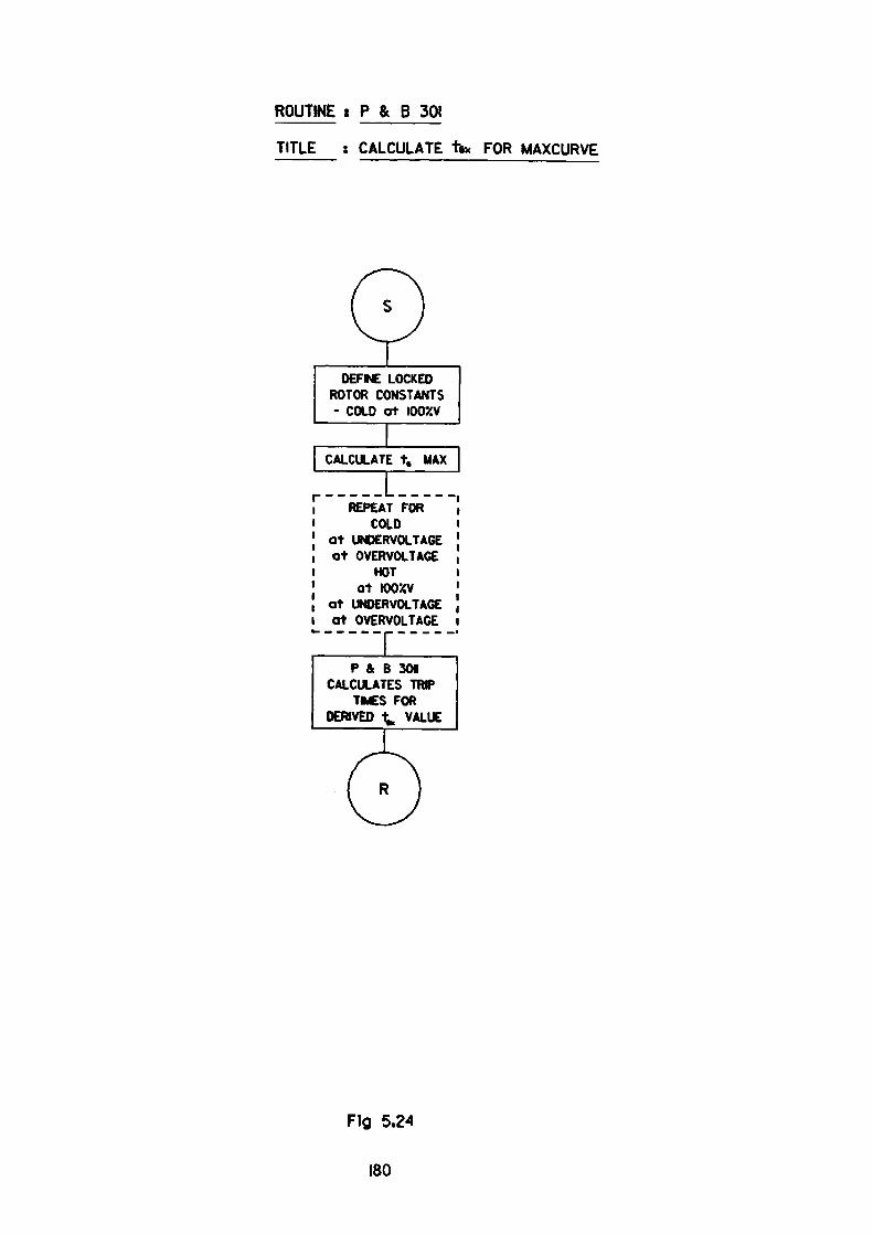
ROUTINE i P & B 301
TITLE : CALCULATE tsx FOR MAXCURVE
DEFINE LOCKED ROTOR CONSTANTS - COLD Ot I005CV
CALCULATE t. MAX
1.REPEAT FOR
COLDat UNDERVOLTAGE at OVERVOLTAGE
HOTat IOOXV
at UNDERVOLTAGE at OVERVOLTAGE
P & B 3011 CALCULATES TRIP
TfcCS FOR DERIVED
Fig 5.24
180
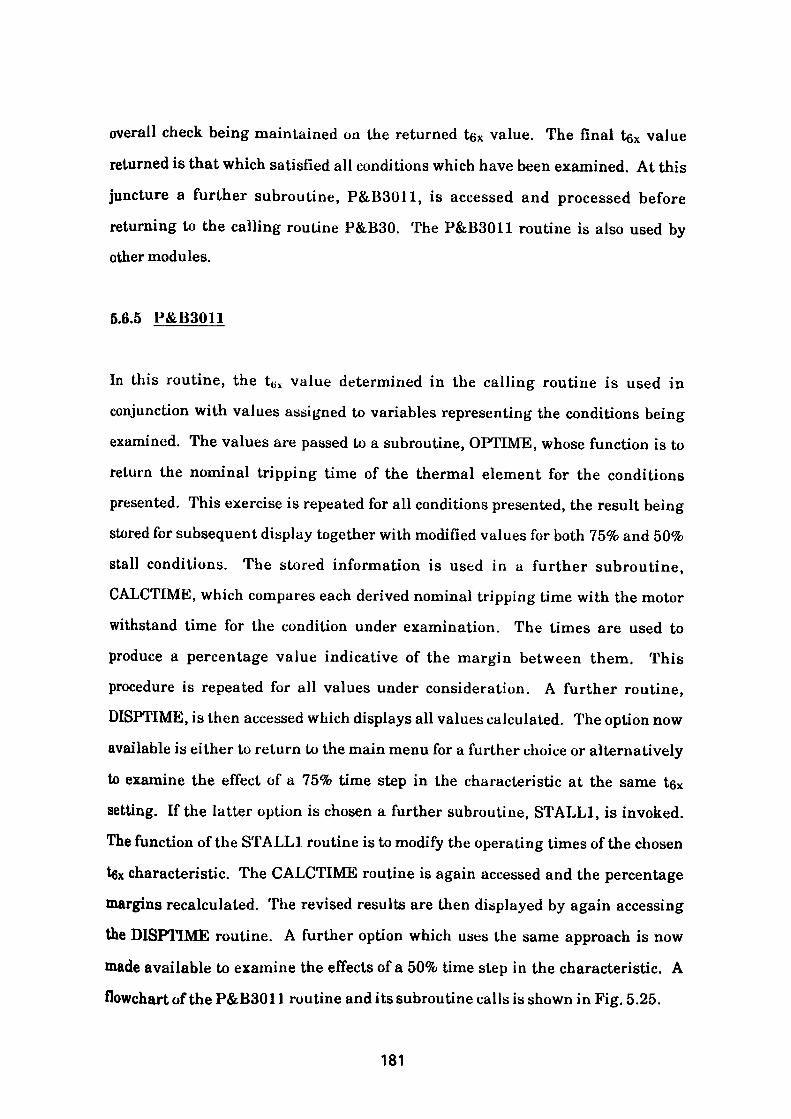
overall check being maintained on the returned tex value. The final tgx value returned is that which satisfied all conditions which have been examined. At this juncture a further subroutine, P&B3011, is accessed and processed before returning to the calling routine P&B30. The P&B3011 routine is also used by other modules.
5.6.5 P&B3011
In this routine, the t<; s value determined in the calling routine is used in conjunction with values assigned to variables representing the conditions being examined. The values are passed to a subroutine, OPTIME, whose function is to return the nominal tripping time of the thermal element for the conditions presented. This exercise is repeated for all conditions presented, the result being stored for subsequent display together with modified values for both 75% and 50% stall conditions. The stored information is used in a further subroutine, CALCTIME, which compares each derived nominal tripping time with the motor withstand time for the condition under examination. The times are used to produce a percentage value indicative of the margin between them. This procedure is repeated for all values under consideration. A further routine, DISPTIME, is then accessed which displays all values calculated. The option now available is either to return to the main menu for a further choice or alternatively to examine the effect of a 75% time step in the characteristic at the same te* setting. If the latter option is chosen a further subroutine, STALL1, is invoked. The function of the STALL1 routine is to modify the operating times of the chosen tex characteristic. The CALCTIME routine is again accessed and the percentage margins recalculated. The revised results are then displayed by again accessing the DISPTIME routine. A further option which uses the same approach is now made available to examine the effects of a 50% time step in the characteristic. A flowchart of the P&B3011 routine and its subroutine calls is shown in Fig. 5.25.
181
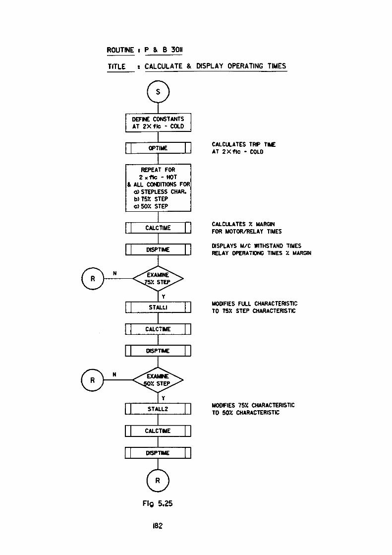
ROUTINE : P & B 3011
TITLE : CALCULATE & DISPLAY OPERATING TIMES
0DEFINE CONSTANTS AT ZXfte - COLD
OPTIME
REPEAT FOR 2 x f to - HOT
& ALL CONDITIONS FOR O)STEPLESS CHAR. W755J STEP 050X STEP
CALCULATES TRIP TIME AT 2Xflc - COLD
CALCULATES '/. MARGIN FOR MOTOR/RELAY TIMES
DISPLAYS M/C WITHSTAND TIMES RELAY OPERATING TIMES X MARGIN
MODIFIES FULL CHARACTERISTIC TO T57. STEP CHARACTERISTIC
MODFIES 75X CHARACTERISTIC TO 50% CHARACTERISTIC

5.6.6 P&B302
If option 2, 'MAXCURVE' with 75% stall feature, is selected in the P&B20
module, the information when passed to the P&B30 module enables the selection
of the subroutine, P&B302, to be carried out.
The P&B302 subroutine follows the same format as found in the P&B301
subroutine except that the initial t6x value is determined with the 75% time step
in the characteristic selected. Calculations and display are again carried out by
calls to the CALCTIME and DISPTIME routines. The routine also makes
provision for the calculated t6x characteristic to be displayed for examination with
the 50% stall feature selected.
5.6.7 P&B303
This routine is called from the P&B30 module when option 3, 'MAXCURVE 1 with
50% stall feature, is selected in the P&B20 module.
The routine determines the maximum tgx value that can be accommodated using a
50% time step in the characteristic. The value is processed and displayed using
the CALCTIME and DISPTIME routines in the same manner as found in the
P&B302 routine.
5.6.8 P&B304
This routine is accessed from P&B30 when any of the 'MINCURVE 1 options are
selected in the P&B20 module. In the P&B304 routine precedence is given to
determining a tex value which will allow the drive to accelerate up to speed
without encroaching on the tripping envelope. The routine incorporates features
183
which take due account of all possible time steps in the characteristic when
processing the conditions presented. The resulting tex value is the minimum
value that satisfies all conditions and is used in the CALCTIME and DISPTIME
routines to quantify and display the calculated values.
5.6.9 User Choice Option
If option 7, 'USER CHOICE', is selected in module P&B20, the user is invited to
supply a tgx value in the range 5-60 seconds. The option number chosen is used in
module P&B30 to redirect the t6x value to the P&B3011 routine. The reader is
referred to the P&B3011 routine discussed earlier.
5.6.10 P&B40
This module when selected displays the relay setting appropriate to the display
shown by the calling routine. The display also includes a mimic of the relay
faceplate with the SGl switchgroup shown in its selected form. A typical display
is shown in Fig. 5.21.
5.7 Interim Conclusion
Chapter 5 introduces a more modern, microprocessor based relay containing
inbuilt features which allow the entire range of thermal characteristics
incorporated within the relay to be selected by means of a faceplate mounted
potentiometer. As discussed in the text, further exploitation of the device is
possible by introducing a step in the thermal characteristic. A comparison with
the relay described in the previous chapter clearly shows the advancement that
has taken place in relay development in a relatively short period of time.
184

The input signals to this relay are sampled using Analogue to Digital (A/D)
converters before being subjected to measurement. These A/D convertors
introduce quantitisation errors into the measured values thus setting a limit on
the accuracy obtainable. The overall accuracy of the relay is incorporated into the
method used to determine the most appropriate range of characteristics for the
application being considered. The solution adopted is discussed at length in the
text and can be seen to clearly satisfy the objective of the program.
185
CHAPTER 6
THE PROTECTION OF VARIABLE SPEED DRIVE TRANSFORMERS
6.1 Introduction
The usual distribution approach to the protection of transformer fed variable
speed drive circuits (VSD) is to provide adequate protection for the transformer
and associated HV cabling only, the motor protection and LV cabling being
handled by the drive control package.
6.1.1 The Problems
Typical VSD circuits are supplied from substations at voltages ranging from 3.3 -
llkV. The remotely sited transformers and drive packages are located as near as
possible to the motor to limit voltage drop in the LV cabling system. Such
installations vary in size, the most common encountered utilise step down
transformers under 3150 kVA. In the case of low rated units it may be difficult to
justify the cost of a 630A 3.3kV or llkV circuit breaker for the primary switching
duty. Similar problems can arise when space on a switchboard is at a premium. In
such cases where multiple transformers are envisaged, a solution may be found by
'daisy chaining' the transformers together and feeding them from a common
circuit breaker. Caution should be exercised, however, as it should be noted that
the working current of the arrangement will now be increased necessitating
higher overload settings whilst the current passed by the smallest transformer
during fault conditions remains unchanged. Hence, the arrangement must be
carefully examined to ensure that the maximum protection is afforded to all
components when subjected to any combination of fault conditions. To achieve
this result manually can be a very time consuming and tedious exercise, so to
186
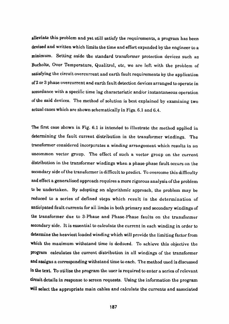
alleviate this problem and yet still satisfy the requirements, a program has been
devised and written which limits the time and effort expended by the engineer to a
minimum. Setting aside the standard transformer protection devices such as
Bucholtz, Over Temperature, Qualitrol, etc, we are left with the problem of
satisfying the circuit overcurrent and earth fault requirements by the application
of 2 or 3 phase overcurrent and earth fault detection devices arranged to operate in
accordance with a specific time lag characteristic and/or instantaneous operation
of the said devices. The method of solution is best explained by examining two
actual cases which are shown schematically in Figs. 6.1 and 6.4.
The first case shown in Fig. 6.1 is intended to illustrate the method applied in
determining the fault current distribution in the transformer windings. The
transformer considered incorporates a winding arrangement which results in an
uncommon vector group. The effect of such a vector group on the current
distribution in the transformer windings when a phase-phase fault occurs on the
secondary side of the transformer is difficult to predict. To overcome this difficulty
and effect a generalised approach requires a more rigorous analysis of the problem
to be undertaken. By adopting an algorithmic approach, the problem may be
reduced to a series of defined steps which result in the determination of
anticipated fault currents for all limbs in both primary and secondary windings of
the transformer due to 3-Phase and Phase-Phase faults on the transformer
secondary side. It is essential to calculate the current in each winding in order to
determine the heaviest loaded winding which will provide the limiting factor from
which the maximum withstand time is deduced. To achieve this objective the
program calculates the current distribution in all windings of the transformer
and assigns a corresponding withstand time to each. The method used is discussed
in the text. To utilise the program the user is required to enter a series of relevant
circuit details in response to screen requests. Using the information the program
will select the appropriate main cables and calculate the currents and associated
187

withstand times for all windings taking due account of the additional circuit
impedances imposed by the HV cable and source.
6.2. Case Study 1 • The Variable Speed Fan
Consider the installation of a variable speed fan powered by a synchronous motor.
The 665 volt 3 phase supply to the synchronous motor is derived from a 12 pulse,
transformer fed, converter system. The transformer primaries being supplied at
11000V.
The transformer and supply details are as follows
3 Phase fault level at source: 93 MVA
System X/R ratio: 8
Supply cable: 320 metres, 6.35/1 IkV, 3 core, 240 mm2, XLPE insulated,
single wire armoured, pvc oversheathed with stranded
aluminium conductors.
The transformer comprises two, two winding transformers enclosed in a single oil
filled tank with both primary windings brought out to common HV terminals.
The rating of each individual two winding transformer is 1530 kVA.
The primary winding in both cases comprises a delta with extended star windings
Secondary 1 is delta with a phase shift of + 7.5°
Secondary 2 is star with a phase shift of + 37.5°
Percentage impedance is 6.5% on rating
The general arrangement described is shown in Fig. 6.1.
Using the data listed above the source impedance may be calculated as follows.
Fault level of source = 93MVA
= V3«Vt«lL (6.1)
188
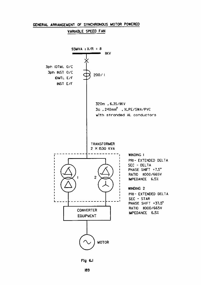
GENERAL ARRANGEMENT OF SYNCHRONOUS MOTOR POWERED
VARIABLE SPEED FAN
93MVA : X/R = 8IIKV
3ph IDTML 0/C
3ph INST 0/C
IDMTL E/F
INST E/F
2007
320m , 6.35/IIKV3c .240mm2 . XLPE/SWA/PVCwith stranded AL conductors
TRANSFORMER 2 X 1530 KVA
CONVERTER
EQUIPMENT
MOTOR
WINDING I
PRI- EXTENDED DELTA SEC - DELTA PHASE SHIFT +7.5° RATIO IIOOO/665V IMPEDANCE 6.5X
WINDING 2
PRI- EXTENDED DELTASEC - STARPHASE SHIFT +37.5°RATIO IIOOO/665VIMPEDANCE 6.5X
Fig €.1
169
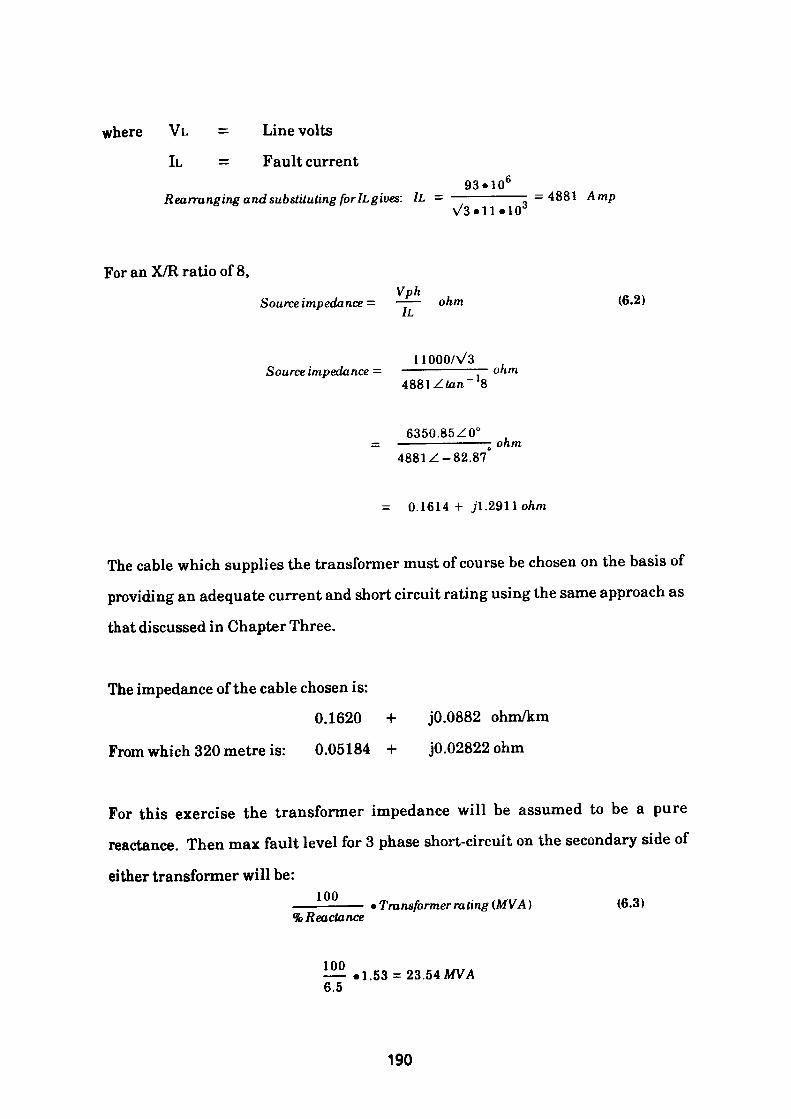
where VL = Line volts
It = Fault current93«106
Rearranging and substituting for IL gives: lL — ———————- =4881 AmpV3«ll «103
For an X/R ratio of 8,Vph
Source impedance = —— ohm (6.2)Lt-i
11000/V3 Source impedance = ———————— ohm
8
6350.85Z00 ————————— ohm4881Z-82.87
= 0.1614 + jl.29Uohm
The cable which supplies the transformer must of course be chosen on the basis of
providing an adequate current and short circuit rating using the same approach as
that discussed in Chapter Three.
The impedance of the cable chosen is:
0.1620 + jO.0882 ohm/km
From which 320 metre is: 0.05184 + j0.02822ohm
For this exercise the transformer impedance will be assumed to be a pure
reactance. Then max fault level for 3 phase short-circuit on the secondary side of
either transformer will be:100 • Transformer rating (MVA) (6.3)
% Reactance
100—— «1.53 = 23.54 MVA6.5
190
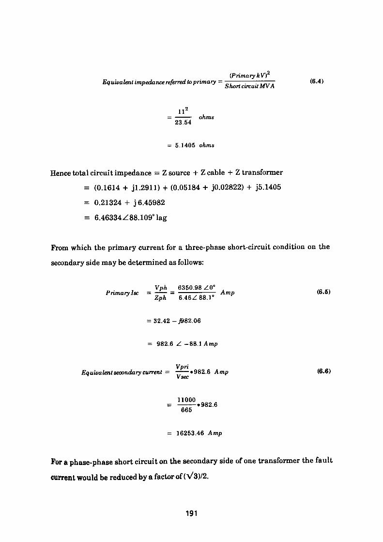
(Primary kVfEquivalent impedance referred to primary = ——————. ,„ „ (6.4)
Short circuit MVA
II 2——— ohms 23.54
= 5.1405 ohms
Hence total circuit impedance = Z source + Z cable + Z transformer
= (0.1614 + jl.2911) -I- (0.05184 + jO.02822) + J5.1405
= 0.21324 + j 6.45982
= 6.46334Z88.109°lag
From which the primary current for a three-phase short-circuit condition on the
secondary side may be determined as follows:
Vph 6350.98 Z0°Primary Isc = —— = ———————— Amp (6.5) Zph 6.46Z88.1"
= 32.42 -J982.06
= 982.6 Z -88.1 Amp
VpriEquivalent secondary current = ——«982.6 Amp (6.6)
Vsec
11000———«982.6 665
= 16253.46 Amp
For a phase-phase short circuit on the secondary side of one transformer the fault
current would be reduced by a factor of (V3)/2.
191
Hence LV. fault current for a phase-phase fault would be
V3 = ——• 16253.46 Amps
- 14075.9 Amps
The concept of symmetrical components must be used to refer this fault current to
the primary windings.
Resolving the secondary fault current into its symmetrical components where the
initial conditions are:
Vb = Vc
Ic = -Ib
la = 0
Now Vb = h2»Vl + h.V2 + Vo
Vc = h.Vi + h2.V2 + Vo
From initial conditions Vb = Vc
Then h2 .Vi + h.V2 + Vo = h-Vi + h2.V2 + Vo (6.7)
Vl(h2-h) + V2(h-h2 ) = 0
-jVs.Vi + jVs.V2 = 0
from which Vl = V2
Now la = lai + Ia2 + lao = 0
lal = -Ia2
Since lao = 0 (No earth-fault current is present)
It therefore follows that:
Vl = E - lauZl where Zi = +ve phase sequence impedance
192
and V2 = - Ia2*Z2 Z2 = -ve phase sequence impedance
So E-Iai«Zi = - Ia2«Z2 E = driving voltage
E = Iai»Zi-Ia2«Z2
E = Iai(Zi + Z2) because lal = Ia2E
From which lal - ——— (6.8)
similarly
Ia2 = ——— (6.9)
Now Ib = h2«Ial + h«Ia2 + lao (6.10)
= h2«Iai + h»Ia2 because lao = 0
= lal (h2 - h) because lal = - Ia2
Vs|Ial| = 14075.9 Amp
In the case considered Zi = Z2 as all components are static
Then Hal I = IIa2l = 14075.9/V3 = 8126.7 Amp
To refer the secondary positive and negative phase sequence currents to the
primary we need to consider two cases:-
1. Primary: Extended DeltajSecondary Delta connected; phase shift + 7.5°
2. Primary: Extended DeltajSecondary Star connected; phase shift + 37.5°
6.2.1 The Transformer with 7.5° Overall Phase Shift
The phase sequence components observed on the Primary side
= Transformation ratio • Secondary side phase sequence components
Thus665
Ml = ———•/al (6.11) 11000
193
665/Ai = ———»8126.7ZO° 11000
As we are calculating current magnitudes only, 0° has been used for convenienceIAI = 491.3ZO°Amp
and IA2 = 491.3Z1800 Amp because lA2= -!AI
Recombination taking account of transformer phase shift gives: (6.12)
IA = 491.3ZO°.1Z7.5° + 491.3Z180°.lZ-7.5° + lo
IB = h2. 491.3ZO°.1Z7.5° + h. 491.3Z180°.1Z-7.5° + lo
1C = h.491.3ZO°.lZ7.5° 491.3Z180°.1Z -7.5° + lo
where h = 1Z1200 , h2 = 1Z2400 andlo = 0
Simplifying gives
IA
IB
1C
from which:
IA
IB
1C
491.3 Z 7.5°
491.3Z247.50
491.3 Z 127.5°
128.26 Z 90° Amp
907.80Z-900 Amp
779.55Z 90° Amp
491.3Z 172.5°
491.3Z292.50
491.3Z52.50
which are the line currents and the currents in the extended delta winding on the
primary side of the transformer.
Referring to Fig. 6.2, it can be seen that the phase currents in the delta winding
satisfy the following equations:-
194
IAA' = lA'B' + IC'A' = 128.26Z900 (6.13)
IBB1 = lA'B' - IB'C' = -907.80Z-900
ICC' = - IB'C 1 + IC'A' = 779.55Z900
Solving the equation by means of the Generalised Matrix Inverse method
produces currents of magnitude
lA'B' = +345.4 Amp
IB'C' = -562.4 Amp
IC'A' = +217.2 Amp
Current distribution in the secondary delta winding is straightforward and does
not need to be calculated.
Referring to Fig. 6.2 it can be seen that for a delta secondary winding the current
distribution will be in the ratio |:i:|
Hence for a phase-phase fault of magnitude 14075.9A
The currents through the limbs will be,
!• 14075.9 = 9383 Amp (6.14)
|.14075.9 = 4691.97 Amp
i» 14075.9 = 4691.97 Amp
The above exercise should be repeated, this time using the maximum source fault
level likely to be encountered. The currents thus calculated represent the
maximum possible currents to which the circuit may be subjected.
195
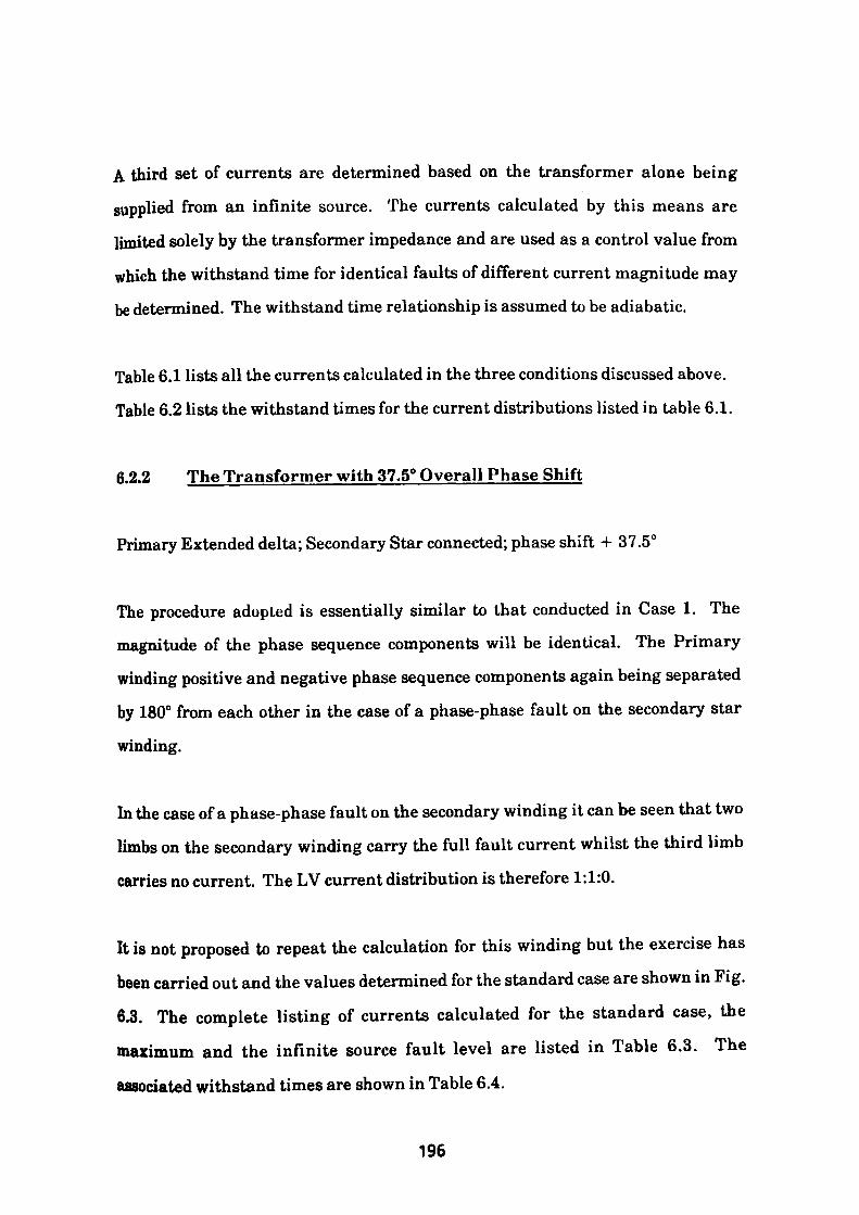
A third set of currents are determined based on the transformer alone being
supplied from an infinite source. The currents calculated by this means are
limited solely by the transformer impedance and are used as a control value from
which the withstand time for identical faults of different current magnitude may
be determined. The withstand time relationship is assumed to be adiabatic.
Table 6.1 lists all the currents calculated in the three conditions discussed above.
Table 6.2 lists the withstand times for the current distributions listed in table 6.1.
6.2.2 The Transformer with 37.5° Overall Phase Shift
Primary Extended delta; Secondary Star connected; phase shift + 37.5°
The procedure adopted is essentially similar to that conducted in Case 1. The
magnitude of the phase sequence components will be identical. The Primary
winding positive and negative phase sequence components again being separated
by 180° from each other in the case of a phase-phase fault on the secondary star
winding.
In the case of a phase-phase fault on the secondary winding it can be seen that two
limbs on the secondary winding carry the full fault current whilst the third limb
carries no current. The LV current distribution is therefore 1:1:0.
It is not proposed to repeat the calculation for this winding but the exercise has
been carried out and the values determined for the standard case are shown in Fig.
6.3. The complete listing of currents calculated for the standard case, the
maximum and the infinite source fault level are listed in Table 6.3. The
associated withstand times are shown in Table 6.4.
196
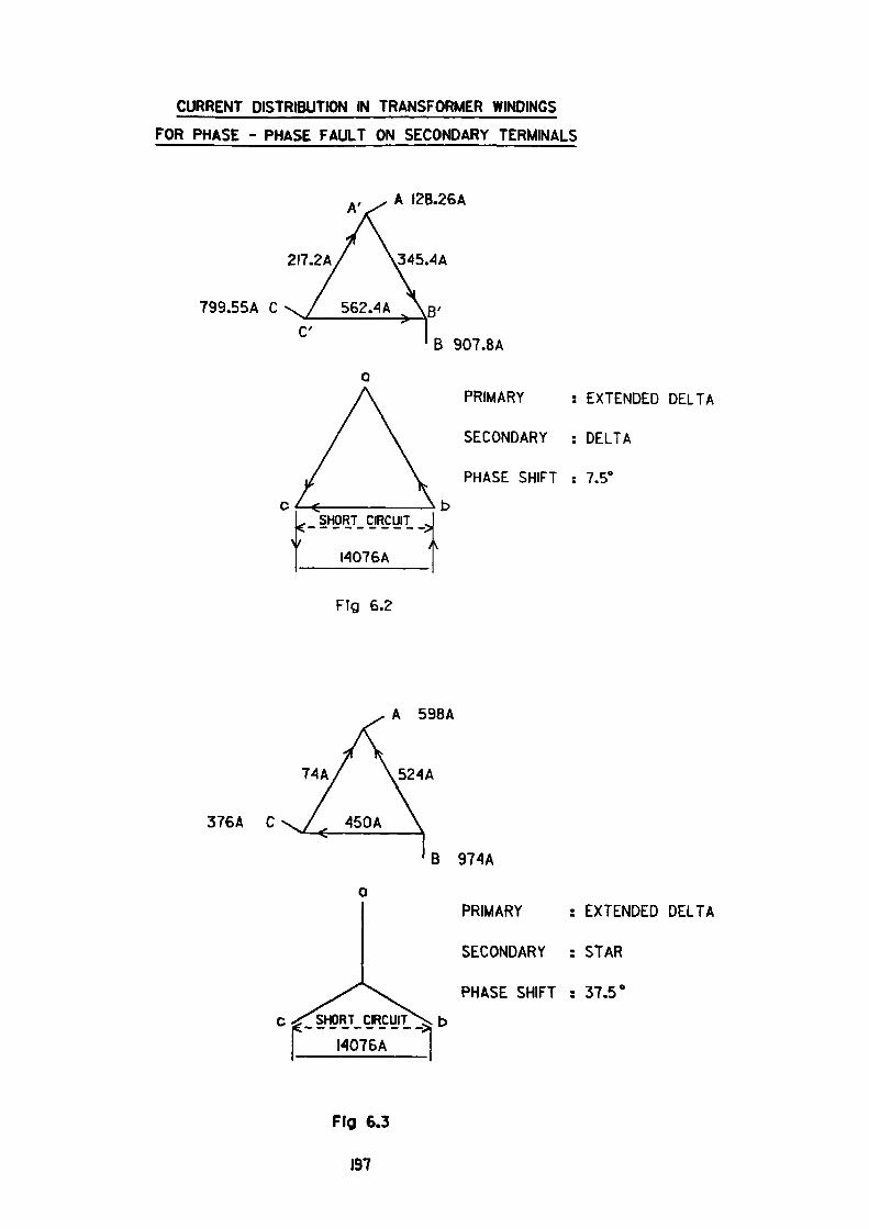
CURRENT DISTRIBUTION IN TRANSFORMER WINDINGS
FOR PHASE - PHASE FAULT ON SECONDARY TERMINALS
A I2B.26A
2I7.2A
799.55A CC'
PRIMARY : EXTENDED DELTA
SECONDARY : DELTA
PHASE SHIFT : 7.5°
- 1
SHORT CIRCUIT
I4076At
Fig 6.2
74A
376A C
A 598A
524A
B 974A
PRIMARY : EXTENDED DELTA
SECONDARY : STAR
PHASE SHIFT : 37.5°
Fig 6.3
197
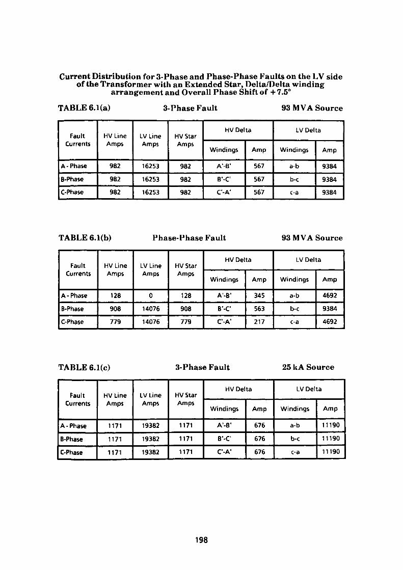
Current Distribution for 3-Phase and Phase-Phase Faults on the LV sideof the Transformer with an Extended Star, Delta/Delta winding
arrangement and Overall Phase Shift of +7.5°
TABLE 6.1(a) 3-Phase Fault 93 MVA Source
Fault Currents
A -Phase
B-Phase
C-Phase
HV Line Amps
982
982
982
LV Line Amps
16253
16253
16253
HV Star Amps
982
982
982
HV Delta
Windings
A'-B'
B'-C
C'-A 1
Amp
567
567
567
LV Delta
Windings
a-b
b-c
c-a
Amp
9384
9384
9384
TABLE 6.1(b) Phase-Phase Fault 93 MVA Source
Fault Currents
A -Phase
B-Phase
C-Phase
HV Line Amps
128
908
779
LV Line Amps
0
14076
14076
HV Star Amps
128
908
779
HV Delta
Windings
A'-B 1
B'-C 1
C'-A1
Amp
345
563
217
LV Delta
Windings
a-b
b-c
c-a
Amp
4692
9384
4692
TABLE 6.1(c) 3-Phase Fault 25 kA Source
Fault Currents
A -Phase
B-Phase
C-Phase
HV Line Amps
1171
1171
1171
LV Line Amps
19382
19382
19382
HV Star Amps
1171
1171
1171
HV Delta
Windings
A'-B 1
B'-C 1
C'-A1
Amp
676
676
676
LV Delta
Windings
a-b
b-c
c-a
Amp
11190
11190
11190
198
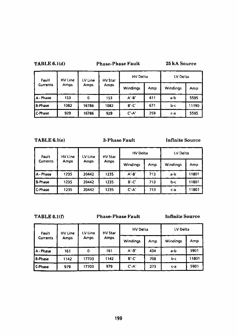
TABLE 6.1 (d) Phase-Phase Fault 25 kA Source
Fault Currents
A -Phase
B-Phase
C-Phase
HV Line Amps
153
1082
929
LV Line Amps
0
16786
16786
HV Star Amps
153
1082
929
HV Delta
Windings
A'-B 1
B'-C'
C'-A'
Amp
411
671
259
LV Delta
Windings
a-b
b-c
c-a
Amp
5595
11190
5595
TABLE 6. l(e) 3-Phase Fault Infinite Source
Fault Currents
A -Phase
B-Phase
C-Phase
HV Line Amps
1235
1235
1235
LV Line Amps
20442
20442
20442
HV Star Amps
1235
1235
1235
HV Delta
Windings
A'-B'
B'-C
C'-A'
Amp
713
713
713
LV Delta
Windings
a-b
b-c
c-a
Amp
11801
11801
11801
TABLE 6.1(f) Phase-Phase Fault Infinite Source
Fault Currents
A -Phase
B-Phase
C-Phase
HV Line Amps
161
1142
979
LV Line Amps
0
17703
17703
HV Star Amps
161
1142
979
HV Delta
Windings
A'-B 1
B'-C
C'-A'
Amp
434
708
273
LV Delta
Windings
a-b
b-c
c-a
Amp
5901
11801
5901
199
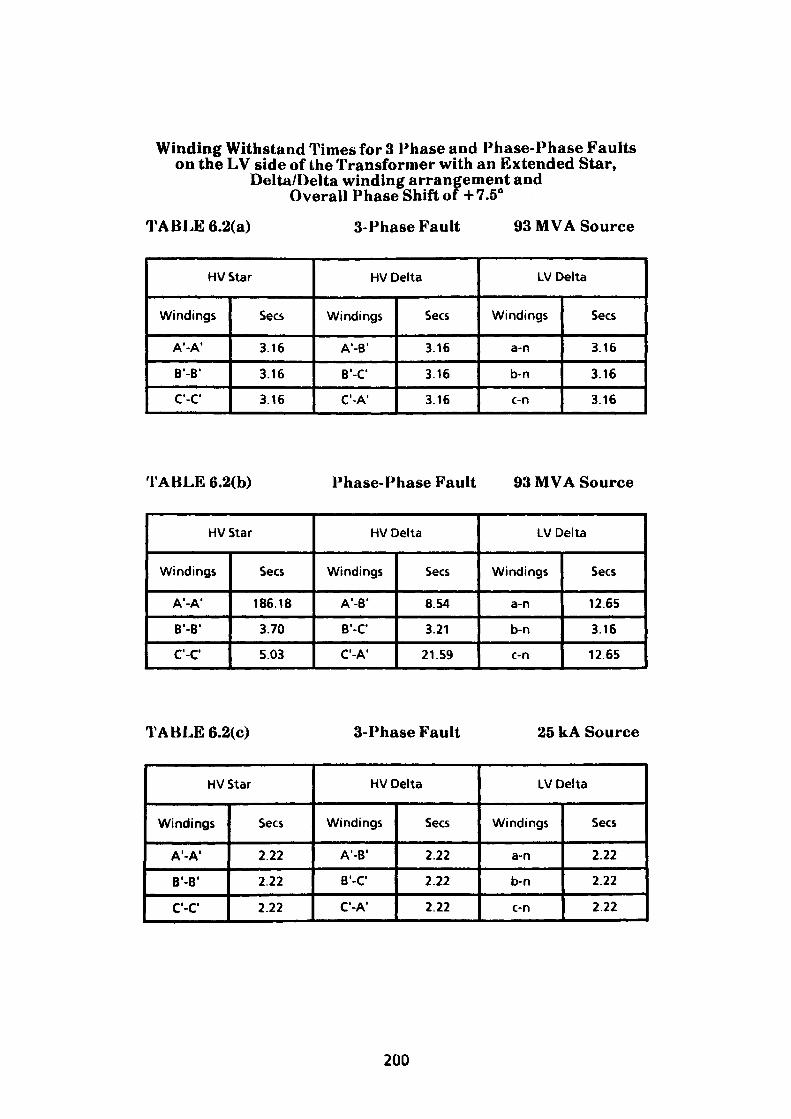
Winding Withstand Times for 3 Phase and Phase-Phase Faultson the LV side of the Transformer with an Extended Star,
Delta/Delta winding arrangement andOverall Phase Shift of +7.5°
TABLE 6.2(a) 3-Phase Fault 93 MVA Source
HVStar
Windings
A'-A'
B'-B 1
C-C
Sees
3.16
3.16
3.16
HV Delta
Windings
A'-B 1
B'-C
C'-A 1
Sees
3.16
3.16
3.16
LV Delta
Windings
a-n
b-n
c-n
Sees
3.16
3.16
3.16
TABLE 6.2(b) Phase-Phase Fault 93 MVA Source
HVStar
Windings
A'-A1
B'-B 1
C'-C
Sees
186.18
3.70
5.03
HV Delta
Windings
A'-B 1
B'-C
C'-A'
Sees
8.54
3.21
21.59
LV Delta
Windings
a-n
b-n
c-n
Sees
12.65
3.16
12.65
TABLE 6.2(c) 3-Phase Fault 25 kA Source
HV Star
Windings
A'-A'
B'-B'
C'-C1
Sees
2.22
2.22
2.22
HV Delta
Windings
A'-B 1
B'-C
C'-A 1
Sees
2.22
2.22
2.22
LV Delta
Windings
a-n
b-n
c-n
Sees
2.22
2.22
222
200
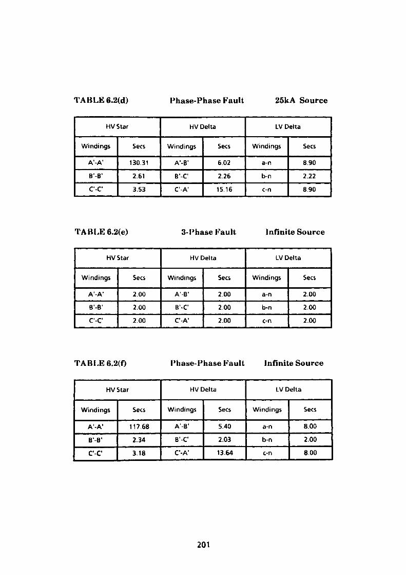
TABLE6.2(d) Phase-Phase Fault 25kA Source
HVStar
Windings
A'-A'
B'-B'
C'-C
Sees
130.31
2.61
3.53
HV Delta
Windings
A'-B 1
B'-C
C'-A1
Sees
6.02
2.26
15.16
LV Delta
Windings
a-n
b-n
c-n
Sees
8.90
2.22
8.90
TABLE 6.2(e) 3-Phase Fault Infinite Source
HV Star
Windings
A'-A 1
B'-B'
C'-C 1
Sees
2.00
2.00
200
HV Delta
Windings
A'-B 1
B'-C
C'-A'
Sees
2.00
2.00
2.00
LV Delta
Windings
a-n
b-n
c-n
Sees
2.00
2.00
2.00
TABLE6.2(f) Phase-Phase Fault Infinite Source
HV Star
Windings
A'-A1
B'-B 1
C'-C1
Sees
11768
2.34
3.18
HV Delta
Windings
A'-B'
B'-C
C'-A'
Sees
5.40
2.03
13.64
LV Delta
Windings
a-n
b-n
c-n
Sees
8.00
2.00
8.00
201
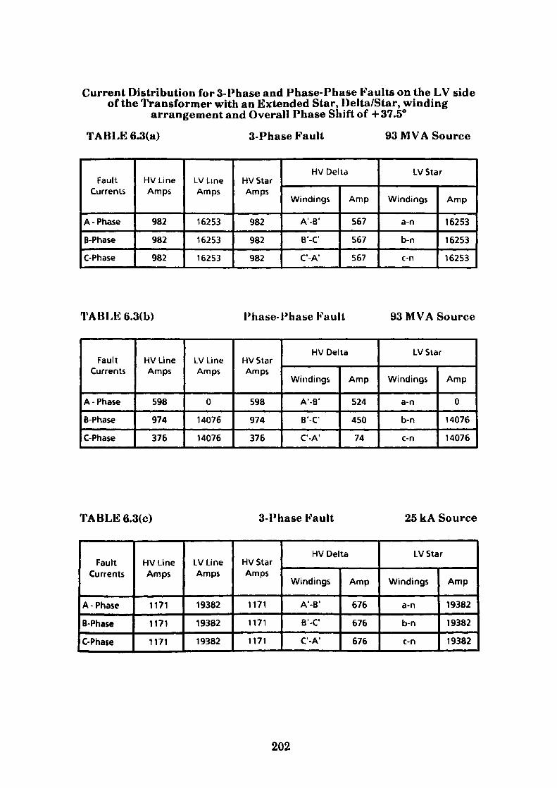
Current Distribution for 3-Phase and Phase-Phase Faults on the LV sideof the Transformer with an Extended Star, Delta/Star, winding
arrangement and Overall Phase Shift of +37.5°
TABLK6.3(a) 3-Phase Fault 93 MVA Source
Fault Currents
A - Phase
B-Phase
C-Phase
HV Line Amps
982
982
982
LV Line Amps
16253
16253
16253
HV Star Amps
982
982
982
HV Delta
Windings
A'-B'
B'-C
C-A 1
Amp
567
567
567
LV Star
Windings
a-n
b-n
c-n
Amp
16253
16253
16253
TABLE 6.3(b) Phase-Phase Fault 93 MVA Source
Fault Currents
A - Phase
B-Phase
C-Phase
HV Line Amps
598
974
376
LV Line Amps
0
14076
14076
HV Star Amps
598
974
376
HV Delta
Windings
A'-B'
B'-C'
C'-A'
Amp
524
450
74
LV Star
Windings
a-n
b-n
c-n
Amp
0
14076
14076
TABLE 6.3(c) 3-Phase Fault 25 kA Source
Fault Currents
A -Phase
B-Phase
C-Phase
HV Line Amps
1171
1171
1171
LV Line Amps
19382
19382
19382
HV Star Amps
1171
1171
1171
HV Delta
Windings
A'-B'
B'-C'
C'-A 1
Amp
676
676
676
LV Star
Windings
a-n
b-n
c-n
Amp
19382
19382
19382
202
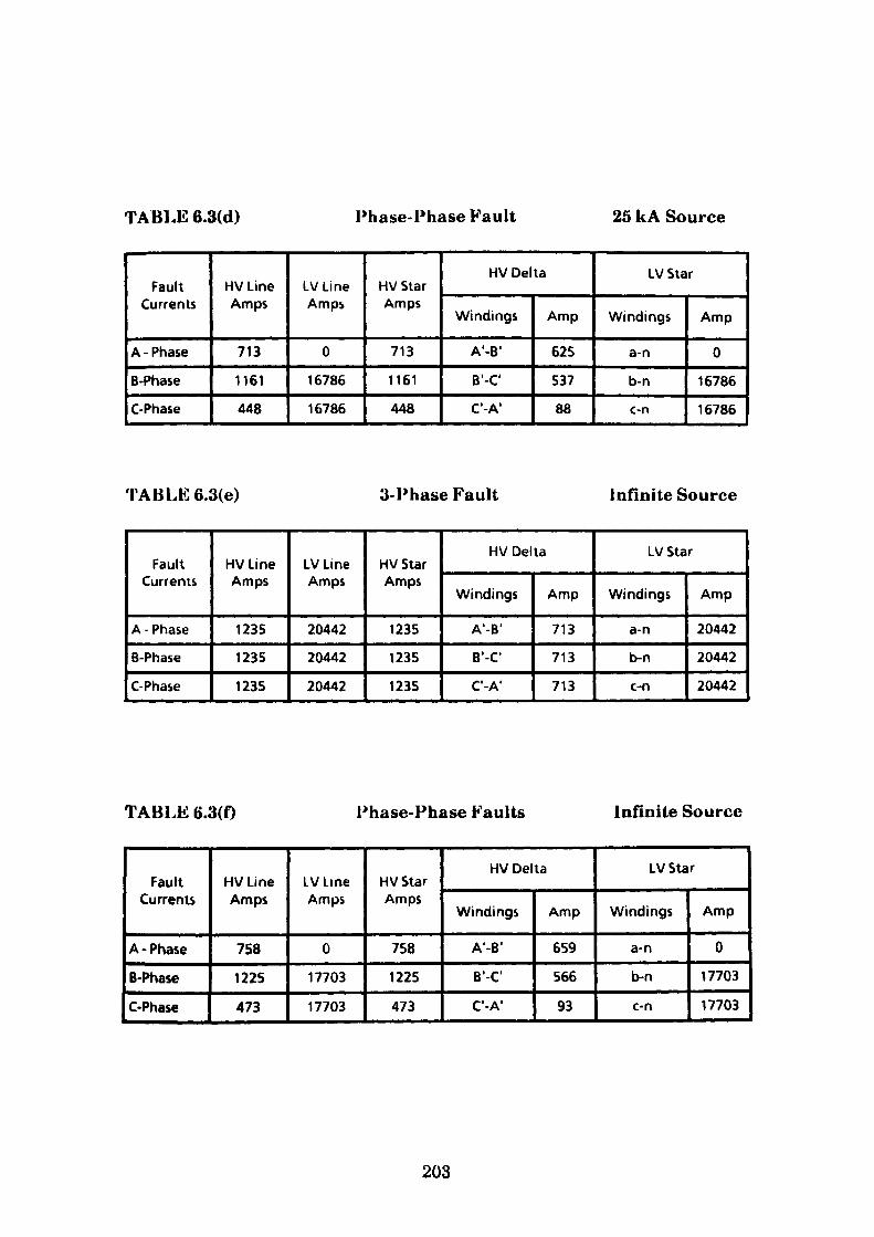
TABLE 6.3(d) Phase-Phase Fault 25 kA Source
Fault Currents
A - Phase
B-Phase
C-Phase
HV Line Amps
713
1161
448
LV Line Amps
0
16786
16786
HV Star Amps
713
1161
448
HV Delta
Windings
A'-B 1
B'-C
C'-A 1
Amp
625
537
88
LV Star
Windings
a-n
b-n
c-n
Amp
0
16786
16786
TABLE 6.3(e) 3-Phase Fault Infinite Source
Fault Currents
A - Phase
B-Phase
C-Phase
HV Line Amps
1235
1235
1235
LV Line Amps
20442
20442
20442
HVStar Amps
1235
1235
1235
HV Delta
Windings
A'-B'
B'-C
C'-A1
Amp
713
713
713
LV Star
Windings
a-n
b-n
c-n
Amp
20442
20442
20442
TABLE 6.3(f) Phase-Phase Faults Infinite Source
Fault Currents
A -Phase
B-Phase
C-Phase
HV Line Amps
758
1225
473
LV Line Amps
0
17703
17703
HV Star Amps
758
1225
473
HV Delta
Windings
A'-B'
B'-C 1
C'-A1
Amp
659
566
93
LV Star
Windings
a-n
b-n
c-n
Amp
0
17703
17703
203
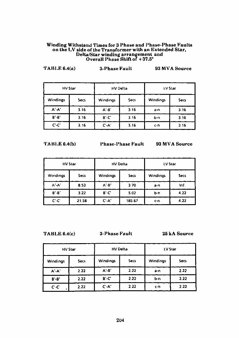
Winding Withstand Times for 3 Phase and Phase-Phase Faultson the LV side of the Transformer with an Extended Star,
Delta/Star winding arrangement andOverall Phase Shift of +37.5°
TABLE 6.4(a) 3-Phase Fault 93 MVA Source
HV Star
Windings
A'-A1
B'-B'
C-C
Sees
3.16
3.16
3.16
HV Delta
Windings
A'-B'
B'-C'
C-A'
Sees
3.16
3.16
3.16
LV Star
Windings
a-n
b-n
c-n
Sees
3.16
3.16
3.16
TABLE 6.4(b) Phase-Phase Fault 93 MVA Source
HV Star
Windings
A'-A'
B'-B'
C'-C
Sees
853
3.22
21.58
HV Delta
Windings
A'-B'
B'-C'
C'-A1
Sees
370
5.02
18567
LV Star
Windings
a-n
b-n
c-n
Sees
Inf.
4.22
4.22
TABLE 6.4(c) 3-Phase Fault 25 kA Source
HV Star
Windings
A'-A'
B'-B'
C'-C' .
Sees
2.22
2.22
2.22
HV Delta
Windings
A'-B'
B'-C
C'-A'
Sees
2.22
2.22
2.22
LV Star
Windings
a-n
b-n
c-n
Sees
2.22
2.22
2.22
204
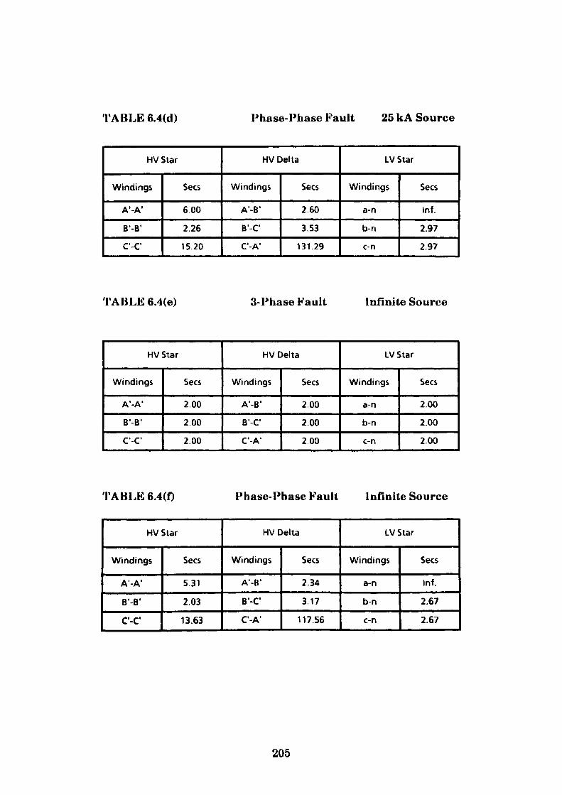
TABLE 6.4(d) Phase-Phase Fault 25 kA Source
HV Star
Windings
A'-A'
B'-B'
C'-C1
Sees
6.00
2.26
15.20
HV Delta
Windings
A'-B'
B'-C
C'-A 1
Sees
2.60
3.53
131.29
LV Star
Windings
a-n
b-n
c-n
Sees
Inf.
2.97
2.97
TABLE6.4(e) 3-Phase Fault Infinite Source
HV Star
Windings
A'-A 1
B'-B 1
C'-C 1
Sees
2.00
2.00
2.00
HV Delta
Windings
A'-B'
B'-C
C-A'
Sees
2.00
2.00
200
LV Star
Windings
a-n
b-n
c-n
Sees
200
2.00
2.00
TABLE 6.4(f) Phase-Phase Fault Infinite Source
HV Star
Windings
A'-A'
B'-B 1
C'-C1
Sees
5.31
2.03
13.63
HV Delta
Windings
A'-B 1
B'-C 1
C'-A'
Sees
2.34
3.17
117.56
LV Star
Windings
a-n
b-n
c-n
Sees
Inf.
2.67
2.67
205
6.3 Case Study 2 - The Algorithmic Approach Applied to a Multi
Transformer Circuit
The second case discussed is shown in Fig. 6.4. The text is intended to illustrate
the method applied to three transformers supplied through a single circuit
breaker and cable. The final settings applied to the overcurrent and earth fault
time lag and instantaneous elements are required to provide common protection
for all circuit components under both phase-phase and three phase fault
conditions. The transformers used are of either delta-star or delta-delta winding
configurations for which winding fault current distribution can be readily
predicted. However, as the transformer current distribution analysis section of
the program is of a generalised nature, the procedure adopted is as previously
discussed in Case Study 1. The complete program which includes the calculation
of settings for the overcurrent and earth fault elements is included in this section
of the work.
Options are provided for circuit protection using either two or three time delayed
and instantaneous overcurrent elements. The program allows the setting for the
selected elements to be calculated using any one of seven different time
characteristics. An identical set of options is available for determining the
limiting values of earth fault setting.
6.3.1 The Temper Mill Application
Consider the supply requirements of a three unit coil temper mill comprising an Uncoiler, Mill and Recoiler section each driven by a dc. motor supplied via thyristor converters. Each converter arrangement is supplied at 660V from two, 11000/660V three-phase transformers mounted in a common oil tank and configured as shown in Fig. 6.4. In the case considered it is intended to supply all three transformers from one llkV circuit breaker. The maximum source
206
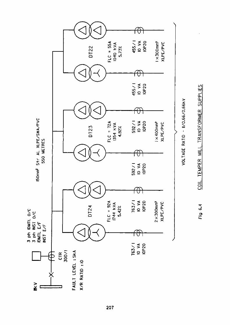
HKV —x
-CTR
300/1
FAULT
LEVEL
: 5kA
X/R
RATIO
:IO
ro
o -g
3 ph
1D
MTL
0/C
3
ph
INST
0/
C
IDM
TL
E/F
IN
ST
E/F
150m
m2
Str
AL
X
LPE
/SW
A/P
VC
55
0 M
ETRE
S
DT2
4A Ver
^x!'
?*•—
""^\
AD
T23
DT2
2
^•w
76
3/
1 -
10
VA
C
IOP2
0 ~
FLC
= 92
A 17
44
kVA
5.42
X
. 76
3/
1 -
^ 10
VA
C
IO
P20
~
2 x
300m
m2
XLPE
/PVC
^^
^^
. 592
/1
-
3 10
VA
C
IO
P20
FLC
=
72A
13
54
kVA
4.
92X
592
/ 1
-
3
10
VA
C
IOP2
0 ~
1 x 4
00m
m2
XLP
E/P
VC
, 455/1
-
^
10
VA
C
IOP2
0
FLC
=
55A
1040
KV
A 5.
73X
, 4
55
/1
-
> 10
VA
C
IO
P20
~
1 x 3
00m
m2
XLP
E/P
VC
VOLT
AGE
RATI
O
- II/
0.66
/0.6
6KV
Fig
6.4
COIL
TE
MPE
R
MIL
L TR
ANSF
OR
MER
SU
PPLI
ES
impedance of the supply being sufficient to provide a fault level of 5kA with an
X/R ratio of 10. Clearly the source impedance will vary with switching conditions
and may well reduce in the future with the addition of new supply sources. Under
such circumstances prudence suggests that the exercise is also conducted at the
maximum rating of the switchgear which in this case is 25 kA. Under normal
running conditions the full load current of the mill is 110A which is less than the
sum of the full load currents of the individual transformers. Prior to selecting the
llkV supply cable, it is necessary to specify the type of circuit breaking device
which is intended to be used. The two options considered are a fully rated circuit
breaker or, alternatively, a fused contactor. In this case study the preferred choice
is the circuit breaker. As a consequence, the cable used must be capable of
carrying the full fault current without damage for the period required to detect
and clear the fault. This time will of course be measured in milliseconds as the
protection will be provided by an instantaneous type element. The protection
relay used in this instance is supplied by GEC ALSTHOM and is electronic in
nature. The type MCGG relay is offered in a variety of element combinations, the
model selected for this exercise being the MCGG82. This relay offers three-phase
IDMTL/DTL overcurrent, instantaneous overcurrent, IDMTL/DTL earth-fault
and instantaneous earth-fault protection. This comprehensive selection of
elements offers considerable application flexibility as a variety of IDMTL/DTL
characteristics may be selected by means of slide switches mounted on the
faceplate. The characteristics offered are in accordance with those specified in
B8142 and are as follows:-
The four 1DMTL (Inverse Definite Minimum time lag) characteristics are
(a) Standard Inverse
(b) Very In verse
(c) Extremely Inverse
(d) Long time Inverse
208
Whereas the three DTL (Definite time lag) characteristics are:
(a) 2 sec
(b) 4 sec
(c) 8 sec
As stated earlier it is necessary to select an llkV supply cable which satisfies the
conditions generally outlined. The type of cable favoured by the writer and used
in this text is of three core construction, utilising stranded aluminium conductors.
The insulation media being XLPE with single wire armouring contained within a
pvc oversheath. Aluminium conductors have been specified in preference to
copper on the basis that it effectively eliminates cable thefts. In the selection
program the entire range of cable CSA's (cross-sectional area) are displayed
together with symbols which are indicative of their suitability. The checks carried
out are:
1. Circuit full load current < cable rating (a) air (b) duct
(c) ground
2. Fault current rating (200m sec) > cable short circuit withstand
3. Earth fault current rating (200m sec) > cable armour fault withstand
4. Percentage volt drop < 2£%
From the displayed list a cable of 150mrn2 is chosen as it is the smallest size which
satisfies the above criteria. The program accesses the datafile from which values
of R (Resistance) and XL (Inductive reactance) are obtained for the required length
of 550 metres.
The values are:
RCABLE = 0.145 ft
XCABLE = 0.053 ft
209
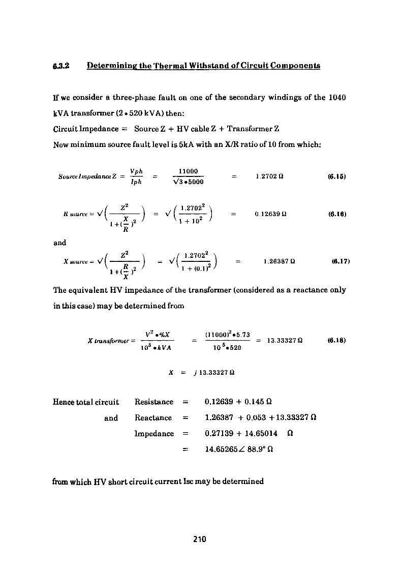
6.3.2 Determining the Thermal Withstand of Circuit Components
If we consider a three-phase fault on one of the secondary windings of the 1040
kVA transformer (2 • 520 kVA) then:
Circuit Impedance = Source Z 4- HV cable Z + Transformer Z
Now minimum source fault level is 5kA with an X/R ratio of 10 from which:
Vph 11000Source I mpedanceZ = -J— = —————— = 1 2702 Q (6.15)
Iph V3»5000
Z* \ I 1.27022 \—^—— = M————IT = 0.12639ii (6.16),£ ^2 ' V 1 + 10 '' - ( R }
and,( 1.27022 \
VI ————— = 1.26387 Q (6.17) V 1 + (O.I)2 '
The equivalent HV impedance of the transformer (considered as a reactance only
in this case) may be determined from
V'2 »%X (11000)2 «5.73X transformer - —————— - ———————— = 13.33327 Q (6.18)
\Q5 »kVA 10 5 «520
X = j 13.33327 Q
Hence total circuit Resistance = 0.12639 + 0.145 Q
and Reactance = 1.26387 + 0.053+13.33327 Q
Impedance = 0.27139 + 14.65014 Q
= 14.65265Z 88.9° Q
from which HV short circuit current Isc may be determined
210
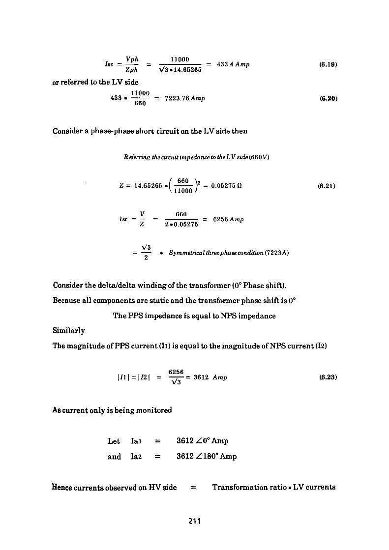
Vph 110007sc = -i- = ———————— = 433.4 Amp (6.19)Zph V3« 14.65265
or referred to the LV side11000
433* ——— = 7223.78 Amp (6.20) 660
Consider a phase-phase short-circuit on the LV side then
Referring the circuit impedance totheLV side (660 VO
/ 660 \9Z = 14.65265 • ———— r = 0.05275 Q (6.21) \11000 /
V 660Isc = — = —————— = 6256 AmpZ 2.0.05275
V3 = —- • Symmetrical three phase condition (7223A)
£t
Consider the delta/delta winding of the transformer (0° Phase shift).
Because all components are static and the transformer phase shift is 0°
The PPS impedance is equal to NPS impedance
Similarly
The magnitude of PPS current (Ii) is equal to the magnitude of NPS current (12)
6256 = |/21 = ——= 3612 Amp (6.23)
As current only is being monitored
Let lai = 3612 Z0° Amp
and Ia2 = 3612 Z180° Amp
Hence currents observed on HV side = Transformation ratio • LV currents
211
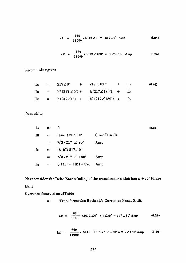
IA\ =660
11000• 3612 Z0° = 217ZO" Amp (6.24)
IA2 -660
11000• 3612Z180° = (6.25)
Recombining gives
IA
IB
1C
217Z00 +
h2(217ZO°) +
h(217ZO°) +
217Z1800 + lo
h (217 Z180°) + lo
h2(217Z180°) + lo
(6.26)
from which
IA = 0
IB = (h2-h)217ZO° Sinceli
V3.217 Z-90° Amp
1C = (h-h2)217ZO°
= V3.217 Z+90° Amp
IA = 0 I IB I = 11C I = 376 Amp
= -Iz
(6.27)
Next consider the Delta/Star winding of the transformer which has a +30° Phase
Shift
Currents observed on HT side
= Transformation Ratio • LV Currents • Phase Shift
6601A\ = ———•3612Z00 • 1Z30" =217Z30°Amp
11000(6.28)
660IAZ = ———• 3612Z180°« 1 Z-30° = 217Zl50°Amp (6.29)
11000
212
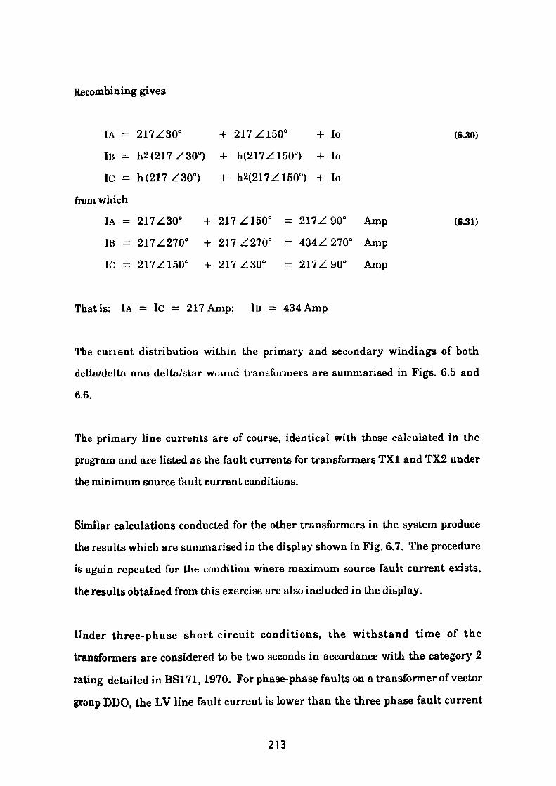
Recombining gives
IA = 217Z300 + 217Z1500 + lo (6.30)
IB = h2(217Z30°) + h(217Z150°) + lo
1C = h(217Z30°) + h2(217Z150°) + lo
from which
1A = 217Z300 + 217Z150" = 217Z 90° Amp (6.31)
IB = 217Z2700 + 217Z2700 = 434Z 270° Amp
1C = 217Z1500 + 217Z300 = 217Z 90° Amp
That is: lA = 1C = 217 Amp; IB = 434 Amp
The current distribution within the primary and secondary windings of both
delta/delta and delta/star wound transformers are summarised in Figs. 6.5 and
6.6.
The primary line currents are of course, identical with those calculated in the
program and are listed as the fault currents for transformers TXI and TX2 under
the minimum source fault current conditions.
Similar calculations conducted for the other transformers in the system produce
the results which are summarised in the display shown in Fig. 6.7. The procedure
is again repeated for the condition where maximum source fault current exists,
the results obtained from this exercise are also included in the display.
Under three-phase short-circuit conditions, the withstand time of the
transformers are considered to be two seconds in accordance with the category 2
rating detailed in BS171,1970. For phase-phase faults on a transformer of vector
group DDO, the LV line fault current is lower than the three phase fault current
213
CURRENT DISTRIBUTION IN TRANSFORMER WINDINGS
(I) FOR 3 - PHASE FAULT ON SECONDARY TERMINALS
433.4A
250.2A/ \250.2A
250.2A \B 433.4A
433.4A
7223.BA
4I70.7/ V4I70.7A
4170.7 A \ B 7223.8A
7223.8A
(II) FOR PHASE - PHASE FAULT ON SECONDARY TERMINALS
I25.IA
C/ 250.2A \B 375.4A
2085.3A
C / 4I70.7A \ B 6256A
Fig 6.5
214
CURRENT DISTRIBUTION IN TRANSFORMER WINDINGS
(I) FOR 3 - PHASE FAULT ON SECONDARY TERMINALS
433.4A
250.2A/ \250.2A
250.2A \ B 433.4A
433.4A
7223.8A
b 7223.8A
7223.8A
(II) FOR PHASE - PHASE FAULT ON SECONDARY TERMINALST
2I6.7A
2I6.7A
C/ 216.7 A \B 2I6.7A
b 6256A
6256A
Fig 6.6
215
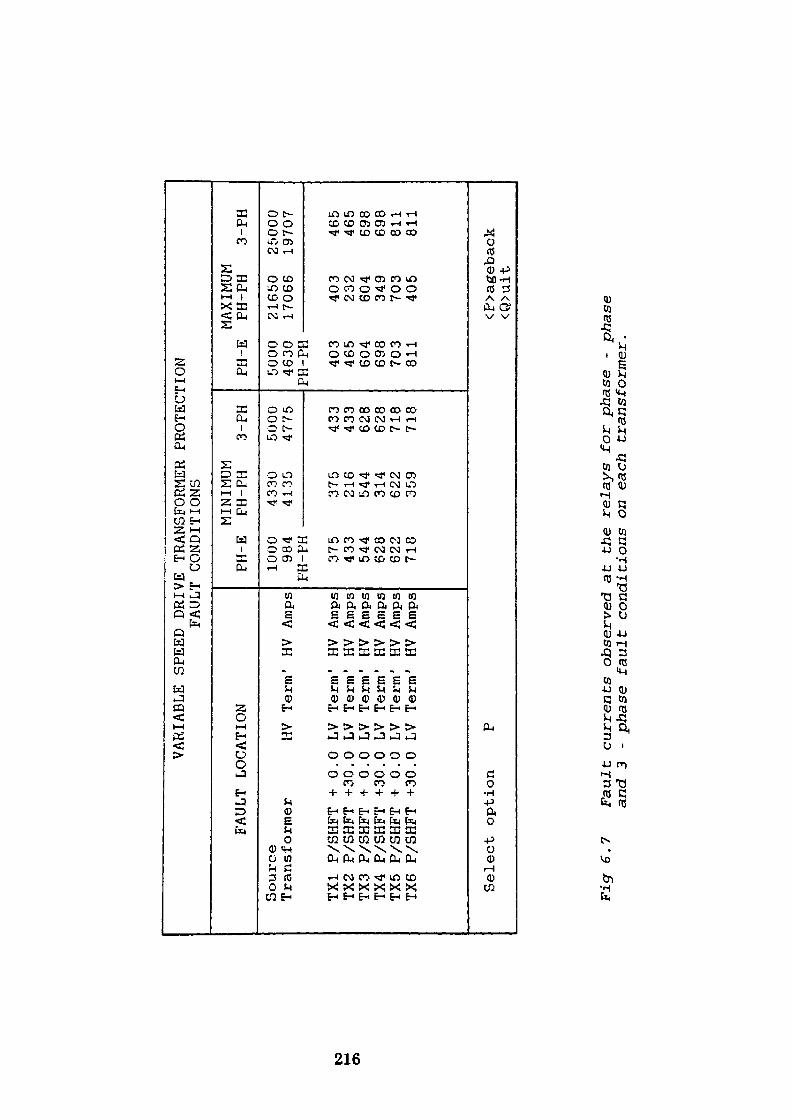
to h^
Oi
VARIABLE
SPEED
DRIVE
TRANSFORMER
FAULT
CONDITIONS
FAULT
LOCATION
Source
Transformer
TX1
P/SHFT +
0.
TX2
P/SHFT +30.
TX3
P/SHFT +
0.
TX4
P/SHFT +30.
TX5
P/SHFT +
0.
TX6
P/SHFT +30.
Sele
ct op
tion
0 0 0 0 0 0
HV LV
LV
LV
LV
LV
LV P
Term
Term
Term
Term
Term
Term
Term
' HV
' HV
' HV
' HV
1 HV
' HV
' HV
Amps
Amps
Amps
Amps
Amps
Amps
Amps
PH-E
1000
984
PH-PH
375
433
544
628
622
718
MINIMUM
PH-PH
4330
4135 375
216
544
314
622
359
PROTECTION
3-PH
5000
4775 433
433
628
628
718
718
PH-E
5000
4630
PH-PH
403
465
604
698
703
811
MAXIMUM
PH-PH
21650
17066
403
232
604
349
703
405
3-PH
25000
19707
465
465
698
698
811
811
<P>age
back
<Q>uit
Fig
6.7
Faul
t cu
rren
ts observed a
t the
rela
ys fo
r phase
- phase
and
3 - phase
faul
t conditions on ea
ch tr
ansf
orme
r.
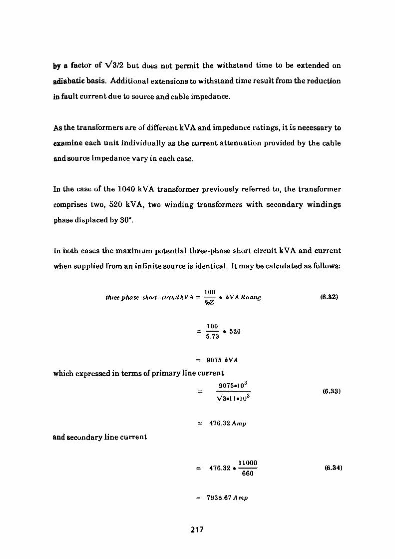
by a factor of V3/2 but does not permit the withstand time to be extended on
adiabatic basis. Additional extensions to withstand time result from the reduction
in fault current due to source and cable impedance.
As the transformers are of different kVA and impedance ratings, it is necessary to
examine each unit individually as the current attenuation provided by the cable
and source impedance vary in each case.
In the case of the 1040 kVA transformer previously referred to, the transformer
comprises two, 520 kVA, two winding transformers with secondary windings
phase displaced by 30°.
In both cases the maximum potential three-phase short circuit kVA and current
when supplied from an infinite source is identical. It may be calculated as follows:
100 three phase short-circuitkVA = —— • kVA Hating (6.32)
100520
5.73
= 9075 kVA which expressed in terms of primary line current
9075«103(6.33)
and secondary line current
V3»ll«103
= 476.32 Amp
11000= 476.32 • ——— (6.34)
660
= 7938.67 Amp
217
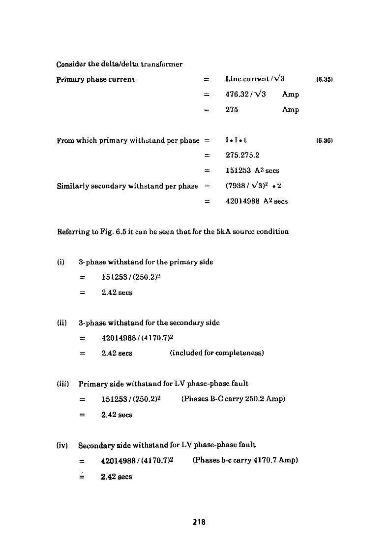
Consider the delta/delta transformer
Primary phase current = Line current /V3
476.32 /V3 Amp
= 275 Amp
(6.35)
From which primary withstand per phase = I«I«t
275.275.2
151253 A2 sees
Similarly secondary withstand per phase = (7938 / v/3)2 »2
42014988 A2 Secs
(6.36)
Referring to Fig. 6.5 it can be seen that for the 5kA source condition
(i) 3-phase withstand for the primary side
1512537(250.2)2
2.42 sees
(ii) 3-phase withstand for the secondary side
42014988 / (4170.7)2
— 2.42 sees (included for completeness)
(iii) Primary side withstand for LV phase-phase fault
1512537(250.2)2 (Phases B-C carry 250.2 Amp)
- 2.42 sees
(iv) Secondary side withstand for LV phase-phase fault
= 42014988 / (4170.7)2 (Phases b-c carry 4170.7 Amp)
= 2.42 sees
218
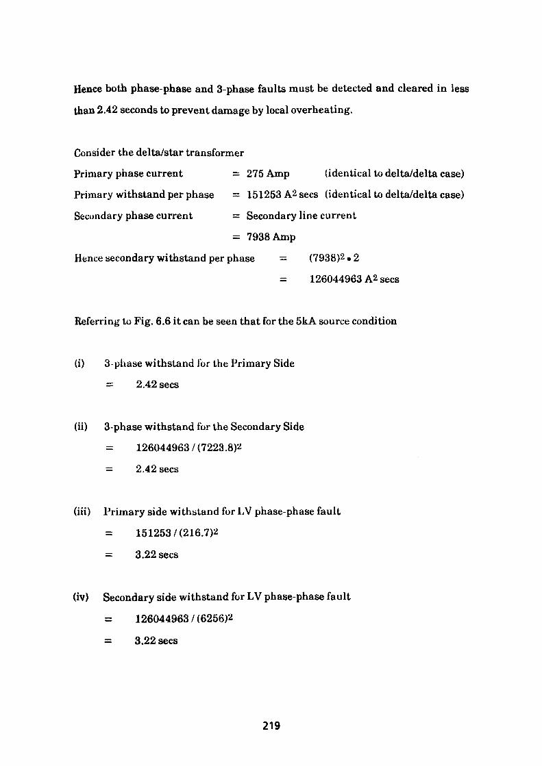
Hence both phase-phase and 3-phase faults must be detected and cleared in less
than 2.42 seconds to prevent damage by local overheating.
Consider the delta/star transformer
Primary phase current = 275 Amp (identical to delta/delta case)
Primary withstand per phase = 151253 A2 sees (identical to delta/delta case)
Secondary phase current = Secondary line current
= 7938 Amp
Hence secondary withstand per phase = (7938)2 • 2
= 126044963 A2 sees
Referring to Fig. 6.6 it can be seen that for the 5kA souree condition
(i) 3 - phase withstand for the Primary Side
= 2.42 sees
(ii) 3-phase withstand for the Secondary Side
126044963 / (7223.8)2
= 2.42 sees
(iii) Primary side withstand for LV phase-phase fault
151253 / (216.7)2
= 3.22 sees
(iv) Secondary side withstand for LV phase-phase fault
= 126044963 / (6256)2
= 3.22 sees
219
Hence to prevent the possibility of overheating either transformer under fault
conditions the relay must be able to detect a primary line current of 375.4 Amp
and disconnect the circuit in less than 2.42 sees.
Where only two overcurrent relays are utilised the requirement is more onerous
as it is necessary to ensure the relay setting will detect primary currents of 216.7
Amps yet still provide disconnection in 2.42 seconds. All six transformers must be
examined of course and their individual withstand times must be determined.
It is not proposed to repeat the calculations for the remaining two pairs of
transformers because they have identical vector group arrangements to the two
units already discussed and are treated in a similar fashion. Table 6.5 lists the
calculated fault currents when supplied from a source of maximum impedance
(5kA-Fault level) and is accompanied by the thermal withstand time for each
condition and transformer. Table 6.6 provides a further set of values for the
arrangement when supplied from a source at minimum impedance (25kA - Fault
level).
Having determined the transformer withstand times for each case, it is necessary
to ensure that the HV cable is also adequately rated for the longer withstand
period at these reduced current ratings in order to ensure that protection can be
afforded by the proposed overcurrent relays. In the interests of economy it is
sometimes possible to use overcurrent relays which monitor two out of three
phases only at the HV switchgear. This approach which was referred to earlier in
the text is ideal for all three-phase faults and phase-phase faults on transformers
with 0° phase shift. However, caution must be exercised when considering the
DYl unit referred to above where the transformer withstand has been determined
on the basis of maximum three-phase short-circuit current being carried in one
phase only whilst the two overcurrent elements may be monitoring the other two
220
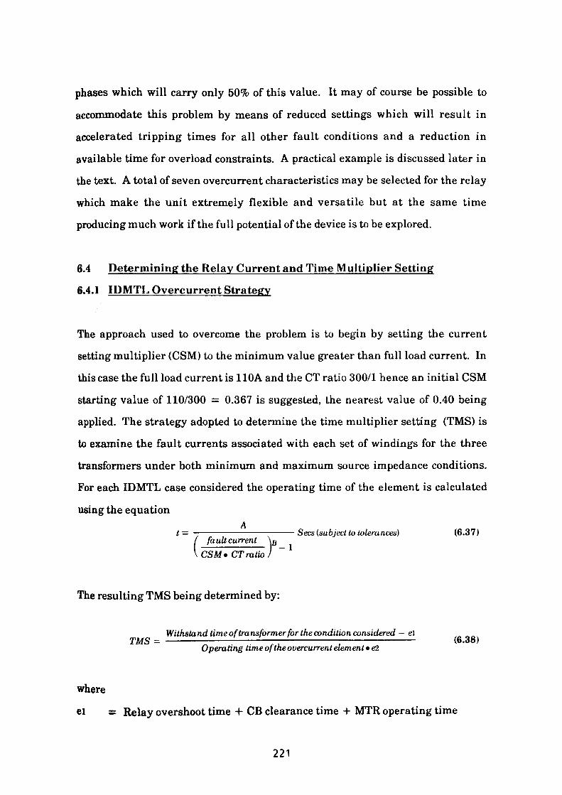
phases which will carry only 50% of this value. It may of course be possible to
accommodate this problem by means of reduced settings which will result in
accelerated tripping times for all other fault conditions and a reduction in
available time for overload constraints. A practical example is discussed later in
the text. A total of seven overcurrent characteristics may be selected for the relay
which make the unit extremely flexible and versatile but at the same time
producing much work if the full potential of the device is to be explored.
6.4 Determining the Relay Current and Time M ultiplier Setting
6.4.1 IDMTL Overcurrent Strategy
The approach used to overcome the problem is to begin by setting the current
setting multiplier (CSM) to the minimum value greater than full load current. In
this case the full load current is 110A and the CT ratio 300/1 hence an initial CSM
starting value of 110/300 = 0.367 is suggested, the nearest value of 0.40 being
applied. The strategy adopted to determine the time multiplier setting (TMS) is
to examine the fault currents associated with each set of windings for the three
transformers under both minimum and maximum source impedance conditions.
For each IDMTL case considered the operating time of the element is calculated
using the equationAt = ———————————-——— Sees (subject to tolerances) (6.37)
/ fault current \p\CSM« CT ratio)
The resulting TMS being determined by:
Withstand time of transformer for the condition considered — e\TMS = ————————-——— '———————;—————————— (6-38) Operating time of the overcurrent element • e2
where
el = Relay overshoot time + CB clearance time + MTR operating time
221
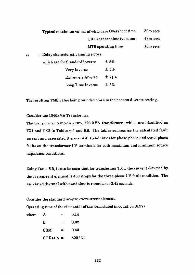
Typical maximum values of which are Overshoot time 30m sees
CB clearance time (vacuum) 48m sees
MTR operating time 10m sees
e2 = Relay characteristic timing errors
which are for Standard Inverse ± 5%
Very Inverse ± 5%
Extremely Inverse ± 7£%
Long Time Inverse + 5%
The resulting TMS value being rounded down to the nearest discrete setting.
Consider the 1040kVA Transformer.
The transformer comprises two, 520 kVA transformers which are identified as
TX1 and TX2 in Tables 6.5 and 6.6. The tables summarise the calculated fault
current and associated thermal withstand times for phase-phase and three-phase
faults on the transformer LV terminals for both maximum and minimum source
impedance conditions.
Using Table 6.5, it can be seen that for transformer TX1, the current detected by
the overcurrent element is 433 Amps for the three-phase LV fault condition. The
associated thermal withstand time is recorded as 2.42 seconds.
Consider the standard inverse overcurrent element.
Operating time of the element is of the form stated in equation (6.37)
where A = 0.14
B = 0.02
CSM = 0.40
CT Ratio = 300/(I)
222
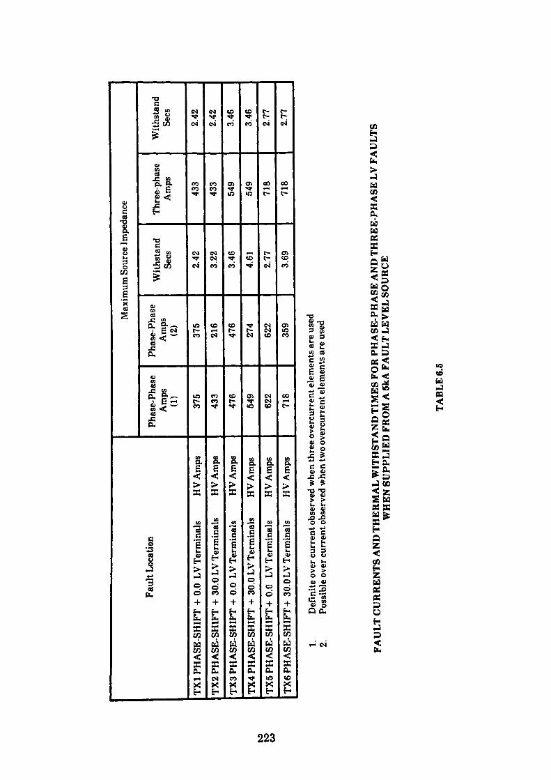
Faul
t Loc
atio
n
TX1
PHA
SE-S
HIF
T +
0.0
LV T
erm
inal
s H
V A
mps
TX2
PHA
SE-S
HIF
T +
30.0
LV
Term
inal
s H
V A
mps
TX3
PHA
SE-S
HIF
T +
0.0
LV T
erm
inal
s HV
Am
ps
TX4
PHA
SE-S
HIF
T +
30.0
LV
Term
inal
s H
V A
mps
TX5
PHA
SE-S
HIF
T +
0.0
LV T
erm
inal
s H
VA
mps
TX6
PHA
SE-S
HIF
T +
30.0
LV
Term
inal
s H
V A
mps
Max
imum
Sou
rce
Impe
danc
e
Phas
e-Ph
ase
Am
ps
(1)
375
433
476
549
622
718
Phas
e-Ph
ase
Am
ps
(2)
375
216
476
274
622
359
With
stan
d Se
es
2.42
3.22
3.46
4.61
2.77 3.69
Thre
e-ph
ase
Am
ps
433
433
549
549
718
718
With
stan
d Se
es
2.42
2.42
3.46
3.46
2.77
2.77
to
to CO
1. D
efin
ite o
ver c
urre
nt o
bser
ved
whe
n th
ree
over
curr
ent e
lem
ents
are
use
d2.
Poss
ible
ove
r cur
rent
obs
erve
d w
hen
two
over
curr
ent e
lem
ents
are
use
d
FAU
LT
CU
RR
EN
TS
AN
D T
HER
MA
L W
ITH
STA
ND
TIM
ES F
OR
PH
ASE
-PH
ASE
AN
D T
HR
EE
-PH
ASE
LV
FA
UL
TS
WH
EN S
UPP
LIE
D F
RO
M A
5kA
FA
ULT
LEV
EL S
OU
RC
E
TABL
E 6.
6

Faul
t Loc
atio
n
TX1
PHA
SE-S
HIF
T +
0.0
LV T
erm
inal
s HV
Am
psTX
2 PH
ASE
-SH
IFT
+ 30
.0 L
V Te
rmin
als
H V
Am
psTX
3 PH
ASE
-SH
IFT
+ 0.
0 LV
Ter
min
als
H V
Am
psTX
4 PH
ASE
-SH
IFT
+ 30
.0 L
V Te
rmin
als
HV A
mps
TX5
PHA
SE-S
HIF
T +0
.0 L
V Te
rmin
als
HV
Am
psTX
6PH
ASE
-SH
IFT-
I- 3
0.0 L
V Te
rmin
als
HV
Am
ps
Min
imum
Sou
rce I
mpe
danc
e
Phas
e-Ph
ase
Am
ps
(1)
403
465
521
602
703
811
Phas
e-Ph
ase
Am
ps
(2)
403
232
521
301
703
405
With
stand
oGCS
2.10
2.80
2.88
3.84
2.17
2.89
Thre
e-ph
ase
Am
ps
465
465
602
602
811
811
With
stan
d Se
es
210
2.10
2.88
2.88
2.17
2.17
10
1. D
efin
ite o
ver c
urre
nt o
bser
ved
whe
n th
ree
over
curr
ent e
lem
ents
are
used
2. Po
ssib
le o
ver c
urre
nt o
bser
ved
whe
n tw
o ove
rcur
rent
elem
ents
are
used
FAU
LT
CU
RR
EN
TS
AN
D T
HER
MA
L W
ITH
STA
ND
TIM
ES F
OR
PH
ASE
-PH
ASE
AN
D T
HR
EE
-PH
ASE
LV
FA
UL
TS
WH
EN S
UPP
LIE
D F
RO
M A
25k
A F
AU
LT L
EVEL
SO
UR
CE
TABL
E 6.
6
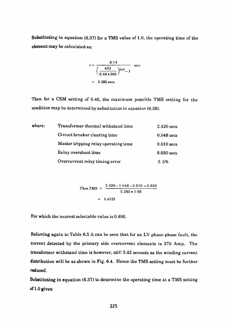
Substituting in equation (6.37) for a TMS value of 1.0, the operating time of the
element may be calculated as:
0.14t — —————————————— ticca ( 433 W ]V0.40«300/
= 5.385 sees
Then for a CSM setting of 0.40, the maximum possible TMS setting for the
condition may be determined by substitution in equation (6.38).
where: Transformer thermal withstand time 2.420 sees
Circuit breaker clearing time 0.048 sees
Master tripping relay operating time 0.010 sees
Relay overshoot time 0.030 sees
Overcurrent relay timing error ± 5%
2.420-0 048-0.010 -0.030 Then T MS = —————————————————— 5.385» 1.05
= 0.4125
For which the nearest selectable value is 0.400.
Referring again to Table 6.5 it can be seen that for an LV phase-phase fault, the
current detected by the primary side overcurrent elements is 375 Amp. The
transformer withstand time is however, still 2.42 seconds as the winding current
distribution will be as shown in Fig. 6.4. Hence the TMS setting must be further
reduced.
Substituting in equation (6.37) to determine the operating time at a TMS setting
of 1.0 gives:
225
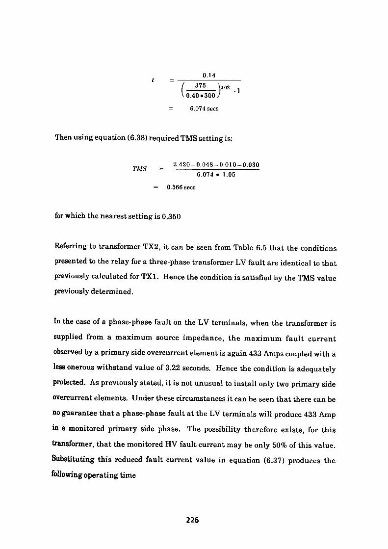
0.14 375 \002
0.40*300
6.074 sees
-1
Then using equation (6.38) required TMS setting is:
2.420-0.048-0.010-0.0301M. o — *——*— - "— ™ "" ———— 6.074 • 1.05
= 0.366 sees
for which the nearest setting is 0.350
Referring to transformer TX2, it can be seen from Table 6.5 that the conditions presented to the relay for a three-phase transformer LV fault are identical to that previously calculated for TX1. Hence the condition is satisfied by the TMS value previously determined.
In the case of a phase-phase fault on the LV terminals, when the transformer is supplied from a maximum source impedance, the maximum fault current observed by a primary side overcurrent element is again 433 Amps coupled with a less onerous withstand value of 3.22 seconds. Hence the condition is adequately protected. As previously stated, it is not unusual to install only two primary side overcurrent elements. Under these circumstances it can be seen that there can be no guarantee that a phase-phase fault at the LV terminals will produce 433 Amp in a monitored primary side phase. The possibility therefore exists, for this transformer, that the monitored HV fault current may be only 50% of this value. Substituting this reduced fault current value in equation (6.37) produces the
following operating time
226
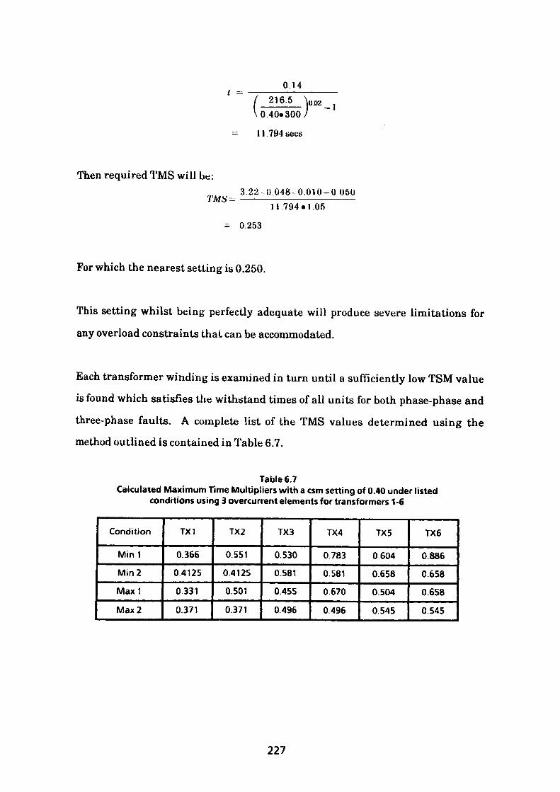
I - 0 14
0.40*300 /
11.794 sees
-1
Then required TMS will be:
TMS- 3.22-0.048-0.010-0 05011 794 • 1.05
= 0.253
For which the nearest setting is 0.250.
This setting whilst being perfectly adequate will produce severe limitations for
any overload constraints that can be accommodated.
Each transformer winding is examined in turn until a sufficiently low TSM value is found which satisfies the withstand times of all units for both phase-phase and
three-phase faults. A complete list of the TMS values determined using the method outlined is contained in Table 6.7.
Table 6.7Calculated Maximum Time Multipliers with a csm setting of 0.40 under listed
conditions using 3 overcurrent elements for transformers 1-6
Condition
Mini
Min2
Max1
Max 2
TX1
0.366
0.4125
0.331
0.371
TX2
0.551
0.4125
0.501
0.371
TX3
0.530
0.581
0.455
0.496
TX4
0783
0.581
0.670
0.496
TX5
0604
0658
0.504
0.545
TX6
0.886
0.658
0.658
0.545
227

Where
Mini
Min2
Maxl
Max 2
TX1-6
Minimum Source Impedance - LV phase-phase fault
Minimum Source Impedance - LV 3-phase fault
Maximum Source Impedance - LV phase-phase fault
Maximum Source Impedance - LV 3-phase fault
Transformers 1 to 6
At this juncture with the CSM and TMS settings for the transformers now
established, it is necessary to consider any constraints which may apply. The
relay operating time may now be determined by modifying equation (6.37).
Hence operating timeA« TMS
t - —————-——— (6.39) / fa alt current \g\ CSM»CTRatiof ~
In practice, the circuit is driven into the overload state for short periods by design.
It is therefore necessary to ensure that the duration of the overload excursions can
be accommodated by the final settings applied to the relay. Three overload
constraints are considered for this circuit.
1. An overload of 175A sustained for 14 sees.
2. An overload of 200A sustained for 9 sees.
3. An overload of 373A sustained for 2 sees.
Substituting the stated values in equation (6.39) produces the following operating
times for the relay.
0.14-0.325(1) , ,„„——-————- 6* sees\0.02/JI75_\0
V 0.4«300 /-1
228
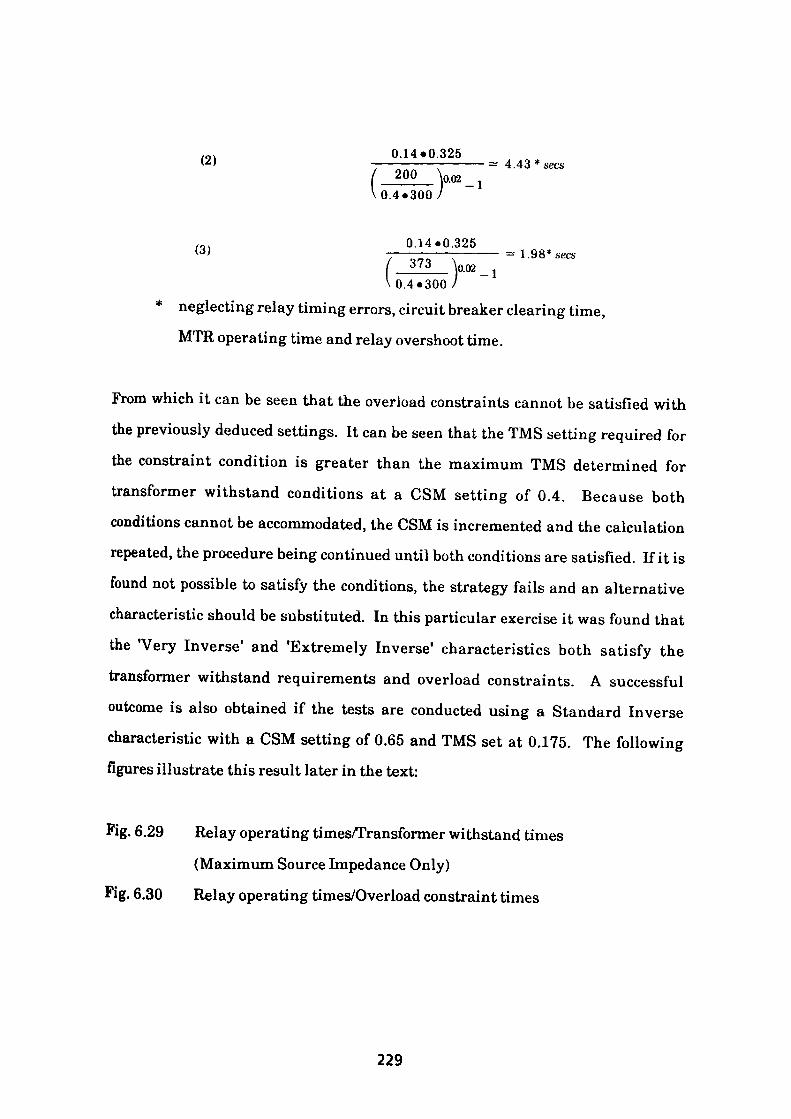
0.14*0.325(2) ___________ = 4.43 * sees200 \o.o2 ]
0.4.300 /
0.14.0.325(3) ———————————— =1.98* sees/_373__ \oo2_jVO.4«300 /
* neglecting relay timing errors, circuit breaker clearing time,MTR operating time and relay overshoot time.
From which it can be seen that the overload constraints cannot be satisfied with the previously deduced settings. It can be seen that the TMS setting required for the constraint condition is greater than the maximum TMS determined for transformer withstand conditions at a CSM setting of 0.4. Because both conditions cannot be accommodated, the CSM is incremented and the calculation repeated, the procedure being continued until both conditions are satisfied. If it is found not possible to satisfy the conditions, the strategy fails and an alternative characteristic should be substituted. In this particular exercise it was found that the "Very Inverse1 and 'Extremely Inverse1 characteristics both satisfy the transformer withstand requirements and overload constraints. A successful outcome is also obtained if the tests are conducted using a Standard Inverse characteristic with a CSM setting of 0.65 and TMS set at 0.175. The following figures illustrate this result later in the text:
Fig. 6.29 Relay operating times/Transformer withstand times(Maximum Source Impedance Only)
Fig. 6.30 Relay operating times/Overload constraint times
229
6.4.2 Definite Time Overcurrent Strategy
This alternative approach allows any one of three definite time lag characteristics
to be used for overcurrent protection, the selection being made by means of slide
switches mounted on the faceplate.
The strategy adopted in this case is to examine the phase-phase and three-phase
short-circuit currents and associated transformer withstand times for each unit in
turn. From the data presented, the value of the minimum fault current condition
when supplied via the maximum source impedance value is recorded. Similarly
the minimum transformer withstand time associated with the maximum fault
current condition when supplied via the minimum source impedance condition is
also noted. Each set of results being updated as required for each transformer
until the two extreme conditions for the system are known. In the case considered,
Fig. 6.7 shows that the minimum detectable current condition is 216 Amp when
two elements are installed and 375 Amp when three are in use. The minimum
transformer withstand time being 2.10 sees as shown in Table 6.6 Clearly if the
relay setting is sensitive enough to detect the minimum fault current condition
then all other fault conditions are equally protected.
Similarly if the operating time is lower than the lowest transformer withstand
value then all conditions are satisfied.
To achieve fault detection of 375 Amp with the three-element arrangement it is
necessary to set the CSM to:
375CSM = ————— = 1.136 1.1*300
230
where 375A is the fault current to be detected
1.1 is a factor representing pick-up errors
300 is the CT ratio
As a current setting of this value does not exist the value must be rounded down to
the nearest setting of 1. J 0 which in primary current terms is nominally 1.10 x 300
= 330 Amp. This is the maximum setting that can be used which will detect all
fault conditions.
Next consider the time multiplier setting (TMS) whose setting is a function of the
timing range chosen, the selectable ranges offered being 2, 4 or 8 sees with an
operating time accuracy of ± 3%.
Hence maximum allowable time multiplier settings for the 3 ranges are
calculated in accordance with equation (6.38).
1. Two Second range
2.10-0.088TMS = ——————— =0.977 Nearest Setting 0.975
1.03*2
2. Four Second range
2.10-0088TMS - —————— =0.488 Nearest Setting 0.475
1.03«4
3. Eight Second range
2 10-0088TMS - ———————-0.244 Nearest Setting 0.225
1.03-8
The above settings when taking maximum tolerances into account result in an
operating time range of ± 3% of the chosen setting.
231
It can be seen that if an operational overload constraint exceeds the primary
current pick-up value of 330 Amp its duration cannot exceed 1.892 seconds
without the possibility of a trip occurring. Should the overload constraint be less
than the pick-up value then its duration may be infinite. Clearly not an ideal
solution but the strategy dues provide complete protection for all short circuit
conditions possible on the secondary sides of the transformers. For low value
overload conditions the CSM may be reduced thus offering a range of possible
settings. In the case under investigation the strategy is marginal, because the
relay is in the energised state due to the overload current of 373 Amp whose
duration of two seconds may exceed the relay definite time setting of two seconds
(1.892 / 2.009) seconds if negative timing tolerances are present.
232
6.5 Instantaneous Overcurrent Elements
The function of the instantaneous elements are to protect the HV cable and
transformer windings under primary short circuit conditions. This is achieved by
setting the relay at a higher level than the maximum fault current available at
the transformer LV terminals. A minimum allowance of 10% should be included
to allow for transient overreach. The maximum setting is determined by the
minimum short circuit current which occurs for phase-phase faults at the
transformer HV terminals when the system is supplied via the maximum source
impedance. Providing the instantaneous overcurrent elements satisfy these
conditions then all other HV fault conditions will be equally satisfied. In the case
under consideration the calculated minimum phase-phase current for HV short
circuits is 4135A (see Fig. 6.7). The usual procedure adopted being to limit the
maximum setting to half this value to provide decisive operation, i.e. 2068A. The
settings of the instantaneous elements are arranged in multiples of the associated
IDMTL/DTL element settings. As both types have been previously discussed the
setting ranges for the two approaches will be addressed below:-
6.5.1 IDMTL - Standard Inverse Characteristic
- Settings CSM 0.65: TMS 0.175
Maximum HV fault current available under LV fault conditions = 811A
Allowing 10% for relay overreach 811*1.1 = 892A
Hence minimum setting > 892A
LV Fault Current 892 Minimum setting = = = 4 57
For which the nearest setting is 5
233
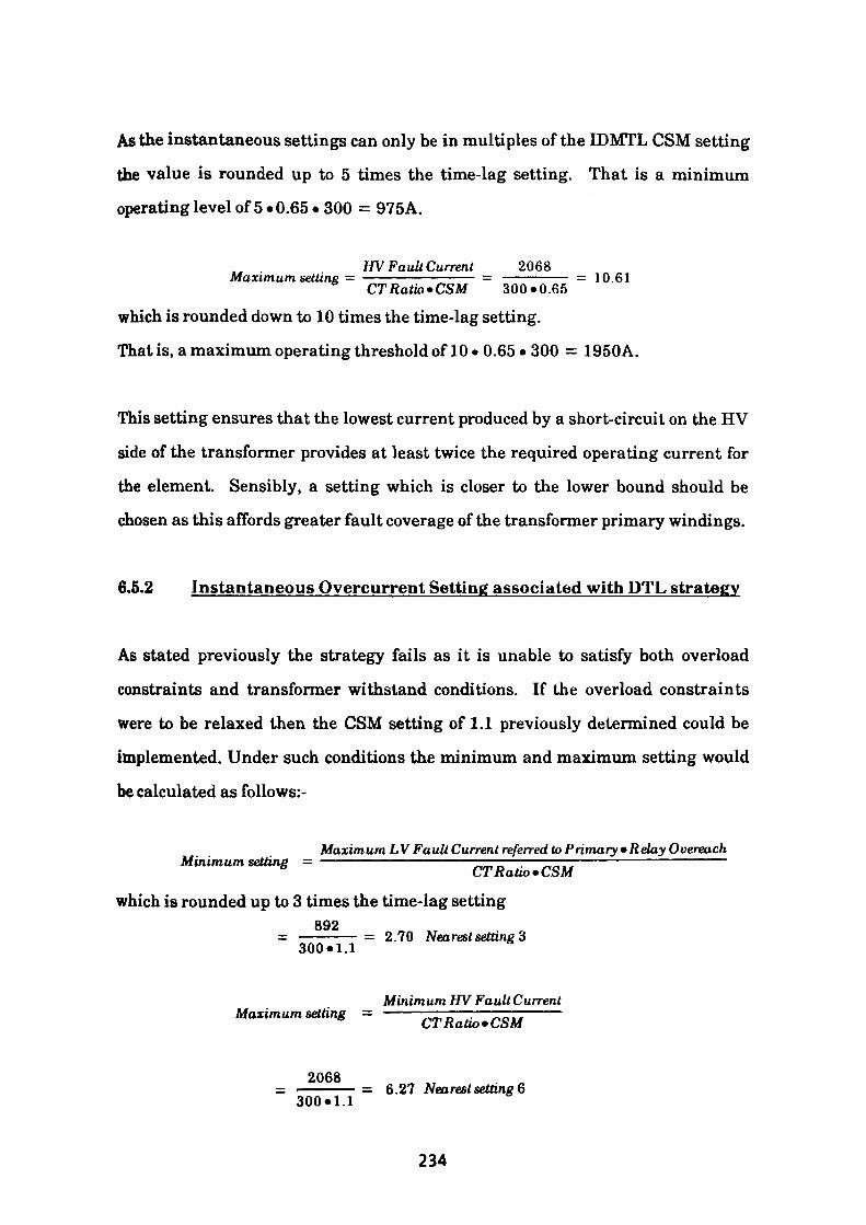
As the instantaneous settings can only be in multiples of the IDMTL CSM setting
the value is rounded up to 5 times the time-lag setting. That is a minimum
operating level of 5 • 0.65 • 300 = 975A.
HV Fa uli Current 2068Maximum setting = ———————— = —————— = 10.61CTRatio»CSM 300*0.65
which is rounded down to 10 times the time-lag setting.
That is, a maximum operating threshold of 10 • 0.65 • 300 = 1950A.
This setting ensures that the lowest current produced by a short-circuit on the HV
side of the transformer provides at least twice the required operating current for
the element. Sensibly, a setting which is closer to the lower bound should be
chosen as this affords greater fault coverage of the transformer primary windings.
6.5.2 Instantaneous Overcurrent Setting associated with DTL strategy
As stated previously the strategy fails as it is unable to satisfy both overload
constraints and transformer withstand conditions. If the overload constraints
were to be relaxed then the CSM setting of 1.1 previously determined could be
implemented. Under such conditions the minimum and maximum setting would
be calculated as follows:-
Maximum LV Fault Current referred to Primary •Relay Ouereach Minimum setting = ——————
which is rounded up to 3 times the time-lag setting892
300«l.l = 2.70 Nearest setting 3
Minimum HV Fault CurrentMaximum setting = ——————;——————CT Ratio* CSM
2068= 6.27 Nearest setting 6
300*1.1
234
6.6 Earth Fault
The earth fault detecting element installed at the point of common coupling (PCC) with the supply will detect the presence of zero sequence current in the main cable and transformeds) primary circuit only. Any earth faults occurring on the LV side of the transformers must be dealt with separately. As a result there is a requirement for instantaneous earth-fault protection only to be installed. The relay discussed, however, contains both time-lag and instantaneous elements. The instantaneous element setting being a multiple of the time-lag CSM setting. Because the time-lag elements are an integral part of the relay construction, it is proposed to calculate time-lag settings which will provide back-up protection for the instantaneous elements. The two principal methods of detecting zero sequence current flow are by means of a core balance current transformer (CBCT) in which the out of balance current of the three phase conductors which pass through it provide the measurement or, alternatively, by using residually connected current transformers. The latter approach is used in this exercise as three single phase current transformers are used to supply the overcurrent relays, the earth fault element being connected at the star point where it will measure residual current, that is 3.10.
As the earth fault element passes no current under normal balanced conditions the current setting multiplier (CSM) can be initially set to the minimum value of 0.05 which is 0.05 • 300 or 15 Amp in terms of primary current. The operating time of the element must of course ensure that the conductor and armour withstand times are not exceeded and this can be achieved by means of the time multiplier setting (TMS). Referring to Fig. 6.7 where:
Maximum earth fault current = 5000 Amp
Withstand time of conductor = 13.5kA/sec
235
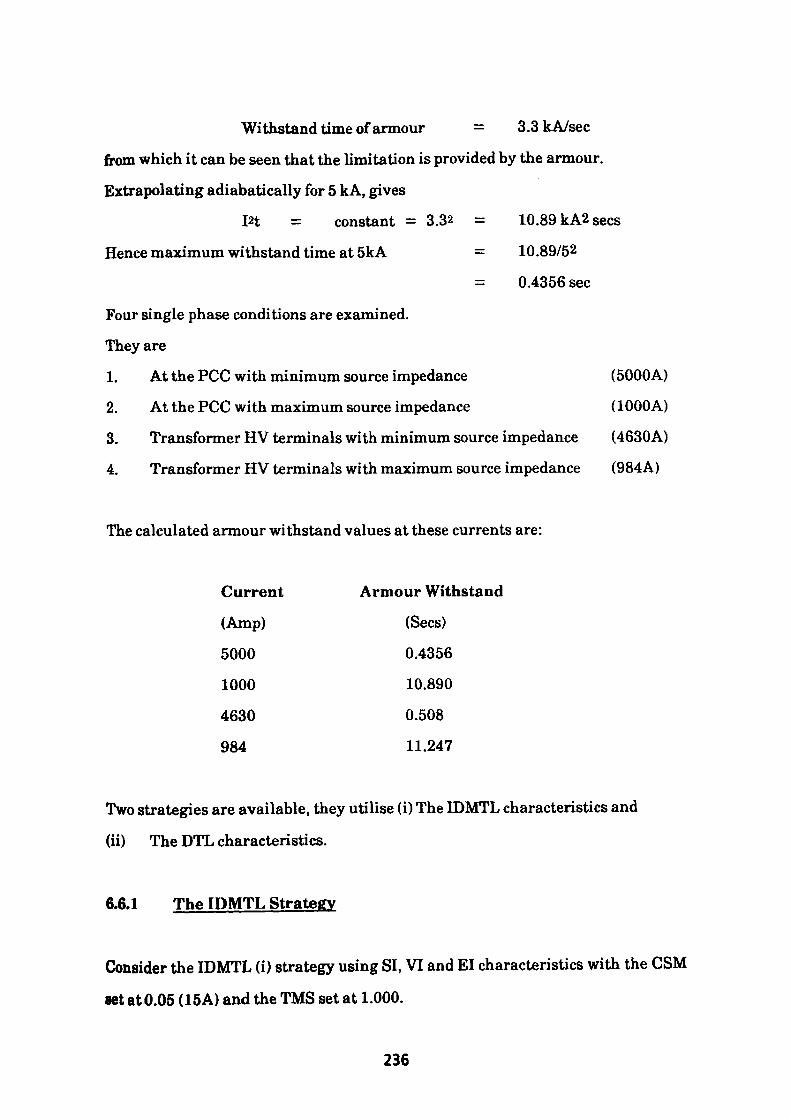
Withstand time of armour = 3.3kA/sec
from which it can be seen that the limitation is provided by the armour.
Extrapolating adiabatically for 5 kA, gives
in = constant = 3.32 = 10.89 kA2 sees
Hence maximum withstand time at 5kA = 10.89/52
= 0.4356 sec
Four single phase conditions are examined.
They are
1. At the PCC with minimum source impedance (5000A)
2. At the PCC with maximum source impedance (1000A)
3. Transformer HV terminals with minimum source impedance (4630A)
4. Transformer HV terminals with maximum source impedance (984A)
The calculated armour withstand values at these currents are:
Current
(Amp)
5000
1000
4630
984
Armour Withstand
(Sees)
0.4356
10.890
0.508
11.247
Two strategies are available, they utilise (i) The IDMTL characteristics and
(ii) The DTL characteristics.
6.6.1 The IDMTL Strategy
Consider the IDMTL (i) strategy using SI, VI and El characteristics with the CSM
set atO.05 (15A) and the TMS set at 1.000.
236
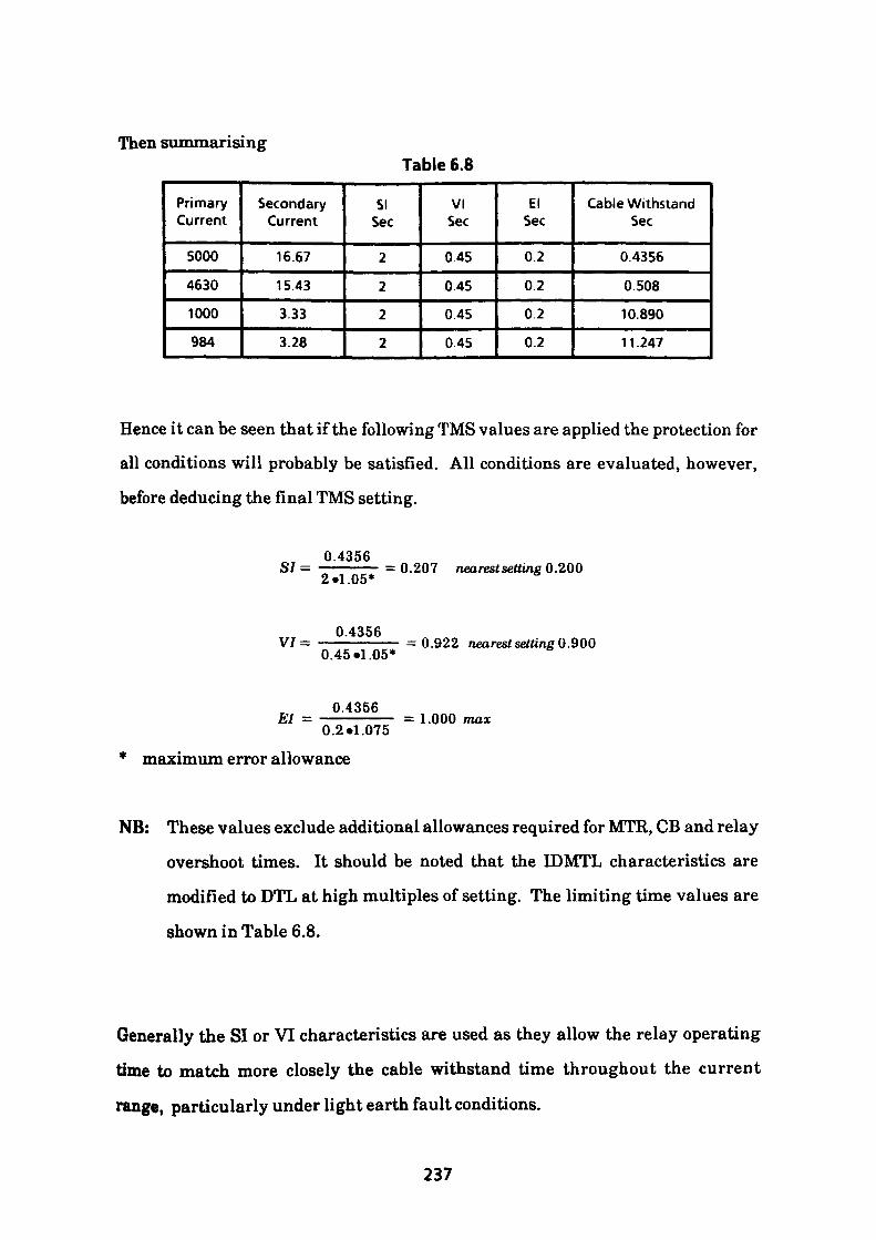
Then summarisingTable 6.8
Primary Current
5000
4630
1000
984
Secondary Current
16.67
15.43
3.33
3.28
SI Sec
2
2
2
2
VI Sec
0.45
0.45
0.45
0.45
El Sec
0.2
0.2
0.2
0.2
Cable Withstand Sec
0.4356
0.508
10.890
11.247
Hence it can be seen that if the following TMS values are applied the protection for
all conditions will probably be satisfied. All conditions are evaluated, however,
before deducing the final TMS setting.
0.4356— =0.207 nearestsetting 0.200
0.2.1.075 * maximum error allowance
2«1.05
0.4356V/= ——————— =0.922 nearest setting 0.900 0.45*1.05*
0.4356 El = —, = 1.000 max
NB: These values exclude additional allowances required for MTR, CB and relay
overshoot times. It should be noted that the IDMTL characteristics are
modified to DTL at high multiples of setting. The limiting time values are
shown in Table 6.8.
Generally the SI or VI characteristics are used as they allow the relay operating
time to match more closely the cable withstand time throughout the current
range, particularly under light earth fault conditions.
237
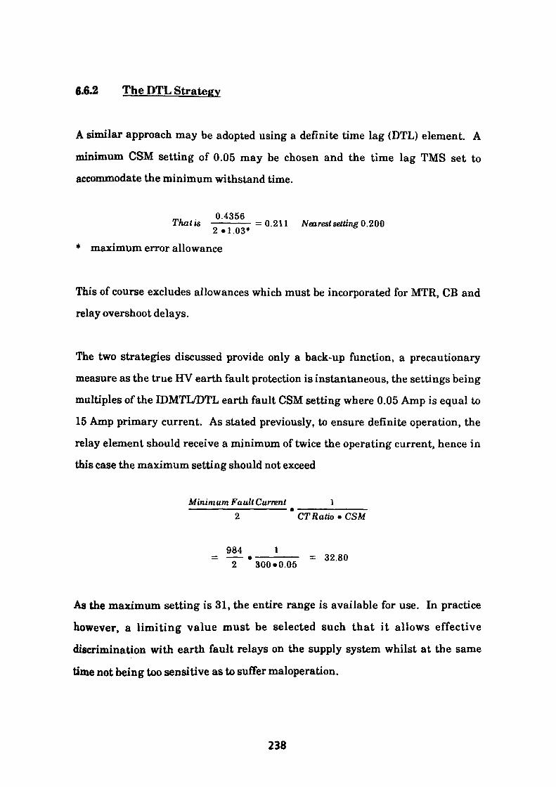
6.6.2 The DTL Strategy
A similar approach may be adopted using a definite time lag (DTL) element. A
minimum CSM setting of 0.05 may be chosen and the time lag TMS set to
accommodate the minimum withstand time.
0.4356Thatis —————=0.211 Nearest setting 0.200 2.1.03*
* maximum error allowance
This of course excludes allowances which must be incorporated for MTR, CB and
relay overshoot delays.
The two strategies discussed provide only a back-up function, a precautionary
measure as the true HV earth fault protection is instantaneous, the settings being
multiples of the IDMTL/DTL earth fault CSM setting where 0.05 Amp is equal to
15 Amp primary current. As stated previously, to ensure definite operation, the
relay element should receive a minimum of twice the operating current, hence in
this case the maximum setting should not exceed
Minimum Fa ult Current ICTRatio • CSM
984 1—— •—————— = 32.80 2 300*0.05
As the maximum setting is 31, the entire range is available for use. In practice
however, a limiting value must be selected such that it allows effective
discrimination with earth fault relays on the supply system whilst at the same
time not being too sensitive as to suffer maloperation.
238
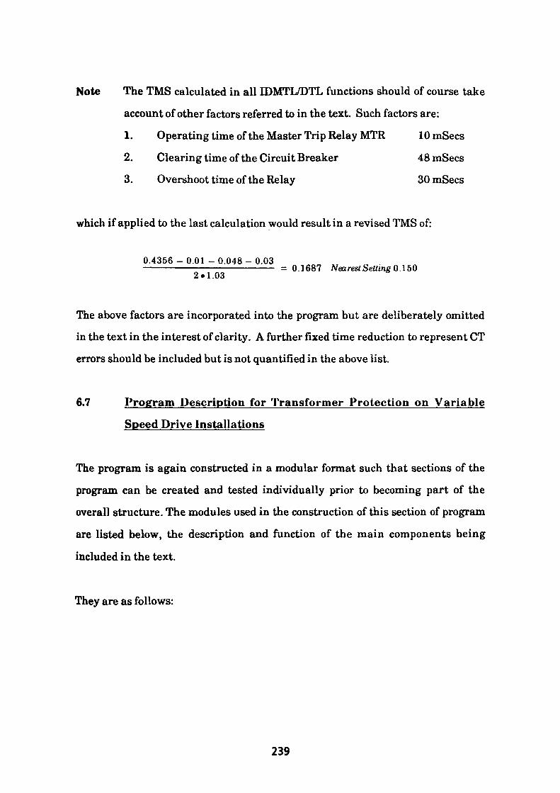
Note The TMS calculated in all IDMTL/DTL functions should of course take
account of other factors referred to in the text. Such factors are:
1. Operating time of the Master Trip Relay MTR 10 mSecs
2. Clearing time of the Circuit Breaker 48 mSecs
3. Overshoot time of the Relay SOmSecs
which if applied to the last calculation would result in a revised TMS of:
0.4356 - 0.01 - 0.048 - 0.03——————————————————— = 0.1687 Nearest Setting 0.150 2»1.03
The above factors are incorporated into the program but are deliberately omitted
in the text in the interest of clarity. A further fixed time reduction to represent CT
errors should be included but is not quantified in the above list.
6.7 Program Description for Transformer Protection on Variable
Speed Drive Installations
The program is again constructed in a modular format such that sections of the
program can be created and tested individually prior to becoming part of the
overall structure. The modules used in the construction of this section of program
are listed below, the description and function of the main components being
included in the text.
They are as follows:
239
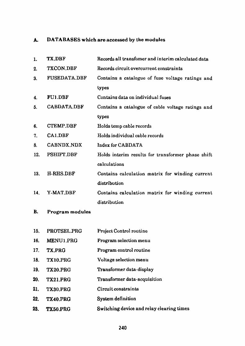
A. DATABASES which are accessed by the modules
1. TX.DBF
2. TXCON.DBF
3. FUSEDATA.DBF
4. FU1.DBF
5. CABDATA.DBF
6. CTEMP.DBF
7. CA1.DBF
8. CABNDX.NDX
12. PSHIFT.DBF
13. H-RHS.DBF
14. Y-MAT.DBF
B. Program modules
Records all transfomer and interim calculated data
Records circuit overcurrent constraints
Contains a catalogue of fuse voltage ratings and
types
Contains data on individual fuses
Contains a catalogue of cable voltage ratings and
types
Holds temp cable records
Holds individual cable records
Index for CABDATA
Holds interim results for transformer phase shift
calculations
Contains calculation matrix for winding current
distribution
Contains calculation matrix for winding current
distribution
15. PROTSEL.PRG
16. MENU1.PRG
17. TX.PRG
18. TX10.PRG
19. TX20.PRG
20. TX21.PRG
21. TX30.PRG
22. TX40.PRG
23. TX50.PRG
Project Control routine
Program selection menu
Program control routine
Voltage selection menu
Transformer data-display
Transformer data-acquisition
Circuit constraints
System definition
Switching device and relay clearing times
240
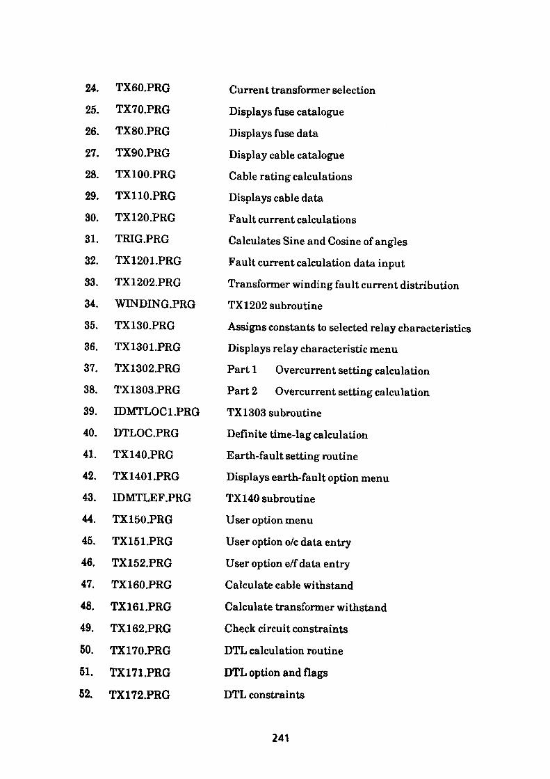
24. TX60.PRG
25. TX70.PRG
26. TX80.PRG
27. TX90.PRG
28. TX100.PRG
29. TX110.PRG
30. TX120.PRG
31. TRIG.PRG
32. TX1201.PRG
33. TX1202.PRG
34. WINDING.PRG
35. TX130.PRG
36. TX1301.PRG
37. TX1302.PRG
38. TX1303.PRG
39. IDMTLOC1.PRG
40. DTLOC.PRG
41. TX140.PRG
42. TX1401.PRG
43. IDMTLEF.PRG
44. TX150.PRG
45. TX151.PRG
46. TX152.PRG
47. TX160.PRG
48. TX161.PRG
49. TX162.PRG
50. TX170.PRG
51. TX171.PRG
52. TX172.PRG
Current transformer selection
Displays fuse catalogue
Displays fuse data
Display cable catalogue
Cable rating calculations
Displays cable data
Fault current calculations
Calculates Sine and Cosine of angles
Fault current calculation data input
Transformer winding fault current distribution
TX1202 subroutine
Assigns constants to selected relay characteristics
Displays relay characteristic menu
Part 1 Overcurrent setting calculation
Part 2 Overcurrent setting calculation
TX1303 subroutine
Definite time-lag calculation
Earth-fault setting routine
Displays earth-fault option menu
TX140 subroutine
User option menu
User option o/c data entry
User option e/f data entry
Calculate cable withstand
Calculate transformer withstand
Check circuit constraints
DTL calculation routine
DTL option and flags
DTL constraints
241
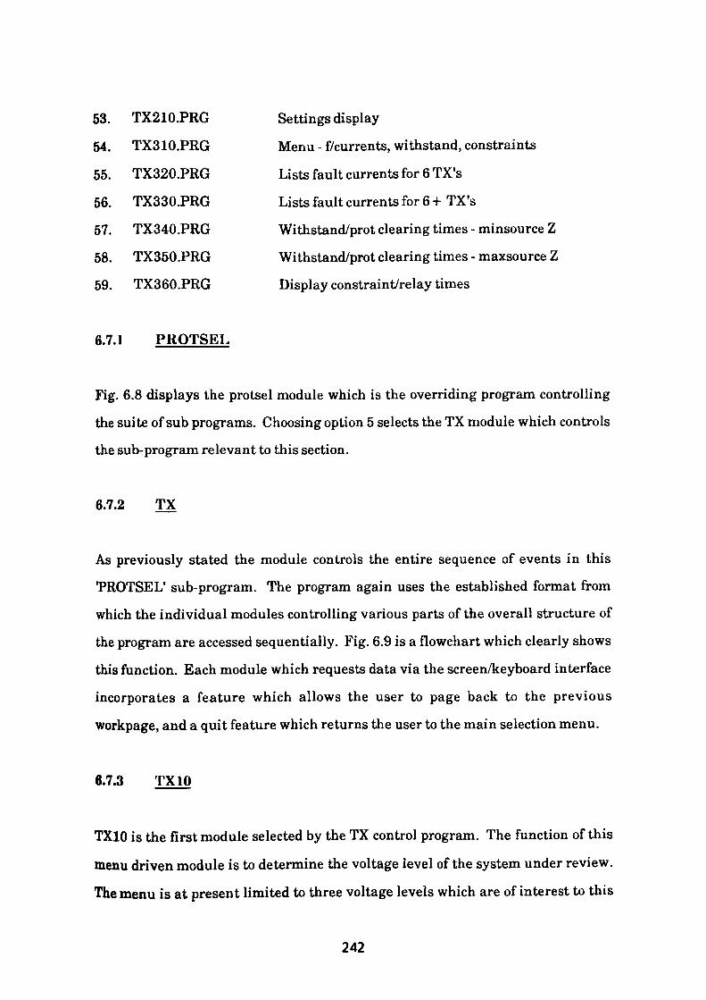
53. TX210.PRG Settings display
54. TX310.PRG Menu - f/currents, withstand, constraints
55. TX320.PRG Lists fault currents for 6 TX's
56. TX330.PRG Lists fault currents for 6 + TX's
57. TX340.PRG Withstand/prot clearing times-minsourceZ
58. TX350.PRG Withstand/prot clearing times - maxsource Z
59. TX360.PRG Display constraint/relay times
6.7.1 PROTSEL
Fig. 6.8 displays the protsel module which is the overriding program controlling
the suite of sub programs. Choosing option 5 selects the TX module which controls
the sub-program relevant to this section.
6.7.2 TX
As previously stated the module controls the entire sequence of events in this
'PROTSEL1 sub-program. The program again uses the established format from
which the individual modules controlling various parts of the overall structure of
the program are accessed sequentially. Fig. 6.9 is a flowchart which clearly shows
this function. Each module which requests data via the screen/keyboard interface
incorporates a feature which allows the user to page back to the previous
workpage, and a quit feature which returns the user to the main selection menu.
6.7.3 TX10
TX10 is the first module selected by the TX control program. The function of this
menu driven module is to determine the voltage level of the system under review.
The menu is at present limited to three voltage levels which are of interest to this
242
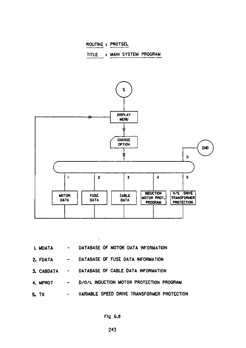
ROUTINE : PROTSEL
TITLE : MAIN SYSTEM PROGRAM
1. MDATA
2. FDATA
3. CABDATA
4. MPROT
5. TX
DATABASE OF MOTOR DATA INFORMATION
DATABASE OF FUSE DATA INFORMATION
DATABASE OF CABLE DATA INFORMATION
D/O/L INDUCTION MOTOR PROTECTION PROGRAM
VARIABLE SPEED DRIVE TRANSFORMER PROTECTION
Fig 6.8
243
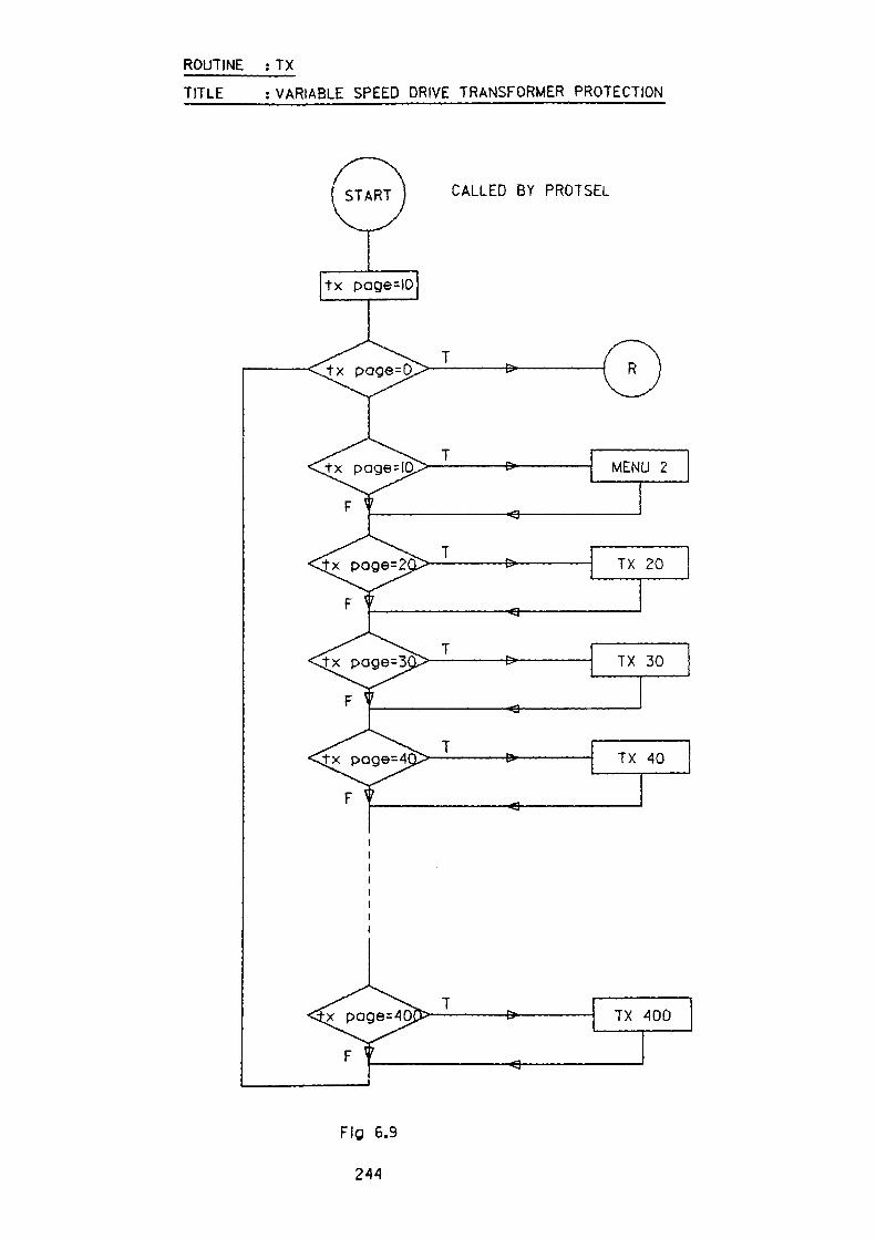
ROUTINE ; TX
TITLE : VARIABLE SPEED DRIVE TRANSFORMER PROTECTION
CALLED BY PROTSEL
J-x page=0.
Fig 6.9
244
project. A screen display of the menu is shown in Fig. 6.10 accompanied by a
flowchart of the module in Fig. 6.11
6.7.4 TX20
This module is used to acquire and store the transformer data relevant to the
circuit under investigation. The routine is shown in the flowchart Fig. 6.12 and
requires the following input of information for each individual transformer.
1. Rating (kVA)
2. Vector Group of Windings
3. Percentage Resistance based on Rating
4. Percentage Reactance based on Rating
5. Phase Shift of Secondary Winding
6. Secondary Voltage
7. Secondary CT Ratio, if fitted.
8. Setting of LV instantaneous overcurrent relays
Using the above listed data, the routine counts the number of shunt connected
transformers and calculates the overall full load current. The acquired data is, of
course, stored for use in later modules. The screen presentation of the data used in
the Temper Mill case study discussed in section 6.3 is shown in Fig. 6.13.
6.7.5 TX30
This module is used to collate the constraints applied to the circuit. The logic used
for data collection is essentially the same as that found in the TX20 routine except
that the input data is required to define the magnitude and duration of the
overloads that the circuit is routinely subjected to during the duty cycle.
245
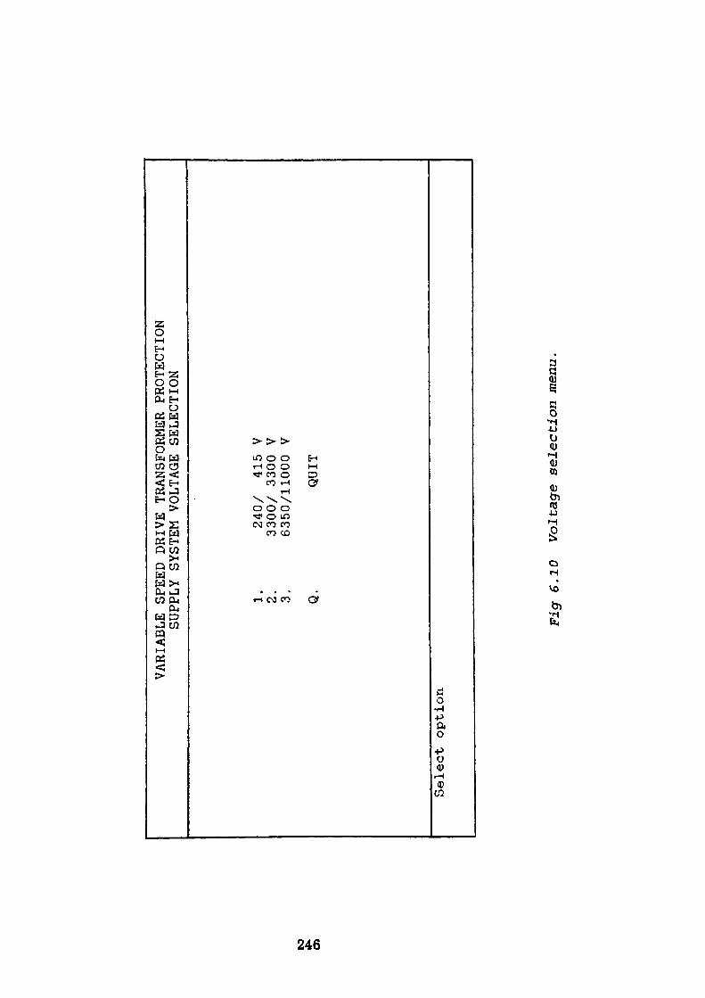
VARIABLE SPEED DR
IVE
TRANSFORMER PROTECTION
SUPPLY SYSTEM VOLTAGE
SELECTION
to *» Cf>
1. 2. 3. Q.
240/
41
5 V
3300
/ 3300 V
6350/11000 V
QUIT
Select option
Fig
6.10
Voltage
selection
menu.
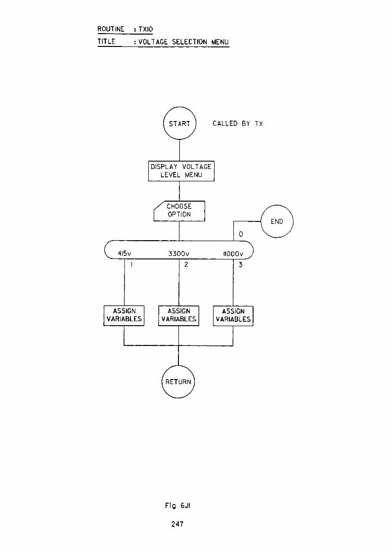
ROUTINE : TXIO
TITLE : VOLTAGE SELECTION MENU
4l5v
START CALLED BY TX
DISPLAY VOLTAGE LEVEL MENU
/ CHOOSE f OPTION
1 ————— 0
3300v
(RETURN)
IIOOOv
Fig 6.11
247
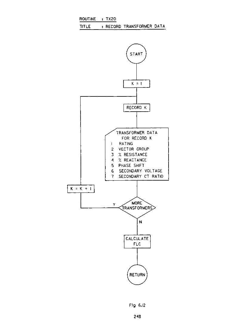
ROUTINE : TX20
TITLE : RECORD TRANSFORMER DATA
TRANSFORMER DATA FOR RECORD K
1 RATING2 VECTOR GROUP3 '/. RESISTANCE A •/. REACTANCE5 PHASE SHIFT6 SECONDARY VOLTAGE7 SECONDARY CT RATIO
Y ^ MORETRANSFORMERS
Fig 6.12
248

to
*- CD
VARIABLE
Supply Volt
Type
<1 &
<2 &
<3>
<4>
s
SPEE
D DR
IVE
TRANSFORMER
PROTECTION
CIRCUIT
DEFINITION
1E>
Tran
sfor
mer
2E>
Tran
sfor
mer
Tran
sfor
mer
Tran
sfor
mer
WNDG
RA
TING
WNDG
No
kVA
type
TX1
TX2
TX3
TX4
TX5
TX6
520
520
677
677
872
872
<M>o
re data
<A>c
cept
/
1 2 1 2 1 2
<R>eject
0 0 0 0 0 0 A
windings
windings
: windings
: windings
:
Pri
Pri
Pri
Pri
. .
. .
. R3
(DEL
TA)
: Sec
(DEL
TA)
: Sec
(STA
R )
: Se
c (STAR
) : Sec
50/11000
(DELTA)
(STA
R )
(DELTA)
(STA
R )
IMPEDANCE
PHASE
SHIF
T LINE VO
LTAG
E SE
COND
ARY
%R
%X
+/-
cleg
' Seco
ndar
y CTR
.00
.00
.00
.00
.00
.00
5.
5.
4.
4.
5.
5.
73
+ 73
+ 92
+ 92
+ 42
+ 42
+
0 30 0 30 0 30
.0
.0
.0
.0
.0
.0
660
660
660
660
660
660
455
455
592
592
763
763
/I
/I
/I
/I
/I
/I
<P>ageback
<Q>uit
Fig
6.1
3 T
rans
form
er d
ata
input
dis
pla
y.
6.7.6 TX40
In this module the user is required to specify the system conditions to which the
apparatus will be connected, the data being used to calculate the phase sequence
impedance components of the source.
The data required is as follows:
Maximum and minimum three-phase fault current at source
X/R ratio for above conditions from which the positive and negative phase
sequence impedance components are calculated.
Maximum and minimum earth fault current at source.
X/R ratio for above condition which are in conjunction with the above allows the
zero phase sequence impedance components to be determined.
A screen display with typical values is shown in Fig. 6.14.
6.7.7 TX50
As stated in the text, it is of paramount importance to establish the type of
switching device to be used, as the use of either circuit breaker or fused contactor
imposes its own additional constraints on the circuit data already acquired. If a
fully rated circuit breaker is chosen then the final protection should include an
instantaneous overcurrent protective device, whereas, in the case of the
alternative fused contactor approach, the short circuit protection function is
provided by the inline fuse. The contactor approach as discussed earlier does have
additional benefits by allowing the installation of a cable which is based on load
requirements rather than potential fault current magnitudes. The module
250
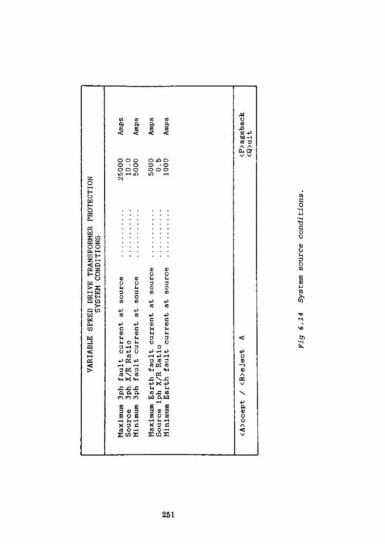
VARIABLE SPEED
DRIVE
TRANSFORMER
PROTEC
TION
SYSTEM CONDITIONS
to
Maximum
3ph
fault
current
at source
Sour
ce
3ph X/R Ratio
Minimum 3ph
fault
current
at source
Maxi
mum
Earth
faul
t cu
rren
t at so
urce
Source Iph
X/R
Ratio
Mini
mum
Earth
fault
curr
ent
at so
urce
25000
10.0
5000
5000 0.5
1000
Amps
Amps
Amps
Amps
<A>ccept /
<R>eject
A<P>age
back
<Q>uit
Figr
6.14
System s
ourc
e conditions.
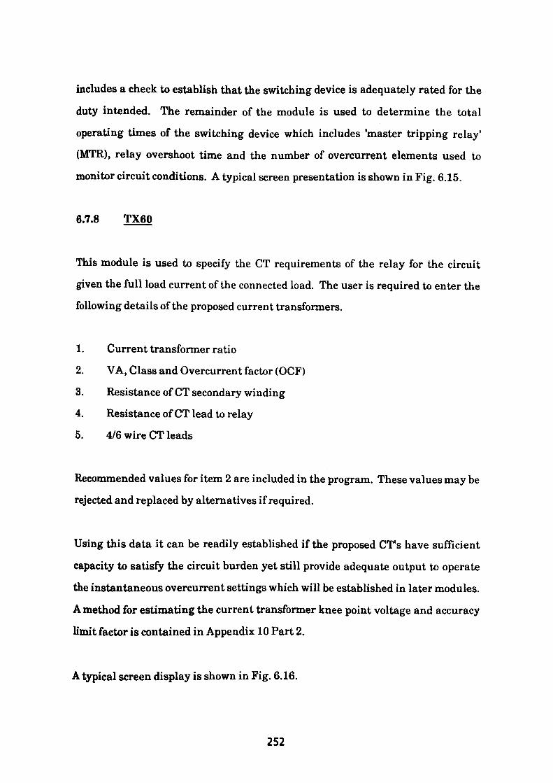
includes a check to establish that the switching device is adequately rated for the
duty intended. The remainder of the module is used to determine the total
operating times of the switching device which includes 'master tripping relay'
(MTR), relay overshoot time and the number of overcurrent elements used to
monitor circuit conditions. A typical screen presentation is shown in Fig. 6.15.
6.7.8 TX60
This module is used to specify the CT requirements of the relay for the circuit
given the full load current of the connected load. The user is required to enter the
following details of the proposed current transformers.
1. Current transformer ratio
2. VA, Class and Overcurrent factor (OCF)
3. Resistance of CT secondary winding
4. Resistance of CT lead to relay
5. 4/6 wire CT leads
Recommended values for item 2 are included in the program. These values may be
rejected and replaced by alternatives if required.
Using this data it can be readily established if the proposed CT's have sufficient
capacity to satisfy the circuit burden yet still provide adequate output to operate
the instantaneous overcurrent settings which will be established in later modules.
A method for estimating the current transformer knee point voltage and accuracy
limit factor is contained in Appendix 10 Part 2.
A typical screen display is shown in Fig. 6.16.
252
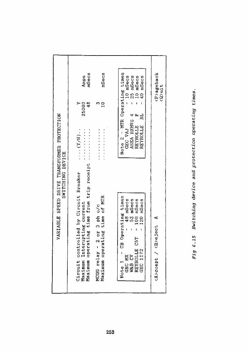
VARIABLE SPEED
DRIVE
TRANSFORMER
PROTECTION
SWITCHING
DEVICE
to en CO
Circuit
controlled by Circuit
Breaker
Maximum
Interupting
current
Maximum
operating
time from trip receipt
MCGG relay
- 2
or 3
ph o/c
Maximum
operating
time of MTR
..(Y/N)
Y25000 48
3 10
Amps
mbecs
Note 1
- CB Operating
times
GEC
MX
- 48 mSecs
W&B
CV
- 52 mSecs
REYROLLE C5T
- 100
mSecs
GEC
1172
- 120
mSecs
Note 2
- MTR
Operating
times
GEC
VAJ
- 10 mSecs
ASEA RXMVS
4 -
25 mSecs
REYROLLE
F -
10 mSecs
REYROLLE
RL
- 40 mSecs
<A>ccept /
<R>eject
A<P>ageback
<Q>uit
Fig
6.15
Sw
itch
ing
devi
ce and pr
otec
tion
operating
times.
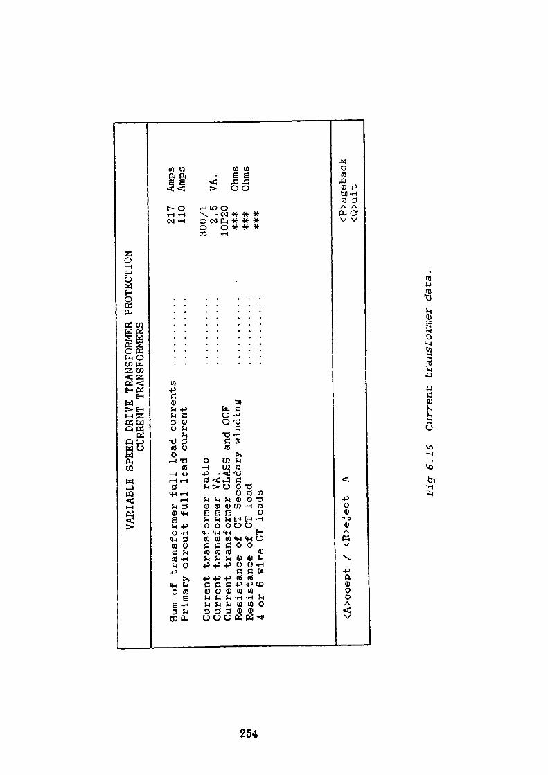
VARIABLE SPEED
DRIVE
TRANSFORMER
PROTECTION
CURRENT
TRANSFORMERS
to C71
Sum
of transformer
full load currents
Primary
circuit
full load current
Current
transformer
ratio
Current
transformer
VA.
Current
transformer
CLASS
and
OCF
Resistance of CT Secondary
winding
Resistance of CT lead
4 or 6 wire CT leads
217
110
Amps
Amps
300/1
2.5
VA.
10P20
***
Ohms
***
Ohms
<A>ccept /
<R>eject
A<P>ageback
<Q>uit
Pigr
6.1
6 C
urre
nt
tran
sfor
mer
dat
a,
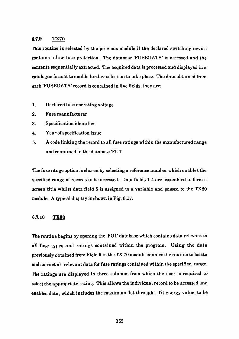
6.7.9 TX70
This routine is selected by the previous module if the declared switching device
contains inline fuse protection. The database TUSEDATA' is accessed and the
contents sequentially extracted. The acquired data is processed and displayed in a
catalogue format to enable further selection to take place. The data obtained from
each TUSEDATA1 record is contained in five fields, they are:
1. Declared fuse operating voltage
2. Fuse manufacturer
3. Specification identifier
4. Year of specification issue
5. A code linking the record to all fuse ratings within the manufactured range
and contained in the database TUl*
The fuse range option is chosen by selecting a reference number which enables the
specified range of records to be accessed. Data fields 1-4 are assembled to form a
screen title whilst data field 5 is assigned to a variable and passed to the TX80
module. A typical display is shown in Fig. 6.17.
6.7.10 TX80
The routine begins by opening the 'FU1 1 database which contains data relevant to
all fuse types and ratings contained within the program. Using the data
previously obtained from Field 5 in the TX 70 module enables the routine to locate
and extract all relevant data for fuse ratings contained within the specified range.
The ratings are displayed in three columns from which the user is required to
select the appropriate rating. This allows the individual record to be accessed and
enables data, which includes the maximum 'let-through1 . I2t energy value, to be
255
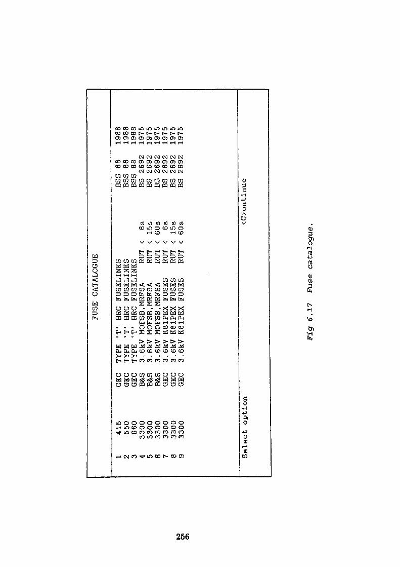
to en
FUSE CATALOGUE
1 2 3 4 5 6 7 8 9
415
550
660
3300
3300
3300
3300
3300
3300
GEC
GEC
GEC
B&S
B&S
B&S
GEC
GEC
GEC
TYPE "T HRC
TYPE 'T'
HRC
TYPE 'T
1 HRC
3. 3. 3. 3. 3. 3.
6kV
6kV
6kV
6kV
6kV
6kV
MOFSB,
MOFSB,
MOFSB
,
FUSEL INKS
FUSELINKS
FUSELINKS
MRFSA
MRFSA
MRFSA
K81PEX FUSES
K81PEX
K81PEX
FUSES
FUSES
RUT
RUT
RUT
RUT
RUT
RUT
Select option
< 6s
< 15s
< 60s
< 6s
< 15s
< 60s
BSS
88
BSS
88BSS
88BS BS BS BS BS BS
2692
2692
2692
2692
2692
2692
1988
1988
1988
1975
1975
1975
1975
1975
1975
<C>ontinue
Fig
6.1
7 F
use
cata
logu
e.
recovered. This particular value is used in later cable selection modules. A
typical display is shown in Fig. 6.18.
6.7.11 TX90
This module is similar in construction to the TX70 module except that the
database which is accessed contains general data associated with cable types. The
database which is called 'CABDATA' contains sixteen fields, some of which are
relevant only to other calling routines.
The more significant fields associated with the TX90 module are:
1. Working voltage
2. Cable type
3. Type of construction
4. Insulation media
5. Type of armouring employed
6. Typeofoversheath
7. Number of cores
8. Aluminium (Al) or Copper (Cu) conductors
9. Stranded or solid conductors
10. A code which uniquely defines the construction.
A typical display is shown in Fig. 6.19 from which it can be seen that the required
cable is selected using the reference number specified alongside each option.
257
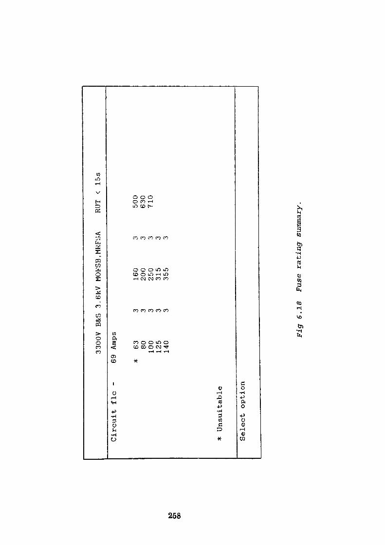
to
en
oo
3300V
B&S
3.6KV
MOFSB.MRFSA
RUT
< 15s
Circuit
flc
-
* Unsuitable
69 Amps
* 63
3 160
3 500
80
3 200
3 630
100
3 250
3 710
125
3 315
3140
3 355
3
Select option
Fig
6.18
Fuse rating summary.

to W
CO
THE
DISTRIBUTION ENGINEERS
ASSISTANT
CABLE
CATALOGUE
1 600/1000
3c
2 600/1000
Ic
3 3800/6600
3c
4 6350/11000
3c
Select option
4 Derating factor 1.
Str
Cu
PVC/EXTR/SWA/PVC
BSS
Str
Cu
XLPE/PVC
BSS
Str
Al
XLPE/SCR/SWA/PVC
IEC
Str
Al
XLPE/SCR/SWA/PVC
IEC
Cable
length 550
mtrs
<C>ontinue
00
<A>ccept /
<R>eject A
6346 1969
M 5467 1977
M 502
1983
M 502
1983
M
<Q>uit
<P>ageback
Fig
6.
19
Cab
le
cata
logue.
6.7.12 TX100
The function of this module is to sequentially extract from a database all relevant
data contained within the cable files selected in the TX90 module. The following
data is extracted for each CSA value of the selected cable type.
1. Cable rating in air, ground and duct.
2. Fault rating of cable conductors and armouring.
3. Positive and zero phase sequence impedance values.
The cable rating values referred to in (1) are each derated in accordance with the
derating factor specified in the TX90 module prior to storage. If the switching
device is a fully rated circuit breaker then, the fault rating data of both conductor
and armouring recorded in (2) are examined in conjunction with the fault currents
specified earlier in the TX40 module to determine if the ratings are adequate. A
symbol is assigned to signify the result. The cable impedance values referred to in
(3) are used in the routine together with the specified cable length to determine
voltage drop in the transformer supply cables. The calculated impedance values
are also stored for use in later modules to calculate transformer fault current
magnitudes. Where the switching device is fuse protected the routine produces
additional symbols which indicate
1. The fuse rating > cable rating
2. The fuse 'let thro1 energy > Cable conductor/armour withstand capability
Each CSA value is processed in the same manner prior to storing the results in a
temporary database.
260
6.7.13 TX110
The function of this module is to provide the maximum information to aid in the
selection of the most appropriate and economical cable rating which satisfies the
circuit conditions. The routine displays the cable CSA values and revised current
ratings in two columns. The data is supplemented by symbols which are
indicative of boundary excursions in excess of the conditions stated in 6.7.12. A typical screen display is shown in Fig. 6.20.
6.7.14 TX120
In this module no user supplied information is required. The routine performs a series of calculations utilising data previously collated in earlier routines. The calculations carried out establish:
1. Maximum three-phase fault current at source
2. Maximum phase-phase fault current at source
3. Maximum phase-earth fault current at source
4. Maximum three-phase fault current at transformer HV windings
5. Maximum phase-phase fault current at transformer HV windings
6. Maximum phase-earth fault current at transformer HV windings
7. Maximum fault current reflected to primary for three-phase fault on
transformer LV terminals
8. Maximum fault current reflected to primary for phase-phase fault on
transformer LV terminals
9. As 7 and 8 except fault currents calculated at the remote end of the LV
cabling when the circuit is supplied via a maximum source impedance (not
implemented).
10. As above except maximum source impedance is used.
261
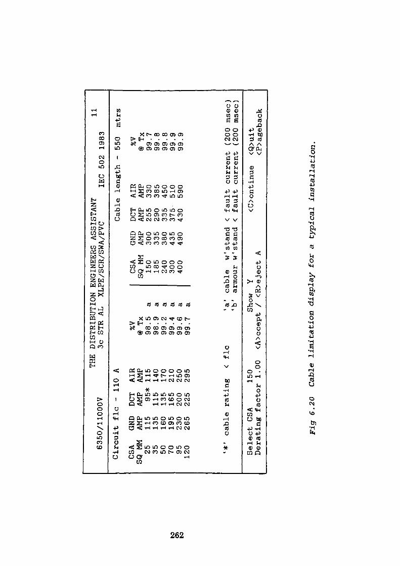
to OS to
6350/11000V
THE
DISTRIBUTION ENGINEERS
ASSISTANT
3c STR
AL
XLPE/SCR/SWA/PVC
IEC
502
1983
11
Circuit
flc
- 110
A
CSA
GND
DCT
AIR
SQ MM
AMP
AMP
AMP
25
115
95*
115
35
135
115
140
50
160
135
170
70
195
165
210
95
230
200
250
120
265
225
295
%V@
Tx
98.5
98.9
99.2
99.4
99.6
99.7
a a a a a a
Cable
length -
550
mtrs
CSA
GND
DCT
AIR
SQ MM
AMP
AMP
AMP
150
300
255
330
185
335
290
385
240
380
335
450
300
435
375
510
400
490
430
590
%V
@ Tx
99.7
99.8
99.8
99.9
99.9
'*'
cable
rating
< flc
'a'
cable
w1 stand
< fault
current
(200 msec)
'b'
armour w'stand
< fault
current
(200 msec)
Select CSA
150
Derating factor 1.00
Show
Y <A>ccept /
<R>eject A
<Oontinue
<Q>uit
<P>ageback
Fig
6.20
Ca
ble
limitation display for
a typical
installation.
6.7.15 TRIG
The function of this subroutine is to accept a transformer phase shift value in
degrees and return the corresponding sine and cosine value to the TX120 calling
routine. The values are obtained by converting the angle to radian measure and
substituting it in the appropriate Maclaurin's series. It is necessary to provide
this routine because DBASE 3+ does not contain these trigometric functions.
This subroutine is called from the TX120 module each time a transformer
calculation is required which for Case Study 2 requires six calls.
6.7.16 TX1201
This subroutine is called by the TX120 module. It is used to calculate the primary
and secondary line currents which appear on the occurrence of a phase-phase short
circuit fault on the secondary terminals of a transformer. The method used is
identical to that described in the text. A feature is included in the routine which
allows the calculated values to be displayed for inspection. The routine which
calculates the line currents for both maximum and minimum source impedance
conditions is called twice for each transformer processed. A total of twelve calls
are made for Case Study 2.
6.7.17 TX1202
This subroutine is called directly after the previous subroutine. Its function is to
calculate the current distribution in each transformer which incorporates delta
windings. The solution is deduced using the Generalised Matrix inversion
approach. As in the previous case, a routine is included which displays the current
distribution if required. With the current distribution now known in all windings,
263
a revised withstand time is allocated to each winding based on an adiabatic
comparison with the known maximum current rating of each winding.
6.7.18 TX130
This sub section of the program deals with the fitting of the relay characteristics to
the overall circuit constraints. Each of the relay characteristics is derived from an
internal lock-up table and complies with BS 142. The characteristics used are
defined by the manufacturer and detailed earlier in this thesis. Initially the
module calls a subroutine whose function is to present the user with a complete
menu of the characteristics available on the GEC ALSTHOM type MCGG
electronic relay. In addition the user is able to specify the number of current
measuring elements used and to verify the effects of any user supplied settings. A
further option displays a summary all the phase-phase and three-phase fault
currents previously calculated. The menu display is shown in Fig. 6.21.
Dependent on the option chosen, constants A and B are selected and substituted in
the characteristic equation which for IDMTL relays is of the form:
A t = ——— seesf-\
where I is the applied current and A and B are constants
6.7.19 Inverse Time Characteristics
Consider Option 1 - Standard Inverse IDMTL characteristic
A calculation is first carried out to determine the current setting multiplier (CSM)
value. The minimum value being considered as the lowest stable setting in excess
264
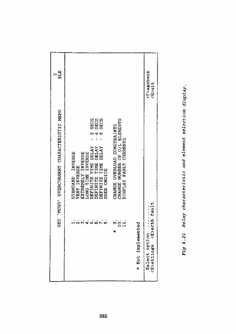
to
o>
en
* Not
GO 1 &
»-* +
<S>etti
GEC
'MCGG
1.
2.
3.
4.
5.
6.
7.
8.
* 9.
10.
11.
impl
emen
ted
option
........
ngs
<E>a
rth
faul
t
OVERCURRENT
CHARACTERISTIC MENU
STANDARD
INVERSE
VERY INVERSE
EXTREMELY
INVERSE
LONG TIME INVERSE
DEFINITE TIME DELAY
- 2 SECS
DEFINITE TIME DELAY
- 4
SECS
DEFINITE TIME DELAY
- 8
SECS
USER CHOICE
CHANGE OVERLOAD CONSTRAINTS
CHANGE NUMBER OF 0/L
ELEMENTS
DISPLAY
FAULT
CURRENTS
3 ELE
<P>ageback
<Q>uit
Figr
6.2
1 R
elay
ch
ara
cter
isti
c an
d el
emen
t se
lect
ion d
isp
lay.
of the circuit FLC. The program then calls a subroutine which is dedicated to
dealing with the circuit overload contraints. This subroutine accesses a database
file containing the magnitude and duration of all known overload constraints
applied to the circuit, each constraint being accessed in turn. The overload values
extracted from the file are substituted in the characteristic equation thus enable
the relay operating time to be determined. The operating time is then adjusted by
means of the time multiplier setting control (TMS) to equate the relay operating
time to the duration of the overload condition. In each case an allowance is made
of the following delays.
1. Relay error
2. Relay overshoot
3. Master trip relay (MTR)
4. Circuit breaker (CB)
If the duration of the overload exceeds the operating time for the relay then the
PSM setting must be increased and the exercise repeated. Similarly any overloads
in excess of thirty seconds are treated as a continuous condition with the CSM set
greater than the overload magnitude. If each overload constraint is satisfactorily
processed in the above manner then the resulting TMS used is the highest TMS
satisfying the constraints. The upper bound checks are carried out by initially
setting the TMS to 1.0. The program on returning from the constraint subroutine
sequentially examines the fault current at each transformer node. An operating
time is calculated for each node using the CSM value previously determined and
compared with the transformer and cable withstand time. As withstand checks on
the transformer and cables have previously been determined for all potential fault
conditions, the TMS, is decremented accordingly to satisfy the circuit withstand
requirements. Provided the TMS setting arrived at is greater than the previously
266
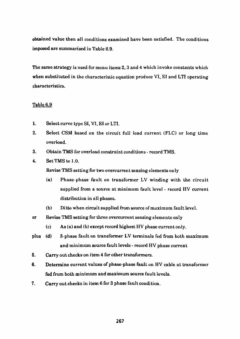
obtained value then all conditions examined have been satisfied. The conditions
imposed are summarised in Table 6.9.
The same strategy is used for menu items 2, 3 and 4 which invoke constants which
when substituted in the characteristic equation produce VI, El and LTI operating
characteristics.
Table 6.9
1. Select curve type SI, VI, El or LTI.
2. Select CSM based on the circuit full load current (FLC) or long time
overload.
3. Obtain TMS for overload constraint conditions - record TMS.
4. Set TMS to 1.0.
Revise TMS setting for two overcurrent sensing elements only
(a) Phase-phase fault on transformer LV winding with the circuit
supplied from a source at minimum fault level - record HV current
distribution in all phases.
(b) Ditto when circuit supplied from source of maximum fault level,
or Revise TMS setting for three overcurrent sensing elements only
(c) As (a) and (b) except record highest HV phase current only,
plus (d) 3-phase fault on transformer LV terminals fed from both maximum
and minimum source fault levels - record HV phase current
5. Carry out checks on item 4 for other transformers.
6. Determine current values of phase-phase fault on HV cable at transformer
fed from both minimum and maximum source fault levels.
7. Carry out checks in item 6 for 3 phase fault condition.
267
6.7.20 Definite Time Lag Characteristics
Menu options 5, 6 and 7 select the Definite Time Lag characteristics. Three time
lags are available 2, 4 or 8 seconds which may be reduced by use of the TMS
control.
The strategy adopted following selection of these options may be best understood
by study of the flow chart shown in Fig. 6.22. The strategy is flawed and should
not be used unless the IDMTL approach fails. Referring to Fig. 6.22 it can be seen
that the minimum CSM setting may be dictated by the magnitude and duration of
the overload constraints. Where the duration of the constraint exceeds the
definite time selected, the CSM is raised thereby ignoring that constraint and any
other of equivalent magnitude but lesser duration. If the circuit withstand times
and overload constraint considerations cannot be satisfied the strategy fails and
an alternative approach should be pursued.
Option 8 of this routine, the 'User Choice' option executes a call to a module
located at TX150.
6.7.21 TX150-152
This module is arranged as a group of three interconnected routines. They form a
part of the 'User Choice1 suite of programs which are depicted on the flowchart
shown in Fig. 6.23. The module TX150 displays an entry form on which the user
is invited to specify the following information.
268
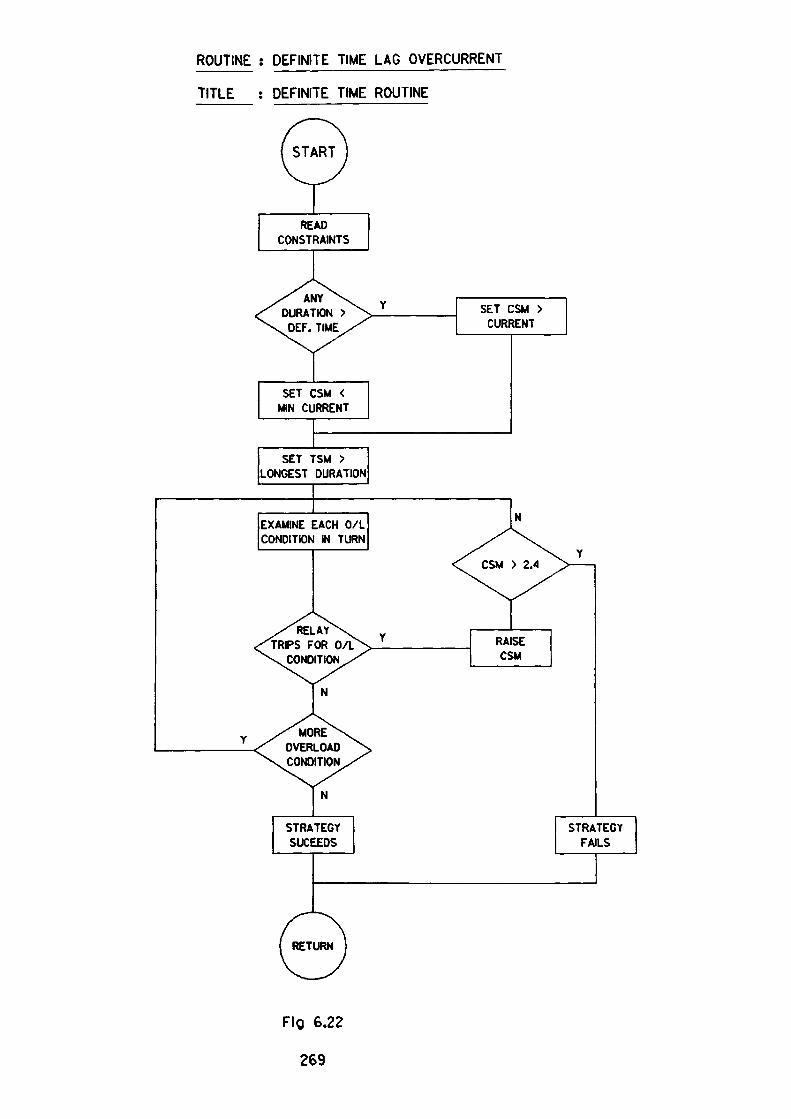
ROUTINE : DEFINITE TIME LAG OVERCURRENT
TITLE : DEFINITE TIME ROUTINE
READ CONSTRAINTS
ANYDURATION >
DEF. TIME
SET CSM < MIN CURRENT
SET TSM > LONGEST DURATION
EXAMINE EACH 0/L CONDITION IN TURN
RELAYTRIPS FOR 0/L
CONDITION
MORE OVERLOAD CONDITION
Fig 6.22
269
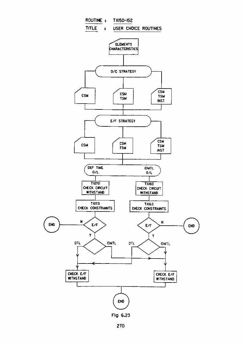
ROUTINE : TXI50-I52
TITLE : USER CHOICE ROUTINES
ELEMENTS IARACTERISTICS
(
—— i
:SM
t/r SIK
r est ™
/"DEF TIMEV^ O/L
CH
TXI70 CHECK CIRCUIT
WITHSTAND
TXIT3 ECK CONSTRAINTS
AILVlI^
A A
1 ———
(iINS
M MT
IDMTL ^N O/L J
TXI60 CHECK CIRCUIT
WITHSTAND
TXI63 CHECK CONSTRAINTS
DTL IDMTL DTL IDMTL
\
\
f ^^
CHECK E/F WITHSTAND
**.
^^.s \
\
f
f
CHECK E/F WITHSTAND
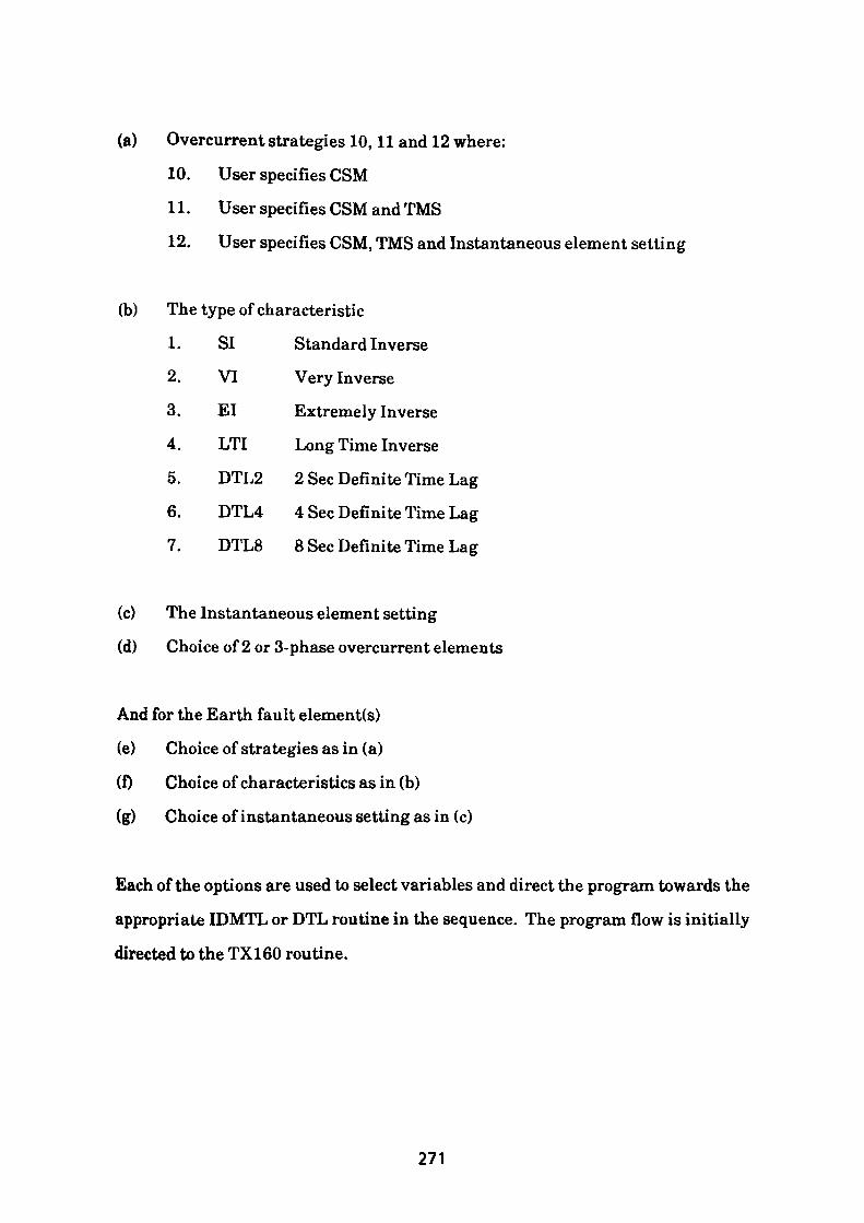
(a) Overcurrent strategies 10,11 and 12 where:
10. User specifies CSM
11. User specifies CSM and TMS
12. User specifies CSM, TMS and Instantaneous element setting
(b) The type of characteristic
1. SI Standard Inverse
2. VI Very Inverse
3. El Extremely Inverse
4. LTI Long Time Inverse
5. DTL2 2 Sec Definite Time Lag
6. DTL4 4 Sec Definite Time Lag
7. DTL8 8 Sec Definite Time Lag
(c) The Instantaneous element setting
(d) Choice of 2 or 3-phase overcurrent elements
And for the Earth fault element(s)
(e) Choice of strategies as in (a)
(f) Choice of characteristics as in (b)
(g) Choice of instantaneous setting as in (c)
Each of the options are used to select variables and direct the program towards the
appropriate IDMTL or DTL routine in the sequence. The program flow is initially
directed to the TX160 routine.
271
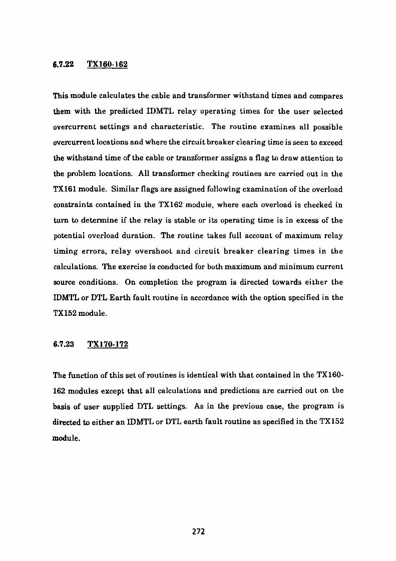
6.7.22 TX160-162
This module calculates the cable and transformer withstand times and compares
them with the predicted IDMTL relay operating times for the user selected
overcurrent settings and characteristic. The routine examines all possible
overcurrent locations and where the circuit breaker clearing time is seen to exceed
the withstand time of the cable or transformer assigns a flag to draw attention to
the problem locations. All transformer checking routines are carried out in the
TX161 module. Similar flags are assigned following examination of the overload
constraints contained in the TX162 module, where each overload is checked in
turn to determine if the relay is stable or its operating time is in excess of the
potential overload duration. The routine takes full account of maximum relay
timing errors, relay overshoot and circuit breaker clearing times in the
calculations. The exercise is conducted for both maximum and minimum current
source conditions. On completion the program is directed towards either the
IDMTL or DTL Earth fault routine in accordance with the option specified in the
TX152 module.
6.7.23 TX170-172
The function of this set of routines is identical with that contained in the TX160-
162 modules except that all calculations and predictions are carried out on the
basis of user supplied DTL settings. As in the previous case, the program is
directed to either an IDMTL or DTL earth fault routine as specified in the TX152
module.
272
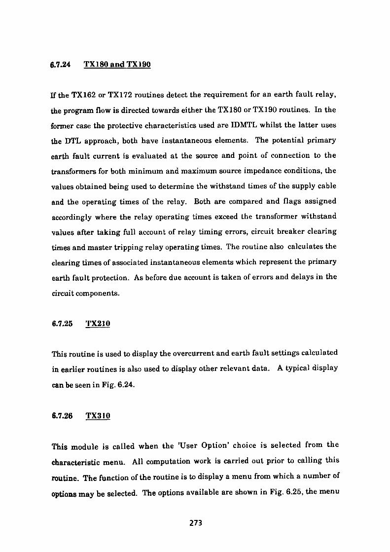
6.7.24 TX180 and TX190
If the TX162 or TX172 routines detect the requirement for an earth fault relay,
the program flow is directed towards either the TX180 or TX190 routines. In the
former case the protective characteristics used are IDMTL whilst the latter uses
the DTL approach, both have instantaneous elements. The potential primary
earth fault current is evaluated at the source and point of connection to the
transformers for both minimum and maximum source impedance conditions, the
values obtained being used to determine the withstand times of the supply cable
and the operating times of the relay. Both are compared and flags assigned
accordingly where the relay operating times exceed the transformer withstand
values after taking full account of relay timing errors, circuit breaker clearing
times and master tripping relay operating times. The routine also calculates the
clearing times of associated instantaneous elements which represent the primary
earth fault protection. As before due account is taken of errors and delays in the
circuit components.
6.7.25 TX210
This routine is used to display the overcurrent and earth fault settings calculated
in earlier routines is also used to display other relevant data. A typical display
can be seen in Fig. 6.24.
6.7.26 TX310
This module is called when the 'User Option 1 choice is selected from the
characteristic menu. All computation work is carried out prior to calling this
routine. The function of the routine is to display a menu from which a number of
options may be selected. The options available are shown in Fig. 6.25, the menu
273
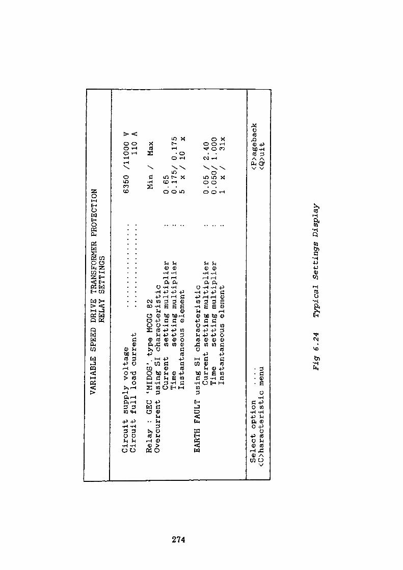
VARIABLE SPEED
DRIVE
TRANSFORMER
PROTECTION
RELAY
SETTINGS
Circ
uit
supp
ly vo
ltag
e Ci
rcui
t fu
ll lo
ad current
to
Relay
: GEC
'MIDOS', type
MCGG 82
Overcurrent
using
SI characteristic
Current
setting
multiplier
Time
setting
multiplier
Instantaneous
element
EARTH
FAULT
using
SI characteristic
Current
setting
multiplier
Time
setting
multiplier
Instantaneous
element
6350 /11000 V
110
A
Min
/ Max
0.65
0.175/ 0.175
5 x
/ 10
x
0.05 /
2.40
0.050/ 1.000
1 x
/ 31x
Select option
....
<C>haracteristic menu
<P>ageback
<Q>uit
Fig
6.24
Typi
cal
Settings D
ispl
ay
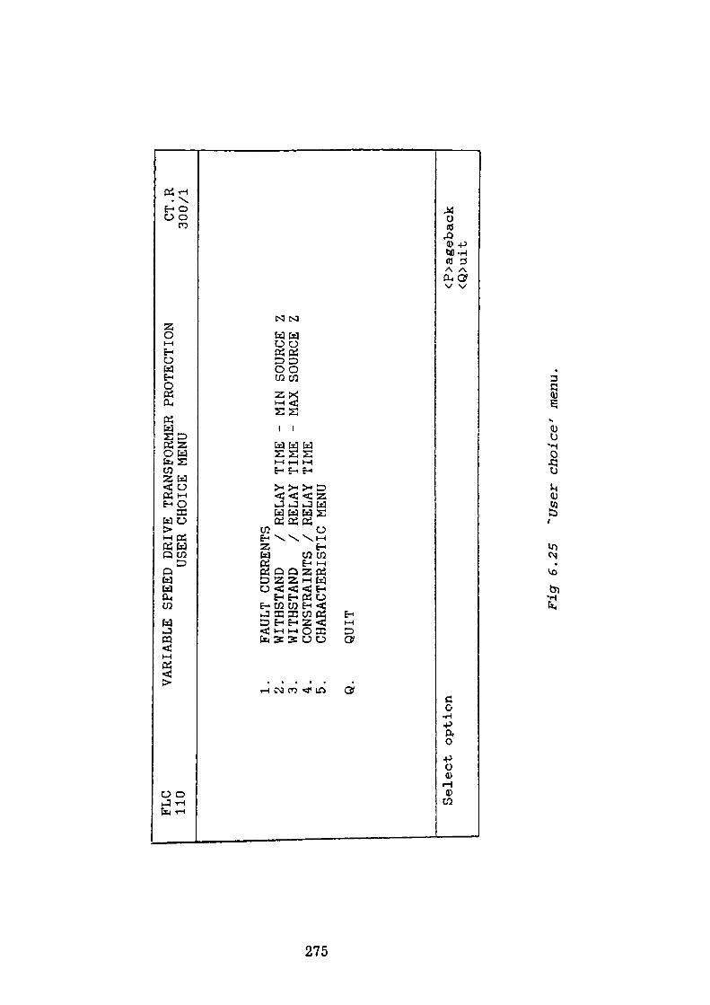
FLC
110
VARIABLE SPEED
DRIVE
TRANSFORMER
PROTEC
TION
USER CHOICE MENU
CT.R
300/1
to
-o Ol
1.
FAULT
CURRENTS
2.
WITHSTAND
/ RELAY
TIME
3.
WITHSTAND
/ RELAY
TIME
4.
CONSTRAINTS
/ RELAY
TIME
5.
CHARACTERISTIC MENU
Q.
QUIT
MIN
SOURCE Z
MAX
SOURCE Z
Select option
<P>ageback
<Q>uit
Fig
6.2
5 "U
ser
choic
e'
men
u.
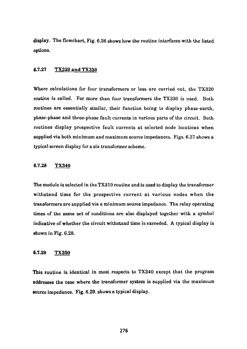
display. The flowchart, Fig. 6.26 shows how the routine interfaces with the listed
options.
6.7.27 TX320 and TX330
Where calculations for four transformers or less are carried out, the TX320
routine is called. For more than four transformers the TX330 is used. Both
routines are essentially similar, their function being to display phase-earth,
phase-phase and three-phase fault currents in various parts of the circuit. Both
routines display prospective fault currents at selected node locations when
supplied via both minimum and maximum source impedances. Figs. 6.27 shows a
typical screen display for a six transformer scheme.
6.7.28 TX340
The module is selected in the TX310 routine and is used to display the transformer
withstand time for the prospective current at various nodes when the
transformers are supplied via a minimum source impedance. The relay operating
times of the same set of conditions are also displayed together with a symbol
indicative of whether the circuit withstand time is exceeded. A typical display is
shown in Fig. 6.28.
6.7.29 TX350
This routine is identical in most respects to TX340 except that the program
addresses the case where the transformer system is supplied via the maximum
source impedance. Fig. 6.29. shows a typical display.
276
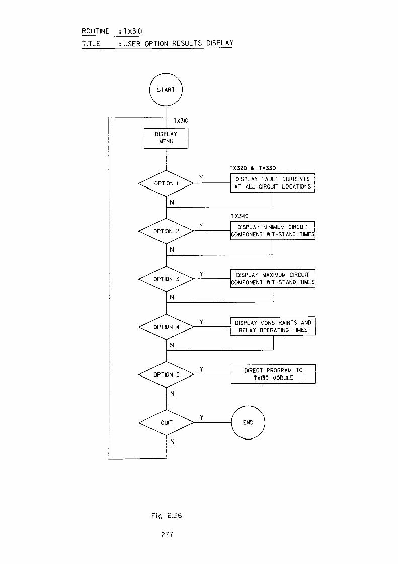
ROUTINE : TX3IO
TITLE :USER OPTION RESULTS DISPLAY
TX320 & TX330
DISPLAY FAULT CURRENTS AT ALL CIRCUIT LOCATIONS
TX340
DISPLAY MINIMUM CIRCUIT COMPONENT WITHSTAND TIMES
\. YON 3 "> — ' ——————
N
DISPLAY MAXIMUM CIRCUIT COMPONENT WITHSTAND TIMES
DISPLAY CONSTRAINTS AND RELAY OPERATING TIMES
DIRECT PROGRAM TO TXI30 MODULE
Fig 6.26
277
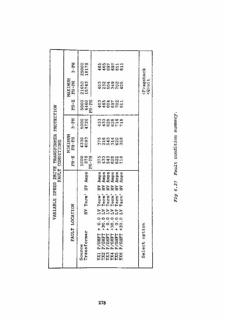
to
~j OO
VARIABLE
SPEED
DRIVE
TRANSFORMER
FAULT
CONDITIONS
FAULT
LOCATION
Sour
ce
Tran
sfor
mer
TX1
P/SHFT +
0 TX2
P/SHFT +30
TX3
P/SHFT +
0 TX4
P/SHFT +30
TX5
P/SHFT +
0 TX6
P/SHFT +30
HV
.0 LV
.0 LV
.0 LV
.0 LV
.0 LV
.0 LV
Term
Term
Term
Term
Term
Term
Term
' HV
1 HV
' HV
1 HV
' HV
' HV
' HV
Amps
Amps
Amps
Amps
Amps
Amps
Amps
PH-E
1000
976
T-1TJ
T31J
rn rn
375
433
543
628
622
718
MINIMUM
PH-PH
4330
4093 375
216
543
314
622
359
PROTECTION
3-PH
5000
4726 433
433
628
628
718
718
PH-E
5000
4460
PH-PH
403
465
604
697
702
811
Select option
MAXIMUM
PH-PH
21650
15743
403
232
604
349
702
405
3-PH
25000
18178
465
465
697
697
811
811
<P>ageback
<Q>uit
Fig
6.2
7 F
ault
co
ndit
ion s
umm
ary.
to -o CO
FLC
110
FAUL
T
Sou
rce
PCC
Tra
fo
HV
Term
TX1
+ 0
LV
Term
TX
2 +3
0 LV
Te
rm
TX3
+ 0
LV
Term
TX
4 +3
0 LV
Te
rm
TX5
+ 0
LV
Term
TX
6 +3
0 LV
Te
rm
VA
RIA
BLE
SPEE
D
DRI
VE
THAW
W
ITHS
TAND
TI
MES
/
PRO
TECT
.X
J T
XT
-
See
s 1
See
s
' S
ees
See
s S
ees
1 S
ees
' S
ees
' S
ees
Sel
ect
opti
on
<O
hara
cte
rist
ic
men
u
.... .
. —
— m
il.
PH-E
7.24
0 0.
519
9.09
3 0.
532
2.09
2 1.
673
2.78
9 1.
395
2.14
1 1.
070
2.85
4 0.
948
2.16
5 0.
943
2.88
7 0.
847
0/C
0.
65
E/F
0.
10
3FOR
MER
PR
OTE
CTIO
N
EON
CLEA
RING
TI
MES
[M
UM S
OURC
E IM
PEDA
I PH
-PH
0.39
3 0.
248
0.74
3 0.
266
2.09
2 1.
673
2.78
9 1.
395
2.14
1 1.
070
2.85
4 0.
948
2.16
5 0.
943
2.88
7 0.
847
/0.1
75
/0.4
00
CT.
R
300/
1 jr
rr^o
iif
3-PH
0.29
0 0.
240
F 0.
557
0.25
8
2.09
2 1.
395
2.09
2 1.
395
2.14
1 0.
948
2.14
1 0.
948
2.16
5 0.
847
2.16
5 0.
847
<P>a
geba
ck
«3>
uit
Fig
6.28
Transformer
withstand
times/protection clearing-
times
supplied from a
minimum
sour
ce im
pedance
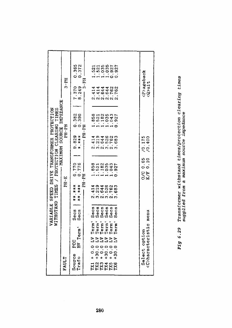
to 00 o
VARIABLE SPEED
DRIVE
TRANSFORMER
PROTECTION
WITHSTAND
TIMES
/ PROTECTION
FAULT
Source
Trafo
TX1
+ 0
TX2
+30
TX3
+ 0
TX4
+30
TX5
+ 0
TX6
+30
PCC
PH-E
Sees
HV Term'
Sees
.0 LV
.0 LV
.0 LV
.0 LV
.0 LV
.0 LV
#*.##*
o.**.***
0.Pfl PIT
111
1 11
Term
' Sees
Term'
Sees
Term
1 Sees
Term
1 Sees
Term'
Sees
Term'
Sees
2.414
1.3.219
1.2.644
1.3.526
1.2.762
1.3.683
0.
MAYTMHM
770
776
9 *
858
521
182
035
043
927
2 3 2 3 2 3
CLEARING
cnnop
T?OV^U Jvvl^
PH-PH
.829
. **#pn i
11
.414
.219
.644
.526
.762
.683
0 0 PH
1 1 1 1 1 0
TIMES
IMPEDANCE
-
.382
.390
7 8
.858
.521
.182
.035
.043
.927
2 2 2 2 2 2
3-PH
.370
0.249
03
DUrn
.414
1.414
1.644
1.644
1.762
0.762
0
.365
.372
.521
.521
.035
.035
.927
.927
Sel
ect
opti
on
<O
hara
cte
rist
ic
men
u0/
C
0.65
E
/F
0.10
/0.1
75
/0.4
00
<P>a
geba
ck
<Q>u
it
Fig
6.2
9 T
rans
form
er w
iths
tand
ti
mes
/pro
tect
ion cl
eari
ng t
imes
su
ppli
ed f
rom
a m
axim
um s
ourc
e im
peda
nce
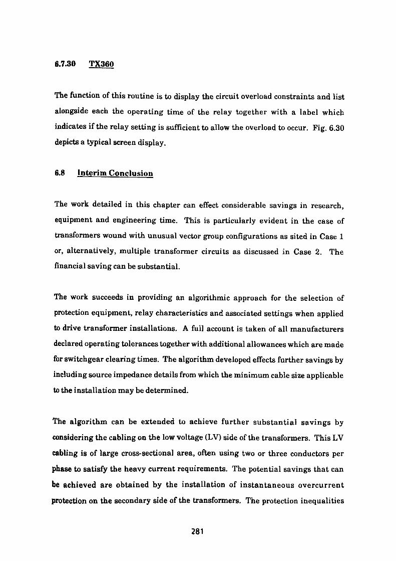
6.7.30 TX360
The function of this routine is to display the circuit overload constraints and list
alongside each the operating time of the relay together with a label which
indicates if the relay setting is sufficient to allow the overload to occur. Fig. 6.30 depicts a typical screen display.
6.8 Interim Conclusion
The work detailed in this chapter can effect considerable savings in research,
equipment and engineering time. This is particularly evident in the case of transformers wound with unusual vector group configurations as sited in Case 1
or, alternatively, multiple transformer circuits as discussed in Case 2. The financial saving can be substantial.
The work succeeds in providing an algorithmic approach for the selection of
protection equipment, relay characteristics and associated settings when applied to drive transformer installations. A full account is taken of all manufacturers
declared operating tolerances together with additional allowances which are made
for switchgear clearing times. The algorithm developed effects further savings by including source impedance details from which the minimum cable size applicable
to the installation may be determined.
The algorithm can be extended to achieve further substantial savings by
considering the cabling on the low voltage (LV) side of the transformers. This LV
cabling is of large cross-sectional area, often using two or three conductors per
phase to satisfy the heavy current requirements. The potential savings that can
be achieved are obtained by the installation of instantaneous overcurrent
protection on the secondary side of the transformers. The protection inequalities
281
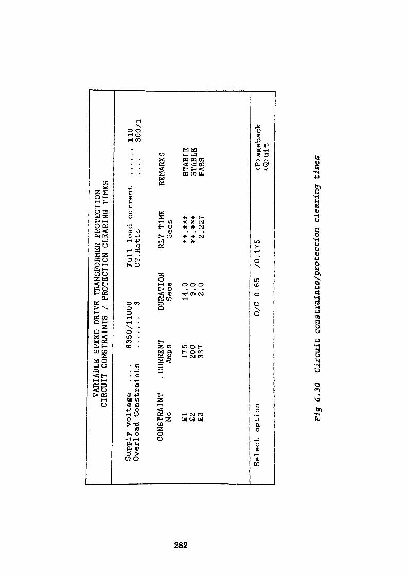
VARIABLE SPEED
DRIVE
TRANSFORMER
PROTECTION
CIRCUIT
CONSTRAINTS
/ PROTECTION CLEARING TIMES
Supply voltage
....
Overload Constraints
6350/11000
.......
3Full load current
CT.Ratio
110
300/
1
to oo
to
CONSTRAINT
No £1
£2
£3
CURRENT
Amps 175
200
337
DURATION
Sees
14.0
9.0
2.0
RLY
TIME
Sees
2.227
REMARKS
STABLE
STABLE
PASS
Select option
0/C
0.65
/0.175
<P>ageback
<Q>uit
Fig
6.30
Circ
uit
cons
trai
nts/
prot
ecti
on clearing times
in the algorithm could then be extended so that the HVIDMTL overcurrent relay is required to protect the LV cabling up to the operating setting of the LV instantaneous relay only.
This work has not been carried out because it is usual for the LV cabling to be supplied and protected by the drive equipment supplier, it can however be incorporated if so desired. The concept of adaptive relaying may be fully exploited in this application as relays are now available with settings which can be changed from a remote location. Such relays can be incorporated in many innovative schemes whereby protection settings may be optimised to suit circuit conditions then subsequently changed to satisfy other product mixes. A further option which is worthy of further exploration is to subdivide the outgoing plant cables into groups and provide separate protection to each subgroup based on the principles previously discussed. All subgroups could be supplied from a common circuit breaker. The range of circuit permutations available is quite large but close study will result in substantial savings and provide a sound engineering solution.
283
CHAPTER 7
Conclusion
The scope of this thesis as detailed in Chapter 2, has been effectively fulfilled in
the preceding text. The text describes the considerable benefits that may be
realised by industry following a rigorous analysis of the intended application.
The problems analysed and solutions suggested may be divided into two parts.
The first part deals with the protection application requirements for direct-on-line
started motors which are of fundamental importance in heavy industry. The
benefits which can be accrued by using this novel approach to exploit the
repetitive nature of the task, will effect substantial savings in engineering time,
switchgear and cabling costs.
The work detailed in the text will remove much of the repetition work as applied
to conventional drive installations, thus allowing engineering time to be used
more effectively on installations requiring closer scrutiny. The novel algorithms
developed can be easily expanded to incorporate any additional requirements that
were suggested as the work proceeded. This tendency has been restrained to some
extent to restrict the work within defined limits but they will no doubt be
incorporated in due course.
The section of the work concerned with the protection of transformer fed variable
speed drives is the area where the greatest single economic benefit can be
obtained. The case studies discussed demonstrate the practicalities of the
techniques which are used, whilst the enhancements suggested will enable
maximum utilisation of the equipment to be obtained.
284
7.1 Future Enhancements
In order to further improve the overall performance of the combined programs, the
following areas should be addressed to provide the greatest benefit.
1. More detailed determination of fuse characteristics would be desirable
together with an expanded database of contactor equipment characteristics
from which fuses and contactor characteristics could be coordinated.
2. More advanced motor protection relays are now available which overcome
some of the deficiencies listed in the text. Typical features now
incorporated allow the adjustment of the 'hot1 operating characteristic
independently to that of the cold operating characteristic. Some relays also allow the immediate resetting of the 'hot' characteristic to the 'cold' curve following receipt of an external command. Algorithms using an expanded set of comparisons could be devised to gain maximum utilisation from these
improved devices.
3. A further desirable feature would be the addition of a simple impedance
measuring device. Such a device could monitor changes in power factor and provide immediate indication of a locked rotor condition during the
acceleration period.
4. During the 'run' mode, most machines would benefit from the use of a more
inverse characteristic to effectively accelerate tripping for abnormal
conditions. Instantaneous or definite time tripping could also be
incorporated for activation or blocking above certain user defined overload
levels.
285

5. In the case of transformer fed variable speed drive installations, the use of
'adaptive relaying' techniques either by operator control or by automatic
means will considerably enhance the opportunity for closer protection and
for major economies to be made. Maximum benefit could be obtained in
some cases by dividing the outgoing circuits into separately protected
subgroups.
286
Bibliography
B8142 - Electrical protective relays
GEC Alsthom Publication No. R-5171
GEC Alsthom Publication No. R-5738
Protection of Industrial Power Systems by T. Davies
Power System protection Volumes 1,2 & 3 - Electricity Council
Protective Relay Application Guide - GEC Measurements
Advanced Motor Protection using microcomputers - J. Brandolino, Multilin
Short circuit currents in three-phase networks - Siemens
Micro-Golds relay instruction manual - P&B Golds
Computer Relaying for Power Systems - A.G. Phadke, J.S. Thorp
287
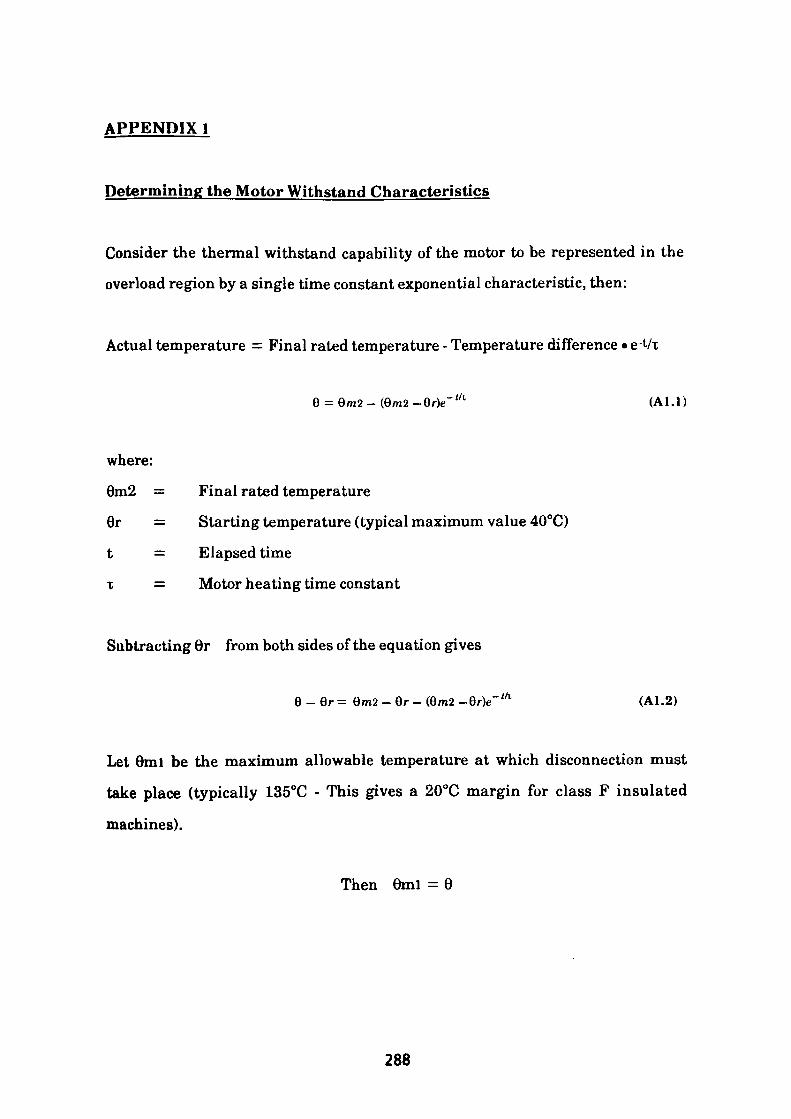
APPENDIX 1
Determining the Motor Withstand Characteristics
Consider the thermal withstand capability of the motor to be represented in the
overload region by a single time constant exponential characteristic, then:
Actual temperature = Final rated temperature - Temperature difference • e-Vx
;/l (Al.l)
where:
6m2 = Final rated temperature
6r = Starting temperature (typical maximum value 40°C)
t — Elapsed time
t = Motor heating time constant
Subtracting 0r from both sides of the equation gives
6 - Qr = 6m2 - Br - (6m2 -Qr)e~ ifi (A1.2)
Let 0ml be the maximum allowable temperature at which disconnection must
take place (typically 135°C - This gives a 20°C margin for class F insulated
machines).
Then 0ml = 0
288
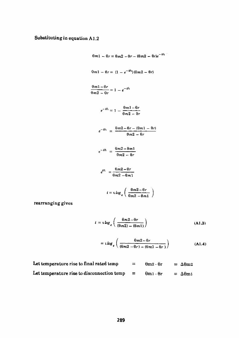
Substituting in equation Al.2
6ml - 6r = 9m2 -9r - (9m2 - 9r)e-i/i
6ml - 8r = (1 - e~ t - Qr)
9ml-6r 9m2 - 9r
= i - e-th
_ tfl 9ml-Gr e = 1 —
9m2 - 9r
-th 9m2-9r-(9ml - Br) 9m2 - 6r
~th 9m2-9ml 9m2 - Br
tfl Gm2-9re =
9m2 -8ml
rearranging gives
/ 9m2-9r \ t = T. log —————— e \ 9m2 -8ml /
t = 9m2-9r \ (9m2)-(8ml)J (A1.3)
9m2-6r(9m2 -8r)- (Gml -Gr (A1.4)
Let temperature rise to final rated temp = 6m2-6r = A6m2
Let temperature rise to disconnection temp = 0ml - 6r = A6mi
289
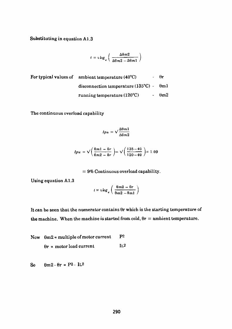
Substituting in equation A1.3
/t = i log ' \A6m2
Aem2-A6ml
For typical values of ambient temperature (40°C) - 6r
disconnection temperature (135°C) - 6ml
running temperature (120°C) - 0m2
The continuous overload capability
,A6mlIpu - V -—— A6m2
,/eml -6r \ ./ 135-40 \ Ipu = V —————— = V ————— = 1.09 \9m2-9r / \ 120-40 /
= 9% Continuous overload capability.
Using equation A1.36m2 - Qr
It can be seen that the numerator contains 6r which is the starting temperature of
the machine. When the machine is started from cold, 6r = ambient temperature.
Now 6m2 « multiple of motor current P2
6r « motor load current IL2
So 6m2 - 6r « P2 - IL2
290
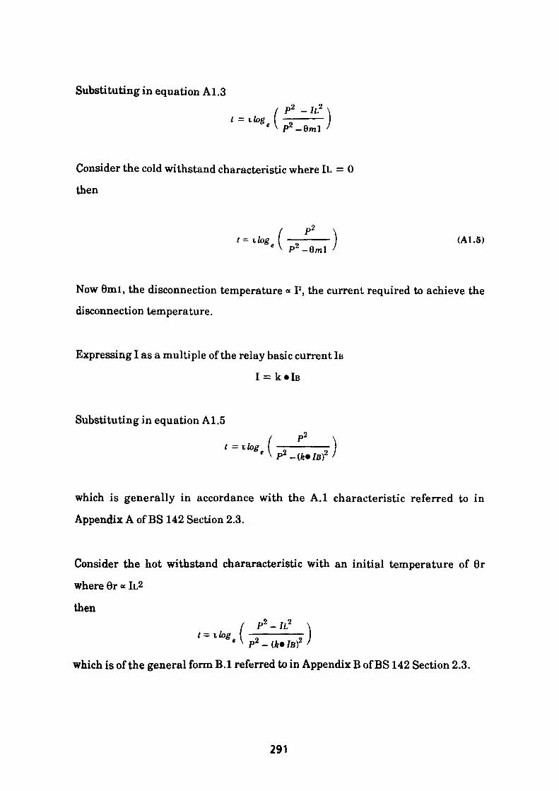
Substituting in equation Al.3O 9
/ P2 - IL* \t = i log I ————— I
e \ p2 _flr»1 /
Consider the cold withstand characteristic where IL = 0
then
P2
P2 -6ml
Now 6ml, the disconnection temperature * I2 , the current required to achieve the
disconnection temperature.
Expressing I as a multiple of the relay basic current IB
Substituting in equation A1.5
which is generally in accordance with the A.I characteristic referred to in
Appendix A of BS 142 Section 2.3.
Consider the hot withstand chararacteristic with an initial temperature of 6r
where 6r « It2
then/ P2 - IL2 \
t=llog I — ——————— -Ie V 2 - '
which is of the general form B.I referred to in Appendix B of BS 142 Section 2.3.
291
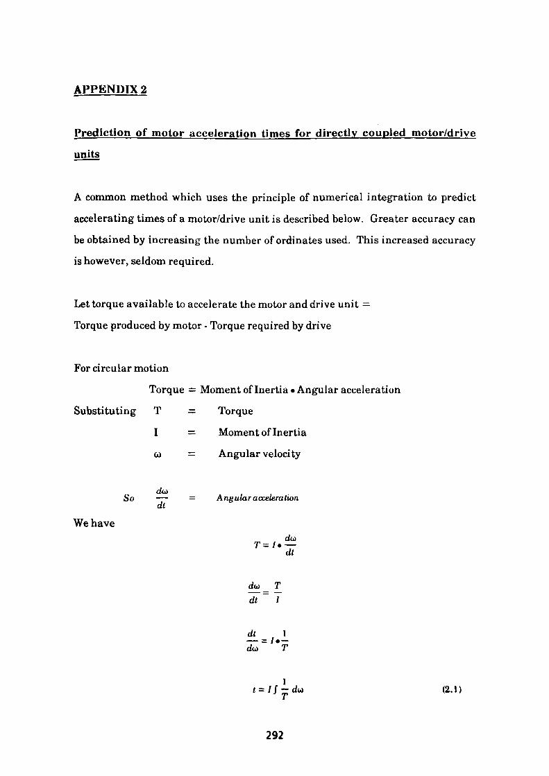
APPENDIX 2
Prediction of motor acceleration times for directly coupled motor/drive
units
A common method which uses the principle of numerical integration to predict
accelerating times of a motor/drive unit is described below. Greater accuracy can
be obtained by increasing the number of ordinates used. This increased accuracy
is however, seldom required.
Let torque available to accelerate the motor and drive unit =
Torque produced by motor - Torque required by drive
For circular motion
Torque = Moment of Inertia-Angular acceleration
Substituting T = Torque
I = Moment of Inertia
co = Angular velocity
So — dt
We have
Angular a ccelera tion
dt
dt
1 T (2.1)
292
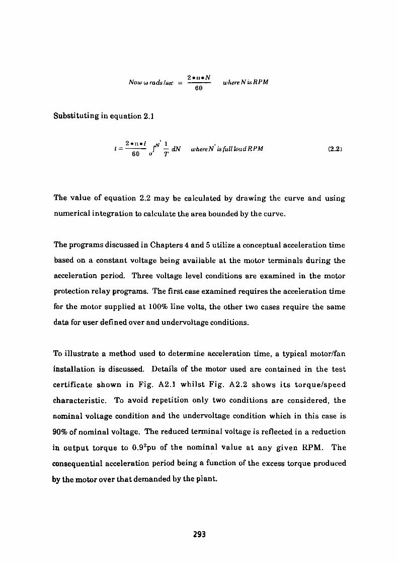
2 • i] *^Now w rods /sec = ————— where N is RPM
60
Substituting in equation 2.1
2«n«7 »,' 1———— r -dN where N is full load RPM (2.2)
60 o T
The value of equation 2.2 may be calculated by drawing the curve and using
numerical integration to calculate the area bounded by the curve.
The programs discussed in Chapters 4 and 5 utilize a conceptual acceleration time
based on a constant voltage being available at the motor terminals during the
acceleration period. Three voltage level conditions are examined in the motor
protection relay programs. The first case examined requires the acceleration time
for the motor supplied at 100% line volts, the other two cases require the same
data for user defined over and undervoltage conditions.
To illustrate a method used to determine acceleration time, a typical motor/fan
installation is discussed. Details of the motor used are contained in the test
certificate shown in Fig. A2.1 whilst Fig. A2.2 shows its torque/speed
characteristic. To avoid repetition only two conditions are considered, the
nominal voltage condition and the undervoltage condition which in this case is
90% of nominal voltage. The reduced terminal voltage is reflected in a reduction
in output torque to 0.92pu of the nominal value at any given RPM. The
consequential acceleration period being a function of the excess torque produced
by the motor over that demanded by the plant.
293

OFFtt
CUSTO
OUTPt— i — —
U. TEST RECORi
MER
D OF T/Encl. CACA Squirrel Cage A.C. WDUCTBN MOTOR No
SIZE D355-8B
T I 120 KW 3300 VOLTS 29.0 AMPS
NO LOAD READINGS
voltsAmpsRJ>JyLCycles
(Wot 1 8x225)
Phase l Phase 23300
12.45750
50103
Phase 3 Volts3300 330012.45
volts-80 847.5
740 RJPM. 50 CYCLES 3 PHASE
STARTING TORQUE
Amps118.0
Nm1396
XF.L.T. XFJ..C. Conn.122 407 Y
SHORT CIRCUIT READING
Amps28.8
WIU225)80
W2-25
No load loss = Total loss - PR = 4741
Time
7.007.308.008.309.009.3010.0010.3011.0011.30
3q1/2
0/Load
Cat
He<
volte
3300iinunnnN
II
3300
3300nit
:ulated
ater -
Stator Amps
28.875nnnuunnu
28.875Sta-
21.7514.47543.5
Pull-oi
292 Wa
Cycles
50niinnniiiiii
50or win
50nn
t Tore
l-ts at
R.P.M.
745
743
742
742ding t<
744746
736
ue = 2
110 vol-
impera-
03 FL
s
KW
129.15ure ri
86.62533.75197.1
r
KVA
165.04se by
124.3182.73248.63
PF
.783resistc
.697
.408
.793
nee =
KW Output
120.1749° c
79.5828.41182.2
Eff
93.0
91.984.292.4
RESISTANCE (OHMS) ACROSS TERMINALS
COLD HOT206 C 2lt
Stotor .53 1.83Conn. 1.53 1.83Y 1.53 1.83
Rotor
Com.
HIGH PRESSURE INSULATION TEST
Stotor flashed to earth for Imlaot 7600 V.A.C. Insulation Resistance 350 M
Heater flashed to earth for I mln. at COO V.A.C. insulation Resistance 100 M
Fig A2.I MANUFACTURERS TYPICAL MOTOR TEST RECORD
294
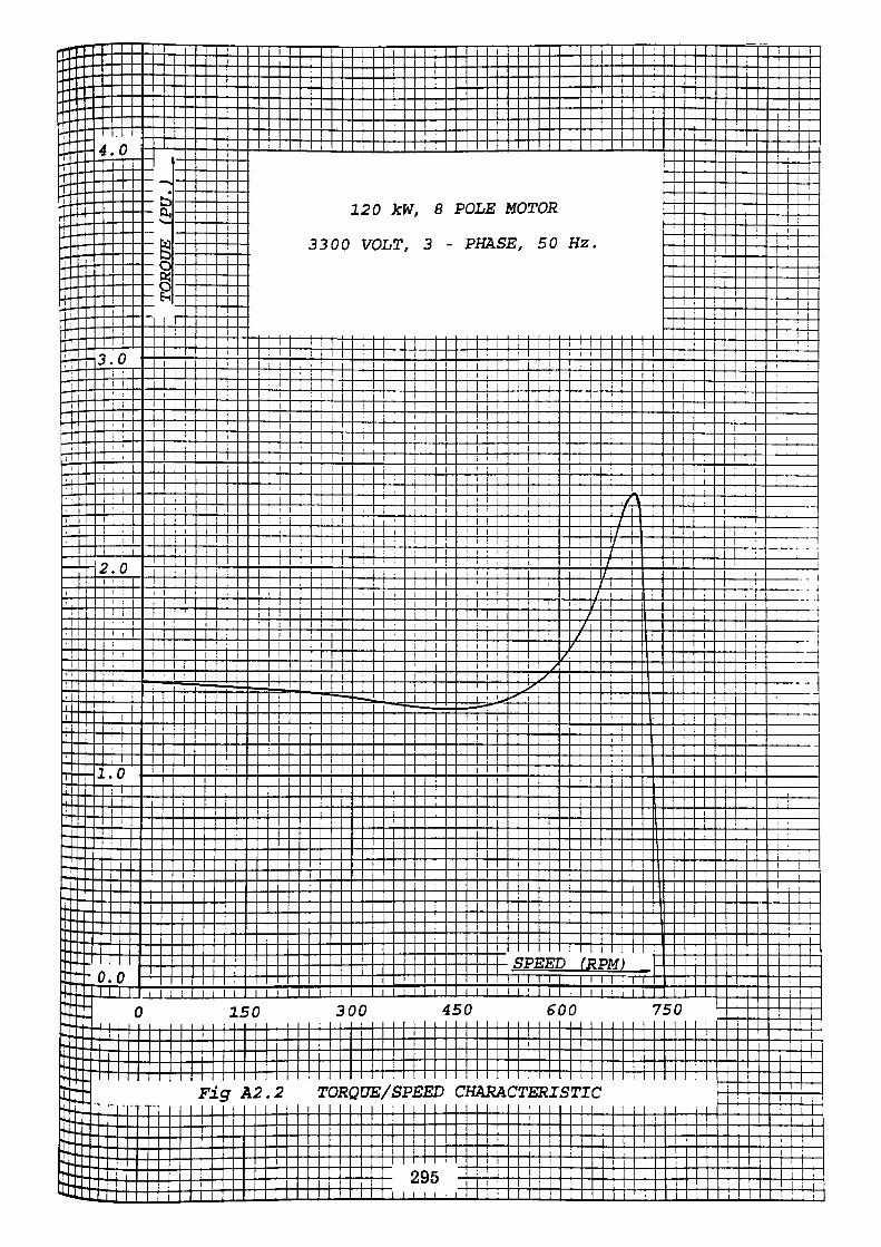
Consider a 3.3kV, 120kW, 8 Pole motor driving a fan. The inertia of the rotating
parts are:
Motor: 37 kgm2
Fan: 342 kgm2
By examination of the manufacturers published data, a set of torque/speed
coordinates have been tabulated for both the motor and the fan. These coordinates
are shown in table A2.1.
The data tabulated has been rearranged into more manageable form using a
Neville-Aitken Interpolation program. The results of the rearrangement are
shown in Tables A2.2 and A2.3. Table A2.2 details the nominal voltage case
whilst Table A2.3 refers to the condition with minimum voltage applied to the
motor.
An explanation of the table follows
Column 1 - RPM values
Column 2 - Motor Torque
Column 3 - Fan Torque
Column 4 - Accelerating Torque
Where Accelerating Torque = Motor Torque - Fan Torque
Column 5 - Average accelerating torque throughout RPM step
That is, typically 50-100 RPM step
Torque at 1 00 RPM - Torque at 50 RPM Average Accelerating Torque = ————————————-————————————
296
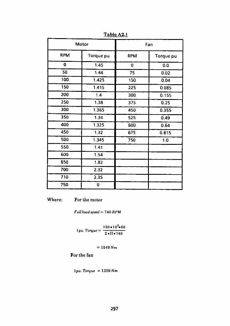
Table A2.1
Motor
RPM
0
50100150
200
250
300
350
400450
500550600
650
700
710
750
Torque pu
1.45
1.441.4251.415
1.41.381.3651.341.3251.321.3451.41
1.54
1.82
2.322.35
0
Fan
RPM
075150225
300375
450
525600675750
Torque pu
0.0
0.020.040.085
0.1550.250.3550.49
0.640.8151.0
Where: For the motor
Full load speed = 740 RPM
\pu. Torque —120«HT«60 2«n«740
= !549Nm
For the fan
Ipu. Torque = 1329Mn
297
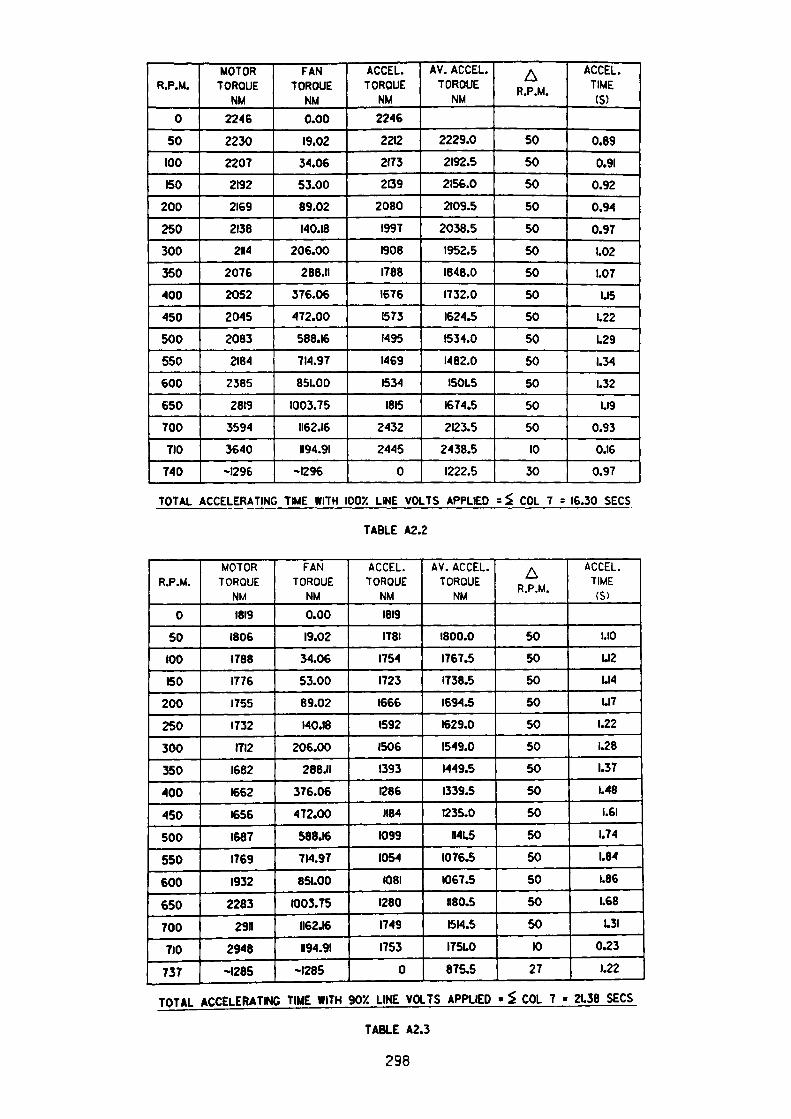
R.P.M.
0
50100
ISO
200
250
300
350400
450
500
550
600
€50TOO
710
740
MOTOR TORQUE
NM2246
223022072192
2169
21382N4
2076
2052
2045
20832184
2385
2819
3594
3640
-1296
FAN TORQUE
NM0.00
19.0234.0653.00
89.02140.18
206.00288.11
376.06
472.00
588.16714.97
851.00
1003.751162.16
1194.91
-1296
ACCEL TORQUE
NM2246
2212
21732139
20801997
19081788
1676
1573
1495
1469
1534
1815
24322445
0
AV. ACCEL. TORQUE
NM
2229.0
2192.5
2156.0
2109.5
2038.51952.51848.0
1732.0
1624.5
1534.0
1482.0
1501.5
1674.5
2123.5
2438.51222.5
A R.P.M.
50
50
50
50
50
50
50
50
50
50
50
50
50
5010
30
ACCEL. TIME (S)
0.89
0.91
0.92
0.94
0.971.02
1.071.15
1.22
1.29
1.34
1.321.19
0.930.16
0.97
TOTAL ACCELERATING TIME WITH IOOX LINE VOLTS APPLIED = £ COL 7 = 16.30 SECS
TABLE A2.2
R.P.M.
0
50
100
60
200
250
300
350
400
450
500
550
600
650
700
710
737
MOTOR TORQUE
NM
1819
1806
1788
1776
1755
1732
1712
1682
1662
1656
1687
1769
1932
2283
2911
2948
-1285
FAN TORQUE
NM
0.00
19.02
34.06
53.00
89.02
140.18
206.00
268JI
376.06
472.00
588.16
714.97
851.00
1003.75
1162.16
H94.9I
-1285
ACCEL. TORQUE
NM
1819
1781
1754
1723
1666
1592
1506
1393
1286
1184
1099
1054
HD8I
1280
1749
1753
0
AV. ACCEL. TORQUE
NM
1800.0
1767.5
1738.5
1694.5
1629.0
1549.0
1449.5
1339.5
1235.0
N4L5
1076.5
1067.5
H80.5
1514.5
1751.0
875.5
AR.P.M.
50
50
50
50
50
50
50
50
50
50
50
50
50
50
10
27
ACCEL. TIME (S)
1.10
UI2
1.14
UI7
1.22
1.28
1.37
1.48
1.61
1.74
1.84
1.66
1.68
1.31
0.23
1.22
TOTAL ACCELERATING TIME WITH 90X LINE VOLTS APPLIED » $ COL 7 - 2L38 SECS
TABLE A2.3
298

Column 6 - RPM step length
Column 7 - Acceleration time in seconds for column 6. The step length is
derived as stated previously from:
60 o T Substituting we have
t = sr
2.FI.7 (37 where t —
60 Torque
where t1 is the accelerating time for A RPM step length considered
Torque means average accelerating torque.
299
APPENDIX 3
Harmonics in the Supply Voltage
When speed control of electric motors is considered, the modern approach is to
incorporate some form of non-linear device in the control unit. These control units
effect control over the motor by varying the output voltage or frequency or a
combination of both, generally by utilising solid state thyristor type equipment.
The object of the control philosophy is to determine the point on the waveform at
which the devices are allowed to conduct, thus it can be seen that the resulting
current flow is non-sinusoidal in nature.
It can be shown that any complex waveform may be considered as the addition of a
number of sinusoidal waveforms comprising of a fundamental frequency and
harmonic terms. If an examination of the complex wave reveals that the positive
half cycle differs from the negative half cycle, then an even harmonic (for example,
a second harmonic) will be present. Such is the case where rectifying equipment
or speed control of motors by phase control of semiconductors is employed.
Consider a 3-phase supply with a second harmonic content
vr = VRl Sin (<•>/ + ipl)+ VR2 Sin (2u>/ +
and
2n 2n v;y = VYlSin(a>t- — +wD+ VY2Sin(2M- — )
3 3
4n 4u v6 = VBlSintot- — +iyl)+ VB2Sin(2(wt- —
3 3
wherevr, vy and vb = Instantaneous voltage values
300
VR1, VY1 and VB1 = peak voltage values of the fundamental
VR2, VY2 and VB2 = peak voltage values of the second harmonic
CO = 2nf, the angular frequency where f is Hertz
= Phase angle of the fundamental waveform
= Phase angle of the harmonic component
reducing the aboveVR2Sin(2ut
try = VY\Sin(u>t- 120°+ipl) + VY2Sin(2u>t- 240°+ij;2)
vb - VBlSm(<o/-240°+i!;l) + VB2Sin(2ut-
Fig. A3.1 depicts the above waveforms where it can be clearly seen that the
second harmonic has a negative phase sequence.
Harmonics are also produced from other sources such as in the output of
generators caused by for instance non-sinusoidal air gap flux distribution. Iron
cored coils such as reactors or transformers are also harmonic generators owing to
the non-linear characteristic of the B-H curve. The greater the saturation the
more harmonic distortion will be present. The resultant waveforms will be
symmetrical in nature which indicates that no even harmonic components are
present. The resultant distortion being caused by odd harmonic values.
Consider a 3-phase supply with odd harmonic content (symbols as previous)
w = VRlSin(ut + ipl) + Vft3Sin(3o>< + vj»3) + Vft5Sin(5u< + vji5)
2n 2n 2n vy= VYlSin(ut- — -f ijil) + VY3Sm(3M- —) +iy3)+ VY5 Sm(5(u>/ - —) 333
301

Sin (uf- — + ml) + VB3 Sin (3(to/ - — )+\j<3) + VB5Sin(5(w* - — ) -I-•3 3 *J
which reduces to
ur= Vfll Sin(w«+iiil) + Vfl3Sin(3o>/ + iy3) + V#5 Sin (5u;« + iji5)
vy= VYlSin(o><- 120° +^1) + VV3 Sm(3wt +\y 3)+ Vr5Sin (5u>< -240° + iy 5)
ufc = VB1 Sin (to< - 240° +qil)+ VB3 Sin (3 w< +q;3)+ VBSSin (5u;<-120°+ vp5)
From which it can be seen that the third harmonic is zero phase sequence in
nature. This is illustrated in Fig. A3.2. Similarly it can be shown that the third
and all triplen harmonics are co-phasal.
The fifth harmonic can be seen to have a negative phase sequence as was observed
with the second harmonic. It can be shown that the 5th, llth, 17th etc. harmonics
all exhibit negative phase sequence characteristics.
The effect of negative phase sequence components in the supply is discussed in
Appendix 4.
302
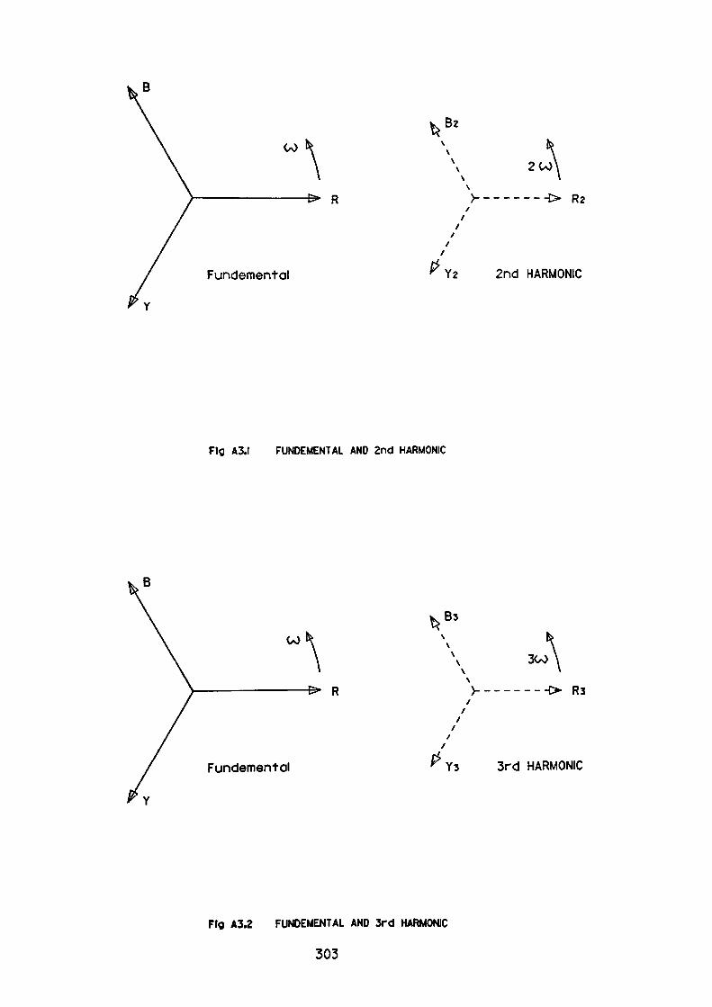
Bz
200\
---> R2
Fundemental Y2 2nd HARMONIC
Fig A3.) FUNDEMENTAL AND 2nd HARMONIC
\Bs
\0^300
---O R3
Fundemental Ys 3rd HARMONIC
Fig A3.2 FUNDEMENTAL AND 3rd HARMONIC
303

APPENDIX 4
Effects of Unbalanced Supply Voltage
Consider the equivalent circuit diagram of an induction motor shown in Fig. A4.1.
The positive phase sequence impedance of the motor equivalent circuit is:
l-SZ = Rs\ + jXs\ + RRI +JXR\ + —— RRI (A4.1)
where: suffix Rl values are rotor values
suffix Si refers to stator values
from whichl-S
Z = Rsi + RR\ + —— RRI +jXsi +jXR\
S + (1-S)\ = Rsi+ RRI —— - —— \ + j(Xsi +XRI)
- Rsi + RRi/S +j(Xsi +XRI)
RRtiS)2 + (XS\ +Xfii) (A4.2)
Differences will occur in individual equivalent circuit component values, mainly
in rotor values. Disregarding the magnetising losses the circuit can be further
simplified to that shown in Fig. A4.2.
In the case of negative sequence impedance of the motor equivalent circuit, the
slip frequency seen by the rotor is again a function of rotor speed (see Fig. A.4.3).
The slip value being 2-S pu. Note at rotor standstill slip = 2-1 = 1 pu. which is
304
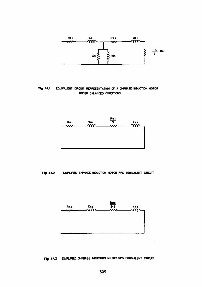
R8i —VW-
Xai RRI ^VW*
XRI
Cm Bm±L R*
S
Fig A4J EQUVALENT CIRCUIT REPRESENTATION OF A 3-PHASE MOUCTION MOTORUNDER BALANCED CONDITIONS
Rsi ——VW-
XsiRm
S XRI
Fig M2 SMPLFtED 3-PHASE MDUCTION MOTOR PPS EQUIVALENT QRCUIT
R82 ——VW-
CS2R*22-S
-VW
Fig A4.3 SMPLIFED 3-PHASE MDUCTION MOTOR NPS EQUIVALENT CIRCUIT
305
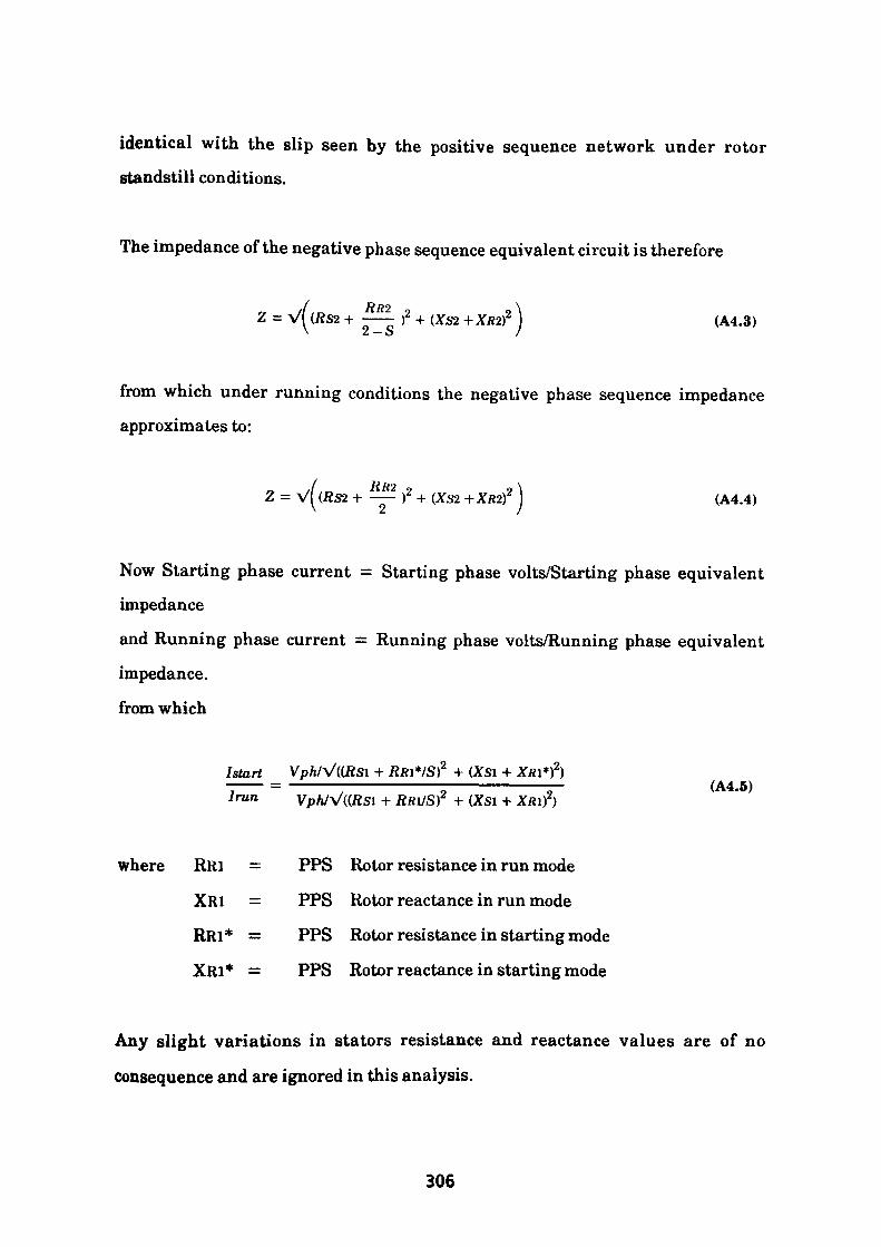
identical with the slip seen by the positive sequence network under rotor standstill conditions.
The impedance of the negative phase sequence equivalent circuit is therefore
Z = V((ftS2 + -^| )2 + (XS2 + XRtf J (A4.3)
from which under running conditions the negative phase sequence impedance approximates to:
,/ RH'2 9 y\Z = V^(fiS2 + —— )J + (XS2 +XR2T } (A4.4)
Now Starting phase current = Starting phase volts/Starting phase equivalent
impedance
and Running phase current = Running phase volts/Running phase equivalent
impedance.
from which
/start Vp/i/V(tRSl + RRl*/S)2 + (XS\ +_—— = —————————————-————————— (A4.5)/run VpWV((fiSl + RRl/Sr + (Xsi + XRi)2)
where RRl = PPS Rotor resistance in run mode
XRI = PPS Rotor reactance in run mode
RRl* = PPS Rotor resistance in starting mode
XRi* = PPS Rotor reactance in starting mode
Any slight variations in stators resistance and reactance values are of no
consequence and are ignored in this analysis.
306
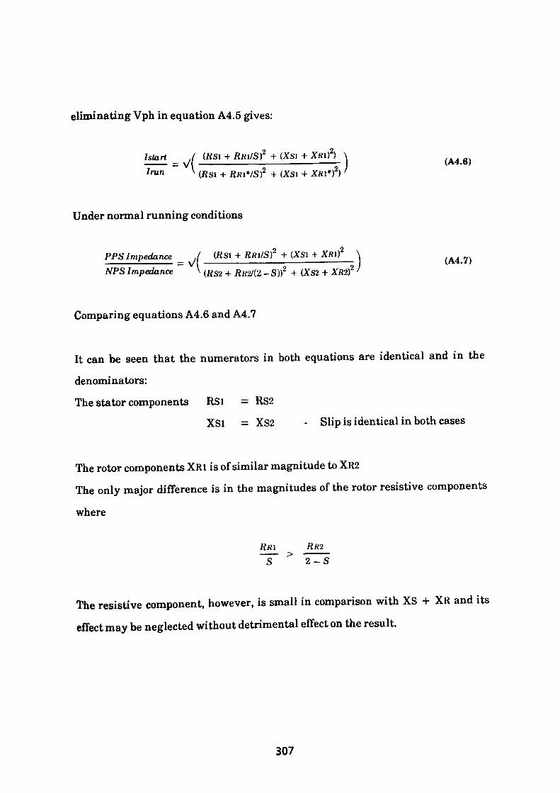
eliminating Vph in equation A4.5 gives:
I run.1 (Rsi + RRI/ST + (xs\ + XRin \
= V( —————————-——————————- (A4.6) v (Rsi + RR\*/S)2 + (Xsi + XR\*)) '
Under normal running conditions
PPS Impedance ,( (RSI + Rfti/S)2 + (XSi +————-———— = VI ———————————————————'•—— | (A4.7)NPS Impedance \ (Rsz + Rlt2/(2 _S))2 + (XS2 + Xfl2)2
Comparing equations A4.6 and A4.7
It can be seen that the numerators in both equations are identical and in the
denominators:
The stator components RSI = RS2
XSl = XS2 - Slip is identical in both cases
The rotor components XRl is of similar magnitude to XR2
The only major difference is in the magnitudes of the rotor resistive components
where
RR\ RR2 ~S~ > 2-S
The resistive component, however, is small in comparison with XS + XR and its
effect may be neglected without detrimental effect on the result.
307
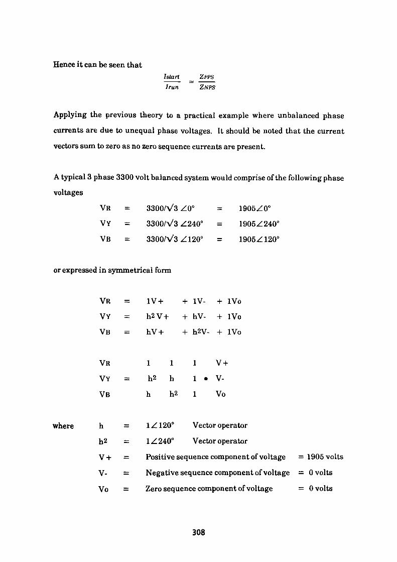
Hence it can be seen thatI start Iran
ZPPSZNPS
Applying the previous theory to a practical example where unbalanced phase
currents are due to unequal phase voltages. It should be noted that the current
vectors sum to zero as no zero sequence currents are present.
A typical 3 phase 3300 volt balanced system would comprise of the following phase
voltages
VR = 3300/V3Z00 = 1905Z00
VY = 3300/V3Z2400 = 1905Z240°
VB = 3300/V3Z1200 = 1905Z1200
or expressed in symmetrical form
VR = 1V+ + IV- + IVo
VY = h2V+ + hV- + IVo
VB hV+ + h2V- + IVo
VR VY VB
l i i V+h2 h 1 • V-h h2 1 Vo
where h
h.2
V +
V-
Vo
1Z120° Vector operator
1Z 240° Vector operator
Positive sequence component of voltage
Negative sequence component of voltage
Zero sequence component of voltage
= 1905 volts
= 0 volts
= 0 volts
308
If the system is required to supply a heavy single phase load such as a phase-phase
load, then the unloaded phase would be at a higher phase-neutral potential than
the loaded phases. The extent of the regulation being a function of load power
factor and source impedance.
Consider a motor with equivalent circuit values as detailed in Appendix 7.
The motor is supplied with unequal voltages such that the negative phase
sequence voltage is 5% of the positive sequence voltage. Such a system satisfying
this criteria may comprise of the following set of symmetrical components.
Let the magnitude of the unloaded phase = 3300/V3 volts, this value being the
result of the vector addition of the positive and negative phase sequence
components. For ease of illustration consider the positive and negative phase
sequence components to be in phase from which it follows that the unloaded phase
comprises of:100 3300—— • —;— = 1814.53ZO V Positive sea uence component 105 V3
and
5 3300—— • —;— = 90.73ZO°V Negatiue sea uence component105 V3
If the unloaded phase is VR then
Positive Sequence Negative Sequence Zero Sequence
VR = 1814.53 + 90.73 + 0 = 1905.26Z00
VY = 1814.53Z240" + 90.73Z1200 + 0 = 1770.91Z-122.540
VB = 1814.53Z1200 + 90.73Z2400 + 0 = 1770.91Z+122.54°
309
Consider the vector arrangement referred to in the above set of equations.
If the above voltages are applied to an induction motor represented by the
equivalent circuit shown in Fig. A7.3.
Then for a running speed of 990 rpm
1000-990Slip = NS- NRlNs = —————— = 0.011000
Admittance of exiting component
= 0.000341-j 0.00672 Siemens
Admittance of rotor component for positive sequence network
i i0.539/0.01+./6.237 53.9+./6.237
= 0.0184Z-6.6°54.26Z6.60
= 0.018308-j 0.002118 Siemens
Total admittance of exiting component + rotor component
= 0.00034 l-jO.00672 + 0.018308-J0.002118
= 0.0186649-jO.008838
= 0.020637Z-25.36° Siemens
310
Equivalent Impedance ~0.020637Z-25.360
48.456Z25.360
= 43.787 + J20.753 Ohms
Total Equivalent Impedance
= Stator Component + Rotor and Exiting Components
0.643 + J5.499 + 43.787 + J20.753
44.43 +J26.252
51.606Z30.580 Ohms
Similarly for the Negative Phase Sequence Network
Admittance of Rotor Component where Slip
1000-9902- —————— = 1.99 1000
3.234/1.99 +J4.5666
= 0.2063Z-70.410
= 0.0692-jO.1944 Siemens
Total Admittance of exiting component + rotor component
= 0.000341-jO.00672 + 0.0692-jO.1944
= 0.0695-J0.2011
= 0.2128Z-70.93° Siemens
311
Equivalent Impedance - —————————— = 4.6996Z70.93°o/ims0.0695-^0.2011
= 1.5356+J4.4416 Ohms
Total Equivalent Impedance
= Stator Component + Rotor and Exiting Component
= 0.643 + J5.499 + 1.5356 + J4.4416
= 2.1786 + J9.9406
= 10.1766Z77.640 Ohms
At Standstill Slip = 1
Admittance of rotor component
= 0.2Z -65.7°2.065/1 +j4. 566
= 0.082230-jO.181821 Siemens
Total Admittance of exiting component + rotor component
= 0.000341-jO.00672 + 0.082230-jO.181821
= 0.082571-J0.188541
= 0.205829Z-66.350 Siemens
1 Equivalent Impedance = -.,_-. .—TTT7 = 4.85Z66.35
= 1.945 + J4.450 Ohms
312
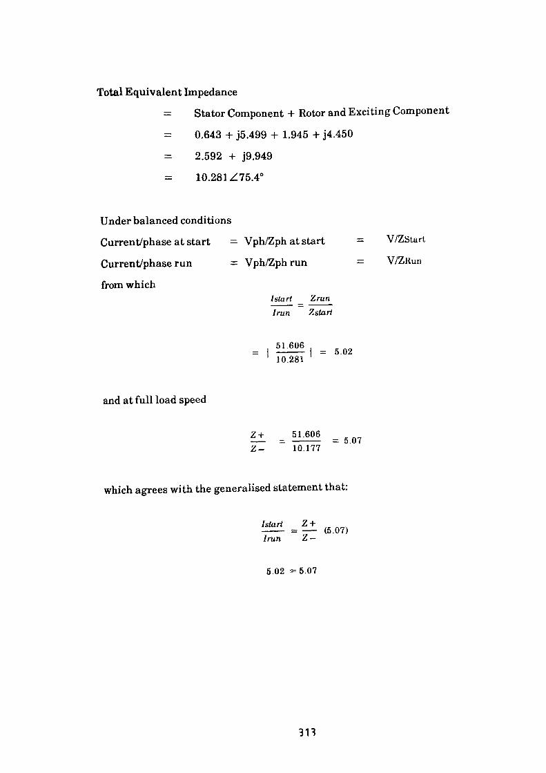
Total Equivalent Impedance
= Stator Component + Rotor and Exciting Component
0.643 + J5.499 + 1.945 + J4.450
2.592 + J9.949
10.281 Z75.40
Under balanced conditions
Current/phase at start = Vph/Zph at start
Current/phase run = Vph/Zph run
from whichI start Iran
Zrun Zstart
V/ZStart
V/ZRun
51.60610.281
= 5.02
and at full load speed
Z + 51.60610.177
= 5.07
which agrees with the generalised statement that:
/start Z +——— = —— (5.07)/ran Z —
5.02 -5.07
313
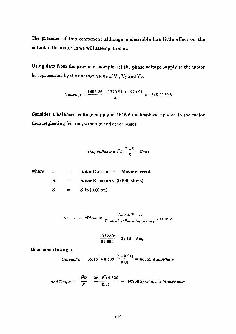
The presence of this component although undesirable has little effect on the output of the motor as we will attempt to show.
Using data from the previous example, let the phase voltage supply to the motor be represented by the average value of Vr, Vy and Vb.
1905.26 + 1770.91+1770.91 Vaverage= ——————————————————— = 1815.69 Volt
Consider a balanced voltage supply of 1815.69 volts/phase applied to the motor then neglecting friction, windage and other losses
/I _ O\
OutputiPhase = I2R ——— Watts
where I = Rotor Current = Motor current
R = Rotor Resistance (0.539 ohms)
S = Slip (O.Olpu)
Voltage/PhaseNow currentJPha.se = ——;—-—————-———-—— (at slip S) Equivalent Phase Impedance
1815.69= 35.18 Amp51.606
then substituting ino (1-0.01)
Output/Ph = 35.18 • 0.539 ————— = 66055 Watts/Phase
I2R 35.182«0.539andTorque = —— - ———————— = 66708 Synchronous Watts/Phase
ij U.U 1
314
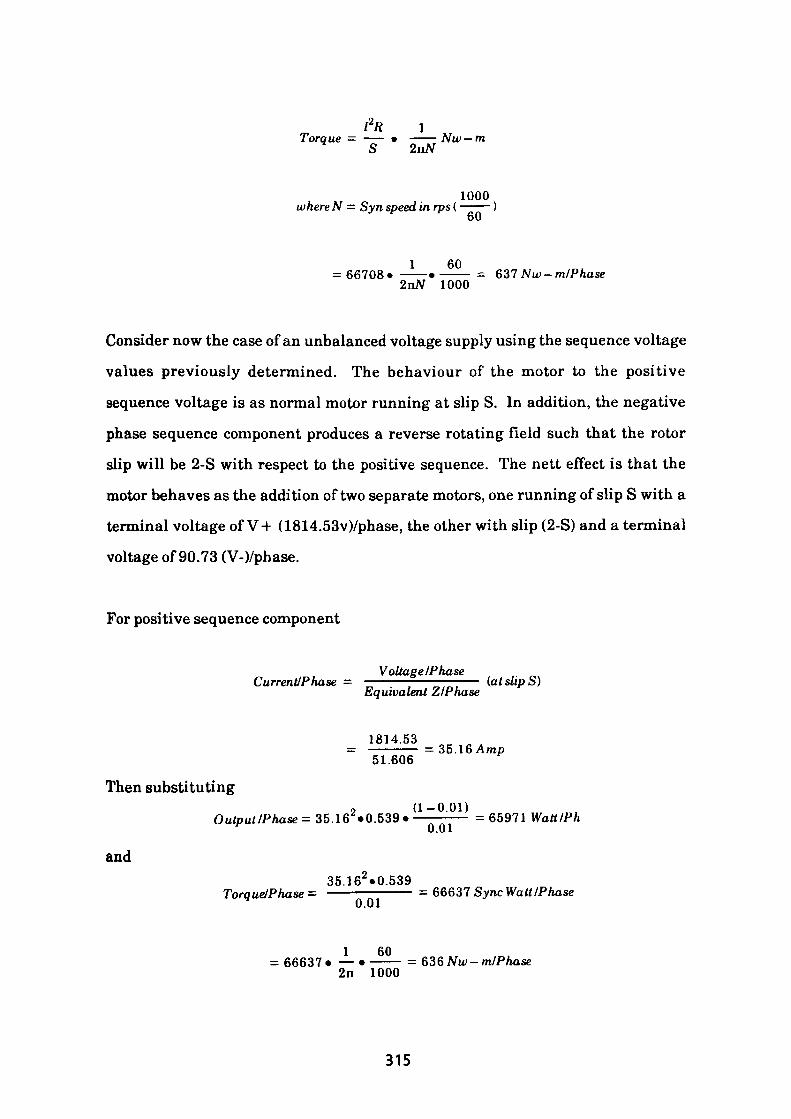
12R 1Torque — —— • ——— Nw — m
S 2nN
1000whereN — Syn speed in rps ( ———
60
1 60= 66708- ———•——— = 637Nw-m/Phase 2nN 1000
Consider now the case of an unbalanced voltage supply using the sequence voltage
values previously determined. The behaviour of the motor to the positive
sequence voltage is as normal motor running at slip S. In addition, the negative
phase sequence component produces a reverse rotating field such that the rotor
slip will be 2-S with respect to the positive sequence. The nett effect is that the
motor behaves as the addition of two separate motors, one running of slip S with a
terminal voltage of V+ (1814.53v)/phase, the other with slip (2-S) and a terminal
voltage of 90.73 (V-)/phase.
For positive sequence component
Voltage/PhaseCurrent/Phase = ———-—————— (at slip S) Equivalent Z/Phase
1814.53= ————— =35.16Amp 51.606
Then substituting
and
9 (1-0.01)Output/Phase = 35.16 »0.539 • ————— = 65971 Watt/Ph
35.162 »0.539Torque/Phase = ———————— = 66637 Sync Watt/Phase
0.01
1 60= 66637 • — • ——— = 636 Nw-m/Phase
2n 1000
315
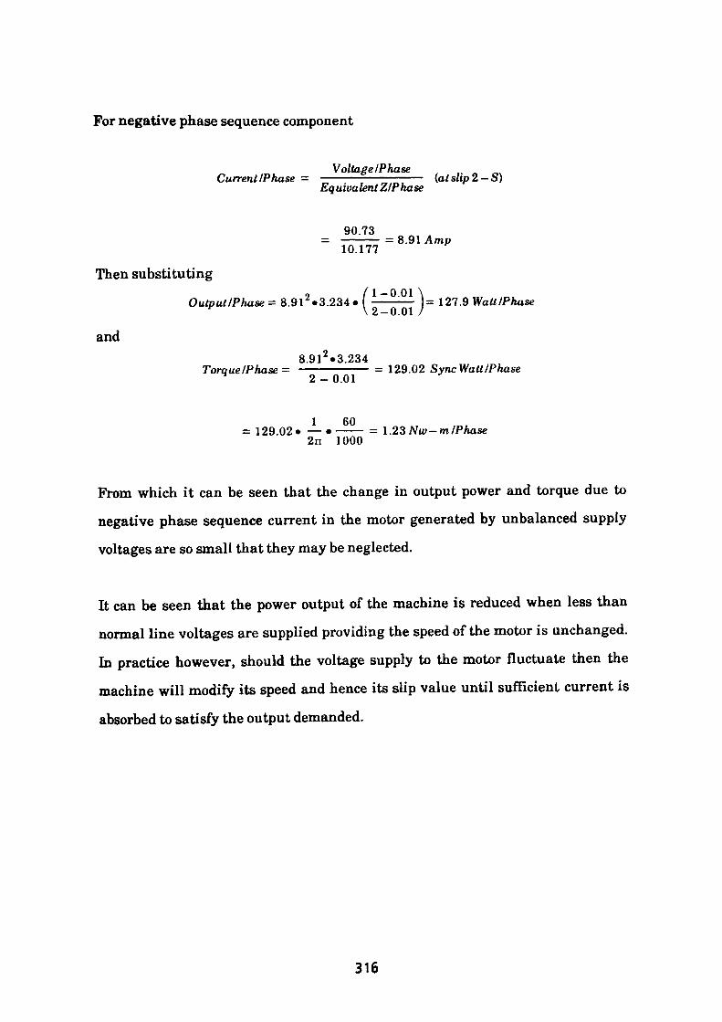
For negative phase sequence component
_, Voltage /Phase Current/Phase = ————2—————— (at slip 2 ~S)
Equivalent Z/Phase
90.73
Then substituting
and
o / 1-0 01 ,Output/Ptiase= 8.91 «3.234« ———:— = 127.9 Watt/Phase
\2-0.01 '
8 91*3 234Torque/Phase = -————:—— = 129.02 SyncWutt/Phase
2-0.01 J
I 60= 129.02* —•——— = l.23Nw-m/Phase
2n 1000
From which it can be seen that the change in output power and torque due to
negative phase sequence current in the motor generated by unbalanced supply
voltages are so small that they may be neglected.
It can be seen that the power output of the machine is reduced when less than
normal line voltages are supplied providing the speed of the motor is unchanged.
In practice however, should the voltage supply to the motor fluctuate then the
machine will modify its speed and hence its slip value until sufficient current is
absorbed to satisfy the output demanded.
316
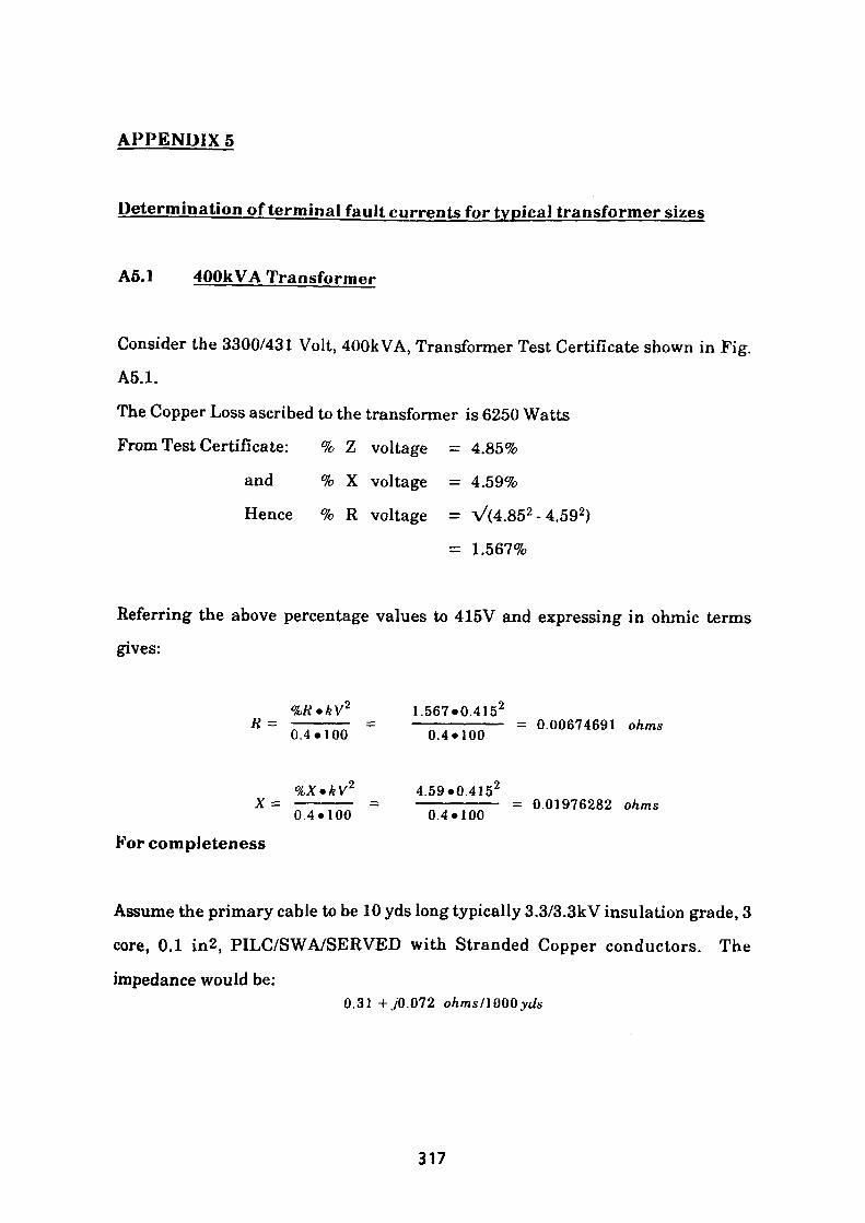
APPENDIX 5
Determination of terminal fault currents for typical transformer sizes
A5.1 400kVA Transformer
Consider the 3300/431 Volt, 400k VA, Transformer Test Certificate shown in Fig.
A5.1.
The Copper Loss ascribed to the transformer is 6250 Watts
From Test Certificate: % Z voltage = 4.85%
and % X voltage = 4.59%
Hence % R voltage = V(4.852 - 4.592)
= 1.567%
Referring the above percentage values to 415V and expressing in ohmic terms gives:
%R»kV2 1.567*0.4152K = ————— = ———————— = 0.00674691 ohms0.4*100 0.4*100
kVZ 4.59*0.415 2x = ————— = ———————— = 0.01976282 ohms0.4*100 0.4*100
For completeness
Assume the primary cable to be 10 yds long typically 3.3/3.3kV insulation grade, 3 core, 0.1 in2, PILC/SWA/SERVED with Stranded Copper conductors. The
impedance would be:0.31 +./0.072 ohms/1000 yds
317
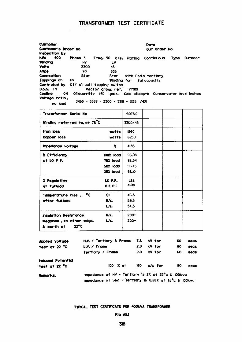
TRANSFORMER TEST CERTIFICATE
CustomerCustomer's Order NoInspection bykVA 400WindingVolts
Phase 3
DoteOur Order No
Continuous Type OutdoorFreq. 50 c/s. RatingHV LV
3300 431 70 535Star Star with Delta tertiary
HV Winding for full capacity Off circuit tapping switch
Vector group ref. YYODl Coding ON Oil quantity 140 gens. Cold on depth Conservator level Inches Voltage ratio,
3465 - 3382 - 3300 - 3218 - 3135 /43I
Connection Tappings on Contrded by B.S.S. 171
no toad
Transformer Serial No
Winding referred to, at 75 C
Iron toss watts Copper toss watts
Impedance voltage X
y. Efficiency 100% toad at LO P F. 75% toad
507. toad 25X toad
X Regulation LO Pf. at fulioad 0.8 P.F.
Temperature rise , *C OH after full toad H.V.
L.V.
Insulation Resistance H.V. megohms , to other wdgs. L.v. fc earth at 22° C
6075IC
3300/431
1560 6250
4.85
98.09 98.34 98.45 98.10
L.66 4.04
46.5 593 543
200+
200+
Applied Voltage test at 22 *C
Induced Potential test ot 22 °C
Remarks,
H.V. / Tertiary & Frame L.v. / Frame Tertiary / Frame
100 % at
7.6 kV for2.0 kV for2.0 kV for
BO c/6 for
60 60 60 sees
60 sees
impedance of HV - Tertiary is 2X at 75°c & lOOkva Impedance of Sec - Tertiary Is O.B6X at 75°c & lOOKva
TYPICAL TEST CERTFICATE FOR 400KVA TRANSFORMER
Fig A5J
318
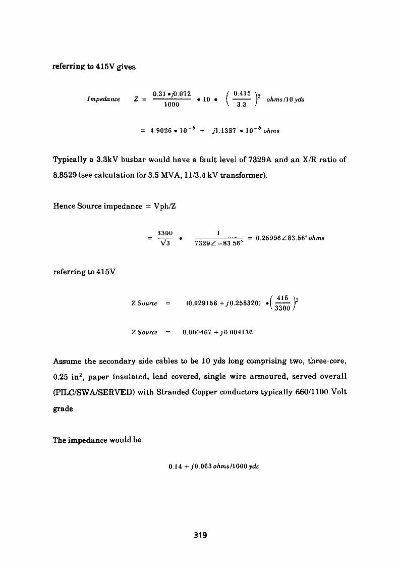
referring to 415V gives
0.31-70.072 / 0.415 \,Impedance Z - ——————— • 10 • I ——— I ohms/10 yds
1000 V 3.3 /
= 4.9026«10~ 5 + 71.1387 • 10~ 5 ohms
Typically a 3.3kV busbar would have a fault level of 7329A and an X/R ratio of
8.8529 (see calculation for 3.5 MVA, 11/3.4 kV transformer).
Hence Source impedance = Vph/Z
3300 1—1— • ————————— = 0.25996Z83.56°o/imsV3 7329Z-83.56"
referring to 415V
/ 415 \2ZSource = (0.029158 +70.258320) • ——— Y
\ 3300 /
ZSource = 0.000467+70.004136
Assume the secondary side cables to be 10 yds long comprising two, three-core,
0.25 in2, paper insulated, lead covered, single wire armoured, served overall
(PILC/SWA/SERVED) with Stranded Copper conductors typically 660/1100 Volt
grade
The impedance would be
0.14 + 70.063o/ims/1000;yds
319

For two cables in parallel of length 10 yds, the impedance would be:
1 10 - .(0.14 + ./0.063). ———2 1000
7«10 ~ 4 + J3.14 .10 ~ 4 ohms
Hence total impedance of transformer circuit comprising HV and LV cables all referred to 415 volt is:
HV Source
HV Cables
Transformer
LV Cables
0.000467 +
4.9026 .10 5 +
0.00674691 +
7.10 4 +
j 0.004136
j 1.1387.10 5
j 0.01976282
j 3.14.10 5
Total Impedance 0.0079628 + j 0.0239417
For a three-phase fault on the LV busbars, the resulting current would be:
415V3 .(0.0079628 +jO. 0239417)
= 9496 Amp
X 0.0239417with an—ratio of —————— = 3.0R 0.0079628
320
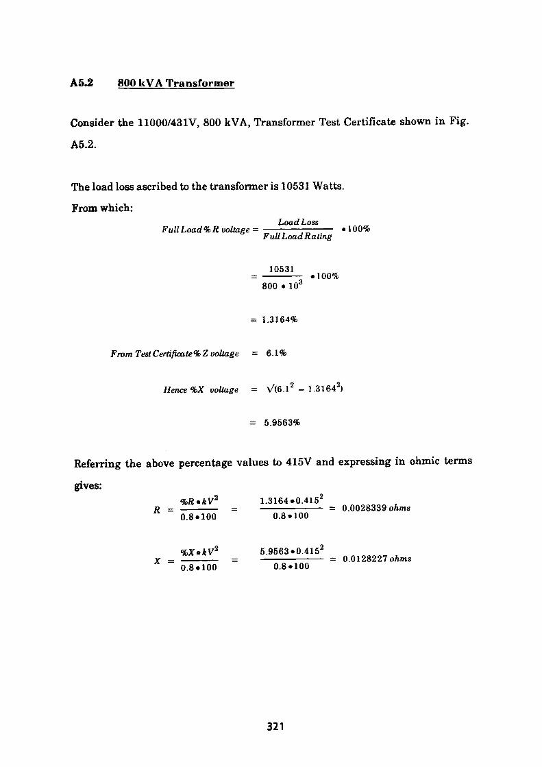
A5.2 800 kVA Transformer
Consider the 11000/431V, 800 kVA, Transformer Test Certificate shown in Fig.
A5.2.
The load loss ascribed to the transformer is 10531 Watts.
From which:Load LossFull Load %R voltage- —————————— *100%
Full Load Rating
10531.100%
800 • 103
= 1.3164%
From Test Certificate % Z voltage = 6.1%
Hence %X voltage = V(6.1 2 - 1.3164 2)
= 5.9563%
Referring the above percentage values to 415V and expressing in ohmic terms
gives:%R»kV2 1.3164*0.415 2
R = ————— = ————————— = 0.0028339 ohms0.8*100 0.8*100
%X»kV2 5.9563.0.4152x - _____ = ————————— = o.Ol28227 ohms
0.8*100 0.8*100
321
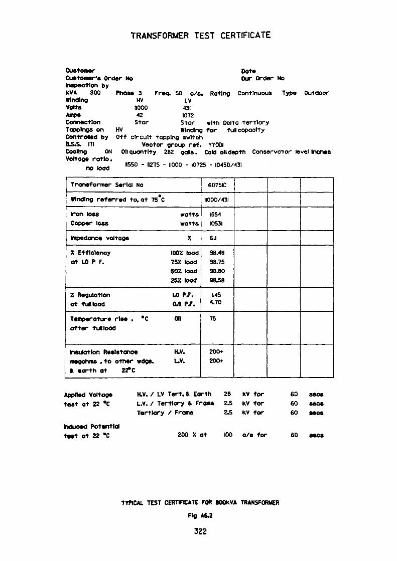
TRANSFORMER TEST CERTIFICATE
CustomerCustomer's Order NoInspection byKVA 800WindingVoltsAmpsConnectionTappings onControBed byB.S.S. 171
Phase 3 HV
11000 42 Star
HV
DateOur Order No
Freq. 50 c/s. Rating Continuous Type Outdoor LV
431 1072Star with Delta tertiary Winding for full capacity
Coding ON Voltage ratio,
no load
Off circuit tapping switchVector group ref. YYODl
282Oil quantity 282 gads. Cold oil depth Conservator level Inches
11550 - 11275 - 11000 - 10725 - KM50/43I
Transformer Serial No
Winding referred to, at 75*C
iron loss watts Copper loss watts
impedance voltage 7.
% Efficiency IOOX. load at UO P F. 75% toad
502 toad 25% toad
JJ Regulation UO P.F. at fun toad 04 PJ.
Temperature rise , °C Oil after fun load
insulation Resistance H.V. megohms .to other wdgs. L.V. & earth at 22° C
6075IC
11000/431
155-4 10531
6.1
9B.4B 98.75 96.80 98.58
US 4.70
75
200+ 200+
Applied Voltage test at 22 *C
induced Potential test at 22 °C
H.V. / LV Tert. & Earth L.V. / Tertiary & Frame Tertiary / Frame
200 X at
2B kV for2.5 kV for2.5 kV for
100 c/s for
60 sees60 sees60 sees
60
TYPICAL TEST CERTIFICATE FOR BOOKVA TRANSFORMER
Fig A5.2
3Z2
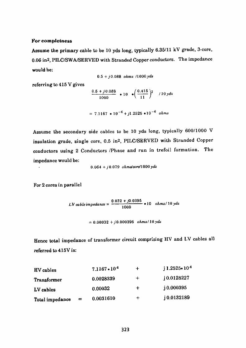
For completeness
Assume the primary cable to be 10 yds long, typically 6.35/11 kV grade, 3-core,
0.06 in2, PILC/SWA/SERVED with Stranded Copper conductors. The impedance
would be:0.5 +JQ.Q&& ohms /1000yds
referring to 415 V gives0.5+J0.088 /0.415\2———-——— .10 •( ——— / 10 yds
1000 V 11 /
= 7.1167 • 10" 6 +jl.2525 «10~ 6 ohms
Assume the secondary side cables to be 10 yds long, typically 600/1000 V
insulation grade, single core, 0.5 in2, PILC/SERVED with Stranded Copper
conductors using 2 Conductors /Phase and run in trefoil formation. The
impedance would be:0.064+./0.079 ohms/core/1000yds
For 2 cores in parallel
0.032 +J0.0395 LV cable impedance = ——————————"10 ohms/IQyds
= 0.00032 +J0.000395 ohms/lQyds
Hence total impedance of transformer circuit comprising HV and LV cables all
referred to 415V is:
HV cables 7.1167.10 6 + j 1.2525.10 6
Transformer 0.0028339 + j 0.0128227
LV cables 0.00032 + j 0.000395
Total impedance = 0.0031610 + j 0.0132189
323
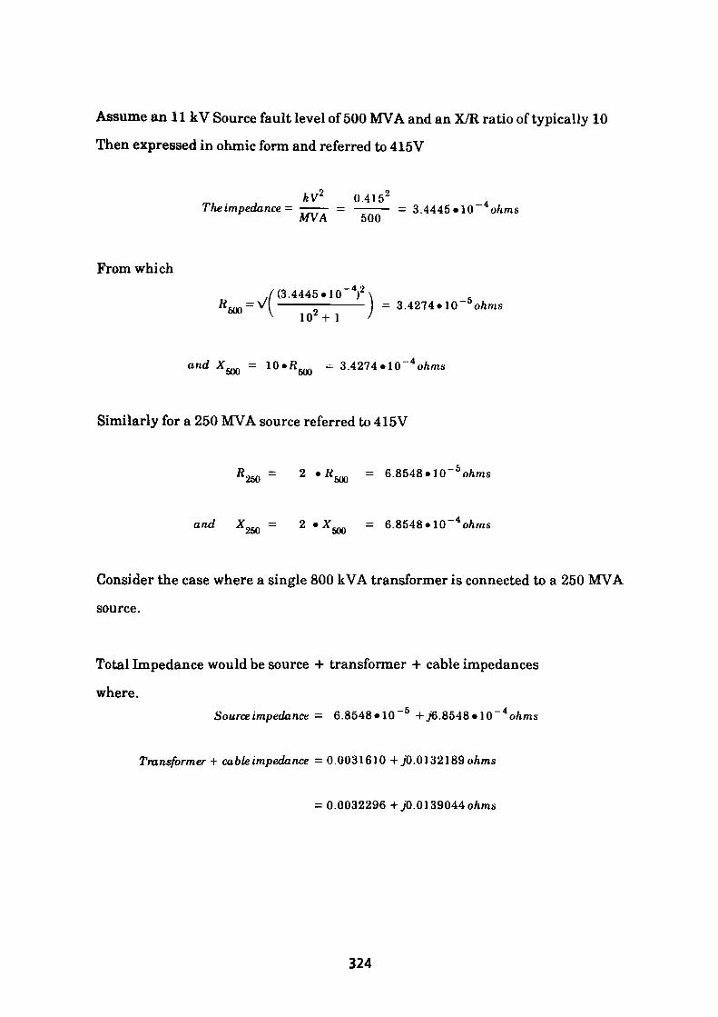
Assume an 11 kV Source fault level of 500 MVA and an X/R ratio of typically 10
Then expressed in ohmic form and referred to 415V
kV 0.415 2The impedance - —— = ———— = 3.4445*10 ohms
MVA 500
From which~ 42./ (3.4445 «10~)\ .———— - ————— = 3.4274«10~ & o/ims
V 102 +1 /
and X = 10«fi™ = 3.4274 •I0~*ohms ouu ouu
Similarly for a 250 MVA source referred to 415V
«„„ = 2 •«_.... = 6.8548«10~ 6 o/imsZoO oUU
and XOKn = 2 •Xam = 6.8548»10~ 4 o/imsjSoU OUU
Consider the case where a single 800 kVA transformer is connected to a 250 MVA
source.
Total Impedance would be source 4- transformer + cable impedances
where.Source impedance = 6.8548«10~ 5 + >6.8548»10~ 4 o/ims
Transformer + cable impedance = 0.0031610 + j0.0132189o/ims
= 0.0032296 +jO. 0139044 ohms
324
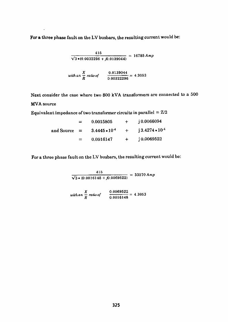
For a three phase fault on the LV busbars, the resulting current would be:
415= 16185 Amp
A/3»(0.0032296 +jO. 0139044)
X 0.0139044with an — ratio of ———————=4.3053
R 0.00322296
Next consider the case where two 800 kVA transformers are connected to a 500
MVA source
Equivalent impedance of two transformer circuits in parallel = Z/2
= 0.0015805 + j 0.0066094
and Source = 3.4445-10 4 + j 3.4274-10 4
= 0.0016147 + j 0.0069522
For a three phase fault on the LV busbars, the resulting current would be:
415= 33570 Amp
(0.0016148 + jO.0069522)
X , 0.0069522 o ^ co witkan - ratioof = 4.3053
325
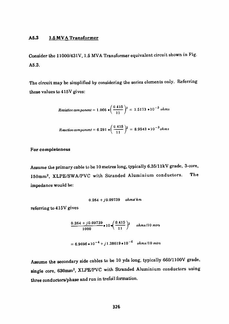
A5.3 1.5 MVA Transformer
Consider the 11000/43IV, 1.5 MVA Transformer equivalent circuit shown in Fig.
A5.3.
The circuit may be simplified by considering the series elements only. Referring
these values to 415V gives:
Resistive component = 1.066 •( ——— )2 = 1.5173 »10~ 3 ohms\ U J
/0415\9 _o Reactive component- 6.291 •! ——— I = 8.9543 »10 ohms
For completeness
Assume the primary cable to be 10 metres long, typically 6.35/1 IkV grade, 3-core,
150mm2 , XLPE/SWA/PVC with Stranded Aluminium conductors. The
impedance would be:
0.264 +./0.09739 ohms/km
referring to 415V gives
0.264+./0.09739 „ , n ——————————— »10»l ——— ohms/10 mtrs
1000
= 6.9696»lO~ 4 +./1.38619»10 ohms/10 mtrs
Assume the secondary side cables to be 10 yds long, typically 660/1100V grade,
single core, 630mm2 , XLPE/PVC with Stranded Aluminium conductors using
three conductors/phase and run in trefoil formation.
326
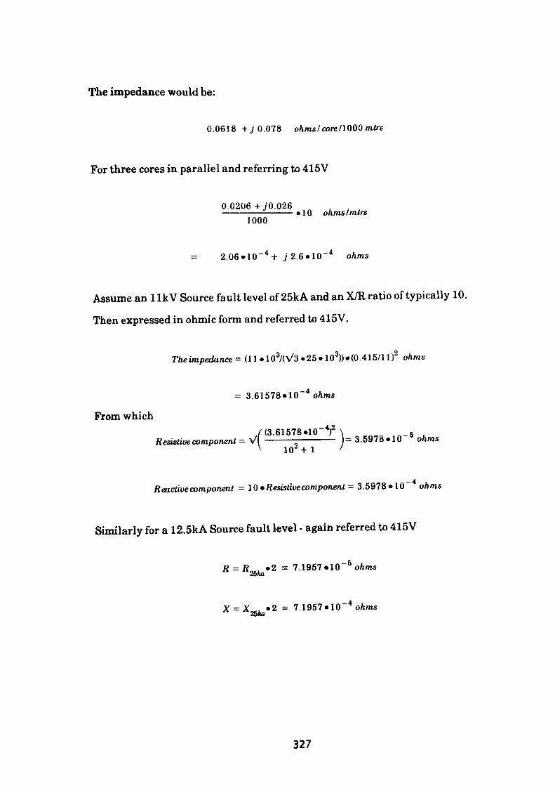
The impedance would be:
0.0618 +y 0.078 ohmslcorellQQQmtrs
For three cores in parallel and referring to 415V
0.0206 +J0.0261000
> 10 ohms Imtrs
2.06«10~4 + J2.6»IQ~* ohms
Assume an llkV Source fault level of 25kA and an X/R ratio of typically 10.
Then expressed in ohmic form and referred to 415V.
Theimpedance= (11 «10 3/(V3 •25«103))»(0.415/11)2 ohms
= 3.61578«10~ 4 o/ims
From which./(3.61578»10~*)2 \ _ 5
Resistive component - VI —————————— 1=3.5978*10 ohmsV 102 +1 >
Reactive component = 10 •Resistive component = 3.5978*10" ohms
Similarly for a 12.5kA Source fault level - again referred to 415V
nei «2 = 7.1957«10~ 5 o/ims2o«I
= 7.1957»10~ 4 o/ims
327
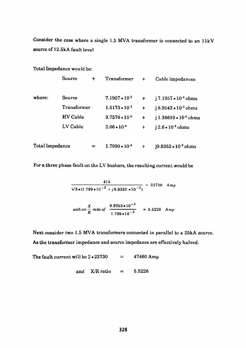
Consider the case where a single 1.5 MVA transformer is connected to an llkV
source of 12.5kA fault level
Total Impedance would be:
Source + Transformer + Cable impedances
where: Source
Transformer
HV Cable
LV Cable
7.1957.10 5
1.5173.10 3
3.7576.10 6
2.06.10 4
j 7.1957 .10 "ohms
j 8.9543 .10 3 ohms
j 1.38619.10 6 ohms
j 2.6 • 10 4 ohms
Total Impedance 1.7990.10 3 -I- J9.9352 • 10 3 ohms
For a three phase fault on the LV busbars, the resulting current would be
415
V3.(1.799.10~ 3 +J9.9352 .10~ 3 )= 23730 Amp
X 9.9352.10 -3
with an — ratio ofR 1.799* 10~ 3
= 5.5226 Amp
Next consider two 1.5 MVA transformers connected in parallel to a 25kA source.
As the transformer impedance and source impedance are effectively halved.
The fault current will be 2 • 23730 47460 Amp
and X/R ratio = 5.5226
328

Single Phase Faults
Consider the associated Zero Phase Sequence equivalent circuit from which it can
be seen that:Zo = ZS2 + ZSE - 0.00274 + j 0.002865 ohms
For a Reference Voltage of 431V
Referring Zo to 415V
/ 415 \ 9—— • 0.00274 +jO. 002865 ohms
\ 431 /
= 0.00254 +j 0.002656 ohms
Previously we have calculated the Positive Sequence Impedance of:
HV Source + HV cable + transformer + LV cable which when referred to 415V
was found to be:
Z+ = 1.7970. 10 3 +j9.9352.10 3 ohms
Similarly for Negative Sequence Impedance
Z _!__ TJ _ «^— ^J _l_
Hence Earth Fault Current at the LV Busbar/or Earth Bar = I^-
where IEF = 3Io.
3»Vp/i
+ + Z - + Zo + 3Z/br Earth Fault Path
Generally the transformer star point is connected by cable to either the 415V
Neutral Busbar on the switchgear or to the Neutral busbar via a common earthing
329
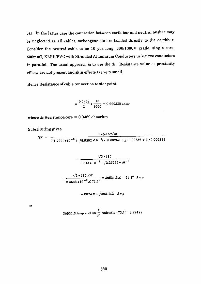
bar. In the latter case the connection between earth bar and neutral busbar may
be neglected as all cables, switchgear etc are bonded directly to the earthbar.
Consider the neutral cable to be 10 yds long, 600/1000V grade, single core,
630mm2, XLPE/PVC with Stranded Aluminium Conductors using two conductors
in parallel. The usual approach is to use the dc. Resistance value as proximity
effects are not present and skin effects are very small.
Hence Resistance of cable connection to star point
0.0469 10= ———— • ——— = 0.000235 ohms
2 1000
where dc Resistance/core = 0.0469 ohms/km
Substituting gives___________________3«(415/\/3)_____________________2(1.7990«10~ 3 + j9.9352 »10~ 3) + 0.00254 +./0.002656 + 3*0.000235
V3«415
6.843 • 10~ 3 +j2.25266 »10" 2
= 30531.3Z -73.1° Amp2.3543»10~ 2 Z73.1'
or
= 8874.2-729213.2 Amp
30531.3 Amp wUh an — ratio often 73.1°= 3.29192 R
330

Consider the case where two 1.5 MVA transformers are connected to a 25 kA
source. As all impedances are effectively halved for identical circuits.
The fault current will be 2 • 30531 = 61062 Amp
and the X/R ratio = 3.29192
331
A5.4 2.0 MVA Transformer
Consider the 11000/431V, 2.0 MVA Transformer equivalent circuit shown in Fig.
A5.4.
Using only the series elements and referring the values to 415V gives
Resistiue component = 0.6455 •( ———j2 = 9.1877-10" 4
/0.415\9 a Reactive component - 4.583«l ——— j = 6.5232-10
For completeness
Assume primary cable to be 30 metres long, typically 6.35/1 IkV grade, 3-core,
PILC/SWA/PVC with 240mm2 Stranded Aluminium conductors. The impedance
would be
0.149 + j 0.0785 ohms/km
referring to 415V gives
6.3624 • 10-6 + j 3.3537 • 10 6 ohms
Assume the LV cables to be 5 mtrs long, typically 660/1100V grade, single core,
630mm2 , PILC with Stranded Aluminium conductors using 4 conductors/phase
and run in trefoil formation. The impedance would be:
0.0618 + j 0.079 ohms /km
For four conductors in parallel and referring to 415V
332
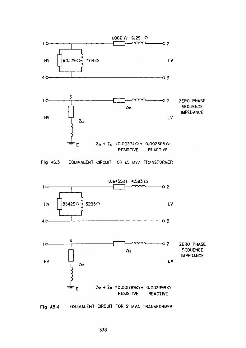
10-
40-
1.066 O 6.29102
HV 60379 OX 77140 LV
-03
HV
-02 ZERO PHASE SEQUENCE IMPEDANCE
LV
ZSE + ZK =0.002740+ 0.002865 O RESISTIVE REACTIVE
Fig A5.3 EQUIVALENT CIRCUIT FOR 1.5 MVA TRANSFORMER
10-
40-
0.64550 4.5B30-02
HV 384250 52980 LV
-03
HVZSE
-02 ZERO PHASE SEQUENCE IMPEDANCE
LV
-=- £ ZsE + Za =0.0017890+ 0.002399 O RESISTIVE REACTIVE
Fig A5.4 EQUIVALENT CIRCUIT FOR 2 MVA TRANSFORMER
333
0.0618+J0.079 5—————————— • ——— ohms4 1000
= 7.725 »10" 5 +j9.875 .10~ 5 ohms
Assuming an llkV Source fault level of 25kA and an X/R ratio of typically 10.
The equivalent source impedance will be as in the previous example. Z25ka source= 3.5978.10" 5 -J3.5978.10~ 4 ohms
Similarly for a 12.5kA sourceZ l2.5kA source ~ 7 - 1 957»10~ 5 -j7.1957 • 10~ 4 ohms
Consider the case where a single 2 MVA transformer is connected to a 12.5kA
source at IlkV
Total Impedance would be the sum of:
Source 7.1957.10 6 + j 7.1957.10 4
Transformer 9.1877.10 4 + j 6.5232. 10 3
HV Cable 6.3624.10 6 + j 3.3537.10 6
LVCable 7.7250.10 5 + j 9.8750.10 5
Total Impedance = 1.0743.10 3 + j 7.34487• 10 3 ohms
For a three phase fault on the LV busbars, the resulting current would be:
415= 32278 Amp
V3»(1.0743.10~ 3 +/7.34487.10- 3)
X 7.34487.10" 3with an — ratio of ————————— = 6.8366R 1.0743*10~ J
334
As two transformers in parallel would clearly exceed the 50kA symmetrical fault rating of the switchgear, the case is not considered. However, the effects of reducing the source fault level to 25kA should be known.
For a three phase fault on the LV busbars, the resulting current would be:
415= 33929 Amp
V3»(1.0386«10~ 3 +./6.9851 «10~ 3)
X 6.9851«10~ 3 with an —ratio of ————————— = 6.7270 R 1.03836«10~ 3
335
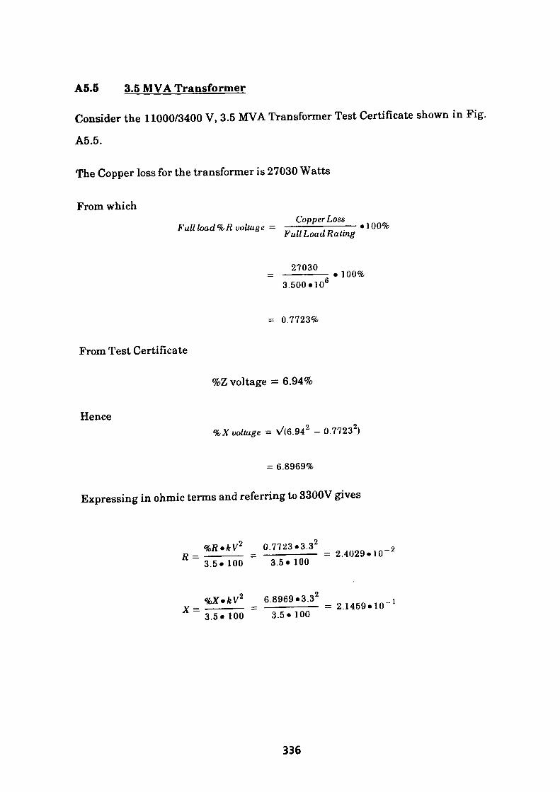
A5.5 3,5 MVA Transformer
Consider the 11000/3400 V, 3.5 MVA Transformer Test Certificate shown in Fig.
A5.5.
The Copper loss for the transformer is 27030 Watts
From whichCopper Loss
Full load % It voltage = ——————————— • 100%Full Load Rating
27030• 100%
3.500.106
= 0.7723%
From Test Certificate
%Z voltage = 6.94%
Hence%X voltage = \/(6.94 2 - 0.7723 2)
= 6.8969%
Expressing in ohmic terms and referring to 3300V gives
*V2 0.7723.3.32 „R = ————— = ———————— = 2.4029«10~ /:
3,5*100 3.5*100
%X»kVz 6.8969 *3.32 .X= ————— = ———————— = 2.1459.10" 1
3.5*100 3.5*100
336
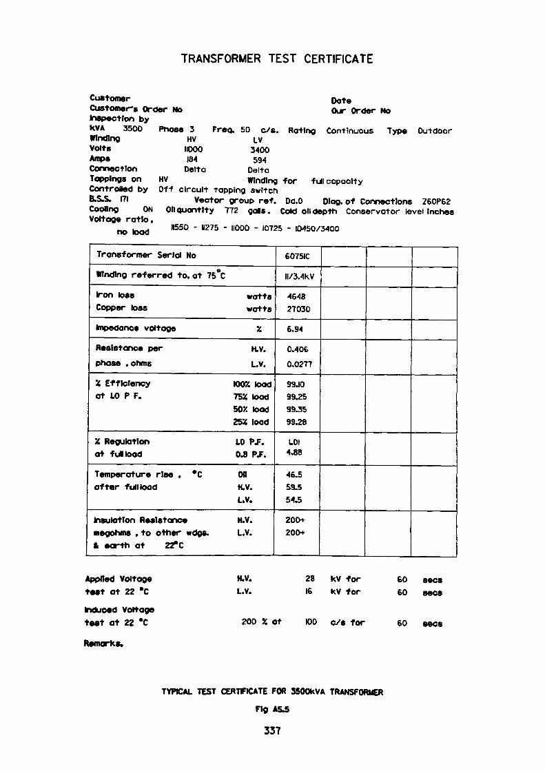
TRANSFORMER TEST CERTIFICATE
CustomerCustomer's Order NoInspection bykVA 3500WindingVoltsAmpsConnectionToppings onControied byB.S.S. 171
DateOur Order No
Phase 3 HV
IIOOO IB-4
Delta
Freq. 50 c/s. Rating Continuous LV
3400 594
Type Outdoor
DeltaHV Winding for Off circuit tapping switch
Vector group ret. Dd.O
full capacity
Dlag. of Connections Z60P62 Cooling ON Oil quantity 772 galls. Cold oil depth Conservator level Inches Voltage ratio.
_ .__, 11550 - 11275 - IIODO - 10725 - 10450/3400 no load
Transformer Serial No
Winding referred to, at 75°C
Iron toss watts Copper loss watts
Impedance voltage %
Resistance per H.V. phase . ohms L.v.
X Efficiency 1002 load at 10 P F. 7554 toad
50X toad 25X load
X Regulation LO PJ. at fultoad 0.8 P.F.
Temperature rise , *C OK after full toad H.V.
L.V.
Insulation Resistance H.V. megohms . to other wdgs. L.V. & earth at 22° C
6075IC
II/3.4KV
4648 27030
6.94
0.406
0.0277
99.10 99.25 99.35 99.28
1.01 4.88
46.5 59.5 54.5
200+ 200+
Applied Voltage test at 22 *C
induced Voltage test at 22 *C
Remarks.
H.V. L.V.
28 kV for 16 kV for
sees
200 % at 100 c/s for
6060
60 sees
TYPICAL TEST CERTFICATE FOR SSOOkVA TRANSFORMER
Fig A&5
337

For completeness
Assume the primary cable to be 10 yds long, typically 6.35/1 IkV grade, 3-core,
0.25in2, PILC/SWA/SERVED with Stranded Copper conductors. The impedance
would be:0.13 +^'0.073oAms/1000>c/s
referring to 3300V gives3_3 V 11 /
0.13+JO.073 /3.3 - • 10 '
1000
= 1.17. 10-4 +j 6.57 • 10 6
Assume the secondary side cables to be 10 yds long, typically 3300/3300V grade,
two 3 core cables, 0.25in2 PILC/SW A/SERVED with Stranded Copper conductors.
The impedance would be:
= 0.14 + j 0.066 ohms /1000 yds
For two cables in parallel0.14+J0.066 10
2 1000
= 7.10 4 + J3.3.10 4 ohms
Assuming an llkV Source fault level of 500MVA and an X/R ratio of typically 10
Then expressed in ohmic form and referred to 3300V
kV2 3.3 2 _ 2 Impedance =——— = —— — 2.178*10 ohms
MVA 500
,(2.178.10~ 2)2——— - ————
10 2 + 1
_ =2. 16719.10 *ohms
X = 10.R = 2.16719.10 2
338
Similarly for a 250 MVA llkV source referred to 3300V
R = 4.33438.10 3
X = 4.33438 .10 2
Consider the case where a single 3.5 MVA transformer is connected to a 250 MVA source
Total Impedance would be the sum of:
Source 4.33438.10 3 + j 4.33438.10 2 ohmsTransformer 2.4029. 10 2 + j 2.1459. 10 * ohmsHVCable 1.17.10 4 + j 6.57.10 5 ohms
LV Cable 7.0 • 10 4 + j 3.3 • 10 4 ohms
Total Impedance = 2.9181.10 2 + J2.58332.10' ohms
For a three phase fault on the LV busbars, the resulting current would be:
415 —-———————————- = 7329 AmpV3.(2.91805* 10~ 2 +^2.58332.10" 1 )
2.58332.10~'with an X/R ratio of ————————-=8.8529
2.918050.10"^
339

Similarly for a three phase fault on the LV busbars with a 500 MVA source at
llkV415
V3«(2.70l38»10~ 2 +j2.36659«10~ 1 )= 7999 Amp
2.36659«10~ 4with an X/K ratio of ————————— = 8.7609
2.70133«10~ 2
For two transformers in parallel on a 500 MVA supply, the LV (3.3 kV) fault
current would be:
2.7329 = 14658 Amp
with an X/R ratio = 8.8529
340
A5.6 4.0 MVA Transformer
Consider the 11000/3400V, 4MVA, DDO Vector group transformer equivalent
circuit shown in Fig. A.5.6.
Using the series element, converting to star configuration and referring the
values to 3300V gives
0.796 / 3300 \, 2 Resistive component -——— • ———— =2.388*103 VllOOO/
5.963 / 3300 \ 2 _,Reactive component = ——— • ———— = 1.7889 «10
3 VllOOO/
For completeness
Assume primary cable to be 10 metres long, typically 6.35/llkV grade, 3-core
PILC/SWA/PVC with 240mm2 Stranded Aluminium conductors. The impedance
would be
0.161 + j 0.090 ohms /1000 mtrs
referring a 10 metre length to 3300V
0.161 +J0.090 / 3300 \2 ———— r V 11000/1000
= 1.449.10 4 + j 8.1.10 5 ohms
Assume the secondary prime cable to be 10 yds long, typically 3.8/6.6kV grade,
two 3-core, 240mm2, XLPE/SWA/PVC with Stranded Aluminium conductors.
The impedance would be:
0.162 + j0.0845 ohms/1000mtrs(1 cable)
341
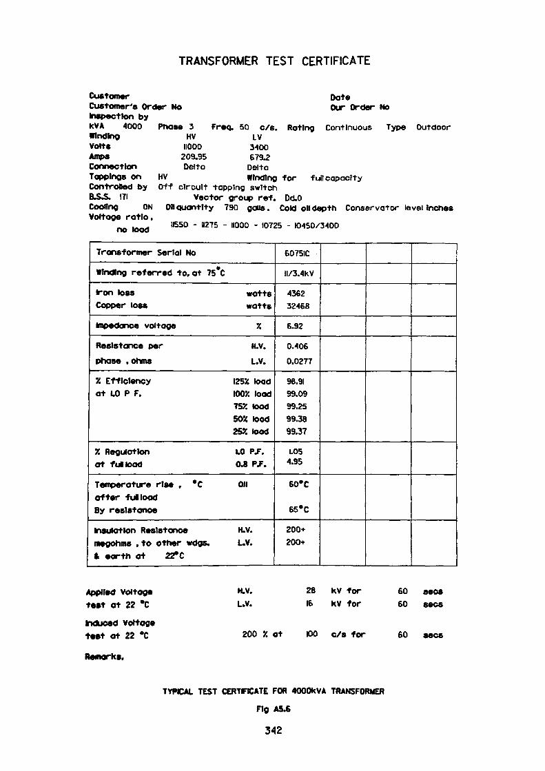
TRANSFORMER TEST CERTIFICATE
Customer DateCustomer's Order No Our Order NoInspection byKVA 4000 Phase 3 Freq. 50 c/s. Rating Continuous Type OutdoorWinding HV LVVolts HOOD 3400Amps 209.95 679.2Connection Delta DeltaToppings on HV Winding for full capacityControlled by Off circuit tapping switchB.&S. 171 Vector group ref. Dd.OCooling ON on quantity 790 galls. Cold oil depth Conservator level InchesVoltage ratio.
^ . ^ 11550 - 11275 - 11000 - 10725 - 10450/3400 no load
Transformer Serial No
Winding referred to, at 75 °C
iron loss watts Copper loss watts
impedance voltage 7.
Resistance per H.V. phase .ohms L.V.
7. Efficiency I25X toad at LO P F. IOOJC load
752 load 50% toad 252 toad
7. Regulation L.O PS. at fultoad 0.8 Pf.
Temperature rise , °C OH after fun load By resistance
insulation Resistance H.V. megohms .to other wags. L.V. ft earth at 22° C
6075IC
II/3.4KV
-4362 32466
6.92
0.406
0.0277
98.91 99.09 99.25 99.38 99.37
1.05 4.95
60*C
65'C
200+ 200+
Applied voltage test at 22 *C
induced voltage test at 22 °C
Remarks.
H.V.
L.V.28 KV for 16 kV for
6060
sees sees
200 7. at 100 c/s for 60 sees
TYPICAL TEST CERTFICATE FOR 4000KVA TRANSFORMER
Fig A5.6
342
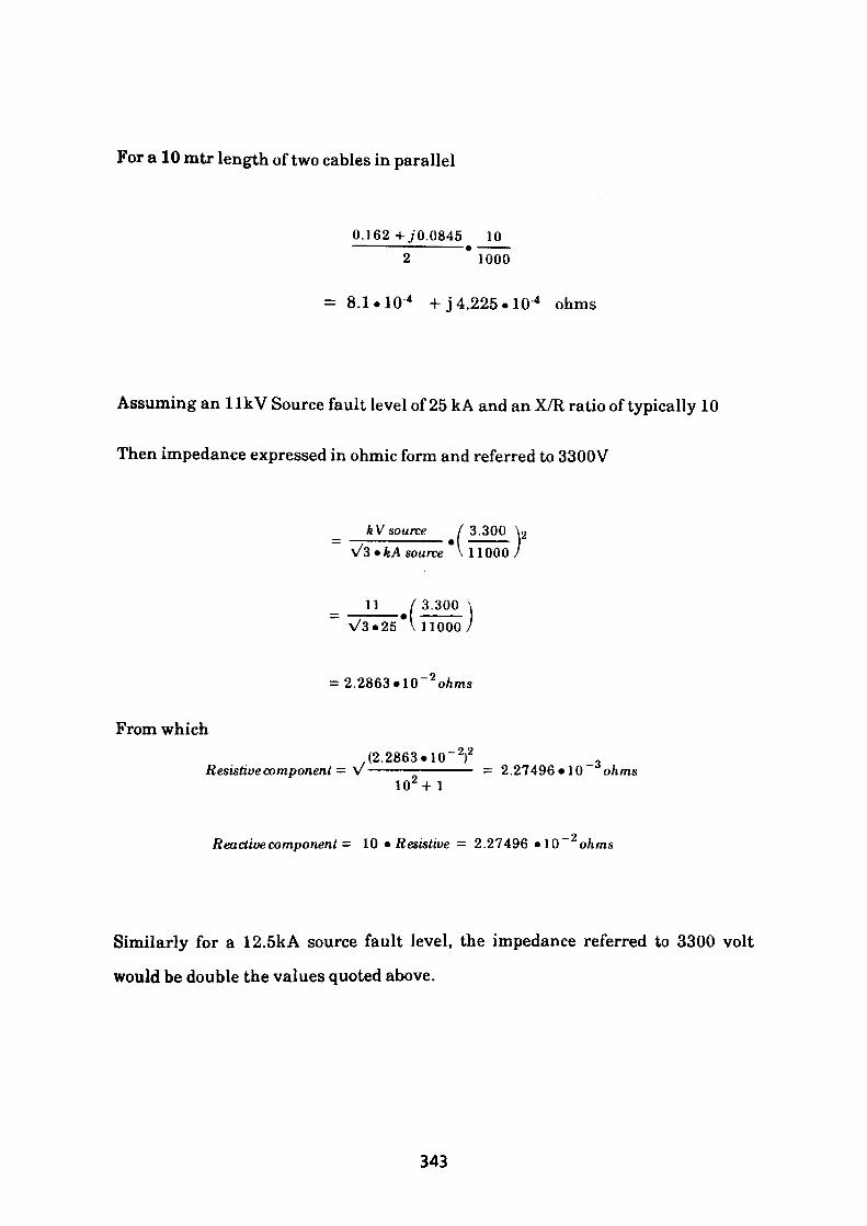
For a 10 mtr length of two cables in parallel
0.162+^0.0845 10
2 1000
= 8.1.10 4 + j 4.225.10 4 ohms
Assuming an llkV Source fault level of 25 kA and an X/R ratio of typically 10
Then impedance expressed in ohmic form and referred to 3300V
k V source V3 * k A source
I 3.300 \2 \ 11000 /
3 30°
From which
V3.25 \110007
= 2.2863.10" 2 oAms
,(2.2863.10~ 2)2Resistive component = V—————————— = 2.27496*10 3 ohms102 +
_ oReactive component = 10 * Resistive = 2.27496 .10 ohms
Similarly for a 12.5kA source fault level, the impedance referred to 3300 volt
would be double the values quoted above.
343
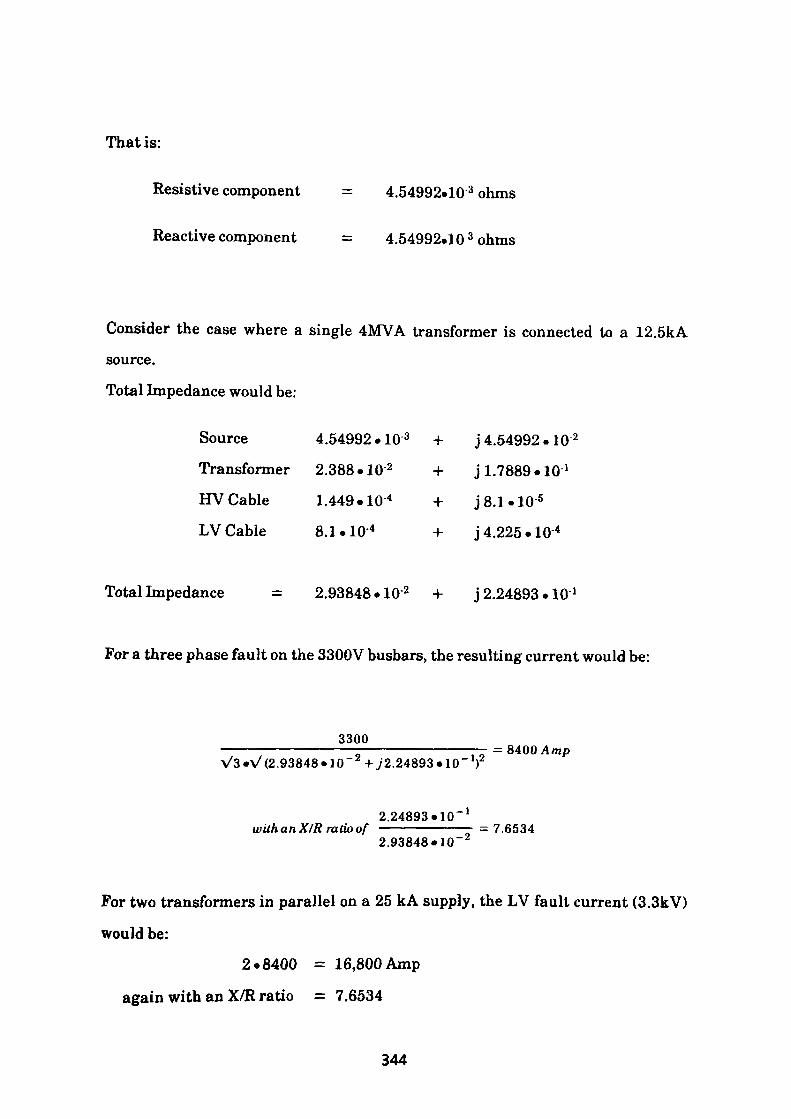
That is:
Resistive component = 4.54992.10 3 ohms
Reactive component = 4.54992.10 3 ohms
Consider the case where a. single 4MVA transformer is connected to a 12.5kAsource.
Total Impedance would be:
Source 4.54992.10 3 + j 4.54992.10 2
Transformer 2.388.10 2 + j 1.7889.10 *
HV Cable 1.449.10 4 + J8.1.10 5
LV Cable 8.1.10 4 + j 4.225.10 4
Total Impedance = 2.93848.10 2 + j 2.24893.10 1
For a three phase fault on the 3300V busbars, the resulting current would be:
3300 ——————————————————————————— = 8400 AmpV3«V(2.93848»10~ 2 +y 2.24893.10" T
2.24893.10" 1wUhanX/Rratioof ——————-=7.6534
2.93848«10~2
For two transformers in parallel on a 25 kA supply, the LV fault current (3.3kV)
would be:
2.8400 = 16,800 Amp
again with an X/R ratio = 7.6534
344
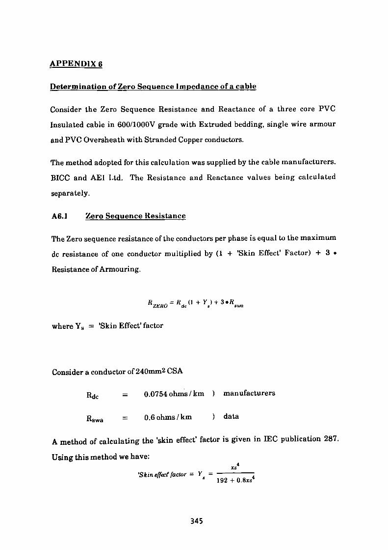
APPENDIX 6
Determination of Zero Sequence Impedance of a cable
Consider the Zero Sequence Resistance and Reactance of a three core PVC
Insulated cable in 600/1000V grade with Extruded bedding, single wire armour
and PVC Oversheath with Stranded Copper conductors.
The method adopted for this calculation was supplied by the cable manufacturers.
BICC and AEI Ltd. The Resistance and Reactance values being calculated
separately.
A6.1 Zero Sequence Resistance
The Zero sequence resistance of the conductors per phase is equal to the maximum
dc resistance of one conductor multiplied by (1 + 'Skin Effect* Factor) + 3 •
Resistance of Armouring.
™M = K S ( } + Y )ZERO dc s
where Ys = 'Skin Effect1 factor
Consider a conductor of 240mm2 CSA
Rdc = 0.0754 ohms / km ) manufacturers
Rswa = 0.6 ohms/km ) data
A method of calculating the 'skin effect' factor is given in EEC publication 287.
Using this method we have:
'Skin effect factor = y = ———————- * 192 + O.Sxs4
345
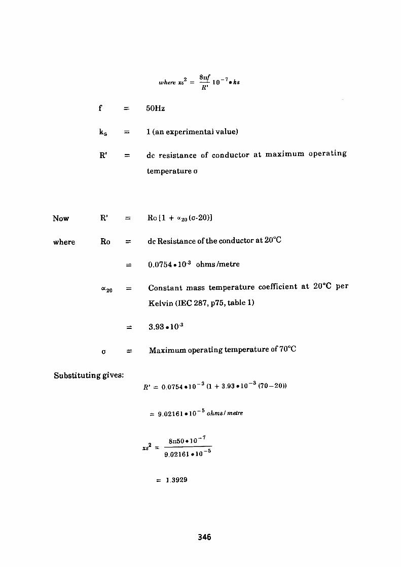
Rf
2 on/ where xs = ——
8n/
50Hz
1 (an experimental value)
dc resistance of conductor at maximum operating
temperature o
Now
where
R1 = Ro[l + « 20 (o-20)]
Ro = dc Resistance of the conductor at 20°C
= 0.0754 • 10 3 ohms/metre
"•20 —
Substituting gives:
Constant mass temperature coefficient at 20°C per
Kelvin (EEC 287, p75, table 1)
3.93.10 3
Maximum operating temperature of70°C
ft* = 0.0754 MO" 3 (1 + 3.93 «10~ 3 (70-20))
= 9.02161«10~ 5 oAms/meire
8n50«10 -7
9.02161*10 -5
= 1.3929
346
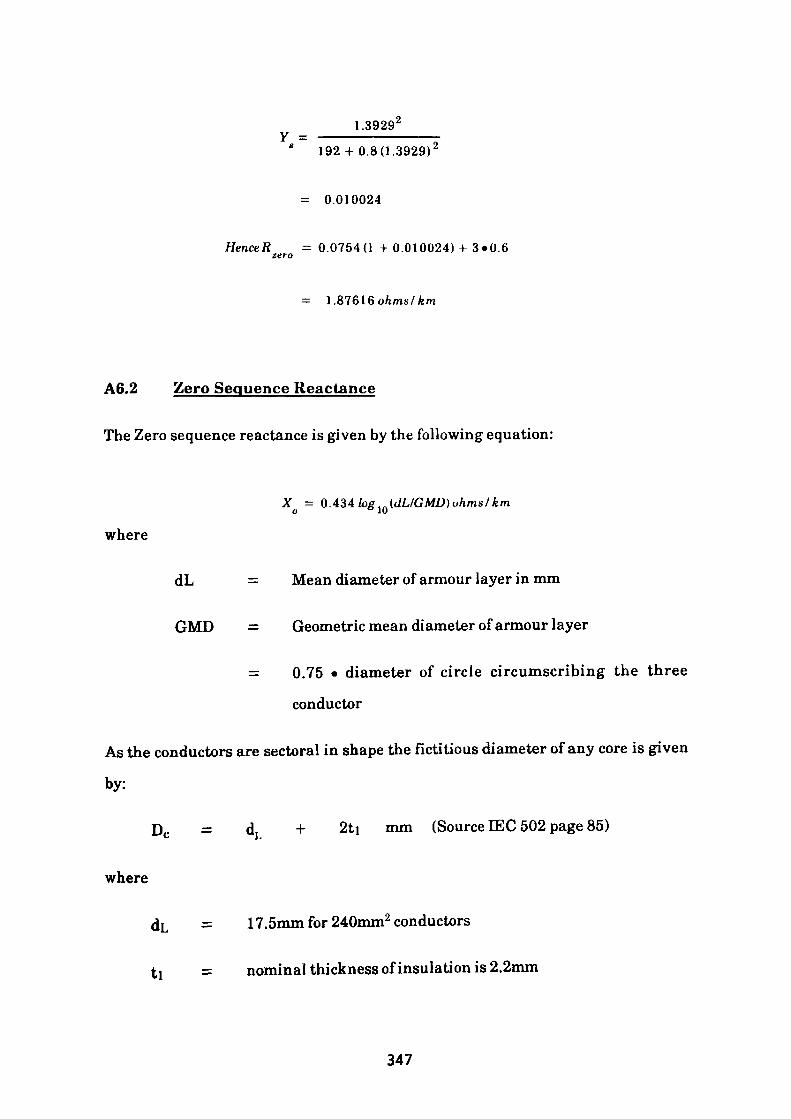
1.3929 2Y = - * 192+ 0.8(1.3929) 2
= 0.010024
= 0.0754(1 + 0.010024) + 3 -0.6
= 1.87616 ohms/ km
A6.2 Zero Sequence Reactance
The Zero sequence reactance is given by the following equation:
Xo = QA34log lo (dL/GMD)ohms/km
where
dL = Mean diameter of armour layer in mm
GMD = Geometric mean diameter of armour layer
= 0.75 • diameter of circle circumscribing the three
conductor
As the conductors are sectoral in shape the fictitious diameter of any core is given
by:
Dc = dL + 2ti mm (Source IEC 502 page 85)
where
dL = 17.5mm for 240mm2 conductors
t = nominal thickness of insulation is 2.2mm
347
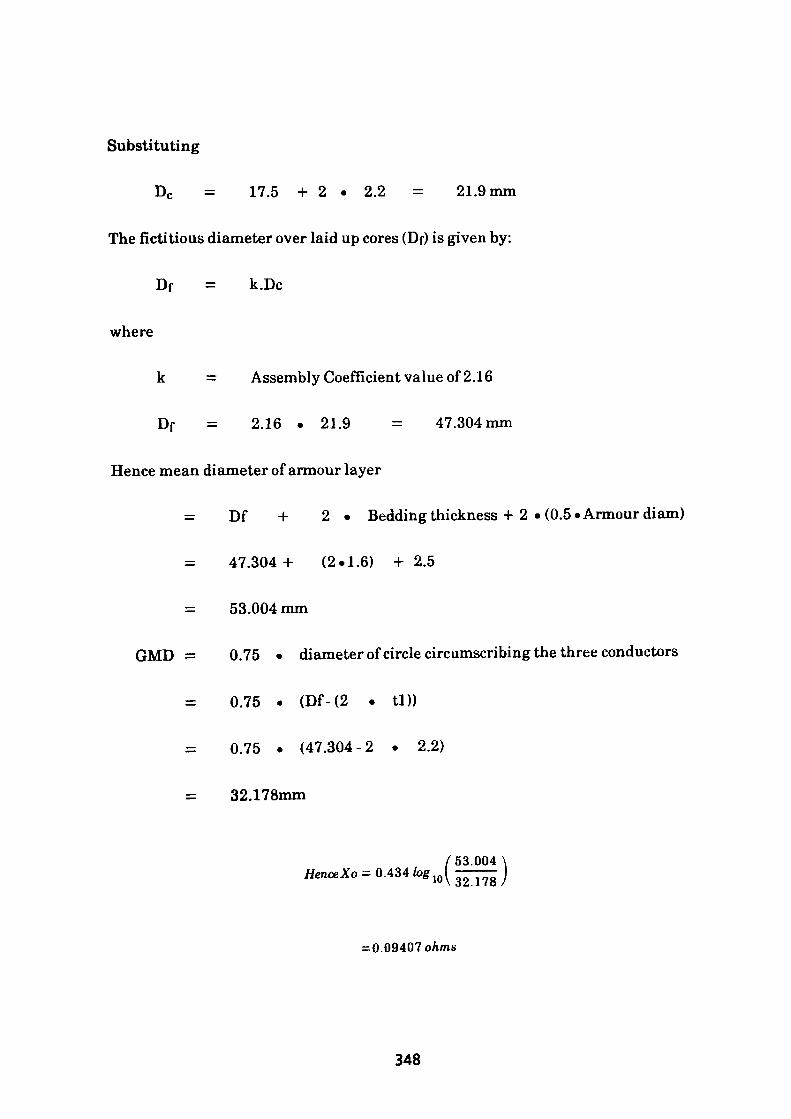
Substituting
Dc = 17.5 + 2 • 2.2 = 21.9mm
The fictitious diameter over laid up cores (Df) is given by:
Df = k.Dc
where
k = Assembly Coefficient value of 2.16
Df = 2.16 . 21.9 = 47.304mm
Hence mean diameter of armour layer
= Df + 2 • Bedding thickness + 2 «(0.5« Armour diam)
= 47.304 + (2-1.6) + 2.5
= 53.004 mm
GMD = 0.75 • diameter of circle circumscribing the three conductors
0.75 • (Df-(2 • tl))
= 0.75 • (47.304-2 . 2.2)
= 32.178mm
/53.004 ^ 0.434 log
= 0.09407 ohms
348

A short program using Lotus 123 has been written to construct tables A6.1 and
A6.2 which follow. Table A6.1 gives the calculated values for Zero Sequence
Resistance for the entire range under consideration, that is, from 1.5mm2 to
400mm2 . Similarly Table A6.2 lists the calculated values for Zero Sequence
Reactance together with the intermediate steps involved.
349
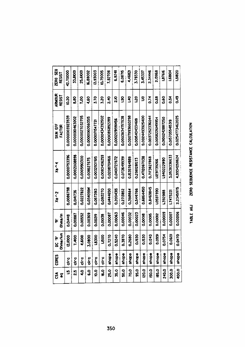
1*1 yi
o
CSA *q1.5 2.5
4.0
6.0
10.0
16.0
25.0
35.0
50.0
70.0
95.0
120.0
150.0
185.0
240.
030
0.0
400.
0
CORE
S
clrc
clrc
clrc
clrc
clrc
clrc
shap
esh
ape
shap
esh
ape
shap
esh
ape
shap
esh
ape
shap
esh
ape
shap
e
DC *
R' O
hms/k
m12
.1000
7.410
04.6
100
3.08
001.8
300
1.150
00.
7270
0.52
400.
3870
0.26
800.1
930
0.153
00.1
240
0.099
10.
0754
0.060
10.
0470
'R*
Ohm
s/m0.0
1448
0.00
887
0.00
552
0.00
369
0.002
190.0
0138
0.00
087
0.00
063
0.00
046
0.00
032
0.00
023
0.000
180.0
0015
0.000
120.
0000
90.
0000
70.
0000
6
Xs^
2
0.00
8679
80.0
1417
360.
0227
822
0.03
4099
40.0
5739
130.0
9132
700.1
4446
500.2
0043
150.2
7138
520.3
9188
840.5
4417
660.
6864
450
0.84
6984
51.0
5979
901.3
9291
881.7
4752
212.
2345
975
Xs~
4
0.00
0075
3396
0.00
0200
8898
0.00
0519
0300
0.001
1627
675
0.00
3293
7615
0.00
8340
6259
0.02
0870
1466
0.04
0172
7672
0.07
3649
9391
0.153
5764
888
0.296
1281
573
0.471
2067
038
0.71
7382
7868
1.123
1739
266
1.940
2229
190
3.05
3833
6633
4.99
3425
8624
SKIN
EFF
FA
CTOR
0.00
0000
3923
939
0.00
0001
0463
002
0.00
0002
7032
755
0.00
0006
0560
515
0.000
0171
5477
21
0.00
0043
4392
502
0.00
0108
6892
289
0.000
2091
9814
560.
0003
8347
5753
80.
0007
9936
6029
80.0
0154
0433
4619
0.00
2449
3925
400
0.00
3725
2336
044
0.00
5822
6149
954
0.01
0024
2887
250
0.015
7055
4153
190.
0254
7734
6202
5
ARMO
UR
RESI
ST10
.20 8.80
7.00
4.60
3.70
3.20
2.40 2.1
01.9
01.4
01.2
01.1
00.
740.
680.
600.
540.
49
ZERO
SEQ
RE
SIST
42.7
0000
33.81
001
25.61
001
16.8
8002
12.93
003
10.7
5005
7.92
708
6.824
116.0
8715
4.468
213.
7933
03.
4533
72.
3444
62.1
3968
1.876
161.6
8104
1.518
20
TABL
E A6
.I ZE
RO S
EQUE
NCE
RESI
STAN
CE C
ALCU
LATI
ON
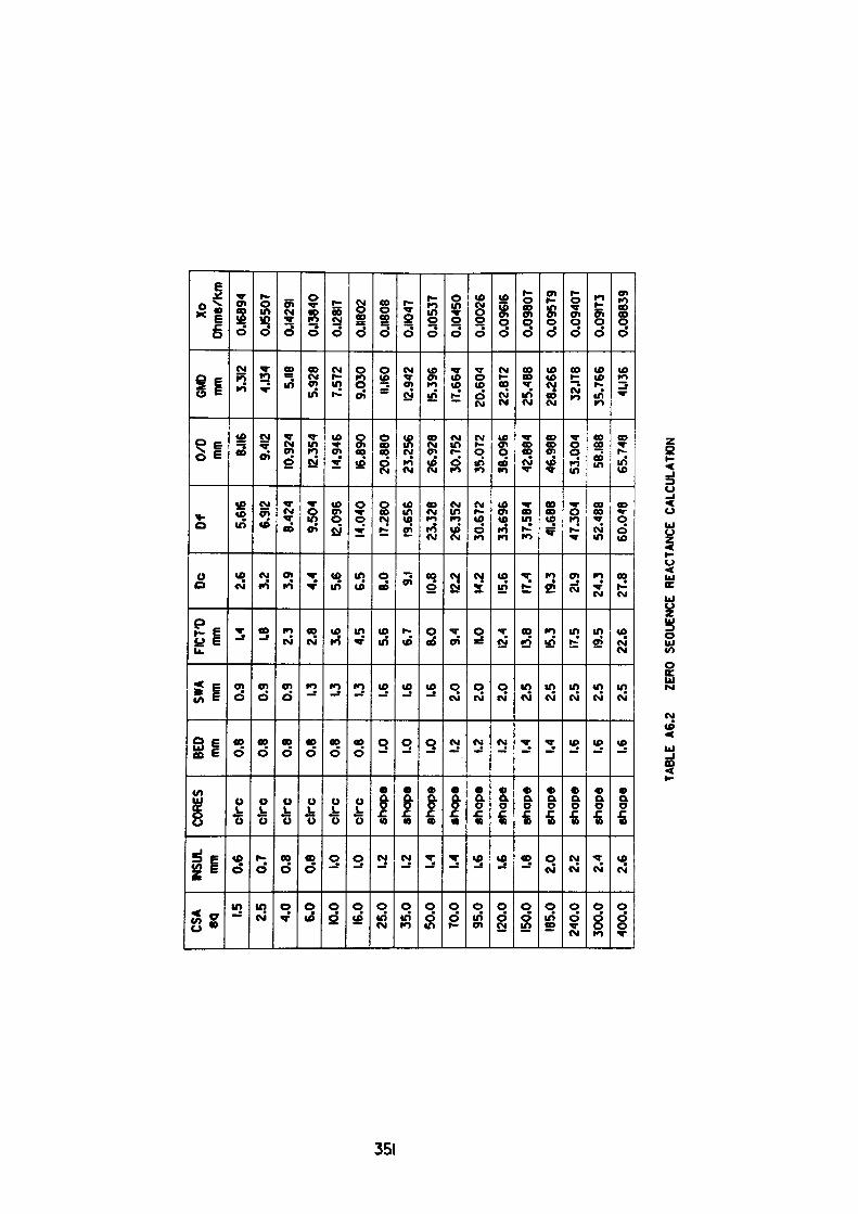
1*1
CSA
«q1.5 2.5
4.0
6.0
10.0
16.0
25.0
35.0
50.0
70.0
95.0
120.0
150.0
185.0
240.
030
0.0
400.
0
INSU
L mm 0.
60.
70.
80.
8 1.0 1.0 1.2 1.2 1.4 1.4 1.6 1.6 1.8 2.0
2.2
2.4
2.6
CORE
S
clrc
ctrc
clrc
clrc
clrc
clrc
shap
esh
ape
shap
esh
ape
shap
esh
ape
shap
esh
ape
shap
esh
ape
shap
e
BED
mm 0.8
0.8
0.8
0.8
0.8
0.8 1.0 1.0 1.0 1.2 1.2 1.2 1.4 1.4 1.6 1.6 1.6
SWA
mm 0.9
0.9 0.9 1.3 1.3 1.3 1.6 1.6 1.6 2.0
2.0
2.0
2.5 2.5 2.5 2.5 2.5
FIC7
'0 mm 1.4 1.8 2.
32.
83.
64.
55.
66.
78.
09.
4 R.O 12.4
13.8
15.3
17.5
19.5
22.6
DC 2.6
3.2
3.9
4.4
5.6
6.5
8.0 9.1 10.8
12.2
14.2
15.6
17.4
19.3
21.9
24.3
27.8
Df 5.616
6.912
8.42
49.
504
12.09
614
.040
17.28
019
.656
23.3
2826
.352
30.6
7233
.696
37.5
8441
.688
47.3
04
52.4
88
60.0
48
0/D
mm 8.1
169.4
1210
.924
12.35
414
.946
16.89
020
.880
23.2
5626
.928
30.7
5235
.072
38.0
9642
.884
46.9
8853
.004
58.18
865
.748
GMD
mm 3.312
4.134
5.118
5.92
87.
572
9.03
011.
16012
.942
15.39
617
.664
20.6
0422
.872
25.4
8828
.266
32.17
835
.766
41.13
6
Xo
Ohm
s/Km
0.168
940.1
5507
0.142
910.1
3840
0.128
170.1
1802
0.118
080.1
1047
0.105
370.1
0450
0.10
026
0.09
616
0.09
807
0.09
579
0.09
407
0.091
730.
0883
9
TABLE
A6.2
ZERO
SEQUENCE R
EACTANCE C
ALCULATION
APPENDIX?
Typical Electric Motor Information
Table A7.1 shows a typical information listing supplied by a manufacturer for a
180kW, 3.3kV Induction motor. Item 17, listed on table A7.1, refers to the
thermal withstand rating of the machine. This data is usually supplied in a
graphical form. Fig. A.7.1 shows a typical characteristic which depicts the
maximum withstand time under overload conditions for the machine at both
ambient and running temperatures. Selected time/current values from these
characteristics are used in the MPROT program. Item 18, listed on table A.7.1,
refers to the Torque/Speed characteristic. A typical characteristic is shown in Fig.
A7.2. This information is used in Appendix 2 to determine the acceleration period
of the motor/drive unit. Fig. A7.3, the equivalent circuit of the motor, may also be
used to determine acceleration times, but is more generally required for use in
power-system study programs. Fig. A.7.4 is a typical test record supplied by the
motor manufacturer. This certificate provides general data from which a circle
diagram could be produced and also includes individual details of the motor heat
run.
352
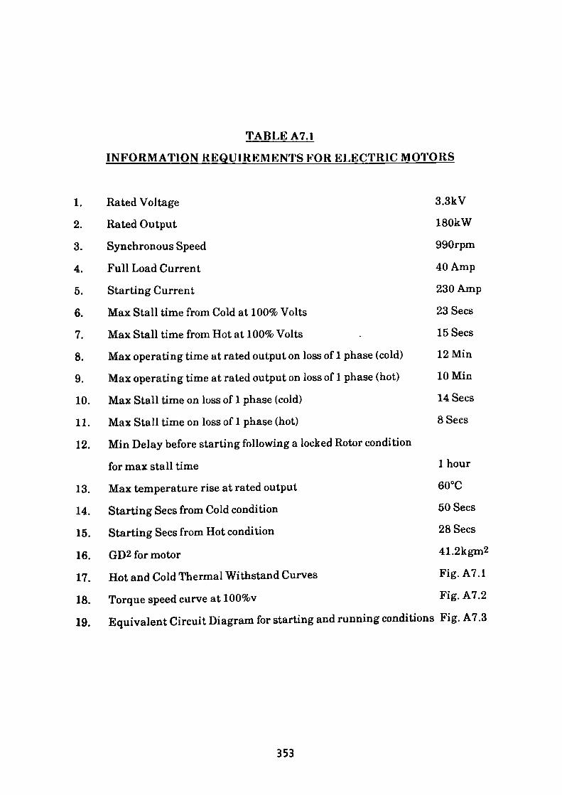
TABLE A7.1
INFORMATION REQUIREMENTS FOR ELECTRIC MOTORS
1. Rated Voltage 3.3kV
2. Rated Output 180kW
3. Synchronous Speed 990rpm
4. Full Load Current 40 Amp
5. Starting Current 230 Amp
6. Max Stall time from Cold at 100% Volts 23 Sees
7. Max Stall time from Hot at 100% Volts . 15 Sees
8. Max operating time at rated output on loss of 1 phase (cold) 12Min
9. Max operating time at rated output on loss of 1 phase (hot) lOMin
10. Max Stall time on loss of 1 phase (cold) 14 Sees
11. Max Stall time on loss of 1 phase (hot) 8 Sees
12. Min Delay before starting following a locked Rotor condition
for max stall time 1 hour
13. Max temperature rise at rated output 60°C
14. Starting Sees from Cold condition 50 Sees
15. Starting Sees from Hot condition 28 Sees
16. GD2 for motor 41.2kgm2
17. Hot and Cold Thermal Withstand Curves Fig. A7.1
18. Torque speed curve at 100%v Fig. A7.2
19. Equivalent Circuit Diagram for starting and running conditions Fig. A7.3
353
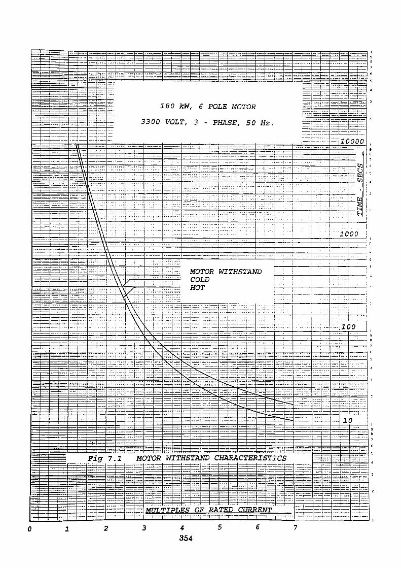
180 JcW, 6 POLE MOTOR
3300 VOLT, 3 - PHASE, 50 Hz
MOTOR WITHSTANDCOLDHOT
WITHSTAND CHARACTERISTICS
MULTIPLES OF RATED CURRENT
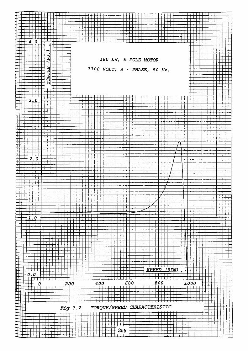
T~in •*
. —— :
1 11 j1
1
1
11
1
' 1
m— J
1
---- c--_.._ - - - _ _
---.___
1 . 0 --I—1—- ---
""
Kj
———— - 0, — —— -
tos—— - o -- — -: :::!::: :1—1 ~~l
3.0 —— — ~ —I
I
Ii i
i i i
i i i: : i
t 1*120 • - ••
' 1 : Ii i . '
1 . 'i l
i 'I ' • 1
i •
'• i !
' ' '
' <
! 1 1
;: . ti , !
i
• * t/ ;l
i ;
.0 ———— -__ 1 J.J.J i i -- 0
1
180 kW, 6 POLE MOTOR
3300 VOLT, 3 - PHASE, 50 Hz.
!
1
|i 1 i
II
! ! lj j
1
i i1' !
1j !
:-.~4±L
1.. I I l 1 1
200
i i
1
1
I j
^~M^^B!
l t
ii
i i
j I
1I
1
••
I
i
ii
1
1
1 i
1
I
i ' - •
1i i
1
I
I• ••
1 {
400
Fig 7.2
1 ___ _j _ |_
i
E~
6(
TORQUE/SPEED
355I !
1I
i1 1
1 . ;1 ' '
I: 1 '
\ .
\l
, l
; , .
1
^-s±
1
30J
; ' '. ! ' j
• /\ s*^s \ :
L_i .
|
|
|
1
1 !
; |
i t 1; i
i i
1 ! ' /, /
/
-if1 I '
y// i/
' \ '
1
CTDC'laT btrCjClD\
i3 •)
j
! 1
1j
t1 1
1 1 1
' 1 ! 1' 1 i
1
f\' / \7 ' 1/ 1/ ' 1/'
\ j
. i ; ;ii-i ,• i
1 i '
; ii^--\±--------
(RPMrm —
3
_ JL
1^_ ___ L
CHARACTERISTIC
1
1000 -
1 ' ' 1 i
11
1X11 i
> ! t
1 1
11
; ii > i ; '
i i
i •
i i i• , . : 1
< • i 1 i ,
1 :
. i , .
• j
'• \ '•
' ' i 1
: • i •
; li ,
I1
1
T" ~r \-\ 1I
I
1 i
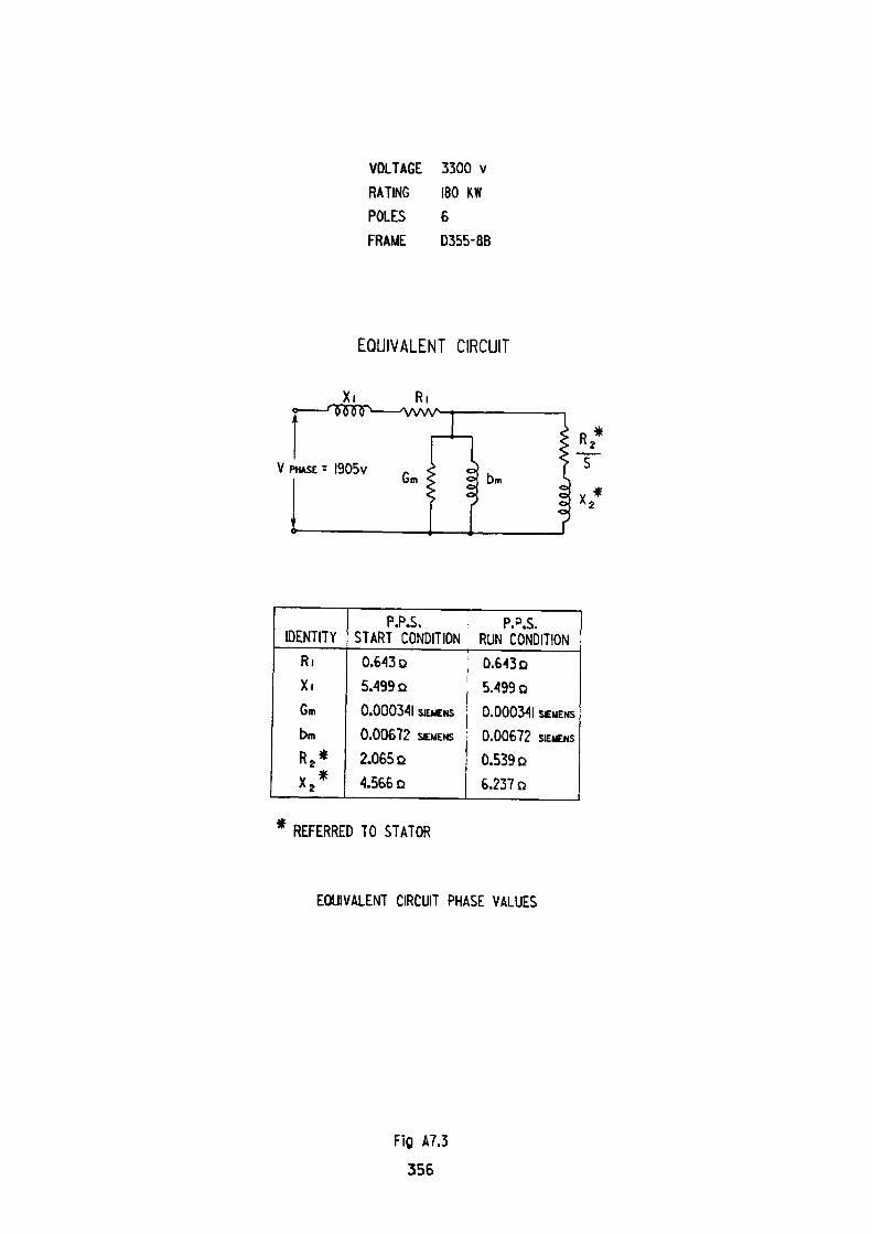
VOLTAGE 3300 vRATING 180 KWPOLES 6FRAME D355-8B
EQUIVALENT CIRCUIT
XL
V PHASE = 1905VGm
IDENTITYRiXiGm
binR 2 *X 2 *
P.P.S. P.P.S.START 'CONDITION RUN CO'NDITION0.643 D ; 0.64305.499 D0.000341 SIEMENS
0.00672 SIEMENS
2.065 Q4.566 Q
5.499 o0.000341 SEMENS
0.00672 SIEMENS
0.53906.237 D
REFERRED TO STATOR
EQUIVALENT CIRCUIT PHASE VALUES
Fig A7.3
356
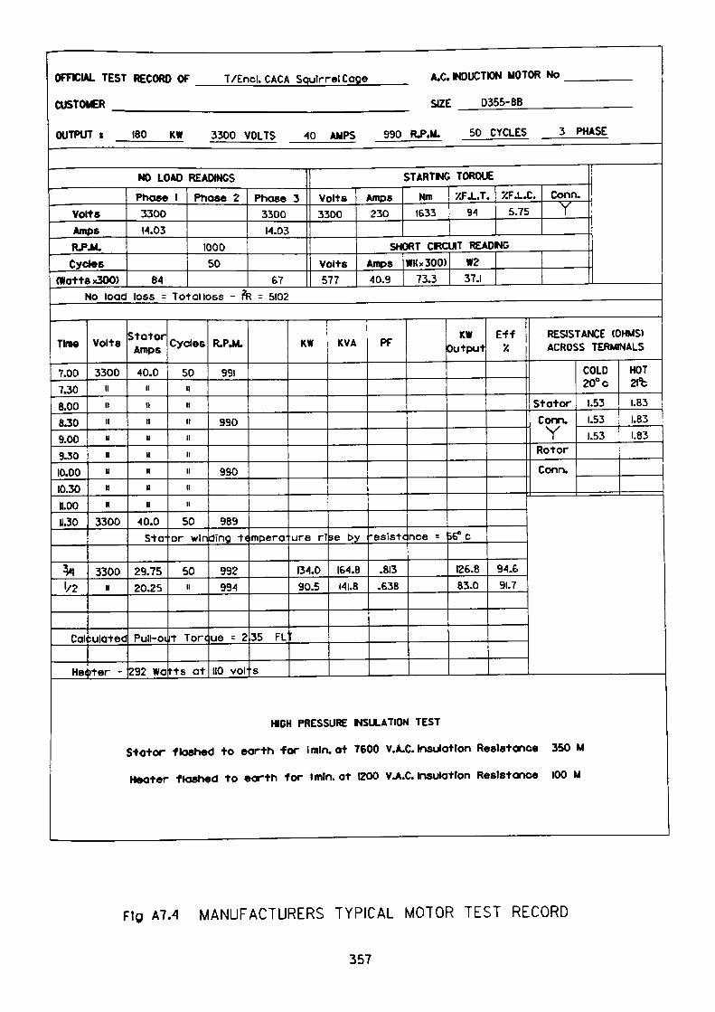
OFFICIAL TEST RECORD OF T/Encl. CACA SoulrrelCage A.C. NDUCTION MOTOR No
CUSTOMER SIZE D355-8B
OUTPUT t 180 KW 3300 VOLTS 40 AMPS 990 R^.M. 50 CYCLES 3 PHASE
NO LOAD READINGS
VoltsAmpsR.P.M.Cycles
(Watte x300>
Phase 1 Phase 2330014.03
100050
84
Phase 3 Volts3300 330014.03
volts67 577
No load loss = Total loss - fa = 5102
STARTWG TORQUE
Amps230
Nm1633
XFJ..T. XFJ..C. Conn.94 5.75 Y
SHORT CIRCUIT READING
Amps40.9
WKx300)73.3
W237.1
Time
7.007.308.00B.309.009.3010.0010.3011.0011.30
fc1/2
Cal
He<
volts
3300ii11iiniinnn
3300
3300n
-ulated
ter -
Stator Amps
40.0iinnnnnnn
40.0Sto-
29.7520.25
Pull-oi
292 Wa
Cycles
50nnnnnnnii
50or wini
50ii
t Tore
rts at
R.P.M.
991
990
990
989ding t«
992994
ue = 2
no voi-
mpera-
35 FL
s
KW
Lire rl
134.090.5
KVA
se by
IS4.8141.8
PF
^•esistc
.813.£38
nee =
KW Output
i6" c
126.883.0
Eff '/.
94.691.7
RESISTANCE (OHMS) ACROSS TERMINALS
COLD HOT20° c 2ft
Stator 1.53 1.83Conn. .53 1.83Y .53 1.83
Rotor
Conn.
HCH PRESSURE INSULATION TEST
Stotor flashed to earth for Imlruot 7600 V.A.C. Insulation Resistance 350 M
Hooter flashed to earth for imln. at 1200 V.A.C. insulation Resistance 100 M
Fig A7.4 MANUFACTURERS TYPICAL MOTOR TEST RECORD
357
APPENDIX 8
Typical Fuse Characteristics
The typical information supplied by manufacturers to describe their products is
generally produced in a graphic form. The three basic requirements necessary to
fingerprint each fuse are:
1. To establish the relationship between the pre-arcing time of the fuse and
the rms symmetrical prospective fault current available at the point of
connection. This relationship is shown in Fig. A8.1.
2. To establish the relationship between the rms symmetrical prospective
fault current at the point of connection and the peak cut-off current of the
fuse. This relationship is shown in Fig. A8.2
3. The manufacturers declaration of:
(a) Minimum Pre-arcing I2t (Amp2 seconds)
(b) Maximum Total I2t (Amp2 seconds)
for each fuse rating
Typical information is shown in Table A8.1.
358
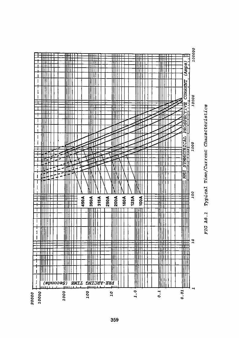
CO en
CD
20000
1000
0
O'
<u1000
:CO
:
100
10 1.0
0.1
0.0
1
•S
10
450A
350A
315A
250A
200A
160A
125A
100A
i 5
\v w c ~\
— r
~> —
•> ~
:Sii_
^N M
= RMS SYMMETRICAL PROSPECTIVE
1——
I I
| I
I I
I |
I I
T-j-r
r ,
, ,
100
1000
10000
(AnK)S)
:
10
00
00
FIG
A8.
1 T
ypic
al
Tim
e/C
urre
nt C
ha
ract
eris
tics
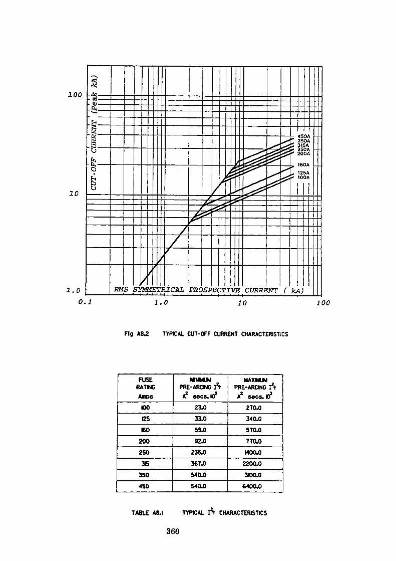
100
20
1.00.1
RMS SYMMETRICAL PROSPECTIVE CURRENT (
450A 350A 31SA 250A 200A
160A _ .125A 100A
1.0 10 100
Fig A8.2 TYPICAL CUT-OFF CURRENT CHARACTERISTICS
FUSE RATMGAmps
100
125
160
200
250
36
350
450
MINIMUM PRE-ARCING ftA2 eecs.103
23.0
33.0
59.0
92.0
235.0
367.0
540.0
540.0
MAXIMUM PRE-ARCING I*t
A2 sees. 10*270.0
340.0
570.0
770.0
•400.0
2200.0
3100.0
6400.0
7ABLE A8.I 7YPICAL It CHARACTERIS7ICS
360
APPENDIX 9
Motor Protection Relay Thermal Characteristics
9.1 B8142, Section 2.3 refers to the specification for thermal electrical relays.
Three relays are specified, they are:
2.1 Thermal electrical relays
2.2 Thermal electrical relays with total memory function
2.3 Thermal electrical relays with partial memory function
The relay specified in 2.2 is defined as:
"A thermal electrical relay which, in its operating characteristic, takes into
account the thermal effects of the load and overload currents existing before the
operation of the relay".
Both relays referred to in this work comply with this definition, the relays are
equipped with a cold overload characteristic which is defined in BS 142, Section
2.3 as:
"Cold Curve - For a thermal electrical relay, the characteristic curve representing
the relationship between specified operating time and current with the relay in a
steady-state no-load condition before the overload occurs".
Let the relay operating characteristic be represented by a single time-constant
exponential equation which will satisfy the motor thermal requirements derived
in Appendix 1, then:
361
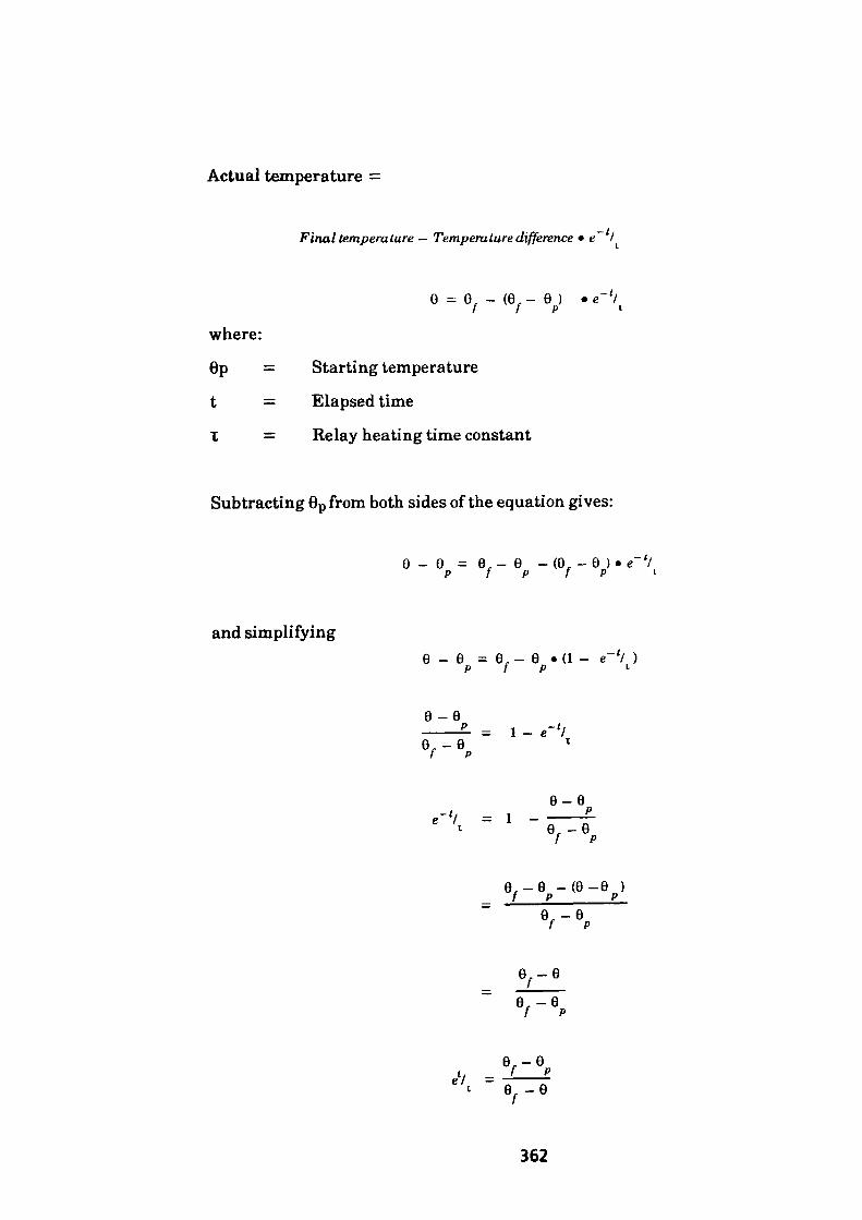
Actual temperature =
Final temperature — Temperature difference • e~ I
where:
6p = Starting temperature
t = Elapsed time
I = Relay heating time constant
Subtracting 6P from both sides of the equation gives:
and simplifying
e _ e = 9,- e -(9, -e p f P f P
9_6 = 9, - 6 •(!- e' 1/ ) p f p l
e-eP = 1 -
e, -e/
e-e. rr•"' - ' -
99 -(6-6 ) / p_____P__
e.-e
e,-e, =-!——*
1 e-e
362
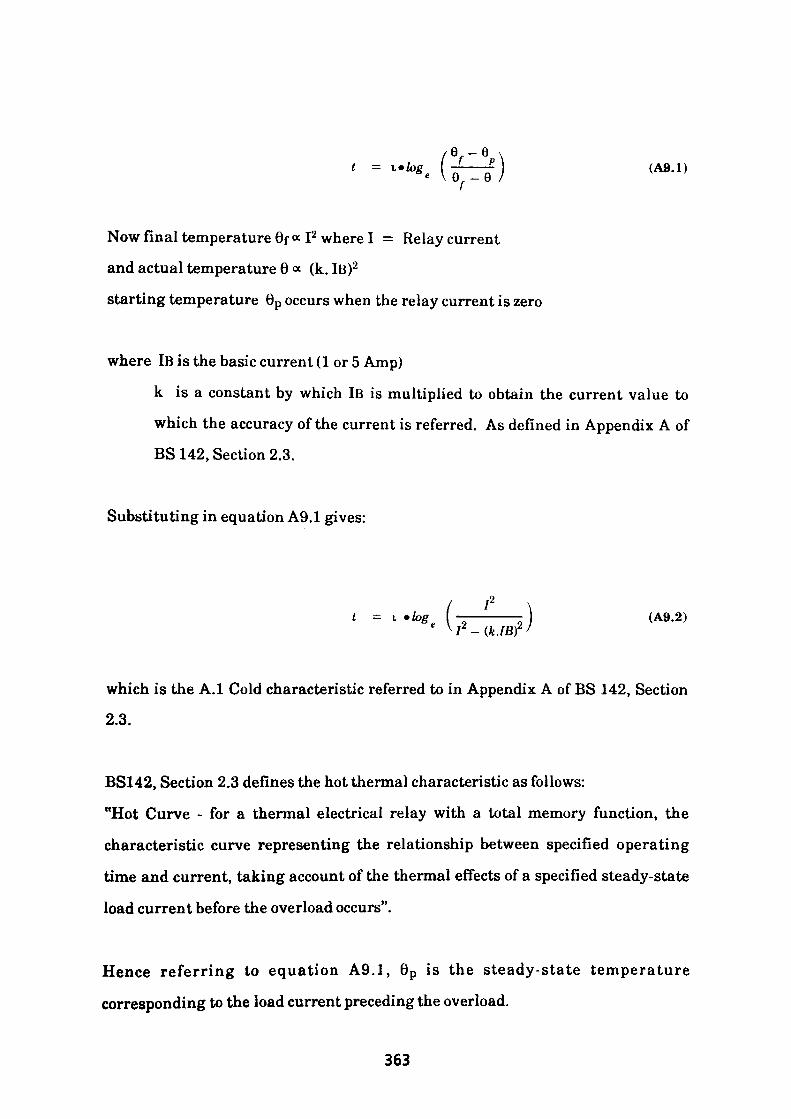
-e
Now final temperature 6f « I2 where I = Relay current
and actual temperature 6 « (k. IB)2
starting temperature 6p occurs when the relay current is zero
where IB is the basic current (1 or 5 Amp)
k is a constant by which IB is multiplied to obtain the current value to
which the accuracy of the current is referred. As defined in Appendix A of
BS 142, Section 2.3.
Substituting in equation A9.1 gives:
(A9.2)
which is the A.I Cold characteristic referred to in Appendix A of BS 142, Section
2.3.
BS142, Section 2.3 defines the hot thermal characteristic as follows:
"Hot Curve - for a thermal electrical relay with a total memory function, the
characteristic curve representing the relationship between specified operating
time and current, taking account of the thermal effects of a specified steady-state
load current before the overload occurs".
Hence referring to equation A9.1, 6 p is the steady-state temperature
corresponding to the load current preceding the overload.
363

Let Ip be the load current proceeding the overload so that the steady-state
temperature 6p « Ip2 .
Substituting for 6p in equation A9.1 gives
which is the B.I Hot characteristic referred to in Appendix B of BS 142, Section
2.3.
By expanding equation A9.3, all equations referred to in BS 142, Section 2.3,
Appendix B can be verified.
Dividing the Numerator and denominator by (kIB)2 in equation (A9.3) gives:
k.lB / \ k.lB )
k' e
.lB / \ I \ k.lB / \~./B UB
(A9.4)
A./B
Since the actual temperature 6 « (k.lB)2
and 6p «Ip2
364

then
from which
IP =6
Substituting for Ip in equation A9.4 gives:
t = i • log — Yk.iB/
- 1
A.IB
6P (i '( *""
9p
f —\ k.iB
(A9.5)
From which it can be seen that equations A9.3, A9.4 and A9.5 comply with the
relay characteristic hot curves stated in BS142, Section 2.3, Appendix B.
365

9.2 Derivation of P&B Microgolds Thermal Characteristic
The trip level of the relay is set at 105% of the nominal relay rating. This value
may be varied by means of the 16/IN potentiometer which enables a variety of CT
ratios to be accommodated and allows modification of the trip level to a user
defined value.
Using P&B golds symbols we have
The 16/lN setting is determined as follows
IQ S Motor FLCIN 1.05 CT Primary RAtio
where S is the required trip level.
From which it can be seen that
/ MultipleofMotorFLC \2 _ ( P_ \2 / " \ Overload Setting I ~\SJ
I — The starting temperatureThermal capacity at overload setting S
1 1 Motor Load \2 / lL \, 6 a - • ——————— r = — r P \S MotorFLC I \ S J
Substituting the above values in equation 9.1 gives:
/ (P/S)2 - (MS? \ t = i*log e (———————J
366
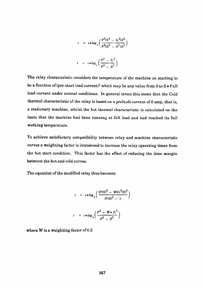
'P2/S2 - lL2/S 2
P2/S2 - S2 /S2
* ~ s 2
The relay characteristic considers the temperature of the machine on starting to be a function of (pre-start load current)2 which may be any value from 0 to S • Full load current under normal conditions. In general terms this mean that the Cold thermal characteristic of the relay is based on a prefault current of 0 amp, that is, a stationary machine, whilst the hot thermal characteristic is calculated on the basis that the machine had been running at full load and had reached its full working temperature.
To achieve satisfactory compatibility between relay and machine characteristic curves a weighting factor is introduced to increase the relay operating times from the hot start condition. This factor has the effect of reducing the time margin between the hot and cold curves.
The equation of the modified relay thus becomes
22
* (PIS)
wiLfisr \- ————— I)2 - 1 '
1L2
- S2
where W is a weighting factor of 0.5
367
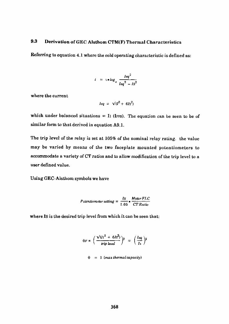
9.3 Derivation of GEC Alsthom CTM(F) Thermal Characteristics
Referring to equation 4.1 where the cold operating characteristic is defined as:
o leq 2 - /S2
where the currentleg = V(/2 + 6/22)
which under balanced situations = II (!PPS). The equation can be seen to be of
similar form to that derived in equation A9,l.
The trip level of the relay is set at 105% of the nominal relay rating, the value
may be varied by means of the two faceplate mounted potentiometers to
accommodate a variety of CT ratios and to allow modification of the trip level to a user defined value.
Using GEC-Alsthom symbols we have
IS Motor FLCPotentiometer setting = —— • —————— 1.05 CT Ratio
where IS is the desired trip level from which it can be seen that:
+ 6/22) \, / leq \,Qf « { ——————— r = — f\ trip level ) \ Is /
6=1 (max thermal capacity)
368
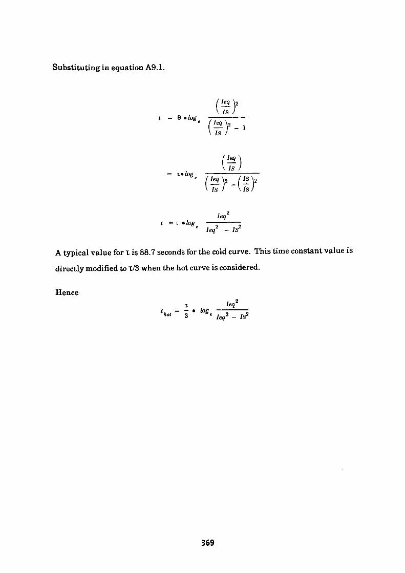
Substituting in equation A9.1.
V is /1 = 0 •**. TT—,——
is'" (!*}'_(!?.
t = t *log
\ IS ls
lege
A typical value for T is 88.7 seconds for the cold curve. This time constant value is
directly modified to T/3 when the hot curve is considered.
Hence
369
APPENDIX 10
Current Transformers
A.10.1 General Information
Current transformers like all transformers rely on the Ampere-Turn balance
principle for their operation.
That is:
Primary Turns • Primary Amps = Secondary Turns • Secondary Amps + Losses
(N.I) primary — (N.I) secondary + (N.I) losses
It can be seen that errors are introduced into the measuring process by the
inclusion of a loss component. The losses are due to a requirement for the primary
circuit to provide:-
(1) The Reactive Ampere-Turns necessary to excite the transformer core
(2) The Active Ampere-Turns necessary to supply the hysteris and eddy
current losses in the iron core and the I2R losses in both the primary and
secondary windings.
Current transformers fall into two distinct classifications, one for metering and
measurement purposes, the other for protection duties. In the former case the
accuracy up to full load is of paramount importance whilst for protection purposes
the performance during the overload condition is the portion of interest. It is the
protection current transformers which are of interest in this document. Protection
current transformers may be subdivided into those conforming to Classes 5P and
10P and those conforming to Class X as referred to in BS 3938: 1973. Accuracy
classes 5P and 10P define the limits of error for accuracy which the current
transformer must comply with.
370
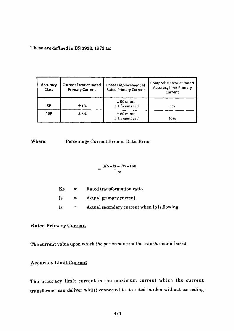
These are defined in BS 3938:1973 as:
Accuracy Class
5P
10P
Current Error at Rated Primary Current
±1%
±3%
Phase Displacement at Rated Primary Current
±60mins; ±1.8centi rad
±60mins; ± 1.8centi rad
Composite Error at Rated Accuracy limit Primary
Current
5%
10%
Where: Percentage Current Error or Ratio Error
KN
IP
Is
_ (KN»IS-ll>) • IQQ~ YP
Rated transformation ratio
Actual primary current
Actual secondary current when Ip is flowing
Rated Primary Current
The current value upon which the performance of the transformer is based.
Accuracy Limit Current
The accuracy limit current is the maximum current which the current
transformer can deliver whilst connected to its rated burden without exceeding
371
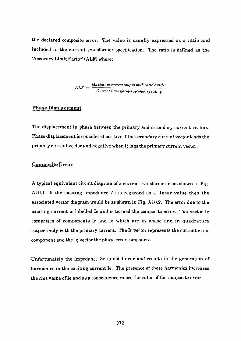
the declared composite error. The value is usually expressed as a ratio and
included in the current transformer specification. The ratio is defined as the 'Accuracy Limit Factor' (ALF) where:
_ Maximum current output with rated burden A Lit1 — —~—————————————————————————— Current Transformer secondary rating
Phase Displacement
The displacement in phase between the primary and secondary current vectors.
Phase displacement is considered positive if the secondary current vector leads the primary current vector and negative when it lags the primary current vector.
Composite Error
A typical equivalent circuit diagram of a current transformer is as shown in Fig. A10.1 If the exciting impedance Ze is regarded as a linear value then the associated vector diagram would be as shown in Fig. A10.2. The error due to the exciting current is labelled le and is termed the composite error. The vector le
comprises of components Ir and Iq which are in phase and in quadrature
respectively with the primary current. The Ir vector represents the current error
component and the Iq vector the phase error component.
Unfortunately the impedance Ze is not linear and results in the generation of harmonics in the exciting current le. The presence of these harmonics increases
the rms value of le and as a consequence raises the value of the composite error.
372
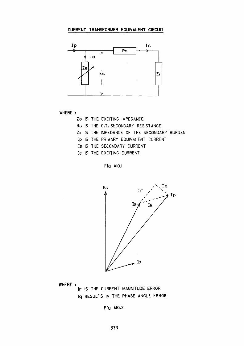
CURRENT TRANSFORMER EQUIVALENT CIRCUIT
IP—>-
Ze1/1
IsRs
Es
v
WHEREZe IS THE EXCITING IMPEDANCE
Rs IS THE C.T. SECONDARY RESISTANCE
ZB IS THE IMPEDANCE OF THE SECONDARY BURDEN
lp IS THE PRIMARY EQUIVALENT CURRENT
Is IS THE SECONDARY CURRENTIe IS THE EXCITING CURRENT
Fig AIO.I
EsA
Ie
WHERE :IT IS THE CURRENT MAGNITUDE ERROR
Iq RESULTS IN THE PHASE ANGLE ERROR
Fig AI0.2
373
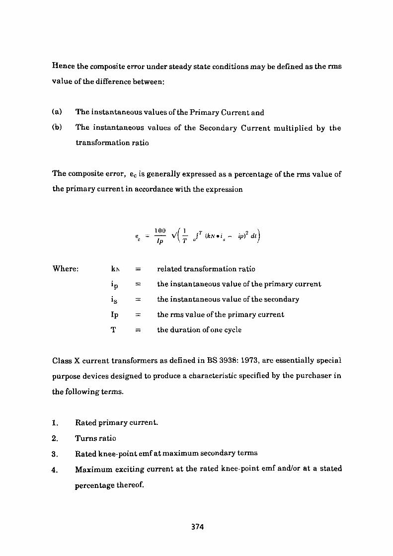
Hence the composite error under steady state conditions may be defined as the rms
value of the difference between:
(a) The instantaneous values of the Primary Current and
(b) The instantaneous values of the Secondary Current multiplied by the
transformation ratio
The composite error, ec is generally expressed as a percentage of the rms value of
the primary current in accordance with the expression
ioo /IT 2e — —— V — f (kN»i — ip) dtc Ip \T ° s
Where: kN = related transformation ratio
ip = the instantaneous value of the primary current
is = the instantaneous value of the secondary
Ip = therms value of the primary current
T = the duration of one cycle
Class X current transformers as defined in BS 3938: 1973, are essentially special
purpose devices designed to produce a characteristic specified by the purchaser in
the following terms.
1. Rated primary current.
2. Turns ratio
3. Rated knee-point emf at maximum secondary terms
4. Maximum exciting current at the rated knee-point emf and/or at a stated
percentage thereof.
374
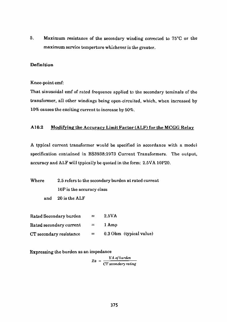
5. Maximum resistance of the secondary winding corrected to 75°C or the
maximum service temperture whichever is the greater.
Definition
Knee-point emf:
That sinusoidal emf of rated frequence applied to the secondary teminals of the
transformer, all other windings being open-circuited, which, when increased by
10% causes the exciting current to increase by 50%.
A10.2 Modifying the Accuracy Limit Factor (ALF) for the MCGG Relay
A typical current transformer would be specified in accordance with a model
specification contained in BS3938:1973 Current Transformers. The output,
accuracy and ALF will typically be quoted in the form: 2.5VA 10P20.
Where 2.5 refers to the secondary burden at rated current
10P is the accuracy class
and 20 is the ALF
Rated Secondary burden = 2.5VA
Rated secondary current = 1 Amp
CT secondary resistance = 0.3 Ohm (typical value)
Expressing the burden as an impedanceVA of burdenZB -
CT secondary rating
375
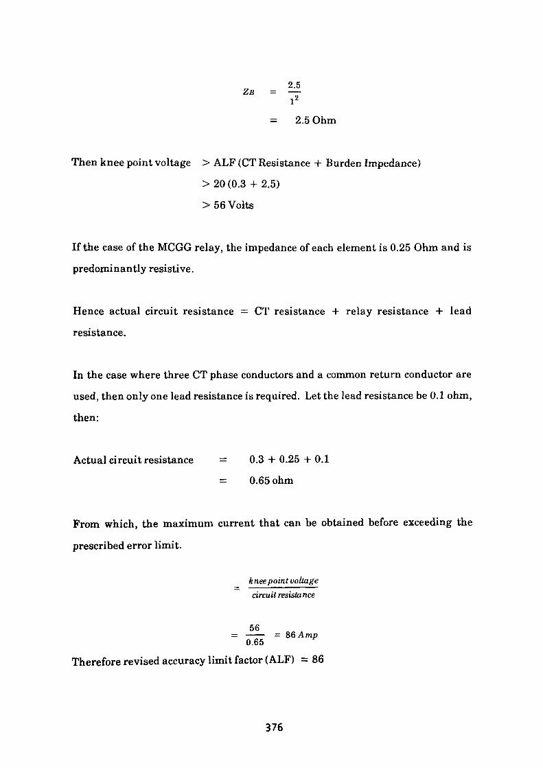
2.5*> = ^
= 2.5 Ohm
Then knee point voltage > ALF (CT Resistance + Burden Impedance)
> 20 (0.3 -I- 2.5)
> 56 Volts
If the case of the MCGG relay, the impedance of each element is 0.25 Ohm and is
predominantly resistive.
Hence actual circuit resistance — CT resistance + relay resistance + lead
resistance.
In the case where three CT phase conductors and a common return conductor are
used, then only one lead resistance is required. Let the lead resistance be 0.1 ohm,
then:
Actual circuit resistance = 0.3 + 0.25 + 0.1
= 0.65 ohm
From which, the maximum current that can be obtained before exceeding the
prescribed error limit.
knee point voltage circuit resistance
56= —— = 86 Amp
0.65
Therefore revised accuracy limit factor (ALF) = 86
376