list of standard construction specifications & drawings page
TRANSCRIPT

List of Standard Construction Specifications & Drawings Page 1 of 13
City of Saskatoon Standard Construction Specifications & Drawings Effective February 4, 2022
To access the current specifications and drawings, please visit the City of Saskatoon specifications and standards website: https://www.saskatoon.ca/business-development/development-regulation/specifications-standards SPECIFICATIONS Division 1 - General Requirements Project Control 01010 Shop Drawings, Product Data and Samples 01015 Testing Laboratory Services 01020 Temporary Facilities 01025 Safety Requirements 01030 Environmental Protection 01035 Cleaning 01040 Products/Workmanship 01045 Project Record Documents 01050 Division 2 - Earthworks Excavation and Embankment Construction 02005 Area Grading 02010 Subgrade Compaction 02015 Construction of Streets and Lanes 02055 Grade Construction for Sidewalk, Curb and Gutter 02060 Division 3 - Aggregates Supply of Aggregates 03001 Granular Base Course 03005 Granular Subbase Course 03010 Stockpiling Aggregates 03015 Testing and Inspection 03020 Handplaced, Grouted and Random Riprap 03050 Geotextiles and Geogrids 03060
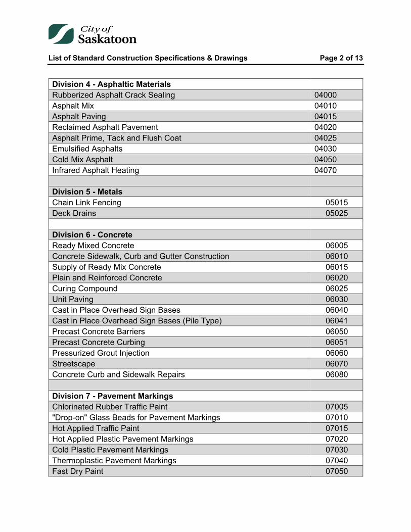
List of Standard Construction Specifications & Drawings Page 2 of 13
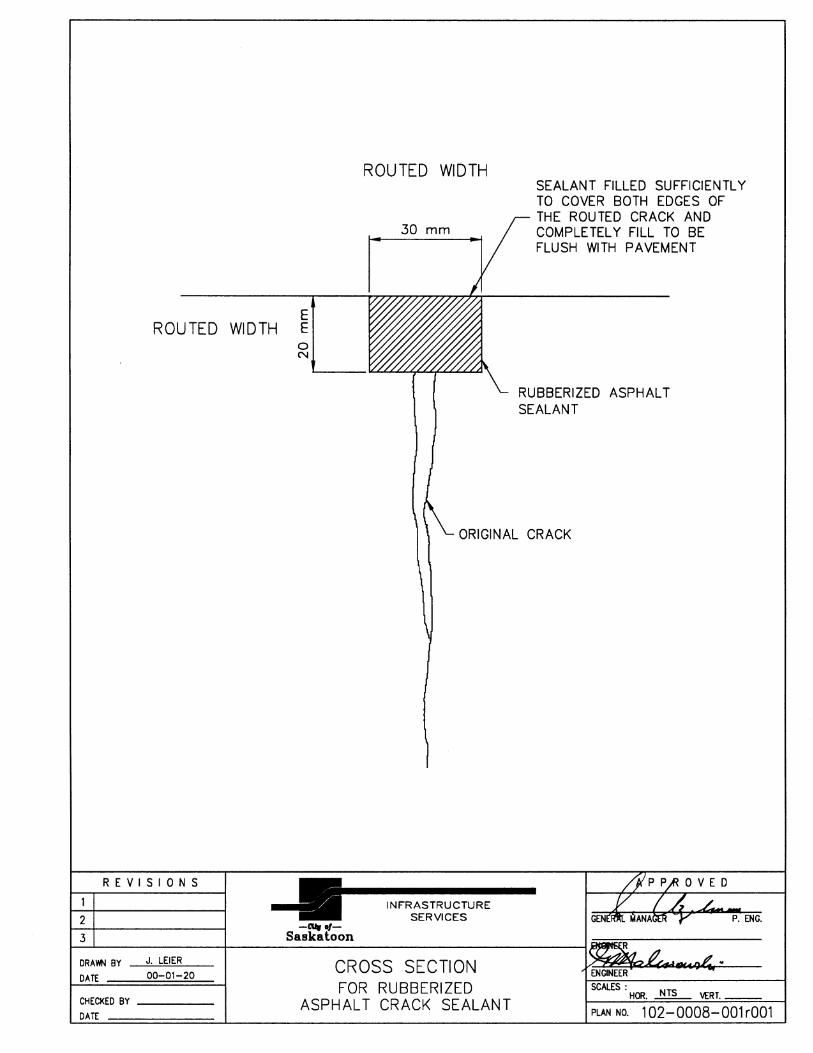
Division 4 - Asphaltic Materials Rubberized Asphalt Crack Sealing 04000 Asphalt Mix 04010 Asphalt Paving 04015 Reclaimed Asphalt Pavement 04020 Asphalt Prime, Tack and Flush Coat 04025 Emulsified Asphalts 04030 Cold Mix Asphalt 04050 Infrared Asphalt Heating 04070 Division 5 - Metals Chain Link Fencing 05015 Deck Drains 05025 Division 6 - Concrete Ready Mixed Concrete 06005 Concrete Sidewalk, Curb and Gutter Construction 06010 Supply of Ready Mix Concrete 06015 Plain and Reinforced Concrete 06020 Curing Compound 06025 Unit Paving 06030 Cast in Place Overhead Sign Bases 06040 Cast in Place Overhead Sign Bases (Pile Type) 06041 Precast Concrete Barriers 06050 Precast Concrete Curbing 06051 Pressurized Grout Injection 06060 Streetscape 06070 Concrete Curb and Sidewalk Repairs 06080 Division 7 - Pavement Markings Chlorinated Rubber Traffic Paint 07005 "Drop-on" Glass Beads for Pavement Markings 07010 Hot Applied Traffic Paint 07015 Hot Applied Plastic Pavement Markings 07020 Cold Plastic Pavement Markings 07030 Thermoplastic Pavement Markings 07040 Fast Dry Paint 07050

List of Standard Construction Specifications & Drawings Page 3 of 13
Division 8 - Water and Sewer Construction Materials - General 08000 Construction Materials - Water Mains 08001 Construction Materials - Sewage Mains 08002 Construction Materials - Service Connection 08003 Gravity Storm and Sanitary Sewer Construction 08010 Sewers Constructed in Tunnels 08015 Catch Basin Construction 08020 Water and Sewer Connections Construction 08025 Water Main Construction 08030 Storm Sewers and Culverts 08040 Gravity Sanitary and Storm Cured-in-Place Pipe (CIPP) Lining 08046 CCTV Camera Sewer Main Inspection 08125 Division 10 - Specialties Bearings 10000 Access Hole Installation 10005 Stationary Truck Scale 10010 Division 11 - Noise Barriers Noise Barriers - General 11000 Concrete Noise Barriers 11001 Transparent Noise Barriers 11002 Division 12 - Traffic Signals Traffic Signal Underground Installation 12600 Division 14 - Shallow Buried Utilities Surface Infrastructure Restoration for Utility Cuts 14001 Division 15 - Construction Materials Construction Materials - Water Mains 15001 Construction Materials - Water Service Connections 15002 Construction Materials - Sewer Mains 15003 Construction Materials - Sewer Service Connections 15004 Construction Materials - Corrosion Protection 15005
List of Standard Construction Specifications & Drawings Page 4 of 13
Construction Materials - Roadways 15006 Construction Materials - Noise Barriers 15007
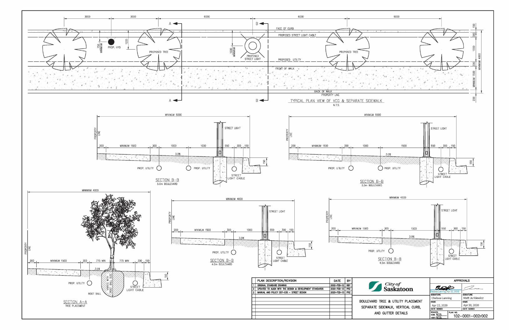
DRAWINGS Boulevards Boulevard Tree & Utility Placement Separate Sidewalk, Vertical Curb, and Gutter Details 1020001002
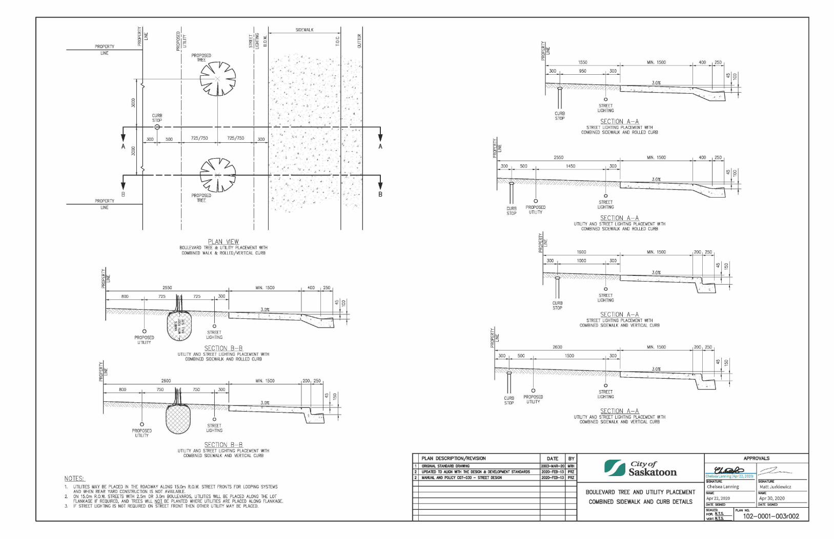
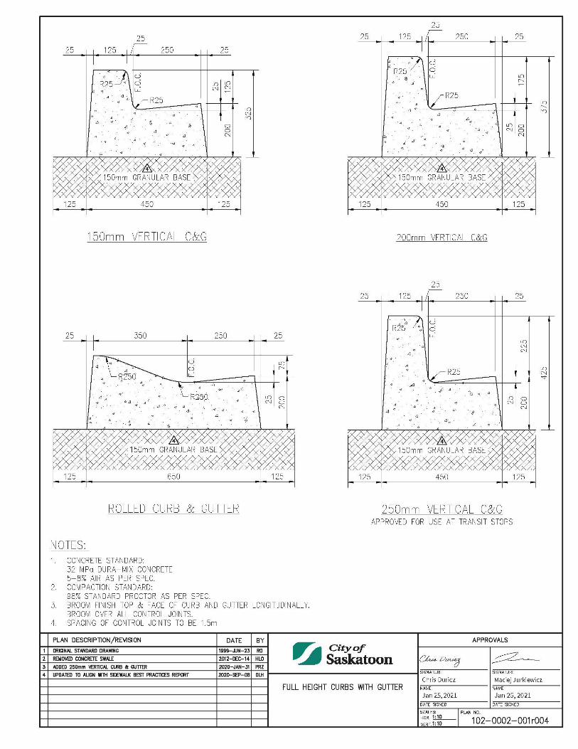
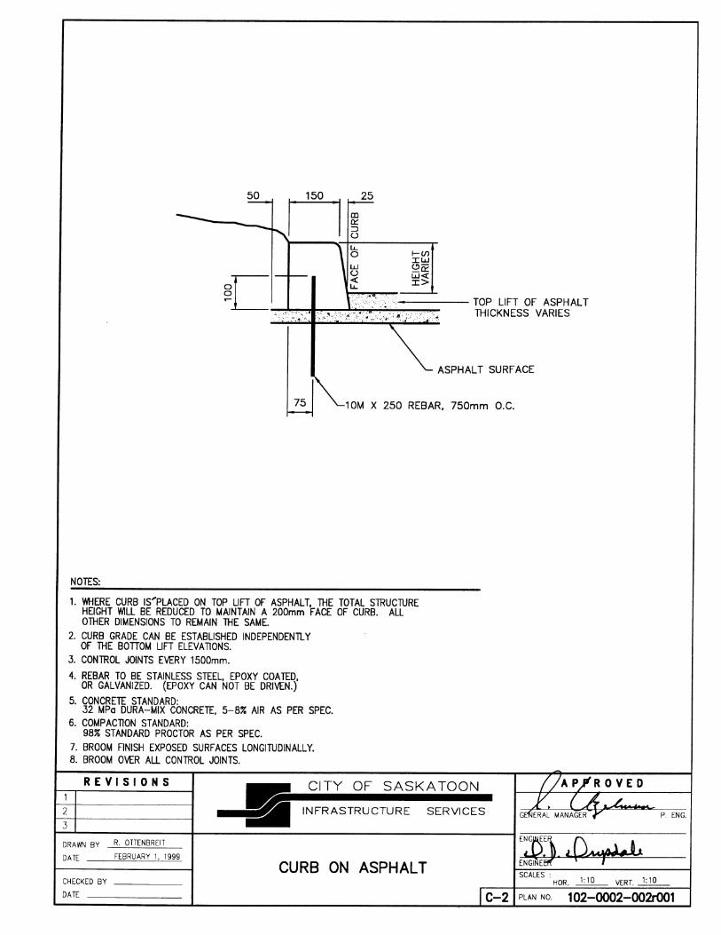
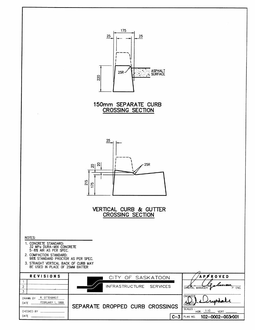
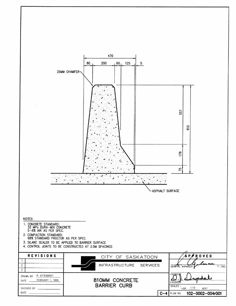
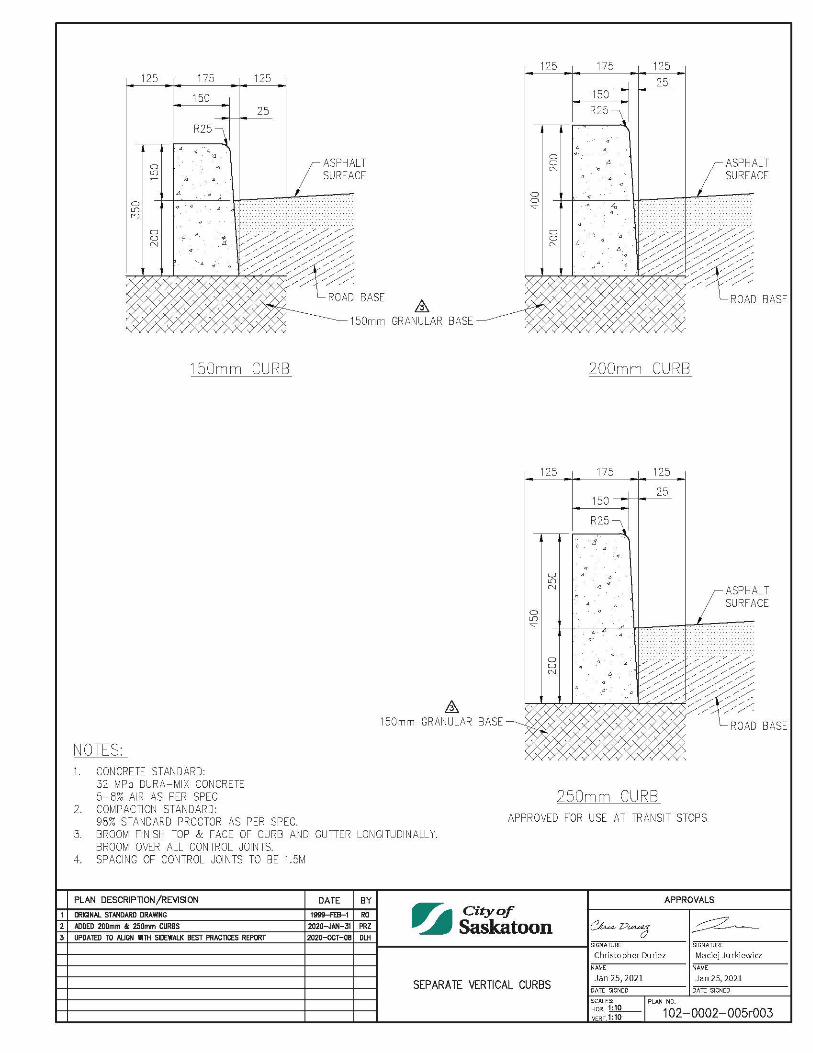
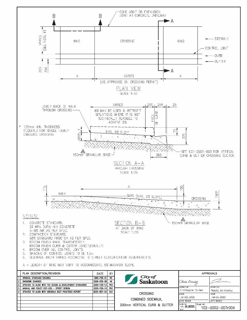
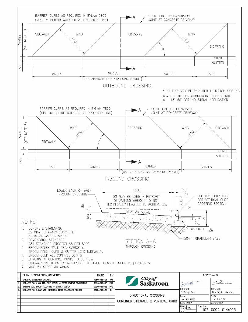
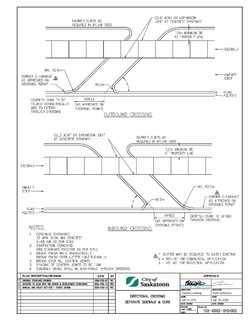
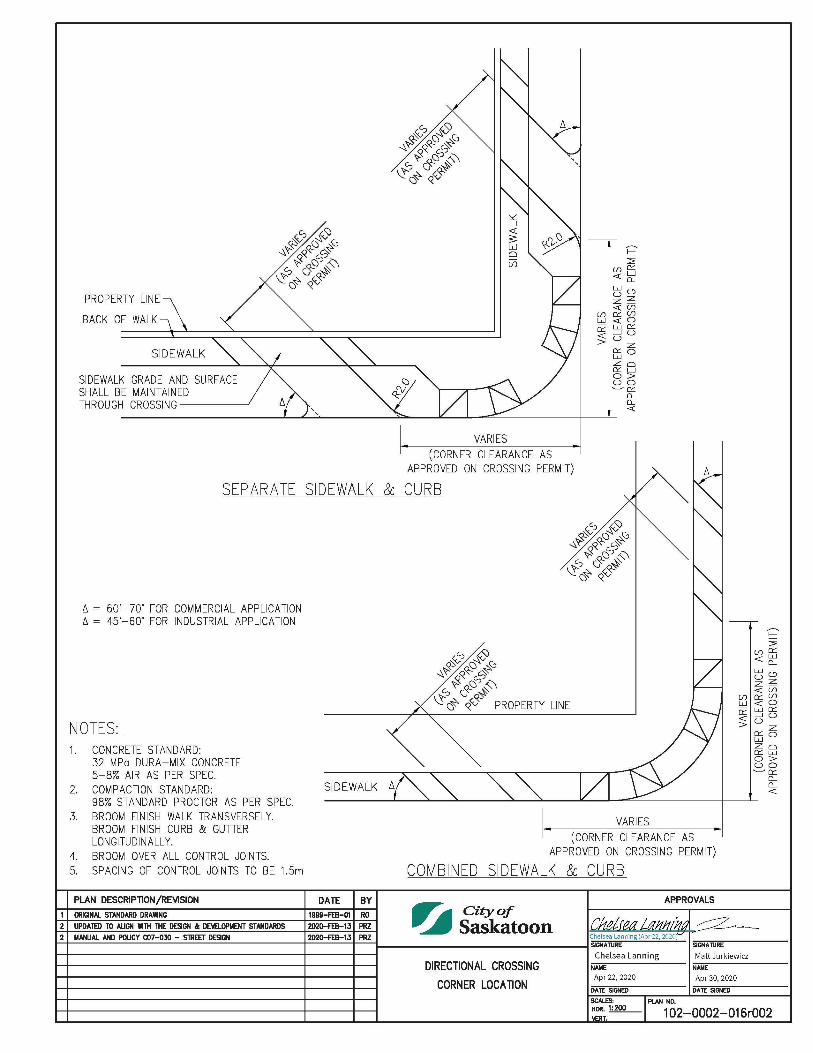
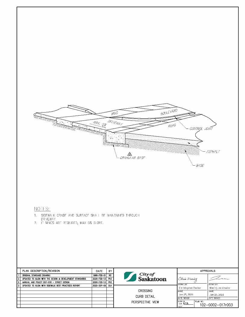
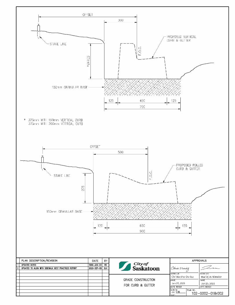
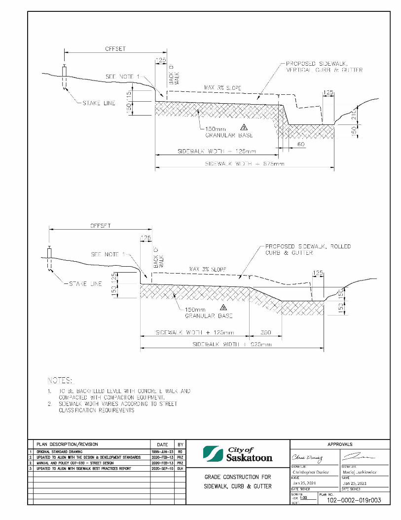
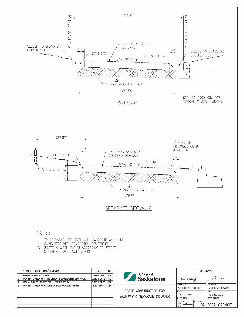
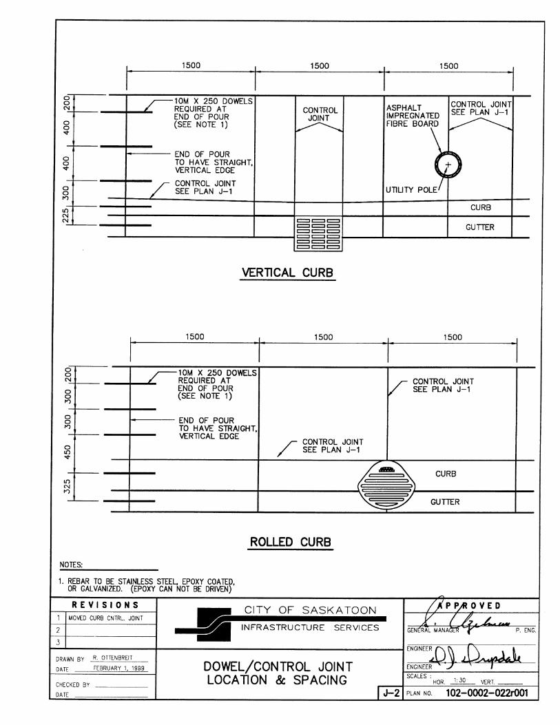
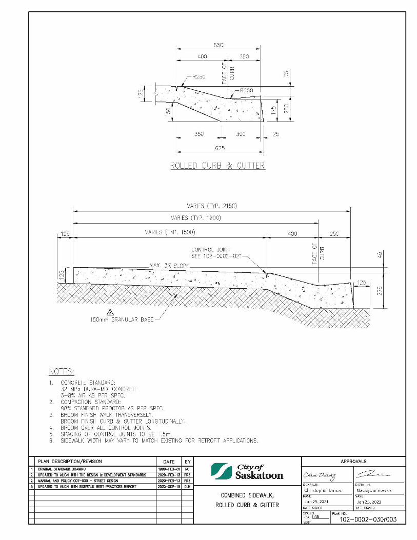
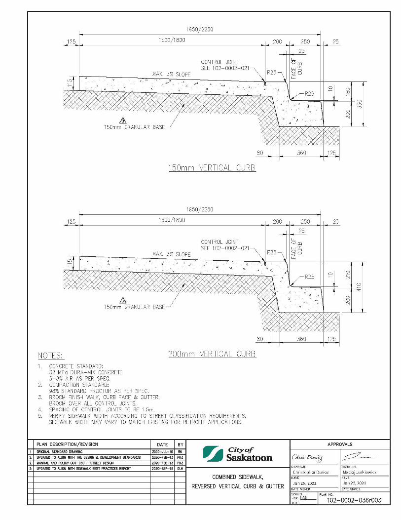
Boulevard Tree and Utility Placement Combined Sidewalk and Curb Details 1020001003 Curbs & Walks Full Heights Curbs and Gutters 1020002001 Curb on Asphalt 1020002002 Separate Dropped Curb Crossings 1020002003 810mm Concrete Barrier Curb 1020002004 Separate Vertical Curb 1020002005 Crossing - Combined Sidewalk, 150mm Vertical Curb & Gutter 1020002006 Crossing - Combined Sidewalk, 200mm Vertical Curb & Gutter 1020002007 Crossing - Combined Sidewalk & 150mm Vertical Curb 1020002008 Crossing - Combined Sidewalk & 200mm Vertical Curb 1020002009 Crossing - Separate Sidewalk, Vertical Curb & Gutter 1020002010 Crossing - Separate Sidewalk & Vertical Curb 1020002011 Crossing - Combined Sidewalk, Rolled Curb & Gutter 1020002012 Curb Return Crossing - Separate Sidewalk & Vertical Curb 1020002013 Directional Crossing - Combined Sidewalk & Vertical Curb 1020002014 Directional Crossing - Separate Sidewalk & Curb 1020002015 Directional Crossing - Corner Location 1020002016 Crossing - Curb Detail - Perspective View 1020002017 Grade Construction for Curb and Gutter 1020002018 Grade Construction for Sidewalk, Curb and Gutter 1020002019 Grade Construction for Walkway & Separate Sidewalk 1020002020 Control Joints 1020002021 Dowel/Control Joint Location and Spacing 1020002022 Pedestrian Ramp - Details 1020002023 Wide Pedestrian Ramp - Texture Details 1020002025 Pedestrian Ramp - Texture Details 1020002026
List of Standard Construction Specifications & Drawings Page 5 of 13
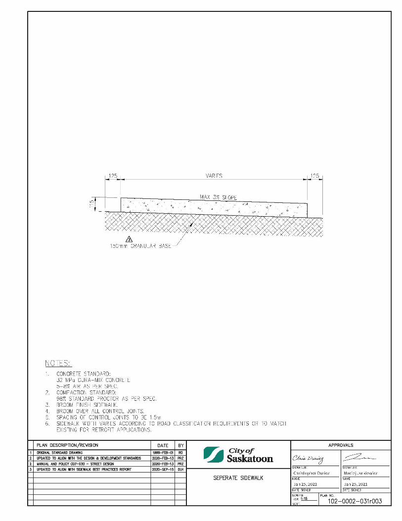
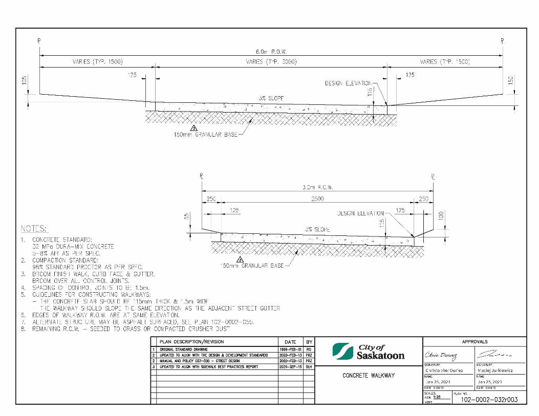
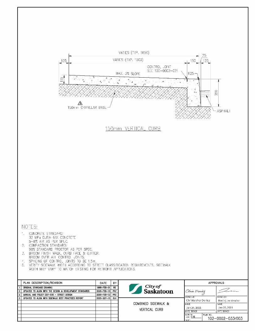
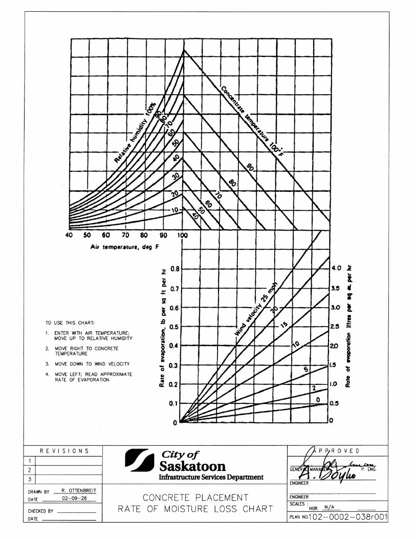
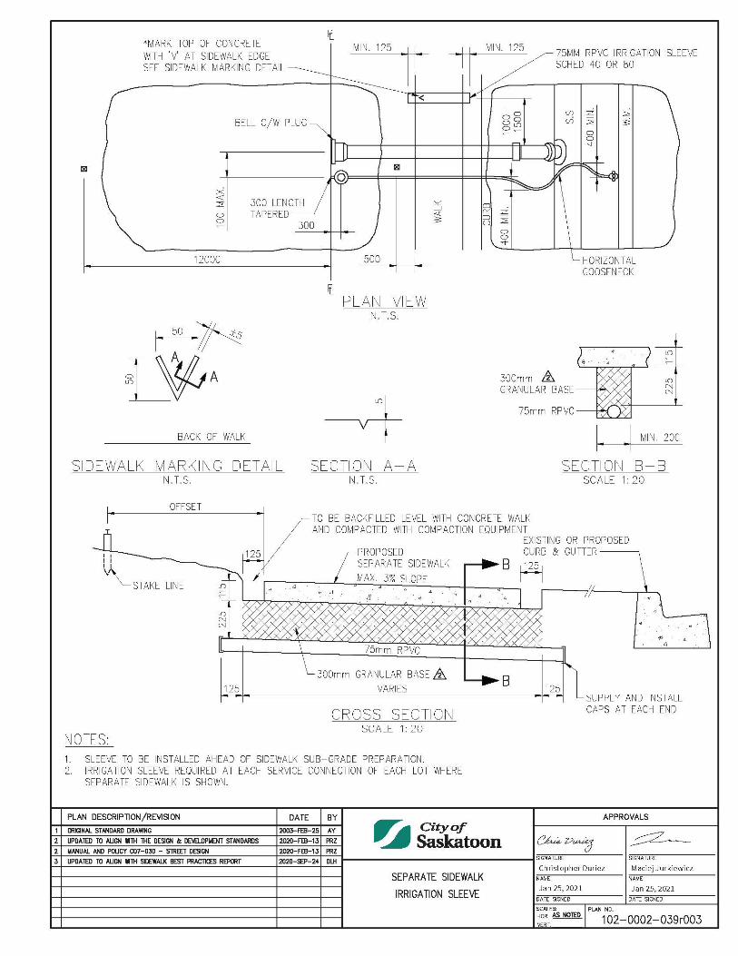
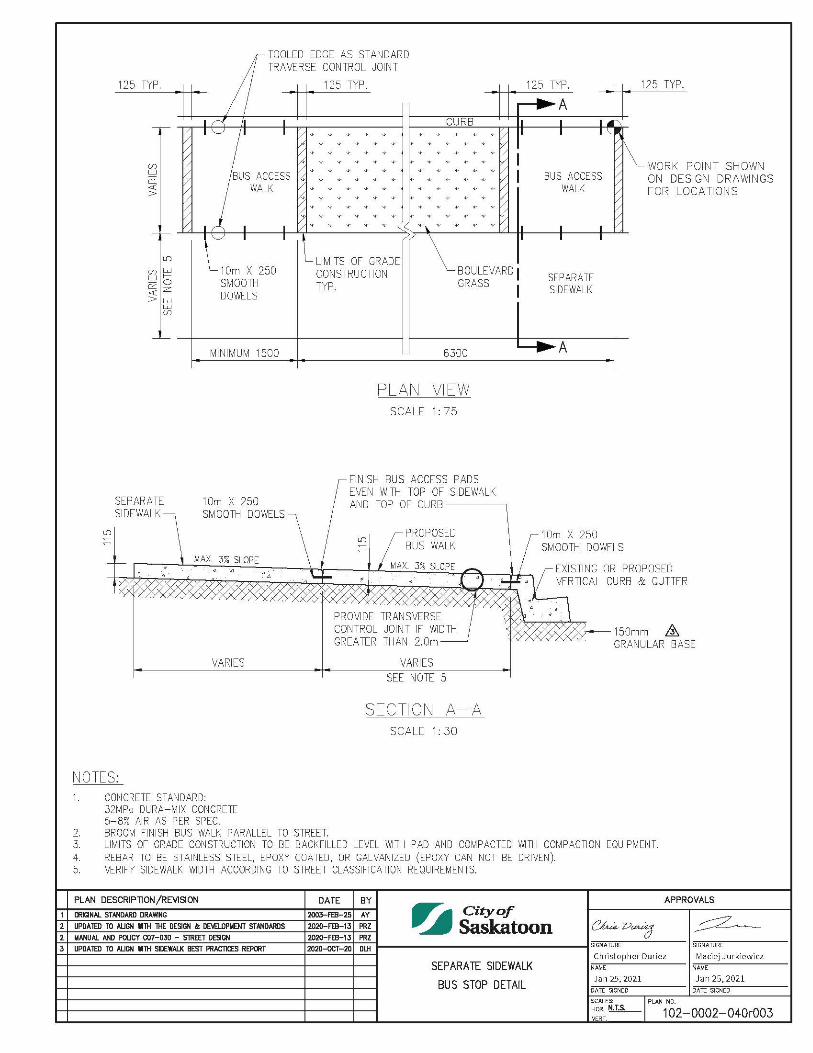
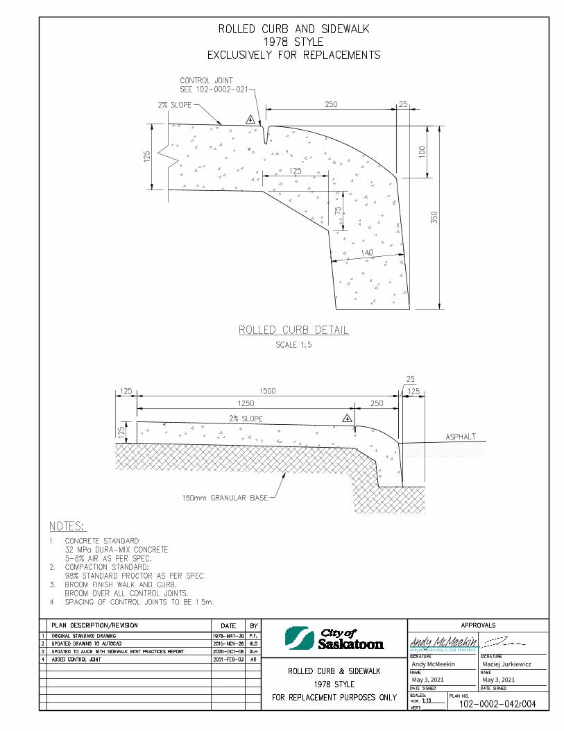
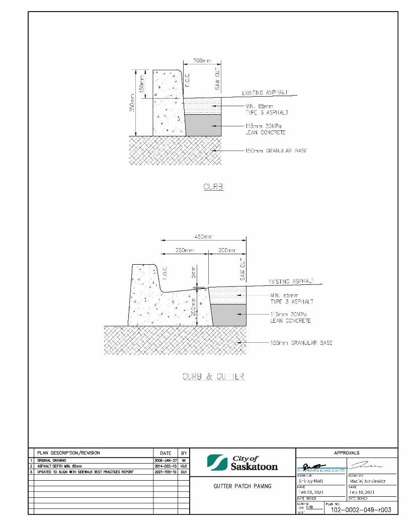
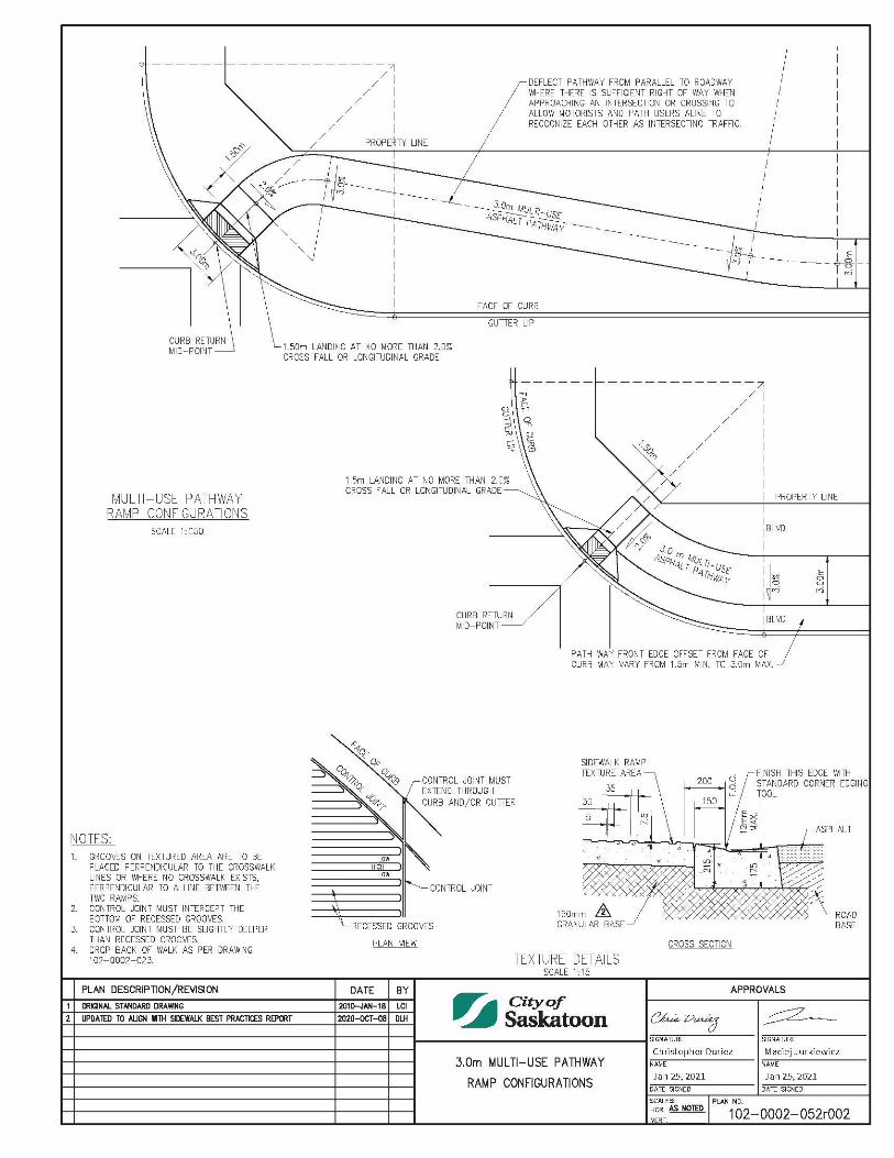
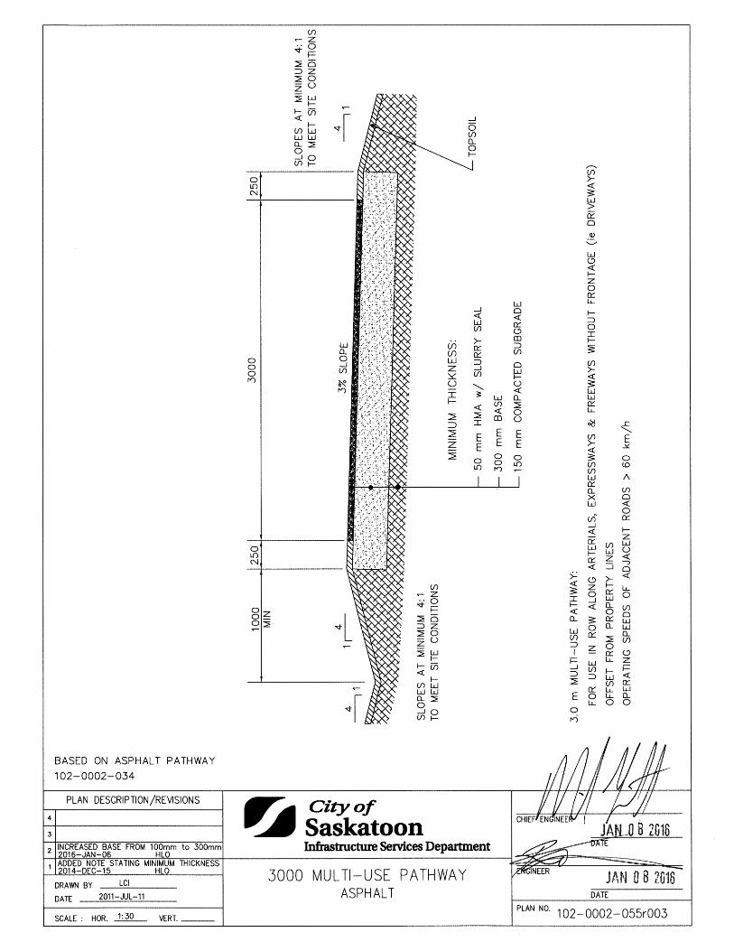
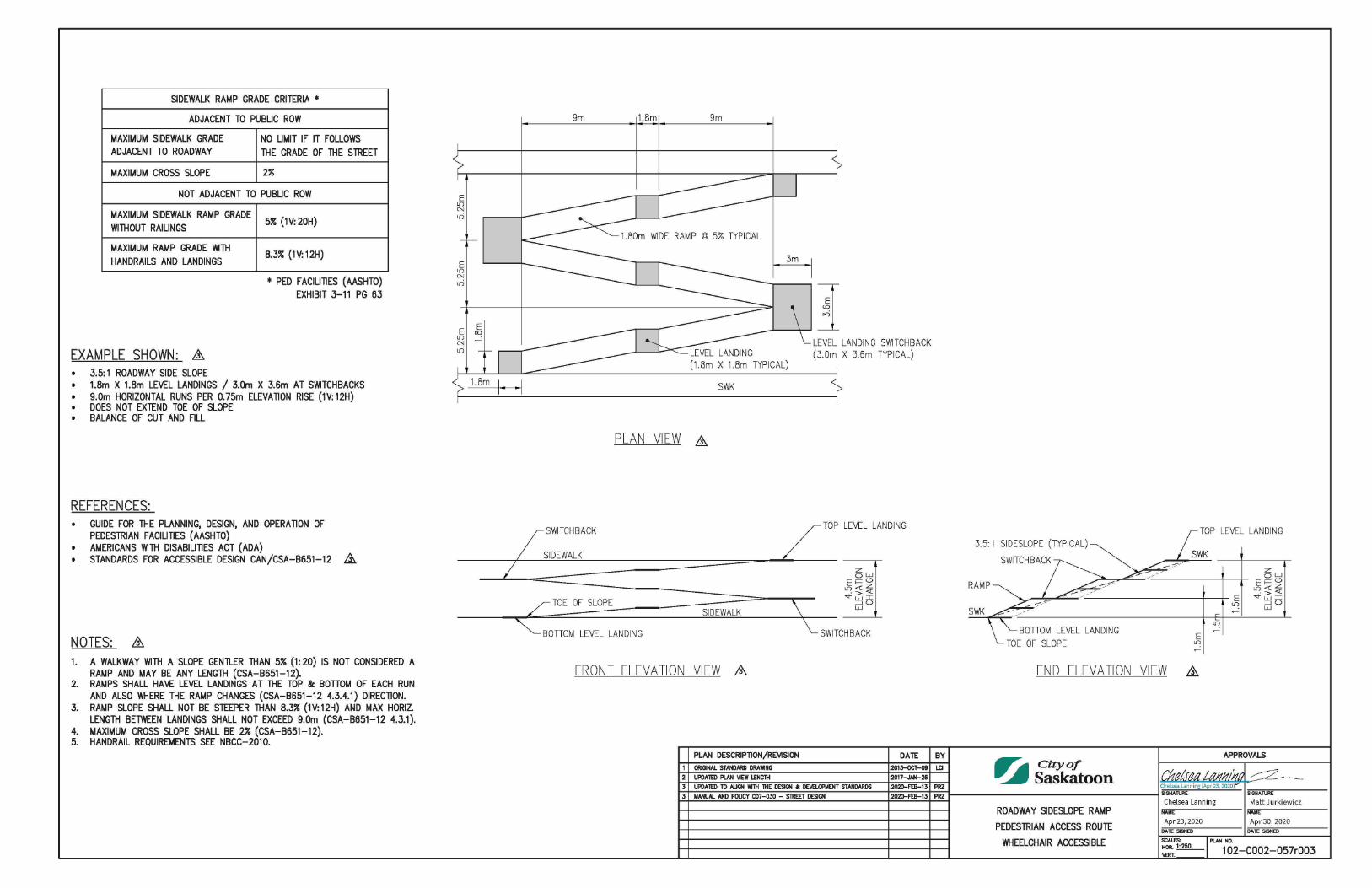
Pedestrian Ramp - Rolled Curb 1020002027 Typical Transition - Combined Sidewalk & Curb 1020002028 Combined Sidewalk, Vertical Curb & Gutter 1020002029 Combined Sidewalk, Rolled Curb & Gutter 1020002030 Separate Sidewalk 1020002031 Concrete Walkway 1020002032 Combined Sidewalk & Vertical Curb 1020002033 Precast Concrete Curb 1020002035 Combined Sidewalk, Reversed Vertical Curb & Gutter 1020002036 Reversed Curb and Gutter Detail 1020002037 Concrete Placement Rate of Moisture Loss Chart 1020002038 Separate Sidewalk Irrigation Sleeve 1020002039 Separate Sidewalk Bus Stop Detail 1020002040 Perpendicular Separate Sidewalk Ramp Details 1020002041 Rolled Curb & Sidewalk 1978 Style 1020002042 Gutter Patch Paving 1020002049 3.0m Multi-Use Pathway Ramp Configurations 1020002052 3000 Multi-Use Pathway Asphalt 1020002055 Roadway Sideslope Ramp Pedestrian Access Wheelchair Accessible 1020002057 Traffic Calming Curb Extensions At A T-Intersection (Collector & Local Streets) 1020002062
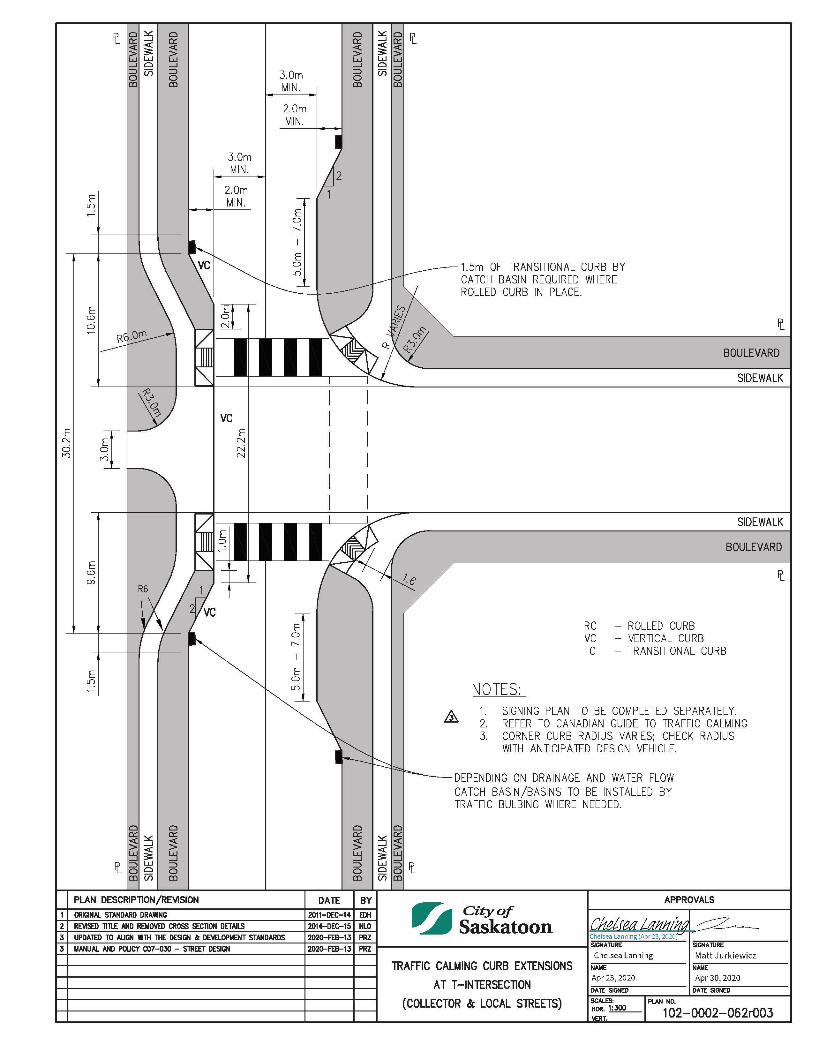
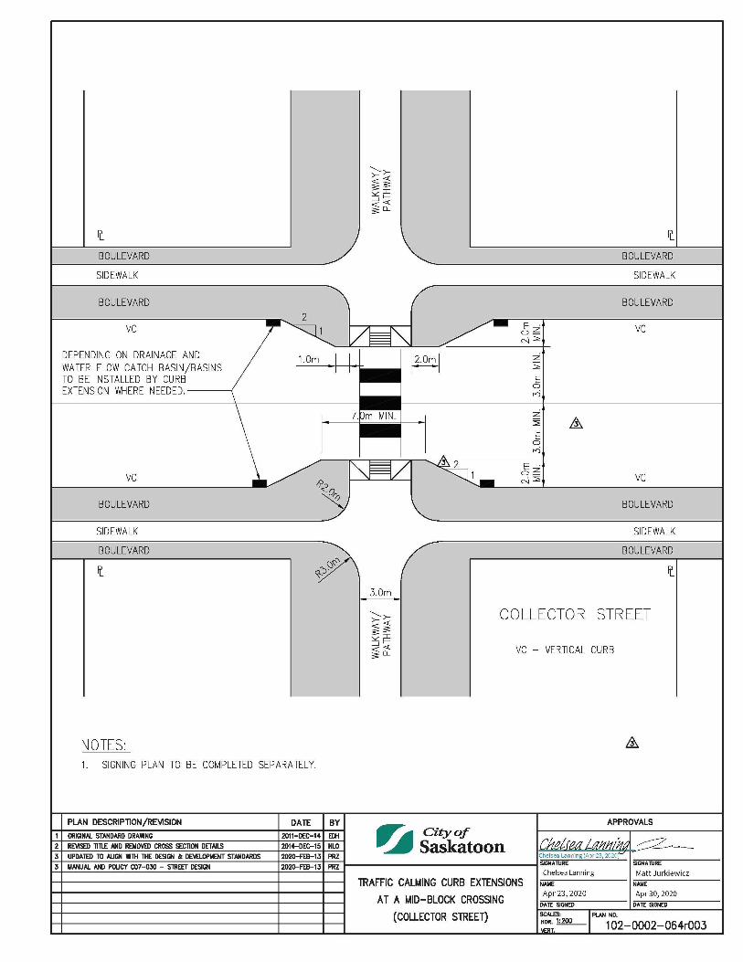
Traffic Calming Curb Extensions At A Mid-Block Crossing (Collector Streets) 1020002064
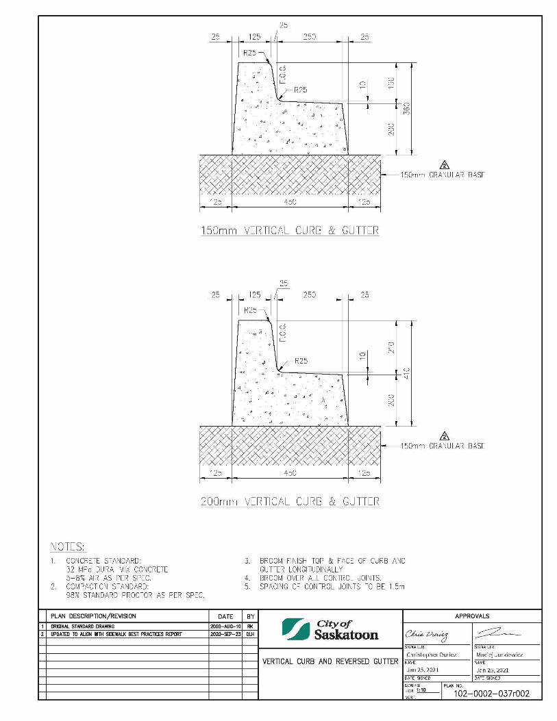
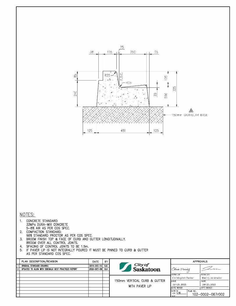
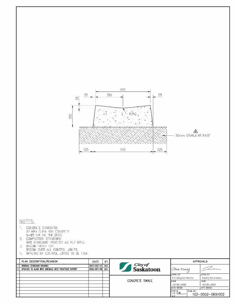
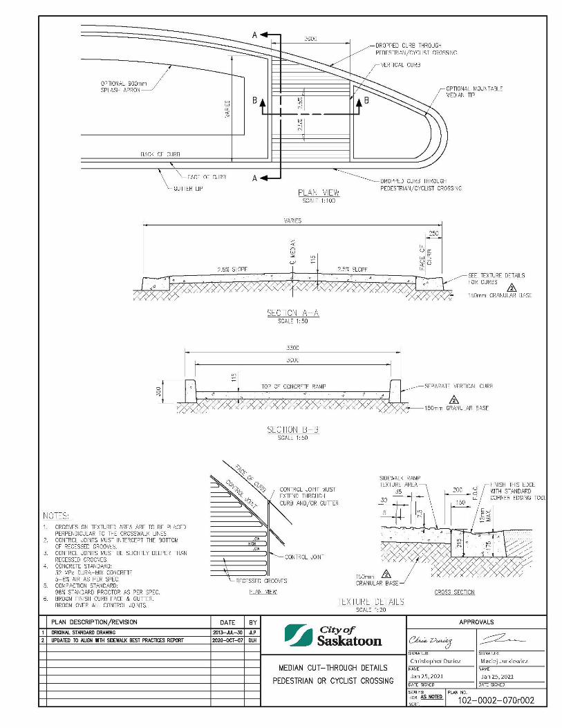
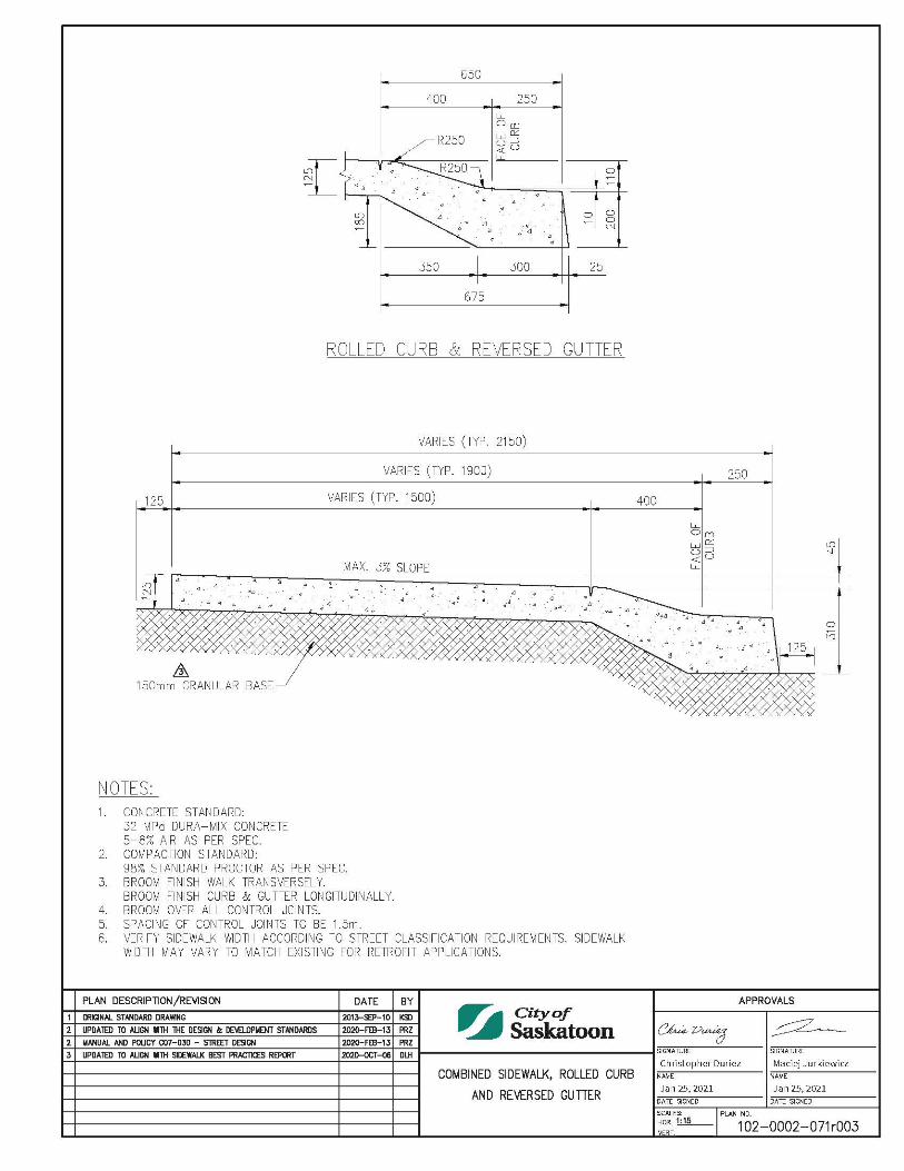
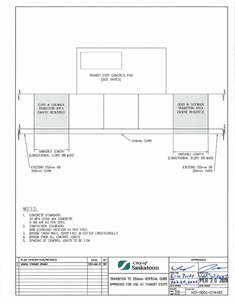
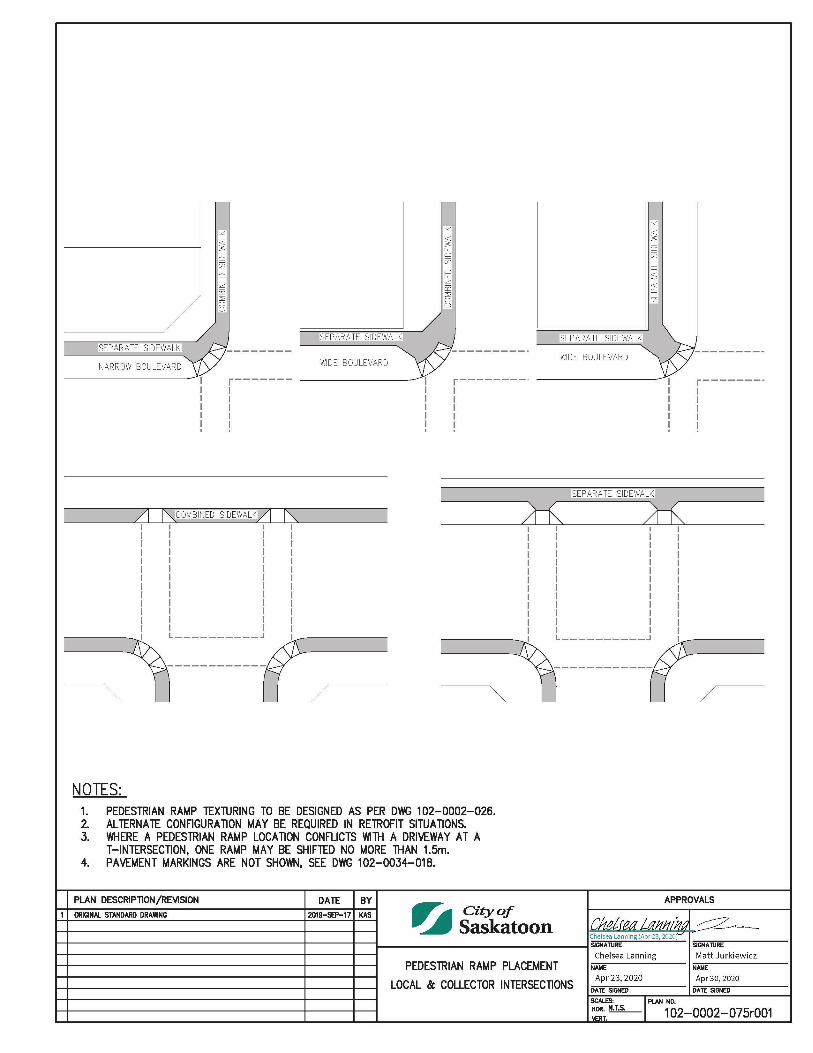
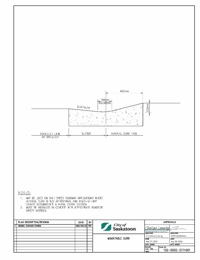
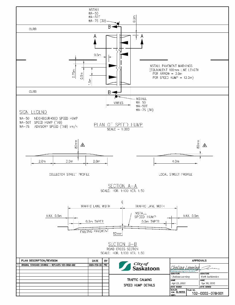
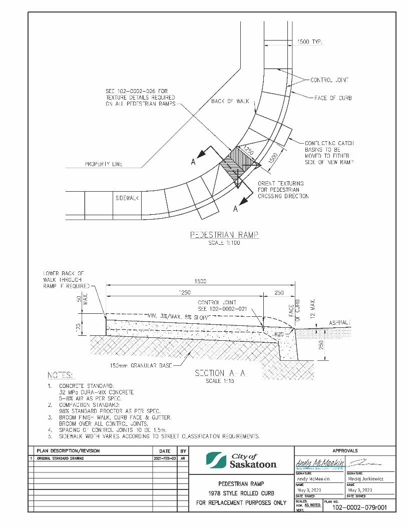
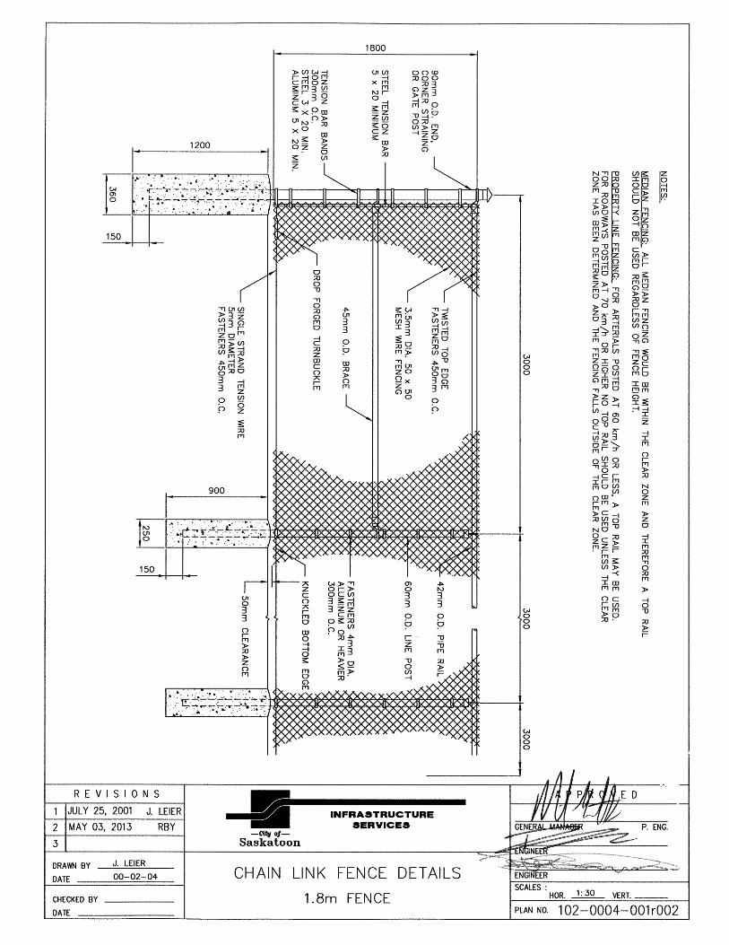
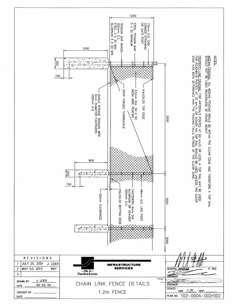
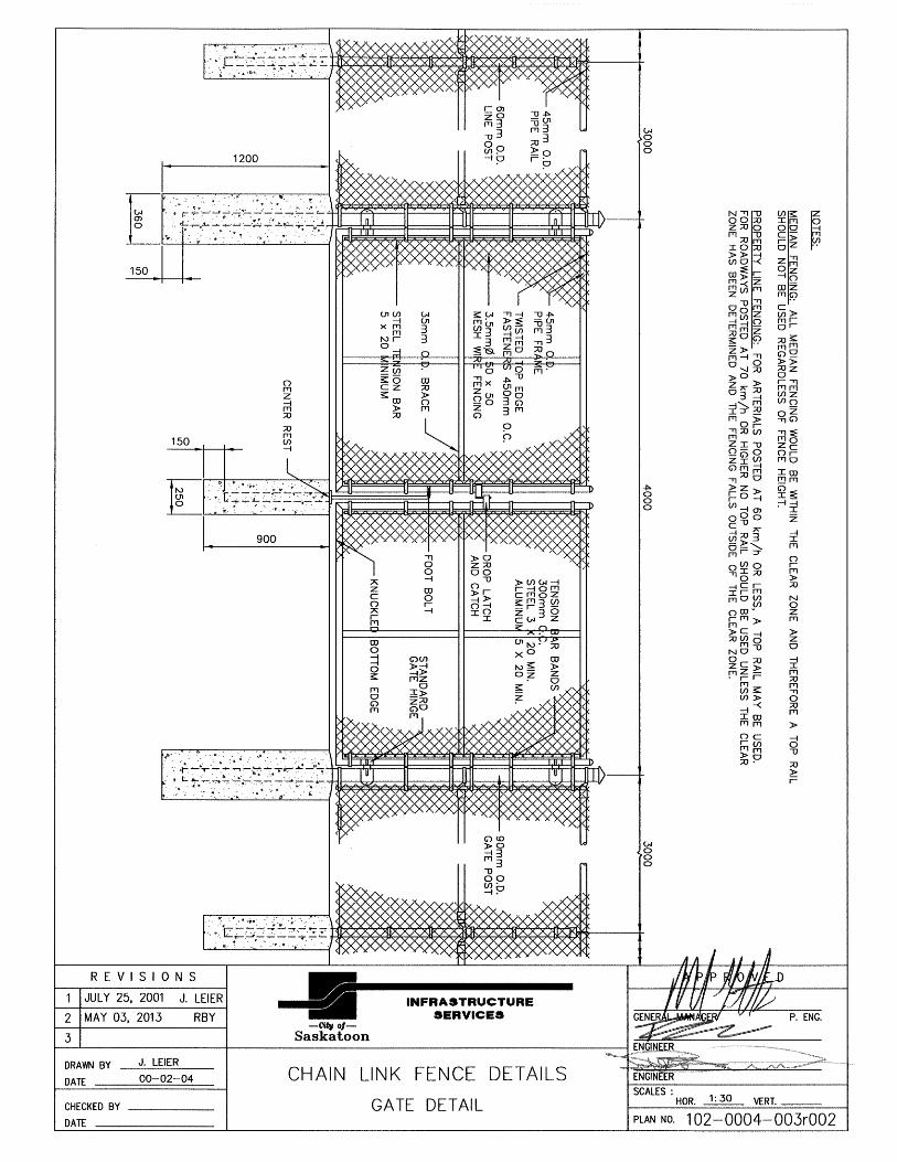
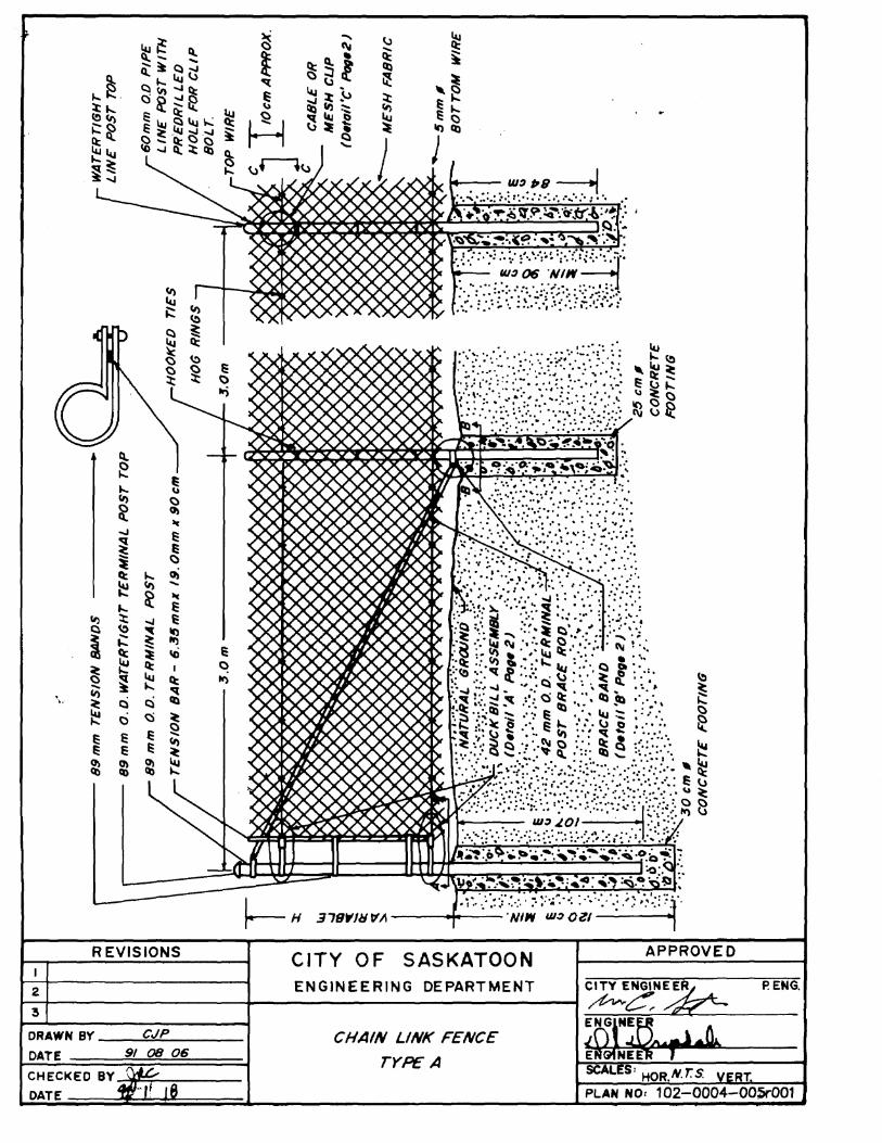
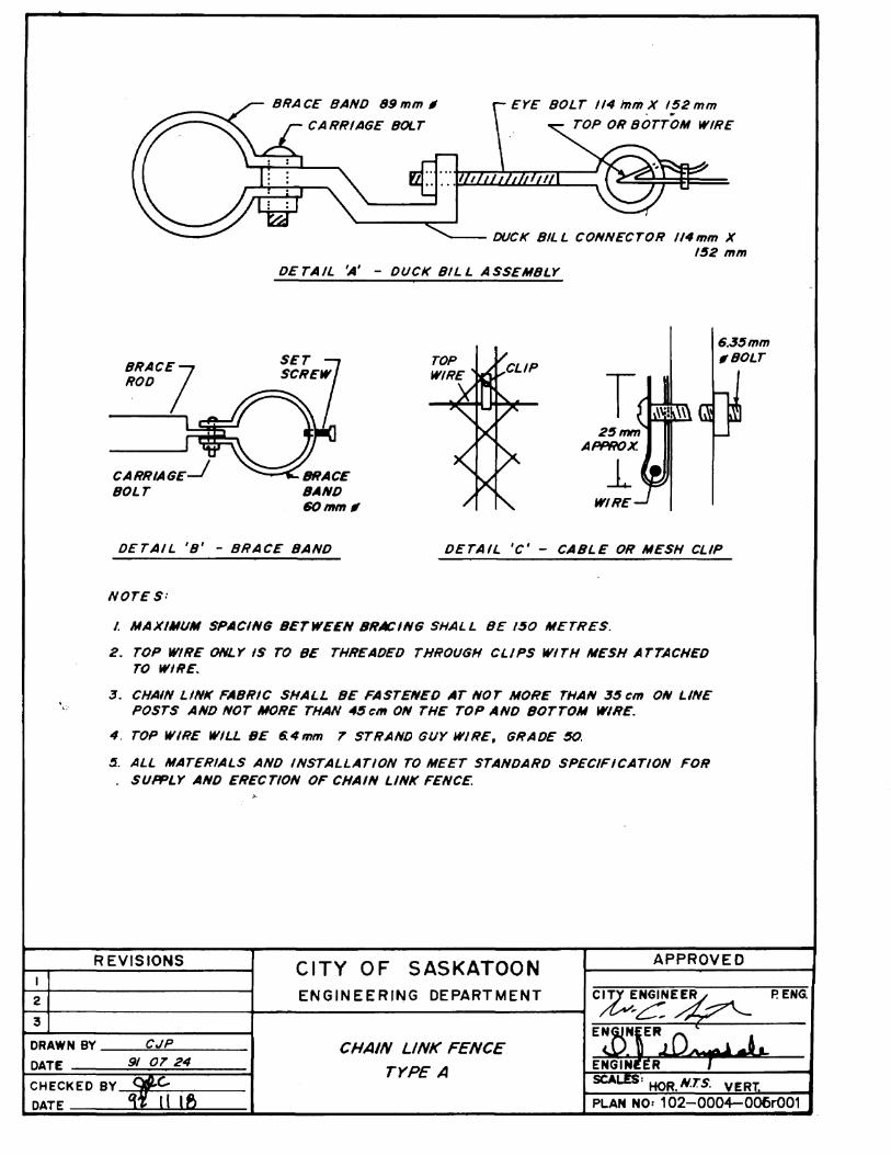
Traffic Calming Curb Extension Options (Collector or Local Streets) 1020002065 150mm Vertical Curb & Gutter with Paver Lip 1020002067 Concrete Swale 1020002069 Cut-Through Median Detail Pedestrian/Cyclist Crossing 1020002070 Combined Sidewalk, Reversed Rolled Curb & Gutter 1020002071 Transition to 250mm Vertical Curb Approved for Use at Transit Stops 1020002074 Pedestrian Ramp Placement Local & Collector Intersections 1020002075 Pedestrian Ramp Placement Arterial Intersections 1020002076 Mountable Curb 1020002077 Traffic Calming Speed Hump Details 1020002078 Pedestrian Ramp 1978 Style Rolled Curb 1020002079 Fences Chain Link Fence Details - 1.8m Fence 1020004001 Chain Link Fence Details - 1.2m Fence 1020004002 Chain Link Fence Details - Gate Detail 1020004003
List of Standard Construction Specifications & Drawings Page 6 of 13
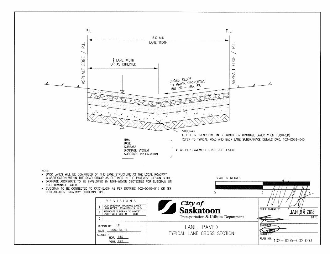
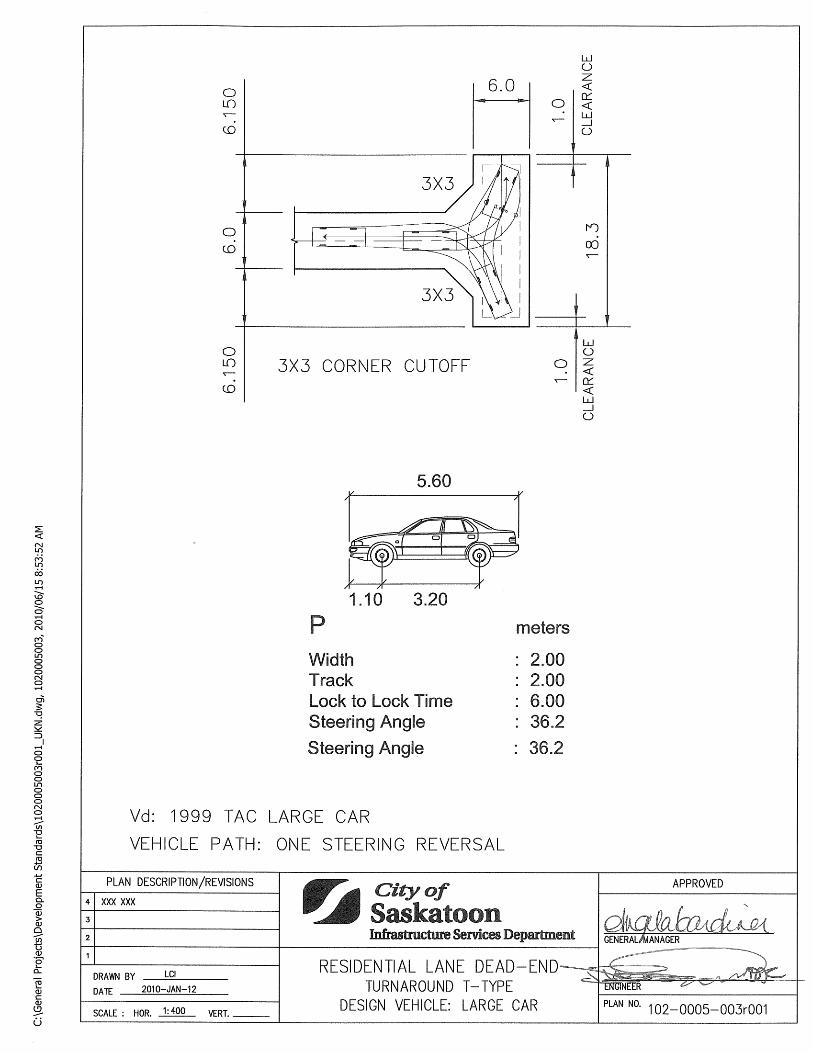
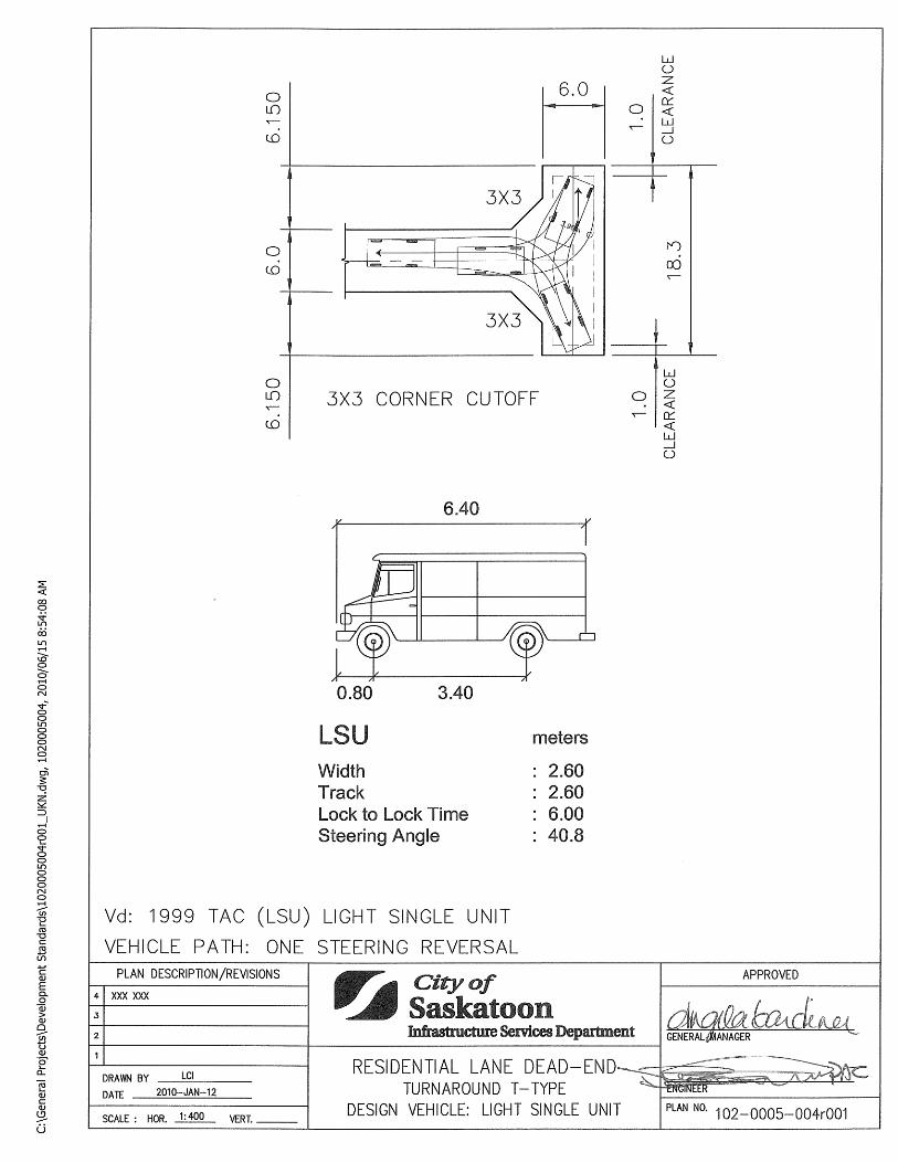
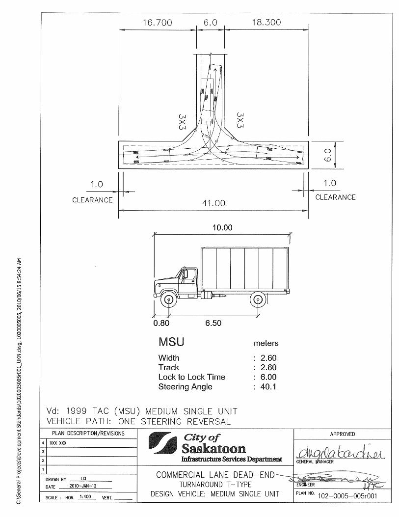
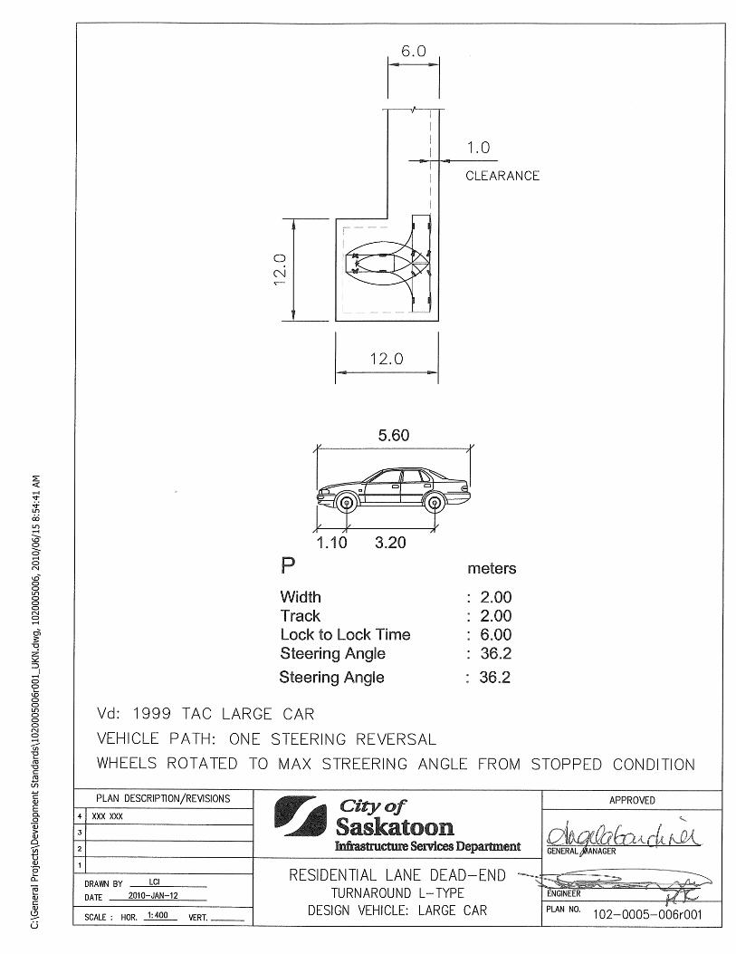
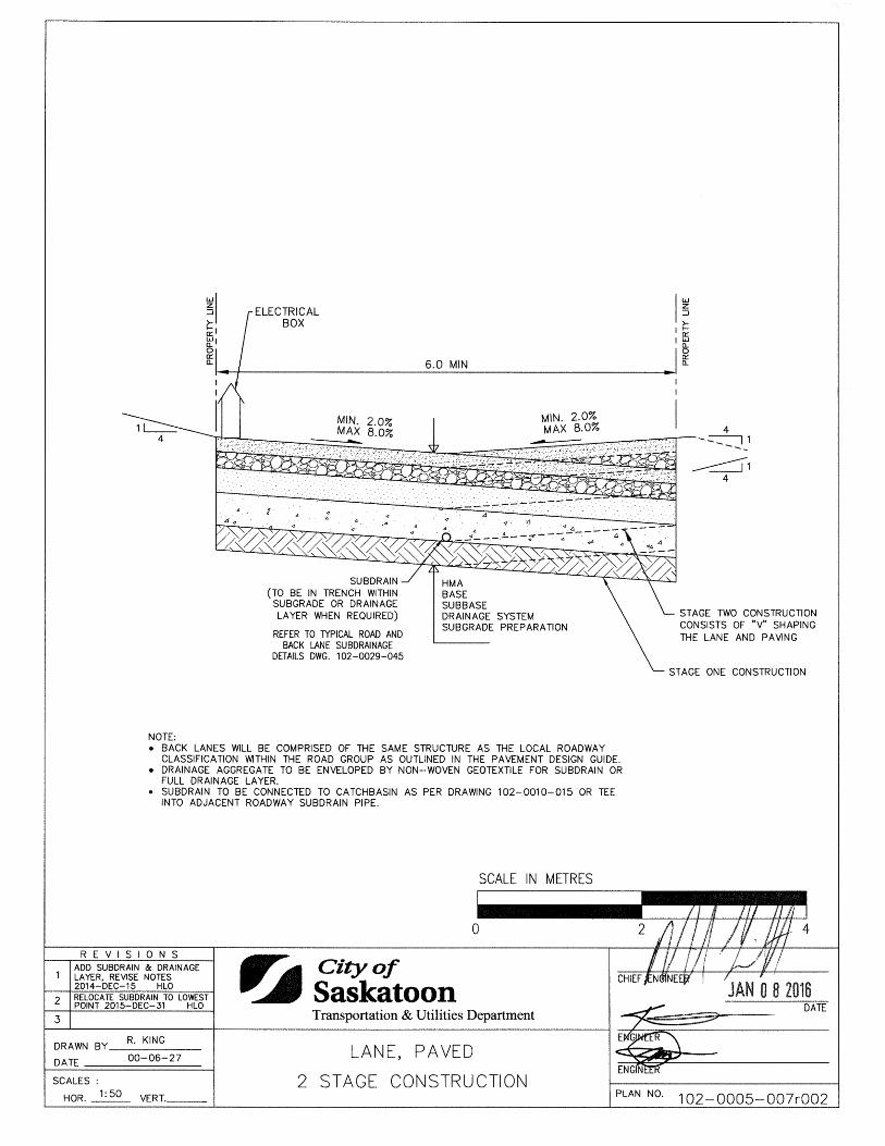
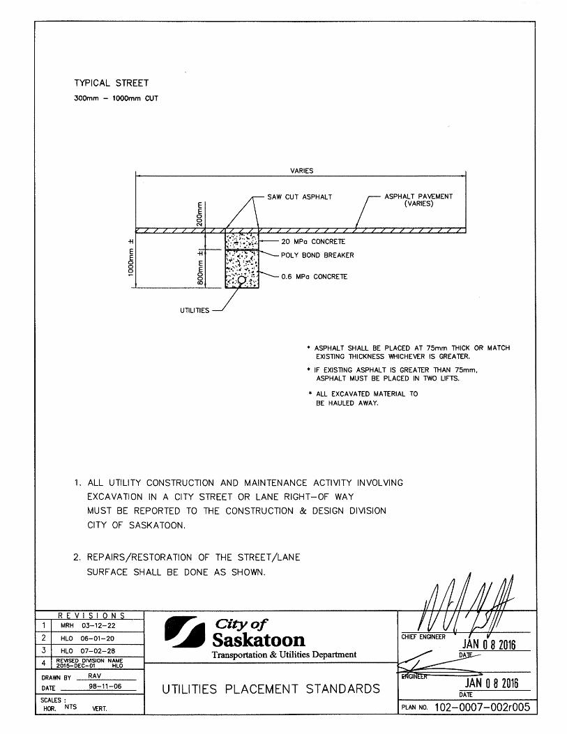
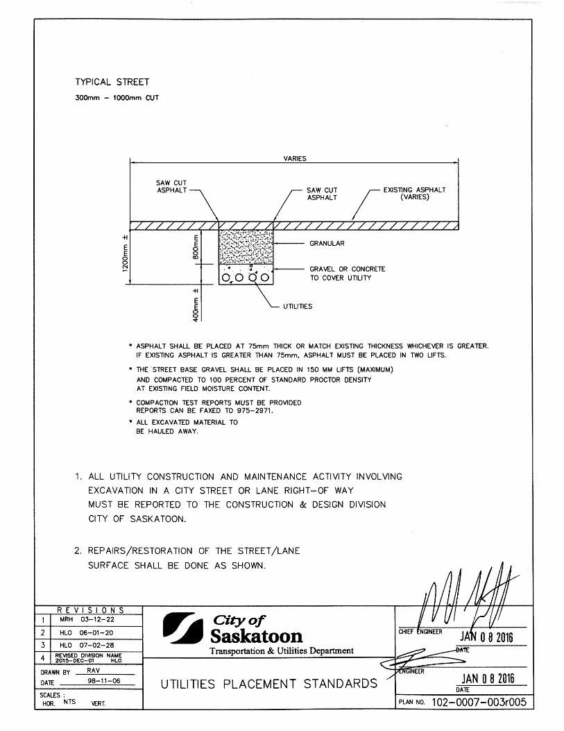
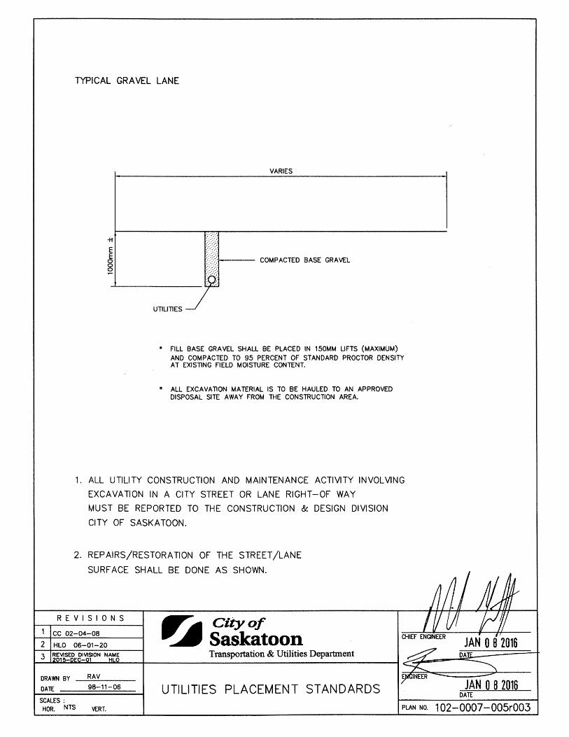
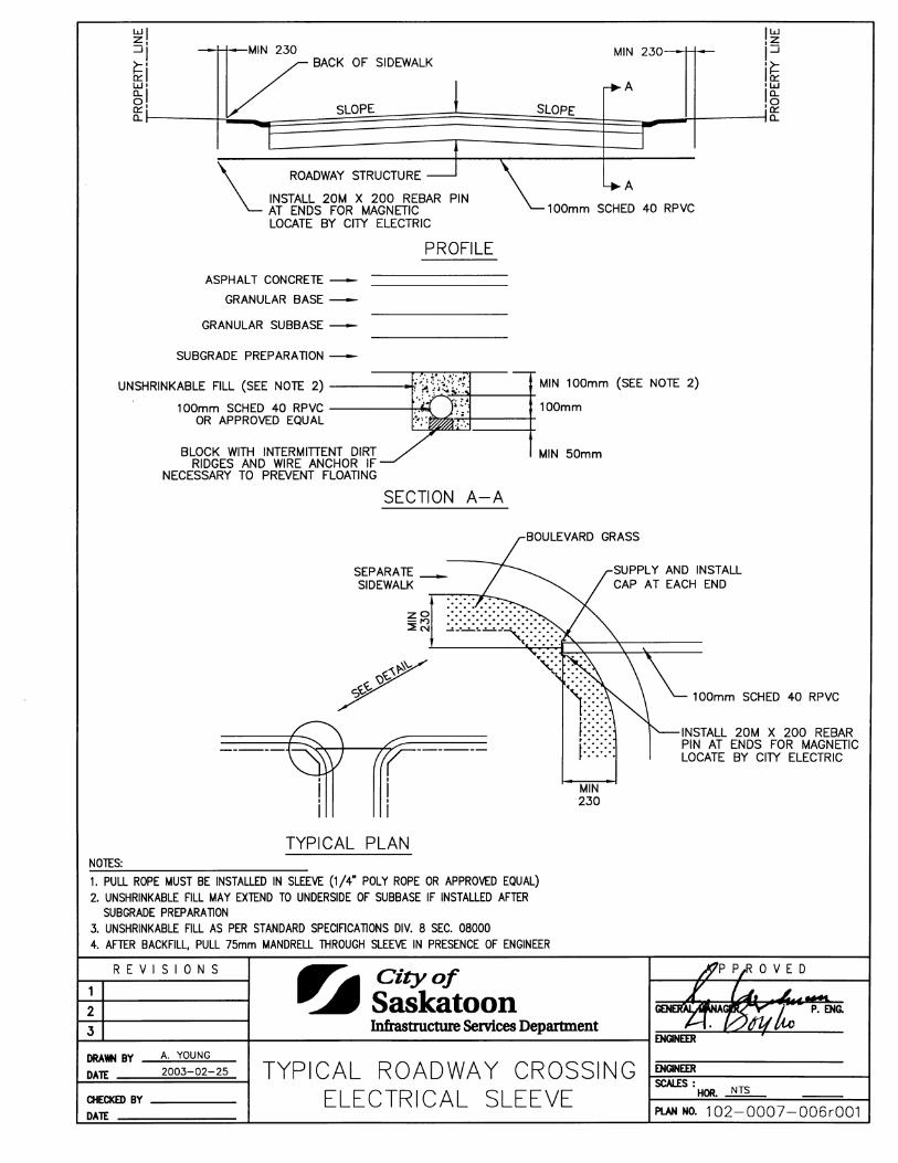
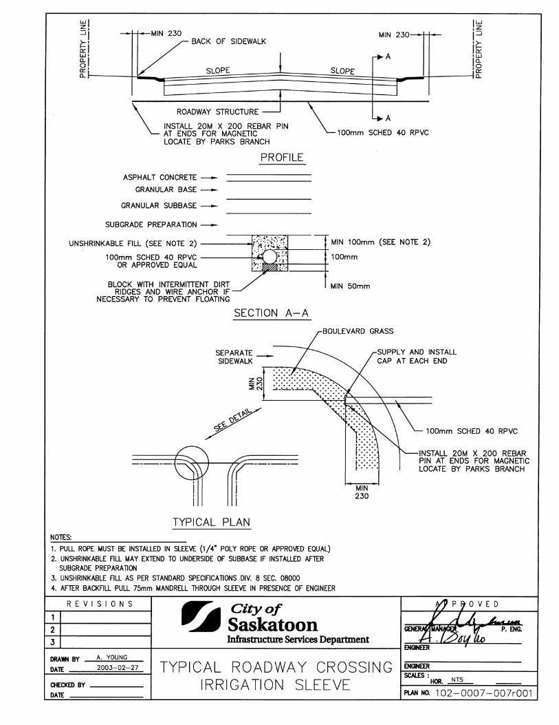
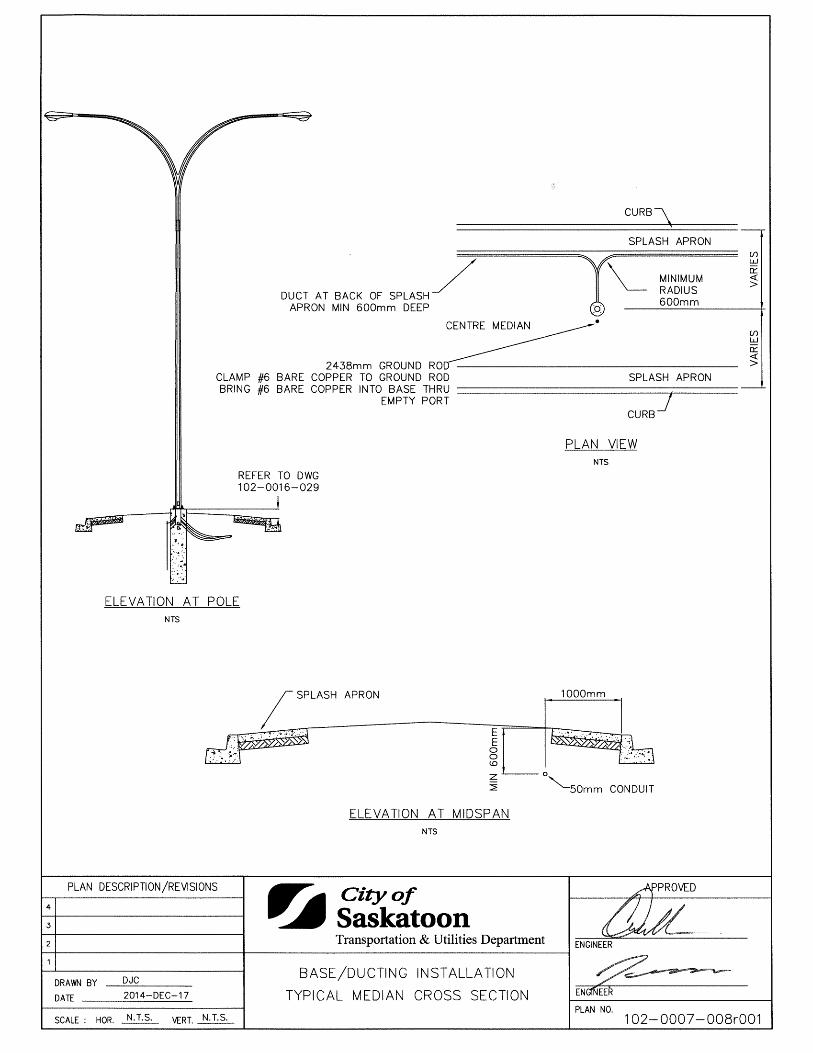
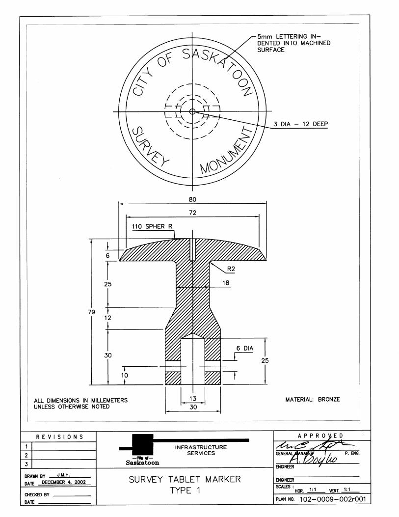
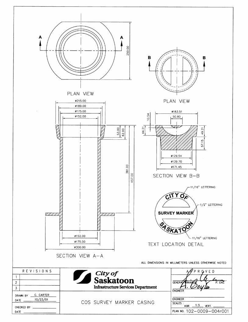
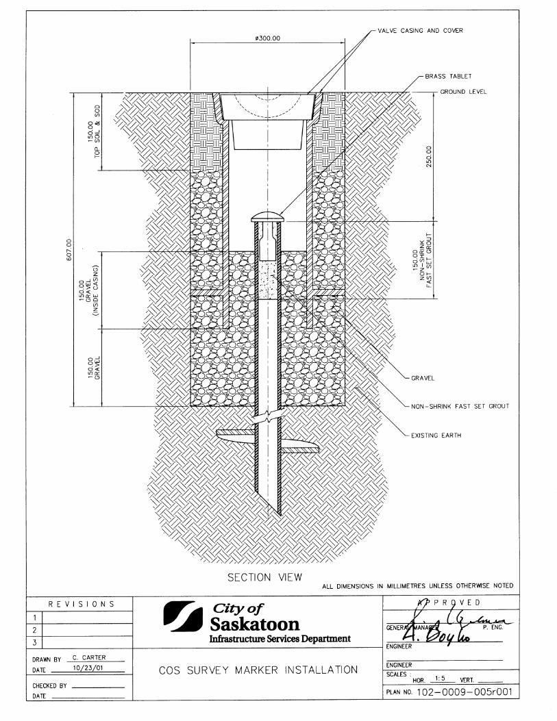
Chain Link Fence Type A 1020004005 Chain Link Fence Type A 1020004006 Lanes Lane, Paved - Typical Lane Cross Section 1020005002 Residential Lane Dead-End Turnaround T-Type: Large Car 1020005003 Residential Lane Dead-End Turnaround T-Type: Light Single Unit 1020005004 Commercial Lane Dead-End Turnaround T-Type: Medium Single Unit 1020005005 Residential Lane Dead-End Turnaround L-Type: Large Car 1020005006 Lane, Paved - 2 Stage Construction 1020005007 Medians Splash Apron 1020006001 Mountable Median Tip 1020006002 Median Ramp 1020006003 830 Median Barrier 1020006005 Traffic Calming Template Temporary Median Island 1020006006 Shallow Buried Utilities Utilities Placement Standards 1020007001 Utilities Placement Standards 1020007002 Utilities Placement Standards 1020007003 Utilities Placement Standards 1020007005 Typical Roadway Crossing Electrical Sleeve 1020007006 Typical Roadway Crossing Irrigation Sleeve 1020007007 Base/Ducting Installation - Typical Median Cross Section 1020007008 Streets Rubberized Asphalt Crack Sealant - Cross Section 1020008001 Surveying Specifications for Survey Stakes 1020009001 Survey Tablet Marker Type 1 1020009002 COS Survey Marker 1020009003 COS Survey Marker Casing 1020009004 COS Survey Marker Installation 1020009005
List of Standard Construction Specifications & Drawings Page 7 of 13
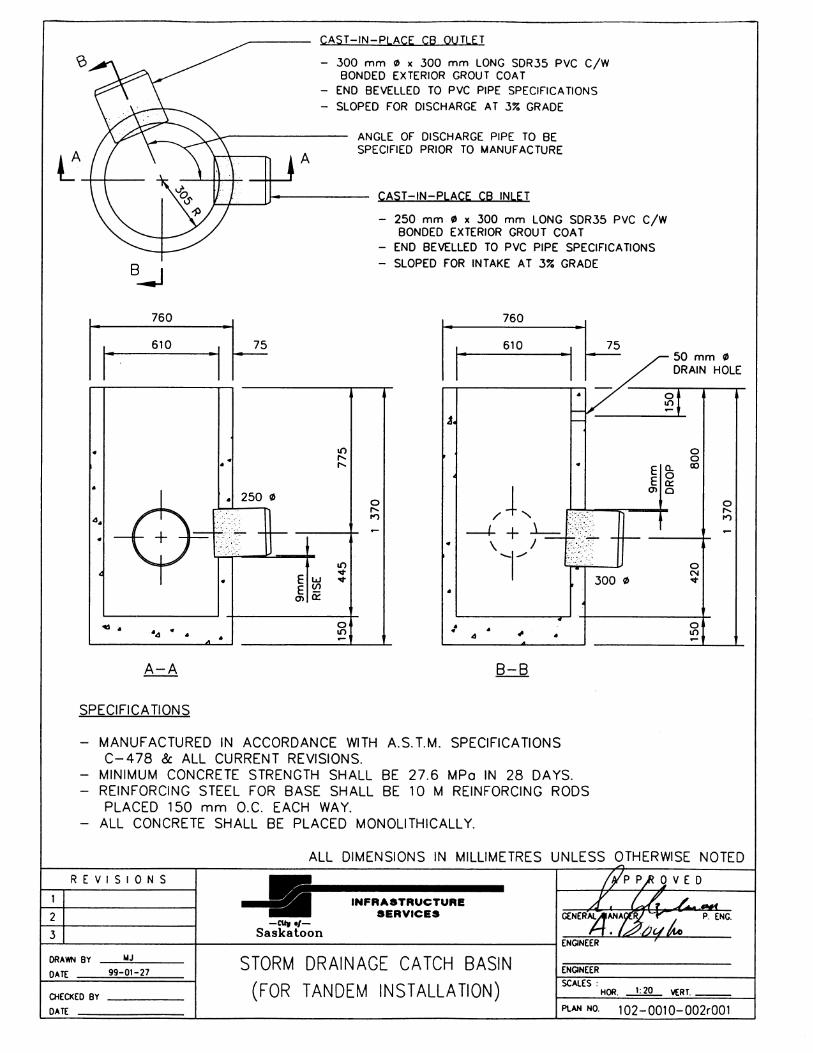
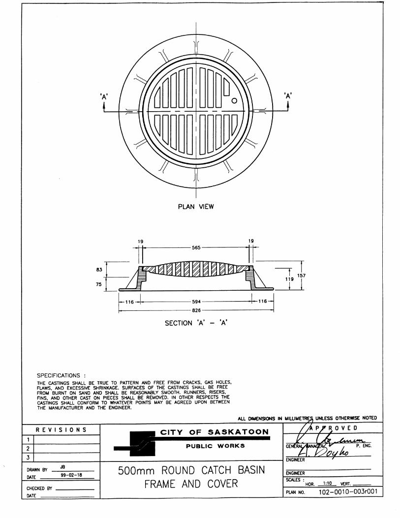
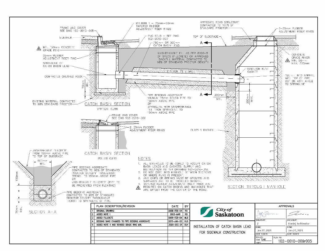
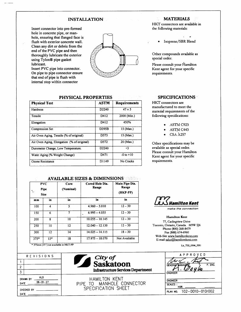
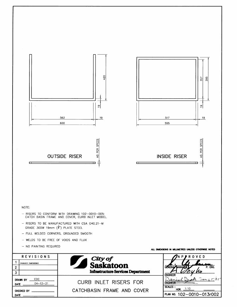
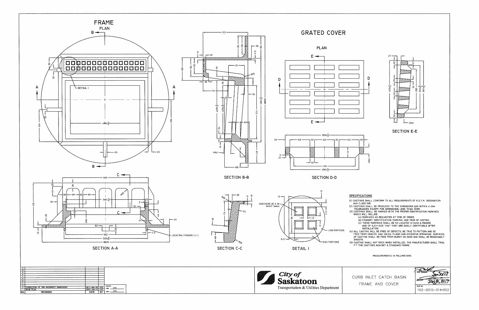
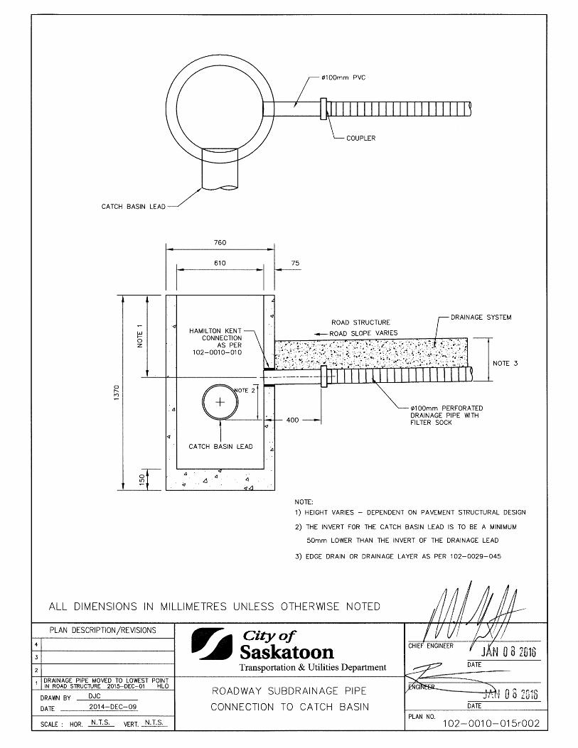
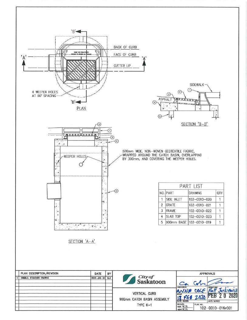
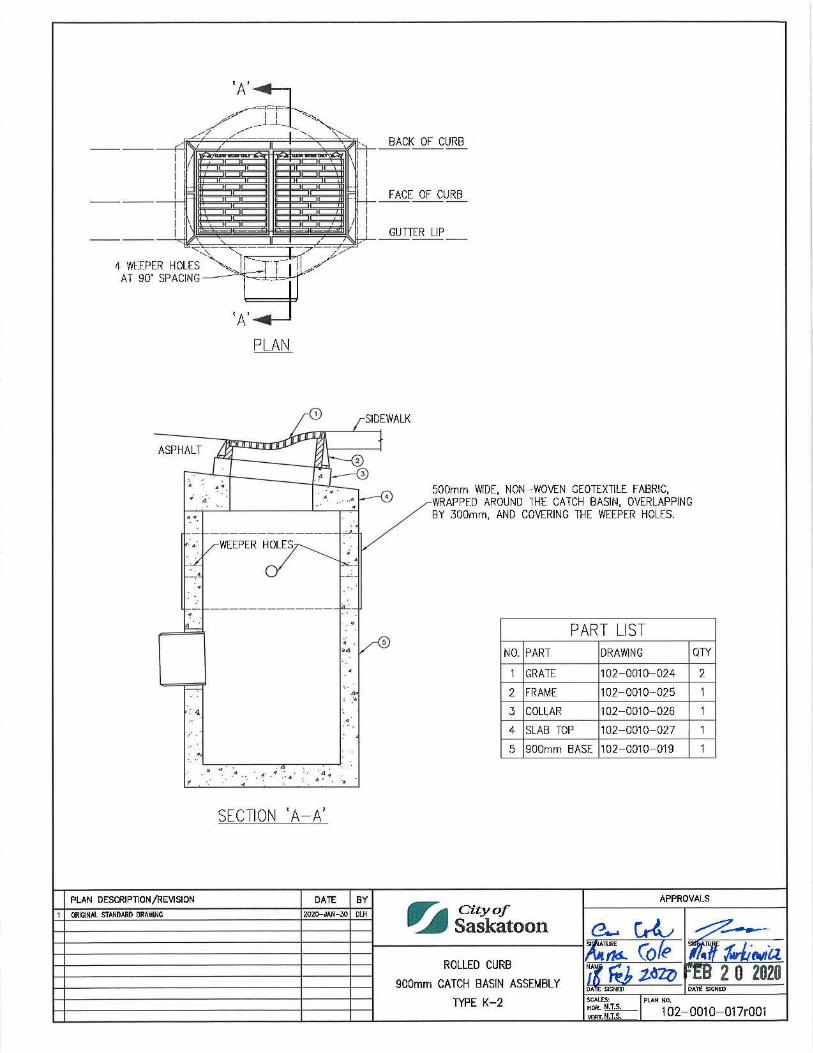
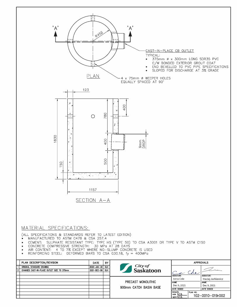
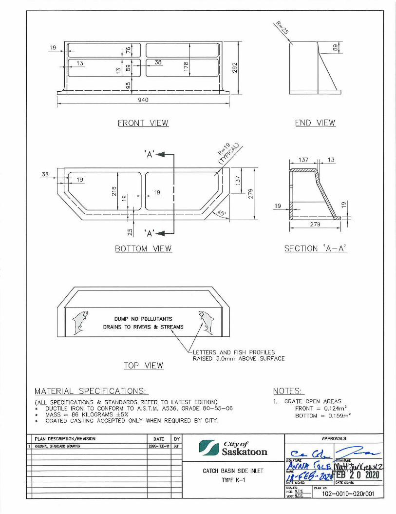
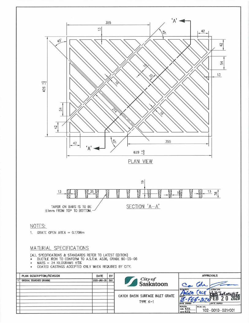
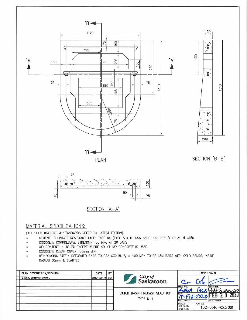
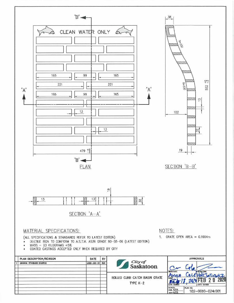
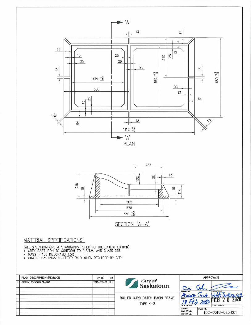
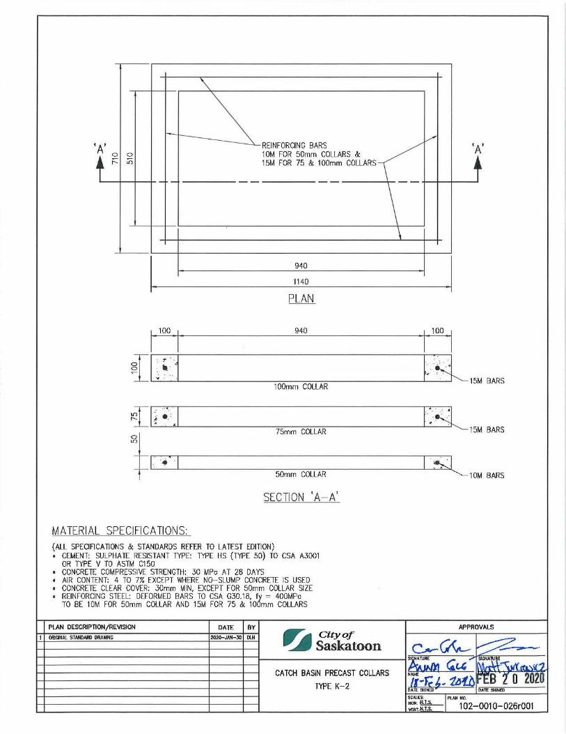
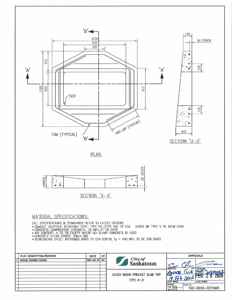
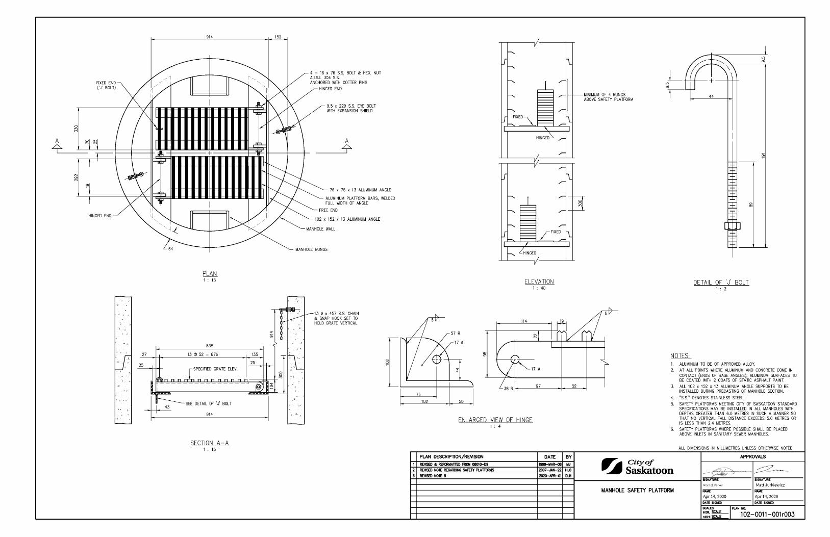
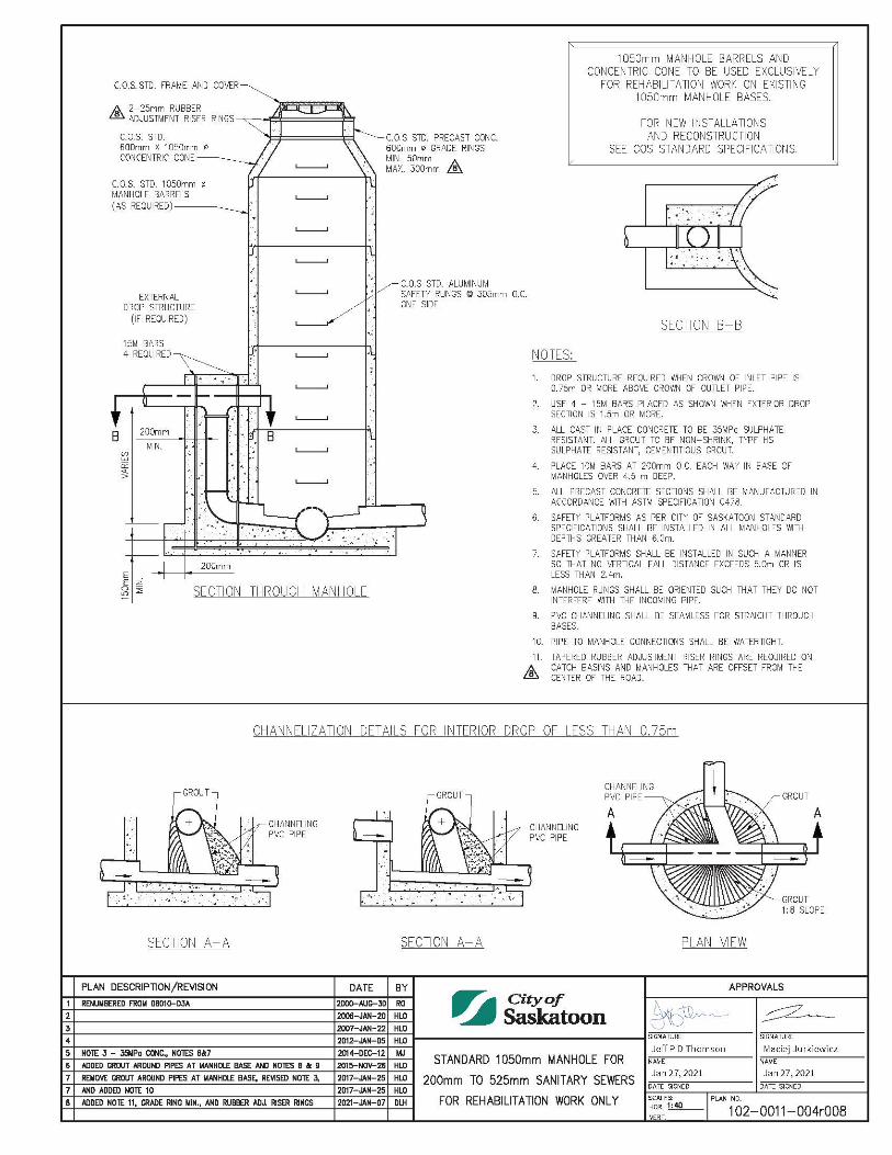
Catch Basins Storm Drainage Catch Basin for Tandem Installation 1020010002 500mm Round Catch Basin Frame and Cover 1020010003 Catch Basin Frame and Cover Surface Inlet Model 1020010004 Catch Basin Frame and Cover Curb Inlet Model 1020010005 Rolled Curb Catch Basin 1020010006 Precast Reinforced Round Catch Basin 1020010007 Installation of Catch Basin Lead for Sidewalk Construction 1020010009 Hamilton Kent Pipe to Manhole Connector Specification Sheet 1020010010 Typical Catch Basin Conversion at Driveway or Crossing 1020010012 Curb Inlet Risers for Catch Basin Frame and Cover 1020010013 Curb Inlet Catch Basin Frame and Cover 1020010014 Roadway Subdrainage Pipe Connection to Catchbasin 1020010015 Vertical Curb 900mm Catch Basin Assembly Type K-1 1020010016 Rolled Curb 900mm Catch Basin Assembly Type K-2 1020010017 Surface Inlet 900mm Catch Basin Assembly Type K-3 1020010018 Precast Monolithic 900mm Catch Basin Base 1020010019 Catch Basin Side Inlet Type K-1 1020010020 Catch Basin Surface Inlet Grate Type K-1 1020010021 Catch Basin Surface Inlet Frame Type K-1 1020010022 Catch Basin Precast Slab Top Type K-1 1020010023 Rolled Curb Catch Basin Grate Type K-2 1020010024 Rolled Curb Catch Basin Frame Type K-2 1020010025 Catch Basin Precast Collars Type K-2 1020010026 Catch Basin Precast Slab Top Type K-2 1020010027 Catch Basin Precast Slab Top Type K-3 1020010028 Manholes Manhole Safety Platform 1020011001 Standard 1050mm Manhole for 200mm to 525mm Sanitary Sewers - For Rehabilitation Work Only 1020011004
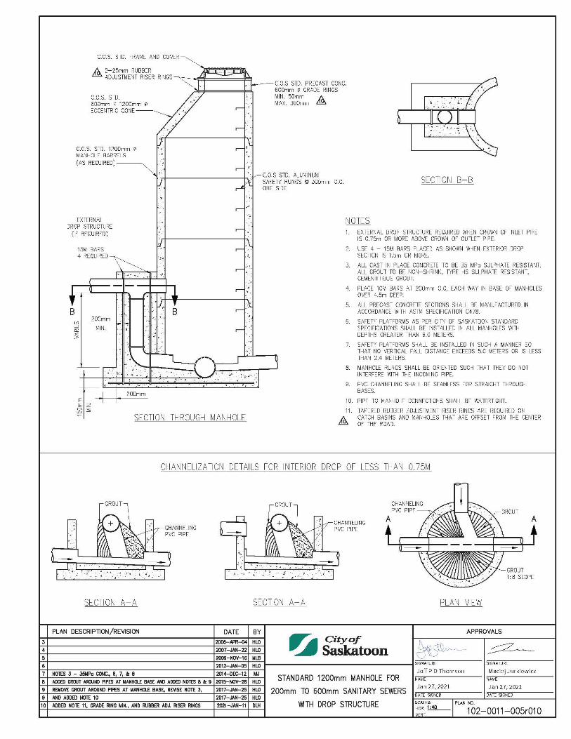
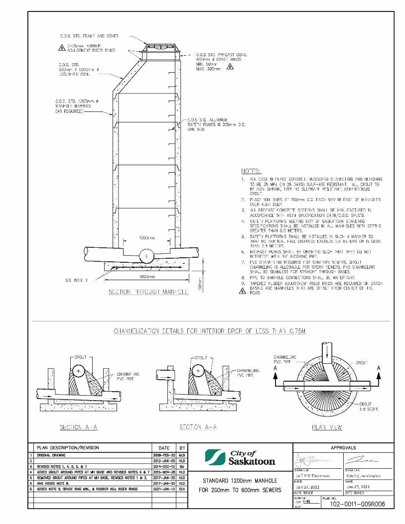
Standard 1200mm manhole for 200mm to 600mm Sanitary Sewers With Drop Structure 1020011005
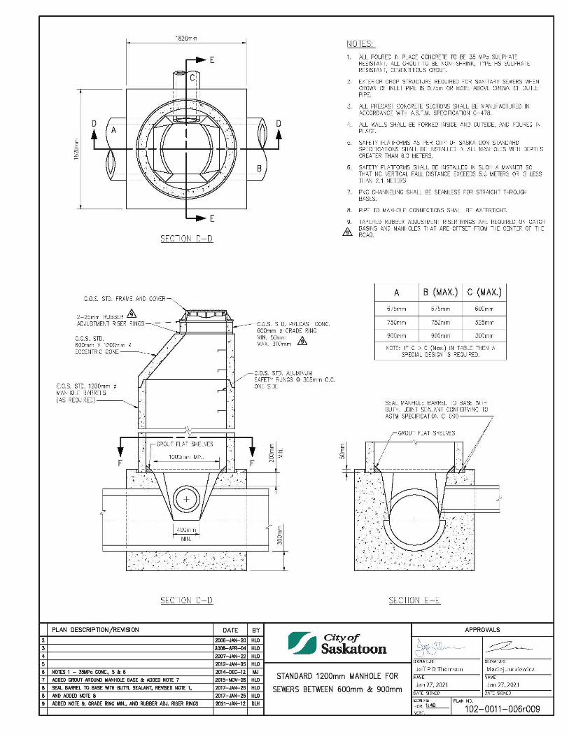
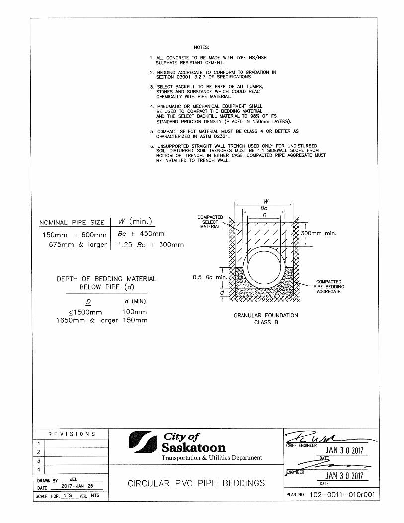
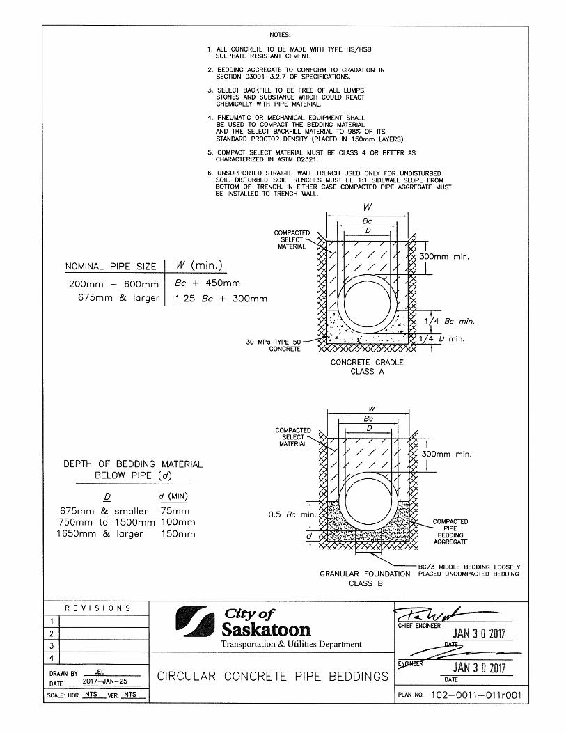
Standard 1200mm Manhole for 675mm to 900mm Sewers 1020011006 Drop Structure Manhole for Connection to Trunk Storm Sewers 1020011008 Standard 1200mm Manhole for 200mm to 600mm Sewers 1020011009 Circular PVC Pipe Beddings 1020011010 Circular Concrete Pipe Beddings 1020011011
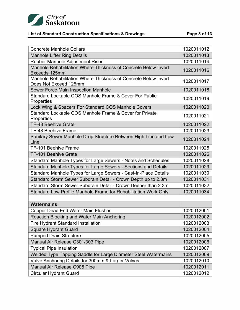
List of Standard Construction Specifications & Drawings Page 8 of 13
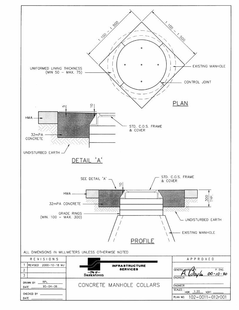
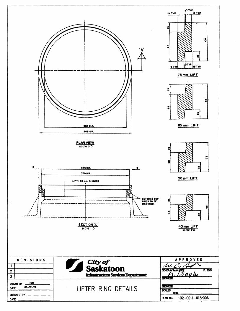
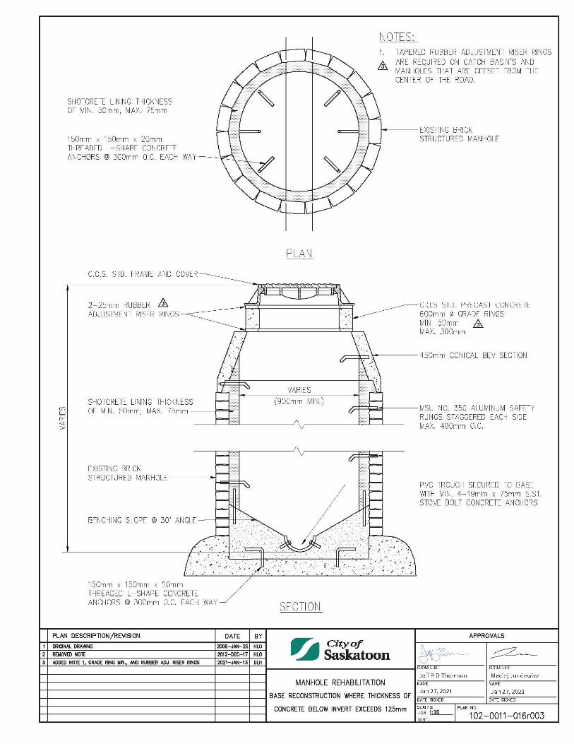
Concrete Manhole Collars 1020011012 Manhole Lifter Ring Details 1020011013 Rubber Manhole Adjustment Riser 1020011014 Manhole Rehabilitation Where Thickness of Concrete Below Invert Exceeds 125mm 1020011016
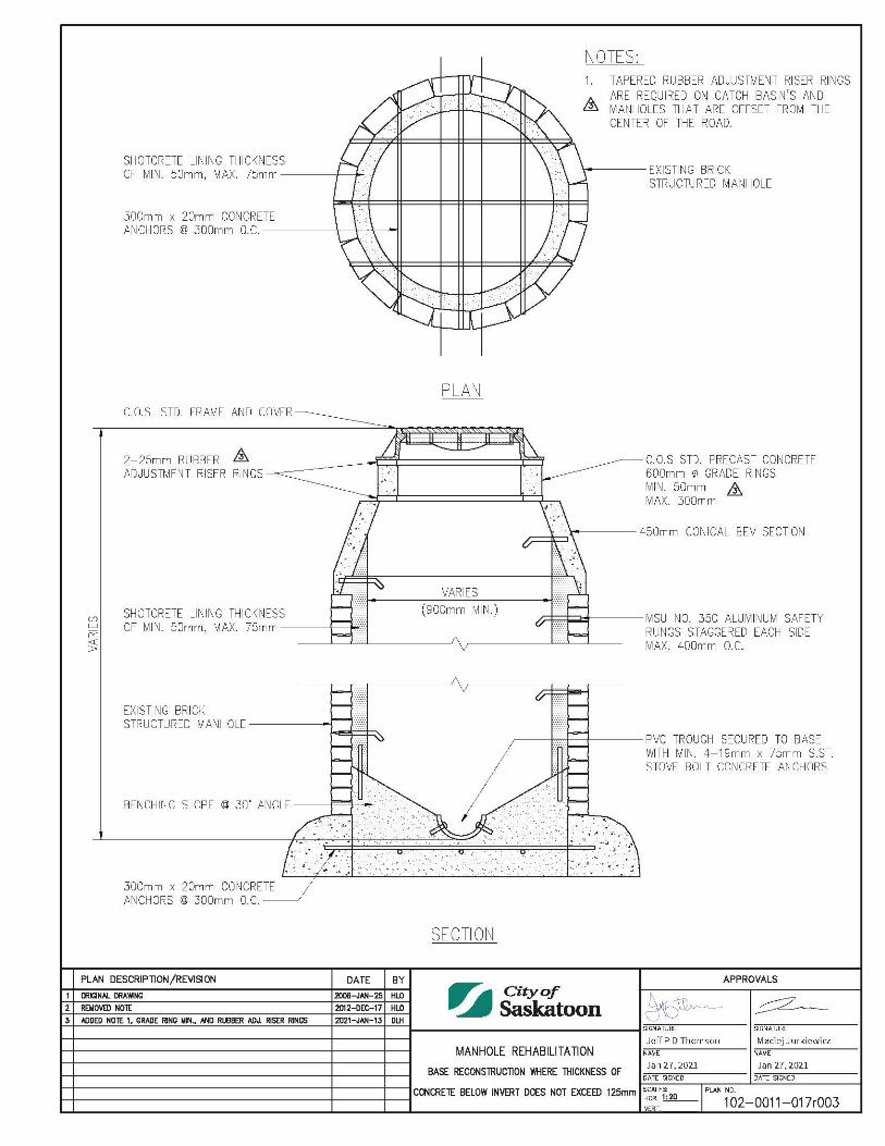
Manhole Rehabilitation Where Thickness of Concrete Below Invert Does Not Exceed 125mm 1020011017
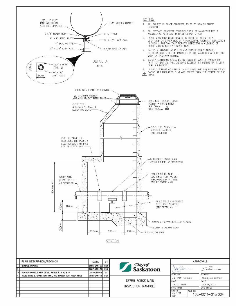
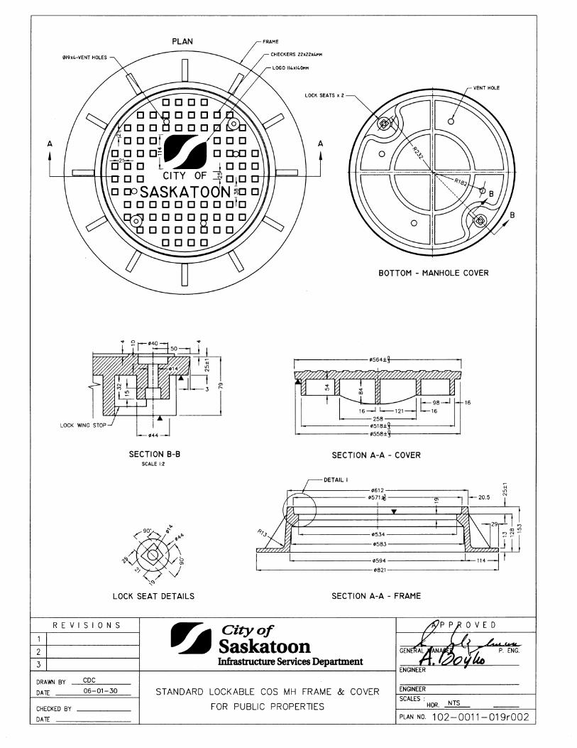
Sewer Force Main Inspection Manhole 1020011018 Standard Lockable COS Manhole Frame & Cover For Public Properties 1020011019
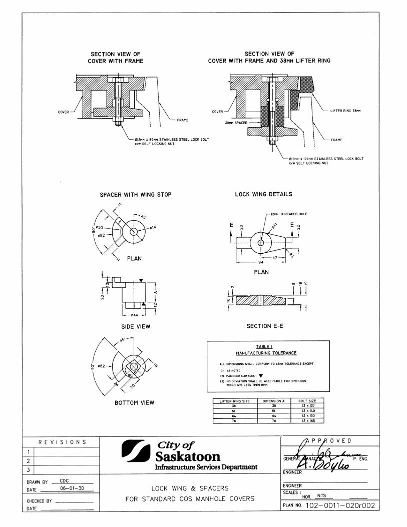
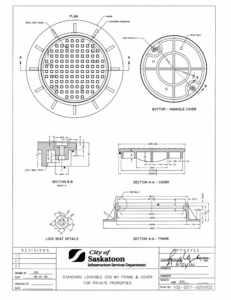
Lock Wing & Spacers For Standard COS Manhole Covers 1020011020 Standard Lockable COS Manhole Frame & Cover for Private Properties 1020011021
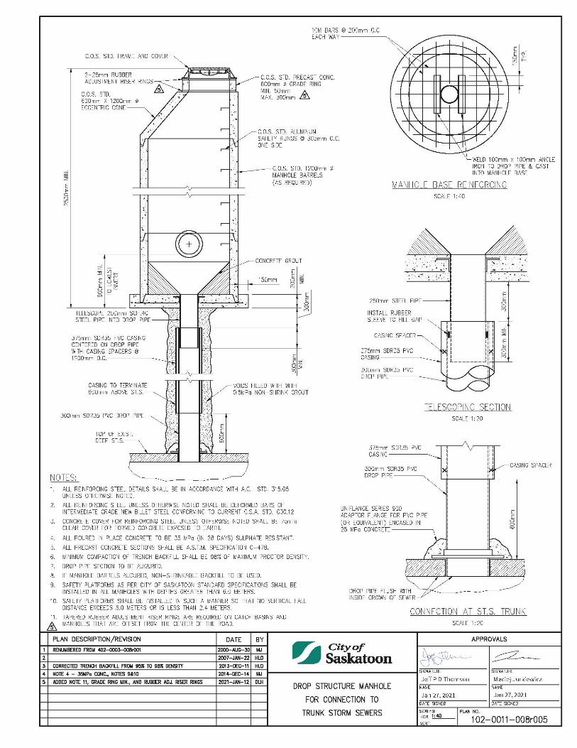
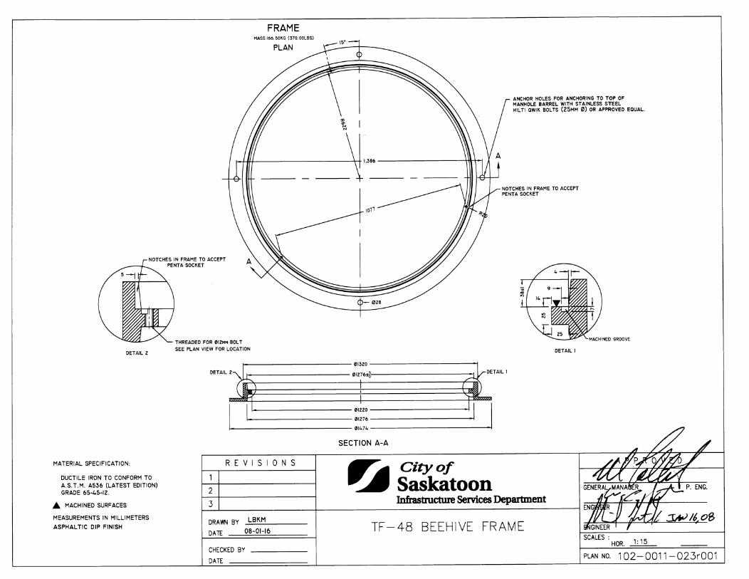
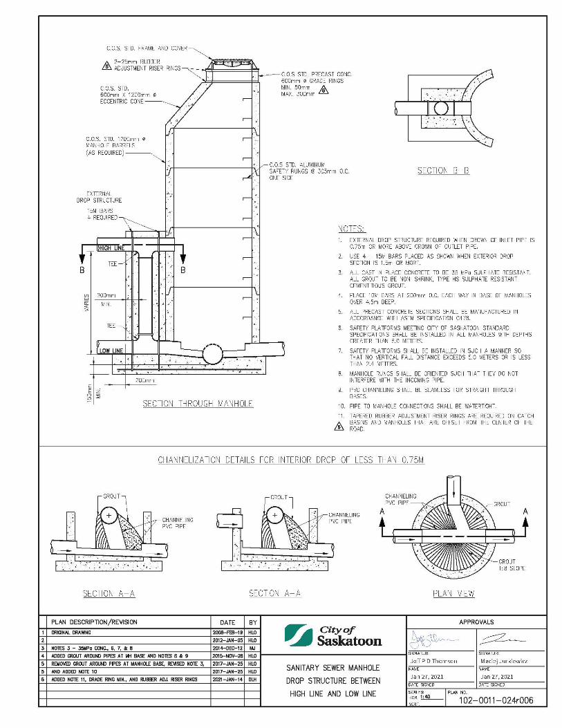
TF-48 Beehive Grate 1020011022 TF-48 Beehive Frame 1020011023 Sanitary Sewer Manhole Drop Structure Between High Line and Low Line 1020011024
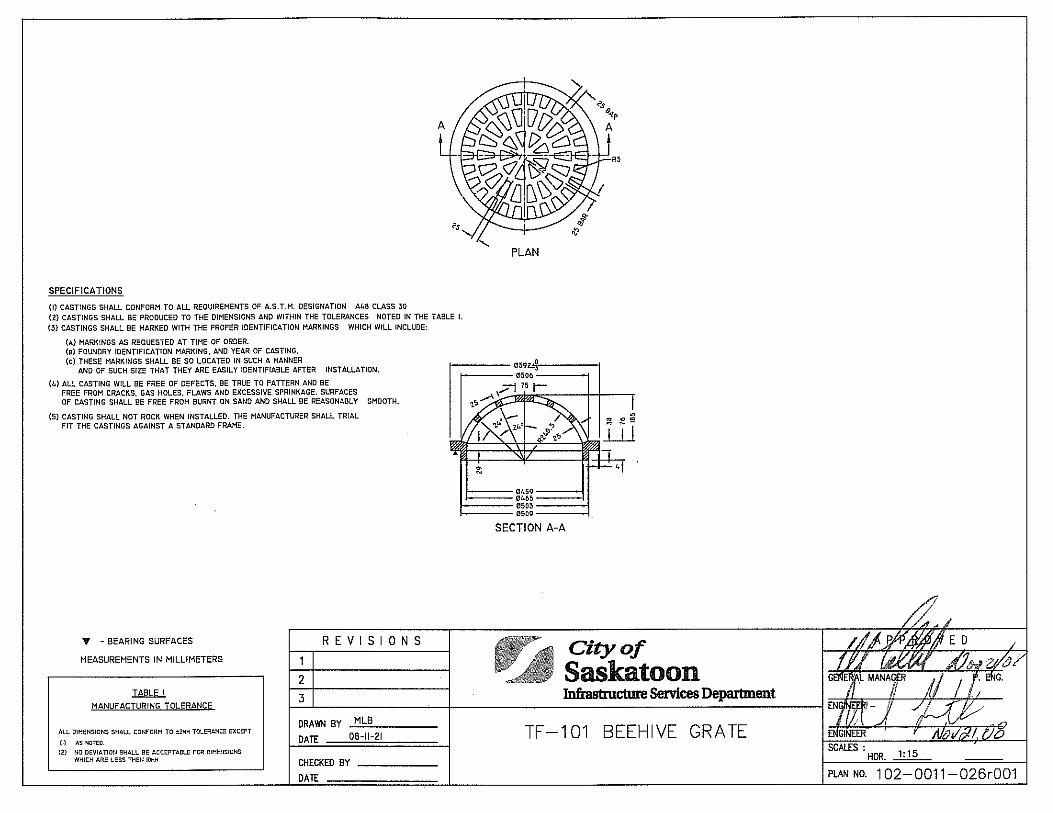
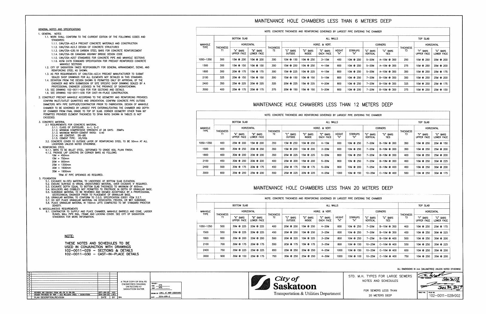
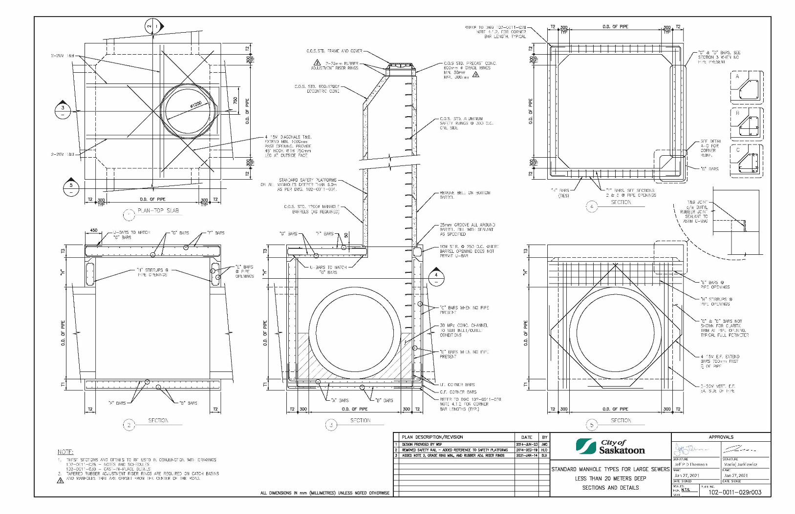
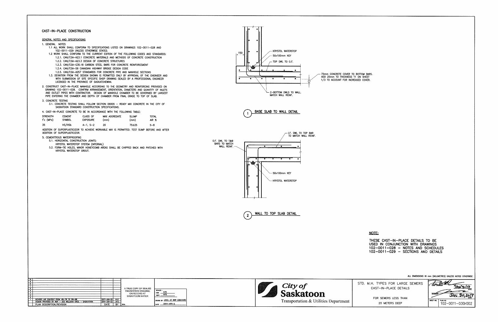
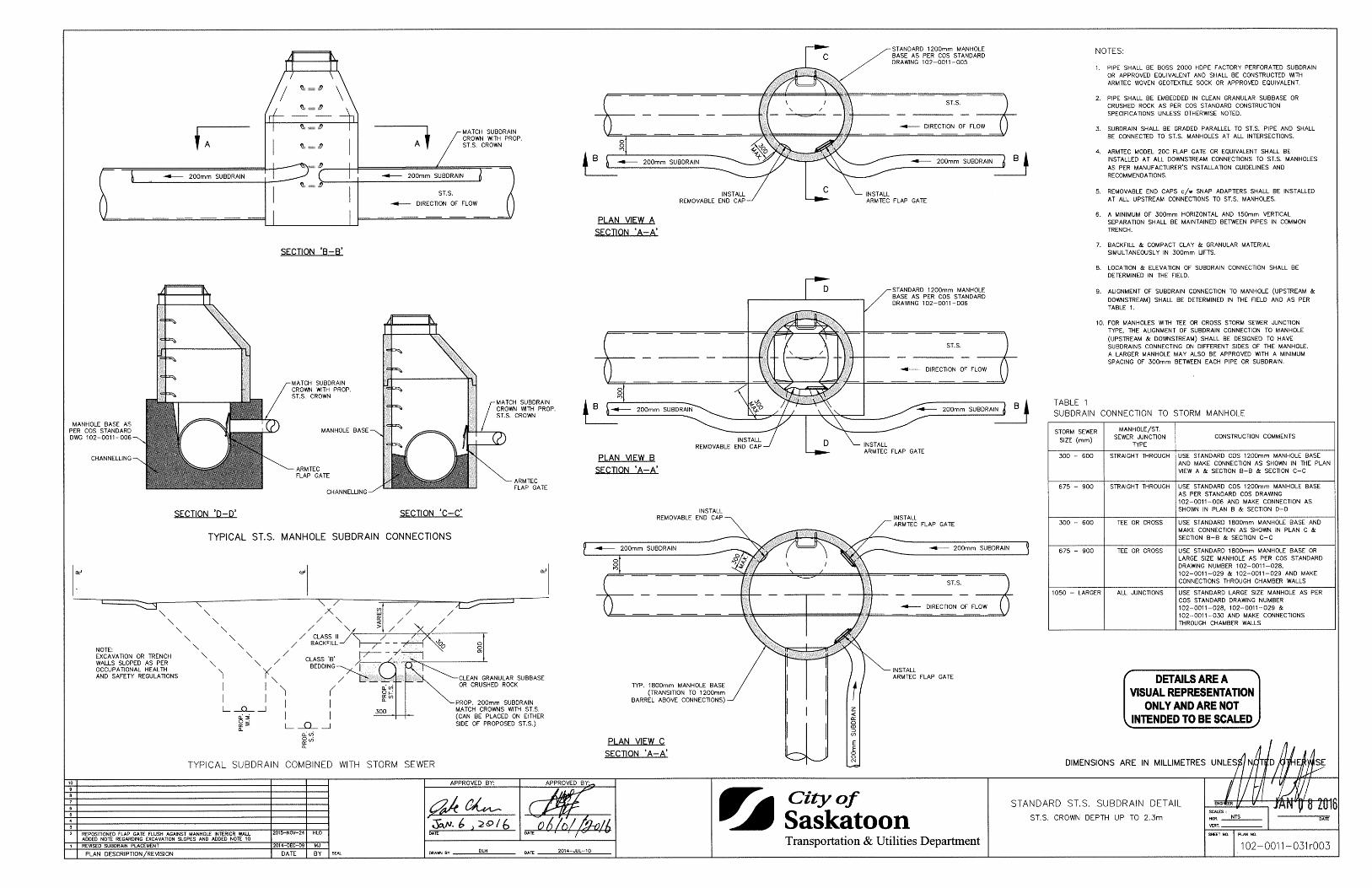
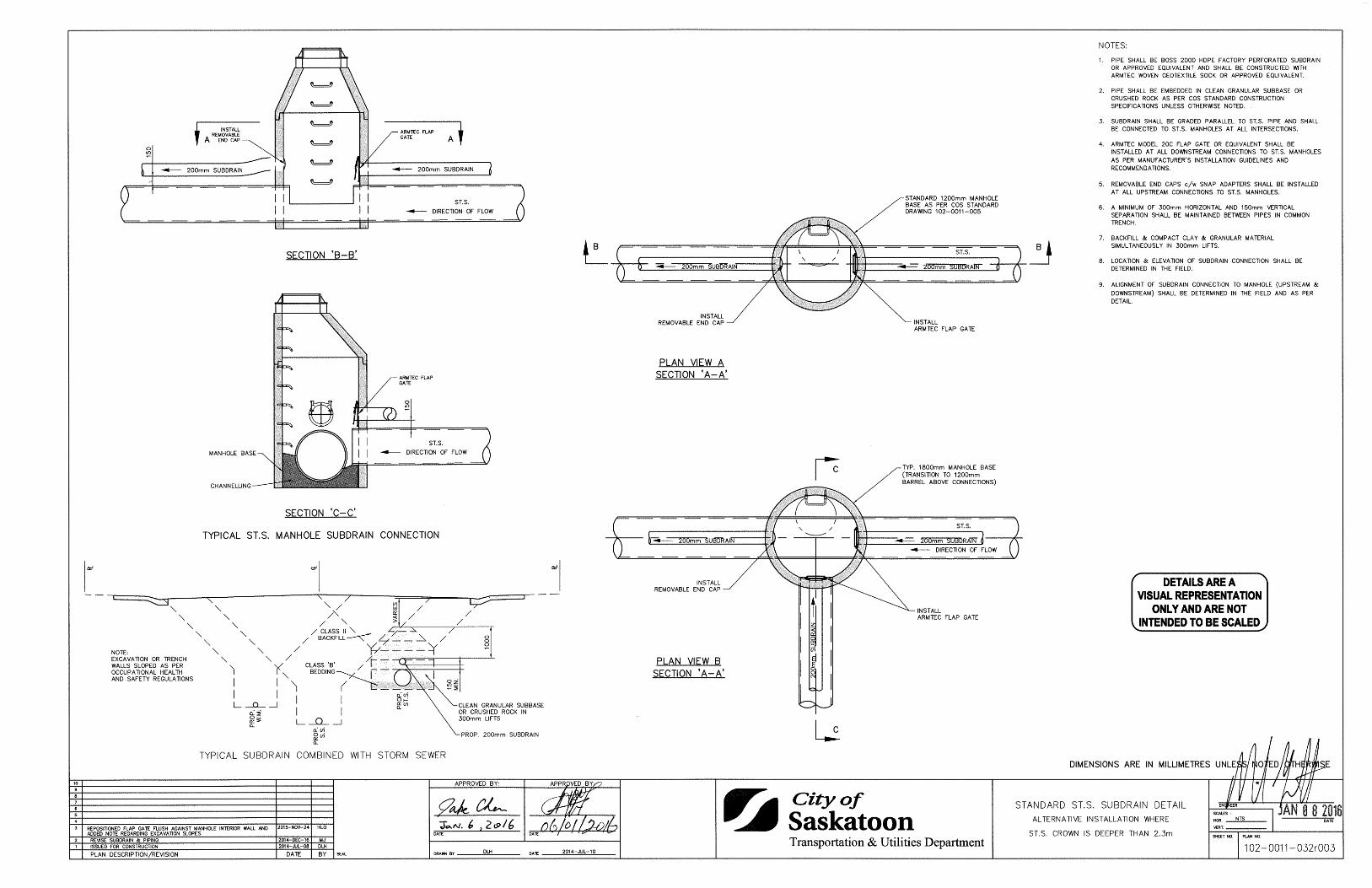
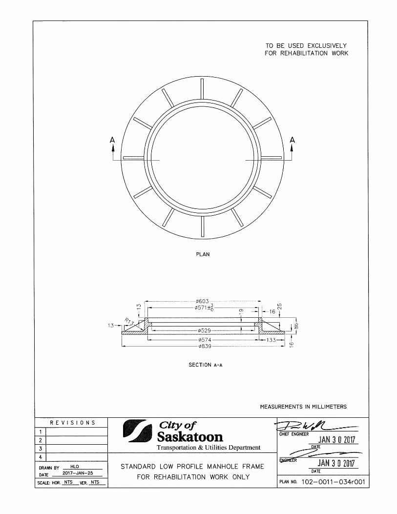
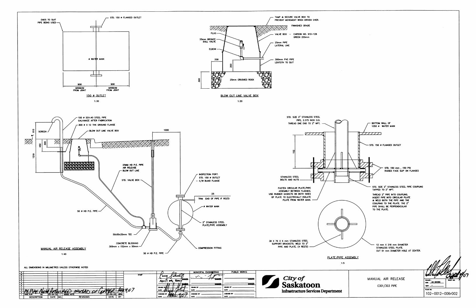
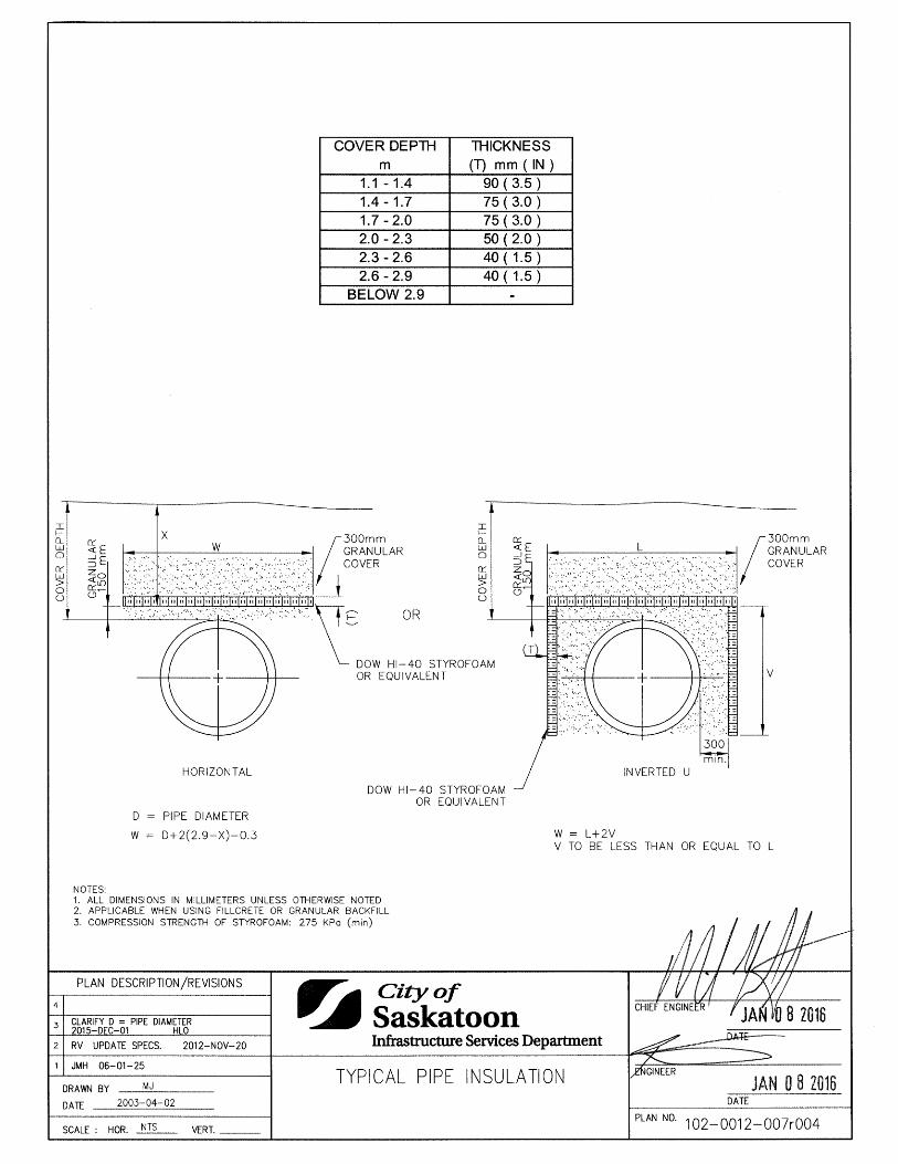
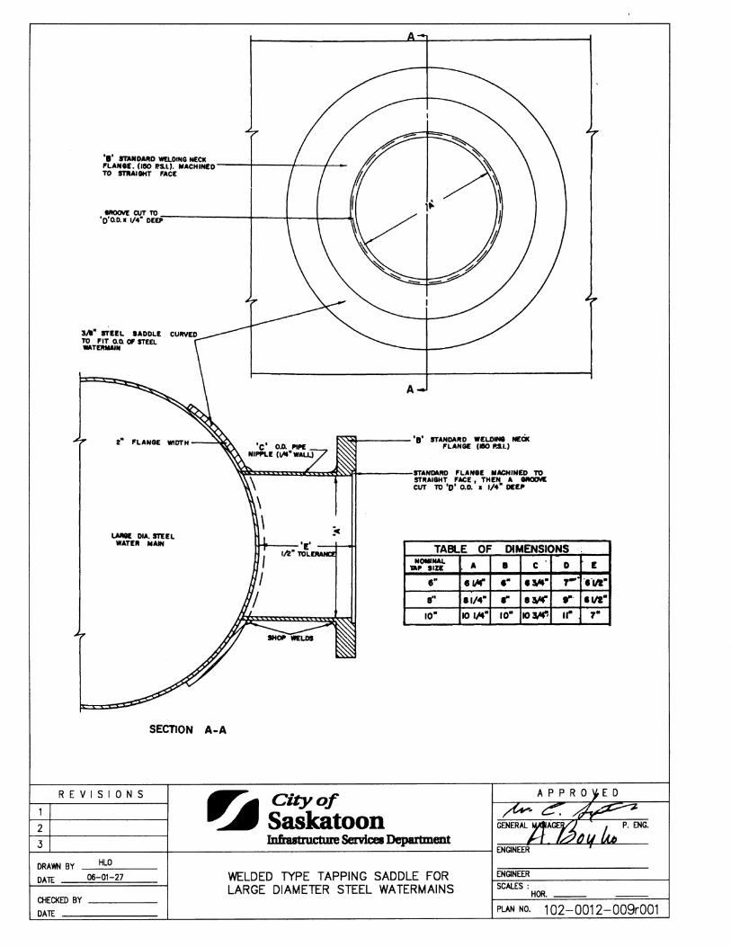
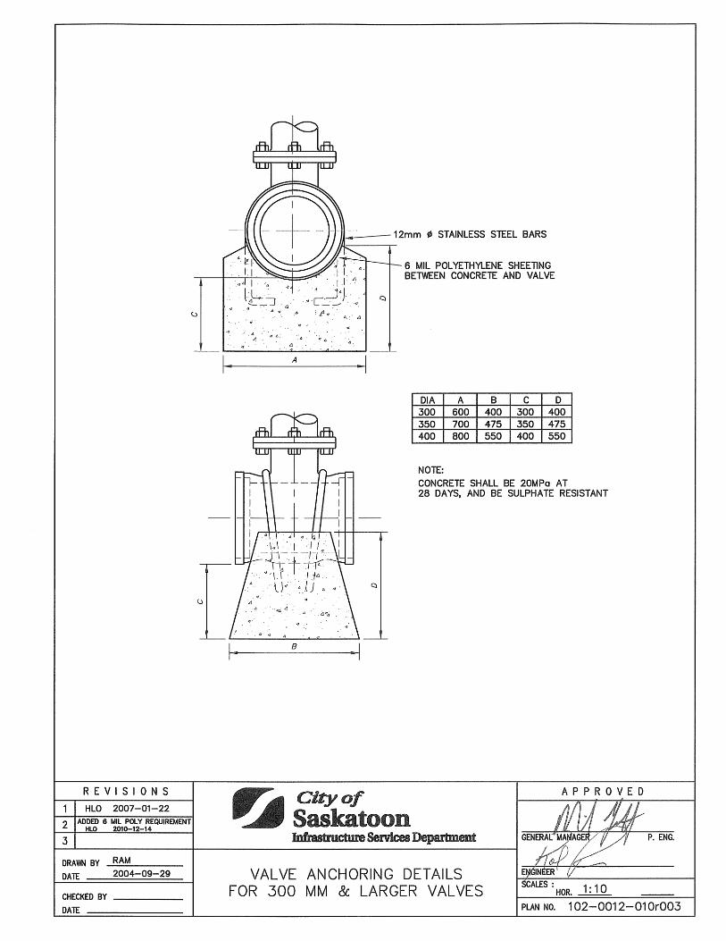
TF-101 Beehive Frame 1020011025 TF-101 Beehive Grate 1020011026 Standard Manhole Types for Large Sewers - Notes and Schedules 1020011028 Standard Manhole Types for Large Sewers - Sections and Details 1020011029 Standard Manhole Types for Large Sewers - Cast-In-Place Details 1020011030 Standard Storm Sewer Subdrain Detail - Crown Depth up to 2.3m 1020011031 Standard Storm Sewer Subdrain Detail - Crown Deeper than 2.3m 1020011032 Standard Low Profile Manhole Frame for Rehabilitation Work Only 1020011034 Watermains Copper Dead End Water Main Flusher 1020012001 Reaction Blocking and Water Main Anchoring 1020012002 Fire Hydrant Standard Installation 1020012003 Square Hydrant Guard 1020012004 Pumped Drain Structure 1020012005 Manual Air Release C301/303 Pipe 1020012006 Typical Pipe Insulation 1020012007 Welded Type Tapping Saddle for Large Diameter Steel Watermains 1020012009 Valve Anchoring Details for 300mm & Larger Valves 1020012010 Manual Air Release C905 Pipe 1020012011 Circular Hydrant Guard 1020012012
List of Standard Construction Specifications & Drawings Page 9 of 13
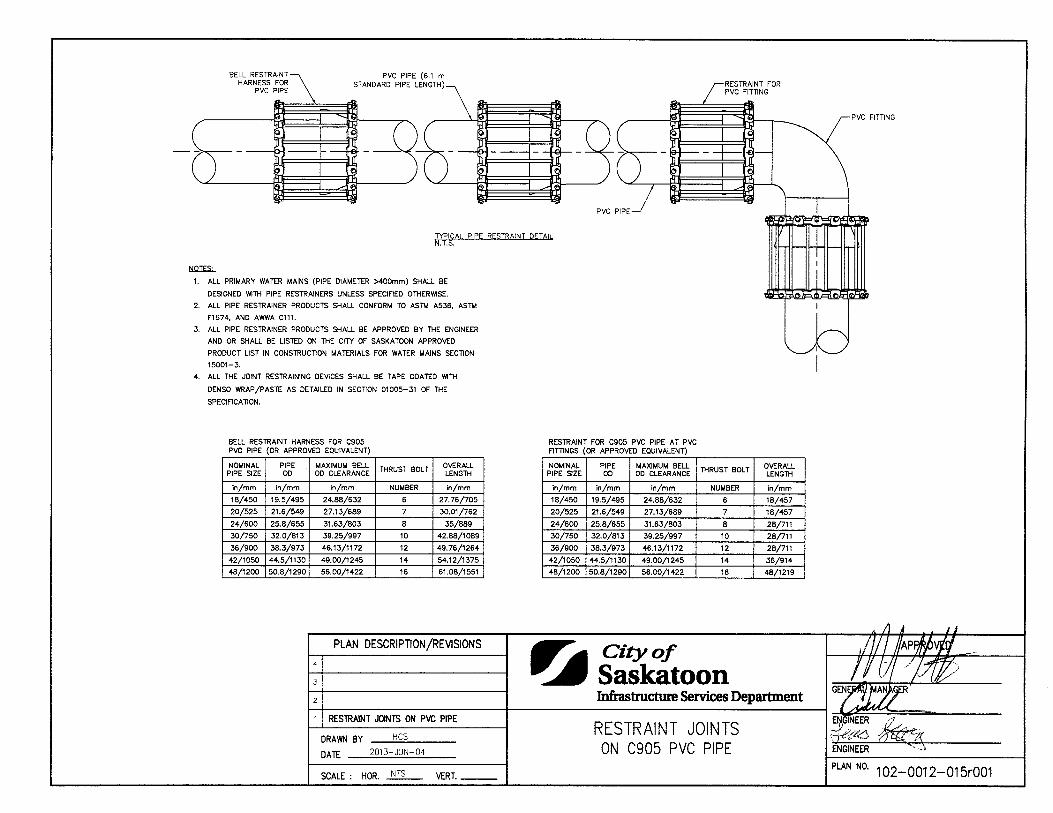
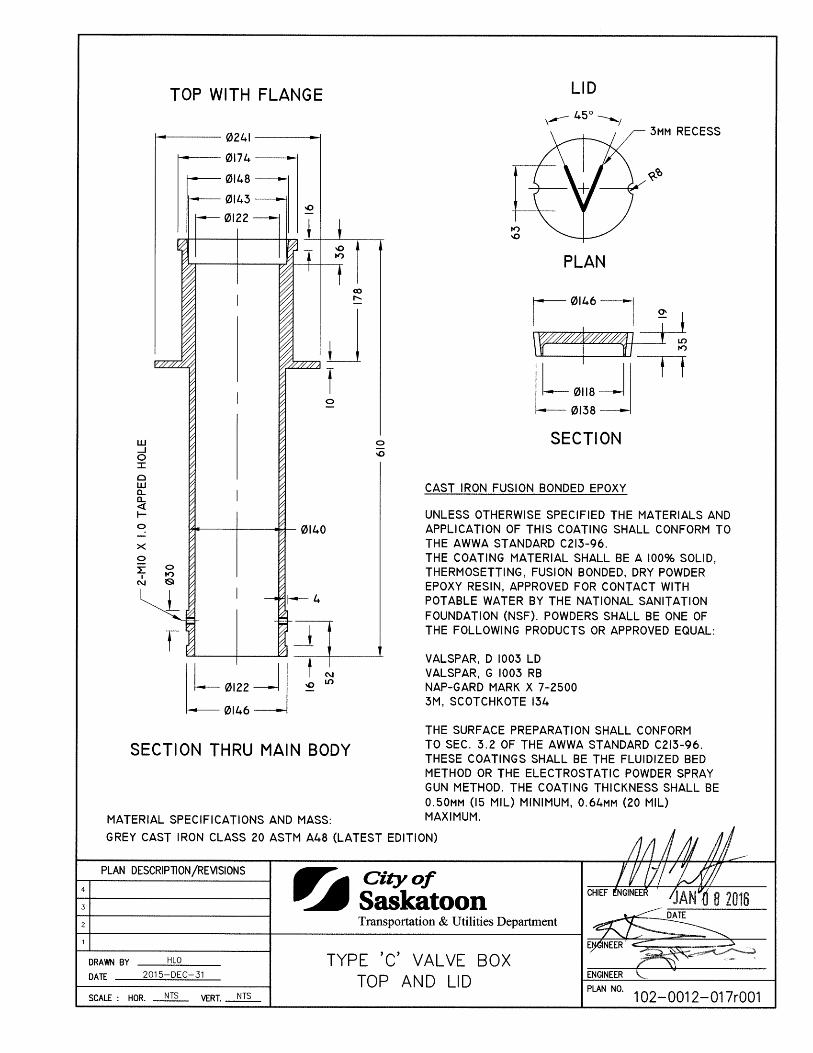
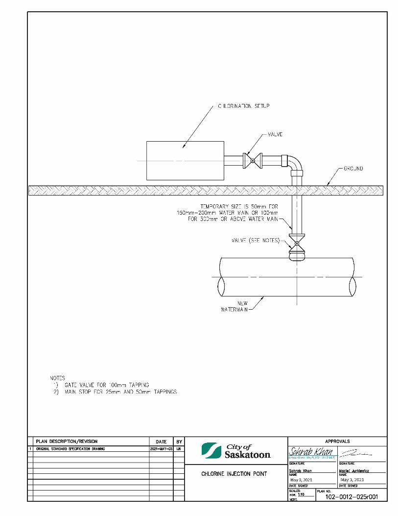
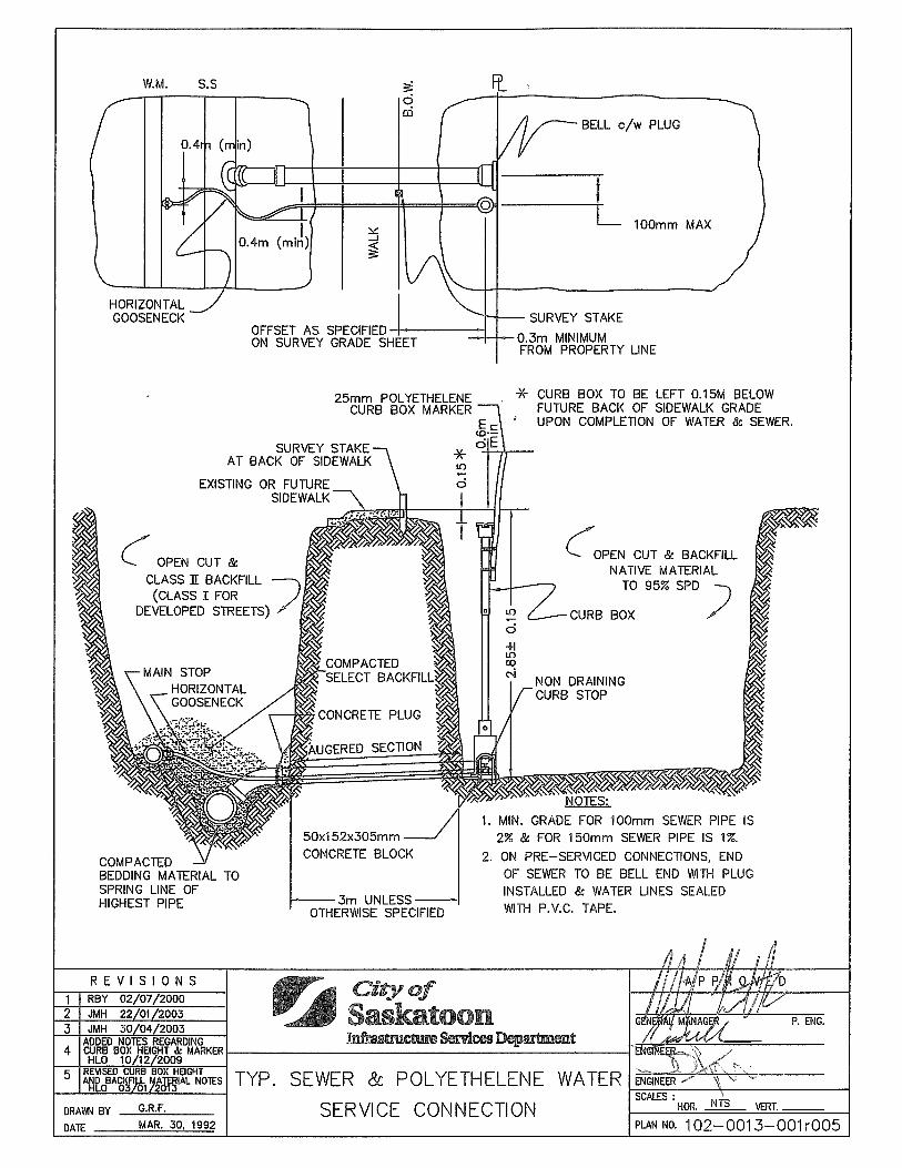
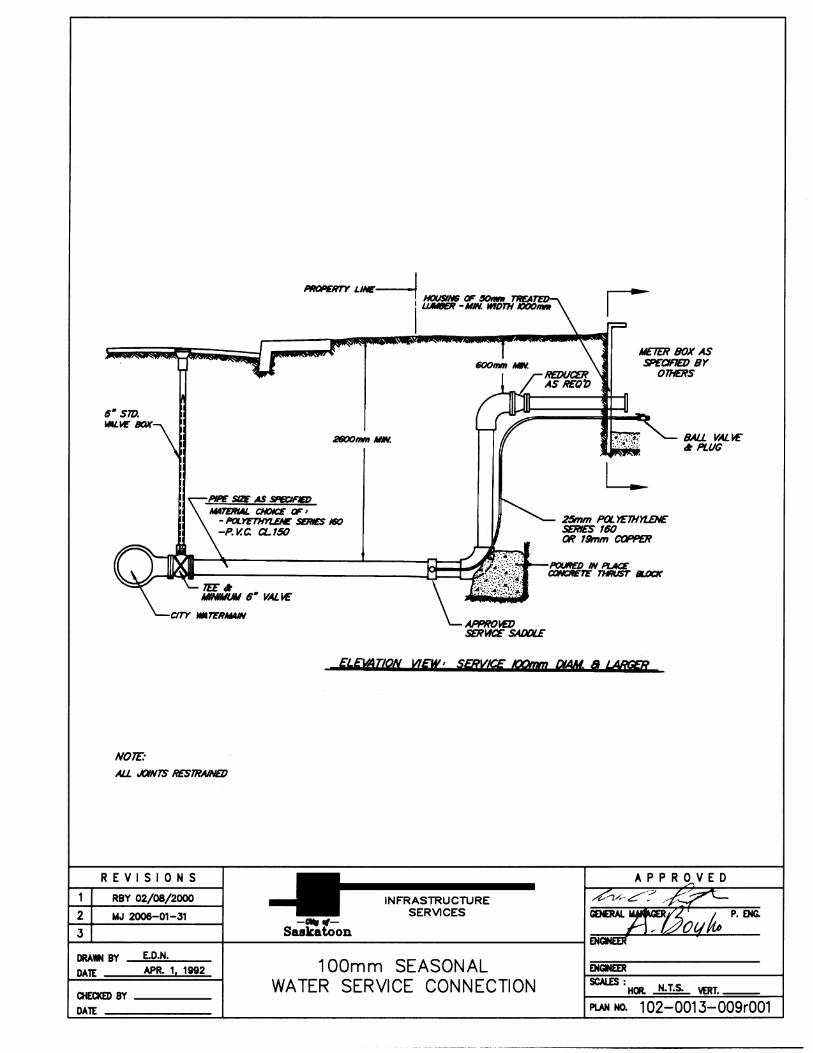
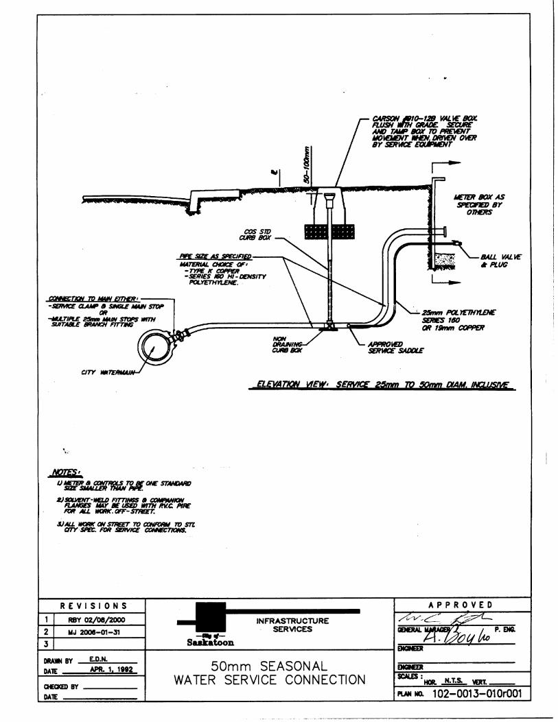
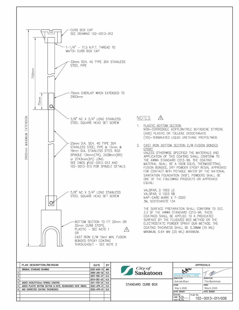
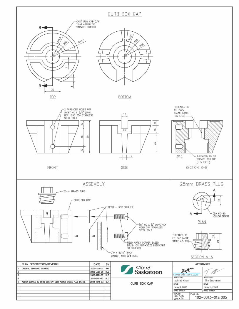
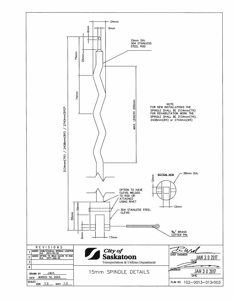
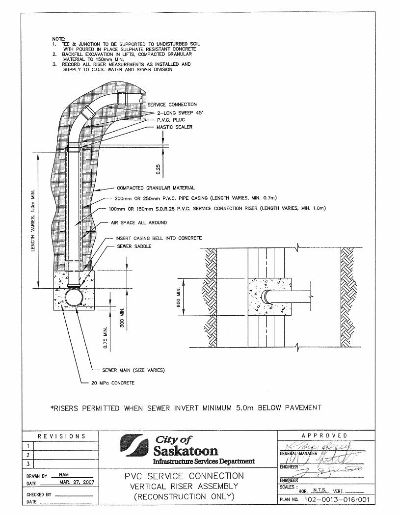
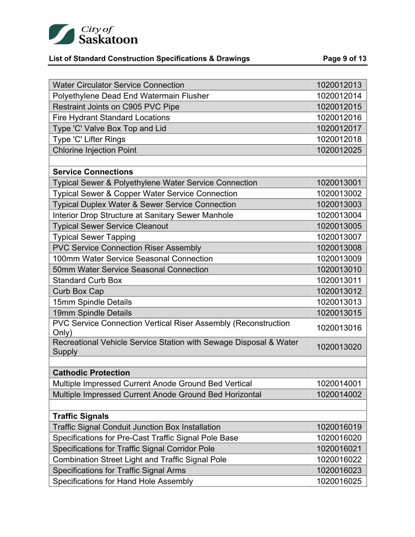
Water Circulator Service Connection 1020012013 Polyethylene Dead End Watermain Flusher 1020012014 Restraint Joints on C905 PVC Pipe 1020012015 Fire Hydrant Standard Locations 1020012016 Type 'C' Valve Box Top and Lid 1020012017 Type 'C' Lifter Rings 1020012018 Chlorine Injection Point 1020012025 Service Connections Typical Sewer & Polyethylene Water Service Connection 1020013001 Typical Sewer & Copper Water Service Connection 1020013002 Typical Duplex Water & Sewer Service Connection 1020013003 Interior Drop Structure at Sanitary Sewer Manhole 1020013004 Typical Sewer Service Cleanout 1020013005 Typical Sewer Tapping 1020013007 PVC Service Connection Riser Assembly 1020013008 100mm Water Service Seasonal Connection 1020013009 50mm Water Service Seasonal Connection 1020013010 Standard Curb Box 1020013011 Curb Box Cap 1020013012 15mm Spindle Details 1020013013 19mm Spindle Details 1020013015 PVC Service Connection Vertical Riser Assembly (Reconstruction Only) 1020013016
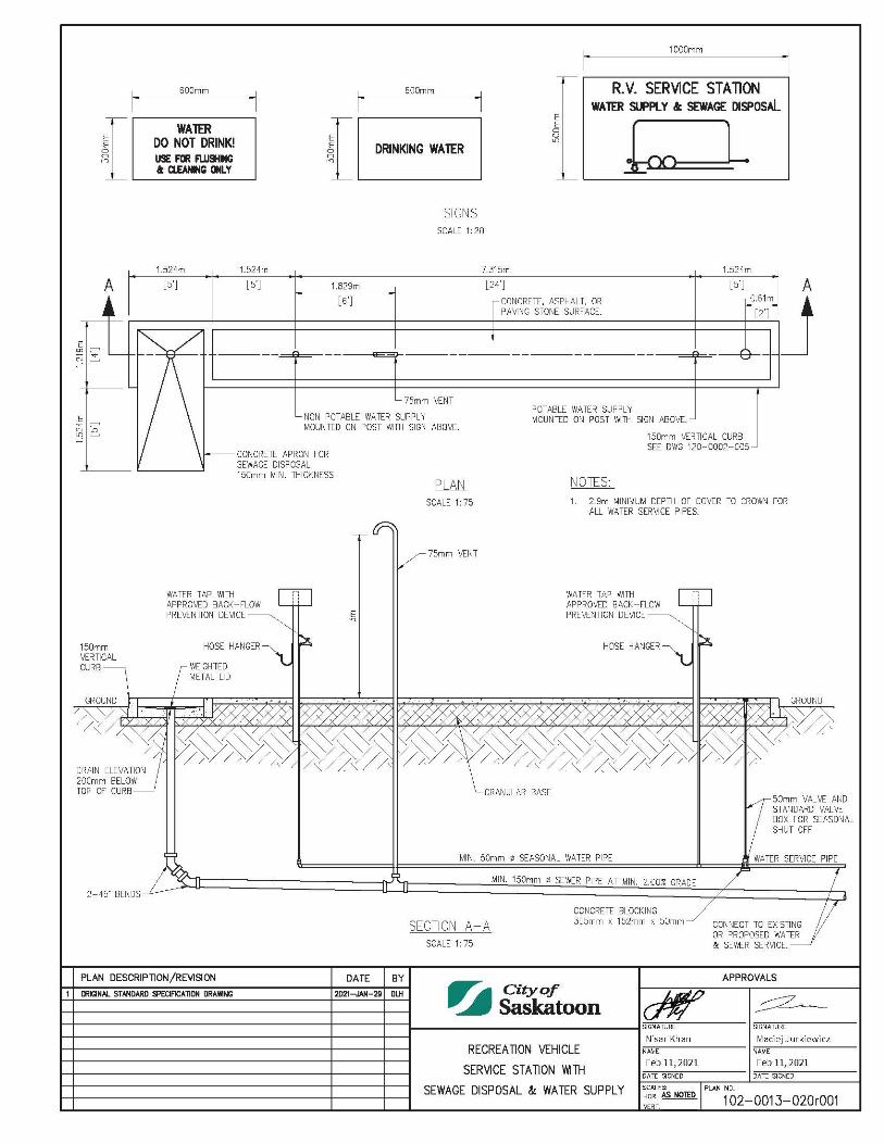
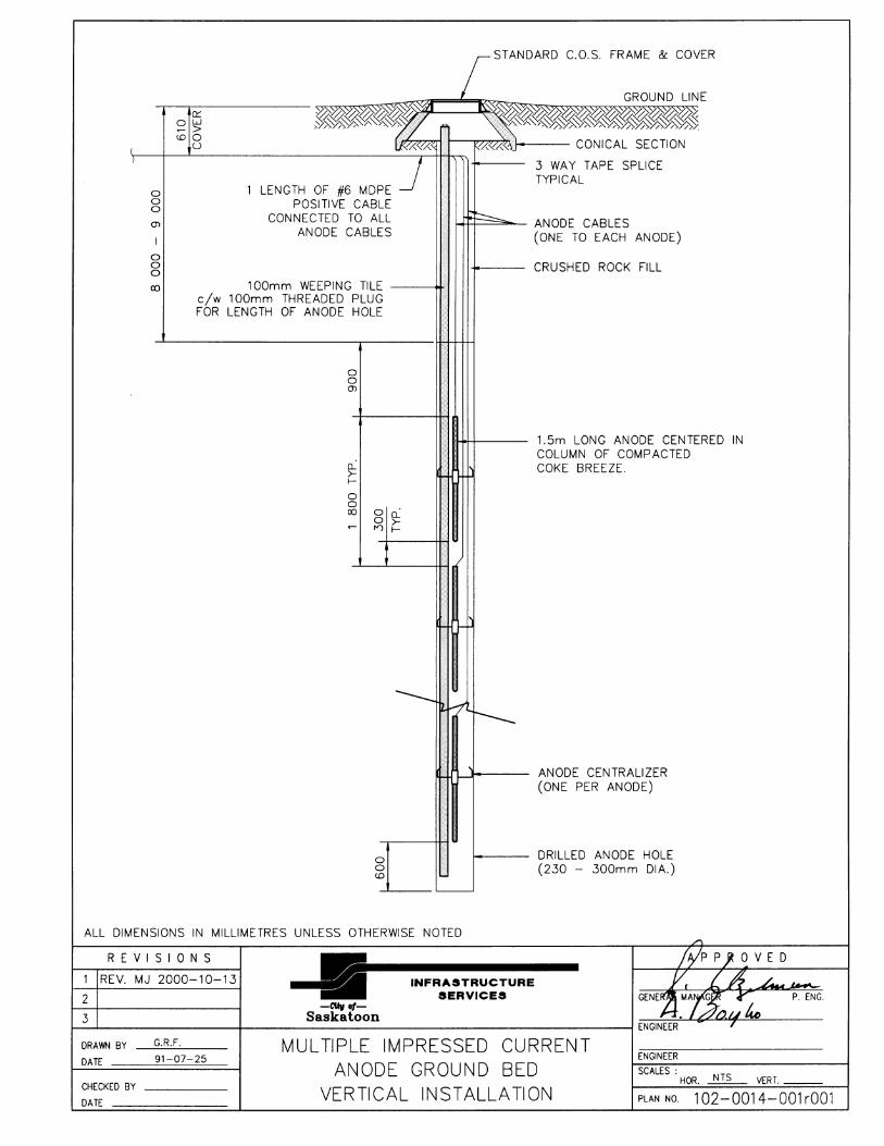
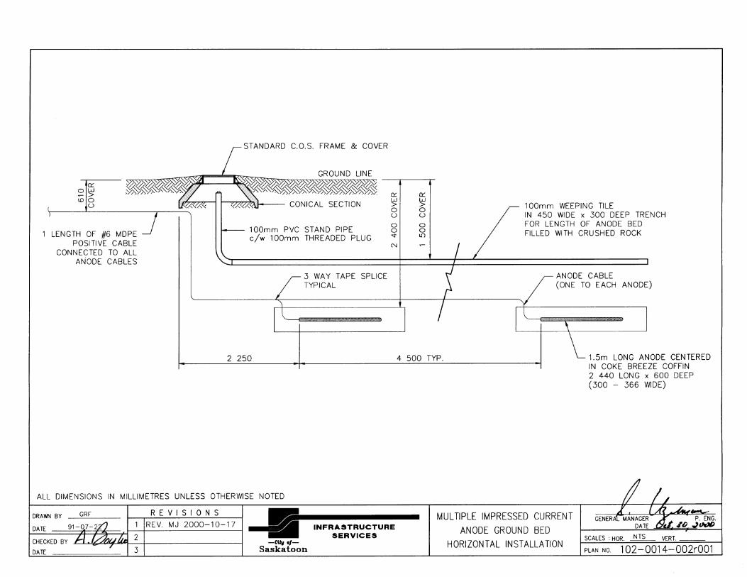
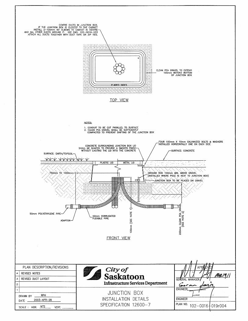
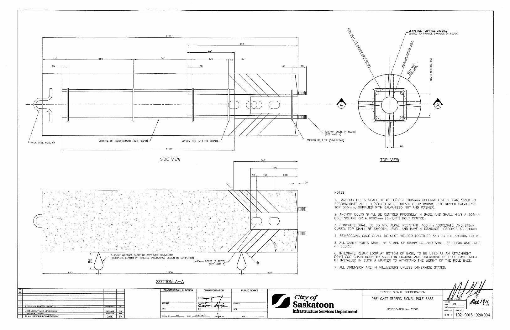
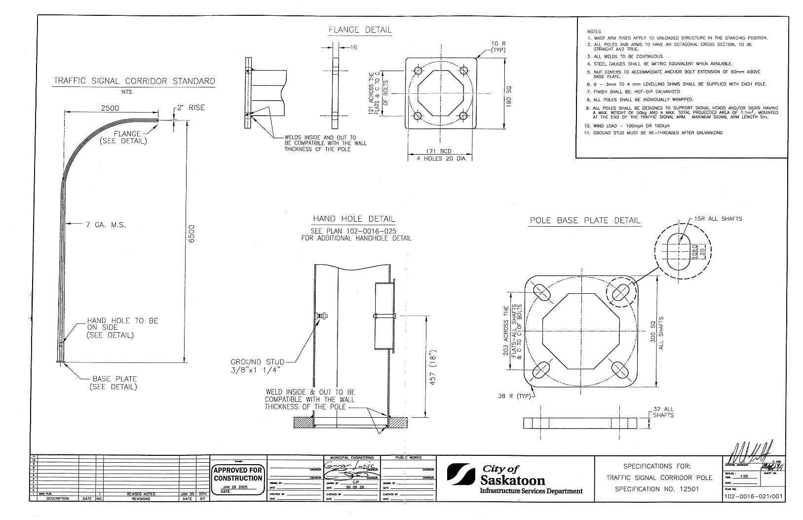
Recreational Vehicle Service Station with Sewage Disposal & Water Supply 1020013020 Cathodic Protection Multiple Impressed Current Anode Ground Bed Vertical 1020014001 Multiple Impressed Current Anode Ground Bed Horizontal 1020014002 Traffic Signals Traffic Signal Conduit Junction Box Installation 1020016019 Specifications for Pre-Cast Traffic Signal Pole Base 1020016020 Specifications for Traffic Signal Corridor Pole 1020016021 Combination Street Light and Traffic Signal Pole 1020016022 Specifications for Traffic Signal Arms 1020016023 Specifications for Hand Hole Assembly 1020016025
List of Standard Construction Specifications & Drawings Page 10 of 13
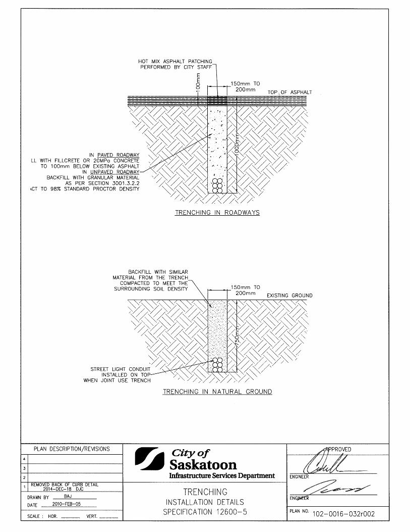
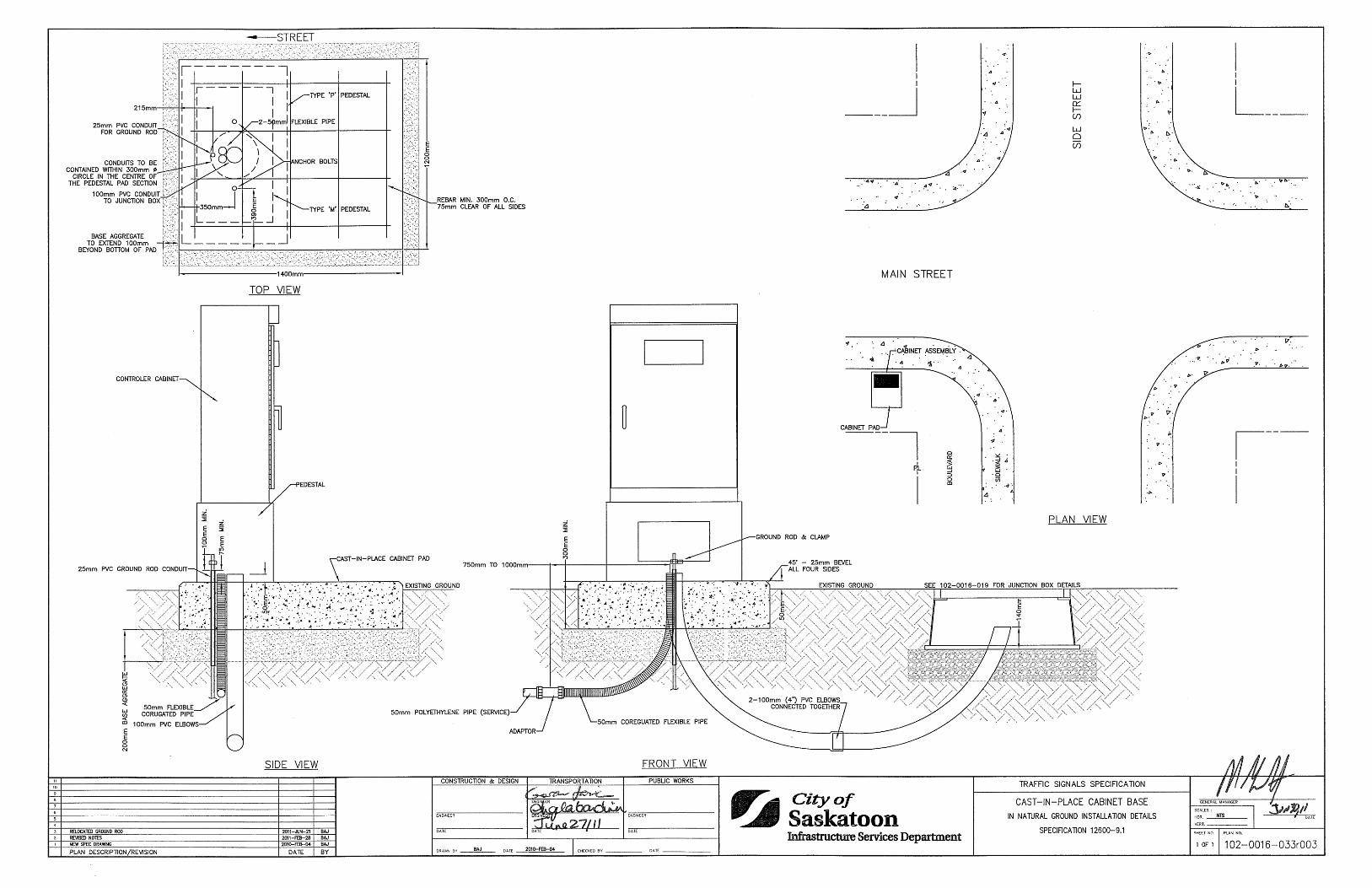
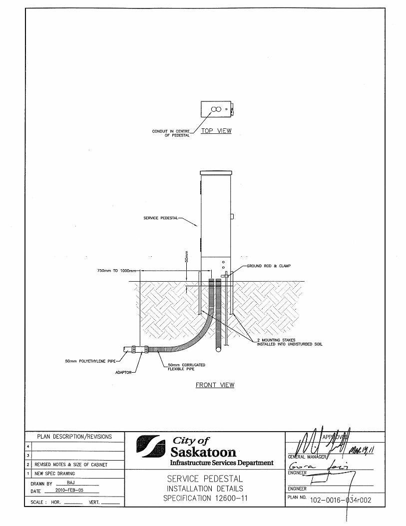
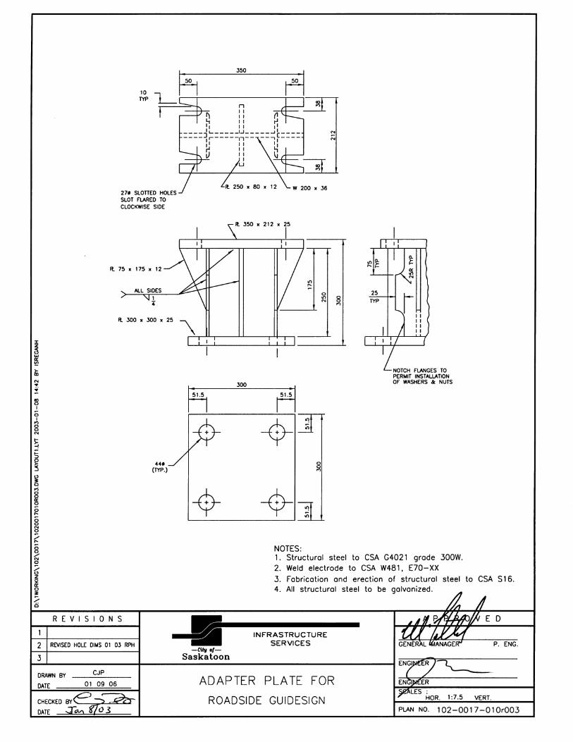
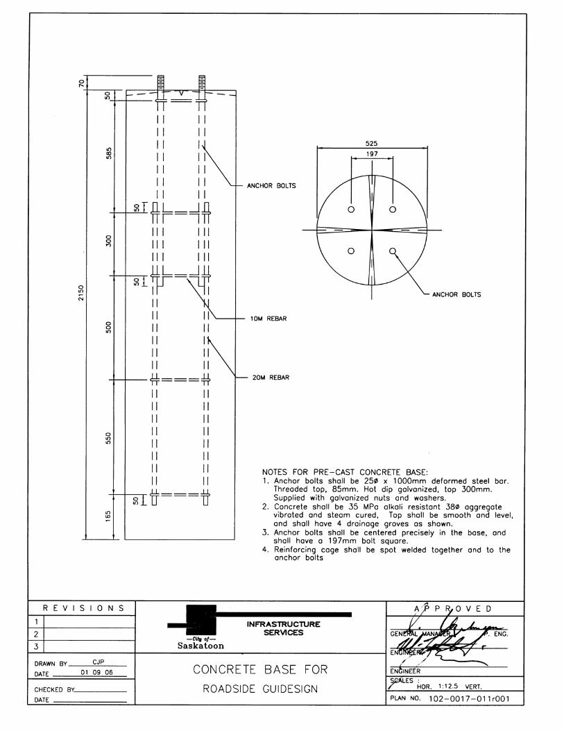
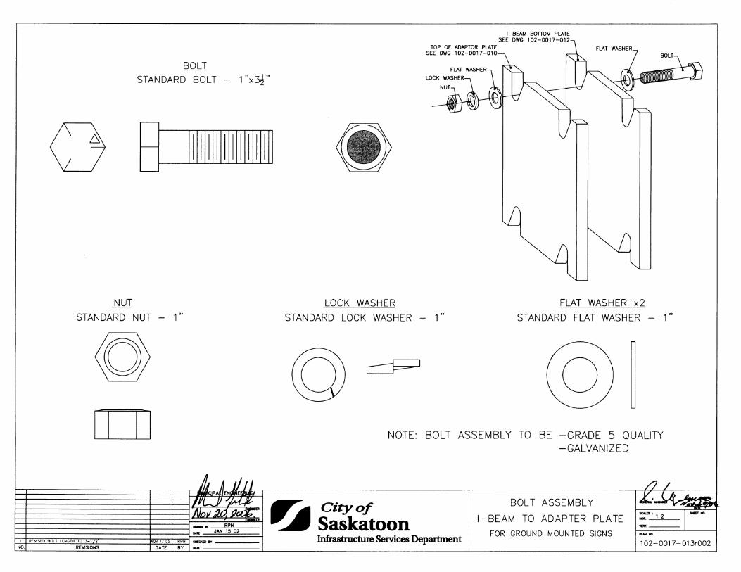
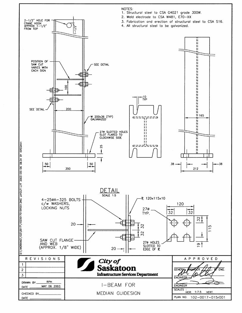
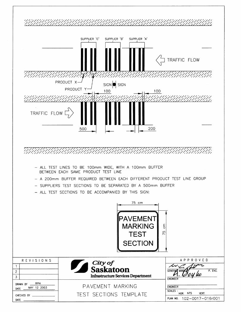
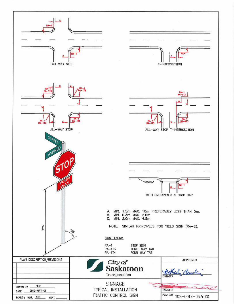
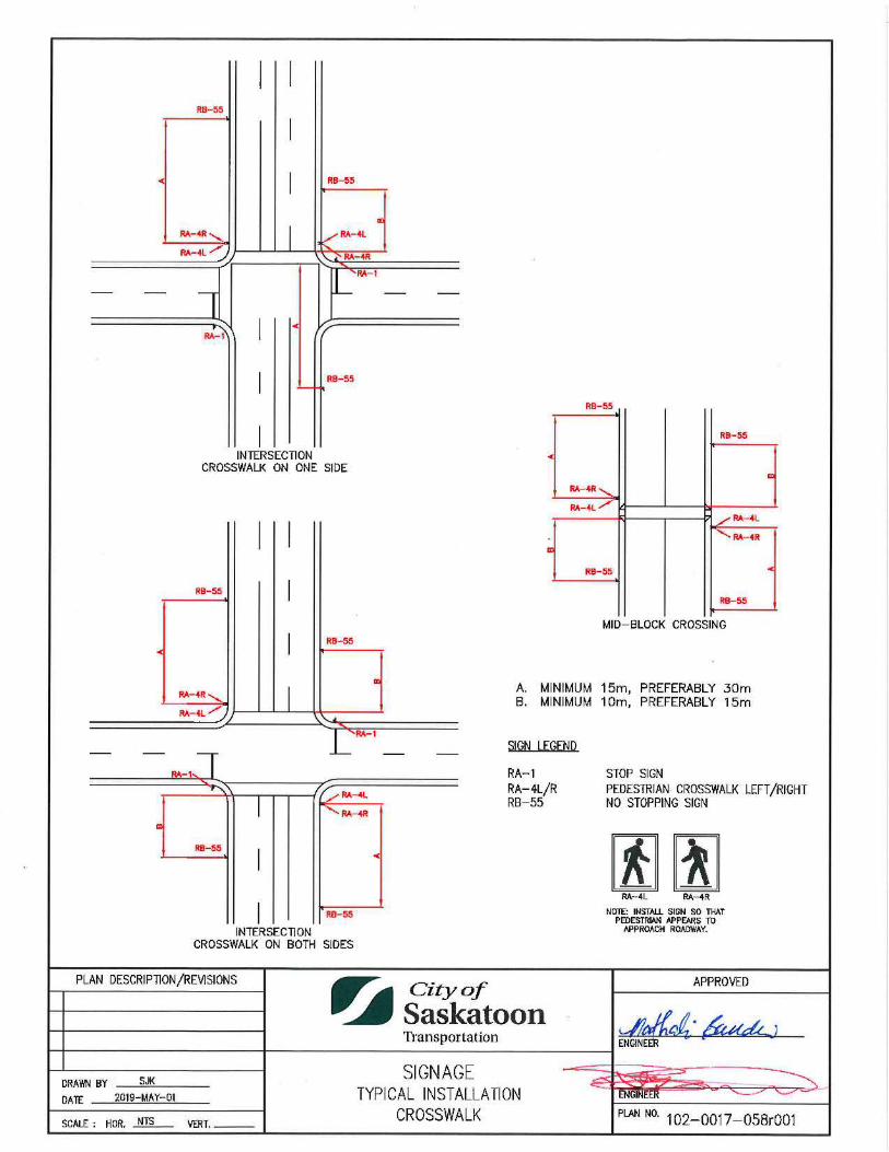
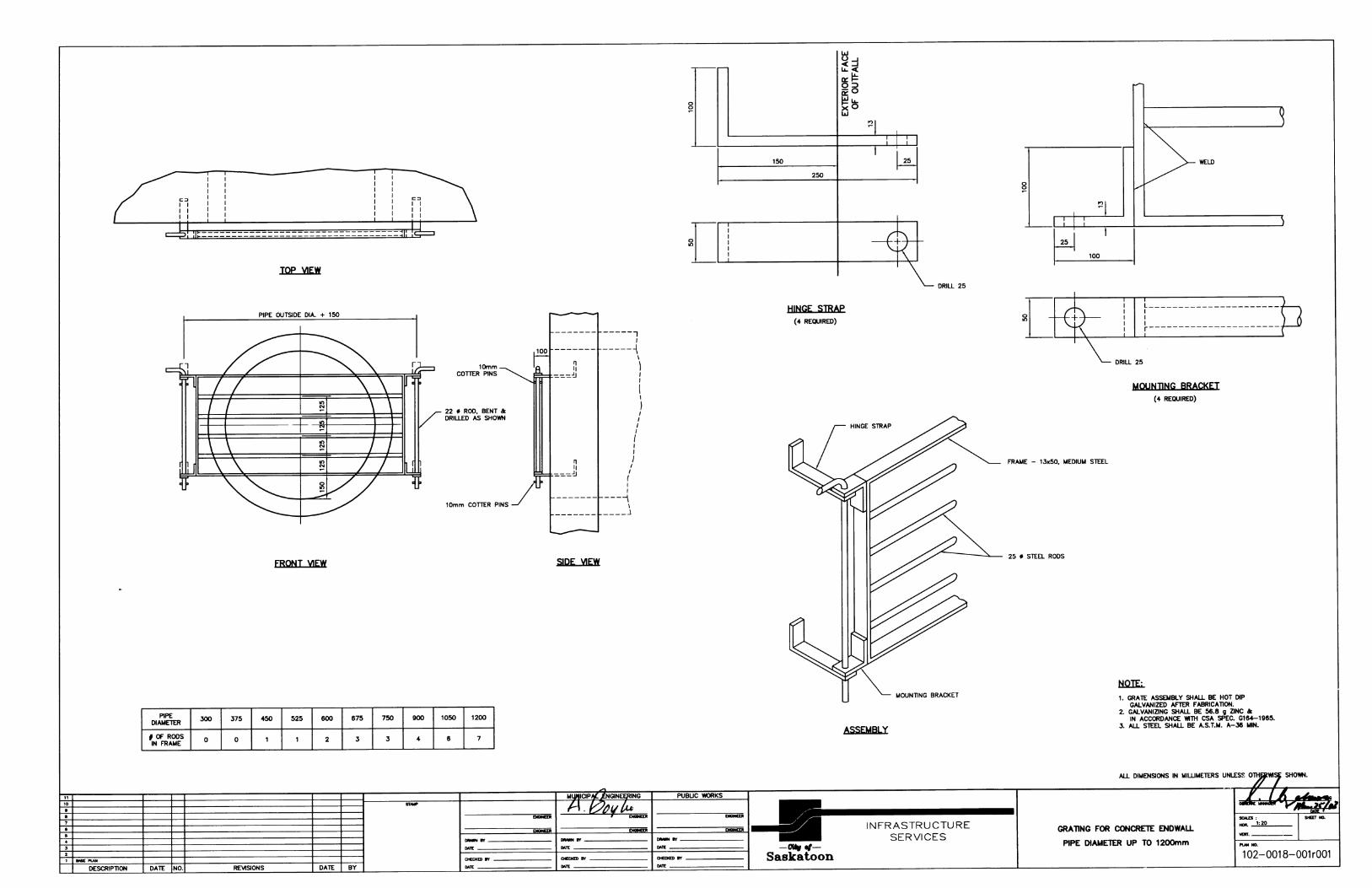
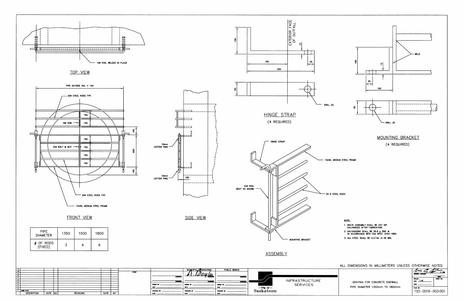
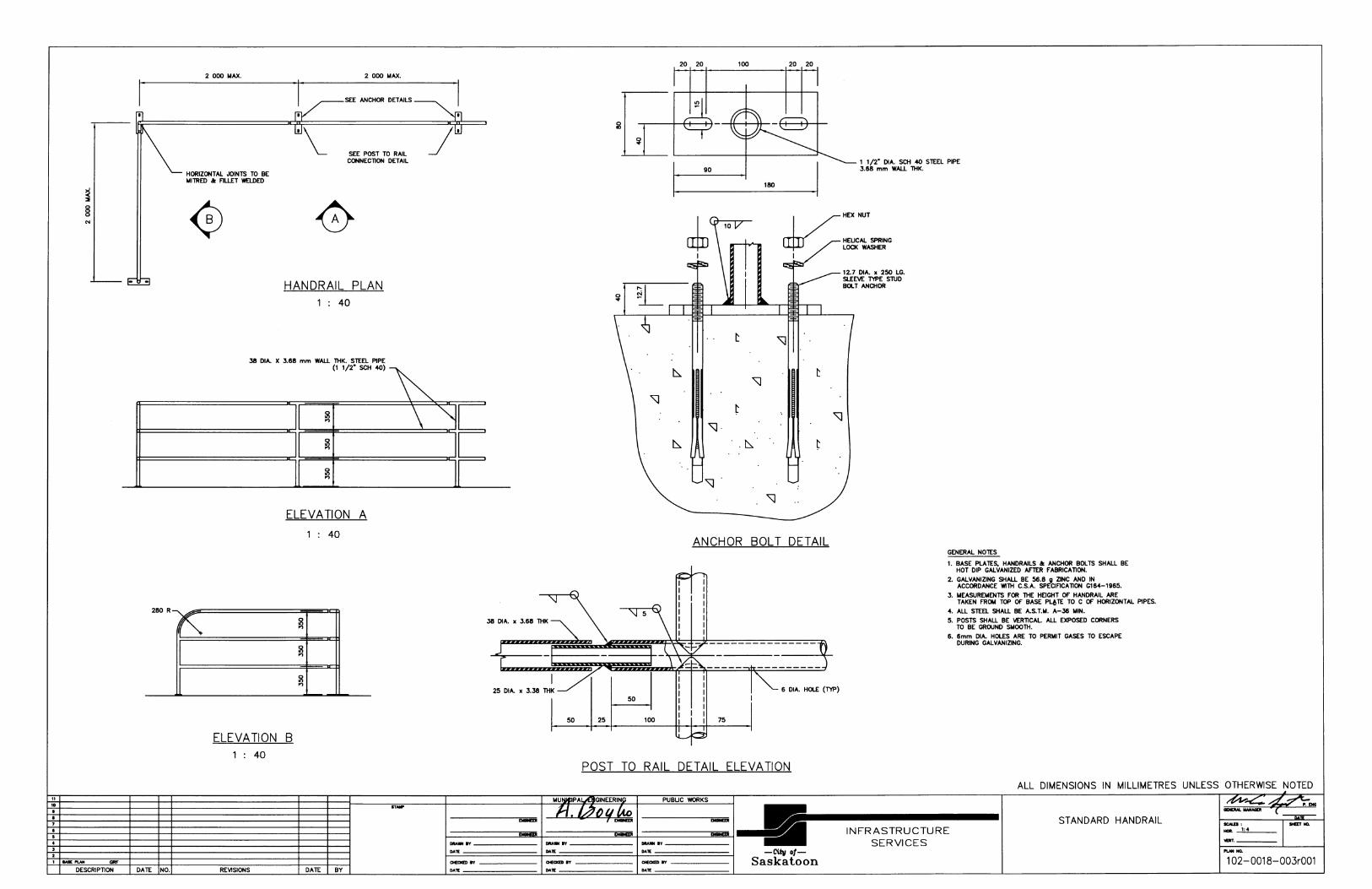
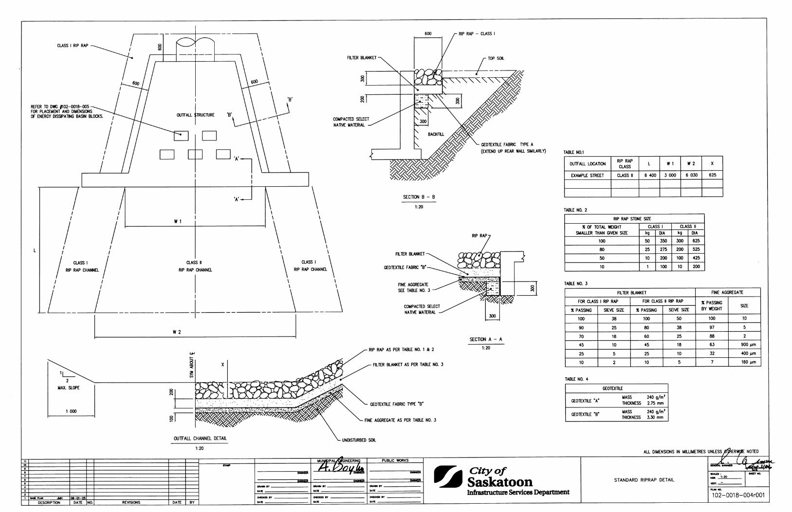
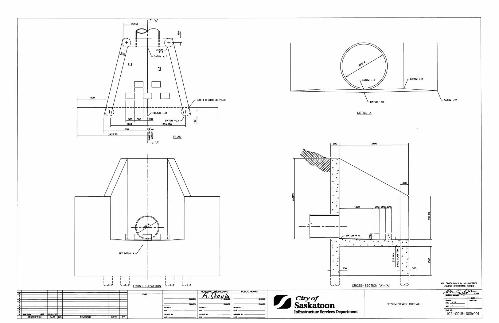
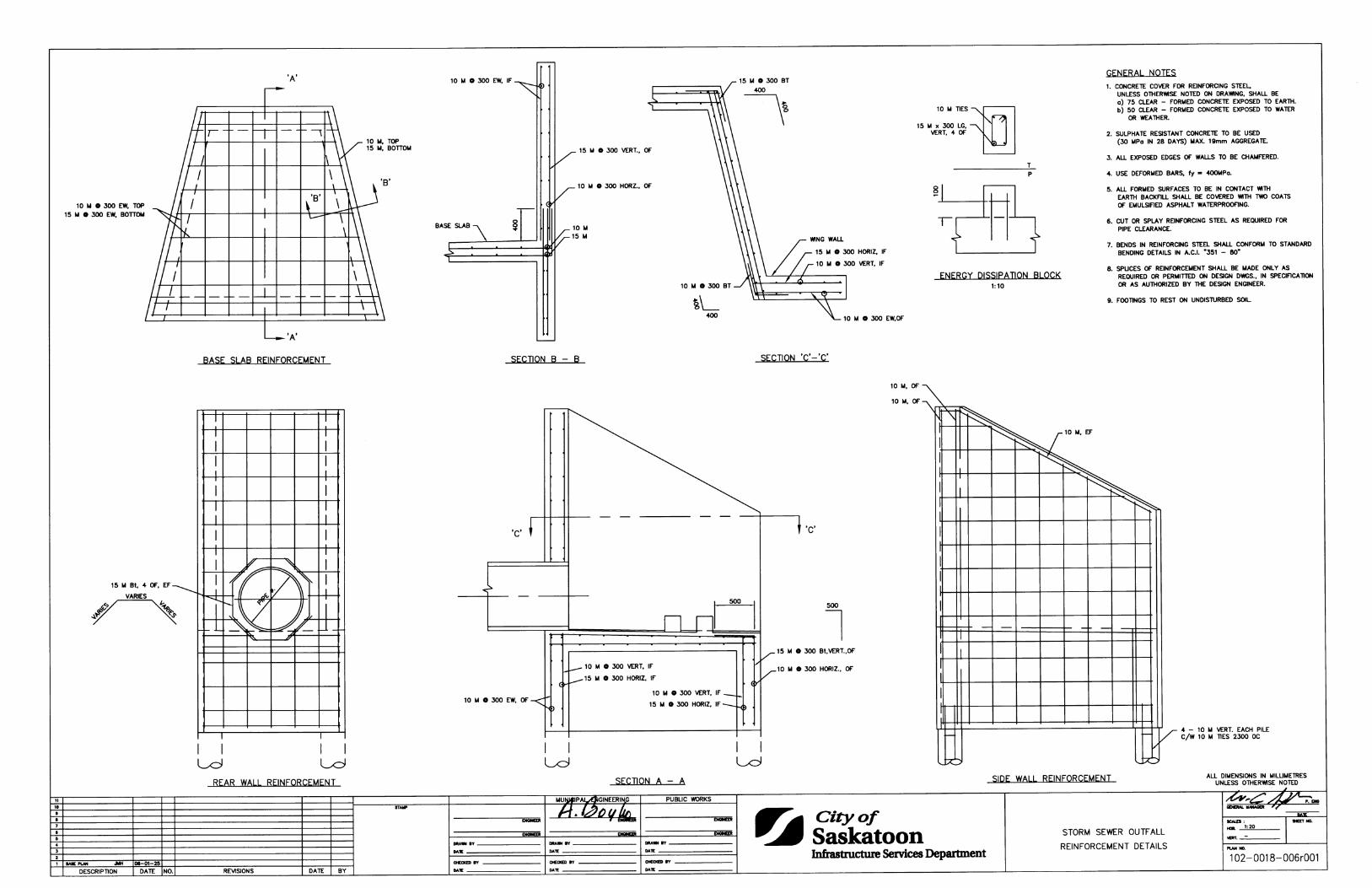
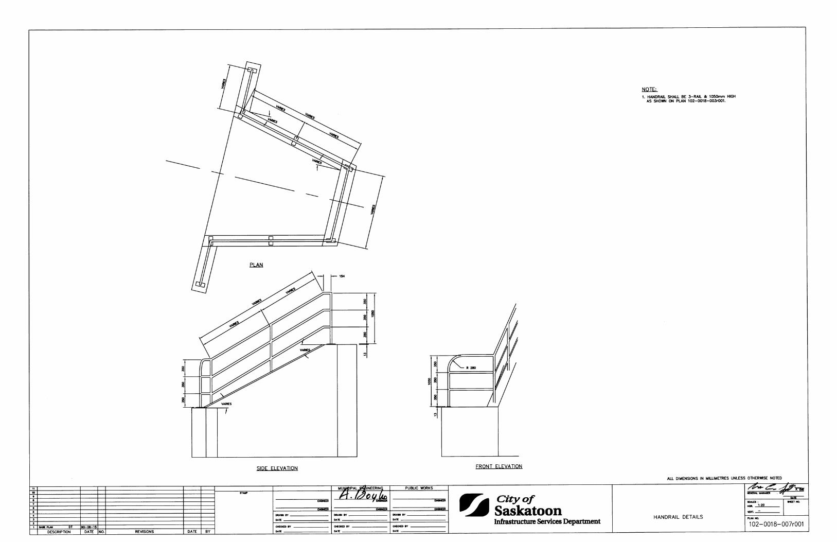
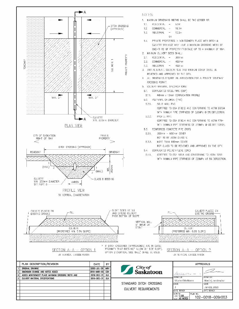
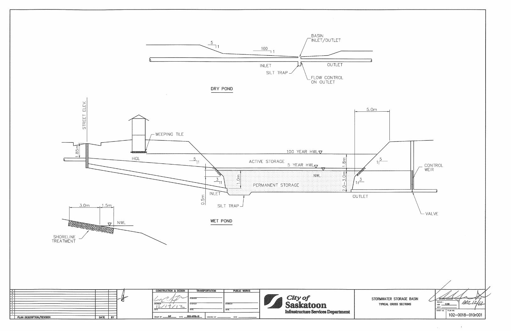
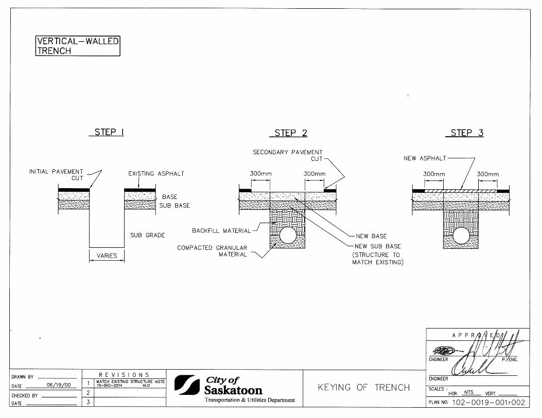
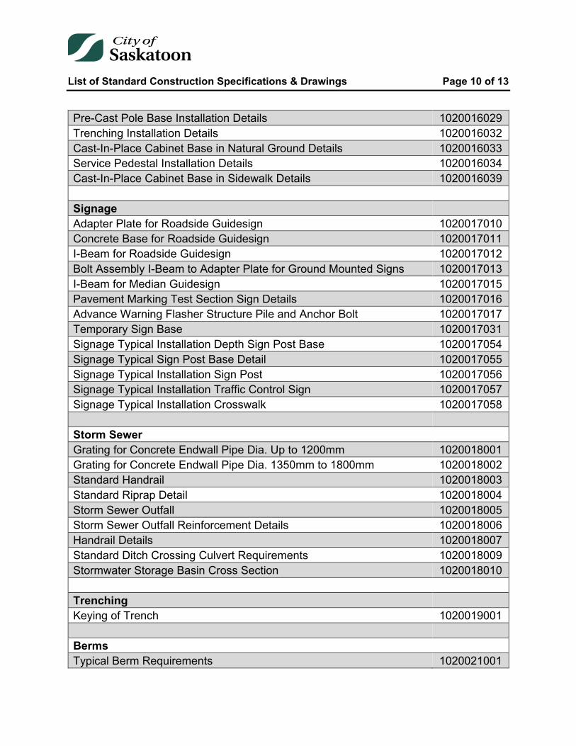
Pre-Cast Pole Base Installation Details 1020016029 Trenching Installation Details 1020016032 Cast-In-Place Cabinet Base in Natural Ground Details 1020016033 Service Pedestal Installation Details 1020016034 Cast-In-Place Cabinet Base in Sidewalk Details 1020016039 Signage Adapter Plate for Roadside Guidesign 1020017010 Concrete Base for Roadside Guidesign 1020017011 I-Beam for Roadside Guidesign 1020017012 Bolt Assembly I-Beam to Adapter Plate for Ground Mounted Signs 1020017013 I-Beam for Median Guidesign 1020017015 Pavement Marking Test Section Sign Details 1020017016 Advance Warning Flasher Structure Pile and Anchor Bolt 1020017017 Temporary Sign Base 1020017031 Signage Typical Installation Depth Sign Post Base 1020017054 Signage Typical Sign Post Base Detail 1020017055 Signage Typical Installation Sign Post 1020017056 Signage Typical Installation Traffic Control Sign 1020017057 Signage Typical Installation Crosswalk 1020017058 Storm Sewer Grating for Concrete Endwall Pipe Dia. Up to 1200mm 1020018001 Grating for Concrete Endwall Pipe Dia. 1350mm to 1800mm 1020018002 Standard Handrail 1020018003 Standard Riprap Detail 1020018004 Storm Sewer Outfall 1020018005 Storm Sewer Outfall Reinforcement Details 1020018006 Handrail Details 1020018007 Standard Ditch Crossing Culvert Requirements 1020018009 Stormwater Storage Basin Cross Section 1020018010 Trenching Keying of Trench 1020019001 Berms Typical Berm Requirements 1020021001
List of Standard Construction Specifications & Drawings Page 11 of 13
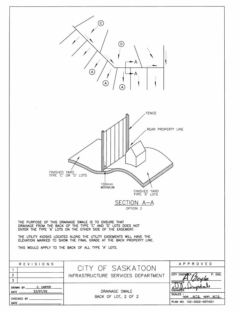
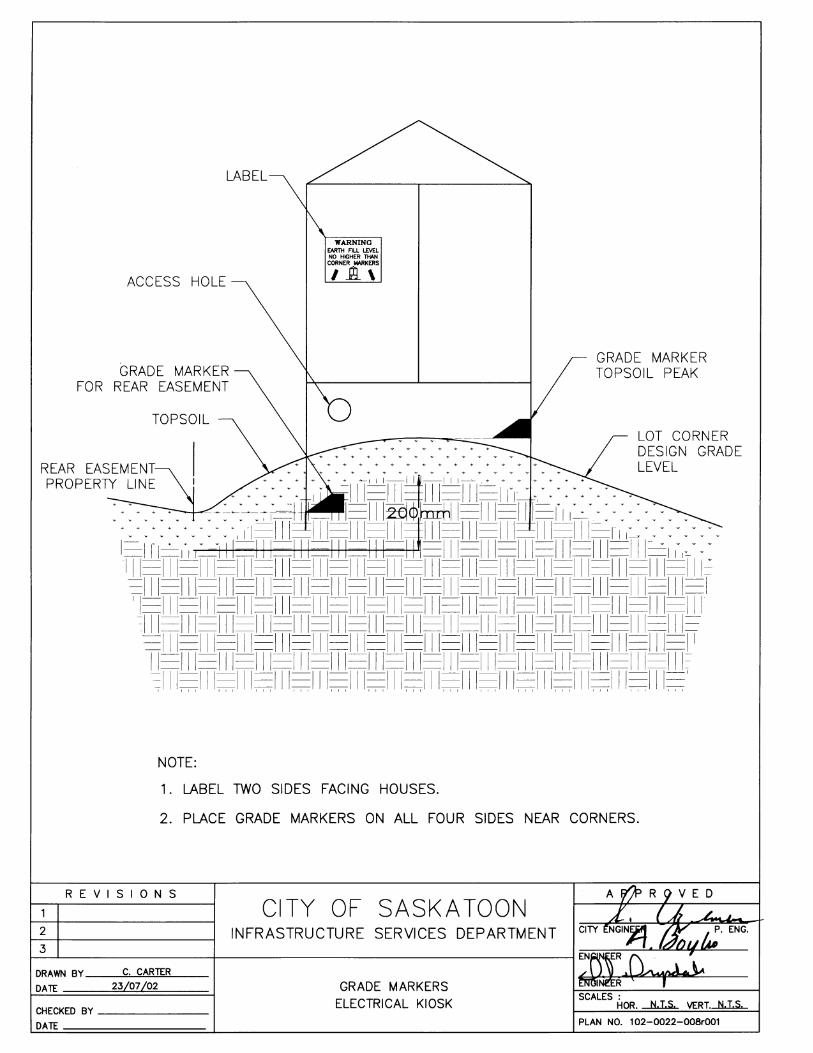
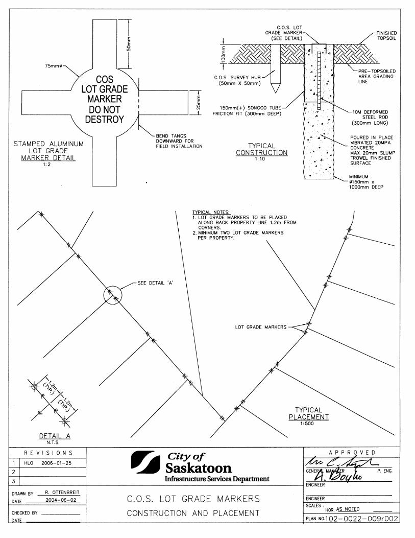
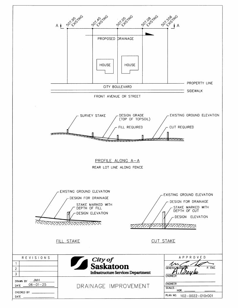
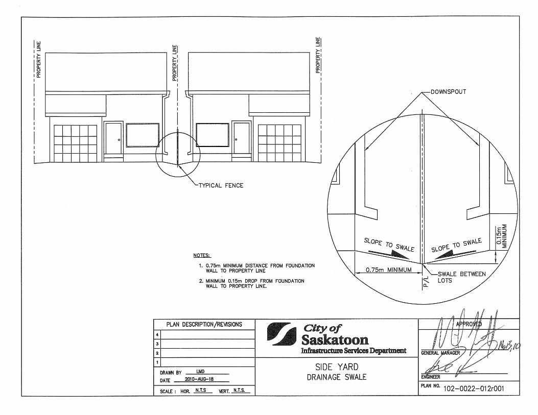
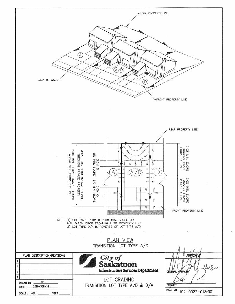
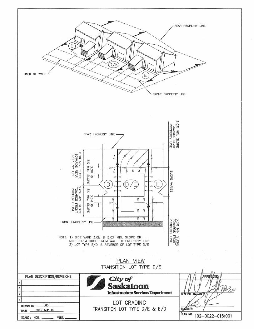
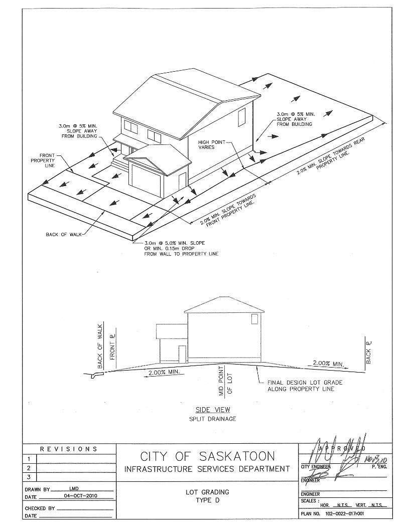
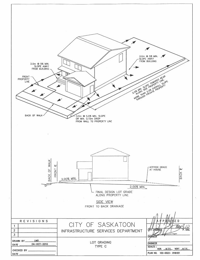
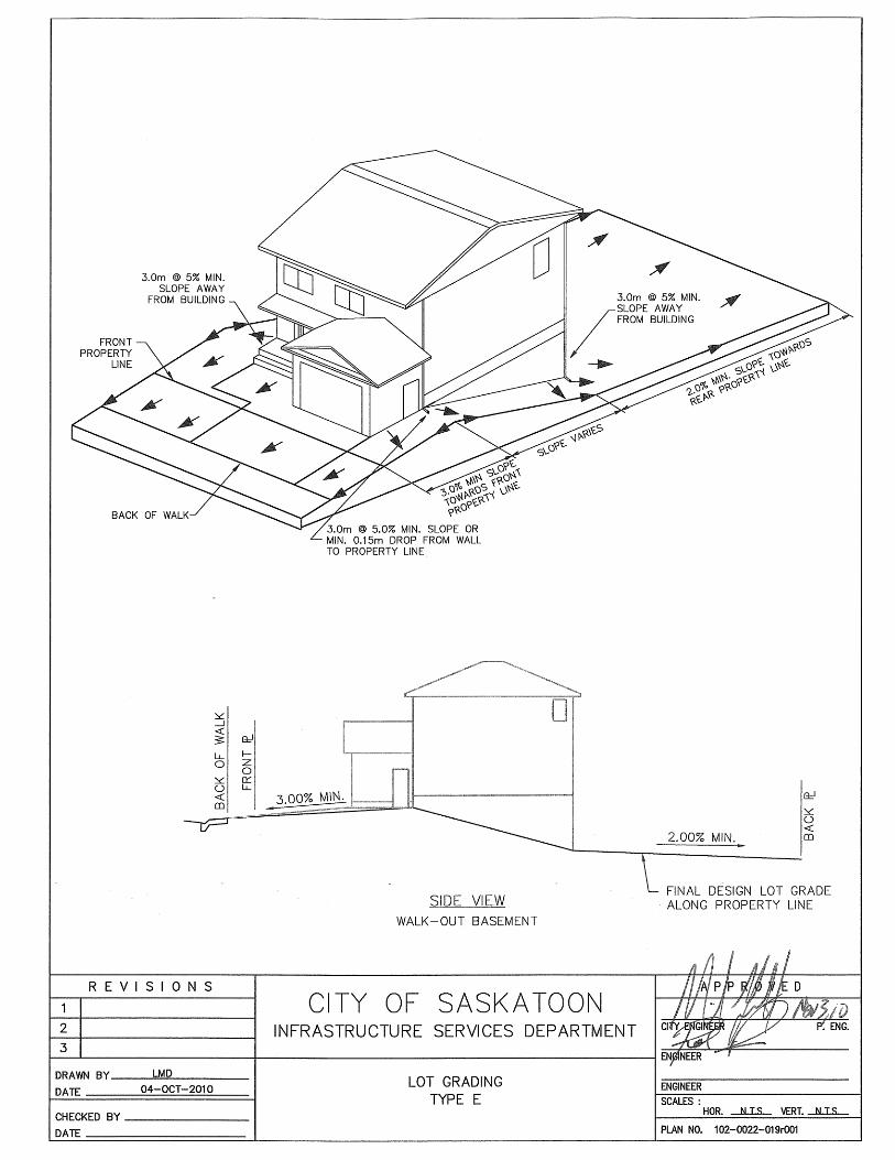
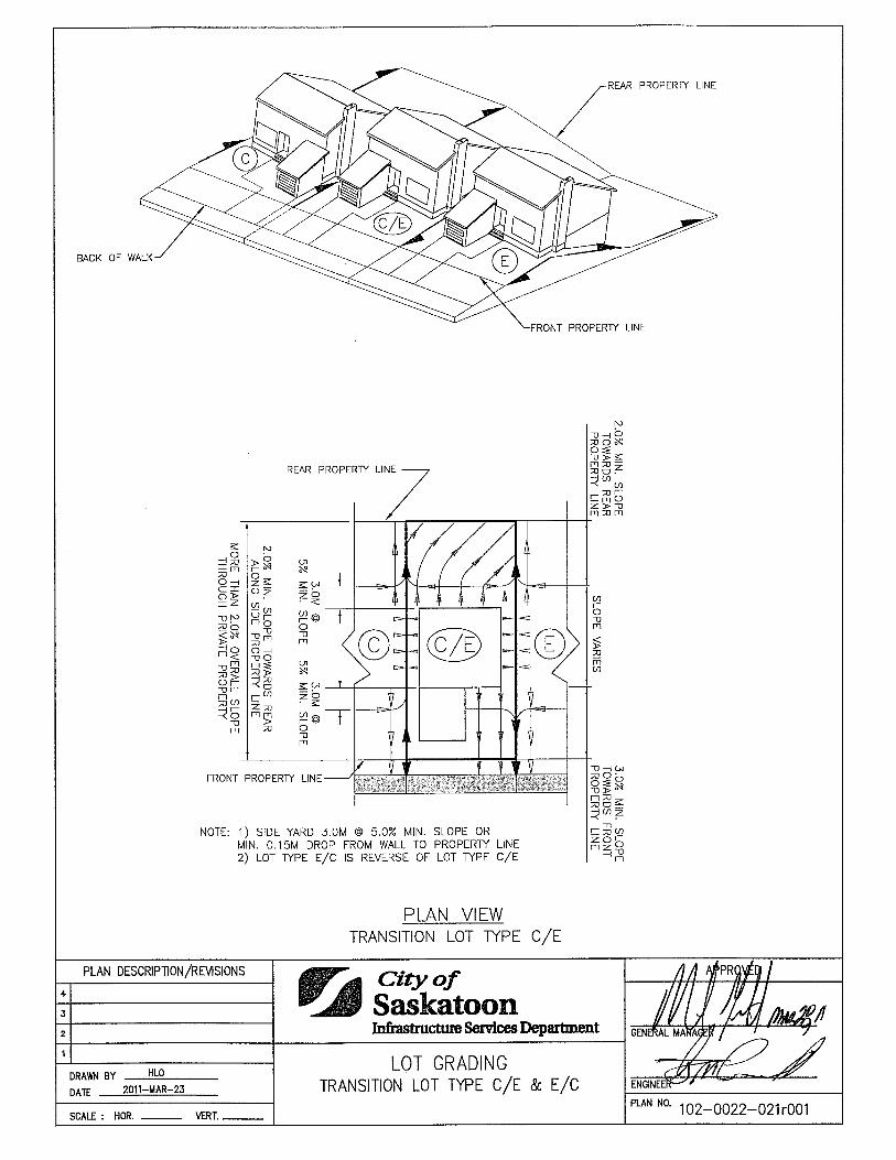
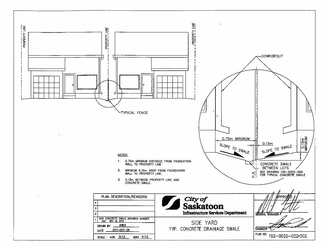
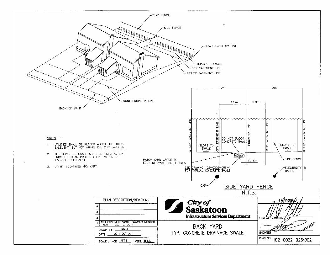
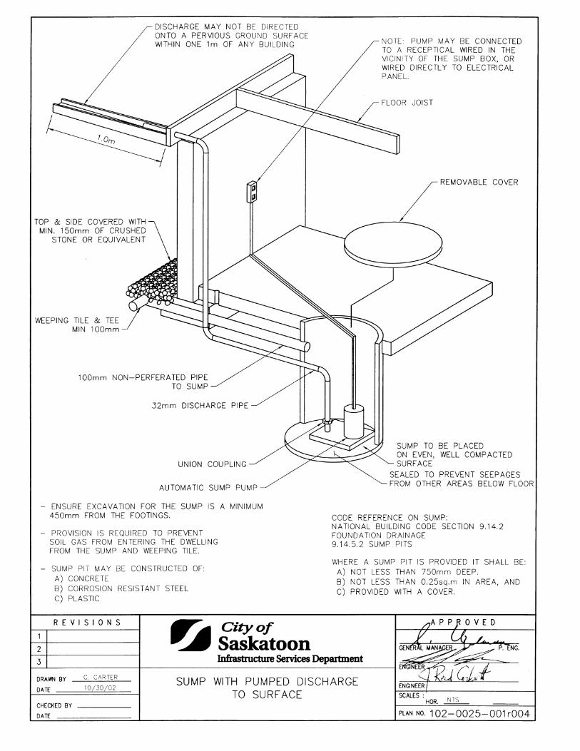
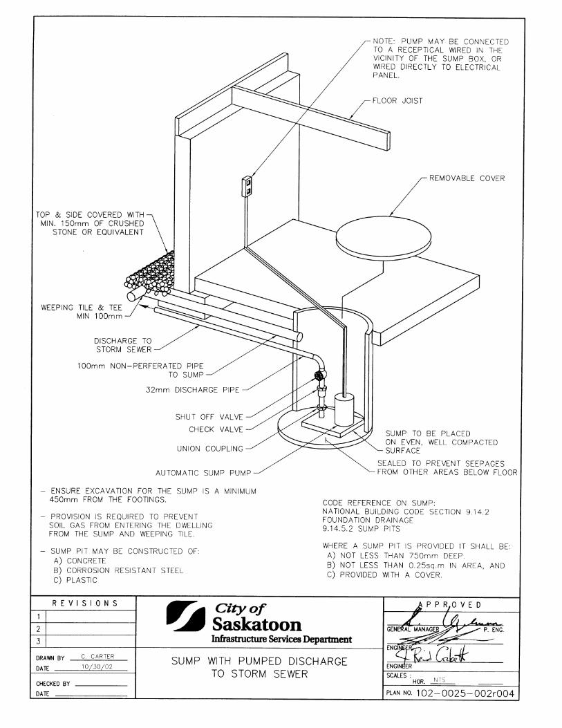
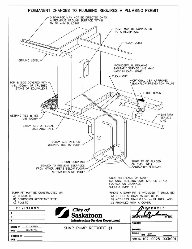
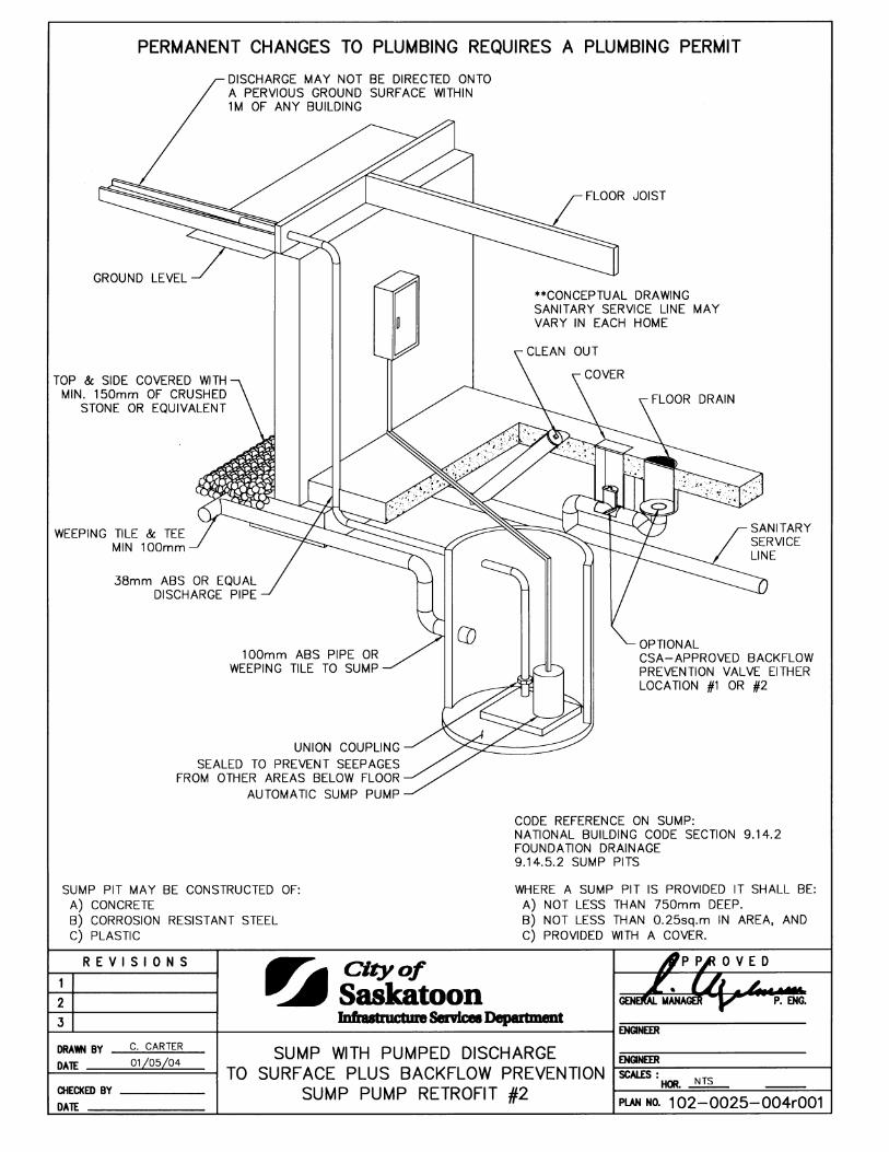
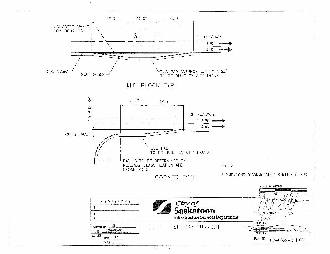
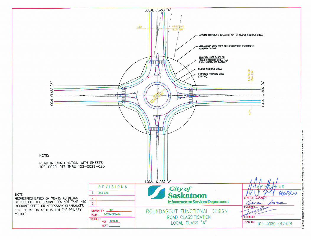
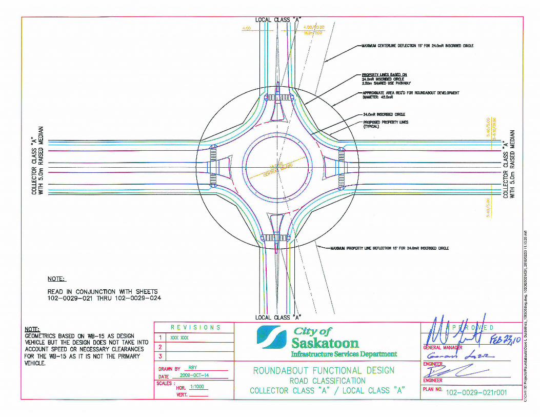
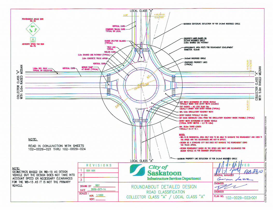
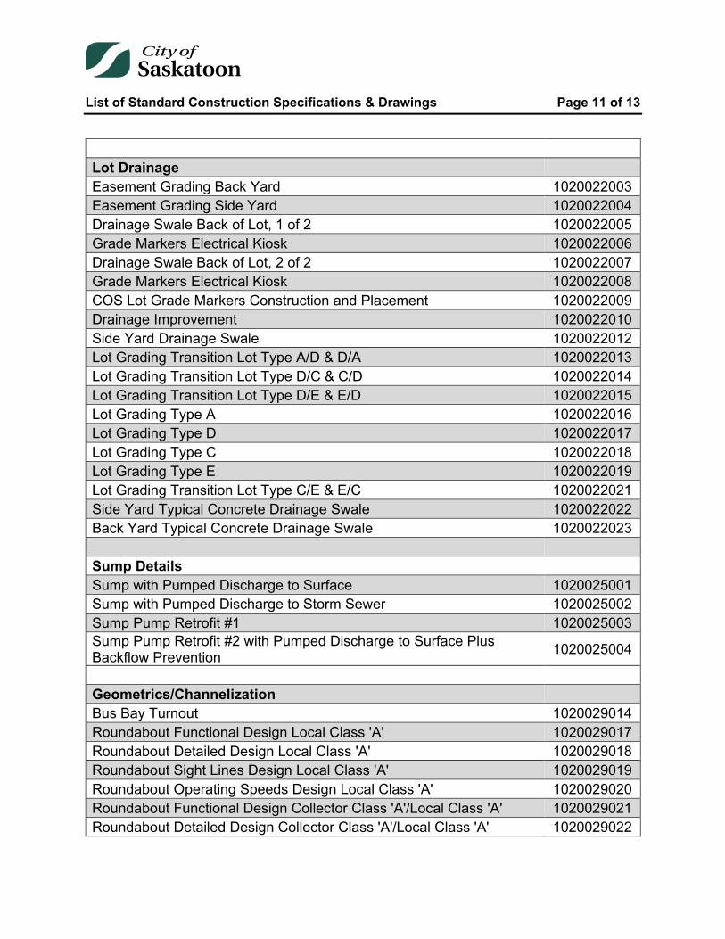
Lot Drainage Easement Grading Back Yard 1020022003 Easement Grading Side Yard 1020022004 Drainage Swale Back of Lot, 1 of 2 1020022005 Grade Markers Electrical Kiosk 1020022006 Drainage Swale Back of Lot, 2 of 2 1020022007 Grade Markers Electrical Kiosk 1020022008 COS Lot Grade Markers Construction and Placement 1020022009 Drainage Improvement 1020022010 Side Yard Drainage Swale 1020022012 Lot Grading Transition Lot Type A/D & D/A 1020022013 Lot Grading Transition Lot Type D/C & C/D 1020022014 Lot Grading Transition Lot Type D/E & E/D 1020022015 Lot Grading Type A 1020022016 Lot Grading Type D 1020022017 Lot Grading Type C 1020022018 Lot Grading Type E 1020022019 Lot Grading Transition Lot Type C/E & E/C 1020022021 Side Yard Typical Concrete Drainage Swale 1020022022 Back Yard Typical Concrete Drainage Swale 1020022023 Sump Details Sump with Pumped Discharge to Surface 1020025001 Sump with Pumped Discharge to Storm Sewer 1020025002 Sump Pump Retrofit #1 1020025003 Sump Pump Retrofit #2 with Pumped Discharge to Surface Plus Backflow Prevention 1020025004 Geometrics/Channelization Bus Bay Turnout 1020029014 Roundabout Functional Design Local Class 'A' 1020029017 Roundabout Detailed Design Local Class 'A' 1020029018 Roundabout Sight Lines Design Local Class 'A' 1020029019 Roundabout Operating Speeds Design Local Class 'A' 1020029020 Roundabout Functional Design Collector Class 'A'/Local Class 'A' 1020029021 Roundabout Detailed Design Collector Class 'A'/Local Class 'A' 1020029022
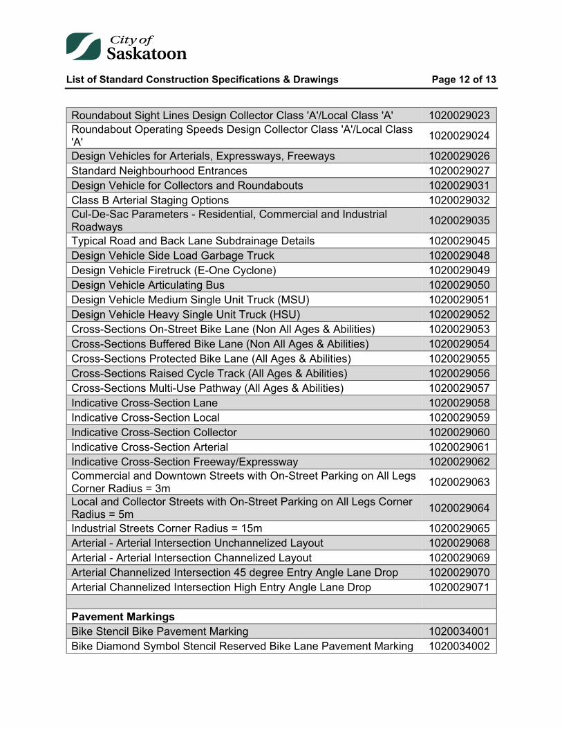
List of Standard Construction Specifications & Drawings Page 12 of 13
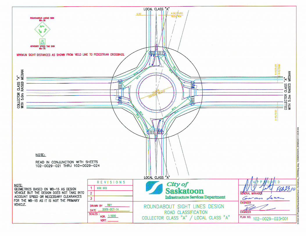
Roundabout Sight Lines Design Collector Class 'A'/Local Class 'A' 1020029023 Roundabout Operating Speeds Design Collector Class 'A'/Local Class 'A' 1020029024
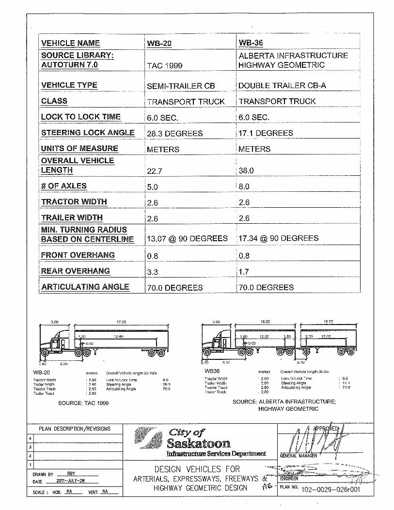
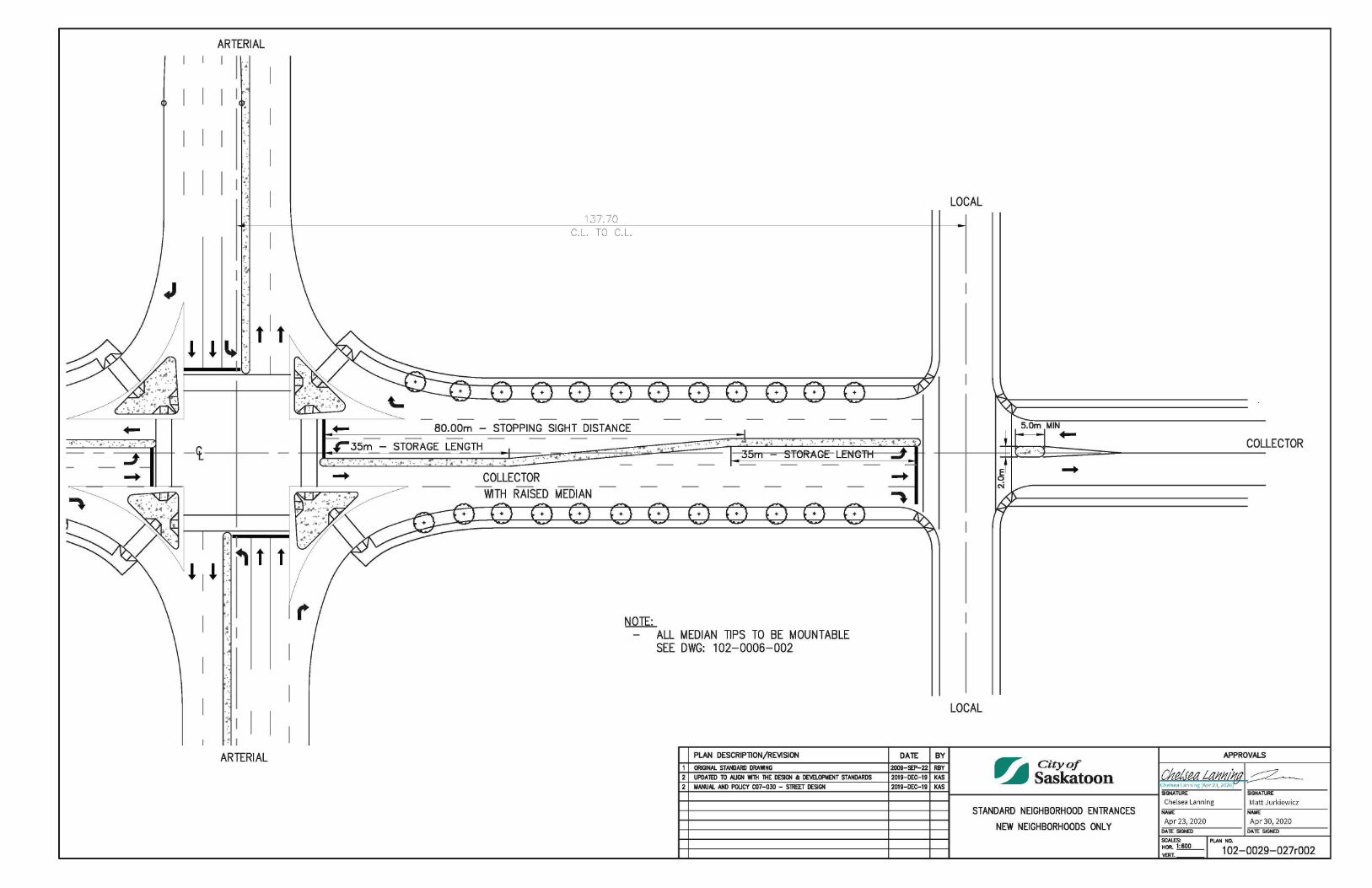
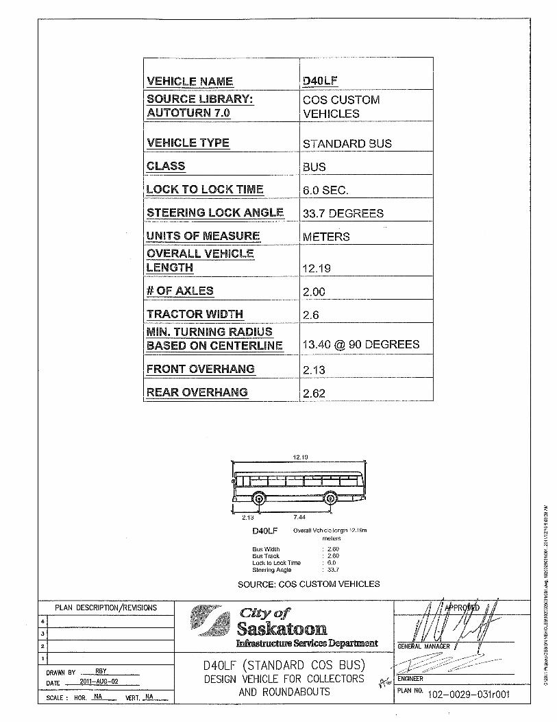
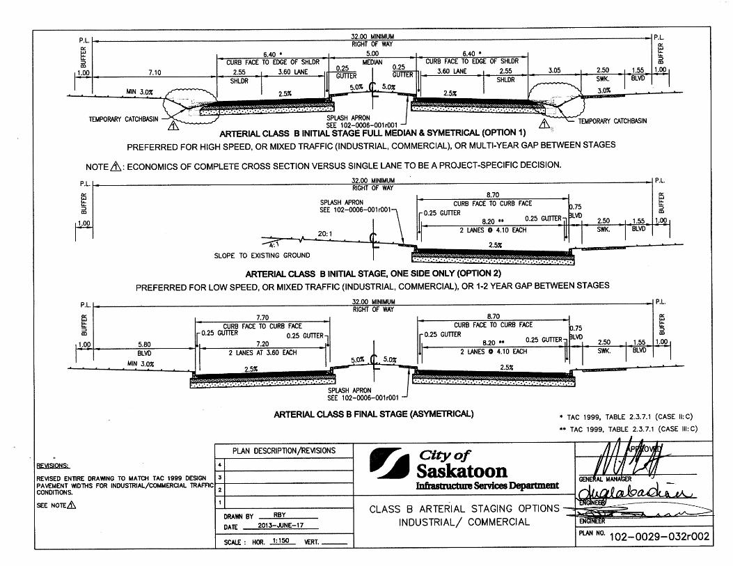
Design Vehicles for Arterials, Expressways, Freeways 1020029026 Standard Neighbourhood Entrances 1020029027 Design Vehicle for Collectors and Roundabouts 1020029031 Class B Arterial Staging Options 1020029032 Cul-De-Sac Parameters - Residential, Commercial and Industrial Roadways 1020029035
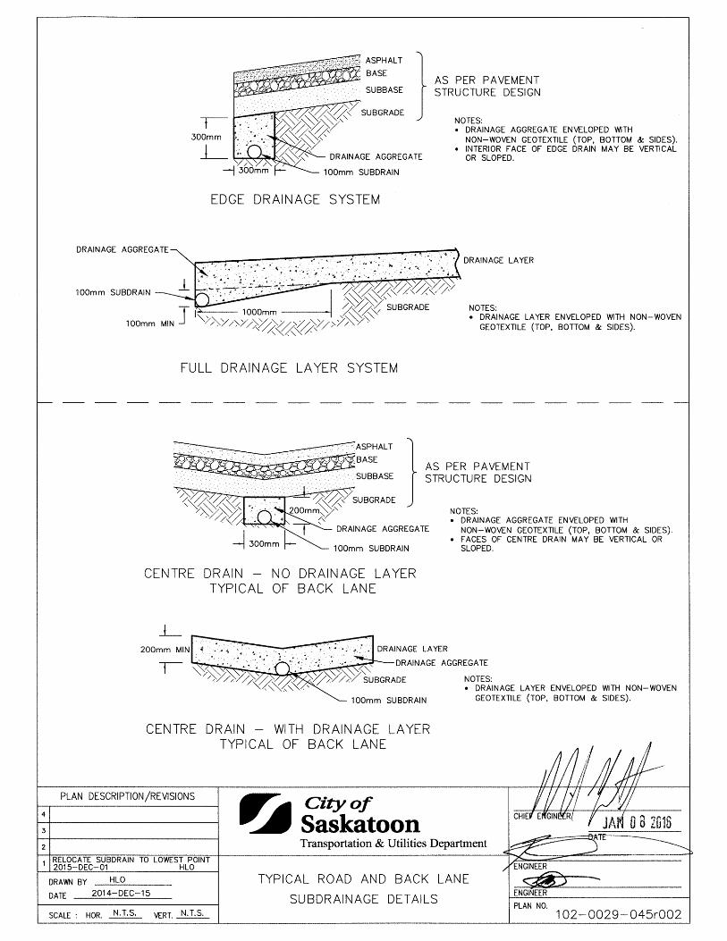
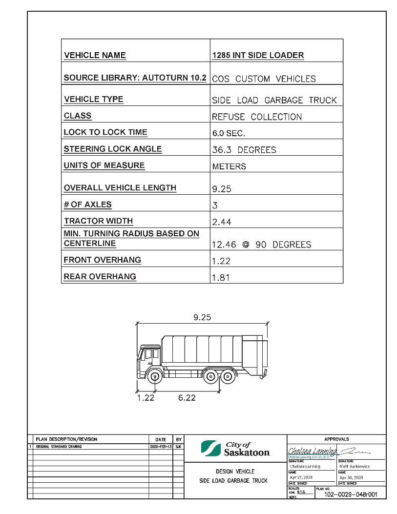
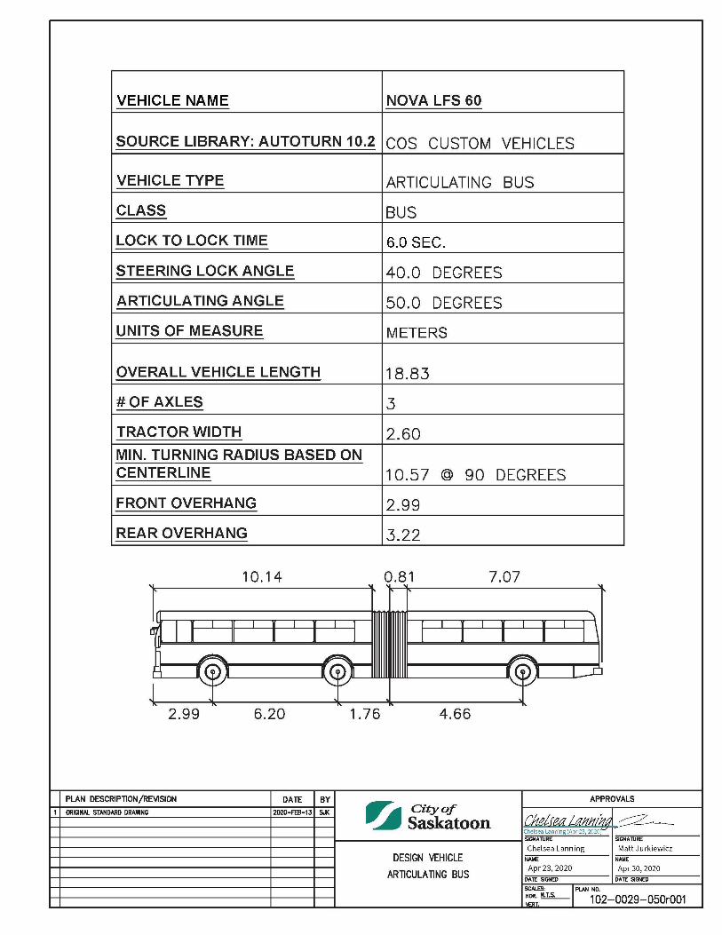
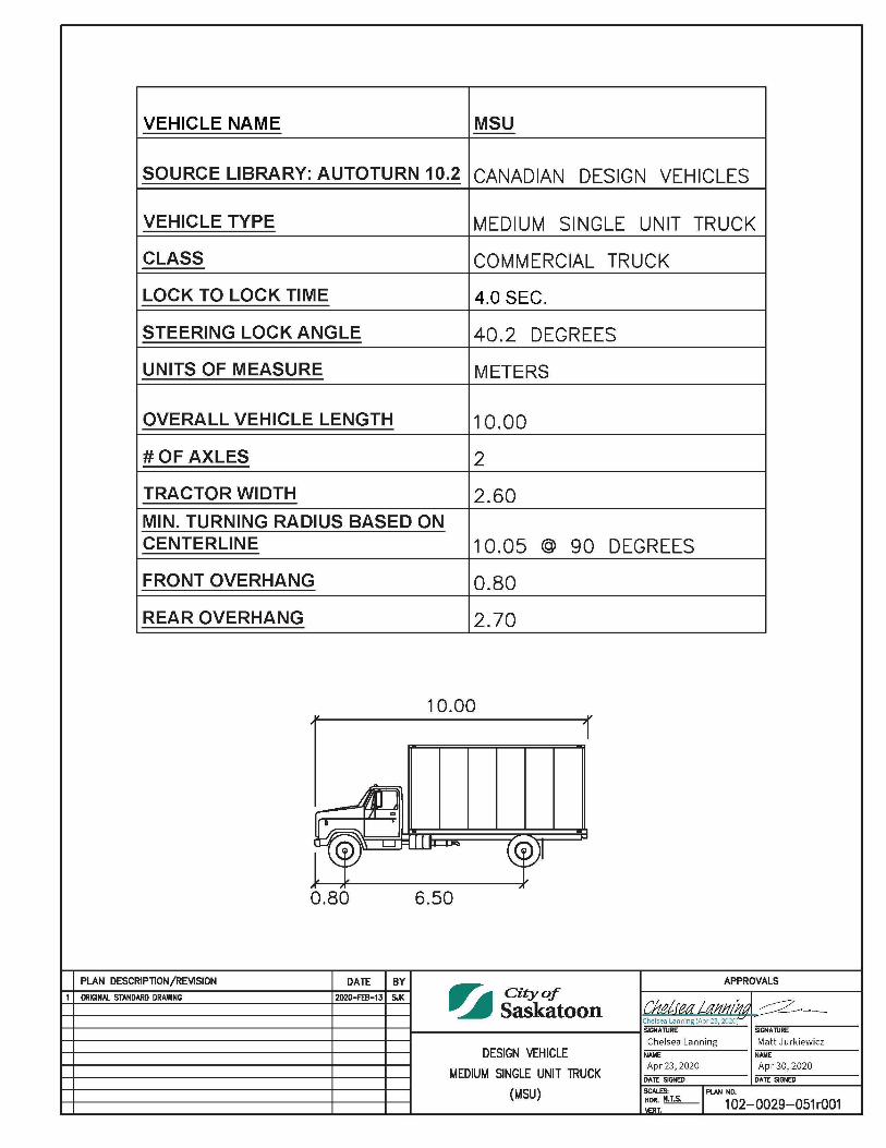
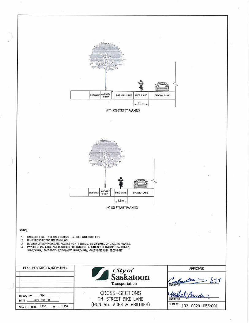
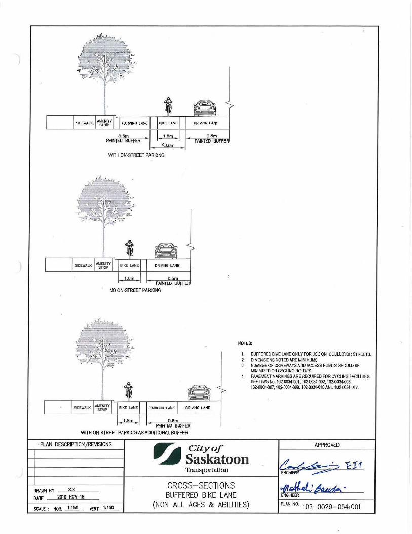
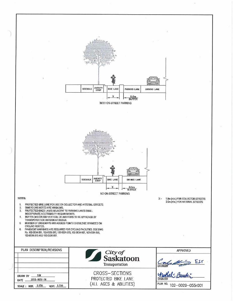
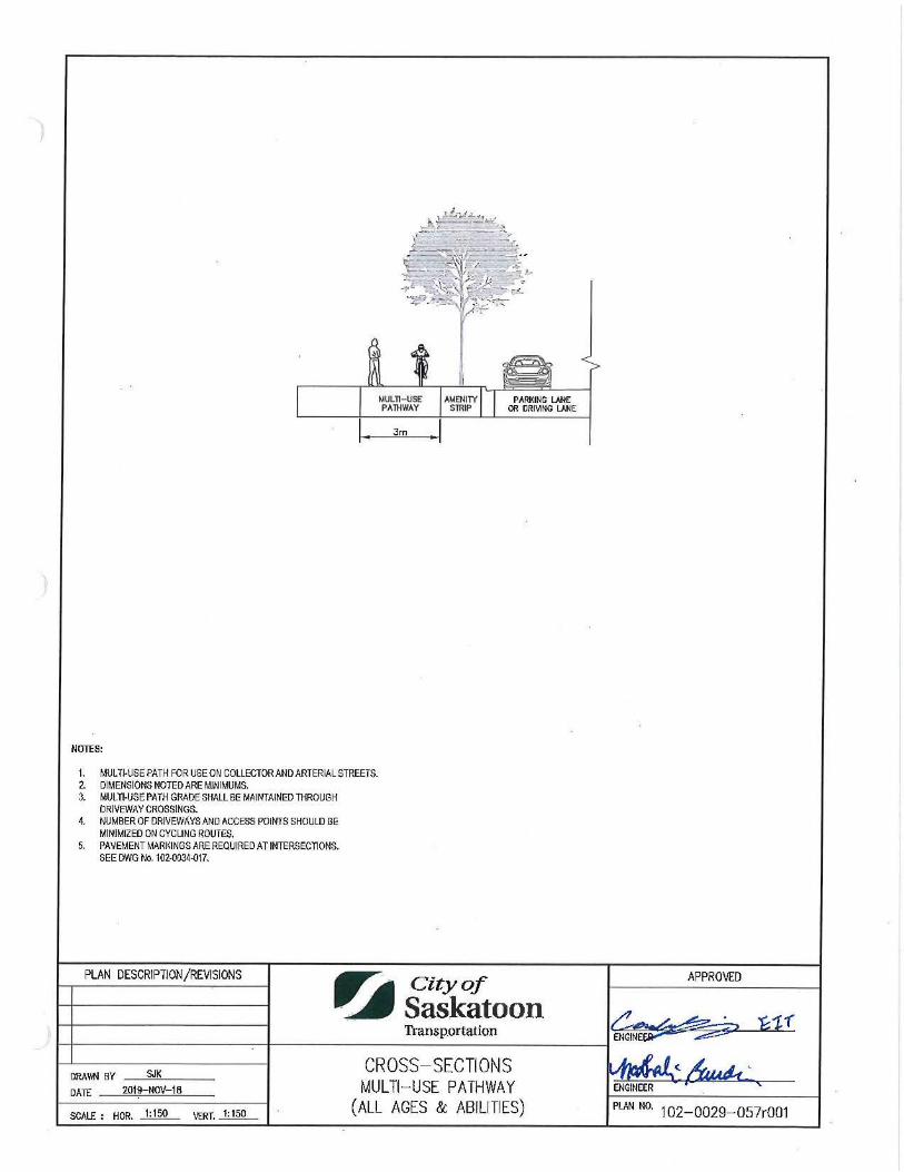
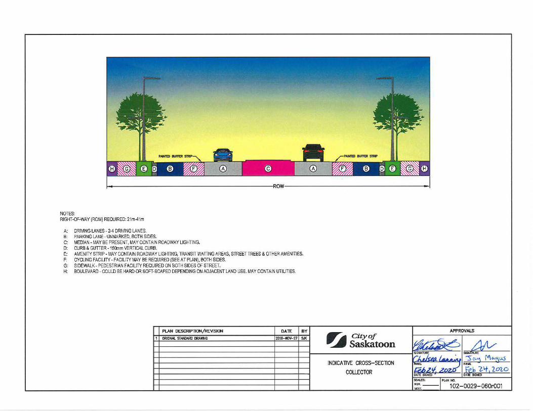
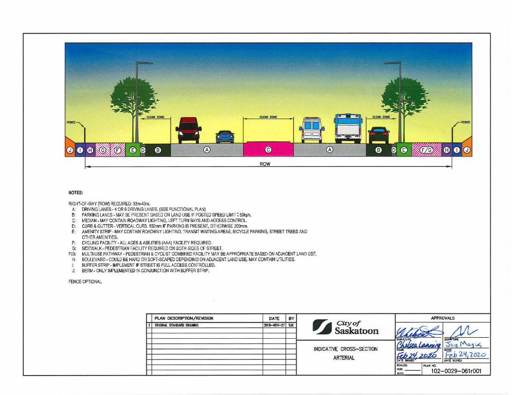
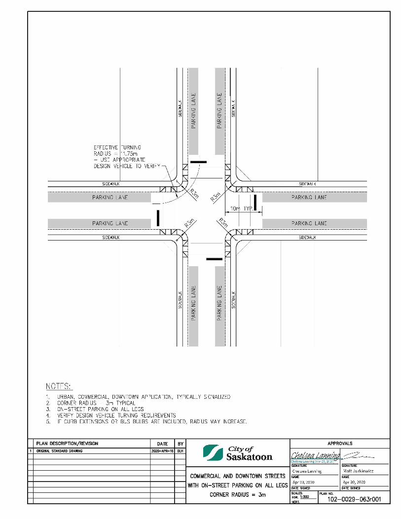
Typical Road and Back Lane Subdrainage Details 1020029045 Design Vehicle Side Load Garbage Truck 1020029048 Design Vehicle Firetruck (E-One Cyclone) 1020029049 Design Vehicle Articulating Bus 1020029050 Design Vehicle Medium Single Unit Truck (MSU) 1020029051 Design Vehicle Heavy Single Unit Truck (HSU) 1020029052 Cross-Sections On-Street Bike Lane (Non All Ages & Abilities) 1020029053 Cross-Sections Buffered Bike Lane (Non All Ages & Abilities) 1020029054 Cross-Sections Protected Bike Lane (All Ages & Abilities) 1020029055 Cross-Sections Raised Cycle Track (All Ages & Abilities) 1020029056 Cross-Sections Multi-Use Pathway (All Ages & Abilities) 1020029057 Indicative Cross-Section Lane 1020029058 Indicative Cross-Section Local 1020029059 Indicative Cross-Section Collector 1020029060 Indicative Cross-Section Arterial 1020029061 Indicative Cross-Section Freeway/Expressway 1020029062 Commercial and Downtown Streets with On-Street Parking on All Legs Corner Radius = 3m 1020029063
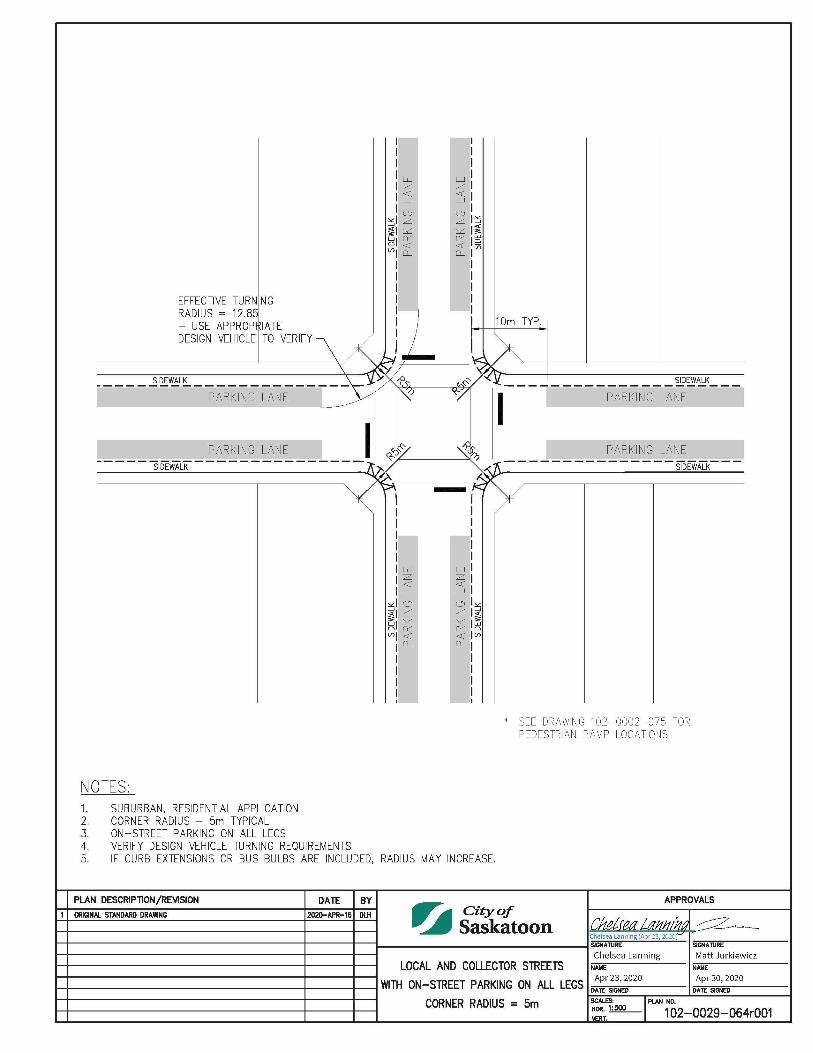
Local and Collector Streets with On-Street Parking on All Legs Corner Radius = 5m 1020029064
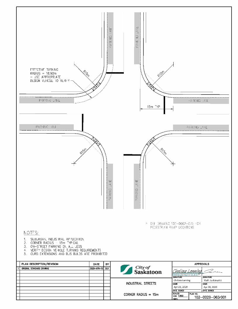
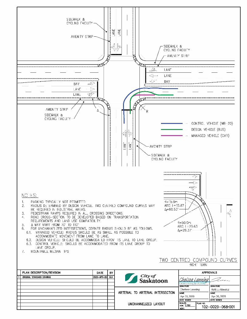
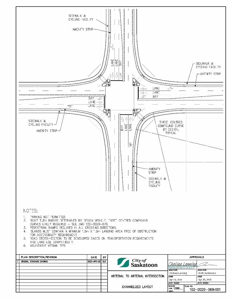
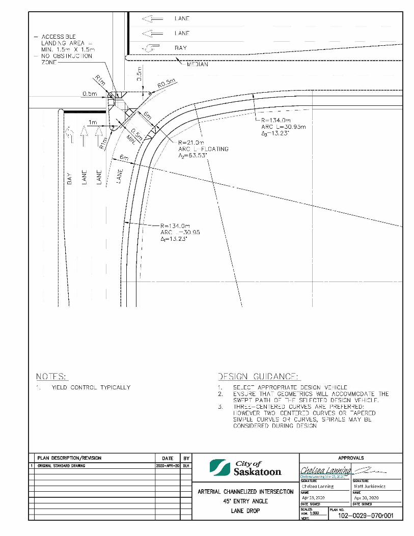
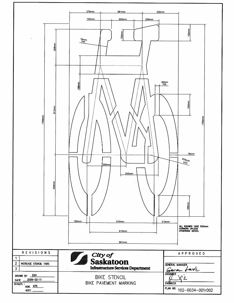
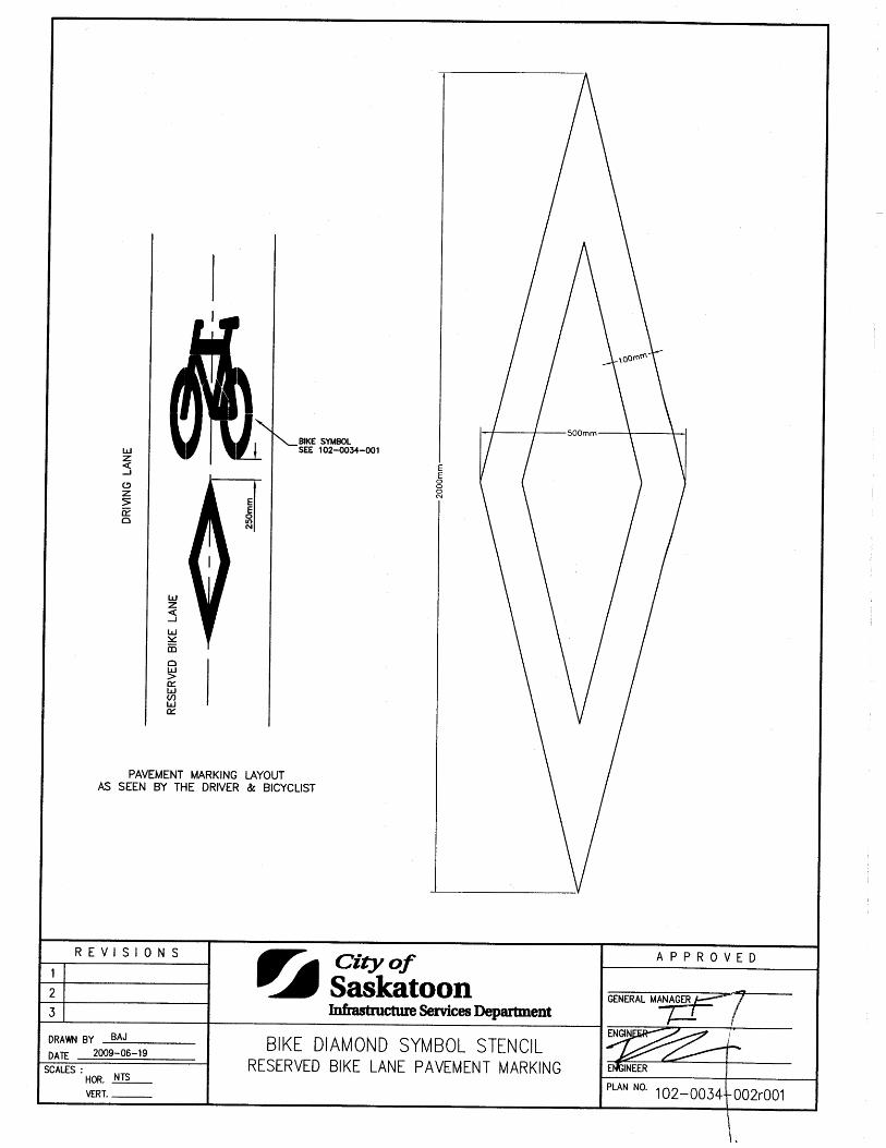
Industrial Streets Corner Radius = 15m 1020029065 Arterial - Arterial Intersection Unchannelized Layout 1020029068 Arterial - Arterial Intersection Channelized Layout 1020029069 Arterial Channelized Intersection 45 degree Entry Angle Lane Drop 1020029070 Arterial Channelized Intersection High Entry Angle Lane Drop 1020029071 Pavement Markings Bike Stencil Bike Pavement Marking 1020034001 Bike Diamond Symbol Stencil Reserved Bike Lane Pavement Marking 1020034002
List of Standard Construction Specifications & Drawings Page 13 of 13
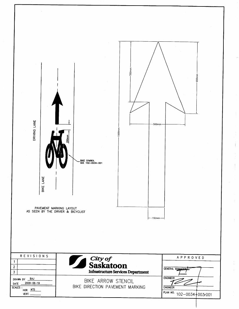
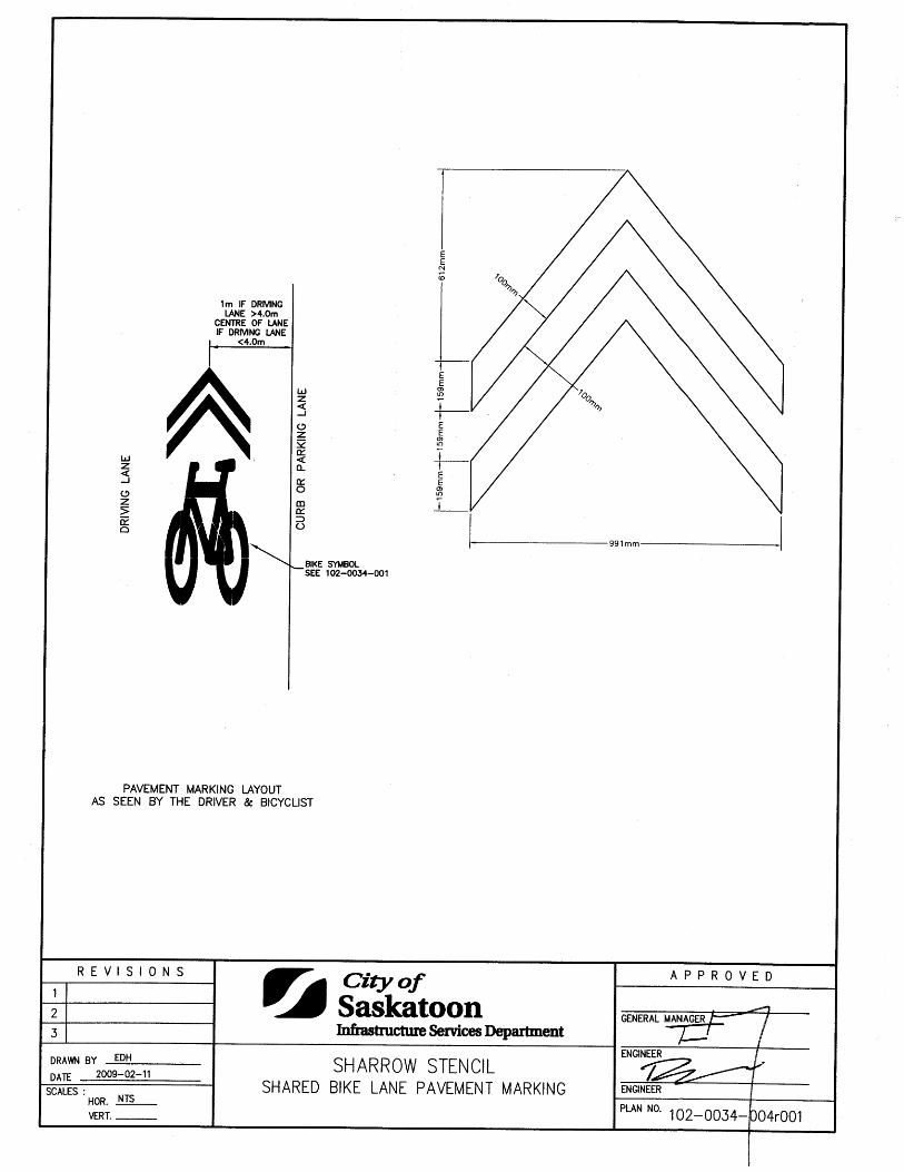
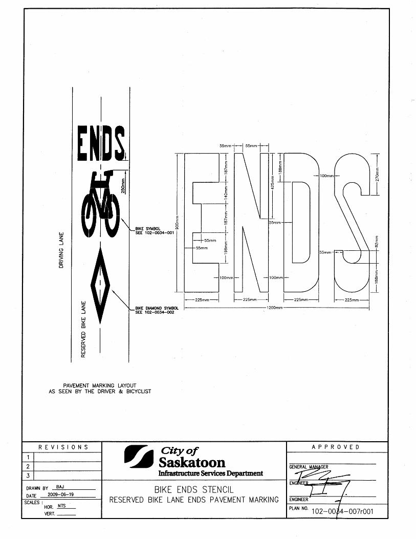
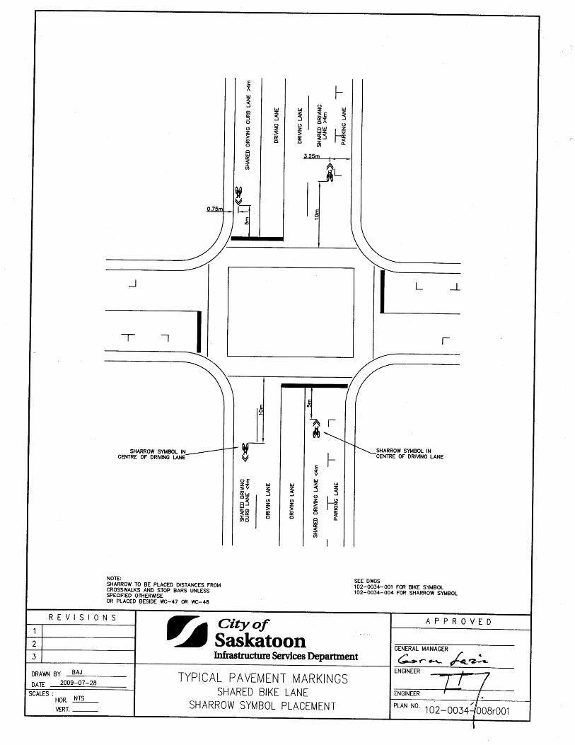
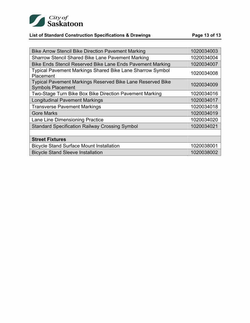
Bike Arrow Stencil Bike Direction Pavement Marking 1020034003 Sharrow Stencil Shared Bike Lane Pavement Marking 1020034004 Bike Ends Stencil Reserved Bike Lane Ends Pavement Marking 1020034007 Typical Pavement Markings Shared Bike Lane Sharrow Symbol Placement 1020034008
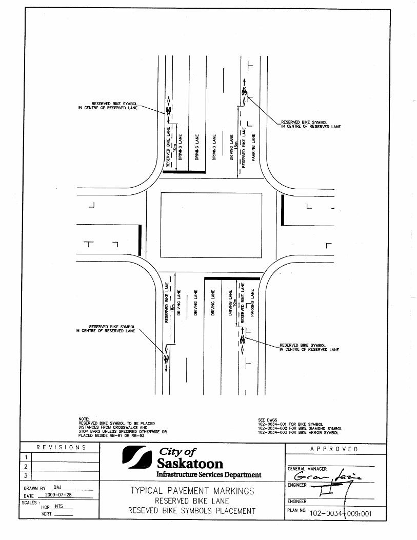
Typical Pavement Markings Reserved Bike Lane Reserved Bike Symbols Placement 1020034009
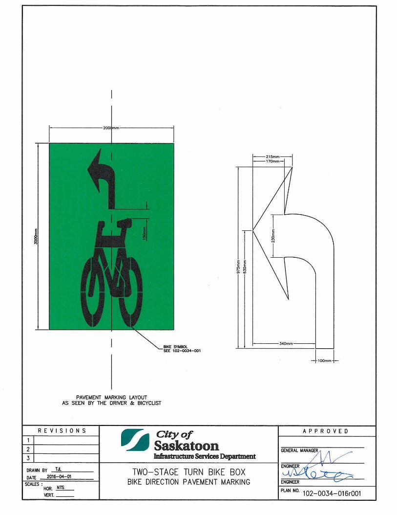
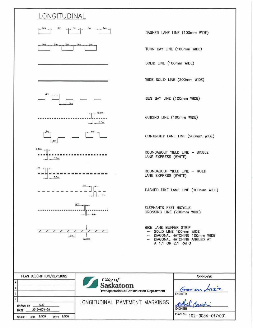
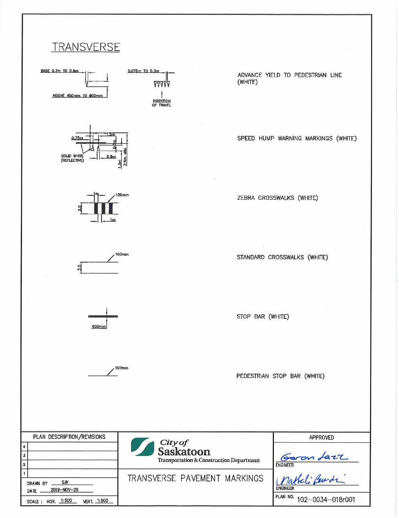
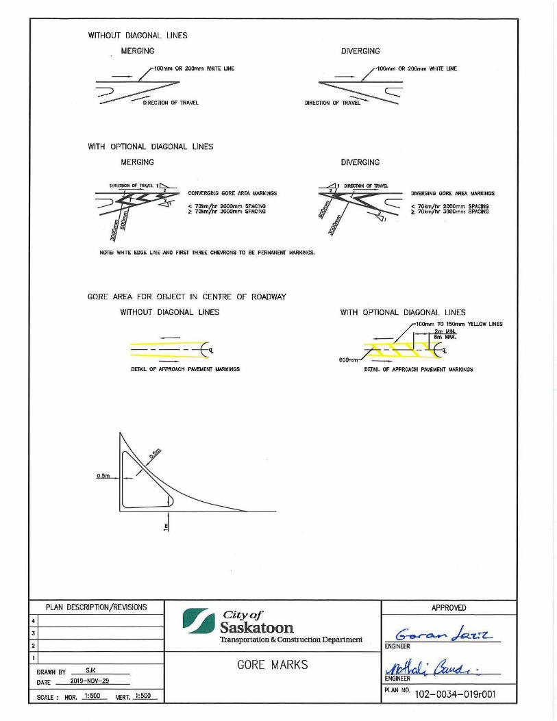
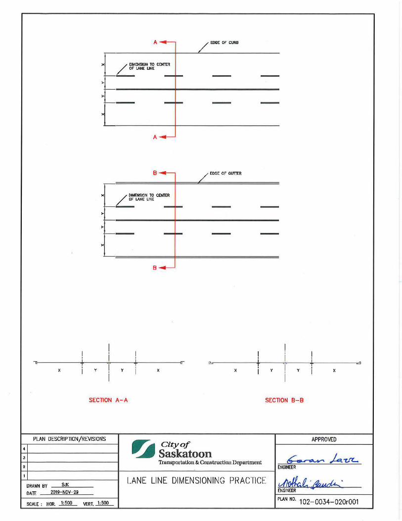
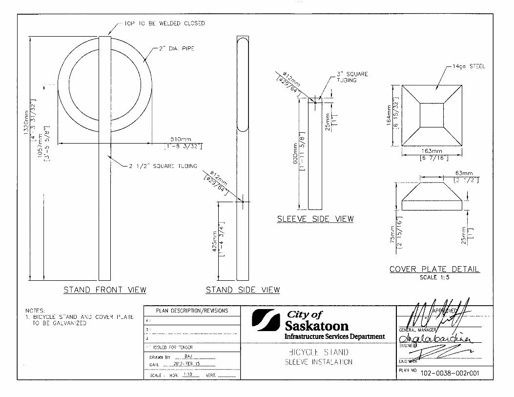
Two-Stage Turn Bike Box Bike Direction Pavement Marking 1020034016 Longitudinal Pavement Markings 1020034017 Transverse Pavement Markings 1020034018 Gore Marks 1020034019 Lane Line Dimensioning Practice 1020034020 Standard Specification Railway Crossing Symbol 1020034021 Street Fixtures Bicycle Stand Surface Mount Installation 1020038001 Bicycle Stand Sleeve Installation 1020038002

General Requirements Division 1 Project Control Section 01010 Revised Date: 2005-01-04 Page 1 of 4
01010 Project Control
Index
01010-1 General 2 1.1 Project Control System Requirements and Application 2 1.2 Method 2 1.3 Effect of Approvals 2 1.4 Preconstruction Meeting 2
01010-2 Scheduling 2 2.1 Post Award 2 2.2 Duration 3 2.3 Arrange Participation 3 2.4 Approval 3
01010-3 Job Meetings 3 3.1 Intervals 3 3.2 Notification 3 3.3 Minutes 3 3.4 Owner-called Meetings 4
01010-4 Measurement and Payment 4

General Requirements Division 1 Project Control Section 01010 Revised Date: 2005-01-04 Page 2 of 4
01010-1 General
1.1 Project Control System Requirements and Application
The Engineer will provide and operate a system of project control as a central communication and management control tool. The Contractor is required to provide detailed data concerning his proposed construction methods to the Engineer. This system will be used to identify, schedule, and monitor activities related to progress of the total project since it will show effect of performance on total project and will identify required efforts to be expended for maintenance of satisfactory progress.
1.2 Method
Project progress will be controlled using a project control system administered by the Engineer. Control may be based on network techniques including critical path method (CPM) for planning, scheduling, monitoring and reporting of project progress.
1.3 Effect of Approvals
Approvals by the Engineer of original network or schedules and revisions thereto, do not relieve the Contractor from any duties or responsibilities required by the Contract.
1.4 Preconstruction Meeting
1. Within 10 days after award of the Contract, the Engineer will request a meeting to discuss and set up administrative procedures and responsibilities. The Contractor shall organize and advise all parties accordingly.
2. Senior representatives of the Owner, Engineer, Contractor, major Subcontractors, Field Inspectors and Superintendents are to be in attendance.
3. Establish time and location of meeting and notify all parties concerned to attend. Notify parties minimum of 5 days before meeting.
01010-2 Scheduling
2.1 Post Award
Within 20 days from Contract award date, provide necessary scheduling or network information such as activity sequencing and duration estimates for submittal of shop drawings and samples, procurement of major equipment and materials, installation and

General Requirements Division 1 Project Control Section 01010 Revised Date: 2005-01-04 Page 3 of 4
testing and subcontract awards, to allow completion of Work Breakdown Structure, Master Milestone network and detailed CPM construction networks. Detailed CPM construction networks must cover period at least three months beginning from date of Contract award, with activity durations not exceeding 15 days.
2.2 Duration
For duration of project provide necessary information to enable detailed CPM networks to be made available at all times for periods of at least three months ahead through to project completion date.
2.3 Arrange Participation
Arrange participation on site and off site of subcontractors and suppliers, as and when necessary, for purpose of network planning, scheduling, updating and progress monitoring.
2.4 Approval
Sign all networks or schedules to indicate approval.
01010-3 Job Meetings
3.1 Intervals
After award of Contract, arrange meetings at regular intervals at times and locations approved by the Engineer.
3.2 Notification
The Contractor shall notify all parties concerned to attend, to ensure proper co-ordination of project work.
3.3 Minutes
The Contractor shall record minutes of these meetings, and circulate minutes to all parties within 7 days of the meeting.
General Requirements Division 1 Project Control Section 01010 Revised Date: 2005-01-04 Page 4 of 4
3.4 Owner-called Meetings
In addition to the above, the Owner will call general site meetings throughout the course of the work. Representatives of the Engineering Consultant and the Contractor will be expected to attend.
01010-4 Measurement and Payment
There will be no separate payment for work outlined in this section.
End of Specification 01010
General Requirements Division 1 Shop Drawings, Product Data and Samples Section 01015 Revised Date: 2005-01-04 Page 1 of 5
01015 Shop Drawings, Product Data and Samples
Index
01015-1 General 2 1.1 Description 2 1.2 Related Work Specified Elsewhere 2 1.3 Submissions 2 1.4 Samples and Mock-Ups 2 1.5 Shop Drawings 3 1.6 Product Data 3 1.7 Responsibility 3 1.8 Measurement for Payment 4
01015-2 Execution 4 2.1 Submission Requirements 4 2.2 Coordination of Submission 4 2.3 Distribution of Submittals after Review 5

General Requirements Division 1 Shop Drawings, Product Data and Samples Section 01015 Revised Date: 2005-01-04 Page 2 of 5
01015-1 General
1.1 Description
This section establishes general requirements for submission of shop drawings, product
data and samples specified for review by the Engineer.
1.2 Related Work Specified Elsewhere
Particular requirements for shop drawings, product data and samples are specified under various sections.
1.3 Submissions
Work involving relevant product may proceed only after submission is reviewed.
Reproductions for submissions: reproducible transparency with one opaque diazo print.
Submissions to include:
1. date and revision dates 2. project title and number 3. name of:
a. contractor b. subcontractor c. supplier d. manufacturer e. separate detailer when pertinent
4. identification of product or material 5. relation to adjacent structure or materials 6. field dimensions, clearly identified as such 7. specification section number 8. applicable standards, such as CSA or CGSB numbers 9. Contractor's stamp, initialled or signed, certifying review of submission,
verification of field measurement and compliance with Contract Documents.
1.4 Samples and Mock-Ups
Submit samples in sizes and quantities specified.
General Requirements Division 1 Shop Drawings, Product Data and Samples Section 01015 Revised Date: 2005-01-04 Page 3 of 5
Where colour, pattern or texture is criterion, submit full range of samples.
Reviewed samples or mock-ups will become standards of workmanship and material against which installed work will be checked on project.
1.5 Shop Drawings
Drawings to be originals, prepared by Contractor, subcontractor, supplier or distributor which illustrate appropriate portion of work; showing fabrication, layout, setting or erection details as specified in appropriate sections.
Maximum sheet size 860 mm x 1120 mm.
Include information required in Subsection 1.3.
1.6 Product Data
Certain specification sections specify that manufacturer's standard schematic drawings, catalogue sheets, diagrams, schedules, performance charts, illustrations and other standard descriptive data will be accepted in lieu of shop drawings.
Above will be accepted only if they conform to following:
• delete information which is not applicable to project. • supplement standard information to provide additional information applicable to
project. • show dimensions and clearances required. • show performance characteristics and capacities.
1.7 Responsibility
Contractor's responsibility for errors and omissions in submission is not relieved by Engineer's review of submittals.
Contractor's responsibility for deviations in submission from requirements of Contract Documents is not relieved by Engineer's review of submission unless Engineer gives written acceptance of specified deviations.

General Requirements Division 1 Shop Drawings, Product Data and Samples Section 01015 Revised Date: 2005-01-04 Page 4 of 5
1.8 Measurement for Payment
No separate measurement to be made for work this section; work is incidental to project costs.
01015-2 Execution
2.1 Submission Requirements
Accompany submissions with transmittal letter in duplicate, containing:
1. date 2. project title and number 3. Contractor's name and address 4. number of each shop drawing, product data and sample submitted. 5. other pertinent data.
Identify details by reference to sheet and detail numbers shown on Contract Drawings.
Notify Engineer, in writing at time of submission, of deviation from requirements of Contract Drawings.
Construct field samples and mock-ups at locations acceptable to Engineer.
Construct each sample or mock-up complete, including work of all trades required to finish work.
Submit number of copies of product data which Contractor requires for distribution plus four copies which will be retained by the Engineer.
2.2 Coordination of Submission
Schedule submissions at least 10 days before dates reviewed submissions will be needed.
Coordinate each submission with requirements of work and Contract Documents.
Review shop drawings, product data and samples prior to submission and verify:
• field measurements
General Requirements Division 1 Shop Drawings, Product Data and Samples Section 01015 Revised Date: 2005-01-04 Page 5 of 5
• field construction criteria • catalogue numbers and similar data
After Engineer's review, distribute copies.
2.3 Distribution of Submittals after Review
Distribute copies of shop drawings and product data which carry Engineer's stamp to:
1. job site file 2. record documents file 3. other prime contractors 4. subcontractors 5. supplier 6. fabricator
Distribute samples as directed.
End of Specification 01015
General Requirements Division 1 Testing Laboratory Services Section 01020 Revised Date: 2005-01-04 Page 1 of 3
01020 Testing Laboratory Services
Index
01020-1 General 2 1.1 Description 2 1.2 Related Requirements Specified Elsewhere 2 1.3 Appointment, Payment and Requirements 2 1.4 Measurement for Payment 3
01020-2 Execution 3 2.1 Contractor's Responsibilities 3 2.2 Frequency and Evaluation of Testing 3
General Requirements Division 1 Testing Laboratory Services Section 01020 Revised Date: 2005-01-04 Page 2 of 3
01020-1 General
1.1 Description
This section establishes general requirements for testing to be performed by testing laboratory designated by the Engineer.
1.2 Related Requirements Specified Elsewhere
Particular requirements for inspection and testing are specified under various specification sections.
1.3 Appointment, Payment and Requirements
1.3.1 Owner and Exceptions
The Owner will appoint and pay for services of a testing laboratory except for the following:
1. Inspection and testing required by laws, ordinances, rules regulations or orders of public authorities.
2. Inspection and testing performed exclusively for Contractor's convenience. 3. Testing, adjustment and balancing of conveying systems, mechanical and
electrical equipment and systems. 4. Mill tests and certificates of compliance. 5. Tests specified to be carried out by Contractor under the supervision of the
Engineer. 6. Additional tests specified in Subsection 1.3.2 Additional Tests.
1.3.2 Additional Tests
Where tests or inspections by designated testing laboratory reveal work not in accordance with contract requirements, the Contractor shall pay costs for additional tests or inspections as Engineer may require to verify acceptability of corrected work. Costs for additional testing will be deducted from Contractor's monthly payment certificates.

General Requirements Division 1 Testing Laboratory Services Section 01020 Revised Date: 2005-01-04 Page 3 of 3
1.4 Measurement for Payment
No separate measurement to be made for work this section, work is incidental to project costs.
01020-2 Execution
2.1 Contractor's Responsibilities
1. Furnish labour and facilities to: a. Provide access to work to be inspected and tested. b. Facilitate inspections and tests. c. Make good work disturbed by inspection and test. d. Provide storage on-site for laboratory's exclusive use to store equipment
and cure test samples. 2. Notify the Engineer sufficiently in advance of operations to allow for assignment
of laboratory personnel and scheduling tests. 3. Where materials are specified to be tested, deliver representative samples in
required quantity to testing laboratory. 4. Pay costs for uncovering and making good work that is covered before required
inspection or testing is completed and approved by the Engineer.
2.2 Frequency and Evaluation of Testing
When not specified separately, frequency of testing to be as directed by the Engineer.
Where not specified separately, the Contractor shall cease operation until corrections to his production process are corrected if any of the following criteria are not met:
1. Average of all tests to equal or exceed specification. 2. Not more than 10% of all tests to be below specification. 3. Average of 3 consecutive tests to equal or exceed specification. 4. Individual test result to equal or exceed 90% of specification.
End of Specification 01020
General Requirements Division 1 Temporary Facilities Section 01025 Revised Date: 2005-01-04 Page 1 of 9
01025 Temporary Facilities
Index
01025-1 General 2 1.1 Description 2 1.2 Definitions 2 1.3 Measurement for Payment 4
01025-2 Execution 4 2.1 Access 4 2.2 Contractor's Site Office 4 2.3 Engineer's Site Office 5 2.4 Storage Sheds 5 2.5 Sanitary Facilities 6 2.6 Parking 6 2.7 Site Enclosures 6 2.8 Security Systems 6 2.9 Power 6 2.10 Heating and Ventilation 7 2.11 Drainage 8 2.12 Site Signs and Notices 8 2.13 Removal of Temporary Facilities 8 2.14 Traffic Operations 8 2.15 Site Maintenance 9

General Requirements Division 1 Temporary Facilities Section 01025 Revised Date: 2005-01-04 Page 2 of 9
01025-1 General
1.1 Description
This section establishes requirements for all temporary facilities including the following:
1. Access 2. Contractor's site office 3. Engineer's site office 4. Storage sheds 5. Sanitary facilities 6. Parking 7. Security systems 8. Power 9. Water supply 10. Heating and ventilation 11. Drainage 12. Signs and notices 13. Mobilization 14. Removal of temporary facilities 15. Maintenance of site 16. Maintenance of traffic
1.2 Definitions
1.2.1 Mobilization
Mobilization includes the following:
1. Supply, installation, and servicing of mobile offices, workshops, stores, housing, etc.
2. Supply and transport to site of equipment used in performing work. 3. Dismantling and removing all temporary facilities upon completion of work and
restoring site to its original condition. 4. Supply and installation and subsequent dismantling and removal of materials and
equipment required for maintenance of traffic.
General Requirements Division 1 Temporary Facilities Section 01025 Revised Date: 2005-01-04 Page 3 of 9
1.2.2 Maintenance of Site
Maintenance of site includes cost of maintaining site during periods when work is delayed, as defined below:
1. Payment made under this section is subject to the terms for schedule extensions listed in General Conditions, Article 00700-34 - Delays, and is subject to approval by the Engineer.
2. Tendered unit price per day to include supervisory staff salaries and expenses, office expenses, equipment costs and operating expenses, telephone, electricity and gas, water and sanitation, labour to maintain and protect site, bond and financing costs, overhead and profit.
3. Payment made only when work is delayed throughout site for full working day. No compensation for inconvenience when work is delayed in one area of site but work continues elsewhere on site.
4. Tendered unit price not to include equipment down-time during delays, for which compensation will be negotiated if and when delay occurs.
1.2.3 Maintenance of Traffic
Maintenance of traffic requires that existing and temporary roads are kept open to traffic and in good condition.
1. Maintain existing road surfaces in original condition. 2. Supply and erect temporary signing and barricades and supply flagmen as may
be required when work interferes with normal traffic flow. 3. Construct detour roads within site as indicated in drawings and maintain surfaces
at all times. 4. Ensure convenience and safety of residents affected by work at all times. 5. Credit Owner for maintenance of traffic expenditures arising from emergency
situations or cases when action is required by Owner due to failure on part of Contractor to perform.
6. Maintain detour signs and barricades within and outside site where indicated in drawings or by the Engineer as per standards established in the City of Saskatoon Traffic Control Manual.

General Requirements Division 1 Temporary Facilities Section 01025 Revised Date: 2005-01-04 Page 4 of 9
1.3 Measurement for Payment
Mobilization to be paid as lump sum with 80% payable upon substantial completion of mobilization as determined by the Engineer, and remaining 20% payable upon total performance of the work.
Maintenance of site to be measure in working days.
Maintenance of traffic to be paid on a cost plus basis in accordance with Article 00700-24 of the General Conditions, and:
1. No payment for maintenance of existing road surfaces within site, initial supply and erection of temporary signs and barricades, construction and maintenance of detours within site.
2. Payment to include replacement of signs and barricades damaged by causes not under the control of the Contractor, maintenance of existing road surfaces outside site, supply of flagmen, inspection and maintenance of detour signs and barricades inside and outside site.
01025-2 Execution
2.1 Access
Provide and maintain adequate access to project site.
Build and maintain temporary roads and provide snow removal during period of work.
If authorized to use existing roads for access to project site, maintain such roads for duration of Contract and make good damage resulting from Contractor's use of roads.
2.2 Contractor's Site Office
Provide office of size to accommodate site meetings and furnished with drawing laydown table, drawing storage rack, three-drawer filing cabinet, shelving and coat hooks when required by Section 01005, Specific Conditions.
Install lighting to provide 750 1x using surface mounted shielded, commercial fixtures with 10% upward light component.

General Requirements Division 1 Temporary Facilities Section 01025 Revised Date: 2005-01-04 Page 5 of 9
Heat to maintain 22° C inside temperature. Provide two operable windows for cross ventilation.
Provide telephone in Contractor's site office. Pay telephone is not acceptable.
2.3 Engineer's Site Office
Provide temporary office for Engineer when required by Section 01005, Specific Conditions.
Inside dimensions minimum 3.6 m long x 3 m wide x 2.4 m high with floor .1 m above grade, complete with 50% opening windows and one lockable door.
Insulate building and provide heating system to maintain 22° C inside temperature at -20° C outside temperature.
Finish inside walls and ceiling with plywood, hardboard or wallboard and paint in selected colours. Finish floor with 19 mm thick plywood.
Install electrical lighting system to provide minimum 750 1x using surface mounted, shielded commercial fixtures with 10% upward light component.
Arrange and pay for telephone in Engineer's office for his exclusive use. Long distance calls placed on this telephone will be paid for by Engineer.
Provide private washroom facilities adjacent to office complete with flush or chemical type toilet, lavatory, mirror and maintain supply of paper towels and toilet tissue.
Equip office with 1 m x 2 m table, four chairs, 6 m of shelving 300 mm wide, one three-drawer filing cabinet, one plan rack and one coat rack and shelf.
Maintain in clean condition.
2.4 Storage Sheds
Provide adequate weathertight sheds with raised floors, for storage of materials, tools, and equipment which are subject to damage by weather.
General Requirements Division 1 Temporary Facilities Section 01025 Revised Date: 2005-01-04 Page 6 of 9
2.5 Sanitary Facilities
Provide sanitary facilities for work force in accordance with governing regulations and ordinances.
Post notices and take such precautions as required by local health authorities. Keep area and premises in sanitary condition.
2.6 Parking
Parking space will be made available on-site. Maintain and administer this space as directed by the Engineer.
2.7 Site Enclosures
Erect temporary site enclosure using new 1.2 m high snow fence wired to rolled steel "T" bar fence posts spaced at 2.4 m oc. Provide one lockable truck gate. Maintain fence in good repair.
Site enclosures required as indicated on Drawings.
2.8 Security Systems
Ensure safety of all equipment and materials on-site. Repair or replace damaged equipment or materials regardless of cause of damage.
Prevent damage to lines and grades established by Engineer. Re-establish lines or grades that become damaged by any cause.
Maintain concrete finishes free from imperfections, regardless of cause, until acceptance of job. Repair damage to concrete surface at no additional cost to Owner.
Take responsibility for safety of all work performed under this Contract and of all existing structures within limits of Contract. Repair damage at no additional cost to Owner.
2.9 Power
Arrange, pay for and maintain temporary electrical power supply in accordance with governing regulations and ordinances.

General Requirements Division 1 Temporary Facilities Section 01025 Revised Date: 2005-01-04 Page 7 of 9
Install temporary facilities for power such as pole lines and underground cables to approval of local power supply authority.
2.10 Heating and Ventilation
Pay for costs of temporary heat and ventilation used during construction, operation, maintenance and removal of equipment. Use of direct-fired heaters discharging waste products into work areas will not be permitted unless prior approval is given by the Engineer.
Furnish and install temporary heat and ventilation in enclosed areas as required to:
1. Facilitate progress of work. 2. Protect work and products against dampness and cold. 3. Prevent moisture condensation on surface. 4. Provide adequate ambient temperatures and humidity levels for storage,
installation and curing of materials. 5. Provide adequate ventilation to meet health regulations for safe working
environment.
Ventilating must achieve the following:
1. Prevent hazardous accumulations of dust, fumes, mists, vapours or gases in areas occupied during construction.
2. Provide local exhaust ventilation to prevent harmful accumulation of hazardous substances into atmosphere of occupied areas.
3. Dispose of exhaust materials in a manner that will not result in harmful exposure to persons.
4. Ventilate storage spaces containing hazardous or volatile materials. 5. Ventilate temporary sanitary facilities. 6. Continue operation of ventilation and exhaust system for time after cessation of
work process to assure removal of harmful elements.
Maintain strict supervision of operation of temporary heating and ventilating equipment.
1. Enforce safe practices. 2. Prevent abuse of services. 3. Enforce conformance with applicable codes and standards.
General Requirements Division 1 Temporary Facilities Section 01025 Revised Date: 2005-01-04 Page 8 of 9
4. Prevent damage to finishes. 5. Vent direct-fired combustion units to outside.
2.11 Drainage
Refer to Section 01035 for site drainage and pumping requirements.
2.12 Site Signs and Notices
Only Project Identification and Consultant/Contractor signboards and notices for safety or instruction are permitted on site.
Format, location and quantity of site signs and notices to be approved by the Engineer.
Signs and notices for safety or instruction to be in English language or commonly understood graphic symbols.
Maintain signboards, signs and notices for duration of project. Remove and dispose of signs off-site when directed by the Engineer.
Erect, maintain, and subsequently dismantle as directed by the Engineer any project signs supplied by the Owner.
2.13 Removal of Temporary Facilities
Remove temporary facilities from site when directed by the Engineer.
When project is closed down at end of construction season, keep facilities operational until close down is approved by the Engineer.
Restore site to original condition to satisfaction of the Engineer.
2.14 Traffic Operations
Maintain, control and safeguard traffic within and immediately abutting site and maintain detour signing on detours outside site indicated on Drawings.
Conform to City Traffic Bylaw.
General Requirements Division 1 Temporary Facilities Section 01025 Revised Date: 2005-01-04 Page 9 of 9
Vehicles with gross weight greater than 5,000 kg to use routes designated in General Conditions.
Requests for street closures to be made through Engineer.
Provide emergency access for police and fire units at all times.
Provide access to private property for local traffic except when such access would prevent work from being completed.
Advise Engineer if modifications to traffic signals operation by Owner is required, such modification at no cost to Contractor.
Construct, sign, and maintain detours to RTAC standards, City of Saskatoon Traffic Control Manual and to approval of the Engineer.
2.15 Site Maintenance
Maintain site at all times. This includes supervision of site maintenance of offices and utilities, maintenance of equipment, daily clean-up, and general care.
End of Specification 01025
General Requirements Division 1 Safety Requirements Section 01030 Revised Date: 2005-01-04 Page 1 of 3
01030 Safety Requirements
Index
01030-1 General 2 1.1 Description 2 1.2 Related Work Specified Elsewhere 2 1.3 Measurement of Payment 2
01030-2 Execution 2 2.1 Construction Safety Measures 2 2.2 Fire Safety Requirements 2 2.3 Overloading 3
General Requirements Division 1 Safety Requirements Section 01030 Revised Date: 2005-01-04 Page 2 of 3
01030-1 General
1.1 Description
This section specifies requirements for ensuring the safety of people and property affected by performance of work.
1.2 Related Work Specified Elsewhere
Particular requirements for safety are specified under various sections.
1.3 Measurement of Payment
No separate measurement for work in this section.
01030-2 Execution
2.1 Construction Safety Measures
Observe and enforce construction safety measures required by Canadian Construction Safety Code, Provincial Government, Worker's Compensation Board and municipal statutes and authorities.
In event of conflict between any provisions of above authorities, the most stringent provision will apply.
2.2 Fire Safety Requirements
Comply with requirements of standard for Building Construction Operations, DFC No. 301-1975, issued by Dominion Fire Commissioner.
This standard may be viewed at Regional Engineer's office and copies may be obtained from:
Dominion Fire Commissioner Sir Charles Tupper Building Riverside Drive OTTAWA, Ontario K1A OM2
General Requirements Division 1 Safety Requirements Section 01030 Revised Date: 2005-01-04 Page 3 of 3
2.3 Overloading
Ensure no part of work is subjected to a load which will endanger its safety or will cause permanent deformation.
End of Specification 01030
General Requirements Division 1 Environmental Protection Section 01035 Revised Date: 2019-02-06 Page 1 of 13
01035 Environmental Protection
Index
01035-1 General 2 1.1 Description 2 1.2 Definitions 2 1.3 Compliance 4 1.4 Resource Conservation 4
01035-2 Specific Requirements 5 2.1 Recycling and Reuse 5 2.2 Disposal of Wastes 5 2.3 Surface and Groundwater Management 6 2.4 Fill Management 6 2.5 Dust Management 6 2.6 Noise Control 7 2.7 Erosion and Sedimentation Prevention 7 2.8 Spill Management 7 2.9 Spill Prevention 8 2.10 Discovery Management 9 2.11 Environmentally Sensitive Lands 10 2.12 Historic Artifacts 11 2.13 Site Clearing 11 2.14 Tree Protection 12 2.15 Wildlife Protection 12 2.16 Invasive Species 12
01035-3 Measurement and Payment 13

General Requirements Division 1 Environmental Protection Section 01035 Revised Date: 2019-02-06 Page 2 of 13
01035-1 General
1.1 Description
This section describes the requirements for protection of the environment, including air, water, land, natural resources, flora, fauna, humans, and their interrelations.
1.2 Definitions
1.2.1 Clean Soil
Clean Soil means soil that does not contain any deleterious substances.
1.2.2 Contaminated Soil
Contaminated Soil means soil material that has chemical concentrations of regulated substances above applicable regulatory criteria.
1.2.3 Contaminated Water
Contaminated Water means water that has chemical concentrations of regulated substances above applicable regulatory criteria.
1.2.4 Construction Waste
Construction Waste is defined as bulk refuse originating from construction, demolition, renovation and re-development projects not including asbestos, waste dangerous goods or material contaminated with waste dangerous goods.
1.2.5 Deleterious Substances
Deleterious Substances refers to substances that, if added to clean soil, would degrade or alter or form part of a process of degradation or alteration of clean soil quality so that it is rendered or could be rendered deleterious to human or environmental habitat.
1.2.6 Drainage Systems
Drainage Systems in an urbanized environment are the water management systems that are constructed to collect, convey, store, and discharge storm water into the naturally formed rivers, creeks, streams, or other water bodies.
General Requirements Division 1 Environmental Protection Section 01035 Revised Date: 2019-02-06 Page 3 of 13
1.2.7 Environmentally Sensitive Lands
Environmentally Sensitive Lands include the following:
• Wetlands; • Open spaces and utility corridors; • Watercourses; • Waterways; • Underground recharge areas; • Riverbanks; • Natural plant habitats; • Animal habitats; • Flood plains; and • Other landforms easily disturbed by development.
1.2.8 Fill
Fill, including Existing on Site Material and Imported Fill Material, is defined by the Park Development Guidelines and Standard Construction Specifications.
1.2.9 Hazardous Waste
Hazardous Waste is a waste with hazardous properties, which may have potential effects to human or environmental health.
1.2.10 Liquid Waste
Liquid Waste includes sludges, solutions, and any other form of waste in liquid or aqueous phase.
1.2.11 Prohibited, noxious, or nuisance weeds
Prohibited, noxious, or nuisance weeds refers to those listed in the Weed Control Act of Saskatchewan.
1.2.12 Waste
Waste means any discarded or abandoned organic or inorganic material, including material or by-products discarded in a manufacturing or producing process; snow; ice;
General Requirements Division 1 Environmental Protection Section 01035 Revised Date: 2019-02-06 Page 4 of 13
soil; rocks; rubble; garbage; tree cuttings; grass; leaves; empty or partly empty tins, boxes, cartons, bottles and containers; discarded paper and fabrics, discarded household utensils; household furniture; household appliances of any nature; trees; concrete; or any other refuse, rubble, or matter.
1.2.13 Watercourse
Watercourse means a drain, ditch, drainage ditch, culvert, water channel, or retention pond, whether natural, constructed, or altered.
1.2.14 Waterway
Waterway means a river, stream, creek or canal, whether natural, constructed or altered, and includes the frozen surface and bed of the hydraulic channel.
1.3 Compliance
It is the responsibility of the Contractor to know which laws, regulations, approvals or permits relate to the work being done within the city.
It is the responsibility of the Contractor to comply with all applicable laws and regulations and ensure that all requirements imposed are met for all activities within the scope of work.
1.4 Resource Conservation
Operate and conduct work in a way that incorporates the principles of:
• Water conservation. • Reduced fuel consumption; • Energy conservation; and • Reducing or creating efficiency such that waste production is minimized.
Where reasonable, attempt to document resource consumption and identify opportunities for conservation.
General Requirements Division 1 Environmental Protection Section 01035 Revised Date: 2019-02-06 Page 5 of 13
01035-2 Specific Requirements
2.1 Recycling and Reuse
All opportunities to divert construction waste from landfills will be examined and identified. At a minimum, recycling cardboard, wood, asphalt, concrete, metal and plastics generated on site will be examined.
2.2 Disposal of Wastes
All waste is prohibited from being buried on site. Refer to the Waste Bylaw, 2004, Anti-Dumping Bylaw, Sewer Use Bylaw, 2017 and the Storm Water Management Utility Bylaw, 2011 for municipal requirements.
Provide adequate receptacles for solid municipal waste and recycling on site. All solid municipal waste and recyclables must be removed from the site in a timely manner. No waste, trash, litter, or debris shall be left onsite following demobilization of the work site. Ensure no waste, trash, litter, or debris is blown off site. Any waste that has migrated off site shall be collected and disposed of.
Any waste or material shall not be abandoned in the course of import, export or transit.
All waste shall be disposed of only at approved facilities.
Disposal of waste into drainage systems, watercourses and waterways is prohibited.
Disposal of liquid waste into the sanitary sewer is regulated by the Sewer Use Bylaw, 2017. A Special Discharge Permit from the City is required for all non-domestic wastewater disposal into the sanitary sewer.
Some liquid wastes may require testing and certification that they are non-hazardous prior to disposal. Testing must be completed by a certified laboratory.
Separate potentially hazardous waste from non-hazardous waste. Dispose of hazardous waste in accordance with regulations.
Fires and burning of rubbish on site is not permitted.

General Requirements Division 1 Environmental Protection Section 01035 Revised Date: 2019-02-06 Page 6 of 13
2.3 Surface and Groundwater Management
Provide temporary drainage and pumping as necessary to keep excavations and the site free from standing water.
Dispose of water pumped from site in accordance with municipal requirements. A Special Discharge Permit may be required.
2.4 Fill Management
All fill sources must be approved by the Engineer. Provide a Chain of Custody. Confirmatory testing may be required. Testing must be completed by a certified laboratory.
Potentially contaminated fill must be disposed of at an approved facility or reused with Engineer approval.
Backfill must be clean and approved by the Engineer. Provide a Chain of Custody. Confirmatory testing may be required. Testing must be completed by a certified laboratory.
Potentially contaminated fill being stored on site must be segregated and isolated from the public and stored in a manner that prevents any offsite migration, as approved by the Engineer.
Clean soil may be taken to the landfill with proper permitting from the City.
2.5 Dust Management
Apply dust control measures as prescribed by the Engineer.
Maintain erosion and pollution control features if installed under this Contract.
Prevent sandblasting and other extraneous materials from contaminating air beyond the application area by providing temporary enclosures.
Wind erosion control measures should consist of applying water or other dust palliatives to prevent or alleviate dust. Do not apply so much that runoff occurs. Cover stockpiles as an alternative to applying water or dust palliative.

General Requirements Division 1 Environmental Protection Section 01035 Revised Date: 2019-02-06 Page 7 of 13
2.6 Noise Control
Noise on site shall be mitigated as to satisfy the Noise Bylaw, 2003 and Occupational Health and Safety requirements.
Consider the surrounding environment and conduct work as to not create excess noise disturbance.
Apply noise control measures as prescribed by the Engineer.
2.7 Erosion and Sedimentation Prevention
Stockpiles should be located in areas with little potential for flooding and at least 15 m (50 ft) from drainage systems and waterways, unless approved by the Engineer. Consider the following options to manage site runoff impacts:
• Grade stockpile areas; • Identify downstream storm drains and manholes, and place a cover, fence or
barrier around them and/or install a sediment trap; and • Place berms, dikes or temporary diversion structures around stockpiles; • Communicate site runoff management measures to the Engineer.
Design and construct temporary crossings so that minimum erosion is caused to waterways.
Ensure adequate erosion and sediment control measures are in place, as defined by the Engineer.
2.8 Spill Management
Spills must be addressed in a manner that will:
1. Stop or eliminate the discharge or release from occurring; 2. Contain the spilled substance so that it does not spread or migrate; 3. Ensure that public, worker and environmental safety is upheld; 4. Clean and remediate the spill impacts; and 5. Fulfill reporting requirements.
Spills must never be hosed down or buried.

General Requirements Division 1 Environmental Protection Section 01035 Revised Date: 2019-02-06 Page 8 of 13
Be prepared for spills by locating and clearly labelling spill kits and used absorbent containers.
A substance release must be reported to the Saskatchewan Ministry of Environment if:
The substance may cause or is causing an adverse effect on the environment; or
The substance meets the criteria set out by the provincial Discharge and Discovery Reporting Standard.
All releases requiring reporting to the Saskatchewan Ministry of Environment shall be communicated to the Engineer at the same time.
2.9 Spill Prevention
Prior to the start of construction activities, all spill hazards must be identified and a Spill Protocol must be developed and communicated to the Engineer.
Construction activity must meet all applicable laws and regulations, including Part III of the provincial Environmental Management and Protection Act, 2010.
Construction material transport, delivery and storage shall satisfy federal, provincial and municipal regulatory requirements, including permitting.
Hazardous material transport, delivery and storage shall satisfy federal, provincial and municipal regulatory requirements, including permitting.
Materials associated with construction activities must be delivered and stored using practices that prevent these materials from polluting water, soil and air.
2.9.1 Fueling activities
Fueling activities shall be managed in a way such that:
1. Fueling areas must: a. Be located on level grade; b. Be located at least 100 m away from waterways; and c. Be located at least 50 m away from catch basins; unless a written
standard operating procedure is developed, approved by the Engineer and followed;
General Requirements Division 1 Environmental Protection Section 01035 Revised Date: 2019-02-06 Page 9 of 13
2. Fueling operations are never left unattended at any time; 3. A drip tray or equivalent localized spill containment is required when fueling; 4. Vehicles and equipment that regularly enter and leave the site are fueled offsite; 5. Fixed bulk fuel tanks require secondary containment and adequate release
detection systems that comply with regulation; 6. Spill kits and appropriate absorbent spill clean-up materials are readily available;
and 7. All leaks and spills are cleaned up immediately and materials used for cleanup
and contaminated soil are disposed of properly
2.9.2 Temporary Sanitary Facilities
Temporary Sanitary Facilities shall be managed such that:
1. Temporary sanitary facilities are not located near drainage systems, watercourses or waterways;
2. Temporary sanitary facilities are located in areas with little potential for flooding; and
3. If the area is deemed to be a high wind area, the facilities shall be secured to prevent overturning; unless approved by the Engineer.
2.9.3 Liquid waste
Liquid waste containment shall be structurally sound, leak-free, and provide sufficient spill containment for the anticipated volume.
Frequently inspect liquid waste containment and spill containment devices for damage or defects and repair as needed.
Locate liquid waste containment such that accidental releases do not discharge to drainage systems, watercourses, or waterways or threaten health or safety.
2.10 Discovery Management
The Engineer may implement additional health and safety procedures for substance discoveries, which could include stopping work in the area of contamination discovery, securing the worksite and taking appropriate measures to protect workers and public safety.
General Requirements Division 1 Environmental Protection Section 01035 Revised Date: 2019-02-06 Page 10 of 13
Laboratory testing may be conducted as designated by the Engineer if suspected contaminated water or soil is encountered. Testing must be completed by a certified laboratory.
The discovery of a substance must be reported to the Saskatchewan Ministry of Environment if:
• The substance may cause or is causing an adverse effect; • The substance discovered is in a quantity or concentration that could pose a
serious risk to the environment or public health or safety; or • The substance meets the criteria set out by the provincial Discharge and
Discovery Reporting Standard for the applicable media with respect to that substance.
All discoveries requiring reporting to the Saskatchewan Ministry of Environment shall be communicated to the Engineer at the same time.
2.11 Environmentally Sensitive Lands
Work that occurs within or adjacent to an Environmentally Sensitive Land shall satisfy all applicable regulations.
Work that occurs within or adjacent to a wetland is to be conducted in a way that considers all aspects of the Civic Council Policy C09-041.
Work that occurs within or adjacent to an open space is to meet the requirements of the Park Development Guidelines and Standard Construction Specifications.
Any proposed works on or adjacent to waterways must satisfy all applicable legislation.
Operation of construction equipment in waterways is prohibited, unless the appropriate permitting is acquired.
Using waterway beds for borrow material is prohibited, unless the appropriate permitting is acquired.
Grade all fill on banks to ensure it is compact, contoured to the natural slope of the site and does not affect slope stability as per the approved design.
General Requirements Division 1 Environmental Protection Section 01035 Revised Date: 2019-02-06 Page 11 of 13
Dumping of waste material, or debris in waterways is prohibited.
2.12 Historic Artifacts
Items of archeological value are protected by the provincial Heritage Property Act and Civic Council Policy C10-020.
Items suspected of antique and relic value remain the property of the owner and should assessed by the owner for protection value.
Items identified by the Contractor before work start shall be protected per Civic Council Policy C10-020.
Items discovered on City property during work shall be protected per Civic Council Policy C10-020 and reported to the owner for value assessment before proceeding with removal of items.
2.13 Site Clearing
Communicate the Site Clearing Plan to the Engineer at least 1 week prior to the site clearing start date.
The Site Clearing Plan should incorporate best management practices to protect and conserve existing natural areas, as well as satisfy applicable legislation related to migratory birds and species at risk.
The Site Clearing Plan must be designed in a way as to let wildlife have the opportunity to vacate the site on their own.
Permit conditions provided by the Engineer will be adhered to for the duration that they are applicable.
Restrict stripping of topsoil and vegetation to those areas designated in the Contract Documents or as marked by the Engineer.
Where possible, maintain existing ground cover to maximize runoff filtration.

General Requirements Division 1 Environmental Protection Section 01035 Revised Date: 2019-02-06 Page 12 of 13
2.14 Tree Protection
Trees on City property shall be protected according to the requirements of Civic Council Policy C09-011 and the Park Development Guidelines and Standard Construction Specifications.
Protect trees and plants on site and adjacent properties, where indicated by the Engineer, in compliance with municipal requirements.
Restrict tree removal to trees identified by the Engineer, in consultation with Urban Forestry.
2.15 Wildlife Protection
Avoid attracting wildlife to the work space by controlling or eliminating common attractants such as food wastes (garbage), standing water and perceived shelter (stockpiles, bins, boxes, etc.).
Any wildlife encountered during construction activities should first be allowed to exit the site on their own, via safe routes.
If safe routes are unavailable, removal and relocation of wildlife must only be done by qualified wildlife service providers working in accordance with applicable laws.
Be aware of key risk periods for migratory birds as stipulated by Environment Canada.
Avoid engaging in potentially destructive activities during key risk periods.
If activities are unavoidable, communicate with the Engineer to establish an appropriate Risk Management Plan that satisfies all applicable legislation, such as the Migratory Birds Convention Act, 1994 and the Species at Risk Act.
2.16 Invasive Species
Invasive species management should be applied where appropriate and as prescribed by the Engineer, in consultation with Parks.
Prohibited, noxious or nuisance weeds management shall be applied where appropriate and as prescribed by the Engineer, in accordance with The Weed Control Act of Saskatchewan.

General Requirements Division 1 Environmental Protection Section 01035 Revised Date: 2019-02-06 Page 13 of 13
01035-3 Measurement and Payment
No separate measurement for payment to be made for work in this section.
End of Specification 01035
General Requirements Division 1 Cleaning Section 01040 Revised Date: 2005-01-04 Page 1 of 3
01040 Cleaning
Index
01040-1 General 2 1.1 Description 2 1.2 Related Work Specified Elsewhere 2 1.3 Measurement for Payment 2
01040-2 Products 2 2.1 Materials 2
01040-3 Execution 2 3.1 General 2 3.2 Cleaning During Construction 2 3.3 Final Cleaning 3
General Requirements Division 1 Cleaning Section 01040 Revised Date: 2005-01-04 Page 2 of 3
01040-1 General
1.1 Description
This section specifies requirements for maintenance and cleaning of site during construction and final clean up.
1.2 Related Work Specified Elsewhere
Particular requirements for cleaning are specified under various sections.
1.3 Measurement for Payment
No separate measurement to be made for work in this section.
01040-2 Products
2.1 Materials
Use only cleaning materials recommended by manufacturer of surface to be cleaned and as recommended by cleaning material manufacturer.
01040-3 Execution
3.1 General
Conduct cleaning and disposal operations to comply with local ordinances and anti-pollution laws.
Store volatile wastes in covered metal containers and remove from premises daily.
Prevent accumulation of wastes which create hazardous conditions.
Provide adequate ventilation during use of volatile or noxious substances.
3.2 Cleaning During Construction
Maintain project grounds and public properties free from accumulations of waste materials and rubbish.
Provide adequate on-site containers for collection of waste materials and rubbish.
General Requirements Division 1 Cleaning Section 01040 Revised Date: 2005-01-04 Page 3 of 3
Remove waste materials and rubbish from site.
3.3 Final Cleaning
In preparation for substantial completion, conduct inspection of sight-exposed interior and exterior surfaces.
Broom clean paved surfaces; rake clean other surfaces of ground where required.
Remove debris and surplus materials from site.
End of Specification 01040
General Requirements Division 1 Products/Workmanship Section 01045 Revised Date: 2005-01-04 Page 1 of 3
01045 Products/Workmanship
Index
01045-1 Products 2 1.1 General 2 1.2 Product Quality 2 1.3 Availability of Products 2
01045-2 Workmanship 2 2.1 General 2 2.2 Coordination 3 2.3 Measurement and Payment 3
General Requirements Division 1 Products/Workmanship Section 01045 Revised Date: 2005-01-04 Page 2 of 3
01045-1 Products
1.1 General
All products, equipment and articles incorporated in the work shall be new, not damaged
or defective and of best grade (compatible with specifications) for the purpose intended.
If requested, furnish evidence as to source and quality of products provided.
1.2 Product Quality
Should any dispute arise as to the quality or fitness of equipment, materials or products, the decision shall rest with the Engineer, and shall be based upon the requirements of this Contract.
1.3 Availability of Products
Immediately on signing the Contract, review the project requirements, anticipate foreseeable supply delays in any items and so notify the Engineer, in order that substitution or other remedial action may be authorized in ample time to prevent work delay. Should the Contractor fail to notify the Engineer at commencement of the work and should it subsequently appear that the work may be delayed for the above reasons, the Engineer reserves the right to substitute more readily available materials or equipment of similar character, at no increase in Contract price.
01045-2 Workmanship
2.1 General
Workmanship shall be of the best quality, executed by workmen experienced and skilled in their respective trades. If work is specified in such manner as to make it impracticable to produce required results, notify the Engineer for further directions.
At all times, enforce discipline and good order among workers. Do not employ any unfit person or anyone unskilled in the duties assigned to him. The Engineer reserves the right to require the removal, from the site, of workers deemed incompetent, careless, insubordinate or otherwise objectionable.

General Requirements Division 1 Products/Workmanship Section 01045 Revised Date: 2005-01-04 Page 3 of 3
2.2 Coordination
Ensure full cooperation and coordination among all trades and provide efficient and continuous supervision.
Make certain that the work of various subcontractors does not conflict or create interference, thus assuring completion of the project in a satisfactory manner.
2.3 Measurement and Payment
There will be no separate payment for work outlined in this section.
End of Specification 01045

General Requirements Division 1 Project Record Documents Section 01050 Revised Date: 2005-01-04 Page 1 of 2
01050 Project Record Documents
Index
01050-1 General 2 1.1 Description 2 1.2 Measurement for Payment 2
01050-2 Execution 2 2.1 Record Drawings 2

General Requirements Division 1 Project Record Documents Section 01050 Revised Date: 2005-01-04 Page 2 of 2
01050-1 General
1.1 Description
This section specifies requirements for documentation of as-built information.
1.2 Measurement for Payment
No separate measurement to be made for work in this section.
01050-2 Execution
2.1 Record Drawings
Engineer will provide two sets of white prints for record drawing purposes.
Maintain project "as-built" record drawings and record accurately significant deviations from Contract Documents caused by site conditions and changes ordered by the Engineer.
Mark "as-built" changes in red.
Record following information:
1. Depths of various elements of foundation in relation to survey datum. 2. Horizontal and vertical location of underground utilities and appurtenances
referenced to permanent surface improvement or property lines. 3. Location of internal utilities and appurtenances concealed in construction,
referenced to visible and accessible features of structure. 4. Field changes of dimension and detail. 5. Changes made by Change Order or Field Order.
At completion of project and prior to final inspection, neatly transfer "as-built" notations to second set and submit both sets to the Engineer.
End of Specification 01050
Earthworks Division 2 Excavation and Embankment Construction Section 02005 Revised Date: 2022-02-04 Page 1 of 8
*Bold text denotes a change in this version (February 2022)
02005 Excavation and Embankment Construction
Index
02005-1 General 2 1.1 Description 2 1.2 Related Work Elsewhere 2 1.3 Definitions 2
02005-2 Materials 3
02005-3 Equipment 3
02005-4 Execution 4 4.1 General 4 4.2 Dust Control 4 4.3 Topsoil Stripping 4 4.4 Excavation 4 4.5 Embankment Construction 5
02005-5 Testing 6
02005-6 Embankment Protection 7
02005-7 Measurement 7
02005-8 Payment 8

Earthworks Division 2 Excavation and Embankment Construction Section 02005 Revised Date: 2022-02-04 Page 2 of 8
*Bold text denotes a change in this version (February 2022)
02005-1 General
1.1 Description
This section specifies requirements for excavating earth materials, disposal of waste excavation and embankment construction within the limits of the Contract and in accordance with the Contract Documents. The work shall be completed to the lines, grades, dimensions and typical cross-sections shown on the plans or as designated by the Engineer.
1.2 Related Work Elsewhere
Subgrade Compaction: Section 02015.
1.3 Definitions
1.3.1 Subgrade
Top surface of the roadbed upon which the pavement structure is constructed.
Only five classes of excavation will be recognized; topsoil removal, excavation to waste, excavation to embankment (NSD) - no specified density, excavation to embankment and rock excavation. All classes shall include removal, free haul, dumping, and where specified, placement, spreading and compaction.
1.3.2 Topsoil Removal
Excavation of material capable of supporting good vegetative growth and suitable for use in top dressing, landscaping and seeding.
1.3.3 Excavation to Waste
Excavation of all materials of whatever nature, excluding materials defined as topsoil or rock found by the Engineer to be unsuitable or in excess of requirements for embankment construction. These may include frozen materials, materials subject to frost action, organic material, spongy or yielding material, asphaltic rubble and wet or saturated materials.
Earthworks Division 2 Excavation and Embankment Construction Section 02005 Revised Date: 2022-02-04 Page 3 of 8
*Bold text denotes a change in this version (February 2022)
1.3.4 Excavation to Embankment (NSD) - No Specified Density
Excavation of all materials of whatever nature, excluding materials defined as topsoil or rock found by the Engineer to be unsuitable or in excess of requirements for embankment construction. These may include frozen materials, materials subject to frost action, organic material, spongy or yielding material, and wet or saturated materials.
1.3.5 Excavation to Embankment
Excavation of all materials of whatever nature, excluding materials defined as topsoil, rock or waste, suitable for embankment construction. These may include sands, gravels, clays, silts and tills which can be excavated with heavy construction equipment and compacted. This item also includes sub-cut where directed by the Engineer.
1.3.6 Rock Excavation
Excavation of boulders or rock fragments having a dimension exceeding 150mm measured in any one direction.
02005-2 Materials
All material used for embankment construction shall be approved by the Engineer. If construction so necessitates the use of borrow material, it will be obtained from sources indicated or designated by the Engineer.
02005-3 Equipment
All tools, machinery, plant and equipment used in handling materials and executing any part of the work, shall be subject to the approval of the Engineer. All such equipment shall be maintained in efficient working order and where any of the machinery, plant or equipment is found to be unsatisfactory, it shall be improved or replaced by the Contractor to the satisfaction of the Engineer.
Earthworks Division 2 Excavation and Embankment Construction Section 02005 Revised Date: 2022-02-04 Page 4 of 8
*Bold text denotes a change in this version (February 2022)
02005-4 Execution
4.1 General
Advise the Engineer sufficiently in advance of excavation operations for initial cross sections to be taken. Maintain crowns and cross slopes to provide good surface drainage.
All inferior material subject to frost action, soft, spongy or yielding spots, or organic material shall be entirely removed and disposed of as directed by the Engineer. Where such materials occur in cut or existing fill sections such that their removal will result in excavation below the subgrade elevation, such excavation will be authorized by the Engineer. These areas shall be backfilled with material approved by the Engineer. Inferior material shall be excavated and disposed of at the contract price for waste excavation or excavation to embankment (NSD). The Engineer will authorize and determine the quantity below the required cross section for the removal of inferior material.
4.2 Dust Control
It will be the responsibility of the Contractor to maintain control of dust at the worksite to ensure safety and to reduce public complaint. Dust control shall be done at the expense of the Contractor.
4.3 Topsoil Stripping
Strip topsoil from areas and to depths indicated or directed prior to beginning of excavation and embankment work. Avoid contamination of topsoil and underlying soil.
The topsoil shall be stockpiled on site for subsequent replacement on the side slopes unless otherwise directed by the Engineer.
4.4 Excavation
Completely use in embankments, suitable materials removed from excavations before taking material from borrow areas.
The Contractor shall be responsible to separate all concrete rubble, asphalt pavement, rock, rubbish, trees, etc., from the earth material and shall dispose of the material to the

Earthworks Division 2 Excavation and Embankment Construction Section 02005 Revised Date: 2022-02-04 Page 5 of 8
*Bold text denotes a change in this version (February 2022)
satisfaction of the Engineer at the designated location. All such material will be classified as waste excavation. Silt soil conducive to objectionable frost heaving shall not be used in embankment areas where the fill is less than 600mm.
Earth materials containing objectionable organic matter shall be excavated and removed from those areas of the roadbed where the fill is less than 600mm in depth.
Where the existing soil in a cut is such that it is not suitable foundation material for the roadway, the unsuitable material shall be removed as waste excavation or excavation to embankment (NSD) or treated in accordance with instructions obtained from the Engineer.
Once the excavation has been completed to the required cross section, the subgrade shall be compacted as stated in specification section 02015 (Subgrade Compaction) and to the depths indicated on the drawings or as designated by the Engineer.
Construct side ditches to depths and widths indicated or directed, to permit ready flow of surface water. Maintain and keep ditches open and free from debris until final acceptance of work.
4.5 Embankment Construction
When directed, scarify or bench existing slopes in side hill or sloping sections to ensure a proper bond between new materials and existing surfaces. Obtain prior approval of method to be used.
Do not place material which is frozen or place material on frozen surfaces. Maintain a crowned surface during construction to ensure ready run-off of surface water.
Embankment shall be constructed of suitable material placed on successive layers not greater than 150mm in depth, distributed uniformly over the full width of the cross section. Each layer shall be spread and bladed evenly by means of a blade grader or other approved equipment at least twice so that rollers used for compaction will bear evenly at all times.
Compact each layer to a minimum 98% Standard Proctor density, ASTM D698 method except last 300mm up to finished subgrade elevation. Compact last 300mm to 100% Standard Proctor density, ASTM D698 method D.

Earthworks Division 2 Excavation and Embankment Construction Section 02005 Revised Date: 2022-02-04 Page 6 of 8
*Bold text denotes a change in this version (February 2022)
The finished subgrade shall be proof-rolled with a piece of heavy equipment such as a fully loaded single or tandem axle truck of sufficient axle load to expose any soft spots in the subgrade. There will be no direct payment for proof-rolling, and it shall be an integral part of subgrade acceptance. Soft spots detected by proof-rolling shall be repaired at the Contractor’s expense.
Boulders and rock fragments with dimensions exceeding 150mm not to be placed within 600mm of finished subgrade elevation.
Boulders and rock fragments with dimensions exceeding 75mm not to be placed within 150mm of finished subgrade.
Remove soft or other unstable material that will not compact properly and fill resulting depressions with approved material.
Shape and compact entire roadbed to within 30mm of design elevations but not uniformly high or low. This requirement must be fulfilled before the work will be accepted.
Do scarifying, blading, compacting or other methods of work as necessary to provide a thoroughly compacted roadbed shaped to grades and cross sections indicated or directed. Refer to Section 02015 Subgrade Compaction.
Finish side slopes to a neat condition, true to lines and grades indicated.
1. Remove boulders encountered in cut slopes and fill resulting cavities.
2. Hand finish slopes that cannot be finished satisfactorily by use of machine.
Place topsoil taken from stockpile or other sources, at locations and to depths directed. Remove surface stones, roots and other debris and leave surface in uniform condition. Trim to maintain embankment slopes.
02005-5 Testing
The Engineer will determine from the test results the section of the road to be considered for evaluation. All individual test results shall be greater than 98% of the Standard Proctor density, ASTM D698.
Earthworks Division 2 Excavation and Embankment Construction Section 02005 Revised Date: 2022-02-04 Page 7 of 8
*Bold text denotes a change in this version (February 2022)
If excess moisture exists in the soil, the embankment shall be dried, to the optimum moisture content as determined by the Standard Proctor Compaction Test. In order to expedite compaction, the embankment shall be aerated. Aerating shall be carried out at the expense of the Contractor.
If the moisture existing in the soil is insufficient for compacting to the specified density and for finishing, the Contractor shall add water. The proper moisture content shall be the optimum moisture content, as determined by the Standard Proctor Compaction Test. The water shall be added uniformly by a pressure water sprayer.
The cost of adding water will be considered incidental to compaction and shall be included in the contract price for compaction.
02005-6 Embankment Protection
After the embankment is compacted and finished, all unnecessary traffic shall be kept off. Should it be necessary to haul material over the completed subgrade, the subgrade failures shall be repaired by the Contractor before placing the subbase.
02005-7 Measurement
Excavation (topsoil, waste and to embankment) will be measured in cubic metres in its original position. The volume will be determined from the cross section method, except that disposal pit, culvert, ditch block, and approach excavations may be determined from the average length, width and depth.
Topsoil replacement and dressing of slopes shall be measured in square metres of horizontal surface covered. This will include hauling from the stockpile and finish grading on slopes.
Rock excavation will be measured in cubic metres. Once all rocks have been removed from the embankment (or excavation) and stockpiled at the location designated by the Engineer, the stockpile volume will be obtained by measuring three maximum mutually perpendicular dimensions.
The limit of free haul will be a 1km radius from the point of excavation. For haul beyond the free haul limit, the unit of measurement for overhaul will be the cubic metre-kilometre. The cubic metre-kilometre is 1 cubic metre hauled 1 kilometre.
Earthworks Division 2 Excavation and Embankment Construction Section 02005 Revised Date: 2022-02-04 Page 8 of 8
*Bold text denotes a change in this version (February 2022)
02005-8 Payment
Payment for Excavation to Embankment will be at the contract unit price per cubic metre. The unit price will be full compensation for excavating, loading, hauling for a distance of 1km, dumping, spreading, blading and compacting earth; and shaping and trimming of slopes and surfaces.
Payment for Excavation to Embankment - NSD will be at the contract unit price per cubic metre. The unit price will be full compensation for excavating, loading, hauling for a distance of 1km, dumping, spreading, blading and levelling earth.
Payment for Excavation to Waste will be at the contract unit price per cubic metre. The unit price will be full compensation for excavating, loading, hauling for a distance of 1km and dumping.
Payment for Topsoil Removal will be at the contract unit price per cubic metre. The unit price will be full compensation for excavating, loading, hauling for a distance of 1km and dumping.
Payment for topsoil replacement and dressing of slopes shall be at the contract unit price per square metre. The unit price shall be full compensation for loading, hauling, spreading to required depth, blading and trimming to the finished slopes and grades.
Payment for rock excavation shall be at the contract unit price per cubic metre. The unit price shall be full compensation for loading, hauling, stockpiling and/or burying of the rock material.
Payment for overhaul shall be at the contract unit price per cubic metre-kilometre.
End of Specification 02005
Earthworks Division 2 Area Grading Section 02010 Revised Date: 2009-12-22 Page 1 of 3
02010 Area Grading
Index
02010-1 General 2 1.1 Safety 2 1.2 Dust Control 2
02010-2 Drainage 2
02010-3 Topsoil 2
02010-4 Construction of Lots 2
02010-5 Compaction of Streets and Easements 2
02010-6 Streets and Easements Design 3
02010-7 Completion 3
Earthworks Division 2 Area Grading Section 02010 Revised Date: 2009-12-22 Page 2 of 3
02010-1 General
1.1 Safety
Construction safety measures are to be enforced and the safety of other Contractors within the same work area is to be observed. Refer to Section 01030.
1.2 Dust Control
It is the responsibility of the Contractor to maintain control of dust at the worksite to ensure safety and to reduce public complaint. Dust control shall be done at the expense of the Contractor
02010-2 Drainage
The Contractor is to maintain drainage of low lying areas, so that in the event of rainfall during the construction excessive moisture accumulations do not saturate those areas and impede the progress of work. Temporary drainage is to be provided at all times to keep the site free from water.
02010-3 Topsoil
Topsoil is to be stripped from areas and to depths indicated prior to beginning of excavation and embankment work. The topsoil shall be hauled to a site as designated by the Engineer. If the topsoil is stockpiled the stockpile shall be levelled, sloped and shall be constructed to occupy the smallest feasible area. Refer to Section 02005.
02010-4 Construction of Lots
Lots are to be shaped and constructed as determined by the plan. All lots are to be left ±100mm of the design grade or as defined in the contract. Any embankment on the lots shall be compacted to 98% Standard Proctor Density.
02010-5 Compaction of Streets and Easements
Streets and easements are to be compacted to a minimum of 98% Standard Proctor Density. Refer to Section 02015.
Earthworks Division 2 Area Grading Section 02010 Revised Date: 2009-12-22 Page 3 of 3
02010-6 Streets and Easements Design
Streets are to be graded to meet the design centreline grades. Easements and property lines shall be ±50mm of the design grade.
02010-7 Completion
All debris, rocks or any other material that is not needed for the area grading is to be removed from the site.
The completed entire area is to be levelled and graded smooth.
End of Specification 02010
Earthworks Division 2 Subgrade Compaction Section 02015 Revised Date: 2022-02-04 Page 1 of 4
*Bold text denotes a change in this version (February 2022)
02015 Subgrade Compaction
Index
02015-1 General 2 1.1 Description 2 1.2 Related Work Elsewhere 2
02015-2 Equipment 2
02015-3 Construction 2
02015-4 Subgrade Protection 4
02015-5 Measurement 4
02015-6 Payment 4
Tables
Table 1: Required Compaction Effort per Road Type 3

Earthworks Division 2 Subgrade Compaction Section 02015 Revised Date: 2022-02-04 Page 2 of 4
*Bold text denotes a change in this version (February 2022)
02015-1 General
1.1 Description
This section specifies requirements for shaping and compacting the subgrade to the required grade, cross section and density. This shall include scarifying, blading, spreading, shaping, trimming, compacting, adding water, drying and repairing subgrade failures before placement of subbase.
1.2 Related Work Elsewhere
Excavation and Embankment Construction: Section 02005
02015-2 Equipment
All tools, machinery, plant and equipment used in executing any part of the work shall be suitable for the work to be carried out and shall be maintained in efficient working order and where any of the machinery, plant or equipment is found to be unsatisfactory, it shall be improved or replaced, by the contractor, to the satisfaction of the Engineer.
02015-3 Construction
Field densities and moisture content tests will be taken by the Engineer to ensure that the subgrade is compacted to the specified density.
Subgrade compaction (150 mm) includes scarifying, shaping and compacting the top 150 mm of the subgrade to the required grade, cross section and density.
Subgrade compaction (300 mm) includes shaping and compacting the top 300 mm of the subgrade to the required grade, cross section and density. The compaction procedure shall consist of removing the top 150 mm of material below the finished grade, compacting and scarifying the bottom 150 mm to the specified density and thereafter placing and compacting the top 150 mm of subgrade.
The following table indicates the required compaction effort per road type if subgrade compaction is required by the Pavement Design Report or Engineer:
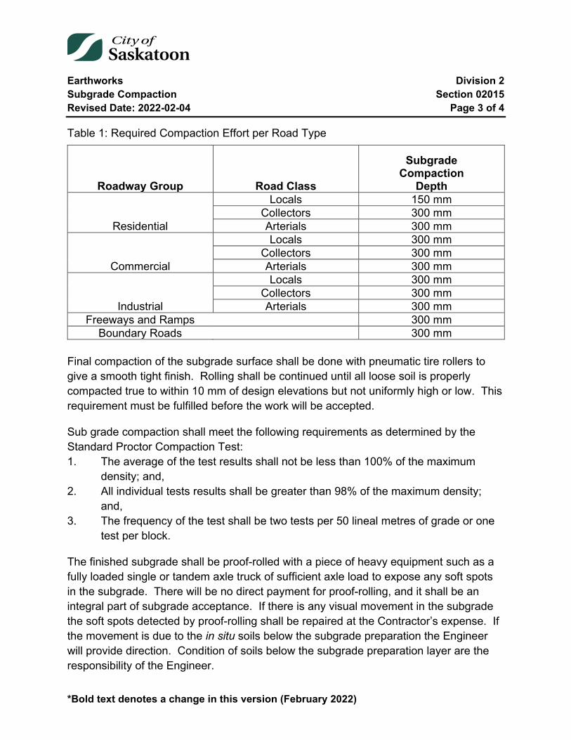
Earthworks Division 2 Subgrade Compaction Section 02015 Revised Date: 2022-02-04 Page 3 of 4
*Bold text denotes a change in this version (February 2022)
Table 1: Required Compaction Effort per Road Type
Roadway Group Road Class
Subgrade Compaction
Depth
Residential
Locals 150 mm Collectors 300 mm Arterials 300 mm
Commercial
Locals 300 mm Collectors 300 mm Arterials 300 mm
Industrial
Locals 300 mm Collectors 300 mm Arterials 300 mm
Freeways and Ramps 300 mm Boundary Roads 300 mm
Final compaction of the subgrade surface shall be done with pneumatic tire rollers to give a smooth tight finish. Rolling shall be continued until all loose soil is properly compacted true to within 10 mm of design elevations but not uniformly high or low. This requirement must be fulfilled before the work will be accepted.
Sub grade compaction shall meet the following requirements as determined by the Standard Proctor Compaction Test: 1. The average of the test results shall not be less than 100% of the maximum
density; and, 2. All individual tests results shall be greater than 98% of the maximum density;
and, 3. The frequency of the test shall be two tests per 50 lineal metres of grade or one
test per block.
The finished subgrade shall be proof-rolled with a piece of heavy equipment such as a fully loaded single or tandem axle truck of sufficient axle load to expose any soft spots in the subgrade. There will be no direct payment for proof-rolling, and it shall be an integral part of subgrade acceptance. If there is any visual movement in the subgrade the soft spots detected by proof-rolling shall be repaired at the Contractor’s expense. If the movement is due to the in situ soils below the subgrade preparation the Engineer will provide direction. Condition of soils below the subgrade preparation layer are the responsibility of the Engineer.
Earthworks Division 2 Subgrade Compaction Section 02015 Revised Date: 2022-02-04 Page 4 of 4
*Bold text denotes a change in this version (February 2022)
If excess moisture exists in the soil, the top 300 mm of the subgrade shall be dried on all roadways, to the optimum moisture content as determined by the Standard Proctor Compaction Test. In order to expedite compaction, the subgrade shall be aerated. Aerating shall be carried out at the expense of the Contractor.
If the moisture existing in the soil is insufficient for compacting to the specified density and for finishing, the Contractor shall add water. The proper moisture content shall be ± 2% of the optimum moisture content as determined by the Standard Proctor Compaction Test. The water shall be added uniformly by a pressure water sprayer.
The cost of adding water will be considered incidental to compaction and shall be included in the contract price for compaction.
Inaccessible areas by large compaction equipment shall be compacted by mechanical hand tampers.
02015-4 Subgrade Protection
After the subgrade is compacted and finished, all unnecessary traffic shall be kept off. Should it be necessary to haul material over the completed subgrade, subgrade failures shall be repaired by the Contractor before placing the subbase.
02015-5 Measurement
Subgrade compaction to the specified depth will be measured in square metres. The finished trimmed top surface of the subgrade, as staked by the Engineer, will be the basis of measurement.
02015-6 Payment
Payment for subgrade compaction to the specified depth will be at the contract unit price per square metre. The unit price will be full compensation for scarifying, blading, spreading, shaping, trimming, compacting, adding water, drying, repairing subgrade failures before placing subbase and finishing the subgrade to the required grade, cross-section and density.
End of Specification 02015

Earthworks Division 2 Construction of Streets and Lanes Section 02055 Revised Date: 2009-12-22 Page 1 of 7
02055 Construction of Streets and Lanes
Index
02055-1 Description of Work 2
02055-2 Equipment 2
02055-3 Excavation 2
02055-4 Subgrade Construction 3 4.1 Description 3 4.2 Materials 3 4.3 Subgrade Compaction 3 4.4 Moisture Content 4 4.5 Condition of Subgrade 4
02055-5 Haul 4
02055-6 Clearing and Grubbing 4
02055-7 Underground Services 5
02055-8 Alterations, Damage, Safety Protection, etc. 5
02055-9 Survey Pins, Stakes, Lines & Levels 6
02055-10 Public Convenience 6
02055-11 Method of Measurement 7 11.1 Excavation 7 11.2 Overhaul 7
02055-12 Basis of Payment 7

Earthworks Division 2 Construction of Streets and Lanes Section 02055 Revised Date: 2009-12-22 Page 2 of 7
02055-1 Description of Work
This specification covers the supply of all labour, equipment and materials necessary for the excavation and compaction of the subgrade to the lines and grades as shown on the drawings and as herein specified.
02055-2 Equipment
All tools, machinery, plant and equipment used in handling materials and executing any part of the work, shall be subject to the approval of the Engineer. All such equipment shall be maintained in efficient working order and where any of the machinery, plant or equipment is found to be unsatisfactory, it shall be improved or replaced by the Engineer.
02055-3 Excavation
The width of roadway and cross section in cut shall be as shown on the drawings and/or staked or designated by the Engineer. Excavation shall normally be to the finished subgrade as shown on the drawings.
Suitable excavated material shall be used as far as practicable in the formation of fills or for other backfill. Materials obtained from excavation and used as fill in the work will be paid for only as excavation. The Contractor shall shape and form both excavation and embankment to the satisfaction of the Engineer.
All inferior material subject to frost action, soft spongy or yielding spots, or organic material shall be entirely removed and disposed of as directed by the Engineer. Where such materials occur in cut or existing fill sections such that their removal will result in excavation below the subgrade elevation, such excavation shall be authorized by the Engineer. These areas shall be backfilled with material approved by the Engineer with suitable imported material. Such inferior material shall be excavated and disposed for the unit bid price for common excavation. The Engineer will authorize and determine the quantity below the required cross section for the removal of inferior material.
Common excavation shall include the excavation of all earth, loose stones, gravel and all other materials (Refer to Section 02005-1.3) and the disposition of same in accordance with these specifications or as directed by the Engineer.

Earthworks Division 2 Construction of Streets and Lanes Section 02055 Revised Date: 2009-12-22 Page 3 of 7
The unit bid price for common excavation shall include the cost for placement in the roadway and compaction as specified herein, trimming or disposal within the free-haul limit or as directed by the Engineer.
02055-4 Subgrade Construction
4.1 Description
Cut sections and embankments or fills shall be constructed in accordance with these specifications and in conformity with the grades and cross sections shown on the plans or as ordered by the Engineer in case of any changes in original plans.
4.2 Materials
Embankment or fill sections shall be constructed with soils approved by the Engineer. The material shall be free from objectionable organic matter, frozen soil, stumps, trees or other objectionable material.
Stones having a dimension 150 millimetres or more when measured in any direction shall be excluded from all fill areas. All stones of larger size shall be removed from the grade and disposed of as directed by the Engineer. No extra payment will be made for such stone removal and disposal.
After the black dirt has been removed from the streets and lanes to the depth specified or approved by the Engineer, care must be taken to incorporate the transition material below the topsoil in the bottom of a fill area. At all times the best quality of material within designated balanced cut and fill sections or other areas as designated by the Engineer shall be incorporated near the surface of the fill area.
4.3 Subgrade Compaction
Embankment shall be constructed of suitable material placed on successive layers not greater than 150 millimetres in depth, distributed over the full width of the cross section. Each layer shall be spread and bladed evenly by means of a blade grader or other approved equipment before placing another lift. During this procedure, the Contractor shall operate his equipment in such a manner where the entire embankment will be compacted to the same degree.

Earthworks Division 2 Construction of Streets and Lanes Section 02055 Revised Date: 2009-12-22 Page 4 of 7
4.4 Moisture Content
When the moisture content of the existing soil is in excess of the amount of moisture required for building a firm embankment, the soil shall be dried to the satisfaction of the Engineer. In order to expedite the project it may be necessary to aerate the soil. The cost of aerating will be considered incidental to excavation with no extra payment.
4.5 Condition of Subgrade
The Contractor shall maintain a street or lane, or part of a street or lane, until such is completed and approved to the satisfaction of the Engineer. Should it be found necessary to haul materials over the subgrade, all cuts, ruts and breaks in the surface of the subgrade so resulting shall be repaired in a manner satisfactory to the Engineer.
Cut and embankment areas shall be trimmed and shaped at the end of each working day in such a manner as to eliminate any ponding of water or saturation of the subgrade in the event of rain.
The Contractor shall shape and trim the street or lane or part thereof when such is to correct grade before commencing excavation in a new area.
02055-5 Haul
The limit of free-haul for removing topsoil and earth excavation will be specified in the General Requirements. For haul exceeding the specified free-haul distance, the Contractor will be paid for overhaul at a unit bid price per cubic metre-kilometre measured along the centre line of the route travelled or the most economical route.
02055-6 Clearing and Grubbing
Clearing and grubbing consists of the removal of all timber, brush, stumps, roots, grain, grass, weeds, rubbish, or other such perishable material from within the limits of the streets and lanes, also from such areas as may be required for off take, ditches, borrow pits, areas for stockpiling topsoil, etc.
All timber, brush, roots, etc. is to be piled at convenient points on the limits of the streets or lanes and disposed of as directed by the Engineer.

Earthworks Division 2 Construction of Streets and Lanes Section 02055 Revised Date: 2009-12-22 Page 5 of 7
The cost of clearing and grubbing will be considered incidental to excavation and must be included within the unit bid price for excavation.
02055-7 Underground Services
The Contractor shall be responsible to have all underground services and utilities located. The Contractor is responsible in the event that damage or disturbance does occur to underground structures.
Where existing underground gas, power, telephone or other street improvements are encountered or may be affected by this construction, the Contractor shall proceed under the direction of the respective Utility Company as the case may be. Should any of the above mentioned underground services require to be re-aligned or regraded to avoid interference with construction, then such work shall be done at the expense of the City or on a Force Account basis.
Whenever an underground service has been exposed or damaged, the Contractor shall immediately notify the respective Utility Company and Engineer to make their own inspection and repairs if required. Such repair work will be done at the expense of the Contractor.
02055-8 Alterations, Damage, Safety Protection, etc.
All manholes, catch basins, valve boxes or any other sewer and water appurtenances shall be raised, lowered, or otherwise altered to meet the new grade by the Contractor and at the expense of the City. After the above mentioned work is completed, the City shall provide adequate notices, barriers, warning lights and all other means of protection for the safety of the public for a maximum period of twenty-four (24) hours, or whenever possible, the Contractor upon reasonable notice from the City shall provide the adequate protection at the initial time when the work is completed. In the event that the Contractor neglects to place the necessary barricades and warning lights, the City may place these and the costs shall be borne by the Contractor. The minimum charge for each placing of notices, warning lights and barricades by the City shall be fifty dollars ($50.00).
During the progress of the work, extreme care shall be taken to protect the above mentioned structures against damage of any nature. Any damage shall be immediately repaired by the Contractor at his own expense. The Contractor shall take all necessary
Earthworks Division 2 Construction of Streets and Lanes Section 02055 Revised Date: 2009-12-22 Page 6 of 7
precautions to prevent material from falling into manholes, catch basins, valve boxes, etc., and shall be responsible for thoroughly cleaning same at the completion of the work.
02055-9 Survey Pins, Stakes, Lines & Levels
All work to be performed under this Contract shall be laid out by the Engineer by means of stakes or reference stakes and the Contractor is required to make the completed work conform to the lines and levels thus indicated.
The Contractor shall, before commencing work at any point, satisfy himself as to the meaning and correctness of all stakes and no claim will be entertained by the City for any allowances based on inaccuracies, or for any alterations subsequently rendered necessary on account of his failure to read same correctly. Should the Contractor discover or suspect any errors, he shall at once discontinue the work until such errors are investigated and rectified, but no claim shall be made or allowed on account thereof on account of any delay occasioned thereby.
The Contractor shall give the Engineer as early notice as possible whenever additional levels, lines, stakes, etc., are required on any portion of the work, stating the location at which such are needed for immediate use.
The Contractor will be held responsible for the preservation of all stakes and survey pins. If any of them are disturbed or destroyed he shall at once notify the Engineer and if in the opinion of the Engineer, the Contractor has been negligent in their protection, then the entire cost of replacing any stakes, survey pins, etc., so destroyed may be charged against the Contractor and deducted from any payments due him under this Contract.
02055-10 Public Convenience
The Contractor shall carry on the said works as to cause the least possible obstruction to streets, lanes or thoroughfares within or adjacent to the construction area, and shall provide temporary access to locations as directed by the Engineer. The Contractor shall provide and maintain all necessary notices, barriers, warning lights or any other means of protection for the safety of the public from the commencement to the completion of his work.
Earthworks Division 2 Construction of Streets and Lanes Section 02055 Revised Date: 2009-12-22 Page 7 of 7
02055-11 Method of Measurement
11.1 Excavation
The quantity of common excavation and stripping for which payment will be made, shall be the volume in cubic metre, measured in its original position and computed by the average end area method for materials excavated or as otherwise determined by the Engineer.
11.2 Overhaul
As per Clause 02055-5.
02055-12 Basis of Payment
Payment for excavation, stripping, overhaul and other items set out in the tender form will be on the basis of unit bid prices as specified in the Tender Form.
The prices tendered for the various classes of excavation shall be full compensation for all hauling within the free-haul limit, formation of embankment or fill, all compaction and subgrade construction as specified herein, trimming of slopes, disposal of surplus material, and the furnishing of all tools, labour, superintendence, equipment and incidentals, necessary to complete the work in a satisfactory and workmanlike manner.
End of Specification 02055
Earthworks Division 2 Grade Construction for Sidewalk, Curb and Gutter Section 02060 Revised Date: 2022-02-04 Page 1 of 10
02060 Grade Construction for Sidewalk, Curb and Gutter
Index
02060-1 General 3 1.1 Description 3 1.2 Definitions 3
02060-2 Materials 3 2.1 Embankment and Subgrade 3 2.2 Base Aggregate 3
02060-3 Equipment 4
02060-4 Construction 4 4.1 Excavation 4 4.2 Embankment 4 4.3 Surplus Material 5 4.4 Subgrade Preparation 5 4.5 Granular Base Preparation 6 4.6 Existing Roadways 6 4.7 Accommodation of Equipment 7 4.8 Granular Fill 7 4.9 Grade Protection 7
02060-5 Testing 8
02060-6 Measurement 8 6.1 Grade Construction - Subgrade 8 6.2 Grade Construction - Base 8 6.3 Extra Excavation 8 6.4 Extra Embankment Construction 9 6.5 Rock Excavation 9
02060-7 Payment 9
Earthworks Division 2 Grade Construction for Sidewalk, Curb and Gutter Section 02060 Revised Date: 2022-02-04 Page 2 of 10
7.1 Grade Construction – Subgrade 9 7.2 Grade Construction – Base 9 7.3 Extra Excavation 9 7.4 Extra Embankment Construction 9 7.5 Rock Excavation 10
Earthworks Division 2 Grade Construction for Sidewalk, Curb and Gutter Section 02060 Revised Date: 2022-02-04 Page 3 of 10
02060-1 General
1.1 Description
This section specifies the requirements for constructing the grade (foundation) for concrete sidewalk, curb and gutter, which shall consist of excavation, embankment construction, and subgrade preparation to the lines, grades, and dimensions specified.
1.2 Definitions
1.2.1 Subgrade
The upper finished layer of material (usually earth) on which the levelling course or the concrete is placed.
1.2.2 Rock Excavation
Excavation of boulders or rock fragments having a dimension exceeding 600 mm measured in any one direction.
1.2.3 Granular Base Layer:
The layer placed just above the subgrade. It typically consists of sand and gravel, crushed stone or quarry rock, slag or other hard durable material of mineral origin. It is typically dense graded with the amount of fines limited to promote drainage.
02060-2 Materials
2.1 Embankment and Subgrade
All material used for embankment and subgrade construction shall be approved by the Engineer. If construction so necessitates the use of borrow material, it will be obtained from the adjacent roadway or as designated by the Engineer.
2.2 Base Aggregate
Specifications for base aggregate are contained in the Aggregates Specification 03001-3.2.2 “Base Aggregate”.
The aggregate shall not be delivered before it has been tested and approved.

Earthworks Division 2 Grade Construction for Sidewalk, Curb and Gutter Section 02060 Revised Date: 2022-02-04 Page 4 of 10
02060-3 Equipment
All tools, machinery, plant and equipment used in executing any part of the work shall be suitable for the work to be carried out and shall be maintained in efficient working order and where any of the machinery, plant or equipment is found to be unsatisfactory, it shall be improved or replaced, by the Contractor, to the satisfaction of the Engineer.
02060-4 Construction
4.1 Excavation
Excavation shall include the removal and satisfactory disposal of all material encountered including earth, gravel, asphalt walk and asphalt driveways required for the construction of sidewalk, curb and gutter. Excavation for boulevards (where required) shall be carried out concurrently with this excavation. The Contractor shall incorporate suitable excavated materials into embankment construction.
Adequate suitable material shall also be retained on site to enable backfilling of the sidewalk, curb and gutter.
All inferior material subject to frost action, soft, spongy or yielding spots, or organic material shall be entirely removed and disposed of as directed by the Engineer. Where such materials occur in cut or existing fill sections such that their removal will result in excavation below the subgrade elevation, extra excavation will be authorized by the Engineer. These areas shall be backfilled with material approved by the Engineer.
4.2 Embankment
Embankments shall be constructed by placing and compacting successive layers of uniform thickness not exceeding 150 mm.
Approved mechanical compaction equipment shall be used to achieve a minimum of 98 percent of the Standard Proctor Density in each layer. Hauling equipment will not be accepted in lieu of compaction equipment.
When more embankment material is required than is readily available from normal excavation for new subdivision development locations, the Contractor will be permitted to borrow from an adjacent unimproved roadway provided that the borrow area is levelled to:
Earthworks Division 2 Grade Construction for Sidewalk, Curb and Gutter Section 02060 Revised Date: 2022-02-04 Page 5 of 10
1. maintain surface drainage, 2. accommodate all vehicular traffic.
Along improved roadways, the Contractor shall supply any material required beyond that which is available from related excavation.
4.3 Surplus Material
Surplus excavated material shall not be sold under any circumstances. It may be wasted by the Contractor only when no specific location is given by the Engineer. When a location is designated, the Contractor shall haul, dump and level the material as directed.
4.4 Subgrade Preparation
Subgrade Preparation only applies to grade construction - subgrade.
Grade Construction-Base requires no defined operation for subgrade preparation but does require compactive effort to create a firm foundation for the placement of the granular base.
Subgrade preparation shall be carried out to a depth not less than 150 mm below the bottom of the concrete structure and extending 125 mm beyond each side of the proposed concrete structure. All material shall be scarified and mixed, then wetted or dried. The subgrade shall be compacted to a minimum of 98% of the Standard Proctor Density by means of approved mechanical compaction equipment. Sheepsfoot rollers may be required by the Engineer in locations with cohesive soil.
The finished subgrade shall be proof-rolled with a piece of heavy equipment such as a fully loaded single or tandem axle truck of sufficient axle load to expose any soft spots in the subgrade. There will be no direct payment for proof-rolling, and it shall be an integral part of subgrade acceptance. Soft spots detected by proof-rolling shall be repaired at the Contractor’s expense.
Transverse or longitudinal service trenches that have not thoroughly settled shall be excavated and backfilled with approved material and compacted to a minimum of 98% of the Standard Proctor Density. The type of mechanical compactor to be used shall be approved by the Engineer.
Earthworks Division 2 Grade Construction for Sidewalk, Curb and Gutter Section 02060 Revised Date: 2022-02-04 Page 6 of 10
Where concrete is hand formed final grade preparation and compaction shall be carried out after the forms are placed. The correct screed shall be used to check the subgrade elevation to ensure adequate thickness for sand or granular levelling course and concrete. When the subgrade preparation is approved, the Contractor will be permitted to place and compact the levelling course which will give the required sidewalk thickness.
A levelling course will not be required when subgrade is cut to design grade and cross section, as with a rotary trimmer. Any loose material left on top of the grade by this operation shall be removed or compacted.
The surface of the subgrade after final trimming and rolling shall be within + 10 mm of the design cross-section and staked elevations.
Boulevard preparation where required shall be carried out concurrently with the subgrade preparation.
Prior to closing down operations for the completion of each day’s work, the subbase material shall be bladed and compacted and, if necessary, covered with sufficient base material to carry traffic.
4.5 Granular Base Preparation
Material shall be kept free from clay and other types of deleterious materials for the duration of the contract. The contractors’ operation shall not disturb underlying work.
Material shall be placed without segregation in uniform layers such that the thickness of the compacted layer is not greater than 150mm.
Base layers shall be bladed to a smooth surface in conformance to the required cross-section and maintained until placement of a subsequent layer where applicable.
The granular base shall be maintained to the tolerances in grade and cross-section and to the specified compaction until the project is accepted.
4.6 Existing Roadways
Any grading, or subgrade preparation, required by the Contractor to accommodate his equipment shall be the responsibility of the Contractor and he shall restore the roadway
Earthworks Division 2 Grade Construction for Sidewalk, Curb and Gutter Section 02060 Revised Date: 2022-02-04 Page 7 of 10
and boulevards to their original condition within five days. Any roadway gravel contaminated by the clay or other material shall be replaced by the Contractor at his expense.
When grade construction is required along an existing gravelled street, the Contractor shall, at his own expense, blade the gravel away from the work and replace the gravel to the satisfaction of the Engineer when the sidewalk, curb and gutter construction has been completed.
During sidewalk reconstruction, if unsuitable subgrade material requires replacement, and if borrow areas, coal chutes or openings require backfilling with granular material, such work shall be carried out by the Contractor at the applicable contract unit prices.
4.7 Accommodation of Equipment
Where it is necessary to carry out extra earthwork to accommodate the Contractor's equipment (for grade preparation or concrete construction) the execution and cost of such work shall be the Contractor's responsibility.
4.8 Granular Fill
When granular fill material is specified under sidewalks, curbs, traffic islands and medians, or to backfill trenches, the specified aggregate shall be supplied, placed and compacted by the Contractor at the respective unit prices. The minimum density of the material shall be 98% of the Standard Proctor Density.
4.9 Grade Protection
The protection of the grade shall be the responsibility of the Contractor from the time that work on the site commences until the concrete structure has been completed and backfilled. If concrete construction is not included in the Contractor's work, his responsibility shall end when the base has been checked, tested and approved by the Engineer.
Any damage caused by persons, vehicles, equipment or adverse weather shall be repaired by the Contractor at his expense.
The grade shall be barricaded against unnecessary traffic. Good surface drainage on the grade and on the adjoining roadway shall be maintained by the Contractor, and he
Earthworks Division 2 Grade Construction for Sidewalk, Curb and Gutter Section 02060 Revised Date: 2022-02-04 Page 8 of 10
shall drain any pools of water by ditching or pumping. No additional payment will be made for these measures.
02060-5 Testing
Testing will be carried out at the following approximate intervals:
Base Aggregate - Initial testing for source approval; minimum of one test per month thereafter.
Subgrade Compaction - two tests per 50 lineal metres of grade. One test is to be taken in the gutter area and one test is to be taken in the walk area.
Initial testing of the base aggregate shall be the Contractor's responsibility and he shall provide copies of reports on the following tests for approval by the Engineer:
1. Wash Sieve Analysis (CSA A23.2-2A, 5A) 2. California Bearing Ratio, Unsoaked (ASTM D1883)
Subsequent testing responsibility shall be in accordance with Section 01020 of the General Requirements.
02060-6 Measurement
6.1 Grade Construction - Subgrade
Grade Construction - Subgrade will be calculated in square metres based on the horizontal width of the proposed concrete structure plus 250 mm, and on the actual length constructed.
6.2 Grade Construction - Base
Grade Construction - Base will be calculated in square metres based on the horizontal width of the proposed concrete structure plus 250 mm, and on the actual length constructed.
6.3 Extra Excavation
Extra excavation will be measured by cross section and calculated in cubic metres as determined by survey grades.

Earthworks Division 2 Grade Construction for Sidewalk, Curb and Gutter Section 02060 Revised Date: 2022-02-04 Page 9 of 10
6.4 Extra Embankment Construction
Extra embankment construction will be measured by cross section and calculated in cubic metres as determined by survey grades. Width and depth as specified by the Engineer.
6.5 Rock Excavation
Rock excavation will be measured in cubic metres based on the actual volume of the individual rocks.
02060-7 Payment
7.1 Grade Construction – Subgrade
Grade Construction - Subgrade will be paid for at the contract unit price per square metre which will be full compensation for subgrade preparation, and all incidental related work.
7.2 Grade Construction – Base
Grade Construction - Base will be paid for at the contract unit price per square metre which will be full compensation for removal and disposal of excess subgrade material, compaction of the finished subgrade to provide a firm and suitable subgrade, supply, placement and compaction of 150 mm of granular base to a minimum of 98% of Standard Proctor Density.
7.3 Extra Excavation
Extra Excavation will be paid for at the contract unit price per cubic metre which will be full compensation for excavating, loading, hauling and disposing of material, and all incidental related work.
7.4 Extra Embankment Construction
Extra Embankment Construction will be paid for at the contract unit price which will be full compensation for placing, compacting, trimming and incidental related work. It shall also include excavating, loading, dumping of earth material when not available from surplus excavated material.
Earthworks Division 2 Grade Construction for Sidewalk, Curb and Gutter Section 02060 Revised Date: 2022-02-04 Page 10 of 10
7.5 Rock Excavation
Rock Excavation shall be paid for at the unit contract price per cubic metre which will be full compensation for excavating, loading, hauling and disposal of the rock, including landfill fees where applicable.
End of Specification 02060
Aggregates Division 3 Supply of Aggregates Section 03001 Revised Date: 2022-02-04 Page 1 of 20
*Bold text denotes a change in this version (February 2022)
03001 Supply of Aggregates
Index
03001-1 Description 3
03001-2 Reference to Standard Specifications 3
03001-3 Materials 3 3.1 General 3 3.2 Classification 5 3.3 Testing 12 3.4 Enforcement of Specifications 14
03001-4 Equipment 15 4.1 Weigh Scales 15 4.2 Trucks 15
03001-5 Construction 16 5.1 Production 16 5.2 Stockpiling 16 5.3 Delivery 17
03001-6 Measurement 19 6.1 Aggregate 19 6.2 Moisture 20 6.3 Quantity Summaries 20
Aggregates Division 3 Supply of Aggregates Section 03001 Revised Date: 2022-02-04 Page 2 of 20
*Bold text denotes a change in this version (February 2022)
Tables
Table 1: Moisture Content – Street Sand ........................................................................ 4 Table 2: Moisture Content – Moisture Control ................................................................. 4 Table 3: Subbase Aggregate Grading Limits ................................................................... 5 Table 4: Base Aggregate Grading Limits ......................................................................... 6 Table 5: Street Sanding Aggregate Grading Limits ......................................................... 7 Table 6: Street Sand – More than 3% passing by weight on the 71µm sieve.................. 7 Table 7: Street Sand – Less than 100% passing by weight on the 9mm sieve ............... 7 Table 8: Plaster Sand Grading Limits .............................................................................. 8 Table 9: Pipe Bedding Aggregate Gradation ................................................................... 9 Table 10: Crushed Rock Grading Limits .......................................................................... 9 Table 11: Crushed Concrete Grading Limits ................................................................. 10 Table 12: Sub-drainage Sand and Natural Fines Grading Limits .................................. 11 Table 13: Bedding Sand Grading Limits ........................................................................ 12 Table 14: Testing and Frequency .................................................................................. 13
Aggregates Division 3 Supply of Aggregates Section 03001 Revised Date: 2022-02-04 Page 3 of 20
*Bold text denotes a change in this version (February 2022)
03001-1 Description
Work under these specifications shall include the supplying, processing, stockpiling, loading, hauling and dumping or spreading of granular material meeting the requirements shown for each classification. Delivery shall be to anywhere within the City of Saskatoon.
03001-2 Reference to Standard Specifications
Reference in these Specifications will be made to the latest edition of the American Society for Testing Materials (A.S.T.M.) and Canadian Standards Association (C.S.A.) covering aggregate and methods of testing aggregates.
03001-3 Materials
3.1 General
Source
The source of the aggregate shall be the locations specified in Schedule "E" - List of Production Locations in the Tender Form or alternate locations acceptable to the Engineer.
Composition
The aggregate shall consist of fragments of durable rock, free from undesirable quantities of soft or flaky particles, shale, loam, vegetation or other deleterious material.
Reclaimed Asphalt Pavement
Reclaimed Asphalt Pavement (RAP) shall be the product of removed pavement materials containing asphalt and aggregates. These materials are generated when asphalt pavements are removed for reconstruction, resurfacing, or to obtain access to buried utilities. Specifications for the addition of reclaimed materials in granular base and subbase layers are contained in the Asphalt Specifications Section 03050 for Granular Base Course and 03010 for Granular Subbase Course.
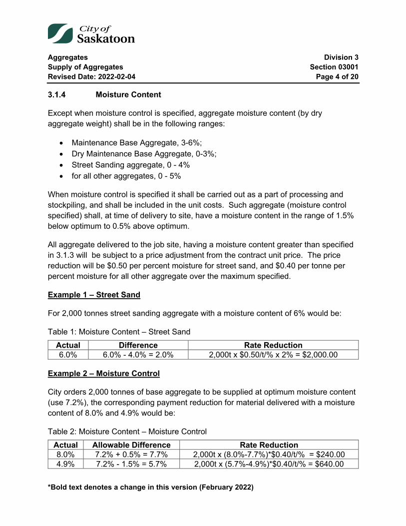
Aggregates Division 3 Supply of Aggregates Section 03001 Revised Date: 2022-02-04 Page 4 of 20
*Bold text denotes a change in this version (February 2022)
Moisture Content
Except when moisture control is specified, aggregate moisture content (by dry aggregate weight) shall be in the following ranges:
• Maintenance Base Aggregate, 3-6%; • Dry Maintenance Base Aggregate, 0-3%; • Street Sanding aggregate, 0 - 4% • for all other aggregates, 0 - 5%
When moisture control is specified it shall be carried out as a part of processing and stockpiling, and shall be included in the unit costs. Such aggregate (moisture control specified) shall, at time of delivery to site, have a moisture content in the range of 1.5% below optimum to 0.5% above optimum.
All aggregate delivered to the job site, having a moisture content greater than specified in 3.1.3 will be subject to a price adjustment from the contract unit price. The price reduction will be $0.50 per percent moisture for street sand, and $0.40 per tonne per percent moisture for all other aggregate over the maximum specified.
Example 1 – Street Sand
For 2,000 tonnes street sanding aggregate with a moisture content of 6% would be:
Table 1: Moisture Content – Street Sand Actual Difference Rate Reduction 6.0% 6.0% - 4.0% = 2.0% 2,000t x $0.50/t/% x 2% = $2,000.00
Example 2 – Moisture Control
City orders 2,000 tonnes of base aggregate to be supplied at optimum moisture content (use 7.2%), the corresponding payment reduction for material delivered with a moisture content of 8.0% and 4.9% would be:
Table 2: Moisture Content – Moisture Control Actual Allowable Difference Rate Reduction 8.0% 7.2% + 0.5% = 7.7% 2,000t x (8.0%-7.7%)*$0.40/t/% = $240.00 4.9% 7.2% - 1.5% = 5.7% 2,000t x (5.7%-4.9%)*$0.40/t/% = $640.00
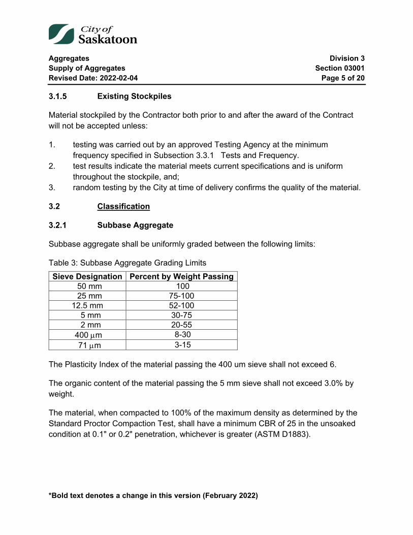
Aggregates Division 3 Supply of Aggregates Section 03001 Revised Date: 2022-02-04 Page 5 of 20
*Bold text denotes a change in this version (February 2022)
Existing Stockpiles
Material stockpiled by the Contractor both prior to and after the award of the Contract will not be accepted unless:
1. testing was carried out by an approved Testing Agency at the minimum frequency specified in Subsection 3.3.1 Tests and Frequency.
2. test results indicate the material meets current specifications and is uniform throughout the stockpile, and;
3. random testing by the City at time of delivery confirms the quality of the material.
3.2 Classification
Subbase Aggregate
Subbase aggregate shall be uniformly graded between the following limits:
Table 3: Subbase Aggregate Grading Limits Sieve Designation Percent by Weight Passing
50 mm 100 25 mm 75-100 12.5 mm 52-100 5 mm 30-75 2 mm 20-55 400 µm 8-30 71 µm 3-15
The Plasticity Index of the material passing the 400 um sieve shall not exceed 6.
The organic content of the material passing the 5 mm sieve shall not exceed 3.0% by weight.
The material, when compacted to 100% of the maximum density as determined by the Standard Proctor Compaction Test, shall have a minimum CBR of 25 in the unsoaked condition at 0.1" or 0.2" penetration, whichever is greater (ASTM D1883).
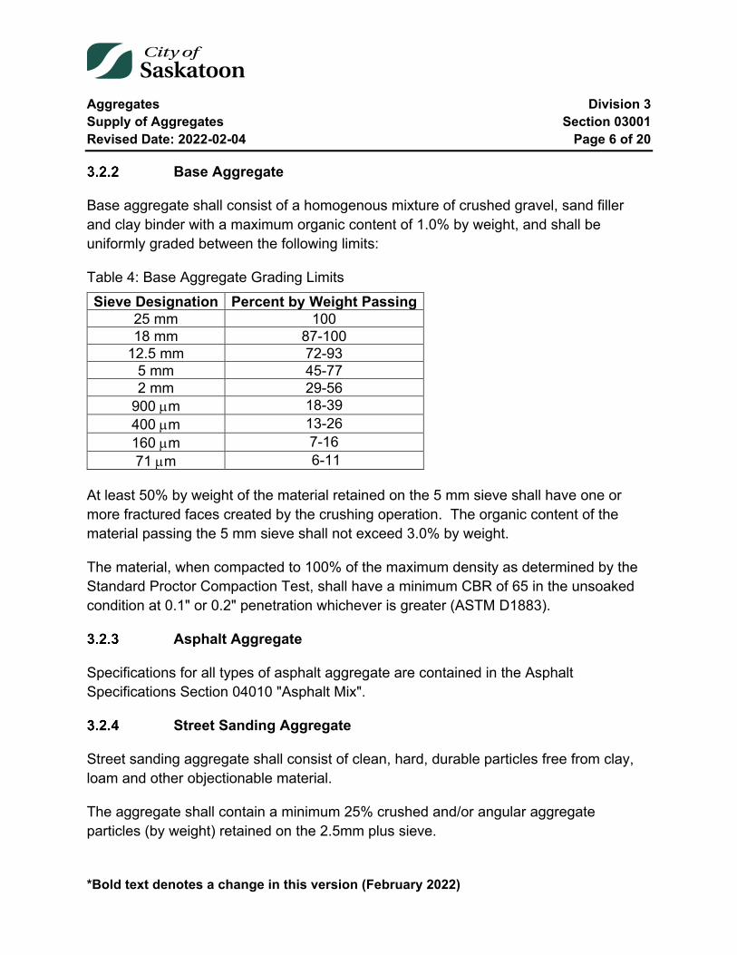
Aggregates Division 3 Supply of Aggregates Section 03001 Revised Date: 2022-02-04 Page 6 of 20
*Bold text denotes a change in this version (February 2022)
Base Aggregate
Base aggregate shall consist of a homogenous mixture of crushed gravel, sand filler and clay binder with a maximum organic content of 1.0% by weight, and shall be uniformly graded between the following limits:
Table 4: Base Aggregate Grading Limits Sieve Designation Percent by Weight Passing
25 mm 100 18 mm 87-100
12.5 mm 72-93 5 mm 45-77 2 mm 29-56
900 µm 18-39 400 µm 13-26 160 µm 7-16 71 µm 6-11
At least 50% by weight of the material retained on the 5 mm sieve shall have one or more fractured faces created by the crushing operation. The organic content of the material passing the 5 mm sieve shall not exceed 3.0% by weight.
The material, when compacted to 100% of the maximum density as determined by the Standard Proctor Compaction Test, shall have a minimum CBR of 65 in the unsoaked condition at 0.1" or 0.2" penetration whichever is greater (ASTM D1883).
Asphalt Aggregate
Specifications for all types of asphalt aggregate are contained in the Asphalt Specifications Section 04010 "Asphalt Mix".
Street Sanding Aggregate
Street sanding aggregate shall consist of clean, hard, durable particles free from clay, loam and other objectionable material.
The aggregate shall contain a minimum 25% crushed and/or angular aggregate particles (by weight) retained on the 2.5mm plus sieve.
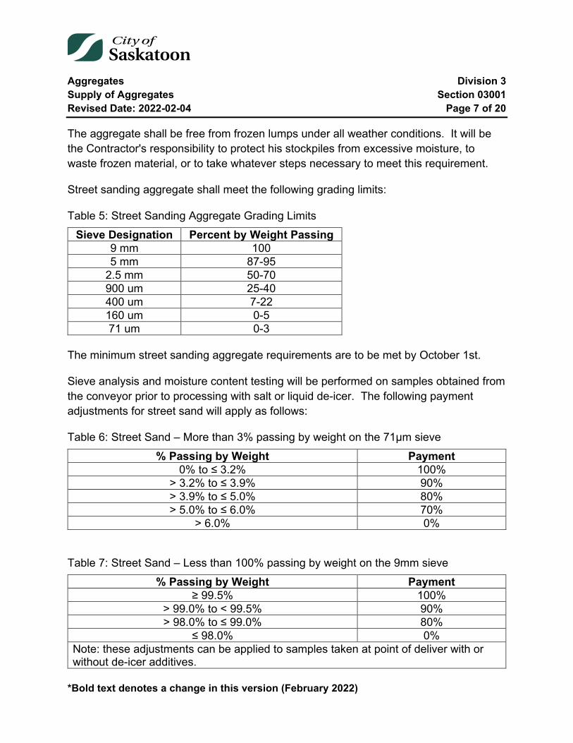
Aggregates Division 3 Supply of Aggregates Section 03001 Revised Date: 2022-02-04 Page 7 of 20
*Bold text denotes a change in this version (February 2022)
The aggregate shall be free from frozen lumps under all weather conditions. It will be the Contractor's responsibility to protect his stockpiles from excessive moisture, to waste frozen material, or to take whatever steps necessary to meet this requirement.
Street sanding aggregate shall meet the following grading limits:
Table 5: Street Sanding Aggregate Grading Limits Sieve Designation Percent by Weight Passing
9 mm 100 5 mm 87-95
2.5 mm 50-70 900 um 25-40 400 um 7-22 160 um 0-5 71 um 0-3
The minimum street sanding aggregate requirements are to be met by October 1st.
Sieve analysis and moisture content testing will be performed on samples obtained from the conveyor prior to processing with salt or liquid de-icer. The following payment adjustments for street sand will apply as follows:
Table 6: Street Sand – More than 3% passing by weight on the 71µm sieve % Passing by Weight Payment
0% to ≤ 3.2% 100% > 3.2% to ≤ 3.9% 90% > 3.9% to ≤ 5.0% 80% > 5.0% to ≤ 6.0% 70%
> 6.0% 0%
Table 7: Street Sand – Less than 100% passing by weight on the 9mm sieve % Passing by Weight Payment
≥ 99.5% 100% > 99.0% to < 99.5% 90% > 98.0% to ≤ 99.0% 80%
≤ 98.0% 0% Note: these adjustments can be applied to samples taken at point of deliver with or without de-icer additives.
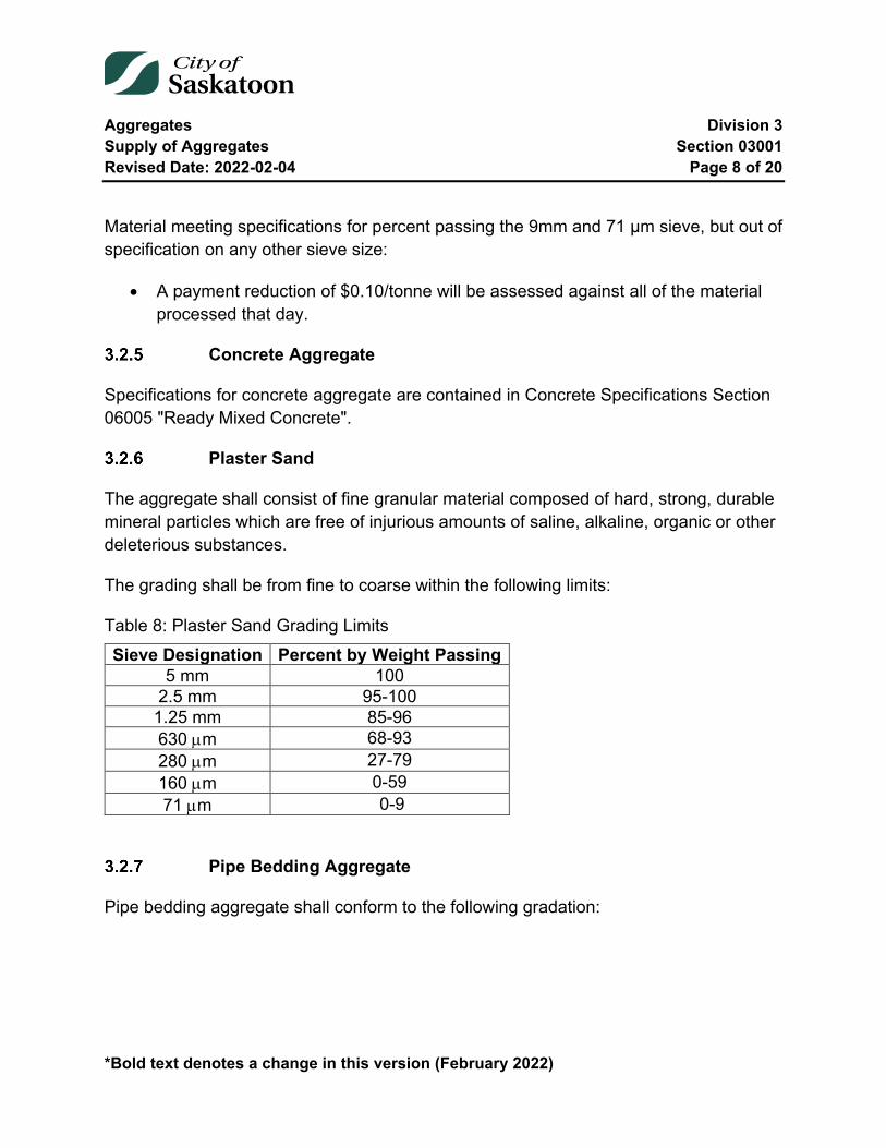
Aggregates Division 3 Supply of Aggregates Section 03001 Revised Date: 2022-02-04 Page 8 of 20
*Bold text denotes a change in this version (February 2022)
Material meeting specifications for percent passing the 9mm and 71 µm sieve, but out of specification on any other sieve size:
• A payment reduction of $0.10/tonne will be assessed against all of the material processed that day.
Concrete Aggregate
Specifications for concrete aggregate are contained in Concrete Specifications Section 06005 "Ready Mixed Concrete".
Plaster Sand
The aggregate shall consist of fine granular material composed of hard, strong, durable mineral particles which are free of injurious amounts of saline, alkaline, organic or other deleterious substances.
The grading shall be from fine to coarse within the following limits:
Table 8: Plaster Sand Grading Limits Sieve Designation Percent by Weight Passing
5 mm 100 2.5 mm 95-100
1.25 mm 85-96 630 µm 68-93 280 µm 27-79 160 µm 0-59 71 µm 0-9
Pipe Bedding Aggregate
Pipe bedding aggregate shall conform to the following gradation:
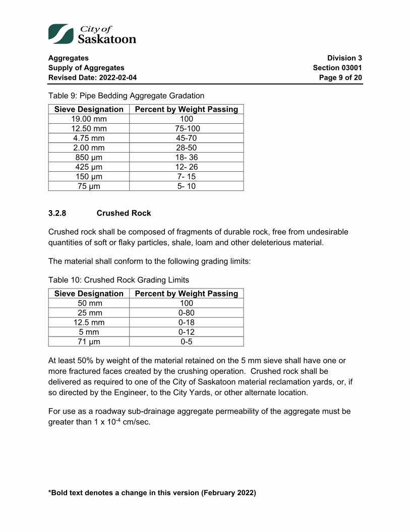
Aggregates Division 3 Supply of Aggregates Section 03001 Revised Date: 2022-02-04 Page 9 of 20
*Bold text denotes a change in this version (February 2022)
Table 9: Pipe Bedding Aggregate Gradation Sieve Designation Percent by Weight Passing
19.00 mm 100 12.50 mm 75-100 4.75 mm 45-70 2.00 mm 28-50 850 µm 18- 36 425 µm 12- 26 150 µm 7- 15 75 µm 5- 10
Crushed Rock
Crushed rock shall be composed of fragments of durable rock, free from undesirable quantities of soft or flaky particles, shale, loam and other deleterious material.
The material shall conform to the following grading limits:
Table 10: Crushed Rock Grading Limits Sieve Designation Percent by Weight Passing
50 mm 100 25 mm 0-80 12.5 mm 0-18
5 mm 0-12 71 µm 0-5
At least 50% by weight of the material retained on the 5 mm sieve shall have one or more fractured faces created by the crushing operation. Crushed rock shall be delivered as required to one of the City of Saskatoon material reclamation yards, or, if so directed by the Engineer, to the City Yards, or other alternate location.
For use as a roadway sub-drainage aggregate permeability of the aggregate must be greater than 1 x 10⁻⁴ cm/sec.

Aggregates Division 3 Supply of Aggregates Section 03001 Revised Date: 2022-02-04 Page 10 of 20
*Bold text denotes a change in this version (February 2022)
Crushed Concrete
Crushed concrete shall be derived from durable fragments of concrete, free from undesirable quantities of soft or flaky particles, shale, loam and other deleterious material.
The material shall conform to the following grading limits:
Table 11: Crushed Concrete Grading Limits Sieve Designation Percent by Weight Passing
50 mm 100 25 mm 0-80 12.5 mm 0-18
5 mm 0-12 71 µm 0-5
At least 50% by weight of the material retained on the 5 mm sieve shall have one or more fractured faces created by the crushing operation. Crushed concrete shall be delivered as required to one of the City of Saskatoon material reclamation yards, or, if so directed by the Engineer, to the City Yards, or other alternate location.
For use as a roadway sub-drainage aggregate, permeability of the aggregate must be greater than 1 x 10⁻⁴ cm/sec.
Sub-drainage Sand and Natural Fines
Sub-drainage Sand and Natural Fines shall be free from soft or flaky particles, shale, loam and other deleterious material.
The gradation of the sub-drainage sand and natural fines shall be within the following limits:
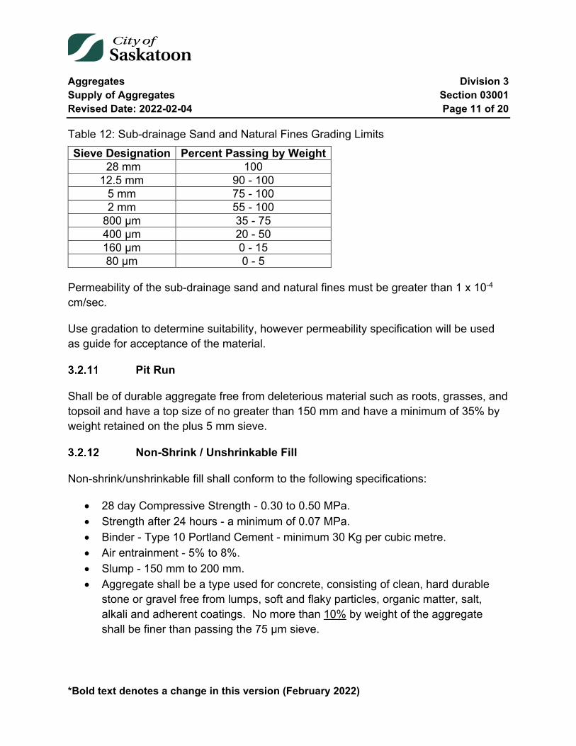
Aggregates Division 3 Supply of Aggregates Section 03001 Revised Date: 2022-02-04 Page 11 of 20
*Bold text denotes a change in this version (February 2022)
Table 12: Sub-drainage Sand and Natural Fines Grading Limits Sieve Designation Percent Passing by Weight
28 mm 100 12.5 mm 90 - 100
5 mm 75 - 100 2 mm 55 - 100
800 µm 35 - 75 400 µm 20 - 50 160 µm 0 - 15 80 µm 0 - 5
Permeability of the sub-drainage sand and natural fines must be greater than 1 x 10⁻⁴ cm/sec.
Use gradation to determine suitability, however permeability specification will be used as guide for acceptance of the material.
Pit Run
Shall be of durable aggregate free from deleterious material such as roots, grasses, and topsoil and have a top size of no greater than 150 mm and have a minimum of 35% by weight retained on the plus 5 mm sieve.
Non-Shrink / Unshrinkable Fill
Non-shrink/unshrinkable fill shall conform to the following specifications:
• 28 day Compressive Strength - 0.30 to 0.50 MPa. • Strength after 24 hours - a minimum of 0.07 MPa. • Binder - Type 10 Portland Cement - minimum 30 Kg per cubic metre. • Air entrainment - 5% to 8%. • Slump - 150 mm to 200 mm. • Aggregate shall be a type used for concrete, consisting of clean, hard durable
stone or gravel free from lumps, soft and flaky particles, organic matter, salt, alkali and adherent coatings. No more than 10% by weight of the aggregate shall be finer than passing the 75 µm sieve.

Aggregates Division 3 Supply of Aggregates Section 03001 Revised Date: 2022-02-04 Page 12 of 20
*Bold text denotes a change in this version (February 2022)
Bedding Sand
The aggregate shall consist of fine granular material composed of hard, strong, durable mineral particles which are free of injurious amounts of saline, alkaline, organic or other deleterious substances.
The grading shall be from fine to coarse within the following limits:
Table 13: Bedding Sand Grading Limits Sieve Designation Percent by Weight Passing
5 mm 95-100 2.5 mm 80-100
1.25 mm 50-85 630 µm 25-60 280 µm 10-30 160 µm 0-15 71 µm 0-5
3.3 Testing
Tests and Frequency
All tests shall be carried out in accordance with current ASTM or CSA Standards. Test frequencies shall apply both to production (quality control) and to delivery (quality assurance).
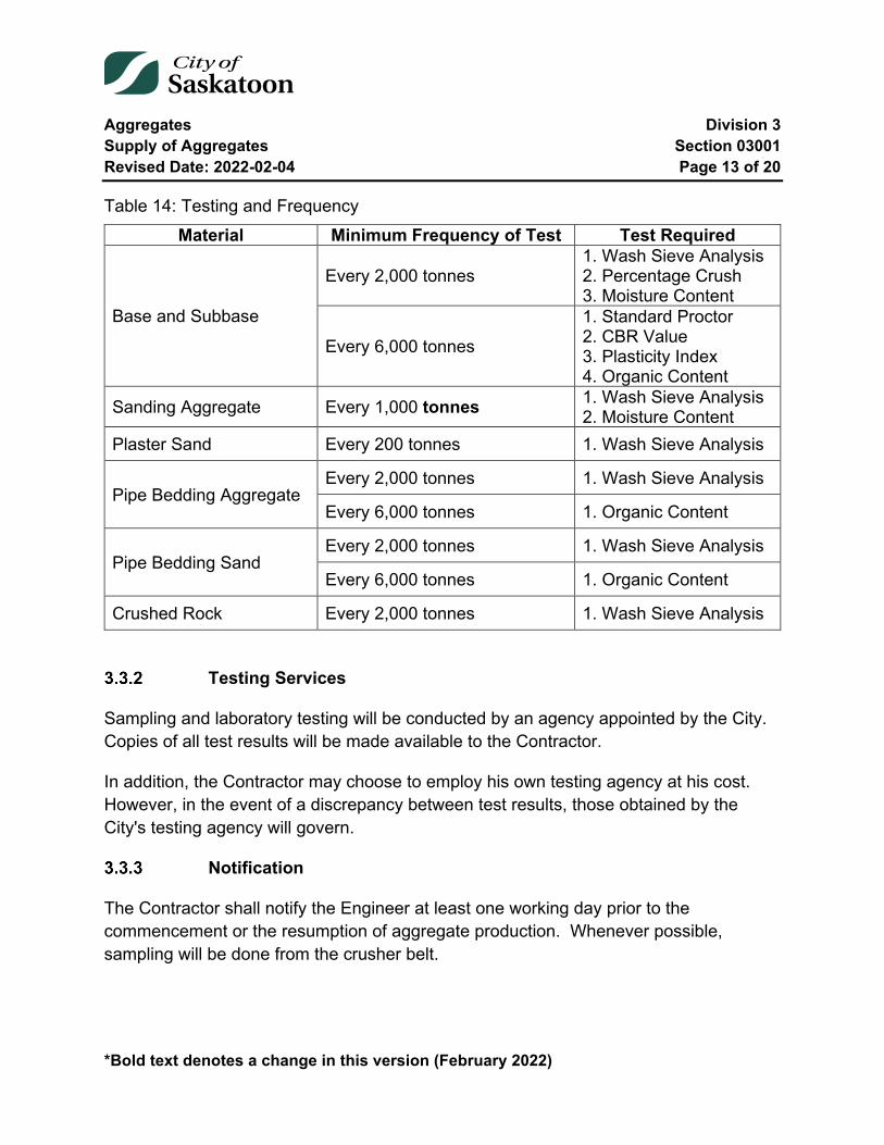
Aggregates Division 3 Supply of Aggregates Section 03001 Revised Date: 2022-02-04 Page 13 of 20
*Bold text denotes a change in this version (February 2022)
Table 14: Testing and Frequency Material Minimum Frequency of Test Test Required
Base and Subbase
Every 2,000 tonnes 1. Wash Sieve Analysis 2. Percentage Crush 3. Moisture Content
Every 6,000 tonnes
1. Standard Proctor 2. CBR Value 3. Plasticity Index 4. Organic Content
Sanding Aggregate Every 1,000 tonnes 1. Wash Sieve Analysis 2. Moisture Content
Plaster Sand Every 200 tonnes 1. Wash Sieve Analysis
Pipe Bedding Aggregate Every 2,000 tonnes 1. Wash Sieve Analysis
Every 6,000 tonnes 1. Organic Content
Pipe Bedding Sand Every 2,000 tonnes 1. Wash Sieve Analysis
Every 6,000 tonnes 1. Organic Content
Crushed Rock Every 2,000 tonnes 1. Wash Sieve Analysis
Testing Services
Sampling and laboratory testing will be conducted by an agency appointed by the City. Copies of all test results will be made available to the Contractor.
In addition, the Contractor may choose to employ his own testing agency at his cost. However, in the event of a discrepancy between test results, those obtained by the City's testing agency will govern.
Notification
The Contractor shall notify the Engineer at least one working day prior to the commencement or the resumption of aggregate production. Whenever possible, sampling will be done from the crusher belt.
Aggregates Division 3 Supply of Aggregates Section 03001 Revised Date: 2022-02-04 Page 14 of 20
*Bold text denotes a change in this version (February 2022)
Costs
The Contractor shall bear the cost of sampling and testing material in the following situations:
1. Initial testing to bring production into specification requirements. 2. Testing as above when source of material is changed. 3. Retesting of material which failed to meet specifications.
Testing for 1 and 2 may be conducted by the Contractor's agency. If the City conducts the testing, the costs will be deducted from any subsequent progress payments.
The cost of other testing initiated by the City during production will be borne by the City. No compensation will be made to the Contractor for testing initiated by the Contractor during current or previous production.
Sieve Analysis
The gradation of the material, when plotted on a semi-log grading chart, shall appear as a smooth curve within the specified band.
The average of the results of any 5 consecutive Wash Sieve Analysis Tests on material sampled at the crusher belt, or any 2 consecutive Wash Sieve Analysis Tests on material sampled at the delivery location, shall be within the grading limits specified for that material. Failure to meet this requirement shall result in the rejection of the material.
3.4 Enforcement of Specifications
Delivery of material to City locations will not be permitted until test results confirm that it meets specifications, and until the stockpile requirements of Section 5.2 have been fully met.
Any deviation from specifications during the production of material shall require the Contractor to take immediate corrective action. Equipment shall be shifted to ensure that there is no contamination of the current stockpile. A new stockpile shall be started adjacent to the former stockpile only after the product has been proven by testing to again meet specifications. Any material of inferior quality, or not in accordance with this specification, brought to, or incorporated into the work shall be immediately removed by
Aggregates Division 3 Supply of Aggregates Section 03001 Revised Date: 2022-02-04 Page 15 of 20
*Bold text denotes a change in this version (February 2022)
the Contractor, at his own expense. In the event of the Contractor failing to comply with this provision, the Engineer may remove such materials, or cause them to be removed and deduct the cost of same from any subsequent progress payments to the Contractor.
In the event that removal of the inferior material is not required by the Engineer for any reason, then an appropriate payment adjustment as defined by the Engineer shall be applied to all of that material delivered to the site on that day.
03001-4 Equipment
4.1 Weigh Scales
The Contractor may weigh large and/or continuous deliveries at the scale most convenient to the source.
The Contractor shall, where indicated in the tendering documents, quote on using their own scale, provided that the scale is certified.
4.2 Trucks
The Contractor may use any trucks of any type capable of delivering in accordance with job requirements. Specific conditions to be met include:
1. Certain delivery points are confined areas such as lanes and parking lots which may prevent the use of trucks larger than tandems.
2. Delivery is either spreading for road construction or dumping in a manner suitable for the project.
3. Centre-dump vehicles will only be permitted where base or subbase is to be spread for roadway construction.
Prior to the start of delivery, the Contractor shall supply a complete list of trucks, owner's names, registration numbers, tare weights and licence load limits. This list shall be updated whenever changes occur.
All trucks shall be weighed when delivery commences and at random times during the Contract.
Aggregates Division 3 Supply of Aggregates Section 03001 Revised Date: 2022-02-04 Page 16 of 20
*Bold text denotes a change in this version (February 2022)
03001-5 Construction
5.1 Production
Blending
Care shall be taken in the selection of material in the pit so as to produce a uniform product.
If blending of materials from more than one source is required to meet specifications, all such blending shall be done in the production equipment.
Sand Elimination
When it is necessary to eliminate sand to meet the grading specifications, the sand shall be removed prior to the crushing operation.
5.2 Stockpiling
Procedure
Each stockpile shall be constructed to contain not less than 10,000 tonnes or one-half of the remaining estimated contract quantity (whichever is less).
The area where the stockpile is to be located shall be shaped to a uniform smooth surface and graded to ensure positive drainage from the stockpile.
The material shall be placed uniformly on a predetermined area, in layers not exceeding 1 m in thickness.
Construction operations shall be controlled to prevent segregation of the various particle sizes.
If material is dumped by vehicles, it shall be spread with a dozer. The construction of each layer shall progress from outer edges toward the centre.
The material shall not be pushed or dumped over the edges or down the faces of the stockpile.
Aggregates Division 3 Supply of Aggregates Section 03001 Revised Date: 2022-02-04 Page 17 of 20
*Bold text denotes a change in this version (February 2022)
The material may be stockpiled from a stacker or conveyor belt only if all material is transported from the conveyor belt across the stockpile by means of a dozer or loader.
At the end of each day, the top of the stockpile and gravel pit shall be properly levelled and sloped. When stockpiling is carried out in winter, the Contractor shall take precautions that no snow is incorporated into the stockpile.
The completed stockpile shall be neat and regular in form and shall be constructed to occupy the smallest feasible area.
If different types of material are to be stockpiled, the piles shall be located and constructed so that no intermingling of material will occur.
Any rejected material must be placed a good distance away from an approved stockpile.
Material which does not meet specification within 5,000 tonnes of crushing will therefore be rejected and a new stockpile will be started in a new location clearly away from the rejected material.
Minimum Quantities
During the construction season, the Contractor shall, on his site, maintain the following minimum stockpile quantities of stockpiled, tested and approved material:
• Base Aggregate: 15,000 tonnes • Subbase Aggregate: 15,000 tonnes • Sanding Aggregate: 10,000 tonnes • Other Material: 5,000 tonnes
All material supplied shall be loaded from a stockpile. Direct delivery from the crusher will not be permitted.
5.3 Delivery
Rate of Delivery
The Contractor shall be prepared to supply the following approximate quantities at a uniform delivery rate during each working day (including Saturdays when prior notice is given).

Aggregates Division 3 Supply of Aggregates Section 03001 Revised Date: 2022-02-04 Page 18 of 20
*Bold text denotes a change in this version (February 2022)
5.3.1.1 Granular Base and Subbase
If one Contractor has the contract to supply aggregate to both sides of the river, the Contractor shall be prepared to deliver up to 2,000 tonnes of aggregate per day to each side of the river or a total up to 4,000 tonnes per day. If a Contractor has only to supply aggregate to one side of the river, the Contractor shall be prepared to deliver up to 3,000 tonnes of aggregate per day.
5.3.1.2 Other Materials
The Contractor shall be prepared to deliver up to 1,000 tonnes per day of any other aggregate materials.
The Contractor and the Engineer shall be in close contact with the progress of the projects to determine daily delivery requirements. Whenever an appreciable change in delivery quantities or actual requirements is known in advance by either party, one party shall give reasonable notice to the other party.
Breakdown
Whenever the Contractor is unable to deliver any material due to major stationary plant or equipment (trucks and self-mobile equipment excluded) breakdown, the Contractor shall immediately notify the Engineer when delivery of material shall resume. Non-delivery time period for material required by the City shall not be longer than 24 hours.
Alternate Sources
In the event that the Contractor fails to supply any or only supplies a portion of material required, the Engineer under this Contract, shall be at liberty to purchase the required material so in default from any firm which is willing and ready to supply. The Contractor shall pay the City, on demand, any increase in the cost of material so purchased, over and above the cost of similar material under this Contract.
Loading Procedure
The Contractor shall provide supervision of the loading operation to ensure correct source and procedures. Material loaded from the stockpile shall be removed in a manner which results in mixing of the full height of the stockpile face.
Aggregates Division 3 Supply of Aggregates Section 03001 Revised Date: 2022-02-04 Page 19 of 20
*Bold text denotes a change in this version (February 2022)
Load Limits
Maximum gross weight of vehicles operating within the City limits shall conform to Section 7 of the Traffic Bylaw No. 7200 and to any current amendments. In addition, the load limit as established by the Saskatchewan licence for each vehicle shall not be exceeded.
Where rural municipal roads are to be used, requirements established by the R.M. Council must be met. This includes road maintenance and load permits.
Truck Routes
Vehicles operating under this Contract shall be confined to routes shown on Schedule No. 8, Division 0, Section 00705 of General Conditions. For purposes of making a delivery, trucks must stay on a designated route to the point closest to the delivery point. The Engineer has the right to assign the final portion of the route, namely over local streets from the designated route to the delivery point.
Maintenance of Haul Routes
The City will, at its own expense, maintain all haul routes within the City limits.
Haul routes outside the limits of the City of Saskatoon shall, insofar as practical with respect to minimizing haul distance, be on numbered provincial Highways.
Where hauling is required over roads outside the City other than along Provincial Highways, the Contractor shall, prior to commencing this Contract, make formal arrangements for the use of such roads with the municipality having jurisdiction. These shall include the extent of the Contractor's responsibility for maintenance of road surface, for traffic safety and for dust palliation. A copy of the agreement shall be submitted to the City prior to commencement of the Contract.
03001-6 Measurement
6.1 Aggregate
The unit of measurement shall be the tonne. If City or Contractor's weigh scales are not in operation, the aggregate weight shall be calculated on the basis of actual volume of
Aggregates Division 3 Supply of Aggregates Section 03001 Revised Date: 2022-02-04 Page 20 of 20
*Bold text denotes a change in this version (February 2022)
material delivered and average unit weight determined from previously weighed truckloads of similar material.
6.2 Moisture
The moisture content (dry weight basis) shall be determined by sampling the material at the place of delivery and averaging the results of each one-month period. This average moisture content shall be applied against the total quantity delivered for that same one-month period to calculate a payment reduction.
6.3 Quantity Summaries
The Contractor shall submit monthly statements for each item showing a daily sub-total and a cumulative total for the period.
End of Specification 03001
Aggregates Division 3 Granular Base Course Section 03005 Revised Date: 2022-02-04 Page 1 of 5
*Bold text denotes a change in this version (February 2022)
03005 Granular Base Course
Index
03005-1 Description 2
03005-2 Materials 2
03005-3 Approval for Base Course 2
03005-4 Construction 3
03005-5 Measurement 5
03005-6 Payment 5
Tables
Table 1: Material Requirements ...................................................................................... 2
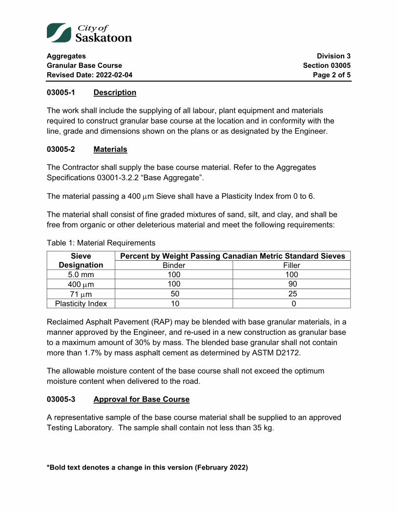
Aggregates Division 3 Granular Base Course Section 03005 Revised Date: 2022-02-04 Page 2 of 5
*Bold text denotes a change in this version (February 2022)
03005-1 Description
The work shall include the supplying of all labour, plant equipment and materials required to construct granular base course at the location and in conformity with the line, grade and dimensions shown on the plans or as designated by the Engineer.
03005-2 Materials
The Contractor shall supply the base course material. Refer to the Aggregates Specifications 03001-3.2.2 “Base Aggregate”.
The material passing a 400 µm Sieve shall have a Plasticity Index from 0 to 6.
The material shall consist of fine graded mixtures of sand, silt, and clay, and shall be free from organic or other deleterious material and meet the following requirements:
Table 1: Material Requirements Sieve
Designation Percent by Weight Passing Canadian Metric Standard Sieves
Binder Filler 5.0 mm 100 100 400 µm 100 90 71 µm 50 25
Plasticity Index 10 0 Reclaimed Asphalt Pavement (RAP) may be blended with base granular materials, in a manner approved by the Engineer, and re-used in a new construction as granular base to a maximum amount of 30% by mass. The blended base granular shall not contain more than 1.7% by mass asphalt cement as determined by ASTM D2172.
The allowable moisture content of the base course shall not exceed the optimum moisture content when delivered to the road.
03005-3 Approval for Base Course
A representative sample of the base course material shall be supplied to an approved Testing Laboratory. The sample shall contain not less than 35 kg.
Aggregates Division 3 Granular Base Course Section 03005 Revised Date: 2022-02-04 Page 3 of 5
*Bold text denotes a change in this version (February 2022)
The following tests shall be performed: 1. Wash Sieve Analysis 2. Plasticity Index 3. C.B.R. Value 4. Standard Proctor Compaction Test 5. Percentage crush of material retained on the 5 mm Sieve.
One copy of the test results shall be submitted to the Engineer at least 7 days before base course construction commences. Base course construction shall not commence unless the material is approved by the Engineer.
The cost of submitting samples and testing by the Testing Laboratory shall be borne by the Contractor until the material is approved by the Engineer. After the material is approved, partial subsequent testing will be carried out at the expense of the Contractor in accordance with the requirements of Testing and Inspection (Specification 03020).
Preliminary approval of the material shall not constitute general acceptance of the stockpile, deposit or source of supply.
03005-4 Construction
Materials shall be handled in a manner such that segregation of the coarser and finer fractions will not occur.
Base aggregate shall be stockpiled after crushing. Stockpiles shall be constructed in accordance with the requirements for stockpiling aggregates (Specification 03015).
The thickness of any compacted base course lift shall not be less than 75 mm and not greater than 150 mm.
Oversize material shall not be incorporated into the base course.
RAP blended granular base shall not be placed within the top 150mm of the granular base course layer.
Base course shall not be spread and compacted if the atmospheric temperature is 2°C and falling.
Aggregates Division 3 Granular Base Course Section 03005 Revised Date: 2022-02-04 Page 4 of 5
*Bold text denotes a change in this version (February 2022)
If excess moisture exists in the base course, it shall be dried to the optimum moisture content as determined by the Standard Proctor Compaction Test.
If necessary for compacting, water shall be added. The optimum moisture content will be determined by the Standard Proctor Compaction Test. Watering and compaction shall be controlled to prevent pumping of fines to the surface or washing fines away.
Each lift shall be compacted to not less than 100% of the maximum density as determined by the Standard Proctor Compaction Test. The density of this section will be considered satisfactory when:
1. Test results average not less than 100% of maximum density; and, 2. All individual test results are greater than 98% of maximum density.
This shall also include base placed under walks and curbs when the grade preparation for the walks and curbs is constructed in conjunction with the roadway.
Once passing density, each lift of granular base shall be proof rolled with a heavy piece of equipment of sufficient axle load to expose any soft spots. Acceptable heavy equipment shall be approved by the Engineer. There will be no direct payment for proof-rolling, and it shall be an integral part of base course acceptance. If there is any visual movement the soft spots detected by proof-rolling shall be repaired at the Contractor’s expense. If the movement is due to the in situ soils below the subgrade preparation the Engineer will provide direction. Condition of soils below the subgrade preparation are the responsibility of the Engineer.
Failures in the subgrade, subbase course or base course which develop on a section of road upon which base course has been deposited, shall be repaired at the expense of the Contractor.
Base course shall be spread by motor graders or other equipment approved by the Engineer.
Any ruts or irregularities formed on the surface of any layer during compaction shall be bladed smooth during compaction operations. The Contractor shall spread and shape each layer to the cross section shown on the drawings or as designated by the Engineer. The finished surface of the final layer shall conform to the longitudinal grade within a
Aggregates Division 3 Granular Base Course Section 03005 Revised Date: 2022-02-04 Page 5 of 5
*Bold text denotes a change in this version (February 2022)
tolerance of 10 mm, but not uniformly high or low, and shall have no depressions or high areas more than 6 mm under a straight edge 3 m long when placed in any direction.
A prime coat shall be placed on the finished final lift of base course in accordance with the requirements for Asphalt Prime, Tack and Flush Coat (Specification 04025).
Streets, roads and lanes used for hauling material, which are damaged, shall be repaired by the Contractor at the Contractor’s expense.
The sewers and manholes shall be cleaned thoroughly using a high pressure sewer flusher. After base gravel placement, all dirt, sand, rocks and other solids resulting from the cleaning operation shall be removed by vacuum truck at the downstream manhole of the section being cleaned.
All accumulations of debris shall be hauled by the Contractor to the pollution control plant for disposal. The Contractor shall be responsible for cleaning and or any damages that result from debris entering the existing sewer system.
The Contractor shall be responsible for removing all debris from catch basins.
03005-5 Measurement
Granular base course will be measured in tonnes or square metres as specified.
03005-6 Payment
Payment for granular base course will be at the contract unit price per tonne, cubic metre, or square metre. The unit price will be full compensation for loading, hauling, dumping, spreading, watering, aerating, compacting, and proof-rolling. The unit price will also be full compensation for adding binder and/or filler sand.
End of Specification 03005
Aggregates Division 3 Granular Subbase Course Section 03010 Revised Date: 2022-02-04 Page 1 of 5
*Bold text denotes a change in this version (February 2022)
03010 Granular Subbase Course
Index
03010-1 Description 2
03010-2 Materials 2
03010-3 Approval of Subbase Course 2
03010-4 Construction 3
03010-5 Measurement 5
03010-6 Payment 5

Aggregates Division 3 Granular Subbase Course Section 03010 Revised Date: 2022-02-04 Page 2 of 5
*Bold text denotes a change in this version (February 2022)
03010-1 Description
The work shall include the supplying of all labour, plant, equipment and materials required to construct granular subbase course at the location and in conformity with the line, grade and dimensions shown on the plans or as designated by the Engineer.
03010-2 Materials
The Contractor shall supply the subbase course material. Refer to the Aggregates Specifications 03001-3.2.1 “Subbase Aggregate”.
The subbase aggregate shall be composed of fragments of durable rock free from undesirable quantities of soft or flaky particles, shale, loam and organic or other deleterious material.
Reclaimed Asphalt Pavement (RAP) may be blended with subbase granular materials, in a manner approved by the Engineer, and re-used in new construction as granular subbase to a maximum amount of 40% by mass. The blended subbase granular shall not contain more than 2.2% by mass asphalt cement as determined by ASTM D2172.
A higher Plasticity Index may be approved by the Engineer if sufficient load bearing capacity can be obtained from the subbase course.
The allowable moisture content of the subbase course shall not exceed the optimum moisture content when delivered to the road.
03010-3 Approval of Subbase Course
A representative sample of the subbase course material shall be supplied to an approved Testing Laboratory. The sample shall contain not less than 35 kg.
The following tests shall be performed.
1. Wash Sieve Analysis 2. Plasticity Index 3. C.B.R. value 4. Standard Proctor Compaction Test
Aggregates Division 3 Granular Subbase Course Section 03010 Revised Date: 2022-02-04 Page 3 of 5
*Bold text denotes a change in this version (February 2022)
One copy of the test results shall be submitted to the Engineer at least 7 days before subbase course construction commences. Subbase course construction shall not commence unless the material is approved by the Engineer.
The cost of submitting samples and testing by the Testing Laboratory shall be borne by the Contractor until the material is approved by the Engineer. After the material is approved, partial subsequent testing will be carried out at the expense of the Contractor in accordance with the requirements of Testing and Inspection (Specification 03020).
Preliminary approval of the material shall not constitute general acceptance of the stockpile, deposit or source of supply.
03010-4 Construction
Materials shall be handled in a manner such that segregation of the coarser and finer fractions will not occur.
Stockpiles shall be constructed in accordance with the requirements for stockpiling aggregates (Specification 03015).
The compacted lift of subbase course shall not exceed 150 mm in depth.
Oversize material shall not be incorporated into the subbase course.
Subbase course shall not be spread and compacted if the atmospheric temperature is 2°C and falling.
If excess moisture exists in the subbase course, it shall be dried to the optimum moisture content as determined by the Standard Proctor Compaction Test.
If necessary for compacting, water shall be added with a pressure distributor. The optimum moisture content will be determined by the Standard Proctor Compaction Test. Watering and compacting shall be controlled to prevent pumping of fines to the surface or washing fines away.

Aggregates Division 3 Granular Subbase Course Section 03010 Revised Date: 2022-02-04 Page 4 of 5
*Bold text denotes a change in this version (February 2022)
Each lift shall be compacted to not less than 100% of the maximum density as determined by the Standard Proctor Compaction Test. The density of this section will be considered satisfactory when:
1. Test results average not less than 100% of maximum density; and, 2. All individual test results are greater than 98% maximum density.
Once passing density, each lift of granular subbase shall be proof rolled with a heavy piece of equipment of sufficient axle load to expose any soft spots. Acceptable heavy equipment shall be approved by the Engineer. There will be no direct payment for proof-rolling, and it shall be an integral part of subbase course acceptance. If there is any visual movement, the soft spots detected by proof-rolling shall be repaired at the Contractor’s expense. If the movement is due to the in situ soils below the subgrade preparation, the Engineer will provide direction. Condition of the soils below the subgrade preparation are the responsibility of the Engineer.
Failures in the subgrade, or subbase course, which develop on a section of roadway upon which subbase course has been deposited, shall be repaired at the expense of the Contractor.
Subbase course shall be spread by motor graders or other equipment approved by the Engineer.
Any ruts or irregularities formed on the surface of any layer during compaction shall be bladed smooth during compaction operations. The Contractor shall spread and shape each layer to the cross section shown on the drawings or as designated by the Engineer. The finished surface of the final layer shall conform to the longitudinal grade within a tolerance of 15 mm, but not uniformly high or low, and shall have no depression or high areas more than 10 mm under a straight edge 3 m long when placed in any direction.
The final lift of subbase course shall have sufficient stability such that when compacted, it will not rut or break through during the hauling and placing of the bottom lift of base course.
Streets, roads and lanes used for hauling material, which are damaged, shall be repaired by the Contractor at the Contractor’s expense.
Aggregates Division 3 Granular Subbase Course Section 03010 Revised Date: 2022-02-04 Page 5 of 5
*Bold text denotes a change in this version (February 2022)
03010-5 Measurement
Granular subbase course will be measured in tonnes or square metres as specified.
03010-6 Payment
Payment for granular subbase course will be at the contract unit price per tonne, cubic metre, or square metre. The unit price will be full compensation for loading, hauling, dumping, spreading, watering, aerating, compacting and proof-rolling.
End of Specification 03010

Aggregates Division 3 Stockpiling Aggregates Section 03015 Revised Date: 2005-01-04 Page 1 of 3
03015 Stockpiling Aggregates
Index
03015-1 Description 2
03015-2 Materials 2
03015-3 Construction 2
03015-4 Payment 3
Aggregates Division 3 Stockpiling Aggregates Section 03015 Revised Date: 2005-01-04 Page 2 of 3
03015-1 Description
The work shall consist of placing aggregates in stockpiles and shall apply to all aggregates stockpiled by the Contractor.
03015-2 Materials
The aggregate shall conform to the requirements of the specification for the material being stockpiled.
03015-3 Construction
The area where the stockpile is to be located shall be shaped to a uniform smooth surface and graded to ensure positive drainage from the stockpile.
Construction operations shall be controlled to prevent segregation of the various particle sizes.
The material shall be placed uniformly, on a predetermined area, in layers not greater than 1 m in thickness. If material is dumped by vehicles, it shall be spread with a dozer. The construction of each layer shall progress from outer edges toward the centre.
The material shall not be pushed or dumped over the edges or down the faces of the stockpile.
The material may be stockpiled from a conveyor belt only if it is transported from the conveyor belt across the stockpile by means of a dozer.
The side slopes of the stockpile shall not be steeper than 1-1/2 : 1
The completed stockpile shall be neat and regular in form and shall be constructed to occupy the smallest feasible area.
If different types of material are to be stockpiled, the piles shall be located and constructed so that no intermingling of material will occur.

Aggregates Division 3 Stockpiling Aggregates Section 03015 Revised Date: 2005-01-04 Page 3 of 3
03015-4 Payment
Stockpiling aggregates in accordance with this specification will not be paid for directly, but will be considered a subsidiary obligation of the Contractor under other contract items.
End of Specification 03015
Aggregates Division 3 Testing and Inspection Section 03020 Revised Date: 2005-01-04 Page 1 of 3
03020 Testing and Inspection
Index
03020-1 Description 2
03020-2 Material Testing 2
Tables
Table 1: Material Testing ................................................................................................. 2
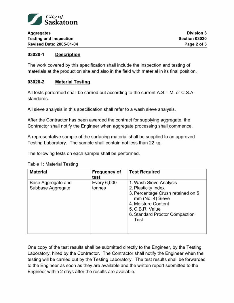
Aggregates Division 3 Testing and Inspection Section 03020 Revised Date: 2005-01-04 Page 2 of 3
03020-1 Description
The work covered by this specification shall include the inspection and testing of materials at the production site and also in the field with material in its final position.
03020-2 Material Testing
All tests performed shall be carried out according to the current A.S.T.M. or C.S.A. standards.
All sieve analysis in this specification shall refer to a wash sieve analysis.
After the Contractor has been awarded the contract for supplying aggregate, the Contractor shall notify the Engineer when aggregate processing shall commence.
A representative sample of the surfacing material shall be supplied to an approved Testing Laboratory. The sample shall contain not less than 22 kg.
The following tests on each sample shall be performed.
Table 1: Material Testing Material Frequency of
test Test Required
Base Aggregate and Subbase Aggregate
Every 6,000 tonnes
1. Wash Sieve Analysis 2. Plasticity Index 3. Percentage Crush retained on 5
mm (No. 4) Sieve 4. Moisture Content 5. C.B.R. Value 6. Standard Proctor Compaction
Test
One copy of the test results shall be submitted directly to the Engineer, by the Testing Laboratory, hired by the Contractor. The Contractor shall notify the Engineer when the testing will be carried out by the Testing Laboratory. The test results shall be forwarded to the Engineer as soon as they are available and the written report submitted to the Engineer within 2 days after the results are available.

Aggregates Division 3 Testing and Inspection Section 03020 Revised Date: 2005-01-04 Page 3 of 3
When test results are not provided as specified, the Engineer may engage a Testing Laboratory to carry out the specified testing. The cost of the testing will be at the expense of the Contractor.
When additional testing is required because of frequent changes in crusher location or aggregate supply, the cost of the additional testing shall be done at the expense of the Contractor. When the quality of the material is in question, the cost of all additional testing required shall be paid for by the Contractor. The cost of original density tests will be paid for by the City of Saskatoon. If the density test does not meet the specifications, any additional testing shall be paid for by the Contractor.
End of Specification 03020
Aggregates Division 3 Hand Placed, Grouted and Random Riprap Section 03050 Revised Date: 2022-02-04 Page 1 of 4
*Bold text denotes a change in this version (February 2022)
03050 Hand Placed, Grouted and Random Riprap
Index
03050-1 Description 2
03050-2 Materials 2 2.1 Riprap 2 2.2 Grout 2
03050-3 Construction 3 3.1 Excavation 3 3.2 Placement of Materials 3
03050-4 Measurement 4
03050-5 Payment 4

Aggregates Division 3 Hand Placed, Grouted and Random Riprap Section 03050 Revised Date: 2022-02-04 Page 2 of 4
*Bold text denotes a change in this version (February 2022)
03050-1 Description
The work shall consist of a protective covering of stone constructed with or without grout on an earth bed or granular filter blanket. Riprap shall be constructed at the locations shown on the plans or as designated by the Engineer.
The Contractor shall supply all labour, material, and equipment necessary to complete the work to the satisfaction of the Engineer.
03050-2 Materials
2.1 Riprap
Riprap material for culverts and other drainage work, shall consist of hard durable field stones, boulders or quality rock.
2.1.1 Type A Riprap
The minimum requirements of Type A Riprap are: Fifty (50) percent of the material must be greater than forty-five (45) kilograms and ninety (90) percent must be greater than twenty-seven (27) kilograms.
2.1.2 Type B Riprap
The minimum requirements of Type B Riprap are: Fifty (50) percent of material must be greater than thirty-four (34) kilograms and ninety (90) percent must be greater than fourteen (14) kilograms.
No stone shall be less than one hundred and fifty (150) mm dimension, with dimension being defined as length, width and depth.
2.2 Grout
The grout shall consist of a mixture of one (1) part Portland Cement and three (3) parts fine clean sand, or as otherwise designated by the Engineer. The consistency shall be such, that it can be easily worked into the spaces between the stones with a mason's trowel.
Aggregates Division 3 Hand Placed, Grouted and Random Riprap Section 03050 Revised Date: 2022-02-04 Page 3 of 4
*Bold text denotes a change in this version (February 2022)
03050-3 Construction
3.1 Excavation
3.1.1 Hand Placed and Grouted Riprap
The aprons and slopes to be riprapped shall be excavated and trimmed to an even, uniform surface so as to provide an adequate foundation upon which the riprap shall be placed. The depth of excavation shall be carried out as shown on plans or as designated by the Engineer.
3.1.2 Random Riprap
The aprons and slopes to be riprapped shall be excavated as shown on the plans or as designated by the Engineer, so as to provide a ledge or support upon which the stones may be dumped.
3.2 Placement of Materials
3.2.1 Hand Placed Riprap
The stones shall be placed by hand, on the prepared aprons and slopes, with the largest stones being placed at the bottom of the slope.
The stones shall be placed as close together as possible without any shaping of the stones themselves.
3.2.2 Grouted Riprap
The stones shall be placed as in 3.2.1 above. Before placement of the grout, the stones shall be thoroughly wetted. The grout shall then be placed, commencing from the bottom of the slope and progressing upward, ensuring that all voids between the stones are filled with grout. The stones shall project a distance of fifty (50) to one hundred (100) millimetres above the grouted surface, depending upon the dimension of the stone itself. After grouting, the surface shall be thoroughly brushed to expose the stone surface to the extent designated above.
Grout shall not be placed when the temperature is four (4) degrees Celsius and falling.
Aggregates Division 3 Hand Placed, Grouted and Random Riprap Section 03050 Revised Date: 2022-02-04 Page 4 of 4
*Bold text denotes a change in this version (February 2022)
The finished grouted surface shall, after sufficient setting, be sprayed with a curing compound supplied by the Contractor.
3.2.3 Random Riprap
Random riprap shall be dumped onto the prepared surface and sufficient handwork utilized, to provide a uniform surface to the satisfaction of the Engineer.
03050-4 Measurement
Measurements shall be based upon surface area (m2) as measured on the accepted completed product and upon one (1) layer of riprapping.
03050-5 Payment
Payment for hand placed, grouted, or random riprap shall be at the contract unit price per square metre as specified on the Tender Form, and be full compensation for supplying, hauling, placing and supplying all labour and equal parts necessary to complete the work to the satisfaction of the Engineer.
End of Specification 03050
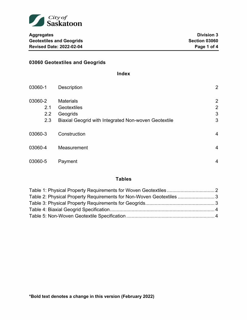
Aggregates Division 3 Geotextiles and Geogrids Section 03060 Revised Date: 2022-02-04 Page 1 of 4
*Bold text denotes a change in this version (February 2022)
03060 Geotextiles and Geogrids
Index
03060-1 Description 2
03060-2 Materials 2 2.1 Geotextiles 2 2.2 Geogrids 3 2.3 Biaxial Geogrid with Integrated Non-woven Geotextile 3
03060-3 Construction 4
03060-4 Measurement 4
03060-5 Payment 4
Tables
Table 1: Physical Property Requirements for Woven Geotextiles ................................... 2 Table 2: Physical Property Requirements for Non-Woven Geotextiles ........................... 3 Table 3: Physical Property Requirements for Geogrids ................................................... 3 Table 4: Biaxial Geogrid Specification ............................................................................. 4 Table 5: Non-Woven Geotextile Specification ................................................................. 4
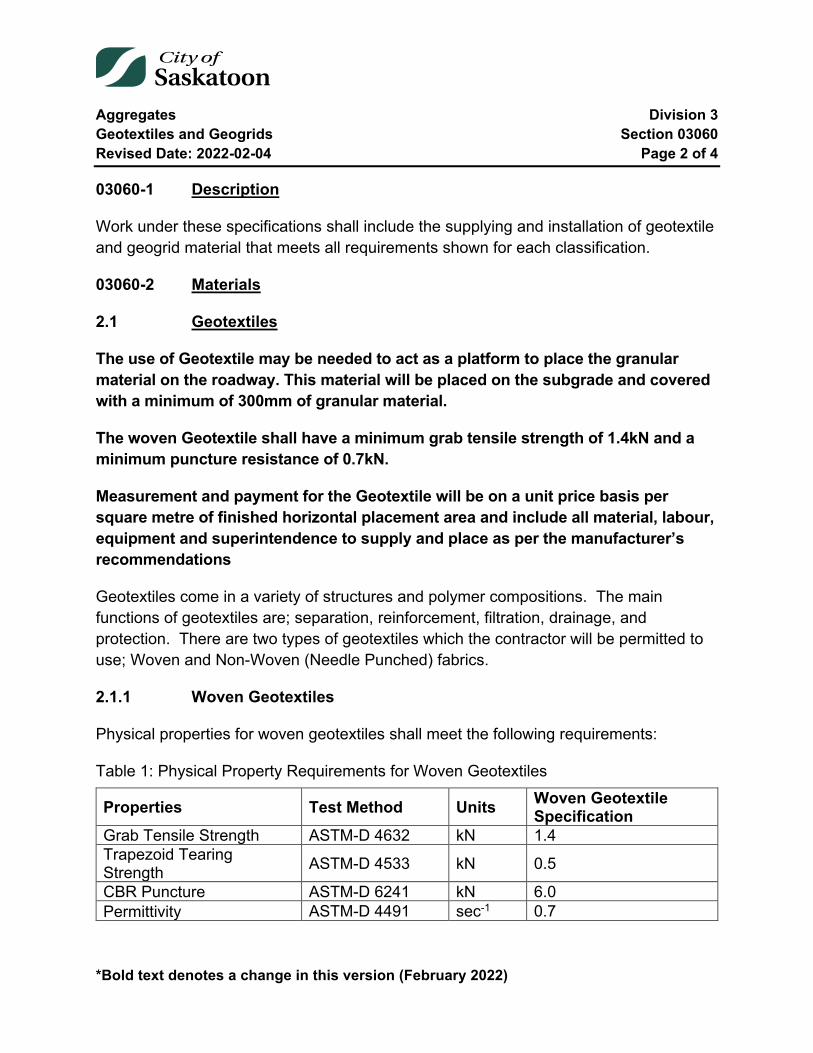
Aggregates Division 3 Geotextiles and Geogrids Section 03060 Revised Date: 2022-02-04 Page 2 of 4
*Bold text denotes a change in this version (February 2022)
03060-1 Description
Work under these specifications shall include the supplying and installation of geotextile and geogrid material that meets all requirements shown for each classification.
03060-2 Materials
2.1 Geotextiles
The use of Geotextile may be needed to act as a platform to place the granular material on the roadway. This material will be placed on the subgrade and covered with a minimum of 300mm of granular material.
The woven Geotextile shall have a minimum grab tensile strength of 1.4kN and a minimum puncture resistance of 0.7kN.
Measurement and payment for the Geotextile will be on a unit price basis per square metre of finished horizontal placement area and include all material, labour, equipment and superintendence to supply and place as per the manufacturer’s recommendations
Geotextiles come in a variety of structures and polymer compositions. The main functions of geotextiles are; separation, reinforcement, filtration, drainage, and protection. There are two types of geotextiles which the contractor will be permitted to use; Woven and Non-Woven (Needle Punched) fabrics.
2.1.1 Woven Geotextiles
Physical properties for woven geotextiles shall meet the following requirements:
Table 1: Physical Property Requirements for Woven Geotextiles
Properties Test Method Units Woven Geotextile Specification
Grab Tensile Strength ASTM-D 4632 kN 1.4 Trapezoid Tearing Strength ASTM-D 4533 kN 0.5
CBR Puncture ASTM-D 6241 kN 6.0 Permittivity ASTM-D 4491 sec-1 0.7
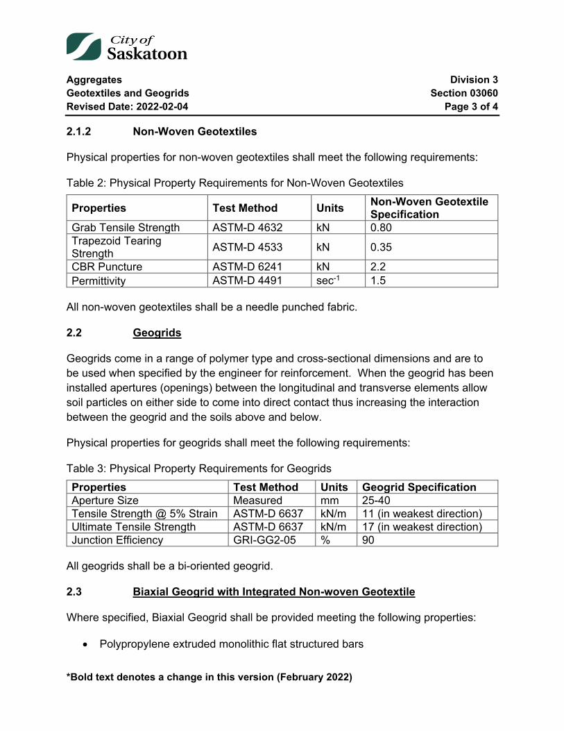
Aggregates Division 3 Geotextiles and Geogrids Section 03060 Revised Date: 2022-02-04 Page 3 of 4
*Bold text denotes a change in this version (February 2022)
2.1.2 Non-Woven Geotextiles
Physical properties for non-woven geotextiles shall meet the following requirements:
Table 2: Physical Property Requirements for Non-Woven Geotextiles
Properties Test Method Units Non-Woven Geotextile Specification
Grab Tensile Strength ASTM-D 4632 kN 0.80 Trapezoid Tearing Strength ASTM-D 4533 kN 0.35
CBR Puncture ASTM-D 6241 kN 2.2 Permittivity ASTM-D 4491 sec-1 1.5
All non-woven geotextiles shall be a needle punched fabric.
2.2 Geogrids
Geogrids come in a range of polymer type and cross-sectional dimensions and are to be used when specified by the engineer for reinforcement. When the geogrid has been installed apertures (openings) between the longitudinal and transverse elements allow soil particles on either side to come into direct contact thus increasing the interaction between the geogrid and the soils above and below.
Physical properties for geogrids shall meet the following requirements:
Table 3: Physical Property Requirements for Geogrids Properties Test Method Units Geogrid Specification Aperture Size Measured mm 25-40 Tensile Strength @ 5% Strain ASTM-D 6637 kN/m 11 (in weakest direction) Ultimate Tensile Strength ASTM-D 6637 kN/m 17 (in weakest direction) Junction Efficiency GRI-GG2-05 % 90
All geogrids shall be a bi-oriented geogrid.
2.3 Biaxial Geogrid with Integrated Non-woven Geotextile
Where specified, Biaxial Geogrid shall be provided meeting the following properties:
• Polypropylene extruded monolithic flat structured bars
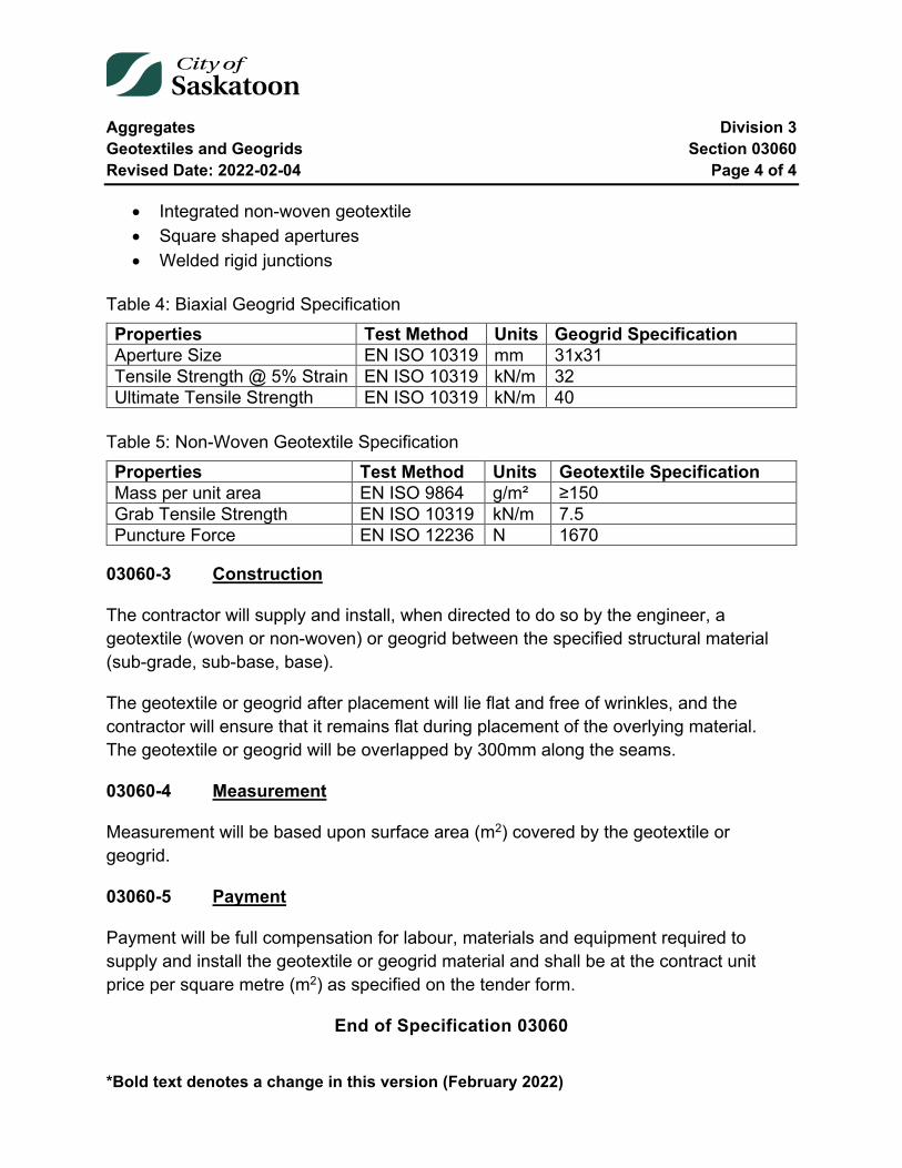
Aggregates Division 3 Geotextiles and Geogrids Section 03060 Revised Date: 2022-02-04 Page 4 of 4
*Bold text denotes a change in this version (February 2022)
• Integrated non-woven geotextile • Square shaped apertures • Welded rigid junctions
Table 4: Biaxial Geogrid Specification Properties Test Method Units Geogrid Specification Aperture Size EN ISO 10319 mm 31x31 Tensile Strength @ 5% Strain EN ISO 10319 kN/m 32 Ultimate Tensile Strength EN ISO 10319 kN/m 40
Table 5: Non-Woven Geotextile Specification Properties Test Method Units Geotextile Specification Mass per unit area EN ISO 9864 g/m² ≥150 Grab Tensile Strength EN ISO 10319 kN/m 7.5 Puncture Force EN ISO 12236 N 1670
03060-3 Construction
The contractor will supply and install, when directed to do so by the engineer, a geotextile (woven or non-woven) or geogrid between the specified structural material (sub-grade, sub-base, base).
The geotextile or geogrid after placement will lie flat and free of wrinkles, and the contractor will ensure that it remains flat during placement of the overlying material. The geotextile or geogrid will be overlapped by 300mm along the seams.
03060-4 Measurement
Measurement will be based upon surface area (m2) covered by the geotextile or geogrid.
03060-5 Payment
Payment will be full compensation for labour, materials and equipment required to supply and install the geotextile or geogrid material and shall be at the contract unit price per square metre (m2) as specified on the tender form.
End of Specification 03060

Asphaltic Materials Division 4 Rubberized Asphalt Crack Sealing Section 04000 Revised Date: 2022-02-04 Page 1 of 6
04000 Rubberized Asphalt Crack Sealing
Index
04000-1 Description 2
04000-2 Materials 2 2.1 Selection of Materials 2
04000-3 Equipment 2 3.1 Melting Kettle 2 3.2 Pavement Crack Router 3 3.3 Hot Compressed Air Lance (HCA Lance) 3 3.4 Crack Filling Devices and Strike-off Tools 3
04000-4 Execution 3 4.1 Crack Preparation 3 4.2 Preparation of the Crack Sealant 4 4.3 Crack Sealing 4 4.4 Concrete Roadway and Sidewalk Joint Sealing 5
04000-5 Measurement and Payment 6
Asphaltic Materials Division 4 Rubberized Asphalt Crack Sealing Section 04000 Revised Date: 2022-02-04 Page 2 of 6
04000-1 Description
This section specifies requirements for labour, machinery, equipment and material required to rout cracked asphaltic pavement and supply and place hot-poured rubberized asphalt sealant in transverse and longitudinal cracks.
04000-2 Materials
2.1 Selection of Materials
The crack sealant shall be a high quality rubberized asphalt sealing compound. This material shall adhere to all bituminous and concrete surfaces and have the flexibility and resiliency to withstand pavement temperatures encountered in Saskatoon.
All products must meet or exceed ASTM Specification D6690. The City has approved Crafco Road Saver 522. This is the only crack seal product approved at this time. Other crack sealing products must be evaluated and approved by the City of Saskatoon prior to use.
04000-3 Equipment
The following list of equipment is required but not limited to complete the work.
3.1 Melting Kettle
The rubberized asphalt sealant shall be heated in a portable, rubber tired, double boiler type unit capable of indirect heating of the sealant. The kettle shall be equipped with:
• Automatic heat controlling device to control product temperature.
• A horizontally mounted built-in paddle agitator capable of automatic operation to keep the sealant under vigorous continuous movement during heating.
• Monitoring thermometers for the sealant temperature and heat transfer oil if present.
• A positive displacement pump to discharge the sealant via a connecting wand such that proper temperatures are maintained.
Asphaltic Materials Division 4 Rubberized Asphalt Crack Sealing Section 04000 Revised Date: 2022-02-04 Page 3 of 6
3.2 Pavement Crack Router
A vertical router capable of cutting grooves with vertical sides in asphaltic concrete pavements to specified widths and depths. Routers must be able to achieve consistent and accurate routing depths. The router must be capable of following meandering cracks with routing restricted to the crack without any unnecessary pavement cutting. The router shall be equipped with suitable screens to prevent flying particles that may be hazardous to personnel or may damage vehicles or property.
3.3 Hot Compressed Air Lance (HCA Lance)
The HCA Lance shall be capable of providing a combined jet of compressed air and a propane flame capable of clearing, heating, drying and darkening a routed or unrouted crack.
3.4 Crack Filling Devices and Strike-off Tools
This equipment must be capable of flattening a head of sealant over the prepared crack if it has been overfilled.
04000-4 Execution
4.1 Crack Preparation
All areas to be routed and or cleaned shall be inspected by the Engineer prior to the work starting. Cracks less than 19 mm in width must be routed to a width of 19 mm or greater. Both sides of the crack shall be routed. All cracks routed shall be routed to a minimum depth of 20 mm. Cracks greater than 30 mm shall not be routed or sealed.
Wedged chips or other non-compressible material shall be removed prior to sealing. The routed and non-routed crack must be cleaned and heated using a HCA lance to remove debris, dust and moisture. The hot rubberized asphalt sealant must be placed within 30 seconds of hot lancing. Pavement surfaces adjacent to the cleaned cracks shall be blown and cleared of all debris that might otherwise contaminate the cleaned crack prior to sealing.
Asphaltic Materials Division 4 Rubberized Asphalt Crack Sealing Section 04000 Revised Date: 2022-02-04 Page 4 of 6
4.2 Preparation of the Crack Sealant
During the melting operation, all foreign material shall be prevented from entering the melter. All sealant protection wrapping is to be removed prior to melting the compound if required by the manufacturer. The compound shall be melted slowly with constant agitation. The manufacturer's maximum safe heating temperature and minimum pour temperatures shall be adhered to at all times. The Engineer may allow temperature lower than the minimum pour temperature when the ambient temperature is high or on steep gradients where the sealant might otherwise flow after placement. The maximum crack seal batch size shall be as much crack filling sealant as can be placed in a given day, or 400 litres, whichever is less.
Reheating unused sealant shall not be permitted. All overheated, diluted or contaminated material shall be removed from the site and disposed of at the Contractor's expense.
4.3 Crack Sealing
At the time of crack filling the ambient temperature shall be a minimum of 5° C and rising. All areas of crack to be sealed shall be inspected by the Engineer prior to placement of the sealant. Crack sealing shall not be performed on alligator cracking or block cracking or cracks wider than 30 mm.
Care is to be taken when filling routed or cleaned cracks. The tip of the wand shall be placed at the bottom of the routed crack or as far into the unrouted crack as possible to ensure uniform application and that no sealant bridges entrapped air pockets. A second application of sealant may be required where excess subsidence occurs. Sealant should be placed so as to fill the route or crack such that both edges of the route or crack are covered.
After placement of the sealant, excess material should be struck off with a strike-off device to leave a flush surface over the crack. The methods of application must be approved by the Engineer in the field prior to commencement of the work.
Where pedestrian or vehicular traffic may cause tracking of the sealant (crosswalks or intersections), the sealed cracks shall be dusted with silica sand or cement powder. Supply and placement of this material shall be a subsidiary obligation of the Contractor and as such there will be no direct payment.
Asphaltic Materials Division 4 Rubberized Asphalt Crack Sealing Section 04000 Revised Date: 2022-02-04 Page 5 of 6
The Contractor shall ensure traffic is not allowed on the newly sealed surface for a period of 1 hour from completion of the crack sealing in order to prevent tracking.
Damage such as embedded stones, excessive debris or moisture in the sealant or obvious contamination shall be rejected. The defective work shall be repaired, removed, replaced or remedied at the Contractor's cost.
All debris from the cleaning and routing operation shall be swept or blown from the surface of the roadway into the gutter for removal by City Forces. All refuse such as wrappings, containers or any other debris resulting from this operation shall be gathered and removed from the site on a daily basis by the Contractor.
The sealed cracks shall be guaranteed for a period of two years from the date of completion of the sealing operation. If, during the warrantee period, the sealant pops out or there is obvious evidence of water or material ingress through the crack, the sealant shall be removed, the crack cleaned and resealed.
4.4 Concrete Roadway and Sidewalk Joint Sealing
Only the deep tooled longitudinal joint located at the top of the rolled curb section of the sidewalk is intended to be sealed. Weeds shall be removed from this joint prior to sealing by handpicking or by use of such tools as a rotary edger. The joint shall then be thoroughly cleaned of debris and remaining organic material by hydro blasting or sand blasting. Any other cleaning method requires the Engineer’s approval.
The concrete faces on either side of the joint shall be dried with compressed air prior to sealing with hot rubberized sealant. Prior to leaving the worksite, the Contractor shall sweep up from both the sidewalk and the gutter all loose debris left as a result of cleaning and shall properly dispose of this debris off-site.
The Contractor shall fill these longitudinal joints with rubberized sealant to a minimum depth of 20 mm measured from the top of the concrete surface. To ensure proper shape factor and to mitigate waste of the sealant product the Contractor shall employ one of the following methods:
1. Insert heat resistant backer rod in the prepared joint. The depth of the backer rod will be set to accommodate the minimum required depth of Hot Rubberized Sealant.
Asphaltic Materials Division 4 Rubberized Asphalt Crack Sealing Section 04000 Revised Date: 2022-02-04 Page 6 of 6
2. Fill the void at the bottom of the prepared joint with fine dry sand. The depth of the sand filler will be set to accommodate the minimum required depth of Hot Rubberized Sealant. After the sand filler has been placed, the exposed sides of the joint between the top of the sand and the top of the concrete shall be wire brushed clean of any sand particles.
3. If the Contractor deems the width of the prepared joint to be sufficiently narrow, he may apply full depth sealant. There will be no additional payment for the extra Sealant used.
Transverse joints at 1.5 metre typical spacing extend from back of sidewalk to lip of gutter. The Contractor shall place temporary filler in the transverse joints on both sides of the longitudinal joint. The purpose of this temporary filler is to prevent spillage of hot sealant from the longitudinal joint. This temporary filler shall match the colour of the hot sealant if it is to be left in place to disintegrate over time or shall be removed after the sealant has set up, with the method of removal such that no holes are left in the sealant afterwards. The Contractor’s temporary filler method must be approved by the Engineer prior to the start of the sidewalk crack sealing.
Any spillage of sealant on the surface of the concrete sidewalk or curb shall be cleaned up immediately by the Contractor.
For aesthetic reasons, the completed longitudinal joint shall be lightly dusted with a fine sand, talcum powder, or cementitious powder at those locations, such as driveway crossings, where there is a risk of traffic driving over newly completed joints.
04000-5 Measurement and Payment
Measurement and payment for rubberized asphalt crack sealing will be on a lineal metre basis and shall be full compensation for the supply of all labour, equipment and material required to rout and clean cracks, supply and apply sealant, supply and place blotting sand where required, provide proper traffic accommodation and clean up all cuttings, debris, and blotting sand before leaving the site.
End of Specification 04000
Asphaltic Materials Division 4 Asphalt Mix Section 04010 Revised Date: 2022-02-04 Page 1 of 15
*Bold text denotes a change in this version (February 2022)
04010 Asphalt Mix
Index
04010-1 General 2 1.1 Description 2 1.2 Related Sections 2 1.3 Definitions 2 1.4 Mix Design Submittals 4
04010-2 Materials 6 2.1 Asphalt Cement 6 2.2 Asphalt Mix Aggregate 8 2.3 Reclaimed Asphalt pavement (RAP) 10 2.4 Asphalt Concrete Mix 10
04010-3 Execution 13 3.1 General 13 3.2 Aggregates 13 3.3 Asphalt Plant Operation 14
04010-4 Testing 14
Tables, Equations and Figures
Table 1: 150-200A Asphalt Cement Grade Requirements 6 Table 2: 150-200A AC Viscosity and Penetration Coordinates 6 Table 3: Gradation for Asphalt Mix Aggregate 8 Table 4: Physical Properties for Asphalt Mix Aggregate 9 Table 5: Physical Properties for Asphalt Mix 12 Figure 1: Asphalt Cement Viscosity and Penetration Requirements 7 Equation 1: Percent Allowable Reclaimed Asphalt Pavement 10

Asphaltic Materials Division 4 Asphalt Mix Section 04010 Revised Date: 2022-02-04 Page 2 of 15
*Bold text denotes a change in this version (February 2022)
04010-1 General
1.1 Description
This section specifies requirements for labour, machinery, plant, equipment and materials required to produce hot mix asphalt concrete.
1.2 Related Sections
Section 04015 Asphalt Paving. Section 04020 Reclaimed Asphalt Pavement
1.3 Definitions
1.3.1 Bitumen
A Class of black or dark coloured (solid, semisolid, or viscous) cementitious substance, natural or manufactured, composed principally of high molecular weight hydrocarbons, of which asphalts, tars, pitches, and asphaltites are typical.
1.3.2 Asphalt
A dark brown to black cementitious material in which the predominating constituents are bitumens which occur in nature or are obtained in petroleum processing.
1.3.3 Asphalt Cement
The bituminous material that is used to bind the asphalt mix aggregate. A fluxed or unfluxed asphalt specifically prepared as to quality and consistency for direct use in the manufacture of bituminous pavements and having a penetration at 25°C (77°F) of between 5 and 300, under a load of 100 g applied for 5 seconds.
1.3.4 Asphalt Aggregate
The individual crushed and processed aggregate fractions before combining to produce the asphalt mix aggregate.
Asphaltic Materials Division 4 Asphalt Mix Section 04010 Revised Date: 2022-02-04 Page 3 of 15
*Bold text denotes a change in this version (February 2022)
1.3.5 Asphalt Mix Aggregate
The mix after combining the asphalt aggregate fractions including filler or blending sand to produce the specified mix gradation.
1.3.6 Asphalt Mix
The mix produced by combining asphalt cement with the asphalt mix aggregate.
1.3.7 Performance Graded (PG) Asphalt Binders
Asphalt binder grade designation used in Superpave. It is based on the binder's mechanical performance at critical temperatures and aging conditions.
1.3.8 Polymer Modified Asphalt
Conventional asphalt cement to which one or more polymer compounds have been added to improve resistance to deformation at high pavement temperatures and often cracking resistance at low temperatures.
1.3.9 Reclaimed Asphalt Pavement (RAP)
Asphalt millings or processed asphalt pavement removals, handled and characterized for RAP to be incorporated into asphalt mix.
1.3.10 Top Lift
The asphalt concrete wearing course.
1.3.11 Bottom Lift
All asphalt concrete courses below the Top lift.
1.3.12 Job Mix Formula
Establishes the target combined aggregate gradation, plant settings, approved asphalt cement content to be used for production of the asphalt mix, and the associated production tolerances, based on the submitted asphalt mix design and the results of the plant trials.
Asphaltic Materials Division 4 Asphalt Mix Section 04010 Revised Date: 2022-02-04 Page 4 of 15
*Bold text denotes a change in this version (February 2022)
1.4 Mix Design Submittals
Contractors and Suppliers must submit a formal Mix Design, carried out by a certified laboratory prior to any hot mix asphalt (HMA) being placed. Marshall Mix designs are to be completed in accordance with the latest edition of the Asphalt Institute Manual Series No. 2 (MS-2), ASTM D6927 and AASHTO T-245 unless otherwise modified by City of Saskatoon requirements.
Any change in Supplier or materials will warrant the submission of a new mix design.
Mix design submissions shall contain, as a minimum:
• Asphalt cement data; o Name of Supplier and source(s) of the base asphalt cement(s) o Type and source(s) of additive(s) o Current laboratory test results of the asphalt cement o Mixing and compaction temperature, as determined by the asphalt
cement’s temperature-viscosity curve, or as recommended by the asphalt cement supplier;
• Aggregate data; o Source(s) of aggregates o Los Angeles Abrasion test results o Sand Equivalency results o Organic Content o Crush Count o Manufactured Fines o Individual Aggregate Gradations
• Reclaimed Asphalt Pavement (RAP) data, where RAP is included in the mix: o Source of the RAP o Asphalt Cement content of the RAP o Asphalt Cement contribution from the RAP o All RAP aggregate gradations for each RAP product o Specific gravity of the combined aggregates (when applicable) o RAP Rheology test results
• Asphalt Mix data; o Aggregate blend proportions

Asphaltic Materials Division 4 Asphalt Mix Section 04010 Revised Date: 2022-02-04 Page 5 of 15
*Bold text denotes a change in this version (February 2022)
o Combined aggregate gradation and bulk specific gravity o Asphalt cement absorption of the combined aggregates o Anti-stripping agent supplier, product name, application rate, and
test results • A minimum of five individual and separate asphalt cement contents
(separated by a minimum of 0.5% AC content) must be used in the mix design;
• The following individual mix property results to be plotted; o Maximum Theoretical Density o Marshall Stability o Marshall Flow o Air Voids o Voids in Mineral Aggregate o Voids Filled with Asphalt o Film Thickness
• The Asphalt Mix Design & Job Mix Formula (JMF) Submission Summary sheet, as provided by the Engineer
1.4.1 Job Mix Formula (JMF)
On an annual basis, the Contractor shall submit a mix design and Job Mix Formula (JMF) for each type of hot mix to be supplied. The Contractor will only supply hot mix for which the Engineer has approved the JMF.
All asphalt mix shall be supplied to the approved job mix formula within the range of tolerances specified. Where tolerances are not specified, the values stated under this section shall be considered absolute, minimums, maximums or allowable ranges. Unless otherwise stated specification limits are based on single tests and include sampling, testing, and process variance.
Tolerances stated in this section and in Section 04015 shall apply to all asphalt concrete mix types unless otherwise specified.
The job mix formula, as originally established, shall remain in effect until modified in writing and approved by the Engineer. Should a change of aggregate(s) be made, or when unsatisfactory results or other conditions make it necessary, the Contractor shall submit a new mix design for approval.
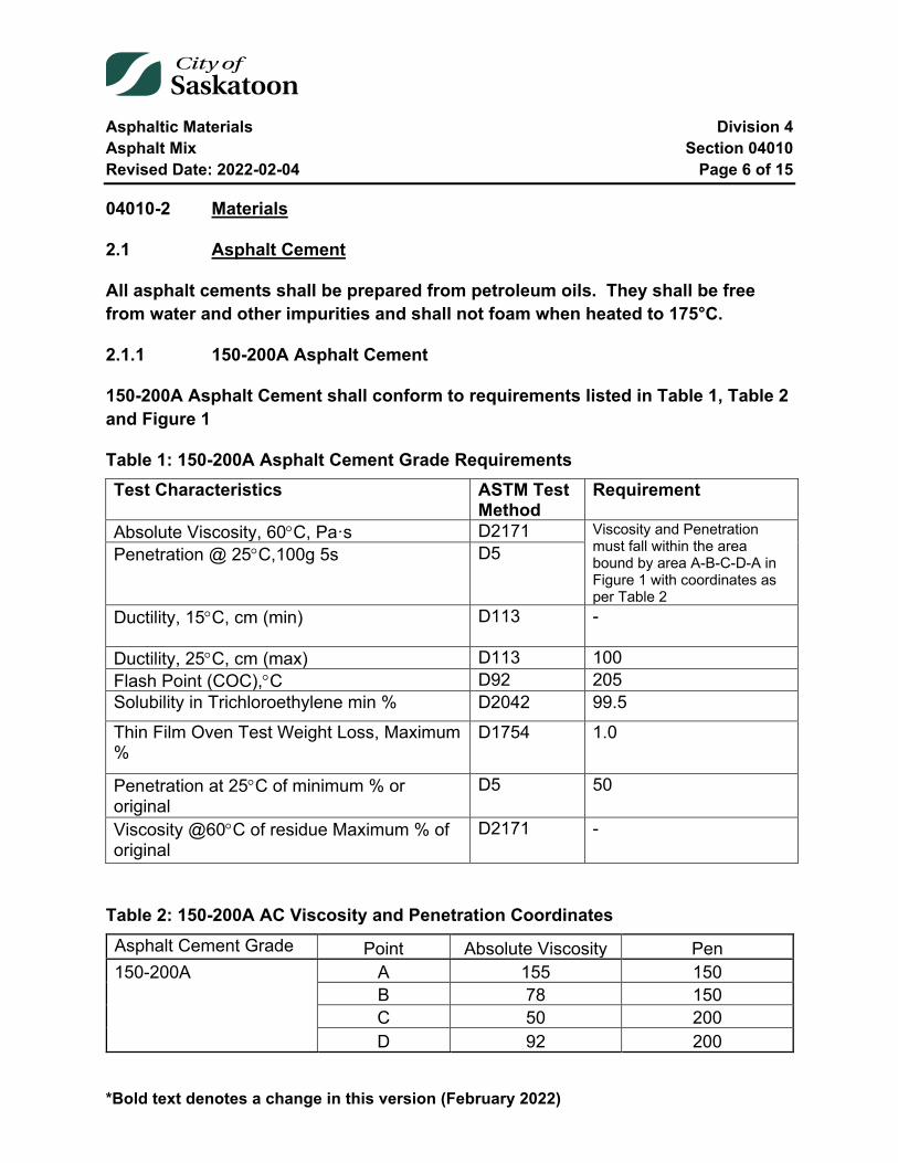
Asphaltic Materials Division 4 Asphalt Mix Section 04010 Revised Date: 2022-02-04 Page 6 of 15
*Bold text denotes a change in this version (February 2022)
04010-2 Materials
2.1 Asphalt Cement
All asphalt cements shall be prepared from petroleum oils. They shall be free from water and other impurities and shall not foam when heated to 175°C.
2.1.1 150-200A Asphalt Cement
150-200A Asphalt Cement shall conform to requirements listed in Table 1, Table 2 and Figure 1
Table 1: 150-200A Asphalt Cement Grade Requirements Test Characteristics ASTM Test
Method Requirement
Absolute Viscosity, 60°C, Pa·s D2171 Viscosity and Penetration must fall within the area bound by area A-B-C-D-A in Figure 1 with coordinates as per Table 2
Penetration @ 25°C,100g 5s D5
Ductility, 15°C, cm (min) D113 -
Ductility, 25°C, cm (max) D113 100 Flash Point (COC),°C D92 205 Solubility in Trichloroethylene min % D2042 99.5 Thin Film Oven Test Weight Loss, Maximum %
D1754 1.0
Penetration at 25°C of minimum % or original
D5 50
Viscosity @60°C of residue Maximum % of original
D2171 -
Table 2: 150-200A AC Viscosity and Penetration Coordinates Asphalt Cement Grade Point Absolute Viscosity Pen 150-200A A 155 150 B 78 150 C 50 200 D 92 200

Asphaltic Materials Division 4 Asphalt Mix Section 04010 Revised Date: 2022-02-04 Page 7 of 15
*Bold text denotes a change in this version (February 2022)
Figure 1: Asphalt Cement Viscosity and Penetration Requirements
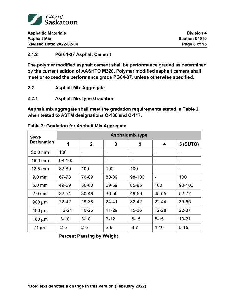
Asphaltic Materials Division 4 Asphalt Mix Section 04010 Revised Date: 2022-02-04 Page 8 of 15
*Bold text denotes a change in this version (February 2022)
2.1.2 PG 64-37 Asphalt Cement
The polymer modified asphalt cement shall be performance graded as determined by the current edition of AASHTO M320. Polymer modified asphalt cement shall meet or exceed the performance grade PG64-37, unless otherwise specified.
2.2 Asphalt Mix Aggregate
2.2.1 Asphalt Mix type Gradation
Asphalt mix aggregate shall meet the gradation requirements stated in Table 2, when tested to ASTM designations C-136 and C-117.
Table 3: Gradation for Asphalt Mix Aggregate
Sieve Designation
Asphalt mix type
1 2 3 9 4 5 (SUTO)
20.0 mm 100 - - - - -
16.0 mm 98-100 - - - - -
12.5 mm 82-89 100 100 100 - -
9.0 mm 67-78 76-89 80-89 98-100 - 100
5.0 mm 49-59 50-60 59-69 85-95 100 90-100
2.0 mm 32-54 30-48 36-56 49-59 45-65 52-72
900 µm 22-42 19-38 24-41 32-42 22-44 35-55
400 µm 12-24 10-26 11-29 15-26 12-28 22-37
160 µm 3-10 3-10 3-12 6-15 6-15 10-21
71 µm 2-5 2-5 2-6 3-7 4-10 5-15
Percent Passing by Weight
Asphaltic Materials Division 4 Asphalt Mix Section 04010 Revised Date: 2022-02-04 Page 9 of 15
*Bold text denotes a change in this version (February 2022)
2.2.2 Fines Composition
Asphalt mix aggregate, retained on the 5.0 mm plus sieves, shall be composed of fragments of durable rock and shall not contain more than 2% by weight of deleterious materials such as shale, ironstone, and coal. The maximum permissible organic content of the material passing the 5.0 mm sieve is 1.0%.
2.2.3 Physical Properties
Physical properties for aggregate shall meet the following requirements:
Table 4: Physical Properties for Asphalt Mix Aggregate
Asphalt mix type
Requirement Test
Designation 1,9, & 5 (SUTO) 2, 3 & 4
Sand Equivalence ASTM D2419 45 min. 45 min. Los Angeles Abrasion (% loss) ASTM C131 30 max. 35 max. Organic Content (% Passing 5.0 mm) 1.0 max. 1.0 max Crush Count (1) (% Retained 5.0 mm Sieve)
80 min. 2 faces
70 min. 1 face
Manufactured Fines (2) (% Passing 5.0 mm Sieve) 70 min. -
Notes:
Crush Count is the percentage of the crushed aggregate retained on the 5.0 mm plus sieves having either 1 or more fractured faces or 2 or more fractured faces, created by the crushing operation.
Manufactured fines are the percentage by mass of crusher run manufactured sand passing the 5mm sieve. For mixes incorporating RAP, 50% of the RAP passing the 5.0 mm sieve shall be considered manufactured sand.
Asphalt mix aggregate shall meet the gradation requirements stated in Table 2, when tested to ASTM designations C-136 and C-117.
Asphaltic Materials Division 4 Asphalt Mix Section 04010 Revised Date: 2022-02-04 Page 10 of 15
*Bold text denotes a change in this version (February 2022)
2.3 Reclaimed Asphalt pavement (RAP)
The Contractor shall follow the best practices for obtaining, managing, sampling and testing RAP, as stated in Section 04020.
For the purpose of the Asphalt Mix design, the maximum allowable binder contribution from RAP for top and bottom lifts are as follows:
• Top lifts with PMA: 10% • Top lifts without PMA: 15% • All bottom lifts: 20%
The methodology used to determine the percent allowable RAP is as follows:
%𝑨𝑨𝑨𝑨𝑨𝑨𝑨𝑨𝑨𝑨𝑨𝑨𝑨𝑨𝑨𝑨𝑨𝑨 𝑹𝑹𝑨𝑨𝑹𝑹 =(% 𝑩𝑩𝑩𝑩𝑩𝑩𝑩𝑩𝑨𝑨𝑩𝑩 𝑪𝑪𝑨𝑨𝑩𝑩𝑪𝑪𝑩𝑩𝑩𝑩𝑨𝑨𝑪𝑪𝑪𝑪𝑩𝑩𝑨𝑨𝑩𝑩)(% 𝑨𝑨𝑪𝑪𝒎𝒎𝑩𝑩𝒎𝒎)
�% 𝑨𝑨𝑪𝑪𝑹𝑹𝑨𝑨𝑹𝑹�
Equation 1: Percent Allowable Reclaimed Asphalt Pavement Where:
• % Binder Contribution = selected to a maximum value specified above • %ACmix = target asphalt content of the selected mix type (% mass by total
mix), • %ACRap = asphalt content of the RAP, as determined by laboratory testing
(% mass by total mix), and • % Allowable RAP = the maximum RAP addition rate (% mass of total mix).
Should a change in the source or addition rate of RAP be made after the mix design has been approved, a new mix design and/or job mix formula shall be submitted to the City of Saskatoon Representative.
2.4 Asphalt Concrete Mix
Asphalt mix shall consist of a homogeneous mixture of asphalt mix aggregate, RAP, and asphalt cement mixed in a central plant.
Asphaltic Materials Division 4 Asphalt Mix Section 04010 Revised Date: 2022-02-04 Page 11 of 15
*Bold text denotes a change in this version (February 2022)
2.4.1 Minimum Asphalt Cement Content
The minimum asphalt content by dry mass of aggregate, inclusive of the virgin asphalt cement and the asphalt cement contributed by the RAP, are as follows:
• 5.0% for Type 1 mixes • 5.3% for Type 2 mixes • 5.7% for Type 3 mixes • 6.5% for Type 9 and Type 4 mixes • 6.3% for Type 9P mixes • 7.0% for Type 5 mixes (SUTO)
2.4.2 Anti Stripping Agent
Anti stripping agent, if required, shall be added to achieve a stripping potential of less than five percent (5%) as determined by the Saskatchewan Ministry of Highways and Infrastructure Stripping Potential Test STP 204-15. The Contractor shall provide test results identifying the type and amount of anti-stripping agent required to meet this requirement. The contractor shall provide the brand name and technical literature of the product to be used. The cost of the anti-stripping agent, if required shall be included in the unit prices under the contract.
2.4.3 Physical Properties
Physical properties for the mix shall meet the following requirements at the design asphalt content and gradation:
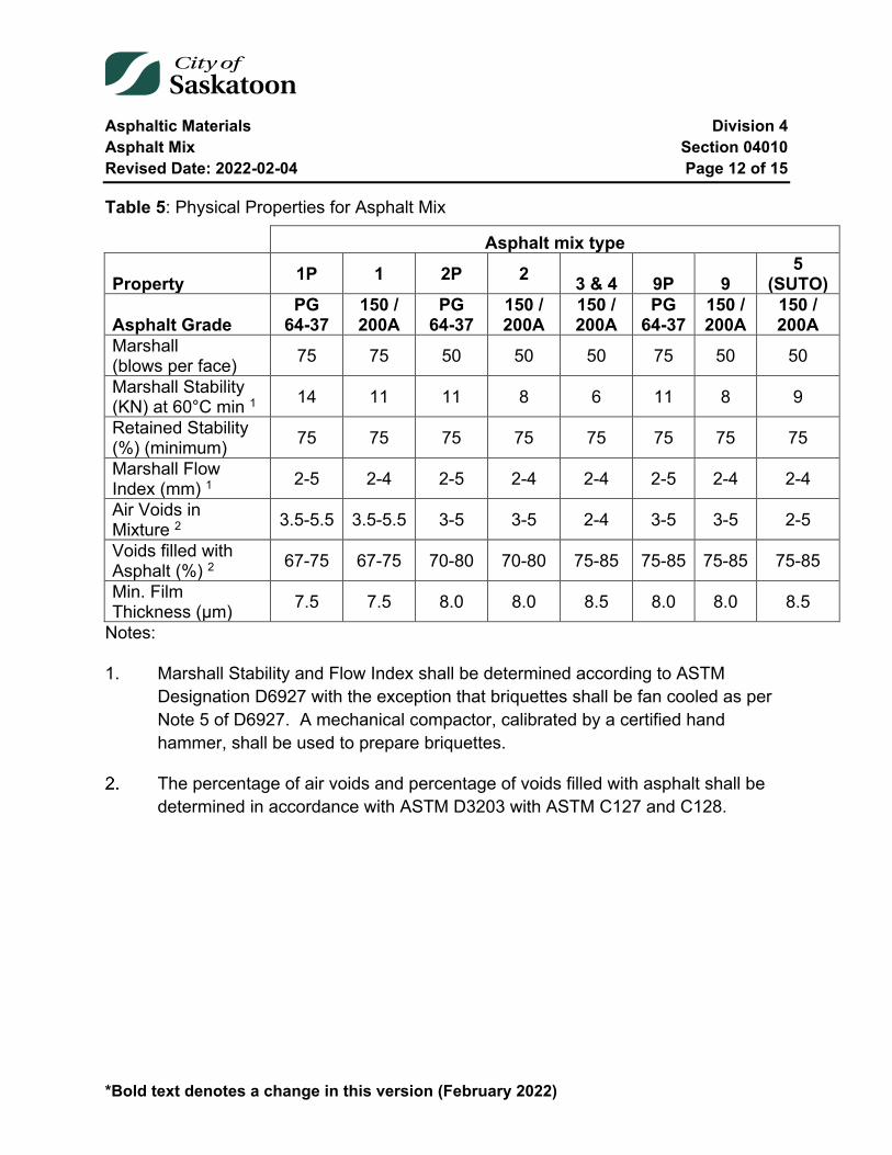
Asphaltic Materials Division 4 Asphalt Mix Section 04010 Revised Date: 2022-02-04 Page 12 of 15
*Bold text denotes a change in this version (February 2022)
Table 5: Physical Properties for Asphalt Mix
Asphalt mix type
Property 1P 1 2P 2 3 & 4 9P 9 5
(SUTO)
Asphalt Grade PG
64-37 150 / 200A
PG 64-37
150 / 200A
150 / 200A
PG 64-37
150 / 200A
150 / 200A
Marshall (blows per face) 75 75 50 50 50 75 50 50
Marshall Stability (KN) at 60°C min 1 14 11 11 8 6 11 8 9
Retained Stability (%) (minimum) 75 75 75 75 75 75 75 75
Marshall Flow Index (mm) 1 2-5 2-4 2-5 2-4 2-4 2-5 2-4 2-4
Air Voids in Mixture 2 3.5-5.5 3.5-5.5 3-5 3-5 2-4 3-5 3-5 2-5
Voids filled with Asphalt (%) 2 67-75 67-75 70-80 70-80 75-85 75-85 75-85 75-85
Min. Film Thickness (µm) 7.5 7.5 8.0 8.0 8.5 8.0 8.0 8.5
Notes:
1. Marshall Stability and Flow Index shall be determined according to ASTM Designation D6927 with the exception that briquettes shall be fan cooled as per Note 5 of D6927. A mechanical compactor, calibrated by a certified hand hammer, shall be used to prepare briquettes.
The percentage of air voids and percentage of voids filled with asphalt shall be determined in accordance with ASTM D3203 with ASTM C127 and C128.
Asphaltic Materials Division 4 Asphalt Mix Section 04010 Revised Date: 2022-02-04 Page 13 of 15
*Bold text denotes a change in this version (February 2022)
04010-3 Execution
3.1 General
All tools, machinery, plant and equipment used in handling materials and executing any part of the work shall be subject to the approval of the Engineer. All such equipment shall be maintained in efficient working order and where any of the machinery plant or equipment is found to be unsatisfactory; it shall be improved or replaced by the Contractor to the satisfaction of the Engineer.
3.2 Aggregates
Deliver and stockpile aggregates in accordance with the requirements of this section.
Segregate aggregate stockpiles by each aggregate fraction processed using substantial dividers or stockpile far enough apart to prevent intermixing.
Stockpile minimum of 50% of total aggregate fractions contracted before commencing trial mix designs. This quantity shall include aggregate stockpiled at both the processing site and asphalt plant site.
Stockpile at the plant site during production at least 15% of the total contracted amount for each size fraction processed.
When hauling into stockpiles after plant mixing has commenced do not deposit material against working face of stockpile.
Construct stockpiles in uniform lifts avoiding segregation by spillage of materials over the ends of previously placed lifts. Do not use stationary conveyors in stockpile construction.
Provide a previously stabilized stockpile base not less than 300 mm in depth to prevent contamination.
Aggregates from intermixed or contaminated stockpiles will be rejected and must be removed or disposed of as directed by the Engineer within 24 hours of rejection.
Asphaltic Materials Division 4 Asphalt Mix Section 04010 Revised Date: 2022-02-04 Page 14 of 15
*Bold text denotes a change in this version (February 2022)
3.3 Asphalt Plant Operation
The asphalt plant and auxiliary equipment shall be such as to combine, dry and heat the asphalt mix aggregate, heat the asphalt cement and accurately proportion the asphalt cement and asphalt mix at a centrally located plant to the requirements of this section.
When combining aggregates during asphalt concrete mix production at no time shall two processed aggregate fractions share the same mechanical cold feed bin.
The asphalt plant shall meet the requirement of ASTM designation D995 for Bituminous Mixing Plant requirements.
The maximum planned storage time for any HMA shall be no more than 24 hours.
The maximum planned silo storage time for Type 1 and any polymer modified mixes shall be no more than 8 hours.
04010-4 Testing
The City of Saskatoon shall appoint an independent testing consultant to perform all tests for quality control of the mix to determine compliance with specification during production (process control), and quality assurance to determine acceptance and payment adjustments to material supplied and placed. This is not intended to relieve the contractor of the responsibility of maintaining their own quality control testing programs for the mix or preventing them from initiating shutdown of production for material that will be out of specification as determined from their own testing program.
Sampling for quality assurance will be done using a random sampling procedure as identified by the Engineer. Where there is continuous production uninterrupted by plant shutdown due to quality control only the predetermined random sampling frequency will be used to determine payment adjustments to the unit bid price.
The quality assurance random sampling will also be the basis for quality control for generating control charts and determining plant shutdown. In addition to the quality assurance sampling the Engineer may also initiate supplementary tests independent of the quality assurance random sampling procedure to supplement the quality control tests for determining process control. These additional tests will not be used for payment adjustment factors unless it results in plant shutdown prior to the sampling for
Asphaltic Materials Division 4 Asphalt Mix Section 04010 Revised Date: 2022-02-04 Page 15 of 15
*Bold text denotes a change in this version (February 2022)
quality assurance in that specific lot of material. The supplementary test in this case will then be used for payment adjustment on that portion of the untested lot. If the supplementary test results in termination of production the contractor will be required to pay for the test.
The Contractor shall retain and pay an independent testing consultant to perform all materials certification tests and mix designs required in this section.
The Contractor, at their sole discretion, will secure samples of polymer modified asphalt cement from each 40-80 tonne shipment. These samples will be stored for a minimum period of six months and the contractor may test as many samples as they wish at their cost. The City will only accept test data from a certified testing lab. If it is discovered that a particular load of asphalt cement does not meet the PG grade the City will pay for the cost of the test and waive the mix adjustments that occur as a result of the lower grade of polymer modified asphalt cement.
End of Specification 04010

Asphaltic Materials Division 4 Asphalt Paving Section 04015 Revised Date: 2022-02-04 Page 1 of 27
*Bold text denotes a change in this version (February 2022)
04015 Asphalt Paving
Index
04015-1 General 3 1.1 Description 3 1.2 Related Sections 3 1.3 Definitions 3
04015-2 Materials 4 2.1 Hot Mix Asphalt 4 2.2 Tack Coat Material 4
04015-3 Equipment 4 3.1 General 4 3.2 Asphalt Plant 4 3.3 Scale 5 3.4 Haul Trucks 5 3.5 Paving Machine 5 3.6 Rollers 5 3.7 Hand Tools 6
04015-4 Execution 6 4.1 Spreading 6 4.2 Compacting 8 4.3 Quality Control 9 4.4 Acceptance, Rejection and Repairs 18
04015-5 Testing 19
04015-6 Measurement 20
04015-7 Payment 20 7.1 Payment Adjustment Factors 20

Asphaltic Materials Division 4 Asphalt Paving Section 04015 Revised Date: 2022-02-04 Page 2 of 27
*Bold text denotes a change in this version (February 2022)
Tables and Equations
Table 1: Minimum Air Temperature Based on Asphalt Mat Thickness ..................... 7 Table 2: Asphalt Cement Quality Control Tests ....................................................... 12 Table 3: Type 1 and 1P - Maximum Permissible Variation ....................................... 13 Table 4: Types 2 and 2P - Maximum Permissible Variation ..................................... 14 Table 5: Type 3 - Maximum Permissible Variation ................................................... 15 Table 6: Types 9 and 9P - Maximum Permissible Variation ..................................... 16 Table 7: Type 5 (SUTO) - Maximum Permissible Variation ...................................... 17 Table 8: Segregation Classifications ......................................................................... 18 Table 9: Asphalt Segregation Repairs ....................................................................... 19 Table 10: Air Void Payment Adjustment Factors...................................................... 22 Table 11: Marshall Stability Payment Adjustment Factors ...................................... 23 Table 12: Asphalt Cement Content Payment Adjustment Factors .......................... 24 Table 13: Compacted Density for Types 2, 3 and 4 .................................................. 25 Table 14: Compacted Density for Type 1 .................................................................. 25 Table 15: Compacted Density for Type 9 .................................................................. 26 Table 16: Variation in Thickness ................................................................................ 26 Equation 1: Calculating "X" for Payment Adjustments ........................................... 26
Asphaltic Materials Division 4 Asphalt Paving Section 04015 Revised Date: 2022-02-04 Page 3 of 27
*Bold text denotes a change in this version (February 2022)
04015-1 General
1.1 Description
This section specifies requirements for all labour, machinery, plant, equipment and materials required to construct asphalt concrete.
Asphalt concrete shall consist of a homogenous mixture of crushed aggregate, Reclaimed Asphalt Pavement (RAP) and asphalt cement mixed in an approved central plant, hauled and spread at or above the minimum workable temperature upon a suitable base and compacted by immediate and intensive rolling so as to construct a smooth surface.
This asphalt concrete is to be constructed within the limits of the Contract Documents. The work shall be completed to the lines, grades, dimensions and typical cross-sections shown on the plans or as designated by the Engineer.
1.2 Related Sections
Specification 04010 Asphalt Mix
1.3 Definitions
Asphalt Cement
The bituminous material that is used to bind the asphalt mix aggregate.
Asphalt Aggregate
The crushed aggregate.
Asphalt Mix Aggregate
The mix after combining the asphalt aggregate fractions including filler or blending sand to produce the specified mix gradation.
Asphalt Mix
The mix produced by combining the asphalt cement with the asphalt mix aggregate.
Asphaltic Materials Division 4 Asphalt Paving Section 04015 Revised Date: 2022-02-04 Page 4 of 27
*Bold text denotes a change in this version (February 2022)
Asphalt Concrete
The asphalt mix, placed and compacted on the roadway.
Reclaimed Asphalt Pavement (RAP)
Asphalt millings or processed asphalt removals, handled and characterized for RAP to be incorporated into asphalt mix.
04015-2 Materials
2.1 Hot Mix Asphalt
The materials used in the production of the HMA shall be according to the requirements of Section 04010 Asphalt Mix for conventional and polymer modified HMA.
2.2 Tack Coat Material
Tack coat materials used during paving operations shall be according to the requirements of Section 04025 Asphalt Prime and Tack Coats.
04015-3 Equipment
3.1 General
All tools, machinery, plant and equipment used in handling materials and executing any part of the work, shall be subject to the approval of the Engineer. All such equipment shall be maintained in efficient working order and where any of the machinery, plant or equipment is found to be unsatisfactory, it shall be improved or replaced by the Contractor to the satisfaction of the Engineer.
3.2 Asphalt Plant
To requirements stated in Specifications Section 04010 Asphalt Mix:
Asphaltic Materials Division 4 Asphalt Paving Section 04015 Revised Date: 2022-02-04 Page 5 of 27
*Bold text denotes a change in this version (February 2022)
3.3 Scale
The Contractor shall supply a suitable scale of approved design. Before any weighing of material, the Contractor shall provide to the Engineer a Certificate from the Department of Trade and Commerce to the effect that the scale has been certified.
3.4 Haul Trucks
The asphalt mix shall be transported in trucks from the asphalt plant to the paving machine in vehicles with tight metal boxes.
The inside surface of all vehicles used for hauling asphalt mix shall be sprayed with diesel fuel or soap solution prior to loading, but excess lubrication will not be permitted. The use of gasoline, kerosene or similar products will not be permitted.
Haul trucks shall be of sufficient size, speed, condition and number to ensure orderly and continuous operation and be compatible with the size and capacity of the paving machine.
Haul trucks shall have covers of sufficient size to protect the asphalt mix from weather conditions and prevent a crust from forming on the asphalt mix.
3.5 Paving Machine
The paving machine shall be a self-propelled spreader capable of spreading the asphalt mix true to line, grade and crown as required.
The paving machine shall be equipped with a hopper and distributing screw of the reversing type to place the asphalt mix evenly in front of adjusting vibrating screeds.
The paving machine shall be equipped with automatic screed controls for controlling longitudinal and transverse slope and joint matching, as recommended or supplied by the manufacturer of the paving machine.
3.6 Rollers
Provide sufficient number of rollers of type and weight to obtain the specified density of compacted asphalt concrete.
Asphaltic Materials Division 4 Asphalt Paving Section 04015 Revised Date: 2022-02-04 Page 6 of 27
*Bold text denotes a change in this version (February 2022)
Steel and pneumatic tire rollers used for compaction shall be kept slightly moistened by water. Steel rollers shall be equipped with scrapers. Pneumatic roller shall be equipped with coco mats. Excessive use of water will not be permitted.
Asphalt Release Agent
The contractor shall add asphalt release agent on the equipment water system to protect from asphalt pickup by pneumatic tire rollers during compaction. The contractor shall determine the amount and supplied dosage required to prevent from asphalt pickup. The contractor will submit the product name and technical specifications of the asphalt release agent that must conform to AASHTO TP102.
3.7 Hand Tools
Lutes or rakes with covered teeth shall be provided during the spreading and finishing operations.
Tamping irons or mechanical compaction equipment shall be provided for compacting material along curbs and gutters and other structures not accessible to rollers.
04015-4 Execution
4.1 Spreading
The asphalt mix shall be spread with a paving machine where at all possible.
The asphalt mix shall be laid on recently cured, primed, granular base or tacked asphalt concrete. The compacted base shall be free from all loose material and have a uniform, planar surface prior to applying the prime coat.
Asphalt mix shall only be spread at the corresponding minimum air temperature and mat thickness listed in Table 1, unless waived by the Engineer.
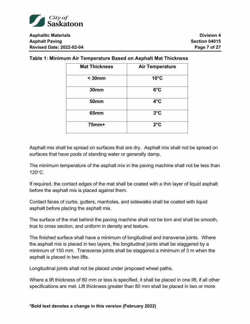
Asphaltic Materials Division 4 Asphalt Paving Section 04015 Revised Date: 2022-02-04 Page 7 of 27
*Bold text denotes a change in this version (February 2022)
Table 1: Minimum Air Temperature Based on Asphalt Mat Thickness Mat Thickness Air Temperature
< 30mm 10°C
30mm 6°C
50mm 4°C
65mm 3°C
75mm+ 2°C
Asphalt mix shall be spread on surfaces that are dry. Asphalt mix shall not be spread on surfaces that have pools of standing water or generally damp.
The minimum temperature of the asphalt mix in the paving machine shall not be less than 120°C.
If required, the contact edges of the mat shall be coated with a thin layer of liquid asphalt before the asphalt mix is placed against them.
Contact faces of curbs, gutters, manholes, and sidewalks shall be coated with liquid asphalt before placing the asphalt mix.
The surface of the mat behind the paving machine shall not be torn and shall be smooth, true to cross section, and uniform in density and texture.
The finished surface shall have a minimum of longitudinal and transverse joints. Where the asphalt mix is placed in two layers, the longitudinal joints shall be staggered by a minimum of 150 mm. Transverse joints shall be staggered a minimum of 3 m when the asphalt is placed in two lifts.
Longitudinal joints shall not be placed under proposed wheel paths.
Where a lift thickness of 80 mm or less is specified, it shall be placed in one lift, if all other specifications are met. Lift thickness greater than 80 mm shall be placed in two or more
Asphaltic Materials Division 4 Asphalt Paving Section 04015 Revised Date: 2022-02-04 Page 8 of 27
*Bold text denotes a change in this version (February 2022)
lifts. Asphalt lifts shall never be placed at a thickness of less than two times the maximum aggregate size for Types 9 and 9P and three times the maximum aggregate size for all other asphalt types except Type 4 which has no restriction.
Surplus asphalt mix shall not be spread over the freshly screed surface. The length of individual paving mats after each day shall be limited, such that the width of road can be covered with any given lift resulting in all transverse joints being kept within 100 m of each other.
4.2 Compacting
Rolling shall start as soon as the pavement will bear the weight of the roller without checking, cracking or undue displacement.
Each lift of asphalt shall be compacted to the density specified in this Section using the Marshall method specified under Section 04010 Asphalt Mix.
The finished surface of the mat shall be well-knit and free from waves, hairline cracks, roller marks, and other unevenness. The finished surface shall be free from depressions exceeding 5 mm as measured in any direction with a 3 m straight edge.
The rollers shall not be left stationary on the fresh asphalt until it has cooled down to ambient temperature as not to leave any obvious dips or marks which would allow water to pond.
The asphalt concrete surface shall be within 5 mm of design elevation but not uniformly high or low. At the lip of gutter the asphalt concrete surface shall be 5 to 10 mm above the lip of gutter.
All areas not accessible by the roller shall be compacted by hand tampers.
Care shall be used to ensure adequate compaction along the face of concrete curb or gutter without damaging the finished concrete. Damaged concrete work shall be replaced by the Contractor.
Asphaltic Materials Division 4 Asphalt Paving Section 04015 Revised Date: 2022-02-04 Page 9 of 27
*Bold text denotes a change in this version (February 2022)
4.3 Quality Control
Process Control and Charting
The Contractor shall maintain the following charts:
• IBar control charts for Process Control • Moving average charts for Specification Compliance
These charts shall be maintained for the following parameters:
1. Mix Parameters
a. Asphalt Cement Content b. Air Voids c. Marshall Stability d. All sieve designation
2. Aggregate during crushing and production:
a. All sieve designations for each aggregate fraction processed into separate stockpiles
A current copy (continuously updated to the most recent test results to next page specification compliance) of the Asphalt Control charts for mix parameters shall be kept at the asphalt plant control centre and be made available for inspection at the engineer’s request.
4.3.1.1 Process Control Charting
Process Control Charting shall consist of the following:
1. IBar Control Chart complete with: a. Upper and Lower Warning Limits: 95% confidence limit (+2 sigma) b. Upper and Lower Control Limits (CUL/LL): 99% confidence limit (+3
sigma) c. Centreline d. All limits re-calculated following data shifts or N=10, N=20, N=30,…
as appropriate chart maintenance.
Asphaltic Materials Division 4 Asphalt Paving Section 04015 Revised Date: 2022-02-04 Page 10 of 27
*Bold text denotes a change in this version (February 2022)
e. All lines are to be labelled with their numerical values.
Note: Upper and Lower warning and control limits and the centreline are statistically calculated from individual tests, given our current sampling methodology.
4.3.1.2 Moving Average Charting
Moving Average Chart complete with:
a. Line showing specification warning zone b. Line showing specification shutdown zone c. Centreline d. Numerical values entered on all lines
Alternate Charting
The contractor can make an alternate charting proposal complete with the following:
1. Charted parameters 2. Testing method summary 3. Minimum one month correlation to Marshall Properties
The Engineer can then decide to substitute the alternate charting in place of one, or all of the contracted requirements with the following stipulations:
If the Contractor fails to maintain a weekly update of his chart, he will revert back to all contract defaults.
Operating Tolerances
The working ranges outlined in Table 4, Table 4, Table 5, Table 6 and Table 7 will be used to assess compliance with specification.
The Contractor shall cease operations when:
1. two consecutive three point moving average points for any property or characteristic fall in the borderline zone
2. two or more tests in four consecutive tests are in the borderline zone or,
Asphaltic Materials Division 4 Asphalt Paving Section 04015 Revised Date: 2022-02-04 Page 11 of 27
*Bold text denotes a change in this version (February 2022)
3. any individual test for any property or characteristic fall in the plant shutdown zone or,
4. The Contractor's process is out of control based on the IBar control chart. The process shall be defined as out of control if it meets one or more of the following criteria:
a. Test result is on or outside the upper or lower control limit. b. There are seven consecutive points above or below the centreline. c. Upward or downward trend. d. An obvious repetitive or cyclical pattern. e. The average of any seven consecutive tests runs at 0.3, or less,
above the lower specification limit.
When the asphalt falls in the shutdown zone, the Contractor shall assume the responsibility of ceasing operations on his own even in the absence of City personnel on site. When asphalt meets the four consecutive or two three point moving average criteria for shutdown, shutdown will be initiated at the instruction of the Engineer. Production shall not commence again until two consecutive tests are within specification limits or it has been demonstrated to the satisfaction of the Engineer that corrective action has been taken.
The aforementioned procedure shall not prevent the City from rejecting specific batches or production runs of asphalt concrete mix that from visual inspection or associated testing do not meet the requirements of this Section.
4.3.3.1 Mix Temperature
Mix temperature at point of plant discharge shall not vary from that specified in the job mix formula my more than10°C.
4.3.3.2 Moisture in mix
Maximum permissible moisture at point of plant discharge is 0.2 % by weight of mix.
Asphalt Cement Quality Control
On subsequent deliveries the suppliers shall provide the following test data:
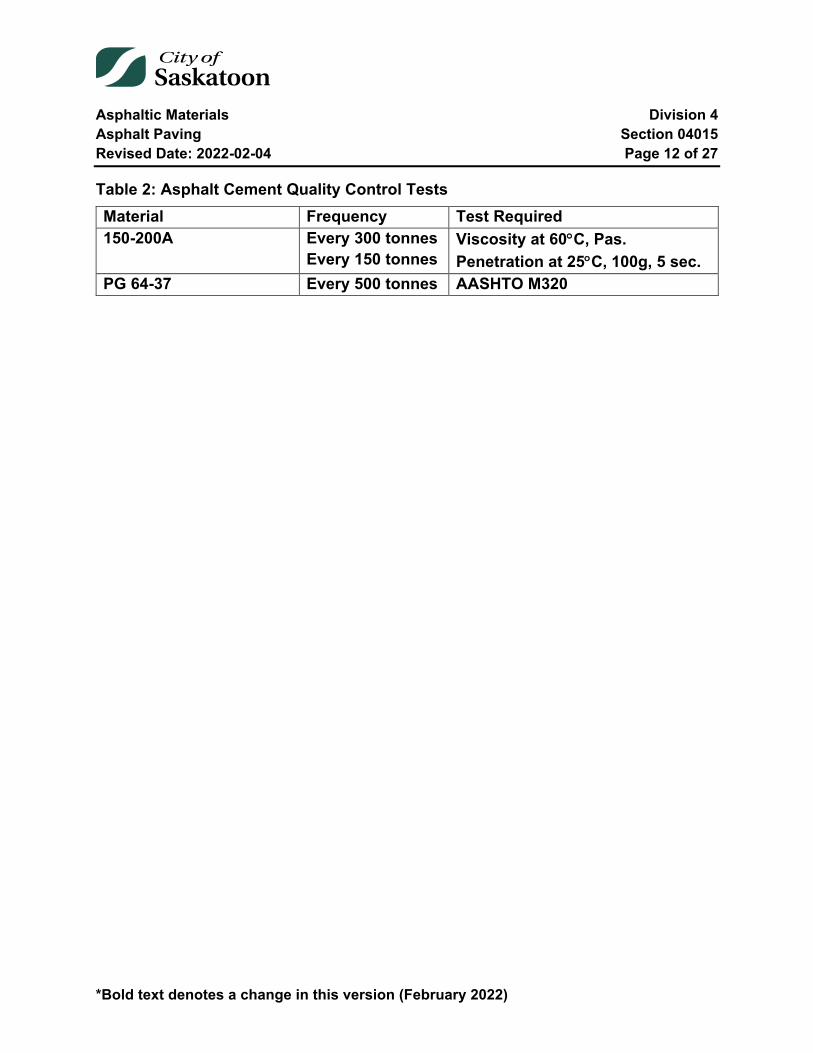
Asphaltic Materials Division 4 Asphalt Paving Section 04015 Revised Date: 2022-02-04 Page 12 of 27
*Bold text denotes a change in this version (February 2022)
Table 2: Asphalt Cement Quality Control Tests Material Frequency Test Required 150-200A Every 300 tonnes
Every 150 tonnes Viscosity at 60°C, Pas. Penetration at 25°C, 100g, 5 sec.
PG 64-37 Every 500 tonnes AASHTO M320
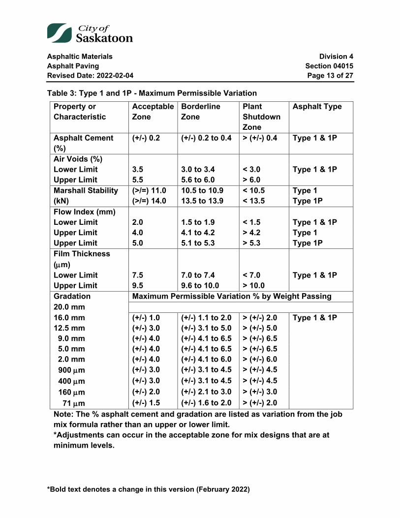
Asphaltic Materials Division 4 Asphalt Paving Section 04015 Revised Date: 2022-02-04 Page 13 of 27
*Bold text denotes a change in this version (February 2022)
Table 3: Type 1 and 1P - Maximum Permissible Variation Property or Characteristic
Acceptable Zone
Borderline Zone
Plant Shutdown Zone
Asphalt Type
Asphalt Cement (%)
(+/-) 0.2 (+/-) 0.2 to 0.4 > (+/-) 0.4 Type 1 & 1P
Air Voids (%) Lower Limit 3.5 3.0 to 3.4 < 3.0 Type 1 & 1P Upper Limit 5.5 5.6 to 6.0 > 6.0 Marshall Stability (kN)
(>/=) 11.0 10.5 to 10.9 < 10.5 Type 1 (>/=) 14.0 13.5 to 13.9 < 13.5 Type 1P
Flow Index (mm) Lower Limit 2.0 1.5 to 1.9 < 1.5 Type 1 & 1P Upper Limit 4.0 4.1 to 4.2 > 4.2 Type 1 Upper Limit 5.0 5.1 to 5.3 > 5.3 Type 1P Film Thickness (µm)
Lower Limit 7.5 7.0 to 7.4 < 7.0 Type 1 & 1P Upper Limit 9.5 9.6 to 10.0 > 10.0 Gradation Maximum Permissible Variation % by Weight Passing 20.0 mm 16.0 mm (+/-) 1.0 (+/-) 1.1 to 2.0 > (+/-) 2.0 Type 1 & 1P 12.5 mm (+/-) 3.0 (+/-) 3.1 to 5.0 > (+/-) 5.0 9.0 mm (+/-) 4.0 (+/-) 4.1 to 6.5 > (+/-) 6.5 5.0 mm (+/-) 4.0 (+/-) 4.1 to 6.5 > (+/-) 6.5 2.0 mm (+/-) 4.0 (+/-) 4.1 to 6.0 > (+/-) 6.0 900 µm (+/-) 3.0 (+/-) 3.1 to 4.5 > (+/-) 4.5 400 µm (+/-) 3.0 (+/-) 3.1 to 4.5 > (+/-) 4.5 160 µm (+/-) 2.0 (+/-) 2.1 to 3.0 > (+/-) 3.0 71 µm (+/-) 1.5 (+/-) 1.6 to 2.0 > (+/-) 2.0
Note: The % asphalt cement and gradation are listed as variation from the job mix formula rather than an upper or lower limit. *Adjustments can occur in the acceptable zone for mix designs that are at minimum levels.
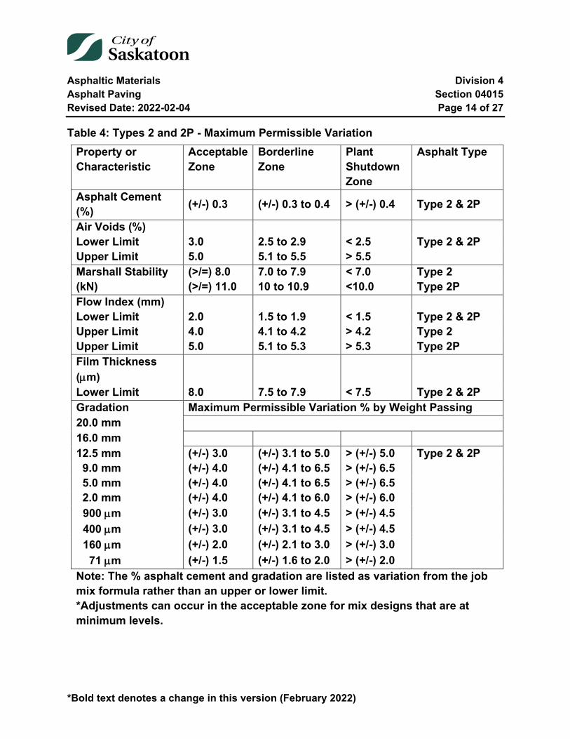
Asphaltic Materials Division 4 Asphalt Paving Section 04015 Revised Date: 2022-02-04 Page 14 of 27
*Bold text denotes a change in this version (February 2022)
Table 4: Types 2 and 2P - Maximum Permissible Variation Property or Characteristic
Acceptable Zone
Borderline Zone
Plant Shutdown Zone
Asphalt Type
Asphalt Cement (%) (+/-) 0.3 (+/-) 0.3 to 0.4 > (+/-) 0.4 Type 2 & 2P
Air Voids (%) Lower Limit 3.0 2.5 to 2.9 < 2.5 Type 2 & 2P Upper Limit 5.0 5.1 to 5.5 > 5.5 Marshall Stability (kN)
(>/=) 8.0 7.0 to 7.9 < 7.0 Type 2 (>/=) 11.0 10 to 10.9 <10.0 Type 2P
Flow Index (mm) Lower Limit 2.0 1.5 to 1.9 < 1.5 Type 2 & 2P Upper Limit 4.0 4.1 to 4.2 > 4.2 Type 2 Upper Limit 5.0 5.1 to 5.3 > 5.3 Type 2P Film Thickness (µm)
Lower Limit 8.0 7.5 to 7.9 < 7.5 Type 2 & 2P Gradation Maximum Permissible Variation % by Weight Passing 20.0 mm 16.0 mm 12.5 mm (+/-) 3.0 (+/-) 3.1 to 5.0 > (+/-) 5.0 Type 2 & 2P 9.0 mm (+/-) 4.0 (+/-) 4.1 to 6.5 > (+/-) 6.5 5.0 mm (+/-) 4.0 (+/-) 4.1 to 6.5 > (+/-) 6.5 2.0 mm (+/-) 4.0 (+/-) 4.1 to 6.0 > (+/-) 6.0 900 µm (+/-) 3.0 (+/-) 3.1 to 4.5 > (+/-) 4.5 400 µm (+/-) 3.0 (+/-) 3.1 to 4.5 > (+/-) 4.5 160 µm (+/-) 2.0 (+/-) 2.1 to 3.0 > (+/-) 3.0 71 µm (+/-) 1.5 (+/-) 1.6 to 2.0 > (+/-) 2.0
Note: The % asphalt cement and gradation are listed as variation from the job mix formula rather than an upper or lower limit. *Adjustments can occur in the acceptable zone for mix designs that are at minimum levels.
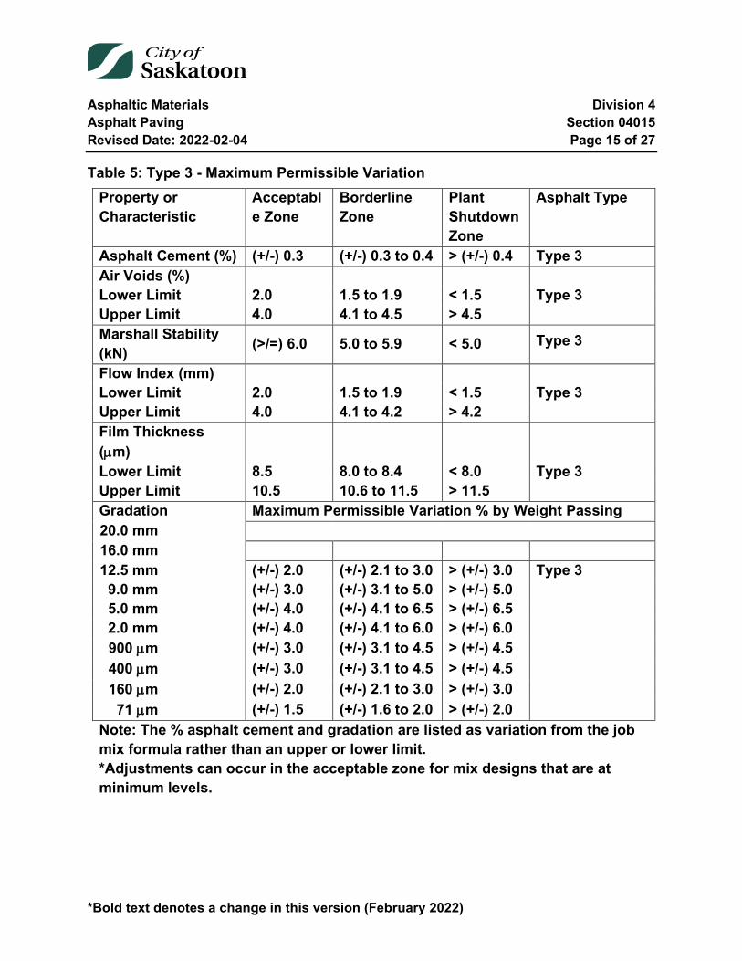
Asphaltic Materials Division 4 Asphalt Paving Section 04015 Revised Date: 2022-02-04 Page 15 of 27
*Bold text denotes a change in this version (February 2022)
Table 5: Type 3 - Maximum Permissible Variation Property or Characteristic
Acceptable Zone
Borderline Zone
Plant Shutdown Zone
Asphalt Type
Asphalt Cement (%) (+/-) 0.3 (+/-) 0.3 to 0.4 > (+/-) 0.4 Type 3 Air Voids (%) Lower Limit 2.0 1.5 to 1.9 < 1.5 Type 3 Upper Limit 4.0 4.1 to 4.5 > 4.5 Marshall Stability (kN) (>/=) 6.0 5.0 to 5.9 < 5.0
Type 3
Flow Index (mm) Lower Limit 2.0 1.5 to 1.9 < 1.5 Type 3 Upper Limit 4.0 4.1 to 4.2 > 4.2 Film Thickness (µm)
Lower Limit 8.5 8.0 to 8.4 < 8.0 Type 3 Upper Limit 10.5 10.6 to 11.5 > 11.5 Gradation Maximum Permissible Variation % by Weight Passing 20.0 mm 16.0 mm 12.5 mm (+/-) 2.0 (+/-) 2.1 to 3.0 > (+/-) 3.0 Type 3 9.0 mm (+/-) 3.0 (+/-) 3.1 to 5.0 > (+/-) 5.0 5.0 mm (+/-) 4.0 (+/-) 4.1 to 6.5 > (+/-) 6.5 2.0 mm (+/-) 4.0 (+/-) 4.1 to 6.0 > (+/-) 6.0 900 µm (+/-) 3.0 (+/-) 3.1 to 4.5 > (+/-) 4.5 400 µm (+/-) 3.0 (+/-) 3.1 to 4.5 > (+/-) 4.5 160 µm (+/-) 2.0 (+/-) 2.1 to 3.0 > (+/-) 3.0 71 µm (+/-) 1.5 (+/-) 1.6 to 2.0 > (+/-) 2.0
Note: The % asphalt cement and gradation are listed as variation from the job mix formula rather than an upper or lower limit. *Adjustments can occur in the acceptable zone for mix designs that are at minimum levels.
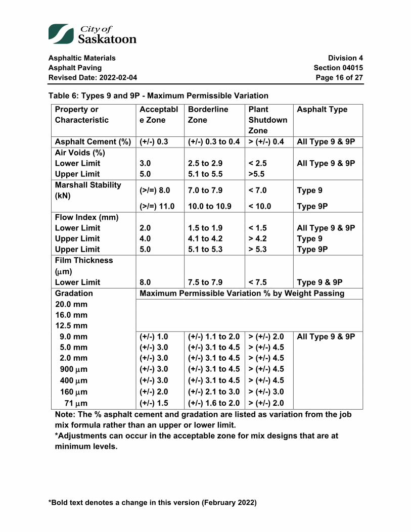
Asphaltic Materials Division 4 Asphalt Paving Section 04015 Revised Date: 2022-02-04 Page 16 of 27
*Bold text denotes a change in this version (February 2022)
Table 6: Types 9 and 9P - Maximum Permissible Variation Property or Characteristic
Acceptable Zone
Borderline Zone
Plant Shutdown Zone
Asphalt Type
Asphalt Cement (%) (+/-) 0.3 (+/-) 0.3 to 0.4 > (+/-) 0.4 All Type 9 & 9P Air Voids (%) Lower Limit 3.0 2.5 to 2.9 < 2.5 All Type 9 & 9P Upper Limit 5.0 5.1 to 5.5 >5.5 Marshall Stability (kN) (>/=) 8.0 7.0 to 7.9 < 7.0 Type 9
(>/=) 11.0 10.0 to 10.9 < 10.0 Type 9P Flow Index (mm) Lower Limit 2.0 1.5 to 1.9 < 1.5 All Type 9 & 9P Upper Limit 4.0 4.1 to 4.2 > 4.2 Type 9 Upper Limit 5.0 5.1 to 5.3 > 5.3 Type 9P Film Thickness (µm)
Lower Limit 8.0 7.5 to 7.9 < 7.5 Type 9 & 9P Gradation Maximum Permissible Variation % by Weight Passing 20.0 mm 16.0 mm 12.5 mm 9.0 mm (+/-) 1.0 (+/-) 1.1 to 2.0 > (+/-) 2.0 All Type 9 & 9P 5.0 mm (+/-) 3.0 (+/-) 3.1 to 4.5 > (+/-) 4.5 2.0 mm (+/-) 3.0 (+/-) 3.1 to 4.5 > (+/-) 4.5 900 µm (+/-) 3.0 (+/-) 3.1 to 4.5 > (+/-) 4.5 400 µm (+/-) 3.0 (+/-) 3.1 to 4.5 > (+/-) 4.5 160 µm (+/-) 2.0 (+/-) 2.1 to 3.0 > (+/-) 3.0 71 µm (+/-) 1.5 (+/-) 1.6 to 2.0 > (+/-) 2.0
Note: The % asphalt cement and gradation are listed as variation from the job mix formula rather than an upper or lower limit. *Adjustments can occur in the acceptable zone for mix designs that are at minimum levels.

Asphaltic Materials Division 4 Asphalt Paving Section 04015 Revised Date: 2022-02-04 Page 17 of 27
*Bold text denotes a change in this version (February 2022)
Table 7: Type 5 (SUTO) - Maximum Permissible Variation Property or Characteristic
Acceptable Zone
Borderline Zone
Plant Shutdown Zone
Asphalt Type
Asphalt Cement (%) (+/-) 0.3 (+/-) 0.3 to 0.4 > (+/-) 0.4 Type 5 Air Voids (%) Lower Limit 2.0 1.5 to 1.9 < 1.5 Type 5 Upper Limit 5.0 5.1 to 5.5 >5.5 Marshall Stability (kN) (>/=) 9.0 8.0 to 8.9 < 8.0 Type 5
Flow Index (mm) Lower Limit 2.0 1.5 to 1.9 < 1.5 Type 5 Upper Limit 4.0 4.1 to 4.2 > 4.2 Type 5 Film Thickness (µm)
Lower Limit 8.5 8.0 to 8.4 < 8.0 Type 5 Gradation Maximum Permissible Variation % by Weight Passing 20.0 mm 16.0 mm 12.5 mm 9.0 mm 5.0 mm (+/-) 1.0 (+/-) 1.1 to 2.0 > (+/-) 2.0 Type 5 2.0 mm (+/-) 3.0 (+/-) 3.1 to 4.5 > (+/-) 4.5 900 µm (+/-) 3.0 (+/-) 3.1 to 4.5 > (+/-) 4.5 400 µm (+/-) 3.0 (+/-) 3.1 to 4.5 > (+/-) 4.5 160 µm (+/-) 2.0 (+/-) 2.1 to 3.0 > (+/-) 3.0 71 µm (+/-) 1.5 (+/-) 1.6 to 2.0 > (+/-) 2.0
Note: The % asphalt cement and gradation are listed as variation from the job mix formula rather than an upper or lower limit. *Adjustments can occur in the acceptable zone for mix designs that are at minimum levels.
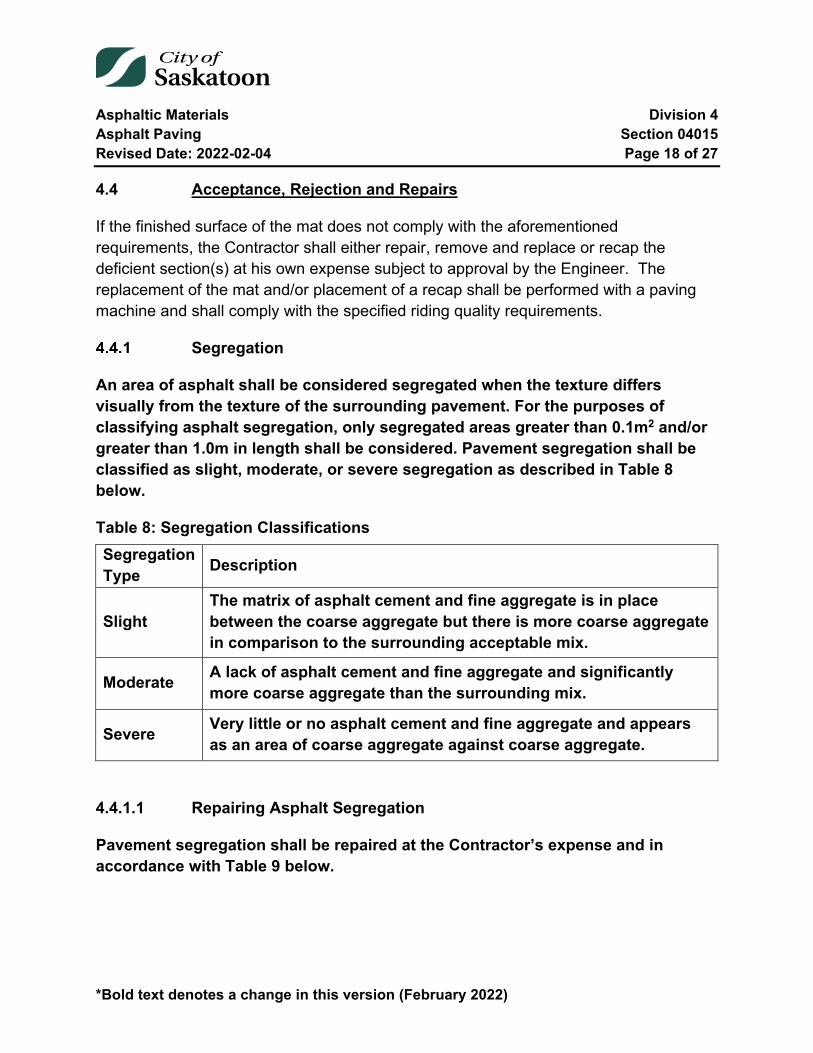
Asphaltic Materials Division 4 Asphalt Paving Section 04015 Revised Date: 2022-02-04 Page 18 of 27
*Bold text denotes a change in this version (February 2022)
4.4 Acceptance, Rejection and Repairs
If the finished surface of the mat does not comply with the aforementioned requirements, the Contractor shall either repair, remove and replace or recap the deficient section(s) at his own expense subject to approval by the Engineer. The replacement of the mat and/or placement of a recap shall be performed with a paving machine and shall comply with the specified riding quality requirements.
Segregation
An area of asphalt shall be considered segregated when the texture differs visually from the texture of the surrounding pavement. For the purposes of classifying asphalt segregation, only segregated areas greater than 0.1m2 and/or greater than 1.0m in length shall be considered. Pavement segregation shall be classified as slight, moderate, or severe segregation as described in Table 8 below.
Table 8: Segregation Classifications Segregation Type Description
Slight The matrix of asphalt cement and fine aggregate is in place between the coarse aggregate but there is more coarse aggregate in comparison to the surrounding acceptable mix.
Moderate A lack of asphalt cement and fine aggregate and significantly more coarse aggregate than the surrounding mix.
Severe Very little or no asphalt cement and fine aggregate and appears as an area of coarse aggregate against coarse aggregate.
4.4.1.1 Repairing Asphalt Segregation
Pavement segregation shall be repaired at the Contractor’s expense and in accordance with Table 9 below.

Asphaltic Materials Division 4 Asphalt Paving Section 04015 Revised Date: 2022-02-04 Page 19 of 27
*Bold text denotes a change in this version (February 2022)
Table 9: Asphalt Segregation Repairs Segregation
Type Required Repair on Lower Lifts Required Repair on Top Lifts
Slight No Repair Required Slurry Seal Patch Moderate No Repair Required Slurry Seal Patch
Severe Removal and Replacement Removal and Replacement
All slurry seal patching shall be performed as per the Engineer’s discretion. All removal and replacement shall be a minimum width between asphalt seams and 3m on either side or as per the Engineer’s discretion.
If excessive segregation continues, the City of Saskatoon may require the work to stop until the Contractor can demonstrate that they have rectified the cause of the segregation.
04015-5 Testing
The Contractor shall provide access for core testing by others.
A core test representing a maximum of 300 tonnes of asphalt mix shall be used to determine payment adjustments. Results which do not meet specification may be averaged with results from 2 additional core tests. Additional cores for determining air voids and density will be taken within 2 meters of the original core location.
Additional cores for determining asphalt thickness will be taken within 5 meters of the original core location. Additional core tests must not be located in a wheel path. The Contractor shall notify the Project Engineer of their intent to do re-cores and shall not proceed without the Project Engineers’ approval.
All additional cores must be requested within one week of the original core test results being communicated to the Contractor by the Engineer. The costs of this additional testing shall be the responsibility of the Contractor. Patching of core test holes with asphalt concrete shall be a subsidiary obligation of the contract and as such, shall not be paid for directly. Bulk samples shall also be taken to determine compliance with mix requirements.
Asphaltic Materials Division 4 Asphalt Paving Section 04015 Revised Date: 2022-02-04 Page 20 of 27
*Bold text denotes a change in this version (February 2022)
This coring and bulk sampling will not necessarily be carried out on a regular basis, therefore, any testing and subsequent penalties will only represent the quantities placed in those areas tested.
04015-6 Measurement
Asphalt concrete will be measured in tonnes or square metres as specified.
The weight of each vehicle shall be determined at the beginning of the work with the fuel tank half full, spare tire in place and the driver in the cab. This weight, called the vehicle weight will be checked and/or amended at the discretion of the Engineer.
The Engineer may place a representative at the Contractor's scales and at the delivery site if the need arises.
Payment for asphalt concrete will be reduced for work which fails to meet specified tolerances. Air voids of the asphalt mix will be measured from test cores or bulk samples.
04015-7 Payment
Payment for asphalt concrete in place will be at the contract unit price per tonne or square metre, adjusted as per the specified adjustment factor for density, air voids, stripping potential, thickness, stability and asphalt content. The unit price will be full compensation for removing overburden, excavating, crushing, screening, stockpiling, and drying the aggregate; supplying, heating and storing the asphalt cement; mixing, loading, hauling, dumping, spreading, compacting, and finishing the asphalt mix. The unit price will also be full compensation for supplying and adding filler or blender sand at the central mixing plant.
7.1 Payment Adjustment Factors
Payment adjustment factors will be used to adjust the contract unit price for materials not complying with the tolerances and values in this section or related specifications. All adjustment factors will be determined on the basis of individual test results. The quantity of material represented by a single test will not exceed 300 tonnes.

Asphaltic Materials Division 4 Asphalt Paving Section 04015 Revised Date: 2022-02-04 Page 21 of 27
*Bold text denotes a change in this version (February 2022)
Adjustment to the unit bid price for non-compliance equals the unit price times the payment adjustment factor(s). Reduced payment for more than one deficiency on any one test sample will be based on the reduced payment, and not the original.
Air Void Payment Adjustment Factors
Air Voids Payment Adjustment Factors (by individual sample tests) are presented in Table 10.
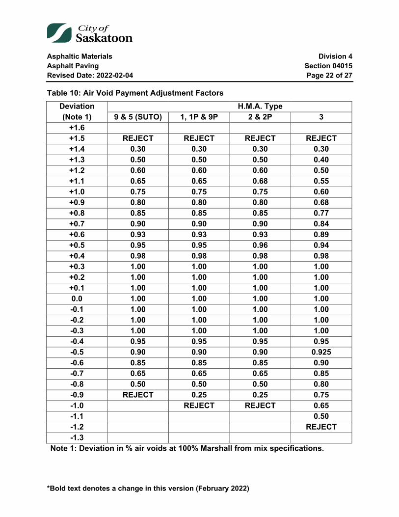
Asphaltic Materials Division 4 Asphalt Paving Section 04015 Revised Date: 2022-02-04 Page 22 of 27
*Bold text denotes a change in this version (February 2022)
Table 10: Air Void Payment Adjustment Factors Deviation H.M.A. Type (Note 1) 9 & 5 (SUTO) 1, 1P & 9P 2 & 2P 3
+1.6 +1.5 REJECT REJECT REJECT REJECT +1.4 0.30 0.30 0.30 0.30 +1.3 0.50 0.50 0.50 0.40 +1.2 0.60 0.60 0.60 0.50 +1.1 0.65 0.65 0.68 0.55 +1.0 0.75 0.75 0.75 0.60 +0.9 0.80 0.80 0.80 0.68 +0.8 0.85 0.85 0.85 0.77 +0.7 0.90 0.90 0.90 0.84 +0.6 0.93 0.93 0.93 0.89 +0.5 0.95 0.95 0.96 0.94 +0.4 0.98 0.98 0.98 0.98 +0.3 1.00 1.00 1.00 1.00 +0.2 1.00 1.00 1.00 1.00 +0.1 1.00 1.00 1.00 1.00 0.0 1.00 1.00 1.00 1.00 -0.1 1.00 1.00 1.00 1.00 -0.2 1.00 1.00 1.00 1.00 -0.3 1.00 1.00 1.00 1.00 -0.4 0.95 0.95 0.95 0.95 -0.5 0.90 0.90 0.90 0.925 -0.6 0.85 0.85 0.85 0.90 -0.7 0.65 0.65 0.65 0.85 -0.8 0.50 0.50 0.50 0.80 -0.9 REJECT 0.25 0.25 0.75 -1.0 REJECT REJECT 0.65 -1.1 0.50 -1.2 REJECT -1.3
Note 1: Deviation in % air voids at 100% Marshall from mix specifications.
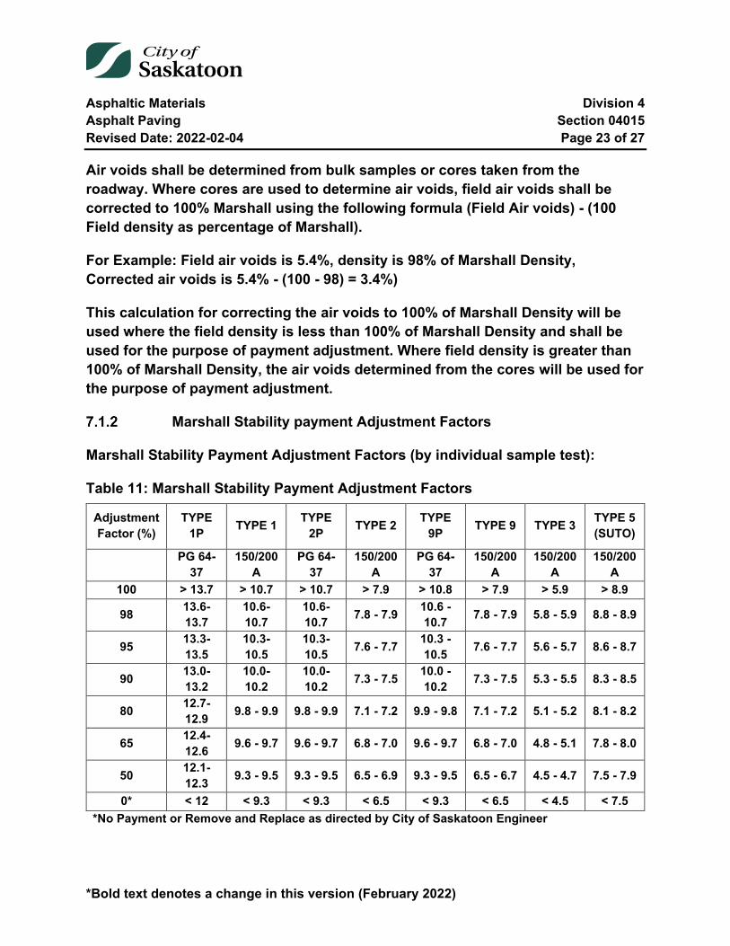
Asphaltic Materials Division 4 Asphalt Paving Section 04015 Revised Date: 2022-02-04 Page 23 of 27
*Bold text denotes a change in this version (February 2022)
Air voids shall be determined from bulk samples or cores taken from the roadway. Where cores are used to determine air voids, field air voids shall be corrected to 100% Marshall using the following formula (Field Air voids) - (100 Field density as percentage of Marshall).
For Example: Field air voids is 5.4%, density is 98% of Marshall Density, Corrected air voids is 5.4% - (100 - 98) = 3.4%)
This calculation for correcting the air voids to 100% of Marshall Density will be used where the field density is less than 100% of Marshall Density and shall be used for the purpose of payment adjustment. Where field density is greater than 100% of Marshall Density, the air voids determined from the cores will be used for the purpose of payment adjustment.
Marshall Stability payment Adjustment Factors
Marshall Stability Payment Adjustment Factors (by individual sample test):
Table 11: Marshall Stability Payment Adjustment Factors
Adjustment Factor (%)
TYPE 1P TYPE 1 TYPE
2P TYPE 2 TYPE 9P TYPE 9 TYPE 3 TYPE 5
(SUTO)
PG 64-37
150/200A
PG 64-37
150/200A
PG 64-37
150/200A
150/200A
150/200A
100 > 13.7 > 10.7 > 10.7 > 7.9 > 10.8 > 7.9 > 5.9 > 8.9
98 13.6-13.7
10.6-10.7
10.6-10.7 7.8 - 7.9 10.6 -
10.7 7.8 - 7.9 5.8 - 5.9 8.8 - 8.9
95 13.3-13.5
10.3-10.5
10.3-10.5 7.6 - 7.7 10.3 -
10.5 7.6 - 7.7 5.6 - 5.7 8.6 - 8.7
90 13.0-13.2
10.0-10.2
10.0-10.2 7.3 - 7.5 10.0 -
10.2 7.3 - 7.5 5.3 - 5.5 8.3 - 8.5
80 12.7-12.9 9.8 - 9.9 9.8 - 9.9 7.1 - 7.2 9.9 - 9.8 7.1 - 7.2 5.1 - 5.2 8.1 - 8.2
65 12.4-12.6 9.6 - 9.7 9.6 - 9.7 6.8 - 7.0 9.6 - 9.7 6.8 - 7.0 4.8 - 5.1 7.8 - 8.0
50 12.1-12.3 9.3 - 9.5 9.3 - 9.5 6.5 - 6.9 9.3 - 9.5 6.5 - 6.7 4.5 - 4.7 7.5 - 7.9
0* < 12 < 9.3 < 9.3 < 6.5 < 9.3 < 6.5 < 4.5 < 7.5 *No Payment or Remove and Replace as directed by City of Saskatoon Engineer

Asphaltic Materials Division 4 Asphalt Paving Section 04015 Revised Date: 2022-02-04 Page 24 of 27
*Bold text denotes a change in this version (February 2022)
Asphalt Cement Content Payment Adjustment Factors
A payment adjustment factor for asphalt cement content payment will be applied to all mix represented by the test that fails to meet the minimum asphalt cement content as outlined in the Contractor’s approved Job Mix Formula (JMF). The adjustment will be:
Table 12: Asphalt Cement Content Payment Adjustment Factors Asphalt Content Deviation from JMF value
Type 1 & 1P Types 2, 2P, 9, 9P & 5 (SUTO) Type 3
+/- 0.1% 1.0 1.0 1.0 +/- 0.2% 1.0 1.0 1.0 +/- 0.3% 0.90 1.0 1.0 +/- 0.4% 0.75 0.90 0.95 +/- 0.5% 0.50 0.70 0.80 +/- 0.6% Reject 0.50 0.65 +/- 0.7% Reject 0.50 +/- 0.8% Reject
Change in asphalt content based on dry mass of aggregate.
“Reject” at the discretion of the Project Engineer shall mean either zero payment or remove and replace.
Density Payment Adjustment Factors
7.1.4.1 Asphalt Mix Types 2, 3, and 4
Unless otherwise specified, asphalt mix Types 2, 3 and 4 shall meet density requirements to 97% of Marshall. The density payment adjustment factors are as follows:
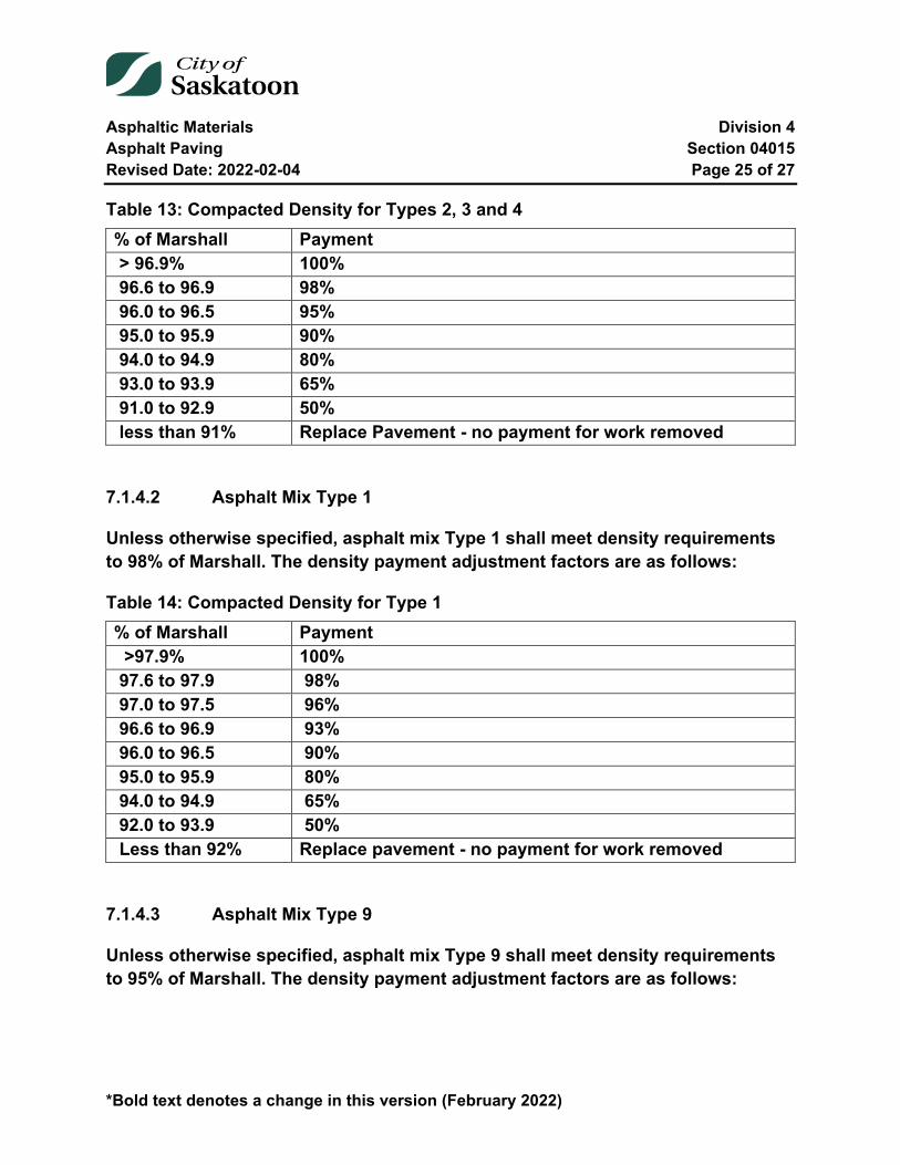
Asphaltic Materials Division 4 Asphalt Paving Section 04015 Revised Date: 2022-02-04 Page 25 of 27
*Bold text denotes a change in this version (February 2022)
Table 13: Compacted Density for Types 2, 3 and 4 % of Marshall Payment > 96.9% 100% 96.6 to 96.9 98% 96.0 to 96.5 95% 95.0 to 95.9 90% 94.0 to 94.9 80% 93.0 to 93.9 65% 91.0 to 92.9 50% less than 91% Replace Pavement - no payment for work removed
7.1.4.2 Asphalt Mix Type 1
Unless otherwise specified, asphalt mix Type 1 shall meet density requirements to 98% of Marshall. The density payment adjustment factors are as follows:
Table 14: Compacted Density for Type 1 % of Marshall Payment >97.9% 100% 97.6 to 97.9 98% 97.0 to 97.5 96% 96.6 to 96.9 93% 96.0 to 96.5 90% 95.0 to 95.9 80% 94.0 to 94.9 65% 92.0 to 93.9 50% Less than 92% Replace pavement - no payment for work removed
7.1.4.3 Asphalt Mix Type 9
Unless otherwise specified, asphalt mix Type 9 shall meet density requirements to 95% of Marshall. The density payment adjustment factors are as follows:
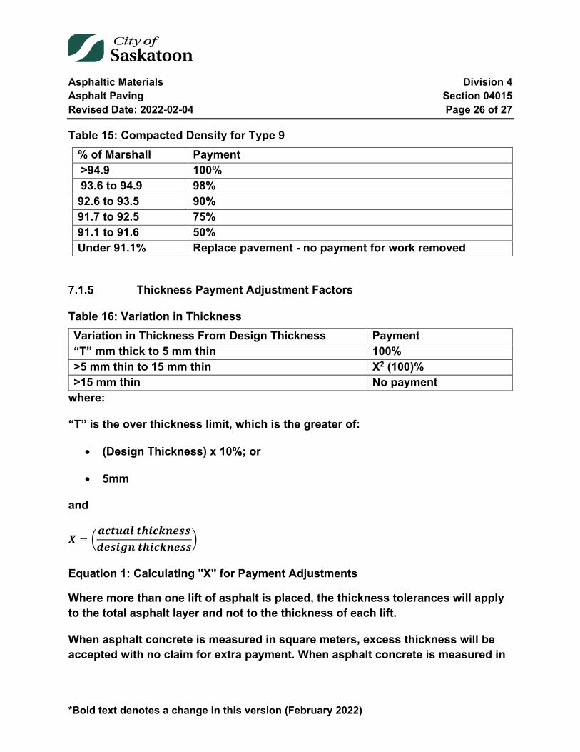
Asphaltic Materials Division 4 Asphalt Paving Section 04015 Revised Date: 2022-02-04 Page 26 of 27
*Bold text denotes a change in this version (February 2022)
Table 15: Compacted Density for Type 9 % of Marshall Payment >94.9 100% 93.6 to 94.9 98% 92.6 to 93.5 90% 91.7 to 92.5 75% 91.1 to 91.6 50% Under 91.1% Replace pavement - no payment for work removed
Thickness Payment Adjustment Factors
Table 16: Variation in Thickness Variation in Thickness From Design Thickness Payment “T” mm thick to 5 mm thin 100% >5 mm thin to 15 mm thin X2 (100)% >15 mm thin No payment
where:
“T” is the over thickness limit, which is the greater of:
• (Design Thickness) x 10%; or
• 5mm
and
𝑿𝑿 = �𝒂𝒂𝒂𝒂𝒂𝒂𝒂𝒂𝒂𝒂𝒂𝒂 𝒂𝒂𝒕𝒕𝒕𝒕𝒂𝒂𝒕𝒕𝒕𝒕𝒕𝒕𝒕𝒕𝒕𝒕𝒅𝒅𝒕𝒕𝒕𝒕𝒕𝒕𝒅𝒅𝒕𝒕 𝒂𝒂𝒕𝒕𝒕𝒕𝒂𝒂𝒕𝒕𝒕𝒕𝒕𝒕𝒕𝒕𝒕𝒕�
Equation 1: Calculating "X" for Payment Adjustments
Where more than one lift of asphalt is placed, the thickness tolerances will apply to the total asphalt layer and not to the thickness of each lift.
When asphalt concrete is measured in square meters, excess thickness will be accepted with no claim for extra payment. When asphalt concrete is measured in
Asphaltic Materials Division 4 Asphalt Paving Section 04015 Revised Date: 2022-02-04 Page 27 of 27
*Bold text denotes a change in this version (February 2022)
tonnes, asphalt concrete in excess of over thickness limit “T” will be paid at 35% of tendered unit price for that item.
Applying Thickness Adjustment
On a single layer HMA paving project the core taken for determining in-situ air voids and density shall be used for calculating the thickness and any adjustment factor and will be applied to that individual test lot.
On a multi-layer HMA paving project the core taken after the final lift of paving for determining the in-situ air voids and density shall be used for calculating the thickness payment adjustment factor, though may not exceed the 300 tonne test lot size (combine all lifts) unless otherwise specified. Additional cores may be taken for determination of thickness not represented by the original core. These additional cores may not exceed the 300 tonne test lot size unless otherwise specified, and will be used for determining the asphalt thickness adjustment factor only. The average cost of the hot mix asphalt structure shall be determined after all the individual test lots have been adjusted for air voids, stability, asphalt cement content and density. The payment adjustment for thickness will be applied to this average cost of the hot mix asphalt mat and corresponding test lot size.
Stripping Potential Payment Adjustment Factors
Random testing of bulk samples will be tested for stripping potential. The Engineer shall apply a penalty of 10% (90% payment) for stripping potential that does not meet the requirements of Section 04010-2.4.2 unless otherwise indicated in the Specific Conditions. The quantity of material representing each test shall not exceed 300 tonnes.
End of Specification 04015
Asphaltic Materials Division 4 Reclaimed Asphalt Pavement Section 04020 Revised Date: 2022-02-04 Page 1 of 6
04020 Reclaimed Asphalt Pavement
Index
04020-1 General 2
04020-2 Definitions 2 2.1 Reclaimed Asphalt Pavement (RAP) 2 2.2 RAP Binder 2 2.3 Rheology 2
04020-3 Materials 2 3.1 RAP 2 3.2 RAP Sources 3 3.3 RAP Sampling and Testing 3 3.4 Basic Tests 4 3.5 Quality Control 4 3.6 RAP Stockpiling 5 3.7 Stockpile Management 6 3.8 RAP Quality Management Documentation 6
04020-4 Asphalt Mix Design 6
Tables
Table 1: Guidelines for Minimum Quality Control Test Frequencies ............................... 5

Asphaltic Materials Division 4 Reclaimed Asphalt Pavement Section 04020 Revised Date: 2022-02-04 Page 2 of 6
04020-1 General
This section covers the best practice for the use of Reclaimed Asphalt Pavement (RAP) material in asphalt mix production and construction. A best practice is a method or technique that when followed results in an end product superior to those achieved with other means and that is used as a benchmark process. A "best" practice may evolve to become better as improvements are discovered.
Best practice is the process of developing and following a standard way of doing things that are commonly achieved in the industry. The Contractor's development and processing of RAP into an end paving product must meet City of Saskatoon Specifications 04010 and 04015.
04020-2 Definitions
2.1 Reclaimed Asphalt Pavement (RAP)
Cold milling material and/or removed and reprocessed pavement materials containing asphalt and aggregates. These materials are generated when asphalt pavements are removed for reconstruction and/or resurfacing. When cold milled and/or properly screened and crushed, the RAP consists of high quality aggregate coated by asphalt cement.
2.2 RAP Binder
The asphalt binder that is present in the reclaimed asphalt pavement.
2.3 Rheology
Rheology is the study of deformation and flow of matter. For asphalt binder rheology, it refers to the flow characteristics of the asphalt binder. Deformation and flow of the asphalt binder in asphalt mix is important in asphalt pavement performance.
04020-3 Materials
3.1 RAP
The Contractor shall fulfil or exceed the requirements of this Best Practice for the management of RAP materials from the time of collection through processing, mix
Asphaltic Materials Division 4 Reclaimed Asphalt Pavement Section 04020 Revised Date: 2022-02-04 Page 3 of 6
design and quality control practices during the production of asphalt mixtures containing RAP. The Contractor shall provide documentation to the City of Saskatoon Representative that best practices have been followed in the handling, characterization, and storage of RAP material, prior to being allowed the use of RAP.
3.2 RAP Sources
Cold Milling – This is the most common process to provide of RAP. The milling process should be closely examined to make sure that the milled material is not contaminated with soil, base materials, paving geotextiles or other foreign material (sulphur, asbestos, rubber, etc.). The milled material that becomes contaminated should be stockpiled separately from RAP to be used in asphalt mix.
Full Depth Pavement Removal – RAP can also be obtained from the removal of the existing pavement using a bulldozer or a backhoe. This process typically results in large chunks of pavement that may be contaminated with underlying soils. This contaminated material should be stored in a separate stockpile and not to be used in the hot mix asphalt. Uncontaminated materials should be processed using a combination of crushing and screening to provide an acceptable RAP material.
RAP Processing – Best practice for RAP processing involves one or more steps to create consistent materials. Screening is used to separate sizes. In some cases, it may be desirable to screen or fractionate RAP to coarse and fine fractions. RAP separation based on sizes increases quality and reduces variability in the RAP properties.
For stockpiles of RAP from multiple sources, particularly stockpiles containing oversize fragments of RAP or pavement slabs, the material should be processed to produce RAP with a maximum size of 25 mm for use in hot mix asphalt.
3.3 RAP Sampling and Testing
Best practice for sampling aggregates applies to the sampling of RAP as well. RAP stockpiles should be sampled as they are being built at the location where they will be fed into the asphalt plant. Sampling at the time the stockpile is built is the best practice and will be easier and more representative of the stockpile compared to samples taken later after the formation of the crust on the face of the RAP stockpile.

Asphaltic Materials Division 4 Reclaimed Asphalt Pavement Section 04020 Revised Date: 2022-02-04 Page 4 of 6
Proper sampling procedures normally used for virgin aggregates should also be used to sample RAP aggregates as included in “AASHTO T2: Sampling of Aggregates”, Standard Specifications for Transportation Materials and Methods of Sampling and Testing, 30th Edition.
3.4 Basic Tests
The following basic properties shall be determined for the proposed RAP:
• Moisture Content (ASTM C 566); • Asphalt Content (ASTM D 2172); • Gradation (ASTM C 136); • Percent Fracture; and • Specific Gravity of coarse and fine fractions (ASTM C 127 & C 128, for mix
design purposes).
Individual representative RAP samples shall be tested to determine moisture content, gradation, percent fracture and asphalt content.
Tests to determine the specific gravity of the coarse and fine fractions of RAP shall be completed on the combined aggregates (obtained by combining the individual reclaimed aggregates retained after the extraction of the asphalt cement).
3.4.1 Asphalt Binder Rheology Testing
For RAP binder rheology testing, the extracted RAP binder is tested for penetration and viscosity. Rheology is measured in terms of penetration at 25°C and viscosity at 60°C (ASTM D 5 & D 4402).
3.5 Quality Control
The Quality Control testing requirements for RAP shall be based on the requirements and minimum test frequency guidelines.
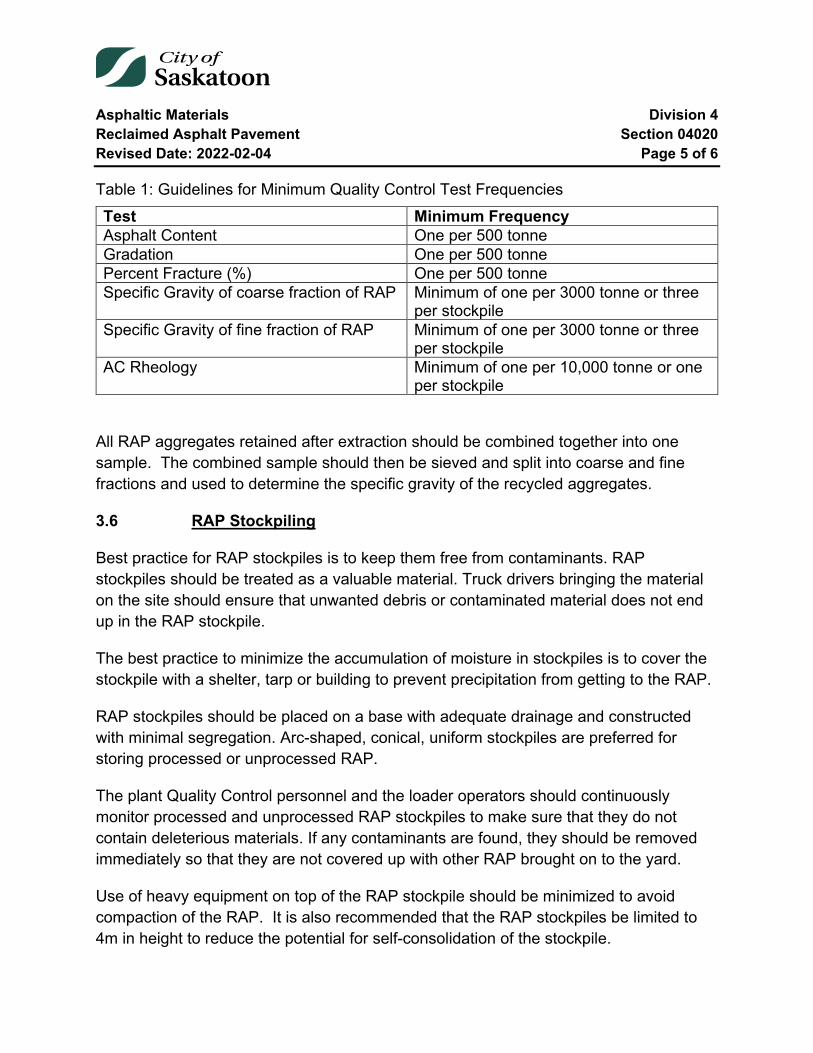
Asphaltic Materials Division 4 Reclaimed Asphalt Pavement Section 04020 Revised Date: 2022-02-04 Page 5 of 6
Table 1: Guidelines for Minimum Quality Control Test Frequencies Test Minimum Frequency Asphalt Content One per 500 tonne Gradation One per 500 tonne Percent Fracture (%) One per 500 tonne Specific Gravity of coarse fraction of RAP Minimum of one per 3000 tonne or three
per stockpile Specific Gravity of fine fraction of RAP Minimum of one per 3000 tonne or three
per stockpile AC Rheology Minimum of one per 10,000 tonne or one
per stockpile
All RAP aggregates retained after extraction should be combined together into one sample. The combined sample should then be sieved and split into coarse and fine fractions and used to determine the specific gravity of the recycled aggregates.
3.6 RAP Stockpiling
Best practice for RAP stockpiles is to keep them free from contaminants. RAP stockpiles should be treated as a valuable material. Truck drivers bringing the material on the site should ensure that unwanted debris or contaminated material does not end up in the RAP stockpile.
The best practice to minimize the accumulation of moisture in stockpiles is to cover the stockpile with a shelter, tarp or building to prevent precipitation from getting to the RAP.
RAP stockpiles should be placed on a base with adequate drainage and constructed with minimal segregation. Arc-shaped, conical, uniform stockpiles are preferred for storing processed or unprocessed RAP.
The plant Quality Control personnel and the loader operators should continuously monitor processed and unprocessed RAP stockpiles to make sure that they do not contain deleterious materials. If any contaminants are found, they should be removed immediately so that they are not covered up with other RAP brought on to the yard.
Use of heavy equipment on top of the RAP stockpile should be minimized to avoid compaction of the RAP. It is also recommended that the RAP stockpiles be limited to 4m in height to reduce the potential for self-consolidation of the stockpile.
Asphaltic Materials Division 4 Reclaimed Asphalt Pavement Section 04020 Revised Date: 2022-02-04 Page 6 of 6
3.7 Stockpile Management
When a stockpile reaches the desired quantity and has been sampled and characterized, no additional RAP material should be added to it. Subsequent RAP material should be stockpiled in a separate stockpile and characterized in the same manner. This process should continue such that characterized stockpiles are not compromised by new RAP materials.
Samples from the RAP stockpile should be taken during stockpiling and testing completed as per the minimum test frequencies specified in Table 1.
3.8 RAP Quality Management Documentation
The Contractor shall document all testing required in this best practice in the form of spreadsheet or other suitable means. The documentation should be “stockpile specific” with a tracking name reference. Once a stockpile is submitted for use in asphalt mixes, no additional RAP will be allowed in that stockpile, and a new stockpile and tracking reference name established.
04020-4 Asphalt Mix Design
RAP shall be included at the proposed addition rates during the mix design. The Contractor shall submit a mix design to the City of Saskatoon Representative for review, as specified in Section 04010- Asphalt Mix.
Should a change in the source or addition rate of RAP be made after the mix design has been approved, a new mix design and/or job mix formula shall be submitted to the City of Saskatoon Representative.
End of Specification 04020
Asphaltic Materials Division 4 Asphalt Prime, Tack and Flush Coat Section 04025 Revised Date: 2022-02-04 Page 1 of 5
04025 Asphalt Prime, Tack and Flush Coat
Index
04025-1 Description 2
04025-2 Material 2
04025-3 Equipment 2
04025-4 Execution 3 4.1 Prime Coats 4 4.2 Tack Coats 4
04025-5 Measurement 5
04025-6 Payment 5
Tables
Table 1: Asphaltic Material Temperature Limits .............................................................. 3
Asphaltic Materials Division 4 Asphalt Prime, Tack and Flush Coat Section 04025 Revised Date: 2022-02-04 Page 2 of 5
04025-1 Description
The work shall consist of supplying and the application of asphaltic material on a prepared surface at locations shown on the plans or as designated by the Engineer.
04025-2 Material
The Contractor shall supply the asphaltic material.
The asphaltic material shall meet the current specifications of the Asphalt Institute. Generally SS-1C emulsified asphalt shall be used for prime, tack or flush coat. The Contractor shall be required to dilute the emulsified asphalt with water, as required.
04025-3 Equipment
All equipment used in executing any part of the work shall be maintained in efficient working order.
The asphaltic material shall be applied by means of a self-powered pressure distributor. The distributor shall have a capacity of not less than 4,500 litres.
The distributor shall be equipped with the following appliances and devices in proper operating condition:
1. Tachometer. 2. Pressure gauge. 3. Adjustable length spray bar. 4. Positive displacement asphalt pump with separate power unit. 5. Heating coils and burner capable of supplying even heat to the bituminous
material. 6. Thermometer well and accurate thermometer.
Before applying bituminous material, the Contractor shall ensure the distributor meets the following adjustments and requirements.
1. The rear chassis springs have been blocked or chained if necessary, to prevent the height of the spray bar from changing as the tank is unloaded.
2. All spray bar nozzles are of the same manufacture, type and size. 3. Clogged nozzles have been removed and cleaned with solvent.
Asphaltic Materials Division 4 Asphalt Prime, Tack and Flush Coat Section 04025 Revised Date: 2022-02-04 Page 3 of 5
4. All nozzles have been set in the spray bar so that the nozzle slots make the same angle (15 to 30) with the longitudinal axis of the spray bar.
5. The spray bar has been adjusted to the correct height to ensure uniform application without streaking.
6. The spray bar has been provided with a positive shut-off to prevent dribbling. 7. The distributor is capable of maintaining a uniform speed.
The distributor may be checked for calibration by following ASTM D2995 by the Engineer before being used on the work.
04025-4 Execution
Asphalt prime, tack and flush coat shall be applied only after authorization has been received from the Engineer.
The Contractor shall supply an experienced operator for the equipment.
Asphalt material for prime coat and tack coat shall be applied only when the surface to be treated is dry. It shall not be applied when the weather is foggy or rainy or when the ground temperature is less than 2°C.
Asphalt material for flush coat shall be applied only when the surface to be treated is dry, when the weather is not foggy or rainy and when the surface temperature is above 10 °C, or as directed by the Engineer.
Before applying asphaltic material, loose dirt or other objectionable material shall be removed from the prepared surface by brooming and other methods. Where base courses become ravelled, the loose material shall be removed or recompacted to a planer uniform surface.
The asphaltic material shall be applied in accordance with the following temperature limits.
Table 1: Asphaltic Material Temperature Limits Type of Asphaltic Material Temperature C° SS-1C N.A. MC-30 25 - 60
Asphaltic Materials Division 4 Asphalt Prime, Tack and Flush Coat Section 04025 Revised Date: 2022-02-04 Page 4 of 5
The asphalt material shall be applied in a single application at the rate per square metre specified by the Engineer.
4.1 Prime Coats
The amount of primer to be used per square metre will be determined by the Engineer after trial runs at the start of the work. As much asphalt shall be applied as can be absorbed by the surface without any excess flushing on the surface. The rate of application shall be between 0.75 to 1.50 litres per square metre. After curing, if any excess primer remains on the surface, the Contractor shall apply an approved sand where necessary to blot up the excess asphalt. The sand cover, where used, shall consist of clean, granular, mineral material approved by the Engineer, all of which shall pass a 5.0mm (No. 4) sieve. Only sufficient sand shall be spread to blot up excess asphalt and such areas shall be broomed to remove excess sand before pavement is laid.
After the prime coat has been applied, it shall be left undisturbed and no pavement shall be laid until the Contractor has obtained the approval of the Engineer or the Engineer’s Representative.
The Contractor shall maintain the primed surface until the surfacing course has been placed. Maintenance shall include spreading any additional sand and patching any breaks in the primed surface. Any areas of primed surface that have become fouled by traffic, or otherwise, shall be cleaned before paving.
Weak spots that show up after the surface has been primed shall be repaired.
4.2 Tack Coats
Unless instructed otherwise tack coat will always be required between layers of asphalt material on City of Saskatoon road rehabilitation work. The Contractor will allow a minimum of 2 hours for tack coat to cure or until the tack coat breaks. Tack coat breaks/broke is defined as the moment when water separates enough from the asphalt tack showing a color change from brown to black. The decision on whether the tack has broke will be made by the Engineer or their representative.
Concrete work adjacent to the roadway and roadway appurtenances shall be protected in a manner to prevent them from being splattered or marred. In the event that any of
Asphaltic Materials Division 4 Asphalt Prime, Tack and Flush Coat Section 04025 Revised Date: 2022-02-04 Page 5 of 5
the appurtenances become splattered or marred, the Contractor shall at his own expense remove all traces of asphaltic materials and have the appurtenances in as good condition as they were before the asphalt priming work began. The distributor spray bar shall be equipped with proper guards.
A hand spray shall be used to apply primer material to areas missed or inaccessible by the distributor.
Joints and seams shall not be overlapped more than 150 mm. The bituminous material application shall be started on a strip of building paper to prevent overlap at transverse joints.
After the hot-mix asphalt surface course is completed, an asphalt flush coat shall be applied, at a rate of 0.50 to 0.75 litres per square metre. Traffic may be permitted to run on the completed flush coat after the asphalt has cured or at a time determined by the Engineer.
04025-5 Measurement
Measurement of asphalt prime, tack and flush coat will be in square metres.
04025-6 Payment
Payment for prime coat, tack coat or flush coat will be at the contract unit price per square metre. The unit price will be full compensation for cleaning and preparing the surface to be treated, supplying, delivering, heating and applying the asphalt material, supplying and applying sand for blotting; and for all labour and equipment necessary to complete the work. If emulsified asphalt is used for prime coat, tack coat or flush coat, the unit price will be full compensation for supplying, hauling, loading and mixing with water.
End of Specification 04025
Asphaltic Materials Division 4 Emulsified Asphalts Section 04030 Revised Date: 2022-02-04 Page 1 of 17
*Bold text denotes a change in this version (February 2022)
04030 Emulsified Asphalts
Index
04030-1 General 3 1.1 Description 3 1.2 Related Sections 3 1.3 Micro Surfacing Mix Design Submittal 3
04030-2 Materials 4 2.1 Emulsified Asphalts 4 2.2 Aggregate 5 2.3 Filler 7 2.4 Micro surfacing Mix 7
04030-3 Equipment 9 3.1 Slurry Seal 9 3.2 Micro Surfacing 10
04030-4 Execution 12 4.1 Slurry Seal coating 12 4.2 Micro Surfacing 13
04030-5 Testing 16
04030-6 Payment 17 6.1 Slurry Seal Coating 17 6.2 Microsurfacing 17
Tables and Equations
Table 1: Emulsified asphalt test exception ...................................................................... 5 Table 2: Slurry Seal Mineral Aggregate Gradation .......................................................... 5 Table 3: Micro Surfacing Aggregate Physical Properties ................................................ 6
Asphaltic Materials Division 4 Emulsified Asphalts Section 04030 Revised Date: 2022-02-04 Page 2 of 17
*Bold text denotes a change in this version (February 2022)
Table 4: Micro Surfacing Gradation Requirements ......................................................... 6 Table 5: Micro Surfacing Mix Requirements .................................................................... 8 Table 6: Micro Surfacing Mix Limits................................................................................. 8 Table 7: Micro Surfacing Application Rates ................................................................... 15

Asphaltic Materials Division 4 Emulsified Asphalts Section 04030 Revised Date: 2022-02-04 Page 3 of 17
*Bold text denotes a change in this version (February 2022)
04030-1 General
1.1 Description
The work covered by this specification shall consist of supplying all plant, labour, equipment and materials and in performing all operations in connection with Emulsified Asphalts in accordance with this specification.
1.2 Related Sections
Section 04025 Asphalt Prime, Tack and Flush Coat
1.3 Micro Surfacing Mix Design Submittal
Prior to construction, the Contractor shall submit a signed mix design for each aggregate type and source. This design will be performed by a testing firm which has experience in designing micro surfacing mixes. After the mix design has been approved, no material substitution will be permitted unless approved by the Engineer.
Compatibility of the aggregate, polymer-modified emulsified asphalt, water, mineral filler, and other additives shall be evaluated in the mix design. The mix design shall be completed using materials consistent with those supplied by the contractor for the project. The mix design submittal shall include the following:
• Emulsified Asphalt data; o Emulsion supplier o Type of emulsion o 24-hour settlement results o Distillation results o Softening point o Penetration @25°C
• Aggregate data; o Source(s) of aggregate o Los Angeles Abrasion test results o Sand Equivalency results
• Micro Surfacing Mix data; o Emulsion content o Residual Asphalt
Asphaltic Materials Division 4 Emulsified Asphalts Section 04030 Revised Date: 2022-02-04 Page 4 of 17
*Bold text denotes a change in this version (February 2022)
o Mineral Filler type and content o Polymer content o Additives o Water content o Aggregate gradation o Mix time @25°C o Wet Cohesion @30 min o Wet Cohesion @60 min
04030-2 Materials
2.1 Emulsified Asphalts
Emulsifiers used to stabilize asphalt emulsions shall not be harmful to the performance of the asphalt in service.
2.1.1 Slurry Seal
The emulsified asphalt shall conform to the requirements of the current specifications of the Asphalt Institute. SS-1 grade emulsified asphalt shall be used with the Penetration of Residue at 38°C shall be 40-90 and a viscosity range of 20-50.
SS-1 and SS-2 grade emulsified asphalt may be used if approved by the Engineer.
The Contractor shall supply the emulsified asphalt.
2.1.2 Micro Surfacing
The emulsified asphalt shall be milled or blended into the asphalt or emulsifier solution prior to the emulsification process. A minimum of three percent (3%) polymer solids based on asphalt weight is required.
The emulsified asphalt and emulsified asphalt residue shall meet the requirements of AASHTO M 208 or ASTM D 2397 for CQS-1HP, with the exceptions shown in Table 1. The temperature for this test should be held at 177°C for 20 minutes.
The climatic conditions should be considered when establishing this range. The solubility test, if required, should be evaluated on the base asphalt.
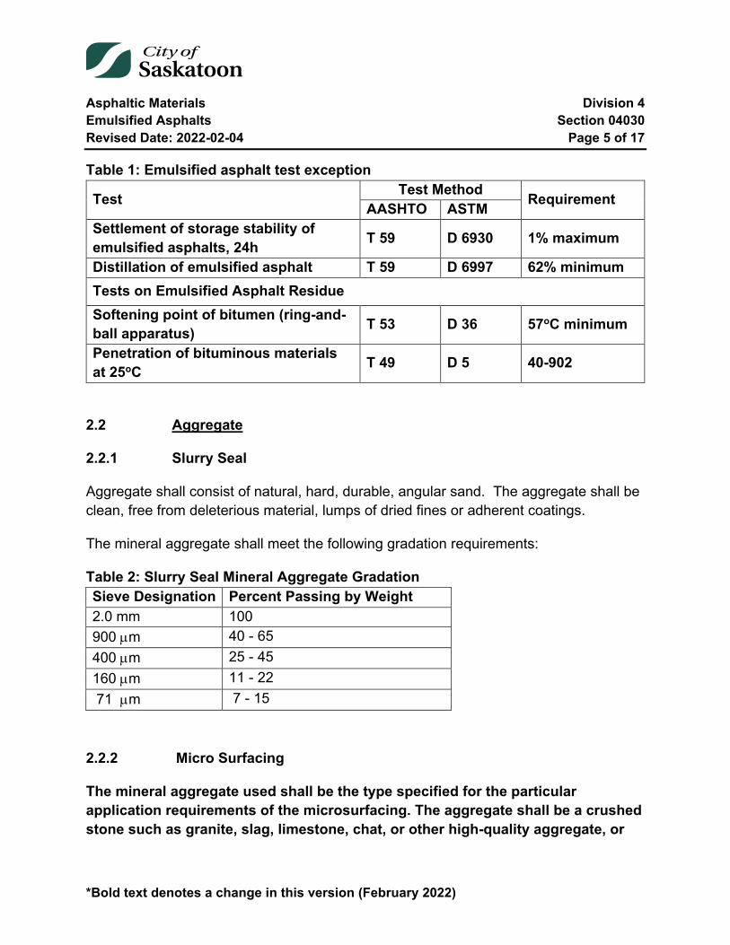
Asphaltic Materials Division 4 Emulsified Asphalts Section 04030 Revised Date: 2022-02-04 Page 5 of 17
*Bold text denotes a change in this version (February 2022)
Table 1: Emulsified asphalt test exception
Test Test Method Requirement AASHTO ASTM Settlement of storage stability of emulsified asphalts, 24h T 59 D 6930 1% maximum
Distillation of emulsified asphalt T 59 D 6997 62% minimum Tests on Emulsified Asphalt Residue Softening point of bitumen (ring-and-ball apparatus) T 53 D 36 57oC minimum
Penetration of bituminous materials at 25oC T 49 D 5 40-902
2.2 Aggregate
2.2.1 Slurry Seal
Aggregate shall consist of natural, hard, durable, angular sand. The aggregate shall be clean, free from deleterious material, lumps of dried fines or adherent coatings.
The mineral aggregate shall meet the following gradation requirements:
Table 2: Slurry Seal Mineral Aggregate Gradation Sieve Designation Percent Passing by Weight 2.0 mm 100 900 µm 40 - 65 400 µm 25 - 45 160 µm 11 - 22 71 µm 7 - 15
2.2.2 Micro Surfacing
The mineral aggregate used shall be the type specified for the particular application requirements of the microsurfacing. The aggregate shall be a crushed stone such as granite, slag, limestone, chat, or other high-quality aggregate, or
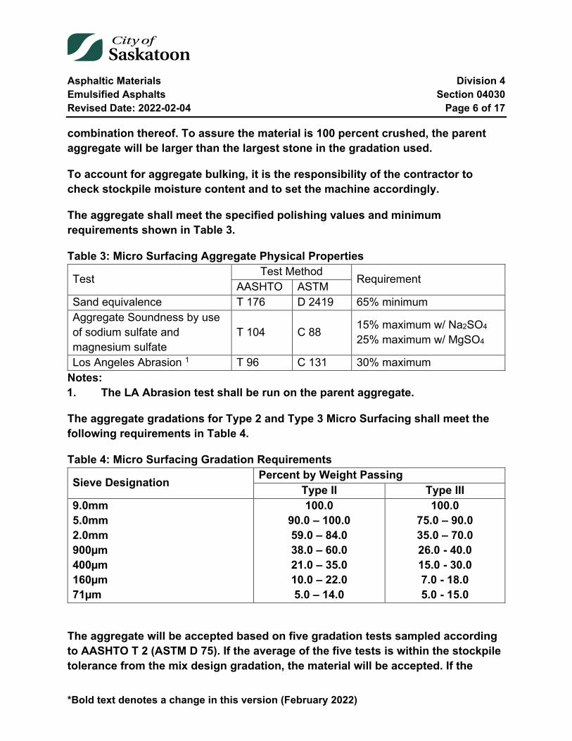
Asphaltic Materials Division 4 Emulsified Asphalts Section 04030 Revised Date: 2022-02-04 Page 6 of 17
*Bold text denotes a change in this version (February 2022)
combination thereof. To assure the material is 100 percent crushed, the parent aggregate will be larger than the largest stone in the gradation used.
To account for aggregate bulking, it is the responsibility of the contractor to check stockpile moisture content and to set the machine accordingly.
The aggregate shall meet the specified polishing values and minimum requirements shown in Table 3.
Table 3: Micro Surfacing Aggregate Physical Properties
Test Test Method Requirement AASHTO ASTM Sand equivalence T 176 D 2419 65% minimum Aggregate Soundness by use of sodium sulfate and magnesium sulfate
T 104 C 88 15% maximum w/ Na2SO4 25% maximum w/ MgSO4
Los Angeles Abrasion 1 T 96 C 131 30% maximum Notes: 1. The LA Abrasion test shall be run on the parent aggregate.
The aggregate gradations for Type 2 and Type 3 Micro Surfacing shall meet the following requirements in Table 4.
Table 4: Micro Surfacing Gradation Requirements
Sieve Designation Percent by Weight Passing Type II Type III
9.0mm 5.0mm 2.0mm 900µm 400µm 160µm 71µm
100.0 90.0 – 100.0 59.0 – 84.0 38.0 – 60.0 21.0 – 35.0 10.0 – 22.0 5.0 – 14.0
100.0 75.0 – 90.0 35.0 – 70.0 26.0 - 40.0 15.0 - 30.0 7.0 - 18.0 5.0 - 15.0
The aggregate will be accepted based on five gradation tests sampled according to AASHTO T 2 (ASTM D 75). If the average of the five tests is within the stockpile tolerance from the mix design gradation, the material will be accepted. If the

Asphaltic Materials Division 4 Emulsified Asphalts Section 04030 Revised Date: 2022-02-04 Page 7 of 17
*Bold text denotes a change in this version (February 2022)
average of those test results is out of specification or tolerance, the contractor will be given the choice to either remove the material or blend additional aggregate with the stockpile material to bring it into compliance. Materials used in blending must meet the required aggregate quality test specifications before blending and must be blended in a manner to produce a consistent gradation. Aggregate blending shall require the submittal of a new mix design.
2.3 Filler
2.3.1 Slurry Seal
When required to produce a proper "slurry consistency", the addition of a correct filler shall be added as required. Commercial fillers consisting of Portland Cement, Hydrated Lime, limestone dust or crusher run dust shall be used. Natural occurring materials, namely, silt or clay, will only be permitted to be used as a filler when approved by the Engineer.
2.3.2 Micro Surfacing
Mineral filler may be used to improve mixture consistency and to adjust mixture breaking and curing properties. Portland cement, hydrated lime, limestone dust, fly ash, or other approved filler meeting the requirements of ASTM D 242 shall be used if required by the mix design. Typical use levels are normally 0.0 - 3.0 percent and may be considered part of the aggregate gradation.
2.4 Micro surfacing Mix
The micro surfacing mix shall be designed to pass the following test requirements in Table 5:

Asphaltic Materials Division 4 Emulsified Asphalts Section 04030 Revised Date: 2022-02-04 Page 8 of 17
*Bold text denotes a change in this version (February 2022)
Table 5: Micro Surfacing Mix Requirements
Test ISSA Table No. Requirement
Mix Time @ 25oC TB 113 Controllable to 120 seconds minimum
Wet Cohesion @ 30 minutes minimum (set) @ 60 minutes minimum (traffic)
TB 139 12 kg-cm minimum 20 kg-cm or near spin minimum
Wet stripping TB 114 Pass (90% minimum) Wet-track abrasion loss over one-hour soak Six-day soak
TB 100 538g/m2 maximum 807g/m2 maximum
Lateral displacement Specific gravity after 1000 cycles of 56.71kg
TB 147 5% maximum
Excess asphalt by LWT sand adhesion TB 109 538g/m2 maximum
Classification compatibility TB 144 11 grade points minimum (AAA, BBB)
The micro surfacing mix shall be designed to the limits listed in Table 6:
Table 6: Micro Surfacing Mix Limits Component Materials Limits
Residual asphalt 5.5 – 10.5% by dry weight of aggregate Type of mineral filler 0 – 3% by dry weight of aggregate
Polymer content Minimum of 3.0% solids based on bitumen weight content
Asphaltic Materials Division 4 Emulsified Asphalts Section 04030 Revised Date: 2022-02-04 Page 9 of 17
*Bold text denotes a change in this version (February 2022)
2.4.1 Water
The water shall be free of harmful salts and contaminants. If the quality of the water is in question a sample shall be submitted to the City.
The Contractor is responsible for providing all water required at the construction site. An application form for a portable water meter is available from the City’s Water and Waste Stream Division.
The Contractor shall not operate any hydrant, valve or curb stop without the Engineer's permission.
2.4.2 Additives
Additives may be used to accelerate or retard the break/set of the micro surfacing. Appropriate additives, and their applicable use range, should be approved by the City as part of the mix design.
2.4.3 Fibres
Fibres shall be added to the micro surfacing mix before the pug mill by mechanical distributor in order to ensure an even distribution throughout the mix.
Fibres shall be 12.5mm (0.5 inches) in length.
04030-3 Equipment
All equipment, tools, and machinery used in the performance of this work shall be maintained in satisfactory working condition.
3.1 Slurry Seal
3.1.1 Mixer Equipment
The slurry seal coat mixing machine shall be a continuous flow mixing unit and be able to accurately deliver and proportion aggregate, asphalt emulsion, and water to a revolving spiralled multiblade mixer and discharge the thoroughly mixed product on a continuous basis in a minimum amount of time.
Asphaltic Materials Division 4 Emulsified Asphalts Section 04030 Revised Date: 2022-02-04 Page 10 of 17
*Bold text denotes a change in this version (February 2022)
The mixing machine shall be equipped with an approved fines feeder with an accurate metering device or method to introduce a predetermined amount of mineral filler into the mixer at the same time and location where the aggregate is fed. A calibrated control for aggregate and asphalt shall be provided capable for accurately proportioning materials.
The mixing machine shall be equipped with a water pressure system and a fog type spray bar adequate for complete fogging of the surface preceding spreading equipment with a maximum application of 0.30 litres per square metre.
The machine while in operation shall have a minimum speed of 18 metres per minute and shall not be allowed to exceed 55 metres per minute. Sufficient machine storage capacity shall be provided to properly mix and apply a minimum of 5 tonnes of slurry.
3.1.2 Spreading Equipment
The mechanical type squeegee distributor shall be equipped with flexible material in contact with the surface to prevent the loss of slurry from the distributor. It shall be maintained so as to prevent loss of slurry on varying grades and crown by adjustments to assure uniform spread and depth.
There shall be a steering device and a flexible strike-off. A piece of burlap or a piece of heavy canvas shall be attached behind the spreader to provide a smooth surface. The squeegee shall be attached behind the mixer.
3.1.3 Auxiliary Equipment:
Hand squeegees, shovels and hand equipment shall be provided as necessary to perform the work.
3.2 Micro Surfacing
All equipment, tools, and machines used in the application of microsurfacing shall be maintained in satisfactory working condition at all times.
All water and emulsion storage containers used in delivery or application of microsurfacing shall be free of contaminants and shall not leak. Spray bar nozzles shall be regularly inspected to ensure that a continuous even spray is being maintained. All lighting and reflectors must remain clean and operational at all times.

Asphaltic Materials Division 4 Emulsified Asphalts Section 04030 Revised Date: 2022-02-04 Page 11 of 17
*Bold text denotes a change in this version (February 2022)
Equipment must be maintained to ensure that contaminants such as, but not limited to, motor oil, antifreeze, or hydraulic fluids are not leaking onto the road. At the discretion of the Engineer, the Contractor will cease operations and rectify the concerns regarding the condition of the equipment or tools.
All counting devices shall be in proper working condition prior to work commencing at each location. The Contractor will not receive payment for work completed with non-working counting devices.
For the safety of the crew, all equipment used in the application of microsurfacing or transportation of its components will have sufficient lighting, reflectors and warning lights to be clearly seen at night.
If the Engineer deems there is insufficient lighting or reflectors, the Contractor will take necessary steps to satisfy the requirements of the Engineer.
3.2.1 Mixing Equipment
The machine shall be specifically designed and manufactured to apply microsurfacing. The material shall be mixed by an automatic-sequenced, self-propelled, front feed, continuous loading, microsurfacing mixing machine. A mobile truck mounted microsurfacing unit is also acceptable.
It shall be a continuous-flow mixing unit that accurately delivers and proportions the mix components through a revolving multi-blade, double-shafted mixer. Sufficient storage capacity for all mix components is required to maintain an adequate supply to the proportioning controls.
When utilizing continuous machinery to minimize transverse joints, the specified machine must be capable of loading materials while continuing to apply microsurfacing. The continuous-run machine shall be equipped to provide the operator with full control of the forward and reverse speeds during application. It shall be equipped with opposite-side driver stations to assist in alignment. The self-loading device, opposite-side driver stations, and forward and reverse speed controls shall be of original-equipment-manufacturer design.
Asphaltic Materials Division 4 Emulsified Asphalts Section 04030 Revised Date: 2022-02-04 Page 12 of 17
*Bold text denotes a change in this version (February 2022)
3.2.2 Proportioning Devices
Individual volume or weight controls for proportioning mix components shall be provided and properly labeled. These proportioning devices are used in material calibration to determine the material output at any time.
3.2.3 Spreading Equipment
The mixture shall be agitated and spread uniformly in the surfacing box by means of twin - shafted paddles or spiral augers fixed in the spreader box. A front seal shall be provided to insure no loss of the mixture at the road contact point. The rear seal shall act as a final strike-off and shall be adjustable. The spreader box and rear strike-off shall be designed and operated such that a uniform consistency is achieved and a free flow of material is provided to the rear strike-off. The spreader box shall have suitable means provided to side shift the box to compensate for variations in the pavement geometry.
A secondary strike-off shall be provided to improve surface texture. The secondary strike-off shall be adjustable to match the width of the spreader box and allow for varying pressures to control the surface texture.
3.2.4 Auxiliary Equipment
Suitable surface preparation equipment, traffic control equipment, hand tools, and other support and safety equipment necessary to perform the work shall be provided by the contractor unless otherwise stated.
04030-4 Execution
Immediately prior to applying slurry seal coat or micro surfacing, the surface shall be cleaned of all loose material, silt spots and other objectionable material.
4.1 Slurry Seal coating
The Slurry Seal Coat shall consist of a mixture of emulsified asphalt, mineral aggregate and water, properly mixed and spread on the surface as specified and as directed by the Engineer.
On old pavement, a tack coat consisting of a dilution of 1 part emulsified asphalt to 3 parts water shall be applied with a conventional pressure distributor
Asphaltic Materials Division 4 Emulsified Asphalts Section 04030 Revised Date: 2022-02-04 Page 13 of 17
*Bold text denotes a change in this version (February 2022)
4.1.1 Mix Preparation
The quantities of aggregate, emulsified asphalt and water shall be measured or weighed into each batch. When preparing slurry seal mixes, the water and emulsified asphalt shall be added first, and then the aggregate. The amount of water used shall be a minimum to provide a fluid homogeneous mixture.
The Contractor shall make trial batches, at his expense, to determine the final blend of mineral aggregate, mineral filler and asphaltic binder until approved by the Engineer. Approximately 9.5 to 11.5 litres of emulsified asphalt shall be used per 45 kilograms of dry aggregate weight
4.1.2 Application
The surface shall be fogged with water from pressure nozzles directly preceding the drag distributor. No puddles of free water shall remain after fogging. The slurry mix shall be of the desired consistency when deposited on surface and no additional elements added. Total time of mixing shall not exceed 4 minutes. A maximum amount of slurry shall be carried in the distributor and the maximum allowable speed shall be 55 m per minute.
The average thickness of slurry seal coat applied shall be 3 mm or approximately 1 tonne per 1,500 square metres of surface.
Slurry seal shall be protected from all traffic until the slurry has set. The minimum time period, in excellent drying weather, shall be 4 hours or the time required for the slurry colour to change from uniform brown to uniform black.
Slurry application shall be suspended when rain is imminent within 12 hours.
4.2 Micro Surfacing
Microsurfacing shall consist of a mixture of polymer-modified emulsified asphalt, mineral aggregate, water, and additives, proportioned, mixed and uniformly spread over a properly prepared surface. The microsurfacing shall be applied as a homogeneous mat, adhere firmly to the prepared surface, and have a skid-resistant texture throughout its service life.

Asphaltic Materials Division 4 Emulsified Asphalts Section 04030 Revised Date: 2022-02-04 Page 14 of 17
*Bold text denotes a change in this version (February 2022)
4.2.1 Calibration
Each mixing unit to be used in the performance of the work shall be calibrated in the presence of the Engineer prior to the start of the project. Previous calibration documentation covering the exact materials to be used may be acceptable, provided that no more than 60 days have passed. The documentation shall include an individual calibration for each material at various settings that can be related to the machine metering devices. Any component replacement affecting material proportioning or measuring requires that the machine be recalibrated. No machine will be allowed to work on the project until the calibration has been completed and accepted by the Engineer.
The Contractor shall repair defective metering devices and components and provide the Engineer notice as to when the equipment will be recalibrated. The Engineer may request the Contractor to verify the calibration of the equipment. There will be no additional payments for calibrating, re-calibration or for verifying the calibration of the equipment.
4.2.2 Tack Coat
Tack Coats shall be applied in accordance to Section 04025.
4.2.3 Protecting Existing Utilities
All utilities shall be protected from the microsurfacing and tack oil by a suitable method. The Engineer must approve the method employed to protect the utility covers. If the Engineer deems the protective coverings material or installation to be unacceptable, the Contractor will cease operations until the installation meets the approval of the Engineer.
Protective coverings must be removed within 24 hours of completion of the work or before the roadway is reopened to traffic. Removal of utility covers includes removal of protective covering material and removal of any microsurfacing material or other material that may be present on the utility.
4.2.4 Application
The microsurfacing is to be applied with a drag (burlap or a similar material) to ensure a uniform textured finish. The Contractor is to apply the microsurfacing in
Asphaltic Materials Division 4 Emulsified Asphalts Section 04030 Revised Date: 2022-02-04 Page 15 of 17
*Bold text denotes a change in this version (February 2022)
such a manner to ensure a continuous seal, tight along curb or gutter where present.
The microsurfacing shall be of the appropriate consistency upon leaving the mixer. A sufficient amount of material shall be carried in all parts of the spreader at all times so that complete coverage is obtained. Overloading of the spreader box shall be avoided. No dry aggregate either spilled from the lay-down machine or existing on the road will be permitted.
Mixes resulting in lumping, unmixed aggregate, roughness or excessive streaking in the mat surface will be rejected and operations ceased until the Contractor proves to the Engineer that the situation has been corrected. Excessive streaking is defined as more than four drag marks greater than 10mm wide and 100mm long, or 25mm wide and 75mm long, in any 25 square meter area. No transverse ripples or longitudinal streaks of 5mm in depth will be permitted, when measured by placing a 3m straight edge over the surface. Mixes that are unable to hold straight lines or that cause an asphalt-rich surface with segregation will be rejected.
It is the responsibility of the Contractor to protect the microsurfacing until it has cured sufficiently to prevent pickup or damage. The Contractor will not be responsible for damage caused by circumstances that are out of their control, such as emergency vehicles requiring access through the work area.
4.2.4.1 Rate of Application
Acceptable Micro Surfacing application rate shall be in accordance with Table 7. Application rates are based upon the weight of aggregate in the mixture.
Table 7: Micro Surfacing Application Rates Aggregate Type Application Rate Type II 14 – 17kg/m2 Type III 16 – 19kg/m2
4.2.4.2 Joints
No excess buildup, uncovered areas, or unsightly appearance shall be permitted on longitudinal or transverse joints. The contractor shall provide suitable width

Asphaltic Materials Division 4 Emulsified Asphalts Section 04030 Revised Date: 2022-02-04 Page 16 of 17
*Bold text denotes a change in this version (February 2022)
spreading equipment to produce a minimum number of longitudinal joints throughout the project. Longitudinal joints shall be placed 200mm from lane lines or as approved by the Engineer. Partial width passes will only be used when necessary and shall not be the last pass of any paved area. The joint shall have no more than a 5mm difference in elevation when measured by placing a 3m straight edge over the joint and measuring the elevation difference.
4.2.4.3 Mixture
The microsurfacing shall possess sufficient stability so that premature breaking of the material in the spreader box does not occur. The mixture shall be homogeneous during and following mixing and spreading. It shall be free of excess liquids which create segregation of the aggregate. Spraying of additional water into the spreader box will not be permitted.
4.2.4.4 Handwork
Areas which cannot be accessed by the mixing machine shall be surfaced using hand squeegees to provide complete and uniform coverage. Handwork shall exhibit the same finish as that applied by the spreader box. All handwork shall be completed prior to final surfacing.
4.2.4.5 Lines
Lines at intersections, curbs, and shoulders will be kept straight to provide a good appearance. A suitable material will be used to mask off the end of streets to provide straight lines. Longitudinal edge lines shall not vary by more than +/-50mm in any 30m length.
04030-5 Testing
The supplier shall, prior to initial delivery, undertake standard control tests and provide test results to prove compliance with the requirements for the desired type and grade of emulsified asphalt.
Asphaltic Materials Division 4 Emulsified Asphalts Section 04030 Revised Date: 2022-02-04 Page 17 of 17
*Bold text denotes a change in this version (February 2022)
04030-6 Payment
6.1 Slurry Seal Coating
Payment for Slurry Seal Coating will be at the contract unit price per square metre. The unit price will be for full compensation for supplying emulsified asphalt slurry seal aggregate and filler, preparing and applying the slurry seal, applying tack coat when required and cleaning the surface to be treated.
6.2 Microsurfacing
Payment for emulsion and aggregate for microsurfacing will be at the contract unit price per tonne. Aggregate and emulsion quantities shall be calculated utilizing the calibration and application rate as measured in the field. The unit price will be full compensation for furnishing all materials, all preparation, mixing and application of materials, and for all labour, equipment, tools, testing, cleaning, and incidentals necessary for completing the work as specified herein.
End of Specification 04030
Asphaltic Materials Division 4 Cold Mix Asphalt Section 04050 Revised Date: 2022-02-04 Page 1 of 4
*Bold text denotes a change in this version (February 2022)
04050 Cold Mix Asphalt
Index
04050-1 Description 2
04050-2 Materials 2 2.1 Asphalt Cement 2 2.2 Aggregate 3
04050-3 Measurement 3
04050-4 Testing 3 4.1 Quality Control 3
04050-5 Payment 4
Tables and Equations
Table 1: Asphalt Cement Properties for Cold Mix Asphalt 2
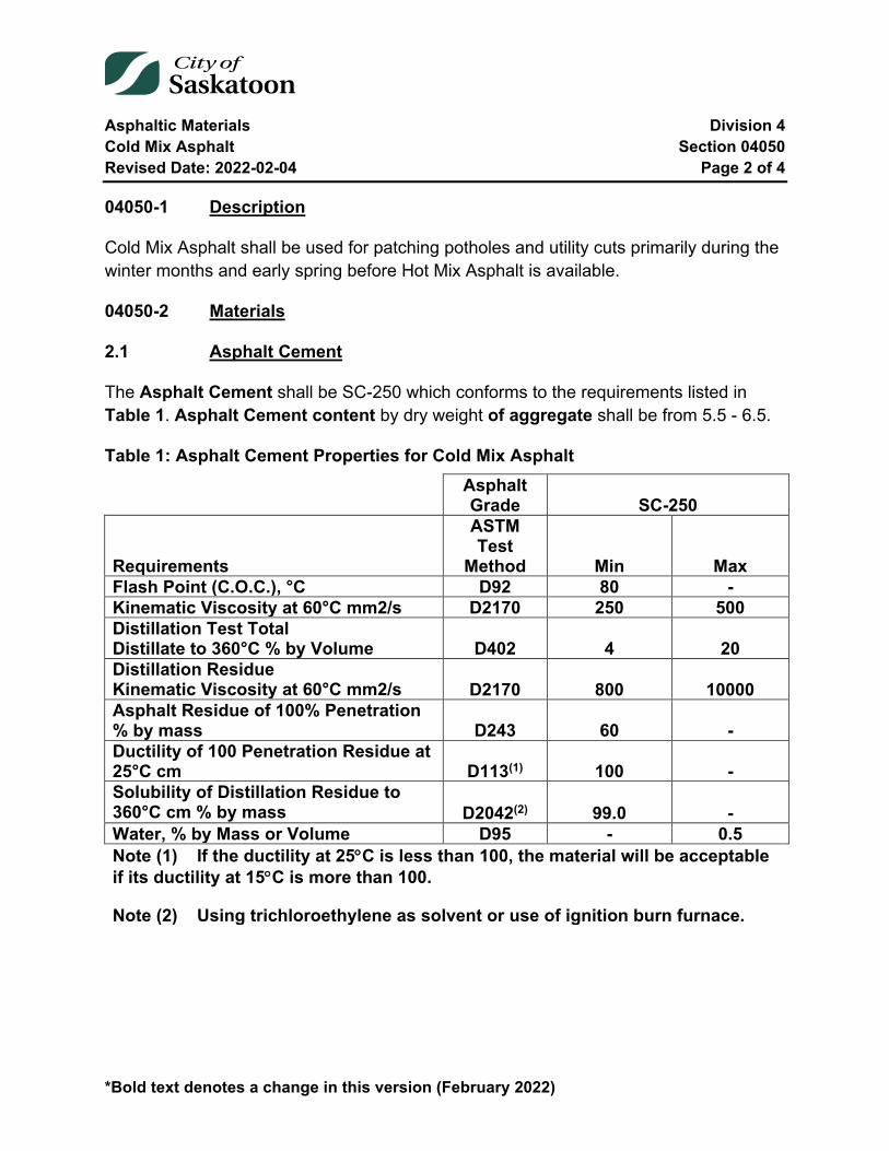
Asphaltic Materials Division 4 Cold Mix Asphalt Section 04050 Revised Date: 2022-02-04 Page 2 of 4
*Bold text denotes a change in this version (February 2022)
04050-1 Description
Cold Mix Asphalt shall be used for patching potholes and utility cuts primarily during the winter months and early spring before Hot Mix Asphalt is available.
04050-2 Materials
2.1 Asphalt Cement
The Asphalt Cement shall be SC-250 which conforms to the requirements listed in Table 1. Asphalt Cement content by dry weight of aggregate shall be from 5.5 - 6.5.
Table 1: Asphalt Cement Properties for Cold Mix Asphalt Asphalt
Grade SC-250
Requirements
ASTM Test
Method Min Max Flash Point (C.O.C.), °C D92 80 - Kinematic Viscosity at 60°C mm2/s D2170 250 500 Distillation Test Total Distillate to 360°C % by Volume D402 4 20 Distillation Residue Kinematic Viscosity at 60°C mm2/s D2170 800 10000 Asphalt Residue of 100% Penetration % by mass D243 60 - Ductility of 100 Penetration Residue at 25°C cm D113(1) 100 - Solubility of Distillation Residue to 360°C cm % by mass D2042(2) 99.0 - Water, % by Mass or Volume D95 - 0.5 Note (1) If the ductility at 25°C is less than 100, the material will be acceptable if its ductility at 15°C is more than 100.
Note (2) Using trichloroethylene as solvent or use of ignition burn furnace.

Asphaltic Materials Division 4 Cold Mix Asphalt Section 04050 Revised Date: 2022-02-04 Page 3 of 4
*Bold text denotes a change in this version (February 2022)
2.2 Aggregate
The Aggregate gradation for Cold Mix Asphalt shall conform to the Type 3 mix as specified in Section 04010. The maximum allowable mixing temperature is 80°C
04050-3 Measurement
Cold Mix asphalt shall be measured in tonnes of material loaded as determined by scales at the Contractor’s plant location.
Material is to be scaled and recorded by the Contractor on duplicate weigh slips. Weigh slips must be signed by both parties at the time of loading and a copy supplied to the City of Saskatoon. Tickets shall include a ticket number, gross, net and tare weights, truck number and cumulative total by asphalt type and project for that day.
The weight of each vehicle shall be determined at the beginning of the work with the fuel tank half full, spare tire in place and the driver in the cab. This weight, called the vehicle weight will be checked and/or amended at the discretion of the Engineer.
04050-4 Testing
The supplier shall, prior to initial delivery, undertake standard control tests and provide test results to prove compliance with the requirements for the desired type and grade of asphalt cement as listed in Table 1.
All tests conducted by the City shall be in accordance with the procedures and methods of the American Society for Testing and Materials (ASTM) except where the Canadian Government Specification Board (C.G.S.B.) and the National Standard Council (N.S.C.) of Canada is indicated.
4.1 Quality Control
Suppliers shall provide all standard control tests as listed in Table 1 for every 100 tonnes of SC-250.
If requested by the City, the supplier shall supply a representative 5 litre sample of SC-250 prior to delivery of any order. The City shall also have the right to obtain samples of not more than 5 litres from each shipment during the course of delivery of any order.
Asphaltic Materials Division 4 Cold Mix Asphalt Section 04050 Revised Date: 2022-02-04 Page 4 of 4
*Bold text denotes a change in this version (February 2022)
04050-5 Payment
Payment for Cold Mix Asphalt will be at the unit price per tonne.
The unit price will be full compensation for removing overburden, excavating, crushing, screening, stockpiling, and drying the aggregate; mixing and loading the asphalt mix.
End of Specification 04050
Asphaltic Materials Division 4 Infrared Asphalt Heating Section 04070 Revised Date: 2022-02-04 Page 1 of 4
04070 Infrared Asphalt Heating
Index
04070-1 General 2 1.1 Description of Work 2
04070-2 Materials 2 2.1 Asphalt Mix Type 2
04070-3 Equipment 2
04070-4 Execution 2 4.1 Preparation 2 4.2 Heater Placement 2 4.3 Heating Temperature 3 4.4 Raking 3 4.5 Rejuvenating 3 4.6 Addition of New Asphalt 3 4.7 Compaction 4 4.8 Cold Weather Application 4
04070-5 Testing 4
Figures
Figure 1: Heater Placement Area Location (not to scale) ................................................ 3
Asphaltic Materials Division 4 Infrared Asphalt Heating Section 04070 Revised Date: 2022-02-04 Page 2 of 4
04070-1 General
1.1 Description of Work
The work under this section includes, but is not limited to, the supply of all superintendence, traffic control, labour, material, equipment and tools required to perform pavement repairs using infrared heater equipment.
04070-2 Materials
2.1 Asphalt Mix Type
Type 2 and Type 4 asphalt concrete and reclaimed asphalt product (RAP) shall be used and will follow the City of Saskatoon Specification unless otherwise approved by the Engineer.
04070-3 Equipment
All tools, machinery, plant and equipment used in handling materials and executing any part of the work shall be subject to the approval of the Engineer. All such equipment shall be maintained in efficient working order and where any of the machinery plant or equipment is found to be unsatisfactory; it shall be improved or replaced by the Contractor to the satisfaction of the Engineer.
04070-4 Execution
4.1 Preparation
Upon arriving on site, the construction area shall be swept to remove any standing water, loose asphalt, and dirt.
4.2 Heater Placement
The area to be restored as shown in Figure 1 shall be squared off at least 150 mm away from the damaged area (pothole).
The area to be heated as shown in Figure 1 shall be squared off at least 150 mm away from the area to be restored.
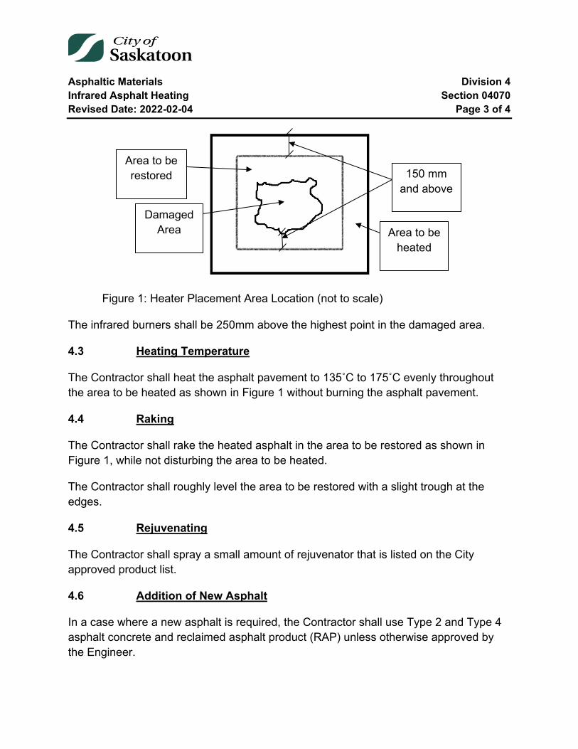
Asphaltic Materials Division 4 Infrared Asphalt Heating Section 04070 Revised Date: 2022-02-04 Page 3 of 4
Figure 1: Heater Placement Area Location (not to scale)
The infrared burners shall be 250mm above the highest point in the damaged area.
4.3 Heating Temperature
The Contractor shall heat the asphalt pavement to 135˚C to 175˚C evenly throughout the area to be heated as shown in Figure 1 without burning the asphalt pavement.
4.4 Raking
The Contractor shall rake the heated asphalt in the area to be restored as shown in Figure 1, while not disturbing the area to be heated.
The Contractor shall roughly level the area to be restored with a slight trough at the edges.
4.5 Rejuvenating
The Contractor shall spray a small amount of rejuvenator that is listed on the City approved product list.
4.6 Addition of New Asphalt
In a case where a new asphalt is required, the Contractor shall use Type 2 and Type 4 asphalt concrete and reclaimed asphalt product (RAP) unless otherwise approved by the Engineer.
Area to be restored
Area to be heated
Damaged Area
150 mm and above
Asphaltic Materials Division 4 Infrared Asphalt Heating Section 04070 Revised Date: 2022-02-04 Page 4 of 4
4.7 Compaction
The Contractor shall have available, at all times, the necessary labour, equipment and tools required to compact the asphalt and base in the area to be heated as shown in Figure 1.
4.8 Cold Weather Application
During when the temperature is below 4˚C the Contractor shall maintain the temperature of asphalt pavement above 135˚C during the duration of construction.
04070-5 Testing
The City of Saskatoon shall appoint an independent testing consultant to perform all tests for quality control of the mix to determine compliance with specification during production (process control), and quality assurance to determine acceptance and payment adjustments to material supplied and placed.
Sampling for quality assurance will be done using a random sampling procedure as identified by the Engineer. Where there is continuous production uninterrupted by plant shutdown due to quality control only the predetermined random sampling frequency will be used to determine payment adjustments to the unit bid price.
The quality assurance random sampling will also be the basis for quality control for generating control charts and determining plant shutdown. In addition to the quality assurance sampling the Engineer may also initiate supplementary tests independent of the quality assurance random sampling procedure to supplement the quality control tests for determining process control. These additional tests will not be used for payment adjustment factors unless it results in plant shutdown prior to the sampling for quality assurance in that specific lot of material. The supplementary test in this case will then be used for payment adjustment on that portion of the untested lot. If the supplementary test results in termination of production the Contractor will be required to pay for the test.
The Contractor shall retain and pay an independent testing consultant to perform all materials certification tests and mix designs required in this section.
End of Specification 04070
Metals Division 5 Chain Link Fencing Section 05015 Revised Date: 2013-01-04 Page 1 of 7
05015 Chain Link Fencing
Index
05015-1 Description 2
05015-2 Materials 2 2.1 General 2 2.2 Finishes 4
05015-3 Construction 4 3.1 Grading 4 3.2 Erection of Fence 4 3.3 Erection of Gates 5 3.4 Patching 5 3.5 Cleaning 6
05015-4 Measurement and Payment 6
05015-5 Pipe Properties and Dimensions 6
Tables
Table 1: Pipe Properties and Dimensions ....................................................................... 6
Metals Division 5 Chain Link Fencing Section 05015 Revised Date: 2013-01-04 Page 2 of 7
05015-1 Description
This section specifies requirements for supply and installation of chain link fence and gates.
05015-2 Materials
2.1 General
2.1.1 Concrete
1. Compressive strength 20 MPa minimum 28 days. 2. Coarse aggregate 19.0 mm maximum size.
2.1.2 Chain Link Fence Fabric
Chain Link Fence Fabric: to CAN2 138.1.
1. Zinc coated steel. 2. Height of wire, 1200 mm or 1800 mm, as per drawing. 3. Size of wire, 3.5 mm diameter. 4. Size in mesh, 50 mm. 5. Knuckled at one selvage and twisted at other.
2.1.3 Posts and rails
Posts and rails: to CAN2 138.1 galvanized steel pipe, standard weight, sizes as per drawings.
2.1.4 Tension wire
Tension wire: single strand, galvanized steel wire, 5 mm diameter.
2.1.5 Fasteners
Fasteners: single strand, aluminium or galvanized steel wire conforming to requirements of fence fabric, 3.5 mm diameter.
Metals Division 5 Chain Link Fencing Section 05015 Revised Date: 2013-01-04 Page 3 of 7
2.1.6 Tension bar
Tension bar: 5 x 20 mm min. galvanized steel.
2.1.7 Tension bar bands
Tension bar bands: 3 x 20 mm min. galvanized steel or 5 x 20 mm min. aluminium.
2.1.8 Pedestrian screen
Pedestrian screen: to standards herein and to sizes and dimensions indicated in drawings.
2.1.9 Gate frames
Gate frames: to ASTM A120, galvanized steel pipe, standard weight, 45 mm O.D. pipe for outside frame, 35 mm O.D. pipe for interior bracing.
1. Gates fabricated as indicated, electrically weld joints and hot-dip galvanize after welding.
2. Fence fabric fastened to gate with twisted selvage at top. 3. Gates furnished with galvanized malleable iron hinges, latch and latch catch with
provision for a padlock which can be attached and operated from either side of installed gate.
4. Double gates furnished with a chain hook to hold gates open and a centre rest with drop bolt for closed position.
2.1.10 Fittings and hardware
Fittings and hardware: cast aluminium alloy, or galvanized steel, malleable or ductile cast iron. Post caps designed to provide a waterproof fit, to fasten securely over posts and to carry top rail.
2.1.11 Zinc pigmented paint
Zinc pigmented paint: to CGSB 1-GP-178M.

Metals Division 5 Chain Link Fencing Section 05015 Revised Date: 2013-01-04 Page 4 of 7
2.2 Finishes
2.2.1 Galvanizing
1. For chain link fabric: to CAN2 138.1 Grade 1. 2. For pipe: 570 g/m2 minimum to CSA B63. 3. For other fittings: to CSA G164.
05015-3 Construction
3.1 Grading
Inspect site and confirm that rough grading by the City of Saskatoon to within 200 mm of final ground line has been completed. Commencement of work this section implies acceptance of site conditions.
Remove debris and correct ground undulations along fence line to obtain a smooth uniform gradient between posts. Provide clearance between bottom of fence and ground surface neither less than 40 mm nor more than 75 mm.
Clean up for 1.5 m on both sides of fence line taking care not to extend operations beyond property limits.
3.2 Erection of Fence
Erect fence along lines indicated or established by Engineer.
Excavate post holes to indicated depths by approved methods.
Space line posts 3 m apart; measured parallel to ground surface.
Space straining posts at equal intervals not exceeding 150 m if distance is greater than 150 m between end or corner posts on straight continuous lengths of fence over reasonably smooth grade.
Install additional straining posts at sharp changes in grade and where Engineer directs.
Install corner post where change in alignment exceeds 20 degree angle.
Install end posts at end of fence and on both sides of gate openings.
Metals Division 5 Chain Link Fencing Section 05015 Revised Date: 2013-01-04 Page 5 of 7
Set posts in concrete. Extend concrete 50 mm above ground level and slope to drain away from posts. Brace to hold posts in plumb position and true to alignment and elevation until concrete has set. Do not concrete posts when air temperature is less than 5 C without Engineer's approval.
Do not install fence fabric until concrete has cured a minimum of 5 days.
Install brace between end and gate posts and nearest line post, placed in centre of panel and parallel to ground surface. Install braces on both sides of corner and straining posts in similar manner.
Install top rail between posts (where required) and fasten securely to posts with waterproof caps.
Install bottom tension wire, stretch tightly and fasten securely to end, corner, gate and straining posts with drop forged turnbuckles and tension bar bands.
Lay out fence fabric, stretch tightly and fasten to end, corner, gate and straining posts with tension bar secured to post with tension bar bands spaced at 300 mm intervals.
Secure fabric to top rails, line posts and bottom tension wire with tie wires at 450 mm intervals. Give tie wires no less than two twists.
3.3 Erection of Gates
Erect gates in locations indicated.
Set gate bottom approximately 40 mm above ground surface.
Determine position of centre gate rest for double gate. Cast gate rest in concrete. Dome concrete above ground level to shed water.
Install gate stops where indicated.
3.4 Patching
Repair damaged galvanized surfaces. Clean damaged surfaces with wire brush removing loose and cracked spelter coatings. Apply two coats of approved zinc pigmented paint to damaged areas.
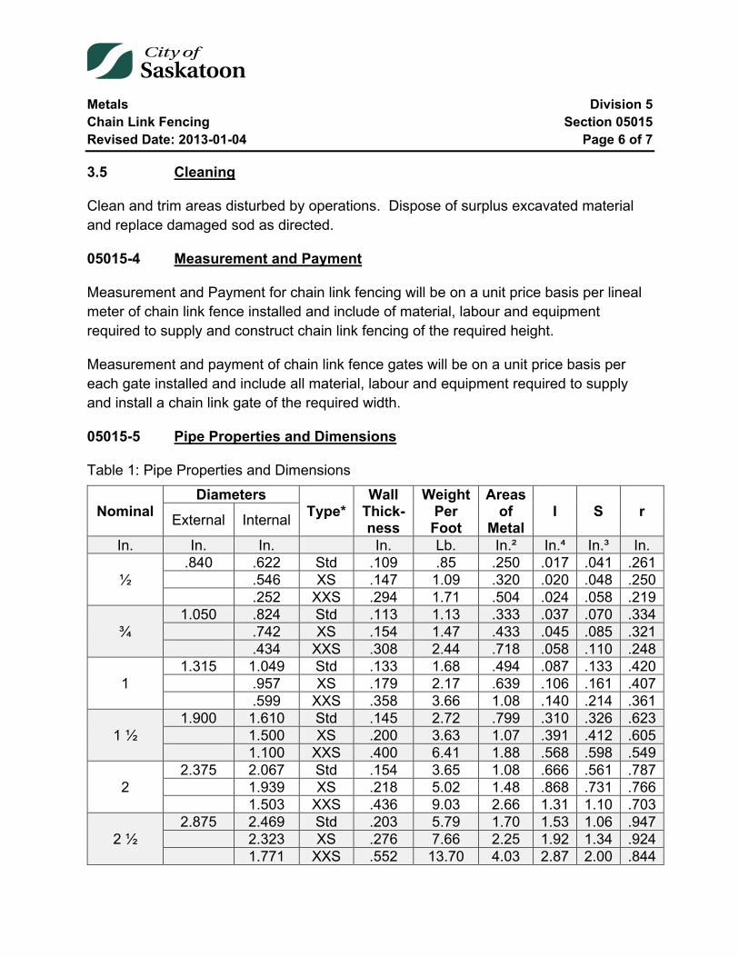
Metals Division 5 Chain Link Fencing Section 05015 Revised Date: 2013-01-04 Page 6 of 7
3.5 Cleaning
Clean and trim areas disturbed by operations. Dispose of surplus excavated material and replace damaged sod as directed.
05015-4 Measurement and Payment
Measurement and Payment for chain link fencing will be on a unit price basis per lineal meter of chain link fence installed and include of material, labour and equipment required to supply and construct chain link fencing of the required height.
Measurement and payment of chain link fence gates will be on a unit price basis per each gate installed and include all material, labour and equipment required to supply and install a chain link gate of the required width.
05015-5 Pipe Properties and Dimensions
Table 1: Pipe Properties and Dimensions
Nominal Diameters
Type* Wall
Thick- ness
Weight Per Foot
Areas of
Metal I S r External Internal
In. In. In. In. Lb. In.² In.⁴ In.³ In.
½ .840 .622 Std .109 .85 .250 .017 .041 .261
.546 XS .147 1.09 .320 .020 .048 .250 .252 XXS .294 1.71 .504 .024 .058 .219
¾ 1.050 .824 Std .113 1.13 .333 .037 .070 .334
.742 XS .154 1.47 .433 .045 .085 .321 .434 XXS .308 2.44 .718 .058 .110 .248
1 1.315 1.049 Std .133 1.68 .494 .087 .133 .420
.957 XS .179 2.17 .639 .106 .161 .407 .599 XXS .358 3.66 1.08 .140 .214 .361
1 ½ 1.900 1.610 Std .145 2.72 .799 .310 .326 .623
1.500 XS .200 3.63 1.07 .391 .412 .605 1.100 XXS .400 6.41 1.88 .568 .598 .549
2 2.375 2.067 Std .154 3.65 1.08 .666 .561 .787
1.939 XS .218 5.02 1.48 .868 .731 .766 1.503 XXS .436 9.03 2.66 1.31 1.10 .703
2 ½ 2.875 2.469 Std .203 5.79 1.70 1.53 1.06 .947
2.323 XS .276 7.66 2.25 1.92 1.34 .924 1.771 XXS .552 13.70 4.03 2.87 2.00 .844
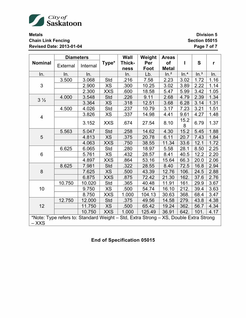
Metals Division 5 Chain Link Fencing Section 05015 Revised Date: 2013-01-04 Page 7 of 7
Nominal Diameters
Type* Wall
Thick- ness
Weight Per Foot
Areas of
Metal I S r External Internal
In. In. In. In. Lb. In.² In.⁴ In.³ In.
3 3.500 3.068 Std .216 7.58 2.23 3.02 1.72 1.16
2.900 XS .300 10.25 3.02 3.89 2.22 1.14 2.300 XXS .600 18.58 5.47 5.99 3.42 1.05
3 ½ 4.000 3.548 Std .226 9.11 2.68 4.79 2.39 1.34 3.364 XS .318 12.51 3.68 6.28 3.14 1.31
4
4.500 4.026 Std .237 10.79 3.17 7.23 3.21 1.51 3.826 XS .337 14.98 4.41 9.61 4.27 1.48
3.152 XXS .674 27.54 8.10 15.28 6.79 1.37
5 5.563 5.047 Std .258 14.62 4.30 15.2 5.45 1.88
4.813 XS .375 20.78 6.11 20.7 7.43 1.84 4.063 XXS .750 38.55 11.34 33.6 12.1 1.72
6 6.625 6.065 Std .280 18.97 5.58 28.1 8.50 2.25
5.761 XS .432 28.57 8.41 40.5 12.2 2.20 4.897 XXS .864 53.16 15.64 66.3 20.0 2.06
8 8.625 7.981 Std .322 28.55 8.40 72.5 16.8 2.94
7.625 XS .500 43.39 12.76 106. 24.5 2.88 6.875 XXS .875 72.42 21.30 162. 37.6 2.76
10 10.750 10.020 Std .365 40.48 11.91 161. 29.9 3.67
9.750 XS .500 54.74 16.10 212. 39.4 3.63 8.750 XXS 1.000 104.13 30.63 368. 68.4 3.47
12 12.750 12.000 Std .375 49.56 14.58 279. 43.8 4.38
11.750 XS .500 65.42 19.24 362. 56.7 4.34 10.750 XXS 1.000 125.49 36.91 642. 101. 4.17
*Note: Type refers to: Standard Weight – Std, Extra Strong – XS, Double Extra Strong – XXS
End of Specification 05015
Metals Division 5 Deck Drains Section 05025 Revised Date: 2005-01-04 Page 1 of 3
05025 Deck Drains
Index
05025-1 Description 2
05025-2 Materials 2
05025-3 Equipment 2
05025-4 Procedure 2
05025-5 Test 2
05025-6 Payment 3
Metals Division 5 Deck Drains Section 05025 Revised Date: 2005-01-04 Page 2 of 3
05025-1 Description
The work shall consist of hydro blasting, rotor routing and/or vibrating loose debris in the deck drain leads on the following bridges: Idylwyld (and ramps) and University Bridge.
05025-2 Materials
The Contractor shall supply all materials to carry out the work.
05025-3 Equipment
The following equipment shall be available for use and in good working order:
• one - hydro blaster capable of 8,000 psi. • one - roto router capable of routing 50 to 100 feet. • two - 50 gallon tanks with a pump capable to discharge at the rate of 50 gallons
per minute. The equipment cited shall not be limited to the work but only as a minimum.
05025-4 Procedure
The Contractor shall rod or hydro blast the vertical deck drain leads on the blocked leads of the University Bridge.
On the Idylwyld Bridge the Contractor shall remove the catch basin grating and test for blockage using 50 gallons of water. If the leads are clear, the Contractor shall replace the catch basin grating to the satisfaction of the Engineer and proceed to the next catch basin.
Where the catch basin lead is clogged, the Contractor shall use the cited equipment to try to clear the lead. In the event that there is no significant progress in the unclogging process, the Engineer shall decide when to stop the endeavour. Their decision is final.
05025-5 Test
Where directed by the Engineer, the Contractor shall cause to be discharged up to 500 gallons of water into a catch basin lead. This is to demonstrate to the Engineer that the lead is open.
Metals Division 5 Deck Drains Section 05025 Revised Date: 2005-01-04 Page 3 of 3
05025-6 Payment
Payment shall be on an hourly basis for:
• Cleaning the leads on the University Bridge. • Cleaning the leads on the Idylwyld Bridge.
The rates shall include all labour, materials and equipment to carry out the work as well as the cost for traffic control.
The payment for the test shall be as specified on a per gallon basis. Included in this shall be the cost of the water and equipment necessary for the test.
End of Specification 05025
Concrete Division 6 Ready Mixed Concrete Section 06005 Revised Date: 2020-02-28 Page 1 of 12
06005 Ready Mixed Concrete
Index
Reference to Standard Specifications 3
Concrete Aggregate 3 2.1 Aggregate Rejection 3
Tests on Concrete Aggregate 4
Cement 4
Providing Chemical and Physical Tests on Cement 5
Water 5
Concrete Proportions and Consistency 5
Mixing of Concrete 6
Flyash 6
Accelerating Admixtures 7
Winter Service and Sulphate Resistance 7
Tests on Concrete 7
Mix Design, Testing, and Deleterious Materials 8
Air-Entraining Admixtures 10
Payment Reduction for Low Air Entrainment 10
Concrete Division 6 Ready Mixed Concrete Section 06005 Revised Date: 2020-02-28 Page 2 of 12
Payment Reductions for Low Strength Concrete 11
Tables
Table 1: Aggregate Testing Limits ................................................................................... 9 Table 2: Air Entrainment Payment Adjustment Factors ................................................. 11
Concrete Division 6 Ready Mixed Concrete Section 06005 Revised Date: 2020-02-28 Page 3 of 12
Reference to Standard Specifications
Reference in these Specifications will be made to the latest edition of the Canadian Standards Association (C.S.A.) for Concrete Materials and Methods of Concrete Construction/Test Methods and Standard Practices for Concrete.
Concrete Aggregate
Aggregate shall consist of clean, hard, durable, crushed stone or gravel free from lumps, soft and flaky particles, organic matter, salt, alkali, free from adherent coatings and shall conform to the C.S.A. Standard Specification for Concrete Aggregates.
2.1 Aggregate Rejection
2.1.1 Fine Aggregate:
Aggregate shall comply with the grading requirements of C.S.A. Standard Specifications.
Aggregate shall be rejected if it:
1. Produces a colour darker than the reference standard specified in the C.S.A. Test Method for Organic Impurities in Sands for Concrete.
2. Contains more than 1% clay lumps, as determined by C.S.A. Methods. 3. Contains more than 3% of material finer than 80 um sieve.
2.1.2 Coarse Aggregate:
Coarse aggregate shall be 20mm nominal and comply with the grading requirements of C.S.A. Standard Specifications.
Aggregate shall be rejected if it:
1. Contains clay lumps in excess of 0.3% as determined by C.S.A. Methods. 2. Contains more than 1% of material finer than the No. 80 um Sieve. 3. Percentage loss is greater than 35% as determined by the Los Angeles Abrasion
Test described in C.S.A. Methods. 4. Contains more than 0.5% low density material as determined by C.S.A. Methods.
Concrete Division 6 Ready Mixed Concrete Section 06005 Revised Date: 2020-02-28 Page 4 of 12
Tests on Concrete Aggregate
The Contractor shall have a Testing Laboratory, approved by the Engineer, perform certain tests on the concrete aggregate according to the current C.S.A. Specifications.
The Contractor shall, at his own expense, supply the following material tests:
1. Wash Sieve Analysis - C.S.A. - A23.2-2A / C.S.A. - A23.2-5A. 2. Organic Impurities - C.S.A. - A23.2-7A. 3. Clay Lumps - C.S.A. - A23.2-3A. 4. Specific Gravity Test - C.S.A. - A23.2-6A for sand and A23.2 - 12A for course
aggregate. 5. Los Angeles Abrasion Test - C.S.A. - A23.2-16A & C.S.A. - A23.2-17A. 6. Test for Soundness of Aggregate - C.S.A. - A23.2-9A. 7. Low density material in aggregate - C.S.A. - A23.2-4A.
The above aggregate tests shall be submitted to the Engineer each year as follows:
1. Seven days before any concrete is placed. 2. During the first week in July. 3. During the first week in September.
The Contractor shall also, at his own expense, supply to the Engineer the proposed concrete mix design at least 7 days before any concrete is placed.
In the event that the original concrete design mix submitted to the Engineer requires changes, such design changes shall be approved by the Engineer or requested by the Engineer and a new concrete design mix shall be submitted at the cost of the Contractor. At no time shall the mix design be changed by the Contractor or concrete supplier unless approved by the Engineer.
All test or mix design reports shall be submitted in duplicate to the Engineer and whenever applicable, be compared to the current C.S.A. Standard or as specified. The report shall be complete and to the satisfaction of the Engineer.
Cement
Cement used on the work shall be a type of Portland Cement conforming to C.S.A. - A23.3.1 unless a different type of cement is specified.
Concrete Division 6 Ready Mixed Concrete Section 06005 Revised Date: 2020-02-28 Page 5 of 12
Providing Chemical and Physical Tests on Cement
The results of the chemical and physical tests on the cement to be used in the production of the ready-mixed concrete shall be supplied to the City Engineer by the manufacturer of the cement. Frequency of tests shall be:
1. As specified by the Engineer. 2. Any time when there is a change in either the chemical or physical properties of
the cement.
Copies of the test results supplied by the manufacturer of the cement will be sufficient, providing that they are certified.
One copy of the report shall be submitted within 5 days to the City Engineer and one copy to the supplier of the ready-mix concrete.
Water
All water used for concrete shall be clean and free from injurious amounts of acid, oil, alkali, organic matter or other deleterious substances.
Concrete Proportions and Consistency
The proportions of aggregates to cement for concrete shall be such as to produce a mixture which will work readily into the corners and angles of the forms without permitting the materials to segregate or excess free water to collect on the surface. The quantity of water used shall be the minimum necessary to produce workable concrete.

Concrete Division 6 Ready Mixed Concrete Section 06005 Revised Date: 2020-02-28 Page 6 of 12
The consistency of the concrete shall be such that the slump shall not exceed 70mm or be less than 25mm for hand placed concrete, and less than 25mm for extruders when tested by the "Standard Method of Slump Test for consistency of Portland Cement Concrete" as described in C.S.A. A23.2-5C. Non-compliance with the slump specified shall constitute sufficient ground for rejection of the concrete.
Mixing of Concrete
The mixing of concrete shall be done in an approved type of mixer which shall ensure a uniform distribution of materials throughout the mass so that the mixture is homogeneous and uniform in colour. The entire contents of the mixing drum shall be discharged before recharging and the drum shall be thoroughly cleaned at frequent intervals. The volume for the mixed material, per batch, shall not exceed the manufacturer's rated capacity of the mixer. The mixing of each batch shall continue for not less than 2 minutes after all the materials (including the water) are in the mixer, at the manufacturer's recommended speed.
Ready-mixed or/and transit mix concrete shall conform in every respect to all specifications herein contained and with the "Standard Specifications for Ready-Mixed Concrete" as described in C.S.A. specifications and shall further be subject to any additional written directions that the Engineer may deem necessary to ensure the obtaining of concrete of the quality specified.
Flyash
Flyash shall not be used in concrete unless the mix design containing flyash has been approved in writing by the Engineer.
As a mineral admixture, flyash shall conform to C.S.A. specification. The material shall be sampled and tested by an independent testing laboratory and copies of the test results shall be submitted to the Engineer for approval.
Flyash shall not replace more than 20% by mass of cement in the concrete. The use of flyash will not be permitted in concrete placed after September 30 each year unless approval is given by the Engineer.

Concrete Division 6 Ready Mixed Concrete Section 06005 Revised Date: 2020-02-28 Page 7 of 12
Accelerating Admixtures
Accelerating admixtures may only be used in non-reinforced concrete with the approval of the Engineer.
The quantity accelerating admixtures shall be approved by the Engineer but at no time shall exceed 2% by weight of cement. Accelerating admixtures shall be used in the concrete when the air temperature is below 5° C or at the discretion of the Engineer.
Winter Service and Sulphate Resistance
The Contractor shall submit additional unit prices per cubic metre for:
1. Heating concrete during cold weather construction. 2. Providing sulphate resistant - Type HS/HSb cement. 3. High early strength - Type HE cement.
Tests on Concrete
During the progress of work, test cylinders will be taken to determine the quality of the concrete. There shall be a minimum of one test per 60 m³. Concrete tests will be done by a Testing Laboratory appointed by the Engineer and paid for by the City of Saskatoon unless otherwise specified. The following tests will be carried out:
1. Slump Test, as per Section 06005-7 of this Specification. 2. Air-Entraining Test, as per Section 06005-13, 06005-14 & 06005-15 of this
Specification. 3. Concrete Compressive Strength (set of 3 test cylinders). One test cylinder will be
broken at 7 days and two test cylinders will be broken at 28 days.
The Contractor shall provide, at his own expense, materials and facilities as the Engineer may require for carrying out the above mentioned tests.
The fresh concrete will be sampled in accordance with C.S.A. Specification.
Concrete with a slump greater than 75mm shall be rodded. Concrete with slump of 25mm to 75mm may be rodded or vibrated. Concrete with slump of less than 25mm shall be consolidated by vibration.
Concrete Division 6 Ready Mixed Concrete Section 06005 Revised Date: 2020-02-28 Page 8 of 12
The concrete supplied shall have a basic minimum specified compressive strength at 28 days. The average of the 2 cylinders of any single test broken at 28 days shall be equal to or greater than the specified strength at 28 days.
Concrete compressive strengths are expressed in the metric designation of megapascals (MPa). The following standard compressive strengths are to be provided as requested:
20.0MPa, 25.0MPa, 30.0MPa, 32.0MPa, 35.0MPa.
Cores
The length of concrete cores shall be measured in accordance with the current C.S.A. Specification.
Mix Design, Testing, and Deleterious Materials
Concrete shall meet CSA specifications unless otherwise specified. Concrete mix properties shall conform to exposure classification C-2 and air content is summarized as follows:
1. Minimum specified 28-day compressive strength: 32MPa 2. Maximum W/C ratio: 0.45 3. Air content: 5% to 8% (20mm aggregate)
The minimum Portland cement content shall be 285kg/m3 with a total minimum cementitious content of 330kg/m3.
Contrary to CSA, the time requirement for casting cylinders will be within 60 minutes from the time of sampling. All testing for slump, air content, and sample for casting cylinders will be done immediately after the first metre of concrete is removed from the concrete truck. Also, contrary to CSA, retempering of concrete to add air entrainment will only be considered for the first truck tested. Following a low air test the City will initiate another concrete test on the next load. The Contractor will be charged for the second concrete test.
In addition to the mix design testing requirements set out in Section 06005 - Ready Mixed Concrete, the Contractor shall provide the following information:
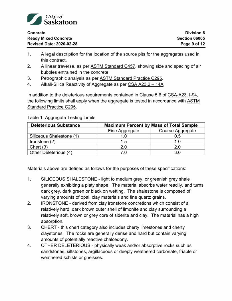
Concrete Division 6 Ready Mixed Concrete Section 06005 Revised Date: 2020-02-28 Page 9 of 12
1. A legal description for the location of the source pits for the aggregates used in this contract.
2. A linear traverse, as per ASTM Standard C457, showing size and spacing of air bubbles entrained in the concrete.
3. Petrographic analysis as per ASTM Standard Practice C295. 4. Alkali-Silica Reactivity of Aggregate as per CSA A23.2 – 14A
In addition to the deleterious requirements contained in Clause 5.6 of CSA-A23.1-94, the following limits shall apply when the aggregate is tested in accordance with ASTM Standard Practice C295.
Table 1: Aggregate Testing Limits Deleterious Substance Maximum Percent by Mass of Total Sample Fine Aggregate Coarse Aggregate Siliceous Shalestone (1) 1.0 0.5 Ironstone (2) 1.5 1.0 Chert (3) 2.0 2.0 Other Deleterious (4) 7.0 3.0
Materials above are defined as follows for the purposes of these specifications:
1. SILICEOUS SHALESTONE - light to medium grey, or greenish grey shale generally exhibiting a platy shape. The material absorbs water readily, and turns dark grey, dark green or black on wetting. The shalestone is composed of varying amounts of opal, clay materials and fine quartz grains.
2. IRONSTONE - derived from clay ironstone concretions which consist of a relatively hard, dark brown outer shell of limonite and clay surrounding a relatively soft, brown or grey core of siderite and clay. The material has a high absorption.
3. CHERT - this chert category also includes cherty limestones and cherty claystones. The rocks are generally dense and hard but contain varying amounts of potentially reactive chalcedony.
4. OTHER DELETERIOUS - physically weak and/or absorptive rocks such as sandstones, siltstones, argillaceous or deeply weathered carbonate, friable or weathered schists or gneisses.

Concrete Division 6 Ready Mixed Concrete Section 06005 Revised Date: 2020-02-28 Page 10 of 12
All petrographic examination on fine and coarse aggregates for concrete must be done on material sampled in the year that the concrete is being placed, unless the following information about the concrete aggregate production is provided to the project engineer:
1. A summary of all test results for sieves sampled at a rate of a minimum of one test per 2,000 tonnes.
2. A petrographic analysis at a rate of a minimum of one analysis for coarse and one for fine aggregate based on a random sample taken during the production of the first 3,000 tonnes. If the first set of petrographic analysis detects no deleterious materials within the specified limits, a random sample taken during each 3,000 tonnes of production shall be recombined and split to produce a representative sample of the concrete aggregate produced. A petrographic analysis for fine and coarse aggregate shall be performed on this aggregate sample.
3. A summary test results for percentage of lightweight aggregates at a frequency of a minimum of one test every 5000 tonnes.
4. The production date of the aggregate stockpile and the estimated current quantity in the stockpile.
5. The location of the gravel pit where the aggregate was produced and the location of the stockpile in the pit area.
Air-Entraining Admixtures
An approved air-entraining agent shall be used in all concrete and shall comply with the "Specifications for Air-Entraining Admixtures for Concrete" as described in C.S.A. specifications and used in strict accordance with the manufacturer's recommendations.
The Contractor shall submit a letter, at least 7 days prior to construction, to the Engineer certifying that the air-entraining agent to be used meets the C.S.A. requirements.
The air-entrainment limits shall be between 5 to 8 percent by volume as determined in accordance with C.S.A. - A 23.2-4C.
Payment Reduction for Low Air Entrainment
Reduction of payment for air entrainment below the minimum specified value shall be calculated and applied as follows:
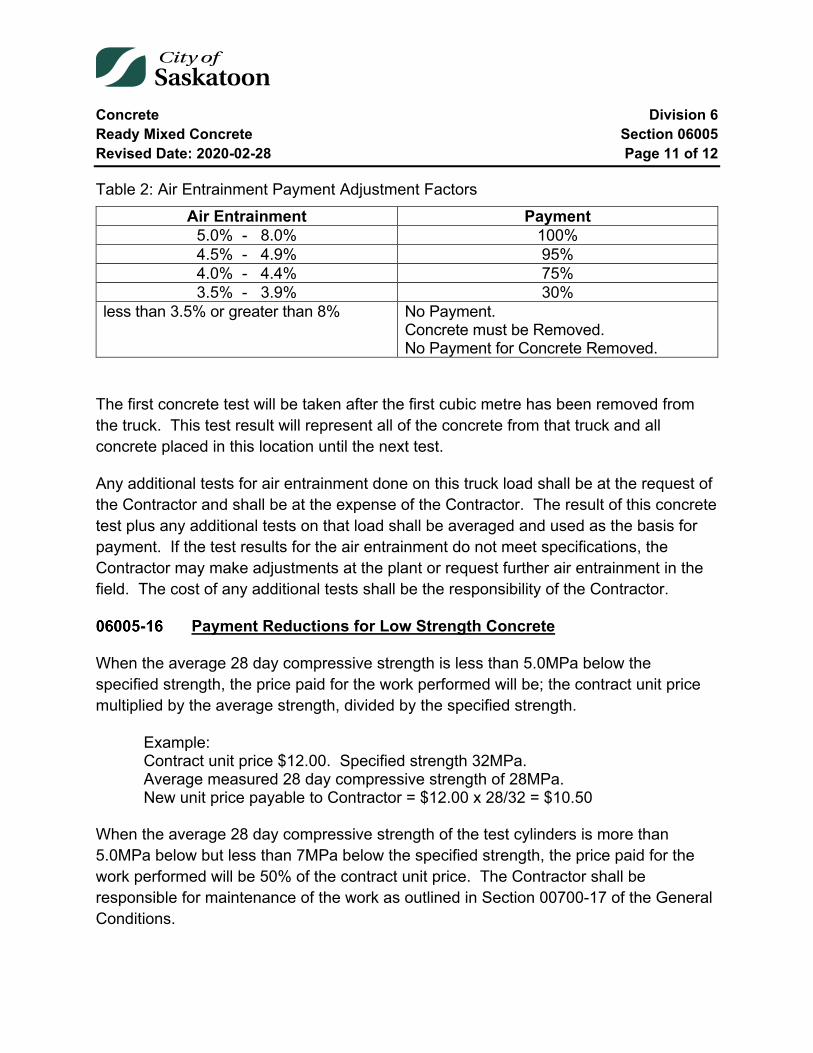
Concrete Division 6 Ready Mixed Concrete Section 06005 Revised Date: 2020-02-28 Page 11 of 12
Table 2: Air Entrainment Payment Adjustment Factors Air Entrainment Payment
5.0% - 8.0% 100% 4.5% - 4.9% 95% 4.0% - 4.4% 75% 3.5% - 3.9% 30%
less than 3.5% or greater than 8% No Payment. Concrete must be Removed. No Payment for Concrete Removed.
The first concrete test will be taken after the first cubic metre has been removed from the truck. This test result will represent all of the concrete from that truck and all concrete placed in this location until the next test.
Any additional tests for air entrainment done on this truck load shall be at the request of the Contractor and shall be at the expense of the Contractor. The result of this concrete test plus any additional tests on that load shall be averaged and used as the basis for payment. If the test results for the air entrainment do not meet specifications, the Contractor may make adjustments at the plant or request further air entrainment in the field. The cost of any additional tests shall be the responsibility of the Contractor.
Payment Reductions for Low Strength Concrete
When the average 28 day compressive strength is less than 5.0MPa below the specified strength, the price paid for the work performed will be; the contract unit price multiplied by the average strength, divided by the specified strength.
Example: Contract unit price $12.00. Specified strength 32MPa. Average measured 28 day compressive strength of 28MPa. New unit price payable to Contractor = $12.00 x 28/32 = $10.50
When the average 28 day compressive strength of the test cylinders is more than 5.0MPa below but less than 7MPa below the specified strength, the price paid for the work performed will be 50% of the contract unit price. The Contractor shall be responsible for maintenance of the work as outlined in Section 00700-17 of the General Conditions.

Concrete Division 6 Ready Mixed Concrete Section 06005 Revised Date: 2020-02-28 Page 12 of 12
When the average 28 day compressive strength of the test cylinders is 7MPa or more below the specified strength, the work shall be replaced at the expense of the Contractor.
The limits of work included in the price reduction or replacement shall be the entire construction represented by the low test(s), but shall not exceed a volume of 60m3 of concrete produced in any one day.
End of Specification 06005
Concrete Division 6 Concrete Sidewalk, Curb and Gutter Construction Section 06010 Revised Date: 2021-02-12 Page 1 of 22
06010 Concrete Sidewalk, Curb and Gutter Construction
Index
06010-1 General Description of Work 3
06010-2 Construction with Extruding Equipment 3 2.1 Concrete Extruding Equipment 3 2.2 Continuity of Work 3 2.3 Retempering Concrete 4 2.4 Tolerances and Enforcement 4
06010-3 Openings and Alterations 5
06010-4 Method of Removing Sidewalk and Curb 6
06010-5 Forms 7
06010-6 Levelling Course 8
06010-7 Placing of Concrete 8
06010-8 Screeds and Templates 9
06010-9 Epoxy – Coated Steel Dowels 10
06010-10 Expansion Joints 10
06010-11 Control Joints 11
06010-12 Returns 11
06010-13 Rolled Curb and Gutter at Corners 11
06010-14 Sidewalk, Curb and Gutter Crossing Cross-Sections 12
06010-15 Finish of Sidewalk, Curb, and Gutter 12
06010-16 Lane and Driveway Crossing 13
Concrete Division 6 Concrete Sidewalk, Curb and Gutter Construction Section 06010 Revised Date: 2021-02-12 Page 2 of 22
06010-17 Private Driveways and Sidewalks 13
06010-18 Reconstruction of Private Sidewalks, Steps and Driveways 13
06010-19 Sidewalk Construction Adjacent to Buildings 13
06010-20 Method of Construction Centre Medians at Turning Bays 13
06010-21 Sidewalk Ramps 14
06010-22 Borrow Areas, Coal Chutes and Existing Openings 14
06010-23 Curing Compounds 14
06010-24 Protection 15
06010-25 Concreting in Sub-Normal Conditions 15
06010-26 Construction Record Imprints 16
06010-27 20 MPa Lean Concrete 16
06010-28 Construction and Modifications to Catch Basins 17
06010-29 Adjusting Curb Boxes 17
06010-30 Salvage Material 17
06010-31 Backfill 17
06010-32 Boulevard 18
06010-33 Progress of Work 19
06010-34 Completion of Work 19
06010-35 Measurement 19
06010-36 Payment 20
Concrete Division 6 Concrete Sidewalk, Curb and Gutter Construction Section 06010 Revised Date: 2021-02-12 Page 3 of 22
06010-1 General Description of Work
The Contractor shall provide all labour, plant, equipment and material together with all proper and required facilities for the construction in an expeditious manner of sidewalks, curbs and other related work all in accordance with the Contract Documents and detail drawings.
06010-2 Construction with Extruding Equipment
2.1 Concrete Extruding Equipment
Slip-form concrete extruding machines may be used for placing concrete provided they meet the following:
1. The machine is one of the well-known models with a proven performance record. 2. The use of the machine has received approval of the Engineer prior to
commencement of any work. 3. The machine is to be operated by an experienced operator. 4. Vibrators on the equipment shall be adequate to produce a dense mass with a
smooth surface free of honeycombing. 5. The equipment shall include automatic grade and line control 6. Should the machine be of a type where the trimmer and extruder are one unit, it
is essential that no deleterious material from the trimmer affect the quality of the concrete.
7. All moulds used in producing the required extruded sections must be in metric dimensions, having a longitudinal deep cut tool mounted in the proper location at a depth of 50mm and width 10mm.
8. Any deviation from the specifications shall be approved by the City Engineer in writing.
2.2 Continuity of Work
Whenever possible, the forming and placing of concrete by conventional methods that may be required to complete corners, catch basins, driveways, crossings and other work, shall be carried out before the concrete's initial set time in conjunction with the extruding machine.
Concrete Division 6 Concrete Sidewalk, Curb and Gutter Construction Section 06010 Revised Date: 2021-02-12 Page 4 of 22
When this procedure is not followed, the completion shall be done within 5 days after the adjacent extruded section is completed.
Workmanship for both the slip-form and conventional method shall be equal quality.
2.3 Retempering Concrete
Concrete arriving on the job site shall not be retempered if test values are within specification at the time of delivery.
1. The addition of water to the mix when the truck arrives on the job shall be permitted provided the following conditions are met:
2. Upon arrival at the job site, the slump is less than that required in the specifications.
3. The water shall be injected into the mixer under such pressure and directions that uniformity of mix will result.
4. The slump after re-tempering shall not exceed the specified limit. 5. Mixing time after the water has been added shall not be less than 3 minutes at
mixing speed. 6. The on-site additions of air entrainment agent or admixtures shall be permitted as
indicated in Section 06005-15.
Retempering concrete shall not be permitted without approval of a COS representative and a testing consultant on site.
2.4 Tolerances and Enforcement
2.4.1 Straight Edge
All exposed concrete surfaces shall be checked by the Contractor with a 3m straight edge and any water pockets or deviations in line or grade exceeding 6mm shall be corrected immediately.
2.4.2 Elevation
Differences in elevation at any given point from that given on the survey stakes shall not exceed + 10mm and the maximum variation from the given elevation between two consecutive stakes shall not be greater than 10 mm.
Concrete Division 6 Concrete Sidewalk, Curb and Gutter Construction Section 06010 Revised Date: 2021-02-12 Page 5 of 22
2.4.3 Alignment
Deviations in alignment at any given point from that given on the survey stakes shall not exceed 25mm in a 30m section.
2.4.4 Crossfall
The crossfall shall not vary more than 5mm per metre of walk width from that specified or shown on the drawings.
2.4.5 Dimensions
Thicknesses and widths of extruded structures shall meet the dimensions shown on the drawings.
Sidewalk or curb not meeting the above criteria shall be replaced. If in the opinion of the Engineer it is not practical to remove and replace the concrete then a reduced payment may be substituted. This payment will be at a percentage of the bid price as detailed in the "Payment" section.
06010-3 Openings and Alterations
When the Engineer or Owner of a utility requires to make alterations to underground services, poles, hydrants, valves, curb boxes, catch basins and other structures, the Contractor shall leave openings in the sidewalk or curb to facilitate these alterations. The length of such openings shall be determined by the Engineer but generally 3 m shall be left open. Such openings shall be initially backfilled with gravel to make the sidewalk safe for public use. In the event that the Contractor fails to leave such openings as required, the Contractor shall, at his own expense, be responsible for making these openings. After alterations have been completed, the Contractor will close the opening with the proper structure.
For catch basins, the Contractor shall be responsible for leaving openings as determined by the Engineer. These openings shall be well framed and shall be 3m in length. It is essential that all openings to be left for catch basins are to be in line with the existing catch basin lead or as directed by the Engineer. All openings left for catch basins shall be filled by the Contractor within a period of 5 days.
Concrete Division 6 Concrete Sidewalk, Curb and Gutter Construction Section 06010 Revised Date: 2021-02-12 Page 6 of 22
Where additional concrete is to be placed at a later date, such as at the end of a block, curb returns or openings, 10M reinforcing steel dowels, 250mm long shall be installed. Two dowels are to be installed along the curb and one every 300mm on centre along the sidewalk. Supplying and installing the dowels shall be the Contractor's responsibility.
The Contractor shall accommodate cross drains in the sidewalk or curb. Material required for cross drains will be supplied by the City. When required, the City will hire a plumber to make proper roof drain connections.
06010-4 Method of Removing Sidewalk and Curb
Unless a clean, straight break already exists along a joint, the ends of the concrete to be removed shall be cut with a concrete saw. The cut shall be of sufficient depth to permit removal without damage to the remaining structure.
During the removal of existing sidewalk, the Contractor shall carefully remove the concrete around existing utilities, services, structures, sign posts, parking meter posts, private sidewalks, driveways, buildings and building entrances. Any damage incurred shall be repaired at the Contractor's expense to the satisfaction of the Engineer.
In removing sidewalk or curb, the Contractor shall only use equipment that will not damage the existing finished roadway surface.
When monolithic curb and gutter is removed, and replaced with vertical curb, the Contractor will be responsible for roadway damage beyond the gutter width. In other areas, the maximum permissible road surface removed shall not be more than 200mm from the face of the construction. For pavement removal, the Contractor shall use a pavement cutter and have a neat vertical cut. Cuts of greater width shall be repaired at the Contractor's expense.
Sidewalk, curb and pavement removed shall be hauled to the disposal site within 24 hours after removal. No payment will be made for overhaul.
Where the existing curb and asphalt walk is to be reconstructed, the Contractor will be paid for curb removal only. Asphalt walk will be considered as common excavation.
Where existing curb is to be reconstructed only and the asphalt walk is to remain, the Contractor shall be permitted to remove a maximum of 300mm of asphalt walk. The
Concrete Division 6 Concrete Sidewalk, Curb and Gutter Construction Section 06010 Revised Date: 2021-02-12 Page 7 of 22
Contractor shall be responsible to cut the asphalt walk and compact the curb backfill. Work of this nature shall be included in the unit price for curb construction.
Where pavement is required to be removed before construction proceeds and when approved for removal by the Engineer, the Contractor shall carefully cut and remove asphalt within the bounds set by the Engineer and haul it to an area designated for this type of material. Should an excess amount be removed outside the boundary set for removal, it will be replaced by the City crews and all charges shall be paid by the Contractor.
06010-5 Forms
For sidewalk reconstruction, if the buildings have a sidewalk ledge or have reinforcing rods protruding from the foundation of the buildings into the old sidewalk, the new sidewalk shall be constructed in one section from the building wall to the curb face.
The Contractor shall be responsible to ensure that there is positive slope on the sidewalk from the building towards the roadway. The normal slope is 30mm per metre. Any slope less than 20mm per metre shall be approved by the Engineer before the concrete is placed.
The forms used for each type of construction shall be the same as the dimensions on the drawings. The forms shall be of metal or 40mm properly-seasoned lumber. They shall be free from warps or other defects and shall have smooth, clean surface adjacent to the concrete. The forms shall be thoroughly cleaned and oiled before any concrete is deposited within them.
The forms shall be well staked, braced and held rigidly to the established line and grade to enable the use of mechanical concrete vibrators and vibrator screeds when placing concrete for curb and sidewalk construction.
Any forms which have lost their shape or dimensions or where surfaces have become dented or rough shall not be used. The Engineer may at any time condemn the forms he considers unsatisfactory to secure the proper quality of work. Inferior workmanship, as a result of poor forming shall be replaced at the cost of the Contractor.
Concrete Division 6 Concrete Sidewalk, Curb and Gutter Construction Section 06010 Revised Date: 2021-02-12 Page 8 of 22
06010-6 Levelling Course
The levelling course shall consist of base aggregate meeting the requirements of Division 2, Section 02060-2.2. For fills of less than 30mm, a smaller sized well-graded aggregate may be substituted after the Engineer has approved the sieve analysis of the material.
The levelling course shall be supplied by the Contractor and compacted to not less than 98% of the Standard Proctor Density for the material. The levelling course shall be used on all hand work.
06010-7 Placing of Concrete
Placing of concrete will be permitted when the compacted levelling course meets the following requirements:
1. The levelling course is within +6mm from the design elevation.
2. The minimum concrete depth shall be 115mm for separate sidewalk, and sidewalk with combined curb and gutter; 125mm for sidewalk with rolled curb and gutter; 180mm for crossings.
No concrete shall be placed before the Engineer has inspected the subgrade or levelling course and approved the same, and the inspection shall take place immediately prior to the placing of the concrete.
The work shall be performed in a manner which results in a curb, sidewalk, combined curb and sidewalk or rolled curb and sidewalk constructed to specified line and grade, uniform in appearance and structurally sound. When checked with a 3m straight edge, the finished surface shall not deviate more than 6mm and the alignment shall not vary more than 6 mm. The rolled curb, gutter and sidewalk finished profile when checked with a template, shall not deviate more than 6mm.
The minimum compressive strength of the concrete shall be 32.0MPa at 28 days. Placing of concrete shall be a continuous operation until the section, panel or scheduled pour is completed. The rate of delivery of the mixed concrete shall be such that the interval between placing successive batches shall not exceed 30 minutes, unless the last load completed the work to a proper construction joint. A maximum time limit of 120 minutes from the time of initial mixing to complete discharge shall be observed.
Concrete Division 6 Concrete Sidewalk, Curb and Gutter Construction Section 06010 Revised Date: 2021-02-12 Page 9 of 22
The material on which concrete is to be laid must be moistened with potable water immediately preceding concrete extruding.
The point of delivery of concrete shall be as close to the work as possible and in no case more than 1m from the point of final deposit in the horizontal and vertical direction. Re-handling of concrete will not be permitted.
Concrete shall be deposited in a manner to prevent segregation of the aggregate. Special care shall be taken in placing concrete to prevent voids, pockets, rough areas and honeycombing. The concrete shall be tamped by using mechanical concrete vibrators or vibrator screed in such a manner as to work the coarse aggregate away from the forms and exposed surfaces. Vibrators or vibrator screeds used in placing concrete shall have a minimum of 5,000 cycles per minute. The vibrator screed shall be used in accordance with the manufacturer's recommendations. Special care shall be taken to prevent over-vibration of the concrete to eliminate concrete bleeding. In combined curb and sidewalk, or curb, the curb and sidewalk crossings portion shall be vibrated by a concrete vibrator.
In rolled curb and sidewalk construction, a steel vibrating screed having the required cross-section shall be used. The rolled curb mold shall be of sufficient longitudinal length to vibrate and compact the plastic concrete to a proper cross-section.
Excess Concrete - All waste concrete including that which is pushed out from the ends of the mould at the front or back of the sidewalk and curb during construction must be removed from the site.
Transit mixers shall not be washed out on any improved roadway.
06010-8 Screeds and Templates
The Contractor shall make and use any templates or screeds that may be required by the Engineer to control construction procedures and methods.
Screeds shall be of rigid construction and equipped with suitable handles. Templates may be of ply board or metal construction. Adjustable screeds and templates will not be permitted. Damaged, bent or worn templates and screeds shall be replaced. An adequate number of replacement screeds and templates shall be maintained.
All screeds and templates shall be checked and approved by the Engineer.
Concrete Division 6 Concrete Sidewalk, Curb and Gutter Construction Section 06010 Revised Date: 2021-02-12 Page 10 of 22
After the forms are set to grade, the correct screed shall be used to check the subgrade elevation to ensure the proper thickness of sand or granular levelling course and concrete. When the subgrade preparation is approved, the Contractor will be permitted to place and compact the levelling which will give the required sidewalk thickness. Thereafter, the back of the sidewalk form shall be checked for final grade and alignment. The sidewalk cross-fall and face of curb slope shall be checked with a level every 8 m.
After the forms are adjusted to final grade alignment, the final elevation of the levelling course shall be checked with a screed.
06010-9 Epoxy – Coated Steel Dowels
Where required by the Engineer, sidewalks must be reinforced in accordance with the drawing provided.
Reinforcing must be 10M epoxy-coated deformed bars of the length shown on the drawings.
This will include drilling a hole of suitable size in existing concrete to accept installation of a minimum of 100mm of dowel.
Bar reinforcing must meet A.S.T.M. A184 and A.S.T.M. A304 intermediate grade new billet deformed steel.
06010-10 Expansion Joints
Expansion joints will not be used in the construction of sidewalks, curbs and gutters unless specified by the Engineer.
Where expansion joints are requested, the Contractor will supply the material and install the expansion joints. Supply and installation will be included in the unit price of the sidewalk or curb.
The expansion joint shall extend completely through the slab and shall be perpendicular and at right angles to the general direction of the sidewalks and curb.
The expansion joint shall be placed 3mm below the sidewalk level. The edges shall be rounded off to a 6mm radius or as approved by the Engineer.
Concrete Division 6 Concrete Sidewalk, Curb and Gutter Construction Section 06010 Revised Date: 2021-02-12 Page 11 of 22
Where utility poles, hydrants or other services require openings left in the sidewalk, the open space shall be formed and left open with the pour of the sidewalk. After the sidewalk has set, the forms will be removed from the opening, expansion material placed on all four sides, the opening filled with concrete and broom finished by the Contractor. This work is to be included in the unit price for sidewalks and curb.
06010-11 Control Joints
Control joints should be provided at regular intervals to form a weak plane, so that cracks are formed at the joints and not in undesired places.
Control joints should be provided at intervals about 1.5 m transversely along the length of the sidewalk.
The control joint is a saw cut or trowel cut about one quarter the depth of the slab that provides a weak plane in the slab where cracking can occur without marring the appearance of the sidewalk on the upper surface.
06010-12 Returns
In general, a standard 8m radius curb return will be used where practical and possible, but the Engineer may change the radius to meet field requirements.
The end of the curb return shall be constructed to grade and form a smooth curve. The length of return constructed shall be determined by the Engineer.
Curb returns shall be poured simultaneously with the separate curb and gutter or combined sidewalk and curb and gutter. Payment will not be made for any work where curb returns are not completed.
06010-13 Rolled Curb and Gutter at Corners
Rolled curb and gutter at corners may be machine poured, providing that an acceptable corner can be extruded. Should the corners require to be hand formed and poured, payment will be made at unit tender prices for the rolled curb and gutter.

Concrete Division 6 Concrete Sidewalk, Curb and Gutter Construction Section 06010 Revised Date: 2021-02-12 Page 12 of 22
06010-14 Sidewalk, Curb and Gutter Crossing Cross-Sections
The Contractor shall construct the standard sidewalk, curb and gutter crossings and the rolled curb and gutter sidewalk to dimensions and slopes as indicated on the appropriate plans.
06010-15 Finish of Sidewalk, Curb, and Gutter
The sidewalk surface shall be levelled with a concrete vibrator screed. Special care shall be taken to prevent over-vibration of the concrete and in no case shall an excess amount of water be brought to the surface.
After the concrete has sufficiently set to permit further finishing without concrete bleeding, the surface shall be brought to a true surface with a wood float. The surface shall be marked as shown on drawings using approved tools. After marking, the surface shall be trowelled smooth with a steel trowel and a uniform brush finish applied with a soft-bristled push broom to the satisfaction of the Engineer.
After the initial concrete set, the curb form shall be removed and the exposed surface of the curb shall be worked to a true surface, trowelled smooth and then given a uniform brush finish to a depth of 200mm from the top of the curb.
The sidewalk to be constructed shall have a contraction joint every 1.5m. In commercial or industrial areas where the sidewalk is over 3m wide, the sidewalk shall be divided into square blocks of approximately 1.5m. Where other features make a different type of division desirable, the sidewalk divisions shall be laid out as directed by the Engineer. Each separate block shall be marked on all edges with an approved marking tool that will round off the edges to a radius of 6mm. The edges of the walk and all dividing lines shall be rigidly straight. Warped lines and ragged edges will not be permitted.
In combined sidewalk, curb and gutter or curb and gutter construction, the top face of curb shall be rounded off to a radius of 2 mm. In separate curb and gutter, the top back of curb shall be rounded off to a radius of 6 mm. For separate curb and gutter, contraction joints shall be constructed every 1.5m. All sidewalk and curb markings and contraction joints shall be no less than 25mm deep, no more than 10mm in width and have a 6mm radius finish. Longitudinal contraction joints shall be no less than 35mm deep, 10mm wide with a 6mm radius finish. When the joint or marking is finished, it shall have a dense, tight concrete finish.
Concrete Division 6 Concrete Sidewalk, Curb and Gutter Construction Section 06010 Revised Date: 2021-02-12 Page 13 of 22
Any substandard construction or finish shall be corrected before the initial concrete set.
Patching thereafter will not be permitted and repairs shall be made by the Contractor by replacing all damaged work to the extent requested by the Engineer.
06010-16 Lane and Driveway Crossing
Sidewalk crossing shall have a concrete slab 180mm thick and the crossing wing shall have concrete thickness increasing from 125mm to 180mm or as indicated on plans. Single family dwellings shall have a concrete slab 125mm thick. The crossings and curb returns shall be constructed and marked as shown on the attached sidewalk plans. The crossings shall be constructed by the Contractor for the locations and width as shown on the plans or staked in the field.
06010-17 Private Driveways and Sidewalks
During sidewalk or curb construction, the Contractor shall be responsible for any damage to private sidewalks and driveways. When modifications are required to private driveways and sidewalks, the Contractor shall carry out the required work at applicable tender prices.
06010-18 Reconstruction of Private Sidewalks, Steps and Driveways
Under this Contract, any work associated with making modifications or repairs to private concrete sidewalks, curb and driveways shall be carried out at applicable contract prices, within a period of 5 days.
Payment for construction of steps will be on Force Account basis.
06010-19 Sidewalk Construction Adjacent to Buildings
Where sidewalk is being constructed adjacent to buildings, the sidewalk shall be poured as one piece from the curb to the building.
06010-20 Method of Construction Centre Medians at Turning Bays
Along centre median roadways, where the median has a total width of less than 2m, the slab shall be poured monolithically with the curb and gutter, or rebar shall be placed every 500mm at back of curb to hold slab from settling.

Concrete Division 6 Concrete Sidewalk, Curb and Gutter Construction Section 06010 Revised Date: 2021-02-12 Page 14 of 22
06010-21 Sidewalk Ramps
Sidewalk ramps shall be constructed as shown on the plans or as staked in the field.
The Contractor must pour the ramps at the time of the sidewalk construction.
06010-22 Borrow Areas, Coal Chutes and Existing Openings
Any additional work involved over normal sidewalk reconstruction regarding coal chutes and various other openings that require to be reconstructed, modified or backfilled shall be carried out under unit bid prices where applicable or on "Force Account" basis. Under most circumstances, the work of this nature will be carried out at the expense of the Property Owner or the Property Owner may carry out the required alterations.
Complete reconstruction of borrow areas (area that forms part of the building's basement and extends under the sidewalk) will not be part of the Contract. Work of this nature will be negotiated by the Engineer with the Property Owner to have the area reconstructed.
However, if the borrow area is structurally sound and the top is poured in two separate lifts, the Contractor will be responsible to reconstruct the sidewalk. If the top lift is less than 100mm, the Contractor shall apply an epoxy adhesive as recommended by the manufacturer on the old concrete. A special fine mix concrete shall be used when requested by the Engineer. Work of this description shall be carried out by the Contractor under unit bid prices.
06010-23 Curing Compounds
Curing compound will be supplied by the Contractor and will be in accordance with the City of Saskatoon Specifications for Curing Compound.
The curing compound shall be applied at the rate of 0.166 litres per square metre or 1 litre per 6 square metres unless otherwise recommended by the manufacturer. The curing compound shall be applied immediately after the surface has been finished and broomed. The compound shall be applied with a pressure sprayer distributor so that the concrete surface is completely coated and sealed in one application.
Concrete Division 6 Concrete Sidewalk, Curb and Gutter Construction Section 06010 Revised Date: 2021-02-12 Page 15 of 22
The Contractor will be responsible to provide a means of checking application rate of curing compound used on any specific site at the request of the Engineer or his representative.
06010-24 Protection
Concrete walk shall be allowed to set a minimum of 24 hours before pedestrian traffic is permitted. Commercial and industrial lane crossings shall be barricaded for 7 days from vehicle traffic and 5 days for residential crossings. Any work damaged within the time period specified shall be replaced at the Contractor's expense.
06010-25 Concreting in Sub-Normal Conditions
During cold weather concrete shall not be placed when the ground temperature is less than 2°C. Freshly placed concrete shall be adequately covered and protected or heated to maintain a minimum air temperature of 5°C for 36 hours under the concrete cover. Covering is to be maintained for 72 hours. The cost of all heating and protection shall be borne by the Contractor.
Concrete that does not meet the minimum temperature requirements shall be replaced at the Contractor's expense. All concrete pouring shall be terminated on or before October 31st, unless written permission is received from the Engineer.
During hot weather, with low relative humidity and gusting winds, the Engineer shall have the right to terminate the concrete pour to prevent plastic shrinkage cracking of the sidewalk. A moisture loss of 0.5 litres/square metre/hour shall be considered such grounds as to terminate the pour (determined from the Portland Cement Association rate of moisture loss graph). If the Contractor continues to pour concrete after the said termination he shall be held responsible for any cracking which appears within a 2 year warranty period and replacement of the sidewalk shall be at his cost.
Before a concrete set-retarder is used, the Contractor shall submit a letter certifying that the set-retarder meets the A.S.T.M. standards and shall be used in accordance with the manufacturer's recommendation.
The Contractor shall limit the amount of sidewalk or curb poured during hot weather to enable the work to be finished to the satisfaction of the Engineer. Protective cover material shall be maintained and used as required to prevent the concrete from setting
Concrete Division 6 Concrete Sidewalk, Curb and Gutter Construction Section 06010 Revised Date: 2021-02-12 Page 16 of 22
too quickly. The Engineer may terminate the concrete pour at any time during hot weather if the concrete sets up too quickly. Surface wetting will not be permitted during finishing.
Whenever deemed necessary by the Contractor and approved by the Engineer, the Contractor may detour traffic from a street when dust caused by local traffic has become injurious to the sidewalk finish. No concrete shall be poured when the wind blows dust on the fresh concrete and any poured previously shall be covered. The Contractor shall maintain on the job sufficient canvas, plastic or other suitable covering to protect the concrete from rain, dust or other adverse weather conditions.
06010-26 Construction Record Imprints
Each block or portion of block of sidewalk constructed shall be marked at each end with a suitable tool showing legibly the name of the Contractor and year of construction.
Curb box locations are to be marked at right angles along the back of sidewalk. Imprint is to be 200mm from the back of sidewalk and have initials C.C. (curb connection).
06010-27 20 MPa Lean Concrete
During sidewalk or curb reconstruction along paved streets, the Contractor shall provide concrete backfill in the pavement area removed along the gutter. The existing pavement edge shall be cut straight and be free from dirt or broken edges. Refer to City of Saskatoon Standard Drawing 102-0002-049 available on the City’s web site.
The base shall consist of a minimum of 150mm of well compacted gravel base. The concrete thickness shall be 115mm. The concrete backfill shall be vibrated mechanically and placed 1 day after the curb pour. In residential streets, the concrete gutter shall be barricaded for 3 days, and barricade for 5 days along heavy traffic routes.
The concrete backfill used shall have a minimum strength of 20.0MPa in 28 days and shall meet all other requirements as specified in this specification. Higher MPa concrete is permitted; however, no water can be added to the concrete.
Concrete Division 6 Concrete Sidewalk, Curb and Gutter Construction Section 06010 Revised Date: 2021-02-12 Page 17 of 22
06010-28 Construction and Modifications to Catch Basins
Catch basin construction and modifications to existing catch basins shall be completed within 7 days after completion of the sidewalk or curb.
To facilitate catch basin construction after the curb or sidewalk has been poured, a 3 metre length shall be left open.
To prevent vertical or horizontal displacement of the curb or sidewalk, 10M epoxy-coated reinforcing bars, 250mm long shall be installed, two along the curb and one every 300mm on center along the sidewalk. Supplying and installing of the reinforcing bars shall be included in the cost of catch basins construction. The catch basin frame shall be sloped to match gutters.
06010-29 Adjusting Curb Boxes
Should the curb box fall within 0.5m from the back of the sidewalk, or within the sidewalk and require to be adjusted in elevation to facilitate the extruder, the Contractor will be paid the tender unit price.
The adjustment of the curb box shall be performed by a qualified person and under supervision of an inspector. The curb box shall be adjusted to 150mm below back of the walk.
A record for payment purposes, specifying the location and number adjusted shall be submitted by the Contractor the following day.
06010-30 Salvage Material
All salvaged material being a result of work done under this Contract shall be returned to the designated disposal site.
06010-31 Backfill
When excavation or grade preparation is done by the sidewalk contractor, the Contractor shall arrange to supply backfill material at his cost, from surplus excavation material encountered in the work. If backfill is brought in by the City, the Contractor shall be responsible for cleaning up any excess backfill supplied to him.
Concrete Division 6 Concrete Sidewalk, Curb and Gutter Construction Section 06010 Revised Date: 2021-02-12 Page 18 of 22
All backfill for sidewalk, combined sidewalk or curb and gutter must be at a slope of 3%. Any slope greater than 3% must be approved by the Engineer. The backfill must start from the top of the walk or curb and meet the existing ground elevations within the street right-of-way (unless otherwise directed by the Engineer).
The backfill must be compacted to a density of not less than 98% of Standard Proctor Density. Material used for backfill must be a soil substantially free from any granular material.
Backfill for lane crossings or private driveways must be at a slope of 1:10 or flatter. A slope greater than 1:10 must be approved by the Engineer. Backfill for lane crossings shall be base gravel or material approved by the Engineer. The curb on reconstruction shall be backfilled with base gravel to adequately ensure safe parallel parking adjacent to the curb and to provide positive drainage.
Backfill operations must be completed not later than 5 days, but not before 1 day after the completion of the curb or sidewalk. If backfilling is not carried out within 5 days, the Engineer may hire equipment and labour to carry out the required work at the expense of the Contractor.
Any curb that has moved within a period of one year after construction due to poor compaction or not enough backfill material placed, shall be replaced by the Contractor at his expense. Re-alignment of the curb by a jacking procedure will not be permitted unless approved by the Engineer.
06010-32 Boulevard
Improvements shall be carried out in accordance with Boulevard Construction (Specification 13055).
When construction is carried out adjacent to an improved boulevard, a maximum of 150mm will be permitted to be removed beyond the curb or sidewalk. Boulevard removed beyond this limit shall be restored at the Contractor's expense. Topsoil will be used for backfill.
Concrete Division 6 Concrete Sidewalk, Curb and Gutter Construction Section 06010 Revised Date: 2021-02-12 Page 19 of 22
06010-33 Progress of Work
The Contractor shall carry out the work in accordance with an approved program as outlined by the Engineer. Whenever the progress of construction is unsatisfactory, the Contractor shall increase the working force when requested by the Engineer.
06010-34 Completion of Work
Sidewalk, curb and gutter, catch basins, backfilling and clean-up will be considered as one unit. Should the Contractor be required to construct new catch basins or modify the existing catch basins, this work shall be completed within 5 days after the completion of the sidewalk or curb. Similarly, the backfilling shall be completed within 5 days. If the work including clean-up is not completed within the specified time, payment for the entire block of sidewalk or curb, boulevard and catch basin construction will be withheld from the monthly progress estimate.
06010-35 Measurement
1. Combined sidewalk, curb and gutter, and combined sidewalk and curb will be measured on the center line of the structure in lineal metres.
2. Separate curb and gutter, and separate curb will be measured along the face of the curb in lineal metres.
3. Concrete walkway 1500mm wide will be measured in lineal metres which shall include topsoil backfill 115mm deep and 1500mm wide.
4. Variable width concrete sidewalk, median slab and sidewalk crossing will be measured in square metres. Crossing areas are based on the length of the crossing (excluding the two wings) and the overall width including any combined curb and gutter.
5. Mountable median tip will be measured by each complete unit of median slab, curb and gutter extending from the end of the tip to 2m beyond the radius point (R.P.).
6. Sidewalk ramp measurement will be by the number of complete units. 7. Concrete removal will be measured and calculated as per bid items. 8. 10 M epoxy-coated dowels will be measured by the number of dowels installed. 9. Asphalt cutting will be measured in lineal metres of single lines cut. 10. Asphalt removal will be measured in square metres for asphalt designated by the
Engineer to be removed and wasted separately from excavation of waste material.
Concrete Division 6 Concrete Sidewalk, Curb and Gutter Construction Section 06010 Revised Date: 2021-02-12 Page 20 of 22
11. Extra gravel fill supplied will be measured in cubic metres based on tickets provided by the Contractor.
12. Extra base gravel placed and compacted will be measured in cubic metres. 13. Concrete backfill will be measured in cubic metres. 14. Saw cutting concrete (minimum depth of 50 mm) will be measured in lineal
metres. 15. Curb box adjustments will be measured by the number of units. 16. Under-strength concrete will be measured in the units for the structure containing
concrete, with a compressive strength less than the specified 28 day strength.
06010-36 Payment
1. Payment for combined sidewalk curb and gutter, and for combined sidewalk and curb will be made at the contract unit price per lineal metre. The unit price will be full compensation for final trimming, forming, supply and placing of levelling course, supply and placing of concrete, vibrating, jointing, finishing, supply and application of curing compound placing and compacting backfill, and all other related work including clean up.
2. Payment for separate curb and gutter and for separate curb will be made at the contract unit price per lineal metre. The unit price will be full compensation for final trimming, forming, supply and placing of levelling course, supply and placing of concrete, vibrating, jointing, finishing, supply and application of curing compounds placing and compacting backfill, and all other related work including clean up.
3. Payment for concrete walkway 1500mm wide will be made at the contract unit price per lineal metre. The unit price will be full compensation for final trimming, forming, supply and placing of levelling course, supply and placing of concrete, vibrating, jointing, finishing, supply and application of curing compound, hauling and placing of topsoil backfill, clean up and related incidental work.
4. Payment for 115mm thick concrete sidewalk of variable width, 100mm concrete median slab and 180mm sidewalk crossing, will be made at the contract unit price per square metre. The unit price will be full compensation for final trimming, forming, supply and placing of levelling course, supply and placing of concrete, vibrating, jointing, finishing, supply and application of curing compounds, backfilling and all related work including clean up.
5. Payment for mountable median tip with gutter, will be made at the contract unit price for each complete tip. The unit price will be full compensation for final

Concrete Division 6 Concrete Sidewalk, Curb and Gutter Construction Section 06010 Revised Date: 2021-02-12 Page 21 of 22
trimming, forming, supply and placing of levelling course, supply and placing of concrete, vibrating, jointing, finishing, supply and application of curing compounds, and all other related work.
6. Payment for sidewalk ramp will be made at the contract unit price for each complete ramp.
7. Payment for concrete removal will be made at the contract unit price per lineal metre or square metre as per bid item. The unit price will be full compensation for the removal, disposal, any charges associated with the disposal, clean up and any related work.
8. Payment for dowels will be made at the contract unit price per each. The unit price will be full compensation for each dowel supplied and installed.
9. Payment for asphalt cutting will be made at the contract unit price per lineal metre. The unit price will be full compensation for all labour and equipment required for cutting asphalt concrete full depth to permit clean removal.
10. Payment for asphalt removal will be made at the contract unit price per square metre. The unit price will be full compensation for the removal, disposal, any charges associated with the disposal, clean up and any related work. If asphalt is not cut before removal or has not been designated by the Engineer to be wasted separately it will be considered as part of common excavation.
11. Payment for extra base gravel fill supplied only, will be made at the contract unit price per cubic metre. The unit price will be full compensation for supply, hauling, and dumping.
12. Payment for extra base gravel placed and compacted to 98% Standard Proctor will be made at the contract unit price per cubic metre. The unit price will be full compensation for any work involved in placing and compacting the base, and clean up.
13. Payment for 20MPa lean concrete will be made at the contract unit price per cubic metre. The unit price will be full compensation for supply, placing, vibrating, finishing and all other related work including clean up.
14. Payment for saw cutting concrete 50mm deep will be made at the contract unit price per lineal metre. The unit price will be full compensation for all equipment, material and labour.
15. Payment for adjusting curb boxes will be made at the contract unit price for each unit adjusted. The unit price will be full compensation for the labour and equipment needed to do the work.
Concrete Division 6 Concrete Sidewalk, Curb and Gutter Construction Section 06010 Revised Date: 2021-02-12 Page 22 of 22
16. Payment for curb on pavement will be made at the contract unit price per lineal metre. The unit price will be full compensation for all equipment, material and labour including the patching of stake holes from forms and string lines.
17. Reduction of payment for under-strength concrete shall be calculated and applied in the manner as outlined in Section 06005-16.
18. When the average 28 day compressive strength of the two test cylinders for any test equals or exceeds the specified strength, the complete work will be paid for at the contract unit prices.
19. Reduction of payment for not meeting specified dimensions or tolerances shall be calculated and applied in the following manner: a. Where tolerances specified in Sections 06010-2.4 or 06010-8 are
exceeded and the Engineer decides that replacement is not practical, payment will be made at 50% of the bid price for the entire quantity which would otherwise require replacement.
b. Where thicknesses and widths of structures are constructed less than, but within 10% of the specified dimensions, payment will be made at 50% of the bid price for the entire quantity which would otherwise require replacement. Structures on which dimensions are more than 10% below those specified shall be removed and replaced at the Contractor's cost.
End of Specification 06010
Concrete Division 6 Supply of Ready Mix Concrete Section 06015 Revised Date: 2005-01-04 Page 1 of 5
06015 Supply of Ready Mix Concrete
Index
06015-1 General 2 1.1 Description 2 1.2 Related Work 2
06015-2 Specific Requirements 2 2.1 Materials 2 2.2 Supply 2 2.3 Payment Adjustments 4
06015-3 Measurement and Payment 4 3.1 Type 10 Concrete 4 3.2 High-Early Strength Additive 4 3.3 Excess Waiting and Discharge Time 5
06015-4 Quality Control Documentation 5
06015-5 Dumping of Excess Material 5
Concrete Division 6 Supply of Ready Mix Concrete Section 06015 Revised Date: 2005-01-04 Page 2 of 5
06015-1 General
1.1 Description
This Section specifies requirements for supply of ready mix concrete to the City of Saskatoon for placement by its own forces or its agents.
The work includes the supply of all constituent materials, handling, mixing, delivery and discharge at the construction site(s).
1.2 Related Work
Ready Mix Concrete - Section 06005
06015-2 Specific Requirements
2.1 Materials
2.1.1 Ready Mixed Concrete
To the requirements as per Section 06005, Ready Mixed Concrete.
2.2 Supply
2.2.1 Days of Work
Normal days of work for the supply of ready mixed concrete shall be 5 days a week, Monday to Friday.
2.2.2 Hours of Work
Hours of delivery will be between 7:00 a.m. and 5:00 p.m., Monday through Friday. Exceptions to the scheduled hours of work will be agreed upon by both parties 24 hours prior to the time of supply. During inclement weather, deliveries will be confirmed on the day of delivery. The number of delivery trips will be minimized by using the largest truck reasonable for that size of a load, unless smaller trucks are specified for a delivery location due to access constraints.
Concrete Division 6 Supply of Ready Mix Concrete Section 06015 Revised Date: 2005-01-04 Page 3 of 5
2.2.3 Ordering of Ready Mixed Concrete
The City will place orders for concrete before 4:30 p.m. prior to the day of delivery, specifying quantity, location(s), and time when concrete is to be delivered.
2.2.4 Truck Routes for Heavy Loads
Vehicles used in the delivery of Ready Mix Concrete will be governed by the City of Saskatoon Traffic Bylaws. A plan marked Schedule No. 8 in Division 0, Section 00705 (General Conditions) shows routes to be used by vehicles with a gross weight in excess of 5,000kg.
Concrete delivery trucks will use the routes on Schedule No. 8, City of Saskatoon Truck Route Map for delivery of concrete from the plant to a point closest to the delivery site. The Engineer reserves the right to establish the truck routes.
2.2.5 Supply
Further to General Conditions Section 00705-22, if the Seller fails to supply the specified materials or meet provisions under this section, the City may without terminating this contract;
1. Secure other sources of supply immediately upon written notice to the Contractor, until the Contractor can demonstrate that their product meets specifications and provision under this Section. The City shall deduct from the Contractor’s payment an incremental cost to secure an alternate supply. The total contract price shall be reduced accordingly.
2. Terminate acceptance of materials immediately upon written notice to the Contractor until the Contractor can demonstrate that their product meets specifications and provisions under this section. The City shall deduct from the payment due the Contractor damages resulting from lost production and or delay in schedule.
3. Deduct from the payment due the Contractor damages resulting from lost production and or delay in schedule for plant breakdown.
Concrete Division 6 Supply of Ready Mix Concrete Section 06015 Revised Date: 2005-01-04 Page 4 of 5
2.2.6 Waiting Time
Discharge time will include a time allotment on a site the greater of 15 minutes or 10 minutes per cubic metre. Site arrival times will be noted on the delivery slip and verified by a City representative on site.
2.3 Payment Adjustments
2.3.1 Materials
Payment reductions will be used to adjust the contract unit price for materials not complying with the specification limits. Payment reductions and specification limits are specified in Section 06005, Ready Mixed Concrete.
All payment adjustments will be determined on the basis of individual test results. The quantity of material represented by a single test lot will not exceed the quantity of material delivered on the test day, up to and including the test load. Reduced payment for more than one deficiency on any test lot will be based on the reduced payment and not the original price.
06015-3 Measurement and Payment
3.1 Type 10 Concrete
Two payment items have been included for the supply and delivery of Type 10 ready mixed concrete based on an order equal to, or greater than 3 cubic metres and an order less than 3 cubic metres.
Measurement and payment of Type 10 ready mixed concrete will be by the cubic metre at the unit price per cubic metre (base price). The unit price per cubic metre will be based on the corresponding payment item.
3.2 High-Early Strength Additive
Measurement and payment for high-early strength additive will be at the tendered unit price per each 1% by weight per cubic metre and will be paid in addition to the base unit price for Type 10 Concrete.

Concrete Division 6 Supply of Ready Mix Concrete Section 06015 Revised Date: 2005-01-04 Page 5 of 5
3.3 Excess Waiting and Discharge Time
Waiting and discharge time in excess of that specified in Section 2.2.6 will be paid as “waiting time” at the unit price per hour. Excess waiting and discharge time will be measured to the nearest minute.
06015-4 Quality Control Documentation
An integral part of the quality assurance testing program is the ongoing verification of concrete quality by the Contractor as part of a daily quality control program. The basis of payment adjustment as per Section 06015-2.3 includes only the concrete supplied on the day of the quality assurance test. This means that more emphasis will be placed on documented procedures that the Contractor has in place for ongoing monitoring of concrete quality.
Of primary interest is the daily verification of air entrainment. As part of the tender submission the Contractor will be required to submit:
1. A brief summary of their quality control program that will be in place during the contract.
2. A sample of daily logs for air entrainment testing and/or other quality control testing initiated by the Contractor.
The proposed quality control program will be considered in the evaluation of the tenders.
06015-5 Dumping of Excess Material
Excess material is to be properly disposed of. Dumping of material in back lanes or vacant lots will not be allowed.
End of Specification 06015
Concrete Division 6 Plain and Reinforced Concrete Section 06020 Revised Date: 2013-01-04 Page 1 of 3
06020 Plain and Reinforced Concrete
Index
06020-1 General 2
06020-2 Scope 2
06020-3 Concrete Production and Delivery 2
06020-4 Concrete Construction 2
06020-5 Reinforcing Steel 3
06020-6 Testing 3
Concrete Division 6 Plain and Reinforced Concrete Section 06020 Revised Date: 2013-01-04 Page 2 of 3
06020-1 General
The General Conditions, Specific Conditions and Instructions to Bidders form an integral part of this Specification and are to be read in conjunction herewith.
06020-2 Scope
The Contractor shall provide all materials, labour, equipment and incidentals necessary to complete the work of this trade. The work shall consist of supplying and storing aggregates, reinforcing steel, cement and admixtures, building forms and falsework, placing reinforcing steel, mixing concrete and placing in forms, finishing surfaces, protection, curing and cleanup all as specified.
06020-3 Concrete Production and Delivery
All concrete shall be centrally manufactured with a controlled mix designed to produce the requirements specified herein. Components shall be separately measured by dry weight and batched at a batching plant. Concrete components, admixtures, storage, handling, mixing and delivery shall all be in accordance with CSA Specification A23.1.
• The Contractor shall submit a copy of all delivery slips to the Engineer. • All concrete at or below ground level shall be made with Portland Sulphate
Resisting Cement. • Concrete shall develop a 28 day compressive strength as shown on the drawings
or stated elsewhere in the Specifications. • The maximum size of aggregate for all concrete shall be 38 mm except where a
reduction in size is required for proper finishing or is otherwise specified. • Air entraining agent shall be added to all concrete to produce an air content of
5% - 8% by volume. • Water/cement ratio shall not exceed 0.50 by weight. • Slumps shall be in accordance with Table 8 of CSA Specification A23.1.
06020-4 Concrete Construction
All phases of concrete construction work including forming, bedding, placement, finish, curing and protection shall be in accordance with CSA Specification A23.1.
Concrete Division 6 Plain and Reinforced Concrete Section 06020 Revised Date: 2013-01-04 Page 3 of 3
Type of finish shall be as specified on the drawings. Approved curing compound shall be used on all concrete placed at or above ground level.
06020-5 Reinforcing Steel
Reinforcing steel shall be as shown on the drawings. Before ordering steel, all order lists and bending diagrams shall be submitted for approval by the Engineer, and no materials shall be ordered until such lists and bending diagrams have been approved.
Bars shall be intermediate grade deformed steel billet bars conforming to current CSA Specifications.
Mesh shall be welded steel wire fabric for concrete reinforcement conforming to the current CSA Specifications.
Details of construction with reinforcing steel including care and handling, cleaning, bending, placing, spacing, splicing and concrete protection shall be in accordance with CSA Specification A23.1.
06020-6 Testing
All testing shall be carried out in accordance with CSA Specification A23.2.
The Contractor shall, at his own expense, undertake all tests necessary for concrete mix design, and for this purpose shall engage an independent testing laboratory approved by the Engineer. Test results shall be submitted to the Engineer not less than 7 days prior to commencement of concrete construction.
Field Tests for concrete quality shall be the responsibility of the Engineer. The Contractor shall provide unhindered access to the work for purposes of inspection and selection of samples. The Owner shall pay for all field testing but there shall be no charge to the Owner for any materials taken for testing purposes.
All aspects of field tests for concrete quality shall be in accordance with CSA Specification A23.1.
End of Specification 06020
Concrete Division 6 Curing Compound Section 06025 Revised Date: 2005-01-04 Page 1 of 3
06025 Curing Compound
Index
06025-1 Material 2 1.1 Composition and Properties 2 1.2 Character of the Film 2 1.3 Consistency 2 1.4 Storage Stability 2 1.5 Drying Time 3 1.6 Moisture Retention 3
06025-2 Certification of Material 3
Concrete Division 6 Curing Compound Section 06025 Revised Date: 2005-01-04 Page 2 of 3
06025-1 Material
1.1 Composition and Properties
The ingredients of liquid membrane-forming compounds (curing compounds) shall not be toxic or dangerously inflammable. Use of benzene, toluene, carbon tetra-chloride, ethyl alcohol, or other toxic materials shall not be permitted.
The compound shall contain a temporary colour indicator which shall be readily distinguishable from the concrete surface for at least four hours after application. The colour shall become inconspicuous within seven days after application.
1.2 Character of the Film
The compound shall adhere to damp concrete and shall form a continuous coherent film when applied at the specified rate of application.
When dry, the covering shall be continuous, flexible, and without breaks or pin-holes and shall remain as unbroken film for at least seven days after application to the laboratory specimen. The liquid membrane-forming compound shall not react deleteriously with the concrete.
1.3 Consistency
The liquid membrane-forming compound (curing compound) shall be of such consistency that it can be readily sprayed to a uniform coating at temperatures above 5°C by means of atomizing nozzles. When sprayed on the vertical face of a damp concrete block in the laboratory at the manufacturer's specified rate of application, it shall not run or sag.
1.4 Storage Stability
The membrane-forming compound shall be storable for at least three months without deterioration and shall resist freezing.
The compound shall not settle to the extent that it cannot be readily restored to uniformity by moderate stirring or agitation by compressed air.
Concrete Division 6 Curing Compound Section 06025 Revised Date: 2005-01-04 Page 3 of 3
1.5 Drying Time
When applied to a damp concrete surface at the specified rate of application, the membrane-forming compound shall feel dry to touch in not more than four hours. When dried, the compound shall not be tacky or track off the concrete when walked upon, or impart a slippery surface to the concrete.
1.6 Moisture Retention
When tested in the water retention test, the liquid membrane-forming compound shall restrict the loss of water present in the test specimen at the time of application of the curing compound to not more than 0.04 grams per square centimetre of area.
06025-2 Certification of Material
Bidders shall submit a letter, in duplicate, from the manufacturer and from an approved testing laboratory certifying that the curing membrane meets the accompanied specification. Bidders shall also provide the following information:
1. Percentage of solids. 2. Specific gravity at 25°C. 3. Reflective index at 25°C. 4. Flash point. 5. Viscosity at 5°C. 6. Resistance to early rainfall. 7. Moisture loss in grams per square centimetre, for periods of one to seven days
exposure time with various rates of applications in square metres per litre at 40°C and 30% relative humidity.
End of Specification 06025
Concrete Division 6 Unit Paving Section 06030 Revised Date: 2013-01-04 Page 1 of 3
06030 Unit Paving
Index
06030-1 General 2 1.1 Work Included 2 1.2 Examination 2 1.3 Layout Work 2 1.4 Testing 2
06030-2 Products 2 2.1 Unit Pavers 2 2.2 Granular Particles 2
06030-3 Execution 3 3.1 Construction of the Base Course 3 3.2 Paver Installation 3
Concrete Division 6 Unit Paving Section 06030 Revised Date: 2013-01-04 Page 2 of 3
06030-1 General
1.1 Work Included
This Section covers the supply and placing of unit paving required for the work.
1.2 Examination
Examine the work of other Sections upon which the work of this Section depends and correct any defects that exist before the work commences.
1.3 Layout Work
All work shall be laid out by the Contractor who shall be fully responsible for the accuracy thereof.
1.4 Testing
Testing shall be carried out as indicated in General Conditions.
Test may include a Standard Proctor Density.
06030-2 Products
2.1 Unit Pavers
Pavers set in sand shall be as specified on the detail sheet and Drawings
Pavers shall have a minimum compressive strength of 50MPa and a maximum water absorption of 5%.
2.2 Granular Particles
Bedding Sand shall be normal weight sand meeting the gradations listed in Section 03001-3.2.11 “Bedding Sand”. Masons sand or dune sand are unacceptable.
Specifications for base course aggregate are contained in Aggregates Specifications Section 03001-3.2.2.
Concrete Division 6 Unit Paving Section 06030 Revised Date: 2013-01-04 Page 3 of 3
06030-3 Execution
3.1 Construction of the Base Course
1. The finished subgrade shall be approved before placement of any base course. 2. The base course shall be spread in layers which, when compacted, will not
exceed 150mm. 3. The base course shall be compacted with suitable compaction equipment that
will ensure a minimum 98% of ASTM Designation D1557. 4. The base course shall be shaped to grade and cross-section with an allowable
local tolerance of 15mm.
3.2 Paver Installation
1. Spread sand to ensure a 25mm depth of the sand bed after installation of unit pavers.
2. Avoid walking on screeded surface. 3. Install pavers true to grade and free of any movement. 4. Verify paver patterns with Project Manager prior to installation. 5. Begin installation from a base line for pavers laying pavers directly on the
screened sand in the patterns indicated. 6. Joint between pavers and edges should be as shown on the detail sheets and
drawings to achieve the design pattern shown. 7. Where required, cut paver units to fit accurately, neatly, and without damaged
edges. 8. Vibrate the pavers to their final level with two or three passes of a vibrating plate
compactor. 9. Spread and sweep, dry, sharp sand into the joints and vibrate down. 10. Spread sand over surface of pavers and broom sand into joints. Finish by gently
washing and sweeping clean.
End of Specification 06030
Concrete Division 6 Cast in Place Overhead Sign Bases Section 06040 Revised Date: 2005-01-04 Page 1 of 5
06040 Cast in Place Overhead Sign Bases
Index
06040-1 General 2 1.1 Description 2 1.2 Related Work Elsewhere 2
06040-2 Materials 2
06040-3 Equipment 2
06040-4 Execution 2
06040-5 Utilities Clearance 4
06040-6 Maintenance of Site Conditions 4
06040-7 Measurement and Payment 4

Concrete Division 6 Cast in Place Overhead Sign Bases Section 06040 Revised Date: 2005-01-04 Page 2 of 5
06040-1 General
1.1 Description
The Contractor, unless otherwise specified, shall provide all labour, plant, equipment and material together with all proper and required facilities for the construction in an expeditious and workmanlike manner of cast-in-place concrete sign bases and other related work all in accordance with these specifications and accompanying plans.
1.2 Related Work Elsewhere
Ready Mixed Concrete: Section 06005.
06040-2 Materials
All materials used for the sign base construction shall be approved by the Engineer.
Reinforcing bars must be deformed bars of the dimensions shown on the drawings. It must be clean and free from defects, kinks, loose rust or mill scale at the time the concrete is placed. Any coatings of hardened concrete are to be removed from the steel.
Bar reinforcing must meet C.S.A. G30.12, deformed bars; grade 400 for all bars except ties may be grade 300.
06040-3 Equipment
All tools, machinery, plant and equipment used in handling materials and executing any part of the work, shall be subject to the approval of the Engineer. All such equipment shall be maintained in efficient working order and where any of the machinery, plant or equipment is found to be unsatisfactory, it shall be improved or replaced by the Contractor to the satisfaction of the Engineer.
06040-4 Execution
The City of Saskatoon will carry out the necessary survey work to provide sign base locations and elevations.
The Contractor shall sawcut the asphalt surface or concrete sidewalk (where necessary) to provide a smooth, well defined limit at the surface of the excavation. All
Concrete Division 6 Cast in Place Overhead Sign Bases Section 06040 Revised Date: 2005-01-04 Page 3 of 5
underlying material shall be removed to the depth and limits set out in the drawings or specified by the Engineer. The sides and floor of the excavation shall be hand shaped to provide smooth, true vertical surfaces to act as the concrete form. The Contractor shall ensure that sufficient clearance is provided between the reinforcing bars and the excavation walls and floor.
The Contractor shall supply, place and secure the reinforcing steel assemblies in the excavation. The anchor rods, which form part of each assembly will be supplied by the Owner. They shall be placed and maintained by the Contractor in correct vertical and horizontal alignment. Tolerances shall be + 10mm in horizontal location and + 6mm in vertical elevation. Failure to meet these tolerances will result in the Contractor, at his own expense, removing and reconstructing the concrete sign base.
Prior to concrete placement, the Contractor shall place the required plastic pipe and electrical ground rod as per the plans or Engineer's direction. The ground rod wire leading to the top of the base through the 50mm plastic pipe shall also be installed. Care must be taken to ensure that the ends of the plastic duct are not plugged with concrete during pouring. The ground rod assembly will be supplied by the Owner.
The Engineer shall be informed upon completion of setting the rebar cage and anchor bolts and prior to concrete placement so as an inspection can be carried out.
The Contractor shall supply and place 30.0MPa, Type 5 (sulfate resistant) concrete for the bases. If required, calcium chloride may be added to prevent freezing; the amount not to exceed 2%.
The Contractor shall properly vibrate the concrete during placing to prevent voids. The upper surface shall be placed flush with the surrounding asphalt or concrete surface. The exposed surfaces shall be trowelled smooth then given a fine brushed finish. The Contractor shall spray all exposed concrete surfaces with Tri-Cote (or approved equal) concrete curing compound.
During freezing weather, the Contractor shall cover each base with an insulating material for a period of 7 days to prevent the concrete from freezing.
Concrete Division 6 Cast in Place Overhead Sign Bases Section 06040 Revised Date: 2005-01-04 Page 4 of 5
06040-5 Utilities Clearance
Before starting any construction or excavation, the Contractor shall be responsible for determining, at his expense, the actual location and elevation of all sewer, water and gas mains or lines, electric light, power, telephone or telecommunications, duct or other such structures or utilities which may exist in the area of the proposed work.
The Contractor shall be responsible for notifying the respective utility at least 48 hours in advance of his intention to carry out operations in the vicinity of the said utility and if required, shall pay for any services supplied for locating of these utilities.
Where construction is required over or adjacent to other services, the method of construction used shall be agreeable to the Engineer and the Utility Authorities concerned.
The Contractor shall be responsible for any damage to existing buried or overhead services resulting from the failure of the Contractor to obtain appropriate clearances or take appropriate precautions when working in the presence of existing services.
06040-6 Maintenance of Site Conditions
During construction, the Contractor shall keep the construction site properly signed and as neat and tidy as possible for the safety of the general public. Where, in the opinion of the Engineer, the Contractor fails to provide proper site maintenance, he shall clean up the site before any additional work is done.
Before leaving the job site, the Contractor shall ensure that all surfaces involving trenching or excavating are restored to their original condition.
The Contractor shall remove any excess material and ensure the construction area is left neat and tidy.
In addition, the Contractor shall furnish the City of Saskatoon with one set of plans suitably marked to show the as built layout for all underground construction.
06040-7 Measurement and Payment
Payment for the construction of the required concrete sign bases will be on a lump sum basis for the price stipulated. This price shall be full compensation for saw cutting,
Concrete Division 6 Cast in Place Overhead Sign Bases Section 06040 Revised Date: 2005-01-04 Page 5 of 5
excavation and disposal of underlying material, supply and placing rebar and concrete, placing anchor bolts, ground rods and plastic pipe and maintaining and cleaning the site.
End of Specification 06040
Concrete Division 6 Cast in Place Overhead Sign Bases (Pile Type) Section 06041 Revised Date: 2005-01-04 Page 1 of 4
06041 Cast in Place Overhead Sign Bases (Pile Type)
Index
06041-1 General 2 1.1 Description 2 1.2 Related Work Elsewhere 2
06041-2 Materials 2
06041-3 Equipment 2
06041-4 Execution 2
06041-5 Utilities Clearance 3
06041-6 Maintenance of Site Conditions 4
06041-7 Measurement and Payment 4

Concrete Division 6 Cast in Place Overhead Sign Bases (Pile Type) Section 06041 Revised Date: 2005-01-04 Page 2 of 4
06041-1 General
1.1 Description
The Contractor, unless otherwise specified, shall provide all labour, plant, equipment and material together with all proper and required facilities for the construction in an expeditious and workmanlike manner of cast-in-place concrete sign bases and other related work all in accordance with these specifications and accompanying plans.
1.2 Related Work Elsewhere
Ready Mixed Concrete: Section 06005.
06041-2 Materials
All materials used for the sign base construction shall be approved by the Engineer.
Reinforcing bars must be deformed bars of the dimensions shown on the drawings. It must be clean and free from defects, kinks, loose rust or mill scale at the time the concrete is placed. Any coatings of hardened concrete are to be removed from the steel.
Bar reinforcing must meet C.S.A. G30.12 M, plain finish new billet deformed steel.
06041-3 Equipment
All tools, machinery, plant and equipment used in handling materials and executing any part of the work, shall be subject to the approval of the Engineer. All such equipment shall be maintained in efficient working order and where any of the machinery, plant or equipment is found to be unsatisfactory, it shall be improved or replaced by the Contractor to the satisfaction of the Engineer.
06041-4 Execution
The City of Saskatoon will carry out the necessary survey work to provide sign base locations and elevations.
The Contractor, where necessary, shall sawcut asphalt surfaces or concrete sidewalk to provide a smooth, well defined limit at the surface of the excavation. All underlying material shall be removed to the depth and limits set out in the drawings or specified by

Concrete Division 6 Cast in Place Overhead Sign Bases (Pile Type) Section 06041 Revised Date: 2005-01-04 Page 3 of 4
the Engineer. The Contractor shall supply, place and secure the reinforcing steel assemblies in the excavation. The anchor rods, which form part of each assembly will be supplied by the Owner. They shall be placed and maintained by the Contractor in correct vertical and horizontal alignment. Tolerances shall be ± 10mm in horizontal location and ± 6mm in vertical elevation. Failure to meet these tolerances will result in the Contractor, at his own expense, removing and reconstructing the concrete sign base.
The Engineer shall be informed upon completion of setting the rebar cage and anchor bolts and prior to concrete placement so as an inspection can be carried out.
The Contractor shall supply and place 25.0MPa, Type 5 (sulfate resistant) concrete for the bases. If required, calcium chloride may be added to prevent freezing; the amount not to exceed 2%.
The Contractor shall properly vibrate the concrete during placing to prevent voids. The upper surface shall be placed flush with the surrounding asphalt or concrete surface. The exposed surfaces shall be trowelled smooth then given a fine brushed finish. The Contractor shall spray all exposed concrete surfaces with Tri-Cote (or approved equal) concrete curing compound.
During freezing weather, the Contractor shall cover each base with an insulating material for a period of 7 days to prevent the concrete from freezing.
06041-5 Utilities Clearance
Before starting any construction or excavation, the Contractor shall be responsible for determining, at his expense, the actual location and elevation of all sewer, water and gas mains or lines, electric light, power, telephone or telecommunications, duct or other such structures or utilities which may exist in the area of the proposed work.
The Contractor shall be responsible for notifying the respective utility at least 48 hours in advance of his intention to carry out operations in the vicinity of the said utility and if required, shall pay for any services supplied for locating of these utilities.
Where construction is required over or adjacent to other services, the method of construction used shall be agreeable to the Engineer and the Utility Authorities concerned.

Concrete Division 6 Cast in Place Overhead Sign Bases (Pile Type) Section 06041 Revised Date: 2005-01-04 Page 4 of 4
The Contractor shall be responsible for any damage to existing buried or overhead services resulting from the failure of the Contractor to obtain appropriate clearances or take appropriate precautions when working in the presence of existing services.
06041-6 Maintenance of Site Conditions
During construction, the Contractor shall keep the construction site properly signed and as neat and tidy as possible for the safety of the general public. Where, in the opinion of the Engineer, the Contractor fails to provide proper site maintenance, he shall clean up the site before any additional work is done.
Before leaving the job site, the Contractor shall ensure that all surfaces involving trenching or excavating are restored to their original condition.
The Contractor shall remove any excess material and ensure the complete construction area he is working in is left neat and tidy.
In addition, the Contractor shall furnish the City of Saskatoon with one set of plans suitably marked to show the as built layout for all underground construction.
06041-7 Measurement and Payment
Payment for the construction of the required concrete sign bases will be on a lump sum basis for the price stipulated. This price shall be full compensation for saw cutting, excavation and disposal of underlying material, supply and placing rebar and concrete, placing anchor bolts, and maintaining and cleaning the site.
End of Specification 06041
Concrete Division 6 Precast Concrete Barriers Section 06050 Revised Date: 2015-01-02 Page 1 of 7
06050 Precast Concrete Barriers
Index
06050-1 Description 2
06050-2 Materials 2 2.1 Qualifications 2 2.2 Concrete 2 2.3 Concrete Testing 3 2.4 Reinforcing Steel 3 2.5 Miscellaneous Metals 4 2.6 Protective Coatings for Exposed Metal 4
06050-3 Construction, Workmanship and Procedures 4 3.1 Forms 4 3.2 Reinforcing Steel 4 3.3 Concrete Compaction (Vibration) 4 3.4 Curing 5 3.5 Concrete Finishing 5 3.6 Concrete Sealer 6
06050-4 Handling, Storage and Delivery 6
06050-5 Installation 6
06050-6 Payment 7
Tables and Equations
Table 1: Product Application ........................................................................................... 6

Concrete Division 6 Precast Concrete Barriers Section 06050 Revised Date: 2015-01-02 Page 2 of 7
06050-1 Description
The work shall consist of supplying all labour, plant, equipment and material for the fabrication and installation of precast concrete barriers in accordance with this Specification, the construction drawings provided herein and the General Requirements.
06050-2 Materials
2.1 Qualifications
The manufacturer is to be CSA certified for Precast Structural Concrete Products under CSA A251 or shall adhere to the specifications as set out under CSA A251. Adherence to the CSA A251 specifications shall be monitored by an independent consultant supplied by the City.
2.2 Concrete
A minimum compressive strength of 35MPa shall be used in fabricating precast concrete barriers.
Cement used on the work shall be Type 1 Portland Cement and conform to current CSA Specifications.
The consistency for hand placed concrete shall be such that the slump shall not exceed 80mm or be less than 25mm.
An approved air entraining agent shall be used in all concrete and shall comply with the Specifications for Air Entraining Admixture for Concrete (A.S.T.M. Designation: C-260) and used in strict accordance with the manufacturer's recommendations. The air entrainment limits shall be between 5 to 8 percent by volume as determined in accordance with C.S.A. A 23.2.18.
Ready mixed concrete shall conform in every respect to all specifications herein contained and with the "Standard Specifications for Ready Mixed Concrete" (A.S.T.M. Designation: C-94 or C.S.A. A 23.1.13) and shall further be subject to any additional written directions that the Engineer may deem necessary to ensure the obtaining of concrete of the quality specified.
Concrete Division 6 Precast Concrete Barriers Section 06050 Revised Date: 2015-01-02 Page 3 of 7
2.3 Concrete Testing
During the progress of the work, test cylinders will be taken to determine the quality of the concrete. Concrete tests will be done by a Testing Laboratory approved by the Engineer.
1. The Contractor shall, at his own expense, supply the following tests.
2. Slump Test
3. Air Entraining Test
Set of three (3) test cylinders. One cylinder will be broken at seven (7) days and two test cylinders will be broken at twenty-eight (28) days.
The Contractor shall provide, at his own expense, materials and facilities as the Engineer may require for carrying out the above mentioned tests.
The fresh concrete will be sampled in accordance with A.S.T.M. Designation: C-172 or C.S.A. A 23.2.21.
Concrete with a slump greater than 75mm shall be rodded. Concrete with slump of 25mm to 75mm may be rodded or vibrated. Concrete with slump of less than 25mm shall be consolidated by vibration.
The concrete supplied shall have a basic minimum specified compressive strength of twenty-eight (28) days. The average of the two (2) cylinders of any single test broken at twenty-eight (28) days shall be equal to or greater than the specified strength at twenty-eight (28) days. No more than one (1) test in ten (10), and no two (2) consecutive tests shall be below the specified strength.
2.4 Reinforcing Steel
Reinforcing steel shall be fabricated from deformed bars and/or welded wire mesh conforming to the requirements of CSA Standard G30.12-M and conforming to the grade shown on the plans. (A.S.T.M. Designation: A-615, Grade 40).

Concrete Division 6 Precast Concrete Barriers Section 06050 Revised Date: 2015-01-02 Page 4 of 7
2.5 Miscellaneous Metals
Miscellaneous metals shall conform to the requirements of A.S.T.M. Designation: A-36 or better.
2.6 Protective Coatings for Exposed Metal
Connectors - coupling inserts shall be completely galvanized with not less than 600g/m2 as per C.S.A. G164-M.
06050-3 Construction, Workmanship and Procedures
3.1 Forms
Forms shall be true to shape, lines and dimensions as called for on the drawings. They shall be substantial and tight to prevent leakage of moisture. Maximum tolerance for final dimensions is as indicated on plans, or where not indicated ±3mm.
The face of the forms shall be treated with a release agent to ensure that stripping of the forms may be carried out without damage to the concrete. Care shall be taken to maintain all embedded steel will be free of the release agent.
3.2 Reinforcing Steel
All reinforcing steel shall be accurately placed in the positions shown on the plans, and shall be retained in such positions by means of bar accessories and wires so that the bars shall not be moved out of alignment during or after the pouring of concrete. The reinforcing steel shall be free from mud, oil, releasing agents or other nonmetallic coatings that adversely affect the bonding capacity.
The maximum permissible tolerance for location of the reinforcing steel shall be +5mm of the location shown on the plans.
The minimum clear cover for reinforcing steel in concrete shall be 40mm or as stated in CAN3-A23.3-M84.
3.3 Concrete Compaction (Vibration)
The concrete shall be thoroughly compacted by mechanical vibrators during casting. The concrete will be worked around reinforcement, embedded fixtures and into the
Concrete Division 6 Precast Concrete Barriers Section 06050 Revised Date: 2015-01-02 Page 5 of 7
corners of the forms. Internal vibrators or form vibrators may be used at the manufacturer's discretion. Care shall be exercised to avoid over vibration that causes aggregate segregation.
3.4 Curing
3.4.1 Moist Curing
The surfaces of fresh concrete shall be kept continuously moist for a period of at least 7 days and are protected against the harmful effects of sunshine, drying winds, cold running water, surface water and mechanical shock. The temperature of the concrete shall be kept at 20°C for not less than 7 days.
3.4.2 Steam Curing
If steam curing is used to maintain a daily cycle of casting, the following criteria for curing shall be adhered to:
1. The maximum rate of temperature rise of the concrete is 20°C per hour. 2. The maximum temperature to which the concrete is raised is 70°C. 3. The maximum rate of cooling is 20°C per hour.
Immediately after stripping of forms, the members shall be steam cured for an additional 12 hours at a temperature of not less than 65°C.
After completion of moist curing or steam curing, the members are stored and allowed to dry out for a further period of 7 days prior to being put into service.
3.5 Concrete Finishing
Honeycomb spots, holes, broken corners and edges, and other concrete spalls shall be repaired by thoroughly cleaning the area, applying an approved bonding agent, and carefully filling with a grout of cement and fine aggregate mixed in proportions to obtain a strength equivalent to that of the concrete being repaired. (35MPa) The resulting surfaces shall be smooth and uniform.
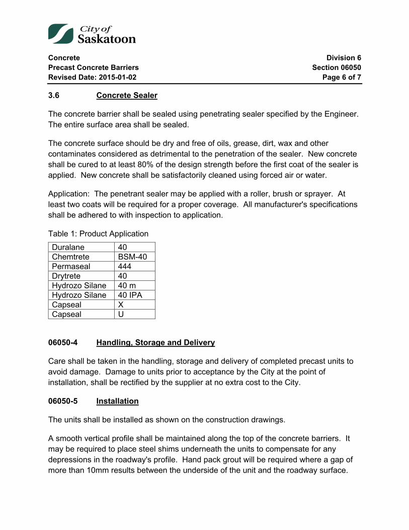
Concrete Division 6 Precast Concrete Barriers Section 06050 Revised Date: 2015-01-02 Page 6 of 7
3.6 Concrete Sealer
The concrete barrier shall be sealed using penetrating sealer specified by the Engineer. The entire surface area shall be sealed.
The concrete surface should be dry and free of oils, grease, dirt, wax and other contaminates considered as detrimental to the penetration of the sealer. New concrete shall be cured to at least 80% of the design strength before the first coat of the sealer is applied. New concrete shall be satisfactorily cleaned using forced air or water.
Application: The penetrant sealer may be applied with a roller, brush or sprayer. At least two coats will be required for a proper coverage. All manufacturer's specifications shall be adhered to with inspection to application.
Table 1: Product Application Duralane 40 Chemtrete BSM-40 Permaseal 444 Drytrete 40 Hydrozo Silane 40 m Hydrozo Silane 40 IPA Capseal X Capseal U
06050-4 Handling, Storage and Delivery
Care shall be taken in the handling, storage and delivery of completed precast units to avoid damage. Damage to units prior to acceptance by the City at the point of installation, shall be rectified by the supplier at no extra cost to the City.
06050-5 Installation
The units shall be installed as shown on the construction drawings.
A smooth vertical profile shall be maintained along the top of the concrete barriers. It may be required to place steel shims underneath the units to compensate for any depressions in the roadway's profile. Hand pack grout will be required where a gap of more than 10mm results between the underside of the unit and the roadway surface.

Concrete Division 6 Precast Concrete Barriers Section 06050 Revised Date: 2015-01-02 Page 7 of 7
06050-6 Payment
Precast concrete barriers are paid for at the unit rate per 2.5 metre unit. A separate unit price will apply to the supply of the transition and terminal ends. Payment for the supply shall be full compensation for all labour, materials and equipment required to fabricate the barriers and deliver to installation site.
A separate unit price will cover the installation of each unit at the location specified by the Engineer.
End of Specification 06050
Concrete Division 6 Precast Concrete Curbing Section 06051 Revised Date: 2015-01-02 Page 1 of 6
06051 Precast Concrete Curbing
Index
06051-1 Description 2
06051-2 Materials 2 2.1 Concrete 2 2.2 Concrete Testing 2 2.3 Reinforcing Steel 3 2.4 Miscellaneous Metals 3
06051-3 Construction, Workmanship and Procedures 4 3.1 Forms 4 3.2 Reinforcing Steel 4 3.3 Concrete Compaction (Vibration) 4 3.4 Concrete Finishing 4 3.5 Concrete Sealer 5
06051-4 Handling, Storage and Delivery 5
06051-5 Installation 5
06051-6 Payment 6

Concrete Division 6 Precast Concrete Curbing Section 06051 Revised Date: 2015-01-02 Page 2 of 6
06051-1 Description
The work shall consist of supplying all labour, plant, equipment and material for the fabrication and installation of precast concrete curbing in accordance with this Specification, the construction drawings provided herein and the General Requirements.
06051-2 Materials
2.1 Concrete
A minimum compressive strength of 35 mPa shall be used in fabricating precast concrete curbing.
Cement used on the work shall be Type 1 Portland Cement and conform to current CSA Specifications.
The consistency for hand placed concrete shall be such that the slump shall not exceed 80 mm or be less than 25 mm.
An approved air entraining agent shall be used in all concrete and shall comply with the Specifications for Air Entraining Admixture for Concrete (A.S.T.M. Designation: C-260) and used in strict accordance with the manufacturer's recommendations. The air entrainment limits shall be between 5 to 8 percent by volume as determined in accordance with C.S.A. A 23.2.18.
Ready mixed concrete shall conform in every respect to all specifications herein contained and with the "Standard Specifications for Ready Mixed Concrete" (A.S.T.M. Designation: C-94 or C.S.A. A 23.1.13) and shall further be subject to any additional written directions that the Engineer may deem necessary to ensure the obtaining of concrete of the quality specified.
2.2 Concrete Testing
During the progress of the work, test cylinders will be taken to determine the quality of the concrete. Concrete tests will be done by a Testing Laboratory approved by the Engineer.
The Contractor shall, at his own expense, supply the following tests.
Concrete Division 6 Precast Concrete Curbing Section 06051 Revised Date: 2015-01-02 Page 3 of 6
1. Slump Test
2. Air Entraining Test
3. Set of three (3) test cylinders. One cylinder will be broken at seven (7) days and two test cylinders will be broken at twenty-eight (28) days.
The Contractor shall provide, at his own expense, materials and facilities as the Engineer may require for carrying out the above mentioned tests.
The fresh concrete will be sampled in accordance with A.S.T.M. Designation: C-172 or C.S.A. A 23.2.21.
Concrete with a slump greater than 75 mm shall be rodded. Concrete with slump of 25 mm to 75 mm may be rodded or vibrated. Concrete with slump of less than 25 mm shall be consolidated by vibration.
The concrete supplied shall have a basic minimum specified compressive strength of twenty-eight (28) days. The average of the two (2) cylinders of any single test broken at twenty-eight (28) days shall be equal to or greater than the specified strength at twenty-eight (28) days. No more than one (1) test in ten (10), and no two (2) consecutive tests shall be below the specified strength.
2.3 Reinforcing Steel
Reinforcing steel shall be fabricated from deformed bars conforming to the requirements of CSA Standard G30.12-M and conforming to the grade shown on the plans. (A.S.T.M. Designation: A-615, Grade 40).
2.4 Miscellaneous Metals
Miscellaneous metals shall conform to the requirements of A.S.T.M. Designation: A-36 or better.
Concrete Division 6 Precast Concrete Curbing Section 06051 Revised Date: 2015-01-02 Page 4 of 6
06051-3 Construction, Workmanship and Procedures
3.1 Forms
Forms shall be true to shape, lines and dimensions as called for on the drawings. They shall be substantial and tight to prevent leakage of moisture. Maximum tolerance for final dimensions is + 5 mm.
The face of the forms shall be treated with a release agent to ensure that stripping of the forms may be carried out without damage to the concrete. Care shall be taken to maintain all embedded steel will be free of the release agent.
3.2 Reinforcing Steel
All reinforcing steel shall be accurately placed in the positions shown on the plans, and shall be retained in such positions by means of bar accessories and wires so that the bars shall not be moved out of alignment during or after the pouring of concrete. The reinforcing steel shall be free from mud, oil, releasing agents or other nonmetallic coatings that adversely affect the bonding capacity.
The maximum permissible tolerance for location of the reinforcing steel shall be ±5 mm of the location shown on the plans.
The minimum clear cover for reinforcing steel in concrete shall be 40 mm or as stated in CAN3-A23.3-M84.
3.3 Concrete Compaction (Vibration)
The concrete shall be thoroughly compacted by mechanical vibrators during casting. The concrete will be worked around reinforcement, embedded fixtures and into the corners of the forms. Internal vibrators or form vibrators may be used at the manufacturer's discretion. Care shall be exercised to avoid over vibration that causes aggregate segregation.
3.4 Concrete Finishing
Honeycomb spots, holes, broken corners and edges, and other concrete spalls shall be repaired by thoroughly cleaning the area, applying an approved bonding agent, and carefully filling with a grout of cement and fine aggregate mixed in proportions to obtain
Concrete Division 6 Precast Concrete Curbing Section 06051 Revised Date: 2015-01-02 Page 5 of 6
a strength equivalent to that of the concrete being repaired. (35 mPa) The resulting surfaces shall be smooth and uniform.
3.5 Concrete Sealer
The concrete barrier shall be sealed using a two component epoxy resin penetrating sealer specified by the Engineer. The entire surface area shall be sealed.
The concrete surface should be dry and free of oils, grease, dirt, wax and other contaminates considered as detrimental to the penetration of the sealer. New concrete shall be cured to at least 80% of the design strength before the first coat of the sealer is applied. New concrete shall be satisfactorily cleaned using forced air or water.
Application: The penetrant sealer may be applied with a roller, brush or sprayer. At least two coats will be required for a proper coverage. All manufacturer's specifications shall be adhered to with inspection to application
Product:
• Niklepoxy Penetrant Sealer Product #1
• Sikagard 70 Penetrant Sealer - polysiloxane resin
• Sikagard 619 Penetrant Sealer
• Concrete chemicals #905
06051-4 Handling, Storage and Delivery
Care shall be taken in the handling, storage and delivery of completed precast units to avoid damage. Damage to units prior to acceptance by the City at the point of installation, shall be rectified by the supplier at no extra cost to the City.
06051-5 Installation
The units shall be installed as shown on the construction drawings.
A smooth vertical profile shall be maintained along the top of the concrete curbs. It may be required to place steel shims underneath the units to compensate for any

Concrete Division 6 Precast Concrete Curbing Section 06051 Revised Date: 2015-01-02 Page 6 of 6
depressions in the roadway's profile. Hand pack grout will be required where a gap of more than 10 mm results between the underside of the unit and the roadway surface.
06051-6 Payment
Precast concrete curbs are paid for at the unit rate per 2.5 metre unit. A separate unit price will apply to the supply of the median ends. Payment for the supply shall be full compensation for all labour, materials and equipment required to fabricate the barriers and deliver to installation site.
A separate unit price will cover the installation of each unit at the location specified by the Engineer.
End of Specification 06051
Concrete Division 6 Pressurized Grout Injection Section 06060 Revised Date: 2006-12-06 Page 1 of 3
06060 Pressurized Grout Injection
Index
06060-1 General 2
06060-2 Scope 2
06060-3 Material 2
06060-4 Construction 2
06060-5 Measurement and Payment 3
Concrete Division 6 Pressurized Grout Injection Section 06060 Revised Date: 2006-12-06 Page 2 of 3
06060-1 General
Supply all material, equipment, labour and supervision necessary to bore pavement, to supply and install pressurized grout as well as filling of bore holes.
06060-2 Scope
The general intent of this work is to stabilize the subgrade only. This work is not intended to slabjack the asphalt or change the cross section.
06060-3 Material
The maximum strength of the cement grout shall be 0.5MPa at 28 days, with a minimum strength of 0.3MPa at 28 days.
The maximum size aggregate to be used in the grout shall be 2.5mm.
The grout shall contain a minimum of 25kg of cement per cubic metre.
The use of fly ash shall be permitted in the cement grout.
Prior to the beginning of work, a mix design must be supplied to the Engineer which in part indicates, a 7 day and a 28 day compressive strength.
The Contractor must also provide the Engineer with the results of a concrete yield test. (SCA A 23.1.2-6C)
06060-4 Construction
The Contractor shall supply, erect and maintain all barricades and signs required to ensure the safe passage of vehicles and pedestrians.
If the roadway being grouted cannot be maintained open to traffic, the City shall divert traffic as required.
The Contractor shall ensure all underground utilities are located before any drilling takes place.
The Contractor shall core through the pavement structure to a point 1.2 metres into the roadbed.
Concrete Division 6 Pressurized Grout Injection Section 06060 Revised Date: 2006-12-06 Page 3 of 3
Grout will be forced under pressure into the core holes until refusal.
Upon completion of the grouting the bore hole is to be struck off level or filled with asphalt mix.
The Contractor will be required to supply and install a minimum of 15m3 of grout each working day.
06060-5 Measurement and Payment
Measurement and payment for pressurized grout injection will be on a two part basis. Payment for drilling of injection bore holes will be based on a unit cost per each hole drilled. Payments shall include drilling the 1.2 metre deep hole, disposing of all cuttings and finishing the hole level with an impervious material.
Payment for supplying and injecting grout will be based on a unit cost per cubic metre of grout injected. Measurement will be based on weigh tickets produced at the production plant as well as summary of the weights of each component used in producing the final product. The result of the concrete yield test will provide the conversion used to convert the weights to a volume for the payment.
End of Specification 06060
Concrete Division 6 Streetscape Section 06070 Revised Date: 2016-01-12 Page 1 of 9
06070 Streetscape
Index
06070-1 Scope 3
06070-2 Method of Removing Sidewalk and Curb 3
06070-3 Asphalt, Concrete and Rubble Disposal 3
06070-4 Subgrade Preparation 3
06070-5 Forms 4
06070-6 Placing Concrete 4
06070-7 Concrete 5
06070-8 Concrete Tests 5
06070-9 Finish Sidewalk, Curb and Gutter 6
06070-10 Curing Compound 7
06070-11 Protection 7
06070-12 Pavement Removal and Repairs 7
06070-13 Sidewalk Support Adjacent to Buildings 7
06070-14 Concrete Pavers 8
06070-15 Placing of Unit Pavers 8

Concrete Division 6 Streetscape Section 06070 Revised Date: 2016-01-12 Page 2 of 9
06070-16 Sidewalk, Curb and Gutter Construction 9
Concrete Division 6 Streetscape Section 06070 Revised Date: 2016-01-12 Page 3 of 9
06070-1 Scope
The Contractor shall supply all labour, plant, equipment and materials for the construction of sidewalks, curbs and unit pavers complete as shown and detailed on the drawings and as described in these Specifications.
06070-2 Method of Removing Sidewalk and Curb
Concrete will be removed to the nearest control joint. No partial squares of sidewalk will be permitted. Unless a clean, straight break already exists along a joint, the ends of the concrete to be removed shall be cut with a concrete saw. The cut shall be of sufficient depth to permit removal without damage to the remaining structure.
06070-3 Asphalt, Concrete and Rubble Disposal
Concrete asphalt and rubble may be disposed at the City of Saskatoon disposal site as specified by the Engineer or as written in the contract.
06070-4 Subgrade Preparation
150mm of material shall be removed and base shall be placed to a depth not less than 150mm below the bottom of the concrete structure. The material shall be mixed, wetted or dried as required.
The subgrade shall be compacted to a minimum of 98% Standard Proctor Density by means of approved mechanical compaction equipment. Sheepsfoot rollers may be required by the Engineer in locations with cohesive soil.
Where concrete is hand poured final grade preparation and compaction shall be carried out after the forms are placed. The subgrade elevation shall be checked to ensure adequate thickness of the granular base and concrete. When the subgrade preparation is approved, the Contractor will be permitted to place and compact the levelling which will give the required sidewalk thickness.
The surface of the subgrade after final trimming and rolling shall be within ±10mm of the design cross section and staked elevations.
Concrete Division 6 Streetscape Section 06070 Revised Date: 2016-01-12 Page 4 of 9
06070-5 Forms
The forms shall be free from warps or other defects and shall have smooth, clean surface adjacent to the concrete. The forms shall be thoroughly cleaned and oiled before any concrete is deposited within them.
The forms shall be well staked, braced and held rigidly to the established line and grade to enable the use of mechanical concrete vibrators and vibrator screeds when placing concrete.
06070-6 Placing Concrete
Concrete shall be placed in a continuous operation. The interval between placing successive batches shall not exceed 30 minutes unless the last load completed the work to an expansion joint. Maximum mixing time of concrete after water has been added shall be 60 minutes.
Concrete shall be placed as close as possible to but no further than one metre from its final position in the forms. Rehandling of concrete shall not be permitted.
It shall be deposited in such a manner that segregation of the aggregates shall not occur.
After placing, the concrete shall be tamped, vibrated or otherwise consolidated to eliminate all voids and honeycombing. Vibrating screeds, shall be operated in accordance with the manufacturer's instructions. Over vibration resulting in bleeding shall not be allowed.
In combined rolled curb and sidewalk areas, a steel vibrating screed shall be used in such a manner as to obtain dense concrete and the required cross section continuously.
Where combined curb and sidewalks are poured, concrete shall be placed by hand in the curb excavation in advance of placing the sidewalk concrete so that subgrade material will not be forced into it from beneath the sidewalk section.
Concrete shall not be placed when the ground temperature is less than 2°C. Concrete shall be covered and heated, if necessary, to maintain a temperature of 5°C for at least 36 hours. Covering shall not be removed for 72 hours. Cost of heating and covering shall be borne by the Contractor.
Concrete Division 6 Streetscape Section 06070 Revised Date: 2016-01-12 Page 5 of 9
Concrete damaged due to freezing shall be replaced by the Contractor at his expense.
During hot weather, an approved set retarder may be used. Sidewalk and curb shall be poured at a rate such that finishing as specified can be accomplished. Surface wetting shall not be permitted during finishing. The Engineer may terminate the work temporarily if, in his opinion, the work cannot be properly finished.
06070-7 Concrete
Concrete materials, method of concrete handling and construction shall conform to the latest edition of CAN3-A23.1 as published by the Canadian Standards Association.
Minimum compressive strength of the concrete at 28 days shall be 32MPa.
Aggregates shall comply with Section 5, CAN3-A23.1.
Nominal aggregate size shall be 30 mm.
Cement shall be Type 10 Normal Portland Cement complying with Section 3, CAN3-A23.1. A minimum of 300 kg of cement per cubic metre of mixed concrete shall be used.
Slump shall not exceed 70mm or be less than 25mm.
An approved air entraining agent complying with Section 6, CAN3-A23.1 shall be used. Air entrainment shall be 5% to 8% by volume.
Water cement ratio shall not exceed 0.38 by weight.
Reinforcing steel shall conform with CSA G30.12-M77 and CSA G30.6.
Calcium chloride may be used as an accelerating agent on the approval of the Engineer. It shall conform to ASTM D-98. Maximum amount of calcium chloride in the mix shall not exceed 2% of cement by weight.
06070-8 Concrete Tests
Ready mixed and transit mixed concrete should conform to CSA A23.1.13.
Concrete Division 6 Streetscape Section 06070 Revised Date: 2016-01-12 Page 6 of 9
After the award of the work, the Contractor shall submit the following information in writing relating to the ready mix concrete supplier.
1. Name, address and contact person. 2. Recent concrete mix design on results of six concrete test cylinders of the same
concrete which will be used for the work.
During the progress of the work, the Contractor shall hire an approved materials testing laboratory and take one set of three concrete test cylinders for each concrete pour. One cylinder will be tested after 7 days of curing and two cylinders will be tested after 28 days of curing. No more than one test in five nor two consecutive tests shall be below the specified concrete strength.
One copy of the test results shall be submitted to the Owner.
06070-9 Finish Sidewalk, Curb and Gutter
Concrete shall be deposited in a manner to prevent segregation of the aggregate. Special care shall be taken in placing concrete to prevent voids, pockets, rough areas and honeycombing. The concrete shall be consolidated by using mechanical concrete vibrators or vibrator screed in such a manner as to work the coarse aggregate away from the forms and exposed surfaces.
After the concrete has sufficiently set to permit further finishing without concrete bleeding, the surface shall be brought to a true surface with a wood float. The surface shall be marked and finished as shown on drawings using approved tools. After marking, the surface shall be trowelled smooth with a steel trowel and a uniform brush finish applied with a soft bristled push broom to the satisfaction of the Engineer.
After the initial concrete set, the curb form shall be removed and the exposed surface of the curb shall be worked to a true surface, trowelled smooth and then given a uniform brush finish.
Substandard work or finished surfaces which are marred or damaged prior to setting shall be replaced by the Contractor at his expense.
Each block or portion of block of sidewalk constructed shall be marked at the end with a suitable tool showing the name of the Contractor and the year of construction.
Concrete Division 6 Streetscape Section 06070 Revised Date: 2016-01-12 Page 7 of 9
Curb returns shall be smooth, continuous curves and shall be tangent where they join the straight sections or another curve.
06070-10 Curing Compound
Apply a curing compound to all exposed surfaces. Curing compound shall comply with ASTM C309, Liquid Membrane - Forming Compounds for Curing Concrete. The rate of application shall be as recommended by the manufacturer or as directed by the Engineer. The pressure spray distributor shall be such that a continuous even coating is applied.
Concrete placed after September 30 will be cured with an application of a penetrating sealer to prevent de-icing agents from spalling the concrete.
The cost of supplying and applying curing compound is to be included in the respective sidewalk and curb unit prices.
06070-11 Protection
Pedestrian traffic shall not be allowed on the walks for 24 hours after the concrete is poured. Lane and driveway crossings shall be barricaded and not used for a period of 5 days after the concrete is poured.
06070-12 Pavement Removal and Repairs
To facilitate the removal and construction of the sidewalk, curb, or curb and gutter, the Contractor shall jack hammer or saw cut the adjacent pavement. Extent of removal shall be kept to a minimum but adequate to enable the work to be performed correctly.
Payment for patch paving will be made on the Contract bid price either included in the curb unit price or on a square metre basis.
06070-13 Sidewalk Support Adjacent to Buildings
At concrete foundations, steps, or sidewalks on property the new sidewalk needs to be dowelled in to the existing concrete structure. The Contractor shall install 250 x 10 rebar into the concrete building foundation. Rebar is to be installed 100mm into the foundation, 50mm from the bottom of the sidewalk.
Concrete Division 6 Streetscape Section 06070 Revised Date: 2016-01-12 Page 8 of 9
This work is included in the unit price payment for the sidewalk.
06070-14 Concrete Pavers
Concrete pavers shall be as specified in the Contract. Type 10 Normal Portland cement shall be used having a minimum strength of 55MPa in 28 days. The maximum water absorption shall be 5%.
The Contractor shall supply the required test data for each project. Test data may be on the pavers manufactured or most current test results obtained in manufacturing similar pavers. If applicable data is not available, appropriate tests as required in the industry shall be performed and one copy provided to the Owner.
Should a special penetrating sealer be required to be applied to provide a minimum of twenty years of service, without spalling, it shall be included in the unit price.
06070-15 Placing of Unit Pavers
After the excavation is completed to the correct elevation, the top 150mm of the subgrade and the 150mm of granular base are to be compacted to a minimum of 98% Standard Proctor Density.
After the granular base has been approved, spread and screed sand to ensure 25mm depth prior to the installation of unit pavers.
Pattern of paver installation to be as shown on plans and verified by Owner.
Pavers are to be installed from a straight edge, laying pavers directly on the screeded sand in the patterns as shown. Install unit pavers true to grade and free of any movement. Joints between pavers should be a maximum of 3mm or as required to achieve the design pattern. The spacing on a curved area shall be equal.
Where required, pavers are to be saw cut neatly to fit accurately.
After the pavers are placed, the pavers are to be vibrated to the final level with two or three passes of a vibrating plate compacter. Spread and sweep dry sharp sand into the joints and vibrate down. Finish by washing and sweeping clean.

Concrete Division 6 Streetscape Section 06070 Revised Date: 2016-01-12 Page 9 of 9
It shall be the responsibility of the Contractor to maintain the appropriate level of the pavers including the filling between the joints with sand during the two year maintenance period.
06070-16 Sidewalk, Curb and Gutter Construction
All work performed shall meet the current standards as outlined for concrete sidewalk, curb and gutter construction, Specification 06010 and as shown on cross section drawings.
End of Specification 06070
Concrete Division 6 Concrete Curb and Sidewalk Repairs Section 06080 Revised Date: 2017-01-31 Page 1 of 9
06080 Concrete Curb and Sidewalk Repairs
Index
06080-1 Scope 3
06080-2 Method of Removing Sidewalk and Curb 3
06080-3 Asphalt, Concrete and Rubble Disposal 3
06080-4 Subgrade Preparation 3
06080-5 Granular Base Course 4
06080-6 Templates 4
06080-7 Forms 4
06080-8 Placing Concrete 5
06080-9 Concrete 6
06080-10 Concrete Tests 6
06080-11 Finish of Sidewalk, Curb and Gutter 7
06080-12 Curing Compound 8
06080-13 Tolerances 8
06080-14 Protection 9
06080-15 Pavement Removal and Repairs 9

Concrete Division 6 Concrete Curb and Sidewalk Repairs Section 06080 Revised Date: 2017-01-31 Page 2 of 9
06080-16 Sidewalk Support Adjacent to Buildings 9
06080-17 Sidewalk, Curb and Gutter Construction 9
Concrete Division 6 Concrete Curb and Sidewalk Repairs Section 06080 Revised Date: 2017-01-31 Page 3 of 9
06080-1 Scope
The Contractor shall supply all labour, plant, equipment and materials for the construction of sidewalks, and curbs complete as shown and detailed on the drawings and as described in these Specifications.
06080-2 Method of Removing Sidewalk and Curb
Concrete will be removed to the nearest control joint or saw cut. Unless a clean, straight break already exists along a joint, the ends of the concrete to be removed shall be cut with a concrete saw. The cut shall be of sufficient depth to permit removal without damage to the remaining structure.
06080-3 Asphalt, Concrete and Rubble Disposal
Concrete asphalt and rubble may be disposed at the City of Saskatoon disposal site as specified by the Engineer or as written in the contract.
06080-4 Subgrade Preparation
150mm of material shall be removed and base shall be placed to a depth not less than 150mm below the bottom of the concrete structure and extending 125mm beyond each side of the proposed concrete structure. The material shall be mixed, wetted or dried as required.
The subgrade shall be compacted to a minimum of 98% Standard Proctor Density by means of approved mechanical compaction equipment. Sheepsfoot rollers may be required by the Engineer in locations with cohesive soil.
Transverse or longitudinal service trenches that have not thoroughly settled shall be excavated and backfilled with approved material and compacted to a minimum 98% Standard Proctor Density. The type of mechanical compactor to be used shall be approved by the Engineer.
Where concrete is hand poured final grade preparation and compaction shall be carried out after the forms are placed. The subgrade elevation shall be checked to ensure adequate thickness of the granular base. When the subgrade preparation is approved, the Contractor will be permitted to place and compact the levelling which will give the required sidewalk thickness.
Concrete Division 6 Concrete Curb and Sidewalk Repairs Section 06080 Revised Date: 2017-01-31 Page 4 of 9
The surface of the subgrade after final trimming and rolling shall be within +10mm of the design cross section and staked elevations.
06080-5 Granular Base Course
The Contractor shall supply the base course material.
The base aggregate shall be composed of fragments of durable rock free from undesirable quantities of soft or flaky particles, loam, organic or other deleterious material.
Specifications for base course aggregate are contained in Aggregates Specifications Section 03001-3.2.2.
06080-6 Templates
Templates shall be supplied and used by the Contractor to check the subgrade finish prior to placing of the concrete and to check the shape of completed work. Templates shall be full scale and represent the true cross section of the concrete for the type of curb or curb and walk being constructed.
If other templates are required, they shall be constructed and used by the Contractor to control the work.
Templates shall be of rigid construction with suitable handles. Damaged or worn templates shall not be used and all templates shall be checked and approved by the Engineer.
No concrete shall be placed until the Engineer has checked and approved subgrade and base course.
06080-7 Forms
The forms used for each type of construction shall be the same as the dimensions on the drawing.
They shall be free from warps or other defects and shall have smooth, clean surface adjacent to the concrete. The forms shall be thoroughly cleaned and oiled before any concrete is deposited within them.
Concrete Division 6 Concrete Curb and Sidewalk Repairs Section 06080 Revised Date: 2017-01-31 Page 5 of 9
The forms shall be well staked, braced and held rigidly to the established line and grade to enable the use of mechanical concrete vibrators and vibrator screeds when placing concrete.
06080-8 Placing Concrete
Concrete shall be placed in a continuous operation. The interval between placing successive batches shall not exceed 30 minutes unless the last load completed the work to an expansion joint. Maximum mixing time of concrete after water has been added shall be 60 minutes.
Concrete shall be placed as close as possible to but no further than one metre from its final position in the forms. Rehandling of concrete shall not be permitted.
It shall be deposited in such a manner that segregation of the aggregates shall not occur.
After placing, the concrete shall be tamped, vibrated or otherwise consolidated to eliminate all voids and honeycombing. Vibrating screeds, shall be operated in accordance with the manufacturer's instructions. Over vibration resulting in bleeding shall not be allowed.
In combined rolled curb and sidewalk areas, a steel vibrating screed shall be used in such a manner as to obtain dense concrete and the required cross section continuously.
Where combined curb and sidewalks are poured, concrete shall be placed by hand in the curb excavation in advance of placing the sidewalk concrete so that subgrade material will not be forced into it from beneath the sidewalk section.
Concrete shall not be placed when the ground temperature is less than 2°C.
Concrete shall be covered and heated, if necessary, to maintain a temperature of 5°C for at least 36 hours. Covering shall not be removed for 72 hours. Cost of heating and covering shall be borne by the Contractor.
Concrete damaged due to freezing shall be replaced by the Contractor at his expense.
During hot weather, an approved set retarder may be used. Sidewalk and curb shall be poured at a rate such that finishing as specified can be accomplished. Surface wetting

Concrete Division 6 Concrete Curb and Sidewalk Repairs Section 06080 Revised Date: 2017-01-31 Page 6 of 9
shall not be permitted during finishing. The Engineer may terminate the work temporarily if, in his opinion, the work cannot be properly finished.
06080-9 Concrete
Concrete materials, method of concrete handling and construction shall conform to the latest edition of CAN3-A23.1 as published by the Canadian Standards Association.
Minimum compressive strength of the concrete at 28 days shall be 32MPa.
Aggregates shall comply with Section 5, CAN3-A23.1.
Nominal aggregate size shall be 30mm.
Cement shall be Type 10 Normal Portland Cement complying with Section 3, CAN3-A23.1. A minimum of 300kg of cement per cubic metre of mixed concrete shall be used.
Slump shall not exceed 70mm or be less than 25mm.
An approved air entraining agent complying with Section 6, CAN3-A23.1 shall be used. Air entrainment shall be 5 to 8 percent by volume.
Water cement ratio shall not exceed 0.38 by weight.
Reinforcing steel shall conform with CSA G30.12-M77 and CSA G30.6.
Calcium chloride may be used as an accelerating agent on the approval of the Engineer. It shall conform to ASTM D-98. Maximum amount of calcium chloride in the mix shall not exceed 2% of cement by weight.
06080-10 Concrete Tests
Ready mixed and transit mixed concrete should conform to CSA A23.1.13.
After the award of the work, the Contractor shall submit the following information in writing relating to the ready mix concrete supplier.
a) Name, address and contact person.
Concrete Division 6 Concrete Curb and Sidewalk Repairs Section 06080 Revised Date: 2017-01-31 Page 7 of 9
b) Recent concrete mix design on results of six concrete test cylinders of the same concrete which will be used for the work.
During the progress of the work, the Contractor shall hire an approved materials testing laboratory and take one set of three concrete test cylinders for each concrete pour. One cylinder will be tested after 7 days of curing and two cylinders will be tested after 28 days of curing. No more than one test in five nor two consecutive tests shall be below the specified concrete strength.
Once copy of the test results shall be submitted to the Owner.
06080-11 Finish of Sidewalk, Curb and Gutter
Concrete shall be deposited in a manner to prevent segregation of the aggregate. Special care shall be taken in placing concrete to prevent voids, pockets, rough areas and honeycombing. The concrete shall be consolidated by using mechanical concrete vibrators or vibrator screed in such a manner as to work the coarse aggregate away from the forms and exposed surfaces.
After the concrete has sufficiently set to permit further finishing without concrete bleeding, the surface shall be brought to a true surface with a wood float. The surface shall be marked and finished as shown on drawings using approved tools. After marking, the surface shall be trowelled smooth with a steel trowel and a uniform brush finish applied with a soft bristled push broom to the satisfaction of the Engineer.
After the initial concrete set, the curb form shall be removed and the exposed surface of the curb shall be worked to a true surface, trowelled smooth and then given a uniform brush finish
Substandard work or finished surfaces which are marred or damaged prior to setting shall be replaced by the Contractor at his expense.
Each block or portion of block of sidewalk constructed shall be marked at the end with a suitable tool showing the name of the Contractor and the year of construction.
All curb box locations shall be marked at right angles to the back line of the sidewalk and 200mm from the back of the walk with an imprinted "C.C." with an arrow pointing to the curb box.

Concrete Division 6 Concrete Curb and Sidewalk Repairs Section 06080 Revised Date: 2017-01-31 Page 8 of 9
Curb returns shall be smooth, continuous curves and shall be tangent where they join the straight sections or another curve.
06080-12 Curing Compound
Apply a curing compound to all exposed surfaces. Curing compound shall comply with ASTM C309, Liquid Membrane - Forming Compounds for Curing Concrete.
The rate of application shall be as recommended by the manufacturer or as directed by the Engineer. The pressure spray distributor shall be such that a continuous even coating is applied.
Concrete placed after September 30 will be cured with an application of a penetrating sealer to prevent de-icing agents from spalling the concrete.
The cost of supplying and applying curing compound is to be included in the respective sidewalk and curb unit prices.
06080-13 Tolerances
All exposed concrete surfaces shall not deviate in line or grade more than 5mm in 4 metres.
Sidewalk elevation shall not vary more than 6mm from that established by the Engineer's grade stakes and the maximum variation from the given elevation between two consecutive stakes shall not exceed 6mm.
Deviation in alignment shall not exceed 10mm in 10 metres from that established by the survey stakes in one direction only.
Crossfall shall not vary more than 4mm per metre from that specified or shown on the drawings, unless approved by the Engineer.
In no case shall the thickness of the concrete be more than 8mm less than the specified thickness.
Concrete Division 6 Concrete Curb and Sidewalk Repairs Section 06080 Revised Date: 2017-01-31 Page 9 of 9
06080-14 Protection
Pedestrian traffic shall not be allowed on the walks for 24 hours after the concrete is poured. Lane and driveway crossings shall be barricaded and not used for a period of 5 days after the concrete is poured.
06080-15 Pavement Removal and Repairs
To facilitate the removal and construction of the sidewalk, curb and curb and gutter, the Contractor shall saw cut the adjacent pavement. The cut should be clean and have no jagged edges. Extent of removal shall be 200mm. Refer to City of Saskatoon Standard Drawing 102-0002-049 available on the City’s web site.
Payment for patch paving will be made on the Contract bid price either included in the curb unit price or on a square metre basis.
06080-16 Sidewalk Support Adjacent to Buildings
At concrete foundations, steps, or sidewalks on property the new sidewalk needs to be dowelled in to the existing concrete structure. The Contractor shall install 250 x 10 rebar spaced at 300mm, into the concrete building foundation. Rebar to be installed 100mm into the foundation, 50mm from the bottom of the sidewalk.
This work is included in the unit price payment for the sidewalk.
06080-17 Sidewalk, Curb and Gutter Construction
All work performed shall meet the current standards as outlined for concrete sidewalk, curb and gutter construction, Specification 06010 and as shown on cross section drawings.
End of Specification 06080
Pavement Markings Division 7 Chlorinated Rubber Traffic Paint Section 07005 Revised Date: 2005-01-04 Page 1 of 7
07005 Chlorinated Rubber Traffic Paint
Index
07005-1 General 2
07005-2 Scope 2
07005-3 General Requirements of Product 2 3.1 Reflectorization 2 3.2 Uniformity 2 3.3 Package Stability 2 3.4 Colour 3 3.5 Quality 3 3.6 Samples 3 3.7 Acceptance and Rejection 3
07005-4 Specific Requirements of Product 4 4.1 Hiding Power 4 4.2 Viscosity 4 4.3 Settling Rate 4 4.4 Colour 4 4.5 Drying Properties 4 4.6 Bleeding 5 4.7 Flexibility 5
07005-5 Packaging 5
07005-6 Certification of Material 6
07005-7 Measurements 6
Appendix 1 7
Pavement Markings Division 7 Chlorinated Rubber Traffic Paint Section 07005 Revised Date: 2005-01-04 Page 2 of 7
07005-1 General
Supply all materials, as specified herein, and in accordance with the Contract Documents.
07005-2 Scope
This specification covers the supply of white or yellow chlorinated rubber traffic paint of a consistency suitable for spray application on bituminous and concrete roadways for marking traffic lines.
07005-3 General Requirements of Product
It is the intent of this specification to procure, for use by the City of Saskatoon, the most efficient traffic paint possible with regard to service and cost. Service includes general appearance, colour, night visibility, and durability. The composition of the paint shall be left to the discretion of the manufacturer, and it is his responsibility to formulate and produce in sufficient quantity, a paint meeting the requirements specified herein.
3.1 Reflectorization
Reflectorization of the paint lines is to be obtained by the introduction during paint application of drop-on (overlay-type) glass beads at the rate of 0.6 kilograms per litre of paint sprayed on the road surface.
The glass beads will be introduced or applied to the wet paint film by means of guns and under air pressure.
3.2 Uniformity
The paint shall be homogeneous, and shall be well dispersed to a uniform and smooth consistency.
The paint shall be capable of easy application with an automatic spray gun and shall flow evenly and smoothly without overspray, using the internal method of atomization.
3.3 Package Stability
The paint shall not cake, liver, curdle, get thicker, settle badly or show any objectional properties in the original unopened container for 12 (twelve) months from date of
Pavement Markings Division 7 Chlorinated Rubber Traffic Paint Section 07005 Revised Date: 2005-01-04 Page 3 of 7
delivery, when stored at a temperature not exceeding 38 degrees C. At the end of this time, it should be capable of being mixed to a uniform condition by simple stirring without difficulty by the use of a paddle.
3.4 Colour
After drying, the white paint shall be pure white, free from dirt or tint, and shall be identical to the white 513-301. The yellow paint shall be identical to the yellow 505-308. The colours 513-301 and 505-308 are established by Canadian Government Specifications Board 1-GP-12.1C. The paint shall not contain any organic colouring matters and shall not discolour in sunlight.
3.5 Quality
The paint must possess the characteristics such that it will not run (flow) when the glass beads are applied in the manner indicated in section 07005-3.1 of the General Requirement.
The paint shall be free from skins, dirt and other foreign matter.
3.6 Samples
Each prospective bidder shall submit (2) two four litre cans of the paint he proposes to furnish at no charge to the City of Saskatoon. The samples shall be plainly marked showing the manufacturer's code number and name for easy reference.
Only those manufacturers whose samples meet all the requirements of this specification shall be considered for eligibility to tender.
Manufacturers may submit up to (3) three samples of different formula if he so desires, providing they meet the specifications as requested. Samples shall be delivered to the City of Saskatoon not later than the date specified on the request for samples, unless an extension of time has been granted by the Engineer. Failure to receive samples by the specified date may be considered sufficient cause for rejection of the sample.
3.7 Acceptance and Rejection
Paint furnished under contract shall be identical to the samples submitted and shall comply with the specification requirements.
Pavement Markings Division 7 Chlorinated Rubber Traffic Paint Section 07005 Revised Date: 2005-01-04 Page 4 of 7
In the event that the traffic paint does not comply with these specifications, or is not identical to the sample submitted, the manufacturer will be required to replace all such paint at his own expense, including all handling and transportation.
07005-4 Specific Requirements of Product
4.1 Hiding Power
The paint shall flow evenly and smoothly and cover solidly in (1) one coat when applied at a rate of 8 square metres per litre.
4.2 Viscosity
The viscosity of the paint shall be eighty (80) plus or minus five (5) Krebs Units at 25 degrees C.
4.3 Settling Rate
The paint shall provide a rating of seven (7) or higher (A.S.T.M. D1309-56).
4.4 Colour
The colour is based on a comparison of the colour under section 07005-3.4.
NOTE: The paint film made by the overlay method of glass beads in the proportion of 0.6 kilograms to one (1) litre of paint shall comply with the following requirements.
4.5 Drying Properties
The paint shall dry to an elastic adherent finish that will not discolour in the sunlight.
The Paint (applied to a sheet of plate glass to give a wet film thickness of 0.38 millimetres) shall dry to the touch in not less than two (2) or more than ten (10) minutes and dry to "no pickup" in not more than twenty (20) minutes at 25 degrees C, 50% to 60% relative humidity (A.S.T.M. D711-55).
NOTE: The paint film is considered to be touch dry when a light touch by the fingers shows a tacky condition but none of the paint adheres to the fingers.
Pavement Markings Division 7 Chlorinated Rubber Traffic Paint Section 07005 Revised Date: 2005-01-04 Page 5 of 7
The paint shall dry sufficiently hard within thirty (30) minutes after application so that there will be no displacement (smear) or discolouration (dirt retention) under traffic conditions.
4.6 Bleeding
The bleeding characteristics shall provide a rating of six (6) or higher of the Photographic Reference Standards. Application A.S.T.M. D969-54. Evaluation A.S.T.M. D898-48.
4.7 Flexibility
The paint shall not crack or peel when subject to the bending test at 23 degrees C. plus or minus 1.5 degrees C. using a 12 mm mandrel (C.G.S.B. Method 119.1).
07005-5 Packaging
The paint shall be packaged in twenty (20) litre pails and/or in two hundred and five (205) litre drums. The pails shall have a removable top (open head) and shall be sturdy enough to withstand normal handling. The drums shall have a removable top (open head) and SHALL BE STURDY ENOUGH TO WITHSTAND ROUGH HANDLING WHEN FILLED WITH PAINT. All pails and drums shall be clean and in good order and shall be plainly marked showing litre or gallonage content, lot or batch number, name and address of manufacturer, manufacturer's code number for the paint and date of packaging. NO DRUM SHALL CONTAIN MORE THAN 205 LITRES OF PAINT.
Pails and drums containing white paint shall be stencilled with white labels, and pails and drums containing yellow paint shall be stencilled with yellow labels for identification purposes.
Pails and drums shall be vapour-proof sealed.
All containers must be shipped on pallets and must be loaded in such a manner as to facilitate unloading by a forklift.
If pails and/or drums are returnable for credit, this must be so specified on the Tender Form.
Pavement Markings Division 7 Chlorinated Rubber Traffic Paint Section 07005 Revised Date: 2005-01-04 Page 6 of 7
07005-6 Certification of Material
The supplier shall submit one complete "Paint Data Form" for each test sample (see Appendix 1). Test samples for which a "Paint Data Form" has not been submitted will not be considered.
Bidders shall state the recommended type of thinner required for the paint that the quotations are based on.
Material supplied of inferior quality shall be replaced by the supplier.
07005-7 Measurements
Traffic paint will be measured in litres.
End of Specification 07005
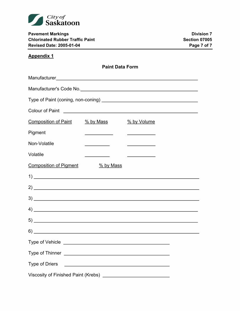
Pavement Markings Division 7 Chlorinated Rubber Traffic Paint Section 07005 Revised Date: 2005-01-04 Page 7 of 7
Appendix 1
Paint Data Form
Manufacturer
Manufacturer's Code No.
Type of Paint (coning, non-coning)
Colour of Paint
Composition of Paint % by Mass % by Volume
Pigment
Non-Volatile
Volatile
Composition of Pigment % by Mass
1)
2)
3)
4)
5)
6)
Type of Vehicle
Type of Thinner
Type of Driers
Viscosity of Finished Paint (Krebs)
Pavement Markings Division 7 “Drop-on” Glass Beads for Pavement Markings Section 07010 Revised Date: 2005-01-04 Page 1 of 5
07010 “Drop-on” Glass Beads for Pavement Markings
Index
07010-1 General 2
07010-2 Scope 2
07010-3 Packaging 2
07010-4 Product: Specific Requirements 2 4.1 Roundness 2 4.2 Colour 2 4.3 Imperfection 3 4.4 Refractive Index 3 4.5 Durability 3 4.6 Crushing Strength 3 4.7 Gradation 3 4.8 Moisture Proof Requirements 4 4.9 Test for Moisture Resistance 4
07010-5 Certification of Material and Rejection 4
Tables
Table 1: Crushing Strength ............................................................................................. 3 Table 2: Gradation Requirements ................................................................................... 4
Pavement Markings Division 7 “Drop-on” Glass Beads for Pavement Markings Section 07010 Revised Date: 2005-01-04 Page 2 of 5
07010-1 General
Supply all materials, as specified herein, and in accordance with the Contract Documents.
07010-2 Scope
This specification is intended to cover glass beads for application on traffic paint for the production of a reflective surface creating night visibility of the paint film without altering day visibility of the markings in any way.
07010-3 Packaging
The glass beads shall be packaged in durable plastic lined waterproof bags so constructed as to ensure safe delivery. The bag, liners, seams and top closures shall be waterproof and leak-proof, and shall be capable of maintaining these properties during transportation and through numerous handlings.
07010-4 Product: Specific Requirements
The beads shall be manufactured from glass of a composition designed to be highly resistant to traffic wear and to the effects of weathering.
The beads shall adhere tightly to standard specification yellow and white traffic paint when applied with a pressurized glass bead gun.
In addition, the glass beads shall conform to the following requirements:
4.1 Roundness
The beads shall be spherical in shape, containing not more than ten (10) percent of irregularly shaped particles by microscopic count.
4.2 Colour
The beads shall be transparent and colourless to prevent their imparting of any noticeable hue to the paint.
Pavement Markings Division 7 “Drop-on” Glass Beads for Pavement Markings Section 07010 Revised Date: 2005-01-04 Page 3 of 5
4.3 Imperfection
The surface of the beads shall be smooth, lustrous, and free from film, foreign matter, scratches and pits. Not more than twenty-five (25) percent by weight of the true spheres shall have imperfections such as milkiness, dark specks, incipient fractures and air inclusions in a form of a single bubble greater than 1/4 of the diameter of the bead, or many bubbles totaling more than 1/3 of the bead diameter when tested under 50x and 100x magnification as follows:
1. Glass beads retained on a .300 mm sieve shall be counted under 50x magnification.
2. Glass beads passing through a .300 mm sieve shall be counted under 100x magnification.
4.4 Refractive Index
The index of refraction of the glass bead shall not be less than 1.50.
4.5 Durability
The beads shall not show any tendency toward decomposition when exposed to atmospheric conditions, moisture, dilute acids, alkalies or paint constituents.
4.6 Crushing Strength
True spheres shall be tested in compression in accordance with A.S.T.M. D-1213-54 for determining the crushing resistance of glass beads. The minimum crushing strength shall be as follows:
Table 1: Crushing Strength Size of Beads Strength
0.9 - 0.6 mesh size 16 kilograms 0.6 - 0.4 mesh size 11.5 kilograms
4.7 Gradation
The beads shall conform to the following gradation requirements:
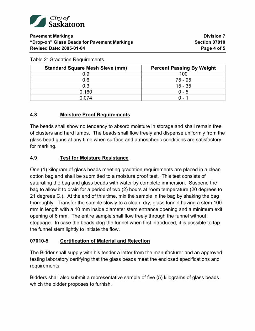
Pavement Markings Division 7 “Drop-on” Glass Beads for Pavement Markings Section 07010 Revised Date: 2005-01-04 Page 4 of 5
Table 2: Gradation Requirements Standard Square Mesh Sieve (mm) Percent Passing By Weight
0.9 100 0.6 75 - 95 0.3 15 - 35
0.160 0 - 5 0.074 0 - 1
4.8 Moisture Proof Requirements
The beads shall show no tendency to absorb moisture in storage and shall remain free of clusters and hard lumps. The beads shall flow freely and dispense uniformly from the glass bead guns at any time when surface and atmospheric conditions are satisfactory for marking.
4.9 Test for Moisture Resistance
One (1) kilogram of glass beads meeting gradation requirements are placed in a clean cotton bag and shall be submitted to a moisture proof test. This test consists of saturating the bag and glass beads with water by complete immersion. Suspend the bag to allow it to drain for a period of two (2) hours at room temperature (20 degrees to 21 degrees C.). At the end of this time, mix the sample in the bag by shaking the bag thoroughly. Transfer the sample slowly to a clean, dry, glass funnel having a stem 100 mm in length with a 10 mm inside diameter stem entrance opening and a minimum exit opening of 6 mm. The entire sample shall flow freely through the funnel without stoppage. In case the beads clog the funnel when first introduced, it is possible to tap the funnel stem lightly to initiate the flow.
07010-5 Certification of Material and Rejection
The Bidder shall supply with his tender a letter from the manufacturer and an approved testing laboratory certifying that the glass beads meet the enclosed specifications and requirements.
Bidders shall also submit a representative sample of five (5) kilograms of glass beads which the bidder proposes to furnish.

Pavement Markings Division 7 “Drop-on” Glass Beads for Pavement Markings Section 07010 Revised Date: 2005-01-04 Page 5 of 5
The tender or quotation will be considered incomplete unless the above information is provided.
Any shipment or shipments of this material supplied to the City of Saskatoon may be sampled at any time after receipt of the shipment. Failure of the material in any shipment to meet any of the requirements of this specification shall constitute cause for rejection or other penalty.
Material supplied of inferior quality shall be replaced by the supplier.
End of Specification 07010
Pavement Markings Division 7 Hot Applied Traffic Paint Section 07015 Revised Date: 2005-01-04 Page 1 of 6
07015 Hot Applied Traffic Paint
Index
07015-1 Scope 2
07015-2 Applicable Specifications 2
07015-3 General Requirements of Product 2 3.1 General 2 3.2 Paint Colour and Cleaner 3 3.3 Physical and Chemical Requirements 3
07015-4 Sampling and Testing 4
07015-5 Quality Assurance 4
07015-6 Delivery and Packaging 4 6.1 Packaging 4 6.2 Markings 5
07015-7 Measurement 5
Appendix 1 – Paint Data Form 6
Tables
Table 1: Paint Physical and Chemical Requirements ...................................................... 3

Pavement Markings Division 7 Hot Applied Traffic Paint Section 07015 Revised Date: 2005-01-04 Page 2 of 6
07015-1 Scope
This specification is intended to cover white and yellow hot applied traffic paint to be applied to either asphaltic or portland cement concrete pavements.
07015-2 Applicable Specifications
The most recent revisions of the following, specifications, test methods and standards form a part of this specification where referenced.
American Society for Testing and Materials (ASTM) D-126, D-713, D-821, D-868, D-969, D-913, D-1394 and E-97.
Canadian Government Standards Board Specification (CGSB) 1-GP-12.1C and 1-GP-71.
07015-3 General Requirements of Product
It is the intent of this specification to procure, for use by the City of Saskatoon, the most efficient traffic paint possible with regard to service and cost. Service includes general appearance, colour, night visibility, and durability. The composition of the paint shall be left to the discretion of the manufacturer, and it is his responsibility to formulate and produce in sufficient quantity, a paint meeting the requirements specified herein.
3.1 General
The paint shall be free from foreign materials, such as dirt, sand or other material capable of clogging screens, valves, pumps, or other equipment used in a paint striping apparatus.
The paint pigment shall be well ground and properly dispersed in the vehicle. The paint shall not cake or thicken in the container and shall not become granular or curdled. Any settled pigment shall be easily redispersed, with minimum resistance to form a smooth uniform product of proper consistency which is capable of being sprayed at the temperature intended for the paint.
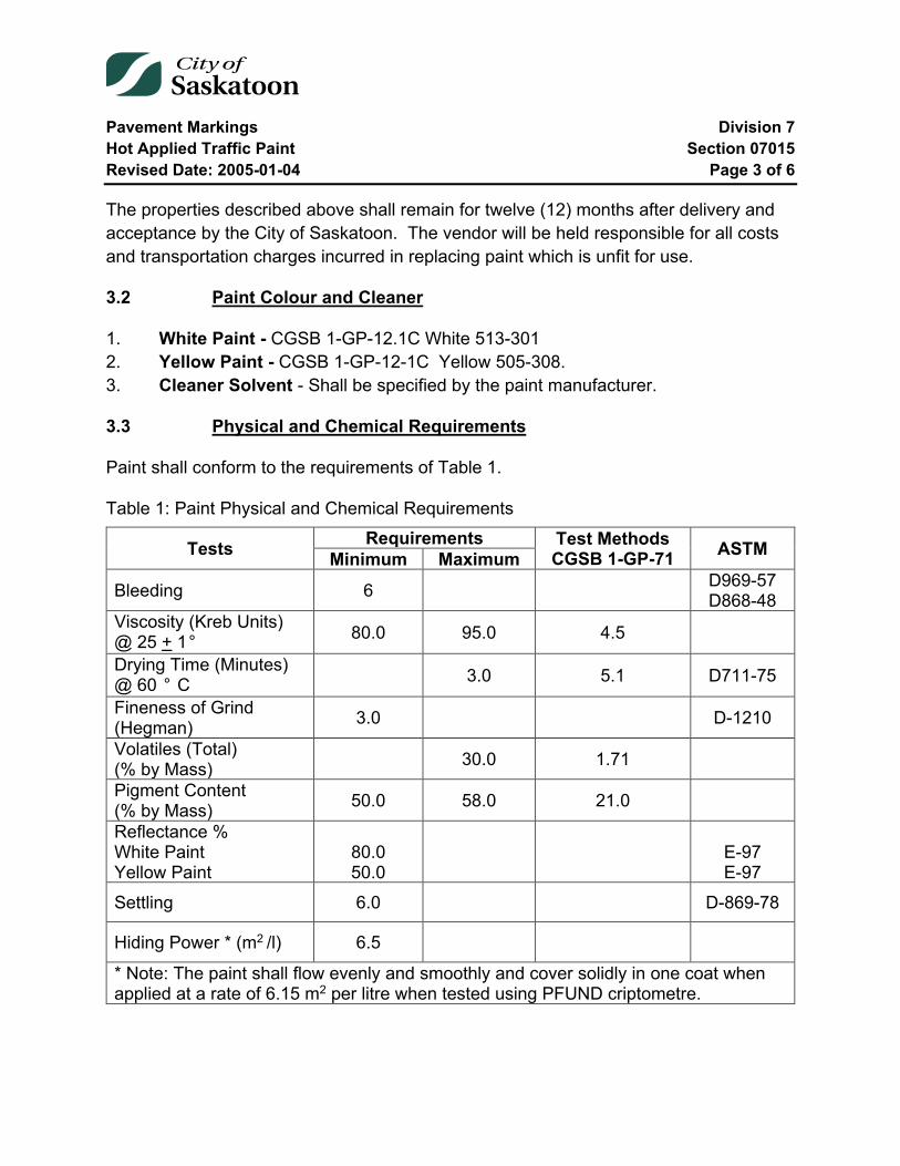
Pavement Markings Division 7 Hot Applied Traffic Paint Section 07015 Revised Date: 2005-01-04 Page 3 of 6
The properties described above shall remain for twelve (12) months after delivery and acceptance by the City of Saskatoon. The vendor will be held responsible for all costs and transportation charges incurred in replacing paint which is unfit for use.
3.2 Paint Colour and Cleaner
1. White Paint - CGSB 1-GP-12.1C White 513-301 2. Yellow Paint - CGSB 1-GP-12-1C Yellow 505-308. 3. Cleaner Solvent - Shall be specified by the paint manufacturer.
3.3 Physical and Chemical Requirements
Paint shall conform to the requirements of Table 1.
Table 1: Paint Physical and Chemical Requirements
Tests Requirements Test Methods CGSB 1-GP-71 ASTM Minimum Maximum
Bleeding 6 D969-57 D868-48
Viscosity (Kreb Units) @ 25 + 1° 80.0 95.0 4.5
Drying Time (Minutes) @ 60 ° C
3.0 5.1 D711-75
Fineness of Grind (Hegman) 3.0 D-1210
Volatiles (Total) (% by Mass) 30.0 1.71
Pigment Content (% by Mass) 50.0 58.0 21.0
Reflectance % White Paint Yellow Paint
80.0 50.0
E-97 E-97
Settling 6.0 D-869-78
Hiding Power * (m2 /l) 6.5
* Note: The paint shall flow evenly and smoothly and cover solidly in one coat when applied at a rate of 6.15 m2 per litre when tested using PFUND criptometre.

Pavement Markings Division 7 Hot Applied Traffic Paint Section 07015 Revised Date: 2005-01-04 Page 4 of 6
07015-4 Sampling and Testing
No samples will be required to be submitted with the tender. Samples may be required for the acceptance of a tender and they will be requested at that time. A sample shall consist of a minimum of two (2) four litre cans of each paint to be tested. All samples shall be clearly identified by the manufacturer's name and code number.
The supplier shall submit one complete "Paint Data Form" for each tendered formulation of paint (see Appendix 1 – Paint Data Form). Tenders for which a "Paint Data Form" has not been submitted will not be considered. Paint data forms which indicate paint that does not meet the requirements of this Specification will be rejected.
07015-5 Quality Assurance
Samples may be taken from paint shipments at any time. These samples shall be subject to inspection and testing. The physical and chemical properties of all shipments and manufacturer's production batch samples shall be identical to those listed on the paint data form. Deviation between the test results and those listed on the paint data form will be cause for rejection. The vendor will be held responsible for all costs and transportation charges incurred in replacing the paint which is unfit for use.
In the event of the rejection of a batch of paint, and if the City of Saskatoon must purchase paint from a source outside this contract to continue its operation, the vendor will be responsible for the difference in cost between the contractual price and any additional costs incurred by the City including any transportation charges.
07015-6 Delivery and Packaging
6.1 Packaging
All manufactured paint shall be prepared at the factory ready for application.
The finished paint shall be furnished in a container size as specified in the original tender contract. When 20 litre containers are specified they shall be round, minimum 24 gauge steel containers with properly fitting lids and seals. When 205 litre drums are specified they shall be round, minimum 18 gauge steel containers equipped with a 50 mm bung.
Pavement Markings Division 7 Hot Applied Traffic Paint Section 07015 Revised Date: 2005-01-04 Page 5 of 6
All containers shall be properly sealed and shall show no signs of leakage and remain in satisfactory condition for a period of twelve (12) months after delivery. The vendor will be held responsible for all costs and transportation charges incurred in replacing paint and containers.
All containers must be shipped on pallets and must be loaded in such a manner as to facilitate unloading by a forklift.
6.2 Markings
Each container shall be clearly marked with weather resistant markings to show the following information:
1. Colour and type of paint 2. Manufacturer's name and address 3. Manufacturer's code and batch numbers 4. Date of filling of container 5. Volume of container
07015-7 Measurement
Traffic paint will be measured in litres.
End of Specification 07015

Pavement Markings Division 7 Hot Applied Traffic Paint Section 07015 Revised Date: 2005-01-04 Page 6 of 6
Appendix 1 – Paint Data Form
Manufacturer___________________________________________________________
Manufacturer's Code No.__________________________________________________
Colour of Paint__________________________________________________________
Composition of Paint % by Mass % by Volume Pigment
Non-Volatile Volatile
Composition of Pigment % by Mass
1)____________________________________________________________________
2)____________________________________________________________________
3)____________________________________________________________________
4)____________________________________________________________________
Type of Vehicle _________________________________________________________
Type of Thinner _________________________________________________________
Type of Driers __________________________________________________________
Viscosity of Finished Paint (Krebs) __________________________________________
Drying Time @ 60°C ___ _______________________________________________
Fineness of Grind _______________________________________________________
Reflectance______________ _____________________________________________
Settling________________________________________________________________
Hiding Power___________________________________________________________
Pavement Markings Division 7 Hot Applied Plastic Pavement Markings Section 07020 Revised Date: 2015-01-02 Page 1 of 7
07020 Hot Applied Plastic Pavement Markings
Index
07020-1 General 2
07020-2 Types of Markings 2 2.1 Longitudinal Markings 2 2.2 Intersection Markings 3
07020-3 Material 4 3.1 General 4 3.2 Durability 4 3.3 Colour 4 3.4 Drying Time 4 3.5 Reflectorization 4
07020-4 Installation 5 4.1 General 5 4.2 Surface Preparation 5
07020-5 Traffic Control and Work Area 5 5.1 General 5
07020-6 Workmanship and Warranty 6 6.1 Adhesion to Pavement 6 6.2 Rejected Work 6 6.3 Warranty Period 6
07020-7 Payment 7
Pavement Markings Division 7 Hot Applied Plastic Pavement Markings Section 07020 Revised Date: 2015-01-02 Page 2 of 7
07020-1 General
This specification covers plastic pavement marking requirements. The field installation locations have been defined based on the frequency of vehicle trips over the marking, typically longitudinal markings and transverse markings, hereafter named longitudinal and intersection markings for easy reference. The longitudinal lead line and first 2 broken lines past the intersection are included in the intersection section as they have a higher frequency of vehicle crossings and therefore are subject to more wear than typical longitudinal lines. All markings covered in this section are long term markings that are not expected to require any maintenance under normal traffic wear for a period exceeding three (3) years.
07020-2 Types of Markings
2.1 Longitudinal Markings
2.1.1 Directional Dividing Lines
Directional Dividing Lines shall be 100 mm wide, yellow in colour, solid or broken and may be a single line or two parallel lines separated by a distance of 100 mm. When broken, the directional dividing line shall consist of a line 5 metres long with an 8 metre skip distance between lines in a consecutive pattern.
2.1.2 Lane Lines
Lane Lines shall be single line, 100 mm wide, white in colour and may be broken or solid. When broken, the lane line shall consist of a line 5 metres long with an 8 metre skip distance between lines in a consecutive pattern.
2.1.3 Pavement Edge Lines
Pavement Edge Lines shall be single, solid line, 100 mm wide and may be yellow or white in colour.
2.1.4 Continuity Lines
Continuity Lines shall be a single line, 200 mm wide, white or yellow in colour and may be broken or solid. When broken, the continuity line shall consist of a line 5 metres long with a 5 metre skip distance between lines in a consecutive pattern.
Pavement Markings Division 7 Hot Applied Plastic Pavement Markings Section 07020 Revised Date: 2015-01-02 Page 3 of 7
2.1.5 Chevrons
Chevrons shall be white or yellow 600mm wide, bordered by a 200mm solid line, and installed as per the Required Permanent Markings at Chevrons Plan No. 102-0028-009r001.
2.2 Intersection Markings
Intersection markings shall be installed as per the Required Permanent Markings at Intersection Plan No. 102-0028-008r001.
2.2.1 Stop Lines
Stop Lines shall be a single solid line, 600 mm wide and white in colour.
2.2.2 Crosswalk Lines
Crosswalk Lines shall be two, parallel, solid lines, 150 mm wide and white in colour. The lines shall be 3.0m apart. Crosswalk markings shall be installed as per Crosswalk Pavement Markings Plan No. 102-0028-001r002.
2.2.3 ‘Zebra’ Crosswalk
‘Zebra’ Crosswalk Shall be two, parallel, solid lines, 100 mm wide and white in colour, with alternating longitudinal lines 1000mm wide and 3.0m long, separated by 1000mm spaces across the roadway. The longitudinal lines shall be located transversely to minimize application in the established vehicle wheel path. Zebra crosswalk markings shall be installed as per Crosswalk Pavement Markings Plan No. 102-0028-001r002.
2.2.4 Arrows/Symbols
Arrows/Symbols shall be white and designed according to the Uniform Traffic Control Device Manual for Canada or City Standard.
2.2.5 Guide Lines
Guide Lines shall be white, 100 mm wide and shall be placed through intersections as extensions of lane lines 0.5 metres long spaced at 0.5 metres.
Pavement Markings Division 7 Hot Applied Plastic Pavement Markings Section 07020 Revised Date: 2015-01-02 Page 4 of 7
07020-3 Material
3.1 General
The material shall be applied to the road surface while in the liquid form and shall sufficiently set to allow traffic to drive over the material with no adverse effects to the material or vehicle. In the solid (dried) state, the material shall not give off fumes which are toxic or otherwise injurious to persons or property.
3.2 Durability
The dried material shall not deteriorate, crack, or decay during air temperature changes within -50 C to +50 C and with exposure to UV light. The material shall not deteriorate by contact with sodium chloride, calcium chloride, or other chemicals used against formation of ice on roadways; oil content of pavement materials; or motor vehicle oil or other fluids.
3.3 Colour
After setting, the colour of the white material shall be similar to standard number 37875 of the standard U.S. Federal Standard 595B, and yellow shall be similar to standard number 33538. The material shall not discolour when exposed to UV light. The material shall maintain its relative colour over the duration of the warranty period (the white marking shall not ‘grey’, nor shall the yellow material ‘fade’).
3.4 Drying Time
The material will be considered dried when a vehicle can drive over the material with no adverse effect to the material or vehicle. The drying time shall not exceed 20 minutes during average summer temperatures and humidity and shall be completely dry after one hour.
3.5 Reflectorization
During placement, glass spheres shall be mixed into the material to the extent required to achieve high levels of retroreflectivity. The pavement marking material shall bond with the beads sufficiently to ensure retention of the beads throughout the life cycle of the pavement marking. The retroreflectivity of the pavement marking shall be measured
Pavement Markings Division 7 Hot Applied Plastic Pavement Markings Section 07020 Revised Date: 2015-01-02 Page 5 of 7
using a retroreflectometer and shall maintain a minimum reflectance value of 75 mcd/sqm/lux at the end of the warranty period for both colours.
The glass beads shall be manufactured from glass of a composition designed to be highly resistant to traffic wear and to the effects of weathering. The beads shall be transparent and colourless to prevent their imparting of any noticeable hue to the paint. Glass beads shall also be applied to surface of extruded material before it has set, at a rate of 140 to 250 g/m².
07020-4 Installation
4.1 General
The pavement marking shall be installed on new asphalt, micro surfacing, old asphalt, old lane lines, and on concrete. Installation of the product shall be performed by hand or using mechanical equipment in a process to minimize traffic restriction delay, and to ensure no damage to public or private property during installation or drying time of the material (no spray or tracking).
4.2 Surface Preparation
All material must be installed on a clean dry road surface. The contractor may choose to use abrasive surface preparation methods for the roadway to maximize surface bonding. The existing pavement damage shall be minimal. No grooving of the roadway will be permitted. Where the location of the new pavement markings conflict with existing pavement markings the new marking shall be installed in the same line as the existing marking. The contractor shall be responsible for removal of any existing marking material at his cost. The owner will only pay for removal of existing markings where relocation is required.
07020-5 Traffic Control and Work Area
5.1 General
Work zone traffic controls shall be set up in accordance with the City of Saskatoon Traffic Control Manual 2004.
The Contractor shall at all times keep traffic congestion to a minimum. The work zone shall be limited to maintain one lane of traffic in all directions at all times. The work shall

Pavement Markings Division 7 Hot Applied Plastic Pavement Markings Section 07020 Revised Date: 2015-01-02 Page 6 of 7
be carried out as quickly as possible to prevent excessive delay and inconvenience to traffic.
07020-6 Workmanship and Warranty
6.1 Adhesion to Pavement
The Contractor shall make all tests and take all samples necessary to assure adequate adhesion between the pavement marking material and the roadway surfaces used by the City. Surface preparation is at the discretion of the Contractor and any markings installed over existing markings is covered by the warranty period even if the old marking bond is deemed to be the failed portion of the application.
6.2 Rejected Work
Poor workmanship such as insufficient material, wrong location, wavy lines, too much overflow, non-uniform lengths, shall be removed by the Contractor and replaced within seven calendar days. Surplus material shall be trimmed to give clean straight edges. The Engineer will give the Contractor written notice of any markings that have been rejected.
6.3 Warranty Period
The Engineer will issue a Completion Certificate for each month the Contractor performs work. The Contractor shall remedy all defects in the work due to faulty material, workmanship or everyday wear for a period of three (3) years from the date of installation. Locations known to have excessive shear forces such as curves or lane lines on entrance ramps/roadways shall not be exempt from the warranty period. The Contractor shall be responsible for placing sufficient product thickness to accommodate these conditions.
The maintenance of the markings during the warranty period shall be the Contractors responsibility and shall be carried on until expiration of the warranty period of which time the Contractor's responsibility shall cease, unless there is an outstanding order from the Engineer requiring the Contractor to correct some of the maintenance that has not been completed.
The Contractor shall supply the Owner with a written three (3) year warranty for retention of at least eighty-five (85) percent of the markings (including wheel path wear

Pavement Markings Division 7 Hot Applied Plastic Pavement Markings Section 07020 Revised Date: 2015-01-02 Page 7 of 7
areas on transverse lines) with minimum retroreflectivity of 75 mcd/sqm/lux at the end of the product warranty.
The Engineer shall give the Contractor written notice of all defects observed within the warranty period.
In the event that the above minimum retention is not met, the Contractor will, at the option of the Engineer, either:
1. Replace the missing sections to the satisfaction of the Engineer at no expense to the City or;
2. Reimburse the City at the same rate the Contract was awarded, for the quantity of line failing to meet the minimum criteria.
07020-7 Payment
Payment is to be made on the basis of the number of lineal metres of material installed as measured by the Engineer in the field for lines, and per unit for arrows/symbols as counted. Chevrons shall consist of a combination of 200mm solid line and 600mm chevron line; zebra markings shall consist of 100mm solid line and 1000mm zebra bar, each measured per unit for each marking type. Crosswalks shall consist of two 150mm lines measured per lineal meter of crossing width measure at the midpoint of the crosswalk (i.e. a 12m wide roadway would result in a 12 units of crosswalk markings, not 24 units).
The unit prices are to include the complete cost of supplying and installing the material, surface preparation, and traffic accommodation (except traffic control on freeways). All costs associated with travel to and from the worksite shall be included in the unit prices.
End of Specification 07020
Pavement Markings Division 7 Cold Plastic Pavement Markings Section 07030 Revised Date: 2015-01-02 Page 1 of 9
07030 Cold Plastic Pavement Markings
Index
07030-1 General 2
07030-2 Materials 2 2.1 General Conditions 2 2.2 Colour 2 2.3 Properties 2 2.4 Glass Beads 4
07030-3 Installation 5 3.1 General 5 3.2 Existing Pavement markings 5 3.3 Application 5 3.4 Traffic Control and Work Area 6 3.5 Adhesion to Pavement 6 3.6 Workmanship 6
07030-4 Types of Markings 7 4.1 General 7 4.2 Description of Markings 8
07030-5 Payment 9
Tables
Table 1: Indentation Resistance ...................................................................................... 4 Table 2: Spheres included in the manufacture of the material ........................................ 4 Table 3: Spheres for application on molten material ....................................................... 4
Pavement Markings Division 7 Cold Plastic Pavement Markings Section 07030 Revised Date: 2015-01-02 Page 2 of 9
07030-1 General
This Specification covers cold plastic material suitable for use as reflecting pavement markings on bituminous pavement and method of application. The materials shall be so manufactured to be applied by extrusion onto the pavement in liquid form with glass spheres mixed in and also dropped onto the material immediately after it is applied.
07030-2 Materials
2.1 General Conditions
The compound shall not deteriorate by contact with sodium chloride, calcium chloride or other chemicals used against formation of ice on roadways or streets, or because of oil dropping from traffic. In the plastic state, the materials shall not give off fumes which are toxic or otherwise injurious to persons or property.
During manufacture, reflecting glass spheres shall be mixed into the material to the extent of not less than 20 percent nor more than 50 percent by weight of the material.
2.2 Colour
The colour of the markings shall be brilliant white or yellow. The brightness value will be obtained with the Gardner Multi-purpose Reflectometer when measuring 0 - 45 daylight luminous directional reflectance with the green filter: shall not be less than 70 percent for white or 55 percent for yellow.
The material shall not be subject to discoloration or bond failure due to ultra violet rays from the sun.
2.3 Properties
2.3.1 Curing Time
The curing time shall be controllable by the workers. Normal curing time shall be from 10 - 35 minutes with 100% curing complete in under one hour at all times. Curing is complete and the material does not rely on glass beads to keep it from tracking during a prolonged curing time.
Pavement Markings Division 7 Cold Plastic Pavement Markings Section 07030 Revised Date: 2015-01-02 Page 3 of 9
2.3.2 Water Absorption
The material shall have no more than 0.5 percent by weight of retained water when tested by ASTM designation D-570, "Water Absorption of Plastic" procedure (A) (24 hour immersion).
2.3.3 Softening Point
The material shall not have a softening point.
2.3.4 Specific Gravity
The specific gravity of the plastic compound at 25 C, shall be from 1.90 - 2.20.
2.3.5 Impact Resistance
Shall not be less than 1.13 Newton-metres at 25 C after the material has been cast into bars of 25 mm2 cross-sectional area, 75 mm long and placed with 25 mm extending above the vice in a cantilevers beam (Izod type) tester using the 2.82 Newton-metre scale. This instrument is described in ASTM designation D-256.
2.3.6 Abrasion Resistance
The material shall have a maximum weight loss of 0.5 grams when subjected to 200 revolutions on a Taber Abraider at 25 C using H-22 Calibrade wheels weighted to 500 grams. The test sample shall be prepared by forming representative lots of material of a thickness of 3.0 mm + 0.1 mm on a 100 mm square plate. The test surface shall be kept wet during the test.
2.3.7 Indentation Resistance
The indentation resistance of the material shall be measured by a Shore Durometer Type A2 as described in ASTM designation, D-1706. The reading of the Shore Durometer after 15 seconds and using a 0.907 kilogram weight shall not be less than the amounts specified below when the material is tested after heating four hours at 204 C and cooled to the following temperatures:

Pavement Markings Division 7 Cold Plastic Pavement Markings Section 07030 Revised Date: 2015-01-02 Page 4 of 9
Table 1: Indentation Resistance Temperature Reading
46 C 65 + 2 25 C 95 + 2
2.3.8 Chemical Resistance
Material test sections, 5 cm x 5 cm should show no signs of degradation after exposure to:
1. 5% NaCl (24 hr. Immersion) 2. 5% CaCl2 (24 hr. Immersion)
2.4 Glass Beads
The surface of the spheres shall be smooth and free from film, scratches and pits. At least 90 percent shall be of true spherical shape and free from milkiness, dark or air inclusions and other defects.
The liquid immersion method of 25 C may be used to determine the refractive index of the glass spheres. A refractive index of 1.50 to 1.60 is required.
The glass spheres shall meet the following gradation requirements when tested in accordance with ASTM designation D-1214.
Table 2: Spheres included in the manufacture of the material Standard Sieve % Passing Passing #270 um 80 - 100 Passing #100 um 0 - 10
Table 3: Spheres for application on molten material
Standard Sieve % Passing Passing #900 um 90 - 100 Passing #300 um 20 – 50 Passing #200 um 0-10
Pavement Markings Division 7 Cold Plastic Pavement Markings Section 07030 Revised Date: 2015-01-02 Page 5 of 9
07030-3 Installation
3.1 General
The material shall be suitable for application in film thickness from 0.5 mm up to 15 mm. Normal surface applications will be from 1.5 to 2.0 mm thick.
The material when cured shall be flexible when cast into film thickness of 2 mm to 5 mm. The material shall contain no solvents.
The material shall be suitable for application on concrete, new asphalt, and old asphalt. Bond strength on any of these surfaces shall be sufficient for the material to remain in place for a number of years, under most normal conditions.
3.2 Existing Pavement markings
Where the location of the new cold plastic markings conflict with existing pavement markings, such as paint, the new marking shall be installed in the same line as the existing marking.
3.3 Application
3.3.1 Longitudinal Joints
The cold plastic markings shall not be installed over a longitudinal joint or seam except transverse markings such as stop lines and crosswalk lines.
3.3.2 Road Surface
All work must be done on a clean dry road surface.
3.3.3 Application Temperature
To insure the best possible adhesion, the compound as specified shall be installed in a liquid state in a temperature range of +5 C to +35 C.
Pavement Markings Division 7 Cold Plastic Pavement Markings Section 07030 Revised Date: 2015-01-02 Page 6 of 9
3.4 Traffic Control and Work Area
3.4.1 Requirements
The Contractor shall at all times keep traffic congestion to a minimum. The work shall be undertaken from one lane only and all men, materials and equipment shall be contained as much as possible in that lane. The work shall be carried out as quickly as possible to prevent excessive delay and inconvenience to traffic.
All equipment or combination of equipment used in the application, including the sweeper, material applicator and cone truck shall operate within 100 metres at any one time.
3.4.2 Work Restrictions
Work on any roadway may be restricted by the Engineer during the following time periods:
1. 0700 - 0900 hours 2. 1600 - 1800 hours 3. In or near residential or built-up areas, where sleeping occupants may be
disturbed, between 2200 and 0700 hours.
3.5 Adhesion to Pavement
The Contractor shall make all tests and take all samples necessary to assure adequate adhesion between the cold plastic material and the pavement. Acceptance of this Contract shall be evidence that the Contractor is satisfied that no adhesion problems will be encountered.
3.6 Workmanship
3.6.1 Rejected Work
Further to Section 00700-15 of the General Conditions, faulty markings, such as unstraight lines, too much overflow, non-uniform lengths, must be redone within five working days.
Pavement Markings Division 7 Cold Plastic Pavement Markings Section 07030 Revised Date: 2015-01-02 Page 7 of 9
3.6.2 Warranty and Maintenance Period
The Contractor shall remedy all defects in the work due to faulty material or workmanship or failure of the work itself for a period of two (2) years from the date of the Completion Certificate.
The Engineer shall give the Contractor written notice of all defects observed within the maintenance period.
The maintenance shall be a continuous operation and shall be carried on until expiration of the maintenance period of which time the Contractor's liability shall cease, unless there is an outstanding order from the Engineer requiring the Contractor to correct some of the maintenance that has not been completed.
The Contractor shall supply the Owner with a written two (2) year maintenance guarantee for retention of at least ninety (90) percent of the longitudinal markings and eighty (80) percent of the transverse markings.
In the event that the above minimum retention is not met due to either a material or installation failure, the contractor will, at the option of the Engineer, either:
1. Replace the missing sections to the satisfaction of the Engineer at no expense to the Owner or;
2. Reimburse the Owner at the same rate the Contract was awarded, for the quantity of line missing.
07030-4 Types of Markings
4.1 General
The pavement markings shown on the plans were designed, where possible, in compliance with the Uniform Traffic Control Manual for Canada. If conflict arises as to the interpretation between the plans and the Uniform Traffic Control Device Manual, precedence shall be given to the plans.
Pavement Markings Division 7 Cold Plastic Pavement Markings Section 07030 Revised Date: 2015-01-02 Page 8 of 9
4.2 Description of Markings
4.2.1 Directional Dividing Lines
Directional Dividing Lines shall be 100 mm wide, yellow in colour, solid or broken and may be a single line or two parallel lines separated by a distance of 100 mm. When broken, the directional dividing line shall consist of a line 5 metres long with an 8 metre skip distance between lines in a consecutive pattern.
4.2.2 Lane Lines
Lane Lines shall be single line, 100 mm wide, white in colour and may be broken or solid. When broken, the lane line shall consist of a line 5 metres long with an 8 metre skip distance between lines in a consecutive pattern.
4.2.3 Pavement Edge Lines
Pavement Edge Lines shall be single, solid line 100 mm wide and may be yellow or white in colour.
4.2.4 Continuity Lines
Continuity Lines shall be a single line, 200 mm wide, white or yellow in colour and may be broken or solid. When broken, the continuity line shall consist of a line 5 metres long with a 5 metre skip distance between lines in a consecutive pattern.
4.2.5 Stop Lines
Stop Lines shall be a single solid line, 600 mm wide and white in colour.
4.2.6 Crosswalk Lines
Crosswalk Lines shall be two parallel, solid lines, 100 mm wide and white in colour.
4.2.7 Arrows
Arrows shall be white and designed according to the Uniform Traffic Control Device Manual for Canada.
Pavement Markings Division 7 Cold Plastic Pavement Markings Section 07030 Revised Date: 2015-01-02 Page 9 of 9
4.2.8 Chevrons
Chevrons shall be white or yellow 600 mm wide and designed according to the Uniform Traffic Control Device Manual for Canada.
07030-5 Payment
Payment is to be made on the basis of the number of lineal metres of material installed except arrows. Payment for arrows is to be made on the basis of unit price per arrow.
The unit prices are to include the complete cost of supplying and installing the material. The amount paid will be based on field measurements by the Engineer.
The plans and schedules provided are to be used for estimating purposes only.
End of Specification 07030
Pavement Markings Division 7 Thermoplastic Pavement Markings Section 07040 Revised Date: 2015-01-02 Page 1 of 11
07040 Thermoplastic Pavement Markings
Index
07040-1 General 3
07040-2 Types of Markings 3 2.1 General 3 2.2 Longitudinal Markings 3 2.3 Intersection Markings 4
07040-3 Material 5 3.1 General 5 3.2 Durability 5 3.3 Colour 6 3.4 Reflectorization 6 3.5 Properties 6 3.6 Glass Beads 8
07040-4 Installation 8 4.1 General 8 4.2 Existing Pavement Markings 8 4.3 Application 9
07040-5 Traffic Control and Work Area 9 5.1 General 9
07040-6 Workmanship and Warranty 9 6.1 Adhesion to Pavement 9 6.2 Rejected Work 10 6.3 Warranty Period 10
07040-7 Payment 11
Pavement Markings Division 7 Thermoplastic Pavement Markings Section 07040 Revised Date: 2015-01-02 Page 2 of 11
Tables
Table 1: Indentation Resistance ...................................................................................... 7 Table 2: Spheres included in the manufacture of the thermoplastic material .................. 8

Pavement Markings Division 7 Thermoplastic Pavement Markings Section 07040 Revised Date: 2015-01-02 Page 3 of 11
07040-1 General
This specification covers thermoplastic material suitable for use as reflecting pavement markings on bituminous pavement and method of application. The materials shall be so manufactured to be applied by extrusion onto the pavement in molten form with glass spheres mixed in and also dropped onto the material immediately after it is applied.
07040-2 Types of Markings
2.1 General
The pavement markings shown on the plans were designed, where possible, in compliance with the Uniform Traffic Control Manual for Canada. If conflict arises as to the interpretation between the plans and the Uniform Traffic Control Device Manual, precedence shall be given to the plans.
2.2 Longitudinal Markings
2.2.1 Directional Dividing Lines
Directional Dividing Lines shall be 100 mm wide, yellow in colour, solid or broken and may be a single line or two parallel lines separated by a distance of 100 mm. When broken, the directional dividing line shall consist of a line 5 metres long with an 8 metre skip distance between lines in a consecutive pattern. The depth of directional dividing line markings shall be 7 mm, 5 mm below and 2 mm above pavement surface, unless specified otherwise.
2.2.2 Lane Lines
Lane Lines shall be single line, 100 mm wide, white in colour and may be broken or solid. When broken, the lane line shall consist of a line 5 metres long with an 8 metre skip distance between lines in a consecutive pattern. The depth of lane line makings shall be 7 mm, 5 mm below and 2 mm above pavement surface, unless specified otherwise.

Pavement Markings Division 7 Thermoplastic Pavement Markings Section 07040 Revised Date: 2015-01-02 Page 4 of 11
2.2.3 Pavement Edge Lines
Pavement Edge Lines shall be single, solid line, 100 mm wide and may be yellow or white in colour. The depth of pavement edge line markings shall be 7 mm, 5 mm below and 2 mm above pavement surface, unless specified otherwise.
2.2.4 Continuity Lines
Continuity Lines shall be a single line, 200 mm wide, white or yellow in colour and may be broken or solid. When broken, the continuity line shall consist of a line 5 metres long with a 5 metre skip distance between lines in a consecutive pattern. The depth of continuity line markings shall be 7 mm, 5 mm below and 2 mm above pavement surface, unless specified otherwise.
2.2.5 Chevrons
Chevrons shall be white or yellow 600 mm wide, bordered by a 200mm solid line and installed as per the Required Permanent Markings at Chevrons Plan No. 102-0028-009r001. The depth of chevron markings shall be 7 mm, 5 mm below and 2 mm above pavement surface, unless specified otherwise.
2.3 Intersection Markings
Intersection markings shall be installed as per the Required Permanent Markings at Intersection Plan No. 102-0028-008r001.
2.3.1 Stop Lines
Stop Lines shall be a single solid line, 600 mm wide and white in colour. The depth of stop line markings shall be 12 mm, 10 mm below and 2 mm above pavement surface, unless specified otherwise.
2.3.2 Crosswalk Lines
Crosswalk Lines shall be two parallel solid lines, 150 mm wide and white in colour. The lines shall be 3.0m apart. The depth of crosswalk line markings shall be 12 mm, 10 mm below and 2 mm above pavement surface unless specified otherwise. Crosswalk markings shall be installed as per Crosswalk Pavement Markings Plan No. 102-0028-001r002.
Pavement Markings Division 7 Thermoplastic Pavement Markings Section 07040 Revised Date: 2015-01-02 Page 5 of 11
2.3.3 ‘Zebra’ Crosswalk
‘Zebra’ Crosswalk shall be two parallel solid lines, 100 mm wide and white in colour, with alternating longitudinal lines 1000mm wide and 3.0m long, separated by 1000mm spaces across the roadway. The longitudinal lines shall be located transversely to minimize application in the established vehicle wheel path. The depth of zebra crosswalk markings shall be 10 mm, 8 mm below and 2 mm above pavement surface unless specified otherwise. Zebra crosswalk markings shall be installed as per Crosswalk Pavement Markings Plan No. 102-0028-001r002.
2.3.4 Arrows/Symbols
Arrows/Symbols shall be white and designed according to the Uniform Traffic Control Device Manual for Canada or City Standard. The depth of arrow markings shall be 7 mm, 5 mm below and 2 mm above pavement surface, unless specified otherwise.
2.3.5 Guide Lines
Guide Lines shall be white, 100 mm wide and shall be placed through intersections as extensions of lane lines 0.5 metres long spaced at 0.5 metres. The depth of guide line markings shall be 12 mm, 10 mm below and 2 mm above pavement surface, unless specified otherwise.
07040-3 Material
3.1 General
The material shall be applied to the road surface while in the liquid form and shall sufficiently set to allow traffic to drive over the material with no adverse effects to the material or vehicle. In the solid (dried) state, the material shall not give off fumes which are toxic or otherwise injurious to persons or property.
3.2 Durability
The dried material shall not deteriorate, crack, or decay during air temperature changes within -50 C to +50 C and with exposure to UV light. The material shall not deteriorate by contact with sodium chloride, calcium chloride, or other chemicals used against formation of ice on roadways; oil content of pavement materials; or motor vehicle oil or other fluids.

Pavement Markings Division 7 Thermoplastic Pavement Markings Section 07040 Revised Date: 2015-01-02 Page 6 of 11
3.3 Colour
After setting, the colour of the white material shall be similar to standard number 37875 of the standard U.S. Federal Standard 595B, and yellow shall be similar to standard number 33538. The material shall not discolour when exposed to UV light. The material shall maintain its relative colour over the duration of the warranty period (the white marking shall not ‘grey’, nor shall the yellow material ‘fade’).
3.4 Reflectorization
During placement, glass spheres shall be mixed into the material to the extent required to achieve high levels of retroreflectivity. The pavement marking material shall bond with the beads sufficiently to ensure retention of the beads throughout the life cycle of the pavement marking. The retroreflectivity of the pavement marking shall be measured using a retroreflectometer and shall maintain a minimum reflectance value of 75 mcd/sqm/lux at the end of the warranty period for both colours.
The glass beads shall be manufactured from glass of a composition designed to be highly resistant to traffic wear and to the effects of weathering. The beads shall be transparent and colourless to prevent their imparting of any noticeable hue to the paint. Glass beads shall also be applied to surface of extruded material before it has set, at a rate of 140 to 250 g/m².
3.5 Properties
3.5.1 Drying Time
The material will be considered dried when a vehicle can drive over the material with no adverse affect to the material or vehicle. The drying time shall not exceed 20 minutes during average summer temperatures and humidity and shall be completely dry after one hour.
3.5.2 Water Absorption
The material shall have no more than 0.5 percent by weight of retained water when tested by ASTM designation D-570, “Water Absorption of Plastics” procedure (A) (24 hr. Immersion).
Pavement Markings Division 7 Thermoplastic Pavement Markings Section 07040 Revised Date: 2015-01-02 Page 7 of 11
3.5.3 Softening Point
The material shall have a softening point of not less than 90 C, as determined by ASTM designation E-28, “Method of Test for Softening Point by Ring and Ball Apparatus”.
3.5.4 Specific Gravity
The specific gravity of the material shall be from 1.9 to 2.2 at 25 C.
3.5.5 Impact Resistance
The impact resistance of the material shall not be less than 1.13 Newton-Metres at 25 C after the material has been heated for four hours at 204 C and cast into bars of 25 mm² cross sectional area, 75 mm long and placed with 25 mm extending above the vice in a cantilever beam tester using 2.82 Newton-Metre scale. This instrument is described in ASTM designation D-246.
3.5.6 Abrasion Resistance
The material shall have a maximum weight loss of 1.0 grams when subjected to 200 revolutions on a Taber Abraider at 25 C using h-22 Calibrade wheels weighted to 500 grams. The test sample shall be prepared by forming representative lots of material of a thickness of 3.0 mm ± 0.1 mm on a 100 mm square plate. The test surface shall be kept wet during the test.
3.5.7 Indentation Resistance
The indentation resistance of the material shall be measured by a Shore Durometer Type A2 as described in ASTM designation, D-1706. The reading of the Shore Durometer after 15 seconds and using a 0.907 Kilogram weight shall not be less than the amounts specified below when the material is tested for temperature:
Table 1: Indentation Resistance Temperature Reading
46 C 65 ± 2 25 C 95 ± 2
Pavement Markings Division 7 Thermoplastic Pavement Markings Section 07040 Revised Date: 2015-01-02 Page 8 of 11
3.5.8 Chemical Resistance
Material test sections, 5 cm x 5 cm should show no signs of degradation after exposure to:
• 5% NaCl (24 hr. Immersion) • 5% CaCl (24 hr. Immersion)
3.6 Glass Beads
The surface of the spheres shall be smooth and free from film, scratches and pits. At least 80 percent shall be of true spherical shape and free from milkiness, dark or air inclusions and other defects.
The liquid immersion method of 25 C may be used to determine the refractive index of the glass spheres. A refractive index of 1.50 to 1.60 is required.
The glass spheres shall meet the following gradation requirements when tested in accordance with ASTM designation D-12214.
Table 2: Spheres included in the manufacture of the thermoplastic material Standard Sieve % Passing Passing #900 µm 90 – 100 Passing #300 µm 20 – 50 Passing #200 µm 0 – 10
07040-4 Installation
4.1 General
The thermoplastic material shall be installed in a groove ground into the pavement surface. The material shall completely fill the groove and extend not less than 2.0 mm above the pavement surface. The depths of the groove vary for different markings and are specified in Section 07040-6.
4.2 Existing Pavement Markings
Where the location of the new thermoplastic markings conflict with existing pavement markings, such as paint, the new marking shall be installed in the same line as the
Pavement Markings Division 7 Thermoplastic Pavement Markings Section 07040 Revised Date: 2015-01-02 Page 9 of 11
existing marking, ensuring that the routed groove completely removes the previous marking material.
4.3 Application
4.3.1 Longitudinal Joints
The thermoplastic markings shall not be installed over a longitudinal joint or seam except transverse markings such as stop lines and crosswalk lines.
4.3.2 Road Surface
All work must be done on a clean dry road surface. All grooves must be clean and dry before the material is installed.
4.3.3 Application Temperature
To ensure the best possible adhesion, the material shall be applied in a melted state at a minimum temperature of 190 C for white markings and 165 C for yellow markings.
No material is to be laid when the air temperatures is below 5 C.
07040-5 Traffic Control and Work Area
5.1 General
Work zone traffic controls shall be set up in accordance with the City of Saskatoon Traffic Control Manual.
The Contractor shall at all times keep traffic congestion to a minimum. The work zone shall be limited to maintain one lane of traffic in all directions at all times. The work shall be carried out as quickly as possible to prevent excessive delay and inconvenience to traffic.
07040-6 Workmanship and Warranty
6.1 Adhesion to Pavement
The Contractor shall make all tests and take all samples necessary to assure adequate adhesion between the pavement marking material and the roadway surfaces used by
Pavement Markings Division 7 Thermoplastic Pavement Markings Section 07040 Revised Date: 2015-01-02 Page 10 of 11
the City. Surface preparation is at the discretion of the Contractor and any markings installed over existing markings is covered by the warranty period even if the old marking bond is deemed to be the failed portion of the application.
6.2 Rejected Work
Poor workmanship such as insufficient material, wrong location, wavy lines, too much overflow, non-uniform lengths, shall be removed by the Contractor and replaced within seven calendar days. Surplus material shall be trimmed to give clean straight edges. The Engineer will give the Contractor written notice of any markings that have been rejected.
6.3 Warranty Period
The Engineer will issue a Completion Certificate for each month the Contractor performs work. The Contractor shall remedy all defects in the work due to faulty material, workmanship or everyday wear for a period of three (3) years from the date of installation.
The maintenance of the markings during the warranty period shall be the Contractor’s responsibility and shall be carried on until expiration of the warranty period of which time the Contractor's responsibility shall cease, unless there is an outstanding order from the Engineer requiring the Contractor to correct some of the maintenance that has not been completed.
The Contractor shall supply the Owner with a written three (3) year warranty for retention of at least ninety (90) percent of the longitudinal markings and eighty (80) percent of the transverse markings.
The Engineer shall give the Contractor written notice of all defects observed within the warranty period.
In the event that the above minimum retention is not met, the Contractor will, at the option of the Engineer, either:
1. Replace the missing sections to the satisfaction of the Engineer at no expense to the City or;
2. Reimburse the City at the same rate the Contract was awarded, for the quantity of line failing to meet the minimum criteria.

Pavement Markings Division 7 Thermoplastic Pavement Markings Section 07040 Revised Date: 2015-01-02 Page 11 of 11
07040-7 Payment
Payment is to be made on the basis of the number of lineal metres of material installed as measured by the Engineer in the field for lines, and per unit for arrows/symbols as counted.
The unit prices are to include the complete cost of supplying and installing the material, surface preparation, and traffic accommodation (except traffic control on freeways). All costs associated with travel to and from the worksite shall be included in the unit prices.
End of Specification 07040
Pavement Markings Division 7 Fast Dry Paint Section 07050 Revised Date: 2015-01-02 Page 1 of 12
07050 Fast Dry Paint
Index
07050-1 Fast Dry Alkyd – Scope 3
07050-2 Fast Dry Alkyd – General Requirements 3 2.1 Uniformity 3 2.2 Storage Stability 3 2.3 Colour 4 2.4 Packaging 4 2.5 Acceptance and Rejection 5 2.6 Late Delivery 5
07050-3 Fast Dry Alkyd – Specific Requirements 5 3.1 Hiding Power 5 3.2 Viscosity 6 3.3 Settling Rate 6 3.4 Colour 6 3.5 Drying Properties 6 3.6 Bleeding 6 3.7 Flexibility 7 3.8 Solids by Volume 7 3.9 Pigment Content by Mass 7 3.10 Retro-reflectivity 7
07050-4 Fast Dry Waterborne – Scope 7
07050-5 Fast Dry Waterborne – General Requirements 7 5.1 Uniformity 8 5.2 Storage Stability 8 5.3 Colour 8 5.4 Packaging 8 5.5 Acceptance and Rejection 9 5.6 Late Delivery 10
Pavement Markings Division 7 Fast Dry Paint Section 07050 Revised Date: 2015-01-02 Page 2 of 12
07050-6 Fast Dry Waterborne – Specific Requirements 10 6.1 Hiding Power 10 6.2 Viscosity 10 6.3 Settling Rate 10 6.4 Colour 11 6.5 Drying Properties 11 6.6 Bleeding 11 6.7 Flexibility 11 6.8 Solids by Volume 11 6.9 Pigment Content by Mass 12 6.10 Retro-reflectivity 12

Pavement Markings Division 7 Fast Dry Paint Section 07050 Revised Date: 2015-01-02 Page 3 of 12
07050-1 Fast Dry Alkyd – Scope
This specification covers the requirements for white and yellow fast dry alkyd traffic paint suitable for airless and air atomized spray application on bituminous highways for marking traffic lines.
07050-2 Fast Dry Alkyd – General Requirements
This specification specifies the most efficient traffic paint possible with regard to service and cost. Service includes general appearance, color, night visibility, and durability. The composition of the paint shall be left to the discretion of the manufacturer, and it is their responsibility to formulate and produce a paint meeting the requirements specified herein.
Reflectorization of the paint lines will be obtained by the introduction of overlay-type glass beads during paint application. The application rate will be 550 grams of glass beads per litre of paint sprayed on the road surface.
The glass beads will be introduced or applied to the wet paint film by means of automatic spray guns and under air pressure.
2.1 Uniformity
The paint shall be homogenous and shall be well dispersed to a uniform and smooth consistency.
The paint shall be capable of easy application with an automatic spray gun. It shall flow evenly and smoothly without overspray, between 20ºC to 60ºC, using the internal atomization or airless spray.
2.2 Storage Stability
The paint shall not cake, liver, curdle, gel, thicken excessively, settle badly or show any objectionable properties for six months from date of delivery, in the original unopened container when stored at a temperature not exceeding 40ºC. At the end of this time, it should be capable of being mixed without difficulty to a uniform condition by simple stirring.
Pavement Markings Division 7 Fast Dry Paint Section 07050 Revised Date: 2015-01-02 Page 4 of 12
2.3 Colour
After drying, the paint shall be free from dirt or tint, and shall match the colours specified in Subsection 3.4 Colour.
2.4 Packaging
The paint shall be packaged in 205 litre returnable “open head” drums or maximum 1230 litre tote tanks as specified in the order.
All containers are to be Canadian General Standards Board approved and certified for the transport of dangerous goods.
Each container shall be plainly marked showing quantity of content, lot and batch number, name and address of manufacturer, manufacturer’s code number for the paint and date of packaging.
Drums are to be good quality open head “returnable” type with 6.0 mil open top poly liners draped outside of containers with separate poly top.
Tote tanks will be mild steel construction with drum type lid. Tanks will contain 6.0 mil open top poly liners draped outside of tank with separate poly top. Outlet will be a 50 mm steel ball valve.
Container liners required for packaging are to be supplied by the supplier.
Tanks and drums are to be thoroughly cleaned including outlets and threaded connections, prior to refilling.
Top tied liners are not acceptable.
Supplier is to be responsible for transporting empty containers, tote tanks and liners returned to factory from City of Saskatoon storage compounds.
At the end of the season the supplier shall pick up the containers and tote tanks no later than December 15 of the current year.
The City of Saskatoon will be responsible for returning any containers and tote tanks to the supplier that are emptied after pick up date.

Pavement Markings Division 7 Fast Dry Paint Section 07050 Revised Date: 2015-01-02 Page 5 of 12
There will not be a deposit charge to the City of Saskatoon for delivered or returned containers.
The City of Saskatoon will not accept bent or damaged containers that are delivered to their site.
Colour of paint shall be clearly identified on each container. Containers shall be vapour-proof sealed.
2.5 Acceptance and Rejection
Paint furnished under contract shall be identical to any sample submitted for performance tests and subsequently approved. In the event that the traffic paint does not comply with these specifications or is not identical with the sample approved, the City shall return the paint to the manufacturer and the manufacturer shall be required to replace all such paint at their own expense, including all handling and transportation costs, with the replacement paint being received by the City within 48 hours of a reported problem. If the new supply is not received within the 48 hours or the replacement traffic paint is still not in compliance with the specifications, the City shall be entitled to reject the paint and seek a replacement product from an alternative supplier.
Supplier may be required to supply production quantities of paint prior to acceptance of total order for evaluation of drying characteristics as outlined in the specification requirements under Section 3.5 – Drying Properties.
2.6 Late Delivery
If the City of Saskatoon’s Pavement Marking Program is jeopardized by late deliveries, the City retains the option to cancel the contract and procure material from alternate prequalified suppliers.
07050-3 Fast Dry Alkyd – Specific Requirements
3.1 Hiding Power
The paint shall flow evenly and smoothly and cover solidly in one coat when applied at a rate of 6.15 m2 per litre when tested using a PFUND CRYPTOMETER.
Pavement Markings Division 7 Fast Dry Paint Section 07050 Revised Date: 2015-01-02 Page 6 of 12
3.2 Viscosity
The viscosity of the paint shall be 80-95 Krebs Units at 25ºC in accordance with ASTM D562.
While the viscosity of the original test sample may be anywhere within the stipulated range, the viscosity of all paint purchased on the basis of these performance tests shall be within plus or minus 5 Krebs Units of the original test sample throughout the production of the entire order providing such variation shall be entirely within the specified limits.
The paint shall have acceptable spraying characteristics within the required working temperature ranges.
3.3 Settling Rate
The paint shall provide a rating of 6 or higher according to ASTM D869.
3.4 Colour
White paint shall conform to Federal Standard 595 B Colours, number 37925. The yellow paint shall conform to Saskatchewan Highways and Infrastructure Yellow Traffic Paint Standard number 88001-SM.
3.5 Drying Properties
The paint shall dry in not more than 3 minutes when pre-heated to 60ºC and tested according to ASTM Method D711.
However, the paint must dry to no-traffic pick up in 30 seconds or less when heated to a temperature not exceeding 60ºC, when applied to pavement by means of a conventional spray striping machine at a wet film thickness of 380 ± 25 µm; with the atmospheric temperature above 20ºC.
3.6 Bleeding
The bleeding characteristics shall provide a rating of 6 or higher in accordance with ASTM D969 and ASTM D868.
Pavement Markings Division 7 Fast Dry Paint Section 07050 Revised Date: 2015-01-02 Page 7 of 12
3.7 Flexibility
The preparation of the test panels shall be in accordance with ASTM D609.
One coat of paint shall be applied to the clean abraded tin-plate panels. The coated panels shall then be air dried at room temperature for 18 hours and subsequently force dried in an oven for 1 hour at 105ºC. The panels shall be removed from the oven and conditioned under room temperature for 24 hours.
The panels shall be bent to room temperature through 180 degrees over a 12.7mm mandrel in not less than 1 second and not more than 1.5 seconds while keeping the coated side uppermost. The bent area shall be examined under 10-power magnification. The paint shall not crack or peel when subjected to the bending test.
3.8 Solids by Volume
The Solids by Volume must be greater or equal to 50%, by comparing wet to dry film measurements, when tested in accordance with ASTM D2697.
3.9 Pigment Content by Mass
The total pigment content shall be greater than or equal to 50% by mass, when tested in accordance with ASTM D2371.
3.10 Retro-reflectivity
Suppliers must indicate the volume of solids for each sample provided.
07050-4 Fast Dry Waterborne – Scope
This specification covers the requirements for white and yellow fast dry acrylic water borne traffic paint suitable for airless and conventional spray application on bituminous highways for marking traffic lines.
07050-5 Fast Dry Waterborne – General Requirements
This specification specifies the most efficient traffic paint possible with regard to service and cost. Service includes general appearance, colour, night visibility, and durability. The composition of the paint shall be left to the discretion of the manufacturer, and it is
Pavement Markings Division 7 Fast Dry Paint Section 07050 Revised Date: 2015-01-02 Page 8 of 12
their responsibility to formulate and produce a paint meeting the requirements specified herein.
Reflectorization of the paint lines will be obtained by the introduction of overlay-type glass beads during paint application. The application rate will be 550 grams of glass beads per litre of paint sprayed on the road surface.
The glass beads will be introduced or applied to the wet paint film by means of automatic spray guns and under air pressure.
5.1 Uniformity
The paint shall be homogenous and shall be well dispersed to a uniform and smooth consistency.
The paint shall be capable of easy application with an automatic spray gun. It shall flow evenly and smoothly without overspray, between 20ºC to 60ºC, using the internal atomization or airless spray.
5.2 Storage Stability
The paint shall not cake, liver, curdle, gel, thicken excessively, settle badly or show any objectionable properties for six months from date of delivery, in the original unopened container when stored at a temperature between 5ºC and 40ºC. At the end of this time, it should be capable of being mixed without difficulty to a uniform condition by simple stirring.
5.3 Colour
After drying, the paint shall be free from dirt or tint, and shall match the colours specified in Subsection 3.4 Colour.
5.4 Packaging
The paint shall be packaged in 205 litre returnable “open head” drums or maximum 1230 litre tote tanks as specified in the order.
All containers are to be Canadian General Standards Board approved and certified for the transport of dangerous goods.
Pavement Markings Division 7 Fast Dry Paint Section 07050 Revised Date: 2015-01-02 Page 9 of 12
Each container shall be plainly marked showing quantity of content, lot and batch number, name and address of manufacturer, manufacturer’s code number for the paint and date of packaging.
Drums are to be good quality open head “returnable” type with 6.0 mil open top poly liners draped outside of containers with separate poly top.
Tote tanks will be mild steel construction with drum type lid. Tanks will contain 6.0 mil open top poly liners draped outside of tank with separate poly top. Outlet will be a 50 mm steel ball valve.
Container liners required for packaging are to be supplied by the supplier.
Tanks and drums are to be thoroughly cleaned including outlets and threaded connections, prior to refilling.
Top tied liners are not acceptable.
Supplier is to be responsible for transporting empty containers, tote tanks and liners returned to factory from City of Saskatoon storage compounds.
At the end of the season the supplier shall pick up the containers and tote tanks no later than December 15 of the current year.
The City of Saskatoon will be responsible for returning any containers and tote tanks to the supplier that are emptied after pick up date.
There will not be a deposit charge to the City of Saskatoon for delivered or returned containers.
The City of Saskatoon will not accept bent or damaged containers that are delivered to their site.
Colour of paint shall be clearly identified on each container. Containers shall be vapour-proof sealed.
5.5 Acceptance and Rejection
Paint furnished under contract shall be identical to any sample submitted for performance tests and subsequently approved. In the event that the traffic paint does
Pavement Markings Division 7 Fast Dry Paint Section 07050 Revised Date: 2015-01-02 Page 10 of 12
not comply with these specifications or is not identical with the sample approved, the manufacturer shall be required to replace all such paint at their own expense, including all handling and transportation.
Supplier may be required to supply production quantities of paint prior to acceptance of total order for evaluation of drying characteristics as outlined in the specification requirements under Section 3.5 – Drying Properties.
5.6 Late Delivery
If the City of Saskatoons’ Pavement Marking Program is jeopardized by late deliveries, the City retains the option to cancel the contract and procure material from alternate prequalified suppliers.
07050-6 Fast Dry Waterborne – Specific Requirements
6.1 Hiding Power
It shall flow evenly and smoothly and cover solidly in one coat when applied at a rate of 6.15 m2 per litre when tested using a PFUND CRYPTOMETER.
6.2 Viscosity
The viscosity of the paint shall be 85-95 Krebs Units at 25ºC in accordance with ASTM D562.
While the viscosity of the original test sample may be anywhere within the stipulated range, the viscosity of all paint purchased on the basis of these performance tests shall be within plus or minus 5 Krebs Units of the original test sample throughout the production of the entire order providing such variation shall be entirely within the specified limits.
The paint shall have acceptable spraying characteristics within the required working temperature ranges.
6.3 Settling Rate
The paint shall provide a rating of 6 or higher according to ASTM D869.
Pavement Markings Division 7 Fast Dry Paint Section 07050 Revised Date: 2015-01-02 Page 11 of 12
6.4 Colour
White paint shall conform to Federal Standard 595 B Colours, number 37925. The yellow paint shall conform to Saskatchewan Highways and Infrastructure Yellow Traffic Paint Standard number 88001-SM.
6.5 Drying Properties
The paint shall dry in not more than 3 minutes when pre-heated to 60ºC and tested according to ASTM Method D711.
However, the paint must dry to no-traffic pick up in 30 seconds or less when heated to a temperature not exceeding 60ºC, when applied to pavement by means of a conventional spray striping machine at a wet film thickness of 305 ± 25 µm; with the atmospheric temperature above 20ºC.
6.6 Bleeding
The bleeding characteristics shall provide a rating of 6 or higher in accordance with ASTM D969 and ASTM D868.
6.7 Flexibility
The preparation of the test panels shall be in accordance with ASTM D609.
One coat of paint shall be applied to the clean abraded tin-plate panels. The coated panels shall then be air dried at room temperature for 18 hours and subsequently force dried in an oven for 1 hour at 105ºC. The panels shall be removed from the oven and conditioned under room temperature for 24 hours.
The panels shall be bent to room temperature through 180 degrees over a 12.7mm mandrel in not less than 1 second and not more than 1.5 seconds while keeping the coated side uppermost. The bent area shall be examined under 10-power magnification. The paint shall not crack or peel when subjected to the bending test.
6.8 Solids by Volume
The Solids by Volume must be greater or equal to 55%, by comparing wet to dry film measurements, when tested in accordance with ASTM D2697.

Pavement Markings Division 7 Fast Dry Paint Section 07050 Revised Date: 2015-01-02 Page 12 of 12
6.9 Pigment Content by Mass
The total pigment content shall be greater than or equal to 50% by mass, when tested in accordance with ASTM D3723.
6.10 Retro-reflectivity
Suppliers must indicate the volume of solids for each sample provided.
End of Specification 07050
Water and Sewer Division 8 Construction Materials – General Section 08000 Revised Date: 2018-04-03 Page 1 of 6
08000 Construction Materials - General
Index
08000-1 Scope 2
08000-2 New Material 2
08000-3 Product Approval 2
08000-4 Corrosion Protection 3 4.1 Asphaltic Coatings 3 4.2 Field Coatings 3 4.3 Bolts 3 4.4 Anodes 3
08000-5 Insulation 4
08000-6 Geotextile 5
08000-7 Granular Materials 5 7.1 Pipe Bedding 5 7.2 Street Surface & Base Gravel 5 7.3 Crushed Rock 5 7.4 Plaster Sand 6
08000-8 Non Shrink / Unshrinkable Fill 6
08000-9 Concrete 6
Tables
Table 1: Anode Composition ........................................................................................... 3
Water and Sewer Division 8 Construction Materials – General Section 08000 Revised Date: 2018-04-03 Page 2 of 6
08000-1 Scope
This Section includes the procedures for obtaining Product Approval and describes certain general materials which have been approved for use in the construction of water and sewage mains in the City of Saskatoon. This Section shall be read in conjunction with Sections 08001, Construction Materials - Water Mains and 08002, Construction Materials - Sewage Mains. Materials which have not been approved for use in any of these three Sections, may only be used with the written approval of the Director of Construction & Design.
08000-2 New Material
All material supplied under this Contract shall be newly manufactured and free from all defects. Salvaged materials from prior use will not be accepted. Materials which have been in storage may not be accepted unless the Supplier can demonstrate that the materials have not been damaged in any way during storage.
08000-3 Product Approval
Suppliers wishing to have a product approved for use in the City of Saskatoon shall submit the following items:
1. A description of the product including detailed drawings and specifications.
2. A sample of the product.
3. Test results indicating compliance with the industry standard specifications such as AWWA, ASTM or CSA. Tests shall be certified by a Professional Engineer from an independent testing firm.
4. A list of users who may be contacted with respect to the product's performance.
At least 8 weeks will be required to evaluate the product. Approval for use in the City of Saskatoon shall be at the discretion of the Director of Construction & Design.
Water and Sewer Division 8 Construction Materials – General Section 08000 Revised Date: 2018-04-03 Page 3 of 6
08000-4 Corrosion Protection
4.1 Asphaltic Coatings
Ferrous metal products for buried installation shall be coated with asphaltic varnish in accordance with Section 10-8.1 of AWWA C110-82.
4.2 Field Coatings
Field coatings shall be Denso paste and tape as supplied by DENSO of Canada Ltd., POLYKEN 927 primer and POLYKEN 932 tape, or approved equal.
4.3 Bolts
Bolts which will be used as a fastening device on any material which will be buried underground shall be type A-304 stainless steel as per ASTM A276.
4.4 Anodes
Galvanic Zinc anodes shall generally be comprised of an insulated electrical copper lead wire, Type II zinc casting, a cardboard tube, and low resistivity backfill. References to the weight of the zinc anode shall be understood to mean the weight of the zinc in the package anode.
The anode lead wire shall be a minimum 3.0 meters of No. 10 American Wire Gauge (AWG) Standard (7 Strand) Copper wire with white TWU minus 40 Degree Centigrade insulation conforming to CSA C22.2 No 75.
Galvanic Zinc anodes shall be made of zinc conforming to ASTM B418-09 Type II. The Anode shall have the following composition:
Table 1: Anode Composition Aluminium 0.005% Maximum Cadmium 0.003% Maximum Iron 0.0014% Maximum Lead 0.003% Maximum Copper 0.002% Maximum Zinc Remainder
Water and Sewer Division 8 Construction Materials – General Section 08000 Revised Date: 2018-04-03 Page 4 of 6
Anode composition shall be determined by an independent testing laboratory and test results verifying compliance with these specification shall be provided. Sampling and methods of zinc anode chemical analysis shall be on accordance with ASTM B418-09.
The zinc shall be cast directly around a minimum of 3.17 mm diameter galvanised steel core. The lead wire shall be connected to the steel core with silver solder and the connections shall be insulated by filling the recess and any voids in the lead wire connection with an electrical potting compound.
The anode shall be packaged in a rugged water permeable cardboard tube with a minim wall thickness of 2.3 mm. The diameter and length of the cardboard tube shall suit the dimensions of the zinc casting and backfill material so that a minimum 25 mm of backfill is provided between the anode and the tube.
Plastic spacers shall be used to centre the anode. The tube ends shall be sealed with plastic caps.
Anode backfill shall be low resistivity (45 ohm-cm Max) gypsum/ bentonite backfill to the following:
• Ground Hydrated Gypsum 75-77%
• Powdered Wyoming Bentonite 15-20%
• Anhydrous Sodium Sulphate 5-8%
The backfill shall have a grain size so that 100% is capable of passing through a 20 mesh screen and 50% will be retained by a 100 mesh screen. The backfill shall be firmly packaged around the anode by means of adequate vibration. Back fill material shall be sufficient quantity to cover all zinc anodes surfaces.
The anode shall be marked with the manufacturer’s name, location, type of anode (Type II to ASTM B418-09 zinc), Zinc weight, date of manufacture and lot number.
08000-5 Insulation
Insulation shall be closed-cell, rigid sheets manufactured from polystyrene foam or approved equal suitable for buried installation. The material shall conform to the
Water and Sewer Division 8 Construction Materials – General Section 08000 Revised Date: 2018-04-03 Page 5 of 6
following specifications as per the City of Saskatoon Standard Drawing 102-0012-007 available on the City’s web site:
Thermal Resistance 1.74 °C/m2/50 mm as per ASTM C177 and C518.
Compressive Strength 275 kPa (min.) as per ASTM D1621.
Shear Strength 200 kPa (avg.) as per ASTM D1621.
Water Absorption 0.7% by volume (max.) as per ASTM D2842.
08000-6 Geotextile
The Geotextile which may be used in trenches to separate aggregates shall be a 100% polyester, non-woven, needle punched engineering fabric with a minimum thickness of 1.90 mm. .
08000-7 Granular Materials
Granular materials shall consist of fragments of durable rock and shall be free from undesirable quantities of soft or flaky particles of shale, loam, organic or other deleterious material.
7.1 Pipe Bedding
Specifications for pipe bedding aggregate are contained in the Aggregates Specifications 03001-3.2.7 “Pipe Bedding Aggregate”.
7.2 Street Surface & Base Gravel
Specifications for gravel to be used for pavement base and street surfacing are contained in the Aggregates Specifications 03001-3.2.2 “Base Aggregate”.
7.3 Crushed Rock
Specifications for crushed rock to be used for the stabilization of the trench bottom or otherwise as directed by the Engineer are contained in the Aggregates Specifications 03001-3.2.8 “Crushed Rock”.
Water and Sewer Division 8 Construction Materials – General Section 08000 Revised Date: 2018-04-03 Page 6 of 6
7.4 Plaster Sand
Specifications for sand to be used in the production of plaster or mortar are contained in the Aggregates Specifications 03001-3.2.6 “Plaster Sand”.
08000-8 Non Shrink / Unshrinkable Fill
Specifications for unshrinkable fill are contained in the Aggregates Specifications 03001-3.2.12 “Unshrinkable Fill”.
08000-9 Concrete
Type HS/HSb sulphate resistant cement shall be used in the manufacture of ready mixed concrete and all other concrete products used. The exposure class of concrete shall be A-1/S-2 as per CSA A23.1 concrete exposure classes.
Slump tests shall be taken using standard Method of Slump Test for consistency of Portland Cement Concrete as described in CSA A23.2-5C. The consistency of the concrete shall be such that the slump shall not exceed 100mm or be less than 50mm. Non-compliance with the slump specified shall constitute sufficient ground for rejection of the concrete.
Concrete shall meet CSA specification unless otherwise specified and the air content shall be as follows:
1. Minimum specified 28-day compressive strength: 35 MPa
2. Air content: 5% to 8%
3. Maximum aggregate size: 20mm
Addition of superplasticizer to achieve workable mix is permitted only on the Engineer’s approval.
End of Specification 08000
Water and Sewer Division 8 Construction Materials – Water Mains Section 08001 Revised Date: 2020-02-28 Page 1 of 9
08001 Construction Materials – Water Mains
Index
08001-1 Scope 2
08001-2 Pipe 2 2.1 Polyvinyl Chloride (PVC) 2 2.2 Polyethylene 2
08001-3 Valves 2 3.1 Gate Valves 2 3.2 Butterfly Valves 3 3.3 Valve Boxes 4
08001-4 Hydrants 5
08001-5 Fittings 6 5.1 Cast Iron 6 5.2 Polyvinyl Chloride 7 5.3 Fabricated Fittings 7
08001-6 Pipe Couplings 7
08001-7 Repair Clamps/Sleeves 9
Tables
Table 1: Hydrant Paint Requirements ............................................................................. 6 Table 2: Length and Bolt Numbers for Couplings ............................................................ 8
Water and Sewer Division 8 Construction Materials – Water Mains Section 08001 Revised Date: 2020-02-28 Page 2 of 9
08001-1 Scope
This Section describes materials which have been approved for use in the construction of 150 mm to 300 mm diameter water mains in the City of Saskatoon. The material shall be suitable for use in a potable water system.
08001-2 Pipe
2.1 Polyvinyl Chloride (PVC)
PVC pipe shall be designed for a working pressure of 1035 kPa and may be used for all sizes from 150 mm to 300 mm diameter. The joint shall be bell and spigot type. The pipe shall be supplied with factory installed elastomeric gasket in the bell end. The pipe shall conform to AWWA C900-81.
2.2 Polyethylene
Polyethylene pipe may be used in special cases when approved by the Director of Construction & Design. Polyethylene pipe shall conform to the most current Canadian Government Specification No. 41-GP-25m. Joints shall be butt fused in accordance with the manufacturer's recommendations. Mechanical joints will only be allowed at valves and other locations approved by the Engineer.
08001-3 Valves
3.1 Gate Valves
Gate valves shall be designed for a minimum working pressure of 1724 kPa and shall be suitable for buried service on horizontal mains.
The valve body shall be either grey cast iron according to ASTM A126-04 class B or ductile iron according to ASTM A536-84. The valve shall have a non rising stem and "O"-ring stem seals. Ductile valve sizes less than twelve (12) inch shall be according to AWWA C509 and valve sizes fourteen (14) inch and up shall be according to AWWA C515 with reduced wall thickness.
Valves shall be supplied with all rubber gaskets required for installation in compliance with ANSI/AWWA C111/A21.11.
Water and Sewer Division 8 Construction Materials – Water Mains Section 08001 Revised Date: 2020-02-28 Page 3 of 9
External bolts shall be Type 304 stainless steel.
The valve shall be operated by a 50 mm square operating nut which shall turn counter clockwise to open.
3.1.1 Double Disc Valves
In addition to the above specifications, double disk valves shall conform to AWWA C500-80 and all current revisions. The valves shall be bronze mounted with a bronze gate. The manufacturer shall supply information in compliance with Section 1.4 of AWWA C500-80. At the time of delivery, the manufacturer shall supply information in compliance with Section 2.2 and 5.2 of AWWA C509-87.
3.1.2 Resilient-seated Valves
In addition to the above specifications, resilient-seated valves shall conform to AWWA C509-87. The manufacturer shall supply information in compliance with Section 1.4, 1.5 and 6.2 of AWWA C509-87. At the time of delivery, the manufacturer shall supply information in compliance with Section 6.3 of AWWA C509-87.
3.2 Butterfly Valves
Butterfly valves which are suitable for buried installation and operation on horizontal mains may be used for 300 mm water mains and shall conform to AWWA C504-80 for Class 150 B valves.
Valves shall be supplied with all gaskets and bolts required for installation.
The valves shall be iron body with stainless steel shaft and "O"-ring stem seals. The disk shall be cast iron with rubber or stainless steel seating edge. External bolts shall be Type 304 stainless steel.
The valve shall have a manual operator with non rising stem and 50 mm square operating nut which shall turn counter clockwise to open.
Water and Sewer Division 8 Construction Materials – Water Mains Section 08001 Revised Date: 2020-02-28 Page 4 of 9
3.3 Valve Boxes
3.3.1 Valve Boxes – Steel and Cast Iron
Valve boxes shall be the sliding type with cast iron top section and boot. The middle section may be either cast iron or steel. The minimum wall thickness shall be 4.6 mm and the box shall extend from 2440 mm to 3280 mm. The boot shall have a minimum inside diameter of 190.5 mm for 150 mm to 200 mm valves and 215.0 mm for 250 mm to 300 mm valves. The valve box shall be supplied with a cast iron cover.
The operating rod shall be solid steel, 32 mm square, with a 50 mm square operating nut and socket. The operating nut shall be connected to the top of the rod with a brass cotter key. The socket at the bottom shall be connected with a 9 mm stainless steel bolt and nut. For water mains and connections at 3 metre depth, the total length of the rod including nut and socket shall be 2130 mm. For water mains and connections at depths more than 3 metres, the top of the extension rod shall not be more than 600 mm or less than 300 mm below the top of the valve box. The rod shall be supplied with a stone and centring disk. A guide plate shall be supplied and installed below the valve operating nut.
All castings shall be clean and sound. A 15 mil (minimum) fusion bonded epoxy coating shall be applied to the top, bottom and mid-sections as follows:
The fusion bonded epoxy coating and its application shall conform to AWWA Standard C213-96 and all current revisions. The coating shall be a 100% solid, thermosetting, fusion bonded, dry powder epoxy resin, approved for contact with potable water by the National Sanitation Foundation (NSF). Powders shall be one of the following products or an approved equal:
• Valspar, D 1003 LD • Valspar, G 1003 RB • Nap-Gard Mark X 7-2500 • 3M, Scotchkote 134
Surface Preparation shall conform to Sec. 3.2 of AWWA Standard C213-96 and all current revisions. Coatings shall be applied to a preheated surface by the fluidized bed method or the electrostatic powder spray gun method. The coating thickness shall be 0.50mm (15 mil) minimum, 0.64mm (20 mil) maximum.
Water and Sewer Division 8 Construction Materials – Water Mains Section 08001 Revised Date: 2020-02-28 Page 5 of 9
3.3.2 Valve Boxes – Plastic
Valve boxes shall be the sliding type with a ductile iron top socket and lid. The top socket and lid shall both have corrosion resistive bitumous coating.
The upper assembly shall be polypropylene with the middle section being PVC. The box shall extend from 2440mm to 3280mm.
The boot shall be made from a single molded piece of ABS or PVC plastic and have a minimum inside diameter of 190.5mm for 150mm to 200mm valves, or 215mm for 250mm to 300mm valves.
The operating rod shall be solid steel, 32mm square, with a 50mm square operating nut and socket. The rod shall be supplied with a stone and centering disk. A guide plate shall be supplied and installed below the valve operating nut.
08001-4 Hydrants
Hydrants shall conform to AWWA C502-80 and shall have a compression type main valve of 127 mm nominal diameter which closes with water pressure. The stem and ground line flange shall be designed to break on impact. The operating nut shall be rotated counter clockwise to open the hydrant.
The hydrant shall have two 65 mm nozzles and one 114 mm pumper nozzle. The nozzle threads shall be to City standard, 6 threads per inch for 65 mm nozzles and 8 threads per inch for 114 mm nozzles. The operating nut on the top of the hydrant and on the nozzle caps shall be triangular and shall match the City of Saskatoon standard. Nozzle caps shall be fitted with chains or cables and shall be secured to the hydrant.
The inlet elbow (boot) shall be supplied with rubber gasket and shall be suitable for connection to 150 mm pipe. Hydrant Base Slabs Shall be 450 mm x 450 mm x 100 mm.
The length of bury, from the ground line flange to the bottom of the boot, shall be 2900 mm. The hydrant barrel, and stem shall be capable of extension at the ground line flange.
The hydrant shall be painted with two coats of highway yellow enamel from the factory. Bolts and/or studs and nuts below ground shall be A304 stainless steel.
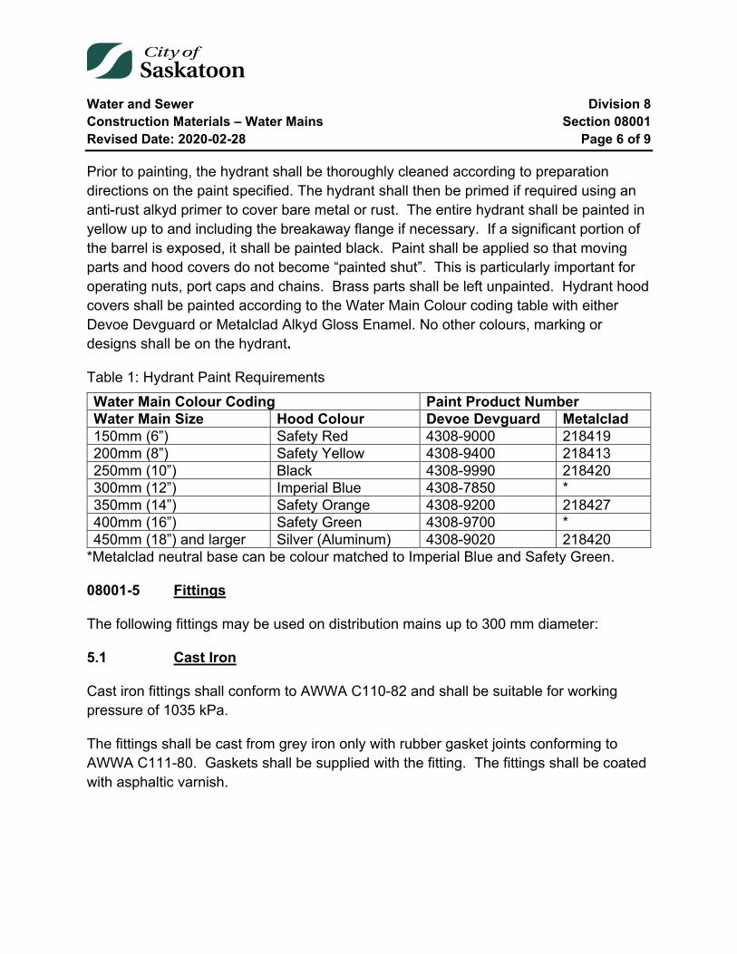
Water and Sewer Division 8 Construction Materials – Water Mains Section 08001 Revised Date: 2020-02-28 Page 6 of 9
Prior to painting, the hydrant shall be thoroughly cleaned according to preparation directions on the paint specified. The hydrant shall then be primed if required using an anti-rust alkyd primer to cover bare metal or rust. The entire hydrant shall be painted in yellow up to and including the breakaway flange if necessary. If a significant portion of the barrel is exposed, it shall be painted black. Paint shall be applied so that moving parts and hood covers do not become “painted shut”. This is particularly important for operating nuts, port caps and chains. Brass parts shall be left unpainted. Hydrant hood covers shall be painted according to the Water Main Colour coding table with either Devoe Devguard or Metalclad Alkyd Gloss Enamel. No other colours, marking or designs shall be on the hydrant.
Table 1: Hydrant Paint Requirements Water Main Colour Coding Paint Product Number Water Main Size Hood Colour Devoe Devguard Metalclad 150mm (6”) Safety Red 4308-9000 218419 200mm (8”) Safety Yellow 4308-9400 218413 250mm (10”) Black 4308-9990 218420 300mm (12”) Imperial Blue 4308-7850 * 350mm (14”) Safety Orange 4308-9200 218427 400mm (16”) Safety Green 4308-9700 * 450mm (18”) and larger Silver (Aluminum) 4308-9020 218420
*Metalclad neutral base can be colour matched to Imperial Blue and Safety Green.
08001-5 Fittings
The following fittings may be used on distribution mains up to 300 mm diameter:
5.1 Cast Iron
Cast iron fittings shall conform to AWWA C110-82 and shall be suitable for working pressure of 1035 kPa.
The fittings shall be cast from grey iron only with rubber gasket joints conforming to AWWA C111-80. Gaskets shall be supplied with the fitting. The fittings shall be coated with asphaltic varnish.

Water and Sewer Division 8 Construction Materials – Water Mains Section 08001 Revised Date: 2020-02-28 Page 7 of 9
5.2 Polyvinyl Chloride
Polyvinyl Chloride fittings shall be HARCO Class 150 as manufactured by the Harrington Corporation, or approved equal.
5.3 Fabricated Fittings
Fabricated fittings, manufactured in accordance with the requirements of AWWA C900-97, may be used on distribution mains from 150mm to 300mm diameter. Such fittings shall meet the testing requirements of CSA specification B137.3. Upon request from the Engineer, proof of compliance with testing requirements shall be provided.
Fabricated fittings, manufactured in accordance with the requirements of AWWA C905-97, may be used on distribution mains from 400mm to 1200mm diameter on a project to project basis as determined by the Engineer. Such fittings shall meet the testing requirements of CSA specification B137.3. Upon request from the Engineer, proof of compliance with testing requirements shall be provided.
08001-6 Pipe Couplings
Pipe couplings shall be manufactured in compliance with AWWA C219-11 or the most current specification. The Coupling shall be supplied with a center ring and end plates produced from the following:
• Ductile iron conforming to ASTM A536-84; • Carbon steel conforming to ASTM A512 and A53 with a yield strength of 30,000
psi; • Cast Iron Conforming to ASTM A97 Grade 32510 or 35018; or • Type 304 stainless steel.
The center ring shall be clearly and permanently marked with the manufacturers name and OD range. Gaskets shall be made of virgin rubber for water service and have a good shelf life with antioxidant and antiozonant properties. Gaskets shall be clearly and permanently marked with the nominal size, pipe OD working range, and the manufacturers' name. The Gaskets shall conform to NSF/ANSI 61, ASTM D2000 and the latest version of AWWA C111.
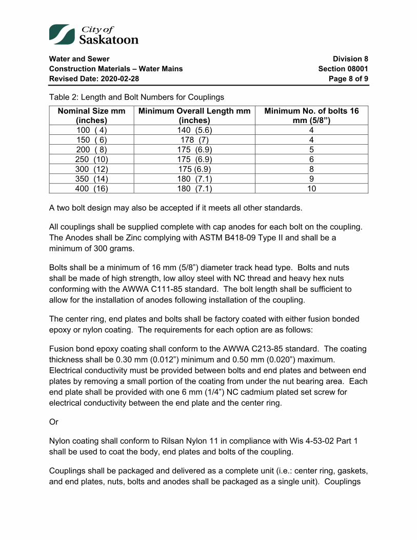
Water and Sewer Division 8 Construction Materials – Water Mains Section 08001 Revised Date: 2020-02-28 Page 8 of 9
Table 2: Length and Bolt Numbers for Couplings Nominal Size mm
(inches) Minimum Overall Length mm
(inches) Minimum No. of bolts 16
mm (5/8”) 100 ( 4) 140 (5.6) 4 150 ( 6) 178 (7) 4 200 ( 8) 175 (6.9) 5 250 (10) 175 (6.9) 6 300 (12) 175 (6.9) 8 350 (14) 180 (7.1) 9 400 (16) 180 (7.1) 10
A two bolt design may also be accepted if it meets all other standards.
All couplings shall be supplied complete with cap anodes for each bolt on the coupling. The Anodes shall be Zinc complying with ASTM B418-09 Type II and shall be a minimum of 300 grams.
Bolts shall be a minimum of 16 mm (5/8”) diameter track head type. Bolts and nuts shall be made of high strength, low alloy steel with NC thread and heavy hex nuts conforming with the AWWA C111-85 standard. The bolt length shall be sufficient to allow for the installation of anodes following installation of the coupling.
The center ring, end plates and bolts shall be factory coated with either fusion bonded epoxy or nylon coating. The requirements for each option are as follows:
Fusion bond epoxy coating shall conform to the AWWA C213-85 standard. The coating thickness shall be 0.30 mm (0.012”) minimum and 0.50 mm (0.020”) maximum. Electrical conductivity must be provided between bolts and end plates and between end plates by removing a small portion of the coating from under the nut bearing area. Each end plate shall be provided with one 6 mm (1/4”) NC cadmium plated set screw for electrical conductivity between the end plate and the center ring.
Or
Nylon coating shall conform to Rilsan Nylon 11 in compliance with Wis 4-53-02 Part 1 shall be used to coat the body, end plates and bolts of the coupling.
Couplings shall be packaged and delivered as a complete unit (i.e.: center ring, gaskets, and end plates, nuts, bolts and anodes shall be packaged as a single unit). Couplings
Water and Sewer Division 8 Construction Materials – Water Mains Section 08001 Revised Date: 2020-02-28 Page 9 of 9
shall be available for all nominal pipe sizes between 100 mm and 400 mm (4 to 16 inches) to accommodate cast iron, PVC, rough barrel and machined end asbestos cement class 150 and standard steel pipe.
08001-7 Repair Clamps/Sleeves
Repair clamps shall be Robar 5600 series or approved equal.
The material of the repair clamps shall be fully passivated all Stainless Steel construction. Gaskets shall be full wrap-around SBR (Buna S) rubber gaskets. Fasteners shall be T304 Stainless Steel material.
The material of the abandon service sleeve shall be fully passivated all stainless steel construction. Gaskets shall be full wrap-around SBR (Buna S) rubber and shall also have a NBR (Buna N) outlet gasket. Fasteners shall be T304 Stainless steel material.
Repair couplings shall have a minimum length to diameter ratio of 1.5:1.
End of Specification 08001
Water and Sewer Division 8 Construction Materials – Sewage Mains Section 08002 Revised Date: 2021-05-31 Page 1 of 8
08002 Construction Materials – Sewage Mains
Index
08002-1 Scope 2
08002-2 Concrete 2
08002-3 Sewer Pipe 2 3.1 Polyvinyl Chloride (PVC) 2 3.2 Reinforced Concrete 3 3.3 Polyethylene Pipe 3 3.4 Perforated Pipe 4
08002-4 Standard Manholes 4 4.1 1050 mm Manholes 5 4.2 1200 mm Manholes 5 4.3 Cast Iron Frame and Cover/Grate 5
08002-5 Pipe to Manhole and Concrete Structures Connectors 6 5.1 Cored Hole Compression-Type Connector 6 5.2 Cored Hole Clamp-Type Connector 7 5.3 Cast-In Compression-Type Connector 7 5.4 Grouted-In Connector 8
Tables and Equations
Table 1: Cored Hole Compression-Type Connector ....................................................... 7 Table 2: Cored Hole Clamp-Type Connector .................................................................. 7 Table 3: Cast-in Compression-Type Connector .............................................................. 7 Table 4: Grouted in Connector ........................................................................................ 8
Water and Sewer Division 8 Construction Materials – Sewage Mains Section 08002 Revised Date: 2021-05-31 Page 2 of 8
08002-1 Scope
This Section describes materials which have been approved for use in the construction of gravity, sanitary and storm sewage mains in the City of Saskatoon. Sewage force mains shall be constructed using pressure pipe, as described in Section 08001, Construction Materials - Water Mains.
08002-2 Concrete
Notwithstanding the provisions of any other specification, Type HS/HSb sulphate resistant cement shall be used in the manufacture of concrete sewer pipe, manhole barrels and other concrete products described herein.
08002-3 Sewer Pipe
The minimum size of pipe which shall be used for the construction of sanitary sewage mains, catch basin lead and storm sewage mains shall be 200 mm, 250 mm and 300 mm respectively.
The minimum size of pipe for roadway subdrainage piping shall be 100 mm diameter.
3.1 Polyvinyl Chloride (PVC)
3.1.1 (Type PSM) PVC Pipe
Smooth wall PVC pipe shall conform to ASTM D3034 and CSA B182.2. The SDR shall not be greater than 35. The pipe shall be supplied with factory installed elastomeric gaskets. Applications include sanitary and storm sewage mains and catch basin leads.
3.1.2 Profile PVC Pipe
Profile PVC pipe shall conform to ASTM F794 and CSA B182.4. The pipe shall be open profile (OP) or dual wall corrugated profile (DWCP). The pipe shall be supplied with factory installed elastomeric gaskets. Applications include storm sewage mains only.
3.1.3 (PR 80) PVC DR51 Pipe
Smooth wall PVC DR51 CIOD 80psi gasketed pressure pipe shall conform to AWWA C900, ASTM D1784, and be certified to CSA B137.3. The pipe shall be supplied with factory installed elastomeric gaskets. Applications include large diameter storm sewage
Water and Sewer Division 8 Construction Materials – Sewage Mains Section 08002 Revised Date: 2021-05-31 Page 3 of 8
mains only (600mm to 1200mm) with up to 6m of ground cover or unless otherwise specified by the Engineer.
3.2 Reinforced Concrete
Reinforced concrete pipe shall be manufactured according to the 5 classes in ASTM C76M-08a or for a specific D-load in ASTM C655M-09.
Pipe larger than 1200 mm shall have a tapered lift hole. A tapered plug shall be supplied to seal the hole. No portion of the plug shall extend into the pipe.
The laying length of standard pipe sections shall not be less than 1.8 m. Bevelled pipe for laying on curves shall be either standard length or one-half standard length. The tolerance on the bevel shall not exceed +0.001 of the pipe diameter.
3.2.1 Joints
Joints shall be the rubber gasket type.
For all pipe installed the joints shall conform to either ASTM C443M-07 or ASTM C361M-08.
3.2.2 Basis of Acceptance
Unless otherwise specified acceptance shall be based on tests described in either ASTM C76M-08a or ASTM C655M-09.
All tests shall be certified by an independent testing firm.
3.3 Polyethylene Pipe
Polyethylene pipe may be used in special cases when approved by the Director of Construction & Design.
Polyethylene pipe shall conform to the current Canadian Government Specification No. 41-GP-25m. Joints shall be butt fused in accordance with the manufacturer's recommendations.
Water and Sewer Division 8 Construction Materials – Sewage Mains Section 08002 Revised Date: 2021-05-31 Page 4 of 8
3.4 Perforated Pipe
Perforated drainage pipe shall be corrugated HDPE pipe with geotextile sock suitable for fine grained soils. The HDPE pipe shall conform to ASTM F405 or ASTM F667 and shall have a minimum stiffness of 200 kPa at 5% deflections according to ASTM D2412. Connection to the catch basin shall be made with a 100 mm diameter SDR35 PVC pipe.
3.4.1 Joints
Couplings shall be silt tight joints and conform to the specifications of ASTM F405 or ASTM F667.
08002-4 Standard Manholes
Precast reinforced concrete manhole barrels, top sections, bases and grade rings shall be manufactured in accordance with the requirements of ASTM Specification C478M-09 and all current revisions.
Twenty (20) mm diameter ribbed, extruded aluminium step rungs, equal to Model 350 Climbing Step as manufactured by MSU Mississauga or an equivalent as approved by the Director of Construction & Design, shall be installed in all manhole barrels.
Step rungs shall be uniformly spaced with centres not more than 305 mm apart.
A minimum clearance of 150mm shall be maintained between the rungs and the manhole barrel.
Notwithstanding the provisions of ASTM C478M-09, the barrels, bases, top slabs and grade rings shall be manufactured in accordance with the dimensions and details shown on current City of Saskatoon Standard Drawings as posted on the City’s Internet web site.
Lifting inserts shall be installed in all manhole barrels and cone tops (eccentric and concentric) for the purpose of lifting and installation. Catch basins shall NOT be equipped with lift holes.
Further to the requirements of article 17 of ASTM C478M-09, the specification designation, the name or trade mark of the manufacturer and the date of manufacture shall be clearly marked, with waterproof paint, on the inside surface of each manhole and catch basin section.
Water and Sewer Division 8 Construction Materials – Sewage Mains Section 08002 Revised Date: 2021-05-31 Page 5 of 8
Manhole Safety Platforms, where required, shall be manufactured in accordance with the detailed drawing supplied with these specifications.
4.1 1050 mm Manholes
Notwithstanding the provisions of ASTM Specification C478M-09, all 1050 mm diameter manhole barrel sections shall be manufactured with a minimum wall thickness of 89 mm (ASTM Class "A" Wall). The top section shall be concentric reducing from 1050 mm to 600 mm. Steps shall be spaced at 406 mm and staggered on opposite sides of the barrel.
1050mm manhole barrels and concentric cone to be used exclusively for rehabilitation work on existing 1050mm manhole bases. 1050mm manholes are not permitted for new construction or reconstruction.
4.2 1200 mm Manholes
Notwithstanding the provisions of ASTM Specification C478M-09, all 1200 mm diameter manhole barrel sections shall be manufactured with a minimum wall thickness of 127 mm (ASTM Class "B" Wall). The top section shall be eccentric reducing from 1200 mm to 600 mm. Steps shall be spaced at 305 mm, in line, along one side of the barrel.
All 1200 mm manhole barrel sections shall have single offset or grooved 0-ring rubber gasket joints manufactured in accordance with the provisions of ASTM Specification C443M-07 and all current revisions. The offset or O-ring rubber gasket shall be approved by the Director of Construction & Design prior to manufacture and acceptance of the manhole barrels. A rubber gasket shall be provided with each manhole section which is supplied.
4.3 Cast Iron Frame and Cover/Grate
Castings shall be grey cast iron and shall be clean, sound and coated with asphaltic varnish.
4.3.1 Manhole Frame and Cover
1. The manhole frame and cover shall be manufactured in accordance with the dimensions shown on current City of Saskatoon Standard Drawings as posted on the City’s Internet web site.
Water and Sewer Division 8 Construction Materials – Sewage Mains Section 08002 Revised Date: 2021-05-31 Page 6 of 8
2. Castings shall conform to all requirements of ASTM designation A48M-00 class 20B.
3. Castings shall be produced to the dimensions and within the tolerances noted.
4. Castings shall be marked with the proper identification markings which will include:
• Foundry identification markings and year of casting
• Markings shall be so located in such a manner and of such size that they are easily identifiable after installation
5. All castings shall be free of defects, be true to pattern and be free from cracks, gas holes, flaws and excessive shrinkage. Surfaces of castings shall be free from burnt- on sand and shall be reasonably smooth.
6. Castings shall not rock when installed. The manufacturer shall trial fit the castings against a standard frame.
08002-5 Pipe to Manhole and Concrete Structures Connectors
Watertight resilient flexible connections between pipe to manhole and concrete structures shall meet or exceed the requirements of ASTM Specification C923, including physical properties of materials and performance testing.
Connectors shall be installed in accordance to manufacture’s specifications. Specialty installation tools shall be acquired from the manufacturer prior to installation.
For precast manhole bases and concrete structures, flexible clamp-type connectors shall be installed by an approved manhole manufacturer.
5.1 Cored Hole Compression-Type Connector
The compression-type flexible connector shall be installed in a precast or cast-in-place manhole or concrete structure with a precision cast or cored hole of specific diameter.
The hole shall be free of imperfections and intruding rebar or wire mesh reinforcement.
Water and Sewer Division 8 Construction Materials – Sewage Mains Section 08002 Revised Date: 2021-05-31 Page 7 of 8
Table 1: Cored Hole Compression-Type Connector Manufacturer Connector Pipe Type Pipe Size (mm) Press-Seal Corporation
Kwik Seal *PVC 100–600 I.D. **CP 300-600 I.D.
Hamilton Kent HKT-CS *PVC 100-375 I.D. *(Type PSM) smooth wall pipe. Contact the pipe manufacturer for profile to smooth wall pipe adapters.
**Storm sewer applications only.
5.2 Cored Hole Clamp-Type Connector
The clamp-type flexible connector shall be installed in a precast or cast-in-place manhole or concrete structure with a precision cast or cored hole of specific diameter.
Table 2: Cored Hole Clamp-Type Connector Manufacturer Connector Pipe Type Pipe Size (mm) Press-Seal Corporation
PSX: Direct Drive & 8QRS
*PVC, CP 43–1130 O.D.
*(Type PSM) smooth wall pipe. Contact the pipe manufacturer for profile to smooth wall pipe adapters.
5.3 Cast-In Compression-Type Connector
The cast-in compression-type flexible connector shall be integrally cast into a concrete structure by an approved manhole manufacturer.
Table 3: Cast-in Compression-Type Connector Manufacturer Connector Pipe Type Pipe Size (mm) Press-Seal Corporation
Econoseal *PVC 107-389 O.D. *PVC 475-813 O.D.
*(Type PSM) smooth wall pipe. Contact the pipe manufacturer for profile to smooth wall pipe adapters.
Water and Sewer Division 8 Construction Materials – Sewage Mains Section 08002 Revised Date: 2021-05-31 Page 8 of 8
5.4 Grouted-In Connector
The grouted-in rigid connector shall be used in cast-in-place structures and manhole doghouse field poured collars when flexible connectors are not an option. All other applications require approval by the City of Saskatoon.
Where required, a structural epoxy-based bonding adhesive and non-shrink Type HS sulphate resistant, cementitious grout shall be used to fill the annular space between the pipe and concrete structure. The concrete structure opening shall be 100-150mm larger than the pipe outside diameter. The pipe and connector shall be centred in the concrete structure opening to permit proper consolidation of the non-shrink grout.
The bonding adhesive and grout shall be specified by an approved manhole manufacturer.
Table 4: Grouted in Connector Manufacturer Connector Pipe Type Pipe Size (mm) Press-Seal Corporation
WS-25 *PVC, CP 100-150 O.D. WS-30 *PVC, CP 200-3658 O.D.
*(Type PSM) smooth wall pipe. Contact the pipe manufacturer for profile to smooth wall pipe adapters.
End of Specification 08002
Water and Sewer Division 8 Construction Materials – Service Connection Section 08003 Revised Date: 2011-03-08 Page 1 of 5
08003 Construction Materials – Service Connection
Index
08003-1 Water Service 2 1.1 Pipe 2 1.2 Valves and Fittings 2
08003-2 Sewer Service 4 2.1 Pipe 4 2.2 Fittings 5 2.3 Saddles 5 2.4 Manholes and Catch Basins 5
Water and Sewer Division 8 Construction Materials – Service Connection Section 08003 Revised Date: 2011-03-08 Page 2 of 5
08003-1 Water Service
1.1 Pipe
This Section applies to materials used in the construction of service connections to City water mains. Connections larger than 50 mm shall conform to Section 08001.
Pipe used for water service shall be either copper tubing, minimum size 19 mm, or polyethylene tubing, minimum size 25 mm.
1.1.1 Copper
Copper tubing shall conform to ASTM B88 for Type K soft copper.
1.1.2 Polyethylene
Polyethylene tubing shall conform to ASTM D2737-03 for materials designated PE2306, PE3306, or PE3406. The SDR for the tubing shall be 9.
1.2 Valves and Fittings
Main stops, curb stops and unions shall conform to AWWA C800-84 and shall be made of brass. Connections shall be the compression type suitable for use with either Type K copper or polyethylene tubing. Compression couplings shall be MUELLER 110, EMCO "Successor", FORD "Pack Joint" or approved equal.
1.2.1 Main Stops
Main stops shall have a standard AWWA inlet thread and a compression coupling on the outlet.
1.2.2 Curb Stops
Curb stops shall be either the ball valve type or plug type with "O"-ring seals and shall be non-draining. FORD Type B44, EMCO "Century", MUELLER "Oriseal" or approved equal shall be used.
1.2.3 Curb Boxes
All castings shall be clean and sound.
Water and Sewer Division 8 Construction Materials – Service Connection Section 08003 Revised Date: 2011-03-08 Page 3 of 5
Curb boxes shall be the sliding type with steel pipe top and bottom sections. The top section shall be 32 mm diameter, schedule 40, type 304 stainless steel and the bottom section shall be 25 mm diameter, schedule 40, type 304 stainless steel. The sliding sections shall have a 3/8” stainless steel set screw. The box shall extend from 2460 to 2900 mm.
The curb box shall have a cast iron cover complete with 15mil (minimum) asphaltic varnish coating. The cover shall have a 25 mm threaded hole fitted with a five sided brass plug through which the curb box key may be inserted when the plug is removed. The connection between the cover and top section shall be threaded.
The boot shall be cast iron complete with 15mil (minimum) epoxy coating throughout. Refer to current City of Saskatoon Standard Drawing as posted on the City’s Internet web site for epoxy specifications. It shall be designed to rest on a base level with the bottom of the curb stop without touching the stop and service tubing. All castings shall be clean and sound. All parts shall be coated as specified.
For all new installations, the operating rod shall be a 2134mm (7ft) long stainless steel rod conforming to ASTM 304. For rehabilitation work, the operating rod shall be 2134mm (7 ft), 2438mm (8 ft) or 2743mm (9 ft) long stainless steel rod conforming to ASTM 304. At the top of the rod the sides shall be flattened to fit the curb box key.
The rod shall be 15mm in diameter for water service diameters up to and including 50mm.
The clevis shall be stainless steel conforming to ASTM 304. The clevis shall be machined or cast with a 17mm wide by 30mm deep by 30mm long slot to accept the curb stop. A hole shall be drilled in the clevis such that a 5/32” brass cotter key can be inserted to make a mechanical connection to the curb stop. The connection between the rod and clevis shall be made by forging a ½”wide square by ½” long end on the rod and inserting it into the mating hole in the clevis. The rod shall be held in the clevis by means of a 3/8” brass rivet.
1.2.4 Inserts
Inserts are required for polyethylene tubing at all compression couplings.
Water and Sewer Division 8 Construction Materials – Service Connection Section 08003 Revised Date: 2011-03-08 Page 4 of 5
The inserts shall be polyethylene with SDR of 13 and length of 38 mm. One end shall be bevelled and the other end flanged. The flange shall be 9.6 mm wide and 1.6 mm thick.
1.2.5 Service Saddles
Service saddles shall be ROBAR 2606 or approved equal for PVC pipe. ROBAR 2786 isolating saddles or approved equal shall be used for iron and steel pipe.
1.2.6 Tapping Sleeve and Valve
Tapping sleeves shall be MUELLER H-615 or approved equal. Tapping valves shall be MUELLER H-667 or approved equal.
1.2.7 Curb Box Marker
Curb box markers shall be installed on new service connections in new subdivisions. Replacement curb boxes will not require installation of the curb box marker. The curb box marker shall be 25mm polyethelene tubing with a minimum length of 0.6 meters above ground. It shall be securely fastened to the curb box spindle using tape or zip ties, as shown in the Service Connection Standard Drawing posted on the City’s Internet web site. The Contractor shall supply the markers and fastening materials unless otherwise directed by the Engineer.
08003-2 Sewer Service
This Section applies to materials used in the construction of service connections to City sanitary and storm sewer mains. The minimum size of connection shall be 100 mm for sanitary and 150 mm for storm. Connections 200 mm or larger shall conform to Section 08002.
2.1 Pipe
2.1.1 Acrylonitrile Butadiene Styrene (ABS)
ABS pipe shall conform to CSA B181.1-73. The minimum SDR shall be 19. The pipe shall be supplied with rubber gaskets.
Water and Sewer Division 8 Construction Materials – Service Connection Section 08003 Revised Date: 2011-03-08 Page 5 of 5
2.1.2 Asbestos Cement (AC)
This pipe material is not approved for use in new construction or reconstruction.
2.1.3 Polyvinyl Chloride (PVC)
PVC pipe shall conform to ASTM D3034-08. The SDR shall be 28 for all sizes less than 200 mm. The pipe shall be supplied with rubber gaskets.
2.1.4 Vitrified Clay Tile (VCT)
This pipe material is not approved for use in new construction or reconstruction.
2.2 Fittings
All bends shall be long radius PVC.
For connection of PVC, pipe couplings shall be PVC supplied with rubber gaskets. PVC to ABS connections shall be made with glued ABS coupling. “Fernco” couplings shall be used for connection of other sewer pipe materials.
2.3 Saddles
Saddles shall be supplied with seat and joint gaskets. When installed the saddle shall extend to the inner surface of the pipe wall but shall not protrude into the pipe.
2.3.1 PVC
Saddles shall conform to ASTM D3034-08 and the SDR shall be 28. The saddle shall be attached with two stainless steel straps tightened with a stainless steel screw assembly. Quick release mechanisms shall not be permitted.
2.4 Manholes and Catch Basins
Where required on service connections, manholes and catch basins shall conform to Section 08002 of these Specifications.
End of Specification 08003
Water and Sewer Division 8 Gravity Storm and Sanitary Sewer Construction Section 08010 Revised Date: 2021-02-12 Page 1 of 19
08010 Gravity Storm and Sanitary Sewer Construction
Index
08010-1 Scope 3 1.1 Existing Infrastructure - Requirements and Fees 3
08010-2 Existing Utilities and Structures 3
08010-3 Excavation 4 3.1 General 4 3.2 Trenching 5 3.3 Trench Width 6 3.4 Rock Excavation 6 3.5 Unstable Subgrade 6
08010-4 Temporary Protective Structures 7
08010-5 Preparation of Trench Bottom 8
08010-6 Pipe Bedding 8 6.1 General 8 6.2 Class A Bedding 8 6.3 Class B Bedding 8
08010-7 Pipe Laying and Jointing 9 7.1 General 9 7.2 Alignment and Grade 9 7.3 Polyvinyl Chloride (PVC) Pipe 10 7.4 Concrete Pipe 10 7.5 Polyethylene Pipe 11
08010-8 Manholes 11 8.1 General 11 8.2 Cast-In-Place Manhole Base 12

Water and Sewer Division 8 Gravity Storm and Sanitary Sewer Construction Section 08010 Revised Date: 2021-02-12 Page 2 of 19
8.3 Precast Manhole Base 12 8.4 Foundation 12 8.5 Pipe Supports 13 8.6 Build Up 14
08010-9 Backfill 15 9.1 Initial Backfill in Pipe Zone 15 9.2 Backfill above Pipe Zone 16 9.3 Street Surfaces 17
08010-10 Testing 18 10.1 General 18 10.2 Infiltration Testing 18 10.3 Exfiltration Testing 19 10.4 Allowable Leakage 19
08010-11 Clean Up 19
Tables
Table 1: Maximum Trench Width .................................................................................... 6

Water and Sewer Division 8 Gravity Storm and Sanitary Sewer Construction Section 08010 Revised Date: 2021-02-12 Page 3 of 19
08010-1 Scope
The General Conditions, Specific Conditions and Material Specifications form an integral part of these Specifications and shall be read in conjunction herewith.
This Section shall include Sewer Connections Construction not regulated by Section 08025 wherein sewer service connections are greater than 150mm in diameter.
The Contractor shall supply all material, labour, equipment, plant and tools necessary to construct the gravity storm and sanitary sewers within and/or under the jurisdiction of the City of Saskatoon as required under its Contracts.
1.1 Existing Infrastructure - Requirements and Fees
Certain fees for inspection, tapping mains, pavement and concrete repair, detouring services and public liability insurance shall be charged by the City to the Contractor on completion of the work.
The contractor shall obtain the conditions of work and fee rates by contacting the Water & Sewer Connections Desk at 975-2461 before estimating or commencing any particular project. The Water & Sewer Connections Desk will outline the requirements and fees so that the Contractor shall know in advance and the safety of the water and sewer system remains intact.
Before any work within the City Right-of-Way is performed, the Contractor shall have an approved permit “Use of Right-of-Way Permit”. This permit shall be obtained by contacting the Transportation Right of Way Group at 975-2460. There may be restrictions on times and dates that portions of Right-of-Way may be available and this will be outlined in the Use of Right-of-Way permit.
08010-2 Existing Utilities and Structures
The location and elevation of existing underground utilities is compiled from records but is not guaranteed. Notwithstanding any other provision, the Contractor shall be responsible for determining at his expense the actual location and elevation of all sewer, water and gas lines, power, telephone or telecommunications conduits, or other such structures or utilities whether or not shown on the plans. The Contractor shall be responsible for notifying the respective utility at least 48 hours in advance of his

Water and Sewer Division 8 Gravity Storm and Sanitary Sewer Construction Section 08010 Revised Date: 2021-02-12 Page 4 of 19
intention to carry out operations in the vicinity of the said utility and if required shall pay for any services supplied for locating these utilities.
When in the course of the work, existing utilities must, for reasonable cause, be temporarily disconnected, the Contractor shall be wholly responsible for notifying all persons affected, at least 48 hours in advance of the outage. The Contractor shall contact the utility owner who may disconnect the utility himself or supervise the Contractor during disconnection. In no case shall the Contractor operate any utility without the approval of the owner.
When a utility is exposed during construction, the Contractor shall immediately inform the owner of the utility, who may inspect the utility prior to backfilling.
Any accidental damage such as severing a cable, scraping the coating on an underground pipe or rupturing the pipe must be reported immediately through the appropriate emergency number.
Where existing utilities or other street improvements are found to be within the lines of the work the Engineer shall be notified. The Contractor shall then proceed as directed by the Engineer or the respective utility corporation.
All costs incurred for the disruption of service and for the repair of surface and/or underground utilities damaged by the Contractor's operation shall be the Contractor's responsibility.
Existing sidewalks and curbs, mains, service connections, catch basin leads and structures removed or damaged by the Contractor shall be repaired or replaced by the Contractor at his own expense.
Maintenance of existing utilities and structures which were disturbed or repaired by the Contractor, shall be the responsibility of the Contractor for the duration of the maintenance period.
08010-3 Excavation
3.1 General
Excavation shall be taken to mean the removal from the trench of all material of whatever kind encountered, for the construction therein of all sewers and manholes. All
Water and Sewer Division 8 Gravity Storm and Sanitary Sewer Construction Section 08010 Revised Date: 2021-02-12 Page 5 of 19
excavations shall be made to the lines and grades as shown on the plans or as established in the field by the Engineer.
3.2 Trenching
The trench shall be excavated only so far in advance of pipe laying as permitted by the Engineer. The walls of the trench shall be sloped or shored up to prevent caving, in accordance with the requirements of the Occupational Health and Safety Regulations. All water encountered in the trench shall be pumped out before saturation of the pipe bedding material occurs. The discharge from the trench dewatering pumps shall be conducted away from the site of the work and into natural drainage channels, drains or storm sewers.
The trench shall be excavated so as to provide a uniform and continuous support for the pipe and fittings on solid undisturbed ground. Any over-excavation by the Contractor below the required grade shall be backfilled at his expense with compacted bedding material.
The earth taken from the trench shall be neatly deposited at the sides, in such manner as to obstruct the street or lane as little as possible. Where it is impracticable in the opinion of the Engineer to place the earth at the side of the trench, it shall be removed and deposited as designated by the Engineer. The Contractor shall repair all walls, crib work, culverts, drains, ditches and embankments which it may be necessary to remove or to pass through in laying the pipes.
The Contractor shall provide for all surface water courses and drainage systems interrupted during the progress of the work, and replace them in as good condition as originally encountered.
The Contractor shall remove all pavement from the surface of any area to be excavated prior to starting the excavation.
The edges of the areas to be removed shall be precut in straight lines for the full depth of the pavement. The Contractor shall then remove the pavement and transport it to the storage site designated by the Engineer.
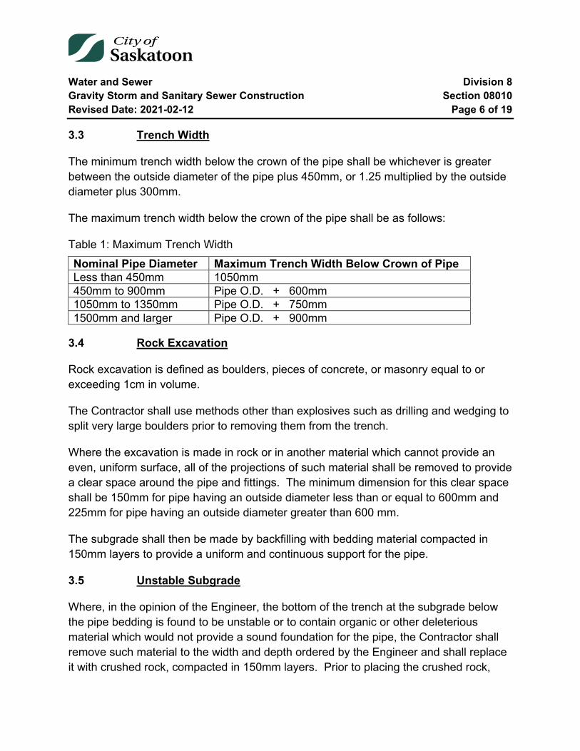
Water and Sewer Division 8 Gravity Storm and Sanitary Sewer Construction Section 08010 Revised Date: 2021-02-12 Page 6 of 19
3.3 Trench Width
The minimum trench width below the crown of the pipe shall be whichever is greater between the outside diameter of the pipe plus 450mm, or 1.25 multiplied by the outside diameter plus 300mm.
The maximum trench width below the crown of the pipe shall be as follows:
Table 1: Maximum Trench Width Nominal Pipe Diameter Maximum Trench Width Below Crown of Pipe Less than 450mm 1050mm 450mm to 900mm Pipe O.D. + 600mm 1050mm to 1350mm Pipe O.D. + 750mm 1500mm and larger Pipe O.D. + 900mm
3.4 Rock Excavation
Rock excavation is defined as boulders, pieces of concrete, or masonry equal to or exceeding 1cm in volume.
The Contractor shall use methods other than explosives such as drilling and wedging to split very large boulders prior to removing them from the trench.
Where the excavation is made in rock or in another material which cannot provide an even, uniform surface, all of the projections of such material shall be removed to provide a clear space around the pipe and fittings. The minimum dimension for this clear space shall be 150mm for pipe having an outside diameter less than or equal to 600mm and 225mm for pipe having an outside diameter greater than 600 mm.
The subgrade shall then be made by backfilling with bedding material compacted in 150mm layers to provide a uniform and continuous support for the pipe.
3.5 Unstable Subgrade
Where, in the opinion of the Engineer, the bottom of the trench at the subgrade below the pipe bedding is found to be unstable or to contain organic or other deleterious material which would not provide a sound foundation for the pipe, the Contractor shall remove such material to the width and depth ordered by the Engineer and shall replace it with crushed rock, compacted in 150mm layers. Prior to placing the crushed rock,

Water and Sewer Division 8 Gravity Storm and Sanitary Sewer Construction Section 08010 Revised Date: 2021-02-12 Page 7 of 19
geotextile fabric shall be installed flat on the trench bottom. The fabric shall extend up the trench walls to accommodate a minimum seam overlap of 900mm or equivalent to the trench width. The top surface of the crushed rock shall be covered with geotextile fabric before any pipe bedding aggregate is placed.
Where, in the opinion of the Engineer, additional support is required for the pipe, the Contractor shall supply all materials and shall construct such additional support in accordance with the plans and specifications which will be provided to him by the Engineer.
08010-4 Temporary Protective Structures
The Contractor shall protect excavations, trenches, shafts and tunnels from cave-ins, collapse, sliding or rolling materials by cutting back the walls and/or supplying and installing Temporary Protective Structures as required by the Occupational Health and Safety Regulations and as may be necessary to protect adjacent property and the work.
The Contractor shall install Temporary Protective Structures to prevent movement in the sides of the excavations. All material required, as well as the labour required for the installation, shall be furnished by the Contractor as part of this Contract.
The Contractor shall ensure that, where required by the Occupational Health and Safety Regulations, a professional engineer certifies that the Temporary Protective Structure, if constructed as drawn, and installed and used as instructed, will provide adequate protection to any worker constructing, installing or using the Temporary Protective Structure. The Contractor shall, prior to commencing construction, provide the Engineer with a copy of this certification for each Temporary Protective Structure which will be used on the project.
The right of the Engineer to order sheeting, bracing, underpinning or any other form of brace or support shall not be construed as creating any obligation on his part to issue such orders and his failure to exercise his right to do so shall not relieve the Contractor from his responsibility for damages to persons or property arising from or upon the work of construction occasioned by negligence or otherwise growing out of a failure on the part of the Contractor to leave in place in the trench sufficient sheeting and bracing to prevent any caving or moving of the ground adjacent to the sides of the trench, or for failure to construct and maintain proper support of all kinds whatsoever in the first instance.
Water and Sewer Division 8 Gravity Storm and Sanitary Sewer Construction Section 08010 Revised Date: 2021-02-12 Page 8 of 19
Sheeting and bracing ordered left in place must be cut off and removed for a depth of 900mm below the established street grade or the existing surface of the street, whichever is lower.
08010-5 Preparation of Trench Bottom
The Contractor shall remove any water which has accumulated in the excavation by pumping before any bedding is placed. The previously installed pipe shall not be used to drain the trench. Loose material shall be removed from the surface and the subgrade shall be thoroughly compacted.
08010-6 Pipe Bedding
6.1 General
The type of bedding to be used with each size and class of pipe shall be as shown on the Tender Form and in the Specific Conditions. The following various classes of bedding are detailed on the current City of Saskatoon Standard Drawing as posted on the City’s Internet web site.
6.2 Class A Bedding
The pipe shall be bedded on a continuous cradle constructed of 30MPa concrete shaped to fit the lowest part of the pipe exterior. The concrete shall be made using Type HS/HSb sulphate resistant cement. The required minimum concrete cradle thickness under the pipe shall be as outlined on the current City of Saskatoon Standard Drawing as posted on the City’s Internet web site for various pipe diameters and shall extend up the sides of the pipe to a height equal to 1/4 of the outside diameter of the pipe. The concrete cradle shall extend over the whole width of the trench and shall be constructed monolithically without horizontal construction joints.
6.3 Class B Bedding
The pipe shall be bedded on a layer of approved pipe bedding aggregate as defined in Section 03001-3.2.7 shaped to fit the lowest part of the pipe exterior. The required minimum depth of the granular material under the pipe shall be as outlined on the current City of Saskatoon Standard Drawing as posted on the City’s Internet web site for various pipe diameters and shall extend up the sides of the pipe to a height equal to 1/2 of the outside diameter of the pipe. Care shall be taken to completely fill all voids under
Water and Sewer Division 8 Gravity Storm and Sanitary Sewer Construction Section 08010 Revised Date: 2021-02-12 Page 9 of 19
the pipe. The bedding material shall be placed in 150mm layers and shall be compacted to 98% of its Standard Proctor Density using mechanical compaction equipment.
08010-7 Pipe Laying and Jointing
7.1 General
The pipe shall be protected against impact shocks and free fall during handling and shall be kept clean at all times.
Each pipe shall be carefully inspected prior to being lowered into the trench and those not meeting specifications shall be rejected and shall be removed from the site of the work. Pipe laying shall commence at the lowest point of the sewer. The individual pipe lengths shall be laid in an uphill direction with spigots pointing downgrade and bell ends in the upgrade direction. The Contractor shall excavate the trench deeper at the location of each joint to facilitate making the joint and so that the pipe will not rest on the bell when it is installed. Each pipe shall be installed so that the bedding material will support it evenly throughout its entire length. The interior of the pipe and the bell must be cleared of all foreign material before the joint is made. The sections of pipe shall be fitted together to form a smooth and uniform invert.
The Contractor shall supply a watertight cap or plug which shall be installed on the end of the pipe while excavation is in progress and when the Contractor leaves the site of the work.
7.2 Alignment and Grade
Gravity sewers shall be installed according to the lines and grades shown on the plans or as staked in the field by the Engineer. The Contractor shall transfer line and grade to the sewer by means of an approved batter board and boning rod system, laser beam system, or other system approved by the Engineer.
Variance from grade shall not exceed 0.03mm per mm of pipe diameter or 10mm whichever is greater. Provided in all cases that such variation does not result in a reverse sloping invert.
Variance from alignment shall not exceed 2 times the variance allowed for grade.
Water and Sewer Division 8 Gravity Storm and Sanitary Sewer Construction Section 08010 Revised Date: 2021-02-12 Page 10 of 19
7.3 Polyvinyl Chloride (PVC) Pipe
Polyvinyl Chloride (PVC) shall be installed as per ASTM D2321 unless specified otherwise.
PVC pipe shall be jointed as follows. The bell, spigot and rubber gasket shall be cleaned with a clean cloth, removing all traces of dirt, grit or plastic cuttings. A thin film (equivalent to a brushed coating) of a lubricant manufactured for this purpose shall be applied uniformly to the bell and spigot areas as indicated by the pipe manufacturer’s published recommendations. With the assistance of a lever pressing on a wooden cushion block which has been placed against the bell end of the pipe, a uniform force shall be applied until the pipe has been inserted to the reference mark.
The Contractor shall use a fine tooth hand saw or a power cut-off saw to cut the pipe where this is required. The ends shall be cut square and shall be bevelled at 15° through 1/2 of the wall thickness using a grinding disc or a flat file. The jointing reference mark shall be re-established using a factory marked pipe of the same size as a guide.
7.4 Concrete Pipe
The sealing surfaces of the pipe shall be carefully checked to ensure that they are smooth, concentric and free from any imperfections which might impair the sealing efficiency of the rubber gasket. Both the tongue and the groove shall be cleaned and the gasket shall be installed on the tongue in accordance with the manufacturer's instructions.
All sliding surfaces shall be well lubricated and the pipes immediately coupled. The interior vertical mating surfaces of the joint are to be uniformly tight with a maximum separation not greater than that recommended by the pipe manufacturer. The proper equipment shall be used to pull the pipes together to ensure that the joints are properly engaged.
Where the alignment of the pipe produces a radius curve which would cause the joints to “open up” beyond the manufacturer’s recommended allowable limit, the Contractor shall install radius pipe to accommodate the curve in the alignment.

Water and Sewer Division 8 Gravity Storm and Sanitary Sewer Construction Section 08010 Revised Date: 2021-02-12 Page 11 of 19
7.5 Polyethylene Pipe
Polyethylene pipe which is being used for sewer construction shall be joined by butt fusing the ends of the pipes. The Contractor shall use the specially designed joining machines complete with alignment jigs, trimmers and heating plate which can be obtained from the pipe manufacturer. The Contractor shall provide personnel who have been trained to perform this procedure and shall ensure that the joints are made in accordance with the manufacturer's specifications.
08010-8 Manholes
8.1 General
The Contractor shall construct manholes on gravity sewers at the locations and grades shown on the plans or as staked in the field by the Engineer.
The Contractor shall supply all materials and construct manholes on the sewer mains in accordance with the City of Saskatoon Standard Drawings as posted on the City’s Internet web site.
1050mm manholes are not permitted for new construction or reconstruction.
Concrete shall conform to Section 08000-9 “Concrete”.
Unshrinkable fill shall conform to Section 08000-8 “Unshrinkable Fill”.
Grout shall conform to Section 08002-5.4 “Grouted-In Connector”.
All sanitary sewer manhole bases shall have a half section of pipe cast in the base with 35MPa Type HS sulphate resistant concrete benched into it. The pipe channeling shall be seamless for straight through and dead end manhole bases.
All sanitary and storm pipe to manhole connections shall incorporate a seal, resulting in a watertight pipe to manhole connection.
Pipe to manhole and concrete structure connections shall conform to Section 08002-5 “Pipe to Manhole and Concrete Structure Connectors”.
Water and Sewer Division 8 Gravity Storm and Sanitary Sewer Construction Section 08010 Revised Date: 2021-02-12 Page 12 of 19
The Contractor shall install stub pipes for future connections at the alignment and grades shown on the plans or as established in the field by the Engineer. The stubs shall be sealed with suitable plugs which will not admit earth or water into the manhole.
The Contractor shall construct a standard City of Saskatoon exterior drop structure at the manhole on any sanitary sewer line where the incoming sewer crown is 750mm or more above the lowest crown of outlet pipe in the manhole.
8.2 Cast-In-Place Manhole Base
Standard 1200mm manholes for sewers 675mm to 900mm in diameter shall have the base constructed using substantial forms. The practice of pouring an unconfined mass of concrete for the base is not acceptable. The Contractor shall not cast the manhole barrel into the manhole base. The opening shall be formed as shown on the standard drawings and the manhole barrel shall be installed into the recess after the forms have been removed.
All manholes constructed on 200mm to 600mm diameter sewers shall have a minimum 150mm thick, measured from the invert, 35MPa Type HS sulphate resistant concrete base, and a single mat of 10M reinforcement at 200mm on centre each way, on manholes over 4.5 metres deep and manholes with an external drop structure. Substantial forms shall confine the concrete.
Saw cut openings (dog houses), will be permitted at the manhole base when tying into the required base half pipe.
8.3 Precast Manhole Base
All precast manhole bases shall be supplied with extra wide bases. For standard 1200mm manholes with a wall thickness of 127mm, the extra wide base shall have an outside diameter of 1829mm.
8.4 Foundation
8.4.1 Stable Subgrade
The Contractor shall excavate in-situ material to the underside of the manhole base elevation. Surface is to be stable, undisturbed material.
Water and Sewer Division 8 Gravity Storm and Sanitary Sewer Construction Section 08010 Revised Date: 2021-02-12 Page 13 of 19
If over excavation occurs then the minimum depth shall be equivalent to the thickness of the manhole base slab. Over excavation depth shall not exceed 600mm.
The Contractor shall backfill the over excavation with Pipe Bedding Aggregate in 150mm lifts compacted to 98% Standard Proctor Density.
An alternative to backfilling the over excavation with pipe bedding aggregate is to use crushed rock, geotextile fabric and pipe bedding aggregate as contained in Specification 8.4.2 Unstable Subgrade.
8.4.2 Unstable Subgrade
The Contractor shall over excavate to a minimum depth of 200mm below the underside of the manhole base elevation.
The Contractor shall backfill the over excavation with crushed rock, compacted in 150mm lifts. Prior to placing the crushed rock, geotextile fabric shall be installed flat on the trench bottom. The fabric shall extend up the trench walls to accommodate a minimum seam overlap of 900mm or equivalent to the trench width. The top surface of the crushed rock shall be covered with geotextile fabric before any pipe bedding aggregate is placed.
The depth of pipe bedding aggregate below the manhole base shall be 100mm. The pipe bedding aggregate shall be compacted to 98% Standard Proctor Density.
8.5 Pipe Supports
8.5.1 Concrete
Concrete pipe supports shall conform to City of Saskatoon Standard Drawing 102-0011-011.
Where specified or approved by the Project Engineer, the Contractor shall use Type HS sulphate resistant concrete to backfill the space under a new concrete pipe to undisturbed soil where it connects to a manhole, including PVC external drop structures.
Concrete fill shall only be placed against undisturbed ground or against substantial forms, which the Contractor shall construct, to contain the concrete while it is being
Water and Sewer Division 8 Gravity Storm and Sanitary Sewer Construction Section 08010 Revised Date: 2021-02-12 Page 14 of 19
placed. These forms shall be removed after the concrete has set and before the Contractor may backfill the remainder of the excavation. The Contractor may not use non-compacted earth backfill as a form to contain the concrete.
8.5.2 Non Shrink / Unshrinkable Fill
The Contractor shall use unshrinkable fill to backfill the space under a new pipe; including service connection pipe, where it connects to a manhole, the space under a new pipe crossing over the excavation adjacent to a manhole, the space between mains of a different elevation which cross in a trench and any portion of an excavation which cannot be mechanically compacted.
Unshrinkable fill shall only be placed against undisturbed ground or against substantial forms, which the Contractor shall construct, to contain the unshrinkable fill while it is being placed. These forms shall be removed after the unshrinkable fill has set and before the Contractor may backfill the remainder of the excavation. The Contractor may not use earth backfill as a form to contain the unshrinkable fill.
8.6 Build Up
Manhole bases shall be channelized and benched prior to build up.
If the Contractor chooses to channelize and bench manholes after build up, they shall supply a camera for inspection. If camera inspection is done, a Panoramo SI 3D Optical Manhole Scanner will be used with video footage submitted to the Engineer.
The manhole riser section barrels shall use Tylox Super Seal Gaskets on all joints.
Cement mortar shall not be used on the rubber gasket joints of manholes constructed with 1200mm diameter precast sections.
The manhole base shall be level and the barrels shall be plumb.
The exposed flat concrete shelf from a precast transition slab top to the manhole barrel riser shall be benched with non-shrink, Type HS sulphate resistant grout, to prevent debris from collecting.
The manhole rungs shall be installed such that they are aligned, uniformly spaced and do not interfere with the incoming piping.
Water and Sewer Division 8 Gravity Storm and Sanitary Sewer Construction Section 08010 Revised Date: 2021-02-12 Page 15 of 19
Manhole safety platforms shall conform to City of Saskatoon Standard Drawing 102-0011-001 available on the City’s web site.
Manholes shall be constructed to final grade by installing rubber adjustment riser rings, one or more concrete grade rings and tapered/or non-tapered adjustment riser rings between the tapered precast manhole section and the cast iron frame. The minimum and maximum depth of grade rings permitted shall be 50mm and 300mm respectively or as directed by the Engineer.
The joints between the top of the tapered precast manhole section, rubber adjustment riser rings, concrete grade rings, tapered/non-tapered rubber adjustment riser rings and the cast iron frame and the joints between themselves shall be bonded using a waterproof elastomeric polyurethane sealant. The sealant shall be applied in a continuous bead around the above noted components approximately 25mm from the inner and outer edges. The sealant must be sufficiently placed between all rings (rubber and concrete) and frames so that when the components are placed together the total areas touching are covered and sealant is squeezed out around the entire inner and outer circumference. A finished bead of sealant shall be placed on the inside and finished smooth. The supply and application of the sealant shall be the responsibility of the Contractor.
08010-9 Backfill
9.1 Initial Backfill in Pipe Zone
The Contractor shall hand place select excavated material which is free from lumps and stones in 150mm lifts above the granular bedding on both sides of the pipe and to a point 300mm above the crown of the pipe over the full width of the trench. The Contractor shall compact each lift to 98% of its Standard Proctor Density.
Placement of haunching materials shall be carried out by methods that will not disturb or damage the pipe.
The haunching material shall be worked in and tamped in the area between the bedding and the underside of the pipe before placement and compaction of the remainder of the material in the embedment zone.
Water and Sewer Division 8 Gravity Storm and Sanitary Sewer Construction Section 08010 Revised Date: 2021-02-12 Page 16 of 19
Compaction equipment and methods used in the haunch zone shall be compatible with the materials used, the location in the trench, and the in-place densities required.
9.2 Backfill above Pipe Zone
9.2.1 Class I Backfill
Approved granular material with a maximum aggregate size of 75mm, shall be placed in 300mm lifts over the whole width of the trench. Each lift shall be compacted to 98% of Standard Proctor Density, using mechanical compaction equipment.
9.2.2 Class II Backfill
Approved excavated material shall be placed in 300mm lifts over the whole width of the trench. Each lift shall be compacted to 98% of Standard Proctor Density, using mechanical compaction equipment.
This backfill may contain course materials but shall be free from brush, frozen or other objectionable material that would prevent proper consolidation or that might cause subsequent settlement.
Rocks or stones not exceeding 10kg in weight may be placed in this portion of the backfill but must be placed by hand.
The Contractor shall be responsible for controlling the moisture content of the backfill material so that the moisture content will be close to the optimum percentage for compaction. The Contractor shall add water to the material if the moisture content is too low or if the moisture content is too high, the Contractor shall move the material to an approved stockpile area, dry the material and then move the material back to the site of the work.
9.2.3 Class III Backfill
Class III backfill shall consist of approved excavated material free from brush and rocks or stones over 10 kilograms and other objectionable material. Backfill material shall be pushed down a ramp or slope of existing backfill and not directly onto the newly bedded pipe.
Water and Sewer Division 8 Gravity Storm and Sanitary Sewer Construction Section 08010 Revised Date: 2021-02-12 Page 17 of 19
The backfill material shall be placed in 750mm lifts over the whole width of the trench. Each lift shall be compacted to a density which is equal to the density of the adjacent soil.
9.2.4 Backfill around Manholes
The Contractor shall carefully select, place and compact backfill material in 150mm lifts for a distance of 600mm around each manhole. The contractor shall compact each lift to a minimum of 98% of the Standard Proctor Density.
9.3 Street Surfaces
9.3.1 General
The Contractor shall use a rubber tired motor grader to spread surface granular materials during compaction and to level earth streets after the backfilling has been completed.
The Contractor shall be responsible for filling trench settlements and repairing street surfaces which settle along the lines of his work during the maintenance period.
9.3.2 Paved Streets
Where excavation has been carried out on a paved street or on a street which has been based and is ready for pavement, the Contractor shall backfill the excavation up to 300mm below the level of the original street surface. The Contractor shall then place 300mm of base gravel to the gradation as specified in Section 08000-7.2 flush with the original street surface and shall compact it to 100% of Standard Proctor Density. Prices tendered for laying pipe, shall include the supply and placing of this gravel unless specified otherwise.
9.3.3 Gravel Streets
Where the excavation has been carried out on a gravel street, the Contractor shall backfill the excavation up to 100mm below the level of the original street surface.
The Contractor shall then place 100mm of base gravel to the gradation as specified in Section 08000-7.2 flush with the original street surface and shall compact it to 100% of
Water and Sewer Division 8 Gravity Storm and Sanitary Sewer Construction Section 08010 Revised Date: 2021-02-12 Page 18 of 19
Standard Proctor Density. Prices tendered for laying pipe, shall include the supply and placing of this gravel unless specified otherwise.
9.3.4 Earth Streets
Where excavation has been carried out on a graded earth street, the Contractor shall backfill the excavation up to the level of the original street surface.
Where the surface of the street has not previously been cut to grade, the Contractor shall spread and level any surplus excavated material over the top of the excavation.
9.3.5 Surplus Excavated Material
Where excavation has been carried out on a paved street, gravelled street or graded earth street all of the excavated material may not be required for backfilling. The Contractor shall load and haul this surplus excavated material to the nearest earth dumping site or to the location as specified in the Specific Conditions. The costs of disposing of this material shall be included in the Contractor's unit prices for constructing sewers.
08010-10 Testing
10.1 General
The Engineer will designate those sections on which testing is to be conducted and whether the tests should be for infiltration or exfiltration.
Infiltration and exfiltration tests will not be required for storm sewers unless specified on the Tender Form or in the Specific Conditions.
The Contractor shall supply all of the labour and equipment necessary to perform these tests. The costs of testing shall be included in the Contractor's unit prices for constructing sewers.
10.2 Infiltration Testing
The pipe at the highest point on the infiltration test section shall be sealed with a water tight plug. The amount of water infiltrating into the test section shall be measured at the low end of the test section by means of an approved weir or meter.
Water and Sewer Division 8 Gravity Storm and Sanitary Sewer Construction Section 08010 Revised Date: 2021-02-12 Page 19 of 19
The duration of the test shall not be less than 4 hours and the length of the test section will be as determined by the Engineer.
10.3 Exfiltration Testing
The pipe section to be tested shall be sealed at its lower extremity with a water tight plug and filled with water so that a hydrostatic head of 600mm is formed above the crown of the pipe at the upper end of the test section.
In no case shall the pressure head on any part of the test section be in excess of 3m of water.
The 600mm head of water shall be maintained by the addition of water for 1 hour prior to commencing the test to allow for normal absorption.
The length of the test period shall not be less than 6 hours. The Contractor shall continue to add water as required throughout the test period in order to maintain the 600mm head of water on the test section. The water added during this time shall be considered to be equal to that lost due to exfiltration.
10.4 Allowable Leakage
The maximum allowable leakage of gravity sewers and appurtenances subjected to exfiltration or infiltration testing shall not exceed 1.85 litres per 24 hours per millimetre of diameter per 100m of sewer pipe.
The Contractor shall, where the actual leakage on a section of sewer exceeded the allowable, repair and/or replace the section and then retest the section until the actual leakage no longer exceeds the allowable.
08010-11 Clean Up
The Contractor shall clean up the site as the work progresses.
The Contractor shall remove all of his equipment, plant, tools and surplus material from the site of the finished work and shall repair and restore all drainage facilities which have been blocked or damaged as a result of the Contractor's operations.
End of Specification 08010
Water and Sewer Division 8 Sewers Constructed in Tunnels Section 08015 Revised Date: 2012-06-06 Page 1 of 13
08015 Sewers Constructed in Tunnels
Index
08015-1 Scope 3
08015-2 Drawings 3
08015-3 Materials 3
08015-4 Tunnel Excavation 3 4.1 General 3 4.2 Tunnel Excavation and Material Removal 4 4.3 Support of Tunnel 4 4.4 Tunnel Headings 4 4.5 Rock Excavation 5 4.6 Explosives 5 4.7 Water Removal 5 4.8 Drainage 5
08015-5 Shafts, Manholes and Alignment Holes 6 5.1 Shafts 6 5.2 Manholes 6 5.3 Alignment Holes 7 5.4 Backfilling Shafts and Around Manholes 7
08015-6 Tunnel Lining 8 6.1 General 8 6.2 Alignment and Grade 8 6.3 Monolithic Concrete Sewer 8 6.4 Galvanized Steel Tunnel Liner 9
08015-7 Tunnel Safety and Accessories 9 7.1 General 9 7.2 Ventilation 10
Water and Sewer Division 8 Sewers Constructed in Tunnels Section 08015 Revised Date: 2012-06-06 Page 2 of 13
7.3 Electric Wiring and Lighting 11 7.4 Hoisting 11
08015-8 Tunnelling Under Compression Air 11
08015-9 Clean-up 13
Water and Sewer Division 8 Sewers Constructed in Tunnels Section 08015 Revised Date: 2012-06-06 Page 3 of 13
08015-1 Scope
The Contractor shall furnish all material, labour, equipment, plant and tools necessary to perform the work required under the Contract. The Contractor shall remove any road surface as stipulated at shaft locations, excavate for shafts and tunnel to the required dimensions, sheet, brace and support the tunnel section during construction, handle all drainage of ground water, provide barricades, guards and warning lights, backfill and consolidate shafts, repair or replace all structures removed or damaged during the course of the fulfilment of the Contract, remove surplus excavated material and cleanup the site of the work.
08015-2 Drawings
The drawings and the specifications are intended to supplement each other. The Contractor shall examine both carefully. Any discrepancies shall be brought to the attention of the Engineer as outlined in the General Conditions.
08015-3 Materials
The Contractor shall supply all materials required for the fulfilment of the Contract except those specifically listed elsewhere in the specification as being supplied by the Owner. The Contractor is solely responsible for delivery to site from point of origin, handling and safe storage of all materials until such time as they are incorporated in the work and it is accepted by the Engineer. The Contractor is further responsible for any surplus material supplied by the Owner until he has returned such surplus to the Owner's storage yard.
08015-4 Tunnel Excavation
4.1 General
The method of tunnelling may vary in accordance with requirements of the particular materials being excavated.
The method of tunnelling shall be subject to prior approval by the Engineer but full responsibility for safety and quality of the work shall be borne by the Contractor. The use of primary tunnel lining will not decrease the specified requirements for tunnel pipe.
Water and Sewer Division 8 Sewers Constructed in Tunnels Section 08015 Revised Date: 2012-06-06 Page 4 of 13
4.2 Tunnel Excavation and Material Removal
Excavation shall mean the removal of all material of whatever kind from the shafts and tunnel for the laying or construction therein of all liner and for the construction of manholes. The tunnel shall be excavated to lines and grades shown on the plans and established by the Engineer. Excavation for the tunnel shall be to the sizes and shapes specified or shown and such as will allow placing of tunnel liner or the full concrete section specified. Excavated material shall be promptly removed from the tunnel and tunnel exit as soon as it is taken out of the heading and disposed of at a site designated by the Engineer. Where the haul to the dump site is greater than 1.6 kilometres from the exit, the Contractor shall be paid for overhaul at the rate set out in the Specific Conditions section. Excavation shall be carried out in accordance with the best rules and methods of tunnel construction with safety to life and property and with a minimum of inconvenience to the public.
4.3 Support of Tunnel
The right of the Engineer to order sheeting, bracing, underpinning or any other form of brace or support shall not be construed as creating any obligation on his part to issue such orders and his failure to exercise his right, shall not relieve the Contractor from his responsibility for damages to persons, or property arising from or upon the work of construction occasioned by negligence or otherwise growing out of a failure on the part of the Contractor to leave in place in the tunnel sufficient sheeting and bracing to prevent any caving or moving of the ground adjacent to the sides of the tunnel, or for failure to construct and maintain proper support of all kinds whatsoever in the first instance.
4.4 Tunnel Headings
Tunnel headings shall not be farther than 7.6 metres from the concrete or tunnel liner section except with the written permission of the Engineer. All mining operations shall cease until this provision is fulfilled and the general procedure of the work indicates that this provision will be maintained. Whenever two headings or a heading and a shaft are to meet underground the final 6.0 metres shall be driven without the use of explosives approximately 1.0 metres smaller in diameter except in the case of soft ground or forepoled tunnels so that adjustment to line or grade may be made. The entire cost of enlarging this connecting tunnel to the specified size and dimensions shall be included
Water and Sewer Division 8 Sewers Constructed in Tunnels Section 08015 Revised Date: 2012-06-06 Page 5 of 13
in the price bid for that section by the Contractor and no additional payment will be made.
4.5 Rock Excavation
Excavation in rock shall be carried out in such a way as to not damage structures above or adjacent to the work. Boulders one quarter of a cubic metre or over within the line of the tunnel will be classified as rock.
4.6 Explosives
The use of explosives shall be permitted only when the Contractor has demonstrated his ability to undertake subsurface blasting with absolutely no damage resulting to structures in the vicinity of the blasts. Only a minimum of nuisance from blasting operations can be tolerated.
The Contractor shall comply with the "Explosives Act" 1927 Revised Statutes of Canada, Chapter 63 and Amendment, and with all regulations made thereafter, plus any local regulations.
4.7 Water Removal
All water shall be removed by the Contractor from the tunnel by pumping or other means and the tunnel must be kept free from water until the structures to be built therein are completed. No concrete shall be placed in water nor shall water be allowed to rise over, drip on or flow over freshly placed concrete until the concrete or mortar has hardened sufficiently to prevent damage. The disposal of water after removal from the tunnel shall be to the satisfaction of the Engineer.
4.8 Drainage
Such drains or outlets as are built as part of this Contract may be used for removal of water under conditions approved by the Engineer but such drains or outlets shall be left in a clean and satisfactory condition at the completion of this Contract.
Water and Sewer Division 8 Sewers Constructed in Tunnels Section 08015 Revised Date: 2012-06-06 Page 6 of 13
08015-5 Shafts, Manholes and Alignment Holes
5.1 Shafts
Construction shafts shall be located to coincide with manholes unless otherwise shown on plans. Additional shafts desired by the Contractor shall be located on streets or easements. Plans of location and proposed type of construction of all shafts shall be submitted by the Contractor for approval of the Engineer before commencement of excavation. Such approval shall not relieve the Contractor from any responsibility or liability under the Contract or from any expenses incurred or delay by reason of encountering any underground objects.
Shafts shall be sized to provide ample space for hoisting operations and for safety ladders, which ladders must be installed in each shaft. Shafts may be of concrete, corrugated steel or timber construction. It is the responsibility of the Contractor to design and construct the shafts to be suitable and safe for the depth and soil conditions.
At all tunnel shafts concrete tunnel liner shall be increased to a minimum thickness of 500mm at the spring lines. That external portion of the concrete shell below and above the spring lines shall be carried vertically downward to the floor of the shaft to form a flat monolithic concrete base. The concrete shall also be carried vertically upward from the spring line to a height which produces a minimum concrete thickness of 500mm at the crown of the sewer. In no case shall the shaft rest on any portion of the sewer pipe.
In the event that steel tunnel liner is being used at a shaft location, such tunnel liner shall be strutted in accordance with the tunnel liner manufacturer's recommendations. The tunnel liner at the shaft locations shall be boxed in with concrete as outlined in the preceding paragraph.
5.2 Manholes
Manholes shall be constructed at the points designated on the plans. The manholes will be constructed according to current City of Saskatoon Standard Drawings as posted on the City’s Internet web site.
Where manholes are required at shaft locations, the Contractor shall cap the shaft with a 300mm thick reinforced concrete slab containing 19mm diameter reinforcing steel bars at 100mm on center each way. The slab shall be capped at an elevation below the
Water and Sewer Division 8 Sewers Constructed in Tunnels Section 08015 Revised Date: 2012-06-06 Page 7 of 13
ground surface as directed by the Engineer. Standard 1050mm diameter manhole pipe shall be constructed from the top of the slab to the surface elevation where the manhole will be equipped with a standard manhole frame and cover. All steps and manhole pipe shall be so arranged so as to allow easy access to the sewer pipe. Only shafts constructed of precast or poured-in-place concrete shall be capped in this manner.
5.3 Alignment Holes
The Contractor shall drill alignment holes where required to ensure proper alignment of the pipe. Alignment holes shall be located within 15.25 metres of each end of each bend with at least one hole in each straight section between bends. The exact location of alignment holes shall be arranged at the time of construction or where required to ensure proper alignment of the pipe. The alignment holes may be used for ventilation purposes and for concreting operations at the option of the Contractor. Alignment holes shall consist of 250mm diameter steel casing driven in a drilled hole over the centre of the tunnel. The casing shall be vertical so a plumb bob will hang free inside it. The top of the hole shall be covered with a substantial steel plate securely fastened but removable. The lower end of the casing shall pass through the tunnel wall and shall be watertight. After the tunnel section is completed, the casing shall be removed, the opening in the tunnel wall filled with concrete and the hole filled with sand.
5.4 Backfilling Shafts and Around Manholes
When the project is completed, the Contractor shall backfill the construction shafts and around manholes. The top of the shaft shall be removed to a point not less than 1.5 metres below finished grade. Backfill shall be imported granular material where the structure is located on a travelled roadway or surplus excavated material if not located on a travelled roadway. Where surplus excavated material is to be used, the Contractor shall first place imported granular material to a point at least 300mm above the top of the sewer.
Every attempt shall be made to consolidate the shaft backfilling to the end that no more than 150mm of settlement shall take place in one year.
The ground surface shall be evenly and smoothly graded to its original condition. The heaping of earth over the shaft excavation will not be permitted. A minimum of 300mm of gravel shall be placed over all shaft excavations located on any City roadways.
Water and Sewer Division 8 Sewers Constructed in Tunnels Section 08015 Revised Date: 2012-06-06 Page 8 of 13
08015-6 Tunnel Lining
6.1 General
The tunnel lining shall completely fill the bore of the tunnel. Where overbreak has occurred, the void shall be completely filled with concrete or with sand-cement grout as determined by the Engineer, and the expense shall be completely borne by the Contractor. The tunnel lining shall be monolithic concrete unless otherwise specified.
6.2 Alignment and Grade
Survey line and grade control markers will be provided by the Engineer in a manner consistent with accepted practices. The Contractor shall establish his own reference and control from this information using a laser beam system or other system approved by the Engineer. The Contractor shall constantly check line and grade and in the event that they do not meet that specified, the work shall be immediately stopped, the Engineer notified, and the cause remedied before proceeding with the work.
The completed sewer shall conform to the prescribed line and grade.
Variance from grade shall not exceed the larger of 12.7mm or 0.03mm per millimetre of pipe diameter. Provided in all cases that such variation does not result in a reverse sloping of invert.
Variance from alignment shall not exceed two (2) times the variance allowed for grade.
6.3 Monolithic Concrete Sewer
Diameter, wall thickness, type and strength shall be as stated on drawings or elsewhere in the specifications. All concrete work shall conform to City of Saskatoon specification 06020 entitled "Plain and Reinforced Concrete".
The lower third of the sewer circumference shall be formed using rolled steel forms. Each form shall be accurately manufactured to fit the specified radius and shall be continuous throughout the length to be poured. The balance of the forms may be of wood or steel provided they are adequate for strength and quality of finish.
Water and Sewer Division 8 Sewers Constructed in Tunnels Section 08015 Revised Date: 2012-06-06 Page 9 of 13
When the forms are removed, all protrusions shall be chipped from the walls of the tunnel and any rough sections shall be mortared. The completed tunnel shall have smooth walls which accurately match the specified radius.
At construction shaft locations, bends and manhole locations, the Contractor shall construct the special sections of tunnel as shown on the plans. The Contractor shall include all the extra cost for additional excavation, labour, concrete and reinforcing steel in his unit price for the standard tunnel construction. No additional payment will be made for these special sections.
6.4 Galvanized Steel Tunnel Liner
Galvanized steel tunnel liner shall be stated on drawings or elsewhere in the specifications. Installation shall be in strict accordance with manufacturers' recommendations and instructions of the Engineer. The Contractor shall cut and reweld tunnel liner as required to make specified bends and deflections. All such reworked metal shall be given two (2) coats of an approved asphalt prior to installation. The Contractor shall include all cost for such special work in his unit price for standard tunnel construction. No additional payment will be made for these special sections.
Where monolithic concrete has been specified but adverse soil conditions make it impossible to construct same, steel tunnel liner may be substituted upon written permission of the Engineer. The steel tunnel liner shall be not less than one standard size or 150mm diameter, whichever is greater, larger than the specified inside diameter for monolithic concrete liner. The steel liner shall be hot dip bituminous coated prior to installation.
The Contractor will be paid for supplying and installing the steel liner at the same unit price as was tendered for installing monolithic concrete liner.
08015-7 Tunnel Safety and Accessories
7.1 General
The Contractor shall comply with all regulations of the Saskatchewan Workmen's Compensation Board and the Saskatchewan Department of Labour respecting the protection of persons working in tunnels and/or in compressed air.

Water and Sewer Division 8 Sewers Constructed in Tunnels Section 08015 Revised Date: 2012-06-06 Page 10 of 13
All power machinery and tools within the tunnel heading and shaft shall be operated by electricity, compressed air or other approved power. The use of internal combustion engines in the tunnel or shafts is forbidden.
The Contractor shall keep adequate first aid kits at the site of the works at all times.
All reasonable precaution against fire shall be taken and adequate fire protection shall be provided in such a manner as may be approved by the Engineer. Head frames built of combustible material shall be open framework. Waste material and rubbish of any kind shall not be allowed to accumulate underground. Only material which may be used within the next 24 hour period may be stored in the tunnel at any time and the tunnel shall be kept free and clear of all material not actually in use. Smoking or the use of unprotected lights shall be prohibited in the head houses, shafts and tunnel and notice shall be posted to this effect. Adequate approved fire extinguishers full and ready for use shall be provided in all surface buildings, head frames and underground workings or where danger of fire seems likely to exist.
7.2 Ventilation
A supply of fresh air to the working chambers shall be sufficient at all times to permit work to be done without damage or discomfort.
Suitable provision shall be made by the best available means to keep the temperature in the working chamber at comfortable levels.
A ventilating plant with a capacity of at least 2.83 cubic metres of air per man per minute shall be installed and used while work is going on, and so much of the other time as is required to produce the conditions herein before specified.
Ventilating pipes shall be of approved size, well supported, strong enough to resist collapse and maintained airtight. Unless otherwise permitted, vent pipes shall be maintained within 45.7 metres of the face of the heading in tunnel. In tunnels 45.7 metres or less in total length, the Contractor may, subject to prior approval of the Engineer, modify this requirement through the assistance of natural ventilation.
Water and Sewer Division 8 Sewers Constructed in Tunnels Section 08015 Revised Date: 2012-06-06 Page 11 of 13
7.3 Electric Wiring and Lighting
All electrical wiring and facilities shall be in accordance with Provincial regulations and shall be maintained in first class conditions. All wiring and conduits in shafts and the tunnel shall be removed on or before completion of the Contract.
The shafts and tunnel shall be lighted with electric lights in sufficient number to insure proper work and inspection. At headings and at places where pipe lining or concrete is being placed or grouting done, and at other points where work is going on or inspection is being made, adequate special illumination shall be provided.
7.4 Hoisting
Bucket cables shall be equipped with an approved safety hook attached directly to the cable and all buckets shall be equipped with approved safety dogs on the bail. No men shall be allowed to ride on loaded buckets and all men shall be required to ride in the bucket and not on the rim or bail. Full safety precautions shall be taken to insure safety of buckets. Cages shall be provided with strong protective roofs.
Safety precautions shall include frequent inspection of hoisting cables, safety catches, hooks and dogs and landing dogs at all landings, and effective devices for the prevention of overwinding shall be provided. All hooks and dogs shall be of the best design. Effective and reliable means shall be provided for indicating at all times to the hoisting engine man, the position of buckets or cages. The efficiency of all safety devices shall be established by satisfactory tests before the hoists are put in service, and at approved intervals thereafter.
In addition to a telephone system, effective and reliable signalling devices shall be maintained at all times to give instant communications from the foot of the shaft and the shaft head to the hoist room.
08015-8 Tunnelling Under Compression Air
If the soil is found to be unstable and of such high water content that operations cannot be carried on satisfactorily with tunnel liners, the soil shall be dewatered. The Contractor shall submit for approval to the Engineer, his proposed method of working with compressed air and proposed air pressures prior to starting this working method.

Water and Sewer Division 8 Sewers Constructed in Tunnels Section 08015 Revised Date: 2012-06-06 Page 12 of 13
The Contractor shall comply with any orders issued by the Workmen's Compensation Board in this connection.
The Contractor shall supply complete compressing equipment, locks, etc. required to supply and control air pressure as required in the tunnels. The compressors both for high pressure air for mining, etc. and low pressure air for ventilation and water control shall be electrically driven with standby diesel or gas engine driven equipment and operated so as to cause a minimum of inconvenience to adjacent residences. Standby equipment for low pressure air shall be arranged for immediate starting in case of failure of electric power. The compressing machinery shall be installed in a weatherproof structure adjacent to the operating shaft. The building shall be tight all around, including at the ground level, eaves, etc. and shall be insulated against sound transmission. Compressors shall be equipped with silencers and receivers on the intake and exhaust lines and engines shall have super quiet exhaust silencers as required to effectively reduce the noise to prevent annoyance to adjacent owners.
Air shall be admitted to the compressors through the roof by steel or cast iron pipes. Compressors shall not be operated after 10 o'clock at night without permission of the Engineer.
Air for ventilation and water control shall be supplied by compressors separate from compressors supplying high pressure air. Low pressure air compressors shall have ample standby units so one compressor can be out of service without reducing the amount of air supplied. Accurate gauges and controls shall be operated to carefully control the air pressure. A recording gauge shall provide a continuous record of the air pressure in each heading and be mounted outside the air lock. Gauges shall be enclosed in locked waterproof cases and shall be kept in continuous operation.
A lock attendant shall be on duty and shall control operation of the air lock and locking out time, whenever air pressure in the tunnel exceeds 103.4 kPa and shall keep a complete record of personnel entering and leaving the tunnel with time of entry and leaving and rate of decompression. Decompression time for all personnel passing through the lock shall be strictly controlled according to the Department of Labour regulations.
Water and Sewer Division 8 Sewers Constructed in Tunnels Section 08015 Revised Date: 2012-06-06 Page 13 of 13
The Contractor shall advise all employees working under compressed air or in other hazardous conditions, of the dangers which might be encountered and of precautions to be taken to assure their safety in cases of emergency.
The Contractor shall provide competent medical attendance and such other medical facilities as may be required by current regulations of the Department of Labour.
The Contractor shall keep complete full records of medical examinations of his personnel working under compressed air and such records shall be available to the Engineer. Any cases of compressed air sickness shall be reported and treated at once. Records of such cases shall be kept on the job and shall be readily accessible. All persons working in compressed air shall undergo regular physical examinations.
08015-9 Clean-up
The tunnel shall be cleaned of construction material, waste and debris as each section is completed. Surface work site areas including shaft and alignment hole locations shall be cleaned up and restored to original condition except where otherwise permitted in writing by the Engineer. Excavated material hauled to dumping sites shall be trimmed and levelled thereon.
End of Specification 08015
Water and Sewer Division 8 Catch Basin Construction Section 08020 Revised Date: 2020-02-28 Page 1 of 8
08020 Catch Basin Construction
Index
08020-1 General Description of Work 2
08020-2 Materials for Catch Basins, Riser Rings & Grade Rings 2
08020-3 Construction 2 3.1 Catch Basin Lead 2 3.2 Roadway Subdrainage Pipe 4 3.3 Catch Basin Units & Storm Sewer Manhole Connections 5 3.4 Catch Basin Frame Adjustment 5 3.5 Existing Utilities 6
08020-4 Payment 7 4.1 Catch Basin 7 4.2 Catch Basin Leads 7 4.3 Roadway Subdrainage Pipe 7 4.4 Catch Basin Raise/Lower 7 4.5 Exchange Frame and Cover 7 4.6 Salvage Catch Basin 8 4.7 Fillcrete 8 4.8 Extra Trench Compaction 8 4.9 Blocking Existing Catch Basin Lead 8
Water and Sewer Division 8 Catch Basin Construction Section 08020 Revised Date: 2020-02-28 Page 2 of 8
08020-1 General Description of Work
The work to be done under this specification consists of providing all labour, plant, tools and equipment and supplying certain materials necessary for the construction of catch basins and leads and other related work, all in accordance with these specifications, the accompanying plans and all City Bylaws.
08020-2 Materials for Catch Basins, Riser Rings & Grade Rings
Materials used for catch basins shall be in accordance with the current ASTM Specification C478M-09, and as per drawings.
Rubber adjustment riser rings for 600 mm catch basin barrels shall be Infra-Riser or approved equal; have a 615mm I.D. and 806mm O.D.; and be flat type or a 25mm to 50mm taper. No rubber adjustment rings are required for 900 mm catch basin barrels.
Concrete grade rings shall be constructed using Type HS/HSb cement. Concrete compressive strength shall be 32MPa, with a minimum of 5 to 8 percent air entrainment. Reinforcement shall be 75 x 75 x 6.25mm wire, single layer on centre. Outside diameter shall be 800mm and inside diameter shall be 600mm with varying height for 600 mm catch basin barrels. For 900 mm catch basin barrels, refer to the standard drawings for dimensions.
The Contractor shall supply all poured in place concrete grout, pipe bedding materials, sealant for rubber adjustment riser rings and any other materials necessary to complete the work.
08020-3 Construction
3.1 Catch Basin Lead
All catch basin leads shall be connected to storm sewer manholes or other catch basin barrels. The connection of leads directly to the mains will not be permitted. Catch basin leads shall be laid in a straight line and at a constant and uniform grade of not less than 2%.

Water and Sewer Division 8 Catch Basin Construction Section 08020 Revised Date: 2020-02-28 Page 3 of 8
3.1.1 Excavation
The minimum width of trench below the crown of the pipe shall be 600mm. Upon excavation of the trench to the required depth, a layer of pipe bedding aggregate shall be placed and compacted to 98% of Standard Proctor Density to a minimum depth of 75mm. Any over-excavation by the Contractor below the required grade shall be backfilled at his expense with an approved compacted aggregate or gravel. Where leads are required to cross an area with unstable soil conditions, the Contractor shall over-excavate to a depth as directed by the Engineer. The over-excavated area shall then be filled with base gravel to the bottom of the pipe. The gravel will be paid for at the price tendered for base gravel in place.
3.1.2 Pipe Laying and Jointing
The Contractor shall establish and maintain line and grade control using a batterboard and boning rod system, laser beam system or other system approved by the Engineer.
The Contractor shall constantly check line and grade and in the event they do not meet that specified, the work shall be immediately stopped, the Engineer notified, and the cause remedied before proceeding with the work.
All pipe shall be installed with the spigots in a downgrade position. Bell holes shall be hand excavated at the end of each pipe for catch basin lead pipe with enlarged socket ends. An even bearing must be given to each pipe as it is installed and all adjustments for line and grade shall be made by hand shovel removal or filling in with compacted pipe bedding aggregate under the body of the pipe and not by wedging or blocking.
There shall be a maximum of two couplers allowed per single catch basin lead. All joints shall be made under the inspection of the Engineer with joints close and evenly abutting all around the pipes, special care being taken so that there will be no sagging of the spigot end in the hub, and that a true, even surface is given to the invert throughout the entire length of the sewer. The interior of the pipes and sockets must be cleared of earth, sand, stones, water and all foreign material before any jointing is done. The installation and jointing of the pipe shall be performed in a workmanlike manner in accordance with manufacturer's recommendations and accepted procedures for the particular material or product being used.
Water and Sewer Division 8 Catch Basin Construction Section 08020 Revised Date: 2020-02-28 Page 4 of 8
Pipe bedding aggregate shall be placed and mechanically compacted to 98% of Standard Proctor Density up to the spring line of the catch basin lead.
3.1.3 Backfill
Backfilling trenches before a thorough inspection by the Engineer or his representative will not be permitted.
The use of Fillcrete (Unshrinkable Fill – See Section 03001-3.2.10) is preferred when backfilling trenches. If Fillcrete is not used, the following methodology will be used for backfill:
Initial backfill in the pipe zone from the spring line of the pipe to 300mm above the crown of the pipe shall consist of select approved backfill hand placed and mechanically tamped to 98% of Standard Proctor Density. Approved excavated material shall then be placed in 150mm lifts over the whole width of the trench. Each lift shall be compacted to 98% of Standard Proctor Density using mechanical compaction equipment.
Granular backfill may be used in lieu of earth backfill. The granular material shall be placed and compacted in even layers to a minimum of 98% of Standard Proctor Density.
Periodical density tests will be performed by the City to make certain that the backfill is compacted to the specified density. Should the backfill not meet the specified density, the Contractor shall undertake to recompact the backfill. Another density test will be performed at the cost of the Contractor.
The cost of supplying, placing and compacting Fillcrete (Unshrinkable Fill – See Section 03001-3.2.10) or granular backfill shall be borne by the Contractor.
3.2 Roadway Subdrainage Pipe
All roadway subdrainage pipe shall be connected to catch basin barrels or T-connected to other subdrainage pipe (ie lane subdrain T-connected to road subdrain).
Subdrainage pipe shall be laid in a straight line matching the grade of the roadway structure it is installed under.
Water and Sewer Division 8 Catch Basin Construction Section 08020 Revised Date: 2020-02-28 Page 5 of 8
3.2.1 Excavation
Excavation shall be performed as per the City of Saskatoon Standard Drawings for drainage layer or subdrain. Any unauthorized over-excavation shall be backfilled with approved compacted aggregate or gravel at the Contractor’s expense.
3.2.2 Pipe Laying and Jointing
The contractor shall establish and maintain line and grade control using a batterboard and boning rod system, laser beam system or other system approved by the engineer.
3.3 Catch Basin Units & Storm Sewer Manhole Connections
Before installing precast catch basin barrels the area under the barrel shall be compacted to a minimum 98% of Standard Proctor density.
Precast concrete catch basin units shall be installed to grade on 75mm of crushed rock (25mm max. size) at the base. Manholes shall be cored and rubber gaskets used for lead installation. Debris resulting from the connection inside manholes shall be removed from the site. Manhole rungs are not to be removed or loosened in any way. If, however this does happen, the method of repair shall be determined by the Engineer and all costs borne by the Contractor.
All catch basin leads protruding into the manhole barrel shall be sloped according to the current City of Saskatoon Standard Drawing.
Roadway subdrainage pipe shall be connected to the catch basin barrel by coring and use of an approved rubber gasket. A 400mm long, 100mm diameter PVC pipe shall be used at the catch basin and connected to the perforated drainage pipe with an approved coupler.
3.4 Catch Basin Frame Adjustment
Catch basin barrels will be left 225mm low to accept grade rings below the catch basin frame.
The rubber adjustment riser rings are to be bonded to the concrete barrel, other rubber adjustment riser rings, and catch basin frame using a waterproof elastomeric polyurethane sealant. The sealant shall be applied in a continuous bead around the

Water and Sewer Division 8 Catch Basin Construction Section 08020 Revised Date: 2020-02-28 Page 6 of 8
above noted components approximately 25mm from the inner and outer edges. The sealant must be sufficiently placed between all grade rings (rubber and concrete) and frames so that when the components are placed together the total areas touching are covered and sealant is squeezed out around the entire inner and outer circumference. A finished bead of sealant shall be placed on the inside and finished smooth. The supply and application of the sealant shall be the responsibility of the Contractor.
In most cases for a 600 mm barrel catch basin, a 25mm rubber adjustment riser will be placed between the catch basin barrel and 150mm concrete grade ring. Between the 150mm concrete grade ring and the catch basin frame will be placed two 25mm - 50mm rubber adjustment rings. For 900 mm barrel catch basins, concrete grade rings will be used to raise the catch basin frame and grate to the roadway elevation. Rubber adjustment risers may be used if such products are available.
3.5 Existing Utilities
Prior to the installation of the catch basin unit and lead in the vicinity of existing underground utilities, the Contractor shall contact the Owner of the utility and undertake all precautions as directed. Any damage caused to the utility shall be repaired at the expense of the Contractor. If hand excavation is required to clear the utilities, such shall be carried out by the Contractor at no additional cost.
On curb returns, the catch basin unit shall be constructed after the straight section of the sidewalk or curb is completed. The catch basin frame shall be set to proper grade and alignment and the sidewalk or curb poured monolithically to the frame. In locations where the curb alignment is straight, the catch basin may be installed after the alignment and grade of the curb or sidewalk has been staked for construction. Separate staking for catch basin construction will not be carried out.
Where an existing catch basin lead is not required, it shall be plugged by suitably concreting the lead at the manhole and at the catch basin barrel. If the catch basin barrel is not removed, it shall be backfilled with compacted granular material.
Water and Sewer Division 8 Catch Basin Construction Section 08020 Revised Date: 2020-02-28 Page 7 of 8
08020-4 Payment
4.1 Catch Basin
Catch basin will be paid for at the unit price tendered per catch basin unit of each size and type. No payment will be made for incomplete units.
4.2 Catch Basin Leads
Payment for catch basin leads will be at the price per lineal metre tendered for each size and based upon measured length from the outside edge of the catch basin grate to the nearest edge of the manhole rim.
This covers the complete work of installing the lead, including excavation to a maximum depth of 2.0 metres, pipe laying and jointing, sealing, and backfilling with Fillcrete (Unshrinkable Fill – See Section 03001-3.2.10) or backfilling with approved material to the specified density.
Where depth of trench excavation exceeds 2.0 metres, the cost of excavation in excess of 2.0 metres will be paid at the unit price for extra excavation.
4.3 Roadway Subdrainage Pipe
Payment for roadway subdrainage pipe will be on a price per lineal metre and based on a measurement from the outside edge of the catch basin grate to the end of the pipe.
This covers the complete work of installing the subdrainage pipe, laying and jointing and includes the PVC connection to the manhole.
4.4 Catch Basin Raise/Lower
Payment for raising and lowering existing catch basins will be paid at the unit price per vertical metre as measured by the Engineer. Payment will include all labour and material required, including bricks and mortar. No payment will be made for adjusting an existing catch basin horizontally if no vertical adjustment is required.
4.5 Exchange Frame and Cover
Payment for exchanging old catch basins or manhole frames and covers will be paid at the unit price which will include all labour and hauling to and from Central Stores.

Water and Sewer Division 8 Catch Basin Construction Section 08020 Revised Date: 2020-02-28 Page 8 of 8
4.6 Salvage Catch Basin
Payment for removing and salvaging existing catch basin units will include all labour and equipment including filling with Fillcrete (Unshrinkable Fill – See Section 03001-3.2.10) or backfilling with approved material and compacting the hole to 98% Standard Proctor and returning salvaged material to Central Stores. Unsalvageable material such as brick is classified as ordinary excavation and shall be removed from the site.
4.7 Fillcrete
Payment for Fillcrete (Unshrinkable Fill – See Section 03001-3.2.10) or compacted granular material, when required at a manhole or trench, will be made at the contract unit price per cubic metre and will include all labour and material required to place and compact to a minimum of 98% Standard Proctor Density.
4.8 Extra Trench Compaction
Payment for extra compaction of trench to increase from specified 98% to a minimum of 100% Standard Proctor Density will be made at the contract unit price and will include all labour, material and equipment required to obtain this additional compaction.
4.9 Blocking Existing Catch Basin Lead
Payment for blocking off existing catch basin leads will be made at the contract unit price for each lead blocked off, and will be full compensation for all labour and material required.
End of Specification 08020
Water and Sewer Division 8 Water and Sewer Connections Construction Section 08025 Revised Date: 2021-02-12 Page 1 of 29
08025 Water and Sewer Connections Construction
Index
08025-1 Scope 3
08025-2 Permits and Fees 3 2.1 Existing Infrastructure - Requirements and Fees 3
08025-3 Materials 4 3.1 Water and Sewer Materials 4 3.2 Concrete 4 3.3 Granular Backfill 4 3.4 Street Surface and Base Gravel 4 3.5 Pipe Bedding Aggregate 4 3.6 Unshrinkable Fill 4 3.7 Crushed Rock 4 3.8 Tapping Method 5
08025-4 Existing Utilities and Structures 7 4.1 General 7 4.2 Conflicting Utilities 7 4.3 Disruption of Service 8 4.4 Existing Sidewalks and Curbs 8 4.5 Signing 8 4.6 Damage to Existing Utilities and Structures 8
08025-5 Excavation 9 5.1 General 9 5.2 Classes of Excavation 9 5.3 Trenching 11
08025-6 Shoring 13
08025-7 Preparation of Trench Bottom 13
Water and Sewer Division 8 Water and Sewer Connections Construction Section 08025 Revised Date: 2021-02-12 Page 2 of 29
08025-8 Connection to Existing Facilities 14 8.1 Tapping Water Mains 14 8.2 Water Services Greater than 50 mm 15 8.3 Tapping of Sewer Mains 16 8.4 Connections into Manholes 17
08025-9 Laying and Jointing Pipe 18 9.1 Sewer Service Pipe 18 9.2 Water Service Pipe 21
08025-10 Inspection 22
08025-11 Backfill 22 11.1 Initial Backfill in the Pipe Zone 22 11.2 Backfill above the Pipe Zone 23 11.3 Backfilling Tunnels 25 11.4 Backfilling in Winter Conditions 25
08025-12 Connection Cut Offs 25 12.1 Domestic Water Connection (50mm or less): 25 12.2 Commercial, Industrial and Multi-unit Water Connection (Up to 50 mm) 26 12.3 Commercial, Industrial and Multi-unit Water Connections (100mm or
greater) 26 12.4 Reuse of an Existing Main Stop 26 12.5 Sanitary Sewer 27
08025-13 Restoration and Clean-up 27
08025-14 Inspection Fees, Tapping Fees, and Refundable Deposits 29
Tables
Table 1: Tapping Method for Various Pipe Materials and Sizes ...................................... 6 Table 2: Inspection Fees, Tapping Fees, and Refundable Deposits ....................... 29
Water and Sewer Division 8 Water and Sewer Connections Construction Section 08025 Revised Date: 2021-02-12 Page 3 of 29
08025-1 Scope
These specifications shall cover the supply of all material, labour, equipment, plant and tools necessary for the construction and cut-off of water, sanitary sewer and storm sewer service connections within Saskatoon’s City Limits.
These specifications regulate the construction of service connections including water services up to 50mm in diameter and sewer services up to 150mm in diameter. The construction of larger service connections is regulated by these specifications together with Water Main Construction, Section 08030 and Gravity Storm and Sanitary Main Construction, Section 08010.
08025-2 Permits and Fees
The Contractor shall construct all service connections as per the drawings submitted with the “Building Application - Water and Sewer Section” form.
Before any work within the City Right-of-Way is performed, the Contractor shall have an approved permit “Use of Right-of-Way Permit”. This permit shall be obtained by contacting the Transportation Right of Way Group at 975-2460. There may be restrictions on times and dates that portions of Right-of-Way may be available, and this will be outlined in the Use of Right-of-Way permit.
2.1 Existing Infrastructure - Requirements and Fees
Certain fees for inspection, tapping mains, pavement and concrete repair, detouring services and public liability insurance shall be charged by the City to the Contractor on completion of the work.
The contractor shall obtain the conditions of work and fee rates by contacting the Water & Sewer Connections Desk at 975-2461 before estimating or commencing any particular project. The Water & Sewer Connections Desk will outline the requirements and fees so that the Contractor shall know in advance and the safety of the water and sewer system remains intact.
Water and Sewer Division 8 Water and Sewer Connections Construction Section 08025 Revised Date: 2021-02-12 Page 4 of 29
08025-3 Materials
3.1 Water and Sewer Materials
Materials for use in the construction of water, sanitary sewer and storm sewer service connections shall conform to Section 08000 and 08003.
3.2 Concrete
All concrete shall be sulphate resistant and have a minimum compressive strength of 20MPa at 28 days.
3.3 Granular Backfill
Granular backfill shall consist of a graded mixture of sand, gravel, and stone of which no portion shall be greater than 75mm in diameter, nor shall the material contain more than 10% by volume passing 0.420mm (No. 100) sieve.
3.4 Street Surface and Base Gravel
Street gravel shall be composed of durable rock, free from undesirable quantities of soft or flaky particles, loam, organic or other deleterious material. Street gravel shall conform to the gradation as per Section 08000-7.2.
3.5 Pipe Bedding Aggregate
Pipe bedding aggregate shall conform to the relevant gradation specifications as per Section 03001-3.2.
3.6 Unshrinkable Fill
This material shall conform to the relevant specifications as per Section 03001-3.2.
3.7 Crushed Rock
Crushed rock is fragments of durable rock, free from undesirable quantities of soft or flaky particles, shale, loam and other harmful material.
Where crushed rock is required the material shall conform to the relevant specifications as per Section 03001-3.2.

Water and Sewer Division 8 Water and Sewer Connections Construction Section 08025 Revised Date: 2021-02-12 Page 5 of 29
3.8 Tapping Method
The method of tapping shall reflect the table below. Any deviations shall be approved by the Engineer and the Water and Waste Operations Division.
See Division 15 – Construction Materials for approved products.
Table Legend: 1. Direct tapping allowed 2. Tap through an approved tapping saddle 3. Tap through an approved tapping tee 4. Tap through an approved tapping sleeve 5. New systems – Connect to a Pre-tapped PVC coupling N/A Not allowed, except where approved by the Engineer and the Water and Waste
Operations Division * Tapping size must be one size smaller than the pipe diameter.
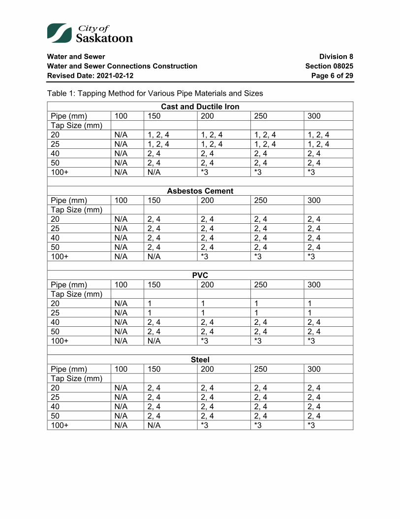
Water and Sewer Division 8 Water and Sewer Connections Construction Section 08025 Revised Date: 2021-02-12 Page 6 of 29
Table 1: Tapping Method for Various Pipe Materials and Sizes Cast and Ductile Iron
Pipe (mm) 100 150 200 250 300 Tap Size (mm) 20 N/A 1, 2, 4 1, 2, 4 1, 2, 4 1, 2, 4 25 N/A 1, 2, 4 1, 2, 4 1, 2, 4 1, 2, 4 40 N/A 2, 4 2, 4 2, 4 2, 4 50 N/A 2, 4 2, 4 2, 4 2, 4 100+ N/A N/A *3 *3 *3
Asbestos Cement Pipe (mm) 100 150 200 250 300 Tap Size (mm) 20 N/A 2, 4 2, 4 2, 4 2, 4 25 N/A 2, 4 2, 4 2, 4 2, 4 40 N/A 2, 4 2, 4 2, 4 2, 4 50 N/A 2, 4 2, 4 2, 4 2, 4 100+ N/A N/A *3 *3 *3
PVC Pipe (mm) 100 150 200 250 300 Tap Size (mm) 20 N/A 1 1 1 1 25 N/A 1 1 1 1 40 N/A 2, 4 2, 4 2, 4 2, 4 50 N/A 2, 4 2, 4 2, 4 2, 4 100+ N/A N/A *3 *3 *3
Steel Pipe (mm) 100 150 200 250 300 Tap Size (mm) 20 N/A 2, 4 2, 4 2, 4 2, 4 25 N/A 2, 4 2, 4 2, 4 2, 4 40 N/A 2, 4 2, 4 2, 4 2, 4 50 N/A 2, 4 2, 4 2, 4 2, 4 100+ N/A N/A *3 *3 *3
Water and Sewer Division 8 Water and Sewer Connections Construction Section 08025 Revised Date: 2021-02-12 Page 7 of 29
08025-4 Existing Utilities and Structures
4.1 General
Before starting any excavation, and at his own expense, the Contractor is responsible for determining the actual location and elevation of all sewer, water and gas mains or lines, electric light, power, telephone or telecommunications conduits, or other such structures or utilities which may exist in the area of the proposed work.
The Contractor is responsible for notifying the respective utility at least 48 hours before his intention to carry out operations near the said utility and if required shall pay for any services supplied for locating these utilities.
4.2 Conflicting Utilities
Where existing utilities conflict with the proposed work, the Contractor shall immediately notify the Engineer and the Owner of the utility. The Contractor shall proceed as directed by the Engineer or utility owner.
If the proposed work can be altered to avoid the conflict with the existing utility and the Engineer so orders, the Contractor shall supply all labour and material required to change his work to conform to the new alignment.
When traversing beneath existing utilities, they must be supported with timber shoring approved by the Engineer. Before backfilling the trench, the suspended utility must be supported from below with well-tamped backfill according to Subsection 11.2.1 Class I Backfill. When the level of compaction required for Class I Backfill is not attainable directly below the duct, the Contractor shall pour non-shrink concrete in compliance with Subsection 3.6. The Contractor shall supply and install this material at his cost.
Where the existing utility must be relocated to avoid conflict with the new work, the Contractor may be ordered to relocate the utility under the direction of the utility owner or the utility owner may relocate the utility himself. In either case, the Contractor shall be responsible for all the costs incurred.
Water and Sewer Division 8 Water and Sewer Connections Construction Section 08025 Revised Date: 2021-02-12 Page 8 of 29
4.3 Disruption of Service
When in the course of the work, existing utilities must, for reasonable cause, be temporarily disconnected, the Contractor shall give all persons affected 48 hours written notice.
The Contractor shall contact the utility owner who may disconnect the utility himself or supervise the Contractor during disconnection.
In no case shall the Contractor operate any utility without the approval of the owner.
All costs incurred during the disruption of service from any utility shall be borne by the Contractor.
4.4 Existing Sidewalks and Curbs
The Contractor shall take precautions to protect existing sidewalks and curbs from damage as a result of his operations. Where it is necessary for equipment to work on or cross existing sidewalks, the Contractor shall carefully place planks or mats on the sidewalks.
4.5 Signing
The Contractor shall sign and demark all excavations to the standard as set out by the Traffic Control Manual (1982). The Contractor shall supply and install all signs, signals, snow fence and barricades necessary for public safety. The Contractor shall securely fence all excavations during unsupervised periods.
Where the work will require the detouring of traffic around the site, the Contractor shall contact the City of Saskatoon Transportation Right of Way Group at 975-2460 and arrange for all necessary detours.
The Contractor shall be responsible for maintaining access to all private property during construction.
4.6 Damage to Existing Utilities and Structures
When a utility is exposed during construction, the Contractor shall immediately inform the owner of the utility, who may inspect the utility before backfilling.
Water and Sewer Division 8 Water and Sewer Connections Construction Section 08025 Revised Date: 2021-02-12 Page 9 of 29
Any damage to the existing utility shall be repaired at the Contractor's expense.
No sidewalk or curb shall be removed by the Contractor without the approval of the Engineer. The City of Saskatoon shall repair sidewalks and curbs damaged or removed by the Contractor without prior approval. Unless otherwise specified, the Contractor shall pay for this work. The Contractor may repair the damage with its own forces, at no charge to the City, only if prior approval was granted by the Engineer. All work must be restored to as-built conditions and conform to current specifications.
All culverts, drains, removed; and ditches, embankments damaged during the work shall be replaced or repaired by the Contractor at his expense to the current specifications enforced by the City. Mains and service connections damaged by the Contractor shall be repaired by the Contractor at his expense subject to the Engineer's approval and inspection.
08025-5 Excavation
5.1 General
The Contractor shall schedule and conduct the work to cause the least interruption to traffic. The Contractor shall refer to Section 00700-45 (Traffic Operations) of the General Conditions and be governed by the regulations stated therein.
The Contractor shall provide for the free passage of surface water and shall not obstruct the gutters of any street.
The Contractor shall protect all trees, shrubbery, fences, poles, survey pins and all other property from damage during the work and shall repair or replace any items removed or damaged at his expense.
5.2 Classes of Excavation
5.2.1 Common Excavation
Common excavation shall be taken to mean the removal of all materials, except rock, from the trench to the lines and levels shown on the plans or specified herein for the construction of service connections.
Water and Sewer Division 8 Water and Sewer Connections Construction Section 08025 Revised Date: 2021-02-12 Page 10 of 29
5.2.2 Rock Excavation
The word "Rock" wherever used as the name of an excavated material, shall mean boulders and pieces of concrete or masonry exceeding 0.25 m3 in volume or solid ledge rock and masonry which, in the opinion of the Engineer, requires for its removal, drilling and blasting.
The Contractor shall note that asphalt or concrete pavements, sidewalks, drains, sewers, manholes, conduits, tanks, soft or disintegrated rock which can be removed with a hand pick or power operated excavator or shovel; loose, shaken or previously blasted rock or broken stone in rock fillings or elsewhere, and rock exterior to the maximum limits of the trench width shall not be considered "rock excavation". Rock shall be disposed of at a site designated by the Engineer.
5.2.3 Blasting
No explosives shall be stored on the site nor shall any blasting be done without the prior approval of the City Manager. Such approval shall not relieve the Contractor of his sole responsibility for any damage or accident to adjoining utilities, properties and structures or other persons as a result of his operations.
The supplying, hauling, handling and storing of all explosives and accessories shall be done according to the rules and regulations of the Explosives Division, Department of Mines, Ottawa and the Mining Act.
5.2.4 Unstable Subgrade
Where the bottom of the trench at subgrade is found to be unstable or to include ashes, cinders, any type of refuse, organic material or large pieces of inorganic material which in the opinion of the Engineer should be removed, the Contractor shall excavate and remove such unsuitable material to the width and depth ordered by the Engineer. The subgrade shall be made by backfilling with an approved granular material in 75mm lifts. Each lift shall be thoroughly compacted to a density approved by the Engineer.
Where the bottom of the trench at subgrade is found to consist of material unstable to such degree that, in the opinion of the Engineer, it cannot be corrected by methods specified above, the Contractor shall construct a foundation for the pipe in accordance with plans prepared by the Engineer.

Water and Sewer Division 8 Water and Sewer Connections Construction Section 08025 Revised Date: 2021-02-12 Page 11 of 29
5.3 Trenching
5.3.1 General
The line of the trench shall be straight from the water and sewer mains to the building or to the point on the lot where the service connection is to terminate.
Where possible the line of the trench shall be perpendicular to the water and sewer mains.
Deviation from this procedure shall only be permitted with the written consent of the Engineer.
The connection may not be laid so as to encroach onto an adjoining Property.
The earth taken from the trench shall be neatly deposited at the sides of the trench to obstruct the street or lane as little as possible. Where it is impractical in the opinion of the Engineer to place the earth at the side of the trench, it shall be removed and deposited to a location designated by the Engineer.
5.3.2 Trench Width and Depth
All trenches shall be sufficient width to permit proper jointing of the pipes but in all cases the width shall be at least 750mm for a single set of services and at least 1000mm wide for a double set of services.
Excavation for the service shall be carried out to provide 2850mm cover at the property line and 2250mm at the building. The slope of the sewer line shall not be less than 20mm per metre.
5.3.3 Trenching on Paved Streets
Paved streets shall include all soil cement and macadamized road surfaces in addition to those paved with asphalt and/or concrete.
Where a service connection is to be constructed on a paved street, only that portion of the street directly above the water and sewer mains shall be open cut. The remainder of the street shall be tunnelled, augured, or use another trenchless method approved by
Water and Sewer Division 8 Water and Sewer Connections Construction Section 08025 Revised Date: 2021-02-12 Page 12 of 29
the Engineer. Additional open cut shafts may be approved by the Engineer to ensure that the correct line and grade are being maintained.
The Contractor is responsible for controlling the removal of the asphalt to ensure that the resulting asphalt cut is rectangular in shape and the walls are vertical. Where soil conditions disrupt the integrity of the initial cut, the contractor shall ensure that the resulting cut meets the specifications listed previously.
5.3.4 Trenchless Methods
Trenchless methods may include methods such as tunnelling, auguring, directional drilling, boring, or pipe bursting as approved by the Engineer.
Where the line of the proposed service connection crosses a street designated arterial or proposed arterial; crosses a sidewalk or the location of a proposed sidewalk; crosses under another buried utility, the Contractor shall excavate using trenchless methods.
Where an existing service line is being replaced, the Contractor shall use pipe bursting unless otherwise specified.
The Contractor shall maintain the correct line and grade on the utility throughout the trenchless section and shall provide for the protection of the workers according to the regulations of the Saskatchewan Department of Labour.
The maximum size of a tunnel, bore hole, or pipe-bursting head shall be the largest outside diameter of the pipe measured at the joint plus 50 mm.
The minimum length of the trenchless section under an existing or proposed sidewalk shall be 3000 mm.
5.3.5 Trenching in Winter Conditions
If thawing of the ground is required, the method shall first be approved by the Engineer.
All excavated material that is frozen or which subsequently becomes frozen shall be removed from the site of the work and shall be disposed of to a site designated by the Engineer.
Water and Sewer Division 8 Water and Sewer Connections Construction Section 08025 Revised Date: 2021-02-12 Page 13 of 29
5.3.6 Excavations for Tappings and Tee Installation
The minimum excavation size required for tapping water mains is 1000mm perpendicular to the main by 900mm along the main
For water connections larger than 50mm the minimum dimensions of the excavation are 1500mm perpendicular to the main by 1500mm along the main.
08025-6 Shoring
Open cut trenches and shafts shall be sheeted and braced as required by the Occupational Health and Safety Regulations of the Saskatchewan Department of Labour and as may be necessary to protect life, property and the work.
All necessary shoring and bracing required for the prevention of movement surrounding the excavation shall be provided for and installed by the Contractor.
The right of the Engineer to order sheeting, bracing, underpinning or any other form of brace or support shall not be construed as creating any obligation on his part to issue such orders, and his failure to exercise his right to do so shall not relieve the Contractor from his responsibility for damages to persons or property arising from or upon the work of construction occasioned by negligence or otherwise growing out of a failure on the part of the Contractor to leave in place in the trench sufficient sheeting and bracing to prevent any caving or moving of the ground adjacent to the sides of the trench, or for failure to construct and maintain proper support of all kinds whatsoever in the first instance.
Sheeting and bracing left in place must be cut off and removed for a depth of 900mm below the established street grade or the existing surface of the street, whichever is lower.
All materials and labour required for shoring shall be furnished by the Contractor.
08025-7 Preparation of Trench Bottom
The Contractor shall remove by pumping or other means approved by the Engineer any water accumulated in the excavation. Trenches shall be free of water before the pipe is laid. Previously laid pipe shall not be used to drain the trench bottom. The disposal of water after removal from the trench shall be to the satisfaction of the Engineer.
Water and Sewer Division 8 Water and Sewer Connections Construction Section 08025 Revised Date: 2021-02-12 Page 14 of 29
The trench bottom shall be shaped in such a way that the body of the pipe rests on solid ground throughout its length, and so that when in final position the pipe is true to line and grade. Bell holes shall be hand excavated below the bottom of the trench and be of sufficient size to allow ample room for making complete and proper pipe joints.
Where the pipe zone contains rock or boulders that may damage the pipe, the bottom of the trench shall be over excavated to a depth of one-fourth (1/4) the diameter of the pipe, but in no case less than 150mm below the bottom of the pipe. Where over excavation of the trench bottom has occurred, the Contractor shall replace the excavated material with approved granular backfill to the invert of the pipe and compact it to 98% of Standard Proctor Density.
08025-8 Connection to Existing Facilities
The Contractor shall supply all materials when making the connection including but not limited to the following: main stops or valves, water pipe, tees, anodes, welded tee (steel pipe), pipe coatings, saddles, pipe hub ends for storm sewer connections and cement mortar.
In all situations, when the existing water main being connected to is cast iron, the contractor shall connect a 24lb anode to the water main as specified in Section 08000-4.4.
8.1 Tapping Water Mains
City employees shall perform all tapping of water services up to 50mm in diameter. When a tapping is required, the Contractor shall give the City 48 hours’ notice and shall have the mains properly exposed and ensure that the trench is safe and properly shored.
The Contractor shall indicate the location on the main where the tapping is to be made.
The Contractor shall supply and install a tapping saddle or sleeve, when required, on the water main at the required location. See Section 08025-3.8 for required tapping method.
Copper water tubing requires a smooth even "Gooseneck" curve at the main stop. 19mm copper connections shall have a gooseneck 300mm above the water main crown. Larger copper connections shall have a gooseneck 400mm above the water
Water and Sewer Division 8 Water and Sewer Connections Construction Section 08025 Revised Date: 2021-02-12 Page 15 of 29
main crown. For copper services the main is tapped at 30 to 45 degrees above the horizontal plane.
Polyethylene connections shall have a horizontal gooseneck extending in two curves a distance of 400mm on each side of the centre line of the connection. The tapping shall be horizontal and perpendicular to the water main.
Tappings shall not be made closer than 450mm from a joint or a main stop.
8.2 Water Services Greater than 50 mm
The Contractor shall supply and install all materials for water services greater than 50 mm.
Water services shall be installed at the City water main by excavating, removing a portion of the water main and installing a water main tee, short length of PVC pipe (each a minimum of 300mm long), and pipe coupling to the existing water mains and a valve on the water service.
The Water Service shall connect horizontally and perpendicular to the water main.
Water services greater than 50mm up to 150mm in diameter, require a 150mm tee, 150mm valve and reducer.
The Contractor shall protect each valve with a 24 pound Anode as specified in Section 08000-4.4. The tee, pipe coupling and all other metal water main fittings shall be connected each with a 12 pound Anode as specified in Section 08000-4.4. The anode shall be attached using a "Cadweld" in compliance with the manufacturers recommended installation procedures. The Contractor shall supply and install sacrificial zinc anodes to provide cathodic protection for all valves, hydrants and cast iron fittings installed under this Contract.
The Contractor shall connect a 24 lb. anode to each hydrant and each valve. Where the anode is connected to a valve, the anode wire shall also be connected to the valve box.
The Contractor shall connect a 12 lb. anode to each cast iron fitting, each Robar coupling and to each copper water service line where the existing service lines are being reconnected into the new water main.

Water and Sewer Division 8 Water and Sewer Connections Construction Section 08025 Revised Date: 2021-02-12 Page 16 of 29
The Contractor shall install the anodes one metre away from the fitting/valve at water main depth and shall connect the anode wire to the cast iron using the "Cadweld" method. The Contractor shall provide experienced personnel who shall make these connections in accordance with the manufacturer's recommendations.
Following welding, the Contractor shall remove all slag from the weld, file off all sharp edges and coat all exposed cast iron surfaces, steel surfaces and "Cadweld" locations with "Denso" tape and paste.
When the installation is complete, the Contractor shall pour 10 litres of water over the anode and backfill uniformly around the anode. The exposed metal surfaces on all metal fittings shall then be field coated in compliance with 08000-4.2.
Where a water service will be made to an existing steel water main it shall be a Reinforced branch conforming to “Steel Water Pipe - A Guide for Design and Installation, American Water Works Association, M11 Manual”. The Branch shall come complete with a flange end suitable for attaching a flanged valve.
8.3 Tapping of Sewer Mains
Sewer and storm sewer mains shall be tapped above the springline of the pipe at 45 degrees to the vertical plane. A 45º Long Radius shall connect to the saddle to allow for connection of the graded service. Where the main pipe is clay tile or concrete only one tapping shall be made into a one length of pipe. Tappings shall not be made closer than 450mm from a joint or another tapping. The method of tapping used shall ensure a smooth edged hole suitable for accommodating the service saddle. No sharp or raised surfaces shall exist within the area covered by the saddle gasket, and the opening shall be sized small enough to allow the entire area of the saddle gasket to make contact with the outside of the pipe.
Where the pipe diameter is too large for existing saddle sizes, the bell end of a pipe may be used for connection to the main. The diameter of the opening shall be no larger than 1 ¼ the diameter of the connecting service; the bell shall not protrude past the inner wall of the main greater than 25 mm, and 0.3 m3 of concrete shall be placed under the connection at the main.
The Contractor shall satisfy himself as to the relative position of the water and sewer leads at the house in order to properly plan his work so that when the mains are tapped
Water and Sewer Division 8 Water and Sewer Connections Construction Section 08025 Revised Date: 2021-02-12 Page 17 of 29
the service pipes can be laid parallel to each other and at the correct grade and alignment.
8.4 Connections into Manholes
8.4.1 Existing Manholes
Wherever it is practicable, sanitary and storm sewer connections shall be made directly into existing manholes.
The Contractor shall supply all material, labour and equipment, required to tap into the manhole and complete the connection. The Contractor shall mortar the service pipe firmly into place, supply grout and reshape the channelling in the manhole if required; trim off the service pipe leaving no more or less than 100mm extending into the inside of the manhole; supply and install an interior drop structure if required and remove any dirt or concrete rubble which has entered the manhole or main sewer as a result of his operations.
8.4.2 Constructing New Manholes
The Contractor shall supply all materials, labour and equipment required to construct the new manhole and complete the connection according to Section 8010-8.
Where the size of a sanitary service exceeds 150mm and the connection cannot be made into an existing manhole, the Contractor shall construct a new standard 1200mm manhole at the point of entry.
Where the size of the storm sewer service exceeds one-half the diameter of the storm sewer main or when the size of the storm sewer service exceeds 250mm, the Contractor shall construct a new 1200mm manhole at the point of entry.
Where the connection is to be made to a large storm or sanitary sewer main, the Engineer may, on request, approve a special connection directly into the main.
Water and Sewer Division 8 Water and Sewer Connections Construction Section 08025 Revised Date: 2021-02-12 Page 18 of 29
08025-9 Laying and Jointing Pipe
9.1 Sewer Service Pipe
9.1.1 General
The pipe shall be protected against impact shocks and free falling during the handling. Pipe shall be kept clean at all times.
Each pipe shall be inspected for defects before being lowered into the trench. Those not conforming to specifications will be rejected, and shall be removed from the site of the work. All sewers shall be laid in an upgrade direction with the bells laid upgrade. The sections of pipe shall be fitted together to form a smooth and uniform invert.
In making joints, care must be taken not to disturb or break joints already made, otherwise the pipes shall be uncovered, and the joints remade.
The interior of pipes shall progressively be freed from all dirt or other superfluous material.
Before leaving the work at any time, all open ends of pipe in place shall be closed with a watertight cap or plug.
Where the point of termination is at the property line, the Contractor shall install a watertight plug.
9.1.2 Bedding
The pipe shall be bedded in a natural solid soil foundation shaped to fit the lowest part of the pipe exterior.
The foundation supporting the pipe shall have a minimum width equal to 60% of the outside diameter of the pipe and shall be carefully hand trimmed and levelled to provide even bearing throughout the whole length of the pipe. The remainder of the pipe shall be surrounded by approved excavated material placed and compacted by hand to fill completely all spaces adjacent to the pipe. If the pipe cannot be laid on a solid soil foundation, bedding sand shall be used. All pipe shall be sand bedded on City of Saskatoon property. All pipe bedding shall be properly compacted with approved tamping machines.
Water and Sewer Division 8 Water and Sewer Connections Construction Section 08025 Revised Date: 2021-02-12 Page 19 of 29
9.1.3 Alignment and Grade
Sewer service lines shall be straight, perpendicular to the main sewer and shall terminate at a point designated by the Engineer.
Sewer service lines shall be installed with a minimum 2% grade, unless specific grades are supplied in the field by the Engineer, in which case these grades shall be adhered to.
9.1.3.1 Use of Bends
Long sweep 22-1/2 degree bends and long sweep 45 degree bends may be used on the horizontal. Short 45 and 22 degree bends shall not be used unless approved by the Engineer. Long sweep bends on the horizontal greater than 45 degrees shall require a cleanout.
9.1.4 Jointing
9.1.4.1 Slip-Seal Joint
This material is not approved for new installations.
9.1.4.2 Plain End Pipe
This material is not approved for new installations.
9.1.4.3 Vitra-Mate or Vitra Flex
This material is not approved for new installations.
9.1.4.4 A.C. Sewer Pipe
This material is not approved for new installations.
9.1.4.5 P.V.C. Sewer Pipe
The spigot and bell ends and/or the coupling as well as the pipe interior shall be carefully cleaned and inspected for damage. The neoprene gaskets shall be properly placed in the bell or coupling groove and the pipe sliding surfaces well lubricated with the approved lubricant.
Water and Sewer Division 8 Water and Sewer Connections Construction Section 08025 Revised Date: 2021-02-12 Page 20 of 29
The spigot end of the pipe shall then be inserted into the bell end or coupling until it is firmly in place according to the manufacturer's instructions. Extreme care shall be exercised in this procedure to ensure that the neoprene gaskets are not dislodged or damaged during the assembly.
9.1.5 Cleanouts
The Contractor shall supply and install a sewer cleanout at the following locations according to the current City of Saskatoon Standard Drawing as posted on the City’s Internet web site:
• At each horizontal deflection in excess of 45 degrees in the line of the sewer service pipe.
• At points on a long sewer service that will provide access for cleaning at intervals not greater than 25 m.
9.1.6 Pipe Laying in Tunnels
The Contractor shall use P.V.C. pipe for that portion of the sewer service connection that is to be constructed in a tunnel.
The Contractor shall ensure that all joints are made as specified prior to installation into tunnel.
9.1.7 Vertical Risers
On some streets where the sanitary sewer is at great depths, the City of Saskatoon has constructed a sanitary sewer stand pipe (riser) to facilitate the construction of the sewer connections. The Contractor may be permitted to excavate down to the main sewer in preference to locating and connecting into the stand pipe. The riser shall be constructed to current specifications.
The City shall endeavour to supply the Contractor with information leading to the location of sewer service risers on deep sewers. In the event that the risers cannot be found, or when found, it proves to be damaged or unusable, the Contractor shall construct a riser according to the current specifications.
Water and Sewer Division 8 Water and Sewer Connections Construction Section 08025 Revised Date: 2021-02-12 Page 21 of 29
9.2 Water Service Pipe
9.2.1 General
The pipe and fittings shall be protected against damage during
Handling, and shall be kept clean and free from dirt. Copper pipe shall not exhibit any signs of crimping or flattening. The Contractor shall use only new material and shall not use short cut-off lengths of pipe less than 2150mm long. Unions shall not be installed between the main stop and the curb stop.
The minimum water service pipe diameter shall be 19mm copper or 25mm polyethylene.
Water service connections with a length greater than 25 m shall be a minimum of 25mm diameter copper and 38mm diameter polyethylene.
Water Services greater than 50mm shall be installed to the requirements of Section 08030 Water Main Construction.
9.2.2 Jointing
All joints at main stops, curb stops, unions or other fittings shall be compression type. Compression joints shall be made according to the manufacturer's recommended procedure.
9.2.3 Curb Stops and Boxes
The non-draining curb stop shall be installed within the City Right-of-Way at a distance of 300mm from the property line unless otherwise directed. A 305mm x 152mm x 50mm concrete bearing block shall be placed under each curb stop.
The Contractor shall fasten the stainless steel spindle to the curb stop with a brass cotter key.
Curb boxes shall be placed vertically plumb and the Water and Sewer Contractor shall leave all curb boxes at 150mm below the future back of sidewalk grade.
Water and Sewer Division 8 Water and Sewer Connections Construction Section 08025 Revised Date: 2021-02-12 Page 22 of 29
Should the existing curb box be located in the street or sidewalk, the Contractor shall cut through the sidewalk or pavement to place the box flush with its surroundings, and also restore the sidewalk or pavement flush with the existing surrounding elevations.
When replacing existing water service connections and installing a new curb stop, the existing curb stop must be removed. The City may approve/authorize abandonment of curb stop on a case-by-case basis. Abandonment shall include removal of the casing and rod.
Connections to vacant lots require a curb box marker. The curb box marker shall be installed a minimum length of 0.6 meters above ground and shall be 25mm polyethylene tubing. It shall be securely fastened to the spindle using tape or zip ties, as shown in the Service Connection Standard Drawing.
08025-10 Inspection
When the work is completed and before any backfilling, the Contractor shall allow an inspection of the work and shall provide all reasonable assistance during the inspection. If backfilling is completed prior to an inspection, the Engineer may require exposure of the connection for inspection purposes. All related costs of this procedure shall be at the expense of the Contractor.
When connecting to the watermain, the Contractor shall turn on the main stop and all joints shall be inspected for leakage.
When the inspection has been completed and all defects have been corrected, the Contractor shall backfill the excavation as specified.
08025-11 Backfill
The Contractor shall start backfilling immediately after the work has been inspected and all defects have been corrected, and shall complete the backfilling on the same date that the inspection was made.
11.1 Initial Backfill in the Pipe Zone
Initial backfill material in the pipe zone shall consist of selected excavated material or imported granular material, free from frozen lumps, rock, large stones, boulders or other unsuitable material. The initial lift shall be hand placed in the trench uniformly on both
Water and Sewer Division 8 Water and Sewer Connections Construction Section 08025 Revised Date: 2021-02-12 Page 23 of 29
sides of the pipe up to the spring line and hand tamped with an appropriate hand tamper to attain a density of 98% of Standard Proctor Density at the optimum field moisture content. Special care shall be taken to thoroughly compact the backfill around and next to the mains at the points where the mains were tapped.
Additional 150mm lifts of selected excavated material or imported granular material, as previously described herein, shall be hand placed in the trench uniformly with each 150mm lift compacted using hand operated mechanical compaction equipment to attain a minimum density of 98% of Standard Proctor Density at the optimum moisture content up to a uniform minimum level 300mm above the crown of the highest pipe in the trench.
11.2 Backfill above the Pipe Zone
After the initial backfill has been placed and compacted, the remainder of the trench shall be backfilled according to one of the following methods. All backfill shall be tested according to the City of Saskatoon's decision.
11.2.1 Class I Backfill
Class I backfill as follows shall be used on all open cut portions on existing paved streets and boulevards.
The Contractor shall supply and place granular material in 300mm lifts, over the whole width of the trench and shall compact each lift to 98% of Standard Proctor Density at optimum moisture content, using mechanical compaction equipment. The compacted granular material shall be brought up to 300mm below the original street level. The Contractor shall supply and place 300mm of street gravel
Flush with the original street level and compact it to 100% of Standard Proctor Density at optimum moisture content.
Under existing sidewalks, the Contractor shall place unshrinkable fill to an elevation 0.3 m below existing grade, unless otherwise directed by the Engineer.
Water and Sewer Division 8 Water and Sewer Connections Construction Section 08025 Revised Date: 2021-02-12 Page 24 of 29
11.2.2 Class II Backfill
Class II backfill, as follows, shall be used on prepaid service connections to backfill open cuts and on cash connections on all portions, other than cuts as per Section 11.2.1 Class I Backfill.
Class II backfill shall be placed uniformly along the trench in maximum 300mm lifts with each lift compacted using mechanical compaction equipment to attain 98% of Standard Proctor Density at the optimum moisture content up to the top of the trench. If the Contractor does not consistently attain the specified compaction, the lift thickness, compactive effort or compaction equipment shall be modified until the specified densities are attained consistently.
This backfill may contain coarse materials but shall be free from brush or other objectionable material that would prevent proper consolidation or that might cause subsequent settlement. Rocks or stones not exceeding 10kg may be placed in this portion of the backfill but must be placed by hand.
Where the excavation is carried out on an earth street, the compacted excavated material shall be brought up to the original street level.
Where the excavation was carried out on a gravel street, the compacted excavated material shall be brought up to 100mm below the original street level. The Contractor shall then supply and place 100mm of street gravel flush with the original street level and compact it to 100% of Standard Proctor Density at existing field moisture content.
Where the excavation was carried out on a paved street, or a street that has been prepared for paving, the compacted excavated material shall be brought up to 300mm below the top of the pavement. The Contractor shall supply and place 300mm of street gravel flush with the original street level and compact it to 100% of Standard Proctor Density at existing field moisture conditions.
11.2.3 Class III Backfill
Class III backfill shall consist of approved excavated material free from brush and rocks or stones over 10kg and other objectionable material. Backfill material shall be pushed down a ramp or slope of existing backfill and not directly onto the newly bedded pipe. The trench shall be compacted to the surface in lifts of 300mm maximum depth. The
Water and Sewer Division 8 Water and Sewer Connections Construction Section 08025 Revised Date: 2021-02-12 Page 25 of 29
minimum compacted effort required shall be that to obtain in-situ density of the adjacent soil type. The backfill shall not be placed at less than 92% Standard Proctor at the optimum moisture content.
11.3 Backfilling Tunnels
Where the excavation is carried out by tunnelling or boring, all voids left in the excavation after the pipe has been installed shall be filled with compacted excavated material or granular material.
Where the Contractor has augured under an existing or future sidewalk, he shall carefully plug all voids around the pipe at the end of the augured section closest to the street with concrete mortar. The remainder of the augured section may be filled with excavated material.
11.4 Backfilling in Winter Conditions
The Contractor shall remove from the site of the work any backfill material that is frozen or unacceptable to the Engineer and shall dispose of it as directed by the Engineer. The Contractor shall, at his expense, supply imported unfrozen granular material to complete the backfilling.
08025-12 Connection Cut Offs
When a water connection is no longer required or is serving a building which is being demolished, it shall be abandoned/decommissioned. The owner of the property served by the connection is responsible for retaining a Licensed Water and Sewer Contractor to perform the cut off. The Contractor shall perform the cut off in compliance with the following:
12.1 Domestic Water Connection (50mm or less):
1. Remove the main stop. 2. Remove all loose material from pipe and finish to a smooth surface. 3. Install a stainless steel repair sleeve (minimum of 300mm in length) as per
manufactures specifications. 4. Removed the top section of the curb box and spindle at a depth of 1000mm
below existing ground.
Water and Sewer Division 8 Water and Sewer Connections Construction Section 08025 Revised Date: 2021-02-12 Page 26 of 29
Or
1. Turn off the main stop. 2. Remove outlet pipe. 3. Remove all loose material from pipe and finish to a smooth surface. 4. Install stainless steel sleeve according to manufacturer’s specifications. 5. Remove the top section of the curb box and spindle at a depth of 1000mm below
existing ground.
12.2 Commercial, Industrial and Multi-unit Water Connection (Up to 50 mm)
Where a connection has been made with more than one main stop (e.g. a 50mm water service connection to the water main using 4 - 25mm main stops), the following shall apply:
1. Remove the section of pipe from the main including all the main stops to be cut-off.
2. Replace section of water main with approved PVC pipe. 3. Use PVC couplings, where practical, to connect the PVC pipe to the existing
pipe. 4. Excavate and remove a portion of each curb box top by cutting the curb boxes
and spindles at a depth of 1000mm below existing ground.
12.3 Commercial, Industrial and Multi-unit Water Connections (100mm or greater)
1. Remove the tee or tapping sleeve, the valve, valve box, valve spindle and section of main to be removed. In the case of a three way valve connection, remove two or three valves at the Engineer’s discretion.
2. Replace section of water main with approved PVC pipe. 3. Use PVC couplings, where practical, to connect the PVC pipe to the existing
pipe.
12.4 Reuse of an Existing Main Stop
1. The reuse of an existing mainstop is not permitted.
Water and Sewer Division 8 Water and Sewer Connections Construction Section 08025 Revised Date: 2021-02-12 Page 27 of 29
2. Where a main stop has been removed and a stainless steel repair sleeve installed, the stainless steel sleeve may be replaced with a repair sleeve complete with a tapping provided that the tapping will be at the correct angle for the new connection material.
3. Where the Contractor chooses to remove an existing repair sleeve and it is found that the sleeve was used in a repair, the Contractor shall install a new repair sleeve and a new tapping shall be made a minimum of 1.0 m from the repair sleeve.
12.5 Sanitary Sewer
Sanitary sewer connections shall be cut-off at the main at the existing saddle location using the following methods:
PVC main - the existing saddle shall be plugged with a PVC plug
Clay Tile main - the existing saddle shall be removed and either replaced with a PVC saddle complete with stainless steel straps, and plugged with a PVC plug; or replaced with a stainless steel repair sleeve. In both cases, the rubber gasket shall form a seal around the opening of the main. The Engineer may approve the use of a PVC plug inserted into the saddle and covered with concrete, where the removal of the saddle may damage the main.
Clay Tile main - the existing in line wye shall be plugged with a PVC plug and concreted.
08025-13 Restoration and Clean-up
The Contractor shall remove all construction planks, equipment, appliances, barricades and surplus materials and shall remove excavated material from natural drainage courses, sidewalks, crossings and do such other work as may be necessary to leave the work on any premises occupied by him in a neat, workmanlike condition. This work shall be done with a minimum of inconvenience to the public. All clean-up costs shall be borne by the Contractor.
The Contractor shall restore or replace all sidewalks, curbing, gutters, shrubbery, turf, fences, irrigation systems, poles and/or other property and surface structures damaged

Water and Sewer Division 8 Water and Sewer Connections Construction Section 08025 Revised Date: 2021-02-12 Page 28 of 29
or removed during the work to a condition meeting current specifications, furnishing all labour and materials incidental thereto.
All excavated material that is not to be used as backfill shall be hauled from the site to a location designated by the Engineer.
Where the Excavation or excavations are on an earth street the Contractor shall level the roadway portion as near as possible to the condition it was originally found as determined by the Engineer.
Where appurtenances such as valves and manholes exist, the road grades shall be brought level with the tops of these structures to avoid them being buried or left protruding from the roadway.
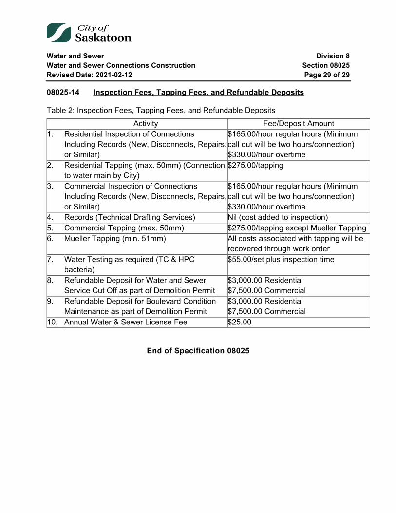
Water and Sewer Division 8 Water and Sewer Connections Construction Section 08025 Revised Date: 2021-02-12 Page 29 of 29
08025-14 Inspection Fees, Tapping Fees, and Refundable Deposits
Table 2: Inspection Fees, Tapping Fees, and Refundable Deposits Activity Fee/Deposit Amount
1. Residential Inspection of Connections Including Records (New, Disconnects, Repairs, or Similar)
$165.00/hour regular hours (Minimum call out will be two hours/connection) $330.00/hour overtime
2. Residential Tapping (max. 50mm) (Connection to water main by City)
$275.00/tapping
3. Commercial Inspection of Connections Including Records (New, Disconnects, Repairs, or Similar)
$165.00/hour regular hours (Minimum call out will be two hours/connection) $330.00/hour overtime
4. Records (Technical Drafting Services) Nil (cost added to inspection) 5. Commercial Tapping (max. 50mm) $275.00/tapping except Mueller Tapping 6. Mueller Tapping (min. 51mm) All costs associated with tapping will be
recovered through work order 7. Water Testing as required (TC & HPC
bacteria) $55.00/set plus inspection time
8. Refundable Deposit for Water and Sewer Service Cut Off as part of Demolition Permit
$3,000.00 Residential $7,500.00 Commercial
9. Refundable Deposit for Boulevard Condition Maintenance as part of Demolition Permit
$3,000.00 Residential $7,500.00 Commercial
10. Annual Water & Sewer License Fee $25.00
End of Specification 08025
Water and Sewer Division 8 Water Main Construction Section 08030 Revised Date: 2021-02-12 Page 1 of 18
08030 Water Main Construction
Index
08030-1 Scope 3 1.1 Existing Infrastructure - Requirements and Fees 3
08030-2 Existing Utilities and Structures 3
08030-3 Excavation 4 3.1 General 4 3.2 Trenching 5 3.3 Trench Width 6 3.4 Rock Excavation 6 3.5 Unstable Subgrade 6
08030-4 Temporary Protective Structures 7
08030-5 Preparation of Trench Bottom 8
08030-6 Pipe Bedding 8 6.1 General 8 6.2 Bedding 8
08030-7 Pipe Laying and Jointing 8 7.1 General 8 7.2 Alignment and Grade 9 7.3 Polyvinyl Chloride (PVC) Pipe 9 7.4 Polyethylene Pipe 10
08030-8 Reaction Blocking 10
08030-9 Valves 10
08030-10 Hydrants 11
Water and Sewer Division 8 Water Main Construction Section 08030 Revised Date: 2021-02-12 Page 2 of 18
08030-11 Cathodic Protection 11
08030-12 Backfill 12 12.1 Initial Backfill in Pipe Zone 12 12.2 Backfill above Pipe Zone 12 12.3 Street Surfaces 13
08030-13 Field Pressure Testing 15
08030-14 Disinfection 15 14.1 Backflow Protection 16 14.2 Chlorinating 16 14.3 Dechlorinating 17
08030-15 Field Sampling for Bacteriological Tests 17
08030-16 Bacteriological Tests 17
08030-17 Clean Up 18
Tables and Equations
Table 1: Chlorine Concentration Requirements for Modified-Slug Method .................... 16 Table 2: Field Water Sampling Requirements ............................................................... 17 Table 3: Bacteriological Test Result Requirements ....................................................... 18 Equation 1: Maxiumum Allowable Leakage ................................................................... 15
Water and Sewer Division 8 Water Main Construction Section 08030 Revised Date: 2021-02-12 Page 3 of 18
08030-1 Scope
The General Conditions, Specific Conditions and Material Specifications form an integral part of these Specifications and shall be read in conjunction herewith.
This Section shall include Water Connections Construction not regulated by Section 08025 wherein water service connections are greater than 50mm in diameter.
The Contractor shall supply all material, labour, equipment, plant and tools necessary to construct the water mains complete with hydrants, valves and fittings within and/or under the jurisdiction of the City of Saskatoon.
1.1 Existing Infrastructure - Requirements and Fees
Certain fees for inspection, tapping mains, pavement and concrete repair, detouring services and public liability insurance shall be charged by the City to the Contractor on completion of the work.
The contractor shall obtain the conditions of work and fee rates by contacting the Water & Sewer Connections Desk at 975-2461 before estimating or commencing any particular project. The Water & Sewer Connections Desk will outline the requirements and fees so that the Contractor shall know in advance and the safety of the water and sewer system remains intact.
Before any work within the City Right-of-Way is performed, the Contractor shall have an approved permit “Use of Right-of-Way Permit”. This permit shall be obtained by contacting the Transportation Right of Way Group at 975-2460. There may be restrictions on times and dates that portions of Right-of-Way may be available and this will be outlined in the Use of Right-of-Way permit.
08030-2 Existing Utilities and Structures
The location and elevation of existing underground utilities is compiled from records but is not guaranteed. Notwithstanding any other provision, the Contractor shall be responsible for determining at his expense the actual location and elevation of all sewer, water and gas lines, power, telephone or telecommunications conduits, or other such structures or utilities whether or not shown on the plans. The Contractor shall be responsible for notifying the respective utility at least 48 hours in advance of his

Water and Sewer Division 8 Water Main Construction Section 08030 Revised Date: 2021-02-12 Page 4 of 18
intention to carry out operations in the vicinity of the said utility and if required shall pay for any services supplied for locating these utilities.
When in the course of the work, existing utilities must, for reasonable cause, be temporarily disconnected, the Contractor shall be wholly responsible for notifying all persons affected, at least 48 hours in advance of the outage. The Contractor shall contact the utility owner who may disconnect the utility himself or supervise the Contractor during disconnection. In no case shall the Contractor operate any utility without the approval of the owner.
When a utility is exposed during construction, the Contractor shall immediately inform the owner of the utility, who may inspect the utility prior to backfilling.
Any accidental damage such as severing a cable, scraping the coating on an underground pipe or rupturing the pipe must be reported immediately through the appropriate emergency number.
Where existing utilities or other street improvements are found to be within the lines of the work the Engineer shall be notified. The Contractor shall then proceed as directed by the Engineer or the respective utility corporation.
All costs incurred for the disruption of service and for the repair of surface and/or underground utilities damaged by the Contractor's operation shall be the Contractor's responsibility.
Existing sidewalks and curbs, mains, service connections, catch basin leads and structures removed or damaged by the Contractor shall be repaired or replaced by the Contractor at his own expense.
Maintenance of existing utilities and structures which were disturbed or repaired by the Contractor, shall be the responsibility of the Contractor for the duration of the maintenance period.
08030-3 Excavation
3.1 General
Excavation shall be taken to mean the removal from the trench of all material of whatever kind encountered, for the construction therein of all water mains and
Water and Sewer Division 8 Water Main Construction Section 08030 Revised Date: 2021-02-12 Page 5 of 18
appurtenances. All excavations shall be made to the lines and grades as shown on the plans or as established in the field by the Engineer.
3.2 Trenching
The trench shall be excavated only so far in advance of pipe laying as permitted by the Engineer. The walls of the trench shall be sloped or shored up to prevent caving, in accordance with the requirements of the Occupational Health and Safety Regulations. All water encountered in the trench shall be pumped out before saturation of the pipe bedding material occurs. The discharge from the trench dewatering pumps shall be conducted away from the site of the work and into natural drainage channels, drains or storm sewers.
The trench shall be excavated so as to provide a uniform and continuous support for the pipe and fittings on solid undisturbed ground. Any over-excavation by the Contractor below the required grade shall be backfilled at his expense with compacted bedding material.
The earth taken from the trench shall be neatly deposited at the sides, in such manner as to obstruct the street or lane as little as possible. Where it is impracticable in the opinion of the Engineer to place the earth at the side of the trench, it shall be removed and deposited as designated by the Engineer.
The Contractor shall repair all walls, crib work, culverts, drains, ditches and embankments which it may be necessary to remove or to pass through in laying the pipes.
The Contractor shall provide for all surface water courses and drainage systems interrupted during the progress of the work, and replace them in as good condition as originally encountered.
The Contractor shall remove all pavement from the surface of any area to be excavated prior to starting the excavation.
The edges of the areas to be removed shall be precut in straight lines for the full depth of the pavement.
The Contractor shall then remove the pavement and transport it to the storage site designated by the Engineer.

Water and Sewer Division 8 Water Main Construction Section 08030 Revised Date: 2021-02-12 Page 6 of 18
3.3 Trench Width
The minimum trench width below the crown of the pipe shall be whichever is greater between the outside diameter of the pipe plus 450 mm, or 1.25 multiplied by the outside diameter plus 300mm.
The maximum trench width below the crown of the pipe, for pipes with a nominal diameter of 300 mm or less, shall be 1050 mm.
3.4 Rock Excavation
Rock excavation is defined as boulders, pieces of concrete, or masonry equal to or exceeding 1 cubic metre in volume.
The Contractor shall, use methods other than explosives such as drilling and wedging to split very large boulders prior to removing them from the trench.
Where the excavation is made in rock or in another material which cannot provide an even, uniform surface, all of the projections of such material shall be removed to provide a clear space around the pipe and fittings. The minimum dimension for this clear space shall be 150 mm for pipe having an outside diameter less than or equal to 600 mm and 225 mm for pipe having an outside diameter greater than 600 mm.
The subgrade shall then be made by backfilling with bedding material compacted in 150 mm layers to provide a uniform and continuous support for the pipe.
3.5 Unstable Subgrade
Where, in the opinion of the Engineer, the bottom of the trench at the subgrade below the pipe bedding is found to be unstable or to contain organic or other deleterious material which would not provide a sound foundation for the pipe, the Contractor shall remove such materials to the width and depth ordered by the Engineer and shall replace it with crushed rock, compacted in 150 mm layers. Prior to placing the crushed rock, geotextile fabric shall be installed flat on the trench bottom. The fabric shall extend up the trench walls to accommodate a minimum seam overlap of 900mm or equivalent to the trench width. The top surface of the crushed rock shall be covered with geotextile fabric before any pipe bedding aggregate is placed.
Water and Sewer Division 8 Water Main Construction Section 08030 Revised Date: 2021-02-12 Page 7 of 18
Where, in the opinion of the Engineer, additional support is required for the pipe, the Contractor shall supply all materials and shall construct such additional support in accordance with the plans and specifications which will be provided to him by the Engineer.
08030-4 Temporary Protective Structures
The Contractor shall protect excavations, trenches, shafts and tunnels from cave-ins, collapse, sliding or rolling materials by cutting back the walls and/or supplying and installing Temporary Protective Structures as required by the Occupational Health and Safety Regulations and as may be necessary to protect adjacent property and the work.
The Contractor shall install Temporary Protective Structures to prevent movement in the sides of the excavations. All material required, as well as the labour required for the installation, shall be furnished by the Contractor as part of this Contract.
The Contractor shall ensure that, where required by the Occupational Health and Safety Regulations, a professional engineer certifies that the Temporary Protective Structure, if constructed as drawn, and installed and used as instructed, will provide adequate protection to any worker constructing, installing or using the Temporary Protective Structure. The Contractor shall, prior to commencing construction, provide the Engineer with a copy of this certification for each Temporary Protective Structure which will be used on the project.
The right of the Engineer to order sheeting, bracing, underpinning or any other form of brace or support shall not be construed as creating any obligation on his part to issue such orders and his failure to exercise his right to do so shall not relieve the Contractor from his responsibility for damages to persons or property arising from or upon the work of construction occasioned by negligence or otherwise growing out of a failure on the part of the Contractor to leave in place in the trench sufficient sheeting and bracing to prevent any caving or moving of the ground adjacent to the sides of the trench, or for failure to construct and maintain proper support of all kinds whatsoever in the first instance.
Sheeting and bracing ordered left in place must be cut off and removed for a depth of 900 mm below the established street grade or the existing surface of the street, whichever is lower.
Water and Sewer Division 8 Water Main Construction Section 08030 Revised Date: 2021-02-12 Page 8 of 18
08030-5 Preparation of Trench Bottom
The Contractor shall remove any water which has accumulated in the excavation by pumping before any bedding is placed. The previously installed pipe shall not be used to drain the trench. Loose material shall be removed from the surface and the subgrade shall be thoroughly compacted.
08030-6 Pipe Bedding
6.1 General
The type of bedding to be used with each size and class of pipe shall be as shown on the Tender Form and in the Specific Conditions. The following various classes of bedding are detailed on the current City of Saskatoon Standard Drawing as posted on the City’s Internet web site.
6.2 Bedding
The pipe shall be bedded on a layer of approved fine granular material as defined in Section 08000-7.1 shaped to fit the lowest part of the pipe exterior. The required minimum depth of the granular material under the pipe shall be as outlined on the current City of Saskatoon Standard Drawing as posted on the City’s Internet web site for various pipe diameters and shall extend up the sides of the pipe to a height equal to one-half (1/2) of the outside diameter of the pipe. Care shall be taken to completely fill all voids under the pipe. The bedding material shall be placed in 150 mm layers and shall be compacted to 98% of Standard Proctor Density using mechanical compaction equipment.
08030-7 Pipe Laying and Jointing
7.1 General
The pipe shall be protected against impact shocks and free fall during handling and shall be kept clean at all times. All pipe to be used for water main distribution shall be sealed before leaving the production plant and shall remain sealed throughout transportation and storage onsite until installed. Each pipe shall be carefully inspected prior to being lowered into the trench and those not meeting specifications shall be rejected and shall be removed from the site of the work. The individual lengths of pipe shall be installed so that the spigot end can be inserted into the bell of the previously
Water and Sewer Division 8 Water Main Construction Section 08030 Revised Date: 2021-02-12 Page 9 of 18
installed pipe. The Contractor shall excavate the trench deeper at the location of each joint to facilitate making the joint and so that the pipe will not rest on the bell when it is installed. Each pipe shall be installed so that the bedding material will support it evenly throughout its entire length. The interior of the pipe and the bell must be cleared of all foreign material before the joint is made.
The Contractor shall supply a watertight cap or plug which shall be installed on the end of the pipe while excavation is in progress and when the Contractor leaves the site of the work.
7.2 Alignment and Grade
Water mains shall be installed according to the lines and grades shown on the plans or as staked in the field by the Engineer. The Contractor shall transfer the line and grade to the water main by means of an approved batter board and boning rod system, laser beam system, or other system approved by the Engineer.
7.3 Polyvinyl Chloride (PVC) Pipe
Polyvinyl Chloride (PVC) shall be installed as per AWWA C605 unless specified otherwise.
PVC pipe shall be jointed as follows. The bell, spigot and rubber gasket shall be cleaned with a clean cloth, removing all traces of dirt, grit or plastic cuttings. A thin film (equivalent to a brushed coating) of an edible, vegetable based lubricant manufactured for this purpose shall be applied uniformly to the bell and spigot areas as indicated by the pipe manufacturer’s published recommendations. With the assistance of a lever pressing on a wooden cushion block which has been placed against the bell end of the pipe, a uniform force shall be applied until the pipe has been inserted to the reference mark.
The Contractor shall use a fine tooth hand saw or a power cut-off saw to cut the pipe where this is required. The ends shall be cut square and shall be bevelled at 15 degrees through one-half of the wall thickness using a grinding disc or a flat file. The jointing reference mark shall be re-established using a factory marked pipe of the same size as a guide.
Water and Sewer Division 8 Water Main Construction Section 08030 Revised Date: 2021-02-12 Page 10 of 18
7.4 Polyethylene Pipe
Polyethylene pipe which is being used for main construction shall be joined by butt fusing the ends of the pipes. The Contractor shall use the specially designed joining machines complete with alignment jigs, trimmers and heating plate which can be obtained from the pipe manufacturer. The Contractor shall provide personnel who have been trained to perform this procedure and shall ensure that the joints are made in accordance with the manufacturer's specifications.
Connections to valves and fittings shall bolted and shall be made using flange assembly consisting of a polyethylene stub-end which must be butt-fused to the end of the pipe and a special metal slip-on flange.
08030-8 Reaction Blocking
Reaction blocking shall be constructed at all hydrants, tees, bends, reducers, caps and plugs. Detailed methods of anchoring and blocking the fittings are shown on the current City of Saskatoon Standard Drawing as posted on the City’s Internet web site.
Concrete shall have a minimum strength of 20 MPa at 28 days. Blocking shall be placed between solid ground and the fittings to be anchored. The area of bearing on the ground in each instance shall be as shown on the current City of Saskatoon Standard Drawing as posted on the City’s Internet web site. The blocking shall be so placed that the pipe and fitting joints will be accessible for repair. 6 Mil polyethylene sheeting shall be placed between the reaction blocking and the pipe or fittings.
Where metal harness tie rods or clamps form an integral part of the reaction blocking they shall be galvanized or rust proofed by methods approved by the Engineer.
In scenarios where primary water mains (pipe diameter >400mm) are designed with pipe restraints, reaction blocking is not required unless specified.
08030-9 Valves
Valves shall be set accurately at the positions shown on the plans and properly jointed into the main. A guide plate shall be installed below the valve operating nut. The valve bonnet shall be set plumb over the guide plate. The valve box shall be set plumb over the valve bonnet. The bottom nut of the extension rod shall be securely fitted on the valve operating nut. On paved streets, the top of the valve box on main and hydrant
Water and Sewer Division 8 Water Main Construction Section 08030 Revised Date: 2021-02-12 Page 11 of 18
valves shall be set flush with the finished paved surface. On gravelled streets and lanes, the top of the valve box on main and hydrant valves shall be set 150 mm below the finished gravelled surface. The two bolts in the top section shall be tightened, and a locking ring shall be clamped to the middle section of the valve box to support the top section. The top of the extension rod shall not be more than 600 mm or less than 300 mm below the top of the valve box.
The Contractor shall mark the location of each valve with a 38 mm x 89 mm x 750 mm stake with letters M.V. painted in red on a white background.
08030-10 Hydrants
The Contractor shall install hydrants at the locations as shown on the plans or as directed by the Engineer.
All hydrants shall be installed in accordance with the current City of Saskatoon Standard Drawing as posted on the City’s Internet web site.
The hydrant shall stand plumb. The hose nozzles shall be parallel with the curb and the pumper nozzle shall face the street.
The hydrant shall be set so that the ground flange is at an elevation of 100mm +/ 50 mm above finished grade.
08030-11 Cathodic Protection
The Contractor shall supply and install sacrificial zinc anodes to provide cathodic protection for all valves, hydrants and cast iron fittings installed.
The Contractor shall connect a 24 lb. anode to each hydrant and each valve. Where the anode is connected to a valve, the anode wire shall also be connected to the valve box.
The Contractor shall connect a 12 lb. anode to each cast iron fitting, each bolted sleeve-type coupling and to each copper water service line where the existing service lines are being reconnected into the new water main.
The Contractor shall install the anodes one metre away from the fitting/valve at water main depth and shall connect the anode wire to the cast iron using the "Cadweld"

Water and Sewer Division 8 Water Main Construction Section 08030 Revised Date: 2021-02-12 Page 12 of 18
method. The Contractor shall provide experienced personnel who shall make these connections in accordance with the manufacturer's recommendations.
Following welding, the Contractor shall remove all slag from the weld, file off all sharp edges and coat all exposed cast iron surfaces, steel surfaces and "Cadweld" locations with corrosion prevention paste and tape.
When the installation is complete, the Contractor shall pour 10 litres of water over the anode and backfill uniformly around the anode.
08030-12 Backfill
12.1 Initial Backfill in Pipe Zone
The Contractor shall hand place select excavated material which is free from lumps and stones in 150 mm lifts above the granular bedding on both sides of the pipe and to a point 300 mm above the crown of the pipe over the full width of the trench. The Contractor shall compact each lift to 98% of Standard Proctor Density using mechanical compaction equipment.
12.2 Backfill above Pipe Zone
12.2.1 Class I Backfill
Approved granular material with a maximum aggregate size of 75 mm, shall be placed in 300 mm lifts over the whole width of the trench. Each lift shall be compacted to 98% of Standard Proctor Density, using mechanical compaction equipment.
12.2.2 Class II Backfill
Approved excavated material shall be placed in 300 mm lifts over the whole width of the trench. Each lift shall be compacted to 98% of Standard Proctor Density, using mechanical compaction equipment.
This backfill may contain coarse materials but shall be free from brush, frozen or other objectionable material that would prevent proper consolidation or that might cause subsequent settlement.
Water and Sewer Division 8 Water Main Construction Section 08030 Revised Date: 2021-02-12 Page 13 of 18
Rocks or stones not exceeding 10 kilograms in weight may be placed in this portion of the backfill but must be placed by hand.
The Contractor shall be responsible for controlling the moisture content of the backfill material so that the moisture content will be close to the optimum percentage for compaction. The Contractor shall add water to the material if the moisture content is too low or if the moisture content is too high, the Contractor shall move the material to an approved stockpile area, dry the material and then move the material back to the site of the work.
12.2.3 Class III Backfill
Class III backfill shall consist of approved excavated material free from brush and rocks or stones over 10 kilograms and other objectionable material. Backfill material shall be pushed down a ramp or slope of existing backfill and not directly onto the newly bedded pipe.
The backfill material shall be placed in 750 mm lifts over the whole width of the trench. Each lift shall be compacted to a density which is equal to the density of the adjacent soil.
12.2.4 Backfill around Valves & Hydrants
The Contractor shall carefully select, place and compact backfill material in 150 mm lifts for a distance of 600 mm around each valve and hydrant. The contractor shall compact each lift to a minimum of 98% of the Standard Proctor Density.
12.3 Street Surfaces
12.3.1 General
The Contractor shall use a rubber tired motor grader to spread surface granular materials during compaction and to level earth streets after the backfilling has been completed.
The Contractor shall be responsible for filling trench settlements and repairing street surfaces which settle along the lines of his work during the maintenance period.
Water and Sewer Division 8 Water Main Construction Section 08030 Revised Date: 2021-02-12 Page 14 of 18
12.3.2 Paved Streets
Where excavation has been carried out on a paved street or on a street which has been based and is ready for pavement, the Contractor shall backfill the excavation up to 300 mm below the level of the original street surface. The Contractor shall then place 300 mm of base gravel to the gradation as specified in Section 08000-7.2 flush with the original street surface and shall compact it to 100% of Standard Proctor Density. Prices tendered for laying pipe, shall include the supply and placing of this gravel unless specified otherwise.
12.3.3 Gravel Streets
Where the excavation has been carried out on a gravel street, the Contractor shall backfill the excavation up to 100 mm below the level of the original street surface.
The Contractor shall then place 100 mm of base gravel to the gradation as specified in Section 08000-7.2 flush with the original street surface and shall compact it to 100% of Standard Proctor Density. Prices tendered for laying pipe, shall include the supply and placing of this gravel unless specified otherwise.
12.3.4 Earth Streets
Where excavation has been carried out on a graded earth street, the Contractor shall backfill the excavation up to the level of the original street surface.
Where the surface of the street has not previously been cut to grade, the Contractor shall spread and level any surplus excavated material over the top of the excavation.
12.3.5 Surplus Excavated Material
Where excavation has been carried out on a paved street, gravelled street or graded earth street all of the excavated material may not be required for backfilling. The Contractor shall load and haul this surplus excavated material to the nearest earth dumping site or to the location as specified in the Specific Conditions. The costs of disposing of this material shall be included in the Contractor's unit prices for constructing water main.
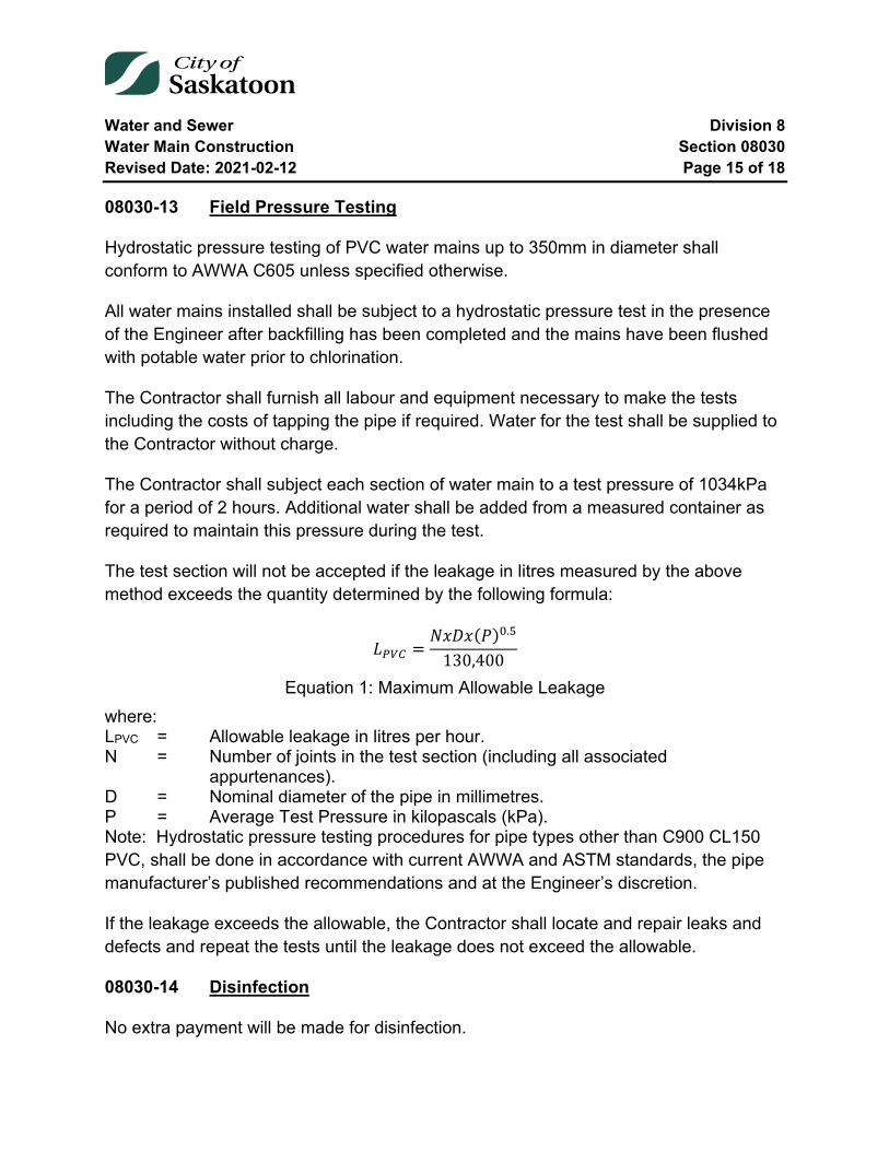
Water and Sewer Division 8 Water Main Construction Section 08030 Revised Date: 2021-02-12 Page 15 of 18
08030-13 Field Pressure Testing
Hydrostatic pressure testing of PVC water mains up to 350mm in diameter shall conform to AWWA C605 unless specified otherwise.
All water mains installed shall be subject to a hydrostatic pressure test in the presence of the Engineer after backfilling has been completed and the mains have been flushed with potable water prior to chlorination.
The Contractor shall furnish all labour and equipment necessary to make the tests including the costs of tapping the pipe if required. Water for the test shall be supplied to the Contractor without charge.
The Contractor shall subject each section of water main to a test pressure of 1034kPa for a period of 2 hours. Additional water shall be added from a measured container as required to maintain this pressure during the test.
The test section will not be accepted if the leakage in litres measured by the above method exceeds the quantity determined by the following formula:
𝐿𝐿𝑃𝑃𝑃𝑃𝑃𝑃 =𝑁𝑁𝑁𝑁𝑁𝑁𝑁𝑁(𝑃𝑃)0.5
130,400
Equation 1: Maximum Allowable Leakage where: LPVC = Allowable leakage in litres per hour. N = Number of joints in the test section (including all associated
appurtenances). D = Nominal diameter of the pipe in millimetres. P = Average Test Pressure in kilopascals (kPa). Note: Hydrostatic pressure testing procedures for pipe types other than C900 CL150 PVC, shall be done in accordance with current AWWA and ASTM standards, the pipe manufacturer’s published recommendations and at the Engineer’s discretion.
If the leakage exceeds the allowable, the Contractor shall locate and repair leaks and defects and repeat the tests until the leakage does not exceed the allowable.
08030-14 Disinfection
No extra payment will be made for disinfection.
Water and Sewer Division 8 Water Main Construction Section 08030 Revised Date: 2021-02-12 Page 16 of 18
14.1 Backflow Protection
The new water main shall be kept isolated from the active distribution system using an approved physical separation, backflow protection, until the disinfection water has been flushed out and satisfactory testing has been completed.
14.2 Chlorinating
Hydrants shall not be used for chlorine injection.
The method chosen to disinfect the water mains shall conform to AWWA C651 Standards, and utilize liquid chlorine solutions as described in AWWA B301 Standards. Deviations from either of the aforementioned Standards, including the initial liquid chlorine concentration, must be approved by the Engineer.
If a deviated method has been agreed upon, if at any time during the process the free chlorine residual drops below 50% of the initial chlorine concentration, then the chlorine concentration shall be restored to the approved initial concentration and the exposure time shall be restarted.
14.2.1 Modified-Slug Method of Chlorinating
The City has approved a modified-slug method of chlorinating. This method consists of completely filling the main with water dosed with chlorine to a concentration of not less than 100 mg/L. All parts of the main and its appurtenances will be exposed to the highly chlorinated water for a period of not less than three (3) hours.
The free chlorine residual shall be measured in the main. If at any time the free chlorine residual drops below 100 mg/L the chlorine concentration shall be restored to the initial concentration, and the exposure time shall be restarted.
Table 1: Chlorine Concentration Requirements for Modified-Slug Method Chlorine Concentration Measurements
Minimum Free Chlorine Concentration (mg/L)
Maximum Free Chlorine Concentration (mg/L)
Initial Concentration 100 200 Post Exposure Concentration
100 n/a*
* Post exposure only requires the minimum free chlorine concentration requirement to be met
Water and Sewer Division 8 Water Main Construction Section 08030 Revised Date: 2021-02-12 Page 17 of 18
14.3 Dechlorinating
The method to dechlorinate the water mains shall conform to AWWA C655 standards, including the dechlorinating plans and procedures.
Solid debris will not be allowed to enter the sanitary or storm sewer systems and must be removed to an approved disposal site.
08030-15 Field Sampling for Bacteriological Tests
The City shall conduct all sampling.
Water sample collection for bacteriological testing shall be as per AWWA C651 Standards. Ambiguities, if any, in the AWWA C651 Standard shall be clarified by the Engineer prior to sampling.
The Contractor shall provide a sampling port, free from interior threads and able to be throttled, so that samples can be collected by City staff.
The City water field sampling requirements are as follows:
Table 2: Field Water Sampling Requirements Description of Measurement Measurement Min. Total Chlorine (mg/L) 0.7 Min. Typical Total Chlorine (mg/L) 1.0 Max. Typical Total Chlorine (mg/L) 2.2 Max. Total Chlorine (mg/L) 3.0 Max. Turbidity (NTU) 1.0
Water samples for bacteriological testing shall be taken when total chlorine measurement results are within the typical range unless otherwise endorsed by the City of Saskatoon Water Laboratory.
08030-16 Bacteriological Tests
The City shall conduct all bacteriological testing.
The City water bacteriological test result requirements are as follows:
Water and Sewer Division 8 Water Main Construction Section 08030 Revised Date: 2021-02-12 Page 18 of 18
Table 3: Bacteriological Test Result Requirements Bacteria Test Type HPC (ct/mL) TC (ct/100mL) NC (ct/mL) Max. Allowable Limit 50.0 0.0 50.0
Bacteriological test result requirements must be fulfilled prior to the water main being placed into service.
08030-17 Clean Up
The Contractor shall clean up the site as the work progresses.
The Contractor shall remove all of his equipment, plant, tools and surplus material from the site of the finished work and shall repair and restore all drainage facilities which have been blocked or damaged as a result of the Contractor's operations.
End of Specification 08030
Water and Sewer Division 8 Storm Sewers and Culverts Section 08040 Revised Date: 04/03/2018 Page 1 of 3
08040 Storm Sewers and Culverts
Index
08040-1 Description of Work 2
08040-2 Materials 2
08040-3 Culvert Installation 2
08040-4 Bedding 2
08040-5 Culvert Inlet and Outlet Treatment 2
08040-6 Measurement 3
08040-7 Payment 3

Water and Sewer Division 8 Storm Sewers and Culverts Section 08040 Revised Date: 04/03/2018 Page 2 of 3
08040-1 Description of Work
This Specification covers the installation of corrugated steel, corrugated poly, reinforced concrete and PVC pipe culverts and riprap. The Contractor shall supply all labour, tools, equipment and materials for the construction of culverts through roadways and embankments, unless otherwise noted.
08040-2 Materials
The Contractor shall supply all culvert and storm sewer materials of the type and class approved by the City.
08040-3 Culvert Installation
The Contractor shall install culverts at locations noted on drawings and to the elevations staked by the Engineer. Culverts shall be placed in a trench and the bottom of trench shall be shaped to uniformly support the lower quadrant of the culvert pipe. Unsuitable foundation material shall be removed to the depth, width, and length authorized by the Engineer and replaced with suitable material.
08040-4 Bedding
All culverts installed under this Contract shall be laid on Class "B" granular bedding as shown on current City of Saskatoon Standard Drawings as posted on the City’s Internet web site. Mechanical or pneumatic compaction equipment shall be used to compact bedding material around and up to the spring line of the pipe and for compacting the select backfill to 300 millimetres above the pipe. All bedding and backfill shall be compacted to 98% of Standard Proctor Density.
08040-5 Culvert Inlet and Outlet Treatment
Culvert inlet and outlet shall be constructed as per the Engineer’s specifications. Riprap shall consist of durable field or quarry stone, hard, dense, resistant to weathering and to water action.
The riprap stones shall be 150 mm to 300 mm in diameter with stone sizes evenly distributed. The area to be riprapped shall be excavated and trimmed and 50 mm pipe bedding aggregate installed prior to placing the stones.
Water and Sewer Division 8 Storm Sewers and Culverts Section 08040 Revised Date: 04/03/2018 Page 3 of 3
08040-6 Measurement
Culverts will be measured in metres. Measurements will be taken parallel to the barrel for the entire length of the culvert.
Riprap will be measured in place, in cubic metres.
08040-7 Payment
Payment for installing corrugated steel, corrugated poly, reinforced concrete, and PVC pipe culverts or storm sewers will be at the contract unit price per metre for the sizes specified in the Tender Form. The unit prices will be full compensation for supplying, unloading, storing, handling and hauling culvert materials, placing Class "B: bedding, excavating, assembling the culvert, backfilling and compacting the backfill material. Payment for riprap will be at the contract unit price per cubic metre. The unit price will be full compensation for excavating and preparing the bed, placing the 50 mm granular bedding, supplying, loading, hauling, unloading, and placing the stones.
Payment for removing unsuitable subgrade material, if directed by the Engineer will be paid for at the Contract Unit Price for unstable subgrade. Unstable subgrade excavated from the bottom of the trench will be measured in cubic metres calculated from the length, width and depth authorized for removal. The unit price shall include excavating and disposing of surplus material and backfilling with stabilized material.
Granular materials salvaged from existing roadways may be used as granular bedding and backfill material when installing culverts. The Contractor will be responsible for handling and transporting the material from the stockpile site to the trench area. The cost of handling granular backfill shall be included in the contract unit price for installing culverts.
End of Specification 08040
Water and Sewer Division 8 Gravity Sanitary and Storm Cured-in-Place Pipe (CIPP) Lining Section 08046 Revised Date: 2021-02-12 Page 1 of 6
08046 Gravity Sanitary and Storm Cured-in-Place Pipe (CIPP) Lining
Index
08046-1 Scope 2
08046-2 Methods 2
08046-3 Materials 2
08046-4 Design 2
08046-5 Submissions 4 5.1 Liner Design 4 5.2 Operations Protocol 4 5.3 Construction Protocol 4
08046-6 Testing 5 6.1 Quality Control 5 6.2 Confined Test Samples 6
Water and Sewer Division 8 Gravity Sanitary and Storm Cured-in-Place Pipe (CIPP) Lining Section 08046 Revised Date: 2021-02-12 Page 2 of 6
08046-1 Scope
The section describes the design, methods, and materials approved for Cured-in-Place Pipe (CIPP) lining for gravity storm and sanitary sewer mains.
08046-2 Methods
CIPP methods shall conform to the following: 1. The current ASTM F1216 “Standard Practice for Rehabilitation of Existing
Pipelines and Conduits by the Inversion and Curing of a Resin-Impregnated Tube” for CIPP work done by inversion methods, or;
2. The current ASTM F1743 “Standard Practice for Rehabilitation of Existing Pipelines and Conduits by the Pulled-in-Place Installation of Cured-in-Place Thermosetting Resin Pipe” for CIPP work done by pull-in methods, or;
3. The current ASTM F2019 “Standard Practices for Rehabilitation of Existing Pipelines and Conduits by the Pulled in Place Installation of Glass Reinforced Plastic (GRP) Cured-In-Place Thermosetting Resin Pipe (CIPP)”.
08046-3 Materials
Rehabilitation by Cured-in-Place Pipe (CIPP) methods shall mean the lining of existing sewers with a resin-felt tube or glass reinforced plastic structure. Minimum material requirements shall conform to the current specification of the relevant CIPP method; ASTM F1216, ASTM 1743, or ASTM 2019.
08046-4 Design
The design objectives for CIPP rehabilitation include the following: 1. Maximize the structural enhancement of the sewer lining process by provision of
a close fit liner with no annulus between the liner and the host pipe.
2. Increase or maintain the hydraulic capacity of the rehabilitated sewer.
3. Reduce infiltration and exfiltration.
4. Prevent root intrusion.
Water and Sewer Division 8 Gravity Sanitary and Storm Cured-in-Place Pipe (CIPP) Lining Section 08046 Revised Date: 2021-02-12 Page 3 of 6
5. Provide sufficient chemical resistance to prevent future host pipe degradation related to the conveyance of sewage.
6. Minimize sewer service disruption as a result of the rehabilitation.
7. Minimize the time required to complete the rehabilitation.
8. Minimize disturbance of pavements and boulevards.
9. Minimize disruption to vehicular and pedestrian traffic.
10. Minimize the impact of construction on commercial, industrial, and institutional enterprises.
Partially deteriorated and fully deteriorated design shall be based on the modified AWWA formula as detailed in Appendix X1 of the current ASTM F1216 and the following minimum design assumptions shall be employed:
1. The groundwater table will be assumed to be one (1) m below the existing ground surface.
2. An enhancement factor (K) of 7.
3. The long-term value for the flexural modulus of elasticity (EL) be deemed to be the projected value at fifty (50) years of a continuous application of the design load on the specific resin and felt composite approved for use.
4. The long-term value for the flexural strength (σL) shall be deemed to be the projected value at fifty (50) years of a continuous application of the design load on the specific resin and felt composite approved for use.
5. The minimum factor of safety (N) to be utilized in the restrained buckling analysis shall be two (2).
6. A minimum value for ovality of three (3) percent shall be used for the existing sewer unless a greater value exists.
7. Use Manning’s formula with assumed “n” value of 0.012 for the CIPP and an “n” value for the host pipe based on the existing condition.
Water and Sewer Division 8 Gravity Sanitary and Storm Cured-in-Place Pipe (CIPP) Lining Section 08046 Revised Date: 2021-02-12 Page 4 of 6
08046-5 Submissions
The following information is required prior to the commencement of the work. • Liner Design – shall be summarized in a tabular format • Operations Protocol • Construction Protocol
5.1 Liner Design
1. The name and manufacturer of the resin and tube proposed for each liner including copies of relevant material specifications outlined in ASTM F1216, ASTM 1743, or ASTM 2019.
2. Liner thickness computations, including all design checks required by these specifications.
3. Confirmation that the hydraulic capacity of the lined pipe will have a hydraulic capacity equal to or greater than the existing pipe.
5.2 Operations Protocol
1. Resin impregnation procedure including catalyst type and dose.
2. The designated location of the wet-out facility.
3. Documentation that the resin proposed for use has not exceeded its shelf life as recommended by the manufacturer of the resin.
4. The volume of resin to be impregnated into each liner section including the proposed excess allowance for polymerization and migration (typically seven (7) percent) into cracks and joints of the host pipe.
5. The roller gap setting required to provide the final installed CIPP thickness based on the volume of resin proposed above.
5.3 Construction Protocol
1. Proposed main line and sewer connection flow control arrangements.
Water and Sewer Division 8 Gravity Sanitary and Storm Cured-in-Place Pipe (CIPP) Lining Section 08046 Revised Date: 2021-02-12 Page 5 of 6
2. The minimum pressure to hold the tube tight against the existing conduit and the maximum pressure so as not to damage the conduit.
3. If the insertion is to be by pull-in methods provide the maximum allowable axial and longitudinal tensile stress for the fabric tube and the arrangement for monitoring pull-in forces during installation.
4. The number and location of heat source monitor gauges.
5. CIPP curing schedule indicating the temperature, staging, duration, and pressure required to achieve a proper cure of the resin and felt tube composite.
6. Anticipated timing for sewer connection and main line service reinstatement.
08046-6 Testing
6.1 Quality Control
6.1.1 Quality Control Records
1. The following quality control records shall be maintained:
a) Summary of the resin impregnation process including: - Volume of resin supplied. - Excess quantity of resin added during the wet out to account
for polymerisation and migration into the host pipe. - Roller gap setting. - Resin catalyst(s) used. - Time and location of the wet out. - Means taken to store and transport the resin impregnated
CIPP from the wet out facility to the job site. - Means of curing internal point repair liners.
b) Continuous log of pressure maintained inside the liner during the curing period.
c) Pulling force used to pull or winch CIPP into place in the host sewer and measured liner elongation.
d) Continuous log of temperature at boiler in and out and at all thermistors placed between the host pipe and the liner at all manholes during the initial cure, cure and cool down periods.
Water and Sewer Division 8 Gravity Sanitary and Storm Cured-in-Place Pipe (CIPP) Lining Section 08046 Revised Date: 2021-02-12 Page 6 of 6
e) Final inspection of lined segments in accordance with Section 08125.
6.2 Confined Test Samples
At the City’s request, testing samples may be required.
1. Provide necessary forms of the same diameter as the host pipe and secure a minimum three hundred (300) mm long full diameter confined test sample from each CIPP.
2. Locate the test sample form in an intermediate manhole or at a termination point and invert through the form.
3. Clearly label the test sample with the respective identification number of the sewer section along with the date in which the liner was installed and provide to the Project Engineer intact in the form.
4. The City will coordinate and pay for CIPP sample testing to confirm the relevant material specifications outlined in ASTM F1216, ASTM 1743, or ASTM 2019.
End of Specification 08046
Water and Sewer Division 8 CCTV Camera Sewer Main Inspection Section 08125 Revised Date: 2018-01-31 Page 1 of 12
08125 CCTV Camera Sewer Main Inspection
Index
08125-1 General 3 1.1 Description of Work 3
08125-2 Sewer Inspection 3 2.1 General 3 2.2 Pan and Tilt Camera Inspections 3 2.3 Digital Scanning Device Inspections 4
08125-3 Equipment 4 3.1 General 4 3.2 Lighting 4 3.3 Video Format 5 3.4 Camera Transport 5
08125-4 Execution 5 4.1 General 5 4.2 Cleaning 6 4.3 Water Dechlorination 6 4.4 Debris Removal 6 4.5 Defect Reporting 7 4.6 Video Format 7 4.7 Pan and Tilt Camera 8 4.8 Digital Scanning Device 9
08125-5 Quality Control 9 5.1 Coding Accuracy 9
08125-6 Flow Control 10
08125-7 Contamination 11

Water and Sewer Division 8 CCTV Camera Sewer Main Inspection Section 08125 Revised Date: 2018-01-31 Page 2 of 12
08125-8 Water Supply 11
08125-9 Measurement and Payment 12
Water and Sewer Division 8 CCTV Camera Sewer Main Inspection Section 08125 Revised Date: 2018-01-31 Page 3 of 12
08125-1 General
1.1 Description of Work
The work under this section includes, but is not limited to, the supply of all superintendence, labour, material, equipment and tools required to:
1. Clean all sewers as outlined in these specifications, AND EITHER a. Inspect sewers using CCTV live video and code defects to NASSCO
PACP standards by a NASSCO PACP qualified operator, OR b. Inspect sewers using a digital scanning device and provide scans of
sewers and code defects to NASSCO PACP standards by a NASSCO PACP qualified operator.
08125-2 Sewer Inspection
2.1 General
Two different levels of inspection will be accepted.
1. Inspection via a pan and tilt type camera capable of panning 360° and tilting 270°. These inspections require NASSCO PACP defect coding to be completed by the contractor during the inspection.
2. Inspection via a digital scanning device. These inspections require NASSCO PACP defect coding to be completed by the contractor during or after the inspection.
Inspection units, of either type, shall have a minimum of one operator on site at all times who has successfully attained NASSCO PACP certification. The operator shall be fully trained in all aspects of sewer inspection and shall be capable of making accurate observations and recording of all conditions, which may be encountered in the sewers.
2.2 Pan and Tilt Camera Inspections
Sewer inspections shall be performed to observe and record structural and service defects, construction defects and construction features and to assess thoroughness of cleaning. All observations shall be coded in accordance with NASSCO PACP 6 or
Water and Sewer Division 8 CCTV Camera Sewer Main Inspection Section 08125 Revised Date: 2018-01-31 Page 4 of 12
above and the findings shall be included in an inspection report submitted on flash or portable hard drive. Operators who have successfully attained NASSCO PACP certification only shall perform the inspections and defect coding.
2.3 Digital Scanning Device Inspections
Sewer inspections shall be performed so that structural and service defects, construction defects and construction features can be observed and post inspection by the City. Surveys shall be coded by the contractor in accordance with NASSCO PACP 6 or above and be included in an inspection report submitted on flash or portable hard drive. Operators who have successfully attained NASSCO PACP certification only shall perform the inspections and defect coding.
08125-3 Equipment
3.1 General
The inspection unit shall consist of a self-contained vehicle with separate areas for viewing and equipment storage. Each inspection unit shall be equipped with fans and blowers to remove any fog which may be present in the sewer at the time of the inspection. Each unit shall have a suitable communication system for its crew members.
Inspection equipment shall consist of cameras, lighting, cables, power source, monitor, digital media recording and storage and other related equipment. The camera shall be pan and tilt type capable of panning 360° and tilting 270°, or a digital scanning device. The adjustment of focus and iris shall allow optimum picture quality and the focal range shall be adjustable from 100 mm to infinity.
3.2 Lighting
The light source shall be adjustable to allow an even distribution of light around the sewer perimeter without loss of contrast, flare out of picture, or shadowing. Video overlay equipment shall be capable of superimposing alpha-numeric information onto the video and shall be capable of providing a minimum of 15 lines of information, 30 characters per line.
Water and Sewer Division 8 CCTV Camera Sewer Main Inspection Section 08125 Revised Date: 2018-01-31 Page 5 of 12
3.3 Video Format
All videos shall be recorded in MPEG2 format and be delivered on flash or portable hard drive media. Videos in DVD format from a proprietary DVD recorder are not acceptable. Flash drives and/or portable hard drives submitted by the Contractor to the Engineer will not be returned to the Contractor.
3.4 Camera Transport
The camera shall be transported through the sewer by means of a rubber tires or crawler tractor. The transport unit must be capable of passing over minor surface imperfections including, but not limited to, broken joints and solid debris up to 40mm in height. Mounting of the camera on a float or skid for tow through the sewer shall only be permitted where the condition of the sewer precludes the use of a tractor and where authorized by the Project Engineer. If the camera is towed the supporting equipment shall not impede the view of the camera and shall be stable to ensure steady and smooth progress.
The camera transport shall permit complete inspection of the sewer from the center of the start manhole to the center of the finish manhole. The transport and cable shall be capable of inspecting a minimum of 200 metres of sewer from a single access point. A remote reading counter shall be used to measure distance traveled from the center of the start manhole and measurements shall be recorded in metres to the nearest 100mm.
The camera height shall be adjustable so as to position the center of the lens in the center of the sewer.
08125-4 Execution
4.1 General
All fog shall be evacuated from the sewer. The camera lens shall be kept clean at all times and the sewer shall be kept clear of fog during the entire inspection.
All inspections shall be performed in the direction of flow unless a reverse set up is required. Inspections shall generally begin with the upstream sewer in the system and proceed downstream in a consecutive manner.
Water and Sewer Division 8 CCTV Camera Sewer Main Inspection Section 08125 Revised Date: 2018-01-31 Page 6 of 12
The face of the start manhole shall be clearly visible at the start of the inspection and the inspection shall be performed from the centre of the start manhole to the centre of the finish manhole.
During the inspection automatic distance measurement shall be indicated on the screen and begin to move immediately as the camera moves.
4.2 Cleaning
Cleaning shall be performed by the Contractor to permit inspection from the upstream manhole to the downstream manhole. Calcium deposits shall be cut back so that a camera can pass through but do not need to be completely removed. Complete removal of all debris is not necessary but if the survey is terminated due to debris a reverse inspection must be attempted.
Caution must be exercised to ensure that the water pressure or cleaning tools do not damage or weaken the existing sewer pipe nor cause flooding of property connected to the sewer. The Contractor shall be responsible for the cost of repair of any such damage or flooding.
4.3 Water Dechlorination
The Contractor shall not use chlorinated water for cleaning or flushing of storm sewer mains. The threshold for chlorinated water is 0.02mg/L. Any water, potable or otherwise, shall be dechlorinated before use in the storm sewer system. Dechlorinating should be used with AWWA approved chemicals. It is the Contractor’s responsibility to dechlorinate the water used in the storm sewer system. No payment shall be made for dechlorinating water for use in the storm sewer system as it is considered subsidiary to the work.
4.4 Debris Removal
All material resulting from cleaning shall be removed at the downstream manhole of the section being cleaned. No solids shall be allowed to pass into the downstream section. All solid material collected shall be hauled by the Contractor to the Heavy Grit Facility located at the City of Saskatoon Landfill. The Contractor will be responsible for payment of tipping fees at the City of Saskatoon Landfill.

Water and Sewer Division 8 CCTV Camera Sewer Main Inspection Section 08125 Revised Date: 2018-01-31 Page 7 of 12
If the flusher hose is used to move the camera through the sewer, the flusher shall not be cleaning while moving the camera through the sewer.
4.5 Defect Reporting
The Contractor shall be responsible for any excavation, including subsequent backfill, compaction, and surface restoration to City Specifications, required to remove a camera or other equipment that becomes jammed in the sewer due to damages caused or fault by the Contractor.
If inspection of an entire sewer cannot be completed due to a collapse, excessive deformation, obstructions or large displaced joints, the equipment shall be moved to the upstream manhole and a reverse inspection shall be attempted. If complete inspection still cannot be performed, the Project Engineer shall be immediately advised. Jointly, the Contractor and the Project Engineer shall decide whether to abandon the inspection, re-perform the inspection following solid debris cutting or removing intruding connections or modifying the camera setup or completion of external point repairs. There will be no payment made for work including, but not limited to, solid debris cutting, cleaning, removing debris, removing intruding connections, modifying the camera setup, completion of external point repairs, or re-inspection of the line following any of the aforementioned work.
If inspection of an entire sewer cannot be completed due to excessive calcium and debris, the equipment shall be moved to the upstream manhole and inspection again attempted. If complete inspection still cannot be performed due to excessive effort to cut calcium or remove debris the Project Engineer shall be immediately advised. Jointly, the Contractor and the Project Engineer shall decide whether to abandon the inspection with abandon evidence provided by the Contractor.
If during the inspection, the Contractor observes a flow disparity, clear water infiltration, hole, collapse, void, or deformation > 10%, they shall capture an image and immediately notify the Project Engineer. The operator must code that observation in the video. If a void is visible or suspected outside of the pipe, the Contractor shall immediately place barricades around the location and notify the Project Engineer.
4.6 Video Format
The inspections shall be recorded in colour in MPEG2 format.

Water and Sewer Division 8 CCTV Camera Sewer Main Inspection Section 08125 Revised Date: 2018-01-31 Page 8 of 12
At the start of each survey a video overlay system shall be used to clearly display, on the monitor and video recording, the following information:
1. Contract ID 2. Street Name 3. Start MH GIS# 4. Finish MH GIS# 5. Sewer Size (Diameter) 6. Sewer ID Number (GIS#) 7. Contractor Name 8. Date & Time of Inspection 9. Direction of Inspection 10. Start MH to Finish MH distance
During the inspection the following information shall be clearly displayed on the periphery of the screen, on the monitor and video recording. The information shall be arranged to minimize interference with the inspection image.
1. Automatic update of the cameras distance from the start manhole 2. Sewer GIS#
Inspection reports and corresponding videos shall be delivered weekly on flash or portable hard drive media. Flash drives or portable hard drive media will not be returned to the Contractor.
The reports must be in Excel format and the videos in MPEG2 format. Both shall be identified with the file naming convention of GIS#_ (abbreviated location) _ yyyymmdd.
The inspections shall also be provided in a PACP 6.0 or above database format for direct import into the City of Saskatoon’s Sewer Inspection software. (PipeLogix).
4.7 Pan and Tilt Camera
The camera speed shall not exceed 9 metres/minute.
During the inspection the picture shall be in focus from the point of observation to a minimum of two pipe diameters ahead. The camera shall be stopped for 2 seconds at major defects and connections, junctions and major branches. Major defects shall

Water and Sewer Division 8 CCTV Camera Sewer Main Inspection Section 08125 Revised Date: 2018-01-31 Page 9 of 12
include, but not be limited to, deformed sewers, holes, large displaced joints, obstructions, and large open joints. At major defects, connections, junctions and major branches the camera shall be positioned in order to provide a perpendicular view. The intent of this procedure is to permit a more detailed inspection of specific defects or construction feature.
4.8 Digital Scanning Device
During the inspection the picture shall be in focus from the point of observation to a minimum of two pipe diameters ahead. Final scans shall not have any missing frames or have minor missing frames accepted by the Project Engineer.
08125-5 Quality Control
Prior to commencement of the first inspection, a test survey shall be provided to the City to ensure the compatibility of import into PipeLogix software.
Camera position tolerance shall be +/- 10% of the diameter of the sewer. If the camera position does not satisfy the requirements, the inspection shall be re-performed at the Contractor’s expense.
Distance measurement within the sewer shall be accurate to within 0.5% of the above ground measurement between the start and finish manhole centres. If the distance measurement does not satisfy the accuracy requirements, the inspection shall be re-performed at the Contractor’s expense.
5.1 Coding Accuracy
Coding accuracy will be evaluated for all surveys. Coding accuracy shall be a function of the number of defects or construction features not recorded (omissions) and the correctness of the coding and classification recorded. Coding accuracy shall satisfy the following requirements:
1. header accuracy 95% 2. detail accuracy 85%
The Contractor shall implement a formal coding accuracy verification system at the onset of the work. Coding accuracy shall be verified by the Contractor on a random

Water and Sewer Division 8 CCTV Camera Sewer Main Inspection Section 08125 Revised Date: 2018-01-31 Page 10 of 12
basis, on a minimum of 10% of the inspection reports. The coding accuracy checks shall be submitted along with the corresponding video.
A minimum of two accuracy verifications shall be performed for each operator for each week working. Coding not satisfying the accuracy requirements shall be returned to the Contractor for re-coding, and the accuracy of the inspection immediately preceding and following the non-compliant inspection shall be verified by the Contractor. This process shall be repeated until the proceeding and subsequent inspections meet the accuracy requirements. Any operator failing to meet the accuracy requirements on two occasions shall not be permitted to code on the remainder of the project until they have successfully reattained the PACP Level of Qualification for PACP qualified operators.
Inspection reports and videos will be reviewed by the Project Engineer to ensure compliance with the specifications within ten (10) working days of submission. The frequency of review will be adjusted based on the results of the review. Non-compliant submissions will be returned for correction by the Contractor, at the Contractor’s expense.
08125-6 Flow Control
For storm pipes, the work is expected to be performed in dry conditions.
For sanitary pipes if the flow depth is more than 25% of the pipe diameter, inspections will not be accepted unless approved by the Project Engineer.
When flow depth, after cleaning and removal of all foreign materials, is greater than 25% of pipe diameter, the Contractor shall capture an image and immediately notify the Project Engineer.
The Contractor may need to plug segments of sewer or work at off-peak hours (12:00 am – 6:00 am) in order to perform cleaning and/or inspection. No extra payment will be made for plugging the sewer as it is considered subsidiary to the work.
If flow controls are undertaken and it is determined that flow levels remain greater than 25% of pipe diameter, the Contractor shall notify the Project Engineer. Jointly, the Contractor and the Project Engineer shall decide whether to continue with the inspection, remove the location from the contract, or replace it with equivalent work.
Surface bypassing is not in the scope of the contract.
Water and Sewer Division 8 CCTV Camera Sewer Main Inspection Section 08125 Revised Date: 2018-01-31 Page 11 of 12
08125-7 Contamination
The City of Saskatoon has a separate Sanitary and Storm sewer system. However, there may be locations where the sanitary and storm system are connected, herein referred to as cross connections.
If during the inspection the Contractor observes a cross connection, they shall capture an image, record the location, and notify the Project Engineer of its existence.
In the event that basements, ditches, roadways, sidewalks, etc should become contaminated due to damages caused or fault by the Contractor, immediate action shall be taken by the Contractor to close the source of contamination. The Contractor will be required to immediately report to the Project Engineer and the Water Security Agency any spills or discharges to the environment. Proper cleanup of the affected area shall follow and no work shall commence until a re-evaluation of the complete process has been carried out by the City. There will be no extra payment made for decontamination, clean up or down time. Permanently controlling the contamination caused by a cross connections are not in the scope of this contract.
The Contractor shall ensure that no upstream flooding occurs during the cleaning or inspection. The Contractor shall allow in the bid price for monitoring of water levels in manholes and for any emergency pumping.
08125-8 Water Supply
The Contractor is responsible for providing all water required at the construction site. Water may be obtained from City fire hydrants via water meters supplied by the City. Only qualified/experienced contractors will be allowed to operate city hydrants.
In some cases, temperatures may be below the threshold where water meters can be supplied. If the City cannot supply a water meter the contractor will be permitted to use fill hydrants, at the Engineers approval. A fill hydrant map will be provided.
To operate a City fill hydrant, training will be required and provided by the City. Any damage resulting from improper operation of hydrants shall be required by the City at the Contractor’s expense.
Water and Sewer Division 8 CCTV Camera Sewer Main Inspection Section 08125 Revised Date: 2018-01-31 Page 12 of 12
08125-9 Measurement and Payment
The unit price for “Clean, Video Inspection, and Defect Code Sewer Main” will be paid for on a per linear metre basis. The length to be paid will be the total number of lineal metres which have been inspected and have had their report submissions accepted. No payment shall be made until such acceptance is made. Measurement shall be taken from the length recorded on the submitted inspection.
Payment shall include the supply of materials, equipment, labour, supervision and all other items required to perform the inspection work as specified.
End of Specification 08125
Specialties Division 10 Bearings Section 10000 Revised Date: 2005-01-04 Page 1 of 3
10000 Bearings
Index
10000-1 Description 2
10000-2 Materials 2
10000-3 Equipment 2
10000-4 Procedure 2
10000-5 Payment 3

Specialties Division 10 Bearings Section 10000 Revised Date: 2005-01-04 Page 2 of 3
10000-1 Description
The work shall consist of water pressure cleaning of the bearings on the Idylwyld and the Traffic Bridges.
10000-2 Materials
The Contractor shall supply all materials to carry out the work.
10000-3 Equipment
All equipment used in executing any part of the work shall be maintained in efficient working order.
The Contractor shall provide all necessary equipment to carry out the work. This shall include but not be limited to a water power spray (hydro blaster) capable of delivering up to 7000 kilopascals (1000psi) spray.
The Owner shall make available a rig that was used by the Electrical Department for a power cable installation, to gain access to the Traffic Bridge piers. The Contractor shall satisfy himself that the rig will be adequate for the job. Minor modifications will be permitted subject to the approval of the Engineer. These modifications shall be on a cost plus fifteen percent (15%) basis for all the work in the modification(s). The Owner shall also supply two (2) safety harnesses.
10000-4 Procedure
Spray the roller bearings and the pot bearing with water spray between 5000 kilopascals (800psi) and 7000 kilopascals (1000psi).
In the roller bearings, remove the debris to the satisfaction of the Engineer.
On the pot bearings, remove the scale to the satisfaction of the Engineer. Weather permitting (temperature) the Owner will supply paint to be applied by the Contractor with a brush to the satisfaction of the Engineer.

Specialties Division 10 Bearings Section 10000 Revised Date: 2005-01-04 Page 3 of 3
10000-5 Payment
The lump sum price shall include all the labour, materials and equipment necessary to carry out the work. Also included in the price shall be all traffic control devices and safety equipment not supplied by the Owner.
End of Specification 10000
Specialties Division 10 Access Hole Installation Section 10005 Revised Date: 2006-12-06 Page 1 of 4
10005 Access Hole Installation
Index
10005-1 Description 2
10005-2 Reference Standards 2 2.1 Concrete 2
10005-3 Materials 2 3.1 Manhole Ladder Rungs 2 3.2 Metal Access Doors 2
10005-4 Equipment 3
10005-5 Protection 3
10005-6 Procedure 3 6.1 Preparation 3 6.2 Construction 3
10005-7 Quality of Work 4
Specialties Division 10 Access Hole Installation Section 10005 Revised Date: 2006-12-06 Page 2 of 4
10005-1 Description
1. The work shall consist of locating the 2'-6" by 3'-0" access holes symmetrically between the columns.
2. The work shall consist of coring at the corners of the access holes and joining up the core holes by saw cutting completely through the concrete.
3. The work shall consist of removing the sawn out concrete and cores from the access holes and disposing of concrete as directed by the Engineer to the landfill site.
4. The work shall include the installation of manhole ladder type rungs as well as four metal access doors.
10005-2 Reference Standards
2.1 Concrete
CSA A-23 1-M77 concrete materials and methods of concrete construction.
10005-3 Materials
Unless otherwise specified the Contractor shall supply all materials to carry out the work.
3.1 Manhole Ladder Rungs
Shall be supplied by the Owner.
3.2 Metal Access Doors
Included and supplied shall be the hook and "I" hinges as well as the fasteners. Locks shall be provided by the City.
Painting of the metal access doors shall be as or equal to:
Shop primer - Mobil Chromox Primer (13-R-50) - 2 mils dry film thickness
Topcoat - Mobil Val-Chem Epoxy Enamel (84 Series) - 2 mils dry film thickness
The fabricator shall follow the manufacturer's instructions regarding surface preparation, methods of priming and topcoating and equipment types.
Specialties Division 10 Access Hole Installation Section 10005 Revised Date: 2006-12-06 Page 3 of 4
10005-4 Equipment
The Contractor shall provide all necessary equipment to carry out the work.
All equipment used in executing any part of the work shall be maintained in efficient working orders.
10005-5 Protection
The City shall provide the closure of the curb lanes (one at a time) between the hours of 9:30 a.m. to 3:30 p.m. Monday to Friday.
The Contractor shall be responsible for maintaining safe pedestrian and bicyclist traffic on the sidewalks.
Any property damaged as a result of work done under this section shall be replaced or repaired to the satisfaction of the Engineer at the Contractor's expense.
10005-6 Procedure
6.1 Preparation
The Contractor shall make preparations for a continuous efficient and safe operation.
All necessary scaffolding and other safety equipment shall be in place prior to the commencement of the construction work.
Each access hole shall be marked prior to commencing coring or cutting.
The required traffic controls shall be in place as well as the required controls for the pedestrians and cyclists.
Water from the coring and cutting shall be permitted to flow into the river; however, the contractor shall install a clay type dam to decant the water.
6.2 Construction
The Contractor shall commence the construction by coring the corners of the access hole. The cores shall be preserved for the Engineer's inspection and or use. The core
Specialties Division 10 Access Hole Installation Section 10005 Revised Date: 2006-12-06 Page 4 of 4
size must be large enough so as not to require over cutting in the sawing operations at the corners. Standard coring procedure shall be followed.
The Contractor shall cut the bottom, followed by the sides, and lastly by the top. The cut concrete shall then be removed out of the hole and broken into manageable sizes. Any reinforcing steel shall be turned over to the Engineer for his inspection or use.
The exposed reinforcing steel in the face shall be painted as per: Primer - 1 coat of red lead oil alkyd type conforming to CGSB 1-GP-140 Finish - 2 coats of an exterior alkyd enamel conforming to CGSB 1-GP-59.
Following the construction of the access hole, the Contractor shall install the rungs as directed by the Engineer. This will involve drilling, hammering and mortaring. The steps of the rungs shall be horizontal.
Finally, the four outside access holes shall be sealed by the installation of the steel access doors. The installation shall involve measuring and drilling.
10005-7 Quality of Work
All work shall be inspected by the Engineer and shall meet with his satisfaction prior to acceptance. All costs associated with the correction of deficiencies shall be carried by the Contractor.
End of Specification 10005
Specialties Division 10 Stationary Truck Scale Section 10010 Revised Date: 2006-12-06 Page 1 of 8
10010 Stationary Truck Sale
Index
10010-1 Scope of Work 2
10010-2 System Configuration 2
10010-3 Design and Construction 3 3.1 General Requirements 3 3.2 Scale 3 3.3 Ticket Printer 4 3.4 Computer 4 3.5 Line Printer 4
10010-4 Functional Requirements 5 4.1 Vehicle In/Out Operation 5 4.2 Information (Data) Flow 5 4.3 Billing Requirements 5 4.4 Database Requirements 6 4.5 Down Loading/Up loading Data 6 4.6 Security and Back Up 6 4.7 Non-normal Operations 7 4.8 Displays, Output Formats, Flexibility 7
10010-5 Installation Requirements 7 5.1 Location 7 5.2 Scale Foundation 7 5.3 Office Layout 7 5.4 Cabling 8 5.5 Telephone Line for Dial-up 8

Specialties Division 10 Stationary Truck Scale Section 10010 Revised Date: 2006-12-06 Page 2 of 8
10010-1 Scope of Work
The Contractor shall design, manufacture, supply, deliver, install, supervise, and commission a Weights and Measures (Consumer and Corporate Affairs, Canada) approved pitless, low profile, flush top, truck scale with all the mechanical and electrical components to indicate, record and data manage truck weights as a variety of trucks exit the City of Saskatoon's Spadina Avenue landfill.
The scale shall be supplied complete and shall be mounted on a contractor designed and approved base which shall be supplied by others. The scale shall be outdoors.
The Contractor shall be responsible for the delivery of the scale and all the necessary appurtenances as well as the unloading and temporary storage of the same.
The Contractor shall integrate the new scale and system with the existing inbound scale and digital reader. The Contractor shall provide a Turnkey System.
Finally, the Contractor shall be responsible for a working scale integrated with the existing system at the landfill meeting all required agencies tests, approvals and certifications prior to the acceptance or any payment for the installation part of the contract by the City.
10010-2 System Configuration
The existing system consists of a 70 foot by 10 foot 80 ton pitless 4 section Fairbanks Scale and a Superior Scale Model DF 1000 Digital Weight Indicator. The scale is outside, whereas the indicator is housed in a heated weigh scale building.
There is in the scale house an electrical panel for the power supply.
The weigh system shall be as per the System Diagram on the next page. The completed system shall have the following: 2 - scales; 1 - digital reader; 1 - ticket printer; 1 - PC; 1 - amber monitor; 1 - line printer.
The scales are to be in parallel with the present scale being dedicated to the incoming vehicles and the proposed scale being used for outgoing vehicles. This is under normal operations.
Specialties Division 10 Stationary Truck Scale Section 10010 Revised Date: 2006-12-06 Page 3 of 8
The computer and the ticket printer shall be in parallel. The monitor and the line printer shall be connected to the computer.
10010-3 Design and Construction
3.1 General Requirements
The scale shall be designed and constructed for industrial use (including dust and vibrations) and shall be of the type approved by Weights and Measures. A system that has not been previously approved by Weights and Measures shall not be accepted. Although under normal operations the proposed scale shall weigh outgoing vehicles, the design and construction of the scale shall be such that the scale can weigh on a continuous basis incoming vehicles.
All components used in the instrumentation including the computer and line printer, shall be used under industrial conditions and shall be so designed and constructed.
Truck weights as determined by the scale load cells shall be transmitted to the digital reader. The information from the reader shall under normal operations be sent to the computer for processing and then a ticket will be generated by the line printer. In the event that the computer is down the information from the reader shall be sent to the ticket printer.
Power surge protection shall be provided for the entire system.
3.2 Scale
1. The scale shall meet the following minimum requirements: 2. The scale shall be capable of weighing tractor/trailer combinations, container
carriers, and load packers, single axle and tandem axle dump trucks and tanker trucks, private cars and trailers.
3. The scale shall be of the pitless, low profile, flush top with no side rails. 4. The physical aspects shall be: 80 ton capacity; 70 foot length; 10 foot width. 5. The weighing mechanism shall be self aligning, self restoring load cells.
In addition, the scale shall be double skinned having a checker plate steel deck and a steel plate underside with no side beams. The deck shall be modular construction. All cell wiring beyond the cell access holes shall be enclosed in rigid steel conduit. Access to all the load cells shall be through the top steel deck. The scale shall have a bumper

Specialties Division 10 Stationary Truck Scale Section 10010 Revised Date: 2006-12-06 Page 4 of 8
checking system for controlling the movement of the scale. The surfaces shall be epoxy painted throughout and all surfaces except the top and sides are to be sealed and rust proofed in addition. All exposed fasteners, shims, washers, etc., are to be of stainless steel. Approved weather skirting shall be provided and installed on both sides of the scale as well as "T" belt for both ends. The load cells shall be weather protected precision load cells with built in lightning protectors. The load cells shall be located inboard with access through the top.
3.3 Ticket Printer
The ticket printer shall be compatible with the Superior Scale Model DF 1000 Digital Weight Indicator. The ticket printer shall be of the "intelligent" type as Industrial Data Systems' Model 750 with 2000 ID memory positions and multiple scale inputs. An equivalent ticket printer may be considered.
3.4 Computer
The computer shall be an IBm PC AT compatible or an equivalent. It shall be designed and manufactured for the industrial environment.
The specific computer shall meet the following minimum requirements:
1. There shall be automatic system backup every ten completed transactions. 2. The computer shall have an internal Hayes compatible modem with
300/1200/2400 BAUD sellectability. The modem shall have auto-dial and auto-answer.
3. In the event of a power failure, a resident UPS must be available for down loading the RAM to a hard disk drive.
4. The computer shall be complete with 640k RAM and a single disk drive and a 20 Meg. CDC hard drive.
5. The computer shall support an amber monitor. 6. Included with the computer shall be an amber screen monitor.
3.5 Line Printer
The line printer shall have as a minimum the following features:
1. A 300cpm speed 2. Be a dot matrix printer with a push track and friction feed.
Specialties Division 10 Stationary Truck Scale Section 10010 Revised Date: 2006-12-06 Page 5 of 8
The line printer shall be a Cilton Model C310 or equivalent.
10010-4 Functional Requirements
4.1 Vehicle In/Out Operation
Under normal operations the existing scale shall be used for inbound vehicles and the proposed scale shall be used for outbound vehicles. However, in the event that the existing scale breaks down, the proposed scale will serve both as the inbound and outbound scale. The same will apply to the existing scale in the event that the proposed scale breaks down.
4.2 Information (Data) Flow
The weight shall be determined by the scale. From the scale the information shall flow to the digital reader. Next the information shall flow either to the ticket printer or the computer. At either location the weight shall be combined with other input and a final record completed as per the weight receipt. At the end of every ten completed records the information shall be automatically down loaded to the hard drive. At the end of every day or at the beginning of the next day the hard drive will copy the records to a remote tape back up. In the event that there is a further need the day's hard drive records shall be committed to floppy disks.
During the time that a vehicle is at the dump face, records shall be kept in the RAM for further processing.
4.3 Billing Requirements
Currently, companies using the landfill extensively have a charge arrangement with City Hall. With the advent of the computer the charge information will be down loaded through the modem to the Engineering Department's PCs and invoices made on a monthly basis.
The invoices shall have the following information:
Date; Company Name and Address; current charges listing the date of the transaction, the unit number, the weight (either metric or imperial), the cost based on the weight, the entrance charge, the total cost for each transaction, the total charges based on the weight, the total entrance charges, the total charges on the specific invoice.

Specialties Division 10 Stationary Truck Scale Section 10010 Revised Date: 2006-12-06 Page 6 of 8
The invoice may extend over more than a single page. Each page shall have a header consisting of the company's name, date, and page number. Also each page shall have a sub total and the last page shall have a final total.
At a future date there may be a requirement that the charges be made against a deposit which would be made at the beginning of the month. The invoicing shall be capable from the outset to accommodate this future requirement.
4.4 Database Requirements
The database shall be capable of handling up to 2000 entries/records a day of the type listed on the weigh scale receipt (minimum of 50 files per record). It shall also be able to recall information on the basis of company name and truck unit number so as to process the transaction. Further the database shall be able to recall information on the basis of vehicle category.
On an as required basis the database shall be capable of producing a summary by customer, account number, vehicle number, vehicle category, material class, material source, tare weight, weight, time in, total weight, entrance fees, total charges. The database shall be capable of identifying companies where the deposit is below a certain amount.
The database shall have the capability to down load the information to Lotus 123, Lotus Symphony and dBase III Plus.
4.5 Down Loading/Up loading Data
Data shall be automatically down loaded at a frequency of not less than every ten completed records during the time that the scale is in operation. Management may at any time request data transmission to a remote computer during a lull in the operation. The data fields shall be as per the weigh scale receipt sheet with the cursor moving from one field to another based on the return key.
4.6 Security and Back Up
There shall be provision for two levels of security, each with a six alpha-numeric password code to upload the data and get the system working. At the end of the day the operator will be required to back up the days transactions onto floppy disks or transmit to a remote tape back up, which will be kept at the Yards Office.
Specialties Division 10 Stationary Truck Scale Section 10010 Revised Date: 2006-12-06 Page 7 of 8
4.7 Non-normal Operations
In the event that the computer fails the next mode of operation will be the ticket printer which will have been previously programmed to provide tare weights based on the various companies and their units. The minimum ticket output shall be as per the sample ticket output. In the event that both the computer and the ticket printer are down the weights will be read off the digital reader and the ticket will be completed manually.
In the event of a power failure the computer will have a UPS to down load the information to the hard drive.
4.8 Displays, Output Formats, Flexibility
The first and foremost display shall be that of the weigh scale receipt. Other displays shall include the invoices, and the summaries as outlined above based on day, week, month and year.
In addition, the information shall be down loaded to the daily Lotus 123 spread sheet.
There shall be flexibility in the system for additional fields.
10010-5 Installation Requirements
5.1 Location
The scale shall be installed on the east side of the existing scale house. The deck of the scale shall be flush with the scale house slab. A by pass road will be constructed east of the proposed scale.
5.2 Scale Foundation
The scale foundation structurally shall be the responsibility of others; however, the Contractor shall be responsible, prior to erecting the scale, for the scale supports being located in the required place and at the required elevation.
5.3 Office Layout
Upon being awarded the Contract, the Contractor shall provide special instructions to the owner if there are any significant modifications required to the scale house. These modifications will be taken under advisement.
Specialties Division 10 Stationary Truck Scale Section 10010 Revised Date: 2006-12-06 Page 8 of 8
5.4 Cabling
The Contractor shall install all necessary cabling including all necessary duct work. Minimum cover on duct work shall be 24 inches.
5.5 Telephone Line for Dial-up
The Contractor shall make all necessary arrangements for providing a telephone line for dialing up the computer.
End of Specification 10010
Noise Barriers Division 11 Noise Barriers – General Section 11000 Revised Date: 2018-01-31 Page 1 of 4
11000 Noise Barriers – General
Index
11000-1 Scope 2
11000-2 New Material 2
11000-3 Product Approval 2
11000-4 Qualifications 2
11000-5 Design 3
11000-6 Sound Transmission Class (STC) 3
11000-7 Post Foundation Concrete 3
11000-8 Materials 3
11000-9 Samples 4
11000-10 Color and Finish 4
11000-11 Drawings 4
11000-12 Construction 4
Noise Barriers Division 11 Noise Barriers – General Section 11000 Revised Date: 2018-01-31 Page 2 of 4
11000-1 Scope
This Section includes the procedures for obtaining Product Approval and describes noise barriers which have been approved for sound attenuation in the City of Saskatoon. This Section shall be read in conjunction with Sections 11001, Construction Materials – Concrete Noise Barriers and 11002, Construction Materials – Transparent Noise Barriers. Materials which have not been approved for use in any of these three Sections, may only be used with the written approval of the Specification and Product Review Committee (SPRC).
11000-2 New Material
All material supplied under this Contract shall be newly manufactured and free from all defects. Salvaged materials from prior use will not be accepted. Materials which have been in storage may not be accepted unless the Supplier can demonstrate that the materials have not been damaged in any way during storage.
11000-3 Product Approval
Suppliers wishing to have a product approved for use in the City of Saskatoon shall submit the following items:
1. A description of the product including detailed drawings and specifications. 2. A sample of the product. 3. Test results indicating compliance with the industry standard specifications such
as ASTM or CSA. Tests shall be certified by a Professional Engineer from an independent testing firm.
4. A list of users who may be contacted with respect to the product’s performance.
At least 8 weeks will be required to evaluate the product. Approval for use in the City of Saskatoon shall be at the direction of the Specification and Product Review Committee (SPRC).
11000-4 Qualifications
Manufacturers shall prove that they are capable of fulfilling these specifications.
Noise Barriers Division 11 Noise Barriers – General Section 11000 Revised Date: 2018-01-31 Page 3 of 4
Prior to beginning the work, the Contractor will submit manufacturer’s samples of product, certified test data, and shop drawings of framing and connection details for approval.
11000-5 Design
The noise barrier shall be designed in accordance with either:
1. CAN/CSA-S6 Canadian Highway Bridge Design Code; or 2. AASHTO Guide Specification for the Structural Design of Sound Barriers, 1989
edition incorporating 1992 & 2002 amendments; or 3. AASHTO LRFD Bridge Design Specification 6th Edition (2012).
Foundations shall be designed to meet or exceed the recommendations of the geotechnical report for the area the noise barrier is to be constructed.
The top of the barrier profile shall be installed level. To accommodate sloping ground, the barrier shall be evenly stepped with all panels installed level.
11000-6 Sound Transmission Class (STC)
The Sound Transmission Class (STC) of the specimen shall be 20 or greater and shall be determined from the measured sound transmission loss in accordance with ASTM-E413.
11000-7 Post Foundation Concrete
Concrete used for post foundations shall achieve a minimum of 25 MPa compressive strength at 28 days.
11000-8 Materials
Noise barriers shall meet or exceed the accelerated weathering test and test for colour fastness. Materials normally subject to damage from Ultra Violet (U.V.) rays shall be treated to make them U.V. resistant.
All materials shall be protected from weather and damage while in transit or at the construction site.
Noise Barriers Division 11 Noise Barriers – General Section 11000 Revised Date: 2018-01-31 Page 4 of 4
11000-9 Samples
Prior to production of materials, the Contractor shall supply samples for visual inspection.
Full production of materials shall not commence until approval of the samples, in respect to finishes, colour, dimensions, tolerances, workmanship, etc. has been given.
The samples approved by the project Engineer shall be used as a standard for consistency of colour and texture.
11000-10 Color and Finish
The coloring used in concrete posts and panels must be integral to the concrete. It is not acceptable to stain the posts and panels after the concrete has cured.
Panels are to be sandstone colored and posts are to be charcoal colored. If the posts are poured integrally with the panels, both may be sandstone.
The surface texture shall be subject to approval by the Engineer.
11000-11 Drawings
The successful tenderer shall be required to submit Shop Drawings to scale showing the proposed method of panel erection, post details, and attachment method. The Shop Drawings and attached notes shall stipulate the construction of both posts and panels and the respective finishes and bear the seal of a professional engineer registered in the Province of Saskatchewan, with permission to consult.
11000-12 Construction
The noise barrier shall be constructed at the location and grade established by the Engineer.
End of Specification 11000
Noise Barriers Division 11 Concrete Noise Barriers Section 11001 Revised Date: 2018-01-31 Page 1 of 3
11001 Concrete Noise Barriers
Index
11001-1 Scope 2
11001-2 General 2
11001-3 Materials 2 3.1 Concrete 2 3.2 Reinforcing Steel 2 3.3 Shop Drawings 3

Noise Barriers Division 11 Concrete Noise Barriers Section 11001 Revised Date: 2018-01-31 Page 2 of 3
11001-1 Scope
This Section describes concrete noise barriers which have been approved for use in the City of Saskatoon. The concrete noise barriers shall be suitable for sound attenuation.
11001-2 General
Supply, fabricate and install concrete noise barriers in accordance with this Specification, the General Requirements, and either:
1. CAN/CSA-S6 Canadian Highway Bridge Design Code; or 2. AASHTO Guide Specification for the Structural Design of Sound Barriers, 1989
edition incorporating 1992 & 2002 amendments; or 3. AASHTO LRFD Bridge Design Specification 6th Edition (2012).
11001-3 Materials
3.1 Concrete
A minimum compressive strength of 25 MPa shall be used in fabricating precast concrete noise barriers.
Cement used on the work shall conform to current CSA specifications.
An approved air entraining agent shall be used in all concrete and shall comply with the Specifications for Air Entraining Admixture for Concrete (A.S.T.M. Designation: C-260) and used in strict accordance with the manufacturer’s recommendations.
The colouring used in the posts and panels must be integral to the concrete. It is not acceptable to stain the posts and panels after the concrete has cured.
Panels are to be sandstone colored and posts are to be charcoal colored. If the posts are poured integrally with the panels, both may be sandstone.
3.2 Reinforcing Steel
Reinforcing steel shall be fabricated from deformed bars and/or welded wire mesh conforming to the requirements of ASTM Designation A615, Grade 400 or CSA G30.12.

Noise Barriers Division 11 Concrete Noise Barriers Section 11001 Revised Date: 2018-01-31 Page 3 of 3
3.3 Shop Drawings
Shop drawings shall be provided by the supplier, detailing all relevant aspects of posts and panels, installation and connection details, and bear the seal of a professional engineer registered in the Province of Saskatchewan, with permission to construct.
End of Specification 11001
Noise Barriers Division 11 Transparent Noise Barriers Section 11002 Revised Date: 2018-04-03 Page 1 of 12
11002 Transparent Noise Barriers
Index
11002-1 Scope 3
11002-2 General 3
11002-3 Materials 3 3.1 Source 3 3.2 Shop Drawings 4 3.3 Transparent Panel Assemblies 4 3.4 Color 4 3.5 Dimensions 4 3.6 Performance Characteristics 4 3.7 Resistance to Weathering 5 3.8 Fire Resistance 5 3.9 Shatter Resistance 6 3.10 Impact Resistance 6 3.11 Graffiti Resistance 6 3.12 Bird Deterrence 6 3.13 Wind Load Resistance 6 3.14 Resistance to Roadside Chemicals 7 3.15 Resistance to Fungi 7
11002-4 Testing 7 4.1 ASTM Standards 7 4.2 Other Standards 8
11002-5 Construction Methods 9
11002-6 Measurement and Payment 9 6.1 Measurement 9 6.2 Payment 9
Noise Barriers Division 11 Transparent Noise Barriers Section 11002 Revised Date: 2018-04-03 Page 2 of 12
Appendix 1 – Aluminum Framed Transparent Panel Assembly Requirements 10
Tables
Table 1: Performance Requirements............................................................................... 4 Table 2: Optical Requirements ........................................................................................ 5 Table 3: Weathering Requirements ................................................................................. 5 Table 4: Flammability Requirements ............................................................................... 5
Noise Barriers Division 11 Transparent Noise Barriers Section 11002 Revised Date: 2018-04-03 Page 3 of 12
11002-1 Scope
This Section covers the construction of transparent noise barrier panels for sound attenuation.
11002-2 General
Furnish materials and construct transparent noise barrier panels as shown on the plans and required by this specification.
11002-3 Materials
Use materials conforming to the pertinent requirements of the following:
The noise barrier shall be a rigid monolithic sheet, and comply with all requirements of this specification.
The structural components of the system shall be designed in accordance with either:
1. CAN/CSA-S6 Canadian Highway Bridge Design Code; or 2. AASHTO Guide Specification for the Structural Design of Sound Barriers, 1989
edition incorporating 1992 & 2002 amendments; or 3. AASHTO LRFD Bridge Design Specification 6th Edition (2012).
Materials will conform to applicable shop drawings.
Manufacturers must have certifications to ISO 9001:2008, ISO14001:2004 and RC 14001:2008. Evidence to be furnished upon request.
Manufacturers must have a minimum 10 year history of producing transparent noise barrier assemblies for highway noise barriers. Evidence of long term performance consisting of performance statement letters or personnel for contact shall be furnished upon request.
3.1 Source
Materials will be supplied as per Specification Section 15007 (Construction Materials – Noise Barriers).
Noise Barriers Division 11 Transparent Noise Barriers Section 11002 Revised Date: 2018-04-03 Page 4 of 12
3.2 Shop Drawings
Shop drawings shall be provided by the supplier, detailing all relevant aspects of sheet installation, and connection details, and bear the seal of a professional engineer registered in the Province of Saskatchewan, with permission to consult.
3.3 Transparent Panel Assemblies
If so required by the contract specifications and drawings, the transparent panel shall be assembled within a frame, to provide a Transparent Panel Assembly. All details of the Transparent Panel Assembly will be detailed on shop drawings and submitted to the Department’s Representative for approval.
Additional requirements for Transparent Panel Assembly are found in Appendix 1
3.4 Color
Unless otherwise specified, the transparent noise barrier shall be colorless.
3.5 Dimensions
Dimensions of the transparent noise barrier panel shall be specified by the applicable drawings. Unless otherwise specified, the tolerance on length and width dimensions shall be –0, +0.25”.
3.6 Performance Characteristics
The transparent noise barrier shall meet the performance requirements of Table 1 when tested in accordance with the associated ASTM test method (or equivalent industry standard).
Table 1: Performance Requirements Property Requirement ASTM Test Method Tensile Strength > 9,250 psi D638 Flexural Modulus > 445,000 psi D790 Rockwell Hardness M-90 D785 STC > 27 E90/E413
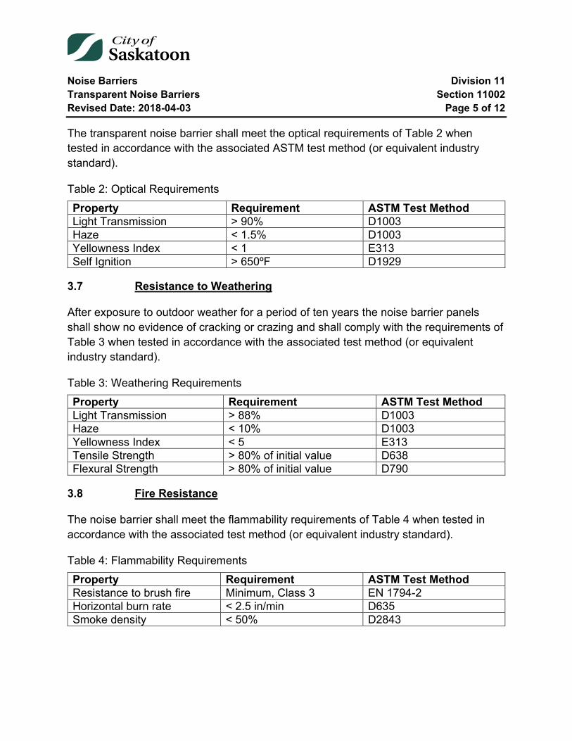
Noise Barriers Division 11 Transparent Noise Barriers Section 11002 Revised Date: 2018-04-03 Page 5 of 12
The transparent noise barrier shall meet the optical requirements of Table 2 when tested in accordance with the associated ASTM test method (or equivalent industry standard).
Table 2: Optical Requirements Property Requirement ASTM Test Method Light Transmission > 90% D1003 Haze < 1.5% D1003 Yellowness Index < 1 E313 Self Ignition > 650ºF D1929
3.7 Resistance to Weathering
After exposure to outdoor weather for a period of ten years the noise barrier panels shall show no evidence of cracking or crazing and shall comply with the requirements of Table 3 when tested in accordance with the associated test method (or equivalent industry standard).
Table 3: Weathering Requirements Property Requirement ASTM Test Method Light Transmission > 88% D1003 Haze < 10% D1003 Yellowness Index < 5 E313 Tensile Strength > 80% of initial value D638 Flexural Strength > 80% of initial value D790
3.8 Fire Resistance
The noise barrier shall meet the flammability requirements of Table 4 when tested in accordance with the associated test method (or equivalent industry standard).
Table 4: Flammability Requirements Property Requirement ASTM Test Method Resistance to brush fire Minimum, Class 3 EN 1794-2 Horizontal burn rate < 2.5 in/min D635 Smoke density < 50% D2843
Noise Barriers Division 11 Transparent Noise Barriers Section 11002 Revised Date: 2018-04-03 Page 6 of 12
3.9 Shatter Resistance
When the panel is to be mounted on a structure or in such a way that if damaged they could pose a hazard to road users or others, the transparent panel be required to retain all broken pieces by employing an internal or external restraint system. Supplier shall show evidence of ability for panels to retain all broken pieces after ten or more years of outdoor exposure.
3.10 Impact Resistance
The noise barrier shall meet the requirements of EN 1794-1, Appendix C.
The noise barrier shall meet the requirements of ANSI Z97.1, safety glazing material.
The noise barrier shall pass the large missile impact test, ASTM E 1996-97/02.
3.11 Graffiti Resistance
Supplier shall recommend an effective, compatible graffiti remover and upon request, shall furnish a product sample and provide a graffiti removal demonstration.
PlexiClean (or equivalent approved graffiti remover for glass and plexiglass) may be used on transparent wall panels to remove graffiti. The PlexiClean product shall be used as per manufacturer’s recommendations.
3.12 Bird Deterrence
Unless specified, all panels shall have the bird deterrence feature with a pattern capable of preventing in excess of 90% of bird impacts. The panel manufacturer shall possess and furnish evidence of the panel efficacy upon request. The bird deterring pattern must be an integral part of the panel, capable of withstanding graffiti removal efforts. Application of films in a secondary, post production process are not allowed due to the tendency of these films to delaminate, haze, or otherwise prematurely degrade the visual performance of the panel.
3.13 Wind Load Resistance
The maximum elastic deflection dmax, under the design wind load shall be less than 3 inches.
Noise Barriers Division 11 Transparent Noise Barriers Section 11002 Revised Date: 2018-04-03 Page 7 of 12
When a load factor of 1.5 is applied to the design wind load:
1. The sheet shall not show any symptoms of failure such as buckling or cracks. 2. The sheet shall not become detached from its supports or fittings.
3.14 Resistance to Roadside Chemicals
The transparent noise barrier shall be resistant to standard de-ice chemicals such as:
• Calcium Chloride, Magnesium Chloride, Potassium Acetate, Calcium / Magnesium Acetate, and Sodium Acetate
3.15 Resistance to Fungi
The transparent noise barrier shall undergo testing in accordance with ASTM G21 and have a zero rating, show no signs of fungi growth, after the standard 28 day test period.
11002-4 Testing
4.1 ASTM Standards
D635 – Standard Test Method for Rate of Burning and/or Extent and Time of Burning of Self-Supporting Plastics in a Horizontal Position
D638 – Test Method for Tensile Properties of Plastic
D785 – Test Method for Rockwell Hardness of Plastics and Electrical Insulating Materials
D790 – Test Methods for Flexural Properties of Unreinforced and Reinforced Plastics and Electrical Insulating Materials
D1003 – Test Methods for Haze and Luminous Transmittance of Transparent Plastics
D1929 – Test Method for Ignition Properties of Plastics
D2843 – Test Method for Density of Smoke from Burning or Decomposition of Plastics
E313 – Standard Practice for Calculating Yellowness and Whiteness Indices from Instrumentally Measured Color Coordinates
Noise Barriers Division 11 Transparent Noise Barriers Section 11002 Revised Date: 2018-04-03 Page 8 of 12
E90 – Standard Method for Laboratory Measurement of Airborne Sound Transmission Loss of Building Partitions
E413 – Standard Classification for Determination of Sound Transmission Class
E1996-97/02 – Standard Test Method for the performance of exterior windows, Curtain Walls, Doors, and Impact Protective Systems Impacted by Windborne Debris in Hurricanes
G21 – Standard Practice for Determining Resistance of Synthetic Polymer Materials to Fungi
G155 – Standard Practice for Operating Xenon Arc Light Apparatus for Exposure of Non-Metallic Materials
4.2 Other Standards
ANSI Standard Z97.1 – Glazing Materials Used in Buildings, Safety Performance Specifications and Methods of Test
EN 1793-2 / ZTV-Lsw 06 – Road Traffic Noise Reducing Devices – Test method for determining the acoustic performance.
EN 1794-1 – Road Traffic Noise Reducing Devices – Non Acoustic Performance
• Part 1 – Mechanical Performance and Stability Requirements • Part 2 – General Safety and Environmental Requirements
ISO 9001:2008 – Quality Management System (Certification)
ISO 14001:2004 & RC 14001:2008 – Environmental Management System and Responsible Care (Certification)
ISO 527-2/1B/5 – Tensile tests on plastics
ISO 178 – Plastics – Determination of Flexural Properties
ISO 1183 – Plastics – Methods for determining the density of non-cellular plastics
ISO 306/B50 – Poly(methyl methacrylate) (PMMA) moulding and extrusion materials
Noise Barriers Division 11 Transparent Noise Barriers Section 11002 Revised Date: 2018-04-03 Page 9 of 12
DIN 53752-A – Testing of Plastics: Determination of the Coefficient of Linear Thermal Expansion
DIN 5036 – Radiometric and Photometric properties of Materials.
11002-5 Construction Methods
Install transparent noise barrier panels in accordance with manufacturer’s recommendations or as directed by the Engineer.
11002-6 Measurement and Payment
6.1 Measurement
The item will be measured by the area in square feet between the top of noise barrier elevation and bottom of noise barrier elevation, as shown in the shop drawing schedule of quantities.
6.2 Payment
The work performed and the materials furnished in accordance with this Item and measured as provided under “Measurement” will be paid for at the unit price bid for “Transparent Noise Barrier Panels”. This price will be full compensation for furnishing and installing all transparent noise barrier panels including framing, welding, fasteners, hardware, all labour, equipment, and incidentals necessary to complete the work.

Noise Barriers Division 11 Transparent Noise Barriers Section 11002 Revised Date: 2018-04-03 Page 10 of 12
Appendix 1 – Aluminum Framed Transparent Panel Assembly Requirements
Framing members shall:
• Consist of profile as approved by the Engineer unless otherwise defined and approved in the project design process.
• Comply with the requirements of ASTM B221 and be of grade 6061-T6. • Meet tolerances as defined by ANSI H35.2-2006 – American National Standard
Dimensional Tolerances for Aluminum Mill Products.
Welding:
For frame designs where welding is required:
• Welds on the bottom surface of the bottom framing member shall be ground flush.
• Welding shall comply with the requirements of AWS D1.2, Structural Welding Code – Aluminum.
• Visual inspection reports required.
Machining:
Removal of U channel section on side framing members should result in a smooth, flush surface. Limit of +0”, -0.030” is allowed only in the immediate area of the U channel.
Gasket:
EPDM gasket will use non migratory plasticizers, must be tested for compatibility with the transparent noise barrier panel.
Fasteners & Hardware:
• Bolts shall be of type 304/304L stainless steel conforming to ASTM A276. • Washers shall be of type 304/304L of 316/316L stainless steel conforming to
ASTM A276.
Coating (where applicable)
Noise Barriers Division 11 Transparent Noise Barriers Section 11002 Revised Date: 2018-04-03 Page 11 of 12
Anodize:
• Per AAMA 611-98 – Voluntary Specification for Anodized Architectural Aluminum Use a Class 1 anodized finish (requires minimum coating thickness of 0.7 mil).
• Coater shall perform and document crosshatch adhesion test results, in accordance with ASTM-3359, for each process batch.
Powder Coat:
• Per AAMA 2604-05 – Voluntary Specification, Performance Requirements and Test Procedures for High Performance Organic Coatings.
• Coater shall have current certification from the coating manufacturer for application of AAMA 2604 architectural powder coatings.
• Powder Coating thickness shall be 3-5 mils for exterior surfaces, wash coat in panel pocket.
• Coater shall perform and document crosshatch adhesion test results, in accordance with ASTM-3359, for each process batch.
Paint:
• Surface Preparation - Solvent Clean per SSPC-SP1. • Surface Preparation - Abrasive blast per SSPC-SP7 brush blast cleaning with
DuPont Starblast non-metallic fine abrasive or equivalent. • Apply one seal coat of CarboCoat 120 water based bonding primer, or
equivalent, thickness 1-2 mils. • Apply finish coat of Carboline 133hb polyurethane, or equivalent, thickness 3-5
mils. Color to be specified. • Perform crosshatch adhesion test in accordance with ASTM-3359.
Assembled Panels:
Following assembly, the manufacturer shall perform an inspection on each panel to ensure the panels have the following characteristics:
Dimension, Assembled Panels
• Length Target ± 0.25” • Height Target ± 0.25”
Noise Barriers Division 11 Transparent Noise Barriers Section 11002 Revised Date: 2018-04-03 Page 12 of 12
• Squareness No more than 0.25” difference between the two diagonals • Waviness ± 0.25” out of flat
Hardware, Torque Setting:
• Bolts shall be tested to confirm a torque of at least 30 ft-lbs or as approved by the Manufacturer and the Engineer.
• Bolts shall be fully engaged (no exposed threads). • Bolts shall not be cross threaded.
Other Criteria:
• When assembled, film is not under gasket. • Gasket is installed to the full length, less up to ¼” at each end, of the U channel
section in which the sheet edge resides. • Hardware (where applicable) is coated to match. • Coating (where applicable) is not damaged or flaking. • Touch-up coating (where applicable) is available for inclusion with shipment.
Documentation Requirements:
The City may request documentation from the contractor related to fabrication/supply of transparent sound wall products.
Typical documentation required of the assigned fabricator include:
1. Aluminum Profile – Certification to ASTM B221, Grade 6061-T6. 2. Aluminum Bar – Certification to ASTM B221, Grade 6061-T6. 3. Hardware – Certification of test to ASTM A276. 4. Coating – Documentation of cross hatch test & certifications as required above. 5. Welding – Visual inspections report per AWS D1.2. 6. Machining – Inspection report to verify requirements of Appendix 1. 7. Final Product – Inspection report to verify requirements of Appendix 1.
End of Specification 11002
Traffic Signals Division 12 Traffic Signal Underground Installation Section 12600 Revised Date: 2011-03-16 Page 1 of 11
12600 Traffic Signal Underground Installation
Index
12600-1 Scope 2
12600-2 Plans and Drawings 2
12600-3 Site Layout / Clearances 2
12600-4 Temporary Traffic Control 2
12600-5 Trenching, Boring & Backfill 3 5.1 Trenching in Existing Roadway 3 5.2 Trenching in Unpaved Roadway 3 5.3 Trenching in Natural Ground 4 5.4 Boring 4
12600-6 Underground Conduit 4
12600-7 Junction Boxes 5
12600-8 Pre-Cast Pole Bases 6
12600-9 Cast-In Place Cabinet Base 7 9.1 Cast-in-Place Cabinet Base in Natural Ground 7 9.2 Cast-in-Place Cabinet Base in Sidewalk 8
12600-10 Pre-Cast Cabinet Base (Temporary) 9
12600-11 Service Pedestals 10
Traffic Signals Division 12 Traffic Signal Underground Installation Section 12600 Revised Date: 2011-03-16 Page 2 of 11
12600-1 Scope
This Section describes the materials used and the normal procedures followed for installation of the underground components of traffic signals indicated below.
• location of existing utilities • installation of underground conduit (trenching or directional bore) • installation of junction boxes • installation of pole bases • installation of traffic signal cabinet concrete base • installation of service pedestals
12600-2 Plans and Drawings
All material shall be installed according to the plans and drawings provided. Where modifications to the plans are required or would enhance the installation, they should be brought to the attention of the Engineer for approval prior to being installed.
Any changes made to the original plans during the field installation shall be noted, and submitted upon project completion to the Engineer.
12600-3 Site Layout / Clearances
All conduit, pole base, junction box, cabinet base, and service pedestal locations shall be marked in the field as per the plans provided and shall be confirmed with the Engineer prior to installation.
The Contractor shall be responsible for acquiring all underground clearances for each location.
12600-4 Temporary Traffic Control
Where the Contractor is the sole workforce at a worksite they shall coordinate and supervise all temporary traffic controls required. The Contractor shall be responsible for maintenance, control and safeguarding of vehicular and pedestrian traffic within and immediately abutting the work area in accordance with City Standards.
Where the City is the primary work force at a worksite, the City will be responsible for maintenance, control and safeguarding of vehicular and pedestrian traffic within and

Traffic Signals Division 12 Traffic Signal Underground Installation Section 12600 Revised Date: 2011-03-16 Page 3 of 11
immediately abutting the work area in accordance with City Standards and on all detours that are not within the work area, at no cost to the Contractor.
12600-5 Trenching, Boring & Backfill
Trenches/boring shall be performed to result in a straight line between termination points as shown on the drawings, and as per the current City of Saskatoon Standard Drawing 102-0016-032 available on the City’s web site. Trenches will be 150mm to 200mm in width and trenched to 1 metre below finished grade when under a roadway, and 750mm below grade when installed behind sidewalks or curbs. Trenching will only be permitted with the approval of the Engineer.
5.1 Trenching in Existing Roadway
Trenches in existing roadways shall be backfilled with fillcrete or 20MPa concrete. Backfill shall extend to 100mm below existing asphalt to allow for hot mix asphalt to be placed matching the existing roadway. Patching shall be performed by City staff and will be coordinated through the Engineer.
Measurement and payment for roadway trenching and backfill will be on a unit price bases per linear metre excavated, and will include all material, labour and equipment required to excavate to 1 metre below finished grade, remove and dispose of surplus material, and provide 20MPa concrete backfill after conduit has been installed.
5.2 Trenching in Unpaved Roadway
Trenches located within a roadway structure through earth or granular materials prior to asphalt placement shall be backfilled with base aggregate as per Section 03001-3.2.2 available on the City’s web site. This material shall be compacted to 98% of Standard Proctor Density using mechanical compacting equipment.
Measurement and payment for trenching in unpaved roadway shall be at unit price per lineal metre excavated, and will include all material, labour and equipment required to excavate to 1 metre below finished grade, remove and dispose of surplus material, and provide granular backfill after conduit has been installed.
Traffic Signals Division 12 Traffic Signal Underground Installation Section 12600 Revised Date: 2011-03-16 Page 4 of 11
5.3 Trenching in Natural Ground
Natural ground is defined as any area that will be finished with topsoil, typically located behind sidewalks, curbs, or in medians. Trenches in uncovered ground shall be backfilled with similar material as removed from the trench, compacted to meet the surrounding soil density.
Measurement and payment for trenching in natural ground shall be at unit price per lineal metre excavated, and will include all material, labour and equipment required to excavate to 750mm below finished grade, remove and dispose of surplus material, and backfill after conduit has been installed.
5.4 Boring
Boring shall be defined as any method of creating a void in the in-situ material without disturbing the surface and includes directional boring and auguring. Boring shall be performed from a sufficient distance away from any existing or future structure or roadway as not to cause damage to that structure. The boring depth shall meet the same depth specifications for trenching. Any excavation required for boring operations shall be backfilled as per the trenching backfill specifications.
Measurement and payment for boring shall be at unit price per lineal metre bored based on hole size (100mm, 200mm, 300mm), and will include all material, labour and equipment required to bore the required hole, remove and dispose of surplus material.
12600-6 Underground Conduit
Underground conduit shall be installed in accordance with the location, size, and number specified on the drawings. All underground conduits shall be 50mm (2”) Polyethylene Pipe (HDPE) when trenching or boring. 50mm (2”) corrugated, double walled, flex pipe will no longer be supplied for trenching or boring. Flex pipe will only be supplied with adaptors to terminate the conduit into a junction box, pole base, cabinet base, or service pedestal as per the current City of Saskatoon Standard Drawings 102-0016-019, 102-0016-029, 102-0016-033, or 102-0016-034 available on the City’s web site. The City of Saskatoon will supply all conduit materials for traffic signal applications unless otherwise stated in the contract documents.
Traffic Signals Division 12 Traffic Signal Underground Installation Section 12600 Revised Date: 2011-03-16 Page 5 of 11
All conduits shall be continuous, without kinks or splices (except when joining polyethylene pipe to corrugated flexible pipe at junction boxes, pole bases, cabinet bases, and service pedestals with a connector supplied by the City) and with minimal deviation from horizontal or vertical alignment between junction boxes. Conduit shall be installed at the bottom of the excavated trench or borehole at the trenching/boring depths specified. When traffic signal conduit and street light conduit are installed in a joint use trench, the uppermost shall always be the street light conduit.
Conduit terminating at a wooden pole shall extend from the ground and contact the pole at the ground surface. The conduit shall terminate one metre above the surface and shall be temporarily strapped to the pole. Conduit terminating on a steel pole or traffic signal cabinet base shall extend 300mm past the surface. Conduit entering precast or cast in place pole bases shall extend through the conduit ports and extend 20mm into the centre opening.
An orange polypropylene twine pull string with a minimum strength of 200 lbs (i.e. Field King 9600, Field King 9000 from the Co-op or equivalent) shall be installed in each conduit. Each duct shall be labelled at both ends to identify the conduit. The pull string (Field King 9600, Field King 9000 from the Co-op or equivalent) shall be taped to the conduit at each end to ensure it cannot be pulled back through the conduit. Each conduit end shall be closed shut with duct tape and/or wooden/plastic plugs to ensure that the interior of the conduit remains free of debris and moisture.
City staff shall inspect and approve all conduits prior to backfilling. All conduit shall be tested to ensure no kinks or blockage exist (with City staff present during testing) by pulling a 25 mm diameter ball through the conduit. The Contractor shall repair any areas that are blocked and repeat the test until the ball can be pulled freely from one conduit end to the other.
Measurement and payment for installation of conduit shall be at unit price per linear metre of each conduit installed and shall include: the pickup from City facilities and delivery to site of conduit; installation of conduit; supply and installation of pull strings, labelling tape and tape for conduit closure; testing of conduit.
12600-7 Junction Boxes
Junction boxes shall be installed in accordance with the location, size, and number specified on the drawings and as per the current City of Saskatoon Standard Drawing
Traffic Signals Division 12 Traffic Signal Underground Installation Section 12600 Revised Date: 2011-03-16 Page 6 of 11
102-0016-019 available on the City’s web site. The City of Saskatoon will supply all junction box materials for traffic signal applications unless otherwise stated in a contract.
The junction box shall be placed on 200mm of clean pea gravel, compacted sufficiently to support the junction box and not allow for settlement. Where junction boxes are installed at locations finished with natural ground surface, the top of the box shall be flush with the surrounding surface or proposed ground surface. Where junction boxes are installed at locations finished with concrete surface, the junction box shall have four 100mm x 10mm galvanized bolt and washer anchors installed horizontally through the wall of the box, one on each side; shall be fitted with a galvanized lid; and the lid shall be set level with the proposed concrete elevation prior to concrete being cast. The concrete surrounding the junction box lid shall be shaped to provide a smooth finish without casting the lid into the concrete. Upon concrete curing, the lid shall be easily removed and replaced to the junction box. Conduit entering the junction box shall extend vertically a minimum of 100 mm into the junction box and shall be cut horizontally. The conduit shall be terminated in the centre of the junction box, bound together with a mechanical fastener such as duct tape or zip ties. The surrounding ground surface affected by the installation of the junction box shall be restored to its original condition.
Measurement and payment shall be per unit for each size and type of junction box installed and shall include: the pickup of all necessary material from City facilities and delivery to installation site; removal and installation of concrete or asphalt; excavation, removal and backfill of any material for installation of junction box; supply and installation of clean pea gravel; installation of the anchor bolts for junction box when installed in concrete.
12600-8 Pre-Cast Pole Bases
Pre-cast pole bases shall be installed in the locations specified on the plans and as per the current City of Saskatoon Standard Drawing 102-0016-029 available on the City’s web site. The City of Saskatoon will supply all pre-cast pole base materials for traffic signal applications unless otherwise stated in the contract documents.
The excavation for the pole base shall be of sufficient width to allow for the mechanical compaction of the backfill material. All loose material shall be removed from the excavation and backfilled with base aggregate as per Section 03001-3.2.2 available on
Traffic Signals Division 12 Traffic Signal Underground Installation Section 12600 Revised Date: 2011-03-16 Page 7 of 11
the City’s web site, and compacted to a minimum 95% Standard Proctor Density. The Contractor shall ensure that the pole bases are installed plumb and level, and that the anchor bolts are aligned with the intended direction of the signal arm. Pole bases shall extend a minimum of 75 mm and maximum 125mm above the final grade of the surrounding or proposed natural ground or concrete surface. A 19mm wooden cover plate shall be installed on each base to prevent moisture and debris from entering. A ground rod shall be installed within the nearest junction box beside each base to an elevation 100mm above the pea gravel. A clamp-on connector, and #6 AWG bare copper ground wire (contractor supplied) shall be attached to the ground rod, and the wire inserted into one of the ports of the pole base through an earth filled excavation. The copper wire (contractor supplied) shall extend past the top of the pole base no less than 0.6m and shall be coiled and stored within the pole base. The surrounding surface affected by the installation of the traffic signal pole base shall be restored to its original condition.
Measurement and payment shall be per unit for each pre-cast pole base installed and shall include: the pickup of all necessary material from City facilities and delivery to installation site; excavation, installation, and backfill of any material for installation of pole base; installation of ground rod; supply and installation of the wooden cover and ground wire.
12600-9 Cast-In Place Cabinet Base
Poured-in-place cabinet bases shall be installed in accordance with the location specified on the drawings. The City of Saskatoon will supply all ground rods and clamps, anchor bolts, and mounting template for traffic signal applications unless otherwise stated in the contract documents.
9.1 Cast-in-Place Cabinet Base in Natural Ground
Where boulevard space allows, the cast-in-place concrete cabinet base will be installed in natural ground in the boulevard as per the current City of Saskatoon Standard Drawing 102-0016-033 available on the City’s web site.
The cast-in-place concrete cabinet base in natural ground shall be 1200mm x 1400mm with a minimum thickness of 300mm. The cast-in-place cabinet base shall be placed on 200mm of base aggregate as per Section 03001-3.2.2 available on the City’s web site, compacted sufficiently to support the cabinet assembly base and not allow for
Traffic Signals Division 12 Traffic Signal Underground Installation Section 12600 Revised Date: 2011-03-16 Page 8 of 11
settlement. The rear section of the cabinet base shall be the pedestal pad and will be the portion of base closest to the roadway measuring 1200mm x 700mm. The pedestal pad will hold the anchor bolt and mounting template for the cabinet pedestal. The front section of the cabinet base shall be the foot pad and will be the portion of pad furthest from the roadway. The City will supply the required anchor bolts and mounting template for the cabinet pedestal. The template shall be oriented as to center the anchor bolts on the pedestal pad of the concrete base. Conduit terminating in the cabinet base shall be contained within a 300 mm diameter circle in the centre of the pedestal pad section of the controller base. Conduit shall extend a minimum of 50 mm above the upper surface of the base. 2 - 100mm (4”) PVC 90 degree long sweep elbows shall be installed to the cabinet junction box and 2 – 50mm (2”) ducts shall be installed as per the plan (either both through the cabinet junction box or one to the junction box the other to the service pedestal). A City supplied copper ground rod shall be installed within a 25mm PVC conduit and extend a minimum of 100 mm above the top of the PVC conduit inside the cabinet base. A clamp-on connector and a #6 AWG bare copper ground wire (contractor supplied) shall be attached to the ground rod and extend .6 m above the top of the cabinet base.
Upon completion of the installation of the conduit, ground rod, and anchor bolts, one mat of 10M deformed bars located at 300mm o/c shall be placed to ensure 75mm clearance on top, bottom, and sides, prior to concrete pour. 35MPa alkali resistant concrete shall be placed around the components. The upper surface of the concrete base shall be trowelled to a smooth finish. The surface of the base shall be gently sloped from the centre to the edges to prevent water from collecting on the pedestal base. The edges shall be bevelled to 45 degrees over 25mm. The surrounding ground surface affected as a result of the installation of the base shall be restored to its original condition.
9.2 Cast-in-Place Cabinet Base in Sidewalk
Where boulevard space is too small or nonexistent, the cast-in-place concrete cabinet base will be installed in the sidewalk as per the current City of Saskatoon Standard Drawing 102-0016-038 available on the City’s web site.
The cast-in-place concrete cabinet base in sidewalk shall be 600mm x 1200mm with a minimum thickness of 300mm. The cast-in-place cabinet base shall be placed on 200mm of base aggregate as per Section 03001-3.2.2 available on the City’s web site,
Traffic Signals Division 12 Traffic Signal Underground Installation Section 12600 Revised Date: 2011-03-16 Page 9 of 11
compacted sufficiently to support the cabinet assembly base and not allow for settlement. The City will supply the required anchor bolts and mounting template for the cabinet pedestal. The template shall be oriented as to center the anchor bolts of the concrete base. Conduit terminating in the cabinet base shall be contained within a 300 mm diameter circle in the centre of the controller base. Conduit shall extend a minimum of 50 mm above the upper surface of the base. 2 - 100mm (4”) PVC 90 degree long sweep elbows shall be installed to the cabinet junction box and 2 – 50mm (2”) ducts shall be installed as per the plan (either both through the cabinet junction box or one to the junction box the other to the service pedestal). A City supplied copper ground rod shall be installed in conjunction with the conduit and extend a minimum of 100 mm above the top of the PVC conduit inside the cabinet base. A clamp-on connector and a #6 AWG bare copper ground wire (contractor supplied) shall be attached to the ground rod and extend .6 m above the top of the cabinet base.
Upon completion of the installation of the conduit, ground rod, and anchor bolts, one mat of 10M deformed bars located at 300mm o/c shall be placed to ensure 75mm clearance on top, bottom, and sides, prior to concrete pour. 35 MPa alkali resistant concrete shall be placed around the components. The pad is to be pinned into existing sidewalk or pinned for new sidewalk to prevent settling. The upper surface of the concrete base shall be trowelled to a smooth finish. The surface of the base shall be gently sloped from the centre to the edges to prevent water from collecting on the pedestal base. The surrounding ground surface affected as a result of the installation of the base shall be restored to its original condition.
Measurement and payment shall be per unit for each cast-in-place cabinet base installed and shall include: pickup of all necessary material from City facilities and delivery to installation site; removal and installation of concrete or asphalt; excavation, removal and backfill of any material for installation of cast-in-place cabinet base; installation of ground rod; supply and installation of rebar, 25mm PVC conduit and 100mm PVC elbows, concrete, and ground wire.
12600-10 Pre-Cast Cabinet Base (Temporary)
Pre-cast Cabinet Bases shall be installed in accordance with the location specified on the drawing. The City of Saskatoon will supply all materials for pre-cast cabinet base materials for traffic signal applications unless otherwise stated in the contract documents.
Traffic Signals Division 12 Traffic Signal Underground Installation Section 12600 Revised Date: 2011-03-16 Page 10 of 11
The excavation for the cabinet base shall be of sufficient width to allow for mechanical compaction of the backfill material. All loose material shall be removed from the excavation and backfilled with a base aggregate as per Section 03001-3.2.2 available on the City’s web site, and compacted to a minimum 95% Standard Proctor density. The Contractor shall ensure that the cabinet base is installed plumb, level, and set to the level specified in the drawings. A 19 mm wooden cover plate shall be installed on the base to prevent moisture and debris from entering the enclosure.
A City supplied copper ground rod shall be installed in the centre of the base and extend a minimum of 100 mm above the surface of the finish ground inside the cabinet base. A clamp – connector and a #6 AWG bare copper ground wire (contractor supplied) shall be attached to the ground rod and extend .6 m above the top of the cabinet base and shall be coiled and stored within.
Measurement and payment for each pre-cast cabinet base installed shall include: the pickup of all necessary material from City Facilities and delivery to the installation site; excavation, removal and backfill of any material for installation of pre-cast cabinet base; installation of the ground rod and clamp; supply and installation of ground wire.
12600-11 Service Pedestals
Service pedestals shall be installed in accordance with the location specified on the drawings, and as per the current City of Saskatoon Standard Drawing
102-0016-034 available on the City’s web site. The City of Saskatoon will supply all service pedestal materials for traffic signal applications unless otherwise stated in the contract documents.
The base of the service pedestal shall be buried between 100mm to 150mm into the soil. A ground rod shall be installed in the service pedestal and extend a minimum of 100mm above the pea gravel base. A clamp-on connector and a #6 AWG bare copper ground wire (contractor supplied) shall be attached to the ground rod and extend .6 m above the top of the cabinet base and shall be coiled and stored within. Conduit entering the junction box shall extend vertically a minimum of 100 mm into the service pedestal and shall be cut horizontally. The conduit shall be terminated in the front half of the service pedestal, bound together with a mechanical fastener such as duct tape or zip ties. The surrounding ground surface affected by the installation of the service pedestal shall be restored to its original condition.
Traffic Signals Division 12 Traffic Signal Underground Installation Section 12600 Revised Date: 2011-03-16 Page 11 of 11
Measurement and payment shall be per unit for each service pedestal installed and shall include: the pickup of all necessary materials from City facilities and delivery to installation site; supply and installation of clean pea gravel; excavation, removal and backfill of any material for installation of service pedestal; installation of the ground rod and clamp; supply and installation of ground wire.
End of Specification 12600
Shallow Buried Utilities Division 14 Surface Infrastructure Restoration for Utility Cuts Section 14001 Revised Date: 2021-02-12 Page 1 of 19
14001 Surface Infrastructure Restoration for Utility Cuts
Index
14001-1 Request to Cut City of Saskatoon Surface Infrastructure 2
14001-2 Cost Schedule for Work Performed by City Forces 2 2.1 Paved Streets and Paved Lanes 2 2.2 Costs for Repair of Concrete Sidewalk and Curb 4 2.3 Costs for Repair of Gravel Lanes 4 2.4 Costs for Repair of Sod and Grass Areas 4 2.5 Costs for Paving Stones in Business Improvement Districts 4
14001-3 Specifications for Work Performed by External Corporation or Contractor 5 3.1 Paved Streets and Paved Lanes 5 3.2 Non-Paved Lanes 11 3.3 Shallow Buried Utilities in Parks and Boulevards 11 3.4 Utility Cuts on Unfinished Paved Road at Base Gravel Stage 12 3.5 Utility Cuts in Areas Graded But No Roadway Structure in Place 12
14001-4 Utility or Contractor Construction 13
14001-5 Deep Buried Utilities (i.e. Water and/or Sewer) 13
Tables
Table 1: Cold Mix Asphalt Temporary Patch Charge Rates (Charged from November 1st until March 31st). .............................................................................................................. 2 Table 2: Maintenance Fee Schedule (Applies to all cuts including gravel or cold mix). .. 2 Table 3: Hot Mix Asphalt Repair Charge Rates ............................................................... 3
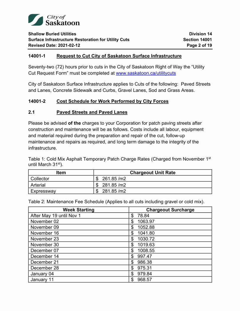
Shallow Buried Utilities Division 14 Surface Infrastructure Restoration for Utility Cuts Section 14001 Revised Date: 2021-02-12 Page 2 of 19
14001-1 Request to Cut City of Saskatoon Surface Infrastructure
Seventy-two (72) hours prior to cuts in the City of Saskatoon Right of Way the “Utility Cut Request Form” must be completed at www.saskatoon.ca/utilitycuts
City of Saskatoon Surface Infrastructure applies to Cuts of the following: Paved Streets and Lanes, Concrete Sidewalk and Curbs, Gravel Lanes, Sod and Grass Areas.
14001-2 Cost Schedule for Work Performed by City Forces
2.1 Paved Streets and Paved Lanes
Please be advised of the charges to your Corporation for patch paving streets after construction and maintenance will be as follows. Costs include all labour, equipment and material required during the preparation and repair of the cut, follow-up maintenance and repairs as required, and long term damage to the integrity of the infrastructure.
Table 1: Cold Mix Asphalt Temporary Patch Charge Rates (Charged from November 1st until March 31st).
Item Chargeout Unit Rate Collector $ 261.85 /m2 Arterial $ 281.85 /m2 Expressway $ 281.85 /m2
Table 2: Maintenance Fee Schedule (Applies to all cuts including gravel or cold mix).
Week Starting Chargeout Surcharge After May 19 until Nov 1 $ 78.84 November 02 $ 1063.97 November 09 $ 1052.88 November 16 $ 1041.80 November 23 $ 1030.72 November 30 $ 1019.63 December 07 $ 1008.55 December 14 $ 997.47 December 21 $ 986.38 December 28 $ 975.31 January 04 $ 979.84 January 11 $ 968.57
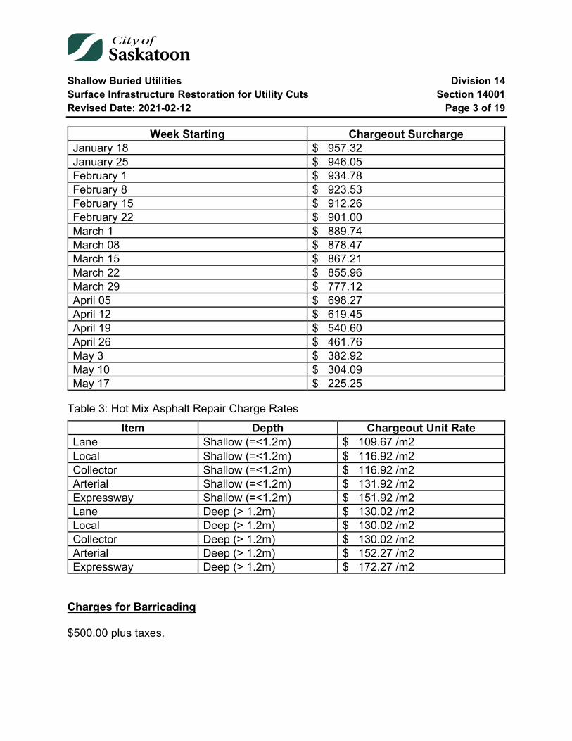
Shallow Buried Utilities Division 14 Surface Infrastructure Restoration for Utility Cuts Section 14001 Revised Date: 2021-02-12 Page 3 of 19
Week Starting Chargeout Surcharge January 18 $ 957.32 January 25 $ 946.05 February 1 $ 934.78 February 8 $ 923.53 February 15 $ 912.26 February 22 $ 901.00 March 1 $ 889.74 March 08 $ 878.47 March 15 $ 867.21 March 22 $ 855.96 March 29 $ 777.12 April 05 $ 698.27 April 12 $ 619.45 April 19 $ 540.60 April 26 $ 461.76 May 3 $ 382.92 May 10 $ 304.09 May 17 $ 225.25
Table 3: Hot Mix Asphalt Repair Charge Rates
Item Depth Chargeout Unit Rate Lane Shallow (=<1.2m) $ 109.67 /m2 Local Shallow (=<1.2m) $ 116.92 /m2 Collector Shallow (=<1.2m) $ 116.92 /m2 Arterial Shallow (=<1.2m) $ 131.92 /m2 Expressway Shallow (=<1.2m) $ 151.92 /m2 Lane Deep (> 1.2m) $ 130.02 /m2 Local Deep (> 1.2m) $ 130.02 /m2 Collector Deep (> 1.2m) $ 130.02 /m2 Arterial Deep (> 1.2m) $ 152.27 /m2 Expressway Deep (> 1.2m) $ 172.27 /m2
Charges for Barricading
$500.00 plus taxes.
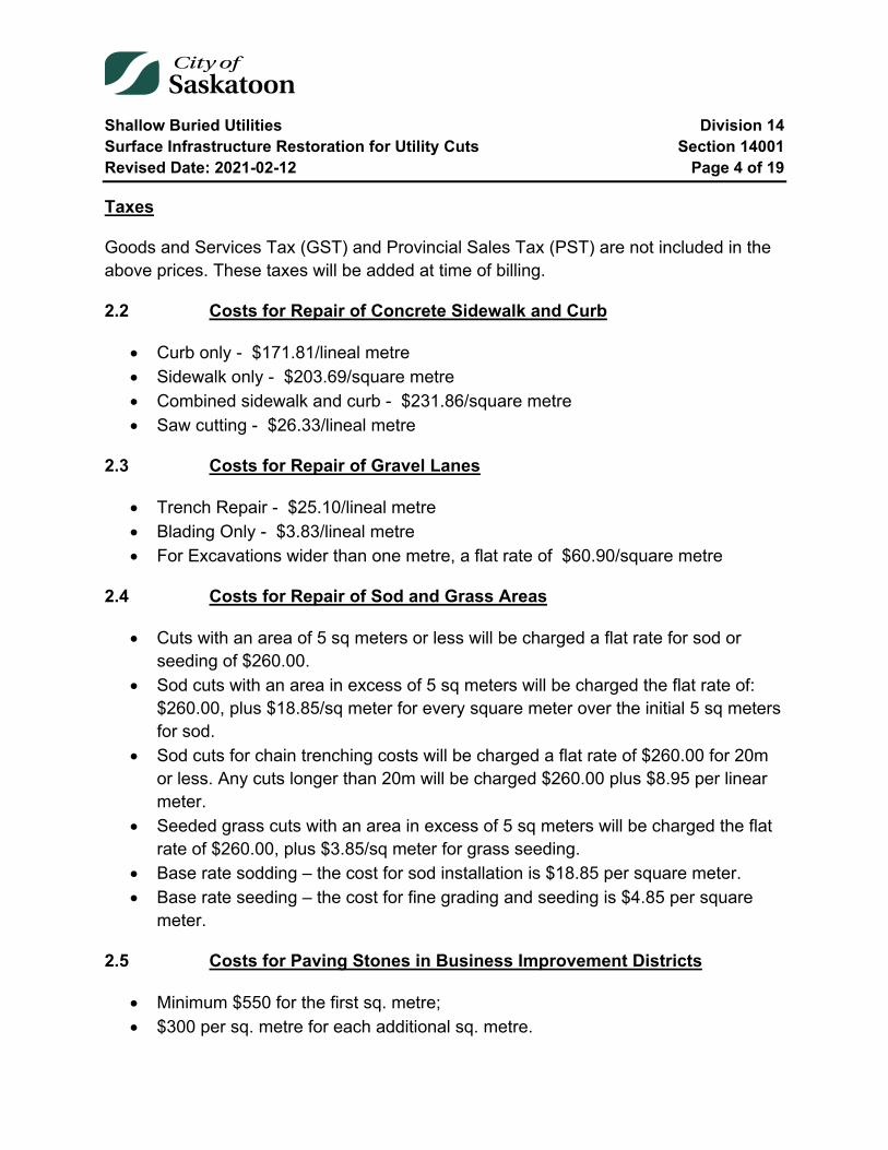
Shallow Buried Utilities Division 14 Surface Infrastructure Restoration for Utility Cuts Section 14001 Revised Date: 2021-02-12 Page 4 of 19
Taxes
Goods and Services Tax (GST) and Provincial Sales Tax (PST) are not included in the above prices. These taxes will be added at time of billing.
2.2 Costs for Repair of Concrete Sidewalk and Curb
• Curb only - $171.81/lineal metre • Sidewalk only - $203.69/square metre • Combined sidewalk and curb - $231.86/square metre • Saw cutting - $26.33/lineal metre
2.3 Costs for Repair of Gravel Lanes
• Trench Repair - $25.10/lineal metre • Blading Only - $3.83/lineal metre • For Excavations wider than one metre, a flat rate of $60.90/square metre
2.4 Costs for Repair of Sod and Grass Areas
• Cuts with an area of 5 sq meters or less will be charged a flat rate for sod or seeding of $260.00.
• Sod cuts with an area in excess of 5 sq meters will be charged the flat rate of: $260.00, plus $18.85/sq meter for every square meter over the initial 5 sq meters for sod.
• Sod cuts for chain trenching costs will be charged a flat rate of $260.00 for 20m or less. Any cuts longer than 20m will be charged $260.00 plus $8.95 per linear meter.
• Seeded grass cuts with an area in excess of 5 sq meters will be charged the flat rate of $260.00, plus $3.85/sq meter for grass seeding.
• Base rate sodding – the cost for sod installation is $18.85 per square meter. • Base rate seeding – the cost for fine grading and seeding is $4.85 per square
meter.
2.5 Costs for Paving Stones in Business Improvement Districts
• Minimum $550 for the first sq. metre; • $300 per sq. metre for each additional sq. metre.
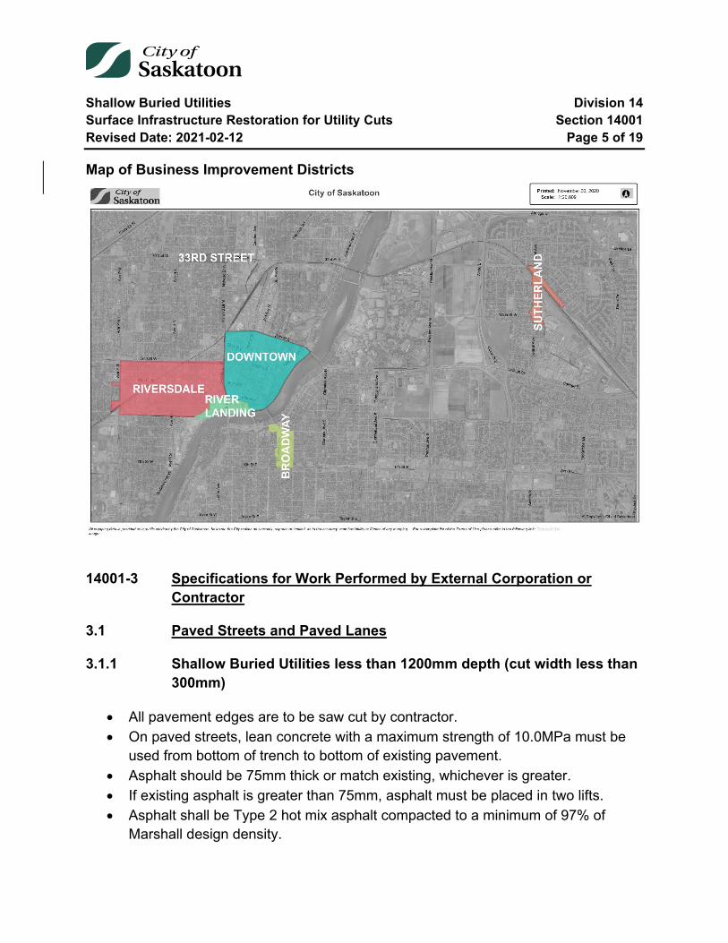
Shallow Buried Utilities Division 14 Surface Infrastructure Restoration for Utility Cuts Section 14001 Revised Date: 2021-02-12 Page 5 of 19
Map of Business Improvement Districts
14001-3 Specifications for Work Performed by External Corporation or Contractor
3.1 Paved Streets and Paved Lanes
3.1.1 Shallow Buried Utilities less than 1200mm depth (cut width less than 300mm)
• All pavement edges are to be saw cut by contractor. • On paved streets, lean concrete with a maximum strength of 10.0MPa must be
used from bottom of trench to bottom of existing pavement. • Asphalt should be 75mm thick or match existing, whichever is greater. • If existing asphalt is greater than 75mm, asphalt must be placed in two lifts. • Asphalt shall be Type 2 hot mix asphalt compacted to a minimum of 97% of
Marshall design density.
Shallow Buried Utilities Division 14 Surface Infrastructure Restoration for Utility Cuts Section 14001 Revised Date: 2021-02-12 Page 6 of 19
• See Plan No. 102-0007-001.
3.1.2 Shallow Buried Utilities less than 1200mm depth (cut width greater than or equal to 300mm)
Can use one of two methods:
Method One
• All pavement edges are to be saw cut by contractor. • Non-shrink fill with a maximum strength of 0.6MPa must be used from bottom of
trench to a point 200mm below the bottom of finished pavement surface. • Place a polyethylene bond breaker between 0.6MPa and the 20MPa concrete. • 200mm of 20MPa concrete must be used below existing asphalt. • Asphalt should be 75mm thick or match existing whichever is greater. • If existing asphalt is greater than 75mm, asphalt must be placed in two lifts. • Asphalt shall be Type 2 hot mix asphalt compacted to a minimum of 97% of
Marshall design density. • All excavated material to be hauled away. • See Plan No. 102-0007-002.
Method Two
• All pavement edges are to be saw cut by contractor. • Utility company is to cover their utility line with concrete or compacted gravel to a
depth of 400mm below top of asphalt. • A plate tamper or vibratory roller must be used for compaction of gravel. • Base gravel shall be placed in 150mm lifts (maximum) and compacted to 100 %
of Standard Proctor Density. • Test results must be provided. Compaction test reports can be faxed to 975-
2971. • Base gravel is to be placed to the bottom of asphalt. • Asphalt should be 75mm thick or match existing whichever is greater. • If existing asphalt is greater than 75mm, asphalt must be placed in two lifts. • Asphalt shall be Type 2 hot mix asphalt compacted to a minimum of 97% of
Marshall design density. • All excavated material to be hauled away.
Shallow Buried Utilities Division 14 Surface Infrastructure Restoration for Utility Cuts Section 14001 Revised Date: 2021-02-12 Page 7 of 19
• If test results are less than the specified density, the contractor must excavate, re-compact and re-test to confirm density. If densities are not met, paving costs will be increased by 20% plus barricading charge.
• If tests are not provided, paving costs will be increased by 30% plus barricading charge.
• Tests shall be taken at a minimum of 50m spacing along project. • See Plan No. 102-0007-003.
3.1.3 Shallow Buried Utilities less than 1200mm depth (cut width greater than or equal to 300mm) Winter Construction (after November 15th) on Collector or Greater Roadways
Utility cuts will not be permitted after November 15th as hot mix asphalt is not available after this date. Under special circumstances road cuts may be permitted upon approval from the City of Saskatoon. The City of Saskatoon will determine how repairs will be made if winter construction is allowed.
3.1.4 Shallow Buried Utilities less than 1200mm depth (on all cuts) Winter Construction (after November 15th) On Local Street or Paved Lanes
Can use one of three methods:
Method One
• All existing snow and ice in the general area is to be removed and trucked off site.
• All excavated material is to be hauled to an approved disposal area off site. • The fill, base gravel shall be placed in 150mm lifts (maximum) and a compactive
effort is to be made. • The cut is to be filled with gravel to the top of asphalt. • The Cut is left in this condition and maintained by the City of Saskatoon through
the winter months. The following steps take place during the subsequent spring season:
• The utility is to arrange with the City to schedule the placement of hot mix asphalt.
• The temporary patch is to be removed by utility.
Shallow Buried Utilities Division 14 Surface Infrastructure Restoration for Utility Cuts Section 14001 Revised Date: 2021-02-12 Page 8 of 19
• If asphalt edge is not clean and straight, the utility or contractor must make a new cut leaving the trench or hole with a straight clean edge.
• If there is no temporary patch excavate gravel to bottom of asphalt or 75mm whichever is greater.
• Base gravel is to be placed to base of asphalt. • The trench must be compacted to 100% of Standard Proctor Density. • If test results are less than the specified density contractor must excavate, re-
compact and re-test to confirm density. Paving costs will be increased by 20% plus barricading charge.
• If tests are not provided, paving costs will be increased by 30% plus barricading charge.
• Tests shall be taken at a minimum of 50m spacing along project. • Test results must be provided. Compaction test reports can be faxed to 975-
2971. • The City of Saskatoon will place hot mix asphalt, and the utility will be charged
based on summer rates. (Refer to Page 2 for Cost Schedule). • If existing asphalt is greater than 75mm, asphalt must be placed in two lifts. • Asphalt shall be Type 2 hot mix asphalt compacted to a minimum of 97% of
Marshall design density.
Method Two
• All existing snow and ice in the general area is to be removed and trucked off site.
• All excavated material is to be hauled to an approved disposal area off site. • The fill, base gravel shall be placed in 150mm lifts (maximum) and an effort is
made to compact materials. • The cut is to be filled with gravel to the top of asphalt. • The Cut is left in this condition and maintained by the City of Saskatoon through
the winter months. The following steps take place during the subsequent spring season:
• The utility is to arrange with the City to schedule the placement of hot mix asphalt.
• The temporary patch is to be removed by utility. • If there is no temporary patch, excavate gravel to bottom of asphalt or 75mm
whichever is greater.

Shallow Buried Utilities Division 14 Surface Infrastructure Restoration for Utility Cuts Section 14001 Revised Date: 2021-02-12 Page 9 of 19
• If asphalt edge is not clean and straight, the utility or contractor must make a new cut, leaving the trench or hole with a straight clean edge.
• If utility or contractor choose not to provide compaction testing then the utility or contractor must remove gravel fill.
• All excavated material is to be hauled away. • Non-shrink fill with a maximum strength of 0.6MPa must be used from bottom of
trench to a point 200mm below the bottom of finished pavement surface. • See Plan No. 102-0007-002. • Place a polyethylene bond breaker between 0.6MPa and the 20MPa concrete. • Bond breaker is not required if 0.6MPa concrete has set already. If they are
poured at the same time the utility or contractor must use bond breaker. • 200mm of 20MPa concrete must be used below existing asphalt. • The City of Saskatoon will place hot mix asphalt, and the utility will be charged
based on summer rates. (Refer to Page 2 for Cost Schedule). • If existing asphalt is greater than 75mm, asphalt must be placed in two lifts. • Asphalt shall be Type 2 hot mix asphalt compacted to a minimum of 97% of
Marshall design density.
Method Three
• All existing snow and ice in the general area is to be removed and trucked off site.
• All pavement edges are to be saw cut by contractor. • All excavated material is to be hauled away. • Non-shrink fill with a maximum strength of 0.6MPa must be used from bottom of
trench to a point 200mm below the bottom of finished pavement surface. • See Plan No. 102-0007-002. • Place a polyethylene bond breaker between 0.6MPa and the 20MPa concrete. • 200mm of 20MPa concrete must be used below existing asphalt. • Concrete must be covered with an insulated tarp for 24 hours. • Utility or contractor shall place gravel from 20Mpa concrete to top of asphalt. The
Cut is left in this condition and maintained by the City of Saskatoon through the winter months. The following steps take place during the subsequent spring season:
• The utility is to arrange with the City to schedule the placement of hot mix asphalt.
Shallow Buried Utilities Division 14 Surface Infrastructure Restoration for Utility Cuts Section 14001 Revised Date: 2021-02-12 Page 10 of 19
• The temporary patch of cold mix is to be removed by the utility • If asphalt edge is not clean and straight, the utility or contractor must make a new
cut leaving the trench with a straight clean edge. • The City of Saskatoon will place hot mix asphalt, and the utility will be charged
based on summer rates. (Refer to Page 2 for Cost Schedule). • If existing asphalt is greater than 75mm, asphalt must be placed in two lifts. • Asphalt shall be Type 2 hot mix asphalt compacted to a minimum of 97% of
Marshall design density.
3.1.5 Shallow Buried Utilities less than 1200mm depth (cut width less than 300mm) Winter Construction (after November 15th) on Collector or Greater Roadways.
• All existing snow and ice in the general area is to be removed and trucked off site.
• All pavement edges are to be saw cut if trencher does not make a smooth cut. • All excavated material is to be hauled to an approved disposal area off site. • Lean concrete with a maximum strength of 10.0MPa must be used from bottom
of trench to bottom of finished pavement surface. • The City of Saskatoon will temporarily patch cuts with cold mix asphalt, the patch
should be 75mm thick. The utility will be charged based on summer rates. (Refer to Page 2 for Cost Schedule). The City of Saskatoon will make the decision whether cold mix asphalt patching will be required, if not the cut will be patched with gravel.
• The Cut is left in this condition and maintained by the City of Saskatoon through the winter months. The following steps take place during the subsequent spring season:
• The utility is to arrange with the City to schedule the placement of hot mix asphalt.
• The temporary patch is to be removed by utility. • If there is no temporary cold mix asphalt patch, excavate the patch gravel to
bottom of asphalt or 75mm whichever is greater. • The City of Saskatoon will place hot mix asphalt, and the utility will be charged
based on summer rates. (Refer to Page 2 for Cost Schedule). • If existing asphalt is greater than 75mm, asphalt must be placed in two lifts.
Shallow Buried Utilities Division 14 Surface Infrastructure Restoration for Utility Cuts Section 14001 Revised Date: 2021-02-12 Page 11 of 19
• Asphalt shall be Type 2 hot mix asphalt compacted to a minimum of 97% of Marshall design density.
• See Plan No. 102-0007-001.
3.2 Non-Paved Lanes
3.2.1 Shallow Buried Utilities in Gravel lanes
• All excavated material is to be hauled to an approved disposal area off site. • The fill base gravel shall be placed in 150mm lifts (maximum) and compacted to
95% of Standard Proctor Density at existing field moisture content. • The surface will be graded and the construction area must be well gravelled. • If construction areas fail the City will fix sites and bill the utility. • See Plan no.102-0007-005.
3.2.2 Shallow Buried Utilities in Gravel Lanes Winter Construction (after November 15th)
• All existing snow and ice in the general area is to be removed and trucked off site.
• All excavated material is to be hauled to an approved disposal area off site. • The fill base gravel shall be placed in 150mm lifts (maximum) and a compacted
effort is to be made. • The surface will be graded and the construction area must be well gravelled. • A restoration report is to be faxed to 975-2971. • If construction areas fail the City will fix sites and bill utility.
3.3 Shallow Buried Utilities in Parks and Boulevards
• Utility cuts should be at least 600mm from curbs or back of walks. If utility wants to place a structure in less than the minimum requirements, the utility will have to back fill the trench or hole with 2MPa non-shrink fill, to 100mm from existing topsoil.
• Trench or hole shall be filled in 150mm lifts (maximum) and compacted to 95% of Standard Proctor Density to a depth 100mm below existing topsoil.
• 100mm of topsoil must be placed over trench or hole. • All extra cut material must be trucked away.
Shallow Buried Utilities Division 14 Surface Infrastructure Restoration for Utility Cuts Section 14001 Revised Date: 2021-02-12 Page 12 of 19
• Grass seed or sod must be placed over the trench or hole. The City of Saskatoon will make the decision on whether seed or sod will be used. The City will stipulate the type of grass seed to be used.
• If trench or hole sinks (within two years) the City of Saskatoon will fill the trench or hole and invoice the utility.
• In parks, the Parks Branch may require that Parks Branch do all the repairs and invoice the utility at standard rates. (Refer to Page 2 for Cost Schedule).
3.4 Utility Cuts on Unfinished Paved Road at Base Gravel Stage
• Excavate and dispose of all trench material. • Install utility as permitted by City of Saskatoon approved layout plan. • Backfill required to be either:
1. Fillcrete (unshrinkable fill) full and complete all remaining trench to the underside of the installed granular subbase;
2. Or reinstallation of native backfill material is allowed as long as a minimum trench width of 1.2 m is excavated and native backfill is installed to 98% of Maximum Standard Proctor Dry Density, (complete with independent testing results paid for by the utility or contractor);
3. Or minimum 10 Mpa Concrete for the full depth of installed granular subbase.
• Approved granular base properly installed to replace the region of base removed. • The City of Saskatoon will have its Roadway Contractor shape and compact the
base prior to paving, the cost of which will be charged to the Utilities account. A minimum charge of $300 will be assessed for a maximum of 125m2, with an additional $2.00 per m2 above 125m2.
3.5 Utility Cuts in Areas Graded But No Roadway Structure in Place
1. Fillcrete (unshrinkable fill) full and complete all remaining trench to the underside of the future subbase; the City of Saskatoon will provide grade stakes for those elevations;
2. Or reinstallation of native backfill material is allowed as long as a minimum trench width of 1.2 m is excavated and native backfill is installed to 98% of Maximum Standard Proctor Dry Density, (complete with independent testing results paid for by the utility or contractor).
Shallow Buried Utilities Division 14 Surface Infrastructure Restoration for Utility Cuts Section 14001 Revised Date: 2021-02-12 Page 13 of 19
14001-4 Utility or Contractor Construction
There may be occasions where it would be beneficial to both parties to have the Contractor or Corporation arrange for asphalt or concrete repairs by a private sector supplier. Prior arrangements should be made with the Roadways Manager or Superintendent. The Roadways Branch City Yards telephone number is 975-2476.
• 2 years of warranty on asphalt work by contractor. • If work completed by a third party hired by a utility company is not satisfactory,
the work will be repaired to a satisfactory state or the City of Saskatoon will make appropriate repairs and charge the utility accordingly.
• Random and scheduled inspections will be made of all work.
14001-5 Deep Buried Utilities (i.e. Water and/or Sewer)
• All pavement edges are to be saw cut by contractor or corporation. • If pavement edge has been damaged than the edge must be moved back to
make the pavement edge a sharp clean line. • All excavated material is to be hauled away. • On all paved streets, the Contractor or Corporation shall place granular backfill
(Class I Backfill) in 300 mm lifts (maximum) over the entire width of the trench and shall compact each lift to 98% of Standard Proctor Density at existing field moisture content, using vibratory mechanical compaction equipment.
• The compacted material shall be brought up to 450 mm below the existing base of asphalt.
• The Contractor or Corporation shall then supply and place 450 mm of street base gravel flush with the original base of asphalt; the street base gravel shall be placed in 150 mm lifts (maximum) and compacted to 100% of Standard Proctor Density at existing field moisture content.
• When the backfilling process can be co-ordinated with the City Yards crew for immediate asphalt patching, the street base should be left down to the base of existing asphalt. If not the hole should be filled to top of existing asphalt with base gravel.
• Asphalt should be 75mm thick or match existing whichever is greater. • If existing asphalt is greater than 75mm, asphalt must be placed in two lifts. • Tests shall be taken at a minimum of 50m spacing along the project. • Test results are required on the following materials:

Shallow Buried Utilities Division 14 Surface Infrastructure Restoration for Utility Cuts Section 14001 Revised Date: 2021-02-12 Page 14 of 19
o Granular base material o Base Gravel
• Copies of all test results must be submitted to the Technical Support Supervisor (Fax 975-2971) and to the Operations Manager (Fax 975-2500).
• If test results are less than the specified density contractor must excavate, re-compact and re-test to confirm density, if not paving costs will be increased by 20%.
• If tests are not provided, paving costs will be increased by 30%.
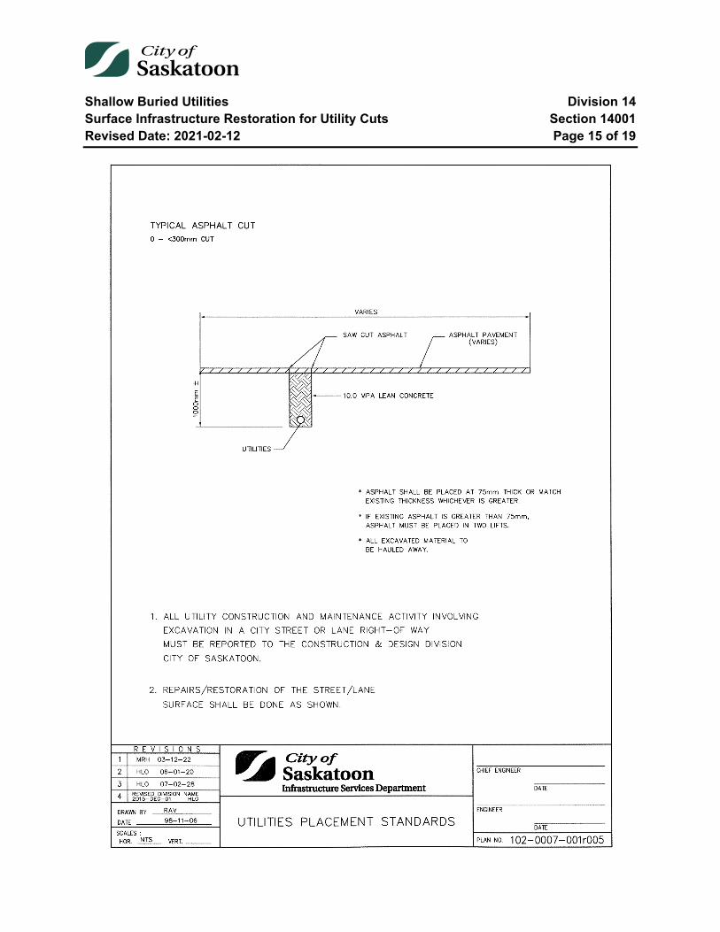
Shallow Buried Utilities Division 14 Surface Infrastructure Restoration for Utility Cuts Section 14001 Revised Date: 2021-02-12 Page 15 of 19
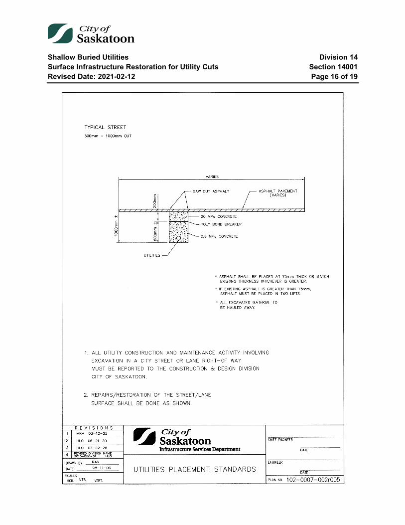
Shallow Buried Utilities Division 14 Surface Infrastructure Restoration for Utility Cuts Section 14001 Revised Date: 2021-02-12 Page 16 of 19
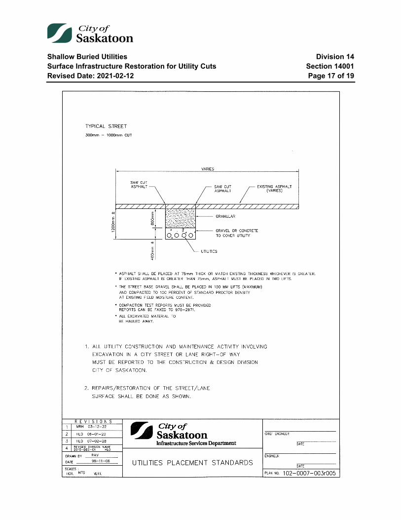
Shallow Buried Utilities Division 14 Surface Infrastructure Restoration for Utility Cuts Section 14001 Revised Date: 2021-02-12 Page 17 of 19
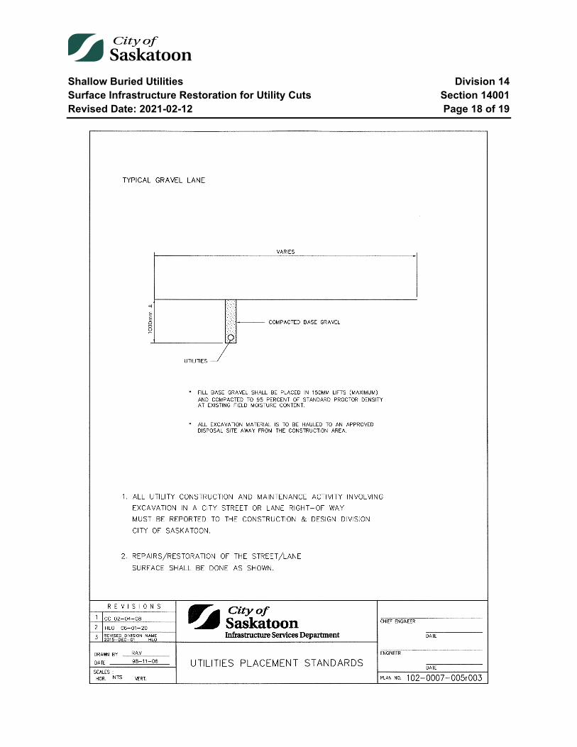
Shallow Buried Utilities Division 14 Surface Infrastructure Restoration for Utility Cuts Section 14001 Revised Date: 2021-02-12 Page 18 of 19

Shallow Buried Utilities Division 14 Surface Infrastructure Restoration for Utility Cuts Section 14001 Revised Date: 2021-02-12 Page 19 of 19
End of Specification 14001
Construction Materials Division 15 Construction Materials – Water Mains Section 15001 Revised Date: 2021-05-31 Page 1 of 20
15001 Construction Materials – Water Mains
Index
15001-1 Water Main Pressure Pipe 3 1.1 Polyvinyl Chloride (PVC) Water Pipe (150mm – 300mm) 3 1.2 Polyvinyl Chloride (PVC) Large Diameter Water Pipe (350mm - 1200mm) 4 1.3 Restrained Joint Polyvinyl Chloride (PVC) Water Pipe and Fittings (150mm – 300mm) 5
15001-2 Water Main Pressure Pipe Fittings 6 2.1 Injection Moulded PVC Pipe Fittings (150mm – 1200mm) 6 2.2 Fabricated PVC Pressure Pipe Fittings 7 2.3 Grey Cast Iron Fittings 8
15001-3 Water Main Pipe Restraints 9 3.1 Pipe Restrainers 9
15001-4 Water Main Valves 10 4.1 Gate Valves 10 4.2 Butterfly Valves 11
15001-5 Water Main Valve Boxes 12 5.1 Valve Boxes – Steel and Cast Iron 12 5.2 Valve Boxes – Plastic 13 5.3 Lifter Rings 14
15001-6 Water Main Hydrants 15 6.1 Hydrants 15
15001-7 Water Main Pipe Couplings 16 7.1 Pipe Couplings 16
15001-8 Water Main Repair Clamps 18 8.1 Repair Clamps/Abandon Service Sleeves 18
Construction Materials Division 15 Construction Materials – Water Mains Section 15001 Revised Date: 2021-05-31 Page 2 of 20
15001-9 Water Main Tapping Sleeves 19 9.1 Tapping Sleeves 19
15001-10 Water Main Tapping Valves 20 10.1 Tapping Valves 20
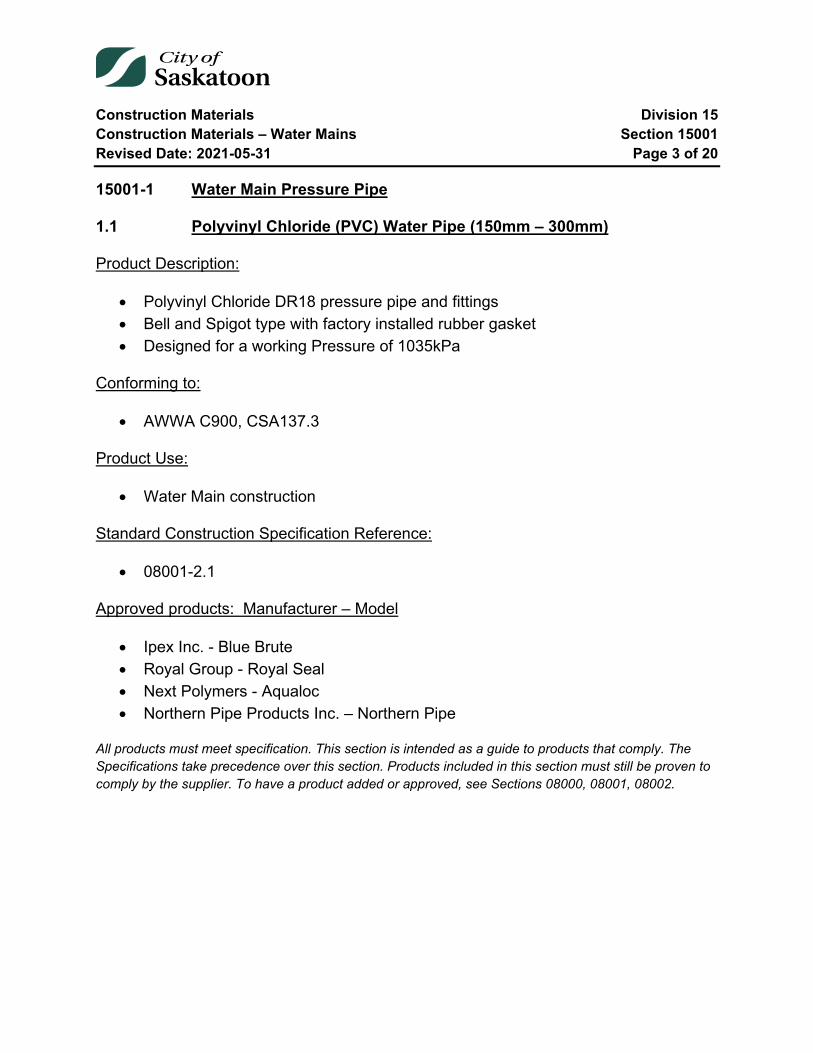
Construction Materials Division 15 Construction Materials – Water Mains Section 15001 Revised Date: 2021-05-31 Page 3 of 20
15001-1 Water Main Pressure Pipe
1.1 Polyvinyl Chloride (PVC) Water Pipe (150mm – 300mm)
Product Description:
• Polyvinyl Chloride DR18 pressure pipe and fittings • Bell and Spigot type with factory installed rubber gasket • Designed for a working Pressure of 1035kPa
Conforming to:
• AWWA C900, CSA137.3
Product Use:
• Water Main construction
Standard Construction Specification Reference:
• 08001-2.1
Approved products: Manufacturer – Model
• Ipex Inc. - Blue Brute • Royal Group - Royal Seal • Next Polymers - Aqualoc • Northern Pipe Products Inc. – Northern Pipe
All products must meet specification. This section is intended as a guide to products that comply. The Specifications take precedence over this section. Products included in this section must still be proven to comply by the supplier. To have a product added or approved, see Sections 08000, 08001, 08002.
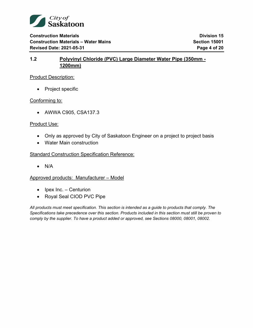
Construction Materials Division 15 Construction Materials – Water Mains Section 15001 Revised Date: 2021-05-31 Page 4 of 20
1.2 Polyvinyl Chloride (PVC) Large Diameter Water Pipe (350mm - 1200mm)
Product Description:
• Project specific
Conforming to:
• AWWA C905, CSA137.3
Product Use:
• Only as approved by City of Saskatoon Engineer on a project to project basis • Water Main construction
Standard Construction Specification Reference:
• N/A
Approved products: Manufacturer – Model
• Ipex Inc. – Centurion • Royal Seal CIOD PVC Pipe
All products must meet specification. This section is intended as a guide to products that comply. The Specifications take precedence over this section. Products included in this section must still be proven to comply by the supplier. To have a product added or approved, see Sections 08000, 08001, 08002.
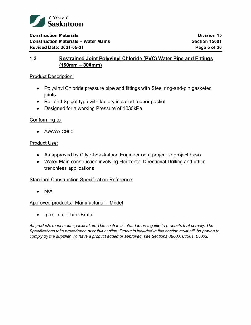
Construction Materials Division 15 Construction Materials – Water Mains Section 15001 Revised Date: 2021-05-31 Page 5 of 20
1.3 Restrained Joint Polyvinyl Chloride (PVC) Water Pipe and Fittings (150mm – 300mm)
Product Description:
• Polyvinyl Chloride pressure pipe and fittings with Steel ring-and-pin gasketed joints
• Bell and Spigot type with factory installed rubber gasket • Designed for a working Pressure of 1035kPa
Conforming to:
• AWWA C900
Product Use:
• As approved by City of Saskatoon Engineer on a project to project basis • Water Main construction involving Horizontal Directional Drilling and other
trenchless applications
Standard Construction Specification Reference:
• N/A
Approved products: Manufacturer – Model
• Ipex Inc. - TerraBrute
All products must meet specification. This section is intended as a guide to products that comply. The Specifications take precedence over this section. Products included in this section must still be proven to comply by the supplier. To have a product added or approved, see Sections 08000, 08001, 08002.
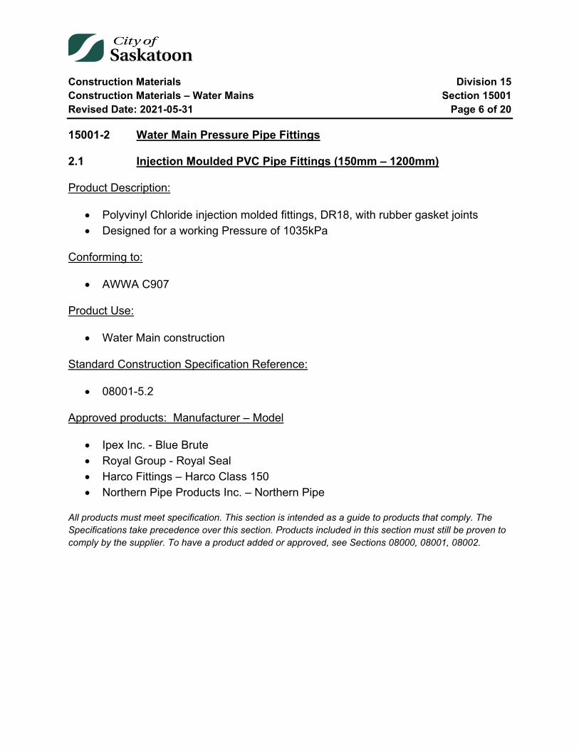
Construction Materials Division 15 Construction Materials – Water Mains Section 15001 Revised Date: 2021-05-31 Page 6 of 20
15001-2 Water Main Pressure Pipe Fittings
2.1 Injection Moulded PVC Pipe Fittings (150mm – 1200mm)
Product Description:
• Polyvinyl Chloride injection molded fittings, DR18, with rubber gasket joints • Designed for a working Pressure of 1035kPa
Conforming to:
• AWWA C907
Product Use:
• Water Main construction
Standard Construction Specification Reference:
• 08001-5.2
Approved products: Manufacturer – Model
• Ipex Inc. - Blue Brute • Royal Group - Royal Seal • Harco Fittings – Harco Class 150 • Northern Pipe Products Inc. – Northern Pipe
All products must meet specification. This section is intended as a guide to products that comply. The Specifications take precedence over this section. Products included in this section must still be proven to comply by the supplier. To have a product added or approved, see Sections 08000, 08001, 08002.
Construction Materials Division 15 Construction Materials – Water Mains Section 15001 Revised Date: 2021-05-31 Page 7 of 20
2.2 Fabricated PVC Pressure Pipe Fittings
Product Description:
• Polyvinyl Chloride fabricated fittings, DR18, with rubber gasket joints • Designed for a working Pressure of 1035kPa
Conforming to:
• AWWA C900 or C905 and CSA B137.3
Product Use:
• Water Main construction • Fittings larger than 300mm, as approved by engineer on a project to project basis • Installed with a zinc anode conforming to City of Saskatoon specifications
Standard Construction Specification Reference:
• 08001-5.3
Approved products: Manufacturer – Model
• Ipex Inc. – Centurion, Blue Brute • Royal Seal CIOD Fittings • Galaxy Plastics – C.I.O.D. PVC C900
All products must meet specification. This section is intended as a guide to products that comply. The Specifications take precedence over this section. Products included in this section must still be proven to comply by the supplier. To have a product added or approved, see Sections 08000, 08001, 08002.
Construction Materials Division 15 Construction Materials – Water Mains Section 15001 Revised Date: 2021-05-31 Page 8 of 20
2.3 Grey Cast Iron Fittings
Product Description:
• Cast Iron fittings, cast from grey cast iron with rubber gasket joints • Designed for a working Pressure of 1035kPa
Conforming to:
• AWWA C110
Product Use:
• Water Main construction • Installed with a zinc anode conforming to City of Saskatoon specifications
Standard Construction Specification Reference:
• 08001-5.1
Approved products: Manufacturer – Model
• Sigma Corporation - Tyton Joint • Norwood Foundry Limited
All products must meet specification. This section is intended as a guide to products that comply. The Specifications take precedence over this section. Products included in this section must still be proven to comply by the supplier. To have a product added or approved, see Sections 08000, 08001, 08002.
Construction Materials Division 15 Construction Materials – Water Mains Section 15001 Revised Date: 2021-05-31 Page 9 of 20
15001-3 Water Main Pipe Restraints
3.1 Pipe Restrainers
Product Description:
• Pipe restraints, consist of ductile iron split restraint rings and high strength low allow (HSLA) connecting rods and fasteners
Conforming to:
• ASTM A536, ASTM F1674 and AWWA C111
Product Use:
• As approved by City of Saskatoon Engineer on a project to project basis • Shall be galvanized or rust proofed by methods approved by the Engineer • To restrain pipe and fitting joints
Standard Construction Specification Reference:
• 08030-8, Drawing 102-0012-002
Approved products: Manufacturer – Model
• Ford Meter Box Company - Uni-flange – 900-C, series 1300-C • Sigma Corporation - Restraint Systems for Ductile Iron Pipe • EBAA Iron, Inc. – Push On Pipe Joints
All products must meet specification. This section is intended as a guide to products that comply. The Specifications take precedence over this section. Products included in this section must still be proven to comply by the supplier. To have a product added or approved, see Sections 08000, 08001, 08002.
Construction Materials Division 15 Construction Materials – Water Mains Section 15001 Revised Date: 2021-05-31 Page 10 of 20
15001-4 Water Main Valves
4.1 Gate Valves
Product Description:
• Gate valve, grey cast or ductile iron body with non rising stem and “O”-ring stem seal
• Designed for a working pressure of 1724 kPa
Product Use:
• Water main construction, Horizontal mains. • Installed with a zinc anode conforming to City of Saskatoon specifications
Standard Construction Specification Reference:
• 08001-3.1
4.1.1 Double Disc Valves
Conforming to:
• AWWA C500
Approved products: Manufacturer – Model
• Mueller Canada – Double Disk Gate Valve • Clow Canada- 2640 • Jenkins Canada (obsolete soon)
4.1.2 Resilient-seated Valves
Conforming to:
• AWWA C509 / C515 , ASTM A126 / A536
Approved products: Manufacturer – Model
• Mueller Canada - Series 2360 (150-300mm) slip on type
Construction Materials Division 15 Construction Materials – Water Mains Section 15001 Revised Date: 2021-05-31 Page 11 of 20
• Clow Canada – Series F-6000 (150-300mm) Tyton fitting type • Jenkins Canada (obsolete soon)
All products must meet specification. This section is intended as a guide to products that comply. The Specifications take precedence over this section. Products included in this section must still be proven to comply by the supplier. To have a product added or approved, see Sections 08000, 08001, 08002.
4.2 Butterfly Valves
Product Description:
• Butterfly Valve, grey cast iron body with stainless steel shaft with O-ring stem seals
• Rubber and stainless steel or stainless steel seated
Conforming to:
• AWWA C504 class 150B Valves
Product Use:
• Water main construction, 300mm horizontal mains. • Installed with a zinc anode conforming to City of Saskatoon specifications
Standard Construction Specification Reference:
• 08001-3.2
Approved products: Manufacturer – Model
• Mueller Canada – Lineseal III • Clow Canada – 4500 class 150 • Jenkins (obsolete soon) • Crispin Valves – Kflo Series 500 (3"-20") and Series 47 (24" - 96")
All products must meet specification. This section is intended as a guide to products that comply. The Specifications take precedence over this section. Products included in this section must still be proven to comply by the supplier. To have a product added or approved, see Sections 08000, 08001, 08002.
Construction Materials Division 15 Construction Materials – Water Mains Section 15001 Revised Date: 2021-05-31 Page 12 of 20
15001-5 Water Main Valve Boxes
5.1 Valve Boxes – Steel and Cast Iron
Product Description:
• Valve Boxes sliding type extending from 2440 mm to 3280 mm • Cast iron cap and boot with the middle section either cast iron or steel
Conforming to:
• AWWA C213
Product Use:
• Water main construction • Installed with a zinc anode conforming to City of Saskatoon specifications
Standard Construction Specification Reference:
• 08001-3.3.1, Drawing 102-0012-017
Approved products: Manufacturer – Model
• Titan Foundry Ltd.

Construction Materials Division 15 Construction Materials – Water Mains Section 15001 Revised Date: 2021-05-31 Page 13 of 20
5.2 Valve Boxes – Plastic
Product Description:
• Type C PI Valve Box • Ductile iron cap with polypropylene upper assembly and PVC lower assembly,
and ABS boot
Product Use:
• Water main construction • Valve repair and maintenance
Standard Construction Specification Reference:
• 08001-3.3.2, Drawing TBD
Approved products: Manufacturer – Model
• WD Industrial Group
All products must meet specification. This section is intended as a guide to products that comply. The Specifications take precedence over this section. Products included in this section must still be proven to comply by the supplier. To have a product added or approved, see Sections 08000, 08001, 08002.

Construction Materials Division 15 Construction Materials – Water Mains Section 15001 Revised Date: 2021-05-31 Page 14 of 20
5.3 Lifter Rings
Product Description:
• Lifter Rings for Valve Box adjustment • Cast iron
Conforming to:
• ASTM A48 Class 20
Product Use:
• Water main rehabilitation and roadway rehabilitation
Standard Construction Specification Reference:
• Drawing 102-0012-018
Approved products: Manufacturer – Model
• Titan Foundry Ltd.
All products must meet specification. This section is intended as a guide to products that comply. The Specifications take precedence over this section. Products included in this section must still be proven to comply by the supplier. To have a product added or approved, see Sections 08000, 08001, 08002.

Construction Materials Division 15 Construction Materials – Water Mains Section 15001 Revised Date: 2021-05-31 Page 15 of 20
15001-6 Water Main Hydrants
6.1 Hydrants
Product Description:
• Hydrants, dry barrel with compression type main valve • 2-65mm nozzles and 114mm pumper nozzle and 150mm inlet elbow (boot)
supplied with rubber gasket. • Designed for a working Pressure of 1035kPa
Conforming to:
• AWWA C502
Product Use:
• Water main construction • Installed with a zinc anode conforming to City of Saskatoon specifications
Standard Construction Specification Reference:
• 08001-4, 08030-10, Drawing 102-0012-003
Approved products: Manufacturer – Model
• Mueller Canada – Canada Valve • Clow Canada – McAvity M67 • Clow Canada (Concorde, Daigle) – D67M
All products must meet specification. This section is intended as a guide to products that comply. The Specifications take precedence over this section. Products included in this section must still be proven to comply by the supplier. To have a product added or approved, see Sections 08000, 08001, 08002.
Construction Materials Division 15 Construction Materials – Water Mains Section 15001 Revised Date: 2021-05-31 Page 16 of 20
15001-7 Water Main Pipe Couplings
7.1 Pipe Couplings
Product Description:
• Bolted, non-restraining sleeve-type couplings • Center sleeve consisting of ductile iron, carbon steel, malleable iron, or Type 304
stainless steel • Two end rings manufactured from either Ductile Iron, Carbon Steel, malleable
Iron, or Type 304 stainless steel • Two rubber wedge gaskets; SBR (buna S), NBR (buna N) or EPDM grade E • High strength, low alloy steel (HSLA) or Type 304 stainless steel nuts and bolts. • Designed for a working Pressure of 1035kPa (150psi)
Conforming to:
• AWWA C219, AWWA C111, NSF/ANSI 61 • Ductile Iron: ASTM A536 • Carbon Steel: ASTM A512 and A53 • Cast Iron: ASTM A97 Grade 32510 or 35018 • Type 304 Stainless steel (coatings not application for stainless steel) • Rubber: ASTM D2000, NSF/ANSI 61 • Epoxy Coating: AWWA C213
Product Use:
• Water main construction, non-restraining connections between two plain ended pipes
• Use of reducing couplings, as approved by engineer on a project to project basis • Each bolt to be supplied with zinc anode cap
Standard Construction Specification Reference:
• 08001-6, 08025-8.2 • For required length and number of bolts 08001-6
Approved products: Manufacturer – Model
Construction Materials Division 15 Construction Materials – Water Mains Section 15001 Revised Date: 2021-05-31 Page 17 of 20
• Robar Industries Ltd. – 1507, 1507R Epoxy coated, HSLA fasteners with anodes • Robar Industries Ltd. – 1696-2B Coupling • Romac Industries Inc. – Macro XP Coupling • Romac Industries Inc. – XR501 Extended range coupling • Smith-Blair – 421 Top Bolt® Wide Range Two Bolt Coupling
All products must meet specification. This section is intended as a guide to products that comply. The Specifications take precedence over this section. Products included in this section must still be proven to comply by the supplier. To have a product added or approved, see Sections 08000, 08001, 08002.
Construction Materials Division 15 Construction Materials – Water Mains Section 15001 Revised Date: 2021-05-31 Page 18 of 20
15001-8 Water Main Repair Clamps
8.1 Repair Clamps/Abandon Service Sleeves
Product Description:
• Designed for a working Pressure of 1035kPa (150psi) and • Stainless Steel Repair Clamps with full wrap around SBR (Buna S) rubber gasket or • Stainless steel Abandon Service Sleeves with SBR (Buna S) liner, and NBR
(Buna N) outlet gasket
Conforming to:
• AWWA C111 Gasket
Product Use:
• To repair service connection cut offs • Not to be used to repair structural damage or defects of the pipe
Standard Construction Specification Reference:
• 08001-7, 08025-12
Approved products: Manufacturer – Model
• Robar Industries Ltd. – 6636AS Model Abandon Service Sleeve • Robar Industries Ltd. – 5600 (COS Spec) • Romac Industries Inc. – SS series
All products must meet specification. This section is intended as a guide to products that comply. The Specifications take precedence over this section. Products included in this section must still be proven to comply by the supplier. To have a product added or approved, see Sections 08000, 08001, 08002.
Construction Materials Division 15 Construction Materials – Water Mains Section 15001 Revised Date: 2021-05-31 Page 19 of 20
15001-9 Water Main Tapping Sleeves
9.1 Tapping Sleeves
Product Description:
• Tapping Sleeve, Cast iron bolted split sleeve type with flange outlet • Designed for a working Pressure of 1035kPa
Conforming to:
• AWWA C111, NSF 61
Product Use:
• Tapping water main services greater than 50mm
Standard Construction Specification Reference:
• 08003-1.2.6, 08025-8.2
Approved products: Manufacturer – Model
• Mueller Canada - H-615 • Robar Industries Ltd. – 6600 Model • Smith Blair – 623 Mechanical Joint
All products must meet specification. This section is intended as a guide to products that comply. The Specifications take precedence over this section. Products included in this section must still be proven to comply by the supplier. To have a product added or approved, see Sections 08000, 08001, 08002.
Construction Materials Division 15 Construction Materials – Water Mains Section 15001 Revised Date: 2021-05-31 Page 20 of 20
15001-10 Water Main Tapping Valves
10.1 Tapping Valves
Product Description:
• Tapping valve, iron body, bronze mounted, nonrising stem gate valve • Designed for a working Pressure of 1035kPa
Conforming to:
• AWWA C500
Product Use:
• Tapping water main services greater than 50mm
Standard Construction Specification Reference:
• 08003-1.2.6
Approved products: Manufacturer – Model
• Mueller Canada – T2300 Series • Clow Canada – 6000 Series
All products must meet specification. This section is intended as a guide to products that comply. The Specifications take precedence over this section. Products included in this section must still be proven to comply by the supplier. To have a product added or approved, see Sections 08000, 08001, 08002.
End of Specification 15001

Construction Materials Division 15 Construction Materials – Water Service Connections Section 15002 Revised Date: 2021-02-12 Page 1 of 9
15002 Construction Materials – Water Service Connections
Index
15002-1 Water Service Connection Pipe 2 1.1 Polyethylene Pipe (25-50mm) 2 1.2 Copper Pipe 3
15002-2 Water Service Connections Saddles and Clamps 4 2.1 Service Saddles (25-50mm) 4 2.2 Service Clamps 5
15002-3 Water Service Connection Valves and Fittings 6 3.1 Main Stops 6 3.2 Curb Stops 7 3.3 Curb Boxes 8 3.4 Fittings 9
Construction Materials Division 15 Construction Materials – Water Service Connections Section 15002 Revised Date: 2021-02-12 Page 2 of 9
15002-1 Water Service Connection Pipe
1.1 Polyethylene Pipe (25-50mm)
Product Description:
• High Density Polyethylene Pipe (HDPE), SDR9, Series 200 (25-50mm) • Designed for a working Pressure of 1035kPa
Conforming to:
• AWWA C901, ASTM D2737
Product Use:
• Water service connections to water mains
Standard Construction Specification Reference:
• 08003-1.1.2, 08025-9.2, Drawing 102-0013-001
Approved products: Manufacturer – Model
• Polytubes – Municipal Series 200, SDR 9 • Ipex Inc. – Municipal Series 200 SDR 9 • KWH Pipe - Sclairpipe
All products must meet specification. This section is intended as a guide to products that comply. The Specifications take precedence over this section. Products included in this section must still be proven to comply by the supplier. To have a product added or approved, see Sections 08000, 08001, 08002.
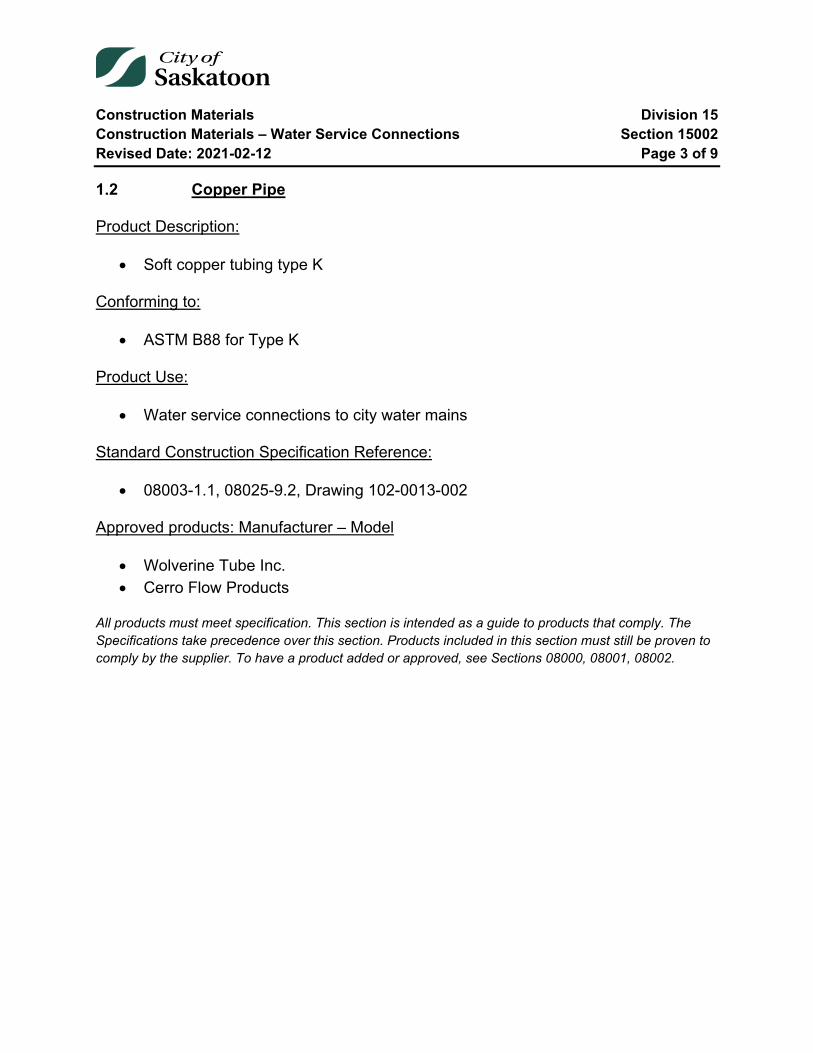
Construction Materials Division 15 Construction Materials – Water Service Connections Section 15002 Revised Date: 2021-02-12 Page 3 of 9
1.2 Copper Pipe
Product Description:
• Soft copper tubing type K
Conforming to:
• ASTM B88 for Type K
Product Use:
• Water service connections to city water mains
Standard Construction Specification Reference:
• 08003-1.1, 08025-9.2, Drawing 102-0013-002
Approved products: Manufacturer – Model
• Wolverine Tube Inc. • Cerro Flow Products
All products must meet specification. This section is intended as a guide to products that comply. The Specifications take precedence over this section. Products included in this section must still be proven to comply by the supplier. To have a product added or approved, see Sections 08000, 08001, 08002.

Construction Materials Division 15 Construction Materials – Water Service Connections Section 15002 Revised Date: 2021-02-12 Page 4 of 9
15002-2 Water Service Connections Saddles and Clamps
2.1 Service Saddles (25-50mm)
Product Description:
Service Saddles for PVC Pipe, shall be made of type 304 stainless steel, with SBR (Buna S) rubber gasket
Service Saddles for iron and steel pipe, Saddle shall be made of Bronze with full wrap around SBR (Buna S) rubber gasket. Type 304 stainless steel straps, washers and nuts.
Designed for a working Pressure of 1035kPa
Conforming to:
• AWWA C800, NSF 61
Product Use:
• To take service outlets off of Water mains
Standard Construction Specification Reference:
• 08003-1.2.5, 08025-8
Approved products: Manufacturer – Model
• Robar Industries Ltd. - Series 2606 for PVC pipe • Robar Industries Ltd – Series 2786 for Iron and Steel Pipe
All products must meet specification. This section is intended as a guide to products that comply. The Specifications take precedence over this section. Products included in this section must still be proven to comply by the supplier. To have a product added or approved, see Sections 08000, 08001, 08002.

Construction Materials Division 15 Construction Materials – Water Service Connections Section 15002 Revised Date: 2021-02-12 Page 5 of 9
2.2 Service Clamps
Product Description:
• Service Clamps (Saddles) shall be made of solid bronze with Type 304 stainless steel double straps, washers and nuts.
• Designed for a working Pressure of 1035kPa
Conforming to:
• AWWA C800, NSF 61
Product Use:
• To take service outlets off of Water mains
Standard Construction Specification Reference:
• See section 08025-3.8, 08025-8
Approved products: Manufacturer – Model
• Robar Industries Ltd. – Series 2706
All products must meet specification. This section is intended as a guide to products that comply. The Specifications take precedence over this section. Products included in this section must still be proven to comply by the supplier. To have a product added or approved, see Sections 08000, 08001, 08002.
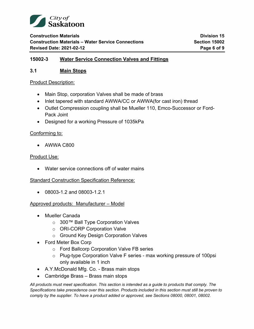
Construction Materials Division 15 Construction Materials – Water Service Connections Section 15002 Revised Date: 2021-02-12 Page 6 of 9
15002-3 Water Service Connection Valves and Fittings
3.1 Main Stops
Product Description:
• Main Stop, corporation Valves shall be made of brass • Inlet tapered with standard AWWA/CC or AWWA(for cast iron) thread • Outlet Compression coupling shall be Mueller 110, Emco-Successor or Ford-
Pack Joint • Designed for a working Pressure of 1035kPa
Conforming to:
• AWWA C800
Product Use:
• Water service connections off of water mains
Standard Construction Specification Reference:
• 08003-1.2 and 08003-1.2.1
Approved products: Manufacturer – Model
• Mueller Canada o 300™ Ball Type Corporation Valves o ORI-CORP Corporation Valve o Ground Key Design Corporation Valves
• Ford Meter Box Corp o Ford Ballcorp Corporation Valve FB series o Plug-type Corporation Valve F series - max working pressure of 100psi
only available in 1 inch • A.Y.McDonald Mfg. Co. - Brass main stops • Cambridge Brass – Brass main stops
All products must meet specification. This section is intended as a guide to products that comply. The Specifications take precedence over this section. Products included in this section must still be proven to comply by the supplier. To have a product added or approved, see Sections 08000, 08001, 08002.
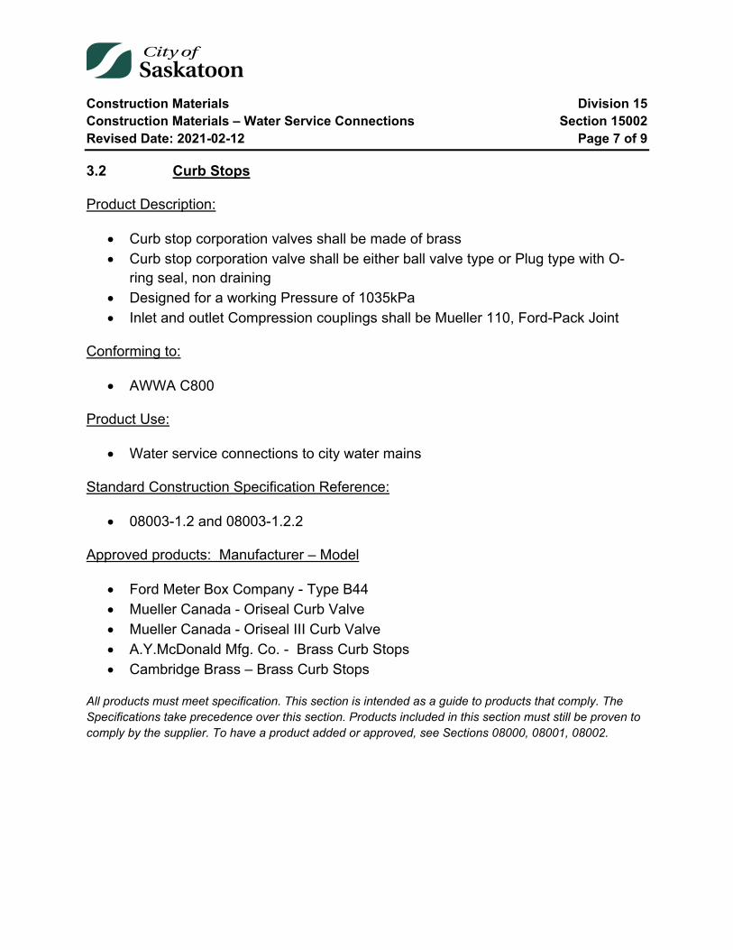
Construction Materials Division 15 Construction Materials – Water Service Connections Section 15002 Revised Date: 2021-02-12 Page 7 of 9
3.2 Curb Stops
Product Description:
• Curb stop corporation valves shall be made of brass • Curb stop corporation valve shall be either ball valve type or Plug type with O-
ring seal, non draining • Designed for a working Pressure of 1035kPa • Inlet and outlet Compression couplings shall be Mueller 110, Ford-Pack Joint
Conforming to:
• AWWA C800
Product Use:
• Water service connections to city water mains
Standard Construction Specification Reference:
• 08003-1.2 and 08003-1.2.2
Approved products: Manufacturer – Model
• Ford Meter Box Company - Type B44 • Mueller Canada - Oriseal Curb Valve • Mueller Canada - Oriseal III Curb Valve • A.Y.McDonald Mfg. Co. - Brass Curb Stops • Cambridge Brass – Brass Curb Stops
All products must meet specification. This section is intended as a guide to products that comply. The Specifications take precedence over this section. Products included in this section must still be proven to comply by the supplier. To have a product added or approved, see Sections 08000, 08001, 08002.

Construction Materials Division 15 Construction Materials – Water Service Connections Section 15002 Revised Date: 2021-02-12 Page 8 of 9
3.3 Curb Boxes
Product Description:
• Curb boxes, sliding type extending from 2.46 to 2.9m • Stainless Steel pipe and spindle • Cast iron cap • Bottom section cast iron or approved plastic
Conforming to:
• ASTM 304
Product Use:
• Water service connections to city water mains
Standard Construction Specification Reference:
• 08001-1.2.3, Drawing 102-0013-011 and 102-0013-012
Approved products: Manufacturer – Model
• Titan Foundry Ltd. – Curb Box, Box Top, Cap, Bottom Section • WD Industrial Group – SB 10 SS SK service box, SB 20 SS SK service box
All products must meet specification. This section is intended as a guide to products that comply. The Specifications take precedence over this section. Products included in this section must still be proven to comply by the supplier. To have a product added or approved, see Sections 08000, 08001, 08002.
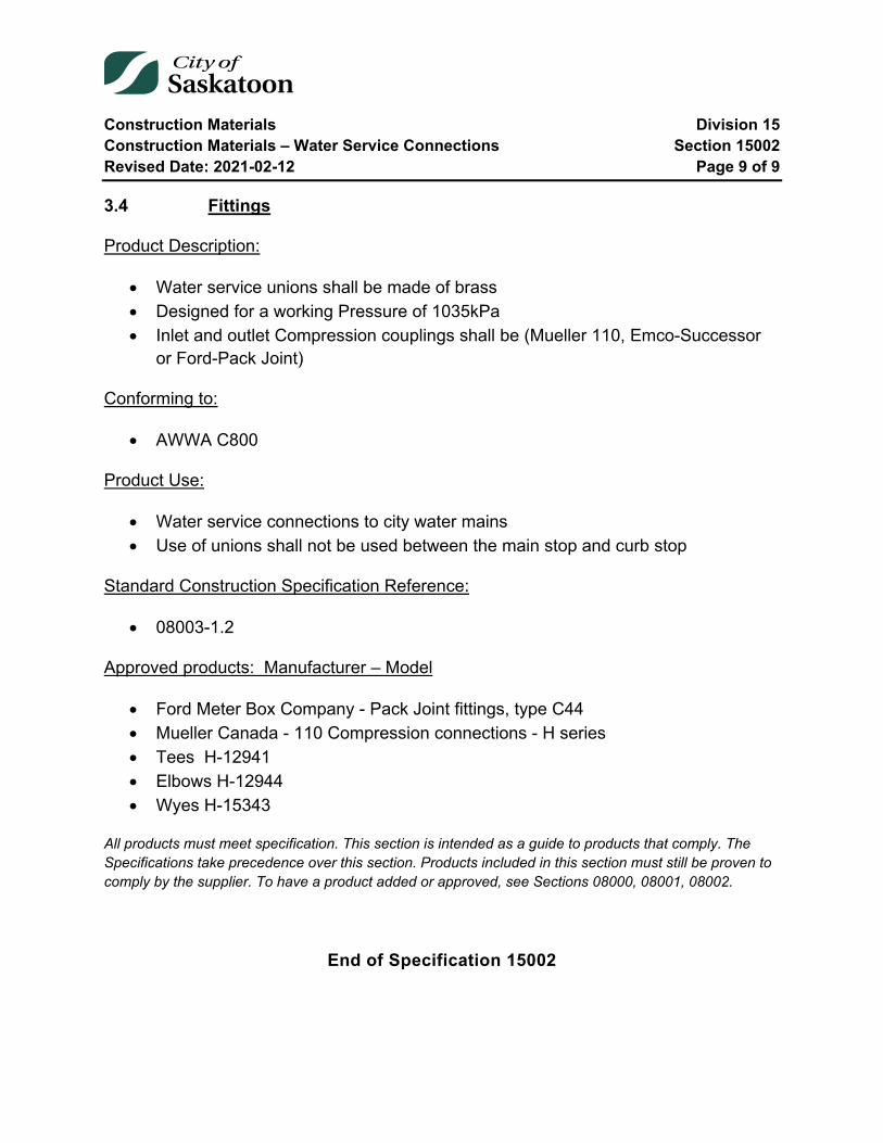
Construction Materials Division 15 Construction Materials – Water Service Connections Section 15002 Revised Date: 2021-02-12 Page 9 of 9
3.4 Fittings
Product Description:
• Water service unions shall be made of brass • Designed for a working Pressure of 1035kPa • Inlet and outlet Compression couplings shall be (Mueller 110, Emco-Successor
or Ford-Pack Joint)
Conforming to:
• AWWA C800
Product Use:
• Water service connections to city water mains • Use of unions shall not be used between the main stop and curb stop
Standard Construction Specification Reference:
• 08003-1.2
Approved products: Manufacturer – Model
• Ford Meter Box Company - Pack Joint fittings, type C44 • Mueller Canada - 110 Compression connections - H series • Tees H-12941 • Elbows H-12944 • Wyes H-15343
All products must meet specification. This section is intended as a guide to products that comply. The Specifications take precedence over this section. Products included in this section must still be proven to comply by the supplier. To have a product added or approved, see Sections 08000, 08001, 08002.
End of Specification 15002
Construction Materials Division 15 Construction Materials – Sewer Mains Section 15003 Revised Date: 2021-05-31 Page 1 of 12
15003 Construction Materials – Sewer Mains
Index
15003-1 Sewer Main Pipe – Gravity Flow 2 1.1 Reinforced Concrete Pipe 2 1.2 Polyvinyl Chloride (PVC) Type PSM, Sanitary and Storm Pipe and Fittings (150-675mm) 3 1.3 Polyvinyl Chloride (PVC) Open Profile Storm Sewer Pipe and Fittings 4 1.4 Polyvinyl Chloride (PVC) Dual Wall Corrugated Profile Storm Sewer Pipe and Fittings 5 1.5 High Density Polyethylene (HDPE) Storm Sewer Gravity Flow Pipe 6 1.6 Polyvinyl Chloride (PVC C900 DR51) PR80, Storm Pipe (600-1200mm) 7
15003-2 Sewer Main Pressure Pipe 8 2.1 High Density Polyethylene (HDPE) Sewer Pressure Pipe 8 2.2 Polyvinyl Chloride (PVC) Sewer Pressure Pipe 9
15003-3 Concrete Manholes and Catch Basins 10 3.1 Reinforced Concrete Manhole Barrels and Catch Basins 10 3.2 Manhole Frames and Covers 11 3.3 Pipe to Manhole and Concrete Structure Connectors 12
Construction Materials Division 15 Construction Materials – Sewer Mains Section 15003 Revised Date: 2021-05-31 Page 2 of 12
15003-1 Sewer Main Pipe – Gravity Flow
1.1 Reinforced Concrete Pipe
Product Description:
• Reinforced Concrete Pipe • Joints shall be the rubber gasket type • Standard pipe lengths shall not be less than 1.8 m
Conforming to:
• ASTM C76 Class 5 or for a specific D-load in ASTM C655 • Pipe joints - ASTM C443 or ASTM C361 • Pipe joints installed at a buried depth of 6m or greater - ASTM C361
Product Use:
• Gravity Sewer construction • Bell and Spigot grove type joints for buried depth of 6m or greater • Beveled pipe and pipe lengths less than 1.8m – as approved by City of
Saskatoon Engineer on a project to project basis
Standard Construction Specification Reference:
• 08002-3.2
Approved products: Manufacturer – Model
• Inland Pipe • Lafarge Canada Inc.
All products must meet specification. This section is intended as a guide to products that comply. The Specifications take precedence over this section. Products included in this section must still be proven to comply by the supplier. To have a product added or approved, see Sections 08000, 08001, 08002.

Construction Materials Division 15 Construction Materials – Sewer Mains Section 15003 Revised Date: 2021-05-31 Page 3 of 12
1.2 Polyvinyl Chloride (PVC) Type PSM, Sanitary and Storm Pipe and Fittings (150-675mm)
Product Description:
• Polyvinyl Chloride Pipe, Bell and Spigot type with factory supplied rubber gasket. • SDR not greater than 35 or SDR 28 at buried depth greater than 6m
Conforming to:
• ASTM D3034 and CSA B182.2
Product Use:
• Gravity Sanitary and Storm Sewer Main construction
Standard Construction Specification Reference:
• 08002-3.1
Approved products: Manufacturer – Model
• Ipex Inc. – Ring Tite • Northern Pipe Products Inc. – Northern Pipe • Royal Group - Royal Seal • Next Polymers - Duraloc • Galaxy Plastics – Gasketed Sewer Fittings
All products must meet specification. This section is intended as a guide to products that comply. The Specifications take precedence over this section. Products included in this section must still be proven to comply by the supplier. To have a product added or approved, see Sections 08000, 08001, 08002.
Construction Materials Division 15 Construction Materials – Sewer Mains Section 15003 Revised Date: 2021-05-31 Page 4 of 12
1.3 Polyvinyl Chloride (PVC) Open Profile Storm Sewer Pipe and Fittings
Profile PVC products are not approved for use as a catch basin lead.
Product Description:
• Polyvinyl Chloride Open Profile (OP) Pipe with concentric reinforcing ribs • Bell and Spigot type with factory supplied rubber gasket
Conforming to:
• ASTM F794 and CSA B182.4
Product Use:
• Gravity flow Storm Sewer Main construction
Standard Construction Specification Reference:
• 08002-3.1.2
Approved products: Manufacturer – Model
• Ipex Inc. - Ultra Rib
All products must meet specification. This section is intended as a guide to products that comply. The Specifications take precedence over this section. Products included in this section must still be proven to comply by the supplier. To have a product added or approved, see Sections 08000, 08001, 08002.
Construction Materials Division 15 Construction Materials – Sewer Mains Section 15003 Revised Date: 2021-05-31 Page 5 of 12
1.4 Polyvinyl Chloride (PVC) Dual Wall Corrugated Profile Storm Sewer Pipe and Fittings
Profile PVC products are not approved for use as a catch basin lead.
Product Description:
• Polyvinyl Chloride, Dual Wall Corrugated Profile (DWCP) pipe • Bell and Spigot type with factory supplied rubber gasket
Conforming to:
• ASTM F794 and CSA B182.4
Product Use:
• Gravity flow storm sewer main construction
Standard Construction Specification Reference:
• 08002-3.1.2
Approved products: Manufacturer – Model
• Royal Group – Kor-Flo (200mm – 900mm) • Ipex Inc. – Ultra X2 (750mm & 900mm)
All products must meet specification. This section is intended as a guide to products that comply. The Specifications take precedence over this section. Products included in this section must still be proven to comply by the supplier. To have a product added or approved, see Sections 08000, 08001, 08002.
Construction Materials Division 15 Construction Materials – Sewer Mains Section 15003 Revised Date: 2021-05-31 Page 6 of 12
1.5 High Density Polyethylene (HDPE) Storm Sewer Gravity Flow Pipe
Product Description:
• Polyethylene Sewer pipe
Conforming to:
• CGSB 41-GP-25M
Product Use:
• Gravity & Low Pressure Applications • As approved by City of Saskatoon Engineer on a project to project basis
Standard Construction Specification Reference:
• 08010-7.5
Approved products: Manufacturer – Model
• KWH Pipe - Weholite • Polytubes
Approved products: Manufacturer – Model (with Conditions)
CSA B182.8 (Storm Sewer) with a minimum ring stiffness of 320KPa, only with CSA B182.8 Type 1 Joints (74KPa) (Boss Ultra Stab 75) is approved for use in storm watermain line applications up to a maximum bury to invert of six metres.
Not approved for use as a catch basin lead.
• Armtec Limited - Boss 2000 320Kpa HDPE • Hancor, Inc. – HDPE • Hancor, Inc. – ADS N-12 WT 1B HDPE
All products must meet specification. This section is intended as a guide to products that comply. The Specifications take precedence over this section. Products included in this section must still be proven to comply by the supplier. To have a product added or approved, see Sections 08000, 08001, 08002.

Construction Materials Division 15 Construction Materials – Sewer Mains Section 15003 Revised Date: 2021-05-31 Page 7 of 12
1.6 Polyvinyl Chloride (PVC C900 DR51) PR80, Storm Pipe (600-1200mm)
Product Description:
• PVC C900 DR51 gasketed pressure pipe for storm sewer applications. • Bell and Spigot type with factory supplied rubber gasket. • DR51 with a depth of cover no greater than 6m
Conforming to:
• CSA B137.3 • AWWA C900 • NSF-61 • ASTM D1784
Product Use:
• Gravity Storm Sewer Main construction
Standard Construction Specification Reference:
• 08002-3.1
Approved products: Manufacturer – Model
• Ipex – Centurion DR51 CIOD 80psi gasketed pressure pipe
All products must meet specification. This section is intended as a guide to products that comply. The Specifications take precedence over this section. Products included in this section must still be proven to comply by the supplier. To have a product added or approved, see Sections 08000, 08001, 08002.
Construction Materials Division 15 Construction Materials – Sewer Mains Section 15003 Revised Date: 2021-05-31 Page 8 of 12
15003-2 Sewer Main Pressure Pipe
2.1 High Density Polyethylene (HDPE) Sewer Pressure Pipe
Product Description:
• High Density Polyethylene Pipe
Conforming to:
• CGSB 41-GP-25M
Product Use:
• Force main construction • As approved by City of Saskatoon Engineer on a project to project basis • Joined by butt fusing the ends of the pipe
Standard Construction Specification Reference:
• 08002-3.3
Approved products: Manufacturer – Model
• KWH Pipe - Sclairpipe • Performance Pipe • Polytubes
All products must meet specification. This section is intended as a guide to products that comply. The Specifications take precedence over this section. Products included in this section must still be proven to comply by the supplier. To have a product added or approved, see Sections 08000, 08001, 08002.
Construction Materials Division 15 Construction Materials – Sewer Mains Section 15003 Revised Date: 2021-05-31 Page 9 of 12
2.2 Polyvinyl Chloride (PVC) Sewer Pressure Pipe
Product Description:
• Polyvinyl Chloride DR41 Class 100 Pressure Pipe • Bell and Spigot type with factory installed gasket
Conforming to:
• AWWA C900, CSA137.3
Product Use:
• Force main construction • As approved by City of Saskatoon Engineer on a project to project basis
Standard Construction Specification Reference:
• N/A
Approved products: Manufacturer – Model
• Ipex Inc.
All products must meet specification. This section is intended as a guide to products that comply. The Specifications take precedence over this section. Products included in this section must still be proven to comply by the supplier. To have a product added or approved, see Sections 08000, 08001, 08002.
Construction Materials Division 15 Construction Materials – Sewer Mains Section 15003 Revised Date: 2021-05-31 Page 10 of 12
15003-3 Concrete Manholes and Catch Basins
3.1 Reinforced Concrete Manhole Barrels and Catch Basins
Product Description:
• Precast reinforced concrete barrels • Joints shall be the rubber gasket type
Conforming to:
• ASTM C478
Product Use:
• Sewer main construction
Standard Construction Specification Reference:
• Section 08002, City of Saskatoon Standard Drawings for Catchbasins and Manholes
Approved products: Manufacturer – Model
• Inland Pipe • Proform Precast Products Inc. • Lafarge Canada Inc. • Souris Valley Industries
All products must meet specification. This section is intended as a guide to products that comply. The Specifications take precedence over this section. Products included in this section must still be proven to comply by the supplier. To have a product added or approved, see Sections 08000, 08001, 08002.
Construction Materials Division 15 Construction Materials – Sewer Mains Section 15003 Revised Date: 2021-05-31 Page 11 of 12
3.2 Manhole Frames and Covers
Product Description:
• Cast Iron Frame and Cover
Conforming to:
• ASTM A48M-00
Product Use:
• Sewer main construction
Standard Construction Specification Reference:
• Section 08002, City of Saskatoon Standard Drawings for Catchbasins and Manholes
Approved products: Manufacturer – Model
• Titan Foundary Ltd. • Westview Sales Ltd.
All products must meet specification. This section is intended as a guide to products that comply. The Specifications take precedence over this section. Products included in this section must still be proven to comply by the supplier. To have a product added or approved, see Sections 08000, 08001, 08002.

Construction Materials Division 15 Construction Materials – Sewer Mains Section 15003 Revised Date: 2021-05-31 Page 12 of 12
3.3 Pipe to Manhole and Concrete Structure Connectors
Product Description:
• Resilient, watertight connection between concrete manholes, structures and pipes.
Conforming to:
• ASTM C923 • ASTM C1478
Product Use:
• Sewer main construction.
Standard Construction Specification Reference:
• Section 08002-5
Approved products: Manufacturer – Model
• Hamilton Kent – HKT-CS • Press–Seal Corporation
o PSX: Direct Drive & 8QRS o Econoseal o Kwik Seal o WS Series Waterstop
All products must meet specification. This section is intended as a guide to products that comply. The Specifications take precedence over this section. Products included in this section must still be proven to comply by the supplier. To have a product added or approved, see Sections 08000, 08001, 08002.
End of Specification 15003
Construction Materials Division 15 Construction Materials – Sewer Service Connections Section 15004 Revised Date: 2018-04-03 Page 1 of 5
15004 Construction Materials – Sewer Service Connections
Index
15004-1 Sewer Service Connection Pipe 2 1.1 Polyvinyl Chloride (PVC) Sewer Service Connection Pipe (100 -200mm) 2
15004-2 Sewer Service Connection Fittings 3 2.1 Polyvinyl Chloride (PVC) Fittings (100 -200mm) 3 2.2 Polyvinyl Chloride (PVC) Saddle and Stainless Steel Straps 4 2.3 High Density Polyethylene (HDPE) Pipe Couplings with Stainless Steel Straps 5
Construction Materials Division 15 Construction Materials – Sewer Service Connections Section 15004 Revised Date: 2018-04-03 Page 2 of 5
15004-1 Sewer Service Connection Pipe
1.1 Polyvinyl Chloride (PVC) Sewer Service Connection Pipe (100 -200mm)
Product Description:
• Polyvinyl Chloride Pipe, SDR 28, Bell and Spigot type with factory supplied rubber gasket
Conforming to:
• ASTM D3034
Product Use:
• Sewer service connections to Sanitary and Storm mains
Standard Construction Specification Reference:
• 08003-2 and 08025-9.1
Approved products: Manufacturer – Model
• Ipex Inc. – Ring Tite • Northern Pipe Products Inc. – Northern Pipe • Next Polymers - Duraloc • Royal Group
All products must meet specification. This section is intended as a guide to products that comply. The Specifications take precedence over this section. Products included in this section must still be proven to comply by the supplier. To have a product added or approved, see Sections 08000, 08001, 08002.
Construction Materials Division 15 Construction Materials – Sewer Service Connections Section 15004 Revised Date: 2018-04-03 Page 3 of 5
15004-2 Sewer Service Connection Fittings
2.1 Polyvinyl Chloride (PVC) Fittings (100 -200mm)
Product Description:
• Polyvinyl Chloride Fittings, SDR28, Bell and Spigot type with factory supplied rubber gasket
• All bends shall be long radius
Conforming to:
• ASTM D3034
Product Use:
• Sewer service connections to Sanitary and Storm mains
Standard Construction Specification Reference:
• 08003-2 and 08025-9.1
Approved products: Manufacturer – Model
• Ipex Inc. – Ring Tite • Northern Pipe Products Inc. – Northern Pipe • Royal Group • GPK Products Inc.
All products must meet specification. This section is intended as a guide to products that comply. The Specifications take precedence over this section. Products included in this section must still be proven to comply by the supplier. To have a product added or approved, see Sections 08000, 08001, 08002.

Construction Materials Division 15 Construction Materials – Sewer Service Connections Section 15004 Revised Date: 2018-04-03 Page 4 of 5
2.2 Polyvinyl Chloride (PVC) Saddle and Stainless Steel Straps
Product Description:
• PVC Saddle supplied with factory installed seat and joint Gaskets, SDR 28, 100-200mm
• Two Stainless Steel Straps without quick release mechanisms
Product Use:
• Sewer service connections to Sanitary and Storm Mains
Conforming to:
• ASTM D3034
Product Use:
• Sanitary and Storm sewer service connections to Sanitary and Storm Mains
Standard Construction Specification Reference:
• 08003-2.3
Approved products: Manufacturer – Model
• Ipex Inc. • Royal Group • GPK Products Inc.
All products must meet specification. This section is intended as a guide to products that comply. The Specifications take precedence over this section. Products included in this section must still be proven to comply by the supplier. To have a product added or approved, see Sections 08000, 08001, 08002.
Construction Materials Division 15 Construction Materials – Sewer Service Connections Section 15004 Revised Date: 2018-04-03 Page 5 of 5
2.3 High Density Polyethylene (HDPE) Pipe Couplings with Stainless Steel Straps
Product Description:
• High Density Polyethylene (HDPE) pipe couplings with stainless steel straps
Product Use:
• When connecting sewer pipe of different types, other than PVC to Acrylonitrile Butadiene Styrene (ABS) pipe
• PVC to Acrylonitrile Butadiene Styrene (ABS) pipe shall be connected with glued ABS Couplings
• As approved by City of Saskatoon Engineer -for sewer connections of the same type of pipe and reducing pipe size applications
Standard Construction Specification Reference:
• 08003-2.2
Approved products: Manufacturer – Model
• Fernco Connectors Ltd. – Fernco • Mission Rubber
All products must meet specification. This section is intended as a guide to products that comply. The Specifications take precedence over this section. Products included in this section must still be proven to comply by the supplier. To have a product added or approved, see Sections 08000, 08001, 08002.
End of Specification 15004
Construction Materials Division 15 Construction Materials – Corrosion Protection Section 15005 Revised Date: 2018-04-03 Page 1 of 3
15005 Construction Materials – Corrosion Protection
Index
15005-1 Corrosion Protection 2 1.1 Anodes 2 1.2 Corrosion Prevention Tape 3
Construction Materials Division 15 Construction Materials – Corrosion Protection Section 15005 Revised Date: 2018-04-03 Page 2 of 3
15005-1 Corrosion Protection
1.1 Anodes
Product Description:
• Galvanic Zinc Anodes
Conforming to:
• ASTM B418
Product Use:
• Water main construction • Installed to all valves, hydrants and cast iron fittings to provide corrosion
protection
Standard Construction Specification Reference:
• 08000-4.4, 08025-8.2, 08030-11
Approved products: Manufacturer – Model
• Corrpro Canada Inc. • Canada Metal Eastern Ltd. • Interprovincial Corrosion Control • Bren Technologies Ltd.
All products must meet specification. This section is intended as a guide to products that comply. The Specifications take precedence over this section. Products included in this section must still be proven to comply by the supplier. To have a product added or approved, see Sections 08000, 08001, 08002.
Construction Materials Division 15 Construction Materials – Corrosion Protection Section 15005 Revised Date: 2018-04-03 Page 3 of 3
1.2 Corrosion Prevention Tape
Product Description:
• Corrosion Prevention Primer and Tape
Conforming to:
• AWWA C217
Product Use:
• Water Main construction
Standard Construction Specification Reference:
• 08000-4.2
Approved products: Manufacturer – Model
• Denso North America Inc. - Denso Paste and Tape • Polyken – 927 primer, 932 tape • PetroWrap
All products must meet specification. This section is intended as a guide to products that comply. The Specifications take precedence over this section. Products included in this section must still be proven to comply by the supplier. To have a product added or approved, see Sections 08000, 08001, 08002.
End of Specification 15005
Construction Materials Division 15 Construction Materials – Roadways Section 15006 Revised Date: 2016-01-12 Page 1 of 2
15006 Construction Materials – Roadways
Index
15006-1 Roadways 2 1.1 Biaxial Geogrid with Integrated Non-woven Geotextile 2
Construction Materials Division 15 Construction Materials – Roadways Section 15006 Revised Date: 2016-01-12 Page 2 of 2
15006-1 Roadways
1.1 Biaxial Geogrid with Integrated Non-woven Geotextile
Product Description:
• Polypropylene extruded monolithic flat structured bars • Integrated non-woven geotextile • Square shaped apertures • Welded rigid junctions
Product Use:
• Reinforcement of pavements and soft subsoils • Reduces aggregate depth requirements • Provides filtration, separation and drainage
Standard Construction Specification Reference:
• 03060-2.3
Approved products: Manufacturer – Model
• Combigrid 40 / 40 Q1 / 151 GRK 3
All products must meet specification. This section is intended as a guide to products that comply. The Specifications take precedence over this section. Products included in this section must still be proven to comply by the supplier.
End of Specification 15006

Construction Materials Division 15 Construction Materials – Noise Barriers Section 15007 Revised Date: 2018-04-03 Page 1 of 3
15007 Construction Materials – Noise Barriers
Index
15007-1 Noise Barriers 2 1.1 Concrete Noise Barriers 2 1.2 Transparent Noise Barriers 3
Construction Materials Division 15 Construction Materials – Noise Barriers Section 15007 Revised Date: 2018-04-03 Page 2 of 3
15007-1 Noise Barriers
1.1 Concrete Noise Barriers
Product Description:
• Precast concrete panel
Conforming to:
• CAN/CSA-S6 Canadian Highway Bridge Design Code; or • AASHTO Guide Specification for the Structural Design of Sound Barriers, 1989
edition incorporating 1992 & 2002 amendments; or • AASHTO LRFD Bridge Design Specification 6th Edition (2012). • ASTM-E413
Product Use:
• Reduce traffic noise
Standard Construction Specification Reference:
• N/A
Approved Products: Manufacturer – Model
• Expocrete Concrete Products Ltd. (now Lafarge Canada Inc.) – AB Fence • Pre-Con Limited – Verti-Crete Sound Wall • Solid Rock Fencing – StoneTree Concrete Fence • Lafarge Canada Inc. – Precast Concrete Noise Barrier (Provisionally Approved)
All products must meet specification. This section is intended as a guide to products that comply. The Specifications take precedence over this section. Products included in this section must still be proven to comply by the supplier. To have a product added or approved, see Sections 11000, 11001, 11002.
Construction Materials Division 15 Construction Materials – Noise Barriers Section 15007 Revised Date: 2018-04-03 Page 3 of 3
1.2 Transparent Noise Barriers
Product Description:
• Transparent thermoplastic panel
Conforming to:
• CAN/CSA-S6 Canadian Highway Bridge Design Code; or • AASHTO Guide Specification for the Structural Design of Sound Barriers, 1989
edition incorporating 1992 & 2002 amendments; or • AASHTO LRFD Bridge Design Specification 6th Edition (2012). • ASTM-E413
Product Use:
• Reduce traffic noise
Standard Construction Specification Reference:
• N/A
Approved Products: Manufacturer – Model
• Evonik Industries (formerly Cyro) – Acrylite Soundstop Noise Barrier • Forster – Fonocon Transparent Noise Barrier
All products must meet specification. This section is intended as a guide to products that comply. The Specifications take precedence over this section. Products included in this section must still be proven to comply by the supplier. To have a product added or approved, see Sections 11000, 11001, 11002.
End of Specification 15007