lightning protection / earthing | finn electric
TRANSCRIPT
www.dehn.de
Lightning Protection / EarthingMain Catalogue 2013/2014
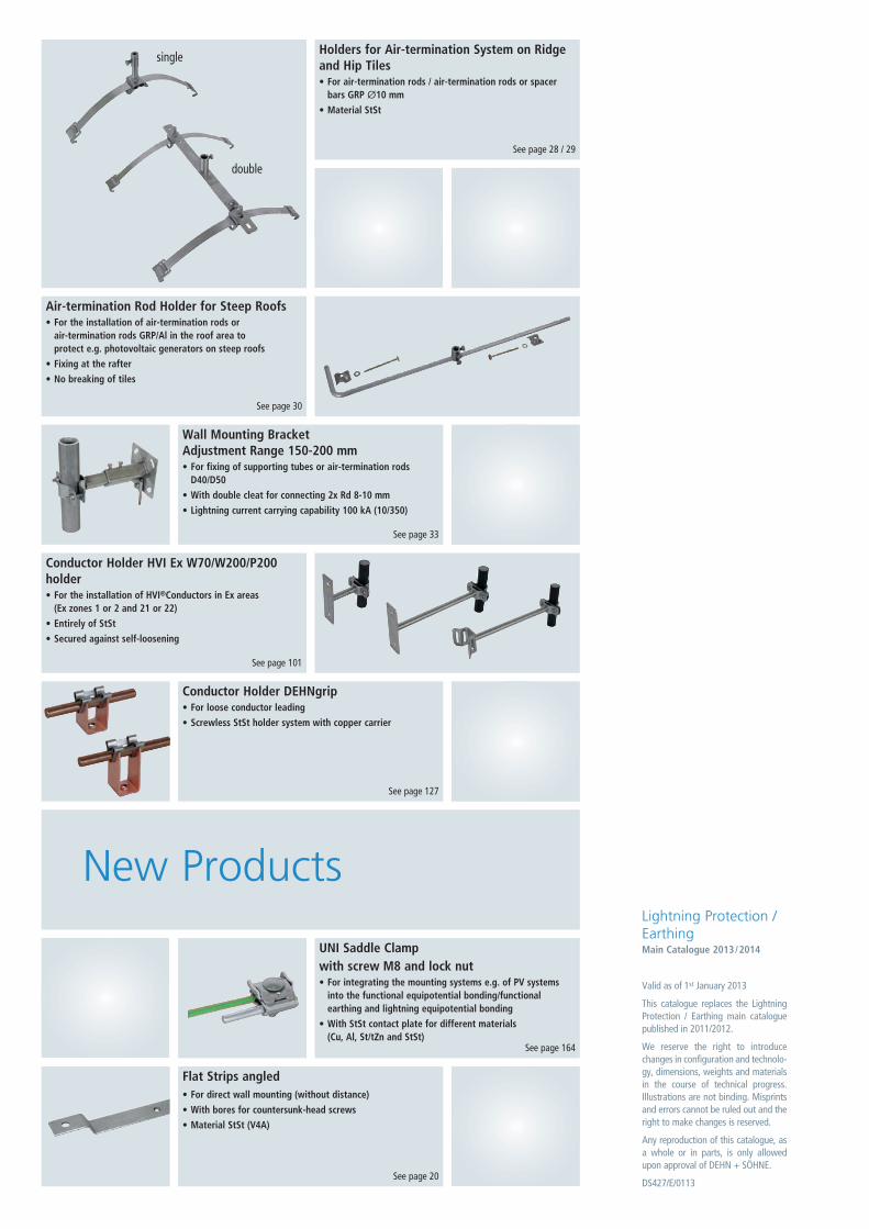
Flat Strips angled• For direct wall mounting (without distance)
• With bores for countersunk-head screws
• Material StSt (V4A)
See page 20
Holders for Air-termination System on Ridgeand Hip Tiles• For air-termination rods / air-termination rods or spacer
bars GRP Ø10 mm
• Material StSt
See page 28 / 29
Valid as of 1st January 2013
This catalogue replaces the LightningProtection / Earthing main cataloguepublished in 2011/2012.
We reserve the right to introducechanges in configuration and technolo-gy, dimensions, weights and materialsin the course of technical progress.Illustrations are not binding. Misprintsand errors cannot be ruled out and theright to make changes is reserved.
Any reproduction of this catalogue, asa whole or in parts, is only allowedupon approval of DEHN + SÖHNE.
DS427/E/0113
Lightning Protection /EarthingMain Catalogue 2013/2014
New Products
Air-termination Rod Holder for Steep Roofs• For the installation of air-termination rods or
air-termination rods GRP/Al in the roof area to protect e.g. photovoltaic generators on steep roofs
• Fixing at the rafter
• No breaking of tiles
See page 30
Wall Mounting Bracket Adjustment Range 150-200 mm• For fixing of supporting tubes or air-termination rods
D40/D50
• With double cleat for connecting 2x Rd 8-10 mm
• Lightning current carrying capability 100 kA (10/350)
See page 33
Conductor Holder HVI Ex W70/W200/P200holder• For the installation of HVI®Conductors in Ex areas
(Ex zones 1 or 2 and 21 or 22)
• Entirely of StSt
• Secured against self-loosening
See page 101
UNI Saddle Clampwith screw M8 and lock nut• For integrating the mounting systems e.g. of PV systems
into the functional equipotential bonding/functional earthing and lightning equipotential bonding
• With StSt contact plate for different materials (Cu, Al, St/tZn and StSt)
See page 164
Conductor Holder DEHNgrip• For loose conductor leading
• Screwless StSt holder system with copper carrier
See page 127
single
double
www.dehn.de
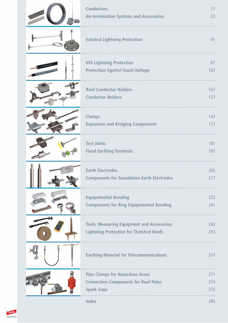
Roof Conductor Holders 107
Conductor Holders 127
Clamps 143
Expansion and Bridging Components 173
Tools, Measuring Equipment and Accessories 243
Lightning Protection for Thatched Roofs 253
Equipotential Bonding 225
Components for Ring Equipotential Bonding 241
Earth Electrodes 205
Components for Foundation Earth Electrodes 217
Test Joints 181
Fixed Earthing Terminals 193
Earthing Material for Telecommunications 257
HVI Lightning Protection 67
Protection Against Touch Voltage 103
Isolated Lightning Protection 41
Pipe Clamps for Hazardous Areas 271
Connection Components for Roof Poles 274
Spark Gaps 275
Index 285
Conductors 17
Air-termination Systems and Accessories 23

Our promise
3www.dehn.de
DEHN protectsOur family-owned company has been specialising in surge protec-tion, lightning protection and safety equipment for many decades.With the key objective of protecting material assets and workers,we have made a name for ourselves in the market.
It was our pioneering spirit and innovative ideas that havedefined our company for more than 100 years and made us amarket leader with more than 1500 employees. Our products anddevelopments reflect our market feasability, commitment andideas.
As early as in 1923 our founder Hans Dehn started production ofexternal lightning protection and earthing components to opti-mise the protection of buildings and installations. In 1954, welaunched the first series of surge protective devices. Constant fur-ther development of these devices ensures safe operation andpermanent availability of electrical and electronic installations.Also in the 1950s, our third sector, safety equipment, was addedto our portfolio.
The Bavarian town of Neumarkt is the heart of our activitieswhere product managers and developers advance our protectiontechnologies. Here we manufacture our high-quality safety pro -ducts.
We offer the best solutionOur concern is to be a reliable and fair partner for our industrial,commercial and technical customers all over the world. To thisend, we always focus on the best solution to protection problems.Our sales teams in Germany and our global network of 11 sub-sidiaries as well as more than 70 international sales partners arecommitted to competent and customer-oriented distribution ofour products. Proximity and close contact with our customers is ofutmost importance to us, be it on-site support by our experiencedfield staff team, our telephone hotline or personal contact attrade fairs.
In hundreds of seminar, workshops and conferences held everyyear throughout the world we impart practical knowledge onproducts and solutions. Our specialised book “Lightning Protection Guide“ and ourbrochures will broaden your practical knowledge. Or visit us at www.dehn.de for more information.
DEHN stands for innovation, highest quality and consistent customer and market orientation – also in the future.
Dr. Peter Zahlmann Dr. Philipp DehnThomas Dehn

4 www.dehn.de
5www.dehn.de
DEHN – worldwide
International SalesDepartment
Tel. +49 9181 906 1462Fax +49 9181 906 1444
AlgeriaArgentinaAustraliaAustriaBelgiumBelizeBoliviaBrazilBulgariaCanadaCap VerdeChileChinaColumbiaCosta RicaCroatiaCubaCzech RepublicDenmarkEl SalvadorEstoniaF.Y.R.O.MFinlandFranceGreat Britain
GreeceGuatemalaHondurasHungaryIcelandIndiaIranIrelandIsraelItalyJapanLatviaLebanonLithuaniaLuxembourgMalaysiaMauritiusMexicoNetherlandsNew ZealandNicaraguaNigeriaNorwayOmanPakistan
PanamaPeruPolandPortugalRomaniaRussiaSaudi ArabiaSerbiaSingaporeSlovakiaSloveniaSouth AfricaSouth KoreaSpainSri LankaSwedenSwitzerlandSyriaTaiwanThailandTurkeyUgandaUnited Arab EmiratesUSAVenezuela
We shall be pleased to nameyou the right contact personof our subsidiaries or repre-sentatives.
6 www.dehn.de
DEHN – informs
Benjamin Franklin, inventor of the lightning conductor, recognisedlightning as an electrical phenomenon back in 1752. It is commonknowledge today that lightning protection is more than a “cage”of air termination system, down conductors and earth termina-tion system. A comprehensive protection system which isexplained and specified in standards, is necessary. The currentstandard series IEC/EN 62305 is an internationally coordinatedand approved standard. It is binding, both legally and technicallyand provides a comprehensive overall concept for lightning protection.
DEHN offers components and devices for complete lightning pro-tection systems. Components for the installation of the ExternalLightning Protection System have to meet the mechanical andelectrical requirements as specified in the standard series EN50164-x. Our products are of course manufactured and tested inaccordance with these relevant standards.
It has been, and will always be our aim to be one step ahead ofthe current state of engineering and to continuously improve inthe interest and benefit of our customers.In our highly specialised laboratories the active parameters oflightning are simulated in order to test installations/systems forlightning safety and to upgrade them if necessary.Special solutions for lightning and surge protective systems canbe tested and analysed in our laboratories in accordance with thecurrent international and national standards. In addition, we havebeen working actively on international and national standard
committees for decades. You can be assured that our products,tools and extensive knowledge are based on the current state ofstandardisation. Implementation of a functional lightning protec-tion system requires the application of components and devicesthat are tested and conform to the latest standards. The installersof lightning protection systems have to choose the components in accordance with the installation requirements of individualsites and to install them correctly. Apart from the mechanicalrequirements, the electrical criteria also have to be consideredand complied with in lightning protection engineering.DEHN provides tests and analyses of lightning protection andsurge protection systems for your safety.
EN 50164Lightning Protection Components (LPC)
Part 1: Requirements for connection compo-nents
Part 2: Requirements for conductors and earthelectrodes
Part 3: Requirements for isolating spark gaps
Part 4: Requirements for conductor fasteners
Part 5: Requirements for earth electrode in -spec tion housings and earth electrodeseals
IEC 62305 / EN 62305Protection against lightning
Part 1: General principles
Part 2: Risk management
Part 3: Physical damage tostructures and life hazard
Part 4: Electrical and electronicsystems within structures
7www.dehn.de
DEHN – informs
DEHNacademy
DEHN offers a wide spectrum for practice orientated educationand training in the fields of surge protection, lightning protection/ earthing and safety equipment. In one or two day seminars andspecial application seminars we give instructions and training forthe practical application of components and devices in specialstructures and systems. More details and information underwww.dehn.de.
DVD
A picture is worth a thousand words. With DVD DS708 we provide3D-Animated films to show the use of products, and we invite youto meet DEHN + SÖHNE on a tour through the company with theDEHNtour DS 707 DVD.
Tender Specifications
A current description of our products for tenders (delivery listtexts) is available in the service download range underwww.dehn.de.
DEHN – quick and direct
Proximity to our customers is important to us! For any questionson special application topics of the DEHN products we are at yourdisposal with the service hotline 09181 906-1750. You can alsocontact our competent partners in your region. We shall bepleased to provide you with the name of the contact person orour subsidiaries or representatives.
The catalogue lightning protection / earthing comprises compo-nents for lightning protection, earthing and equipotential bond-ing. More technical information is available under www.dehn.de.We also shall be pleased to send you the brochures.
Brochures, Data Sheets, Test Reports and Audit Records
DEHN provides you with detailed installation instructions, datasheets and test reports in order to support you in the design ofinstallations and systems. The necessary technical details arereadily available and documentation is continuously updatedand always available under www.dehn.de. After the systeminstallation we also consult and assist you in the technical docu-mentation, e.g. concerning a system inspection and the corre-sponding test protocols (e.g. a lightning protection system test-ing in accordance with IEC/EN 62305-3 or a documentation ofthe earth-termination system). These are also available underwww.dehn.de.Numerous brochures with practical information on our productsas well as many application proposals complete the range ofservices available and can also be downloaded at www.dehn.de.
Planning Software for Lightning Protection Systems
The DEHNsupport Toolbox software program provides easy to useand practical programmes for planners and installers, rangingfrom a complete risk assessment to the calculation of the airter-mination rod length, the determination of the separation distanceand the calculation of the length of the earth electrodes.Designing of a lightning protection system is thus considerablyeasier. See also the following page for more details.
LIGHTNING PROTECTION GUIDE Reference Book
For more than 30 years, the DEHN LIGHTNING PROTECTIONGUIDE has been an indispensable aid for the technical expert andis the trademark for practice orientated technical literature in thefield of lightning and surge protection of buildings and structures.Whatever you need for the practical understanding of lightningand surge protection – the LIGHTNING PROTECTION GUIDE pro-vides comprehensive and detailed expert know ledge about e.g.standards, regulations, project planning basics, installation exam-ples and application proposals for special cases on more than 300pages. The DEHN LIGHTNING PROTECTION GUIDE is available asbook, as pdf file on CD or at www.dehn.de.
8 www.dehn.de
DEHNsupport Toolbox
Calculation Programme for Lightning Protection Systems The DEHNsupport Toolbox provides a calculation tool for the spe-cific determination and realisation of lightning and surge protec-tion measures based on the requirements of the IEC/EN 62305-1to 4 standard series. In addition to international requirements,there are country-specific adaptations which were integrated intothe software and which are regularly extended. In order to give theuser a targeted support for his application the DEHNsupportToolbox offers a variety of planning aids:
DEHN Risk Tool; Risk management in accordance with IEC/EN 62305-2Risk analysis: Analysing the hazard potential for buildings andstructures allows for an economically reasonable selection of protection measures, suitable for the characteristics and the utilisation of the building or structure.
DEHN Distance Tool; Calculation of the separation distance in accordance with IEC/EN 62305-3 Basis of the DEHN Distance Tool module is a 3D building modelwith automatic calculation of the separation distance s.Calculation is based on the nodal-point-potential method. Theautomatic calculation saves time and simplifies the work steps.
DEHN Air-termination Tool; Calculation of the air-termina-tion rod length in accordance with IEC/EN 62305-3This software tool allows for calculating of air-termination rodlengths depending on the class of the lightning protection system.
DEHN Earthing Tool; Calculation of the earth electrodelength in accordance with IEC/EN 62305-3This software provides an aid to determine the necessary earthelectrode length depending on the type of earth electrode and onthe specific earth resistance.
Detailed information and a
demo version is available on
our homepage www.dehn.de
System requirements • Operating Systems Supported:
Windows® XPWindows® VistaWindows® 7Windows® 8
• Office package with word processing and spreadsheet
• Internet connection (optional)
DEHNsupport Toolbox software can be obtained from DEHN. Theproduct includes two single user licences. A server installation ispossible. DEHNsupport Toolbox software is available in differentcombinations:
Basic EditionDEHNsupport Basic Edition software with risk analysis, earth elec-trode length calculation, determination of air-termination rodlength and calculation of separation distance (usual).
Distance Edition Single User InstallationDEHNsupport Distance Edition software with risk analysis, earthelectrode length calculation, determination of air-termination rodlength and calculation of separation distance according to thenodal-point-potential method.
Distance Edition Multi User InstallationAlso a multi user installation can be obtained. The price dependson the number of users.
Upgrading from Basic to Distance EditionUpgrading for calculating the separation distance according tothe nodal-point-potential method for an already installed BasicEdition can be obtained.
Detailed information, order form and DEMO version are availableon our homepage www.dehn.de.
Order Information
Programme Contents
9www.dehn.de
Requirements for External Lightning Protection Components
Components used for installing the external lightning pro-tection system shall meet certain mechanical and electricalrequirements, which are specified in the EN 50164-x stan-dard series. Lightning protection components are cate-gorised according to their function, for example connec-tion components (EN 50164-1, conductors and earth elec-trodes (EN 50164-2).
Testing of conventional lightning protection componentsMetal lightning protection components (clamps, conductors, air-termination rods, earth electrodes) exposed to weathering haveto be subjected to artificial ageing/conditioning prior to testing toverify their suitability for the intended application. In accordancewith EN 60068-2-52 and BS EN ISO 6988 metal components aresubjected to artificial ageing and tested in two steps.
Natural weathering and exposure to corrosion of lightning protection components
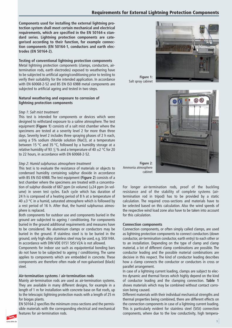
Step 1: Salt mist treatmentThis test is intended for components or devices which weredesigned to withstand exposure to a saline atmosphere. The testequipment (Figure 1) consists of a salt mist chamber where thespecimens are tested at a severity level 2 for more than threedays. Severity level 2 includes three spraying phases of 2 h each,using a 5% sodium chloride solution (NaCl), at a temperaturebetween 15 °C and 35 °C, followed by a humidity storage at arelative humidity of 93 +2
–3 % and a temperature of 40 ±2 °C for 20to 22 hours, in accordance with EN 60068-2-52.
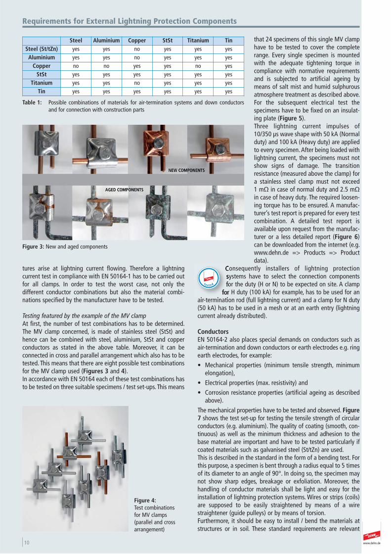
Step 2: Humid sulphurous atmosphere treatmentThis test is to evaluate the resistance of materials or objects tocondensed humidity containing sulphur dioxide in accordancewith BS EN ISO 6988. The test equipment (Figure 2) consists of atest chamber where the specimens are treated with a concentra-tion of sulphur dioxide of 667 ppm (in volume) (±24 ppm (in vol-ume) in seven test cycles. Each cycle which has duration of 24 h is composed of a heating period of 8 h at a temperature of40 ±3 °C in a humid, saturated atmosphere which is followed bya rest period of 16 h. After that, the humid sulphurous atmos-phere is replaced.Both components for outdoor use and components buried in theground are subjected to ageing / conditioning. For componentsburied in the ground additional requirements and measures haveto be considered. No aluminium clamps or conductors may beburied in the ground. If stainless steel is to be buried in theground, only high-alloy stainless steel may be used, e.g. StSt V4A.In accordance with DIN VDE 0151 StSt V2A is not allowed.Components for indoor use such as equipotential bonding barsdo not have to be subjected to ageing / conditioning. The sameapplies to components which are embedded in concrete. Thesecomponents are therefore often made of non-galvanised (black)steel.
Air-termination systems / air-termination rodsMainly air-termination rods are used as air-termination systems.They are available in many different designs, for example in alength of 1 m for installation with concrete base on flat roofs, upto the telescopic lightning protection masts with a length of 25 mfor biogas plants. EN 50164-2 specifies the minimum cross-sections and the permis-sible materials with the corresponding electrical and mechanicalfeatures for air-termination rods.
For longer air-termination rods, proof of the buckling resistance and of the stability of complete systems (air- termination rod in tripod) has to be provided by a static calculation. The required cross-sections and materials have to be selected based on this calculation. Also the wind speeds of the respective wind load zone also have to be taken into accountfor this calculation.
Connection componentsConnection components, or often simply called clamps, are usedas lightning protection components to connect conductors (downconductor, air-termination conductor, earth entry) to each other orto an installation. Depending on the type of clamp and clampmaterial, a lot of different clamp combinations are possible. Theconductor leading and the possible material combinations aredecisive in this respect. The kind of conductor leading describeshow a clamp connects the conductor or conductors in cross orparallel arrangement. In case of a lightning current loading, clamps are subject to elec-tro dynamic and thermal forces which highly depend on the kindof conductor leading and the clamping connection. Table 1shows materials which may be combined without contact corro-sion being caused.Different materials with their individual mechanical strengths andthermal properties being combined, there are different effects onthe connection components in case of a lightning current loading.This is particularly evident for stainless steel (StSt) connectioncomponents, where due to the low conductivity, high tempera-
Figure 2: Ammonia atmosphere
cabinet
Figure 1:Salt spray cabinet
10 www.dehn.de
Requirements for External Lightning Protection Components
tures arise at lightning current flowing. Therefore a lightning current test in compliance with EN 50164-1 has to be carried outfor all clamps. In order to test the worst case, not only the different conductor combinations but also the material combi -nations specified by the manufacturer have to be tested.
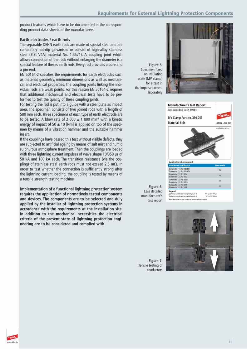
Testing featured by the example of the MV clampAt first, the number of test combinations has to be determined.The MV clamp concerned, is made of stainless steel (StSt) andhence can be combined with steel, aluminium, StSt and copperconductors as stated in the above table. Moreover, it can be connected in cross and parallel arrangement which also has to betested. This means that there are eight possible test combinationsfor the MV clamp used (Figures 3 and 4). In accordance with EN 50164 each of these test combinations hasto be tested on three suitable specimens / test set-ups. This means
that 24 specimens of this single MV clamphave to be tested to cover the completerange. Every single specimen is mountedwith the adequate tightening torque incompliance with normative requirementsand is subjected to artificial ageing bymeans of salt mist and humid sulphurousatmosphere treatment as described above.For the subsequent electrical test the specimens have to be fixed on an insulat-ing plate (Figure 5).Three lightning current impulses of 10/350 μs wave shape with 50 kA (Normalduty) and 100 kA (Heavy duty) are appliedto every specimen. After being loaded withlightning current, the specimens must notshow signs of damage. The transitionresistance (measured above the clamp) fora stainless steel clamp must not exceed 1 mΩ in case of normal duty and 2.5 mΩin case of heavy duty. The required loosen-ing torque has to be ensured. A manufac-turer’s test report is prepared for every testcombination. A detailed test report isavailable upon request from the manufac-turer or a less detailed report (Figure 6)can be downloaded from the internet (e.g.www.dehn.de => Products => Productdata).
Consequently installers of lightning protection systems have to select the connection components for the duty (H or N) to be expected on site. A clamp
for H duty (100 kA) for example, has to be used for anair-termination rod (full lightning current) and a clamp for N duty(50 kA) has to be used in a mesh or at an earth entry (lightningcurrent already distributed).
Conductors EN 50164-2 also places special demands on conductors such asair-termination and down conductors or earth electrodes e.g. ringearth electrodes, for example:
• Mechanical properties (minimum tensile strength, minimumelongation),
• Electrical properties (max. resistivity) and
• Corrosion resistance properties (artificial ageing as describedabove).
The mechanical properties have to be tested and observed. Figure7 shows the test set-up for testing the tensile strength of circularconductors (e.g. aluminium). The quality of coating (smooth, con-tinuous) as well as the minimum thickness and adhesion to thebase material are important and have to be tested particularly ifcoated materials such as galvanised steel (St/tZn) are used.This is described in the standard in the form of a bending test. Forthis purpose, a specimen is bent through a radius equal to 5 timesof its diameter to an angle of 90°. In doing so, the specimen maynot show sharp edges, breakage or exfoliation. Moreover, thehandling of conductor materials shall be light and easy for theinstallation of lightning protection systems. Wires or strips (coils)are supposed to be easily straightened by means of a wirestraightener (guide pulleys) or by means of torsion. Furthermore, it should be easy to install / bend the materials atstructures or in soil. These standard requirements are relevant
t e s t e d
Figure 4:Test combinations for MV clamps (parallel and crossarrangement)
Figure 3: New and aged components
Steel Aluminium Copper StSt Titanium TinSteel (St/tZn) yes yes no yes yes yesAluminium yes yes no yes yes yes
Copper no no yes yes no yesStSt yes yes yes yes yes yes
Titanium yes yes no yes yes yesTin yes yes yes yes yes yes
Table 1: Possible combinations of materials for air-termination systems and down conductorsand for connection with construction parts
11www.dehn.de
Requirements for External Lightning Protection Components
product features which have to be documented in the correspon-ding product data sheets of the manufacturers.
Earth electrodes / earth rodsThe separable DEHN earth rods are made of special steel and arecompletely hot-dip galvanised or consist of high-alloy stainlesssteel (StSt V4A; material No. 1.4571). A coupling joint whichallows connection of the rods without enlarging the diameter is aspecial feature of theses earth rods. Every rod provides a bore anda pin end.EN 50164-2 specifies the requirements for earth electrodes suchas material, geometry, minimum dimensions as well as mechani-cal and electrical properties. The coupling joints linking the indi-vidual rods are weak points. For this reason EN 50164-2 requiresthat additional mechanical and electrical tests have to be per-formed to test the quality of these coupling joints.For testing the rod is put into a guide with a steel plate as impactarea. The specimen consists of two joined rods with a length of500 mm each. Three specimens of each type of earth electrode areto be tested. A blow rate of 2 000 ± 1 000 min-1 with a kineticenergy of impact of 50 ± 10 [Nm] is applied on top of the speci-men by means of a vibration hammer and the suitable hammerinsert.If the couplings have passed this test without visible defects, theyare subjected to artificial ageing by means of salt mist and humidsulphurous atmosphere treatment. Then the couplings are loadedwith three lightning current impulses of wave shape 10/350 μs of50 kA and 100 kA each. The transition resistance (via the cou-pling) of stainless steel earth rods must not exceed 2.5 mΩ. Inorder to test whether the connection is sufficiently strong afterthe lightning current loading, the coupling is tested by means ofa tensile strength testing machine.
Implementation of a functional lightning protection systemrequires the application of normatively tested componentsand devices. The components are to be selected and dulyapplied by the installer of lightning protection systems inaccordance with the requirements at the installation site.In addition to the mechanical necessities the electrical criteria of the present state of lightning protection engi-neering are to be considered and complied with.
Figure 5: Specimen fixed
on insulating plate (MV clamp)
for a test in the impulse current
laboratory
Figure 7:Tensile testing of
conductors
Figure 6:Less detailed
manufacturer’s test report
Test according to EN 50164-1
non-binding picture
Manufacturer’s Test Report
MV Clamp Part No. 390 059
Material: StSt
Application: above ground
Connected conductor Test result
Conductor (1): Rd 8 St/tZnConductor (2): Rd 8 St/tZnConductor (1): Rd 8 CuConductor (2): Rd 8 CuConductor (1): Rd 8 StStConductor (2): Rd 8 StStConductor (1): Rd 8 AlConductor (2): Rd 8 Al
N
H
H
H
LegendLightning current carrying capability class H 100 kA (10/350 μs)Lightning current carrying capability class N 50 kA (10/350 μs)
More details on the test conditions are available on request.
12 www.dehn.de
Different electrical system equipment is interacting in electrical installations:
• High-voltage technology (HV systems)
• Medium voltage technology (MV systems)
• Low-voltage technology (LV systems)
• Information technology (IT systems)
Basis for a reliable interaction of the different systems is a commonearth-termination system and a common equpotential bonding system. Itis important that all conductors, clamps and connectors are specified forthe various applications.
For buildings with integrated transformers, standards and guidelines concer-ning power plants with nominal voltages over 1 kV have to be considered.
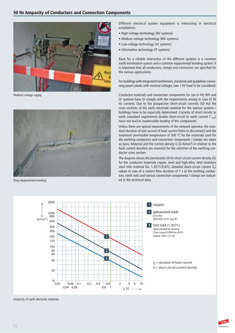
Conductor materials and connection components for use in HV, MV andLV systems have to comply with the requirements arising in case of 50Hz currents. Due to the prospective short-circuit currents (50 Hz) thecross sections of the earth electrode material for the various systems /buildings have to be especially determined. Currents of short-circuits toearth (standard requirement double short-circuit to earth current I"kEE)must not lead to inadmissible heating of the components.
Unless there are special requirements of the network operator, the stan-dard duration of one second of fault current (time to disconnect) and themaximum permissible temperature of 300 °C for the materials used forthe earthing conductors and connection components / clamps are takenas basis. Material and the current density G (in A/mm²) in relation to thefault current duration are essential for the selection of the earthing con-ductor cross section.
The diagram shows the permissible 50 Hz short-circuit current density (G)for the conductor materials copper, steel and high-alloy steel (stainlesssteel V4A material No. 1.4571/316Ti). Detailed short-circuit current (Ik)values in case of a current flow duration of 1 s at the earthing conduc-tors, earth rods and various connection components / clamps are indicat-ed in the technical data.Ring equipotential bonding
50 Hz Ampacity of Conductors and Connection Components
copper
galvanised steelsee also
DIN VDE 0101 Fig. B1
StSt V4A (1.4571)determined by testing
(Test report EPM No. 6337
dated 1993-12-16)
G
[A/mm2]
tF [s]
0,020,04
0,060,08
0,1 0,2 0,40,6
0,81
2 4 6 1010
20
40
6080
100
150
200
300
400
600
8001000
2000
tF = duration of fault current
G = short-circuit current density
Ampacity of earth electrode materials
Medium voltage supply
13www.dehn.de
In the following a calculaton of the short-circuit current to earth for thedesign of the earth conductor:
Version 1Specification of the three-pole short-circuit current by the system opera-tor, e.g. I"k3 ≈ 15000 A
Version 2Calculation of a theoretical worst case, asssuming that the supplying vol-tage will not collapse (remains constant).The short-circuit voltage (uk) is used to determine the max. three-poleshort-circuit current. The three-pole short-circuit current I"k3 is the max.three-pole short-circuit current at the transformer, neglecting an impe-dance on the fault site (Z = 0).
In the calculation exemplarily a transformer with the following data isconsidered:
Nominal capacity of the transformer S = 630 kVANominal voltage on low-voltage side U = 400 VShort-circuit voltage uk = 6.05 %
Design for short-circuitLinear conversion for the short-circuit voltage (worst case):
SI’’k3 = ––––––––––––
√ 3 1 U 1 uk
630 1 103 VAI’’k3 = ––––––––––––––––– ≈ 15000 A
√ 3 1 400 V 1 0.0605
For dimensioning the cross section of an earthing conductor / earthingbus conductor, the worst case of a double short-circuit to earth in a sys-tem shall be assumed. Therefore earth-termination systems shall bedesigned for the double short-circuit current to earth (I"kEE).
I’’kEE = 0.85 1 I’’k3
I’’kEE = 0.85 1 15000 A ≈ 12750 A
Based on the three-pole short-circuit-current to earth, the German stan-dard DIN VDE 0101 "Starkstromanlagen mit Wechselspannungen über 1 kV" specifies a factor of 85 % for the dimensioning of the short-circuitcurrent to earth.
For the double short-circuit current to earth I"kEE, the earthing con-ductor/the protective equipotential bonding conductor has to be desig-ned directly up to the transformer. In this simplified calculation, reductionfactors, e.g. by the cable shields, are not considered.
If the short-circuit current to earth spreads via the earthingconductor/protective equipotential bonding conductor to the transformerinto the mesh of a system (earthing bus conductor or intermeshed earth-termination system), it may be assumed that the current will be distribu-ted at the nodal point into two directions. The asymmetry in the inter-meshing of the earth-termination system can be assumed with a suffi-cient accuracy to be 65 %. The short-circuit current to earth which has tobe taken into account for this earth-termination system (earthing busconductor or intermeshed earth-termination system) is specified as I’’kEE
(branch) in our example.
I’’kEE (branch) = 0.65 1 I’’kEE
I’’kEE (branch) = 0.65 1 12750 A ≈ 8300 A
A current of I"kEE (branch) = 8300 A therefore is taken as basis for thedimensioning of the cross section of this earth-termination system in theexample shown.
Determination of the resulting cross sectionThe cross section of a conductor results from the material and the discon-necting time. In the German standard VDE 0101 the maximum short- circuit current density G [A/mm2] is specified for different materials (see VDE 0101 Figure B1 ).
Table: Short-circuit current density G
The determined current now is divided by the current density G of therespective material and the assigned disconnecting time and the mini-mum cross section Amin of the conductor will be determined.
I’’kEE / (branch)Amin = –––––––––– [mm2]
G
With the cross section calculated, the conductor may be selected. Alwaysthe next largest nominal cross section will be taken.
50 Hz Ampacity of Conductors and Connection Components
Legend:
S Nominal capacity [VA]U Nominal voltage (low voltage) [V]uk Short-circuit voltage [%]Ik Short-circuit current [A]I’’k3 Three-pole short-circuit current [A]I’’kEE Double short-circuit current to earth [A]G Short-circuit current density [A/mm2]Amin Minimum cross section [mm2]
Time St/tZn Copper StSt (V4A)
0.3 s 129 A/mm2 355 A/mm2 70 A/mm2
0.5 s 100 A/mm2 275 A/mm2 55 A/mm2
1 s 70 A/mm2 195 A/mm2 37 A/mm2
3 s 41 A/mm2 122 A/mm2 21 A/mm2
5 s 31 A/mm2 87 A/mm2 17 A/mm2
14 www.dehn.de
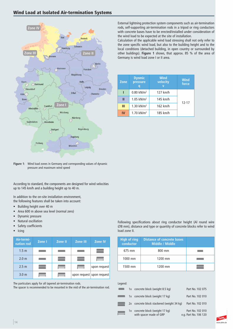
External lightning protection system components such as air-terminationrods, self-supporting air-termination rods in a tripod or ring conductorswith concrete bases have to be erected/installed under consideration ofthe wind load to be expected at the site of installation.Calculation of the applicable wind load stressing shall not only refer tothe zone specific wind load, but also to the building height and to thelocal conditions (detached building, in open country or surrounded byother buildings). Figure 1 shows, that approx. 85 % of the area ofGermany is wind load zone I or II area.
Figure 1: Wind load zones in Germany and corresponding values of dynamicpressure and maximum wind speed
Wind Load at Isolated Air-termination Systems
The particulars apply for all tapered air-termination rods. The spacer is recommended to be mounted in the mid of the air-termination rod.
According to standard, the components are designed for wind velocitiesup to 145 km/h and a building height up to 40 m.
In addition to the on-site installation environment,the following features shall be taken into account:
• Building height over 40 m• Area 600 m above sea level (normal zero)• Dynamic pressure• Natural oscillation• Safety coefficients• Icing
Following specifications about ring conductor height (Al round wire Ø8 mm), distance and type or quantity of concrete blocks refer to windload zone II.
ZoneDynmic pressure
q
Wind velocity
v
Windforce
I 0.80 kN/m2 127 km/h
12-17II 1.05 kN/m2 145 km/h
III 1.30 kN/m2 162 km/h
IV 1.70 kN/m2 185 km/h
Air-termi -nation rod
Zone I Zone II Zone III Zone IV
1.5 m
2.0 m
2.5 m upon request
3.0 m upon request upon request
High of ringconductor
Distance of concrete basesMiddle / Middle
675 mm 800 mm
1000 mm 1200 mm
1500 mm 1200 mm
Legend:
1x concrete block (weight 8.5 kg) Part No. 102 075
1x concrete block (weight 17 kg) Part No. 102 010
2x concrete block stackered (weight 34 kg) Part No. 102 010
1x concrete block (weight 17 kg) Part No. 102 010 with spacer made of GRP e.g. Part No. 106 120
15www.dehn.de
Abbreviations
Symbols:
Screws Screw heads
a Half-round wood screw h Slot Countersunk head b wood screw
i Hexagon
Wood screw with
j Hexagon with slot c
threaded head
k Cross recessed d Cheese head screw
l Star drivee Truss head screw m Combined slot f Knurled screw
g Countersunk screw
r Raised head screw
The following list shows and explains all abbreviations mentionedin this catalogue.
Conductor Types:Abbreviation Conductor Types
Fl Flat conductor (strip)
Rd Round conductor (round wire)
Materials:Abbreviation Description
Al Aluminium
AlMgSi Aluminium magnesium silicon wrought alloy
StSt Stainless steel Material No.: ASTM/AISI 304 (Material No.: 1.4301) Material No.: ASTM/AISI 305 (Material No.: 1.4303)
StSt (V4A) Stainless stell Material No.: ASTM/AISI 316 (Material No.: 1.4401) Material No.: ASTM/AISI 316L (Material No.: 1.4404) Material No.: ASTM/AISI 316Ti (Material No.: 1.4571)
St/blank Steel (black)
St/tZn Steel, hot dip galvanised
St/gal Zn Steel, galvanised
St / Cu Steel, copper-coated
MCI Malleable cast iron
MCI/tZn Malleable cast iron, hot dip galvanised
ZDC Zinc die casting
GCI Grey cast iron
Cu Copper, electrical copper
RCB Red castin brass
Ms Brass
Ms/gal Cu Brass, copper coated
Ms/gal Sn Brass, tin-coated
Cu/gal Sn Copper, tin-coated
Sn Tin
K Plastic material / Polyethylene / Polyamide / Polystyrene
PVC Polyvinyl chloride
GRP Glass-fibre reinforced plastic
UP Polyester (unsaturated)
PA Polyamide
EVA Ethylene vinyl acetate copolymer
XLPE Cross-linked polyethylene
Miscellaneous:
Tested according to EN 50164-1
New products+
Discontinued products
>
t e s t e d
Recommended values:
Screw Tightening torque
M5 / M6 ≥ 4 Nm
M8 ≥ 10 Nm
M10 ≥ 20 Nm
M12 ≥ 25 Nm

16 www.dehn.de
www.dehn.de 17
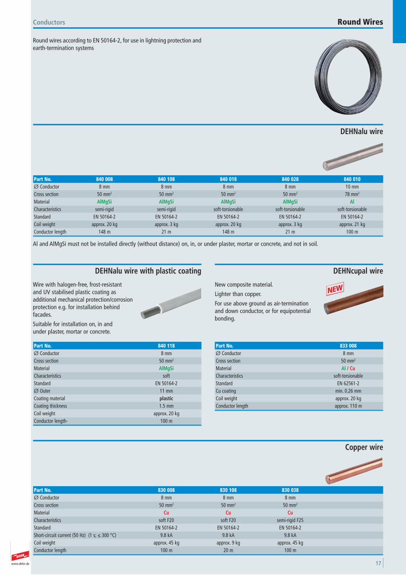
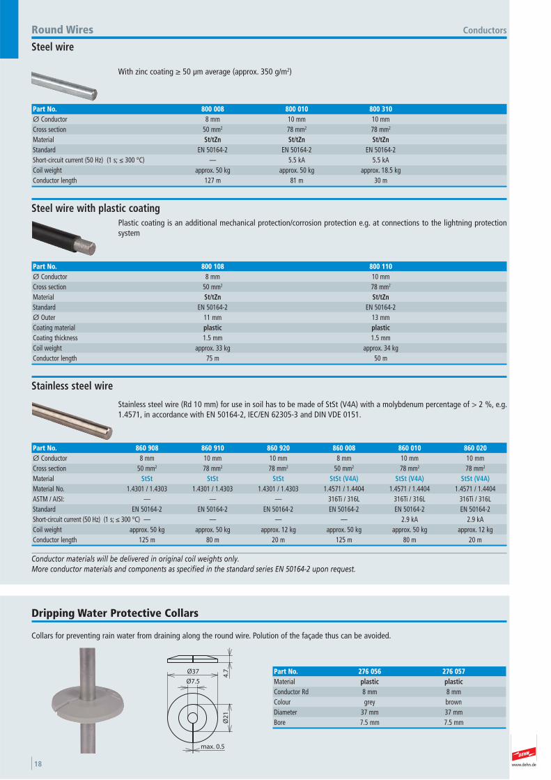
Round wires according to EN 50164-2, for use in lightning protection andearth-termination systems
Conductors
Al and AlMgSi must not be installed directly (without distance) on, in, or under plaster, mortar or concrete, and not in soil.
DEHNalu wire
Part No. 840 008 840 108 840 018 840 028 840 010Ø Conductor 8 mm 8 mm 8 mm 8 mm 10 mmCross section 50 mm2 50 mm2 50 mm2 50 mm2 78 mm2
Material AlMgSi AlMgSi AlMgSi AlMgSi AlCharacteristics semi-rigid semi-rigid soft-torsionable soft-torsionable soft-torsionable Standard EN 50164-2 EN 50164-2 EN 50164-2 EN 50164-2 EN 50164-2 Coil weight approx. 20 kg approx. 3 kg approx. 20 kg approx. 3 kg approx. 21 kgConductor length 148 m 21 m 148 m 21 m 100 m
Round Wires
Wire with halogen-free, frost-resistant and UV stabilised plastic coating as additional mechanical protection/corrosionprotection e.g. for installation behindfacades.
Suitable for installation on, in and under plaster, mortar or concrete.
DEHNalu wire with plastic coating
Part No. 840 118Ø Conductor 8 mmCross section 50 mm2
Material AlMgSiCharacteristics soft Standard EN 50164-2 Ø Outer 11 mmCoating material plasticCoating thickness 1.5 mmCoil weight approx. 20 kgConductor length- 100 m
Copper wire
Part No. 830 008 830 108 830 038Ø Conductor 8 mm 8 mm 8 mmCross section 50 mm2 50 mm2 50 mm2
Material Cu Cu CuCharacteristics soft F20 soft F20 semi-rigid F25 Standard EN 50164-2 EN 50164-2 EN 50164-2 Short-circuit current (50 Hz) (1 s; ≤ 300 °C) 9.8 kA 9.8 kA 9.8 kACoil weight approx. 45 kg approx. 9 kg approx. 45 kgConductor length 100 m 20 m 100 m
New composite material.
Lighter than copper.
For use above ground as air-termination and down conductor, or for equipotentialbonding.
+
DEHNcupal wire
Part No. 833 008Ø Conductor 8 mmCross section 50 mm2
Material Al / CuCharacteristics soft-torsionable Standard EN 62561-2 Cu coating min. 0.26 mmCoil weight approx. 20 kgConductor length approx. 110 m
www.dehn.de18
Plastic coating is an additional mechanical protection/corrosion protection e.g. at connections to the lightning protectionsystem
Conductors
Part No. 800 108 800 110Ø Conductor 8 mm 10 mmCross section 50 mm2 78 mm2
Material St/tZn St/tZnStandard EN 50164-2 EN 50164-2 Ø Outer 11 mm 13 mmCoating material plastic plasticCoating thickness 1.5 mm 1.5 mmCoil weight approx. 33 kg approx. 34 kgConductor length 75 m 50 m
Stainless steel wire (Rd 10 mm) for use in soil has to be made of StSt (V4A) with a molybdenum percentage of > 2 %, e.g.1.4571, in accordance with EN 50164-2, IEC/EN 62305-3 and DIN VDE 0151.
Stainless steel wire
Part No. 860 908 860 910 860 920 860 008 860 010 860 020Ø Conductor 8 mm 10 mm 10 mm 8 mm 10 mm 10 mmCross section 50 mm2 78 mm2 78 mm2 50 mm2 78 mm2 78 mm2
Material StSt StSt StSt StSt (V4A) StSt (V4A) StSt (V4A)Material No. 1.4301 / 1.4303 1.4301 / 1.4303 1.4301 / 1.4303 1.4571 / 1.4404 1.4571 / 1.4404 1.4571 / 1.4404 ASTM / AISI: — — — 316Ti / 316L 316Ti / 316L 316Ti / 316L Standard EN 50164-2 EN 50164-2 EN 50164-2 EN 50164-2 EN 50164-2 EN 50164-2 Short-circuit current (50 Hz) (1 s; ≤ 300 °C) — — — — 2.9 kA 2.9 kACoil weight approx. 50 kg approx. 50 kg approx. 12 kg approx. 50 kg approx. 50 kg approx. 12 kgConductor length 125 m 80 m 20 m 125 m 80 m 20 m
Conductor materials will be delivered in original coil weights only.More conductor materials and components as specified in the standard series EN 50164-2 upon request.
Collars for preventing rain water from draining along the round wire. Polution of the façade thus can be avoided.
Dripping Water Protective Collars
max. 0.5
Ø7.5
Ø2
1
Ø37
4.7 Part No. 276 056 276 057
Material plastic plasticConductor Rd 8 mm 8 mmColour grey brown Diameter 37 mm 37 mmBore 7.5 mm 7.5 mm
With zinc coating ≥ 50 μm average (approx. 350 g/m2)
Round Wires
Steel wire
Part No. 800 008 800 010 800 310Ø Conductor 8 mm 10 mm 10 mmCross section 50 mm2 78 mm2 78 mm2
Material St/tZn St/tZn St/tZnStandard EN 50164-2 EN 50164-2 EN 50164-2 Short-circuit current (50 Hz) (1 s; ≤ 300 °C) — 5.5 kA 5.5 kACoil weight approx. 50 kg approx. 50 kg approx. 18.5 kgConductor length 127 m 81 m 30 m
Steel wire with plastic coating
www.dehn.de 19
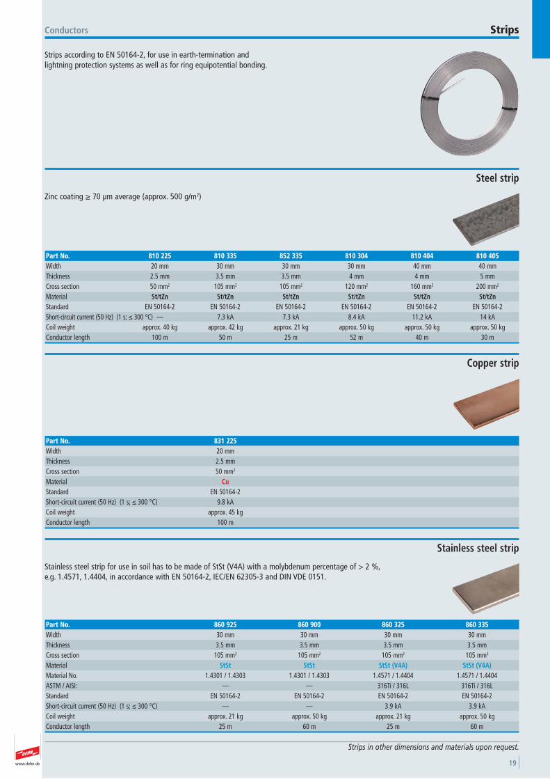
Strips according to EN 50164-2, for use in earth-termination and lightning protection systems as well as for ring equipotential bonding.
Conductors Strips
Strips in other dimensions and materials upon request.
Zinc coating ≥ 70 μm average (approx. 500 g/m2)
Steel strip
Part No. 810 225 810 335 852 335 810 304 810 404 810 405Width 20 mm 30 mm 30 mm 30 mm 40 mm 40 mmThickness 2.5 mm 3.5 mm 3.5 mm 4 mm 4 mm 5 mmCross section 50 mm2 105 mm2 105 mm2 120 mm2 160 mm2 200 mm2
Material St/tZn St/tZn St/tZn St/tZn St/tZn St/tZnStandard EN 50164-2 EN 50164-2 EN 50164-2 EN 50164-2 EN 50164-2 EN 50164-2 Short-circuit current (50 Hz) (1 s; ≤ 300 °C) — 7.3 kA 7.3 kA 8.4 kA 11.2 kA 14 kACoil weight approx. 40 kg approx. 42 kg approx. 21 kg approx. 50 kg approx. 50 kg approx. 50 kgConductor length 100 m 50 m 25 m 52 m 40 m 30 m
Copper strip
Part No. 831 225Width 20 mmThickness 2.5 mmCross section 50 mm2
Material CuStandard EN 50164-2 Short-circuit current (50 Hz) (1 s; ≤ 300 °C) 9.8 kACoil weight approx. 45 kgConductor length 100 m
Stainless steel strip for use in soil has to be made of StSt (V4A) with a molybdenum percentage of > 2 %, e.g. 1.4571, 1.4404, in accordance with EN 50164-2, IEC/EN 62305-3 and DIN VDE 0151.
Stainless steel strip
Part No. 860 925 860 900 860 325 860 335Width 30 mm 30 mm 30 mm 30 mmThickness 3.5 mm 3.5 mm 3.5 mm 3.5 mmCross section 105 mm2 105 mm2 105 mm2 105 mm2
Material StSt StSt StSt (V4A) StSt (V4A)Material No. 1.4301 / 1.4303 1.4301 / 1.4303 1.4571 / 1.4404 1.4571 / 1.4404 ASTM / AISI: — — 316Ti / 316L 316Ti / 316L Standard EN 50164-2 EN 50164-2 EN 50164-2 EN 50164-2 Short-circuit current (50 Hz) (1 s; ≤ 300 °C) — — 3.9 kA 3.9 kACoil weight approx. 21 kg approx. 50 kg approx. 21 kg approx. 50 kgConductor length 25 m 60 m 25 m 60 m
www.dehn.de20
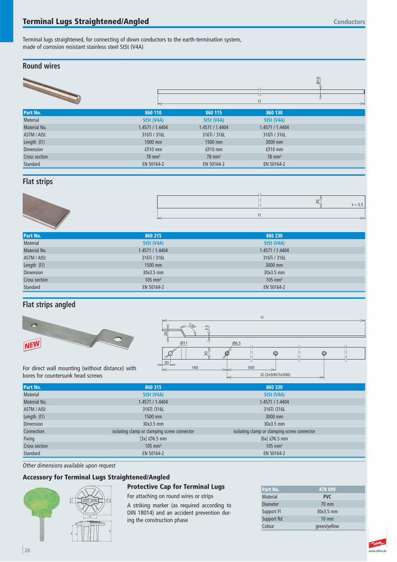
Terminal lugs straightened, for connecting of down conductors to the earth-termination system, made of corrosion resistant stainless steel StSt (V4A)
ConductorsTerminal Lugs Straightened/Angled
Other dimensions available upon request
l1
Ø1
0
Round wires
Part No. 860 110 860 115 860 130Material StSt (V4A) StSt (V4A) StSt (V4A)Material No. 1.4571 / 1.4404 1.4571 / 1.4404 1.4571 / 1.4404 ASTM / AISI: 316Ti / 316L 316Ti / 316L 316Ti / 316LLength (l1) 1000 mm 1500 mm 3000 mmDimension Ø10 mm Ø10 mm Ø10 mmCross section 78 mm2 78 mm2 78 mm2
Standard EN 50164-2 EN 50164-2 EN 50164-2
l1
30
t = 3.5
Flat strips
Part No. 860 215 860 230Material StSt (V4A) StSt (V4A)Material No. 1.4571 / 1.4404 1.4571 / 1.4404 ASTM / AISI: 316Ti / 316L 316Ti / 316L Length (l1) 1500 mm 3000 mmDimension 30x3.5 mm 30x3.5 mmCross section 105 mm2 105 mm2
Standard EN 50164-2 EN 50164-2
30
l1
160 500
l2 (2x500/5x500)
20
Ø11 Ø6.5
20
120°
3.5
For direct wall mounting (without distance) withbores for countersunk head screws
Flat strips angled
Part No. 860 315 860 330Material StSt (V4A) StSt (V4A)Material No. 1.4571 / 1.4404 1.4571 / 1.4404 ASTM / AISI: 316Ti /316L 316Ti /316LLength (l1) 1500 mm 3000 mmDimension 30x3.5 mm 30x3.5 mmConnection isolating clamp or clamping screw connector isolating clamp or clamping screw connector Fixing [3x] Ø6.5 mm [6x] Ø6.5 mmCross section 105 mm2 105 mm2
Standard EN 50164-2 EN 50164-2
49
3538
Ø7
0
6
32
Ø1
2.5
Accessory for Terminal Lugs Straightened/Angled
Conductors
Part No. 478 099Material PVCDiameter 70 mmSupport Fl 30x3.5 mmSupport Rd 10 mmColour green/yellow
Protective Cap for Terminal Lugs For attaching on round wires or strips
A striking marker (as required according toDIN 18014) and an accident prevention dur-ing the construction phase
+
www.dehn.de 21
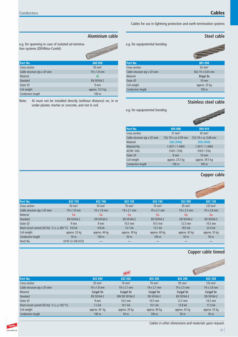
Cables for use in lightning protection and earth-termination systems
Conductors Cables
Cables in other dimensions and materials upon request.
Conductors
e.g. for spanning in case of isolated air-termina-tion systems (DEHNiso-Combi)
Aluminium cable
Part No. 840 050Cross section 50 mm2
Cable structure qty x Ø wire 19 x 1.8 mmMaterial AlStandard EN 50164-2 Outer Ø 9 mmCoil weight approx. 13.5 kgConductors length 100 m
e.g. for equipotential bonding
Steel cable
Part No. 801 050Cross section 42 mm2
Cable structure qty x Ø wire [6x] 19 x 0.65 mmMaterial St/gal ZnOuter Ø 10 mmCoil weight approx. 35 kgConductors length 100 m
Copper cable
Part No. 832 739 832 740 832 192 832 193 832 095 832 120Cross section 50 mm2 50 mm2 70 mm2 70 mm2 95 mm2 120 mm2
Cable structure qty x Ø wire 19 x 1.8 mm 19 x 1.8 mm 19 x 2.1 mm 19 x 2.1 mm 19 x 2.5 mm 19 x 2.8 mmMaterial Cu Cu Cu Cu Cu CuStandard EN 50164-2 EN 50164-2 EN 50164-2 EN 50164-2 EN 50164-2 EN 50164-2 Outer Ø 9 mm 9 mm 10.5 mm 10.5 mm 12.5 mm 14.5 mmShort-circuit current (50 Hz) (1 s; ≤ 300 °C) 9.8 kA 9.8 kA 13.7 kA 13.7 kA 18.5 kA 23.4 kACoil weight approx. 22 kg approx. 44 kg approx. 30 kg approx. 60 kg approx. 42 kg approx. 53 kgConductors length 50 m 100 m 50 m 100 m 50 m 50 mStock No. 6145-12-336-0722 — — — — —
Copper cable tinned
Part No. 832 839 832 202 832 292 832 295 832 320Cross section 50 mm2 70 mm2 70 mm2 95 mm2 120 mm2
Cable structure qty x Ø wire 19 x 1.8 mm 19 x 2.1 mm 19 x 2.1 mm 19 x 2.5 mm 19 x 2.8 mmMaterial Cu/gal Sn Cu/gal Sn Cu/gal Sn Cu/gal Sn Cu/gal SnStandard EN 50164-2 DIN EN 50164-2 EN 50164-2 EN 50164-2 EN 50164-2 Outer Ø 9 mm 10.5 mm 10.5 mm 12.5 mm 14.5 mmShort-circuit current (50 Hz) (1 s; ≤ 150 °C) 7.2 kA 10.1 kA 10.1 kA 13.8 kA 17.3 kACoil weight approx. 44 kg approx. 30 kg approx. 60 kg approx. 42 kg approx. 53 kgConductors length 100 m 50 m 100 m 50 m 50 m
e.g. for equipotential bonding
Stainless steel cable
Part No. 850 008 850 010Cross section 27 mm2 42 mm2
Cable structure qty x Ø wire [7x] 19 x ca. 0.59 mm [7x] 19 x ca. 0.68 mmMaterial StSt (V4A) StSt (V4A)Material No. 1.4571 / 1.4404 1.4571 / 1.4404 ASTM / AISI: 316Ti / 316L 316Ti / 316L Outer Ø 8 mm 10 mmCoil weight approx. 23.5 kg approx. 39.5 kgConductors length 100 m 100 m
+
Note: Al must not be installed directly (without distance) on, in orunder plaster, mortar or concrete, and not in soil.

www.dehn.de22
www.dehn.de 23
Air-termination rods for protecting roof-mounted structures, chimneys,etc. Also for erection with concrete base
Due to the wind load, air-termination rods of more than 2.5 m in freelength, erected on concrete base, need to be additionally fixed, e.g. byDEHNiso spacers.
Air-termination Systems and Accessories Air-termination Rods
1000
Ø1
0
Especially for wedge mounting with concrete base 8.5 kg (Part No. 102 075) or for fixing with conductor holders
Diameter 10 mm, chamfered
Part No. 101 000 101 009 101 007Total length (l1) 1000 mm 1000 mm 1000 mmMaterial Al StSt CuStandard EN 50164-2 EN 50164-2 EN 50164-2 Diameter 10 mm 10 mm 10 mm
l1
Ø1
6Diameter 16 mm, chamfered
Part No. 104 150 104 200 104 250 104 300 483 100 483 125 483 150 483 200Total length (l1) 1500 mm 2000 mm 2500 mm 3000 mm 1000 mm 1250 mm 1500 mm 2000 mmMaterial AlMgSi AlMgSi AlMgSi AlMgSi St/tZn St/tZn St/tZn St/tZnStandard EN 50164-2 EN 50164-2 EN 50164-2 EN 50164-2 EN 50164-2 EN 50164-2 EN 50164-2 EN 50164-2 Diameter 16 mm 16 mm 16 mm 16 mm 16 mm 16 mm 16 mm 16 mm
1000
l1
Ø1
6
Ø1
0
Length of tapering 1000 mm each
With tapering, chamfered
Part No. 103 210 103 220 103 230 103 240 103 250 103 260 103 280Total length (l1) 1500 mm 2000 mm 2500 mm 3000 mm 3500 mm 4000 mm 5000 mmMaterial AlMgSi AlMgSi AlMgSi AlMgSi AlMgSi AlMgSi AlMgSiStandard EN 50164-2 EN 50164-2 EN 50164-2 EN 50164-2 EN 50164-2 EN 50164-2 EN 50164-2 Diameter 16/10 mm 16/10 mm 16/10 mm 16/10 mm 16/10 mm 16/10 mm 16/10 mmType chamfered chamfered chamfered chamfered chamfered chamfered chamfered
M1
6
45 1000
l1
Ø1
6
Ø1
0
Length of tapering 1000 mm each
With tapering, thread M16
Part No. 103 211 103 221 103 231 103 241 103 251 103 261Total length (l1) 1500 mm 2000 mm 2500 mm 3000 mm 3500 mm 4000 mmMaterial AlMgSi AlMgSi AlMgSi AlMgSi AlMgSi AlMgSiStandard EN 50164-2 EN 50164-2 EN 50164-2 EN 50164-2 EN 50164-2 EN 50164-2 Diameter 16/10 mm 16/10 mm 16/10 mm 16/10 mm 16/10 mm 16/10 mmType M16 M16 M16 M16 M16 M16
www.dehn.de24
Ø1
6
t1
l1
1000
Ø1
0
Light design; length of tapering 1000 mm each
Air-termination Systems and AccessoriesAir-termination Rods
Tubular air-termination rods with tapering
Part No. 103 480 103 417 103 419 103 429 103 439 103 449Total length (l1) 5000 mm 1500 mm 1500 mm 2000 mm 2500 mm 3000 mmMaterial AlMgSi Cu StSt StSt StSt StStStandard EN 50164-2 EN 50164-2 EN 50164-2 EN 50164-2 EN 50164-2 EN 50164-2 Diameter 16/10 mm 16/10 mm 16/10 mm 16/10 mm 16/10 mm 16/10 mmWall thickness of pipe (t1) 2.5 mm 2.5 mm 3 mm 3 mm 3 mm 3 mm
Part No. 103 410 103 420 103 430 103 440 103 450 103 460Total length (l1) 1500 mm 2000 mm 2500 mm 3000 mm 3500 mm 4000 mmMaterial AlMgSi AlMgSi AlMgSi AlMgSi AlMgSi AlMgSiStandard EN 50164-2 EN 50164-2 EN 50164-2 EN 50164-2 EN 50164-2 EN 50164-2 Diameter 16/10 mm 16/10 mm 16/10 mm 16/10 mm 16/10 mm 16/10 mmWall thickness of pipe (t1) 2.5 mm 2.5 mm 2.5 mm 2.5 mm 2.5 mm 2.5 mm
l1
30
Ø1
6
and clamping screw for connecting Rd 7-10 mm
With forged lug
Part No. 100 100 100 150Total length (l1) 1000 mm 1500 mmMaterial St/tZn St/tZnStandard EN 50164-(1+2) EN 50164-(1+2) Diameter 16 mm 16 mmTerminal clamping range 7-10 mm 7-10 mm
t e s t e d
6000
Ø1
6
Diameter 16 mm, for cutting to length on site
Part No. 104 600Total length (l1) 6000 mmMaterial AlMgSiStandard EN 50164-2 Diameter 16 mm
Connecting sleeve with embossings (stop) to join longer air-terminationrods (transport length)
Using the connecting sleeve requires an additional fixing of the air-ter-mination rod above the sleeve.
Connecting Sleeve for Air-termination Rods
Ø28
Ø1
7
Ø1
8
90
4242
Part No. 385 216Material AlClamping range Rd / Rd 16 / 16 mmScrew di M8x12 mmMaterial of screw StStOuter Ø 28 mmStandard EN 50164-1
t e s t e d
www.dehn.de 25
Concrete bases for air-termination rods protecting small-sized roof super-structures on flat roofs and for installing spacers of the DEHNiso spacerprogramme e.g. for isolated ring conductors or for self-supporting air-ter-mination rods in the tripod (only with a weight of 17 kg)
Air-termination Systems and Accessories Concrete Bases
60
18
90
325
Ø337
28
26
41
80114
40depth 40 mm
Stackable, for air-termination rod Ø16 mm, chamfered, tapered, or forDEHNiso spacer Ø16 mm
Weight 17 kg, for wedge mounting
Part No. 102 010Weight 17 kgSupport wedge Ø16 mm Diameter Ø 337 mmMaterial concrete (C45/55)Material of wedge StSt
Ø347
Ø337
32
4
325
60
18
90
41
80114
40depth 40 mm
28
26
Stackable
Weight 17 kg, for wedge mounting, with adapted support plate
Part No. 102 340Weight 17 kgSupport wedge Ø16 mm Diameter Ø 337 mmMaterial concrete (C45/55)Material of wedge StSt
www.dehn.de26
90
30
2626 21 28
Ø240
230
60
18
For air-termination rods Ø10 mm, length 1000 mm or DEHNiso spacersØ16 mm, length up to 675 mm (distance 0.8 m)
Air-termination Systems and AccessoriesConcrete Bases
Weight 8.5 kg, for wedge mounting
Part No. 102 075Weight 8.5 kgSupport wedge Ø10/16 mm Diameter Ø 240 mmMaterial concrete (C45/55)Material of wedge StSt
65
Ø40
3
90
325
80114
40
41
Ø337
depth 40 mm
For air-termination rods with thread M16
Weight 17 kg, with threaded adapter
Part No. 102 002Weight 17 kgSupport thread M16 Diameter Ø 337 mmMaterial concrete (C45/55)Material of adapter plastic
90
30
2626 21 28
Ø240
230
65
Ø40
3
For air-termination rods with thread M16 and additional fixing e.g. withDEHNiso spacers
Weight 8.5 kg, with threaded adapter
Part No. 102 003Weight 8.5 kgSupport thread M16 Diameter Ø 240 mmMaterial concrete (C45/55)Material of adapter plastic
www.dehn.de 27
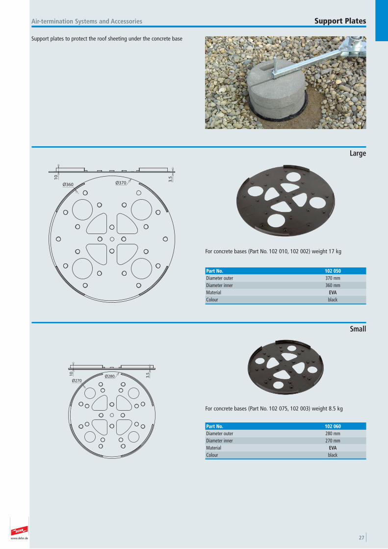
Support plates to protect the roof sheeting under the concrete base
Air-termination Systems and Accessories Support Plates
10
3.5
Ø360 Ø370
For concrete bases (Part No. 102 010, 102 002) weight 17 kg
Large
Part No. 102 050Diameter outer 370 mmDiameter inner 360 mmMaterial EVAColour black
10
Ø280Ø270
3.5
For concrete bases (Part No. 102 075, 102 003) weight 8.5 kg
Small
Part No. 102 060Diameter outer 280 mmDiameter inner 270 mmMaterial EVAColour black
www.dehn.de28
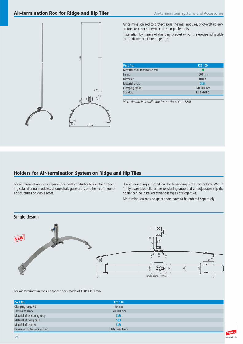
Air-termination rod to protect solar thermal modules, photovoltaic gen-erators, or other superstructures on gable roofs
Installation by means of clamping bracket which is stepwise adjustableto the diameter of the ridge tiles.
Air-termination Systems and AccessoriesAir-termination Rod for Ridge and Hip Tiles
More details in installation instructions No. 15283
24
1
120-240
Ø10
20
10
00
Part No. 123 109Material of air-termination rod AlLength 1000 mmDiameter 10 mmMaterial of clip StStClamping range 120-240 mmStandard EN 50164-2
For air-termination rods or spacer bars with conductor holder, for protect-ing solar thermal modules, photovoltaic generators or other roof-mount-ed structures on gable roofs.
Holder mounting is based on the tensioning strap technology. With afirmly assembled clip at the tensioning strap and an adjustable clip theholder can be installed at various types of ridge tiles.
Air-termination rods or spacer bars have to be ordered separately.
Holders for Air-termination System on Ridge and Hip Tiles
34
60
45
82
Ø20
Ø16
15
Ø10.5
25
42
43
40
SW
17
clamping range
For air-termination rods or spacer bars made of GRP Ø10 mm
Single design
Part No. 123 110Clamping range Rd 10 mmTensioning range 120-300 mmMaterial of tensioning strap StStMaterial of fixing bush StStMaterial of bracket StStDimension of tensioning strap 500x25x0.3 mm
+
www.dehn.de 29
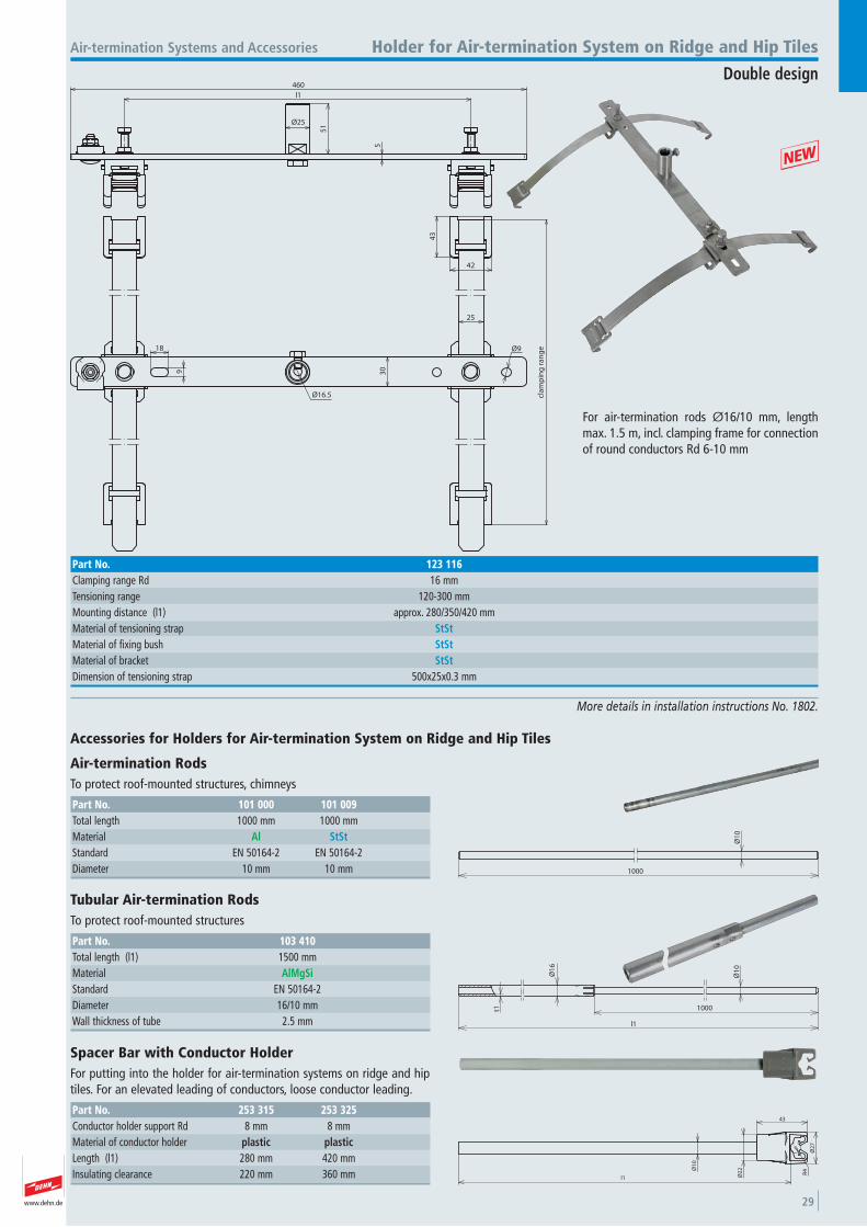
More details in installation instructions No. 1802.
5
51
460
l1
Ø25
cla
mp
ing
ra
ng
e
25
30
Ø16.5
43
Ø918
9
42
For air-termination rods Ø16/10 mm, lengthmax. 1.5 m, incl. clamping frame for connectionof round conductors Rd 6-10 mm
Air-termination Systems and Accessories Holder for Air-termination System on Ridge and Hip Tiles
Double design
Part No. 123 116Clamping range Rd 16 mmTensioning range 120-300 mmMounting distance (l1) approx. 280/350/420 mmMaterial of tensioning strap StStMaterial of fixing bush StStMaterial of bracket StStDimension of tensioning strap 500x25x0.3 mm
+
Ø1
0
l1
R4
Ø2
2
Ø2
7
43
Spacer Bar with Conductor Holder For putting into the holder for air-termination systems on ridge and hiptiles. For an elevated leading of conductors, loose conductor leading.
Part No. 253 315 253 325Conductor holder support Rd 8 mm 8 mmMaterial of conductor holder plastic plasticLength (l1) 280 mm 420 mmInsulating clearance 220 mm 360 mm
1000
Ø1
0Accessories for Holders for Air-termination System on Ridge and Hip Tiles
Air-termination Rods To protect roof-mounted structures, chimneys
Part No. 101 000 101 009Total length 1000 mm 1000 mmMaterial Al StStStandard EN 50164-2 EN 50164-2 Diameter 10 mm 10 mm
Ø1
6
t1
l1
1000
Ø1
0
Tubular Air-termination Rods To protect roof-mounted structures
Part No. 103 410Total length (l1) 1500 mmMaterial AlMgSiStandard EN 50164-2 Diameter 16/10 mmWall thickness of tube 2.5 mm
www.dehn.de30
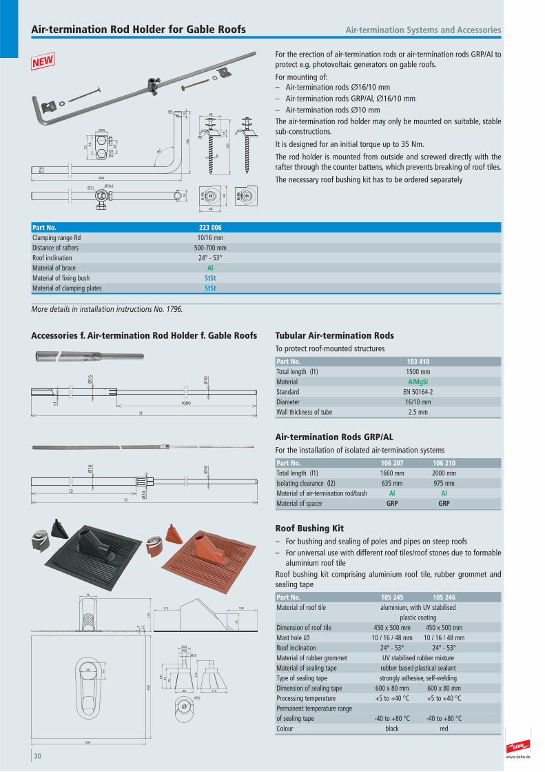
For the erection of air-termination rods or air-termination rods GRP/Al toprotect e.g. photovoltaic generators on gable roofs.
For mounting of:– Air-termination rods Ø16/10 mm– Air-termination rods GRP/Al, Ø16/10 mm– Air-termination rods Ø10 mmThe air-termination rod holder may only be mounted on suitable, stablesub-constructions.
It is designed for an initial torque up to 35 Nm.
The rod holder is mounted from outside and screwed directly with therafter through the counter battens, which prevents breaking of roof tiles.
The necessary roof bushing kit has to be ordered separately
Air-termination Systems and AccessoriesAir-termination Rod Holder for Gable Roofs
More details in installation instructions No. 1796.
890
13
8
Ø1
6
Ø5
40
52 29
90°
8
R8
16
48
12
0
Ø28
Ø1
6
10
Ø16.5Ø11
24
44
48
Part No. 223 006Clamping range Rd 10/16 mmDistance of rafters 500-700 mmRoof inclination 24° - 53° Material of brace AlMaterial of fixing bush StStMaterial of clamping plates StSt
+
l2
l1 Ø2
0
Ø1
6
Ø1
0
Air-termination Rods GRP/AL For the installation of isolated air-termination systems
Part No. 106 207 106 210Total length (l1) 1660 mm 2000 mmIsolating clearance (l2) 635 mm 975 mmMaterial of air-termination rod/bush Al AlMaterial of spacer GRP GRP
500
45
0
69
74
14
4
1.54
75
75
130113
708
910
7
80
12
3
115
Ø52
Ø20
Ø14
Ø10
Roof Bushing Kit – For bushing and sealing of poles and pipes on steep roofs– For universal use with different roof tiles/roof stones due to formable
aluminium roof tileRoof bushing kit comprising aluminium roof tile, rubber grommet andsealing tape
Part No. 105 245 105 246Material of roof tile aluminium, with UV stabilised
plastic coatingDimension of roof tile 450 x 500 mm 450 x 500 mmMast hole Ø 10 / 16 / 48 mm 10 / 16 / 48 mmRoof inclination 24° - 53° 24° - 53° Material of rubber grommet UV stabilised rubber mixtureMaterial of sealing tape rubber based plastical sealantType of sealing tape strongly adhesive, self-weldingDimension of sealing tape 600 x 80 mm 600 x 80 mmProcessing temperature +5 to +40 °C +5 to +40 °CPermanent temperature range of sealing tape -40 to +80 °C -40 to +80 °CColour black red
Ø1
6
t1
l1
1000
Ø1
0
Accessories f. Air-termination Rod Holder f. Gable Roofs Tubular Air-termination Rods To protect roof-mounted structures
Part No. 103 410Total length (l1) 1500 mmMaterial AlMgSiStandard EN 50164-2 Diameter 16/10 mmWall thickness of tube 2.5 mm
www.dehn.de 31
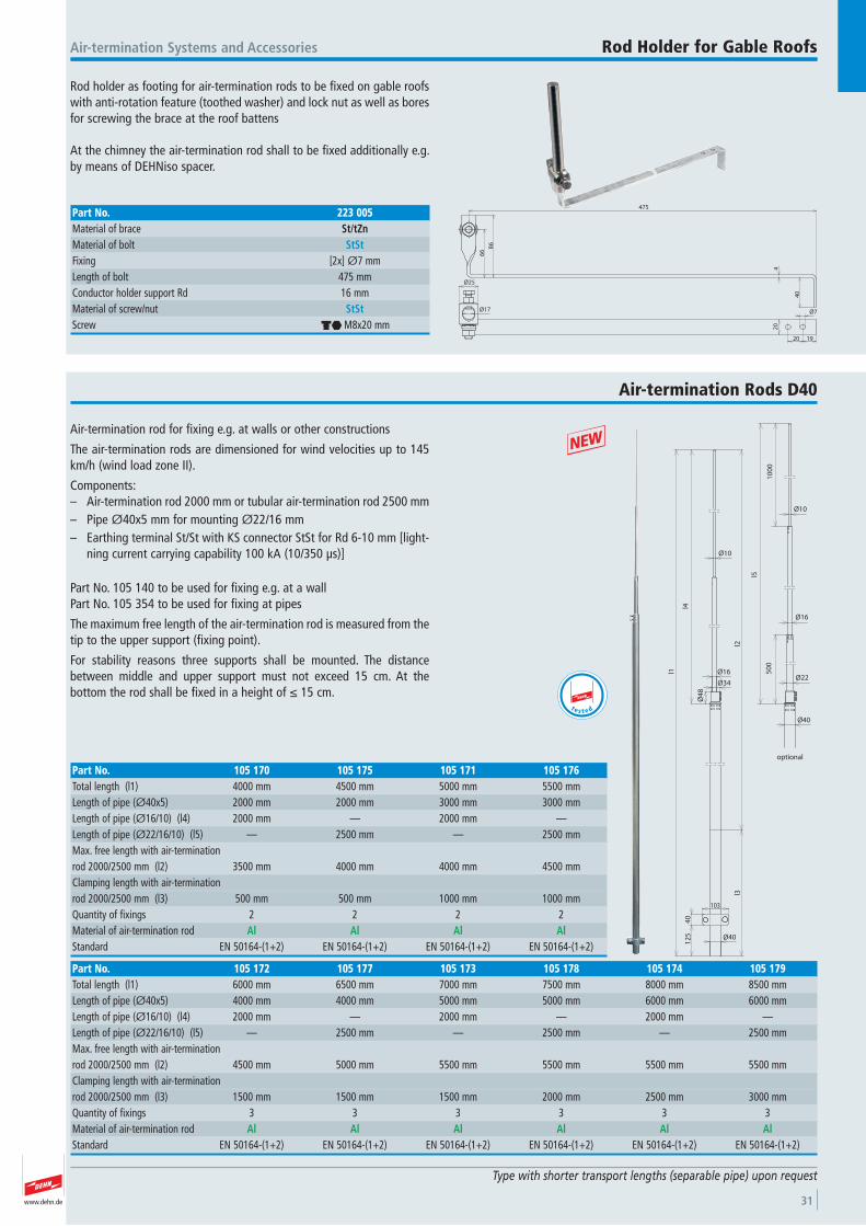
Rod holder as footing for air-termination rods to be fixed on gable roofswith anti-rotation feature (toothed washer) and lock nut as well as boresfor screwing the brace at the roof battens
At the chimney the air-termination rod shall to be fixed additionally e.g.by means of DEHNiso spacer.
Air-termination Systems and Accessories Rod Holder for Gable Roofs
66
86
475
40
4
Ø25
Ø17 Ø7
1920
20
Part No. 223 005Material of brace St/tZnMaterial of bolt StStFixing [2x] Ø7 mmLength of bolt 475 mmConductor holder support Rd 16 mmMaterial of screw/nut StStScrew di M8x20 mm
Air-termination rod for fixing e.g. at walls or other constructions
The air-termination rods are dimensioned for wind velocities up to 145km/h (wind load zone II).
Components:– Air-termination rod 2000 mm or tubular air-termination rod 2500 mm– Pipe Ø40x5 mm for mounting Ø22/16 mm– Earthing terminal St/St with KS connector StSt for Rd 6-10 mm [light-
ning current carrying capability 100 kA (10/350 μs)]
Part No. 105 140 to be used for fixing e.g. at a wallPart No. 105 354 to be used for fixing at pipes
The maximum free length of the air-termination rod is measured from thetip to the upper support (fixing point).
For stability reasons three supports shall be mounted. The distancebetween middle and upper support must not exceed 15 cm. At the bottom the rod shall be fixed in a height of ≤ 15 cm.
+
Air-termination Rods D40
Type with shorter transport lengths (separable pipe) upon request
Part No. 105 172 105 177 105 173 105 178 105 174 105 179Total length (l1) 6000 mm 6500 mm 7000 mm 7500 mm 8000 mm 8500 mmLength of pipe (Ø40x5) 4000 mm 4000 mm 5000 mm 5000 mm 6000 mm 6000 mmLength of pipe (Ø16/10) (l4) 2000 mm — 2000 mm — 2000 mm —Length of pipe (Ø22/16/10) (l5) — 2500 mm — 2500 mm — 2500 mmMax. free length with air-termination rod 2000/2500 mm (l2) 4500 mm 5000 mm 5500 mm 5500 mm 5500 mm 5500 mmClamping length with air-termination rod 2000/2500 mm (l3) 1500 mm 1500 mm 1500 mm 2000 mm 2500 mm 3000 mmQuantity of fixings 3 3 3 3 3 3 Material of air-termination rod Al Al Al Al Al AlStandard EN 50164-(1+2) EN 50164-(1+2) EN 50164-(1+2) EN 50164-(1+2) EN 50164-(1+2) EN 50164-(1+2)
Part No. 105 170 105 175 105 171 105 176Total length (l1) 4000 mm 4500 mm 5000 mm 5500 mmLength of pipe (Ø40x5) 2000 mm 2000 mm 3000 mm 3000 mmLength of pipe (Ø16/10) (l4) 2000 mm — 2000 mm —Length of pipe (Ø22/16/10) (l5) — 2500 mm — 2500 mmMax. free length with air-termination rod 2000/2500 mm (l2) 3500 mm 4000 mm 4000 mm 4500 mmClamping length with air-termination rod 2000/2500 mm (l3) 500 mm 500 mm 1000 mm 1000 mmQuantity of fixings 2 2 2 2 Material of air-termination rod Al Al Al AlStandard EN 50164-(1+2) EN 50164-(1+2) EN 50164-(1+2) EN 50164-(1+2)
Ø40
12
54
0
103
l1
Ø4
8
l4
l3l2
Ø10
Ø16
Ø34
optional
10
00
Ø22
Ø16
Ø10
l5
50
0
Ø40
t e s t e d
www.dehn.de32
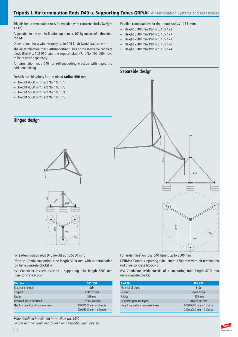
Tripods for air-termination rods for erection with concrete blocks (weight 17 kg)
Adjustable to the roof inclination up to max. 10° by means of a threadedrod M16
Dimensioned for a wind velocity up to 145 km/h (wind load zone II)
The air-termination rods D40/supporting tubes or the stackable concreteblock (Part No. 102 010) and the support plate (Part No. 102 050) haveto be ordered separately.
Air-termination rods D40 for self-supporting erection with tripod, noadditional fixing.
Possible combinations for the tripod radius 590 mm:
– Height 4000 mm:Part No. 105 170– Height 4500 mm:Part No. 105 175 – Height 5000 mm:Part No. 105 171 – Height 5500 mm:Part No. 105 176
Possible combinations for the tripod radius 1155 mm:
– Height 6000 mm:Part No. 105 172 – Height 6500 mm:Part No. 105 177 – Height 7000 mm:Part No. 105 173 – Height 7500 mm:Part No. 105 178 – Height 8000 mm:Part No. 105 174
Air-termination Systems and AccessoriesTripods f. Air-termination Rods D40 a. Supporting Tubes GRP/Al
More details in installation instructions No. 1690For use in other wind load zones / wind velocities upon request.
R590
60
0
12
50
1410
Ø54
45
For air-termination rods D40 height up to 5500 mm,
DEHNiso Combi supporting tube length 3200 mm with air-terminationrod (nine concrete blocks) or
HVI Conductor inside/outside of a supporting tube length 3200 mm(nine concrete blocks)
Hinged design
Part No. 105 290Material of tripod StStSupport Ø40/50 mmRadius 590 mmRequired space for tripod 1230x1370 mmHeight - quantity of concrete bases 4000/4500 mm – 3 blocks
5000/5500 mm – 6 blocks
Ø54
20
00
R1155
2340
20
70
For air-termination rods D40 height up to 8000 mm,
DEHNiso Combi supporting tube length 4700 mm with air-terminationrod (nine concrete blocks) or
HVI Conductor inside/outside of a supporting tube length 4700 mm (nine concrete blocks)
Separable design
Part No. 105 291Material of tripod StStSupport Ø40/50 mmRadius 1155 mmRequired space for tripod 2050x2300 mmHeight - quantity of concrete bases 6000/6500 mm – 6 blocks
7000/8000 mm – 9 blocks
www.dehn.de 33
Air-termination Systems and Accessories
Ø40
15
2
64
3
2.5 80
10
0
320
50 50
25
Ø5.1
11 20 15
4011
75
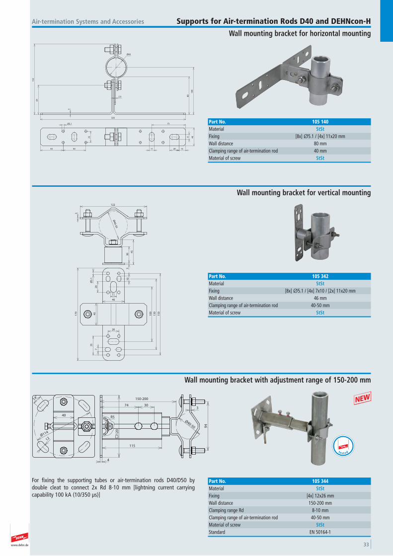
Supports for Air-termination Rods D40 and DEHNcon-H
Wall mounting bracket for horizontal mounting
Part No. 105 140Material StStFixing [8x] Ø5.1 / [4x] 11x20 mmWall distance 80 mmClamping range of air-termination rod 40 mmMaterial of screw StSt
45
Ø40-50
30
3
3
122
40
7
Ø5
.13
54
0
17
0
10
11
20
15
0
13
0
20
10
0
Wall mounting bracket for vertical mounting
Part No. 105 342Material StStFixing [8x] Ø5.1 / [4x] 7x10 / [2x] 11x20 mmWall distance 46 mmClamping range of air-termination rod 40-50 mmMaterial of screw StSt
14°
12
40
Ø114 12
0
4
115
74 303
94
150-200
Ø40-50
R5
For fixing the supporting tubes or air-termination rods D40/D50 by double cleat to connect 2x Rd 8-10 mm [lightning current carrying capability 100 kA (10/350 μs)]
Wall mounting bracket with adjustment range of 150-200 mm
Part No. 105 344Material StStFixing [4x] 12x26 mmWall distance 150-200 mmClamping range Rd 8-10 mmClamping range of air-termination rod 40-50 mmMaterial of screw StStStandard EN 50164-1
t e s t e d
+
www.dehn.de34
400
349 40
400-700
94
Ø40/5
0
34 1
20
1240
14°
40
x4
30
x3
Ø114
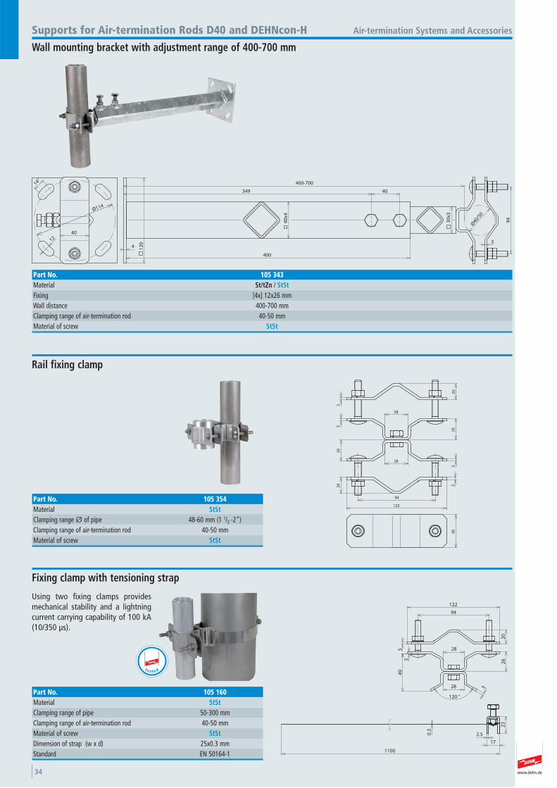
Air-termination Systems and AccessoriesSupports for Air-termination Rods D40 and DEHNcon-H
Wall mounting bracket with adjustment range of 400-700 mm
Part No. 105 343Material St/tZn / StStFixing [4x] 12x26 mmWall distance 400-700 mmClamping range of air-termination rod 40-50 mmMaterial of screw StSt
28
28
20
33
26
20 3
32
6
94
122
40
Rail fixing clamp
Part No. 105 354Material StStClamping range Ø of pipe 48-60 mm (1 1/2 -2") Clamping range of air-termination rod 40-50 mmMaterial of screw StSt
94
122
3
20
26
28
28
120 °
34
9
3
23
17
2.5
1100
0.3
Using two fixing clamps providesmechanical stability and a lightningcurrent carrying capability of 100 kA(10/350 μs).
Fixing clamp with tensioning strap
Part No. 105 160Material StStClamping range of pipe 50-300 mmClamping range of air-termination rod 40-50 mmMaterial of screw StStDimension of strap (w x d) 25x0.3 mmStandard EN 50164-1
t e s t e d
www.dehn.de 35
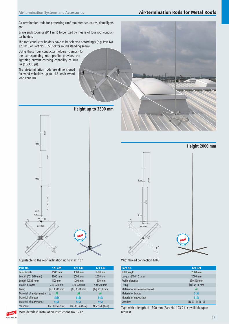
Air-termination rods for protecting roof-mounted structures, domelightsetc.
Brace ends (borings Ø11 mm) to be fixed by means of four roof conduc-tor holders.
The roof conductor holders have to be selected accordingly (e.g. Part No.223 010 or Part No. 365 059 for round standing seam).
Using these four conductor holders (clamps) forthe corresponding roof profile, provides thelightning current carrying capability of 100kA (10/350 μs).
The air-termination rods are dimensionedfor wind velocities up to 162 km/h (windload zone III).
Air-termination Systems and Accessories Air-termination Rods for Metal Roofs
10
00
20
00
Ø16
Ø10
30
230-520
Ø11
595
5
With thread connection M16
Height 2000 mm
Part No. 123 021Total length 2000 mmLength (Ø16/10 mm) 2000 mmProfile distance 230-520 mmFixing [4x] Ø11 mmMaterial of air-termination rod AlMaterial of braces StStMaterial of nut/washer StStStandard EN 50164-(1+2)
Type with a length of 1500 mm (Part No. 103 211) available uponrequest.
t e s t e d
20
00
10
00
Ø22
Ø16
Ø10
5
Ø40
50
0 /
10
00
/ 1
50
0
55
30
230-520
Ø11
595
Adjustable to the roof inclination up to max. 10°
Height up to 3500 mm
Part No. 123 425 123 430 123 435Total length 2500 mm 3000 mm 3500 mmLength (Ø16/10 mm) 2000 mm 2000 mm 2000 mmLength (Ø22 mm) 500 mm 1000 mm 1500 mmProfile distance 230-520 mm 230-520 mm 230-520 mmFixing [4x] Ø11 mm [4x] Ø11 mm [4x] Ø11 mmMaterial of air-termination rod Al Al AlMaterial of braces StSt StSt StStMaterial of nut/washer StST StSt StStStandard EN 50164-(1+2) EN 50164-(1+2) EN 50164-(1+2)
t e s t e d
More details in installation instructions No. 1712.
www.dehn.de36
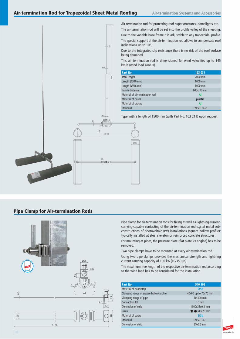
Air-termination rod for protecting roof superstructures, domelights etc.
The air-termination rod will be set into the profile valley of the sheeting.
Due to the variable base frame it is adjustable to any trapezoidal profile.
The special support of the air-termination rod allows to compensate roofinclinations up to 10°.
Due to the integrated slip resistance there is no risk of the roof surfacebeing damaged.
This air termination rod is dimensioned for wind velocities up to 145km/h (wind load zone II).
Air-termination Systems and AccessoriesAir-termination Rod for Trapezoidal Sheet Metal Roofing
Ø10
10
00
20
00
Ø1
6
105
15
6
600-770
60
0
30
Ø110
Ø16
Part No. 123 031Total length 2000 mmLength (Ø10 mm) 1000 mmLength (Ø16 mm) 1000 mmProfile distance 600-770 mmMaterial of air-termination rod AlMaterial of bases plasticMaterial of braces AlStandard EN 50164-2
Type with a length of 1500 mm (with Part No. 103 211) upon request
Pipe clamp for air-termination rods for fixing as well as lightning-current-carrying-capable contacting of the air-termination rod e.g. at metal sub-constructions of photovoltaic (PV) installations (square hollow profile);typically installed at steel skeleton or reinforced concrete structures
For mounting at pipes, the pressure plate (flat plate 2x angled) has to beremoved.
Two pipe clamps have to be mounted at every air-termination rod.
Using two pipe clamps provides the mechanical strength and lightningcurrent carrying capacity of 100 kA (10/350 μs).
The maximum free length of the respective air-termination rod accordingto the wind load has to be considered for the installation.
Pipe Clamp for Air-termination Rods
Ø25
15
28120°
3
3
64
Ø17
23
2.5
17
0.3
25
1100
40
Part No. 540 105Material of head/strip StStClamping range of square hollow profile 40x60 up to 70x70 mmClamping range of pipe 50-300 mmConnection Rd 16 mmDimension of strip 1100x25x0.3 mmScrew d i M8x20 mmMaterial of screw StStStandard EN 50164-1 Dimension of strip 25x0.3 mm
t e s t e d
www.dehn.de 37
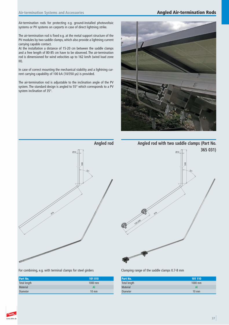
Air-termination rods for protecting e.g. ground-installed photovoltaicsystems or PV systems on carports in case of direct lightning strike.
The air-termination rod is fixed e.g. at the metal support structure of thePV modules by two saddle clamps, which also provide a lightning currentcarrying capable contact. At the installation a distance of 15-20 cm between the saddle clampsand a free length of 80-85 cm have to be observed. The air-terminationrod is dimensioned for wind velocities up to 162 km/h (wind load zoneIII).
In case of correct mounting the mechanical stability and a lightning cur-rent carrying capability of 100 kA (10/350 μs) is provided.
The air-termination rod is adjustable to the inclination angle of the PVsystem. The standard design is angled to 55° which corresponds to a PVsystem inclination of 35°.
Air-termination Systems and Accessories Angled Air-termination Rods
50
0
476
55°
150-200
Ø10
Clamping range of the saddle clamps 0.7-8 mm
Angled rod with two saddle clamps (Part No. 365 031)
Part No. 101 110Total length 1000 mmMaterial AlDiameter 10 mm
50
0
476
55°
Ø10
For combining, e.g. with terminal clamps for steel girders
Angled rod
Part No. 101 010Total length 1000 mmMaterial AlDiameter 10 mm
www.dehn.de38
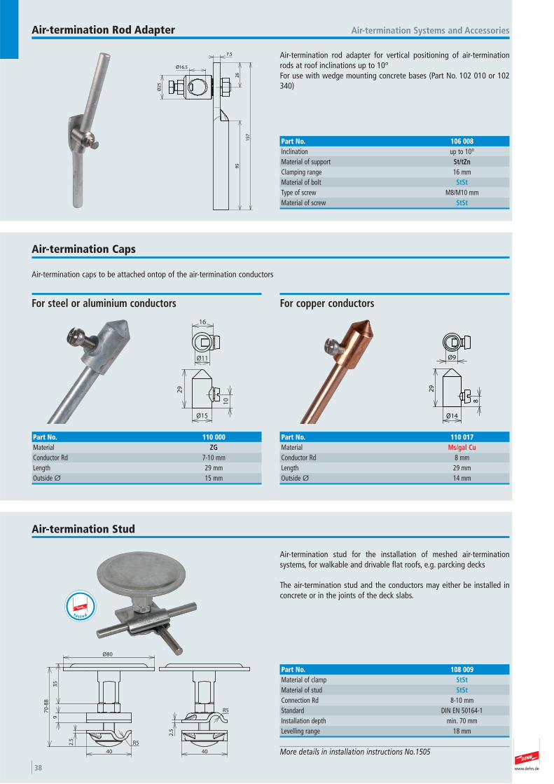
Air-termination rod adapter for vertical positioning of air-terminationrods at roof inclinations up to 10°For use with wedge mounting concrete bases (Part No. 102 010 or 102340)
Air-termination Systems and AccessoriesAir-termination Rod Adapter
Ø2
5
Ø16.5
7.5
95
15
7
26
Part No. 106 008Inclination up to 10° Material of support St/tZnClamping range 16 mmMaterial of bolt StStType of screw M8/M10 mmMaterial of screw StSt
Air-termination caps to be attached ontop of the air-termination conductors
Air-termination Caps
16
Ø11
29
10
Ø15
For steel or aluminium conductors
Part No. 110 000Material ZGConductor Rd 7-10 mmLength 29 mmOutside Ø 15 mm
Ø9
29
Ø14
8
For copper conductors
Part No. 110 017Material Ms/gal CuConductor Rd 8 mmLength 29 mmOutside Ø 14 mm
Air-termination stud for the installation of meshed air-termination systems, for walkable and drivable flat roofs, e.g. parcking decks
The air-termination stud and the conductors may either be installed inconcrete or in the joints of the deck slabs.
Air-termination Stud
More details in installation instructions No.1505
Ø80
35
70
-88
9
R5
40
2.5
2.5
R5
40
Part No. 108 009Material of clamp StStMaterial of stud StStConnection Rd 8-10 mmStandard DIN EN 50164-1 Installation depth min. 70 mmLevelling range 18 mm
t e s t e d
www.dehn.de 39
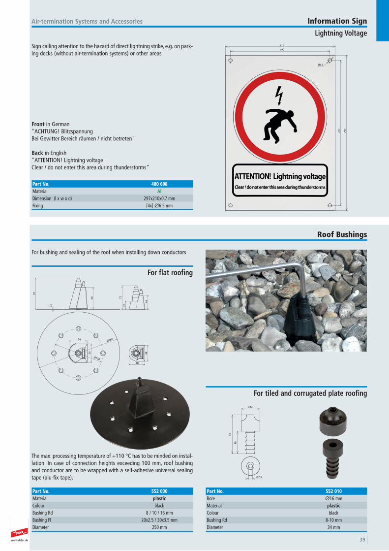
Sign calling attention to the hazard of direct lightning strike, e.g. on park-ing decks (without air-termination systems) or other areas
Air-termination Systems and Accessories
Front in German"ACHTUNG! BlitzspannungBei Gewitter Bereich räumen / nicht betreten"
Back in English"ATTENTION! Lightning voltageClear / do not enter this area during thunderstorms"
Information Sign
Lightning Voltage
Part No. 480 698Material AlDimension (l x w x d) 297x210x0.7 mmFixing [4x] Ø6.5 mm
190
210
Ø6.5
27
7
29
7
For bushing and sealing of the roof when installing down conductors
Roof Bushings
65
97
2.5
72
27
44
59
54
Ø150
Ø250
48
48
The max. processing temperature of +110 °C has to be minded on instal-lation. In case of connection heights exceeding 100 mm, roof bushingand conductor are to be wrapped with a self-adhesive universal sealingtape (alu-fix tape).
For flat roofing
Part No. 552 030Material plasticColour black Bushing Rd 8 / 10 / 16 mmBushing Fl 20x2.5 / 30x3.5 mmDiameter 250 mm
Ø34
70
40
Ø7.5
For tiled and corrugated plate roofing
Part No. 552 010Bore Ø16 mmMaterial plasticColour black Bushing Rd 8-10 mmDiameter 34 mm

www.dehn.de40
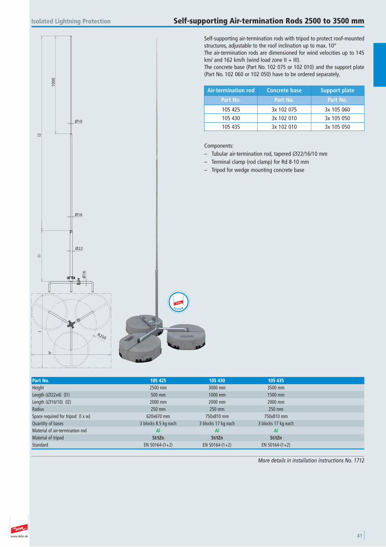
www.dehn.de 41
Self-supporting air-termination rods with tripod to protect roof-mountedstructures, adjustable to the roof inclination up to max. 10°The air-termination rods are dimensioned for wind velocities up to 145km/ and 162 km/h (wind load zone II + III).The concrete base (Part No. 102 075 or 102 010) and the support plate(Part No. 102 060 or 102 050) have to be ordered separately.
Components:– Tubular air-termination rod, tapered Ø22/16/10 mm– Terminal clamp (rod clamp) for Rd 8-10 mm – Tripod for wedge mounting concrete base
Air-termination rod Concrete base Support plate
Part No. Part No. Part No.
105 425 3x 10² 075 3x 10⁵ 060105 430 3x 10² 010 3x 10⁵ 050105 435 3x 10² 010 3x 10⁵ 050
Isolated Lightning Protection Self-supporting Air-termination Rods 2500 to 3500 mm
More details in installation instructions No. 1712
10
00
Ø22
Ø16
Ø10
Ø1
6
l2l1
R250
l
b
Part No. 105 425 105 430 105 435Height 2500 mm 3000 mm 3500 mmLength (Ø22x4) (l1) 500 mm 1000 mm 1500 mmLength (Ø16/10) (l2) 2000 mm 2000 mm 2000 mmRadius 250 mm 250 mm 250 mmSpace required for tripod (l x w) 620x670 mm 750x810 mm 750x810 mmQuantity of bases 3 blocks 8.5 kg each 3 blocks 17 kg each 3 blocks 17 kg each Material of air-termination rod Al Al AlMaterial of tripod St/tZn St/tZn St/tZnStandard EN 50164-(1+2) EN 50164-(1+2) EN 50164-(1+2)
t e s t e d
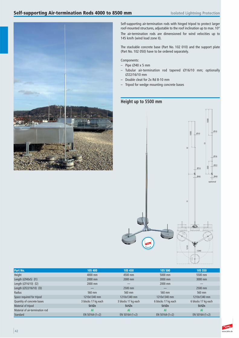
www.dehn.de42
Self-supporting air-termination rods with hinged tripod to protect largerroof-mounted structures, adjustable to the roof inclination up to max. 10°
The air-termination rods are dimensioned for wind velocities up to 145 km/h (wind load zone II).
The stackable concrete base (Part No. 102 010) and the support plate(Part No. 102 050) have to be ordered separately.
Components:– Pipe Ø40 x 5 mm– Tubular air-termination rod tapered Ø16/10 mm; optionally
Ø22/16/10 mm– Double cleat for 2x Rd 8-10 mm– Tripod for wedge mounting concrete bases
Isolated Lightning ProtectionSelf-supporting Air-termination Rods 4000 to 8500 mm
Ø40
10
00
l2l1
Ø16
Ø10
12
10
1340
optional
10
00
Ø22
Ø16
Ø10
l3
50
0
Ø40
Height up to 5500 mm
Part No. 105 400 105 450 105 500 105 550Height 4000 mm 4500 mm 5000 mm 5500 mmLength (Ø40x5) (l1) 2000 mm 2000 mm 3000 mm 3000 mmLength (Ø16/10) (l2) 2000 mm — 2000 mm —Length (Ø22/16/10) (l3) — 2500 mm — 2500 mmRadius 560 mm 560 mm 560 mm 560 mmSpace required for tripod 1210x1340 mm 1210x1340 mm 1210x1340 mm 1210x1340 mmQuantity of concrete bases 3 blocks 17 kg each 3 blocks 17 kg each 6 blocks 17 kg each 6 blocks 17 kg each Material of tripod St/tZn St/tZn St/tZn St/tZnMaterial of air-termination rod Al Al Al AlStandard EN 50164-(1+2) EN 50164-(1+2) EN 50164-(1+2) EN 50164-(1+2)
t e s t e d
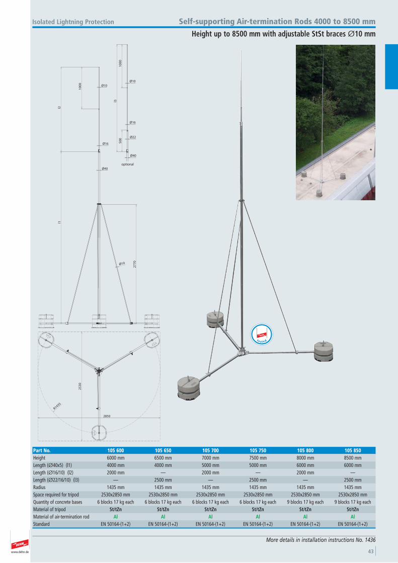
www.dehn.de 43
More details in installation instructions No. 1436
Ø10
Ø40
Ø16
27
70
Ø10
10
00
l2l1
R1435
25
30
2850
optional
10
00
Ø22
Ø16
Ø10
l3
50
0
Ø40
Isolated Lightning Protection Self-supporting Air-termination Rods 4000 to 8500 mm
Height up to 8500 mm with adjustable StSt braces Ø10 mm
Part No. 105 600 105 650 105 700 105 750 105 800 105 850Height 6000 mm 6500 mm 7000 mm 7500 mm 8000 mm 8500 mmLength (Ø40x5) (l1) 4000 mm 4000 mm 5000 mm 5000 mm 6000 mm 6000 mmLength (Ø16/10) (l2) 2000 mm — 2000 mm — 2000 mm —Length (Ø22/16/10) (l3) — 2500 mm — 2500 mm — 2500 mmRadius 1435 mm 1435 mm 1435 mm 1435 mm 1435 mm 1435 mmSpace required for tripod 2530x2850 mm 2530x2850 mm 2530x2850 mm 2530x2850 mm 2530x2850 mm 2530x2850 mmQuantity of concrete bases 6 blocks 17 kg each 6 blocks 17 kg each 6 blocks 17 kg each 6 blocks 17 kg each 9 blocks 17 kg each 9 blocks 17 kg each Material of tripod St/tZn St/tZn St/tZn St/tZn St/tZn St/tZnMaterial of air-termination rod Al Al Al Al Al AlStandard EN 50164-(1+2) EN 50164-(1+2) EN 50164-(1+2) EN 50164-(1+2) EN 50164-(1+2) EN 50164-(1+2)
t e s t e d
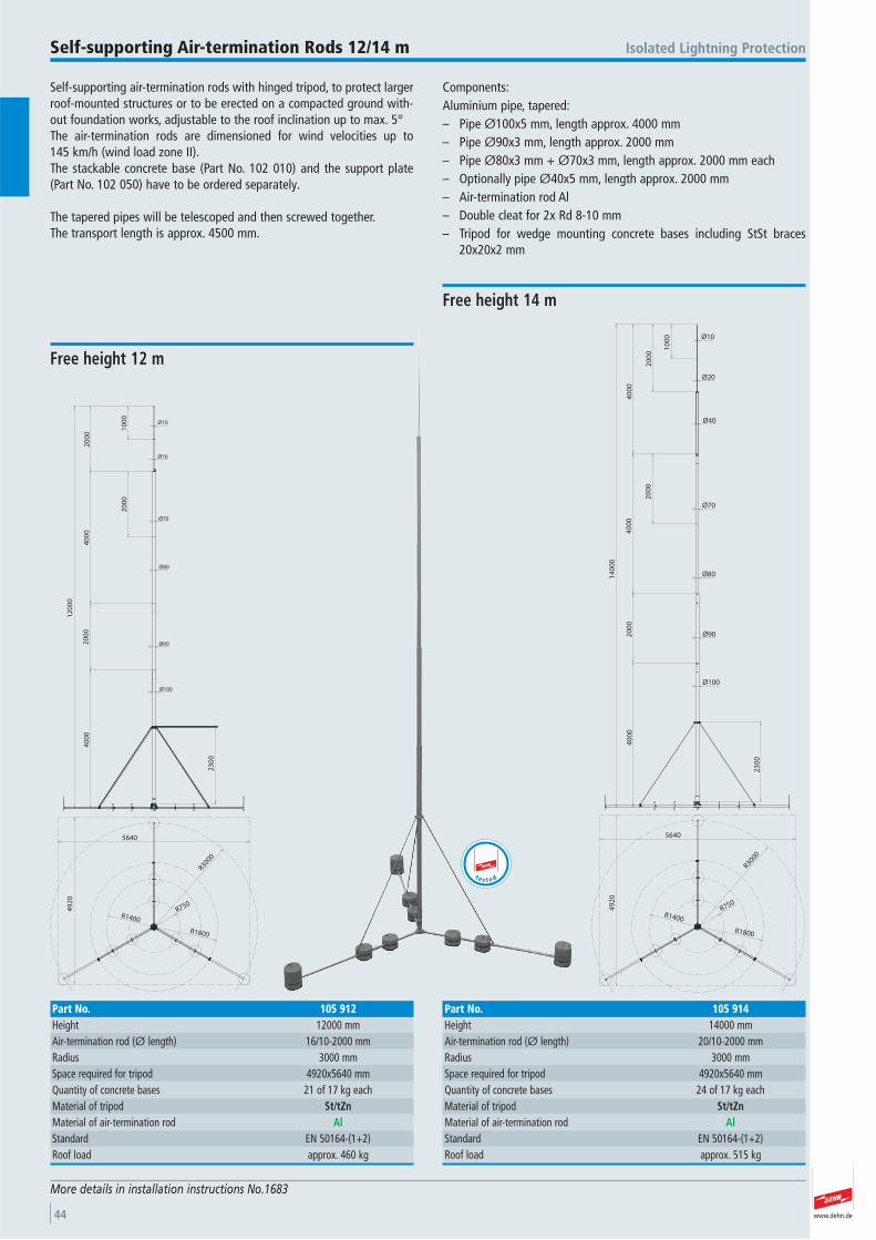
www.dehn.de44
Self-supporting air-termination rods with hinged tripod, to protect largerroof-mounted structures or to be erected on a compacted ground with-out foundation works, adjustable to the roof inclination up to max. 5° The air-termination rods are dimensioned for wind velocities up to 145 km/h (wind load zone II).The stackable concrete base (Part No. 102 010) and the support plate (Part No. 102 050) have to be ordered separately.
The tapered pipes will be telescoped and then screwed together.The transport length is approx. 4500 mm.
Components:Aluminium pipe, tapered:– Pipe Ø100x5 mm, length approx. 4000 mm– Pipe Ø90x3 mm, length approx. 2000 mm– Pipe Ø80x3 mm + Ø70x3 mm, length approx. 2000 mm each– Optionally pipe Ø40x5 mm, length approx. 2000 mm– Air-termination rod Al– Double cleat for 2x Rd 8-10 mm– Tripod for wedge mounting concrete bases including StSt braces
20x20x2 mm
Isolated Lightning ProtectionSelf-supporting Air-termination Rods 12/14 m
More details in installation instructions No.1683
Ø100
Ø90
23
00
40
00
20
00
40
00
20
00
10
00
Ø10
Ø16
Ø70
Ø80
20
00
12
00
0
R750
R3000
49
20
5640
R1800
R1400
Free height 12 m
Part No. 105 912Height 12000 mmAir-termination rod (Ø length) 16/10-2000 mmRadius 3000 mmSpace required for tripod 4920x5640 mmQuantity of concrete bases 21 of 17 kg each Material of tripod St/tZnMaterial of air-termination rod AlStandard EN 50164-(1+2) Roof load approx. 460 kg
t e s t e d
R750
R3000
49
20
5640
R1800
R1400
Ø100
Ø90
23
00
40
00
20
00
10
00
20
00
40
00
40
00
20
00
14
00
0
Ø80
Ø70
Ø40
Ø20
Ø10
Free height 14 m
Part No. 105 914Height 14000 mmAir-termination rod (Ø length) 20/10-2000 mmRadius 3000 mmSpace required for tripod 4920x5640 mmQuantity of concrete bases 24 of 17 kg each Material of tripod St/tZnMaterial of air-termination rod AlStandard EN 50164-(1+2) Roof load approx. 515 kg
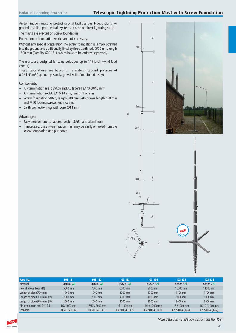
www.dehn.de 45
Air-termination mast to protect special facilities e.g. biogas plants orground-installed photovoltaic systems in case of direct lightning strike.
The masts are erected on screw foundation.
Excavation or foundation works are not necessary.
Without any special preparation the screw foundation is simply screwedinto the ground and additionally fixed by three earth rods Ø20 mm, length1500 mm (Part No. 620 151), which have to be ordered separately.
The masts are designed for wind velocities up to 145 km/h (wind loadzone II).These calculations are based on a natural ground pressure of 0.02 kN/cm2 (e.g. loamy, sandy, gravel soil of medium density).
Components:– Air-termination mast St/tZn and Al, tapered Ø70/60/40 mm– Air-termination rod Al Ø16/10 mm, length 1 or 2 m– Screw foundation St/tZn, length 800 mm with braces length 530 mm
and M10 locking screws with lock nut– Earth connection lug with bore Ø11 mm
Advantages: – Easy erection due to tapered design St/tZn and aluminium – If necessary, the air-termination mast may be easily removed from the
screw foundation and put down
Isolated Lightning Protection Telescopic Lightning Protection Mast with Screw Foundation
More details in installation instructions No. 1581
Ød1
Ø40
Ø60
Ø70
Ø11
20
0
80
01
70
0l2
l3l4
l1
R530
Part No. 103 121 103 122 103 123 103 124 103 125 103 126Material St/tZn / Al St/tZn / Al St/tZn / Al St/tZn / Al St/tZn / Al St/tZn / AlHeight above floor (l1) 6000 mm 7000 mm 8000 mm 9000 mm 10000 mm 11000 mmLength of pipe Ø70 mm 1700 mm 1700 mm 1700 mm 1700 mm 1700 mm 1700 mmLength of pipe Ø60 mm (l2) 2000 mm 2000 mm 4000 mm 4000 mm 6000 mm 6000 mmLength of pipe Ø40 mm (l3) 2000 mm 2000 mm 2000 mm 2000 mm 2000 mm 2000 mmAir-termination rod (d1) (l4) 16 / 1000 mm 16/10 / 2000 mm 16 / 1000 mm 16/10 / 2000 mm 16 / 1000 mm 16/10 / 2000 mmStandard EN 50164-(1+2) EN 50164-(1+2) EN 50164-(1+2) EN 50164-(1+2) EN 50164-(1+2) EN 50164-(1+2)
t e s t e d
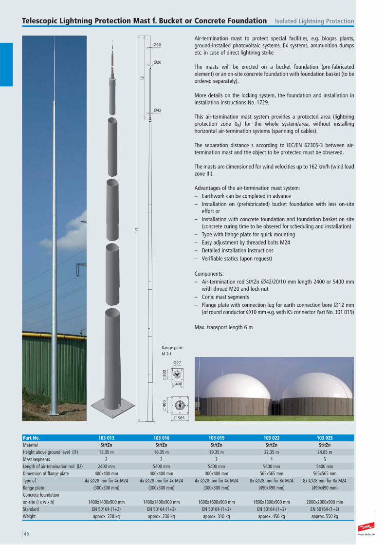
www.dehn.de46
Air-termination mast to protect special facilities, e.g. biogas plants,ground-installed photovoltaic systems, Ex systems, ammunition dumpsetc. in case of direct lightning strike
The masts will be erected on a bucket foundation (pre-fabricated element) or an on-site concrete foundation with foundation basket (to beordered separately).
More details on the locking system, the foundation and installation ininstallation instructions No. 1729.
This air-termination mast system provides a protected area (lightningprotection zone 0B) for the whole system/area, without installing horizontal air-termination systems (spanning of cables).
The separation distance s according to IEC/EN 62305-3 between air- termination mast and the object to be protected must be observed.
The masts are dimensioned for wind velocities up to 162 km/h (wind loadzone III).
Advantages of the air-termination mast system:– Earthwork can be completed in advance – Installation on (prefabricated) bucket foundation with less on-site
effort or– Installation with concrete foundation and foundation basket on site
(concrete curing time to be obsered for scheduling and installation)– Type with flange plate for quick mounting– Easy adjustment by threaded bolts M24– Detailed installation instructions– Verifiable statics (upon request)
Components:– Air-termination rod St/tZn Ø42/20/10 mm length 2400 or 5400 mm
with thread M20 and lock nut – Conic mast segments – Flange plate with connection lug for earth connection bore Ø12 mm
(of round conductor Ø10 mm e.g. with KS connector Part No. 301 019)
Max. transport length 6 m
Isolated Lightning ProtectionTelescopic Lightning Protection Mast f. Bucket or Concrete Foundation
l1
l2
Ø10
Ø20
Ø42
49
0
565
Ø27
400
30
0
flange plate
M 2:1
Part No. 103 013 103 016 103 019 103 022 103 025Material St/tZn St/tZn St/tZn St/tZn St/tZnHeight above ground level (l1) 13.35 m 16.35 m 19.35 m 22.35 m 24.85 mMast segments 2 2 3 4 5 Length of air-termination rod (l2) 2400 mm 5400 mm 5400 mm 5400 mm 5400 mmDimension of flange plate 400x400 mm 400x400 mm 400x400 mm 565x565 mm 565x565 mmType of 4x Ø28 mm for 4x M24 4x Ø28 mm for 4x M24 4x Ø28 mm for 4x M24 8x Ø28 mm for 8x M24 8x Ø28 mm for 8x M24 flange plate (300x300 mm) (300x300 mm) (300x300 mm) (490x490 mm) (490x490 mm) Concrete foundation on-site (l x w x h) 1400x1400x900 mm 1400x1400x900 mm 1600x1600x900 mm 1800x1800x900 mm 2000x2000x900 mmStandard EN 50164-(1+2) EN 50164-(1+2) EN 50164-(1+2) EN 50164-(1+2) EN 50164-(1+2) Weight approx. 228 kg approx. 230 kg approx. 310 kg approx. 450 kg approx. 550 kg
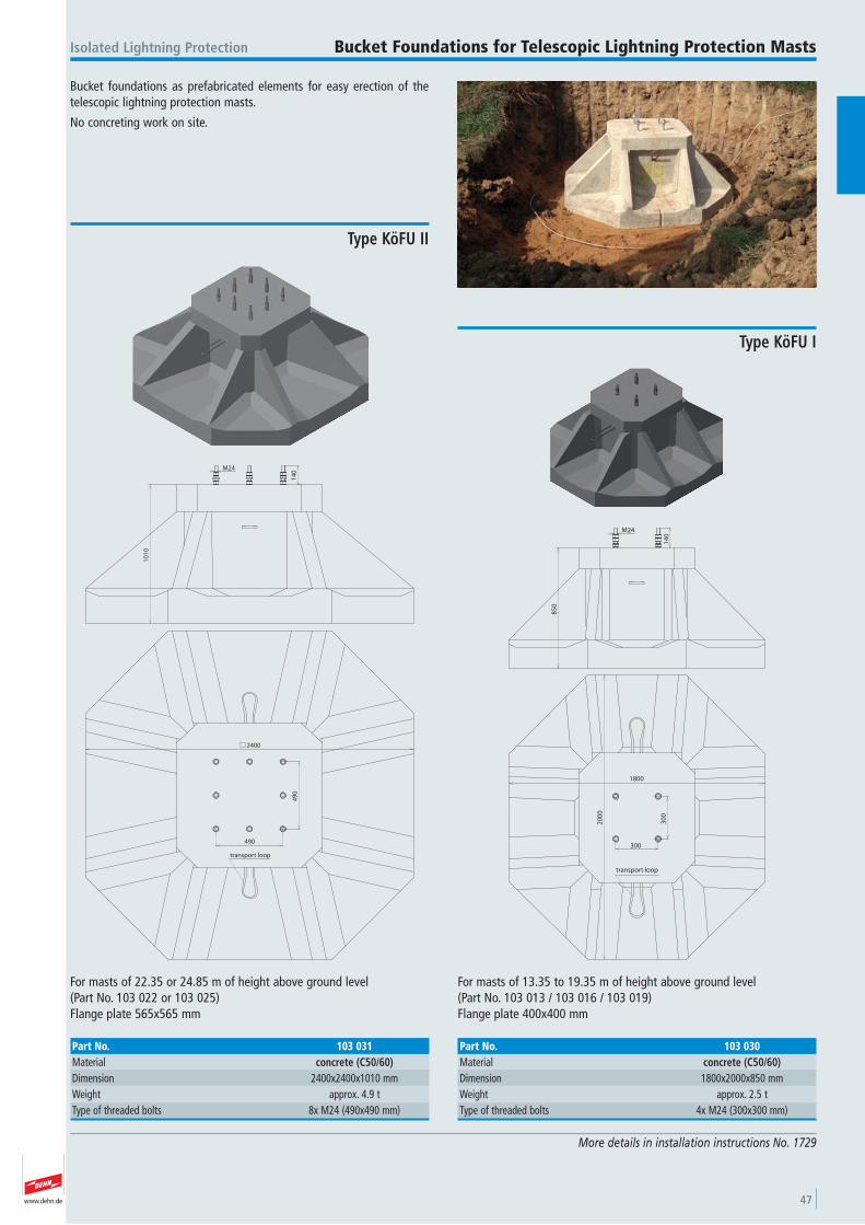
www.dehn.de 47
Bucket foundations as prefabricated elements for easy erection of thetelescopic lightning protection masts.
No concreting work on site.
Isolated Lightning Protection Bucket Foundations for Telescopic Lightning Protection Masts
More details in installation instructions No. 1729
85
0
14
0
M24
1800
20
00
30
0
300
transport loop
For masts of 13.35 to 19.35 m of height above ground level (Part No. 103 013 / 103 016 / 103 019) Flange plate 400x400 mm
Type KöFU I
Part No. 103 030Material concrete (C50/60)Dimension 1800x2000x850 mmWeight approx. 2.5 tType of threaded bolts 4x M24 (300x300 mm)
14
0
10
10
M24
2400
490
49
0
transport loop
For masts of 22.35 or 24.85 m of height above ground level (Part No. 103 022 or 103 025)Flange plate 565x565 mm
Type KöFU II
Part No. 103 031Material concrete (C50/60)Dimension 2400x2400x1010 mmWeight approx. 4.9 tType of threaded bolts 8x M24 (490x490 mm)
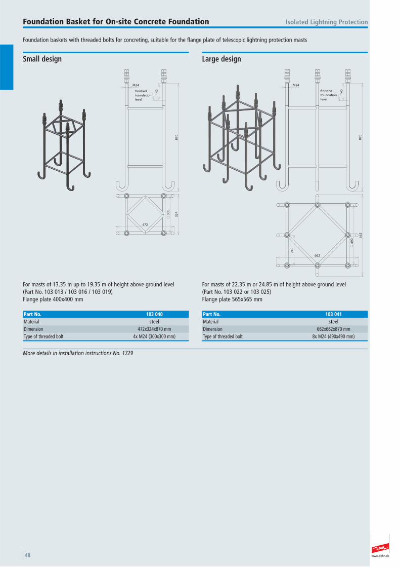
www.dehn.de48
Foundation baskets with threaded bolts for concreting, suitable for the flange plate of telescopic lightning protection masts
Isolated Lightning ProtectionFoundation Basket for On-site Concrete Foundation
More details in installation instructions No. 1729
87
0
M24
14
0
472
32
430
0
finished
foundation
level
For masts of 13.35 m up to 19.35 m of height above ground level (Part No. 103 013 / 103 016 / 103 019) Flange plate 400x400 mm
Small design
Part No. 103 040Material steelDimension 472x324x870 mmType of threaded bolt 4x M24 (300x300 mm)
M24
87
0
14
0
662
66
2
49
0
24
5
finished
foundation
level
For masts of 22.35 m or 24.85 m of height above ground level (Part No. 103 022 or 103 025)Flange plate 565x565 mm
Large design
Part No. 103 041Material steelDimension 662x662x870 mmType of threaded bolt 8x M24 (490x490 mm)
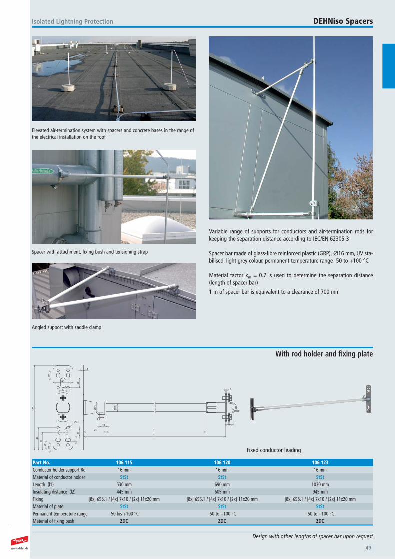
www.dehn.de 49
Variable range of supports for conductors and air-termination rods forkeeping the separation distance according to IEC/EN 62305-3
Spacer bar made of glass-fibre reinforced plastic (GRP), Ø16 mm, UV sta-bilised, light grey colour, permanent temperature range -50 to +100 °C
Material factor km = 0.7 is used to determine the separation distance(length of spacer bar)
1 m of spacer bar is equivalent to a clearance of 700 mm
Elevated air-termination system with spacers and concrete bases in the range ofthe electrical installation on the roof
Isolated Lightning Protection DEHNiso Spacers
Angled support with saddle clamp
Spacer with attachment, fixing bush and tensioning strap
Design with other lengths of spacer bar upon request
10
45
Ø2
3
3
l1
l2
2
R8
Ø1
6
2
17
0
40
20
10
10
20
35
45
20
Ø5.1
11
7
Fixed conductor leading
With rod holder and fixing plate
Part No. 106 115 106 120 106 123Conductor holder support Rd 16 mm 16 mm 16 mmMaterial of conductor holder StSt StSt StStLength (l1) 530 mm 690 mm 1030 mmInsulating distance (l2) 445 mm 605 mm 945 mmFixing [8x] Ø5.1 / [4x] 7x10 / [2x] 11x20 mm [8x] Ø5.1 / [4x] 7x10 / [2x] 11x20 mm [8x] Ø5.1 / [4x] 7x10 / [2x] 11x20 mmMaterial of plate StSt StSt StStPermanent temperature range -50 bis +100 °C -50 to +100 °C -50 to +100 °CMaterial of fixing bush ZDC ZDC ZDC
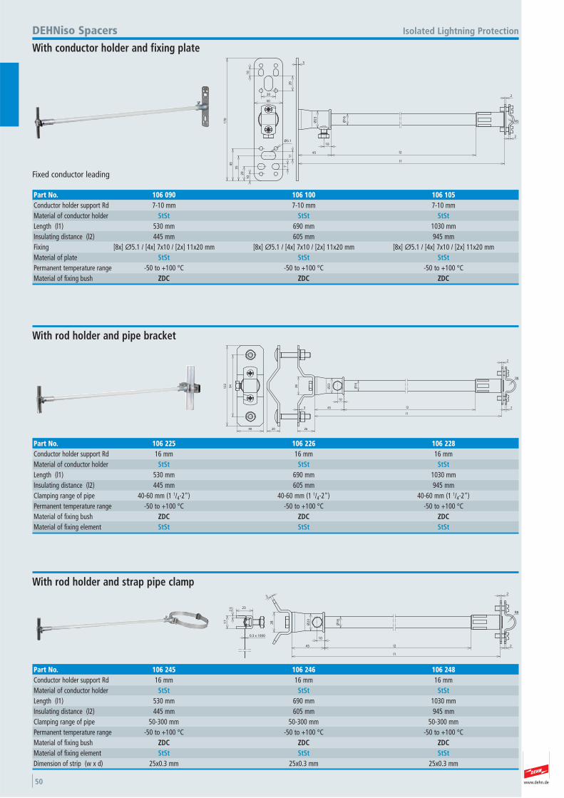
www.dehn.de50
10
45
Ø2
3
Ø1
6
l2
l1
2
R5
2
3
17
0
40
20
10
10
20
35
45
20
Ø5.1
11
7
Fixed conductor leading
Isolated Lightning ProtectionDEHNiso Spacers
With conductor holder and fixing plate
Part No. 106 090 106 100 106 105Conductor holder support Rd 7-10 mm 7-10 mm 7-10 mmMaterial of conductor holder StSt StSt StStLength (l1) 530 mm 690 mm 1030 mmInsulating distance (l2) 445 mm 605 mm 945 mmFixing [8x] Ø5.1 / [4x] 7x10 / [2x] 11x20 mm [8x] Ø5.1 / [4x] 7x10 / [2x] 11x20 mm [8x] Ø5.1 / [4x] 7x10 / [2x] 11x20 mmMaterial of plate StSt StSt StStPermanent temperature range -50 to +100 °C -50 to +100 °C -50 to +100 °CMaterial of fixing bush ZDC ZDC ZDC
R8
2
2
45
28
3
2620
94
l1
l2
10
40
12
2
Ø1
6
Ø2
3
With rod holder and pipe bracket
Part No. 106 225 106 226 106 228Conductor holder support Rd 16 mm 16 mm 16 mmMaterial of conductor holder StSt StSt StStLength (l1) 530 mm 690 mm 1030 mmInsulating distance (l2) 445 mm 605 mm 945 mmClamping range of pipe 40-60 mm (1 1/4-2") 40-60 mm (1 1/4-2") 40-60 mm (1 1/4-2") Permanent temperature range -50 to +100 °C -50 to +100 °C -50 to +100 °CMaterial of fixing bush ZDC ZDC ZDCMaterial of fixing element StSt StSt StSt
R8
2
2
3
23
2.5
17
0.3 x 100010
l1
l245
28
Ø1
6
Ø2
3
With rod holder and strap pipe clamp
Part No. 106 245 106 246 106 248Conductor holder support Rd 16 mm 16 mm 16 mmMaterial of conductor holder StSt StSt StStLength (l1) 530 mm 690 mm 1030 mmInsulating distance (l2) 445 mm 605 mm 945 mmClamping range of pipe 50-300 mm 50-300 mm 50-300 mm Permanent temperature range -50 to +100 °C -50 to +100 °C -50 to +100 °CMaterial of fixing bush ZDC ZDC ZDCMaterial of fixing element StSt StSt StStDimension of strip (w x d) 25x0.3 mm 25x0.3 mm 25x0.3 mm
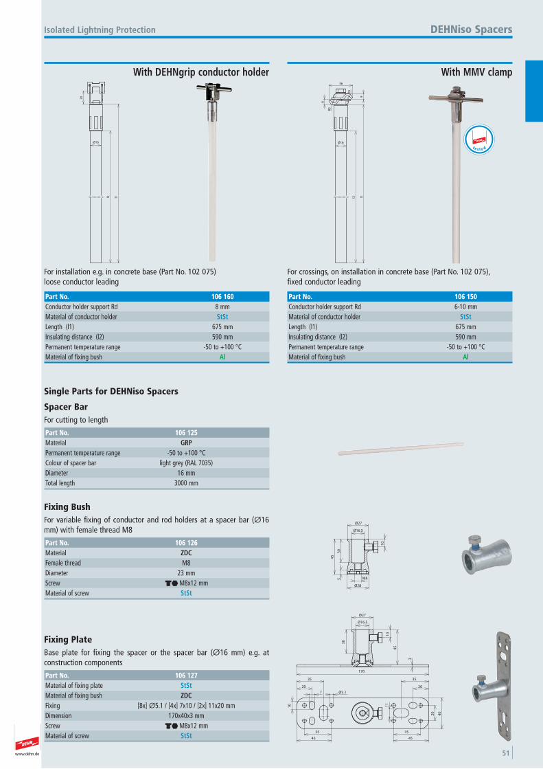
www.dehn.de 51
20
l1l2
Ø16
For installation e.g. in concrete base (Part No. 102 075)loose conductor leading
Isolated Lightning Protection
With DEHNgrip conductor holder
DEHNiso Spacers
Part No. 106 160Conductor holder support Rd 8 mmMaterial of conductor holder StStLength (l1) 675 mmInsulating distance (l2) 590 mmPermanent temperature range -50 to +100 °CMaterial of fixing bush Al
R5
8
9
R5
36
l1l2
Ø16
For crossings, on installation in concrete base (Part No. 102 075),fixed conductor leading
With MMV clamp
Part No. 106 150Conductor holder support Rd 6-10 mmMaterial of conductor holder StStLength (l1) 675 mmInsulating distance (l2) 590 mmPermanent temperature range -50 to +100 °CMaterial of fixing bush Al
t e s t e d
Single Parts for DEHNiso Spacers
Spacer Bar For cutting to length
Part No. 106 125Material GRPPermanent temperature range -50 to +100 °CColour of spacer bar light grey (RAL 7035) Diameter 16 mmTotal length 3000 mm
10
Ø16.5
Ø27
30
Ø28
45
5 M8
Fixing Bush For variable fixing of conductor and rod holders at a spacer bar (Ø16mm) with female thread M8
Part No. 106 126Material ZDCFemale thread M8 Diameter 23 mmScrew di M8x12 mmMaterial of screw StSt
45
10
3
30
Ø16.5
Ø27
170
35
45
10
7
20
35
Ø5.1
20
35
45
20
40
35
11
Fixing Plate Base plate for fixing the spacer or the spacer bar (Ø16 mm) e.g. at construction components
Part No. 106 127Material of fixing plate StStMaterial of fixing bush ZDCFixing [8x] Ø5.1 / [4x] 7x10 / [2x] 11x20 mmDimension 170x40x3 mmScrew di M8x12 mmMaterial of screw StSt
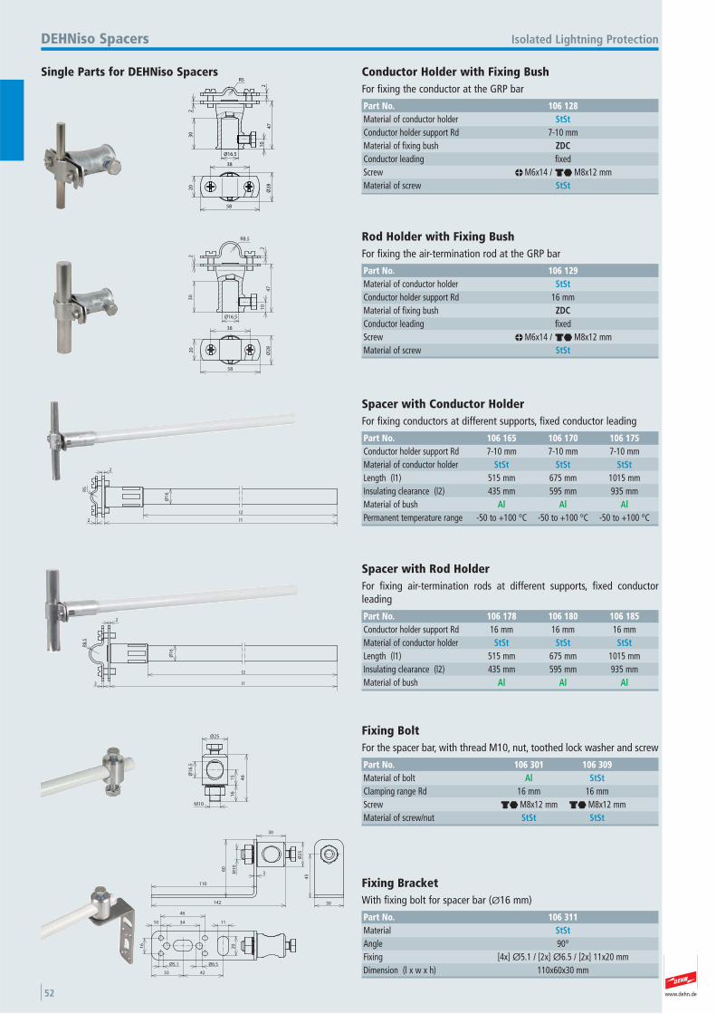
www.dehn.de52
Ø16.5
30
47
2
21
0
R5
38
58
20
Ø2
8
Single Parts for DEHNiso Spacers
Isolated Lightning ProtectionDEHNiso Spacers
Conductor Holder with Fixing Bush For fixing the conductor at the GRP bar
Part No. 106 128Material of conductor holder StStConductor holder support Rd 7-10 mmMaterial of fixing bush ZDCConductor leading fixed Screw m M6x14 / di M8x12 mmMaterial of screw StSt
Ø16.5
30
47
2
R8.5
2
10
38
58
20
Ø2
8
Rod Holder with Fixing Bush For fixing the air-termination rod at the GRP bar
Part No. 106 129Material of conductor holder StStConductor holder support Rd 16 mmMaterial of fixing bush ZDCConductor leading fixed Screw m M6x14 / di M8x12 mmMaterial of screw StSt
R5
2
2
l1
l2
Ø1
6
Spacer with Conductor Holder For fixing conductors at different supports, fixed conductor leading
Part No. 106 165 106 170 106 175Conductor holder support Rd 7-10 mm 7-10 mm 7-10 mmMaterial of conductor holder StSt StSt StStLength (l1) 515 mm 675 mm 1015 mmInsulating clearance (l2) 435 mm 595 mm 935 mmMaterial of bush Al Al AlPermanent temperature range -50 to +100 °C -50 to +100 °C -50 to +100 °C
l1
l2
Ø1
6
R8
.5
2
2
Spacer with Rod Holder For fixing air-termination rods at different supports, fixed conductor leading
Part No. 106 178 106 180 106 185Conductor holder support Rd 16 mm 16 mm 16 mmMaterial of conductor holder StSt StSt StStLength (l1) 515 mm 675 mm 1015 mmInsulating clearance (l2) 435 mm 595 mm 935 mmMaterial of bush Al Al Al
46
16
15
Ø25
Ø1
6.5
M10
Fixing Bolt For the spacer bar, with thread M10, nut, toothed lock washer and screw
Part No. 106 301 106 309Material of bolt Al StStClamping range Rd 16 mm 16 mmScrew di M8x12 mm di M8x12 mmMaterial of screw/nut StSt StSt
30
Ø2
5
142
M1
0
10 34
46
11
20
4233
Ø5.1 Ø6.5
16
45
30
110
60
3
Fixing Bracket With fixing bolt for spacer bar (Ø16 mm)
Part No. 106 311Material StStAngle 90° Fixing [4x] Ø5.1 / [2x] Ø6.5 / [2x] 11x20 mmDimension (l x w x h) 110x60x30 mm
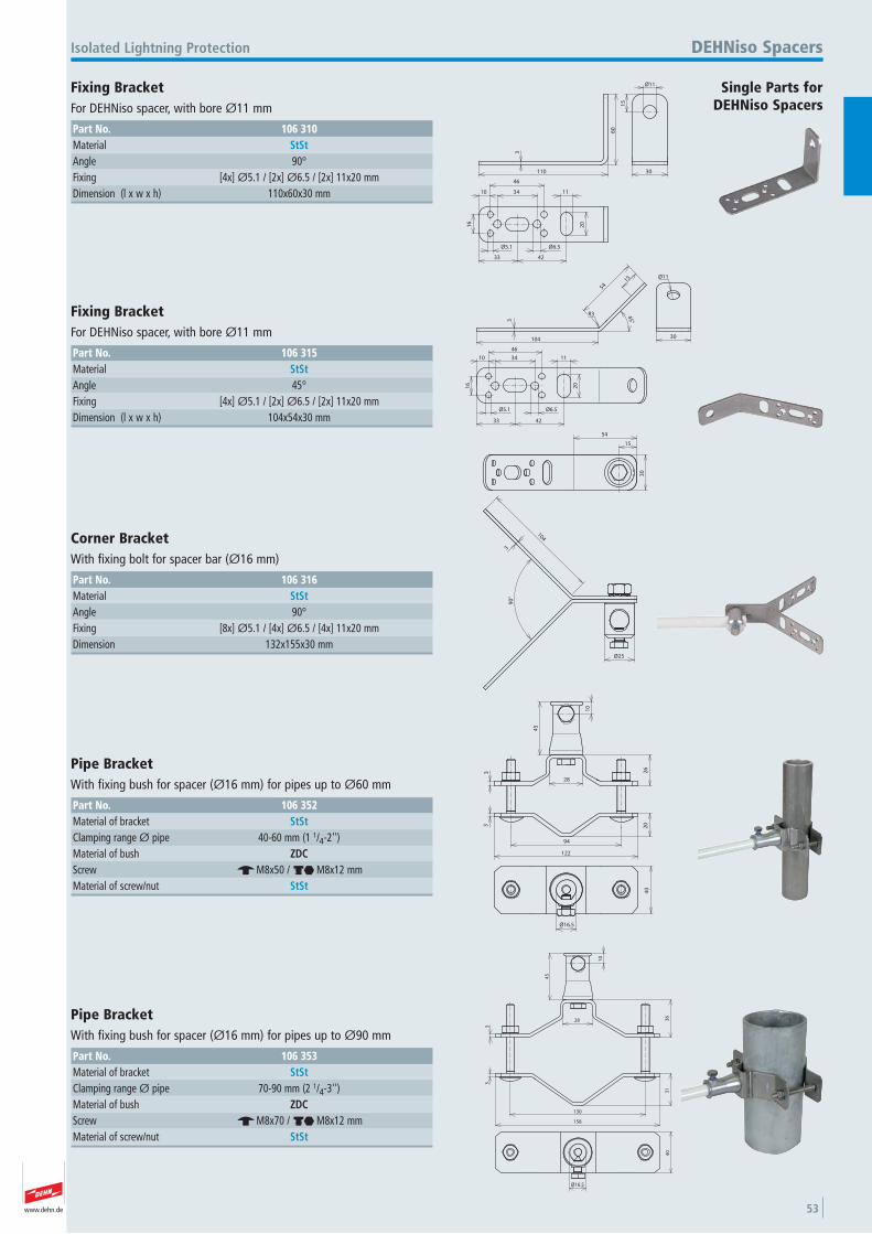
www.dehn.de 53
110
60
3
15
Ø11
30
10
16
42
34
46
33
Ø5.1 Ø6.5
20
11
Single Parts for DEHNiso Spacers
Isolated Lightning Protection DEHNiso Spacers
Fixing Bracket For DEHNiso spacer, with bore Ø11 mm
Part No. 106 310Material StStAngle 90° Fixing [4x] Ø5.1 / [2x] Ø6.5 / [2x] 11x20 mmDimension (l x w x h) 110x60x30 mm
54
R3
15
3
104
45°
30
Ø11
10 34
46
11
20
4233
Ø5.1 Ø6.5
16
Fixing Bracket For DEHNiso spacer, with bore Ø11 mm
Part No. 106 315Material StStAngle 45° Fixing [4x] Ø5.1 / [2x] Ø6.5 / [2x] 11x20 mmDimension (l x w x h) 104x54x30 mm
30
54
15
104
3
90
°
Ø25
Corner Bracket With fixing bolt for spacer bar (Ø16 mm)
Part No. 106 316Material StStAngle 90° Fixing [8x] Ø5.1 / [4x] Ø6.5 / [4x] 11x20 mmDimension 132x155x30 mm
28
94
122
10
45
3 26
3 20
Ø16.5
40
Pipe Bracket With fixing bush for spacer (Ø16 mm) for pipes up to Ø60 mm
Part No. 106 352Material of bracket StStClamping range Ø pipe 40-60 mm (1 1/4-2'') Material of bush ZDCScrew e M8x50 / di M8x12 mmMaterial of screw/nut StSt
28
10
33
36
31
45
158
130
40
Ø16.5
Pipe Bracket With fixing bush for spacer (Ø16 mm) for pipes up to Ø90 mm
Part No. 106 353Material of bracket StStClamping range Ø pipe 70-90 mm (2 1/4-3'') Material of bush ZDCScrew e M8x70 / di M8x12 mmMaterial of screw/nut StSt
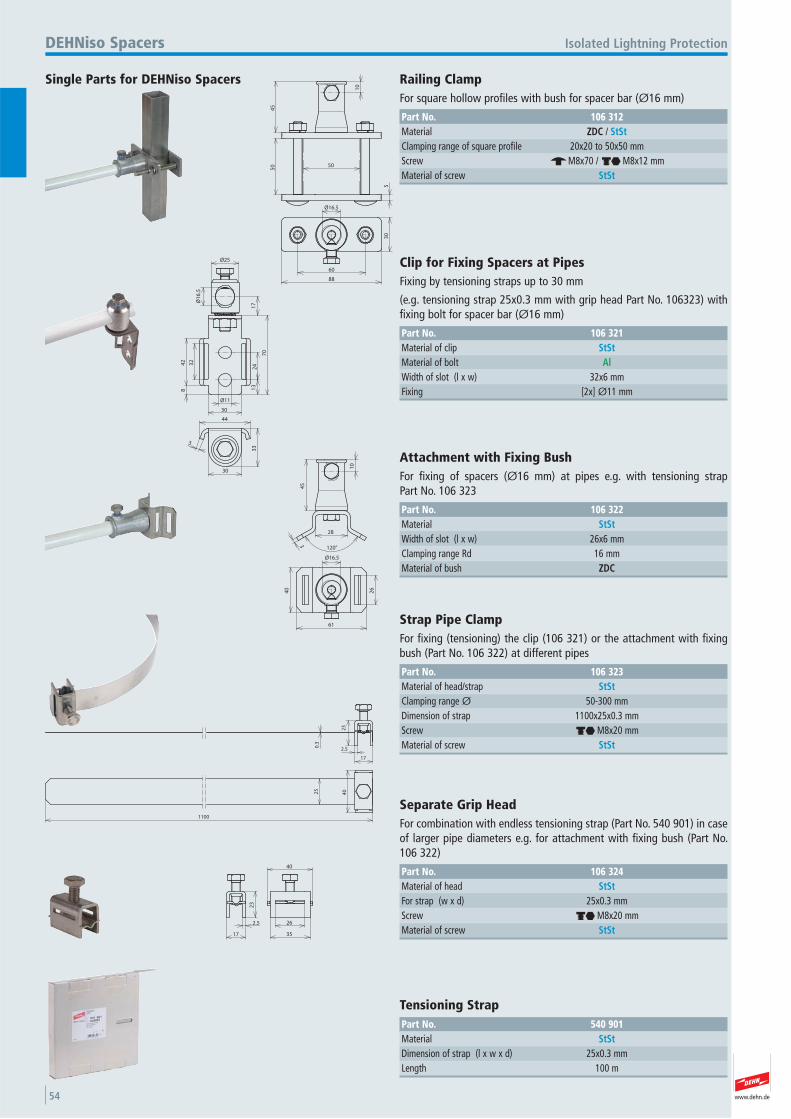
www.dehn.de54
50
45
10
5
50
30
60
88
Ø16.5
Single Parts for DEHNiso Spacers
Isolated Lightning ProtectionDEHNiso Spacers
Railing Clamp For square hollow profiles with bush for spacer bar (Ø16 mm)
Part No. 106 312Material ZDC / StStClamping range of square profile 20x20 to 50x50 mmScrew e M8x70 / di M8x12 mmMaterial of screw StSt
17
13
24
Ø1
6.5
Ø257
0
32
42
8
Ø11
30
44
3
30
33
Clip for Fixing Spacers at Pipes Fixing by tensioning straps up to 30 mm
(e.g. tensioning strap 25x0.3 mm with grip head Part No. 106323) withfixing bolt for spacer bar (Ø16 mm)
Part No. 106 321Material of clip StStMaterial of bolt AlWidth of slot (l x w) 32x6 mmFixing [2x] Ø11 mm
10
45
28
3
120°
40
61
26
Ø16.5
Attachment with Fixing Bush For fixing of spacers (Ø16 mm) at pipes e.g. with tensioning strap Part No. 106 323
Part No. 106 322Material StStWidth of slot (l x w) 26x6 mmClamping range Rd 16 mmMaterial of bush ZDC
23
17
2.50.3
4025
1100
Strap Pipe Clamp For fixing (tensioning) the clip (106 321) or the attachment with fixingbush (Part No. 106 322) at different pipes
Part No. 106 323Material of head/strap StStClamping range Ø 50-300 mmDimension of strap 1100x25x0.3 mmScrew di M8x20 mmMaterial of screw StSt
23
2.5
17 35
26
40
Separate Grip Head For combination with endless tensioning strap (Part No. 540 901) in caseof larger pipe diameters e.g. for attachment with fixing bush (Part No.106 322)
Part No. 106 324Material of head StStFor strap (w x d) 25x0.3 mmScrew di M8x20 mmMaterial of screw StSt
Tensioning Strap Part No. 540 901Material StStDimension of strap (l x w x d) 25x0.3 mmLength 100 m
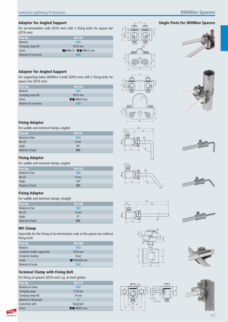
www.dehn.de 55
33
20
Ø1
6.5
3
37
R8.5
Ø10
73
40
25
Single Parts for DEHNiso Spacers
Isolated Lightning Protection DEHNiso Spacers
Adapter for Angled Support For air-termination rods (Ø16 mm) with 2 fixing bolts for spacer bar(Ø16 mm)
Part No. 106 325Material StStClamping range Rd 16/16 mmScrew dh M6x12 / di M8x12 mmMaterial of screw/nut StSt
60
20
3Ø
16
.5
37
25R
40
100
10Ø
16
25
Adapter for Angled Support For supporting tubes DEHNiso Combi (Ø50 mm) with 2 fixing bolts forspacer bar (Ø16 mm)
Part No. 106 326Material StStClamping range Rd 50/16 mmScrew di M8x16 mmMaterial of screw/nut StSt
10
45
58
88
Ø8
Ø1
6.5
90°
Fixing Adapter For saddle and terminal clamps, angled
Part No. 106 341Material of bar StStBar Ø 8 mmAngle 90° Material of bush ZDC
10
45 130°
Ø8
Ø1
6.5
Fixing Adapter For saddle and terminal clamps, angled
Part No. 106 342Material of bar StStBar Ø 8 mmAngle 130° Material of bush ZDC
10
130
8Ø
45
100
Ø1
6.5
Fixing Adapter For saddle and terminal clamps, straight
Part No. 106 340Material of bar StStBar Ø 8 mmAngle 0° Material of bush ZDC
3
R8
3
16
16
R8
40
50
44
MV Clamp Especially for the fixing of air-termination rods at the spacer bar withoutfixing bush
Part No. 393 069Material StStConductor holder support Rd 16/16 mmConductor leading fixed Screw e M10x50 mmMaterial of screw StSt
30
53
75
R8
22
5
19
20
10
25
Terminal Clamp with Fixing Bolt For fixing of spacers (Ø16 mm) e.g. at steel girders
Part No. 106 319Material of clamp StStClamping range 5-18 mmClamping range Rd 16 mmMaterial of fixing bolt AlConnection with fixing bolt Screw di M8x25 mm
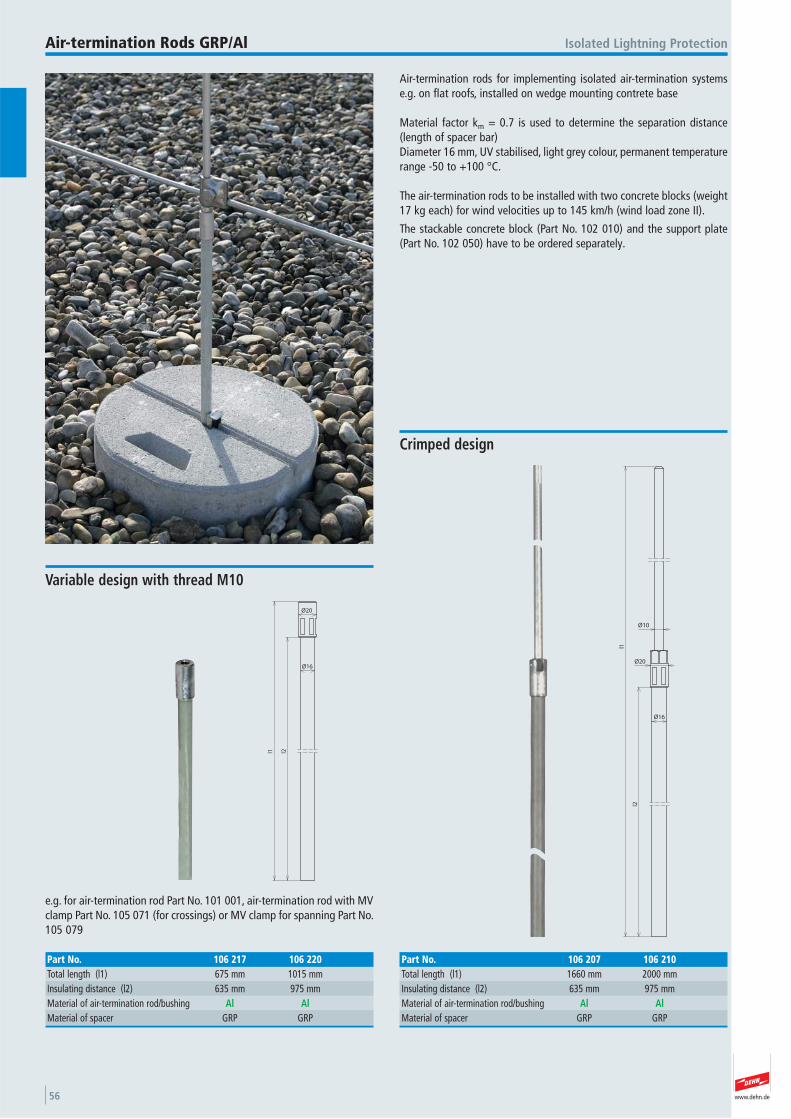
www.dehn.de56
Air-termination rods for implementing isolated air-termination systemse.g. on flat roofs, installed on wedge mounting contrete base
Material factor km = 0.7 is used to determine the separation distance(length of spacer bar)Diameter 16 mm, UV stabilised, light grey colour, permanent temperaturerange -50 to +100 °C.
The air-termination rods to be installed with two concrete blocks (weight17 kg each) for wind velocities up to 145 km/h (wind load zone II).
The stackable concrete block (Part No. 102 010) and the support plate(Part No. 102 050) have to be ordered separately.
Isolated Lightning ProtectionAir-termination Rods GRP/Al
l2
l1
Ø20
Ø16
Ø10
Crimped design
Part No. 106 207 106 210Total length (l1) 1660 mm 2000 mmInsulating distance (l2) 635 mm 975 mmMaterial of air-termination rod/bushing Al AlMaterial of spacer GRP GRP
l2l1
Ø20
Ø16
e.g. for air-termination rod Part No. 101 001, air-termination rod with MVclamp Part No. 105 071 (for crossings) or MV clamp for spanning Part No.105 079
Variable design with thread M10
Part No. 106 217 106 220Total length (l1) 675 mm 1015 mmInsulating distance (l2) 635 mm 975 mmMaterial of air-termination rod/bushing Al AlMaterial of spacer GRP GRP
www.dehn.de 57
10
00
Ø10
30 M10
Accessories for Air-termination Rods GRP/Al
Isolated Lightning Protection Air-termination Rods GRP/Al
Air-termination Rod with Lock Nut For screwing in
Part No. 101 001Material StStDiameter 10 mmLength 1000 mmThread M10 Material of nut StStStandard EN 50164-2
R5
70 9
40
10
00
Air-termination Rod with MV Clamp For screwing in
Part No. 105 071Material of air-termination spike StStMaterial of MV clamp StStAir-termination rod (l x Ø) 1000x10 mmClamping range Rd 8-10 mmThread M10 Standard EN 50164-(1+2)
t e s t e d
R5
2.5
40
40
MV Clamp for Spanning For screwing in
Part No. 105 079Material StStClamping range Rd 8-10 mmType of scew di M10x30 mmMaterial of screw StStStandard EN 50164-1
t e s t e d
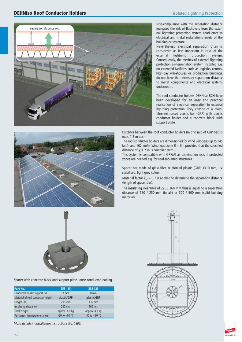
www.dehn.de58
Non-compliance with the separation distanceincreases the risk of flashovers from the exter-nal lightning protection system conductors toelectrical and metal installations inside of thebuilding or structure.Nevertheless, electrical separation often is considered as less important in case of theexternal lightning protection system.Consequently, the meshes of external lightningprotection air-termination system installed e.g.on extended facilities such as logistics centres,high-bay warehouses or production buildings,do not have the necessary separation distanceto metal components and electrical systemsunderneath.
The roof conductor holders DEHNiso RCH havebeen developed for an easy and practical realisation of electrical separation in externallightning protection. They consist of a glass-fibre reinforced plastic bar (GRP) with plasticconductor holder and a concrete block with support plate.
Distance between the roof conductor holders (mid to mid of GRP bar) ismax. 1.2 m each.The roof conductor holders are dimensioned for wind velocities up to 145km/h and 162 km/h (wind load zone II + III), provided that the specifieddistance of ≤ 1.2 m is complied with. This system is compatible with GRP/Al air-termination rods, if protectedzones are needed e.g. for roof-mounted structures.
Spacer bar made of glass-fibre reinforced plastic (GRP) Ø10 mm, UV stabilised, light grey colour
Material factor km = 0.7 is applied to determine the separation distance(length of spacer bar).
The insulating clearance of 220 / 360 mm thus is equal to a separationdistance of 150 / 250 mm (in air) or 300 / 500 mm (solid building material).
Isolated Lightning ProtectionDEHNiso Roof Conductor Holders
More details in installation instructions No. 1802.
74
Ø10
R4
43
Ø22
Ø27
l1
Ø300
180Spacer with concrete block and support plate, loose conductor leading
Part No. 253 115 253 125Conductor holder support Rd 8 mm 8 mmMaterial of roof conductor holder plastic/GRP plastic/GRPLength (l1) 295 mm 435 mmInsulating clearance 220 mm 360 mmTotal weight approx. 4.8 kg approx. 4.8 kgPermanent temperature range -30 to +80 °C -30 to +80 °C
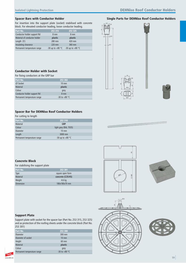
www.dehn.de 59
Ø10
l1
R4
Ø22
Ø27
43
Single Parts for DEHNiso Roof Conductor Holders
Isolated Lightning Protection DEHNiso Roof Conductor Holders
Spacer Bars with Conductor Holder For insertion into the support plate (socket) stabilised with concreteblock. For elevated conductor leading, loose conductor leading.
Part No. 253 315 253 325Conductor holder support Rd 8 mm 8 mmMaterial of conductor holder plastic plasticLength (l1) 280 mm 420 mmInsulating clearance 220 mm 360 mmPermanent temperature range -30 up to +80 °C -30 up to +80 °C
Ø22
18
R4
29
43
Ø27
22
15
Conductor Holder with Socket For fixing conductors at the GRP bar
Part No. 253 302Ø Socket 10 mmMaterial plasticColour grey Conductor holder support Rd 8 mmPermanent temperature range -30 to +80 °C
Spacer Bar for DEHNiso Roof Conductor Holders For cutting to length
Part No. 253 310Material GRPColour light grey (RAL 7035) Diameter 10 mmLength 3000 mmPermanent temperature range -30 up to +80 °C
18
0
Ø65
70
Concrete Block For stabilising the support plate
Part No. 253 301Type square open form Material concrete (C35/45)Weight 4.6 kgDimension 180x180x70 mm
60
12
Ø10
Ø300
Support Plate Support plate with socket for the spacer bar (Part No. 253 315, 253 325)and as protection of the roofing sheets under the concrete block (Part No.253 301)
Part No. 253 300Diameter 300 mmDiameter of socket 10 mmHeight 60 mmMaterial plasticColour grey Permanent temperature range -30 to +80 °C
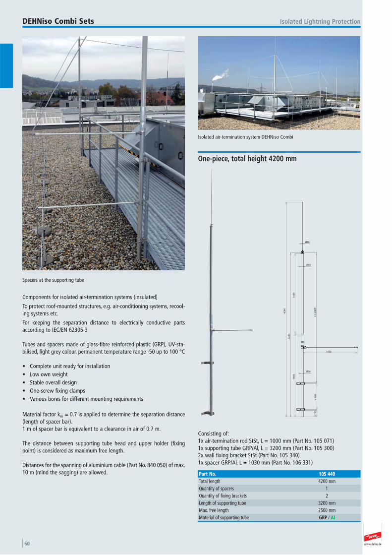
www.dehn.de60
Components for isolated air-termination systems (insulated)
To protect roof-mounted structures, e.g. air-conditioning systems, recool-ing systems etc.
For keeping the separation distance to electrically conductive partsaccording to IEC/EN 62305-3
Tubes and spacers made of glass-fibre reinforced plastic (GRP), UV-sta-bilised, light grey colour, permanent temperature range -50 up to 100 °C
• Complete unit ready for installation• Low own weight• Stable overall design• One-screw fixing clamps• Various bores for different mounting requirements
Material factor km = 0.7 is applied to determine the separation distance(length of spacer bar).1 m of spacer bar is equivalent to a clearance in air of 0.7 m.
The distance between supporting tube head and upper holder (fixingpoint) is considered as maximum free length.
Distances for the spanning of aluminium cable (Part No. 840 050) of max.10 m (mind the sagging) are allowed.
Isolated air-termination system DEHNiso Combi
Spacers at the supporting tube
Isolated Lightning ProtectionDEHNiso Combi Sets
Ø10
1030
x ≤
25
00
15
35
16
50
≥ 5
00
≤ 1
50
32
00
42
00
Ø50
Ø50
Consisting of: 1x air-termination rod StSt, L = 1000 mm (Part No. 105 071) 1x supporting tube GRP/Al, L = 3200 mm (Part No. 105 300) 2x wall fixing bracket StSt (Part No. 105 340) 1x spacer GRP/Al, L = 1030 mm (Part No. 106 331)
One-piece, total height 4200 mm
Part No. 105 440Total length 4200 mmQuantity of spacers 1 Quantity of fixing brackets 2 Length of supporting tube 3200 mmMax. free length 2500 mmMaterial of supporting tube GRP / Al
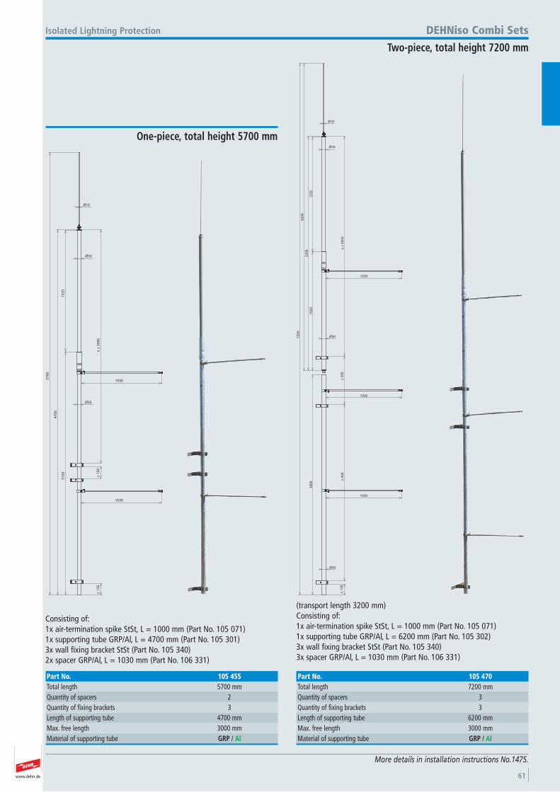
www.dehn.de 61
More details in installation instructions No.1475.
Ø10
Ø50
1030
≤ 1
50
1030
31
50
15
35
47
00
57
00
Ø50
≤ 1
50
x ≤
30
00
Consisting of:1x air-termination spike StSt, L = 1000 mm (Part No. 105 071) 1x supporting tube GRP/Al, L = 4700 mm (Part No. 105 301)3x wall fixing bracket StSt (Part No. 105 340) 2x spacer GRP/Al, L = 1030 mm (Part No. 106 331)
Isolated Lightning Protection
One-piece, total height 5700 mm
Part No. 105 455Total length 5700 mmQuantity of spacers 2 Quantity of fixing brackets 3 Length of supporting tube 4700 mmMax. free length 3000 mmMaterial of supporting tube GRP / Al
Ø10
Ø50
15
35
1030
16
50
Ø50
x ≤
30
00
32
00
42
00
1030
Ø50
≥ 5
00
1030
≤ 1
50
30
00
72
00
≥ 5
00
(transport length 3200 mm) Consisting of:1x air-termination spike StSt, L = 1000 mm (Part No. 105 071) 1x supporting tube GRP/Al, L = 6200 mm (Part No. 105 302) 3x wall fixing bracket StSt (Part No. 105 340) 3x spacer GRP/Al, L = 1030 mm (Part No. 106 331)
DEHNiso Combi Sets
Two-piece, total height 7200 mm
Part No. 105 470Total length 7200 mmQuantity of spacers 3 Quantity of fixing brackets 3 Length of supporting tube 6200 mmMax. free length 3000 mmMaterial of supporting tube GRP / Al
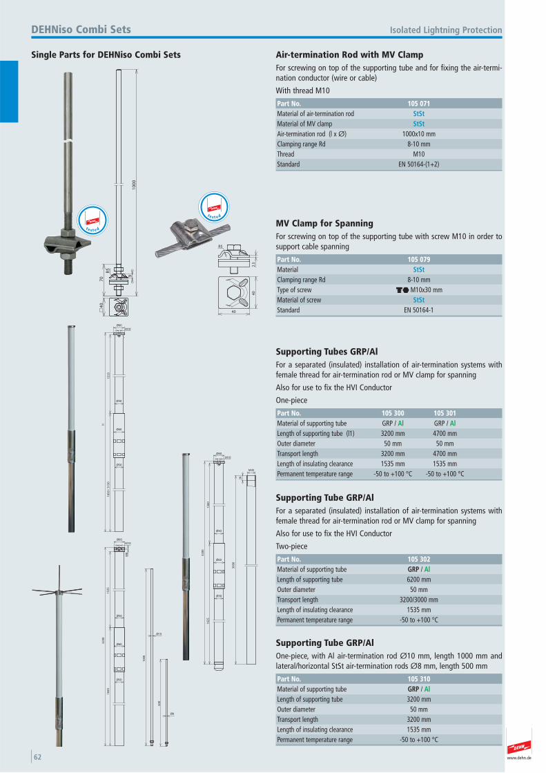
www.dehn.de62
R5
70 9
40
10
00
Single Parts for DEHNiso Combi Sets
Isolated Lightning ProtectionDEHNiso Combi Sets
Air-termination Rod with MV Clamp For screwing on top of the supporting tube and for fixing the air-termi-nation conductor (wire or cable)
With thread M10
Part No. 105 071Material of air-termination rod StStMaterial of MV clamp StStAir-termination rod (l x Ø) 1000x10 mmClamping range Rd 8-10 mmThread M10 Standard EN 50164-(1+2)
t e s t e d
R5
2.5
40
40
MV Clamp for Spanning For screwing on top of the supporting tube with screw M10 in order tosupport cable spanning
Part No. 105 079Material StStClamping range Rd 8-10 mmType of screw di M10x30 mmMaterial of screw StStStandard EN 50164-1
t e s t e d
15
35
16
50
/ 3
15
0
l1
Ø60
Ø50
Ø50
M10
Ø60
Supporting Tubes GRP/Al For a separated (insulated) installation of air-termination systems withfemale thread for air-termination rod or MV clamp for spanning
Also for use to fix the HVI Conductor
One-piece
Part No. 105 300 105 301Material of supporting tube GRP / Al GRP / AlLength of supporting tube (l1) 3200 mm 4700 mmOuter diameter 50 mm 50 mmTransport length 3200 mm 4700 mmLength of insulating clearance 1535 mm 1535 mmPermanent temperature range -50 to +100 °C -50 to +100 °C
30
00
28
M45
15
60
16
25
32
00
Ø60
Ø50
Ø50
M10
Ø60
Supporting Tube GRP/Al For a separated (insulated) installation of air-termination systems withfemale thread for air-termination rod or MV clamp for spanning
Also for use to fix the HVI Conductor
Two-piece
Part No. 105 302Material of supporting tube GRP / AlLength of supporting tube 6200 mmOuter diameter 50 mmTransport length 3200/3000 mmLength of insulating clearance 1535 mmPermanent temperature range -50 to +100 °C
Ø60
Ø50
M10
M8
Ø60
15
35
16
50
32
00
10
00
50
0
Ø10
Ø8
Ø50
Supporting Tube GRP/Al One-piece, with Al air-termination rod Ø10 mm, length 1000 mm andlateral/horizontal StSt air-termination rods Ø8 mm, length 500 mm
Part No. 105 310Material of supporting tube GRP / AlLength of supporting tube 3200 mmOuter diameter 50 mmTransport length 3200 mmLength of insulating clearance 1535 mmPermanent temperature range -50 to +100 °C
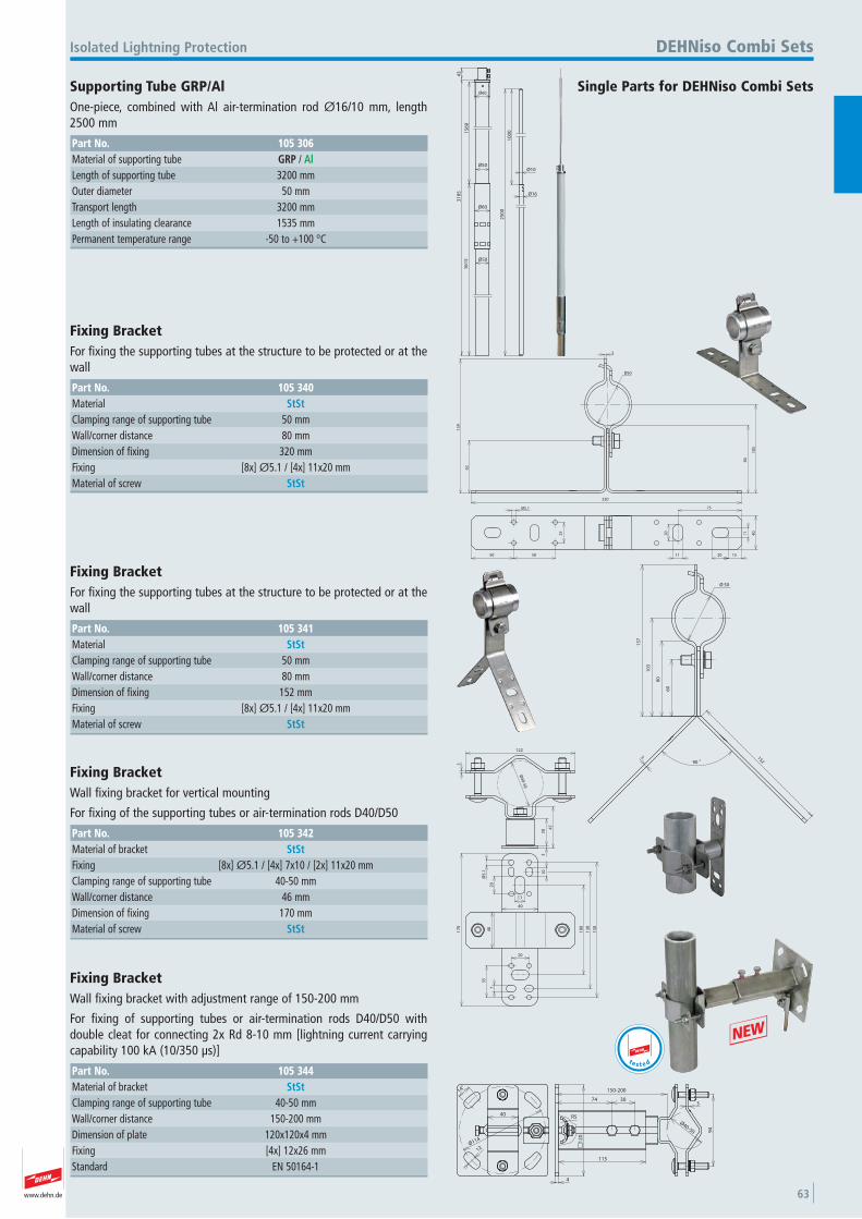
www.dehn.de 63
25
00
10
00
Ø10
Ø16
15
60
16
15
31
85
Ø60
Ø50
Ø50
Ø60
43
Single Parts for DEHNiso Combi Sets
Isolated Lightning Protection DEHNiso Combi Sets
Supporting Tube GRP/Al One-piece, combined with Al air-termination rod Ø16/10 mm, length2500 mm
Part No. 105 306Material of supporting tube GRP / AlLength of supporting tube 3200 mmOuter diameter 50 mmTransport length 3200 mmLength of insulating clearance 1535 mmPermanent temperature range -50 to +100 °C
Ø50
3
320
62
15
9
80
10
5
50 50 11 20
40
75
20
Ø5.1
25
15
11
Fixing Bracket For fixing the supporting tubes at the structure to be protected or at thewall
Part No. 105 340Material StStClamping range of supporting tube 50 mmWall/corner distance 80 mmDimension of fixing 320 mmFixing [8x] Ø5.1 / [4x] 11x20 mmMaterial of screw StSt
90 °152
60
50Ø
3
80
10
3
15
7
Fixing Bracket For fixing the supporting tubes at the structure to be protected or at thewall
Part No. 105 341Material StStClamping range of supporting tube 50 mmWall/corner distance 80 mmDimension of fixing 152 mmFixing [8x] Ø5.1 / [4x] 11x20 mmMaterial of screw StSt
45
Ø40-50
30
3
3
122
40
7
Ø5
.13
54
0
17
0
10
11
20
15
0
13
0
20
10
0
Fixing Bracket Wall fixing bracket for vertical mounting
For fixing of the supporting tubes or air-termination rods D40/D50
Part No. 105 342Material of bracket StStFixing [8x] Ø5.1 / [4x] 7x10 / [2x] 11x20 mmClamping range of supporting tube 40-50 mmWall/corner distance 46 mmDimension of fixing 170 mmMaterial of screw StSt
14°
12
40
Ø114 12
0
4
115
74 303
94
150-200
Ø40-50
R5
Fixing Bracket Wall fixing bracket with adjustment range of 150-200 mm
For fixing of supporting tubes or air-termination rods D40/D50 with double cleat for connecting 2x Rd 8-10 mm [lightning current carryingcapability 100 kA (10/350 μs)]
Part No. 105 344Material of bracket StStClamping range of supporting tube 40-50 mmWall/corner distance 150-200 mmDimension of plate 120x120x4 mmFixing [4x] 12x26 mmStandard EN 50164-1
+t e s t e d
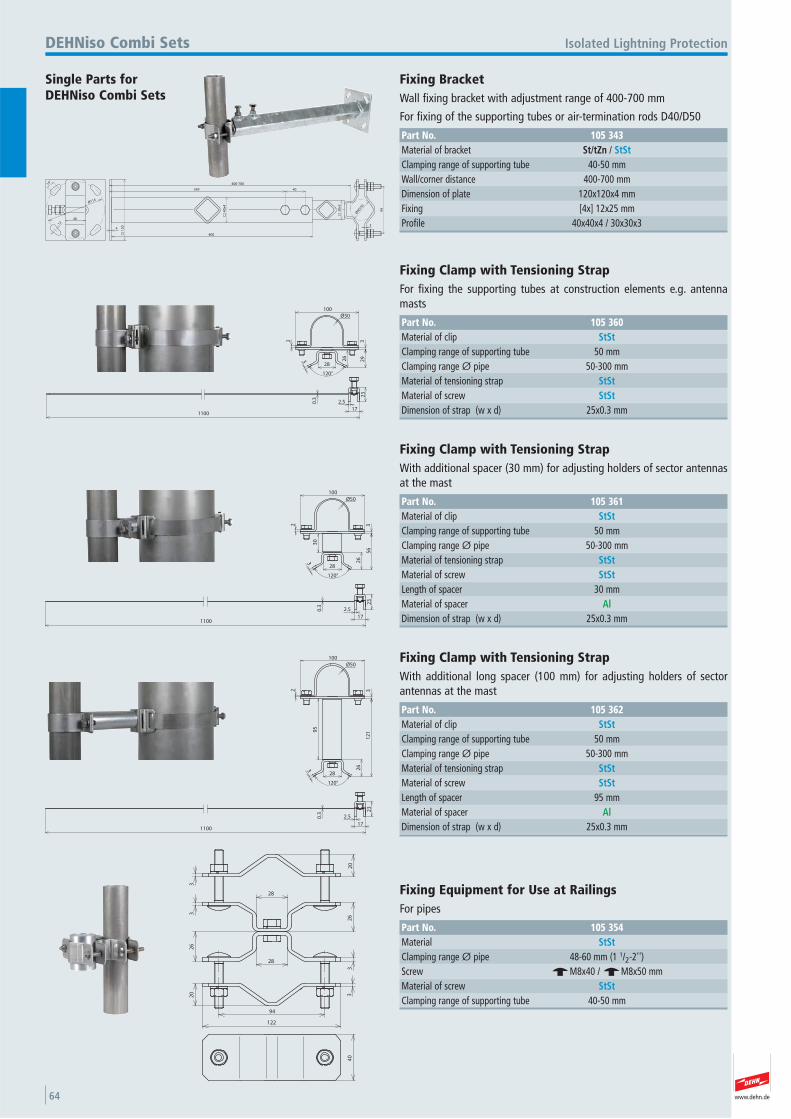
www.dehn.de64
400
349 40
400-700
94
Ø40/5
0
34 1
20
1240
14°
40
x4
30
x3
Ø114
Single Parts for DEHNiso Combi Sets
Isolated Lightning ProtectionDEHNiso Combi Sets
Fixing Bracket Wall fixing bracket with adjustment range of 400-700 mm
For fixing of the supporting tubes or air-termination rods D40/D50
Part No. 105 343Material of bracket St/tZn / StStClamping range of supporting tube 40-50 mmWall/corner distance 400-700 mmDimension of plate 120x120x4 mmFixing [4x] 12x25 mmProfile 40x40x4 / 30x30x3
2 3
100
3 26
29
28
Ø50
120°
2.5
17
23
0.3
1100
Fixing Clamp with Tensioning Strap For fixing the supporting tubes at construction elements e.g. antennamasts
Part No. 105 360Material of clip StStClamping range of supporting tube 50 mmClamping range Ø pipe 50-300 mmMaterial of tensioning strap StStMaterial of screw StStDimension of strap (w x d) 25x0.3 mm
2 3
100
3 26
56
28
30
Ø50
120°
2.5
17
23
0.3
1100
Fixing Clamp with Tensioning Strap With additional spacer (30 mm) for adjusting holders of sector antennasat the mast
Part No. 105 361Material of clip StStClamping range of supporting tube 50 mmClamping range Ø pipe 50-300 mmMaterial of tensioning strap StStMaterial of screw StStLength of spacer 30 mmMaterial of spacer AlDimension of strap (w x d) 25x0.3 mm
2 3
100
3 26
12
1
28
95
Ø50
120°
2.5
17
23
0.3
1100
Fixing Clamp with Tensioning Strap With additional long spacer (100 mm) for adjusting holders of sectorantennas at the mast
Part No. 105 362Material of clip StStClamping range of supporting tube 50 mmClamping range Ø pipe 50-300 mmMaterial of tensioning strap StStMaterial of screw StStLength of spacer 95 mmMaterial of spacer AlDimension of strap (w x d) 25x0.3 mm
28
28
20
33
26
20 3
32
6
94
122
40
Fixing Equipment for Use at Railings For pipes
Part No. 105 354Material StStClamping range Ø pipe 48-60 mm (1 1/2-2'') Screw e M8x40 / e M8x50 mmMaterial of screw StStClamping range of supporting tube 40-50 mm
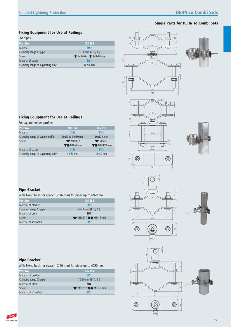
www.dehn.de 65
94
203
3
28
28
26
36
31
33
130
158
Single Parts for DEHNiso Combi Sets
Isolated Lightning Protection DEHNiso Combi Sets
Fixing Equipment for Use at Railings For pipes
Part No. 105 355Material StStClamping range Ø pipe 70-90 mm (2 1/4-3'') Screw e M8x40 / e M8x70 mmMaterial of screw StStClamping range of supporting tube 40-50 mm
20
26
20
-50
/12
0
60/70
88/98
5
33
28
50/60
122
40
Rd40-50
Fixing Equipment for Use at Railings For square hollow profiles
Part No. 105 356 105 376Material StSt StStClamping range of square profile 20x20 to 50x50 mm 60x120 mmScrew e M8x40 / e M8x40 /
di M8x70 mm di M8x150 mmMaterial of screw StSt StStClamping range of supporting tube 40-50 mm 40-50 mm
28
94
122
10
45
3 26
3 20
Ø16.5
40
Pipe Bracket With fixing bush for spacer (Ø16 mm) for pipes up to Ø60 mm
Part No. 106 352Material of bracket StStClamping range Ø pipe 40-60 mm (1 1/4-2'') Material of bush ZDCScrew e M8x50 / di M8x12 mmMaterial of screw/nut StSt
28
10
33
36
31
45
158
130
40
Ø16.5
Pipe Bracket With fixing bush for spacer (Ø16 mm) for pipes up to Ø90 mm
Part No. 106 353Material of bracket StStClamping range Ø pipe 70-90 mm (2 1/4-3'') Material of bush ZDCScrew e M8x70 / di M8x12 mmMaterial of screw/nut StSt
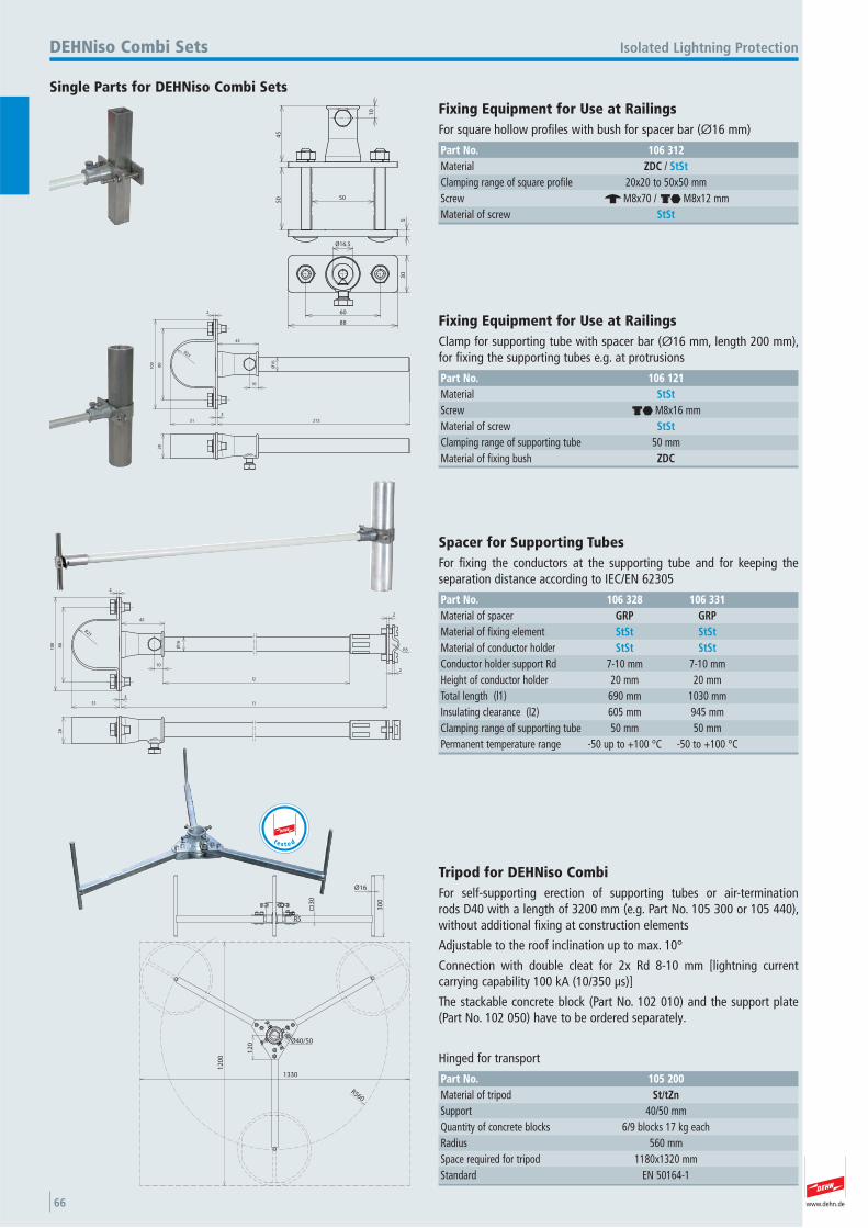
www.dehn.de66
50
45
10
5
50
30
60
88
Ø16.5
Single Parts for DEHNiso Combi Sets
Isolated Lightning ProtectionDEHNiso Combi Sets
Fixing Equipment for Use at Railings For square hollow profiles with bush for spacer bar (Ø16 mm)
Part No. 106 312Material ZDC / StStClamping range of square profile 20x20 to 50x50 mmScrew e M8x70 / di M8x12 mmMaterial of screw StSt
R25
80
10
0
2
3
21551
10
45
28
Ø1
6
Fixing Equipment for Use at Railings Clamp for supporting tube with spacer bar (Ø16 mm, length 200 mm),for fixing the supporting tubes e.g. at protrusions
Part No. 106 121Material StStScrew di M8x16 mmMaterial of screw StStClamping range of supporting tube 50 mmMaterial of fixing bush ZDC
R25
80
10
0
2
3
l151
10
452
2
R5
l2
28
Ø1
6
Spacer for Supporting Tubes For fixing the conductors at the supporting tube and for keeping the separation distance according to IEC/EN 62305
Part No. 106 328 106 331Material of spacer GRP GRPMaterial of fixing element StSt StStMaterial of conductor holder StSt StStConductor holder support Rd 7-10 mm 7-10 mmHeight of conductor holder 20 mm 20 mmTotal length (l1) 690 mm 1030 mmInsulating clearance (l2) 605 mm 945 mmClamping range of supporting tube 50 mm 50 mmPermanent temperature range -50 up to +100 °C -50 to +100 °C
12
00
1330
12
0
R560
30
0
Ø16
30
R5
Ø40/50
Tripod for DEHNiso Combi For self-supporting erection of supporting tubes or air-termination rods D40 with a length of 3200 mm (e.g. Part No. 105 300 or 105 440),without additional fixing at construction elements
Adjustable to the roof inclination up to max. 10°
Connection with double cleat for 2x Rd 8-10 mm [lightning current carrying capability 100 kA (10/350 μs)]
The stackable concrete block (Part No. 102 010) and the support plate(Part No. 102 050) have to be ordered separately.
Hinged for transport
Part No. 105 200Material of tripod St/tZnSupport 40/50 mmQuantity of concrete blocks 6/9 blocks 17 kg each Radius 560 mmSpace required for tripod 1180x1320 mmStandard EN 50164-1
t e s t e d
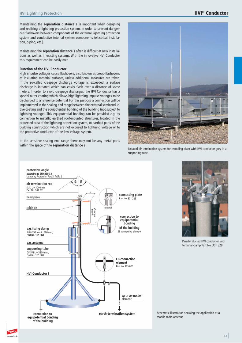
www.dehn.de 67
Maintaining the separation distance s is important when designingand realising a lightning protection system, in order to prevent danger-ous flashovers between components of the external lightning protectionsystem and conductive internal system components (electrical installa-tion, piping, etc.).
Maintaining the separation distance s often is difficult at new installa-tions as well as in existing systems. With the innovative HVI Conductorthis requirement can be easily met.
Function of the HVI Conductor:High impulse voltages cause flashovers, also known as creep-flashovers,at insulating material surfaces, unless additional measures are taken. If the so-called creepage discharge voltage is exceeded, a surface discharge is initiated which can easily flash over a distance of somemeters. In order to avoid creepage discharges, the HVI Conductor has aspecial outer coating which allows high lightning impulse voltages to bedischarged to a reference potential. For this purpose a connection will beimplemented in the sealing end range between the external semiconduc-tive coating and the equipotential bonding of the building (not subject tolightning voltage). This equipotential bonding can be provided e.g. byconnection to metallic earthed roof-mounted structures, located in theprotected area of the lightning protection system, to earthed parts of thebuilding construction which are not exposed to lightning voltage or tothe protective conductor of the low-voltage system.
In the sensitive sealing end range there may not be any metal parts within the space of the separation distance s.
Isolated air-termination system for recooling plant with HVI conductor grey in asupporting tube
HVI Lightning Protection HVI® Conductor
otective anglepraccording to EN 62305-3
101 001.art NoP L = 1000 mmStSt,
od-termination rair
head piece
aTTaart 3,Lightning Protection Paccording to EN 62305-3
aaable 2
s
301 229.art NoPPaconnecting plate
cable tie
105 360art NoP90 mm to 300 mm,ØStSt
fixing clamp..ge
optional
unit
rang
ese
alin
g
EB connecting elementof the building
bondingequipotentialconnection to
105 360.art NoP
105 300.art NoPGFK/AI L = 3200 mm,supporting tube
antenna..ge
elementEB connection
elementEB connection
HVI Conductor I
P
earth connection
405 020.art NoP
of the buildingequipotential bonding
connection to
equipotential bonding
earth-termination system
earth-termination system
elementearth connection
Schematic illustration showing the application at amobile radio antenna
Parallel ducted HVI conductor withterminal clamp Part No. 301 329
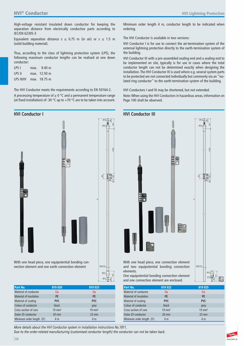
www.dehn.de68
Ø20/23
2749
36
Ø1
11
45
0
Ø10
Ø25
l1
10
5
40
40
10
7
Ø10
Ø23
With one head piece, one equipotential bonding con-nection element and one earth connection element
HVI Lightning Protection
HVI Conductor I
Part No. 819 020 819 023Material of conductor Cu CuMaterial of insulation PE PEMaterial of coating PVC PVCColour of conductor black grey Cross section of core 19 mm2 19 mm2
Outer Ø conductor 20 mm 23 mmMinimum order length (l1) 4 m 4 m
More details about the HVI Conductor system in installation instructions No.1811. Due to the order-related manufacturing (customised conductor length) the conductor can not be taken back.
HVI® Conductor
High-voltage resistant insulated down conductor for keeping the separation distance from electrically conductive parts according to IEC/EN 62305-3
Equivalent separation distance s ≤ 0.75 m (in air) or s ≤ 1.5 m (solid building material).
Thus, according to the class of lightning protection system (LPS), the following maximum conductor lengths can be realised at one down conductor:
LPS I max. 9.40 m
LPS II max. 12.50 m
LPS III/IV max. 18.75 m
The HVI Conductor meets the requirements according to EN 50164-2.
A processing temperature of ≥ 0 °C and a permanent temperature range(at fixed installation) of -30 °C up to +70 °C are to be taken into account.
Minimum order length 4 m, conductor length to be indicated when ordering.
The HVI Conductor is available in two versions:
HVI Conductor I is for use to connect the air-termination system of theexternal lightning protection directly to the earth-termination system ofthe building.
HVI Conductor III with a pre-assembled sealing end and a sealing end tobe implemented on site, typically is for use in cases where the total conductor length can not be determined exactly when designing theinstallation. The HVI Conductor III is used where e.g. several system partsto be protected are not connected individually but commonly via an "iso-lated ring conductor" to the earth-termination system of the building.
HVI Conductors I and III may be shortened, but not extended.
Note: When using the HVI Conductors in hazardous areas, information onPage 100 shall be observed.
10
7
40
Ø10
Ø23
Ø20/23
2749
36
Ø1
11
45
0
Ø10
Ø25
l1
10
7
40
With one head piece, one connection elementand two equipotential bonding connection elements. One equipotential bonding connection elementand one connection element are enclosed.
HVI Conductor III
Part No. 819 022 819 025Material of conductor Cu CuMaterial of insulation PE PEMaterial of coating PVC PVCColour of conductor black grey Cross section of core 19 mm2 19 mm2
Outer Ø conductor 20 mm 23 mmMinimum order length (l1) 4 m 4 m
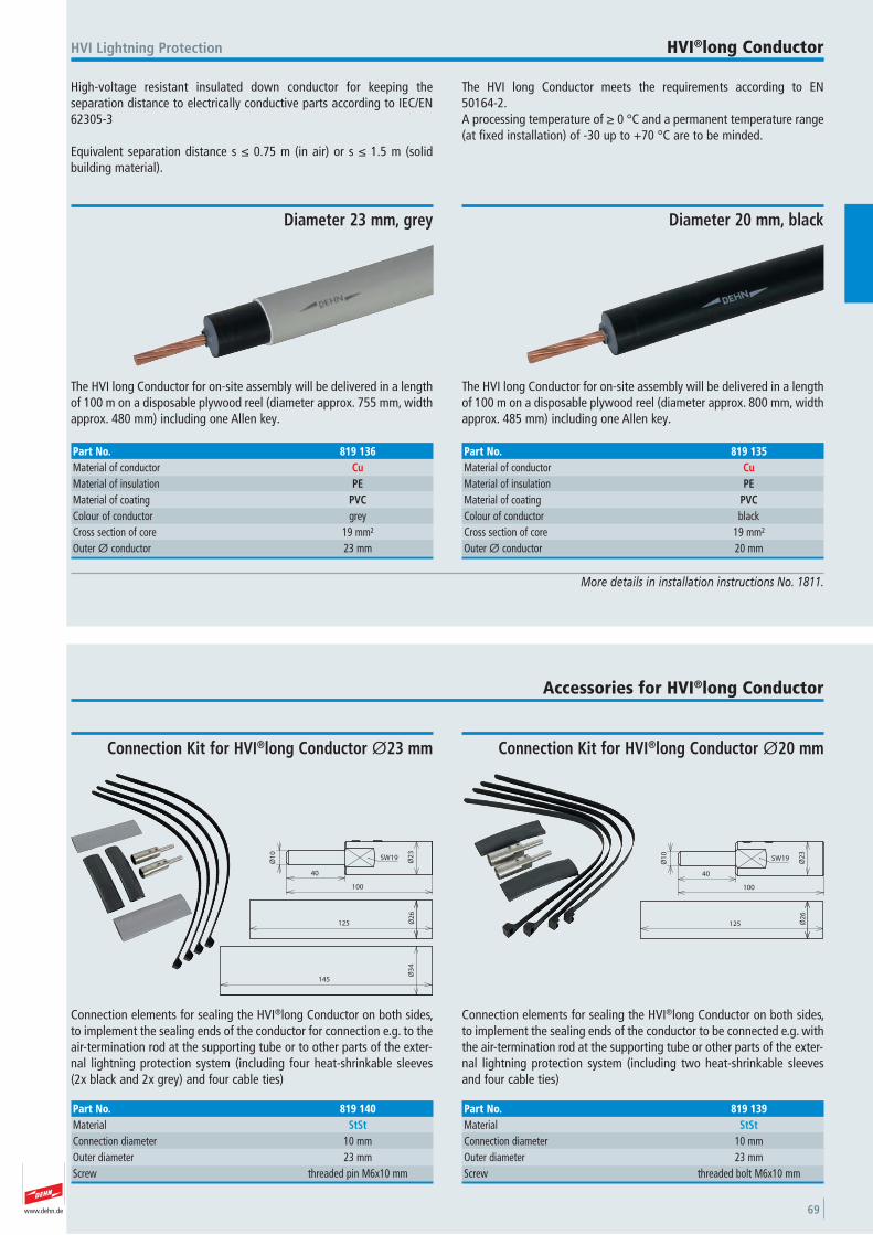
www.dehn.de 69
High-voltage resistant insulated down conductor for keeping the separation distance to electrically conductive parts according to IEC/EN62305-3
Equivalent separation distance s ≤ 0.75 m (in air) or s ≤ 1.5 m (solidbuilding material).
The HVI long Conductor meets the requirements according to EN 50164-2.A processing temperature of ≥ 0 °C and a permanent temperature range(at fixed installation) of -30 up to +70 °C are to be minded.
HVI Lightning Protection HVI®long Conductor
More details in installation instructions No. 1811.
The HVI long Conductor for on-site assembly will be delivered in a lengthof 100 m on a disposable plywood reel (diameter approx. 800 mm, widthapprox. 485 mm) including one Allen key.
Diameter 20 mm, black
Part No. 819 135Material of conductor CuMaterial of insulation PEMaterial of coating PVCColour of conductor black Cross section of core 19 mm²Outer Ø conductor 20 mm
The HVI long Conductor for on-site assembly will be delivered in a lengthof 100 m on a disposable plywood reel (diameter approx. 755 mm, widthapprox. 480 mm) including one Allen key.
Diameter 23 mm, grey
Part No. 819 136Material of conductor CuMaterial of insulation PEMaterial of coating PVCColour of conductor grey Cross section of core 19 mm²Outer Ø conductor 23 mm
Accessories for HVI®long Conductor
40
100
125
SW19
Ø1
0
Ø2
3Ø
26
Connection elements for sealing the HVI®long Conductor on both sides,to implement the sealing ends of the conductor to be connected e.g. withthe air-termination rod at the supporting tube or other parts of the exter-nal lightning protection system (including two heat-shrinkable sleevesand four cable ties)
Connection Kit for HVI®long Conductor Ø20 mm
Part No. 819 139Material StStConnection diameter 10 mmOuter diameter 23 mmScrew threaded bolt M6x10 mm
40
100
125
SW19
Ø1
0
Ø2
3Ø
26
145
Ø3
4
Connection elements for sealing the HVI®long Conductor on both sides,to implement the sealing ends of the conductor for connection e.g. to theair-termination rod at the supporting tube or to other parts of the exter-nal lightning protection system (including four heat-shrinkable sleeves(2x black and 2x grey) and four cable ties)
Connection Kit for HVI®long Conductor Ø23 mm
Part No. 819 140Material StStConnection diameter 10 mmOuter diameter 23 mmScrew threaded pin M6x10 mm
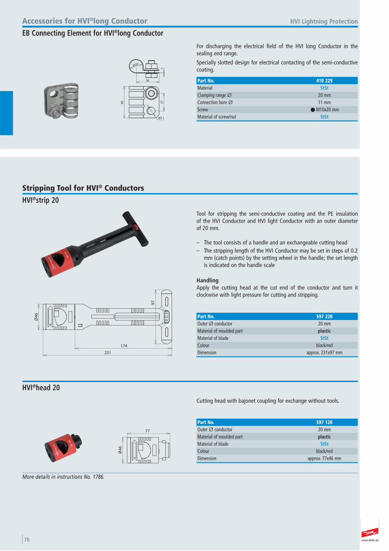
www.dehn.de70
49
Ø11
27
Ø20
1
36
For discharging the electrical field of the HVI long Conductor in the sealing end range.
Specially slotted design for electrical contacting of the semi-conductivecoating.
HVI Lightning ProtectionAccessories for HVI®long Conductor
EB Connecting Element for HVI®long Conductor
Part No. 410 229Material StStClamping range Ø 20 mmConnection bore Ø 11 mmScrew i M10x20 mmMaterial of screw/nut StSt
More details in instructions No. 1786.
97
174
231
Ø4
6
Tool for stripping the semi-conductive coating and the PE insulation of the HVI Conductor and HVI light Conductor with an outer diameter of 20 mm.
– The tool consists of a handle and an exchangeable cutting head– The stripping length of the HVI Conductor may be set in steps of 0.2
mm (catch points) by the setting wheel in the handle; the set lengthis indicated on the handle scale
HandlingApply the cutting head at the cut end of the conductor and turn it clockwise with light pressure for cutting and stripping.
Stripping Tool for HVI® Conductors
HVI®strip 20
Part No. 597 220Outer Ø conductor 20 mmMaterial of moulded part plasticMaterial of blade StStColour black/red Dimension approx. 231x97 mm
77
Ø4
6
Cutting head with bajonet coupling for exchange without tools.
HVI®head 20
Part No. 597 120Outer Ø conductor 20 mmMaterial of moulded part plasticMaterial of blade StStColour black/red Dimension approx. 77x46 mm
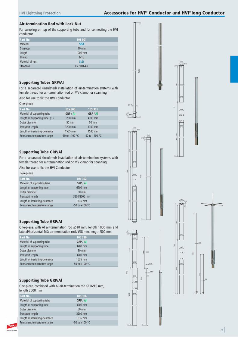
www.dehn.de 71
HVI Lightning Protection Accessories for HVI® Conductor and HVI®long Conductor
10
00
Ø10
30 M10
Air-termination Rod with Lock Nut For screwing on top of the supporting tube and for connecting the HVIconductor
Part No. 101 001Material StStDiameter 10 mmLength 1000 mmThread M10 Material of nut StStStandard EN 50164-2
30
00
28
M45
15
60
16
25
32
00
Ø60
Ø50
Ø50
M10
Ø60
Supporting Tube GRP/Al For a separated (insulated) installation of air-termination systems withfemale thread for air-termination rod or MV clamp for spanning
Also for use to fix the HVI Conductor
Two-piece
Part No. 105 302Material of supporting tube GRP / AlLength of supporting tube 6200 mmOuter diameter 50 mmTransport length 3200/3000 mmLength of insulating clearance 1535 mmPermanent temperature range -50 to +100 °C
Ø60
Ø50
M10
M8
Ø60
15
35
16
50
32
00
10
00
50
0
Ø10
Ø8
Ø50
Supporting Tube GRP/Al One-piece, with Al air-termination rod Ø10 mm, length 1000 mm andlateral/horizontal StSt air-termination rods Ø8 mm, length 500 mm
Part No. 105 310Material of supporting tube GRP / AlLength of supporting tube 3200 mmOuter diameter 50 mmTransport length 3200 mmLength of insulating clearance 1535 mmPermanent temperature range -50 to +100 °C
25
00
10
00
Ø10
Ø16
15
60
16
15
31
85
Ø60
Ø50
Ø50
Ø60
43
Supporting Tube GRP/Al One-piece, combined with Al air-termination rod Ø16/10 mm, length 2500 mm
Part No. 105 306Material of supporting tube GRP / AlLength of supporting tube 3200 mmOuter diameter 50 mmTransport length 3200 mmLength of insulating clearance 1535 mmPermanent temperature range -50 to +100 °C
15
35
16
50
/ 3
15
0
l1
Ø60
Ø50
Ø50
M10
Ø60
Supporting Tubes GRP/Al For a separated (insulated) installation of air-termination systems withfemale thread for air-termination rod or MV clamp for spanning
Also for use to fix the HVI Conductor
One-piece
Part No. 105 300 105 301Material of supporting tube GRP / Al GRP / AlLength of supporting tube (l1) 3200 mm 4700 mmOuter diameter 50 mm 50 mmTransport length 3200 mm 4700 mmLength of insulating clearance 1535 mm 1535 mmPermanent temperature range -50 to +100 °C -50 to +100 °C
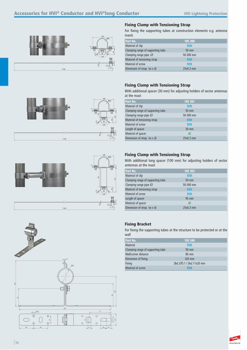
www.dehn.de72
2 3
100
3 26
29
28
Ø50
120°
2.5
17
23
0.3
1100
HVI Lightning ProtectionAccessories for HVI® Conductor and HVI®long Conductor
Fixing Clamp with Tensioning Strap For fixing the supporting tubes at construction elements e.g. antennamasts
Part No. 105 360Material of clip StStClamping range of supporting tube 50 mmClamping range pipe Ø 50-300 mmMaterial of tensioning strap StStMaterial of screw StStDimension of strap (w x d) 25x0.3 mm
2 3
100
3 26
56
28
30
Ø50
120°
2.5
17
23
0.3
1100
Fixing Clamp with Tensioning Strap With additional spacer (30 mm) for adjusting holders of sector antennasat the mast
Part No. 105 361Material of clip StStClamping range of supporting tube 50 mmClamping range pipe Ø 50-300 mmMaterial of tensioning strap StStMaterial of screw StStLength of spacer 30 mmMaterial of spacer AlDimension of strap (w x d) 25x0.3 mm
2 3
100
3 26
12
1
28
95
Ø50
120°
2.5
17
23
0.3
1100
Fixing Clamp with Tensioning Strap With additional long spacer (100 mm) for adjusting holders of sectorantennas at the mast
Part No. 105 362Material of clip StStClamping range of supporting tube 50 mmClamping range pipe Ø 50-300 mmMaterial of tensioning strap StStMaterial of screw StStLength of spacer 95 mmMaterial of spacer AlDimension of strap (w x d) 25x0.3 mm
Ø50
3
320
62
15
9
80
10
5
50 50 11 20
40
75
20
Ø5.1
25
15
11
Fixing Bracket For fixing the supporting tubes at the structure to be protected or at thewall
Part No. 105 340Material StStClamping range of supporting tube 50 mmWall/corner distance 80 mmDimension of fixing 320 mmFixing [8x] Ø5.1 / [4x] 11x20 mmMaterial of screw StSt
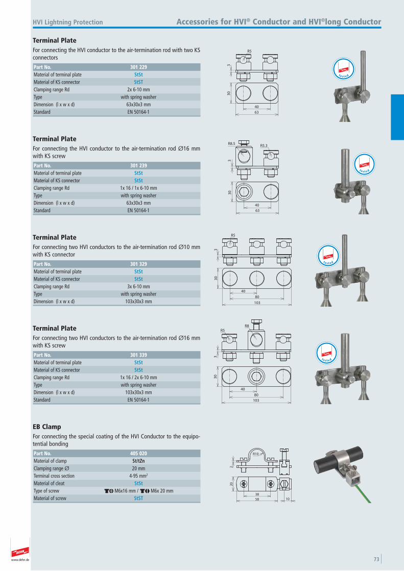
www.dehn.de 73
33
0
63
40
R5
HVI Lightning Protection Accessories for HVI® Conductor and HVI®long Conductor
Terminal Plate For connecting the HVI conductor to the air-termination rod with two KSconnectors
Part No. 301 229Material of terminal plate StStMaterial of KS connector StSTClamping range Rd 2x 6-10 mmType with spring washer Dimension (l x w x d) 63x30x3 mmStandard EN 50164-1
t e s t e d
3
R8.5R5.3
30
63
40
Terminal Plate For connecting the HVI conductor to the air-termination rod Ø16 mmwith KS screw
Part No. 301 239Material of terminal plate StStMaterial of KS connector StStClamping range Rd 1x 16 / 1x 6-10 mmType with spring washer Dimension (l x w x d) 63x30x3 mmStandard EN 50164-1
t e s t e d
R5
33
0
103
80
40
Terminal Plate For connecting two HVI conductors to the air-termination rod Ø10 mmwith KS connector
Part No. 301 329Material of terminal plate StStMaterial of KS connector StStClamping range Rd 3x 6-10 mmType with spring washer Dimension (l x w x d) 103x30x3 mm
t e s t e d
3
R5R8
103
30
40
80
Terminal Plate For connecting two HVI conductors to the air-termination rod Ø16 mmwith KS screw
Part No. 301 339Material of terminal plate StStMaterial of KS connector StStClamping range Rd 1x 16 / 2x 6-10 mmType with spring washer Dimension (l x w x d) 103x30x3 mmStandard EN 50164-1
t e s t e d
20
58 10
38
R10
2
EB Clamp For connecting the special coating of the HVI Conductor to the equipo-tential bonding
Part No. 405 020Material of clamp St/tZnClamping range Ø 20 mmTerminal cross section 4-95 mm2
Material of cleat StStType of screw dm M6x16 mm / dj M6x 20 mmMaterial of screw StST
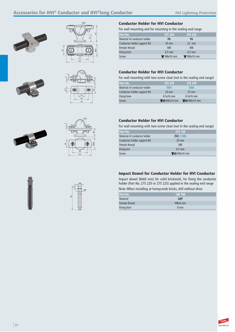
www.dehn.de74
19
42
Ød1
25
Ø3
0
69
44
HVI Lightning ProtectionAccessories for HVI® Conductor and HVI®long Conductor
Conductor Holder for HVI Conductor For wall mounting and for mounting in the sealing end range
Part No. 275 220 275 225Material of conductor holder PA PAConductor holder support Rd 20 mm 23 mmFemale thread M8 M8 Fixing bore 6.5 mm 6.5 mmScrew r M6x16 mm r M6x16 mm
R10
2
10
22
20
58
16
6.5
38
Conductor Holder for HVI Conductor For wall mounting with two-screw cleat (not in the sealing end range)
Part No. 275 229 275 239Material of conductor holder StSt StStConductor holder support Rd 20 mm 23 mmFixing bore 6.5x16 mm 6.5x16 mmScrew dm M6x14 mm dm M6x14 mm
20
2
R10
Ø3
0
58
20
38
Conductor Holder for HVI Conductor For wall mounting with two-screw cleat (not in the sealing end range)
Part No. 275 120Material of conductor holder ZDC / StStConductor holder support Rd 20 mmFemale thread M8 Fixing bor 6.5 mmScrew dm M6x16 mm
60
6
Ø8
M8
Impact Dowel for Conductor Holder for HVI Conductor Impact dowel (8x60 mm) for solid brickwork, for fixing the conductorholder (Part No. 275 220 or 275 225) applied in the sealing end range
Note: When installing at honeycomb bricks, drill without drive
Part No. 106 760Material GRPFemale thread M8x6 mmFixing bore 8 mm
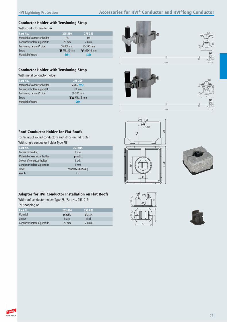
www.dehn.de 75
2.5
17
23
0.3
1100
41
26
61
120°
3
Ø20
HVI Lightning Protection Accessories for HVI® Conductor and HVI®long Conductor
Conductor Holder with Tensioning Strap With conductor holder PA
Part No. 275 330 275 333Material of conductor holder PA PAConductor holder support Rd 20 mm 23 mmTensioning range Ø pipe 50-300 mm 50-300 mmScrew r M6x16 mm r M6x16 mmMaterial of screw StSt StSt
2.5
17
23
0.3
1100
26
202
120°
61
3
Ø20
Conductor Holder with Tensioning Strap With metal conductor holder
Part No. 275 320Material of conductor holder ZDC / StStConductor holder support Rd 20 mmTensioning range Ø pipe 50-300 mmScrew dm M6x16 mmMaterial of screw StSt
56 7
0
R4
10
0
13
Ø4
7Roof Conductor Holder for Flat Roofs For fixing of round conductors and strips on flat roofs
With single conductor holder Type FB
Part No. 253 015Conductor leading loose Material of conductor holder plasticColour of conductor holder black Conductor holder support Rd 8 mmBlock concrete (C35/45)Weight 1 kg
Ø20
32
25
42
3220
Adapter for HVI Conductor Installation on Flat Roofs With roof conductor holder Type FB (Part No. 253 015)
For snapping on
Part No. 253 026 253 027Material plastic plasticColour black blackConductor holder support Rd 20 mm 23 mm
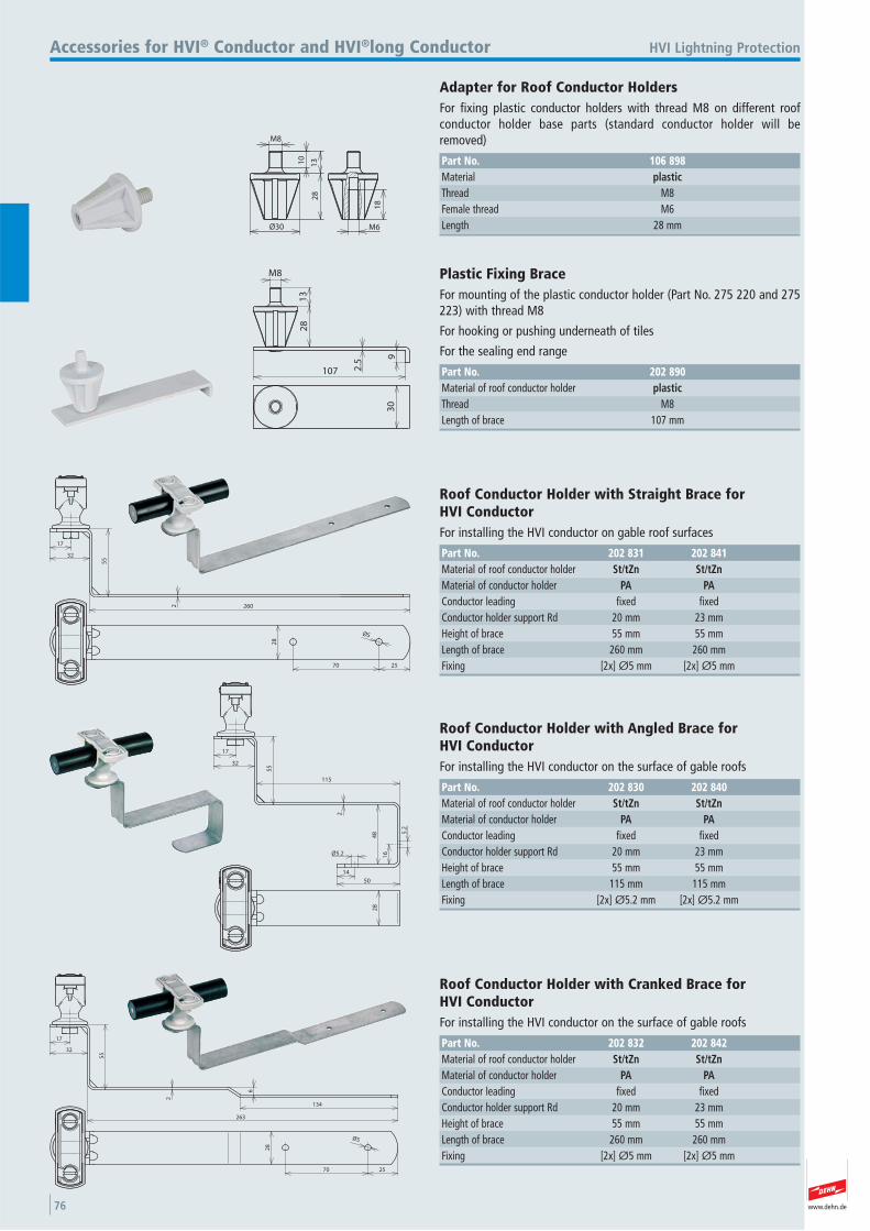
www.dehn.de76
M8
10
13
Ø30
28
18
M6
HVI Lightning ProtectionAccessories for HVI® Conductor and HVI®long Conductor
Adapter for Roof Conductor Holders For fixing plastic conductor holders with thread M8 on different roof conductor holder base parts (standard conductor holder will be removed)
Part No. 106 898Material plasticThread M8 Female thread M6 Length 28 mm
107
9
28
13
M8
2.5
30
Plastic Fixing Brace For mounting of the plastic conductor holder (Part No. 275 220 and 275223) with thread M8
For hooking or pushing underneath of tiles
For the sealing end range
Part No. 202 890Material of roof conductor holder plasticThread M8 Length of brace 107 mm
260
17
32
55
2
25
28
Ø5
70
Roof Conductor Holder with Straight Brace for HVI Conductor For installing the HVI conductor on gable roof surfaces
Part No. 202 831 202 841Material of roof conductor holder St/tZn St/tZnMaterial of conductor holder PA PAConductor leading fixed fixed Conductor holder support Rd 20 mm 23 mmHeight of brace 55 mm 55 mmLength of brace 260 mm 260 mmFixing [2x] Ø5 mm [2x] Ø5 mm
17
32
55
115
48
Ø5.2
14
50
2
16
5.2
28
Roof Conductor Holder with Angled Brace for HVI Conductor For installing the HVI conductor on the surface of gable roofs
Part No. 202 830 202 840Material of roof conductor holder St/tZn St/tZnMaterial of conductor holder PA PAConductor leading fixed fixed Conductor holder support Rd 20 mm 23 mmHeight of brace 55 mm 55 mmLength of brace 115 mm 115 mmFixing [2x] Ø5.2 mm [2x] Ø5.2 mm
17
32
55
2
25
28
Ø5
70
263
134
6
Roof Conductor Holder with Cranked Brace for HVI Conductor For installing the HVI conductor on the surface of gable roofs
Part No. 202 832 202 842Material of roof conductor holder St/tZn St/tZnMaterial of conductor holder PA PAConductor leading fixed fixed Conductor holder support Rd 20 mm 23 mmHeight of brace 55 mm 55 mmLength of brace 260 mm 260 mmFixing [2x] Ø5 mm [2x] Ø5 mm
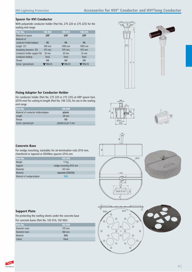
www.dehn.de 77
Ø16
l2 l11
9
Ød
1
HVI Lightning Protection Accessories for HVI® Conductor and HVI®long Conductor
Spacer for HVI Conductor With polyamide conductor holder (Part No. 275 220 or 275 225) for thesealing end range
Part No. 106 852 106 812 106 813Material of spacer GRP GRP GRPMaterial of conductor holder/adapter PA PA PALength (l1) 500 mm 1000 mm 1000 mmInsulating clearance (l2) 475 mm 975 mm 975 mmConductor holder support Rd 20 mm 20 mm 23 mmConductor leading fixed fixed fixed Thread M8 M8 M8 Screw / grooved pin r M6x16 r M6x16 r M6x16
284
1
M8
25
Ø5
12
Ø30
Ø16.5
Fixing Adapter for Conductor Holder For conductor holder (Part No. 275 220 or 275 225) at GRP spacer bars(Ø16 mm) for cutting to length (Part No. 106 125), for use in the sealingend range
Part No. 106 899Material of conductor holder/adapter plasticLength 28 mmThread M8 Screw / grooved pin cylindrical pin 5 mm
60
18
90
325
Ø337
28
26
41
80114
40depth 40 mm
Concrete Base For wedge mounting, stackable, for air-termination rods Ø16 mm, chamfered or tapered or DEHNiso spacers Ø16 mm
Part No. 102 010Weight 17 kgSupport wedge mounting Ø16 mmDiameter 337 mmMaterial concrete (C45/55)Material of wedge/adapter StSt
10
3.5
Ø360 Ø370Support Plate For protecting the roofing sheets under the concrete base
For concrete bases (Part No. 102 010, 102 002)
Part No. 102 050Diameter outer 370 mmDiameter inner 360 mmMaterial EVAColour black
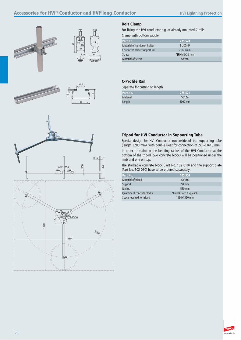
www.dehn.de78
50
23
R12
R10.7
24
34
HVI Lightning ProtectionAccessories for HVI® Conductor and HVI®long Conductor
Bolt Clamp For fixing the HVI conductor e.g. at already mounted C rails
Clamp with bottom saddle
Part No. 275 520Material of conductor holder St/tZn-PConductor holder support Rd 20/23 mmScrew dh M6x25 mmMaterial of screw St/tZn
16.5
18
35
1.5
C-Profile Rail Separate for cutting to length
Part No. 275 521Material St/tZnLength 2000 mm
12
00
1330
R560
30
30
0
Ø16
R5
12
0 Ø40/50
Tripod for HVI Conductor in Supporting Tube Special design for HVI Conductor run inside of the supporting tube(length 3200 mm), with double cleat for connection of 2x Rd 8-10 mm
In order to maintain the bending radius of the HVI Conductor at the bottom of the tripod, two concrete blocks will be positioned under thelimb and one on top.
The stackable concrete block (Part No. 102 010) and the support plate(Part No. 102 050) have to be ordered separately.
Part No. 105 350Material of tripod St/tZnSupport 50 mmRadius 560 mmQuantity of concrete blocks 9 blocks of 17 kg each Space required for tripod 1180x1320 mm
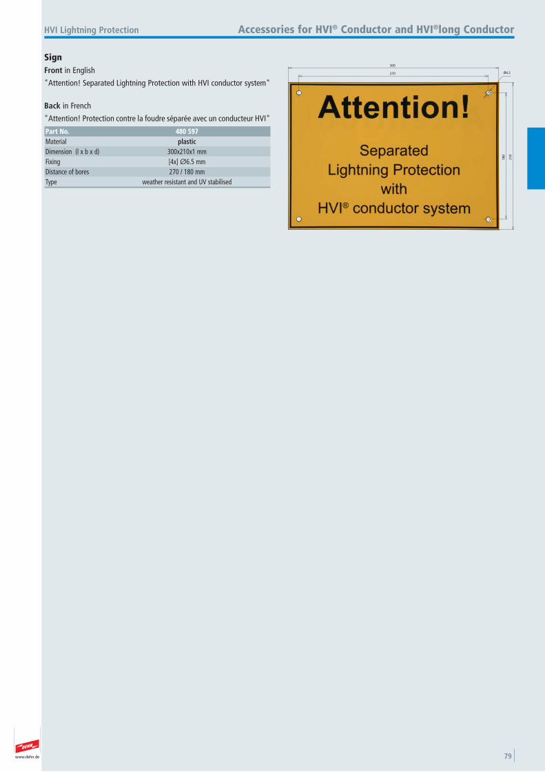
www.dehn.de 79
HVI Lightning Protection Accessories for HVI® Conductor and HVI®long Conductor
SignFront in English
"Attention! Separated Lightning Protection with HVI conductor system"
Back in French
"Attention! Protection contre la foudre séparée avec un conducteur HVI"
Part No. 480 597Material plasticDimension (l x b x d) 300x210x1 mmFixing [4x] Ø6.5 mmDistance of bores 270 / 180 mmType weather resistant and UV stabilised
270
300
18
0
21
0
Ø6.5
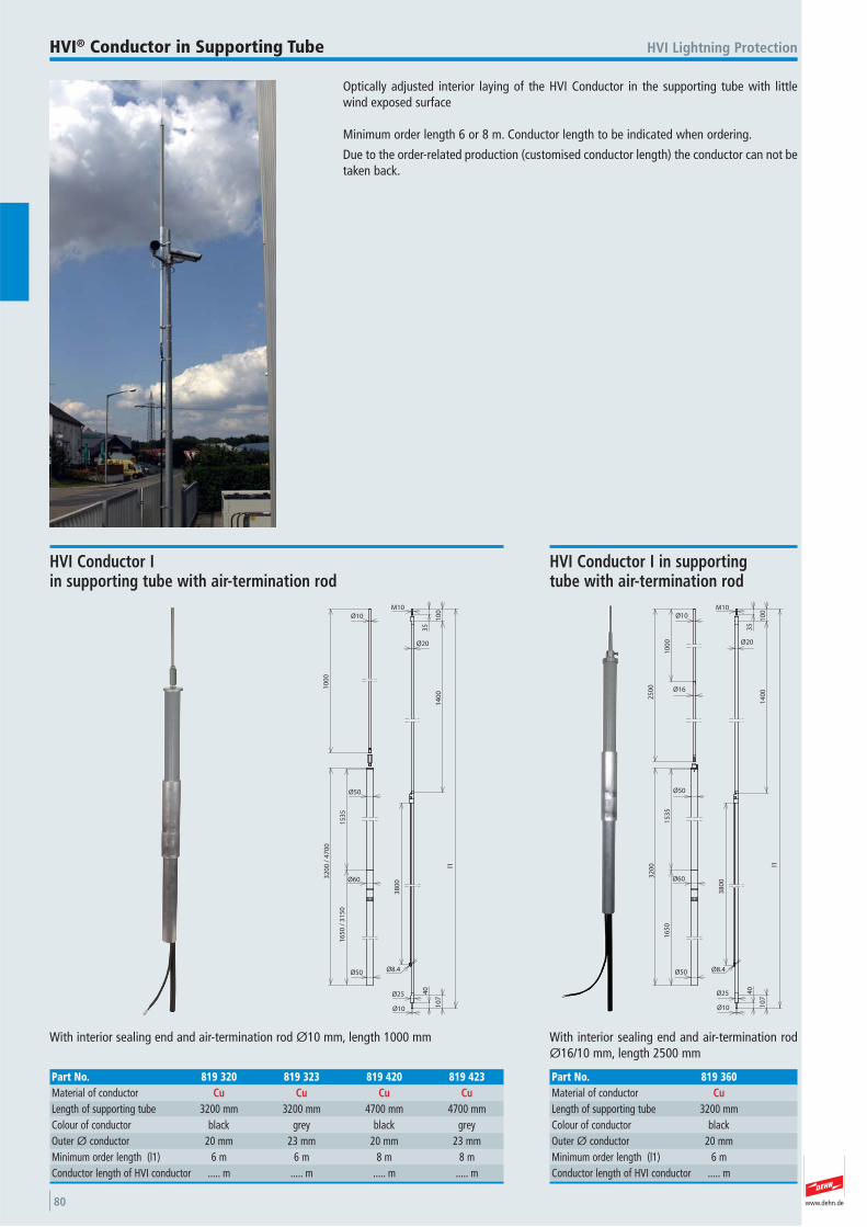
www.dehn.de80
Optically adjusted interior laying of the HVI Conductor in the supporting tube with littlewind exposed surface
Minimum order length 6 or 8 m. Conductor length to be indicated when ordering.
Due to the order-related production (customised conductor length) the conductor can not betaken back.
HVI Lightning ProtectionHVI® Conductor in Supporting Tube
10
00
Ø10
Ø50
15
35
M10
35
10
01
40
0
Ø20
16
50
/ 3
15
0
Ø60
Ø50
38
00
Ø10
40
10
7
Ø25
l1
32
00
/ 4
70
0
Ø8.4
With interior sealing end and air-termination rod Ø10 mm, length 1000 mm
HVI Conductor I in supporting tube with air-termination rod
Part No. 819 320 819 323 819 420 819 423Material of conductor Cu Cu Cu CuLength of supporting tube 3200 mm 3200 mm 4700 mm 4700 mmColour of conductor black grey black grey Outer Ø conductor 20 mm 23 mm 20 mm 23 mmMinimum order length (l1) 6 m 6 m 8 m 8 mConductor length of HVI conductor ..... m ..... m ..... m ..... m
Ø50
15
35
M10
35
10
01
40
0
Ø20
16
50
Ø60
Ø50
38
00
Ø10
40
10
7
Ø25
l1
32
00
10
00
25
00 Ø16
Ø10
Ø8.4
With interior sealing end and air-termination rodØ16/10 mm, length 2500 mm
HVI Conductor I in supporting tube with air-termination rod
Part No. 819 360Material of conductor CuLength of supporting tube 3200 mmColour of conductor black Outer Ø conductor 20 mmMinimum order length (l1) 6 mConductor length of HVI conductor ..... m
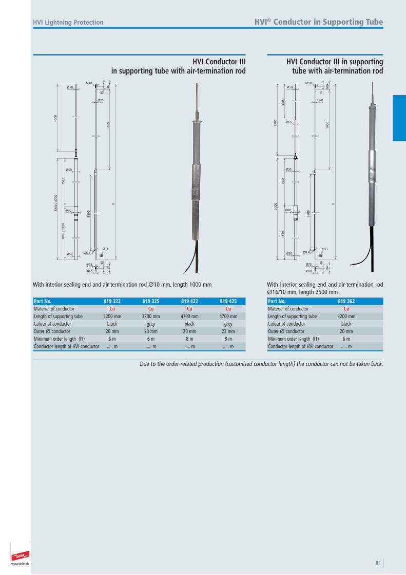
www.dehn.de 81
Due to the order-related production (customised conductor length) the conductor can not be taken back.
Ø50
15
35
M10
50
10
01
40
0
Ø20
16
50
/ 3
15
0
Ø60
Ø50
38
00
Ø10
40
10
7
Ø23
l1
32
00
/ 4
70
01
00
0
Ø10
Ø8.4Ø11
With interior sealing end and air-termination rod Ø10 mm, length 1000 mm
HVI Lightning Protection
HVI Conductor III in supporting tube with air-termination rod
HVI® Conductor in Supporting Tube
Part No. 819 322 819 325 819 422 819 425Material of conductor Cu Cu Cu CuLength of supporting tube 3200 mm 3200 mm 4700 mm 4700 mmColour of conductor black grey black grey Outer Ø conductor 20 mm 23 mm 20 mm 23 mmMinimum order length (l1) 6 m 6 m 8 m 8 mConductor length of HVI conductor ..... m ..... m ..... m ..... m
Ø50
15
35
M10
35
10
01
40
0
Ø20
16
50
Ø60
Ø50
38
00
Ø10
40
10
7
Ø23
l1
32
00
10
00
25
00
Ø16
Ø10
Ø8.4Ø11
With interior sealing end and air-termination rodØ16/10 mm, length 2500 mm
HVI Conductor III in supporting tube with air-termination rod
Part No. 819 362Material of conductor CuLength of supporting tube 3200 mmColour of conductor black Outer Ø conductor 20 mmMinimum order length (l1) 6 mConductor length of HVI conductor ..... m
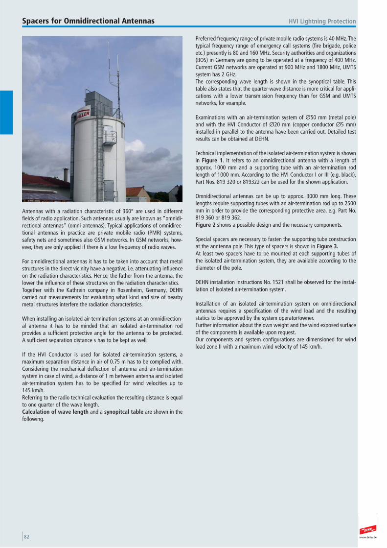
www.dehn.de82
Antennas with a radiation characteristic of 360° are used in differentfields of radio application. Such antennas usually are known as “omnidi-rectional antennas” (omni antennas). Typical applications of omnidirec-tional antennas in practice are private mobile radio (PMR) systems, safety nets and sometimes also GSM networks. In GSM networks, how-ever, they are only applied if there is a low frequency of radio waves.
For omnidirectional antennas it has to be taken into account that metalstructures in the direct vicinity have a negative, i.e. attenuating influenceon the radiation characteristics. Hence, the father from the antenna, thelower the influence of these structures on the radiation characteristics.Together with the Kathrein company in Rosenheim, Germany, DEHN carried out measurements for evaluating what kind and size of nearbymetal structures interfere the radiation characteristics.
When installing an isolated air-termination systems at an omnidirection-al antenna it has to be minded that an isolated air-termination rod provides a sufficient protective angle for the antenna to be protected. A sufficient separation distance s has to be kept as well.
If the HVI Conductor is used for isolated air-termination systems, a maximum separation distance in air of 0.75 m has to be complied with.Considering the mechanical deflection of antenna and air-terminationsystem in case of wind, a distance of 1 m between antenna and isolatedair-termination system has to be specified for wind velocities up to 145 km/h.Referring to the radio technical evaluation the resulting distance is equalto one quarter of the wave length. Calculation of wave length and a synopitcal table are shown in thefollowing.
Preferred frequency range of private mobile radio systems is 40 MHz. Thetypical frequency range of emergency call systems (fire brigade, policeetc.) presently is 80 and 160 MHz. Security authorities and organizations(BOS) in Germany are going to be operated at a frequency of 400 MHz.Current GSM networks are operated at 900 MHz and 1800 MHz, UMTSsystem has 2 GHz.The corresponding wave length is shown in the synoptical table. Thistable also states that the quarter-wave distance is more critical for appli-cations with a lower transmission frequency than for GSM and UMTSnetworks, for example.
Examinations with an air-termination system of Ø50 mm (metal pole)and with the HVI Conductor of Ø20 mm (copper conductor Ø5 mm)installed in parallel to the antenna have been carried out. Detailed testresults can be obtained at DEHN.
Technical implementation of the isolated air-termination system is shownin Figure 1. It refers to an omnidirectional antenna with a length ofapprox. 1000 mm and a supporting tube with an air-termination rodlength of 1000 mm. According to the HVI Conductor I or III (e.g. black),Part Nos. 819 320 or 819322 can be used for the shown application.
Omnidirectional antennas can be up to approx. 3000 mm long. Theselengths require supporting tubes with an air-termination rod up to 2500mm in order to provide the corresponding protective area, e.g. Part No.819 360 or 819 362. Figure 2 shows a possible design and the necessary components.
Special spacers are necessary to fasten the supporting tube constructionat the anntenna pole. This type of spacers is shown in Figure 3.At least two spacers have to be mounted at each supporting tubes of the isolated air-termination system, they are available according to thediameter of the pole.
DEHN installation instructions No. 1521 shall be observed for the instal-lation of isolated air-termination system.
Installation of an isolated air-termination system on omnidirectionalantennas requires a specification of the wind load and the resulting statics to be approved by the system operator/owner.Further information about the own weight and the wind exposed surfaceof the components is available upon request. Our components and system configurations are dimensioned for windload zone II with a maximum wind velocity of 145 km/h.
HVI Lightning ProtectionSpacers for Omnidirectional Antennas
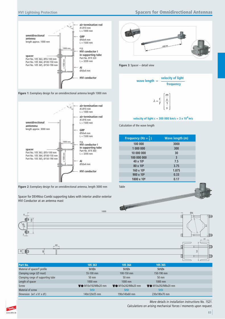
www.dehn.de 83
velocity of light c = 300 000 km/s = 3 x 10 m/s
wave length =velocity of light
frequency
cf
ms
s1
8
Calculation of the wave length
Frequency (Hz = Wave length (m)
100 000 30001 000 000 30010 000 000 30100 000 000 3
40 x 106 7.580 x 10⁶ 3.75160 x 10⁶ 1.875900 x 10⁶ 0.331800 x 10⁶ 0.17
)1s–
Table
HVI conductor
α
1000 mm
≥ 1
000
mm
omnidirectionalantennalength approx. 1000 mm
air-termination rodAl Ø10 mmL = 1000 mm
GRPØ50x4 mmL = 1500 mm
AlØ50x4 mm
spacerPart No. 105 363, Ø55-100 mmPart No. 105 364, Ø100-150 mmPart No. 105 365, Ø150-190 mm
e.g.HVI conductor Iin supporting tubePart No. 819 320L = 3200 mm
Figure 1: Exemplary design for an omnidirectional antenna length 1000 mm
HVI conductor
α
1000 mm
≥ 1
000
mm
omnidirectionalamtemmalength approx. 3000 mm
air-termination rodAl Ø10 mmL = 1000 mm
air-termination rodAl Ø16 mmL = 1500 mm
GRPØ50x4 mmL = 1500 mm
e.g.HVI conductor Iin supporting tubePart No. 819 360L = 3200 mm
AlØ50x4 mm
spacerPart No. 105 363, Ø55-100 mmPart No. 105 364, Ø100-150 mmPart No. 105 365, Ø150-190 mm
Figure 2: Exemplary design for an omnidirectional antenna, length 3000 mm
Figure 3: Spacer – detail view
More details in installation instructions No. 1521.Calculations on arising mechanical forces / moments upon request.
HVI Lightning Protection Spacers for Omnidirectional Antennas
Ød
b1
1000
Ø50
10
0
6
2
t1
h1
28
40
40
Spacer for DEHNiso Combi supporting tubes with interior and/or exteriorHVI Conductor at an antenna mast
Part No. 105 363 105 364 105 365Material of spacer/T profile St/tZn St/tZn St/tZnClamping range (Ø mast) 55-100 mm 100-150 mm 150-190 mmClamping range of supporting tube 50 mm 50 mm 50 mmLength of spacer 1000 mm 1000 mm 1000 mmScrew di M10x192/M8x20 mm di M10x242/M8x20 mm di M10x292/M8x20 mmMaterial of screw StSt StSt StStDimension (w1 x h1 x d1) 140x120x55 mm 190x140x60 mm 230x180x70 mm
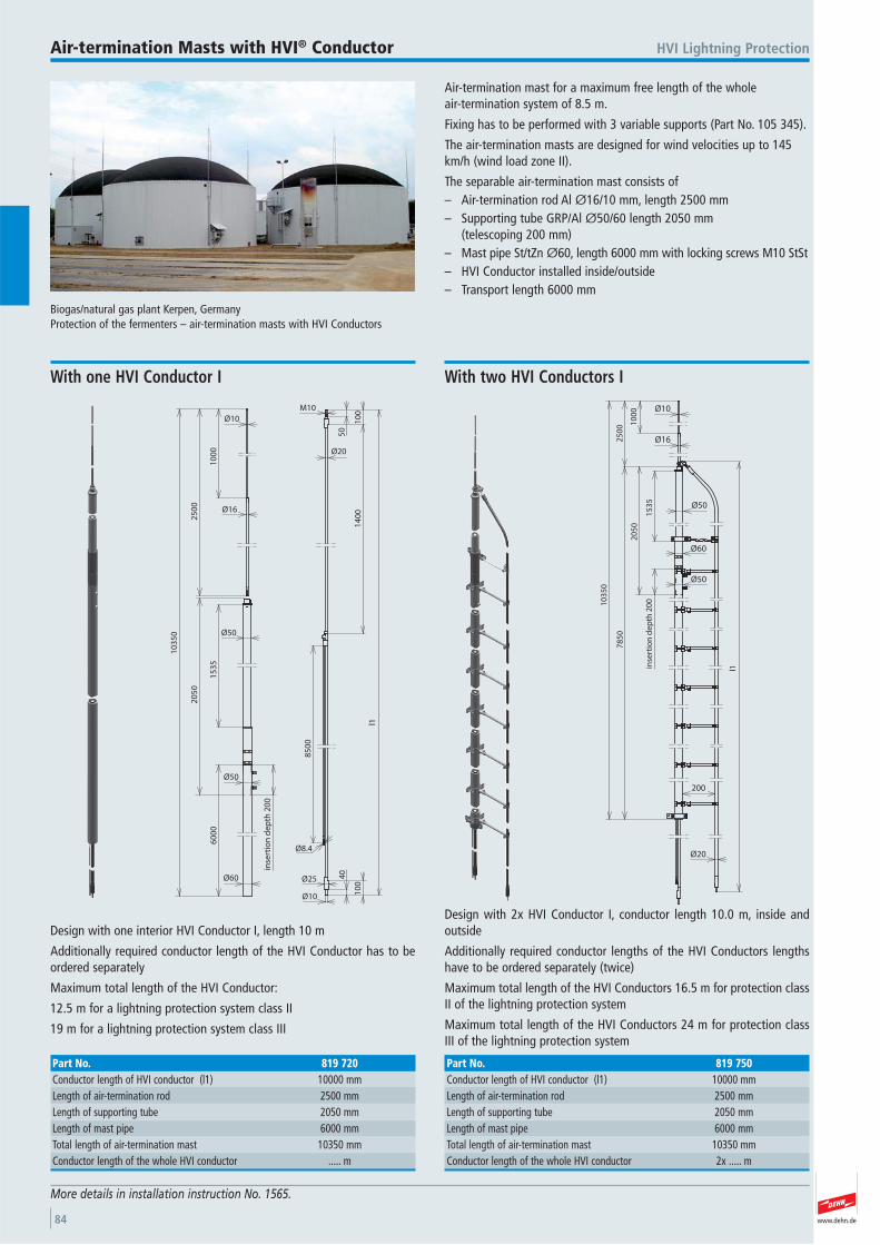
www.dehn.de84
Air-termination mast for a maximum free length of the whole air-termination system of 8.5 m.
Fixing has to be performed with 3 variable supports (Part No. 105 345).
The air-termination masts are designed for wind velocities up to 145km/h (wind load zone II).
The separable air-termination mast consists of– Air-termination rod Al Ø16/10 mm, length 2500 mm– Supporting tube GRP/Al Ø50/60 length 2050 mm
(telescoping 200 mm)– Mast pipe St/tZn Ø60, length 6000 mm with locking screws M10 StSt– HVI Conductor installed inside/outside– Transport length 6000 mm
Biogas/natural gas plant Kerpen, GermanyProtection of the fermenters – air-termination masts with HVI Conductors
HVI Lightning ProtectionAir-termination Masts with HVI® Conductor
More details in installation instruction No. 1565.
Ø50
15
35
60
00
Ø60
20
50
10
00
25
00
Ø16
Ø10
Ø50
inse
rtio
n d
ep
th 2
00
M10
50
10
01
40
0
Ø20
85
00
Ø10
40
10
0
Ø25
l1
Ø8.4
10
35
0
Design with one interior HVI Conductor I, length 10 m
Additionally required conductor length of the HVI Conductor has to beordered separately
Maximum total length of the HVI Conductor:
12.5 m for a lightning protection system class II
19 m for a lightning protection system class III
With one HVI Conductor I
Part No. 819 720Conductor length of HVI conductor (l1) 10000 mmLength of air-termination rod 2500 mmLength of supporting tube 2050 mmLength of mast pipe 6000 mmTotal length of air-termination mast 10350 mmConductor length of the whole HVI conductor ..... m
78
50
l1
10
00
25
00
15
35
inse
rtio
n d
ep
th 2
00
20
50
10
35
0
Ø10
Ø16
Ø50
Ø60
Ø50
Ø20
200
Design with 2x HVI Conductor I, conductor length 10.0 m, inside and outside
Additionally required conductor lengths of the HVI Conductors lengthshave to be ordered separately (twice)
Maximum total length of the HVI Conductors 16.5 m for protection classII of the lightning protection system
Maximum total length of the HVI Conductors 24 m for protection classIII of the lightning protection system
With two HVI Conductors I
Part No. 819 750Conductor length of HVI conductor (l1) 10000 mmLength of air-termination rod 2500 mmLength of supporting tube 2050 mmLength of mast pipe 6000 mmTotal length of air-termination mast 10350 mmConductor length of the whole HVI conductor 2x ..... m
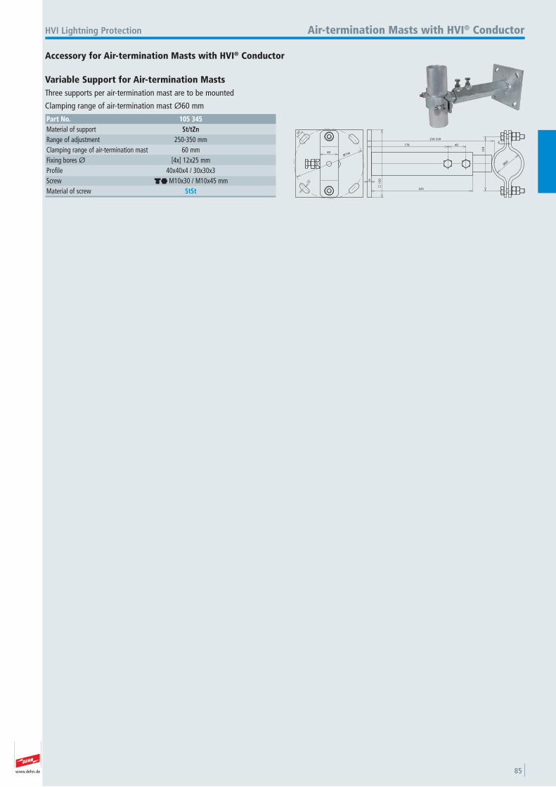
www.dehn.de 85
178 40
250-3506
12
0
Ø60
225
8
40
12
15
0
Ø156
10°
Accessory for Air-termination Masts with HVI® Conductor
HVI Lightning Protection Air-termination Masts with HVI® Conductor
Variable Support for Air-termination Masts Three supports per air-termination mast are to be mounted
Clamping range of air-termination mast Ø60 mm
Part No. 105 345Material of support St/tZnRange of adjustment 250-350 mmClamping range of air-termination mast 60 mmFixing bores Ø [4x] 12x25 mmProfile 40x40x4 / 30x30x3 Screw di M10x30 / M10x45 mmMaterial of screw StSt
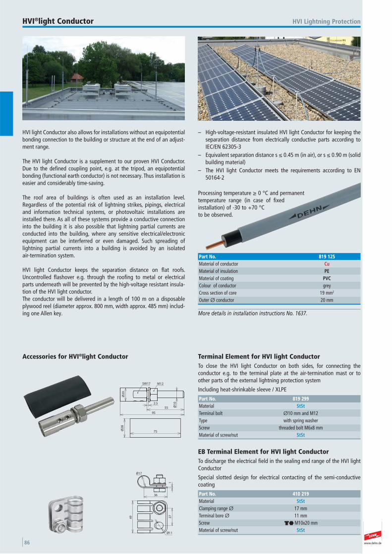
www.dehn.de86
HVI light Conductor also allows for installations without an equipotentialbonding connection to the building or structure at the end of an adjust-ment range.
The HVI light Conductor is a supplement to our proven HVI Conductor.Due to the defined coupling point, e.g. at the tripod, an equipotentialbonding (functional earth conductor) is not necessary. Thus installation iseasier and considerably time-saving.
The roof area of buildings is often used as an installation level.Regardless of the potential risk of lightning strikes, pipings, electricaland information technical systems, or photovoltaic installations areinstalled there. As all of these systems provide a conductive connectioninto the building it is also possible that lightning partial currents areconducted into the building, where any sensitive electrical/electronicequipment can be interferred or even damaged. Such spreading of lightning partial currents into a building is avoided by an isolated air-termination system.
HVI light Conductor keeps the separation distance on flat roofs.Uncontrolled flashover e.g. through the roofing to metal or electricalparts underneath will be prevented by the high-voltage resistant insula-tion of the HVI light conductor.The conductor will be delivered in a length of 100 m on a disposable plywood reel (diameter approx. 800 mm, width approx. 485 mm) includ-ing one Allen key.
– High-voltage-resistant insulated HVI light Conductor for keeping theseparation distance from electrically conductive parts according toIEC/EN 62305-3
– Equivalent separation distance s ≤ 0.45 m (in air), or s ≤ 0.90 m (solidbuilding material)
– The HVI light Conductor meets the requirements according to EN50164-2
Processing temperature ≥ 0 °C and permanenttemperature range (in case of fixedinstallation) of -30 to +70 °Cto be observed.
HVI Lightning ProtectionHVI®light Conductor
More details in installation instructions No. 1637.
Part No. 819 125Material of conductor CuMaterial of insulation PEMaterial of coating PVCColour of conductor grey Cross section of core 19 mm2
Outer Ø conductor 20 mm
Ø1
02.5
55
95
Ø2
0
75Ø2
8
M12SW17
Accessories for HVI®light Conductor Terminal Element for HVI light Conductor To close the HVI light Conductor on both sides, for connecting the conductor e.g. to the terminal plate at the air-termination mast or toother parts of the external lightning protection system
Including heat-shrinkable sleeve / XLPE
Part No. 819 299Material StStTerminal bolt Ø10 mm and M12 Type with spring washer Screw threaded bolt M6x8 mmMaterial of screw/nut StSt
49
Ø11
27
Ø17
1
36
EB Terminal Element for HVI light Conductor To discharge the electrical field in the sealing end range of the HVI lightConductor
Special slotted design for electrical contacting of the semi-conductivecoating
Part No. 410 219Material StStClamping range Ø 17 mmTerminal bore Ø 11 mmScrew di M10x20 mmMaterial of screw/nut StSt
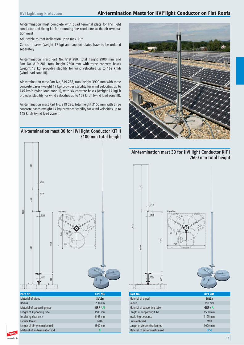
www.dehn.de 87
Air-termination mast complete with quad terminal plate for HVI lightconductor and fixing kit for mounting the conductor at the air-termina-tion mast
Adjustable to roof inclination up to max. 10°
Concrete bases (weight 17 kg) and support plates have to be orderedseparately
Air-termination mast Part No. 819 280, total height 2900 mm and Part No. 819 281, total height 2600 mm with three concrete bases(weight 17 kg) provides stability for wind velocities up to 162 km/h (wind load zone III).
Air-termination mast Part No, 819 285, total height 3900 mm with threeconcrete bases (weight 17 kg) provides stability for wind velocities up to145 km/h (wind load zone II), with six contrete bases (weight 17 kg) itprovides stability for wind velocities up to 162 km/h (wind load zone III).
Air-termination mast Part No. 819 286, total height 3100 mm with threeconcrete bases (weight 17 kg) provides stability for wind velocities up to145 km/h (wind load zone II).
HVI Lightning Protection Air-termination Masts for HVI®light Conductor on Flat Roofs
Ø22
Ø30
Ø10
10
00
15
00
26
10
22
0
R250
74
0
790
top view:
11
95
Air-termination mast 30 for HVI light Conductor KIT I2600 mm total height
Part No. 819 281Material of tripod St/tZnRadius 250 mmMaterial of supporting tube GRP / AlLength of supporting tube 1500 mmInsulating clearance 1195 mmFemale thread M10 Length of air-termination rod 1000 mmMaterial of air-termination rod StSt
Ø22
Ø30
Ø10
10
00
15
00
30
60
22
0
R250
74
0
790
top view:
45
0
Ø16
11
95
Air-termination mast 30 for HVI light Conductor KIT II3100 mm total height
Part No. 819 286Material of tripod St/tZnRadius 250 mmMaterial of supporting tube GRP / AlLength of supporting tube 1500 mmInsulating clearance 1195 mmFemale thread M16 Length of air-termination rod 1500 mmMaterial of air-termination rod Al
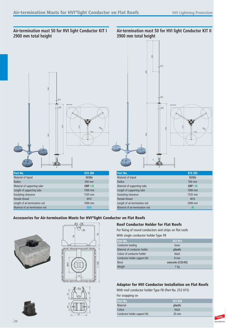
www.dehn.de88
10
00
19
00
Ø50
Ø10
R56012
10
1340
top view:
15
35
R5
HVI Lightning Protection
Air-termination mast 50 for HVI light Conductor KIT I 2900 mm total height
Part No. 819 280Material of tripod St/tZnRadius 560 mmMaterial of supporting tube GRP / AlLength of supporting tube 1900 mmInsulating clearance 1535 mmFemale thread M10 Length of air-termination rod 1000 mmMaterial of air-termination rod StSt
Air-termination Masts for HVI®light Conductor on Flat Roofs
10
00
20
00
Ø50
Ø16
Ø10
19
00
R56012
10
1340
top view:
15
35
R5
Air-termination mast 50 for HVI light Conductor KIT II 3900 mm total height
Part No. 819 285Material of tripod St/tZnRadius 560 mmMaterial of supporting tube GRP / AlLength of supporting tube 1900 mmInsulating clearance 1535 mmFemale thread M16 Length of air-termination rod 2000 mmMaterial of air-termination rod Al
56 7
0
R4
10
0
13
Ø4
7
Accessories for Air-termination Masts for HVI®light Conductor on Flat Roofs
Roof Conductor Holder for Flat Roofs For fixing of round conductors and strips on flat roofs
With single conductor holder Type FB
Part No. 253 015Conductor leading loose Material of conductor holder plasticColour of conductor holder black Conductor holder support Rd 8 mmBlock concrete (C35/45)Weight 1 kg
Ø20
32
25
42
3220
Adapter for HVI Conductor Installation on Flat Roofs With roof conductor holder Type FB (Part No. 253 015)
For snapping on
Part No. 253 026Material plasticColour black Conductor holder support Rd 20 mm
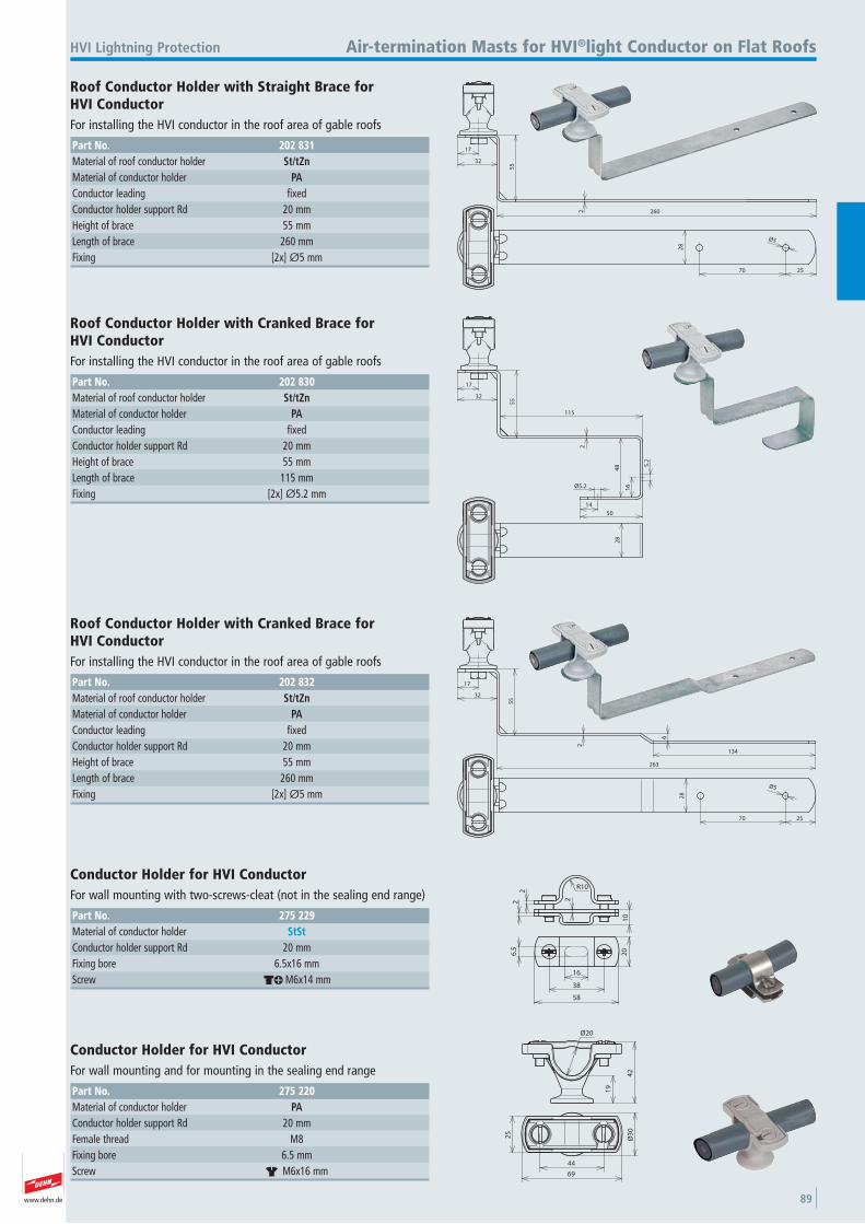
www.dehn.de 89
260
17
32
55
2
25
28
Ø5
70
HVI Lightning Protection Air-termination Masts for HVI®light Conductor on Flat Roofs
Roof Conductor Holder with Straight Brace for HVI Conductor For installing the HVI conductor in the roof area of gable roofs
Part No. 202 831Material of roof conductor holder St/tZnMaterial of conductor holder PAConductor leading fixed Conductor holder support Rd 20 mmHeight of brace 55 mmLength of brace 260 mmFixing [2x] Ø5 mm
17
32
55
115
48
Ø5.2
14
50
2
16
5.2
28
Roof Conductor Holder with Cranked Brace for HVI Conductor For installing the HVI conductor in the roof area of gable roofs
Part No. 202 830Material of roof conductor holder St/tZnMaterial of conductor holder PAConductor leading fixed Conductor holder support Rd 20 mmHeight of brace 55 mmLength of brace 115 mmFixing [2x] Ø5.2 mm
17
32
55
2
25
28
Ø5
70
263
134
6
Roof Conductor Holder with Cranked Brace for HVI Conductor For installing the HVI conductor in the roof area of gable roofs
Part No. 202 832Material of roof conductor holder St/tZnMaterial of conductor holder PAConductor leading fixed Conductor holder support Rd 20 mmHeight of brace 55 mmLength of brace 260 mmFixing [2x] Ø5 mm
R10
2
10
22
20
58
16
6.5
38
Conductor Holder for HVI Conductor For wall mounting with two-screws-cleat (not in the sealing end range)
Part No. 275 229Material of conductor holder StStConductor holder support Rd 20 mmFixing bore 6.5x16 mmScrew dk M6x14 mm
19
42
Ø20
25
Ø3
0
69
44
Conductor Holder for HVI Conductor For wall mounting and for mounting in the sealing end range
Part No. 275 220Material of conductor holder PAConductor holder support Rd 20 mmFemale thread M8 Fixing bore 6.5 mmScrew r M6x16 mm
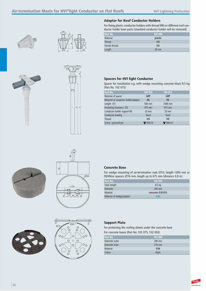
www.dehn.de90
M8
10
13
Ø30
28
18
M6
HVI Lightning ProtectionAir-termination Masts for HVI®light Conductor on Flat Roofs
Adapter for Roof Conductor Holders For fixing plastic conductor holders with thread M8 on different roof con-ductor holder base parts (standard conductor holder will be removed)
Part No. 106 898Material plasticThread M8 Female thread M6 Length 28 mm
Ø16
l2 l11
9
Ød
1
Spacers for HVI light Conductor Spacer for installation e.g. with wedge mounting concrete block 8.5 kg(Part No. 102 075)
Part No. 106 852 106 812Material of spacer GRP GRPMaterial of conductor holder/adapter PA PALength (l1) 500 mm 1000 mmInsulating clearance (l2) 475 mm 975 mmConductor holder support Rd 20 mm 20 mmConductor leading fixed fixed Thread M8 M8 Screw / grooved pin r M6x16 r M6x16
90
30
2626 21 28
Ø240
230
60
18
Concrete Base For wedge mounting of air-termination rods Ø10, length 1000 mm orDEHNiso spacers Ø16 mm, length up to 675 mm (distance 0.8 m)
Part No. 102 075Total weight 8.5 kgDiameter 240 mmMaterial concrete (C45/55) Material of wedge/adapter StSt
10
Ø280Ø270
3.5 Support Plate
For protecting the roofing sheets under the concrete base
For concrete bases (Part No. 102 075, 102 003)
Part No. 102 060Diameter outer 280 mmDiameter inner 270 mmMaterial EVAColour black
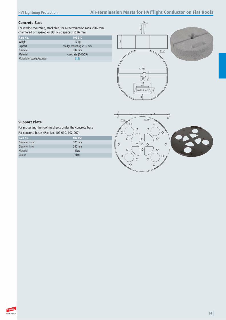
www.dehn.de 91
60
18
90
325
Ø337
28
26
41
80114
40depth 40 mm
HVI Lightning Protection Air-termination Masts for HVI®light Conductor on Flat Roofs
Concrete Base For wedge mounting, stackable, for air-termination rods Ø16 mm,chamfered or tapered or DEHNiso spacers Ø16 mm
Part No. 102 010Weight 17 kgSupport wedge mounting Ø16 mmDiameter 337 mmMaterial concrete (C45/55)Material of wedge/adapter StSt
10
3.5
Ø360 Ø370
Support Plate For protecting the roofing sheets under the concrete base
For concrete bases (Part No. 102 010, 102 002)
Part No. 102 050Diameter outer 370 mmDiameter inner 360 mmMaterial EVAColour black
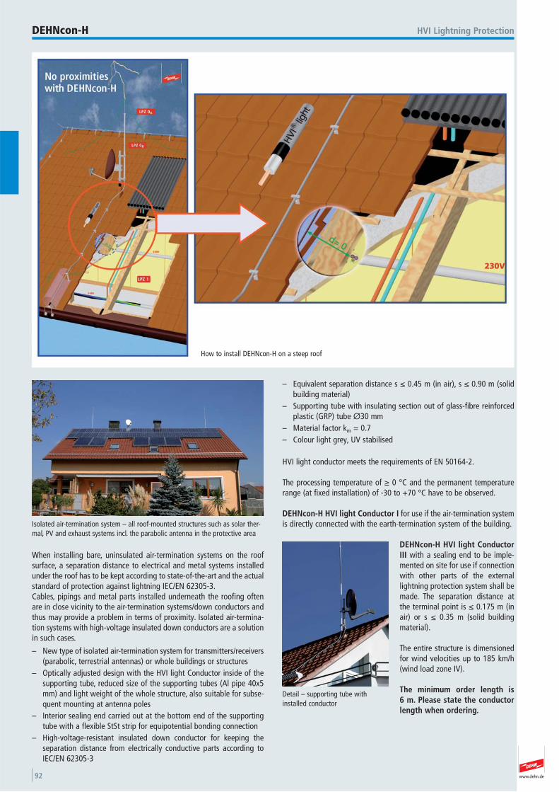
www.dehn.de92
When installing bare, uninsulated air-termination systems on the roofsurface, a separation distance to electrical and metal systems installedunder the roof has to be kept according to state-of-the-art and the actualstandard of protection against lightning IEC/EN 62305-3.Cables, pipings and metal parts installed underneath the roofing oftenare in close vicinity to the air-termination systems/down conductors andthus may provide a problem in terms of proximity. Isolated air-termina-tion systems with high-voltage insulated down conductors are a solutionin such cases.
– New type of isolated air-termination system for transmitters/receivers(parabolic, terrestrial antennas) or whole buildings or structures
– Optically adjusted design with the HVI light Conductor inside of thesupporting tube, reduced size of the supporting tubes (Al pipe 40x5mm) and light weight of the whole structure, also suitable for subse-quent mounting at antenna poles
– Interior sealing end carried out at the bottom end of the supportingtube with a flexible StSt strip for equipotential bonding connection
– High-voltage-resistant insulated down conductor for keeping the separation distance from electrically conductive parts according toIEC/EN 62305-3
– Equivalent separation distance s ≤ 0.45 m (in air), s ≤ 0.90 m (solidbuilding material)
– Supporting tube with insulating section out of glass-fibre reinforcedplastic (GRP) tube Ø30 mm
– Material factor km = 0.7– Colour light grey, UV stabilised
HVI light conductor meets the requirements of EN 50164-2.
The processing temperature of ≥ 0 °C and the permanent temperaturerange (at fixed installation) of -30 to +70 °C have to be observed.
DEHNcon-H HVI light Conductor I for use if the air-termination systemis directly connected with the earth-termination system of the building.
DEHNcon-H HVI light ConductorIII with a sealing end to be imple-mented on site for use if connectionwith other parts of the externallightning protection system shall bemade. The separation distance atthe terminal point is ≤ 0.175 m (inair) or s ≤ 0.35 m (solid buildingmaterial).
The entire structure is dimensionedfor wind velocities up to 185 km/h(wind load zone IV).
The minimum order length is 6 m. Please state the conductorlength when ordering.
How to install DEHNcon-H on a steep roof
HVI Lightning ProtectionDEHNcon-H
Detail – supporting tube withinstalled conductor
Isolated air-termination system – all roof-mounted structures such as solar ther-mal, PV and exhaust systems incl. the parabolic antenna in the protective area
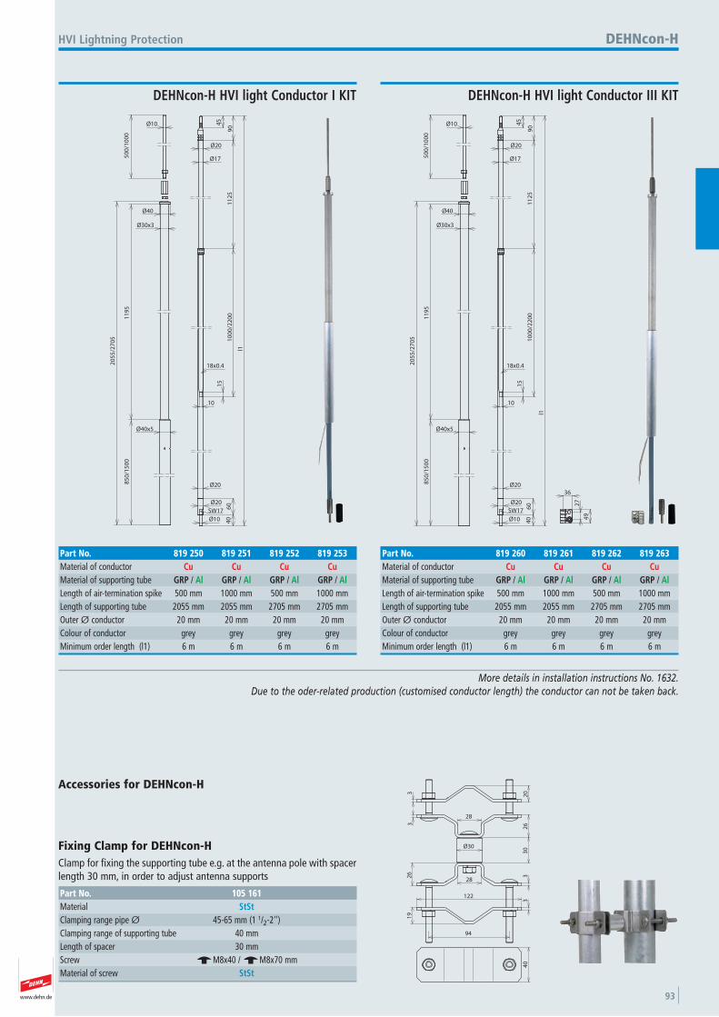
www.dehn.de 93
More details in installation instructions No. 1632. Due to the oder-related production (customised conductor length) the conductor can not be taken back.
l1
50
0/1
00
0Ø10
Ø40
Ø30x3
11
95
85
0/1
50
0
20
55
/27
05
Ø40x5
45
90
11
25
10
00
/22
00
10
15
40
60
Ø10
Ø20
Ø20
Ø17
Ø20
18x0.4
SW17
HVI Lightning Protection
DEHNcon-H HVI light Conductor I KIT
DEHNcon-H
Part No. 819 250 819 251 819 252 819 253Material of conductor Cu Cu Cu CuMaterial of supporting tube GRP / Al GRP / Al GRP / Al GRP / AlLength of air-termination spike 500 mm 1000 mm 500 mm 1000 mmLength of supporting tube 2055 mm 2055 mm 2705 mm 2705 mmOuter Ø conductor 20 mm 20 mm 20 mm 20 mmColour of conductor grey grey grey grey Minimum order length (l1) 6 m 6 m 6 m 6 m
l1
50
0/1
00
0
Ø10
Ø40
Ø30x3
11
95
85
0/1
50
0
20
55
/27
05
Ø40x5
45
90
11
25
10
00
/22
00
10
15
40
60
Ø10
Ø20
Ø20
Ø17
Ø20
18x0.4
27
49
36
SW17
DEHNcon-H HVI light Conductor III KIT
Part No. 819 260 819 261 819 262 819 263Material of conductor Cu Cu Cu CuMaterial of supporting tube GRP / Al GRP / Al GRP / Al GRP / AlLength of air-termination spike 500 mm 1000 mm 500 mm 1000 mmLength of supporting tube 2055 mm 2055 mm 2705 mm 2705 mmOuter Ø conductor 20 mm 20 mm 20 mm 20 mmColour of conductor grey grey grey grey Minimum order length (l1) 6 m 6 m 6 m 6 m
28
28
94
122
19
26
33
26
20
33
30Ø30
40
Accessories for DEHNcon-H
Fixing Clamp for DEHNcon-H Clamp for fixing the supporting tube e.g. at the antenna pole with spacerlength 30 mm, in order to adjust antenna supports
Part No. 105 161Material StStClamping range pipe Ø 45-65 mm (1 1/2-2'') Clamping range of supporting tube 40 mmLength of spacer 30 mmScrew e M8x40 / e M8x70 mmMaterial of screw StSt
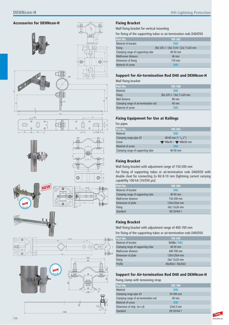
www.dehn.de94
45
Ø40-50
30
3
3
122
40
7
Ø5
.13
54
0
17
0
10
11
20
15
0
13
0
20
10
0
Accessories for DEHNcon-H
HVI Lightning ProtectionDEHNcon-H
Fixing Bracket Wall fixing bracket for vertical mounting
For fixing of the supporting tubes or air-termination rods D40/D50
Part No. 105 342Material of bracket StStFixing [8x] Ø5.1 / [4x] 7x10 / [2x] 11x20 mmClamping range of supporting tube 40-50 mmWall/corner distance 46 mmDimension of fixing 170 mmMaterial of screw StSt
Ø40
15
2
64
3
2.5 80
10
0
320
50 50
25
Ø5.1
11 20 15
4011
75
Support for Air-termination Rod D40 and DEHNcon-H Wall fixing bracket
Part No. 105 140Material StStFixing [8x] Ø5.1 / [4x] 11x20 mmWall distance 80 mmClamping range of air-termination rod 40 mmMaterial of screw StSt
28
28
20
33
26
20 3
32
6
94
122
40
Fixing Equipment for Use at Railings For pipes
Part No. 105 354Material StStClamping range pipe Ø 48-60 mm (1 1/2-2'') Screw e M8x40 / e M8x50 mmMaterial of screw StStClamping range of supporting tube 40-50 mm
14°
12
40
Ø114 12
0
4
115
74 303
94
150-200
Ø40-50
R5
Fixing Bracket Wall fixing bracket with adjustment range of 150-200 mm
For fixing of supporting tubes or air-termination rods D40/D50 with double cleat for connecting 2x Rd 8-10 mm [lightning current carryingcapability 100 kA (10/350 μs)]
Part No. 105 344Material of bracket StStClamping range of supporting tube 40-50 mmWall/corner distance 150-200 mmDimension of plate 120x120x4 mmFixing [4x] 12x26 mmStandard EN 50164-1
t e s t e d
+
400
349 40
400-700
94
Ø40/5
0
34 1
20
1240
14°
40
x4
30
x3
Ø114
Fixing Bracket Wall fixing bracket with adjustment range of 400-700 mm
For fixing of the supporting tubes or air-termination rods D40/D50
Part No. 105 343Material of bracket St/tZn / StStClamping range of supporting tube 40-50 mmWall/corner distance 400-700 mmDimension of plate 120x120x4 mmFixing [4x] 12x25 mmProfile 40x40x4 / 30x30x3
94
122
3
20
26
28
28
120 °
34
9
3
23
17
2.5
1100
0.3
Support for Air-termination Rod D40 and DEHNcon-H Fixing clamp with tensioning strap
Part No. 105 160Material StStClamping range pipe Ø 50-300 mmClamping range of air-termination rod 40 mmMaterial of screw StStDimension of strip (w x d) 25x0.3 mmStandard EN 50164-1
t e s t e d
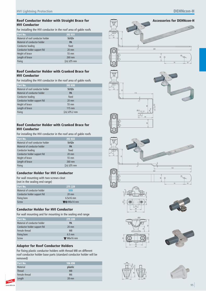
www.dehn.de 95
260
17
32
55
2
25
28
Ø5
70
Accessories for DEHNcon-H
HVI Lightning Protection DEHNcon-H
Roof Conductor Holder with Straight Brace for HVI Conductor For installing the HVI conductor in the roof area of gable roofs
Part No. 202 831Material of roof conductor holder St/tZnMaterial of conductor holder PAConductor leading fixed Conductor holder support Rd 20 mmHeight of brace 55 mmLength of brace 260 mmFixing [2x] Ø5 mm
17
32
55
115
48
Ø5.2
14
50
2
16
5.2
28
Roof Conductor Holder with Cranked Brace for HVI Conductor For installing the HVI conductor in the roof area of gable roofs
Part No. 202 830Material of roof conductor holder St/tZnMaterial of conductor holder PAConductor leading fixed Conductor holder support Rd 20 mmHeight of brace 55 mmLength of brace 115 mmFixing [2x] Ø5.2 mm
17
32
55
2
25
28
Ø5
70
263
134
6
Roof Conductor Holder with Cranked Brace for HVI Conductor For installing the HVI conductor in the roof area of gable roofs
Part No. 202 832Material of roof conductor holder St/tZnMaterial of conductor holder PAConductor leading fixed Conductor holder support Rd 20 mmHeight of brace 55 mmLength of brace 260 mmFixing [2x] Ø5 mm
R10
2
10
22
20
58
16
6.5
38
Conductor Holder for HVI Conductor For wall mounting with two-screws-cleat (not in the sealing end range)
Part No. 275 229Material of conductor holder StStConductor holder support Rd 20 mmFixing bore 6.5x16 mmScrew dk M6x14 mm
19
42
Ø20
25
Ø3
0
69
44
Conductor Holder for HVI Conductor For wall mounting and for mounting in the sealing end range
Part No. 275 220Material of conductor holder PAConductor holder support Rd 20 mmFemale thread M8 Fixing bore 6.5 mmScrew r M6x16 mm
M8
10
13
Ø30
28
18
M6
Adapter for Roof Conductor Holders For fixing plastic conductor holders with thread M8 on different roof conductor holder base parts (standard conductor holder will beremoved)
Part No. 106 898Material plasticThread M8 Female thread M6 Length 28 mm
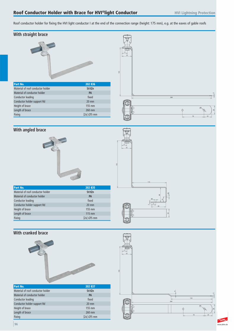
www.dehn.de96
Roof conductor holder for fixing the HVI light conductor I at the end of the connection range (height: 175 mm), e.g. at the eaves of gable roofs
HVI Lightning ProtectionRoof Conductor Holder with Brace for HVI®light Conductor
2
260
15
5
32
17
28
Ø5
2570
With straight brace
Part No. 202 836Material of roof conductor holder St/tZnMaterial of conductor holder PAConductor leading fixed Conductor holder support Rd 20 mmHeight of brace 155 mmLength of brace 260 mmFixing [2x] Ø5 mm
48
14
Ø5
2
Ø5
16
48
115
15
5
32
17
28
With angled brace
Part No. 202 835Material of roof conductor holder St/tZnMaterial of conductor holder PAConductor leading fixed Conductor holder support Rd 20 mmHeight of brace 155 mmLength of brace 115 mmFixing [2x] Ø5 mm
2
6
134
260
15
5
32
17
28
Ø5
2570
With cranked brace
Part No. 202 837Material of roof conductor holder St/tZnMaterial of conductor holder PAConductor leading fixed Conductor holder support Rd 20 mmHeight of brace 155 mmLength of brace 260 mmFixing [2x] Ø5 mm
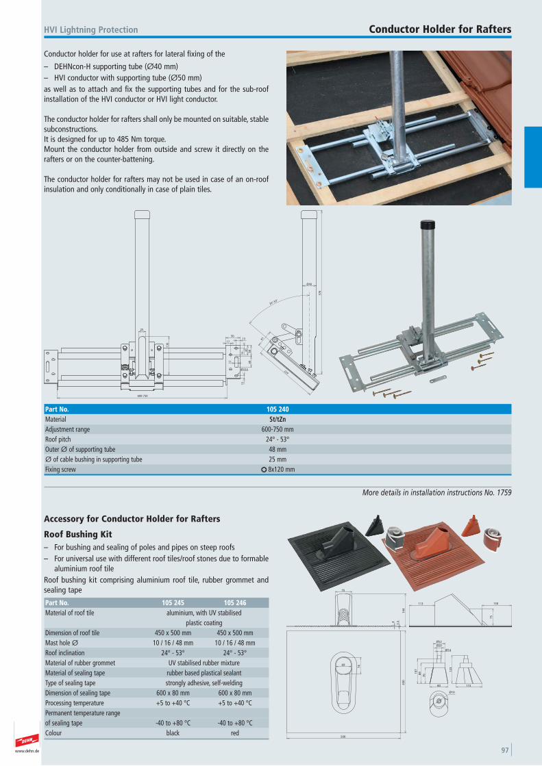
www.dehn.de 97
Conductor holder for use at rafters for lateral fixing of the
– DEHNcon-H supporting tube (Ø40 mm)– HVI conductor with supporting tube (Ø50 mm) as well as to attach and fix the supporting tubes and for the sub-roofinstallation of the HVI conductor or HVI light conductor.
The conductor holder for rafters shall only be mounted on suitable, stablesubconstructions.It is designed for up to 485 Nm torque.Mount the conductor holder from outside and screw it directly on therafters or on the counter-battening.
The conductor holder for rafters may not be used in case of an on-roofinsulation and only conditionally in case of plain tiles.
HVI Lightning Protection Conductor Holder for Rafters
More details in installation instructions No. 1759
600-750
25
13
6
50
11
15 6
0
15
1713
60
50
Ø10.5 229
61
57
8
Ø48
24°-53°
Part No. 105 240Material St/tZnAdjustment range 600-750 mmRoof pitch 24° - 53° Outer Ø of supporting tube 48 mmØ of cable bushing in supporting tube 25 mmFixing screw l 8x120 mm
500
45
0
69
74
14
4
1.54
75
75
130113
708
910
7
80
12
3
115
Ø52
Ø20
Ø14
Ø10
Accessory for Conductor Holder for Rafters
Roof Bushing Kit – For bushing and sealing of poles and pipes on steep roofs– For universal use with different roof tiles/roof stones due to formable
aluminium roof tileRoof bushing kit comprising aluminium roof tile, rubber grommet andsealing tape
Part No. 105 245 105 246Material of roof tile aluminium, with UV stabilised
plastic coatingDimension of roof tile 450 x 500 mm 450 x 500 mmMast hole Ø 10 / 16 / 48 mm 10 / 16 / 48 mmRoof inclination 24° - 53° 24° - 53° Material of rubber grommet UV stabilised rubber mixtureMaterial of sealing tape rubber based plastical sealantType of sealing tape strongly adhesive, self-weldingDimension of sealing tape 600 x 80 mm 600 x 80 mmProcessing temperature +5 to +40 °C +5 to +40 °CPermanent temperature range of sealing tape -40 to +80 °C -40 to +80 °CColour black red
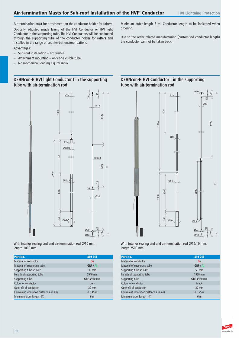
www.dehn.de98
Air-termination mast for attachment on the conductor holder for rafters
Optically adjusted inside laying of the HVI Conductor or HVI lightConductor in the supporting tube. The HVI Conductors will be conductedthrough the supporting tube of the conductor holder for rafters andinstalled in the range of counter-battens/roof battens.
Advantages:– Sub-roof installation – not visible– Attachment mounting – only one visible tube– No mechanical loading e.g. by snow
Minimum order length 6 m. Conductor length to be indicated whenordering.
Due to the order related manufacturing (customised conductor length)the conductor can not be taken back.
HVI Lightning ProtectionAir-termination Masts for Sub-roof Installation of the HVI® Conductor
13
85
35
01
19
5
29
40
11
25
10
00
l1
18x0.4
10
00
Ø10
Ø60x5
Ø40x5
Ø30x3
Ø40
Ø17
Ø10
Ø20 40
10
0
Ø20
10
15
45
90
With interior sealing end and air-termination rod Ø10 mm, length 1000 mm
DEHNcon-H HVI light Conductor I in the supporting tube with air-termination rod
Part No. 819 241Material of conductor CuMaterial of supporting tube GRP / AlSupporting tube Ø GRP 30 mmLength of supporting tube 2940 mmSupporting tube GRP Ø30 mmColour of conductor grey Outer Ø of conductor 20 mmEquivalent separation distance s (in air) ≤ 0.45 mMinimum order length (l1) 6 m
M10
35
10
01
40
0
Ø20
38
00
l1
Ø8.4
15
60
35
0
25
00
19
50
10
00
Ø10
Ø60
Ø50
Ø16
Ø10
40
10
7
Ø23
With interior sealing end and air-termination rod Ø16/10 mm, length 2500 mm
DEHNcon-H HVI Conductor I in the supporting tube with air-termination rod
Part No. 819 245Material of conductor CuMaterial of supporting tube GRP / AlSupporting tube Ø GRP 50 mmLength of supporting tube 1950 mmSupporting tube GRP Ø50 mmColour of conductor black Outer Ø of conductor 20 mmEquivalent separation distance s (in air) ≤ 0.75 mMinimum order length (l1) 6 m
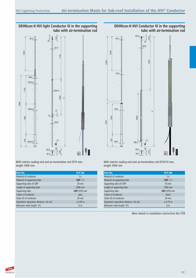
www.dehn.de 99
More details in installation instructions No.1759
Air-termination Masts for Sub-roof Installation of the HVI® Conductor
13
85
35
01
19
5
29
40
11
25
10
00
l1
18x0.4
10
00
Ø10
Ø60x5
Ø40x5
Ø30x3
Ø40
Ø17
Ø20
10
15
45
90
Ø10
40
10
0
Ø25
Ø11
With interior sealing end and air-termination rod Ø10 mm, length 1000 mm
HVI Lightning Protection
DEHNcon-H HVI light Conductor III in the supporting tube with air-termination rod
Part No. 819 242Material of conductor CuMaterial of supporting tube GRP / AlSupporting tube Ø GRP 30 mmLength of supporting tube 2940 mmSupporting tube GRP Ø30 mmColour of conductor grey Outer Ø of conductor 20 mmEquivalent separation distance s (in air) ≤ 0.45 mMinimum order length (l1) 6 m
M10
35
10
01
40
0
Ø20
38
00
Ø10
40
10
7Ø23
l1
Ø8.4Ø11
15
60
35
0
25
00
19
50
10
00
Ø10
Ø60
Ø50
Ø16
With interior sealing end and air-termination rod Ø16/10 mm, length 2500 mm
DEHNcon-H HVI Conductor III in the supporting tube with air-termination rod
Part No. 819 246Material of conductor CuMaterial of supporting tube GRP / AlSupporting tube Ø GRP 50 mmLength of supporting tube 1950 mmSupporting tube GRP Ø50 mmColour of conductor black Outer Ø of conductor 20 mmEquivalent separation distance s (in air) ≤ 0.75 mMinimum order length (l1) 6 m
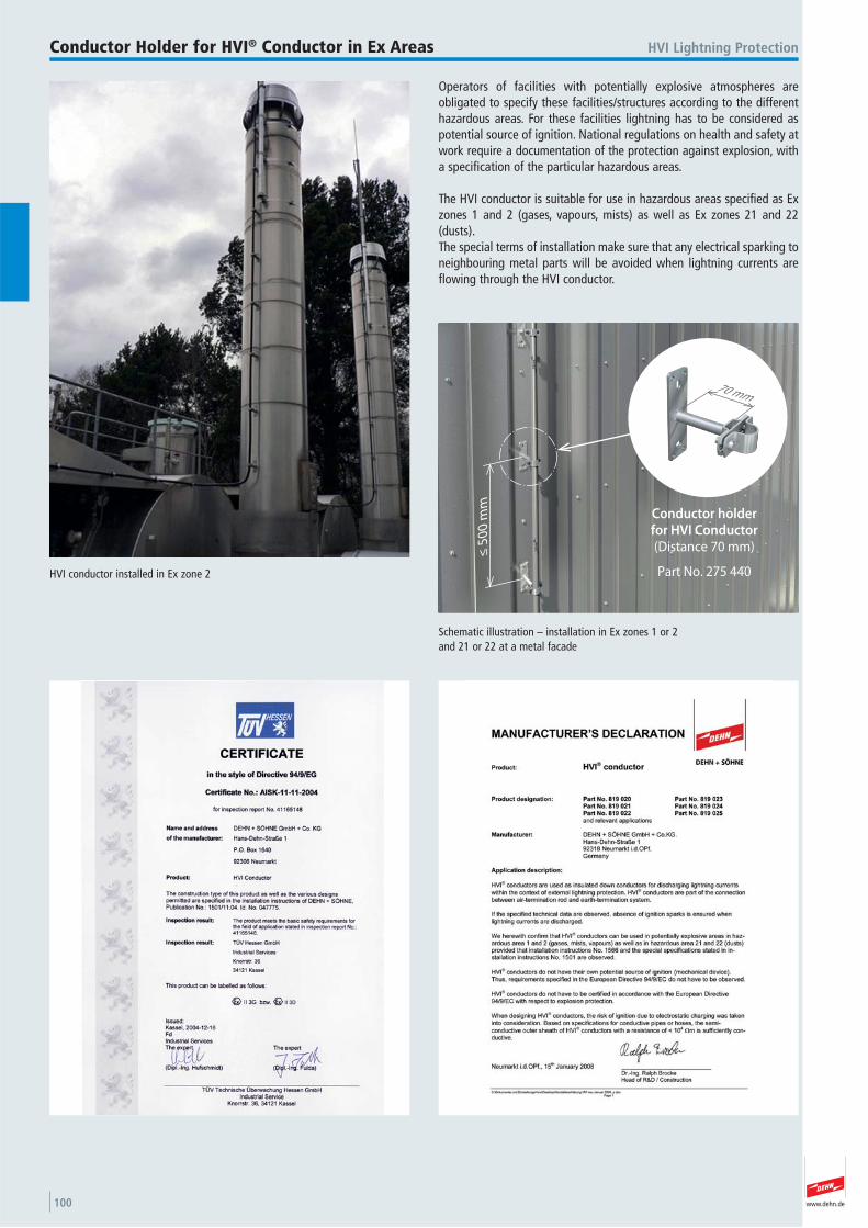
www.dehn.de100
Operators of facilities with potentially explosive atmospheres are obligated to specify these facilities/structures according to the differenthazardous areas. For these facilities lightning has to be considered aspotential source of ignition. National regulations on health and safety atwork require a documentation of the protection against explosion, witha specification of the particular hazardous areas.
The HVI conductor is suitable for use in hazardous areas specified as Exzones 1 and 2 (gases, vapours, mists) as well as Ex zones 21 and 22(dusts).The special terms of installation make sure that any electrical sparking toneighbouring metal parts will be avoided when lightning currents areflowing through the HVI conductor.
HVI conductor installed in Ex zone 2
HVI Lightning ProtectionConductor Holder for HVI® Conductor in Ex Areas
≤ 5
00
mm
70 mm
Conductor holderfor HVI Conductor(Distance 70 mm)
Part No. 275 440
Schematic illustration – installation in Ex zones 1 or 2 and 21 or 22 at a metal facade
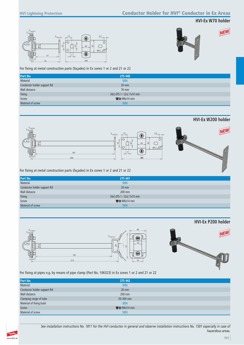
www.dehn.de 101
See installation instructions No. 1811 for the HVI conductor in general and observe installation instructions No. 1501 especially in case of hazardous areas.
HVI Lightning Protection
70
22
2
Ø1
23
57
30
19
15
7
10
5.5
20
100
R10
Ø5.1
For fixing at metal construction parts (façades) in Ex zones 1 or 2 and 21 or 22
+
Conductor Holder for HVI® Conductor in Ex Areas
HVI-Ex W70 holder
Part No. 275 440Material StStConductor holder support Rd 20 mmWall distance 70 mmFixing [4x] Ø5.1 / [2x] 7x10 mmScrew dm M6x14 mmMaterial of screw StSt
200
22
2
Ø1
2
3
187
30
19
15
7
10
5.5
20R10
Ø5.1
For fixing at metal construction parts (façades) in Ex zones 1 or 2 and 21 or 22
+
HVI-Ex W200 holder
Part No. 275 441Material StStConductor holder support Rd 20 mmWall distance 200 mmFixing [4x] Ø5.1 / [2x] 7x10 mmScrew dm M6x14 mmMaterial of screw StSt
28
61
20
26
40
213
22
2
Ø1
2
3
187
R10
For fixing at pipes e.g. by means of pipe clamp (Part No. 106323) in Ex zones 1 or 2 and 21 or 22
+
HVI-Ex P200 holder
Part No. 275 442Material StStConductor holder support Rd 20 mmWall distance 200 mmClamping range of tube 50-300 mmMaterial of fixing bush StStScrew dm M6x14 mmMaterial of screw StSt
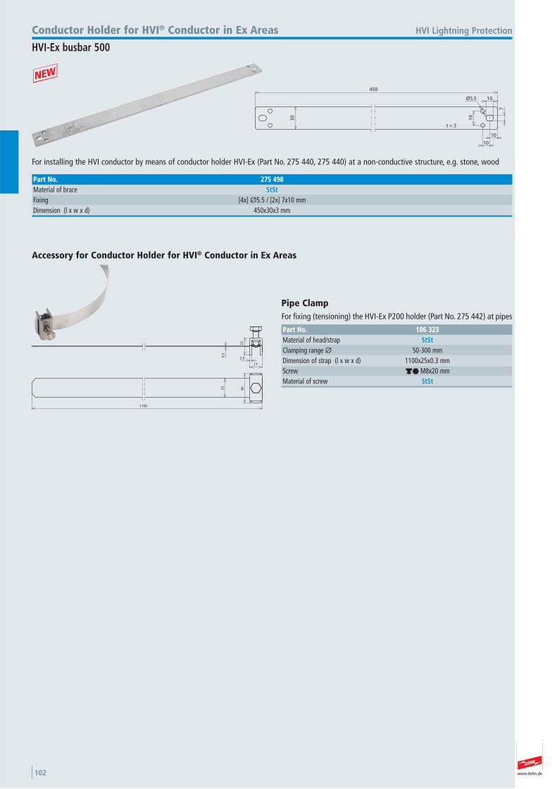
www.dehn.de102
450
10
10
7
10
19
30
t = 3
Ø5.5
For installing the HVI conductor by means of conductor holder HVI-Ex (Part No. 275 440, 275 440) at a non-conductive structure, e.g. stone, wood
+
HVI Lightning ProtectionConductor Holder for HVI® Conductor in Ex Areas
HVI-Ex busbar 500
Part No. 275 498Material of brace StStFixing [4x] Ø5.5 / [2x] 7x10 mmDimension (l x w x d) 450x30x3 mm
23
17
2.50.3
4025
1100
Accessory for Conductor Holder for HVI® Conductor in Ex Areas
Pipe Clamp For fixing (tensioning) the HVI-Ex P200 holder (Part No. 275 442) at pipes
Part No. 106 323Material of head/strap StStClamping range Ø 50-300 mmDimension of strap (l x w x d) 1100x25x0.3 mmScrew di M8x20 mmMaterial of screw StSt
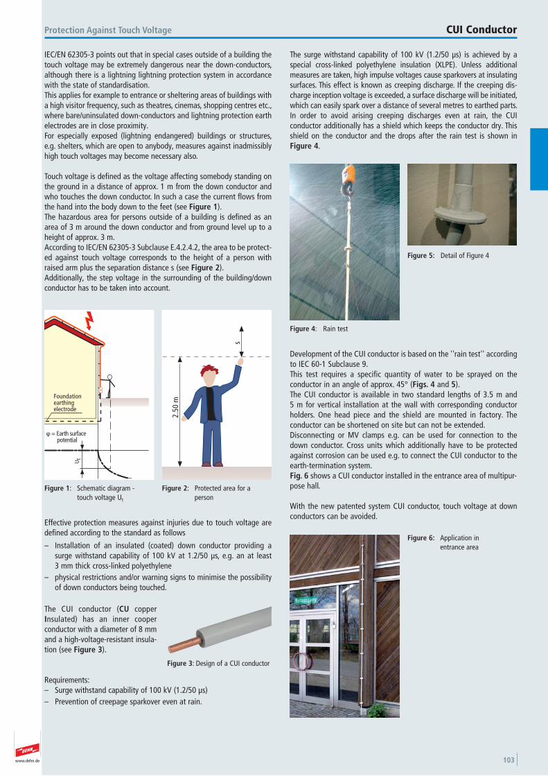
www.dehn.de 103
IEC/EN 62305-3 points out that in special cases outside of a building thetouch voltage may be extremely dangerous near the down-conductors,although there is a lightning lightning protection system in accordancewith the state of standardisation.This applies for example to entrance or sheltering areas of buildings witha high visitor frequency, such as theatres, cinemas, shopping centres etc.,where bare/uninsulated down-conductors and lightning protection earthelectrodes are in close proximity.For especially exposed (lightning endangered) buildings or structures,e.g. shelters, which are open to anybody, measures against inadmissiblyhigh touch voltages may become necessary also.
Touch voltage is defined as the voltage affecting somebody standing onthe ground in a distance of approx. 1 m from the down conductor andwho touches the down conductor. In such a case the current flows fromthe hand into the body down to the feet (see Figure 1).The hazardous area for persons outside of a building is defined as anarea of 3 m around the down conductor and from ground level up to aheight of approx. 3 m.According to IEC/EN 62305-3 Subclause E.4.2.4.2, the area to be protect-ed against touch voltage corresponds to the height of a person withraised arm plus the separation distance s (see Figure 2).Additionally, the step voltage in the surrounding of the building/downconductor has to be taken into account.
Foundationearthingelectrode
Ut
φ = Earth surface potential
Figure 1: Schematic diagram - touch voltage Ut
Figure 2: Protected area for a person
s
2.50
m
Effective protection measures against injuries due to touch voltage aredefined according to the standard as follows
– Installation of an insulated (coated) down conductor providing asurge withstand capability of 100 kV at 1.2/50 μs, e.g. an at least 3 mm thick cross-linked polyethylene
– physical restrictions and/or warning signs to minimise the possibilityof down conductors being touched.
The CUI conductor (CU copperInsulated) has an inner cooper conductor with a diameter of 8 mmand a high-voltage-resistant insula-tion (see Figure 3).
Requirements:– Surge withstand capability of 100 kV (1.2/50 μs)– Prevention of creepage sparkover even at rain.
Figure 3: Design of a CUI conductor
Figure 4: Rain test
Protection Against Touch Voltage CUI Conductor
Development of the CUI conductor is based on the ''rain test'' accordingto IEC 60-1 Subclause 9.This test requires a specific quantity of water to be sprayed on the conductor in an angle of approx. 45° (Figs. 4 and 5). The CUI conductor is available in two standard lengths of 3.5 m and 5 m for vertical installation at the wall with corresponding conductorholders. One head piece and the shield are mounted in factory. The conductor can be shortened on site but can not be extended.Disconnecting or MV clamps e.g. can be used for connection to thedown conductor. Cross units which additionally have to be protectedagainst corrosion can be used e.g. to connect the CUI conductor to theearth-termination system.Fig. 6 shows a CUI conductor installed in the entrance area of multipur-pose hall.
With the new patented system CUI conductor, touch voltage at downconductors can be avoided.
Figure 5: Detail of Figure 4
Figure 6: Application in entrance area
The surge withstand capability of 100 kV (1.2/50 μs) is achieved by a special cross-linked polyethylene insulation (XLPE). Unless additionalmeasures are taken, high impulse voltages cause sparkovers at insulatingsurfaces. This effect is known as creeping discharge. If the creeping dis-charge inception voltage is exceeded, a surface discharge will be initiated,which can easily spark over a distance of several metres to earthed parts. In order to avoid arising creeping discharges even at rain, the CUI conductor additionally has a shield which keeps the conductor dry. Thisshield on the conductor and the drops after the rain test is shown inFigure 4.
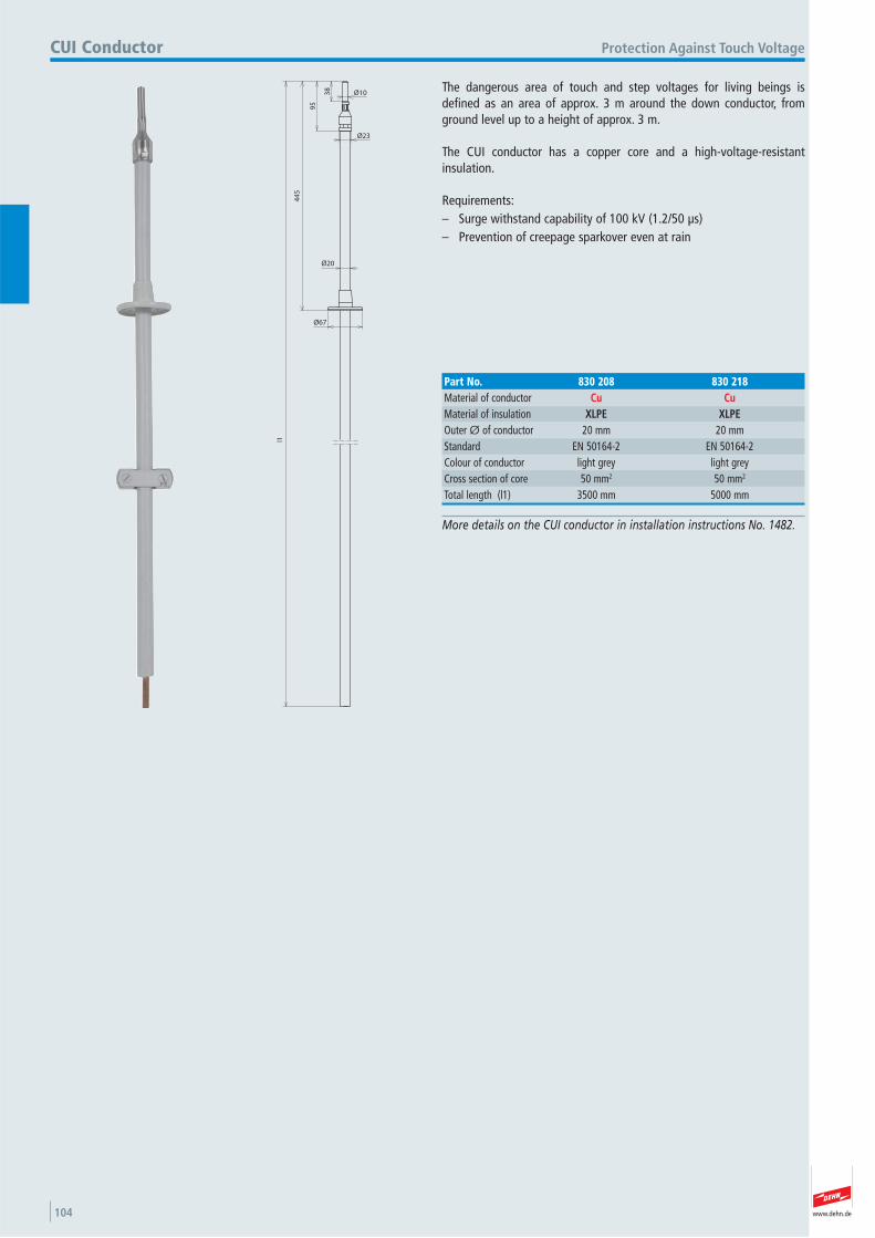
www.dehn.de104
More details on the CUI conductor in installation instructions No. 1482.
Protection Against Touch VoltageCUI Conductor
38
95
44
5
l1
Ø10
Ø23
Ø67
Ø20
The dangerous area of touch and step voltages for living beings isdefined as an area of approx. 3 m around the down conductor, fromground level up to a height of approx. 3 m.
The CUI conductor has a copper core and a high-voltage-resistant insulation.
Requirements:– Surge withstand capability of 100 kV (1.2/50 μs)– Prevention of creepage sparkover even at rain
Part No. 830 208 830 218Material of conductor Cu CuMaterial of insulation XLPE XLPEOuter Ø of conductor 20 mm 20 mmStandard EN 50164-2 EN 50164-2 Colour of conductor light grey light grey Cross section of core 50 mm2 50 mm2
Total length (l1) 3500 mm 5000 mm
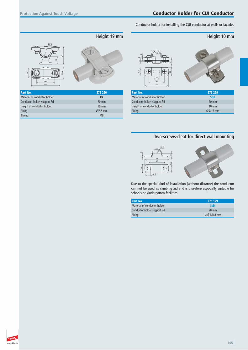
www.dehn.de 105
Conductor holder for installing the CUI conductor at walls or façades
Protection Against Touch Voltage Conductor Holder for CUI Conductor
19
42
Ø20
25
Ø3
0
69
44
Height 19 mm
Part No. 275 220Material of conductor holder PAConductor holder support Rd 20 mmHeight of conductor holder 19 mmFixing Ø6.5 mmThread M8
R10
2
10
22
20
58
16
6.5
38
Height 10 mm
Part No. 275 229Material of conductor holder StStConductor holder support Rd 20 mmHeight of conductor holder 10 mmFixing 6.5x16 mm
20
58
6.5
8.2
38
8
2
R10
Due to the special kind of installation (without distance) the conductorcan not be used as climbing aid and is therefore especially suitable forschools or kindergarten facilities.
Two-screws-cleat for direct wall mounting
Part No. 275 129Material of conductor holder StStConductor holder support Rd 20 mmFixing [2x] 6.5x8 mm
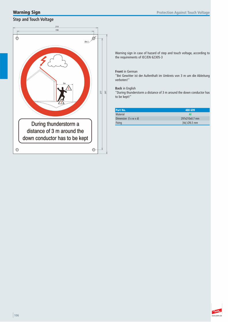
www.dehn.de106
Warning sign in case of hazard of step and touch voltage, according tothe requirements of IEC/EN 62305-3
Protection Against Touch Voltage
Front in German"Bei Gewitter ist der Aufenthalt im Umkreis von 3 m um die Ableitungverboten!"
Back in English"During thunderstorm a distance of 3 m around the down conductor hasto be kept!"
Warning Sign
Step and Touch Voltage
Part No. 480 699Material AlDimension (l x w x d) 297x210x0.7 mmFixing [4x] Ø6.5 mm
190
210
Ø6.5
27
7
29
7
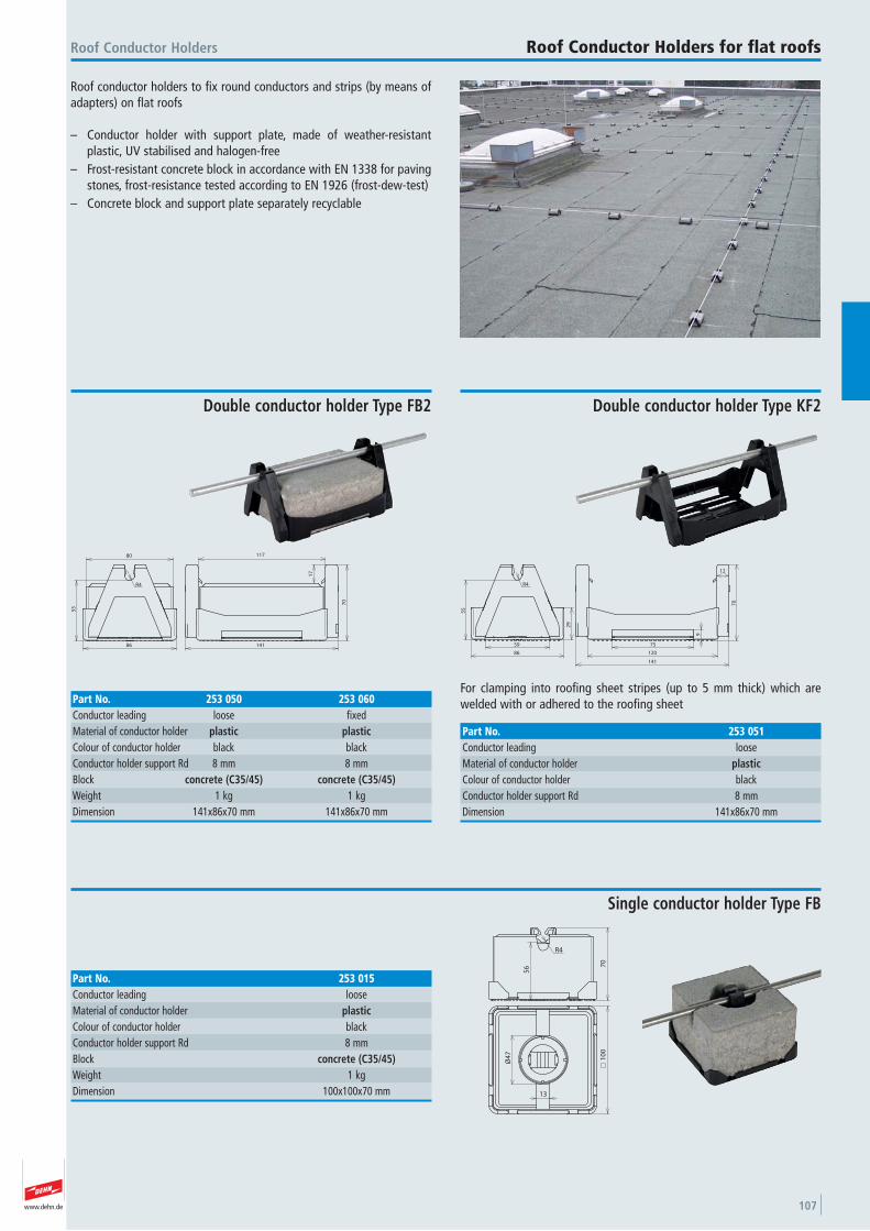
www.dehn.de 107
Roof conductor holders to fix round conductors and strips (by means ofadapters) on flat roofs
– Conductor holder with support plate, made of weather-resistant plastic, UV stabilised and halogen-free
– Frost-resistant concrete block in accordance with EN 1338 for pavingstones, frost-resistance tested according to EN 1926 (frost-dew-test)
– Concrete block and support plate separately recyclable
Roof Conductor Holders Roof Conductor Holders for flat roofs
80
55
86
R4
117
17
141
70
Double conductor holder Type FB2
Part No. 253 050 253 060Conductor leading loose fixed Material of conductor holder plastic plasticColour of conductor holder black black Conductor holder support Rd 8 mm 8 mmBlock concrete (C35/45) concrete (C35/45)Weight 1 kg 1 kgDimension 141x86x70 mm 141x86x70 mm
55
29
86
59
R4
75
120
141
9
12
70
For clamping into roofing sheet stripes (up to 5 mm thick) which arewelded with or adhered to the roofing sheet
Double conductor holder Type KF2
Part No. 253 051Conductor leading loose Material of conductor holder plasticColour of conductor holder black Conductor holder support Rd 8 mmDimension 141x86x70 mm
56 7
0
R4
10
0
13
Ø4
7
Single conductor holder Type FB
Part No. 253 015Conductor leading loose Material of conductor holder plasticColour of conductor holder black Conductor holder support Rd 8 mmBlock concrete (C35/45)Weight 1 kgDimension 100x100x70 mm
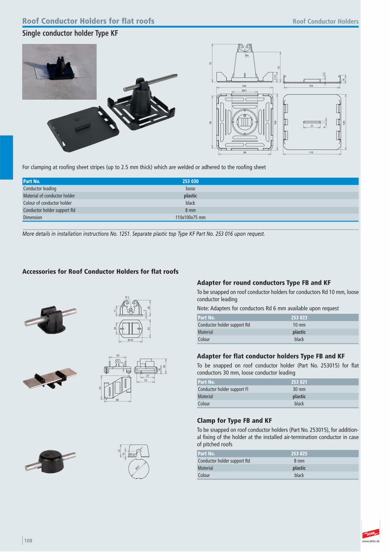
www.dehn.de108
70
R4
17
.5
55
102
5.5
14
Ø47
100
96
96
10
0
110
10
0
31
4
For clamping at roofing sheet stripes (up to 2.5 mm thick) which are welded or adhered to the roofing sheet
Roof Conductor HoldersRoof Conductor Holders for flat roofs
Single conductor holder Type KF
Part No. 253 030Conductor leading loose Material of conductor holder plasticColour of conductor holder black Conductor holder support Rd 8 mmDimension 110x100x75 mm
2
28
17
5R
42Ø
3220
Accessories for Roof Conductor Holders for flat roofs
Adapter for round conductors Type FB and KF To be snapped on roof conductor holders for conductors Rd 10 mm, looseconductor leading
Note: Adapters for conductors Rd 6 mm available upon request
Part No. 253 023Conductor holder support Rd 10 mmMaterial plasticColour black
More details in installation instructions No. 1251. Separate plastic top Type KF Part No. 253 016 upon request.
30
3
26
4
25
32
42
48
Adapter for flat conductor holders Type FB and KF To be snapped on roof conductor holder (Part No. 253015) for flat conductors 30 mm, loose conductor leading
Part No. 253 021Conductor holder support Fl 30 mmMaterial plasticColour black
22
10 Ø7.6
Ø37
Clamp for Type FB and KF To be snapped on roof conductor holders (Part No. 253015), for addition-al fixing of the holder at the installed air-termination conductor in caseof pitched roofs
Part No. 253 025Conductor holder support Rd 8 mmMaterial plasticColour black
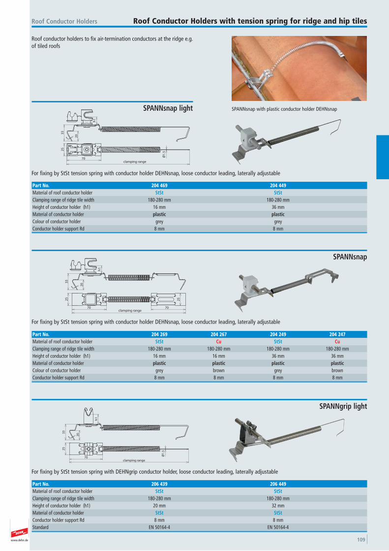
www.dehn.de 109
Roof conductor holders to fix air-termination conductors at the ridge e.g.of tiled roofs
SPANNsnap with plastic conductor holder DEHNsnap
Roof Conductor Holders Roof Conductor Holders with tension spring for ridge and hip tiles
33
20
h1
25
70
Ø1
.5clamping range
1
For fixing by StSt tension spring with conductor holder DEHNsnap, loose conductor leading, laterally adjustable
SPANNsnap light
Part No. 204 469 204 449Material of roof conductor holder StSt StStClamping range of ridge tile width 180-280 mm 180-280 mmHeight of conductor holder (h1) 16 mm 36 mmMaterial of conductor holder plastic plasticColour of conductor holder grey grey Conductor holder support Rd 8 mm 8 mm
h1
203
3
70 70clamping range
25
25
1
For fixing by StSt tension spring with conductor holder DEHNsnap, loose conductor leading, laterally adjustable
SPANNsnap
Part No. 204 269 204 267 204 249 204 247Material of roof conductor holder StSt Cu StSt CuClamping range of ridge tile width 180-280 mm 180-280 mm 180-280 mm 180-280 mmHeight of conductor holder (h1) 16 mm 16 mm 36 mm 36 mmMaterial of conductor holder plastic plastic plastic plasticColour of conductor holder grey brown grey brown Conductor holder support Rd 8 mm 8 mm 8 mm 8 mm
33
20
h1
25
70clamping range
Ø1
.5
1
For fixing by StSt tension spring with DEHNgrip conductor holder, loose conductor leading, laterally adjustable
SPANNgrip light
Part No. 206 439 206 449Material of roof conductor holder StSt StStClamping range of ridge tile width 180-280 mm 180-280 mmHeight of conductor holder (h1) 20 mm 32 mmMaterial of conductor holder StSt StStConductor holder support Rd 8 mm 8 mmStandard EN 50164-4 EN 50164-4
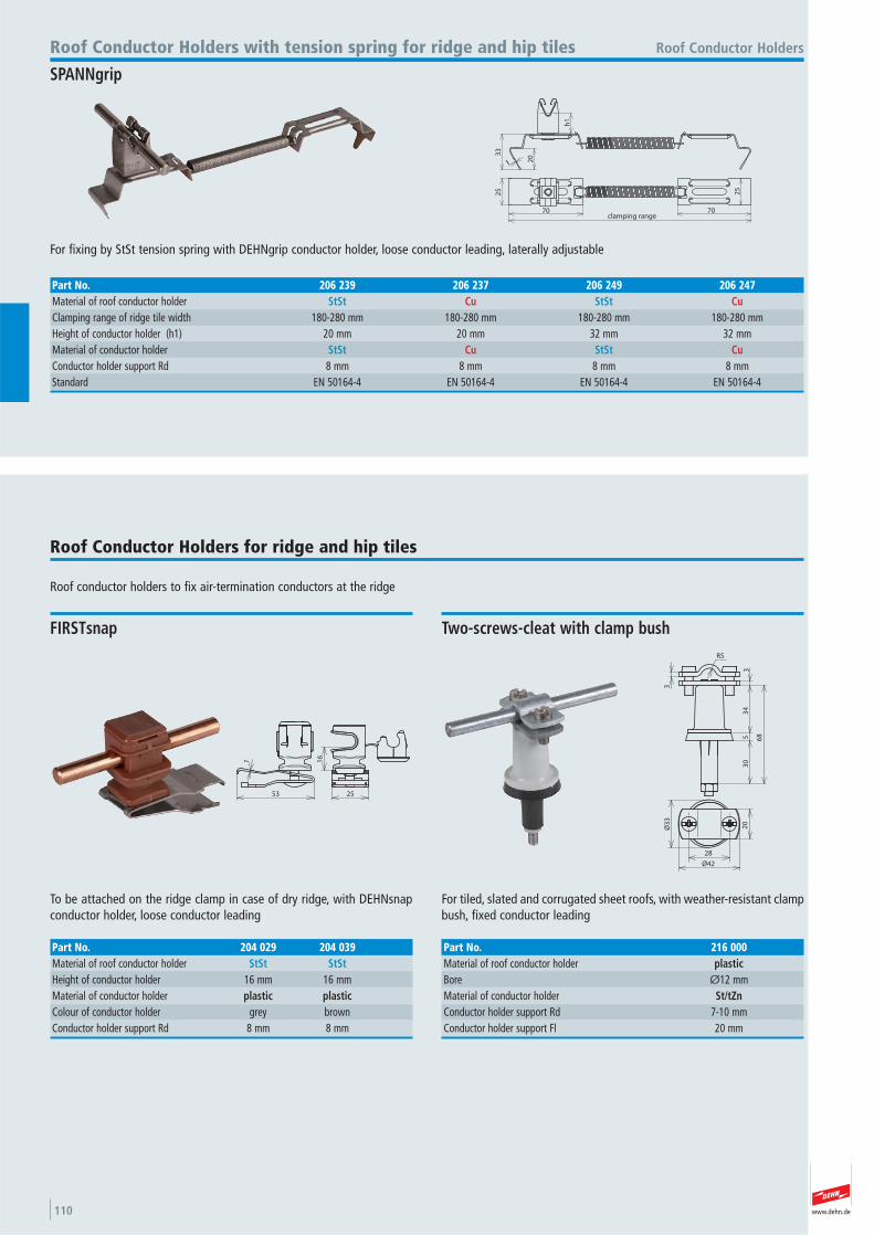
www.dehn.de110
h1
203
32
5
70 70clamping range
25
1
For fixing by StSt tension spring with DEHNgrip conductor holder, loose conductor leading, laterally adjustable
Roof Conductor HoldersRoof Conductor Holders with tension spring for ridge and hip tiles
SPANNgrip
Part No. 206 239 206 237 206 249 206 247Material of roof conductor holder StSt Cu StSt CuClamping range of ridge tile width 180-280 mm 180-280 mm 180-280 mm 180-280 mmHeight of conductor holder (h1) 20 mm 20 mm 32 mm 32 mmMaterial of conductor holder StSt Cu StSt CuConductor holder support Rd 8 mm 8 mm 8 mm 8 mmStandard EN 50164-4 EN 50164-4 EN 50164-4 EN 50164-4
Roof conductor holders to fix air-termination conductors at the ridge
Roof Conductor Holders for ridge and hip tiles
53
1 16
25
To be attached on the ridge clamp in case of dry ridge, with DEHNsnapconductor holder, loose conductor leading
FIRSTsnap
Part No. 204 029 204 039Material of roof conductor holder StSt StStHeight of conductor holder 16 mm 16 mmMaterial of conductor holder plastic plasticColour of conductor holder grey brown Conductor holder support Rd 8 mm 8 mm
30
53
43
R5
3
68
20
28
Ø3
3
Ø42
For tiled, slated and corrugated sheet roofs, with weather-resistant clampbush, fixed conductor leading
Two-screws-cleat with clamp bush
Part No. 216 000Material of roof conductor holder plasticBore Ø12 mmMaterial of conductor holder St/tZnConductor holder support Rd 7-10 mmConductor holder support Fl 20 mm
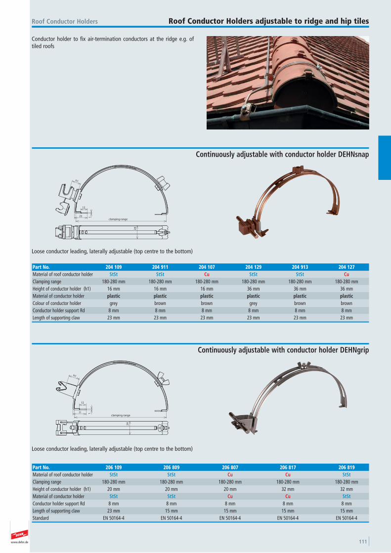
www.dehn.de 111
Conductor holder to fix air-termination conductors at the ridge e.g. oftiled roofs
Roof Conductor Holders Roof Conductor Holders adjustable to ridge and hip tiles
h1
23
12
1
clamping range
24
Loose conductor leading, laterally adjustable (top centre to the bottom)
Continuously adjustable with conductor holder DEHNsnap
Part No. 204 109 204 911 204 107 204 129 204 913 204 127Material of roof conductor holder StSt StSt Cu StSt StSt CuClamping range 180-280 mm 180-280 mm 180-280 mm 180-280 mm 180-280 mm 180-280 mmHeight of conductor holder (h1) 16 mm 16 mm 16 mm 36 mm 36 mm 36 mmMaterial of conductor holder plastic plastic plastic plastic plastic plasticColour of conductor holder grey brown brown grey brown brown Conductor holder support Rd 8 mm 8 mm 8 mm 8 mm 8 mm 8 mmLength of supporting claw 23 mm 23 mm 23 mm 23 mm 23 mm 23 mm
h1
l1
12
1
clamping range
24
Loose conductor leading, laterally adjustable (top centre to the bottom)
Continuously adjustable with conductor holder DEHNgrip
Part No. 206 109 206 809 206 807 206 817 206 819Material of roof conductor holder StSt StSt Cu Cu StStClamping range 180-280 mm 180-280 mm 180-280 mm 180-280 mm 180-280 mmHeight of conductor holder (h1) 20 mm 20 mm 20 mm 32 mm 32 mmMaterial of conductor holder StSt StSt Cu Cu StStConductor holder support Rd 8 mm 8 mm 8 mm 8 mm 8 mmLength of supporting claw 23 mm 15 mm 15 mm 15 mm 15 mmStandard EN 50164-4 EN 50164-4 EN 50164-4 EN 50164-4 EN 50164-4
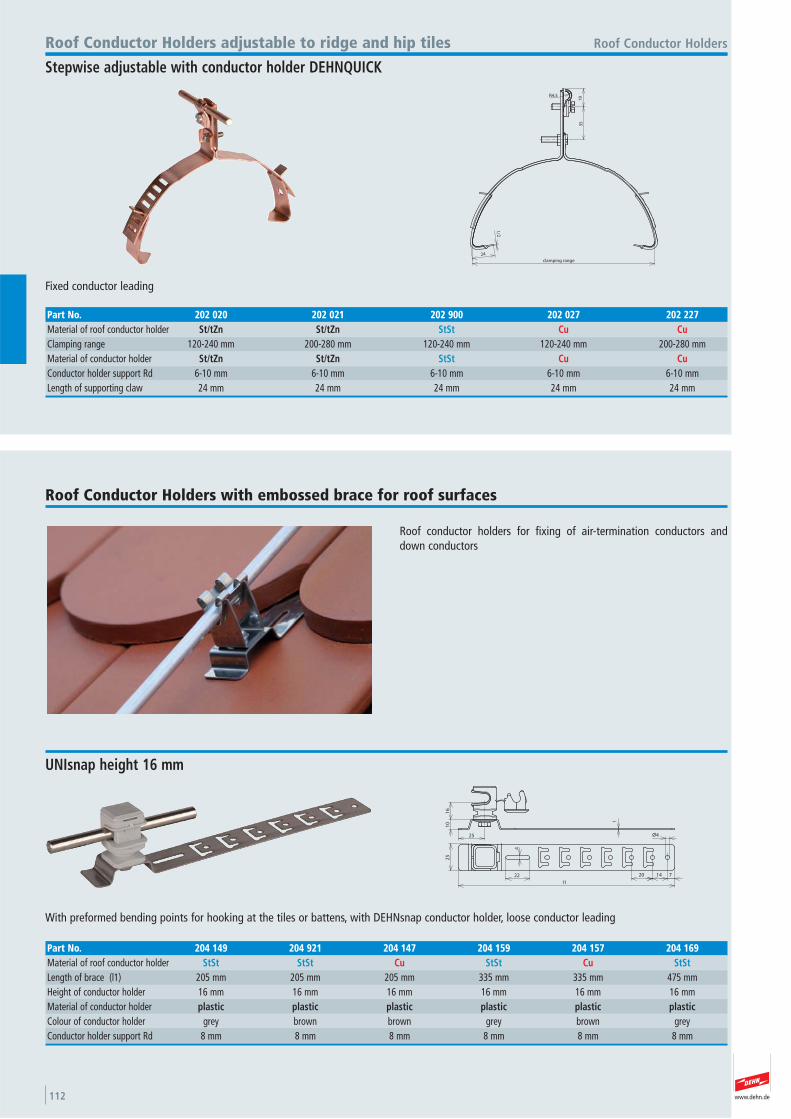
www.dehn.de112
19
35
1/2
24
clamping range
R4.5
Fixed conductor leading
Roof Conductor HoldersRoof Conductor Holders adjustable to ridge and hip tiles
Stepwise adjustable with conductor holder DEHNQUICK
Part No. 202 020 202 021 202 900 202 027 202 227Material of roof conductor holder St/tZn St/tZn StSt Cu CuClamping range 120-240 mm 200-280 mm 120-240 mm 120-240 mm 200-280 mmMaterial of conductor holder St/tZn St/tZn StSt Cu CuConductor holder support Rd 6-10 mm 6-10 mm 6-10 mm 6-10 mm 6-10 mmLength of supporting claw 24 mm 24 mm 24 mm 24 mm 24 mm
Roof conductor holders for fixing of air-termination conductors anddown conductors
Roof Conductor Holders with embossed brace for roof surfaces
16
10
25
1
25
22
4
1420
Ø4
l1
7
With preformed bending points for hooking at the tiles or battens, with DEHNsnap conductor holder, loose conductor leading
UNIsnap height 16 mm
Part No. 204 149 204 921 204 147 204 159 204 157 204 169Material of roof conductor holder StSt StSt Cu StSt Cu StStLength of brace (l1) 205 mm 205 mm 205 mm 335 mm 335 mm 475 mmHeight of conductor holder 16 mm 16 mm 16 mm 16 mm 16 mm 16 mmMaterial of conductor holder plastic plastic plastic plastic plastic plasticColour of conductor holder grey brown brown grey brown grey Conductor holder support Rd 8 mm 8 mm 8 mm 8 mm 8 mm 8 mm
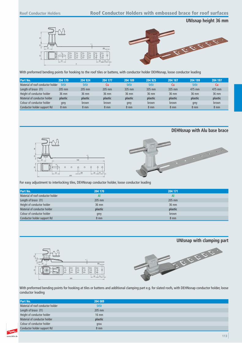
www.dehn.de 113
10
1
25
36
25
224
1420
Ø4
7
l1
With preformed bending points for hooking to the roof tiles or battens, with conductor holder DEHNsnap, loose conductor leading
Roof Conductor Holders Roof Conductor Holders with embossed brace for roof surfaces
UNIsnap height 36 mm
Part No. 204 179 204 924 204 177 204 189 204 925 204 187 204 199 204 197Material of roof conductor holder StSt StSt Cu StSt StSt Cu StSt CuLength of brace (l1) 205 mm 205 mm 205 mm 335 mm 335 mm 335 mm 475 mm 475 mmHeight of conductor holder 36 mm 36 mm 36 mm 36 mm 36 mm 36 mm 36 mm 36 mmMaterial of conductor holder plastic plastic plastic plastic plastic plastic plastic plasticColour of conductor holder grey brown brown grey brown brown grey brown Conductor holder support Rd 8 mm 8 mm 8 mm 8 mm 8 mm 8 mm 8 mm 8 mm
10
16
25
25
71420
205
1
Ø4
With preformed bending points for hooking at tiles or battens and additional clamping part e.g. for slated roofs, with DEHNsnap conductor holder, looseconductor leading
UNIsnap with clamping part
Part No. 204 089Material of roof conductor holder StStLength of brace (l1) 205 mmHeight of conductor holder 16 mmMaterial of conductor holder plasticColour of conductor holder grau Conductor holder support Rd 8 mm
10
36
1
25
25
22
4
160
71420Ø4
205
For easy adjustment to interlocking tiles, DEHNsnap conductor holder, loose conductor leading
DEHNsnap with Alu base brace
Part No. 204 170 204 171Material of roof conductor holder Al AlLength of brace (l1) 205 mm 205 mmHeight of conductor holder 36 mm 36 mmMaterial of conductor holder plastic plasticColour of conductor holder grey brown Conductor holder support Rd 8 mm 8 mm
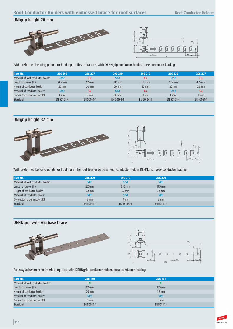
www.dehn.de114
32
10
25
1
4
22
25
20 14 7
l1
Ø4
With preformed bending points for hooking at the roof tiles or battens, with conductor holder DEHNgrip, loose conductor leading
Roof Conductor Holders
UNIgrip height 32 mm
Part No. 206 309 206 319 206 329Material of roof conductor holder StSt StSt StStLength of brace (l1) 205 mm 335 mm 475 mmHeight of conductor holder 32 mm 32 mm 32 mmMaterial of conductor holder StSt StSt StStConductor holder support Rd 8 mm 8 mm 8 mmStandard EN 50164-4 EN 50164-4 EN 50164-4
10
h1
25
1
25
205
22 Ø4
4
20 14 7
Ø4
For easy adjustment to interlocking tiles, with DEHNgrip conductor holder, loose conductor leading
DEHNgrip with Alu base brace
Part No. 206 170 206 171Material of roof conductor holder Al AlLength of brace (l1) 205 mm 205 mmHeight of conductor holder 20 mm 32 mmMaterial of conductor holder StSt StStConductor holder support Rd 8 mm 8 mmStandard EN 50164-4 EN 50164-4
10
20
25
1
25
22 71420
l1
4
Ø4
With preformed bending points for hooking at tiles or battens, with DEHNgrip conductor holder, loose conductor leading
Roof Conductor Holders with embossed brace for roof surfaces
UNIgrip height 20 mm
Part No. 206 209 206 207 206 219 206 217 206 229 206 227Material of roof conductor holder StSt Cu StSt Cu StSt CuLength of brace (l1) 205 mm 205 mm 335 mm 335 mm 475 mm 475 mmHeight of conductor holder 20 mm 20 mm 20 mm 20 mm 20 mm 20 mmMaterial of conductor holder StSt Cu StSt Cu StSt CuConductor holder support Rd 8 mm 8 mm 8 mm 8 mm 8 mm 8 mmStandard EN 50164-4 EN 50164-4 EN 50164-4 EN 50164-4 EN 50164-4 EN 50164-4
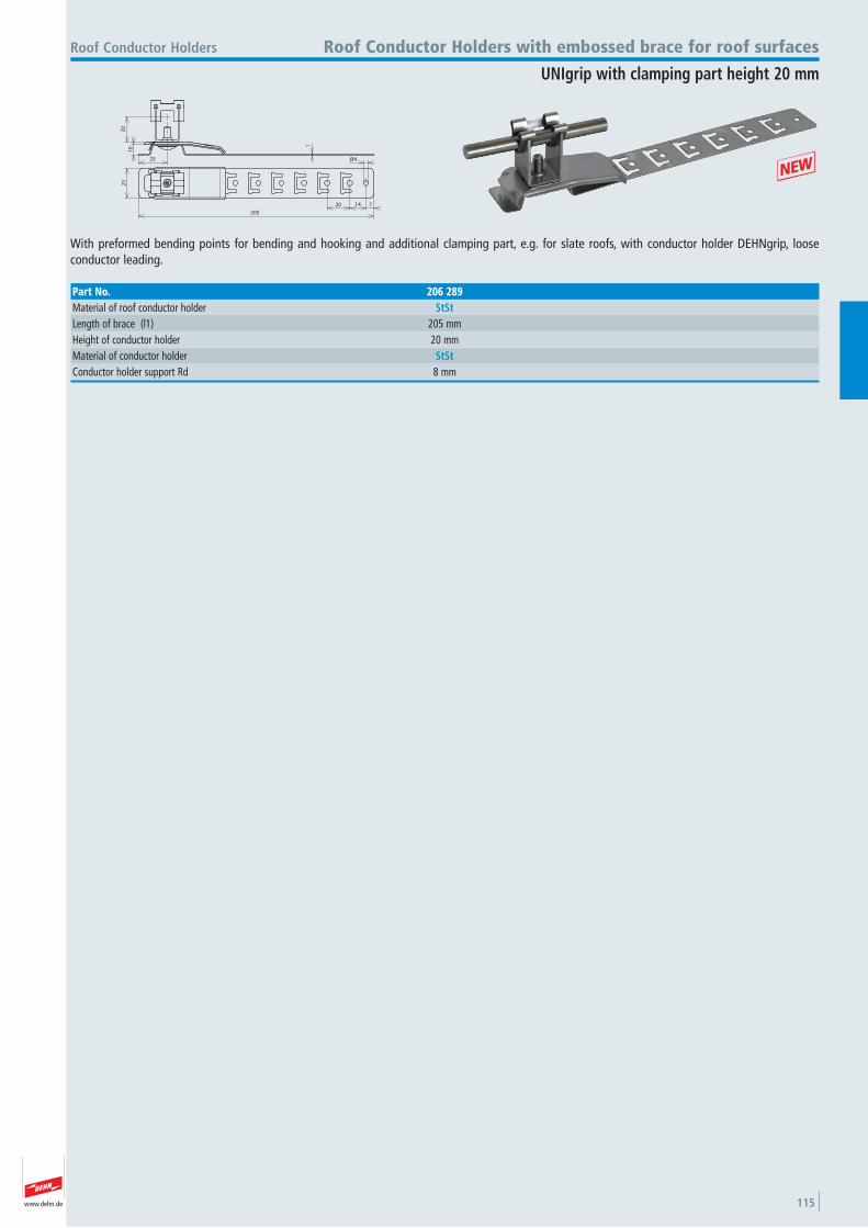
www.dehn.de 115
10
20
25
25
71420
205
1
Ø4
With preformed bending points for bending and hooking and additional clamping part, e.g. for slate roofs, with conductor holder DEHNgrip, loose conductor leading.
Roof Conductor Holders with embossed brace for roof surfaces
UNIgrip with clamping part height 20 mm
Part No. 206 289Material of roof conductor holder StStLength of brace (l1) 205 mmHeight of conductor holder 20 mmMaterial of conductor holder StStConductor holder support Rd 8 mm
+
Roof Conductor Holders
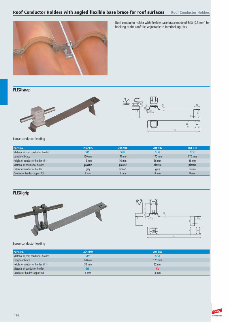
www.dehn.de116
Roof conductor holder with flexible base brace made of StSt (0.3 mm) forhooking at the roof tile, adjustable to interlocking tiles
Roof Conductor HoldersRoof Conductor Holders with angled flexible base brace for roof surfaces
10
20
29
20
1
h1
25
170
0.3
Loose conductor leading
FLEXIsnap
Part No. 204 935 204 936 204 937 204 938Material of roof conductor holder StSt StSt StSt StStLength of brace 170 mm 170 mm 170 mm 170 mmHeight of conductor holder (h1) 16 mm 16 mm 36 mm 36 mmMaterial of conductor holder plastic plastic plastic plasticColour of conductor holder grey brown grey brown Conductor holder support Rd 8 mm 8 mm 8 mm 8 mm
10
0.3
20
1
20
29
170
25
32
Loose conductor leading
FLEXIgrip
Part No. 204 949 204 957Material of roof conductor holder StSt StStLength of brace 170 mm 170 mmHeight of conductor holder (h1) 32 mm 32 mmMaterial of conductor holder StSt CuConductor holder support Rd 8 mm 8 mm
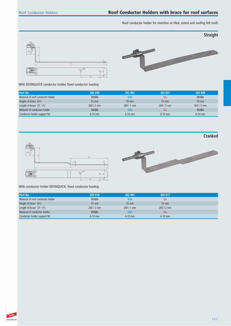
www.dehn.de 117
Roof conductor holder for insertion at tiled, slated and roofing felt roofs
Roof Conductor Holders Roof Conductor Holders with brace for roof surfaces
20
32
h1
l1
2
70 25
28
Ø5
R4.5
With DEHNQUICK conductor holder, fixed conductor leading
Straight
Part No. 202 040 202 902 202 037 202 008Material of roof conductor holder St/tZn StSt Cu St/tZnHeight of brace (h1) 55 mm 55 mm 55 mm 70 mmLength of brace (l1 / t1) 260 / 2 mm 260 / 1 mm 260 / 2 mm 420 / 2 mmMaterial of conductor holder St/tZn StSt Cu St/tZnConductor holder support Rd 6-10 mm 6-10 mm 6-10 mm 6-10 mm
20
32
55
l1
t1
134
6
R4.5
70 28
28
Ø5
With conductor holder DEHNQUICK, fixed conductor leading
Cranked
Part No. 202 010 202 901 202 017Material of roof conductor holder St/tZn StSt CuHeight of brace (h1) 55 mm 55 mm 55 mmLength of brace (l1 / t1) 260 / 2 mm 260 / 1 mm 260 / 2 mmMaterial of conductor holder St/tZn StSt CuConductor holder support Rd 6-10 mm 6-10 mm 6-10 mm
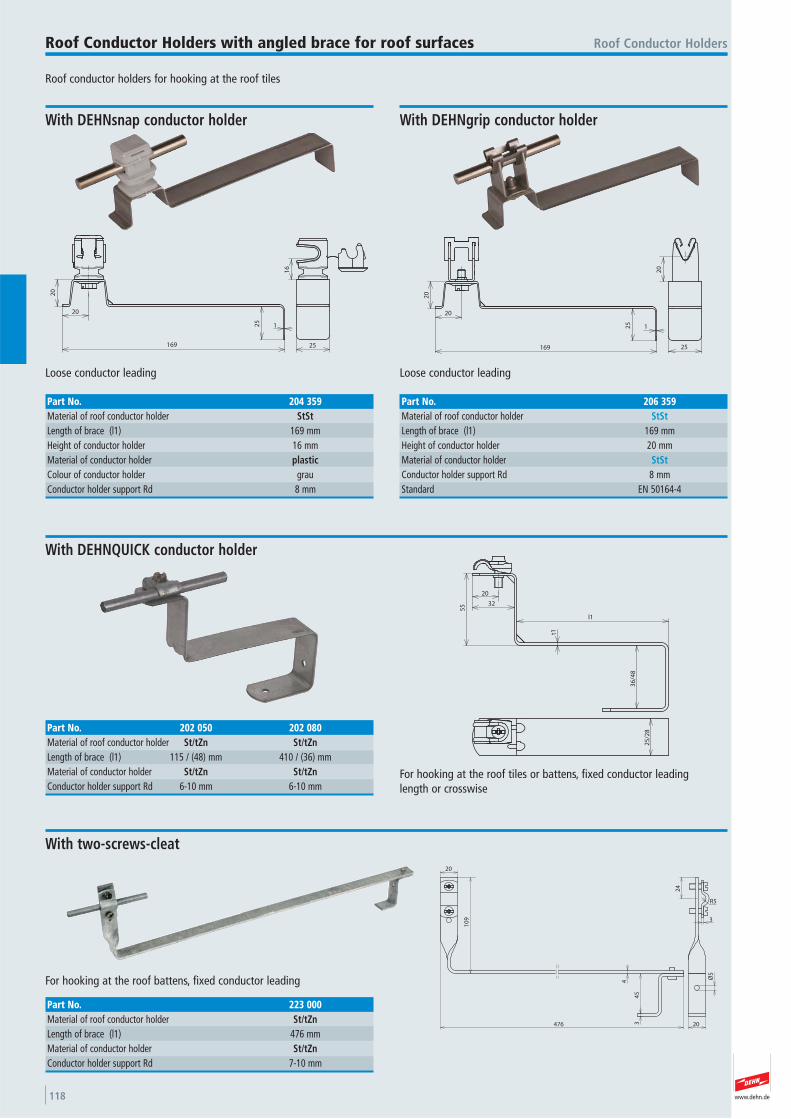
www.dehn.de118
Roof conductor holders for hooking at the roof tiles
Roof Conductor HoldersRoof Conductor Holders with angled brace for roof surfaces2
0
20
169
125
25
16
Loose conductor leading
With DEHNsnap conductor holder
Part No. 204 359Material of roof conductor holder StStLength of brace (l1) 169 mmHeight of conductor holder 16 mmMaterial of conductor holder plasticColour of conductor holder grau Conductor holder support Rd 8 mm
20
169
125
20
25
20
Loose conductor leading
With DEHNgrip conductor holder
Part No. 206 359Material of roof conductor holder StStLength of brace (l1) 169 mmHeight of conductor holder 20 mmMaterial of conductor holder StStConductor holder support Rd 8 mmStandard EN 50164-4
20
32
l1
36
/48
t1
55
25
/28
For hooking at the roof tiles or battens, fixed conductor leading length or crosswise
With DEHNQUICK conductor holder
Part No. 202 050 202 080Material of roof conductor holder St/tZn St/tZnLength of brace (l1) 115 / (48) mm 410 / (36) mmMaterial of conductor holder St/tZn St/tZnConductor holder support Rd 6-10 mm 6-10 mm
20
10
9
476 34
5
4
24
3
Ø5
20
R5
For hooking at the roof battens, fixed conductor leading
With two-screws-cleat
Part No. 223 000Material of roof conductor holder St/tZnLength of brace (l1) 476 mmMaterial of conductor holder St/tZnConductor holder support Rd 7-10 mm
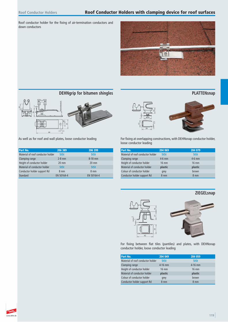
www.dehn.de 119
Roof conductor holder for the fixing of air-termination conductors anddown conductors
Roof Conductor Holders Roof Conductor Holders with clamping device for roof surfaces
1
26
Kle
mm
be
reic
h
80
Ø5
29
7
20
As well as for roof and wall plates, loose conductor leading
DEHNgrip for bitumen shingles
Part No. 206 389 206 399Material of roof conductor holder StSt StStClamping range 2-8 mm 8-18 mmHeight of conductor holder 20 mm 20 mmMaterial of conductor holder StSt StStConductor holder support Rd 8 mm 8 mmStandard EN 50164-4 EN 50164-4
16
1 Ø20
17
26
1.5
For fixing at overlapping constructions, with DEHNsnap conductor holder,loose conductor leading
PLATTENsnap
Part No. 204 069 204 079Material of roof conductor holder StSt StStClamping range 4-6 mm 4-6 mmHeight of conductor holder 16 mm 16 mmMaterial of conductor holder plastic plasticColour of conductor holder grey brown Conductor holder support Rd 8 mm 8 mm
16
21
1
1
25
42
For fixing between flat tiles (pantiles) and plates, with DEHNsnap conductor holder, loose conductor leading
ZIEGELsnap
Part No. 204 049 204 059Material of roof conductor holder StSt StStClamping range 4-16 mm 4-16 mmHeight of conductor holder 16 mm 16 mmMaterial of conductor holder plastic plasticColour of conductor holder grey brown Conductor holder support Rd 8 mm 8 mm
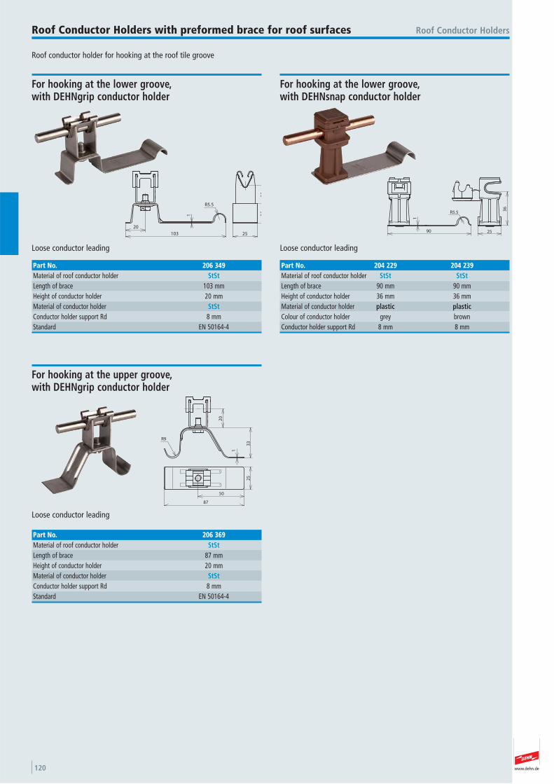
www.dehn.de120
Roof conductor holder for hooking at the roof tile groove
Roof Conductor HoldersRoof Conductor Holders with preformed brace for roof surfaces
20
103
1
20
20
25
R5.5
Loose conductor leading
For hooking at the lower groove, with DEHNgrip conductor holder
Part No. 206 349Material of roof conductor holder StStLength of brace 103 mmHeight of conductor holder 20 mmMaterial of conductor holder StStConductor holder support Rd 8 mmStandard EN 50164-4
R5.5
90
1
25
36
Loose conductor leading
For hooking at the lower groove, with DEHNsnap conductor holder
Part No. 204 229 204 239Material of roof conductor holder StSt StStLength of brace 90 mm 90 mmHeight of conductor holder 36 mm 36 mmMaterial of conductor holder plastic plasticColour of conductor holder grey brown Conductor holder support Rd 8 mm 8 mm
R9
20
33
1
25
50
87
Loose conductor leading
For hooking at the upper groove, with DEHNgrip conductor holder
Part No. 206 369Material of roof conductor holder StStLength of brace 87 mmHeight of conductor holder 20 mmMaterial of conductor holder StStConductor holder support Rd 8 mmStandard EN 50164-4
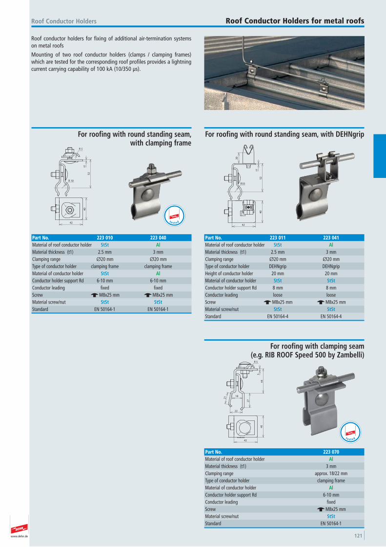
www.dehn.de 121
Roof conductor holders for fixing of additional air-termination systemson metal roofs
Mounting of two roof conductor holders (clamps / clamping frames)which are tested for the corresponding roof profiles provides a lightningcurrent carrying capability of 100 kA (10/350 μs).
Roof Conductor Holders Roof Conductor Holders for metal roofs
5R
t1
10R
52
42
40
For roofing with round standing seam, with clamping frame
Part No. 223 010 223 040Material of roof conductor holder StSt AlMaterial thickness (t1) 2.5 mm 3 mmClamping range Ø20 mm Ø20 mmType of conductor holder clamping frame clamping frame Material of conductor holder StSt AlConductor holder support Rd 6-10 mm 6-10 mmConductor leading fixed fixed Screw e M8x25 mm e M8x25 mmMaterial screw/nut StSt StStStandard EN 50164-1 EN 50164-1
t e s t e d
20
t1
R10
52
40
42
For roofing with round standing seam, with DEHNgrip
Part No. 223 011 223 041Material of roof conductor holder StSt AlMaterial thickness (t1) 2.5 mm 3 mmClamping range Ø20 mm Ø20 mmType of conductor holder DEHNgrip DEHNgrip Height of conductor holder 20 mm 20 mmMaterial of conductor holder StSt StStConductor holder support Rd 8 mm 8 mmConductor leading loose loose Screw e M8x25 mm e M8x25 mmMaterial screw/nut StSt StStStandard EN 50164-4 EN 50164-4
3
18
22
44
27
21
5R
42
40
For roofing with clamping seam (e.g. RIB ROOF Speed 500 by Zambelli)
Part No. 223 070Material of roof conductor holder AlMaterial thickness (t1) 3 mmClamping range approx. 18/22 mmType of conductor holder clamping frame Material of conductor holder AlConductor holder support Rd 6-10 mmConductor leading fixed Screw e M8x25 mmMaterial screw/nut StStStandard EN 50164-1
t e s t e d
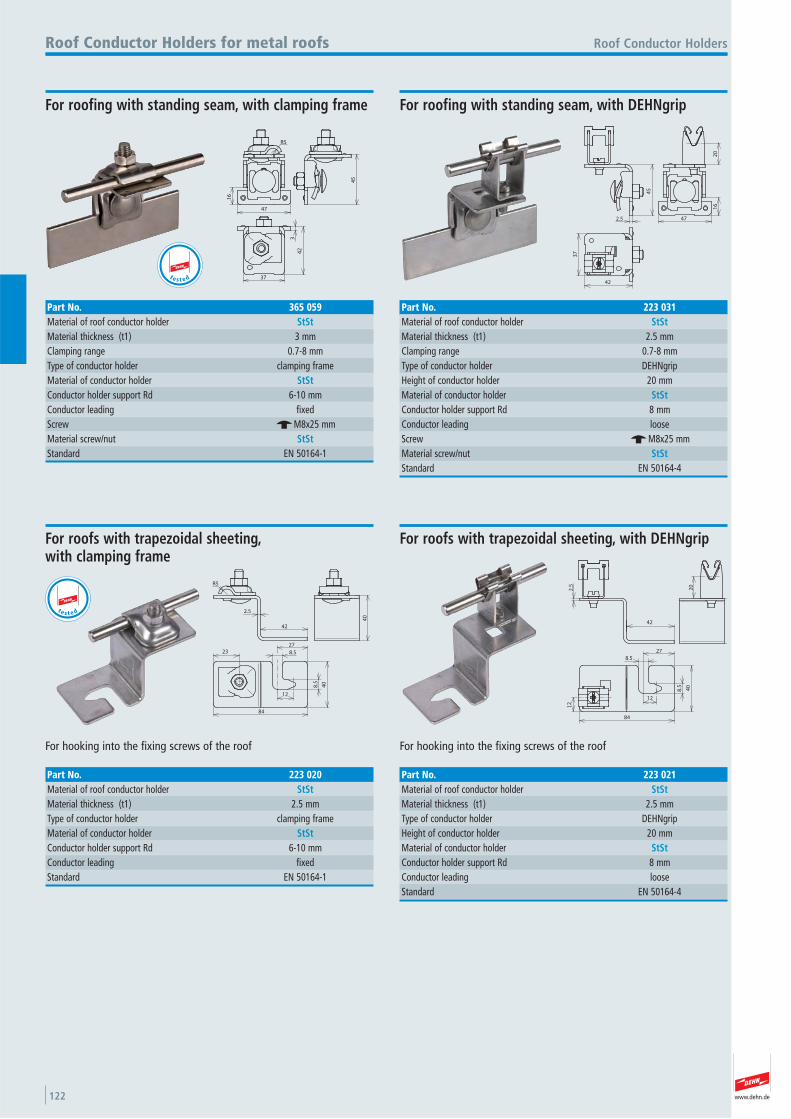
www.dehn.de122
16
R5
47
45
3
42
37
Roof Conductor HoldersRoof Conductor Holders for metal roofs
Part No. 365 059Material of roof conductor holder StStMaterial thickness (t1) 3 mmClamping range 0.7-8 mmType of conductor holder clamping frame Material of conductor holder StStConductor holder support Rd 6-10 mmConductor leading fixed Screw e M8x25 mmMaterial screw/nut StStStandard EN 50164-1
For roofing with standing seam, with clamping frame
45
2.5 47
16
20
42
37
For roofing with standing seam, with DEHNgrip
Part No. 223 031Material of roof conductor holder StStMaterial thickness (t1) 2.5 mmClamping range 0.7-8 mmType of conductor holder DEHNgrip Height of conductor holder 20 mmMaterial of conductor holder StStConductor holder support Rd 8 mmConductor leading loose Screw e M8x25 mmMaterial screw/nut StStStandard EN 50164-4
R5
2.5
42
40
23 8.5
12
8.5
40
27
84
For hooking into the fixing screws of the roof
For roofs with trapezoidal sheeting, with clamping frame
Part No. 223 020Material of roof conductor holder StStMaterial thickness (t1) 2.5 mmType of conductor holder clamping frame Material of conductor holder StStConductor holder support Rd 6-10 mmConductor leading fixed Standard EN 50164-1
2.5
42
20
12
12
8.5
27
8.5 40
84
For hooking into the fixing screws of the roof
For roofs with trapezoidal sheeting, with DEHNgrip
Part No. 223 021Material of roof conductor holder StStMaterial thickness (t1) 2.5 mmType of conductor holder DEHNgrip Height of conductor holder 20 mmMaterial of conductor holder StStConductor holder support Rd 8 mmConductor leading loose Standard EN 50164-4
t e s t e d
te s t e d
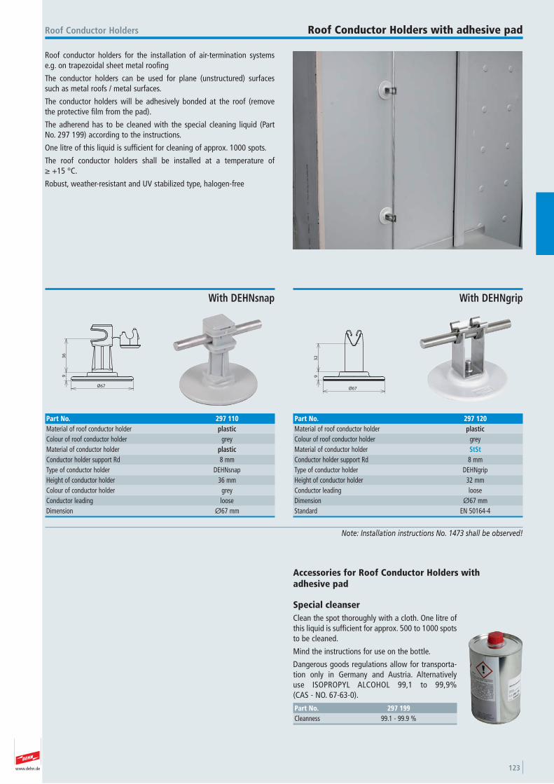
www.dehn.de 123
Roof conductor holders for the installation of air-termination systems e.g. on trapezoidal sheet metal roofing
The conductor holders can be used for plane (unstructured) surfaces such as metal roofs / metal surfaces.
The conductor holders will be adhesively bonded at the roof (remove the protective film from the pad).
The adherend has to be cleaned with the special cleaning liquid (Part No. 297 199) according to the instructions.
One litre of this liquid is sufficient for cleaning of approx. 1000 spots.
The roof conductor holders shall be installed at a temperature of ≥ +15 °C.
Robust, weather-resistant and UV stabilized type, halogen-free
Roof Conductor Holders Roof Conductor Holders with adhesive pad
Note: Installation instructions No. 1473 shall be observed!
9
Ø67
36
With DEHNsnap
Part No. 297 110Material of roof conductor holder plasticColour of roof conductor holder grey Material of conductor holder plasticConductor holder support Rd 8 mmType of conductor holder DEHNsnap Height of conductor holder 36 mmColour of conductor holder grey Conductor leading loose Dimension Ø67 mm
32
9
Ø67
With DEHNgrip
Part No. 297 120Material of roof conductor holder plasticColour of roof conductor holder grey Material of conductor holder StStConductor holder support Rd 8 mmType of conductor holder DEHNgrip Height of conductor holder 32 mmConductor leading loose Dimension Ø67 mmStandard EN 50164-4
Accessories for Roof Conductor Holders with adhesive pad
Special cleanser Clean the spot thoroughly with a cloth. One litre ofthis liquid is sufficient for approx. 500 to 1000 spotsto be cleaned.
Mind the instructions for use on the bottle.
Dangerous goods regulations allow for transporta-tion only in Germany and Austria. Alternatively use ISOPROPYL ALCOHOL 99,1 to 99,9% (CAS - NO. 67-63-0).
Part No. 297 199Cleanness 99.1 - 99.9 %
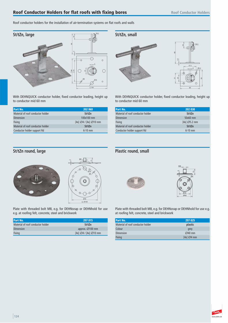
www.dehn.de124
Roof conductor holders for the installation of air-termination systems on flat roofs and walls
Roof Conductor HoldersRoof Conductor Holders for flat roofs with fixing bores
18
66
2.5
R4.5
37.5
31
4
20
60
50
Ø5.2
With DEHNQUICK conductor holder, fixed conductor leading, height upto conductor mid 60 mm
St/tZn, small
Part No. 202 030Material of roof conductor holder St/tZnDimension 50x60 mmFixing [4x] Ø5.2 mmMaterial of roof conductor holder St/tZnConductor holder support Rd 6-10 mm
21
8
66
R4.5
70
80
100
Ø4Ø10
4
20
With DEHNQUICK conductor holder, fixed conductor leading, height upto conductor mid 60 mm
St/tZn, large
Part No. 202 060Material of roof conductor holder St/tZnDimension 100x100 mmFixing [4x] Ø4 / [4x] Ø10 mmMaterial of roof conductor holder St/tZnConductor holder support Rd 6-10 mm
152 M8
Ø10
Ø4
Ø78
ca. Ø100
Plate with threaded bolt M8, e.g. for DEHNsnap or DEHNhold for use e.g. at roofing felt, concrete, steel and brickwork
St/tZn round, large
Part No. 297 015Material of roof conductor holder St/tZnDimension approx. Ø100 mmFixing [4x] Ø4 / [4x] Ø10 mm
M8
153
Ø4
Ø30
Ø40
Plate with threaded bolt M8, e.g. for DEHNsnap or DEHNhold for use e.g.at roofing felt, concrete, steel and brickwork
Plastic round, small
Part No. 297 025Material of roof conductor holder plasticColour grey Dimension Ø40 mmFixing [4x] Ø4 mm
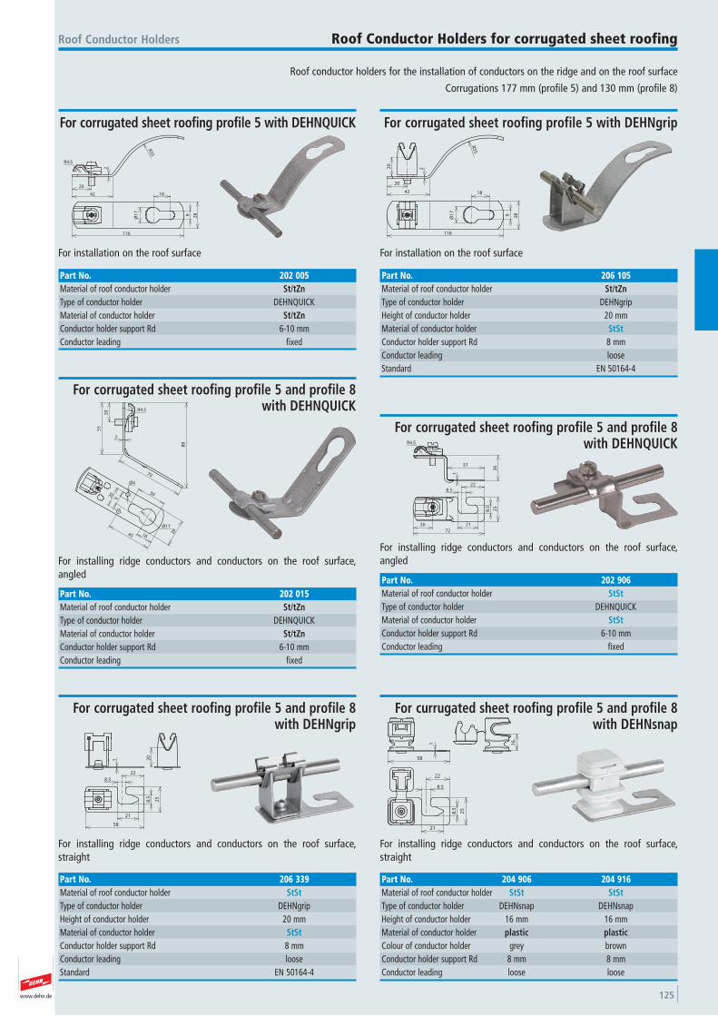
www.dehn.de 125
Roof conductor holders for the installation of conductors on the ridge and on the roof surface
Corrugations 177 mm (profile 5) and 130 mm (profile 8)
Roof Conductor Holders Roof Conductor Holders for corrugated sheet roofing
20
42
2
R4.5
R55
Ø1
7
18
9 28
116
For installation on the roof surface
For corrugated sheet roofing profile 5 with DEHNQUICK
Part No. 202 005Material of roof conductor holder St/tZnType of conductor holder DEHNQUICK Material of conductor holder St/tZnConductor holder support Rd 6-10 mmConductor leading fixed
R5
5
42
220
20
116
Ø1
7
9 28
18
For installation on the roof surface
For corrugated sheet roofing profile 5 with DEHNgrip
Part No. 206 105Material of roof conductor holder St/tZnType of conductor holder DEHNgrip Height of conductor holder 20 mmMaterial of conductor holder StStConductor holder support Rd 8 mmConductor leading loose Standard EN 50164-4
20
53
70
88
2
R4.5
920
1645
30
Ø4
Ø17
28
For installing ridge conductors and conductors on the roof surface, angled
For corrugated sheet roofing profile 5 and profile 8with DEHNQUICK
Part No. 202 015Material of roof conductor holder St/tZnType of conductor holder DEHNQUICK Material of conductor holder St/tZnConductor holder support Rd 6-10 mmConductor leading fixed
R4.5
37
26
1
20
72
21
8.5 25
8.522
For installing ridge conductors and conductors on the roof surface, angled
For corrugated sheet roofing profile 5 and profile 8with DEHNQUICK
Part No. 202 906Material of roof conductor holder StStType of conductor holder DEHNQUICK Material of conductor holder StStConductor holder support Rd 6-10 mmConductor leading fixed
8.5
25
21
22
8.5
58
1 20
For installing ridge conductors and conductors on the roof surface,straight
For corrugated sheet roofing profile 5 and profile 8with DEHNgrip
Part No. 206 339Material of roof conductor holder StStType of conductor holder DEHNgrip Height of conductor holder 20 mmMaterial of conductor holder StStConductor holder support Rd 8 mmConductor leading loose Standard EN 50164-4
1
58
16
22
8.5
25
8.5
21
For installing ridge conductors and conductors on the roof surface,straight
For currugated sheet roofing profile 5 and profile 8with DEHNsnap
Part No. 204 906 204 916Material of roof conductor holder StSt StStType of conductor holder DEHNsnap DEHNsnap Height of conductor holder 16 mm 16 mmMaterial of conductor holder plastic plasticColour of conductor holder grey brown Conductor holder support Rd 8 mm 8 mmConductor leading loose loose

www.dehn.de126
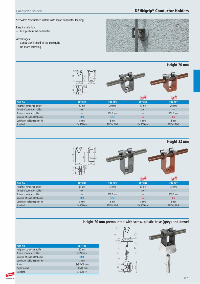
www.dehn.de 127
Screwless StSt holder system with loose conductor leading
Easy installation:– Just push in the conductor
Advantages: – Conductor is fixed in the DEHNgrip– No more screwing
Conductor Holders DEHNgrip® Conductor Holders
33
20
20
1.5
20
26
M6
Ø7
.8
Height 20 mm
Part No. 207 019 207 009 207 017 207 007Height of conductor holder 20 mm 20 mm 20 mm 20 mmThread of conductor holder M6 — M6 —Bore of conductor holder — Ø7.8 mm — Ø7.8 mmMaterial of conductor holder StSt StSt Cu CuConductor holder support Rd 8 mm 8 mm 8 mm 8 mmStandard EN 50164-4 EN 50164-4 EN 50164-4 EN 50164-4
20
32
46
1.5
20
26
M6
Ø7
.8
Height 32 mm
Part No. 207 039 207 029 207 037 207 027Height of conductor holder 32 mm 32 mm 32 mm 32 mmThread of conductor holder M6 — M6 —Bore of conductor holder — Ø7.8 mm — Ø7.8 mmMaterial of conductor holder StSt StSt Cu CuConductor holder support Rd 8 mm 8 mm 8 mm 8 mmStandard EN 50164-4 EN 50164-4 EN 50164-4 EN 50164-4
+ +
+ +
19
14
43
37
40
Ø3
5
26
Height 20 mm premounted with screw, plastic base (grey) and dowel
Part No. 207 109Height of conductor holder 20 mmBore of conductor holder Ø7.8 mmMaterial of conductor holder StStConductor holder support Rd 8 mmScrew ak 5x50 mmPlastic dowel Ø8x40 mmStandard EN 50164-4
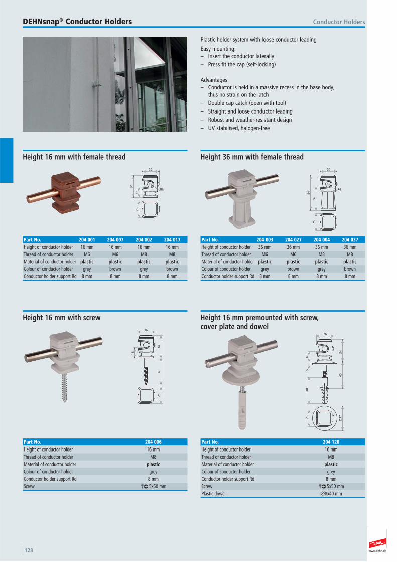
www.dehn.de128
Plastic holder system with loose conductor leading
Easy mounting:– Insert the conductor laterally – Press fit the cap (self-locking)
Advantages: – Conductor is held in a massive recess in the base body,
thus no strain on the latch– Double cap catch (open with tool)– Straight and loose conductor leading – Robust and weather-resistant design– UV stabilised, halogen-free
Conductor HoldersDEHNsnap® Conductor Holders
26
34
16
R4
25
Height 16 mm with female thread
Part No. 204 001 204 007 204 002 204 017Height of conductor holder 16 mm 16 mm 16 mm 16 mmThread of conductor holder M6 M6 M8 M8 Material of conductor holder plastic plastic plastic plasticColour of conductor holder grey brown grey brown Conductor holder support Rd 8 mm 8 mm 8 mm 8 mm
26
54
36
R4
25
Height 36 mm with female thread
Part No. 204 003 204 027 204 004 204 037Height of conductor holder 36 mm 36 mm 36 mm 36 mmThread of conductor holder M6 M6 M8 M8 Material of conductor holder plastic plastic plastic plasticColour of conductor holder grey brown grey brown Conductor holder support Rd 8 mm 8 mm 8 mm 8 mm
34
26
16
40
25
Height 16 mm with screw
Part No. 204 006Height of conductor holder 16 mmThread of conductor holder M8 Material of conductor holder plasticColour of conductor holder grey Conductor holder support Rd 8 mmScrew ak 5x50 mm
34
26
16
40
52
5
Ø3
74
0
Height 16 mm premounted with screw, cover plate and dowel
Part No. 204 120Height of conductor holder 16 mmThread of conductor holder M8 Material of conductor holder plasticColour of conductor holder grey Conductor holder support Rd 8 mmScrew ak 5x50 mmPlastic dowel Ø8x40 mm
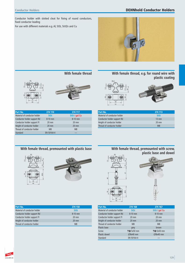
www.dehn.de 129
Conductor holder with slotted cleat for fixing of round conductors, fixed conductor leading
For use with different materials e.g. Al, StSt, St/tZn and Cu
Conductor Holders DEHNhold Conductor Holders
20
1.51
.5
R5
18
20
26
40
With female thread
Part No. 274 110 274 117Material of conductor holder StSt StSt / gal CuConductor holder support Rd 8-10 mm 8-10 mmConductor holder support Fl 20 mm 20 mmHeight of conductor holder 20 mm 20 mmThread of conductor holder M8 M8 Standard EN 50164-4 —
R5
16
14
1.51
.51
8
Ø3
5
40
26
With female thread, premounted with plastic base
Part No. 274 150Material of conductor holder StStConductor holder support Rd 8-10 mmConductor holder support Fl 20 mmHeight of conductor holder 20 mmThread of conductor holder M8
26
Ø3
5
40
18
37
40
1.5
1.5R5
14
16
With female thread, premounted with screw, plastic base and dowel
Part No. 274 160 274 167Material of conductor holder StSt StSt / gal CuConductor holder support Rd 8-10 mm 8-10 mmConductor holder support Fl 20 mm 20 mmHeight of conductor holder 20 mm 20 mmThread of conductor holder M8 M8 Plastic base grey brown Screw ak 5x50 mm ak 5x50 mmPlastic dowel Ø8x40 mm Ø8x40 mmStandard EN 50164-4 —
R6.5
1.5
20
1.5
38
18
20
52
With female thread, e.g. for round wire with plastic coating
Part No. 274 113Material of conductor holder StStConductor holder support Rd 13 mmHeight of conductor holder 20 mmThread of conductor holder M8
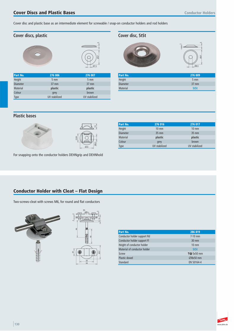
www.dehn.de130
Cover disc and plastic base as an intermediate element for screwable / snap-on conductor holders and rod holders
Conductor HoldersCover Discs and Plastic Bases
14
20
Ø35
Ø8
.5
For snapping onto the conductor holders DEHNgrip and DEHNhold
Plastic bases
Part No. 276 016 276 017Height 10 mm 10 mmDiameter 35 mm 35 mmMaterial plastic plasticColour grey brown Type UV stabilized UV stabilized
Ø3
7
Ø7.5
5
Cover discs, plastic
Part No. 276 006 276 007Height 5 mm 5 mmDiameter 37 mm 37 mmMaterial plastic plasticColour grey brown Type UV stabilized UV stabilized
Ø3
7
Ø8.5
1
5
Cover disc, StSt
Part No. 276 009Height 5 mmDiameter 37 mmMaterial StSt
Two-screws-cleat with screws M6, for round and flat conductors
Conductor Holder with Cleat – Flat Design
40
51
0
R5
22
2
46
58
20
Ø3
7
38
Part No. 286 819Conductor holder support Rd 7-10 mmConductor holder support Fl 30 mmHeight of conductor holder 10 mmMaterial of conductor holder StStScrew ak 5x50 mmPlastic dowel Ø8x50 mmStandard EN 50164-4
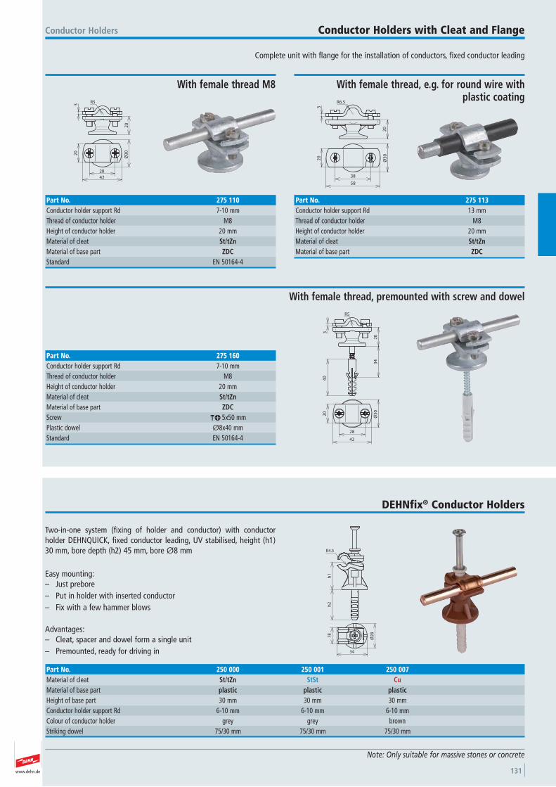
www.dehn.de 131
Complete unit with flange for the installation of conductors, fixed conductor leading
Conductor Holders Conductor Holders with Cleat and Flange
R5
3
20
28
20
42
Ø3
0
With female thread M8
Part No. 275 110Conductor holder support Rd 7-10 mmThread of conductor holder M8 Height of conductor holder 20 mmMaterial of cleat St/tZnMaterial of base part ZDCStandard EN 50164-4
R5
3
20
34
40
28
20
42
Ø3
0
With female thread, premounted with screw and dowel
Part No. 275 160Conductor holder support Rd 7-10 mmThread of conductor holder M8 Height of conductor holder 20 mmMaterial of cleat St/tZnMaterial of base part ZDCScrew ak 5x50 mmPlastic dowel Ø8x40 mmStandard EN 50164-4
R6.5
3
20
20
38
58
Ø3
0
With female thread, e.g. for round wire with plastic coating
Part No. 275 113Conductor holder support Rd 13 mmThread of conductor holder M8 Height of conductor holder 20 mmMaterial of cleat St/tZnMaterial of base part ZDC
Two-in-one system (fixing of holder and conductor) with conductor holder DEHNQUICK, fixed conductor leading, UV stabilised, height (h1)30 mm, bore depth (h2) 45 mm, bore Ø8 mm
Easy mounting:– Just prebore– Put in holder with inserted conductor – Fix with a few hammer blows
Advantages:– Cleat, spacer and dowel form a single unit– Premounted, ready for driving in
DEHNfix® Conductor Holders
Note: Only suitable for massive stones or concrete
h1
R4.5
h2
34
18
Ø2
8
Part No. 250 000 250 001 250 007Material of cleat St/tZn StSt CuMaterial of base part plastic plastic plasticHeight of base part 30 mm 30 mm 30 mmConductor holder support Rd 6-10 mm 6-10 mm 6-10 mmColour of conductor holder grey grey brown Striking dowel 75/30 mm 75/30 mm 75/30 mm
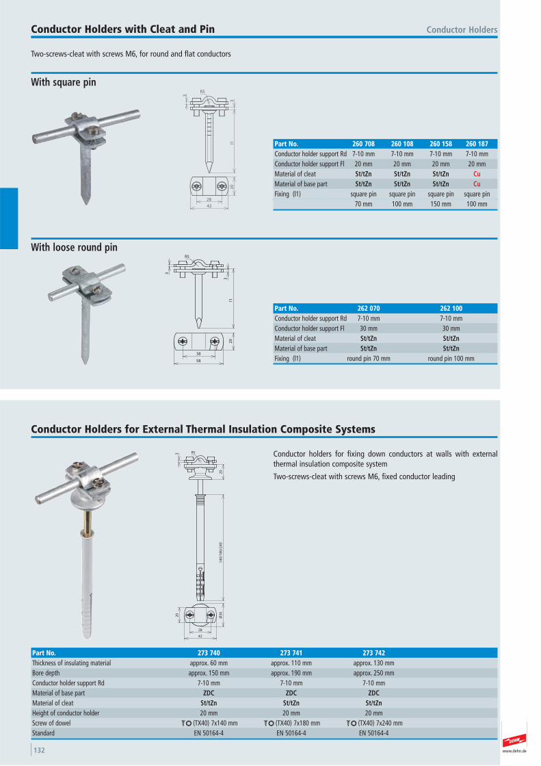
www.dehn.de132
Two-screws-cleat with screws M6, for round and flat conductors
Conductor HoldersConductor Holders with Cleat and Pin
l1
3
3
R5
28
42
20
With square pin
Part No. 260 708 260 108 260 158 260 187Conductor holder support Rd 7-10 mm 7-10 mm 7-10 mm 7-10 mmConductor holder support Fl 20 mm 20 mm 20 mm 20 mmMaterial of cleat St/tZn St/tZn St/tZn CuMaterial of base part St/tZn St/tZn St/tZn CuFixing (l1) square pin square pin square pin square pin 70 mm 100 mm 150 mm 100 mm
R5
3
3
l1
38
20
58
With loose round pin
Part No. 262 070 262 100Conductor holder support Rd 7-10 mm 7-10 mmConductor holder support Fl 30 mm 30 mmMaterial of cleat St/tZn St/tZnMaterial of base part St/tZn St/tZnFixing (l1) round pin 70 mm round pin 100 mm
Conductor holders for fixing down conductors at walls with externalthermal insulation composite system
Two-screws-cleat with screws M6, fixed conductor leading
Conductor Holders for External Thermal Insulation Composite Systems
R53
20
14
0/1
80
/24
0
28
20
42
Ø3
0
Part No. 273 740 273 741 273 742Thickness of insulating material approx. 60 mm approx. 110 mm approx. 130 mmBore depth approx. 150 mm approx. 190 mm approx. 250 mmConductor holder support Rd 7-10 mm 7-10 mm 7-10 mmMaterial of base part ZDC ZDC ZDCMaterial of cleat St/tZn St/tZn St/tZnHeight of conductor holder 20 mm 20 mm 20 mmScrew of dowel bl (TX40) 7x140 mm bl (TX40) 7x180 mm bl (TX40) 7x240 mmStandard EN 50164-4 EN 50164-4 EN 50164-4
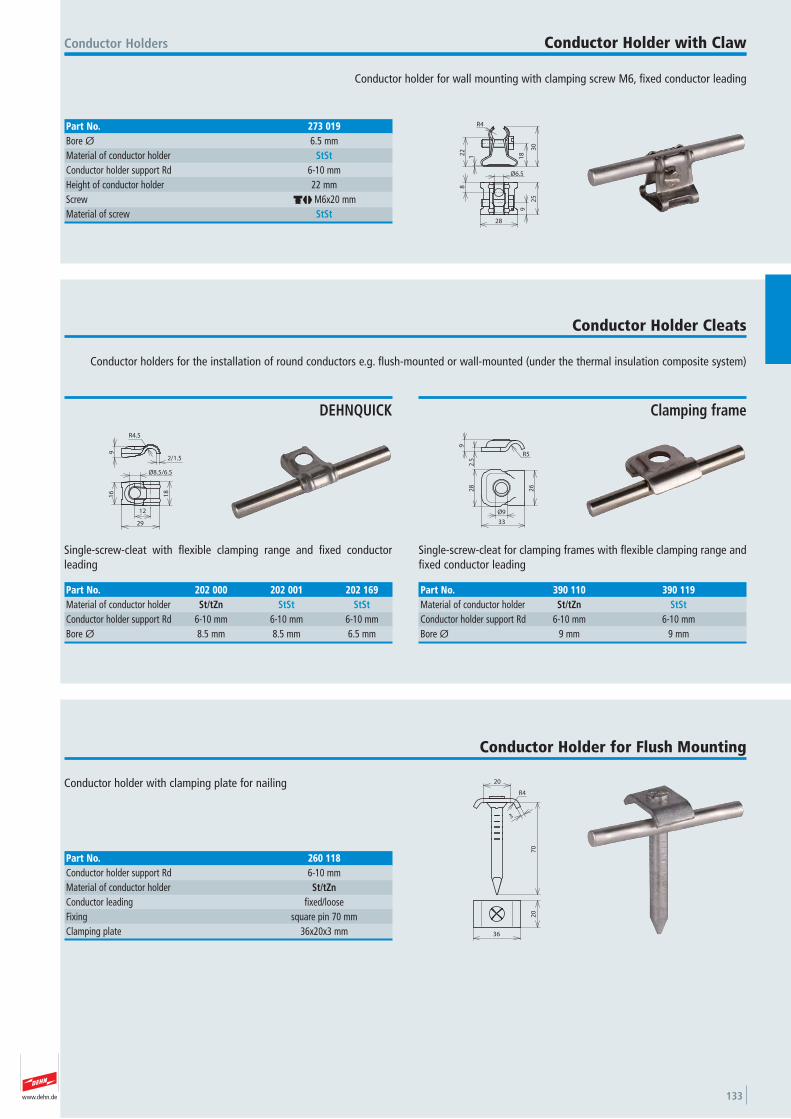
www.dehn.de 133
Conductor holder for wall mounting with clamping screw M6, fixed conductor leading
Conductor Holders Conductor Holder with Claw
R4
18
30
22
1
Ø6.5
28
9
25
8
Part No. 273 019Bore Ø 6.5 mmMaterial of conductor holder StStConductor holder support Rd 6-10 mmHeight of conductor holder 22 mmScrew dj M6x20 mmMaterial of screw StSt
Conductor holders for the installation of round conductors e.g. flush-mounted or wall-mounted (under the thermal insulation composite system)
Conductor Holder Cleats
18
12
29
16
Ø8.5/6.5
9
R4.5
2/1.5
Single-screw-cleat with flexible clamping range and fixed conductor leading
DEHNQUICK
Part No. 202 000 202 001 202 169Material of conductor holder St/tZn StSt StStConductor holder support Rd 6-10 mm 6-10 mm 6-10 mmBore Ø 8.5 mm 8.5 mm 6.5 mm
26
33
28
Ø9
R5
2.5
9
Single-screw-cleat for clamping frames with flexible clamping range andfixed conductor leading
Clamping frame
Part No. 390 110 390 119Material of conductor holder St/tZn StStConductor holder support Rd 6-10 mm 6-10 mmBore Ø 9 mm 9 mm
Conductor holder with clamping plate for nailing
Conductor Holder for Flush Mounting
R4
20
70
3
20
36
Part No. 260 118Conductor holder support Rd 6-10 mmMaterial of conductor holder St/tZnConductor leading fixed/loose Fixing square pin 70 mmClamping plate 36x20x3 mm
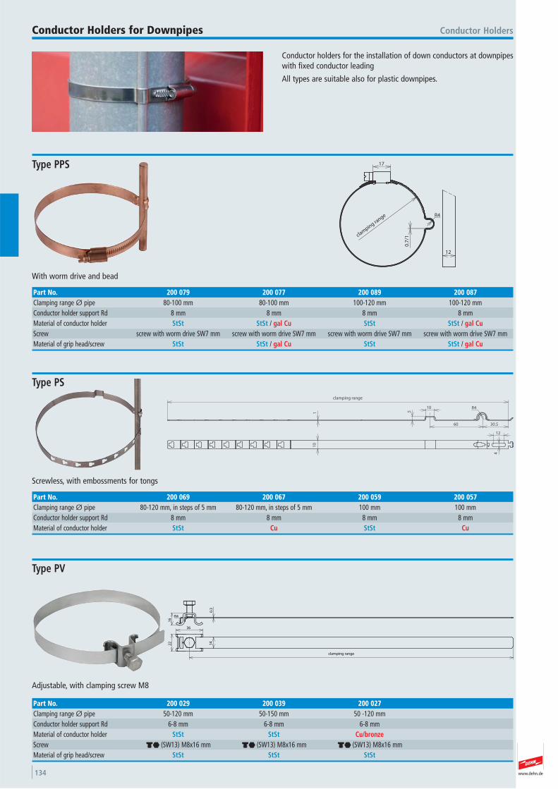
www.dehn.de134
Conductor holders for the installation of down conductors at downpipeswith fixed conductor leading
All types are suitable also for plastic downpipes.
Conductor HoldersConductor Holders for Downpipes
clamping ra
nge
0.7
/1
R4
17
12
With worm drive and bead
Type PPS
Part No. 200 079 200 077 200 089 200 087Clamping range Ø pipe 80-100 mm 80-100 mm 100-120 mm 100-120 mmConductor holder support Rd 8 mm 8 mm 8 mm 8 mmMaterial of conductor holder StSt StSt / gal Cu StSt StSt / gal CuScrew screw with worm drive SW7 mm screw with worm drive SW7 mm screw with worm drive SW7 mm screw with worm drive SW7 mmMaterial of grip head/screw StSt StSt / gal Cu StSt StSt / gal Cu
30.560
R41051
clamping range
10
4
12
Screwless, with embossments for tongs
Type PS
Part No. 200 069 200 067 200 059 200 057Clamping range Ø pipe 80-120 mm, in steps of 5 mm 80-120 mm, in steps of 5 mm 100 mm 100 mmConductor holder support Rd 8 mm 8 mm 8 mm 8 mmMaterial of conductor holder StSt Cu StSt Cu
16
R4
0.3
14
36
22
clamping range
Adjustable, with clamping screw M8
Type PV
Part No. 200 029 200 039 200 027Clamping range Ø pipe 50-120 mm 50-150 mm 50 -120 mmConductor holder support Rd 6-8 mm 6-8 mm 6-8 mmMaterial of conductor holder StSt StSt Cu/bronzeScrew di (SW13) M8x16 mm di (SW13) M8x16 mm di (SW13) M8x16 mmMaterial of grip head/screw StSt StSt StSt
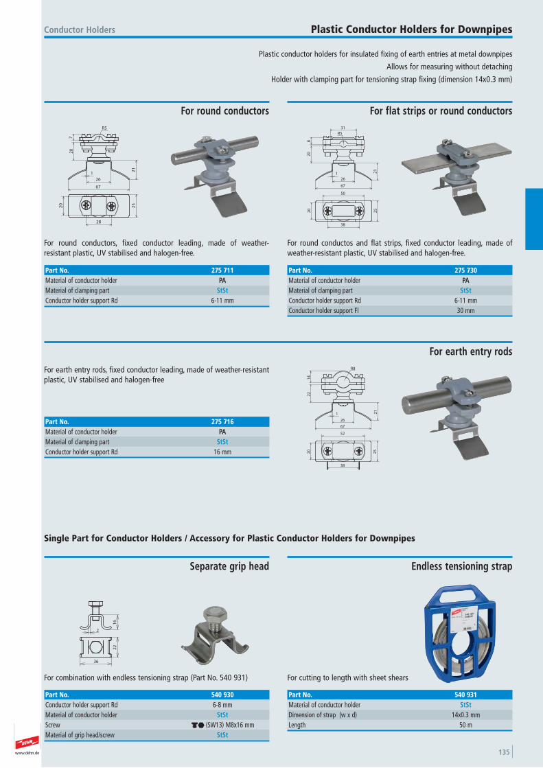
www.dehn.de 135
16
2
36
22
For combination with endless tensioning strap (Part No. 540 931)
Conductor Holders
Separate grip head
Single Part for Conductor Holders / Accessory for Plastic Conductor Holders for Downpipes
Part No. 540 930Conductor holder support Rd 6-8 mmMaterial of conductor holder StStScrew di (SW13) M8x16 mmMaterial of grip head/screw StSt
For cutting to length with sheet shears
Endless tensioning strap
Part No. 540 931Material of conductor holder StStDimension of strap (w x d) 14x0.3 mmLength 50 m
Plastic conductor holders for insulated fixing of earth entries at metal downpipes
Allows for measuring without detaching
Holder with clamping part for tensioning strap fixing (dimension 14x0.3 mm)
Plastic Conductor Holders for Downpipes
R5
72
0
21
26
1
67
20
25
28
For round conductors, fixed conductor leading, made of weather- resistant plastic, UV stabilised and halogen-free.
For round conductors
Part No. 275 711Material of conductor holder PAMaterial of clamping part StStConductor holder support Rd 6-11 mm
31
20
8
R5
21
67
26
1
25
20
50
38
For round conductos and flat strips, fixed conductor leading, made ofweather-resistant plastic, UV stabilised and halogen-free.
For flat strips or round conductors
Part No. 275 730Material of conductor holder PAMaterial of clamping part StStConductor holder support Rd 6-11 mmConductor holder support Fl 30 mm
1
67
26
21
22
14
R8
20
25
38
52
For earth entry rods, fixed conductor leading, made of weather-resistantplastic, UV stabilised and halogen-free
For earth entry rods
Part No. 275 716Material of conductor holder PAMaterial of clamping part StStConductor holder support Rd 16 mm
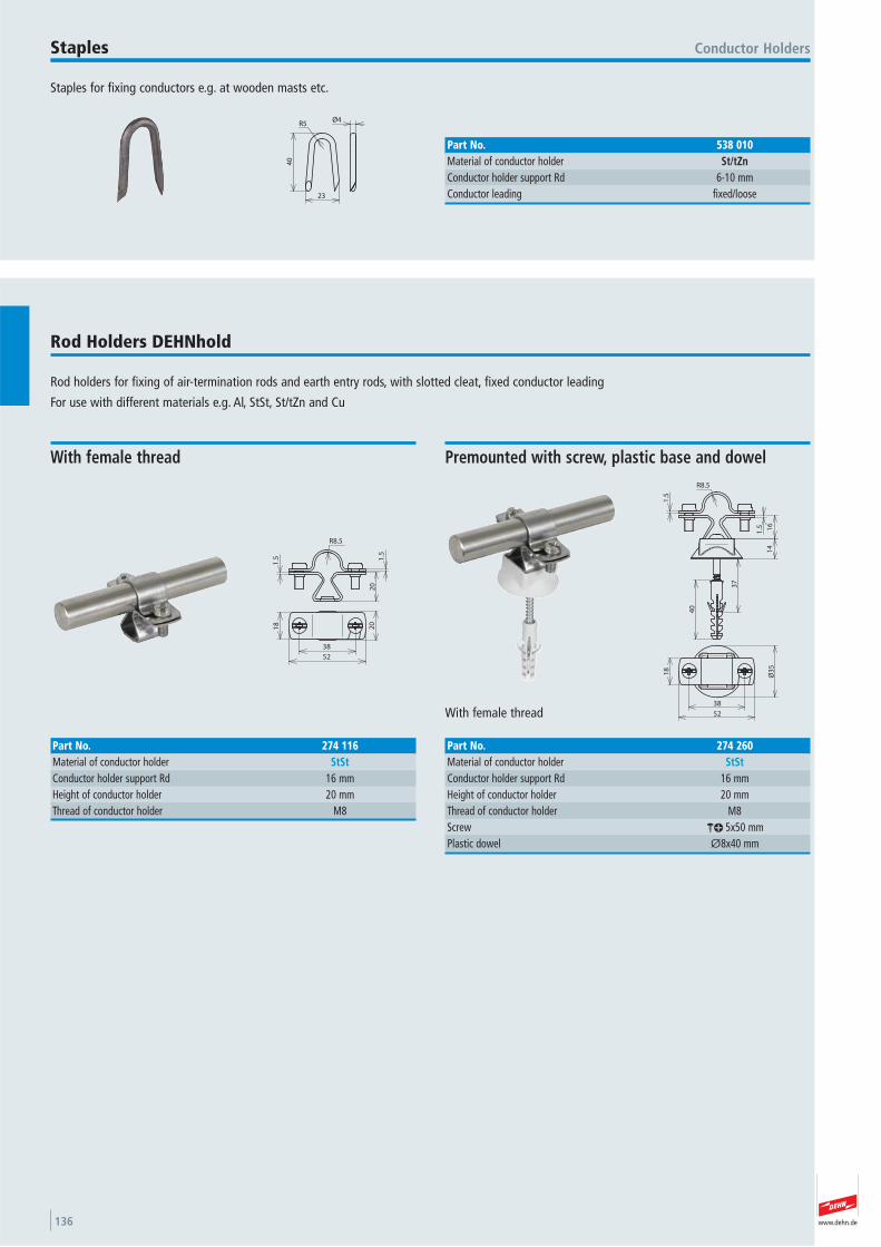
www.dehn.de136
Staples for fixing conductors e.g. at wooden masts etc.
Conductor HoldersStaples
40
23
R5Ø4
Part No. 538 010Material of conductor holder St/tZnConductor holder support Rd 6-10 mmConductor leading fixed/loose
Rod holders for fixing of air-termination rods and earth entry rods, with slotted cleat, fixed conductor leading
For use with different materials e.g. Al, StSt, St/tZn and Cu
Rod Holders DEHNhold 2
0
R8.5
1.5
1.5
18
52
20
38
With female thread
Part No. 274 116Material of conductor holder StStConductor holder support Rd 16 mmHeight of conductor holder 20 mmThread of conductor holder M8
R8.5
16
14
1.5
1.5
40
37
18
Ø3
5
52
38
With female thread
Premounted with screw, plastic base and dowel
Part No. 274 260Material of conductor holder StStConductor holder support Rd 16 mmHeight of conductor holder 20 mmThread of conductor holder M8 Screw ak 5x50 mmPlastic dowel Ø8x40 mm
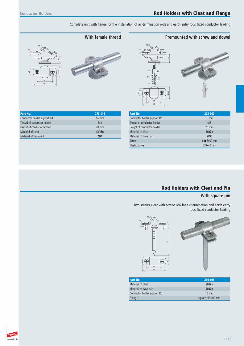
www.dehn.de 137
Complete unit with flange for the installation of air-termination rods and earth entry rods, fixed conductor leading
Conductor Holders Rod Holders with Cleat and Flange
20
3
R8.5
38
20
58
Ø3
0
With female thread
Part No. 275 116Conductor holder support Rd 16 mmThread of conductor holder M8 Height of conductor holder 20 mmMaterial of cleat St/tZnMaterial of base part ZDC
40
20
3
R8.5
41
38
20
58
Ø3
0
Premounted with screw and dowel
Part No. 275 260Conductor holder support Rd 16 mmThread of conductor holder M8 Height of conductor holder 20 mmMaterial of cleat St/tZnMaterial of base part ZDCScrew ak 5x50 mmPlastic dowel Ø8x40 mm
Two-screws-cleat with screws M6 for air-termination and earth entryrods, fixed conductor leading
Rod Holders with Cleat and Pin
With square pin
R8.5
3
l1
38
20
58
3
Part No. 260 106Material of cleat St/tZnMaterial of base part St/tZnConductor holder support Rd 16 mmFixing (l1) square pin 100 mm
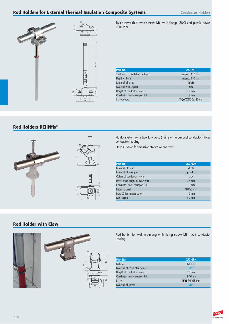
www.dehn.de138
Two-screws-cleat with screws M6, with flange (ZDC) and plastic dowelØ10 mm
Conductor HoldersRod Holders for External Thermal Insulation Composite Systems
3
20
R8
14
0/1
80
38
20
58
Ø3
0
Part No. 273 731Thickness of insulating material approx. 110 mmDepth of bore approx. 190 mmMaterial of cleat St/tZnMaterial o base part ZDCHeight of conductor holder 20 mmConductor holder support Rd 16 mmScrew/dowel bl (TX40) 7x180 mm
Holder system with two functions (fixing of holder and conductor), fixedconductor leading
Only suitable for massive stones or concrete
Rod Holders DEHNfix®
42
R8
10
0
22
40
Ø2
8
Part No. 252 000Material of cleat St/tZnMaterial of base part plasticColour of conductor holder grey Installation height of base part 42 mmConductor holder support Rd 16 mmImpact dowel 100/60 mmBore Ø for impact dowel 10 mmBore depth 60 mm
Rod holder for wall mounting with fixing screw M6, fixed conductor leading
Rod Holder with Claw
1
46
R8
28
Ø6.5
9
25
29
8
Part No. 275 019Bore Ø 6.5 mmMaterial of conductor holder StStHeight of conductor holder 28 mmConductor holder support Rd 13-16 mmScrew dj M6x25 mmMaterial of screw StSt
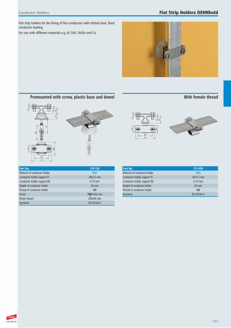
www.dehn.de 139
Flat strip holders for the fixing of flat conductors with slotted cleat, fixedconductor leading
For use with different materials e.g. Al, StSt, St/tZn and Cu
Conductor Holders Flat Strip Holders DEHNhold
20
1.5
1.5
18
20
52
38
With female thread
Part No. 274 030Material of conductor holder StStConductor holder support Fl 30x3.5 mmConductor holder support Rd 6-10 mmHeight of conductor holder 20 mmThread of conductor holder M8 Standard EN 50164-4
16
14
1.51
.5
40
37
18
Ø3
5
52
38
Premounted with screw, plastic base and dowel
Part No. 274 230Material of conductor holder StStConductor holder support Fl 30x3.5 mmConductor holder support Rd 6-10 mmHeight of conductor holder 20 mmThread of conductor holder M8 Screw ak 5x50 mmPlastic dowel Ø8x40 mmStandard EN 50164-4
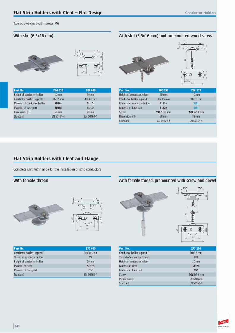
www.dehn.de140
Two-screws-cleat with screws M6
Conductor HoldersFlat Strip Holders with Cleat – Flat Design
3
10
14 10
20
l1
With slot (6.5x16 mm)
Part No. 284 030 284 040Height of conductor holder 10 mm 10 mmConductor holder support Fl 30x3.5 mm 40x4-5 mmMaterial of conductor holder St/tZn St/tZnMaterial of base part St/tZn St/tZnDimension (l1) 58 mm 70 mmStandard EN 50164-4 EN 50164-4
3 10
45
20
58
14
With slot (6.5x16 mm) and premounted wood screw
Part No. 286 030 286 139Height of conductor holder 10 mm 10 mmConductor holder support Fl 30x3.5 mm 30x3.5 mmMaterial of conductor holder St/tZn StStMaterial of base part St/tZn StStScrew ak 5x50 mm ak 5x50 mmDimension (l1) 58 mm 58 mmStandard EN 50164-4 EN 50164-4
Complete unit with flange for the installation of strip conductors
Flat Strip Holders with Cleat and Flange
3
20
20
38
58
Ø3
0
With female thread
Part No. 275 030Conductor holder support Fl 30x30.5 mmThread of conductor holder M8 Height of conductor holder 20 mmMaterial of cleat St/tZnMaterial of base part ZDCStandard EN 50164-4
20
40
3
33
38
20
Ø3
0
58
With female thread, premounted with screw and dowel
Part No. 275 230Conductor holder support Fl 30x3.5 mmThread of conductor holder M8 Height of conductor holder 20 mmMaterial of cleat St/tZnMaterial of base part ZDCScrew ak 5x50 mmPlastic dowel Ø8x40 mmStandard EN 50164-4
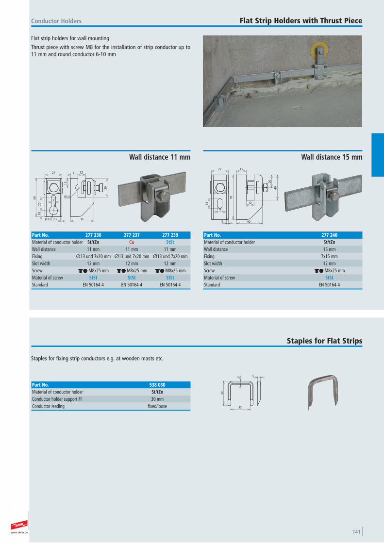
www.dehn.de 141
Flat strip holders for wall mounting
Thrust piece with screw M8 for the installation of strip conductor up to11 mm and round conductor 6-10 mm
Conductor Holders Flat Strip Holders with Thrust Piece
Ø13 2.5
10
20
7
60
27
R5.5
15
11 12
30
36
Wall distance 11 mm
Part No. 277 230 277 237 277 239Material of conductor holder St/tZn Cu StStWall distance 11 mm 11 mm 11 mmFixing Ø13 und 7x20 mm Ø13 und 7x20 mm Ø13 und 7x20 mmSlot width 12 mm 12 mm 12 mmScrew di M8x25 mm di M8x25 mm di M8x25 mmMaterial of screw StSt StSt StStStandard EN 50164-4 EN 50164-4 EN 50164-4
3
7
15
27
70
15
12
20
40
40
Wall distance 15 mm
Part No. 277 240Material of conductor holder St/tZnWall distance 15 mmFixing 7x15 mmSlot width 12 mmScrew di M8x25 mmMaterial of screw StStStandard EN 50164-4
Staples for fixing strip conductors e.g. at wooden masts etc.
Staples for Flat Strips
32
40
5 5
Part No. 538 030Material of conductor holder St/tZnConductor holder support Fl 30 mmConductor leading fixed/loose
www.dehn.de142
Dowels for rigid foam plates to fix conductor holders, flat strip and rodholders in external thermal insulation composite systems.
With star drive (TX40)
Mounting with wood screws Ø4.5 mm
These dowel are only suitable for conductor holder fixing, if there are noadditional tensile forces on the down conductor.
Conductor HoldersDowels for Rigid Foam Plates
More details in installation instructions No. 1459.
1
50
7
Ø2
5TX40
Short design
Part No. 200 600Material PAThickness of insulating material 60 mmLength of anchoring depth 50 mmWorking load of Styrofoam PS20 35 NWorking load of rigid foam plates 60 N
117
85
Ø2
5
TX40
Long design
Part No. 200 601Material PAThickness of insulating material 100 mmLength of anchoring depth 85 mmWorking load of Styrofoam PS20 60 NWorking load of rigid foam plates 85 N
Hanger bolt for fixing of conductor, flat strip and rod holders with female thread
Wood Screws with Threaded Head
13
l2
l1
M8
Ø15
Part No. 528 850 528 870Material St/gal Zn St/gal ZnThread M8 M8 Length (l1) 53 mm 73 mmLength (l2) 32 mm 42 mm
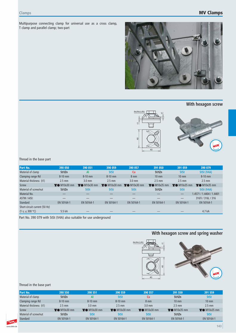
www.dehn.de 143
Multipurpose connecting clamp for universal use as a cross clamp, T clamp and parallel clamp; two-part
Clamps MV Clamps
t1
t1
R4/R4.5/R5
40
40
Thread in the base part
With hexagon screw
Part No. 390 050 390 051 390 059 390 057 391 050 391 059 390 079Material of clamp St/tZn Al StSt Cu St/tZn StSt StSt (V4A)Clamping range Rd 8-10 mm 8-10 mm 8-10 mm 8 mm 10 mm 10 mm 8-10 mmMaterial thickness (t1) 2.5 mm 3.0 mm 2.5 mm 3.0 mm 2.5 mm 2.5 mm 2.5 mmScrew di M10x30 mm di M10x30 mm di M10x30 mm di M10x30 mm di M10x35 mm di M10x35 mm di M10x35 mmMaterial of screw/nut St/tZn StSt StSt StSt St/tZn StSt StSt (V4A)Material No. — — — — — — 1.4571 / 1.4404 / 1.4401 ASTM / AISI: — — — — — — 316Ti / 316L / 316Standard EN 50164-1 EN 50164-1 EN 50164-1 EN 50164-1 EN 50164-1 EN 50164-1 EN 50164-1 Short-circuit current (50 Hz)(1 s; ≤ 300 °C) 5.5 kA — — — — — 4.7 kA
Part No. 390 079 with StSt (V4A) also suitable for use underground
t e s t e d
R4/R4.5/R5 t14
0
40
Thread in the base part
With hexagon screw and spring washer
Part No. 390 550 390 551 390 559 390 557 391 550 391 559Material of clamp St/tZn Al StSt Cu St/tZn StStClamping range Rd 8-10 mm 8-10 mm 8-10 mm 8 mm 10 mm 10 mmMaterial thickness (t1) 2.5 mm 3.0 mm 2.5 mm 3.0 mm 2.5 mm 2.5 mmScrew di M10x30 mm di M10x30 mm di M10x30 mm di M10x30 mm di M10x35 mm di M10x35 mmMaterial of screw/nut St/tZn StSt StSt StSt St/tZn StStStandard EN 50164-1 EN 50164-1 EN 50164-1 EN 50164-1 EN 50164-1 EN 50164-1
t e s t e d
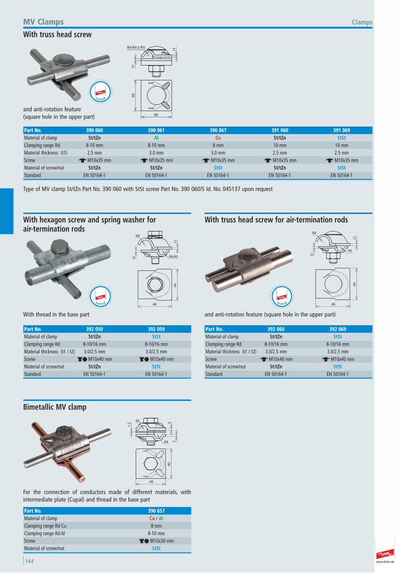
www.dehn.de144
40
40
t1
t1
R4/R4.5/R5
and anti-rotation feature (square hole in the upper part)
ClampsMV Clamps
With truss head screw
Part No. 390 060 390 061 390 067 391 060 391 069Material of clamp St/tZn Al Cu St/tZn StStClamping range Rd 8-10 mm 8-10 mm 8 mm 10 mm 10 mmMaterial thickness (t1) 2.5 mm 3.0 mm 3.0 mm 2.5 mm 2.5 mmScrew e M10x35 mm e M10x35 mm e M10x35 mm e M10x35 mm e M10x35 mmMaterial of screw/nut St/tZn St/tZn StSt St/tZn StStStandard EN 50164-1 EN 50164-1 EN 50164-1 EN 50164-1 EN 50164-1
Type of MV clamp St/tZn Part No. 390 060 with StSt screw Part No. 390 060/S Id. No. 045137 upon request
t e s t e d
44
48
R4/R5
t1
t2
R8
With thread in the base part
With hexagon screw and spring washer for air-termination rods
Part No. 392 050 392 059Material of clamp St/tZn StStClamping range Rd 8-10/16 mm 8-10/16 mmMaterial thickness (t1 / t2) 3.0/2.5 mm 3.0/2.5 mmScrew di M10x40 mm di M10x40 mmMaterial of screw/nut St/tZn StStStandard EN 50164-1 EN 50164-1
t e s t e d
44
48
t1
R5
t2
R8
and anti-rotation feature (square hole in the upper part)
With truss head screw for air-termination rods
Part No. 392 060 392 069Material of clamp St/tZn StStClamping range Rd 8-10/16 mm 8-10/16 mmMaterial thickness (t1 / t2) 3.0/2.5 mm 3.0/2.5 mmScrew e M10x40 mm e M10x40 mmMaterial of screw/nut St/tZn StStStandard EN 50164-1 EN 50164-1
1.5
R5 3
3R4
40
40
For the connection of conductors made of different materials, with intermediate plate (Cupal) and thread in the base part
Bimetallic MV clamp
Part No. 390 657Material of clamp Cu / AlClamping range Rd Cu 8 mmClamping range Rd Al 8-10 mmScrew di M10x30 mmMaterial of screw/nut StSt
t e s t e d
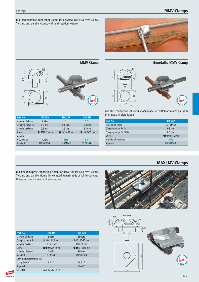
www.dehn.de 145
Mini multipurpose connecting clamp for universal use as a cross clamp,T clamp and parallel clamp, with anti-rotation feature
Clamps MMV Clamps
2.5
R5
2.5
3328
MMV Clamp
Part No. 390 250 390 257 390 259Material of clamp St/tZn Cu StStClamping range Rd 6-8 mm 6-8 mm 6-8 mmMaterial thickness 2.5 mm 2.5 mm 2.5 mmScrew e M10x35 mm e M10x35 mm e M10x35 mmMaterial of screw/nut St/tZn StSt StStStandard EN 50164-1 EN 50164-1 EN 50164-1
t e s t e d
R5
35
2.5
1.5
33
2830
For the connection of conductors made of different materials, with intermediate plate (Cupal)
Bimetallic MMV Clamp
Part No. 390 267Material of clamp Cu / St/tZnClamping range Rd Cu 6-8 mmClamping range Rd St/tZn 6-8 mmScrew e M10x35 mmMaterial of screw/nut StStStandard EN 50164-1
t e s t e d
Maxi multipurpose connecting clamp for universal use as a cross clamp,T clamp and parallel clamp, for connecting earth rods or reinforcements;three-part, with thread in the base part
MAXI MV Clamps
2
3
3
16
16
R13
R8
75
75
Part No. 308 041 308 040Material of clamp St/tZn St/bareClamping range Rd 8-16 / 15-25 mm 8-16 / 15-25 mmMaterial thickness 3.0 / 2.0 mm 3.0 / 2.0 mmScrew di M12x65 mm di M12x65 mmMaterial of screw St/tZn St/bareStandard EN 50164-1 EN 50164-1 Short-circuit current (50 Hz)(1 s; ≤ 300 °C) 6.2 kA 10.2 kAApproval — UL467B Stock No. 5999-12-362-1557 —
t e s t e d
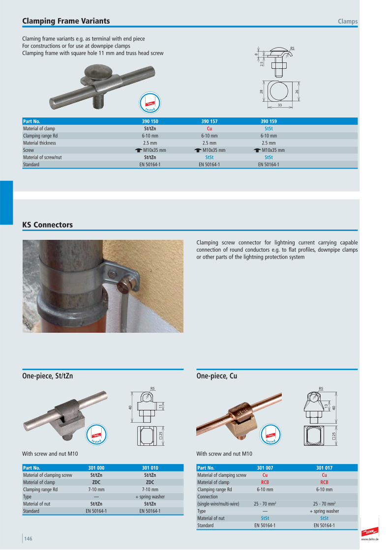
www.dehn.de146
Claming frame variants e.g. as terminal with end piece For constructions or for use at downpipe clampsClamping frame with square hole 11 mm and truss head screw
ClampsClamping Frame Variants
2.5
8
R5
33
26
28
Part No. 390 150 390 157 390 159Material of clamp St/tZn Cu StStClamping range Rd 6-10 mm 6-10 mm 6-10 mmMaterial thickness 2.5 mm 2.5 mm 2.5 mmScrew e M10x35 mm e M10x35 mm e M10x35 mmMaterial of screw/nut St/tZn StSt StStStandard EN 50164-1 EN 50164-1 EN 50164-1
t e s t e d
Clamping screw connector for lightning current carrying capable connection of round conductors e.g. to flat profiles, downpipe clamps or other parts of the lightning protection system
KS Connectors
25
40
R5
11
With screw and nut M10
One-piece, St/tZn
Part No. 301 000 301 010Material of clamping screw St/tZn St/tZnMaterial of clamp ZDC ZDCClamping range Rd 7-10 mm 7-10 mmType — + spring washer Material of nut St/tZn St/tZnStandard EN 50164-1 EN 50164-1
t e s t e d
13
40
R5
25
With screw and nut M10
One-piece, Cu
Part No. 301 007 301 017Material of clamping screw Cu CuMaterial of clamp RCB RCBClamping range Rd 6-10 mm 6-10 mmConnection (single-wire/multi-wire) 25 - 70 mm2 25 - 70 mm2
Type — + spring washer Material of nut StSt StStStandard EN 50164-1 EN 50164-1
t e s t e d
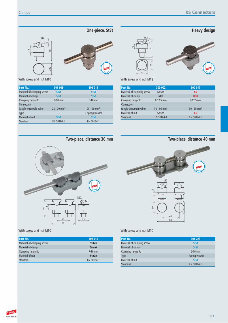
www.dehn.de 147
10
6
40
R5
Ø2
2
With screw and nut M10
Clamps
One-piece, StSt
Part No. 301 009 301 019Material of clamping screw StSt StStMaterial of clamp StSt StStClamping range Rd 6-10 mm 6-10 mmConnection (single-wire/multi-wire) 25 - 70 mm2 25 - 70 mm2
Type — + spring washer Material of nut StSt StStStandard EN 50164-1 EN 50164-1
KS Connectors
t e s t e d
R6.5
6
12
48
30
30
With screw and nut M12
Heavy design
Part No. 300 002 300 017Material of clamping screw St/tZn CuMaterial of clamp MCI RCBClamping range Rd 8-12.5 mm 8-12.5 mmConnection (single-wire/multi-wire) 50 - 95 mm2 50 - 95 mm2
Material of nut St/tZn CuStandard EN 50164-1 EN 50164-1
t e s t e d
25
40
R5.5
12
55
30
With screw and nut M10
Two-piece, distance 30 mm
Part No. 302 010Material of clamping screw St/tZnMaterial of clamp ZamakClamping range Rd 7-10 mmMaterial of nut St/tZnStandard EN 50164-1
t e s t e d 33
0
63
40
R5
With screw and nut M10
Two-piece, distance 40 mm
Part No. 301 229Material of clamping screw StStMaterial of clamp StStClamping range Rd 6-10 mmType + spring washer Material of nut StStStandard EN 50164-1
t e s t e d
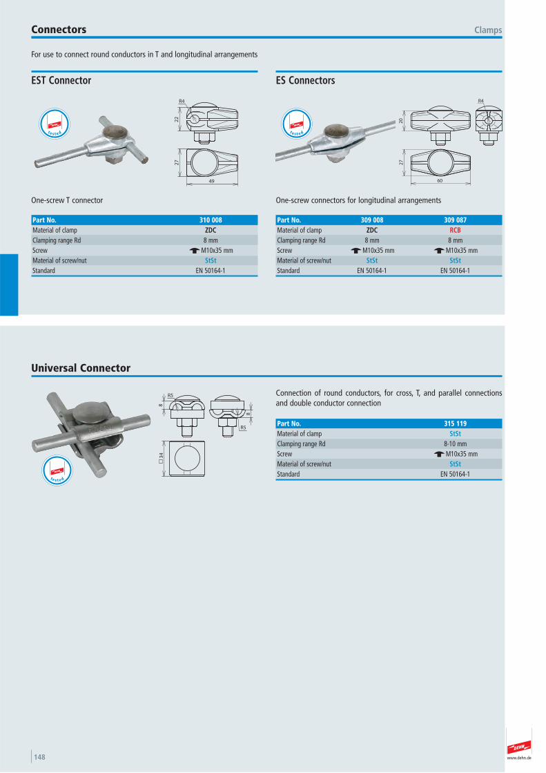
www.dehn.de148
For use to connect round conductors in T and longitudinal arrangements
ClampsConnectors
R4
22
27
49
One-screw T connector
EST Connector
Part No. 310 008Material of clamp ZDCClamping range Rd 8 mmScrew e M10x35 mmMaterial of screw/nut StStStandard EN 50164-1
t e s t e d
20
R4
27
60
One-screw connectors for longitudinal arrangements
ES Connectors
Part No. 309 008 309 087Material of clamp ZDC RCBClamping range Rd 8 mm 8 mmScrew e M10x35 mm e M10x35 mmMaterial of screw/nut StSt StStStandard EN 50164-1 EN 50164-1
t e s t e d
Connection of round conductors, for cross, T, and parallel connectionsand double conductor connection
Universal Connector
R5
83
4
R5
8
Part No. 315 119Material of clamp StStClamping range Rd 8-10 mmScrew e M10x35 mmMaterial of screw/nut StStStandard EN 50164-1
t e s t e d
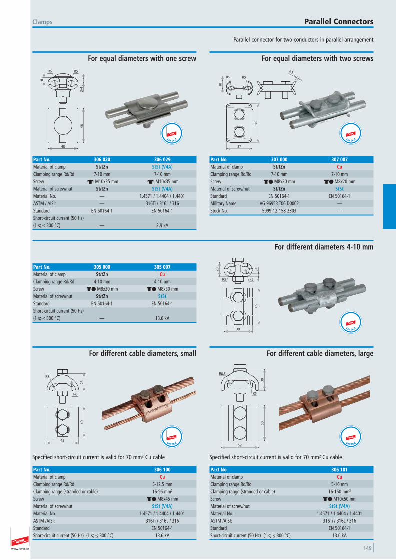
www.dehn.de 149
Parallel connector for two conductors in parallel arrangement
Clamps Parallel Connectors
6
R5 R5
3/4
46
40
For equal diameters with one screw
Part No. 306 020 306 029Material of clamp St/tZn StSt (V4A)Clamping range Rd/Rd 7-10 mm 7-10 mmScrew e M10x35 mm e M10x35 mmMaterial of screw/nut St/tZn StSt (V4A)Material No. — 1.4571 / 1.4404 / 1.4401 ASTM / AISI: — 316Ti / 316L / 316Standard EN 50164-1 EN 50164-1 Short-circuit current (50 Hz) (1 s; ≤ 300 °C) — 2.9 kA
t e s t e d
R5R5
10
2.5
56
37
For equal diameters with two screws
Part No. 307 000 307 007Material of clamp St/tZn CuClamping range Rd/Rd 7-10 mm 7-10 mmScrew di M8x20 mm di M8x20 mmMaterial of screw/nut St/tZn StStStandard EN 50164-1 EN 50164-1 Military Name VG 96953 T06 D0002 —Stock No. 5999-12-158-2303 —
t e s t e d
4
20
R5 R5
50
39
For different diameters 4-10 mm
Part No. 305 000 305 007Material of clamp St/tZn CuClamping range Rd/Rd 4-10 mm 4-10 mmScrew di M8x30 mm di M8x30 mmMaterial of screw/nut St/tZn StStStandard EN 50164-1 EN 50164-1 Short-circuit current (50 Hz) (1 s; ≤ 300 °C) — 13.6 kA
t e s t e d
23
R6
R8
40
42
Specified short-circuit current is valid for 70 mm² Cu cable
For different cable diameters, small
Part No. 306 100Material of clamp CuClamping range Rd/Rd 5-12.5 mmClamping range (stranded or cable) 16-95 mm2
Screw di M8x45 mmMaterial of screw/nut StSt (V4A)Material No. 1.4571 / 1.4404 / 1.4401 ASTM /AISI: 316Ti / 316L / 316Standard EN 50164-1 Short-circuit current (50 Hz) (1 s; ≤ 300 °C) 13.6 kA
t e s t e d
R8.5
R5
30
50
52
Specified short-circuit current is valid for 70 mm² Cu cable
For different cable diameters, large
Part No. 306 101Material of clamp CuClamping range Rd/Rd 5-16 mmClamping range (stranded or cable) 16-150 mm2
Screw di M10x50 mmMaterial of screw/nut StSt (V4A)Material No. 1.4571 / 1.4404 / 1.4401 ASTM /AISI: 316Ti / 316L / 316Standard EN 50164-1 Short-circuit current (50 Hz) (1 s; ≤ 300 °C) 13.6 kA
t e s t e d
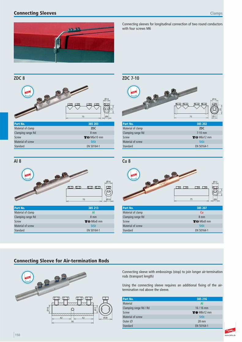
www.dehn.de150
Connecting sleeves for longitudinal connection of two round conductorswith four screws M6
ClampsConnecting Sleeves
75 Ø9
17
Ø14
ZDC 8
Part No. 385 203Material of clamp ZDCClamping range Rd 8 mmScrew dj M6x10 mmMaterial of screw StStStandard EN 50164-1
t e s t e d
75 Ø11
Ø16
20
ZDC 7-10
Part No. 385 202Material of clamp ZDCClamping range Rd 7-10 mmScrew dj M6x12 mmMaterial of screw StStStandard EN 50164-1
t e s t e d
75 Ø10
Ø16
Al 8
Part No. 385 213Material of clamp AlClamping range Rd 8 mmScrew dj M6x8 mmMaterial of screw StStStandard EN 50164-1
t e s t e d
75 Ø9
15
Ø13
Cu 8
Part No. 385 207Material of clamp CuClamping range Rd 8 mmScrew dj M6x8 mmMaterial of screw StStStandard EN 50164-1
t e s t e d
Connecting sleeve with embossings (stop) to join longer air-terminationrods (transport length)
Using the connecting sleeve requires an additional fixing of the air- termination rod above the sleeve.
Connecting Sleeve for Air-termination Rods
Ø28
Ø1
7
Ø1
8
90
4242
Part No. 385 216Material AlClamping range Rd / Rd 16 / 16 mmScrew di M8x12 mmMaterial of screw StStOuter Ø 28 mmStandard EN 50164-1
t e s t e d
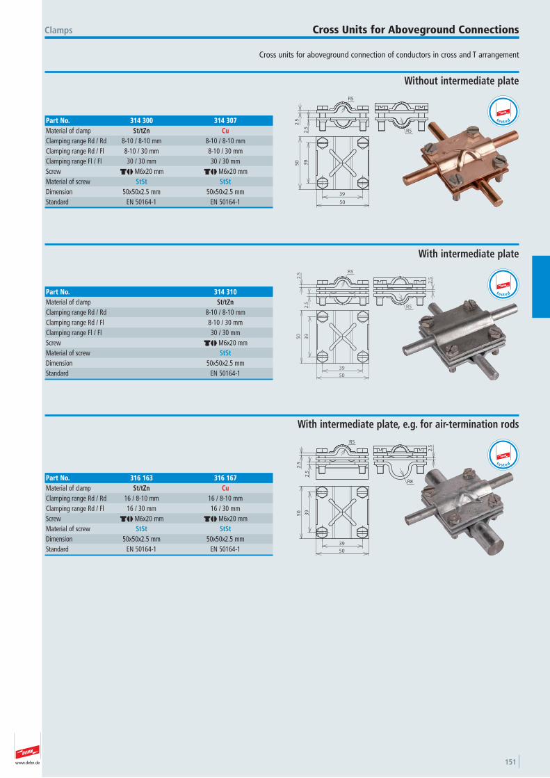
www.dehn.de 151
Cross units for aboveground connection of conductors in cross and T arrangement
Clamps Cross Units for Aboveground Connections
2.5
2.5
R5
R5
50
50
39
39
Without intermediate plate
Part No. 314 300 314 307Material of clamp St/tZn CuClamping range Rd / Rd 8-10 / 8-10 mm 8-10 / 8-10 mmClamping range Rd / Fl 8-10 / 30 mm 8-10 / 30 mmClamping range Fl / Fl 30 / 30 mm 30 / 30 mmScrew dj M6x20 mm dj M6x20 mmMaterial of screw StSt StStDimension 50x50x2.5 mm 50x50x2.5 mmStandard EN 50164-1 EN 50164-1
t e s t e d
2.52
.5
R5
R52.5
39
39
50
50
With intermediate plate
Part No. 314 310Material of clamp St/tZnClamping range Rd / Rd 8-10 / 8-10 mmClamping range Rd / Fl 8-10 / 30 mmClamping range Fl / Fl 30 / 30 mmScrew dj M6x20 mmMaterial of screw StStDimension 50x50x2.5 mmStandard EN 50164-1
t e s t e d
R5
2.5
2.5
2.5
R8
39
39
50
50
With intermediate plate, e.g. for air-termination rods
Part No. 316 163 316 167Material of clamp St/tZn CuClamping range Rd / Rd 16 / 8-10 mm 16 / 8-10 mmClamping range Rd / Fl 16 / 30 mm 16 / 30 mmScrew dj M6x20 mm dj M6x20 mmMaterial of screw StSt StStDimension 50x50x2.5 mm 50x50x2.5 mmStandard EN 50164-1 EN 50164-1
t e s t e d
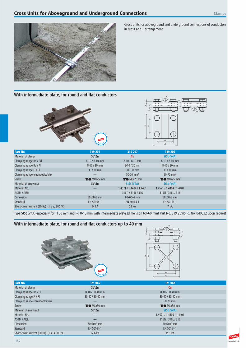
www.dehn.de152
Cross units for aboveground and underground connections of conductorsin cross and T arrangement
ClampsCross Units for Aboveground and Underground Connections
3
3
3
R5
R5
60
60
40
40
With intermediate plate, for round and flat conductors
Part No. 319 201 319 207 319 209Material of clamp St/tZn Cu StSt (V4A)Clamping range Rd / Rd 8-10 / 8-10 mm 8-10 / 8-10 mm 8-10 / 8-10 mmClamping range Rd / Fl 8-10 / 30 mm 8-10 / 30 mm 8-10 / 30 mmClamping range Fl / Fl 30 / 30 mm 30 / 30 mm 30 / 30 mmClamping range (stranded/cable) — 50-70 mm2 50-70 mm2
Screw di M8x25 mm di M8x25 mm di M8x25 mmMaterial of screw/nut St/tZn StSt (V4A) StSt (V4A)Material No. — 1.4571 / 1.4404 / 1.4401 1.4571 / 1.4404 / 1.4401 ASTM / AISI: — 316Ti / 316L / 316 316Ti / 316L / 316Dimension 60x60x3 mm 60x60x4 mm 60x60x3 mmStandard EN 50164-1 EN 50164-1 EN 50164-1 Short-circuit current (50 Hz) (1 s; ≤ 300 °C) 14 kA 29 kA 7 kA
Type StSt (V4A) especially for Fl 30 mm and Rd 8-10 mm with intermediate plate (dimension 60x60 mm) Part No. 319 209/S Id. No. 040332 upon request
t e s t e d
R5
3
3
3
70
70
49
49
With intermediate plate, for round and flat conductors up to 40 mm
Part No. 321 045 321 047Material of clamp St/tZn CuClamping range Rd / Fl 8-10 / 30-40 mm 8-10 / 30-40 mmClamping range Fl / Fl 30-40 / 30-40 mm 30-40 / 30-40 mmClamping range (stranded/cable) — 50-70 mm2
Screw di M8x30 mm di M8x30 mmMaterial of screw/nut St/tZn StSt (V4A)Material No. — 1.4571 / 1.4404 / 1.4401 ASTM / AISI: — 316Ti / 316L / 316Dimension 70x70x3 mm 70x70x3 mmStandard EN 50164-1 EN 50164-1 Short-circuit current (50 Hz) (1 s; ≤ 300 °C) 12.6 kA 35.1 kA
t e s t e d
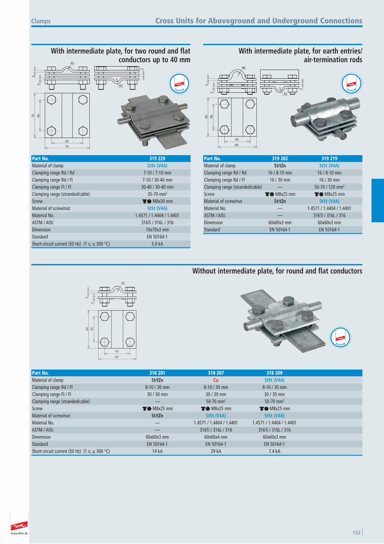
www.dehn.de 153
R5
3
3
3 R5
70
70
49
49
Clamps
With intermediate plate, for two round and flat conductors up to 40 mm
Cross Units for Aboveground and Underground Connections
Part No. 319 229Material of clamp StSt (V4A)Clamping range Rd / Rd 7-10 / 7-10 mmClamping range Rd / Fl 7-10 / 30-40 mmClamping range Fl / Fl 30-40 / 30-40 mmClamping range (stranded/cable) 35-70 mm2
Screw di M8x30 mmMaterial of screw/nut StSt (V4A)Material No. 1.4571 / 1.4404 / 1.4401 ASTM / AISI: 316Ti / 316L / 316Dimension 70x70x3 mmStandard EN 50164-1 Short-circuit current (50 Hz) (1 s; ≤ 300 °C) 5.0 kA
t e s t e d
R8
3
3
3
R5
60
60
40
40
With intermediate plate, for earth entries/air-termination rods
Part No. 319 202 319 219Material of clamp St/tZn StSt (V4A)Clamping range Rd / Rd 16 / 8-10 mm 16 / 8-10 mmClamping range Rd / Fl 16 / 30 mm 16 / 30 mmClamping range (stranded/cable) — 50-70 / 120 mm2
Screw di M8x25 mm di M8x25 mmMaterial of screw/nut St/tZn StSt (V4A)Material No. — 1.4571 / 1.4404 / 1.4401 ASTM / AISI: — 316Ti / 316L / 316Dimension 60x60x3 mm 60x60x3 mmStandard EN 50164-1 EN 50164-1
t e s t e d
R5
3
3
60
60
40
40
Without intermediate plate, for round and flat conductors
Part No. 318 201 318 207 318 209Material of clamp St/tZn Cu StSt (V4A)Clamping range Rd / Fl 8-10 / 30 mm 8-10 / 30 mm 8-10 / 30 mmClamping range Fl / Fl 30 / 30 mm 30 / 30 mm 30 / 30 mmClamping range (stranded/cable) — 50-70 mm2 50-70 mm2
Screw di M8x25 mm di M8x25 mm di M8x25 mmMaterial of screw/nut St/tZn StSt (V4A) StSt (V4A)Material No. — 1.4571 / 1.4404 / 1.4401 1.4571 / 1.4404 / 1.4401 ASTM / AISI: — 316Ti / 316L / 316 316Ti / 316L / 316Dimension 60x60x3 mm 60x60x4 mm 60x60x3 mmStandard EN 50164-1 EN 50164-1 EN 50164-1 Short-circuit current (50 Hz) (1 s; ≤ 300 °C) 14 kA 29 kA 7.4 kA
t e s t e d
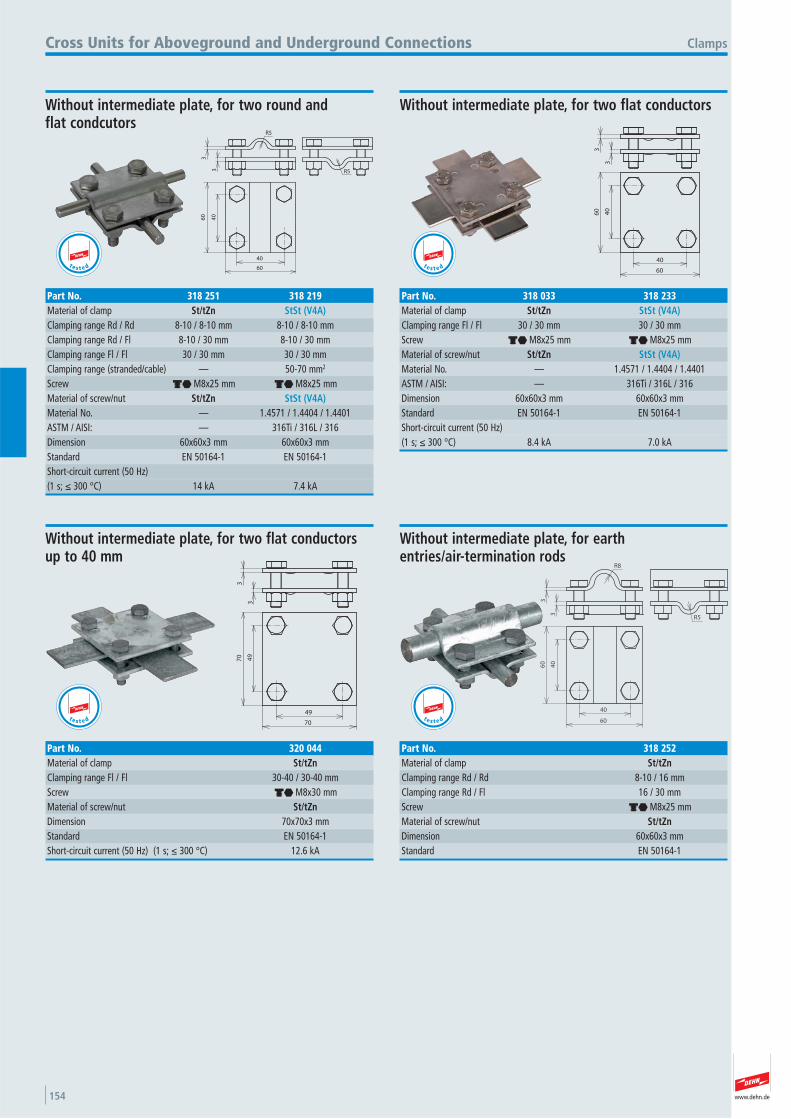
www.dehn.de154
R53
R5
60
60
40
40
3
Clamps
Without intermediate plate, for two round and flat condcutors
Cross Units for Aboveground and Underground Connections
Part No. 318 251 318 219Material of clamp St/tZn StSt (V4A)Clamping range Rd / Rd 8-10 / 8-10 mm 8-10 / 8-10 mmClamping range Rd / Fl 8-10 / 30 mm 8-10 / 30 mmClamping range Fl / Fl 30 / 30 mm 30 / 30 mmClamping range (stranded/cable) — 50-70 mm2
Screw di M8x25 mm di M8x25 mmMaterial of screw/nut St/tZn StSt (V4A)Material No. — 1.4571 / 1.4404 / 1.4401 ASTM / AISI: — 316Ti / 316L / 316Dimension 60x60x3 mm 60x60x3 mmStandard EN 50164-1 EN 50164-1 Short-circuit current (50 Hz) (1 s; ≤ 300 °C) 14 kA 7.4 kA
t e s t e d
3
3
60
60
40
40
Without intermediate plate, for two flat conductors
Part No. 318 033 318 233Material of clamp St/tZn StSt (V4A)Clamping range Fl / Fl 30 / 30 mm 30 / 30 mmScrew di M8x25 mm di M8x25 mmMaterial of screw/nut St/tZn StSt (V4A)Material No. — 1.4571 / 1.4404 / 1.4401 ASTM / AISI: — 316Ti / 316L / 316Dimension 60x60x3 mm 60x60x3 mmStandard EN 50164-1 EN 50164-1 Short-circuit current (50 Hz) (1 s; ≤ 300 °C) 8.4 kA 7.0 kA
t e s t e d
3
3
70
70
49
49
Without intermediate plate, for two flat conductors up to 40 mm
Part No. 320 044Material of clamp St/tZnClamping range Fl / Fl 30-40 / 30-40 mmScrew di M8x30 mmMaterial of screw/nut St/tZnDimension 70x70x3 mmStandard EN 50164-1 Short-circuit current (50 Hz) (1 s; ≤ 300 °C) 12.6 kA
t e s t e d
3
3
R8
R5
60
60
40
40
Without intermediate plate, for earth entries/air-termination rods
Part No. 318 252Material of clamp St/tZnClamping range Rd / Rd 8-10 / 16 mmClamping range Rd / Fl 16 / 30 mmScrew di M8x25 mmMaterial of screw/nut St/tZnDimension 60x60x3 mmStandard EN 50164-1
t e s t e d
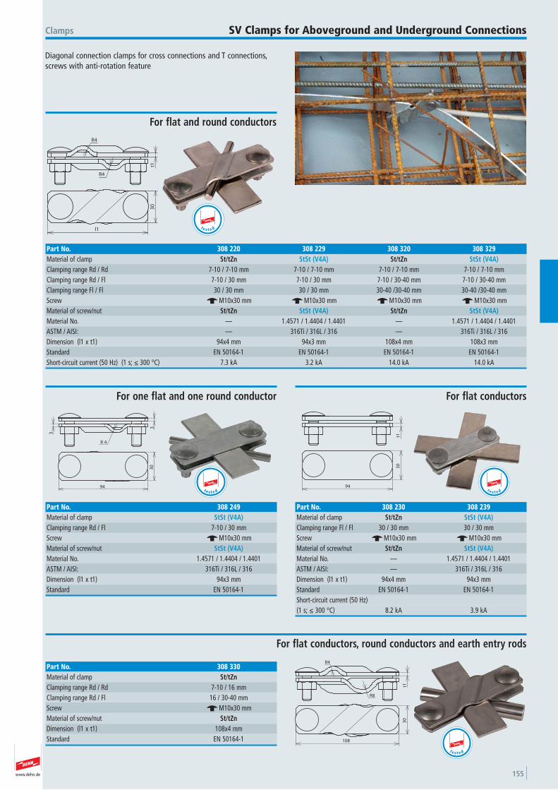
www.dehn.de 155
Diagonal connection clamps for cross connections and T connections, screws with anti-rotation feature
Clamps SV Clamps for Aboveground and Underground Connections
R4
R4
t13
0
l1
For flat and round conductors
Part No. 308 220 308 229 308 320 308 329Material of clamp St/tZn StSt (V4A) St/tZn StSt (V4A)Clamping range Rd / Rd 7-10 / 7-10 mm 7-10 / 7-10 mm 7-10 / 7-10 mm 7-10 / 7-10 mmClamping range Rd / Fl 7-10 / 30 mm 7-10 / 30 mm 7-10 / 30-40 mm 7-10 / 30-40 mmClamping range Fl / Fl 30 / 30 mm 30 / 30 mm 30-40 /30-40 mm 30-40 /30-40 mmScrew e M10x30 mm e M10x30 mm e M10x30 mm e M10x30 mmMaterial of screw/nut St/tZn StSt (V4A) St/tZn StSt (V4A)Material No. — 1.4571 / 1.4404 / 1.4401 — 1.4571 / 1.4404 / 1.4401 ASTM / AISI: — 316Ti / 316L / 316 — 316Ti / 316L / 316Dimension (l1 x t1) 94x4 mm 94x3 mm 108x4 mm 108x3 mmStandard EN 50164-1 EN 50164-1 EN 50164-1 EN 50164-1 Short-circuit current (50 Hz) (1 s; ≤ 300 °C) 7.3 kA 3.2 kA 14.0 kA 14.0 kA
t e s t e d
R 4
3
3
94
30
For one flat and one round conductor
Part No. 308 249Material of clamp StSt (V4A)Clamping range Rd / Fl 7-10 / 30 mmScrew e M10x30 mmMaterial of screw/nut StSt (V4A)Material No. 1.4571 / 1.4404 / 1.4401 ASTM / AISI: 316Ti / 316L / 316Dimension (l1 x t1) 94x3 mmStandard EN 50164-1
t e s t e d
t13
0
94
For flat conductors
Part No. 308 230 308 239Material of clamp St/tZn StSt (V4A)Clamping range Fl / Fl 30 / 30 mm 30 / 30 mmScrew e M10x30 mm e M10x30 mmMaterial of screw/nut St/tZn StSt (V4A)Material No. — 1.4571 / 1.4404 / 1.4401 ASTM / AISI: — 316Ti / 316L / 316Dimension (l1 x t1) 94x4 mm 94x3 mmStandard EN 50164-1 EN 50164-1 Short-circuit current (50 Hz) (1 s; ≤ 300 °C) 8.2 kA 3.9 kA
t e s t e d
t1
R4
R8
108
30
For flat conductors, round conductors and earth entry rods
Part No. 308 330Material of clamp St/tZnClamping range Rd / Rd 7-10 / 16 mmClamping range Rd / Fl 16 / 30-40 mmScrew e M10x30 mmMaterial of screw/nut St/tZnDimension (l1 x t1) 108x4 mmStandard EN 50164-1
t e s t e d
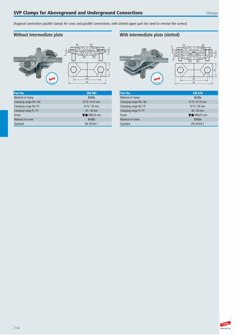
www.dehn.de156
Diagonal connection parallel clamps for cross and parallel connections, with slotted upper part (no need to remove the screws)
ClampsSVP Clamps for Aboveground and Underground Connections
3
R5R5
R5 R5
3
30
83
60
Without intermediate plate
Part No. 308 060Material of clamp St/tZnClamping range Rd / Rd 8-10 / 8-10 mmClamping range Rd / Fl 8-10 / 30 mmClamping range Fl / Fl 30 / 30 mmScrew di M8x25 mmMaterial of screw St/tZnStandard EN 50164-1
3
33
R5 R5
R5R5
30
83
60
With intermediate plate (slotted)
Part No. 308 070Material of clamp St/tZnClamping range Rd / Rd 8-10 / 8-10 mmClamping range Rd / Fl 8-10 / 30 mmClamping range Fl / Fl 30 / 30 mmScrew di M8x25 mmMaterial of screw St/tZnStandard EN 50164-1
t e s t e dte s t e d
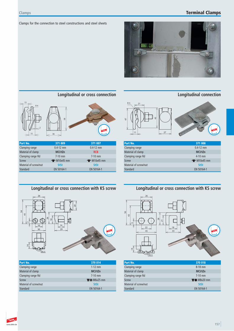
www.dehn.de 157
Clamps for the connection to steel constructions and steel sheets
Clamps Terminal Clamps
13
15
2
4R
36
58
Longitudinal or cross connection
Part No. 371 009 371 007Clamping range 0.4-12 mm 0.4-12 mmMaterial of clamp MCI/tZn RCBClamping range Rd 7-10 mm 7-10 mmScrew e M10x45 mm e M10x45 mmMaterial of screw/nut StSt StStStandard EN 50164-1 EN 50164-1
t e s t e d
47
11
21
45
5R
27
Longitudinal connection
Part No. 371 008Clamping range 0.4-12 mmMaterial of clamp MCI/tZnClamping range Rd 4-10 mmScrew e M10x45 mmMaterial of screw/nut StStStandard EN 50164-1
t e s t e d
26
54
7
41
30
16 14
29
182
6
20
R5.5
14
Longitudinal or cross connection with KS screw
Part No. 370 014Clamping range 1-12 mmMaterial of clamp MCI/tZnClamping range Rd 7-10 mmScrew dj M6x25 mmMaterial of screw/nut StStStandard EN 50164-1
t e s t e d
26
43
56
45
9
22 18
33
212
8
14
R5.5
Longitudinal or cross connection with KS screw
Part No. 370 018Clamping range 8-18 mmMaterial of clamp MCI/tZnClamping range Rd 7-10 mmScrew di M8x20 mmMaterial of screw/nut StStStandard EN 50164-1
t e s t e d
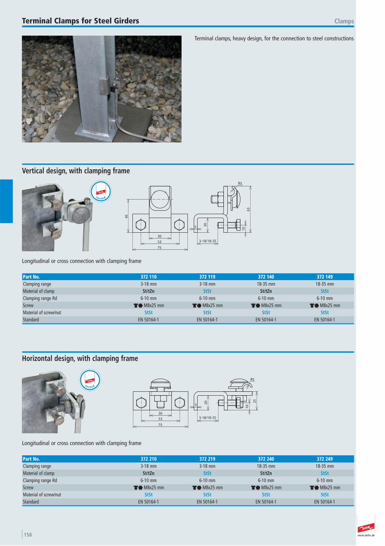
www.dehn.de158
Terminal clamps, heavy design, for the connection to steel constructions
ClampsTerminal Clamps for Steel Girders
20
5
63
R5
3-18/18-351
053
30
75
45
Longitudinal or cross connection with clamping frame
Vertical design, with clamping frame
Part No. 372 110 372 119 372 140 372 149Clamping range 3-18 mm 3-18 mm 18-35 mm 18-35 mmMaterial of clamp St/tZn StSt St/tZn StStClamping range Rd 6-10 mm 6-10 mm 6-10 mm 6-10 mmScrew di M8x25 mm di M8x25 mm di M8x25 mm di M8x25 mmMaterial of screw/nut StSt StSt StSt StStStandard EN 50164-1 EN 50164-1 EN 50164-1 EN 50164-1
t e s t e d
20
5
25
R5
3-18/18-35
10
30
75
53
Longitudinal or cross connection with clamping frame
Horizontal design, with clamping frame
Part No. 372 210 372 219 372 240 372 249Clamping range 3-18 mm 3-18 mm 18-35 mm 18-35 mmMaterial of clamp St/tZn StSt St/tZn StStClamping range Rd 6-10 mm 6-10 mm 6-10 mm 6-10 mmScrew di M8x25 mm di M8x25 mm di M8x25 mm di M8x25 mmMaterial of screw/nut StSt StSt StSt StStStandard EN 50164-1 EN 50164-1 EN 50164-1 EN 50164-1
t e s t e d
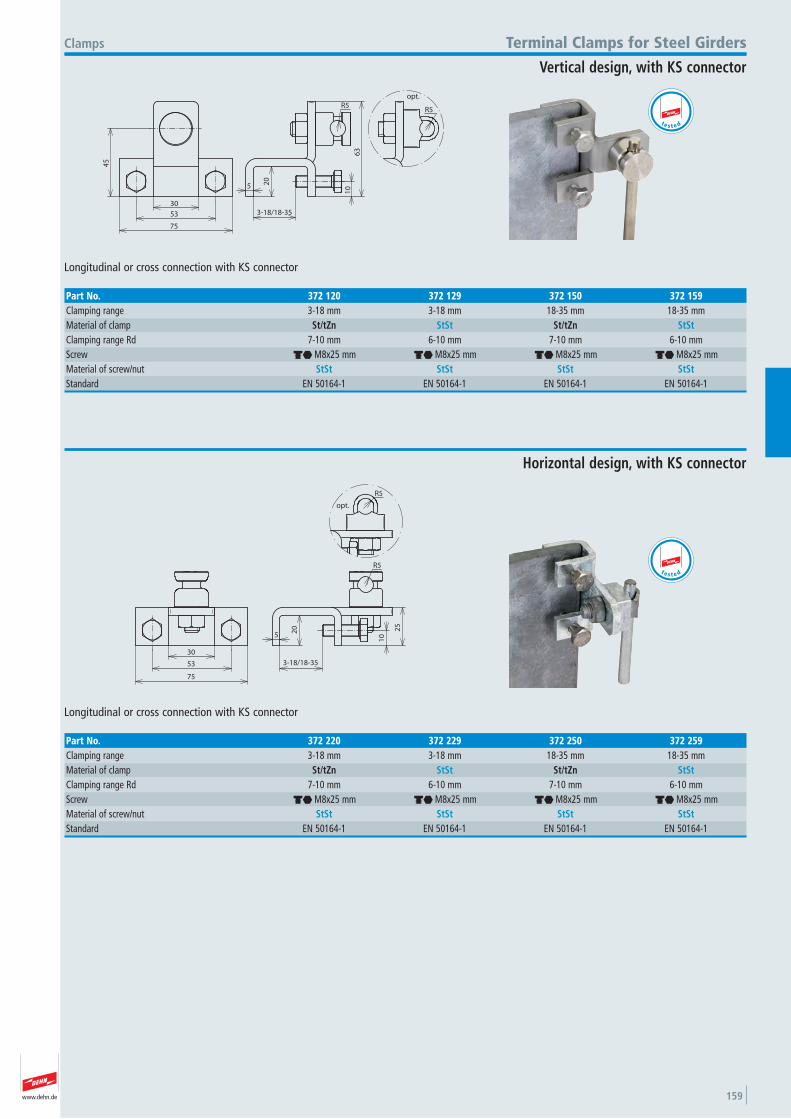
www.dehn.de 159
5 20
10
63
R5
3-18/18-35
45
30
75
53
R5
opt.
Longitudinal or cross connection with KS connector
Clamps Terminal Clamps for Steel Girders
Vertical design, with KS connector
Part No. 372 120 372 129 372 150 372 159Clamping range 3-18 mm 3-18 mm 18-35 mm 18-35 mmMaterial of clamp St/tZn StSt St/tZn StStClamping range Rd 7-10 mm 6-10 mm 7-10 mm 6-10 mmScrew di M8x25 mm di M8x25 mm di M8x25 mm di M8x25 mmMaterial of screw/nut StSt StSt StSt StStStandard EN 50164-1 EN 50164-1 EN 50164-1 EN 50164-1
t e s t e d
5
10
20 25
R5
3-18/18-35
30
75
53
R5
opt.
Longitudinal or cross connection with KS connector
Horizontal design, with KS connector
Part No. 372 220 372 229 372 250 372 259Clamping range 3-18 mm 3-18 mm 18-35 mm 18-35 mmMaterial of clamp St/tZn StSt St/tZn StStClamping range Rd 7-10 mm 6-10 mm 7-10 mm 6-10 mmScrew di M8x25 mm di M8x25 mm di M8x25 mm di M8x25 mmMaterial of screw/nut StSt StSt StSt StStStandard EN 50164-1 EN 50164-1 EN 50164-1 EN 50164-1
t e s t e d
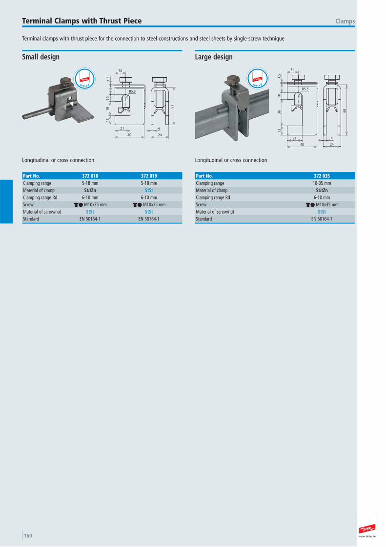
www.dehn.de160
Terminal clamps with thrust piece for the connection to steel constructions and steel sheets by single-screw technique
ClampsTerminal Clamps with Thrust Piece
1.5
10
19
13
21
40
R5.5
24
4
51
15
Longitudinal or cross connection
Small design
Part No. 372 018 372 019Clamping range 5-18 mm 5-18 mmMaterial of clamp St/tZn StStClamping range Rd 6-10 mm 6-10 mmScrew di M10x35 mm di M10x35 mmMaterial of screw/nut StSt StStStandard EN 50164-1 EN 50164-1
t e s t e d
21
40
13
36
10
1.5
R5.5
15
4
24
68
Longitudinal or cross connection
Large design
Part No. 372 035Clamping range 18-35 mmMaterial of clamp St/tZnClamping range Rd 6-10 mmScrew di M10x35 mmMaterial of screw/nut StStStandard EN 50164-1
t e s t e d
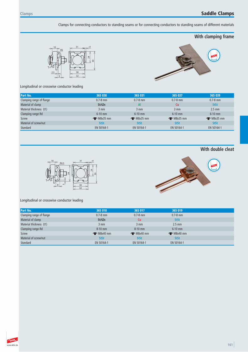
www.dehn.de 161
Clamps for connecting conductors to standing seams or for connecting conductors to standing seams of different materials
Clamps Saddle Clamps
30
32
24
39
t131
2.5
3
10
9
R5
Longitudinal or crosswise conductor leading
With clamping frame
Part No. 365 030 365 031 365 037 365 039Clamping range of flange 0.7-8 mm 0.7-8 mm 0.7-8 mm 0.7-8 mmMaterial of clamp St/tZn Al Cu StStMaterial thickness (t1) 3 mm 3 mm 3 mm 2.5 mmClamping range Rd 6-10 mm 6-10 mm 6-10 mm 6-10 mmScrew e M8x35 mm e M8x35 mm e M8x35 mm e M8x35 mmMaterial of screw/nut StSt StSt StSt StStStandard EN 50164-1 EN 50164-1 EN 50164-1 EN 50164-1
t e s t e d
31 t1
24
39
30
32
3
34
3
10
8
R4.5
Longitudinal or crosswise conductor leading
With double cleat
Part No. 365 010 365 017 365 019Clamping range of flange 0.7-8 mm 0.7-8 mm 0.7-8 mmMaterial of clamp St/tZn Cu StStMaterial thickness (t1) 3 mm 3 mm 2.5 mmClamping range Rd 8-10 mm 8-10 mm 6-10 mmScrew e M8x40 mm e M8x40 mm e M8x40 mmMaterial of screw/nut StSt StSt StStStandard EN 50164-1 EN 50164-1 EN 50164-1
t e s t e d

www.dehn.de162
50
18
8
9
64
28
28
2.5
6
113
R5
Longitudinal or crosswise conductor leading
Clamps
With two-screws-cleat
Saddle Clamps
Part No. 251 002 251 027Clamping range of flange 0.7-5 mm 0.7-5 mmMaterial of clamp St/tZn CuMaterial thickness (t1) 2.5 mm 2.5 mmClamping range Rd 7-10 mm 7-10 mmScrew dj M6x12 mm dj M6x12 mmMaterial of screw/nut StSt StStStandard EN 50164-1 EN 50164-1
t e s t e d
Ø32
21
2.5
R5
6
16 7
12
28
5
Ø32
Longitudinal or crosswise conductor leading
With two-screws-cleat, e.g. for standing seams
Part No. 365 000 365 007Clamping range of flange 0.7-6 mm 0.7-6 mmMaterial of clamp ZDC RCBClamping range Rd 7-10 mm 7-10 mmScrew dm M6x16 mm dm M6x16 mmMaterial of screw/nut StSt StStStandard EN 50164-1 EN 50164-1
47
12
33
59
26
7.5
28
39
10.5
17
2.5
3
R5
Close to a roof or wall areaLongitudinal and crosswise conductor leading
With clamping frame, for hooking at seams
Part No. 365 020 365 027Clamping range of flange 0.7-10 mm 0.7-10 mmMaterial of clamp St/tZn CuMaterial thickness (t1) 3 mm 3 mmClamping range Rd 6-10 mm 6-10 mmScrew dj M6x16 / dj M6x16 / di M8x20 mm di M8x20 mmMaterial of screw/nut StSt StStStandard EN 50164-1 EN 50164-1
t e s t e d
te s t e d
82
8
28
42
11
59
12
47
3
R5
3
20
17
10.5
Close to a roof or wall area Longitudinal and crosswise conductor leading
With two-screws-cleat, for hooking at seams
Part No. 365 040 365 047Clamping range of flange 0.7-10 mm 0.7-10 mmMaterial of clamp St/tZn CuMaterial thickness (t1) 3 mm 3 mmClamping range Rd 7-10 mm 7-10 mmScrew dm M6x16 mm dm M6x16 mmMaterial of screw/nut StSt StStStandard EN 50164-1 EN 50164-1
t e s t e d
10
R5
2.5
1.5
3
31 3
24
13
39
30
32
Bimetallic, for Cu seams, with intermediate plate (Cupal)
Part No. 365 117Clamping range of flange 0.7-8 mmMaterial of clamp St/tZn / CuClamping range Rd 6-10 mmScrew e M8x35 mmMaterial of screw/nut StStStandard EN 50164-1
t e s t e d
10
R5
2.5
1.5
3
31 3
24
13
39
30
32
Bimetallic, for St/tZn seams, with intermediate plate (Cupal)
Part No. 365 127Clamping range of flange 0.7-8 mmMaterial of clamp Cu / St/tZnClamping range Rd 6-10 mmScrew e M8x35 mmMaterial of screw/nut StSt
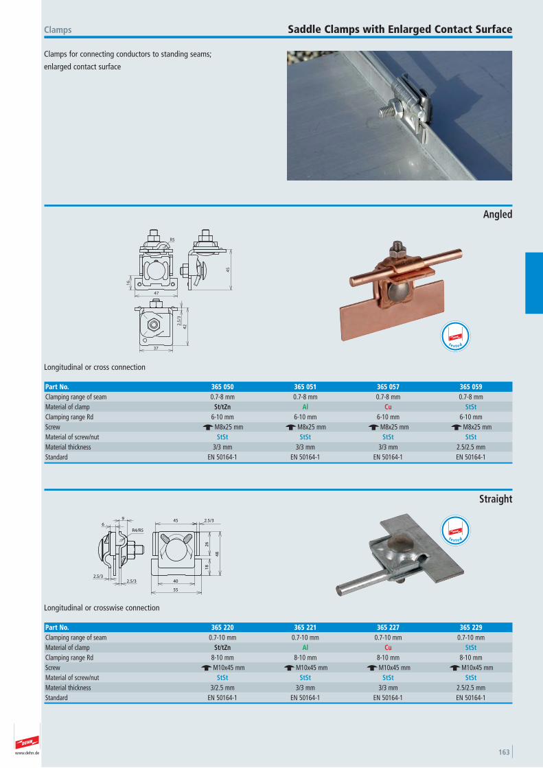
www.dehn.de 163
Clamps for connecting conductors to standing seams;
enlarged contact surface
Clamps Saddle Clamps with Enlarged Contact Surface
16
R5
47
45
2.5
/3
42
37
Longitudinal or cross connection
Angled
Part No. 365 050 365 051 365 057 365 059Clamping range of seam 0.7-8 mm 0.7-8 mm 0.7-8 mm 0.7-8 mmMaterial of clamp St/tZn Al Cu StStClamping range Rd 6-10 mm 6-10 mm 6-10 mm 6-10 mmScrew e M8x25 mm e M8x25 mm e M8x25 mm e M8x25 mmMaterial of screw/nut StSt StSt StSt StStMaterial thickness 3/3 mm 3/3 mm 3/3 mm 2.5/2.5 mmStandard EN 50164-1 EN 50164-1 EN 50164-1 EN 50164-1
t e s t e d
6
9
R4/R5
2.5/32.5/3
40
55
18
26
48
45 2.5/3
Longitudinal or crosswise connection
Straight
Part No. 365 220 365 221 365 227 365 229Clamping range of seam 0.7-10 mm 0.7-10 mm 0.7-10 mm 0.7-10 mmMaterial of clamp St/tZn Al Cu StStClamping range Rd 8-10 mm 8-10 mm 8-10 mm 8-10 mmScrew e M10x45 mm e M10x45 mm e M10x45 mm e M10x45 mmMaterial of screw/nut StSt StSt StSt StStMaterial thickness 3/2.5 mm 3/3 mm 3/3 mm 2.5/2.5 mmStandard EN 50164-1 EN 50164-1 EN 50164-1 EN 50164-1
t e s t e d
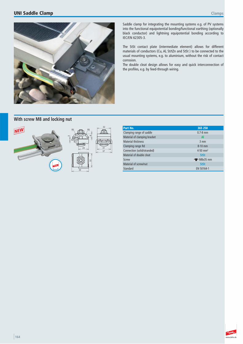
www.dehn.de164
Saddle clamp for integrating the mounting systems e.g. of PV systemsinto the functional equipotential bonding/functional earthing (optionallyblack conductor) and lightning equipotential bonding according toIEC/EN 62305-3.
The StSt contact plate (intermediate element) allows for different materials of conductors (Cu, Al, St/tZn and StSt ) to be connected to theusual mounting systems, e.g. to aluminium, without the risk of contactcorrosion.The double cleat design allows for easy and quick interconnection of the profiles, e.g. by feed-through wiring.
ClampsUNI Saddle Clamp
83
24
32
39
32
31
37
R5 R5
With screw M8 and locking nut
Part No. 365 250Clamping range of saddle 0.7-8 mmMaterial of clamping bracket AlMaterial thickness 3 mmClamping range Rd 8-10 mmConnection (solid/stranded) 4-50 mm2
Material of double cleat StStScrew e M8x35 mmMaterial of screw/nut StStStandard EN 50164-1 t e s t e d
+
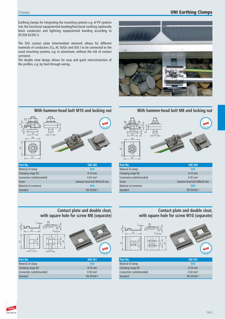
www.dehn.de 165
Earthing clamps for integrating the mounting systems e.g. of PV systemsinto the functional equipotential bonding/functional earthing (optionallyblack conductor) and lightning equipotential bonding according toIEC/EN 62305-3.
The StSt contact plate (intermediate element) allows for different materials of conductors (Cu, Al, St/tZn and StSt ) to be connected to theusual mounting systems, e.g. to aluminium, without the risk of contactcorrosion.The double cleat design allows for easy and quick interconnection of the profiles, e.g. by feed-through wiring.
Clamps UNI Earthing Clamps
R5
8
23
4
R5
34
37
32
11
6
With hammer-head bolt M8 and locking nut
Part No. 540 250Material of clamp StStClamping range Rd 8-10 mmConnection (solid/stranded) 4-50 mm2
Screw hammer-head bolt M8x30 mmMaterial of screw/nut StStStandard EN 50164-1
t e s t e d
8
23
R5
5
11
6
32
37
34
With hammer-head bolt M10 and locking nut
Part No. 540 260Material of clamp StStClamping range Rd 8-10 mmConnection (solid/stranded) 4-50 mm2
Screw hammer-head bolt M10x30 mmMaterial of screw/nut StStStandard EN 50164-1
t e s t e d
9
11 10
32 329
37 3
8
R51
6
Contact plate and double cleat, with square hole for screw M8 (separate)
Part No. 540 251Material of clamp StStClamping range Rd 8-10 mmConnection (solid/stranded) 4-50 mm2
Standard EN 50164-1
t e s t e d
1112
11
3232
37 3
8
R51
6
12
Contact plate and double cleat, with square hole for screw M10 (separate)
Part No. 540 261Material of clamp StStClamping range Rd 8-10 mmConnection (solid/stranded) 4-50 mm2
Standard EN 50164-1
t e s t e d
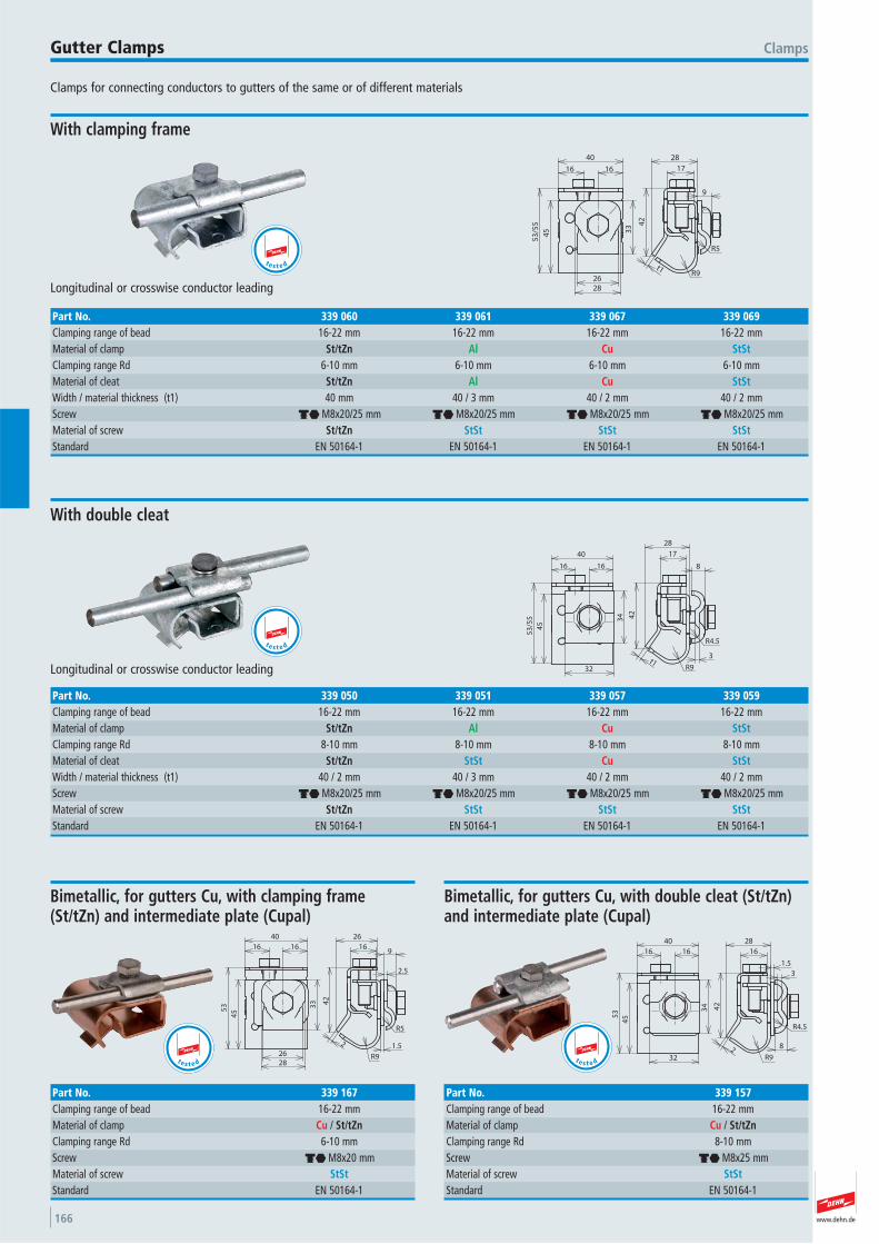
www.dehn.de166
Clamps for connecting conductors to gutters of the same or of different materials
ClampsGutter Clamps
2628
45
53
/55
33
1616
40
t1R9
R5
42
17
28
9
Longitudinal or crosswise conductor leading
With clamping frame
Part No. 339 060 339 061 339 067 339 069Clamping range of bead 16-22 mm 16-22 mm 16-22 mm 16-22 mmMaterial of clamp St/tZn Al Cu StStClamping range Rd 6-10 mm 6-10 mm 6-10 mm 6-10 mmMaterial of cleat St/tZn Al Cu StStWidth / material thickness (t1) 40 mm 40 / 3 mm 40 / 2 mm 40 / 2 mmScrew di M8x20/25 mm di M8x20/25 mm di M8x20/25 mm di M8x20/25 mmMaterial of screw St/tZn StSt StSt StStStandard EN 50164-1 EN 50164-1 EN 50164-1 EN 50164-1
t e s t e d
t1R9
R4.5
3
8
17
28
42
40
16
32
34
45
53
/55
16
Longitudinal or crosswise conductor leading
With double cleat
Part No. 339 050 339 051 339 057 339 059Clamping range of bead 16-22 mm 16-22 mm 16-22 mm 16-22 mmMaterial of clamp St/tZn Al Cu StStClamping range Rd 8-10 mm 8-10 mm 8-10 mm 8-10 mmMaterial of cleat St/tZn StSt Cu StStWidth / material thickness (t1) 40 / 2 mm 40 / 3 mm 40 / 2 mm 40 / 2 mmScrew di M8x20/25 mm di M8x20/25 mm di M8x20/25 mm di M8x20/25 mmMaterial of screw St/tZn StSt StSt StStStandard EN 50164-1 EN 50164-1 EN 50164-1 EN 50164-1
t e s t e d
16
26
2.5
9
R5
1.5
R9
2
42
33
2628
455
3
16 16
40
Bimetallic, for gutters Cu, with clamping frame (St/tZn) and intermediate plate (Cupal)
Part No. 339 167Clamping range of bead 16-22 mmMaterial of clamp Cu / St/tZnClamping range Rd 6-10 mmScrew di M8x20 mmMaterial of screw StStStandard EN 50164-1
t e s t e d
40
53
32
34
16 16
45
28
42
2R9
8
R4.5
3
1.5
16
Bimetallic, for gutters Cu, with double cleat (St/tZn) and intermediate plate (Cupal)
Part No. 339 157Clamping range of bead 16-22 mmMaterial of clamp Cu / St/tZnClamping range Rd 8-10 mmScrew di M8x25 mmMaterial of screw StStStandard EN 50164-1
t e s t e d
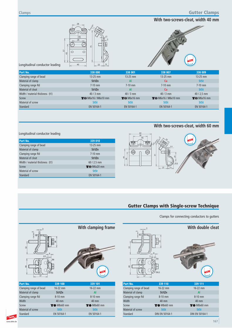
www.dehn.de 167
R5
28
404
3
57
28
t1
1322
75
3
3
R1
Longitudinal conductor leading
Clamps Gutter Clamps
With two-screws-cleat, width 40 mm
Part No. 338 000 338 001 338 007 338 009Clamping range of bead 13-25 mm 13-25 mm 13-25 mm 13-25 mmMaterial of clamp St/tZn Al Cu StStClamping range Rd 7-10 mm 7-10 mm 7-10 mm 7-10 mmMaterial of cleat St/tZn Al Cu StStWidth / material thickness (t1) 40 / 3 mm 40 / 3 mm 40 / 3 mm 40 / 2,5 mmScrew dj M6x16 / M6x10 mm dj M6x16 mm dj M6x16 / M6x10 mm dj M6x16 mmMaterial of screw StSt StSt StSt StStStandard EN 50164-1 EN 50164-1 EN 50164-1 EN 50164-1
t e s t e d
364
4
60
R5
38
23 15
R10
2.5
20
3
2.5
61
24
Longitudinal conductor leading
With two-screws-cleat, width 60 mm
Part No. 339 010Clamping range of bead 13-25 mmMaterial of clamp St/tZnClamping range Rd 7-10 mmMaterial of cleat St/tZnWidth / material thickness (t1) 60 / 2.5 mmScrew dj M6x20 mmMaterial of screw StStStandard EN 50164-1
t e s t e d
Clamps for connecting conductors to gutters
Gutter Clamps with Single-screw Technique
37
40
2.5
9
R4
R5
32
28
3
3
With clamping frame
Part No. 339 100 339 101Clamping range of bead 16-22 mm 16-22 mmMaterial of clamp St/tZn AlClamping range Rd 8-10 mm 8-10 mmWidth 40 mm 40 mmScrew di M8x60 mm di M8x60 mmMaterial of screw StSt StStStandard EN 50164-1 EN 50164-1
t e s t e d
40
37
8
R4.5
R4
3
32
3
3
32
With double cleat
Part No. 339 110 339 111Clamping range of bead 16-22 mm 16-22 mmMaterial of clamp St/tZn AlClamping range Rd 8-10 mm 8-10 mmWidth 40 mm 40 mmScrew di M8x60 mm di M8x60 mmMaterial of screw StSt StStStandard DIN EN 50164-1 DIN EN 50164-1
t e s t e d
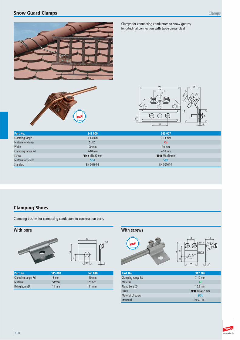
www.dehn.de168
Clamps for connecting conductors to snow guards, longitudinal connection with two-screws-cleat
ClampsSnow Guard Clamps
14
28
90
R5
35
20
3
2
28
28
2
50
Part No. 343 000 343 007Clamping range 3-13 mm 3-13 mmMaterial of clamp St/tZn CuWidth 90 mm 90 mmClamping range Rd 7-10 mm 7-10 mmScrew dj M6x20 mm dj M6x20 mmMaterial of screw StSt StStStandard EN 50164-1 EN 50164-1
t e s t e d
Clamping bushes for connecting conductors to construction parts
Clamping Shoes
Ø11
38
40
14
R4/5
1
With bore
Part No. 345 008 345 010Clamping range Rd 8 mm 10 mmMaterial St/tZn St/tZnFixing bore Ø 11 mm 11 mm
15
12
23
43 Ø10.5
28
19
Ø11.5
3
With screws
Part No. 347 205Clamping range Rd 7-10 mmMaterial AlFixing bore Ø 10.5 mmScrew dj M6x12 mmMaterial of screw StStStandard EN 50164-1
t e s t e d
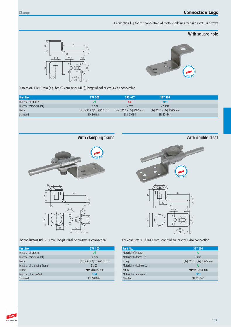
www.dehn.de 169
Connection lug for the connection of metal claddings by blind rivets or screws
Clamps Connection Lugs
14
30
11 Ø5.2
Ø6
.5
18
20
28 8
12
t1
512
7
81
Dimension 11x11 mm (e.g. for KS connector M10), longitudinal or crosswise connection
With square hole
Part No. 377 005 377 017 377 009Material of bracket Al Cu StStMaterial thickness (t1) 3 mm 2 mm 2.5 mmFixing [4x] Ø5.2 / [2x] Ø6.5 mm [4x] Ø5.2 / [2x] Ø6.5 mm [4x] Ø5,2 / [2x] Ø6.5 mmStandard EN 50164-1 EN 50164-1 EN 50164-1
t e s t e d
30
16
3
81
27
51
R5
Ø5.2
Ø6
.5
18
20
28 8
12
For conductors Rd 6-10 mm, longitudinal or crosswise connection
With clamping frame
Part No. 377 100Material of bracket AlMaterial thickness (t1) 3 mmFixing [4x] Ø5.2 / [2x] Ø6.5 mmMaterial of clamping frame St/tZnScrew e M10x30 mmMaterial of screw/nut StStStandard EN 50164-1
t e s t e d
16
3
81
27
51
Ø5.2
Ø6
.5
18
20
28 8
12
32
For conductors Rd 8-10 mm, longitudinal or crosswise connection
With double cleat
Part No. 377 200Material of bracket AlMaterial thickness (t1) 3 mmFixing [4x] Ø5.2 / [2x] Ø6.5 mmMaterial of double cleat AlScrew e M10x30 mmMaterial of screw/nut StStStandard EN 50164-1
t e s t e d
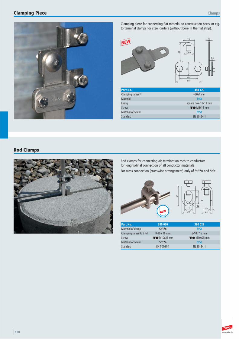
www.dehn.de170
Clamping piece for connecting flat material to construction parts, or e.g.to terminal clamps for steel girders (without bore in the flat strip).
ClampsClamping Piece
25
43
30
40
58
2.5
2.5
11
Part No. 380 129Clamping range Fl –30x4 mmMaterial StStFixing square hole 11x11 mmScrew di M8x16 mmMaterial of screw StStStandard EN 50164-1
+
Rod clamps for connecting air-termination rods to conductors for longitudinal connection of all conductor materials
For cross connection (crosswise arrangement) only of St/tZn and StSt
Rod Clamps
45
17
30
28
R43/4
25
Part No. 380 020 380 029Material of clamp St/tZn StStClamping range Rd / Rd 8-10 / 16 mm 8-10 / 16 mmScrew di M10x25 mm di M10x25 mmMaterial of screw St/tZn StStStandard EN 50164-1 EN 50164-1
t e s t e d
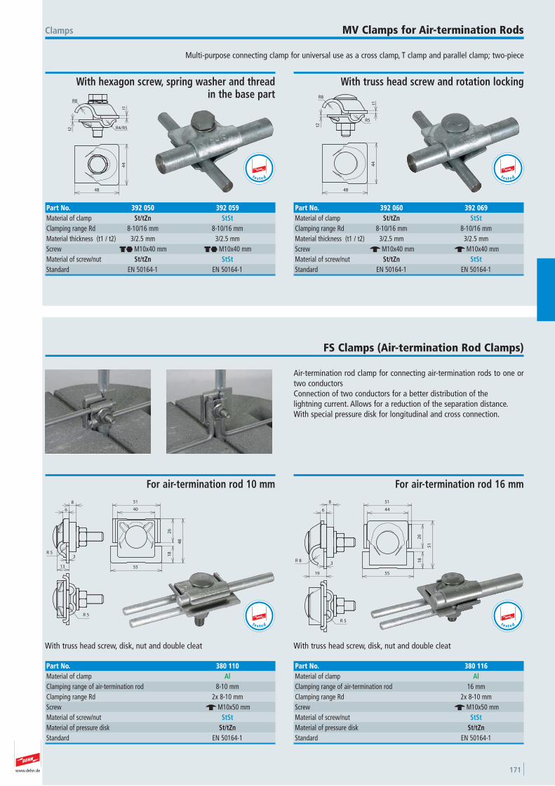
www.dehn.de 171
Multi-purpose connecting clamp for universal use as a cross clamp, T clamp and parallel clamp; two-piece
Clamps MV Clamps for Air-termination Rods
44
48
R4/R5t1
t2
R8
With hexagon screw, spring washer and thread in the base part
Part No. 392 050 392 059Material of clamp St/tZn StStClamping range Rd 8-10/16 mm 8-10/16 mmMaterial thickness (t1 / t2) 3/2.5 mm 3/2.5 mmScrew di M10x40 mm di M10x40 mmMaterial of screw/nut St/tZn StStStandard EN 50164-1 EN 50164-1
t e s t e d
44
48
t1
R5
t2
R8
With truss head screw and rotation locking
Part No. 392 060 392 069Material of clamp St/tZn StStClamping range Rd 8-10/16 mm 8-10/16 mmMaterial thickness (t1 / t2) 3/2.5 mm 3/2.5 mmScrew e M10x40 mm e M10x40 mmMaterial of screw/nut St/tZn StStStandard EN 50164-1 EN 50164-1
t e s t e d
Air-termination rod clamp for connecting air-termination rods to one ortwo conductorsConnection of two conductors for a better distribution of the lightning current. Allows for a reduction of the separation distance.With special pressure disk for longitudinal and cross connection.
FS Clamps (Air-termination Rod Clamps)
6
8
5R3
13
40
26
18
48
55
51
5R
With truss head screw, disk, nut and double cleat
For air-termination rod 10 mm
Part No. 380 110Material of clamp AlClamping range of air-termination rod 8-10 mmClamping range Rd 2x 8-10 mmScrew e M10x50 mmMaterial of screw/nut StStMaterial of pressure disk St/tZnStandard EN 50164-1
t e s t e d
8R
6
8
19
3
44
51
26
18
51
55
5R
With truss head screw, disk, nut and double cleat
For air-termination rod 16 mm
Part No. 380 116Material of clamp AlClamping range of air-termination rod 16 mmClamping range Rd 2x 8-10 mmScrew e M10x50 mmMaterial of screw/nut StStMaterial of pressure disk St/tZnStandard EN 50164-1
t e s t e d

www.dehn.de172
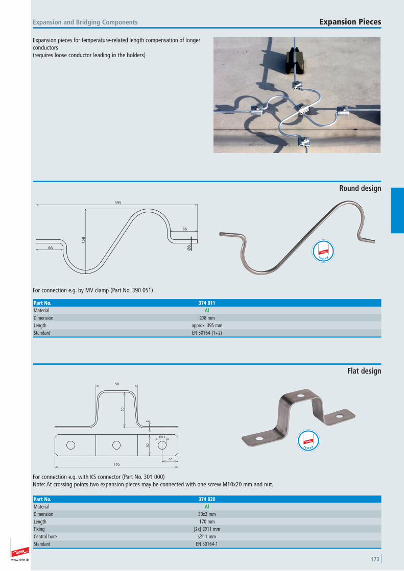
www.dehn.de 173
Expansion pieces for temperature-related length compensation of longerconductors (requires loose conductor leading in the holders)
Expansion and Bridging Components Expansion Pieces
66
15
8
66
Ø8
395
For connection e.g. by MV clamp (Part No. 390 051)
Round design
Part No. 374 011Material AlDimension Ø8 mmLength approx. 395 mmStandard EN 50164-(1+2)
t e s t e d
58
50
2
22
30
Ø11
170
For connection e.g. with KS connector (Part No. 301 000)Note: At crossing points two expansion pieces may be connected with one screw M10x20 mm and nut.
Flat design
Part No. 374 020Material AlDimension 30x2 mmLength 170 mmFixing [2x] Ø11 mmCentral bore Ø11 mmStandard EN 50164-1
t e s t e d
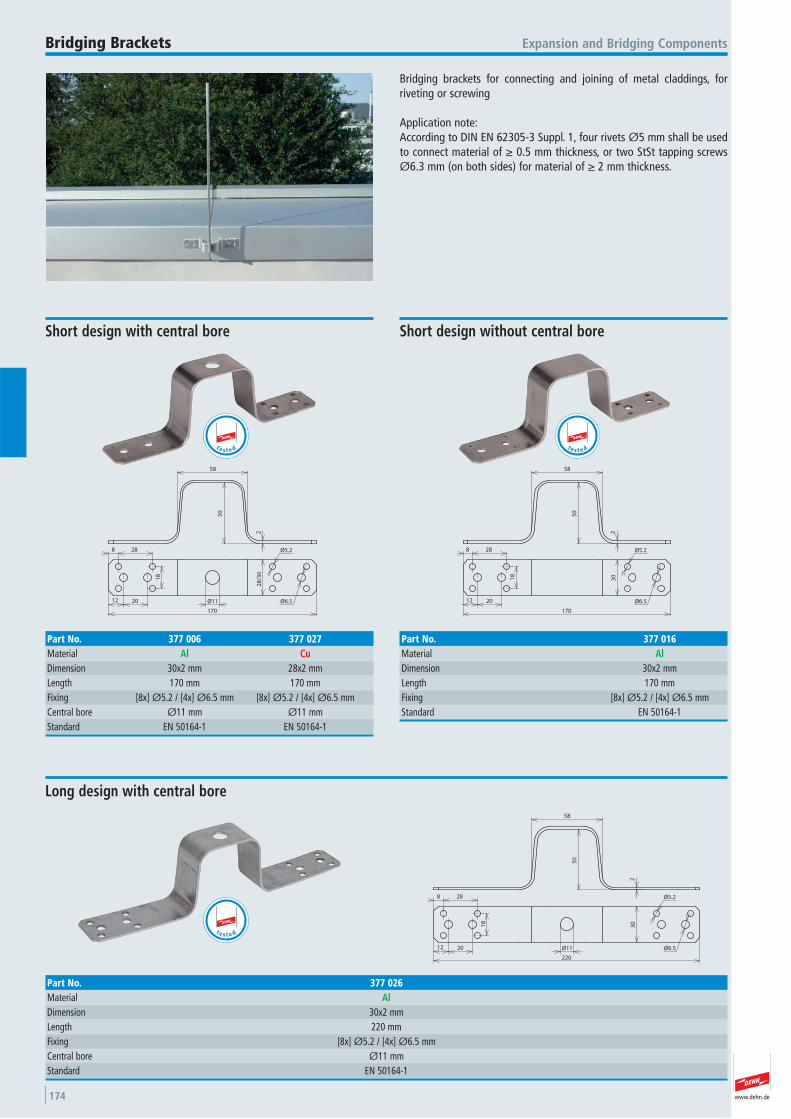
www.dehn.de174
Bridging brackets for connecting and joining of metal claddings, for riveting or screwing
Application note:According to DIN EN 62305-3 Suppl. 1, four rivets Ø5 mm shall be usedto connect material of ≥ 0.5 mm thickness, or two StSt tapping screwsØ6.3 mm (on both sides) for material of ≥ 2 mm thickness.
Expansion and Bridging ComponentsBridging Brackets
58
50
2
8 28
18
12 20 Ø11 Ø6.5
Ø5.2
28
/30
170
Short design with central bore
Part No. 377 006 377 027Material Al CuDimension 30x2 mm 28x2 mmLength 170 mm 170 mmFixing [8x] Ø5.2 / [4x] Ø6.5 mm [8x] Ø5.2 / [4x] Ø6.5 mmCentral bore Ø11 mm Ø11 mmStandard EN 50164-1 EN 50164-1
t e s t e d
58
50
2
8 28
18
12 20 Ø6.5
Ø5.2
30
170
Short design without central bore
Part No. 377 016Material AlDimension 30x2 mmLength 170 mmFixing [8x] Ø5.2 / [4x] Ø6.5 mmStandard EN 50164-1
t e s t e d
58
50
2
8 28
18
12 20 Ø6.5
Ø5.2
30
220
Ø11
Long design with central bore
Part No. 377 026Material AlDimension 30x2 mmLength 220 mmFixing [8x] Ø5.2 / [4x] Ø6.5 mmCentral bore Ø11 mmStandard EN 50164-1
t e s t e d
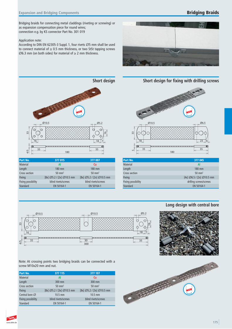
www.dehn.de 175
Bridging braids for connecting metal claddings (riveting or screwing) oras expansion compensation piece for round wires;connection e.g. by KS connector Part No. 301 019
Application note:According to DIN EN 62305-3 Suppl. 1, four rivets Ø5 mm shall be usedto connect material of ≥ 0.5 mm thickness, or two StSt tapping screwsØ6.3 mm (on both sides) for material of ≥ 2 mm thickness.
Expansion and Bridging Components Bridging Braids
Ø10.5
33
16
180
18 7
Ø5.2
16
35 35
4/5
Short design
Part No. 377 015 377 007Material Al CuLength 180 mm 180 mmCross section 50 mm2 50 mm2
Fixing [8x] Ø5.2 / [2x] Ø10.5 mm [8x] Ø5.2 / [2x] Ø10.5 mmFixing possibility blind rivets/screws blind rivets/screws Standard EN 50164-1 EN 50164-1
t e s t e d
Ø10.5
33
18
180
23 6
Ø6.5
35 355
Short design for fixing with drilling screws
Part No. 377 045Material AlLength 180 mmCross section 50 mm2
Fixing [4x] Ø6.5 / [2x] Ø10.5 mmFixing possibility drilling screws/screws Standard EN 50164-1
t e s t e d
Ø10.5
33
16
300
18 7
Ø5.2
16
35 35
4/5
Ø10.5
30
Note: At crossing points two bridging braids can be connected with ascrew M10x20 mm and nut.
Long design with central bore
Part No. 377 115 377 107Material Al CuLength 300 mm 300 mmCross section 50 mm2 50 mm2
Fixing [8x] Ø5.2 / [3x] Ø10.5 mm [8x] Ø5.2 / [3x] Ø10.5 mmCentral bore Ø 10.5 mm 10.5 mmFixing possibility blind rivets/screws blind rivets/screws Standard EN 50164-1 EN 50164-1
t e s t e d
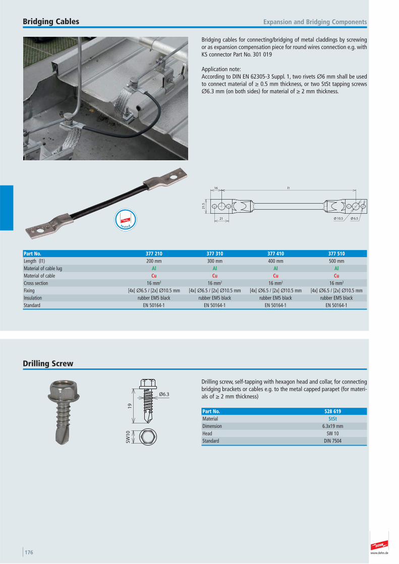
www.dehn.de176
Bridging cables for connecting/bridging of metal claddings by screwingor as expansion compensation piece for round wires connection e.g. withKS connector Part No. 301 019
Application note:According to DIN EN 62305-3 Suppl. 1, two rivets Ø6 mm shall be usedto connect material of ≥ 0.5 mm thickness, or two StSt tapping screwsØ6.3 mm (on both sides) for material of ≥ 2 mm thickness.
Expansion and Bridging ComponentsBridging Cables
l116
21
.5
21 10.5Ø 6.5Ø
Part No. 377 210 377 310 377 410 377 510Length (l1) 200 mm 300 mm 400 mm 500 mmMaterial of cable lug Al Al Al AlMaterial of cable Cu Cu Cu CuCross section 16 mm2 16 mm2 16 mm2 16 mm2
Fixing [4x] Ø6.5 / [2x] Ø10.5 mm [4x] Ø6.5 / [2x] Ø10.5 mm [4x] Ø6.5 / [2x] Ø10.5 mm [4x] Ø6.5 / [2x] Ø10.5 mmInsulation rubber EM5 black rubber EM5 black rubber EM5 black rubber EM5 black Standard EN 50164-1 EN 50164-1 EN 50164-1 EN 50164-1
t e s t e d
Drilling screw, self-tapping with hexagon head and collar, for connectingbridging brackets or cables e.g. to the metal capped parapet (for materi-als of ≥ 2 mm thickness)
Drilling Screw
Ø6.3
19
SW
10
Part No. 528 619Material StStDimension 6.3x19 mmHead SW 10 Standard DIN 7504
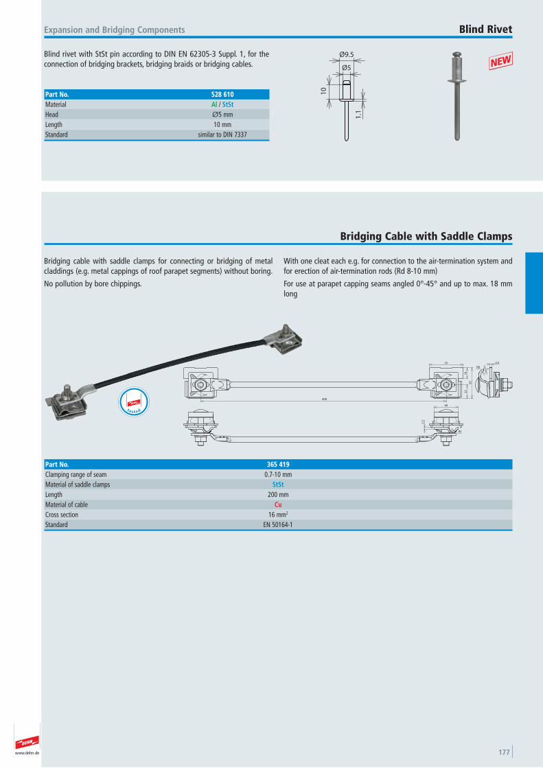
www.dehn.de 177
Blind rivet with StSt pin according to DIN EN 62305-3 Suppl. 1, for theconnection of bridging brackets, bridging braids or bridging cables.
Expansion and Bridging Components Blind Rivet
10
1.1
Ø5
Ø9.5
Part No. 528 610Material Al / StStHead Ø5 mmLength 10 mmStandard similar to DIN 7337
+
Bridging cable with saddle clamps for connecting or bridging of metalcladdings (e.g. metal cappings of roof parapet segments) without boring.
No pollution by bore chippings.
With one cleat each e.g. for connection to the air-termination system andfor erection of air-termination rods (Rd 8-10 mm)
For use at parapet capping seams angled 0°-45° and up to max. 18 mmlong
Bridging Cable with Saddle Clamps
400
22
18
50
55
R8 3
2.5
2.5
40
R5
Part No. 365 419Clamping range of seam 0.7-10 mmMaterial of saddle clamps StStLength 200 mmMaterial of cable CuCross section 16 mm2
Standard EN 50164-1
t e s t e d
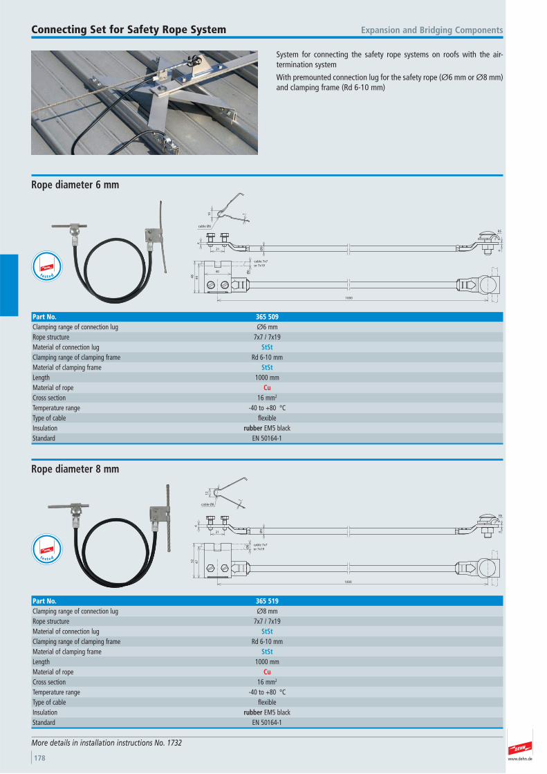
www.dehn.de178
System for connecting the safety rope systems on roofs with the air- termination system
With premounted connection lug for the safety rope (Ø6 mm or Ø8 mm)and clamping frame (Rd 6-10 mm)
Expansion and Bridging ComponentsConnecting Set for Safety Rope System
More details in installation instructions No. 1732
10 1
4
21 4
40
48
44
1000
cable Ø6
R5
Ø9
Ø6
cable 7x7
or 7x19
Rope diameter 6 mm
Part No. 365 509Clamping range of connection lug Ø6 mmRope structure 7x7 / 7x19 Material of connection lug StStClamping range of clamping frame Rd 6-10 mmMaterial of clamping frame StStLength 1000 mmMaterial of rope CuCross section 16 mm2
Temperature range -40 to +80 °CType of cable flexible Insulation rubber EM5 black Standard EN 50164-1
21
4
cable Ø8
12
1
Ø9
R5
4
Ø8
4752
1000
cable 7x7
or 7x19
Rope diameter 8 mm
Part No. 365 519Clamping range of connection lug Ø8 mmRope structure 7x7 / 7x19 Material of connection lug StStClamping range of clamping frame Rd 6-10 mmMaterial of clamping frame StStLength 1000 mmMaterial of rope CuCross section 16 mm2
Temperature range -40 to +80 °CType of cable flexible Insulation rubber EM5 black Standard EN 50164-1
t e s t e d
te s t e d
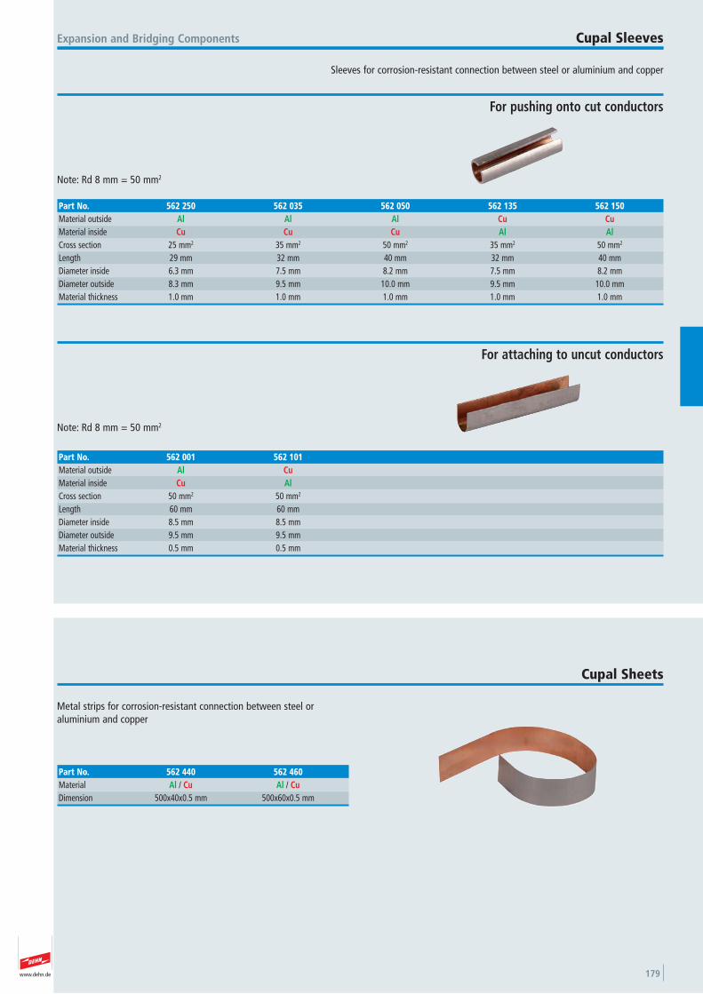
www.dehn.de 179
Sleeves for corrosion-resistant connection between steel or aluminium and copper
Expansion and Bridging Components Cupal Sleeves
Note: Rd 8 mm = 50 mm2
For pushing onto cut conductors
Part No. 562 250 562 035 562 050 562 135 562 150Material outside Al Al Al Cu CuMaterial inside Cu Cu Cu Al AlCross section 25 mm2 35 mm2 50 mm2 35 mm2 50 mm2
Length 29 mm 32 mm 40 mm 32 mm 40 mmDiameter inside 6.3 mm 7.5 mm 8.2 mm 7.5 mm 8.2 mmDiameter outside 8.3 mm 9.5 mm 10.0 mm 9.5 mm 10.0 mmMaterial thickness 1.0 mm 1.0 mm 1.0 mm 1.0 mm 1.0 mm
Note: Rd 8 mm = 50 mm2
For attaching to uncut conductors
Part No. 562 001 562 101Material outside Al CuMaterial inside Cu AlCross section 50 mm2 50 mm2
Length 60 mm 60 mmDiameter inside 8.5 mm 8.5 mmDiameter outside 9.5 mm 9.5 mmMaterial thickness 0.5 mm 0.5 mm
Metal strips for corrosion-resistant connection between steel or aluminium and copper
Cupal Sheets
Part No. 562 440 562 460Material Al / Cu Al / CuDimension 500x40x0.5 mm 500x60x0.5 mm

www.dehn.de180
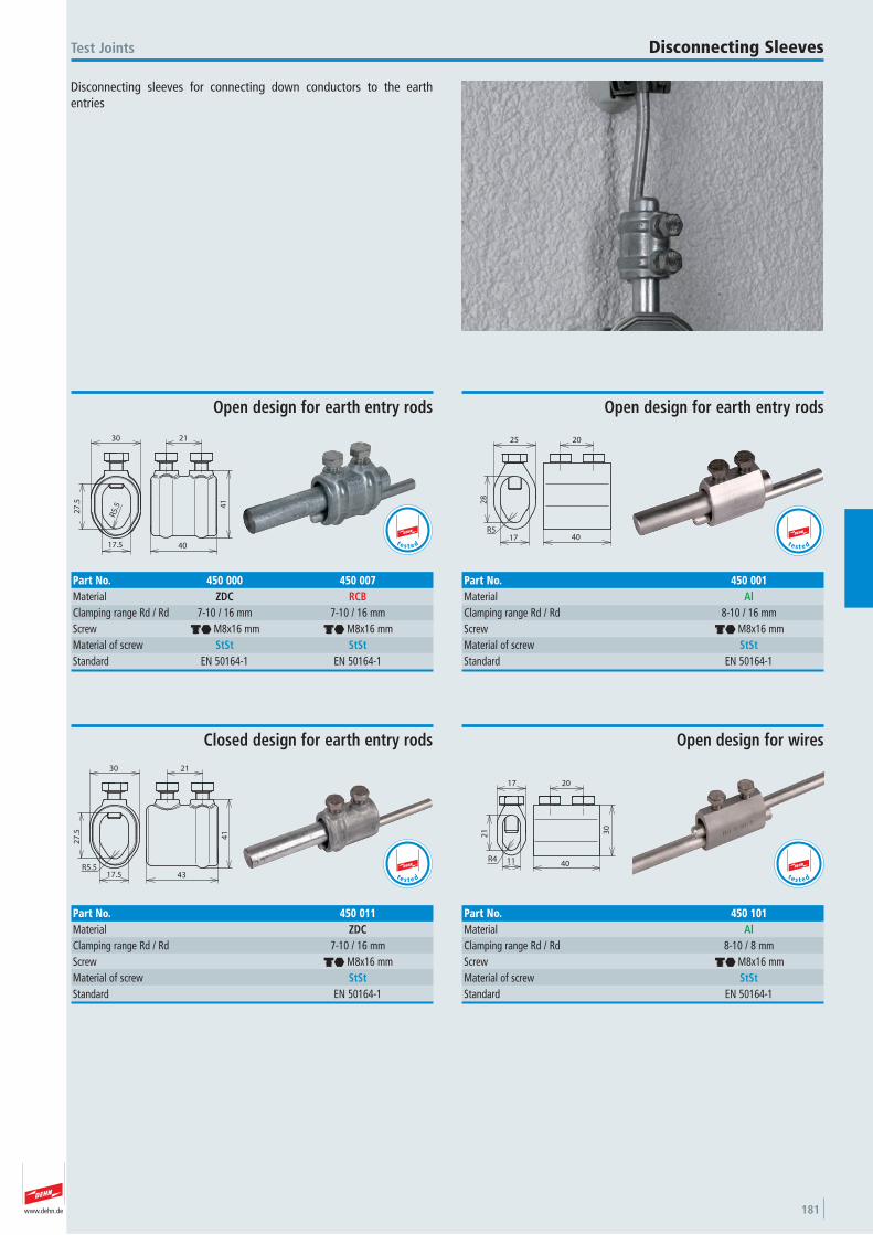
www.dehn.de 181
Disconnecting sleeves for connecting down conductors to the earthentries
Test Joints Disconnecting Sleeves
17.5
27
.5
30
R5.
5 41
40
21
Open design for earth entry rods
Part No. 450 000 450 007Material ZDC RCBClamping range Rd / Rd 7-10 / 16 mm 7-10 / 16 mmScrew di M8x16 mm di M8x16 mmMaterial of screw StSt StStStandard EN 50164-1 EN 50164-1
t e s t e d
25
17R5
28
40
20
Open design for earth entry rods
Part No. 450 001Material AlClamping range Rd / Rd 8-10 / 16 mmScrew di M8x16 mmMaterial of screw StStStandard EN 50164-1
t e s t e d
30
27
.5
17.5
41
43
21
R5.5
Closed design for earth entry rods
Part No. 450 011Material ZDCClamping range Rd / Rd 7-10 / 16 mmScrew di M8x16 mmMaterial of screw StStStandard EN 50164-1
t e s t e d
17
21
11R4
30
40
20
Open design for wires
Part No. 450 101Material AlClamping range Rd / Rd 8-10 / 8 mmScrew di M8x16 mmMaterial of screw StStStandard EN 50164-1
t e s t e d
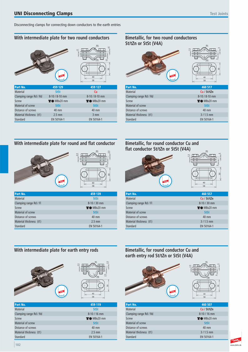
www.dehn.de182
Disconnecting clamps for connecting down conductors to the earth entries
Test JointsUNI Disconnecting Clamps
t1
t1t1R5
40
58
30
R5
With intermediate plate for two round conductors
Part No. 459 129 459 127Material StSt CuClamping range Rd / Rd 8-10 / 8-10 mm 8-10 / 8-10 mmScrew di M8x20 mm di M8x20 mmMaterial of screw StSt StStDistance of screws 40 mm 40 mmMaterial thickness (t1) 2.5 mm 3 mmStandard EN 50164-1 EN 50164-1
t e s t e d
R5
33
R5
1.5
58
30
40
Bimetallic, for two round conductores St/tZn or StSt (V4A)
Part No. 460 517Material Cu / St/tZnClamping range Rd / Rd 8-10 / 8-10 mmScrew di M8x20 mmMaterial of screw StStDistance of screws 40 mmMaterial thickness (t1) 3 / 1.5 mmStandard EN 50164-1
t e s t e d2
.5
R5
2.5
2.5
58
40
30
With intermediate plate for round and flat conductor
Part No. 459 139Material StStClamping range Rd / Fl 8-10 / 30 mmScrew di M8x20 mmMaterial of screw StStDistance of screws 40 mmMaterial thickness (t1) 2.5 mmStandard EN 50164-1
t e s t e d
R5
1.5
33
58
30
40
Bimetallic, for round conductor Cu and flat conductor St/tZn or StSt (V4A)
Part No. 460 557Material Cu / St/tZnClamping range Rd / Fl 8-10 / 30 mmScrew di M8x20 mmMaterial of screw StStDistance of screws 40 mmMaterial thickness (t1) 3 / 1.5 mmStandard EN 50164-1
t e s t e d
R5
2.5
R8
2.5
2.5
58
40
30
With intermediate plate for earth entry rods
Part No. 459 119Material StStClamping range Rd / Rd 8-10 / 16 mmScrew di M8x20 mmMaterial of screw StStDistance of screws 40 mmMaterial thickness (t1) 2.5 mmStandard EN 50164-1
R5
33
1.5
R8
58
30
40
Bimetallic, for round conductor Cu and earth entry rod St/tZn or StSt (V4A)
Part No. 460 507Material Cu / St/tZnClamping range Rd / Rd 8-10 / 16 mmScrew di M8x20 mmMaterial of screw StStDistance of screws 40 mmMaterial thickness (t1) 3 / 1.5 mmStandard EN 50164-1
t e s t e dte s t e d
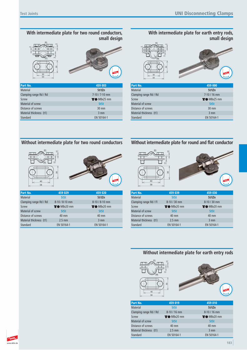
www.dehn.de 183
R5
3
3
3R5
50
30
30
Test Joints
With intermediate plate for two round conductors,small design
Part No. 459 003Material St/tZnClamping range Rd / Rd 7-10 / 7-10 mmScrew di M8x25 mmMaterial of screw StStDistance of screws 30 mmMaterial thickness (t1) 3 mmStandard EN 50164-1
UNI Disconnecting Clamps
t e s t e d
R5
33
3
R8
50
30
30
With intermediate plate for earth entry rods, small design
Part No. 459 000Material St/tZnClamping range Rd / Rd 7-10 / 16 mmScrew di M8x25 mmMaterial of screw StStDistance of screws 30 mmMaterial thickness (t1) 3 mmStandard EN 50164-1
t1t1
R5
R5
58
30
40
Without intermediate plate for two round conductors
Part No. 459 029 459 020Material StSt St/tZnClamping range Rd / Rd 8-10 / 8-10 mm 8-10 / 8-10 mmScrew di M8x20 mm di M8x20 mmMaterial of screw StSt StStDistance of screws 40 mm 40 mmMaterial thickness (t1) 2.5 mm 3 mmStandard EN 50164-1 EN 50164-1
t e s t e d
te s t e d
R5
t1
t1
58
40
30
Without intermediate plate for round and flat conductor
Part No. 459 039 459 030Material StSt St/tZnClamping range Rd / Fl 8-10 / 30 mm 8-10 / 30 mmScrew di M8x20 mm di M8x20 mmMaterial of screw StSt StStDistance of screws 40 mm 40 mmMaterial thickness (t1) 2.5 mm 3 mmStandard EN 50164-1 EN 50164-1
t e s t e d
t1t1
R5
R8
58
30
40
Without intermediate plate for earth entry rods
Part No. 459 019 459 010Material StSt St/tZnClamping range Rd / Rd 8-10 / 16 mm 8-10 / 16 mmScrew di M8x20 mm di M8x20 mmMaterial of screw StSt StStDistance of screws 40 mm 40 mmMaterial thickness (t1) 2.5 mm 3 mmStandard EN 50164-1 EN 50164-1
t e s t e d
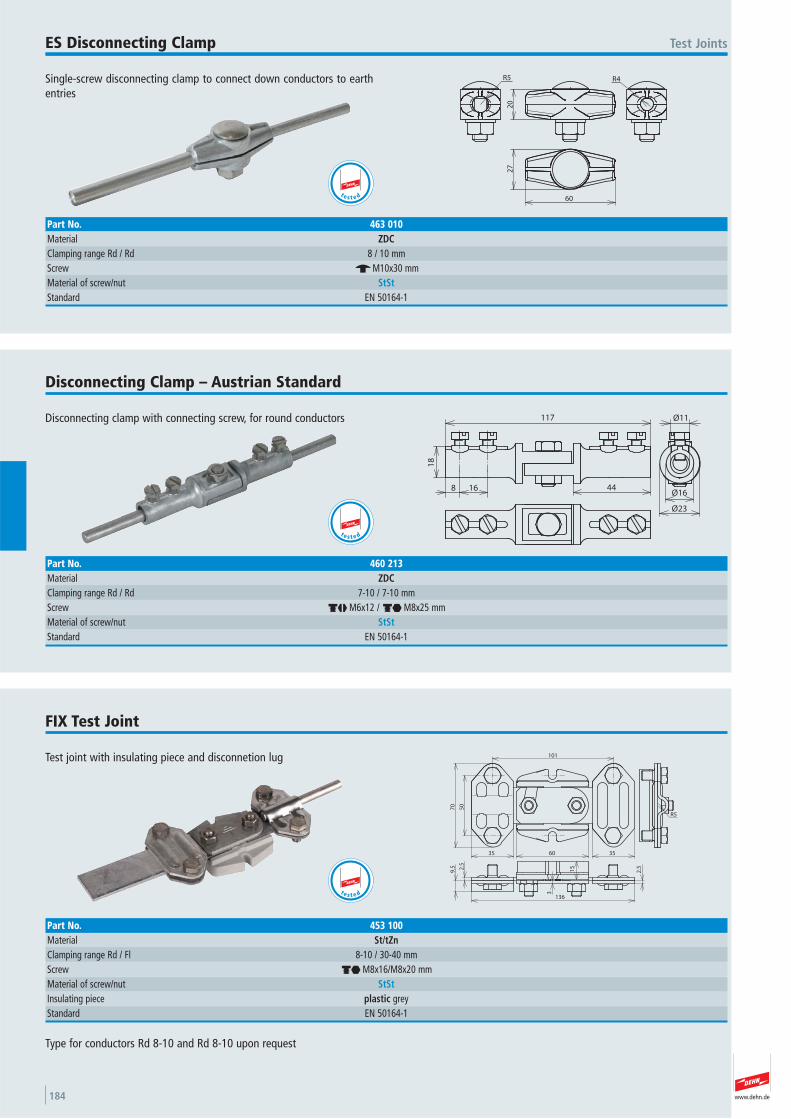
www.dehn.de184
Single-screw disconnecting clamp to connect down conductors to earthentries
Test JointsES Disconnecting Clamp
20
R4R5
60
27
Part No. 463 010Material ZDCClamping range Rd / Rd 8 / 10 mmScrew e M10x30 mmMaterial of screw/nut StStStandard EN 50164-1
t e s t e d
Disconnecting clamp with connecting screw, for round conductors
Disconnecting Clamp – Austrian Standard
18
44
117
8 16Ø16
Ø23
Ø11
Part No. 460 213Material ZDCClamping range Rd / Rd 7-10 / 7-10 mmScrew dj M6x12 / di M8x25 mmMaterial of screw/nut StStStandard EN 50164-1
t e s t e d
Test joint with insulating piece and disconnetion lug
FIX Test Joint
101
50
70
35 60 35
R5
15
3
2.5
9.5
2.5
136
Part No. 453 100Material St/tZnClamping range Rd / Fl 8-10 / 30-40 mmScrew di M8x16/M8x20 mmMaterial of screw/nut StStInsulating piece plastic grey Standard EN 50164-1
Type for conductors Rd 8-10 and Rd 8-10 upon request
t e s t e d
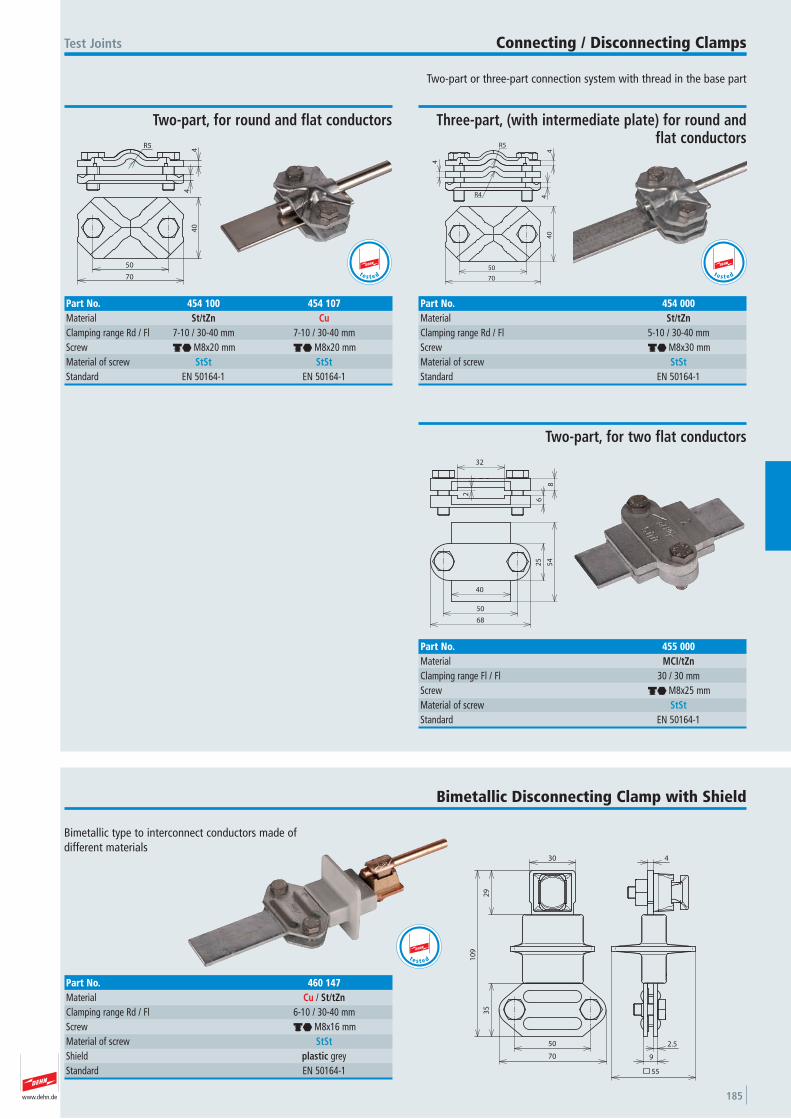
www.dehn.de 185
Two-part or three-part connection system with thread in the base part
Test Joints Connecting / Disconnecting Clamps
44
R5
70
40
50
Two-part, for round and flat conductors
Part No. 454 100 454 107Material St/tZn CuClamping range Rd / Fl 7-10 / 30-40 mm 7-10 / 30-40 mmScrew di M8x20 mm di M8x20 mmMaterial of screw StSt StStStandard EN 50164-1 EN 50164-1
t e s t e d 70
40
50
4
44
R5
R4
Three-part, (with intermediate plate) for round andflat conductors
Part No. 454 000Material St/tZnClamping range Rd / Fl 5-10 / 30-40 mmScrew di M8x30 mmMaterial of screw StStStandard EN 50164-1
t e s t e d
322
8
6
40
25
54
50
68
Two-part, for two flat conductors
Part No. 455 000Material MCI/tZnClamping range Fl / Fl 30 / 30 mmScrew di M8x25 mmMaterial of screw StStStandard EN 50164-1
Bimetallic Disconnecting Clamp with Shield
30
29
35
10
9
50
70
55
2.5
9
4
Part No. 460 147Material Cu / St/tZnClamping range Rd / Fl 6-10 / 30-40 mmScrew di M8x16 mmMaterial of screw StStShield plastic grey Standard EN 50164-1
t e s t e d
Bimetallic type to interconnect conductors made of different materials
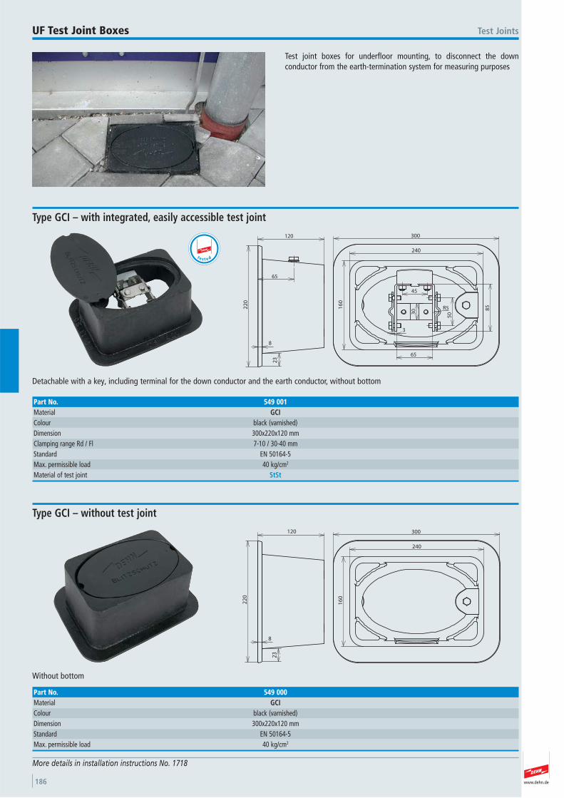
www.dehn.de186
Test joint boxes for underfloor mounting, to disconnect the down conductor from the earth-termination system for measuring purposes
Test JointsUF Test Joint Boxes
More details in installation instructions No. 1718
2402
20
16
0
300
65
120
23
8
R5
30
45
3
65
50
85
Detachable with a key, including terminal for the down conductor and the earth conductor, without bottom
Type GCI – with integrated, easily accessible test joint
Part No. 549 001Material GCIColour black (varnished) Dimension 300x220x120 mmClamping range Rd / Fl 7-10 / 30-40 mmStandard EN 50164-5 Max. permissible load 40 kg/cm2
Material of test joint StSt
240
22
0
16
0
120
23
8
300
Without bottom
Type GCI – without test joint
Part No. 549 000Material GCIColour black (varnished) Dimension 300x220x120 mmStandard EN 50164-5 Max. permissible load 40 kg/cm2
t e s t e d
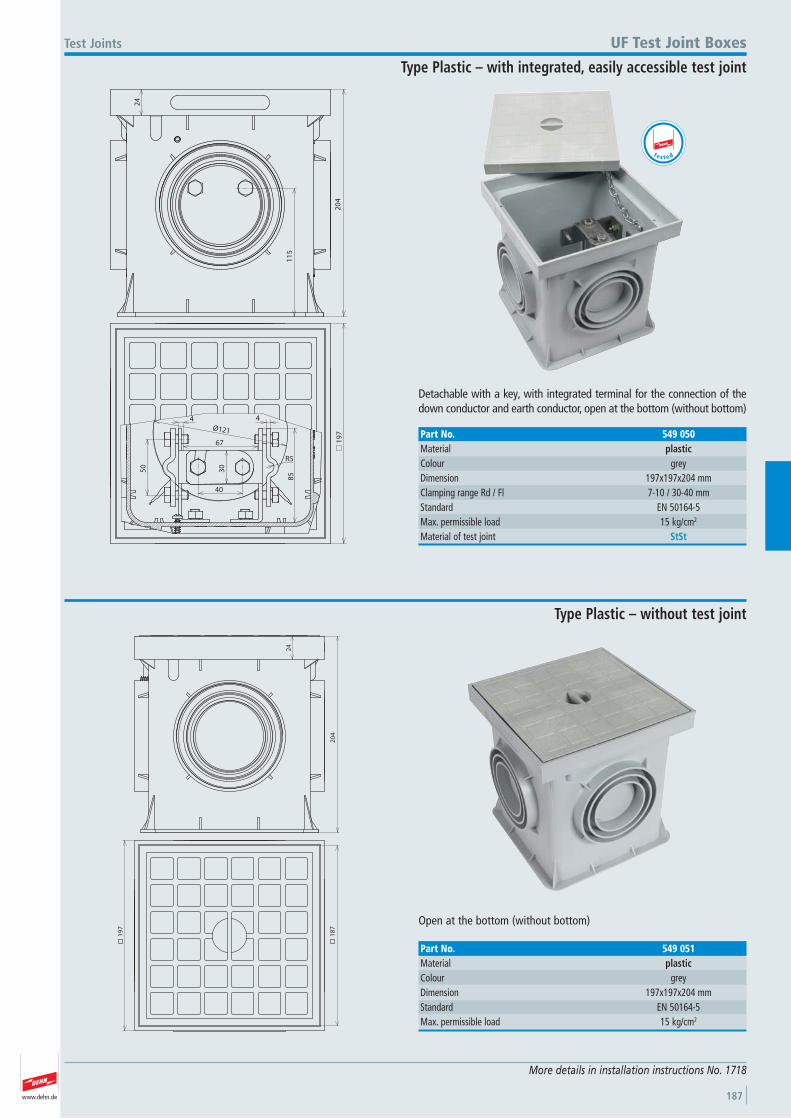
www.dehn.de 187
24
20
4
11
5
40
67
4
R5
30
50
85
19
7
Ø121
4
Detachable with a key, with integrated terminal for the connection of thedown conductor and earth conductor, open at the bottom (without bottom)
Test Joints UF Test Joint Boxes
Type Plastic – with integrated, easily accessible test joint
Part No. 549 050Material plasticColour grey Dimension 197x197x204 mmClamping range Rd / Fl 7-10 / 30-40 mmStandard EN 50164-5 Max. permissible load 15 kg/cm2
Material of test joint StSt
More details in installation instructions No. 1718
t e s t e d
20
4
24
19
7
18
7
Open at the bottom (without bottom)
Type Plastic – without test joint
Part No. 549 051Material plasticColour grey Dimension 197x197x204 mmStandard EN 50164-5 Max. permissible load 15 kg/cm2
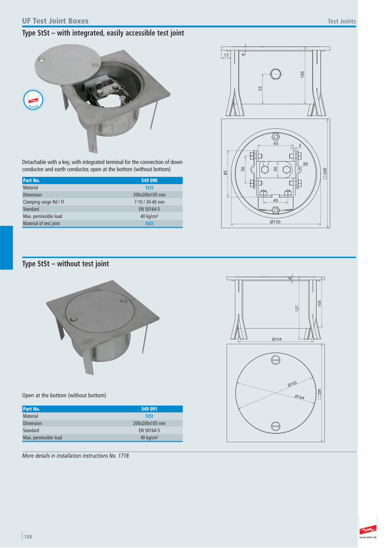
www.dehn.de188
617
10
5
55
30
50
85
R5
20
0
45
365
Ø150
Detachable with a key, with integrated terminal for the connection of downconductor and earth conductor, open at the bottom (without bottom)
Test JointsUF Test Joint Boxes
Type StSt – with integrated, easily accessible test joint
Part No. 549 090Material StStDimension 200x200x105 mmClamping range Rd / Fl 7-10 / 30-40 mmStandard EN 50164-5 Max. permissible load 40 kg/cm2
Material of test joint StSt
t e s t e d
8
10
5
Ø154
12
7
20
0
Ø165
Ø164Open at the bottom (without bottom)
Type StSt – without test joint
Part No. 549 091Material StStDimension 200x200x105 mmStandard EN 50164-5 Max. permissible load 40 kg/cm2
More details in installation instructions No. 1718
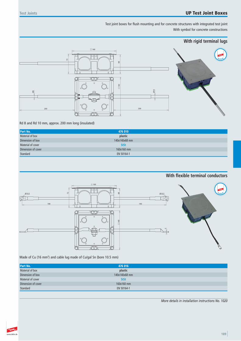
www.dehn.de 189
Test joint boxes for flush mounting and for concrete structures with integrated test joint
With symbol for concrete constructions
Test Joints UP Test Joint Boxes
More details in installation instructions No. 1020
160
72
68
14
0
200
Ø1
0
Ø8
200
Rd 8 and Rd 10 mm, approx. 200 mm long (insulated)
With rigid terminal lugs
Part No. 476 010Material of box plasticDimension of box 140x140x68 mmMaterial of cover StStDimension of cover 160x160 mmStandard EN 50164-1
t e s t e d
72
160
68
Ø10.5Ø10.5
190 190
3
14
0
Made of Cu (16 mm2) and cable lug made of Cu/gal Sn (bore 10.5 mm)
With flexible terminal conductors
Part No. 476 016Material of box plasticDimension of box 140x140x68 mmMaterial of cover StStDimension of cover 160x160 mmStandard EN 50164-1
t e s t e d
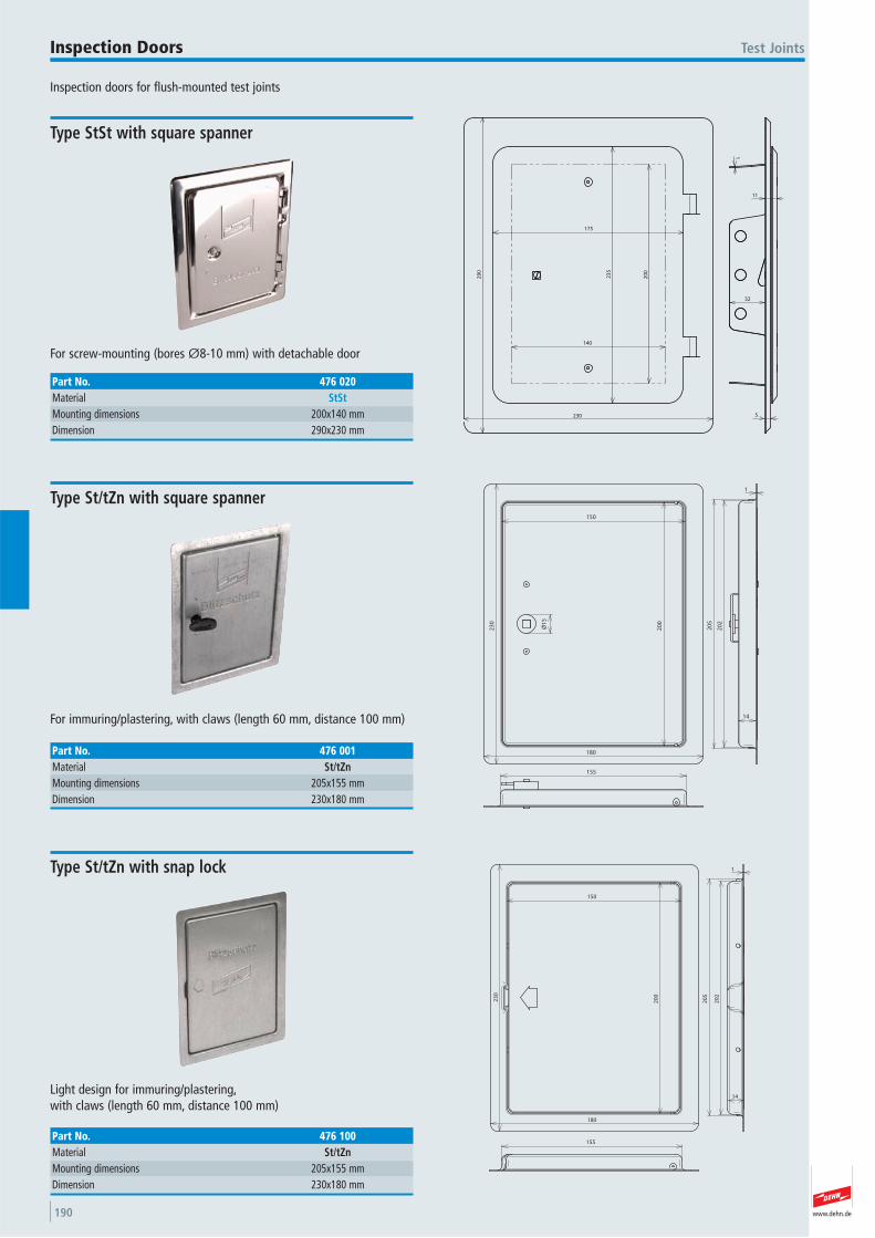
www.dehn.de190
Inspection doors for flush-mounted test joints
Test JointsInspection Doors
230
29
0
23
5
175
140
20
0
1
32
5
11
For screw-mounting (bores Ø8-10 mm) with detachable door
Type StSt with square spanner
Part No. 476 020Material StStMounting dimensions 200x140 mmDimension 290x230 mm
20
5
Ø1
5
23
0
180
20
0
150
20
214
1
155
For immuring/plastering, with claws (length 60 mm, distance 100 mm)
Type St/tZn with square spanner
Part No. 476 001Material St/tZnMounting dimensions 205x155 mmDimension 230x180 mm
180
23
0
150
20
0
20
2
14
1
155
20
5
Light design for immuring/plastering, with claws (length 60 mm, distance 100 mm)
Type St/tZn with snap lock
Part No. 476 100Material St/tZnMounting dimensions 205x155 mmDimension 230x180 mm

www.dehn.de 191
Number plates for marking the test joints
Number plates with company logo upon request
Test Joints Number Plates
15 12 34
38
R53
58
1.5
State the numbers required when placing your order
With embossed number for round / flat conductors
Part No. 480 005Material AlClamping range Rd / Fl 7-10 / 30 mmScrew dm M6x16 mmMaterial of screw StSt
34
R8
3
1.5
38
58
15 12
State the numbers required when placing your order
With embossed number for earth entry rods
Part No. 480 006Material AlClamping range Rd 16 mmScrew dm M6x16 mmMaterial of screw StSt
34
38
R53
58
1.5
For on-site labelling with punch-type numbers 0-9, size 10 mm.
Without number for round / flat conductors
Part No. 480 003Material AlClamping range Rd / Fl 7-10 / 30 mmScrew dm M6x16 mmMaterial of screw StSt
34
R8
3
1.5
38
58
For on-site labelling with punch-type numbers 0-9, size 10 mm.
Without number for earth entry rods
Part No. 480 004Material AlClamping range Rd 16 mmScrew dm M6x16 mmMaterial of screw StSt
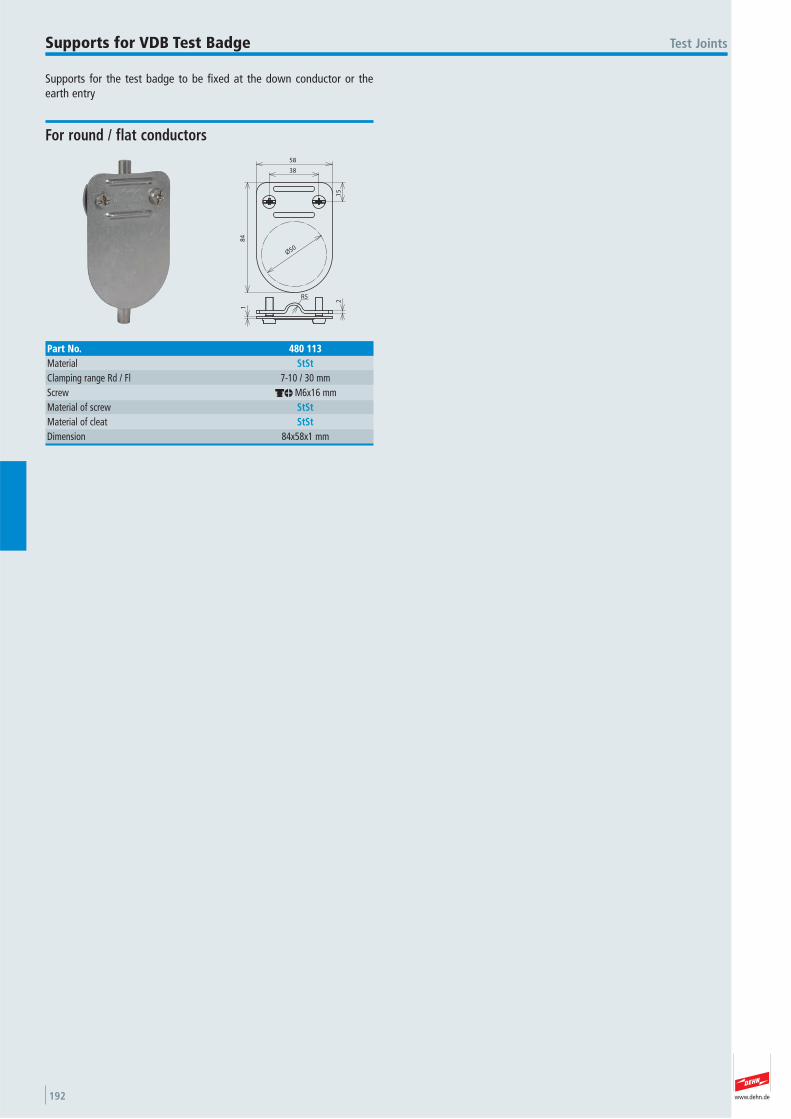
www.dehn.de192
Supports for the test badge to be fixed at the down conductor or theearth entry
Test JointsSupports for VDB Test Badge
38
58
84
15
Ø50
R5
2
1
For round / flat conductors
Part No. 480 113Material StStClamping range Rd / Fl 7-10 / 30 mmScrew dm M6x16 mmMaterial of screw StStMaterial of cleat StStDimension 84x58x1 mm
www.dehn.de 193
Fixed earthing terminals for installation into concrete as corrosion-freeconnection to the earth-termination system for protective equipotentialbonding and/or functional equipotential bonding of the down conductore.g. to the reinforcement of buildings.
For the double thread M10 and M12 mind the following minimumlengths of the screws:
35 mm of M10 (thread length 40 mm)15 mm of M12 (thread length 20 mm)
– Connection possibility at the terminal axis e.g. by cross unit Part No.319 201, or connecting clamp, e.g. Part No. 308 025 for the reinforce-ment
– Connection possibility for the equipotential bonding bar, e.g. by endpieces Part No. 390 499
– Connection possibility for flat conductors at the terminal plate (front)by terminal clamp Part No. 478 141, or at the back of the fixed earth-ing terminal without terminal axis, by terminal clamp Part No. 478 129
– Terminal axis screwed-in or press-fitted– Snap-on plastic cover (yellow), sealed with pressure tested O-ring
(test pressure 0.5 bar)
Fixed Earthing Terminals Fixed Earthing Terminals
More details in installation instructions No. 1476.
Ø8
6
12
4
Ø8
0
2.5
50
39
180
Ø1
0
Ø60
M10/M12
SW19
3x Ø4.5
With terminal axis (l = 180 mm, Ø10 mm)
Type M
Part No. 478 011 478 019Terminal thread M10 / M12 M10 / M12 Material of plate StSt (V4A) StSt (V4A)Material No. 1.4571 / 1.4404 / 1.4401 1.4571 / 1.4404 / 1.4401 ASTM / AISI: 316Ti / 316L / 316 316Ti / 316L / 316Material of axis St/tZn StStTerminal plate Ø 80 mm 80 mmShort-circuit current (50 Hz) (1 s; ≤ 300 °C) 6.5 kA 3.9 kAStandard EN 50164-1 EN 50164-1
t e s t e d
www.dehn.de194
M10/M12
Ø60
3x Ø4.5
2.5
39
50
Ø8
0
Ø8
6
12 SW19
4
Fixed Earthing TerminalsFixed Earthing Terminals
Type M without terminal axis
Part No. 478 012Terminal thread M10 / M12 Material of plate StSt (V4A)Material No. 1.4571 / 1.4404 / 1.4401 ASTM / AISI: 316Ti / 316L / 316Terminal plate Ø 80 mmShort-circuit current (50 Hz) (1 s; ≤ 300 °C) 9.3 kAStandard EN 50164-1
Specified short-circuit current applies for the connection with copper cable lug
t e s t e d
2.5
22 180
247
Ø1
0
4
Ø8
6
12
Ø60
M10/M12
SW14
Ø8
0
3x Ø4.5
Terminal axis (l = 180 mm, Ø10 mm)
Type M press-fitted
Part No. 478 041 478 049Terminal thread M10 / M12 M10 / M12 Material of plate StSt (V4A) StSt (V4A)Material No. 1.4571 / 1.4404 / 1.4401 1.4571 / 1.4404 / 1.4401 ASTM / AISI: 316Ti / 316L / 316 316Ti / 316L / 316Material of axis St/tZn StStTerminal plate Ø 80 mm 80 mmShort-circuit current (50 Hz) (1 s; ≤ 300 °C) 3.7 kA 3.3 kAStandard EN 50164-1 EN 50164-1
Part No. 478 049 with UL certification
t e s t e d
M10/M12
Ø60
3x Ø4.5
2.5
39
50
Ø8
0
Ø8
6
12 SW19
4
9
2.5
R5
R5
For round conductors 8-10 mm, design requiring little space in the shuttering
Type M with MV clamp
Part No. 478 112Terminal thread M10 / M12 Material of plate StSt (V4A)Material No. 1.4571 / 1.4404 / 1.4401 ASTM / AISI: 316Ti / 316L / 316Terminal plate Ø 80 mmShort-circuit current (50 Hz) (1 s; ≤ 300 °C) 9.3 kAStandard EN 50164-1
t e s t e d
More details in installation instructions No. 1476.
www.dehn.de 195
Ø60
M10/M12
Ø1
0
1138
80
Ø1
9
Ø7
0
Ø8
6
Ø8
0
247
4
3x Ø4.5
Against penetration of water along the axis into the wall (tested with 5 bar compressed air according to EN 50164-5 and 1 bar pressure water)
Part No. 478 051Terminal thread M10 / M12 Material of plate StSt (V4A)Material No. 1.4571 / 1.4404 / 1.4401 ASTM / AISI: 316Ti / 316L / 316Material of axis St/tZnTerminal plate Ø 80 mmShort-circuit current (50 Hz) (1 s; ≤ 300 °C) 3.7 kAMaterial of water barrier PVCStandard EN 50164-1
Fixed Earthing Terminals
Ø8
6
12
Ø9
0
104
50
31
180
Ø1
0
M10/M12
Ø65
Ø46
SW19
3x Ø6
With plastic ring and terminal axis (l = 180 mm, Ø10 mm)
Type K
Part No. 478 200Terminal thread M10 / M12 Material of plate StSt (V4A)Material No. 1.4571 / 1.4404 / 1.4401 ASTM / AISI: 316Ti / 316L / 316Material of axis St/tZnTerminal plate Ø 46 mmShort-circuit current (50 Hz) (1 s; ≤ 300 °C) 6.5 kAStandard EN 50164-1
t e s t e d
te s t e d
More details in installation instructions No. 1476.
Fixed Earthing Terminals
Type M press-fitted with additional water barrier
www.dehn.de196
Fixed earthing terminal with terminal thread M16 for higher current loadings (50 Hz), e.g. for connecting the ring equipotential bonding system with the earth-termination systems of power plants having a nominal a.c. voltage over 1 kV (transformer earthing).
The connection cable may be connected e.g. with a cross unit (Part No.318 207/318 209) to the further components of the earth-termination system, or to the reinforcement with the corresponding clamps.
With snap-on plastic cover (yellow) and sealing around the terminalthread for the formwork installation.
Fixed Earthing TerminalsFixed Earthing Terminal M16
More details in installation instructions No. 1689
Ø8
0x2
.5
56
Ø1
0.5
3.5
Ø9
0
45°
Ø60
3x Ø4.5
M1
6
400
SW22
Part No. 478 027Terminal thread M16 Material of plate StSt (V4A)Material No. 1.4571 / 1.4404 / 1.4401 ASTM / AISI: 316Ti / 316L / 316Material of cable Cu/gal SnCross section of terminal cable 70 mm²Length of terminal cable 400 mmDiameter of terminal cable 10.5 mmTerminal plate Ø 80 mmStandard EN 50164-1 Short-circuit current (50 Hz) (1 s; ≤ 300 °C) 11 kA
t e s t e d
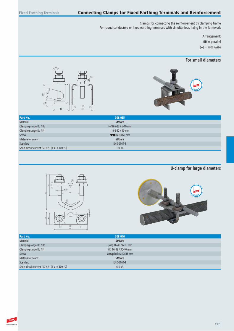
www.dehn.de 197
Clamps for connecting the reinforcement by clamping frameFor round conductors or fixed earthing terminals with simultanious fixing in the formwork
Arrangement:
(II) = parallel
(+) = crosswise
Fixed Earthing Terminals Connecting Clamps for Fixed Earthing Terminals and Reinforcement
R5
42
51
22
10
40
50
15
For small diameters
Part No. 308 035Material St/bareClamping range Rd / Rd (+/II) 6-22 / 6-10 mmClamping range Rd / Fl (+) 6-22 / 40 mmScrew di M10x60 mmMaterial of screw St/bareStandard EN 50164-1 Short-circuit current (50 Hz) (1 s; ≤ 300 °C) 1.0 kA
t e s t e d
55 6
92
R5
4
M10
48
3033
5
88
58
U-clamp for large diameters
Part No. 308 046Material St/bareClamping range Rd / Rd (+/II) 16-48 / 6-10 mmClamping range Rd / Fl (II) 16-48 / 30-40 mmScrew stirrup bolt M10x48 mmMaterial of screw St/bareStandard EN 50164-1 Short-circuit current (50 Hz) (1 s; ≤ 300 °C) 6.5 kA
t e s t e d
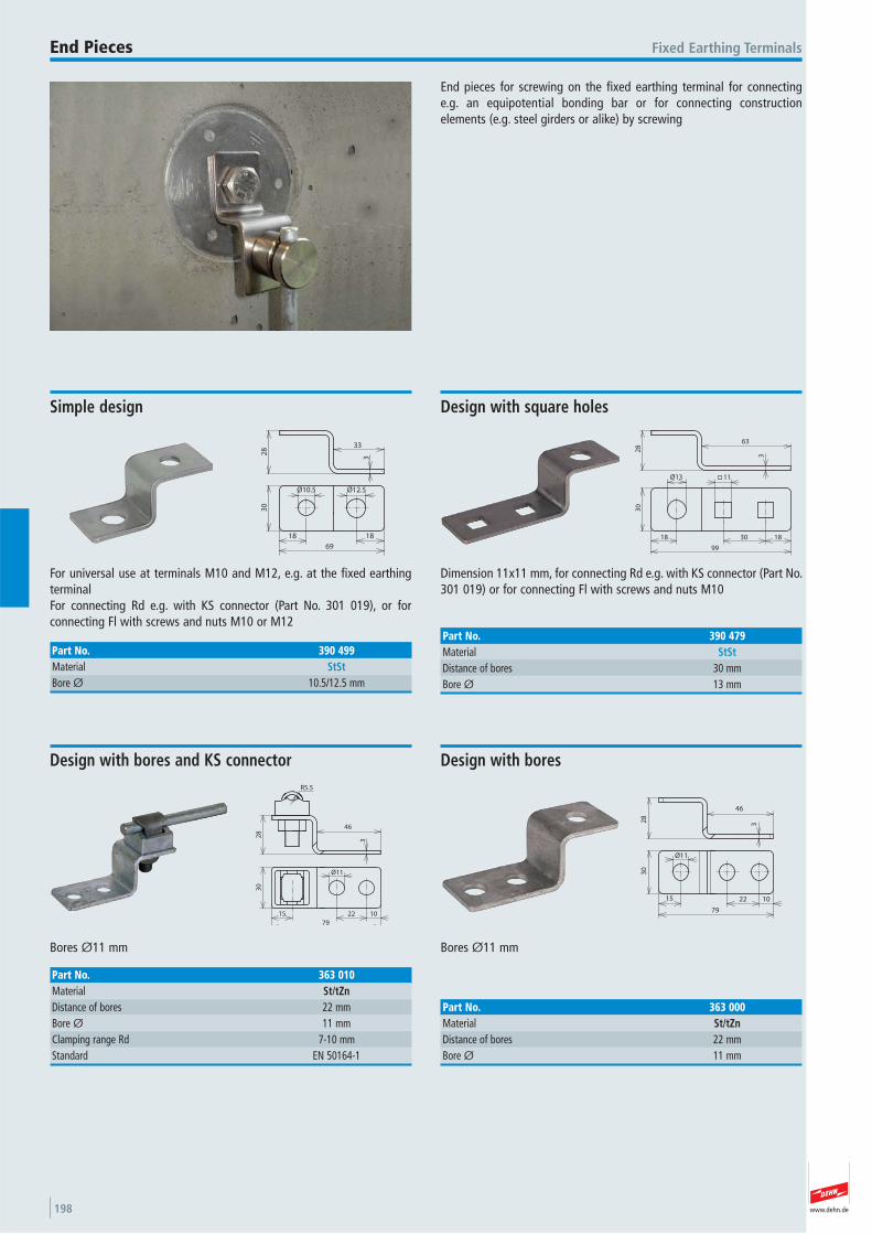
www.dehn.de198
End pieces for screwing on the fixed earthing terminal for connecting e.g. an equipotential bonding bar or for connecting construction elements (e.g. steel girders or alike) by screwing
Fixed Earthing TerminalsEnd Pieces
33
28
69
3
30
Ø10.5 Ø12.5
1818
For universal use at terminals M10 and M12, e.g. at the fixed earthingterminalFor connecting Rd e.g. with KS connector (Part No. 301 019), or for connecting Fl with screws and nuts M10 or M12
Simple design
Part No. 390 499Material StStBore Ø 10.5/12.5 mm
1830
30
Ø13 11
18
3
28
63
99
Dimension 11x11 mm, for connecting Rd e.g. with KS connector (Part No.301 019) or for connecting Fl with screws and nuts M10
Design with square holes
Part No. 390 479Material StStDistance of bores 30 mmBore Ø 13 mm
R5.5
28
46
3
79
15 1022
30
Ø11
Bores Ø11 mm
Design with bores and KS connector
Part No. 363 010Material St/tZnDistance of bores 22 mmBore Ø 11 mmClamping range Rd 7-10 mmStandard EN 50164-1
30
15 1022
Ø11
79
3
46
28
Bores Ø11 mm
Design with bores
Part No. 363 000Material St/tZnDistance of bores 22 mmBore Ø 11 mm
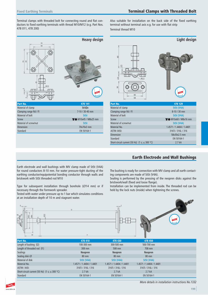
www.dehn.de 199
Terminal clamps with threaded bolt for connecting round and flat con-ductors to fixed earthing terminals with thread M10/M12 (e.g. Part Nos. 478 011, 478 200)
Also suitable for installation on the back side of the fixed earthing terminal without terminal axis e.g. for use with flat strip
Terminal thread M10
Fixed Earthing Terminals Terminal Clamps with Threaded Bolt
3
3
R5
45
M10
49
70
49
70
Heavy design
Part No. 478 141Material of clamp St/tZnClamping range Rd / Fl 7-10 / 30-40 mmMaterial of bolt StStScrew di M10x45 / M8x25 mmMaterial of screw/nut StStDimension 70x70x3 mmStandard EN 50164-1
t e s t e d
2.5
2.5
R5.5
60
40
58
30
Light design
Part No. 478 129Material of clamp StSt (V4A)Clamping range Rd / Fl 8-10 / 30 mmMaterial of bolt StSt (V4A)Screw di M10x60 / M8x16 mmMaterial of screw/nut StSt (V4A)Material No. 1.4571 / 1.4404 / 1.4401 ASTM /AISI: 316Ti / 316L / 316Dimension 58x30x2.5 mmStandard EN 50164-1 Short-circuit current (50 Hz) (1 s; ≤ 300 °C) 2.7 kA
t e s t e d
Earth electrode and wall bushings with MV clamp made of StSt (V4A) for round conductors 8-10 mm. For water pressure-tight ducting of theearthing conductor/equipotential bonding conductor through walls andbrickwork with StSt threaded rod M10
Type for subsequent installation through borehole (Ø14 mm) or if necessary through the formwork spreader.Tested with water under pressure up to 1 bar which simulates conditionsat an installation depth of 10 m and stagnant water.
The bushing is ready for connection with MV clamp and all earth contact-ing components are made of StSt (V4A).Sealing is performed by the pressing of the neopren disks against thebrickwork/wall (fixed and loose flange).Installation can be implemented from inside. The threaded rod can beheld by the lock nuts (inside) when tightening the screws.
Earth Electrode and Wall Bushings
More details in installation instructions No.1332
Ø5
3
6
Ø8
0R5
3
l149
Ø1
3
M1
0
l2
Part No. 478 410 478 430 478 450Length of bushing (l2) 100-300 mm 300-500 mm 500-700 mmLength of threaded rod (l1) 308 mm 508 mm 708 mmSealings Neopren Neopren NeoprenSealing disk Ø 80 mm 80 mm 80 mmMaterial of disk StSt (V4A) StSt (V4A) StSt (V4A)Material No. 1.4571 / 1.4404 / 1.4401 1.4571 / 1.4404 / 1.4401 1.4571 / 1.4404 / 1.4401 ASTM / AISI: 316Ti / 316L / 316 316Ti / 316L / 316 316Ti / 316L / 316Short-circuit current (50 Hz) (1 s; ≤ 300 °C) 2.7 kA 2.7 kA 2.7 kAStandard EN 50164-1 EN 50164-1 EN 50164-1
t e s t e d
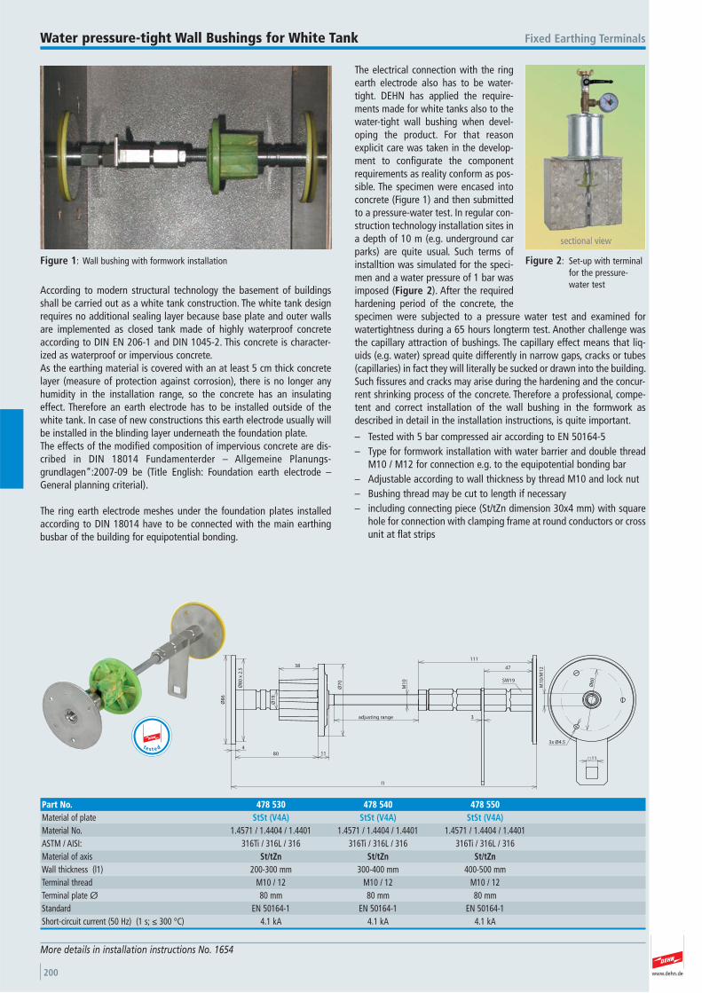
www.dehn.de200
According to modern structural technology the basement of buildingsshall be carried out as a white tank construction. The white tank designrequires no additional sealing layer because base plate and outer wallsare implemented as closed tank made of highly waterproof concreteaccording to DIN EN 206-1 and DIN 1045-2. This concrete is character-ized as waterproof or impervious concrete.As the earthing material is covered with an at least 5 cm thick concretelayer (measure of protection against corrosion), there is no longer anyhumidity in the installation range, so the concrete has an insulatingeffect. Therefore an earth electrode has to be installed outside of thewhite tank. In case of new constructions this earth electrode usually willbe installed in the blinding layer underneath the foundation plate.The effects of the modified composition of impervious concrete are dis-cribed in DIN 18014 Fundamenterder – Allgemeine Planungs -grundlagen“:2007-09 be (Title English: Foundation earth electrode –General planning criterial).
The ring earth electrode meshes under the foundation plates installedaccording to DIN 18014 have to be connected with the main earthingbusbar of the building for equipotential bonding.
The electrical connection with the ringearth electrode also has to be water-tight. DEHN has applied the require-ments made for white tanks also to thewater-tight wall bushing when devel-oping the product. For that reasonexplicit care was taken in the develop-ment to configurate the componentrequirements as reality conform as pos-sible. The specimen were encased intoconcrete (Figure 1) and then submittedto a pressure-water test. In regular con-struction technology installation sites ina depth of 10 m (e.g. underground carparks) are quite usual. Such terms ofinstalltion was simulated for the speci-men and a water pressure of 1 bar wasimposed (Figure 2). After the requiredhardening period of the concrete, thespecimen were subjected to a pressure water test and examined forwatertightness during a 65 hours longterm test. Another challenge wasthe capillary attraction of bushings. The capillary effect means that liq-uids (e.g. water) spread quite differently in narrow gaps, cracks or tubes(capillaries) in fact they will literally be sucked or drawn into the building.Such fissures and cracks may arise during the hardening and the concur-rent shrinking process of the concrete. Therefore a professional, compe-tent and correct installation of the wall bushing in the formwork asdescribed in detail in the installation instructions, is quite important.
– Tested with 5 bar compressed air according to EN 50164-5– Type for formwork installation with water barrier and double thread
M10 / M12 for connection e.g. to the equipotential bonding bar– Adjustable according to wall thickness by thread M10 and lock nut– Bushing thread may be cut to length if necessary– including connecting piece (St/tZn dimension 30x4 mm) with square
hole for connection with clamping frame at round conductors or crossunit at flat strips
Fixed Earthing TerminalsWater pressure-tight Wall Bushings for White Tank
More details in installation instructions No. 1654
Ø6
0
M1
0/M
12
3x Ø4.5
Ø8
0 x
2.5
Ø8
6
480
38
11
l1
Ø7
0
Ø1
9
M1
0
adjusting range
47
111
3
SW19
11
Part No. 478 530 478 540 478 550Material of plate StSt (V4A) StSt (V4A) StSt (V4A)Material No. 1.4571 / 1.4404 / 1.4401 1.4571 / 1.4404 / 1.4401 1.4571 / 1.4404 / 1.4401 ASTM / AISI: 316Ti / 316L / 316 316Ti / 316L / 316 316Ti / 316L / 316Material of axis St/tZn St/tZn St/tZnWall thickness (l1) 200-300 mm 300-400 mm 400-500 mmTerminal thread M10 / 12 M10 / 12 M10 / 12 Terminal plate Ø 80 mm 80 mm 80 mmStandard EN 50164-1 EN 50164-1 EN 50164-1 Short-circuit current (50 Hz) (1 s; ≤ 300 °C) 4.1 kA 4.1 kA 4.1 kA
t e s t e d
Figure 2: Set-up with terminalfor the pressure-water test
Figure 1: Wall bushing with formwork installation
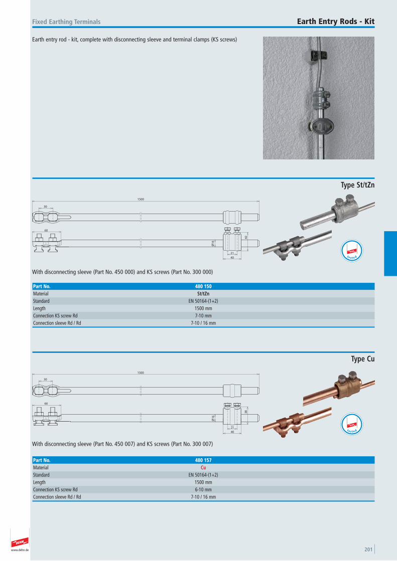
www.dehn.de 201
Earth entry rod - kit, complete with disconnecting sleeve and terminal clamps (KS screws)
Fixed Earthing Terminals Earth Entry Rods - Kit
60
21
40
Ø1
6
42
1500
30
With disconnecting sleeve (Part No. 450 000) and KS screws (Part No. 300 000)
Type St/tZn
Part No. 480 150Material St/tZnStandard EN 50164-(1+2) Length 1500 mmConnection KS screw Rd 7-10 mmConnection sleeve Rd / Rd 7-10 / 16 mm
t e s t e d
30
1500
60
21
40
38
Ø1
6
With disconnecting sleeve (Part No. 450 007) and KS screws (Part No. 300 007)
Type Cu
Part No. 480 157Material CuStandard EN 50164-(1+2) Length 1500 mmConnection KS screw Rd 6-10 mmConnection sleeve Rd / Rd 7-10 / 16 mm
t e s t e d
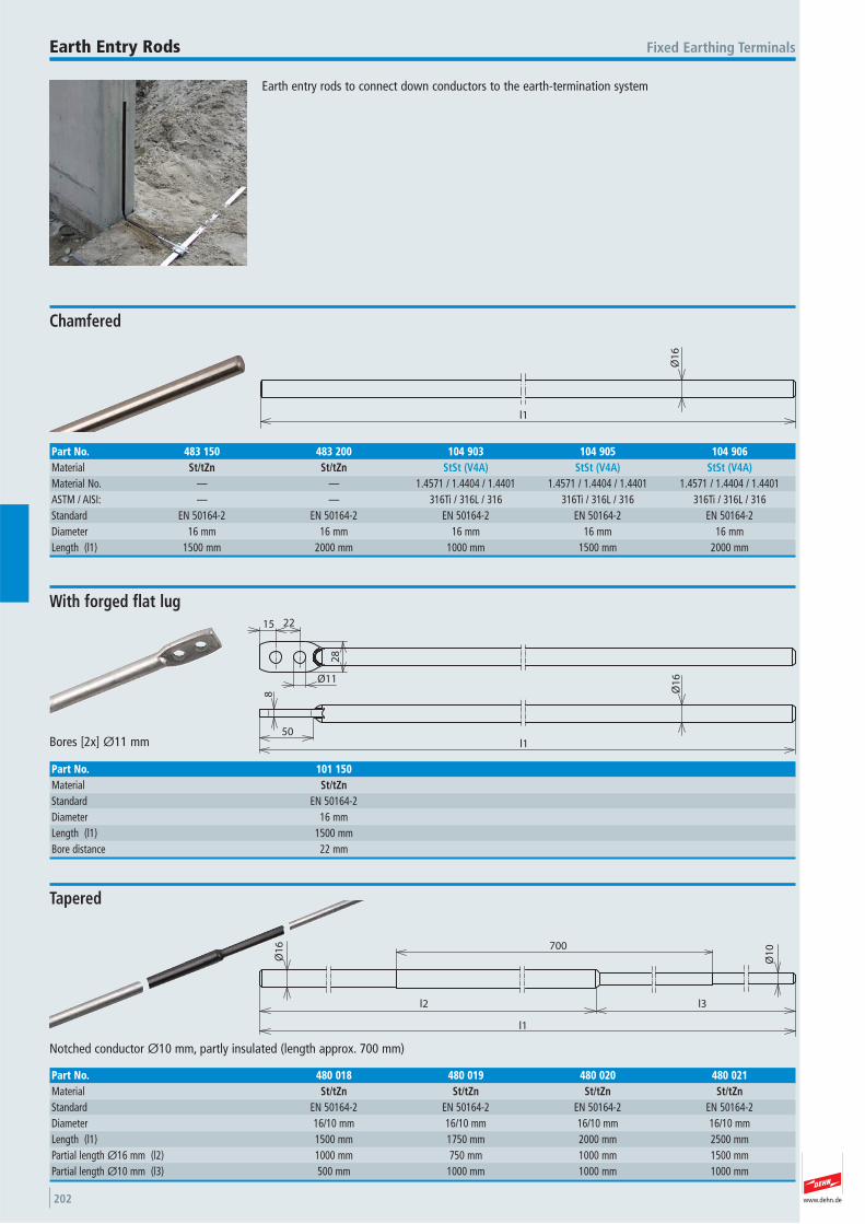
www.dehn.de202
Earth entry rods to connect down conductors to the earth-termination system
Fixed Earthing TerminalsEarth Entry Rods
l1
Ø1
6
Chamfered
Part No. 483 150 483 200 104 903 104 905 104 906Material St/tZn St/tZn StSt (V4A) StSt (V4A) StSt (V4A)Material No. — — 1.4571 / 1.4404 / 1.4401 1.4571 / 1.4404 / 1.4401 1.4571 / 1.4404 / 1.4401 ASTM / AISI: — — 316Ti / 316L / 316 316Ti / 316L / 316 316Ti / 316L / 316Standard EN 50164-2 EN 50164-2 EN 50164-2 EN 50164-2 EN 50164-2 Diameter 16 mm 16 mm 16 mm 16 mm 16 mmLength (l1) 1500 mm 2000 mm 1000 mm 1500 mm 2000 mm
50
8 Ø1
6
l1
15 22
28
Ø11
Bores [2x] Ø11 mm
With forged flat lug
Part No. 101 150Material St/tZnStandard EN 50164-2 Diameter 16 mmLength (l1) 1500 mmBore distance 22 mm
700
l1
Ø1
6
Ø1
0
l3l2
Notched conductor Ø10 mm, partly insulated (length approx. 700 mm)
Tapered
Part No. 480 018 480 019 480 020 480 021Material St/tZn St/tZn St/tZn St/tZnStandard EN 50164-2 EN 50164-2 EN 50164-2 EN 50164-2 Diameter 16/10 mm 16/10 mm 16/10 mm 16/10 mmLength (l1) 1500 mm 1750 mm 2000 mm 2500 mmPartial length Ø16 mm (l2) 1000 mm 750 mm 1000 mm 1500 mmPartial length Ø10 mm (l3) 500 mm 1000 mm 1000 mm 1000 mm
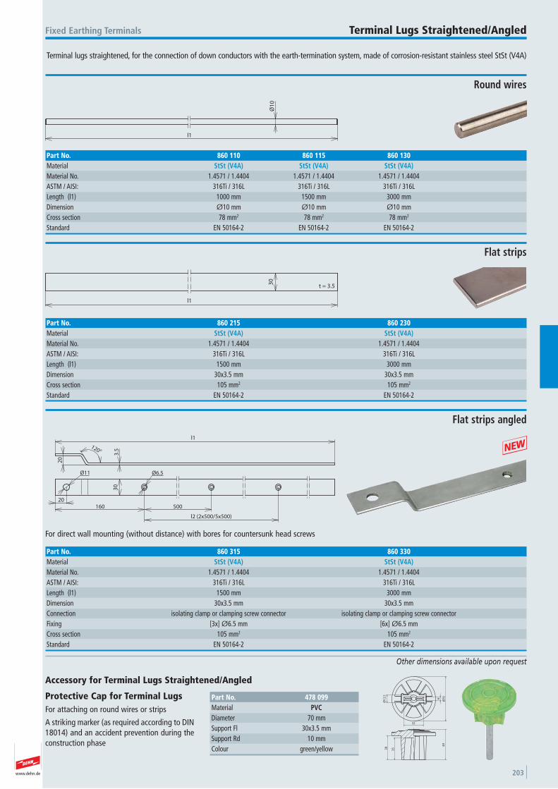
www.dehn.de 203
Terminal lugs straightened, for the connection of down conductors with the earth-termination system, made of corrosion-resistant stainless steel StSt (V4A)
Fixed Earthing Terminals Terminal Lugs Straightened/Angled
Other dimensions available upon request
l1
Ø1
0
Round wires
Part No. 860 110 860 115 860 130Material StSt (V4A) StSt (V4A) StSt (V4A)Material No. 1.4571 / 1.4404 1.4571 / 1.4404 1.4571 / 1.4404 ASTM / AISI: 316Ti / 316L 316Ti / 316L 316Ti / 316LLength (l1) 1000 mm 1500 mm 3000 mmDimension Ø10 mm Ø10 mm Ø10 mmCross section 78 mm2 78 mm2 78 mm2
Standard EN 50164-2 EN 50164-2 EN 50164-2
l1
30
t = 3.5
Flat strips
Part No. 860 215 860 230Material StSt (V4A) StSt (V4A)Material No. 1.4571 / 1.4404 1.4571 / 1.4404 ASTM / AISI: 316Ti / 316L 316Ti / 316LLength (l1) 1500 mm 3000 mmDimension 30x3.5 mm 30x3.5 mmCross section 105 mm2 105 mm2
Standard EN 50164-2 EN 50164-2
30
l1
160 500
l2 (2x500/5x500)
20
Ø11 Ø6.5
20
120°
3.5
For direct wall mounting (without distance) with bores for countersunk head screws
Flat strips angled
Part No. 860 315 860 330Material StSt (V4A) StSt (V4A)Material No. 1.4571 / 1.4404 1.4571 / 1.4404 ASTM / AISI: 316Ti / 316L 316Ti / 316LLength (l1) 1500 mm 3000 mmDimension 30x3.5 mm 30x3.5 mmConnection isolating clamp or clamping screw connector isolating clamp or clamping screw connector Fixing [3x] Ø6.5 mm [6x] Ø6.5 mmCross section 105 mm2 105 mm2
Standard EN 50164-2 EN 50164-2
+4
9
3538
Ø7
0
6
32
Ø1
2.5
Accessory for Terminal Lugs Straightened/Angled
Protective Cap for Terminal Lugs For attaching on round wires or strips
A striking marker (as required according to DIN18014) and an accident prevention during theconstruction phase
Part No. 478 099Material PVCDiameter 70 mmSupport Fl 30x3.5 mmSupport Rd 10 mmColour green/yellow

www.dehn.de204
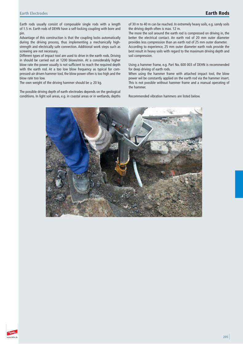
www.dehn.de 205
Earth rods usually consist of composable single rods with a length of 1.5 m. Earth rods of DEHN have a self-locking coupling with bore andpin.Advantage of this construction is that the coupling locks automaticallyduring the driving process, thus implementing a mechanically high-strength and electrically safe connection. Additional work steps such asscrewing are not necessary.Different types of impact tool are used to drive in the earth rods. Drivingin should be carried out at 1200 blows/min. At a considerably higherblow rate the power usually is not sufficient to reach the required depthwith the earth rod. At a too low blow frequency as typical for com-pressed-air driven hammer tool, the blow power often is too high and theblow rate too low. The own weight of the driving hammer should be ≥ 20 kg.
The possible driving depth of earth electrodes depends on the geologicalconditions. In light soil areas, e.g. in coastal areas or in wetlands, depths
of 30 m to 40 m can be reached. In extremely heavy soils, e.g. sandy soilsthe driving depth often is max. 12 m. The more the soil around the earth rod is compressed on driving in, thebetter the electrical contact. An earth rod of 20 mm outer diameter provides less compression than an earth rod of 25 mm outer diameter.According to experience, 25 mm outer diameter earth rods provide thebest result in heavy soils with regard to the maximum driving depth andsoil compression.
Using a hammer frame, e.g. Part No. 600 003 of DEHN is recommendedfor deep driving of earth rods. When using the hammer frame with attached impact tool, the blowpower wil be constantly applied on the earth rod via the hammer insert.This is not possible without hammer frame and a manual operating ofthe hammer.
Recommended vibration hammers are listed below.
Earth Electrodes Earth Rods
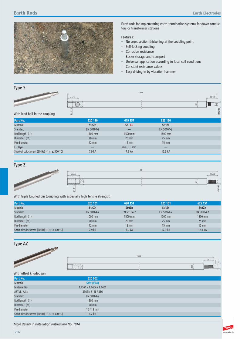
www.dehn.de206
Earth rods for implementing earth-termination systems for down conduc-tors or transformer stations
Features:– No cross section thickening at the coupling point– Self-locking coupling– Corrosion resistance– Easier storage and transport– Universal application according to local soil conditions– Constant resistance values– Easy driving-in by vibration hammer
Earth ElectrodesEarth Rods
More details in installation instructions No. 1014
38/4334/43
1500
Ø1
2/1
5
Ø1
2/1
5
d1
With lead ball in the coupling
Type S
Part No. 620 150 619 157 625 150Material St/tZn St / Cu St/tZnStandard EN 50164-2 — EN 50164-2 Rod length (l1) 1500 mm 1500 mm 1500 mmDiameter (d1) 20 mm 20 mm 25 mmPin diameter 12 mm 12 mm 15 mmCu layer — min. 0.3 mm —Short-circuit current (50 Hz) (1 s; ≤ 300 °C) 7.9 kA 7.9 kA 12.3 kA
40/45
Ø1
2/1
5
d1
l1
37/42
Ø1
2/1
5
With triple knurled pin (coupling with especially high tensile strength)
Type Z
Part No. 620 101 620 151 625 101 625 151Material St/tZn St/tZn St/tZn St/tZnStandard EN 50164-2 EN 50164-2 EN 50164-2 EN 50164-2 Rod length (l1) 1000 mm 1500 mm 1000 mm 1500 mmDiameter (d1) 20 mm 20 mm 25 mm 25 mmPin diameter 12 mm 12 mm 15 mm 15 mmShort-circuit current (50 Hz) (1 s; ≤ 300 °C) 7.9 kA 7.9 kA 12.3 kA 12.3 kA
Ø2
0
1500
35
Ø1
0
Ø1
3
With offset knurled pin
Type AZ
Part No. 620 902Material StSt (V4A)Material No. 1.4571 / 1.4404 / 1.4401 ASTM / AISI: 316Ti / 316L / 316 Standard EN 50164-2 Rod length (l1) 1500 mmDiameter (d1) 20 mmPin diameter 10 / 13 mmShort-circuit current (50 Hz) (1 s; ≤ 300 °C) 4.2 kA
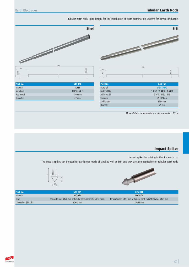
www.dehn.de 207
Tubular earth rods, light design, for the installation of earth-termination systems for down conductors
Earth Electrodes Tubular Earth Rods
More details in installation instructions No. 1515.
120
1500
Ø2
1.5
Ø2
7x2
.3
Steel
Part No. 640 150Material St/tZnStandard EN 50164-2 Rod length 1500 mmDiameter 27 mm
Ø2
1
1500
60
Ø2
5x2
StSt
Part No. 649 150Material StSt (V4A)Material No. 1.4571 / 1.4404 / 1.4401 ASTM / AISI: 316Ti / 316L / 316 Standard EN 50164-2 Rod length 1500 mmDiameter 25 mm
Impact spikes for driving-in the first earth rod
The impact spikes can be used for earth rods made of steel as well as StSt and they are also applicable for tubular earth rods.
Impact Spikes
l1
d1
15
Part No. 620 001 625 001Material MCI/tZn MCI/tZnType for earth rods Ø20 mm or tubular earth rods St/tZn Ø27 mm for earth rods Ø25 mm or tubular earth rods StSt (V4A) Ø25 mm Dimension (d1 x l1) 20x40 mm 25x45 mm
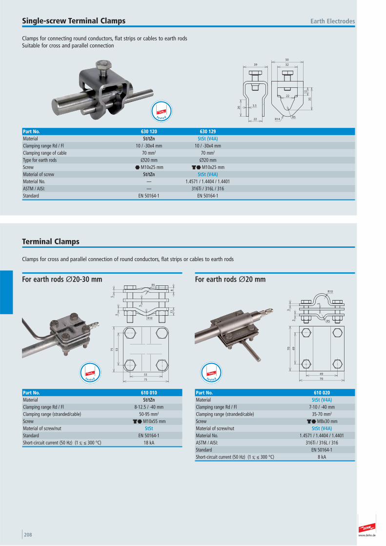
www.dehn.de208
Clamps for connecting round conductors, flat strips or cables to earth rodsSuitable for cross and parallel connection
Earth ElectrodesSingle-screw Terminal Clamps
32
50
22
12
35
R5R14
3.5
22
26
39
Part No. 630 120 630 129Material St/tZn StSt (V4A)Clamping range Rd / Fl 10 / -30x4 mm 10 / -30x4 mmClamping range of cable 70 mm2 70 mm2
Type for earth rods Ø20 mm Ø20 mmScrew i M10x25 mm di M10x25 mmMaterial of screw St/tZn StSt (V4A)Material No. — 1.4571 / 1.4404 / 1.4401 ASTM / AISI: — 316Ti / 316L / 316 Standard EN 50164-1 EN 50164-1
t e s t e d
Clamps for cross and parallel connection of round conductors, flat strips or cables to earth rods
Terminal Clamps
5
5
5
81
3
R5
R10
53
53
75
75
For earth rods Ø20-30 mm
Part No. 610 010Material St/tZnClamping range Rd / Fl 8-12.5 / -40 mmClamping range (stranded/cable) 50-95 mm2
Screw di M10x55 mmMaterial of screw/nut StStStandard EN 50164-1 Short-circuit current (50 Hz) (1 s; ≤ 300 °C) 18 kA
t e s t e d
R10
R53
3
3
49
49
70
70
For earth rods Ø20 mm
Part No. 610 020Material StSt (V4A)Clamping range Rd / Fl 7-10 / -40 mmClamping range (stranded/cable) 35-70 mm2
Screw di M8x30 mmMaterial of screw/nut StSt (V4A)Material No. 1.4571 / 1.4404 / 1.4401 ASTM / AISI: 316Ti / 316L / 316 Standard EN 50164-1 Short-circuit current (50 Hz) (1 s; ≤ 300 °C) 8 kA
t e s t e d
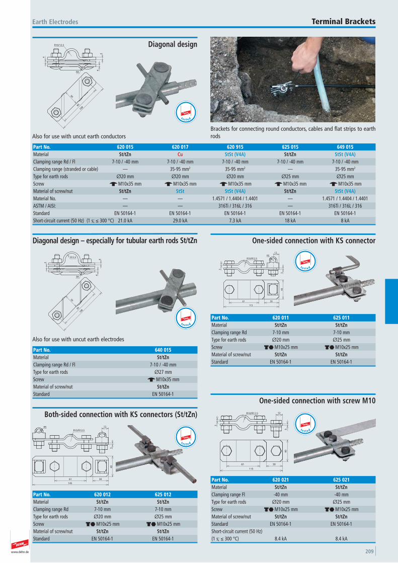
www.dehn.de 209
Brackets for connecting round conductors, cables and flat strips to earthrods
Earth Electrodes Terminal Brackets
85
108
30
R4
4
4
4
R10/12.5
Also for use with uncut earth conductors
Diagonal design
Part No. 620 015 620 017 620 915 625 015 649 015Material St/tZn Cu StSt (V4A) St/tZn StSt (V4A)Clamping range Rd / Fl 7-10 / -40 mm 7-10 / -40 mm 7-10 / -40 mm 7-10 / -40 mm 7-10 / -40 mmClamping range (stranded or cable) — 35-95 mm2 35-95 mm2 — 35-95 mm2
Type for earth rods Ø20 mm Ø20 mm Ø20 mm Ø25 mm Ø25 mmScrew e M10x35 mm e M10x35 mm e M10x35 mm e M10x35 mm e M10x35 mmMaterial of screw/nut St/tZn StSt StSt (V4A) St/tZn StSt (V4A)Material No. — — 1.4571 / 1.4404 / 1.4401 — 1.4571 / 1.4404 / 1.4401 ASTM / AISI: — — 316Ti / 316L / 316 — 316Ti / 316L / 316 Standard EN 50164-1 EN 50164-1 EN 50164-1 EN 50164-1 EN 50164-1 Short-circuit current (50 Hz) (1 s; ≤ 300 °C) 21.0 kA 29.0 kA 7.3 kA 18 kA 8 kA
t e s t e d
85108
30
R4
R13.5
4
4
4
Also for use with uncut earth electrodes
Diagonal design – especially for tubular earth rods St/tZn
Part No. 640 015Material St/tZnClamping range Rd / Fl 7-10 / -40 mmType for earth rods Ø27 mmScrew e M10x35 mmMaterial of screw/nut St/tZnStandard EN 50164-1
t e s t e d
3
R10/R12.5
12
3
61 30
115
40
R5
One-sided connection with KS connector
Part No. 620 011 625 011Material St/tZn St/tZnClamping range Rd 7-10 mm 7-10 mmType for earth rods Ø20 mm Ø25 mmScrew di M10x25 mm di M10x25 mmMaterial of screw/nut St/tZn St/tZnStandard EN 50164-1 EN 50164-1
t e s t e d
3
12
R10/R12.5
R5
145
61 30
40
Both-sided connection with KS connectors (St/tZn)
Part No. 620 012 625 012Material St/tZn St/tZnClamping range Rd 7-10 mm 7-10 mmType for earth rods Ø20 mm Ø25 mmScrew di M10x25 mm di M10x25 mmMaterial of screw/nut St/tZn St/tZnStandard EN 50164-1 EN 50164-1
t e s t e d
3
R10/R12.5 12
3
61 30
115
40
One-sided connection with screw M10
Part No. 620 021 625 021Material St/tZn St/tZnClamping range Fl -40 mm -40 mmType for earth rods Ø20 mm Ø25 mmScrew di M10x25 mm di M10x25 mmMaterial of screw/nut St/tZn St/tZnStandard EN 50164-1 EN 50164-1 Short-circuit current (50 Hz) (1 s; ≤ 300 °C) 8.4 kA 8.4 kA
t e s t e d
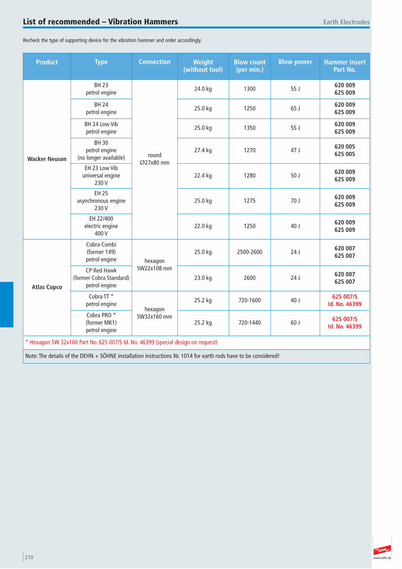
www.dehn.de210
Recheck the type of supporting device for the vibration hammer and order accordingly.
Product Type Connection Weight(without tool)
Blow count(per min.)
Blow power Hammer InsertPart No.
Wacker Neuson
BH 23petrol engine
roundØ27x80 mm
24.0 kg 1300 55 J620 009625 009
BH 24petrol engine
25.0 kg 1250 65 J620 009625 009
BH 24 Low Vibpetrol engine
25.0 kg 1350 55 J620 009625 009
BH 30petrol engine
(no longer available)27.4 kg 1270 47 J
620 005625 005
EH 23 Low Vibuniversal engine
230 V22.4 kg 1280 50 J
620 009625 009
EH 25asynchronous engine
230 V25.0 kg 1275 70 J
620 009625 009
EH 22/400electric engine
400 V22.0 kg 1250 40 J
620 009625 009
Atlas Copco
Cobra Combi(former 149)petrol engine hexagon
SW22x108 mm
25.0 kg 2500-2600 24 J620 007625 007
CP Red Hawk(former Cobra Standard)
petrol engine23.0 kg 2600 24 J
620 007625 007
Cobra TT *petrol engine
hexagonSW32x160 mm
25.2 kg 720-1600 40 J625 007/S
Id. No. 46399
Cobra PRO *(former MK1)petrol engine
25.2 kg 720-1440 60 J625 007/S
Id. No. 46399
* Hexagon SW 32x160 Part No. 625 007/S Id. No. 46399 (special design on request)
Note: The details of the DEHN + SÖHNE installation instructions Nr. 1014 for earth rods have to be considered!
Earth ElectrodesList of recommended – Vibration Hammers

www.dehn.de 211
Hammer inserts to drive in earth rods by vibration hammer
For earth rods Types S + ZØ20 mm (pin Ø12 mm Part No. 620...) orØ25 mm (pin Ø15 mm Part No. 625...)
For Atlas Copco equipment several types of supports can be used. Please note when placing your order.
Earth Electrodes Hammer Inserts for Earth Rods
Design for other types of hammer available upon request.
l1
200
8025
Ø2
7
15°
Ø2
8
d1
Ø4
0
34
Ø40
Design for Wacker Neuson
Part No. 620 005 625 005Type EH 23/230, EH 22/400 and BHF 30 EH 23/230, EH 22/400 and BHF 30 Adapter round Ø27x80 mm round Ø27x80 mm Material St/bare St/bareBore (d1 x l1) 13x50 mm 16x55 mmLength 200 mm 200 mm
Special hammer insert for earth rods d=20 mm, StSt for Wacker equipment Part No. 620 005/S Id. No. 046377 upon request.
l1
260
d1
Ø7
0
Ø2
8
Ø2
7
15°
8025
34
Ø40
Heavy design for Wacker Neuson
Part No. 620 009 625 009Type EH 23 Low Vib, BH 24 Low Vib, BH 23 and EH 25 EH 23 Low Vib, BH 24 Low Vib, BH 23 and EH 25 Adapter round Ø27x80 mm round Ø27x80 mm Material St/bare St/bareBore (d1 x l1) 13x50 mm 16x55 mmLength 260 mm 260 mm
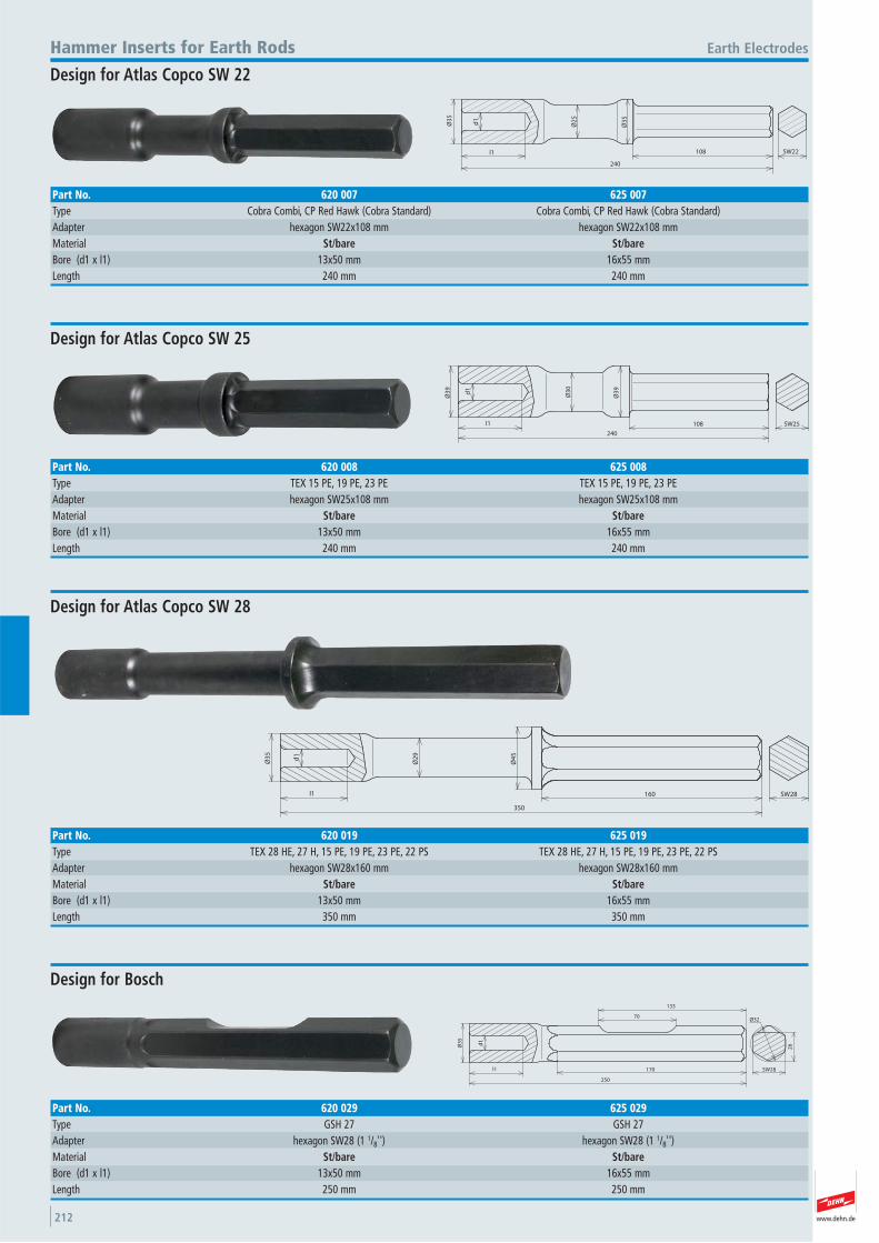
www.dehn.de212
l1
240
Ø3
5
Ø2
5
d1
Ø3
5
108 SW22
Earth ElectrodesHammer Inserts for Earth Rods
Design for Atlas Copco SW 22
Part No. 620 007 625 007Type Cobra Combi, CP Red Hawk (Cobra Standard) Cobra Combi, CP Red Hawk (Cobra Standard) Adapter hexagon SW22x108 mm hexagon SW22x108 mm Material St/bare St/bareBore (d1 x l1) 13x50 mm 16x55 mmLength 240 mm 240 mm
l1
240
108
Ø3
9
Ø3
0
d1
Ø3
9
SW25
Design for Atlas Copco SW 25
Part No. 620 008 625 008Type TEX 15 PE, 19 PE, 23 PE TEX 15 PE, 19 PE, 23 PE Adapter hexagon SW25x108 mm hexagon SW25x108 mm Material St/bare St/bareBore (d1 x l1) 13x50 mm 16x55 mmLength 240 mm 240 mm
l1
350
d1
Ø3
5
Ø2
9
Ø4
5
160 SW28
Design for Atlas Copco SW 28
Part No. 620 019 625 019Type TEX 28 HE, 27 H, 15 PE, 19 PE, 23 PE, 22 PS TEX 28 HE, 27 H, 15 PE, 19 PE, 23 PE, 22 PS Adapter hexagon SW28x160 mm hexagon SW28x160 mm Material St/bare St/bareBore (d1 x l1) 13x50 mm 16x55 mmLength 350 mm 350 mm
l1
250
70
d1
Ø3
5
170
133
Ø32
26
SW28
Design for Bosch
Part No. 620 029 625 029Type GSH 27 GSH 27 Adapter hexagon SW28 (1 1/8'') hexagon SW28 (1 1/8'') Material St/bare St/bareBore (d1 x l1) 13x50 mm 16x55 mmLength 250 mm 250 mm
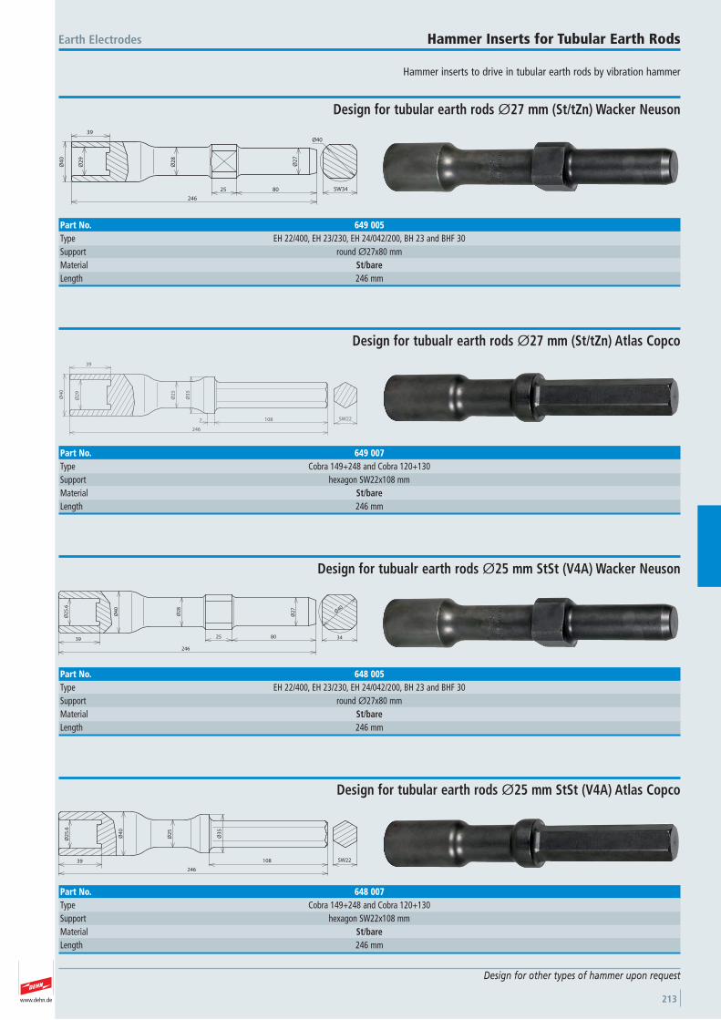
www.dehn.de 213
Hammer inserts to drive in tubular earth rods by vibration hammer
Earth Electrodes Hammer Inserts for Tubular Earth Rods
Design for other types of hammer upon request
39
Ø2
9
Ø4
0
Ø2
8
25 80
Ø2
7
246
SW34
Ø40
Design for tubular earth rods Ø27 mm (St/tZn) Wacker Neuson
Part No. 649 005Type EH 22/400, EH 23/230, EH 24/042/200, BH 23 and BHF 30 Support round Ø27x80 mm Material St/bareLength 246 mm
39
Ø2
9
Ø4
0
Ø2
5
Ø3
5
7 108
246
SW22
Design for tubualr earth rods Ø27 mm (St/tZn) Atlas Copco
Part No. 649 007Type Cobra 149+248 and Cobra 120+130 Support hexagon SW22x108 mm Material St/bareLength 246 mm
Ø2
5.6
Ø4
0
39
Ø2
8
25 80
Ø2
7
246
34
Ø40
Design for tubualr earth rods Ø25 mm StSt (V4A) Wacker Neuson
Part No. 648 005Type EH 22/400, EH 23/230, EH 24/042/200, BH 23 and BHF 30 Support round Ø27x80 mm Material St/bareLength 246 mm
39
Ø2
5.6
Ø4
0
Ø2
5
108
246
Ø3
5
SW22
Design for tubular earth rods Ø25 mm StSt (V4A) Atlas Copco
Part No. 648 007Type Cobra 149+248 and Cobra 120+130 Support hexagon SW22x108 mm Material St/bareLength 246 mm
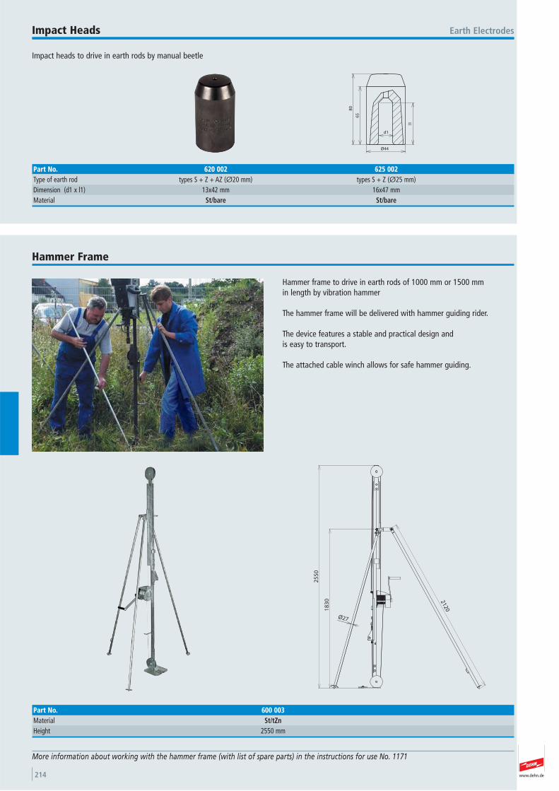
www.dehn.de214
Impact heads to drive in earth rods by manual beetle
Earth ElectrodesImpact Heads
80
l1
65
d1
Ø44
Part No. 620 002 625 002Type of earth rod types S + Z + AZ (Ø20 mm) types S + Z (Ø25 mm) Dimension (d1 x l1) 13x42 mm 16x47 mmMaterial St/bare St/bare
Hammer frame to drive in earth rods of 1000 mm or 1500 mm in length by vibration hammer
The hammer frame will be delivered with hammer guiding rider.
The device features a stable and practical design and is easy to transport.
The attached cable winch allows for safe hammer guiding.
Hammer Frame
More information about working with the hammer frame (with list of spare parts) in the instructions for use No. 1171
25
50
Ø27
212018
30
Part No. 600 003Material St/tZnHeight 2550 mm
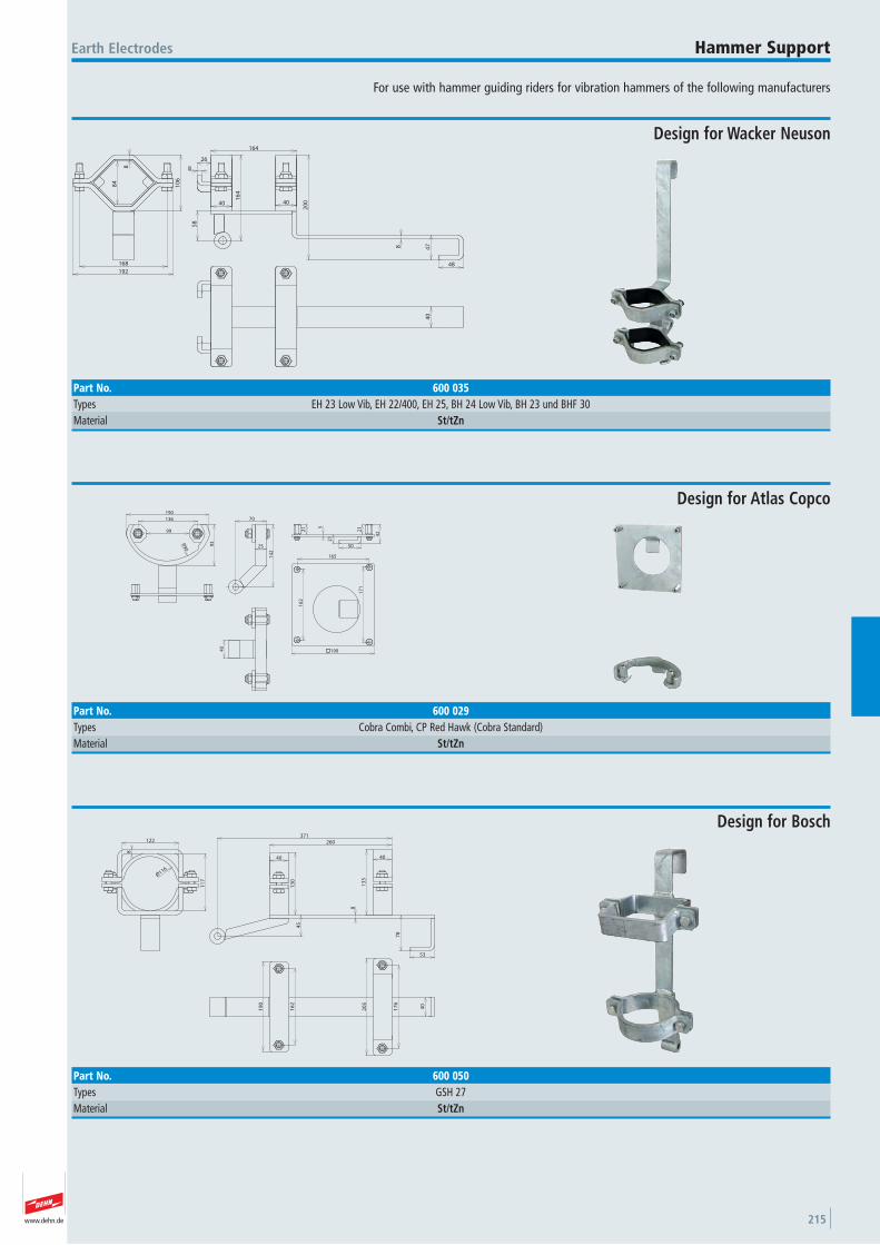
www.dehn.de 215
For use with hammer guiding riders for vibration hammers of the following manufacturers
Earth Electrodes Hammer Support
8
4040
164
8
26
47
48
58
16
4
20
0
40
10
6
8
168
192
84
Design for Wacker Neuson
Part No. 600 035Types EH 23 Low Vib, EH 22/400, EH 25, BH 24 Low Vib, BH 23 und BHF 30 Material St/tZn
215
21
25
21
50
42
14
2
70
93R90
99
136
190
165
16
2
17
1
40
190
Design for Atlas Copco
Part No. 600 029Types Cobra Combi, CP Red Hawk (Cobra Standard) Material St/tZn
8
13
0
40
13
3
40
260371
78
45
53
122
8
11
7
Ø116
19
0
20
5
40
16
2
17
6
Design for Bosch
Part No. 600 050Types GSH 27 Material St/tZn
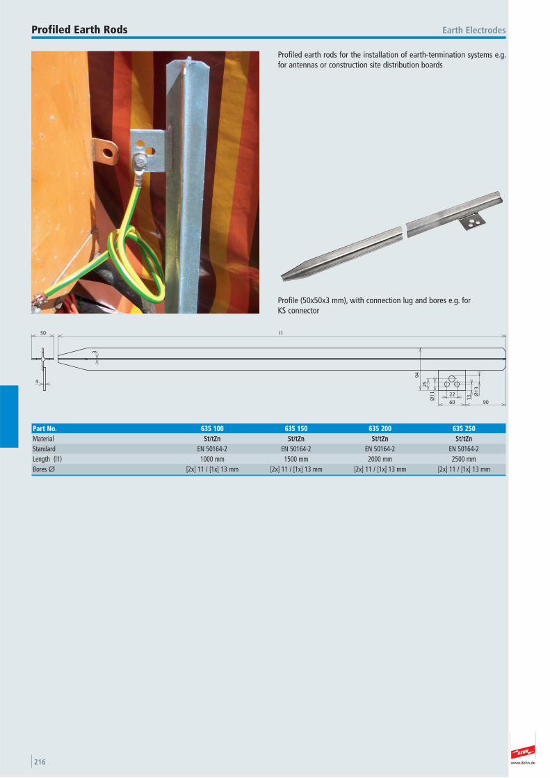
www.dehn.de216
Profiled earth rods for the installation of earth-termination systems e.g.for antennas or construction site distribution boards
Earth ElectrodesProfiled Earth Rods
90
22
60
13
25
Ø1
3
Ø1
1
l1
4
94
50
3
Profile (50x50x3 mm), with connection lug and bores e.g. for KS connector
Part No. 635 100 635 150 635 200 635 250Material St/tZn St/tZn St/tZn St/tZnStandard EN 50164-2 EN 50164-2 EN 50164-2 EN 50164-2 Length (l1) 1000 mm 1500 mm 2000 mm 2500 mmBores Ø [2x] 11 / [1x] 13 mm [2x] 11 / [1x] 13 mm [2x] 11 / [1x] 13 mm [2x] 11 / [1x] 13 mm
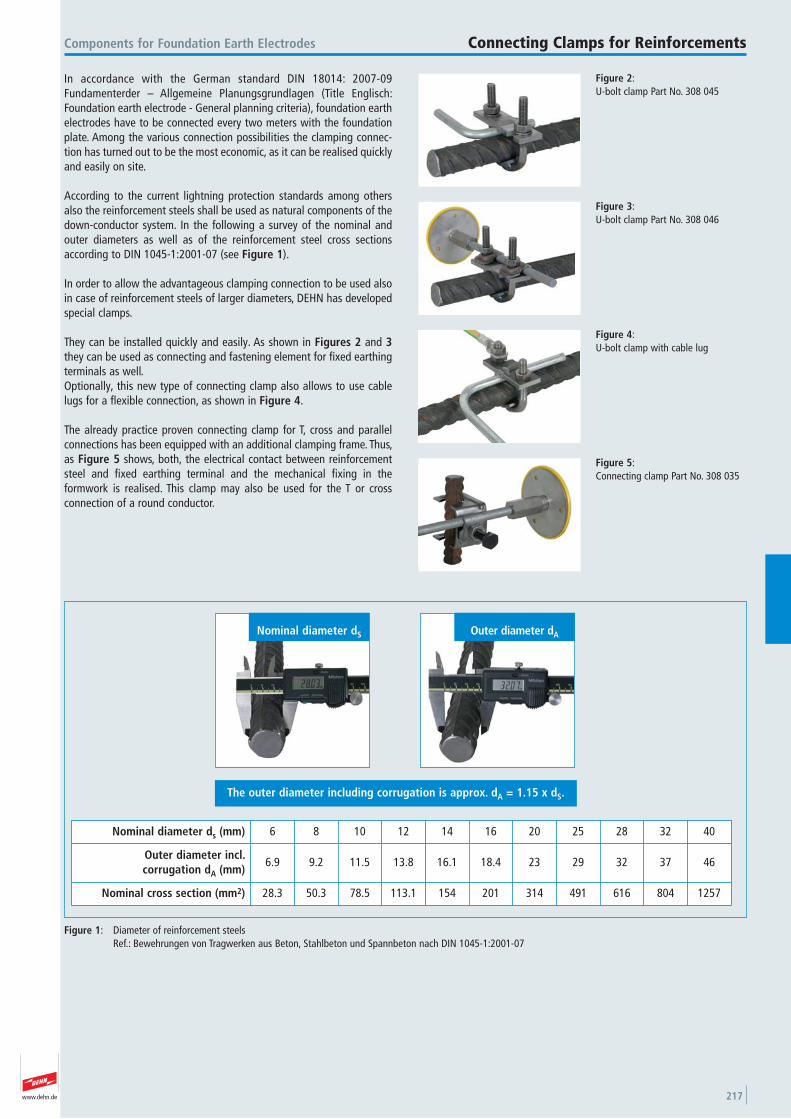
www.dehn.de 217
In accordance with the German standard DIN 18014: 2007-09Fundamenterder – Allgemeine Planungsgrundlagen (Title Englisch:Foundation earth electrode - General planning criteria), foundation earthelectrodes have to be connected every two meters with the foundationplate. Among the various connection possibilities the clamping connec-tion has turned out to be the most economic, as it can be realised quicklyand easily on site.
According to the current lightning protection standards among othersalso the reinforcement steels shall be used as natural components of thedown-conductor system. In the following a survey of the nominal andouter diameters as well as of the reinforcement steel cross sectionsaccording to DIN 1045-1:2001-07 (see Figure 1).
In order to allow the advantageous clamping connection to be used alsoin case of reinforcement steels of larger diameters, DEHN has developedspecial clamps.
They can be installed quickly and easily. As shown in Figures 2 and 3they can be used as connecting and fastening element for fixed earthingterminals as well.Optionally, this new type of connecting clamp also allows to use cablelugs for a flexible connection, as shown in Figure 4.
The already practice proven connecting clamp for T, cross and parallelconnections has been equipped with an additional clamping frame. Thus,as Figure 5 shows, both, the electrical contact between reinforcementsteel and fixed earthing terminal and the mechanical fixing in the formwork is realised. This clamp may also be used for the T or cross connection of a round conductor.
Figure 1: Diameter of reinforcement steelsRef.: Bewehrungen von Tragwerken aus Beton, Stahlbeton und Spannbeton nach DIN 1045-1:2001-07
Figure 2:U-bolt clamp Part No. 308 045
Components for Foundation Earth Electrodes Connecting Clamps for Reinforcements
Figure 3:U-bolt clamp Part No. 308 046
Figure 4:U-bolt clamp with cable lug
Figure 5:Connecting clamp Part No. 308 035
The outer diameter including corrugation is approx. dA = 1.15 x dS.
Outer diameter dANominal diameter dS
Nominal diameter ds (mm) 6 8 10 12 14 16 20 25 28 32 40
Outer diameter incl. corrugation dA (mm)
6.9 9.2 11.5 13.8 16.1 18.4 23 29 32 37 46
Nominal cross section (mm2) 28.3 50.3 78.5 113.1 154 201 314 491 616 804 1257
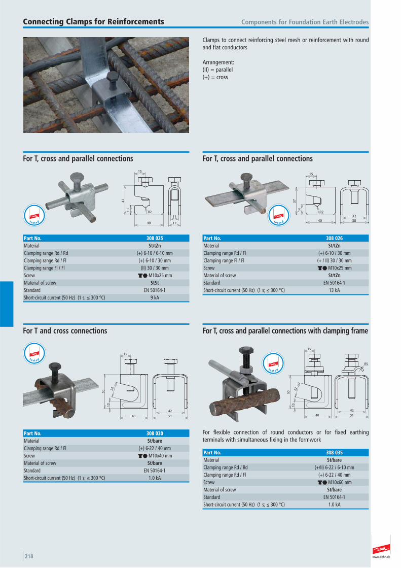
www.dehn.de218
11
17
41
13
R2
40
15
Components for Foundation Earth Electrodes
For T, cross and parallel connections
Part No. 308 025Material St/tZnClamping range Rd / Rd (+) 6-10 / 6-10 mmClamping range Rd / Fl (+) 6-10 / 30 mmClamping range Fl / Fl (II) 30 / 30 mmScrew di M10x25 mmMaterial of screw StStStandard EN 50164-1 Short-circuit current (50 Hz) (1 s; ≤ 300 °C) 9 kA
Clamps to connect reinforcing steel mesh or reinforcement with roundand flat conductors
Arrangement:(II) = parallel(+) = cross
Connecting Clamps for Reinforcements
t e s t e d 3832
15
37
14
R2
40
For T, cross and parallel connections
Part No. 308 026Material St/tZnClamping range Rd / Fl (+) 6-10 / 30 mmClamping range Fl / Fl (+ / II) 30 / 30 mmScrew di M10x25 mmMaterial of screw St/tZnStandard EN 50164-1 Short-circuit current (50 Hz) (1 s; ≤ 300 °C) 13 kA
t e s t e d
42
51
15
22
10
50
40
For T and cross connections
Part No. 308 030Material St/bareClamping range Rd / Fl (+) 6-22 / 40 mmScrew di M10x40 mmMaterial of screw St/bareStandard EN 50164-1 Short-circuit current (50 Hz) (1 s; ≤ 300 °C) 1.0 kA
t e s t e dR5
42
51
22
10
40
50
15
For flexible connection of round conductors or for fixed earthing terminals with simultaneous fixing in the formwork
For T, cross and parallel connections with clamping frame
Part No. 308 035Material St/bareClamping range Rd / Rd (+/II) 6-22 / 6-10 mmClamping range Rd / Fl (+) 6-22 / 40 mmScrew di M10x60 mmMaterial of screw St/bareStandard EN 50164-1 Short-circuit current (50 Hz) (1 s; ≤ 300 °C) 1.0 kA
t e s t e d
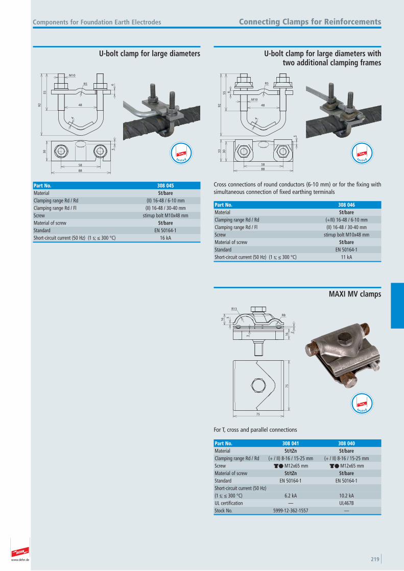
www.dehn.de 219
6
55
92
4
M10
R5
48
58
88
30 5
Components for Foundation Earth Electrodes Connecting Clamps for Reinforcements
U-bolt clamp for large diameters
Part No. 308 045Material St/bareClamping range Rd / Rd (II) 16-48 / 6-10 mmClamping range Rd / Fl (II) 16-48 / 30-40 mmScrew stirrup bolt M10x48 mmMaterial of screw St/bareStandard EN 50164-1 Short-circuit current (50 Hz) (1 s; ≤ 300 °C) 16 kA
t e s t e d
55 6
92
R5
4
M10
48
3033
5
88
58
Cross connections of round conductors (6-10 mm) or for the fixing withsimultaneous connection of fixed earthing terminals
U-bolt clamp for large diameters with two additional clamping frames
Part No. 308 046Material St/bareClamping range Rd / Rd (+/II) 16-48 / 6-10 mmClamping range Rd / Fl (II) 16-48 / 30-40 mmScrew stirrup bolt M10x48 mmMaterial of screw St/bareStandard EN 50164-1 Short-circuit current (50 Hz) (1 s; ≤ 300 °C) 11 kA
t e s t e d
2
3
3
16
16
R13
R8
75
75
For T, cross and parallel connections
MAXI MV clamps
Part No. 308 041 308 040Material St/tZn St/bareClamping range Rd / Rd (+ / II) 8-16 / 15-25 mm (+ / II) 8-16 / 15-25 mmScrew di M12x65 mm di M12x65 mmMaterial of screw St/tZn St/bareStandard EN 50164-1 EN 50164-1 Short-circuit current (50 Hz)(1 s; ≤ 300 °C) 6.2 kA 10.2 kAUL certification — UL467B Stock No. 5999-12-362-1557 —
t e s t e d
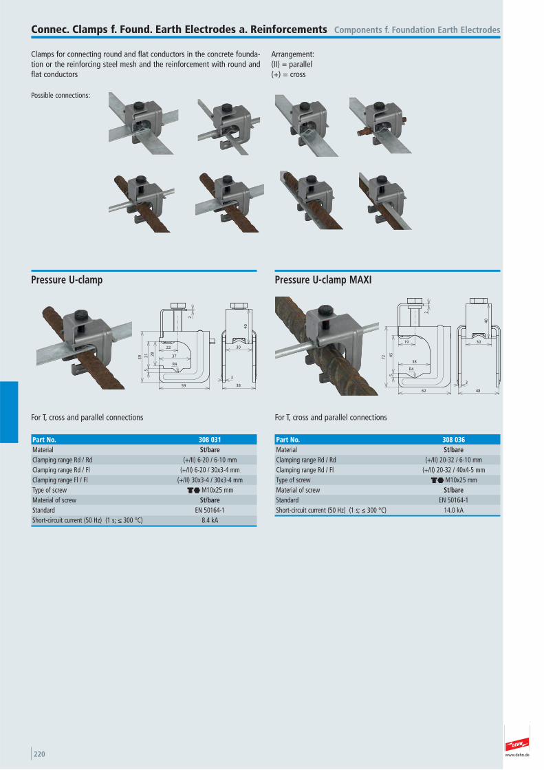
www.dehn.de220
Clamps for connecting round and flat conductors in the concrete founda-tion or the reinforcing steel mesh and the reinforcement with round andflat conductors
Arrangement:(II) = parallel(+) = cross
Possible connections:
Components f. Foundation Earth ElectrodesConnec. Clamps f. Found. Earth Electrodes a. Reinforcements
22
2
28
31 37
59
59
5
3
38
30
40
R4
For T, cross and parallel connections
Pressure U-clamp
Part No. 308 031Material St/bareClamping range Rd / Rd (+/II) 6-20 / 6-10 mmClamping range Rd / Fl (+/II) 6-20 / 30x3-4 mmClamping range Fl / Fl (+/II) 30x3-4 / 30x3-4 mmType of screw di M10x25 mmMaterial of screw St/bareStandard EN 50164-1 Short-circuit current (50 Hz) (1 s; ≤ 300 °C) 8.4 kA
19
45
5
38
62
72
2
30
40
3
48
R4
For T, cross and parallel connections
Pressure U-clamp MAXI
Part No. 308 036Material St/bareClamping range Rd / Rd (+/II) 20-32 / 6-10 mmClamping range Rd / Fl (+/II) 20-32 / 40x4-5 mmType of screw di M10x25 mmMaterial of screw St/bareStandard EN 50164-1 Short-circuit current (50 Hz) (1 s; ≤ 300 °C) 14.0 kA
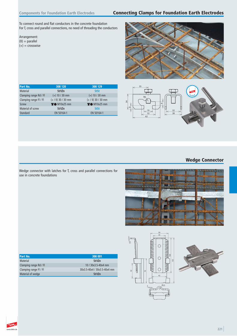
www.dehn.de 221
To connect round and flat conductors in the concrete foundationFor T, cross and parallel connections, no need of threading the conductors
Arrangement: (II) = parallel (+) = crosswise
Components for Foundation Earth Electrodes Connecting Clamps for Foundation Earth Electrodes
32
38
8
34
R6
35
19
32
62
9
Part No. 308 120 308 129Material St/tZn StStClamping range Rd / Fl (+) 10 / 30 mm (+) 10 / 30 mmClamping range Fl / Fl (+ / II) 30 / 30 mm (+ / II) 30 / 30 mmScrew di M10x25 mm di M10x25 mmMaterial of screw St/tZn StStStandard EN 50164-1 EN 50164-1
t e s t e d
Wedge connector with latches for T, cross and parallel connections foruse in concrete foundations
Wedge Connector
R5.53
35
50
10
0
13
5
42
7042
2.5
Part No. 308 001Material St/tZnClamping range Rd / Fl 10 / 30x3.5-40x4 mmClamping range Fl / Fl 30x3.5-40x4 / 30x3.5-40x4 mmMaterial of wedge St/tZn
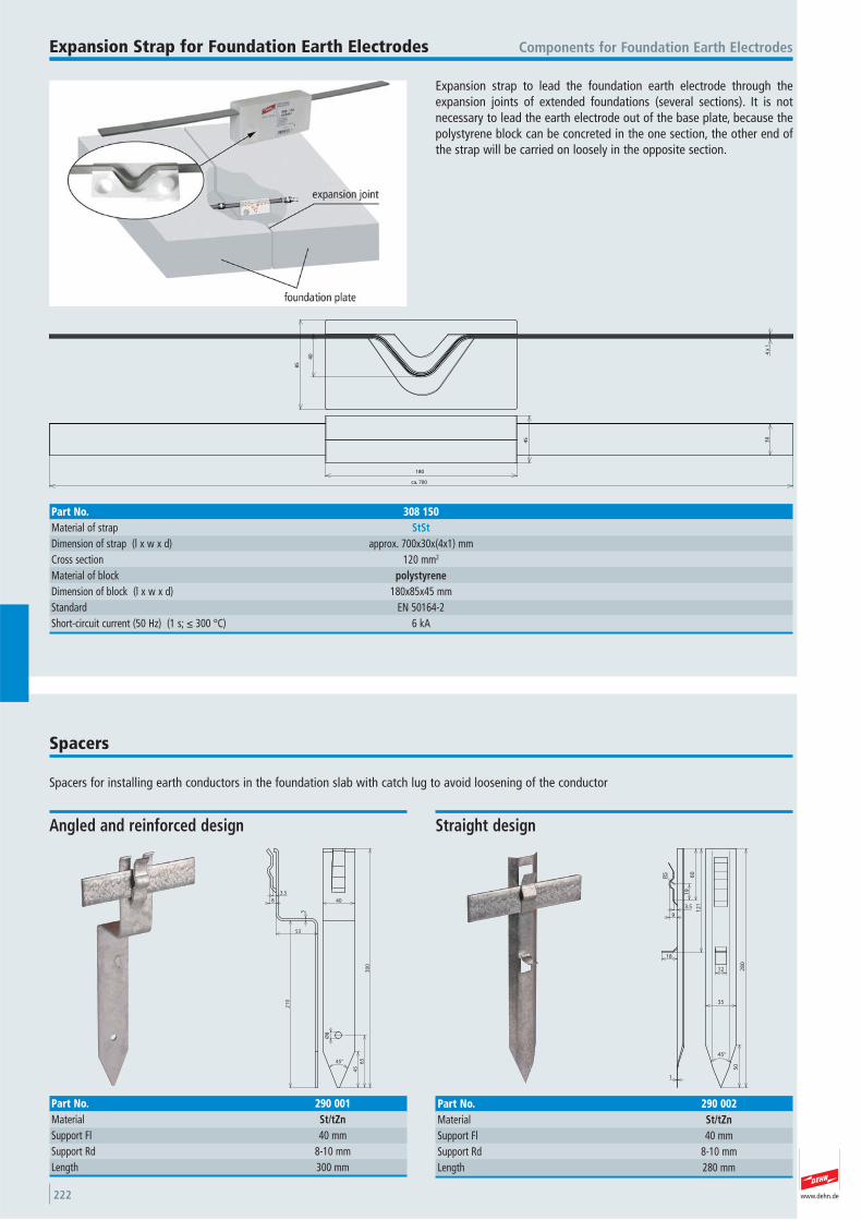
www.dehn.de222
Expansion strap to lead the foundation earth electrode through theexpansion joints of extended foundations (several sections). It is not necessary to lead the earth electrode out of the base plate, because thepolystyrene block can be concreted in the one section, the other end ofthe strap will be carried on loosely in the opposite section.
Components for Foundation Earth ElectrodesExpansion Strap for Foundation Earth Electrodes
40
85
4 x
1
45 30
180
ca. 700
Part No. 308 150Material of strap StStDimension of strap (l x w x d) approx. 700x30x(4x1) mmCross section 120 mm2
Material of block polystyreneDimension of block (l x w x d) 180x85x45 mmStandard EN 50164-2 Short-circuit current (50 Hz) (1 s; ≤ 300 °C) 6 kA
Spacers for installing earth conductors in the foundation slab with catch lug to avoid loosening of the conductor
Spacers
45°
45
65
30
0
Ø8
40
53
21
0
3
3.5
8
Angled and reinforced design
Part No. 290 001Material St/tZnSupport Fl 40 mmSupport Rd 8-10 mmLength 300 mm
12
50
28
0
35
19
60
12
13.5
9
R5
18
1
45°
Straight design
Part No. 290 002Material St/tZnSupport Fl 40 mmSupport Rd 8-10 mmLength 280 mm
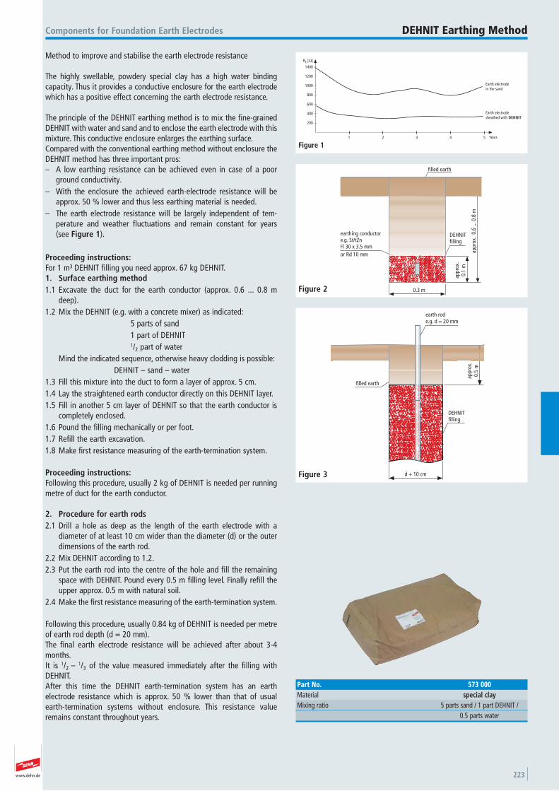
www.dehn.de 223
Method to improve and stabilise the earth electrode resistance
The highly swellable, powdery special clay has a high water bindingcapacity. Thus it provides a conductive enclosure for the earth electrodewhich has a positive effect concerning the earth electrode resistance.
The principle of the DEHNIT earthing method is to mix the fine-grainedDEHNIT with water and sand and to enclose the earth electrode with thismixture. This conductive enclosure enlarges the earthing surface.Compared with the conventional earthing method without enclosure theDEHNIT method has three important pros:– A low earthing resistance can be achieved even in case of a poor
ground conductivity.– With the enclosure the achieved earth-electrode resistance will be
approx. 50 % lower and thus less earthing material is needed.– The earth electrode resistance will be largely independent of tem -
perature and weather fluctuations and remain constant for years (see Figure 1).
Proceeding instructions:For 1 m³ DEHNIT filling you need approx. 67 kg DEHNIT.1. Surface earthing method1.1 Excavate the duct for the earth conductor (approx. 0.6 ... 0.8 m
deep).1.2 Mix the DEHNIT (e.g. with a concrete mixer) as indicated:
5 parts of sand1 part of DEHNIT1/2 part of water
Mind the indicated sequence, otherwise heavy clodding is possible:DEHNIT – sand – water
1.3 Fill this mixture into the duct to form a layer of approx. 5 cm.1.4 Lay the straightened earth conductor directly on this DEHNIT layer.1.5 Fill in another 5 cm layer of DEHNIT so that the earth conductor is
completely enclosed.1.6 Pound the filling mechanically or per foot.1.7 Refill the earth excavation.1.8 Make first resistance measuring of the earth-termination system.
Proceeding instructions:Following this procedure, usually 2 kg of DEHNIT is needed per runningmetre of duct for the earth conductor.
2. Procedure for earth rods2.1 Drill a hole as deep as the length of the earth electrode with a
diameter of at least 10 cm wider than the diameter (d) or the outerdimensions of the earth rod.
2.2 Mix DEHNIT according to 1.2.2.3 Put the earth rod into the centre of the hole and fill the remaining
space with DEHNIT. Pound every 0.5 m filling level. Finally refill theupper approx. 0.5 m with natural soil.
2.4 Make the first resistance measuring of the earth-termination system.
Following this procedure, usually 0.84 kg of DEHNIT is needed per metreof earth rod depth (d = 20 mm).The final earth electrode resistance will be achieved after about 3-4months.It is 1/2 – 1/3 of the value measured immediately after the filling withDEHNIT.After this time the DEHNIT earth-termination system has an earth electrode resistance which is approx. 50 % lower than that of usualearth-termination systems without enclosure. This resistance valueremains constant throughout years.
Components for Foundation Earth Electrodes DEHNIT Earthing Method
RE [Ω]
1400
1200
1000
800
600
400
200
1 2 3 4 5 Years
Earth electrodein the sand
Earth electrodesheathed with DEHNIT
Figure 1
filled earth
DEHNITfilling
appr
ox.
0.1
m
appr
ox.
0.6
... 0
.8 m
0.3 m
earthing conductore.g. St/tZnFl 30 x 3.5 mmor Rd 10 mm
Figure 2
earth rode.g. d = 20 mm
appr
ox.
0.5
md + 10 cm
filled earth
DEHNITfilling
Figure 3
Part No. 573 000Material special clayMixing ratio 5 parts sand / 1 part DEHNIT /
0.5 parts water

www.dehn.de224
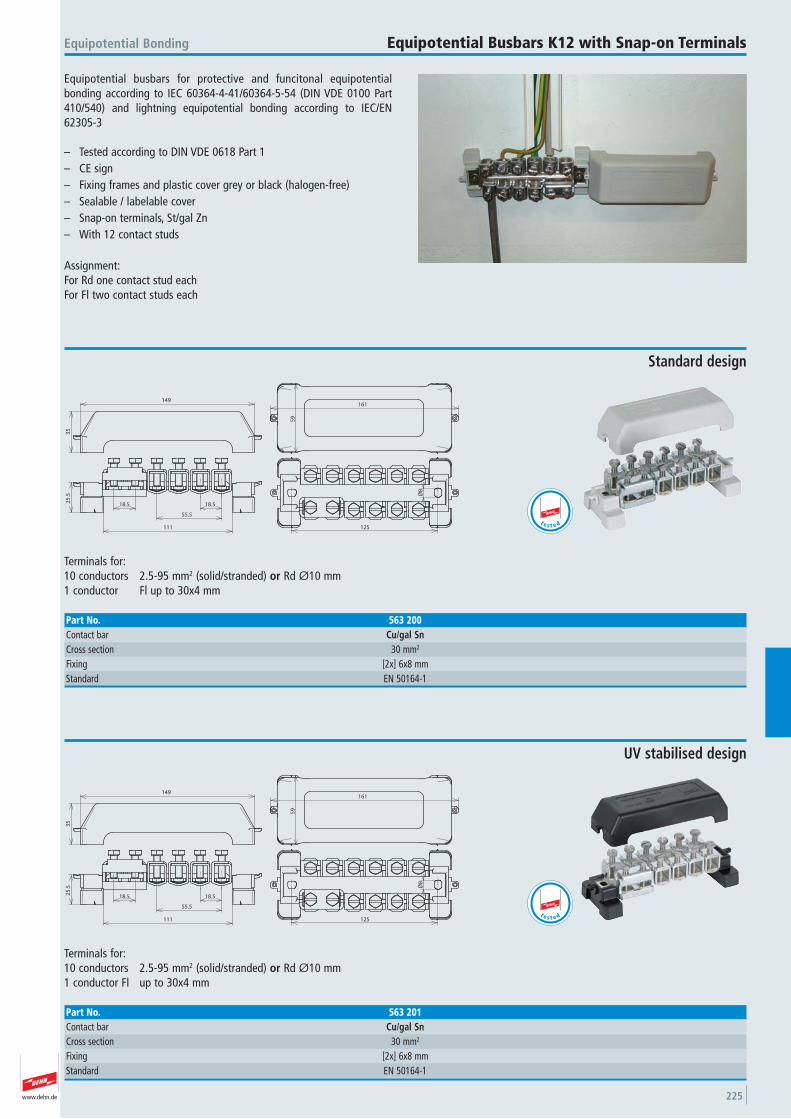
www.dehn.de 225
Equipotential busbars for protective and funcitonal equipotential bonding according to IEC 60364-4-41/60364-5-54 (DIN VDE 0100 Part410/540) and lightning equipotential bonding according to IEC/EN62305-3
– Tested according to DIN VDE 0618 Part 1– CE sign– Fixing frames and plastic cover grey or black (halogen-free)– Sealable / labelable cover– Snap-on terminals, St/gal Zn– With 12 contact studs
Assignment: For Rd one contact stud eachFor Fl two contact studs each
Equipotential Bonding Equipotential Busbars K12 with Snap-on Terminals
161
59
Ø8
125
18.5
55.5
111
18.525
.53
5
149
Terminals for:10 conductors 2.5-95 mm2 (solid/stranded) or Rd Ø10 mm1 conductor Fl up to 30x4 mm
Standard design
Part No. 563 200Contact bar Cu/gal SnCross section 30 mm2
Fixing [2x] 6x8 mmStandard EN 50164-1
t e s t e d
161
59
Ø8
125
18.5
55.5
111
18.525
.53
5
149
Terminals for:10 conductors 2.5-95 mm2 (solid/stranded) or Rd Ø10 mm1 conductor Fl up to 30x4 mm
UV stabilised design
Part No. 563 201Contact bar Cu/gal SnCross section 30 mm2
Fixing [2x] 6x8 mmStandard EN 50164-1
t e s t e d
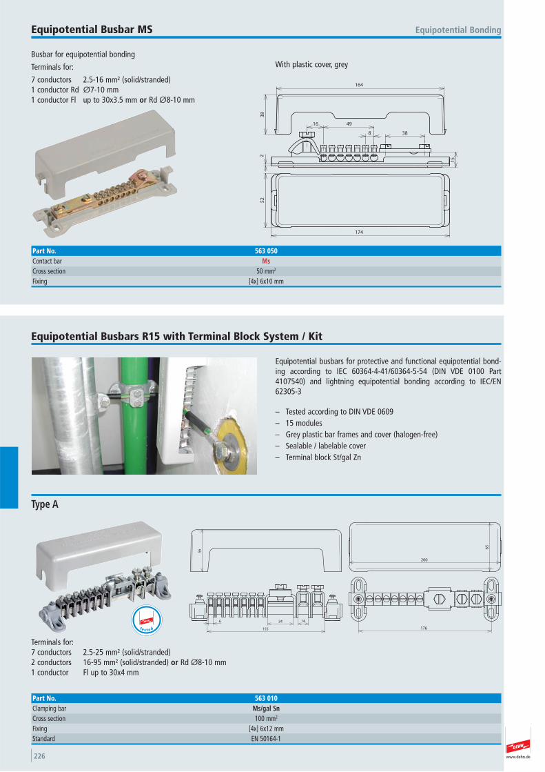
www.dehn.de226
Busbar for equipotential bonding
Terminals for:
7 conductors 2.5-16 mm² (solid/stranded)1 conductor Rd Ø7-10 mm1 conductor Fl up to 30x3.5 mm or Rd Ø8-10 mm
With plastic cover, grey
Equipotential BondingEquipotential Busbar MS
164
38
2
8
4916
38
15
52
174
Part No. 563 050Contact bar MsCross section 50 mm2
Fixing [4x] 6x10 mm
Equipotential busbars for protective and functional equipotential bond-ing according to IEC 60364-4-41/60364-5-54 (DIN VDE 0100 Part4107540) and lightning equipotential bonding according to IEC/EN62305-3
– Tested according to DIN VDE 0609– 15 modules– Grey plastic bar frames and cover (halogen-free)– Sealable / labelable cover– Terminal block St/gal Zn
Equipotential Busbars R15 with Terminal Block System / Kit
6 34 14
155
56
176
200
65
Terminals for:7 conductors 2.5-25 mm² (solid/stranded)2 conductors 16-95 mm² (solid/stranded) or Rd Ø8-10 mm1 conductor Fl up to 30x4 mm
Type A
Part No. 563 010Clamping bar Ms/gal SnCross section 100 mm2
Fixing [4x] 6x12 mmStandard EN 50164-1
t e s t e d
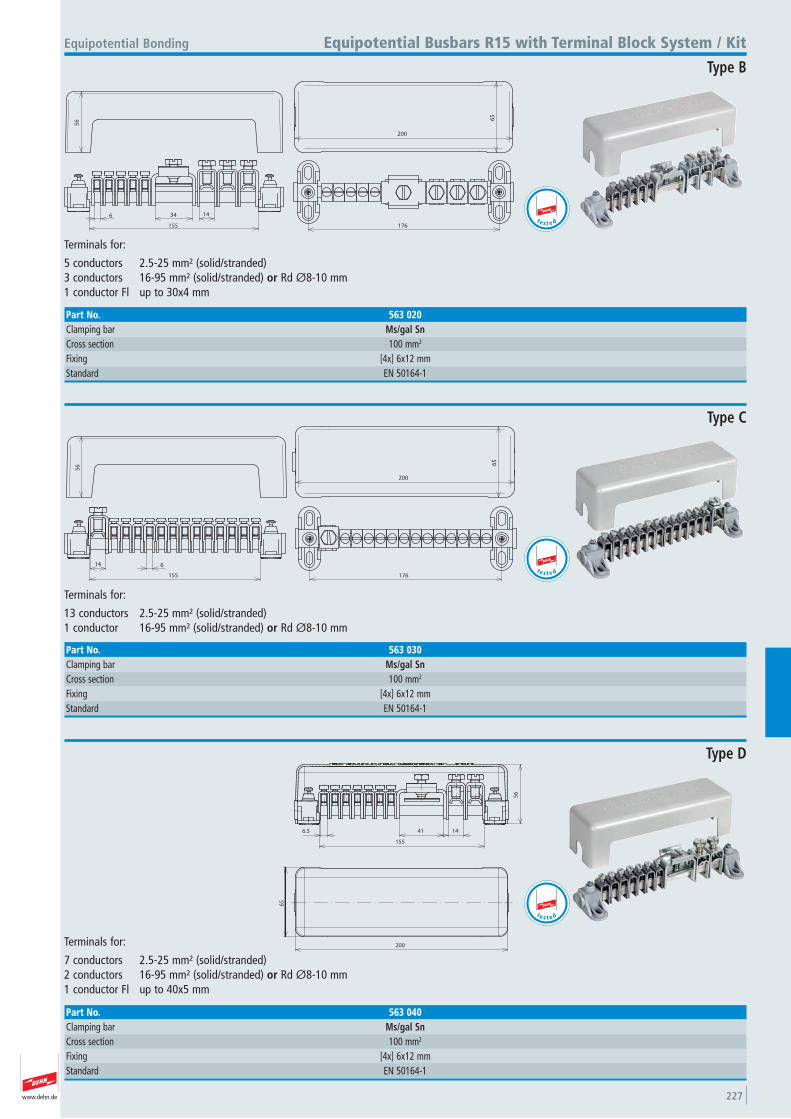
www.dehn.de 227
14346
155
56
200
65
176
Terminals for:
5 conductors 2.5-25 mm² (solid/stranded)3 conductors 16-95 mm² (solid/stranded) or Rd Ø8-10 mm1 conductor Fl up to 30x4 mm
Equipotential Bonding Equipotential Busbars R15 with Terminal Block System / Kit
Type B
Part No. 563 020Clamping bar Ms/gal SnCross section 100 mm2
Fixing [4x] 6x12 mmStandard EN 50164-1
t e s t e d
614
155
56 6
5
200
176
Terminals for:
13 conductors 2.5-25 mm² (solid/stranded)1 conductor 16-95 mm² (solid/stranded) or Rd Ø8-10 mm
Type C
Part No. 563 030Clamping bar Ms/gal SnCross section 100 mm2
Fixing [4x] 6x12 mmStandard EN 50164-1
t e s t e d
200
65
6.5 41 14
155
56
Terminals for:
7 conductors 2.5-25 mm² (solid/stranded)2 conductors 16-95 mm² (solid/stranded) or Rd Ø8-10 mm1 conductor Fl up to 40x5 mm
Type D
Part No. 563 040Clamping bar Ms/gal SnCross section 100 mm2
Fixing [4x] 6x12 mmStandard EN 50164-1
t e s t e d
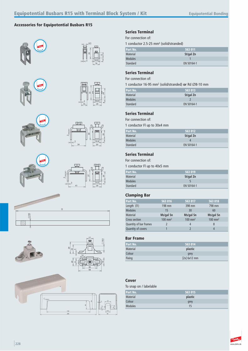
www.dehn.de228
16
10.5
3
26
12
2
6.5
Accessories for Equipotential Busbars R15
Equipotential BondingEquipotential Busbars R15 with Terminal Block System / Kit
Series Terminal For connection of:
1 conductor 2.5-25 mm² (solid/stranded)
Part No. 563 011Material St/gal ZnModules 1 Standard EN 50164-1
t e s t e d
2
14
35
20
10.54
24
Series Terminal For connection of:
1 conductor 16-95 mm2 (solid/stranded) or Rd Ø8-10 mm
Part No. 563 013Material St/gal ZnModules 2 Standard EN 50164-1
t e s t e d
3
34
2 30
10.4
20
32
0
Series Terminal For connection of:
1 conductor Fl up to 30x4 mm
Part No. 563 012Material St/gal ZnModules 4 Standard EN 50164-1
t e s t e d
3
41
2
27
20
10.5
32
0
Series Terminal For connection of:
1 conductor Fl up to 40x5 mm
Part No. 563 019Material St/gal ZnModules 5 Standard EN 50164-1
t e s t e d
l1
10
Clamping Bar Part No. 563 016 563 017 563 018Length (l1) 198 mm 398 mm 798 mmModules 15 30 60 Material Ms/gal Sn Ms/gal Sn Ms/gal SnCross section 100 mm2 100 mm2 100 mm2
Quantity of bar frames 2 4 8 Quantity of covers 1 2 4
3222
9
17
10
.5
58
620
36
10
12
Bar Frame Part No. 563 014Material plasticColour grey Fixing [2x] 6x12 mm
154
200
5°
30
56
13
16.5
65
8
222
Cover To snap on / labelable
Part No. 563 015Material plasticColour grey Modules 15
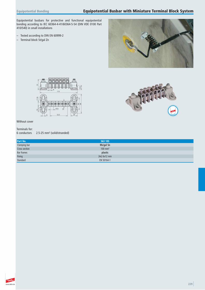
www.dehn.de 229
Equipotential busbars for protective and functional equipotential bonding according to IEC 60364-4-41/60364-5-54 (DIN VDE 0100 Part410/540) in small installations
– Tested according to DIN EN 60999-2– Terminal block St/gal Zn
Equipotential Bonding Equipotential Busbar with Miniature Terminal Block System
31
6113
13
.5
206
12
10
10.5
52.5
16
36
58
Without cover
Terminals for:6 conductors 2.5-25 mm² (solid/stranded)
Part No. 563 105Clamping bar Ms/gal SnCross section 100 mm2
Bar frames plasticFixing [4x] 6x12 mmStandard EN 50164-1
t e s t e d
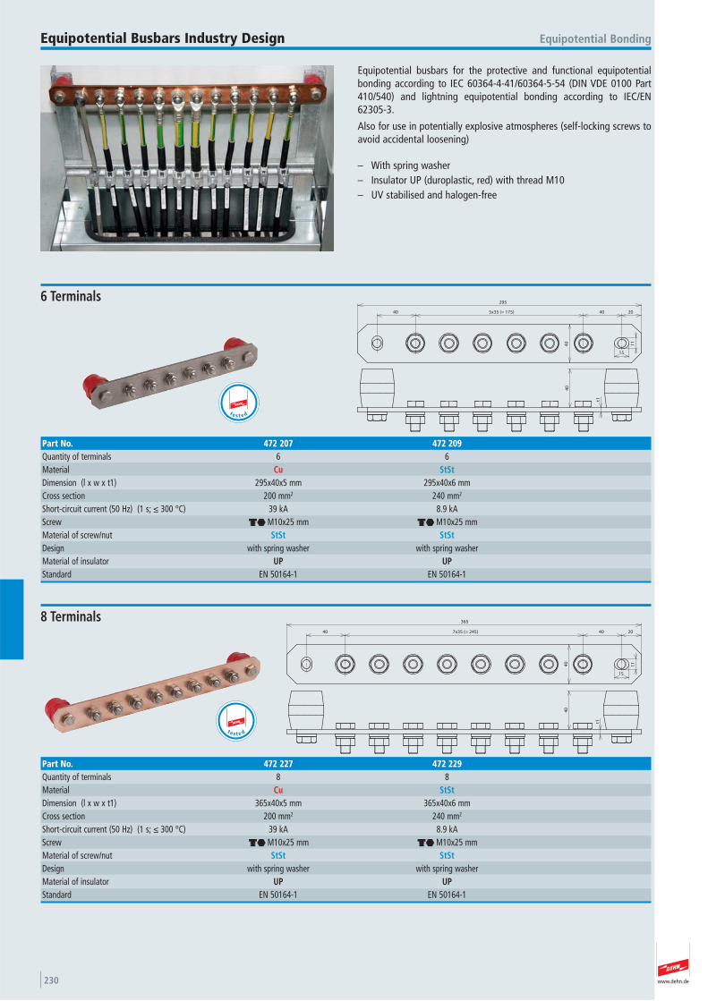
www.dehn.de230
Equipotential busbars for the protective and functional equipotentialbonding according to IEC 60364-4-41/60364-5-54 (DIN VDE 0100 Part410/540) and lightning equipotential bonding according to IEC/EN62305-3.
Also for use in potentially explosive atmospheres (self-locking screws toavoid accidental loosening)
– With spring washer– Insulator UP (duroplastic, red) with thread M10– UV stabilised and halogen-free
Equipotential BondingEquipotential Busbars Industry Design
40
295
11
15
20405x35 (= 175)40
t1
40
6 Terminals
Part No. 472 207 472 209Quantity of terminals 6 6 Material Cu StStDimension (l x w x t1) 295x40x5 mm 295x40x6 mmCross section 200 mm2 240 mm2
Short-circuit current (50 Hz) (1 s; ≤ 300 °C) 39 kA 8.9 kAScrew di M10x25 mm di M10x25 mmMaterial of screw/nut StSt StStDesign with spring washer with spring washer Material of insulator UP UPStandard EN 50164-1 EN 50164-1
t e s t e d
7x35 (= 245)
365
204040
40
t1
40
11
15
8 Terminals
Part No. 472 227 472 229Quantity of terminals 8 8 Material Cu StStDimension (l x w x t1) 365x40x5 mm 365x40x6 mmCross section 200 mm2 240 mm2
Short-circuit current (50 Hz) (1 s; ≤ 300 °C) 39 kA 8.9 kAScrew di M10x25 mm di M10x25 mmMaterial of screw/nut StSt StStDesign with spring washer with spring washer Material of insulator UP UPStandard EN 50164-1 EN 50164-1
t e s t e d
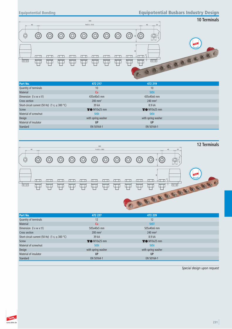
www.dehn.de 231
Special design upon request
435
204040 9x35 (= 315)
40 11
15
t1
40
Equipotential Bonding Equipotential Busbars Industry Design
10 Terminals
Part No. 472 217 472 219Quantity of terminals 10 10 Material Cu StStDimension (l x w x t1) 435x40x5 mm 435x40x6 mmCross section 200 mm2 240 mm2
Short-circuit current (50 Hz) (1 s; ≤ 300 °C) 39 kA 8.9 kAScrew di M10x25 mm di M10x25 mmMaterial of screw/nut StSt StStDesign with spring washer with spring washer Material of insulator UP UPStandard EN 50164-1 EN 50164-1
40 11x35 (= 385)
505
2040
40
11
15
t1
40
12 Terminals
Part No. 472 237 472 239Quantity of terminals 12 12 Material Cu StSTDimension (l x w x t1) 505x40x5 mm 505x40x6 mmCross section 200 mm2 240 mm2
Short-circuit current (50 Hz) (1 s; ≤ 300 °C) 39 kA 8.9 kAScrew di M10x25 mm di M10x25 mmMaterial of screw/nut StSt StStDesign with spring washer with spring washer Material of insulator UP UPStandard EN 50164-1 EN 50164-1
t e s t e d
te s t e d
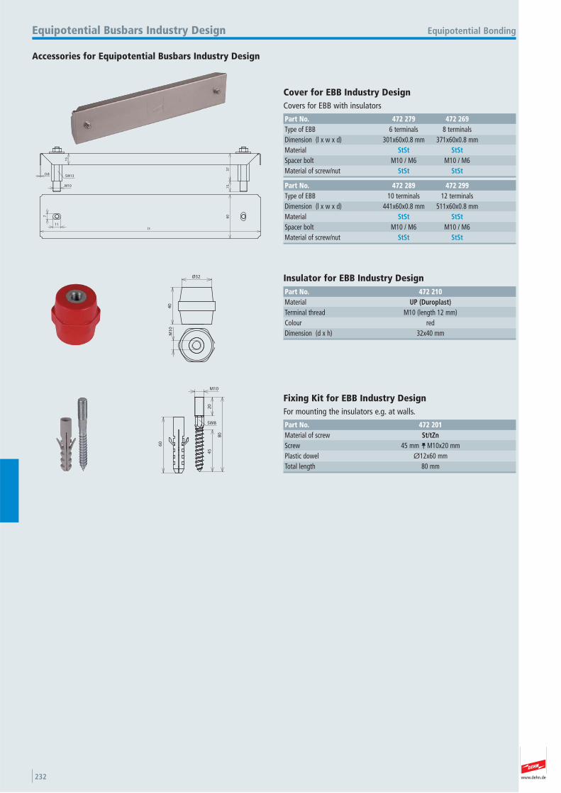
www.dehn.de232
40
Ø32
M1
0
Accessories for Equipotential Busbars Industry Design
Equipotential BondingEquipotential Busbars Industry Design
Insulator for EBB Industry Design Part No. 472 210Material UP (Duroplast)Terminal thread M10 (length 12 mm) Colour red Dimension (d x h) 32x40 mm
0.8
15
37
15M10
11
7
l16
0
SW13
Part No. 472 289 472 299Type of EBB 10 terminals 12 terminals Dimension (l x w x d) 441x60x0.8 mm 511x60x0.8 mmMaterial StSt StStSpacer bolt M10 / M6 M10 / M6 Material of screw/nut StSt StSt
Cover for EBB Industry Design Covers for EBB with insulators
Part No. 472 279 472 269Type of EBB 6 terminals 8 terminals Dimension (l x w x d) 301x60x0.8 mm 371x60x0.8 mmMaterial StSt StStSpacer bolt M10 / M6 M10 / M6 Material of screw/nut StSt StSt
60
M10
20
80
45
SW8
Fixing Kit for EBB Industry Design For mounting the insulators e.g. at walls.
Part No. 472 201Material of screw St/tZnScrew 45 mm c M10x20 mmPlastic dowel Ø12x60 mmTotal length 80 mm
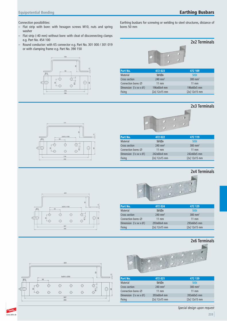
www.dehn.de 233
Connection possibilities:– Flat strip with bore: with hexagon screws M10, nuts and spring
washer– Flat strip (-40 mm) without bore: with cleat of disconnecting clamps
e.g. Part No. 454 100– Round conductor: with KS connector e.g. Part No. 301 000 / 301 019
or with clamping frame e.g. Part No. 390 150
Earthing busbars for screwing or welding to steel structures, distance ofbores 50 mm
Equipotential Bonding Earthing Busbars
Special design upon request
126
50
t1
50
30
6012
Ø15
170
196
Ø1
1
2x2 Terminals
Part No. 472 023 472 109Material St/tZn StStCross section 240 mm2 300 mm2
Connection bores Ø 11 mm 11 mmDimension (l x w x d1) 196x60x4 mm 196x60x5 mmFixing [2x] 12x15 mm [2x] 12x15 mm
171
50
t1
50
2x50 (=100)
216
242
6012
Ø15
30 11
Ø
2x3 Terminals
Part No. 472 022 472 119Material St/tZn StStCross section 240 mm2 300 mm2
Connection bores Ø 11 mm 11 mmDimension (l x w x d1) 242x60x4 mm 242x60x5 mmFixing [2x] 12x15 mm [2x] 12x15 mm
224
50
t1
50
3x50 (=150)
30
293
267
12
Ø15
6011
Ø
2x4 Terminals
Part No. 472 024 472 129Material St/tZn StStCross section 240 mm2 300 mm2
Connection bores Ø 11 mm 11 mmDimension (l x w x d1) 293x60x4 mm 293x60x5 mmFixing [2x] 12x15 mm [2x] 12x15 mm
323
50
t1
5x50 (=250)
50
30
367
393
60
Ø1
1
Ø15
12
2x6 Terminals
Part No. 472 021 472 139Material St/tZn StStCross section 240 mm2 300 mm2
Connection bores Ø 11 mm 11 mmDimension (l x w x d1) 393x60x4 mm 393x60x5 mmFixing [2x] 12x15 mm [2x] 12x15 mm
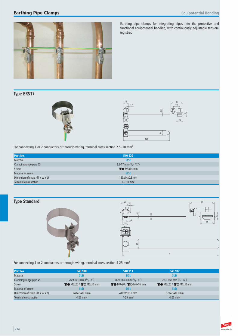
www.dehn.de234
Earthing pipe clamps for integrating pipes into the protective and functional equipotential bonding, with continuously adjustable tension-ing strap
Equipotential BondingEarthing Pipe Clamps
15
21
37
19
0.3
13
9
1.5
15
135
14
For connecting 1 or 2 conductors or through-wiring, terminal cross section 2.5–10 mm2
Type BRS17
Part No. 540 920Material StStClamping range pipe Ø 9.5-17 mm (1/8 - 3/8'') Screw dm M5x14 mmMaterial of screw StStDimension of strap (l1 x w x d) 135x14x0.3 mmTerminal cross-section 2.5-10 mm2
25
l1
2
16
0.3
2
26 61
19
35
For connecting 1 or 2 conductors or through-wiring, terminal cross-section 4-25 mm2
Type Standard
Part No. 540 910 540 911 540 912Material StSt StSt StStClamping range pipe Ø 26.9-60.3 mm (3/4 - 2'') 26.9-114.3 mm (3/4 - 4'') 26.9-165 mm (3/4 - 6'') Screw di M8x20 / dm M6x16 mm di M8x20 / dm M6x16 mm di M8x20 / dm M6x16 mmMaterial of screw StSt StSt StStDimension of strap (l1 x w x d) 240x25x0.3 mm 410x25x0.3 mm 570x25x0.3 mmTerminal cross-section 4-25 mm2 4-25 mm2 4-25 mm2
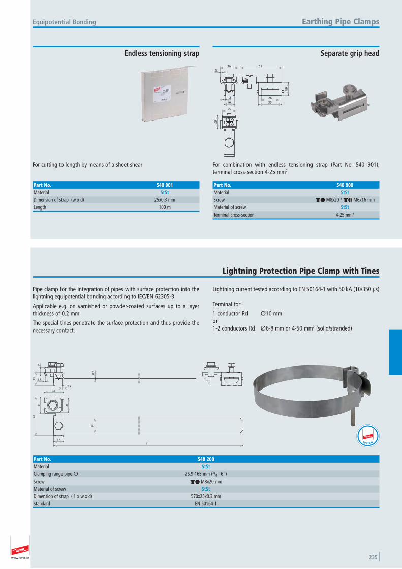
www.dehn.de 235
2
26
2
16
61
19
26
35
20
20
For combination with endless tensioning strap (Part No. 540 901), terminal cross-section 4-25 mm2
Equipotential Bonding Earthing Pipe Clamps
Separate grip head
Part No. 540 900Material StStScrew di M8x20 / dm M6x16 mmMaterial of screw StStTerminal cross-section 4-25 mm2
For cutting to length by means of a sheet shear
Endless tensioning strap
Part No. 540 901Material StStDimension of strap (w x d) 25x0.3 mmLength 100 m
Pipe clamp for the integration of pipes with surface protection into thelightning equipotential bonding according to IEC/EN 62305-3
Applicable e.g. on varnished or powder-coated surfaces up to a layerthickness of 0.2 mm
The special tines penetrate the surface protection and thus provide thenecessary contact.
Lightning current tested according to EN 50164-1 with 50 kA (10/350 μs)
Terminal for:
1 conductor Rd Ø10 mm or 1-2 conductors Rd Ø6-8 mm or 4-50 mm2 (solid/stranded)
Lightning Protection Pipe Clamp with Tines
2.5
2.5
34
23
15
0.3
17
l1
25
30
25
68
Part No. 540 200Material StStClamping range pipe Ø 26.9-165 mm (3/4 - 6'') Screw di M8x20 mmMaterial of screw StStDimension of strap (l1 x w x d) 570x25x0.3 mmStandard EN 50164-1
t e s t e d
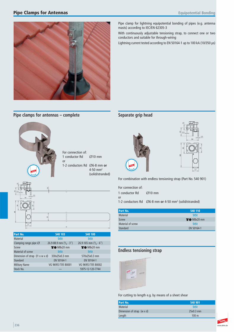
www.dehn.de236
Pipe clamp for lightning equipotential bonding of pipes (e.g. antennamasts) according to IEC/EN 62305-3
With continuously adjustable tensioning strap, to connect one or twoconductors and suitable for through-wiring
Lightning current tested according to EN 50164-1 up to 100 kA (10/350 μs)
Equipotential BondingPipe Clamps for Antennas
2.5
2.5
34
23
15
0.3
17
l1
25
30
25
68
For connection of: 1 conductor Rd Ø10 mm or 1-2 conductors Rd Ø6-8 mm or
4-50 mm2
(solid/stranded)
Pipe clamps for antennas – complete
Part No. 540 103 540 100Material StSt StStClamping range pipe Ø 26.9-88.9 mm (3/4 - 3'') 26.9-165 mm (3/4 - 6'') Screw di M8x20 mm di M8x20 mmMaterial of screw StSt StStDimension of strap (l1 x w x d) 330x25x0.3 mm 570x25x0.3 mmStandard EN 50164-1 EN 50164-1 Military Name VG 96953 T05 B0001 VG 96953 T05 B0002Stock No. — 5975-12-120-7744
t e s t e d
2.5
2.5
34
23
15
17
30
25
68
For combination with endless tensioning strap (Part No. 540 901)
For connection of:
1 conductor Rd Ø10 mm or 1-2 conductors Rd Ø6-8 mm or 4-50 mm2 (solid/stranded)
Separate grip head
Part No. 540 110Material StStScrew di M8x20 mmMaterial of screw StStStandard EN 50164-1
t e s t e d
For cutting to length e.g. by means of a sheet shear
Endless tensioning strap
Part No. 540 901Material StStDimension of strap (w x d) 25x0.3 mmLength 100 m
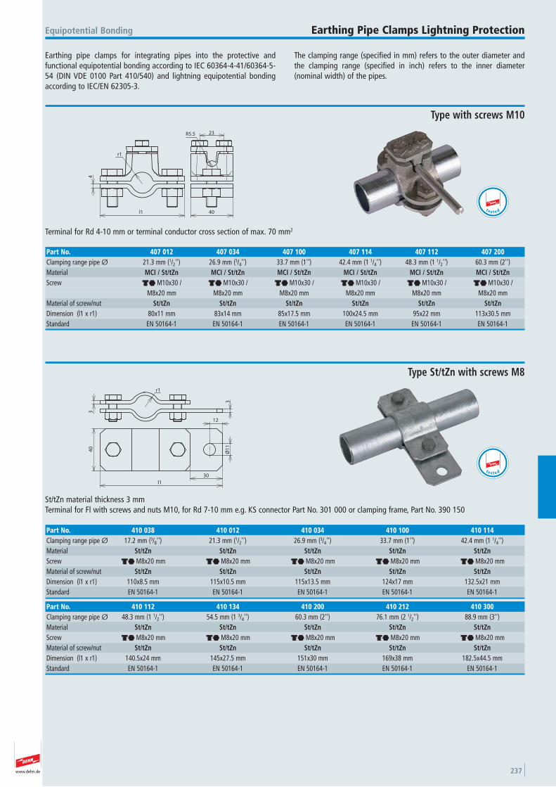
www.dehn.de 237
Earthing pipe clamps for integrating pipes into the protective and functional equipotential bonding according to IEC 60364-4-41/60364-5-54 (DIN VDE 0100 Part 410/540) and lightning equipotential bondingaccording to IEC/EN 62305-3.
The clamping range (specified in mm) refers to the outer diameter andthe clamping range (specified in inch) refers to the inner diameter (nominal width) of the pipes.
Equipotential Bonding Earthing Pipe Clamps Lightning Protection
r1
4
l1 40
R5.5 23
Terminal for Rd 4-10 mm or terminal conductor cross section of max. 70 mm2
Type with screws M10
Part No. 407 012 407 034 407 100 407 114 407 112 407 200Clamping range pipe Ø 21.3 mm (1/2'') 26.9 mm (3/4'') 33.7 mm (1'') 42.4 mm (1 1/4'') 48.3 mm (1 1/2'') 60.3 mm (2'') Material MCI / St/tZn MCI / St/tZn MCI / St/tZn MCI / St/tZn MCI / St/tZn MCI / St/tZnScrew di M10x30 / di M10x30 / di M10x30 / di M10x30 / di M10x30 / di M10x30 / M8x20 mm M8x20 mm M8x20 mm M8x20 mm M8x20 mm M8x20 mmMaterial of screw/nut St/tZn St/tZn St/tZn St/tZn St/tZn St/tZnDimension (l1 x r1) 80x11 mm 83x14 mm 85x17.5 mm 100x24.5 mm 95x22 mm 113x30.5 mmStandard EN 50164-1 EN 50164-1 EN 50164-1 EN 50164-1 EN 50164-1 EN 50164-1
t e s t e d
r1
3
3
12
Ø1
1
30
l1
40
St/tZn material thickness 3 mmTerminal for Fl with screws and nuts M10, for Rd 7-10 mm e.g. KS connector Part No. 301 000 or clamping frame, Part No. 390 150
Type St/tZn with screws M8
Part No. 410 112 410 134 410 200 410 212 410 300Clamping range pipe Ø 48.3 mm (1 1/2'') 54.5 mm (1 3/4'') 60.3 mm (2'') 76.1 mm (2 1/2'') 88.9 mm (3'') Material St/tZn St/tZn St/tZn St/tZn St/tZnScrew di M8x20 mm di M8x20 mm di M8x20 mm di M8x20 mm di M8x20 mmMaterial of screw/nut St/tZn St/tZn St/tZn St/tZn St/tZnDimension (l1 x r1) 140.5x24 mm 145x27.5 mm 151x30 mm 169x38 mm 182.5x44.5 mmStandard EN 50164-1 EN 50164-1 EN 50164-1 EN 50164-1 EN 50164-1
Part No. 410 038 410 012 410 034 410 100 410 114Clamping range pipe Ø 17.2 mm (3/8'') 21.3 mm (1/2'') 26.9 mm (3/4'') 33.7 mm (1'') 42.4 mm (1 1/4'') Material St/tZn St/tZn St/tZn St/tZn St/tZnScrew di M8x20 mm di M8x20 mm di M8x20 mm di M8x20 mm di M8x20 mmMaterial of screw/nut St/tZn St/tZn St/tZn St/tZn St/tZnDimension (l1 x r1) 110x8.5 mm 115x10.5 mm 115x13.5 mm 124x17 mm 132.5x21 mmStandard EN 50164-1 EN 50164-1 EN 50164-1 EN 50164-1 EN 50164-1
t e s t e d
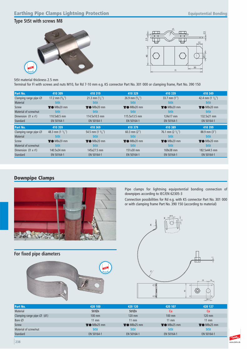
www.dehn.de238
2.5
2.5
r1
12
30l1
Ø1
1
40
StSt material thickness 2.5 mmTerminal for Fl with screws and nuts M10, for Rd 7-10 mm e.g. KS connector Part No. 301 000 or clamping frame, Part No. 390 150
Equipotential BondingEarthing Pipe Clamps Lightning Protection
Type StSt with screws M8
Part No. 410 359 410 369 410 379 410 389 410 399Clamping range pipe Ø 48.3 mm (1 1/2'') 54.5 mm (1 3/4'') 60.3 mm (2'') 76.1 mm (2 1/2'') 88.9 mm (3'') Material StSt StSt StSt StSt StStScrew di M8x20 mm di M8x20 mm di M8x20 mm di M8x20 mm di M8x20 mmMaterial of screw/nut StSt StSt StSt StSt StStDimension (l1 x r1) 140.5x24 mm 145x27.5 mm 151x30 mm 169x38 mm 182.5x44.5 mmStandard EN 50164-1 EN 50164-1 EN 50164-1 EN 50164-1 EN 50164-1
Part No. 410 309 410 319 410 329 410 339 410 349Clamping range pipe Ø 17.2 mm (3/8'') 21.3 mm (1/2'') 26.9 mm (3/4'') 33.7 mm (1'') 42.4 mm (1 1/4'') Material StSt StSt StSt StSt StStScrew di M8x20 mm di M8x20 mm di M8x20 mm di M8x20 mm di M8x20 mmMaterial of screw/nut StSt StSt StSt StSt StStDimension (l1 x r1) 110.5x8.5 mm 114.5x10.5 mm 115.5x13.5 mm 124x17 mm 132.5x21 mmStandard EN 50164-1 EN 50164-1 EN 50164-1 EN 50164-1 EN 50164-1
t e s t e d
Pipe clamps for lightning equipotential bonding connection of downpipes according to IEC/EN 62305-3
Connection possibilities for Rd e.g. with KS connector Part No. 301 000or with clamping frame Part No. 390 150 (according to material)
Downpipe Clamps
d1
1
11
Ø10
1629
40
Ø11
X
X
For fixed pipe diameters
Part No. 420 100 420 120 420 107 420 127Material St/tZn St/tZn Cu CuClamping range pipe Ø (d1) 100 mm 120 mm 100 mm 120 mmBore Ø 11 mm 11 mm 11 mm 11 mmScrew di M8x25 mm di M8x25 mm di M8x25 mm di M8x25 mmMaterial of screw/nut StSt StSt StSt StStStandard EN 50164-1 EN 50164-1 EN 50164-1 EN 50164-1
t e s t e d
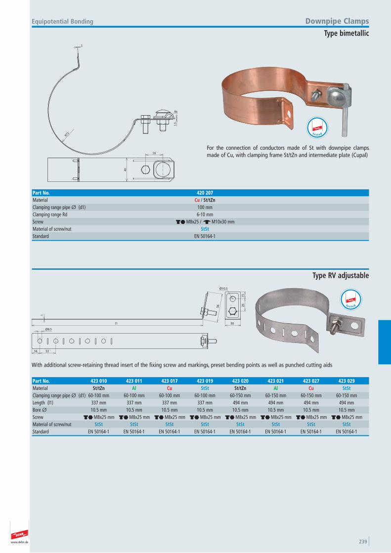
www.dehn.de 239
R73
1
1.5
R5
40
29
For the connection of conductors made of St with downpipe clampsmade of Cu, with clamping frame St/tZn and intermediate plate (Cupal)
Equipotential Bonding Downpipe Clamps
Type bimetallic
Part No. 420 207Material Cu / St/tZnClamping range pipe Ø (d1) 100 mmClamping range Rd 6-10 mmScrew di M8x25 / e M10x30 mmMaterial of screw/nut StStStandard EN 50164-1
t e s t e d
1
l1
56
15
25
30
Ø10.5
Ø8.5
16 32
With additional screw-retaining thread insert of the fixing screw and markings, preset bending points as well as punched cutting aids
Type RV adjustable
Part No. 423 010 423 011 423 017 423 019 423 020 423 021 423 027 423 029Material St/tZn Al Cu StSt St/tZn Al Cu StStClamping range pipe Ø (d1) 60-100 mm 60-100 mm 60-100 mm 60-100 mm 60-150 mm 60-150 mm 60-150 mm 60-150 mmLength (l1) 337 mm 337 mm 337 mm 337 mm 494 mm 494 mm 494 mm 494 mmBore Ø 10.5 mm 10.5 mm 10.5 mm 10.5 mm 10.5 mm 10.5 mm 10.5 mm 10.5 mmScrew di M8x25 mm di M8x25 mm di M8x25 mm di M8x25 mm di M8x25 mm di M8x25 mm di M8x25 mm di M8x25 mmMaterial of screw/nut StSt StSt StSt StSt StSt StSt StSt StStStandard EN 50164-1 EN 50164-1 EN 50164-1 EN 50164-1 EN 50164-1 EN 50164-1 EN 50164-1 EN 50164-1
t e s t e d
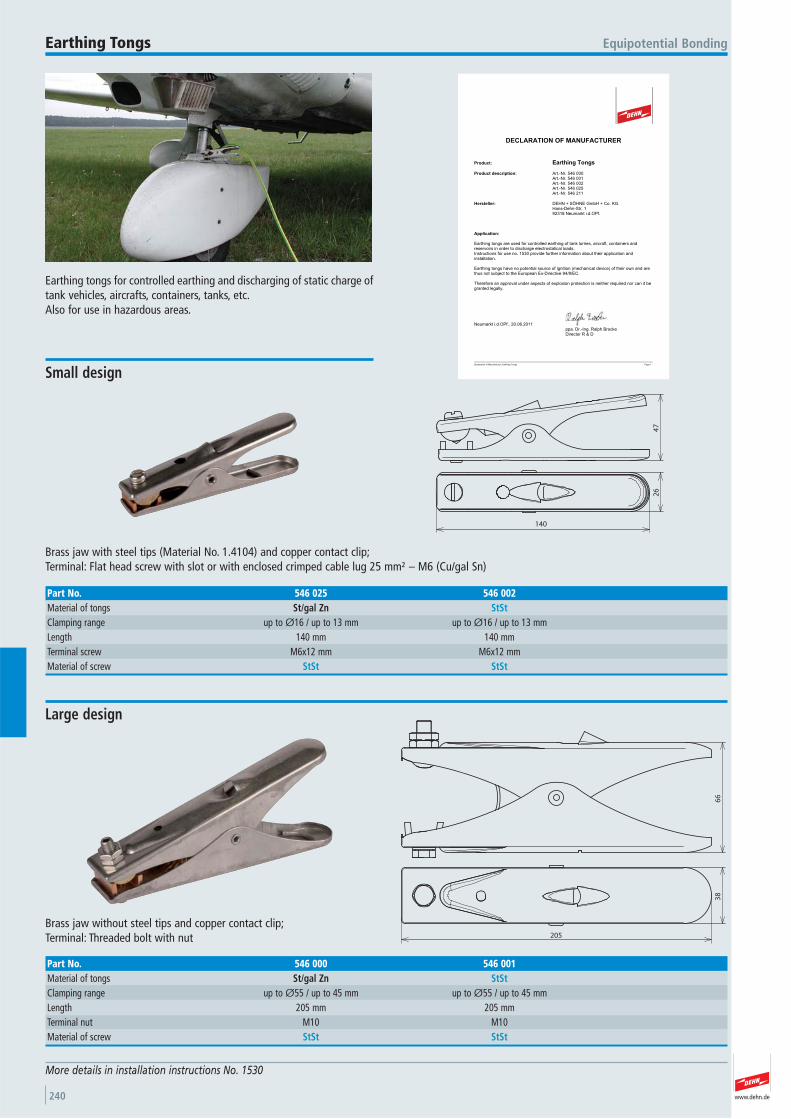
www.dehn.de240
More details in installation instructions No. 1530
Equipotential BondingEarthing Tongs
47
26
140
Brass jaw with steel tips (Material No. 1.4104) and copper contact clip; Terminal: Flat head screw with slot or with enclosed crimped cable lug 25 mm² – M6 (Cu/gal Sn)
Small design
Part No. 546 025 546 002Material of tongs St/gal Zn StStClamping range up to Ø16 / up to 13 mm up to Ø16 / up to 13 mmLength 140 mm 140 mmTerminal screw M6x12 mm M6x12 mmMaterial of screw StSt StSt
Earthing tongs for controlled earthing and discharging of static charge oftank vehicles, aircrafts, containers, tanks, etc.Also for use in hazardous areas.
Declaration of Manufacturer_Earthing Tongs Page 1
DECLARATION OF MANUFACTURER
Product: Earthing Tongs
Product description: Art.-Nr. 546 000Art.-Nr. 546 001Art.-Nr. 546 002Art.-Nr. 546 025Art.-Nr. 546 211
Hersteller: DEHN + SÖHNE GmbH + Co. KG.Hans-Dehn-Str. 192318 Neumarkt i.d.OPf.
Application:
Earthing tongs are used for controlled earthing of tank lorries, aircraft, containers andreservoirs in order to discharge electrostatical loads.Instructions for use no. 1530 provide further information about their application andinstallation.
Earthing tongs have no potential source of ignition (mechanical device) of their own and are thus not subject to the European Ex-Directive 94/9/EC.
Therefore an approval under aspects of explosion protection is neither required nor can it be granted legally.
Neumarkt i.d.OPf., 20.06.2011ppa. Dr.-Ing. Ralph BrockeDirector R & D
205
66
38
Brass jaw without steel tips and copper contact clip; Terminal: Threaded bolt with nut
Large design
Part No. 546 000 546 001Material of tongs St/gal Zn StStClamping range up to Ø55 / up to 45 mm up to Ø55 / up to 45 mmLength 205 mm 205 mmTerminal nut M10 M10 Material of screw StSt StSt
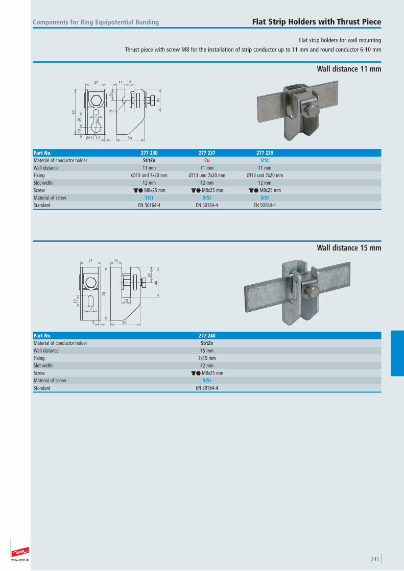
www.dehn.de 241
Flat strip holders for wall mounting
Thrust piece with screw M8 for the installation of strip conductor up to 11 mm and round conductor 6-10 mm
Components for Ring Equipotential Bonding Flat Strip Holders with Thrust Piece
Ø13 2.5
10
20
7
60
27
R5.51
5
11 12
30
36
Wall distance 11 mm
Part No. 277 230 277 237 277 239Material of conductor holder St/tZn Cu StStWall distance 11 mm 11 mm 11 mmFixing Ø13 und 7x20 mm Ø13 und 7x20 mm Ø13 und 7x20 mmSlot width 12 mm 12 mm 12 mmScrew di M8x25 mm di M8x25 mm di M8x25 mmMaterial of screw StSt StSt StStStandard EN 50164-4 EN 50164-4 EN 50164-4
3
7
15
27
70
15
12
20
40
40
Wall distance 15 mm
Part No. 277 240Material of conductor holder St/tZnWall distance 15 mmFixing 7x15 mmSlot width 12 mmScrew di M8x25 mmMaterial of screw StStStandard EN 50164-4
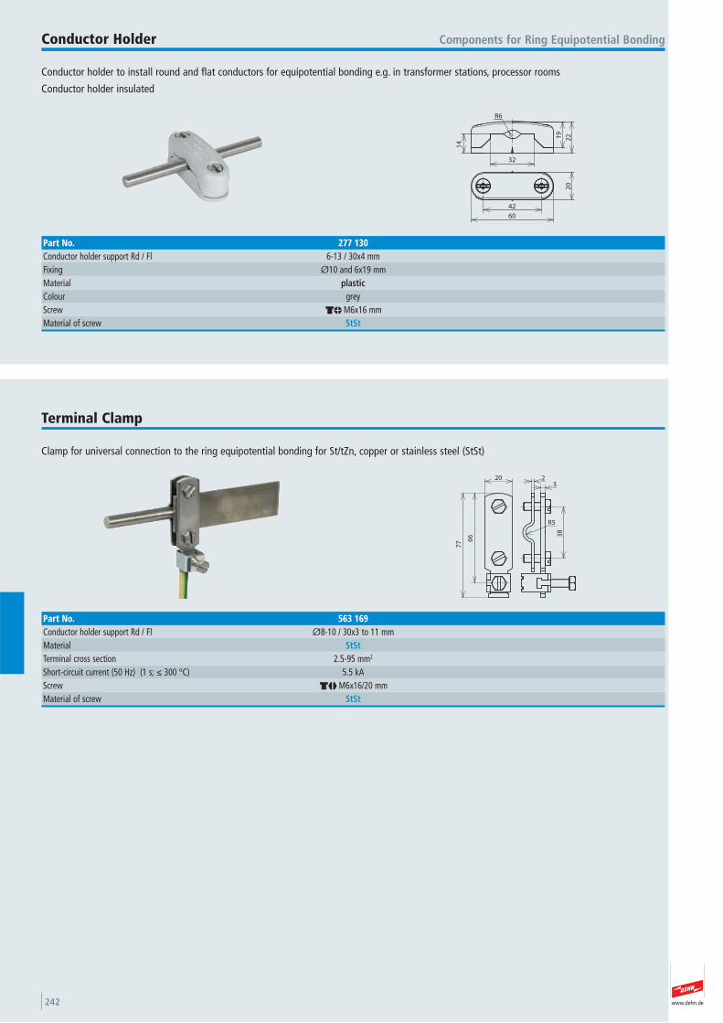
www.dehn.de242
Conductor holder to install round and flat conductors for equipotential bonding e.g. in transformer stations, processor rooms
Conductor holder insulated
Components for Ring Equipotential BondingConductor Holder
20
60
42
R6
14
32
19
22
Part No. 277 130Conductor holder support Rd / Fl 6-13 / 30x4 mmFixing Ø10 and 6x19 mmMaterial plasticColour grey Screw dm M6x16 mmMaterial of screw StSt
Clamp for universal connection to the ring equipotential bonding for St/tZn, copper or stainless steel (StSt)
Terminal Clamp
20
77
38
66
R5
23
Part No. 563 169Conductor holder support Rd / Fl Ø8-10 / 30x3 to 11 mmMaterial StStTerminal cross section 2.5-95 mm2
Short-circuit current (50 Hz) (1 s; ≤ 300 °C) 5.5 kAScrew dj M6x16/20 mmMaterial of screw StSt
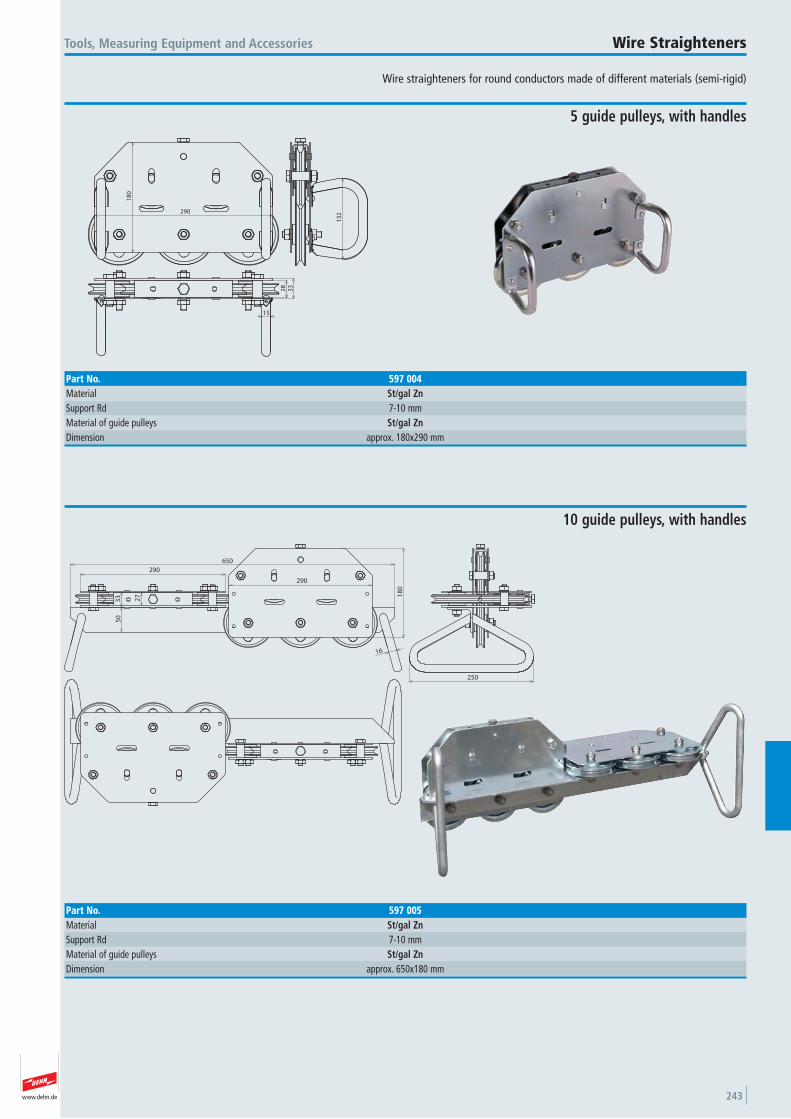
www.dehn.de 243
Wire straighteners for round conductors made of different materials (semi-rigid)
Tools, Measuring Equipment and Accessories Wire Straighteners
290
18
0
13
2
15
28
33
5 guide pulleys, with handles
Part No. 597 004Material St/gal ZnSupport Rd 7-10 mmMaterial of guide pulleys St/gal ZnDimension approx. 180x290 mm
290
290
650
18
0
27
33
50
16
250
10 guide pulleys, with handles
Part No. 597 005Material St/gal ZnSupport Rd 7-10 mmMaterial of guide pulleys St/gal ZnDimension approx. 650x180 mm
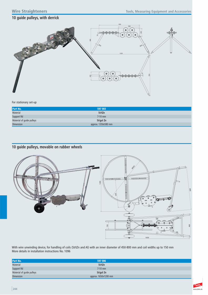
www.dehn.de244
Ø34
58
0
10
950
500
20
0
Ø34
1350
95
0
20
0
10
For stationary set-up
Tools, Measuring Equipment and AccessoriesWire Straighteners
10 guide pulleys, with derrick
Part No. 597 003Material St/tZnSupport Rd 7-10 mmMaterial of guide pulleys St/gal ZnDimension approx. 1350x580 mm
55
0
Ø200
Ø92
0
84
0
12
00
1650
15
0
46
0
With wire unwinding device, for handling of coils (St/tZn and Al) with an inner diameter of 450-800 mm and coil widths up to 150 mmMore details in installation instructions No. 1096
10 guide pulleys, movable on rubber wheels
Part No. 597 006Material St/tZnSupport Rd 7-10 mmMaterial of guide pulleys St/gal ZnDimension approx. 1650x1200 mm
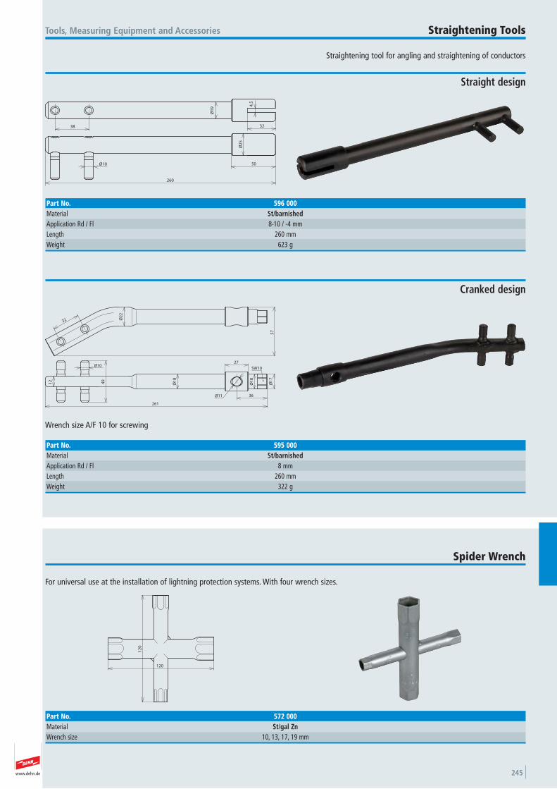
www.dehn.de 245
Straightening tool for angling and straightening of conductors
Tools, Measuring Equipment and Accessories Straightening Tools
Ø1
9 4.5
32
260
Ø10 50
Ø2
5
38
Straight design
Part No. 596 000Material St/barnishedApplication Rd / Fl 8-10 / -4 mmLength 260 mmWeight 623 g
57
32
Ø10
12 49
Ø1
8
Ø11 36
261
27
Ø1
8
Ø1
7
Ø2
2
SW10
Wrench size A/F 10 for screwing
Cranked design
Part No. 595 000Material St/barnishedApplication Rd / Fl 8 mmLength 260 mmWeight 322 g
For universal use at the installation of lightning protection systems. With four wrench sizes.
Spider Wrench
120
12
0
Part No. 572 000Material St/gal ZnWrench size 10, 13, 17, 19 mm
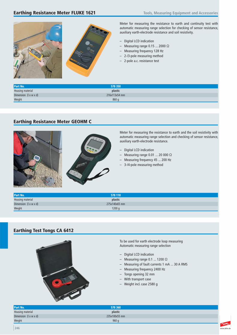
www.dehn.de246
Meter for measuring the resistance to earth and continuity test withautomatic measuring range selection for checking of sensor resistance,auxiliary earth-electrode resistance and soil resistivity.
– Digital LCD indication– Measuring range 0.15 ... 2000 Ω– Measuring frequency 128 Hz– 2-/3-pole measuring method– 2-pole a.c. resistance test
Tools, Measuring Equipment and AccessoriesEarthing Resistance Meter FLUKE 1621
Part No. 578 350Housing material plasticDimension (l x w x d) 216x113x54 mmWeight 860 g
Meter for measuring the resistance to earth and the soil resistivity withautomatic measuring range selection and checking of sensor resistance,auxiliary earth-electrode resistance.
– Digital LCD indication– Measuring range 0.01 ... 20 000 Ω– Measuring frequency 45 ... 200 Hz– 3-/4-pole measuring method
Earthing Resistance Meter GEOHM C
Part No. 578 110Housing material plasticDimension (l x w x d) 275x140x65 mmWeight 1200 g
To be used for earth electrode loop measuring Automatic measuring range selection
– Digital LCD indication– Measuring range 0.1 ... 1200 Ω– Measuring of fault currents 1 mA ... 30 A RMS– Measuring frequency 2400 Hz– Tongs opening 32 mm– With transport case– Weight incl. case 2580 g
Earthing Test Tongs CA 6412
Part No. 578 360Housing material plasticDimension (l x w x d) 235x100x55 mmWeight 960 g
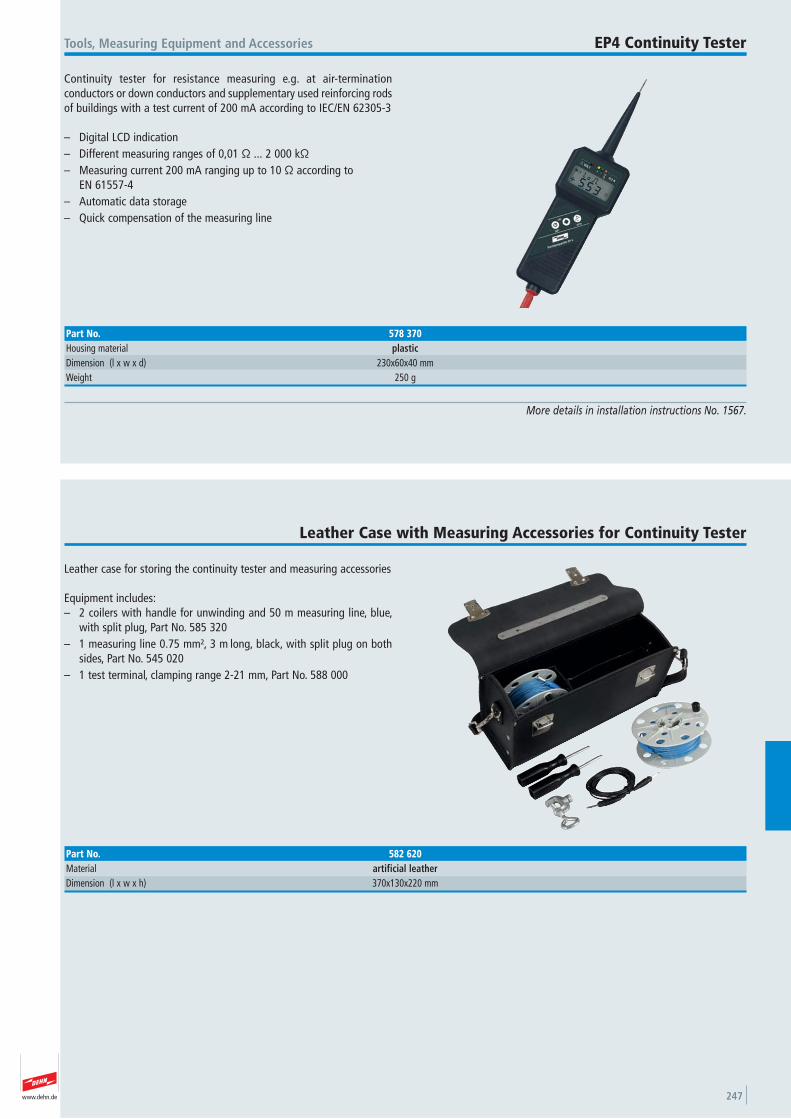
www.dehn.de 247
Continuity tester for resistance measuring e.g. at air-termination conductors or down conductors and supplementary used reinforcing rodsof buildings with a test current of 200 mA according to IEC/EN 62305-3
– Digital LCD indication– Different measuring ranges of 0,01 Ω ... 2 000 kΩ– Measuring current 200 mA ranging up to 10 Ω according to
EN 61557-4– Automatic data storage – Quick compensation of the measuring line
Tools, Measuring Equipment and Accessories EP4 Continuity Tester
More details in installation instructions No. 1567.
Part No. 578 370Housing material plasticDimension (l x w x d) 230x60x40 mmWeight 250 g
Leather case for storing the continuity tester and measuring accessories
Equipment includes:– 2 coilers with handle for unwinding and 50 m measuring line, blue,
with split plug, Part No. 585 320– 1 measuring line 0.75 mm², 3 m long, black, with split plug on both
sides, Part No. 545 020– 1 test terminal, clamping range 2-21 mm, Part No. 588 000
Leather Case with Measuring Accessories for Continuity Tester
Part No. 582 620Material artificial leatherDimension (l x w x h) 370x130x220 mm
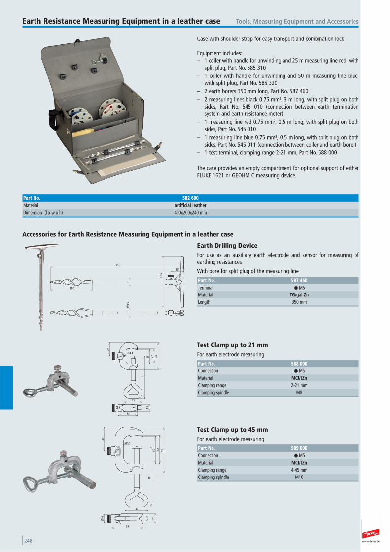
www.dehn.de248
Case with shoulder strap for easy transport and combination lock
Equipment includes:– 1 coiler with handle for unwinding and 25 m measuring line red, with
split plug, Part No. 585 310– 1 coiler with handle for unwinding and 50 m measuring line blue,
with split plug, Part No. 585 320– 2 earth borers 350 mm long, Part No. 587 460– 2 measuring lines black 0.75 mm², 3 m long, with split plug on both
sides, Part No. 545 010 (connection between earth termination system and earth resistance meter)
– 1 measuring line red 0.75 mm², 0.5 m long, with split plug on bothsides, Part No. 545 010
– 1 measuring line blue 0.75 mm², 0.5 m long, with split plug on bothsides, Part No. 545 011 (connection between coiler and earth borer)
– 1 test terminal, clamping range 2-21 mm, Part No. 588 000
The case provides an empty compartment for optional support of eitherFLUKE 1621 or GEOHM C measuring device.
Tools, Measuring Equipment and AccessoriesEarth Resistance Measuring Equipment in a leather case
Part No. 582 600Material artificial leatherDimension (l x w x h) 400x200x240 mm
35
350
11
13
5
Ø1
5
110
Accessories for Earth Resistance Measuring Equipment in a leather case
Earth Drilling Device For use as an auxiliary earth electrode and sensor for measuring of earthing resistances
With bore for split plug of the measuring line
Part No. 587 460Terminal f M5 Material TG/gal ZnLength 350 mm
24
75
27
25 49
33
Ø4.4
35
13
Test Clamp up to 21 mm For earth electrode measuring
Part No. 588 000Connection f M5 Material MCI/tZnClamping range 2-21 mmClamping spindle M8
44
Ø4.4
11
1
50 52
85
42
20
58
Ø1
6
Test Clamp up to 45 mm For earth electrode measuring
Part No. 589 000Connection f M5 Material MCI/tZnClamping range 4-45 mmClamping spindle M10
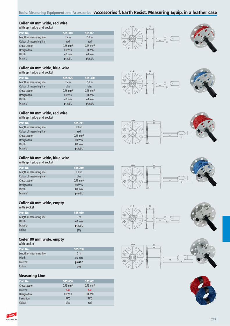
www.dehn.de 249
40
55
55155
Ø140
3
Tools, Measuring Equipment and Accessories Accessories f. Earth Resist. Measuring Equip. in a leather case
Coiler 40 mm wide, red wire With split plug and socket
Part No. 585 310 585 051Length of measuring line 25 m 50 mColour of measuring line red red Cross section 0.75 mm2 0.75 mm2
Designaiton H05V-K H05V-K Width 40 mm 40 mmMaterial plastic plastic
40
55
55155
Ø140
3
Coiler 40 mm wide, blue wire With split plug and socket
Part No. 585 025 585 320Length of measuring line 25 m 50 mColour of measuring line blue blue Cross section 0.75 mm2 0.75 mm2
Designaiton H05V-K H05V-K Width 40 mm 40 mmMaterial plastic plastic
80
95
95195
3
Ø140
Coiler 80 mm wide, red wire With split plug and socket
Part No. 585 211Length of measuring line 100 mColour of measuring line red Cross section 0.75 mm2
Designaiton H05V-K Width 80 mmMaterial plastic
80
95
95195
3
Ø140
Coiler 80 mm wide, blue wire With split plug and socket
Part No. 585 210Length of measuring line 100 mColour of measuring line blue Cross section 0.75 mm2
Designaiton H05V-K Width 80 mmMaterial plastic
40
55
55155
Ø140
3
Coiler 40 mm wide, empty With socket
Part No. 585 010Length of measuring line 0 mWidth 40 mmMaterial plasticColour grey
80
95
95195
3
Ø140
Coiler 80 mm wide, empty With socket
Part No. 585 200Length of measuring line 0 mWidth 80 mmMaterial plasticColour grey
Measuring Line Part No. 545 000 545 001Cross section 0.75 mm2 0.75 mm2
Material Cu CuDesignaiton H05V-K H05V-K Insulation PVC PVCColour blue red
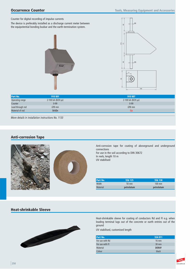
www.dehn.de250
Counter for digital recording of impulse currents
The device is preferably installed as a discharge current meter betweenthe equipotential bonding busbar and the earth-termination system.
Tools, Measuring Equipment and AccessoriesOccurrence Counter
More details in installation instructions No. 1133
48
72
46
17
5
Ø8
Ø8
17
58
100
Part No. 910 001 910 007Operating range 2-100 kA (8/20 μs) 2-100 kA (8/20 μs) Counter 0-99 0-99 Lead-through rod Ø8 mm Ø8 mmMaterial of rod St/tZn Cu
Anti-corrosion tape for coating of aboveground and underground connectionsFor use in the soil according to DIN 30672In reels, length 10 mUV stabilised
Anti-corrosion Tape
Part No. 556 125 556 130Width 50 mm 100 mmMaterial petrolatum petrolatum
Heat-shrinkable sleeve for coating of conductors Rd and Fl e.g. whenleading terminal lugs out of the concrete or earth entries out of theground
UV stabilised, customised length
Heat-shrinkable Sleeve
Part No. 554 011For use with Rd 16 mmFor use with Fl 30 mmMaterial DERAYColour black
www.dehn.de 251
Special coating paint for lightning protection components and conductors, weather resistant
The coating paint may be used without pretreatment also for weathered,hot-dip galvanized, spray-galvanized and electrogalvanized surfaces aswell as aluminium sheets.
Hazardous materials regulations allow for transportation only inGermany and Austria. Alternatively use a suitable zinc protection paint.
Tools, Measuring Equipment and Accessories Special Coating Paint
Part No. 559 010 559 011Colour grey brown Content 0.75 litres 0.75 litres
Clip for fixing at pipes by tensioning strap Part No. 540 901 (dimension25x0.3mm) combined with grip head Part No. 106 324, with square hole,suitable for screws M8
Clip
40
26x6
120°
26
61
34
9
3
Part No. 106 320Material StStClamping range pipe Ø approx. 50-300 mmSlot width 26x6 mm
+

www.dehn.de252
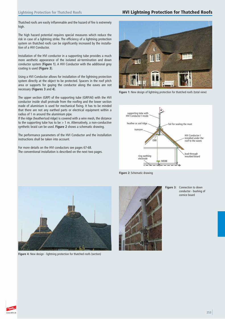
www.dehn.de 253
Thatched roofs are easily inflammable and the hazard of fire is extremelyhigh.
The high hazard potential requires special measures which reduce therisk in case of a lightning strike. The efficiency of a lightning protectionsystem on thatched roofs can be significantly increased by the installa-tion of a HVI Conductor.
Installation of the HVI conductor in a supporting tube provides a muchmore aesthetic appearance of the isolated air-termination and down conductor system (Figure 1). A HVI Conductor with the additional greycoating is used (Figure 3).
Using a HVI Conductor allows for installation of the lightning protectionsystem directly at the object to be protected. Spacers in the roof pitcharea or supports for guying the conductor along the eaves are not necessary (Figures 3 and 4).
The upper section (GRP) of the supporting tube (GRP/Al) with the HVIconductor inside shall protrude from the roofing and the lower sectionmade of aluminium is used for mechanical fixing. It has to be mindedthat there are not any earthed parts or electrical equipment within aradius of 1 m around the aluminium pipe.If the ridge (heather/sod ridge) is covered with a wire mesh, the distanceto the supporting tube has to be > 1 m. Alternatively, a non-conductivesynthetic braid can be used. Figure 2 shows a schematic drawing.
The performance parameters of the HVI Conductor and the installationinstructions shall be taken into account.
For more details on the HVI conductors see pages 67-68.The conventional installation is described on the next two pages.
Figure 1: New design of lightning protection for thatched roofs (total view)
Figure 2: Schematic drawing
supporting tube withHVI Conductor I inside
heather or sod ridge
transom
foil for sealing the mast
HVI Conductor I installed under the roof to the eaves
lead-throughmoulded board
EBB
ring earthingelectrode
MEBB
Lightning Protection for Thatched Roofs HVI Lightning Protection for Thatched Roofs
Figure 3: Connection to down conductor - bushing of cornice board
Figure 4: New design - lightning protection for thatched roofs (section)
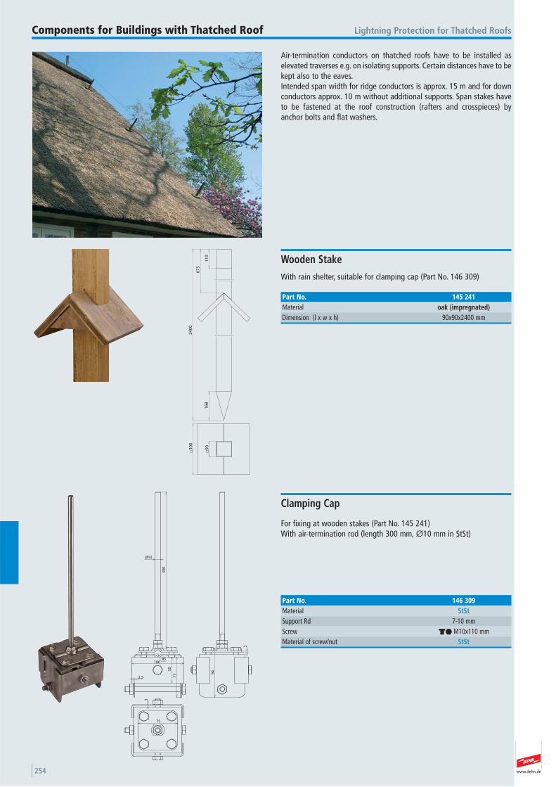
www.dehn.de254
Air-termination conductors on thatched roofs have to be installed as elevated traverses e.g. on isolating supports. Certain distances have to bekept also to the eaves.Intended span width for ridge conductors is approx. 15 m and for downconductors approx. 10 m without additional supports. Span stakes haveto be fastened at the roof construction (rafters and crosspieces) byanchor bolts and flat washers.
Lightning Protection for Thatched RoofsComponents for Buildings with Thatched Roof
11
0
67
5
24
00
16
89
0
30
0
With rain shelter, suitable for clamping cap (Part No. 146 309)
Wooden Stake
Part No. 145 241Material oak (impregnated)Dimension (l x w x h) 90x90x2400 mm
50
77
2.5
94
30
0
Ø10
75
100R5
3
3
For fixing at wooden stakes (Part No. 145 241)With air-termination rod (length 300 mm, Ø10 mm in StSt)
Clamping Cap
Part No. 146 309Material StStSupport Rd 7-10 mmScrew di M10x110 mmMaterial of screw/nut StSt
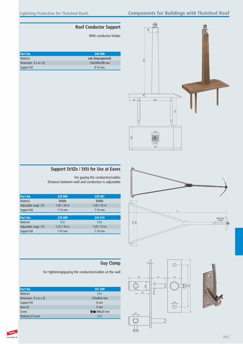
www.dehn.de 255
30
41
02
4
60 205
17
4
14
8
325
46
33
With conductor holder
Lightning Protection for Thatched Roofs Components for Buildings with Thatched Roof
Roof Conductor Support
Part No. 240 000Material oak (impregnated)Dimension (l x w x h) 134x300x598 mmSupport Rd 6-10 mm
Part No. 239 000 239 001Material St/tZn St/tZnAdjustable range (l1) 1.05-1.20 m 1.40-1.55 mSupport Rd 7-10 mm 7-10 mm
adjusting range
l1
47
7
52
6
For guying the conductors/cablesDistance between wall and conductors is adjustable
Support St/tZn / StSt for Use at Eaves
Part No. 239 009 239 019Material StSt StStAdjustable range (l1) 1.25-1.55 m 1.45-1.75 mSupport Rd 7-10 mm 7-10 mm
60
Ø2
5
42
4
Ø1
2.5
12
0
15
0
40
Ø9
40
Ø12
For tightening/guying the conductors/cables at the wall
Guy Clamp
Part No. 241 009Material StStDimension (l x w x d) 150x40x4 mmSupport Rd 8 mmBore Ø 9 mmScrew di M8x20 mmMaterial of screw StSt

www.dehn.de256
www.dehn.de 257
Earthing conductor made of highly flexible copper line, frost-resistant, UV stabilised
Packing in accordance with VG 96927-11
Earthing Material for Telecommunications Earthing Conductors with Cable Lugs open
Packing in accordance with specifications of the VG standards has to be explicitely indicated when ordering.
10.4Ø8
R12 25
64
l1
8
2
2
Cable lug, 2x open, 2x M8/M10
Part No. 410 070 410 099 410 140 410 150 410 199 410 299Cable cross section 10 mm2 10 mm2 10 mm2 10 mm2 10 mm2 10 mm2
Cable length (l1) 7.05 m 10.0 m 14.0 m 15.0 m 20.0 m 30.0 mCable lug open 2xM8/M10 2xM8/M10 2xM8/M10 2xM8/M10 2xM8/M10 2xM8/M10 Colour black black black black black black Military Name VG 96927 T011 A056 VG 96927 T011 A057 VG 96927 T011 A058 VG 96927 T011 A059 VG 96927 T011 A060 VG 96927 T011 A061Stock No. 6150-12-156-9111 6150-12-156-9112 6150-12-156-6207 6150-12-161-4272 6150-12-156-9113 6150-12-156-9114
Part No. 410 025 410 030 410 035 410 040 410 050 410 060Cable cross section 10 mm2 10 mm2 10 mm2 10 mm2 10 mm2 10 mm2
Cable length (l1) 2.55 m 3.05 m 3.55 m 4.05 m 5.05 m 6.05 mCable lug open 2xM8/M10 2xM8/M10 2xM8/M10 2xM8/M10 2xM8/M10 2xM8/M10 Colour black black black black black black Military Name VG 96927 T011 A050 VG 96927 T011 A051 VG 96927 T011 A052 VG 96927 T011 A053 VG 96927 T011 A054 VG 96927 T011 A055Stock No. 6150-12-156-9072 6150-12-156-9109 6150-12-156-9071 6150-12-156-9070 6150-12-156-6051 6150-12-156-9110
Part No. 410 003 410 005 410 006 410 010 410 015 410 020Cable cross section 10 mm2 10 mm2 10 mm2 10 mm2 10 mm2 10 mm2
Cable length (l1) 0.35 m 0.55 m 0.65 m 1.05 m 1.55 m 2.05 mCable lug open 2xM8/M10 2xM8/M10 2xM8/M10 2xM8/M10 2xM8/M10 2xM8/M10 Colour black black black black black black Military Name VG 96927 T011 A044 VG 96927 T011 A045 VG 96927 T011 A046 VG 96927 T011 A047 VG 96927 T011 A048 VG 96927 T011 A049Stock No. 6150-12-156-9107 6150-12-156-8386 6150-12-156-9108 6150-12-156-8387 6150-12-156-9069 6150-12-156-9073
Ø8
10.4
25
64
l1
Ø56
15
10
23
13
25
46
2
8
2
2
6
2
R12
Cable lug, 2x open, 1x M8/M10 and 1x M5/M6
Part No. 410 603 410 605 410 610 410 615 410 620 410 625 410 630Cable cross section 10 mm2 10 mm2 10 mm2 10 mm2 10 mm2 10 mm2 10 mm2
Cable length (l1) 0.35 m 0.55 m 1.05 m 1.55 m 2.05 m 2.55 m 3.05 mCable lug open 1xM8/M10 1xM8/M10 1xM8/M10 1xM8/M10 1xM8/M10 1xM8/M10 1xM8/M10 1xM5/M6 1xM5/M6 1xM5/M6 1xM5/M6 1xM5/M6 1xM5/M6 1xM5/M6 Colour black black black black black black black Military Name — — — VG 96927 T011 A123 — — —Stock No. — — — 6150-12-308-6928 — — 6150-12-353-5887
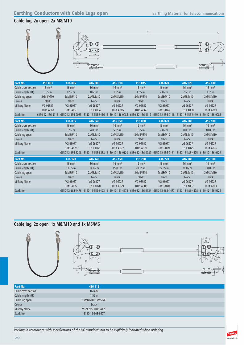
www.dehn.de258
10.4Ø8
R12 25
64
l1
8
2
2
Earthing Material for TelecommunicationsEarthing Conductors with Cable Lugs open
Cable lug, 2x open, 2x M8/M10
Part No. 416 120 416 140 416 150 416 200 416 220 416 280 416 300Cable cross section 16 mm2 16 mm2 16 mm2 16 mm2 16 mm2 16 mm2 16 mm2
Cable length (l1) 12.05 m 14.05 m 15.05 m 20.05 m 22.05 m 28.05 m 30.03 mCable lug open 2xM8/M10 2xM8/M10 2xM8/M10 2xM8/M10 2xM8/M10 2xM8/M10 2xM8/M10 Colour black black black black black black black Military Name VG 96927 VG 96927 VG 96927 VG 96927 VG 96927 VG 96927 VG 96927 T011 A077 T011 A078 T011 A079 T011 A080 T011 A081 T011 A082 T011 A083Stock No. 6150-12-188-4476 6150-12-156-9123 6150-12-161-4273 6150-12-156-9124 6150-12-188-4477 6150-12-188-4478 6150-12-156-9125
Part No. 416 035 416 040 416 050 416 060 416 070 416 080 416 100Cable cross section 16 mm2 16 mm2 16 mm2 16 mm2 16 mm2 16 mm2 16 mm2
Cable length (l1) 3.55 m 4.05 m 5.05 m 6.05 m 7.05 m 8.05 m 10.05 mCable lug open 2xM8/M10 2xM8/M10 2xM8/M10 2xM8/M10 2xM8/M10 2xM8/M10 2xM8/M10 Colour black black black black black black black Military Name VG 96927 VG 96927 VG 96927 VG 96927 VG 96927 VG 96927 VG 96927 T011 A070 T011 A071 T011 A072 T011 A073 T011 A074 T011 A075 T011 A076Stock No. 6150-12-156-6208 6150-12-156-8388 6150-12-156-9120 6150-12-156-9082 6150-12-156-9121 6150-12-188-4475 6150-12-156-9122
Part No. 416 003 416 005 416 006 416 010 416 015 416 020 416 025 416 030Cable cross section 16 mm2 16 mm2 16 mm2 16 mm2 16 mm2 16 mm2 16 mm2 16 mm2
Cable length (l1) 0.35 m 0.55 m 0.65 m 1.05 m 1.55 m 2.05 m 2.55 m 3.05 mCable lug open 2xM8/M10 2xM8/M10 2xM8/M10 2xM8/M10 2xM8/M10 2xM8/M10 2xM8/M10 2xM8/M10 Colour black black black black black black black black Military Name VG 96927 VG 96927 VG 96927 VG 96927 VG 96927 VG 96927 VG 96927 VG 96927 T011 A062 T011 A063 T011 A064 T011 A065 T011 A066 T011 A067 T011 A068 T011 A069Stock No. 6150-12-156-9115 6150-12-156-9085 6150-12-156-9116 6150-12-156-9084 6150-12-156-9117 6150-12-156-9118 6150-12-156-9119 6150-12-156-9083
Ø8
10.4
25
64
l1
Ø56
15
10
23
13
25
46
2
8
2
2
6
2
R12
Cable lug, 2x open, 1x M8/M10 and 1x M5/M6
Part No. 416 516Cable cross section 16 mm2
Cable length (l1) 1.55 mCable lug open 1xM8/M10 1xM5/M6 Colour black Military Name VG 96927 T011 A125Stock No. 6150-12-308-6607
Packing in accordance with specifications of the VG standards has to be explicitely indicated when ordering.
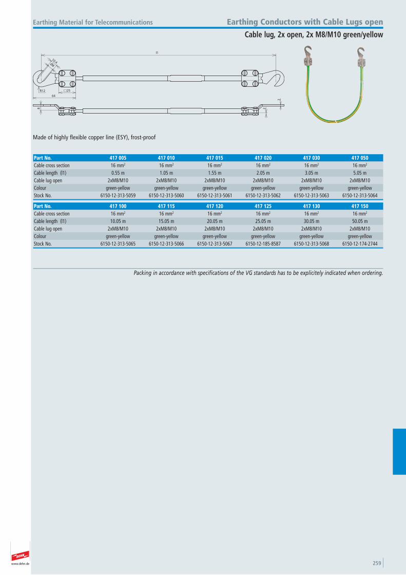
www.dehn.de 259
10.4Ø8
R12 25
64
l1
8
2
2
Made of highly flexible copper line (ESY), frost-proof
Earthing Material for Telecommunications Earthing Conductors with Cable Lugs open
Cable lug, 2x open, 2x M8/M10 green/yellow
Part No. 417 100 417 115 417 120 417 125 417 130 417 150Cable cross section 16 mm2 16 mm2 16 mm2 16 mm2 16 mm2 16 mm2
Cable length (l1) 10.05 m 15.05 m 20.05 m 25.05 m 30.05 m 50.05 mCable lug open 2xM8/M10 2xM8/M10 2xM8/M10 2xM8/M10 2xM8/M10 2xM8/M10 Colour green-yellow green-yellow green-yellow green-yellow green-yellow green-yellow Stock No. 6150-12-313-5065 6150-12-313-5066 6150-12-313-5067 6150-12-185-8587 6150-12-313-5068 6150-12-174-2744
Part No. 417 005 417 010 417 015 417 020 417 030 417 050Cable cross section 16 mm2 16 mm2 16 mm2 16 mm2 16 mm2 16 mm2
Cable length (l1) 0.55 m 1.05 m 1.55 m 2.05 m 3.05 m 5.05 mCable lug open 2xM8/M10 2xM8/M10 2xM8/M10 2xM8/M10 2xM8/M10 2xM8/M10 Colour green-yellow green-yellow green-yellow green-yellow green-yellow green-yellow Stock No. 6150-12-313-5059 6150-12-313-5060 6150-12-313-5061 6150-12-313-5062 6150-12-313-5063 6150-12-313-5064
Packing in accordance with specifications of the VG standards has to be explicitely indicated when ordering.
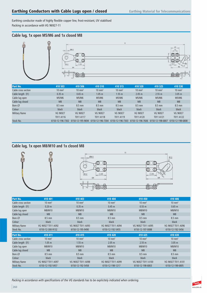
www.dehn.de260
Earthing conductor made of highly flexible copper line, frost-resistant, UV stabilised
Packing in accordance with VG 96927-11
Earthing Material for TelecommunicationsEarthing Conductors with Cable Lugs open / closed
Packing in accordance with specifications of the VG standards has to be explicitely indicated when ordering.
25
64
Ø8.5
l1
2
8
2
R12Ø5
6
15
10
23
13
25
46
2
6
2
Cable lug, 1x open M5/M6 and 1x closed M8
Part No. 410 503 410 506 410 510 410 515 410 520 410 525 410 530Cable cross section 10 mm2 10 mm2 10 mm2 10 mm2 10 mm2 10 mm2 10 mm2
Cable length (l1) 0.35 m 0.65 m 1.05 m 1.55 m 2.05 m 2.55 m 3.05 mCable lug open M5/M6 M5/M6 M5/M6 M5/M6 M5/M6 M5/M6 M5/M6 Cable lug closed M8 M8 M8 M8 M8 M8 M8 Bore Ø 8.5 mm 8.5 mm 8.5 mm 8.5 mm 8.5 mm 8.5 mm 8.5 mmColour black black black black black black black Military Name VG 96927 VG 96927 VG 96927 VG 96927 VG 96927 VG 96927 VG 96927 T011 A116 T011 A117 T011 A118 T011 A119 T011 A120 T011 A121 T011 A122Stock No. 6150-12-196-7302 6150-12-195-9694 6150-12-196-7304 6150-12-196-7303 6150-12-196-7606 6150-12-198-6807 6150-12-198-6808
25
64
Ø8.5
l1
Ø810.425
64
2
8
2
R12
R12
Cable lug, 1x open M8/M10 and 1x closed M8
Part No. 410 411 410 415 410 420 410 425 410 430Cable cross section 10 mm2 10 mm2 10 mm2 10 mm2 10 mm2
Cable length (l1) 1.05 m 1.55 m 2.05 m 2.55 m 3.05 mCable lug open M8/M10 M8/M10 M8/M10 M8/M10 M8/M10 Cable lug closed M8 M8 M8 M8 M8 Bore Ø 8.5 mm 8.5 mm 8.5 mm 8.5 mm 8.5 mmColour black black black black black Military Name VG 96927 T011 A097 VG 96927 T011 A098 VG 96927 T011 A099 VG 96927 T011 A100 VG 96927 T011 A101Stock No. 6150-12-192-5457 6150-12-192-5458 6150-12-198-1217 6150-12-198-6803 6150-12-198-6805
Part No. 410 401 410 403 410 404 410 450 410 406Cable cross section 10 mm2 10 mm2 10 mm2 10 mm2 10 mm2
Cable length (l1) 0.20 m 0.35 m 0.45 m 0.55 m 0.65 mCable lug open M8/M10 M8/M10 M8/M10 M8/M10 M8/M10 Cable lug closed M8 M8 M8 M8 M8 Bore Ø 8.5 mm 8.5 mm 8.5 mm 8.5 mm 8.5 mmColour black black black black black Military Name VG 96927 T011 A092 VG 96927 T011 A093 VG 96927 T011 A094 VG 96927 T011 A095 VG 96927 T011 A096Stock No. 6150-12-300-9132 6150-12-195-9490 6150-12-192-5455 6150-12-197-0088 6150-12-192-5456
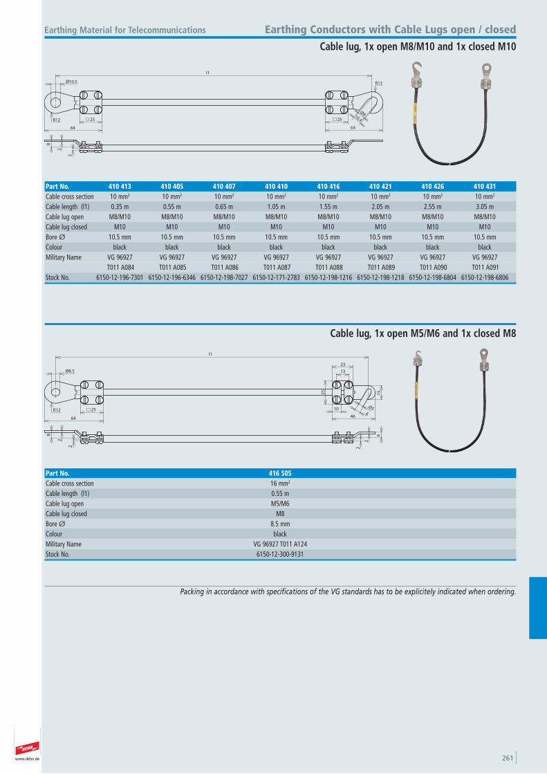
www.dehn.de 261
25
64
Ø10.5
l1
Ø810.425
64
2
8
2
R12
R12
Earthing Material for Telecommunications Earthing Conductors with Cable Lugs open / closed
Cable lug, 1x open M8/M10 and 1x closed M10
Part No. 410 413 410 405 410 407 410 410 410 416 410 421 410 426 410 431Cable cross section 10 mm2 10 mm2 10 mm2 10 mm2 10 mm2 10 mm2 10 mm2 10 mm2
Cable length (l1) 0.35 m 0.55 m 0.65 m 1.05 m 1.55 m 2.05 m 2.55 m 3.05 mCable lug open M8/M10 M8/M10 M8/M10 M8/M10 M8/M10 M8/M10 M8/M10 M8/M10 Cable lug closed M10 M10 M10 M10 M10 M10 M10 M10 Bore Ø 10.5 mm 10.5 mm 10.5 mm 10.5 mm 10.5 mm 10.5 mm 10.5 mm 10.5 mmColour black black black black black black black black Military Name VG 96927 VG 96927 VG 96927 VG 96927 VG 96927 VG 96927 VG 96927 VG 96927 T011 A084 T011 A085 T011 A086 T011 A087 T011 A088 T011 A089 T011 A090 T011 A091Stock No. 6150-12-196-7301 6150-12-196-6346 6150-12-198-7027 6150-12-171-2783 6150-12-198-1216 6150-12-198-1218 6150-12-198-6804 6150-12-198-6806
25
64
Ø8.5
l1
2
8
2
R12Ø5
6
15
10
23
13
25
46
2
6
2
Cable lug, 1x open M5/M6 and 1x closed M8
Part No. 416 505Cable cross section 16 mm2
Cable length (l1) 0.55 mCable lug open M5/M6 Cable lug closed M8 Bore Ø 8.5 mmColour black Military Name VG 96927 T011 A124Stock No. 6150-12-300-9131
Packing in accordance with specifications of the VG standards has to be explicitely indicated when ordering.
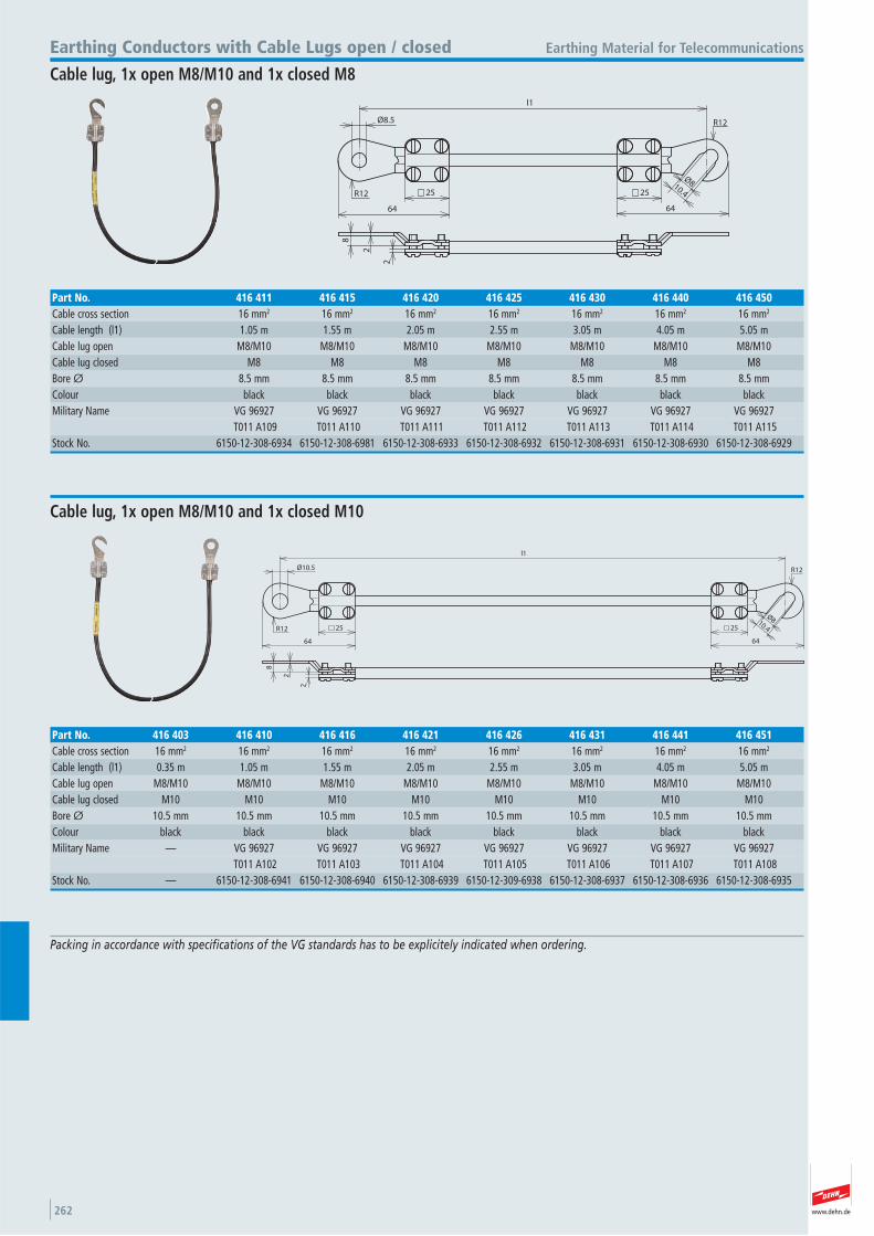
www.dehn.de262
25
64
Ø8.5
l1
Ø810.425
64
2
8
2
R12
R12
Earthing Material for TelecommunicationsEarthing Conductors with Cable Lugs open / closed
Cable lug, 1x open M8/M10 and 1x closed M8
Part No. 416 411 416 415 416 420 416 425 416 430 416 440 416 450Cable cross section 16 mm2 16 mm2 16 mm2 16 mm2 16 mm2 16 mm2 16 mm2
Cable length (l1) 1.05 m 1.55 m 2.05 m 2.55 m 3.05 m 4.05 m 5.05 mCable lug open M8/M10 M8/M10 M8/M10 M8/M10 M8/M10 M8/M10 M8/M10 Cable lug closed M8 M8 M8 M8 M8 M8 M8 Bore Ø 8.5 mm 8.5 mm 8.5 mm 8.5 mm 8.5 mm 8.5 mm 8.5 mmColour black black black black black black black Military Name VG 96927 VG 96927 VG 96927 VG 96927 VG 96927 VG 96927 VG 96927 T011 A109 T011 A110 T011 A111 T011 A112 T011 A113 T011 A114 T011 A115Stock No. 6150-12-308-6934 6150-12-308-6981 6150-12-308-6933 6150-12-308-6932 6150-12-308-6931 6150-12-308-6930 6150-12-308-6929
Packing in accordance with specifications of the VG standards has to be explicitely indicated when ordering.
25
64
Ø10.5
l1
Ø810.425
64
2
8
2
R12
R12
Cable lug, 1x open M8/M10 and 1x closed M10
Part No. 416 403 416 410 416 416 416 421 416 426 416 431 416 441 416 451Cable cross section 16 mm2 16 mm2 16 mm2 16 mm2 16 mm2 16 mm2 16 mm2 16 mm2
Cable length (l1) 0.35 m 1.05 m 1.55 m 2.05 m 2.55 m 3.05 m 4.05 m 5.05 mCable lug open M8/M10 M8/M10 M8/M10 M8/M10 M8/M10 M8/M10 M8/M10 M8/M10 Cable lug closed M10 M10 M10 M10 M10 M10 M10 M10 Bore Ø 10.5 mm 10.5 mm 10.5 mm 10.5 mm 10.5 mm 10.5 mm 10.5 mm 10.5 mmColour black black black black black black black black Military Name — VG 96927 VG 96927 VG 96927 VG 96927 VG 96927 VG 96927 VG 96927 T011 A102 T011 A103 T011 A104 T011 A105 T011 A106 T011 A107 T011 A108Stock No. — 6150-12-308-6941 6150-12-308-6940 6150-12-308-6939 6150-12-309-6938 6150-12-308-6937 6150-12-308-6936 6150-12-308-6935
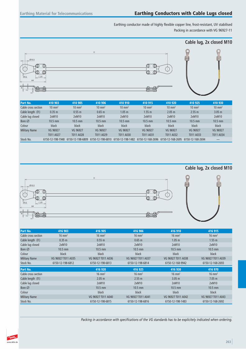
www.dehn.de 263
Earthing conductor made of highly flexible copper line, frost-resistant, UV stabilised
Packing in accordance with VG 96927-11
Earthing Material for Telecommunications Earthing Conductors with Cable Lugs closed
Packing in accordance with specifications of the VG standards has to be explicitely indicated when ordering.
25
64
Ø10.5
l1
2
8
2
R12
Cable lug, 2x closed M10
Part No. 410 903 410 905 410 906 410 910 410 915 410 920 410 925 410 930Cable cross section 10 mm2 10 mm2 10 mm2 10 mm2 10 mm2 10 mm2 10 mm2 10 mm2
Cable length (l1) 0.35 m 0.55 m 0.65 m 1.05 m 1.55 m 2.05 m 2.55 m 3.05 mCable lug closed 2xM10 2xM10 2xM10 2xM10 2xM10 2xM10 2xM10 2xM10 Bore Ø 10.5 mm 10.5 mm 10.5 mm 10.5 mm 10.5 mm 10.5 mm 10.5 mm 10.5 mmColour black black black black black black black black Military Name VG 96927 VG 96927 VG 96927 VG 96927 VG 96927 VG 96927 VG 96927 VG 96927
T011 A027 T011 A028 T011 A029 T011 A030 T011 A031 T011 A032 T011 A033 T011 A034Stock No. 6150-12-198-1948 6150-12-198-6809 6150-12-198-6810 6150-12-198-1482 6150-12-168-2696 6150-12-168-2695 6150-12-168-2694 —
25
64
Ø10.5
l1
2
8
2
R12
Cable lug, 2x closed M10
Part No. 416 920 416 925 416 930 416 970Cable cross section 16 mm2 16 mm2 16 mm2 16 mm2
Cable length (l1) 2.05 m 2.55 m 3.05 m 7.05 mCable lug closed 2xM10 2xM10 2xM10 2xM10 Bore Ø 10.5 mm 10.5 mm 10.5 mm 10.5 mmColour black black black black Military Name VG 96927 T011 A040 VG 96927 T011 A041 VG 96927 T011 A042 VG 96927 T011 A043Stock No. 6150-12-198-6815 6150-12-198-6816 6150-12-198-1483 6150-12-168-2692
Part No. 416 903 416 905 416 906 416 910 416 915Cable cross section 16 mm2 16 mm2 16 mm2 16 mm2 16 mm2
Cable length (l1) 0.35 m 0.55 m 0.65 m 1.05 m 1.55 mCable lug closed 2xM10 2xM10 2xM10 2xM10 2xM10 Bore Ø 10.5 mm 10.5 mm 10.5 mm 10.5 mm 10.5 mmColour black black black black black Military Name VG 96927 T011 A035 VG 96927 T011 A036 VG 96927 T011 A037 VG 96927 T011 A038 VG 96927 T011 A039Stock No. 6150-12-198-6812 6150-12-198-6813 6150-12-198-6814 6150-12-168-9942 6150-12-168-2693
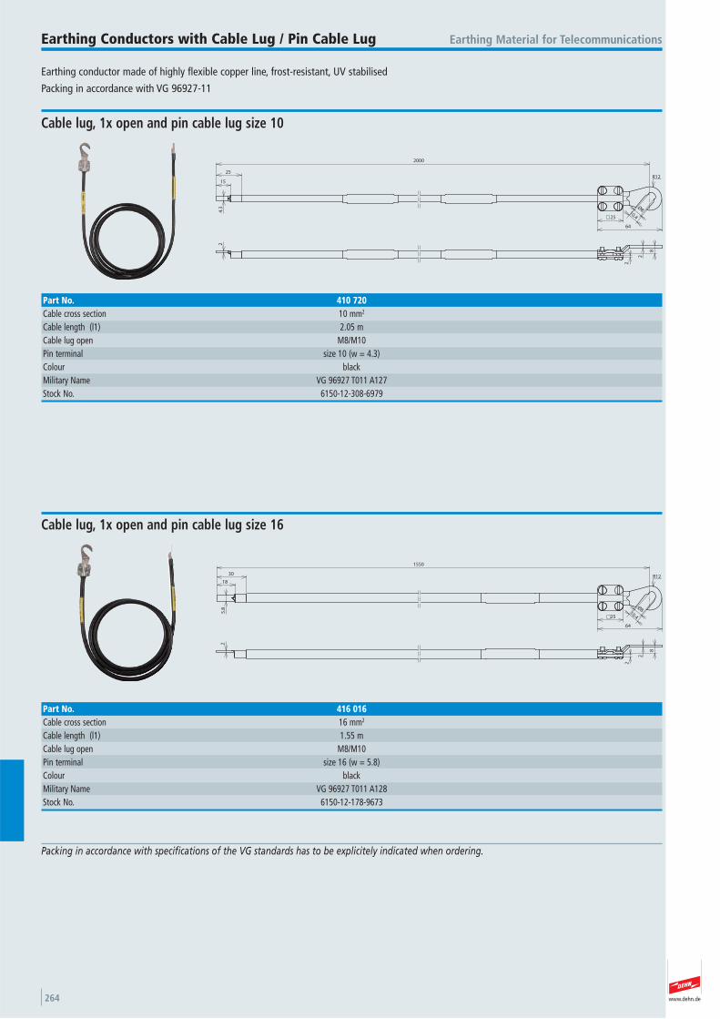
www.dehn.de264
Earthing conductor made of highly flexible copper line, frost-resistant, UV stabilised
Packing in accordance with VG 96927-11
Earthing Material for TelecommunicationsEarthing Conductors with Cable Lug / Pin Cable Lug
Packing in accordance with specifications of the VG standards has to be explicitely indicated when ordering.
2000
15
25
4.3
2
2
8
2
Ø810.425
64
R12
Cable lug, 1x open and pin cable lug size 10
Part No. 410 720Cable cross section 10 mm2
Cable length (l1) 2.05 mCable lug open M8/M10 Pin terminal size 10 (w = 4.3) Colour black Military Name VG 96927 T011 A127Stock No. 6150-12-308-6979
18
30
5.8
2
1550
2
8
2
Ø810.425
64
R12
Cable lug, 1x open and pin cable lug size 16
Part No. 416 016Cable cross section 16 mm2
Cable length (l1) 1.55 mCable lug open M8/M10 Pin terminal size 16 (w = 5.8) Colour black Military Name VG 96927 T011 A128Stock No. 6150-12-178-9673
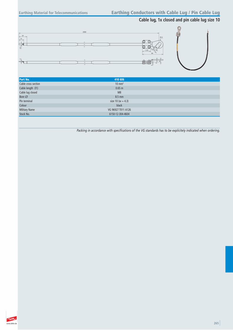
www.dehn.de 265
2000
15
25
4.3
2
2
8
2
Ø810.425
64
R12
Earthing Material for Telecommunications Earthing Conductors with Cable Lug / Pin Cable Lug
Cable lug, 1x closed and pin cable lug size 10
Part No. 410 606Cable cross section 10 mm2
Cable length (l1) 0.65 mCable lug closed M8 Bore Ø 8.5 mmPin terminal size 10 (w = 4.3) Colour black Military Name VG 96927 T011 A126Stock No. 6150-12-304-4604
Packing in accordance with specifications of the VG standards has to be explicitely indicated when ordering.
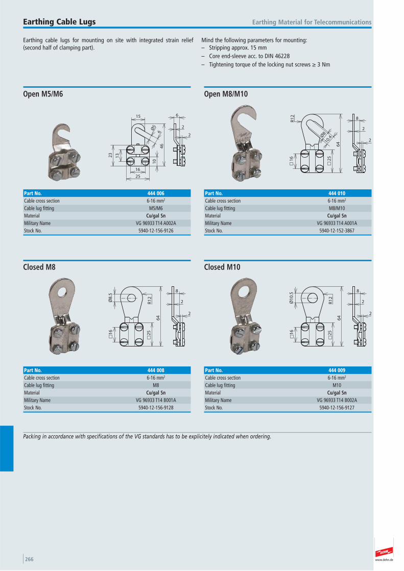
www.dehn.de266
Earthing cable lugs for mounting on site with integrated strain relief (second half of clamping part).
Mind the following parameters for mounting:– Stripping approx. 15 mm– Core end-sleeve acc. to DIN 46228– Tightening torque of the locking nut screws ≥ 3 Nm
Earthing Material for TelecommunicationsEarthing Cable Lugs
Packing in accordance with specifications of the VG standards has to be explicitely indicated when ordering.
16
Ø5
6
15
10
23
13
25
46
2
6
2
Open M5/M6
Part No. 444 006Cable cross section 6-16 mm2
Cable lug fitting M5/M6 Material Cu/gal SnMilitary Name VG 96933 T14 A002AStock No. 5940-12-156-9126
2
8
2
Ø8
10.42
5
64
R1
21
6
Open M8/M10
Part No. 444 010Cable cross section 6-16 mm2
Cable lug fitting M8/M10 Material Cu/gal SnMilitary Name VG 96933 T14 A001AStock No. 5940-12-152-3867
2
8
2
25
64
Ø8
.5
R1
2
16
Closed M8
Part No. 444 008Cable cross section 6-16 mm2
Cable lug fitting M8 Material Cu/gal SnMilitary Name VG 96933 T14 B001AStock No. 5940-12-156-9128
2
8
2
25
64
Ø1
0.5
R1
2
16
Closed M10
Part No. 444 009Cable cross section 6-16 mm2
Cable lug fitting M10 Material Cu/gal SnMilitary Name VG 96933 T14 B002AStock No. 5940-12-156-9127
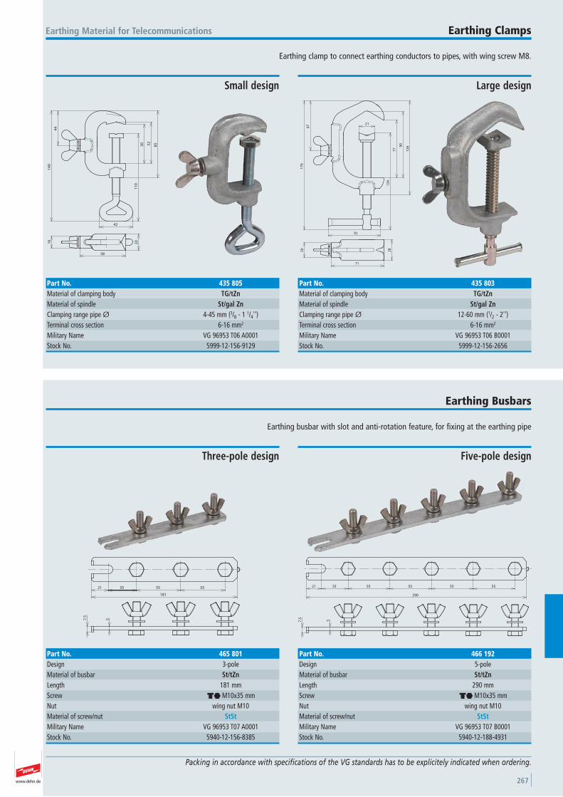
www.dehn.de 267
Earthing clamp to connect earthing conductors to pipes, with wing screw M8.
Earthing Material for Telecommunications Earthing Clamps
Packing in accordance with specifications of the VG standards has to be explicitely indicated when ordering.
44
14
0
42
11
0
50 52
85
16
58
20
Small design
Part No. 435 805Material of clamping body TG/tZnMaterial of spindle St/gal ZnClamping range pipe Ø 4-45 mm (3/8 - 1 1/4'')Terminal cross section 6-16 mm2
Military Name VG 96953 T06 A0001Stock No. 5999-12-156-9129
70
67
17
6
21
13
4
77
90
12
6
71
28
20
Large design
Part No. 435 803Material of clamping body TG/tZnMaterial of spindle St/gal ZnClamping range pipe Ø 12-60 mm (1/2 - 2'')Terminal cross section 6-16 mm2
Military Name VG 96953 T06 B0001Stock No. 5999-12-156-2656
Earthing busbar with slot and anti-rotation feature, for fixing at the earthing pipe
Earthing Busbars
7.5
5
21 35 55 55
181
Three-pole design
Part No. 465 801Design 3-pole Material of busbar St/tZnLength 181 mmScrew di M10x35 mmNut wing nut M10 Material of screw/nut StStMilitary Name VG 96953 T07 A0001Stock No. 5940-12-156-8385
57.5
21 35 55 55 55 55
290
Five-pole design
Part No. 466 192Design 5-pole Material of busbar St/tZnLength 290 mmScrew di M10x35 mmNut wing nut M10 Material of screw/nut StStMilitary Name VG 96953 T07 B0001Stock No. 5940-12-188-4931
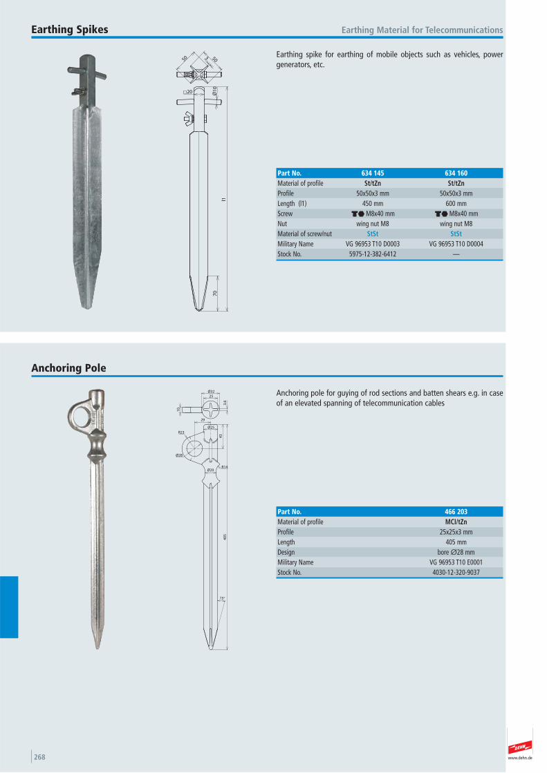
www.dehn.de268
Earthing spike for earthing of mobile objects such as vehicles, powergenerators, etc.
Earthing Material for TelecommunicationsEarthing Spikes
20 Ø1
0
l1
70
5050 3
Part No. 634 145 634 160Material of profile St/tZn St/tZnProfile 50x50x3 mm 50x50x3 mmLength (l1) 450 mm 600 mmScrew di M8x40 mm di M8x40 mmNut wing nut M8 wing nut M8 Material of screw/nut StSt StStMilitary Name VG 96953 T10 D0003 VG 96953 T10 D0004Stock No. 5975-12-382-6412 —
Anchoring pole for guying of rod sections and batten shears e.g. in caseof an elevated spanning of telecommunication cables
Anchoring Pole
Ø25
29
43
R23
Ø28
R14Ø20
15°
40
53
.6
25
Ø32
10
Part No. 466 203Material of profile MCI/tZnProfile 25x25x3 mmLength 405 mmDesign bore Ø28 mm Military Name VG 96953 T10 E0001Stock No. 4030-12-320-9037
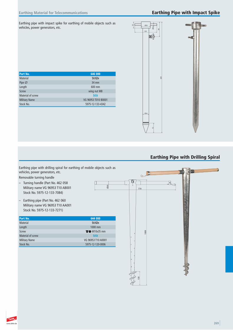
www.dehn.de 269
Earthing pipe with impact spike for earthing of mobile objects such asvehicles, power generators, etc.
Earthing Material for Telecommunications Earthing Pipe with Impact Spike
52
Ø34
80Ø
10
35
Ø50
120
60
0
Part No. 646 000Material St/tZnPipe Ø 34 mmLength 600 mmScrew wing nut M8 Material of screw StStMilitary Name VG 96953 T010 B0001Stock No. 5975-12-133-4342
Earthing pipe with drilling spiral for earthing of mobile objects such asvehicles, power generators, etc.
Removable turning handle
– Turning handle (Part No. 462 058Military name VG 96953 T10 AB001 Stock No. 5975-12-133-7084)
– Earthing pipe (Part No. 462 060Military name VG 96953 T10 AA001 Stock No. 5975-12-133-7271)
Earthing Pipe with Drilling Spiral
770
10
00
Ø3
0
13
0
Part No. 644 000Material St/tZnLength 1000 mmScrew di M10x35 mmMaterial of screw StStMilitary Name VG 96953 T10 A0001Stock No. 5975-12-120-0006

www.dehn.de270
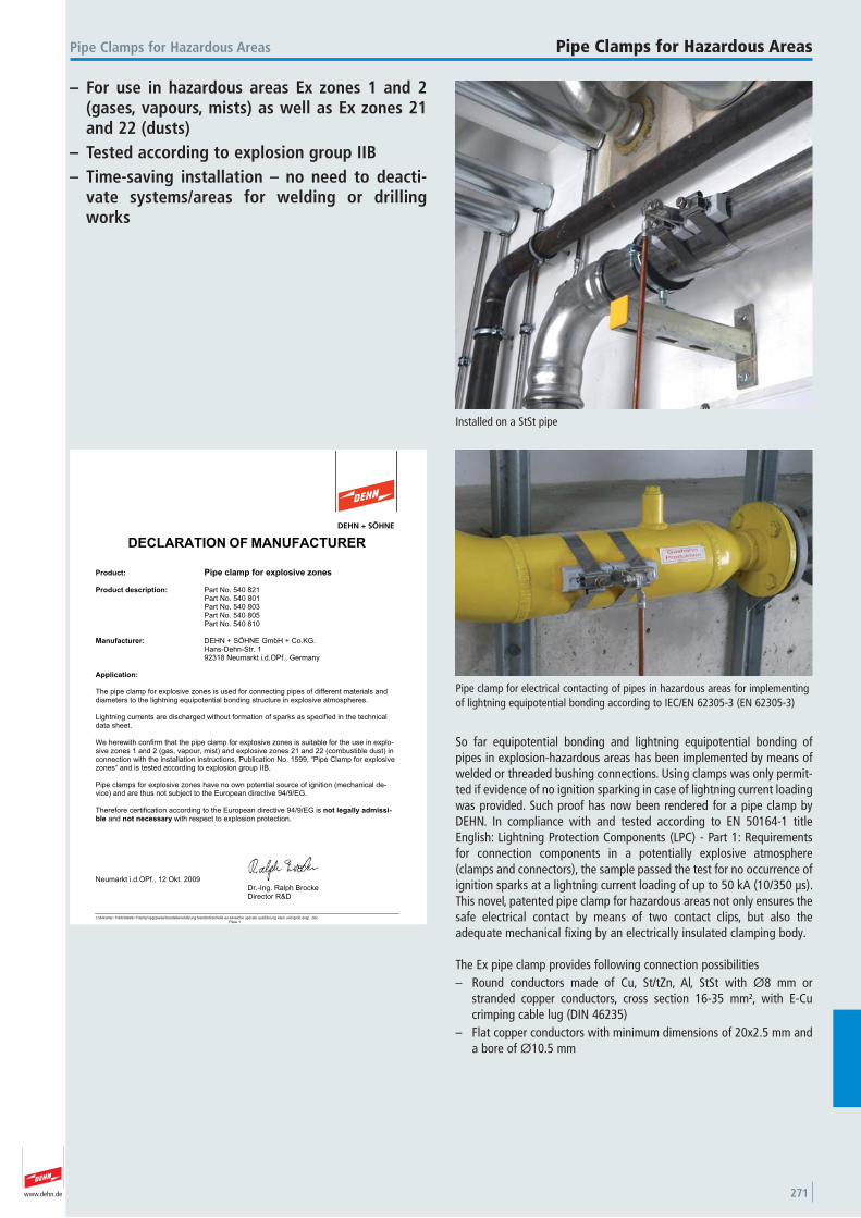
www.dehn.de 271
So far equipotential bonding and lightning equipotential bonding ofpipes in explosion-hazardous areas has been implemented by means ofwelded or threaded bushing connections. Using clamps was only permit-ted if evidence of no ignition sparking in case of lightning current loadingwas provided. Such proof has now been rendered for a pipe clamp byDEHN. In compliance with and tested according to EN 50164-1 titleEnglish: Lightning Protection Components (LPC) - Part 1: Requirementsfor connection components in a potentially explosive atmosphere(clamps and connectors), the sample passed the test for no occurrence ofignition sparks at a lightning current loading of up to 50 kA (10/350 μs).This novel, patented pipe clamp for hazardous areas not only ensures thesafe electrical contact by means of two contact clips, but also the adequate mechanical fixing by an electrically insulated clamping body.
The Ex pipe clamp provides following connection possibilities– Round conductors made of Cu, St/tZn, Al, StSt with Ø8 mm or
stranded copper conductors, cross section 16-35 mm², with E-Cucrimping cable lug (DIN 46235)
– Flat copper conductors with minimum dimensions of 20x2.5 mm anda bore of Ø10.5 mm
Pipe clamp for electrical contacting of pipes in hazardous areas for implementingof lightning equipotential bonding according to IEC/EN 62305-3 (EN 62305-3)
Installed on a StSt pipe
Pipe Clamps for Hazardous Areas Pipe Clamps for Hazardous Areas
c:\dokume~1\drb\lokale~1\temp\xpgrpwise\herstellererklärung bandrohrschelle ex-bereiche upd ate ausführung klein und groß engl. .docPage 1
DECLARATION OFMANUFACTURER
Product: Pipe clamp for explosive zones
Product description: Part No. 540 821Part No. 540 801Part No. 540 803Part No. 540 805Part No. 540 810
Manufacturer: DEHN + SÖHNE GmbH + Co.KG.Hans-Dehn-Str. 192318 Neumarkt i.d.OPf., Germany
Application:
The pipe clamp for explosive zones is used for connecting pipes of different materials anddiameters to the lightning equipotential bonding structure in explosive atmospheres.
Lightning currents are discharged without formation of sparks as specified in the technicaldata sheet.
We herewith confirm that the pipe clamp for explosive zones is suitable for the use in explo-sive zones 1 and 2 (gas, vapour, mist) and explosive zones 21 and 22 (combustible dust) inconnection with the installation instructions, P
not legally admissi-ble and not necessary with respect to explosion protection.
Neumarkt i.d.OPf., 12 Okt. 2009Dr.-Ing. Ralph BrockeDirector R&D
– For use in hazardous areas Ex zones 1 and 2(gases, vapours, mists) as well as Ex zones 21and 22 (dusts)
– Tested according to explosion group IIB– Time-saving installation – no need to deacti-
vate systems/areas for welding or drillingworks
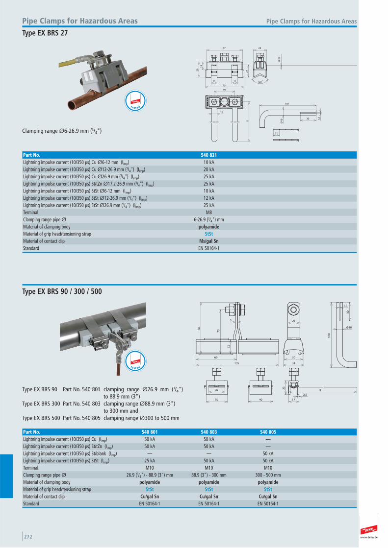
www.dehn.de272
67
73
11 11
29
15
24
0.2
5
120 °
25
10
39
l1
Ø1
0
107
30 1.5
11Clamping range Ø6-26.9 mm (3/4")
Pipe Clamps for Hazardous AreasPipe Clamps for Hazardous Areas
Type EX BRS 27
Part No. 540 821Lightning impulse current (10/350 μs) Cu Ø6-12 mm (Iimp) 10 kALightning impulse current (10/350 μs) Cu Ø12-26.9 mm (3/4") (Iimp) 20 kALightning impulse current (10/350 μs) Cu Ø26.9 mm (3/4") (Iimp) 25 kALightning impulse current (10/350 μs) St/tZn Ø17.2-26.9 mm (3/4") (Iimp) 25 kALightning impulse current (10/350 μs) StSt Ø6-12 mm (Iimp) 10 kALightning impulse current (10/350 μs) StSt Ø12-26.9 mm (3/4") (Iimp) 12 kALightning impulse current (10/350 μs) StSt Ø26.9 mm (3/4") (Iimp) 25 kATerminal M8 Clamping range pipe Ø 6-26.9 (3/4") mmMaterial of clamping body polyamideMaterial of grip head/tensioning strap StStMaterial of contact clip Ms/gal SnStandard EN 50164-1
66
23
738
6
3
135
20
34
30
40
26
35 17
2.5
23
l1
1.5
30
Ø101
08
Type EX BRS 90 Part No. 540 801 clamping range Ø26.9 mm (3/4")to 88.9 mm (3")
Type EX BRS 300 Part No. 540 803 clamping range Ø88.9 mm (3")to 300 mm and
Type EX BRS 500 Part No. 540 805 clamping range Ø300 to 500 mm
Type EX BRS 90 / 300 / 500
Part No. 540 801 540 803 540 805Lightning impulse current (10/350 μs) Cu (Iimp) 50 kA 50 kA —Lightning impulse current (10/350 μs) St/tZn (Iimp) 50 kA 50 kA —Lightning impulse current (10/350 μs) St/blank (Iimp) — — 50 kALightning impulse current (10/350 μs) StSt (Iimp) 25 kA 50 kA 50 kATerminal M10 M10 M10 Clamping range pipe Ø 26.9 (3/4") - 88.9 (3") mm 88.9 (3") - 300 mm 300 - 500 mmMaterial of clamping body polyamide polyamide polyamideMaterial of grip head/tensioning strap StSt StSt StStMaterial of contact clip Cu/gal Sn Cu/gal Sn Cu/gal SnStandard EN 50164-1 EN 50164-1 EN 50164-1
t e s t e d
te s t e d
www.dehn.de 273
66
23
738
6
3
135
20
34
30
40
26
35 17
2.5
23
1.5
30
Ø10
10
8
For use with endless tensioning strap (Part No. 540 901) Clamping ranges Ø26.9 mm (3/4") to 500 mm
Pipe Clamps for Hazardous Areas Pipe Clamps for Hazardous Areas
Separate clamping body
Part No. 540 810Lightning impulse current (10/350 μs) Cu (Iimp) 50 kALightning impulse current (10/350 μs) St/tZn (Iimp) 50 kALightning impulse current (10/350 μs) StSt (Iimp) 25 kATerminal M10 Clamping range pipe Ø 26.9 (3/4") - 500 mmMaterial of clamping body polyamideMaterial of grip head/tensioning strap StStMaterial of contact clip Cu/gal SnStandard EN 50164-1
Accessory for Pipe Clamps for Hazardous Areas
Tensioning Strap Part No. 540 901Material StStDimension of strap (l x w x d) 25x0.3 mmLength 100 m
t e s t e d
More details in installation instructions No. 1599.
www.dehn.de274
– For indirect connection of an overhead lineroof pole to the external lightning protectionsystem
– Corrosion-resistant stainless steel connections
For indirect connection of an overhead line roof pole to the external lightningprotection system
Connection Components for Roof PolesProtective Spark Gap
The DSFS spark gap allows to indirectly connect an overhead line roofpole to the external lightning protection system
142
30
Ø4
0
11
Ø13
67
Typ DSFSPart No. 920 000100% lightning impulse sparkover voltage (1.2/50 μs) (Urimp) ~ 25 kVNominal discharge current (8/20 μs) (In) 25 kADegree of protection IP 54 Power frequency sparkover voltage (50 Hz) (Uaw) ~ 10 kVMaterial (connection) StStConnection slot Ø13x11 mm Enclosure material plastic
Pipe clamp to connect the protective spark gap to the overhead line roofpole
r1
3
3
12
Ø1
1
30
l1
40
Pipe Clamps for Roof Poles
Part No. 410 212 410 300Clamping range of pipe 76.1 mm 88.9 mmClamping range Ø pipe 2 1/2" 3" Material St/tZn St/tZnBore Ø 11 mm 11 mmScrew di M8x20 mm di M8x20 mmMaterial of screw/nut St/tZn St/tZnDimension (l1 x r1) 169x38 mm 182.5x44.5 mmStandard EN 50164-1 EN 50164-1
t e s t e d
Conductor holder for fixing of round conductors at overhead line roofpoles, insulated clamp bush
Conductor Holders for Roof Poles
2
Ø76/89
28
35
148/161
Part No. 425 076 425 089Clamping range Ø pipe 76 mm 89 mmMaterial St/tZn St/tZnConductor holder support Rd 8-10 mm 8-10 mmConductor leading fixed fixed Screw di M8x20 mm di M8x20 mmMaterial of screw/nut StSt StSt
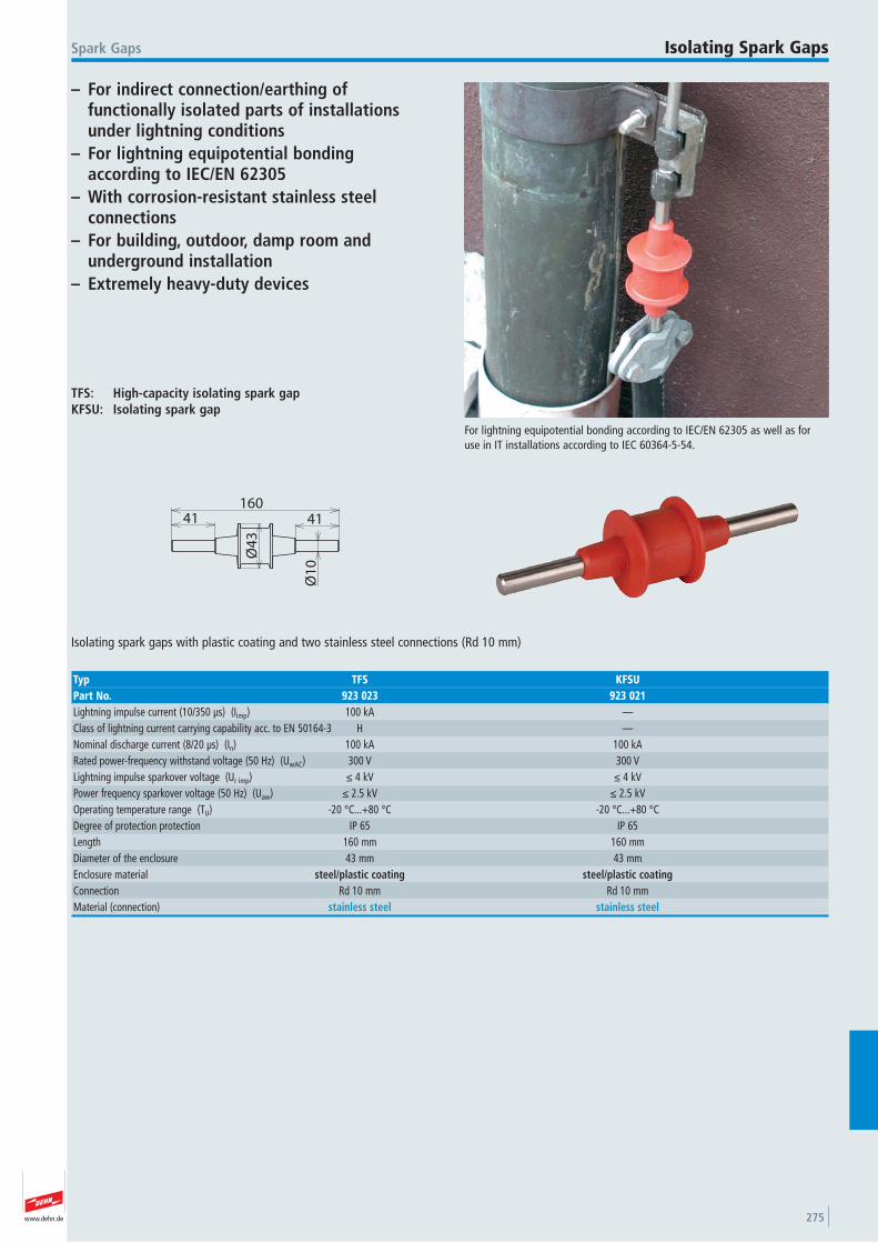
www.dehn.de 275
– For indirect connection/earthing of functionally isolated parts of installationsunder lightning conditions
– For lightning equipotential bonding according to IEC/EN 62305
– With corrosion-resistant stainless steel connections
– For building, outdoor, damp room and underground installation
– Extremely heavy-duty devices
For lightning equipotential bonding according to IEC/EN 62305 as well as foruse in IT installations according to IEC 60364-5-54.
Spark Gaps Isolating Spark Gaps
TFS: High-capacity isolating spark gapKFSU: Isolating spark gap
41 41160
Ø1
0
Ø4
3
Isolating spark gaps with plastic coating and two stainless steel connections (Rd 10 mm)
Typ TFS KFSUPart No. 923 023 923 021Lightning impulse current (10/350 μs) (Iimp) 100 kA —Class of lightning current carrying capability acc. to EN 50164-3 H —Nominal discharge current (8/20 μs) (In) 100 kA 100 kARated power-frequency withstand voltage (50 Hz) (UwAC) 300 V 300 VLightning impulse sparkover voltage (Ur imp) ≤ 4 kV ≤ 4 kVPower frequency sparkover voltage (50 Hz) (Uaw) ≤ 2.5 kV ≤ 2.5 kVOperating temperature range (TU) -20 °C...+80 °C -20 °C...+80 °C Degree of protection protection IP 65 IP 65 Length 160 mm 160 mmDiameter of the enclosure 43 mm 43 mmEnclosure material steel/plastic coating steel/plastic coatingConnection Rd 10 mm Rd 10 mm Material (connection) stainless steel stainless steel
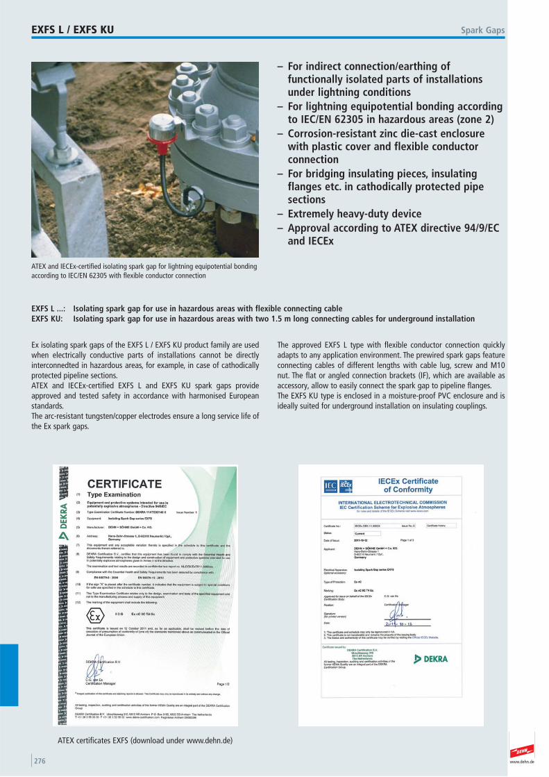
www.dehn.de276
– For indirect connection/earthing of functionally isolated parts of installationsunder lightning conditions
– For lightning equipotential bonding accordingto IEC/EN 62305 in hazardous areas (zone 2)
– Corrosion-resistant zinc die-cast enclosurewith plastic cover and flexible conductor connection
– For bridging insulating pieces, insulatingflanges etc. in cathodically protected pipesections
– Extremely heavy-duty device– Approval according to ATEX directive 94/9/EC
and IECEx
ATEX and IECEx-certified isolating spark gap for lightning equipotential bondingaccording to IEC/EN 62305 with flexible conductor connection
Spark GapsEXFS L / EXFS KU
EXFS L ...: Isolating spark gap for use in hazardous areas with flexible connecting cableEXFS KU: Isolating spark gap for use in hazardous areas with two 1.5 m long connecting cables for underground installation
Ex isolating spark gaps of the EXFS L / EXFS KU product family are usedwhen electrically conductive parts of installations cannot be directly interconnedted in hazardous areas, for example, in case of cathodicallyprotected pipeline sections.ATEX and IECEx-certified EXFS L and EXFS KU spark gaps provideapproved and tested safety in accordance with harmonised Europeanstandards.The arc-resistant tungsten/copper electrodes ensure a long service life ofthe Ex spark gaps.
The approved EXFS L type with flexible conductor connection quicklyadapts to any application environment. The prewired spark gaps featureconnecting cables of different lengths with cable lug, screw and M10nut. The flat or angled connection brackets (IF), which are available as accessory, allow to easily connect the spark gap to pipeline flanges.The EXFS KU type is enclosed in a moisture-proof PVC enclosure and isideally suited for underground installation on insulating couplings.
ATEX certificates EXFS (download under www.dehn.de)
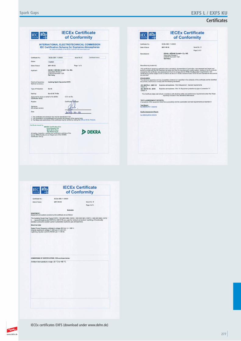
www.dehn.de 277
Spark Gaps EXFS L / EXFS KU
Certificates
IECEx certificates EXFS (download under www.dehn.de)
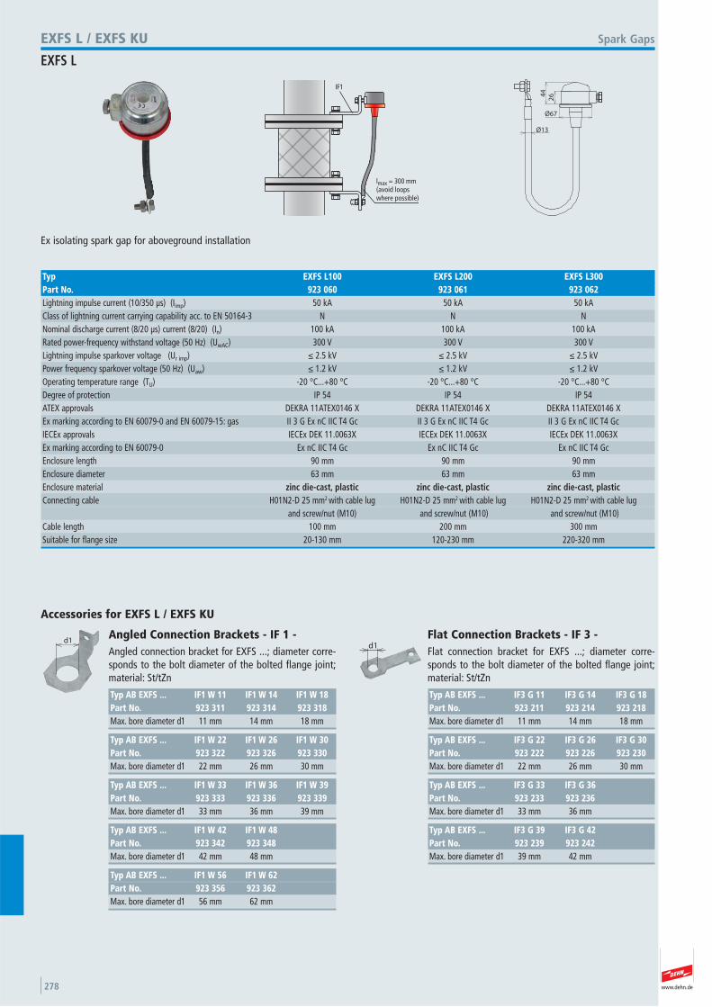
www.dehn.de278
lmax = 300 mm(avoid loopswhere possible)
IF1
Ø13
Ø67
264
4
Ex isolating spark gap for aboveground installation
Spark GapsEXFS L / EXFS KU
EXFS L
Typ EXFS L100 EXFS L200 EXFS L300Part No. 923 060 923 061 923 062Lightning impulse current (10/350 μs) (Iimp) 50 kA 50 kA 50 kAClass of lightning current carrying capability acc. to EN 50164-3 N N N Nominal discharge current (8/20 μs) current (8/20) (In) 100 kA 100 kA 100 kARated power-frequency withstand voltage (50 Hz) (UwAC) 300 V 300 V 300 VLightning impulse sparkover voltage (Ur imp) ≤ 2.5 kV ≤ 2.5 kV ≤ 2.5 kVPower frequency sparkover voltage (50 Hz) (Uaw) ≤ 1.2 kV ≤ 1.2 kV ≤ 1.2 kVOperating temperature range (TU) -20 °C...+80 °C -20 °C...+80 °C -20 °C...+80 °C Degree of protection IP 54 IP 54 IP 54 ATEX approvals DEKRA 11ATEX0146 X DEKRA 11ATEX0146 X DEKRA 11ATEX0146 X Ex marking according to EN 60079-0 and EN 60079-15: gas II 3 G Ex nC IIC T4 Gc II 3 G Ex nC IIC T4 Gc II 3 G Ex nC IIC T4 Gc IECEx approvals IECEx DEK 11.0063X IECEx DEK 11.0063X IECEx DEK 11.0063X Ex marking according to EN 60079-0 Ex nC IIC T4 Gc Ex nC IIC T4 Gc Ex nC IIC T4 Gc Enclosure length 90 mm 90 mm 90 mmEnclosure diameter 63 mm 63 mm 63 mmEnclosure material zinc die-cast, plastic zinc die-cast, plastic zinc die-cast, plasticConnecting cable H01N2-D 25 mm2 with cable lug H01N2-D 25 mm2 with cable lug H01N2-D 25 mm2 with cable lug and screw/nut (M10) and screw/nut (M10) and screw/nut (M10) Cable length 100 mm 200 mm 300 mmSuitable for flange size 20-130 mm 120-230 mm 220-320 mm
d1
Accessories for EXFS L / EXFS KU
Typ AB EXFS ... IF1 W 56 IF1 W 62Part No. 923 356 923 362Max. bore diameter d1 56 mm 62 mm
Typ AB EXFS ... IF1 W 42 IF1 W 48Part No. 923 342 923 348Max. bore diameter d1 42 mm 48 mm
Typ AB EXFS ... IF1 W 33 IF1 W 36 IF1 W 39Part No. 923 333 923 336 923 339Max. bore diameter d1 33 mm 36 mm 39 mm
Typ AB EXFS ... IF1 W 22 IF1 W 26 IF1 W 30Part No. 923 322 923 326 923 330Max. bore diameter d1 22 mm 26 mm 30 mm
Angled Connection Brackets - IF 1 - Angled connection bracket for EXFS ...; diameter corre-sponds to the bolt diameter of the bolted flange joint;material: St/tZn
Typ AB EXFS ... IF1 W 11 IF1 W 14 IF1 W 18Part No. 923 311 923 314 923 318Max. bore diameter d1 11 mm 14 mm 18 mm
d1
Typ AB EXFS ... IF3 G 39 IF3 G 42Part No. 923 239 923 242Max. bore diameter d1 39 mm 42 mm
Typ AB EXFS ... IF3 G 33 IF3 G 36Part No. 923 233 923 236Max. bore diameter d1 33 mm 36 mm
Typ AB EXFS ... IF3 G 22 IF3 G 26 IF3 G 30Part No. 923 222 923 226 923 230Max. bore diameter d1 22 mm 26 mm 30 mm
Flat Connection Brackets - IF 3 - Flat connection bracket for EXFS ...; diameter corre-sponds to the bolt diameter of the bolted flange joint;material: St/tZn
Typ AB EXFS ... IF3 G 11 IF3 G 14 IF3 G 18Part No. 923 211 923 214 923 218Max. bore diameter d1 11 mm 14 mm 18 mm
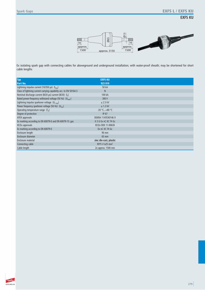
www.dehn.de 279
approx. 3150
Ø6
5 Ø1
3
16
approx.
1500
16
approx.
1500
Ex isolating spark gap with connecting cables for aboveground and underground installation; with water-proof sheath; may be shortened for short cable lengths
Spark Gaps EXFS L / EXFS KU
EXFS KU
Typ EXFS KUPart No. 923 019Lightning impulse current (10/350 μs) (Iimp) 50 kAClass of lightning current carrying capability acc. to EN 50164-3 N Nominal discharge current (8/20 μs) current (8/20) (In) 100 kARated power-frequency withstand voltage (50 Hz) (UwAC) 300 VLightning impulse sparkover voltage (Ur imp) ≤ 2.5 kVPower frequency sparkover voltage (50 Hz) (Uaw) ≤ 1.2 kVOperating temperature range (TU) -20 °C...+80 °C Degree of protection IP 67 ATEX approvals DEKRA 11ATEX0146 X Ex marking according to EN 60079-0 and EN 60079-15: gas II 3 G Ex nC IIC T4 Gc IECEx approvals IECEx DEK 11.0063X Ex marking according to EN 60079-0 Ex nC IIC T4 Gc Enclosure length 90 mmEnclosure diameter 63 mmEnclosure material zinc die-cast, plastic Connecting cable NYY-J-1x25 mm2
Cable length 2x approx. 1500 mm
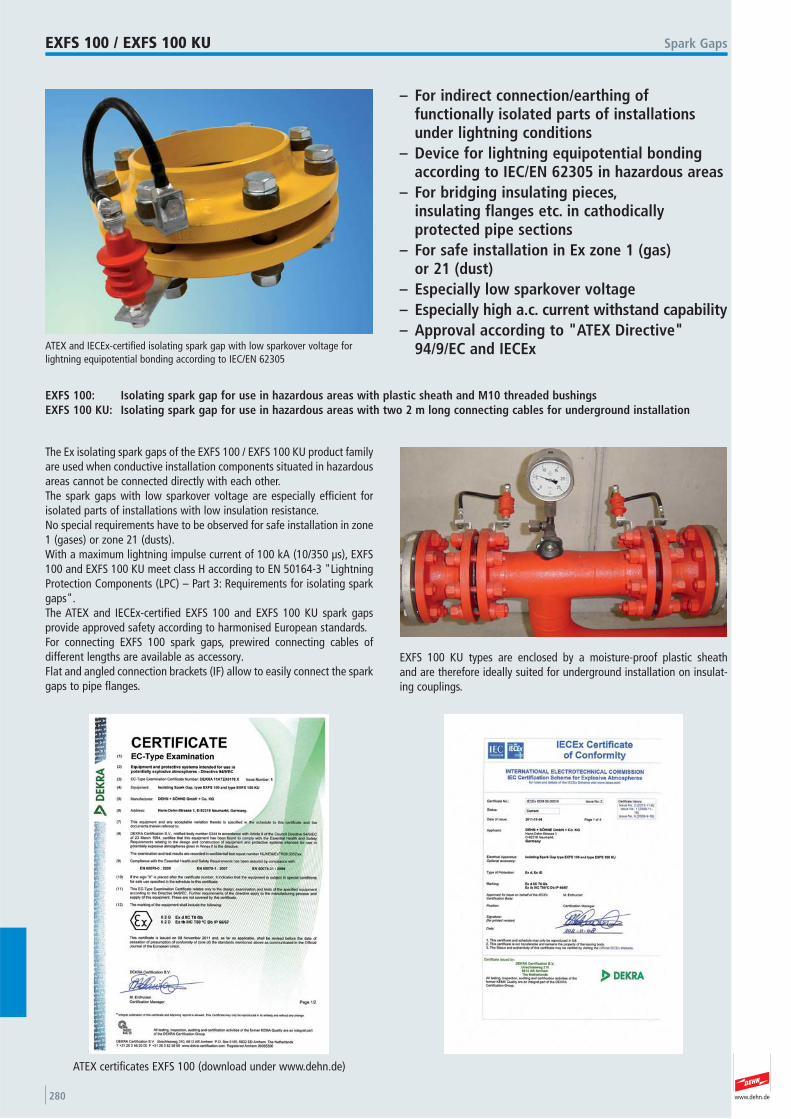
www.dehn.de280
– For indirect connection/earthing of functionally isolated parts of installationsunder lightning conditions
– Device for lightning equipotential bondingaccording to IEC/EN 62305 in hazardous areas
– For bridging insulating pieces, insulating flanges etc. in cathodically protected pipe sections
– For safe installation in Ex zone 1 (gas) or 21 (dust)
– Especially low sparkover voltage– Especially high a.c. current withstand capability– Approval according to "ATEX Directive"
94/9/EC and IECExATEX and IECEx-certified isolating spark gap with low sparkover voltage forlightning equipotential bonding according to IEC/EN 62305
Spark GapsEXFS 100 / EXFS 100 KU
EXFS 100: Isolating spark gap for use in hazardous areas with plastic sheath and M10 threaded bushingsEXFS 100 KU: Isolating spark gap for use in hazardous areas with two 2 m long connecting cables for underground installation
The Ex isolating spark gaps of the EXFS 100 / EXFS 100 KU product familyare used when conductive installation components situated in hazardousareas cannot be connected directly with each other. The spark gaps with low sparkover voltage are especially efficient for isolated parts of installations with low insulation resistance.No special requirements have to be observed for safe installation in zone1 (gases) or zone 21 (dusts).With a maximum lightning impulse current of 100 kA (10/350 μs), EXFS100 and EXFS 100 KU meet class H according to EN 50164-3 "LightningProtection Components (LPC) – Part 3: Requirements for isolating sparkgaps". The ATEX and IECEx-certified EXFS 100 and EXFS 100 KU spark gaps provide approved safety according to harmonised European standards.For connecting EXFS 100 spark gaps, prewired connecting cables of different lengths are available as accessory. Flat and angled connection brackets (IF) allow to easily connect the sparkgaps to pipe flanges.
EXFS 100 KU types are enclosed by a moisture-proof plastic sheath and are therefore ideally suited for underground installation on insulat-ing couplings.
ATEX certificates EXFS 100 (download under www.dehn.de)
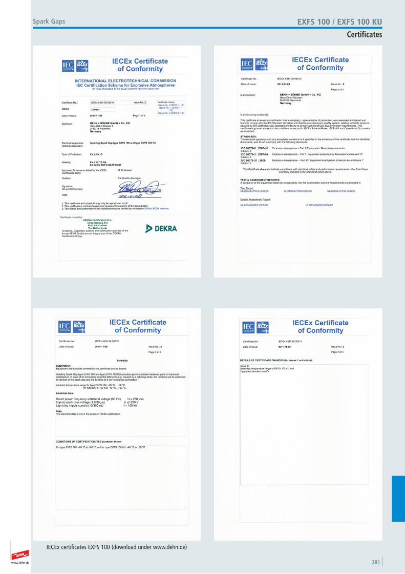
www.dehn.de 281
EXFS 100 / EXFS 100 KU
Certificates
Spark Gaps
IECEx certificates EXFS 100 (download under www.dehn.de)
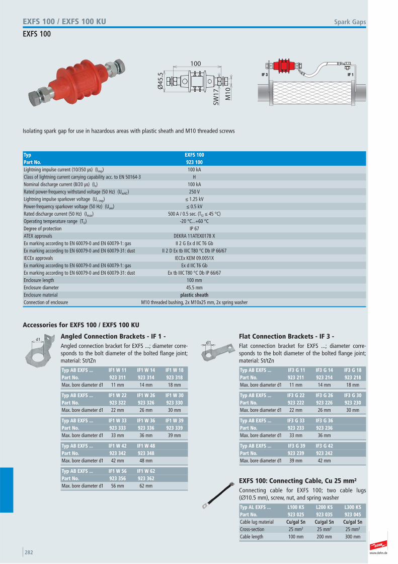
www.dehn.de282
100
Ø4
5.5
SW
17
M1
0
Isolating spark gap for use in hazardous areas with plastic sheath and M10 threaded screws
Spark GapsEXFS 100 / EXFS 100 KU
EXFS 100
Typ EXFS 100Part No. 923 100Lightning impulse current (10/350 μs) (Iimp) 100 kAClass of lightning current carrying capability acc. to EN 50164-3 H Nominal discharge current (8/20 μs) (In) 100 kARated power-frequency withstand voltage (50 Hz) (UwAC) 250 VLightning impulse sparkover voltage (Ur imp) ≤ 1.25 kVPower-frequency sparkover voltage (50 Hz) (Uaw) ≤ 0.5 kVRated discharge current (50 Hz) (Imax) 500 A / 0.5 sec. (TU: ≤ 45 °C) Operating temperature range (TU) -20 °C...+60 °C Degree of protection IP 67 ATEX approvals DEKRA 11ATEX0178 X Ex marking according to EN 60079-0 and EN 60079-1: gas II 2 G Ex d IIC T6 Gb Ex marking according to EN 60079-0 and EN 60079-31: dust II 2 D Ex tb IIIC T80 °C Db IP 66/67 IECEx approvals IECEx KEM 09.0051X Ex marking according to EN 60079-0 and EN 60079-1: gas Ex d IIC T6 Gb Ex marking according to EN 60079-0 and EN 60079-31: dust Ex tb IIIC T80 °C Db IP 66/67 Enclosure length 100 mmEnclosure diameter 45.5 mmEnclosure material plastic sheathConnection of enclosure M10 threaded bushing, 2x M10x25 mm, 2x spring washer
d1
Accessories for EXFS 100 / EXFS 100 KU
Typ AB EXFS ... IF1 W 56 IF1 W 62Part No. 923 356 923 362Max. bore diameter d1 56 mm 62 mm
Typ AB EXFS ... IF1 W 42 IF1 W 48Part No. 923 342 923 348Max. bore diameter d1 42 mm 48 mm
Typ AB EXFS ... IF1 W 33 IF1 W 36 IF1 W 39Part No. 923 333 923 336 923 339Max. bore diameter d1 33 mm 36 mm 39 mm
Typ AB EXFS ... IF1 W 22 IF1 W 26 IF1 W 30Part No. 923 322 923 326 923 330Max. bore diameter d1 22 mm 26 mm 30 mm
Angled Connection Brackets - IF 1 - Angled connection bracket for EXFS ...; diameter corre-sponds to the bolt diameter of the bolted flange joint;material: St/tZn
Typ AB EXFS ... IF1 W 11 IF1 W 14 IF1 W 18Part No. 923 311 923 314 923 318Max. bore diameter d1 11 mm 14 mm 18 mm
d1
Typ AB EXFS ... IF3 G 39 IF3 G 42Part No. 923 239 923 242Max. bore diameter d1 39 mm 42 mm
Typ AB EXFS ... IF3 G 33 IF3 G 36Part No. 923 233 923 236Max. bore diameter d1 33 mm 36 mm
Typ AB EXFS ... IF3 G 22 IF3 G 26 IF3 G 30Part No. 923 222 923 226 923 230Max. bore diameter d1 22 mm 26 mm 30 mm
Flat Connection Brackets - IF 3 - Flat connection bracket for EXFS ...; diameter corre-sponds to the bolt diameter of the bolted flange joint;material: St/tZn
Typ AB EXFS ... IF3 G 11 IF3 G 14 IF3 G 18Part No. 923 211 923 214 923 218Max. bore diameter d1 11 mm 14 mm 18 mm
EXFS 100: Connecting Cable, Cu 25 mm² Connecting cable for EXFS 100; two cable lugs (Ø10.5 mm), screw, nut, and spring washer
Typ AL EXFS ... L100 KS L200 KS L300 KSPart No. 923 025 923 035 923 045Cable lug material Cu/gal Sn Cu/gal Sn Cu/gal SnCross-section 25 mm2 25 mm2 25 mm2
Cable length 100 mm 200 mm 300 mm
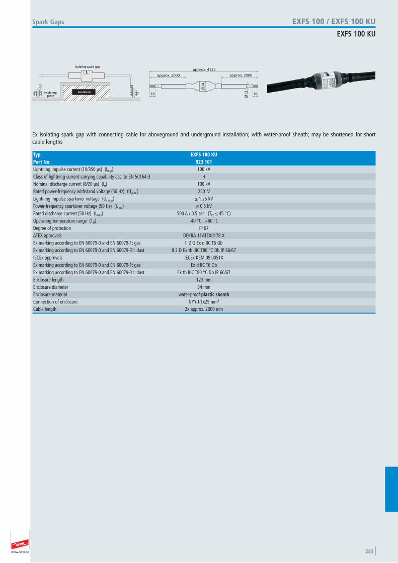
www.dehn.de 283
insulating piece
isolating spark gap
insulation
approx. 4125
Ø3
4
Ø1
3
1616
approx. 2000 approx. 2000
Ex isolating spark gap with connecting cable for aboveground and underground installation; with water-proof sheath; may be shortened for short cable lengths
Spark Gaps EXFS 100 / EXFS 100 KU
EXFS 100 KU
Typ EXFS 100 KUPart No. 923 101Lightning impulse current (10/350 μs) (Iimp) 100 kAClass of lightning current carrying capability acc. to EN 50164-3 H Nominal discharge current (8/20 μs) (In) 100 kARated power-frequency withstand voltage (50 Hz) (UwAC) 250 VLightning impulse sparkover voltage (Ur imp) ≤ 1.25 kVPower-frequency sparkover voltage (50 Hz) (Uaw) ≤ 0.5 kVRated discharge current (50 Hz) (Imax) 500 A / 0.5 sec. (TU: ≤ 45 °C) Operating temperature range (TU) -40 °C...+60 °C Degree of protection IP 67 ATEX approvals DEKRA 11ATEX0178 X Ex marking according to EN 60079-0 and EN 60079-1: gas II 2 G Ex d IIC T6 Gb Ex marking according to EN 60079-0 and EN 60079-31: dust II 2 D Ex tb IIIC T80 °C Db IP 66/67 IECEx approvals IECEx KEM 09.0051X Ex marking according to EN 60079-0 and EN 60079-1: gas Ex d IIC T6 Gb Ex marking according to EN 60079-0 and EN 60079-31: dust Ex tb IIIC T80 °C Db IP 66/67 Enclosure length 123 mmEnclosure diameter 34 mmEnclosure material water-proof plastic sheathConnection of enclosure NYY-J-1x25 mm2
Cable length 2x approx. 2000 mm

www.dehn.de284
www.dehn.de 285
Part No. Page Part No. Page Part No. Page Part No. Page Part No. Page Part No. Page
Part Nos / Page Index
100 100 24100 150 24
101 000 23101 001 71101 007 23101 009 23101 010 37101 110 37101 150 202
102 002 26102 003 26102 010 25102 050 27102 060 27102 075 26102 340 25
103 013 46103 016 46103 019 46103 022 46103 025 46103 030 47103 031 47103 040 48103 041 48103 121 45103 122 45103 123 45103 124 45103 125 45103 126 45103 210 23103 211 23103 220 23103 221 23103 230 23103 231 23103 240 23103 241 23103 250 23103 251 23103 260 23103 261 23103 280 23103 410 24103 417 24103 419 24103 420 24103 429 24103 430 24103 439 24103 440 24103 449 24103 450 24103 460 24103 480 24
104 150 23104 200 23104 250 23104 300 23104 600 24104 903 202104 905 202104 906 202
105 071 57105 079 57105 140 33105 160 34105 161 93105 170 31105 171 31105 172 31105 173 31105 174 31105 175 31105 176 31105 177 31105 178 31105 179 31105 200 66105 240 97105 245 97105 246 97105 290 32105 291 32105 300 71105 301 71105 302 71105 306 71105 310 71105 340 72105 341 63105 342 33105 343 34105 344 33105 345 85105 350 78105 354 34105 355 65105 356 65105 360 72105 361 72105 362 72105 363 83105 364 83105 365 83105 376 65105 400 42105 425 41105 430 41105 435 41105 440 60105 450 42105 455 61
105 470 61105 500 42105 550 42105 600 43105 650 43105 700 43105 750 43105 800 43105 850 43105 912 44105 914 44
106 008 38106 090 50106 100 50106 105 50106 115 49106 120 49106 121 66106 123 49106 125 51106 126 51106 127 51106 128 52106 129 52106 150 51106 160 51106 165 52106 170 52106 175 52106 178 52106 180 52106 185 52106 207 56106 210 56106 217 56106 220 56106 225 50106 226 50106 228 50106 245 50106 246 50106 248 50106 301 52106 309 52106 310 53106 311 52106 312 66106 315 53106 316 53106 319 55106 320 251106 321 54106 322 54106 323 54106 324 54106 325 55106 326 55106 328 66
106 331 66106 340 55106 341 55106 342 55106 352 53106 353 53106 760 74106 812 77106 813 77106 852 77106 898 76106 899 77
108 009 38
110 000 38110 017 38
123 021 35123 031 36123 109 28123 110 28123 116 29123 425 35123 430 35123 435 35
145 241 254
146 309 254
200 027 134200 029 134200 039 134200 057 134200 059 134200 067 134200 069 134200 077 134200 079 134200 087 134200 089 134200 600 142200 601 142
202 000 133202 001 133202 005 125202 008 117202 010 117202 015 125202 017 117202 020 112202 021 112202 027 112202 030 124202 037 117202 040 117202 050 118
202 060 124202 080 118202 169 133202 227 112202 830 76202 831 76202 832 76202 835 96202 836 96202 837 96202 840 76202 841 76202 842 76202 890 76202 900 112202 901 117202 902 117202 906 125
204 001 128204 002 128204 003 128204 004 128204 006 128204 007 128204 017 128204 027 128204 029 110204 037 128204 039 110204 049 119204 059 119204 069 119204 079 119204 089 113204 107 111204 109 111204 120 128204 127 111204 129 111204 147 112204 149 112204 157 112204 159 112204 169 112204 170 113204 171 113204 177 113204 179 113204 187 113204 189 113204 197 113204 199 113204 229 120204 239 120204 247 109204 249 109204 267 109204 269 109
204 359 118204 449 109204 469 109204 906 125204 911 111204 913 111204 916 125204 921 112204 924 113204 925 113204 935 116204 936 116204 937 116204 938 116204 949 116204 957 116
206 105 125206 109 111206 170 114206 171 114206 207 114206 209 114206 217 114206 219 114206 227 114206 229 114206 237 110206 239 110206 247 110206 249 110206 289 115206 309 114206 319 114206 329 114206 339 125206 349 120206 359 118206 369 120206 389 119206 399 119206 439 109206 449 109206 807 111206 809 111206 817 111206 819 111
207 007 127207 009 127207 017 127207 019 127207 027 127207 029 127207 037 127207 039 127207 109 127
216 000 110
www.dehn.de286
Part No. Page Part No. Page Part No. Page Part No. Page Part No. Page Part No. Page
Part Nos / Page Index
223 000 118223 005 31223 006 30223 010 121223 011 121223 020 122223 021 122223 031 122223 040 121223 041 121223 070 121
239 000 255239 001 255239 009 255239 019 255
240 000 255
241 009 255
250 000 131250 001 131250 007 131
251 002 162251 027 162
252 000 138
253 015 107253 021 108253 023 108253 025 108253 026 75253 027 75253 030 108253 050 107253 051 107253 060 107253 115 58253 125 58253 300 59253 301 59253 302 59253 310 59253 315 59253 325 59
260 106 137260 108 132260 118 133260 158 132260 187 132260 708 132
262 070 132262 100 132
273 019 133273 731 138273 740 132273 741 132273 742 132
274 030 139274 110 129274 113 129274 116 136274 117 129274 150 129274 160 129274 167 129274 230 139274 260 136
275 019 138275 030 140275 110 131275 113 131275 116 137275 120 74275 129 105275 160 131275 220 74275 225 74275 229 74275 230 140275 239 74275 260 137275 320 75275 330 75275 333 75275 440 101275 441 101275 442 101275 498 102275 520 78275 521 78275 711 135275 716 135275 730 135
276 006 130276 007 130276 009 130276 016 130276 017 130276 056 18276 057 18
277 130 242277 230 241277 237 241277 239 241277 240 241
284 030 140
284 040 140
286 030 140286 139 140286 819 130
290 001 222290 002 222
297 015 124297 025 124297 110 123297 120 123297 199 123
300 002 147300 017 147
301 000 146301 007 146301 009 147301 010 146301 017 146301 019 147301 229 73301 239 73301 329 73301 339 73
302 010 147
305 000 149305 007 149
306 020 149306 029 149306 100 149306 101 149
307 000 149307 007 149
308 001 221308 025 218308 026 218308 030 218308 031 220308 035 218308 036 220308 040 219308 041 219308 045 219308 046 219308 060 156308 070 156308 120 221308 129 221308 150 222308 220 155
308 229 155308 230 155308 239 155308 249 155308 320 155308 329 155308 330 155
309 008 148309 087 148
310 008 148
314 300 151314 307 151314 310 151
315 119 148
316 163 151316 167 151
318 033 154318 201 153318 207 153318 209 153318 219 154318 233 154318 251 154318 252 154
319 201 152319 202 153319 207 152319 209 152319 219 153319 229 153
320 044 154
321 045 152321 047 152
338 000 167338 001 167338 007 167338 009 167
339 010 167339 050 166339 051 166339 057 166339 059 166339 060 166339 061 166339 067 166339 069 166339 100 167339 101 167
339 110 167339 111 167339 157 166339 167 166
343 000 168343 007 168
345 008 168345 010 168
347 205 168
363 000 198363 010 198
365 000 162365 007 162365 010 161365 017 161365 019 161365 020 162365 027 162365 030 161365 031 161365 037 161365 039 161365 040 162365 047 162365 050 163365 051 163365 057 163365 059 163365 117 162365 127 162365 220 163365 221 163365 227 163365 229 163365 250 164365 419 177365 509 178365 519 178
370 014 157370 018 157
371 007 157371 008 157371 009 157
372 018 160372 019 160372 035 160372 110 158372 119 158372 120 159372 129 159372 140 158
372 149 158372 150 159372 159 159372 210 158372 219 158372 220 159372 229 159372 240 158372 249 158372 250 159372 259 159
374 011 173374 020 173
377 005 169377 006 174377 007 175377 009 169377 015 175377 016 174377 017 169377 026 174377 027 174377 045 175377 100 169377 107 175377 115 175377 200 169377 210 176377 310 176377 410 176377 510 176
380 020 170380 029 170380 110 171380 116 171380 129 170
385 202 150385 203 150385 207 150385 213 150385 216 150
390 050 143390 051 143390 057 143390 059 143390 060 144390 061 144390 067 144390 079 143390 110 133390 119 133390 150 146390 157 146390 159 146
www.dehn.de 287
Part No. Page Part No. Page Part No. Page Part No. Page Part No. Page Part No. Page
Part Nos / Page Index
390 250 145390 257 145390 259 145390 267 145390 479 198390 499 198390 550 143390 551 143390 557 143390 559 143390 657 144
391 050 143391 059 143391 060 144391 069 144391 550 143391 559 143
392 050 144392 059 144392 060 144392 069 144
393 069 55
405 020 73
407 012 237407 034 237407 100 237407 112 237407 114 237407 200 237
410 003 257410 005 257410 006 257410 010 257410 012 237410 015 257410 020 257410 025 257410 030 257410 034 237410 035 257410 038 237410 040 257410 050 257410 060 257410 070 257410 099 257410 100 237410 112 237410 114 237410 134 237410 140 257410 150 257410 199 257
410 200 237410 212 237410 219 86410 229 70410 299 257410 300 237410 309 238410 319 238410 329 238410 339 238410 349 238410 359 238410 369 238410 379 238410 389 238410 399 238410 401 260410 403 260410 404 260410 405 261410 406 260410 407 261410 410 261410 411 260410 413 261410 415 260410 416 261410 420 260410 421 261410 425 260410 426 261410 430 260410 431 261410 450 260410 503 260410 506 260410 510 260410 515 260410 520 260410 525 260410 530 260410 603 257410 605 257410 606 265410 610 257410 615 257410 620 257410 625 257410 630 257410 720 264410 903 263410 905 263410 906 263410 910 263410 915 263410 920 263410 925 263410 930 263
416 003 258416 005 258416 006 258416 010 258416 015 258416 016 264416 020 258416 025 258416 030 258416 035 258416 040 258416 050 258416 060 258416 070 258416 080 258416 100 258416 120 258416 140 258416 150 258416 200 258416 220 258416 280 258416 300 258416 403 262416 410 262416 411 262416 415 262416 416 262416 420 262416 421 262416 425 262416 426 262416 430 262416 431 262416 440 262416 441 262416 450 262416 451 262416 505 261416 516 258416 903 263416 905 263416 906 263416 910 263416 915 263416 920 263416 925 263416 930 263416 970 263
417 005 259417 010 259417 015 259417 020 259417 030 259417 050 259417 100 259417 115 259417 120 259
417 125 259417 130 259417 150 259
420 100 238420 107 238420 120 238420 127 238420 207 239
423 010 239423 011 239423 017 239423 019 239423 020 239423 021 239423 027 239423 029 239
425 076 274425 089 274
435 803 267435 805 267
444 006 266444 008 266444 009 266444 010 266
450 000 181450 001 181450 007 181450 011 181450 101 181
453 100 184
454 000 185454 100 185454 107 185
455 000 185
459 000 183459 003 183459 010 183459 019 183459 020 183459 029 183459 030 183459 039 183459 119 182459 127 182459 129 182459 139 182
460 147 185460 213 184
460 507 182460 517 182460 557 182
463 010 184
465 801 267
466 192 267466 203 268
472 021 233472 022 233472 023 233472 024 233472 109 233472 119 233472 129 233472 139 233472 201 232472 207 230472 209 230472 210 232472 217 231472 219 231472 227 230472 229 230472 237 231472 239 231472 269 232472 279 232472 289 232472 299 232
476 001 190476 010 189476 016 189476 020 190476 100 190
478 011 193478 012 194478 019 193478 027 196478 041 194478 049 194478 051 195478 099 203478 112 194478 129 199478 141 199478 200 195478 410 199478 430 199478 450 199478 530 200478 540 200478 550 200
480 003 191480 004 191480 005 191480 006 191480 018 202480 019 202480 020 202480 021 202480 113 192480 150 201480 157 201480 597 79480 698 39480 699 106
483 100 23483 125 23483 150 23483 200 23
528 610 177528 619 176528 850 142528 870 142
538 010 136538 030 141
540 100 236540 103 236540 105 36540 110 236540 200 235540 250 165540 251 165540 260 165540 261 165540 801 272540 803 272540 805 272540 810 273540 821 272540 900 235540 901 235540 910 234540 911 234540 912 234540 920 234540 930 135540 931 135
545 000 249545 001 249
546 000 240546 001 240546 002 240546 025 240549 000 186
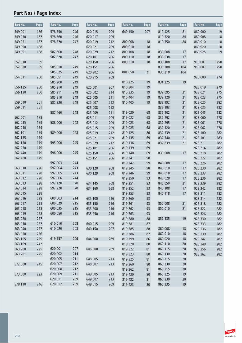
www.dehn.de288
Part No. Page Part No. Page Part No. Page Part No. Page Part No. Page Part No. Page
Part Nos / Page Index
549 001 186549 050 187549 051 187549 090 188549 091 188
552 010 39552 030 39
554 011 250
556 125 250556 130 250
559 010 251559 011 251
562 001 179562 035 179562 050 179562 101 179562 135 179562 150 179562 250 179562 440 179562 460 179
563 010 226563 011 228563 012 228563 013 228563 014 228563 015 228563 016 228563 017 228563 018 228563 019 228563 020 227563 030 227563 040 227563 050 226563 105 229563 169 242563 200 225563 201 225
572 000 245
573 000 223
578 110 246
578 350 246578 360 246578 370 247
582 600 248582 620 247
585 010 249585 025 249585 051 249585 200 249585 210 249585 211 249585 310 249585 320 249
587 460 248
588 000 248
589 000 248
595 000 245
596 000 245
597 003 244597 004 243597 005 243597 006 244597 120 70597 220 70
600 003 214600 029 215600 035 215600 050 215
610 010 208610 020 208
619 157 206
620 001 207620 002 214620 005 211620 007 212620 008 212620 009 211620 011 209620 012 209
620 015 209620 017 209620 019 212620 021 209620 029 212620 101 206620 150 206620 151 206620 902 206620 915 209
625 001 207625 002 214625 005 211625 007 212625 008 212625 009 211625 011 209625 012 209625 015 209625 019 212625 021 209625 029 212625 101 206625 150 206625 151 206
630 120 208630 129 208
634 145 268634 160 268
635 100 216635 150 216635 200 216635 250 216
640 015 209640 150 207
644 000 269
646 000 269
648 005 213648 007 213
649 005 213649 007 213649 015 209
649 150 207
800 008 18800 010 18800 108 18800 110 18800 310 18
801 050 21
810 225 19810 304 19810 335 19810 404 19810 405 19
819 020 68819 022 68819 023 68819 025 68819 125 86819 135 69819 136 69819 139 69819 140 69819 241 98819 242 99819 245 98819 246 99819 250 93819 251 93819 252 93819 253 93819 260 93819 261 93819 262 93819 263 93819 280 88819 281 87819 285 88819 286 87819 299 86819 320 80819 322 81819 323 80819 325 81819 360 80819 362 81819 420 80819 422 81819 423 80
819 425 81819 720 84819 750 84
830 008 17830 038 17830 108 17830 208 104830 218 104
831 225 19
832 095 21832 120 21832 192 21832 193 21832 202 21832 292 21832 295 21832 320 21832 739 21832 740 21832 839 21
833 008 17
840 008 17840 010 17840 018 17840 028 17840 050 21840 108 17840 118 17
850 008 21850 010 21
852 335 19
860 008 18860 010 18860 020 18860 110 20860 115 20860 130 20860 215 20860 230 20860 315 20860 325 19860 330 20860 335 19
860 900 19860 908 18860 910 18860 920 18860 925 19
910 001 250910 007 250
920 000 274
923 019 279923 021 275923 023 275923 025 282923 035 282923 045 282923 060 278923 061 278923 062 278923 100 282923 101 283923 211 282923 214 282923 218 282923 222 282923 226 282923 230 282923 233 282923 236 282923 239 282923 242 282923 311 282923 314 282923 318 282923 322 282923 326 282923 330 282923 333 282923 336 282923 339 282923 342 282923 348 282923 356 282923 362 282
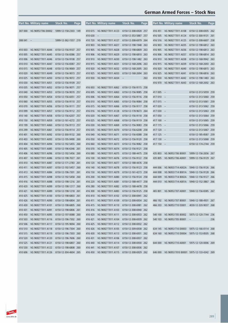
www.dehn.de 289
Part No. Military name Stock No. Page Part No. Military name Stock No. Page Part No. Military name Stock No. Page
German Armed Forces – Stock Nos
307 000 VG 96953 T06 D0002 5999-12-158-2303 149
308 041 – 5999-12-362-1557 219
410 003 VG 96927 T011 A044 6150-12-156-9107 257
410 005 VG 96927 T011 A045 6150-12-156-8386 257
410 006 VG 96927 T011 A046 6150-12-156-9108 257
410 010 VG 96927 T011 A047 6150-12-156-8387 257
410 015 VG 96927 T011 A048 6150-12-156-9069 257
410 020 VG 96927 T011 A049 6150-12-156-9073 257
410 025 VG 96927 T011 A050 6150-12-156-9072 257
410 030 VG 96927 T011 A051 6150-12-156-9109 257
410 035 VG 96927 T011 A052 6150-12-156-9071 257
410 040 VG 96927 T011 A053 6150-12-156-9070 257
410 050 VG 96927 T011 A054 6150-12-156-6051 257
410 060 VG 96927 T011 A055 6150-12-156-9110 257
410 070 VG 96927 T011 A056 6150-12-156-9111 257
410 099 VG 96927 T011 A057 6150-12-156-9112 257
410 140 VG 96927 T011 A058 6150-12-156-6207 257
410 150 VG 96927 T011 A059 6150-12-161-4272 257
410 199 VG 96927 T011 A060 6150-12-156-9113 257
410 299 VG 96927 T011 A061 6150-12-156-9114 257
410 401 VG 96927 T011 A092 6150-12-300-9132 260
410 403 VG 96927 T011 A093 6150-12-195-9490 260
410 404 VG 96927 T011 A094 6150-12-192-5455 260
410 405 VG 96927 T011 A085 6150-12-196-6346 261
410 406 VG 96927 T011 A096 6150-12-192-5456 260
410 407 VG 96927 T011 A086 6150-12-198-7027 261
410 410 VG 96927 T011 A087 6150-12-171-2783 261
410 411 VG 96927 T011 A097 6150-12-192-5457 260
410 413 VG 96927 T011 A084 6150-12-196-7301 261
410 415 VG 96927 T011 A098 6150-12-192-5458 260
410 416 VG 96927 T011 A088 6150-12-198-1216 261
410 420 VG 96927 T011 A099 6150-12-198-1217 260
410 421 VG 96927 T011 A089 6150-12-198-1218 261
410 425 VG 96927 T011 A100 6150-12-198-6803 261
410 426 VG 96927 T011 A090 6150-12-198-6804 261
410 430 VG 96927 T011 A101 6150-12-198-6805 260
410 431 VG 96927 T011 A091 6150-12-198-6806 261
410 450 VG 96927 T011 A095 6150-12-197-0088 260
410 503 VG 96927 T011 A116 6150-12-196-7302 260
410 506 VG 96927 T011 A117 6150-12-195-9694 260
410 510 VG 96927 T011 A118 6150-12-196-7304 260
410 515 VG 96927 T011 A119 6150-12-196-7303 260
410 520 VG 96927 T011 A120 6150-12-196-7606 260
410 525 VG 96927 T011 A121 6150-12-198-6807 260
410 530 VG 96927 T011 A122 6150-12-198-6808 260
410 606 VG 96927 T011 A126 6150-12-304-4604 265
410 615 VG 96927 T011 A123 6150-12-308-6928 257
410 630 – 6150-12-353-5887 257
410 720 VG 96927 T011 A127 6150-12-308-6979 264
410 903 VG 96927 T011 A027 6150-12-198-1948 263
410 905 VG 96927 T011 A028 6150-12-198-6809 263
410 906 VG 96927 T011 A029 6150-12-198-6810 263
410 910 VG 96927 T011 A030 6150-12-198-1482 263
410 915 VG 96927 T011 A031 6150-12-168-2696 263
410 920 VG 96927 T011 A032 6150-12-168-2695 263
410 925 VG 96927 T011 A033 6150-12-168-2694 263
410 930 VG 96927 T011 A034 – 263
416 003 VG 96927 T011 A062 6150-12-156-9115 258
416 005 VG 96927 T011 A063 6150-12-156-9085 258
416 006 VG 96927 T011 A064 6150-12-156-9116 258
416 010 VG 96927 T011 A065 6150-12-156-9084 258
416 015 VG 96927 T011 A066 6150-12-156-9117 258
416 016 VG 96927 T011 A128 6150-12-178-9673 264
416 020 VG 96927 T011 A067 6150-12-156-9118 258
416 025 VG 96927 T011 A068 6150-12-156-9119 258
416 030 VG 96927 T011 A069 6150-12-156-9083 258
416 035 VG 96927 T011 A070 6150-12-156-6208 258
416 040 VG 96927 T011 A071 6150-12-156-8388 258
416 050 VG 96927 T011 A072 6150-12-156-9120 258
416 060 VG 96927 T011 A073 6150-12-156-9082 258
416 070 VG 96927 T011 A074 6150-12-156-9121 258
416 080 VG 96927 T011 A075 6150-12-188-4475 258
416 100 VG 96927 T011 A076 6150-12-156-9122 258
416 120 VG 96927 T011 A077 6150-12-188-4476 258
416 140 VG 96927 T011 A078 6150-12-156-9123 258
416 150 VG 96927 T011 A079 6150-12-161-4273 258
416 200 VG 96927 T011 A080 6150-12-156-9124 258
416 220 VG 96927 T011 A081 6150-12-188-4477 258
416 280 VG 96927 T011 A082 6150-12-188-4478 258
416 300 VG 96927 T011 A083 6150-12-156-9125 258
416 410 VG 96927 T011 A102 6150-12-308-6941 262
416 411 VG 96927 T011 A109 6150-12-308-6934 262
416 415 VG 96927 T011 A110 6150-12-308-6981 262
416 416 VG 96927 T011 A103 6150-12-308-6940 262
416 420 VG 96927 T011 A111 6150-12-308-6933 262
416 421 VG 96927 T011 A104 6150-12-308-6939 262
416 425 VG 96927 T011 A112 6150-12-308-6932 262
416 426 VG 96927 T011 A105 6150-12-309-6938 262
416 430 VG 96927 T011 A113 6150-12-308-6931 262
416 431 VG 96927 T011 A106 6150-12-308-6937 262
416 440 VG 96927 T011 A114 6150-12-308-6930 262
416 441 VG 96927 T011 A107 6150-12-308-6936 262
416 450 VG 96927 T011 A115 6150-12-308-6929 262
416 451 VG 96927 T011 A108 6150-12-308-6935 262
416 505 VG 96927 T011 A124 6150-12-300-9131 261
416 516 VG 96927 T011 A125 6150-12-308-6607 258
416 903 VG 96927 T011 A035 6150-12-198-6812 263
416 905 VG 96927 T011 A036 6150-12-198-6813 263
416 906 VG 96927 T011 A037 6150-12-198-6814 263
416 910 VG 96927 T011 A038 6150-12-168-9942 263
416 915 VG 96927 T011 A039 6150-12-168-2693 263
416 920 VG 96927 T011 A040 6150-12-198-6815 263
416 925 VG 96927 T011 A041 6150-12-198-6816 263
416 930 VG 96927 T011 A042 6150-12-198-1483 263
416 970 VG 96927 T011 A043 6150-12-168-2692 263
417 005 – 6150-12-313-5059 259
417 010 – 6150-12-313-5060 259
417 015 – 6150-12-313-5061 259
417 020 – 6150-12-313-5062 259
417 030 – 6150-12-313-5063 259
417 050 – 6150-12-313-5064 259
417 100 – 6150-12-313-5065 259
417 115 – 6150-12-313-5066 259
417 120 – 6150-12-313-5067 259
417 125 – 6150-12-185-8587 259
417 130 – 6150-12-313-5068 259
417 150 – 6150-12-174-2744 259
435 803 VG 96953 T06 B0001 5999-12-156-2656 267
435 805 VG 96953 T06 A0001 5999-12-156-9129 267
444 006 VG 96933 T14 A002A 5940-12-156-9126 266
444 008 VG 96933 T14 B001A 5940-12-156-9128 266
444 009 VG 96933 T14 B002A 5940-12-156-9127 266
444 010 VG 96933 T14 A001A 5940-12-152-3867 266
465 801 VG 96953 T07 A0001 5940-12-156-8385 267
466 192 VG 96953 T07 B0001 5940-12-188-4931 267
466 203 VG 96953 T10 E0001 4030-12-320-9037 268
540 100 VG 96953 T05 B0002 5975-12-120-7744 236
540 103 VG 96953 T05 B0001 – 236
634 145 VG 96953 T10 D0003 5975-12-166-0114 268
634 160 VG 96953 T10 D0004 5975-12-153-8505 268
644 000 VG 96953 T10 A0001 5975-12-120-0006 269
646 000 VG 96953 T010 B0001 5975-12-133-4342 269
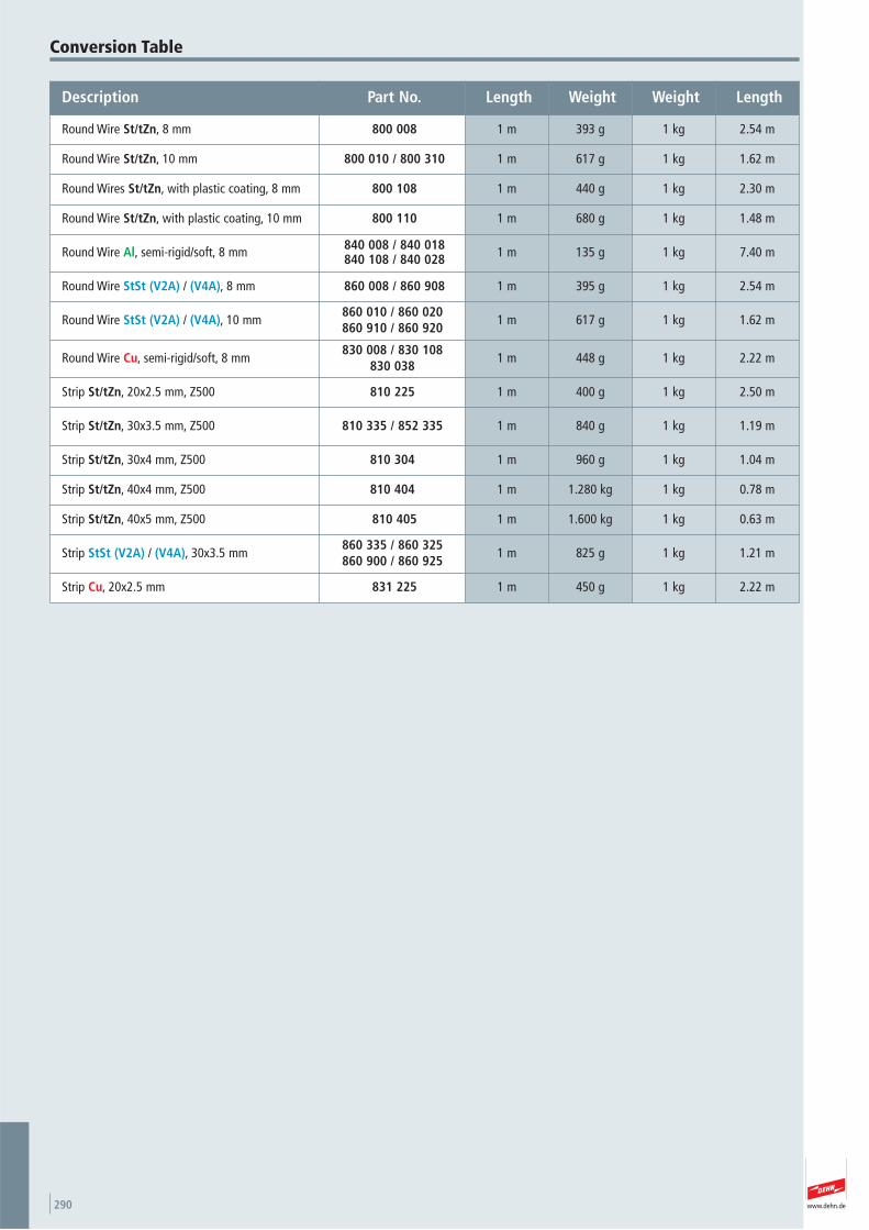
www.dehn.de290
Conversion Table
Description Part No. Length Weight Weight Length
Round Wire St/tZn, 8 mm 800 008 1 m 393 g 1 kg 2.54 m
Round Wire St/tZn, 10 mm 800 010 / 800 310 1 m 617 g 1 kg 1.62 m
Round Wires St/tZn, with plastic coating, 8 mm 800 108 1 m 440 g 1 kg 2.30 m
Round Wire St/tZn, with plastic coating, 10 mm 800 110 1 m 680 g 1 kg 1.48 m
Round Wire Al, semi-rigid/soft, 8 mm 840 008 / 840 018840 108 / 840 028 1 m 135 g 1 kg 7.40 m
Round Wire StSt (V2A) / (V4A), 8 mm 860 008 / 860 908 1 m 395 g 1 kg 2.54 m
Round Wire StSt (V2A) / (V4A), 10 mm860 010 / 860 020860 910 / 860 920
1 m 617 g 1 kg 1.62 m
Round Wire Cu, semi-rigid/soft, 8 mm830 008 / 830 108
830 0381 m 448 g 1 kg 2.22 m
Strip St/tZn, 20x2.5 mm, Z500 810 225 1 m 400 g 1 kg 2.50 m
Strip St/tZn, 30x3.5 mm, Z500 810 335 / 852 335 1 m 840 g 1 kg 1.19 m
Strip St/tZn, 30x4 mm, Z500 810 304 1 m 960 g 1 kg 1.04 m
Strip St/tZn, 40x4 mm, Z500 810 404 1 m 1.280 kg 1 kg 0.78 m
Strip St/tZn, 40x5 mm, Z500 810 405 1 m 1.600 kg 1 kg 0.63 m
Strip StSt (V2A) / (V4A), 30x3.5 mm860 335 / 860 325860 900 / 860 925
1 m 825 g 1 kg 1.21 m
Strip Cu, 20x2.5 mm 831 225 1 m 450 g 1 kg 2.22 m
www.dehn.de 291
Since we do not plan systems or parts of sys-tems, our product recommendations should beregarded as product information and for advi-sory purposes only. Our oral and written appli-cation proposals are based on experience and
are specified to the best of our knowledge. Wedo not accept any liability in this respect. Thisparticularly applies to the different conditionsof use which are beyond our control. We recom-mend to check whether the respective DEHN
product is suitable for the intended application.Application, use and processing of our productsare beyond our control. Therefore, the product iscompletely subject to the user’s responsibility.
Trademarks
– BLITZPLANER®
– DEHNgrip®
– DEHNfix®
– DEHNQUICK®
– DEHNsnap®
– HVI®
– ...MIT SICHERHEIT DEHN.®
– Colour trademark "red" 302 40 296.9
and our brand
are registered trademarks of DEHN + SÖHNE GmbH + Co.KG.in Germany
Notes
www.dehn.de292
Accessories for HVI Conductor and HVI long Conductor 71
Accessories for HVI long Conductor 69Air-termination Caps 38Air-termination Masts for HVI light
Conductor on Flat Roofs 87Air-termination Masts for Sub-roof
Installation of the HVI Conductor 98Air-termination Masts with
HVI Conductor 84Air-termination Rod Adapter 38Air-termination Rod for Ridge and
Hip Tiles 28Air-termination Rod for Trapezoidal
Sheet Metal Roofing 36Air-termination Rod Holder for
Gable Roofs 30Air-termination Rods 23Air-termination Rods D40 31Air-termination Rods for Metal Roofs 35Air-termination Rods GRP/AI 56Air-termination Stud 38Anchoring Pole 268Angled Air-termination Rods 37Anti-corrosion Tape 250
Bimetallic Disconnecting Clamp with Shield 185
Blind Rivet 177Bridging Brackets 174Bridging Braids 175Bridging Cable with Saddle Clamps 177Bridging Cables 176Bucket Foundations for Telescopic
Lightning Protection Masts 47
Cables 21Clamping Frame Variants 146Clamping Piece 170Clamping Shoes 168Clip 251Components for Buildings with
Thathed Roof 254Concrete Bases 25Conductor Holder 242Conductor Holder for CUI Conductor 105Conductor Holder for HVI Conductor
in Ex Areas 100Conductor Holder for Rafters 97Conductor Holders 127 – 135Conductor Holders for Roof Poles 274Connecting / Disconnecting Clamps 185Connecting Clamps for Fixed Earthing
Terminals and Reinforcement 197Connecting Clamps for Foundation
Earth Electrodes 221Connecting Clamps for
Reinforcements 217 – 220Connecting Set for Safety
Rope System 178Connecting Sleeve for
Air-termination Rods 24/150Connecting Sleeves 150Connection Lugs 169
Connectors 148Cover Discs and Plastic Bases 130Cross Units 151 – 154CUI Conductor 103Cupal Sheets 179Cupal Sleeves 179
DEHNcon-H 92DEHNiso Combi Sets 60DEHNiso Roof Conductor Holders 58DEHNiso Spacers 49DEHNIT Earthing Method 223Disconnecting Clamp –
Austrian Standard 184Disconnecting Sleeves 181Dowels for Rigid Foam Plates 142Downpipe Clamps 238Drilling Screw 176Dripping Water Protective Collars 18
Earth Electrode and Wall Bushings 199Earth Entry Rods – Kit 201Earth Entry Rods 202Earth Resistance Measuring
Equipment in a leather case 248Earth Rods 205Earthing Busbars 233/267Earthing Cable Lugs 266Earthing Clamps 267Earthing Conductors 257 – 265Earthing Pipe Clamps 234Earthing Pipe Clamps
Lightning Protection 237Earthing Pipe with Drilling Spiral 269Earthing Pipe with Impact Spike 269Earthing Resistance Meter 246Earthing Spikes 268Earthing Test Tongs CA 6412 246Earthing Tongs 240End Pieces 198EP4 Continuity Tester 247Equipotential Busbars 225 – 232ES Disconnecting Clamp 184EXFS 100 / EXFS 100 KU 280EXFS L / EXFS KU 276Expansion Pieces 173Expansion Strap for Foundation
Earth Electrodes 222
FIX Test Joint 184Fixed Earthig Terminal M16 196Fixed Earthing Terminals 193Flat Strip Holders DEHNhold 139Flat Strip Holders with Cleat –
Flat Design 140Flat Strip Holders with
Cleat and Flange 140Flat Strip Holders with
Thrust Piece 141/241Foundation Basket for On-site
Concrete Foundation 48FS Clamps 171
Gutter Clamps 166Gutter Clamps with
Single-screw Technique 167
Hammer Frame 214Hammer Inserts for Earth Rods 211Hammer Inserts for
Tubular Earth Rods 213Hammer Support 215Heat-shrinkable Sleeve 250Holders for Air-termination System
on Ridge an Hip Tiles 28HVI Conductor 67HVI Conductor in Supporting Tube 80HVI light Conductor 86HVI Lightning Protection for Thatched Roofs 253HVI long Conductor 69
Impact Heads 214Impact Spikes 207Information Sign 39Inspection Doors 190Isolating Spark Gaps 275
KS Connectors 146
Leather Case with Measuring Accessories for Continuity Tester 247
Lightning Protection Pipe Clamp with Tines 235
MAXI MV Clamps 145MMV Clamps 145MV Clamps 143MV Clamps for Air-termination Rods 171
Number Plates 191
Occurrence Counter 250
Parallel Connectors 149Pipe Clamp for Air-termination Rods 36Pipe Clamps for Antennas 236Pipe Clamps for Hazardous Areas 271Pipe Clamps for Roof Poles 274Plastic Conductor Holders for
Downpipes 135Profiled Earth Rods 216Protective Spark Gap 274
Rod Clamps 170Rod Holder for Gable Roofs 31Rod Holder with Claw 138Rod Holders DEHNfix 138Rod Holders DEHNhold 136Rod Holders for External Thermal
Insulation Composite Systems 138Rod Holders with Cleat 137Roof Bushings 39Roof Conductor Holder with Brace
for HVI light Conductor 96Roof Conductor Holders 107 – 125
Roof Conductor Holders for ridge and hip tiles 110
Round Wires 17
Saddle Clamps 161Saddle Clamps with Enlarged
Contact Surface 163Self-supporting Air-termination
Rods 12/14 m 44Self-supporting Air-termination
Rods 41/42Single-screw Terminal Clamps 208Snow Guard Clamps 168Spacers 222Spacers for Omnidirectional Antennas 82Special Coating Paint 251Spider Wrench 245Staples 136Staples for Flat Strips 141Straightening Tools 245Stripping Tool for HVI Conductors 70Strips 9Support Plates 27Supports for Air-termination Rods
D40 and DEHNcon-H 33Supports for VDB Test Badge 192SV Clamps 155SVP Clamps 156
Telescopic Lightning Protection Masts 45/46
Terminal Brackets 209Terminal Clamps 157/208/242Terminal Clamps for Steel Girders 158Terminal Clamps with Threaded Bold 199Terminal Clamps with Thrust Piece 160Terminal Lugs
Straightened/Angled 20/203Tripods for Air-termination Rods D40
and Supporting Tubes GRP/AI 32Tubular Earth Rods 207
UF Test Joint Boxes 186UNI Disconnecting Clamps 182UNI Earthing Clamps 165UNI Saddle Clamp 164Universal Connector 148UP Test Joint Boxes 189
Warning Sign 106Water pressure-tight Wall Bushings
for White Tank 200Wedge Connector 221Wire Straighteners 243Wood Screws with Threaded Head 142
Product Page Product Page Product Page Product Page
Key Words

DS427/E/0113 © Copyright 2013 DEHN + SÖHNE
Surge ProtectionLightning ProtectionSafety EquipmentDEHN protects.
Tel. +49 9181 906-0Fax +49 9181 [email protected]
Hans-Dehn-Str. 1Postfach 164092306 NeumarktGermany
DEHN + SÖHNEGmbH + Co.KG.