levelvue b10 - campbell scientific
TRANSCRIPT

Revision: 09/2022Copyright © 2020 – 2022Campbell Scientific, Inc.
Table of contents1. Introduction 1
2. Precautionary statements 1
3. Initial inspection 1
4. QuickStart 2
5. Overview 5
6. Specifications 76.1 Pressure transducer 76.2 Air flow 86.3 Power 86.4 Communications 86.5 Enclosure 96.6 Environmental 9
7. Installation 97.1 Verify operation 107.2 Wiring 107.3 Power considerations 127.4 Default settings 127.5 Setup using keypad/display 147.6 Campbell Scientific data logger programming 16
7.6.1 SDI-12 programming 167.6.2 Modbus programming 16
7.7 Field installation 177.7.1 Site selection 177.7.2 Enclosure mounting 177.7.3 Desiccator installation 187.7.4 Orifice line and conduit installation 20
8. Operation 228.1 Principles of operation 228.2 Keypad/display menu 23
Table of Contents - i

8.2.1 Stage setup 248.2.2 Bubbler setup 248.2.3 System setup 258.2.4 Communication setup 268.2.5 Diagnostic/Test 268.2.6 System information 30
8.3 SDI-12 measurement and extended commands 308.4 Modbus register map 338.5 Secured orifice line 388.6 Long orifice lines 408.7 Orifice-line outlet orientation 408.8 Orifice-line outlet types 41
9. Maintenance and troubleshooting 429.1 Replacing desiccant 429.2 Lithium battery replacement 439.3 Plugged orifice outlet 449.4 Cold weather 459.5 Preventing or fixing orifice-line leaks 459.6 Updating operating system 459.7 Troubleshooting 46
Appendix A. Example program 49
Appendix B. SDI-12 sensor support 51B.1 SDI-12 command basics 51
B.1.1 Acknowledge active command (a!) 52B.1.2 Send identification command (al!) 52B.1.3 Start verification command (aV!) 53B.1.4 Address query command (?!) 53B.1.5 Change address command (aAb!) 53B.1.6 Start measurement commands (aM!) 54B.1.7 Start concurrent measurement commands (aC!) 54B.1.8 Start measurement commands with cyclic redundancy check (aMC! and aCC!) 56B.1.9 Stopping a measurement command 56B.1.10 Send data command (aD0! … aD9!) 56B.1.11 Extended commands 57B.1.12 SDI-12 version 1.4 identify measurement commands and responses 57
Table of Contents - ii

B.2 SDI-12 transparent mode 58B.2.1 Changing an SDI-12 address 59
B.3 References 61
Appendix C. Field calibration check 62
Table of Contents - iii

1. IntroductionThe LevelVUE B10 is a continuous-air-flow bubbler that measures ground water, surface water, orany liquid level. It consists of an integrated circuit board, pressure sensors to measure andcontrol tank and line pressures, a 12 VDC industrial compressor, a 0.8 liter air tank, and anintegrated keypad/display. Three pressure ranges are available: 15 psi (34.6 ft, 10.5 m), 30 psi(69.2 ft, 21.0 m), or 50 psi (115 ft, 35.0 m). The bubbler communicates with a data logger or RTUusing either SDI-12 or Modbus protocols. Although this document only includes exampleprograms for Campbell Scientific CRBasic data loggers, any data logging device capable of SDI-12 or Modbus communications can be used to retrieve the LevelVUE B10 measurements.
2. Precautionary statementsl READ AND UNDERSTAND the Safety section at the back of this manual.l Not using a desiccator will void your warranty. Campbell Scientific offers a desiccator kit,
which is recommended for use with the LevelVUE B10.l The sensor can survive temporary operation for 1.5 times the maximum rated pressure
(Table 6-1 [p. 7]). However, measurements made beyond the rated pressure range will beinaccurate.
l Do not use quick connect fittings as these tend to leak.l Mount the LevelVUE B10 in a location where it will not get jarred or shift during operation.
3. Initial inspectionl Upon receipt of the LevelVUE B10, inspect the packaging for shipping damage, and, if
found, report the damage to the carrier in accordance with policy.l Carefully open the package to avoid damaging or cutting the orifice-line tubing (if
ordered). A thorough inspection of the tubing is prudent.
LevelVUE™B10 Water-Level Bubbler 1

l Compare the pressure range printed on the bottom of the enclosure with the pressurerange listed in the shipping document to ensure that the correct pressure range wasreceived.
l Verify that the orifice line Swagelok® fitting and air intake line barbed fitting were shippedwith the LevelVUE B10. They are shipped in a small bag inside the enclosure. Do thefollowing to locate these items:
o Open the enclosure lido Press on the black magneto Lift the keypad panel
l NOTE:The orifice line Swagelok® fitting may already be installed on the LevelVUE B10.
l Verify that all bubbler accessories were sent. The following accessories (ordered separately)are often shipped with the LevelVUE B10:
o Orifice lineo Desiccator kito Desiccant
4. QuickStartA video that describes data logger programming using Short Cut is available at:www.campbellsci.com/videos/cr1000x-data logger-getting-started-program-part-3 . ShortCut is an easy way to program your data logger to measure the sensor and assign data loggerwiring terminals. Short Cut is available as a download on www.campbellsci.com . It is includedin installations of LoggerNet, RTDAQ, and PC400.
The following procedure also shows using Short Cut to program the LevelVUE B10.
1. Open Short Cut and click Create New Program.
2. Double-click the data logger model.
LevelVUE™B10 Water-Level Bubbler 2

3. In the Available Sensors and Devices box, type LevelVUEB10 or locate the sensor in theSensors > Water > Level & Flow folder. Double-click LevelVUEB10 Water-Level ContinuousFlow Bubbler. Stage defaults to feet and temperature defaults to degrees Celsius. Thesecan be changed by clicking the Stage or Temperature box and selecting a different option.Type the correct SDI-12 Address for the LevelVUE B10.
4. Click the Wiring tab to see how the sensor is to be wired to the data logger. The defaultcontrol terminal for SDI-12 is C1. To change to another terminal, click the terminal nameand select another terminal. Click OK after wiring the sensor.
LevelVUE™B10 Water-Level Bubbler 3

5. Repeat steps three and four for other sensors you want to measure. Click Next.
6. In Output Setup, type the scan rate, a Table Name, and Data Output Storage Interval. ClickNext.
NOTE:Because of the sensor response time, Campbell Scientific recommends measurementscans of at least 30 seconds.
7. Select the output options.
LevelVUE™B10 Water-Level Bubbler 4
8. Click Finish and save the program. Send the program to the data logger if the data loggeris connected to the computer.
9. If the sensor is connected to the data logger, check the output of the sensor in the datadisplay in LoggerNet, RTDAQ, or PC400 to make sure it is making reasonablemeasurements.
5. OverviewThe LevelVUE B10 bubbler incorporates all the components of a self-contained pressurized airsupply system. It has an air compressor, air tank, and other components of older conoflowsystems. However, instead of pressurized air tanks and manual valves used in conoflow systems,the LevelVUE B10 meters the airflow to create a constant flow in the line regardless of the waterdepth above the orifice. Precision sensors monitor the tank and line pressures to consistentlymaintain the same airflow. The precision sensor monitoring the pressure on the orifice lineprecisely detects the pressure required to push air through the line. This pressure value is directlyrelated to water depth. A simple conversion is applied to the pressure value to generate waterdepth in feet, meters, or other units. Proprietary electronics control the pump and calculate themeasurements. The LevelVUE B10 has a digital SDI-12 or RS-485 output that allows any datalogger that supports SDI-12 or Modbus protocols to retrieve the LevelVUE B10 measurements.Figure 5-1 (p. 6) shows a LevelVUE B10-based system that uses a Campbell Scientific data loggerand SDI-12 protocol.
LevelVUE™B10 Water-Level Bubbler 5
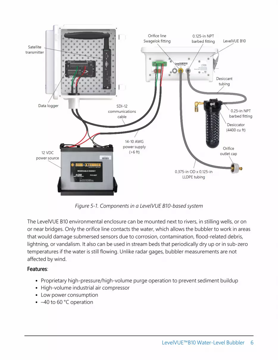
Figure 5-1. Components in a LevelVUE B10-based system
The LevelVUE B10 environmental enclosure can be mounted next to rivers, in stilling wells, or onor near bridges. Only the orifice line contacts the water, which allows the bubbler to work in areasthat would damage submersed sensors due to corrosion, contamination, flood-related debris,lightning, or vandalism. It also can be used in stream beds that periodically dry up or in sub-zerotemperatures if the water is still flowing. Unlike radar gages, bubbler measurements are notaffected by wind.
Features:
l Proprietary high-pressure/high-volume purge operation to prevent sediment buildupl High-volume industrial air compressorl Low power consumptionl –40 to 60 °C operation
LevelVUE™B10 Water-Level Bubbler 6

l Three pressure ranges: 15 psi, 30 psi, and 50 psil Built-in keypad/display for full setup, measurement, and maintenance operationsl Proprietary air flow/bubble generation for years of trouble-free operationl Large volume desiccator to minimize maintenance frequencyl Incorporated SDI-12 version 1.4 metadata commands for identification of datal Compatible with SDI-12 and Modbus controllers including Campbell Scientific GRANITE-
series, CR6, CR1000X, CR800-series, CR350-series, CR300-series, CR3000, and CR1000 dataloggers
l High water mark detection (crest stage) between normal SDI-12 measurement requests
6. SpecificationsCompliance documents: View at www.campbellsci.com/levelvueb10
6.1 Pressure transducerTable 6-1: Pressure range, depth, and resolution
Pressure range Water depth range1 Resolution
0 to 15 psi 0 to 10.54 m (34.6 ft) ±2.1 mm (0.007 ft)
0 to 30 psi 0 to 21 m (69.20 ft) ±4.26 mm (0.014 ft)
0 to 50 psi 0 to 35.16 m (115.35 ft) ±7.11 mm (0.023 ft)1Level calculations assume 1 psi = 0.7031 m (2.3067 ft) of water.
Accuracy: ≤ 0.02% of full scale output (FSO)over temperature range
Sensor overpressure rating: 1.5 times the pressure range
LevelVUE™B10 Water-Level Bubbler 7

6.2 Air flowDescription: Microprocessor controlled constant air flow
over full pressure range and temperature.
Bubble rate: Programmable 30 to 120 bubbles per minutes;based on 6.35 mm (0.25 inch) inner-diameter outlet.
60 bubbles per minute default
Purge operation
Manual: Requested from keypad/display
SDI-12: Command for purge under program control
Modbus: Command for purge under program control
Automatic-timed purge: Once a day to once a month with 1 day resolution
Purge pressure: 30 to 90 psi, programmable
Purge sustain time: 0 to 30 s, programmable
Pressure inlet port: 1/8-inch female NPT
Orifice-line outlet port: 1/8-inch female NPT
6.3 PowerInput voltage range: 11.5 to 16.5 VDCCurrent
Standby: 5 mACompressor active: 7 A typical, 10 A maximumStart-up surge current: 18 A maximum
6.4 CommunicationsSDI-12 SDI-12 V 1.4 compliant
Response time: 10 s for M! SDI-12 command with default averaging time of5 seconds
Default address: 0
LevelVUE™B10 Water-Level Bubbler 8

RS-485
Protocol: Modbus
Default address: 1
Default configuration: 8-bit, even parity, 1 stop bit, 19200 bps baud rate
Data type: 32-bit float, no reversal of the byte order (ABCD)
Built-in keypad/display: Graphical 8-line-by-20-character display.Menu fully supports system setup.
6.5 EnclosureMaterial: Fiberglass
Width: 28.9 cm (11.4 in)
Height: 34 cm (13.4 in)
Depth: 13 cm (5.2 inch)
Weight: 7.5 kg (16.5 lb)
6.6 EnvironmentalOperating temperature: –40 to 60 °C
Storage temperature: –40 to 80 °C
Relative humidity: 0 to 95%, non-condensing
7. Installation7.1 Verify operation 10
7.2 Wiring 10
7.3 Power considerations 12
7.4 Default settings 12
7.5 Setup using keypad/display 14
7.6 Campbell Scientific data logger programming 16
7.7 Field installation 17
LevelVUE™B10 Water-Level Bubbler 9
7.1 Verify operationBefore installing the LevelVUE B10, verify its operation using the following procedure:
1. Remove the plug from the orifice line Outlet fitting on the LevelVUE B10. Save the plug foruse later.
2. Connect the LevelVUE B10 to the power supply (Wiring [p. 10]). After connecting thebubbler to the power supply, the bubbler will take an initial atmospheric measurement andcalibrate itself. The compressor also will turn on to initially charge the tank and start theflow of air out of the system. If the compressor does not turn on, check the power supply.The LevelVUE B10 must be connected directly to the battery.
3. Connect a short piece of orifice line tubing to the Outlet fitting and place the end of thetubing in a bucket or tube of water, and bubbles should appear in 15 to 20 seconds.
4. Press the soft key button directly under Measure on the display to initiate a measurementsequence. Once the measurement is complete ensure that the reading is reasonable basedon the depth of the orifice line and an offset of 0.00.
5. Press the soft key button directly under Purge on the display to initiate a line purge. Thecompressor will charge the tank to 60 psi and release the air out the orifice line. This maytake a few seconds.
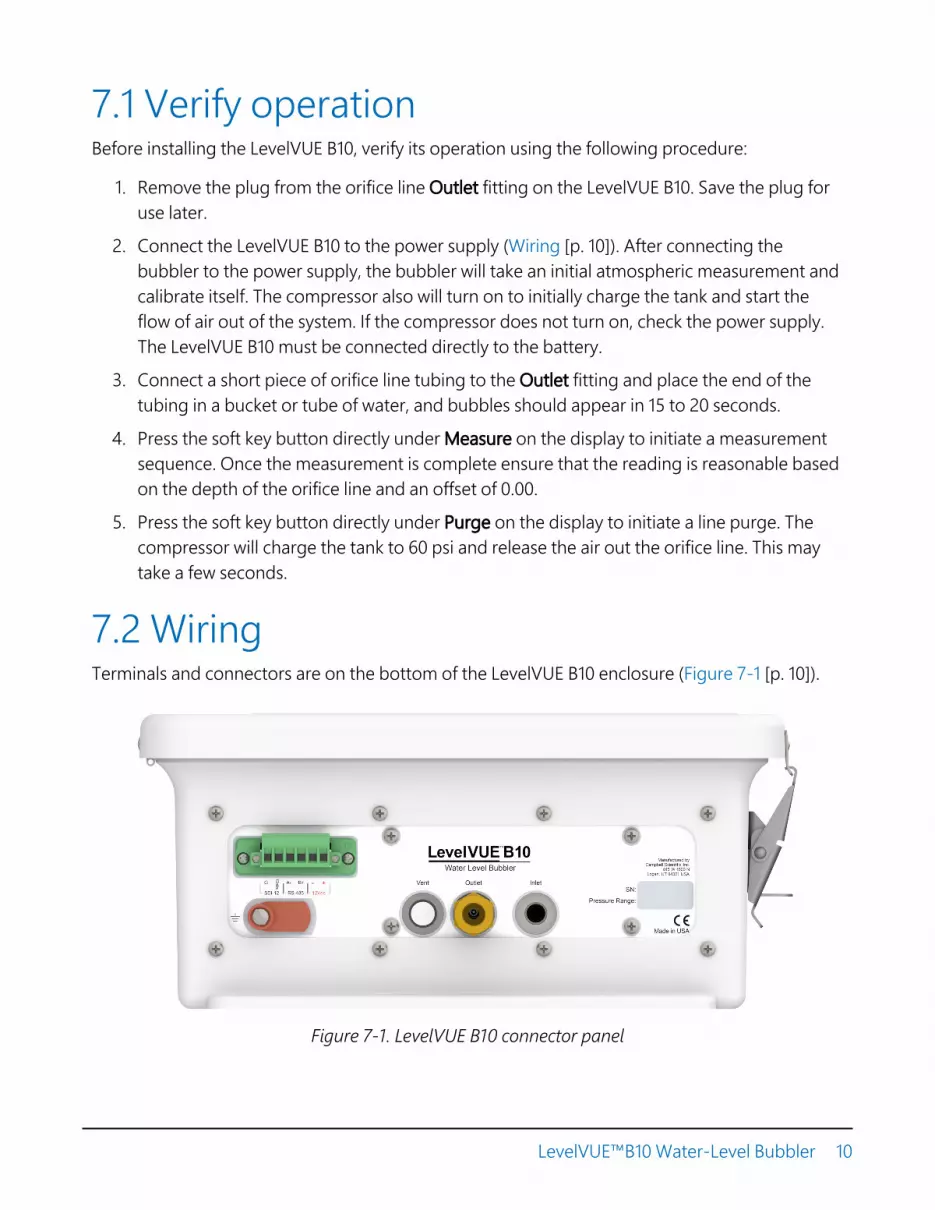
7.2 WiringTerminals and connectors are on the bottom of the LevelVUE B10 enclosure (Figure 7-1 [p. 10]).
Figure 7-1. LevelVUE B10 connector panel
LevelVUE™B10 Water-Level Bubbler 10

Table 7-1 (p. 11) provides wiring to a data logger when using SDI-12 and Table 7-2 (p. 11) provideswiring to a data logger when using Modbus. The air compressor and electronics connect directlyto the battery using a 16 to 20 AWG wire. Keep wire lengths less than 3 m (6 ft).
The SDI-12 output can be directly read by many devices including all Campbell Scientific dataloggers. RS-485 output can be directly read by a CR6-series, CR1000X-series, or Modbus RTURS-485 network. Other Campbell Scientific data loggers can use an MD485 multidrop interfaceto read the RS-485 output. Refer to the MD485 manual for information about using the MD485.
Table 7-1: LevelVUE B10 terminal, function, and connections for SDI-12 measurements
LevelVUE B10terminal Function Data logger or RTU
terminal Power supply
SDI-12 Data SDI-12 signalSDI-12 Data, C, SDI-12,
or U configured for SDI-121
SDI-12 G Ground G (digital groundconnection)
12Vdc + Power 12V
12Vdc – Power ground G, GND1U and C terminals are automatically configured by the measurement instruction for Campbell Scientific CR6 datalogger.
NOTE:For Campbell Scientific CR6 and CR1000X data loggers making SDI-12 measurements,conflicts may occur when a companion terminal is used for a triggering instruction such asTimerInput(), PulseCount(), or WaitDigTrig(). For example, if the LevelVUE B10 isconnected to C3 on a CR1000X, C4 cannot be used in the TimerInput(), PulseCount(),or WaitDigTrig() instructions.
Table 7-2: LevelVUE B10 terminal, function, and connections for Modbus measurements
LevelVUE B10terminal Function Data logger or RTU
terminal1 Power supply
RS-485 A– RS-485A A–, C odd
RS-485 B+ RS-485B B+, C even
12Vdc + Power 12V
12Vdc – Power ground G, GND1Assumes the sensor directly connects to the data logger.
LevelVUE™B10 Water-Level Bubbler 11
7.3 Power considerationsThe current load of the internal compressor requires the LevelVUE B10 to be connected directlyto the 12 VDC battery. The battery should be recharged using AC power or a solar panel. Do notpower the LevelVUE B10 using the 12 V excitation terminal from the data logger and do not usethe PS150 or PS200 because the current limit switch on these devices will trip when thecompressor tries to turn on. Specific power requirements depend on communications methods,frequency of site visits, and site location. Contact Campbell Scientific for more information.
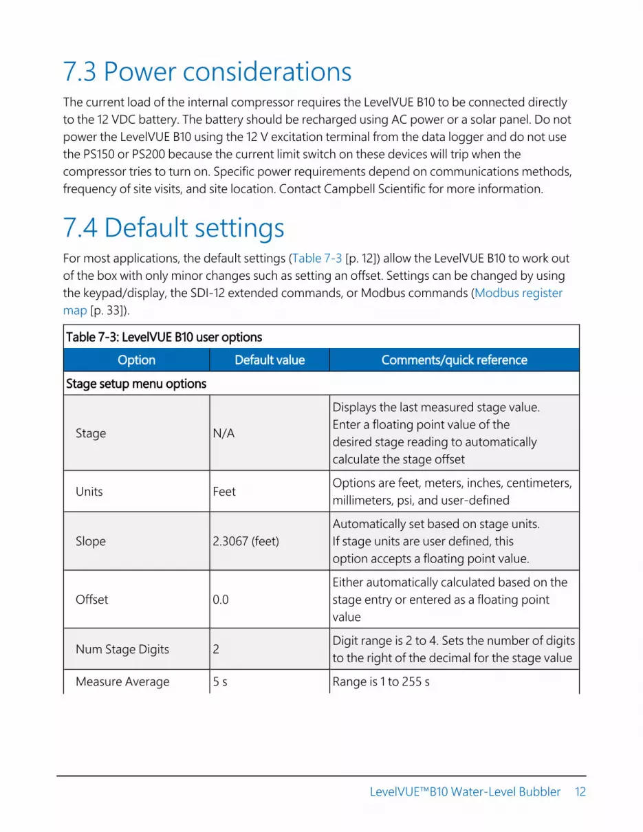
7.4 Default settingsFor most applications, the default settings (Table 7-3 [p. 12]) allow the LevelVUE B10 to work outof the box with only minor changes such as setting an offset. Settings can be changed by usingthe keypad/display, the SDI-12 extended commands, or Modbus commands (Modbus registermap [p. 33]).
Table 7-3: LevelVUE B10 user options
Option Default value Comments/quick reference
Stage setup menu options
Stage N/A
Displays the last measured stage value.Enter a floating point value of thedesired stage reading to automaticallycalculate the stage offset
Units Feet Options are feet, meters, inches, centimeters,millimeters, psi, and user-defined
Slope 2.3067 (feet)Automatically set based on stage units.If stage units are user defined, thisoption accepts a floating point value.
Offset 0.0Either automatically calculated based on thestage entry or entered as a floating pointvalue
Num Stage Digits 2 Digit range is 2 to 4. Sets the number of digitsto the right of the decimal for the stage value
Measure Average 5 s Range is 1 to 255 s
LevelVUE™B10 Water-Level Bubbler 12

Table 7-3: LevelVUE B10 user options
Option Default value Comments/quick reference
Bubbler setup menu options
Bubble Rate 60 bubbles perminute
Bubble-rate range is30 to 120 bubbles per minute
Purge Pressure 60 psi Purge-pressure range is 30 to 90 psi
Purge Sustain 10 s Purge-sustain range is 0 to 60 s
Auto Purge 0Range is 0 to 30 days0 disables auto purge1 to 30 = once a day to once every 30 days
System setup menu options
Date Does not reset System date in format of yyyy/mm/dd
Time Does not reset System time in format of hh:mm:ss
Display Sleep 5 minutes Range is 1 to 15 minutes
Display Brightness 80% Range is 10 to 100%
Temperature Units ° C Options are ° C or ° F
Reset to Defaults N/A Resets options to default values
Communications setup menu options
SDI-12 Address 0 Possible addresses: 0 to 9 (Standard),A to Z, a to z
Modbus Address 1 Possible addresses: 1 to 247.
RS-485 Baud Rate 19200 bps Standard baud rates from 9600 to 115200 bps
RS-485 Parity even Options are even, odd, none
RS-485 Stop Bits 2 Options are 1 or 2
Diagnostics/test menu options
Status Errors N/A Displays error (Table 8-1 (p. 27) ornone if no errors are detected
Test Line Noise N/A Press Enter to perform a line noise test
Test Line Leak N/A Press Enter to perform a line leak test
LevelVUE™B10 Water-Level Bubbler 13

Table 7-3: LevelVUE B10 user options
Option Default value Comments/quick reference
Reset Min / Max N/APress Enter to reset the min and maxbattery values to the current battery valuelevel
Min Battery Voltage N/A Displays the minimum voltage detectedon the battery
Max Battery Voltage N/A Displays the maximum voltage detectedon the battery
System information menu options
Clear Purge Counter N/A Press Enter to reset purge counter to zero
Clear System ResetCounter N/A Press Enter to reset the system reset counter
to zero
Purge Counter N/A Displays the number of purges since last reset
System Reset Counter N/A Displays the number of system resets sincelast reset
Sensor SN N/A Displays the sensor serial number
OS version N/A Displays the current operating system version
7.5 Setup using keypad/displayThe LevelVUE B10 includes a keypad/display to set up, make measurements, and troubleshootthe unit. Although the LevelVUE B10 can be completely setup using the SDI-12 or Modbusprotocols, using the keypad/display is more convenient for setting up and testing. Open theenclosure lid to access the keypad/display.
LevelVUE™B10 Water-Level Bubbler 14

Figure 7-2. LevelVUE B10 keypad/display
Press the right arrow key to open a menu and show the available options. Fixed values are shownnext to an equal sign (=), while editable options are displayed inside square brackets ([ ]). To edita menu, press the right arrow key at the chosen menu and use the up and down arrow keys tomake the changes to the parameter.
The following example shows the process for changing the stage setting.
1. Press the down arrow key to move to the setup screen.
2. Press the right arrow key to access the stage setup screen.
3. Press the right arrow key and press the Enter key.
4. Use the right and left arrow keys to move the cursor to the digit you want changed, thenuse the up and down arrow keys to change the number.
5. Press Enter when the number is changed to the correct value.
LevelVUE™B10 Water-Level Bubbler 15

7.6 Campbell Scientific data loggerprogrammingA data logger or RTU can remotely control and retrieve LevelVUE B10 data. Programming basicsfor Campbell Scientific CRBasic data loggers are provided in the following sections. If usinganother manufacturer's data logger or RTU, refer to their documentation for programminginformation. An SDI-12 program example for a Campbell Scientific data logger is provided inExample program (p. 49).
7.6.1 SDI-12 programmingThe SDI12Recorder() instruction is used to measure a LevelVUE B10 configured for SDI-12measurements. The SDI12Recorder() instruction sends a request to the sensor to make ameasurement and then retrieves the measurement from the sensor. See SDI-12 measurementand extended commands (p. 30) for more information.
For most data loggers, the SDI12Recorder() instruction has the following syntax:
SDI12Recorder(Destination, SDIPort, SDIAddress, “SDICommand”, Multiplier, Offset,FillNAN, WaitonTimeout)
Valid values for the SDIAddress are 0 through 9, A through Z, and a through z; alphabeticalcharacters need to be enclosed in quotes (for example, “A”). Also enclose the SDICommand inquotes as shown. The Destination parameter must be an array. The required number ofvalues in the array depends on the command (see Table 8-2 [p. 31]).
FillNAN and WaitonTimeout are optional parameters (refer to CRBasic Help for moreinformation).
7.6.2 Modbus programmingThe RS-485 output can be directly read by a CR6-series, CR1000X-series, or Modbus RTU RS-485network. Other Campbell Scientific data loggers can use an MD485 multidrop interface to readthe RS-485 output. Refer to the MD485 manual for information about using the MD485.
A CR6 or CR1000X data logger programmed as a Modbus Master can retrieve the values storedin the Input Registers (Modbus register map [p. 33]). To do this, the CRBasic program requiresSerialOpen() followed by ModbusMaster(). The SerialOpen instruction has the followingsyntax:
SerialOpen (ComPort, Baud, Format, TXDelay, BufferSize, Mode)
LevelVUE™B10 Water-Level Bubbler 16

The Format parameter is typically set to logic 1 low; even parity, one stop bit, 8 data bits. TheMode parameter should configure the ComPort as RS-485 half-duplex, transparent.
The ModbusMaster() instruction has the following syntax:
ModbusMaster (Result, ComPort, Baud, Addr, Function, Variable, Start, Length,Tries, TimeOut, [ModbusOption])
The Addr parameter must match the sensor Modbus address. To collect all of the values, theStart parameter needs to be 1 and the Length parameter needs to correspond with theregister count (see Modbus register map [p. 33]). For ModbusOption parameter use 2, whichmeans the Modbus variable array is defined as a 32-bit float or a Long, with no reversal of thebyte order (ABCD).
7.7 Field installation7.7.1 Site selection 17
7.7.2 Enclosure mounting 17
7.7.3 Desiccator installation 18
7.7.4 Orifice line and conduit installation 20
7.7.1 Site selectionThe site selection is often based on the type of water being measured. Water in rivers andstreams will act differently than in lakes and reservoirs. In rivers and streams, choose a locationwhere the water velocity remains constant regardless of water levels. Care must also be taken toprevent errors caused by drawdown and buildup such as around a bridge pier. In lakes andreservoirs, wind can cause wave action and buildup on the face of the dam or other structure.Select a location that will be less affected by these conditions.
7.7.2 Enclosure mounting1. Choose a location that is accessible for servicing electrical connections and plumbing
fittings, but will not get jarred or shifted during operation.
2. Place the enclosure at the desired height with connectors pointing down so that moistureor condensation that could collect on the connectors do not access the inner componentsof the equipment.
LevelVUE™B10 Water-Level Bubbler 17

3. Secure the enclosure to a wall or flat surface using user-supplied bolts. The enclosureincludes holes at the top and bottom of the enclosure for mounting the LevelVUE B10.
4. Route a 14 AWG copper wire from the enclosure grounding lug to an earth ground.
7.7.3 Desiccator installationWARNING:Not using a desiccator will void your warranty.
An external desiccator is required to dry the compressor intake air and prevent accumulation ofmoisture in the tank, manifold, and other areas in the system. Campbell Scientific offers adesiccator kit (Figure 7-3 [p. 19]), which is recommended for use with the LevelVUE B10.
LevelVUE™B10 Water-Level Bubbler 18
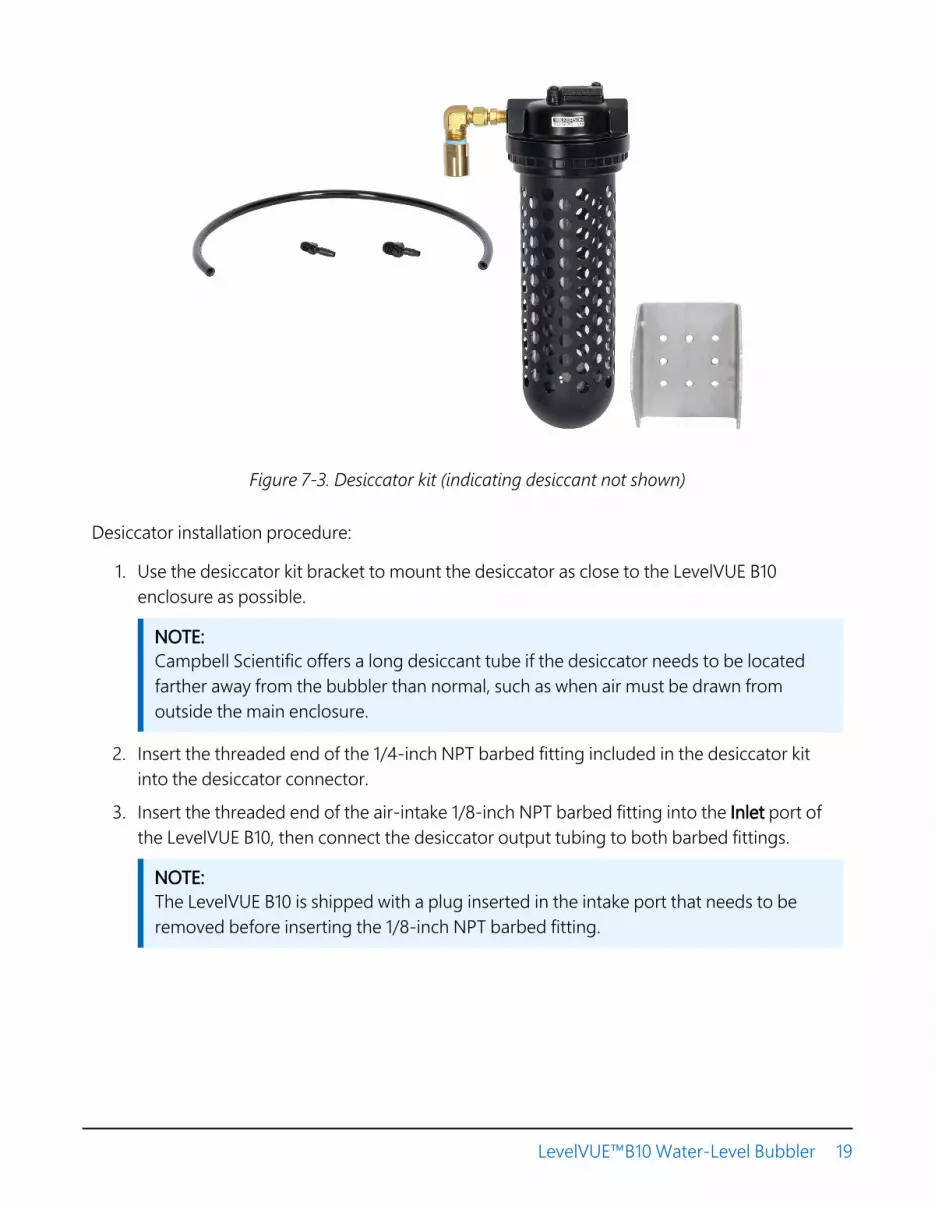
Figure 7-3. Desiccator kit (indicating desiccant not shown)
Desiccator installation procedure:
1. Use the desiccator kit bracket to mount the desiccator as close to the LevelVUE B10enclosure as possible.
NOTE:Campbell Scientific offers a long desiccant tube if the desiccator needs to be locatedfarther away from the bubbler than normal, such as when air must be drawn fromoutside the main enclosure.
2. Insert the threaded end of the 1/4-inch NPT barbed fitting included in the desiccator kitinto the desiccator connector.
3. Insert the threaded end of the air-intake 1/8-inch NPT barbed fitting into the Inlet port ofthe LevelVUE B10, then connect the desiccator output tubing to both barbed fittings.
NOTE:The LevelVUE B10 is shipped with a plug inserted in the intake port that needs to beremoved before inserting the 1/8-inch NPT barbed fitting.
LevelVUE™B10 Water-Level Bubbler 19
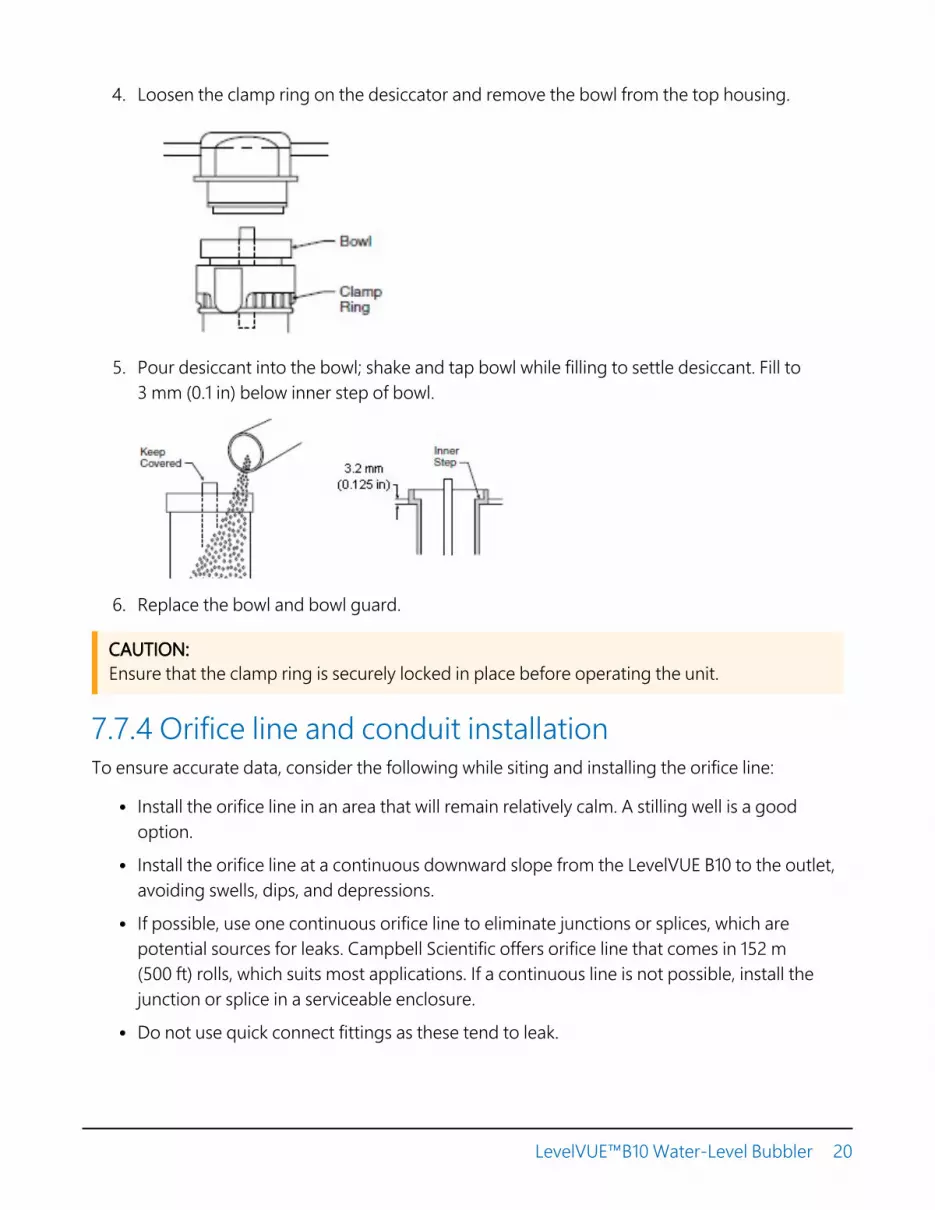
4. Loosen the clamp ring on the desiccator and remove the bowl from the top housing.
5. Pour desiccant into the bowl; shake and tap bowl while filling to settle desiccant. Fill to3 mm (0.1 in) below inner step of bowl.
6. Replace the bowl and bowl guard.
CAUTION:Ensure that the clamp ring is securely locked in place before operating the unit.
7.7.4 Orifice line and conduit installationTo ensure accurate data, consider the following while siting and installing the orifice line:
l Install the orifice line in an area that will remain relatively calm. A stilling well is a goodoption.
l Install the orifice line at a continuous downward slope from the LevelVUE B10 to the outlet,avoiding swells, dips, and depressions.
l If possible, use one continuous orifice line to eliminate junctions or splices, which arepotential sources for leaks. Campbell Scientific offers orifice line that comes in 152 m(500 ft) rolls, which suits most applications. If a continuous line is not possible, install thejunction or splice in a serviceable enclosure.
l Do not use quick connect fittings as these tend to leak.
LevelVUE™B10 Water-Level Bubbler 20
l Protect the orifice line inside a 53 mm (2-inch) steel conduit that is fastened to a permanentand secure structure such as bridge pier, cement slab, or pilings.
l Avoid sharp bends in the conduit during installation. Sharp bends can result in kinks andmake installation more difficult.
l If the orifice line crosses a road, ensure that it is buried deep enough to prevent the linefrom being crushed from vehicles using the road.
l Use an orifice-line cap to secure the orifice line output to the conduit. The orifice-line capoffered by Campbell Scientific works for most installations. Refer to Orifice-line outlet types(p. 41) for more information.
l Mount the orifice-line outlet vertically or slightly turned to the horizontal position andperpendicular to the primary direction of flow. Refer to Orifice-line outlet orientation (p. 40)for more information.
The installation procedure follows:
1. Secure the conduit to a permanent and secure structure such as bridge pier, cement slab,or pilings.
2. Route the orifice line inside the conduit.
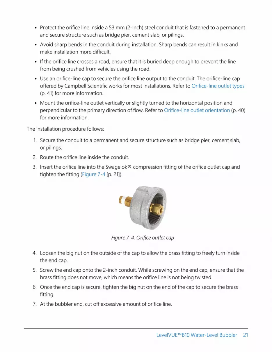
3. Insert the orifice line into the Swagelok® compression fitting of the orifice outlet cap andtighten the fitting (Figure 7-4 [p. 21]).
Figure 7-4. Orifice outlet cap
4. Loosen the big nut on the outside of the cap to allow the brass fitting to freely turn insidethe end cap.
5. Screw the end cap onto the 2-inch conduit. While screwing on the end cap, ensure that thebrass fitting does not move, which means the orifice line is not being twisted.
6. Once the end cap is secure, tighten the big nut on the end of the cap to secure the brassfitting.
7. At the bubbler end, cut off excessive amount of orifice line.
LevelVUE™B10 Water-Level Bubbler 21

8. Remove the plug from the Swagelok® fitting on the Outlet port.
9. Insert this orifice line into the Swagelok® compression fitting on the bubbler outlet andtighten.
10. Secure any extra orifice line and orient it horizontally to avoid low points in the line.
8. Operation8.1 Principles of operation 22
8.2 Keypad/display menu 23
8.3 SDI-12 measurement and extended commands 30
8.4 Modbus register map 33
8.5 Secured orifice line 38
8.6 Long orifice lines 40
8.7 Orifice-line outlet orientation 40
8.8 Orifice-line outlet types 41
8.1 Principles of operationA bubbler operates by establishing a constant flow of air that is independent of the water level(pressure) above the orifice line outlet. As the water level rises, the bubbler increases the pressurein the tank to maintain a constant flow of bubbles. The water level is proportional to the pressurerequired to move the air to the end of the orifice line. The bubbles indicate air at the end of theline:
Pressure = ρ x g x h
Where:
Pressure (Pa)ρ = density of the water (1000 kg/m3)g = gravitational constant (9.8 m/s2)h = height of the column of water (m)100 kPa = 14.5 psi
LevelVUE™B10 Water-Level Bubbler 22
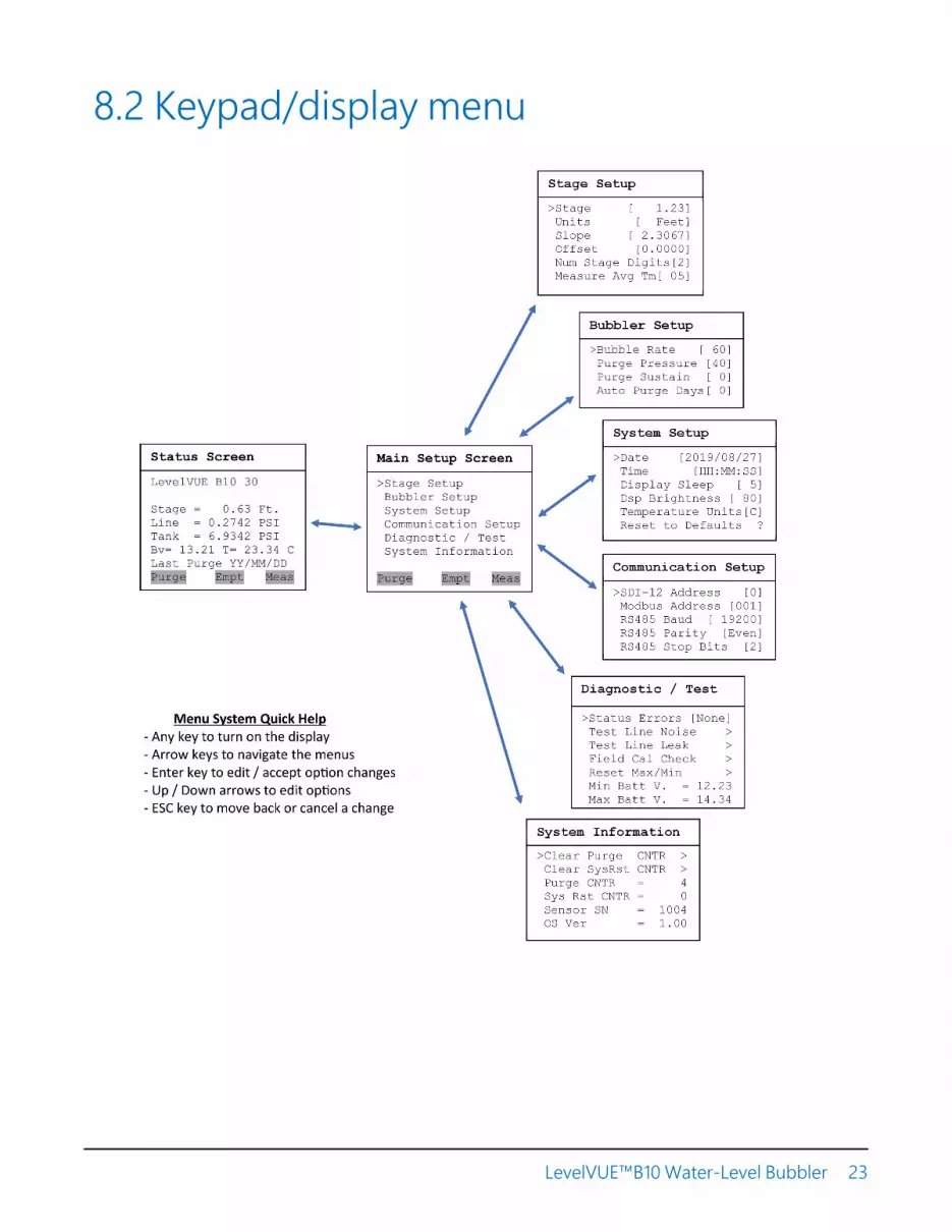
8.2 Keypad/display menu
LevelVUE™B10 Water-Level Bubbler 23

8.2.1 Stage setup
Stage: Displays the last measured stage. The user can enter a new stage and the system willcalculate a new offset based on the new stage.
Units: Units used to report the water level. Default is feet. When changed, the slope value isautomatically adjusted to provide water level measurements in the selected units. The user-defined option allows the user to manually enter a slope that does not match a predefined value.
Slope: Slope or conversion factor used to convert the raw psi reading into units of feet, meters, oruser-defined. If the Units option is set to user-defined, the slope can be changed to any value.
Offset: Difference between the water-level reference point and the level of the orifice-line outlet.The user can enter the offset here. Alternatively, the user can enter a value for the Stage [xx.xx]option and the LevelVUE B10 will calculate the correct offset.
Num Stage Digits: Number of digits used to display the stage value on the display. Default is 2.
Measure Average: Averaging time (in seconds) that the LevelVUE B10 uses to make a water levelmeasurement. Default is 5 seconds. Entering a longer averaging time can reduce noise caused bywater conditions such as waves or turbulence. Please note that the actual measurement time willbe 3 to 4 seconds longer than this value due to internal processing.
8.2.2 Bubbler setup
Bubble Rate: Rate of the airflow in the orifice line. Range is 30 to 120 bubbles per minute. The rateis affected by the orifice-outlet size, orientation of the outlet, and the pressure difference in thetank and line, etc. With a lower bubble rate, the air compressor may run less frequently. Higherrates allow the system to respond more quickly to water level increases. Default setting is 60bubbles per minute, which is sufficient for most applications. With a standard 1/8 ID orifice line
LevelVUE™B10 Water-Level Bubbler 24

and a 1/4 inch outlet, 60 bubbles per minute tracks a rise of 1 foot per 10 seconds. A rise fasterthan 1 foot per 10 seconds requires a faster bubble rate.
Purge Pressure: Default is 60 psi. Regularly use a high-pressure purge to keep the orifice lineclear of debris. Silty streams or installations with long orifice lines may require a higher purgepressure. More frequent purges are also recommended for silty streams.
Purge Sustain: Length of time (in seconds) that the compressor runs after reaching the purgepressure and opening the purge valve. Default is 10. Increasing the purge sustain time may makethe purge more efficient and may increase the air flow.
Auto Purge: Automatic purge rate (in days). The automatic purge rate can be once a day to onceevery 30 days. A setting of 0 disables automatic purging.
NOTE:See the note following the Date and Time options (System setup [p. 25]) for more informationon the Auto Purge function.
8.2.3 System setup
Date: A correct date is needed for the Auto Purge option. Set this up when you initially set up thesystem.
Time [HH:MM:SS]: The correct time is needed for the Auto Purge option. Set this up when youinitially set up the system or if it changes.
NOTE:The Date and Time are only used for the Auto Purge option and should be set to the localtime. The Auto Purge occurs immediately after the measurement at or just after 12:00 noon,local time. This schedule allows the line to stabilize before the next measurement and ensuresthat the purge occurs during the day light hours when the battery is at a higher charge levelwhen using solar power. If the Date and Time are not set, the Auto Purge occurs at anunpredictable schedule.
Display Sleep: Amount of time (in minutes) that the keypad can be idle before the display turnsoff. Default is 5 minutes.
Dsp Brightness: Brightness or contrast of the display. Default is 80.
LevelVUE™B10 Water-Level Bubbler 25

Temperature Units: Options are degree C and F.
Reset to Defaults ?: Resets to default values (Table 7-3 [p. 12]).
NOTE:This option does not reset the date, time, minimum and maximum battery voltage, and errorand status flags.
CAUTION:Resetting the LevelVUE B10 to the defaults changes the SDI-12 and Modbus addresses to thedefaults. Therefore, SDI-12 or Modbus communications will be unresponsive until the datalogger program is changed to match the default addresses or the SDI-12 or Modbus addressin the LevelVUE B10 is changed to match the data logger.
8.2.4 Communication setup
SDI-12 Address: Valid addresses are 0 through 9, a through z, and A through Z. Each SDI-12device connected to the same SDI-12 signal terminal needs a unique SDI-12 address. Default is 0.
Modbus Address: Each Modbus device connected to the same RS-485 terminals needs a uniqueModbus address. Default is 001.
RS485 Baud: Baud rate for the RS-485 port used for Modbus operations. Default is 19200.
RS485 Parity: Setting must match the data logger or Modbus RTU setting. Default is Even.
RS485 Stop Bits: Number of stop bits used for the RS-485 (Modbus) interface. Default is 2.
8.2.5 Diagnostic/Test
LevelVUE™B10 Water-Level Bubbler 26

Status Errors
Displays True if errors are detected or None if errors are not detected. If errors are detected,press the Enter key and the first error will be displayed (Table 8-1 [p. 27]).
The error code returned with an SDI-12 command is the sum of the weighted value for eacherror. Weighted values were chosen to ensure the sum is unique for each error combination. Forexample, if error 1 and error 6 were detected, the SDI-12 error code will be 33 (1+32).
Some errors or status messages are automatically cleared once the error is resolved. The moreserious errors remain active until they are manually reset by the user.
Table 8-1: Error flag descriptions
Errornumber
SDI-12Weighted
ValueType Error description and
recommended action
Messagedisplayed on
screenReset
1 1 Error Line sensor exceeded pressure range.Check for plugged line.
Line SenRnge Err Manual
2 2 Error Tank sensor exceeded pressure range.Check for plugged line.
Tank SenRnge Err Manual
3 4 Error Temperature value exceeded range. TemperatureRnge Err Manual
4 8 Error Pressure not increasing (stalledcompressor or leak).
Pressure UpErr Manual
5 16 Error Pressure not decreasing. Check forobstruction or plugged orifice line.
Pressure DwnErr Manual
6 32 Error Tank offset calculation timeout. Tank OffsetTO Manual
7 64 Error Tank offset calculation out of rangeerror.
Tank OffsetError Manual
8 128 Error Compressor over current. Checkbattery/charge system.
CompressorOver Amps Manual
9 256 Error RTC battery low voltage warning.Change the RTC battery.
RTC BatteryLow Manual
LevelVUE™B10 Water-Level Bubbler 27
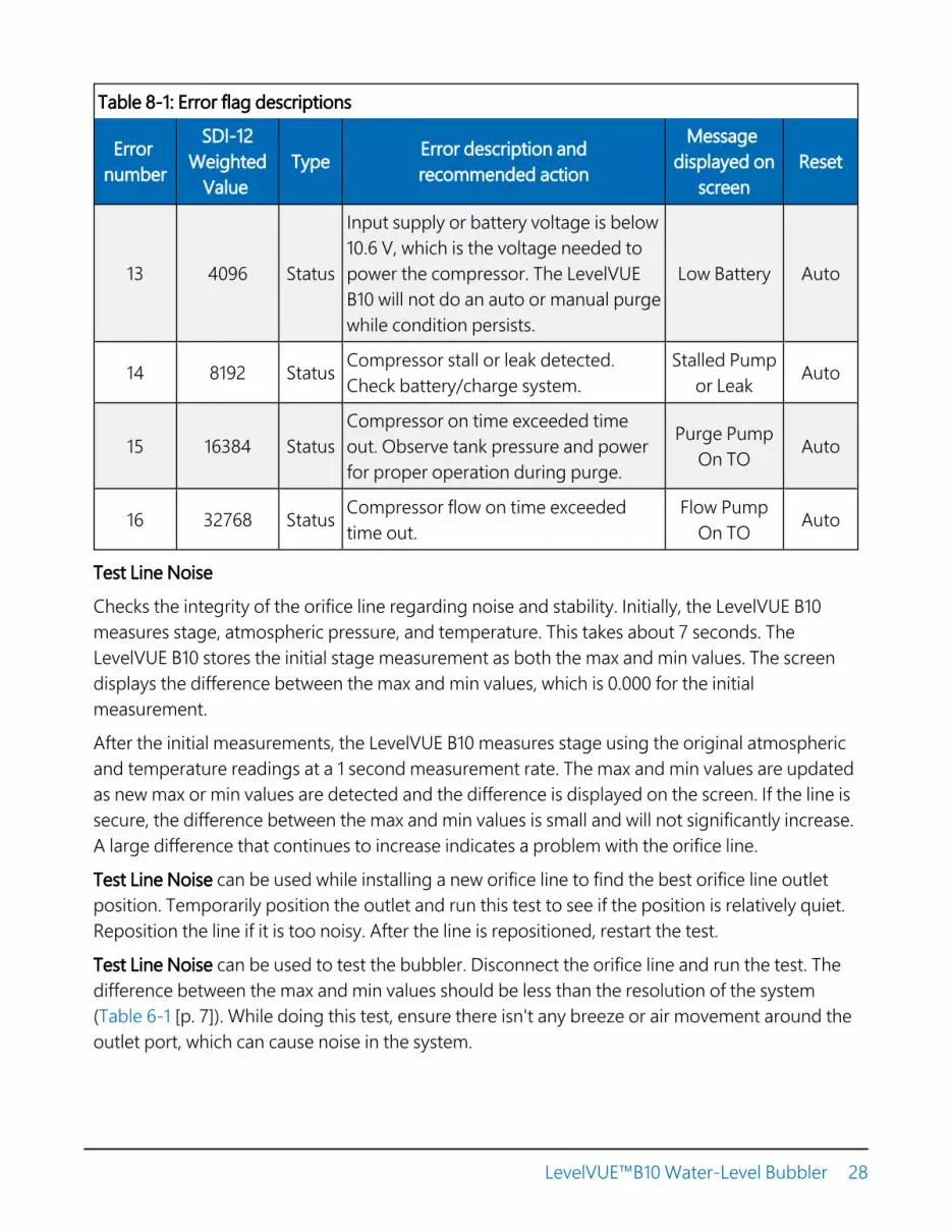
Table 8-1: Error flag descriptions
Errornumber
SDI-12Weighted
ValueType Error description and
recommended action
Messagedisplayed on
screenReset
13 4096 Status
Input supply or battery voltage is below10.6 V, which is the voltage needed topower the compressor. The LevelVUEB10 will not do an auto or manual purgewhile condition persists.
Low Battery Auto
14 8192 Status Compressor stall or leak detected.Check battery/charge system.
Stalled Pumpor Leak Auto
15 16384 StatusCompressor on time exceeded timeout. Observe tank pressure and powerfor proper operation during purge.
Purge PumpOn TO Auto
16 32768 Status Compressor flow on time exceededtime out.
Flow PumpOn TO Auto
Test Line Noise
Checks the integrity of the orifice line regarding noise and stability. Initially, the LevelVUE B10measures stage, atmospheric pressure, and temperature. This takes about 7 seconds. TheLevelVUE B10 stores the initial stage measurement as both the max and min values. The screendisplays the difference between the max and min values, which is 0.000 for the initialmeasurement.
After the initial measurements, the LevelVUE B10 measures stage using the original atmosphericand temperature readings at a 1 second measurement rate. The max and min values are updatedas new max or min values are detected and the difference is displayed on the screen. If the line issecure, the difference between the max and min values is small and will not significantly increase.A large difference that continues to increase indicates a problem with the orifice line.
Test Line Noise can be used while installing a new orifice line to find the best orifice line outletposition. Temporarily position the outlet and run this test to see if the position is relatively quiet.Reposition the line if it is too noisy. After the line is repositioned, restart the test.
Test Line Noise can be used to test the bubbler. Disconnect the orifice line and run the test. Thedifference between the max and min values should be less than the resolution of the system(Table 6-1 [p. 7]). While doing this test, ensure there isn't any breeze or air movement around theoutlet port, which can cause noise in the system.
LevelVUE™B10 Water-Level Bubbler 28

Test Line Leak
Leaks are one of the biggest problems with bubbler systems. Normally, the leak is at the fittingthat connects the orifice line to the bubbler or somewhere between that fitting and the end ofthe orifice line. Tightening the orifice line fitting an 1/8 turn often resolves the problem. When aleak exist, the stage value will remain equal to the offset value.
However, a small percentage (1%) of the leaks are in the bubbler itself. This test verifies thebubbler is not leaking. To use this test, disconnect the orifice line and replace it with the plugshipped on the LevelVUE B10 outlet fitting. This test turns on the compressor and fills the tank toa pressure slightly below the pressure range of the bubbler. The system lets the pressures in thesystem equalize for about 15 seconds before displaying the max pressure, min pressure, and thedifference of the max and min pressures. The test displays a count-down timer and runs forabout 5 minutes (300 seconds). The difference value may rise while the system is equalizing, butafter 15 seconds, the difference should be less than 0.15. After 1 or 2 minutes, the differenceshould be stable. Contact Campbell Scientific if the difference value continues to rise significantly.
Field Cal Check
Use this option in conjunction with an off-the-shelf field calibration tool to regularly verify thefield calibration. Some agencies require this. Refer to Field calibration check (p. 62) for moreinformation.
Reset Max/Min
Use this option at the end of a site visit to reset the minimum and maximum battery voltagedetected. At the beginning of the next site visit look at the value of the minimum and maximumbattery voltages detected since the last site visit to help determine the status of the battery andthe charging system.
Min Batt V. XX.XX
Displays the minimum battery voltage detected since the last time this was reset. A low readingindicates a weak battery or an inadequate charging system.
Max Batt V. XX.XX
Displays the maximum battery voltage detected since the last time this was reset. A high readingmay indicate a faulty regulator or other charging system problem.
LevelVUE™B10 Water-Level Bubbler 29

8.2.6 System information
Clear Purge CNTR: Clears the purge counter. To see if the system is purging as often as expected,use this option at the end of a site visit to set the purge counter to zero. At the beginning of thenext site visit, check that the purge counter has a value that corresponds with the expectednumber of purges.
Clear SysRST CNTR: Sets the system reset counter to 0. See Sys RST CNTR that follows.
Purge CNTR = X: Number of orifice-line purges since the last reset.
Sys RST CNTR = X: Number of system resets. If the Clear SysRST CNTR is used at the end of eachsite visit, this will show the number of resets since the last visit. System resets indicate that thebattery may be weakening, inadequate power wiring, or the charge system needs servicing.
Sensor SN = XXXX: Serial number of the LevelVUE B10. A support person may ask for this numberif the LevelVUE B10 needs servicing.
OS Ver = X.XX: Operating system (OS) version number currently loaded into the system.Campbell Scientific recommends using the latest OS. Use Campbell Scientific DeviceConfiguration Utility to update the OS. Also, if service is needed, a support person may ask forthe OS version number.
8.3 SDI-12 measurement and extendedcommandsThe LevelVUE B10 responds to the SDI-12 commands shown in Table 8-2 (p. 31). Because ofdelays, the M! commands require, the measurement scans should be 10 seconds or more. The C!commands follow the same pattern as the M! commands with the exception that they do notrequire the data logger to pause its operation until the values are ready.
NOTE:SDI-12 sensor support (p. 51) describes the SDI-12 commands. Additional SDI-12 informationis available at www.sdi-12.org .
LevelVUE™B10 Water-Level Bubbler 30

Table 8-2: LevelVUE B10 SDI-12 measurement and extended commands
SDI-12 command(a is the sensor address) Values returned or function Description
aM!, aC!, aMc!, or aCc!
1. Stage (m or ft)2. Line pressure (psi)3. Tank pressure (psi)4. Temperature (°C)5. Battery voltage (VDC)6. Error code1
7. Stage crest (m or ft)8. Stage crest time
The stage crest time is a timeoffset. It is the number ofseconds in the past from thecurrent measurement thatthe crest stage value wasdetected.
aXWSR=rrr.rr!
Where, rrr.rr= stagereference
Write stage value Use to change stagereference to rrr.rr inconfigured units.
aXWSU=x!
Where, x = units value
Write stage units Use to change the stageunits, where:
0=in
1=ft
2=mm
3=cm
4=m
5=psi
6=user-specified (used withthe aXWSS=s.sssssss!command)
aXRSU! Read stage units
aXWSS=s.sssssss!
Where, s.sssssss=2.3066587or 0.7032496
Write stage slope Use to change the units forstage. This command is onlyused when the stage unitsare set to user-specified(aXWSU=6!).
Feet = 2.3066587 (default)
Meters = 0.7032496
LevelVUE™B10 Water-Level Bubbler 31

Table 8-2: LevelVUE B10 SDI-12 measurement and extended commands
SDI-12 command(a is the sensor address) Values returned or function Description
aXRSS! Read stage slope.
aXWCO=o.oo!
Where, o.oo= stage offset
Write calculated stage offset Use to update stage offset.
aXRCO! Read calculated stage offset.
aXWBR=bb!
Where, bb= bubble rate
Write bubble rate (bubbles perminute)
Use to change the bubblerate.
Default = 60 bubbles perminute
aXRBR! Read bubble rate Bubbles per minute
aXWPP=pp!
Where, pp= purge pressure
Write purge pressure (psi). Use to change the purgepressure.
Default = 60 psi
Range: 30 to 90 psi
aXRPP! Read purge pressure (psi)
aXP! Initiate bubbler purge sequence
aXWPA=tt!
Where, tt= purge time
Write purge assist time(seconds)
Use to set the time thecompressor runs during thepurge sequence after thepurge valve opens.
Default = 20 s
aXRPA! Read purge assist time (seconds)
aXWSD=dd!
Where, dd= digits
Write stage digits Use to set the number ofdigits to the right of thedecimal for the stage value.
Default = 2
aXRSD! Read stage digits
LevelVUE™B10 Water-Level Bubbler 32

Table 8-2: LevelVUE B10 SDI-12 measurement and extended commands
SDI-12 command(a is the sensor address) Values returned or function Description
aXWMT=tt!
Where, tt= stage mean time
Write stage mean time(seconds)
Use to increase or decreasethe averaging time of stagemeasurements
Default = 5 s
aXRMT! Read stage mean time (s)
aXWAP=tt!
Where, tt= auto purgesetting
Write auto-purge setting (days) 0 = off (no auto-purge)
Range = 1 to 30 days
aXRAP! Read auto-purge setting (days)
aXATZ! Reset sensor to defaults (Defaultsettings [p. 12])
aXTEST!
1. Stage (m or ft)2. Line pressure (psi)3. Tank pressure (psi)4. Temperature (°C)5. Battery voltage (VDC)6. Error code1
Use to put the sensor into acontinuous output modewith data being transmittedto the terminal every second.Any command will interruptthe continuous output modeand resume normaloperation.
aXHELP! Returns the supported SDI-12commands by the LevelVUE B10
1 The error code is the sum of the weighted value for each error. The errors and weighted values are listed inthe Error flag descriptions table.
8.4 Modbus register mapThe Modbus data type is 32-bit float with no reversal. Table 8-3 (p. 34) provides the input registermap (function code 4). Table 8-4 (p. 35) provides the holding register map (function code 3).
LevelVUE™B10 Water-Level Bubbler 33
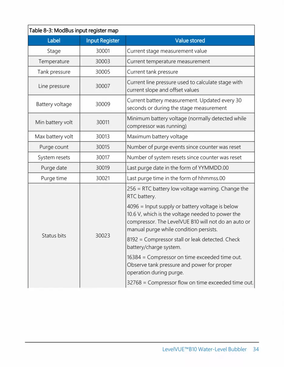
Table 8-3: ModBus input register map
Label Input Register Value stored
Stage 30001 Current stage measurement value
Temperature 30003 Current temperature measurement
Tank pressure 30005 Current tank pressure
Line pressure 30007 Current line pressure used to calculate stage withcurrent slope and offset values
Battery voltage 30009 Current battery measurement. Updated every 30seconds or during the stage measurement
Min battery volt 30011 Minimum battery voltage (normally detected whilecompressor was running)
Max battery volt 30013 Maximum battery voltage
Purge count 30015 Number of purge events since counter was reset
System resets 30017 Number of system resets since counter was reset
Purge date 30019 Last purge date in the form of YYMMDD.00
Purge time 30021 Last purge time in the form of hhmmss.00
Status bits 30023
256 = RTC battery low voltage warning. Change theRTC battery.
4096 = Input supply or battery voltage is below10.6 V, which is the voltage needed to power thecompressor. The LevelVUE B10 will not do an auto ormanual purge while condition persists.
8192 = Compressor stall or leak detected. Checkbattery/charge system.
16384 = Compressor on time exceeded time out.Observe tank pressure and power for properoperation during purge.
32768 = Compressor flow on time exceeded time out.
LevelVUE™B10 Water-Level Bubbler 34

Table 8-3: ModBus input register map
Label Input Register Value stored
Crest max 30025 Maximum crest stage observed between twosuccessive stage measurements
Crest offset 30027This is a time offset. It is the number of seconds in thepast from the current measurement that the creststage value was detected.
Table 8-4: Modbus holding register map
Label Holdingregister
Read(function code 3) Write (function code 16)
Stage Ref 40001 Last stage value
Measures and recalculates the offsetrequired to make the current stagevalue equal to the value written to thisregister
Stage Units 40003
Returns a numberfrom 0 to 6indicating the units,where:
0 inches1 feet (default)2 millimeters3 centimeters4 meters5 psi6 User-defined
Enter a value in a range of 0 to 6, where:
0 inches1 feet (default)2 millimeters3 centimeters4 meters5 psi6 User-defined (must enter a stageslope value described in the followingrow)
LevelVUE™B10 Water-Level Bubbler 35

Table 8-4: Modbus holding register map
Label Holdingregister
Read(function code 3) Write (function code 16)
Stage Slope 40005
Returns the followingvalues depending onthe stage units:
27.68 inches2.3067 feet (default)703.08 millimeters70.308 centimeters0.70308 meters1 psiUser-defined
To write a user-defined value the stage-units register must first be set to 6.
Stage Offset 40007 Returns the stageoffset value. Enter the stage offset value.
Date 40009Returns the systemdate in the format ofYYMMDD.00
Enter the system date, as a float, in theformat of YYMMDD.00
Time 40011Returns the systemtime in the format ofhhmmss.00
Enter the system time, as a float, in theformat of hhmmss.00
MeasurementAverage Duration 40013
Returns themeasurementaveraging time inseconds.
Enter the measurement averaging timein seconds. The range is from 1 to 255.
Temperature Units 40015Returns:
0 Celsius1 Fahrenheit
Enter 0 for Celsius or 1 for Fahrenheit
Bubble Rate 40017Returns the bubblerate. Range is 30 to120
Enter the bubble rate. Range is 30 to120
Purge Pressure 40019Returns purgepressure in psi.Range is 30 to 90.
Enter the purge pressure in psi. Range is30 to 90.
LevelVUE™B10 Water-Level Bubbler 36

Table 8-4: Modbus holding register map
Label Holdingregister
Read(function code 3) Write (function code 16)
Purge SustainDuration 40021
Returns purgesustain time inseconds. Range is 0to 30.
Enter purge sustain time in seconds.Range is 0 to 30.
Auto Purge Interval 40023 Returns auto purgeinterval in days.
Enter auto purge interval in days. Rangeis 0 to 30 days
Display Sleep 40025Returns display sleeptimeout period inminutes.
Enter display sleep timeout period inminutes. Range is 1 to 15.
Display Brightness 40027Returns the displaybrightness option.Range is 10 to 100
Enter the display brightness between 10and 100. Value will be rounded tonearest ten.
Reset Status Values 40029 Returns 0.00
Entering a non-zero value such as 1.00will reset status values to the following:
Purge count: 0
Minimum battery value: current batteryvoltage
Maximum battery value: current batteryvoltage
System Resets: 0
Modbus Address 40031 Returns the Modbusdevice address
Enter a new Modbus address. Range is 1to 247.
LevelVUE™B10 Water-Level Bubbler 37

Table 8-4: Modbus holding register map
Label Holdingregister
Read(function code 3) Write (function code 16)
Measure Now 40033
Returns a 0.00 ortime till currentmeasurement isready in seconds.
Entering a non-zero value causes theunit to make a stage measurement. Theregister will then hold the number ofseconds till the measurement iscomplete. Once the register becomeszero, new measurement values will beavailable in the following InputRegisters:
Stage, Line Pressure , Tank pressure,Battery Voltage , and Temperature.
Purge Now 40035
Returns a 0 when notpurging. Returns a 1if in the process ofrunning a purge.
Writing a non-zero value (1.00) willcause system to purge.
8.5 Secured orifice lineCampbell Scientific recommends protecting the orifice line inside a 53 mm (2-inch) steel conduit.Fasten the conduit to a permanent and secure structure such as bridge pier, cement slab, orpilings to prevent movement. If the conduit moves, the orifice line can stretch, kink, or break. Astretched orifice line restricts the air flow, which increases pressure, causing erroneously highstage measurements. A broken orifice line leaks. If a leak is present, the measured stage value willbe the same or close to the offset value. Kinks create erratic data. These same problems can alsooccur if the orifice line crosses a road and the line is not properly protected from the traffic on theroad.
If the outlet of the orifice line shifts but is still stable, the vertical shift will be seen in the data. Thisproblem occurs when the orifice line mount near the outlet has been hit by large debris such as alog. Scour can also cause mounts to shift. Figure 8-1 (p. 39) shows the sharp rise in water level,possibly indicating that the orifice line shifted down by about 0.20 feet.
LevelVUE™B10 Water-Level Bubbler 38

Figure 8-1. Sharp rise in water level indicating orifice line shift.
The orifice outlet cap must be secure the keep the outlet of orifice line from moving. If the outletof the orifice line shifts vertically, the water level measurement will show a sharp rise or fall.Horizontal movement can create an unwanted pressure or vacuum on the line causing noise inthe data. This type of noise is often called painting. The frequent fluctuations in gageheight inFigure 8-2 (p. 40) could be due to a loose orifice end cap. Regardless of the source of noise, themeasurement averaging time can be increased to minimize the noise in the data.
LevelVUE™B10 Water-Level Bubbler 39
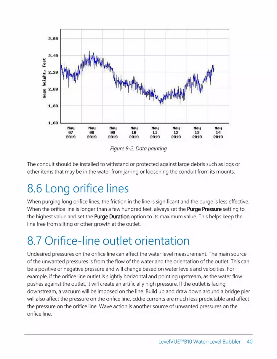
Figure 8-2. Data painting
The conduit should be installed to withstand or protected against large debris such as logs orother items that may be in the water from jarring or loosening the conduit from its mounts.
8.6 Long orifice linesWhen purging long orifice lines, the friction in the line is significant and the purge is less effective.When the orifice line is longer than a few hundred feet, always set the Purge Pressure setting tothe highest value and set the Purge Duration option to its maximum value. This helps keep theline free from silting or other growth at the outlet.
8.7 Orifice-line outlet orientationUndesired pressures on the orifice line can affect the water level measurement. The main sourceof the unwanted pressures is from the flow of the water and the orientation of the outlet. This canbe a positive or negative pressure and will change based on water levels and velocities. Forexample, if the orifice line outlet is slightly horizontal and pointing upstream, as the water flowpushes against the outlet, it will create an artificially high pressure. If the outlet is facingdownstream, a vacuum will be imposed on the line. Build up and draw down around a bridge pierwill also affect the pressure on the orifice line. Eddie currents are much less predictable and affectthe pressure on the orifice line. Wave action is another source of unwanted pressures on theorifice line.
LevelVUE™B10 Water-Level Bubbler 40

In most cases, the unwanted pressured due to water flow will have less impact on the orifice linewhen mounted vertically or slightly turned to the horizontal position and perpendicular to theprimary direction of flow. However, a bubble can form on a vertically oriented orifice line outletthat adds to the water depth. In still water, this increase can be as much as 0.003 m (0.01 ft). Inmoving water, the bubble is ripped off the end of the outlet before it has time to grow. In asystem that has an error specification of 0.02% or 0.002 m (0.007 ft) of water for a 15 psi unit, thisunwanted pressure can double that error percentage if the outlet is not properly oriented.
Bubbler systems are designed to reduce or eliminate the noise caused by the unwantedpressures and the bubble growth. In most cases, the default measurement averaging time of 1second is sufficient, but if noise is still noticed in the data and the line is stable, increasing thisaveraging time to 5 to 10 seconds will reduce noise in the system.
8.8 Orifice-line outlet typesCampbell Scientific offers an orifice-line outlet that consists of a 1/4-inch ID fitting mounted inthe end cap for the 53 mm (2-inch) conduit. This type of outlet can be mounted vertically orslightly horizontal, and responds quickly to small rises in the water level. The LevelVUE B10average bubble rate is based on using this type of orifice outlet cap.
An end cap with a large air chamber may be better for sites with quick rises in water levels (fasterthan 0.3 m/10 s (1 ft/10 s)), heavy wave action, or silting issues. With the standard outlet, waterpushes up the orifice line at a rate equal to the rise of the water. Depending on the level change,it may take a few to several seconds for the system to start bubbling again. Measurements madeduring this time will be lower than the actual level. An end cap with a large air chamber greatlyreduces the errors caused by the rapid and large rises in water levels because it acts as anintegrator.
In shallow streams, silt may cover the outlet when the river bottom shifts. Silt can restrict the airflow, causing data errors. Silt is less likely to restrict the air flow when the air chamber is large. Thetimed purge option should also be activated when in silty environments.
Drawbacks to an end cap with a large air chamber include that it must be mounted horizontal, itmay be harder to protect from large debris, and it takes more time for the system to fill the airchamber. Measurements made while the air chamber is filling will be inaccurate. Noisier data alsooccurs during small rises in the water level.
LevelVUE™B10 Water-Level Bubbler 41
9. Maintenance andtroubleshooting
NOTE:All factory repairs and recalibrations require a returned material authorization (RMA) andcompletion of the “Statement of Product Cleanliness and Decontamination” form. Refer tothe Assistance page at the end of this manual for more information.
9.1 Replacing desiccant 42
9.2 Lithium battery replacement 43
9.3 Plugged orifice outlet 44
9.4 Cold weather 45
9.5 Preventing or fixing orifice-line leaks 45
9.6 Updating operating system 45
9.7 Troubleshooting 46
9.1 Replacing desiccantRegularly replace the desiccant. Desiccant replacement frequency depends on the humidity ofthe site and the size of the desiccator. For new installations, Campbell Scientific recommendschecking the desiccant at least once a month. After a few months, users can adjust how oftenthey check the desiccant. Replacement silica gel desiccant is available at: www.campbellsci.com .
Desiccant replacement procedure:
1. Remove power from the LevelVUE B10.
2. Depressurize the input line.
LevelVUE™B10 Water-Level Bubbler 42
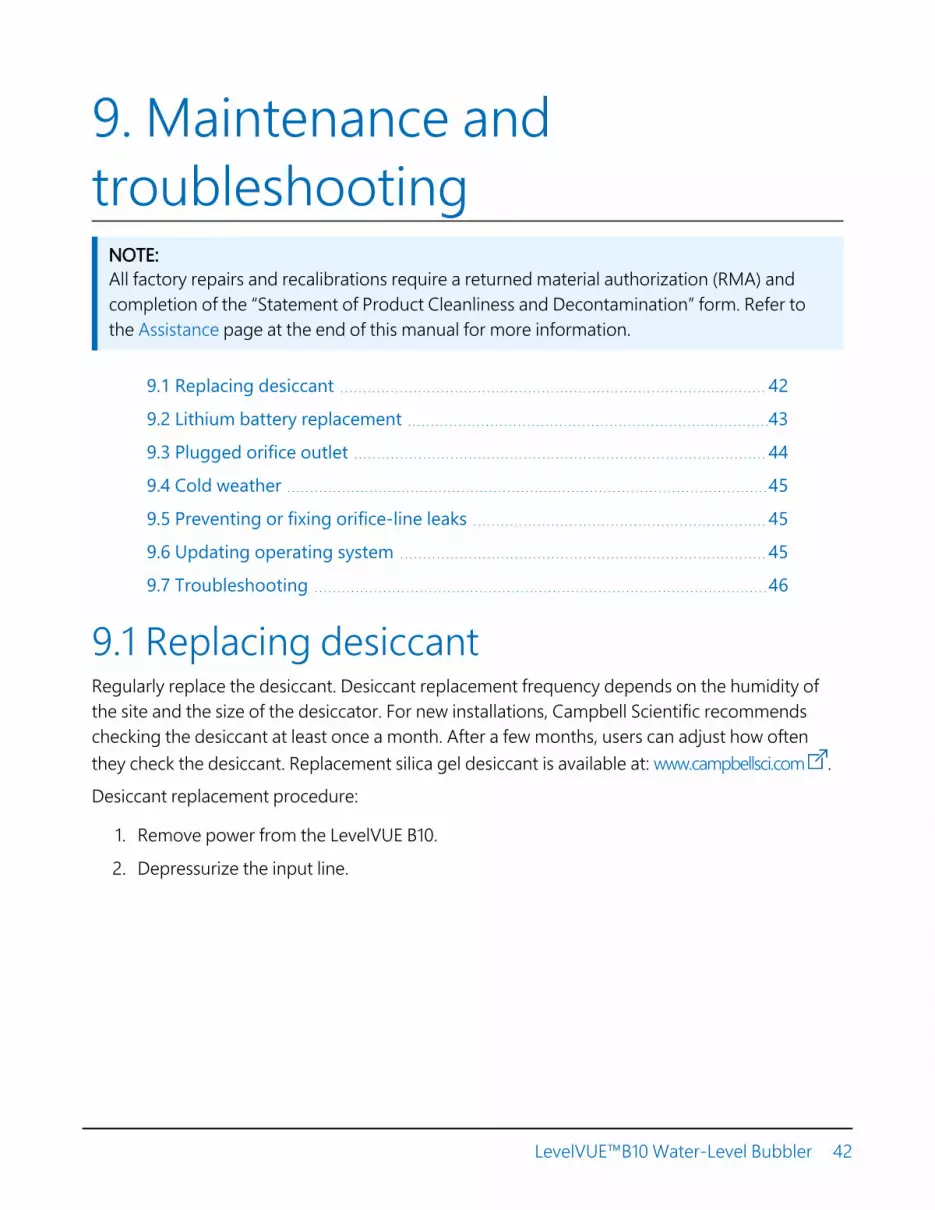
3. Loosen the clamp ring on the desiccator and remove the bowl from the top housing.
4. Pour out used desiccant and dispose of it according to the safety data sheet originallyshipped with the desiccator kit.
5. Open new desiccant container.
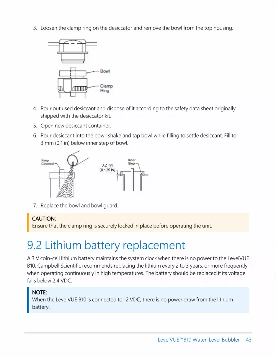
6. Pour desiccant into the bowl; shake and tap bowl while filling to settle desiccant. Fill to3 mm (0.1 in) below inner step of bowl.
7. Replace the bowl and bowl guard.
CAUTION:Ensure that the clamp ring is securely locked in place before operating the unit.
9.2 Lithium battery replacementA 3 V coin-cell lithium battery maintains the system clock when there is no power to the LevelVUEB10. Campbell Scientific recommends replacing the lithium every 2 to 3 years, or more frequentlywhen operating continuously in high temperatures. The battery should be replaced if its voltagefalls below 2.4 VDC.
NOTE:When the LevelVUE B10 is connected to 12 VDC, there is no power draw from the lithiumbattery.
LevelVUE™B10 Water-Level Bubbler 43

Lithium battery replacement procedure:
1. Open the swing panel located at the bottom-left edge of the plate that protects the circuitboard below the USB port (Figure 9-1 [p. 44]).
Figure 9-1. Lithium battery location
2. Remove the old battery.
3. Insert the new battery with the positive side up (plus sign facing the metal plate).
NOTE:Although inserting the battery incorrectly will not damage the system, the lithium battery willbe drained quickly.
DANGER:Misuse of the internal lithium battery can cause severe injury. Do not recharge, disassemble,heat above 100 °C (212 °F), solder directly to the cell, incinerate, or expose contents to water.Dispose of spent lithium batteries properly.
9.3 Plugged orifice outletThe orifice line outlet can become plugged from silt build up, moss growth, or debris. Oftenthese conditions occur over a long period of time. Silt or moss build up restricts air flow that canincrease the water level readings. This restriction in air flow is not consistent causing the data tofluctuate.
LevelVUE™B10 Water-Level Bubbler 44

Manually purge the system during each site visit to keep the orifice line free from blockage.When the water is lower and the outlet is accessible, inspect the outlet for growth. Clean theoutlet with a wire brush, as needed. Use a pipe cleaner or heavy stiff wire such as a coat hanger toremove buildup from inside the outlet. Purge the system while cleaning the orifice outlet to helpkeep the line cleared.
Relocate the outlet if it is constantly being covered in silt.
9.4 Cold weatherIn cold and humid weather areas, disable the purge feature during the cold season. If in a coldand humid area, the desiccant is less effective in preventing frozen particles from accessing areasof the system that could cause problems when the frozen particles melt.
Ice formed at the surface of the water can compress the orifice line and restrict the air flow. Waterin the conduit that freezes has no place to expand, causing erroneously high water-levelmeasurements.
9.5 Preventing or fixing orifice-line leaksBecause bubblers contain several tubes, fittings, and valves, leaks are one of the biggestproblems with bubbler systems. Campbell Scientific designed and manufactured the LevelVUEB10 to ensure these internal components are installed properly and to be leak free. However, caremust also be taken when connecting and installing the orifice line to avoid leaks. Do not usequick connect fittings as these tend to leak, and avoid extra fittings when possible. Try to use onecontinuous orifice line to eliminate junctions or splices, which are potential sources for leaks.Campbell Scientific offers orifice line that comes in 500-foot rolls, which suits most applications.The rare application that requires orifice lines longer than 500 feet should include the junction orsplice in a serviceable enclosure.
Find leaks in orifice lines or connectors by using a mixture of water and dish soap. Apply a smallamount of the dish-soap mixture to fittings that are suspected of leaking. The dish-soap mixturewill bubble where the fitting is leaking. Always wipe the fitting off with a dry rag.
9.6 Updating operating systemCampbell Scientific Device Configuration Utility is used to update the operating system (OS). TheDevice Configuration Utility is available as a download on www.campbellsci.com . It is includedin installations of LoggerNet, PC400, or RTDAQ.
LevelVUE™B10 Water-Level Bubbler 45

1. Open the Device Configuration Utility.
2. In the Device Type box, type LevelVUE B10 and click on LevelVUE B10
3. Before connecting this product to your computer for the first time, click the Install USBDriver button to install the driver.
4. Apply power (+12 VDC) to the Power connector.
5. Connect a USB cable between one of your computer USB ports and the USB port on thedevice .
6. In the left panel, select the appropriate serial port. If you browse for the serial port, it shouldbe identified with the LevelVUE B10 designation in the browse dialogue.
7. Click the Start button below.
8. A file open dialogue box will appear that will allow you to select the file to be sent. Whenyou have selected the file, click the OK button.
9. After the operating system has been successfully sent, the device will reboot and should beready to use in approximately 30 seconds.
CAUTION:Do not remove power for at least 30 seconds.
9.7 TroubleshootingTable 9-1 (p. 47) provide symptoms, causes, and solutions for problems. Most problems arecaused by orifice line or programming issues. A line noise test can be used to determine whethernoisy data is caused by an orifice line issue or a problem with the LevelVUE B10. Refer toDiagnostic/Test (p. 26) for more information.
LevelVUE™B10 Water-Level Bubbler 46

Table 9-1: Symptoms, possible causes, and solutions
Symptom Possible cause Solution
Stage is alwaysthe same value as
the offset
A leak is in the orifice line between thewater surface and the LevelVUE B10. Aleak in this area can result in a linepressure value of zero. This causes thestage value to equal the offset valuebecause of the equation used tocalculate stage:
Stage = Pressure • Slope + offset
Use water/dish soap mixture to lookfor leaks in the orifice line. Normallythe leak will be at one of the fittingsconnecting the orifice line to theLevelVUE B10. See Preventing orfixing orifice-line leaks (p. 45).
Data is painting
1. Orifice line outlet is not stable.Any movement in the orifice lineoutlet will have a direct effect onthe data.
2. Moisture in the orifice line cancreate friction for the air flowand cause abnormal pressuresin the line that affect thepressure caused by water depth.
3. Waves, choppy water,fluctuations in water flow createsdifferent pressures and vacuumson the orifice line outlet, whichcreates noise in the line.
4. Loose orifice end cap
1. Ensure that the orifice line isinside a conduit that isfastened to a permanent andsecure structure such as bridgepier, cement slab or pilings.The conduit should beprotected from large debrissuch as logs to prevent thedebris from jarring orloosening the conduit from itsmounts. See Secured orificeline (p. 38).
2. Regularly purge the line tohelp keep moisture out. Alsomake sure there are no lowpoints in the orifice line thatallow moisture to collect.
3. Increase the averaging time by5 to 10 seconds.
4. Tighten end cap.
An unexpectedsharp rise or fall
in water leveldata
The orifice-line outlet mount mayhave shifted because of large debrissuch as a log hitting the orifice linemount near the outlet or because ofscour.
Clear debris and secure the mount.Ensure that the conduit is installed towithstand or is protected from largedebris that may jar or loosen theconduit from its mounts. . SeeSecured orifice line (p. 38).
LevelVUE™B10 Water-Level Bubbler 47

Table 9-1: Symptoms, possible causes, and solutions
Symptom Possible cause Solution
Compressorseems to run
slow.
Battery may not have sufficientvoltage to run the compressor.
Make sure the battery is sufficientlycharged to handle the needed powerrequirements to run the compressor.Check the charging system. Cleanthe solar panel
Water levelvalues drift low at
night
The battery may be weak and onlyable to turn on the compressor whenthe solar charging system is alsosupplying power.
Check the battery voltage andreplace the battery if needed. Checkthe charging system. Clean the solarpanel
All LevelVUE B10output values
read 0
1. No SDI12Recorder()instruction in data loggerprogram.
2. Conditional statement thattriggers reading is notevaluating as true
1. Add SDI12Recorder()instruction to data loggerprogram
2. Check logic of conditionalstatement that triggersreadings
First value readsNAN and all
other values read0 or never
change from onemeasurement to
another.
1. LevelVUE B10 SDI-12 addressdoes not match addressspecified in data loggerprogram
2. LevelVUE B10 is not connectedto the SDI-12 terminal specifiedin data logger program
3. LevelVUE B10 not beingpowered
1. Change LevelVUE B10 SDI-12address or modify program sothat they match
2. Connect wire to correctterminal or modify program tomatch wiring
3. Make sure the LevelVUE B10 iswired correctly and matchesthe data logger program
Readings erratic,including NANsand 9999999s
Multiple devices with sameSDI-12 address sharing sameU or C terminal
Connect each SDI-12 device toa different U or C terminalor give them unique SDI-12addresses. Ensure that you revisethe data logger program toaccount for these changes.
LevelVUE™B10 Water-Level Bubbler 48

Appendix A. Example programTable A-1 (p. 49) provides wiring for the SDI-12 example program (CRBasic Example 1 [p. 49]).
Table A-1: Wiring for SDI-12 example program
LevelVUE B10 terminal Function CR1000X terminal Power supply
SDI-12 Data SDI-12 signal C1
SDI-12 G Ground ⏚
12Vdc + Power 12V
12Vdc - Power ground G
CRBasic Example 1: CR1000X program measuring the LevelVUE B10 using SDI-12
'CR1000X Series Data Logger'Declare variables and Units
Public BattVPublic PTemp_CPublic LVData(8)
'Rename the variable names
Alias LVData(1)=StageAlias LVData(2)=Line_psiAlias LVData(3)=Tank_psiAlias LVData(4)=LVB10_TempAlias LVData(5)=LVB10_BattAlias LVData(6)=LVB10_ErrorCodeAlias LVData(7)=Crest_StageAlias LVData(8)=Crest_Tm_Offs
Units BattV=VoltsUnits PTemp_C=Deg CUnits Stage=feetUnits Line_psi=psiUnits Tank_psi=psiUnits LVB10_Temp=Deg CUnits LVB10_Batt=voltsUnits LVB10_ErrorCode=code
LevelVUE™B10 Water-Level Bubbler 49

CRBasic Example 1: CR1000X program measuring the LevelVUE B10 using SDI-12
Units Crest_Stage=feetUnits Crest_Tm_Offs=seconds
'Define a data tableDataTable(MainData,True,-1)DataInterval(0,5,Min,10)Sample (1,Stage,FP2)Sample (1,Line_psi,FP2)Sample (1,Tank_psi,FP2)Sample (1,LVB10_Temp,FP2)Sample (1,LVB10_Batt,FP2)Sample (1,LVB10_ErrorCode,FP2)Sample(1,Crest_Stage,FP2)Sample(1,Crest_Tm_Offs,FP2)Sample(1,BattV,FP2)Sample(1,PTemp_C,FP2)
EndTable
'Main programBeginProg'Main scanScan(5,Sec,1,0)
'Default CR1000X data logger Voltage measurement 'BattV'Battery(BattV)
'Default CR1000X data logger Wiring Panel Temperature measurement 'PTemp_C'PanelTemp(PTemp_C,60)
'LevelVUEB10 Water-Level Continuous Flow Bubbler measurementsIf TimeIntoInterval(0,5,Min) ThenSDI12Recorder (LVData(),C1,0,"M!",1.0,0)
EndIf
'Call the data tables and store dataCallTable MainData
NextScanEndProg
LevelVUE™B10 Water-Level Bubbler 50

Appendix B. SDI-12 sensorsupportSDI-12, Serial Data Interface at 1200 baud, is a protocol developed to simplify sensor and datalogger compatibility. Only three wires are necessary — serial data, ground, and 12 V. With uniqueaddresses, multiple SDI-12 sensors can connect to a single SDI-12 terminal on a CampbellScientific data logger.
This appendix discusses the structure of SDI-12 commands and the process of querying SDI-12sensors. For more detailed information, refer to version 1.4 of the SDI-12 protocol, available atwww.sdi-12.org .
For additional information, refer to the SDI-12 Sensors | Transparent Mode and SDI-12 Sensors |Watch or Sniffer Mode videos.
B.1 SDI-12 command basicsSDI-12 commands have three components:
l Sensor address (a) – a single character and the first character of the command. Use thedefault address of zero (0) unless multiple sensors are connected to the same port.
l Command body – an upper case letter (the “command”), optionally followed by one ormore alphanumeric qualifiers.
l Command termination (!) – an exclamation mark.
An active sensor responds to each command. Responses have several standard forms and alwaysterminate with <CR><LF> (carriage return and line feed). Standard SDI-12 commands are listedin Table B-1 (p. 51).
Table B-1: Campbell Scientific sensor SDI-12 command and response set
Name Command Response1
Acknowledge Active a! a<CR><LF>
Send Identification aI!allccccccccmmmmmmvvvxxx...xx
<CR><LF>
Start Verification aV! atttn <CR><LF>
LevelVUE™B10 Water-Level Bubbler 51

Table B-1: Campbell Scientific sensor SDI-12 command and response set
Name Command Response1
Address Query ?! a<CR><LF>
Change Address aAb! b<CR><LF>
Start Measurement aM!aM1!...aM9!
atttn<CR><LF>
Start Measurementand Request CRC
aMC!aMC1!...aMC9!
atttn <CR><LF>
Start Concurrent Measurement aC!aC1!...aC9!
atttnn<CR><LF>
Start Concurrent Measurementand Request CRC
aCC!aCC1!...aCC9!
atttnn<CR><LF>
Send Data aD0!...aD9!a<values><CR><LF> or
a<values><CRC><CR><LF>
Continuous Measurement aR0!...aR9! a<values><CR><LF>
Continuous Measurementand Request CRC
aRC0!...aRC9! a<values><CRC><CR><LF>
Extended Commands aXNNN! a<values><CR><LF>1 Information on each of these commands is given in the following sections.
B.1.1 Acknowledge active command (a!)The Acknowledge Active command (a!) is used to test a sensor on the SDI-12 bus. An activesensor responds with its address.
B.1.2 Send identification command (al!)Sensor identifiers are requested by issuing command aI!. The reply is defined by the sensormanufacturer but usually includes the sensor address, SDI-12 version, manufacturer’s name, andsensor model information. Serial number or other sensor specific information may also beincluded.
aI! allccccccccmmmmmmvvvxxx...xx<CR><LF>
a Sensor SDI-12 address
ll SDI-12 version number (indicates compatibility)
LevelVUE™B10 Water-Level Bubbler 52

cccccccc 8-character vendor identification
mmmmmm 6 characters specifying the sensor model
vvv 3 characters specifying the sensor version (operating system)
xxx…xx Up to 13 optional characters used for a serial number or other specificsensor information that is not relevant for operation of the data logger
<CR><LF> Terminates the responseSource: SDI-12: A Serial-Digital Interface Standard for Microprocessor-Based Sensors (see References).
B.1.3 Start verification command (aV!)The response to a Start Verification command can include hardware diagnostics, but like the aI!command, the response is not standardized.
Command: aV!
Response: atttn<CR><LF>
a = sensor address
ttt = time, in seconds, until verification information is available
n = the number of values to be returned when one or more subsequent D! commands areissued
B.1.4 Address query command (?!)Command ?! requests the address of the connected sensor. The sensor replies to the query withthe address, a. This command should only be used with one sensor on the SDI-12 bus at a time.
B.1.5 Change address command (aAb!)Multiple SDI-12 sensors can connect to a single SDI-12 terminal on a data logger. Each device ona single terminal must have a unique address.
A sensor address is changed with command aAb!, where a is the current address and b is thenew address. For example, to change an address from 0 to 2, the command is 0A2!. The sensorresponds with the new address b, which in this case is 2.
NOTE:Only one sensor should be connected to a particular terminal at a time when changingaddresses.
LevelVUE™B10 Water-Level Bubbler 53

B.1.6 Start measurement commands (aM!)A measurement is initiated with the M! command. The response to each command has the formatttn<CR><LF>, where
a = sensor address
ttt = time, in seconds, until measurement data is available. When the data is ready, the sensornotifies the data logger, and the data logger begins issuing D commands.
n = the number of values returned when one or more subsequent D commands are issued. Forthe aM! command, n is an integer from 0 to 9.
When the aM! is issued, the data logger pauses its operation and waits until either it receives thedata from the sensor or the time, ttt, expires. Depending on the scan interval of the data loggerprogram and the response time of the sensor, this may cause skipped scans to occur. In this casemake sure your scan interval is longer than the longest measurement time (ttt).
Table B-2: Example aM! sequence
0M! The data logger makes a request to sensor 0 to start a measurement.
00352<CR><LF> Sensor 0 immediately indicates that it will return two values within thenext 35 seconds.
0<CR><LF> Within 35 seconds, sensor 0 indicates that it has completed themeasurement by sending a service request to the data logger.
0D0!The data logger immediately issues the first D command to collectdata from the sensor.
0+.859+3.54<CR><LF> The sensor immediately responds with the sensor address and thetwo values.
B.1.7 Start concurrent measurement commands (aC!)A concurrent measurement (aC!) command follows the same pattern as the aM! command withthe exception that it does not require the data logger to pause its operation, and other SDI-12sensors may take measurements at the same time. The sensor will not issue a service request tonotify the data logger that the measurement is complete. The data logger will issue the aD0!command during the next scan after the measurement time reported by the sensor has expired.To use this command, the scan interval should be 10 seconds or less. The response to eachcommand has the form atttn<CR><LF>, where
a = the sensor address
ttt = time, in seconds, until the measurement data is available
LevelVUE™B10 Water-Level Bubbler 54

nn = the number of values to be returned when one or more subsequent D commands areissued.
See the following example. A data logger has three sensors wired into terminal C1. The sensorsare addresses X, Y, and Z. The data logger will issue the following commands and receive thefollowing responses:
Table B-3: Example aC! sequence
XC!The data logger makes a request to sensor X to starta concurrent measurement.
X03005<CR><LF>Sensor X immediately indicates that it will have 5(05) values ready for collection within the next 30(030) seconds.
YC!The data logger makes a request to sensor Y to starta concurrent measurement.
Y04006<CR><LF>Sensor Y immediately indicates that it will have 6(06) values ready for collection within the next 40(040) seconds.
ZC!The data logger makes a request to sensor Z to starta concurrent measurement.
Z02010<CR><LF>Sensor Z immediately indicates that it will have 10values ready for collection within the next 20 (020)seconds.
ZD0!After 20 seconds have passed, the data logger startsthe process of collecting the data by issuing the firstD command to sensor Z.
Z+1+2+3+4+5+6+7+8+9+10<CR><LF> Sensor Z immediately responds with the sensoraddress and the 10 values.
XD0!
10 seconds later, after a total of 30 seconds havepassed, the data logger starts the process ofcollecting data from sensor X by issuing the first Dcommand.
X+1+2+3+4+5<CR><LF> The sensor immediately responds with the sensoraddress and the 5 values.
LevelVUE™B10 Water-Level Bubbler 55

Table B-3: Example aC! sequence
YD0!
Ten seconds later, after a total of 40 seconds havepassed, the data logger starts the process ofcollecting data from sensor Y by issuing the first Dcommand.
Y+1+2+3+4+5+6<CR><LF> The sensor immediately responds with the sensoraddress and the 6 values.
B.1.8 Start measurement commands with cyclicredundancy check (aMC! and aCC!)Error checking is done by using measurement commands with cyclic redundancy checks (aMC!or aCC!). This is most commonly implemented when long cable lengths or electronic noise mayimpact measurement transmission to the data logger. When these commands are used, the datareturned in response to D or R commands must have a cyclic redundancy check (CRC) codeappended to it. The CRC code is a 16-bit value encoded within 3 characters appended before the<CR><LF>. This code is not returned in the data table but checked by the data logger as itcomes. The code returned is based on the SDI-12 protocol. See the SDI-12 communicationspecification for version 1.4 available at www.sdi-12.org to learn more about how the CRCcode is developed.
B.1.9 Stopping a measurement commandA measurement command (M!) is stopped if it detects a break signal before the measurement iscomplete. A break signal is sent by the data logger before most commands.
A concurrent measurement command (C!) is aborted when another valid command is sent tothe sensor before the measurement time has elapsed.
B.1.10 Send data command (aD0! … aD9!)The Send Data command requests data from the sensor. It is issued automatically with every typeof measurement command (aM!, aMC!, aC!, aCC!). When the measurement command is aM!or aMC!, the data logger issues the aD0! command once a service request has been receivedfrom the sensor or the reported time has expired. When the data logger is issuing concurrentcommands (aC! or aCC!), the Send Data command is issued after the required time has elapsed(no service request will be sent by the sensor). In transparent mode (see SDI-12 transparent mode[p. 58]), the user asserts this command to obtain data.
Depending on the type of data returned and the number of values a sensor returns, the datalogger may need to issue aD0! up to aD9! to retrieve all data. A sensor may return up to 35
LevelVUE™B10 Water-Level Bubbler 56

characters of data in response to a D command that follows an M! or MC! command. A sensormay return up to 75 characters of data in response to a D command that follows a C! or CC!command. Data values are separated by plus or minus signs.
Command: aD0! (aD1! … aD9!)
Response: a<values><CR><LF> or a<values><CRC><CR><LF>
where:
a = the sensor address
<values> = values returned with a polarity sign (+ or –)
<CR><LF> = terminates the response
<CRC> = 16-bit CRC code appended if data was requested with aMC! or aCC!.
B.1.11 Extended commandsMany sensors support extended SDI-12 commands. An extended command is specific to a makeof sensor and tells the sensor to perform a specific task. They have the following structure.Responses vary from unit to unit. See the sensor manual for specifics.
Command: aXNNNN!
The command will start with the sensor address (a), followed by an X, then a set of optionalletters, and terminate with an exclamation point.
Response: a<optional values><CR><LF>
The response will start with the sensor address and end with a carriage return/line feed.
B.1.12 SDI-12 version 1.4 identify measurement commandsand responsesVersion 1.4 compliant sensors must respond to identify commands for each type of measurementcommand and each parameter with a command. The broad identify commands return how manyvariables will be returned with a given measurement command and the time it will take thesensor to respond. The specific identify parameter commands will return a SHEF code, themeasurement units, and the type of measurement (sample, count, or average). For moreinformation see the SDI-12 version 1.4 specification.
(http://sdi-12.org/current_specification/SDI-12_version-1_4-May-1-2017.pdf)
LevelVUE™B10 Water-Level Bubbler 57

Table B-4: Supported V1.4 Commands (Command Information)
Type of Command Command1 Sensor Response1
Identify measurement for Mcommands aIM!, aIMC! atttn<CR><LF>
Identify measurement for Ccommands aIC!, aICC! atttnn<CR><LF>
Identify measurement for Vcommands aIV! atttn<CR><LF>
1Where a is theSDI-12 address; ttt is the response time; and n is the number of values returned
Table B-5: Supported V1.4 Commands (Parameter Identification) in the LevelVUE B10
Parameter Command 1 Sensor Response1
Stage aIM_001!, aIC_001! a,HG,xx,sample;<CR><LF>
Line pressure aIM_002!, aIC_002! a,LP,PSI,sample;<CR><LF>
Tank pressure aIM_003!, aIC_003! a,TP,PSI,sample;<CR><LF>
Temperature aIM_004!, aIC_004! a,TMP,y,sample;<CR><LF>
Battery voltage aIM_005!, aIC_005! a,VB,V,sample;<CR><LF>
Error code aIM_006!, aIC_006! a,ERROR,CODE,sample;<CR><LF>
Peak stage aIM_007!, aIC_007! a,HG2,xx,sample;<CR><LF>
Peak stage offset time aIM_008!, aIC_008! a,HG2_TIME,SEC,sample;<CR><LF>
1Where a is the SDI-12 address; xx is either ft or m; and y is either C or F.
B.2 SDI-12 transparent modeSystem operators can manually interrogate and enter settings in probes using transparent mode.Transparent mode is useful in troubleshooting SDI-12 systems because it allows directcommunication with probes. Data logger security may need to be unlocked before activating thetransparent mode.
Transparent mode is entered while the computer is communicating with the data logger througha terminal emulator program. It is accessed through Campbell Scientific data logger support
LevelVUE™B10 Water-Level Bubbler 58

software or other terminal emulator programs. Data logger keyboards and displays cannot beused.
The terminal emulator is accessed by navigating to the Tools list in PC400 or the Datalogger listin the Connect screen of LoggerNet.
Watch videos/sdi12-sensors-transparent-mode from our website.
Data loggers from other manufacturers will also have a transparent mode. Refer to thosemanuals on how to use their transparent mode.
The following examples show how to enter transparent mode and change the SDI-12 address ofan SDI-12 sensor. The steps shown in Changing an SDI-12 address (p. 59) are used with mostCampbell Scientific data loggers.
B.2.1 Changing an SDI-12 addressThis example was done with a CR1000X, but the steps are only slightly different for CR6, CR3000,CR800-series, CR300-series, CR1000 data loggers.
1. Connect an SDI-12 sensor to the CR1000X.
2. Open Device Configuration utility.
3. Under Device Type, type the data logger model and double-click on the model type. Thisexample uses a CR1000X directly connected to the computer USB port.
4. Select the correct Communication Port and click Connect.
LevelVUE™B10 Water-Level Bubbler 59

5. Click the Terminal tab.
6. Select All Caps Mode.
7. Press Enter until the data logger responds with the data logger (CR1000X>) prompt.
8. Type SDI12 and press Enter.
9. At the Select SDI12 Port prompt, type the number corresponding to the control port wherethe sensor is connected and press Enter. In this example the sensor is connected to C3. Theresponse Entering SDI12 Terminal indicates that the sensor is ready to accept SDI-12commands.
10. To query the sensor for its current SDI-12 address, type ?! and press Enter. The sensorresponds with its SDI-12 address. If no characters are typed within 60 seconds, the mode isexited. In that case, simply type SDI12 again, press Enter, and type the correct control portnumber when prompted.
LevelVUE™B10 Water-Level Bubbler 60

11. To change the SDI-12 address, type aAb!, where a is the current address from the previousstep and b is the new address. Press Enter. The sensor changes its address and respondswith the new address. In the following example, the sensor address is changed from 0 to B.
12. To exit SDI-12 transparent mode, click Close Terminal.
NOTE:The transparent mode for the CR6, CR3000, CR800-series, CR300-series, and CR1000 dataloggers is similar to that shown for the CR1000X.
B.3 ReferencesSDI-12 Support Group. SDI-12: A Serial-Digital Interface Standard for Microprocessor-BasedSensors – Version 1.4. River Heights, UT: SDI-12 Support Group, 2017. https://sdi-12.org/specification .
LevelVUE™B10 Water-Level Bubbler 61
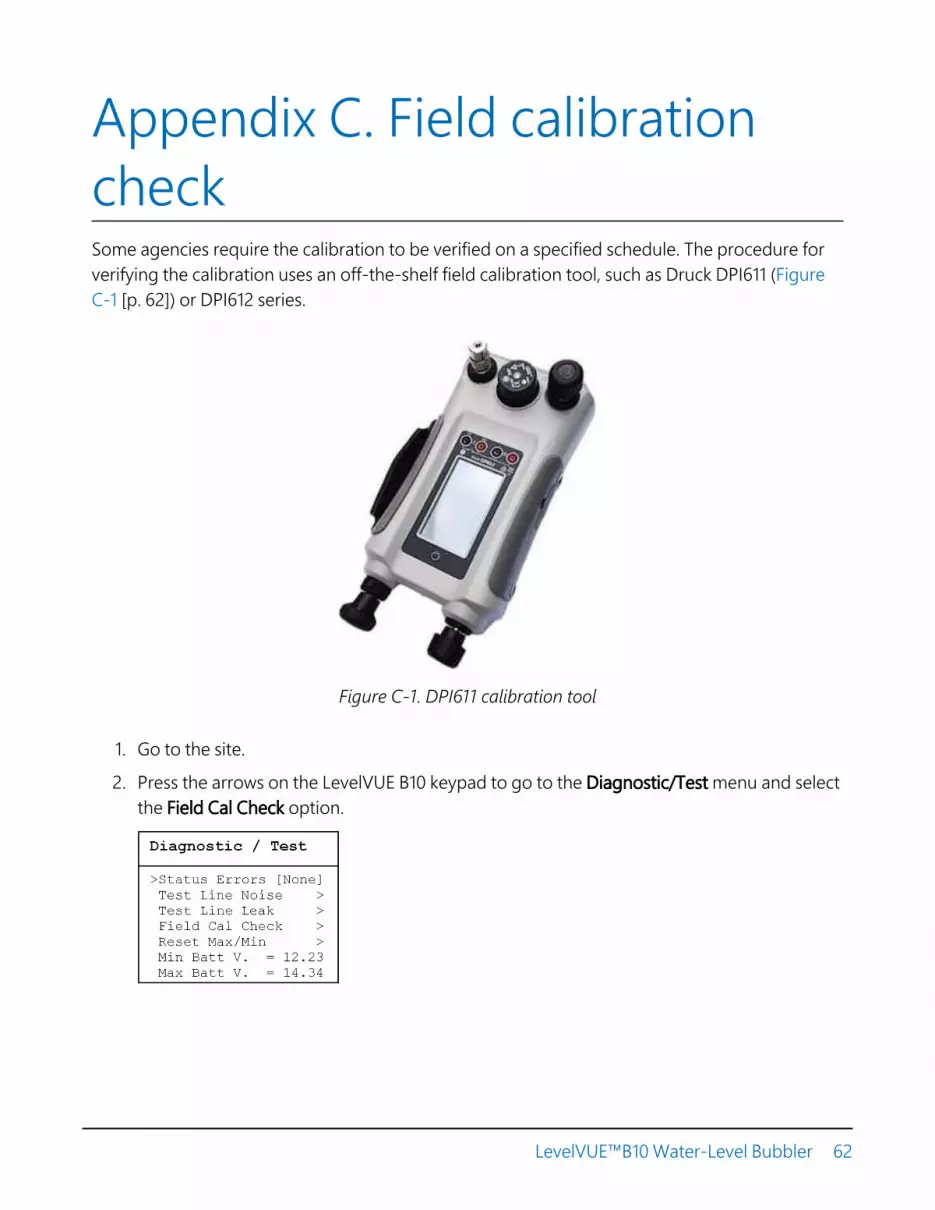
Appendix C. Field calibrationcheckSome agencies require the calibration to be verified on a specified schedule. The procedure forverifying the calibration uses an off-the-shelf field calibration tool, such as Druck DPI611 (FigureC-1 [p. 62]) or DPI612 series.
Figure C-1. DPI611 calibration tool
1. Go to the site.
2. Press the arrows on the LevelVUE B10 keypad to go to the Diagnostic/Test menu and selectthe Field Cal Check option.
LevelVUE™B10 Water-Level Bubbler 62

3. When the following screen appears, disconnect the orifice line and connect the LevelVUEB10 outlet to the calibration tool.
Run Field Cal Check?
Attach Field
Cal. Tool.
YES NO
4. Select YES to start the test. The following message will be briefly displayed:
Run Field Cal Check?Setting Up…
Please WaitTimeout Counter 899
5. At this point, the purge valve is activated to allow pressures in the system to equalizequickly. Also, the built-in compressor is disabled allowing the pressure to be controlledsolely by the calibration tool. The test will time out after about 15 minutes. Once the systempressures equalize the following screen is displayed:
Run Field Cal
Line PSI: x.xxx
Timeout Counter 321STOP TCRST
6. While the test is running, the pressure measured by the LevelVUE B10 is displayed on thescreen. This value should be very close to the value displayed on the calibration tool. Keepin mind, it may take a few seconds for the system to equalize after the pressure is changed.The test can be stopped at any time by pressing the soft key STOP or reset to run longer bypressing the soft key TCRST (Timeout Counter Reset). While the test is running, adjust thepressure as needed to verify proper operation.
CAUTION:Do not pressurize the system higher than the rated pressure range.
It is good practice to test the pressure at each end of the range and at a mid-point. Forexample, on a 0 to 30 psi bubbler, test at about 0.100 psi, 15.000 psi, and at 29.900 psi. Topass the test, the bubbler and the calibrator readings need to be within the systemaccuracy. For example, a 30 psi unit with a maximum error of ±0.02% passes the calibration
LevelVUE™B10 Water-Level Bubbler 63

test if the bubbler value is within ±0.006 psi (30 psi x 0.02% = 0.006 psi) of the calibratorvalue.
NOTE:The worst-case error is additive. The bubbler accuracy is 0.02% and the calibratoraccuracy is typically 0.01%. Therefore, the worst case error is 0.03% (0.02% + 0.01%). Fora 30 psi unit, this is ±0.009 psi (0.0003 x 30).
7. Once the test is stopped or the timeout expires, the unit will ask if the field calibrator toolhas been removed. After removing the calibrator, reconnect the LevelVUE B10 orifice line.The timeout counter defaults to 30 seconds to provide enough time to switch the line.
Run Field Cal
Field Cal ToolRemoved?
Timeout Counter 28EXIT TCRST
8. After the test, reconnect the orifice line and purge the line to ensure water is out of theorifice line.
LevelVUE™B10 Water-Level Bubbler 64
Limited warrantyProducts manufactured by Campbell Scientific are warranted by Campbell Scientific to be freefrom defects in materials and workmanship under normal use and service for twelve monthsfrom the date of shipment unless otherwise specified on the corresponding product webpage.See Product Details on the Ordering Information pages at www.campbellsci.com . Othermanufacturer's products, that are resold by Campbell Scientific, are warranted only to the limitsextended by the original manufacturer.
Refer to www.campbellsci.com/terms#warranty for more information.
CAMPBELL SCIENTIFIC EXPRESSLY DISCLAIMS AND EXCLUDES ANY IMPLIED WARRANTIES OFMERCHANTABILITY OR FITNESS FOR A PARTICULAR PURPOSE. Campbell Scientific herebydisclaims, to the fullest extent allowed by applicable law, any and all warranties and conditionswith respect to the Products, whether express, implied or statutory, other than those expresslyprovided herein.

AssistanceProducts may not be returned without prior authorization.
Products shipped to Campbell Scientific require a Returned Materials Authorization (RMA) orRepair Reference number and must be clean and uncontaminated by harmful substances, suchas hazardous materials, chemicals, insects, and pests. Please complete the required forms prior toshipping equipment.
Campbell Scientific regional offices handle repairs for customers within their territories. Pleasesee the back page for the Global Sales and Support Network or visitwww.campbellsci.com/contact to determine which Campbell Scientific office serves yourcountry.
To obtain a Returned Materials Authorization or Repair Reference number, contact yourCAMPBELL SCIENTIFIC regional office. Please write the issued number clearly on the outside ofthe shipping container and ship as directed.
For all returns, the customer must provide a “Statement of Product Cleanliness andDecontamination” or “Declaration of Hazardous Material and Decontamination” form andcomply with the requirements specified in it. The form is available from your CAMPBELLSCIENTIFIC regional office. Campbell Scientific is unable to process any returns until we receivethis statement. If the statement is not received within three days of product receipt or isincomplete, the product will be returned to the customer at the customer’s expense. CampbellScientific reserves the right to refuse service on products that were exposed to contaminants thatmay cause health or safety concerns for our employees.

SafetyDANGER — MANY HAZARDS ARE ASSOCIATED WITH INSTALLING, USING, MAINTAINING, AND WORKING ON OR AROUND TRIPODS, TOWERS,AND ANY ATTACHMENTS TO TRIPODS AND TOWERS SUCH AS SENSORS, CROSSARMS, ENCLOSURES, ANTENNAS, ETC. FAILURE TO PROPERLYAND COMPLETELY ASSEMBLE, INSTALL, OPERATE, USE, AND MAINTAIN TRIPODS, TOWERS, AND ATTACHMENTS, AND FAILURE TO HEEDWARNINGS, INCREASES THE RISK OF DEATH, ACCIDENT, SERIOUS INJURY, PROPERTY DAMAGE, AND PRODUCT FAILURE. TAKE ALL REASONABLEPRECAUTIONS TO AVOID THESE HAZARDS. CHECK WITH YOUR ORGANIZATION'S SAFETY COORDINATOR (OR POLICY) FOR PROCEDURES ANDREQUIRED PROTECTIVE EQUIPMENT PRIOR TO PERFORMING ANY WORK.Use tripods, towers, and attachments to tripods and towers only for purposes for which they are designed. Do not exceed design limits. Be familiarand comply with all instructions provided in product manuals. Manuals are available at www.campbellsci.com. You are responsible for conformancewith governing codes and regulations, including safety regulations, and the integrity and location of structures or land to which towers, tripods, andany attachments are attached. Installation sites should be evaluated and approved by a qualified engineer. If questions or concerns arise regardinginstallation, use, or maintenance of tripods, towers, attachments, or electrical connections, consult with a licensed and qualified engineer orelectrician.General
l Protect from over-voltage.l Protect electrical equipment from water.l Protect from electrostatic discharge (ESD).l Protect from lightning.l Prior to performing site or installation work, obtain required approvals and permits. Comply with all governing structure-height regulations.l Use only qualified personnel for installation, use, and maintenance of tripods and towers, and any attachments to tripods and towers. The
use of licensed and qualified contractors is highly recommended.l Read all applicable instructions carefully and understand procedures thoroughly before beginning work.l Wear a hardhat and eye protection, and take other appropriate safety precautions while working on or around tripods and towers.l Do not climb tripods or towers at any time, and prohibit climbing by other persons. Take reasonable precautions to secure tripod and tower
sites from trespassers.l Use only manufacturer recommended parts, materials, and tools.
Utility and Electricall You can be killed or sustain serious bodily injury if the tripod, tower, or attachments you are installing, constructing, using, or maintaining, or
a tool, stake, or anchor, come in contact with overhead or underground utility lines.l Maintain a distance of at least one-and-one-half times structure height, 6 meters (20 feet), or the distance required by applicable law,
whichever is greater, between overhead utility lines and the structure (tripod, tower, attachments, or tools).l Prior to performing site or installation work, inform all utility companies and have all underground utilities marked.l Comply with all electrical codes. Electrical equipment and related grounding devices should be installed by a licensed and qualified
electrician.l Only use power sources approved for use in the country of installation to power Campbell Scientific devices.
Elevated Work and Weatherl Exercise extreme caution when performing elevated work.l Use appropriate equipment and safety practices.l During installation and maintenance, keep tower and tripod sites clear of un-trained or non-essential personnel. Take precautions to prevent
elevated tools and objects from dropping.l Do not perform any work in inclement weather, including wind, rain, snow, lightning, etc.
Maintenancel Periodically (at least yearly) check for wear and damage, including corrosion, stress cracks, frayed cables, loose cable clamps, cable tightness,
etc. and take necessary corrective actions.l Periodically (at least yearly) check electrical ground connections.
Internal Batteryl Be aware of fire, explosion, and severe-burn hazards.l Misuse or improper installation of the internal lithium battery can cause severe injury.l Do not recharge, disassemble, heat above 100 °C (212 °F), solder directly to the cell, incinerate, or expose contents to water. Dispose of spent
batteries properly.WHILE EVERY ATTEMPT IS MADE TO EMBODY THE HIGHEST DEGREE OF SAFETY IN ALL CAMPBELL SCIENTIFIC PRODUCTS, THE CUSTOMERASSUMES ALL RISK FROM ANY INJURY RESULTING FROM IMPROPER INSTALLATION, USE, OR MAINTENANCE OF TRIPODS, TOWERS, ORATTACHMENTS TO TRIPODS AND TOWERS SUCH AS SENSORS, CROSSARMS, ENCLOSURES, ANTENNAS, ETC.

AustraliaLocation:Phone:Email:Website:
Garbutt, QLD Australia61.7.4401.7700info@campbellsci.com.auwww.campbellsci.com.au
BrazilLocation:Phone:Email:Website:
São Paulo, SP Brazil11.3732.3399vendas@campbellsci.com.brwww.campbellsci.com.br
CanadaLocation:Phone:Email:Website:
Edmonton, AB [email protected]
ChinaLocation:Phone:Email:Website:
Beijing, P. R. China86.10.6561.0080info@campbellsci.com.cnwww.campbellsci.com.cn
Costa RicaLocation:Phone:Email:Website:
San Pedro, Costa [email protected]
FranceLocation:Phone:Email:Website:
Vincennes, [email protected]
GermanyLocation:Phone:Email:Website:
Bremen, [email protected]
IndiaLocation:Phone:Email:Website:
New Delhi, DL [email protected]
South AfricaLocation:Phone:Email:Website:
Stellenbosch, South [email protected]
SpainLocation:Phone:Email:Website:
Barcelona, [email protected]
ThailandLocation:Phone:Email:Website:
Bangkok, [email protected]
UKLocation:Phone:Email:Website:
Shepshed, Loughborough, [email protected]
USALocation:Phone:Email:Website:
Logan, UT [email protected]
Campbell Scientific Regional Offices