lehigh preserve a feasibility study of group technology and interactive graphics for conceptual...
TRANSCRIPT

Lehigh UniversityLehigh Preserve
Theses and Dissertations
1-1-1982
A feasibility study of group technology andinteractive graphics for conceptual plant layout.Robert William Kimble
Follow this and additional works at: http://preserve.lehigh.edu/etd
Part of the Industrial Engineering Commons
This Thesis is brought to you for free and open access by Lehigh Preserve. It has been accepted for inclusion in Theses and Dissertations by anauthorized administrator of Lehigh Preserve. For more information, please contact [email protected].
Recommended CitationKimble, Robert William, "A feasibility study of group technology and interactive graphics for conceptual plant layout." (1982). Thesesand Dissertations. Paper 2006.

A FEASIBILITY STUDY OF GROUP TECHNOLOGY
AND INTERACTIVE GRAPHICS
FOR CONCEPTUAL PLANT LAYOUT
by
Robert William Kimble
A Thesis
Presented to the Graduate Committee
of Lehigh University
in Candidacy for the Degree of
Master of Science
in
Industrial Engineering
Lehigh University
1982

ProQuest Number: EP76279
All rights reserved
INFORMATION TO ALL USERS The quality of this reproduction is dependent upon the quality of the copy submitted.
In the unlikely event that the author did not send a complete manuscript and there are missing pages, these will be noted. Also, if material had to be removed,
a note will indicate the deletion.
uest
ProQuest EP76279
Published by ProQuest LLC (2015). Copyright of the Dissertation is held by the Author.
All rights reserved. This work is protected against unauthorized copying under Title 17, United States Code
Microform Edition © ProQuest LLC.
ProQuest LLC. 789 East Eisenhower Parkway
P.O. Box 1346 Ann Arbor, Ml 48106-1346

CERTIFICATE OF APPROVAL
This thesis is accepted and approved in partial
fulfillment of the requirements for the degree of Master
of Science.
?- /- Xi~ FdateT
Chairman of Department
11

ACKNOWLEDGMENTS
I wish to thank Emory w. Zimmers, Jr., my major
thesis advisor and Louis J. Plebani, my minor advisor for
providing guidance and advice in pursuing this work.
I also wish to thank Herbert w, Purdy and his
associates for the use of the graphics equipment and for
furnishing sources of information that assisted in the
case study work.
ill

Table of Contents
ABSTRACT 1
CHAPTER 1 - INTRODUCTION 3
CHAPTER 2 - PROBLEM DEFINITION 6
CHAPTER 3 - BACKGROUND INFORMATION 9
3.1 Group Technology Concepts 9 3.2 Computer-Aided Geometric Plant Layout 13
CHAPTER 4: - ANALYSIS 20
4.1 Part Family and Product Design 20 4.2 High-Level Language Interface to CAD/CAM Data Base 21
CHAPTER. 5 - SYSTEM DESIGN AND DEVELOPMENT OF 24 PROCEDURES
5.1 Hardware and Software 24 5.2 Program Development 26 5.3 Program Implementation 39 5..4 Program Execution 51 5.5 Plant Layout Techniques 52
CHAPTER 6 - CASE STUDY 58
6.1 Current Situation and Objectives' 58 6.2 Proposed Solution 61 6.3 Benefits of Proposed Solution 82
CHAPTER; T - CONCLUSION 86
CHAPTER. 8' - SUMMARY 88
CHAPTER. 9 - RECOMMENDATIONS FOR FUTURE WORK 91
REFERENCES' 96
APPENDIX A: - GLOSSARY OF CAD/CAM TERMINOLOGY 99
APPENDIX B - FORTRAN INTERFACE SUBROUTINES 103
APPENDIX Cl - COMMONLY USED GRAPHICS TABLET STROKES 105
VITA! 107
iv

List of Figures'
Figure Figure Figure Figure Figure Figure Figure Figure
Figure Figure
Figure
3-1: 4-1: 5-1: 5-2: 5-3: 5-4: 5-5: 5-6:
5-7: 5-8:
5-9:
Figure 5-10:
Figure 5-11:
Figure 5-12:
Figure: 5-13:
Figure 5-14: Figure 5-15:
Figure 5-16: Figure: 5-17: Figure 6-1:
Figure 6-2:
Figure 6-3:
Figure 6-4:
Figure 6-5:
Figure: 6-6:
Figure 6-7: Figure; 6-8:
Generalized Software Model for CAD/CAM 18 Application Program/User Interaction 22 Hardware Diagram 27 Interactive Graphics Views 29 Design with Hidden Lines 30 Design with Hidden Lines Removed 31 Design Repetition 32 Part Family Models with Component 34 Differences Terminology with Program Prompts 33 Generalized Application Program 36 Lifecycle Memory Layout during Execution of 41 User Command Example of Task Building for Drawing 43 Structure Access User Command Table for- Drawing 45 Structure Access Example of Task Building for 48 File Structure Access User Command Table for File Structure 48 Access Implementation of User Command 50 Promptings while Running User Command 53 214 Design Created by User Command 214 54 Paper Menu with Graphics Commands 57 Plan and Elevation Views of Cooler 66 Structure Cooler Family of Parts1 Shown in 67 Elevation View Kiln Family of Parts Shown in Elevation 68 and Plan Views Preheater Family of Parts Shown In 69 Elevation View Indirect Command File for Drawing 71 Structure Access Execution of UCMDBLD.CMD for Data 72 Structure Access Prompts for Executing User Command 213 74 Result of Executing User Command 213 75

Figure 6-9r Figure 6-10: Figure 6-ll; Figure 6-12«
Figure 6-13: Figure 6-14:
Figure 6-15t
Figure: 6»16*
Figure 9-11
Figure: 9-2: Figure 9-3:
Cooler Moved Using Pen and Tablet Prompts for Executing User Command 212 Addition of Kiln to Display View Position of Cooler and Kiln after Work Point Determination Prompts for Executing User Command 215 Preheater Added to Display View Containing Kiln and Cooler Position of Cooler, Kiln, and Preheater after Work Point Determination in the Elevation View Position of Cooler, Kim, and Preheater after Work Point Determination in the Plan View Program Modules for Hypothetical Application Programs Isometric View of Figure 6-15 Local and Remote Processing
76 77 78 79
80 81
83
84
92
94 95
Vi

List of< Tables
T*bl»:6-li Dimensional Data for Combination Coolers 65
vli

ABSTRACT
The feasibility of using group technology concepts
in combination Kith interactive graphics technology was
demonstrated for the conceptual design of plant layouts.
A cement process plant served as an example for
demonstrating the conceptual plant layout using a CAD/CAM
system. A technique was developed to produce traditional
drafting board designs using software modules created on
and executed by the graphics system.
The concept used group technology principles to
categorize equipments into families based on overall
design and functional requirement similarities. Once
equipment families were established programs were written
that would create variations of equipment assigned to a
particular family. Variations included slight design
differences, such as accessory components attached to the
equipment, and different dimensional sizes.
The application design programs were written in
FORTRAN and used subroutines to access the
three-dimensional graphics data base in order to gather
graphics information. The programs were created so that
a conceptual engineer or draftsman would understand the
prompts asking for dimensional data when these programs
were executed. This FORTRAN interface to the CAD/CAM
system allowed the designer to automatically create
1
y

designs rather than build the entire design with
paper-and-pencil methods or manual graphics techniques,
such as with the electronic pen and tablet.
Once the designs were created the final plant layout
was done using the electronic pen and tablet. A minimal
amount of graphics commands were required to perform this
function. The graphics display view allowed for the plan
and elevation views of the conceptual plant layout to be
constructed simultaneously.
The graphics system for accomplishing the work
consisted of a 16-bit minicomputer acting as the host
processor. A technique was discussed to compile, task
build, and load programs into the graphics operating
system where they were executed.
A demonstration was presented to support the
technical feasibility of using the CAD/CAM system for
constructing conceptual designs of plant layouts.

CHAPTER 1 - INTRODUCTION
The major objective of the work done in this thesis
is1 to use the family of parts concept and to develop
programs that automatically create conceptual designs of
plant equipment layouts using interactive graphics. The
equipment is grouped Into families with similar
functional requirements and overall shapes. Once the
equipment is categorized the software modules are written
that design these specific equipment families.. This
concept is also the first step to simplifying the
manufacturing and assembling of the equipment.
The performance of this work requires a computer
graphics system capable of creating three-dimensional
(3-D) models. Also, a high-level language interface to
the three-dimensional data base of the graphics system is
necessary. This high-level language interface allows a
program designer to write software modules that construct
specific pieces of equipment. Once the programs are
created the user or the design engineer simply executes
the program and inputs dimensional data to give the
desired equipment model.
One major reason for pursuing this work is to reduce
drawing production time at the conceptual stage of
development. Particularly at this design stage, there
are many revisions made to models, which when using

traditional drafting board techniques require a lot of
time. Using software modules to create equipment designs
is1 a feasible way to diminish drawing production time.
Chapter 5 describes the procedures used to build the
programs. The concepts in the thesis are generic but the
system used to reach the objective is specific.
Given the size computer used to construct the
models, there are several procedures to follow in order
to prepare the final program. The initial source code is
created using an operating system different from the
graphics operating system. The programs must be
compiled, taste built or linked to computer memory
locations, and loaded into the graphics operating system
prior to the design engineer's execution of the programs.
Chapter 6 describes the use of indirect command files
that automatically prepare the software programs for
implementation.
The thesis includes a case study in Chapter 6 which
demonstrates the principles outlined in Chapter 5. A
cement processing plant is used as an example, and the
software programs create the preheater, Kiln, and cooler
equipments. The final equipment layout is accomplished
by using the manual graphics techniques, such as tablet
strokes and tablet paper menu with the graphics pen and
tablet.

Recommendations for future work are provided in the
last chapter, which examines solids modeling and large
program modules to perform other functions in addition to
design. These recommendations are based upon the use of
a larger computer than is used for the thesis work.
To assist the reader with an understanding of the
concepts outlined in this thesis* a glossary is provided
explaining the hardware and software terminology in
Appendix A.

CHAPTER 2 -PROBLEM DEFINITION
Traditionally in the paper-and-pencil environment,
design organization has been done through what is called
the master layout. Paper layouts have limited function
and are difficult to update and use. At the conceptual
stage of design, modifications and updates occur quite
frequently,- which present a series of difficulties. For
example, details expand as the project matures and minor
changes in design can create major calculations. Working
with paper-and-pencil techniques can be difficult,
especially when erasures have to be made, and it is not
uncommon to start from scratch when updates occur. Paper
changes dimensions with humidity, creating the
possibility of creeping Inaccuracies, especially with
large layouts. Removing the paper layout from the
drafting board can cause the paper to change dimension,
since the tension created by the drafting tape is now
released.
Another problem with using traditional drafting
techniques is the difficulty to maintain standardization
throughout the various engineering and manufacturing
functions. If standards can be introduced at the
conceptual: design stage, then misinterpretation will be
minimized throughout the development of the design part.
With paper-and-pencil drafting procedures, however,

unnecessary variations do occur resulting in errors due
to misinterpretation of the less familiar practices.
Even enforcing drafting standards does not always
eliminate drawing variations among departments because of
personnel changes, departmental practices, inexperience
of draftsmen, etc.
The conceptual design of the master layout becomes
difficult to update once the project has matured.
Traditional drafting layouts require that a person be
assigned to updating the master layout and this can
become a real problem. As the project progresses, the
number of designers increases' requiring more
communication for proper update, and schedules must be
met which prevent some updates from being recorded.
This thesis explores the use of interactive computer
graphics for solving these traditional drafting problems
of standardization, updating, and dimensional inaccuracy.
It also uses the group technology concept to categorize
designs into specific families.
In order for most design engineers to be productive
on a graphics system, they must be familiar with drawing
commands. In many cases a certain amount of leadtime is
required to bring a design engineer up to a productive
level of output. Drawing production at the conceptual
stage of design is important since updates and
modifications are made regularly. 7

If maximum benefit from any kind of conceptual
design activity is to be realized, then the design of the
machine or part, assemblies, subassemblies, and component
parts must be organized. In order for design activity to
be successful!, it is important that organization take
place at the earliest conceptual phase of design so that
less scrap and rework occurs at the manufacturing stage.

CHAPTER. 3 - BACKGROUND INFORMATION
3.1 Group Technology concepts
According to Professor V. B. Solaja CiJ of the
Institute of< Machine Tools, Belgrade, Yugoslavia, a
general definition of group technology is the following:
"Group technology is the realization that many problems are similar, and that by grouping similar problems, a single solution can be found to a set of problems, thus saving time and effort."
Phillips and ElGomayel Cl] provide a more specific
definition of group technology, as applied to
manufacturing:
"Group technology is a manufacturing Philosophy in which similar parts are identified and grouped together to take advantage of their simllarltes in manufacturing and design."
In the course of development of group technology,
the meaning of the concept has been made even more
general as to apply to organizational principles where it
can be implemented in all production-linked departments.
Drawing production is no exception to the situation. In
engineering and manufacturing departments of an
organization where drafting is done, group technology can
contribute significantly to drawing production where
similar parts can be grouped according to design. When

the drafting procedures are done either on a drafting
board or by computer graphics, group technology can
assist with the design function. Drawing production is
especially enhanced when the group technology concept is
utilized along with computer graphics. This is
demonstrated in Chapters 5 and 6.
The part family, which is a facet of group
technology, is a collection of parts that are similar
based on geometric shape and size. This definition is
usually expanded to include groups of parts that have
similar processing steps for their manufacture.
According to Groover [23 there are three general methods
for grouping parts into families, which are:
1. Visual inspection.
2. A classification and coding system.
3. Production flow analysis.
Phillips and ElGomayel [1] define the engineering
product design process as the application of scientific
Knowledge to the creation of models. This enables an
engineering product to be made such that stipulated
conditions are met and that the most economic
manufacturing sequence is used. The design stage is the
foundation of the entire manufacturing process, and for
this reason the importance of design and its impact on
10

all subsequent stages of manufacture Is most critical.
Group technology and the family of parts technique can
make the engineering design function more efficient.
According to Phillips and ElGomayel [l], there are
four major benefits to be obtained by implementing the
family of parts principle when grouping equipment design.
These include the following:
1. Eliminates unnecessary equipment varieties. Phillips and ElGomayel [11 estimate that around 10 to 20 per cent of all product designs are unnecessary.
2. Eliminates duplication of design effort. The main reason for duplication is that product designs are probably designed at different times by different personnel. Another reason can be contributed to poor retrieval and storage of design files.
3. Introduces cost savings. Prevention of unnecessary design duplication becomes very important when one considers the total cost of putting a product through all the stages of design, estimating, costing, production planning/ and the ensuing manufacturing. Pre-production costs can amount to as much as 80 percent of the total cost of a product. Substantial: savings accrue when this unnecessary duplication of effort at the pre-production stage is eliminated.
4. Reduces production leadtime. Since many product designs are similar from one job to the next, it is possible to manufacture these similar products from pre-existing designs with limited modifications. This allows for customer orders to be met on time by eliminating long production leadtimes.
Product classification and coding are important to
11

improve the engineering design process. Where a large
number of parts are manufactured, the family of parts
principle must be implemented Kith a classification and
coding system. Product classification is the process of
assigning various parts into predefined classes, and
coding is allocating symbols to the classes defined in
the classification. Hyde C33 gives a definition of
industrial classification as:
"A technique for arranging the individual items comprising any aspect of a business in a logical and systematic hierarchy, whereby like things are brought together by virtue of their similarities and then separated by their essential differences."
According to Phillips and ElGomayel ClJ part
classification is generally based on the following
concepts:
1. Design, Parts are grouped into families because of similar design features or overall shape,
2. Production. Parts are grouped into families which require similar manufacturing processes.
3. Design and Production.. Parts are grouped into families based on the above two classification concepts.
The work done in Chapter 6 for the case study uses
the design classification concept, Equipment designs are
grouped into families based on design similarities, and
12

the coding system used Is simply the general equipment
name. Writing application programs that create equipment
designs is an expensive and time-consuming task, and for
this reason the group technology concept is used to help
diminish these costs.
Not only does group technology permit savings in
money and time at the design stage, but it also provides
increased efficiency and economics in the later
manufacturing stages.
3.2 Cbmputer-Alded Geometric' Plant: Layout
The process of design is an iterative process
characterized by Shigley C4] to consist of the following
six phases:
1. Recognition of need.
2. Definition of problem.
3. Synthesis.
4. Analysis and optimization.
5. Evaluation.
6. Presentation.
Groover C23 has written that the computer can
beneficially be used in three of the above design phases.
These Include the following:
1. Synthesis (engineering design).
13

2. Analysis and Optimization (engineering analysis).
3. Presentation (preparation of the engineering models).
The Incentives for designers to use computers are
well established. Computer-aided design and
computer-aided manufacture (CAD/CAM) techniques enable
the draftsman to undertake a more rigorous design process
than is otherwise possible, and to provide the facility
to perform tasks which are not at present feasible
without the use of a computer. Unlike traditional
methods, designs created by a computer permit the drawing
to be stored in the computer memory or some type of
off-line storage in a numeric form. The CAD/CAM system
enables the designer to input data into the file
containing the drawing in order to modify the model, and
to allow the designer or other user to extract
information from the drawing file.
According to Davies C5), there are four advantages a
CAD/CAM system offers over conventional methods, which
may be present to a greater or lesser degree in any
particular system.
1. Improvement in efficiency of recording the design data, especially true where there are many repetitive or standard features.
2. Improvement in efficiency when modifying the drawing file, especially valuable when each
14

design is a minor variation of a previous design.
3. Improvement in the accuracy or. completeness of the recorded information, thereby helping to eliminate ambiguity or misinterpretation.
4. Improvement in the efficiency of extracting information from the drawing file, most valuable when information not normally present on traditional drawings is required.
Allan C6J states that a typical CAD/CAM system is
comprised of the following components:
1. Designer.
2. Hardware.
3. Software,
4. Design Assignment.
The software features of the CAD/CAM system are
emphasized throughout this thesis.
The software features of a CAD/CAM facility are
comparable to those of any digital computer facility.
There is an operating system containing utilities, system
diagnostics, and high-level programming languages.
Typical CAD/CAM software includes programs to perform
graphics manipulation functions and to accomplish
graphics drawing functions, such as "adding a line or
arc".
A program for drawing generation produces a sequence
of instructions whose execution by a special hardware
15

processor results in the generation of a number of
graphics primitives in a certain appearance on a cathode
ray tube (CRT) screen. Giloi C7J states that a primitive
is< anything for which there is a hardware generator in
the display processor (points, lines, arcs, surface
patches, etc). Primitives may be categorized as being
either graphics primitives or symbols. In the former
case the data type can be a real or integer number
representing coordinates, and in the latter case the data
type is a: character code(s).
The display processor is responsible for generating
and manipulating the graphics displays. Hence, the
execution of a display program consists mainly in the
process of translating a high-level language program
segment into an object language which is Interpreted by
the special display processor.
A generalized software model for a CAD/CAM system Is
shown dlagrammatically in Figure 3-1, as noted by
Bridges C8J. In actual computer graphics applications
the ability of a language for constructing and managing
data bases is egually or even more important than its
ability for writing graphics programs. Drawing data is
stored in the data base system, which supports the entire
design process. The user is separated from the data base
by the application program. Application programs may
16

Include the graphics drawing program, user-written
high-level language programs, numerical control (NO
programs, or design analysis programs. The software
model illustrates that the user has access to
information, but only in terms of user-oriented
interfaces.
In order for the design engineer or draftsman to use
computer-aided design technigues, he or she must have a
basic knowledge of and familiarity with the graphics
input commands. In many cases time does not permit for
this training. One way for the design engineer to be
productive on the graphics system is to make the drawing
procedures as user-oriented as possible. This can be
accomplished by having the user respond to prompts that
question the user for various input data. These specific
application programs are designed such that the user can
add his expertise to the drawing procedure and at the
same time be productive. The data to be Inputted into
these application programs are numerical values
sufficient to describe the design typically given to a
draftsman. This allows the graphics system to be
operated by personnel who are familiar only with details
of product design, and not necessarily with computer
programming or manual techniques for creating drawings on
the CAD/CAM system.
17

Figure 3»ll Generalized Software Model for CAD/CAM
Data Base Management
System
i i
Application Programs
i i
Software Design
Programmer
Input/ Output
Systems
I User
18

The high-level language interface to CAD/CAM can
support graphics-oriented functions for programming use.
This allows the user to create his own application
programs for user-specific jobs. It is this high-level
language interface to the CAD/CAM data base which makes
maximum use of the graphics system possible.
By making use of group technology concepts and a
high-level language interface to the CAD/CAM system, it
is the purpose of the work in this thesis to test the
feasibility of improving drawing production time at the
conceptual stage of design.
19

CHAPTER 4 - ANALYSIS
4.1 Part Family ahd Product Design
As is mentioned in Chapter 2, the major objective of
the thesis is to develop software programs that access
the CAD/CAM graphics data base in order to produce
equipment design for conceptual plant layouts. This
implies that a high-level language be used to create the
programs that draw the plant equipment, which was
previously drawn on drafting boards. Traditional
drafting board techniques for synthesizing product design
usually lack standards for information description and
structure. This is manifest in product design in several
ways:
1. Information is stored in a number of different forms, making integration difficult.
2. As the Information reappears in different forms there is a large element of redundant information carried.
3. The many sources of information lead to coordination problems with obsolete data often left unnoticed.
In order to make this transition from traditional
drafting techniques to core" uter-aided drawing procedures,
the group technology concept must be used to categorize
the existing equipment designs into similar product
design groups. The part family term implies that the
20

equipment be grouped according to product design
similarities. The family of parts concept can also be
used to classify products based on manufacturing
sequences, but for this work the design features are
used.
4.2 High-Level: Language Interface to- CAD/CAM Data Base
The design work discussed in Chapter 5 uses FORTRAN
as the programming language for supporting
graphics-oriented functions. FORTRAN is used since this
is' available on the graphics system which makes the
models. There are at least two alternative languages
that can perform the same function, which are assembly
language and BASIC. Assembly language is not used
because of the program designer's inexperience with the
language. BASIC does not have the precision that FORTRAN
has, and It provides a poorer response time compared to
FORTRAN.
The application programs must originate from an
analysis of the end-user's requirements. The results of
this analysis must provide a precise and detailed
user-oriented specification for using the programs. That
is> a specification describing the program's Interaction
with the eventual: users and containing details of what
the program is to do and the context in which It is to
operate must be established. This functional
21
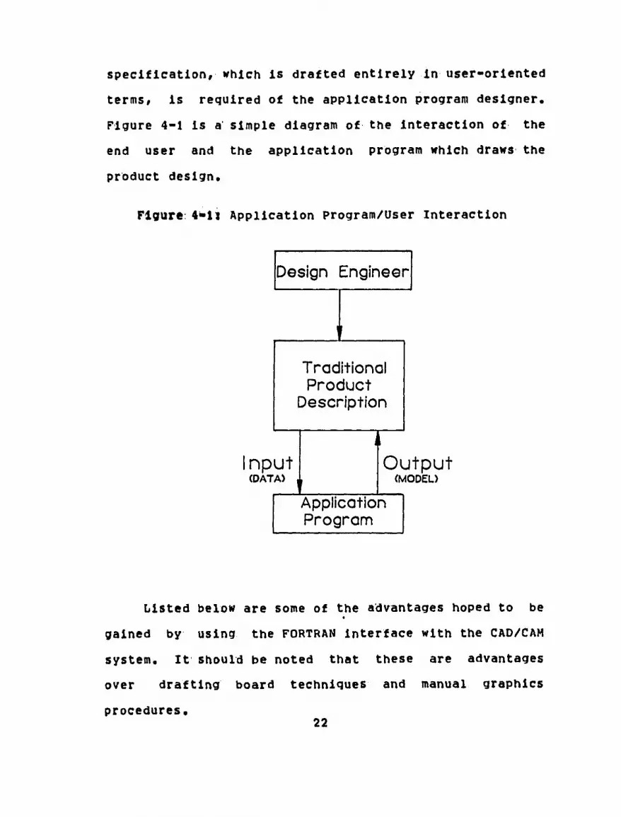
specification, which is drafted entirely in user-oriented
terms, is required of the application program designer.
Figure 4-1 is a simple diagram of the interaction of the
end user and the application program which draws the
product design.
Figure 4*ll Application Program/User Interaction
Design Engineer
i Traditional Product
Description
nput (DATA)
Output (MODEL)
Application Program
Listed below are some of the advantages hoped to be
gained by using the FORTRAN interface with the CAD/CAM
system. It should be noted that these are advantages
over drafting board techniques and manual graphics
procedures. 22

1. Designs drawn to scale.
2. Coordination within the design department.
3. Coordination among displayed views.
4. Speed of production.
5. Cheaper.
6. Revisions made easier.
7. Introduction of standardization.
8. Better quality drawings.
It Is the application program designer's
responsibility to integrate the needs of the design
engineer so that the program creates the desired model.
Therefore, the programmer must have sufficient knowledge
of the product In addition to a thorough understanding of
a high-level language that can be used to interface the
CAD/CAM data base.
Grouping plant equipment based on design
similarities ahd using a FORTRAN interface to the CAD/CAM
graphics data base for model generation are the two
principal techniques for performing the conceptual plant
layout in this thesis.
23

CHAPTER. 5 - SYSTEM DESIGN AND DEVELOPMENT OF PROCEDURES'
5,1 Hardware and software
The hardware used for the design work Is the system
discussed by Zimmers and Plebani C9]. A minicomputer
with 16 address lines, which provides 64K unique byte
addresses of memory, is used. This system's data base is
maintained on a magnetic disk along with the system
software. There are two operating systems on the system
disk. The graphics operating system is used for running
the application programs and for the plant layout
techniques, which are both discussed in Chapter 6. The
other operating system, which operates in real-time with
multiprogramming capabilities, is used for the
application program development. The importance of this
second operating system is clarified in section 5.3 when
the operating environments are explained for inserting
the application programs into the graphics operating
system.
This 16-bit minicomputer acts as the system host and
a graphics processor interfaces this host computer and
the input/output terminals. The graphics processor is
responsible for transferring data between the terminals
and memory, for interpreting and processing operator
commands, and for generating and manipulating the
graphics displays.
24

The terminals are work stations which provide
command entry, program editing, and graphics editing
capabilities. The terminals have digital tablets and
electronic pens as cursor control for graphics editing.
The use of a paper menu for the digitizing tablet is
explained in Chapter 6, where it is used for assisting
with the plant layout. An alphanumeric keyboard is
provided for text entry and can be used as an alternative
means of system control. This is the input device used
for creating and editing application programs. The
alphanumeric keyboard is the only data input device for
accessing the second operating system mentioned above. A
graphics CRT display provides operator feedback, which is
either a vector refresh CRT or storage CRT.
There are two graphics application systems available
for use, which are either two-dimensional or
three-dimensional. The 3-D graphics application system
is* the one used for running the application programs as
well as configuring plant layouts. The reason for using
this system is explained in the next chapter. A FORTRAN
interface is used, which resides as part of the second
operating system mentioned above, to write the
application programs for constructing the equipment
designs.. The FORTRAN interface permits the user's
program to access the 3-D data base. Figure 5-1 is a
25

brief diagram showing the hardware used. Four CRT
displays exist as part of the system which are not shown
in Figure 5-1. For a detailed description of the
hardware layout, refer to Zimmers and Plebani C9J.
5.2 Program: Development
When writing programs that automatically draw
equipment designs, two major guidelines are followed.
The first is to provide a flexible system of
communication and object definition which is easy for a
person with little or no computer experience to use. The
second guideline Is that the usage of the programs should
be natural: for the design engineer.
The designs drawn by the application programs are
wire frame models of equipment design. Solids modeling
is not used because of insufficient computational
abilities of the host computer. The conceptual design of
plant layouts generally uses a plan or top view and an
elevation or front view. An elevation view may also
imply a right or left view of the design, but for the
case study the elevation signifies a front view. One
advantage to using the graphics system is that the
elevation and plan views can be created simultaneously
when constructing the plant layout. The application
programs written are constructed so that the equipment
designs can be drawn in three dimensions. Therefore,
26

Figure 5-1t Hardware Dlagr am
16-B
IT
MIN
ICO
MP
UT
ER
—■—
\
P
LOT
TE
R
\
GR
AP
HIC
S
PR
OC
ES
SO
R
Q: O
TA
BLE
T
i w
r^\
\U 27

LINE PRINTER
( MAG )
200 Mb DISK
GRAPHICS PROCESSOR
CRT
<Q C
tn ■
a: a* i a <
(V
0
►1 0) 3
TABLET

when the user displays the equipment created by the
programs on the CRT screen, there is depth in the plan
view as well as corresponding length and width in the
elevation view. Interactive manipulation and the display
of additional; views of the designs provides the user with
a complete grasp of the developing geometry. The reader
is referred to Figure 5-2 for a description of the
graphics views.
The application programs written do not create
dimensions automatically. At the conceptual stage of
design, dimensions are not necessary and will only add
confusion. Dimension lines are sometimes used for
describing overall plant layout sizes, but they are not
used for delineating equipment and equipment component
sizes. If these dimensions are required, then they can
be added using the electronic pen and tablet once the
overall plant layout is completed.
In order to create the FORTRAN programs, the
application designer must have a thorough understanding
of the equipment design. It is important that the
correct FORTRAN format statements be used in order to
provide the proper precision to the model and to
accommodate the dimensional sizes of the part family.
Since there are cases using the metric system and/or the
English system, the natural units setting is selected
28

Figure 5»2i Interactive Graphics Views
Width-
i O) c CD
Q.
Width
ELEVATION (FRONT) VIEW
PLAN (TOP) VIEW
29

manually at the time the program Is executed on the
graphics operating system. However* when writing the
programs, there must be a statement in the program that
scales the input data with respect to the CAD/CAM
system's scale.
The application program designer must be aware of
the confusion and distortion of meaning that hidden lines
may cause when writing the programs. Figure 5-3
represents a design with hidden lines which was intended
to represent the design in Figure 5-4.
Figure 5-31 Design with Hidden Lines
It is important that the program designer consider
designs that have repetitive components. Production time
is greatly decreased when programs automatically draw
30

Figure 5-4i Design with Hidden Lines Removed
designs that are repetitive in nature. For example, when
constructing a building structure there may be any number
of floors to be constructed. The program can be written
so that when the user runs the program it prompts the
design engineer for the number of floors to be drawn.
The designs in Figure 5-5 are all created by the same
FORTRAN program, with the difference being the number of
floors inputted into the program.
The family of parts concept groups equipment based
on overall design similarities where the only differences
among the models may be accessory components attached to
the equipment. Figure 5-6 demonstrates this feature
where both models are drawn by the same program. The
31

Figure 5-5i Design Repetition
32

program prompts the user if a heat exchanger is to be
added. If the user types "¥ES", then program execution
is- directed to a subprogram that constructs this
component, If< the user types "NO" to the prompt, then
program execution skips this subprogram. The last major
consideration when writing programs is to provide prompts
with which the user is familiar. For example in Figure
5-7 below, length, depth, and width may have different
meanings to various users. It is not uncommon for a
component part to have several names with no one common
name among the engineering departments. This problem
must be dealt with by demanding standardization
throughout the organization. Problems of this nature can
be alleviated by using the group technology concept.
Figure 5-7: Terminology with Program Prompts
ENTER COOLER WIDTH ENTER COOLER HEIGHT ENTER HEIGHT OF KILN HOOD ENTER DEPTH OF KILN HOOD ENTER COOLER DEPTH
ENTER KILN DIAMETER ENTER KILN LENGTH
ENTER PREHEATER WIDTH ENTER PREHEATER HEIGHT ENTER PREHEATER DEPTH ENTER FIRST FLOOR ABOVE GRADE
Figure 5-8 shows a generalized application program
lifecycle. It begins by identifying the model to be
33

Figure 5-6t Part Family Models with Component Differences
34

drawn by the graphics system. Secondly, the design
engineer's requirements must be established followed by
writing of the application software. The implementation
of the program is next, which is discussed in more detail
in Chapter 6. This involves compiling, task building
(linking the program to appropriate computer memory), and
loading the program into the graphics operating system.
Once the program is in the graphics disk area, it can be
tested by executing the program using typical drafting
data. At this point the design engineer must be
satisfied with the model created by the program. Last,
the program must be maintained. This Includes
modifications to the software if design changes should
occur.
The FORTRAN Interface routines for accessing the 3-D
graphics data base support the following features:
1. Drawing structure access routines which Include a full range of read, modify, add, and delete functions.
2. File structure access routines which create data files and perform file manipulations.
3. Terminal input/output which provides routines to output messages to the graphics display and receive input from the work station keyboard during execution of a user command.
The FORTRAN interface routines are designed to
provide interactive processing on the 3-D graphics data
35

Figure 5-8» Generalized Application Program Lifecycle
Design I dentification and Definition
t Requirements Specification
by Design Engineer
i Program Development
mplementation
i Testing
I Maintenance
base, and it is these routines which comprise the
application programs discussed previously. A model/
which is created by manual graphics techniques, consists
of three parts: dictionary, component definitions, and
component instances. A model created by the FORTRAN
36

interface routines consists of only component definitions
and component instances, A dictionary is composed of
graphics commands for creating model components. These
commands are routines such as "add a line", "move a
circle", "rotate a line", or similar commands. With
manual graphics techniques, these commands can be
executed by using the electronic pen and tablet and/or
alphanumeric keyboard mentioned in section 5.1. A
component definition describes the appearance of a given
type of component. For example, a component may be a
solid line, dashed line, dimension line, point, or
similar entity. A component instance describes where the
component is placed in the drawing. In other words the
coordinate location of a component is described by the
component Instance.
The difference between a model created by the
FORTRAN Interface routines as opposed to manual graphics
techniques is that the latter has a dictionary associated
with it. The reason for this is that the FORTRAN
interface routines perform the same function as the
dictionary commands. The difference between the two is
that the dictionary commands must be executed using
manual techniques such as with the electronic pen and
tablet, while the FORTRAN interface routines can be
executed by typing a single command and the desired user
37

command number. It is also possible for dictionary
commands to be executed more than one at a time by a
process of command sequences known as macros. However,
one very distinct advantage of FORTRAN subroutines over
dictionary commands is that the former can get
information from an existing model on the display view
more easily and efficiently than dictionary commands. It
is* also important to note that a model created by the
FORTRAN interface routines can be modified by using the
dictionary commands.
The drawing structure access routines consist of a
list of records which are grouped into component
instances. There are two types of records: component
instance records, which describe a component instance,
and data/text records, which hold data or text
information supplementary to the component instance.
A record is composed of a header containing record
attributes and record information. Record attributes
consist of such items as component definition type, view
on the display screen from which the component definition
is« visible, and other such features. Record information
is a list of drawing cube coordinates which describe the
component instances' position in the drawing view.
Data structure accessing routines allow for reading,
modifying, or creating records and reading or modifying
38

component definitions. The following routines are for
data structure accessing:
1. GET: get a record or definition.
2. HOD: modify a record or definition.
3. ADD: add a record.
It should be noted that a definition cannot be added
by using the FORTRAN interface routines. This must be
done by using manual techniques. This does not mean that
drawings created by FORTRAN routines are not composed of
component definitions, as was mentioned previously. The
reader is referred to Appendix B for a description of the
functional specifications of the FORTRAN subroutines.
5.3 Program Implementation
This section describes the preparation of user
commands. The source code is referred to as a FORTRAN
program, while the final program preparation of
implementing the source code is designated the term user
command. This distinction becomes more apparent
throughout this section.
The computer storage available on the minicomputer
for user commands is divided into two areas called the
resident and overlay areas. An overlay is a program
segment which must be configured to fit into the overlay
computer storage area when the user command is executed
39

by the graphics operating system. This configuration of
overlay sizes is discussed in this section under the task:
build operation. Figure 5-9 presents a visual
description of the computer memory layout during
execution of a user command.
A user command may consist of one or more overlay(s)
depending on the size of the FORTRAN program. If the
memory area cannot accommodate the entire user command;
then the user command must be broken down into multiple
overlays. A further application of overlays is discussed
in Chapter 6. Since the work presented in the case study
uses only single overlays, preparation of user commands
composed of single overlays is discussed in this section.
There are three steps required to transform a
FORTRAN program into a user command for execution, which
are:
1. Compiling.
2. Task Building.
3. Loading user command into graphics operating system.
Compiling
The compiler or language translator translates the
symbolic (source) program into a relocatable (object)
40

Figure 5-9i Memory Layout during Execution of User Command [103
0
2200
4400
5400
60000
STACK & VECTORS
BUFFER PAGING AREA
COMMON MODULE
FORTRAN PROGRAM (USER COMMAND)
USER COMMON AREA
GRAPHICS SYSTEM
41

module. Compilation also produces a list file, which is
useful for identifying source code errors. The source
program can be compiled by using the following command:
F0K> 'Object File'.OBJ,'List File'.l*ST='Source File'.FTN
The "FOR" command Invoices the compiler. The ".OBJ"
file type is the object module produced, which is used
for taste building, and the H.LST" file type is the list
file. On the right-hand side of the command or the input
side is the FORTRAN source program.
Task: Building:
The taste builder is invoiced in order to link the
relocatable object module from several sources into a
taste image. The task image is used for executing the
user commands once they are loaded into the graphics
operating system. There are three different object
modules used to create the taste image. In addition to
the object module created from the source code, there is
a' common module, which is specific to the FORTRAN
interface subroutines, and there is a library module,
which contains all the FORTRAN interface subroutines.
Not only is a taste-image file created but so is a map
42

file. This memory allocation file lists information
about the allocation of task memory and the resolution of
any undefined symbols. Figure 5-10 is an example of the
task build commands.
Figure 5-10s Example of Task Building for Drawing Structure Access
TKB> 'Task-Image '.TSK,*Map File'.MAP='Common Module'.OBJ TKB> 'Object Filename'.OBJ TKB> 'Library of FORTRAN Interface Routines'/LB,OLB TKB> / TKB> PAR=GEM:4400:S3400 TKB> TASKs'User Command Number'S'Overlay Number' TKB> //
The "TK3" symbol causes the invocation of the task
builder. Line one specifies the name of the task-image
file, the name of the map file, and the start of a list
of input files. There are three input files in Figure
5-10. The common module object file is the common area
to the FORTRAN interface routines, the object filename is
the relocatable object module after compiling the source
program, and the library definitions file contains all
the FORTRAN subroutines. Each library listed roust have
the "/LB" switch present. It is important to note that
the file type extension is ".OLB". This still implies
that the file is an object module; however, the symbol is
different indicating a library object module. The first
object module listed is the common module since this must
43

be in a particular place in memory preceding the source
program's object module. The order of listing of the
other two object modules is not important. The common
module file and the library definitions file are obtained
from the system vendor and may be located in the user's
file directory with the source program. The slash in
line four indicates the end of the list of inputs and the
set of desired options to follow. The HPAR=" option in
line five is extremely important. This is what specifies
the area: of memory for which the task image is to build.
"GEN" is a name commonly used for a general-purpose
region of memory. The third parameter is the address of
the starting location of the task image in computer
memory. It must be a multiple of octal 100. The fourth
parameter is the length in octal bytes of the area for
which the task image is to build. It should be noted
that the top address of the memory allocation for the
user command is octal 60000. Octal 53400 is the largest
number which can be assigned to this parameter, since
beyond octal: 60000 are the three-dimensional graphics
application programs. If the user command cannot fit
into this memory allocation space, then the user command
aiust be subdivided into multiple overlays. Line seven is
the "TASK" line which specifies the name of the user
command (decimal), followed by a "$", and then the
44

overlay number of the user command. The work done in the
case study uses a single overlay; therefore, the overlay
number is one. The last line with the double slash
indicates that the task build session is complete.
Before the user command can be inserted into the
graphics operating system a user command table must be
constructed. This table consists of the user command
number and describes the starting and ending computer
addresses of the overlay of the user command. Figure
5-11 shows how a user command table is constructed.
Figure 5-11* User Command Table for Drawing Structure Access
•TITLE UCMT U .MCALL IOTMAC IOTMAC -u. OVLY name .END
4400,60000
The symbol "UCMT" stands for user command table and
"u" in lines one and three is a decimal number between 1
and 255, which is also the user command number in Figure
5-10. The number is negative in line three which is
merely a software convention to differentiate user
commands from other types of programs. The "IOTMAC"
declaration initializes the user command table and
defines the user command number in line three. The
"OVLV" declaration specifies the lower and upper limits
45

of the user command as it resides in computer memory.
The name of the overlay must be specified to be at most
four characters long and start with a letter. It is used
for documentation purposes only, and is not required by
any other modules. The start of the user command at its
computer location address is required in line four, which
is' identical to the start address in line five of Figure
5-11. The end computer location address of the user
command is specified to be octal 60000.
The user command table must be assembled by invoking
the "MAC" command. The assembler is a language
translator for assembly language, and the command is the
following:
MAO UCHTU .OBJ, UCMTU . l,ST=UCMTu. MAC
The "u" represents the user command number, and an object
module and a list file are generated. This object file
is' used for task building the user command table as
follows:
TKD> UCMTU.TSK,UCMTu.MAP=UCMTu,OBJ TKB> / TKB> PAR=GEM:7000:1000 TKB> TASKsUCMT TKB> //
46

A task-Image file of the user command table and a map
allocation file are created, which Is similar to Figure
5-11. The first line has only one object module as the
input file and the task-image name in line four is
"UCMT". The third parameter of line three represents the
starting address location of the task-image file in
computer memory. The fourth parameter indicates the
length of the task-image file in octal bytes.
As mentioned previously, the FORTRAN interface
routines are able to perform file structure accessing.
In order to do this the file structure access routines
must be included when performing the task build
operations above. These routines require 5000 bytes of
memory; and therefore, the user command may not go into
the top 5000 bytes of the partition. Instead of the top
address location of 60000, the new top address location
must be changed to 53000. The task build parameters must
be changed from those in Figure 5-11 above. Figures 5-12
and 5-13 show the address location changes for the
task-image file of the user command and the user command
table description, respectively. The reader should note
that the task build function for the user command table
remains the same.
Loading User Cbnnahd
47

Figure 5-12* Example of Task Building for File Structure Access
TKB> 'Task-Image'.TSK,'Map File'.MAP='Common Module'.OBJ TKB> 'Object Filename'.OBJ TKB> 'Library of FORTRAN Interface Routines VLB.OLB TKB> / TKB> PAR=GEN:4400:46400 TKB> TASK='User Command Number'S'Overlay Number' TKB> //
Figure 5=13; User Command Table for File Structure Access
.TITLE UCMT u
.MCALL IOTMAC IOTMAC -U. OVL* name .END
4400,60000
The next sequence to preparing the user command is
to load the user command overlay as built by the task:
builder into the graphics operating system. All of the
sequences performed so far on the user command have been
done using the operating system that was used for
creating the FORTRAN application programs. The sequence
to be executed now loads this program as an overlay into
the graphics system where it can be run and tested.
The user command table is loaded into the graphics
system followed by the user command task image. The user
command table identifies the name of the user command
48

overlay, how long the overlay is, and where the overlay
IS' loaded Into memory. The user command table Itself is
an overlay that resides in the system area to help
identify the user command overlay. An example of loading
the overlay is as follows;
LOV> [group,user]'Destination System File'.SYS= UCMT.TSK,UCMD.TSK
The user command table task-image file must be
listed first because this assigns the user command's
position in memory. The destination system file now
holds the task-image files of the user command and user
command table. The "[group,user]" represents the user
identification code where the system file resides.
If the loading of each overlay into the graphics
operating system is successful, then a message is
displayed giving the name of the overlay or the number of
the user command and its relative overlay number,
followed by the overlay length, start address in computer
memory, and disk address. Examples of these are shown in
the case study. Figure 5-14 is a diagram listing the
seguence of operations reguired to prepare a user command
for entry into the graphics system.
49

Figure 5-14: Implementation of User Command
/~\
w
s~\
v_y
50

en © LOAD UCMT
AND USER COMMAND
INTO GRAPHICS
WORLD
C
n w i
3 •o I-" * 3 (9 O c» Of rt H- O D
O Hi
C M n ►i
o o 3 3 01 3 a

5w4 Program: Execution
In order for the user command to be executed, it
must have been prepared correctly by the implementation
procedures mentioned in section 5.3. For the program to
be run, it must reside within the graphics operating
system. The overlay is resident on the disk which can be
brought into computer memory for use by the central
processing unit (CPU) and then returned to the disk. The
overlay storage area in the graphics system is distinct
from the graphics file storage area.
To execute a FORTRAN user command, the user types
the following:
UCMD n,
where "n" is the identifying number of the user command.
The appropriate program is brought into computer memory
from disk and starts executing. Figure 5-9 illustrates
the computer memory layout description while executing a
FORTRAN user command. The common module is 1000 octal
bytes long starting at address location 4400 and
continuing to 5400. The user command begins at address
location 5400 and may continue to 60000, if the user
common area Is not required. The user common area is
used for multiple overlays, which have common data among
them. Beyond location 60000 resides the graphics
application software. 51

If the user wishes to run a user command with number
"214", he or she simply types "UCMD 214" at the work
station terminal. The program begins prompting the user
with the following questions, and the user responds by
typing in the data. Figure 5-15 is' a listing of the
prompts and responses to "user command 214".
The reader should refer to Figure 5-16 for an
illustration of the plan and elevation views after having
executed "user command 214".
5.5- Plant' Layout. Techniques
The plant layout of the conceptual designs is done
using manual- graphics techniques as< opposed to making it
a: function of the FORTRAN user commands. Unless the
layout is quite standardized it is very difficult to
build programs that automatically configure equipment
with respect to one another for the final layout. The
conceptual design layouts done in the next chapter are
too customized, and no two project layouts are identical.
These plant layout problems are best solved by using such
manual graphics input techniques like tablet strokes,
tablet menu, or combination of the two.
The commands to manipulate the overall equipment
layout are very basic graphics commands. Commands to
"move", "rotate", "enlarge", or "delete" the equipment
are commands that are not difficult to learn or use and
do not interfere with the user from being productive. 52

Figure 5»15J Promptings while Running User Command 214 [11]
A COMBINATION COOLER WILL BE CONSTRUCTED THE FIRST PORTION HOUSES THE KILN HOOD THE SECOND PORTION HOUSES THE HEAT EXCHANGER THE HEAT EXCHANGER HILL BE CONSTRUCTED FROM THE TOP
IF 5fOU DO NOT WISH FOR THE HEAT EXCHANGER TO BE CONSTRUCTED IN THIS MANNER, THEN TYPE 'N' FOR NO, OTHERWISE TYPE #Y*. IF NO IS TYPED, THEN THE HEAT EXCHANGER MUST BE MANUALLY CONSTRUCTED OR NOT CONSTRUCTED AT ALL.
ENTER WIDTH OF KILN HOOD PORTION OF COOLER: 12.0; ENTER LENGTH OF KILN PORTION OF COOLER: 45.6;
ENTER WIDTH OF HEAT EXCHANGER PORTION OF COOLER: 9.0; ENTER LENGTH OF HEAT EXCHANGER PORTION OF COOLER: 23.56;
FLOOR LINES WILL BE CONSTRUCTED MANUALLY
ENTER CONVEYOR HEIGHT FROM GRADE LEVEL: 7.0;
IF THERE IS NO HEAT EXCHANGER, THE HEAT EXCHANGER BASE WILL BE CONSTRUCTED ANYWAY FOR PIPING
ENTER DISTANCE OF HEAT EXCHANGER FROM HEAT EXCHANGER PORTION OF COOLER: 5.0; ENTER BASE HEIGHT OF HEAT EXCHANGER ABOVE CONVEYOR LINE: 18.3; ENTER BASE LENGTH OF HEAT EXCHANGER: 5.63; ENTER BASE WIDTH OF HEAT EXCHANGER: 6,73;
53

Figure 5-16x Design Created by User Command 214
\Z7
ELEVATION VIEW
PLAN VIEW
54

The user commands produce the individual equipment
designs, and it' is the design engineer's responsibility
to assemble the layout. This is one way for the design
engineer to input his expertise into the drafting
process, which Is difficult to capture in an application
program. It is also important to win the approval of the
design engineer's acceptance of the graphics system, and
this is one way to achieve this goal. With the graphics
system, many views can be evaluated, Interference
checking can be accomplished, and components can be
assembled and disassembled very easily to assist In
further design considerations.
As mentioned previously the user can manipulate the
designs by using tablet strokes or dotting a tablet menu.
The graphics system allows the user to draw a symbol on
the tablet using the electronic pen and to assign a
command to the tablet symbol as a definition. For
example, If the design engineer wishes to magnify a part
of the drawing he or she may stroke a tablet symbol
around the part of the drawing to be magnified as
follows:
55

Several of these tablet symbols and an explanation of
their meaning are provided in Appendix C.
It is sometimes difficult for the user to remember
the tablet symbol*, and therefore the user may wish to use
the paper menu assigned to the tablet. The paper menu is
good for displaying the many views available with the
graphics system in addition to "moving" and "rotating"
parts. The menu is a matrix of commands assigned to the
tablet whereby the user merely dot6 a square area
representing the graphics command. Figure 5-17 is an
illustration of a paper menu and its associated commands.
The design engineer need only be acguainted with a few of
these menu commands in order to create the plant layout.
By using this design technique it is possible for
the tedious equipment design work to be accomplished with
the FORTRAN user commands while the less difficult plant
layout procedures are performed using the electronic pen
and tablet. By employing this procedure, drawing
production is decreased and the design engineer can
concentrate on more creative work.
56

Figure: 5-17? Paper Menu with Graphics Commands C123
57

-4
srone
CTRL EDIT
LOAD
m •VI
o 3
WW®L% MARC ?
MARC 340
MARC p
OWE 9UC
se 14
.0001
KiS
r^.
■R3X
fR/TO
FC»«
n
V. or
"mux DC
DRILL
SHAPE
^> PEN
OJEATE WARP PAIR WARP
CO Z0
GRID
ADO •VI
k£Sii JOIN
33 PEN TgQ £5
MILT FILT
GKMt RULE
3 IVI Da.
RR iN/i/sFfl J06X .129
§5 000 "ixvz *T<: 53!
SNAP
AOO •V?
Jffiil
DX
AOO
AOO •9V
AOOC •s m R'
3u0
MO
2 NON srr SET
Q»'0 | AXIS | HOLE
ON cm
Ss
REV •Al
XHAT
too OR J00
•3
aeoT PROP
5 VI
^
S" 75J yics.
M
•£ IVI
#
$
IE EOUAL
DIVIDE
GRID
ID
Al •9
VI
z ®
RflRW
orrue mne LIST TAPE
am •v'
4> ^ <§r
S^R
"©
SLICE OFF
CALC
.MPl V2
* V2
COT SECT
96RO
A OHIO
V3
V3^
num. DZRI Msxo IZIM ON
■RRC KITS
J2L M n
ON
ON
ON
ON
ON
ON
ore
SSL OFF
OFT
OPT
Off r.»
orr
MIN/ MAX
STD
cm CURR
HI
CURR OL
OCX raww PLOT
I
PLOT 2
E-M
u-e
<
»Cg
DEC?
DIM EXT EXT
ONLY DIM
ONLY
DECT
EOT rouci HWMU VIEW
OR *
hfcimC
prRc-xaiia ON
1/8
OIMP
INTO 0
otimi REP
TOL
HMCF OLD ■n#KL.$N OLD
.11. OR IHX xa
fOMtT
rava ECMP mm
E«M»
M-W
xiprac CftETE NEW
CELL
9C CELL
POD
M-
3NAP •VI
3SNAP •31
•VI
POO •VI
oec t
DADO • I
TJAW
JCZ.
I/I
l/l*
PTH
DADO
DADO REF
H?"V
TFRM
fCO
tarn oon
SNAP rHT
SNAP ROT
SNAP TOP
DADO •C7
ffi£ ^
1/2
1/32
WBBf
t/4
1/44
IEADO
PIT, EXT UiS.
\axK pea pea •31 «vi
r H
xH
p»oi mn
A9CRT
EDIT
^
PH
i. XX
MOVE XYZ
1"8
1-4
1*10
?«■?
TREX
^
°K H»
jjoH 9MC-
SO. SHOW SCL
3-1
2-J
1-1
or %
EDIT TEXT "W"
P2
PI
CCLR
IT LEVEL
TO *~ 2 DT2
an "*5
CCLR
GR
SHOW SHOW
F SHOW r R
PRE ZOOM
S S cc
cc
cc EXT LINT
NAME GRUP
w A
LEVEL
ATXT
■EJ
CL2
27" A
SIZE
CLt 3
COLR L
ro]
SHOW R
SHOW T R
INFO
XX
MX
MiBf «0i RX
ROTA OA0
SEL COOP
YL.
SHOW T
SHOW T F
SHOW KRF
SIN
YY
MY TJIRR- •VI
RY
ROTA •VI
_RPI *8
COLR C
E
3T RATIO H»W
PONT
PHI
COLR LC
AQ|[VF
33" SET
ANCLE
PONT
PONT
POINT la]
SELECT
ISO SAVE VIEW
OET VIEW
SAVE
3AV3
LIST sirs RET BIN
22
MZ MiRR
RZ
TO | PROM mm oe iMtua ORUP ORUP
OET
GETS
A XYZ
PEN
ROTA
VROT
ana FORM
BJT
4
T3~ ANGLE
FONT
A DEP
SP ON t
UN- sun
W ANSLE
S»M»B ttfwt
PONT
A LEVEL
WA ON T
TCLR
[WH]
REF
10 13 18 EOT
ONLY
•VI
•SI
0.0.0
DIS
32
s KALAH
?
e n 14
SELC uva •V2
•S2
OIST
ffi
5: .NAT KALM
NO
UEDT
8 8
12 15
JUIHJ •v?
•s? ALL
vena
2§ AU.
SXAR
c H
■
at •o m «i
z 3 C
P1
o ►1 a» •o sr o (A
n o 3 3 ai 3 o.
to

CHAPTER 6 - CASE STUDY
6.1 Current' situation and Objectives'
The case study is an application of the design
considerations explained in the previous five chapters to
the cement processing industry. Prior to discussing the
conceptual design of a cement plant layout/ it is
important to describe the current methods for designing
the process equipment.
The model: to be created is referred to as a plot
plan that shows the plan and elevation views of all
process equipment with relationship to existing
facilities, such as buildings, roadways, or existing
process equipment. The plot plan also shows a general
arrangement of the processing equipment. The model is
used for generating proposals for prospective customers.
That is, the plot plan tells the customer in general
terms what the cement plant designer has to offer.
It is the responsibility of the conceptual
engineering department to create the model. The
conceptual engineer receives a general idea of what the
customer is requesting and may include such descriptions
as:
1. Type of cement process (wet or dry).
2. Contour map of proposed plant location.
3. Existing facilities. 58

4. Processing equipment to be used.
After receiving these requirements the conceptual
engineer begins to interact with the various equipment
groups for more specific process equipment designs. As
the project continues to mature, there is more
interaction among the engineering departments.
At this conceptual stage of design development there
are many modifications and updates made to the plot plan.
In order to ease the work required to perform a design
modification, the conceptual engineer constructs a master
plan. This master plan is drawn to scale specified by
the customer and contains the equipment layout. The
master plan is drawn on a brown pigment material called
sepia and is performed by the print department. The
sepia is an exact copy of the original master plan as
drawn by the conceptual engineer. The sepia is easier to
modify as opposed to the paper master plan. When
modifications are made the designer must eradicate
unwanted lines by pouring chemical remover over the
drawing. Once the undesirable components are removed,
the conceptual engineer draws the updates directly onto
the modified sepia. Many master Plan sepias are made to
assist with making updates during the conceptual design
process. This method of drawing updates consumes
man-hours and money for print processing.
59

The engineer usually draws the plan view first, and
from this he or she constructs the elevation view. When
drawing the designs it is also important that the
engineer draw all: components to scale* Dimension lines
for conceptual designs are not required and only makes
the final: layout confusing. Dimension lines may be added
to represent the overall distance from new to existing
equipment but is only done upon customer request.
The basic equipments to the cement plant are the
preheater, Kiln, and cooler. These three pieces of
equipment are assembled so that the preheater connects to
the one end of the kiln, and the other end of the kiln
connects to the cooler. When assembling the equipment
the work point or intersection of the cooler and kiln is
determined first, followed by the work point
determination of the kiln and preheater. The assemblage
of these three products is backwards from the process
flow of the cement. The ingredients of the cement first
enter the preheater and are heated to a specific
temperature. Cement ingredients then drop to the kiln,
which rotates on wheels, and the ingredients undergo
further chemical reaction. Once formed, the calcified
product enters the cooler where it is chilled, and
unformed Ingredients are screened to reenter the process
flow at the beginning of the kiln. There are many other
60

pieces of equipment attached to the cement plant layout
and are currently under application program development.
The design construction and layout using the CAD/CAM
system is demonstrated with the preheater, kiln, and
cooler.
Listed below are the objectives to be achieved by
implementing the family of parts concept for constructing
FORTRAN user commands for drawing the cement equipment.
1. Reduce misinterpretation of design updates within the conceptual engineering department.
2. Maintain more timely design updates.
3. Make design modifications faster and easier.
4. Drawings made to scale easier and more accurately.
5. Construct plan and elevation views simultaneously.
6. Introduce standardization to equipment design.
7. Easier storage and retrieval of drawings.
8. Introduce higher quality drawings.
9. Allow for more creativity by design engineer.
10. Reduce problems created by the transfer of engineering personnel from one department to another due to work load fluctuations.
6.2 Proposed Solution
The hardware and software used for creating and
executing the FORTRAN user commands are identical to the
hardware and software described in section 5.1. The
61

first phase of the generalized application program
lifecycle as illustrated in Figure 5-8 indicates that the
design identification followed by the requirements
specification, as outlined by the design engineer, must
be considered first. One way to develop software for
equipment design is to collect dimensional data from
existing models. This existing design information is
obtained from the respective equipment engineering
groups, such as the kiln, preheater, or cooler structural
groups. For example, Table 6-1 illustrates dimensional
data for a combination cooler as obtained from the cooler
engineering group. Associated with Table 6-1 is Figure
6-1 showing the plan and elevation views of the cooler as
drawn on a drafting board. The first column in Table 6-1
shows the cooler size. This indicates a combination
cooler with two sets of grates. The first group of three
numbers is the slope grate size while the second group is
the horizontal grate size. The first number to the left
of the dash of the dimensional data is in feet, and the
second number is in inches.
The application program designer communicates with
the various engineering groups in addition to the
conceptual engineering department. If the program
designer is to interact with only one of these groups,
then the FORTRAN user commands will probably fail to
62

accommodate all design considerations. The conceptual
engineer's plot plan does not consist of all the detail
as< shown in Figure 6-1; however, the real purpose In
studying this dimensional data is to create FORTRAN
format "statements that accommodate the various ranges of
dimensional data. The FORTRAN format statements are used
to allocate computer storage space for the data punched
Into the programs when executed by the design engineer.
Another technique used to help develop application
programs is to peruse the many drawing files of
previously hand-drawn designs so that the program is
capable of creating almost all design modifications of
the equipment. This concept is built on the family of
parts principle. Upon examining these drawing files
there are invariably many designs which can be
eliminated, since they are obsolete. This grouping of
design similarities begins the standardization process,
which is carried through to the final equipment
manufacturing. Figures 6-2, 6-3, and 6-4 show families
of parts with conceptual design similarities for the
cooler, kiln, and preheater, respectively.
After considering the various' dimensional data and
the equipment similarities, it is possible to write a
FORTRAN user command that accommodates the data and
design similarities. For example, one FORTRAN user
63

command can create the family of parts designs in Figure
6-2 given the ranges of dimensional data in Table 6-1.
Likewise, a single user command creates the kiln designs
in Figure 6-3, and another produces the preheater designs
in Figure 6-4.
The conversion of drafting techniques over to
graphics' user commands uses equipment names as the
classification system. At the present time the user
commands created are able to produce most designs of the
cooler, kiln, and preheater. However, as the software
development progresses to accommodate all designs and the
number of programs begin to increase, then a
classification and coding system may need to be
implemented.
Once the design considerations are studied, the
program designer begins to write the user commands using
the FORTRAN interface routines. To assist the programmer
are editors for making software changes.
Having written the user commands the program
designer implements- the programs by using the system
compiler and task builder. Chapter 5 provides an
explanation of the preparation of user commands for
execution. To accelerate the preparation of user
commands, an indirect command file may be executed to
automatically perform the compiling, task building, and
64-

Table 6-1J Dimensional Data for Combination Coolers
Cooler Size A B
720S/934H 60- -7 5/8 23-7 7/16 33-8 3/16 720S/945H 11- -5 23-7 7/16 44-5 9/16 731S/945H 82- -4 9/16 34-7 44-5 9/16
820S/1050H 75« -8 3/4 23-7 7/16 48-9 5/16 831S/1050H 86-8 5/16 34- -7 48-9 5/16 920S/1147H 73« -6 7/8 23-7 7/16 46-7 7/16 931S/1150H 86« "8 5/16 34- -7 48-9 5/16 1020S/1247H 73- •4 7/8 23-5 7/16 46-7 7/16 1031S/1250H 86-6 5/16 34-5 48-9 5/16
D E F G H
10-6 19-0 3-0 8-11 1/2 9-5 10-6 3-0
3-0 11-0 19-6 3-0 9-5 1/2 9-0
12- 5/16 3-0 11-6 3-0
12-6 5/16 3-0 12-0 2-10
13- 5/16 2-10
8-4 30-9 3/8 12-4 1/2 10-4 1/2 12-4 1/2 10-4 1/2 12-4 1/2 10-4 1/2 13-4 1/2 11-4 1/2 13-4 1/2 11-4 1/2 14-4 1/2 12-4 1/2 14-4 1/2 12-4 1/2 15-4 1/2 13-4 1/2 15-4 1/2 13-4 1/2
65

Figure 6-ij Plan and Elevation Views of Cooler structure
^T N
*
I X
/
<
L
\ \
xss
J
66

Figure 6»2l Cooler Family of Parts Shown in Elevation View
^7
67

Figure 6«3i Kiln Family of Parts Shown in Elevation and Plan Views
68

Figure 6-4t Preheater Family of Parts Shown in Elevation View
69

loading of the overlay into the graphics operating
system. An indirect command file is a text file
containing a series of commands exclusive to a single
taslc. To initiate indirect command files, the user
replaces a command string with a file specifier, preceded
by an "at" sign (£). The task requesting input then
accesses the specified file and starts to read and
respond to the commands contained within it. The default
file type for indirect command files is ".CMD". Figure
6-5 is a listing of an indirect command file named
"UCMDBLD" with file type ".CMD". In order to run this
file to completion the FORTRAN program and the user
command table must both be created. This file compiles,
task builds, and loads the user command and user command
table into the graphics operating system automatically.
This command file is specific for single overlays and for
drawing structure access only.
In order to execute the indirect command file, the
user types "eUCMDBLD" as in Figure 6-6 or he or she may
type the file name and the file type, such as
"UCMDBLD.CMD". Figure 6-6 is an execution of an indirect
command file for data structure accessing of a user
command numbered "212".
Once the user commands are loaded into the graphics
operating system, they can be executed. The first user
70
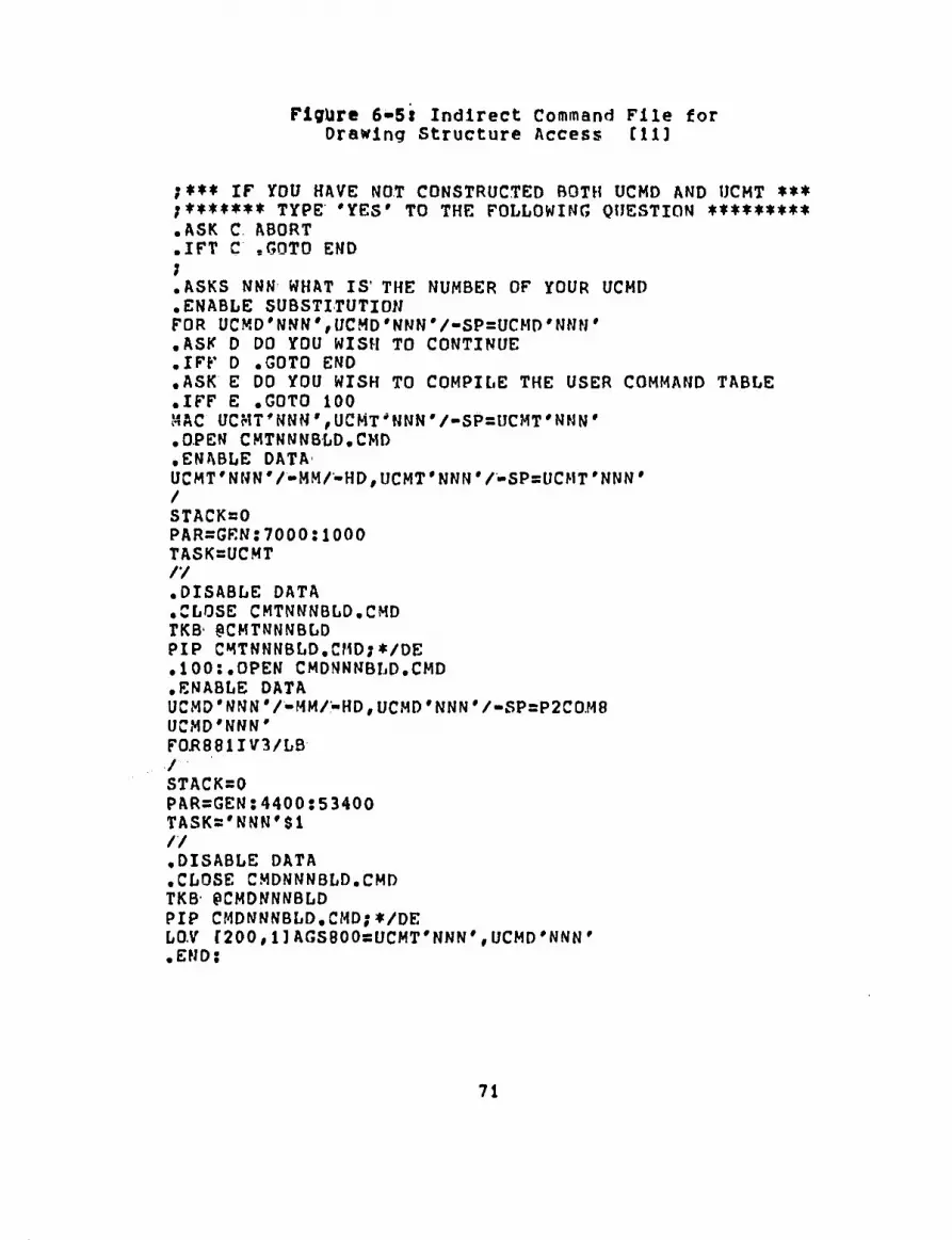
Figure 6-5t Indirect Command File for Drawing Structure Access til]
;*** IF YOU HAVE NOT CONSTRUCTED BOTH UCMD AND UCMT *** ;******* TYPE 'YES' TO THE FOLLOWING QUESTION ********* .ASK C. ABORT .IFT C .GOTO END ; .ASKS NNN WHAT IS' THE NUMBER OF YOUR UCMD .ENABLE SUBSTITUTION FOR UCMD'NNN',UCMD 'NNN V-SP=UCMD 'NNM' .ASK D DO YOU WISH TO CONTINUE .IFF D .GOTO END .ASK E DO YOU WISH TO COMPILE THE USER COMMAND TABLE .IFF E .GOTO 100 MAC UCMT'NNN',UCMT*NNN*/-SP=UCMT'NNN' .OPEN CMTNNNBLD.CMD .ENABLE DATA UCMT'NNNV-MM/-HD,UCMT'NNNV-SPsUCMT*NNN' / STACK=0 PAR=GRN:7000:1000 TASK=UCMT // .DISABLE DATA .CLOSE CMTNNNBLD.CMD TKB' 3CMTNNNBLD PIP CMTNNNBLD.CMD;*/DE .100:.OPEN CMDNNNBLD.CMD .ENABLE DATA UCMD* NNN V-MM/-HD, UCMD' NNN '/-SP=P2C0.M8 UCMD'NNN' FOK881IV3/LB / STACK=0 PAR=GEN:4400:53400 TASK='NNN'$1 // .DISABLE DATA .CLOSE CMDNNNBLD.CMD TKB PCMDNNNBLD PIP CMDNNNBLD.CMD;*/DE LOV r200,UAGS800=UCMT'NNN', UCMD'NNN' • END;
71

Figure 6-6» Execution of UCMDBLD.CMD for Drawing Structure Access C113
>3UCMDBLD ;*** IF 5fOU HAVE NOT CONSTRUCTED BOTH UCMD AND UCMT *** .******* TYPE 'YES* TO THE FOLLOWING QUESTION *♦♦***** >* ABORT? [Y/NJ: N >; >* WHAT IS THE NUMBER OF YOUR UCMD [S]: 212 >FDR UCMD212,UCMD212/-SP=UCMD212 >* DO YOU WISH TO CONTINUE? tY/N]: Y >* DO YOU WISH TO COMPILE THE USER COMMAND TABLE? CY/N]:Y >MAC UCMT212,UCMT212/-SP=UCMT212 >TKB 9CMTNNNBLD >PIP CMTNNNBLD.CMD;*/DE >TKB PCMDNNNBLD >PIP CMDNNNBLD.CMD;*/DE >LOV r200,UAGS800=UCMT212,UCHD212
UCMT
,L=400 ,S=7O00 ,D=150
UCMD 212,1
.L«25600 ,S=4400 .D=10000 >8 <EOF>
72

commahd to be run is "UCMD 213", which builds the cooler.
Figure 6-7 is a listing of the prompts when the user
command is run. The corresponding dimensional data are
also shown as specified by the user, The scale setting
is- 49152 graphics units to 1 natural unit, which
corresponds to a scale of one-to-one. Prior to executing
the user command, the user types "SNTU 49152 1" to
establish the scale setting. All drawings constructed in
the remainder of this chapter use this scale setting.
Figure 6-8 is an illustration of the plan and elevation
views shown simultaneously after executing "UCMD 213".
The design engineer constructing the equipment and
the resulting layout knows that the work point of the
cooler and kiln must be determined first. He or she
moves the cooler to the left-hand side of the drawing
view, which is shown in Figure 6-9. This movement of the
cooler is accomplished with the electronic pen and
tablet.
The next piece of equipment to be designed is the
kiln and is created by executing "user command 212". The
prompts and corresponding inputs are shown in Figure
6-10. Natural units are not requested with this user
command as with the previous user command; however, the
scale setting is identical to the scale for creating the
model in Figure 6-8.
73

Figure 6-7: Prompts for Executing User Command 213 [11]
A COMBINATION COOLER WILL BE CONSTRUCTED THE FIRST PORTION HOUSES THE KILN HOOD THE SECOND PORTION HOUSES THE VENT THE VENT WILL BE CONSTRUCTED FROM THE TOP
ENTER WIDTH OF KILN HOOD PORTION OF COOLER* 9 87* ENTER LENGTH OF KILN HOOD PORTION OF COOLER: 28.51;
ENTER WIDTH OF VENT PORTION OF COOLER: 12.63; ENTER LENGTH OF VENT PORTION OF COOLER: 45.89;
FLOOR LINES WILL BE BUILT MANUALLY
ENTER CONVEYOR HEIGHT FROM GRADE LEVEL: 7.4;
ENTER DISTANCE OF VENT FROM VENT PORTION OF COOLER: 4.623; ENTER VENT BASE HEIGHT ABOVE CONVEYOR LINE: 12.67; ENTER BASE LENGTH OF VENT: 6.2; ENTER BASE WIDTH OF VENT: 5.8;
ENTER KILN HOOD BASE HEIGHT ABOVE CONVEYOR LINE: 11.0; ENTER KILN HOOD LENGTH: 9.0; ENTER KILN HOOD HEIGHT: 9.23; ENTER KILN HOOD WIDTH: 13.79;
74

Figure 6-8! Result of Executing User Command 213
J
ELEVATION VIEW
PLAN VIEW
75

Figure 6»9: Cooler Moved Using Pen and Tablet
ELEVATION VIEW
I PLAN VIEW
76

Figure 6-10: Prompts for Executing User Command 212 (111
MAXIMUM NUMBER OF TIRES THAT CAN BE ENTERED a 6 ENTER LENGTH OF KILN: 80.0; ENTER DIAMETER OF KILN: 7.8;
ENTER TOTAL NUMBER OF TIRES TO BE ENTERED: 3; ENTER DISTANCE OF GEAR FROM LAST TIRE: 10.;
ENTER DISTANCE OF TIRE II FROM DISCHARGE: 15.6; ENTER DISTANCE OF TIRE 92 FROM DISCHARGE: 35.46; ENTER DISTANCE OF TIRE »3 FROM DISCHARGE: 66.71;
Figure 6-11 shows the kiln added to the same drawing
containing the cooler. The design engineer establishes
the cooler-kiln work point and positions the kiln with
respect to the cooler as shown in Figure 6-12. The kiln
Is- positioned at a four degree angle from grade level.
The last component added Is the preheater structure,
and the prompts and corresponding dimensional data are
illustrated in Figure 6-13. This user command is
numbered "215" and is like the previous user commands in
that it does not reguest units of measurement. For most
design work, a natural units setting is required and is
established by Issuing the following command:
SNTU 49152 1 FT.
Figure 6-14 shows the preheater added to the drawing
view containing the kiln and cooler in only the elevation
view. Figure 6-15 shows the correct intersection point,
77

rtgur« 6*iit Addition of Kiln to Display View
L' . I, .1
urm
L' I
@
nrn
/
^
ELEVATION VIEW
78
D PLAN VIEW

Figure 6-121 Position of Cooler and Kiln after Work point Determination
ELEVATION VIEW
■I '■
n ,ln 111
D 1—r PLAN VIEW
79

Figure: 6-13: Prompts for Executing User Command 215 till
INPUT APPROXIMATE HEIGHT OF INTAKE END OF KILN FROM GRADE LEVEL: 32.89;
INPUT TOTAL NUMBER OF STAGES OR FLOORS TO BE BUILT: 4.;
INPUT APPROXIMATE DISTANCE OF FIRST FLOOR BELOW WORK POINT OF KILN-PREHEATER: 9.7;
INPUT DISTANCE OF SECOND FLOOR ABOVE WORK POINT OF KILN-PREHEATER: 45.29;
INPUT DISTANCE OF THIRD FLOOR ABOVE SECOND FLOOR: 26.54;
INPUT DISTANCE OF FOURTH FLOOR ABOVE THIRD FLOOR: 28.71;
IF A ROOF IS NOT TO BE CONSTRUCTED, THEN TJfPE 'N' FOR NO: N;
ENTER PREHEATER STRUCTURE LENGTH: 23.64;
ENTER PREHEATER STRUCTURE WIDTH: 24.87;
80

Figure 6-14j preheater Added to Display View Containing Kiln and Cooler
h ELEVATION
VIEW
81

as determined by the design engineer, of the preheater
and kiln. Figure 6-15 also shows the final layout of the
cooler, kiln, and preheater in the elevation view.
Figure 6-16 shows the final layout of the cooler, Kiln,
and preheater in the plan view,
6,3 Benefits of' Proposed Solution
As a result of implementing the CAD/CAM system for
creating the conceptual design of a cement plant layout,
many of the objectives as stated at the beginning of this
chapter are obtainable. Listed below are the benefits
acgulred along with a brief description.
1. Misinterpretation of design updates within the conceptual engineering group is diminished. The graphics system uses a data base that Is common to all users.
2. Design modifications are more up-to-date. Because of the ease of running the user commands the conceptual model can be made current more easily.
3. Models are made to scale easier and more accurately than drafting board techniques. A single command that establishes the scale setting is issued prior to running the user commands. All lines created are automatically drawn to scale.
4. Conceptual design of the plot plan can be made faster than traditional drafting board models because the plan and elevation views are made simultaneously.
5. Standardization is introduced at two points: a) when FORTRAN user commands are created and b) when graphics procedures are followed.
82

Figure 6-15* Position of Cooler, Kiln* and Preheater after Work Point Determination
in the Elevation View
s ELEVATION
VIEW
83

Figure 6-16: Position of Cooler, Kiln, and Preheater after Wortc Point Determination
in the Plan View
.1 '■
a in 111
D PLAN VIEW
84

6. Magnetic tape for model storage requires less space than large cabinets for paper models, and retrieval of magnetic tapes are easier and are unaffected by humidity.
7. The computer is able to draw a straighter line, and overall design quality is Improved.
8. Automatic model production by user commands eases model repetition and eliminates tedious erasure of design mistakes. This allows the design engineer to spend more time doing creative problem-solving.
Applying the group technology principles for
software development of equipment families and using the
FORTRAN interface to the CAD/CAM data base provides
construction of a conceptual plant layout to be done
efficiently as demonstrated with the cement process
Plant.
85

CHAPTER 7 - CONCLUSION
The feasibility of using the group technology
concept and interactive computer graphics for conceptual
plant layout is demonstrated in this thesis.
Creating a model automatically by executing a
software program is especially well suited for conceptual
designs. These designs are not overly complicated and
undergo frequent changes. It is very difficult to
develop a program for detailed models because the
software development would be overwhelming. Many of the
changes that the conceptual designs undergo are
dimensional alterations. These variations are easy to
accommodate with the FORTRAN user commands, since the
user simply reruns the corresponding user command and
Inputs the new dimensional data.
Designers are generally enthusiastic when they are
given the opportunity to use the computer graphics system
and directly experience its capabilities. The conceptual
designer finds that it removes much of the drudgery from
the paper-and-pencil method. By using the graphics
system the designer controls the process since he or she
must input the dimensional data into the user commands
and establish the work points for the final equipment
layout.
Grouping of designs based on similarities can be
86

accomplished when initiating the FORTRAN user commands
and the graphics techniques. It is necessary to group
similar designs based on overall shape and functional
requirements when writing the FORTRAN application
programs. The goal is to develop one software program
that can create as many possible variations, for example,
of the preheater. Software development Is a costly item,
and pursuing efficient program design is important.
In many organizations standardization procedures are
often neglected. If the standardization practices are
initiated at the beginning of the conceptual design
stage, then design updates can be made with less
confusion. Standardization also has significant
advantages for manufacturing, and for this reason the
family of parts concept, as it applies to design, helps
to establish the standard criterion.
87

CHAPTER 8 • SUMMARY
The goal of this thesis was to decrease the drawing
production time o£ conceptual designs for plant layouts.
This was achieved by employing the group technology
concept and particularly, the family of parts principle.
Families of equipment designs were grouped according to
design similarities in order to be created by specific
FORTRAN user commands. The FORTRAN user commands were
executed in the graphics operating system by inputting
dimensional data to the program prompts. After the data
had been inputted the models were created. Chapter 6
provided information about a case study where cement
process equipment was grouped based on functional
requirements and overall shapes. For example, the kiln,
cooler, and preheater were classified as three distinct
groups, and each equipment group was created by a single
user command specific for that equipment design.
A beneficial by-product from employing the group
technology concept was that standards were Introduced
early in the design phase of the equipment. These
standards are Important since they can assist with the
detailed design and further with the final manufacturing
of the equipment.
In order to construct the final plant layout, the
design engineer need only run the FORTRAN user command
88

for creating the equipment design and then manipulate the
design structures into a feasible plant layout through
manual graphics techniques. However* to create the
FO.RTRAN user command requires an application program
designer with FORTRAN experience as well as knowledge of
the equipment to be designed. Chapter 5 explained the
procedures to prepare a user command. After writing the
software for the program, the application program was
compiled, taste built, and loaded into the graphics
operating system. Chapter 6 contained an indirect
command file that was capable of executing the above
three functions automatically. At any point aifter
compiling or task building, the indirect command file was
able to be aborted if errors existed.
Once the user command was loaded into the graphics
system, it was able to be executed. This simply involved
typing the appropriate command and the corresponding user
command number. When executed the programs began by
prompting the user for dimensional data and asking for
various options. For example, in Chapter 6 the user
command to construct the preheater strucutre prompted the
user whether or not a roof was to be constructed.
The design engineer was able to lay out the
equipment as it was created. For example, the work point
for the kiln and cooler was determined after constructing
89

both of the designs. Equipment layout was very difficult
to accomplish with user commands' because of the many
variables for establishing work points. The graphics pen
and tablet commands were very basic for assisting in the
plant layout, and the design engineer can learn these
very quickly.
90

CHAPTER 9 - RECOMMENDATIONS FOR FUTURE WORK
As discussed in this thesis, the user commands
produce elevation and plan views of the equipment design.
Future work might include additional programs to provide
further information, such as generalized costing
information based on bill of material data and
environmental: information. Environmental considerations
may include plant requirements and energy consumption
given process capacity. All of this Information would be
extremely useful, in addition to the conceptual design of
the plant layout, for generating customer proposals.
These programs could exist as individual program
modules structured as one main program. This program
could be designed to enable a designer to obtain an
overall appraisal: of the planning, environmental, and
cost aspects of a' proposed plant layout at the conceptual
design stage. The whole program would be intended to
provide a simple interface for the non-expert computer
user and would be structured entirely in terms of
user-meaningful input and output within the problem
domain. Figure 9-1 is a description of some hypothetical
program modules that may be considered.
In addition future work might include constructing
solid models of the equipment designs, which is the
closest replica of a physical model. As indicated by
91

Flour* 9*li Program Modules for Hypothetical Application Programs
Standard Data Process Equipment Type Dimensional Data Accessory Components Plant Layout
Additional Related Data Bill of Material Fuel for Energy Equipment Considerations-
process capacity, site, etc.
DATA MODIFICATION
. GRAPHICS plan elevation Isometric
_ ENVIRONMENT
plant requirements energy consumption
L COSTING
Krouse(13), solid models overcome the drawbacks of wire
frames and surface models by defining parts
mathematically as solid objects. Solid modeling provides
a more complete equipment description for design and
manufacturing. For example, Figure 9-2 is an
Illustration of the isometric view of Figure 6-15. From
92

this three-dimensional wire frame model, the solids model
would be created, however, requiring more computer
processing time and computer memory as compared to the
wire frame model.
A stand-alone interactive graphics system or
sometimes referred to as a turnkey system was used for
the design work: in this thesis. However, to initiate the
program modules and solid modeling concept mentioned
above would require distributed processing using a large
mainframe computer as the host computer. Distributed
processing refers to execution of the program modules at
various functional departments, such as the costing
department, manufacturing department, design department,
etc. There would be terminals at these various
department locations all linked to a mainframe computer,
that would serve as the common data base. The ln-house
minicomputer used for the thesis work is inherently
restrictive on the size of the problem which it can
solve. Restrictions arise mainly from lack of processing
power and/or the ability to store and efficiently
manipulate large data volumes.
The terms local and remote processing refer to
computations performed at the user's work station and
processing executed at a central location distant from
the user's work station, respectively. Distributed
93

Plgurt 9-21 Isometric View of Figure 6-15
94

processing makes use of both local and remote operations
yet provides for the use of a central data base. The
work performed In the thesis used local processing by a
minicomputer. Remote processing is usually done by a
large mainframe computer; and for distributed processing
capabilities using the system described in Chapter 5,
this would require the minicomputer to be linked to a
mainframe computer. Figure 9-3 illustrates the
processing capabilities when using local and remote data
processing.
Figure 9-3j Local and Remote Processing
LOCAL REMOTE
Interactive Graphics Graph Plotting Application Data Storage Total Information Data Base
On-Stte Design Calculations Large-scale Computations Interactive Calculations
Future work may include developing more
sophisticated application programs which may encompass
applications other than design, such as purchasing and
inventory information. It may also be meaningful to take
the wire frame models created In three dimensions and
make the solid model of each equipment. All of this
work, however, would require a larger processor as
compared to the CPU used for this thesis work.
95

REFERENCES
1. Phillips, Rolan H. and ElGomayel, Joseph, "Group Technology Applied to Product Design," Technical report, Purdue University, August 1977, Published by The Manufacturing Productivity Education Committee CMAPEC].
2. Groover, Miicell P., Automation, Production Systems, and Coiputer-Aided Manufacturing, Prentice-Hall, Inc., 1980.
3. Hyde, W. F., "Helping Management to Manage Better Through Classification and Coding the Data Base," Brisch, Birn and Partners, Inc., England, 1977.
4. Shigley, J. E., Mechanical* Engineering Design, McGraw-Hill Book Company, 1977.
5. Davles, R. s., "A Review of Computer Techniques for Representation of Geometry," 4th International Conference and Exhibition on Computers in Design Engineering:, Journal of Computer-Aided Design, March 1980, pp. 213-225.
6. Allan, J. J., "CAD Systems," Proceedings of the IFIP Conference on Co»puter-Aided Design Systems, North-Holland Publishing Company, February 1976, pp. 203-210.
7. Giloi, Wolfgang K., "On High-Level Programming Systems for Structured Display Programming," Proceedings of SIGGRAPH '77, ACM-SIGGRAPH, 1977, pp. 61-69.
8. Bridges, Alan H., "standards for Architectural Software," 4th International: Conference and Exhibition on Computers In Design Engineering, Journal! of Computer-Aided Design, March 1980, pp. 280-290.
9. Zlmmers, Emory W. and Plebani, Louis J., "Using a Turnkey Graphics System.in Computer.Integrated Manufacturing," Industrial! Engineering, Vol. 13, No. 11, November 1981, pp. 98-104.
10. Applicon Incorporated, AGS/881--I FORTRAN Interface User's Manual, 1980.
96

11. Kimble, Robert W., "Supplement to AGS/881-I FORTRAN Interface User's Manual," 1982, Lehlgh University.
12. Appllcon incorporated, AGS/1808-I Draft3D Userware, 1981.
13. Davison, J. A., "The Tactical and Strategic Impact of RUCAPS Implementation In the Design Office," 4th International Conference and Exhibition on Computers in Design' Engineering1, Journal of Computer-Aided Design, March 1980, pp. 320-327.
14. Applicon Incorporated, AGS/880 User's Guide Volume II-, 1979, Revised April 1981.
15. Applicon Incorporated, AGS/RSX Program Development Utilities and Procedures, 1980.
16. Besant, C. B., Computer-Aided Design and Manufacture, Ellis Horwood Limited, 1980.
17. Machover, Carl, "What Are the Tools?," in The CAD/! CAM: Handbook, Carl Machover and Robert E. Biauth, eds., Computervision Corporation, 1980, pp. 17-45.
18. McMurtry, David H«, "Conceptual Design.and Analysis Using Computer Graphics," 4th International Conference and Exhibition on Computers in Design Engineering, Journal of Computer-Aided Design, March 1980, pp. 181-185.
19. Ford, R., "Distributed Processing in CAD," 4th International Conference and Exhibition on Computers in' Design' Engineering, Journal of Computer-Aided Design, March 1980, pp. 353-359.
20. Nio, M., Kataolca, H., and Ochi, T., "Distributed Processing Terminal system for CAD/CAM," IEEE, 1979, pp. 547-552.
21. Stern, Robert A. and Stern, Nancy B., Principles of Data' Processing, John Wiley & Sons, 1979, Second edition.
22. Krouse, John, "Solid Models for Computer Graphics," Machine Design, May 20, 1982, Volume 54, Number 12, pp. 50-55.
97

23. Marshall, Philip s., "Do It Yourself CAD/CAM," Machine: Design, May 6, 1982, Volume 54, Number 10, PP. 74-79.
98

APPENDIX A - GLOSSARY OF CAD/CAM TERMINOLOGY (14),(21)
Address: A label designating a location of memory. The address location In this thesis refers to an octal number as the label.
Assembler: The translation process that produces an absolute machine language of a low-level symbolic programming language; a simpler process than a compilation.
Bit: The smallest unit of information in a digital system; a digit in a number system with only two digits: 0 and 1.
Byte: A sequence of eight bits used to represent a character in storage.
CAD/CAM: (Computer-Aided Design/Computer-Aided Manufacturing). CAD is the process which uses a computer to assist in the creation or modification of a design. CAM is the process employing computer technology to manage and control the operations of a manufacturing facility.
Compilation: The translation process that produces an absolute machine language equivalent of a high-level symbolic programming language. The program that performs this is called the compiler.
Component Definitions:
Component Instances:
A general term that includes graphic parts of a drawing (elements) which may be added, selected, and manipulated.
The coordinate location of a component.
CPU: (Central: Processing Unit). The device that controls the actual operations of the computer system; these include input, data transfer, arithmetic, logic, and output operations which are part of each user program*
CRT: (Cathode Ray Tube). A terminal device that prints messages on a television-like tube.
99

cursor Control: A movable mark on a CRT display, used to call
attention to the current position of the electronic pen.
Data Base: Stored digital data representing a collection of
stored items, alphanumeric elements, and graphic elements. The data base is used to create, edit, and represent drawings.
Dictionary: A list of commands used to perform graphics functions.
Display Processor:
Dotting:
A microprogrammed processor that interprets and processes operator commands and generates and manipulates the graphics displays.
The physical motion of placing the electronic pen onto the tablet in order for the graphics system to interpret a command.
Electronic' Pen: A hand-held, pen-like instrument that, with
a tablet, Inputs positioned data and symbols to the graphics operating system.
Format Stateaent: A FORTRAN statement that describes where and
how the input and output information Is to be represented.
Hidden Lines:
List File:
Macro:
Map File:
Line segments that are behind other lines or planes in the projected view of an object.
A record of the source program which is used to help the programmer with fixing software errors,
A set of system commands grouped together under an abbreviated name or tablet symbol.
A record of the memory allocation of a task-image file. The map file defines the address limits where the program resides in computer memory
100

Object' Code:
when executed.
A machine language equivalent of a source program.
Operating! system:
Overlay:
A series of control programs that enable a computer to automatically handle tasks that would otherwise require manual intervention. These tasks include compilation, scheduling, input/output control, and so on.
A program segment which is divided into a manageable size segment to fit in an assigned location space of computer memory.
Prompt: Any method of informing the user of possible actions or options.
Record: A unit of information consisting of fields of data.
Source Code:
surface Model::
A program written in a symbolic programming language such as FORTRAN.
A model; created by connecting various types of user-selected surface elements to represent part geometry.
Tablet: In computer graphics, an input device that has a writing surface with a direct correspondence between positions on the tablet and addressable points on the display surface of a display device.
Task Build: The process of linking the object code into an
executable task-image file with assigned memory locations.
Task Image: The file produced by the task builder.
Tablet Menu: An input device consisting of command squares on
a digitizing surface. It eliminates the need
101

Tablet Strokes:
for an Input keyboard for common commands.
A line, point, or open or closed figure drawn with the stylus as part of a tablet symbol.
Turnaround' Time: The time required for a given amount of
information to be processed In a given time and under specified conditions.
Turnkey Graphics System
User Command:
A name used to describe a computer graphics system, which is usually purchased from a single vendor In a ready-to-use package of standard hardware, software, and services.
A program written using the FORTRAN interface subroutines that is prepared for execution by the.graphics operating system. It may consist of one or more overlays.
User Identification Code:
Wire Frame Model::
(UIC). A code that identifies a particular user in a multi-user system. The format of the UIC is two arguments separated by a comma and enclosed in brackets.
A model representing part edges with interconnected line elements.
102

APPENDIX B- - FORTRAN INTERFACE Sl/BRftUTINES (10)
Routine:
SETUP
IOSA
RGHDR
RGCRD
GETDT
RMHDR
RMCRD
MODDT
Description
Sets up the buffers for FORTRAN Interface data accessing.
Positions drawing structure access at the beginning of the drawing data structure.
Positions drawing structure access so that it is ready to access the next record in the GET buffer.
Gets a piece of the body of a component Instance record for the FORTRAN user command. It positions drawing structure access at the reqested coordinate instance in a component Instance record.
Gets a piece of a data/ text record for the FORTRAN program.
Changes the record header attributes of the most recently accessed record.
Replaces the value in the last coordinate instance returned by RGCRD with a user's modified coordinate Instance.
Modifies the piece of Data/ Text record most recently returned by GETDT,
103

DELETE
RAHDR
RACRO
ADDDT
FINADD
DISPLY
KEYBRD
Deletes a record from the buffer*
Begins a new record which will be added to the end of the drawing. It finishes up the previous record added, and starts the new one by Placing the record header into the add buffer.
Adds a coordinate instance to the record being built in the old buffer.
Adds a portion of data/text to the record currently being built in the add buffer.
Finishes the record currently being built in the add buffer.
Sends an ASCII string to the station display device.
Inputs an ASCII character string from the station keyboard.
104

APPENDIX Cl - COMMONLY USED GRAPHICS TABLET STROKES (12)
strokes Definition Function
SELC; Select Center. Selects all of a line even if only part of it is within rectangular area defined by tablet stroke.
SELV; Select Vertex. Select end of lines, arcs, or points.
UNSC ; Unselect Center,
UNSV Unselect Vertex.
;UU Unselect all.
;DD Delete all selected items.
;GO; Executes command and repaints the CRT screen,
;GG GOSH. Display change without repainting screen.
/ 2 MV;GO
105
Moves the view by the distance

between the two dots.
DM; Calls the menu buttons on the tablet menu.
/ 2 MM; Moves selected items by difference between first and second dots in direction from one to two.
ADD; Adds line to drawing between gridded beginning and end of tablet stroke.
106

VITA
The author was born in WiUiamsport, Pennsylvania on
May 10, 1954, the son of Robert H. and Patricia
A. tumble.
He received his high school diploma from Loyalsock
Township High School in June 1972 and continued his
studies at The Pennsylvania State University. At Penn
State he recieved a Bachelor of Science in Chemical
Engineering and minor in Chemistry with distinction in
March 1977.
After graduating he worked for Sandoz, Inc., East
Hanover, NJ and for GAF Corp., Whitehall, PA as a process
engineer and chemist.
He began work towards the M. S. Degree in Industrial
Engineering in the fall of 1981 after receiving a
Distinguished Fellowship in Computer-Aided Manufacturing.
107