lecture notes # 1 outline of the lecture @bullet microcomputers and microprocessors @bullet...
TRANSCRIPT

EENG410/INFE410 – Microprocessors IFall 08/09 – Lecture Notes # 1
Outline of the Lecture� Microcomputers and Microprocessors� Evolution of Intel 80x86 Family Microprocessors� Binary and Hexadecimal Number Systems
M ICROCOMPUTERS AND M ICROPROCESSORS
There are three major parts of a Computer System.1. Central Processing Unit (CPU) : Also simply called as the microprocessor acts as the brain coordinating all activities within a computer.2. The Memory : The program instructions and data are primarily stored.3. The Input/Output (I/O) Devices : Allow the computer to input information for processing and then output the results. I/O Devices are also known as computer peripherals.
The integrated Circuit (IC) chip containing the CPU is called the microprocessor and the entire computer including the microprocessor, memory and I/O is called a microcomputer.
The CPU is connected to memory and I/O devices through a strip of wires called a bus. The bus inside a computer carries information from place to place. In every computer there are three types of busses:1. Address Bus: The address bus is used to identify the memory location or I/O device the processor intends to communicate with. The width of the Address Bus rages from 20 bits (8086) to 36 bits for (Pentium II).2. Data Bus: Data bus is used by the CPU to get data from / to send data to the memory or the I/O devices. The width of a microprocessor is used to classify the microprocessor. The size of data bus of Intel microprocessors vary between 8-bit (8085) to 64-bit (Pentium).3. Control Bus. How can we tell if the address on the bus is memory address or an I/O device address? This where the control bus comes in. Each time the processor outputs an address it also activates one of the four control bus signals: Memory Read, Memory Write, I/O Read and I/O Write.
¾ The address and control bus contains output lines only, therefore it is unidirectional, but the data bus is bidirectional.¾ There two types of memory used in microcomputers:♦ RAM (Random Access Memory/ Read-Write memory) is used by the computer for the temporary storage of the programs that is running. Data is lost when the computer is turned off. So known as volatile memory.♦ ROM (Read Only Memory) the information in ROM is permanent and not lost when the power is turned off. Therefore, it is called nonvolatile memory.Note that RAM is sometimes referred as primary storage, where magnetic /optical disks are calledsecondary storage.
Address Bus
RAM ROM Printer Disk Monitor Keyboard
CPUData Bus
Read/Write Control Bus
Internal organisation of a microcomputer
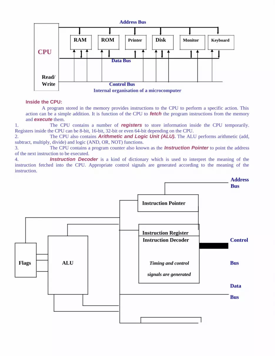
Inside the CPU:A program stored in the memory provides instructions to the CPU to perform a specific action. This
action can be a simple addition. It is function of the CPU to fetch the program instructions from the memory and execute them.
1. The CPU contains a number of registers to store information inside the CPU temporarily. Registers inside the CPU can be 8-bit, 16-bit, 32-bit or even 64-bit depending on the CPU.2. The CPU also contains Arithmetic and Logic Unit (ALU). The ALU performs arithmetic (add, subtract, multiply, divide) and logic (AND, OR, NOT) functions.3. The CPU contains a program counter also known as the Instruction Pointer to point the address of the next instruction to be executed.4. Instruction Decoder is a kind of dictionary which is used to interpret the meaning of the instruction fetched into the CPU. Appropriate control signals are generated according to the meaning of the instruction.
AddressBus
Instruction Pointer
Instruction RegisterInstruction Decoder Control
Flags ALU Timing and control Bus
signals are generated
Data
Bus

Internal Register A
Busses Register B
Register C
Register D
Internal block diagram of a CPU

The Figure below demonstrates the interaction between the CPU, memory and I/O Devices.

Brief History of the Computers• 1946 The first generation of Computer ENIAC was started to be used based on the vacuum tube technology.• 1958 the first transistorized computer TRADIC was announced by IBM.• 1959 first IC was invented.• 1960s ICs were started to be used in CPU boards.• 1970s entire CPU was put in a single chip. (1971 the first microprocessor of Intel 4004 (4-bit data bus and 2300 transistors)• Late 1970s Intel 8080/85 appeared with 8-bit data bus and 16-bit address bus and used from traffic light controllers to homemade computers.• 1981 First PC was introduced by IBM with Intel 8088 microprocessor.• Motorola emerged with 6800. Apple Macintosh computers started to use 68000 series of microprocessors.
E VOLUTION OF I NTEL 80 X 86 F AMILY M ICROPROCESSORS
Processor Year Transistors Clock Rate External Internal Add. BusIntro. (MHz.) Data Bus Data Bus
4004 1971 2,250 0.108 4 8 128008 1972 3,500 0.200 8 8 148080 1974 6,000 3 8 8 168085 1976 6,000 6 8 8 168086 1978 29,000 10 16 16 208088 1979 29,000 10 8 16 2080286 1982 134,000 12.5 16 16 25
80386DX 1985 275,000 33 32 32 3280386SX 1988 275,000 33 16 32 24
Pentium C 1993 3,100,000 66 -200 64 32 32Pentium MMX 1997 4,500,000 300 64 32 32
Pentium Pro 1995 5,500,000 200 64 32 36Pentium II 1997 7,500,000 233-450 64 32 36Pentium III 1999 9,500,000 550-733 64 32 36
Itanium 2001 30,000,000 800-… 128 64 64
B INARY AND H EXADECIMAL N UMBER S YSTEMS As human being we use base 10 (decimal) arithmetic Computers use base 2 (binary) system.Base 16 Hexadecimal number system is a convenient way of represented binary numbers. ASCII (binary format of the alphanumeric code) is explained.
Decimal and Binary number systems:-There is a speculation of the fact that Humans use base 10 system is because they have 10 fingers.
But there is no speculation behind the fact that the computers use binary system. The binary system is used in computers, because 1 and zero represent the two voltage levels of on and off.
There are 10 digits in Decimal system: 0,1,2,3,4,5,6,7,8,9There are only 2 digits in Binary system: 0,1 (Binary digits are referred as bits)

Converting from decimal to binary:Example: Convert 2510 to binary:
Remainder25/2 = 12 1 LSB (least significant bit)12/2 = 6 06/2 = 3 03/2 = 1 11/2 = 0 1 MSB (most significant bit)
Therefore, 2510 = 110012
Converting from binary to decimal:Example: Convert 1101012 to decimal:
1101012 =1x20 =1x1 =
Decimal1
0x21 =0x2 = 01x22 =1x4 = 40x23 =0x8 = 01x24 =1x16 = 161x25 =1x32 = + 32
53 1101012 =5310Hexadecimal Number system:Hexadecimal system is defined to be the base 16 number system and is used as a convenient representation of binary numbers.

Hexadecimal Binary Decimal0 0000 01 0001 12 0010 23 0011 34 0100 45 0101 56 0110 67 0111 78 1000 89 1001 9A 1010 10B 1011 11C 1100 12D 1101 13E 1110 14F 1111 15

Converting from binary to hex (hexadecimal):Example: Convert 1001111101012 to hex:
1001 1111 0101= 9F 5
Therefore, 1001111101012 = 9F5 Hex
Converting from hex to binary:Example: Convert hex 29B to binary:
2 9 B= 0010 1001 1011 Dropping zeros, 29B = 1010011011
Converting from decimal to hex (hexadecimal):Example: Convert 4510 to hex:
Quotient Remainder45/16 = 2 13 (hex D) LSD (least significant bit)2/16 = 0 2 MSD (most significant bit)
Therefore, 4510 = 2D16 = 2DH
Converting from hex to decimal:Example: Convert 6B216 to decimal:
6B216 =2 x 160 = 2 x 1 =
Decimal2
11x161 = 11x16 = 1766 x 162= 6x256 = + 1536
1714 Therefore, 6B216 = 171410
Addition and subtraction in binary numbers:Addition Example:
1101 A + B Carry Sum1001 0 + 0 0 0
+ 10110 0 + 1 0 1101100 1 + 0 0 1
1 + 1 1 0Binary Addition
Subtraction of Binary Numbers:Given binary numbers x and y. x–y is performed by taking 2’s complement of y and adding to x.
11001001 – 10011101 => 2’s complement of 10011101= 01100010 (1’s complement)+1

(2’s complement)11001001
01100011
+ 011000111 00101100
Addition and subtraction in hex numbers:Addition Example:
23D9 LSD : 9 + 14 = 23 23-16= 7 with a carry to next digit+ 94BE 1+13+11 = 25 25-16= 9 with a carry to next digit
B897 1+3+4 = 8MSD 2 + 9 = B
Subtraction Example:
59F LSD : 15 - 8 = 7– 2B8 25 (9+16) – 11 (B) = 14, which is E
2E7 MSD 4 (5–1) –2 = 2ASCII Code : (American Standard Code for Information Interchange)Hex Symbol Hex Symbol41 A 61 a42 B 62 b42 C 62 c44 D 64 d45 E 65 e46 F 66 f47 G 67 g48 H 68 h49 I 69 i4A J 6A j4B K 6B k4C L 6C l4D M 6D m4E N 6E n4F O 6F o50 P 70 p51 Q 71 q52 R 72 r53 S 73 s54 T 74 t55 U 75 u56 V 76 v57 W 77 w58 X 78 x59 Y 79 y5A Z 7A z
Some important terminology:

bit 0nibble 0000byte 0000 0000word 0000 0000 0000 0000double-word 0000 0000 0000 0000 0000 0000 0000 0000quad-word 0000 0000 0000 0000 0000 0000 0000 0000 0000 0000 0000 0000 0000 0000 0000 0000
1 kilobyte is 2 10 bytes. (Abbreviation K is used) Some floppy disks hold 356K bytes of data. 1 megabyte is 220 bytes. (a little over a million 1,048,576)1 gigabyte is 230 bytes (over 1 trillion)1 terabyte is 240 bytes