learoyd rd wps kelair pumps om manual volume 6
TRANSCRIPT

Nr
d4C'ec`IN 1 II 11111111
tt):acz
Learoyd Rd WPS Kelair Pumps OM Manual Volume 6
Q-Pulse Id TMS607 Active 29/01/2014 Page 1 of 209
O
410
22020 10 4000
46T:: 4400 4400 42C0 3600 4220 0:4. 1220 m.S.C.L. MAIN _
- -
-100- r- I
,
I
O
/ I .1
(
S 49.8.S0
'
49.850o
o F.S.L. 49.850 ; F.S.L. 49-.A o
4
III /// ;
II BOLTEC DEAD /// II
PLATE /// /// ///
BOLTED DEAD PLATE
oF.S.L. 49.850 I r - -
- - - - I I
r 11-
R.L. 49.80001 C}.__ L ,
__TLET MAIN
3400
(
101
01
01
01
'
0
4400
A. VENTILATION TL.
1
I \`THRLtST WALL 1 i
I 1
vr; , ,
i---;-..,
____ , ______ ,_t_, _ 7
I
4400 1 1200
R.L. 53.000 /// /// I// // /
/ //
10
0
\O
Ii
III LOADING BAY
R.L. i50.000 o
o.R.L. 50.000 I- -T1
R.L. 49.800 44
J
R.L. 50.000
_ _VARLSEIL
-I
SPEED DRIES
lgggN 1AZ
FLOOR PLATE
th PLAN SCALE 1 :50
ROLLER DOOR
0-
4.4
L.
-
I WASH BASIN
F.S.L. 49.850 o
O
FLOOR PLATE
TRANSFORMER BAY F L. 49.750
o
H.V.
I I I
R.L. 49.750
ACCESS RAMP
0 L. 49.650
o
e1
I I Id 1 phc,,
jl ',--c:A. 100 P'V'C DRAIN
NOTE FOR CONDUIT SIZES AND DETAILS REFER OWE. 486/4/7-80053
900
DOUBLE -SKIN PLASTERBOARD CEILING i
CRANE RAIL BEA
ACOUSTIC LOUVRES
CONCRETE iTHRUST
WALL
I
I I
I I I IT
11,i111=41
Y.
R.L.47.700
SECTIONAL ELEVATION SCALE 1:50
5 0 10 20 30 40 50 60 70
I ;
TRANSFORMER BAY
R.L. 49.750
IY
1.
90 100 110 120 130 140 :50 160
R.L. 49.650
N
R.L. 50.150
BLOCKOUTS FOR CONDUITS
500 0 500 1000 1500 2000 2500 1,,I I I I I I
SCALE OF MILLIMETRES 1 50
A 4.4.95
DATE PUMP REMOVE:
AMETIXENT
°RECTOR OF PD. G. PS.
DATE
1343,4EEp ORIGINAL SII:NED DATE CHARGE R. .BOWERPV.:
SLPERVISM ORIG. SIGN. RPE.12 , DATE EN2INEE4 P. GAW 3727 2: /: '
NANE I DATE
S. MOBBS 1997
CHECKED
UCB FLE
DRAWN
0-EOCED
CADD FLE
SURVEYS)
Mery at,
JJV SEPT. '..;";r
J E F OCT .9
47PD345 iSLRVEY Na
RID BCCK
Brisbane =
Water PROJECT
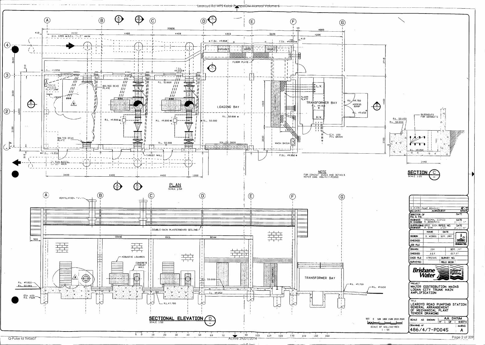
MAJOR DISTRIBUTION MAINS LOGAN CITY TRUNK MAIN AMPLIFICATION
TITLE
LEAROYD ROAD PUMPING STATION GENERAL ARRANGEMENT OF MECHANICAL PLANT TENDER DRAWING
SCALE AS 9-DAN N' 1 OF 4 SHEETS
0AWGM JAS .43,11
486/4/7-PD045
A.FL DATUM
Learoyd Rd WPS Kelair Pumps OM Manual Volume 6
Q-Pulse Id TMS607 Active 29/01/2014 Page 2 of 209
B
DIA. 1220 M.S.C.L. INLET MAIN
j
I I . 1 i I
I I
S I
\ i /
I I x/ -2100.-.--______--_-_--------- (
/1 i \
1 1 A I 4 / i \
i \ / \
i I
--.. 1_ ---
I : : I
-7,
1
600
BLOCKOUTS FOR CONDUITS
LIMIT ' OF CONTRACT
STUB PIPE 762 OD
di4 4,4411
6.T
Pfd.:
DN 25 SYSTEM DRAIN
ON 450 . 400 ECCENTRIC F ENLARGER
R.L. 49.800 C I
L
DN 25 SYSTEM DRAIN
STUB PIPE 635 OD
COLLAR JOINT PRESSURE TAPPING (D)
ON 700 BUTTERFLY VALVE
ON 455 . 700 ECCENTRIC REDUCER
DN450 TIED DISMANTLING JOINT (REFER DETAIL DwG. 466/4/7-P004BI
PUMP
DN400 TIED DISMANTLING JOINT (REFER DETAIL DWG. 486/4/7-P0048/
HANOI-IDLE (REFER DETAIL DWG. 486/4/7-P0048)
DN 450 OEMAG ORV-G OR DRV-B CHECK VALVE
ON 450 600 ECCENTRIC ENLARGER
ON 600 BUTTERFLY VALVE
PRESSURE TAPPING (D)
COLLAR JOINT
LIMIT Or-tONYRWt7-
d
THRUST WALL
\ ;
\ 1 1 , /
/ '
I 1 V-1 1 1
1 1
1--
1 i /
. _ _ _ . ------ ------ -1 ------ ' --- - ' '
ON 910 M.S.C.L. OUTLET MAIN I
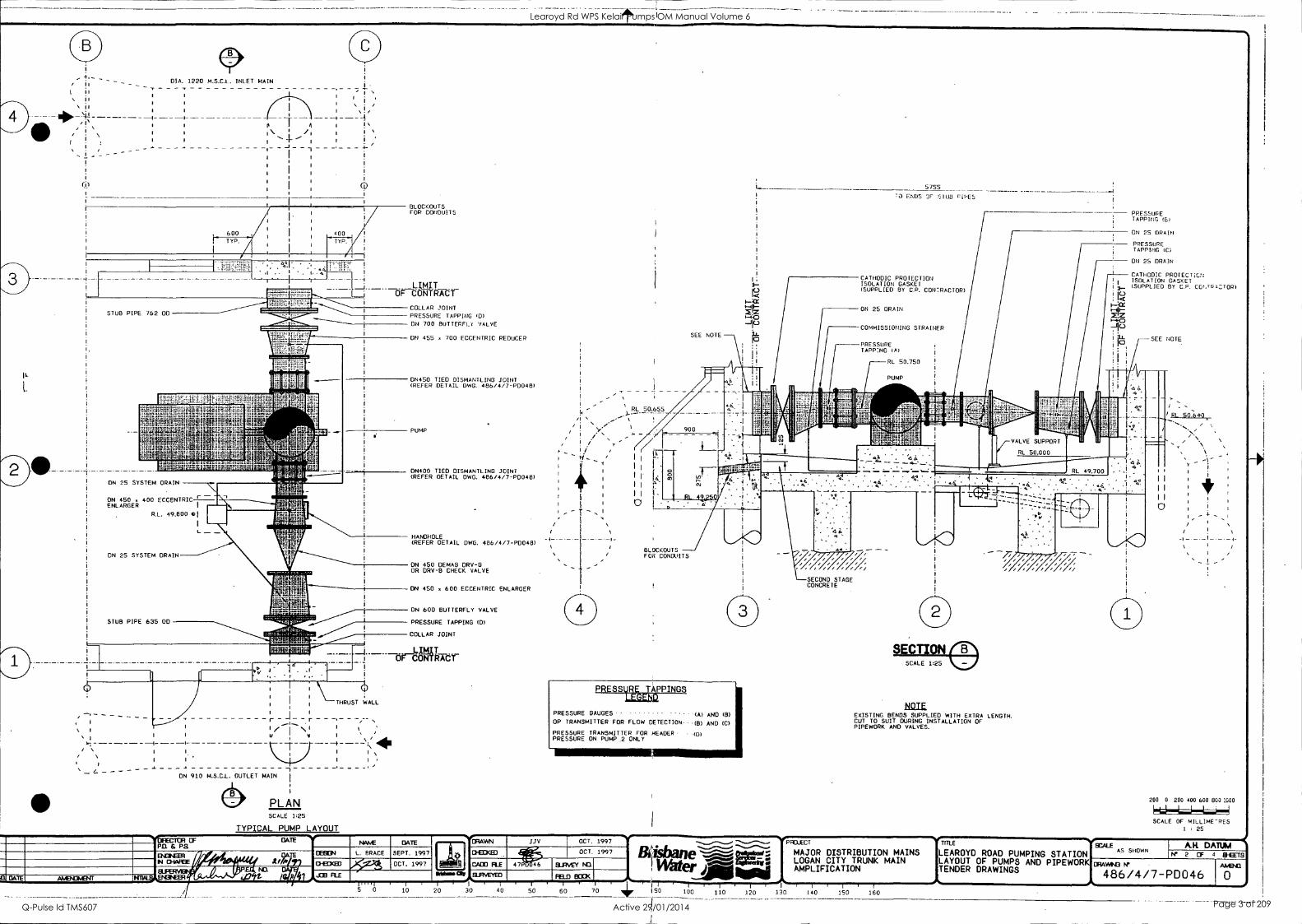
PLAN SCALE 125
TYPICAL PUMP LAYOUT
RL 50.655
/
/ /
I/
I I
I I
I I
I I H I I I
O '
SEE NOTE
5755
7) ENDS 3F STUB riPES
CATHODIC PROTECTION ISOLATION GASKET (SUPPLIED BY C.P. CON7RACTOR)
ON 25 DRAIN
COMMISSIONING STRAINER
-PRESSURE TAPP:NG (A)
RL 50.750
PUMP
PRESSURE TAPPING (6)
ON 25 DRAIN
PRESSURE TAPPING IC)
ON 25 DRAIN
.i. CATHODIC PROTECTIOU illI I ISOLATION GASKET i 3,... (SuPPLIE0 BY C.F. CC-:.10P)
i ri ; < I-:CC '.4-
*0 .-4.0
7jKi i i:LL SEE NOTE. I I° I : ;
I
_
BLOCKOUTS FOR CONDUITS
PRESSURE ASPINGS
PRESSURE GAUGES -------------- (A) AND (B)
DP TRANSMITTER FOR FLOW DETECTION---(8) AND (C)
PRESSURE TRANSMITTER FOR HEADER- (D) PRESSURE ON PUMP 2 ONLY
5 0 10 20 30 40
'/' SECOND STAGE CONCRETE
NOTE EXISTING BENDS SUPPLIED WITH EXTRA LENGTH. CUT TO SUIT DURING INSTALLATION OF PIPEWORK AND VALVES.
OA
PFCLECT T a E %I SCALE
MAJOR DISTRIBUTION MAINS LEAROYD ROAD PUMPING STATION AS SHOWN
LOGAN CITY TRUNK MAIN AMPLIFICATION TENDER DRAWINGS
LAYOUT OF PUMPS AND PIPEWORK DIAwN3w
0
200 0 200 400 600 800 1000
SCALE OF MILLIME-PES 1 : 25
I
60 70 lk I 90 100 110 120 .130 140 150
AR DATUM IY 2 CF 4 HHEETS
AA4341
486/4/7-PD046 0
Learoyd Rd WPS Kelair Pumps OM Manual Volume 6
Q-Pulse Id TMS607 Active 29/01/2014 Page 3 of 209

KelairPumps
Head Office Sydney Gateway Estate 215 yValters'Ficrad Amdell Park NSW 2148 Telephone: 61 2.9678 9466 Facsimile: 61:2 9678 9455 Omit [email protected] (Amin)
[email protected] MSW Sales)
Queensland Office 5/89 dijaWs Street' Suniner Park GILD 4074 Telephone: 07 3279 5700 Facsimile: 07 3279 5711 Ernst: [email protected]
1. .nian Office 1/12 South Street Invermay TAS 7248 Telephone: 03 6331 6733 Facsimile: 03 6331 9102 Email: [email protected]
Victorian Office 19 Edward Street Oakteigh VIC 3166 Telephone: 03 9569 7855 Facsimile: 03 9569 7866 Email: [email protected]
Western Australia Office Coma Corporate Centre 11 Preston Street Como WA 6152 Telephone: 08 9367 0633 Facsimile: 08 9474 5636 Email: [email protected]
,elair Pumps Australia Pty Ltd
A.C.N. 001 308 381
Website: http://www.kelairpumps.com.au
OPERATION & MAINTENANCE
MANUAL
CLIENT : Kilpatrick Green Pty Ltd
ORDER No. : 441/843941
SITE/PLANT : Learoyd Road - Brisbane '
PUMPSET :- Water Transfer Pumps: LP - 110015 - BM (Kelair / ABS)
JOB No. : 110015
CONTRACT : CQ5121/8
Standard conditions of sale and warranty available on request
Learoyd Rd WPS Kelair Pumps OM Manual Volume 6
Q-Pulse Id TMS607 Active 29/01/2014 Page 4 of 209

KelairPumps
PAGE Rev i
REVISIONS
Revision 1: As per Clients Request ( Fax Dated 13/05/99 )
Learoyd Rd WPS Kelair Pumps OM Manual Volume 6
Q-Pulse Id TMS607 Active 29/01/2014 Page 5 of 209
1[4. KelairPumps
PAGE Contents i
CONTENTS
1: Introduction 2: Description of Equipment 3: Design Criteria & Process Description 4: Installation and Precommissioning 5: Start Up and Shut Down Procedures 6: Commissioning 7: Operations 8: Maintenance 9: Fault Protection and Rectification
10: Isolation and Restoration Procedures 11: List of Sub-Contractor and Proprietary Equipment 12: Recommended Spare Parts and Special Tools 13: List of Engineering Drawings 14: Training 15: List of Contract Variations and Plant Modifications 16: Commissioning and Test Reports 17: Appendix 1 - Fan Monitor 18: Appendix 2 - Motor Installation & Maintenance Instructions 19: Appendix 3 - Variable Speed Drive
Learoyd Rd WPS Kelair Pumps OM Manual Volume 6
Q-Pulse Id TMS607 Active 29/01/2014 Page 6 of 209

1: Introduction
CONTENTS: INTRODUCTION & CONTACT DETAILS
KelairPumps
PAGE 1.00
PAGE Page 1.01
Learoyd Rd WPS Kelair Pumps OM Manual Volume 6
Q-Pulse Id TMS607 Active 29/01/2014 Page 7 of 209
Kelair Pumps Australia Pty Ltd Page 1.01
fiS
INTRODUCTION
These instructions have been prepared to assist you in the
installation, operation and maintenance of your pump. We urge
you to read and follow all of the directions in this manual.
If you have a problem that is not covered in this manual please do
not hesitate to contact :
Kelair Pumps Australia Pty Ltd
General Hours: Monday to Friday 7:30am - 5:00pm
Qld Tech Sales: (07) 3279 5700
H.O. (Sydney): (02) 9678 9466
After Hours:
Service Manager: 0411 600 601
Learoyd Rd WPS Kelair Pumps OM Manual Volume 6
Q-Pulse Id TMS607 Active 29/01/2014 Page 8 of 209

2: Description of Equipment
CONTENTS: PUMPSET DESCRIPTION
KelairPumps
PAGE 2.00
PAGE Page 2.01
Learoyd Rd WPS Kelair Pumps OM Manual Volume 6
Q-Pulse Id TMS607 Active 29/01/2014 Page 9 of 209
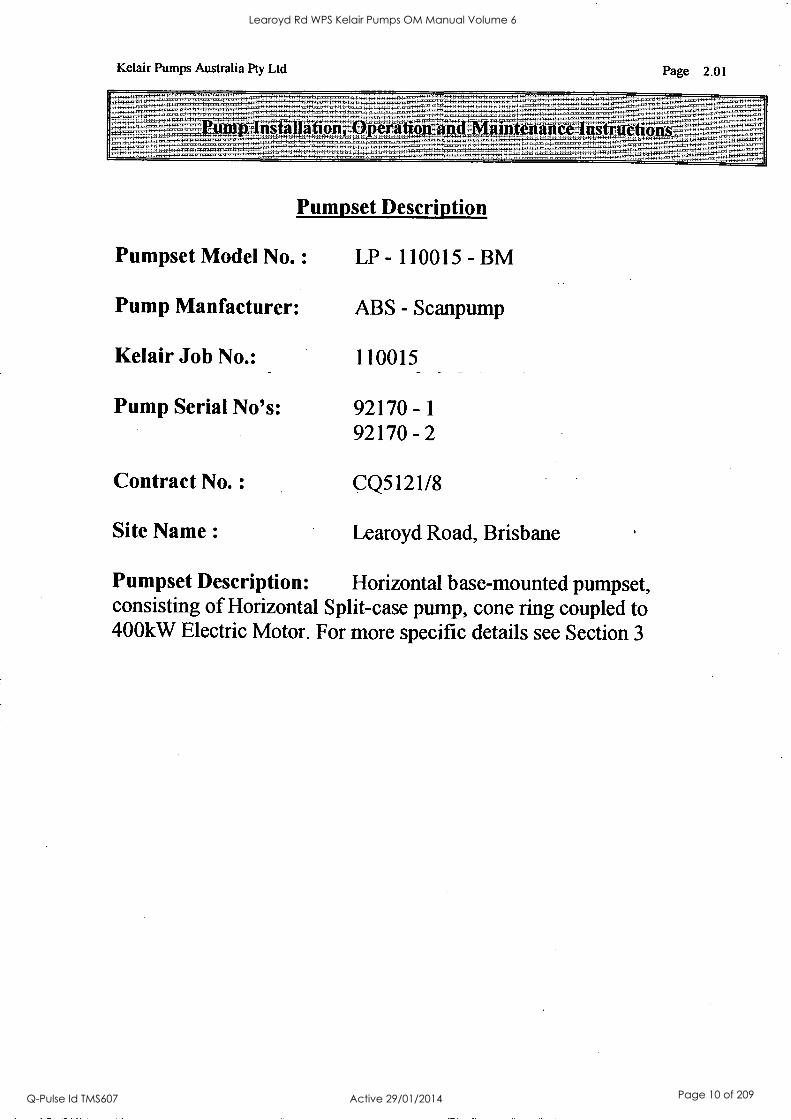
Kelair Pumps Australia Pty Ltd Page 2.01
- - ns in o = 'enTaATIVI- aintenanm instructions Pp tilt
Pumpset Description
Pumpset Model No. : LP - 110015 - BM
Pump Manfacturer: ABS - Scanpump
Kelair Job No.: 110015
Pump Serial No's: 92170 -1 92170 - 2
Contract No. : CQ5121/8
Site Name : Learoyd Road, Brisbane
Pumpset Description: Horizontal base-mounted pumpset, consisting of Horizontal Split-case pump, cone ring coupled to 400kW Electric Motor. For more specific details see Section 3
Learoyd Rd WPS Kelair Pumps OM Manual Volume 6
Q-Pulse Id TMS607 Active 29/01/2014 Page 10 of 209

KelairPumps
PAGE 3.00
3: Design Criteria & Process Description
CONTENTS : PAGE KELAIR DATA SHEET (No. 13364) Page 3.01 ABS TECHNICAL DATA SHEET Page 3.02 OVERALL DIMENSIONS Page 3.03
Learoyd Rd WPS Kelair Pumps OM Manual Volume 6
Q-Pulse Id TMS607 Active 29/01/2014 Page 11 of 209
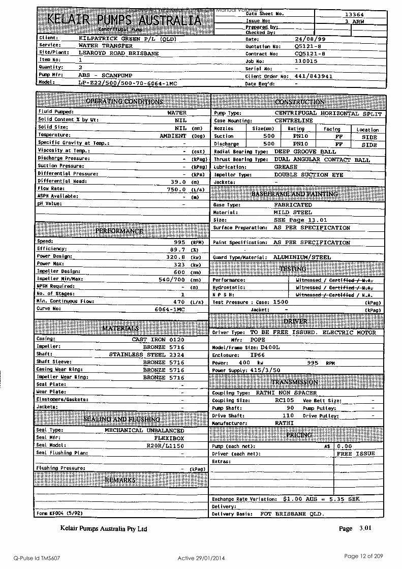
KELAIR PUMPS "AUSTRALIA. , . Centrtfiigal. Pump
Data Sheet No. 13364 Issue No: 3 ARW Prepared bv; Checked by: I
Client: KILPATRICK GREEN P/L (QLD) Date: 24/08/99 Service: WATER TRANSFER Quotation No: Q5121-8 Site/Plant: LEAROYD ROAD BRISBANE Contract No: CQ5121-8 Item No: 1 Job No: 110015 Quantity: 2 Serial No: - Pump Mfr: ABS - SCANPUMP Client Order No: 441/843941 Model: LP-Z22 500 500-70-6064-1MC Date R :
OPERATING CONDITIONS CONSTRUCTION' Fluid Pumped: WATER Pump Type: CENTRIFUGAL HORIZONTAL SPLIT Solid Content X by Wt: NIL Case Mounting: CENTRELINE Solid Size: NIL (ran) Nozzles Size(m) Rating Facing Location Temperature: AMBIENT (Deg) Suction 500 PN10 FF SIDE Specific Gravity at Temp.: - Discharge 500 PN10 FF SIDE Viscosity at Temp.: - (cst) Radial Bearing Type: DEEP GROOVE BALL Discharge Pressure: - (kPag) Thrust Bearing Type: DUAL ANGULAR CONTACT BALL Suction Pressure: - (kPag) Lubrication: GREASE Differential Pressure: - (kPa) Impel ler Type: DOUBLE SUCTION EYE Differential Head: 39.0 (m) Jackets: - Flow Rate: 750.0 (L/s)
BASEFRAME AND MIMING NSPH Available: - (m)
pH Value: - Base Type: FABRICATED Material: MILD STEEL Size: SEE Page 13.01
... . ..._-__ ERFE P OR MAN C
Surface Preparation: AS PER SPECIFICATION
Speed: 995 (RPM) Paint Specification: AS PER SPECIFICATION Efficiency: 89.7 (X) -
Power Design: 320.8 (kw) Guard Type/Material: ALUMINIUM/STEEL Power Max: 323 (kw)
TESTING Impeller Design: 600 (mm)
Impeller Min/Max: 540/700 (mm) Performance: Witnessed / Dert-i-fi-ed-/--14-.-A-7
NPSH Required: - (m) Hydrostatic:
N P S H:
Witnessed / Gert-lf-fecl-EN7A7,-
Witnessed -/ i--Certifi-ed / N.A. No. of Stages: 1
Min. Continuous Flow: 470 (L/s) Test Pressure : Case: 1500 (kPag) Curve No: 6064-1MC Jacket: - (kPag)
DRIVER MATERIALS
Driver Type: TO BE FREE ISSUED. ELECTRIC MOTOR Mfr: POPE Casing: CAST IRON 0120
Impel ler: BRONZE 5716 Model/Frame Size: D400L Shaft: STAINLESS STEEL 2324 Enclosure: IP66 Shaft Sleeve: BRONZE 5716 Power: 400 kw 995 RPM Casing Wear Ring: BRONZE 5716 Power Supply: 415/3/50
...
TRANSMISSION Impeller Wear Ring: BRONZE 5716 Seal Plate: - Wear Plate: - Coupling Type: RATHI NON SPACER Elastomers/Gaskets: - Coupling Si ze: RC105 Vee Belt Size: - Jackets: - Pump Shaft: 90 Pump Pulley: -
Drive Shaft: 110 Drive Pulley: - SEALING ND IMING A M Manufacturer: RATHI
Seal Type: MECHANICAL UNBALANCED ?MING Seal Mfr: FLEXIBOX
Seal Model: R2OR/L1150 Pump (each net): AS
Driver (each net):
0.00 FREE ISSUE Seal Flushing Plan: -
Extras:
Flushing Pressure: - (kPag)
REMARKS
Exchange Rate Variation: $1.00 AUS = 5.35 SEK Delivery:
Form KF004 (5/92) Delivery Basis: FOT BRISBANE OLD.
Kelair Pumps Australia Pty Ltd Page 3.01
Learoyd Rd WPS Kelair Pumps OM Manual Volume 6
Q-Pulse Id TMS607 Active 29/01/2014 Page 12 of 209
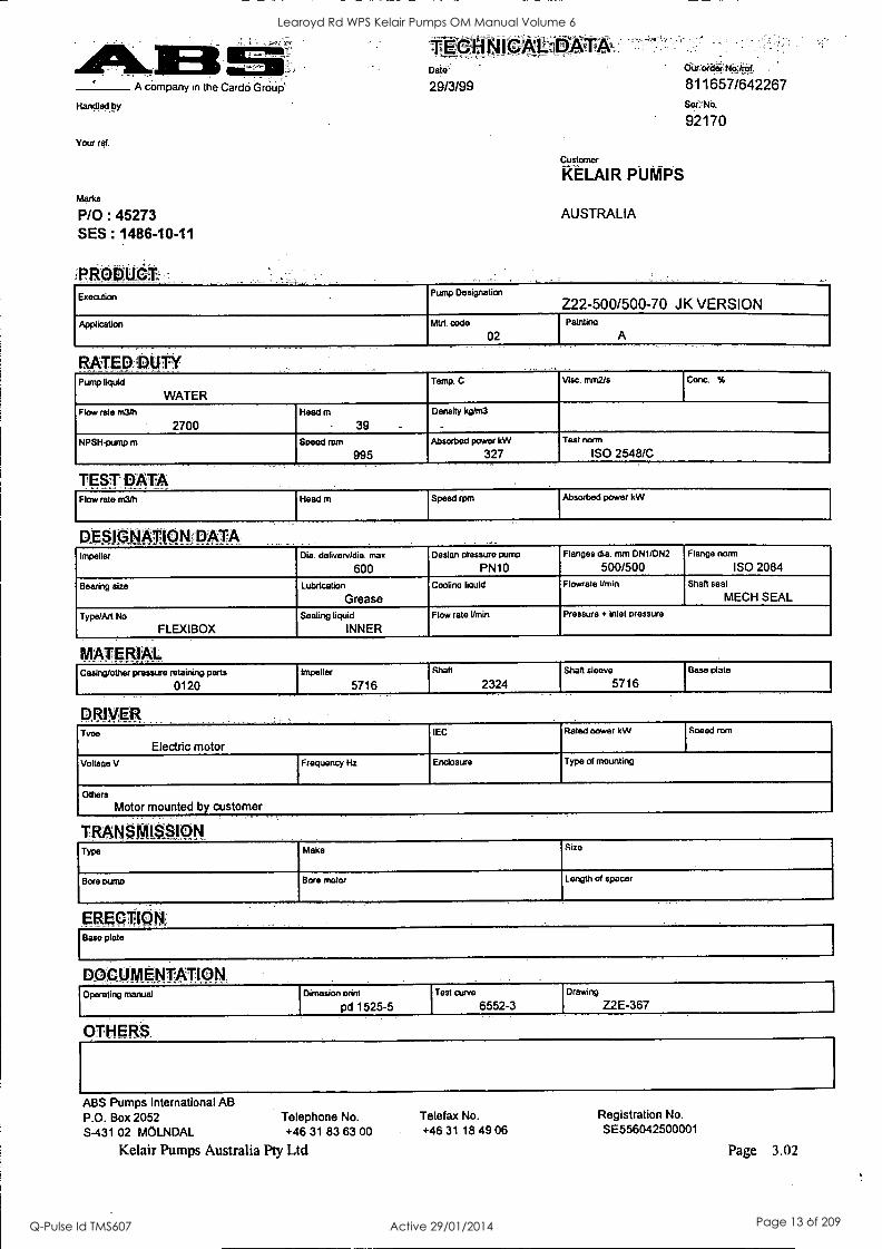
Handled by
Your ref.
A company in the Cardo Group''
Marks
P/0 : 45273 SES : 1486-10-11
Debi:
29/3/99
Customer
KELAIR PUMPS
AUSTRALIA
Oic order:NW/ref.
811657/642267 Ser.-No.
92170
Execution Pump Designation
222-500/500-70 JK VERSION Application Mtrl. code
02
Paintina
A
RATED DUTY Pump liquid
WATER Temp. C Visc. mrn2/s Conc. %
Flow rate math
2700 Head m
39 Density kg/m3
_
NPSH-pump m Speed ram
995 Absorbed power kW
327
- Test norm
ISO 2548/C
TEST: DATA Flow rate m3/h Head m Speed rpm Absorbed power kW
DESIGNATION DATA Impeller Dia. delivery /dia. max
600 Design ofessure pump
PN10 Flanges dia. mm DN1/DN2
500/500 Flange norm
ISO 2084
Bearing size Lubrication
Grease Cooling liquid Flowrate Umin Shaft seal
MECN SEAL
Type/Art No
FLEXIBOX Sealing liquid
INNER Flow rate l/min Pressure + inlet pressure
MATERIAL Casing/other pressure retaining parts
0120 Impeller
5716
S haft
2324 Shaft sleeve
5716 Base plate
DRIVER. Tvoe
Electric motor IEC Rated cower kW Speed ram
Voltage V I Frequency Hz Enclosure Type of mounting
Others
Motor mounted by customer
TRANSMISSION Type Make Size
Bore pump Bore motor Length of spacer
ERECTION Base plate
DOCUMENTATION. Operating manual Dimesion orint Test curve Drawing
pd 1525-5 6552-3 Z2E-367
OTHERS.
ABS Pumps International AB P.O. Box 2052 Telephone No.
S-431 02 MOLNDAL +46 31 83 63 00
Kelair Pumps Australia Pty Ltd
Telefax No. +46 31 18 49 06
Registration No. SE556042500001
Page 3.02
Learoyd Rd WPS Kelair Pumps OM Manual Volume 6
Q-Pulse Id TMS607 Active 29/01/2014 Page 13 of 209
Kelair Pumps Australia Page 3.03
Overall Dimensions
Entire Unit Dimensions Length : 3681 mm Approx. Width : 1600 mm Approx. Height: 1715 mm Approx.
Unit Weights Pump : 2200 kg Motor : 2900 kg Baseplate: 990 kg TOTAL: 6090 kg Approx.
NOTE: For more dimensional details see Page 13.01
Recommended Minimum Flow: 470 L/S
Learoyd Rd WPS Kelair Pumps OM Manual Volume 6
Q-Pulse Id TMS607 Active 29/01/2014 Page 14 of 209

4: Installation and Precommissioning
CONTENTS: INSTALLATION INSTRUCTIONS
KelairPumps
PAGE 4.00
PAGE Pages 4.01- 13
Learoyd Rd WPS Kelair Pumps OM Manual Volume 6
Q-Pulse Id TMS607 Active 29/01/2014 Page 15 of 209
Kelair Pumps Australia
MOUNTING
Before mounting
A horizontal pump can either be mounted separately on blocks or together with the motor on a concrete foundation. Recesses for blocks or foundation bolts should be made in the foundation before mounting.
Mounting of Pump and Motor on a Common Base Plate
1 Lift base plate with pump and motor into position.
2 Place alignment wedges between foundation and base plate, close to the foundation bolts. Knock in the wedges so that the base plate is lifted approx. 1 cm.
With the help of the wedges align the base plate accurately according to the instructions below.
4 Concrete under the base plate and tighten the foundation bolts when the concrete has hardened. Fill the space between the foundation and base plate completely.
Mounting of Pump and Motor Separately
1 Tighten the ancor blocks to pump and motor respectively. By placing shims between the blocks and pump or motor, a pump and motor with slightly different heights can be mounted and aligned without the blocks having to be altered.
2 Lift pump and motor into position with the blocks hanging in the recesses.
.3 Align the base plate according to the instructions below.
4 Concrete the blocks to the foundation and when the concrete has hardened check that they are tightened.
Page 4.01
Installation of pump and motor on a concrete foundation
The foundation should be constructed in accordance with relevant standard specifications. Recesses should be made according to applicable dimension prints. Smooth off the foundation carefully to simplify rough alignment and ensure proper packing- up.
Fit the mounting pads on to pump and motor. To permit future realignment, a shim at least 5 mm thick should be used between mounting pads and motor. Place the pump on the foundation and measure its position. Particular care must be taken to ensure that the pump shaft is horizontal. Place the motor on the foundation and line it up with the pump. Accurate alignment will simplify final adjustment after grouting. Try to attain a deviation of less than 0.05 mm both axially and radially.
Pump and motor are grouted in with an expanding type of concrete, which should be allowed to set according to the maker's instructions. Carry out final alignment of pump-motor. Tolerances will depend on the type of coupling, but a value less than 0.05 mm radially and axially should be aimed at.
NOTE: Different thermal expansions must be compensated by different heights of pump and motor.
Fit dowel pins to locate pump and motor.
Check the alignment after piping has been connec- ted. Deviations must not exceed the values that the coupling allows. When a gear coupling or other type of coupling that permits slight disalignment is used, the alignment should be checked again after a period of operation. This check should be made with pump and motor at operating temperature.
If a gear or hydraulic coupling is included in the plant, the installation procedure is the same. First place the pump, then the gear with a shim at least 5 mm thick between mounting pad and gear, then place the motor.
When measuring up the position of the pump, parti- cular care must be taken to ensure that the motor comes into the correct position on the foundation.
Learoyd Rd WPS Kelair Pumps OM Manual Volume 6
Q-Pulse Id TMS607 Active 29/01/2014 Page 16 of 209
Kelair Pumps Australia Page 4.02
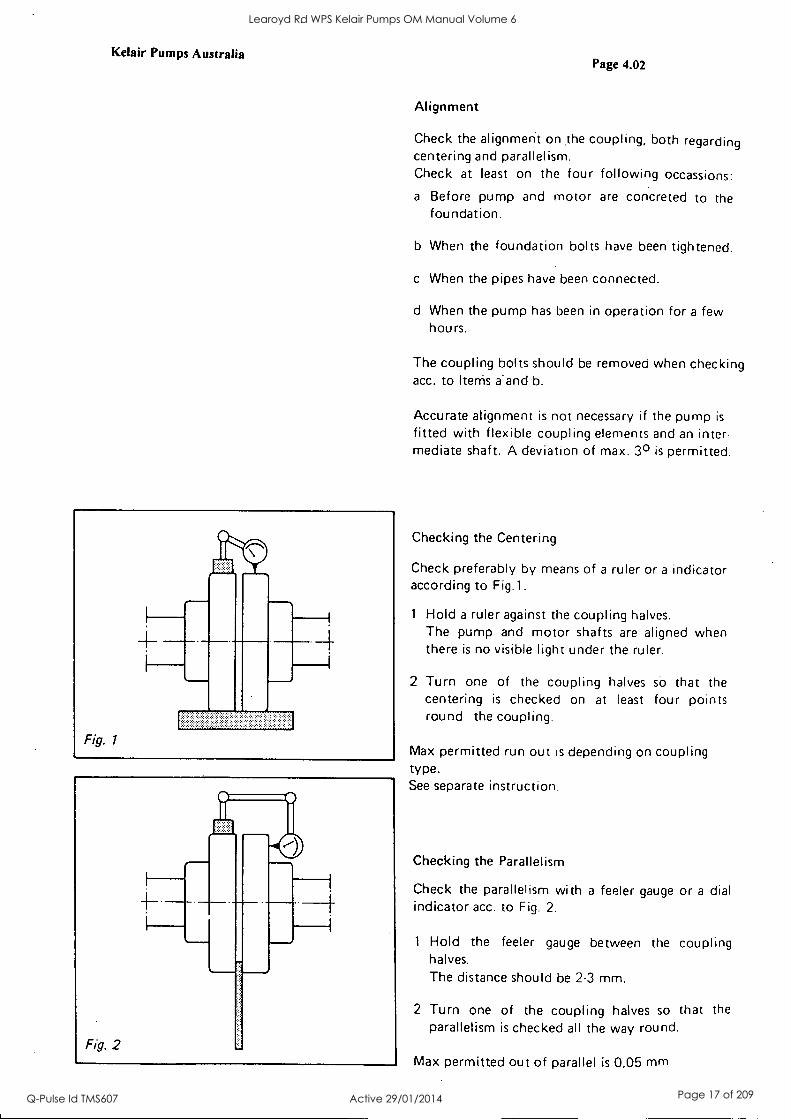
Alignment
Check the alignment on .the coupling, both regarding centering and parallelism. Check at least on the four following occassions:
a Before pump and motor are concreted to the foundation.
b When the foundation bolts have been tightened.
c When the pipes have been connected.
d When the pump has been in operation for a few hours.
The coupling bolts should be removed when checking acc. to Items a-and b.
Accurate alignment is not necessary if the pump is
fitted with flexible coupling elements and an inter- mediate shaft. A deviation of max. 3° is permitted.
Checking the Centering
Check preferably by means of a ruler or a indicator according to Fig.1.
1 Hold a ruler against the coupling halves. The pump and motor shafts are aligned when there is no visible light under the ruler.
2 Turn one of the coupling halves so that the centering is checked on at least four points round the coupling.
Max permitted run out is depending on coupling type. See separate instruction.
Checking the Parallelism
Check the parallelism with a feeler gauge or a dial indicator acc. to Fig. 2.
1 Hold the feeler gauge between the coupling halves. The distance should be 2-3 mm.
2 Turn one of the coupling halves so that the parallelism is checked all the way round.
Max permitted out of parallel is 0,05 mm
Learoyd Rd WPS Kelair Pumps OM Manual Volume 6
Q-Pulse Id TMS607 Active 29/01/2014 Page 17 of 209
Kelair Pumps Australia Page 4.03
CONNECTIONS
Pipe Connections
The pipes must not cause any strain on the pump casing. They should therefore be supported as close to the casing as possible. Pumps for hot liquids should have pipes with expansion loops or compen- sators. The sealing surfaces on the connection fianges must be parallel to those of the pump.
Pressure Gauge Connections
BSP 3/8" connections are hued on suction and delivery branches.
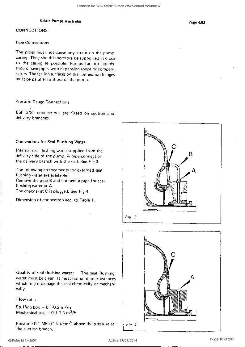
Connections for Seal Flushing Water
Internal seal flushing water supplied from the delivery side of the pump. A pipe connection the delivery branch with the seal. See Fig.3.
The following arrangements for externed seal flushing water are available: Remove the pipe B and connect a pipe for seal flushing water at A. The channel at C is plugged. See Fig.4.
Dimension of connection acc. to Table 1.
Quality of seal flushing water: The seal flushing water must be clean. It must not contain substances which might damage the seal chemically or mechani cally.
Flow rate:
Stuffing box - 0.1-0.2 m3/h Mechanical seal - 0.1-0.3 m3/h
Pressure: 0.1 MPa (1 kp/cm2) above the pressure at the suction branch.
Fig 4
Learoyd Rd WPS Kelair Pumps OM Manual Volume 6
Q-Pulse Id TMS607 Active 29/01/2014 Page 18 of 209
Kelair Pumps Australia
Fig. 5
Page 4.04
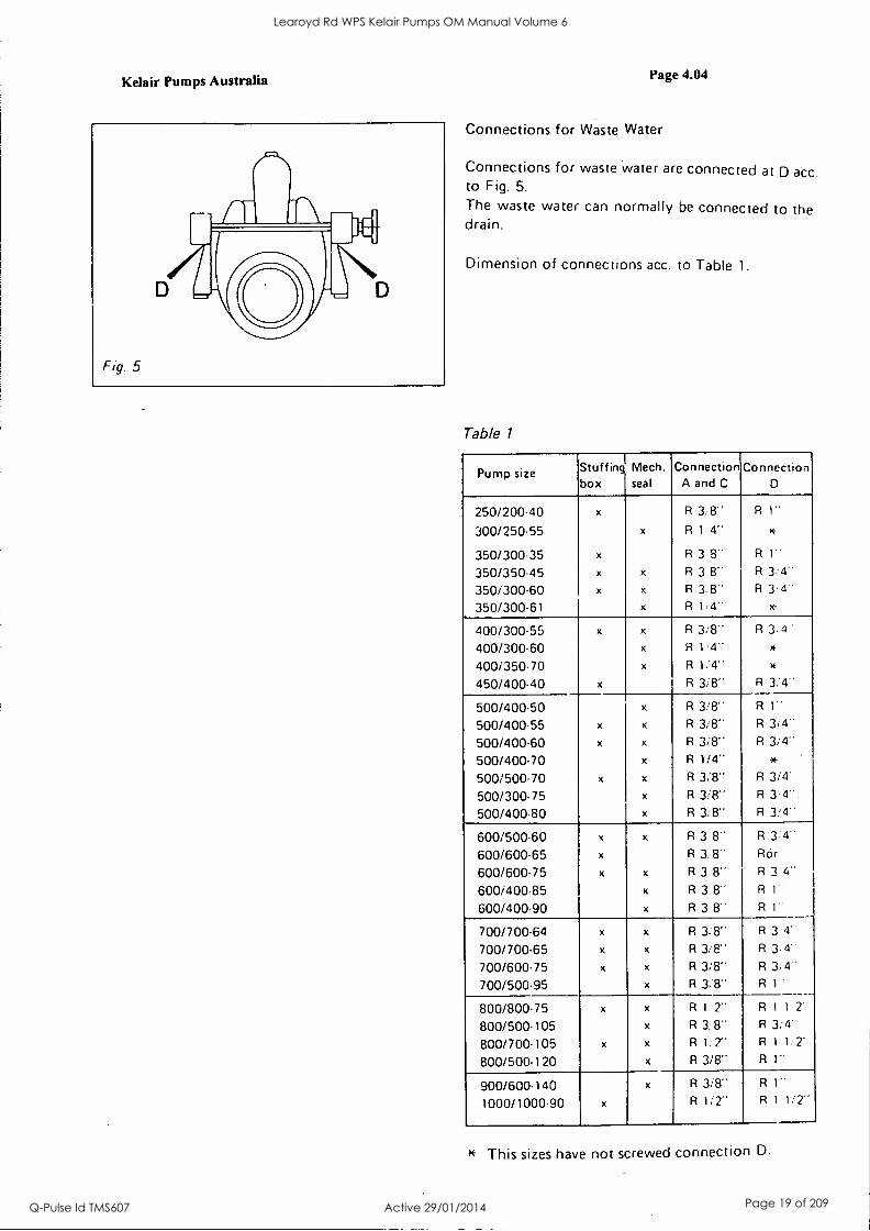
Connections for Waste Water
Connections for waste water are connected at D acc to Fig. 5.
The waste water can normally be connected to the drain.
Dimension of connections acc. to Table 1.
Table 1
Pump size Stuffing box
1 Mech. seal
Connection A and C
Connection D
250/200-40 x R 3:8" R 1"
300/250.55 x R 1 4" x-
350/300-35 x R 3 8.. R 1"
350/350-45 x x R 3 8" R 3:4" 350/300-60 x x R 3.8" R 3.4"
350/300-61 x R 1,4" x-
400/300-55 x x R 3;8" R 3.4
400/300.60 x R 1.4- *
400/350.70 x R 1:4" 4*
450/400-40 x R 3/8" R 3:4"
500/400-50 x R 3/8" R I- 500/400.55 x x R 318" R 314"
500/400.60 x x R 3/8" R 3/4" 500/400-70 x R 1/4"
500/500-70 x x R 3/8" R 3/4"
500/300-75 x R 3/8 R 3-4".
500/400-80 x R 3/8" R 3/4"
600/500.60 x x R 3.8" R 3:4"
600/600-65 x R 3.8" Mit 600/600.75 x x R 3 8" R 3 4-
600/400-85 x R 3 8" R 1"
600/400-90 x R 3 8" R 1-
700/700-64 x x R 3/8" R 3 4-
700/700.65 x x R 3.8" R 3-4'.
700/600-75 x x R 3/8" R 3,4"
700/500.95 x R 38" R 1"
800/800-75 x x R 1 2" R 1 1 2'
800/500-105 x R 3.8" R 3i4..
800/700-105 x x R 1:2" R 1 1:2'
800/500-120 x R 3/8" R 1"
900/600.140 x R 3/8" R 1"
1000/1000-90 x R 1/2" R 1 1,'2"
This sizes have not screwed connection D.
Learoyd Rd WPS Kelair Pumps OM Manual Volume 6
Q-Pulse Id TMS607 Active 29/01/2014 Page 19 of 209
Kelair Pumps Australia
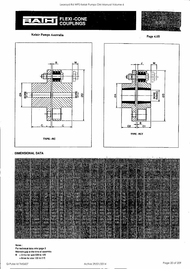
C
TYPE -RC
r'
DIMENSIONAL DATA
Notes :
For technical data refer page 3
Maintain gap at the time of assembly
B = 3 mm for size 020 to 105
6mm for size 120 to 215
Page 4.05
C2 B
C1
TYPE-RCT
0
Learoyd Rd WPS Kelair Pumps OM Manual Volume 6
Q-Pulse Id TMS607 Active 29/01/2014 Page 20 of 209
Kelair Pumps Australia
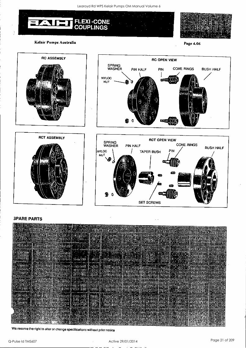
SPARE PARTS
a
Page 4.06
We reserve the right to alter or change specifications without prior notice
Learoyd Rd WPS Kelair Pumps OM Manual Volume 6
Q-Pulse Id TMS607 Active 29/01/2014 Page 21 of 209
Kelair Pumps Australia Pty Ltd Page 4.07
nWilationir Operation and Main on
PLANT PREPARATION:
GENERAL PUMP DATA
Each pump is thoroughly inspected, both in the manufacturing proceSs and as a final product to assure
trouble free operation.
Prior to shipping the pump, the case and any bearing oil housingS are drained. Covers are piked on the
suction and discharge flanges to keep dirt out.
HANDLING:
Use extreme care in handling the unit, placing slings carefully so that stress will not be imposed on the
pump or base. Never place cable slings around the pump shaft.
Any eye bolts located on the driver and pump case or cover are intended for lifting only those parts and not
the complete unit.
All equipment should be thoroughly checkb'd when delivered. Shortages or damages should be retiOrted
immediately to the local agent of the transportation company.
STORAGE:
If the unit is not to be placed in service immediately, it should be stored in a dry location and protected from
dirt and moisture internally and externally.
Do not remove the suction and discharge flange covers until the unit is to be piped.
Parts subject to attack by moisture, such as bearings, shaft and other finiShed parts should be protetted and
inspected periodically and the protective coating renewed as needed.
The pump will require additional protection if it is to be stored for an extended period. Dry the inside of the
pump thoroughly. Fill the liquid end with oil, kerosene, or another suitable protective liquid. Fill oil bearing
housing(s) as high as possible with lubricating oil. Rotate the shaft occasionally to prevent pitting of the finished surfaces and to keep the rotating element free.
Learoyd Rd WPS Kelair Pumps OM Manual Volume 6
Q-Pulse Id TMS607 Active 29/01/2014 Page 22 of 209

Kelair Pumps Australia Pty Ltd Page 4.08
nstaIIation, Operation and Maintenance, instructions
INSTALLATION
Please refer to BCC Standard Specifications and Clause 6.8.3 Setup and alignment of pumps (of the Tender Documents) and if variation exists follow those instructions.
FOUNDATION:
The foundation must be rigid enough to support the pump, auxiliary equipment, driver and baseplate, and
prevent vibration and misalignment during operation. The standard pump bases are designed to be grouted
into a concrete foundation.
Pour the concrete foundation well in advance of placement of the unit to allow ample time for curing.
Position foundation bolts in that the bolts have freedom of movement in the sleeve.
Roughen the surface of the foundation to allow a good bond between the foundation and the grout. Stuff
waste into the open portion between the foundation bolts and pipe sleeves to prevent grout from filling the
cavity and destroying the pipe sleeve's function.
LEVELLING THE BASEPLATE:
The baseplate will be easier to handle if the pump and driver are removed before the levelling operations are started. Remove any protective coating on the support pads. Do not use an abrasive material to
remove any coating as it can easily be removed usually with a solvent. Blocks and shims (or wedges) will
be required for installing the baseplate on the foundation. Set the blocks at each foundation bolt as shown
in figures 2 and 3. The blocks should provide a minimum distance of 1" from the top of the foundation to the bottom of the baseplate in order to establish grout space.
Lower the baseplate onto the blocks and level in direction A-B, C-D, and G-H as shown in figure 3 with a
spirit level on the machined pads. Between each levelling operation remove shims or adjust wedges as
necessary. Lightly tighten bolts directly connected with each levelling operation as it is performed. After the
base is level, recheck the alignment in all directions and make final adjustments. Foundation bolts are not
to be tight. The baseplate is now ready for grouting.
GROUTING THE BASEPLATE:
Build a. wooden form around the baseplate to retain the grout. Select a good grade of commercial grout material and mix to the recommended consistency. Pour and work the grout until the space between the
top of the foundation and the deck of the baseplate is filled solid. If desired, holes can be drilled in the
baseplate to aid air escape. Allow ample time for the grout to set. Do not remove the blocks and shims (or
wedges) after grouting. After the grout is set, tighten the nuts on the foundation bolts.
Learoyd Rd WPS Kelair Pumps OM Manual Volume 6
Q-Pulse Id TMS607 Active 29/01/2014 Page 23 of 209
Kelair Pumps Australia Pty Ltd
Pum Installation Operation ani
Page 4.09
Maintenanceinstructions
GROUT HOLE
r 0
NOTE - oNe SET AX EACH OF BLOCKS AND SHIMS OR WEDGES R_EQUiREID FOR EACH FOUNDATION BOLT
FIGURE 2
/,
FOUNDATION BOLT HOLE
I
BLOCK
El GROUT 4711 HOLE
f I
E-F. A-5
ai_E;)- L
I 4--
FIGURE 3
Learoyd Rd WPS Kelair Pumps OM Manual Volume 6
Q-Pulse Id TMS607 Active 29/01/2014 Page 24 of 209
Kelair Pumps Australia Pty Ltd Page 4.10
Pump Purlrmp Installatr_on, Operation and: Maitntenance I.nstriuctio
ALIGNMENT:
Accurate aligning of the pump and driver is required. Noises, shaft ship, vibration, excessive wear or failure
of the coupling, bearings bushings, rings and possible seizure of the rotating element can result from poor
alignment.
Remove any protective coating from the coupling and shaft, and clean them thoroughly.
Except for pumps furnished with a tapered shaft extension, heat should be applied to the outside of the
coupling hub to mount or remove the coupling.
Place the pump on the pads and position it with the dowel pins. Secure the pump by bolting it down to the
pad.
Place the driver on the baseplate pads so that the distance between the pump and driver shaft ends agrees
with the figure specified on the certified outline drawing.
Temperature expansion of the driver, and pump (when the pump is in hot service), is recognised as being a
consideration in alignment but it is difficult to establish set rules regarding this expansion because of the
number of varying factors involved. Therefore, THE FIRST ALIGNMENT CAN BE CONSIDERED TO BE
ONLY PRELIMINARY. The alignment must be rechecked after the pump has run at the operating condition
a few hours, and again after several days, and corrective measures taken as needed.
CONNECTING SUCTION AND DISCHARGE PIPING:
Correct suction and discharge piping connections are essential to prevent misalignment, overheated
bearings and excessive wear on parts.
The suction line should be as short and direct as possible and be of ample size. Bends and fitting should be
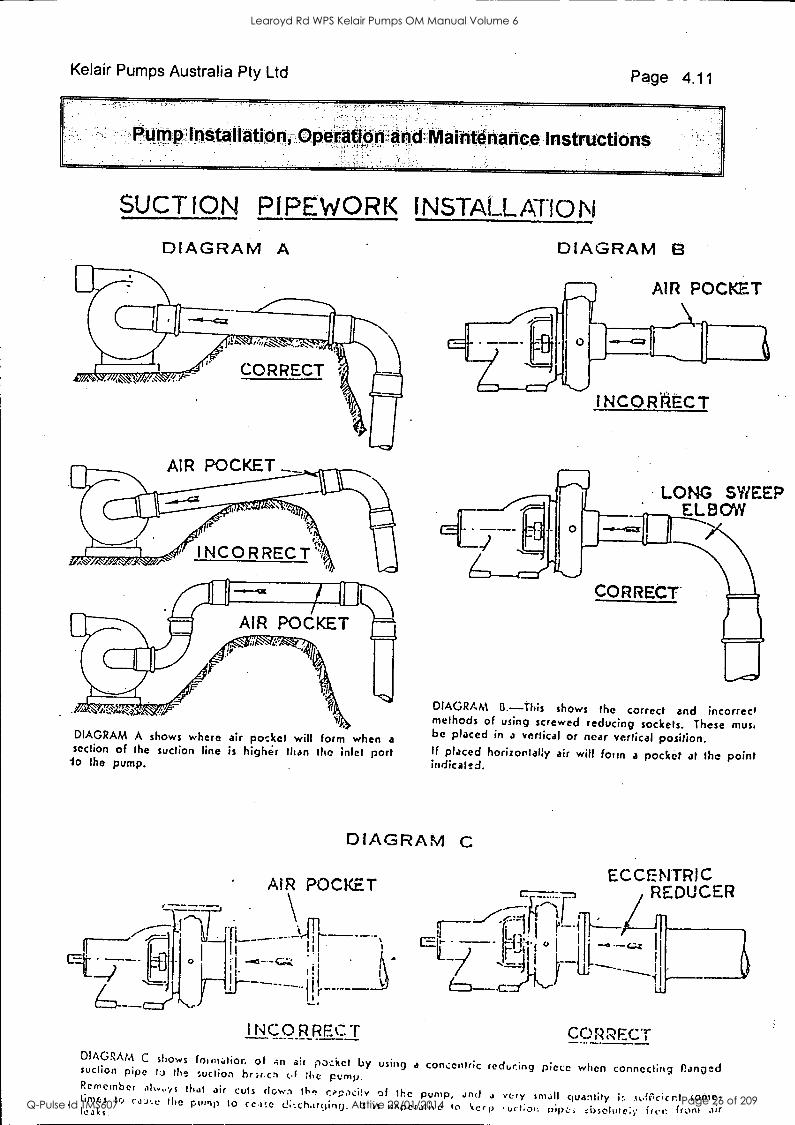
kept down to an absolute minimum. If elbows or bends are required they should be the long radius type. Figure A shows the preferred suction piping set-up and an incorrect set-up for a double suction pump.
Concentric reducers should not be used on a horizontal suction line. The use of this type of reducer will create an air or gas pocket which may cause trouble in the unit. The use of an eccentric reducer (Diagram "C") is recommended.
An isolating valve and check valve should be installed in the discharge line. The isolating valve is used in
priming and shutting down the unit. The check valve is used to prevent reverse flow through the pump in
the event of a power failure.
Learoyd Rd WPS Kelair Pumps OM Manual Volume 6
Q-Pulse Id TMS607 Active 29/01/2014 Page 25 of 209
Kelair Pumps Australia Pty Ltd Page 4.11
P-um nstailation peraticon Maintenance. Instructions
SUCTION PIPEWORK INSTALLATIONI
DIAGRAM A DIAGRAM B
AIR POCKET
AIR POCKET
Ac sy INCORRECT
AIR POCKET
DIAGRAM A shows where air pocket will form when a section of the suction line is highir than the inlet port io the pump.
I NCO RREC T
LONG SWEEP ELBOW
CORRECT
DIAGRAM B.-This shows the correct and incorrect methods of using screwed reducing sockets. These musi be placed in a vertical or near vertical position. If placed horizontaBy air will fowl a pocket at the point indicated.
DIAGRAM C
AIR POCKET
INCORRECT DIAGRAM C shows foimalior. of A n at inaszicet by using suction pipe I:) the suction br:a.crl (A the pump.
-.1
at - ,L11
ECCENTRIC REDUCER
CORRFC:T
a concentric reducing piece when connecting Banged Remember alwoys that air cuts clown the opacity of the pump, and a very small quantity is s(ilcict sonic- times tri cs..e the pump to ceate d;,charcjing. It is imperative 10 1/4er p urt;011 free from att. kaki.
Learoyd Rd WPS Kelair Pumps OM Manual Volume 6
Q-Pulse Id TMS607 Active 29/01/2014 Page 26 of 209
Kelair Pumps Australia Pty Ltd Page 4.12
All piping must be supported independent of the pump and free of tendencies to impose strains on the pump. Units pumping hot fluid must have expansion joints or loops in the piping to prevent strain on the pump nozzles due to expansion.
If an expansion joint is installed in the piping between the pump and the nearest point of anchor in the piping, it should be noted that a force equal to the area of the expansion joint times the pressure in the pipe will be transmitted to the pump proper. Some slip type couplings have the same effect. This force may exceed the allowable flange loading. If an expansion joint of slip type coupling must be used, it is recommended that either an anchor be installed between it and the pump or that the joint be restrained or otherwise designed so as to prevent this force from being transmitted to the pump.
Do not weld pipe lines while they are bolted to the pump. Inspect the piping and pump suction and discharge cavities for foreign matter or scale, and clean them thoroughly before pipe connections are made.
The pump flange and pipe flange faces must be parallel, and mate perfectly without force being required to align them. When this is accomplished set the gasket and bolt them together.
A temporary strainer should be installed as close as possible to the suction flange for filtering of the pumped liquid. This strainer should be used until the line has been completely flushed.
It is recommended that a differential pressure gauge be installed for observation of a pressure drop across the strainer. A considerable drop in the differential pressure indicates that the strainer is clogging, and that the unit should be shut down immediately and the strainer cleaned. An alternate method for detecting pressure loss is to install pressure gauges on either side of the strainer.
FINAL ALIGNMENT CHECK:
After all piping connections have been completed, the alignment should be checked to be sure that the piping has not altered the pump and driver alignment.
CONNECTING PUMP AND DRIVER:
Turn the pump shaft by hand to assure smooth unrestricted rotation. Clamp the driver coupling slip shroud tight and start the driver for an instant. Check the rotation of the driver against the rotation arrow on the pump.
Connect the coupling halves and where required insert the disc, grid-member, spacer or jackshaft. Refer to the coupling manufacturers' instructions regarding lubrication required.
Learoyd Rd WPS Kelair Pumps OM Manual Volume 6
Q-Pulse Id TMS607 Active 29/01/2014 Page 27 of 209
Kelair Pumps Australia Pty Ltd Page 4.13
p Installation t nance ns tlon , Jo
MECHANICAL SEAL:
Unless otherwise specified, mechanical seals are mounted in the punip at the factory, and no adjatenents to
the seal are necessary before placing the unit in service.
FINAL CHECK LIST:
Driver rotation agrees with the rotation arrow on the pump. Do no operate pump backwards at any time.
Coupling halves and spacer or jackshaft, if used, are tightly bolted together and lubricated.
Ensure the bearings are properly packed with grease. Refer to page 8.03 for grease details.
Necessary gauges, thermometers, thermo-switches and pressure switches are properly installed.
Cooling water and sealing oil (if any) are circulating properly. All pipe connections and plugs are tight.
Learoyd Rd WPS Kelair Pumps OM Manual Volume 6
Q-Pulse Id TMS607 Active 29/01/2014 Page 28 of 209
KelairPumps
PAGE 5.00
5: Start Up and Shut Down Procedures
CONTENTS : PAGE START-UP & SHUT-DOWN PROCEDURES Page 5.01-4 ADDITIONAL PROCEDURES & CHECKS Page 5.05
(See Also Section 4)
Learoyd Rd WPS Kelair Pumps OM Manual Volume 6
Q-Pulse Id TMS607 Active 29/01/2014 Page 29 of 209
Kelair Pumps Australia Pty Ltd
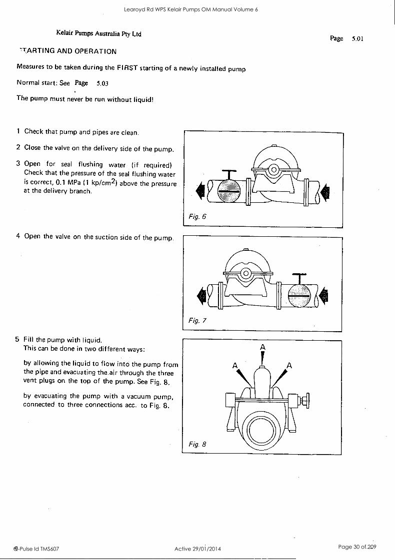
'TARTING AND OPERATION
Measures to be taken during the FIRST starting of a newly installed pump
Normal start: See Page 5.03
The pump must never be run without liquid!
1 Check that pump and pipes are clean.
2 Close the valve on the delivery side of the pump.
3 Open for seal flushing water (if required) Check that the pressure of the seal flushing water is correct, 0.1 MPa (1 kp /cm2) above the pressure at the delivery branch.
4 Open the valve on the suction side of the pump.
5 Fill the pump with liquid. This can be done in two different ways:
by allowing the liquid to flow into the pump from the pipe and evacuating the air through the three vent plugs on the top of the pump. See Fig. 8.
by evacuating the pump with a vacuum pump, connected to three connections acc. to Fig. 8.
a
Page 5.01
Learoyd Rd WPS Kelair Pumps OM Manual Volume 6
Q-Pulse Id TMS607 Active 29/01/2014 Page 30 of 209
Kelair Pumps Australia Pty Ltd Page 5.02
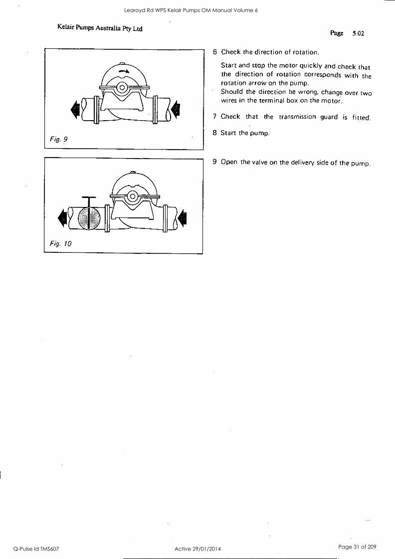
6 Check the direction of rotation.
Start and stop the motor quickly and check that the direction of rotation corresponds with the rotation arrow on the pump. Should the direction be wrong, change over two wires in the terminal box on the motor.
7 Check that the transmission guard is fitted.
8 Start the pump.
9 Open the valve on the delivery side of the pump.
Learoyd Rd WPS Kelair Pumps OM Manual Volume 6
Q-Pulse Id TMS607 Active 29/01/2014 Page 31 of 209
Kelair Pumps Australia Pty Ltd
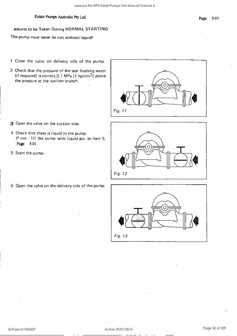
.tasures to be Taken During NORMAL STARTING
The pump must never be run without liquid!
1 Close the valve on delivery side of the pump.
2 Check that the pressure of the seal flushing water (if required) is correct,0.1 MPa (1 kp/cm2) above the pressure at the suction branch.
3 Open the valve on the suction side.
4 Check that there is liquid in the pump. If not - fill the pump with liquid acc. to Item 5,
Page 5.01
5 Start the pump.
6 Open the valve on the delivery side of the pump.
Page 5.03
Fig. 12
Learoyd Rd WPS Kelair Pumps OM Manual Volume 6
Q-Pulse Id TMS607 Active 29/01/2014 Page 32 of 209

Kelair Pumps Australia Pty Ltd Page 5.04
Measures to be Taken During Operation
The volumetric flow is regulated by means of a valve on the delivery side of the pump. During operation the valve on the suction side must be fully open Check the bearing temperature regularly. It should not exceed 100°C. Pumps with temperature guard - see separate in- structions.
Measures to be Taken When Stopping
Close the valve on the delivery side of the pump if there is any risk for return flow. NOTE that the seal flushing water should ALWAYS be on when the pump is under pressure, also when the pump has been stopped.
Learoyd Rd WPS Kelair Pumps OM Manual Volume 6
Q-Pulse Id TMS607 Active 29/01/2014 Page 33 of 209
Kelair Pumps Australia Pty Ltd Page 5.05
ADDITIONAL PROCEDURES & CHECKS
INSPECTION:
As soon as the pump is running check the following items: -
a. The cooling water and circulating system (if any) b. The suction and discharge gauges. They should correspond to the rated
conditions. c. Ball bearings. They should be operating-quietly. d. The pressure gauge used with the suction strainer. It should be watched
for any change in differential pressure.
ALIGNMENT CHECK:
The pump and driver alignment should be checked after the pump has been
running at the operating condition for a few hours.
Stop the pump and check the alignment as previously described. It is
recommended that the alignment be checked again after a few days of normal
operation.
FREEZING:
If the pump is exposed to freezing temperatures after it is shut down, drain all
water (or other liquid that will freeze) from the pump case, heat exchangers,
cooling jackets and piping.
Learoyd Rd WPS Kelair Pumps OM Manual Volume 6
Q-Pulse Id TMS607 Active 29/01/2014 Page 34 of 209

IL! KelairPumps
PAGE 6.00
6: Commissioning
CONTENTS : PAGE (Refer to Section 5)
Learoyd Rd WPS Kelair Pumps OM Manual Volume 6
Q-Pulse Id TMS607 Active 29/01/2014 Page 35 of 209

El KelairPumps
PAGE 7.00
7: Operations
CONTENTS : PAGE (Refer to Section 5)
Learoyd Rd WPS Kelair Pumps OM Manual Volume 6
Q-Pulse Id TMS607 Active 29/01/2014 Page 36 of 209
8: Maintenance
1[1 KelairPumps
PAGE 8.00
CONTENTS : PAGE SERVICE & MAINTENANCE SHEDULE 8.01 - 3 PUMP DISSASSEMBLY & REASSEMBLY 8.04 - 8 MECHANICAL SEAL INSTRUCTIONS 8.09 - 16 CASING FACE BOLT & GASKET DETAIL 8.17 - 20
Learoyd Rd WPS Kelair Pumps OM Manual Volume 6
Q-Pulse Id TMS607 Active 29/01/2014 Page 37 of 209

Kelair Pumps Australia Pty Ltd Page 8.01
ctions-
MAINTENANCE
PUMP:
Your pump must be properly maintained if it is to deliver its full value. A conscientious
maintenance program will assure high pump performance and minimise pump shutdowns.
RECOMMENDED MAINTENANCE SCHEDULE
DAILY:
Check the bearing temperature, and watch for vibration.
WEEKLY:
Carry out daily inspection.
See Page 8.03 for details on "Weekly Inspection"
QUARTERLY:
Check the alignment of the unit.
SEMI-ANNUALLY:
Re lap or replace the seal face on mechanical seals if excessive wear and leakage are apparent.
Check the bearings for wear and replace if necessary.
ANNUALLY:
See Page 8.03 for details on "Yearly Inspection"
Check the valves, gauges, etc., for condition and accuracy.
EVERY 4 YEARS:
See Page 8.03 for details on "Inspection Every Four Years"
Learoyd Rd WPS Kelair Pumps OM Manual Volume 6
Q-Pulse Id TMS607 Active 29/01/2014 Page 38 of 209
Kelair Pumps Australia Pty Ltd
lERVICE AND MAINTENANCE
Lubrication of the Pump
The pump bearings are filled with grease when the pump is delivered. The bearing temperature must be
checked carefully after the starting up of the pump. If there is too much grease in the bearings the temperature may increase to slightly above normal which is 70°C. This is normal if the temperature drops to the normal value after a short while.
Clean all lubricating points before lubrication.
Reduce the lubricating intervals BY HALF when the bearing temperatures are 70-85°C.
.educe the lubricating intervals TO ONE QUARTER when the bearing temperatures exceed 85°C.
Pumps in dusty, dirty or corrosive environments should also be lubricated at shorter intervals.
Table 2
Page 8.02
Pump size
Lubricating intervals in operating hours
Lubricating point A I
at different speeds in r/min Lubricating point B
Amount of grease in g
1800 1500 1000 750 1800 1500 1000 750 A B
250 20040 9000 12000 18000 9000 12000 18000 30 15
300 250.55 6000 8000 14000 6000 8000 14000 50 30 350 300 35 9000 12000 18000 9000 12000 18000 30 15
350 35045 7000 9000 15000 7000 9000 15000 50 30
350 300.60 5000 7000 12000 5000 7000 12000 80 40 350 300.61 5000 7000 12000 5000 7000 12000 80 40
400 300.55 5000 7000 12000 5000 7000 12000 80 40 400 300.60 5000 7000 12000 5000 7000 12000 BG 40 400 350 70 3000 5000 9000 3000 5000 9000 120 60 450 400.40 7000 9000 15000 20000 7000 9000 15000 20000 50 30
500 400.50 12000 17000 12000 17000 80 40 500 400 55 7000 12000 17000 7000 12000 17000 80 40 500 400.60 4000 6000 11000 4000 6000 11000 100 50
500 400.70 3000 5000 9000 3000 5000 9000 120 60
.5,00 500.70 6000 11000 15000 6000 11000 15000 100 50
500 300 75 I 3000 5000 9000 3000 5000 9000 110 40
500 400.80 3000 5000 9000 2000 3!00 8000 110 50
600 500.60 ' 6000 11000 15000 6000 11000 15000 100 50
600 GOO 65 3500 8000 12000 3500 6000 12000 50 50
GOO 600 75 9000 14000 9000 14000 110 50
GOO 400 85 4500 9000 3500 8000 110 70
GOO 400.90 4500 9000 2500 7000 120 100
700 100.64 4500 9000 14000 4500 9000 14000 120 60
700. 700.65 4500 9000 14000 4500 9000 14000 120 60
700,600 75 9000 14000 8000 12000 110 50
700.500 95 9000 14000 6000 9000 120 110
800;800.75 8000 12000 8000 12000 150 70
800:500 105 7000 10000 5000 8000 200 80
800. 700 105 7000 10000 1000 10000 200 100
800:500 120 I 7000 10000 -1000 7000 200 130
900/600 140 4000 7000 ?000 5000 260 110
1000 1000 90 1 1100 4000 130 60
Learoyd Rd WPS Kelair Pumps OM Manual Volume 6
Q-Pulse Id TMS607 Active 29/01/2014 Page 39 of 209
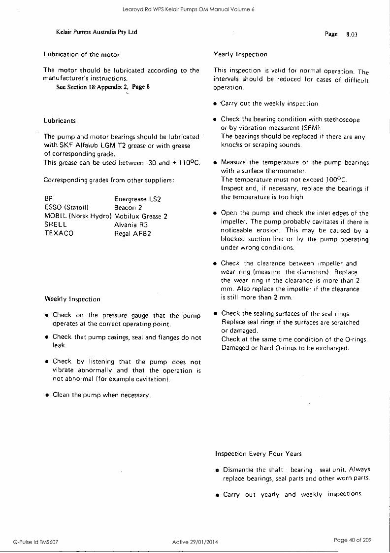
Kelair Pumps Australia Pty Ltd Page 8.03
Lubrication of the motor
The motor should be lubricated according to the manufacturer's instructions.
See Section 18:Appendix 2, Page 8
Lubricants
The pump and motor bearings should be lubricated with SKF Alfa lub LGM T2 grease or with grease of corresponding grade.
This grease can be used between -30 and + 1100C.
Corresponding grades from other suppliers:
BP Energrease LS2 ESSO (Statoil) Beacon 2
MOBIL (Norsk Hydro) Mobilux Grease 2
SHELL Alvania R3 TEXACO Regal AFB2
Weekly Inspection
Check on the pressure gauge that the pump operates at the correct operating point.
Check that pump casings, seal and flanges do not leak.
Check by listening that the pump does not vibrate abnormally and that the operation is
not abnormal (for example cavitation).
Clean the pump when necessary.
Yearly Inspection
This inspection is valid for normal operation. The intervals should be reduced for cases of difficult operation.
.Carry out the weekly inspection.
Check the bearing condition with stethoscope or by vibration measurent (SPM). The bearings should be replaced if there are any knocks or scraping sounds.
Measure the temperature of the pump bearings with a surface thermometer. The temperature must not exceed 100°C. Inspect and, if necessary, replace the bearings if the temperature is too high.
Open the pump and check the inlet edges of the impeller. The pump probably cavitates if there is
noticeable erosion. This may be caused by a
blocked suction line or by the pump operating under wrong conditions.
Check the clearance between impeller and wear ring (measure the diameters). Replace the wear ring if the clearance is more than 2
mm. Also replace the impeller if the clearance is still more than 2 mm.
Check the sealing surfaces of the seal rings. Replace seal rings if the surfaces are scratched or damaged. Check at the same time condition of the 0-rings. Damaged or hard 0-rings to be exchanged.
Inspection Every Four Years
Dismantle the shaft - bearing seal unit. Always replace bearings, seal parts and other worn parts.
Carry out yearly and weekly inspections.
Learoyd Rd WPS Kelair Pumps OM Manual Volume 6
Q-Pulse Id TMS607 Active 29/01/2014 Page 40 of 209
Kelair Pumps Australia Pty Ltd
-Scanpump
Page 8.04
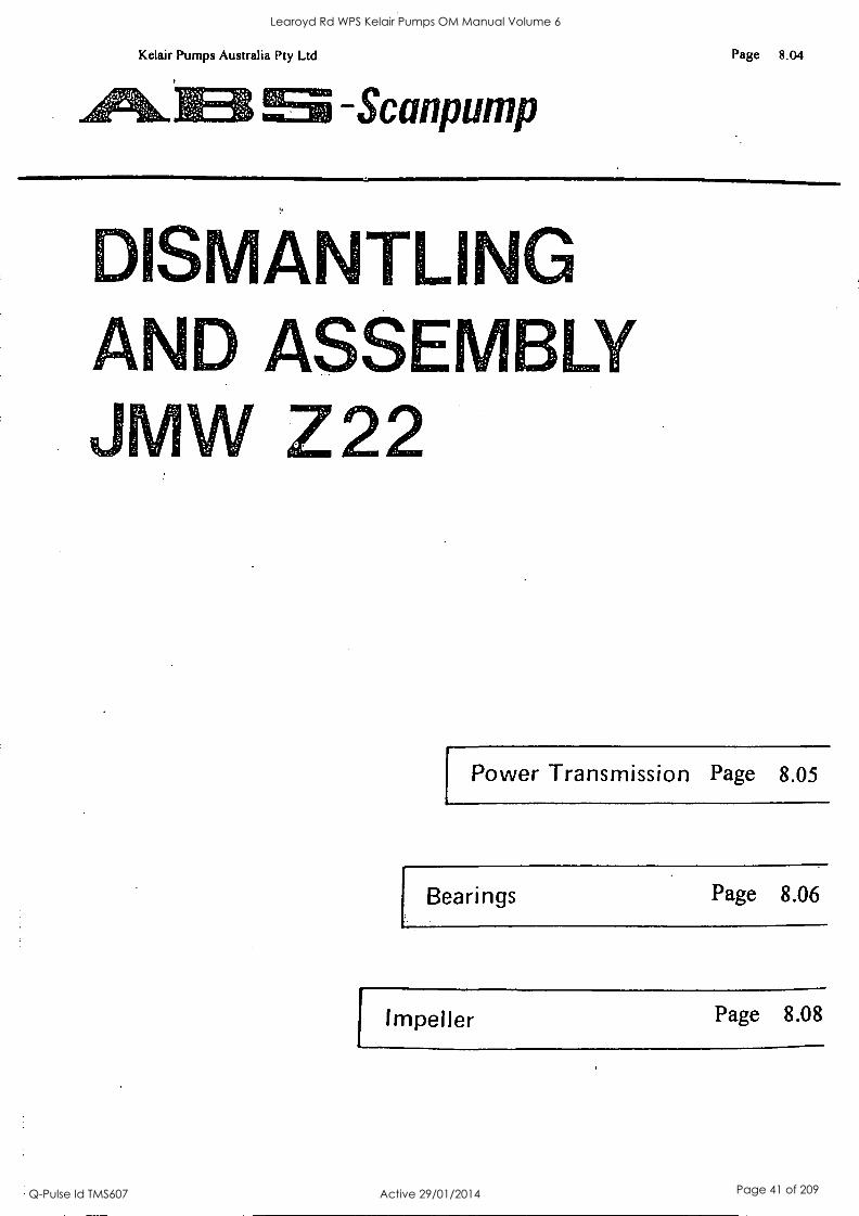
ISMANTLING AND ASSEMBLY JMW Z22
Power Transmission Page 8.05
Bearings Page 8.06
Impeller Page 8.08
Learoyd Rd WPS Kelair Pumps OM Manual Volume 6
Q-Pulse Id TMS607 Active 29/01/2014 Page 41 of 209
Kelair Pumps Australia Pty Ltd
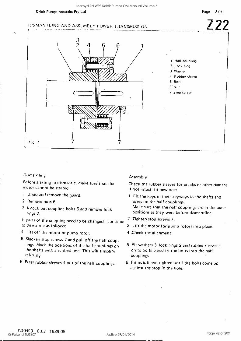
DISMANTLING AND ASSLMI3LY POWER TRANSMISSION
Fig 1
3 2 4
7
ev..11.
hi NI s'a .4011 11111
vim rasd ,, 7
1 Half coupling 2 Lock ring 3 Washer
4 Rubber sleeve
5 Bolt
6 Nut 7 Stop screw
Page 8.05
Z22
Dismantling
Before starting to dismantle, make sure that the motor cannot be started. 1 Undo and remove the guard.
2 Remove nuts 6.
3 Knock out coupling bolts 5 and remove lock rings 2.
If parts of the coupling need to be changed - continue to dismantle as follows: 4 Lift off the motor or pump rotor. 5 Slacken stop screws 7 and pull off the half coup-
lings. Mark the positions of the half couplings on the shafts with a scribed line. This will simplify refitting.
6 Press rubber sleeves 4 out of the half couplings.
PD0493 EcI.2 198905
Assembly
Check the rubber sleeves for cracks or other damage If not intact, fit new ones.
1 Fit the keys in their keyways in the shafts and press on the half couplings. Make sure that the half couplings are in the same positions as they were before dismantling.
2 Tighten stop screws 7.
3 Lift the motor (or pump rotor) into place.
4 .Check the alignment
5 Fit washers 3, lock rings 2 and rubber sleeves 4
on to bolts 5 and fit the bolts into the half couplings.
6 Fit nuts 6 and tighten until the bolts come up against the stop in the hole.
Learoyd Rd WPS Kelair Pumps OM Manual Volume 6
Q-Pulse Id TMS607 Active 29/01/2014 Page 42 of 209
Kelair Pumps Australia Pty Ltd
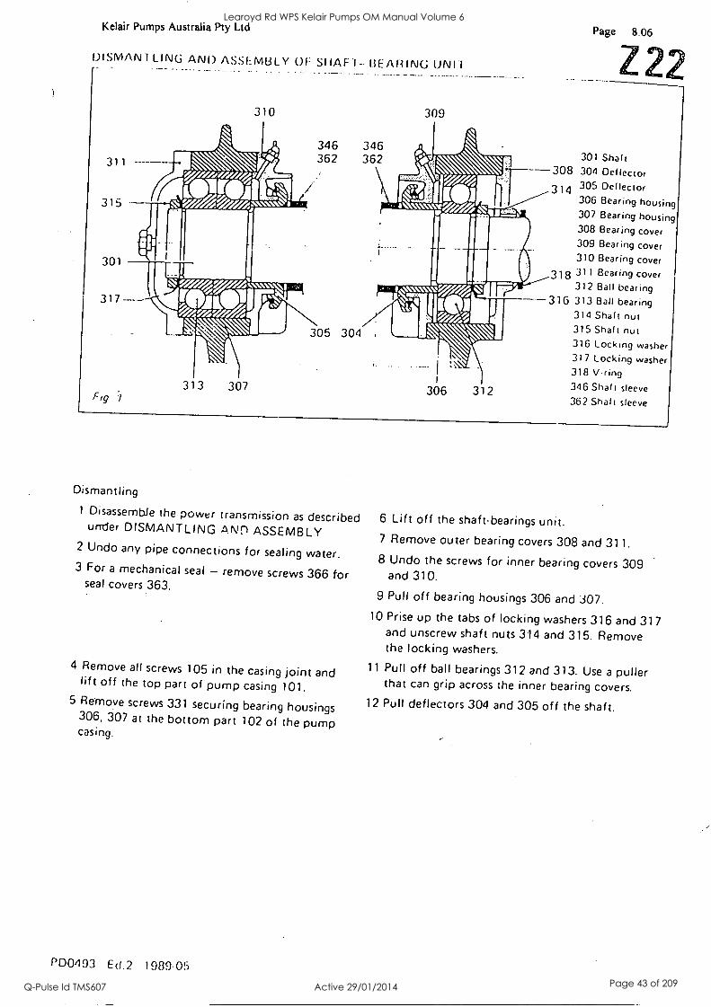
DISMAN1 LING AND ASSEMBLY Of: SHAF.1-- BEARING ()NH
311 -
315
301
317
Fig 1
310
dew, si SSV 4
07/ 4.61.v..:, e J A re/. ;lir
313 307
346 346 362 362
305 304
309
306 312
Page 8.06
301 Shaft 308 304 Deflector 314 305 Deflector
306 Bearing housing 307 Bearing housing 308 Bearing cover 309 Bear ing cover 310 Bearing cover
318 311 Bearing cover 312 Ball bearing
316 313 Ball bearing 314 Shaft nut 315 Shaft nut 316 Locking washer 317 Locking washer 318 Vring 346 Shalt sleeve
362 Shalt sleeve
Dismantling
1 Disassemble the power transmission as described under DISMANTLING ANn ASSEMBLY
2 Undo any pipe connections for sealing water. 3 For a mechanical seal - remove screws 366 for
seal covers 363.
4 Remove all screws 105 in the casing joint and lift off the top part of pump casing 101. 5 Remove screws 331 securing bearing housings
306, 307 at the bottom part 102 of the pump casing.
PD01193 Ed .2 1989 05
6 Lift off the shaft-bearings unit. 7 Remove outer bearing covers 308 and 311. 8 Undo the screws for inner bearing covers 309
and 310.
9 Pull off bearing housings 306 and 307. 10 Prise up the tabs of locking washers 316 and 317
and unscrew shaft nuts 314 and 315. Remove the locking washers.
11 Pull off ball bearings 312 and 313. Use a puller that can grip across the inner bearing covers.
12 Pull deflectors 304 and 305 off the shaft.
Learoyd Rd WPS Kelair Pumps OM Manual Volume 6
Q-Pulse Id TMS607 Active 29/01/2014 Page 43 of 209
Kelair Pumps Australia Pty Ltd Page 8.07
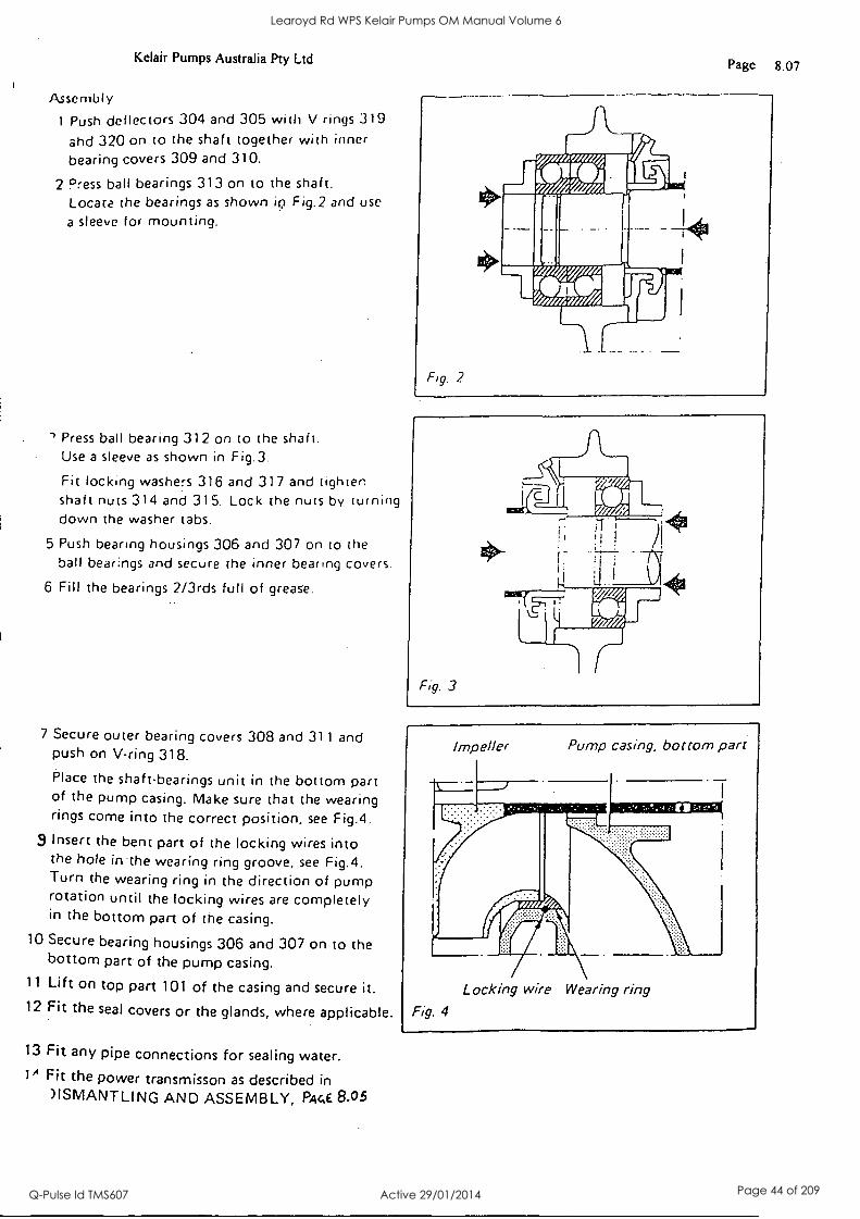
Assembly
1 Push deflectors 304 and 305 with V rings 319
and 320 on to the shaft together with inner
bearing covers 309 and 310.
2 Press ball bearings 313 on to the shaft. Locate the bearings as shown iQ Fig.2 and use
a sleeve for mounting.
Press ball bearing 312 on to the shaft. Use a sleeve as shown in Fig.3.
Fit locking washers 316 and 317 and tighten shaft nuts 314 and 315. Lock the nuts by turning down the washer tabs.
5 Push bearing housings 306 and 307 on to the ball bearings and secure the inner bearing covers.
6 Fill the bearings 2/3rds full of grease.
7 Secure outer bearing covers 308 and 311 and push on V-ring 318.
Place the shaftbearings unit in the bottom part of the pump casing. Make sure that the wearing rings come into the correct position, see Fig.4.
3 Insert the bent part of the locking wires into the hole in 'the wearing ring groove, see Fig.4. Turn the wearing ring in the direction of pump rotation until the locking wires are completely in the bottom part of the casing.
10 Secure bearing housings 306 and 307 on to the bottom part of the pump casing.
11 Lift on top part 101 of the casing and secure it. 12 Fit the seal covers or the glands, where applicable.
13 Fit any pipe connections for sealing water. 1A Fit the power transmisson as described in
)ISMANTLING AND ASSEMBLY, PA4E 8.05
F1g. 2
Learoyd Rd WPS Kelair Pumps OM Manual Volume 6
Q-Pulse Id TMS607 Active 29/01/2014 Page 44 of 209
Kelair Pumps Australia Pty Ltd
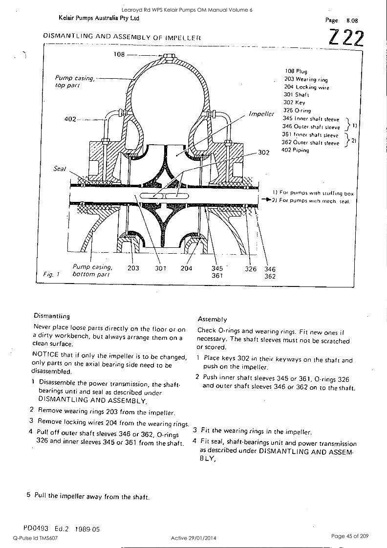
DISMANTLING AND ASSEMBLY OF IMPELLER
Pump casing, top part
--------,-
Page 8.08
Z22 108 Plug
203 Wearing ring 204 Locking wire 301 Shaf t
302 Key
326 0ring 345 Inner shaft sleeve
346 Outer shaft sleeve 361 Inner shaft sleeve 362 Outer shalt sleeve 402 Piping
1) For pumps with stuffing box -' -2) For pumps with mech. seal.
Fig. 1
Pump casing, bottom part
203 301 204 345 361
Dismantling
Never place loose parts directly on the floor or on a dirty workbench, but always arrange them on a clean surface.
NOTICE that if only the impeller is to be changed, only parts on the axial bearing side need to be disassembled.
1 Disassemble the power transmission, the shaft- bearings unti and seal as described under DISMANTLING AND ASSEMBLY,
2 Remove wearing rings 203 from the impeller. 3 Remove locking wires 204 from the wearing rings 4 Pull off outer shaft sleeves 346 or 362, 0-rings
326 and inner sleeves 345 or 361 from the shaft.
5 Pull the impeller away from the shaft.
PD0493 Ed.2 1989 05
Assembly
Check 0-rings and wearing rings. Fit new ones if necessary. The shaft sleeves must not be scratched or scored.
1 Place keys 302 in their keyways on the shaft and push on the impeller.
2 Push inner shaft sleeves 345 or 361, 0-rings 326 and outer shaft sleeves 346 or 362 on to the shaft.
3 Fit the wearing rings in the impeller. 4 Fit seal, shaft-bearings unit and power transmission
as described under DISMANTLING AND ASSEM- BLY,
Learoyd Rd WPS Kelair Pumps OM Manual Volume 6
Q-Pulse Id TMS607 Active 29/01/2014 Page 45 of 209
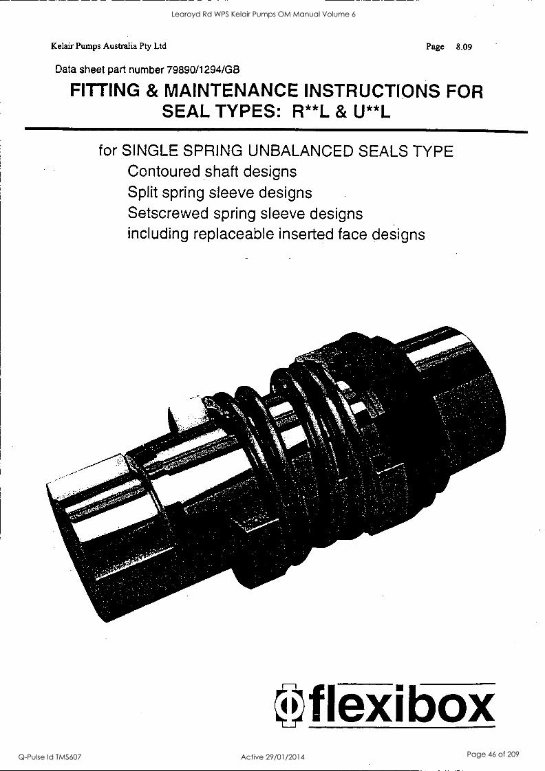
Kelair Pumps Australia Pty Ltd Page 8.09
Data sheet part number 79890/1294/GB
FITTING & MAINTENANCE INSTRUCTIONS FOR SEAL TYPES: R**L & U**L
for SINGLE SPRING UNBALANCED SEALS TYPE Contoured shaft designs Split spring sleeve designs Setscrewed spring sleeve designs including replaceable inserted face designs
Iflexi box
Learoyd Rd WPS Kelair Pumps OM Manual Volume 6
Q-Pulse Id TMS607 Active 29/01/2014 Page 46 of 209

Kelair Pumps Australia Pty Ltd Page 8.10
This instruction covers the installation, operation and maintenance of unbalanced mechanical seals of the spring- driven type (including those with circulation and quench connections).
UNPACKING AND STORAGE OF THE SEAL The seal should be unpacked carefully and examined for signs of transit damage.
If the seal is not to be used immediately it
should be repackaged as appropriate and stored in good conditions. It should be noted that gaskets and '0' rings may
deteriorate if stored for long periods, particularly if subjected to extremes of temperature and humidity.
Documentation supplied with the seal should be kept for future reference.
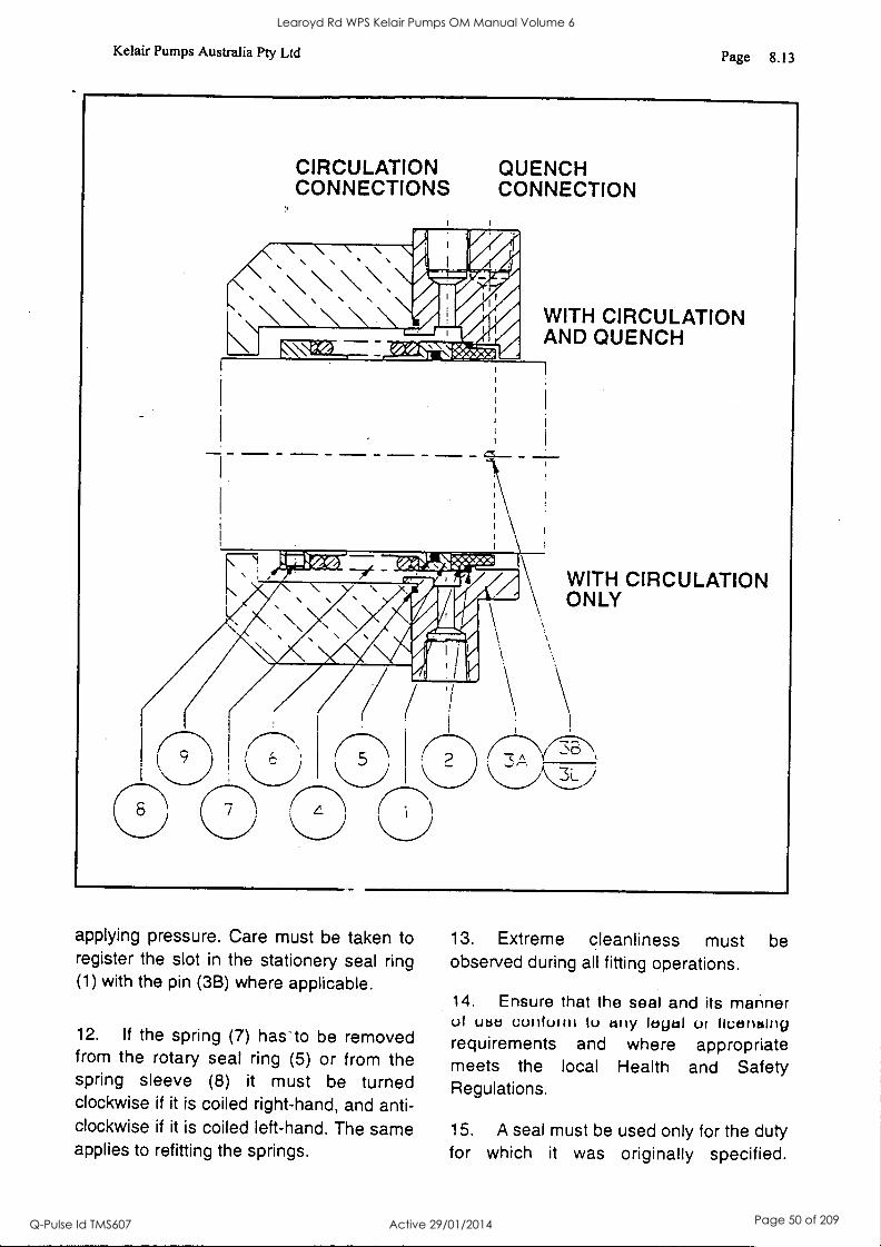
DESCRIPTION
Referring to the drawing, it will be seen that seals with circulation connections and seals with circulation and quench connections differ only in the design of the seal plate (3).
Sealing action is obtained by arranging for intimate contact between a stationary and
a rotating seal ring. The faces of these seal rings are lapped to optical standards of flatness thereby effectively preventing leakage from the gland.
Each seal consists of two sub-assemblies -
the stationary assembly of parts (1) to (4), and the rotary assembly of parts (5) to (9).
Stationary Assembly: The stationary seal ring (1), resiliently supported by the stationary seal ring packing (2), is held in the seal plate (3), which is bolted to the face of the stuffing box. Under certain conditions a pin (3B) is provided to prevent rotation of the
stationary seal ring (1) in the seal plate (3). In all other cases the friction of the stationary seal ring packing (2) suffices. The seal plate gasket (4) is made in the form of an 0-ring, or of a flat washer.
Rotary Assembly:
The rotary seal ring (5) is positively, yet resiliently, driven from the spring sleeve (8) by means of the spring (7). For this
purpose the spring is coiled right-hand or left -hand according to the direction of shaft rotation and has specially designed ends
Learoyd Rd WPS Kelair Pumps OM Manual Volume 6
Q-Pulse Id TMS607 Active 29/01/2014 Page 47 of 209
Kelair Pumps Australia Pty Ltd
which are an interference fit on the necks of the rotary seal ring (5) and of the spring sleeve (8) respectively. The latter is fastened to the shaft by means of one or two set screws (9). In certain seal installations, the design of the spring sleeve may vary slightly from that shown in the accompanying diagram, or may even be replaced by a profile, machined directly onto the pump shaft.
Apart from driving the rotary seal ring (5) the spring (7) also furnishes the initial pressure between the two seal faces. A rotary seal ring packing (6) is located inside the rotary seal ring (5) to prevent any leakage at this point.
Materials for all parts are chosen in accordance with the working conditions under which each individual seal has to operate. The stationary seal ring (1) is usually made from specially developed grades of compounded carbon, which are self-lubricating and extremely hard wearing.
The static seals (2), (4) and (6) are made from synthetic rubbers or other resilient materials, and the remaining components from the most suitable ferrous and non- ferrous metals, including selected grades of stainless steel. The spring (7), made from heavy gauge wire, does not suffer from the disadvantages associated with
Page 8.11
small springs confined in narrow cavities.
All Flexibox Mechanical Seals are designed to cope efficiently with a certain degree of shaft misalignment, eccentricity, whip, thermal expansion and end float. The spring (7) is of large diameter and correspondingly low rate, thus allowing for considerable deviations from the specified working length without upsetting the designed pressure conditions between the seal faces. The resilient stationary and rotary seal ring packings (2) and (6) provide a further degree of self-alignment.
Flexibox Mechanical Seals with Circulation Connections are arranged for the forced flow of some of the pumped liquid around the stationary and rotary seal rings, in order to remove frictional heat at its place of generation, and to prevent the accumulation of harmful sediments and/or polymers around the seal. Reference to the diagram will show that this feature has been provided by arranging an annular chamber in the seal plate (3), surrounding the seal rings (1) and (5), through which the liquid is led from a point of higher pressure in the pump to a point of lower pressure. The Quench Connection is normally used to direct steam, water or methanol to the atmosphere side of the seal, thus preventing carbonization, crystallization, icing, etc.
FITTING, OPERATING AND MAINTENANCE Pumps vary so much in type and design that it is impracticable to provide detailed fitting instructions for each individual application. Reference to the maker's sectional drawing of the pump and to the particular Flexibox drawing illustrating the seal being fitted will make it quite clear how to proceed. The following points do, however, require special attention.
1. The shaft must run true, free from vibration and have no perceptible end play. If the shaft is fitted with a sleeve this must be truly concentric, and suitable arrange- ments must be made to prevent leakage between the shaft, and the sleeve.
2. The shaft or shaft sleeve must have a tolerance of +0.00/-0.05mm (0.002 inch) on the nominal dimension, and a surface
Learoyd Rd WPS Kelair Pumps OM Manual Volume 6
Q-Pulse Id TMS607 Active 29/01/2014 Page 48 of 209
Kelair Pumps Australia Pty Ltd
finish better than 0.8 micrometers (32 micro inches) CLA, in the region of the rotary seal ring packing (6). Shaft or shaft sleeve material must be such as to prevent any surface deterioration by corrosive attack either inside or outgide the seal.
3. Any shoulder over which the rotary seal ring packing (6) passes, during the fitting operation must be chamfered 15' x 3mm or longer. Particular care must be taken not to damage the rotary seal ring packing (6) by splines, keyways, spanner holes etc.
4. The face of the stuffing box must be machined flat and at right angles to the shaft.
5. It is very important to make sure that a seal with the correct hand of spring is fitted. Looking at the face of the rotary seal ring, clockwise shaft rotation requires a right-hand spring, and anti-clockwise rotation, a left-hand spring.
6. Only a trace of lubricant should be applied to the shaft or shaft sleeve surface when fitting the rotary assembly of the seal. No lubricant should be applied to the two seal faces, which must be protected from damage prior to and during fitting.
WARNING: Ethylene propylene is not compatible with mineral oils and silicon rubbers are not compatible with silicon oils.
7. The spring sleeve (8) must be fastened to the shaft or shaft sleeve, in accordance with the dimensional in- formation supplied on the Flexibox drawing Illustrating the Reel heing fitted. If sot screws (9) are used, they must be tightened hard to prevent displacement of the spring sleeve (8) in operation.
8. In the majority of seal installations, circulation is provided by connecting one of the tapped holes in the seal plate (3) to
Page 8.12
the pump discharge branch, and allowing the pumped product to circulate in through the stuffing box and back into the pump. Nothing else is needed if the generated head of the pump does not exceed 1.5 bar gauge (22 p.s.i.g.). For higher heads it is necessary to install a Flexibox Flow Controller.
If installed, the flow controller should be fully open and remain so for a few hours. It
can then be adjusted to pass the minimum flow necessary to keep the seal plate (3) at substantially the same temperature as the rest of the pump.
9. When dealing with new installations, or when pumping liquids containing foreign matter, it is advisable to provide a suitable strainer on the line leading to the seal so as to protect it (and the flow controller) from damage. Care must, however, be taken to inspect and clean the strainer frequently in order to maintain circulation.
10. It is advisable to keep spares for parts (1), (2), (4), (5) and (6) in stock. When re-ordering, please quote the part numbers from the Flexibox drawing illustrating the seal in question. Components (2), (4) and (6) should never be used more than once.
11. When replacing the stationary seal ring (1) in the seal plate (3), the stationary seal ring packing (2) must first be placed around the neck of the stationary seal ring (1) and pushed home against its shoulder.
Care must be taken not to twist the stationary seal ring packing (2). In most cases, it will be found quite easy to fit the stationery noel ring (1) Into the recess of the seal plate (3), particularly It a trace of lubricant has been applied. If a press is used to perform this operation, the rotary seal ring (5) should be placed in contact with the stationary seal ring (1), and the neck of the rotary seal ring (5) protected with a block of wood or fibre before
Learoyd Rd WPS Kelair Pumps OM Manual Volume 6
Q-Pulse Id TMS607 Active 29/01/2014 Page 49 of 209
Kelair Pumps Australia Pty Ltd Page 8.13
CIRCULATION QUENCH CONNECTIONS CONNECTION
WITH CIRCULATION AND QUENCH
!PRICIR, -FRO.603:2NSIMI WITH CIRCULATION
\ ONLY
9 ) t:Si,)
applying pressure. Care must be taken to register the slot in the stationery seal ring (1) with the pin (3B) where applicable.
12. If the spring (7) has' to be removed from the rotary seal ring (5) or from the spring sleeve (8) it must be turned clockwise if it is coiled right-hand, and anti- clockwise if it is coiled left-hand. The same applies to refitting the springs.
13. Extreme cleanliness must be observed during all fitting operations.
14. Ensure that the seal and its manner Ut Utiti CO11101111 to tiny legal or licensing requirements and where appropriate meets the local Health and Safety Regulations.
15. A seal must be used only for the duty for which it was originally specified.
Learoyd Rd WPS Kelair Pumps OM Manual Volume 6
Q-Pulse Id TMS607 Active 29/01/2014 Page 50 of 209
Kelair Pumps Australia Pty Ltd
Although a seal may be correctly specified at time of order, the conditions of operation can sometimes be changed before the seal is put into use. Please check the duty conditions against the appropriate Flexibox General arrangement drawing and ensure that the operating condition's are within the recommendations.
IMPORTANT: If the conditions of operation are changed without approval from Flexibox then we would decline responsibility for any consequent damage and the user would assume all risks.
16. If, after a prolonged period of satisfactory operation, a seal develops a gradually increasing leak, it should be changed as soon as possible. The seal performance does not normally improve by further use.
17. Ensure that the materials of construction are appropriate to the application and particularly that the secondary packings are compatible with the pumped fluid. These packing materials will normally be Nitrile rubber or Fluoroelastomer or Ethylene Propylene dependent on your order. In certain cases, the materials of construction of the seal might be unsuitable for carrying out a performance test using water at the pumpmaker's works. Please contact FLEXIBOX in case of doubt.
18. Quench connections should be made in accordance with individual requirements.
Notes on Hazardous Products
ATTENTION: If the seal is to be fitted to equipment which handles a hazardous product then special care must be taken when fitting,
Page 8.14
operating and maintaining the seal;
Appropriate protective clothing should be worn.
If there is any danger of fire then you should be aware of the location of the fire alarms and fire extinguishers.
Mechanical seals operating normally will have a small amount of leakage across the seal faces. To cater for this leakage or for the failure of the
provision should be made to guide the leakage away to a safe location. However if such provision is made, do not modify the seal in any way without consulting Flexibox.
If replacement parts are fitted then the replaced items must be disposed of with due regard to their possible hazardous nature.
Operation
BEFORE STARTING THE EQUIPMENT ENSURE THAT ALL NECESSARY SAFETY PROCEDURES ARE BEING OBSERVED.
Ensure that the product fluid is present at the seal faces before start-up.
Mechanical seals should not run dry even for short periods, as this is liable to damage the seal faces.
Correct functioning of the circulation system is essential for efficient seal performance and the safety of the installation.
Ensure that the seal is properly maintained and that the correct flow rate is achieved.
Excessive vibration is detrimental to
Learoyd Rd WPS Kelair Pumps OM Manual Volume 6
Q-Pulse Id TMS607 Active 29/01/2014 Page 51 of 209
Kelair Pumps Australia Pty Ltd
seal operation and care should be taken to obtain smooth running conditions.
Periodically inspect fasteners for tightness.
Periodically inspect for signs of leakage.
If restarting after a prolonged shut down it is recommended that the equipment is flushed with clean liquid.
NOTE: A properly selected Mechanical seal will normally run for long periods without attention and it should not be disturbed unnecessarily. However, if leakage does occur it should be attended to as soon as possible before the leakage becomes a hazard.
Inspection and Maintenance
DANGER: Maintenance work must only be carried out when the equipment is stationary and the pumped fluids are at atmospheric pressure and temperature and when the pump has been made safe.
Maintenance work must only be carried out by suitably qualified personnel. Flexibox can provide training where appropriate.
Flexibox seals are designed for a long but finite life and so some wear will eventually occur. It will usually be beneficial to inspect the seal on a routine basis and rectify worn parts as necessary rather than wait for a breakdown to happen.
If excessive leakage does occur there may be underlying factors (such as a change in duty conditions, wear in the pump bearings or excessive vibration) which have caused
Page 8.15
the seal to leak and these should be looked for when the equipment is inspected.
ATTENTION: If items require re-conditioning by Flexibox they should be decontaminated and then returned to us with a document confirming the decontamination.
NOTE: WHEN CARRYING OUT MAINTENANCE WORK ONLY FLEXIBOX APPROVED SPARES SHOULD BE USED.
Genuine Flexibox spares may be obtained from Flexibox companies and Agents. To obtain the correct parts quote the Flexibox seal reference or consult the Bill of Materials on the General Arrangement drawing when one has been supplied.
It is highly recommended that the complete Mechanical seals are returned to Flexiservice for refurbishment.
WARNING: All reasonable care has been taken in the design and manufacture of this seal to ensure that it will be safe when properly used. However these instructions are general and it is assumed the user is aware of the requirements of his plant and the fluid to be sealed.
Flexibox will provide advice on the use of their seal but the following matters are the sole responsibility of the user:
Compliance with statutory plant requirements.
Compliance with other safety requirements.
Final choice of a seal for a particular duty.
Learoyd Rd WPS Kelair Pumps OM Manual Volume 6
Q-Pulse Id TMS607 Active 29/01/2014 Page 52 of 209
Kelair Pumps Australia Pty Ltd
Notes on these Instructions These instructions should be available to everybody who has need of them at the place where the seal is used.
In accordance with the European agree- ments certain words or symbols have particular meanings, when used within these instructions or when applied to actual seal parts. They are used as follows:
Page 8.16
`IMPORTANT' - is used for items of particular concern when using the seal.
`ATTENTION' - where there is an obligation or prohibition concerning the avoidance of risk.
`DANGER' (or '1' printed in a triangle) - where there is an obligation or prohibition concerning harm to people or damage to the equipment.
aflexibox Mechanical Seals Flexibox mechanical seals are designed to prevent leakage of virtually any kind of fluid from between a rotating shaft and its housing, even under extreme pressure, high speed or high temperature. The quality of Flexibox design, engineering and materials ensures. sealing integrity, which in turn produces real savings in terms of plant efficiency, low maintenance costs and minimum downtime. The comprehensive ranges available cover a wide variety of applications and sizes.
UNBALANCED SEALS for pressures up to 10.5 bar. Standard seals for general duties Seals to DIN 24960, ISO 3069 and BS 5257 etc Split Seals for easy refurbishing.
BALANCED SEALS for pressures up to 70 bar. Standard process pump seals
Advanced single spring design Seals to DIN 24960, ISO 3069 and BS 5257 etc Seals to API 610 and API 682 Seals to light hydrocarbons High temperature seals High viscosity, abrasive duty seals General purpose cartridge seals
SEALS FOR SPECIAL APPLICATIONS High duty seals for very high pressures (100 bar) and speeds (50,000 rpm) PTFE bellows seals for aggressive corrosives High temperature and general purpose metal bellows seals Standby seals for back-up security and zero emissions High integrity double seals
azzazons Flexible Couplings Metastream flexible power transmission couplings absorb static and dynamic misalignments which inevitably occur between nominally in-line shafts. The Metastream coupling is renowned for its ability to accept misalignment without vibration, or transmission of high loads to the associated machinery.
The all-metal construction of the coupling avoids the need for lubrication or extensive maintenance. High torsional rigidity and good inherent balance make the couplings ideal for high speed applications. All Metastream couplings incorporate spacer retention anti- fly features.
M SERIES UNIQUE SPOKE FORM MEMBRANE COUPLING TO API 610 The ultimate in safety and reliability for critical process
pump applications. Ratings from 2W to 10,000W per rev/min.
MHS high power weight ratio spacer coupling for medium to high power and speed drives.
T SERIES RING FORM MEMBRANE COUPLINGS Ratings from 2W to 50,000W per rev/min.
Economy ranges for low and medium speed applications High performance space couplings for turbines, alternators, centrifugal compressors etc. High torque ranges for marine main drives, large offshore oil pumps and boiler feed pumps, generators, etc. Standardised couplings to DIN 740, API 610, API 671 etc.
FLEXIBOX LIMITED, Nash Road, Trafford Park, Manchester, M17 1SS Tel: 0161 872 2484 Fax: 0161 872 1654
Learoyd Rd WPS Kelair Pumps OM Manual Volume 6
Q-Pulse Id TMS607 Active 29/01/2014 Page 53 of 209
i
11.49 L
LO
Ind 0141
1xt9 ON
IP] Ilaii xi) 6/34 1.01 Jamal
.
1
009E£1,
'Cu
Waal O
L-005/005-Z
ZZ
1114 viggesuP9 ati 9144
I
pea .amai punam
01 7 UO
3 Jaj
Learoyd Rd WPS Kelair Pumps OM Manual Volume 6
Q-Pulse Id TMS607 Active 29/01/2014 Page 54 of 209
Kelair Pumps Australia Pty Ltd Page 8.18
22!1ifl1lU for dr1flin it no. AY
440,355 -190,380 445,40 -310,410 360,400 410.-372 445,425 460,470 .460.-215 460;157 -470;100 495,47 .508.0
-140,355 490,380 -245.397 -310,610 48000 -410,312 445,325 480,270 -400,215 .460,157 -470,100 495.47 1,do,ssa 187,375 245.381 Z88,382 " 338,325 365,280 mins 808,196 465,189 517,189 570,172 613,147 154,102 680,60 639.0
140,-355 187,475 246,401 298..362 338,-325 366480 378,435 468,198 4178.489 617,-189 670,-172 813.147 838r102 880,40
483,128 Dbeseernbie bac upper pact 645,-135 Disassemble bett upper part
-465,242.5 Cortical pin 667,48 Conical pin
The width of the Sealing face is approximately 32mm. Gaskets consist of a sealing band, PTFE 5x2mm; and a gasket,Klinger SIL C-4400, 0.5mm thick.
Learoyd Rd WPS Kelair Pumps OM Manual Volume 6
Q-Pulse Id TMS607 Active 29/01/2014 Page 55 of 209
Kaiak Pumps Australia Pty Ltd
Scanpump GERGMOSAMSER Typ Eelicoil VI-gangor
STANDARD
Page 8.19
trig=12-lo
thonamisatao t Medbelap arta pp
snonteratte Ott
YtjEmnhet: Ra < 0,3 pm
d2 = kiirndiameter 12 = ganginsatsens anvandbara lamgd ti = borrdjulo fOr mellancAngtapp t2 fullskuren (anvandbar) Ongraingd t3 = skruvans inskrumingadjup med
medbringartappen kvar
Benffaming: Beteokning: Exempel: Haterial: Standard:
GKinginsatS dxL M10x1S Rostfritt still SS 2333 med Mt= 43-50 Svensk films ei
Mrsanic c. Mot %a Vo sima4 Am.'s= usonsmw igwas.
Learoyd Rd WPS Kelair Pumps OM Manual Volume 6
Q-Pulse Id TMS607 Active 29/01/2014 Page 56 of 209
Kelair Pumps Australia Pty Ltd
Scanpump STANDARD
Page 8.20
GXIMINSATSER
Typ Helicoil
M-Onor
ftam. 5129.001
adwpave
2
1986-12-10 3.
Standarddlmensioner:
Gang- aolaittg
1
DO M.
12 tl Ala.
Y2
min.
t3
ma.
?ate vary
Ack.
Jag= *W.
(12
ma.
0,7 4 3,36 6,80 4,0 3,0 3.7
4,15 4,29 6 5,30 8,80 6,00 5,0 6,1
4,20
0,8 S 4,20 8,20 5,00 3,8 4.3
6,20 5,17 5,93 7,5 6.70 30,70 7,50 6,3 6,9
1,0 6 5,00 10,00 6,00 4,5 4,2
6,3o 6,22 6,41 9 8,00 13,00 9,00 7,5 6,9
Ise 1,25 8 6,75 23,00 6,00 6,2 6,7
6,40 8,27 8,48 12 10,75 17,00 12.00 10,2 7,4
1,5 10 8,50 16,00 10,00 7,8 5,0
10,50 10,32 10,56 ls 13,50 21,00 15,00 12,8
,
8,1
1,75 12 10,25 19,00 32,00 9,4 5,2
12,50 12,38 12,64
13 16,25 1
25,00 18,00 15,4 8,4
K16 2,0 16 14,00 24,00 16,00 13,1 6,1
16,50 16,43 16,73 24 22,00 92,00 24,00 21,1 9,7
2,5. 20 17,50 30,00 70,00 16,3 6.3
20,75 20,54 20,00 .e 30 27,50 40,00 30,00 26,3 10.0
024 3,0 24 21,00 36,00 24,00 19,6 6,2
24,75 24,65 15,05 36 33,00 48,00 36,00 31,6 10,0
3,5 30 26,60 44,00 30,00 24,8 7,0
31,00 30,76 31,21 45 41,50 59,00 45,00 39,8 11,0
104 4,0 36 82,00 52,00 36,00 30,1
.. 7,0
37,00 36,87 37,34 54 50,00 70,00 54,00 48,1 11,1
Learoyd Rd WPS Kelair Pumps OM Manual Volume 6
Q-Pulse Id TMS607 Active 29/01/2014 Page 57 of 209

9: Fault Protection and Rectification
CONTENTS :
TROUBLESHOOTING
KelairPumps
PAGE 9.00
PAGE Pages 9.01-2
Learoyd Rd WPS Kelair Pumps OM Manual Volume 6
Q-Pulse Id TMS607 Active 29/01/2014 Page 58 of 209
Kelair Pumps Australia Pty Ltd Page 9.01
TROUBLE SHOOTING:
The Trouble Shooting chart has been prepared to assist you in tracing
possible causes for the most common troubles experienced in the operation of centrifugal pumps.
Enquiries involving problems not covered by this chart should be directed to Kelair Pumps Australia Pty Ltd.
TROUBLE SHOOTING
TROUBLE POSSIBLE CAUSES
Pump not primed LIQUID Air or vapour pocket in suction line NOT Pump not up to rated speed DELIVERED Wrong Rotation
Impeller or passages clogged
Available NPSH not sufficient (ie suction head too low) Pump not up to rated speed
FAILURE Wrong rotation TO Impeller or passages partially clogged DELIVER Wear rings worn or impeller damaged RATED Air or gasses in liquid CAPACITY Viscosity or specific gravity not as specified AND Air or vapour pocket in suction line PRESSURE Air leak at Mechanical seal
Total head greater than head for which pump designed
PUMP Air leak in suction line LOSSES Air leak at mecanical seal PRIME Air or gasses in liquid
Learoyd Rd WPS Kelair Pumps OM Manual Volume 6
Q-Pulse Id TMS607 Active 29/01/2014 Page 59 of 209
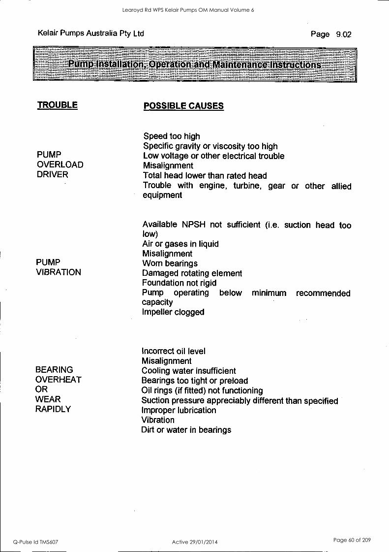
Kelair Pumps Australia Pty Ltd Page 9.02
anon Rerationrand Vlaintenan
TROUBLE POSSIBLE CAUSES
Speed too high Specific gravity or viscosity too high
PUMP Low voltage or other electrical trouble OVERLOAD Misalignment DRIVER Total head lower than rated head
Trouble with engine, turbine, gear or other allied equipment
Available NPSH not sufficient (i.e. suction head too low) Air or gases in liquid Misalignment
PUMP Worn bearings VIBRATION Damaged rotating element
Foundation not rigid Pump operating below minimum recommended capacity Impeller clogged
Incorrect oil level Misalignment
BEARING Cooling water insufficient OVERHEAT Bearings too tight or preload OR Oil rings (if fitted) not functioning WEAR Suction pressure appreciably different than specified RAPIDLY Improper lubrication
Vibration Dirt or water in bearings
Learoyd Rd WPS Kelair Pumps OM Manual Volume 6
Q-Pulse Id TMS607 Active 29/01/2014 Page 60 of 209

KelairPumps
10: Isolation and Restoration Procedures
CONTENTS: NOT USED
PAGE 10.00
PAGE
Learoyd Rd WPS Kelair Pumps OM Manual Volume 6
Q-Pulse Id TMS607 Active 29/01/2014 Page 61 of 209

KelainPumps
PAGE 11.00
11: List of Sub-Contractor and Proprietary Equipment
CONTENTS: NOT USED
PAGE
Learoyd Rd WPS Kelair Pumps OM Manual Volume 6
Q-Pulse Id TMS607 Active 29/01/2014 Page 62 of 209

KelairPumps
PAGE 12.00
12: Recommended Spare Parts and Special Tools
CONTENTS : PAGE ABS SPAREPARTS LIST Page 12.01-3 ORDERING DETAILS Page 12.04 OTHER SPARE PARTS INFORMATION Page 12.04
Learoyd Rd WPS Kelair Pumps OM Manual Volume 6
Q-Pulse Id TMS607 Active 29/01/2014 Page 63 of 209
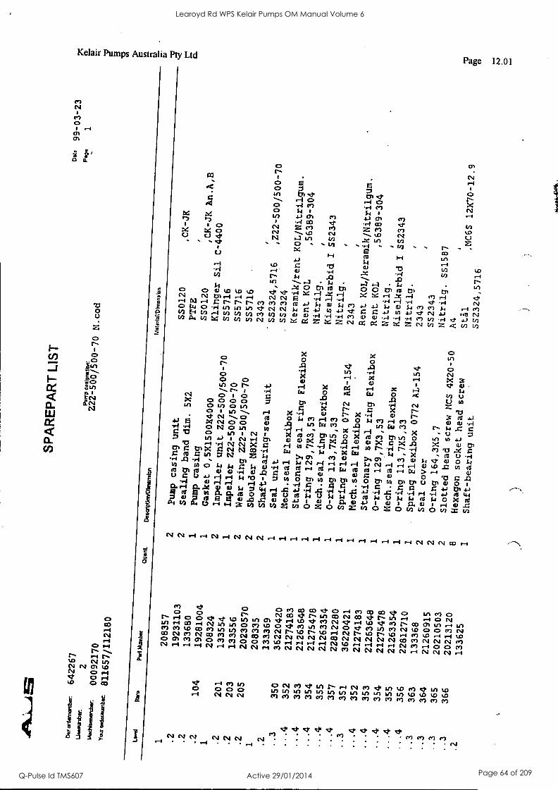
642267
2
00092170
811657/112180
SPA
RE
PAR
T L
IST
Pum
p de
alyn
atlo
n:
N.cod
Dat
e 99-03-23
Pek
e 1
Leve
l It
em
Pat A
mbe
r Q
uad.
D
esai
Vie
rieb
nens
trA
Mot
erla
t:Din
ensi
sa
1
208357
2
Pump casing unit
SS0120
,CK-JK
.2
19231103
2
Sealing band dim. 5X2
PTFE
.2
133680
1
Pump casing
SS0120
,CK-JK An.A,B
.2
104
19281004
1
Gasket 0,5X1500X4000
Klinger Sil C-4400
1
208324
2
Impeller unit Z22- 500/500 -70
SS5716
.2
201
133554
1
Impeller Z22-500/500-70
SS5716
.2
203
133556
2
Wear ring Z22 -500/500 -70
SS5716
.2
205
20230570
2
Shoulder M8X12
2343
1
208335
2
Shaft-bearing-seal unit
SS2324,57I6
,222-500/500-70
.2
133369
1
Seal unit
SS2324
..3
350
36220420
1
Mech.seal Flexibox
Keramik/rent KOL/Witrilgum
...4
352
21274183
1
Stationary seal ring Flexibox
Rent KOL
,56389 -304
-.4
353
21263648
1
0-ring 129,7X3,53
Nitrilg.
...4
354
21275478
1
Mech.seal ring Flexibox
Kiselkarbid I SS2343
...4
355
21263354
1
0-ring 113,7X5,33
Nitrilg.
...4
357
22812280
1
Spring Flexibox 0772 AR-154
2343
..3
351
36220421
1
Mech.seal Flexibox
Rent KOL/keramik/Nitrilgum.
...4
352
21274183
1
Stationary seal ring Flexibox
Rent KOL
,56389-304
...4
353
21263648
1
0-ring 129,7X3,53
Nitrilg.
...4
354
21275478
1
Nech.seal ring Flexibox
Kiselkarbid I SS2343
...4
355
21263354
1
0-ring 113,7X5,33
Nitrilg.
...4
356
22812710
1
Spring Flexibox 0772 AL-154
2343
..3
363
133368
2
Seal cover
SS2343
..3
364
21260915
2
0-ring 164,3X5,7
Nitrilg. SS1587
..3
365
20210503
2
Slotted head screw MCS 4X20-50
A4
..3
366
20213120
Hexagon socket head screw
StAl
,MC6S 12X70-12.9
.2
133625
1
Shaft-bearing unit
sS23245716
Learoyd Rd WPS Kelair Pumps OM Manual Volume 6
Q-Pulse Id TMS607 Active 29/01/2014 Page 64 of 209
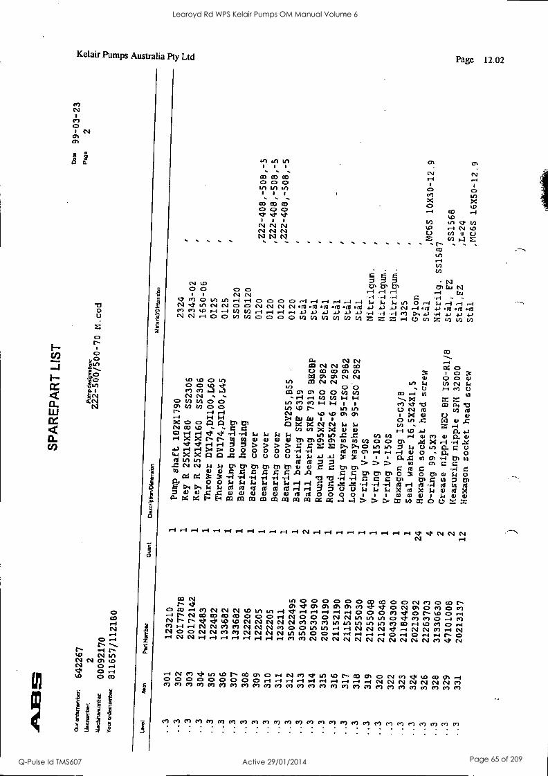
Our
cire
emum
bw
Wen
wrb
ec
Ntr
umun
tar
\cw
t.:v*
0100
1m
642267
2
00092170
811657/112180
SP
AR
EP
AR
T L
IST
Pum
p de
skpr
atio
n:
Z22-500/500-70 (1.cod
Dab, 99-03-23
Pape
2
Lon
,' no
m
Par
t Nur
rbw
Q
uint
D
ustr
Iptiv
n/D
irren
sion
M
a!er
iaY
DFr
ensb
n
..3
301
123210
1
Pump shaft 102X1790
2324
,
..3
302
20177878
1
Key R 25X14X180
SS2306
2343-02
..3
303
20172142
1
Key R 25X14X160
SS2306
1650-06
..3
304
122483
1
Thrower DY174,DI100,L60
0125
..3
305
122482
1
Thrower DY174,D1100,L45
0125
..3
306
133682
1
Bearing housing
SS0120
..3
307
133682
1
Bearing housing
SS0120
..3
308
122206
1
Bearing cover
0120
,Z22- 408,- 508, -5
..3
309
122205
1
Bearing cover
0120
=2-408,-508,-5
..3
310
122205
1
Bearing cover
0120
,Z22-408,-508,-5
..3
311
123211
1
Bearing cover DY255,B55
0120
,
..3
312
35022495
1
Ball bearing SKr 6319
Stil
,
..3
313
35030140
2
Ball bearing SKr 7319 BECBP
Stal
,
..3
314
20530190
1
Round nut M95X2-6 ISO 2982
Stal
f
..3
315
20530190
1
Round nut M95X2-6 ISO 2982
Stil
.
..3
316
21152190
1
Locking waysher 95-ISO 2982
Stal
.
..3
317
21152190
1
Locking waysher 95-ISO 2982
Stal
..3
318
21255030
1
V-ring V-905
Nitrilgum.
..3
319
21255048
1
V-ring V-1505
Nitrilgum.
..3
320
21255048
1
V-ring V-1505
Nitrilgum.
..3
322
20430300
1
Hexagon plug IS0-03/8
1325
..3
323
21184420
1
Seal washer 16,5X24X1,5
Gylon
,
..3
324
20213092
24
Hexagon socket head screw
Stal
,MC6S 10X30-12.9
..3
326
21263703
4
0-ring 99,5X3
Nitrilg. SS1587
..3
328
31330630
2
Grease nipple NEC BH ISO-R1/8
Stal, F2
,SS1568
..3
329
47101008
2
Measuring nipple SPM 32000
Stal,FZ
,L=24
..3
331
20213137
12
Hexagon socket head screw
Stal
,MC6S 16X50-12.9
Learoyd Rd WPS Kelair Pumps OM Manual Volume 6
Q-Pulse Id TMS607 Active 29/01/2014 Page 65 of 209
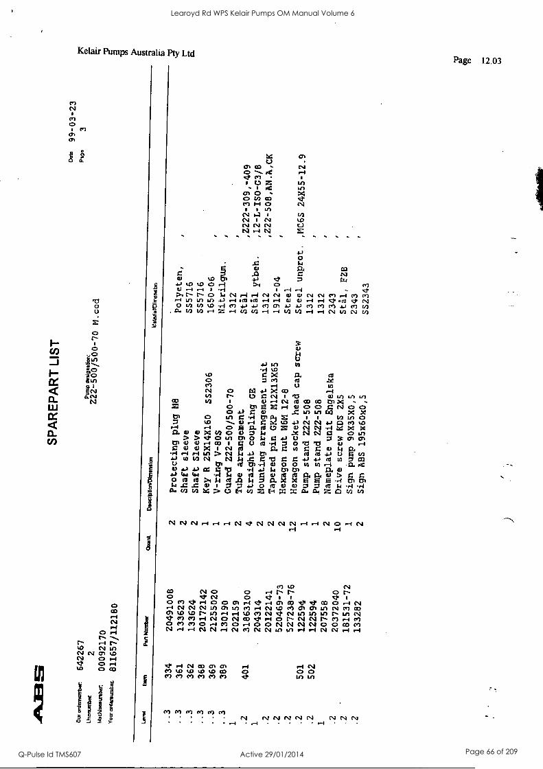
Our
ord
emor
rbar
Lirs
enU
ateC
1,43
011
001'
rib:tr
.
Yoa
r art
arou
rats
c
642267
2
00092170
811657/112180
SP
AR
EP
AR
T L
IST
Pum
p is
esig
natio
n:
Z22-500/500-70 M.cod
oats
99-03-23
1312
o 3
Leve
l ham
PanNumbet
Qua
rt
Dim
apoW
Mm
imA
n M
alez
iaV
DItr
embn
..3
334
20491008
2
Protecting plug M8
Polyeten,
..3
361
133623
2
Shaft sleeve
SS5716
..3
362
133624
2
Shaft Sleeve
SS5716
..3
368
20172142
1
Key R 25X14X160
SS2306
1650-06
..3
369
21255020
1
V-ring V-80S
Nitrilgum.
..3
389
130190
1
Guard Z22 -500/500 -70
1312
1
202159
2
Tube arrangement
Sta.].
,Z222-309,-409
.2
401
31863100
4
Straight coupling GE
Stil ytbeh.
,12-L-ISO-G3/8
1
204314
2
Mounting arrangement unit
1312
,222-508,AN.A,CK
.2
20122141
2
Tapered pin GKP M12X13X65
1912-04
.2
520469-73
2
Hexagon nut M6M 12-8
Steel
.2
527238-76
12
Hexagon socket head cap screw
Steel unprot. ,MC6S 24X55-12.9
.2
501
122594
1
Pump stand Z22 -508
1312
.2
502
122594
1
Pump stand Z22-508
1312
1
207558
2
Nameplate unit Engelska
2343
.2
20372040
10
Drive screw KDS 2X5
Stil, FZB
.2
181531-72
1
Sign pump 90X35X0,5
2343
.2
133282
2
Sign ABS 195x60x0,5
SS2343
Learoyd Rd WPS Kelair Pumps OM Manual Volume 6
Q-Pulse Id TMS607 Active 29/01/2014 Page 66 of 209
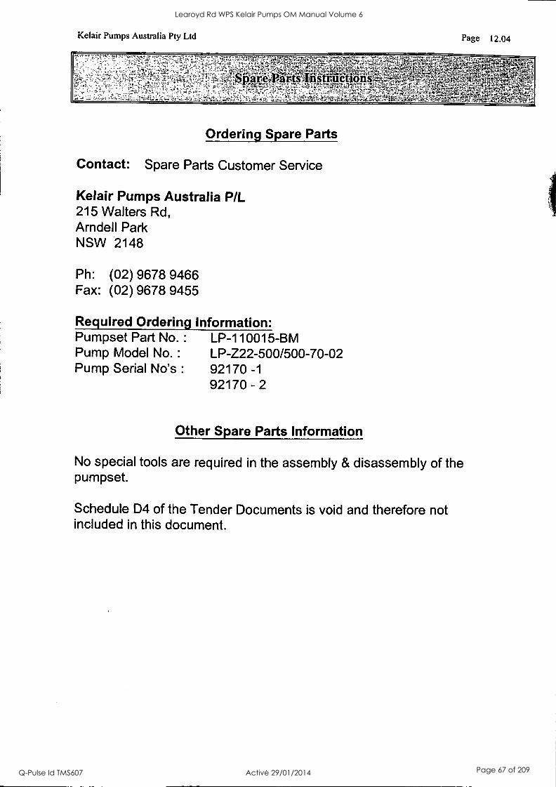
Kelair Pumps Australia Pty Ltd Page 12.04
Ordering Spare Parts
Contact: Spare Parts Customer Service
Kelair Pumps Australia P/L 215 Walters Rd, Arndell Park NSW 2148
Ph: (02) 9678 9466 Fax: (02) 9678 9455
Required Ordering Information: Pumpset Part No. : LP-110015-BM Pump Model No. : LP-Z22-500/500-70-02 Pump Serial No's : 92170 -1
92170 - 2
Other Spare Parts Information
No special tools are required in the assembly & disassembly of the pumpset.
Schedule D4 of the Tender Documents is void and therefore not included in this document.
Learoyd Rd WPS Kelair Pumps OM Manual Volume 6
Q-Pulse Id TMS607 Active 29/01/2014 Page 67 of 209
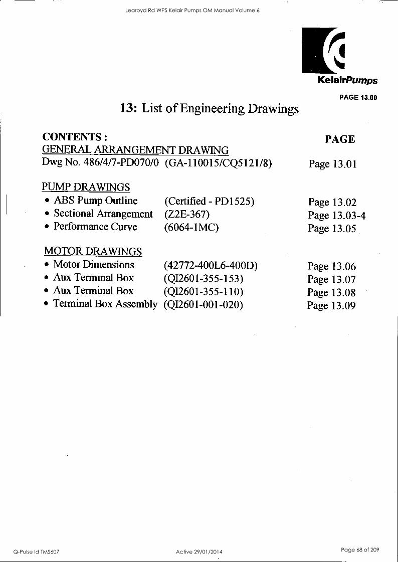
13: List of Engineering Drawings
CONTENTS: GENERAL ARRANGEMENT DRAWING Dwg No. 486/4/7-PD070/0 (GA-110015/CQ5121/8)
KelairPumps
PAGE 13.00
PAGE
Page 13.01
PUMP DRAWINGS ABS Pump Outline (Certified - PD1525) Page 13.02 Sectional Arrangement (Z2E-367) Page 13.03-4 Performance Curve (6064-1MC) Page 13.05
MOTOR DRAWINGS Motor Dimensions (42772-400L6-400D) Page 13.06 Aux Terminal Box (QI2601-355-153) Page 13.07 Aux Terminal Box (QI2601-355-110) Page 13.08 Terminal Box Assembly (QI2601-001-020) Page 13.09
Learoyd Rd WPS Kelair Pumps OM Manual Volume 6
Q-Pulse Id TMS607 Active 29/01/2014 Page 68 of 209
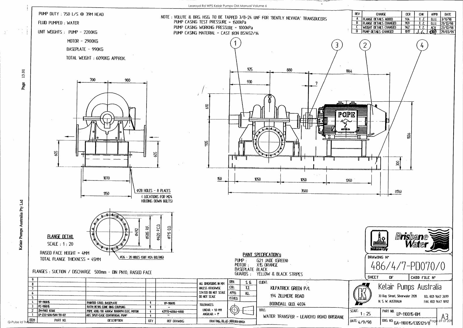
PUMP DUTY : 750 L/S @ 39M HEAD
FLUID PUMPED : WATER
UNIT WEIGHTS : PUMP - 2200KG
MOTOR - 2900KG
BASEPLATE - 990K6
TOTAL WEIGHT : 6090KG APPROX.
700 900
L f 1
so
NM-
FLANGE DETAIL
SCALE : 1 : 20
1070
1150
NOTE : VOLUTE & BRG. HSG. TO BE TAPPED 3/8-24 UNF FOR 'BENTLY NEVADA' TRANSDUCERS PUMP CASING TEST PRESSURE = 1500kPa
PUMP CASING WORKING PRESSURE = 1000kPa PUMP CASING MATERIAL = CAST IRON BS1452/14
028 HOLES - 8 PLACES
( LOCATIONS FOR 1424
HOLDING DOWN BOLTS)
RAISED FACE HEIGHT = 4MM
TOTAL FLANGE THICKNESS = 45MM 026 - 20 HOLES (SUIT M24 BOUM)
FLANGES : SUCTION / DISCHARGE 500mm - DIN PN10, RAISED FACE
REV WANE ECR 0-1K APPD
A FIANCE DETAILS ADDED 934 T. Z. DJ...
FUNEE DETAILS CHANGED
WEEHT DETAILS CHANGED
PUT DETAIS CHANGED
959 T. Z. DJ.J.
962
1017
T. Z.
PAINT SPECFICATION's
PUMP 621 JADE (GREEN) MOTOR : XIS ORANGE BASEPLATE BLACK GUARDS : YELLOW 8, BLACK STRIPES
Bristhl@ne, Water.
DATE
3/1V98 21/12/98 23/12/98 29/03/99
7486/4/7-PD070/0 SHEET OF CADD FILE N°
9
All MONK IN NH
MESS OTLERWISE
STATED BO NOT SCALE
DO NOT SCALE
ORK S. G. 8
T.Z. 7
APP KL 6
ISSUED:
4 YP-110015 PAINTED STEEL RASO:UTE YP-110015 TOLERANCES:
LINEAR: tO MM
ANGULAR: 4 f 3 FC-110015 RATH RCVS COW RIG COUPLIC
2 ZM-EPEE ISSUE POPE 4001-110 400KW 1000RPM ELEC. MOTOR 42772-40016-4000 LP-M-500/500-70-02 ABS SPIH-CASE CENTRFUGAL PLOP
ITEM PART NO. DESCRIPTION OTY REF DRAWING DRAFTING TO AS 1100.101-1992
CLIENT:
KILPATRICK GREEN P/L
194 ZILLMERE ROAD
BOONDALL GILD. 4034
Ketair Pumps Australia 33 Day Street, Siverwater 2128 TEL (02) 9647 2699
N. S. W. AUSTRALIA FAX. (02) 9647 1092
TITLE:
WATER TRANSFER - LEAROYD ROAD BRISBANE
SCALE: 1 : 25
DATE 4/9/98
PART NO.
LP-110015-BM
ORG. NO: 6A-110015/C05121/8
A3
Learoyd Rd WPS Kelair Pumps OM Manual Volume 6
Q-Pulse Id TMS607 Active 29/01/2014 Page 69 of 209
IN-LINE, HORIZONTAL SHAFT ANTI-CLOCKWISE ROTATION
Version JK Arrangement A
Z 22 PD1525
Ed. 5 Date 1996 10 16
Kelair Pumps Australia Pty Ltd Page 13.02
Si
ABS Pumps International AB CERTIFIED DRAWING
Type Flange PN/ND DN1 DN2
Pump hi h3 h4
1999 -03- 2 9
Our ref sli651 I q2,1-10-1-z Your ref.: 1:V0 Lt 2;1% h9 0 Lit
Z22-500/500-70 10 / 16 500 500 880 500 700 900 500 1810 170 610 360 2200 Z22-600/600-65 10 / 16 600 600 961 620 620 880 620 1945 165 680 350 3000 Z22-600/600-75 10 / 16 600 600 950 650 900 1100 650 1920 165 785 400 3800 Z22-700/700-65 10 700 700 950 750 750 1100 750 1920 165 805 310 3400 2.22-800/700-105 10 800 700 1100 900 1000 1300 900 2220 200 1000 550 5700 Z22-900/800-90 10 900 800 1130 800 900 1300 800 2280 230 960 470 4800 Z22- 1000/1000 -90 10 1000 1000 1160 850 1200 1600 850 2340 215 1070 470 8200
Foot Shaft Conn. Type mi m2 m4 n1 n2 n6 c si di t u 01 Q2 Q3 Z22- 500/500 -70 800 650 500 1350 1250 1150 25 28 90js6 95 25h9 R3/8" R11/4" R3/8" 722-600/600-65 950 800 650 1440 1320 1060 30 30 115js6 122 32h9 R3/8" R1" R3/8" 2.22-600/600-75 950 800 650 1550 1400 1250 30 35 100js6 106 28h9 R3/8" R11/4" R3/8" Z22-700/700-65 1200 1050 900 1630 1450 1270 30 28 100js6 106 28h9 R3/8" R1" R3/8" 722-800/700-105 1400 1250 1080 1750 1550 1350 40 36 135js6 143 36h9 R3/8" 50 R1/2" Z22-900/800-90 1370 1200 1050 1770 1590 1290 30 30 140js6 148 36h9 R3/8" R1" R3/8" 2.22-1000/1000-90 1400 1200 1020 2100 1950 1640 30 42 140js6 148 36h9 R3/8" R11/4" R1/7'
PN /ND di Dh Ds F Qi Q2 Q3 ebbLI(C yUdyC rnnnny fanny u4uw 20x20710 45
10 600 725 20 x 30 780 36 Manornetre Evacuation Liquide d'etancheite 10 700 840 24 x 30 895 40 Manometer Evakuierung DichtungsflOssigkeit 10 800 950 24 x 33 1015 44 Manometer Evakuering Tatningsvatska 10 900 1050 28 x 33 1115 46 10 1000 1160 28 x 36 1230 50 16 500 650 20 x 33 710 45 16 600 770 20 x 36 840 40
0:PSWP>pd1525.chp This dimension drawing replaces both PD1525 ed. 3 and PD1526 ed. 1
Learoyd Rd WPS Kelair Pumps OM Manual Volume 6
Q-Pulse Id TMS607 Active 29/01/2014 Page 70 of 209
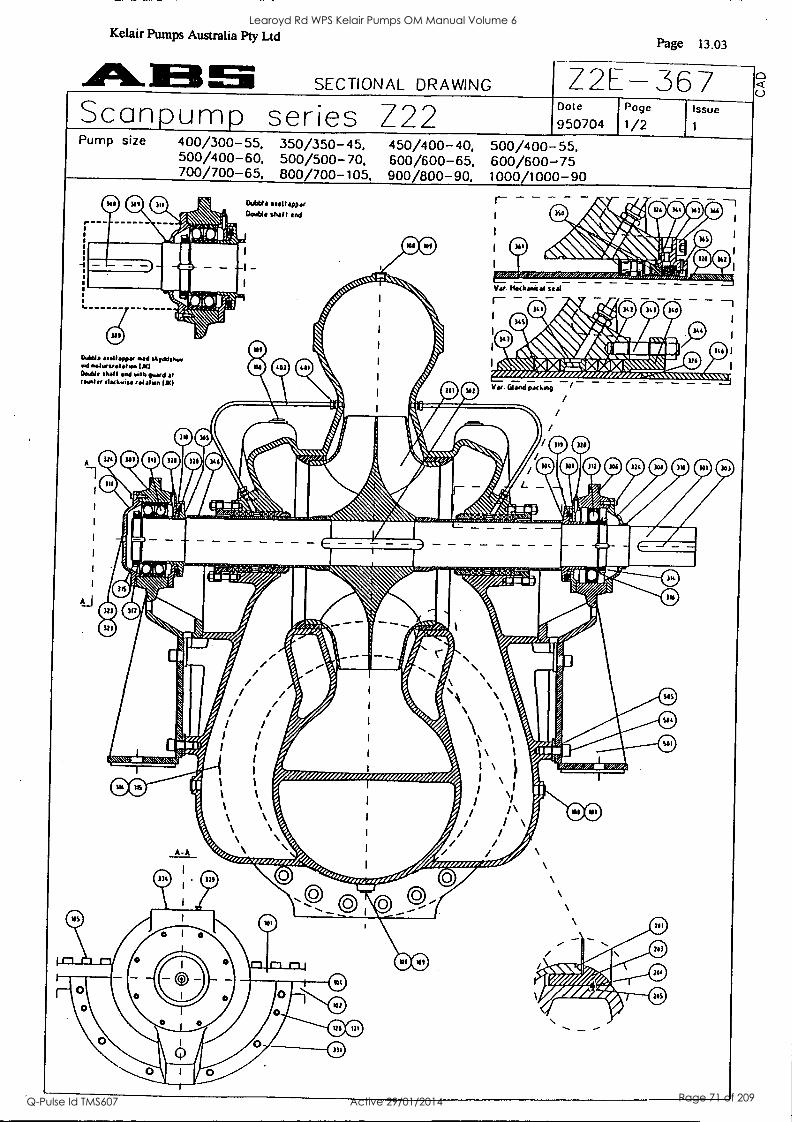
I 1
el
S 11
11 al
11
11 11 1
:11 as /
-
11 1 110
. 11 .11 GOO 11 :10 I 111
1 51 11 I
0 0 a 0 444
'min 0 ggp APo., 10" 0 1-14111rfti4 .......
11/414,441V- $ A40 0 0
bs sk 4
CD 4%, \ riAux WI
FLZ":2:± 0 0 0 0 \ 00
...--,,-. %' :
I v._
I
t , I 7,
, \ N
.1 ,- , ismuilkW.
\ .k
" AMLie,
,c ....
41"
II 4 \
000000 ii '4(' .A'
.0.11046s 1 Mr I AM =. =
rIlleiFimumwo w - %Ed... , . :- . 4,
0 111
n; :
,
w/zzzr, zi.elee tete/me, Avezet. es./ I. i
% . / ., / o
0 mow ill / / , silim/
0 ' fr s,. s / k 1 / 1. , / /
01 // ri, Is .,,, 1, iiiii 1 I 54, #/ /
fr,
/ ';', 0,,,, ;,. .W111r411r
rlillia 111.112 %/4,/,
__.....ry II ,k/
11
As3vemehe / 1
t V e e
e f 5%, e
3 31,..
/., / / / , ..........................
.. sikiriz, 1. e...././
® 00 ®
00
MIN all
0 0
0
AllmatO I I I &O
00
0-0
Learoyd Rd WPS Kelair Pumps OM Manual Volume 6
Q-Pulse Id TMS607 Active 29/01/2014 Page 71 of 209
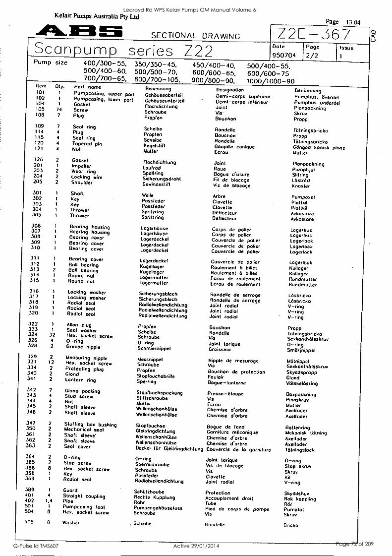
Kelair Pumps Australia Pty Ltd
436..1E31 SECTIONAL DRAWING
Page 13.04
Z2E-367 Scanpump series Z22 Pump size 400/300-55.
500/400-60, 700/700-65,
350/350-45. 500/500-70, 800/700-105,
450/4 600/ 900/8
00-40, 600-65, 00-90,
Dote
950704
500/400-55, 600/600-75 1000/1060-90
Page
2/2 Issue
1
Item Oly. Port name Benennung 101 1 Pumpcosing, upper p art Gehouseoberteil 102 1 Pumpcosing, lower po rt Gehouseunterteil 104 1 Gasket Flochdichtung 105 74 Screw Schroube 108 7 Plug Propf en
109 7 Seol ring Scheibe 114 4 Plug Proplen 115 4 Seal ring Scheibe 120 4 Tapered pin Kegelstif t 121 4 Nut Muller
126 2 Gasket Flochdichtung 201 1 Impeller Loufrod 203 2 Wear ring Spoltring 204 2 Locking wire Sicherungsdroht 205 2 Shoulder Gewindeslilt
301 Shaft Welle 302 Key Pass( eder 303 Key Possleder 304 Thrower Spritzring 305 Thrower Spritzring
306 1 Bearing housing Logerhouse 307 1 Bearing housing Logerhbuse 308 1 Bearing cover Logerdeckel 309 1 Bearing cover Logerdeckel 310 1 Beoring cover Logerdeckel
311 1 Bearing cover Logerdeckel 312 1 Boll beoring Kugelloger 313 2 Boll bearing Kugelloger 314 1 Round nut Logermut ter 315 1 Round nut Logermut ter
316 Locking washer Sicherungsblech 317 Locking washer Sicherungsblech 318 Radial scot Rodialwellendichtung 319 Rodiol seol Rodiolwellendichtung 320 Rodiol seal Rodiolwellendichtung
322 1 Allen plug Propf en 323 1 Seal washer Scheibe 324 32 Hex, socket screw Schroube 326 4 0-ring 0-ring 328 2 Greose nipple Schmiernippel
329 2 Meosuring nipple Messnippel 331 12 Hex. socket screw Schraube 334 2 Protecting plug Propfen 340 2 Gland Stoplbuchsbrille 341 2 Lantern ring Sperring
342 7 Glond pocking Stopfbuchspockung 343 4 Stud screw Stiftschroube 344 4 Nut Mutter 345 2 Shot t sleeve WellenschonhUlse 346 2 Shalt sleeve Wellenschonhtilse
347 2 Stuffing box bushing Stoplbuchse 350 2 Mechanical seol Gleitringdichtung 361 2 Shaft sleeve' Wellenschontase 362 2 Shalt sleeve Wellenschonhillse 363 2 Seal cover Deckel filr Gleitringdichtung
364 2 0-ring 0-ring 365 2 Stop screw Sperrschroube 366 8 Hex. socket screw Schraube 368 1 Key Possleder 369 1 Rodiol seal Rodiolwellendichtung
389 1 Guard Schiilzhoube 401 4 Straight coupling Rachte Kupplung 402 1,4 Pipe Rohr 501 1 Pumpcosing foot Pumpengehbusefuss 504 8 Hex. socket screw Schraube
505 8 Washer , Scheibe
Designation Demi- corps superieur Demi-corps inf trieur Joint Vis Bouchon
Rondelle Bouchon Rondelle Goupitle conique Ecrou
Joint Roue Bogue d usure Fil de blocoge Vis de blocoge
Arbre Clovet le Clovette Deflecteur Deflecteur
Corps de polier Corps de polier Couvercle de polier Couvercle de polier Couvercle de polier
Couvercle de polier Roulement b billes Roulement a billes Ecrou de roulement Ecrou de roulement
Rondelle de serroge Rondelle de serroge Joint rodiol Joint rodiol Joint radial
Bouchon Rondelle
Vis Joint torique Groisseur
Nipple de mesuroge Vis Bouchon de protection Fouloir Bogue-lonterne
Presse-etoupe Vis Ecrou Chemise d'orbre Chemise d'orbre
Bogue de fond Gorniture meconique Chemise Warbre Chemise d'orbre Couvercle de lo garniture
Joint torique Vis de blocoge Vis Clovette Joint radial
Protection Accouplement droit Tube Pied de corps de pompe Vis
Rondelle
Benomning Pumphus, overdel Pumphus underdel Plonpockning Skruv Propp
Tittningsbricko Propp Totningsbricko Gtingod konisk pinne Mutter
Plonpockning Pumphjul Slitring Lastrod Knosler
Pumpoxel Plollkil Plottkil Avkostore Avkostore
Logerhus Logerhus Logerlock Logerlock Logerlock
Logerlock Kulloger Kulloger Rundmulter Rundmulter
Lesbricko Lesbricko V- ring V-ring V-ring
Propp Totningsbricko Sexkonthelsskruv 0-ring Smorjnippel
Molnippel Sexkonth6Isskruv Skyddspropp Gland Votskel6sring
Boxpockning Pinnskruv Mutter Axelfoder Axelfoder
Bollenring Mekonisk tlitning Axelfoder Axelfoder Ttitningslock
0-ring Stop skruv Skruv Kit V-ring
Skyddshuv Rok koppling Rot' Pumpfot Skruv
Bricko
Learoyd Rd WPS Kelair Pumps OM Manual Volume 6
Q-Pulse Id TMS607 Active 29/01/2014 Page 72 of 209
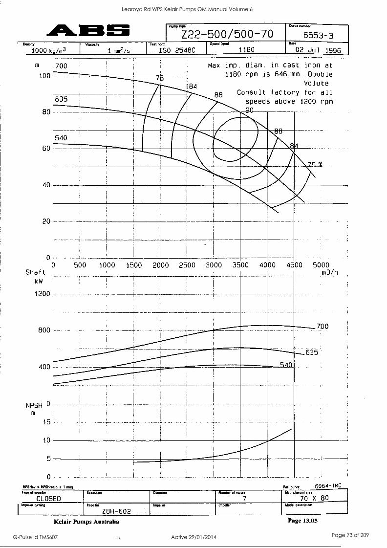
Pun-wr- Z22-500/500-70 Curve nun
6553-3 Density
1000 kg/m3 Viscosity
Mff12/5
Teat norm
ISO 2548C Speed Irpml
1180 N.
02 Jul 1996
m .700
100
80
60
40
20
0
Shaft
kW
1200
800
184
635
Max imp. diam. in cast iron at
1180 rpm is 646'mm. Double
Volute.
88 Consult factory for all
speeds above 1200 rpm
mow , MM.
540 riallinV r
,,,,,- .,41,. 5
, 1
i -gNipir ,
, _, .
,
400 -
500 1000 1500 2000 2500 3000 3500 4000 4500 5000 m3/h
NPSH 0 - m
15-
10
5
0
_L
700
635
NPSHav NPSHnsced + 1 maq Ref. curve: 6064 -]MC Type of impeller
CLOSED Execution Diameter Number of vanes
7
Min channel area
70 X 80 Impeller turning Impeller
Z8H-602 Impeller Impeller Model description
Kelair Pumps Australia Page 13.05
Learoyd Rd WPS Kelair Pumps OM Manual Volume 6
Q-Pulse Id TMS607 Active 29/01/2014 Page 73 of 209
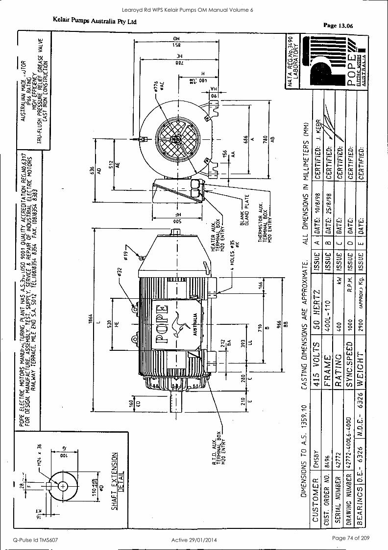
SH
AF
T
EX
TE
NS
ION
D
ET
AIL
PO
PE
E
LEC
TR
IC
MO
TO
RS
M
AN
UI-
RL
TU
RIN
G
PLA
NT
H
AS
A
.S.3
yv1/
150
9001
Q
UA
LIT
Y A
CC
RE
DIT
AT
ION
R
EG
.N0.
6317
F
OR
D
ES
IGN
. M
AN
UF
AC
TU
RE
. A
SS
EM
BLY
. T
ES
T.
SU
PP
LY.
SE
RV
ICE
&
R
EP
AIR
O
F
IND
US
TR
IAL
ELE
CT
RIC
M
OT
OR
S
RA
ILW
AY
T
ER
RA
CE
. M
ILE
E
ND
S
.A.
5012
T
EL.
(08)
8354
83
54
FA
X.
(08)
8354
83
83
R.T
.O.
AU
X.
TE
RM
INA
L B
OX
M
20
EN
TR
Y
1864
530
636
AU
ST
RA
LIA
N
MA
DE
.U
TO
R
IP66
R
A T
ING
H
IGH
E
FF
ICIE
NC
Y
TR
U-F
LUS
H
PR
ES
SU
RE
R
ELI
EF
G
RE
AS
E V
ALV
E
CA
ST
IR
ON
C
ON
ST
RU
CT
ION
032
019
160
ED
HE
AT
ER
A
UX
. T
ER
MIN
AL
BO
X
M20
E
NT
RY
4 H
OLE
S
035
OK
210
280
B
BLA
NK
G
LAN
D
PLA
TE
TH
ER
MIS
TO
R
AU
X.
TE
RM
INA
L B
OX
M
20
EN
TR
Y
AB
DIM
EN
SIO
NS
T
O
A.S
. 13
59.1
0 C
AS
TIN
G
DIM
EN
SIO
NS
A
RE
A
PP
RO
XIM
AT
E.
ALL
D
IME
NS
ION
S
IN
MIL
LIM
ET
ER
S
(MM
)
CU
ST
OM
ER
E
MS
BY
41
5 V
OL
TS
50
HE
RT
Z
ISS
UE
A
D
AT
E:
10/8
/98
CE
RT
IFIE
D:
J.
KE
R
CO
ST
. O
RD
ER
N
O.
8496
FR
AM
E
400L
-110
IS
SU
E
B
DA
TE
: 25
/8/9
8 C
ER
TIF
IED
:
SE
RIA
L N
UM
BE
R
4277
2 R
AT
ING
40
0 kW
IS
SU
E
C
DA
TE
: C
ER
TIF
IED
:
DR
AW
ING
N
UM
BE
R
4277
2-40
0L6-
4000
SY
NC
.SPE
ED
10
00
R.P
.M.
ISS
UE
0
DA
TE
: C
ER
TIF
IED
:
BE
AR
ING
S
D.E
.-
6326
I N
.D.E
.-
6326
W
EIG
HT
29
00
(AP
PR
OX
.)
Kg.
IS
SU
E
DA
TE
: C
ER
TIF
IED
:
NA
TA
R
EG
.No.
3490
LA
BO
RA
TO
RY
POPE
W
&u.
..sm
aAw
Al
Learoyd Rd WPS Kelair Pumps OM Manual Volume 6
Q-Pulse Id TMS607 Active 29/01/2014 Page 74 of 209
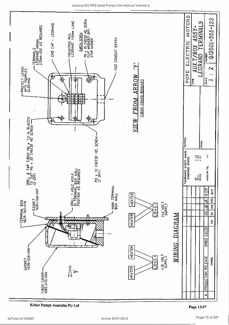
T/B
OX
C
OV
ER
10
85-0
15-0
00
GA
SK
ET
10
30-0
28-0
00
TE
RM
INA
L B
OX
P
RO
TE
CT
LE
AD
S
1629
-160
-018
W
ITH
vI
DA
FLE
X
DR
ILL
&
TA
P
T/B
OX
M
6 x
1.0
(4
PLA
CE
S)
SLE
EV
ING
GA
SK
ET
T
O
SU
IT
M6
x 20
C
HE
ES
E
HD
S
CR
EW
1630
-160
-007
(3
O
FF
)
415
VO
L T
S
UP
PLY
DR
ILL
1 H
OLE
02
0.0
IN
TE
RM
INA
L B
OX
W
ALL
P
OS
ITIO
N
AS
R
EQ
UIR
ED
MA
IN
TE
RM
INA
L B
OX
W
ALL
240
VO
LT
SU
PP
LY
WIR
ING
D
IAG
RA
M
PR
OD
UC
TIO
N
RE
LEA
SE
E
MB
O
4242
0 G
G /A
C
HA
NG
E
ON
BY
C
KD
P
50
M3
x 12
C
HE
ES
E
HD
. S
CR
EW
(2
O
FF
)
TE
RM
INA
L S
LE
GR
AN
D
VIK
ING
2.
5mm
-US
E
AS
R
EQ
UIR
ED
EN
O
CA
P
- LE
GR
AN
D
MO
UN
TIN
G
RA
IL
LEG
RA
ND
11
0mm
LO
NG
EA
RT
H S
CR
EW
/16
x 25
C
HE
ES
E
HO
. S
CR
EW
F
LAT
W
AS
HE
R(2
OF
F)
ST
AR
W
AS
HE
R
M20
C
ON
DU
IT
EN
TR
Y
VIE
W
FRO
M
AR
RO
W
'Y'
T/B
OX
C
OV
ER
R
EM
OV
ED
TOLERANCES EXCEPT WHERE
OT
HE
RW
ISE
S
TA
TE
D
MA
TE
RIA
L
xX
* tO
xx.x
* 0.5
XX
.XX
0.
1 FINISH
13.1
2.97
ANGULAR TM.
*1.
DA
TE
POPE ELECTRIC MOTORS
NA
AU
X.T
/BO
X
ASS
Y-
LE
GR
AN
D
TE
RM
INA
LS
SC
ALE
1 :
2 N
UM
BE
R
Q12
601-
355
-153
Learoyd Rd WPS Kelair Pumps OM Manual Volume 6
Q-Pulse Id TMS607 Active 29/01/2014 Page 75 of 209
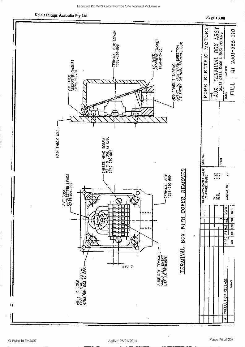
M5
x 12
LO
NG
C
HE
ES
E H
EA
D
SC
RE
W
0753
-504
-008
(4
O
FF
) LL
CC
PV
C
BU
SH
P
RO
TE
CT
ING
LE
AD
S
0713
-004
-007
1111
111M
IIIIII
IIIIII
I
1111
4044
4.4g
II
Irl1
;171
1111
1131
1 IIM
IIIIV
IIIM
UIII
I
AU
XIL
IAR
Y
TE
MIN
ALS
W
AG
O
SID
E
EN
TR
Y
US
E
AS
R
EQ
UIR
ED
T
ER
MIN
AL
BO
X
1229
-010
-000
MA
IN
T/B
OX
W
ALL
CH
EE
SE
H
EA
D
SC
RE
W
x 8
LON
G
(2
OF
F)
0750
-030
-001
TE
RM
INA
L
BO
X
WIT
H
CO
VE
R
RE
MO
VE
D
2.0
TH
ICK
N
EO
PR
EN
E
GA
SK
ET
10
30-0
09-0
0
TE
RM
INA
L B
OX
C
OV
ER
10
85-0
10-0
00
2.0
TH
ICK
N
EO
PR
EN
E
GA
SK
ET
10
30-0
10-0
0
M20
C
ON
DU
IT
TH
RE
AD
.E
NT
RY
T
O
FA
CE
S
AM
E
DIR
EC
TIO
N
AS
E
NT
RY
O
N
MA
IN
TE
RM
INA
L B
OX
A
TOLERANCES EXCEPT WHERE
OTHERWISE STATED
XX
11
.0
XX
.X
10.5
X
X.X
X
10.1
ANGULAR TOL.
*1
MATERIAL
FIN
ISH
PR
OD
UC
TIO
N
RE
LEA
SE
18
082
PT
3/
5/94
CH
AN
GE
C
/N
BY
cx0 PSO
GATE
POPE
E
LE
CT
RIC
M
OT
OR
S N
AM
E
AU
X.
TE
RM
INA
L
BO
X
ASS
Y
SU
ITS
03
55.
0400
&
04
50
MO
TO
RS
SCALE
I
HUMBER
FUL
L
QI
2601
-355
-110
tO
O111
eD
00
Learoyd Rd WPS Kelair Pumps OM Manual Volume 6
Q-Pulse Id TMS607 Active 29/01/2014 Page 76 of 209
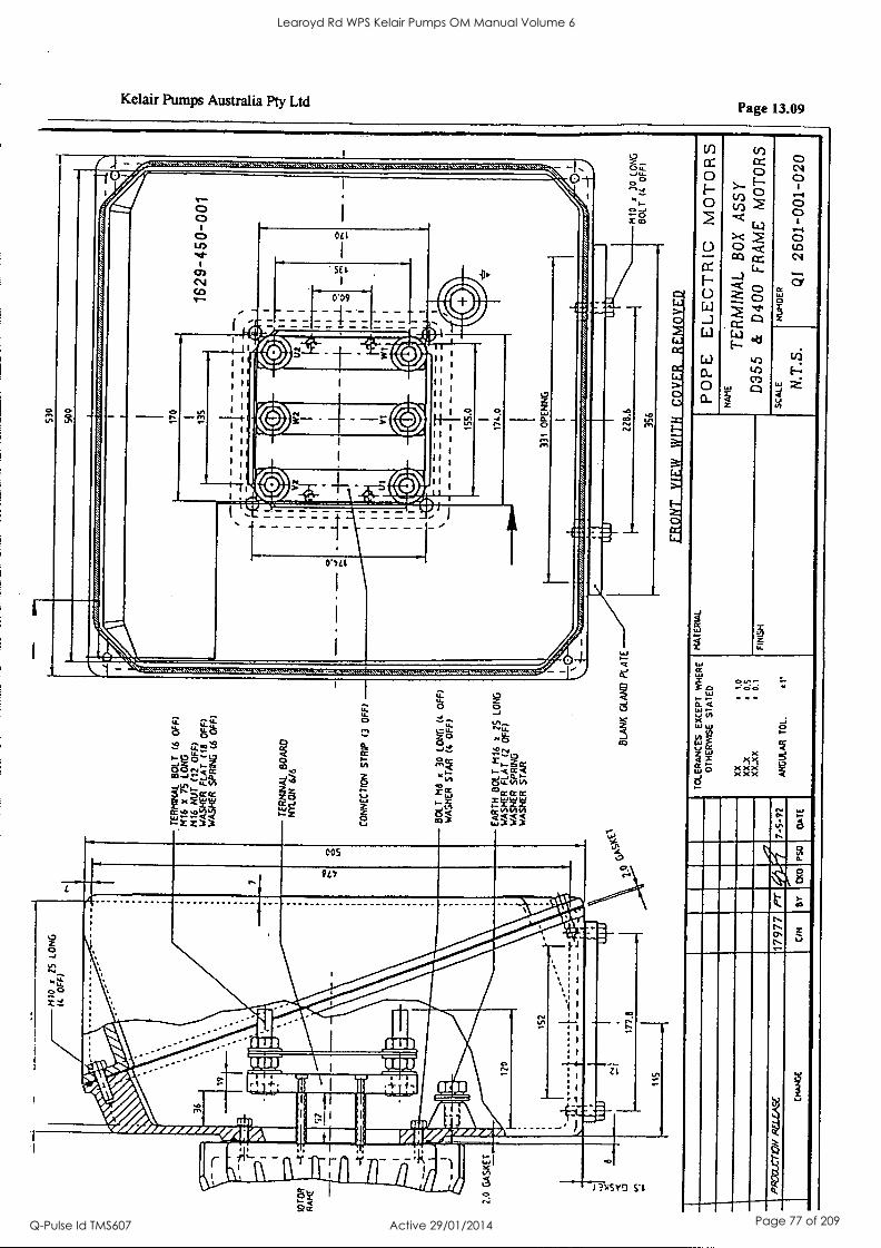
On-I00-T
O9t
lb baownN
'STN
alv3s
3):10.1.0N1
31^1Vdd
00f7G
9900 A
SSV
X09
IVN
IM131
3tim
S1:10101N
011:1103-13 3d0d
.1 '101
U'IlfIO
NY
t'o xX
X
5'0 x
X'X
x ot
XX
031V1S
3S
tolt831410 3113H
/A
1d3)X3
93314vd3101
31Y0
Z6-S
-L
OS
d 0)0
N/)
LL
6LL
lor4vH3
ZY
777ed ,rated
WO
7)
1109 01401
OC
N
01W
03AC
M311
113/100 H
.L1M
A
131A IN
083
9.9ZZ
31teld
ON
1/19 X
NV
113
0'7LL
O'S
SL
I
I
I I I
1.00-0917-6Z91.
OE
S
1
k1Y1S
/1311S
Y/i
0N1ddS
)13H
5Y/i
(4d0 Z
) 1V
11 a-IV/A
9N
01 S
Z
x 9114
1100 141t1Y3
WO
7)
UtelS
113)1S
VM
>
01401
OE
x
9W
1109
f330 E
) dla1S
N
O11)3N
NO
3
9/9 NO
W
C8V
O9
10104/131
511
13XS
Y0 N
W)
00101
(110 9)
0)/19dS
2/3HS
Y/4
(40 91)
1111d ki3HS
Wi
fdd0 Z
1) 111N
9114
0N01
SL
91H,
(110 9) 1109
lleNO
4031
(idO
7) 0N
01 S
Z
x
Learoyd Rd WPS Kelair Pumps OM Manual Volume 6
Q-Pulse Id TMS607 Active 29/01/2014 Page 77 of 209

14: Training
CONTENTS: NOT USED
ID KelairPumps
PAGE 14.00
PAGE
Learoyd Rd WPS Kelair Pumps OM Manual Volume 6
Q-Pulse Id TMS607 Active 29/01/2014 Page 78 of 209

IDI KelairPumps
PAGE 15.00
15: List of Contract Variations and Plant Modifications
CONTENTS: NOT USED
PAGE
Learoyd Rd WPS Kelair Pumps OM Manual Volume 6
Q-Pulse Id TMS607 Active 29/01/2014 Page 79 of 209
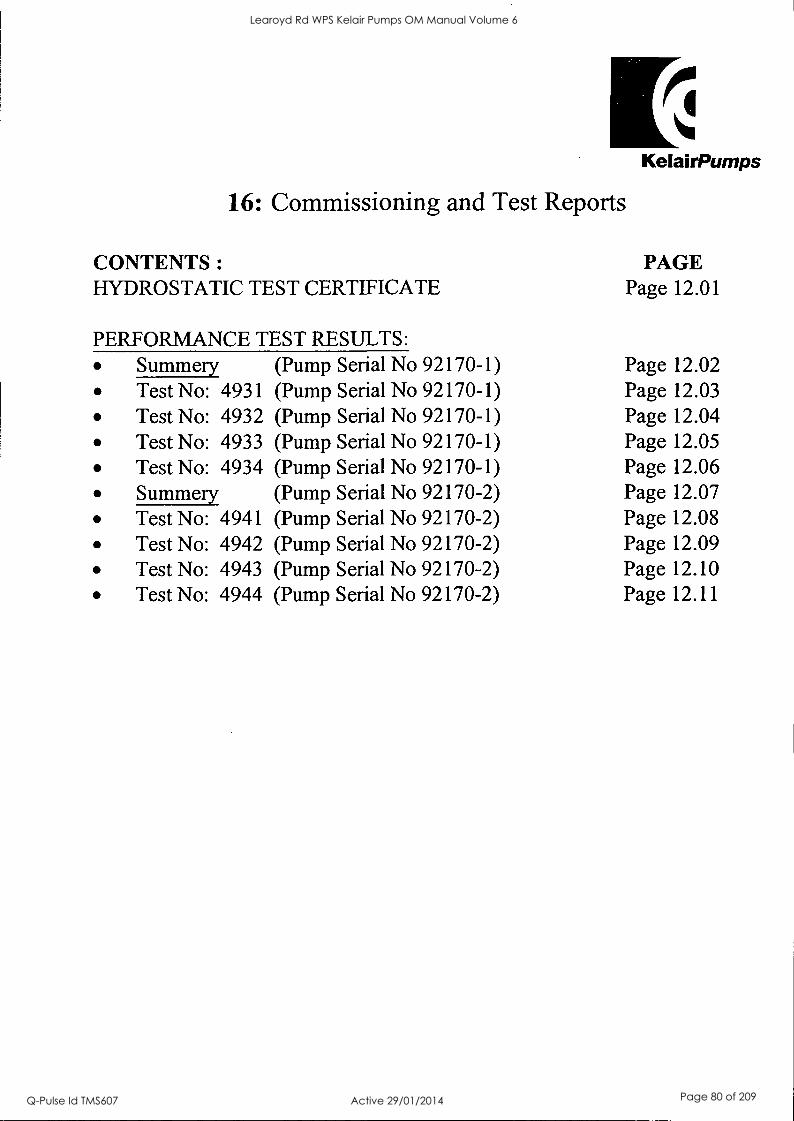
ID KelairPumps
16: Commissioning and Test Reports
CONTENTS :
HYDROSTATIC TEST CERTIFICATE
PERFORMANCE TEST RESULTS:
PAGE Page 12.01
Summery (Pump Serial No 92170-1) Page 12.02 Test No: 4931 (Pump Serial No 92170-1) Page 12.03 Test No: 4932 (Pump Serial No 92170-1) Page 12.04 Test No: 4933 (Pump Serial No 92170-1) Page 12.05 Test No: 4934 (Pump Serial No 92170-1) Page 12.06 Summery (Pump Serial No 92170-2) Page 12.07 Test No: 4941 (Pump Serial No 92170-2) Page 12.08 Test No: 4942 (Pump Serial No 92170-2) Page 12.09 Test No: 4943 (Pump Serial No 92170-2) Page 12.10 Test No: 4944 (Pump Serial No 92170-2) Page 12.11
Learoyd Rd WPS Kelair Pumps OM Manual Volume 6
Q-Pulse Id TMS607 Active 29/01/2014 Page 80 of 209
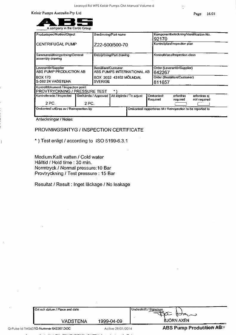
Kelair Pumps Australia Pty Ltd ASS A company in the Cardo Group
Page 16.01
Produktspecifikation/Object
CENTRIFUGAL PUMP
Benamning/Part name
Z22-500/500-70
Komponentbeteckning/Identification No.
92170 KontrollplantInspection plan
Sammanstallningsritning/General assembly drawing
Detaljritning/Part drawing Kontrollklass/Inspection class
Leverantar/Supplier ABS PUMP PRODUCTION AB
BOX 170 S-592 24 VADSTENA
Sesta Ilare/Customer ABS PUMPS INTERNATIONAL AB
BOX 2052 43102 MOLNDAL SVERIGE
Order (Leverantar/Supplier)
642267 Order (Sesta Ilare/Customer)
811657 Kontrolldokument / Inspection point PROVTRYCKNING / PRESSURE TEST * ) Kontrollerade / Inspected
2 PC.
Godkanda / Approved
2 PC.
Att atgarda / To adjust Omkontroll Required
erfordras erfordras ej required not required
I
Omkontroll uffores av / Reinspection by I Omkontroll rapporteras till / Reinspection to be reported to
Anteckningar / Notes
PROVNINGSINTYG / INSPECTION CERTIFICATE
* ) Test enligt / according to ISO 5199-6.3.1
Medium:Kallt vatten / Cold water Ha / Hold time : 30 min. Normtryck / Normal pressure:10 Bar Provtryckning / Test pressure : 15 Bar
Resultat / Result : Inget lackage / No leakage
Ort och datum / Place and date
VADSTENA 1999-04-09
Underskrift / Si nat
JORN AXEN _-
ID-Nummer:642267.DOC ABS Pump Production AB
Learoyd Rd WPS Kelair Pumps OM Manual Volume 6
Q-Pulse Id TMS607 Active 29/01/2014 Page 81 of 209
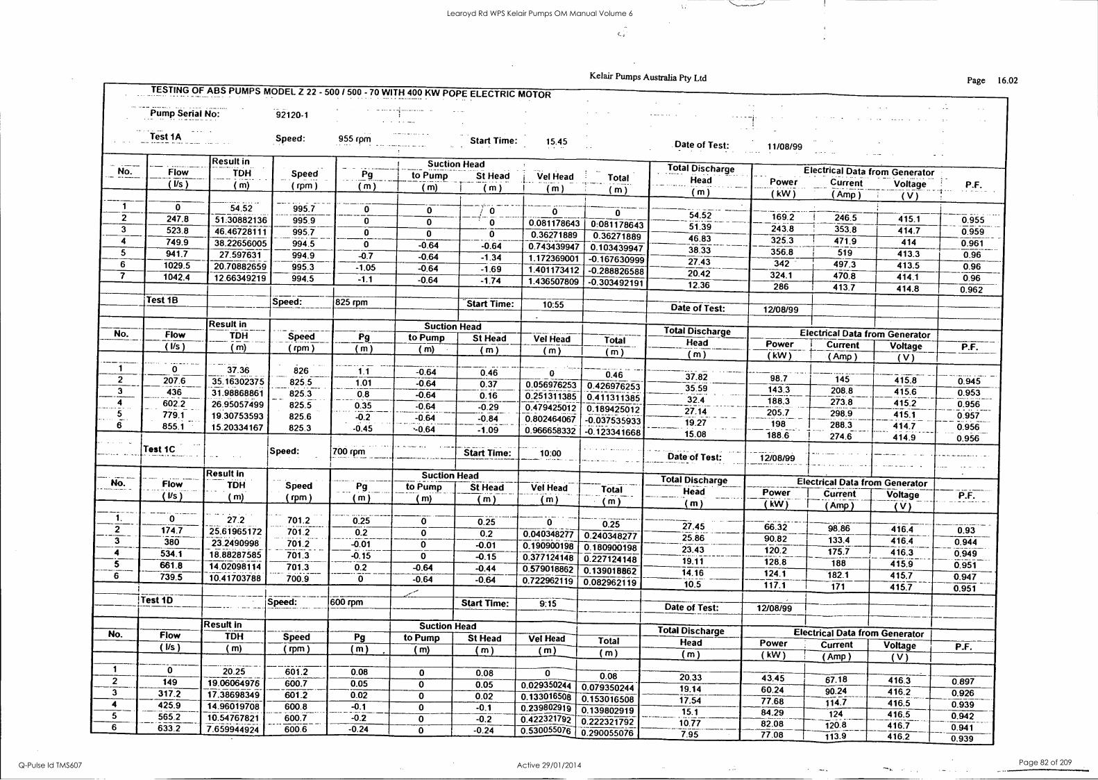
Kelair Pumps Australia Pty Ltd Page 16.02 TESTING OF ABS PUMPS MODEL Z 22 - 500 / 500 - 70 WITH 400 KW POPE ELECTRIC MOTOR
. .
. .
Pump Serial No 92120-1 : - .._ .. ..
.. __. . _ ._.._ .. Test 1A Speed: 955 rpm Start Time 15.45 Date of Test: 11/08/99 .. ...
No. Flow (Us)
Result in TDH .._._ ( m)
Speed .. .._
(rpm) Pg m
Suction Head to Pump St Head
( m) m )
Vel Head Total ( m ) ( m )
Total Discharge . ._.._ . . . _..
Head
( m )
Electrical Data from Generator Power Current Voltage P.F. ________ _____ ...-.
-..( Wij ( Amp ) ( V )
995.7 995.9
_6 _ _ 0 .
169.2 - 0 54.52 0 0 i 0 _
0 54.52 i 246.5 415.1 0.955 2 247.8 51:30882136 0 0 0.081178643 0:081178643 51.39 243.8 ! 353.8 414.7 0.959 3 523.8 46.46728111 995.7
994.5 0 0 0 0.36271889 0.36271889 46.83 25.3
356.8 ! 471.9 Ti 414 0.961 4 749.9 38.22656005 0 -0.64 -0.64 0.743439947 0.103439947 38.33 519 413.3 0.96 5 941.7 27.597631 994.9
995.3 -0.7 -0.64 -1.34 1.172369001 -0.167630999 27.43 342 - 497.3 413.5 0.96 6 1029.5 20.70882659 -1.05 -0.64 -1.69 1.401173412 -0.288826588 20.42 ----324.1 470.8 414.1 0.96 7 1042.4 12.66349219 994.5 -1.1 -0.64 -1.74 1.436507809 -0.303492191 12.36 286 413.7 414.8 0.962
Test 1B Speed: 825 rpm Start Time: 10:55 Date of Test: 12/08/99
Result in TDH
( m)
Speed
(rpm)
Suction Head Total Discharge Electrical Data from Generator No. Flow Pg to Pump St Head Vel Head Total Head Power kW )
.
' Current Voltage P.F. ( Ws ) ( m ) ( m) ( m ) ( m ) ( m ) _ _____._
( m ) ___
( Amp ) ( V ) 1 0 7.36
35.16302375 31.98868861 26.95057499 19.30753593 15.20334167
826 825.5 825.3 825.5 825.6 825.3
1.1 -0.64 0.46 0 0.46 37.82 66.7 415.8 0.945 145 207.6 436
66ii----- 779.1
_
f 855.1
1.01 -0.64 0.37 0.056976253 0.25111385 4.47942012 0.802464067
0.426976253 0.411311385 0:189425012
-0.037535933 -0.123341668
35.59 143.3 208.8 415.6 0:953_ 6.656 0.957 0.956
_ .
0.956
3
4 0.8 -0.64 0.16 32.4 188.3
. ... 205.7 ...___. 198
188.6
273.8 .....:___ 298.9 288.3 274.6
415.2 0.35 -0.2 -6.45
-0.64 :=6.64
J6.64
-0.29 27.14 415.1 414.7 414.9
-oiii -1.09
19.27 15.08
Test 1C 1 Speed: 700 rpm _ .. . _. .. _ ..__ - __ ___ - Start Time` _ ___ bate of Test: -14/08/99
No. --- - -------- -
Flow ._. .. ..
Result In TDH
( m)
Speed
(rpm)
--- - - - - Pg
( . _
m )
Suction Head
.... Vel Head
( m )
Total
( m )
Total Discharge Electrical iOwei-T
_ ... .
(kW)
66.32
Data from _ du rre n f
(Amp)
Generator Voltage_
( V ) P.F.
0.93 0.944
_ to Pump
( m)
St Head
( m) _ ___ Head
( m )
27.45 27.2
25.61965172
18.88287585 14.02098114 10.4170788
701.2 701.2 701.2 76f.6- - --
0.25 0.25 0 0.25 98.86 416.4 174.7
380 0.2
-0.01 0 0.2 0.040348277 0.240348277 25.86 90.82 133.4 416.4 0 -0.01 0.190900198 0.180900198 23.43
1411 ---- 120.2 175.7 416.3
415.9 0.949 6.651
4 534.1 -0.15 0 -0.15 0.377124148 0.227124148 -128.6 188 5 6 ----- --- 661.8 - 739.5
701.3 700.9
0.2 -0.64 -0.44 0.579018862 0.139018862 14.16 124.1 182.1 415.7 _0.947 - 0.95--i- 0 -0.64 -0.64 0.722962119 0.082962119 10.5 117.1 -171 415.7 ..-
Test 1D _
Speed: __ 600 m Start Time: 915 Date of Test: 12/08/99 _ _
Result in Suction Head Total Discharge Electrical Data from Generator No. Flow TDH Speed Pg to Pump St Head Vel Head Total Head Power Current ( kW ) r ( Amp )
Voltage ( V )
P.F. (Us) ( m) (rpm) ( m) ( m) ( m ) (r11) ( m ) ( m )
20.25 _._
601.2 _ 1 0 0.08 0 0.08 0
0.029350244 0.08 20.33 43.45 67.18 416.3 0.897 149 19.06064976
17.38698349 640.7
- 601.2 0.05 0 0.05 0.079350244 19.14 60.24 90.24 416.2 _
416.5 0.926_
._
0.939 3 317.2 0.02 0 0.02 0.133016508 0.153016508 17.54 77.68 114.7 4 425.9
565.2 6-iiii
14.96019708 10.54767821 -i.66446--i4
600.8 600.7 666.6
-0.1 0 -0.1 0.239802919 0.139802919 15.1
10.77 84.29 124 416.5
416.7 0.942 644f
5 -0.2 -0.2 0A22321792 0.5301i-5507i
0.222321792 82.08 120.8 113.4
6 -0.24 0 -0.24 0.290055076 7.95 77:08 416.2 0.939
Learoyd Rd WPS Kelair Pumps OM Manual Volume 6
Q-Pulse Id TMS607 Active 29/01/2014 Page 82 of 209
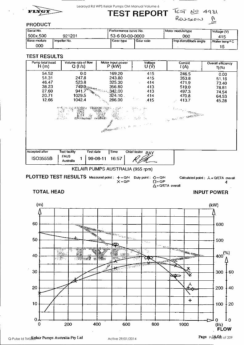
PRODUCT
TEST REPORT
Serial No.
500x.500 921201 Performance curve No.
53-6 00-00-0000 Motor module/type
000 Voltage (V)
415 Base module
000 Impeller No. Gear type Gear ratio Imp.diarn/Blade angle Water temp° C
15
TEST RESULTS Pump total head
H (m) Volume rate of flow
0 (I /s) Motor input power
P (kW) Voltage U (V)
Current I (A)
Overall efficiency
54.52 0.0 169.20 415 246.5 0.00 51.31 247.8 243.80 415 353.8 51.16 46.47 523.8 325.30 414 471.9 73.40 38.23 74919p1, - 356.80 413 519.0 78.81 27.60 941.7 ,342.00 413 497.3 74.54 20.71 1029.5 3'24:10 414 470.8 64.53 12.66 1042.4 286.00 -.418 413.7 45.28
Accepted after
IS03555B
Test facility
FAUS Australia
Test date I Time
1 99-08-11 16:57
Chief tester y
KELAIR PUMPS AUSTRALIA (955 rpm)
PLOTTED TEST RESULTS
TOTAL HEAD
(m)
60
50
40
30
20
10
Measured point : = Q/H Duty point : 40.= Q/H
X = 0/P = Q/P A= Q/ETA overall
Calculated point :A = Q/ETA overall
4
INPUT POWER
(kW)
......"---'''".-"--...-....---.."""Qqa,..._ ........ -,:. , '
-f-
4...7-::
-R.
Awaso........-. .
...I Imo..
...
...."
A
o, 0 200
Kelair Pumps Australia Pty Ltd
400 600 800 1000
600
500
(0/0) 400
300
200
100
60
4
20
0 10 (Vs) FLOW
Page 16.03
Learoyd Rd WPS Kelair Pumps OM Manual Volume 6
Q-Pulse Id TMS607 Active 29/01/2014 Page 83 of 209
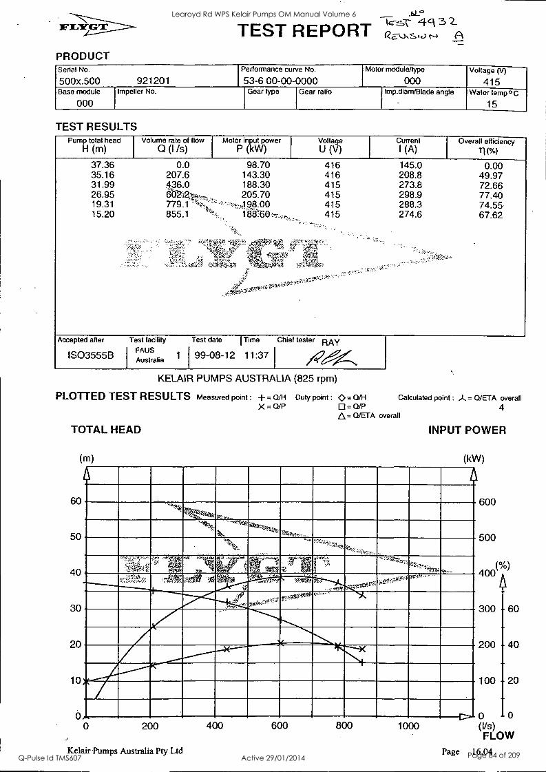
PRODUCT
4ck 3 2- TEST REPORT Rs, Serial No.
500x.500 921201 Performance curve No.
53-6 00-00-0000 Motor module/type
000 Voltage (V)
415 Base module
000 Impeller No. Gear type Gear ratio Imp.diam/Blade angle Water temp o C
15
TEST RESULTS Pump total head Motor input power Voltage Current Overall efficiency
H (m) P (kW) U (V) I (A) /I(%)
37.36 35.16 31.99 26.95 19.31 15.20
0.0 207.6 436.0
779.1 '- 855.1
98.70 143.30 188.30 205.70 Ass.00 186:760,:r
416 145.0 0.00 416 208.8 49.97 415 273.8 72.66 415 298.9 77.40 415 288.3 74.55 415 274.6 67.62
!;,A,.=-'4
Accepted after
1S03555B
Test facility
FAUS Australia
Test date I Time Chief tester RAY
1 199 -08 -12 11:37
KELAIR PUMPS AUSTRALIA (825 rpm)
PLOTTED TEST RESULTS Measured point : -F. Q/H Duty point : Q = Q/H Calculated point : J.= Q/ETA overall X = Q/P 0 = Q/P 4
Z),= Q/ETA overall
TOTAL HEAD
(m)
60
50
40
30
20
10
INPUT POWER
(kW)
'et. ...
'', 441,..-..s,
, .,., .k ,,,s
, ''.1 ''''''''/',Zt3i*:::-
.. ...
;?114.s.,;': :ate r' :,...A osv'...,.....444,,,,,;. ..,.
wow.14.- ... ......rA.z., --
. .... -..,,,.
- ,,,,::..r. ---!.-
3I
. _ r-......_ 6,-
Volume rate of How
Q (I /s)
0 200
Kelair Pumps Australia Pty Ltd
400 600 800 1000
600
500
(0/0) 400
300
200
100
60
4
20
0 10 (Vs) FLOW
Page 16.04
Learoyd Rd WPS Kelair Pumps OM Manual Volume 6
Q-Pulse Id TMS607 Active 29/01/2014 Page 84 of 209
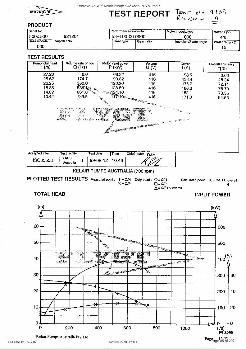
PRODUCT
TEST REPORT TT-&I- N,21/4-hS1 A
Serial No.
500x.500 921201 Performance curve No.
53-6 00-00-0000 Motor module/type
000 Voltage (V)
415 Base module
000 Impeller No. Gear type Gear ratio frnp.diarn/Blade angle Water tempo C
15
TEST RESULTS Pump total head
H (m) Volume rate of flow
0 (I Is) Motor input power
P (kW) Voltage U (V)
Current I (A)
Overall efficiency
TI(%)
27.20 0.0 66.32 416 98.9 0.00 25.62 174.7 90.82 416 133.4 48.34 23.25 380.0 120.20 416 175.7 72.11 18.88 53-4U,,, , 128.80 416 188.0 76.79 14.02 661.8 -'..,:. '',44,4 24.10 416 182.1 73.35 10.42 739.5 '--%, 110, 416 --g......i.z.i. 171.0 64.53
Accepted after
IS03555B
Test facility
FAUS Australia
Test date I Time Chief tester RAY
1 99-08-12 10:46
KELAIR PUMPS AUSTRALIA (700 rpm)
PLOTTED TEST RESULTS Measured point : = Q/H Duty point : 0.= Q/H Calculated point : A= Q/ETA overall X = Q/P D=QJP 4
A= Q/ETA overall
TOTAL HEAD
(m)
60
50
40
30
20
10
0
INPUT POWER
(kW)
''''?: 2,-- re.li, ,.,,..
_....,-.... _
f..1,,ar,
- °Y '.;r,,,,.
" .. 1:1-ii;;;::' ''''...,:::-YI,
-:5
"`" '''t; le 30' , 4°' ...--ti ,qt? ,-1. tax v
--1,,,, , ,4.2,
,..:,c,f,":11, .
:::'Ar.:',"!:J. . :; . ,,, ';.......,"-; Ar: r r.../.1.,0:`
..;q,1,,,,,,,' ,;.F.,, -
0 iX ..
,CISP47:64 ,ISSAgas."`- ''
0015.:*
.,....
r
4110""'" - r---
0 200
Kelair Pumps Australia Pty Ltd
400 600 800 1000
600
500
(0/0) 400
300
200
100
60
4
20
0 10 (Vs) FLOW
Page 16.05
Learoyd Rd WPS Kelair Pumps OM Manual Volume 6
Q-Pulse Id TMS607 Active 29/01/2014 Page 85 of 209
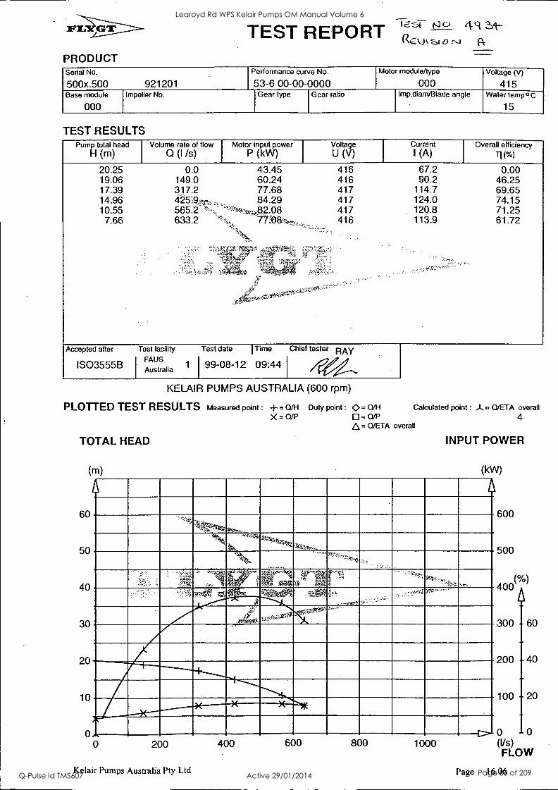
PRODUCT
TEST REPORT 16,-"1- ``)" 41 ..c-u.T.,1 R
Serial No.
500x.500 921201 Performance curve No.
53-6 00-00-0000 Motor module/type
000 Voltage (V)
415 Base module
000 Impeller No. Gear type Gear ratio Imp.diarn/Blade angle Water temp °C
15
TEST RESULTS Pump total head
H (m) Volume rate of flow
0 (I /s)
20.25 0.0 19.06 149.0 17.39 317.2 14.96 10.55 565.2. 7.66 633.2
Motor input power P (kW)
Voltage U (V)
Current I (A)
Overall efficiency
11( %)
43.45 416 67.2 0.00 60.24 416 90.2 46.25 77.68 417 114.7 69.65 84.29 417 124.0 74.15
417 120.8 71.25 416 113.9 61.72
Accepted after
IS03555B
Test facility
FAUS Australia
Test date I Time Chief tester RAY
1 99-08-12 09:44
KELAIR PUMPS AUSTRALIA (600 rpm)
PLOTTED TEST RESULTS Measured point : -1-= Q/H Duty point : 0= Q/H Calculated point : A = 0/ETA overall X = Q/P 0= Q/P 4
Q/ETA overall
TOTAL HEAD
(m)
60
50
40
30
20
10
INPUT POWER
(kW)
- ---.:710
" -
5'
Ta;irte ,i -
r-,..
200
Kelair Pumps Australia Pty Ltd
400 600 800 1000
600
500
0/0 400
(
300 60
200 4
100 20
0 10 (Vs) FLOW
Page 16.06
Learoyd Rd WPS Kelair Pumps OM Manual Volume 6
Q-Pulse Id TMS607 Active 29/01/2014 Page 86 of 209
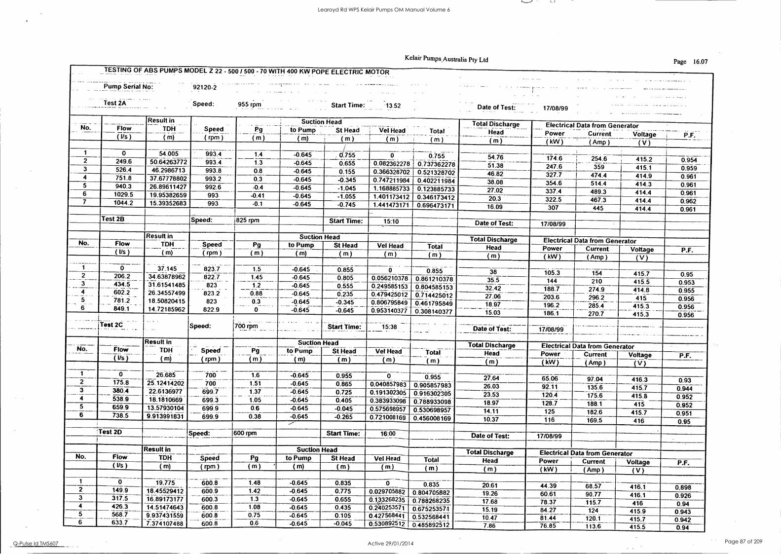
Kelair Pumps,Australia Pty Ltd Page 16.07 TESTING OF ABS PUMPS MODEL Z 22 - 500 / 500 - 70 WITH 400 KW POPE ELECTRIC MOTOR ....
Pump Serial No: 92120-2 . . . .. _
. .
Date of Test: Test 2A - Speed: 955 rpm Start Time 13.52 17/08/99 . . ...
No Flow Result in
. .... _ .
TDH
( m)
Speed ( rpm )
_._. Pg
(m)
Suction Head ____ ... ...._ _ ....._ .. .
to Pump St Head _..:
(- m) (m) Vel Head Total
Cm ) (m)
Total Total Discharge Head
( m )
Electrical Data from Generator Power Current (kW) ' (Amp)
Voltage P.F. ( Us ) ( V )
. 993.4 993.4
1 0 54.005 1.4
1.3 -0.645 -0.645
d 755 0 0.55 0.737362278 0.5213287-6i 0.402-276974
54.76 174.6 254.6 415.2 0.954 2 249.6 50.64263772 0.655 0.082362278 51.38 46.82 38.08
247.6 327.7 354.6
359 474.4 514.4
. 415.1 414.9 414.3
0.959 0.961 0.961
3 526.4 46.2986713 993.8 0.8 -0.645 0.155 0.366328702 0.747211484 4 751.8 37.67778802 993.2 0.3 -0.645 -0.345
5 940.3 26.89611427 992.6 -0.4 -0.645 -1.045 1.168885733 0.123885733 27.02 337.4 489.3 414.4 0.961 6 1029.5 19.95382659 993 -0.41 -0.645 -1.055 1.401173412 0.346173412 20.3 322.5 467.3 414.4 0.962 7 1044.2 15.39352683 993 -0.1 -0.645 -0.745 1.441473171 0.696473171 16.09 307 445 414.4 0.961
Test 2B Speed: 1825 rpm Start Time: 15:10 Date of Test: 17/08/99
Result in Suction Head Total Discharge Electrical Data from Generator No. Flow (1/s )
TDH
( m)
Speed ( rpm )
Pg to Pump St Head Vel Head Total Head Power Current Voltage P.F. ( m ) ( m) ( m ) ( rn ) ( m ) ( m ) ( kW ) ( Amp ) ( V )
1 0 37.145 823.7 822.7
_ 823
823.2 823
822.9
1.5 -0.645 0.855 0.865 0.55 _ ....
0
0.05621678
0.479425012
0:95314037i
0.855 0.861210378
0.714425012 0.461795849 0.308140377
38 35.5
105.3 144
154
210 415.7 415.5
0.95 0.953
2
3 ---- 4
5 _
6
206.2 434.5
---- - --- 602.2 7812
. . _. . .
849.1
34.63878962 31.61541485
- 26.34557499 18.50820415 14.72185962
1.45 f.-------
0.88 0.3_
_
-0.645 4.66 ..___ 32.42 188.7
203.6 274.9 296.2
414.8 0.955 -0.645 --- -0.64
... .. _.__ -0.645
0.235 27.06 415 0.956 -61,f5----"--6656765646 -0.645
18.97 - 15.03 196.2 285.4
270.7 415.3 415.3
0.956 186.1 0.956
____ Test 2d .._. .. Speed: .. .._.
700 rpm _ .._ __ ..... .. Start Time: 15:38 .._._. ____ . ._ _ Date of Test: 17/08/99
- --- No. Flow
Tos )---
Result In TDH
- ( m) Speed
. .
( rpm )
Pg
( m )
Suction to Pump
. _ Am)
Head _.
St Head WI Head ______
(m) (m) Total (m)
Total Discharge Electrical Data from Generator Head Power Current Voltage P.F. (m) (kW) ( Amp ) ( V )
26.685 25.12414202 2i.ii* 3607 18.1810669
700 . .
0.955 1
2 0
175.6 - 1.6 -0.645 0.955 0 27.64 65.06 97.04 416.3 0.93 700
699.7 -----694.3
1.51
1.37 1.05
-0.645 0.865 0.040857983 0.905857983 26.03 92.11 135.6 415.7 0.944 3 38674 -0.645 0.725 0.191302305 0.916302305 23.53 120.4 175.6 415.8 0.952 4 538.9 -0.645 0.405 0.383933098 0.788933098 18.97 128.7 188.1 415 0.952 5 659.9 13.57930104 9.913991831
6949_ 699.9
0.6 -0.645 -0.045 0.575698957 0.530698957 0.456008169
14.11 125 182.6 415.7 0.951 6 738.5 0.38 -0.645 -0.265 0.721008169 10.37 116 169.5 416 0.95 ' . Test 20 Speed: 600 rpm Start Time: 16:00 Date of Test: 17/08/99
Result in , Suction Head Total Discharge Electrical Data from Generator No. Flow TDH Speed Pg to Pump St Head Vel Head Total Head Power Current Voltage P.F. (Ifs) (m) ( '111)
600.8
(m) (m) (m) (m) (m) (m) (kW) ( Amp ) ( V )
1 0 19.775 1.48 -0.645 0.835 0 0.835 20.61 44.39 68.57 416.1 0.898 2 149.9 18.45529412 16.89173177 14.51474643
64_6.9
600.3 1.42 -0.645 0.775 0.029705882 0.804705882 19.26 60.61 90.77 416.1 0.926 3 317.5 1.3 -0.645 0.655 0.133268b5 0.788268235 17.68 78.37 115.7 416 0.94 4 426.3 6668
6664 5.00.8
1.08 -0.645 0.435 0.240253571 0.6752537-1 6i32568441 07485892512
15.19 84.27 124 415.9 0.943 5
6 --- 568.7 833.7
9.937431559 7.374167,188
0.75 -0.645 0.105 0.427568441 10.47 81.44 120.1 415.7 0.942 0.6 -0.645 -0.045 0:530892512 7.86 76.85 113.6 415.5 0.94
Learoyd Rd WPS Kelair Pumps OM Manual Volume 6
Q-Pulse Id TMS607 Active 29/01/2014 Page 87 of 209
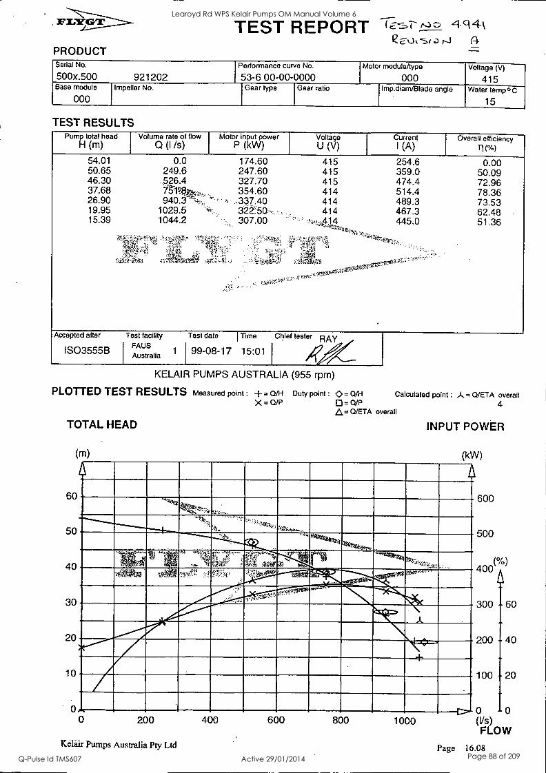
PRODUCT
TEST REPORT 1q4 Q01/4.),sia
Serial No.
500x.500 921202 Performance curve No.
53-6 00-00-0000 Motor module/type
000 Voltage (V)
415 Base module
000 Impeller No. Gear type Gear ratio Imp.diam/Blade angle Water temp 0 C
15
TEST RESULTS Pump total head Volume rate of flow Motor input power Voltage Current Overall efficiency
H (m) Q(I /s) P (kW) U (V) I (A) II(%) 54.01 50.65 46.30 37.68 26.90 19.95 15.39
0.0 249.6 5,26.4 71q$4,, 940.3
1029.5 1044.2
174.60 247.60 327.70 354.60 .337.40
307.00
415 415 415 414 414 414
254.6 359.0 474.4 514.4 489.3 467.3 445.0
4r
0.00 50.09 72.96 78.36 73.53 62.48 51.36
Accepted after
IS03555B
Test facility FAUS
Il Australia
Test date I Time
1 99-08-17 15:01
Chief tester RAY
KELAIR PUMPS AUSTRALIA (955 rpm)
PLOTTED TEST RESULTS Measured point : --= Q/H Duty point : 0= Q/H X= 0/13 0=0/P
A= Cl/ETA overall
TOTAL HEAD
(m)
60
50
40
30
20
10
0 0
Calculated point : Q/ETA overall 4
INPUT POWER
(kW)
,....k
',!..p.1...
Co
.±) * ...., ° .4t.3
N., ,:i
,...
,. 40,1:
.
V4'1,1 'P:1::'.:w, '-'..i...',",l'isezi%*. 3tio"" :.
n` ;,.$:*rsfog6"'"--
t elm. A
- ...
±
1"-....
200
Kelair Pumps Australia Pty Ltd
400 600 800 1 000
600
500
(0/0) 400
300 60
200 4
100 20
0 10 (Vs) FLOW
Page 16.08
Learoyd Rd WPS Kelair Pumps OM Manual Volume 6
Q-Pulse Id TMS607 Active 29/01/2014 Page 88 of 209

PRODUCT
TEST REPORT To U.
Serial No.
500x.500 921202 Performance curve No.
53-6 00-00-0000 Motor module/type
000 Voltage (V)
415 Base module
000 Impeller No. Gear type Gear ratio Imp.diarn/Blade angle Water tempo C
15
TEST RESULTS Pump total head
Fl (m) Volume rate of flow
(I /s) Motor input power
P (kW)
37.15 0.0 105.30 34.64 206.2 144.00 31.62 434.5 188.70 26.35 6d2..kT, 203.60 18.51 781.2 196.20 14.72 849.1 186:10-
Voltage U (V)
Current I (A)
Overall efficiency
416 154.0 0.00 416 210.0 48.66 415 274.9 71.41 415 296.2 76.44 415 285.4 72.29 415 270.7 65.89
Accepted after
IS03555B
Test facility
FAUS Australia
Test date Time Chief tester RAY 1 199 -08 -17 15:31
KELAIR PUMPS AUSTRALIA (825 rpm)
PLOTTED TEST RESULTS Measured point : -4-= Q/H Duty point : 0= Q/H Calculated point : A= Q/ETA overall X = 0/P 0 = 0/F' 4
A= Q/ETA overall
TOTAL HEAD
(m)
60
50
40
30
20
10
INPUT POWER
(kW)
TV,. ;';',U,
14.. . 'V i
. 1 aniiiriat...
11111111111111111.. ,
A
-....0411
Ith.
o 0 200
Kelair Pumps Australia Pty Ltd
400 600 800 1000
600
500
(0/0) 400
300
200
100
60
40
20
0 10 (Vs) FLOW
Page 16.09
Learoyd Rd WPS Kelair Pumps OM Manual Volume 6
Q-Pulse Id TMS607 Active 29/01/2014 Page 89 of 209
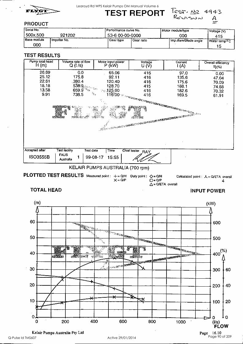
PRODUCT
TEST REPORT 111' ^---)=2 4-143 cvsty Serial No.
500x.500 921202 Performance curve No.
53-6 00-00-0000 Motor module/type
000 Voltage (V)
415 Base module
000 Impeller No. Gear type Gear ratio Imp.diam/Blade angle Water temp ° C
15
TEST RESULTS Pump total head Volume rate of flow Motor input power Voltage Current Overall efficiency
H (m) Q (I Is) P (kW) U (V) I (A) li( %)
26.69 25.12 22.61 18.18 13.58
9.91
0.0 175.8
659.9 738.5
65.06 92.11
120.40 128.70 :1_25.00
416 97.0 0.00 416 135.6 47.04 416 175.6 70.09 415 188.1 74.68 416 182.6 70.32 416 169.5 61.91
-
Accepted after
IS03555B
Test facility
FAUS Australia
Test date I Time
1 99-08-17 15:55
Chief tester RAY
KELAIR PUMPS AUSTRALIA (700 rpm)
PLOTTED TEST RESULTS Measured point :
TOTAL HEAD
(m)
60
50
40
30
20
10
4- =QM Dutypoint: <>=0/H 0= OM X = D/P
Calculated point : A = Q/ETA overall 4
A= 0/ETA overall
INPUT POWER
(kW)
I. If
x..%%t. U
'''''5;:g .
' 1 IAA 70
1 -'. ...,
. .
Istoloa° .f. ,. --
-
67Z..'''........."......."4( .
r- o 0 200
Kelair Pumps Australia Pty Ltd
400 600 800 1000
600
500
(°/0) 400
300
200
100
60
40
20
0 10 (Vs) FLOW
Page 16.10
Learoyd Rd WPS Kelair Pumps OM Manual Volume 6
Q-Pulse Id TMS607 Active 29/01/2014 Page 90 of 209
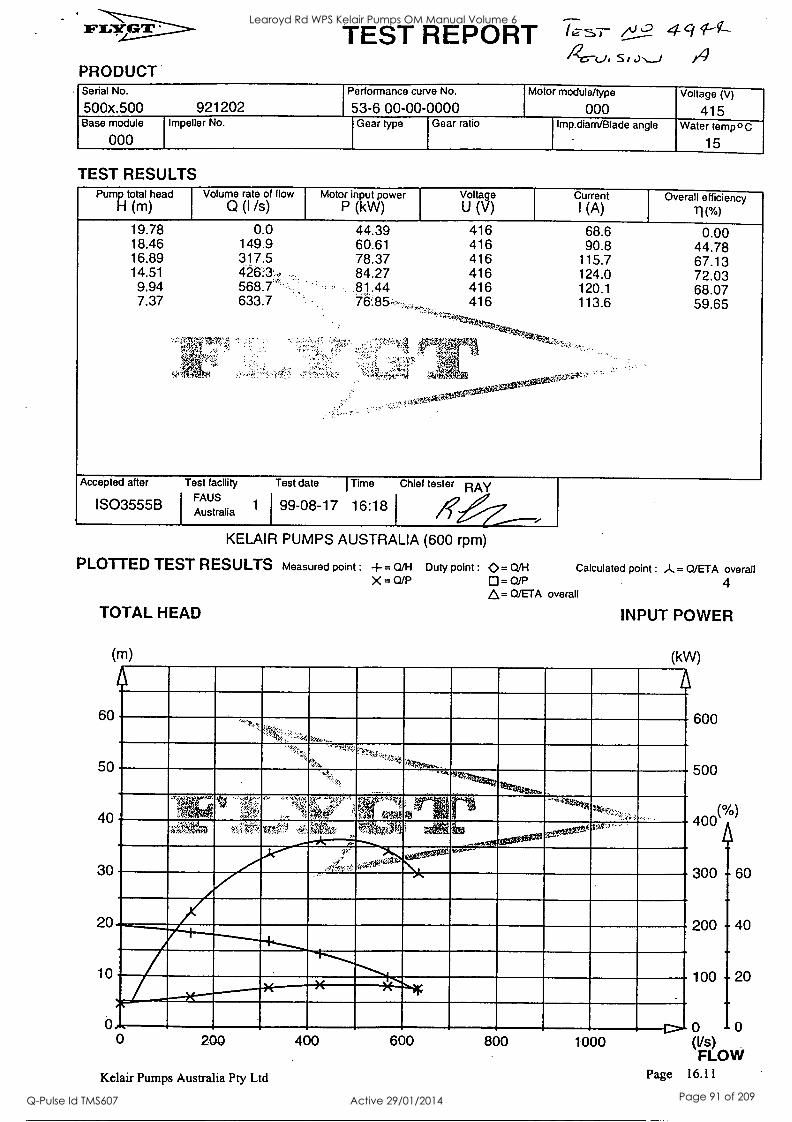
PRODUCT
TEST REPORT SI 4
Serial No.
500x.500 921202 Performance curve No.
53-6 00-00-0000 Motor module/type
000 Voltage (V)
415 Base module
000 Impeller No. Gear type Gear ratio Imp.diarn/Blade angle Water temp°C
15
TEST RESULTS Pump total head
H (m) Volume rate of flow
Q (I /s) Motor input power
P (kW) Voltage U (V)
Current I (A)
Overall efficiency 11 (%)
19.78 0.0 44.39 416 68.6 0.00 18.46 149.9 60.61 416 90.8 44.78 16.89 317.5 78.37 416 115.7 67.13 14.51 4263: 84.27 416 124.0 72.03 9.94 568.7 .81.44 416 120.1 68.07 7.37 633.7 416 113.6 59.65
Accepted after
IS03555B
Test facility FAUS
Australia
Test date I Time Chief tester RAY
1 99-08-17 16:18
KELAIR PUMPS AUSTRALIA (600 rpm)
PLOTTED TEST RESULTS Measured point : += Q/H Duty point : Q= Q/H Calculated point : A= Q/ETA overall X = a/P 0=0/P 4
A= Q/ETA overall
TOTAL HEAD
(m)
60
50
40
30
20
10
INPUT POWER
(kW)
'';:;!, ".!.., .""''''-'"
.:'..,,,
ip,
- ,..
'k'Z'st.1....
..1..,,,
.._... .
,.,', i - - -
-.0- , ?0,1.-.19 : +1 Ivi4
.A.
... r--,.. 0 200
Kelair Pumps Australia Pty Ltd
400 600 800 1000
600
500
(0/0)
400
300
200
100
60
40
20
0 i 0 (Vs)
FLOW Page 16.11
Learoyd Rd WPS Kelair Pumps OM Manual Volume 6
Q-Pulse Id TMS607 Active 29/01/2014 Page 91 of 209
KelairPumps
PAGE 17.00
17: Appendix 1
CONTENTS : PAGE SCHEDULE D5 - VIBRATION LIMITS FOR PUMPS Page 67 FAN MONITOR Pages : 19 - 24
91 -94
Learoyd Rd WPS Kelair Pumps OM Manual Volume 6
Q-Pulse Id TMS607 Active 29/01/2014 Page 92 of 209
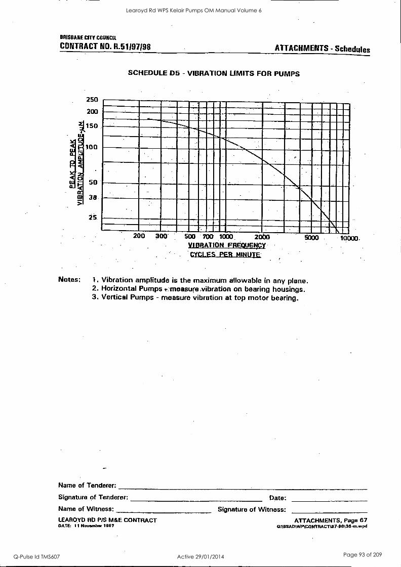
BRISBANE CITY COUNCIL
CONTRACT NO. R.51197198 ATTACHMENTS - Schedules
250
200
1150
SCHEDULE D5 - VIBRATION LIMITS FOR PUMPS
200 300' 500 700 1000. 20b0 VIBRATION FREQUENCY
CYCLES PER MINUTE
Notes: 1. Vibration amplitude is the maximum allowable in any plane. 2. Horizontal Pumps e. measure, ibration on bearing housings. 3. Vertical Pumps - measure vibration at top motor bearing.
10000.
Name of Tenderer:
Signature of Tenderer: Date:
Name of Witness: Signature of Witness: LEAROYD RD P/S M&E CONTRACT °ATE: 11 ttovembet 1997
ATTACHMENTS, Page 67 CPA9SAMWMCOMTRACT107-013136-m,wpd
Learoyd Rd WPS Kelair Pumps OM Manual Volume 6
Q-Pulse Id TMS607 Active 29/01/2014 Page 93 of 209
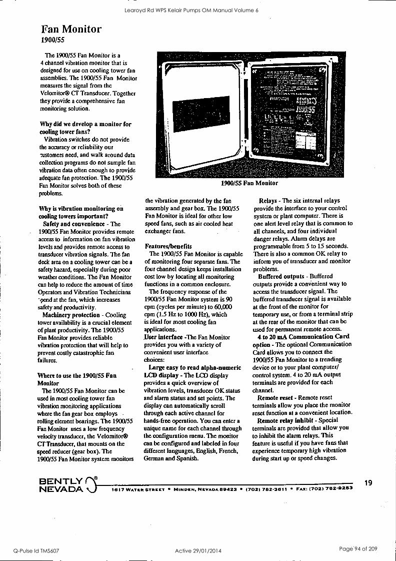
Fan Monitor 1900/55
The 1900/55 Fan Monitor is a 4 channel vibration monitor that is
designed for use on cooling tower fan assemblies. The 1900/55 Fan Monitor measures the signal from the Velomitor® cr Transducer. Together they provide a comprehensive fan monitoring solution.
Why did we develop a monitor for cooling tower fans?
Vibration switches do not provide the accuracy or reliability our customers need, and walk around data collection programs do not sample fan vibration data often enough to provide adequate fan protection. The 1900/55 Fan Monitor solves both of these problems.
Why is vibration monitoring on cooling towers important?
Safety and convenience - The 1900/55 Fan Monitor provides remote access to information on fan vibration levels and provides remote access to transducer vibration signals. The fan deck area on a cooling tower can be a
safety hazard, especially during poor weather conditions. The Fan Monitor can help to reduce the amount of time Operators and Vibration Technicians spend at the fan, which increases safety and productivity.
Machinery protection - Cooling tower availability is a crucial element of plant productivity. The 1900/55 Fan Monitor provides reliable vibration protection that will help to prevent costly catastrophic fan failures.
Where to use the 1900/55 Fan Monitor
The 1900/55 Fan Monitor can be used in most cooling tower fan vibration monitoring applications where the fan gear box employs rolling element bearings. The 1900/55 Fan Monitor uses a low frequency velocity transducer, the Velomitor® CT Transducer, that mounts on the speed reducer (gear box). The 1900/55 Fan Monitor system monitors
r
1900/55 Fan Monitor
the vibration generated by the fan assembly and gear box. The 1900/55 Fan Monitor is ideal for other low speed fans, such as air cooled heat exchanger fans.
Features/benefits The 1900/55 Fan Monitor is capable
of monitoring four separate fans. The four channel design keeps installation cost low by locating all monitoring functions in a common enclosure.
The frequency response of the 1900/55 Fan Monitor system is 90 cpm (cycles per minute) to 60,000 cpm (1.5 Hz to 1000 Hz), which is ideal for most cooling fan applications. _User interface -The Fan Monitor provides you with a variety of convenient user interface choices:
Large easy to read alpha-numeric LCD display - The LCD display provides a quick overview of vibration levels, transducer OK status and alarm status and set points. The display can automatically scroll through each active channel for hands-free operation. You can enter a unique name for each channel through the configuration menu. The monitor can be configured and labeled in four different languages, English, French, German and Spanish.
Relays - The six internal relays provide the interface to your control system or plant computer. There is
one alert level relay that is common to all channels, and four individual danger relays. Alarm delays are programmable from 5 to 15 seconds. There is also a common OK relay to inform you of transducer and monitor problems.
Buffered outputs - Buffered outputs provide a convenient way to access the transducer signal. The buffered transducer signal is available at the front of the monitor for temporary use, or from a terminal strip at the rear of the monitor that can be used for permanent remote access.
4 to 20 mA Communication Card option - The optional Communication Card allows you to connect the 1900/55 Fan Monitor to a trending device or to your plant computer/ control system. 4 to 20 mA output terminals are provided for each channel.
Remote reset - Remote reset terminals allow you place the monitor reset function at a convenient location.
Remote relay inhibit - Special terminals are provided that allow you to inhibit the alarm relays. This feature is useful if you have fans that experience temporary high vibration during start up or speed changes.
BENTLY NEVADA 1617 WATERS NIINDKR, NEVADA 89423 (702) 782-3611 FAX: (702) 782-9253
19
Learoyd Rd WPS Kelair Pumps OM Manual Volume 6
Q-Pulse Id TMS607 Active 29/01/2014 Page 94 of 209
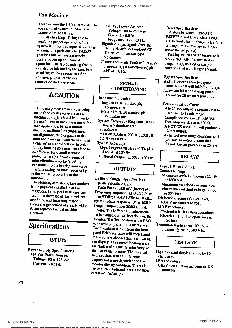
Fan Monitor
You can wire the inhibit terminals into your control system to reduce the chance of false alarms.
Fault checking - Being able to verify the proper operation of the system is important, especially if there is a machine problem. The 1900/55 provides internal system checks during power up and normal operation. The fault checking feature can also be initiated by the user. Fault checking verifies proper monitor voltages, proper transducer connection and operation.
ACAUT1ON
If housing measurements are being _
made for overall protection of the machine, thought should be given to the usefulness of the measurement for each application. Most common machine malfunctions (imbalance, misalignment, etc.) originate at the rotor and cause an increase (or at least a change) in rotor vibration. In order for any housing measurement alone to be effective for overall machine protection, a significant amount of rotor vibration must be faithfully transmitted to the bearing housing or machine casing, or more specifically, to the mounting location of the transducer.
In addition, care should be exercised in the physical installation of the transducer. Improper installation can result in a decrease of the transducer amplitude and frequency response and/or the generation of signals which do not represent actual machine vibration.
Specifications
INPUTS
Power Supply Specifications 120 Vac Power Source:
Voltage: 90 to 125 Vac. Current: <0.11A.
20
240 Vac Power Source: Voltage: 180 to 2.50 Vac. Current: <0.05A. Frequency: 47 to 63 Hz.
Signal: Accepts signals from the Bendy Nevada Velomitor® CT Transducer or similar type Velomitors.
Transducer Scale Factor: 3.94 mV/ (um/sec) pk, (100mVginisec) pk ±5% at 100 Hz.
SIGNAL CONDITIONING
Monitor Full-scale: English units: 2 in/sec pk,
15 in/sec rms. Metric Units: 50 mm/see pk,
35 mm/sec rms. System Frequency Response (when
using a Velomitor CT Transducer.
±1.0 dB 3.0 11Z to 900 Hz; ±3.0 dB 1.5 Hz to 1.0 kHz.
System Accuracy: Liquid crystal display: ±10% plus
5 counts at 100 Hz. Buffered Output: ±10% at 100 Hz.
OUTPUTS
Buffered Output Specifications (with Velomitor CT): Scale Factor: 500 mV (in/sec) pk.
Frequency response: ±1.0 dB 3.0 Hz to 900Hz; ±3.0dB 1.5Hz to1.0 kHz.
System phase response: 0° at 100Hz. Output Impedance: 3000 typical.
Note: The buffered transducer out- put is available at two locations on the monitor. The first location is the BNC connector on the monitor front panel. The transducer output from the front panel BNC connector will correspond to the current channel that is shown on the display. The second location is on the "buffered output" terminal strip at the rear of the monitor. The terminal strip provides four simultaneous outputs and is not dependent on the monitor display condition. The scale factor at each buffered output location is 500 mV (in/see) pk.
Reset Specifications A short between "REMOTE
RESET" A and B will clear a NOT OK latched alert or danger relay (alert or danger relays that are no longer above the set points).
Pushing the "RESET" button will clear a NOT OK, latched alert or danger relay, an alert or danger condition that is no longer present.
Bypass Specifications A short between remote bypass
units A and B will inhibit all relays. Relays are inhibited during power
up and for 18 ms after power up.
Communication Card: 4 to 20 mA output is proportional to
monitor full-scale range. Compliance voltage 18 to 36 Vdc. Total loop resistance to 600 0. A NOT OK condition will produce a
2 mA output. A channel over-range condition will produce an output greater than 21 mA, but no greater than 26 mA.
RELAYS
Type: 1 Form C SPDT. Contact Ratings:
Maximum switched power: 224 W or 1600 VA.
Maximum switched current: 8 A. Maximum switched voltage: 28 dc
or 300 Vac. Dielectric Strength (at sea level):
4000 Vrms contact to coil. Life Expectancy:
Mechanical: 10 million operations. Electrical: 1 million operations at
-rated load. Insulation Resistance: 1000 M
minimum, @ 20° C, 500 Vdc.
DISPLAYS
Liquid crystal display: 2 line by 16 characters.
LED Indicators: OK: Green LED on indicates an OK
condition.
Learoyd Rd WPS Kelair Pumps OM Manual Volume 6
Q-Pulse Id TMS607 Active 29/01/2014 Page 95 of 209

Fan Monitor
Alert: Yellow LED on indicates vibration level is higher than alert set point.
Danger: Red LED on indicates vibration level is higher than danger set point.
Bypass: Red LED on indicates a
channel is bypassed.
CONTROLS
Program mode switch: Allows access to the main configuration menu during initial monitor set up.
ENVIRONMENTAL LIMITS
Operating Temperature: -20°C to +70° C (-4°F to +158°F).
Storage Temperature: -30°C to
00°C ( -22 °F to +194°F). Maximum Relative Humidity: 95%
po ncondensing. cord osu re: Type 4 enclosure,
fiberglass. ItiptImpedance at transducer
lit at: 1 M Q in parallel with pF typical. The noise floor will not exceed
0.70mmisec pk (0.03 in/sec pk). alannEMI: Passes all tests
=wired to achieve CE mark.
PHYSICAL
Dimensions: Height: 337 mm (13.25 inches). Width: 295 mm (11.62 inches). Depth: 130 mm (5.13 inches).
ACCESSORIES
190155-01 Operation Manual
190101-01 Type 4 housing. The housing is used when the monitor is mounted locally on the fan deck, or when mounted in other outdoor locations.
190501-AA-BB-CC Velomitor CF Transducer, see data sheet L.5053 for transducer ordering information.
106769-01 Terminal Housing for terminating transducer signal cable from the Velomitor CT outside the fan stack. This junction box is provided with terminal strips.
Ordering Information A BCD
1900/55 - OD -00 -DO -00
Option Descriptions A OD Power Supply Option
O 1 120 Vac Power Supply O 2 240 Vac Power Supply
B DO Communication Option O 0 No communication O 1 4 to 20 mA output
COO O 1
O 2
O 3 O 4
Language Option English French German Spanish
D 00 Hazardous area approvals 0 0 No approvals 0 1 CSA/NRTLJC
21
Learoyd Rd WPS Kelair Pumps OM Manual Volume 6
Q-Pulse Id TMS607 Active 29/01/2014 Page 96 of 209
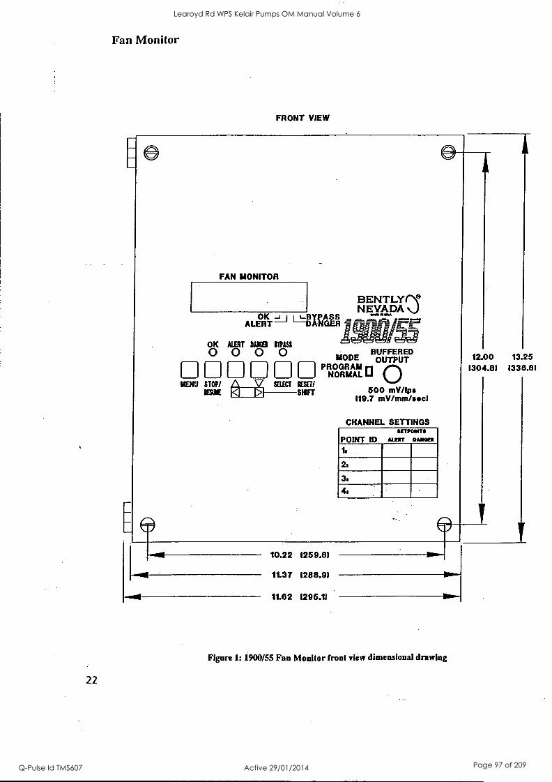
Fan Monitor
FRONT VIEW
FAN MONITOR
MENU STOP/ IBLIE
PROGRAM MODE
BUFFERED OUTPUT
NORMAL 0 500 mV/Ips
119.7 mV /mm /sect
CHANNEL SETTINGS {WOWS
POINT ID MEET DAM=
22
10.22 1259.81
1t37 1288.91
11.82 1296.11
Figure 1: 1900/55 Fan Monitor front view dimensional drawing
12.00 13.25 (304.81 1338.81
Learoyd Rd WPS Kelair Pumps OM Manual Volume 6
Q-Pulse Id TMS607 Active 29/01/2014 Page 97 of 209
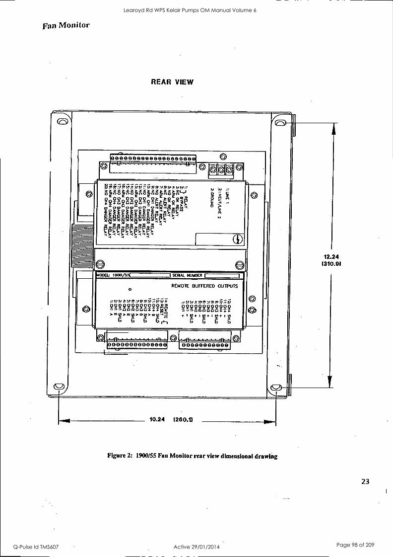
Fan Monitor
REAR VIEW
eeseesseseeeseeeee 4J
!cfsPReh.
?0142E802222keR!R
FalgaVISP4er-c hdphegpqa m mm mm mm m
gli-UMV-Mq
- U F 2 6
00a: moo/ssl 1 SERIAL NUMBER
0
222222222222AA 7.60D.wv.wy>mroA
6 6 6 61,1
1
REMOTE BUFFERED OUTPUTS
tt'Se4-$PRPT
222EFIEEM? 4.8T+Iv+IT+IT
6 6 6 G
111111111111111111 00000000000
12.24 1310.91
10.24 1280.11
Figure 2: 1900/55 Fan Monitor rear view dimensional drawing
23
Learoyd Rd WPS Kelair Pumps OM Manual Volume 6
Q-Pulse Id TMS607 Active 29/01/2014 Page 98 of 209
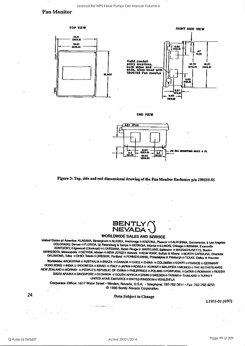
Fan Monitor
TOP VIEW
Valid conduit entry locations, both aides and ends, when used withNi- 1900/55 Fan monitor
RIGHT BIDE VIEW
1
71114111 11 I- 1 L. --1
1.51 .37
14-7 167016 . 3
END VIEW
0111.21 4.66 I
0.09172.91 mom
16.51 1393.91
Figure 3: Top, side and end dimensional drawing of the Fan Monitor Enclosure p/n 190101-01
BENTLY NEVADA
WORLDWIDE SALES AND SERVICE United States of America: ALABAMA. Birmingham o ALASKA. Anchorage o ARIZONA, Phoenix o CALIFORNIA. Sacramento, & Los Angeles COLORADO. Denver o FLORIDA, SI. Petersburg & Tampa a GEORGIA. Atlanta a ILLINOIS, Chicago o INDIANA. Evansville KENTUCKY, Edgewood (Cincinnati) o LOUISIANA, Baton Rouge o MARYLAND. Baltimore o MASSACHUSETTS, Boston MINNESOTA, Minneapolis a NEVADA. Minden a NEW JERSEY. Newark a NEW YORK. Buffalo & Albany a NORTH CAROLINA, Charlotte
OKLAHOMA, Tulsa o OHIO. Toledo o OREGON, Portland a PENNSYLVANIA, Philadelphia & Pittsburgh o TEXAS. Dallas & Houston Worldwide: ARGENTINA 0 AUSTRALIA o BRAZIL 0 CANADA a CHILE a CHINA a COLOMBIA o EGYPT o FRANCE a GERMANY
HONG KONG o INDIA a INDONESIA o ISRAEL o ITALY o JAPAN o KOREA a KUWAIT a MALAYSIA a MEXICO a THE NETHERLANDS NEW ZEALAND a NORWAY a PEOPLE'S REPUBLIC OF CHINA o PHILIPPINES a POLAND o PORTUGAL 0 QATAR a ROMANIA a RUSSIA
SAUDI ARABIA 0 SINGAPORE 0 SLOVAKIA 0 SOUTH AFRICA o SPAIN a SWEDEN a TAIWAN o THAILAND a TURKEY UNITED ARAB EMIRATES a UNITED KINGDOM o VENEZUELA
Corporate Office: 1617 Water Street Minden, Nevada, U.S.A. Telephone: 702-782-3611 Fax: 702-782-9253 © 1996 Bently Nevada Corporation
24 Data Subject to Change L1955 -01(4/97)
Learoyd Rd WPS Kelair Pumps OM Manual Volume 6
Q-Pulse Id TMS607 Active 29/01/2014 Page 99 of 209
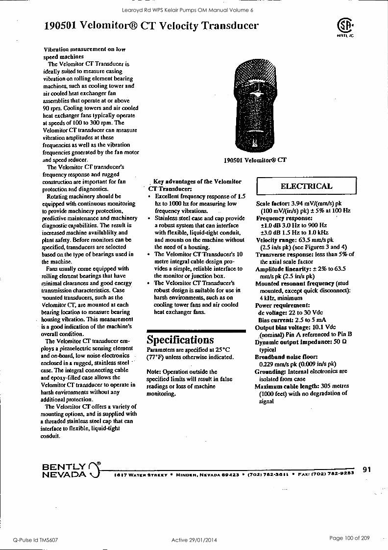
190501 Velomitor® CT Velocity Transducer
Vibration measurement on low speed machines
The Velomitor CT Transducer is
ideally suited to measure casing vibration on rolling element bearing machines, such as cooling tower and air cooled heat exchanger fan assemblies that operate at or above 90 rpm. Cooling towers and air cooled heat exchanger fans typically operate at speeds of 100 to 300 rpm. The Velomitor CT transducer can measure vibration amplitudes at these frequencies as well as the vibration frequencies generated by the fan motor and speed reducer.
The Velomitor CT transducer's frequency response and rugged construction are important for fan protection and diagnostics.
Rotating machinery should be equipped with continuous monitoring to provide machinery protection, predictive maintenance and machinery diagnostic capabilities. The result is increased machine availablilty and plant safety. Before monitors can be specified, transducers are selected based on the type of bearings used in the machine.
Fans usually come equipped with rolling element bearings that have minimal clearances and good energy transmission characteristics. Case mounted transducers, such as the Velomitor CT, are mounted at each bearing location to measure bearing housing vibration. This measurement is a good indication of the machine's overall condition.
The Velomitor CT transducer em- ploys a piezoelectric sensing element and on-board, low noise electronics enclosed in a rugged, stainless steel case. The integral connecting cable and epoxy-filled case allows the Velomitor CT transducer to operate in
harsh environments without any additional protection.
The Velomitor CT offers a variety of mounting options, and is supplied with a threaded stainless steel cap that can interface to flexible, liquid-tight conduit.
BENTLY
190501 Velomitor® CT
Key advantages of the Velomitor CT Transducer:
Excellent frequency response of 1.5 hz to 1000 hz for measuring low frequency vibrations. Stainless steel case and cap provide a robust system that can interface with flexible, liquid-tight conduit, and mounts on the machine without the need of a housing. The Velomitor CT Transducer's 10 metre integral cable design pro- vides a simple, reliable interface to the monitor or junction box. The Velomitor CT Transducer's robust design is suitable for use in harsh environments, such as on cooling tower fans and air cooled heat exchanger fans.
Specifications Parameters are specified at 25°C (77°F) unless otherwise indicated.
Note: Operation outside the specified limits will result in false readings or loss of machine monitoring.
ELECTRICAL
Scale factor: 3.94 mV/(mm/s) pk (100 mV/(in/s) pk) ± 5% at 100 Hz
Frequency response: ±1.0 dB 3.0 Hz to 900 Hz ±-3.0 dB 1.5 Hz to 1.0 kHz
Velocity range: 63.5 mm/s pk (2.5 in/s pk) (see Figures 3 and 4)
Transverse response: less than 5% of the axial scale factor
Amplitude linearity: ± 2% to 63.5 mm/s pk (2.5 in/s pk)
Mounted resonant frequency (stud mounted, except quick disconnect): 4 kHz, minimum
Power requirement: dc voltage: 22 to 30 Vdc Bias current: 2.5 to 5 mA
Output bias voltage: 10.1 Vdc (nominal) Pin A referenced to Pin B
Dynamic output Impedance: 50 0 typical
Broadband noise floor 0.229 mm/s pk (0.009 in/s pk)
Grounding: Internal electronics are isolated from case
Maximum cable length: 305 metres (1000 feet) with no degradation of signal
NEVADA 1617 WATER STREET MINDEN, NEVADA 60423 (702) 782-3611 FAR: (702) 782-9253 91
Learoyd Rd WPS Kelair Pumps OM Manual Volume 6
Q-Pulse Id TMS607 Active 29/01/2014 Page 100 of 209
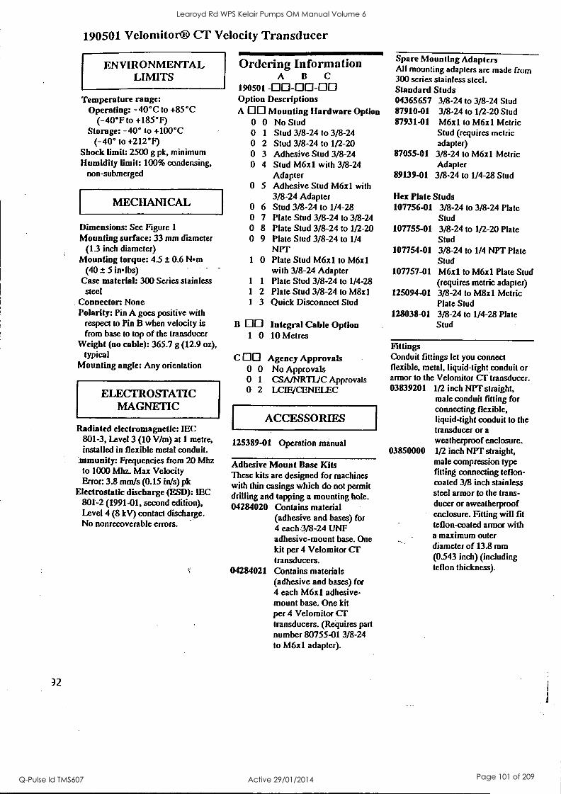
190501 Velomitor® CT Velocity Transducer
ENVIRONMENTAL LIMITS
Temperature range: Operating: -40°C to +85°C
(-40°F to +185°F) Storage: -40° to +100°C
(-40° to +212°F) Shock limit: 2500 g pk, minimum Humidity limit: 100% condensing,
non-submerged
MECHANICAL
Dimensions: See Figure 1
Mounting surface: 33 mm diameter (13 inch diameter)
Mounting torque: 4.5 ± 0.6 Nrn (40 I- 5 inlbs)
Case material: 300 Series stainless steel
Connector: None Polarity: Pin A goes positive with
respect to Pin B when velocity is from base to top of the transducer
Weight (no cable): 365.7 g (12.9 oz), typical
Mounting angle: Any orientation
ELECTROSTATIC MAGNETIC
Radiated electromagnetic: IEC
Ordering Information A B C
190501 -00-00-00 Option Descriptions A DO Mounting Hardware Option
0 0 No Stud 0 1 Stud 3/8-24 to 3/8-24 0 2 Stud 3/8-24 to 1/2-20 0 3 Adhesive Stud 3/8-24 0 4 Stud M6x1 with 3/8-24
Adapter 0 5 Adhesive Stud M6x1 with
3/8-24 Adapter 0 6 Stud 3/8-24 to 1/4-28 0 7 Plate Stud 3/8-24 to 3/8-24 0 8 Plate Stud 3/8-24 to 1/2-20 0 9 Plate Stud 3/8-24 to 1/4
NPT 1 0 Plate Stud M6x1 to M6x1
with 3/8-24 Adapter 1 1 Plate Stud 3/8-24 to 1/4-28 1 2 Plate Stud 3/8-24 to M8x1 1 3 Quick Disconnect Stud
B Integral Cable Option 1 0 10 Metres
C OD Agency Approvals 0 0 No Approvals 0 1 CSA/NRTUC Approvals 0 2 LCIE/CENELEC
ACCESSORIES
801-3, Level 3 (10 V/m) at 1 metre, installed in flexible metal conduit.
:mmunity: Frequencies from 20 Mhz to 1000 Mhz. Max Velocity Error: 3.8 mm/s (0.15 in/s) pk
Electrostatic discharge (ESD): IEC 801-2 (1991-01, second edition), Level 4 (8 kV) contact discharge. No nonrecoverable errors.
32
125389-01 Operation manual
Adhesive Mount Base Kits These kits are designed for machines with thin casings which do not permit drilling and tapping a mounting hole. 04284020 Contains material
(adhesive and bases) for 4 each :3/8 -24 UNF adhesive-mount base. One kit per 4 Velomitor Cr transducers.
04284021 Contains materials (adhesive and bases) for 4 each M6x1 adhesive- mount base. One kit per 4 Velomitor Cr transducers. (Requires part number 80755-01 3/8-24 to M6x1 adapter).
Spare Mounting Adapters All mounting adapters are made from 300 series stainless steel. Standard Studs 04365657 3/8-24 to 3/8-24 Stud 87910-01 3/8-24 to 1/2-20 Stud 87931-01 M6x1 to M6x1 Metric
Stud (requires metric adapter)
87055-01 3/8-24 to M6x1 Metric Adapter
89139-01 3/8-24 to 1/4-28 Stud
Hex Plate Studs 107756-01 3/8-24 to 3/8-24 Plate
Stud 107755-01 3/8-24 to 1/2-20 Plate
Stud 107754-01 3/8-24 to 1/4 NPT Plate
Stud 107757-01 M6x1 to M6x1 Plate Stud
(requires metric adapter) 125094-01 3/8-24 to M8x1 Metric
Plate Stud 128038-01 3/8-24 to 1/4-28 Plate
Stud
Fittings Conduit fittings let you connect flexible, metal, liquid-tight conduit or armor to the Velomitor Cr transducer. 03839201 1/2 inch NPT straight,
male conduit fitting for connecting flexible, liquid-tight conduit to the transducer or a weatherproof enclosure.
03850000 1/2 inch NPT straight, male compression type fitting connecting teflon- coated 3/8 inch stainless steel armor to the trans- ducer or aweatherproof enclosure. Fitting will fit teflon-coated armor with a maximum outer diameter of 13.8 mm (0.543 inch) (including teflon thickness).
Learoyd Rd WPS Kelair Pumps OM Manual Volume 6
Q-Pulse Id TMS607 Active 29/01/2014 Page 101 of 209
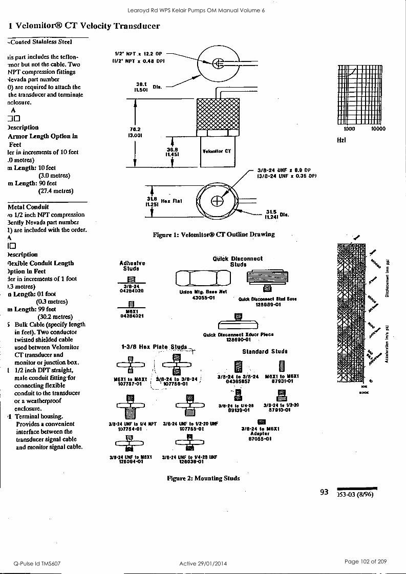
1 Velomitor® Cl' Velocity Transducer
-Coated Stainless Steel
us part includes the teflon- mor but not the cable. Two NPT compression fittings 'levada part number 0) are required to attach the the transducer and terminate nclosure.
A
DO )escription Armor Length Option in Feet ler in increments of 10 feet .0 metres) in Length: 10 feet
(3.0 metres) m Length: 90 feet
(27.4 metres)
Metal Conduit ro 1/2 inch NPT compression 3ently Nevada part number 1) are included with the order. A
1 )ascription flexible Conduit Length )ption in Feet ler in increments of 1 foot 13 metres) n Length: 01 foot
(0.3 metres) m Length: 99. feet
(30.2 metres) S Bulk Cable (specify length
in feet). Two conductor twisted shielded cable used between Velomitor CT transducer and monitor or junction box.
t 1/2 inch DPI straight, male conduit fitting-for connecting flexible conduit to the transducer or a weatherproof enclosure.
1 Terminal housing. Provides a convenient interface between the transducer signal cable and monitor signal cable.
1/2' NPT .x 12.2 DP
11/2' NPT x 0.48 DPI
38.1 Dla. 11.501
78.2 13.001
1
4
38.8 11.451
$
Veloadlor CT
3/8-24 UHF z 8.9 DP
13/8-24 IMF x 0.35 DPI
11.25t8 1
3 Hex Flat
Adhesive Studs
3/8-24 04284020
____EI____. 118/(1
04284021
31.5 11.24101a.
Figure 1: Velomitor® CT Outline Drawing
Dula( Disconnect Studs
Union Mtg. Base Nut 43055-01
1-3/8 Hex Plate Studs
IACIX1 to M8X1 107757-01
3/8-24 to 3/8-24 107758-01
Quick Disconnect Stud Base
128889-01
Quick Disconnect Xducr Piece 128890-01
Standard Studs
U 3/8-24 to 3/8-24
04385057 M8X1 to 118X1
87931-01
3/8 -24 to 1/4-21 3/8-24 to V2-20 89139-01 87910-01
3/8-24 UNF to 1/4 NPT 3/814 UNF to V2-20 UNF 107755-01
. 4FD 3/8.24 UNF to 118X1 3/0-24 UNF to 1/4-28 IMF
125094-01 128038-01
107764 -01
Figure 2: Mounting Studs
3/8.24 to M8X1 Adapter
87055-01
1000
HzI
10000
93 )53 -03 (8/96)
Learoyd Rd WPS Kelair Pumps OM Manual Volume 6
Q-Pulse Id TMS607 Active 29/01/2014 Page 102 of 209
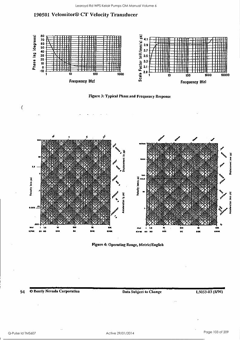
I
.1
1111111111 1111111111111 111111M111111111 MIIIIII111111111111111 1111111111111111
ismuummes 111111111111111111 IIMIN11 11111111111 N IMINIVOI11111
11111111131111111111111 11111111.1111111
1111111111". 11111111111111111110:
IIIMINIMMI11
IM11 1111 11 IMIIII11 IIIII1111 1 1111111111111111 111111111111 INI 11111 IMIIIM1111 =WNW!! 1111M111 MIIIIIIIIII11 01111111 111111111 IMIIIIIII IMMIESIB11 INIWIIIIIII IIIIIIIIIIIl 1111 IIMIIII11111 11111111 MINI1111 =111111 11111111111111511 INIIN11111 =own mmel mosexii Imosel ocuswli mwlo :22.1.1miell immommi mommeli =mown momIilowasamil
- 1/4" F4' 'rit 1,erro ii
el P.I t,c;.:::.1 P4 410 ..';:;1441,10
k*.W"' tk. irrl V%%i:' MPo:
.::.;.1.. .1\`, / o 4' . nwv a e; ra :b.::0,* ...7 ra , wo A: ir. 'zi: Into: . .tZCIlfall!: TZCII. s .'l'IrI'i, 'NVAP1101.4K`M:114,14:2MIS!) 1E001; :.4: 4 -Z4' ' c11 '1;gf, NM::'%4: ' k .to.k .":!; :127,:,::::....=;f4. , ,:r.z:,.. . -.=; . .. .,
0:;;,:24:;:i;:=Z:241....:=;5:1::::::.:::7:44..:::n;: !..:.zcirop:..tzce:ii."zcen .tz7.110t, Rol!:;:::::4Midel;;;;;;!AT.iill *4-1/001,
4M:i; i.-.:...16-:::...:-. 11:::::::::.
i
--. ,.... 1
....n. ;M"r.""rng!.40.1111. ./711.01' < g::Mi.'r.%.:, woe:r4.,:a.;: .:Ar:ral:!::. v.- 1 i.v.:0,:.,"11/001. ."TZ"..I''-'4 /1401;V:<$.:g11.1,C..*:' 4.:,.,, /01,:!::'44 4.:,,%ee v. 10%;;I2N g:r '.4.k .;:,..4.s. ., . .. 4:N1;%:I4 ;;;.V4, .1;;.k. ...I.
1 11
I I 1
111
gw411111111111M1111111111 11111111 MINIM 11/1111111111MIIIIIIIIM11111111 1111111111111 IIM1111111111111111111111111111111111111 1/11111111111111111111111111M111111111 11111111111 1111111111111111111111111111111111 11111111111 IIMI11111111111M111111111111111111111111111111111 111111111111M11111111111111111111 W 11111 IMIN111111111M111111111111111 1111111 11111111111111M1111111111M111111111 ME111111
. 111111111111111 111111111111111 IN 111111
1 1 1
a 1 : '.
Learoyd Rd WPS Kelair Pumps OM Manual Volume 6
Q-Pulse Id TMS607 Active 29/01/2014 Page 103 of 209

KelairPumps
PAGE 18.00
18: Appendix 2
CONTENTS : PAGE MOTOR INSTALLATION & MAINTENANCE MANUAL
(For contents see the forth page of this section)
Learoyd Rd WPS Kelair Pumps OM Manual Volume 6
Q-Pulse Id TMS607 Active 29/01/2014 Page 104 of 209

PEM-MAN
JANUARY 99
POPE ELECTRIC MOTORS
INSTALLATION AND MAINTENANCE MANUAL
TEFC
LOW VOLTAGE
SQUIRREL CAGE INDUCTION MOTORS
Customer : Emsby Serial No. : 42772
415 Volts 34 50 Hertz
Sydney Melbourne Adelaide Perth Brisbane Mackay
E-mail: infotk000e.com.au - Internet: http://www.pope.com.au/pope
Learoyd Rd WPS Kelair Pumps OM Manual Volume 6
Q-Pulse Id TMS607 Active 29/01/2014 Page 105 of 209
Pope Electric Motors
PREFACE
Health & Safety at Work
Information in this manual is given for guidance purposes only. Pope Electric Motors cannot accept responsibility for the way in which it is interpreted, or any consequence as a result.
Abuse of electrical equipment can be hazardous. Every effort should be made to eliminate these hazards and the following notes should assist in minimising these risks.
All motors are carefully inspected and tested before dispatch, to ensure they comply with the relevant specifications in relation to electrical and mechanical parts and they operate safely.
This manual gives guidance for installation and maintenance procedures for the TEFC range of Pope
Cage induction motors. It should be carefully read prior to installation and commissioning the
motor.
Further information can be obtained from the following standards:
AS1359 Rotating Electrical Machines. General requirements.
AS1359.101 Rating and Performance
AS4024 Safeguarding of Machinery
AS3000 Electrical Installation - Building, Structures and Premises (known as SAA Wiring Rules)
Learoyd Rd WPS Kelair Pumps OM Manual Volume 6
Q-Pulse Id TMS607 Active 29/01/2014 Page 106 of 209
l'ope Electric Motors
CONTENTS
1. GENERAL
1.1 Inspection And Storage
1.2 Installation
1.3 Bearing Sizes And Lubrication Intervals
1.4 Recommended Greases
1.5 Bearing Maintenance
1.6 Cable Terminations
1.7 Anti - Condensation Heaters
1.8 Thermal Protection Devices
1.9 Overcurrent Protection
2. MAINTENANCE
2.1 Routine Maintenance
2.2 Workshop Repairs
3. APPENDICES
APPENDIX 1 - Tightening Torques For Shaft Locking Clamp Bolts
APPENDIX 2 - Standard Drive End Shaft Dimensions
APPENDIX 3 - Bearing Sizes And Lubrication Interval
2
3
4
8
9
10
11
12
13
14
15
16
17
Learoyd Rd WPS Kelair Pumps OM Manual Volume 6
Q-Pulse Id TMS607 Active 29/01/2014 Page 107 of 209

Pope Electric Motors
GENERAL
Learoyd Rd WPS Kelair Pumps OM Manual Volume 6
Q-Pulse Id TMS607 Active 29/01/2014 Page 108 of 209

Pope Electric Motors 3
1.1 INSPECTION AND STORAGE
Squirrel cage electric motors used in industry today are robust, reliable machines requiring little maintenance. There are however a few conditions that should be checked to ensure this reliability.
Inspection
On delivery check the following:
I) Are the rating plate details and enclosure as ordered?
2) Can the motor shaft be rotated?
3) Was the motor damaged during transit?
4) Are the condensation drain holes in the correct position for the motor mounting application?
5) If the winding is meggered to earth, ensure that the thermal protectors are not inadvertently damaged (see Thermal Protectors Section 1.7)
6) If a shaft locking clamp is fitted check that it was secured properly for transit. Motors with roller bearings should have a locking clamp fitted during transit even when mounted on the driven equipment
Storage
When the motor is not for immediate use store as follows:
1) Ina clean dry place
2) Cover with waterproof cover if outdoors
3) If fitted with anti-condensation heaters, the heaters should be energised if the environment is
likely to be damp
4) Free from vibration from any external source. If a shaft locking clamp has been supplied ensure that it is secure. External vibration can cause false brinelling of bearings resulting in additional noise when running and premature failure of the bearing
42772 Rev A INSTALLATION & MAINTENANCE MANUAL
Learoyd Rd WPS Kelair Pumps OM Manual Volume 6
Q-Pulse Id TMS607 Active 29/01/2014 Page 109 of 209
Pope Electric Motors 4
1.2 INSTALLATION
Motor reliability is dependant on proper installation therefore the following precautions should be
observed:
1.2.1. If a motor is installed while construction work is in progress, ensure that it is covered to prevent
contamination from oil, water or dust.
1.2.2. Motors that use ROLLER bearings are fitted with a shaft locking clamp to stop axial movement of the rotor assembly. This axial movement gives rise to a phenomenon termed "false brinelling" which eventually leads to premature bearing failure. The clamp should therefore remain fitted for as long as possible. Motors likely to remain stationary for lengthy periods should have
locking clamps refitted. (Refer to Appendix 1 for tightening torques)
Note - All locking clamp bolts should be of high tensile steel and the nuts stainless steel.
1.2.3. As rotor and shaft assemblies are finely balanced during manufacture, it is essential that pulleys
and couplings also be balanced. This could prevent premature failure of the motor and the driven
equipment due to vibration. The Drive end shaft extension is balanced with a halfkey therefore
pulleys or couplings should be balanced without a keyway.
1.2.4. When slide rails are used in conjunction with pulley drives etc. the adjusting screw ends should
be positioned, one between the motor and load at drive shaft end and the other diagonally
opposite. This helps speedy and accurate belt aligning, tensioning and replacement.
1.2.5. Do not use undue force in fitting pulleys and couplings. These should be machined to H7 limits.
It is recommended that both shaft and bore be cleaned and lubricated. If still too tight, heat up
the pulley or coupling in air or oil to approximately 95°C. Similarly, shock methods must not be
used in removing pulleys and couplings. Use correct wheel or pulley removers to prevent shaft
and bearing damage.
1.2.6. Pope Electric Motors' shafts are machined to Australian Standard 1359-10/1985 dimensions.
(Refer to Appendix 2 for standard dimensions)
42772 Rev A INSTALLATION & MAINTENANCE MANUAL
Learoyd Rd WPS Kelair Pumps OM Manual Volume 6
Q-Pulse Id TMS607 Active 29/01/2014 Page 110 of 209
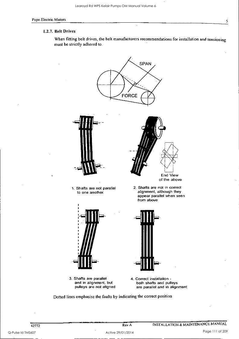
Pope Electric Motors
1.2.7. Belt Drives
When fitting belt drives, the belt manufacturers recommendations for installation and tensioning must be strictly adhered to.
1. Shafts are not parallel to one another.
3. Shafts are parallel and in alignment, but pulleys are not aligned
End View of the above
2. Shafts are not in correct alignment, although they appear parallel when seen from above
4. Correct installation - both shafts and pulleys are parallel and in alignment
Dotted lines emphasise the faults by indicating the correct position
42772 Rev A INSTALLATION & MAINTENANCE MANUAL
Learoyd Rd WPS Kelair Pumps OM Manual Volume 6
Q-Pulse Id TMS607 Active 29/01/2014 Page 111 of 209
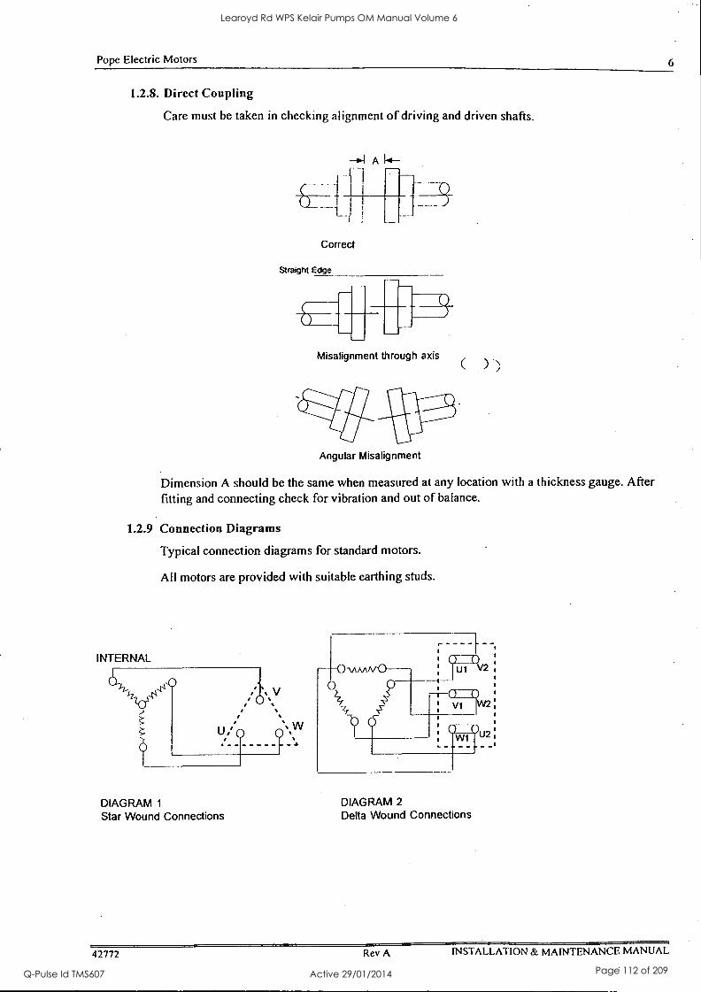
Pope Electric Motors 6
1.2.8. Direct Coupling
Care must be taken in checking alignment of driving and driven shafts.
Correct
Straight Edge
1.4-
Misalignment through axis
Angular Misalignment
Dimension A should be the same when measured at any location with a thickness gauge. After fitting and connecting check for vibration and out of balance.
1.2.9 Connection Diagrams
Typical connection diagrams for standard motors.
All motors are provided with suitable earthing studs.
INTERNAL
DIAGRAM 1
Star Wound Connections DIAGRAM 2 Delta Wound Connections
42772 Rev A INSTALLATION & MAINTENANCE MANUAL
Learoyd Rd WPS Kelair Pumps OM Manual Volume 6
Q-Pulse Id TMS607 Active 29/01/2014 Page 112 of 209
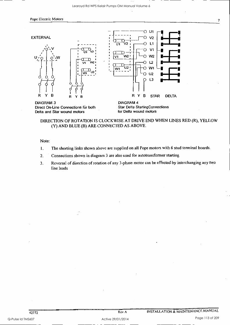
Pope Electric Motors 7
EXTERNAL
r
R Y B
DIAGRAM 3 Direct On-Line Connections for both Delta and Star wound motors
Ui V2 I
0 U1
O V2
L1
O V1
O W2
W1 U2
L2
O U2
L3
R Y B STAR DELTA
DIAGRAM 4 Star Delta StartingConnections for Delta wound motors
DIRECTION OF ROTATION IS CLOCKWISE AT DRIVE END WHEN LINES RED (R), YELLOW (Y) AND BLUE (B) ARE CONNECTED AS ABOVE.
Note:
1. The shorting links shown above are supplied on all Pope motors with 6 stud terminal boards.
2. Connections shown in diagram 3 are also used for autotransformer starting
3. Reversal of direction of rotation of any 3-phase motor can be effected by interchanging any two
line leads
42772 Rev A INSTALLATION & MAINTENANCE MANUAL
Learoyd Rd WPS Kelair Pumps OM Manual Volume 6
Q-Pulse Id TMS607 Active 29/01/2014 Page 113 of 209
Pope Electric Motors 8
1.3 BEARING SIZES AND LUBRICATION INTERVALS
(Refer to Appendix 3 - bearing sizes and lubrication intervals for details)
Re-lubrication intervals are based on a maximum bearing outer ring temperature of 70° C.
The re-lubrication interval should be reduced by half for every 15° C that the bearing outer ring temperature exceeds 70° C.
The re-lubrication interval should be reduced by half if the motor is mounted vertically.
Where grease may be contaminated or the grease serves as a seal against moisture, then the re- lubrication interval should be further reduced.
For example bearing manufacturers quote a situation in which the bearing housing has water running over it for which they recommend weekly re-greasing.
42772 Rev A INSTALLATION & MAINTENANCE MANUAL
Learoyd Rd WPS Kelair Pumps OM Manual Volume 6
Q-Pulse Id TMS607 Active 29/01/2014 Page 114 of 209
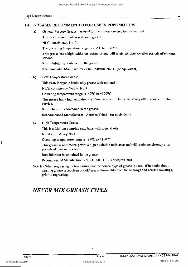
Pope Electric Motors 9
1.4 GREASES RECOMMENDED FOR USE IN POPE MOTORS
a) General Purpose Grease - as used for the motors covered by this manual
This is a Lithium hydroxy-stearate grease.
NLGI consistency No. 3.
The operating temperature range is -35°C to +120° C.
This grease has a high oxidation resistance and will retain consistency after periods of extreme service.
Rust inhibitor is contained in the grease.
Recommended Manufacturer - Shell Alvania No. 3 (or equivalent)
b) Low Temperature Grease
This is an inorganic hecite clay grease with mineral oil
NLGI consistency No.2 to No.3
Operating temperature range is -40°C to +120°C
This grease has a high oxidation resistance and will retain consistency after periods of extreme service.
Rust inhibitor is contained in the grease.
Recommended Manufacturer - Aeroshell No.6 (or equivalent)
c) High Temperature Grease
This is a Lithium complex soap base with mineral oils.
NLGI consistency No.3
Operating temperature range is -25°C to +150°C
This grease is non-melting with a high oxidation resistance and will retain consistency after periods of extreme service.
Rust inhibitor is contained in the grease.
Recommended Manufacturer - S.K.F. LIGHT 3 (or equivalent)
NOTE - When regreasing motors ensure that the correct type of grease is used. If in doubt about existing grease type, clean out old grease thoroughly from the bearings and bearing housings, prior to regreasing.
NEVER MIX GREASE TYPES
42772 Rev A INSTALLATION & MAINTENANCE MANUAL
Learoyd Rd WPS Kelair Pumps OM Manual Volume 6
Q-Pulse Id TMS607 Active 29/01/2014 Page 115 of 209
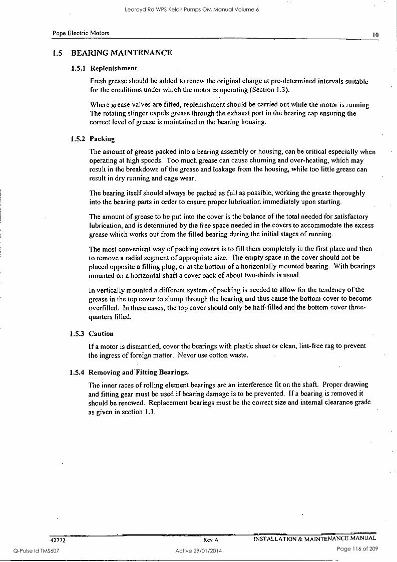
Pope Electric Motors 10
1.5 BEARING MAINTENANCE
1.5.1 Replenishment
Fresh grease should be added to renew the original charge at pre-determined intervals suitable for the conditions under which the motor is operating (Section 1.3).
Where grease valves are fitted, replenishment should be carried out while the motor is running. The rotating slinger expels grease through the exhaust port in the bearing cap ensuring the correct level of grease is maintained in the bearing housing.
1.5.2 Packing
The amount of grease packed into a bearing assembly or housing, can be critical especially when operating at high speeds. Too much grease can cause churning and over-heating, which may result in the breakdown of the grease and leakage from the housing, while too little grease can result in dry running and cage wear.
The bearing itself should always be packed as full as possible, working the grease thoroughly into the bearing parts in order to ensure proper lubrication immediately upon starting.
The amount of grease to be put into the cover is the balance of the total needed for satisfactory lubrication, and is determined by the free space needed in the covers to accommodate the excess grease which works out from the filled bearing during the initial stages of running.
The most convenient way of packing covers is to fill them completely in the first place and then to remove a radial segment of appropriate size. The empty space in the cover should not be
placed opposite a filling plug, or at the bottom of a horizontally mounted bearing. With bearings mounted on a horizontal shaft a cover pack of about two-thirds is usual.
In vertically mounted a different system of packing is needed to allow for the tendency of the grease in the top cover to slump through the bearing and thus cause the bottom cover to become overfilled. In these cases, the top cover should only be half-filled and the bottom cover three- quarters filled.
1.5.3 Caution
If a motor is dismantled, cover the bearings with plastic sheet or clean, lint-free rag to prevent
the ingress of foreign matter. Never use cotton waste.
1.5.4 Removing and-Fitting Bearings.
The inner races of rolling element bearings are an interference fit on the shaft. Proper drawing and fitting gear must be used if bearing damage is to be prevented. If a bearing is removed it
should be renewed. Replacement bearings must be the correct size and internal clearance grade
as given in section 1.3.
42772 Rev A INSTALLATION & MAINTENANCE MANUAL
Learoyd Rd WPS Kelair Pumps OM Manual Volume 6
Q-Pulse Id TMS607 Active 29/01/2014 Page 116 of 209
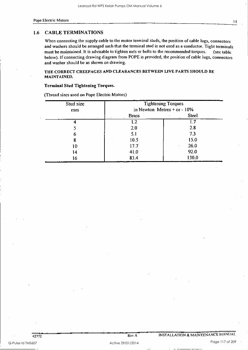
Pope Electric Motors I I
1.6 CABLE TERMINATIONS
When connecting the supply cable to the motor terminal studs, the position of cable lugs, connectors and washers should be arranged such that the terminal stud is not used as a conductor. Tight terminals must be maintained. It is advisable to tighten nuts or bolts to the recommended torques. (see table below). If connecting drawing diagram from POPE is provided, the position of cable lugs, connectors and washer should be as shown on drawing.
THE CORRECT CREEPAGES AND CLEARANCES BETWEEN LIVE PARTS SHOULD BE MAINTAINED.
Terminal Stud Tightening Torques.
(Thread sizes used on Pope Electric Motors)
Stud size mm
Tightening Torques in Newton Metres + or - 10%
Brass Steel
4 1.2 1.7
5 2.0 2.8
6 5.1 7.3
8 10.5 15.0
10 17.7 26.0 14 41.0 92.0 16 83.4 130.0
42772 Rev A INSTALLATION & MAINTENANCE MANUAL
Learoyd Rd WPS Kelair Pumps OM Manual Volume 6
Q-Pulse Id TMS607 Active 29/01/2014 Page 117 of 209

Pope Electric Motors 12
1.7 ANTI - CONDENSATION HEATERS
Anti-condensation heaters are located inside some machines. They are usually energised when the motor is not in use, thus preventing condensation forming inside the windings. Dampness in the windings is a common form of winding failure.
TESTING
Megger test to earth and to motor windings 1000 Vdc for 120/240 volt heaters
CONNECTIONS
Details of heater connection are located in an auxiliary box located on the top of the motor frame or on the side of the main terminal box. Heater connection details can also be found in POPE GA drawing if provided.
CAUTION
THE HEATER ISOLATION WILL BE SEPARATE FROM THE MOTOR ISOLATION
42772 Rev A INSTALLATION & MAINTENANCE MANUAL
Learoyd Rd WPS Kelair Pumps OM Manual Volume 6
Q-Pulse Id TMS607 Active 29/01/2014 Page 118 of 209
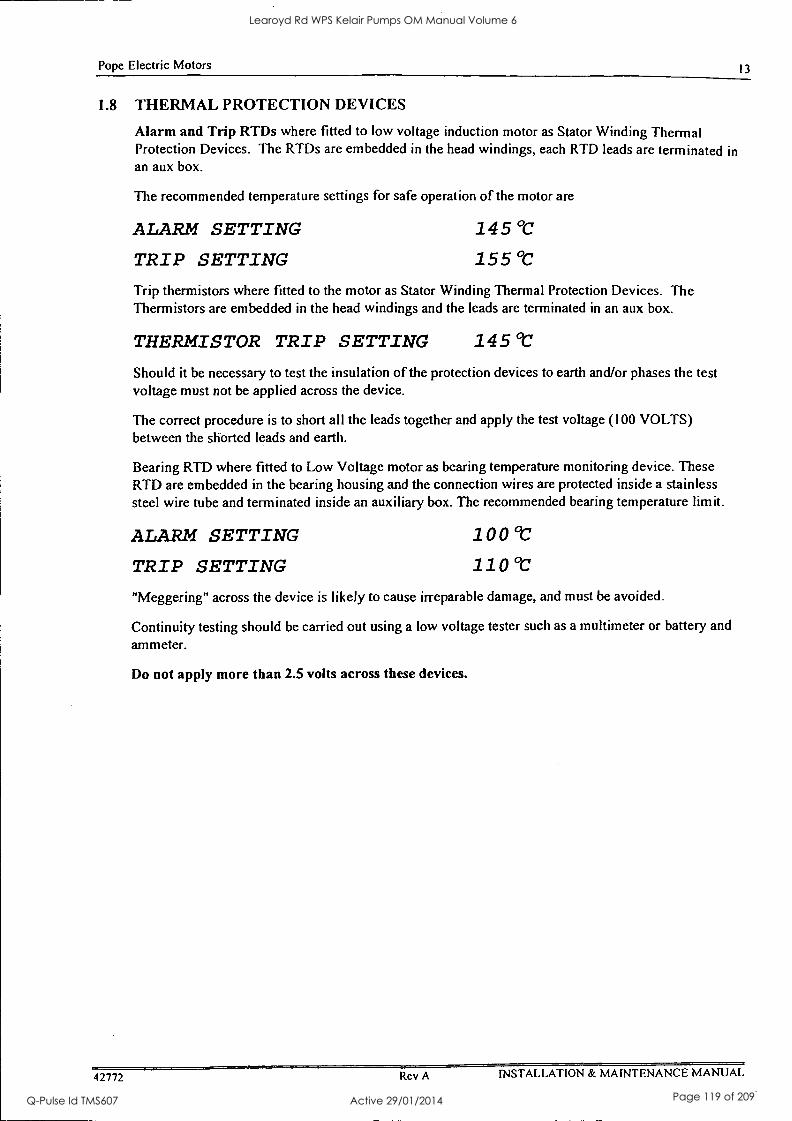
Pope Electric Motors 13
1.8 THERMAL PROTECTION DEVICES
Alarm and Trip RTDs where fitted to low voltage induction motor as Stator Winding Thermal Protection Devices. The RTDs are embedded in the head windings, each RTD leads are terminated in an aux box.
The recommended temperature settings for safe operation of the motor are
ALARM SETTING
TRIP SETTING
145 °C
155 °C
Trip thermistors where fitted to the motor as Stator Winding Thermal Protection Devices. The Therm istors are embedded in the head windings and the leads are terminated in an aux box.
THERMISTOR TRIP SETTING 145 °C
Should it be necessary to test the insulation of the protection devices to earth and/or phases the test voltage must not be applied across the device.
The correct procedure is to short all the leads together and apply the test voltage (100 VOLTS) between the shorted leads and earth.
Bearing RTD where fitted to Low Voltage motor as bearing temperature monitoring device. These RTD are embedded in the bearing housing and the connection wires are protected inside a stainless steel wire tube and terminated inside an auxiliary box. The recommended bearing temperature limit.
ALARM SETTING
TRIP SETTING
100 °C
110 °C
"Meggering" across the device is likely to cause irreparable damage, and must be avoided.
Continuity testing should be carried out using a low voltage tester such as a multimeter or battery and ammeter.
Do not apply more than 2.5 volts across these devices.
42772 Rev A INSTALLATION & MAINTENANCE MANUAL
Learoyd Rd WPS Kelair Pumps OM Manual Volume 6
Q-Pulse Id TMS607 Active 29/01/2014 Page 119 of 209

Pope Electric Motors 14
1.9 OVERCURRENT PROTECTION
Over current protection should be used and it shall be set in accordance with the following safe stall times -
Full voltage stall from hot not to exceed 15 seconds
Full voltage stall from cold not to exceed 20 seconds. STALLING THE MOTOR FOR LONGER THAN THIS CAN CAUSE INTERNAL DAMAGE
42772 Rev A INSTALLATION & MAINTENANCE MANUAL
Learoyd Rd WPS Kelair Pumps OM Manual Volume 6
Q-Pulse Id TMS607 Active 29/01/2014 Page 120 of 209

Pope Electric Motors
3. APPENDICES
Learoyd Rd WPS Kelair Pumps OM Manual Volume 6
Q-Pulse Id TMS607 Active 29/01/2014 Page 121 of 209
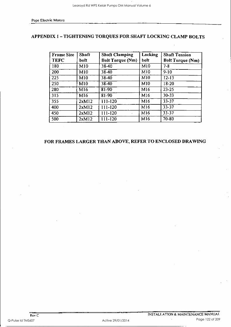
Pope Electric Motors
APPENDIX 1- TIGHTENING TORQUES FOR SHAFT LOCKING CLAMP BOLTS
Frame Size TEFC
Shaft bolt
Shaft Clamping Bolt Torque (Nm)
Locking bolt
Shaft Tension Bolt Torque (Nm)
180 M10 38-40 M10 7-8
200 M10 38-40 M10 9-10 225 M10 38-40 M10 12-13
250 M10 38-40 M10 18-20
280 M16 81-90 M16 23-25 315 M16 81-90 M16 30-33
355 2xM12 111-120 M16 33-37 400 2xM12 111-120 M16 33-37 450 2xM12 111-120 M16 33-37 500 2xM12 111-120 M16 70-80
FOR FRAMES LARGER THAN ABOVE, REFER TO ENCLOSED DRAWING
Rev C INSTALLATION & MAINTENANCE MANUAL
Learoyd Rd WPS Kelair Pumps OM Manual Volume 6
Q-Pulse Id TMS607 Active 29/01/2014 Page 122 of 209
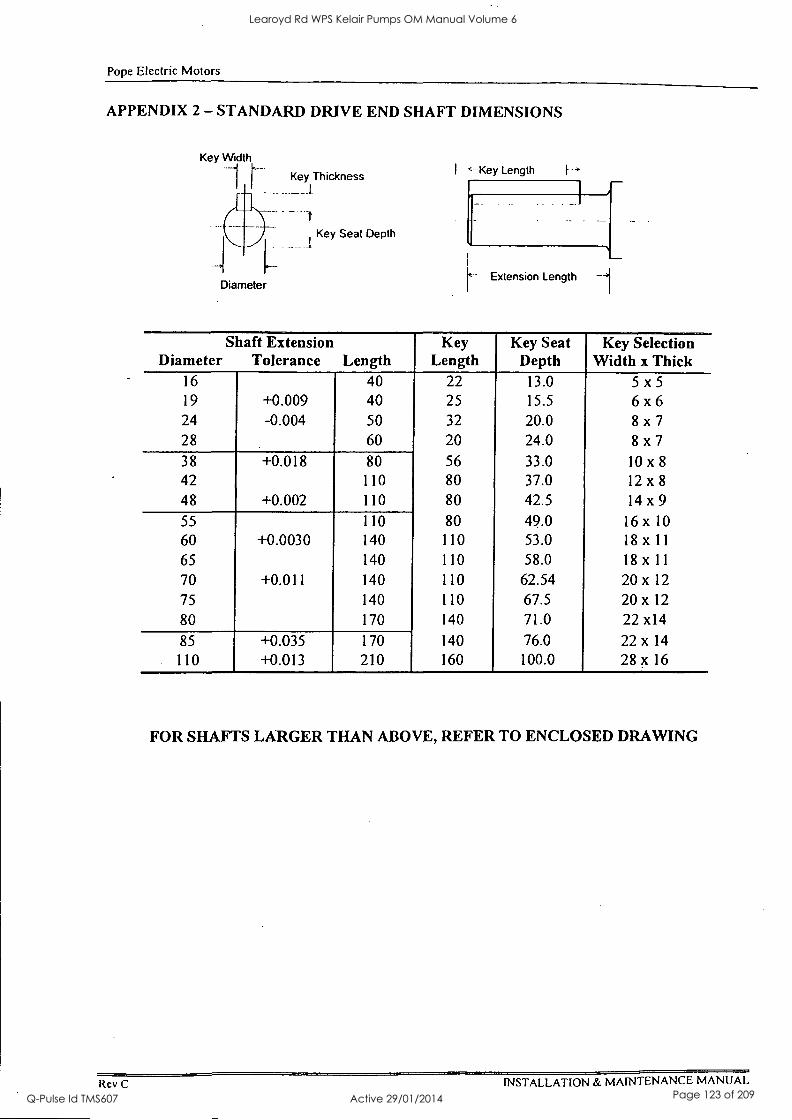
Pope Electric Motors
APPENDIX 2 - STANDARD DRIVE END SHAFT DIMENSIONS
Key Thickness
Diameter
Key Seat Depth
I ' -Key Length
Extension Length -1
Shaft Extension Diameter Tolerance Length
Key Length
Key Seat Depth
Key Selection Width x Thick
16 40 22 13.0 5 x 5
19 +0.009 40 25 15.5 6 x 6
24 -0.004 50 32 20.0 8 x 7
28 60 20 24.0 8 x 7
38 +0.018 80 56 33.0 10 x 8
42 110 80 37.0 12 x 8
48 +0.002 110 80 42.5 14 x 9
55 110 80 49.0 16 x 10
60 +0.0030 140 110 53.0 18 x 11
65 140 110 58.0 18 x 11
70 +0.011 140 110 62.54 20 x 12
75 140 110 67.5 20 x 12
80 170 140 71.0 22 x14
85 +0.035 170 140 76.0 22 x 14
110 +0.013 210 160 100.0 28 x 16
FOR SHAFTS LARGER THAN ABOVE, REFER TO ENCLOSED DRAWING
Rev C INSTALLATION & MAINTENANCE MANUAL
Learoyd Rd WPS Kelair Pumps OM Manual Volume 6
Q-Pulse Id TMS607 Active 29/01/2014 Page 123 of 209
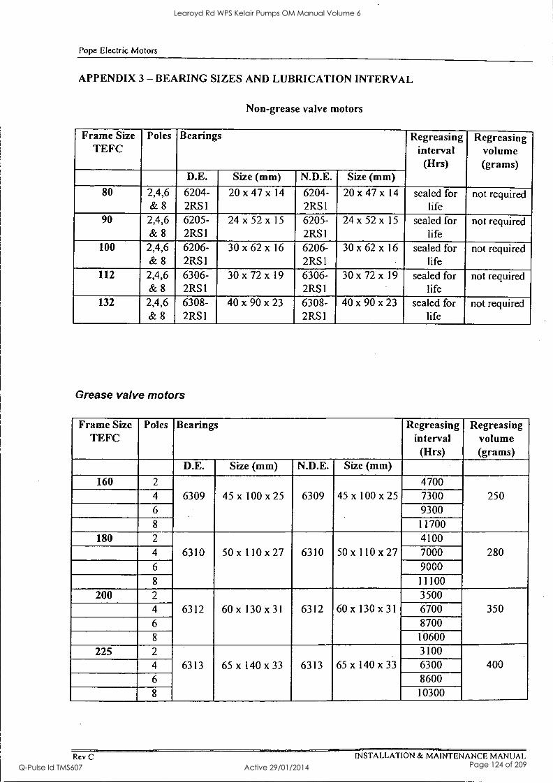
Pope Electric Motors
APPENDIX 3 - BEARING SIZES AND LUBRICATION INTERVAL
Non-grease valve motors
Frame Size TEFC
Poles Bearings Regreasing interval (Hrs)
Regreasing volume (grams)
D.E. Size (mm) N.D.E. Size (mm) 80 2,4,6 6204- 20 x 47 x 14 6204- 20 x 47 x 14 sealed for not required
& 8 2RS1 2RS1 life 90 2,4,6 6205- 24 x 52 x 15 6205- 24 x 52 x 15 sealed for not required
& 8 2RS1 2RS I life 100 2,4,6 6206- 30 x 62 x 16 6206- 30 x 62 x 16 sealed for not required
& 8 2RS1 2RS1 life 112 2,4,6 6306- 30 x 72 x 19 6306- 30 x 72 x 19 sealed for not required
& 8 2RS1 2RS1 life 132 2,4,6 6308- 40 x 90 x 23 6308- 40 x 90 x 23 sealed for not required
& 8 2RS1 2RS I life
Grease valve motors
Frame Size TEFC
Poles Bearings Regreasing interval (Hrs)
Regreasing volume (grams)
D.E. Size (mm) N.D.E. Size (mm)
160 2
6309 45 x 100 x 25 6309 45 x 100 x 25 4700
250 4 7300 6 9300 8 11700
180 2
6310 50 x 110 x 27 6310 50 x 110 x27 4100
280 4 7000 6 9000 8 11100
200 2
6312 60 x 130 x31 6312 60 x 130 x31 3500
350 4 6700 6 8700 8 10600
225 2
6313 65 x 140 x 33 6313 65 x 140 x 33
3100 400 4 6300
6 8600
8 10300
Rev C INSTALLATION & MAINTENANCE MANUAL
Learoyd Rd WPS Kelair Pumps OM Manual Volume 6
Q-Pulse Id TMS607 Active 29/01/2014 Page 124 of 209
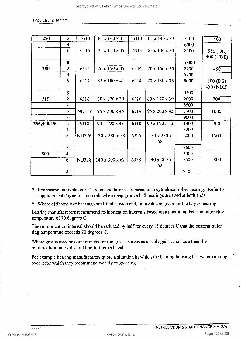
Pope Electric Motors
250 2 6313 65 x 140 x 33 6313 65 x 140 x 33 3100 400 4
75 x 150 x 37 6313 65 x 140 x 33
6000 6 6315 8300 550 (DE)
400 (NDE) 8 10000
280 2 6314 70 x 150 x 35 6314 70 x 150 x35 2700 450 4
6317 85x 180x 41 6314 70 x 150x 35
5700 800 (DE)
450 (NDE) 6 8000
8 9500 315 2 6316 80 x 170 x 39 6316 80 x 170 x 39 2000 700
4
NU319 95 x 200 x 45 6319 95 x 200 x 45
5500 1000 6 7700
8 9000 355,400,450 2 6318 90 x 190 x 43 6318 90 x 190 x 43 1400 900
4
NU326 130 x 280 x 58 6326 130 x 280 x
58
3200 1500 6 6000
8 7600
500 4
NU328 140 x 300 x 62 6328 140 x 300 x
62
3000 1800 6 5500
8 7500
* Regreasing intervals on 315 frame and larger, are based on a cylindrical roller bearing. Refer to suppliers' catalogue for intervals when deep groove ball bearings are used at both ends
* Where different size bearings are fitted at each end, intervals are given for the larger bearing
Bearing manufacturers recommend re-lubrication intervals based on a maximum bearing outer ring temperature of 70 degrees C.
The re-lubrication interval should be reduced by half for every 15 degrees C that the bearing outer ring temperature exceeds 70 degrees C.
Where grease may be contaminated or the grease serves as a seal against moisture then the relubrication interval should be further reduced.
For example bearing manufacturers quote a situation in which the bearing housing has water running over it for which they recommend weekly re-greasing.
Rev C INSTALLATION & MAINTENANCE MANUAL
Learoyd Rd WPS Kelair Pumps OM Manual Volume 6
Q-Pulse Id TMS607 Active 29/01/2014 Page 125 of 209

I Di KelairPumps
PAGE 19.00
19: Appendix 3
CONTENTS: ' PAGE VARIABLE SPEED DRIVE Pages 1-1 to 15-2
Learoyd Rd WPS Kelair Pumps OM Manual Volume 6
Q-Pulse Id TMS607 Active 29/01/2014 Page 126 of 209

Omniverter Drive Multipurpose Inverter
75 kW to 1.0 MW
11110111101100
11111111101110
11111111101110
1110111011101
111111110111011
11111110111011
11111111101110 11111110111011
11111111101110 11111110111011
IIn11u101110 11011110111101
USER MANUAL 48070031.DOC
VECTEK VECTRON INDUSTRIES LTD
21 Carnegie Road, Onekawa Napier, New Zealand Phone ++64 6 843 1400 Fax ++64 6 843 0398 www.vectek.co.nz
Learoyd Rd WPS Kelair Pumps OM Manual Volume 6
Q-Pulse Id TMS607 Active 29/01/2014 Page 127 of 209
Omniverter drive parameters relate to drive software version 6.0 or later.
Revision History
H Released 27 August 1998 1) Recommended spares list updated and given its own appendix (was section 6.2, now appendix 4). 2) Corrected parameter description for 'LOW parameters in analogue I/O modules 100,110, 120 & 130. Used to
read 'ie. 4mA or -10V% now 'ie. 4rnA or OV'. 3) Enhanced module and parameter descriptions for module group 400:MOTOR in section 4. 4) Enhanced module and parameter descriptions for module group 500:VECTOR CONTROL in section 4. 5) Default values changed for 520:GAINS to match drive software version 5.6 onwards. 6) Range increased for 510:IBOOST to match drive software version 5.6 onwards (increased to +/-250%). 7) Enhanced descriptions in sections 3.4 and 3.5. 8) Improved Figure 3-1. 9) Additional rating information for Table 1-1 and Section 1.4.2.
I Released 30 October 1998 1) Corrected parameter description for parameter 7B0:ENABLE in section 4. 2) Added descriptions in sections 4 & 10 for parameters 020:KB S/R and 020:EXTS/R new to version 6.0 software. 3) Added tables in sections 4 & 10 for module 1CO:SERIAL COMMS new to version 6.0 software. 4) Added tables in sections 4 & 10 for module 7CO:PRESET SELECT new to version 6.0 software. 5) Added tables in sections 4 & 10 for module 7D0:PID CONTROLLER new to version 6.0 software. 6) Added tables in sections 4 & 10 for module 7E0:SKIP BANDS new to version 6.0 software. 7) Added tables in sections 4 & 10 for modules 7F0:COMPARATOR1, 7G0:COMPARATOR2,
7H0:COMPARATOR3 new to version 6.0 software. 8) Updated section 5 with new source and destination ports, including serial communications parameter codes for
source ports. 9) Added new appendix: section 11 Appendix 7 - Serial Communications. 10) Updated Figures 2-4 and 2-6 with new parameters. 11) Updated Figure 2-5 with earth screens on digital inputs and pot. supply. 12) Updated Figure 2-5 with earth screens on digital inputs and pot. supply. 13) Added new appendix: section 13 Appendix 9 - Bearing Filters - Protecting Motor Bearings. 14) Added new appendix: section 14 Appendix 10 - Mains Harmonic Reduction. 15) Updated Figure 3-1 with ME (motor earth terminals). 16) Deleted OD4 0150 from Table 1-1 and replaced with OD4 170.
Learoyd Rd WPS Kelair Pumps OM Manual Volume 6
Q-Pulse Id TMS607 Active 29/01/2014 Page 128 of 209
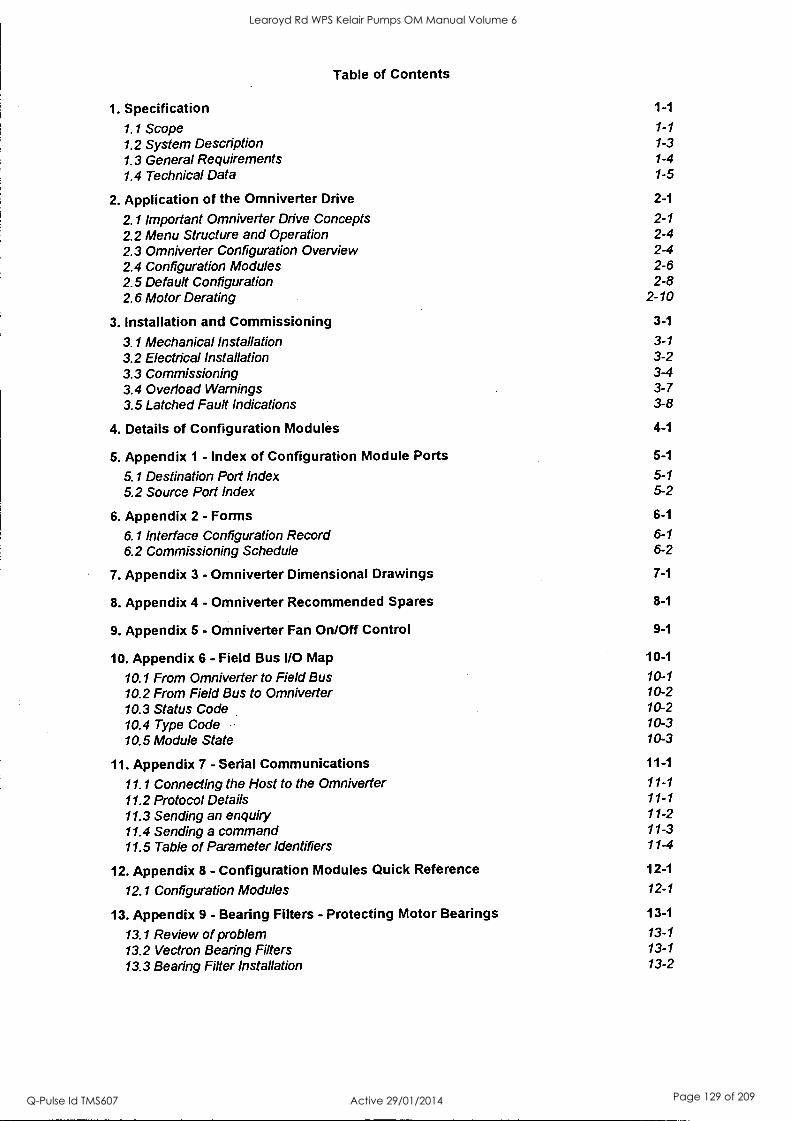
Table of Contents
1. Specification 1-1
1.1 Scope 1-1
1.2 System Description 1-3
1.3 General Requirements 1-4
1.4 Technical Data 1-5
2. Application of the Omniverter Drive 2-1
2.1 Important Omniverter Drive Concepts 2-1 2.2 Menu Structure and Operation 2-4 2.3 Omniverter Configuration Overview 2-4 2.4 Configuration Modules 2-6 2.5 Default Configuration 2-8 2.6 Motor Derating 2-10
3. Installation and Commissioning 3-1
3.1 Mechanical Installation 3-1 3.2 Electrical Installation 3-2 3.3 Commissioning 3-4 3.4 Overload Warnings 3-7 3.5 Latched Fault Indications 3-8
4. Details of Configuration Modules 4-1
5. Appendix 1 - Index of Configuration Module Ports 5-1
5.1 Destination Port Index 5-1 5.2 Source Port Index 5-2
6. Appendix 2 - Forms 6-1
6.1 Interface Configuration Record 6-1
6.2 Commissioning Schedule 6-2
7. Appendix 3 - Omniverter Dimensional Drawings 7-1
8. Appendix 4 - Omniverter Recommended Spares 8-1
9. Appendix 5 - Omniverter Fan On/Off Control 9-1
10. Appendix 6 - Field Bus I/O Map 10-1
10.1 From Omniverter to Field Bus 10-1
10.2 From Field Bus to Omniverter 10-2 10.3 Status Code 10-2 10.4 Type Code 10-3 10.5 Module State 10-3
11. Appendix 7 - Serial Communications 11-1
11.1 Connecting the Host to the Omniverter 11-1
11.2 Protocol Details 11-1
11.3 Sending an enquiry 11-2
11.4 Sending a command 11-3 11.5 Table of Parameter Identifiers 11-4
12. Appendix 8 - Configuration Modules Quick Reference 12-1
12.1 Configuration Modules 12-1
13. Appendix 9 - Bearing Filters - Protecting Motor Bearings 13-1
13.1 Review of problem 13-1
13.2 Vectron Bearing Filters 13-1
13.3 Bearing Filter Installation 13-2
Learoyd Rd WPS Kelair Pumps OM Manual Volume 6
Q-Pulse Id TMS607 Active 29/01/2014 Page 129 of 209
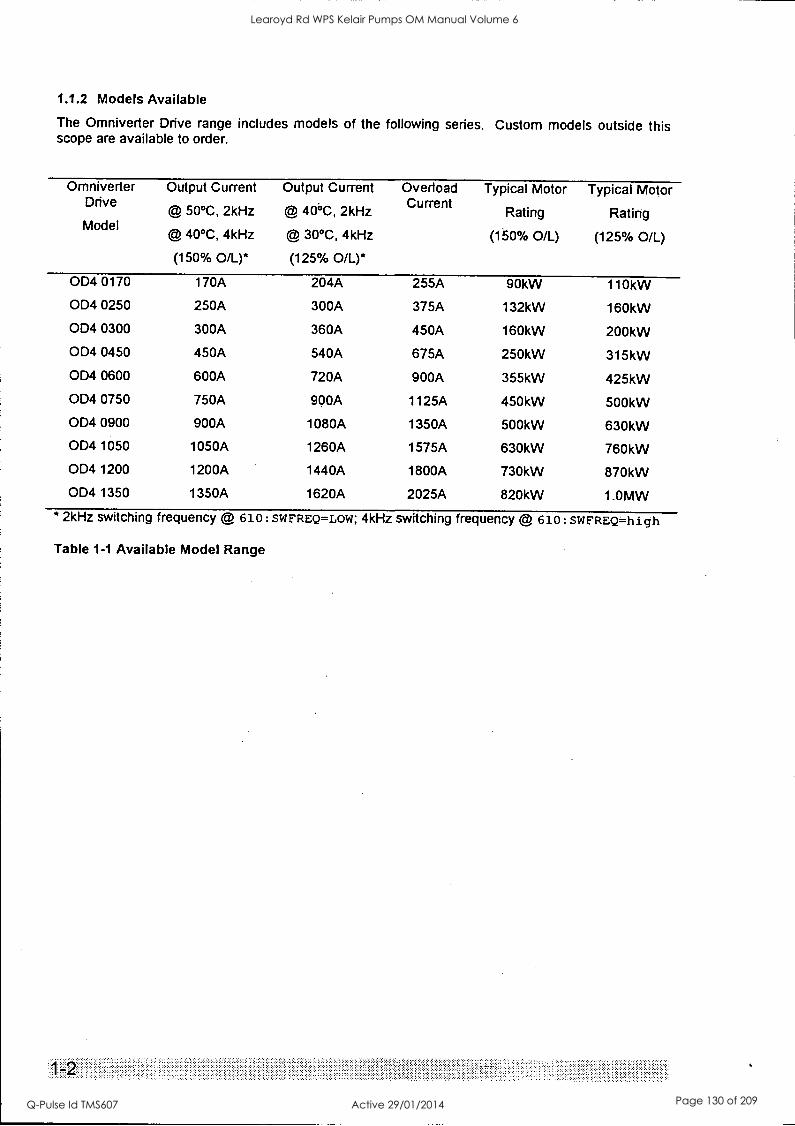
1.1.2 Models Available
The Omniverter Drive range includes models of the following series. Custom models outside this scope are available to order.
Omniverter Output Current Output Current Overload Typical Motor Typical Motor Drive © 50°C, 2kHz © 40°C, 2kHz Current
Rating Rating Model
@ 40°C, 4kHz © 30°C, 4kHz (150% 0/L) (125% OIL)
(150% 0/L)* (125% OIL)*
OD4 0170 170A 204A 255A 90kW 110kW
OD4 0250 250A 300A 375A 132kW 160kW
OD4 0300 300A 360A 450A 160kW 200kW
OD4 0450 450A 540A 675A 250kW 315kW
OD4 0600 600A 720A 900A 355kW 425kW
OD4 0750 750A 900A 1125A 450kW 500kW
OD4 0900 900A 1080A 1350A 500kW 630kW
OD4 1050 1050A 1260A 1575A 630kW 760kW
OD4 1200 1200A 1440A 1800A 730kW 870kW
OD4 1350 1350A 1620A 2025A 820kW 1.0MW
* 2kHz switching frequency @ 610: SWFREQ=LOW; 4kHz switching frequency @ 610: SWFREQ=high
Table 1-1 Available Model Range
............. > . . .
Learoyd Rd WPS Kelair Pumps OM Manual Volume 6
Q-Pulse Id TMS607 Active 29/01/2014 Page 130 of 209

Omniverter Drive
1.2 System Description
The Omniverter Drive range benefits from the use of the latest electronic technologies in association with today's most advanced motor control theory.
1.2.1 Components
Semiconductor fuse protection
AC line reactors for reduced harmonic distortion and immunity to mains disturbances
Rectifier incorporating solid state charging control for improved reliability
Inverter Grade Electrolytic Capacitors
Homogenous IGBTs for improved paralleling
Output dv/dt limiting filters to protect motor windings and reduce RFI
32 bit RISC Microprocessor necessary for true sensorless vector algorithms
1.2.2 Construction
IP20 environmental protection with IP54 option
Modular structure minimising spares holding requirements
Modular structure permitting subsequent up-scaling or down-scaling
Surface or through panel mount to simplify provision for cooling airflow
Panel width of <250mm per 150A (180A 40 deg C) to minimise switchboard and installation costs
1.2.3 Digital Control and Diagnostics
The Omniverter Drive range incorporates digital control. A remote mountable keyboard and display incorporates a four line, eighty character back lit display with status information presented in plain language. Two LEDs provide immediate indication of Omniverter Drive status.
1.2.4 Configurable Interfacing and Control
The Omniverter Drive provides facility for highly configurable interfacing. Analogue inputs and analogue outputs can be programmed individually for voltage or current (4-20mA) control. Fully isolated digital inputs may be configured for active high or active low operation from +24 or +12V.
Two high speed digital outputs and three change over power relays each may be programmed to signal one of many conditions.
Special function modules permit user configuration of all control inputs and outputs. Custom modules can be developed on request.
1.2.5 True Sensor less Vector Control
A very advanced form of sensorless vector (also known as sensorless field oriented) control, trade- named Vectorque, is incorporated.
Unlike normal voltage/frequency controllers, Vectorque directly controls the current and torque of an induction motor. This facility eliminates the characteristic low speed instability often exhibited by traditional control methods and provides many other advantages - speed is controlled more precisely and transient overloads are absorbed without causing trips. ...
Learoyd Rd WPS Kelair Pumps OM Manual Volume 6
Q-Pulse Id TMS607 Active 29/01/2014 Page 131 of 209
The Vectorque true sensorless vector implementation in the Omniverter Drive incorporates parameter insensitive algorithms which avoid such problems altogether. Vectorque algorithrris have only become practical through the use of a very powerful 32 bit RISC microprocessor.
1.2.6 Modular Mechanical Design
The Omniverter Drive is unique in adopting a modular approach to mechanical construction. This permits ready change of size (add or remove modules) at a later date while minimising spares holding requirements since the same components are used in all models.
1.2.7 Radio Frequency Suppression
The Omniverter drives include radio interference suppression to the requirements of CISPR11 (AS /NZS 2064:1997) level A, suitable for industrial environments (formal tests to be completed).
1.2.8 Special Options
The following special options are available together with full custom solutions:
Dynamic Brake option - facility is included for internal fitting and control of dynamic brake switching transistors. External power resistors are supplied to order.
Regenerative / Unity Power Factor / Software Option - Ofnhiverter Drive may be supplied together with a full four quadrant regenerative inverter / rectifier for applications requiring much braking or very low harmonic distortion of the supply.
Harmonic Reduction Options - Several options exist for the reduction of harmonic distortion of the supply in high power applications - contact your supplier. Refer to Appendix 10 - Mains Har &tonic Reduction for details of 12 pulse options for the Omniverter driVes.
Bearing Protection - AC drives increase risk to motor bearings. Various solutions exist inclikling special bearing filters. Refer to Appendix 9 - Bearing Filtet$ - Protecting Motor Bearings.
1.3 General Requirements
1.3.1 Standards
Vectron Industries operates a quality system in accordance with the general requirements of ISO 9001, and plans to apply for accreditation in 1998.
Omniverter Drive is designed to meet the CE Mark requireMetits of European Safety and EMC Directives.
1.3.2 Components and Materials
All materials and parts comprising the Omniverter Drive are new and in current produCtion, and to ensure maximum reliability, are used well within the parameters recommended by the supplier.
Learoyd Rd WPS Kelair Pumps OM Manual Volume 6
Q-Pulse Id TMS607 Active 29/01/2014 Page 132 of 209
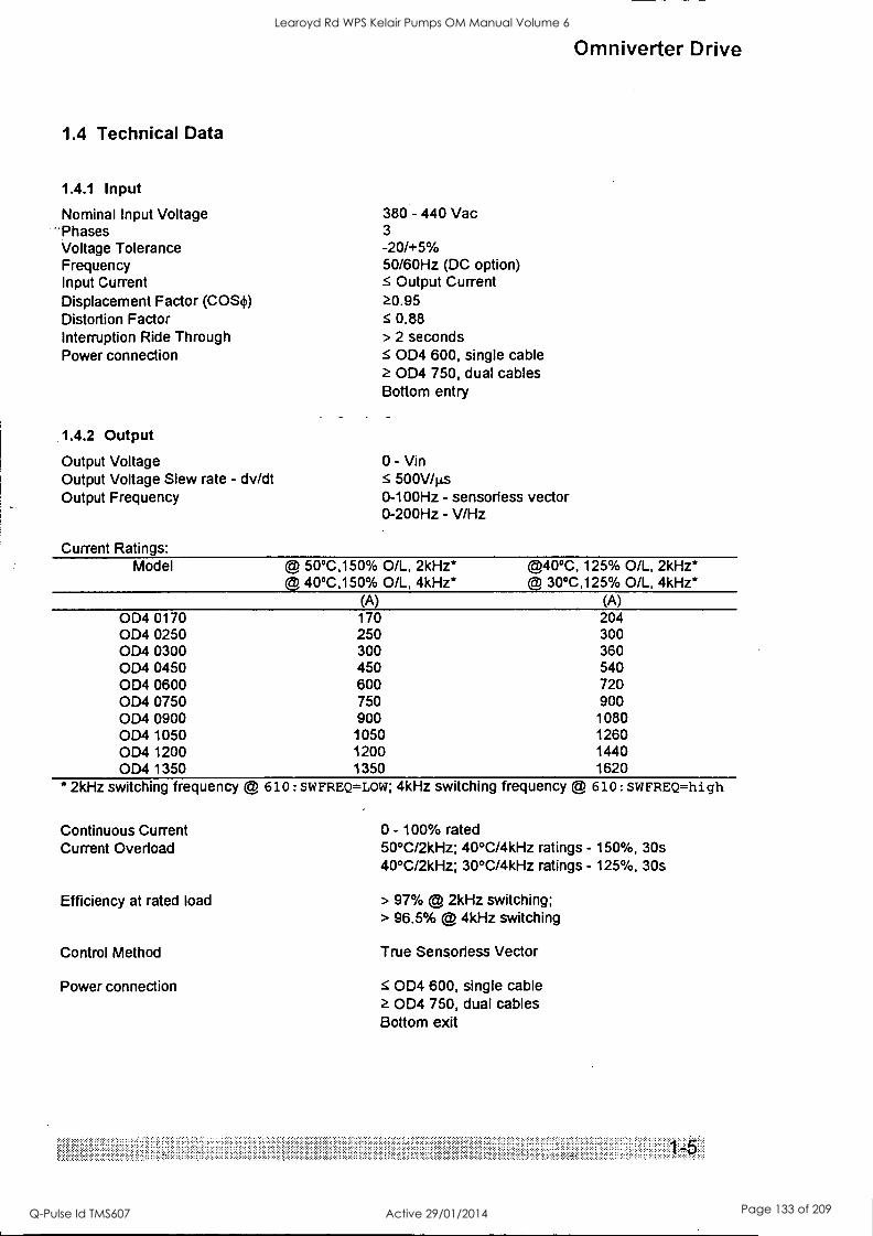
1.4 Technical Data
1.4.1 Input
Nominal Input Voltage -Phases Voltage Tolerance Frequency Input Current Displacement Factor (COS.) Distortion Factor Interruption Ride Through Power connection
1.4.2 Output
Output Voltage Output Voltage Slew rate - dv/dt Output Frequency
Current Ratings:
380 - 440 Vac 3 -20/+5% 50/60Hz (DC option) S Output Current n.95 s 0.88 > 2 seconds
OD4 600, single cable OD4 750, dual cables
Bottom entry
0 - Vin 500V /µs
0-100Hz - sensorless vector 0-200Hz - V/Hz
Omniverter Drive
Model 50°C,150% 0/L, 2kHz* @40°C, 125% OIL, 2kHz* 40°C,150% 0/L, 4kHz* 30°C,125% 0/L, 4kHz*
(A) (A) OD4 0170 170 204 OD4 0250 250 300 OD4 0300 300 360 OD4 0450 450 540 OD4 0600 600 720 OD4 0750 750 900 OD4 0900 900 1080 OD4 1050 1050 1260 OD4 1200 1200 1440 OD4 1350 1350 1620
* 2kHz switching frequency © 610 : SWFREQ=LOW; 4kHz switching frequency @ 610: SWFREQ=high
Continuous Current Current Overload
Efficiency at rated load
Control Method
Power connection
0 - 100% rated 50°C/2kHz; 40°C/4kHz ratings - 150%, 30s 40°C/2kHz; 30°C/4kHz ratings - 125%, 30s
> 97% © 2kHz switching; > 96.5% @ 4kHz switching
True Sensor less Vector
OD4 600, single cable OD4 750, dual cables
Bottom exit
'
Learoyd Rd WPS Kelair Pumps OM Manual Volume 6
Q-Pulse Id TMS607 Active 29/01/2014 Page 133 of 209
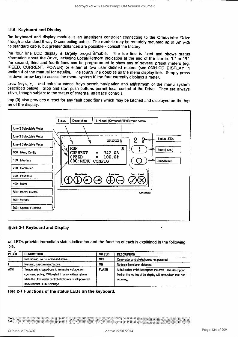
I.1.5 Keyboard and Display
The keyboard and display module is an intelligent controller connecting to the Omniverter Drive hrough a standard 9 way D connecting cable. The module may be remotely mounted up to 3m with he standard cable, but greater distances are possible - consult the factory.
The four line LCD display is largely prograMmable. The top line is fixed and shows status ',formation about the Drive, including Local/Remote indication at the end of the line ie. "L" or "R". The second, third and fourth lines can be programmed to show any of several preset meters (eg. >PEED, CURRENT, POWER) or either of two user defined meters (see 030:LCD DISPLAY in Iection 4 of the manual for details). The fourth line doubles as the menu display line. Simply press le down arrow key to access the menu system if line four currently displays a meter.
%crow keys, +, - and enter or cancel keys permit navigation and adjiistment of the menu system described below). Stop and start push buttons permit local control of the Drive. They are always ctive, though subject to the status of external interface controls.
;top (0) also provides a reset for any fault conditions which may be latched and displayed on the top ne of the display.
Line 2 Selectable Meter
Line 3 Selectable Meter
Line 4 Selectable Meter
000: Menu Config
100 : Interface
200 : Controller
300: Fault Info
400: Motor
500: Vector Control
600 : Inverter
700 : Special Function
Status Description (Keyboard)/R=Remote control
,
........,, ....,.. 2, .9.---
RUN R CURRENT = 342.0A SPEED = 100.0%
CONFIG
Go ( 0 )'.
CPTT"b
Ch anp Value EM Caned e @ 0 00 \ l Omni005e
Status LEDs
Start (Local)
Stop/Reset
igure 2-1 Keyboard and Display
tvo LEDs provide immediate status indication and the function of each is explained in the following ble.
IN LED DESCRIPTION OK LED DESCRIPTION
P Not running, no run command active. OFF Omniverter control electronics not powered.
I Running, run command active. ON No faults have been detected.
ASH Temporarily stopped due to low mains voltage, run
command active. Will restart if mains voltage returns
while the Omniverter control electronics is still powered
from residual DC bus voltage.
FLASH A fault exists which has tripped the drive. The description
field on the top line of the display will state which fault has
occurred.
able 2-1 Functions of the status LEDs on the keyboard.
Learoyd Rd WPS Kelair Pumps OM Manual Volume 6
Q-Pulse Id TMS607 Active 29/01/2014 Page 134 of 209
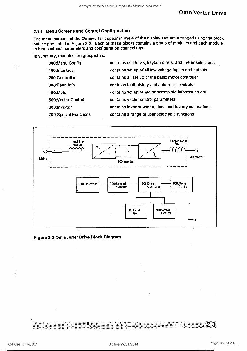
Omniverter Drive
2.1.6 Menu Screens and Control Configuration
The menu screens of the Omniverter appear in line 4 of the display and are arranged using the block outline presented in Figure 2-2. Each of these blocks contains a group of modules and each module in turn contains parameters and configuration connections.
In summary, modules are grouped as:
000:Menu Config contains edit locks, keyboard refs. and meter selections.
100:Interface contains set up of all low voltage inputs and outputs
200:Controller contains all set up of the basic motor controller
300:Fault Info contains fault history and auto reset controls
400:Motor contains set up of motor nameplate information etc
500:Vector Control contains vector control parameters
600:Inverter contains inverter user options and factory calibrations
700:Special Functions contains a range of user selectable functions
r Input line rectifier
Mains I
L
100:Interface
600:Inverter
700:Special Function
200:Drive Controller
1 Output dV/dti
filter
400:Motor
_J
300:Fauh Info
000:Menu Config
500:Vector Control
Figure 2-2 Omniverter Drive Block Diagram
Learoyd Rd WPS Kelair Pumps OM Manual Volume 6
Q-Pulse Id TMS607 Active 29/01/2014 Page 135 of 209
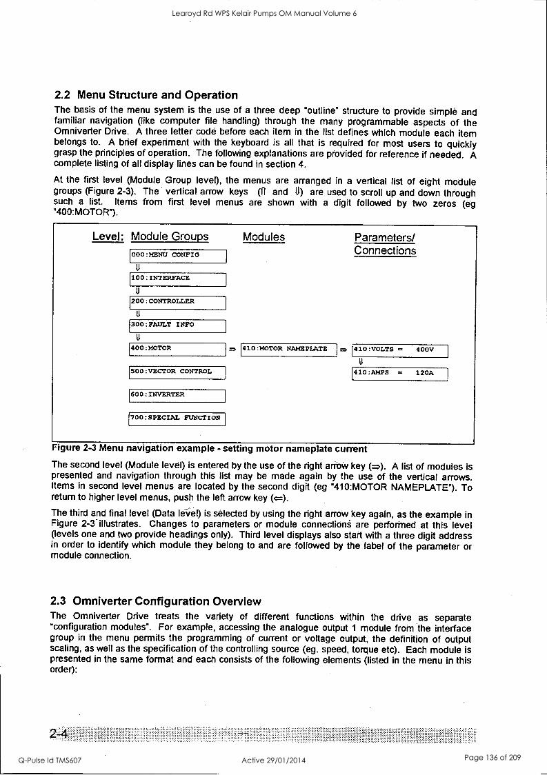
2.2 Menu Structure and Operation The basis of the menu system is the use of a three deep "outline" structure to provide simple and familiar navigation (like computer file handling) through the many programmable aspects of the Omniverter Drive. A three letter code before each item in the list defines which module each item belongs to. A brief experiment with the keyboard is all that is required for most users to quickly grasp the principles of operation. The following explanations are provided for reference if needed. A complete listing of all display lines can be found in section 4.
At the first level (Module Group level), the menus are arranged in a vertical list of eight module groups (Figure 2-3). The vertical arrow keys (ft and 11) are used to scroll up and down thitugh such a list. Items from first level menus are shown with a digit followed by two zeros (eg "400:MOTOR").
Level: Module Groups Modules
000:MENU CONFIG
100: INTERFACE
200: CONTROLLER
300:FAULT INFO
400:MOTOR
SOO:VECTOR CONTROL
600: INVERTER
700:SPECIAL FUNCTION
410:MOTOR NAMEPLATE
Parameters/ Connections
410:VOLTS = 400V
410:AMPS = 120A
Figure 2-3 Menu navigation example - setting motor nameplate current
The second level (Module level) is entered by the use of the right arrow key A list of modules is presented and navigation through this list may be made again by the use of the vertical arrows. Items in second level menus are located by the second digit (eg "410:MOTOR NAMEPLATE"). To return to higher level menus, push the left arrow key (=). The third and final level (Data lei/el) is selected by using the right arrow key again, as the example in Figure 2-3.illustrates. Changes to parameters or module connections are performed at this level (levels one and two provide headings only). Third level displays also start with a three digit address in order to identify which module they belong to and are followed by the label of the parameter or module connection.
2.3 Omniverter Configuration Overview The Omniverter Drive treats the variety of different functions within the drive as separate "configuration modules". For example, accessing the analogue output 1 module from the interface group in the menu permits the programming of current or voltage output, the definition of output scaling, as well as the specification of the controlling source (eg. speed, torque etc). Each module is presented in the same format and each consists of the following elements (listed in the menu in this order):
.". . .... ....
Learoyd Rd WPS Kelair Pumps OM Manual Volume 6
Q-Pulse Id TMS607 Active 29/01/2014 Page 136 of 209
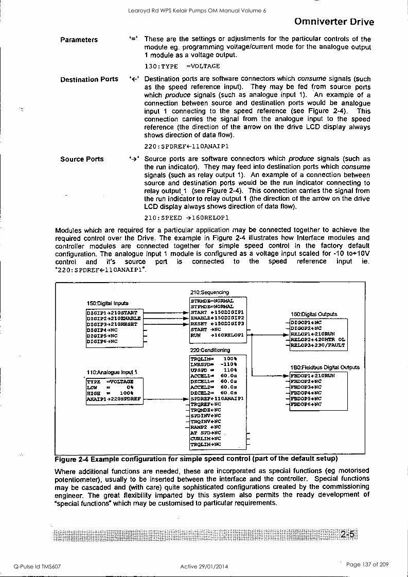
Parameters
Destination Ports
Source Ports
1<_.1
Omniverter Drive
These are the settings or adjustments for the particular controls of the module eg. programming voltage/current mode for the analogue output 1 module as a voltage output.
130:TYPE =VOLTAGE
Destination ports are software connectors which consume signals (such as the speed reference input). They may be fed from source ports which produce signals (such as analogue input 1). An example of a connection between source and destination ports would be analogue input 1 connecting to the speed reference (see Figure 2-4). This connection carries the signal from the analogue input to the speed reference (the direction of the arrow on the drive LCD display always shows direction of data flow).
220:SPDREFE-110ANAIP1
Source ports are software connectors which produce signals (such as the run indicator). They may feed into destination ports which consume signals (such as relay output 1). An example of a connection between source and destination ports would be the run indicator connecting to relay output_1 (see Figure 2-4). This connection carries the signal from the run indicator to relay output 1 (the direction of the arrow on the drive LCD display always shows direction of data flow).
210:SPEED 4160RELOP1
Modules which are required for a particular application may be connected together to achieve the required control over the Drive. The example in Figure 2-4 illustrates how Interface modules and controller modules are connected together for simple speed control in the factory default configuration. The analogue input 1 module is configured as a voltage input scaled for -10 to+10V control and it's source port is connected to the speed reference input ie. "220: SPDREFE-110ANAIP1".
150:Digital Inputs
DIGIP14210START DIGIP24210ENABLE DIGIP34210RESET DIGIP49NC DIGIP53NC DIGIP6 -'NC
110:Analogue Input1.
TYPE =VOLTAGE LOW = 0% HIGH = 100% AMAIP14220SPDREF
210:Sequemng STRMDE=NORMAL STPMDE=NORMAL START (-150DIGIP1 ENA8LE4-150DIGIP2 RESET 4-150DIGIP3 START 4NC RUN 4160RELOP1
220:CondMoning
TRQLIM= 100% LWRSPD= -110% UPSPD = 110% ACCZL1= 60.Os DECEL1= 60.03 ACCE12= 60.0s DECEL2= 60.Os SPDREF4-110ANAIP1 TRQREF4-NC TRQMDE4-NC SPDINV+NC TRQYWV4-NC RAMP2 ENC AT SPD4NC CURLIM4NC TROLIM4NC
160:Digital Outputs DIOOP14 -NC DIGOP24-NC RELOP14-210RUN RELOP24-420MTR OL RELOP3+230/FAULT
1130:Fieldbus Digital Outputs FEDOP1+210RUN FBDOP24-14C FBDOP34-14C FBDOP44-NC FEDOP5+NC 1714D0P64-NC
Figure 2-4 Example configuration for simple speed control (part of the default setup)
Where additional functions are needed, these are incorporated as special functions (eg motorised potentiometer), usually to be inserted between the interface and the controller. Special functions may be cascaded and (with care) quite sophisticated configurations created by the commissioning engineer. The great flexibility imparted by this system also permits the ready development of "special functions" which may be customised to particular requirements.
Learoyd Rd WPS Kelair Pumps OM Manual Volume 6
Q-Pulse Id TMS607 Active 29/01/2014 Page 137 of 209
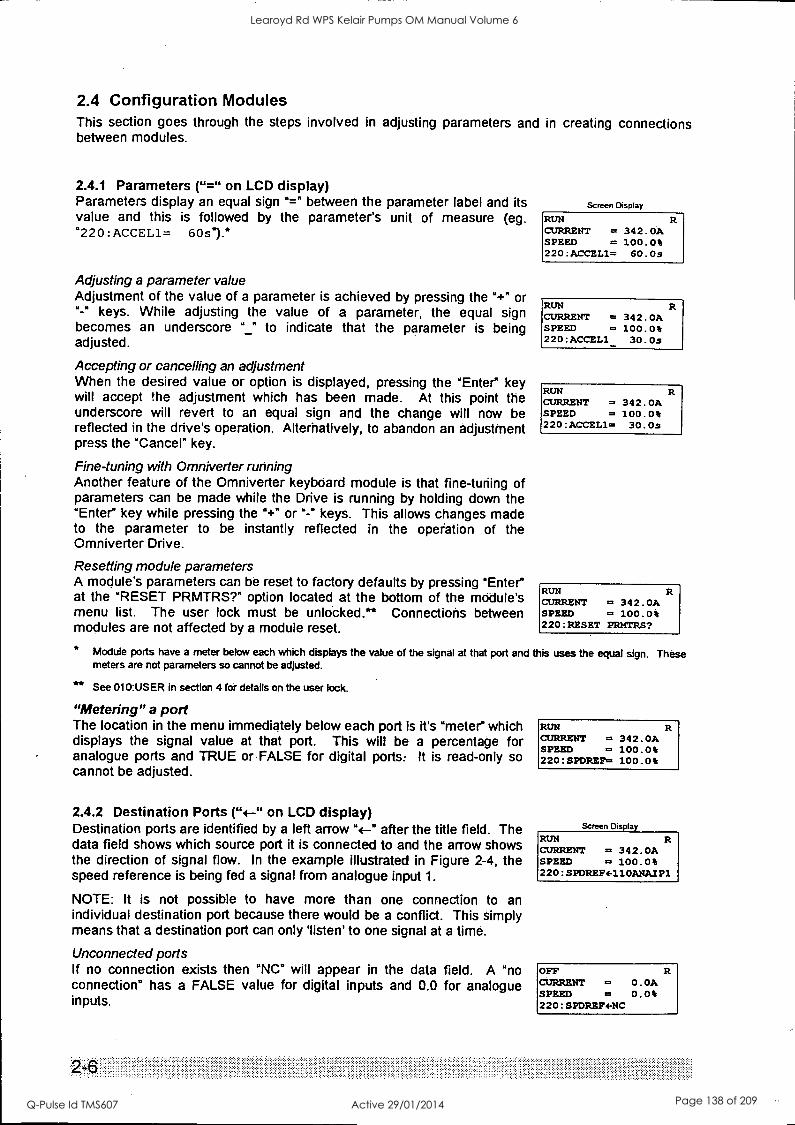
2.4 Configuration Modules This section goes through the steps involved in adjusting parameters and in creating connections between modules.
2.4.1 Parameters ("=" on LCD display) Parameters display an equal sign "=" between the parameter label and its value and this is followed by the parameter's unit of measure (eg. "220:ACCEL1= 60s1.*
Adjusting a parameter value Adjustment of the value of a parameter is achieved by pressing the "+" or "-" keys. While adjusting the value of a parameter, the equal sign becomes an underscore "_" to indicate that the parameter is being adjusted.
Accepting or cancelling an adjustment When the desired value or option is displayed, pressing the "Enter" key will accept the adjustment which has been made. At this point the underscore will revert to an equal sign and the change will now be reflected in the drive's operation. Alterhatively, to abandon an adjustment press the "Cancel" key.
Fine-tuning with Omniverter running Another feature of the Omniverter keyboard module is that fine-turiing of parameters can be made while the Drive is running by holding down the "Enter" key while pressing the "+" or "-" keys. This allows changes made to the parameter to be instantly reflected in the operation of the Omniverter Drive.
Resetting module parameters A module's parameters can be reset to factory defaults by pressing "Enter" at the "RESET PRMTRS?" option located at the bottom of the module's menu list. The user lock must be unlocked." Connections between modules are not affected by a module reset.
Screen Display
RUN CURRENT = SPEED = 220:ACCEL1=
342.OA 100.0% 60.0$
RUN CURRENT = 342.OA SPEED = 100.0% 220:ACCELl_ 30.Os
RUN CURRENT = 342.0A SPEED = 100.0% 220:ACCEL1= 30.Os
RUN CURRENT = 342.0A SPEED = 100.0% 220:RESET PRMTRS?
* Module ports have a meter below each which displays the value of the signal at that port and this uses the equal sigm meters are not parameters so cannot be adjusted.
** See 010:USER in section 4 for details on the user lock.
"Metering" a port The location in the menu immediately below each port is it's "meter" which displays the signal value at that port. This will be a percentage for analogue ports and TRUE orFALSE for digital ports: It is read-only so cannot be adjusted.
2.4.2 Destination Ports ( "+.-" on LCD display) Destination ports are identified by a left arrow "4-" after the title field. The data field shows which source port it is connected to and the arrow shows the direction of signal flow. In the example illustrated in Figure 2-4, the speed reference is being fed a signal from analogue input 1.
NOTE: It is not possible to have more than one connection to an individual destination port because there would be a conflict. This simply means that a destination port can only 'listen' to one signal at a time.
Unconnected ports If no connection exists then "NC° will appear in the data field. A "no connection" has a FALSE value for digital inputs and 0.0 for analogue inputs.
2-6 .............. . . .....
These
RUN CURRENT = 342.0A SPEED = 100.0% 220:SPDREF= 100.0%
Screen Display
RUN CURRENT = 342.0A SPEED = 100.0% 220:SPDREF4-110ANAIP1
OFF CURRENT = 0.0A SPEED = 0.0% 220:SPDREF4 -NC
Learoyd Rd WPS Kelair Pumps OM Manual Volume 6
Q-Pulse Id TMS607 Active 29/01/2014 Page 138 of 209
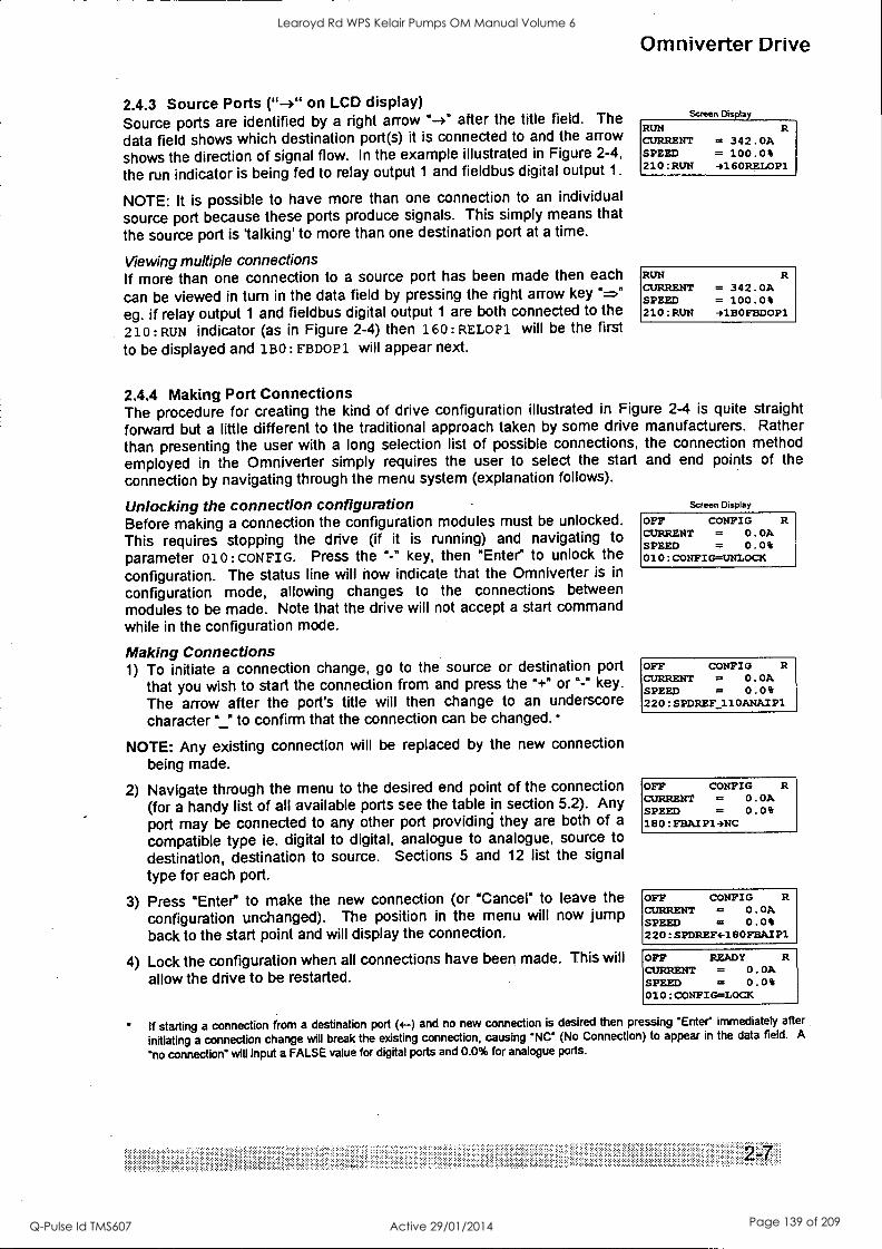
2.4.3 Source Ports ( "-+" on LCD display) Source ports are identified by a right arrow "-+" after the title field. The
data field shows which destination port(s) it is connected to and the arrow
shows the direction of signal flow. In the example illustrated in Figure 2-4,
the run indicator is being fed to relay output 1 and fieldbus digital output 1.
NOTE: It is possible to have more than one connection to an individual
source port because these ports produce signals. This simply means that
the source port is 'talking' to more than one destination port at a time.
Viewing multiple connections If more than one connection to a source port has been made then each
can be viewed in turn in the data field by pressing the right arrow key " =" eg. if relay output 1 and fieldbus digital output 1 are both connected to the
210: RUN indicator (as in Figure 2-4) then 160 : RELOP1 will be the first
to be displayed and 150: FBDOP1 will appear next.
Omniverter Drive
Screen Display
RUN CURRENT SPEED 210: RUN
R = 342.OA = 100.0% 4160RELOP1
RUN CURRENT SPEED 210: RUN
R = 342.OA = 100.0% 41BOFBDOP1
2.4.4 Making Port Connections The procedure for creating the kind of drive configuration illustrated in Figure 2-4 is quite straight
forward but a little different to the traditional approach taken by some drive manufacturers. Rather
than presenting the user with a long selection list of possible connections, the connection method employed in the Omniverter simply requires the user to select the start and end points of the
connection by navigating through the menu system (explanation follows).
Unlocking the connection configuration Before making a connection the configuration modules must be unlocked. This requires stopping the drive (if it is running) and navigating to parameter 010 : CONFIG. Press the "-" key, then "Enter" to unlock the
configuration. The status line will now indicate that the Omniverter is in
configuration mode, allowing changes to the connections between modules to be made. Note that the drive will not accept a start command while in the configuration mode.
Making Connections 1) To initiate a connection change, go to the source or destination port
that you wish to start the connection from and press the "+" or "-" key.
The arrow after the port's title will then change to an underscore character "_" to confirm that the connection can be changed.
NOTE: Any existing connection will be replaced by the new connection being made.
2) Navigate through the menu to the desired end point of the connection (for a handy list of all available ports see the table in section 5.2). Any port may be connected to any other port providing they are both of a
compatible type ie. digital to digital, analogue to analogue, source to
destination, destination to source. Sections 5 and 12 list the signal
type for each port.
3) Press "Enter" to make the new connection (or "Cancel" to leave the
configuration unchanged). The position in the menu will now jump back to the start point and will display the connection.
4) Lock the configuration when all connections have been, made. This will allow the drive to be restarted.
Screen Display
OFF CONFIG CURRENT = 0.0A SPEED = 0.0% 010:CONFIG=UNLOCK
OFF CONFIG CURRENT = 0.OA SPEED = 0.0% 220:SPDREF110ANAIP1
OFF CONFIG R CURRENT = 0.0A SPEED = 0.0% 180:FBAIP14NC
OFF CONFIG R CURRENT = 0.0A SPEED = 0.0% 220:SPDREF4-180FSAIP1
OFF READY CURRENT = 0.0A SPEED = 0.0% 010:CONFIG=LOCK
if starting a connection from a destination port (4-) and no new connection is desired then pressing 'Enter immediately after
initiating a connection change will break the existing connection, causing "NC' (No Connection) to appear in the data field. A
"no connection" will Input a FALSE value for digital ports and 0.0% for analogue ports.
Learoyd Rd WPS Kelair Pumps OM Manual Volume 6
Q-Pulse Id TMS607 Active 29/01/2014 Page 139 of 209
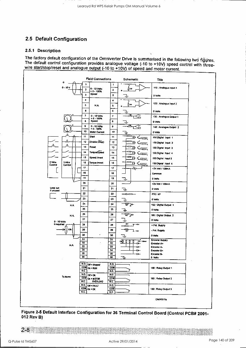
2.5 Default Configuration
2.5.1 Description
The factory default configuration of the Omniverter Drive is summarised in the following two fiatires. The default control configuration provides analogue voltage (-10 to +10V) speed control with three- wire start/stop/reset and analogue output (-10 to +10V) of speed and motor current.
2 Wire Control
Loop out It unused
3 Wm Control
0 - 10 Vdts required
N.A.
NA
NA
To Mores
Field Connections Schematic Title
1
0 - 10 Volts 6rro 110 : An e Input Mut 1 2 2
= 0 - 100% Speed
0 Volts 3 3
4 4 L-. NA 721
120 : Analogue Input 2 5 5
--a 0 votts 6 6
( 7 0- 10 Volts = 0 - 100% Speed
7
-7_
1 130: Analogue Output 1
o Volts
- 8 8
at t<r, 9 0- 10 Volts = 0 - 100%
9
-3_
140: Analogue Output 2
0 Volts
- 10 Motor Current 10
11 Start 11 ----c=11 . 150:DIgnal Input 1
= 12 Enable (Stop) 12 $ a <. 150:Dignal Input 2
13 Reset 13 $ a (,... 150:Dlgrtal Input 3
(=7' 14 TorqueJSpeed 14 a It . 150:Digital Input 4
15 Speed Invert 15 --='-al C 150:Digital Input 5 .r 15 Torque Invert 15 c=) a a ,..., 150:DIghd Input 6
17 17 T 24 Von / 100mA
18 18 Common
19 19 0 Volts
20 20 +24 Volt / 100mA
21 21 0 Volts
22 22 PTC VP -40-4=s- 23 23 0 Volts
24 24 /s----.2t- 150: Degttal Output 1 -__i 25 25 0 Volts
26 26 --(9??I- 160: Digital Output 2
27 27 _ 0 Volts
28 28 7 OW Pd. Supply
29 29 f-'9.--1. tsv - Pot. Supply
30 30 0 Volts
31 31 Encoder Supply p 1111111. nv , WO. Encoder A+ 32 32 is 33 Encoder A-
34 34 Encoder B 38 35 Encoder B- 36 36 0 Volts
N.O. off . mined
O n = RUN
N.O.
160 : Relay Output 1 COM COM
N.C. N.C.
On MOTOR
OVERLOAD
N.O.
160: Relay Output 2 C" COM
N.C. N C. N.O.--'). Cff *FAULT on . ok
N.O.
160 : Relay Output 3 COM COM
N.C. N.C.
OMN1011a
Figure 2-5 Default Interface Configuration for 36 Terminal Control Board (Control PCB# 2001- 012 Rev B)
2-
Learoyd Rd WPS Kelair Pumps OM Manual Volume 6
Q-Pulse Id TMS607 Active 29/01/2014 Page 140 of 209
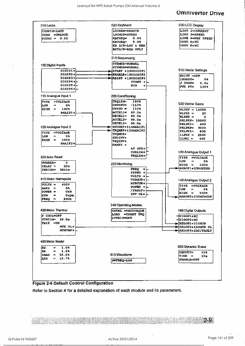
Omniverter Drive
010:Locks
CONFIG=LOCK USER =UNLOCK FCTRY = 0.00
150:DigitaHnpats
DIGIP19 DIGIP24 DIGIP33 DIGIP43 DIGIP54 DIGIP64
11 Vmalogue Input 1
TYPE =VOLTAGE LOW = 0% HIGH = 100%
ANAJP14
120:Analogue Input 2
TYPE =VOLTAGE LOW = 0% HIGH = 100%
ANAJP24
020:Keyboard
LOCREM=REMOTE LOCMDE=SPEED KBFREQ= 0.0% KBTORQ= 0.0% K8 S/R=LOC 6 REM EXTS/R=REM ONLY
210:Sequendng
STRMDE = NORMAL STPMDE=NORMAL START 4-150DIGIP1 ENABLE+150DIGIP2 RESET 4-150DIGIP3
START 4 RUN 4
220:Conditioning
320:Auto Reset
NUMBER= 0
DELAY = 30s PERIOD= 3600s
410:Motor Nameplate
VOLTS = 400V AMPS = OA POWER = OkW RPM = Orpm FREQ = 50Hz
420:Motor Thermal
F COOL=OFF STRTIM= 10.0s TRIP =ON
MTR OL4 MTRTMP4
TROLIM= 150% LWRSPD= -110% UPSPD = 110% ACCEL1= 60.Os DECEL1= 60.Os ACCEL2= 60.Os DECEL2= 60.Os SPDREF4-110ANAIP1 TRQREF4-120ANAIP2 TRQMDE+ SPDINV+ TROINV4 RAMP2
AT SPD9 CURLIM3 TRQLIM4
230:Monitoring
FREQ 4 SPEED 4 VOLTS 4 TORQUES MTRCUR4 POWER 4 /FAULT-* INV OL4
240:Operating Modes
CNTRL =VECTORQUE LOAD CONST TRQ LVTRIP=OFF
30:LCD Display
LINE 2=CURRENT LINE 3=SPEED LINE 4=REg SPEED USER A+NC USER Be-NC
510:Vector Settings
HOIST =OFF IBOOST= 0% J COMP= 0.0s FWK PT= 120%
520:Vector Gains
WLPEP = 16000 WLPKI = 20 WL14.00 = 0
PHLPKP= 10000 PHLPKI= 400 FRLPKP= 3000 FRLPKI= 800 ILPKP = 2000 ILPKI = 400
130:Analogue Output 1
TYPE =VOLTAGE LOW = 0% HIGH = 100% ANA0P1+230SPEED
140:Analogue Output 2
430:Motor Model
RS = 1.0% RR = 1.0% IMAG = 50.0% LKG = 16.7%
610:Waveform
SWFREQ=LOW
TYPE =VOLTAGE LOW = 04 HIGH = 100% ANAOP24-230MTRCUR
160:Digital Outputs
DIGOP1ENC DIGOPEENC RELOP1+210RUN RELOP24-420MTR OL RELOP34-230/FAULT
630:Dynamic Brake
DBOUTY= 104 TIME = lOs ENABLE=OFF
Figure 2-6 Default Control Configuration
Refer to Section 4 for a detailed explanation of each module and its parameters.
Learoyd Rd WPS Kelair Pumps OM Manual Volume 6
Q-Pulse Id TMS607 Active 29/01/2014 Page 141 of 209
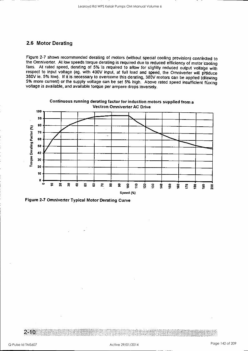
2.6 Motor Derating
Figure 2-7 shows recommended derating of motors (without special cooling provision) connected to the Omniverter. At low speeds torque derating is required due to reduced efficiency of motor 'cooling fans. At rated speed, derating of 5% 'is required to allow for slightly reduced output voltage with respect to input voltage (eg. with 400V input, at full load and speed, the Omniverter will produce 380V ie. 5% low). If it is necessary to overcome this derating, 380V motors can be applied (dtalAring 5% more current) or the supply voltage can be set 5% high. Above rated speed insufficient fluxing voltage is available, and available torque per ampere drops inversely.
Continuous running derating factor for induction motors supplied from a Vectron Omniverter AC Drive
uu
90
80
N......._
70
60
SO
40
"INIbm-a-
30
20
10
0 a 4:, c* /- 04 00000000000000000C el .1. 20 CD P. CO CO 0 /' (Nt el cr WI CO is CO CO C
Speed (%)
Figure 2-7 Omniverter Typical Motor Derating Curve
...... ....
Learoyd Rd WPS Kelair Pumps OM Manual Volume 6
Q-Pulse Id TMS607 Active 29/01/2014 Page 142 of 209
Omniverter Drive
3. Installation and Commissioning
3.1 Mechanical Installation
3.1.1 Mounting
The Omniverter Drive is supplied with brackets for surface mounting. The same mounting brackets can be repositioned centrally to permit through wall mounting. Through wall mounting permits the main air stream to be placed external to an electrical switchboard, eliminating the need for additional switchboard cooling. Refer to Figure 1-2 Dimensional Details, for dimensions.
3.1.2 Cooling
Cooling airflows in the Omniverter Drives must not be impeded. If mounting internally in a
switchboard, sufficient airflow must be provided (See Section 1.4.8 for power loss and airflow information).
Two methods are available to the installer to simplify this problem.
Through wall mounting-- if through wall mounted care must be taken to allow for remaining losses of about 30% in the switchboard itself. Additional air flow exhausting from the top of the switchboard is usually required.
Make provision for air inlet into the switchboard and duct exhaust air outside the switchboard directly from the Omniverter Drive outlet. The Omniverter Drive fan has sufficient power to draw and exhaust its cooling air requirements as long as ducting is not restrictive. This can eliminate the need for additional air supply.
In all cases check that airflow is unimpeded and cooling is adequate during commissioning.
Learoyd Rd WPS Kelair Pumps OM Manual Volume 6
Q-Pulse Id TMS607 Active 29/01/2014 Page 143 of 209
3.2 Electrical Installation
3.2.1 EMC (Electromagnetic Compatibility)
Electromagnetic compatibility refers to the safe and reliable operation of both the Omnivertee Drive and other equipment sharing the same electromagnetic operating environment.
To assure EMC and radio interference levels are achieved, it is irilportant that installation is carried out exactly according to the instructions of this manual.
3.2.2 Control (Signal) Cabling
Normal control cabling practice applies. Controls should be screened and earthed at the OmniVerter Drive end only. Control cable should be run at least 1m away from power cables (especially power output cables from AC Drives) and, where necessary, should cross power cables only at right angles.
3.2.3 Earthing
The Omniverter must be solidly bonded to power supply earth before energising the drive. Potentially high leakage currents necessitate a permanent connection between drive chassis and mains earth.
Mains power earth must be connected to the PE terminal.
Motor earth must be made directly from motor chassis to drive motor earth terminal (ME) - preferibly via the motor cable screen bonded at both ends. Where maximum radio suppression is required, screened three core cables must be used and the cable screen must be well bonded to the motor frame and connected directly to the Omniverter ME terminal - it must not be connected elsewhere en-route.
3.2.4 Power Cabling
Power Cabling requirements are summarised in Figure 3-1 Power Connection Details.
Omniverter Drive models up to OD4 600 are designed for connection with single input and output cables. Models OD4 750 and above have dual termination points designed for connection to paralleled cable runs.
Cable entry is made through a gland plate at the bottom of the Omniverter Drive.
The Omniverter Drive has very effective RFI filtering built in as standard.
In sensitive applications, and where output cables run with other output cables or near mains supply cables, a screened three-core motor cable is recommended. Such a cable must be solidly and directly bonded to both the motor and Omniverter Drive chassis to be effective.
3.2.5 Motor Bearing Protection
AC Drives can place motor bearings at increased risk due to flow of induced currents. Refer to Appendix 9 - Bearing Filters - Protecting Motor Bearings.
Risks can be minimised by ensuring the motor and load earths are made as recommended in this section.
Refer to 13.3 Bearing Filter Installation if installing bearing protection filters
3-2
Learoyd Rd WPS Kelair Pumps OM Manual Volume 6
Q-Pulse Id TMS607 Active 29/01/2014 Page 144 of 209
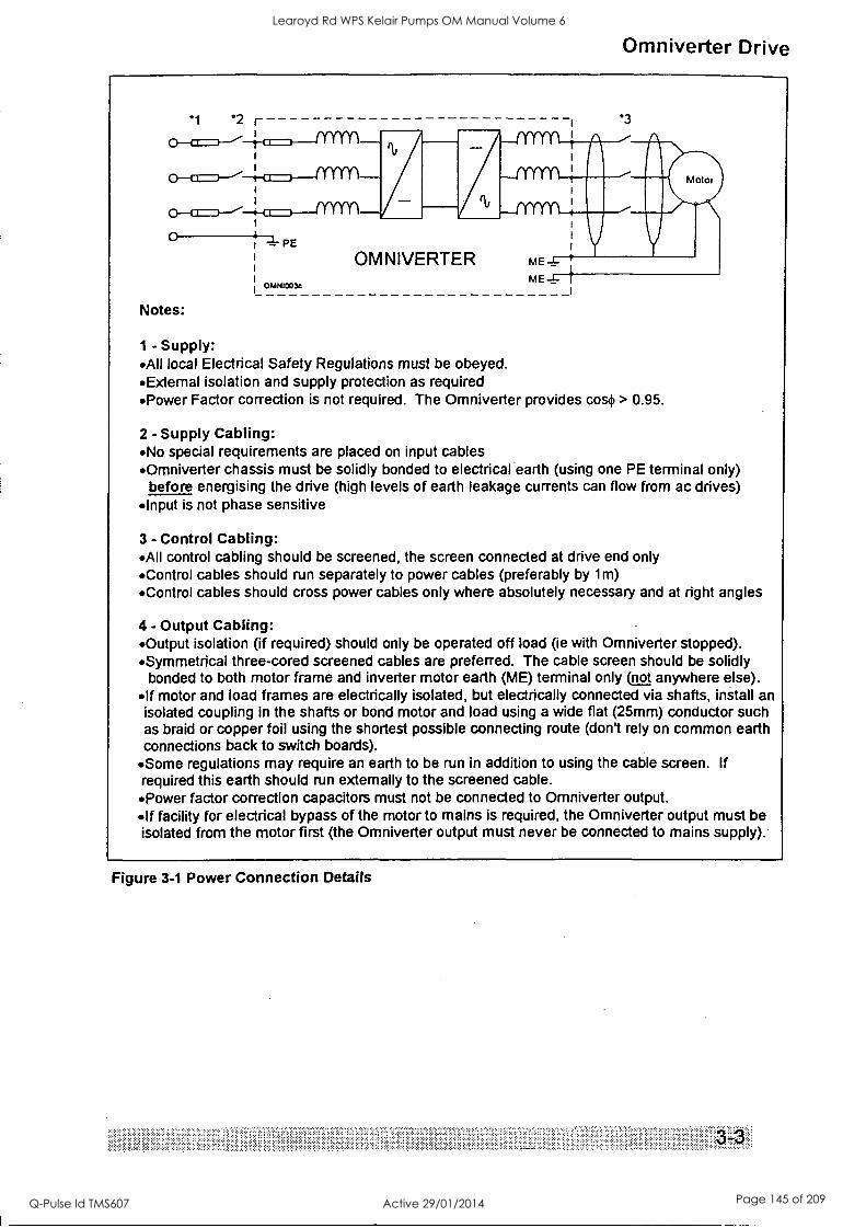
Omniverter Drive
*1 *2
O 4 , =.-. PE
OMNI003c
Notes:
Oka
OMNIVERTER
*3
Motor
mE f
- Supply: All local Electrical Safety Regulations must be obeyed. Extemal isolation and supply protection as required Power Factor correction is not required. The Omniverter provides cos. > 0.95.
2 - Supply Cabling: No special requirements are placed on input cables Omniverter chassis must be solidly bonded to electrical earth (using one PE terminal only)
before energising the drive (high levels of earth leakage currents can flow from ac drives) Input is not phase sensitive
3 - Control Cabling: All control cabling should be screened, the screen connected at drive end only Control cables should run separately to power cables (preferably by 1m) Control cables should cross power cables only where absolutely necessary and at right angles
4 - Output Cabling: Output isolation (if required) should only be operated off load (ie with Omniverter stopped). Symmetrical three-cored screened cables are preferred. The cable screen should be solidly
bonded to both motor frame and inverter motor earth (ME) terminal only not anywhere else). If motor and load frames are electrically isolated, but electrically connected via shafts, install an isolated coupling in the shafts or bond motor and load using a wide flat (25mm) conductor such as braid or copper foil using the shortest possible connecting route (don't rely on common earth connections back to switch boards).
Some regulations may require an earth to be run in addition to using the cable screen. If required this earth should run externally to the screened cable. Power factor correction capacitors must not be connected to Omniverter output. If facility for electrical bypass of the motor to mains is required, the Omniverter output must be isolated from the motor first (the Omniverter output must never be connected to mains supply).
Figure 3-1 Power Connection Details
Learoyd Rd WPS Kelair Pumps OM Manual Volume 6
Q-Pulse Id TMS607 Active 29/01/2014 Page 145 of 209

3.3 Commissioning For convenience section 6.2 presents a suggested commissioning schedule.
3.3.1 Safety Warning
Omniverter Drive is a high power electronic device. It is usually connected to high energy mains supplies.
Installation of Omniverter Drive must only be carried out under supervision of staff who are suitably qualified and experienced in the installation of such equipment.
Service must only be carried out by staff who are suitably qualified and experienced in the service of such equipment.
All usual safety precautions concerning power electronic equipment must be observed.
Safety glasses must be worn if operating the drive with the covers removed.
Capacitors in the Omniverter store charge. Allow at least fifteen minutes for charge to dissipate before servicing.
3.3.2 Installation Inspection
Mechanical
Check that the mechanical mounting of the drive is adequate.
Thermal
Check that airflow paths are free and are able to carry the required air flow (approx. 6m3/min per module, flowing into the bottom rear of the drive and exhausting at the top rear of the drive). Check that thermal design caters for potential heat loss (approx. 70% of motor load at the rear cooling path, 30% (max) at front cooling path - see Figure 1-2).
Electrical
Check the electrical installation of cables, crimps and lugs making sure that sizing is appropriate. Check at the drive input, output and motor terminals.
Check that the earthing has been carried out correctly accolting to the instructions in Figure 3-1.
Ensure that no loose material, swarf or moisture has entered the drive.
3.3.3 Energising the Drive
Warning: Omniverter Drive is powered from high energy electrical supplies. Suitably qualified staff must inspect and approve the installation prior to powering the Drive. Safety is the responsibility of the commissioning engineer. Safety should never be compromised.
Ensure mechanical safety by
- making sure all staff are clear of connected machinery
- if necessary, decoupling the motor shaft
- if possible, isolating the motor while programming the Drive
- open the PTC circuit - this will always prevent the Omniverter Drive starting, regardless of set up.
Turn the power on. The fans should start and the display should illuminate. If the PTC circuit has been opened the display will indicate a motor PTC fault.
...
Learoyd Rd WPS Kelair Pumps OM Manual Volume 6
Q-Pulse Id TMS607 Active 29/01/2014 Page 146 of 209
Omniverter Drive
3.3.4 Using the Omniverter in its "Standard Configuration"
When received ex factory, the Omniverter Drive has been fully reset to default condition (see Section 2.5). Often the drive can be used in this configuration, or with only a few simple adjustments. For more information about any parameter or setting refer to the relevant screen detail in Section 4.
The standard configuration sets the drive up with a very standard set of inputs and outputs (refer to Figure 2-5).
The standard configuration is set up for voltage inputs and outputs (+/- 10V = -100 to +100% which means 0 to +10V = 0 to 100%). If current (4-20mA) input or output is required, the analogue channels can be reprogrammed using the appropriate interface programming screens (100: INTERFACE).
Standard parameters are preset: -
acceleration 220 : ACCEL1= 60.0 seconds
deceleration 220: DECEL1= 60.0 seconds
upper speed limit 220:UPSPD = 110% of rated motor speed
lower speed limit 220: LWRSPD= -110% of rated motor speed
If negative speed (ie. reverse) is not desired, it is a good idea to set 220: LWRSPD to 0%.
Normal start (ramp from zero speed) and stop (ramp to zero speed) are set.
For those familiar with earlier generation drives and used to having to set up "boost" controls, note that normal Vectorque control does not need (or therefore provide) any form of boost adjustment.
Motor nameplate (410:MOTOR NAMEPLATE) details must be entered correctly to ensure motor protection and provide correct operation. Following entry of the motor parameters, the option is
given to "410: CALCULATE MODEL?". It is important to accept this option (press the Enter key) at this point to have the motor model parameters automatically calculated from the nameplate data entered.
For standard motors and applications, these are usually the only parameters which must be set prior to operation of the drive.
Warning: Vectorque must not be used with motors rated at less than 1/3 of the drive current rating (for test purposes with small motors V/Hz mode can be used - set 240: CNTRL =V/Hz). Attempts to
trial very small motors in Vectorque mode will result in excessive motor current and damage to the motor.
3.3.5 Master Reset
If necessary the Omniverter can be fully reset to the ex-factory state using the master reset screen 040: RESET (but note motor parameters (410: MOTOR NAMEPLATE) are not reset).
3.3.6 Local or Remote Control
Operation may be achieved from the local keyboard controls if required. Change screen 020: LOCREM= to LOCAL to obtain local control. In local control, the speed reference is taken from
the keyboard setting (020: KBFREQ= ) Stop and start are controlled purely from the keyboard controls - all external inputs are disabled (but motor PTC remains active - this can be useful if wanting a completely assured lock out mechanism while setting up).
Change screen 020: LOCREM= to REMOTE to return to remote control.
3.3.7 Advanced Set Up
For more detailed setups, the user is referred to section 2 detailing the concepts and methods employed in the Omniverter, and section 4, detailing the function, default setting, range and setup of each individual screen.
Learoyd Rd WPS Kelair Pumps OM Manual Volume 6
Q-Pulse Id TMS607 Active 29/01/2014 Page 147 of 209
3.3.8 Start Up
Plan an approach which will allow Drive system to be exercised safely, always ensuring the Omniverter Drive can be stopped immediately if necessary.
Remove Motor Isolation.
Reset any fault indications (push 0 button to reset faults).
Start the Omniverter Drive in an appropriate mode of operation which permits observation of operation. Check direction of motor shaft rotation and that motor currents are correct.
With care, check operation at higher speeds or torque. Check acalerations and decelerations are appropriate.
Always check that motor currents and speeds are as expected.
If any faults are reported, refer to 3.5 Latched Fault Indications to determine cause and suggested solution.
If starting problems are encountered, 430: MOTOR module parameters may need to be trimmed. If motor rocks back and forth at start up or spins in the wrong direction sometimes 430: IMAG may be set too low - refer to Table 4-2.
If start sometimes results in a current limit or trip, 430 : RS in may be set too high - refer to Table 4-2.
If insufficient starting torque is generated, 4 30 : IMAG may be set too low - refer to Table 4-2.
With high starting torque loads indicatidns of motor overload and torque limit are not unusual - these are warnings that the motor will overheat if operation at the level of load is prolonged and that the inverter has trimmed acceleration or frequency to reduce torque respectively. The warnings are provided for information only - no change to set up is necessarily required.
If extended periods of operation at low speed (<20% speed) are envisaged, 430 : IMAG should be optimised. To do this, run the motor at no (or light) load above 20% speed and take note of the no load current (in Amps) on the LCD display. Set 430: IMAG to the no load current as a percentage of the motor nameplate current. If this method is impractical refer to 4 30 : IMAG in Section 4.
.. ... . . .
. . . . .
Learoyd Rd WPS Kelair Pumps OM Manual Volume 6
Q-Pulse Id TMS607 Active 29/01/2014 Page 148 of 209
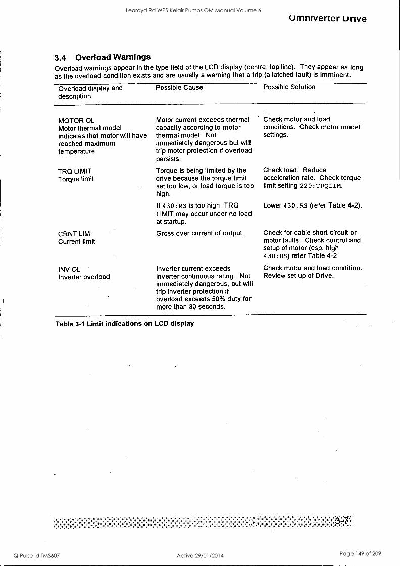
tl
umniverter unve
3.4 Overload Warnings Overload warnings appear in the type field of the LCD display (centre, top line). They appear as long as the overload condition exists and are usually a warning that a trip (a latched fault) is imminent.
Overload display and description
Possible Cause Possible Solution
MOTOR OL Motor thermal model indicates that motor will have reached maximum temperature
TRQ LIMIT Torque limit
CRNT LIM Current limit
INV OL Inverter overload
Motor current exceeds thermal capacity according to motor thermal model. Not immediately dangerous but will trip motor protection if overload persists.
Torque is being limited by the drive because the torque limit set too low, or load torque is too high.
If 430: RS is too high, TRQ LIMIT may occur under no load at startup.
Gross over current of output.
Inverter current exceeds inverter continuous rating. Not immediately dangerous, but will trip inverter protection if overload exceeds 50% duty for more than 30 seconds.
Check motor and load conditions. Check motor model settings.
Check load. Reduce acceleration rate. Check torque limit setting 220 : TRQLIM.
Lower 430: RS (refer Table 4-2).
Check for cable short circuit or motor faults. Check control and setup of motor (esp. high 430: RS) refer Table 4-2.
Check motor and load condition. Review set up of Drive.
Table 3-1 Limit indications on LCD display
Learoyd Rd WPS Kelair Pumps OM Manual Volume 6
Q-Pulse Id TMS607 Active 29/01/2014 Page 149 of 209
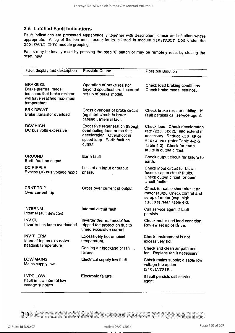
3.5 Latched Fault Indications Fault indications are presented alphabetically together with description, cause and solution where appropriate. A log of the ten most recent faults is listed in module 310: FAULT LOG under the 300: FAULT INFO module grouping.
Faults may be locally reset by pressing the stop 13' button or may be remotely reset by closing the reset input.
Fault display and description Possible Cause Possible Solution
BRAKE OL Brake thermal model indicates that brake resistor will have reached maximum temperature
BRK DESAT Brake transistor overload
DCV HIGH DC bus volts excessive
GROUND Earth fault on output
DC RIPPLE Excess DC bus voltage ripple
CRNT TRIP Over current trip
INTERNAL internal fault detected
INV OL Inverter has been overlokled
INV THERM Internal trip on excessive heatsink temperature
LOW MAINS Mains supply low
LVDC LOW Fault in low internal low voltage supplies
Operation of brake resistor beyond specification. Income& set up of brake model.
Gross overload of brake circuit (eg short circuit in brake cabling), internal fault
Excessive regeneration through overhauling load or too fast deceleration. Overshoot in speed loop. Earth fault on output.
Earth fault
Loss of an input or output phase.
Gross over current of output
Internal circuit fault
Inverter thermal model has tripped the protection due to timed excessive current
Excessively hot ambient temperature.
Cooling air blockage or fan failure.
Electrical supply low fault
Electronic failure
Check load braking conditions. Check brake model settings.
Check brake resistor cabling. If fault persists call service agent.
Check load. Check deceleration rate (220: DECEL) and extend if necessary. Reduce 430: RR or 520 : WLPKI (refer Table 4-2 & Table 4-3). Check for earth faults in output circuit.
Check output circuit for failure to earth.
Check input circuit for blown fuses or open circuit faults. Check output circuit for open circuit faults.
Check for cable short circuit or motor faults. Check control and setup of motor (esp. high 430: RS) refer Table 4-2.
Call service agent if fault persists
Check motor and load condition. Review set up of Drive.
Check environment is not excessively hot.
Check and clean air path and fan. Replace fan if necessary.
Check mains supply; disable low voltage trip option (240: LVTRI P).
If fault persists call service agent
Learoyd Rd WPS Kelair Pumps OM Manual Volume 6
Q-Pulse Id TMS607 Active 29/01/2014 Page 150 of 209
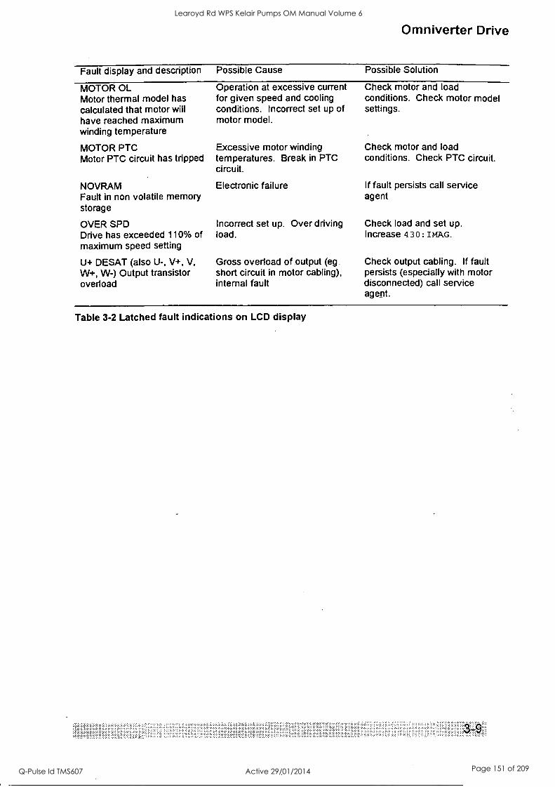
Omniverter Drive
Fault display and description Possible Cause Possible Solution
MOTOR OL Motor thermal model has calculated that motor will have reached maximum winding temperature
MOTOR PTC Motor PTC circuit has tripped
NOVRAM Fault in non volatile memory storage
OVER SPD Drive has exceeded 110% of maximum speed setting
U+ DESAT (also U-, V+, V, W+, W-) Output transistor overload
Operation at excessive current for given speed and cooling conditions. Incorrect set up of motor model.
Excessive motor winding temperatures. Break in PTC circuit.
Electronic failure
Incorrect set up. Over driving load.
Gross overload of output (eg short circuit in motor cabling), internal fault
Check motor and load conditions. Check motor model settings.
Check motor and load conditions. Check PTC circuit.
If fault persists call service agent
Check load and set up. Increase 4 30 : IMAG.
Check output cabling. If fault persists (especially with motor disconnected) call service agent.
Table 3-2 Latched fault indications on LCD display
.. ....... .... . ...
Learoyd Rd WPS Kelair Pumps OM Manual Volume 6
Q-Pulse Id TMS607 Active 29/01/2014 Page 151 of 209
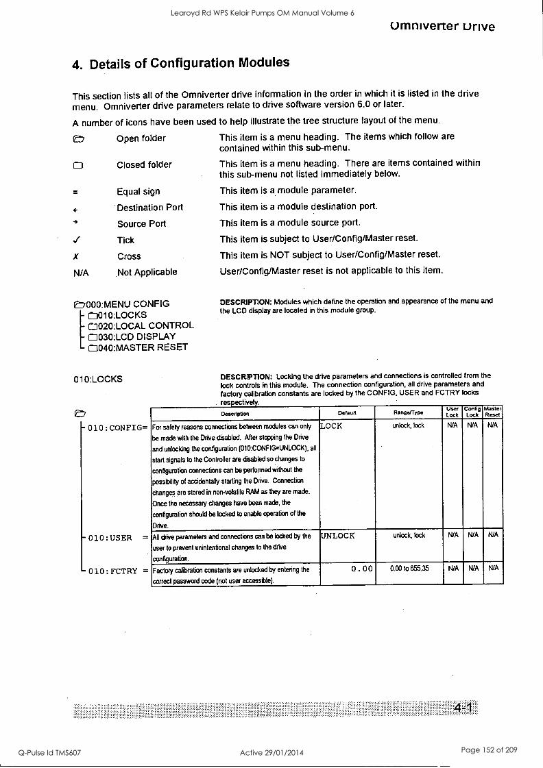
omniverter unve
4. Details of Configuration Modules
This section lists all of the Omniverter drive information in the order in which it is listed in the drive menu. Omniverter drive parameters relate to drive software version 6.0 or later.
A number of icons have been used to help illustrate the tree structure layout of the menu.
L7 Open folder This item is a menu heading. The items which follow are contained within this sub-menu.
O Closed folder This item is a menu heading. There are items contained within this sub-menu not listed immediately below.
Equal sign This item is a module parameter.
Destination Port This item is a module destination port.
4 Source Port This item is a module source port.
Tick This item is subject to User/Config/Master reset.
X Cross This item is NOT subject to User/Config/Master reset.
N/A Not Applicable User/Config/Master reset is not applicable to this item.
L7000:MENU CONFIG [0010:LOCKS 0020:LOCAL CONTROL 00301CD DISPLAY 0040:MASTER RESET
010: LOCKS
- 010 : CONFIG=
- 010 :USER =
010:FCTRY =
DESCRIPTION: Modules which define the operation and appearance of the menu and
the LCD display are located in this module group.
DESCRIPTION: Locking the drive parameters and connections is controlled from the
lock controls in this module. The connection configuration, all drive parameters and
factory calibration constants are locked by the CONFIG, USER and FCTRY locks res tive .
Description Default Range/Type User Lock
Config Lock
Master Reset
For safety reasons connections between modules can only
be made with the Drive disabled. After stopping the Drive
and unlocking the configuration (010:CONFIG=UNLOCK), all
start signals to the Controller are disabled so changes to
configuration connections can be performed without the
possibility of accidentally starting the Drive. Connection
changes are stored in non-volatile RAM as they are made.
Once the necessary changes have been made, the
configuration should be locked to enable operation of the
Drive.
LOCK unlock, lock N/A NIA N/A
All drive parameters and connections can be locked by the
user to prevent unintentional changes to the drive
configuration.
UNLOCK unlock, lock N/A N/A N/A
Factory calibration constants are unlocked by entering the
correct password code (not user accessble).
0 . 00 0.00 to 655.35 N/A N/A N/A
' ''
Learoyd Rd WPS Kelair Pumps OM Manual Volume 6
Q-Pulse Id TMS607 Active 29/01/2014 Page 152 of 209
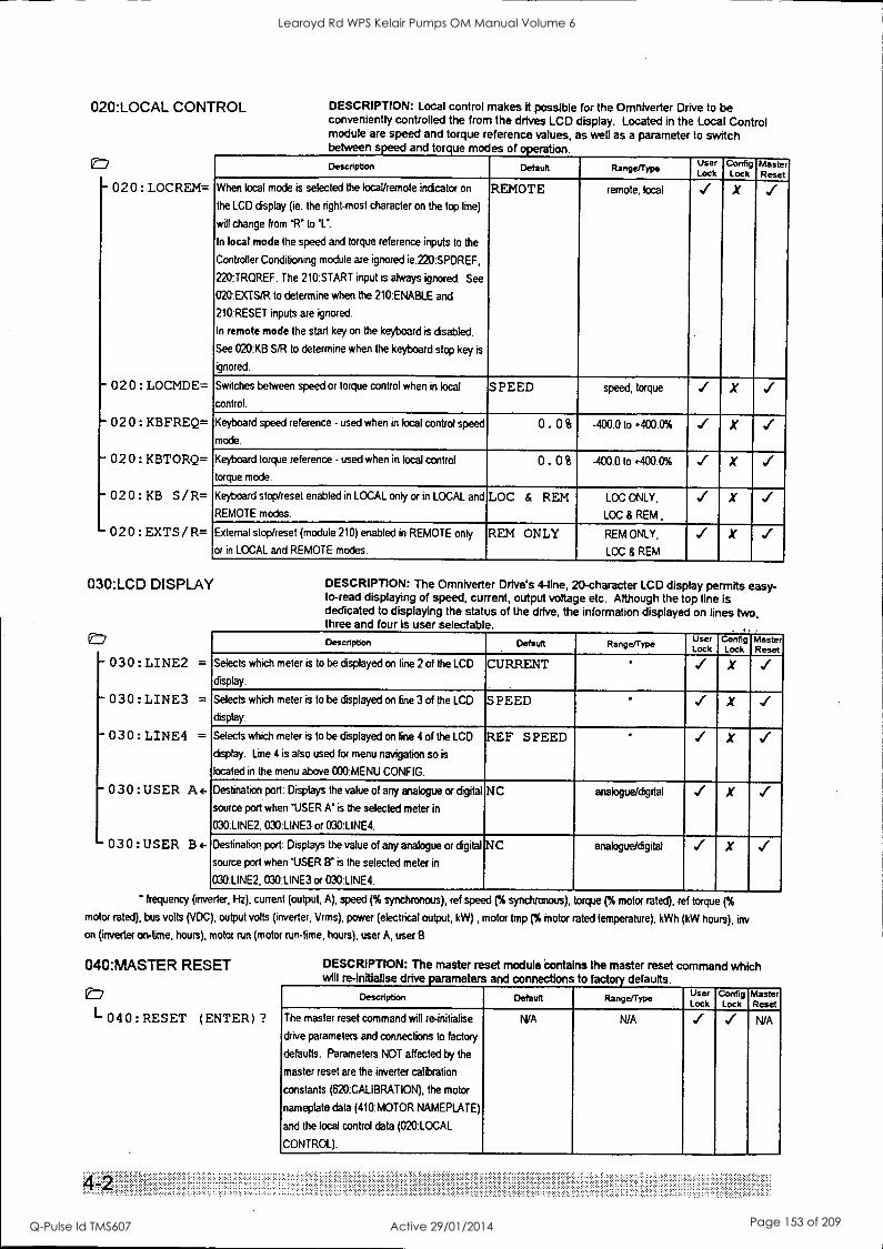
020:LOCAL CONTROL
- 020 : LOCREM=
-020:LOCMDE=
-020:KBFREQ=
020:KBTORQ=
020:KB S/R=
020:EXTS/R=
DESCRIPTION: Local control makes it possible for the Omniverter Drive to be conveniently controlled the from the drives LCD display. Located in the Local Control module are speed and torque reference values, as well as a parameter to switch between speed and torque modes of operation.
Description Default Range/Type User Lock
Config Lock
Master Reset
When local mode is selected the locaVremote indicator on
the LCD display (ie. the right-most character on the top line)
will change from 'Fr to V. In local mode the speed and torque reference inputs to the
Controller Conditioning module are ignored ie.220:SP0REF,
220:TRQREF. The 210:START input is always ignored. See
020:EXTS/R to determine when the 210:ENABLE and
210:RESET inputs are ignored.
In remote mode the start key on the keyboard is disabled.
See 020:KB S/R to determine when the keyboard stop key is
ignored.
REMOTE remote, local X
Switches between speed or torque control when in local
control.
S PEED speed, torque X
Keyboard speed reference - used when in local control speed
mode.
0. 0% -400.0 to +400.0% X
Keyboard torque reference - used when in local control
torque mode.
0. 0 % -400.0 to +400.0% X
Keyboard stop/reset enabled in LOCAL only or in LOCAL and
REMOTE modes.
LOC & REM LOC ONLY,
LOC & REM ,
X
External stop/reset (module 210) enabled in REMOTE only
or in LOCAL and REMOTE modes.
REM ONLY REM ONLY,
LOC & REM
X
030:LCD DISPLAY
030:LINE2 =
030:LINE3 =
030: LINE4 =
030:USER A 4-
030:USER BE-
DESCRIPTION: The Omniverter Drive's 4-line, 20-character LCD display permits easy- to-read displaying of speed, current, output voltage etc. Although the top line is dedicated to displaying the status of the drive, the information displayed on lines two, three and four is user selectable.
Description Default RangeJType User Lock
Config Lock
Master Reset
Selects which meter is to be displayed on line 2 of the LCD
display.
CURRENT X
Selects which meter is to be displayed on line3of the LCD
display.
SPEED X
Selects which meter is to be displayed on line4of the LCD
display. Line 4 is also used for menu navigation so is
located in the menu above 000:MENU CONFIG.
REF SPEED ' X ..(
Destination port: Displays the value of any analogue or digital
source port when 'USER A' is the selected meter in
030:LINE2, 030:LINE3 or 030:LINE4.
NC analogue/digital X
Destination port: Displays the value of any analogue or digital
source port when 'USER B' is the selected meter in
030:LINE2, 030:LINE3 or 030:LINE4.
NC analogueldgital X
' frequency (inverter, Hz), current (output, A), speed (% synchronous), ref speed (% synchronous), torque (% motor rated), ref torque (%
motor rated), bus volts (VDC), output volts (inverter, Vrms), power (electrical output, kW) , motor Imp (% motor rated temperature), kWh (kW hours), inv
on (inverter on-time, hours), motor run (motor run-time, hours), user A, user B
040:MASTER RESET
E7
L 040: RESET (ENTER) ?
DESCRIPTION: The master reset module bonta ns the master reset command which will re-Initialise drive parameters and connections to factory defaults.
Description Default Range/Type Use Lock
Contig Lock
Master Reset
The master reset command will re-initialise
drive parameters and connections to factory
defaults. Parameters NOT affected by the
master reset are the inverter calibration
constants (620:CALIBRATION), the motor
nameplate data (410:MOTOR NAMEPLATE)
and the local control data (020:LOCAL
CONTROL).
N/A N/A N/A
Learoyd Rd WPS Kelair Pumps OM Manual Volume 6
Q-Pulse Id TMS607 Active 29/01/2014 Page 153 of 209
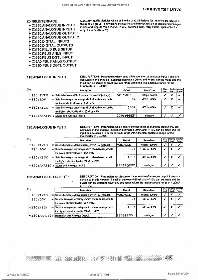
0:7I0O:INTERFACE - 0110:ANALOGUE INPUT 1
- 0120:ANALOGUE INPUT 2
h- 0130:ANALOGUE OUTPUT 1
- 0140:ANALOGUE OUTPUT 2
- 1:3150:DIGITAL INPUTS - 0160:DIGITAL OUTPUTS - 0170:FIELD BUS SETUP - 0180:FBUS ANLG INPUT
0190:FBUS DGTL INPUT 01A0:FBUS ANLG OUTPUT 1231 BO:FBUS DGTL OUTPUT
110:ANALOGUE INPUT 1
et' -110:TYPE = -110:LOW =
-110:HIGH =
110 : ANAI P1 -)
umniverter unve
DESCRIPTION: Modules which define the control interface for the drive are located in this module group. They define the scaling and interconnection of digital and analogue inputs and outputs (for 4-20mA, +/-10V, switched input, relay output, open collector output and field bus i/o).
DESCRIPTION: Parameters which control the operation of analogue input 1 only are contained in this module. Selection between 4-20mA and +/-10V can be made and the input can be scaled to cover any sub-range within the total analogue range for the Omniverter of +/-400%.
Description Default Range/Type User Lock
Config Lock
Master Reset
Selects betiveeii 4-20mA (current) or =+/-10V (voltage). . VOLTAGE voltage, current X
Sets the analogue percentage which should correspond to
the lowest electrical level ie. 4mA or OV.
0 % -400 to +400% X ..i
Sets the analogue percentage which should correspond to
the highest electrical level ie. 20mA or +10V.
10 0 % -400 to +400% ..t X
Source port: Analogue Input 1 220SPDREF analogue
120:ANALOGUE INPUT 2
-120:TYPE = 120:LOW =
- 120:HIGH =
120:ANAIP2-
DESCRIPTION: Parameters which control the operation of analogue input 2 only are contained in this module. Selection between 4-20mA and +/-10V can be made and the input can be scaled to cover any sub-range within the total analogue range for the Omniverter of +1-400%.
Description Default Range/Type User Lock
Config Lock
Master Reset
Selects between 4-20mA (current) or =+/-10V (voltage). VOLTAGE voltage, current X
Sets the analogue percentage which should correspond to
the lowest electrical level ie. 4mA or OV.
0 % ' -400 to +400% X
Sets the analogue percentage which should correspond to
the highest electrical level ie. 20mA or +10V.
10 0 % -400 to +400% X
Source port: Analogue Input 2 22 OTRQREF analogue
130:ANALOGUE OUTPUT 1
e:7
-130:TYPE = -130:LOW =
-130:HIGH =
-130:ANA0P1c-
DESCRIPTION: Parameters which control the operation of analogue output 1. only are contained in this module. Selection between 4-20mA and +/-10V can be made and the output can be scaled to cover any sub-range within the total analogue range of 4-20mA or +/-10V.
Description Default Range/Type User Lock
Config Lock
Master Reset
Selects between 4-20mA (current) or =+/-10V (voltage). VOLTAGE voltage, current X
Sets the analogue percentage which should correspond to
the lowest electrical levet ie. 4mA or OV.
0 % -400 to +400% ../ X
Sets the analogue percentage which should correspond to
the highest electrical level ie. 20mA or +10V.
100% -400 to +400% X
Destination port: Analogue Output 1 230SPEED analogue
Learoyd Rd WPS Kelair Pumps OM Manual Volume 6
Q-Pulse Id TMS607 Active 29/01/2014 Page 154 of 209
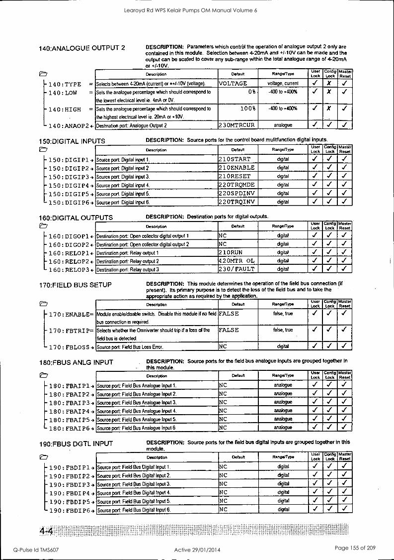
140:ANALOGUE OUTPUT 2
e 140:TYPE =
-140:LOW =
- 140:HIGH =
- 140:ANA0P24-
150:DIGITAL INPUTS
DESCRIPTION: Parameters which control the operation of analogue output 2 only are contained in this module. Selection between 4-20mA and +/-10V can be made and the output can be scaled to cover any sub-range within the total analogue range of 4-20mA or +/-10V.
Description Default Range/Type User Lock
Config Lock
Master Reset
Selects between 4-20mA (current) or =+/-10V (voltage). VOLTAGE voltage, current X
Sets the analogue percentage which should correspond to
the lowest electrical level ie. 4mA or OV.
0% -400 to +400% X ,,(
Sets the analogue percentage which should correspond to
the highest electrical level ie. 20iPA or +10V.
100% -400 to +400% X
Destination port: Analogue Output 2 230MTRCUR analogue
- -150:DIGIP24 - 150: DIGIP3 -,
- 150: DIGIP4
150:DIGIP53 - 150: DIGIP6-,
DESCRIPTION: Source ports for the control board mulitfunction digital inputs.
Description Default Rangefrype User Lock
Config Lock
Master Reset
Source port: Digital input 1. 210START digital ..1
Source port: Digital input 2. 210ENABLE digital -.1
Source port: Digital input 3. 210RESET digital
Source port: Digital input 4. 22 OTRQMDE digital
Source port: Digital input 5. 220SPDINV digital
Source port: Digital input 6. 220TRQINV digital
160:DIGITAL OUTPUTS E:7
- 160: DIGOP14-
- 160:DIGOP24-
- 160: RELOP14-
- 160 : RELOP2 e- 160: RELOP3 4-
DESCRIPTION: Destination ports for digital outputs.
Description Default Range/Type User Lock
Config Lock
Master Reset
Destination port: Open collector digital output 1 NC digital
Destination port: Open collector digital output 2 NC digital
Destination port: Relay output 1 210 RUN digital
Destination port: Relay output2 42 OMTR OL digital
Destination port: Relay output 3 230/ FAULT digital
170:FIELD BUS SETUP
- 170 : ENABLE=
- 170: FBTRIP=
170:FBLOSS4
DESCRIPTION: This module determines the operation of the field bus connection (if present). Its primary purpose is to detect the loss of the field bus and to take the appropriate action as required by the application.
Description Default Range Type User Lock
Config Lock
Master Reset
Module enable/disable switch. Disable this module if no field
bus connection is required.
FALSE false, true
Selects whether the Omniverter should trip if a loss of the
field bus is detected.
FALSE false, true
'
Source port: Field Bus Loss Error. NC digital
180:FBUS ANLG INPUT
e7 - 1130: FBAI P1 -)
- 180: FBAIP29 -180:FBAIP3-,
- 180 : FBAI P4 -)
180 : FBAI P5
180: FBAIP6-)
DESCRIPTION: Source ports for the field bus analogue Inputs are grouped together in
this module.
Description Default Range/Type User Lock
Config Lock
Master Reset
Source port: Field Bus Analogue Input 1. NC analogue ../ ../
Source port: Field Bus Analogue Input 2. NC analogue ..1
Source port: Field Bus Analogue Input 3. NC analogue
Source port: Field Bus Analogue Input 4. NC analogue
Source port: Field Bus Analogue Input 5. NC analogue
Source port: Field Bus Analogue Input 6. NC analogue
190:FBUS DGTL INPUT
- 190: FBDIP1
- 190: FBDIP2
- 190: FBDIP3-)
- 190 : FBDI P4 -)
- 190: FBDIP5-,
- 190: FBDIP6-,
DESCRIPTION: Source ports for the field bus digital inputs are grouped together in this module.
Description Default Range/Type User Lock
Config Lock
Master Reset
Source port: Field Bus Digital Input 1. NC digital
Source port: Field Bus Digital Input 2. NC digital
Source port: Field Bus Digital Input 3. NC digital
Source port: Field Bus Digital Input 4. NC digital
Source port: Field Bus Digital Input 5. NC digital
Source port: Field Bus Digital Input 6. NC digital
Learoyd Rd WPS Kelair Pumps OM Manual Volume 6
Q-Pulse Id TMS607 Active 29/01/2014 Page 155 of 209
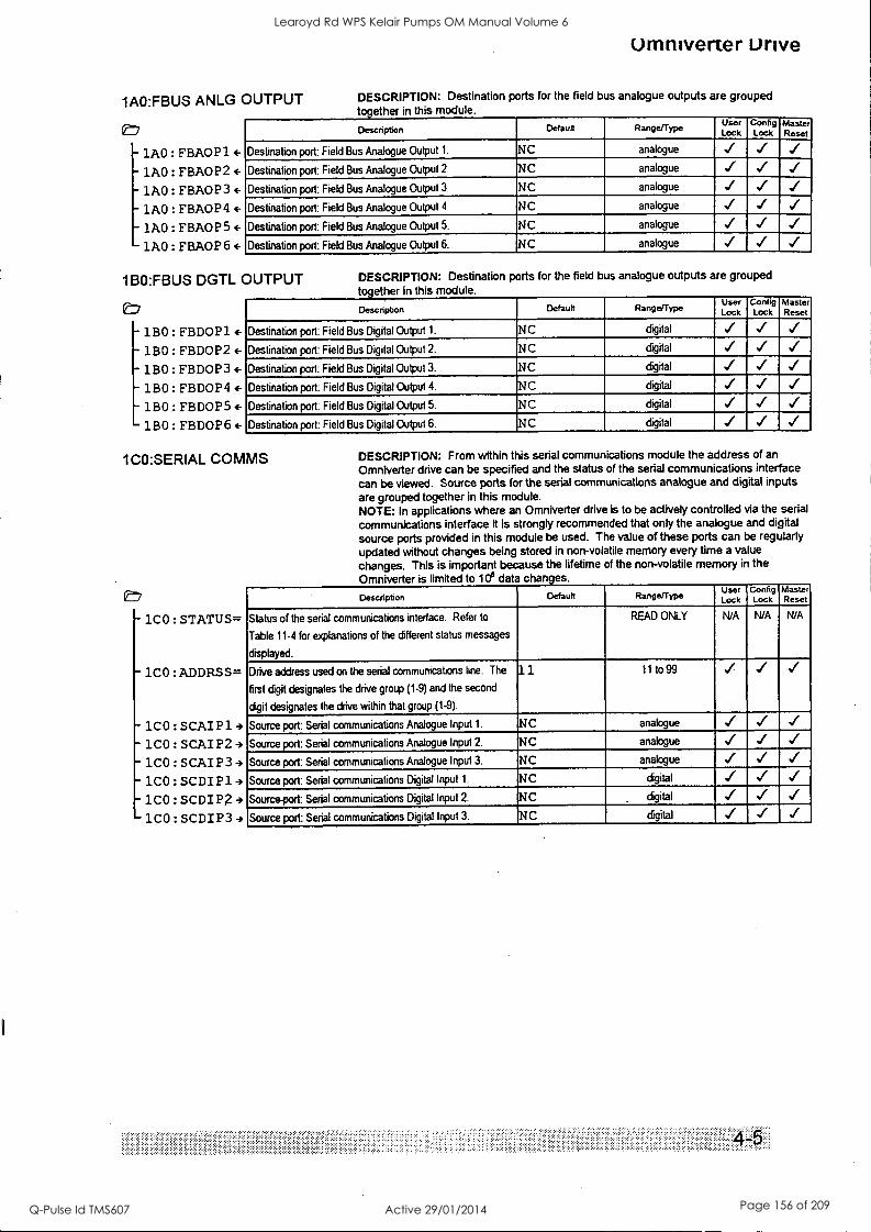
1AO:FBUS ANLG OUTPUT
0=7
1AO:FBAOP1(-
1AO:FBA0P2+ -1AO:FBA0P3+ 1AO:FaA0P44-
1AO:FBA0P5+ 1AO:FBA0P6+
Omniverter unve
DESCRIPTION: Destination ports for the field bus analogue outputs are grouped together in this module.
Description Default Range/Type User Lock
Config Lock
Master Reset
Destination port: Field Bus Analogue Output 1. NC analogue ../
Destination port: Field Bus Analogue Output 2. NC analogue ,./
Destination port: Field Bus Analogue Output 3. NC analogue
Destination port: Field Bus Analogue Output 4. NC analogue ../ ,/ Destination port: Field Bus Analogue Output 5. NC analogue
Destination port: Field Bus Analogue Output 6. NC analogue
1BO:FBUS DGTL OUTPUT
- 1B0 : FBDOP 1 4-
1B0 : FBDOP2 (-
- 180 FBDOP3
- 1B0: FBDOP4
- 1B0 : FBDOP5 E-
- 1B0 FBDOP6 4-
DESCRIPTION: Destination ports for the field bus analogue outputs are grouped
together in this module.
Description Default Range/Type User Lock
Config Lock
Master Reset
Destination port: Field Bus Digital Output 1. NC digital
Destination port: Field Bus Digital Output 2. NC digital
Destination port: Field Bus Digital Output 3. NC digital
Destination port: Field Bus Digital Output 4. NC digital ../
Destination port: Field Bus Digital Output 5. NC digital
Destination port: Field Bus Digital Output 6. NC digital ,./
1CO:SERIAL COMMS
- lc° : STATUS=
1C0 :ADDRSS=
- 1C0 : SCAI P1 4 1C0 SCAIP2 -)
- 1C0 : SCAIP3 1CO:SCDIP1
-1CO:SCDIn-, 1CO:SCDIP39
DESCRIPTION: From within this serial communications module the address of an
Omniverter drive can be specified and the status of the serial communications interface can be viewed. Source ports for the serial communications analogue and digital inputs are grouped together in this module. NOTE: In applications where an Omniverter drive is to be actively controlled via the serial
communications interface it is strongly recommended that only the analogue and digital
source ports provided in this module be used. The value of these ports can be regularly updated without changes being stored in non-volatile memory every time a value
changes. This is important because the lifetime of the non-volatile memory in the Omniverter is limited to 106 data changes.
Description Default Range/Type Use( Lock
Config Lock
Master Reset
Status of the serial communications interface. Refer to
Table 11-4 for explanations of the different status messages
displayed.
READ ONLY N/A N/A N/A
Drive address used on the serial communications line. The
first digit designates the drive group (1-9) and the second
digit designates the drive within that group (1-9).
11 11 to 99
Source port: Serial communications Analogue Input 1. NC analogue
Source port: Serial communications Analogue Input 2. NC analogue
Source port: Serial communications Analogue Input 3. NC analogue
Source port: Serial communications Digital Input 1. NC digital
Source-port: Serial communications Digital Input 2. NC . digital
Source port: Serial communications Digital Input 3. NC digital
Learoyd Rd WPS Kelair Pumps OM Manual Volume 6
Q-Pulse Id TMS607 Active 29/01/2014 Page 156 of 209
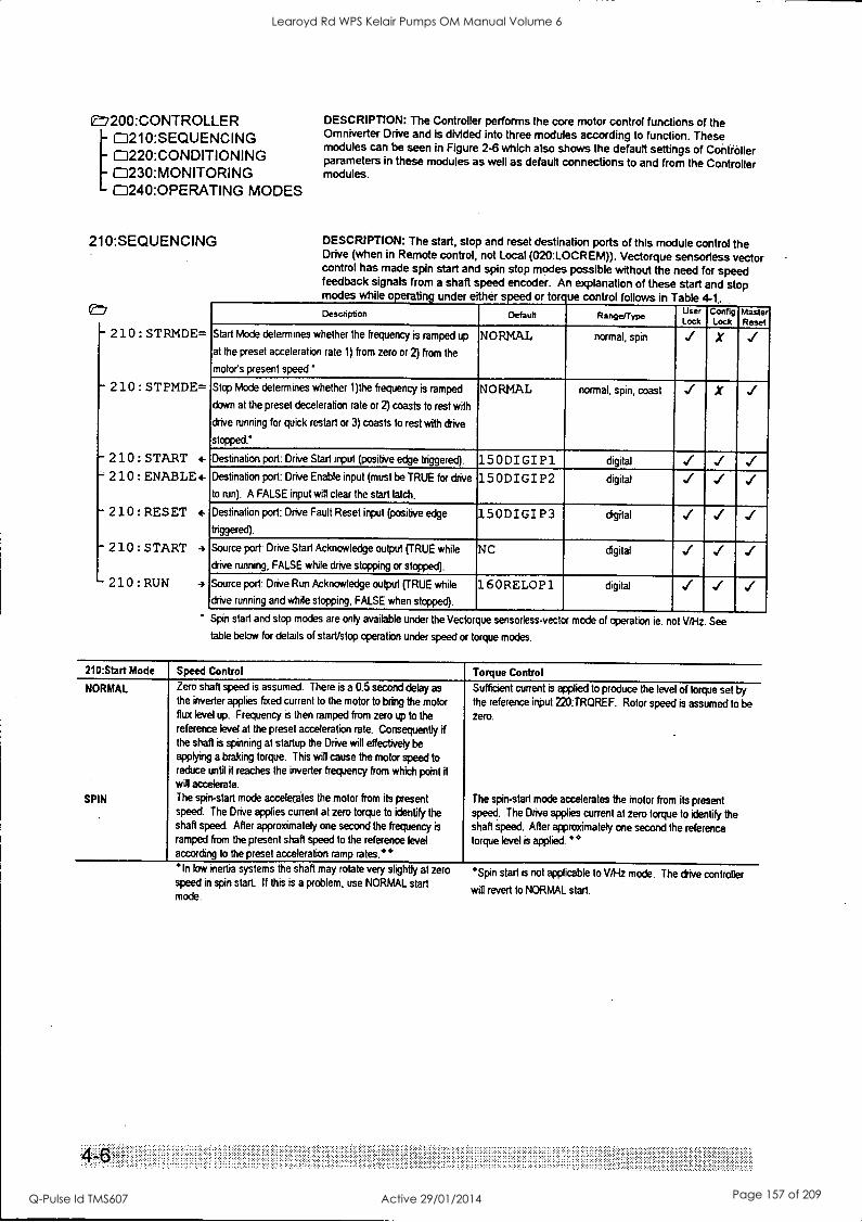
e7200:CONTROLLER 1 J210:SEQUENCING f3220:CONDITIONING C3230:MONITORING 0240:OPERATING MODES
210:SEQUENCING
eD
- 210 : STRMDE=
- 210 : STPMDE=
-210: START *.
210 : ENABLE*.
- 210:RESET
- 210 : START
210:RUN 4
DESCRIPTION: The Controller performs the core motor control functions of the Omniverter Drive and is divided into three modules according to function. These modules can be seen in Figure 2-6 which also shows the default settings of Contioller parameters in these modules as well as default connections to and from the Controller modules.
DESCRIPTION: The start, stop and reset destination ports of this module control the Drive (when in Remote control, not Local (020:LOCREM)). Vectorque sensortess vector control has made spin start and spin stop modes possible without the need for speed feedback signals from a shaft speed encoder. An explanation of these start and stop modes while operating under either speed or torque control follows in Table 4-1. Description Default RangeJType User
Lock Config Lock
Master Reset
Start Mode determines whether the frequency is ramped up
at the preset acceleration rate 1) from zero or 2) from the
motor's present speed'
NORMAL normal, spin X
Stop Mode determines whether 1)the frequency is ramped
down at the preset deceleration rate or 2) coasts to rest with
drive running for quick restart or 3) coasts to rest with drive
stopped.'
NORMAL normal, spin, coast X
Destination port: Drive Start input (positive edge triggered). 15 ODI GI P1 digital ../ Destination port: Drive Enable input (must be TRUE for drive
to run). A FALSE input will clear the start latch.
150DI GI P2 digital
Destination port: Drive Fault Reset input (positive edge
triggered).
150DI GI P3 digital
Source port: Drive Start Acknowledge output (TRUE while
drive running, FALSE while drive stopping or stopped).
NC digital
Source port: Drive Run Acknowledge output (TRUE while
drive running and while stopping, FALSE when stopped).
160RELOP1 digital
Spin start and stop modes are only available under the Vectorque sensorless-vector mode of operation ie. not V/Hz. See
table below for details of start/stop operation under speed or torque modes.
210:Start Mode
NORMAL
SPIN
Speed Control
Zero shaft speed is assumed. There is a 0.5 second delay as the inverter applies fixed current to the motor to bring the motor flux level up. Frequency is then ramped from zero up to the reference level at the preset acceleration rate. Consequently if the shaft is spinning at startup the Drive will effectively be applying a braking torque. This will cause the motor speed to reduce until it reaches the inverter frequency from which point it will accelerate.
The spin-start mode accelerates the motor from its present speed. The Drive applies current at zero torque to identify the shaft speed. After approximately one second the frequency is ramped from the present shaft speed to the reference level according to the preset acceleration ramp rates.**
Torque Control
Sufficient current is applied to produce the level of torque set by the reference input 220:TRQREF. Rotor speed is assumed to be zero.
The spin-start mode accelerates the motor from its present speed. The Drive applies current at zero torque to identify the shaft speed. After approximately one second the reference torque level is applied. **
*In low inertia systems the shaft may rotate very slightly at zero speed in spin start. If this is a problem, use NORMAL start mode.
°Spin start is not applicable to V/1-1z mode. The drive controller
will revert to NORMAL start.
Learoyd Rd WPS Kelair Pumps OM Manual Volume 6
Q-Pulse Id TMS607 Active 29/01/2014 Page 157 of 209
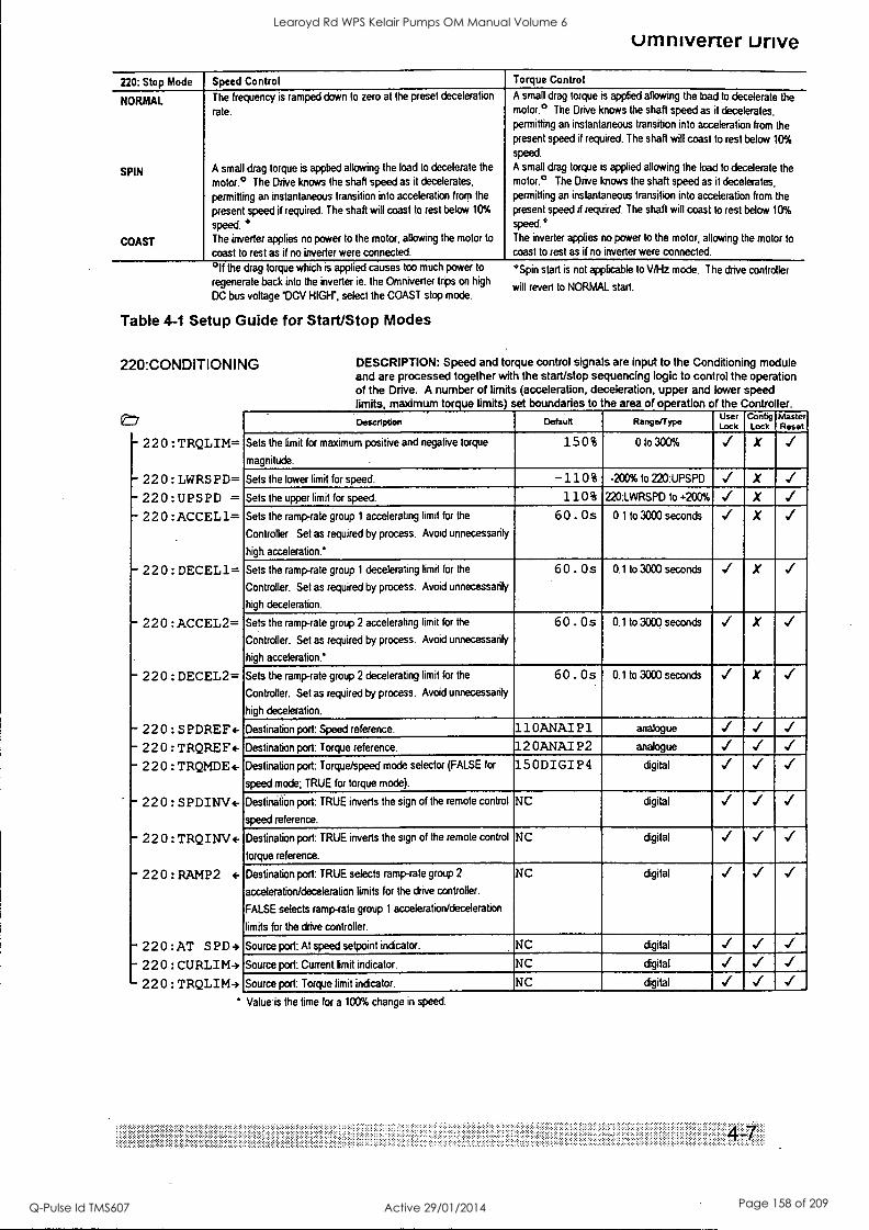
umniverter urive
220: Stop Mode Speed Control Torque Control
NORMAL
SPIN
COAST
The frequency is ramped down to zero at the preset deceleration
rate.
A small drag torque is applied allowing the load to decelerate the
motor.° The Drive knows the shaft speed as it decelerates,
permitting an instantaneous transition into acceleration from the
present speed if required. The shaft will coast to rest below 10%
speed. ° The inverter applies no power to the motor, allowing the motor to
coast to rest as if no inverter were connected.
°If the drag torque which is applied causes too much power to
regenerate back into the inverter ie. the Omniverter trips on high
DC bus voltage 'DCV HIGH", select the COAST stop mode.
Table 4-1 Setup Guide for Start/Stop Modes
220:CONDITIONING
- 220 : TRQLIM=
- 220 : LWRSPD=
- 220:UPSPD = - 220 :ACCEL1=
- 220 : DECEL1=
- 220 :ACCEL2=
- 220 : DECEL2=
- 220 : SPDREF4-
- 220 : TRQFLEF+
- 220 : TRQMDE4-
- 220 : SPDINV4-
- 22 0 : TRQINV4-
- 220:RAMP2 4-
- 220:AT SPD9
- 220 : CURLIM4 220 : TRQLIM4
A small drag torque is applied allowing the load to decelerate the motor.° The Drive knows the shaft speed as it decelerates, permitting an instantaneous transition into acceleration from the present speed if required. The shaft will coast to rest below 10%
speed.
A small drag torque is applied allowing the load to decelerate the motor.° The Drive knows the shaft speed as it decelerates, permitting an instantaneous transition into acceleration from the present speed if required. The shaft will coast to rest below 10%
speed.° The inverter applies no power to the motor, allowing the motor to
coast to rest as if no inverter were connected.
°Spin start is not applicable to V/Hz mode. The drive controller
will revert to NORMAL start.
DESCRIPTION: Speed and torque control signals are input to the Conditioning module and are processed together with the start/stop sequencing logic to control the operation of the Drive. A number of limits (acceleration, deceleration, upper and lower speed limits, maximum torque limits) set boundaries to the area of operation of the Controller.
Description Default Range/Type User Lock
Config Lock
Master Reset
Sets the limit for maximum positive and negative torque
magnitude.
15 0 % 0 to 300% X
Sets the lower limit for speed. -110 % -200% to 220:UPSPD X
Sets the upper limit for speed. 110% 220:LWRSPD to +200% X
Sets the ramp-rate group 1 accelerating limit for the
Controller. Set as required by process. Avoid unnecessarily
high acceleration.*
6 0. Os 0.1 to 3000 seconds X
Sets the ramp-rate group 1 decelerating limit for the
Controller. Set as required by process. Avoid unnecessarily
high deceleration.
60 . Os 0.1 to 3000 seconds X
Sets the ramp-rate group 2 accelerating limit for the
Controller. Set as required by process. Avoid unnecessarily
high acceleration.*
60 . Os 0.1 to 3000 seconds X
Sets the ramp-rate group 2 decelerating limit for the
Controller. Set as required by process. Avoid unnecessarily
high deceleration.
60 . Os 0.1 to 3000 seconds X
Destination port: Speed reference. 11 OANAI P1 analogue
Destination port: Torque reference. 12 OANAI P2 analogue
Destination port: Torque/speed mode selector (FALSE for
speed mode; TRUE for torque mode).
15 ODIGI P4 digital
Destination port: TRUE inverts the sign of the remote control
speed reference.
NC digital
Destination port: TRUE inverts the sign of the remote control
torque reference.
NC digital
Destination port: TRUE selects ramp-rate group 2
acceleration/deceleration limits for the drive controller.
FALSE selects ramprate group 1 acceleration/deceleration
limits for the drive controller.
NC digital
Source port: At speed setpoint indicator. NC digital
Source port: Current limit indicator. NC digital
Source port: Torque limit indicator. NC digital
Value is the time for a 100% change in speed.
Learoyd Rd WPS Kelair Pumps OM Manual Volume 6
Q-Pulse Id TMS607 Active 29/01/2014 Page 158 of 209
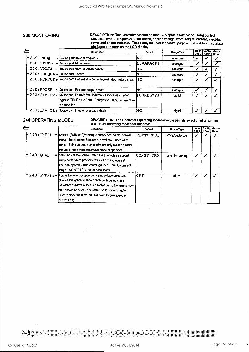
230: MONITORING
eD
- 230: FREQ 4
- 230: SPEED
- 230: VOLTS 4
- 230: TORQUE4
230: MTRCUR4
230:POWER 4
230:/FAULT-,
230:INV OL4
DESCRIPTION: The Controller Monitoring module outputs a number of useful control variables: inverter frequency, shaft speed, applied voltage, motor torque, current, electrical power and a fault indicator. These may be used for control purposes, linked to appropriate interfaces or shown on the LCD display.
Description Default Range/Type User Lock
Config Lock
Master Reset
Source port: Inverter frequency. NC analogue
Source port: Motor speed. 13 OANA0P1 analogue i Source port: Inverter output voltage. NC analogue
Source port: Torque. NC analogue
Source port: Current as a percentage of rated motor current. NC analogue
Source port: Electrical output power. NC analogue
Source port: Failsafe fault indicator (r indicates inverted
logic) ie. TRUE = No Fault. Changes to FALSE for any drive
trip condition.
160 RELO P3 digital
Source port: Inverter overload indicator. NC digital
240:OPERATING MODES
e:7
- 240:CNTRL =
- 240:LOAD =
240: LVTRIP=
DESCRIPTION: The Controller Operating Modes module permits selection of a number of different operating modes for the drive.
Description Default Range/Type User Lock
Config Lock
Master Reset
Selects 1)V/1-1z or 2)Vectorque encoderless vector control
mode. Limited torque features are available under V/Hz
control. Spin start and stop modes are only available under
the Vectorque sensorless vector mode of operation.
VECTORQUE VA-1z, Vectorque
Selecting variable torque (VAR TRQ") enables a special
pump curve which provides reduced flux and noise at
fractional speeds - suits centrifugal loads. Set to constant
torque ('CONST TRQ") for all other loads.
CONS T TRQ const trq, var trq
Forces Drive to trip upon low mains voltage detection.
Disable this option to allow ride-through during mains
disturbances (drive output is disabled during low mains; spin
start should be selected to restart on to spinning motor.
In V/Hz mode the motor will run down to zero speed on
current limit).
OFF off, on
,, ,, , .... ..........................
Learoyd Rd WPS Kelair Pumps OM Manual Volume 6
Q-Pulse Id TMS607 Active 29/01/2014 Page 159 of 209
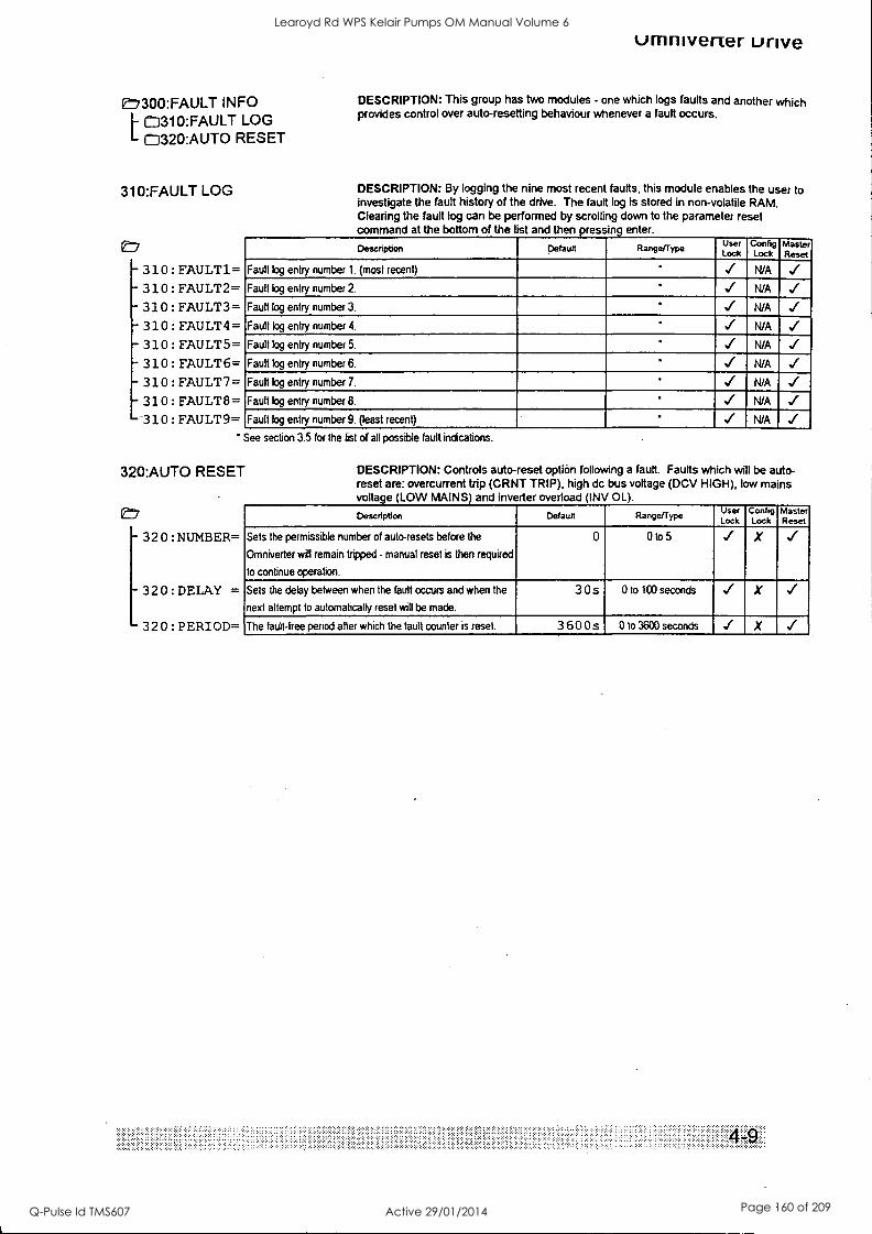
E77300:FAULT INFO C3310:FAULT LOG
L 0320:AUTO RESET
310:FAULT LOG
- 310: FAULT1= - 310: FAULT2= 1- 310 : FAULT3= - 310: FAULT4= -310: FAULTS= - 310: FAULT6= - 310: FAULT7= - 310: FAULT8=
-310: FAULT9=
umnivener urive
DESCRIPTION: This group has two modules - one which logs faults and another which provides control over auto-resetting behaviour whenever a fault occurs.
DESCRIPTION: By logging the nine most recent faults, this module enables the user to investigate the fault history of the drive. The fault log is stored in non-volatile RAM. Clearing the fault log can be performed by scrolling down to the parameter reset command at the bottom of the list and then oressina enter.
Description Default Range/Type User Lock
Config Lock
Master Reset
Fault log entry number 1. (most recent) N/A - Fault log entry number 2. ' N/A
Fault log entry number 3. N/A
Fault log entry number 4. N/A
Fault log entry number 5. N/A
Fault log entry number 6. N/A
Fault log entry number 7. N/A
Fault log entry number 8. N/A ../ Fault log entry number 9. (least recent) N/A
See section 3.5 for the list of all possible fault indications.
320:AUTO RESET
E7
- 320:NUMBER=
- 320: DELAY =
320:PERIOD=
DESCRIPTION: Controls auto-reset option following a fault. Faults which will be auto- reset are: overcurrent trip (CRNT TRIP), high dc bus voltage (DCV HIGH), low mains voltage (LOW MAINS) and inverter overload (INV OL).
Description Default Range/Type User Lock
Config Lock
Master Reset
Sets the permissible number of auto-resets before the
Omniverter will remain tripped - manual reset is then required
to continue operation.
0 0 to 5 X
Sets the delay between when the fault occurs and when the
next attempt to automatically reset will be made.
3 0 s 0 to 100 seconds X 1
The fault-free period after which the fault counter is reset. 3 6 0 0 S 0 to 3600 seconds X
Learoyd Rd WPS Kelair Pumps OM Manual Volume 6
Q-Pulse Id TMS607 Active 29/01/2014 Page 160 of 209
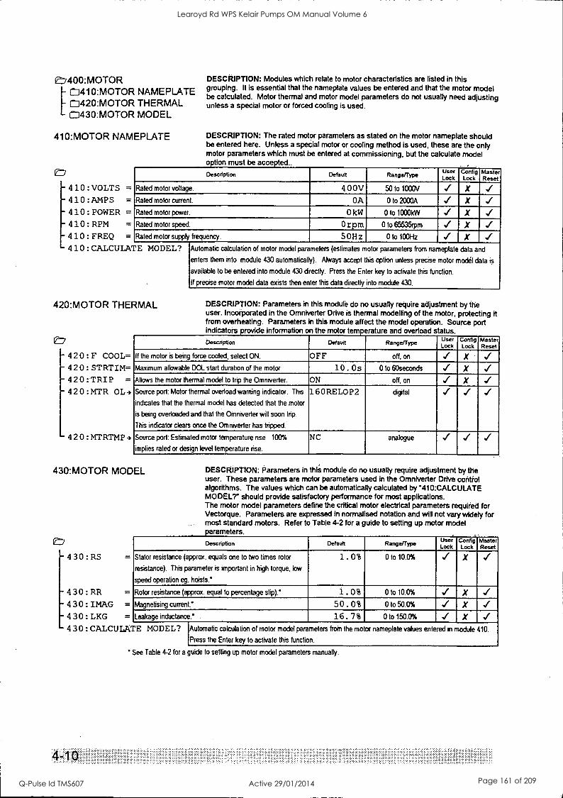
e:7400:MOTOR [CD410:MOTOR NAMEPLATE
C3420:MOTOR THERMAL C:1430:MOTOR MODEL
410:MOTOR NAMEPLATE
-4 10:VOLTS =
-410:AMPS =
- 4 10 : POWER = -410:RPM =
4 1 0 : FREQ =
4 1 0 : CALCULA
DESCRIPTION: Modules which relate to motor characteristics are listed in this grouping. It is essential that the nameplate values be entered and that the motor model be calculated. Motor thermal and motor model parameters do not usually need adjusting unless a special motor or forced cooling is used.
DESCRIPTION: The rated motor parameters as stated on the motor nameplate should be entered here. Unless a special motor or cooling method is used, these are the only motor parameters which must be entered at commissioning, but the calculate model motion must be accepted..
Description Default Range/Type User Lock
Config Lock
Master Reset
Rated motor voltage. 4 0 OV 50 to 1000V X Rated motor current. OA 0 to 2000A X Rated motor power. 0 kW 0 to 1000kW X Rated motor speed. 0 rpm 0 to 65535rpm X Rated motor supply frequency. 50Hz 0 to 100Hz X r E MODEL? Automatic calculation of motor model parameters (estimates motor parameters from nameplate data and
enters them into module 430 automatically). Always accept this option unless precise motor model data is
available to be entered into module 430 directly. Press the Enter key to activate this function.
If precise motor model data exists then enter this data directly into module 430.
420:MOTOR THERMAL
- 4 2 0 : F COOL= - 420 : STRTIM= 420:TRIP =
- 420:MTR OL4
-4 2 0 : MTRTMP -)
DESCRIPTION: Parameters in this module do no usually require adjustment by the user. Incorporated in the Omniverter Drive is thermal modelling of the motor, protecting it from overheating. Parameters 'n this module affect the model operation. Source port indicators provide information on the motor temperature and overload status.
Description Default Range/Type User Lock
Config Lock
Master Reset
If the motor is being force cooled, select ON. 0 FF off, on X Maximum allowable DOL start duration of the motor. 10 . Os 0 to 60seconds X Allows the motor thermal model to trip the Omniverter. ON off, on X Source port: Motor thermal overload warning indicator. This
indicates that the thermal model has detected that the motor
is being overloaded and that the Omniverter will soon trip.
This indicator clears once the Omniverter has tripped.
1 6 0 RELOP 2 digital
Source port: Estimated motor temperature rise. 100%
implies rated or design level temperature rise.
NC analogue ../
430:MOTOR MODEL
-4 3 0 : RS
-430:RR =
-430:IMAG =
-430:LKG =
430:CALCULA
DESCRIPTION: Parameters in this module do no usually require adjustment by the user. These parameters are motor parameters used in the Omniverter Drive control algorithms. The values which can be automatically calculated by "410:CALCULATE MODEL'?" should provide satisfactory performance for most applications. The motor model parameters define the critical motor electrical parameters required for Vectorque. Parameters are expressed in normalised notation and will not vary widely for most standard motors. Refer to Table 4-2 for a guide to setting up motor model parameters.
Description Default Range/Type User Lock
Config Lock
Master Reset
Stator resistance (approx. equals one to two times rotor
resistance). This parameter is important in high torque, low
speed operation eg. hoists.*
1 . 0$ 0 to 10.0% ./. X
Rotor resistance (approx. equal to percentage slip)' 1.0% 0 to 10.0% . X ..4
Magnetising current.' 5 0. 0 % 0 to 50.0% X Leakage inductance.' 1 6 . 7 % 0 to 150.0%
rE MODEL? Automatic calculation of motor model parameters from the motor nameplate values entered in module 410.
Press the Enter key to activate this function.
See Table 4-2 for a guide to setting up motor model parameters manually.
Learoyd Rd WPS Kelair Pumps OM Manual Volume 6
Q-Pulse Id TMS607 Active 29/01/2014 Page 161 of 209

umnivener unve
NOTE: "410 : CALCULATE MODEL?" uses the following formulae to automatically calculate motor model values. This function should be used to generate values unless more precise data about the motor parameters is available directly.
Parameter Setting Effect on performance
RS: Stator resistance
RS is typically 0.4% to 2.3% (smaller in large motors)
RS approximately equals 75% of the percentage motor slip at full
load.
RS = 100 x Rpn x POWER / VOLTS2
where Rpn = Equivalent cold motor phase to neutral resistance in
ohms. Note that Rpn = Line to line resistance / 2.
The stator resistance has an important effect on peak torque
especially at very low speed. If it is too small peak starting
torque will be reduced. If it is too high then the drive will source
high current limited by the current limit, but be unable to run up to
speed and may surge at low speed.
Provides automatic boost in ViHz mode.
RR: Rotor resistance
RR is typically 0.5% to 3% (smaller in large motors)
RR approximately equals the percentage motor slip at full load.
With encoderless operation this motor is not critical unless high
accuracy is needed in the speed control.
RR = 100 x1 ( 1 - (poles x RPM)/(120 x FREQ) r number of motor oe where poles is the poles. p
The rotor resistance primarily corrects for slip in the induction
motor. If it is set too low then the shaft speed will be lower than
the set-point under load. If it is set too high then the opposite will
occur. Excessively high rotor resistance settings may cause
surging at low speeds with light loads. Doesn't affect torque
significantly and can be set to zero if speed regulation is not
important.
Provides slip compensation in V/Hz mode.
IMAG:
Magnetising Current.
IMAG typically equals (approximately) the percentage no load
current of the motor.
Typical values are 30% to 70% depending on motor design
(higher for high pole number machines)
No-load current can be read directly from the LCD display if the
motor is run above 20% speed with less than 10% load.
IMAG only has effect below 20% speed and is important to
achieve correct operation at low speeds.
IMAG = 100 x Int x 1.732 x VOLTS / POWER
where Inl = rms no-load current in amps
It can also be approximated from the nameplate data using:
IMAG =100 x [ (1/PF2 - 1 )01) - LKG
where: PF = full load power factor of the motor
and LKG == the % leakage as given below.
The magnetising current parameter defines the magnetic field
current in the motor at low speeds. If it is set too low the motor
will not generate correct torque.at low speed. It is acceptable
and beneficial to set this level significantly higher than the normal
no-load current to ensure sufficient flux is available if high
starting torque is required. If set much too high the motor will
operate at higher current than necessary and may surge at low
speed with light load. If it is set too low the motor may not
support the load at low speed and will not start reliably.
Sets magnetising current in V/Hz mode.
LKG:
Leakage inductance.
This parameter is typically 10% to 20% in most standard motors
and generally does not need adjustment from the default.
LKG = 628 x FREQ x L x POWER / VOLTS2*
where L = total leakage inductance in henrys.
It can be approxiinated from:
LKG= 100 x AMPS / DOL_AMPS
where DOL_AMPS is the rms starting current for the motor.
Under normal operating conditions the leakage inductance
parameter has little observable influence so can be left at the
default setting.
The leakage inductance parameter has a small effect on the
dynamic performance of the vector control and the peak torque
capability of the system.
Extreme settings may destabilise the control. .
nnttrnna)-.-s tint Tr *1100 corn D/ ....... I.,, ..........1...1.. ....c...... .1 4s,,, ...Met.
Table 4-2 Setup Guide for Motor Model Parameters
Learoyd Rd WPS Kelair Pumps OM Manual Volume 6
Q-Pulse Id TMS607 Active 29/01/2014 Page 162 of 209
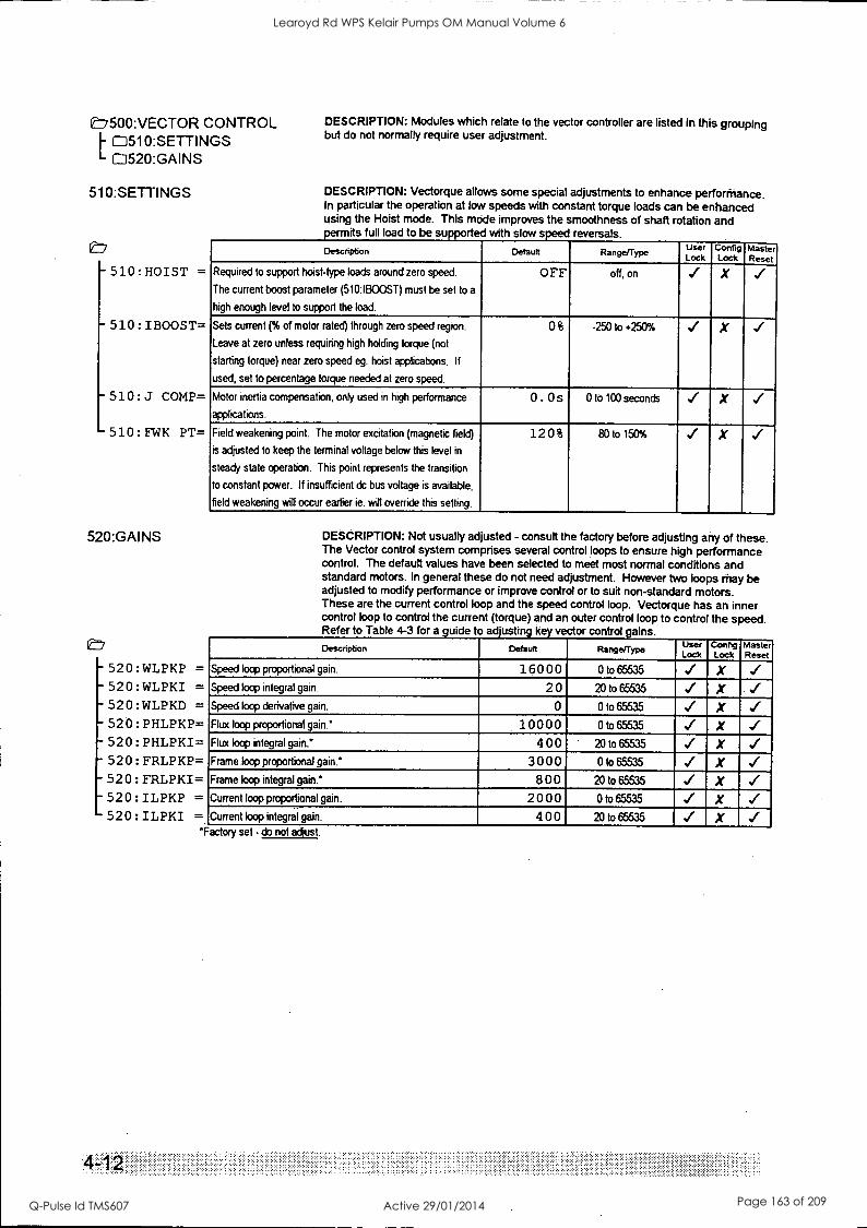
L7500:VECTOR CONTROL M510:SETTINGS C=1520:GAINS
510:SETTINGS
V7
- 510:HOIST =
- 510 : IBOOST=
-510:J COMP=
- 510 : FWK PT=
520:GAINS
- 520 :WLPKP = - 520 :WLPKI = - 520 :WLPKD = - 520 : PHLPKP= - 520 : PHLPKI= - 520 : FRLPKP=
520 : FRLPKI= 520: ILPKP = 520 : ILPKI
4-1
DESCRIPTION: Modules which relate to the vector controller are listed in this grouping but do not normally require user adjustment.
DESCRIPTION: Vectorque allows some special adjustments to enhance perforfnance. In particular the operation at low speeds with constant torque loads can be enhanced using the Hoist mode. This mode improves the smoothness of shaft rotation and
rmits full load to be supported with slow speed reversals.
Description Defautt Range/Type User Lock
Config Lock
Master Reset
Required to support hoist-type loads around zero speed.
The current boost parameter (510:IBOOST) must be set to a
high enough level to support the load.
OFF off, on X
Sets current (% of motor rated) through zero speed region.
Leave at zero unless requiring high holding torque (not
starting torque) near zero speed eg. hoist applications. If
used, set to percentage torque needed at zero speed.
0$ -250 to +250% -4/ X
Motor inertia compensation, only used in high performance
applications.
0 . 0 s 0 to 100 seconds X
Field weakening point. The motor excitation (magnetic field)
is adjusted to keep the terminal voltage below this level in
steady state operation. This point represents the transition
to constant power. If insufficient dc bus voltage is available,
field weakening will occur earlier ie. will override this setting.
12 0 % 80 to 150% X
DESCRIPTION: Not usually adjusted - consult the factory before adjusting any of these. The Vector control system comprises several control loops to ensure high performance control. The default values have been selected to meet most normal conditions and standard motors. In general these do not need adjustment. However two loops may be adjusted to modify performance or improve control or to suit non-standard motors. These are the current control loop and the speed control loop. Vectorque has an inner control loop to control the current (torque) and an outer control loop to control the speed. Refer to Table 4-3 for a guide to adjusting key vector control gains.
Description Default Range/Type User Lock
coring Lock
Master Reset
Speed loop proportional gain. 160 0 0 0 to 65535 X Speed loop integral gain. 2 0 20 to 65535 X Speed loop derivative gain. 0 0 to 65535 X Flux loop proportional gain! 10 0 0 0 0 to 65535 X Flux loop integral gain! 4 00 20 to 65535 X Frame loop proportional gain! 3 00 0 0 to 65535 X Frame loop integral gain! 8 00 20 to 65535 X Current loop proportional gain. 2 0 0 0 0 to 65535 X Current loop integral gain. 4 00 20 to 65535
*Factory set - do not adjust.
Learoyd Rd WPS Kelair Pumps OM Manual Volume 6
Q-Pulse Id TMS607 Active 29/01/2014 Page 163 of 209
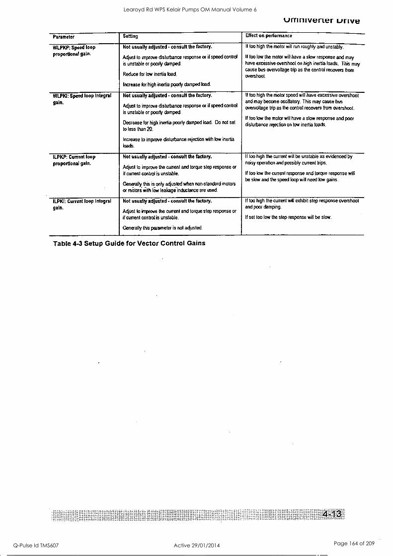
umnivener unve Parameter Setting Effect on performance
WLPKP: Speed loop proportional gain.
Not usually adjusted consult the factory.
Adjust to improve disturbance response or if speed control
is unstable or poorly damped.
Reduce for low inertia load.
Increase for high inertia poorly damped load.
If too high the motor will run roughly and unstably.
If too low the motor will have a slow response and may have excessive overshoot on high inertia loads. This may cause bus overvoltage trip as the control recovers from overshoot.
WLPKI: Speed loop Integral gain.
Not usually adjusted consult the factory.
Adjust to improve dstuibance response or if speed control
is unstable or poorly damped.
Decrease for high inertia poorly damped load. Do not set
to less than 20.
Increase to improve disturbance rejection with low inertia
loads.
If too high the motor speed will have excessive overshoot and may become oscillatory. This may cause bus
overvoltage trip as the control recovers from overshoot.
If too low the motor will have a slow response and poor disturbance rejection on low inertia loads.
ILPKP: Current loop
proportional galn. Not usually adjusted consult the factory.
Adjust to improve the current and torque step response or
if current control is unstable.
Generally this is only adjusted when non-standard motors
or motors with low leakage inductance are used.
If too high the current will be unstable as evidenced by noisy operation and possibly current trips.
If too low the current response and torque response will be slow and the speed loop will need low gains.
ILPKI: Current loop integral galn.
Not usually adjusted consult the factory.
Adjust to improve the current and torque step response or
if current control is unstable.
Generally this parameter is not adjusted.
If too high the current will exhibit step response overshoot and poor damping.
If set too low the step response will be slow.
Table 4-3 Setup Guide for Vector Control Gains
Learoyd Rd WPS Kelair Pumps OM Manual Volume 6
Q-Pulse Id TMS607 Active 29/01/2014 Page 164 of 209
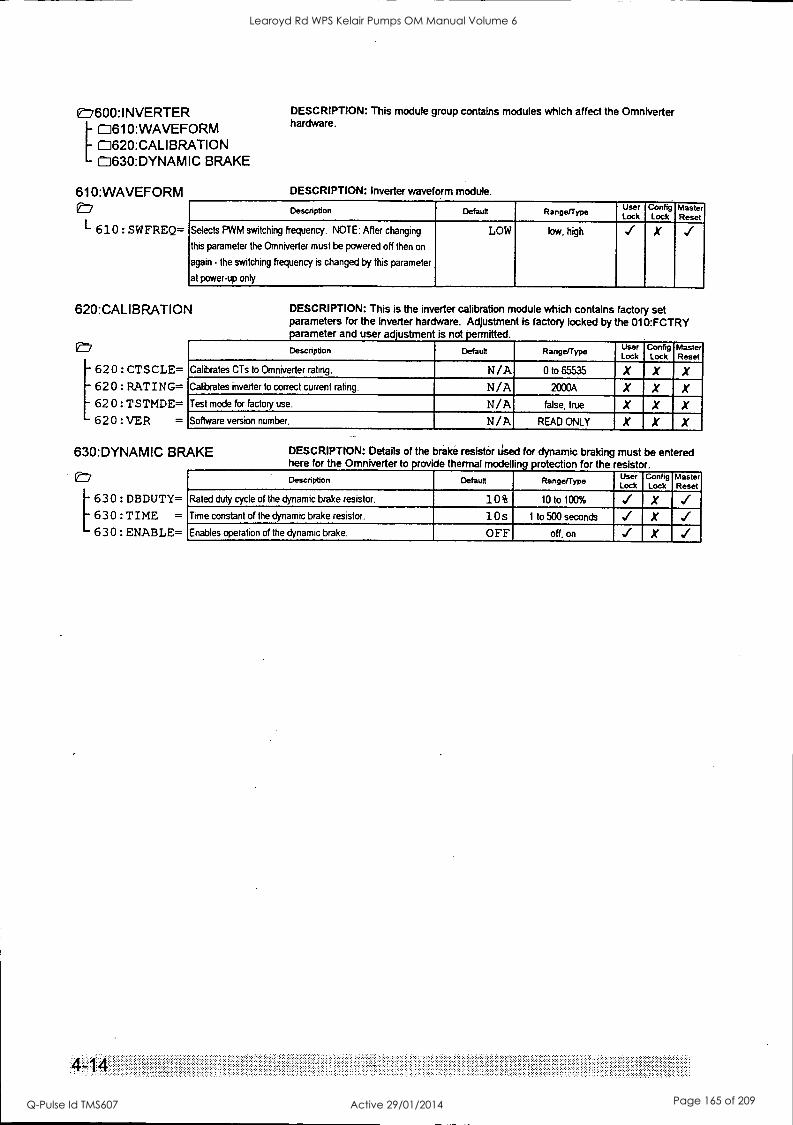
E=7600:INVERTER 4610: WAVEFORM 0620:CALIBRATION 0630:DYNAMIC BRAKE
610:WAVEFORM
L 610: SWFREQ=
DESCRIPTION: This module group contains modules which affect the Omniverter hardware.
DESCRIPTION: Inverter waveform module.
Description Default Range/Type User Lock
Config Lock
Master Reset
Selects PWM switching frequency. NOTE: After changing
this parameter the Omniverter must be powered off then on
again - the switching frequency is changed by this parameter
at power-up only.
LOW low, high X
620:CALIBRATION
[620:CTSCLE= 620:RATING= 620:TSTMDE= 620:VER =
DESCRIPTION: This is the inverter calibration module which contains factory set parameters for the inverter hardware. Adjustment is factory locked by the 010:FCTRY parameter and user adjustment is not permitted.
Description Default Range/Type User Lock
Config Lock
Master Reset
Calibrates CTs to Omniverter rating. N/A 0 to 65535 X X X Calibrates inverter to correct current rating. N/A 2000A X X X Test mode for factory use. N/A false, true X X X Software version number. N/A READ ONLY X X X
630:DYNAMIC BRAKE
[630:DBDUTY= 630:TIME =
630:ENABLE=
4-1
DESCRIPTION: Details of the brake resistor used for dynamic braking must be entered here for the Omniverter to provide thermal model ing protection for the resisto Description Default Range/Type User
Lock Config Lock
Master Reset
Rated duty cycle of the dynamic brake resistor. 10 $ 10 to 100% X ../ Time constant of the dynamic brake resistor. 1 Os 1 to 500 seconds X Enables operation of the dynamic brake. OFF off, on X
Learoyd Rd WPS Kelair Pumps OM Manual Volume 6
Q-Pulse Id TMS607 Active 29/01/2014 Page 165 of 209
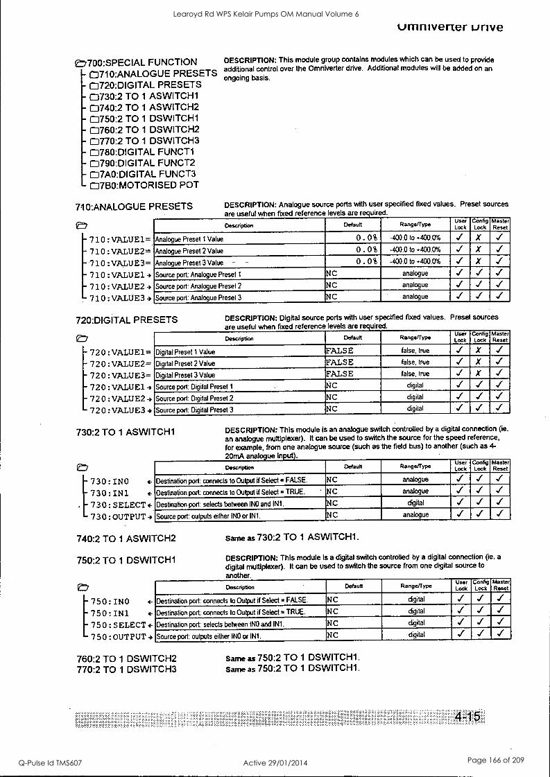
CE7700:SPECIAL FUNCTION - 0710:ANALOGUE PRESETS - 0720:DIGITAL PRESETS - 0730:2 TO 1 ASWITCH1 - 0740:2 TO 1 ASWITCH2 - 0750:2 TO 1 DSWITCH1 - 0760:2 TO 1 DSWITCH2 - 0770:2 TO 1 DSWITCH3 - 0780:DIGITAL FUNCT1 - 0790:DIGITAL FUNCT2
07A0:DIGITAL FUNCT3 - 0760:MOTORISED POT
7:10:ANALOGUE PRESETS
^ 710 :VALUE1=
- 710 :VALUE2=
- 710 :VALUE3=
-710:VALUE13 - 710 :VALUE24
710:VALUE3-)
umniverter unve
DESCRIPTION: This module group contains modules which can be used to provide additional control over the Omniverter drive. Additional modules will be added on an ongoing basis.
DESCRIPTION: Analogue sou ce ports with use specified fixed values. Preset sources are useful when fixed reference levels are required.
Description Default Range/Type User Lock
Config Lock
Master Reset
Analogue Preset 1 Value 0 . 0% -400.0 to +400.0% X
Analogue Preset 2 Value 0. 0% -400.0 to +400.0% X
Analogue Preset 3 Value - - 0 . 0 % -400.0 to +400.0% X
Source port Analogue Preset 1 NC analogue
Source port: Analogue Preset 2 NC analogue
Source port: Analogue Preset 3 NC analogue
720:DIGITAL PRESETS
er/
- 720 :VALUE1= 720:VALUE2=
- 720: VALUE3= - 720:VALUE14 - 720 :VALUE24 720 :VALUE3
DESCRIPTION: Digital source ports with user specified fixed values. Preset sources are useful when fixed reference levels are required.
Description Default Range/Type User Lock
Config Lock
Master Reset
Digital Preset 1 Value FALSE false, true X
Digital Preset 2 Value FALSE false, true X
Digital Preset 3 Value FALSE false, true X
Source port: Digital Preset 1 NC digital
Source port: Digital Preset 2 ' NC digital
Source port: Digital Preset 3 NC digital
730:2 TO 1 ASWITCH1
er/
[
730:INO +
730:IN1 +
. 730:SELECT+ 730:OUTPUT4
DESCRIPTION: This module is an analogue switch controlled by a digital connection (ie.
an analogue multiplexer). It can be used to switch the source for the speed reference,
for example, from one analogue source (such as the field bus) to another (such as 4-
2OrnA analogue in ut ).
Description Default Range/Type User Lock
Config Lock
Master Reset
Destination port: connects to Output if Select = FALSE. NC analogue
Destination port: connects to Output if Select = TRUE. ' NC analogue
Destination port: selects between INO and IN1. NC digital
Source port: outputs either INO or IN1. NC analogue
740:2 TO 1 ASWITCH2
750:2 TO 1 DSWITCH1
e,
[750:INO 4-
750:IN1 4-
750:SELECT+ 750:OUTPUT4
Same as 730:2 TO 1 ASWITCH1.
DESCRIPTION: This module is a digital switch controlled by a digital connection (ie. a
digital multiplexer). It can be used to switch the source from one digital source to
another.
Description Default Range/Type User Lock
Co Lock Reset
Destination port: connects to Output if Select = FALSE. NC digital
Destination port: connects to Output if Select = TRUE. NC digital
Destination port: selects between INO and IN1. NC digital
Source port: outputs either INO or IN1. NC digital
760:2 TO 1 DSWITCH2 770:2 TO 1 DSWITCH3
Same as 750:2 TO 1 DSWITCH1. Same as 750:2 TO 1 DSWITCH1.
Learoyd Rd WPS Kelair Pumps OM Manual Volume 6
Q-Pulse Id TMS607 Active 29/01/2014 Page 166 of 209
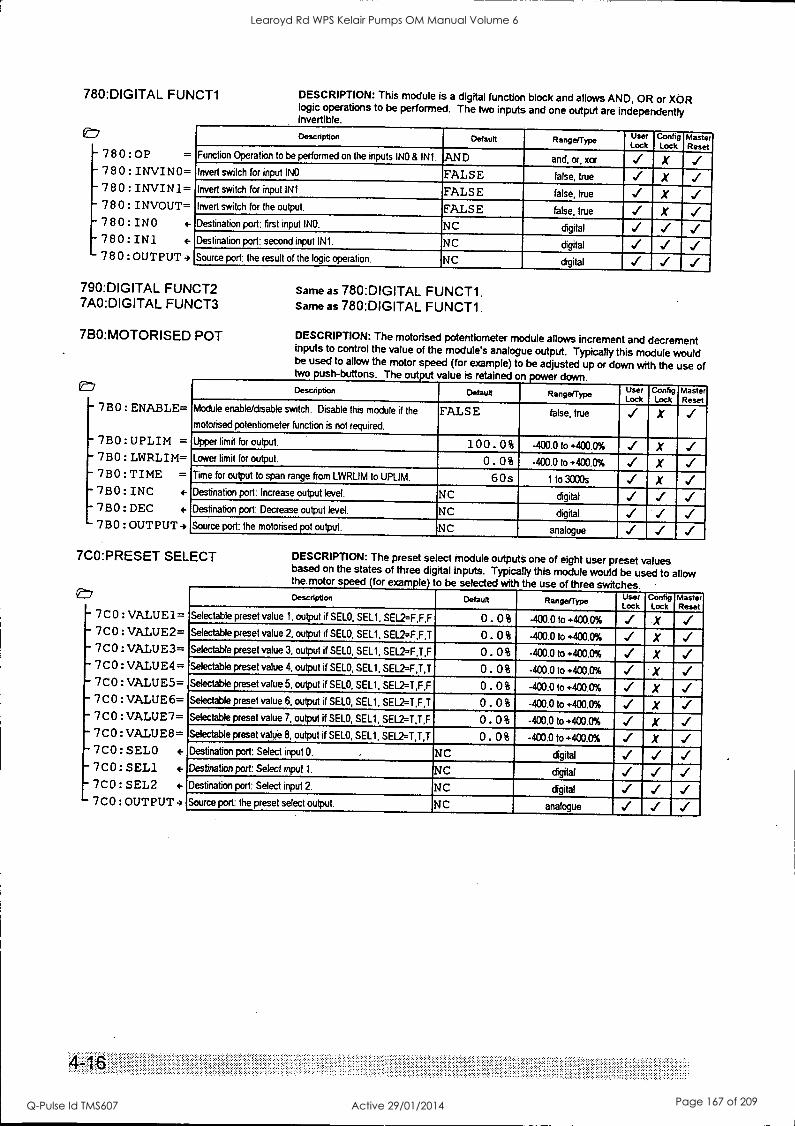
780:DIGITAL FUNCT1
E77
-780:0P =
-780:INVINO= -780:INVIN1=
780:INVOUT= 780:INO 780:IN1 780:OUTPUT4
DESCRIPTION: This module is a digital function block and allows AND, OR or XOR logic operations to be performed. The two inputs and one output are independently invertible.
Description Default User Lock
Config Lock
Master Reset
Function Operation to be performed on the inputs INO 8 IN1. AND and, or, xor X Invert switch for input INO. FALSE false, true X .1 Invert switch for input IN1. FALSE false, true
- X
-
Invert switch for the output. FALSE false, true X Destination port: first input INO. NC digital
Destination port: second input IN1. NC digital
Source port: the result of the logic operation. NC digital
790:DIGITAL FUNCT2 7A0:DIGITAL FUNCT3
7B0:MOTORISED POT
On'
-7B0:ENABLE=
-7 BO : UPLIM = - 713 0 : LWRLIM= - 780: TIME =
7BO: INC 4-
7BO: DEC 4-
- 7B0 : OUTPUT-,
Same as 780:DIGITAL FUNCT1. Same as 780:DIGITAL FUNCT1.
DESCRIPTION: The motorised potentiometer module allows increment and decrement inputs to control the value of the module's analogue output. Typically this module would be used to allow the motor speed (for example) to be adjusted up or down with the use of two push -buttons. The output value is retained on power down. Description Default Range/Type User
Lock Config Lock
Master Reset
Module enable/disable switch. Disable this module if the
motorised potentiometer function is not required.
FALSE false, true .,( X
Upper limit for output. 100 . 0% -400.0 to +400.0% X Lower limit for output. 0 . 0 % -400.0 to .400.0% X Time for output to span range from LWRLIM to UPLIM. 6 Os 1 to 3000s X Destination port: Increase output level. NC digital
Destination port: Decrease output level. NC digital ../ Source port: the motorised pot output. NC analogue
7CO:PRESET SELECT
e,
7CO:VALUE1= - 7C0 :VALUE2=
7C0 : VALUE3= 7CO:VALUE4=
- 7C0 : VALUE5= 7C0 : VALUE6= 7C0 : VALUE7= 7CO:VALUE8= 7CO: SELO <-
7CO:SEL1 7C0: SEL2 4-
7C0 :OUTPUT -)
DESCRIPTION: The preset select module outputs one of eight user preset values based on the states of three digital inputs. Typically this module would be used to allow the motor speed (for example) to be selected with the use of three switches. Description Default Range/Type User
Lock Config Lock
Master Reset
Selectable preset value 1, output if SELO, SEL1, SEL2=F,F,F 0. 0% -400.0 to +400.0% X Selectable preset value 2, output if SELO, SEL1, SEL2=F,F,T 0. 0% -400.0 to +400.0% X Selectable preset value 3, output if SELO, SEL1, SEL2=F,T,F 0 . 0% -400.0 to +400.0% X Selectable preset value 4, output if SELO, SEL1, SEL2=F,T,T 0. 0% -400.0 to +400.0% X Selectable preset value 5, output if SELO, SELl. SEL2=T,F,F 0. o % -400.0 to +400.0% X ../ Selectable preset value 6, output if SELO, SEL1, SEL2=T,F,T 0. 0% -400.0 to +400.0% X Selectable preset value 7, output if SELO, SEL1, SEL2=T,T,F 0. 0% -400.0 to +400.0% X Selectable preset value 8, output if SELO, SEL1, SEL2=T,T,T 0. 0% -400.0 to +400.0% X Destination pod: Select input O. . NC digital ../ Destination port: Select input I. NC digital ..( Destination port: Select input 2. NC digital
Source port: the preset select output. NC analogue
:: :
Learoyd Rd WPS Kelair Pumps OM Manual Volume 6
Q-Pulse Id TMS607 Active 29/01/2014 Page 167 of 209
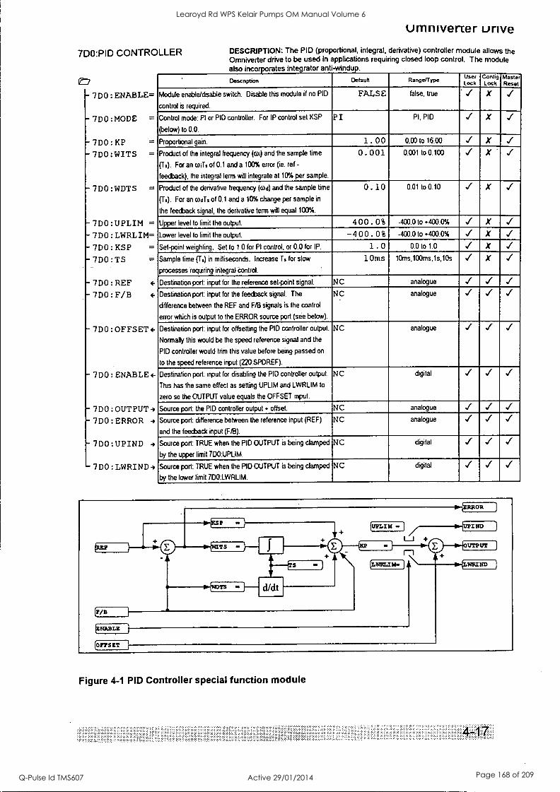
(maw If=
7D0:PID CONTROLLER
E7
- 7D0:ENABLE=
-7D0:MODE =
- 7DO:KP - 700:WITS =
- 7DO:WDTS =
7D0:UPLIM =
7D0:LWRLIM= 7D0:KSP =
7D0:TS
- 7DO:REF 7D0: F/B 4-
- 7D0 :OFFSET 4-
- 7 DO : ENABLE 4-
- 7D0:OUTPUT-)
7D0 : ERROR
- 7D0:UPIND
- 7D0 LWRIND4
umniverter unve DESCRIPTION: The PID (proportional, integral, derivative) controller module allows the Omniverter drive to be used in applications requiring closed loop control. The module also incorporates integrator anti- windup.
Description Default Range/Type User Lock
Config Lock
Master Reset
Module enable/disable switch. Disable this module if no PID
control is required.
FALSE false, true ' X
Control mode: PI or PID controller. For IP control set KSP
(below) to 0.0.
P I PI, PIO X
Proportional gain. 1 . 00 0.00 to 16.00 X
Product of the integral frequency (o) and the sample time
(T.). For an wiTs of 0.1 and a 100% error (ie. ref -
feedback), the integral term will integrate at 10% per sample.
0. 00 1 0.001 to 0.100 X -
Product of the derivative frequency (cod) and the sample time
(Ti). For an codTs of 0.1 and a 10% change per sample in
the feedback signal, the derivative term will equal 100%.
0. 10 0.01 to 0.10 X
Upper level to limit the output. 4 00 . 0 $ -400.0 to +400.0% X
Lower level to limit the output. -4 0 0 . 0 $ -400.0 to +400.0% X
Set-point weighting. Set to 1.0 for PI control, or 0.0 for IP. 1 . 0 0.0 to 1.0 X
Sample time (T.) in milliseconds. Increase T. for slow
processes requiring integral control.
10ms tOms,100ms,ls,10s X
Destination port: input for the reference set-point signal. NC analogue ,./ ,./ ../
Destination port: input for the feedback signal. The
difference between the REF and FIB signals is the control
error which is output to the ERROR source port (see below).
NC analogue ,./
Destination port: input for offsetting the PID controller output.
Normally this would be the speed reference signal and the
PID controller would trim this value before being passed on
to the speed reference input (220:SPDREF).
NC analogue ../
Destination port: input for disabling the PID controller output.
This has the same effect as setting UPLIM and LWRLIM to
zero so the OUTPUT value equals the OFFSET input.
NC digital ,./
Source port: the PID controller output + offset. NC analogue
Source port: difference between the reference input (REF)
and the feedback input (FIB).
NC analogue
Source port: TRUE when the PID OUTPUT is being clamped
by the upper limit 7D0:UPLIM.
NC digital ,./
Source port: TRUE when the PID OUTPUT is being clamped
by the lower limit 700:LWRLIM.
NC digital ../
1p
LE
(OPTS ET
____.#.. d/dt
(UPLIM..
fa ERROR
94-TP I ND
OUTPUT
WM=
Figure 4-1 PID Controller special function module
Learoyd Rd WPS Kelair Pumps OM Manual Volume 6
Q-Pulse Id TMS607 Active 29/01/2014 Page 168 of 209
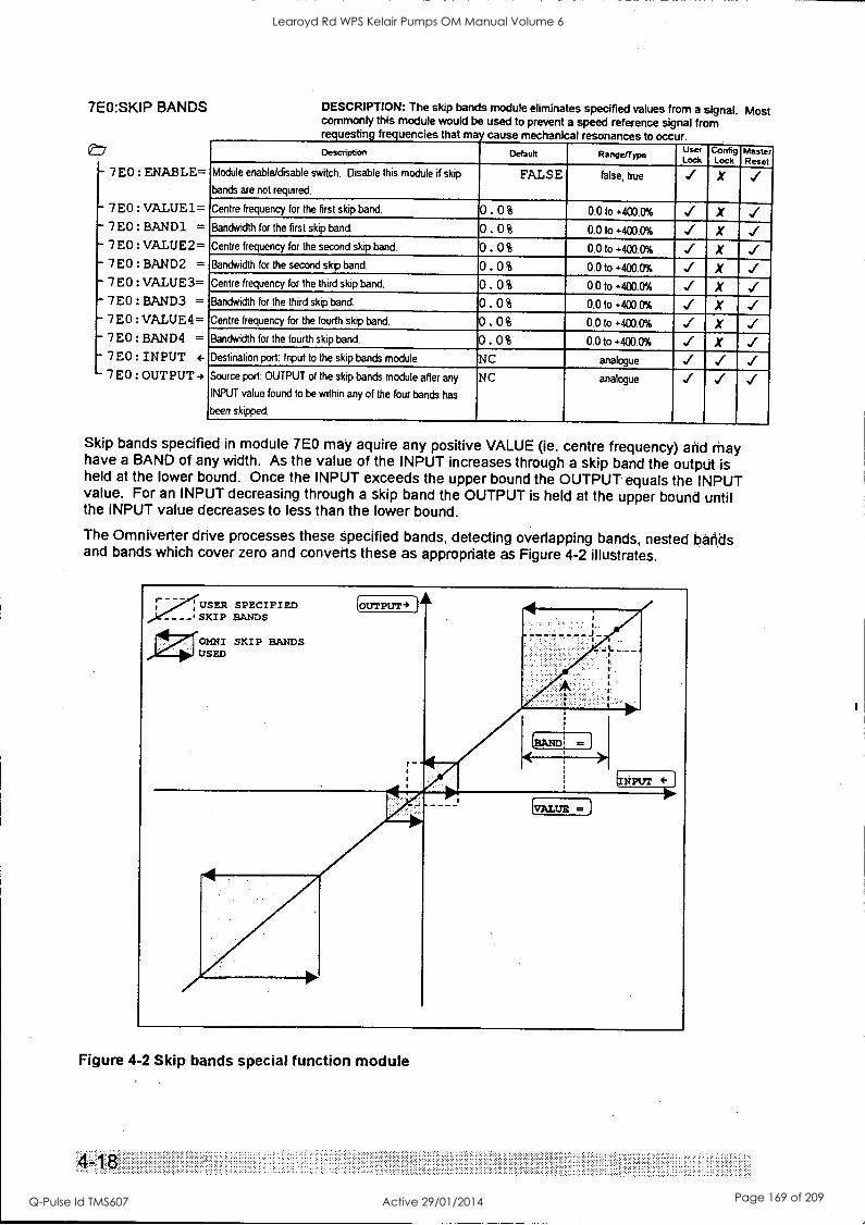
mivbi =)
INTALUE mi
7E0:SKIP BANDS
E7
-7 EO : ENABLE=
7E0:VALUE1=
-7E0:BAND1 =
7E0:VALUE2= 7E0:BANN = 7E0:VALUE3=
-7E0:BAND3 = 7E0:VALUE4= 7E0:BAND4 = 7E0:INPUT 4-
7E0:OUTPUT4
DESCRIPTION: The skip bands module eliminates specified values from a signal. Most commonly this module would be used to prevent a speed reference signal from requesting frequencies that may cause mechanical resonances to occur. Description Default Range/Type
User Lock
Config Lock
Master Reset
Module enable/disable switch. Disable this module if skip
bands are not required.
FALSE false, true X ../
Centre frequency for the first skip band. 0.0% 0.0 to +400.0% X Bandwidth for the first skip band. 0.0% 0.0 to +400.0% X Centre frequency for the second skip band. 0.0% 0.0 to +400.0%
Bandwidth for the second skip band. 0.0% 0.0 to +400.0% X Centre frequency for the third skip band. 0.0% 0.0 to +400.0% X Bandwidth for the third skip band. 0. 0 % 0.0 to +400.0% X Centre frequency for the fourth skip band. 0.0% 0.0 to +400.0% X Bandwidth for the fourth skip band. 0. 0% 0.0 to +400.0% X Destination port: Input to the skip bands module. NC analogue
Source port: OUTPUT of the skip bands module after any
INPUT value found to be within any of the four bands has
been skipped.
NC analogue
Skip bands specified in module 7E0 may aquire any positive VALUE (ie. centre frequency) and may have a BAND of any width. As the value of the INPUT increases through a skip band the output is held at the lower bound. Once the INPUT exceeds the upper bound the OUTPUT equals the INPUT value. For an INPUT decreasing through a skip band the OUTPUT is held at the upper bound until the INPUT value decreases to less than the lower bound.
The Omniverter drive processes these specified bands, detecting overlapping bands, nested bands and bands which cover zero and converts these as appropriate as Figure 4-2 illustrates.
....v..../...... :- - - - : USER SPECIFIED
- - - -I SKIP BANDS
01;10MN/ SKIP BANDS
USED
OUTPUT-)
NPUT
Figure 4-2 Skip bands special function module
4
Learoyd Rd WPS Kelair Pumps OM Manual Volume 6
Q-Pulse Id TMS607 Active 29/01/2014 Page 169 of 209
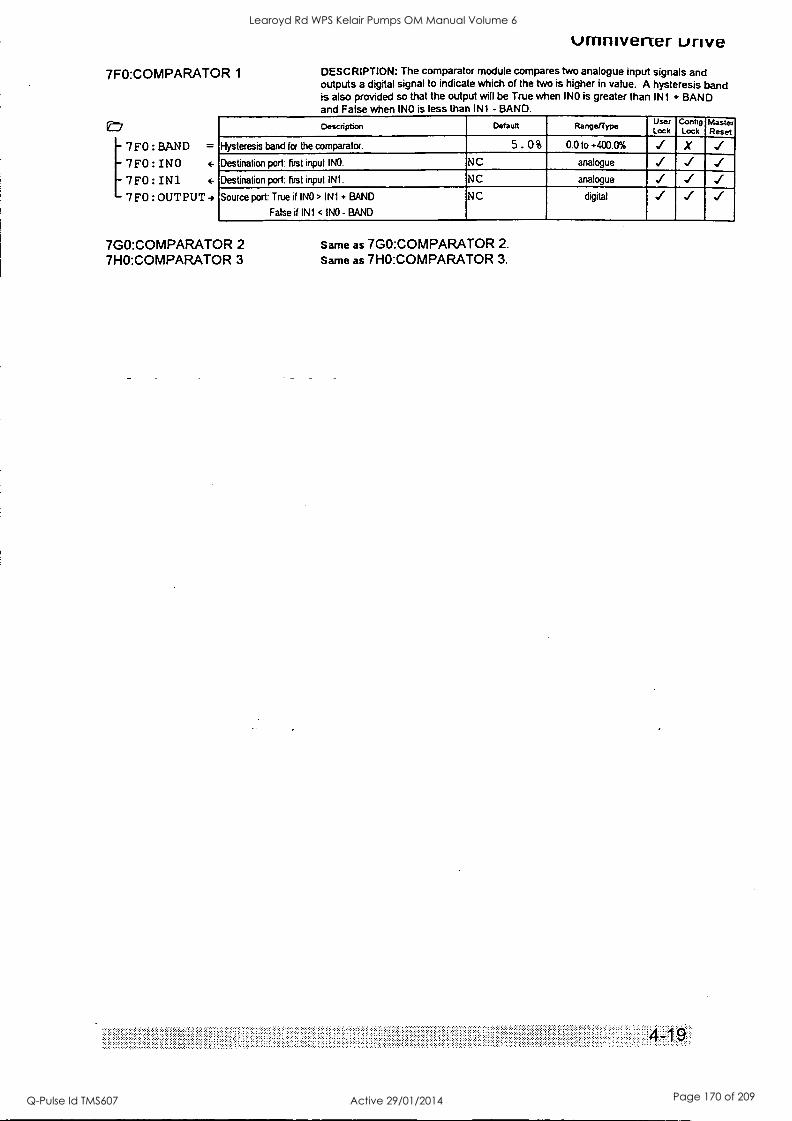
7F0:COMPARATOR 1
,e-
[7FO:RAND =
7FO:INO 4-
7FO:IN1 4-
7FO:OUTPUT4
umniverter unve DESCRIPTION: The comparator module compares two analogue input signals and outputs a digital signal to indicate which of the two is higher in value. A hysteresis band is also provided so that the output will be True when INO is greater than IN1 + BAND and False when INO is less than IN1 - BAND.
Description Default User Lock
Config Lock
Master Reset
Hysteresis band for the comparator. 5. 0% 0.0 to +400.0% X
Destination port first input INO. NC analogue
Destination port: first input IN1. NC analogue ../
Source port: True if INO > IN1 + BAND
False if IN1 < INO - BAND
NC digital
7G0:COMPARATOR 2 7H0:COMPARATOR 3
'' ' : ::::::
Same as 7G0:COMPARATOR 2. Same as 7H0:COMPARATOR 3.
:::":::'
Learoyd Rd WPS Kelair Pumps OM Manual Volume 6
Q-Pulse Id TMS607 Active 29/01/2014 Page 170 of 209
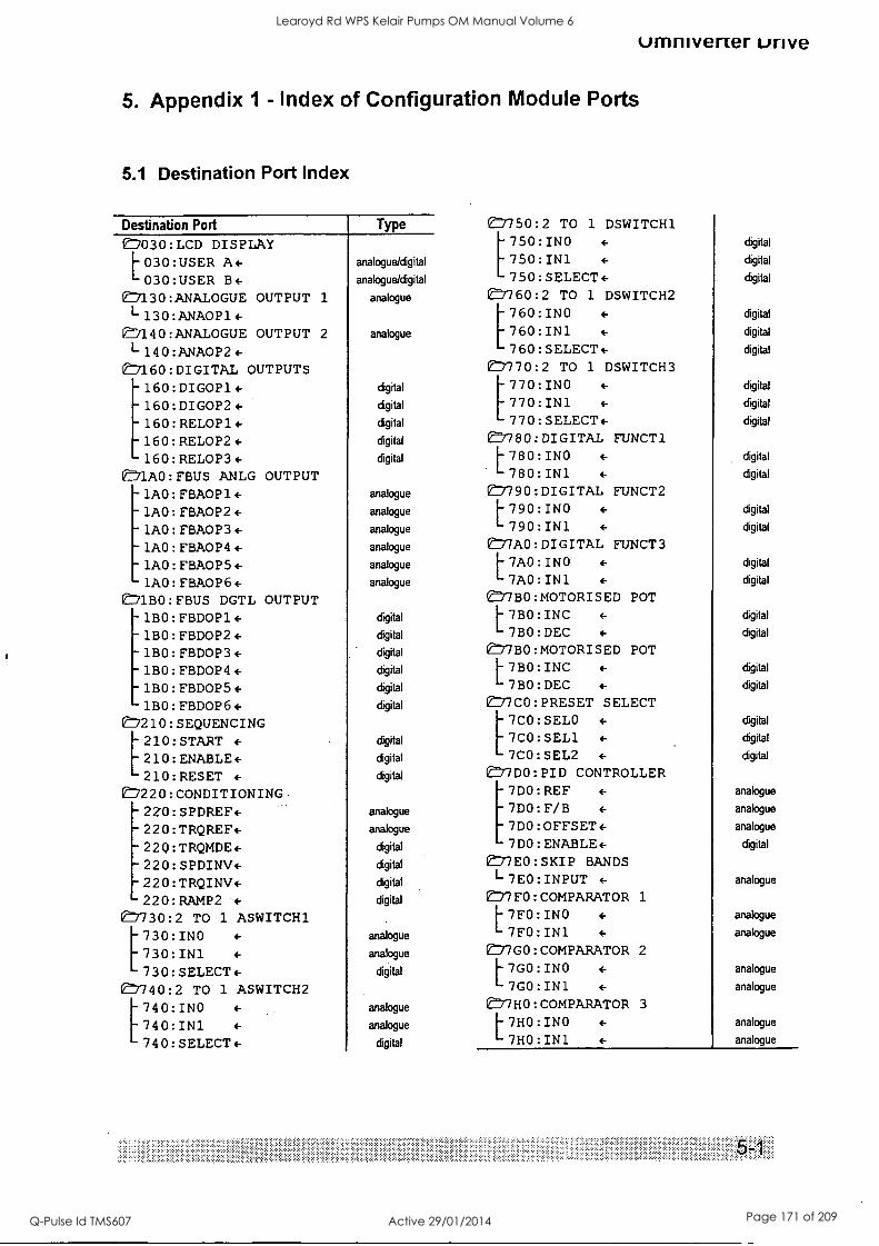
umnivener urive
5. Appendix 1 - Index of Configuration Module Ports
5.1 Destination Port Index
Destination Port 1030:LCD DISPLAY L030:USER A+ 030:USER B+
e71130:ANALOGUE OUTPUT 1
1-130:ANA0P1+ '140:ANALOGUE OUTPUT 2
1-140:ANA0P2+ ED160:DIGITAL OUTPUTS - 160:DIGOP1+ - 160:DIGOP2+ -160:RELOP1+ - 160:RELOP2+ 160:RELOP3+
OnlAO:FBUS ANLG OUTPUT -1AO:FBA0P1+ 1AO:FBA0P2+
- 1AO:FBA0P3+ -1AO:FBA0P4+ - 1AO:FBA0P5+ 1AO:FBA0P6+
E:71BO:FBUS DGTL OUTPUT -1BO:FBDOP1+ ,-1BO:FBDOP2+ -1BO:FBDOP3+ -1BO:FBDOP4+ -1BO:FBDOP5+ -1BO:FBDOP6+ 7210:SEQUENCING [210:START +
210:ENABLE+ 210:RESET +
E7220:CONDITIONING - 2ZO:SPDREF+ -220:TRQREF+ -220:TRQMDE+ -220:SPDINV+ - 220:TRQINV+ -220:RAMP2 +
ED730:2 TO 1 ASWITCH1 [730:INO +
730:IN1 +
730:SELECT+ 7740:2 TO 1 ASWITCH2 [740:INO +
740:IN1 +
740:SELECT+
Type
analogue/digital
analogue/digital
analogue
analogue
digital
digital
digital
digital
digital
analogue
analogue
analogue
analogue
analogue
analogue
digital
digital
digital
digital
digital
digital
digital
digital
digital
analogue
analogue
digital
digital
digital
digital
analogue
analogue
digital
analogue
analogue
digital
eD'750:2 TO 1 DSWITCH1 [750:INO +
750:IN1 +
750:SELECT+ CJ'760:2 TO 1 DSWITCH2 [760:INO +
760:IN1 +
760:SELECT+ Of:7770:2 TO 1 DSWITCH3 [770:INO +
770:IN1 +
770:SELECT+ e7180:DIGITAL FUNCT1 L780:INO +
780:IN1 +
1790: DIGITAL FUNCT2 L790:INO +
790:IN1 +
e77AO:DIGITAL FUNCT3 L7AO:INO +
7A0:IN1 +
0=BO:MOTORISED POT L7BO:INC +
7B0:DEC +
/7BO:MOTORISED POT L7BO:INC +
7BO:DEC +
e7CO:PRESET SELECT [7C0:SELO +
7CO:SEL1 +
7CO:SEL2 +
e77DO:PID CONTROLLER [7D0:REF +
7DO:F/B +
7D0:OFFSET+ 7D0:ENABLE+
Vf:77E0:SKIP BANDS L7E0:INPUT +
e77FO:COMPARATOR 1
L7FO:INO +
7FO:IN1 +
(77GO:COMPARATOR 2 L7GO:INO +
7GO:IN1 +
e777HO:COMPARATOR 3
L7HO:INO +
7HO:IN1 +
digital
digital
digital
digital
digital
digital
digital
digital
digital
digital
digital
digital
digital
digital
digital
digital
digital
digital
digital
digital
digital
digital
analogue
analogue
analogue
digital
analogue
analogue
analogue
analogue
analogue
analogue
analogue
Learoyd Rd WPS Kelair Pumps OM Manual Volume 6
Q-Pulse Id TMS607 Active 29/01/2014 Page 171 of 209
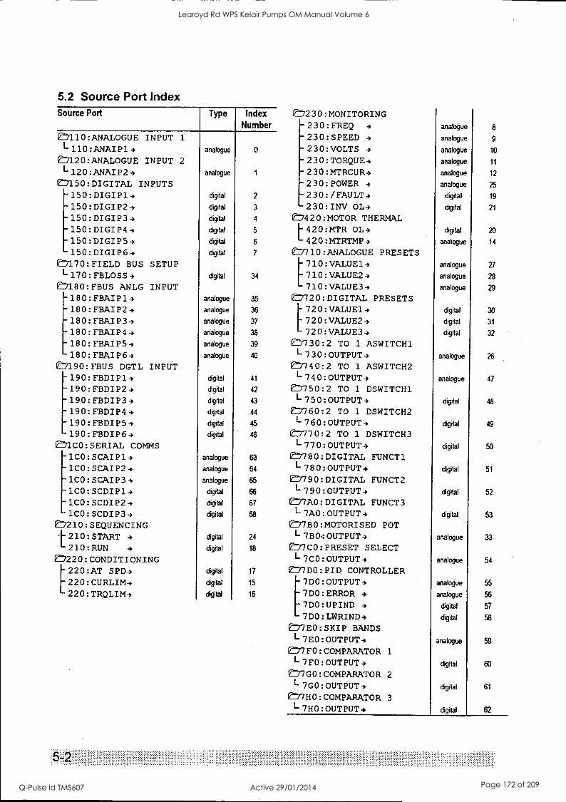
5.2 Source Port Index Source Port
e77110:ANALOGUE INPUT 1
1-110:ANAIP14 ED120:ANALOGUE INPUT 2
L120:ANAIP24 e7150:DIGITAL INPUTS -150:DIGIP14 - 150:DIGIP24 - 150:DIGIP34 -150:DIGIP44 -150:DIGIP54 150:DIGIP64
E7170:FIELD BUS SETUP 1-170:FBLOSS4
(7180:FBUS ANLG INPUT -180:FBAIP14 -180:FBAIP24 -180:FBAIP34 -180:FBAIP44 -180:FBAIP54 -180:FBAIP64
?190:FBUS DGTL INPUT -190:FBDIP14 -190:FBDIP24 -190:FBDIP34 -190:FBDIP44 -190:FBDIP54 190:FBDIP64
E71CO:SERIAL COMMS -1CO:SCAIP14 -1CO:SCAIP24 - 1CO: SCAIP34 -1CO:SCDIP14 -1CO:SCDIP24 1CO:SCDIP34
07210: SEQUENCING 1:210:START 4
210:RUN 4
®220: CONDITIONING [220:AT SPD4 220:CURLIM4 220:TRQLIM4
Type
analogue
analogue
digital
digital
digital
digital
digital
digital
digital
analogue
analogue
analogue
analogue
analogue
analogue
digital
digital
digital
digital
digital
digital
analogue
analogue
analogue
digital
digital
digital
digital
digital
digital
digital
digital
Index Number
0
2
3
4
5
6
7
34
35
36
37
38
39
40
41
42
43
44
45
46
63
64
65
66
67
68
24
18
17
15
16
E7230:MONITORING -230:FREQ 4
-230:SPEED 4
-230:VOLTS 4
- 230:TORQUE4 -230:MTRCUR4 -230:POWER 4
-230:/FAULT4 -230:INV OL4
C:7420:MOTOR THERMAL L420:MTR OL4 420:MTRTMP4
e=7710:ANALOGUE PRESETS [710:VALUE14 710:VALUE24 710:VALUE34
E7120:DIGITAL PRESETS 720:VALUE14 720:VALUE24 720:VALUE34
e7130:2 TO 1 ASWITCH1 1-730:OUTPUT4 E7740:2 TO 1 ASWITCH2 L740:OUTPUT4 07750:2 TO 1 DSWITCH1 1-750:OUTPUT4 e7760:2 TO 1 DSWITCH2 1-760:OUTPUT4
0:7770:2 TO 1 DSWITCH3 L770:OUTPUT4
07780: DIGITAL FUNCT1 L780:OUTPUT4
e 790:DIGITAL FUNCT2 1-790:OUTPUT4
eD7AO:DIGITAL FUNCT3 I- 7AO:OUTPUT-) 077BO:MOTORISED POT L7BO:OUTPUT4 e 1C0 :PRESET SELECT 1-7CO:OUTPUT4 77DO:PID CONTROLLER [7DO:OUTPUT4 7D0:ERROR 4
7DO:UPIND 4
7D0:LWRIND4 e777E0:SKIP BANDS L7EO:OUTPUT4
e /FO:COMPARATOR 1
L7FO:OUTPUT4 e77GO:COMPARATOR 2
L7GO:OUTPUT4 e77H0:COMPARATOR 3
I- 7HO:OUTPUT-,
analogue 8
analogue 9
analogue 10
analogue 11
analogue 12
analogue 25
digital 19
digital 21
digital 20
analogue 14
analogue 27
analogue 28
analogue
digital 30
digital 31
digital 32
analogue 26
analogue 47
digital 48
digital 49
digital 50
digital 51
digital 52
digital 53
analogue 33
analogue 54
analogue 55
analogue 56
digital 57
digital 58
analogue 59
digital 60
digital 61
digital 62
, .... ..
Learoyd Rd WPS Kelair Pumps OM Manual Volume 6
Q-Pulse Id TMS607 Active 29/01/2014 Page 172 of 209
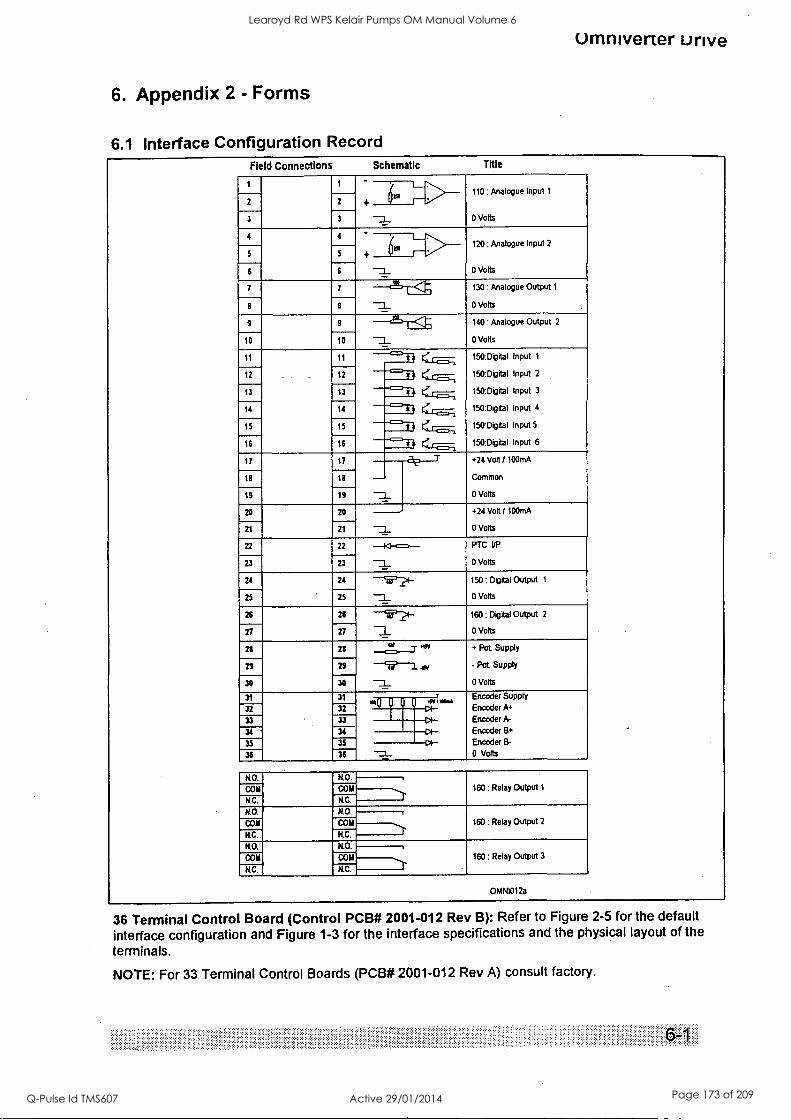
Umniverter Drive
6. Appendix 2 - Forms
6.1 Interface Configuration Record Field Connections Schematic Title
110: Analogue Input 1
0 Volts
2 2
Z 3 3
4 4 120: Analogue Input 2
0 Volts
del . 5 5
-3_ 6 6
7 7 -'-`2'-r< 130: Analogue Output 1
0 Volts Z 8 8
9 9 <----
140 : Analogue Output 2
0 Volts
L
-3_ 10 10
11 11 ----fl ... o 150:Digital Input 1
150:Digital Input 2
150:Digital Input 3
150:Digital Input 4
150:Digital Input 5
150:Digital Input 6
12 12 $4 o 13 13
14 14 1= $ 4 o 15 15 'il <..i. 16 16
17 17 a? T +24 Volt / 100mA
Common
0 Volts Z 18 18
19 19
20 20 +24 Volt / 10OrnA
0 Volts Z 21 21
22 22 -p-o--- Z
PTC VP
0 Volts 23 23
24 24 -755P2I- Z 150: Digital Output 1
0 Volts 25 25
26 26 --V7I- Z 160: Digital Output 2
()Volts 27 27
21 28 aii
+ Pot. Supply
- Pot Supply
0 Volts
29 29 1 .tri Z 30 30
31 31
122,Il .4"1" Encoder Supply
Encoder A. Encoder A-
Encoder B+
Encoder B-
0 Volts
32 32 NI 33 33
34 34
35 35 36
KO. KO. 160: Relay Output 1 COM COM
N.C. N.C.
N.O. N.O.
160: Relay Output 2 COM COM
N.C. N.C.
KO. NO. 160: Relay Output 3 COM COM
N.C. KC.
OMNI012a
36 Terminal Control Board (Control PCB# 2001-012 Rev B): Refer to Figure 2-5 for the default interface configuration and Figure 1-3 for the interface specifications and the physical layout of the terminals.
NOTE: For 33 Terminal Control Boards (PCB# 2001-012 Rev A) consult factory.
Learoyd Rd WPS Kelair Pumps OM Manual Volume 6
Q-Pulse Id TMS607 Active 29/01/2014 Page 173 of 209

6.2 Commissioning Schedule
Customer: Date/time:
Site: Engineer:
No. Test OK Comments
PRE-POWER
1 visual checks
1.1 no swarf/wire strands
1.2 no physical damage
1.3 clearances
1.4 no conducting debris
1.5 no insulation damage
1.6 no interference
1.7 pcb connections
1.8 wires out of place
1.9 no heat sink air path blockage
1.10 good ventilation
2 POWER CONNECTIONS
2.1 Ll, L2, L3 continuity input
2.2 U, V, W continuity output
2.3 tight connections
2.4 washers used
2.5 correct glanding .
2.6 filter opt. U,V,W in/out
2.7 no short input to input .
2.8 no short input to gnd
2.9 no short opt to gnd
2.10 motor continuity
Learoyd Rd WPS Kelair Pumps OM Manual Volume 6
Q-Pulse Id TMS607 Active 29/01/2014 Page 174 of 209
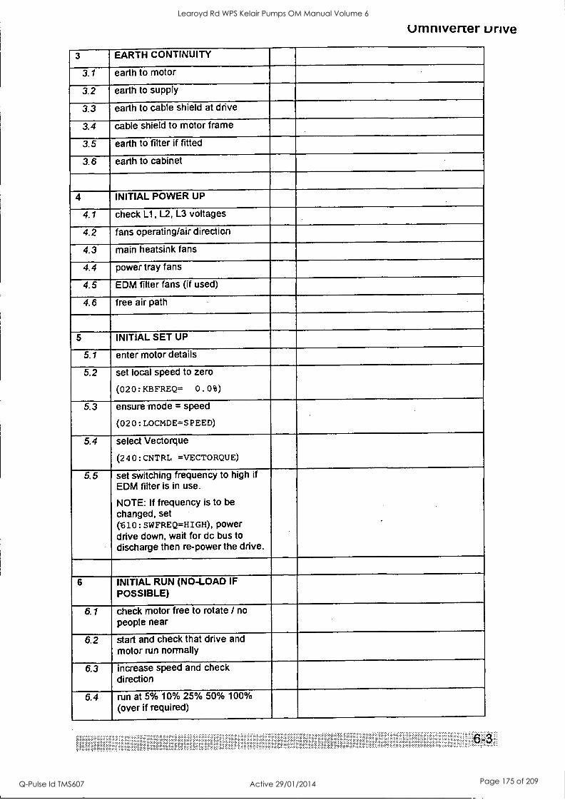
umniverter unve
3 EARTH CONTINUITY
3.1 earth to motor
3.2 earth to supply
- 3.3 earth to cable shield at drive
3.4 cable shield to motor frame
3.5 earth to filter if fitted
3.6 earth to cabinet
4 INITIAL POWER UP
4.1 check Li, L2, L3 voltages
4.2 fans operating/air direction
4.3 main heatsink fans
4.4 power tray fans
4.5 EDM filter fans (if used)
4.6 free air path
5 INITIAL SET UP
5.1 enter motor details
5.2 set local speed to zero
(020: KBFREQ= 0 . 0 is)
5.3 ensure mode = speed
(02 0 : LOCMDE=S PEED)
5.4 select Vectorque
(2 4 0 : CNTRL =VECTORQUE)
5.5 set switching frequency to high if EDM filter is in use.
NOTE: If frequency is to be changed, set (610: SWFREQ=HIGH), power drive down, wait for dc bus to discharge then re-power the drive.
6 INITIAL RUN (NO-LOAD IF POSSIBLE)
6.1 check motor free to rotate / no people near
6.2 start and check that drive and motor run normally
6.3 increase speed and check direction
6.4 run at 5% 10% 25% 50% 100% (over if required)
Learoyd Rd WPS Kelair Pumps OM Manual Volume 6
Q-Pulse Id TMS607 Active 29/01/2014 Page 175 of 209

6.5 check output current (LCD display), also waveform, level & balance.
6.6 check input current waveform, level & balance
6.7 check motor noise
6.8 check motor vibration
6.9 check motor voltage.
6.10 check motor stability
7 AT LOAD
7.1 check input current waveform, level & balance
7.2 check output current waveform, level & balance (LCD display)
7.3 check EDM filter dc feedback currents (if used)
7.4 run at full load > 10mins
7.5 check temperature (if possible) of connections
7.6 check hot start
8 USER SETUP
8.1 set up user connections and functions as desired
8.2 check digital inputs (in local)
8.3 check digital outputs
8.4 check analogue output scaling
8.5 check analogue input scaling
8.6 set drive in remote and check correct functioning .
8.7 set up LCD display line
8.8 clear any logged faults
8.9 set configuration locks
8.10 record configuration in manual
8.11 test user setup
6
Learoyd Rd WPS Kelair Pumps OM Manual Volume 6
Q-Pulse Id TMS607 Active 29/01/2014 Page 176 of 209

umniverter unve
7. Appendix 3 - Omniverter Dimensional Drawings See document 4807005 for dimensional drawings.
Learoyd Rd WPS Kelair Pumps OM Manual Volume 6
Q-Pulse Id TMS607 Active 29/01/2014 Page 177 of 209
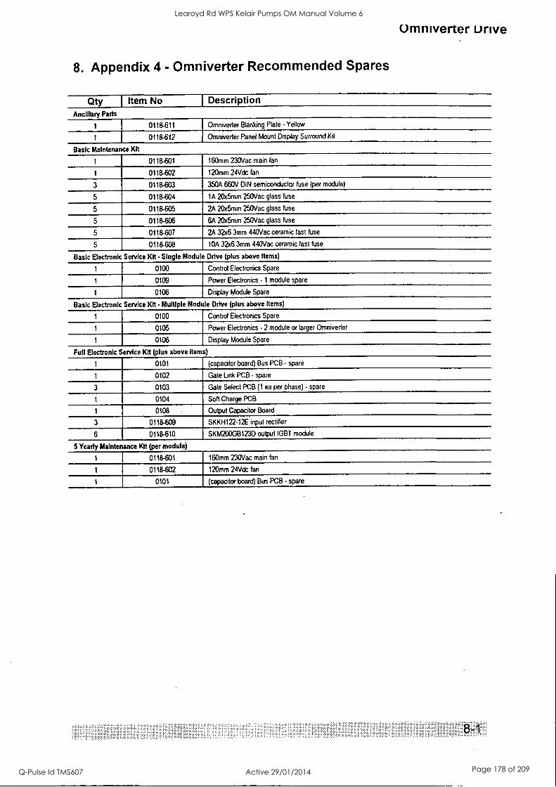
Umniverter Drive
8. Appendix 4 - Omniverter Recommended Spares
Qty 1 Item No Ancillary Parts
1
1
Basic Maintenance Kit
I Description
0118-611
0118-612
Omniverter Blanking Plate - Yellow
Omniverter Panel Mount Display Surround Kit
1 0118-601 160mm 230Vac main fan
1 0118-602 120mm 24Vdc fan
3 0118-603 350A 660V DIN semiconductor fuse (per module)
5 0118-604 1A 20x5mm 250Vac glass fuse
5 0118-605 2A 20x5mm 250Vac glass fuse
5 0118-606 6A 20x5mm 250Vac glass fuse
5 0118-607 2A 32x6.3mm 440Vac ceramic fast fuse
5 0118-608 WA 32x6.3mm 440Vac ceramic fast fuse
Basic Electronic Service Kit Single Module Drive (plus above items)
0100 Control Electronics Spare
0109 Power Electronics - 1 module spare
1 0106 Display Module Spare
Basic Electronic Service Kit Multiple Module Drive (plus above items)
1 0100 Control Electronics Spare
1 0105 Power Electronics - 2 module or larger Omniverter
1 0106 Display Module Spare
Full Electronic Service Kit (plus above items)
1 0101 (capacitor board) Bus PCB - spare
1 0102 Gate Link PCB - spare
3 0103 Gate Select PCB (1 ea per phase) - spare
1 0104 Soft Charge PCB
1 0108 Output Capacitor Board
3 0118-609 SKKH122-12E input rectifier
6 0118-610 SKM200GB123D output IGBT module
5 Yearly Maintenance Kit (per module)
1 0118-601 160mm 230Vac main fan
1 0118-602 120mm 24Vdc fan
1 0101 (capacitor board) Bus PCB - spare
Learoyd Rd WPS Kelair Pumps OM Manual Volume 6
Q-Pulse Id TMS607 Active 29/01/2014 Page 178 of 209
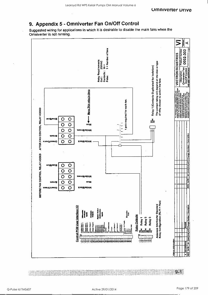
umniverter urive
9. Appendix 5 - Omniverter Fan On/Off Control Suggested wiring for applications in which it is desirable to disable the main fans when the
Omniverter is not running.
Ja
g < E z 3 ce. -
= c Z000 a.
aM8MMEI 0 0 0 0
UMOJ8
Uia.10/UODJO
onmanis
11/#60J8
UCHUO/UilitlEt
0 0 0 0 0 0
0 0 0 0 0 0 0 0 0 0
anis
UMOJEUKILIAA
432113101111M -
UMOJEIrdMILMA
1
t /I /I 1 g
3 to 3 - "
11 It I 1$11$//i 1 ! i If g
lailgia.a1111111u4hglgiAliiiil
onig
1
Ill II 11111
0
D O
X 1,1
c 0 IP t.
5 -
C C w
01 c c g
tJ L ,
0
AAA
C.)
E C) Z C.)
r,
C) 3 0 C)
6:
c- o c 2
cl 0
o 00
a
E
z
U
5
C.
9
8
I
I
C.
4 C.
Learoyd Rd WPS Kelair Pumps OM Manual Volume 6
Q-Pulse Id TMS607 Active 29/01/2014 Page 179 of 209

(miniver-ter Drive
10. Appendix 6 - Field Bus I/O Map The following table documents the way in which the I/O memory of the field bus hardware is assigned. Output consists of a Drive Status section, six analogue outputs and six digital outputs. Input is divided into six analogue inputs and six digital inputs. This mapping is independent of the specific field bus in use (ie. DeviceNet, lnterbus-S etc.).
10.1 From Omniverter to Field Bus Byte Offset
Title Description Data Type
0 Status Code (see 10.3 following) unsigned byte
1 Type Code (see 10.4 following) unsigned byte
2 170 : ENABLE Module State (see 10.5 following) BOOLEAN - unsigned byte
3 Reserved unsigned byte
Table 10-1 Status outputs from the Omniverter to the field bus
Byte Offset
Title Description Default Connection
Data Type
4 1A0 : FBAOP 1 4- FB Analogue Output 1 230: SPEED signed 16 bit word'
6 1A0 : FBAOP24- FB Analogue Output 2 230 :MTRCUR signed 16 bit word*
8 1A0 : FBA0P3<- FB Analogue Output 3 signed 16 bit word*
10 1A0 : FBA0P4(- FB Analogue Output 4 signed 16 bit word'
12 1A0 : FBAOP 54- FB Analogue Output 5 signed 16 bit word'
14 1A0 : FBAOP 6+. FB Analogue Output 6 signed 16 bit word'
Table 10-2 Analogue outputs from the Omniverter to the field bus
* Word storage uses the Intel convention - the low byte is stored first, the high byte is stored second. Analogue values are
normalised to 2^13 (8192, 2000h) eg. +100% = +8192 (2000h), -100% = -8192 (E000h).
Byte Offset
Title Description Default Connection
Data Type
16 1B0 : FBDOP1+ FB Digital Output 1 210: RUN BOOLEAN - unsigned byte
17 1B0 : FBDOP24 FB Digital Output 2 420:MTR OL BOOLEAN - unsigned byte
18 1B0 : FBDOP34 FB Digital Output 3 230:/FAULT BOOLEAN - unsigned byte
19 1B0 : FBDOP44 FB Digital Output 4 BOOLEAN - unsigned byte
20 1B0 : FBDOP54 FB Digital Output 5 BOOLEAN - unsigned byte
21 180: FBDOP64 FB Digital Output 6 BOOLEAN - unsigned byte
Table 10-3 Digital outputs from the Omniverter to the field bus
Learoyd Rd WPS Kelair Pumps OM Manual Volume 6
Q-Pulse Id TMS607 Active 29/01/2014 Page 180 of 209
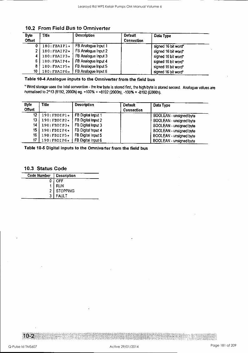
10.2 From Field Bus to Omniverter Byte Offset
Title Description Default Connection
Data Type
0 18 0 : FBAI P13 FB Analogue Input 1 signed 16 bit word' 2 18 0 : FBAI P24 FB Analogue Input 2 signed 16 bit word' 4 18 0 : FBAI P34 FB Analogue Input 3 signed 16 bit word' 6 180: FBAI P44 FB Analogue Input 4 signed 16 bit word' 8 18 0 : FBAI P 54 FB Analogue Input 5 signed 16 bit word'
10 180: FBAI P64 FB Analogue Input 6 signed 16 bit word'
Table 10-4 Analogue inputs to the Omniverter from the field bus
* Word storage uses the Intel convention - the low byte is stored first, the high byte is stored second. Analogue values are normalised to 2'13 (8192, 2000h) eg. +100% = +8192 (2000h), -100% = -8192 (E000h).
Byte Offset
Title Description Default Connection
Data Type
12 190:FBDIP14 FB Digital Input 1 BOOLEAN - unsigned byte 13 190:FBDIP24 FB Digital Input 2 BOOLEAN - unsigned byte 14 1 9 0 : FBDI P34 FB Digital Input 3 BOOLEAN - unsigned byte 15 190:FBDIP44 FB Digital Input 4 BOOLEAN - unsigned byte 16 190:FBDIP54 FB Digital Input 5 BOOLEAN - unsigned byte 17 190: FBDI P64 FB Digital Input 6 BOOLEAN - unsigned byte
Table 10-5 Digital inputs to the Omniverter from the field bus
10.3 Status Code Code Number
0
1
2
3
Description OFF
RUN
STOPPING
FAULT
'
Learoyd Rd WPS Kelair Pumps OM Manual Volume 6
Q-Pulse Id TMS607 Active 29/01/2014 Page 181 of 209
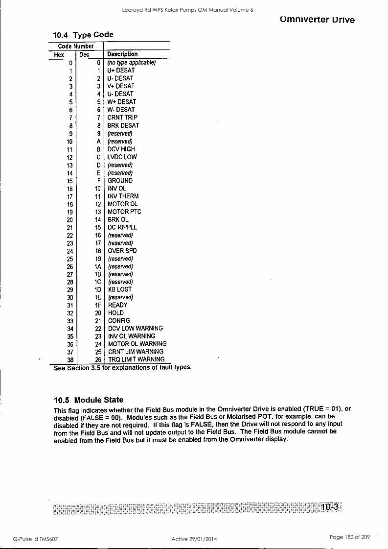
Omniverter Drive
10.4 Type Code Code Number
Hex Dec Description
0 0 (no type applicable)
1 1 U+ DESAT
2 2 U- DESAT
3 3 V+ DESAT
4 4 U- DESAT
5 5 W+ DESAT
6 6 W- DESAT
7 7 CRNT TRIP
8 8 BRK DESAT
9 9 (reserved)
10 A (reserved)
11 B DCV HIGH
12 C LVDC LOW
13 D (reserved)
14 E (reserved)
15 F GROUND
16 10 INV OL
17 11 INV THERM
18 12 MOTOR OL
19 13 MOTOR PTC
20 14 BRK OL
21 15 DC RIPPLE
22 16 (reserved)
23 17 (reserved)
24 18 OVER SPD
25 19 (reserved)
26 1A (reserved)
27 1B (reserved)
28 1C (reserved)
29 1D KB LOST
30 1 E (reserved)
31 1F READY
32 20 HOLD
33 21 CONFIG
34 22 DCV LOW WARNING
35 23 INV OL WARNING
36 24 MOTOR OL WARNING
37 25 CRNT LIM WARNING
38 26 TRQ LIMIT WARNING
See Section 3.5 for explanations of fault types.
10.5 Module State This flag indicates whether the Field Bus module in the Omniverter Drive is enabled (TRUE = 01), or
disabled (FALSE = 00). Modules such as the Field Bus or Motorised POT, for example, can be
disabled if they are not required. If this flag is FALSE, then the Drive will not respond to any input
from the Field Bus and will not update output to the Field Bus. The Field Bus module cannot be
enabled from the Field Bus but it must be enabled from the Omniverter display.
.. .
Learoyd Rd WPS Kelair Pumps OM Manual Volume 6
Q-Pulse Id TMS607 Active 29/01/2014 Page 182 of 209
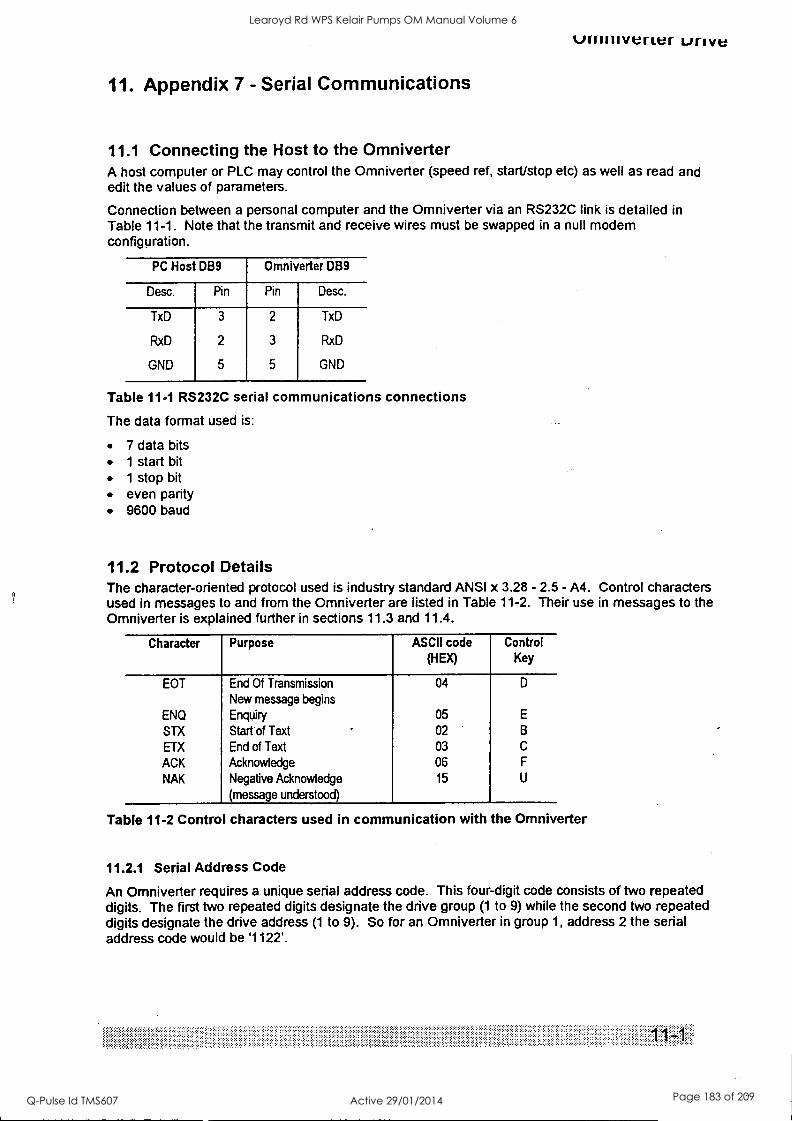
uminvener LJIIVe
11. Appendix 7 - Serial Communications
11.1 Connecting the Host to the Omniverter A host computer or PLC may control the Omniverter (speed ref, start/stop etc) as well as read and edit the values of parameters.
Connection between a personal computer and the Omniverter via an RS232C link is detailed in Table 11-1. Note that the transmit and receive wires must be swapped in a null modem configuration.
PC Host DB9 Omniverter DB9
Desc. Pin Pin Desc.
TxD
RxD
GND
3
2
5
2
3
5
TxD
RxD
GND
Table 11-1 RS232C serial communications connections
The data format used is:
7 data bits 1 start bit 1 stop bit even parity 9600 baud
11.2 Protocol Details The character-oriented protocol used is industry standard ANSI x 3.28 - 2.5 - A4. Control characters used in messages to and from the Omniverter are listed in Table 11-2. Their use in messages to the Omniverter is explained further in sections 11.3 and 11.4.
Character Purpose ASCII code (HEX)
Control Key
EOT End Of Transmission 04 D
New message begins
ENQ Enquiry 05 E
STX Start of Text 02 B
ETX End of Text 03 C
ACK Acknowledge 06 F
NAK Negative Acknowledge 15 U
(message understood)
Table 11-2 Control characters used in communication with the Omniverter
11.2.1 Serial Address Code
An Omniverter requires a unique serial address code. This four-digit code consists of two repeated digits. The first two repeated digits designate the drive group (1 to 9) while the second two repeated digits designate the drive address (1 to 9). So for an Omniverter in group 1, address 2 the serial address code would be '1122'.
Learoyd Rd WPS Kelair Pumps OM Manual Volume 6
Q-Pulse Id TMS607 Active 29/01/2014 Page 183 of 209
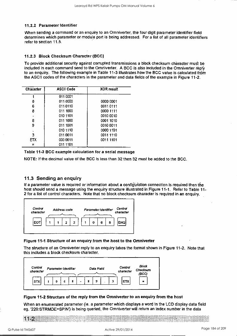
11.2.2 Parameter Identifier
When sending a command or an enquiry to an Omniverter, the four digit parameter identifier field determines which parameter or module port is being addressed. For a list of all parameter identifiers refer to section 11.5.
11.2.3 Block Checksum Character (BCC)
To provide additional security against corrupted transmissions a block checksum character must be included in each command send to the Omniverter. A BCC is also included in the Omniverter reply to an enquiry. The following example in Table 11-3 illustrates hOw the BCC value is calculated frr5rn the ASCII codes of the characters in the parameter and data fields of the example in Figure 11-2.
Character ASCII Code XOR result
1 011 0001
0 011 0000 0000 0001
6 011 0110 0011 0111
8 011 1000 0000 1111
010 1101 0010 0010
8 011 1000 0001 1010
9 011 1001 0010 0011
010 1110 0000 1101
3 011 0011 0011 1110
ETX 000 0011 0011 1101
011 1101
Table 11-3 BCC example calculation for a serial message
NOTE: If the decimal value of the BCC is less than 32 then 32 must be added to the BCC.
11.3 Sending an enquiry If a parameter value is required or information about a configuration connection is required then the host should send a message using the enquiry structure illustrated in Figure 11-1. Refer to Table 11- 2 for a list of control characters. Note that no block checksum character is required in an enquiry.
Control Address code character
EOT 2 2
Parameter Identifier Control character
0 6 8 ENQ
Figure 11-1 Structure of an enquiry from the host to the Omniverter
The structure of an Omniverter reply to an enquiry takes the format shown in Figure 11-2. Note that this includes a block checksum character.
Control Parameter Identifier Data Field Control Block
character character Checksum (BCC)
STX 0 6 9 3 ETX
Figure 11-2 Structure of the reply from the Omniverter to an enquiry from the host
When an enumerated parameter (ie. a parameter which displays a word in the LCD display data field eg. '220:STRMDE= SPIN') is being queried, the Omniverter will return an index number in the data
Learoyd Rd WPS Kelair Pumps OM Manual Volume 6
Q-Pulse Id TMS607 Active 29/01/2014 Page 184 of 209
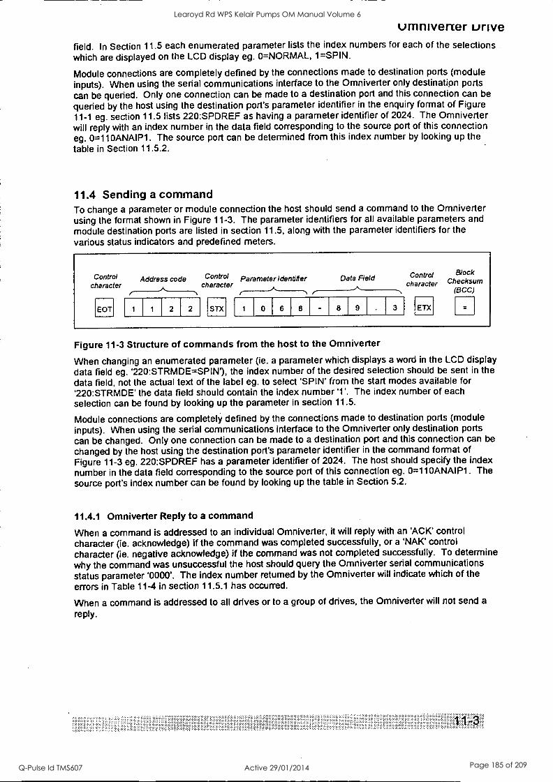
umnivener urive field. In Section 11.5 each enumerated parameter lists the index numbers for each of the selections which are displayed on the LCD display eg. 0=NORMAL, 1=SPIN.
Module connections are completely defined by the connections made to destination ports (module inputs). When using the serial communications interface to the Omniverter only destinatipn ports can be queried. Only one connection can be made to a destination port and this connection can be
queried by the host using the destination port's parameter identifier in the enquiry format of Figure 11-1 eg. section 11.5 lists 220:SPDREF as having a parameter identifier of 2024. The Omniverter will reply with an index number in the data field corresponding to the source port of this connection eg. 0=110ANAIP1. The source port can be determined from this index number by looking up the table in Section 11.5.2.
11.4 Sending a command To change a parameter or module connection the host should send a command to the Omniverter using the format shown in Figure 11-3. The parameter identifiers for all available parameters and module destination ports are listed in section 11.5, along with the parameter identifiers for the various status indicators and predefined meters.
Control ti Control Control Address code Parameter Identifier Data Field
character character character
EOT 2 2 [STX 0 6 8 8 9 3 ETX
Block Checksum
(BCC)
Figure 11-3 Structure of commands from the host to the Omniverter
When changing an enumerated parameter (ie. a parameter which displays a word in the LCD display data field eg. 220:STRMDE=SP1N), the index number of the desired selection should be sent in the data field, not the actual text of the label eg. to select 'SPIN' from the start modes available for '220:STRMDE' the data field should contain the index number '1'. The index number of each selection can be found by looking up the parameter in section 11.5.
Module connections are completely defined by the connections made to destination ports (module inputs). When using the serial communications interface to the Omniverter only destination ports can be changed. Only one connection can be made to a destination port and this connection can be
changed by the host using the destination port's parameter identifier in the command format of Figure 11-3 eg. 220:SPDREF has a parameter identifier of 2024. The host should specify the index number in the data field corresponding to the source port of this connection eg. 0=110ANAIP1. The source port's index number can be found by looking up the table in Section 5.2.
11.4.1 Omniverter Reply to a command
When a command is addressed to an individual Omniverter, it will reply with an 'ACK' control character (ie. acknowledge) if the command was completed successfully, or a `NAK' control character (ie. negative acknowledge) if the command was not completed successfully. To determine why the command was unsuccessful the host should query the Omniverter serial communications status parameter '0000'. The index number returned by the Omniverter will indicate which of the errors in Table 11-4 in section 11.5.1 has occurred.
When a command is addressed to all drives or to a group of drives, the Omniverter will not send a
reply.
Learoyd Rd WPS Kelair Pumps OM Manual Volume 6
Q-Pulse Id TMS607 Active 29/01/2014 Page 185 of 209
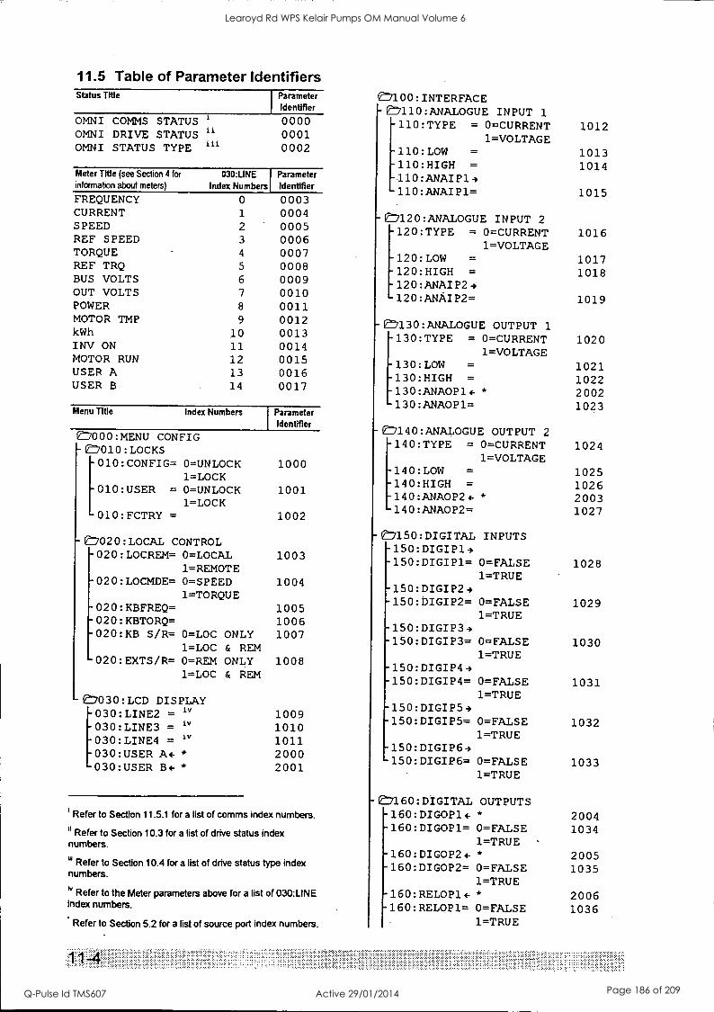
11.5 Table of Parameter Identifiers Status Title
OMNI COMMS STATUS 1
OMNI DRIVE STATUS " OMNI STATUS TYPE 1"
Parameter
Identifier
0000 0001 0002
Meter Title (see Section 4 for
information about meters)
FREQUENCY CURRENT SPEED REF SPEED TORQUE REF TRQ BUS VOLTS OUT VOLTS POWER MOTOR TMP kWh INV ON MOTOR RUN USER A USER B
030:LINE Index Numbers
0 1
2 3
4
5
6
7
8
9
10 11
12 13
14
Parameter Identifier
0003 0004 0005 0006 0007 0008 0009 0010 0011 0012 0013 0014 0015 0016 0017
Menu Title Index Numbers Parameter Identifier
1000:MENU CONFIG - 7010 :LOCKS
010:CONFIG= 0=UNLOCK 1=LOCK
010:USER = 0=UNLOCK 1=LOCK
010:FCTRY =
1000
1001
1002
-E020:LOCAL CONTROL -020:LOCREM= 0=LOCAL 1003
1=REMOTE -020:LOCMDE= 0=SPEED 1004
1=TORQUE -020:KBFREQ= -020:KBTORQ= -020:KB S/R= 0=LOC ONLY
1=LOC & REM -020:EXTS/R= 0=REM ONLY
1=LOC & REM
1030:LCD DISPLAY 030:LINE2 = iv
030:LINE3 = iv
030:LINE4 = iv
030:USER A4- *
030:USER B4-*
1005 1006 1007
1008
1009 1010 1011 2000 2001
Refer to Section 11.5.1 for a list of comms index numbers.
II Refer to Section 10.3 for a list of drive status index numbers.
iiiRefer to Section 10.4 for a list of drive status type index numbers.
iv Refer to the Meter parameters above for a list of 030:LINE index numbers.
Refer to Section 5.2 for a list of source port index numbers.
....... .
7100:INTERFACE e7110:ANALOGUE INPUT 1
-110:TYPE = 0=CURRENT 1012 1=VOLTAGE
-110:LOW = 1013 -110:HIGH = 1014 -110:ANAIP14 -110:ANAIP1= 1015
-C-120:ANALOGUE INPUT 2
-120:TYPE = 0=CURRENT 1016 1=VOLTAGE
-120:LOW = 1017 -120:HIGH = 1018 -120:ANAIP24 -120:ANAIP2= 1019
-e:7130:ANALOGUE OUTPUT 1
-130:TYPE = 0=CURRENT 1020 1=VOLTAGE
-130:LOW = 1021 130:HIGH = 1022
-130:ANA0P14- * 2002 130:ANA0P1= 1023
0-140:ANALOGUE OUTPUT 2
140:TYPE = 0=CURRENT 1024 1=VOLTAGE
140:LOW = 1025 140:HIGH = 1026 140:ANA0P24- * 2003 140:ANA0P2= 1027
C,150: DIGITAL INPUTS -150:DIGIP1-, -150:DIGIP1= 0=FALSE
1=TRUE -150:DIGIP24 -150:DIGIP2= 0 =FALSE
1=TRUE -150:DIGIP3e -150:DIGIP3= 0=FALSE
1=TRUE -150:DIGIP49 -150:DIGIP4= 0=FALSE
1=TRUE -150:DIGIP54 -150:DIGIP5= 0=FALSE
1=TRUE -150:DIGIP64 150:DIGIP6= 0=FALSE
1=TRUE
1028
1029
1030
1031
1032
1033
-e7160:DIGITAL OUTPUTS -160:DIGOP14- * 2004 -160:DIGOP1= 0=FALSE 1034
1=TRUE -160:DIGOP24- * 2005 .160:DIGOP2= 0=FALSE 1035
1=TRUE -160:RELOP14- * 2006 -160:RELOP1= 0=FALSE 1036
1=TRUE
Learoyd Rd WPS Kelair Pumps OM Manual Volume 6
Q-Pulse Id TMS607 Active 29/01/2014 Page 186 of 209
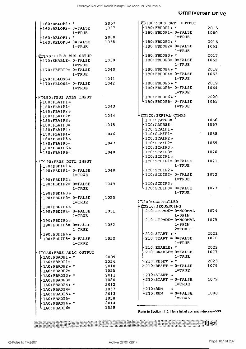
160:RELOP2+ * 160:RELOP2= 0=FALSE
1=TRUE 160:RELOP34- *
2007 1037
2008
-71130:FBUS
umnivener urive DGTL OUTPUT
-1BO:FBDOP14- * 2015 -1BO:FBDOP1= 0=FALSE 1060
1=TRUE
160:RELOP3= 0=FALSE 1038 -180:FBDOP2+ * 2016 1=TRUE -1BO:FBDOP2= 0 =FALSE 1061
1=TRUE
-1170:FIELD BUS SETUP -1BO:FBDOP34- * 2017
170:ENABLE= 0=FALSE 1039 -1BO:FBDOP3= 0=FALSE 1062 1=TRUE 1=TRUE
170:FBTRIP= 0=FALSE 1040 -1BO:FBDOP44-* 2018 1=TRUE -1BO:FBDOP4= 0=FALSE 1063
170:FBLOSS4 1041 1=TRUE
170:FBLOSS= 0=FALSE 1042 -1BO:FBDOP54- * 2019 1=TRUE -1B0:FBDOP5= 0=FALSE 1064
1=TRUE
E:7180: FBUS ANLG INPUT -1BO:FBDOP64-* 2020 -180: FBAIP1 4 1BO:FBDOP6= 0=FALSE 1065
-180: FBAIP1= 1043 1=TRUE
-180: FBAIP2 4 -180: FBAIP2= 1044 ED1C0:SERIAL COMMS -180: FBAIP3 4 -1CO:STATUS= 1066
-180: FBAI P3= 1045 -1CO:ADDRSS= 1067
-180: FBAI P4 4 -1CO:SCAIP14 -180: FBAIP4= 1046 -1CO:SCAIP1= 1068
-180: FBAI P5 4 -1CO:SCAIP24 180: FBAIP5= 1047 1CO:SCAIP2= 1069
180: FBAI P64 1CO:SCAIP34
180: FBAIP6= 1048 1CO:SCAIP3= 1070 1CO:SCDIP14
-'190:FBUS DGTL INPUT 1CO:SCDIP1= 0=FALSE 1071
190:FBDIP14 1=TRUE -190:FBDIP1= 0=FALSE 1048 1CO:SCDIP24
1=TRUE 1CO:SCDIP2= 0=FALSE 1072
190:FBDIP24 1=TRUE 190:FBDIP2= 0 =FALSE 1049 1CO:SCDIP34
1=TRUE 1CO:SCDIP3= 0=FALSE 1073
190:FBDIP34 1=TRUE
-190:FBDIP3= 0 =FALSE 1050 1=TRUE /200: CONTROLLER
190:FBDIP44 -E7210:SEQUENCING 190:FBDIP4= 0=FALSE 1051 -210:STRMDE= 0=NORMAL 1074
1=TRUE 1=SPIN 190:FBDIP54 -210:STPMDE= 0=NORMAL 1075
190:FBDIP5= 0=FALSE 1052 1=SPIN 1=TRUE 2=COAST
190:FBDIP64 -210:START 4-* 2021
190:FBDIP5= 0=FALSE 1053 -210:START = 0=FALSE 1076
1=TRUE 1=TRUE -210:ENABLE+ * 2022
:71A0: FBUS ANLG OUTPUT -210:ENABLE= 0=FALSE 1077
-1A0: FBA0P14- * 2009 1=TRUE
-1A0: FBA0P1= 1054 -210:RESET F * 2023
- 'AO : FBA0P24- * 2010 -210:RESET = 0=FALSE 1078
-1A0: FBA0P2= 1055 1=TRUE
-1A0 : E1BAOP34- * 2011 -210:START 4
-1A0: FBA0P3= 1056 -210:START = 0=FALSE 1079
-1A0: FBA0P44- * 2012 1=TRUE
-1A0: FBA0P4= 1057 -210:RUN 4
-1A0: FBA0P54- * 2013 -210:RUN = 0=FALSE 1080
-1A0: FBA0P5= 1058 1=TRUE
-1A0: FBA0P6 * 2014
1AO: FBA0P6= 1059 I Refer to Section 11.5.1 for a list of comms index numbers.
Learoyd Rd WPS Kelair Pumps OM Manual Volume 6
Q-Pulse Id TMS607 Active 29/01/2014 Page 187 of 209
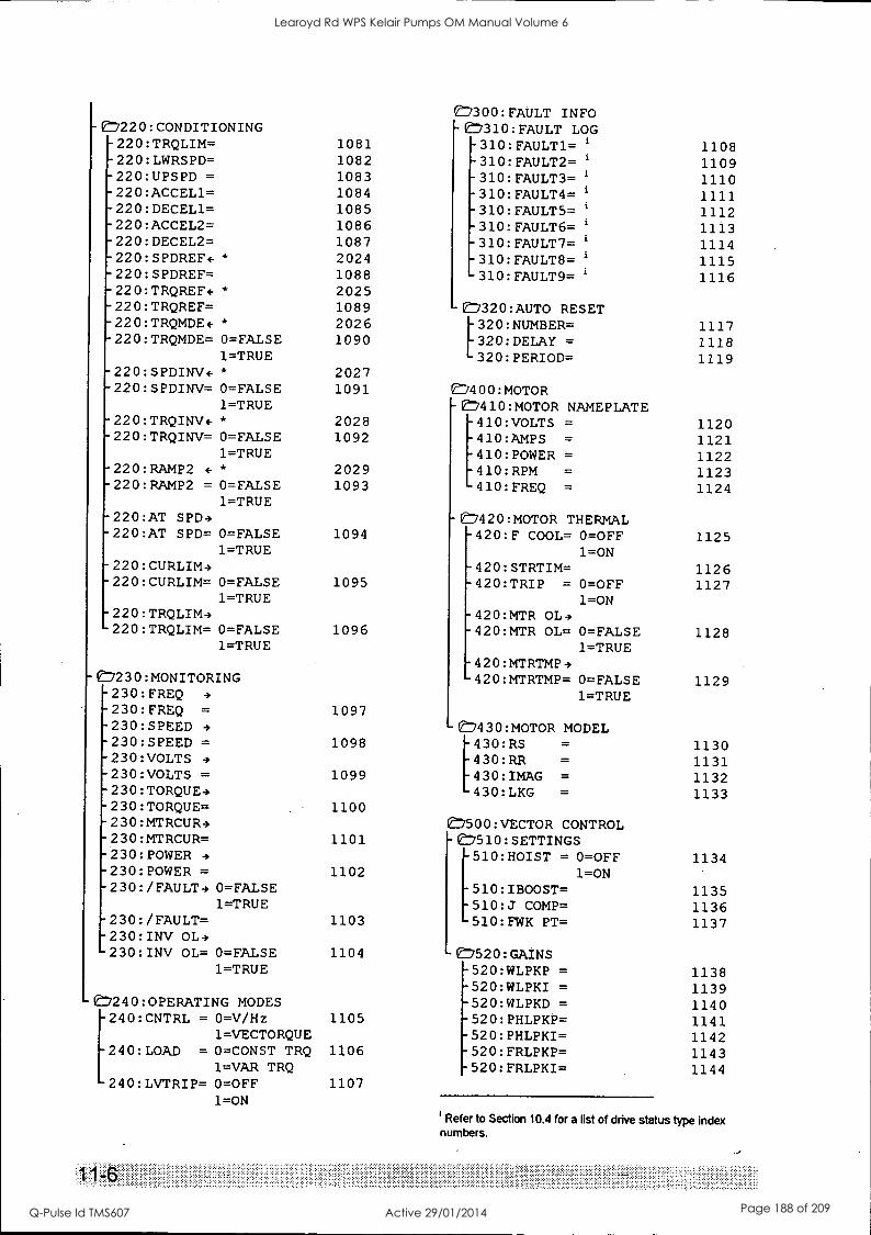
'300: FAULT INFO C7220:CONDITIONING E7310: FAULT LOG 220:TRQLIM= 1081 -310:FAULT1= 1108 220:LWRSPD= 1082 -310:FAULT2= 1109 220:UPSPD = 1083 -310:FAULT3= 1110 220:ACCEL1= 1084 -310:FAULT4= 1111 220:DECEL1= 1085 -310:FAULT5= 1112 220:ACCEL2= 1086 -310:FAULT6= 1113 220:DECEL2= 1087 -310:FAULT7= 1114 220:SPDREF4 * 2024 -310:FAULT8= 1115 220:SPDREF= 1088 310:FAULT9= 1116
-220:TRQREF4- * 2025 220:TRQREF= 1089 -CD320:AUTO RESET 220:TRQMDE4-* 2026 1117 -220:TRQMDE= 0=FALSE
[320:NUMBER= 1090 320:DELAY = 1118
1=TRUE 320:PERIOD= 1119 -220:SPDINV4-* 2027 -220:SPDINV= 0=FALSE 1091 E7400:MOTOR
1=TRUE C7410:MOTOR NAMEPLATE -220:TRQINV4- * 2028 410:VOLTS = 1120 -220:TRQINV= 0=FALSE 1092 -410:AMPS = 1121
1=TRUE -410:POWER = 1122 -220:RAMP2 (-* 2029 -410:RPM = 1123 -220:RAMP2 = 0=FALSE 1093 -410:FREQ = 1124
1=TRUE -220:AT SPD4 7420:MOTOR THERMAL -220:AT SPD= 0=FALSE 1094 -420:F COOL= 0=OFF 1125
1=TRUE 1=ON -220:CURLIM4 420:STRTIM= 1126 -220:CURLIM= 0=FALSE 1095 420:TRIP = 0=OFF 1127
1=TRUE 1=ON -220:TRQLIM4 420:MTR OL4 -220:TRQLIM= 0=FALSE 1096 420:MTR OL= 0=FALSE 1128
1=TRUE 1=TRUE 420:MTRTMP4
-07230:MONITORING 420:MTRTMP= 0=FALSE 1129 -230:FREQ 4 1=TRUE -230:FREQ = 1097 -230:SPEED 4 -E7430:MOTOR MODEL -230:SPEED = 1098 430:RS = 1130 -230:VOLTS 4 430:RR = 1131 -230:VOLTS = 1099 430:IMAG = 1132 -230: TORQUE-, 430:LKG = 1133 -230:TORQUE= 1100 -230:MTRCUR4 7500:VECTOR CONTROL -230:MTRCUR= 1101 -7510:SETTINGS -230:POWER 4 510:HOIST = O =OFF 1134 -230:POWER = 1102 1=ON -230: /FAULT- 0=FALSE 510:IBOOST= 1135
1=TRUE 510:J COMP= 1136 -230:/FAULT= 1103 510:FWK PT= 1137 -230:INV OL4 230:INV OL= 0=FALSE 1104 e7520:GAINS
1=TRUE -520:WLPKP = 1138 -520:WLPKI = 1139
C7240:0PERATING MODES -520:WLPKD = 1140 240:CNTRL = 0=V/Hz 1105 -520:PHLPKP= 1141
1=VECTORQUE -520:PHLPKI= 1142 240:LOAD = 0=CONST TRQ 1106 -520:FRLPKP= 1143
1=VAR TRQ -520:FRLPKI= 1144 240:LVTRIP= 0=OFF 1107
1=ON ' Refer to Section 10.4 for a list of drive status type index numbers.
Learoyd Rd WPS Kelair Pumps OM Manual Volume 6
Q-Pulse Id TMS607 Active 29/01/2014 Page 188 of 209
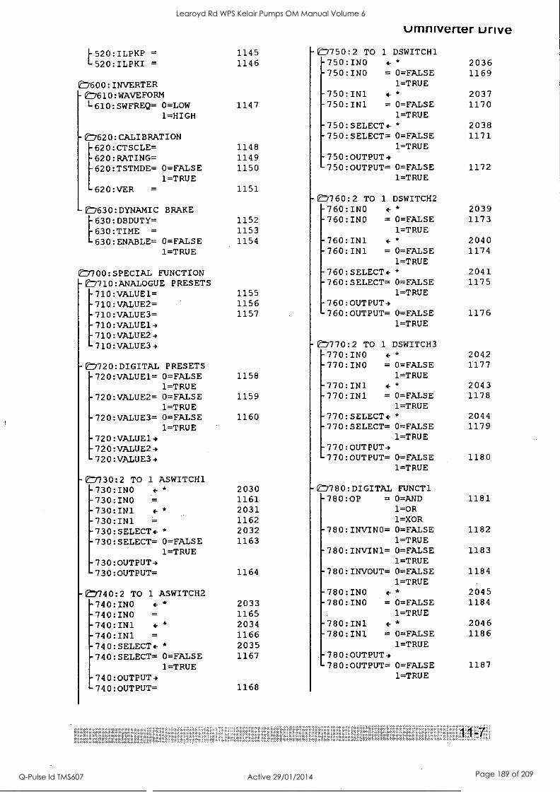
}-520:ILPKP = 520:ILPKI =
0600:INVERTER 1610:WAVEFORM L-610:SWFREQ= 0=LOW
1=HIGH
C-620:CALIBRATION 620:CTSCLE= 620:RATING= 620:TSTMDE= 0=FALSE
1=TRUE 620:VER =
- 2630:DYNAMIC BRAKE [630:DBDUTY= 630:TIME =
630:ENABLE= 0 -FALSE 1=TRUE
7700:SPECIAL FUNCTION -E,710:ANALOGUE PRESETS -710:VALUE1= -710:VALUE2= -710:VALUE3= -710:VALUE14 -710:VALUE24 -710:VALUE34
-E:7720:DIGITAL PRESETS -720:VALUE1= 0=FALSE
1=TRUE -720:VALUE2= 0=FALSE
1=TRUE -720:VALUE3= 0=FALSE
1=TRUE -720:VALUE14 -720:VALUE24 -720:VALUE34
-en730:2 TO 1 ASWITCH1 -730:INO + *
-730:INO = -730:IN1 F *
-730:IN1 = -730:SELECT+ * -730:SELECT= 0=FALSE
1=TRUE -730:OUTPUT4 730:OUTPUT=
-740:2 TO 1 ASWITCH2 -740:INO + *
-740:INO =
-740:IN1 4-*
-740:IN1 =
-740:SELECT+ * -740:SELECT= 0=FALSE
1=TRUE 740:OUTPUT4 740:OUTPUT=
umniverter unve
1145 -750:2 TO 1 DSWITCH1 1146 -750:INO 4- *
-750:INO = 0=FALSE 1=TRUE
-750:IN1 4-*
1147 -750:IN1 = 0=FALSE 1=TRUE
-750:SELECT+ * -750:SELECT= 0=FALSE
1148 1=TRUE 1149 -750:OUTPUT-, 1150 -750:OUTPUT= 0=FALSE
1=TRUE 1151
- 1760:2 TO 1 DSWITCH2 -760:INO 4-*
1152 -760:INO = 0=FALSE 1153 1=TRUE 1154 -760:IN1 4-*
-760:IN1 = 0=FAISE 1=TRUE
-760:SELECT+ * -760:SELECT= 0=FALSE
1155 1=TRUE 1156 -760:OUTPUT-) 1157 '760:OUTPUT= 0=FALSE
1=TRUE
1158
1159
1160
2030 1161 2031 1162 2032 1163
1164
2033 1165 2034 1166 2035 1167
1168
E7770:2 TO 1 DSWITCH3 770:INO 4- *
770:INO = 0=FALSE 1=TRUE
770:IN1 4- *
770:IN1 = 0=FALSE 1=TRUE
770:SELECT+ * 770:SELECT= 0=FALSE
1=TRUE 770:OUTPUT4 770:OUTPUT= 0=FALSE
1=TRUE
E7780:DIGITAL FUNCT1 -780:0P = 0=AND
1=OR 1=XOR
-780:INVINO= 0=FALSE 1=TRUE
-780:INVIN1= 0=FALSE 1=TRUE
-780:INVOUT= 0=FALSE 1=TRUE
-780:INO 4-*
-780:INO = 0=FALSE 1=TRUE
-780:IN1 + *
-780:IN1 = 0=FALSE 1=TRUE
-780:OUTPUT-) 780:OUTPUT= 0=FALSE
1=TRUE
2036 1169
2037 1170
2038 1171
1172
2039 1173
2040 1174
2041 1175
1176
2042 1177
2043 1178
2044 1179
1180
1181
1182
1183
1184
2045 1184
2046 1186
1187
Learoyd Rd WPS Kelair Pumps OM Manual Volume 6
Q-Pulse Id TMS607 Active 29/01/2014 Page 189 of 209
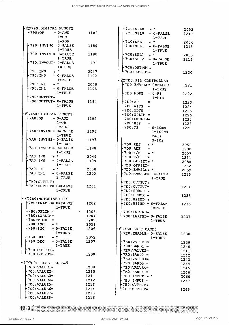
-7790:DIGITAL FUNCT2 -7CO:SELO 4- 2053 -790:0P = 0=AND 1188 -7CO:SELO = 0=FALSE 1217
1=OR 1=TRUE 1=XOR -7CO:SEL1 * 2054
-790:INVINO= 0=FALSE 1189 -7CO:SEL1 = 0=FALSE 1218 1=TRUE 1=TRUE
-790:INVIN1= 0=FALSE 1190 -7CO:SEL2 4-* 2055 1=TRUE -7CO:SEL2 = 0=FALSE 1219
-790:INVOUT= 0=FALSE 1191 1=TRUE 1=TRUE -7CO:OUTPUT4
-790:INO 4-* 2047 7CO:OUTPUT= 1220 790:INO = 0=FALSE 1192
1=TRUE -ED7DO:PID CONTROLLER 790:IN1 4- 2048 7DO:ENABLE= 0=FALSE 1221 790:IN1 = 0=FALSE 1193 1=TRUE
1=TRUE ,-7DO:MODE = 0=PI 1222 790:OUTPUT4 1=PID 790:OUTPUT= 0=FALSE 1194 7DO:KP 1223
1=TRUE 7DO:WITS = 1224 7DO:WDTS = 1225
17AO:DIGITAI FUNCT3 7DO:UPLIM = 1226 7A0:0P = 0=AND 1195 7DO:LWRLIM= 1227
1=OR 7DO:KSP = 1228 1=XOR 7DO:TS = 0=10ms 1229
7AO:INVINO= 0=FALSE 1196 1=100ms 1=TRUE 2=ls
7AO:INVIN1= 0=FALSE 1197 3=10s 1=TRUE 7D0: REF 4- * 2056
7AO:INVOUT= 0=FALSE 1198 7DO:REF 1230 1=TRUE 7DO:F/B F 2057
7AO:INO F * 2049 7DO:F/B 1231 7AO:INO = 0=FALSE 1199 7DO:OFFSET+ * 2058
1=TRUE 7DO:OFFSET= 1232 7AO:IN1 F * 2050 7DO:ENABLE4- * 2059 7AO:IN1 = 0=FALSE 1200 7DO:ENABLE= 0=FALSE 1233
1=TRUE 1=TRUE 7AO:OUTPUT4 7DO:OUTPUT4 7AO:OUTPUT= 0=FALSE 1201 7DO:OUTPUT= 1234
1=TRUE 7DO:ERROR 4
7DO:ERROR = 1235 77BO:MOTORISED POT 7DO:UPIND 4 -7BO:ENABLE= 0=FALSE 1202 7DO:UPIND = 0 =FALSE 1236
1=TRUE 1=TRUE -7BO:UPLIM = 1203 -7DO:LWRIND4 -730:LWRLIM= 1204 -7DO:LWRIND= 0=FALSE 1237 -7BO:TIME = 1205 1=TRUE -7BO:INC 4-
* 2051 -7BO:INC = 0=FALSE 1206 -0-7E0:SKIP BANDS
1=TRUE -7E0:ENABLE= 0=FALSE 1238 -7BO:DEC 4-
* 2052 1=TRUE -780:DEC = 0=FALSE 1207 -7E0:VALUE1= 1239
1=TRUE -7E0:BAND1 = 1240 -7BO:OUTPUT4 -7E0:VALUE2= 1241 -7BO:OUTPUT= 1208 -7E0:BAND2 = 1242
-7E0:VALUE3= 1243 -e77CO:PRESET SELECT -7E0:BAND3 = 1244 -7CO:VALUE1= 1209 -7E0:VALUE4= 1245 -7CO:VALUE2= 1210 -7E0:BAND4 = 1246 -7CO:VALUE3= 1211 -7E0:INPUT 4-* 2060 -7CO:VALUE4= 1212 -7E0:INPUT = 1247 -7CO:VALUE5= 1213 -7E0:OUTPUT4 -7CO:VALUE6= 1214 -7E0:OUTPUT= 1248 -7CO:VALUE7= 1215 -7CO:VALUE8= 1216
Learoyd Rd WPS Kelair Pumps OM Manual Volume 6
Q-Pulse Id TMS607 Active 29/01/2014 Page 190 of 209
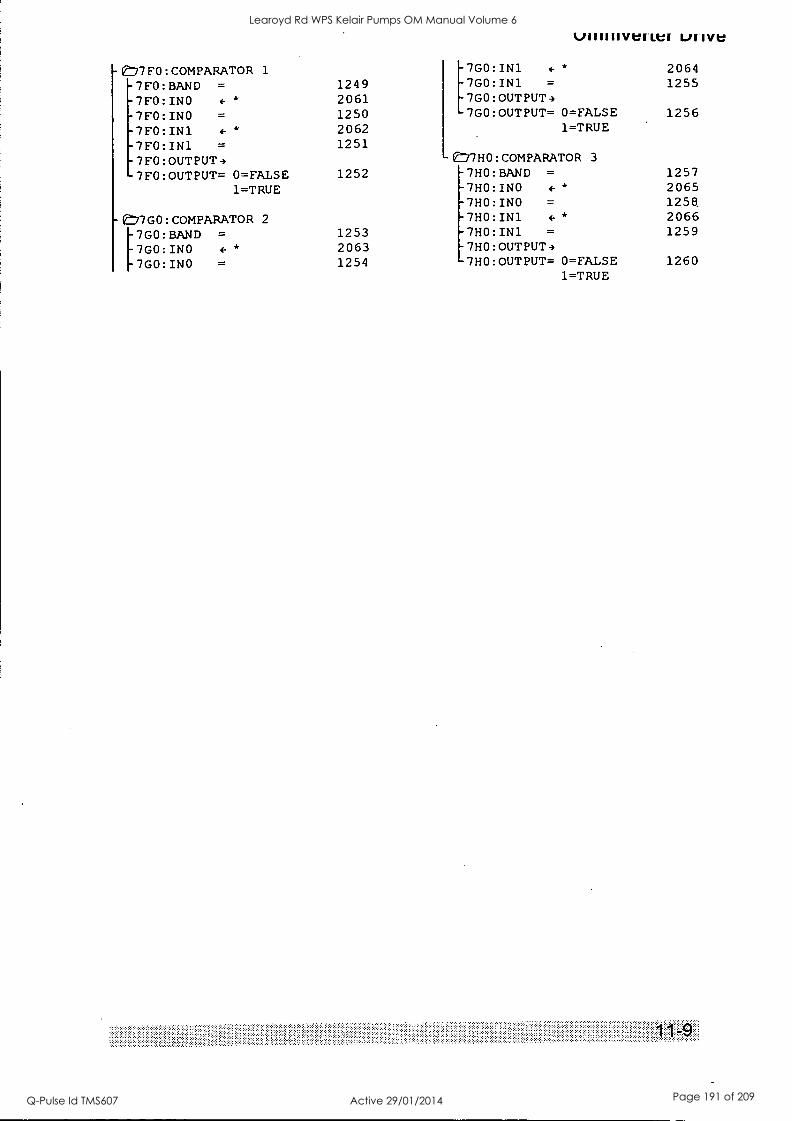
IJIIVe
e,7FO:COMPARATOR 1 7GO:IN1 f * 2064
7FO:BAND = 1249 7G0:IN1 = 1255
7FO:INO 4- * 2061 7GO:OUTPUT4
7FO:INO 1250 7GO:OUTPUT= 0=FALSE 1256
7FO:IN1 2062 1=TRUE
7FO:IN1 1251
7FO:OUTPUT4 E=77HO:COMPARATOR 3
7F0:OUTPUT= 0=FAISE 1252 -7HO:BAND = 1257
1=TRUE -7HO:INO f* 2065 -7HO:INO = 1258.
-e777GO:COMPARATOR 2 -7HO:IN1 f° 2066
= 1253 -7HO:IN1 = 1259 [7GO:BAND 7G0:INO ++ 2063 -7HO:OUTPUT4 7GO:INO = 1254 7HO:OUTPUT= 0=FALSE 1260
1=TRUE
Learoyd Rd WPS Kelair Pumps OM Manual Volume 6
Q-Pulse Id TMS607 Active 29/01/2014 Page 191 of 209
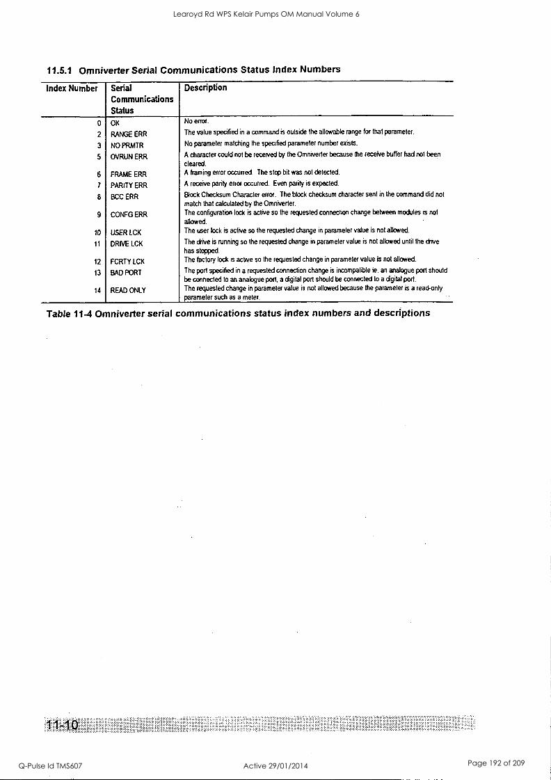
11.5.1 Omniverter Serial Communications Status Index Numbers
Index Number Serial Communications Status
0 OK
2 RANGE ERR
3 NO PRMTR
5 OVRUN ERR
6 FRAME ERR
7 PARITY ERR
8 BCC ERR
9 CONFG ERR
10 USER LCK
11 DRIVE LCK
12 FCRTY LCK
13 BAD PORT
14 READ ONLY
Description
No error.
The value specified in a command is outside the allowable range for that parameter.
No parameter matching the specified parameter number exists.
A character could not be received by the Omniverter because the receive buffer had not been
cleared.
A framing error occurred. The stop bit was not detected.
A receive parity error occurred. Even parity is expected.
Block Checksum Character error. The block checksum character sent in the command did not
match that calculated by the Omniverter.
The configuration lock is active so the requested connection change between modules is not
allowed.
The user lock is active so the requested change in parameter value is not allowed.
The drive is running so the requested change in parameter value is not allowed until the drive
has stopped.
The factory lock is active so the requested change in parameter value is not allowed.
The port specified in a requested connection change is incompatible ie. an analogue port should
be connected to an analogue port, a digital port should be connected to a digital port.
The requested change in parameter value is not allowed because the parameter is a read-only
parameter such as a meter.
Table 11-4 Omniverter serial communications status index numbers and descriptions
Learoyd Rd WPS Kelair Pumps OM Manual Volume 6
Q-Pulse Id TMS607 Active 29/01/2014 Page 192 of 209
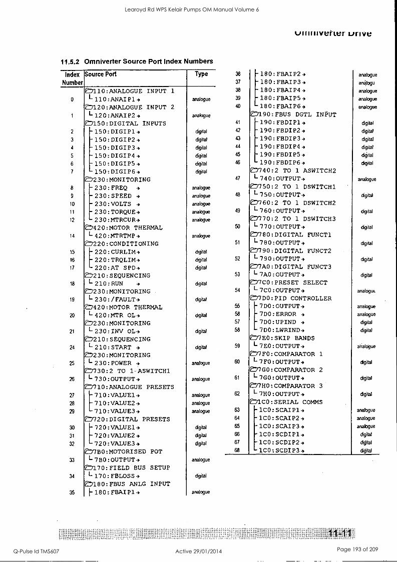
11.5.2 Omniverter Source Port Index Numbers
Index Number
Source Port Type
En110:ANALOGUE INPUT 1
0 L110:ANAIP14 analogue
7120:ANALOGUE INPUT 2
1 I-120:ANAIP24 analogue
En150:DIGITAL INPUTS 2 -150:DIGIP14 digital
3 -150:DIGIP24 digital
4 -150:DIGIP34 digital
5 -150:DIGIP44 digital
6 -150:DIGIP54 digital
7 -150:DIGIP64 digital
En230:MONITORING 8 -230:FREQ 4 analogue
9 -230:SPEED 4 analogue
10 -230:VOLTS 4 analogue
11 -230:TORQUE4 analogue
12 -230:MTRCUR4 analogue
:7420:MOTOR THERMAL 14 I-420:MTRTMP4 analogue
E7220:CONDITIONING 15 220:CURLIM4 digital
16 220:TRQLIM4 digital
17 220:AT SPD4 digital
En210:SEQUENCING 18 L210:RUN 4
n230:MONITORING digital
19 I-230:/FAULT4 digital
En420:MOTOR THERMAL 4 I-420:MTR OL4 digital
7230:MONITORING 21 L230:INV OL4 digital
8210: SEQUENCING 24 L210:START 4 digital
En230:MONITORING 25 L-230:POWER 4 analogue
:7730:2 TO 1 ASWITCH1 4 L730:OUTPUT4 analogue
E7710:ANALOGUE PRESETS 27 710:VALUE14 analogue
28 710:VALUE24 analogue
29 710:VALUE34 analogue
1720:DIGITAL PRESETS 30 720:VALUE14 digital
31 720:VALUE24 digital
32 720:VALUE34 digital
ED/BO:MOTORISED POT 33 L7BO:OUTPUT4 analogue
7170:FIELD BUS SETUP 34 I-170:FBLOSS4 digital
1180:FBUS ANLG INPUT I-180:FBAIP14 analogue
36
37
38
40
ulmilveiter unve
-180:FBAIP24 -180:FBAIP34 180:FBAIP44 180:FBAIP54 180:FBAIP64
En190:FBUS DGTL INPUT
analogue
an4logu
analogue
analogue
analogue
41 -190:FBDIP14 digital
42 -190:FBDIP24 digital
43 190:FBDIP34 digital
44 -190:FBDIP44 digital
45 -190:FBDIP54 digital
46 -190:FBDIP64 digital
E1740:2 TO 1 ASWITCH2 47 1-740:OUTPUT4 analogue
E7750:2 TO 1 DSWITCH1 48 1-750:OUTPUT4 digital
En760:2 TO 1 DSWITCH2 49 L760:OUTPUT4 digital
E7770:2 TO 1 DSWITCH3 50 L770:OUTPUT4 digital
En780:DIGITAL FUNCT1 51 L780:OUTPUT4 digital
En790:DIGITAL FUNCT2 52 1-790:OUTPUT4 digital
En/AO:DIGITAL FUNCT3 53 1-7AO:OUTPUT4 digital
En7C0 :PRESET SELECT 54 L7CO:OUTPUT4 analogue
L77DO:PID CONTROLLER 55 7DO:OUTPUT4 analogue
56 7D0: ERROR 4 analogue
57 7D0:UPIND 4 digital
58 7D0 :LWRIND4 digital
O77E0:SKIP BANDS 59 L7E0:OUTPUT4 analogue
En7FO:COMPARATOR 1
60 L7FO:OUTPUT4 digital
E77GO:COMPARATOR 2
61 L7GO:OUTPUT4 digital
77HO:COMPARATOR 3 62 L7HO:OUTPUT4 digital
71CO:SERIAL COMMS 63 -1CO:SCAIP14 analogue
64 -1CO:SCAIP24 analogue
65 -1CO:SCAIP34 analogue
66 -1CO:SCDIP14 digital
67 -1CO:SCDIP24 digital
1C0 :SCDIP34 digital
Learoyd Rd WPS Kelair Pumps OM Manual Volume 6
Q-Pulse Id TMS607 Active 29/01/2014 Page 193 of 209
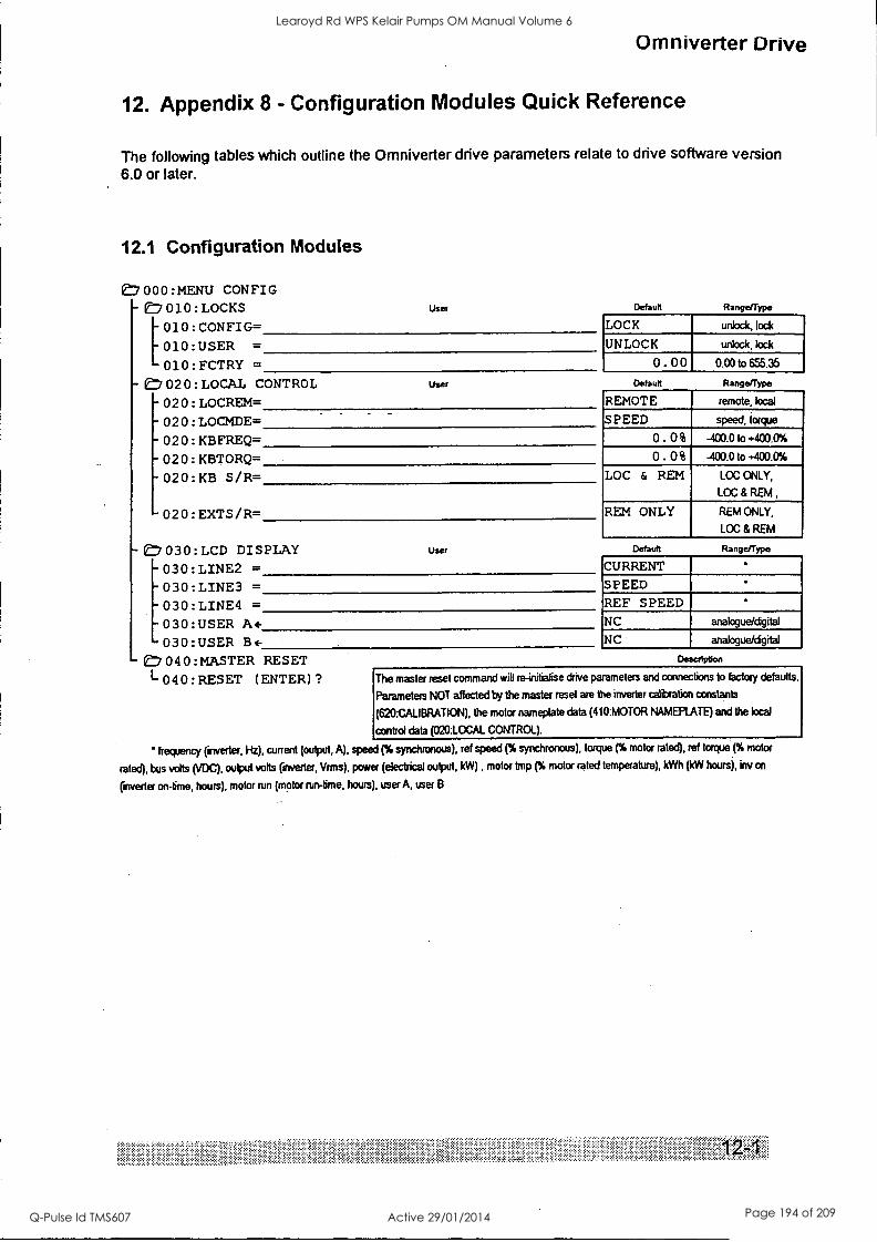
Omniverter Drive
12. Appendix 8 - Configuration Modules Quick Reference
The following tables which outline the Omniverter drive parameters relate to drive software version 6.0 or later.
12.1 Configuration Modules
if:7 000 :MENU CONFIG - 010 :LOCKS
[010 : CONFIG= 010 :USER =
010 : FCTRY =
- 0=7 02 0 : LOCAL CONTROL
- 02 0 : LOCREM=
- 02 0 : LOCMDE=
02 0 : KBFFtEQ=
02 0 : KBTORQ=
020:KB S/R=
-020:EXTS/R=
User Default Range/Type
LOCK unlock, lock
UNLOCK unlock, lock
0.00 User
- 030: LCD DISPLAY - 030 : LINE2 =
- 030 :LINE3 = - 030 :LINE4 =
User
- 030:USER A+ - 030 :USER B+
0 4 0 : MASTER RESET
I- 040 : FtESET (ENTER) ?
Default
0.0010 655.35
Range/Type
REMOTE remote, local
SPEED speed, torque
0. 0% -400.0 to *400.0%
0. 0% -400.0 to +400.0%
LOC & REM LOC ONLY,
LOC & REM ,
REM ONLY REM ONLY,
LOC & REM
Default Range/Type
CURRENT
SPEED REF SPEED NC analogue/digital
NC analogue/cigital
Description
The master reset command will re-initialise drive parameters and connections to factory defaults.
Parameters NOT affected by the master reset are the inverter calibration constants
(620:CALIBRATION), the motor nameplate data (410:MOTOR NAMEPLATE) and the local
control data (020:LOCAL CONTROL).
' frequency (inverter, Hz), current (output, A), speed (% synchronous), ref speed (% synchronous), torque (% motor rated), ref torque (% motor
rated), bus volts (VDC), output volts (inverter, Vrrns), power (electrical output, kW) , motor amp (% motor rated temperature), kWh (kW hours), kw on
(inverter on-time, hours), motor run (motor run-time, hours), user A, user B
Learoyd Rd WPS Kelair Pumps OM Manual Volume 6
Q-Pulse Id TMS607 Active 29/01/2014 Page 194 of 209
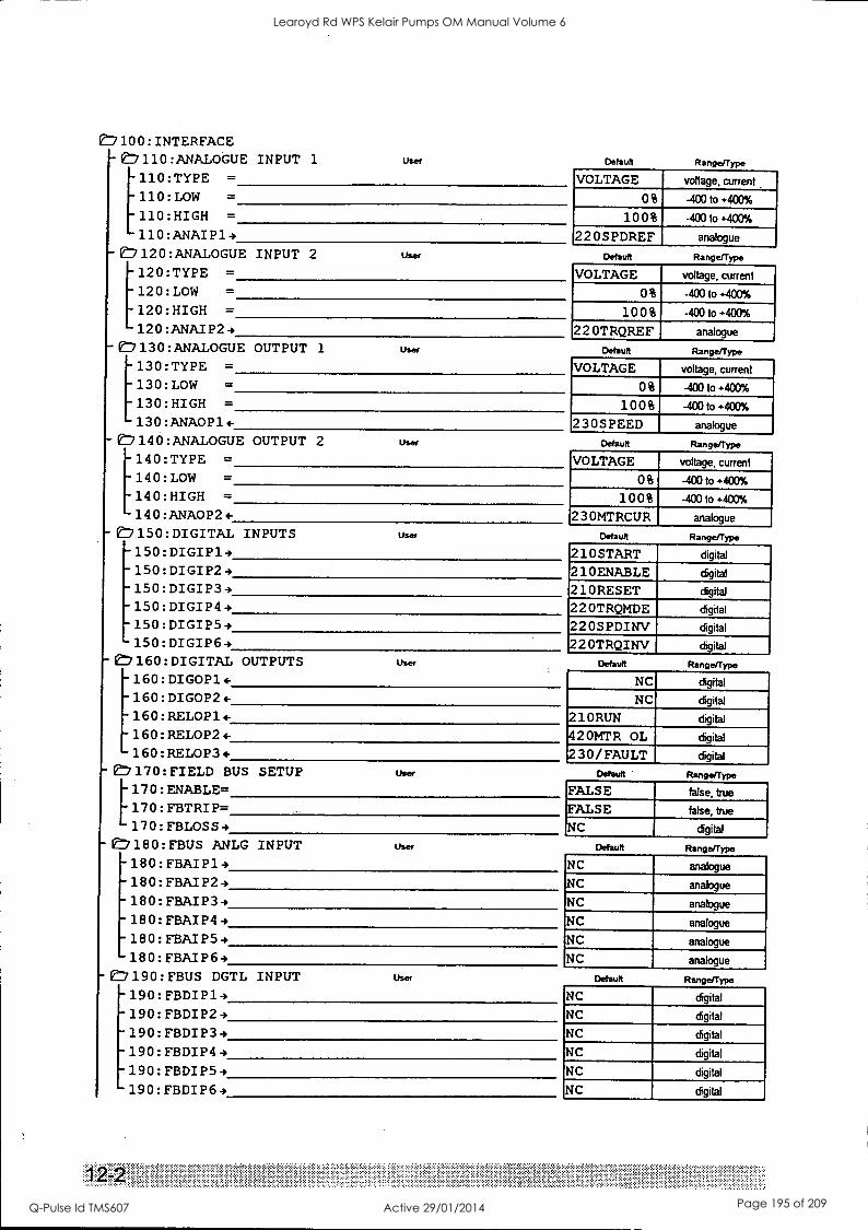
C1100: INTERFACE - 0:7110 :ANALOGUE INPUT 1 user
110: TYPE =
110:LOW =
110:HIGH =
110 : ANAI P14
-(7 120 :ANALOGUE INPUT 2 user
120:TYPE = 120: LOW = 120:HIGH = 120 : MAI P24
- E, 130 :ANALOGUE OUTPUT 1 User
= [130:TYPE 130:LOW = 130:HIGH = 130 : ANAOP1-
- e:7140 : ANALOGUE OUTPUT 2 user
[140:TYPE =
140:LOW =
140:HIGH =
140 : ANA0P24-
- 17150: DIGITAL INPUTS User
-150:DIGIP13 -150:DIGIP29 -150: DIGIP34 - 150:DIGIP44 -150:DIGIP54 150:DIGIP6 -,
- 1:1160: DIGITAL OUTPUTS user
- 160: DIGOP1 . - 160: DIGOP2 t- - 160: FtELOP1 +
- 160: RELOP24-
160: RELOP34 - 17170: FIELD BUS SETUP User
[170: ENABLE= 170: FBTRIP= 170: FBLOSS 4
- e:7180: FBUS ANLG INPUT User
- 180: FBAI P14 - 180: FBAI P24
-180:FBAIP34 - 180: FBAIP44 -180: FBAI P54 - 180: FBAIP64
- ef:/ 190: FBUS DGTL INPUT User
-190: FBDI P19 - 190: FBDIP24 - 190: FBDI P34 - 190: FBDIP44 -190: FBDIP59 190: FBDIP64
Default Range/Type
VOLTAGE voltage, current
0% -40010+400%
100% -40010+400%
220S PDREF analogue
Default Range/Type
VOLTAGE voltage, current
0% -40010+400%
100% -400 to +400%
22 OTRQREF analogue
Default Range/Type
VOLTAGE voltage, current
0% -40010+400%
100% -40010+400%
230S PEED analogue
Default RangefType
VOLTAGE voltage, current
0% -40010+400%
100% -40010+400%
23 OMTRCUR analogue
Default Range/Type
210START digital
210ENABLE digital
210RESET digital
22 OTRQMDE digital
220S PDINV digital
22 OTRQINV digital
Default Range/Type
NC digital
NC digital
210RUN digital
420MTR OL digital
230/FAULT digital
Default Range/Type
FALSE false, true
FALSE false, true
NC digital
Default Range/Type
NC analogue
NC analogue
NC analogue
NC analogue
NC analogue
NC analogue
Default RangefType
NC digital
NC digital
NC digital
NC digital
NC digital
NC digital
Learoyd Rd WPS Kelair Pumps OM Manual Volume 6
Q-Pulse Id TMS607 Active 29/01/2014 Page 195 of 209
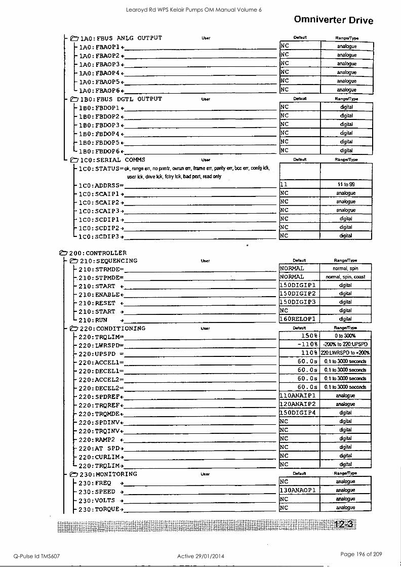
- E:71A0 : FBUS ANLG OUTPUT user
1AO: FBA0P1 1A0: FBA0P2 (-
1A0: FBAO P3 +
-'AO: FBA0P4 +
- 1A0 : FI3A0P5 +
- 1A0 : FBAOP 6 +
- E,1BO : FBUS DGTL OUTPUT user
-1BO: FBDOP1
- 1130: FBDOP2
- 1B0 : FBDOP3+ - 1B0 : FBDOP4 +
- 1B0 : FBDOP5 +
1B0 : FBDOP6+ 1C0: SERIAL COMMS User
1C0 : STATUS= ok, range err, no prmtr, ovrun err, frame err, parity err, bcc err, confg Ick,
user Ick, drive Ick, fctry Ick, bad port, read only
1CO:ADDRSS= - 1CO: SCAIP14
1CO: SCAI P24 -1CO:SCAIP34 -1CO:SCDIP19 -1C0:SCDIP2 -1CO:SCDIP39
1E77200 : CONTROLLER - 210: SEQUENCING
- 210: STRMDE=
-.210: STPMDE=
User
- 210: START +
-210: ENABLE+ ^ 210: RESET
- 210: START
210:RUN 4
220: CONDITIONING - 220: TRQLIM= - 220: LWRSPD=
220:UPSPD = - 220 : ACCEL1=
220: DECEL1= 220 : ACCEL2= 220: DECEL2=
- 220: SPDREF+
- 220: TRQREF+
- 220: TRQMDE+
- 220: SPDINV+ - 220: TRQINV+ - 220: RAMP2 4-
- 22 0 :AT SPD4
- 220: CURLIM9
User
220:TRQLIM3 -E7Y230:MONITORING
[230:FREQ 9
230:SPEED 4
230:VOLTS 4
230:TORQUE4
User
Omniverter Drive
Default
NC
Range/Type
analogue
NC analogue
NC analogue
NC analogue
NC analogue
NC analogue
Default Ran
NC digital
NC digital
NC digital
NC digital
NC digital
NC digital
Default Range/Type
11 11to99
NC analogue
NC analogue
NC analogue
NC digital
NC digital
NC digital
Default Range/Type
NORMAL normal, spin
NORMAL normal, spin, coast
150DIGIP1 digital
150DIGIP2 digital
150DIGIP3 digital
NC digital
160RELOP1 digital
Default Range/Type
150% 0 to 300%
-110% -200% to 220:UPSP0
110% 220:LWRSPD to 200%
60 . Os 0.1 to 3000 seconds
60. Os 0.1 to 3000 seconds
60 . Os 0.1 to 3000 seconds
60 . Os 0.1 to 3000 seconds
110ANAI P1 analogue
12 OANAI P2 analogue
150DIGIP4 digital
NC digital
NC digital
NC digital
NC digital
N C digital
NC digital
Default Range/Type
NC analogue
13 OANAOP 1 analogue
NC analogue
NC analogue
Learoyd Rd WPS Kelair Pumps OM Manual Volume 6
Q-Pulse Id TMS607 Active 29/01/2014 Page 196 of 209
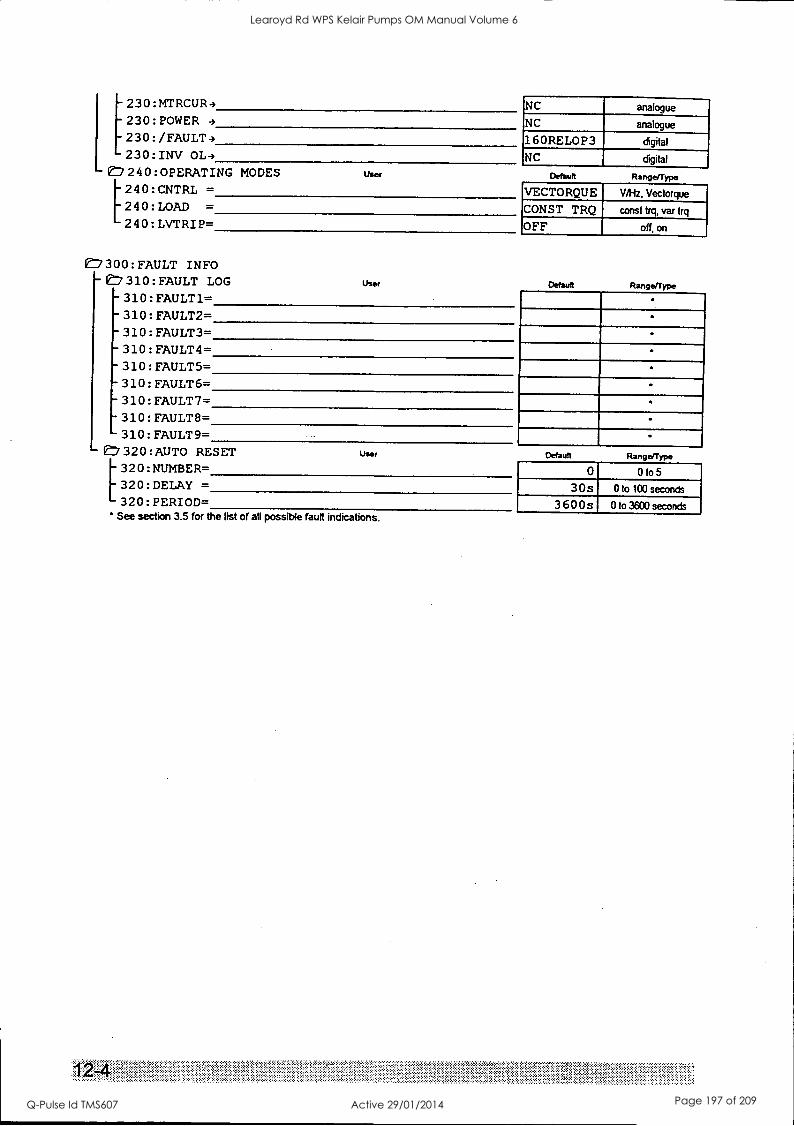
230:MTRCUR4 230:POWER 4
230:/FAULT4 230:INV OL4
e7 240 :OPERATING MODES User
240: CNTRL = 240: LOAD =
240: LVTRI P=
NC analogue
NC analogue
160RELOP3 digital
N C digital
Default RangefType
VECTORQUE Vil-tz, Vectorque
CONST TRQ const trq, var trq
OFF off, on
300
- E, : FAULT INFO 310: FAULT LOG User
- 310: FAULT1= Default RangelType
- 310: FAULT2= - 310 : FAULT3= - 310: FAULT4= -310: FAULTS= - 310: FAULT6= - 310: FAULT7= - 310: FAULT 8= 310: FAULT9=
e:7320 :AUTO R
[320:NUMBER= 320:DELAY =
320:PERIOD=
User Default Range/Type
O 0 to5
30s 0 to 100 seconds
3600s 0 to 3600 seconds * See section 3.5 for the list of all possible fault indications.
Learoyd Rd WPS Kelair Pumps OM Manual Volume 6
Q-Pulse Id TMS607 Active 29/01/2014 Page 197 of 209
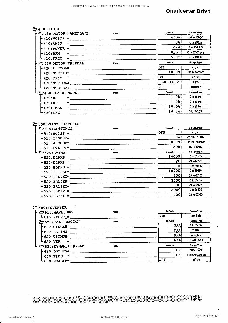
(7 400 :MOTOR -k7 410 : MOTOR NAMEPLATE
410:VOLTS =
410:AMPS =
410: POWER =
410:RPM =
410 : FREQ =
-V7 420 :MOTOR THERMAL 420 : F COOL=
420 : STRTIM=
420: TRIP =
420:MTR 0L4
420 :MTRTMP +
-(:1 430 :MOTOR MODEL
User
Omniverter Drive
Default Range/Type
400V 50 to 1000V
OA 0 to 2000A
0 kW 0 to 1000kIN - Orpm 0 to 65535nom
5 0Hz _
OW 1C0Hz
= [430:RS
930: RR =
430 : IMAG =
430 : LKG =
User
User
Default Range/Type
OFF off, on
10. 0 s 0 to 60seconds
ON off, on
16 ORELOP2 digital
NC analogue
Default Range/Type
1.0% Ow100%
1.0% OW100%
50.0% _
OW500%
16.7% Oto150.0%
e7500:VECTOR CONTROL e7 510 : SETTINGS
510 :HOIST =
510: IBOOST= 510 : J COMP=
510 : EWK PT=
Vf:7 52 0 : GAINS
- 52 0 : WLPKP = - 520 :WLPKI =
- 520 :WLPKD =
- 520 : PHLPKP= - 520 : PHLPKI= - 520 : FRLPKP= - 520 : FFtLPKI=
- 520 : ILPKP =
- 520 : ILPKI =
User Default Range/Type
OFF off, on
0 % -250 to +250%
0 . Os 0 to 100 seconds
120% 80 to 150%
User Default Range/Type
16000 0 to 65535
20 2010 65535
0 0 to 65535
10000 0 to 65535
400 20 to 65535
3000 0 to 65535
800 20 to 65535
2000 0 to 65535
400 20 to 65535
e7600:INVERTER -e7610:WAVEFORM L610:SWFREQ=
User
-7 620:CALIBRATION [620:CTSCLE= 620:RATING= 620:TSTMDE= 620:VER =
e7630:DYNAMIC [630:DBDUTY= 630:TIME =
630:ENABLE=
User
Default Range/Type
LOW low, high
Default Range/Type
N/A 0 to 65535
N/A 2000A
N/A false, true
N/A READ ONLY
BRAKE User Default Range/Type
10% 1010100%
10 s 1 to 500 seconds
OFF off, on
Learoyd Rd WPS Kelair Pumps OM Manual Volume 6
Q-Pulse Id TMS607 Active 29/01/2014 Page 198 of 209
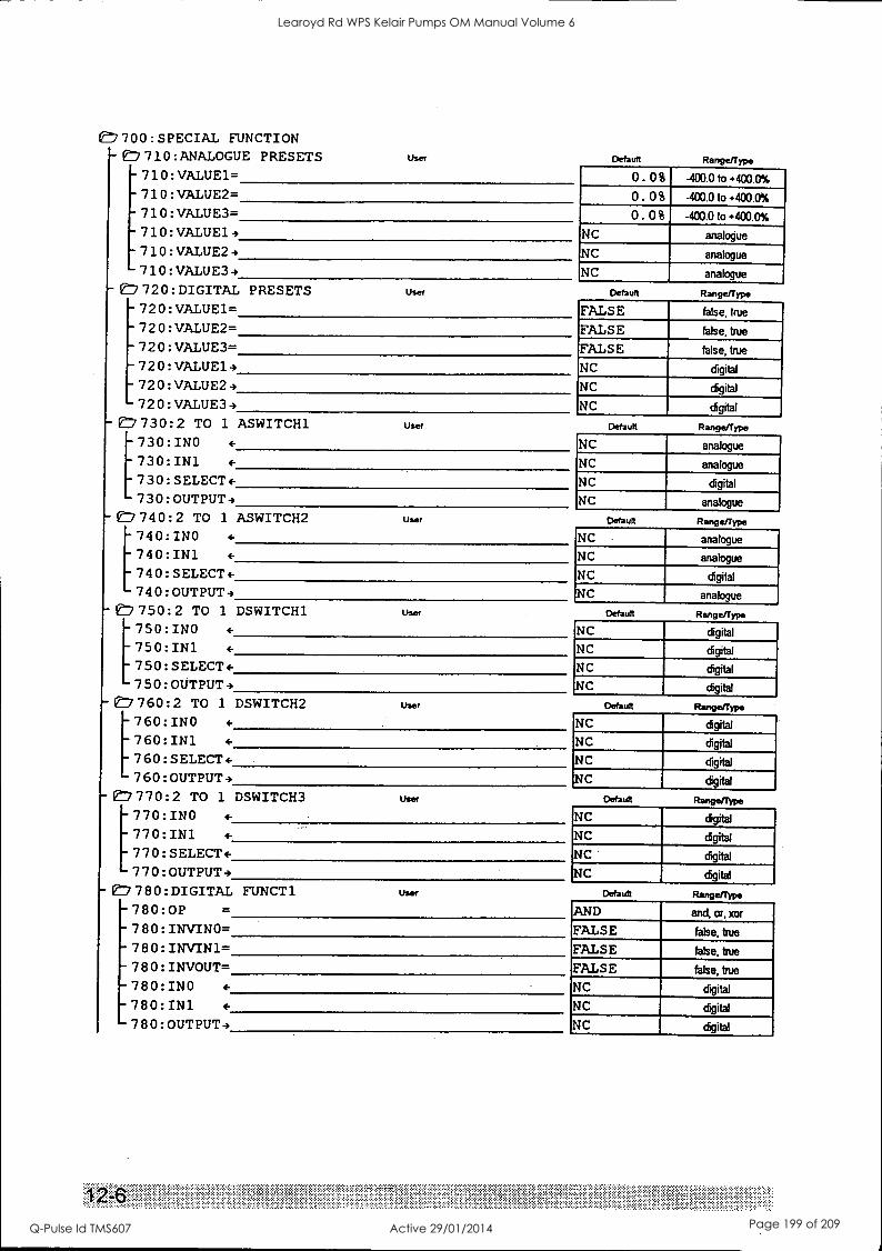
1E7 700 : SPECIAL FUNCTION 710: ANALOGUE PRESETS
- 710 :VALUE1= - 710 : VALUE2=
User
- 710 : VALUE3=
-710:VALUE1-, - 710 : VALUE2 4 - 710 : VALUE3 4
- 1E7 72 0 : DIGITAL PRESETS - 720: VALUE1= - 72 0 : VALUE2= - 72 0 : VALUE3= - 72 0 :VALUE14 -7 20 : VALUE2 4 - 72 0 : VALUE3 4
- 1E, 730:2 TO 1 ASWITCH1 [730: INO 4-
730:IN1 +
7 30 : SELECT + 7 30 : OUTPUT 4
- e7/ 7 4 0 : 2 TO 1 ASWITCH2 [740:INO +
740:IN1 +
7 4 0 : SELECT + 7 4 0 : OUTPUT 4
- er7 750 : 2 TO 1 DSWITCH1 [750:INO +
750: IN1 +
750:SELECT+ 750 : OUTPUT
- 1 7 60 : 2 TO 1 DSWITCH2 [760: INO +
760:1N1 +
7 60 : SELECT + 7 60 : OUTPUT -,
-17 7 7 0 : 2 TO 1 DSWITCH3 [770:INO +
770:IN1 +
7 7 0 : SELECT + 77 0 : OUTPUT 4
- 1 7 8 0 : DIGITAL FUNCT 1
-780:0P =
-7 8 0 : INVINO= -7 8 0 : INVIN1= -7 80 : INVOUT= - 780:INO +
- 780:IN1 +
-7 8 0 : OUTPUT 4
User
User
Default Range/Type
0. 0% -400.0 to +400.0%
0. 0% -400.0 to +400.0%
0. 0% -400.0 to +400,0%
NC analogue
NC analogue
NC analogue
Default Range /type
FALSE false, true
FALSE false, true
FALSE false, true
NC digital
NC digital
NC digital
Default Range/Type
NC analogue
NC analogue
NC digital
NC analogue
User Default Range/Type
NC analogue
NC analogue
NC digital
NC analogue
User Default Range/Type
NC digital
NC digital
NC digital
NC digital
User Default
NC digital
NC digital
NC digital
NC digital
User Default
User
Rangerrype
NC digital
NC digital
NC digital
NC digital
Default Range/Type
AND and, or, xor
FALSE false, true
FALSE false, true
FALSE false, true
NC digital
NC digital
NC digital
Learoyd Rd WPS Kelair Pumps OM Manual Volume 6
Q-Pulse Id TMS607 Active 29/01/2014 Page 199 of 209
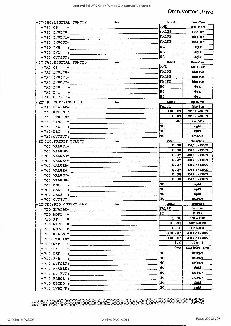
t7 7 90 : DIGITAL FUNCT2
-790:0P = - 790 : INVINO= -7 90 : INV1N1=
- 790 : INVOUT=
- 790: INO 4-
- 790: IN1 - 790:OUTPUT-)
- On' 7A0 : DIGITAL FUNCT3
- 7A0: OP =
- 7A0 : INVINO= - 7A0 : INVIN1=
7A0 : INVOUT= - 7A0 : INO 4-
- 7A0 : IN1
Omniverter Drive
User Default
User
- 7A0 : OUTPUT -)
- 7 B 0 :MOTOR' S ED POT
-7 BO : ENABLE=
- 7B0 : UPLIM = -7 BO : LWRLIM=
- 7B0 : TIME = - 7B0 : INC 4-
- 7B0 : DEC 4-
User
- 7B0 : OUTPUT-, - gf:i 7 CO : PRESET SELECT
- 7C0 : VALUE1= - 7C0 : VALUE2= - 7C0 : VALUE3= - 7C0 : VALUE4= -7 C 0 : VALUES= -7 C 0 : VALUES= - 7C0 : VALUE7= - 7C0 : VALUE8= - 7C0 : SELO 4-
- 7C0 :SEL1 4-
7C0 : SEL2 4-
-7 CO : OUTPUT
User
-E77DO:PID CONTROLLER
-7DO:ENABLE= - 7DO:MODE =
-7DO:KP =
- 7DO:WITS =
-7DO:WDTS =
-7DO:UPLIM =
-7DO:LWRLIM= -7DO:KSP =
-7DO:TS -7DO:REF 4-
-7DO:F/B 4-
-7DO:OFFSET4- -7DO:ENABLE4- -7DO:OUTPUT4 - 7DO:ERROR 4
-7DO:UPIND 4
-7DO:LWRIND-)
User
Range/Type
AND and, or, xor
FALSE false, true
FALSE false, true
FALSE false, true
NC digital
NC digital
NC . digital
Default Range/Type
AND and, or, xor
FALSE false, true
FALSE false, true
FALSE false, true
NC digital
NC digital
NC digital
Default Range/Type
FALSE false, true
100 . 0% -400.0 to +403.0%
0. 0 % -400.0 to +400.0%
6 0 s 1 to 3000s
NC digital
NC digital
NC analogue
Default Range/Type
0. 0% -400.0 to +400.0%
0. 0 % -403.0 to +400.0%
0. 0% -400.0 to +400.0%
0. 0% -400.0 to +400.0%
0. 0% -400.0104400.0%
0. 0% -400.0 to +400.0%
0. 0% -400.0 to +400.0%
0. 0% -400.0 to +400.0%
NC digital
NC digital
NC digital
NC analogue
Default Range/Type
FALSE false, true
PI PI, PID
1. 0 0 0.00 to 16.00
0. 001 0.001 to 0.1C0
0.10 0.01 to 0.10
4 0 0. 0 % -400.0 to +400.0%
-4 0 0. 0 % -400.0 to +400.0%
1. 0 0.0 to 1.0
10ms 10ms,100ms,1s,10s
NC analogue
NC analogue
NC analogue
NC digital
NC analogue
NC analogue
NC digital
NC digital
Learoyd Rd WPS Kelair Pumps OM Manual Volume 6
Q-Pulse Id TMS607 Active 29/01/2014 Page 200 of 209
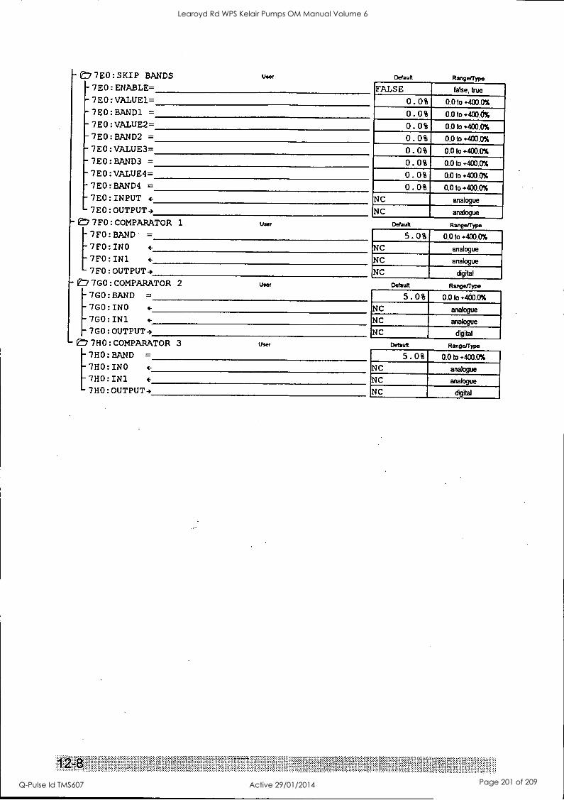
-C77E0:SKIP BANDS -7E0:ENABLE=
User
- 7E0:VALUE1=
-7E0:BAND1 =
-7E0:VALUE2= -7E0:BAND2 = -7E0:VALUE3=
7E0:BAND3 = 7E0:VALUE4= 7E0:BAND4 = 7E0:INPUT 4.
7E0:OUTPUT+ -'7FO:COMPARATOR 1 User
7FO:BAND =
7FO:INO 4-
7FO:IN1 4-
7FO:OUTPUT+ -E:77GO:COMPARATOR 2
Default Range/Type
FALSE false, true
0.0% 0.O to
o.o% 0.0 to
o.o% 0.ft,..400.0%
o.o% 0.O to
o.o% 0.O to
o.o% 0.O to
o.o% 0.0 to
o.o% 0.0 to
NC analogue
NC analogue
Default Rmgerype
5. 0% 0.0 to +400.0%
NC analogue
NC analogue
NC digital
User Default
7GO:BAND = 7G0:INO 4-
7GO:IN1 4-
7GO:OUTPUT+ -77HO:COMPARATOR 3
[7HO:BAND =
7HO:INO 4.
7H0:IN1 4-
7HO:OUTPUT+
Range/Type
5.0% 0.Oto+400.0%
NC analogue
NC analogue
NC digital
User Default Range/T
5.0% 0.0 to +400.0%
NC analogue
NC analogue
NC digital
Learoyd Rd WPS Kelair Pumps OM Manual Volume 6
Q-Pulse Id TMS607 Active 29/01/2014 Page 201 of 209
Omniverter Drive
13. Appendix 9 - Bearing Filters - Protecting Motor Bearings
13.1 Review of problem Common mode voltages present in the output waveforms of all PWM ac drives pose some risk to motor bearings from unintentional flow of electrical current through the bearings (resulting in electrical discharge machining (EDM) of the bearings). Not all motors or installations are affected and it is not always possible to predict susceptibility, but risks do increase with larger size motors. Though three different mechanisms can be responsible, all risks can be minimised by appropriate methods, or the use of special common mode (bearing) fitters.
The most dangerous effect arises due to imperfect earthing of the motor, leading to non-zero motor frame to ground voltages with resultant possibility of ground current leakage via the bearings and motor shaft to the load (particularly when the load is earthed independently to the motor). While the coifed application of fully shielded cable (ie bonded to both the motor frame and drive motor earth points) will minimise frame-ground voltage, this becomes increasingly impractical with the large cables required for bigger drives.
If separate phase and earth cables must be run, additional protection should be provided to block possible bearing currents:
- insulate both motor bearings, or
- insulate the non-drive-end (nde) bearing and use an insulated coupling, or
- fit a Vectron Bearing Filter between drive and motor.
Other lesser effects (capacitive rotor charging and circulating currents) are also overcome by the above methods.
Note that the insulating methods can leave sufficient voltage across insulation boundaries to cause sparking if inadvertently shorted so these methods are not recommended for explosive atmospheres - use a fitter in such applications.
Vectron strongly recommend against the fitting of shaft earthing brushes as these have been shown to exacerbate problems in some cases (create a greater problem for bearings at the opposing end of the motor, or transfer the problem to load bearings).
Contact Vectron for papers giving a more in depth review of this Issue.
13.2 Vectron Bearing Filters Vectron has developed _a range of filters to protect motor bearings. The function of these is to eliminate the drive output common mode voltages which are responsible for bearing currents. Over 90% attenuation of common mode voltage is achieved.
Table 13-1 lists the bearing filters available. The filters are modular in design and sized to match the drive modules.
Note: The bearing filters are designed for use at 4kHz switching frequency or higher. The Omniverter must be set for high switching frequency and the reduced 4kHz current and temperature ratings of the Omniverters must therefore be observed.
Learoyd Rd WPS Kelair Pumps OM Manual Volume 6
Q-Pulse Id TMS607 Active 29/01/2014 Page 202 of 209
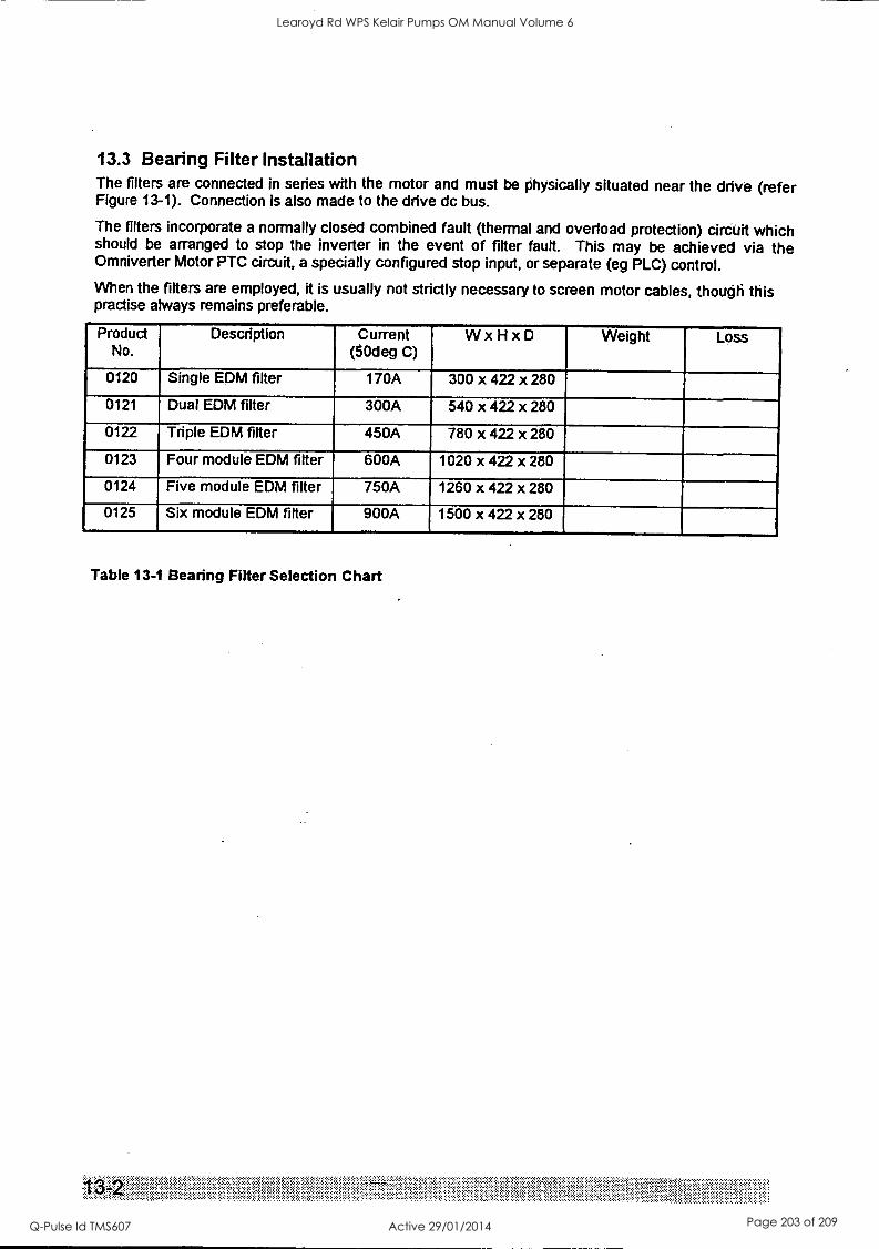
13.3 Bearing Filter Installation The filters are connected in series with the motor and must be physically situated near the drive (refer Figure 13-1). Connection is also made to the drive dc bus.
The filters incorporate a normally closed combined fault (thermal and overload protection) circuit which should be arranged to stop the inverter in the event of filter fault. This may be achieved via the Omniverter Motor PTC circuit, a specially configured stop input, or separate (eg PLC) control.
When the filters are employed, it is usually not strictly necessary to screen motor cables, though this practise always remains preferable.
Product No.
Description Current (50deg C)
W x H x D Weight Loss
0120 Single EDM filter 170A 300 x 422 x 280
0121 Dual EDM filter 300A 540 x 422 x 280
0122 Triple EDM filter 450A 780 x 422 x 280
0123 Four module EDM fitter 600A 1020 x 422 x 280
0124 Five module EDM filter 750A 1260 x 422 x 280
0125 Six module EDM filter 900A 1500 x 422 x 280
Table 13-1 Bearing Filter Selection Chart
s's
Learoyd Rd WPS Kelair Pumps OM Manual Volume 6
Q-Pulse Id TMS607 Active 29/01/2014 Page 203 of 209
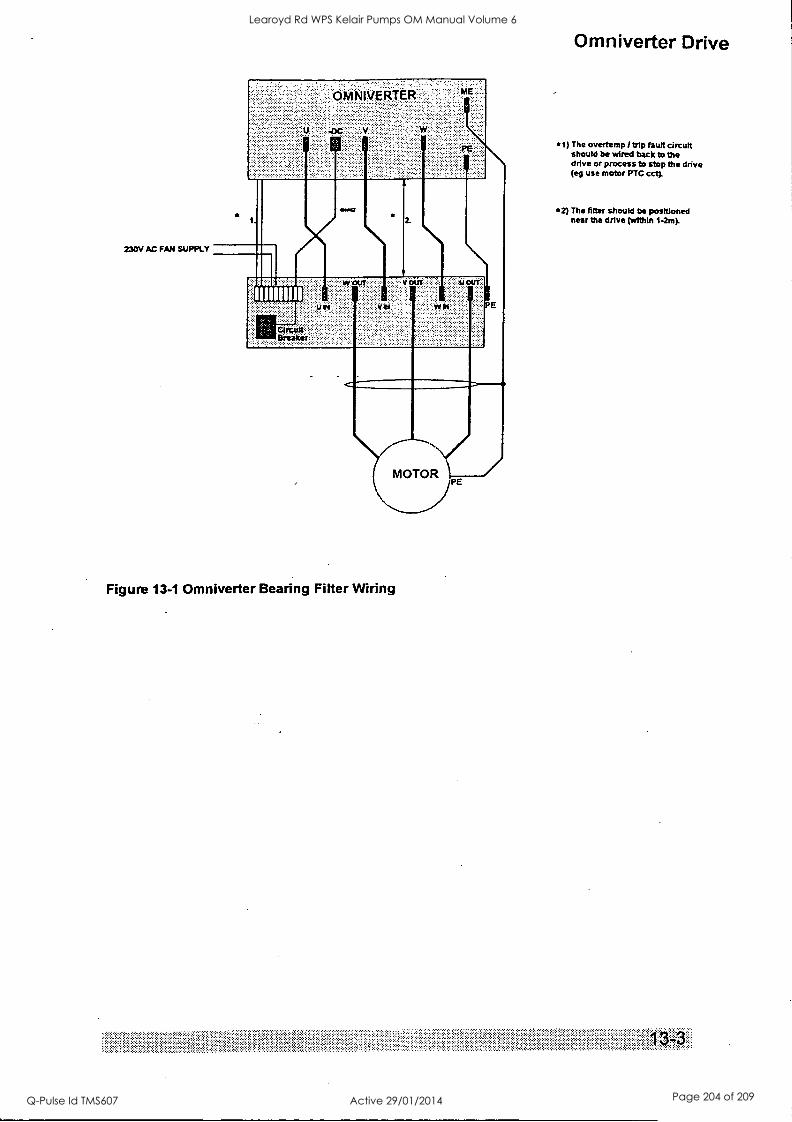
230V AC FAN SUPPLY
PE
E , 1111111111
.:. W OUT. ' .. V OUT :::' ir : OUT
W V W In
CitrOJN Breaker
E
MOTOR\( jPE
Figure 13-1 Omniverter Bearing Filter Wiring
Omniverter Drive
*1) The overtemp / trip fault circuit should be wired back to the drive or process to stop the drive (eg use motor PTC cct).
*2) The fitter should be positioned near the drive (within 1-2m).
Learoyd Rd WPS Kelair Pumps OM Manual Volume 6
Q-Pulse Id TMS607 Active 29/01/2014 Page 204 of 209
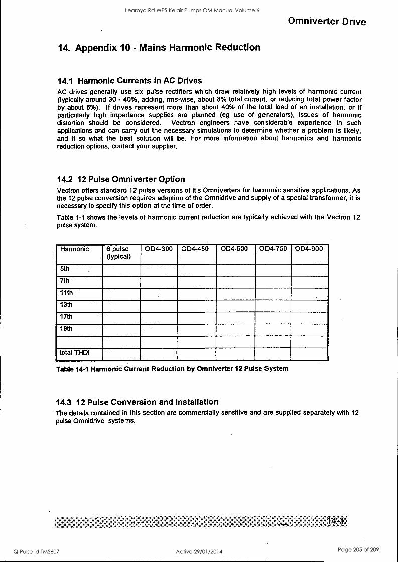
Omniverter Drive
14. Appendix 10 - Mains Harmonic Reduction
14.1 Harmonic Currents in AC Drives AC drives generally use six pulse rectifiers which draw relatively high levels of harmonic current (typically around 30 - 40%, adding, rrns-wise, about 8% total current, or reducing total power factor by about 8%). If drives represent more than about 40% of the total load of an installation, or if particularly high impedance supplies are planned (eg use of generators), issues of harmonic distortion should be considered. Vectron engineers have considerable experience in such applications and can carry out the necessary simulations to determine whether a problem is likely, and if so what the best solution will be. For more information about harmonics and harmonic reduction options, contact your supplier.
14.2 12 Pulse Omniverter Option Vectron offers standard 12 pulse versions of it's Omniverters for harmonic sensitive applications. As the 12 pulse conversion requires adaption of the Omnidrive and supply of a special transformer, it is necessary to specify this option at the time of order.
Table 1-1 shows the levels of harmonic current reduction are typically achieved with the Vectron 12 pulse system.
Harmonic 6 pulse (typical)
OD4-300 OD4-450 OD4-600 OD4-750 OD4-900
5th
7th
11th
13th
17th
19th
total THDi
Table 14-1 Harmonic Current Reduction by. Omniverter 12 Pulse System
14.3 12 Pulse Conversion and Installation The details contained in this section are commercially sensitive and are supplied separately with 12 pulse Omnidrive systems.
s.wenow.
Learoyd Rd WPS Kelair Pumps OM Manual Volume 6
Q-Pulse Id TMS607 Active 29/01/2014 Page 205 of 209
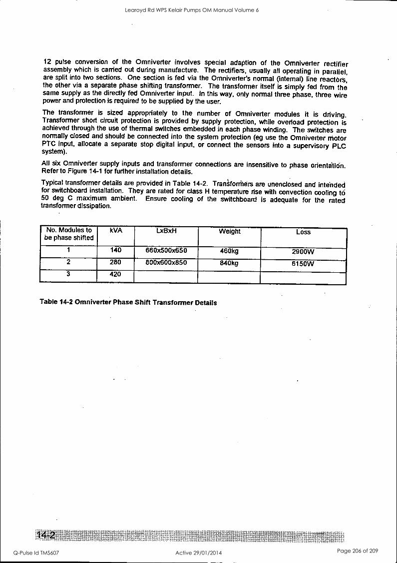
12 pulse conversion of the Omniverter involves special adaption of the Omniverter rectifier assembly which is carried out during manufacture. The rectifiers, usually all operating in parallel, are split into two sections. One section is fed via the Omniverter's normal (internal) line reactors, the other via a separate phase shifting transformer. The transformer itself is simply fed from the same supply as the directly fed Omniverter input. In this way, only normal three phase, three wire power and protection is required to be supplied by the user:
The transformer is sized appropriately to the number of Omniverter modules it is driving. Transformer short circuit protection is provided by supply protection, while overload protection is achieved through the use of thermal switches embedded in each phase winding. The switches are normally closed and should be connected into the system protection (eg use the Omniverter motor PTC Input, allocate a separate stop digital input, or connect the sensors into a supervisory PLC system).
All six Omniverter supply inputs and transformer connections are insensitive to phase orientation. Refer to Figure 14-1 for further installation details.
Typical transformer details are provided in Table 14-2. Traniforthers are unenclosed and intended for switchboard installation. They are rated for class H temperature rise with convection cooling to 50 deg C maximum ambient. Ensure cooling of the switchboard is adequate for the rated transformer dissipation.
No. Modules to be phase shifted
kVA LxBxH Weight Loss
1 140 660x500x650 460kg 2900W 2 280 800x600x850 840kg 6150W 3 420
Table 14-2 Omniverter Phase Shift Transformer Details
Learoyd Rd WPS Kelair Pumps OM Manual Volume 6
Q-Pulse Id TMS607 Active 29/01/2014 Page 206 of 209
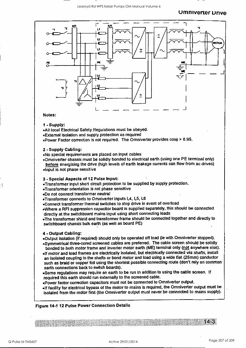
Omniverter unve
RA L1
L2
13
Notes:
001 ANA
.4
L J
1 - Supply: All local Electrical Safety Regulations must be obeyed. Extemal isolation and supply protection as required Power Factor correction is not required. The Omniverter provides cos+ > 0.95.
2 - Supply Cabling: No special requirements are placed on input cables Omniverter chassis must be solidly bonded to electrical earth (using one PE terminal only)
before energising the drive (high levels of earth leakage currents can flow from ac drives) Input is not phase sensitive
3 - Special Aspects of 12 Pulse Input: 'Transformer input short circuit protection to be supplied by supply protection. Transformer orientation is not phase sensitive Do not connect transformer neutral Transformer connects to Omniverter inputs L4, L5, L6
Connect transformer thermal switches to stop drive in event of overload Where a RFI suppression capacitor board is supplied separately, this should be connected
directly at the switchboard mains input using short connecting leads
The transformer shield and transformer frame should be connected together and directly to switchboard chassis bulk earth (as well as board PE)
4 - Output Cabling: Output isolation (if required) should only be operated off load (ie with Omniverter stopped).
Symmetrical three-cored screened cables are preferred. The cable screen should be solidly bonded to both motor frame and inverter motor earth (ME) terminal only not anywhere else).
If motor and load frames are electrically isolated, but electrically connected via shafts, install an isolated coupling in the shafts or bond motor and load using a wide flat (25mm) conductor such as braid or copper foil using the shortest possible connecting route (don't rely on common earth connections back to switch boards).
'Some regulations may require an earth to be run in addition to using the cable screen. If required this earth should run externally to the screened cable.
Power factor correction capacitors must not be connected to Omniverter output. If facility for electrical bypass of the motor to mains is required, the Omniverter output must be
isolated from the motor first (the Omniverter output must never be connected to mains supply).
Figure 14-1 12 Pulse Power Connection Details
Learoyd Rd WPS Kelair Pumps OM Manual Volume 6
Q-Pulse Id TMS607 Active 29/01/2014 Page 207 of 209

15. Index
airflow, 1-7 analogue
inputs, 4-3 outputs, 4-3
commissioning, 3-4 schedule, 6-2
control configuration, 2-4 quick reference, 11-1
control panel, 1-6 current
overload, 1-5 ratings, 1-5
default control configuration, 2-11 interface configuration, 2-9
destination ports explained, 2-5 how to use, 2-6 quick reference index, 5-1
digital inputs, 4-4 outputs, 4-4
dimensions, 1-7 Displacement Factor (COSO), 1-5 Distortion Factor, 1-5 dynamic brake, 1-4, 4-14 electrical installation
control cabling, 3-2 EMC, 3-2 power cabling, 3-2
fault auto reset, 4-9 displays, causes and solutions, 3-8 log, 4-9
field bus analogue inputs, 4-4 analogue outputs, 4-5 digital inputs, 4-5 digital outputs, 4-5 drive status codes, 10-2 drive type codes, 10-3 I/O map, 10-1 setup, 4-4 trip on loss of communication, 4-4
harmonic distortion, 1-3, 1-4 interruption ride through, 1-5, 4-8 inverter rating
at 40 degrees C, 1-3, 1-5, 1-6, 2-9 at 50 degrees C, 1-6, 2-9
keyboard. See LCD display LCD display, 2-2, 4-1
menu display line, 2-2 status line, 2-2 user selectable meters, 4-2
limits torque, speed, accel, decel, 4-7
Omniverter Drive
local/remote control, 4-2 locks, 4-1 mechanical installation
cooling, 3-1 mounting, 3-1
menu system, 2-3 navigation, 2-4 structure, 2-4
models available, 1-2, 1-7, 3-2 motor
derating, 2-12 parameters, 4-10 thermal model protection, 4-10
open collector outputs, 4-4 option
RS 485 serial interface, 1-6 options
4-quadrant regenerative unit, 1-4 harmonic reduction, 1-4
output frequency, 1-5 voltage, 1-5
parameters auto-calculate motor model, 4-10 explained, 2-5 fine-tuning motor model, 4-11 fine-tuning vector gains, 4-13 how to use, 2-6
power connection, 1-5 power factor, 1-4 protection, 1-3, 3-8
inverter, 1-6 motor, 1-6
reduced flux operation, 4-8 relay outputs, 4-4 reset
master, 4-2 module, 2-6
safety, 1- 4,3-3, 3-4 set points - references
torque, speed, 4-7 source ports
explained, 2-5 how to use, 2-8 quick reference index, 5-2
spares list, recommended, 8-1 special functions, 4-15
2 to 1 analogue switch (mux), 4-15 2 to 1 digital switch (mux), 4-16 digital functions(AND,OR,XOR), 4-16 motorised potentiometer, 4-16 presets, 4-15
Learoyd Rd WPS Kelair Pumps OM Manual Volume 6
Q-Pulse Id TMS607 Active 29/01/2014 Page 208 of 209

speed mode, 4-7 standards, 1-4 start and stop modes, 4-6 start/stop/reset, 4-6 switching frequency, 4-14 terminals
wiring, 2-9 torque mode, 4-2, 4-7 V/Hz Mode, 2-9
selected, 4-8
vector control sensorless. See Vectorque
Vectorque explained, 2-9 mode selected, 4-8 options and settings, 4-12
voltage input, 1-5 tolerance, 1-5
weight, 1-7
Learoyd Rd WPS Kelair Pumps OM Manual Volume 6
Q-Pulse Id TMS607 Active 29/01/2014 Page 209 of 209