laser printer phaser 3450 - printertec
TRANSCRIPT
SERVICE
LASER PRINTERPhaser 3450
Manual
LASER PRINTER CONTENTS
1. Precautions
2. Reference Information
3. Specifications
4. Summary of product
5. Disassembly and Reassembly
6. Alignment and Adjustments
7. Troubleshooting
8. Exploded Views and Parts List
9. Block Diagram
10. Connection Diagram
11. Circuit Description
11
1-1
Precautions
Service Manual
1. PrecautionsThe cautions in the below are items needed to keep in mind when maintaining and servicing.Please read carefully and keep the contents in mind to prevent accidents while servicing and preventany damages to the damage.
1.1 Warning for safety.
(1) Request the service by qualified service person.The service for this machine must be performed by a service person who took the additional education ofthis field. It is dangerous if unqualified service person or user tries to fix the machine.
(2) Do not rebuild it discretionary. Do not attach or change parts discretionary. Do not disassemble, fix, and rebuilt it. If you do, printer will notwork and electric shock or a fire can be occurred.
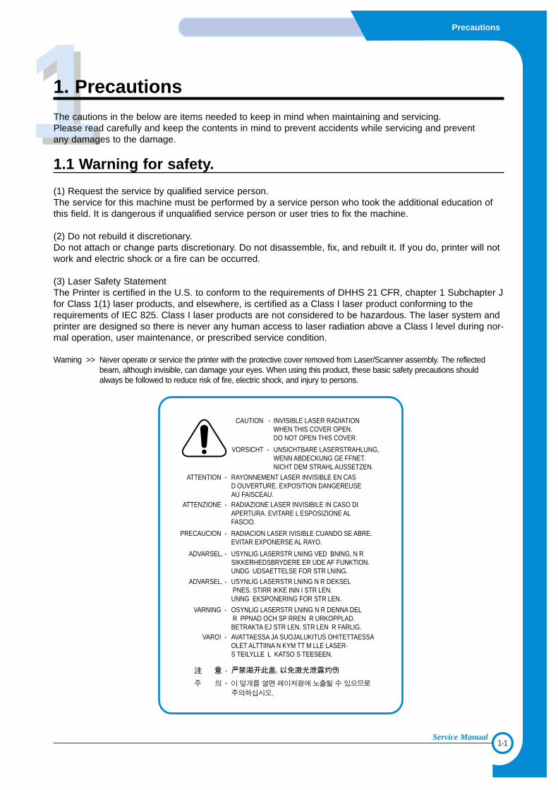
(3) Laser Safety StatementThe Printer is certified in the U.S. to conform to the requirements of DHHS 21 CFR, chapter 1 Subchapter Jfor Class 1(1) laser products, and elsewhere, is certified as a Class I laser product conforming to therequirements of IEC 825. Class I laser products are not considered to be hazardous. The laser system andprinter are designed so there is never any human access to laser radiation above a Class I level during nor-mal operation, user maintenance, or prescribed service condition.
Warning >> Never operate or service the printer with the protective cover removed from Laser/Scanner assembly. The reflectedbeam, although invisible, can damage your eyes. When using this product, these basic safety precautions shouldalways be followed to reduce risk of fire, electric shock, and injury to persons.
CAUTION - INVISIBLE LASER RADIATION WHEN THIS COVER OPEN. DO NOT OPEN THIS COVER.
VORSICHT - UNSICHTBARE LASERSTRAHLUNG, WENN ABDECKUNG GE FFNET. NICHT DEM STRAHL AUSSETZEN.
ATTENTION - RAYONNEMENT LASER INVISIBLE EN CAS D OUVERTURE. EXPOSITION DANGEREUSE AU FAISCEAU.
ATTENZIONE - RADIAZIONE LASER INVISIBILE IN CASO DI APERTURA. EVITARE L ESPOSIZIONE AL FASCIO.
PRECAUCION - RADIACION LASER IVISIBLE CUANDO SE ABRE. EVITAR EXPONERSE AL RAYO.
ADVARSEL. - USYNLIG LASERSTR LNING VED BNING, N R SIKKERHEDSBRYDERE ER UDE AF FUNKTION. UNDG UDSAETTELSE FOR STR LNING.
ADVARSEL. - USYNLIG LASERSTR LNING N R DEKSEL PNES. STIRR IKKE INN I STR LEN. UNNG EKSPONERING FOR STR LEN.
VARNING - OSYNLIG LASERSTR LNING N R DENNA DEL R PPNAD OCH SP RREN R URKOPPLAD. BETRAKTA EJ STR LEN. STR LEN R FARLIG.
VARO! - AVATTAESSA JA SUOJALUKITUS OHITETTAESSA OLET ALTTIINA N KYM TT M LLE LASER-S TEILYLLE L KATSO S TEESEEN.
1-2
Precautions
Service Manual
1.2 Caution for safety
1.2.1 Precaution related noxious material
There is a possibility to get harm from noxious material if you ignore the below information.
(1) Do not touch the damaged LCD. This PRINTER has LCD in control panel. Noxious liquid to human body exists in theLCD. If it gets into your mouth, immediately see a doctor. If it gets into eyes or on skin, immediately wash it off formore than 15 minutes with flowing water and see a doctor.
(2) The toner in a printer cartridge contains a chemical material, which might harm human body if it is swallowed.Please keep children out of the toner cartridge.
1.2.2 Precaution related electric shock or fire
It is possible to get electric shock or burn by fire if you don't fallow the instructions of the manual.
(1) Use exact voltage. Please do use an exact voltage and wall socket. If not, a fire or an electric leakage can becaused.
(2) Use authorized power cord. Do use the power cord supplied with PRINTER. A fire can occur when over currentflows in the power cord.
(3) Do not insert many cords in an outlet. If you do, a fire can be occurr due to flow over current over flow in an out-let.
(4) Do not put water or extraneous matter in the PRINTER. Please do not put water, other liquid, pin, clip, etc. It cancause a fire, electric shock, or malfunction. If it happens, turn off the power and remove the power plug from theoutlet immediately.
(5) Do not touch the power plug with wet hands. When servicing, do remove the power plug from outlet. And do notinsert or take off it with wet hands. Electric shock can be occur.
(6) Caution when inserting or taking off the power plug. The power plug has to be inserted completely. If not, a firecan be caused due to poor contact. When taking off the power plug, do grip the plug and take it off. If grip the lineand pull over, it could be damaged. This could cuase a fire or electric shock.
(7) Management of power cord. Do not bend, twist, or bind it and place other materials on it. Also, do not fix it withstaples. If the power cord gets damage, a fire or electric shock can be caused. A damaged power cord must bereplaced immediately. Do not repair the damaged part and reuse it. A repaired part with plastic tape can beoccurred a fire or electric shock. Do not spread chemicals on the power cord. Do not spread insecticide on thepower cord. A fire or electric shock can be occurred due to thinner(weak) cover of the power cord.
(8) Check whether the power outlet and the power plug are damaged, pressed, chopped, or on fire. When such poorconditions are found, repair it immediately. Avoid pressure or cut when moving the machine.
(9) Caution when thundering, and being flash of lightening. It causes a fire or electric shock. Take the power plug offwhen thundering. Do not touch cable and device when thundering and being flash of lightening.
(10) Avoid places where there is moisture or dust. Do not install the printer in a place where lots of dusts or humidi-fier are around. A fire can occur. A plug part needs to be cleaned well with dried fabric to remove dust. If waterdrops are dripped on the place cover with dust, a fire can occur.
(11) Avoid direct sunlight. Do not install the printer near to window where directly contacts to the sunlight. If themachine contacts sunlight long time, the machine cannot work properly because inner temperature of themachine is getting higher. A fire can be caused.
(12) Turn off the power and take off the plug when a smoke, strange smell, or sound from the machine. If you keepusing it, a fire can occur.
(13) Do not insert steel or metal piece inside/outside of the machine. Do not put steel or metal piece into a ventila-tor. An electric shock can happen.
1-3
Precautions
Service Manual
1.2.3 Precaution related handling the machine.
If you ignore this information, you get hurt and machine could be damaged.
(1) Do not install unit on uneven surfaces or slanted floors.
Please confirm that unit is correctly balanced after installation. Machine may fall over when itis not bal-
anced correctly.
(2) Be careful not to insert a finger or hair in the rotating unit.
Be careful not to insert a finger of hair in the rotating unit (motor, fan, paper feeding part, etc) while the
machine is operating. Once it happens, you could harm.
(3) Do not place any containers of water/chemical or small metals. If those are got into the inner side of
machine, a fire or electric shock can occur.
(4) Do not install machine in areas where moisture or dust exists. For example, do not install machine near
open windows, damage maybe caused by these conditions.
(5) Do not place a candle, burning cigarettes, and etc. on the machine. Do not install it near to a heater. A fire
can occur.
1.2.4 Precaution when assembly/disassembly
When replace parts, do it very carefully. Do memorize the location of each cable before replace parts forreconnecting it afterwards. Do memorize. Please perform the below before replace or disassemblying anyparts.
(1) Check the contents stored in the memory. All the information will be erased after replace main board. The
information needed to keep has to be written down.
(2) Remove printer cables and power cord.
(3) Take off printer cables and power code connected to printer.
(4) Do use formal parts and same standardized goods when replacing parts.Must check the product name,
part cord, rated voltage, rated current, operating temperature, etc.
(5) Do not give an over-force when release or tighten up the plastic parts.
(6) Be careful not to drop the small parts such as screws in the printer.
(7) Be careful not to change the location of small parts such as screws when assembling and disassembling.
(8) Do remove dust or foreign matters completely to prevent fire of tracking, short, or etc.
(9) After finished repair, check the assembled state whether it is the same as before the repair or not.
1-4
Precautions
Service Manual
1.3 ESD Precautions
Certain semiconductor devices can be easily damaged by static electricity. Such components are commonlycalled “Electrostatically Sensitive (ES) Devices”, or ESDs. Examples of typical ESDs are: integrated circuits,some field effect transistors, and semiconductor “chip” components.The techniques outlined below should be followed to help reduce the incidence of component damage causedby static electricity.
Caution >>Be sure no power is applied to the chassis or circuit, and observe all other safety precautions.
1. Immediately before handling a semiconductor component or semiconductor-equipped assembly, drain off
any electrostatic charge on your body by touching a known earth ground. Alternatively, employ a commer-
cially available wrist strap device, which should be removed for your personal safety reasons prior to apply-
ing power to the unit under test.
2. After removing an electrical assembly equipped with ESDs, place the assembly on a conductive surface,
such as aluminum or copper foil, or conductive foam, to prevent electrostatic charge buildup in the vicinity
of the assembly.
3. Use only a grounded tip soldering iron to solder or desolder ESDs.
4. Use only an “anti-static” solder removal device. Some solder removal devices not classified as “anti-static”
can generate electrical charges sufficient to damage ESDs.
5. Do not use Freon-propelled chemicals. When sprayed, these can generate electrical charges sufficient to
damage ESDs.
6. Do not remove a replacement ESD from its protective packaging until immediately before installing it. Most
replacement ESDs are packaged with all leads shorted together by conductive foam, aluminum foil, or a
comparable conductive material.
7. Immediately before removing the protective shorting material from the leads of a replacement ESD, touch
the protective material to the chassis or circuit assembly into which the device will be installed.
8. Maintain continuous electrical contact between the ESD and the assembly into which it will be installed,
until completely plugged or soldered into the circuit.
9. Minimize bodily motions when handling unpackaged replacement ESDs. Normal motions, such as the
brushing together of clothing fabric and lifting one’s foot from a carpeted floor, can generate static electric-
ity sufficient to damage an ESD.
22
2-1
Reference Information
Service Manual
2. Reference Information
This chapter describes the reference information for applying this training manual, and it is consist-ed of the tool list, the abbreviation table, the outline of model, and so on.
2.1 Tool for Troubleshooting
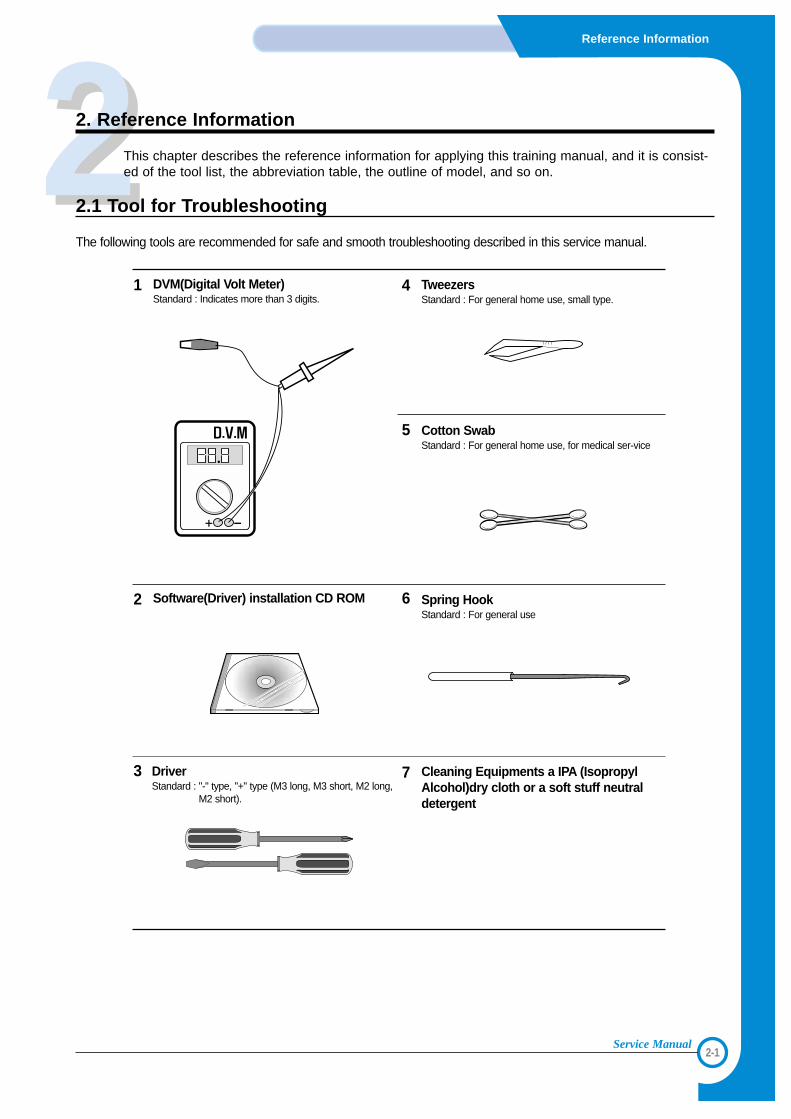
The following tools are recommended for safe and smooth troubleshooting described in this service manual.
DriverStandard : "-" type, "+" type (M3 long, M3 short, M2 long,
M2 short).
4
Cotton SwabStandard : For general home use, for medical ser-vice
6Software(Driver) installation CD ROM
3 Cleaning Equipments a IPA (IsopropylAlcohol)dry cloth or a soft stuff neutraldetergent
7
Spring HookStandard : For general use
TweezersStandard : For general home use, small type.
5
DVM(Digital Volt Meter)Standard : Indicates more than 3 digits.
1
2
2-2
Reference Information
Service Manual
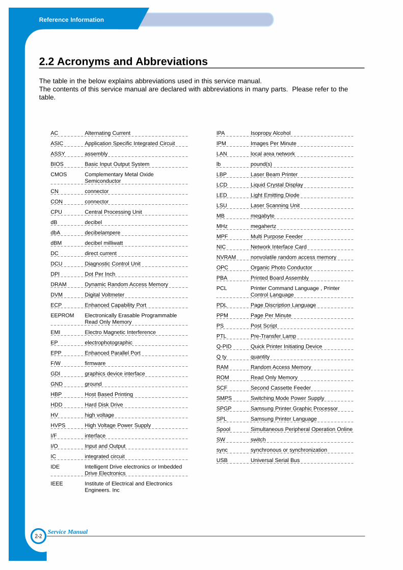
2.2 Acronyms and Abbreviations
The table in the below explains abbreviations used in this service manual.The contents of this service manual are declared with abbreviations in many parts. Please refer to thetable.
AC Alternating Current
ASIC Application Specific Integrated Circuit
ASSY assembly
BIOS Basic Input Output System
CMOS Complementary Metal OxideSemiconductor
CN connector
CON connector
CPU Central Processing Unit
dB decibel
dbA decibelampere
dBM decibel milliwatt
DC direct current
DCU Diagnostic Control Unit
DPI Dot Per Inch
DRAM Dynamic Random Access Memory
DVM Digital Voltmeter
ECP Enhanced Capability Port
EEPROM Electronically Erasable ProgrammableRead Only Memory
EMI Electro Magnetic Interference
EP electrophotographic
EPP Enhanced Parallel Port
F/W firmware
GDI graphics device interface
GND ground
HBP Host Based Printing
HDD Hard Disk Drive
HV high voltage
HVPS High Voltage Power Supply
I/F interface
I/O Input and Output
IC integrated circuit
IDE Intelligent Drive electronics or ImbeddedDrive Electronics
IEEE Institute of Electrical and ElectronicsEngineers. Inc
IPA Isopropy Alcohol
IPM Images Per Minute
LAN local area network
lb pound(s)
LBP Laser Beam Printer
LCD Liquid Crystal Display
LED Light Emitting Diode
LSU Laser Scanning Unit
MB megabyte
MHz megahertz
MPF Multi Purpose Feeder
NIC Network Interface Card
NVRAM nonvolatile random access memory
OPC Organic Photo Conductor
PBA Printed Board Assembly
PCL Printer Command Language , PrinterControl Language
PDL Page Discription Language
PPM Page Per Minute
PS Post Script
PTL Pre-Transfer Lamp
Q-PID Quick Printer Initiating Device
Q ty quantity
RAM Random Access Memory
ROM Read Only Memory
SCF Second Cassette Feeder
SMPS Switching Mode Power Supply
SPGP Samsung Printer Graphic Processor
SPL Samsung Printer Language
Spool Simultaneous Peripheral Operation Online
SW switch
sync synchronous or synchronization
USB Universal Serial Bus
2-3
Reference Information
Service Manual
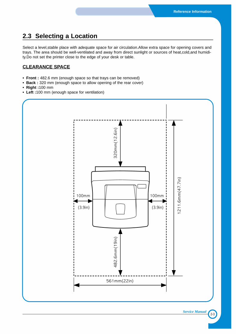
2.3 Selecting a Location
Select a level,stable place with adequate space for air circulation.Allow extra space for opening covers andtrays. The area should be well-ventilated and away from direct sunlight or sources of heat,cold,and humidi-ty.Do not set the printer close to the edge of your desk or table.
CLEARANCE SPACE
• Front : 482.6 mm (enough space so that trays can be removed)• Back : 320 mm (enough space to allow opening of the rear cover)• Right :100 mm• Left :100 mm (enough space for ventilation)
33
3-1
Specifications
Service Manual
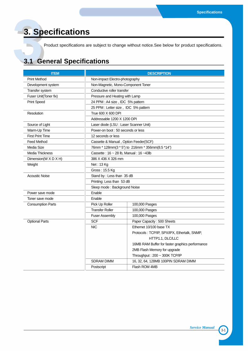
3. SpecificationsProduct specifications are subject to change without notice.See below for product specifications.
3.1 General Specifications
ITEM DESCRIPTION
Print Method Non-impact Electro-photography
Development system Non-Magnetic, Mono-Component Toner
Transfer system Conductive roller transfer
Fuser Unit(Toner fix) Pressure and Heating with Lamp
Print Speed 24 PPM : A4 size , IDC 5% pattern
25 PPM : Letter size , IDC 5% pattern
Resolution True 600 X 600 DPI
Addressable 1200 X 1200 DPI
Source of Light Laser diode (LSU : Laser Scanner Unit)
Warm-Up Time Power-on boot : 50 seconds or less
First Print Time 12 seconds or less
Feed Method Cassette & Manual , Option Feeder(SCF)
Media Size 76mm * 128mm(3 * 5”) to 216mm * 356mm(8.5 *14”)
Media Thickness Cassette : 16 ~ 28 lb, Manual : 16 ~43lb
Dimension(W X D X H) 386 X 436 X 326 mm
Weight Net : 13 Kg
Gross : 15.5 Kg
Acoustic Noise Stand by : Less than 35 dB
Printing: Less than 53 dB
Sleep mode : Background Noise
Power save mode Enable
Toner save mode Enable
Consumption Parts Pick Up Roller 100,000 Pasges
Transfer Roller 100,000 Pasges
Fuser Assembly 100,000 Pasges
Optional Parts SCF Paper Capacity : 500 Sheets
NIC Ethernet 10/100 base TX
Protocols : TCP/IP, SPX/IPX, Ethertalk, SNMP,
HTTP1.1, DLC/LLC
16MB RAM Buffer for faster graphics performance
2MB Flash Memory for upgrade
Throughput : 200 ~ 300K TCP/IP
SDRAM DIMM 16, 32, 64, 128MB 100PIN SDRAM DIMM
Postscript Flash ROM 4MB
3-2
Specifications
Service Manual
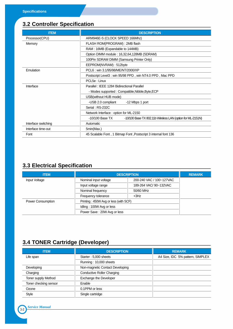
3.3 Electrical Specification
ITEM DESCRIPTION REMARK
Input Voltage Nominal input voltage 200-240 VAC / 100~127VAC
Input voltage range 189-264 VAC/ 90~132VAC
Nominal frequency 50/60 MHz
Frequency tolerance +3Hz
Power Consumption Printing : 450W Avg or less (with SCF)
Idling : 100W Avg or less
Power Save : 20W Avg or less
3.2 Controller SpecificationITEM DESCRIPTION
Processor(CPU) ARM946E-S (CLOCK SPEED 166Mhz)
Memory FLASH ROM(PROGRAM) : 2MB flash
RAM : 16MB (Expandable to 144MB)
Option DIMM module : 16,32,64,128MB (SDRAM)
100Pin SDRAM DIMM (Samsung Printer Only)
EEPROM(NVRAM) : 512byte
Emulation PCL6 : win 3.1/95/98/ME/NT/2000/XP
Postscript Level3 : win 95/98 PPD , win NT4.0 PPD , Mac PPD
PCL5e : Linux
Interface Parallel : IEEE 1284 Bidirectional Parallel
- Modes supported : Compatible,Nibble,Byte,ECP
USB(without HUB mode)
-USB 2.0 compliant -12 Mbps 1 port
Serial : RS-232C
Network Interface : option for ML-2150
-10/100 Base TX -10/100 Base TX 802.11b Wireless LAN (option for ML-2151N)
Interface switching Automatic
Interface time-out 5min(Max.)
Font 45 Scalable Font , 1 Bitmap Font ,Postscript 3 internal font 136
3.4 TONER Cartridge (Developer)
ITEM DESCRIPTION REMARK
Life span Starter : 5,000 sheets A4 Size, IDC 5% pattern, SIMPLEX
Running : 10,000 sheets
Developing Non-magnetic Contact Developing
Charging Conductive Roller Charging
Toner supply Method Exchange the Developer
Toner checking sensor Enable
Ozone 0.1PPM or less
Style Single cartridge
3-3
Specifications
Service Manual
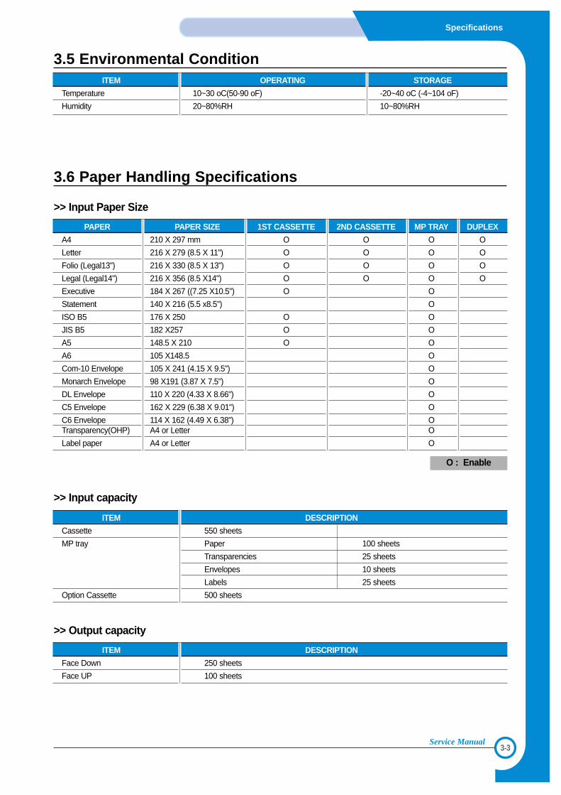
3.6 Paper Handling Specifications
>> Input Paper Size
>> Input capacity
>> Output capacity
PAPER PAPER SIZE 1ST CASSETTE 2ND CASSETTE MP TRAY DUPLEX
A4 210 X 297 mm O O O O
Letter 216 X 279 (8.5 X 11") O O O O
Folio (Legal13") 216 X 330 (8.5 X 13") O O O O
Legal (Legal14") 216 X 356 (8.5 X14") O O O O
Executive 184 X 267 ((7.25 X10.5") O O
Statement 140 X 216 (5.5 x8.5") O
ISO B5 176 X 250 O O
JIS B5 182 X257 O O
A5 148.5 X 210 O O
A6 105 X148.5 O
Com-10 Envelope 105 X 241 (4.15 X 9.5") O
Monarch Envelope 98 X191 (3.87 X 7.5") O
DL Envelope 110 X 220 (4.33 X 8.66") O
C5 Envelope 162 X 229 (6.38 X 9.01") O
C6 Envelope 114 X 162 (4.49 X 6.38") OTransparency(OHP) A4 or Letter O
Label paper A4 or Letter O
O : Enable
ITEM DESCRIPTION
Cassette 550 sheets
MP tray Paper 100 sheets
Transparencies 25 sheets
Envelopes 10 sheets
Labels 25 sheets
Option Cassette 500 sheets
ITEM DESCRIPTION
Face Down 250 sheets
Face UP 100 sheets
3.5 Environmental ConditionITEM OPERATING STORAGE
Temperature 10~30 oC(50-90 oF) -20~40 oC (-4~104 oF)
Humidity 20~80%RH 10~80%RH

3-4
Specifications
Service Manual
4-1
Summary of product
Service Manual
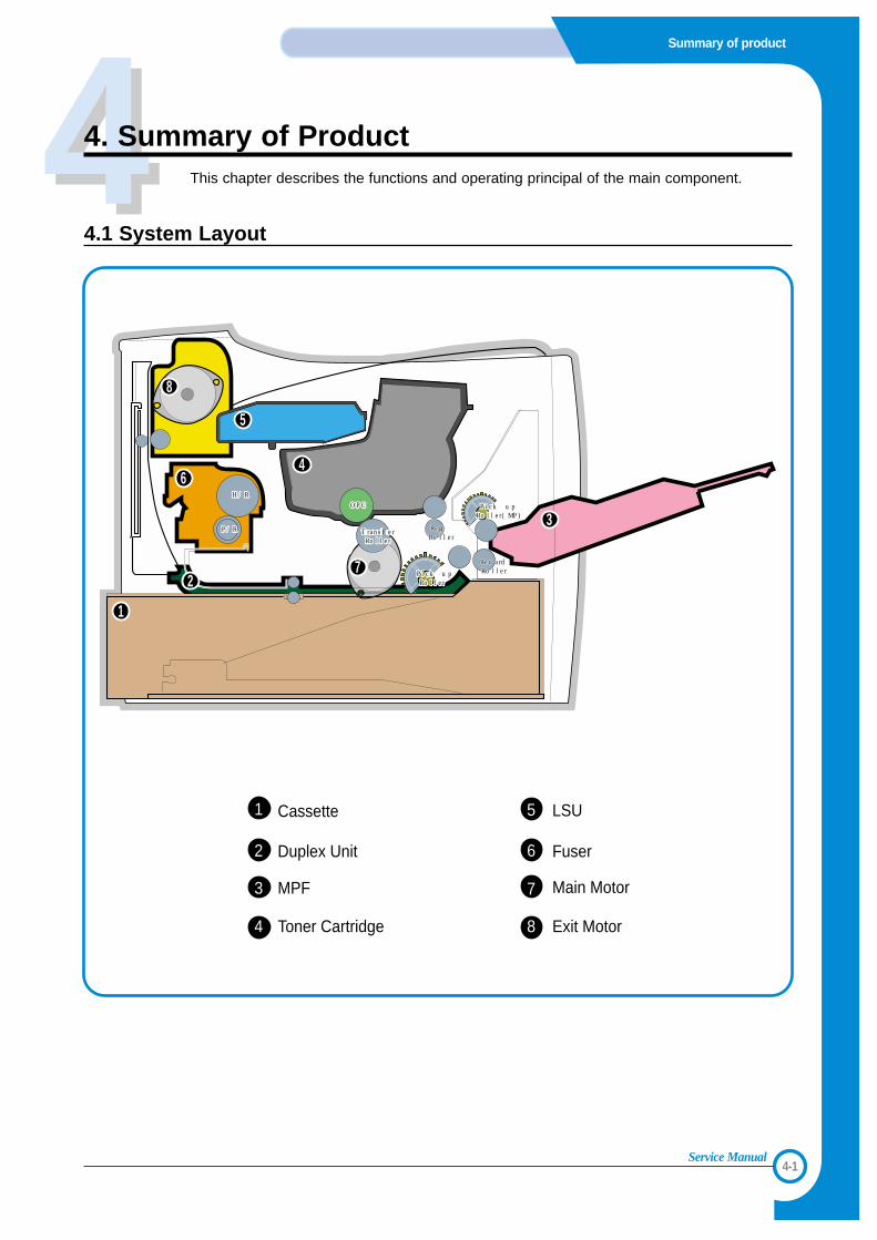
444. Summary of ProductThis chapter describes the functions and operating principal of the main component.
4.1 System Layout
P/RP/R
H/RH/R
Transfer ransfer RollerRoller
Pick up Pick up RollerRoller
Pick up Pick up Roller(MP)Roller(MP)
OPCOPC
P/R
H/R
Transfer Roller
Pick up Roller
Pick up Roller(MP)
RegiRegiRollerRollerRegiRoller
RetardRetardRollerRollerRetardRoller
OPC
5
6
7
8
1
2
3
4
Toner Cartridge Exit Motor
LSU5Cassette1
Fuser6Duplex Unit2
Main Motor7MPF3
84
4-2
Summary of Product
Service Manual
4.1.1 Feeding
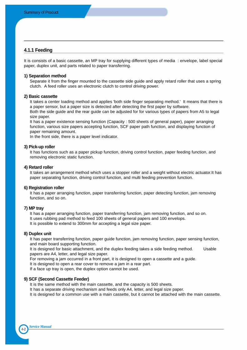
It is consists of a basic cassette, an MP tray for supplying different types of media : envelope, label specialpaper, duplex unit, and parts related to paper transferring.
1) Separation methodSeparate it from the finger mounted to the cassette side guide and apply retard roller that uses a springclutch. A feed roller uses an electronic clutch to control driving power.
2) Basic cassetteIt takes a center loading method and applies 'both side finger separating method.' It means that there isa paper sensor, but a paper size is detected after detecting the first paper by software. Both the side guide and the rear guide can be adjusted for for various types of papers from A5 to legalsize paper.It has a paper existence sensing function (Capacity : 500 sheets of general paper), paper arrangingfunction, various size papers accepting function, SCF paper path function, and displaying function ofpaper remaining amount.In the front side, there is a paper level indicator.
3) Pick-up rollerIt has functions such as a paper pickup function, driving control function, paper feeding function, andremoving electronic static function.
4) Retard rollerIt takes an arrangement method which uses a stopper roller and a weight without electric actuator.It haspaper separating function, driving control function, and multi feeding prevention function.
6) Registration rollerIt has a paper arranging function, paper transferring function, paper detecting function, jam removingfunction, and so on.
7) MP trayIt has a paper arranging function, paper transferring function, jam removing function, and so on.It uses rubbing pad method to feed 100 sheets of general papers and 100 envelops. It is possible to extend to 300mm for accepting a legal size paper.
8) Duplex unitIt has paper transferring function, paper guide function, jam removing function, paper sensing function,and main board supporting function.It is designed for basic attachment, and the duplex feeding takes a side feeding method. Usablepapers are A4, letter, and legal size paper.For removing a jam occurred in a front part, it is designed to open a cassette and a guide. It is designed to open a rear cover to remove a jam in a rear part.If a face up tray is open, the duplex option cannot be used.
9) SCF (Second Cassette Feeder)It is the same method with the main cassette, and the capacity is 500 sheets.It has a separate driving mechanism and feeds only A4, letter, and legal size paper.It is designed for a common use with a main cassette, but it cannot be attached with the main cassette.
4-3
Summary of product
Service Manual
4.1.2 Transfer
It consists of a PTL (Pre-transfer Lamp) and a transfer roller. A PTL sheds light on an OPC drum, lowersan electric potential of an OPC drum's surface, and improves the efficiency of the transfer.A transfer roller transfers toner on an OPC drum to the paper.Life span : Print over 60,000 sheets (In 15~30(C)
4.1.3 Driver Ass'y
By driving the motor, the system takes power. It is consisted of a main motor for feeding and a developer,and sub-motors for fuser and duplex reverse turn.
4.1.4 Fuser
It is consisted of a heat lamp, heat roller, pressure roller, thermistor and thermostat. It sticks the toner on apaper by heat and pressure to complete the printing job.
1) ThermostatWhen a heat lamp is overheated, a Thermostat cuts off the main power to prevent over-heating.
3) Heat rollerThe heat roller transfers the heat from the heat lamp to apply a heat on the paper. The surface of aheat roller is coated with Teflon, so toner does not stick to the surface.
4) Pressure rollerA pressure roller mounted under a heat roller is made of a silicon resin, and the surface also is coatedwith Teflon. When a paper passes between a heat roller and a pressure roller, toner adheres to the sur-face of a paper permanently.
5) Items for safetyProtecting device for overheating
- 1st protection device : Hardware cuts off when overheated- 2nd protection device : Software cuts off when overheated- 3rd protection device : Thermostat cuts off main power.
Safety device- A fuser power is cut off when a front cover is opened- Maintain a temperature of fuser cover's surface under 80(C for user, and attach a caution label at
where customer can see easily when customer open a rear cover.
4.1.5 LSU (Laser Scanner Unit)
It is the core part of the LBP which switches from the video data received to the controller to the electrostat-ic latent image on the OPC drum by controlling laser beam, exposing OPC drum, and turning principle ofpolygon mirror. The OPC drum is turned with the paper feeding speed. The /HSYNC signal is createdwhen the laser beam from LSU reaches the end of the polygon mirror, and the signal is sent to the con-troller. The controller detects the /HSYNC signal to adjust the vertical line of the image on paper. In otherwords, after the /HSYNC signal is detected, the image data is sent to the LSU to adjust the left margin onpaper. The one side of the polygon mirror is one line for scanning.
4-4
Summary of Product
Service Manual
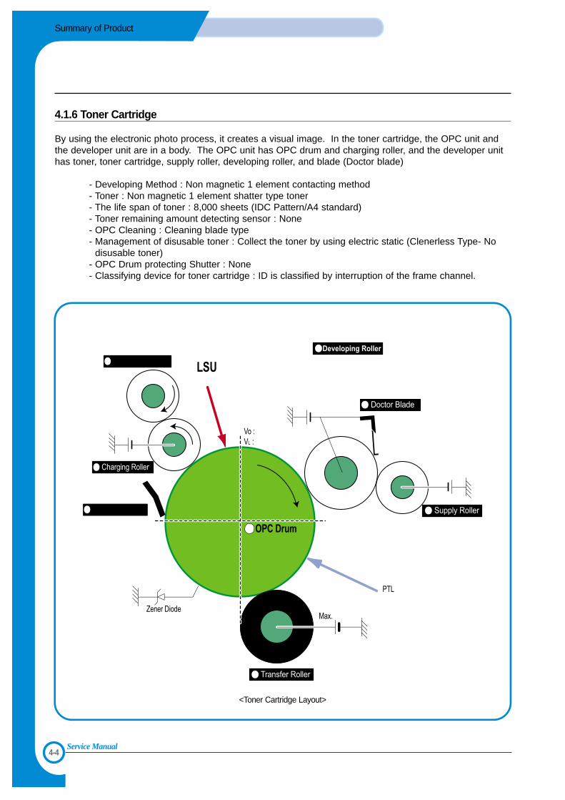
4.1.6 Toner Cartridge
By using the electronic photo process, it creates a visual image. In the toner cartridge, the OPC unit andthe developer unit are in a body. The OPC unit has OPC drum and charging roller, and the developer unithas toner, toner cartridge, supply roller, developing roller, and blade (Doctor blade)
- Developing Method : Non magnetic 1 element contacting method- Toner : Non magnetic 1 element shatter type toner- The life span of toner : 8,000 sheets (IDC Pattern/A4 standard)- Toner remaining amount detecting sensor : None- OPC Cleaning : Cleaning blade type- Management of disusable toner : Collect the toner by using electric static (Clenerless Type- No
disusable toner)- OPC Drum protecting Shutter : None- Classifying device for toner cartridge : ID is classified by interruption of the frame channel.
Cleaning Roller
Cleaning Blade
-750V
-470V
-650V
0.16mW
-1.5KV
-100V
1
2
3
4
5
6
7
8
+4.2kV
-150V
<Toner Cartridge Layout>
4-5
Summary of product
Service Manual
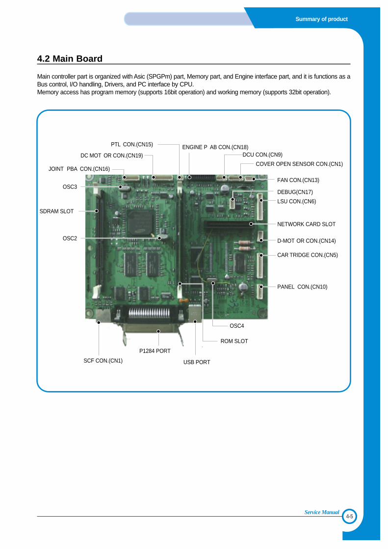
4.2 Main Board
Main controller part is organized with Asic (SPGPm) part, Memory part, and Engine interface part, and it is functions as aBus control, I/O handling, Drivers, and PC interface by CPU.Memory access has program memory (supports 16bit operation) and working memory (supports 32bit operation).
USB PORT
ROM SLOT
PANEL CON.(CN10)
CAR TRIDGE CON.(CN5)
D-MOT OR CON.(CN14)
NETWORK CARD SLOT
LSU CON.(CN6)
DEBUG(CN17)
FAN CON.(CN13)
COVER OPEN SENSOR CON.(CN1)
DCU CON.(CN9)
SDRAM SLOT
OSC3
OSC2
OSC4
PTL CON.(CN15)
JOINT PBA CON.(CN16)
DC MOT OR CON.(CN19)ENGINE P AB CON.(CN18)
P1284 PORT
SCF CON.(CN1)
4-6
Summary of Product
Service Manual
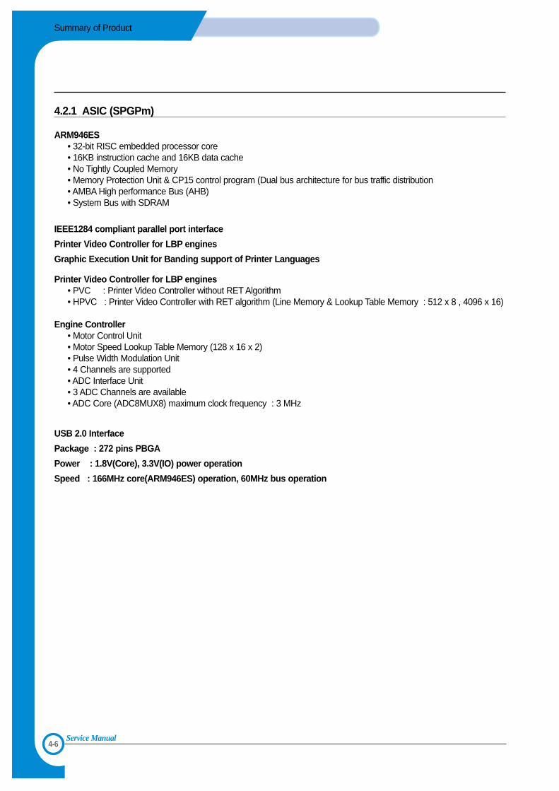
4.2.1 ASIC (SPGPm)
ARM946ES • 32-bit RISC embedded processor core• 16KB instruction cache and 16KB data cache• No Tightly Coupled Memory• Memory Protection Unit & CP15 control program (Dual bus architecture for bus traffic distribution• AMBA High performance Bus (AHB)• System Bus with SDRAM
IEEE1284 compliant parallel port interface
Printer Video Controller for LBP engines
Graphic Execution Unit for Banding support of Printer Languages
Printer Video Controller for LBP engines• PVC : Printer Video Controller without RET Algorithm• HPVC : Printer Video Controller with RET algorithm (Line Memory & Lookup Table Memory : 512 x 8 , 4096 x 16)
Engine Controller• Motor Control Unit • Motor Speed Lookup Table Memory (128 x 16 x 2)• Pulse Width Modulation Unit • 4 Channels are supported • ADC Interface Unit • 3 ADC Channels are available• ADC Core (ADC8MUX8) maximum clock frequency : 3 MHz
USB 2.0 Interface
Package : 272 pins PBGA
Power : 1.8V(Core), 3.3V(IO) power operation
Speed : 166MHz core(ARM946ES) operation, 60MHz bus operation
4-7
Summary of product
Service Manual
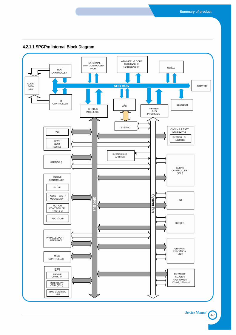
4.2.1.1 SPGPm Internal Block Diagram
AHB BUS
SFR BUS INTERFACE
SYSTEM BUS
INTERFACE
PARALLEL PORT
INTERFACE
UART(3CH)
SDRAM CONTROLLER
(5CH)
HCT
ROTATOR/ SCALER/
HALFTONER 1024x8, 256x8x 4
gCODEC
GRAPHIC
EXECUTION UNIT
MISC CONTROLLER
ARM946E -S CORE 16KB ICACHE
16KB DCACHE
CLOCK & RESET
GENERATOR
SYSTEM BUS
ARBITER
MAC
USB2.0
EXTERNAL
DMA CONTROLLER (4CH)
PVC
HPVC 512x8
4096x16
LSU I/F
PULSE WIDTH MODULATOR
ENGINE
CONTROLLER
MOT OR CONTROLLER
128x16 x2
ADC (3CH)
ADDR/ DATA MUX
SFR
Bus
System
Bus
INTERRUPT CTRL (5CH)
TIME CONTROL UNIT
ENGINE Comm. I/F
EPI
SYSMAC
SYSTEM PLL
(120MHz)
ARBITER
DECODER
ROM CONTROLLER
IO CONTROLLER
4-8
Summary of Product
Service Manual
4.2.2. Memory part
>> Flash Memory It stores the System Program.• Capacity : 2M Byte• Access Time : 70 nsec
>>SDRAM It is used as Swath buffer, System working memory area, etc. when printing. It stores the font list, compressed intoflash memory, on DRAM and uses it as PCL font.• Capacity : 16M Byte (Basic), upto 144M Byte (Option)• DIMM : 16MB / 32MB / 64MB /128MB• Type : SDRAM 100MHz/133MHz , 16bit
>>ROM DIMMIt supports the option ROM DIMM 1 Slot for supporting the Postscript level 3.• Capacity : 4MByte• Access Time : 70nsec
4.2.3. RESET Circuit
After printer power is ON and 50~200 ms are passed, the reset signal from RESET IC (XC61FN3112MR) resets variousIC such as the CPU, Memory, etc. to prevent malfunction of the set by setting the initial value of port.
4.2.4. ClOCK Circuit
Basically, it consists of the Crystal (12MHz) and Capacitor (27pF) which is connected to the crystal in parallel, and it isinputted to the MCLLK_Signal via the FS781. The purpose of the adding FS781 is substitution of EMI.
4.2.5. INTERFACE Part
>>IEEE1284It supports the IEEE 1284 B Type Connection, and the protocol supports the IPP, ECP, Compatibility, Byte, and Nibblemode.
>>USB2.0USB2.0 Compliant, 12Mbps 1 port
>>Network• Option : Ethernet 10/100 Base TX• Protocol : SPX/IPX, TCP/IP,Appletalk, SNMP, HTTP 1.1, DLC/LLC
>>Panel• LCD : 16Char. * 2 Line / Back-light(Blue)• Key : 9 Key• LED : 3 LEDThe UART method is used for the controller and panel interface, and the HR 48R50 Holtak Micom is used
4-9
Summary of product
Service Manual
4.2.6. Sensor input circuit
4.2.6.1. Paper Empty SensingThe Paper empty sensor (Photo Interrupter) on the engine board informs the state of paper to CPU whether it is empty ornot by operation of the actuator.When cassette is empty, it detects the fact by reading the D24 Bit of CPU, and then displays the fact on the LCD panel.
4.2.6.2. MP SensingBy operation of the MP Sensor (Photo Interrupter) on frame and Actuator, it informs the state of paper to CPU whether itis empty or not. It reads the D25 Bit of CPU for recognizing paper in MP, and paper is fed from MP if there is.
4.2.6.3. Paper Feeding When paper passes the actuator on the feed sensor part, it detects the signal of Photo interrupter, informs the paper feed-ing state to CPU, and then sprays the image data after certain time. If it doesn't detect the feed sensor within 1 sec. after paper is fed, paper jam0 (CPU #Y13) is occurred. (Displays on theLCD panel)
4.2.6.4. Toner Remain SensingThe Developer terminal is mounted to the joint board located on frame. When the developer is inserted, it is adhered to thecontacting point of the joint board to sense whether the developer exists or not, ID, amount of toner, and so on.
4.2.6.5. Paper Exit SensingIt detects paper state whether paper gets out from the set with operation of exit sensor on the engine board and actuatoron the frame. Paper detects the on/off time of exit sensor by reading CPU #W11, and the normal operation or jam infor-mation is informed to the CPU.The paper JAM2 is informed. (Displays the state on LCD panel)
4.2.6.6. Cover Open SensingThe Cover open sensor is located on the front cover. After the front cover is opened, +24V and +5V (DC fan, solenoid,main motor, polygon motor part of LSU, HVPS, LSU Laser diode), which is supplied to each unit, is cut off.
4.2.6.7. DC FAN/Solenoid Driving CircuitA fan driving circuit is driven by a transistor and a controller which is in the CPU.It is automatically turned off when a machine turns to sleep mode.There are two solenoids, and it is driven by an MP signal and a paper pick-up signal.
4.2.6.8. Motor Driving CircuitA main motor (BLDC) drives a feeding and developing unit and an exit motor (Step) drives a Fuser and anExit ass'y.When printing with a duplex function, it rotates the Exit Motor to a normal/reverse direction. It controls bydividing the acceleration section, standard speed section, and reducing speed section. A BLDC Motor isoperated by a clock and enable signal, and a Step Motor is managed with an AN8495 driver IC.
4-10
Summary of Product
Service Manual
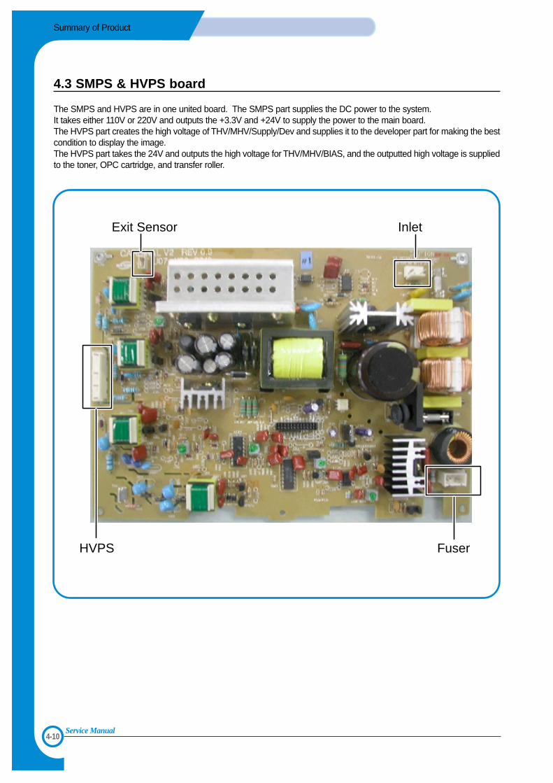
4.3 SMPS & HVPS board
The SMPS and HVPS are in one united board. The SMPS part supplies the DC power to the system.It takes either 110V or 220V and outputs the +3.3V and +24V to supply the power to the main board.The HVPS part creates the high voltage of THV/MHV/Supply/Dev and supplies it to the developer part for making the bestcondition to display the image. The HVPS part takes the 24V and outputs the high voltage for THV/MHV/BIAS, and the outputted high voltage is suppliedto the toner, OPC cartridge, and transfer roller.
Exit Sensor
HVPS Fuser
Inlet
4-11
Summary of product
Service Manual
4.3.1. HVPS(High Voltage Power Supply)
1) Transfer high voltage (THV (+))- Function : It is a voltage that transfers toner on an OPC Drum to paper.- Output voltage : MAX +4.2 KV +/- 5% (Duty is changeable, Not loading)- 1.6KV +/- 15% (When cleaning, 200MOhm - It transfers toners with (+) polarity of transfer roller to an OPC Drum.- Error type : IF THV (+) is not outputted, it causes a low density due to toner on an OPC Drum if it is not transferred to
paper. It is possible that over-flow occurs if toner is piled up in a toner vessel continuously.
2) Charge voltage (MHV)- Function : It is a voltage that charges a surface of OPC to -750V~-900V. - Output voltage : -1.3KV~1.5KV DC +/- 50V- Error type : IF MHV is not outputted, toner overflows and reaches to an OPC drum if surface of an OPC is not
charged. A black paper is printed out when it happens.
3) Cleaning voltage : THV (-)- Function : It removes contamination at a rear by sending (-) polarity in a transfer roller to OPC drum to take toner.- Output voltage : A change range is large according to a load because there is no feedback control =(-600V~-1200V)- Error type : An error due to contamination of toner on a backside of printing paper.
4) Developing voltage (DEV)- Function : It is a voltage that develops toner with electronic potential difference of the section exposed by LSU (Laser
Scanning Unit).* When printing, exposing voltage of OPC is -250V and exposing voltage of DEV is -470V. Therefore,
toner with (-) polarity is developed on an exposed section.- Output voltage : -400V~470DC +/- 20V- Error type : a) If DEV is GND, a density gets extremely low.
b) When DEV is floating due to instable of terminal’s contacting point, and etc., density gets extremelyhigh.
5) Supplying voltage (SUP)- Function : It is a voltage that supplies toner to a developing roller.- Output voltage : -580V~650V DC +/- 50V (Use AENER, Gearing of DEV - (-)180V more than DEV) - Error type : a) When SUP is GND, density gets extremely low.
b) If SUP is floating due to instable of terminal’s contacting point, and etc., density gets extremely lowthat it is hard to catch up with eyes.
6) OPC Ground ZENER voltage- Function : It is a voltage to prevent an image contamination under the condition of low temperature and low humidity
environment.- When a set prints without an output voltage, -100V is maintained on OPC ground.
(-100V AENER diode is connected to OPC ground)- Error type : a) When ZENER diode is - 0V, there is no serious image problem in general environment, but in low tem-
perature and low humidity environment, it is possible that a contamination occur on entire image b) When ZENER diode is disconnected, a blank page is printed out. (It is the same case as when a
ZENER diode is disconnected to OPC ground.)
4-12
Summary of Product
Service Manual
4.3.2 SMPS(Switching Mode Power Supply)
It is the power source for the whole system. It is an independent module so it is possible to use for common use. It ismounted at the bottom of the set.It consists of the SMPS part, which supplies the DC power for driving the system, and the AC heater control part, whichsupplies the power for fuser. SMPS has three outputting channels (3.3V, 5V and +24V).There are three kinds of power, 120V exclusive (America), 220V exclusive (Europe), and 220V for china (nations with insta-ble power supply).
>>AC Input• Inputting rated voltage : AC 220V ~ 240V AC 120V / AC 220V• Inputting voltage fluctuating range : AC 198V ~ 264V AC 90V ~ 135V / AC 198V ~ 264V• Rated frequency : 50/60 Hz• Frequency fluctuating range : 47 ~ 63 Hz• Inputting voltage : Under 5.0Arms/2.5Arms
>>Rated Power Output
>>Consumption Power
>>Length of Power Cord : 1830 ± 50mm
>>Power Switch : Use
NO Item CH1 CH2 CH3 Remark1 Channel name +3.3V +5V +24.0V
2 CONNECTOR PIN CON 3 CON 3 CON 33.3V PIN : 12, 14 5V PIN : 8 24V PIN : 2, 4, 6GND PIN : 16, 18 GND PIN : 7 GND : 7, 8, 10
3 Rated outputting voltage 3.3V ± 5% +5V ± 5% +24V ± 5%, -5%(3.2 ~ 3.4V) (4.75 ~ 5.25V) (21.6 ~ 26.4V)
4 Maximum outputting voltage 1.5 A 0.5 A 0.5 A
5 Peak loading voltage 1.5 A 0.5 A 0.5 A 1ms
6 Ripple noise voltage 200mVp-p 100mVp-p 500mVp-p
7 Maximum output 5 W 2.5 W 84 W
8 Peak output 5 W 2.5 W 84 W 1ms
NO Item CH1 CH2 CH3 System(+3.3V) (+5V) (+24V)
1 Stand-By 0.6 A 0.07 A 0.4 A AVG : 100 Wh
2 PRINTING 1.0 A 0.14 A 2.0 A AVG : 350 Wh
3 Sleep-Mode 0.4 A 0.01 A 0.4 A AVG : 15 Wh
4-13
Summary of product
Service Manual
>>Feature • Insulating resistance : over 50MΩ(at DC 500V) • Insulating revisiting pressure Must be no problem within 1min. (at 1500Vzc, 10mA)• Leaking voltage : under 3.5mA• Running voltage : under 50A peak (at 25°C, Cold start)
Under 60A peak (in other conditions)• Rising Time : Within 2sec• Falling Time : over 20ms• Surge : Ring Wave 6KV-500A (Normal, Common)
>>Environment Condition• Operating temperature range : 0°C~50°C• Maintaining temperature range : -25°C~85°C• Maintaining humid range : 10% ~90% RH• Operating atmospheric pressure range : 1
>>EMI RequirementCISPR ,FCC, CE, MIC, C-Tick,
>>Safty Requrement IEC950 UL1950, CSA950, C-UL, NOM, TUV, Semko, Nemko, iK, CB, CCC(CCIB),GOST, EPA
4.3.3 Fuser AC Power Control
Fuser (HEAT LAMP) gets heat by using AC power. The AC power controls the switch with the Triac, a semiconductorswitch. The 'On/Off control' is operated when the gate of the Triac is turned on/off by Photo triac, which is insulting part.In the other words, the AC control part is passive circuit, so it turns the heater on/off with taking signal from engine controlpart. When the 'HEATER ON' signal is turned on at engine, the LED of PC1 (Photo Triac) takes the voltage and flashes.From the flashing light, the Triac part (light receiving part) takes the voltage, and the voltage is supplied to the gate of Triacand flows into the Triac. As a result, the AC current flows in the heat lamp, and heat is occurred.On the other hand, when the signal is off, the PC1 is off, the voltage is cut off at the gate of Triac, the Triac becomes off,and then the heat lamp is turned off.
>>Triac (THY1) feature :12A,600V SWITCHING
>>Phototriac Coupler (PC3) • Turn On If Current : 16mA• High Repetive Peak Off State Voltage : Min 600V
4-14
Summary of Product
Service Manual
4.4 Engine F/W
4.4.1 Feeding
If feeding from a cassette, the drive of the pickup roller is controlled by controlling the solenoid. The on/off of the solenoidis controlled by controlling the general output port or the external output port. If feeding from a manual feeder, decide toinsert the paper according to the operation of the manual sensor, and by driving the main motor, insert the paper in frontof the feed sensor. While paper moves, occurrence of jam is judged as below. (Refer to the [6.2 Paper Transfer rout])
4.4.1.1 Jam 0• After picking up, paper cannot entered due to paper mis-feed.• After picking up, paper entered but it cannot reach to the feed sensor in certain time due to slip, etc.• After picking up, if the feed sensor is not on, repack up. After repacking up, if the feed sensor is not on
after certain time, it is Jam 0.- It is a status that the leading edge of the paper doesn’t pass the feed sensor.
• Even though the paper reaches to the feed sensor, the feed sensor doesn’t turn on.- It is a status that the leading edge of the paper already passed the feed sensor.
4.4.1.2 Jam 1• After the leading edge of the paper passes the feed sensor, the tailing edge of the paper cannot pass the
feed sensor after certain time. (The feed sensor cannot be Off)• After the leading edge of the paper passes the feed sensor, the paper cannot reach the exit sensor after
certain time. (The exit sensor cannot be On)- The paper exists between the feed sensor and the exit sensor.
4.4.1.3 Jam 2• After the tailing edge of the paper passes the feed sensor, the paper cannot pass the exit sensor after
certain time.
4.4.1.4 Duplex Jam 1A leading edge of a paper didn't reach a Duplex Sensor after certain time passes.
4.4.1.5 Duplex Jam 2After a leading edge of the paper passes the Duplex Sensor, the rear edge of the paper does not pass aDuplex Sensor within a certain time.
4.4.2 Drive
A main motor (BLDC) drives a feeding and developing unit and an exit motor (Step) drives a Fuser and anExit ass'y.When printing with a duplex function, it rotates the Exit Motor to a normal/reverse direction. It controls bydividing the acceleration section, standard speed section, and reducing speed section. A BLDC Motor isoperated by a clock and enable signal, and a Step Motor is managed with an AN8495 driver IC.
4.4.3 Transfer
The charging voltage, developing voltage and the transfer voltage are controller by PWM (Pulse WidthModulation). The each output voltage is changeable due to the PWM duty. The transfer voltage admittedwhen the paper passes the transfer roller is decided by environment recognition. The resistance value ofthe transfer roller is changed due to the surrounding environment or the environment of the set, and thevoltage value, which changes due to the environments, is changed through AD converter. The voltagevalue for impressing to the transfer roller is decided by the changed value.
4-15
Summary of product
Service Manual
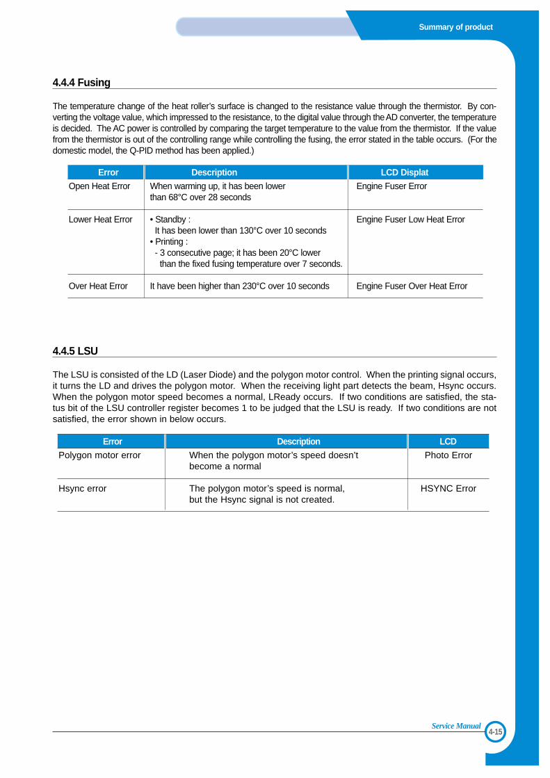
4.4.4 Fusing
The temperature change of the heat roller’s surface is changed to the resistance value through the thermistor. By con-verting the voltage value, which impressed to the resistance, to the digital value through the AD converter, the temperatureis decided. The AC power is controlled by comparing the target temperature to the value from the thermistor. If the valuefrom the thermistor is out of the controlling range while controlling the fusing, the error stated in the table occurs. (For thedomestic model, the Q-PID method has been applied.)
4.4.5 LSU
The LSU is consisted of the LD (Laser Diode) and the polygon motor control. When the printing signal occurs,it turns the LD and drives the polygon motor. When the receiving light part detects the beam, Hsync occurs.When the polygon motor speed becomes a normal, LReady occurs. If two conditions are satisfied, the sta-tus bit of the LSU controller register becomes 1 to be judged that the LSU is ready. If two conditions are notsatisfied, the error shown in below occurs.
Error Description LCD DisplatOpen Heat Error When warming up, it has been lower Engine Fuser Error
than 68°C over 28 seconds
Lower Heat Error • Standby : Engine Fuser Low Heat ErrorIt has been lower than 130°C over 10 seconds
• Printing : - 3 consecutive page; it has been 20°C lower than the fixed fusing temperature over 7 seconds.
Over Heat Error It have been higher than 230°C over 10 seconds Engine Fuser Over Heat Error
Error Description LCDPolygon motor error When the polygon motor’s speed doesn’t Photo Error
become a normal
Hsync error The polygon motor’s speed is normal, HSYNC Errorbut the Hsync signal is not created.

4-16
Summary of Product
Service Manual
55
5-1
Disassembly and Reassembly
Service Manual
5. Disassembly and Reassembly
5.1 General Precautions on Disassembly
When you disassemble and reassemble compo-nents, you must use extreme caution. The closeproximity of cables to moving parts makes properrouting a must. If components are removed, any cables disturbedby the procedure must be restored as close aspossible to their original positions. Before remov-ing any component from the machine, note thecable routing that will be affected.
Whenever servicing the machine, youmust perform as follows:
1. Check to verify that documents are not storedin memory.
2. Be sure to remove the toner cartridge beforeyou disassemble parts.
3. Unplug the power cord.
4. Use a flat and clean surface.
5. Replace only with authorized components.
6. Do not force plastic-material components.
7. Make sure all components are in their properposition.
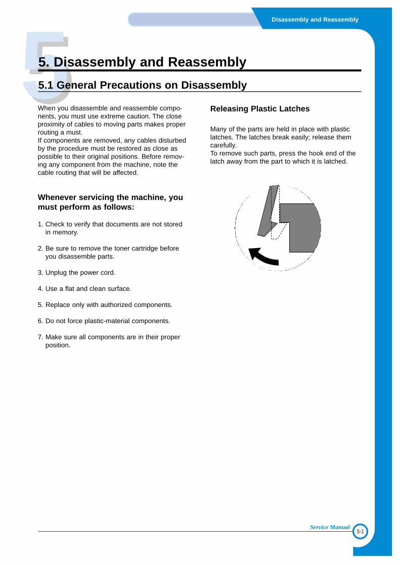
Releasing Plastic Latches
Many of the parts are held in place with plasticlatches. The latches break easily; release themcarefully. To remove such parts, press the hook end of thelatch away from the part to which it is latched.
5-2
Disassembly and Reassembly
Service Manual
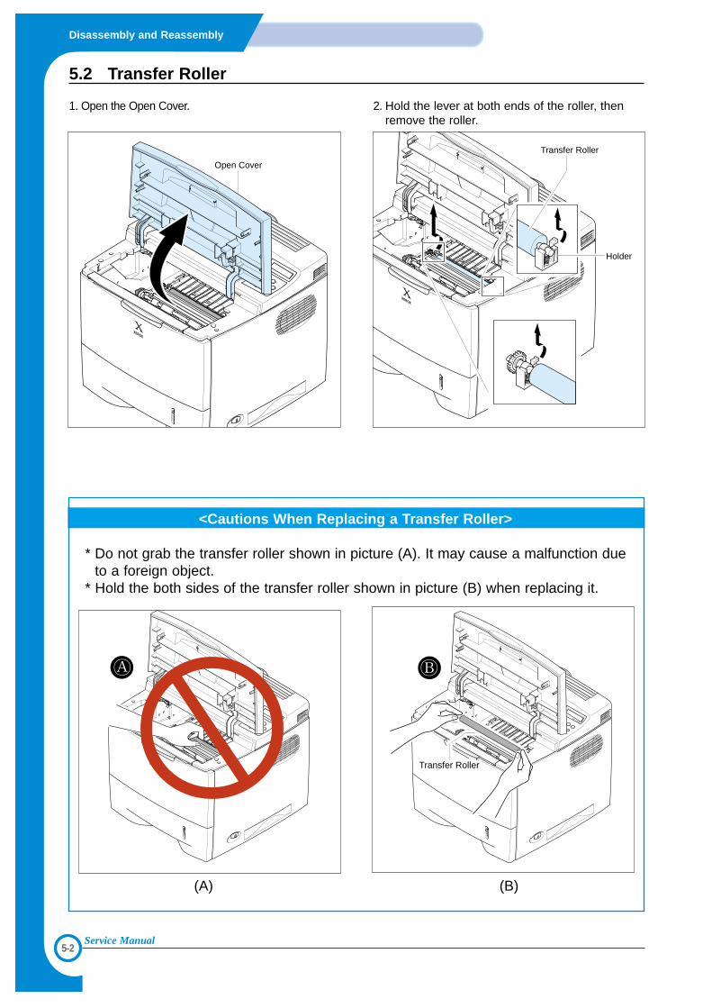
5.2 Transfer Roller
1. Open the Open Cover. 2. Hold the lever at both ends of the roller, thenremove the roller.
<Cautions When Replacing a Transfer Roller>
* Do not grab the transfer roller shown in picture (A). It may cause a malfunction dueto a foreign object.
* Hold the both sides of the transfer roller shown in picture (B) when replacing it.
Transfer RollerTransfer RollerTransfer Roller
(A) (B)
Transfer Roller
Holder
Open Cover
5-3
Disassembly and Reassembly
Service Manual
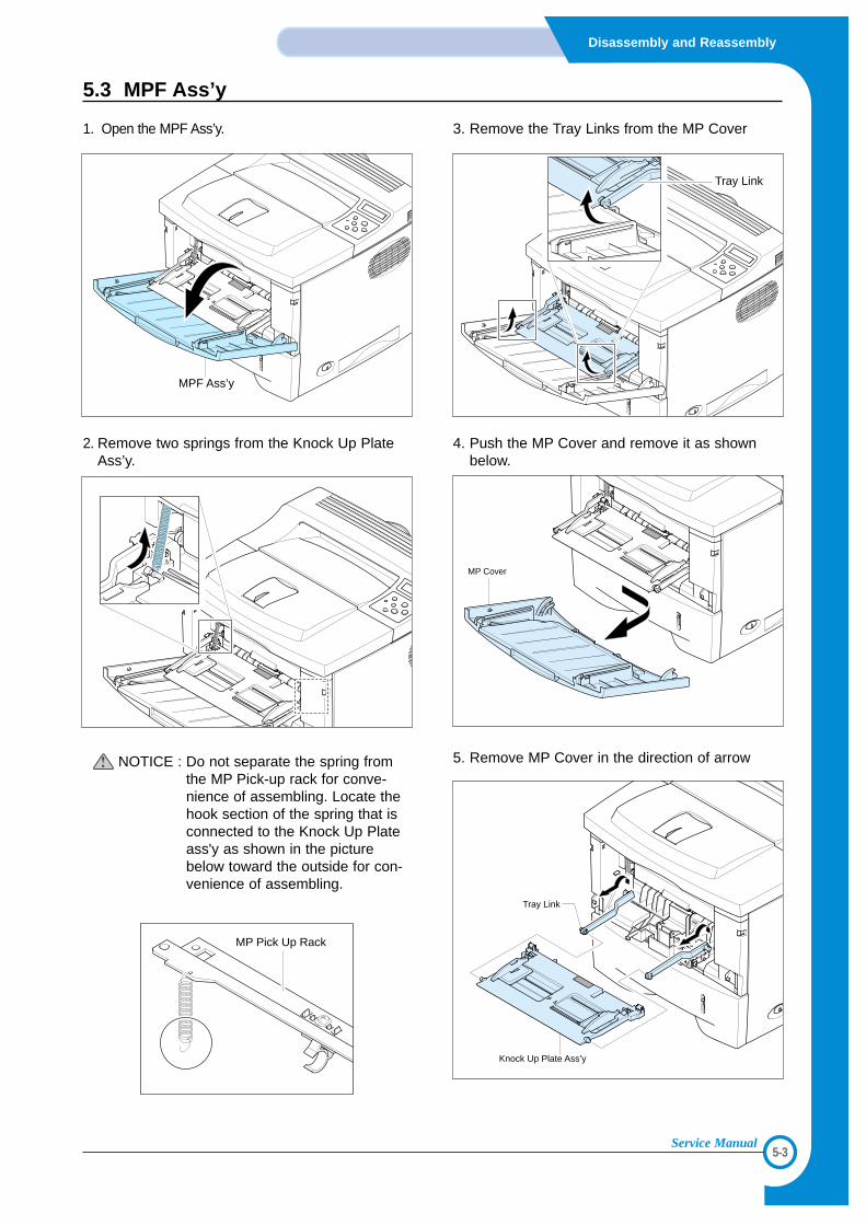
5.3 MPF Ass’y
1. Open the MPF Ass’y.
2. Remove two springs from the Knock Up PlateAss’y.
NOTICE : Do not separate the spring fromthe MP Pick-up rack for conve-nience of assembling. Locate thehook section of the spring that isconnected to the Knock Up Plateass'y as shown in the picturebelow toward the outside for con-venience of assembling.
3. Remove the Tray Links from the MP Cover
4. Push the MP Cover and remove it as shownbelow.
5. Remove MP Cover in the direction of arrow
MPF Ass’y
Tray Link
MP Cover
MP Pick Up Rack
Knock Up Plate Ass’y
Tray Link
5-4
Disassembly and Reassembly
Service Manual
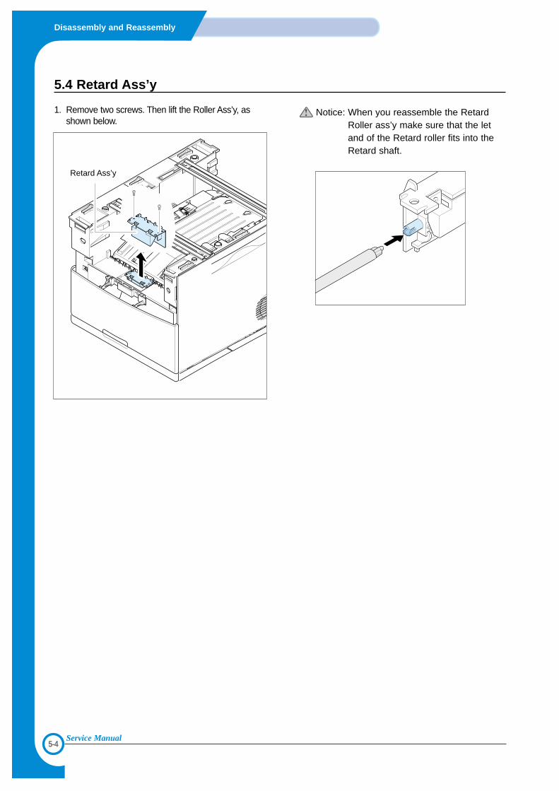
5.4 Retard Ass’y
1. Remove two screws. Then lift the Roller Ass’y, asshown below.
Notice: When you reassemble the RetardRoller ass’y make sure that the letand of the Retard roller fits into theRetard shaft.
Retard Ass’y
5-5
Disassembly and Reassembly
Service Manual
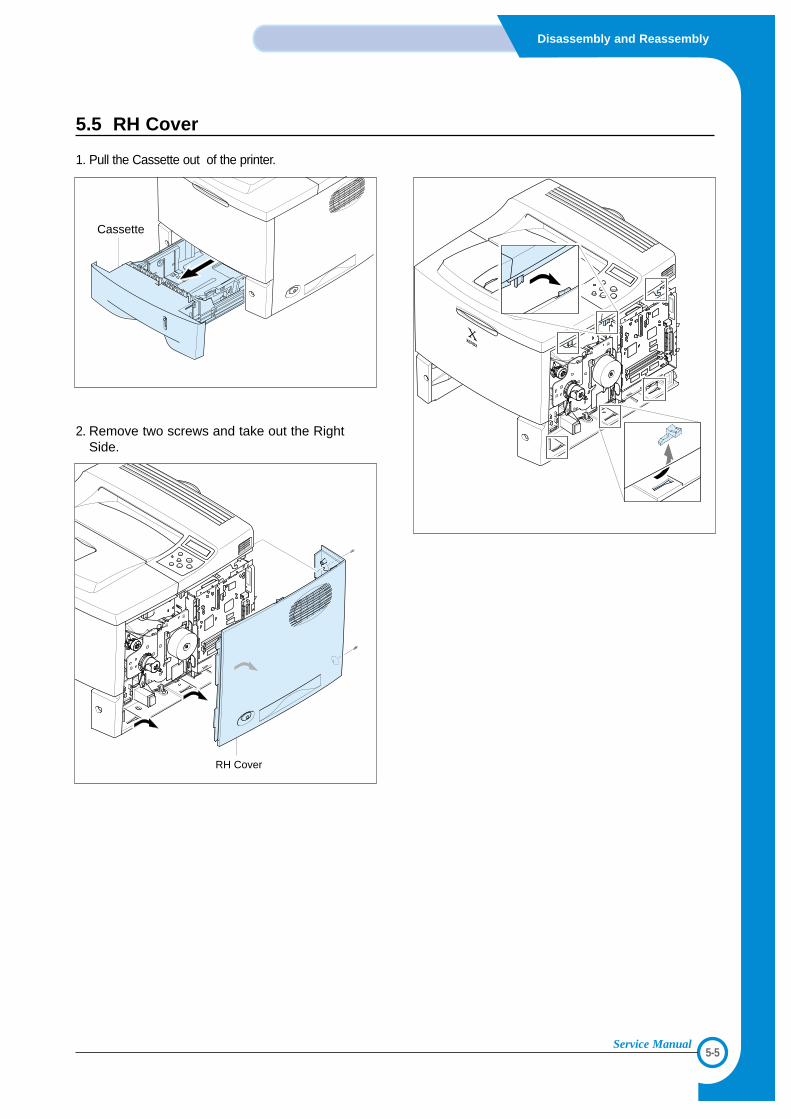
5.5 RH Cover
1. Pull the Cassette out of the printer.
2. Remove two screws and take out the RightSide.
RH Cover
Cassette
5-6
Disassembly and Reassembly
Service Manual
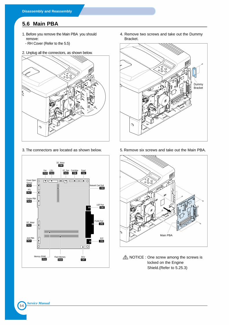
5.6 Main PBA
1. Before you remove the Main PBA you shouldremove:- RH Cover (Refer to the 5.5)
2. Unplug all the connectors, as shown below.
3. The connectors are located as shown below.
4. Remove two screws and take out the DummyBracket.
5. Remove six screws and take out the Main PBA.
NOTICE : One screw among the screws islocked on the EngineShield.(Refer to 5.25.3)
Dummy Bracket
Main PBAJoint PBACN14
Memory (RAM) CN12
Flash Memory CN16
SCFCN1
USP PortCN2
P1284 PortCN3
DCU CN7
DC_MotorCN11
Engine PBACN18
Cover Open SensorCN20
PTLCN17
Fan CN15
LSU CN10
DC_FanCN21
CartridgeCN6
PanelCN4
DC_Motor CN8
Network Card SoltCN9
5-7
Disassembly and Reassembly
Service Manual
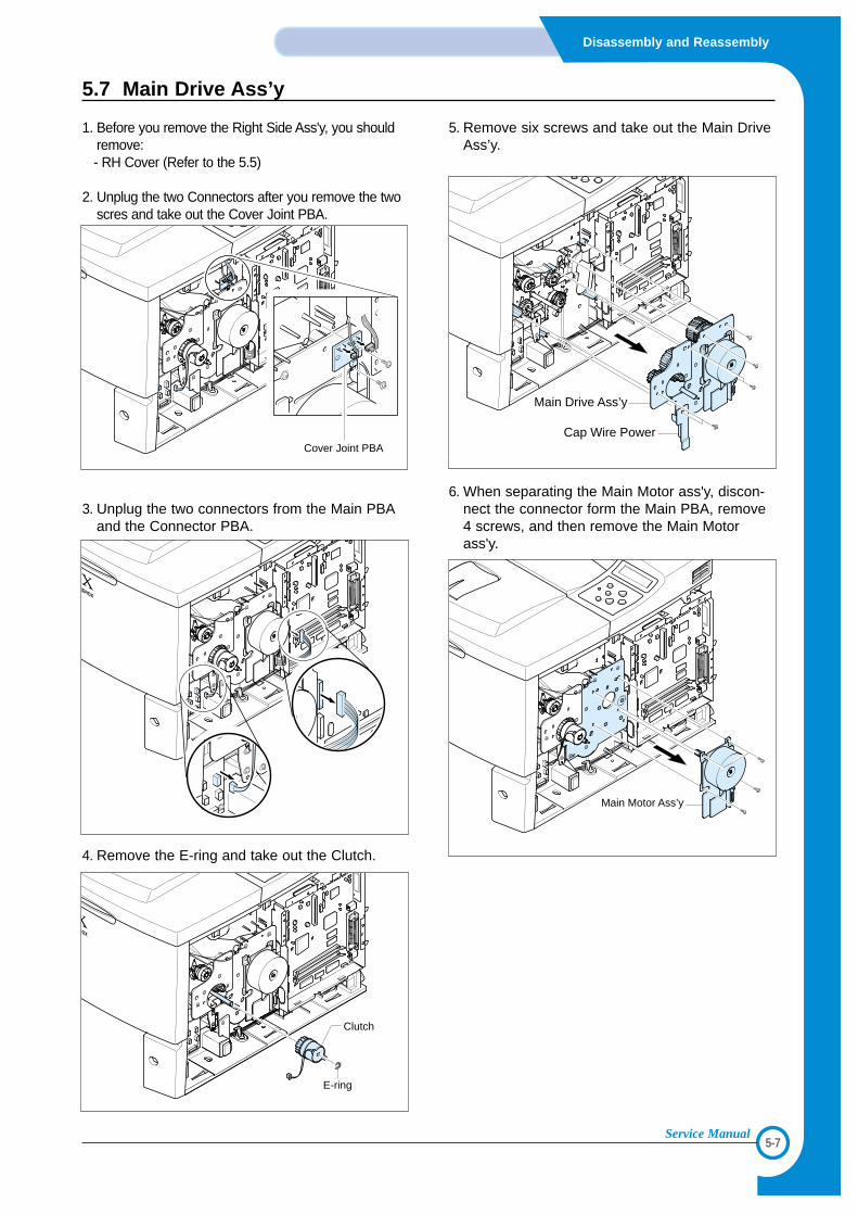
5.7 Main Drive Ass’y
1. Before you remove the Right Side Ass'y, you shouldremove:- RH Cover (Refer to the 5.5)
2. Unplug the two Connectors after you remove the twoscres and take out the Cover Joint PBA.
3. Unplug the two connectors from the Main PBAand the Connector PBA.
4. Remove the E-ring and take out the Clutch.
5. Remove six screws and take out the Main DriveAss’y.
6. When separating the Main Motor ass'y, discon-nect the connector form the Main PBA, remove4 screws, and then remove the Main Motorass'y.
Clutch
E-ring
Main Drive Ass’y
Cap Wire Power
Main Motor Ass’y
Cover Joint PBA
5-8
Disassembly and Reassembly
Service Manual
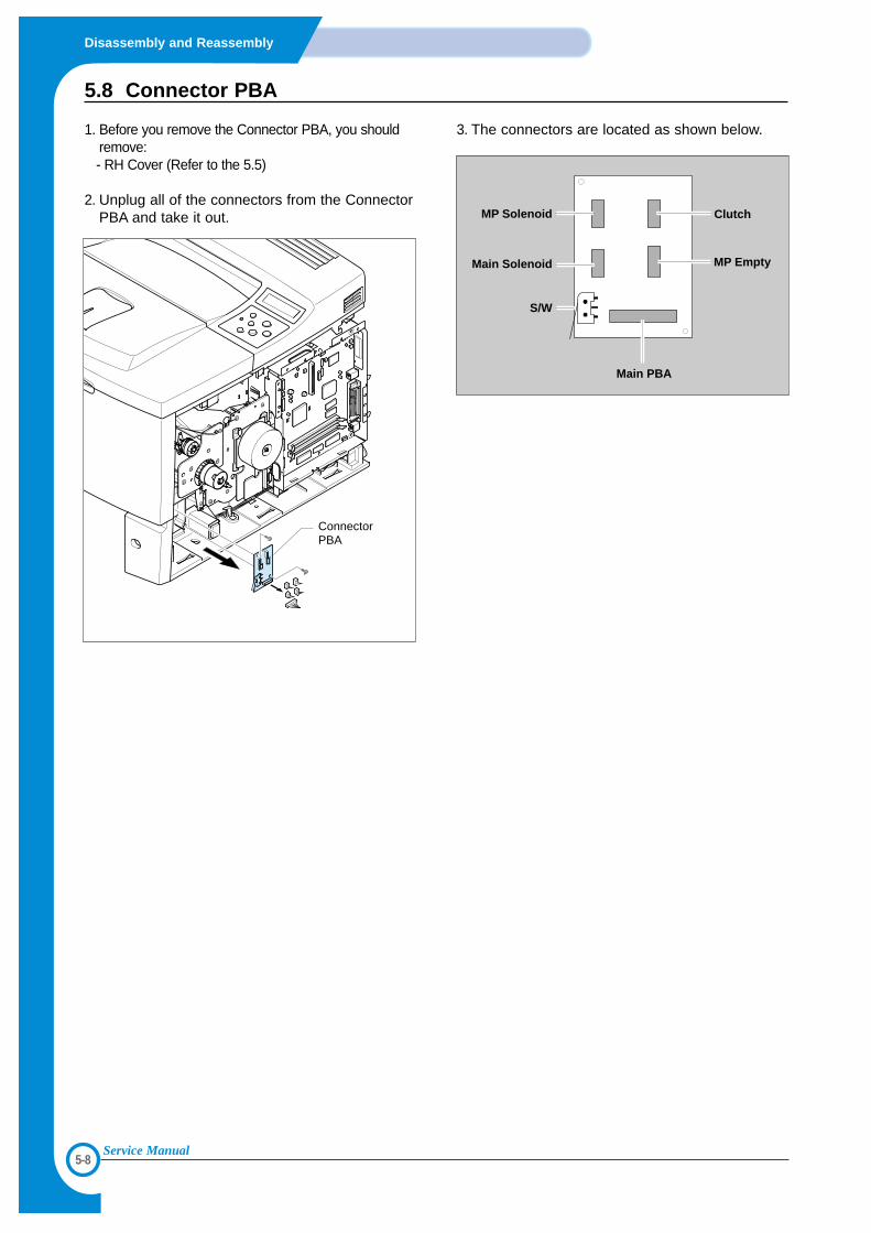
5.8 Connector PBA
1. Before you remove the Connector PBA, you shouldremove:- RH Cover (Refer to the 5.5)
2. Unplug all of the connectors from the ConnectorPBA and take it out.
3. The connectors are located as shown below.
ConnectorPBA
Clutch
MP Empty
Main PBA
MP Solenoid
Main Solenoid
S/W
5-9
Disassembly and Reassembly
Service Manual
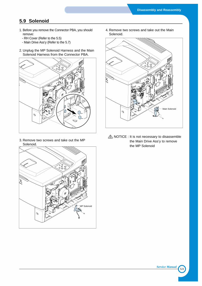
5.9 Solenoid
1. Before you remove the Connector PBA, you shouldremove:- RH Cover (Refer to the 5.5)- Main Drive Ass’y (Refer to the 5.7)
2. Unplug the MP Solenoid Harness and the MainSolenoid Harness from the Connector PBA.
3. Remove two screws and take out the MPSolenoid.
4. Remove two screws and take out the MainSolenoid.
NOTICE : It is not necessary to disassemblethe Main Drive Ass’y to removethe MP Solenoid
MP Solenoid
Main Solenoid
5-10
Disassembly and Reassembly
Service Manual
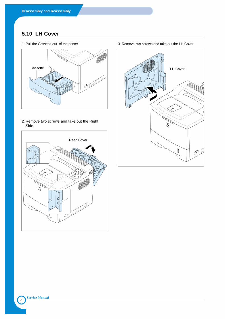
5.10 LH Cover
1. Pull the Cassette out of the printer.
2. Remove two screws and take out the RightSide.
3. Remove two screws and take out the LH Cover
Rear Cover
Cassette LH Cover
5-11
Disassembly and Reassembly
Service Manual
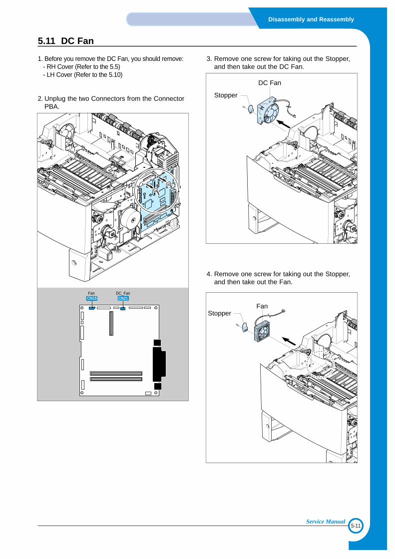
5.11 DC Fan
1. Before you remove the DC Fan, you should remove:- RH Cover (Refer to the 5.5)- LH Cover (Refer to the 5.10)
2. Unplug the two Connectors from the ConnectorPBA.
3. Remove one screw for taking out the Stopper,and then take out the DC Fan.
4. Remove one screw for taking out the Stopper,and then take out the Fan.
Fan CN15
DC_FanCN21
DC Fan
Stopper
FanStopper
5-12
Disassembly and Reassembly
Service Manual
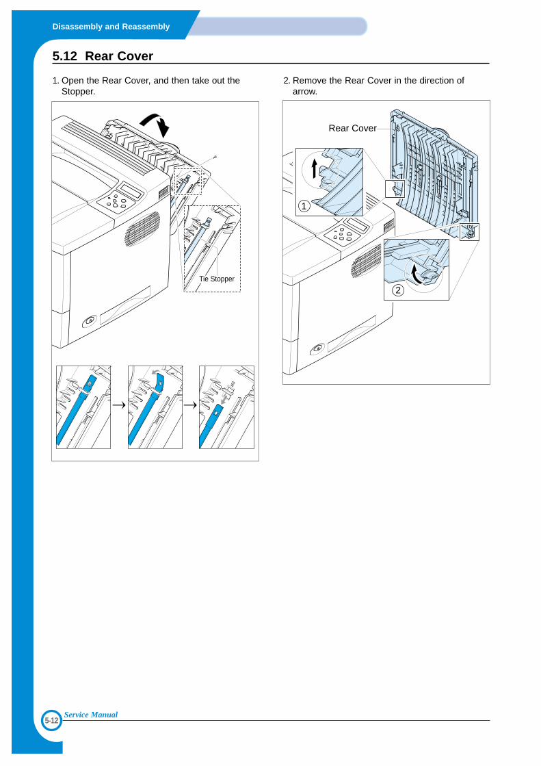
5.12 Rear Cover
1. Open the Rear Cover, and then take out theStopper.
2. Remove the Rear Cover in the direction ofarrow.
Tie Stopper
Rear Cover
1
2
5-13
Disassembly and Reassembly
Service Manual
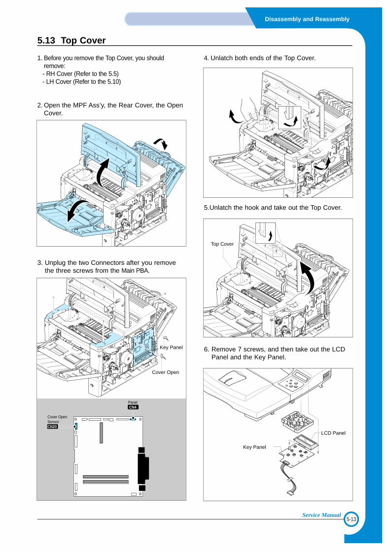
5.13 Top Cover
1. Before you remove the Top Cover, you shouldremove:- RH Cover (Refer to the 5.5)- LH Cover (Refer to the 5.10)
2. Open the MPF Ass’y, the Rear Cover, the OpenCover.
3. Unplug the two Connectors after you removethe three screws from the Main PBA.
4. Unlatch both ends of the Top Cover.
5.Unlatch the hook and take out the Top Cover.
6. Remove 7 screws, and then take out the LCDPanel and the Key Panel.
Top Cover
Key Panel
LCD Panel
Cover Open SensorCN20
PanelCN4
Key Panel
Cover Open
5-14
Disassembly and Reassembly
Service Manual
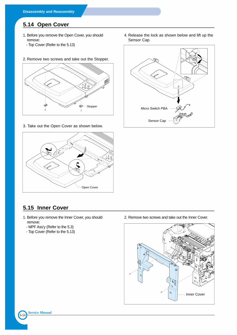
5.14 Open Cover
1. Before you remove the Open Cover, you shouldremove:- Top Cover (Refer to the 5.13)
2. Remove two screws and take out the Stopper.
3. Take out the Open Cover as shown below.
4. Release the lock as shown below and lift up theSensor Cap.
StopperMicro Switch PBA
Sensor Cap
Open Cover
5.15 Inner Cover
1. Before you remove the Inner Cover, you shouldremove:- MPF Ass’y (Refer to the 5.3) - Top Cover (Refer to the 5.13)
2. Remove two screws and take out the Inner Cover.
Inner Cover
5-15
Disassembly and Reassembly
Service Manual
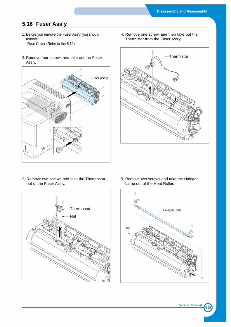
5.16 Fuser Ass’y
1. Before you remove the Fuser Ass’y, you shouldremove:- Rear Cover (Refer to the 5.12)
2. Remove four screws and take out the FuserAss’y.
3. Remove two screws and take the Thermostatout of the Fuser Ass’y.
4. Remove one screw, and then take out theThermistor from the Fuser Ass’y.
5. Remove two screws and take the HalogenLamp out of the Heat Roller.
Fuser Ass’y
Thermistor
Thermostat
Nut
Halogen Lamp
Nut
5-16
Disassembly and Reassembly
Service Manual
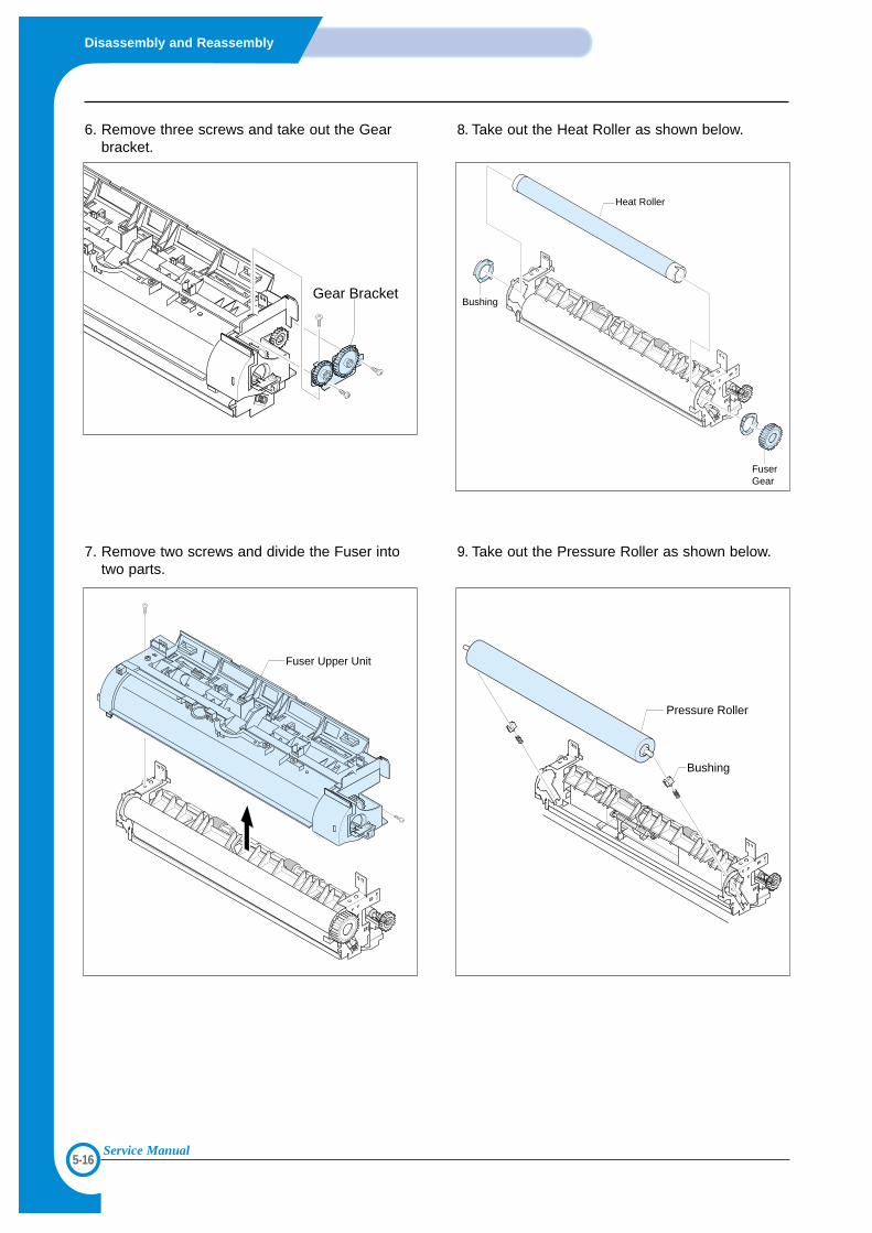
6. Remove three screws and take out the Gearbracket.
7. Remove two screws and divide the Fuser intotwo parts.
8. Take out the Heat Roller as shown below.
9. Take out the Pressure Roller as shown below.
Heat Roller
Bushing
FuserGear
Pressure Roller
Bushing
Gear Bracket
Fuser Upper Unit
5-17
Disassembly and Reassembly
Service Manual
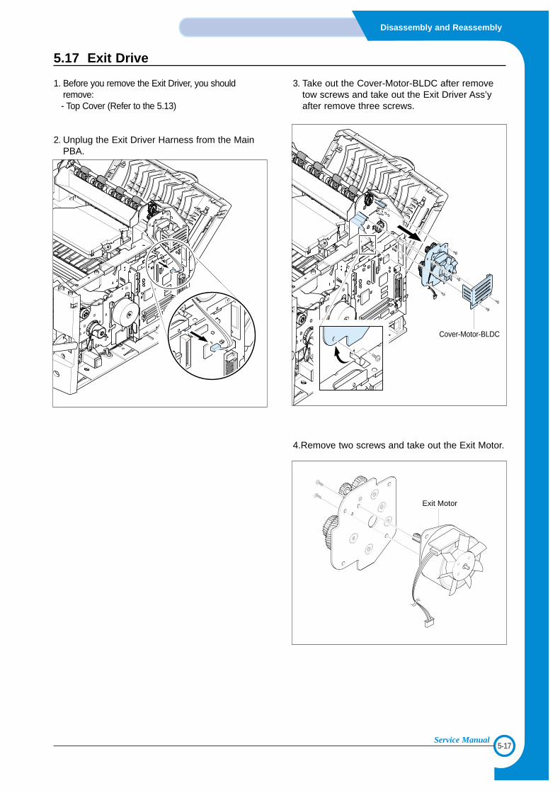
5.17 Exit Drive
1. Before you remove the Exit Driver, you shouldremove:- Top Cover (Refer to the 5.13)
2. Unplug the Exit Driver Harness from the MainPBA.
3. Take out the Cover-Motor-BLDC after removetow screws and take out the Exit Driver Ass’yafter remove three screws.
4.Remove two screws and take out the Exit Motor.
Cover-Motor-BLDC
Exit Motor
5-18
Disassembly and Reassembly
Service Manual
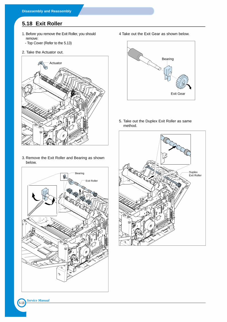
5.18 Exit Roller
1. Before you remove the Exit Roller, you shouldremove:- Top Cover (Refer to the 5.13)
2. Take the Actuator out.
3. Remove the Exit Roller and Bearing as shownbelow.
4 Take out the Exit Gear as shown below.
5. Take out the Duplex Exit Roller as samemethod.
Actuator
Exit Roller
Bearing
Exit Gear
Bearing
Duplex Exit Roller
5-19
Disassembly and Reassembly
Service Manual
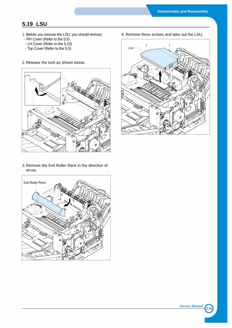
5.19 LSU
1. Before you remove the LSU, you should remove:- RH Cover (Refer to the 5.5)- LH Cover (Refer to the 5.10)- Top Cover (Refer to the 5.5)
2. Release the lock as shown below.
3. Remove the Exit Roller Rack in the direction ofarrow.
4. Remove three screws and take out the LSU.
LSU
5-20
Disassembly and Reassembly
Service Manual
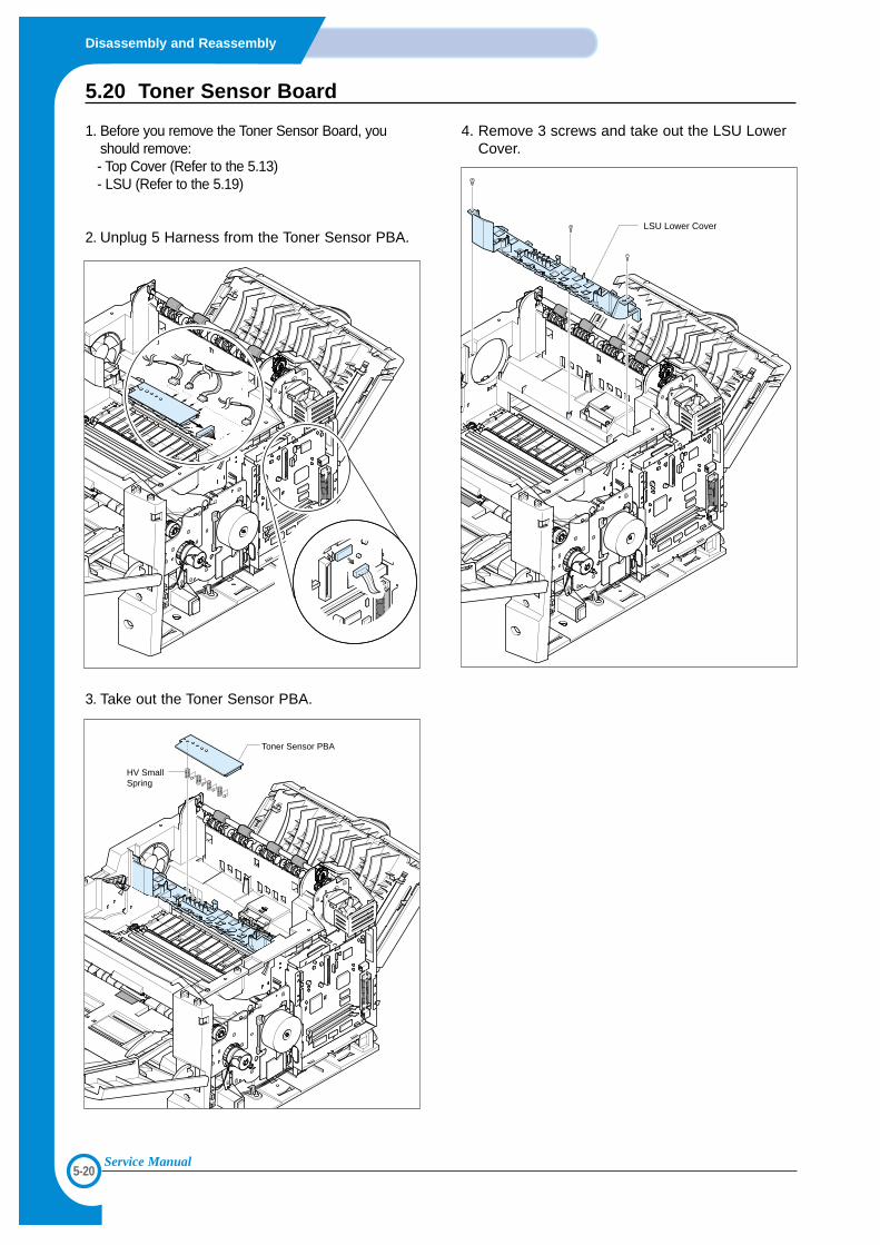
5.20 Toner Sensor Board
1. Before you remove the Toner Sensor Board, youshould remove:- Top Cover (Refer to the 5.13) - LSU (Refer to the 5.19)
2. Unplug 5 Harness from the Toner Sensor PBA.
3. Take out the Toner Sensor PBA.
4. Remove 3 screws and take out the LSU LowerCover.
LSU Lower Cover
HV SmallSpring
Toner Sensor PBA
5-21
Disassembly and Reassembly
Service Manual
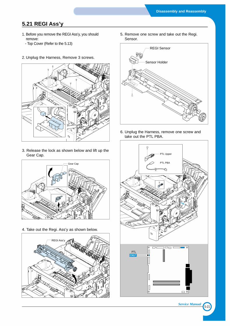
5.21 REGI Ass’y
1. Before you remove the REGI Ass’y, you shouldremove:- Top Cover (Refer to the 5.13)
2. Unplug the Harness, Remove 3 screws.
3. Release the lock as shown below and lift up theGear Cap.
4. Take out the Regi. Ass’y as shown below.
5. Remove one screw and take out the Regi.Sensor.
6. Unplug the Harness, remove one screw andtake out the PTL PBA.
REGI Sensor
Sensor Holder
PTL PBA
PTL Upper
PTLCN17
Gear Cap
REGI Ass’y
5-22
Disassembly and Reassembly
Service Manual
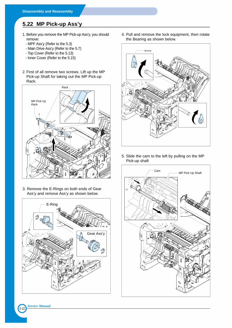
5.22 MP Pick-up Ass’y
1. Before you remove the MP Pick-up Ass’y, you shouldremove:- MPF Ass’y (Refer to the 5.3)- Main Drive Ass’y (Refer to the 5.7) - Top Cover (Refer to the 5.13) - Inner Cover (Refer to the 5.15)
2. First of all remove two screws. Lift up the MPPick-up Shaft for taking out the MP Pick-upRack.
3. Remove the E-Rings on both ends of GearAss’y and remove Ass’y as shown below.
4. Pull and remove the lock equipment, then rotatethe Bearing as shown below.
5. Slide the cam to the left by pulling on the MPPick-up shaft
MP Pick UpRack
Rack
Bearing
CamMP Pick Up Shaft
E-Ring
Gear Ass’y
5-23
Disassembly and Reassembly
Service Manual
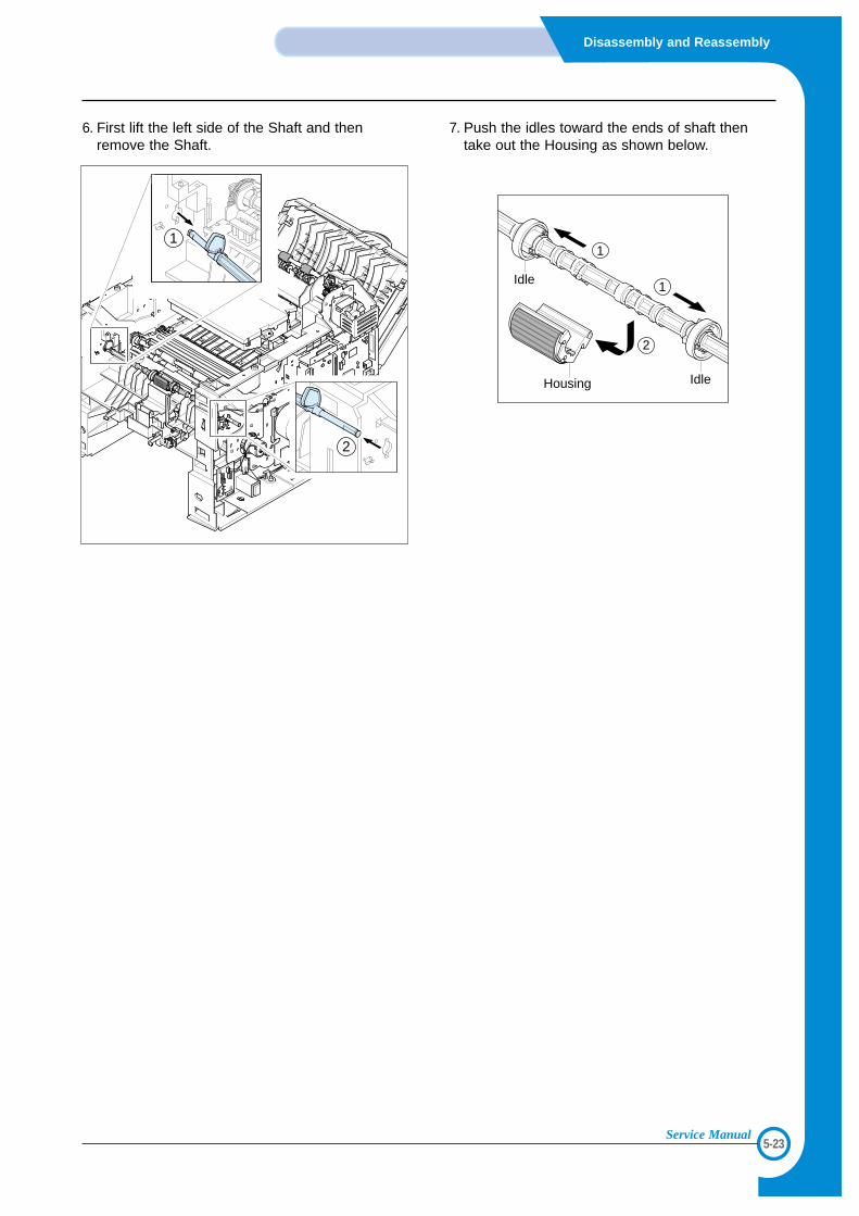
6. First lift the left side of the Shaft and thenremove the Shaft.
7. Push the idles toward the ends of shaft thentake out the Housing as shown below.
1
2
Idle
Housing
1
2
1
Idle
5-24
Disassembly and Reassembly
Service Manual
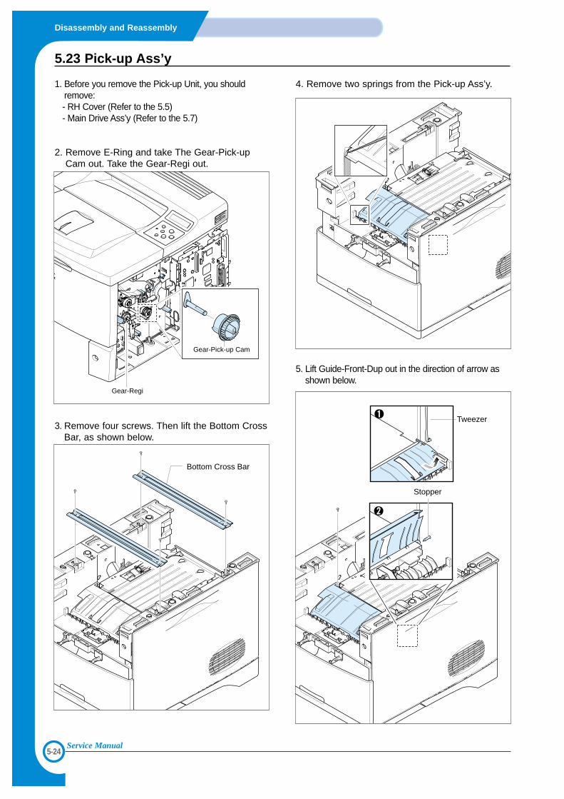
5.23 Pick-up Ass’y
1. Before you remove the Pick-up Unit, you shouldremove:- RH Cover (Refer to the 5.5)- Main Drive Ass’y (Refer to the 5.7)
2. Remove E-Ring and take The Gear-Pick-upCam out. Take the Gear-Regi out.
3. Remove four screws. Then lift the Bottom CrossBar, as shown below.
4. Remove two springs from the Pick-up Ass’y.
5. Lift Guide-Front-Dup out in the direction of arrow asshown below.
Bottom Cross Bar
Stopper
Tweezer
Gear-Pick-up Cam
Gear-Regi
5-25
Disassembly and Reassembly
Service Manual
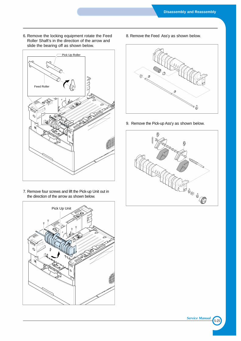
6. Remove the locking equipment rotate the FeedRoller Shaft’s in the direction of the arrow andslide the bearing off as shown below.
7. Remove four screws and lift the Pick-up Unit out inthe direction of the arrow as shown below.
8. Remove the Feed Ass’y as shown below.
9. Remove the Pick-up Ass’y as shown below.
Pick Up Unit
Pick Up Roller
Feed Roller
5-26
Disassembly and Reassembly
Service Manual
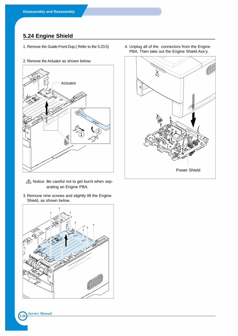
5.24 Engine Shield
1. Remove the Guide-Front-Dup.( Refer to the 5.23.5)
2. Remove the Actuator as shown below.
Notice: Be careful not to get burnt when sep-arating an Engine PBA.
3. Remove nine screws and slightly lift the EngineShield, as shown below.
4. Unplug all of the connectors from the EnginePBA. Then take out the Engine Shield Ass’y.
Actuator
12
Power Shield
5-27
Disassembly and Reassembly
Service Manual
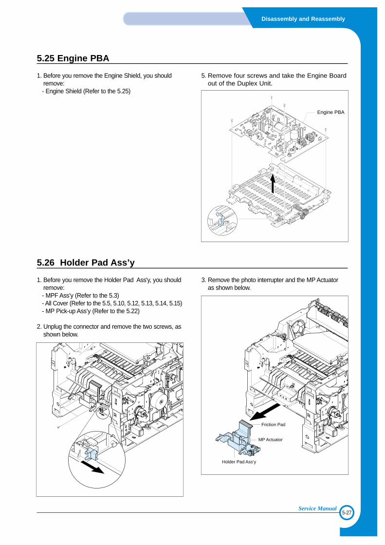
5.25 Engine PBA
1. Before you remove the Engine Shield, you shouldremove:- Engine Shield (Refer to the 5.25)
5. Remove four screws and take the Engine Boardout of the Duplex Unit.
Engine PBA
5.26 Holder Pad Ass’y
1. Before you remove the Holder Pad Ass'y, you shouldremove:- MPF Ass’y (Refer to the 5.3) - All Cover (Refer to the 5.5, 5.10, 5.12, 5.13, 5.14, 5.15) - MP Pick-up Ass’y (Refer to the 5.22)
2. Unplug the connector and remove the two screws, asshown below.
3. Remove the photo interrupter and the MP Actuatoras shown below.
Holder Pad Ass’y
MP Actuator
Friction Pad
66
6-1
Alignment & Adjustments
Service Manual
6. Alignment and Adjustments
This chapter describes the main functions for service, such as the product maintenancemethod, the test output related to maintenance and repair, DCU using method, Jam removingmethod, and so on. It includes the contents of manual.
6.1 How to use EDC (Engine Diagnostic Control) Mode
6.1.1 EDC Setup
• EDC(Engine Diagnostic Control, EDC will be used below) is considered to test and check whether each functions ofmachinery and h/w module are normal or not. All of the test function are able to be controlled by the keys and LCDwindow on the panel without any other kits.
• It’s developed for related engineers, not for users.
6.1.2 Entering/Exiting Method For EDC
<1> Outline• The method for entering “EDC” mode is especial because it is intended for technicians and not users• After Entering the mode, the message, “Engine EDC Mode” is displayed.• On the mode, an engineer should press the “Menu Key” to search each function he would like to test.• Turn the power off, after the test is entirely end.
<2> Usage1. Power off the printer.2. Pressing the “Select key”, power the printer on.3. Keep pressing it until the message, “Engine EDC Mode” is shown on the panel.4. Follow the usage for a function you would like to use.5. Turn the power off, after the test is complete.
6.1.3 Usage & Function of Key on OPE
6.1.4 Usage & Function of LCD
Key Function Description Remarks
Menu Menu To enter the main Menu
Arrow (right) Search a Menu/ Input Data To search a Menu and input a data
Arrow (left) Search a Menu/ Input Data To search a Menu and input a data
Select Execute / Select To execute a function
Cancel Stop / Cancel To stop a function
Upper Level Move To move to the upper level
Line Characters Description Remarks
Top 16 Make engineers recognizing a test location.
[Main Menu] or [Function] is displayed.
Bottom 16 Make engineers recognizing a menu or function to be tested
A menu or function name displayed
6-2
Alignment & Adjustments
Service Manual
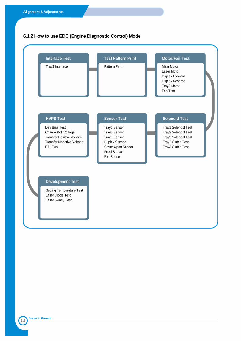
6.1.2 How to use EDC (Engine Diagnostic Control) Mode
Tray3 Interface
Interface Test
Pattern Print
Setting Temperature TestLaser Diode TestLaser Ready Test
Dev Bias Test Charge Roll Voltage Transfer Positive Voltage Transfer Negative VoltagePTL Test
Main Motor Laser Motor Duplex Forward Duplex Reverse Tray3 Motor Fan Test
Tray1 Sensor Tray2 SensorTray3 Sensor Duplex Sensor Cover Open SensorFeed SensorExit Sensor
Solenoid Test
Motor/Fan Test
Sensor TestHVPS Test
Development Test
Test Pattern Print
Tray1 Solenoid Test Tray2 Solenoid Test Tray3 Solenoid Test Tray2 Clutch Test Tray3 Clutch Test
6-3
Alignment & Adjustments
Service Manual
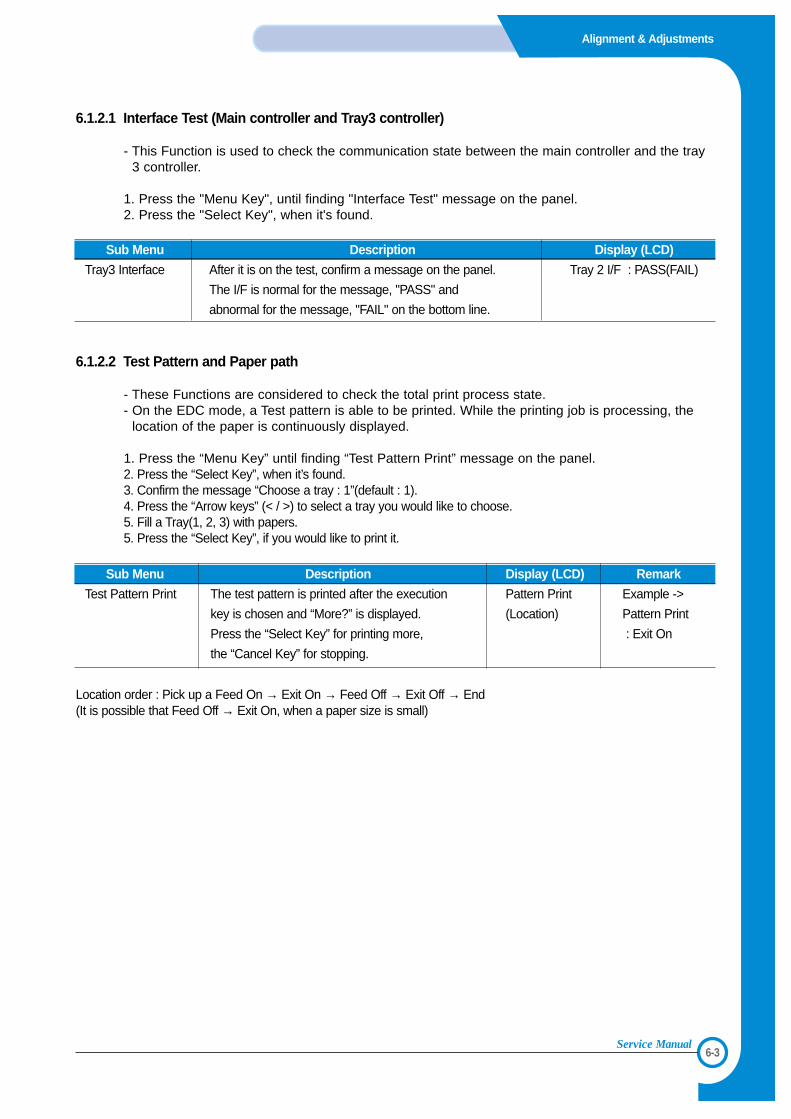
6.1.2.1 Interface Test (Main controller and Tray3 controller)
- This Function is used to check the communication state between the main controller and the tray3 controller.
1. Press the "Menu Key", until finding "Interface Test" message on the panel.2. Press the "Select Key", when it's found.
Sub Menu Description Display (LCD)
Tray3 Interface After it is on the test, confirm a message on the panel. Tray 2 I/F : PASS(FAIL)
The I/F is normal for the message, "PASS" and
abnormal for the message, "FAIL" on the bottom line.
6.1.2.2 Test Pattern and Paper path
- These Functions are considered to check the total print process state.- On the EDC mode, a Test pattern is able to be printed. While the printing job is processing, the
location of the paper is continuously displayed.
1. Press the “Menu Key” until finding “Test Pattern Print” message on the panel.2. Press the “Select Key”, when it’s found.3. Confirm the message “Choose a tray : 1”(default : 1).4. Press the “Arrow keys” (< / >) to select a tray you would like to choose.5. Fill a Tray(1, 2, 3) with papers.5. Press the “Select Key”, if you would like to print it.
Location order : Pick up a Feed On → Exit On → Feed Off → Exit Off → End(It is possible that Feed Off → Exit On, when a paper size is small)
Sub Menu Description Display (LCD) Remark
Test Pattern Print The test pattern is printed after the execution Pattern Print Example ->
key is chosen and “More?” is displayed. (Location) Pattern Print
Press the “Select Key” for printing more, : Exit On
the “Cancel Key” for stopping.
6-4
Alignment & Adjustments
Service Manual
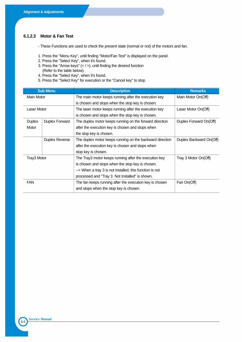
6.1.2.3 Motor & Fan Test
- These Functions are used to check the present state (normal or not) of the motors and fan.
1. Press the "Menu Key", until finding "Motor/Fan Test" is displayed on the panel.2. Press the "Select Key", when it's found.3. Press the "Arrow keys" (< / >), until finding the desired function
(Refer to the table below).4. Press the "Select Key", when it's found.5. Press the "Select Key" for execution or the "Cancel key" to stop.
Sub Menu Description Remarks
Main Motor The main motor keeps running after the execution key Main Motor On(Off)
is chosen and stops when the stop key is chosen.
Laser Motor The laser motor keeps running after the execution key Laser Motor On(Off)
is chosen and stops when the stop key is chosen.
Duplex Duplex Forward The duplex motor keeps running on the forward direction Duplex Forward On(Off)
Motor after the execution key is chosen and stops when
the stop key is chosen.
Duplex Reverse The duplex motor keeps running on the backward direction Duplex Backward On(Off)
after the execution key is chosen and stops when
stop key is chosen.
Tray3 Motor The Tray3 motor keeps running after the execution key Tray 3 Motor On(Off)
is chosen and stops when the stop key is chosen.
--> When a tray 3 is not installed, this function is not
processed and "Tray 3 Not Installed" is shown.
FAN The fan keeps running after the execution key is chosen Fan On(Off)
and stops when the stop key is chosen.
6-5
Alignment & Adjustments
Service Manual
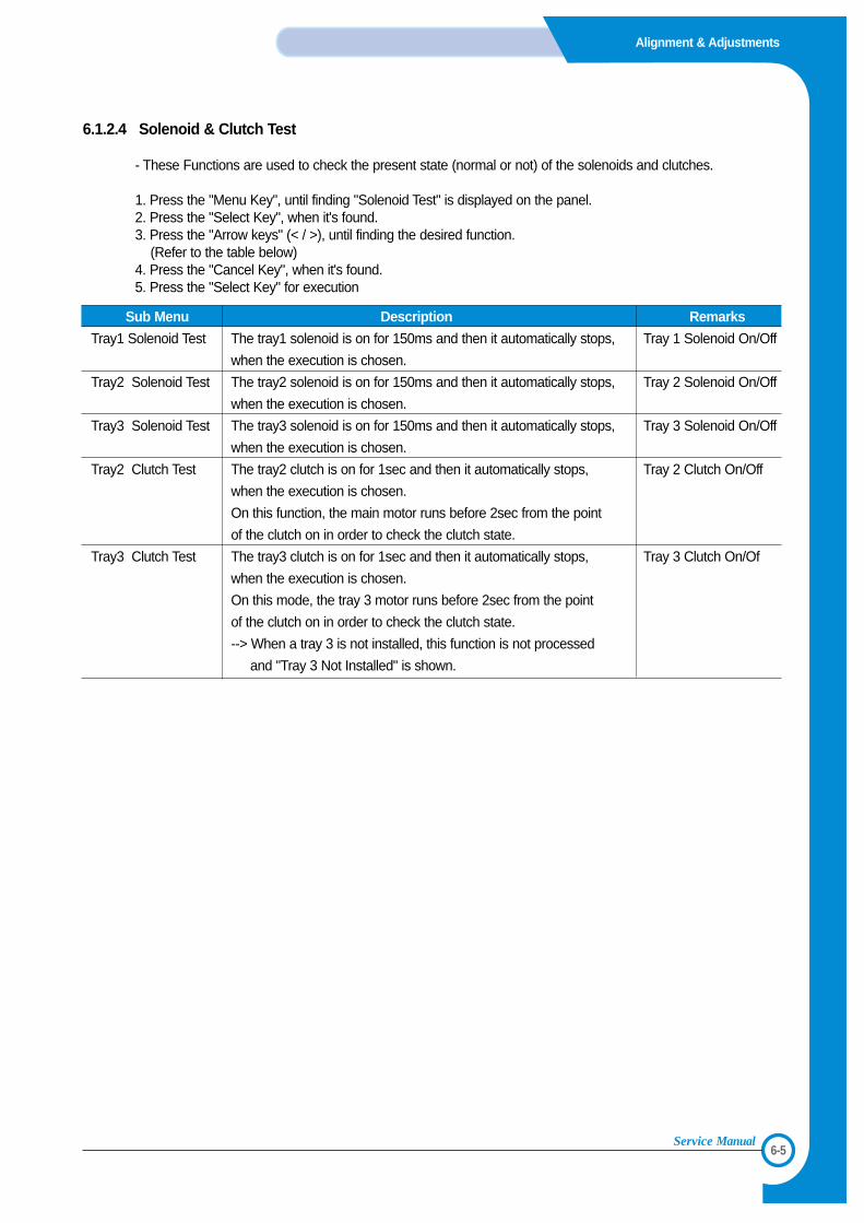
6.1.2.4 Solenoid & Clutch Test
- These Functions are used to check the present state (normal or not) of the solenoids and clutches.
1. Press the "Menu Key", until finding "Solenoid Test" is displayed on the panel.2. Press the "Select Key", when it's found.3. Press the "Arrow keys" (< / >), until finding the desired function.
(Refer to the table below)4. Press the "Cancel Key", when it's found.5. Press the "Select Key" for execution
Sub Menu Description Remarks
Tray1 Solenoid Test The tray1 solenoid is on for 150ms and then it automatically stops, Tray 1 Solenoid On/Off
when the execution is chosen.
Tray2 Solenoid Test The tray2 solenoid is on for 150ms and then it automatically stops, Tray 2 Solenoid On/Off
when the execution is chosen.
Tray3 Solenoid Test The tray3 solenoid is on for 150ms and then it automatically stops, Tray 3 Solenoid On/Off
when the execution is chosen.
Tray2 Clutch Test The tray2 clutch is on for 1sec and then it automatically stops, Tray 2 Clutch On/Off
when the execution is chosen.
On this function, the main motor runs before 2sec from the point
of the clutch on in order to check the clutch state.
Tray3 Clutch Test The tray3 clutch is on for 1sec and then it automatically stops, Tray 3 Clutch On/Of
when the execution is chosen.
On this mode, the tray 3 motor runs before 2sec from the point
of the clutch on in order to check the clutch state.
--> When a tray 3 is not installed, this function is not processed
and "Tray 3 Not Installed" is shown.
6-6
Alignment & Adjustments
Service Manual
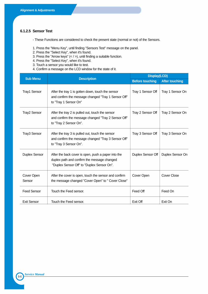
6.1.2.5 Sensor Test
- These Functions are considered to check the present state (normal or not) of the Sensors.
1. Press the "Menu Key", until finding "Sensors Test" message on the panel.2. Press the "Select Key", when it's found.3. Press the "Arrow keys" (< / >), until finding a suitable function.4. Press the "Select Key", when it's found.3. Touch a sensor you would like to test.4. Confirm a message on the LCD window for the state of it.
Sub Menu DescriptionDisplay(LCD)
Before touching After touching
Tray1 Sensor After the tray 1 is gotten down, touch the sensor Tray 1 Sensor Off Tray 1 Sensor On
and confirm the message changed "Tray 1 Sensor Off"
to "Tray 1 Sensor On"
Tray2 Sensor After the tray 2 is pulled out, touch the sensor Tray 2 Sensor Off Tray 2 Sensor On
and confirm the message changed "Tray 2 Sensor Off"
to "Tray 2 Sensor On".
Tray3 Sensor After the tray 3 is pulled out, touch the sensor Tray 3 Sensor Off Tray 3 Sensor On
and confirm the message changed "Tray 3 Sensor Off"
to "Tray 3 Sensor On".
Duplex Sensor After the back cover is open, push a paper into the Duplex Sensor Off Duplex Sensor On
duplex path and confirm the message changed
"Duplex Sensor Off" to "Duplex Sensor On".
Cover Open After the cover is open, touch the sensor and confirm Cover Open Cover Close
Sensor the message changed "Cover Open" to " Cover Close"
Feed Sensor Touch the Feed sensor. Feed Off Feed On
Exit Sensor Touch the Feed sensor. Exit Off Exit On
6-7
Alignment & Adjustments
Service Manual
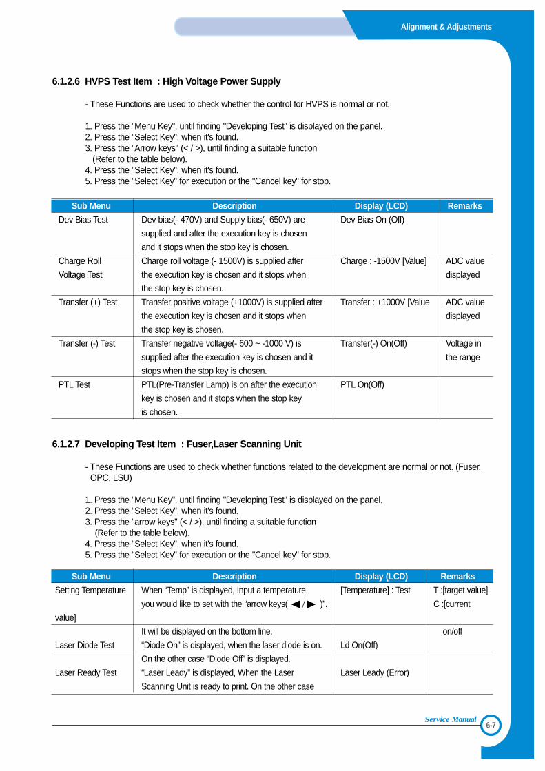
6.1.2.6 HVPS Test Item : High Voltage Power Supply
- These Functions are used to check whether the control for HVPS is normal or not.
1. Press the "Menu Key", until finding "Developing Test" is displayed on the panel.2. Press the "Select Key", when it's found.3. Press the "Arrow keys" (< / >), until finding a suitable function
(Refer to the table below).4. Press the "Select Key", when it's found.5. Press the "Select Key" for execution or the "Cancel key" for stop.
Sub Menu Description Display (LCD) Remarks
Dev Bias Test Dev bias(- 470V) and Supply bias(- 650V) are Dev Bias On (Off)
supplied and after the execution key is chosen
and it stops when the stop key is chosen.
Charge Roll Charge roll voltage (- 1500V) is supplied after Charge : -1500V [Value] ADC value
Voltage Test the execution key is chosen and it stops when displayed
the stop key is chosen.
Transfer (+) Test Transfer positive voltage (+1000V) is supplied after Transfer : +1000V [Value ADC value
the execution key is chosen and it stops when displayed
the stop key is chosen.
Transfer (-) Test Transfer negative voltage(- 600 ~ -1000 V) is Transfer(-) On(Off) Voltage in
supplied after the execution key is chosen and it the range
stops when the stop key is chosen.
PTL Test PTL(Pre-Transfer Lamp) is on after the execution PTL On(Off)
key is chosen and it stops when the stop key
is chosen.
6.1.2.7 Developing Test Item : Fuser,Laser Scanning Unit
- These Functions are used to check whether functions related to the development are normal or not. (Fuser,OPC, LSU)
1. Press the "Menu Key", until finding "Developing Test" is displayed on the panel.2. Press the "Select Key", when it's found.3. Press the "arrow keys" (< / >), until finding a suitable function
(Refer to the table below).4. Press the "Select Key", when it's found.5. Press the "Select Key" for execution or the "Cancel key" for stop.
Sub Menu Description Display (LCD) Remarks
Setting Temperature When “Temp” is displayed, Input a temperature [Temperature] : Test T :[target value]
you would like to set with the “arrow keys( )”. C :[current
value]
It will be displayed on the bottom line. on/off
Laser Diode Test “Diode On” is displayed, when the laser diode is on. Ld On(Off)
On the other case “Diode Off” is displayed.
Laser Ready Test “Laser Leady” is displayed, When the Laser Laser Leady (Error)
Scanning Unit is ready to print. On the other case
6-8
Alignment & Adjustments
Service Manual
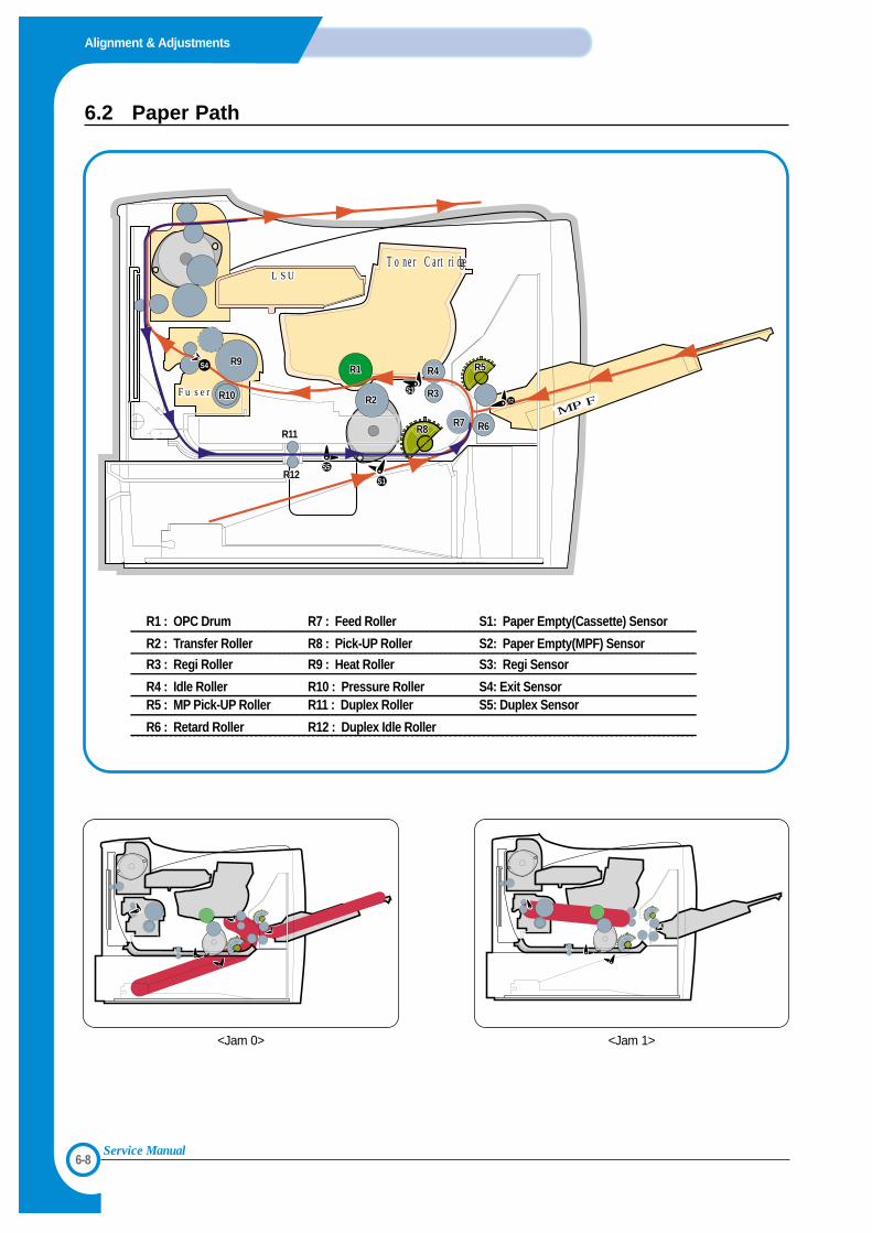
6.2 Paper Path
LSU
솔레노이드솔레노이드
Toner CartridgeToner Cartridge
MPFFuserFuser
LSUToner Cartridge
MPFFuser
R1R1
S1
S2
S3
S4
S5
R9R9
R3R10R10
R11R11
R12R12
R2R2R3
R4
R3
R4 R5R5
R6R6R7R7R8R8
R1 : OPC Drum R7 : Feed Roller S1: Paper Empty(Cassette) Sensor
R2 : Transfer Roller R8 : Pick-UP Roller S2: Paper Empty(MPF) Sensor
R3 : Regi Roller R9 : Heat Roller S3: Regi Sensor
R4 : Idle Roller R10 : Pressure Roller S4: Exit SensorR5 : MP Pick-UP Roller R11 : Duplex Roller S5: Duplex Sensor
R6 : Retard Roller R12 : Duplex Idle Roller
<Jam 0> <Jam 1>
6-9
Alignment & Adjustments
Service Manual
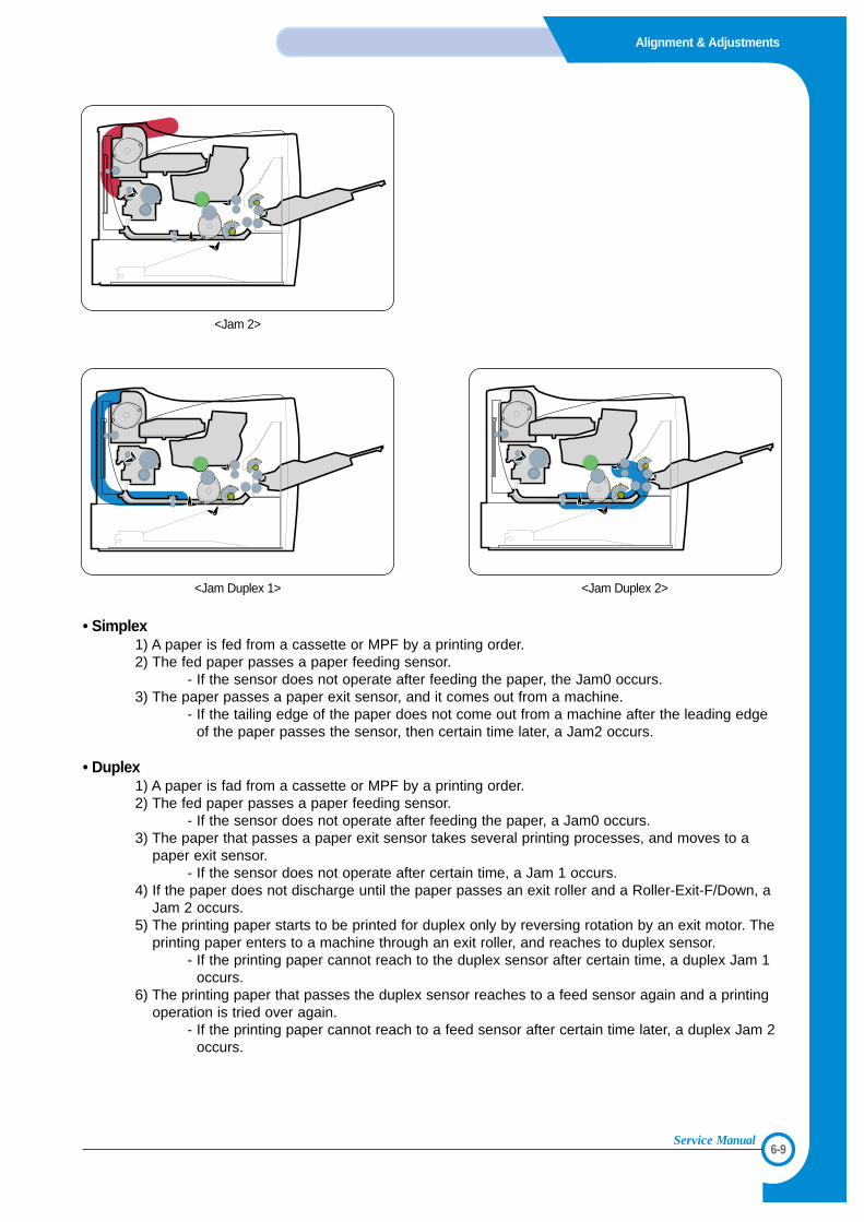
• Simplex1) A paper is fed from a cassette or MPF by a printing order.2) The fed paper passes a paper feeding sensor.
- If the sensor does not operate after feeding the paper, the Jam0 occurs. 3) The paper passes a paper exit sensor, and it comes out from a machine.
- If the tailing edge of the paper does not come out from a machine after the leading edgeof the paper passes the sensor, then certain time later, a Jam2 occurs.
• Duplex1) A paper is fad from a cassette or MPF by a printing order.2) The fed paper passes a paper feeding sensor.
- If the sensor does not operate after feeding the paper, a Jam0 occurs. 3) The paper that passes a paper exit sensor takes several printing processes, and moves to a
paper exit sensor.- If the sensor does not operate after certain time, a Jam 1 occurs.
4) If the paper does not discharge until the paper passes an exit roller and a Roller-Exit-F/Down, aJam 2 occurs.
5) The printing paper starts to be printed for duplex only by reversing rotation by an exit motor. Theprinting paper enters to a machine through an exit roller, and reaches to duplex sensor.
- If the printing paper cannot reach to the duplex sensor after certain time, a duplex Jam 1occurs.
6) The printing paper that passes the duplex sensor reaches to a feed sensor again and a printingoperation is tried over again.
- If the printing paper cannot reach to a feed sensor after certain time later, a duplex Jam 2occurs.
<Jam 2>
<Jam Duplex 1> <Jam Duplex 2>
6-10
Alignment & Adjustments
Service Manual
6.2.1 Clearing Paper Jams
When a paper jam occurs,the display on the control panel shows the message indicating the corresponding location of thepaper jam.
6.2.1.1 Tips for Avoiding Paper Jams
By selecting the correct paper types, most paper jams can be avoided. If a paper jam occurs, follow the steps outlined in
• Ensure that the adjustable guides are positioned correctly.• Do not overload the tray. Ensure that the paper is below the paper capacity mark on the right inside of the tray.• Do not remove the paper from the tray while printing.• Flex, fan and straighten the paper before loading. • Do not use creased, damp or highly curled paper.• Do not mix paper types in the input tray.• Use only recommended print media.• Ensure that the recommended print side is facing down when loading paper into the input tray.
6.2.1.2 In the Paper Feed Area(Jam 0)
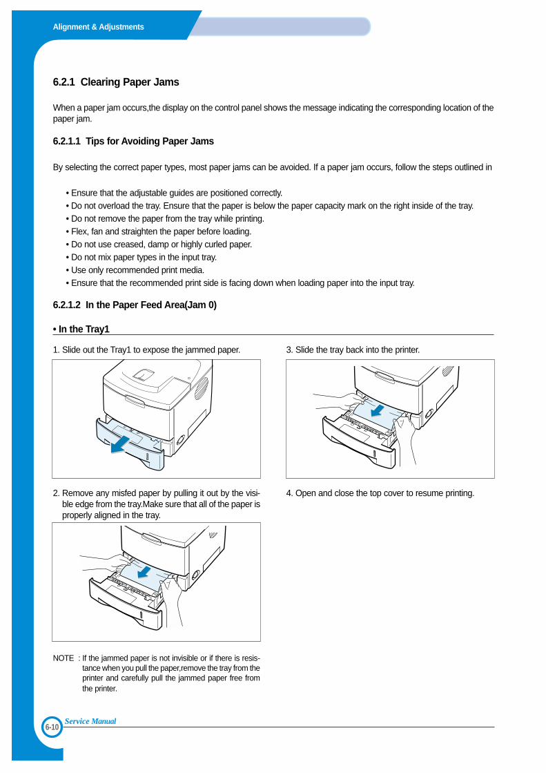
• In the Tray1
1. Slide out the Tray1 to expose the jammed paper.
2. Remove any misfed paper by pulling it out by the visi-ble edge from the tray.Make sure that all of the paper isproperly aligned in the tray.
NOTE : If the jammed paper is not invisible or if there is resis-tance when you pull the paper,remove the tray from theprinter and carefully pull the jammed paper free fromthe printer.
3. Slide the tray back into the printer.
4. Open and close the top cover to resume printing.
6-11
Alignment & Adjustments
Service Manual
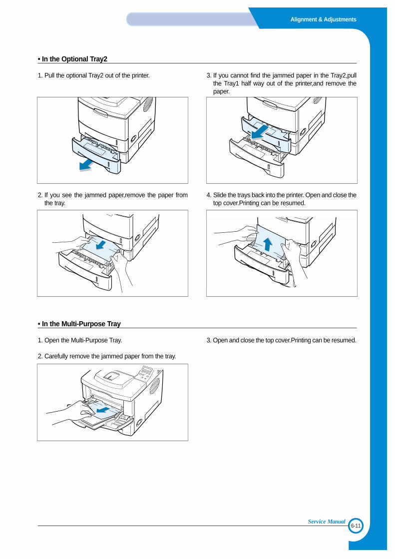
• In the Optional Tray2
1. Pull the optional Tray2 out of the printer.
2. If you see the jammed paper,remove the paper fromthe tray.
3. If you cannot find the jammed paper in the Tray2,pullthe Tray1 half way out of the printer,and remove thepaper.
4. Slide the trays back into the printer. Open and close thetop cover.Printing can be resumed.
• In the Multi-Purpose Tray
1. Open the Multi-Purpose Tray.
2. Carefully remove the jammed paper from the tray.
3. Open and close the top cover.Printing can be resumed.
6-12
Alignment & Adjustments
Service Manual
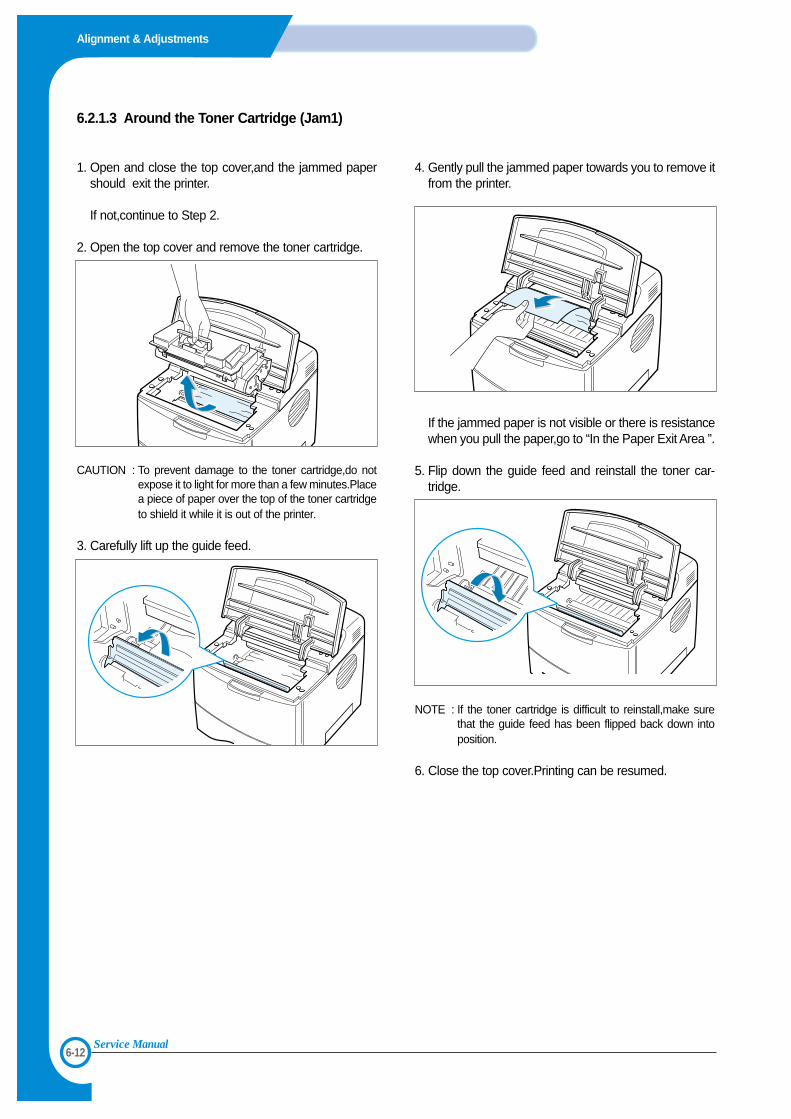
6.2.1.3 Around the Toner Cartridge (Jam1)
1. Open and close the top cover,and the jammed papershould exit the printer.
If not,continue to Step 2.
2. Open the top cover and remove the toner cartridge.
CAUTION : To prevent damage to the toner cartridge,do notexpose it to light for more than a few minutes.Placea piece of paper over the top of the toner cartridgeto shield it while it is out of the printer.
3. Carefully lift up the guide feed.
4. Gently pull the jammed paper towards you to remove itfrom the printer.
If the jammed paper is not visible or there is resistancewhen you pull the paper,go to “In the Paper Exit Area ”.
5. Flip down the guide feed and reinstall the toner car-tridge.
NOTE : If the toner cartridge is difficult to reinstall,make surethat the guide feed has been flipped back down intoposition.
6. Close the top cover.Printing can be resumed.
6-13
Alignment & Adjustments
Service Manual
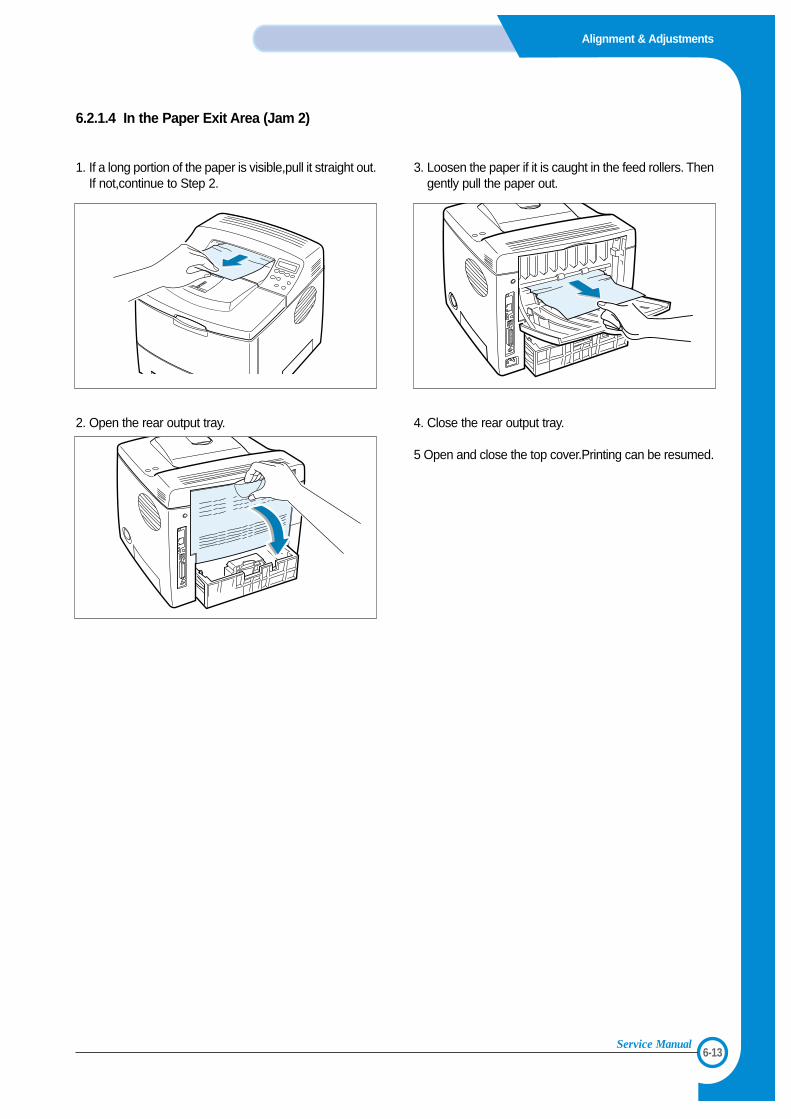
6.2.1.4 In the Paper Exit Area (Jam 2)
1. If a long portion of the paper is visible,pull it straight out.If not,continue to Step 2.
2. Open the rear output tray.
3. Loosen the paper if it is caught in the feed rollers. Thengently pull the paper out.
4. Close the rear output tray.
5 Open and close the top cover.Printing can be resumed.
6-14
Alignment & Adjustments
Service Manual
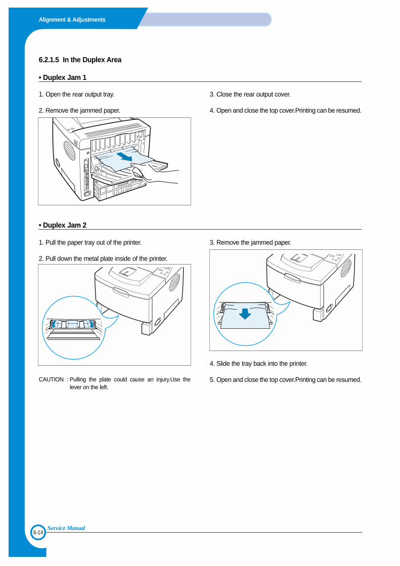
6.2.1.5 In the Duplex Area
• Duplex Jam 1
1. Open the rear output tray.
2. Remove the jammed paper.
3. Close the rear output cover.
4. Open and close the top cover.Printing can be resumed.
• Duplex Jam 2
1. Pull the paper tray out of the printer.
2. Pull down the metal plate inside of the printer.
CAUTION : Pulling the plate could cause an injury.Use thelever on the left.
3. Remove the jammed paper.
4. Slide the tray back into the printer.
5. Open and close the top cover.Printing can be resumed.
6-15
Alignment & Adjustments
Service Manual
6.3 Sample Pattern
This product has the several sample patterns for maintenance. With the sample patterns, check the existence of the abnor-mality. The patterns help to regularly maintain the product.
6.3.1 Printing a Demo PagePrint a demo page to make sure that the printer is operating correctly.
1. Press the Menu button on the control panel until you see “Information ” on the bottom line of the display..
2. Press the Enter button to access the Menu.
3. Press the scroll button until you see “Demo Page ” on the bottom line.
4. Press the Enter button .
A demo page showing the printer ’s features and capabilities prints out.
6.3.2 Printing a cleaning sheetIf you are experiencing blurred,faded or smeared printouts,you can clear the problem by printing a cleaning sheet,provid-ed by your printer.You can print :
• OPC Cleaning sheet :cleans the OPC drum of the toner cartridge.• Fuser Cleaning sheet :cleans the fuser unit inside the printer.
This process will produce a page with toner debris,which should be discarded.
1. Ensure that the printer is turned on and in ready mode with paper loaded in the tray.
2. Press the Menu button on the control panel until you see “Setup ” on the bottom line of the display..
3. Press the Enter button to access the Menu.
4. Press the scroll button until “Maintenance ” displays on the bottom line and press the Enter button .
5. Press the scroll button to select the required option,“OPC Cleaning ” or “Fuser Cleaning.”
6. Press the Enter button .
Your printer automatically picks up a sheet of paper from the tray and prints out a cleaning sheet with dust or tonerparticles on it.
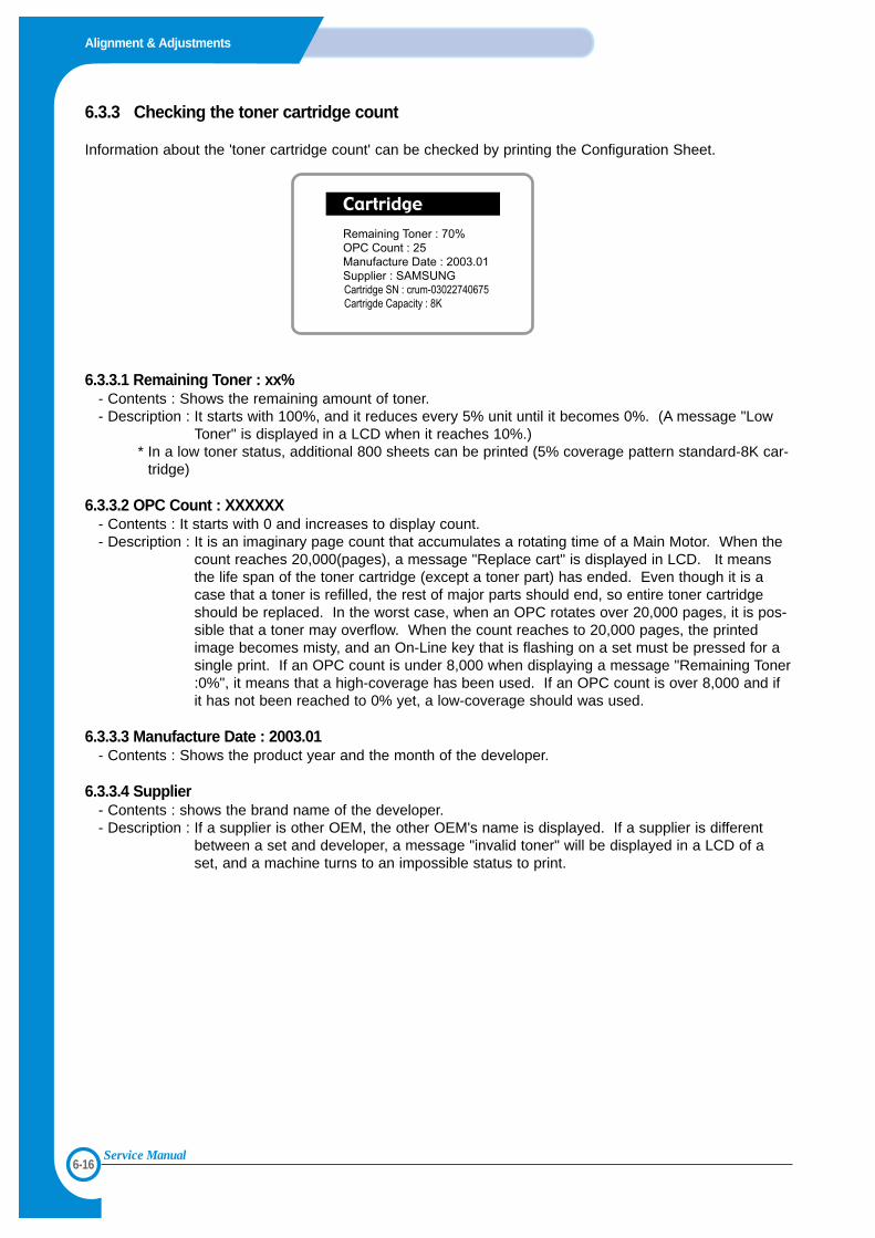
6-16
Alignment & Adjustments
Service Manual
6.3.3 Checking the toner cartridge count
Information about the 'toner cartridge count' can be checked by printing the Configuration Sheet.
6.3.3.1 Remaining Toner : xx%- Contents : Shows the remaining amount of toner.- Description : It starts with 100%, and it reduces every 5% unit until it becomes 0%. (A message "Low
Toner" is displayed in a LCD when it reaches 10%.)* In a low toner status, additional 800 sheets can be printed (5% coverage pattern standard-8K car-
tridge)
6.3.3.2 OPC Count : XXXXXX- Contents : It starts with 0 and increases to display count.- Description : It is an imaginary page count that accumulates a rotating time of a Main Motor. When the
count reaches 20,000(pages), a message "Replace cart" is displayed in LCD. It meansthe life span of the toner cartridge (except a toner part) has ended. Even though it is acase that a toner is refilled, the rest of major parts should end, so entire toner cartridgeshould be replaced. In the worst case, when an OPC rotates over 20,000 pages, it is pos-sible that a toner may overflow. When the count reaches to 20,000 pages, the printedimage becomes misty, and an On-Line key that is flashing on a set must be pressed for asingle print. If an OPC count is under 8,000 when displaying a message "Remaining Toner:0%", it means that a high-coverage has been used. If an OPC count is over 8,000 and ifit has not been reached to 0% yet, a low-coverage should was used.
6.3.3.3 Manufacture Date : 2003.01- Contents : Shows the product year and the month of the developer.
6.3.3.4 Supplier - Contents : shows the brand name of the developer.- Description : If a supplier is other OEM, the other OEM's name is displayed. If a supplier is different
between a set and developer, a message "invalid toner" will be displayed in a LCD of aset, and a machine turns to an impossible status to print.
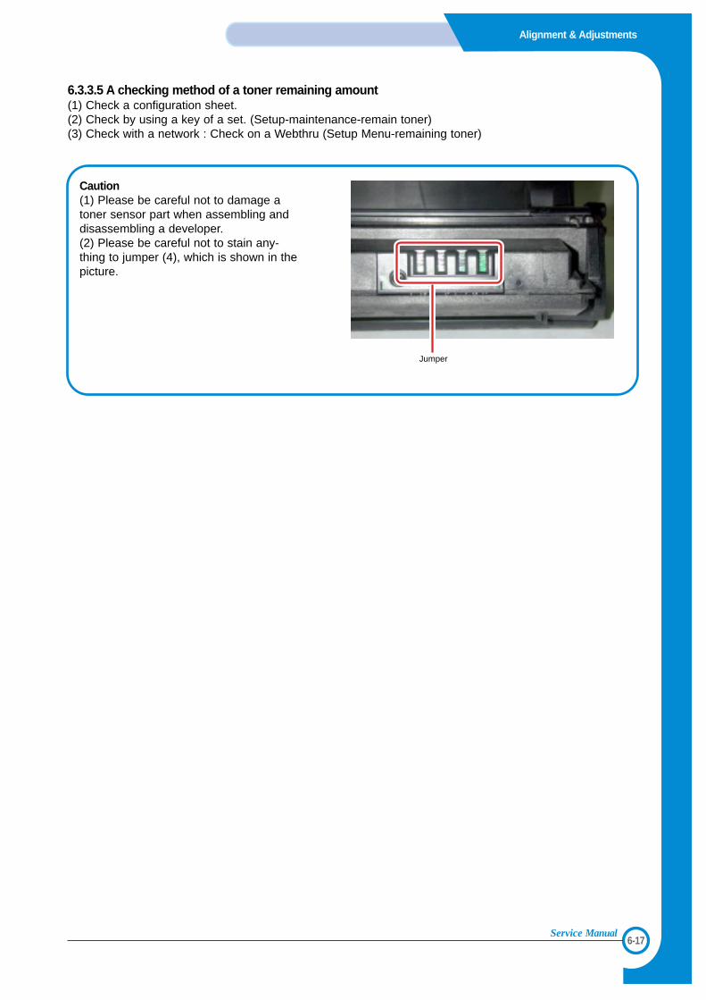
6-17
Alignment & Adjustments
Service Manual
6.3.3.5 A checking method of a toner remaining amount(1) Check a configuration sheet.(2) Check by using a key of a set. (Setup-maintenance-remain toner)(3) Check with a network : Check on a Webthru (Setup Menu-remaining toner)
Jumper
Caution(1) Please be careful not to damage atoner sensor part when assembling anddisassembling a developer.(2) Please be careful not to stain any-thing to jumper (4), which is shown in thepicture.
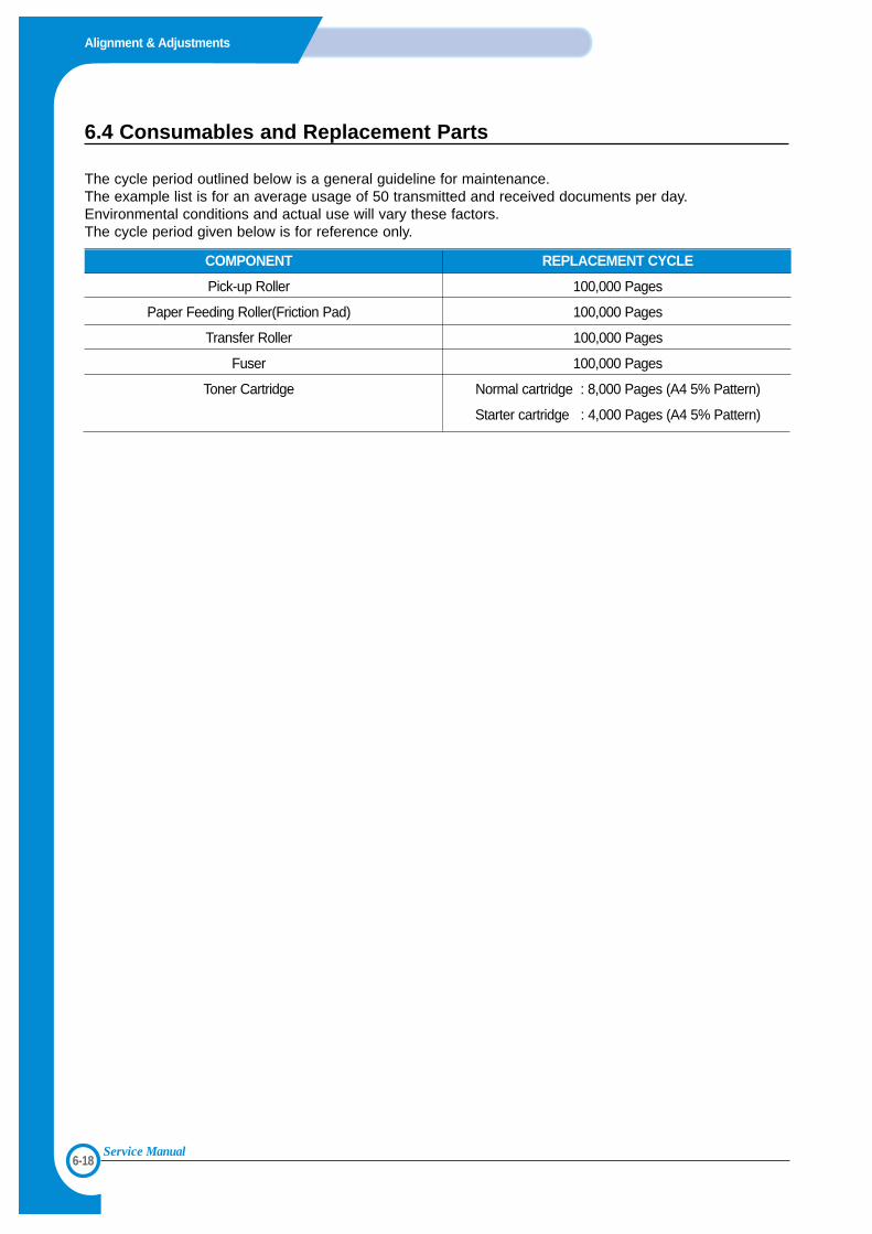
6-18
Alignment & Adjustments
Service Manual
COMPONENT REPLACEMENT CYCLE
Pick-up Roller 100,000 Pages
Paper Feeding Roller(Friction Pad) 100,000 Pages
Transfer Roller 100,000 Pages
Fuser 100,000 Pages
Toner Cartridge Normal cartridge : 8,000 Pages (A4 5% Pattern)
Starter cartridge : 4,000 Pages (A4 5% Pattern)
6.4 Consumables and Replacement Parts
The cycle period outlined below is a general guideline for maintenance. The example list is for an average usage of 50 transmitted and received documents per day. Environmental conditions and actual use will vary these factors. The cycle period given below is for reference only.
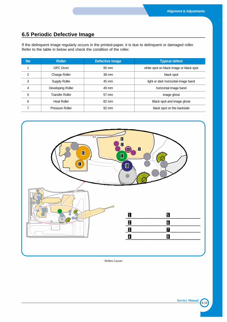
6-19
Alignment & Adjustments
Service Manual
6.5 Periodic Defective Image
If the delinquent image regularly occurs in the printed-paper, it is due to delinquent or damaged roller.Refer to the table in below and check the condition of the roller.
No Roller Defective image Typical defect
1 OPC Drum 95 mm white spot on black image or black spot
2 Charge Roller 38 mm black spot
3 Supply Roller 45 mm light or dark horizontal image band
4 Developing Roller 49 mm horizontal image band
5 Transfer Roller 57 mm image ghost
6 Heat Roller 82 mm Black spot and image ghost
7 Pressure Roller 92 mm black spot on the backside
솔레노이드솔레노이드
R11
R12
OPC DrumCharge RollerSupply RollerDeveloping Roller
Transfer RollerHeat RollerPressure RollerCleaning Roller
1
2
3
4
1
8
34
5
6
7
2
5
6
7
8
<Rollers Layout>

6-20
Alignment & Adjustments
Service Manual
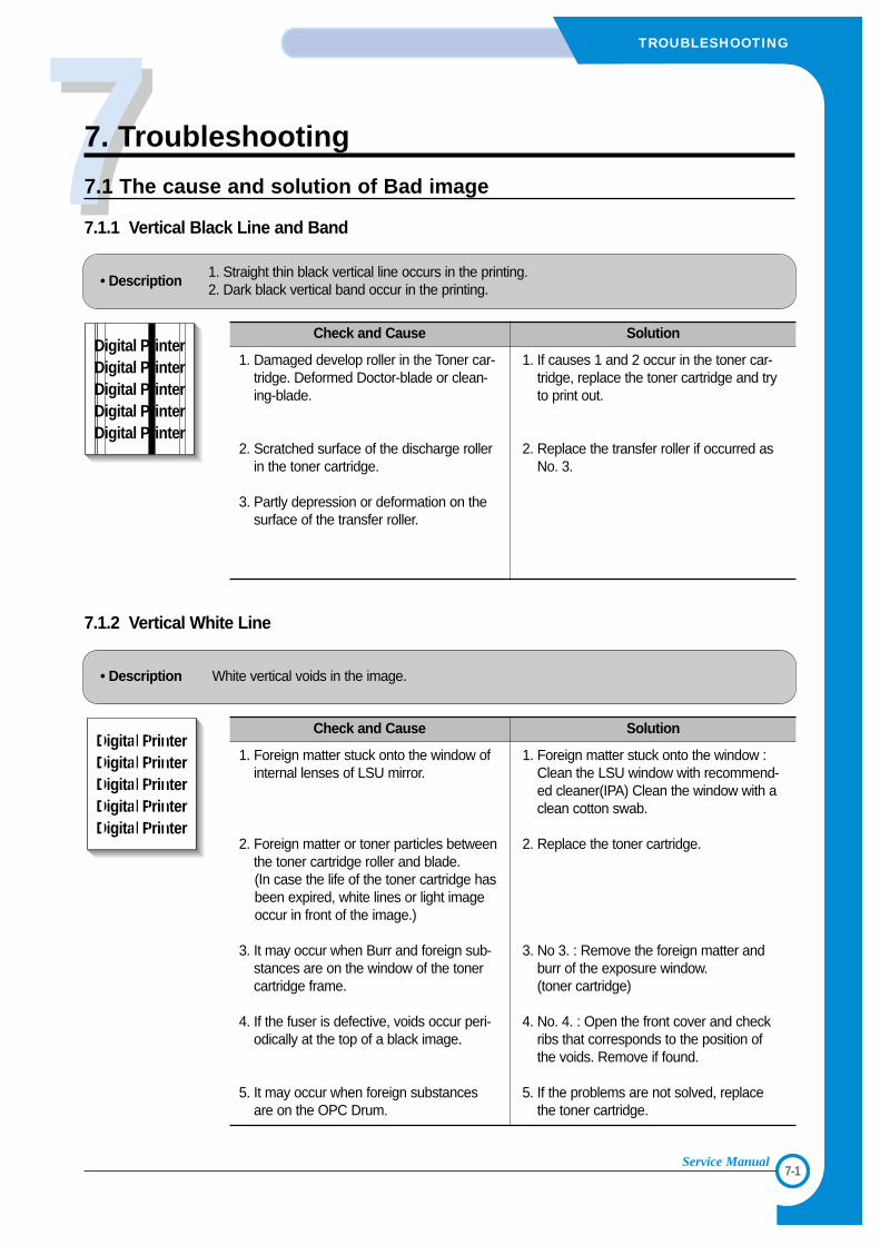
77
7-1
TROUBLESHOOTING
Service Manual
7. Troubleshooting
7.1 The cause and solution of Bad image
7.1.1 Vertical Black Line and Band
• Description1. Straight thin black vertical line occurs in the printing.2. Dark black vertical band occur in the printing.
Digital PrinterDigital PrinterDigital PrinterDigital PrinterDigital Printer
Check and Cause Solution
1. Damaged develop roller in the Toner car-tridge. Deformed Doctor-blade or clean-ing-blade.
2. Scratched surface of the discharge rollerin the toner cartridge.
3. Partly depression or deformation on thesurface of the transfer roller.
1. If causes 1 and 2 occur in the toner car-tridge, replace the toner cartridge and tryto print out.
2. Replace the transfer roller if occurred asNo. 3.
7.1.2 Vertical White Line
• Description White vertical voids in the image.
Digital PrinterDigital PrinterDigital PrinterDigital PrinterDigital Printer
Check and Cause Solution
1. Foreign matter stuck onto the window ofinternal lenses of LSU mirror.
2. Foreign matter or toner particles betweenthe toner cartridge roller and blade.(In case the life of the toner cartridge hasbeen expired, white lines or light imageoccur in front of the image.)
3. It may occur when Burr and foreign sub-stances are on the window of the tonercartridge frame.
4. If the fuser is defective, voids occur peri-odically at the top of a black image.
5. It may occur when foreign substancesare on the OPC Drum.
1. Foreign matter stuck onto the window :Clean the LSU window with recommend-ed cleaner(IPA) Clean the window with aclean cotton swab.
2. Replace the toner cartridge.
3. No 3. : Remove the foreign matter andburr of the exposure window.(toner cartridge)
4. No. 4. : Open the front cover and checkribs that corresponds to the position ofthe voids. Remove if found.
5. If the problems are not solved, replacethe toner cartridge.
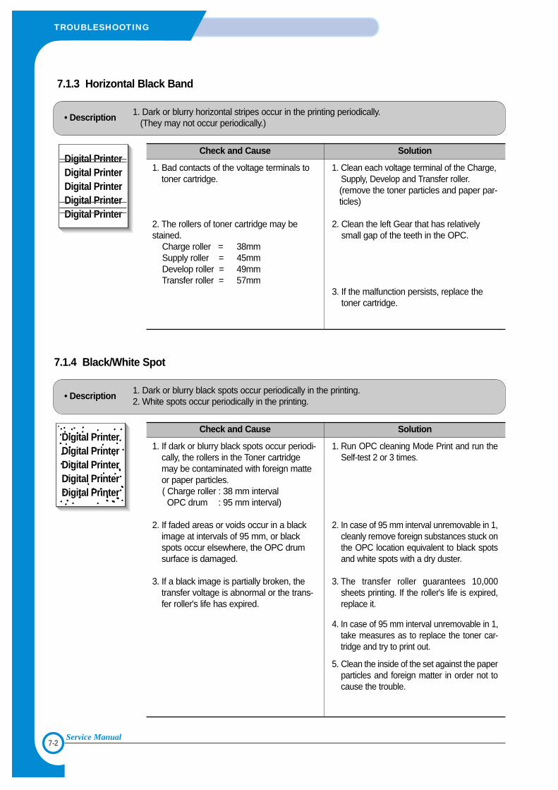
7-2
TROUBLESHOOTING
Service Manual
7.1.3 Horizontal Black Band
• Description1. Dark or blurry horizontal stripes occur in the printing periodically.
(They may not occur periodically.)
Digital PrinterDigital PrinterDigital PrinterDigital PrinterDigital Printer
Check and Cause Solution
1. Bad contacts of the voltage terminals totoner cartridge.
2. The rollers of toner cartridge may bestained.
Charge roller = 38mmSupply roller = 45mmDevelop roller = 49mmTransfer roller = 57mm
1. Clean each voltage terminal of the Charge,Supply, Develop and Transfer roller.(remove the toner particles and paper par-ticles)
2. Clean the left Gear that has relativelysmall gap of the teeth in the OPC.
3. If the malfunction persists, replace thetoner cartridge.
7.1.4 Black/White Spot
• Description1. Dark or blurry black spots occur periodically in the printing.2. White spots occur periodically in the printing.
Digital PrinterDigital PrinterDigital PrinterDigital PrinterDigital Printer
Check and Cause Solution
1. If dark or blurry black spots occur periodi-cally, the rollers in the Toner cartridgemay be contaminated with foreign matteor paper particles.( Charge roller : 38 mm intervalOPC drum : 95 mm interval)
2. If faded areas or voids occur in a blackimage at intervals of 95 mm, or blackspots occur elsewhere, the OPC drumsurface is damaged.
3. If a black image is partially broken, thetransfer voltage is abnormal or the trans-fer roller's life has expired.
1. Run OPC cleaning Mode Print and run theSelf-test 2 or 3 times.
2. In case of 95 mm interval unremovable in 1,cleanly remove foreign substances stuck onthe OPC location equivalent to black spotsand white spots with a dry duster.
3. The transfer roller guarantees 10,000sheets printing. If the roller's life is expired,replace it.
4. In case of 95 mm interval unremovable in 1,take measures as to replace the toner car-tridge and try to print out.
5. Clean the inside of the set against the paperparticles and foreign matter in order not tocause the trouble.
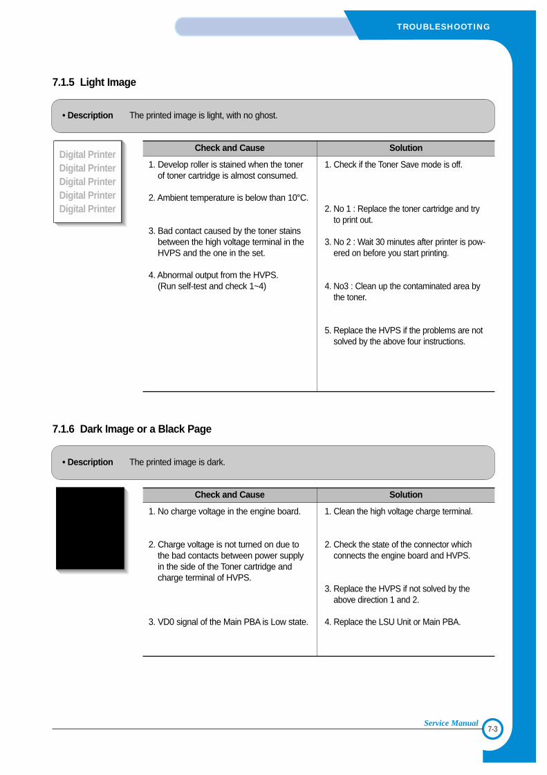
7-3
TROUBLESHOOTING
Service Manual
7.1.5 Light Image
• Description The printed image is light, with no ghost.
Digital PrinterDigital PrinterDigital PrinterDigital PrinterDigital Printer
Check and Cause Solution
1. Develop roller is stained when the tonerof toner cartridge is almost consumed.
2. Ambient temperature is below than 10°C.
3. Bad contact caused by the toner stainsbetween the high voltage terminal in theHVPS and the one in the set.
4. Abnormal output from the HVPS.(Run self-test and check 1~4)
1. Check if the Toner Save mode is off.
2. No 1 : Replace the toner cartridge and tryto print out.
3. No 2 : Wait 30 minutes after printer is pow-ered on before you start printing.
4. No3 : Clean up the contaminated area bythe toner.
5. Replace the HVPS if the problems are notsolved by the above four instructions.
7.1.6 Dark Image or a Black Page
• Description The printed image is dark.
Digital PrinterDigital PrinterDigital PrinterDigital PrinterDigital Printer
Check and Cause Solution
1. No charge voltage in the engine board.
2. Charge voltage is not turned on due tothe bad contacts between power supplyin the side of the Toner cartridge andcharge terminal of HVPS.
3. VD0 signal of the Main PBA is Low state.
1. Clean the high voltage charge terminal.
2. Check the state of the connector whichconnects the engine board and HVPS.
3. Replace the HVPS if not solved by theabove direction 1 and 2.
4. Replace the LSU Unit or Main PBA.
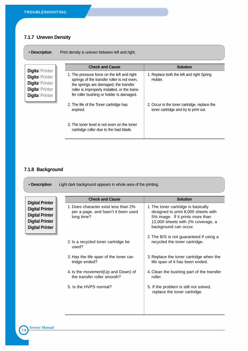
7-4
TROUBLESHOOTING
Service Manual
7.1.7 Uneven Density
• Description Print density is uneven between left and right.
Check and Cause Solution
1. The pressure force on the left and rightsprings of the transfer roller is not even,the springs are damaged, the transferroller is improperly installed, or the trans-fer roller bushing or holder is damaged.
2. The life of the Toner cartridge hasexpired.
3. The toner level is not even on the tonercartridge roller due to the bad blade.
1. Replace both the left and right SpringHolder.
2. Occur in the toner cartridge, replace thetoner cartridge and try to print out.
7.1.8 Background
• Description Light dark background appears in whole area of the printing.
Digital PrinterDigital PrinterDigital PrinterDigital PrinterDigital Printer
Check and Cause Solution
1. Does character exist less than 2%per a page, and hasn’t it been usedlong time?
2. Is a recycled toner cartridge beused?
3. Has the life span of the toner car-tridge ended?
4. Is the movement(Up and Down) ofthe transfer roller smooth?
5. Is the HVPS normal?
1. The toner cartridge is basicallydesigned to print 8,000 sheets with5% image. If it prints more than12,000 sheets with 2% coverage, abackground can occur.
2. The B/S is not guaranteed if using arecycled the toner cartridge.
3. Replace the toner cartridge when thelife span of it has been ended.
4. Clean the bushing part of the transferroller.
5. If the problem is still not solved,replace the toner cartridge.
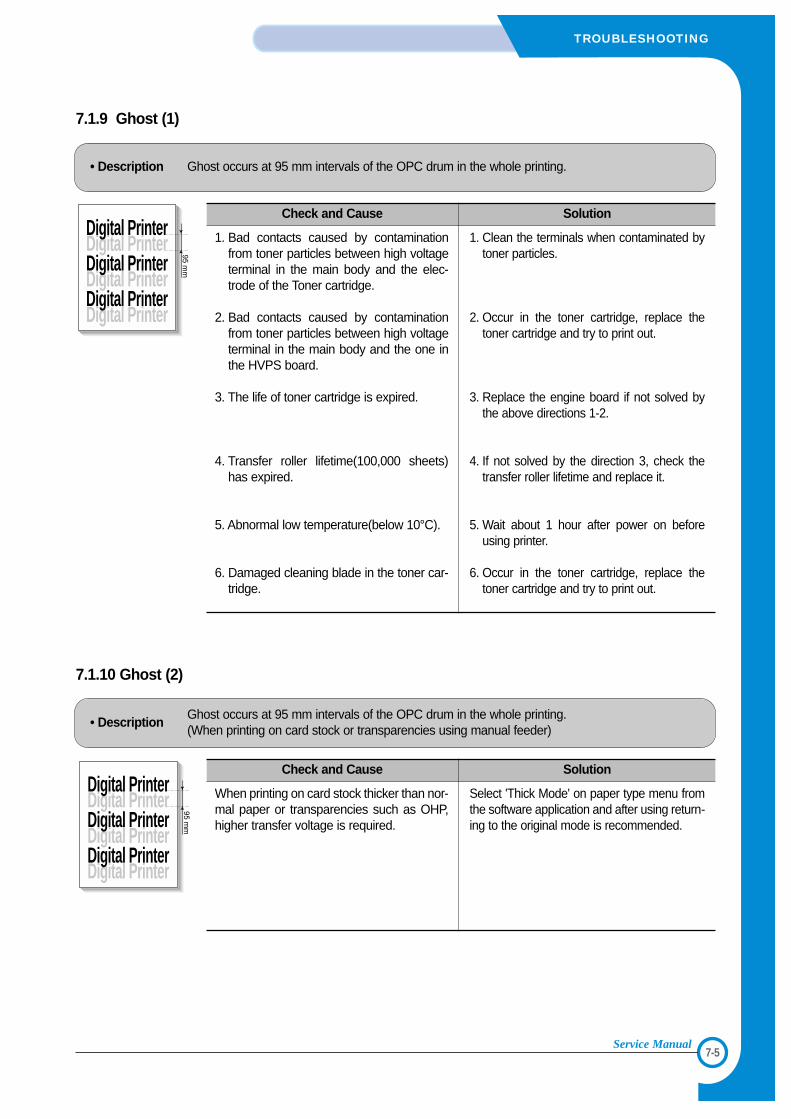
7-5
TROUBLESHOOTING
Service Manual
7.1.9 Ghost (1)
• Description Ghost occurs at 95 mm intervals of the OPC drum in the whole printing.
Digital Printer
Digital Printer
Digital Printer
Digital Printer
Digital Printer
Digital Printer
95 mm
Check and Cause Solution
1. Bad contacts caused by contaminationfrom toner particles between high voltageterminal in the main body and the elec-trode of the Toner cartridge.
2. Bad contacts caused by contaminationfrom toner particles between high voltageterminal in the main body and the one inthe HVPS board.
3. The life of toner cartridge is expired.
4. Transfer roller lifetime(100,000 sheets)has expired.
5. Abnormal low temperature(below 10°C).
6. Damaged cleaning blade in the toner car-tridge.
1. Clean the terminals when contaminated bytoner particles.
2. Occur in the toner cartridge, replace thetoner cartridge and try to print out.
3. Replace the engine board if not solved bythe above directions 1-2.
4. If not solved by the direction 3, check thetransfer roller lifetime and replace it.
5. Wait about 1 hour after power on beforeusing printer.
6. Occur in the toner cartridge, replace thetoner cartridge and try to print out.
7.1.10 Ghost (2)
• DescriptionGhost occurs at 95 mm intervals of the OPC drum in the whole printing.(When printing on card stock or transparencies using manual feeder)
Digital Printer
Digital Printer
Digital Printer
Digital Printer
Digital Printer
Digital Printer
95 mm
Check and Cause Solution
When printing on card stock thicker than nor-mal paper or transparencies such as OHP,higher transfer voltage is required.
Select 'Thick Mode' on paper type menu fromthe software application and after using return-ing to the original mode is recommended.
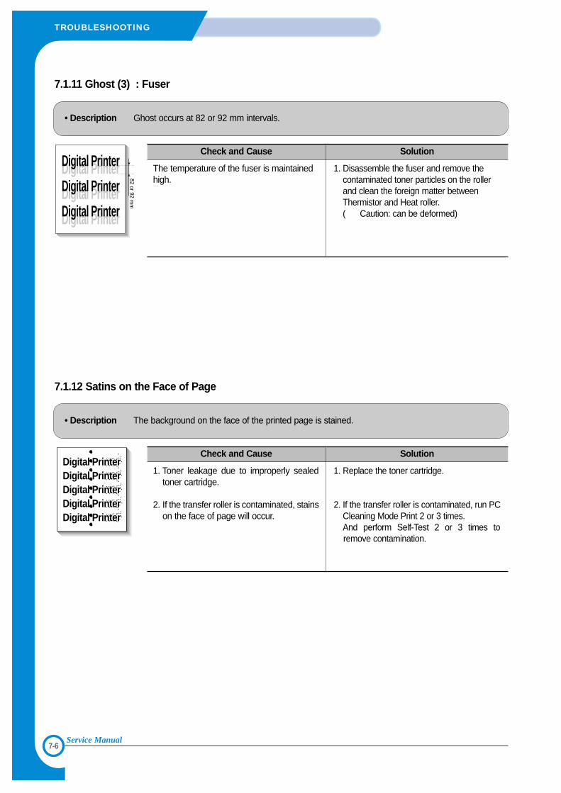
7-6
TROUBLESHOOTING
Service Manual
7.1.11 Ghost (3) : Fuser
• Description Ghost occurs at 82 or 92 mm intervals.
Digital Printer
Digital Printer
Digital Printer
Digital Printer
Digital Printer
Digital Printer
82 or 92 mm
Check and Cause Solution
The temperature of the fuser is maintainedhigh.
1. Disassemble the fuser and remove thecontaminated toner particles on the rollerand clean the foreign matter betweenThermistor and Heat roller. ( Caution: can be deformed)
7.1.12 Satins on the Face of Page
• Description The background on the face of the printed page is stained.
Digital PrinterDigital PrinterDigital PrinterDigital PrinterDigital Printer
Check and Cause Solution
1. Toner leakage due to improperly sealedtoner cartridge.
2. If the transfer roller is contaminated, stainson the face of page will occur.
1. Replace the toner cartridge.
2. If the transfer roller is contaminated, run PCCleaning Mode Print 2 or 3 times.And perform Self-Test 2 or 3 times toremove contamination.
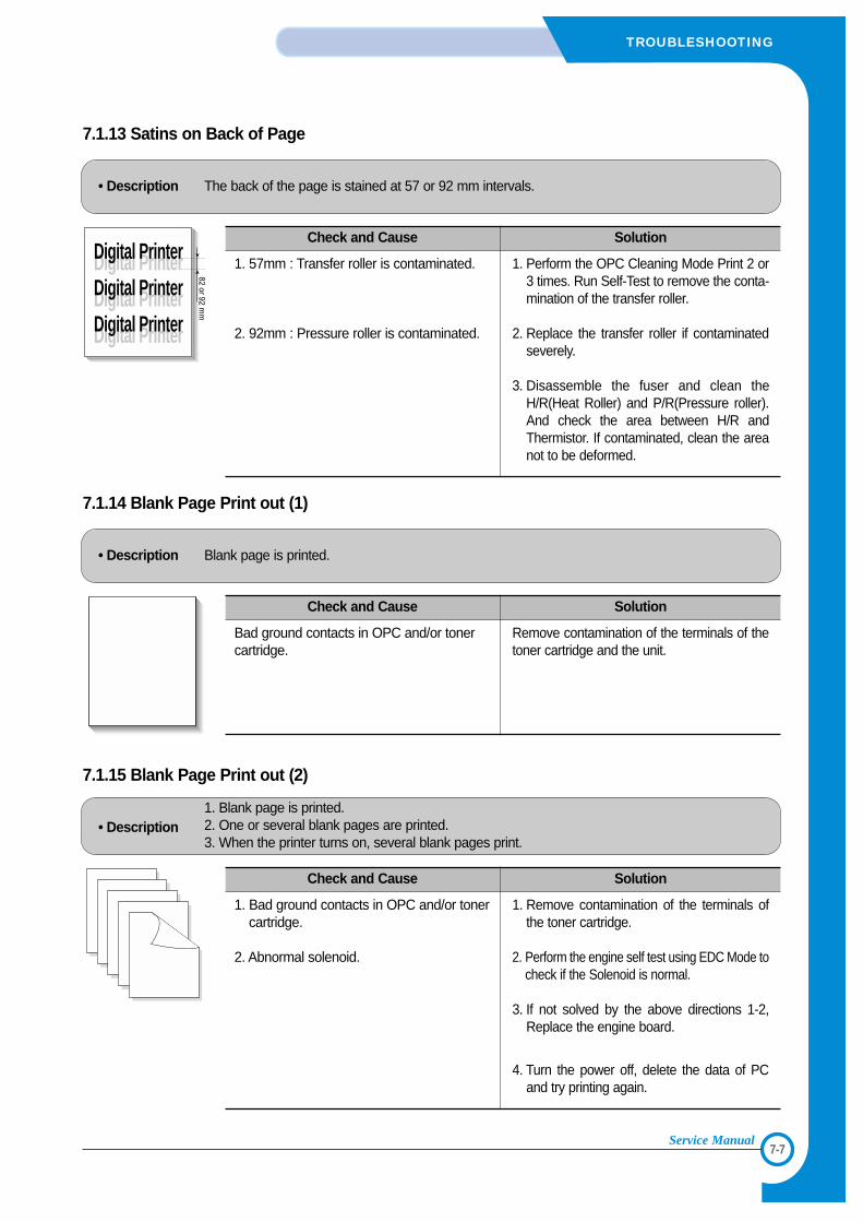
7-7
TROUBLESHOOTING
Service Manual
7.1.13 Satins on Back of Page
• Description The back of the page is stained at 57 or 92 mm intervals.
Digital Printer
Digital Printer
Digital Printer
Digital Printer
Digital Printer
Digital Printer
82 or 92 mm
Check and Cause Solution
1. 57mm : Transfer roller is contaminated.
2. 92mm : Pressure roller is contaminated.
1. Perform the OPC Cleaning Mode Print 2 or3 times. Run Self-Test to remove the conta-mination of the transfer roller.
2. Replace the transfer roller if contaminatedseverely.
3. Disassemble the fuser and clean theH/R(Heat Roller) and P/R(Pressure roller).And check the area between H/R andThermistor. If contaminated, clean the areanot to be deformed.
7.1.14 Blank Page Print out (1)
• Description Blank page is printed.
Digital PrinterDigital PrinterDigital PrinterDigital PrinterDigital Printer
Check and Cause Solution
Bad ground contacts in OPC and/or tonercartridge.
Remove contamination of the terminals of thetoner cartridge and the unit.
7.1.15 Blank Page Print out (2)
• Description1. Blank page is printed.2. One or several blank pages are printed.3. When the printer turns on, several blank pages print.
Check and Cause Solution
1. Bad ground contacts in OPC and/or tonercartridge.
2. Abnormal solenoid.
1. Remove contamination of the terminals ofthe toner cartridge.
2. Perform the engine self test using EDC Mode tocheck if the Solenoid is normal.
3. If not solved by the above directions 1-2,Replace the engine board.
4. Turn the power off, delete the data of PCand try printing again.
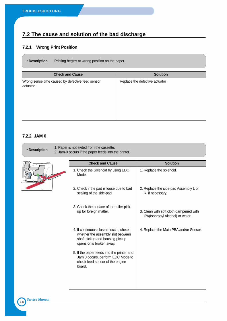
7-8
TROUBLESHOOTING
Service Manual
7.2 The cause and solution of the bad discharge
7.2.1 Wrong Print Position
• Description Printing begins at wrong position on the paper.
Check and Cause Solution
Wrong sense time caused by defective feed sensoractuator.
Replace the defective actuator
7.2.2 JAM 0
• Description1. Paper is not exited from the cassette.2. Jam-0 occurs if the paper feeds into the printer.
Check and Cause Solution
1. Check the Solenoid by using EDCMode.
2. Check if the pad is loose due to badsealing of the side-pad.
3. Check the surface of the roller-pick-up for foreign matter.
4. If continuous clusters occur, checkwhether the assembly slot betweenshaft-pickup and housing-pickupopens or is broken away.
5. If the paper feeds into the printer andJam 0 occurs, perform EDC Mode tocheck feed-sensor of the engineboard.
1. Replace the solenoid.
2. Replace the side-pad Assembly L orR, if necessary.
3. Clean with soft cloth dampened withIPA(Isopropyl Alcohol) or water.
4. Replace the Main PBA and/or Sensor.
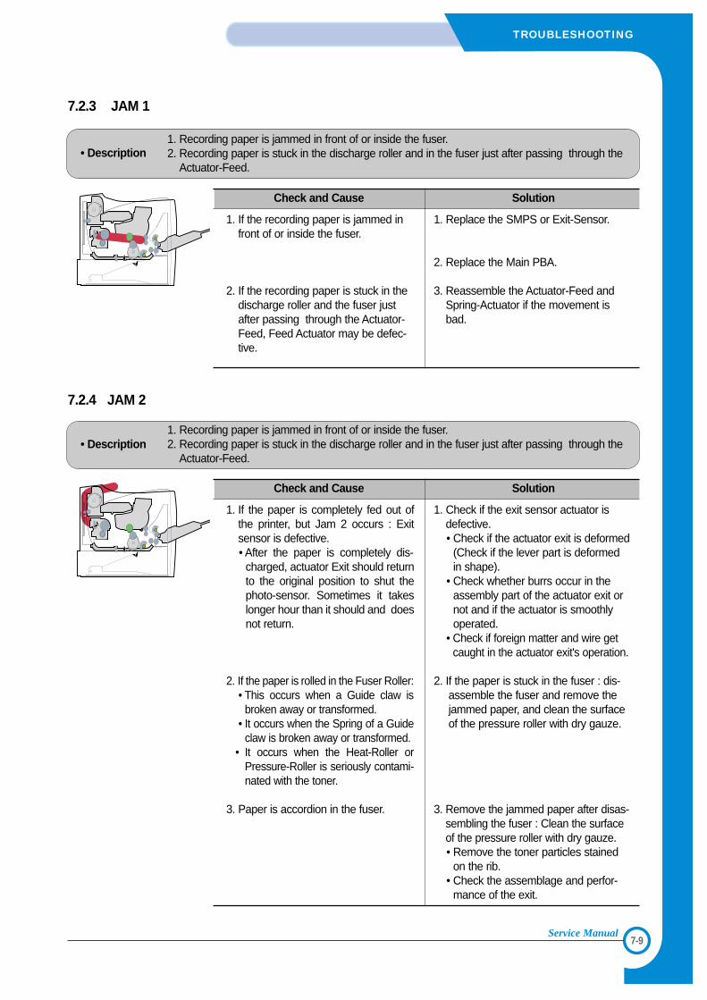
7-9
TROUBLESHOOTING
Service Manual
7.2.4 JAM 2
• Description1. Recording paper is jammed in front of or inside the fuser.2. Recording paper is stuck in the discharge roller and in the fuser just after passing through the
Actuator-Feed.
Check and Cause Solution
1. If the paper is completely fed out ofthe printer, but Jam 2 occurs : Exitsensor is defective.• After the paper is completely dis-
charged, actuator Exit should returnto the original position to shut thephoto-sensor. Sometimes it takeslonger hour than it should and doesnot return.
2. If the paper is rolled in the Fuser Roller:• This occurs when a Guide claw is
broken away or transformed.• It occurs when the Spring of a Guide
claw is broken away or transformed.• It occurs when the Heat-Roller or
Pressure-Roller is seriously contami-nated with the toner.
3. Paper is accordion in the fuser.
1. Check if the exit sensor actuator isdefective.• Check if the actuator exit is deformed
(Check if the lever part is deformedin shape).
• Check whether burrs occur in theassembly part of the actuator exit ornot and if the actuator is smoothlyoperated.
• Check if foreign matter and wire getcaught in the actuator exit's operation.
2. If the paper is stuck in the fuser : dis-assemble the fuser and remove thejammed paper, and clean the surfaceof the pressure roller with dry gauze.
3. Remove the jammed paper after disas-sembling the fuser : Clean the surfaceof the pressure roller with dry gauze.• Remove the toner particles stained
on the rib.• Check the assemblage and perfor-
mance of the exit.
7.2.3 JAM 1
• Description1. Recording paper is jammed in front of or inside the fuser.2. Recording paper is stuck in the discharge roller and in the fuser just after passing through the
Actuator-Feed.
Check and Cause Solution
1. If the recording paper is jammed infront of or inside the fuser.
2. If the recording paper is stuck in thedischarge roller and the fuser justafter passing through the Actuator-Feed, Feed Actuator may be defec-tive.
1. Replace the SMPS or Exit-Sensor.
2. Replace the Main PBA.
3. Reassemble the Actuator-Feed andSpring-Actuator if the movement isbad.
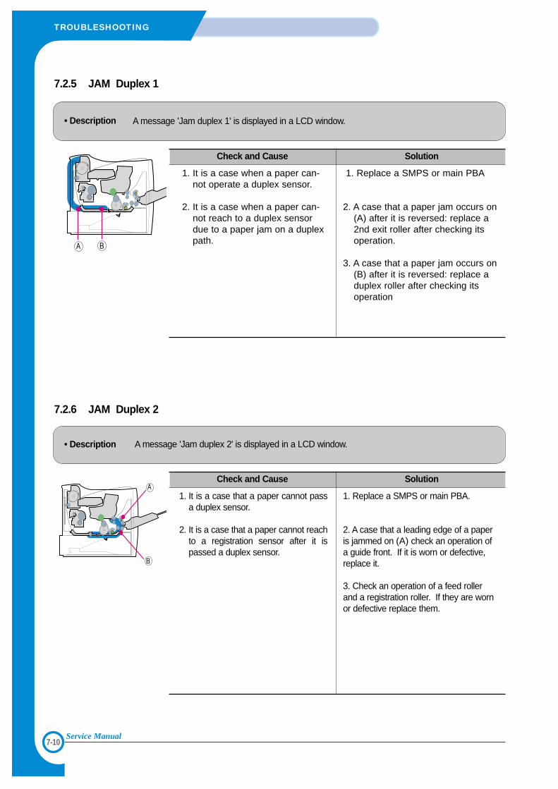
7-10
TROUBLESHOOTING
Service Manual
7.2.6 JAM Duplex 2
• Description A message 'Jam duplex 2' is displayed in a LCD window.
Check and Cause Solution
1. It is a case that a paper cannot passa duplex sensor.
2. It is a case that a paper cannot reachto a registration sensor after it ispassed a duplex sensor.
1. Replace a SMPS or main PBA.
2. A case that a leading edge of a paperis jammed on (A) check an operation ofa guide front. If it is worn or defective,replace it.
3. Check an operation of a feed rollerand a registration roller. If they are wornor defective replace them.
7.2.5 JAM Duplex 1
• Description A message 'Jam duplex 1' is displayed in a LCD window.
Check and Cause Solution
1. It is a case when a paper can-not operate a duplex sensor.
2. It is a case when a paper can-not reach to a duplex sensordue to a paper jam on a duplexpath.
1. Replace a SMPS or main PBA
2. A case that a paper jam occurs on(A) after it is reversed: replace a2nd exit roller after checking itsoperation.
3. A case that a paper jam occurs on(B) after it is reversed: replace aduplex roller after checking itsoperation
7-11
TROUBLESHOOTING
Service Manual
7.2.7 Multi-Feeding
• Description Multiple sheets of paper are fed at once.
Check and Cause Solution
1. Solenoid malfunction(the solenoid does not workproperly): Perform EDC Mode.
2. Pad-Friction is contaminated with foreign matter.(oil..)
3. The face of paper is blended.
1. Replace the solenoid if necessary.
2. Replace the Main PBA.
3. Clean the pad friction with soft cloth dampened withIPA(Isopropyl Alcohol).
4. Use the smooth paper.
7.2.8 Paper rolled in the fuser
• Description If contaminated at intervals of 57mm on the back of a paper.
Check and Cause Solution
1. Contamination of the pressure roller or heatroller (Background, Hot off set).
2. Check the claw of the fuser whether it isdeformed.
1. After disassembling the fuser, clean contami-nation between the heat roller and the ther-mostor and remove the contamination of thepressure roller.
2. If there is heavy background, repair it by thebackground troubleshooting method.
3. Clean the surface of the heat roller with IPA orwater
4. Check the warp or separation of the print clawand the holder plate claw, and then manage it.
7-12
TROUBLESHOOTING
Service Manual
7.2.9 Paper rolled on the OPC Drum
• Description Paper is rolled up in the OPC.
Check and Cause Solution
1. Paper is too much thin.
2. The face of paper is curled.
1. Recommend to use normal paper.
2. How to remove the rolled paper in the OPC.• Remove the paper while turning the OPC against
the ongoing direction. • Clean fingerprints on the OPC softly with soft
cloth dampened with tissue.
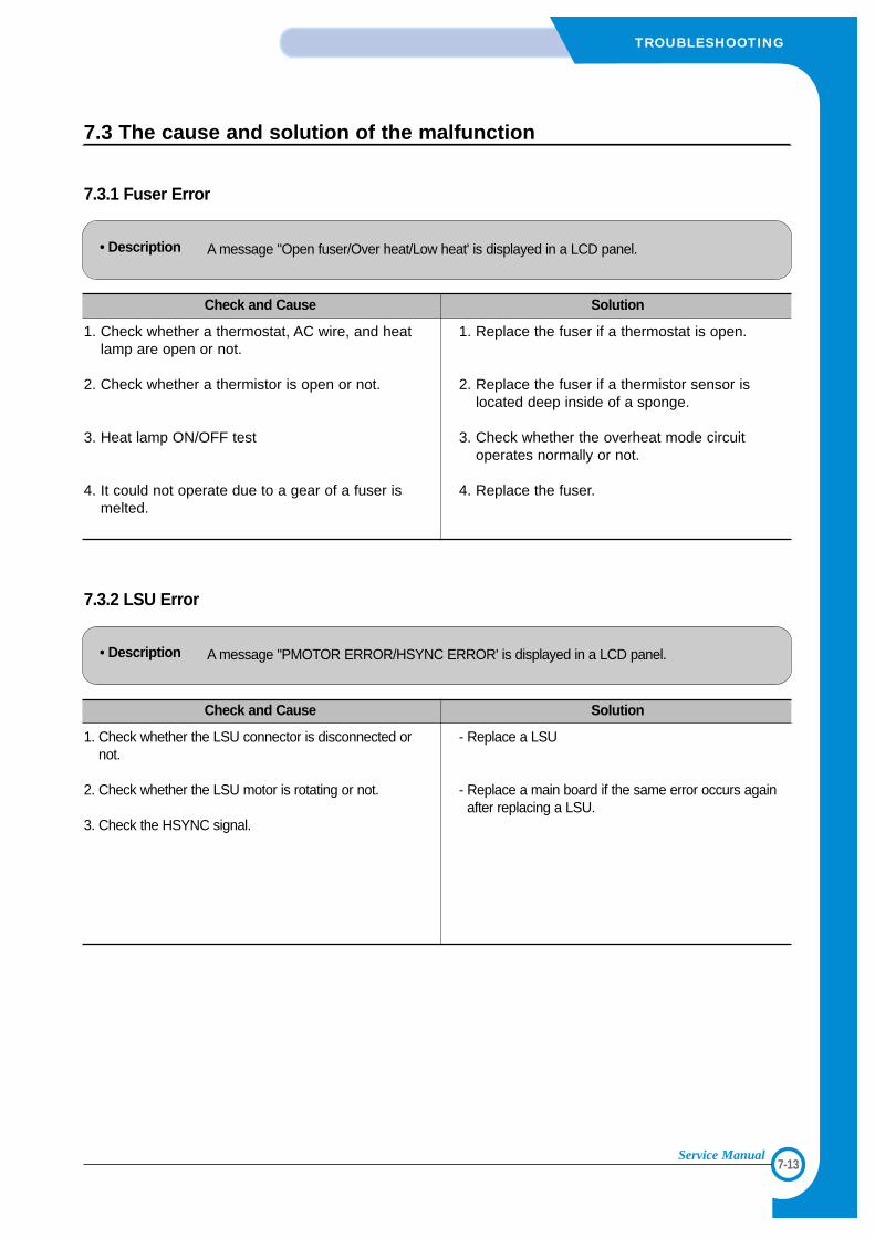
7-13
TROUBLESHOOTING
Service Manual
7.3 The cause and solution of the malfunction
7.3.1 Fuser Error
• Description A message "Open fuser/Over heat/Low heat' is displayed in a LCD panel.
Check and Cause Solution
1. Check whether a thermostat, AC wire, and heatlamp are open or not.
2. Check whether a thermistor is open or not.
3. Heat lamp ON/OFF test
4. It could not operate due to a gear of a fuser ismelted.
1. Replace the fuser if a thermostat is open.
2. Replace the fuser if a thermistor sensor islocated deep inside of a sponge.
3. Check whether the overheat mode circuitoperates normally or not.
4. Replace the fuser.
7.3.2 LSU Error
• Description A message "PMOTOR ERROR/HSYNC ERROR' is displayed in a LCD panel.
Check and Cause Solution
1. Check whether the LSU connector is disconnected ornot.
2. Check whether the LSU motor is rotating or not.
3. Check the HSYNC signal.
- Replace a LSU
- Replace a main board if the same error occurs againafter replacing a LSU.
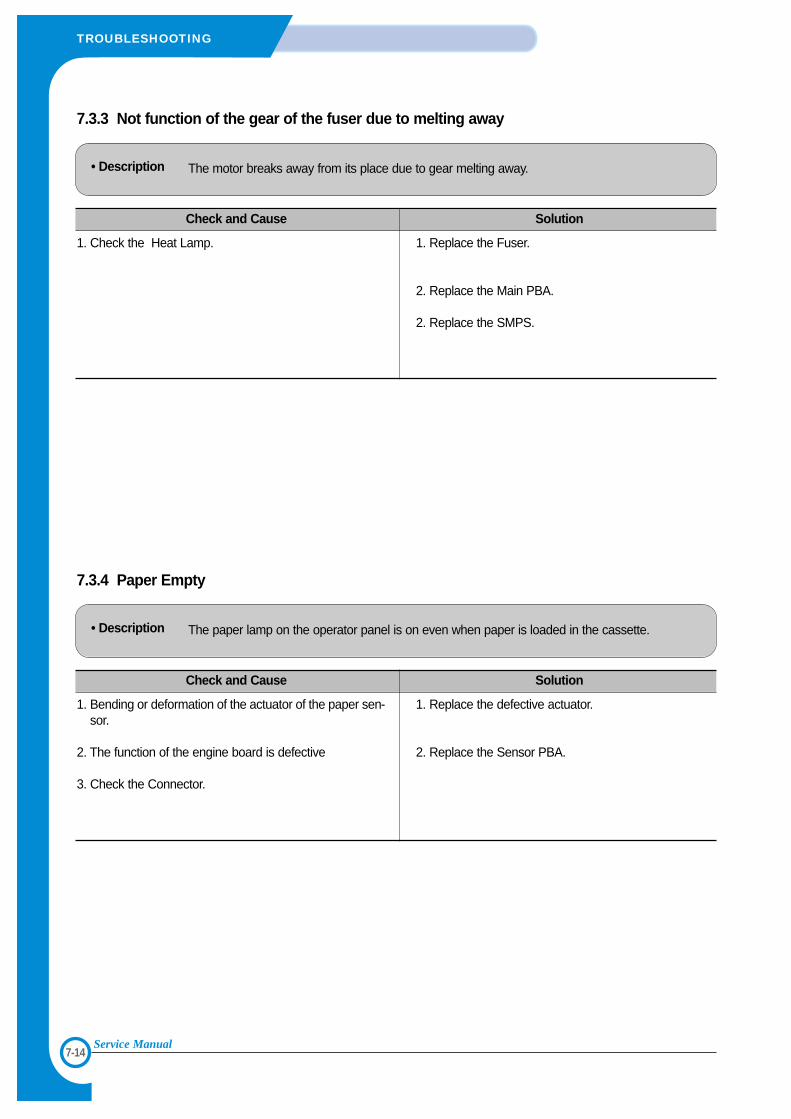
7-14
TROUBLESHOOTING
Service Manual
7.3.3 Not function of the gear of the fuser due to melting away
• Description The motor breaks away from its place due to gear melting away.
Check and Cause Solution
1. Check the Heat Lamp. 1. Replace the Fuser.
2. Replace the Main PBA.
2. Replace the SMPS.
7.3.4 Paper Empty
• Description The paper lamp on the operator panel is on even when paper is loaded in the cassette.
Check and Cause Solution
1. Bending or deformation of the actuator of the paper sen-sor.
2. The function of the engine board is defective
3. Check the Connector.
1. Replace the defective actuator.
2. Replace the Sensor PBA.
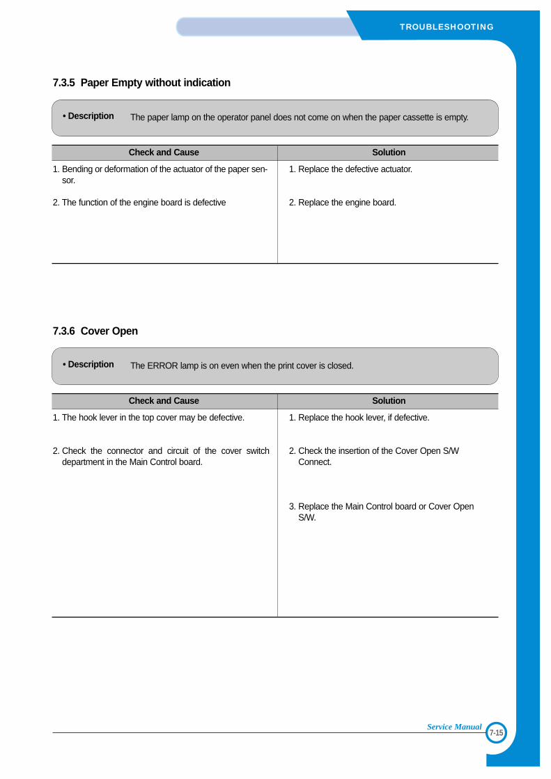
7-15
TROUBLESHOOTING
Service Manual
7.3.5 Paper Empty without indication
• Description The paper lamp on the operator panel does not come on when the paper cassette is empty.
Check and Cause Solution
1. Bending or deformation of the actuator of the paper sen-sor.
2. The function of the engine board is defective
1. Replace the defective actuator.
2. Replace the engine board.
7.3.6 Cover Open
• Description The ERROR lamp is on even when the print cover is closed.
Check and Cause Solution
1. The hook lever in the top cover may be defective.
2. Check the connector and circuit of the cover switchdepartment in the Main Control board.
1. Replace the hook lever, if defective.
2. Check the insertion of the Cover Open S/WConnect.
3. Replace the Main Control board or Cover OpenS/W.
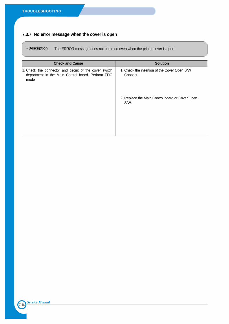
7-16
TROUBLESHOOTING
Service Manual
7.3.7 No error message when the cover is open
• Description The ERROR message does not come on even when the printer cover is open
Check and Cause Solution
1. Check the connector and circuit of the cover switchdepartment in the Main Control board. Perform EDCmode
1. Check the insertion of the Cover Open S/WConnect.
2. Replace the Main Control board or Cover OpenS/W.
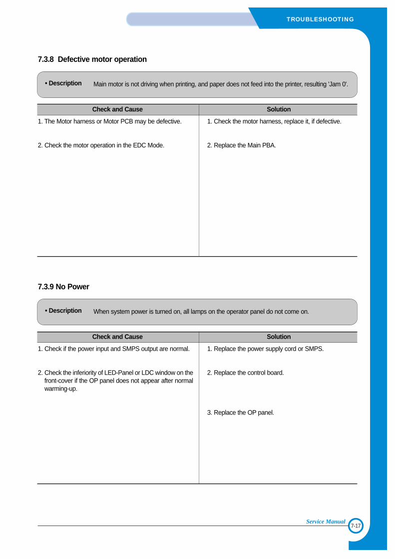
7-17
TROUBLESHOOTING
Service Manual
7.3.8 Defective motor operation
• Description Main motor is not driving when printing, and paper does not feed into the printer, resulting 'Jam 0'.
Check and Cause Solution
1. The Motor harness or Motor PCB may be defective.
2. Check the motor operation in the EDC Mode.
1. Check the motor harness, replace it, if defective.
2. Replace the Main PBA.
7.3.9 No Power
• Description When system power is turned on, all lamps on the operator panel do not come on.
Check and Cause Solution
1. Check if the power input and SMPS output are normal.
2. Check the inferiority of LED-Panel or LDC window on thefront-cover if the OP panel does not appear after normalwarming-up.
1. Replace the power supply cord or SMPS.
2. Replace the control board.
3. Replace the OP panel.
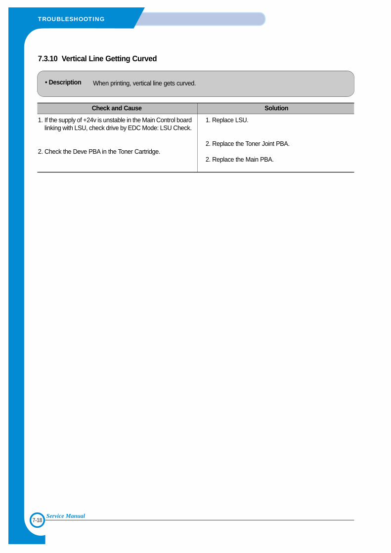
7-18
TROUBLESHOOTING
Service Manual
7.3.10 Vertical Line Getting Curved
• Description When printing, vertical line gets curved.
Check and Cause Solution
1. If the supply of +24v is unstable in the Main Control boardlinking with LSU, check drive by EDC Mode: LSU Check.
2. Check the Deve PBA in the Toner Cartridge.
1. Replace LSU.
2. Replace the Toner Joint PBA.
2. Replace the Main PBA.
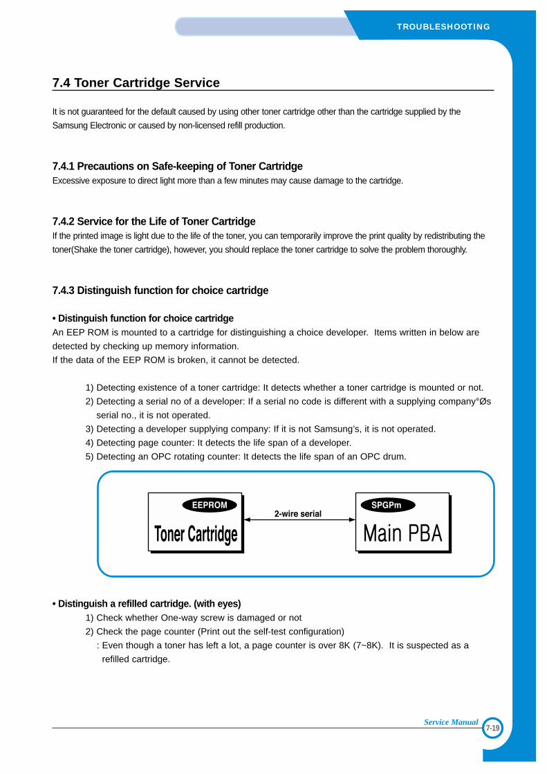
7-19
TROUBLESHOOTING
Service Manual
7.4 Toner Cartridge Service
It is not guaranteed for the default caused by using other toner cartridge other than the cartridge supplied by the
Samsung Electronic or caused by non-licensed refill production.
7.4.1 Precautions on Safe-keeping of Toner CartridgeExcessive exposure to direct light more than a few minutes may cause damage to the cartridge.
7.4.2 Service for the Life of Toner CartridgeIf the printed image is light due to the life of the toner, you can temporarily improve the print quality by redistributing the
toner(Shake the toner cartridge), however, you should replace the toner cartridge to solve the problem thoroughly.
7.4.3 Distinguish function for choice cartridge
• Distinguish function for choice cartridgeAn EEP ROM is mounted to a cartridge for distinguishing a choice developer. Items written in below are
detected by checking up memory information.
If the data of the EEP ROM is broken, it cannot be detected.
1) Detecting existence of a toner cartridge: It detects whether a toner cartridge is mounted or not.
2) Detecting a serial no of a developer: If a serial no code is different with a supplying company°Øs
serial no., it is not operated.
3) Detecting a developer supplying company: If it is not Samsung’s, it is not operated.
4) Detecting page counter: It detects the life span of a developer.
5) Detecting an OPC rotating counter: It detects the life span of an OPC drum.
• Distinguish a refilled cartridge. (with eyes)1) Check whether One-way screw is damaged or not
2) Check the page counter (Print out the self-test configuration)
: Even though a toner has left a lot, a page counter is over 8K (7~8K). It is suspected as a
refilled cartridge.
7-20
TROUBLESHOOTING
Service Manual
7.4.4 Error message (LCD window) related in a toner sensorIt explains a message related in toner sensor in a LCD.
7.4.4.1 Invalid Toner- Contents: It is displayed when a supplier is different between a developer and a set. If this message is shown up, a
printing process cannot operate.
- Solution: Attach a suitable developer (the same supplier's) to a set. (A unique key has been applied.)
7.4.4.2 Low Toner- Contents: This message shows up when a message "remaining toner: 10%" is displayed in a cartridge count informa-
tion. And the same message shows up when an OPC count becomes 18,000 (page).
- Solution: It means that a toner in the developer has been almost ended. Replace the developer.
7.4.4.3 Replace Cartridge- Contents: This message shows up when an OPC count becomes 20,000 (pages). It means the life span of a toner
cartridge (except a toner part) has been ended. Even though a case that a toner is refilled, the rest of major
parts have been ended, so entire toner cartridge might be replaced.
- Solution: If an OPC rotates about 20,000 (page), in a worst case, a toner overflows and it may cause a system fail.
Therefore, recommend a user to replace a developer. When continuously using, even though a count reach-
es to 20,000 pages, a printed image becomes misty, and an on-line key that is flashing on a set must be
pressed for a single print.
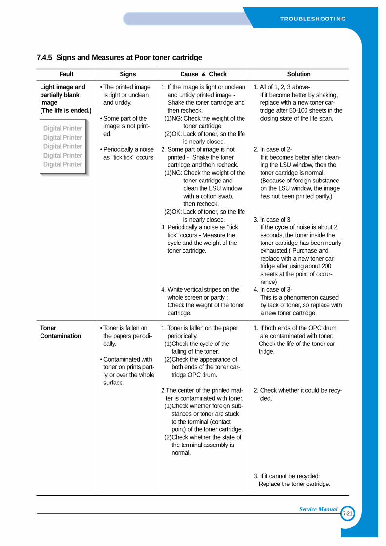
7-21
TROUBLESHOOTING
Service Manual
7.4.5 Signs and Measures at Poor toner cartridge
Fault Signs Cause & Check Solution
Light image andpartially blankimage(The life is ended.)
TonerContamination
• The printed imageis light or uncleanand untidy.
• Some part of theimage is not print-ed.
• Periodically a noiseas "tick tick" occurs.
• Toner is fallen onthe papers periodi-cally.
• Contaminated withtoner on prints part-ly or over the wholesurface.
1. If the image is light or uncleanand untidy printed image -Shake the toner cartridge andthen recheck.
(1)NG: Check the weight of thetoner cartridge
(2)OK: Lack of toner, so the lifeis nearly closed.
2. Some part of image is notprinted - Shake the tonercartridge and then recheck.
(1)NG: Check the weight of thetoner cartridge andclean the LSU windowwith a cotton swab,then recheck.
(2)OK: Lack of toner, so the lifeis nearly closed.
3. Periodically a noise as "ticktick" occurs - Measure thecycle and the weight of thetoner cartridge.
4. White vertical stripes on thewhole screen or partly : Check the weight of the tonercartridge.
1. Toner is fallen on the paperperiodically.
(1)Check the cycle of thefalling of the toner.
(2)Check the appearance ofboth ends of the toner car-tridge OPC drum.
2.The center of the printed mat-ter is contaminated with toner.(1)Check whether foreign sub-
stances or toner are stuckto the terminal (contactpoint) of the toner cartridge.
(2)Check whether the state ofthe terminal assembly isnormal.
1. All of 1, 2, 3 above-If it become better by shaking,replace with a new toner car-tridge after 50-100 sheets in theclosing state of the life span.
2. In case of 2-If it becomes better after clean-ing the LSU window, then thetoner cartridge is normal.(Because of foreign substanceon the LSU window, the imagehas not been printed partly.)
3. In case of 3-If the cycle of noise is about 2seconds, the toner inside thetoner cartridge has been nearlyexhausted.( Purchase andreplace with a new toner car-tridge after using about 200sheets at the point of occur-rence)
4. In case of 3-This is a phenomenon causedby lack of toner, so replace witha new toner cartridge.
1. If both ends of the OPC drumare contaminated with toner:Check the life of the toner car-tridge.
2. Check whether it could be recy-cled.
3. If it cannot be recycled:Replace the toner cartridge.
Digital PrinterDigital PrinterDigital PrinterDigital PrinterDigital Printer
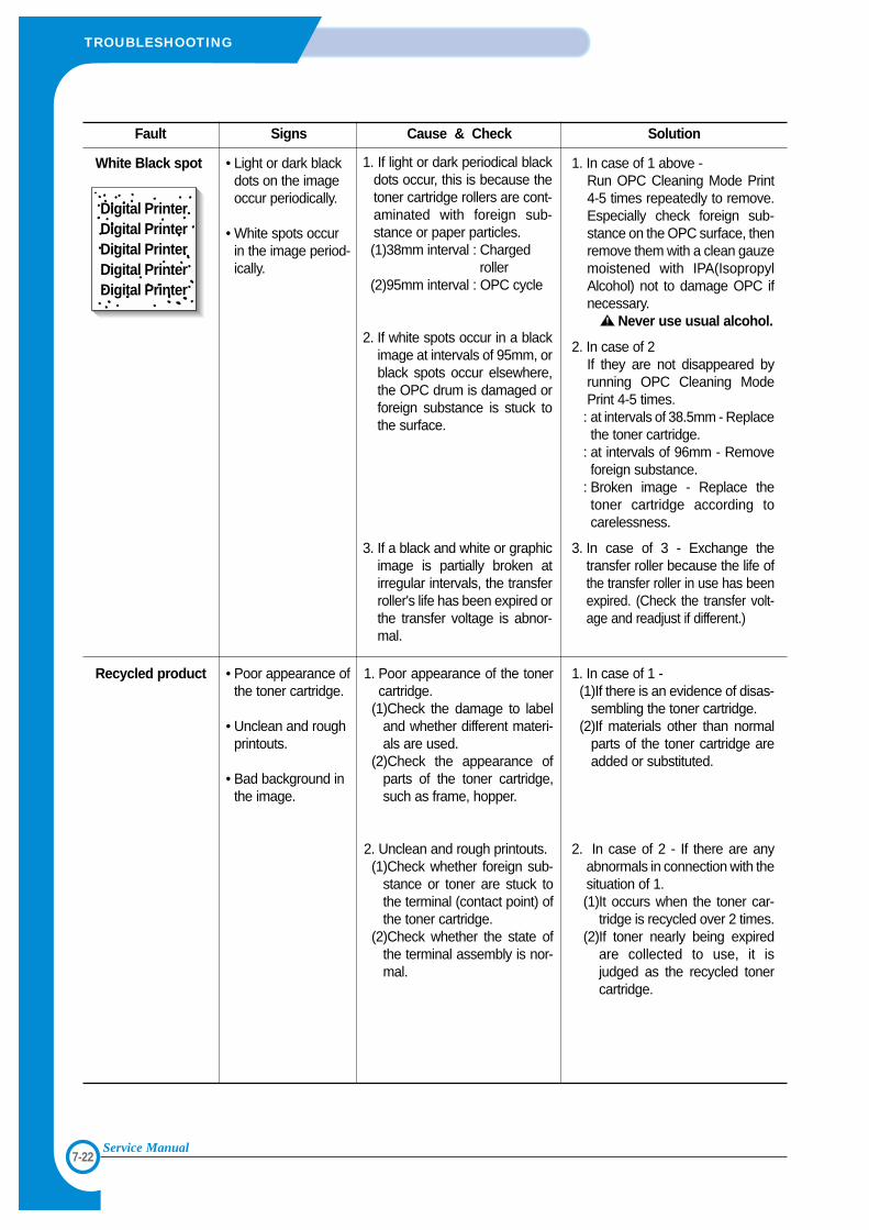
7-22
TROUBLESHOOTING
Service Manual
Fault Signs Cause & Check Solution
White Black spot
Recycled product
• Light or dark blackdots on the imageoccur periodically.
• White spots occurin the image period-ically.
• Poor appearance ofthe toner cartridge.
• Unclean and roughprintouts.
• Bad background inthe image.
1. If light or dark periodical blackdots occur, this is because thetoner cartridge rollers are cont-aminated with foreign sub-stance or paper particles.(1)38mm interval : Charged
roller(2)95mm interval : OPC cycle
2. If white spots occur in a blackimage at intervals of 95mm, orblack spots occur elsewhere,the OPC drum is damaged orforeign substance is stuck tothe surface.
3. If a black and white or graphicimage is partially broken atirregular intervals, the transferroller's life has been expired orthe transfer voltage is abnor-mal.
1. Poor appearance of the tonercartridge.
(1)Check the damage to labeland whether different materi-als are used.
(2)Check the appearance ofparts of the toner cartridge,such as frame, hopper.
2. Unclean and rough printouts.(1)Check whether foreign sub-
stance or toner are stuck tothe terminal (contact point) ofthe toner cartridge.
(2)Check whether the state ofthe terminal assembly is nor-mal.
1. In case of 1 above -Run OPC Cleaning Mode Print4-5 times repeatedly to remove.Especially check foreign sub-stance on the OPC surface, thenremove them with a clean gauzemoistened with IPA(IsopropylAlcohol) not to damage OPC ifnecessary.
Never use usual alcohol.
2. In case of 2If they are not disappeared byrunning OPC Cleaning ModePrint 4-5 times. : at intervals of 38.5mm - Replacethe toner cartridge.
: at intervals of 96mm - Removeforeign substance.
: Broken image - Replace thetoner cartridge according tocarelessness.
3. In case of 3 - Exchange thetransfer roller because the life ofthe transfer roller in use has beenexpired. (Check the transfer volt-age and readjust if different.)
1. In case of 1 -(1)If there is an evidence of disas-
sembling the toner cartridge.(2)If materials other than normal
parts of the toner cartridge areadded or substituted.
2. In case of 2 - If there are anyabnormals in connection with thesituation of 1.(1)It occurs when the toner car-
tridge is recycled over 2 times.(2)If toner nearly being expired
are collected to use, it isjudged as the recycled tonercartridge.
Digital PrinterDigital PrinterDigital PrinterDigital PrinterDigital Printer
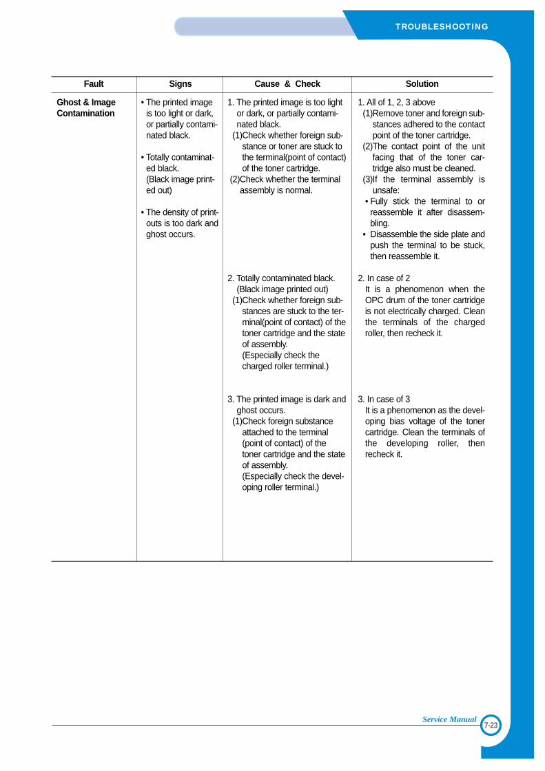
7-23
TROUBLESHOOTING
Service Manual
Fault Signs Cause & Check Solution
Ghost & ImageContamination
• The printed imageis too light or dark,or partially contami-nated black.
• Totally contaminat-ed black.(Black image print-ed out)
• The density of print-outs is too dark andghost occurs.
1. The printed image is too lightor dark, or partially contami-nated black.
(1)Check whether foreign sub-stance or toner are stuck tothe terminal(point of contact)of the toner cartridge.
(2)Check whether the terminalassembly is normal.
2. Totally contaminated black.(Black image printed out)
(1)Check whether foreign sub-stances are stuck to the ter-minal(point of contact) of thetoner cartridge and the stateof assembly. (Especially check thecharged roller terminal.)
3. The printed image is dark andghost occurs.
(1)Check foreign substanceattached to the terminal(point of contact) of thetoner cartridge and the stateof assembly. (Especially check the devel-oping roller terminal.)
1. All of 1, 2, 3 above(1)Remove toner and foreign sub-
stances adhered to the contactpoint of the toner cartridge.
(2)The contact point of the unitfacing that of the toner car-tridge also must be cleaned.
(3)If the terminal assembly isunsafe:
• Fully stick the terminal to orreassemble it after disassem-bling.
• Disassemble the side plate andpush the terminal to be stuck,then reassemble it.
2. In case of 2It is a phenomenon when theOPC drum of the toner cartridgeis not electrically charged. Cleanthe terminals of the chargedroller, then recheck it.
3. In case of 3It is a phenomenon as the devel-oping bias voltage of the tonercartridge. Clean the terminals ofthe developing roller, thenrecheck it.
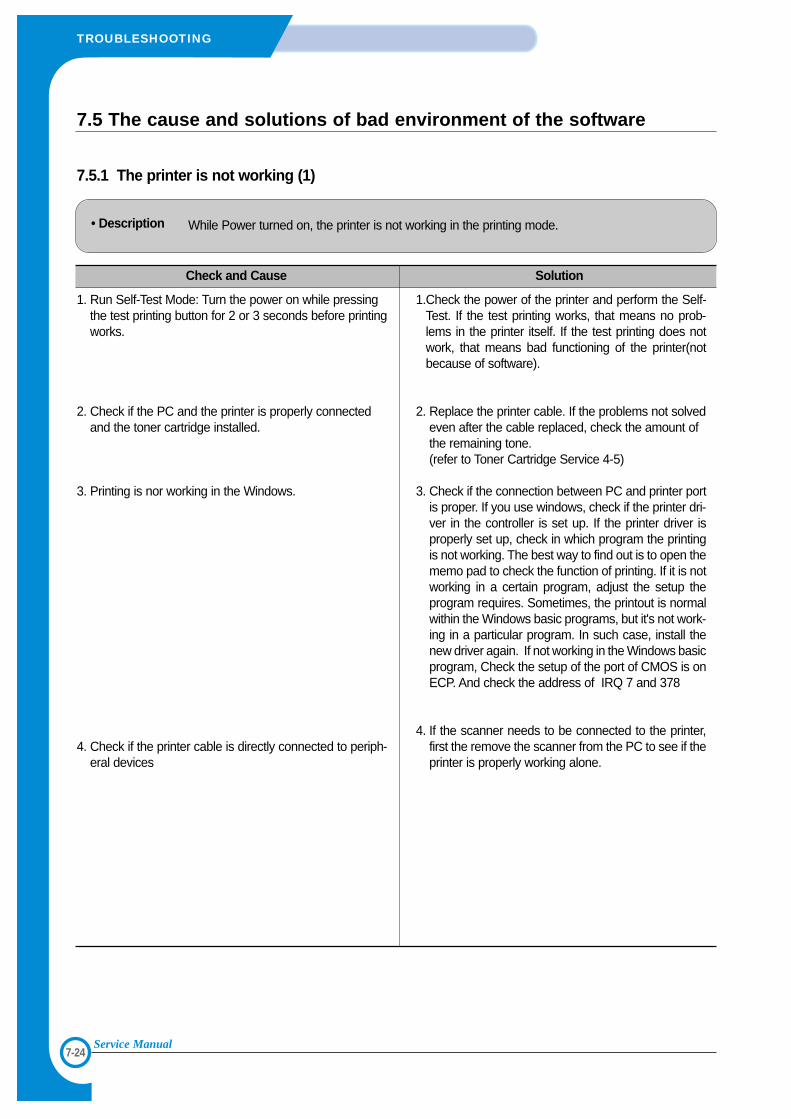
7-24
TROUBLESHOOTING
Service Manual
7.5 The cause and solutions of bad environment of the software
7.5.1 The printer is not working (1)
• Description While Power turned on, the printer is not working in the printing mode.
Check and Cause Solution
1. Run Self-Test Mode: Turn the power on while pressingthe test printing button for 2 or 3 seconds before printingworks.
2. Check if the PC and the printer is properly connectedand the toner cartridge installed.
3. Printing is nor working in the Windows.
4. Check if the printer cable is directly connected to periph-eral devices
1.Check the power of the printer and perform the Self-Test. If the test printing works, that means no prob-lems in the printer itself. If the test printing does notwork, that means bad functioning of the printer(notbecause of software).
2. Replace the printer cable. If the problems not solvedeven after the cable replaced, check the amount ofthe remaining tone.(refer to Toner Cartridge Service 4-5)
3. Check if the connection between PC and printer portis proper. If you use windows, check if the printer dri-ver in the controller is set up. If the printer driver isproperly set up, check in which program the printingis not working. The best way to find out is to open thememo pad to check the function of printing. If it is notworking in a certain program, adjust the setup theprogram requires. Sometimes, the printout is normalwithin the Windows basic programs, but it's not work-ing in a particular program. In such case, install thenew driver again. If not working in the Windows basicprogram, Check the setup of the port of CMOS is onECP. And check the address of IRQ 7 and 378
4. If the scanner needs to be connected to the printer,first the remove the scanner from the PC to see if theprinter is properly working alone.
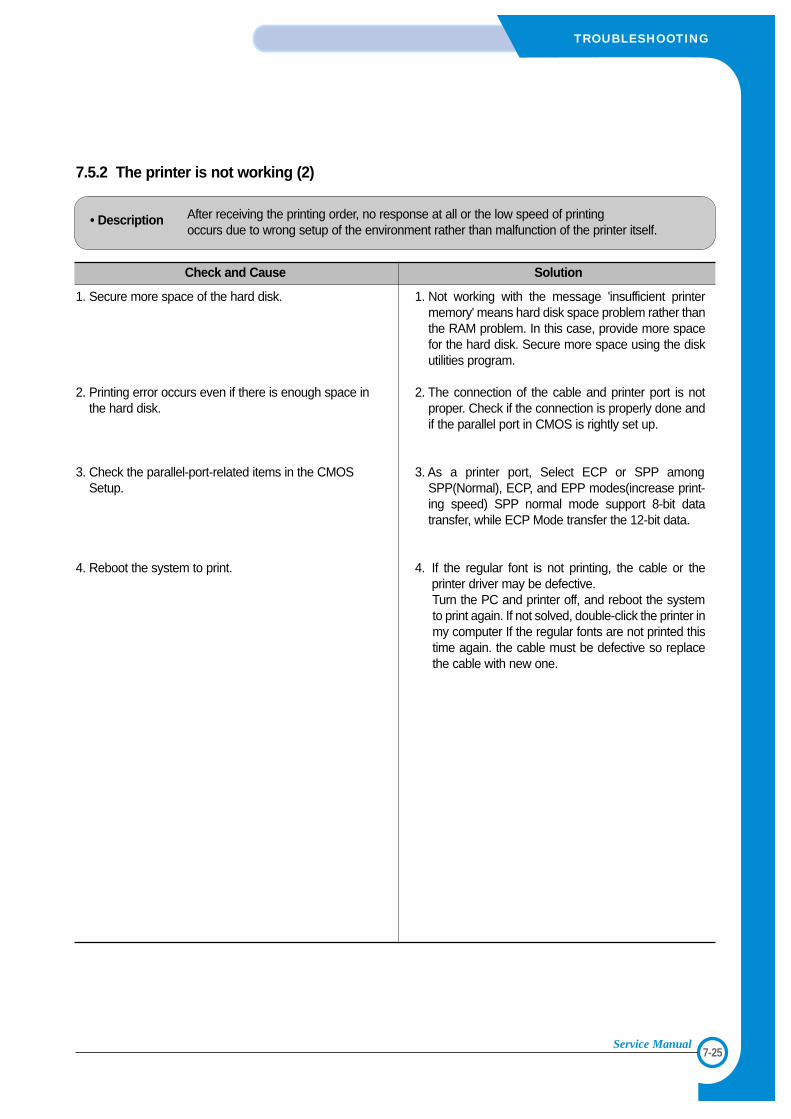
7-25
TROUBLESHOOTING
Service Manual
7.5.2 The printer is not working (2)
• Description After receiving the printing order, no response at all or the low speed of printing occurs due to wrong setup of the environment rather than malfunction of the printer itself.
Check and Cause Solution
1. Secure more space of the hard disk.
2. Printing error occurs even if there is enough space inthe hard disk.
3. Check the parallel-port-related items in the CMOSSetup.
4. Reboot the system to print.
1. Not working with the message 'insufficient printermemory' means hard disk space problem rather thanthe RAM problem. In this case, provide more spacefor the hard disk. Secure more space using the diskutilities program.
2. The connection of the cable and printer port is notproper. Check if the connection is properly done andif the parallel port in CMOS is rightly set up.
3. As a printer port, Select ECP or SPP amongSPP(Normal), ECP, and EPP modes(increase print-ing speed) SPP normal mode support 8-bit datatransfer, while ECP Mode transfer the 12-bit data.
4. If the regular font is not printing, the cable or theprinter driver may be defective.Turn the PC and printer off, and reboot the systemto print again. If not solved, double-click the printer inmy computer If the regular fonts are not printed thistime again. the cable must be defective so replacethe cable with new one.
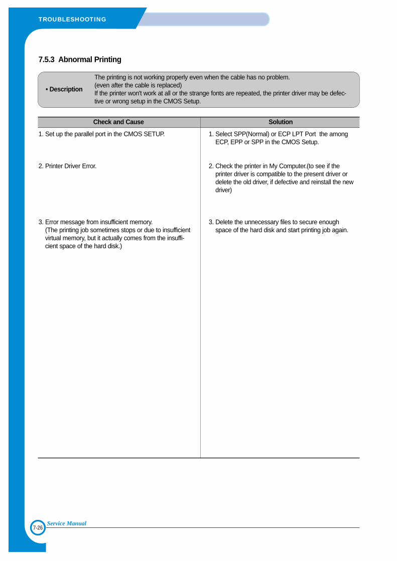
7-26
TROUBLESHOOTING
Service Manual
7.5.3 Abnormal Printing
• Description
The printing is not working properly even when the cable has no problem.(even after the cable is replaced) If the printer won't work at all or the strange fonts are repeated, the printer driver may be defec-tive or wrong setup in the CMOS Setup.
Check and Cause Solution
1. Set up the parallel port in the CMOS SETUP.
2. Printer Driver Error.
3. Error message from insufficient memory. (The printing job sometimes stops or due to insufficientvirtual memory, but it actually comes from the insuffi-cient space of the hard disk.)
1. Select SPP(Normal) or ECP LPT Port the amongECP, EPP or SPP in the CMOS Setup.
2. Check the printer in My Computer.(to see if theprinter driver is compatible to the present driver ordelete the old driver, if defective and reinstall the newdriver)
3. Delete the unnecessary files to secure enoughspace of the hard disk and start printing job again.
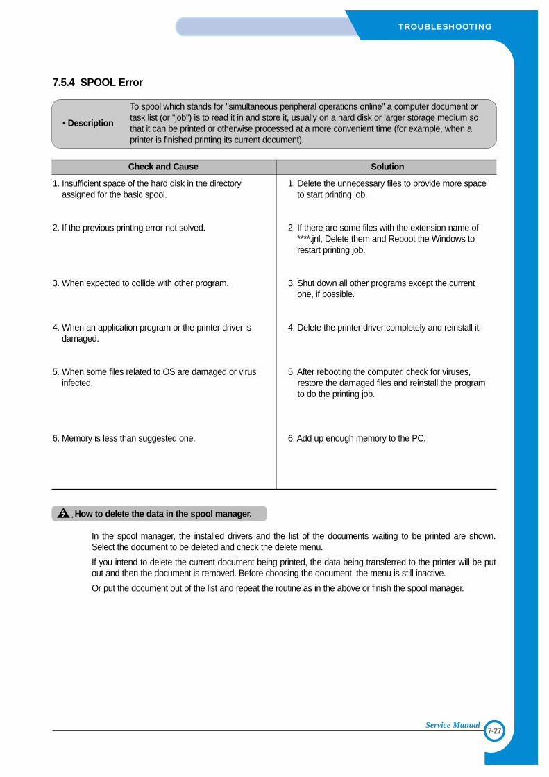
7-27
TROUBLESHOOTING
Service Manual
7.5.4 SPOOL Error
• Description
To spool which stands for "simultaneous peripheral operations online" a computer document ortask list (or "job") is to read it in and store it, usually on a hard disk or larger storage medium sothat it can be printed or otherwise processed at a more convenient time (for example, when aprinter is finished printing its current document).
Check and Cause Solution
1. Insufficient space of the hard disk in the directoryassigned for the basic spool.
2. If the previous printing error not solved.
3. When expected to collide with other program.
4. When an application program or the printer driver isdamaged.
5. When some files related to OS are damaged or virusinfected.
6. Memory is less than suggested one.
1. Delete the unnecessary files to provide more spaceto start printing job.
2. If there are some files with the extension name of****.jnl, Delete them and Reboot the Windows torestart printing job.
3. Shut down all other programs except the currentone, if possible.
4. Delete the printer driver completely and reinstall it.
5 After rebooting the computer, check for viruses,restore the damaged files and reinstall the programto do the printing job.
6. Add up enough memory to the PC.
How to delete the data in the spool manager.
In the spool manager, the installed drivers and the list of the documents waiting to be printed are shown. Select the document to be deleted and check the delete menu.
If you intend to delete the current document being printed, the data being transferred to the printer will be putout and then the document is removed. Before choosing the document, the menu is still inactive.
Or put the document out of the list and repeat the routine as in the above or finish the spool manager.

7-28
TROUBLESHOOTING
Service Manual
88
8-1
EXPLODED VIEW & PARTS LIST
Service Manual
8. Exploded Views and Parts List
8.1 Main Assembly . . . . . . . . . . . . . . . . . . . . . . . . . . . . . . . . . . . . . . . . . . page(8-2)
8.2 Base-Houshing Assembly . . . . . . . . . . . . . . . . . . . . . . . . . . . . . . . . . . page(8-6)
8.3 Frame Assembly (0 ~ 37) . . . . . . . . . . . . . . . . . . . . . . . . . . . . . . . . . . . . page(8-7)
Frame Assembly (37 ~ 71) . . . . . . . . . . . . . . . . . . . . . . . . . . . . . . . . . . . page(8-8)
8.4 Fuser Assembly . . . . . . . . . . . . . . . . . . . . . . . . . . . . . . . . . . . . . . . . . page(8-13)
8.5 Main Driver Assembly . . . . . . . . . . . . . . . . . . . . . . . . . . . . . . . . . . . . . page(8-16)
8.6 Exit Driver Assembly . . . . . . . . . . . . . . . . . . . . . . . . . . . . . . . . . . . . . . page(8-17)
8.7 Regi Assembly . . . . . . . . . . . . . . . . . . . . . . . . . . . . . . . . . . . . . . . . . . . page(8-18)
8.8 SMPS Assembly . . . . . . . . . . . . . . . . . . . . . . . . . . . . . . . . . . . . . . . . . . page(8-19)
8.9 Cassette Assembly . . . . . . . . . . . . . . . . . . . . . . . . . . . . . . . . . . . . . . . . page(8-21)
8.10 SCF Assembly . . . . . . . . . . . . . . . . . . . . . . . . . . . . . . . . . . . . . . . . . . page(8-23)
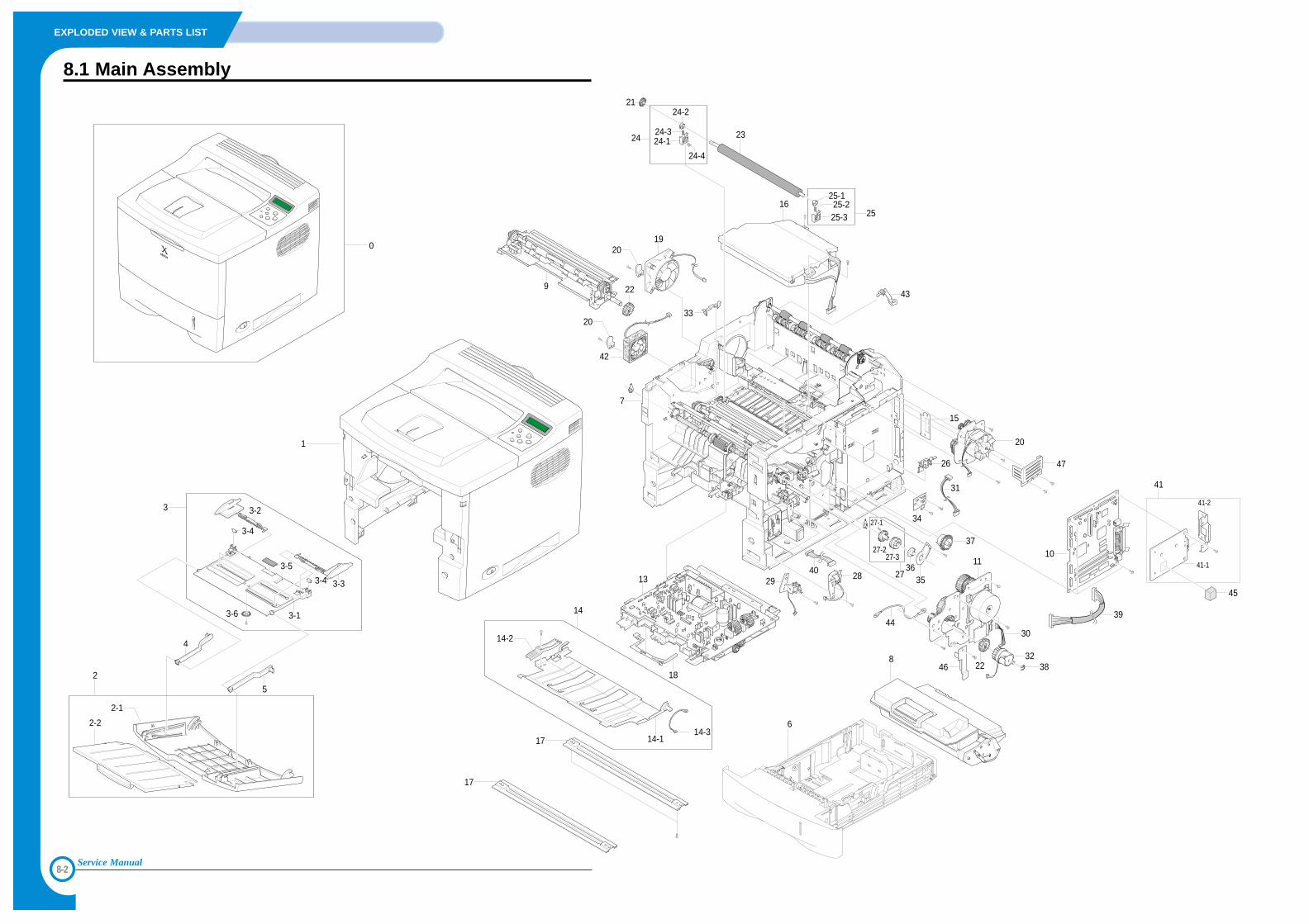
8-2
EXPLODED VIEW & PARTS LIST
Service Manual
8.1 Main Assembly
7
16
11
3238
30
13
18
8
6
0
3
2-1
2-2
2
4
5
3-1
3-2
3-33-4
3-4
3-5
3-6
1
14
14-2
14-114-3
17
17
33
9 22
34
22
29 28
44
19
20
45
31
20
20
2736
35
27-1
27-227-3
42
24 24-1
24-2
24-4
24-3
25
25-125-225-3
43
23
21
26
3710
41
41-1
41-2
39
40
15
46
47
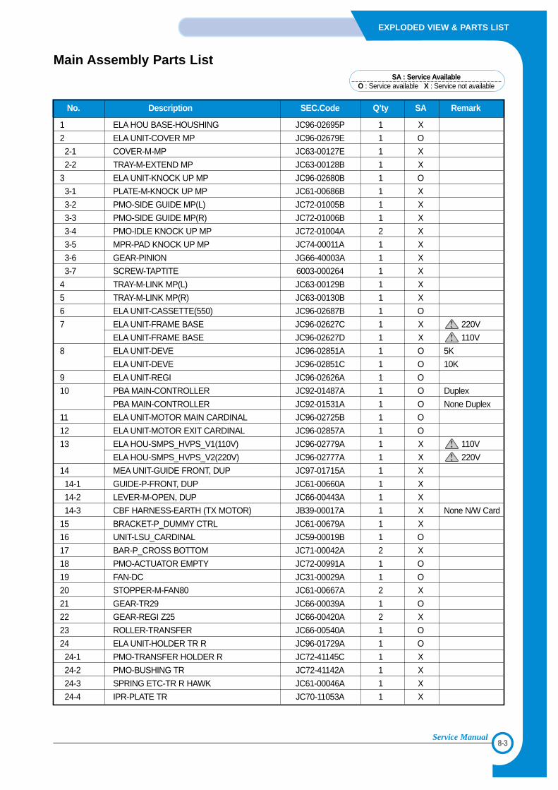
8-3
EXPLODED VIEW & PARTS LIST
Service Manual
No. Description SEC.Code Q’ty SA Remark
1 ELA HOU BASE-HOUSHING JC96-02695P 1 X
2 ELA UNIT-COVER MP JC96-02679E 1 O
2-1 COVER-M-MP JC63-00127E 1 X
2-2 TRAY-M-EXTEND MP JC63-00128B 1 X
3 ELA UNIT-KNOCK UP MP JC96-02680B 1 O
3-1 PLATE-M-KNOCK UP MP JC61-00686B 1 X
3-2 PMO-SIDE GUIDE MP(L) JC72-01005B 1 X
3-3 PMO-SIDE GUIDE MP(R) JC72-01006B 1 X
3-4 PMO-IDLE KNOCK UP MP JC72-01004A 2 X
3-5 MPR-PAD KNOCK UP MP JC74-00011A 1 X
3-6 GEAR-PINION JG66-40003A 1 X
3-7 SCREW-TAPTITE 6003-000264 1 X
4 TRAY-M-LINK MP(L) JC63-00129B 1 X
5 TRAY-M-LINK MP(R) JC63-00130B 1 X
6 ELA UNIT-CASSETTE(550) JC96-02687B 1 O
7 ELA UNIT-FRAME BASE JC96-02627C 1 X 220V
ELA UNIT-FRAME BASE JC96-02627D 1 X 110V
8 ELA UNIT-DEVE JC96-02851A 1 O 5K
ELA UNIT-DEVE JC96-02851C 1 O 10K
9 ELA UNIT-REGI JC96-02626A 1 O
10 PBA MAIN-CONTROLLER JC92-01487A 1 O Duplex
PBA MAIN-CONTROLLER JC92-01531A 1 O None Duplex
11 ELA UNIT-MOTOR MAIN CARDINAL JC96-02725B 1 O
12 ELA UNIT-MOTOR EXIT CARDINAL JC96-02857A 1 O
13 ELA HOU-SMPS_HVPS_V1(110V) JC96-02779A 1 X 110V
ELA HOU-SMPS_HVPS_V2(220V) JC96-02777A 1 X 220V
14 MEA UNIT-GUIDE FRONT, DUP JC97-01715A 1 X
14-1 GUIDE-P-FRONT, DUP JC61-00660A 1 X
14-2 LEVER-M-OPEN, DUP JC66-00443A 1 X
14-3 CBF HARNESS-EARTH (TX MOTOR) JB39-00017A 1 X None N/W Card
15 BRACKET-P_DUMMY CTRL JC61-00679A 1 X
16 UNIT-LSU_CARDINAL JC59-00019B 1 O
17 BAR-P_CROSS BOTTOM JC71-00042A 2 X
18 PMO-ACTUATOR EMPTY JC72-00991A 1 O
19 FAN-DC JC31-00029A 1 O
20 STOPPER-M-FAN80 JC61-00667A 2 X
21 GEAR-TR29 JC66-00039A 1 O
22 GEAR-REGI Z25 JC66-00420A 2 X
23 ROLLER-TRANSFER JC66-00540A 1 O
24 ELA UNIT-HOLDER TR R JC96-01729A 1 O
24-1 PMO-TRANSFER HOLDER R JC72-41145C 1 X
24-2 PMO-BUSHING TR JC72-41142A 1 X
24-3 SPRING ETC-TR R HAWK JC61-00046A 1 X
24-4 IPR-PLATE TR JC70-11053A 1 X
Main Assembly Parts ListSA : Service Available
O : Service available X : Service not available
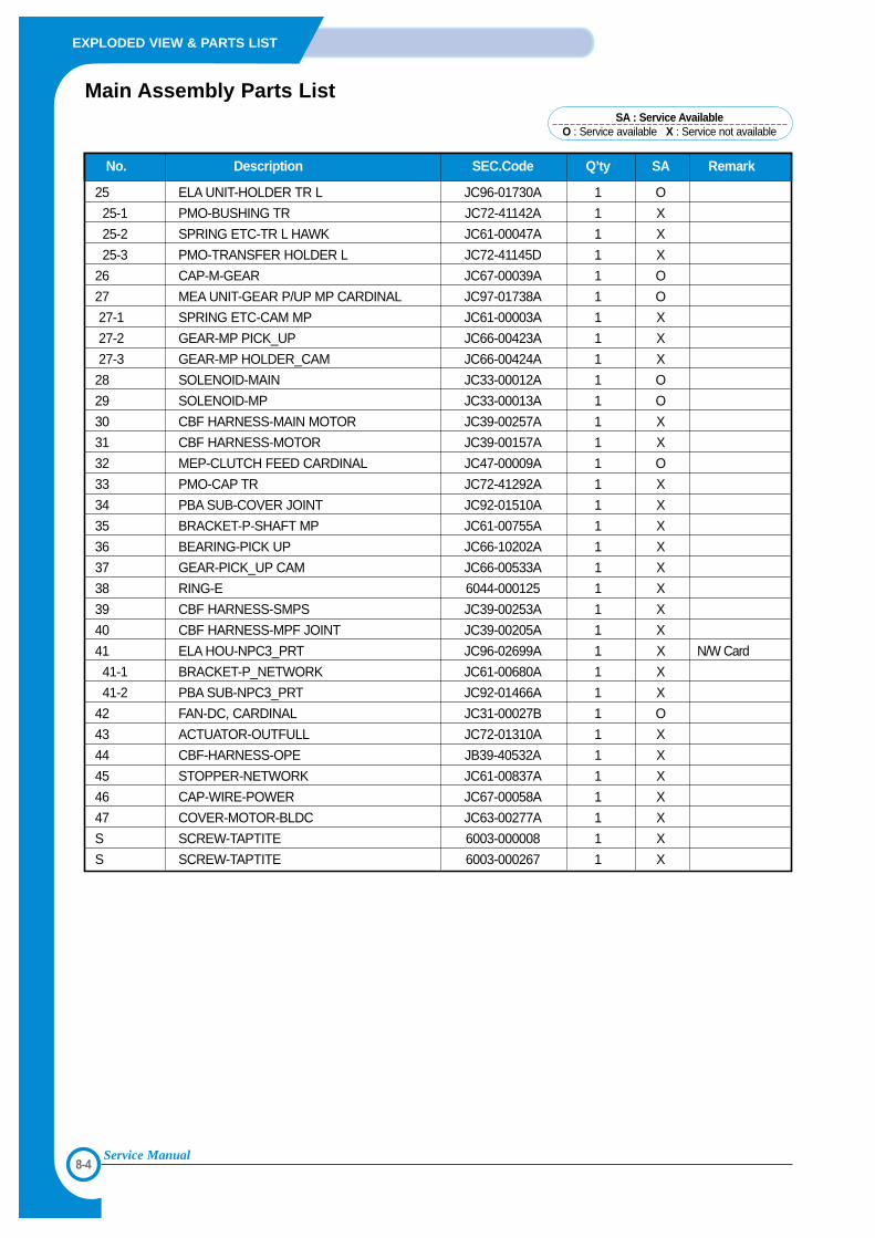
8-4
EXPLODED VIEW & PARTS LIST
Service Manual
No. Description SEC.Code Q’ty SA Remark
25 ELA UNIT-HOLDER TR L JC96-01730A 1 O
25-1 PMO-BUSHING TR JC72-41142A 1 X
25-2 SPRING ETC-TR L HAWK JC61-00047A 1 X
25-3 PMO-TRANSFER HOLDER L JC72-41145D 1 X
26 CAP-M-GEAR JC67-00039A 1 O
27 MEA UNIT-GEAR P/UP MP CARDINAL JC97-01738A 1 O
27-1 SPRING ETC-CAM MP JC61-00003A 1 X
27-2 GEAR-MP PICK_UP JC66-00423A 1 X
27-3 GEAR-MP HOLDER_CAM JC66-00424A 1 X
28 SOLENOID-MAIN JC33-00012A 1 O
29 SOLENOID-MP JC33-00013A 1 O
30 CBF HARNESS-MAIN MOTOR JC39-00257A 1 X
31 CBF HARNESS-MOTOR JC39-00157A 1 X
32 MEP-CLUTCH FEED CARDINAL JC47-00009A 1 O
33 PMO-CAP TR JC72-41292A 1 X
34 PBA SUB-COVER JOINT JC92-01510A 1 X
35 BRACKET-P-SHAFT MP JC61-00755A 1 X
36 BEARING-PICK UP JC66-10202A 1 X
37 GEAR-PICK_UP CAM JC66-00533A 1 X
38 RING-E 6044-000125 1 X
39 CBF HARNESS-SMPS JC39-00253A 1 X
40 CBF HARNESS-MPF JOINT JC39-00205A 1 X
41 ELA HOU-NPC3_PRT JC96-02699A 1 X N/W Card
41-1 BRACKET-P_NETWORK JC61-00680A 1 X
41-2 PBA SUB-NPC3_PRT JC92-01466A 1 X
42 FAN-DC, CARDINAL JC31-00027B 1 O
43 ACTUATOR-OUTFULL JC72-01310A 1 X
44 CBF-HARNESS-OPE JB39-40532A 1 X
45 STOPPER-NETWORK JC61-00837A 1 X
46 CAP-WIRE-POWER JC67-00058A 1 X
47 COVER-MOTOR-BLDC JC63-00277A 1 X
S SCREW-TAPTITE 6003-000008 1 X
S SCREW-TAPTITE 6003-000267 1 X
Main Assembly Parts ListSA : Service Available
O : Service available X : Service not available
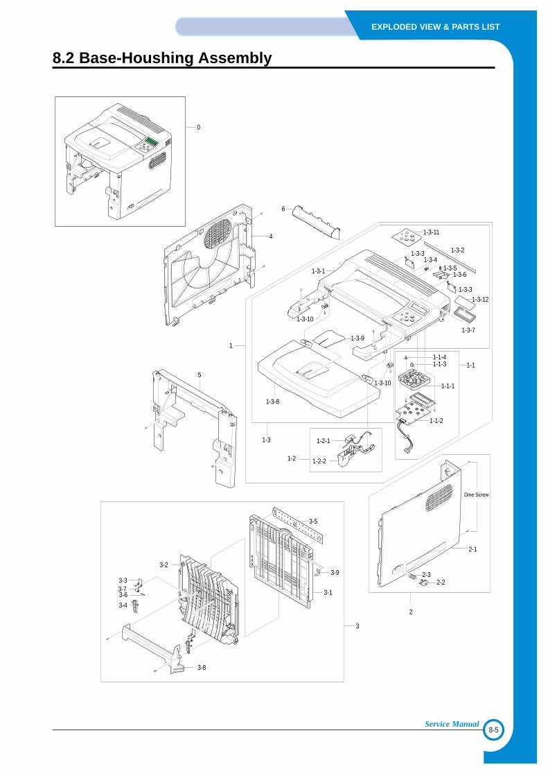
8-5
EXPLODED VIEW & PARTS LIST
Service Manual
8.2 Base-Houshing Assembly
1
1-3-2
1-3-11
1-3-3
1-3-3
1-3-7
1-3-12
1-3-1
1-3-41-3-5
1-3-6
1-3-8
1-2
1-3
1-3-9
1-3-10
1-3-10
1-2-1
1-2-2
5
3
2
3-1
3-9
3-5
3-2
3-8
3-33-73-6
3-4
0
4
2-1
Dine Screw
6
1-1-1
1-1-31-1-4
1-1-2
1-1
2-22-3
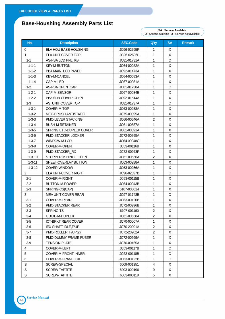
8-6
EXPLODED VIEW & PARTS LIST
Service Manual
No. Description SEC.Code Q’ty SA Remark
0 ELA HOU BASE-HOUSHING JC96-02695P 1 X
1 ELA UNIT-COVER TOP JC96-02696L 1 X
1-1 AS-PBA LCD PNL_KB JC81-01731A 1 O
1-1-1 KEY-M-BUTTON JC64-00082A 1 X
1-1-2 PBA MAIN_LCD PANEL JC92-01473A 1 X
1-1-3 KEY-M-CANCEL JC64-00083A 1 X
1-1-4 CAP-M-LED JC67-00051A 1 X
1-2 AS-PBA OPEN_CAP JC81-01738A 1 O
1-2-1 CAP-M-SENSOR JC67-00034B 1 X
1-2-2 PBA SUB-COVER OPEN JC92-01514A 1 X
1-3 AS_UNIT COVER TOP JC81-01737A 1 O
1-3-1 COVER-M-TOP JC63-00258A 1 X
1-3-2 MEC-BRUSH ANTISTATIC JC75-00095A 1 X
1-3-3 PMO-LEVER STACKING JC66-00646A 2 X
1-3-4 BUSH-M-RETAINER JC61-00657A 1 X
1-3-5 SPRING ETC-DUPLEX COVER JC61-00391A 1 X
1-3-6 PMO-STACKER LOCKER JC72-00995A 1 X
1-3-7 WINDOW-M-LCD JC64-00048C 1 X
1-3-8 COVER-M-OPEN JC63-00116B 1 X
1-3-9 PMO-STACKER_RX JC72-00973F 1 X
1-3-10 STOPPER-M-HINGE OPEN JC61-00656A 2 X
1-3-11 SHEET-OVERLAY BUTTON JC63-00288A 1 X
1-3-12 COVER-WINDOW JC63-00256A 1 X
2 ELA UNIT-COVER RIGHT JC96-02697B 1 O
2-1 COVER-M-RIGHT JC63-00115B 1 X
2-2 BUTTON-M-POWER JC64-00043B 1 X
2-3 SPRING-CS(CAP) 6107-000014 1 X
3 MEA UNIT-COVER REAR JC97-01743B 1 O
3-1 COVER-M-REAR JC63-00120B 1 X
3-2 PMO-STACKER REAR JC72-00996B 1 X
3-3 SPRING-TS 6107-001160 2 X
3-4 GUIDE-M-DUPLEX JC61-00658A 2 X
3-5 ICT-BRKT REAR COVER JC70-00007A 1 X
3-6 IEX-SHAFT IDLE,F/UP JC70-20901A 2 X
3-7 PMO-ROLLER_F/UP(2) JC72-20902A 2 X
3-8 PMO-DUMMY FRAME FUSER JC72-00999A 1 X
3-9 TENSION-PLATE JC70-00465A 1 X
4 COVER-M-LEFT JC63-00117B 1 O
5 COVER-M-FRONT INNER JC63-00118B 1 O
6 COVER-M-FRAME EXIT JC63-00122B 1 O
S SCREW-SPECIAL 6009-001351 4 X
S SCREW-TAPTITE 6003-000196 9 X
S SCREW-TAPTITE 6003-000119 5 X
Base-Houshing Assembly Parts ListSA : Service Available
O : Service available X : Service not available
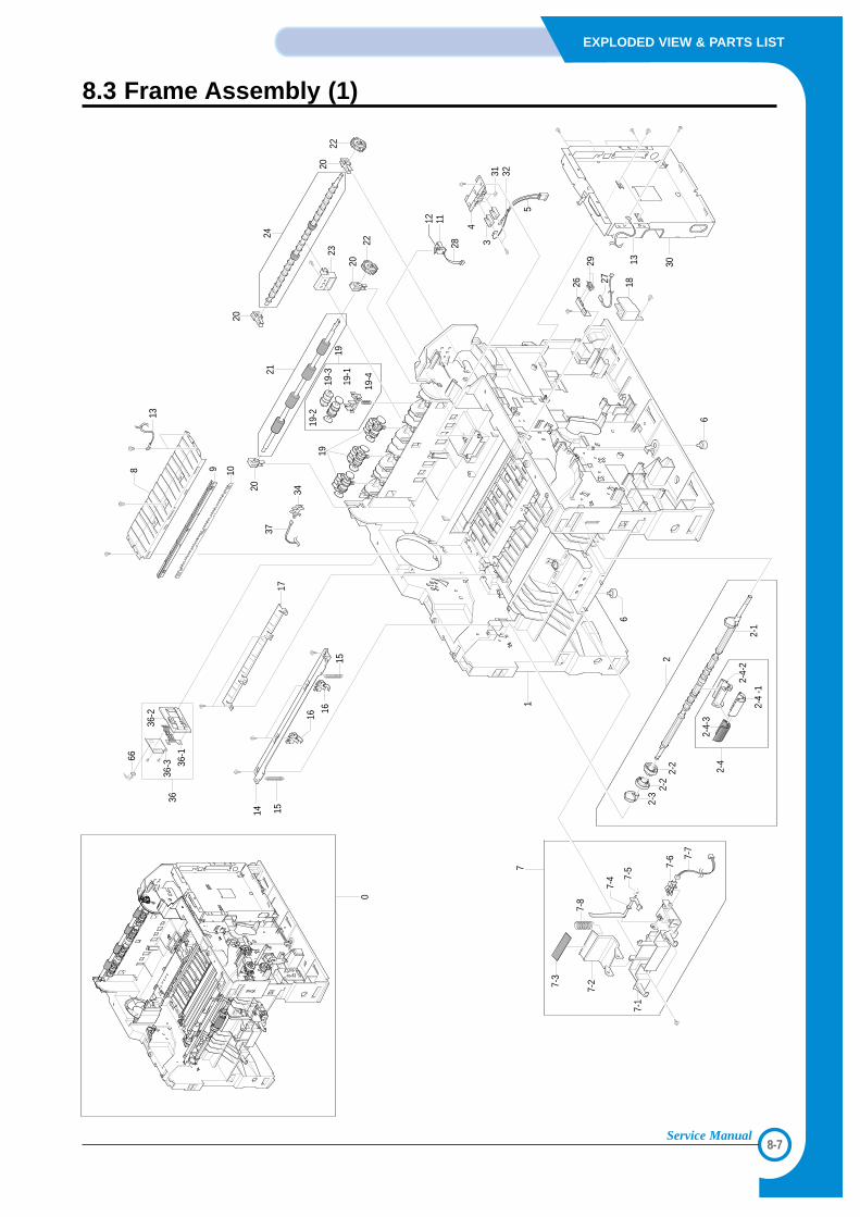
8-7
EXPLODED VIEW & PARTS LIST
Service Manual
8.3 Frame Assembly (1)
1
2
6
6
2-1
7
2-2
2-2
2-3
2-4
2-4
-1
2-4-
2
2-4-
3
7-1
7-27-3
7-8
7-4 7-
5 7-6 7-
7
5
14 15
16
16
15
8
13
9 10
1919
-1
19-2
19-3
19-4
19
20 34
3721
22
23
20
20
24
2022
1112
28
4
3
26 27 18
29 13 30
17
0
31 32
66
3636
-1
36-3
36-2
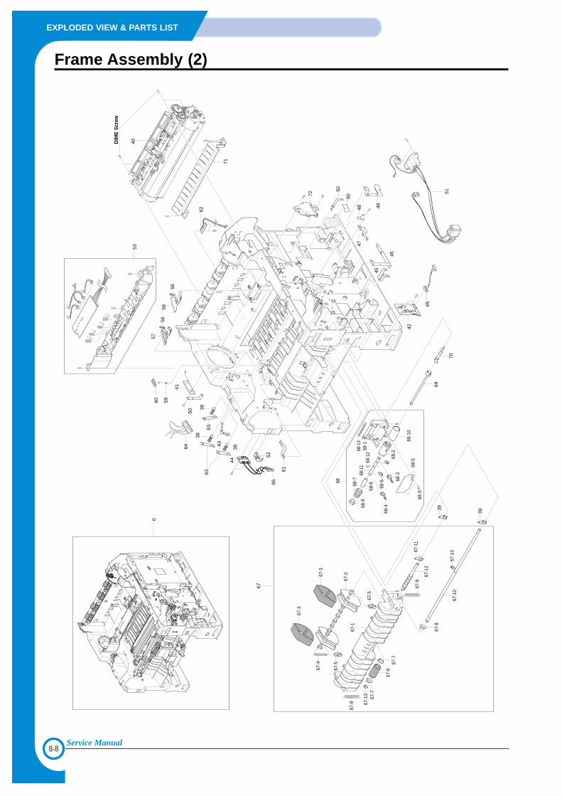
8-8
EXPLODED VIEW & PARTS LIST
Service Manual
Frame Assembly (2)
53
67
68
69
67-1
67-2
67-3
67-3
67-4
67-5
67-5
67-1
367
-7
67-9
67-6
67-7
67-8
67-1
2
67-9
67-1
067
-13
39
67-1
1
68-1
68-1
3
68-S
68-5
70
39
42
65
45
46
4748 49
60
50
72 51
57
5658
5659
41
60
6363
38
50
38
4438
43
5266
61
62
71
0
64
68-3
68-2
68-1
0
68-4
68-6
68-1
268
-11
68-9
68-868
-7
DIM
E S
crew
40
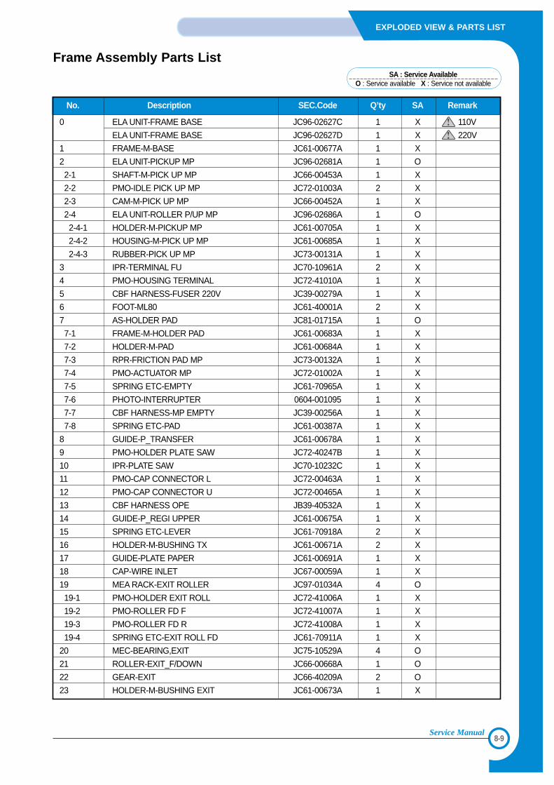
8-9
EXPLODED VIEW & PARTS LIST
Service Manual
No. Description SEC.Code Q’ty SA Remark
0 ELA UNIT-FRAME BASE JC96-02627C 1 X 110V
ELA UNIT-FRAME BASE JC96-02627D 1 X 220V
1 FRAME-M-BASE JC61-00677A 1 X
2 ELA UNIT-PICKUP MP JC96-02681A 1 O
2-1 SHAFT-M-PICK UP MP JC66-00453A 1 X
2-2 PMO-IDLE PICK UP MP JC72-01003A 2 X
2-3 CAM-M-PICK UP MP JC66-00452A 1 X
2-4 ELA UNIT-ROLLER P/UP MP JC96-02686A 1 O
2-4-1 HOLDER-M-PICKUP MP JC61-00705A 1 X
2-4-2 HOUSING-M-PICK UP MP JC61-00685A 1 X
2-4-3 RUBBER-PICK UP MP JC73-00131A 1 X
3 IPR-TERMINAL FU JC70-10961A 2 X
4 PMO-HOUSING TERMINAL JC72-41010A 1 X
5 CBF HARNESS-FUSER 220V JC39-00279A 1 X
6 FOOT-ML80 JC61-40001A 2 X
7 AS-HOLDER PAD JC81-01715A 1 O
7-1 FRAME-M-HOLDER PAD JC61-00683A 1 X
7-2 HOLDER-M-PAD JC61-00684A 1 X
7-3 RPR-FRICTION PAD MP JC73-00132A 1 X
7-4 PMO-ACTUATOR MP JC72-01002A 1 X
7-5 SPRING ETC-EMPTY JC61-70965A 1 X
7-6 PHOTO-INTERRUPTER 0604-001095 1 X
7-7 CBF HARNESS-MP EMPTY JC39-00256A 1 X
7-8 SPRING ETC-PAD JC61-00387A 1 X
8 GUIDE-P_TRANSFER JC61-00678A 1 X
9 PMO-HOLDER PLATE SAW JC72-40247B 1 X
10 IPR-PLATE SAW JC70-10232C 1 X
11 PMO-CAP CONNECTOR L JC72-00463A 1 X
12 PMO-CAP CONNECTOR U JC72-00465A 1 X
13 CBF HARNESS OPE JB39-40532A 1 X
14 GUIDE-P_REGI UPPER JC61-00675A 1 X
15 SPRING ETC-LEVER JC61-70918A 2 X
16 HOLDER-M-BUSHING TX JC61-00671A 2 X
17 GUIDE-PLATE PAPER JC61-00691A 1 X
18 CAP-WIRE INLET JC67-00059A 1 X
19 MEA RACK-EXIT ROLLER JC97-01034A 4 O
19-1 PMO-HOLDER EXIT ROLL JC72-41006A 1 X
19-2 PMO-ROLLER FD F JC72-41007A 1 X
19-3 PMO-ROLLER FD R JC72-41008A 1 X
19-4 SPRING ETC-EXIT ROLL FD JC61-70911A 1 X
20 MEC-BEARING,EXIT JC75-10529A 4 O
21 ROLLER-EXIT_F/DOWN JC66-00668A 1 O
22 GEAR-EXIT JC66-40209A 2 O
23 HOLDER-M-BUSHING EXIT JC61-00673A 1 X
Frame Assembly Parts ListSA : Service Available
O : Service available X : Service not available
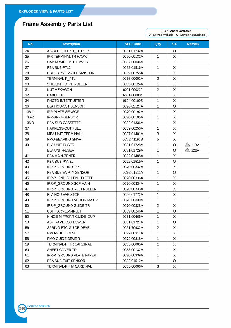
8-10
EXPLODED VIEW & PARTS LIST
Service Manual
No. Description SEC.Code Q’ty SA Remark
24 AS-ROLLER EXIT_DUPLEX JC81-01732A 1 O
25 IPR-TERMINAL TR HAWK JC70-00132A 1 X
26 CAP-M-WIRE PTL LOWER JC67-00036A 1 X
27 PBA SUB-PTL2 JC92-01516A 1 X
28 CBF HARNESS-THERMISTOR JC39-00255A 1 X
29 TERMINAL-P_PTL JC65-00001A 2 X
30 SHIELD-P_CONTROLLER JC63-00124A 1 X
31 NUT-HEXAGON 6021-000222 2 X
32 CABLE TIE 6501-000004 1 X
34 PHOTO-INTERRUPTER 0604-001095 1 X
36 ELA HOU-CST SENSOR JC96-02127A 1 O
36-1 IPR-PLATE-SENSOR JC70-00192A 1 X
36-2 IPR-BRKT-SENSOR JC70-00195A 1 X
36-3 PBA-SUB CASSETTE JC92-01336A 1 X
37 HARNESS-OUT FULL JC39-00250A 1 X
38 MEA UNIT-TERMINAL:L JC97-01401A 3 X
39 PMO-BEARING SHAFT JC72-41191B 5 X
40 ELA UNIT-FUSER JC81-01728A 1 O 110V
ELA UNIT-FUSER JC81-01729A 1 O 220V
41 PBA MAIN-ZENER JC92-01488A 1 X
42 PBA SUB-PANEL JC92-01519A 1 O
43 IPR-P_GROUND OPC JC70-00332A 1 X
44 PBA SUB-EMPTY SENSOR JC92-01511A 1 O
45 IPR-P_GND SOLENOID FEED JC70-00336A 1 X
46 IPR-P_GROUND SCF MAIN JC70-00334A 1 X
47 IPR-P_GROUND REGI ROLLER JC70-00333A 1 X
48 ELA HOU-VARISTOR JC96-01772A 1 X
49 IPR-P_GROUND MOTOR MAIN2 JC70-00330A 1 X
50 IPR-P_GROUND GUIDE TR JC70-00328A 2 X
51 CBF HARNESS-INLET JC39-00246A 1 O
52 HINGE-M-FRONT GUIDE, DUP JC61-00666A 1 X
53 AS-FRAME LSU LOWER JC81-01727A 1 O
56 SPRING ETC-GUIDE DEVE JC61-70932A 2 X
57 PMO-GUIDE DEVE L JC72-00317A 1 X
58 PMO-GUIDE DEVE R JC72-00318A 1 X
59 TERMINAL-P_TR CARDINAL JC65-00005A 1 X
60 SHEET-COVER TR JC63-00132A 1 X
61 IPR-P_GROUND PLATE PAPER JC70-00339A 1 X
62 PBA SUB-EXIT SENSOR JC92-01512A 1 O
63 TERMINAL-P_HV CARDINAL JC65-00006A 3 X
Frame Assembly Parts ListSA : Service Available
O : Service available X : Service not available
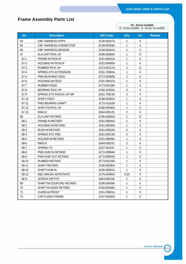
8-11
EXPLODED VIEW & PARTS LIST
Service Manual
No. Description SEC.Code Q’ty SA Remark
64 CBF HARNESS-HVPS JC39-00247A 1 X
65 CBF HARNESS-CONNECTOR JC39-00259A 1 X
66 CBF HARNESS-SENSOR JC39-00261A 1 X
67 ELA UNIT-PICK UP JC96-02683A 1 O
67-1 FRAME-M-PICKUP JC61-00641A 1 X
67-2 HOUSING-M-PICKUP JC61-00636A 1 X
67-3 RUBBER-PICK UP JC73-00127A 2 O
67-4 SPRING ETC-EXTENSION JC61-70950A 1 X
67-5 PMO-BUSHING FEED JC72-00382B 2 X
67-6 HOUSING-M-FEED JC61-00637A 1 X
67-7 RUBBER-FEED JC73-00128A 1 X
67-8 BEARING-PICK UP JC66-10202A 3 X
67-9 SPRING ETC-KNOCK UP MP JC61-70913A 2 X
67-10 SHAFT-FEED JC66-00592A 1 X
67-11 PMO-BEARING SHAFT JC72-41191B 1 X
67-12 SHAFT-M-PICK UP JC66-00440A 1 X
67-13 RING-E 6044-000125 2 X
68 ELA UNIT-RETARD JC96-02682A 1 O
68-1 FRAME-M-RETARD JC61-00640A 1 X
68-2 HOUSING-M-RETARD JC61-00635A 1 X
68-3 BUSH-M-RETARD JC61-00652A 2 X
68-4 SPRING ETC-PAD JC61-00013A 2 X
68-5 HOLDER-M-RETARD JC61-00638A 1 X
68-6 RING-E 6044-000231 2 X
68-7 SPRING-TS 6107-001157 1 X
68-8 PMO-HUB IN RETARD JC72-00994A 1 X
68-9 PMO-HUB OUT RETARD JC72-00993A 1 X
68-10 RUBBER-RETARD JC73-00129A 1 X
68-11 SHAFT-RETARD JC66-00590A 1 X
68-12 SHAFT-HUB IN JC66-00591A 1 X
68-13 MEC-BRUSH ANTISTATIC JC75-00095A 0.25 X
68-S SCREW-TAPTITE 6003-000196 2 X
69 SHAFT-M-COUPLING RETARD JC66-00439A 1 X
70 SHAFT-M-GEAR RETARD JC66-00438A 1 X
71 GUIDE-M-FRONT JC61-00801A 1 X
72 CAP-FUSER-FRAME JC67-00060A 1 X
Frame Assembly Parts ListSA : Service Available
O : Service available X : Service not available
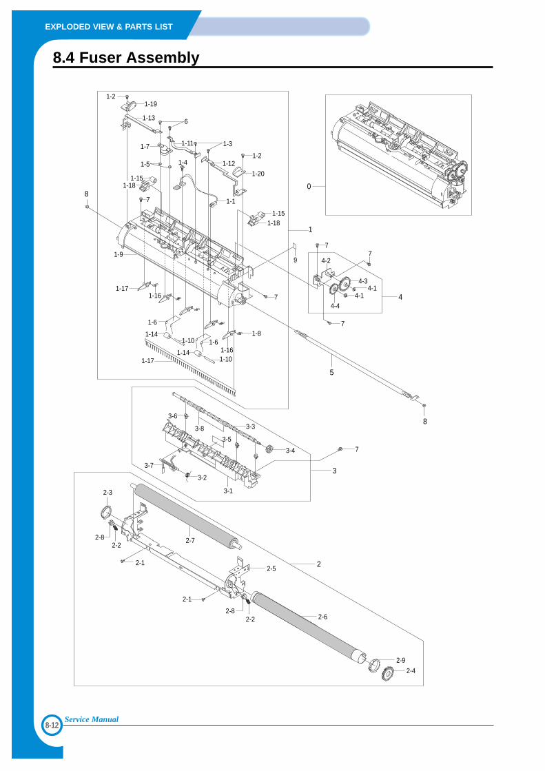
8-12
EXPLODED VIEW & PARTS LIST
Service Manual
8.4 Fuser Assembly
2-1
2-2
2-2
2-8
2-8
2-5
2-3
2-7
3-1
2-6
2-9
2-4
3-6
3-7
3-2
3-4
3-3
1-17
1-14
1-6
1-10
1-141-10
7
3-8
3-5
1-61-8
5
3
2
1-16
1-161-17
8
1-2
1-13
1-19
7
1-9
8
1-7
1-5
6
1-31-11
1-4 1-12
1-1
7
9
4-4
7
4-14-1
74-2
1-18 1-15
7
4-3
1-181-15
1
0
4
2-1
1-2
1-20
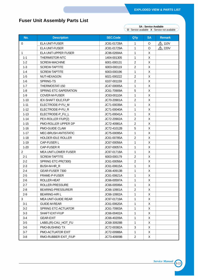
8-13
EXPLODED VIEW & PARTS LIST
Service Manual
No. Description SEC.Code Q’ty SA Remark
0 ELA UNIT-FUSER JC81-01728A 1 O 110V
ELA UNIT-FUSER JC81-01729A 1 O 220V
1 ELA UNIT-UPPER FUSER JC96-02694A 1 X
1-1 THERMISTOR-NTC 1404-001305 1 X
1-2 SCREW-MACHINE 6001-000131 2 X
1-3 SCREW-TAPTITE 6003-000119 2 X
1-4 SCREW-TAPTITE 6003-000196 1 X
1-5 NUT-HEXAGON 6021-000222 2 X
1-6 SPRING-TS 6107-001159 2 X
1-7 THERMOSTAT-150 JC47-00005A 1 X
1-8 SPRING ETC-SAPERATION JC61-70909A 5 X
1-9 COVER-M-FUSER JC63-00110A 1 X
1-10 IEX-SHAFT IDLE,F/UP JC70-20901A 2 X
1-11 ELECTRODE-P-FU_M JC71-00039A 1 X
1-12 ELECTRODE-P-FU_R JC71-00040A 1 X
1-13 ELECTRODE-P_FU_L JC71-00041A 1 X
1-14 PEX-ROLLER F/UP(2) JC72-20902A 2 X
1-15 PMO-ROLLER UPPER DP JC72-40981A 2 X
1-16 PMO-GUIDE CLAW JC72-41012B 5 X
1-17 MEC-BRUSH ANTISTATIC JC75-00095A 1 X
1-18 HOLDER-IDLE ROLLER JC61-00785A 2 X
1-19 CAP-FUSER L JC67-00056A 1 X
1-20 CAP-FUSER R JC67-00057A 1 X
2 MEA UNIT-LOWER FUSER JC97-01718A 1 X
2-1 SCREW-TAPTITE 6003-000179 2 X
2-2 SPRING ETC-PR(7300) JC61-00056A 2 X
2-3 BUSH-M-HR_R JC61-00615A 1 X
2-4 GEAR-FUSER 7300 JC66-40913B 1 X
2-5 FRAME-P-FUSER JC61-00621A 1 X
2-6 ROLLER-HEAT JC66-00597A 1 X
2-7 ROLLER-PRESSURE JC66-00599A 1 X
2-8 BEARING-PRESSURE/R JC66-10901A 2 X
2-9 BEARING-H/R L JC66-10902A 1 X
3 MEA UNIT-GUIDE REAR JC97-01719A 1 X
3-1 GUIDE-M-REAR JC61-00620A 1 X
3-2 SPRING ETC-ACTUATOR JC61-70903A 1 X
3-3 SHAFT-EXIT-F/UP JC66-00402A 1 X
3-4 GEAR-EXIT JC66-40209A 1 X
3-5 LABEL(R)-CAU_HOT_FU JC68-30928B 1 X
3-6 PMO-BUSHING TX JC72-00382A 3 X
3-7 PMO-ACTUATOR EXIT JC72-00988A 1 X
3-8 RMO-RUBBER EXIT_F/UP JC73-40909B 2 X
Fuser Unit Assembly Parts ListSA : Service Available
O : Service available X : Service not available
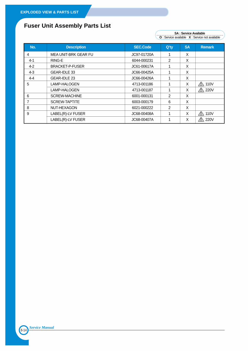
8-14
EXPLODED VIEW & PARTS LIST
Service Manual
No. Description SEC.Code Q’ty SA Remark
4 MEA UNIT-BRK GEAR FU JC97-01720A 1 X
4-1 RING-E 6044-000231 2 X
4-2 BRACKET-P-FUSER JC61-00617A 1 X
4-3 GEAR-IDLE 33 JC66-00425A 1 X
4-4 GEAR-IDLE 23 JC66-00426A 1 X
5 LAMP-HALOGEN 4713-001186 1 X 110V
LAMP-HALOGEN 4713-001187 1 X 220V
6 SCREW-MACHINE 6001-000131 2 X
7 SCREW-TAPTITE 6003-000179 6 X
8 NUT-HEXAGON 6021-000222 2 X
9 LABEL(R)-LV FUSER JC68-00408A 1 X 110V
LABEL(R)-LV FUSER JC68-00407A 1 X 220V
Fuser Unit Assembly Parts ListSA : Service Available
O : Service available X : Service not available
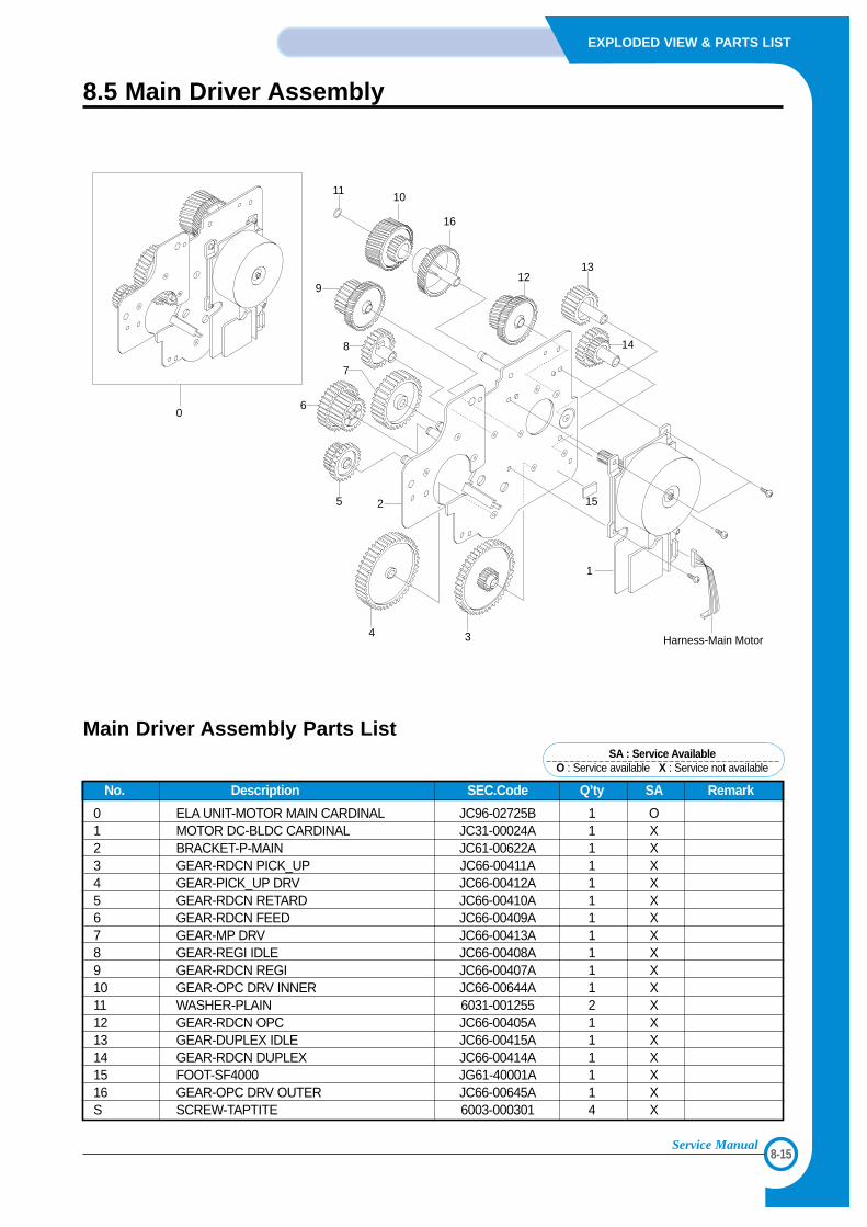
8-15
EXPLODED VIEW & PARTS LIST
Service Manual
8.5 Main Driver Assembly
0
1
1525
34
6
7
8
9
16
10
1213
14
Harness-Main Motor
11
No. Description SEC.Code Q’ty SA Remark
0 ELA UNIT-MOTOR MAIN CARDINAL JC96-02725B 1 O1 MOTOR DC-BLDC CARDINAL JC31-00024A 1 X2 BRACKET-P-MAIN JC61-00622A 1 X3 GEAR-RDCN PICK_UP JC66-00411A 1 X4 GEAR-PICK_UP DRV JC66-00412A 1 X5 GEAR-RDCN RETARD JC66-00410A 1 X6 GEAR-RDCN FEED JC66-00409A 1 X7 GEAR-MP DRV JC66-00413A 1 X8 GEAR-REGI IDLE JC66-00408A 1 X9 GEAR-RDCN REGI JC66-00407A 1 X10 GEAR-OPC DRV INNER JC66-00644A 1 X11 WASHER-PLAIN 6031-001255 2 X12 GEAR-RDCN OPC JC66-00405A 1 X13 GEAR-DUPLEX IDLE JC66-00415A 1 X14 GEAR-RDCN DUPLEX JC66-00414A 1 X15 FOOT-SF4000 JG61-40001A 1 X16 GEAR-OPC DRV OUTER JC66-00645A 1 XS SCREW-TAPTITE 6003-000301 4 X
Main Driver Assembly Parts ListSA : Service Available
O : Service available X : Service not available
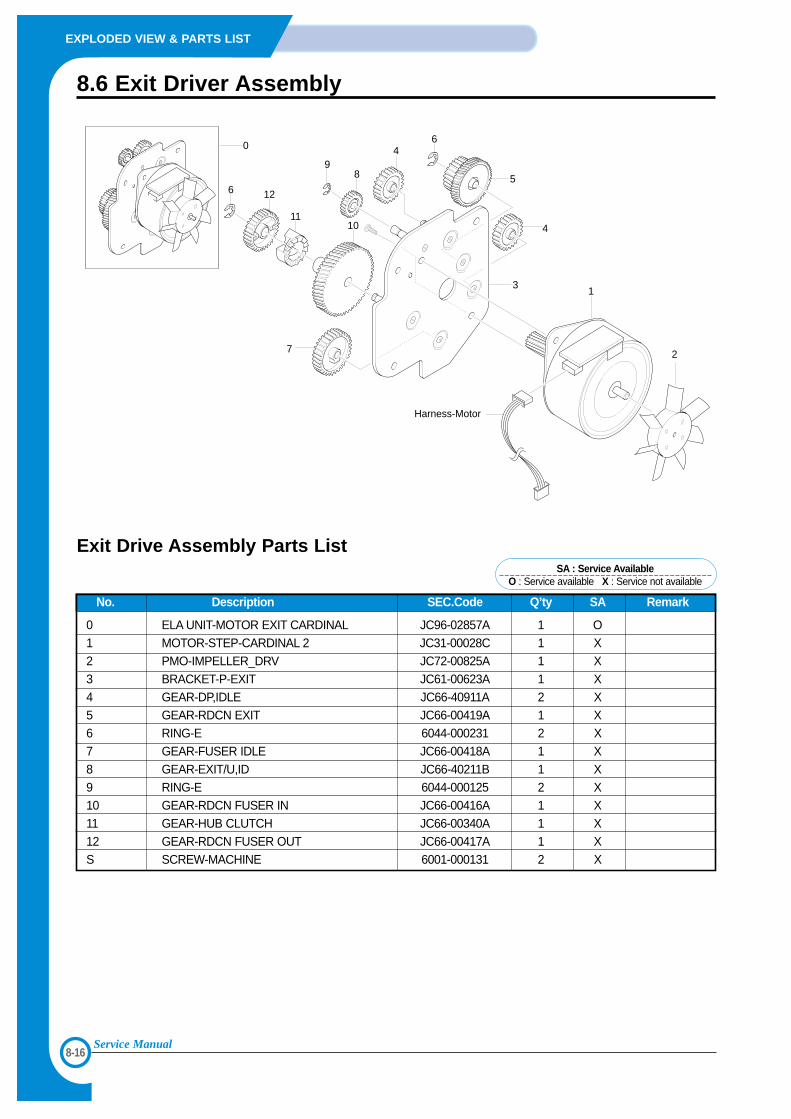
8-16
EXPLODED VIEW & PARTS LIST
Service Manual
8.6 Exit Driver Assembly
0 4
1
2
Harness-Motor
3
4
5
6
6
89
1011
12
7
No. Description SEC.Code Q’ty SA Remark
0 ELA UNIT-MOTOR EXIT CARDINAL JC96-02857A 1 O1 MOTOR-STEP-CARDINAL 2 JC31-00028C 1 X2 PMO-IMPELLER_DRV JC72-00825A 1 X3 BRACKET-P-EXIT JC61-00623A 1 X4 GEAR-DP,IDLE JC66-40911A 2 X5 GEAR-RDCN EXIT JC66-00419A 1 X6 RING-E 6044-000231 2 X7 GEAR-FUSER IDLE JC66-00418A 1 X8 GEAR-EXIT/U,ID JC66-40211B 1 X9 RING-E 6044-000125 2 X10 GEAR-RDCN FUSER IN JC66-00416A 1 X11 GEAR-HUB CLUTCH JC66-00340A 1 X12 GEAR-RDCN FUSER OUT JC66-00417A 1 XS SCREW-MACHINE 6001-000131 2 X
Exit Drive Assembly Parts ListSA : Service Available
O : Service available X : Service not available
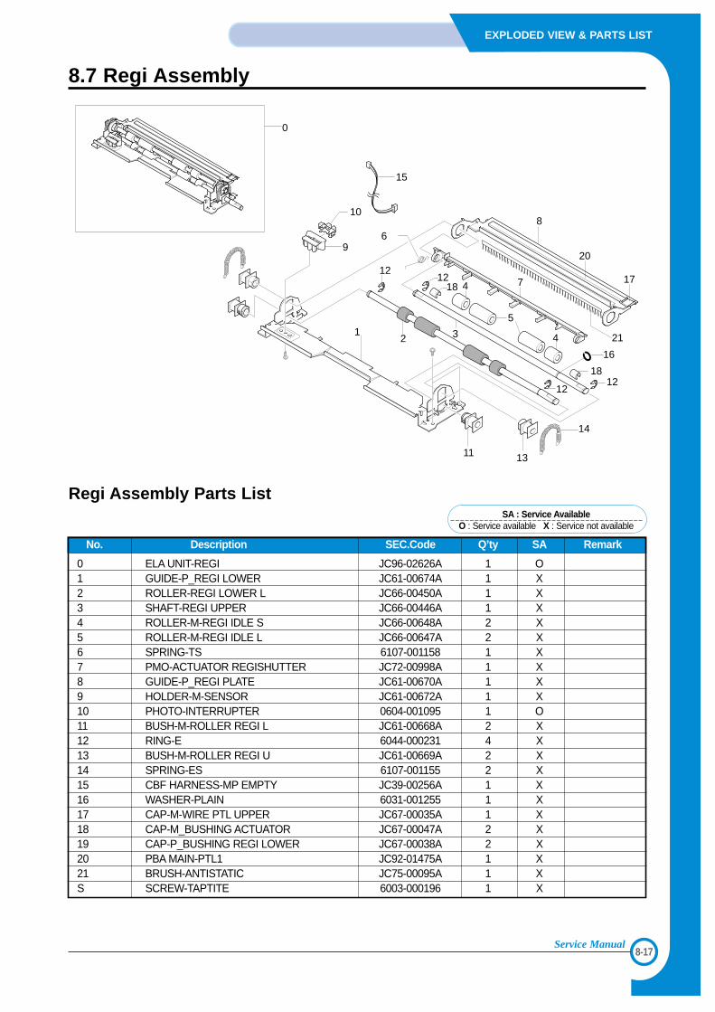
8-17
EXPLODED VIEW & PARTS LIST
Service Manual
8.7 Regi Assembly
12
12
3
4
5
4
18
16
1218
1212
6
7
21
20
17
810
9
15
11 13
14
0
No. Description SEC.Code Q’ty SA Remark
0 ELA UNIT-REGI JC96-02626A 1 O1 GUIDE-P_REGI LOWER JC61-00674A 1 X2 ROLLER-REGI LOWER L JC66-00450A 1 X3 SHAFT-REGI UPPER JC66-00446A 1 X4 ROLLER-M-REGI IDLE S JC66-00648A 2 X5 ROLLER-M-REGI IDLE L JC66-00647A 2 X6 SPRING-TS 6107-001158 1 X7 PMO-ACTUATOR REGISHUTTER JC72-00998A 1 X8 GUIDE-P_REGI PLATE JC61-00670A 1 X9 HOLDER-M-SENSOR JC61-00672A 1 X10 PHOTO-INTERRUPTER 0604-001095 1 O11 BUSH-M-ROLLER REGI L JC61-00668A 2 X12 RING-E 6044-000231 4 X13 BUSH-M-ROLLER REGI U JC61-00669A 2 X14 SPRING-ES 6107-001155 2 X15 CBF HARNESS-MP EMPTY JC39-00256A 1 X16 WASHER-PLAIN 6031-001255 1 X17 CAP-M-WIRE PTL UPPER JC67-00035A 1 X18 CAP-M_BUSHING ACTUATOR JC67-00047A 2 X19 CAP-P_BUSHING REGI LOWER JC67-00038A 2 X20 PBA MAIN-PTL1 JC92-01475A 1 X21 BRUSH-ANTISTATIC JC75-00095A 1 XS SCREW-TAPTITE 6003-000196 1 X
Regi Assembly Parts ListSA : Service Available
O : Service available X : Service not available
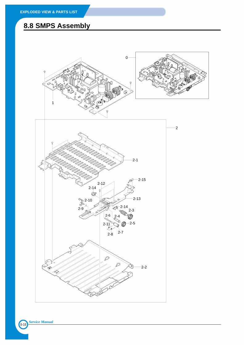
8-18
EXPLODED VIEW & PARTS LIST
Service Manual
8.8 SMPS Assembly
0
1
2-1
2
2-13
2-15
2-142-12
2-142-3
2-4
2-5
2-6
2-72-8
2-11
2-9
2-10
2-2
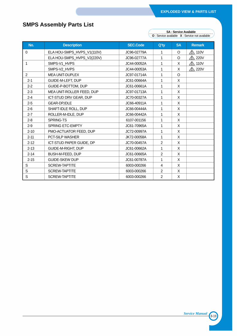
8-19
EXPLODED VIEW & PARTS LIST
Service Manual
No. Description SEC.Code Q’ty SA Remark
0 ELA HOU-SMPS_HVPS_V1(110V) JC96-02779A 1 O 110V
ELA HOU-SMPS_HVPS_V2(220V) JC96-02777A 1 O 220V
1 SMPS-V1_HVPS JC44-00052A 1 X 110V
SMPS-V2_HVPS JC44-00053A 1 X 220V
2 MEA UNIT-DUPLEX JC97-01714A 1 O
2-1 GUIDE-M-LEFT, DUP JC61-00664A 1 X
2-2 GUIDE-P-BOTTOM, DUP JC61-00661A 1 X
2-3 MEA UNIT-ROLLER FEED, DUP JC97-01713A 1 X
2-4 ICT-STUD DRV GEAR, DUP JC70-00327A 1 X
2-5 GEAR-DP,IDLE JC66-40911A 1 X
2-6 SHAFT-IDLE ROLL, DUP JC66-00444A 1 X
2-7 ROLLER-M-IDLE, DUP JC66-00442A 1 X
2-8 SPRING-TS 6107-001156 1 X
2-9 SPRING ETC-EMPTY JC61-70965A 1 X
2-10 PMO-ACTUATOR FEED, DUP JC72-00997A 1 X
2-11 PCT-SILP WASHER JK72-00058A 1 X
2-12 ICT-STUD PAPER GUIDE, DP JC70-00457A 2 X
2-13 GUIDE-M-RIGHT, DUP JC61-00662A 1 X
2-14 BUSH-M-FEED, DUP JC61-00665A 2 X
2-15 GUIDE-SKEW DUP JC61-00787A 1 X
S SCREW-TAPTITE 6003-000266 4 X
S SCREW-TAPTITE 6003-000266 2 X
S SCREW-TAPTITE 6003-000266 2 X
SMPS Assembly Parts ListSA : Service Available
O : Service available X : Service not available
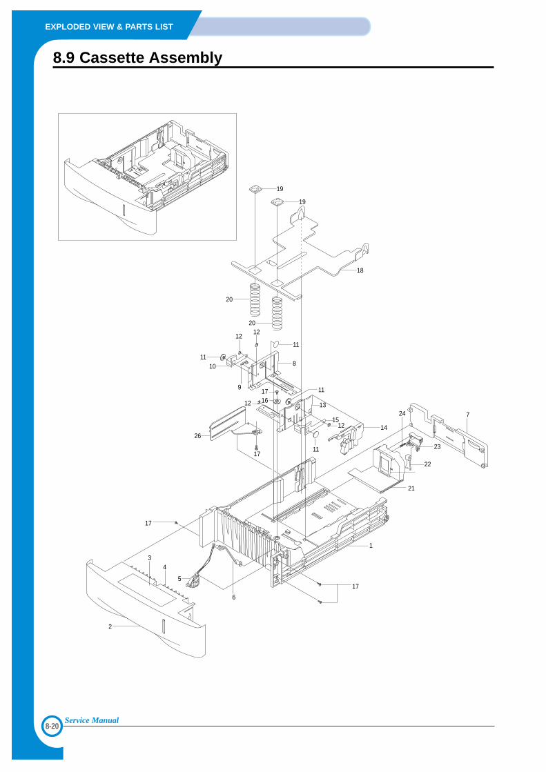
8-20
EXPLODED VIEW & PARTS LIST
Service Manual
8.9 Cassette Assembly
19
19
20
20
1110
1212
11
8
11
13
12
11
14
7
23
24
22
21
1
17
9
26
1617
17
12
15
18
6
5
2
34
17
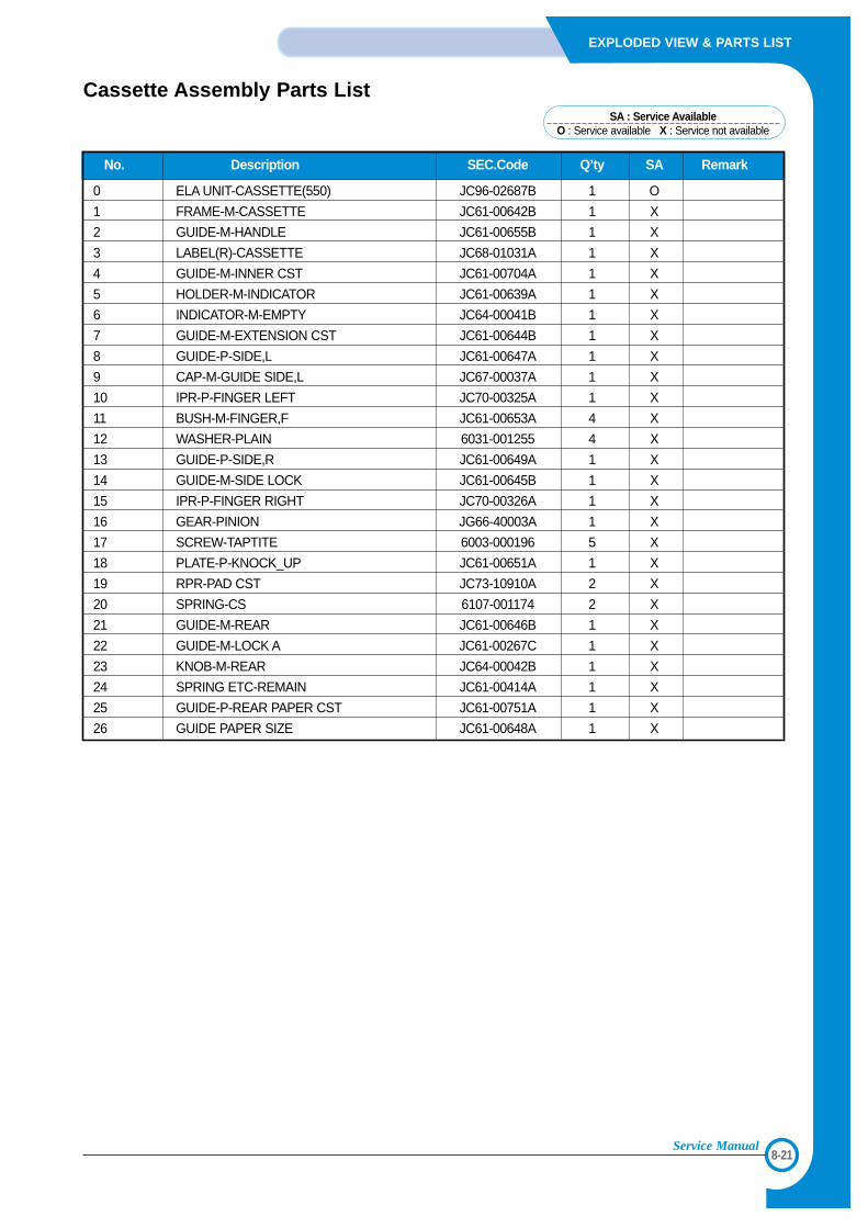
8-21
EXPLODED VIEW & PARTS LIST
Service Manual
No. Description SEC.Code Q’ty SA Remark
0 ELA UNIT-CASSETTE(550) JC96-02687B 1 O
1 FRAME-M-CASSETTE JC61-00642B 1 X
2 GUIDE-M-HANDLE JC61-00655B 1 X
3 LABEL(R)-CASSETTE JC68-01031A 1 X
4 GUIDE-M-INNER CST JC61-00704A 1 X
5 HOLDER-M-INDICATOR JC61-00639A 1 X
6 INDICATOR-M-EMPTY JC64-00041B 1 X
7 GUIDE-M-EXTENSION CST JC61-00644B 1 X
8 GUIDE-P-SIDE,L JC61-00647A 1 X
9 CAP-M-GUIDE SIDE,L JC67-00037A 1 X
10 IPR-P-FINGER LEFT JC70-00325A 1 X
11 BUSH-M-FINGER,F JC61-00653A 4 X
12 WASHER-PLAIN 6031-001255 4 X
13 GUIDE-P-SIDE,R JC61-00649A 1 X
14 GUIDE-M-SIDE LOCK JC61-00645B 1 X
15 IPR-P-FINGER RIGHT JC70-00326A 1 X
16 GEAR-PINION JG66-40003A 1 X
17 SCREW-TAPTITE 6003-000196 5 X
18 PLATE-P-KNOCK_UP JC61-00651A 1 X
19 RPR-PAD CST JC73-10910A 2 X
20 SPRING-CS 6107-001174 2 X
21 GUIDE-M-REAR JC61-00646B 1 X
22 GUIDE-M-LOCK A JC61-00267C 1 X
23 KNOB-M-REAR JC64-00042B 1 X
24 SPRING ETC-REMAIN JC61-00414A 1 X
25 GUIDE-P-REAR PAPER CST JC61-00751A 1 X
26 GUIDE PAPER SIZE JC61-00648A 1 X
Cassette Assembly Parts ListSA : Service Available
O : Service available X : Service not available
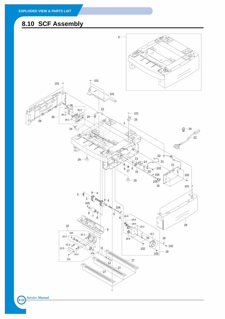
8-22
EXPLODED VIEW & PARTS LIST
Service Manual
8.10 SCF Assembly
105
105
32
31
102
101
28
103
102
18-1
24
0
101
101
20
27
27
11
12
27
10-1104
104
10-2
10-3
10-4
10-5
101
109
4
26
26
4
56
6 6
1314
17 15 33
16
23
104
105
8
87
125
101
22
34
102
33 19
18
101
102
21
2918-2
18-3
18-4
18-5
18-6
2336
3535-1
35-3
35-2

8-23
EXPLODED VIEW & PARTS LIST
Service Manual
No. Description SEC.Code Q’ty SA Remark
0 MEA UNIT-SECOND FEEDER JC96-02842B 1 X1 PMO-FRAME SCF JC61-00643B 1 X2 MEA UNIT-PICK UP JC96-02683A 1 O2-1 HOUSING-PICK UP JC61-00636A 1 X2-2 RUBBER-PICK UP JC73-00127A 2 X
3 SPRING-PICK UP JC61-70950A 1 X4 PMO-BUSHING FEED JC72-00382B 2 X5 SHAFT-PICK UP JC66-00440A 1 X6 PMO-BEARING SHAFT JC72-41191B 4 X7 MEA UNIT ROLLER FEED JC96-02685A 1 X8 BEARING-PICK UP JC66-10202A 2 X9 PMO-GUIDE INNER-SCF JC61-00650A 1 X10 ELA UNIT-RETARD JC96-02682A 1 O11 COUPLING-RETARD SHAFT-SCF JC66-00441A 1 X12 SHAFT-GEAR RETARD JC66-00438A 1 X13 GEAR-PICK UP CAM SCF JC66-00534A 1 X14 SOLENOID-WHITE JC33-00013A 1 O15 SHAFT FEED SCF JC66-00593A 1 X16 CLUTCH-FEED SCF JC47-00009B 1 O17 GEAR-REGI Z25 JC66-00420A 1 X18 ELA UNIT-BRACKET SCF JC96-02858A 1 X18-1 MOTOR-SCF JC31-00005E 1 O18-2 IPR-BRK MOTOR SCF JC61-00624A 1 X18-3 GEAR REGI IDLE JC66-00408A 1 X18-4 GEAR SCF RDCN RETARD JC66-00410A 1 X18-5 GEAR SCF RDCN PICKUP JC66-00428A 1 X18-6 GEAR SCF RDCN FEED JC66-00427A 1 X
19 IPR-GND SPRING,FEED JC70-00464A 1 X20 PHOTO-INTERRUPTER 0604-001095 1 X21 PCB CONTROLLER ASSY JC92-01436A 1 O22 CBF HARNESS-SCF JC39-00248A 1 O23 CABLE PHOTO-INTERRUPTER JC39-00250A 1 X24 PMO-ACTUATOR EMPTY SCF JC72-00992A 1 O25 IPR-GND TOP JC70-11028A 1 X26 FOOT-RUBBER HAWK16 JC61-40001A 2 X27 IPR-BAR CROSS BOTTOM JC71-00042A 3 X28 PMO-COVER L-SCF JC63-00112B 1 X29 PMO-COVER R-SCF JC63-00113B 1 X30 PMO-COVER DUMMY-SCF JC63-00114B 1 X31 CBF HARNESS-SCF GND JC39-40608A 1 X32 CBF HARNESS-LIU GND JB39-00103A 1 X33 CBF HARNESS-OPE JC39-40532A 1 X34 BUSH-CABLE JC61-00804A 1 X35 ELA HOU-CST SENSOR HAWK16 JC96-02127A 1 X35-1 IPR-PLATE SENSOR JC70-00192A 1 X35-2 IPR-BRACKET SENSOR JC70-00195A 1 X35-3 PBA SUB-CASSETTE JC92-01336A 1 X
36 HARNESS PAPER-SIZE JC96-02127A 1 X
SCF Assembly Parts ListSA : Service Available
O : Service available X : Service not available
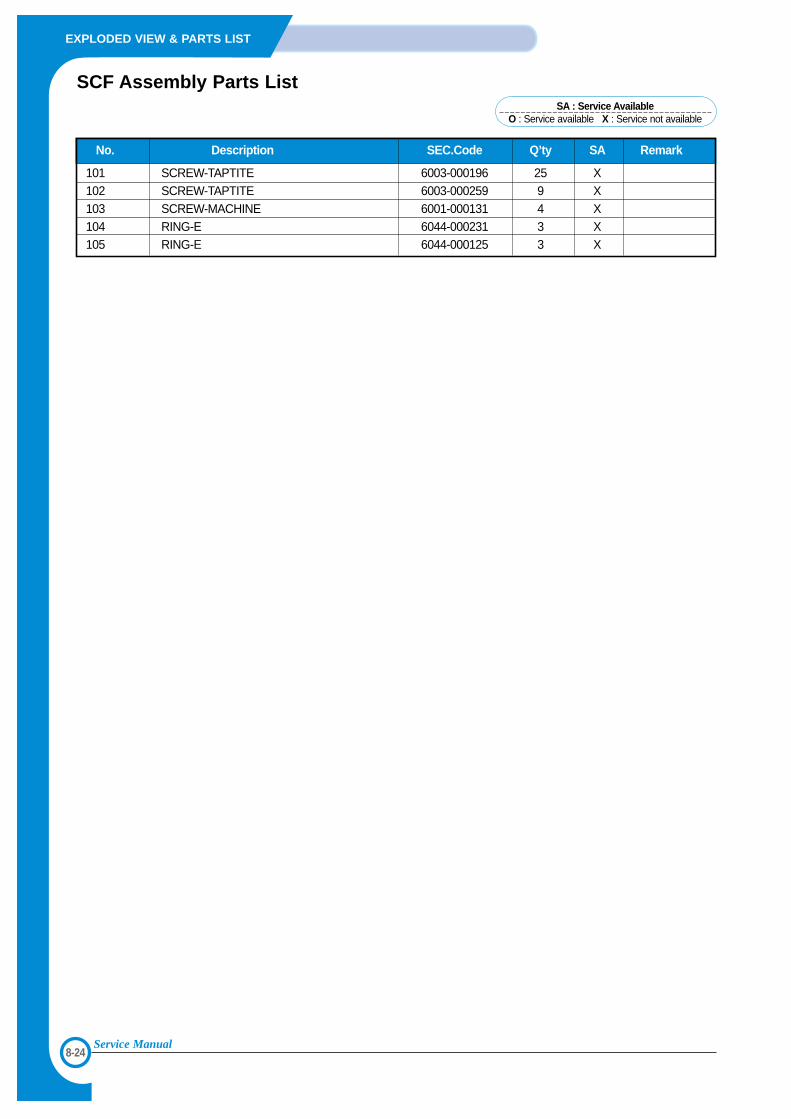
8-24
EXPLODED VIEW & PARTS LIST
Service Manual
No. Description SEC.Code Q’ty SA Remark
101 SCREW-TAPTITE 6003-000196 25 X102 SCREW-TAPTITE 6003-000259 9 X10³ SCREW-MACHINE 6001-000131 4 X10⁴ RING-E 6044-000231 3 X10⁵ RING-E 6044-000125 3 X
SCF Assembly Parts ListSA : Service Available
O : Service available X : Service not available
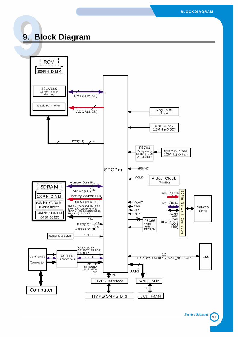
99
9-1
BLOCKDIAGRAM
Service Manual
9. Block Diagram
ADDR(1: 23)
29L V16016Mbit Flash
M emory
Mask Font ROM
ROM
SPGPm nFSYNC
ACK* ,BU SY,SELECT ,ERROR,FAULT *
SELIN*ST ROBE*AUT OFD*
INI*
PD(0:7)
EIRQ(0:3)*4
nIOCS(0:5)*6
RCS(0:3) 4
nWAITnWR
INT *nRD
Cent ronic s
Connec tor
PANEL 5Pin
6
HVPS Int er face
24
16
HVPS/ SMPS B’d
100PIN DIMM
L CD Panel
60
Pin
Netw
ork
Co
nne
cto
r
NetworkCard
DATA(16:31)
nWAITnRDnWR
NPC_RESETIOCSEIRQ
Computer
Sy s tem c lock12M Hz(X- t al )
FS781Fr equenc y
Scaling EMIA t tenuator
RESET *XC61FN 3112M R
DA TA (16:31)
Video- Clock78 MHz
VCLK*
32
Memory Data Bus
11
Memory Address Bus
14
SDRAM _CA S,SDRAM_RAS,BA0*,BA1* ,SDRAM_WE* ,SDRAM _CS(0:1) ,SDQM (0:3) ,SD_CLK (1:2) ,CL KE
64Mbit SDRA MK 4S641632C
SDRA M
64Mbit SDRA MK 4S641632C
DRAMA(0:11)
DRAMD(0:31)
100PI N DI MM
74ACT 245T r ansceiv er
3
LSULREADY* , ,LSYNC* ,VDO* ,P_MOT * ,CLK
UART
12
Regulat or1.8V
USB c lock12MHz(OSC)
93C664M bitSer ialEEPR OM
ADDR(1:13)

9-2
BLOCKDIAGRAM
Service Manual
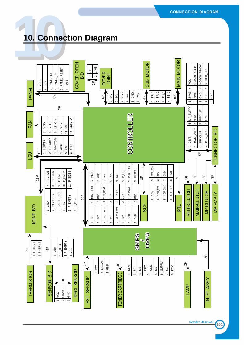
1010
10-1
CONNECTION DIAGRAM
Service Manual
10. Connection DiagramLS
U
CO
VER
OPE
NB
’D
PAN
EL
CO
VER
JOIN
T
CO
NN
EC
TOR
B’D
PTL
MA
IN-C
LUTC
H
SM
PS
/H
VP
S
CO
NTR
OLL
ERS
MP
S/
HV
PS
CO
NTR
OLL
ER
SUB
MO
TOR
LAM
P
INLE
TA
SS’Y
REG
I-CLU
TCH
3P
2P
EXIT
SEN
SO
R
1V
CC
2S
IGN
AL
3G
ND3P
TONE
R CA
RTRI
DGE
4P
1M
HV
2N
C
3N
C
4O
PC
GN
D
5N
C
6S
UPP
LY
7N
C
8D
EV
24P
SEN
SO
RB
’D
THER
MIS
TOR
JOIN
TB
’D
2P
1T
HER
M1
2T
HER
M2
1G
ND
2P
_RE
GI
3P
_EM
PTY
4V
CC4P
11P
1LS
UC
LK
2LR
EAD
Y*
3P
MO
TOR
*
4G
ND
524
V
63.
3V
7V
DO
-
8V
DO
+
9LD
_ON
*
10G
ND
115V
S
12nH
SYN
C
1G
ND
2C
AR
T_C
LK
3C
AR
T_D
ATA
43.
3V
5P
_EM
PTY
6P
_RE
GI
7TH
ER
M1
8TH
ER
M2
9P
_SIZ
E1
10P
_SIZ
E2
11P
_SIZ
E3
12P
1V
CC
23.
3V
3P
ANE
L_TX
4P
ANE
L_R
X
5P
ANE
L_R
ESE
T
6G
ND
6P 6P
124
V
224
V
324
VS
424
VS
5G
ND
65V
S
2P1
24
224
VS
MA
INM
OTO
R
4P
1P
A_1
2P
A_2
3P
B_1
4P
B_2
8P
124
VS
224
VS
3G
ND
4G
ND
5G
ND
6V
CC
7nS
TAR
T_ST
OP
8M
OTO
R_R
EAD
Y
9M
OTO
R_C
LK
2P
124
VS
2M
AIN
_CLU
T
3M
P_C
LUT
4R
EG
I_C
LUT
8P
5M
P_E
MPT
Y
63.
3V
7P
RO
_MF
8G
ND
MP
-CLU
TCH
REG
ISE
NS
OR
3P
1V
CC
2S
IGN
AL
3G
ND
MP
-EM
PTY
3P 2P 2P 3P
1N
C
224
V
3D
EV
_PW
M
424
V
5M
HV
_PW
M
624
V
7G
ND
8G
ND
9M
HV
_REA
D
10G
ND
11T
HV
_RE
AD
123.
3V
13T
HV
_EN
143.
3V
15T
HV
_PW
M
16G
ND
1724
VS
18G
ND
19V
CC
20V
CC
21N
C
22P
_EX
IT
23P
_DU
PLE
X
24F
US
ER
13.
3V
2S
CF
_ST
S
3S
CF
_CM
D
4S
CF
_CL
K
5S
CF
_RD
Y
624
V
7G
ND
8G
ND
SC
F8P
FAN
3P

10-2
CONNECTION DIAGRAM
Service Manual
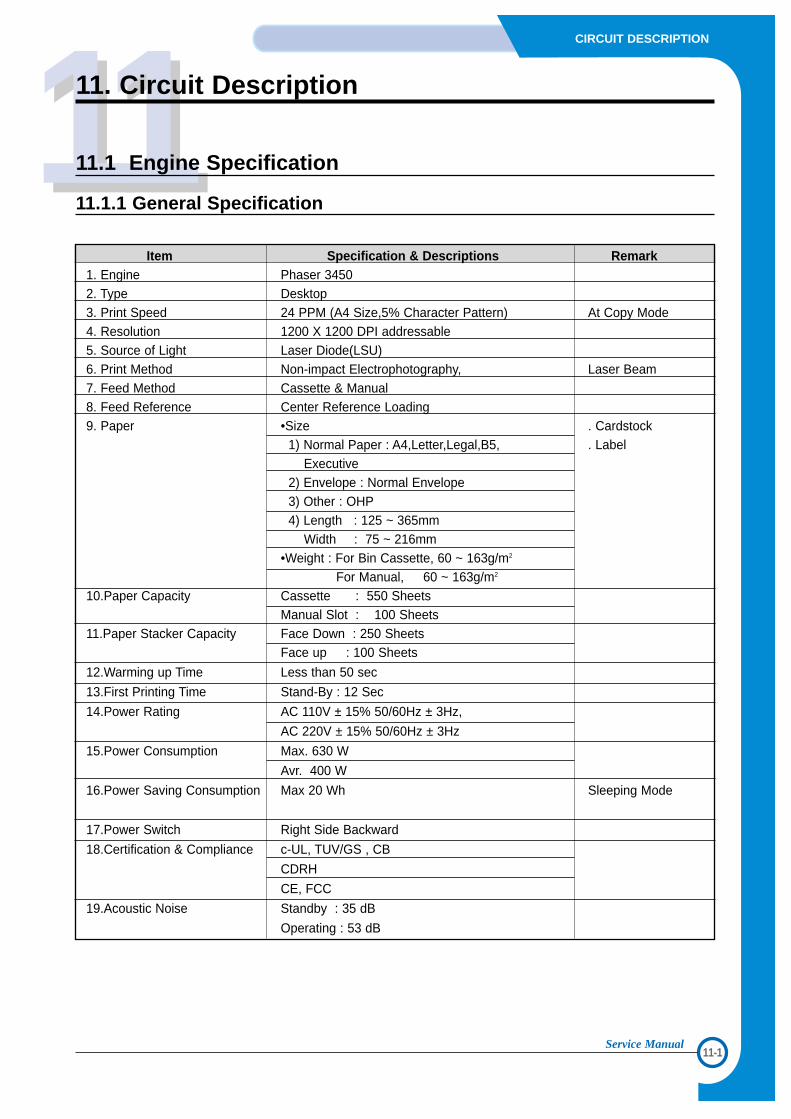
1111
11-1
CIRCUIT DESCRIPTION
Service Manual
11. Circuit Description
11.1 Engine Specification
11.1.1 General Specification
Item Specification & Descriptions Remark1. Engine Phaser 34502. Type Desktop3. Print Speed 24 PPM (A4 Size,5% Character Pattern) At Copy Mode4. Resolution 1200 X 1200 DPI addressable5. Source of Light Laser Diode(LSU)6. Print Method Non-impact Electrophotography, Laser Beam7. Feed Method Cassette & Manual8. Feed Reference Center Reference Loading9. Paper •Size . Cardstock
1) Normal Paper : A4,Letter,Legal,B5, . LabelExecutive
2) Envelope : Normal Envelope3) Other : OHP4) Length : 125 ~ 365mm
Width : 75 ~ 216mm•Weight : For Bin Cassette, 60 ~ 163g/m2
For Manual, 60 ~ 163g/m2
10.Paper Capacity Cassette : 550 SheetsManual Slot : 100 Sheets
11.Paper Stacker Capacity Face Down : 250 SheetsFace up : 100 Sheets
12.Warming up Time Less than 50 sec
13.First Printing Time Stand-By : 12 Sec
14.Power Rating AC 110V ± 15% 50/60Hz ± 3Hz,
AC 220V ± 15% 50/60Hz ± 3Hz
15.Power Consumption Max. 630 W
Avr. 400 W
16.Power Saving Consumption Max 20 Wh Sleeping Mode
17.Power Switch Right Side Backward
18.Certification & Compliance c-UL, TUV/GS , CB
CDRH
CE, FCC
19.Acoustic Noise Standby : 35 dB
Operating : 53 dB
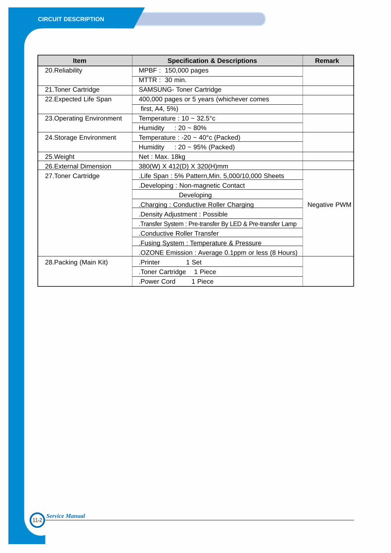
11-2
CIRCUIT DESCRIPTION
Service Manual
Item Specification & Descriptions Remark20.Reliability MPBF : 150,000 pages
MTTR : 30 min.
21.Toner Cartridge SAMSUNG- Toner Cartridge
22.Expected Life Span 400,000 pages or 5 years (whichever comes
first, A4, 5%)
23.Operating Environment Temperature : 10 ~ 32.5°c
Humidity : 20 ~ 80%
24.Storage Environment Temperature : -20 ~ 40°c (Packed)
Humidity : 20 ~ 95% (Packed)
25.Weight Net : Max. 18kg
26.External Dimension 380(W) X 412(D) X 320(H)mm
27.Toner Cartridge .Life Span : 5% Pattern,Min. 5,000/10,000 Sheets
.Developing : Non-magnetic Contact
Developing
.Charging : Conductive Roller Charging Negative PWM
.Density Adjustment : Possible
.Transfer System : Pre-transfer By LED & Pre-transfer Lamp
.Conductive Roller Transfer
.Fusing System : Temperature & Pressure
.OZONE Emission : Average 0.1ppm or less (8 Hours)
28.Packing (Main Kit) .Printer 1 Set
.Toner Cartridge 1 Piece
.Power Cord 1 Piece
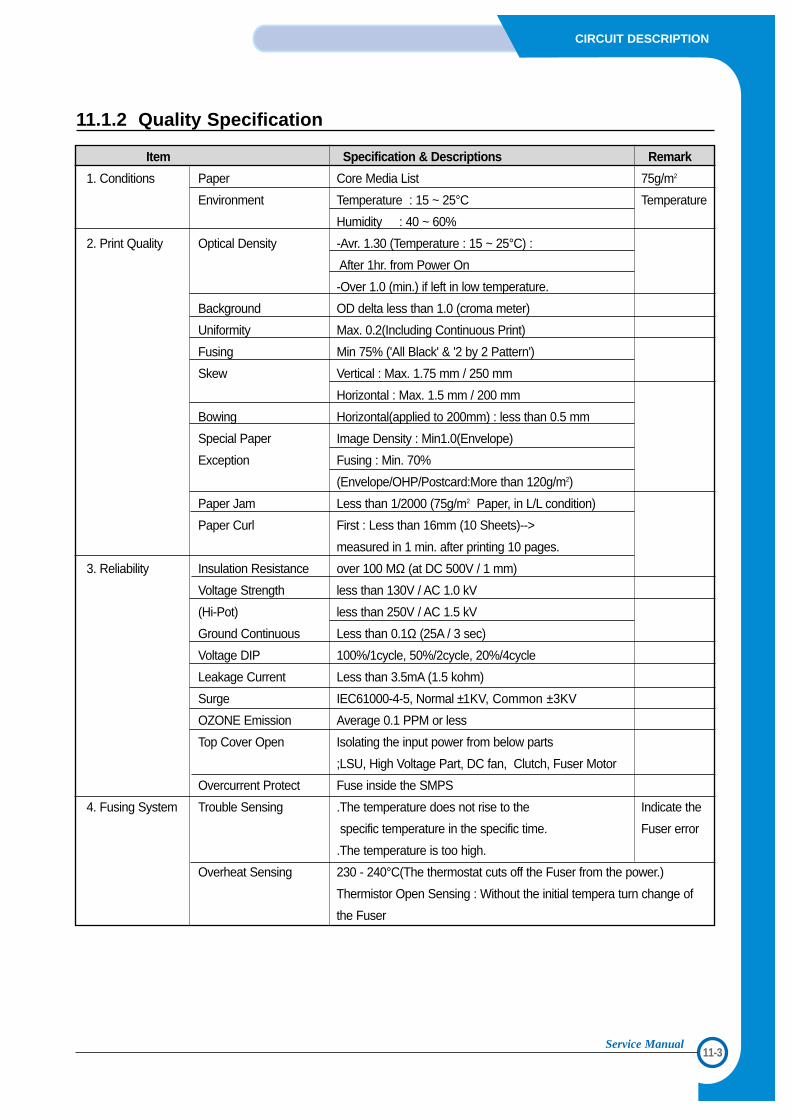
11-3
CIRCUIT DESCRIPTION
Service Manual
Item Specification & Descriptions Remark
1. Conditions Paper Core Media List 75g/m2
Environment Temperature : 15 ~ 25°C Temperature
Humidity : 40 ~ 60%
2. Print Quality Optical Density -Avr. 1.30 (Temperature : 15 ~ 25°C) :
After 1hr. from Power On
-Over 1.0 (min.) if left in low temperature.
Background OD delta less than 1.0 (croma meter)
Uniformity Max. 0.2(Including Continuous Print)
Fusing Min 75% ('All Black' & '2 by 2 Pattern')
Skew Vertical : Max. 1.75 mm / 250 mm
Horizontal : Max. 1.5 mm / 200 mm
Bowing Horizontal(applied to 200mm) : less than 0.5 mm
Special Paper Image Density : Min1.0(Envelope)
Exception Fusing : Min. 70%
(Envelope/OHP/Postcard:More than 120g/m2)
Paper Jam Less than 1/2000 (75g/m2 Paper, in L/L condition)
Paper Curl First : Less than 16mm (10 Sheets)-->
measured in 1 min. after printing 10 pages.
3. Reliability Insulation Resistance over 100 MΩ (at DC 500V / 1 mm)
Voltage Strength less than 130V / AC 1.0 kV
(Hi-Pot) less than 250V / AC 1.5 kV
Ground Continuous Less than 0.1Ω (25A / 3 sec)
Voltage DIP 100%/1cycle, 50%/2cycle, 20%/4cycle
Leakage Current Less than 3.5mA (1.5 kohm)
Surge IEC61000-4-5, Normal ±1KV, Common ±3KV
OZONE Emission Average 0.1 PPM or less
Top Cover Open Isolating the input power from below parts
;LSU, High Voltage Part, DC fan, Clutch, Fuser Motor
Overcurrent Protect Fuse inside the SMPS
4. Fusing System Trouble Sensing .The temperature does not rise to the Indicate the
specific temperature in the specific time. Fuser error
.The temperature is too high.
Overheat Sensing 230 - 240°C(The thermostat cuts off the Fuser from the power.)
Thermistor Open Sensing : Without the initial tempera turn change of
the Fuser
11.1.2 Quality Specification
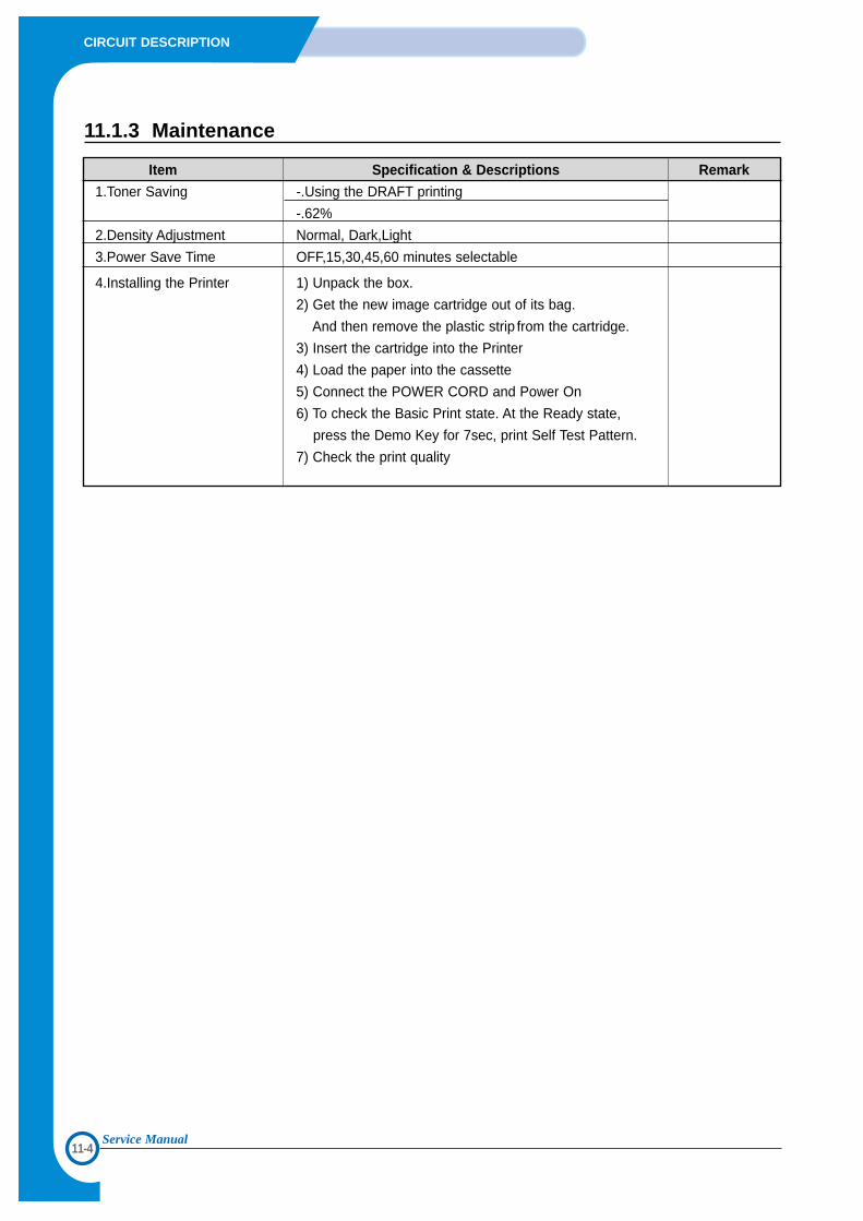
11-4
CIRCUIT DESCRIPTION
Service Manual
11.1.3 Maintenance
Item Specification & Descriptions Remark
1.Toner Saving -.Using the DRAFT printing
-.62%
2.Density Adjustment Normal, Dark,Light
3.Power Save Time OFF,15,30,45,60 minutes selectable
4.Installing the Printer 1) Unpack the box.
2) Get the new image cartridge out of its bag.
And then remove the plastic strip from the cartridge.
3) Insert the cartridge into the Printer
4) Load the paper into the cassette
5) Connect the POWER CORD and Power On
6) To check the Basic Print state. At the Ready state,
press the Demo Key for 7sec, print Self Test Pattern.
7) Check the print quality
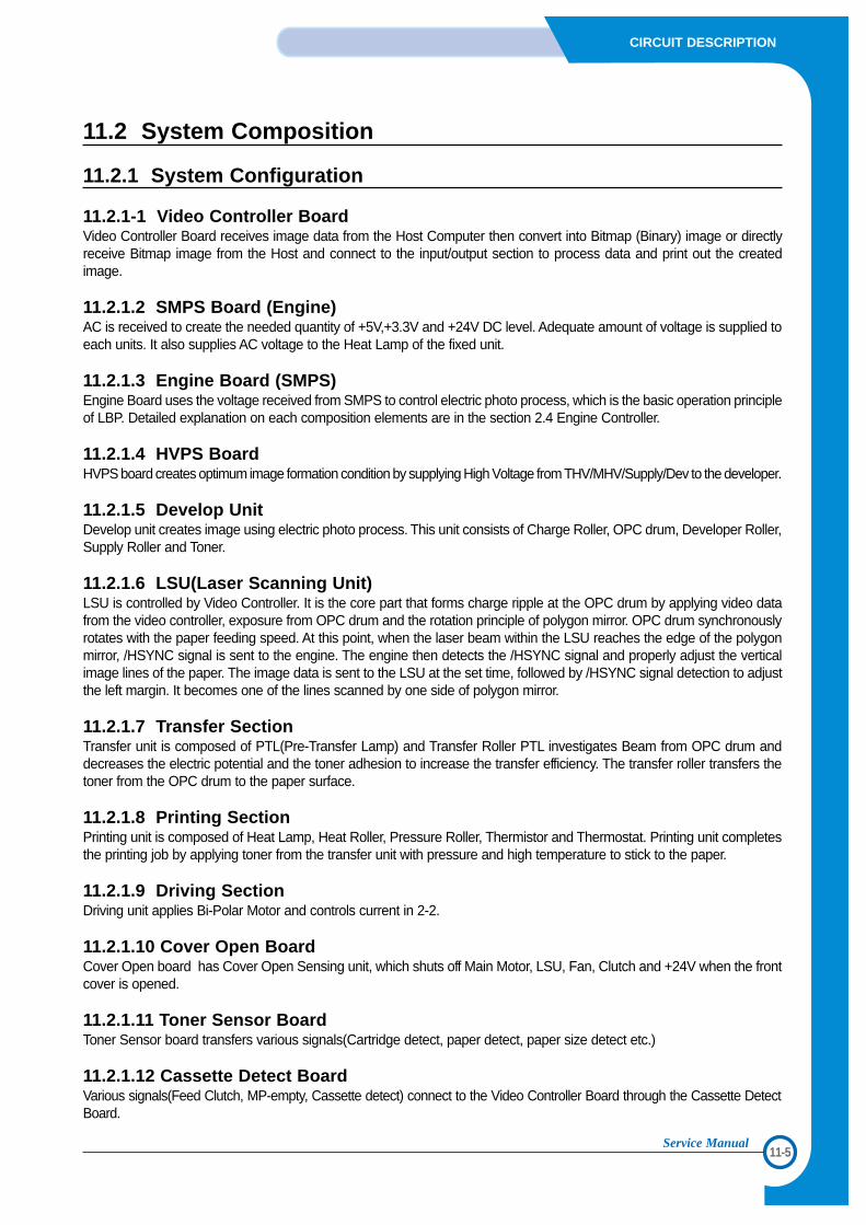
11-5
CIRCUIT DESCRIPTION
Service Manual
11.2 System Composition
11.2.1 System Configuration
11.2.1-1 Video Controller Board Video Controller Board receives image data from the Host Computer then convert into Bitmap (Binary) image or directlyreceive Bitmap image from the Host and connect to the input/output section to process data and print out the createdimage.
11.2.1.2 SMPS Board (Engine)AC is received to create the needed quantity of +5V,+3.3V and +24V DC level. Adequate amount of voltage is supplied toeach units. It also supplies AC voltage to the Heat Lamp of the fixed unit.
11.2.1.3 Engine Board (SMPS)Engine Board uses the voltage received from SMPS to control electric photo process, which is the basic operation principleof LBP. Detailed explanation on each composition elements are in the section 2.4 Engine Controller.
11.2.1.4 HVPS BoardHVPS board creates optimum image formation condition by supplying High Voltage from THV/MHV/Supply/Dev to the developer.
11.2.1.5 Develop UnitDevelop unit creates image using electric photo process. This unit consists of Charge Roller, OPC drum, Developer Roller,Supply Roller and Toner.
11.2.1.6 LSU(Laser Scanning Unit)LSU is controlled by Video Controller. It is the core part that forms charge ripple at the OPC drum by applying video datafrom the video controller, exposure from OPC drum and the rotation principle of polygon mirror. OPC drum synchronouslyrotates with the paper feeding speed. At this point, when the laser beam within the LSU reaches the edge of the polygonmirror, /HSYNC signal is sent to the engine. The engine then detects the /HSYNC signal and properly adjust the verticalimage lines of the paper. The image data is sent to the LSU at the set time, followed by /HSYNC signal detection to adjustthe left margin. It becomes one of the lines scanned by one side of polygon mirror.
11.2.1.7 Transfer SectionTransfer unit is composed of PTL(Pre-Transfer Lamp) and Transfer Roller PTL investigates Beam from OPC drum anddecreases the electric potential and the toner adhesion to increase the transfer efficiency. The transfer roller transfers thetoner from the OPC drum to the paper surface.
11.2.1.8 Printing SectionPrinting unit is composed of Heat Lamp, Heat Roller, Pressure Roller, Thermistor and Thermostat. Printing unit completesthe printing job by applying toner from the transfer unit with pressure and high temperature to stick to the paper.
11.2.1.9 Driving SectionDriving unit applies Bi-Polar Motor and controls current in 2-2.
11.2.1.10 Cover Open BoardCover Open board has Cover Open Sensing unit, which shuts off Main Motor, LSU, Fan, Clutch and +24V when the frontcover is opened.
11.2.1.11 Toner Sensor BoardToner Sensor board transfers various signals(Cartridge detect, paper detect, paper size detect etc.)
11.2.1.12 Cassette Detect BoardVarious signals(Feed Clutch, MP-empty, Cassette detect) connect to the Video Controller Board through the Cassette DetectBoard.
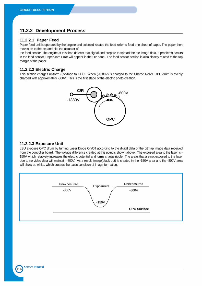
11-6
CIRCUIT DESCRIPTION
Service Manual
11.2.2 Development Process
11.2.2.1 Paper Feed Paper feed unit is operated by the engine and solenoid rotates the feed roller to feed one sheet of paper. The paper thenmoves on to the set and hits the actuator of the feed sensor. The engine at this time detects that signal and prepare to spread the the image data. If problems occursin the feed sensor, Paper Jam Error will appear in the OP panel. The feed sensor section is also closely related to the topmargin of the paper.
11.2.2.2 Electric ChargeThis section charges uniform (-)voltage to OPC. When (-1380V) is charged to the Charge Roller, OPC drum is evenlycharged with approximately -800V. This is the first stage of the electric photo creation.
11.2.2.3 Exposure UnitLSU exposes OPC drum by turning Laser Diode On/Off according to the digital data of the bitmap image data receivedfrom the controller board. The voltage difference created at this point is shown above. The exposed area to the laser is -150V, which relatively increases the electric potential and forms charge ripple. The areas that are not exposed to the laserdue to no video data will maintain -800V. As a result, image(black dot) is created in the -150V area and the -800V areawill show up white, which creates the basic condition of image formation.
C/R
-1380V
-800V
OPC
UnexposuredExposured
-800V
-150V
-800V
Unexposured
OPC Surface
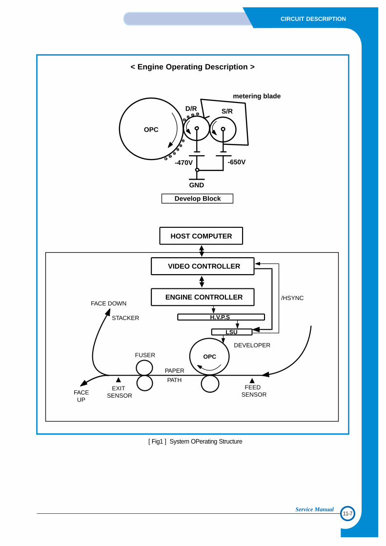
11-7
CIRCUIT DESCRIPTION
Service Manual
H.V.P.S
LSU
/HSYNC
HOST COMPUTER
VIDEO CONTROLLER
ENGINE CONTROLLERFACE DOWN
STACKER
FUSER
PAPER
PATH FEEDSENSORFACE
UP
EXITSENSOR
DEVELOPER
OPC
metering blade
-470V -650V
Develop Block
OPC
D/R S/R
GND
< Engine Operating Description >
[ Fig1 ] System OPerating Structure
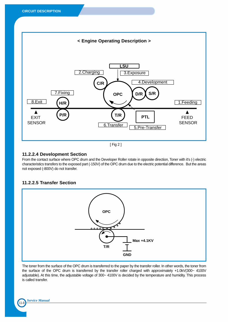
11-8
CIRCUIT DESCRIPTION
Service Manual
< Engine Operating Description >
[ Fig 2 ]
11.2.2.4 Development SectionFrom the contact surface where OPC drum and the Developer Roller rotate in opposite direction, Toner with it's (-) electriccharacteristics transfers to the exposed part (-150V) of the OPC drum due to the electric potential difference. But the areasnot exposed (-800V) do not transfer.
11.2.2.5 Transfer Section
The toner from the surface of the OPC drum is transferred to the paper by the transfer roller. In other words, the toner fromthe surface of the OPC drum is transferred by the transfer roller charged with approximately +1.0kV(300~ 4100Vadjustable). At this time, the adjustable voltage of 300~ 4100V is decided by the temperature and humidity. This processis called transfer.
OPC
T/R
Max +4.1KV
GND
LSU2.Charging
7.Fixing
8.Exit
EXITSENSOR 6.Transfer 5.Pre-Transfer
FEEDSENSOR
3.Exposure
4.Development
1.FeedingH/R
P/R
C/R
OPC
T/R PTL
D/R S/R
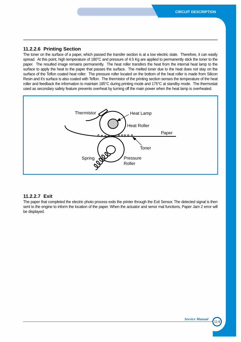
11-9
CIRCUIT DESCRIPTION
Service Manual
11.2.2.6 Printing SectionThe toner on the surface of a paper, which passed the transfer section is at a low electric state. Therefore, it can easilyspread. At this point, high temperature of 180°C and pressure of 4.5 Kg are applied to permanently stick the toner to thepaper. The resulted image remains permanently. The heat roller transfers the heat from the internal heat lamp to thesurface to apply the heat to the paper that passes the surface. The melted toner due to the heat does not stay on thesurface of the Teflon coated heat roller. The pressure roller located on the bottom of the heat roller is made from SiliconResin and it's surface is also coated with Teflon. The thermistor of the printing section senses the temperature of the heatroller and feedback the information to maintain 185°C during printing mode and 175°C at standby mode. The thermostatused as secondary safety feature prevents overheat by turning off the main power when the heat lamp is overheated.
11.2.2.7 ExitThe paper that completed the electric photo process exits the printer through the Exit Sensor. The detected signal is thensent to the engine to inform the location of the paper. When the actuator and senor mal functions, Paper Jam 2 error willbe displayed.
Thermistor Heat Lamp
Heat Roller
Paper
Toner
PressureRoller
Spring
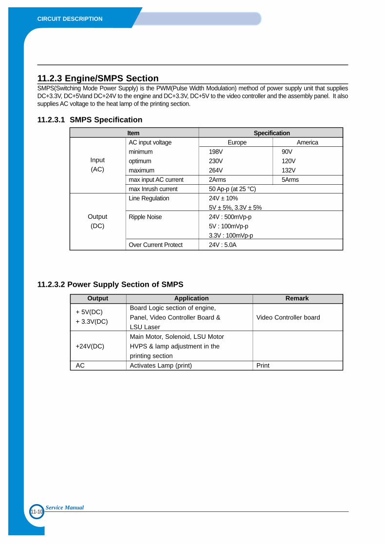
11-10
CIRCUIT DESCRIPTION
Service Manual
11.2.3 Engine/SMPS SectionSMPS(Switching Mode Power Supply) is the PWM(Pulse Width Modulation) method of power supply unit that suppliesDC+3.3V, DC+5Vand DC+24V to the engine and DC+3.3V, DC+5V to the video controller and the assembly panel. It alsosupplies AC voltage to the heat lamp of the printing section.
11.2.3.1 SMPS Specification
Item SpecificationAC input voltage Europe Americaminimum 198V 90Voptimum 230V 120V maximum 264V 132Vmax input AC current 2Arms 5Armsmax Inrush current 50 Ap-p (at 25 °C)Line Regulation 24V ± 10%
5V ± 5%, 3.3V ± 5%Ripple Noise 24V : 500mVp-p
5V : 100mVp-p3.3V : 100mVp-p
Over Current Protect 24V : 5.0A
11.2.3.2 Power Supply Section of SMPS
Output Application Remark
+ 5V(DC)Board Logic section of engine,
+ 3.3V(DC)Panel, Video Controller Board & Video Controller board
LSU Laser
Main Motor, Solenoid, LSU Motor
+24V(DC) HVPS & lamp adjustment in the
printing section
AC Activates Lamp (print) Print
Input(AC)
Output(DC)
11-11
CIRCUIT DESCRIPTION
Service Manual
11.2.3.3 Circuit
1) AC Input and DCAC input unit is composed of FUSE, VARISTOR, NOISECAPACITOR and LINE FILTER. DC unit is composed ofBRIDGE DIODE and ELECTRIC CAPACITOR. TheFUSE(F1) has specification of 125V/8A for 110V and250V/5A for 220V. FUSE contains the function to preventdamage due to SMPS fire in the event of malfunction of 1st. PWM Control and parts causing excess voltage.NOISE CAPACITOR is EMI counter part, which iscomposed of CAPACITOR(C1, C14) for the normal modenoise and CAPACITOR(C3, C4, C9, C34) for commonmode noise. Larger the capacity of the CAPACITOR,greater the NOISE absorption effect. But, adequatecapacitor should be carefully selected since leakagecurrent increases with the increased capacity in capacitor,which has high potential of electric shock. The Line Filterconnected to the Capacitor has the EMI Noise eliminatingfunction. Especially, the filter and the capacitor not onlyabsorbs the noise being transferred out of the printerthrough power line, it also absorbs the opposite noisecoming from the exterior.
2) SWITCHING Control Section SMPS is driven by OSC. It has uniform switchingfrequency and the range of 'On Time' Pulse may varydepending on the surrounding condition. Basic operationprocedure is as following.Turn on the AC power. AC input voltage will pass throughthe Noise Filter circuit, Bridge Diode(BD1) and capacitor(C6). The rectified DC voltage supplies the bias voltage tothe pin6 of PWM contract IC IC1 (2BS01) through R2 adR3. Then, turn on the Gate in the FET. At this point thecurrent passed through FET will flow through the 1sttrance coil T1. Pin #4 and the supporting current in thetrance #7 and 8 will be abandoned. The current flowing through the 1st trance coil Q1(IIN60)will rapidly increase current in #2 Drain and this processwill block the abandoned current in the 2nd trance coil ofthe transformer to flow out. Followed by this operation,due to the surrounding condition change, Drain currentreaches the critical rigging point of Q1(hfe). This is causedby the relative decrease in Drain current compared totime. This indicates that Q1 is unable to maintain Onstatus. Such condition is the area of Insufficient GateCurrent. According to the FET characteristics. The drain voltage ofQ1 operate in switching models which are composed ofturn on state and turn off state. When Q1 is turned off, thecreated electrical power in 1st trans (#2~#4) will betransfered to the 2nd trans. (#13, 14, 15, 9~#10, 11, 12)
The current then flows into PC1(PHOTO COUPLER) tobypass the IC1 feedback. Then, U1 turns on. Throughsuch repetitious process, the current flowing through 2ndtrance coil is filtered to create necessary DC voltage. DCoutput and feedback circuit are created by +24V of D5and C19. +5V is created by abandoned voltage from the2nd. trance coil due to D5 and C19. In order to maintainuniform DC output level, detect the output level from R11and R12 to maintain uniform level, then enabled feedbackby disconnecting the Shunt Regular IC(IC2) and usedPHOTO COUPLER (PC1).
3) Fixed Temperature ControlTo control the fixed lamp, the control signal of "FUSERON" in Logic section and the supply of DC voltage in theSMPS section is necessary. The circuit turns on when the"FUSER ON" sends the operation signal and the DCpower is supplied. The operation principle of control circuitof fixed lamp is as following. Trigger current flows to TriacDriver IC6 LED due to "FUSER ON" of Logic. Then thePhoto detector of IC6 will detect the infrared ray and theTriac of IC5 will activate. The current will then send theTrigger input to the Gate of Triac IC5. At this point IC5 will be activated and AC power will besupplied to the fixed lamp, then the lamp will turn on andthe temperature will rise. Because the fixed lamp circuituses AC voltage as it's voltage supply, bidirectional Triac(IC5) is applied, since it has advantage in price, size andreliability compared to unidirectional SCR. The Gate terminal of Triac can be triggered as ordered oropposite direction signal. Once the triac turns on, it cannotbe controlled by the Gate signal. It maintains until the levelof current flowing in the main terminal falls below the levelof maintaining current. In other words, it cannot be turnedoff by counter current as that of SCR. Such characteristicsis categorized as Critical Rigging Time Rate ( Commutation: dv/dt). In the application of electric power exchange,Triac either turns off the activation or switches twice ineach period at Zero Crossing. Such switching movementis called Commutation. It is able to turn off the triac at the end of the half period
by deleting the Gate signal. It is possible when the levelof (IL) current is below the level of maintaining current.When the Triac commutation is Off, the voltage willinstantly change to opposite direction and the VAC willincrease to the maximum level. At this time, the range ofincrease rate is decided by dv/dt and the Overshootvoltage is decided by the circuit. Also, the voltage of Triacwill have same level of voltage when the commutation ofTriac is Off.
11-12
CIRCUIT DESCRIPTION
Service Manual
11.2.3.4 Sensor Input Circuit
1) Paper Empty SensingThe Paper Empty Sensor(Photo Interrupter), which islocated in the Engine Board informs the CPU the statusof paper volume through the operation of actuator fixedon the frame. If there is no paper in the Cassette, it notifiesthe second LED(yellow) of the panel LED by reading the#103 of U18.
2) Paper Feeding SensingWhen the fed paper passes through the actuator of thefeed sensor, it notifies that the paper is being transferredto CPU by detecting the Photo Interrupter signal and theimage data is distributed after set amount of timepasses.(related to top layer of paper) If the feed sensordoes not detect within 1 second of paper feeding, JAM0(U18 #105) will occur.
3) Paper MP Sensing(Photo Interrupt)By operating of actuator, which is attached to frame, MPsensor detects existence of paper in MP, and informsstatus to CPU. Paper status is detected by U27 K26pin.If paper exists, it is fed in MP status.
4) Paper Exit Sensing(Photo Interrupt)Actuator, which is attached to frame and connected toEngine Board (SMPS) CN4, detects if paper exits fromfusing unit. CPU detects information of normal operationand jam by that U18109pin detects on/off signal of exitsensor (photo interrupt), and it display jam2 status onLCD Panel.
5) Paper Duplex Sensing(Photo Interrupt)Sensor (OP1) attached on engine board(SMPS) detectspaper information when operating duplex printing. CPUdetects information of jam and normal operation by thatU18 102pin detects the detecting signal, and it displaysduplex jam1 or duplex jam2 on LCD panel according tostatus of entering duplex paper.
6) Paper Out Bin Full Sensing(Photo Interrupt)Out Bin Full Sensor detects existing paper amount byoperating actuator attached to frame, and informs thestatus to CPU. U18 114pin detects existing paperamount and displays the status on LCD panel.
7) Paper Size Sensing(tact switch)It detects each size of fed papers in cassette, and itarranges and manages data when printing. Itdistinguishes 8 kinds of paper by 3 switch combinations,and it is consisted of 8 combinations of U18106/107/108pin.
8) Cassette Sensing(micro switch)By U27 K25pin, cassette detecting function checkswhether tray2 is open or not. When Tray2 is open, LCDpanel displays error status.
9) Toner Cartridge SensingIt controls memory data of EEPROM in developing unit bycontacting to contacting point of joint board mounted toframe, and it detects supplier, manufacturing date, tonerremained amount. It writes and reads data by U27A25/D23/J24 pin and operates with 2-WIRE bus method. When toner remaining amount is 15%, it displays lowtoner on LCD panel to inform toner cartridge detectingsignal.
11-13
CIRCUIT DESCRIPTION
Service Manual
11.2.3.5 Output Control Circuit
1) Main / Sub FanMain Fan and Sub Fan are in-take-type. Main Fan is offin sleep mode, and Sub Fan operates when printing tocontrol temperature of inside SMPS. Main Fan is controlled by TR of Q10 by receiving signalfrom U18 18pin, and Sub Fan becomes chopping bysignal of U18 20pin and controlled by TR of Q12.
2) Main MotorIn initial set up stage, Main motor's talk amount aboutoperating load is set up as BLDC type. It delivers powerfor feed device and operation device (Fusing unit isoperated by exit motor) Main Motor has driver IC andsupplies +24V/+5V. It sends Start/stop (L operation) andclock signal to motor unite to operate motor, and itsrotating speed is controlled by clock frequency. Amongcontrolling signals, start/stop signal controls U18 19pin,and clock signal controls U18 68pin. If moving current ishigh when driving, it maintains speed within 600ms(standard speed). Current is changed depending onloading.
3) Exit MotorExit motor drives a fuser, and it rotates clockwise orcounterclockwise when simplex or duplex printing isworking.
4) Main / MP SolenoidSolenoid functions to pick up fed paper from cassette orMP. Operating time is 150ms. Main solenoid is controlledby Q4 TR with U27 E23pin signal, and MP solenoid iscontrolled by Q5 TR with U27 C24pin signal. Operatingcurrent is under 250mA.
5) Regi ClutchRegi Clutch functions to separate paper. Clutch preventsoverlapping delivery of fed paper. After passing 500ms,when paper detects the feed signal, it turns off and separates papers.U27 A26 pin signal controls Q6 TR, and operating currentis under 150mA.
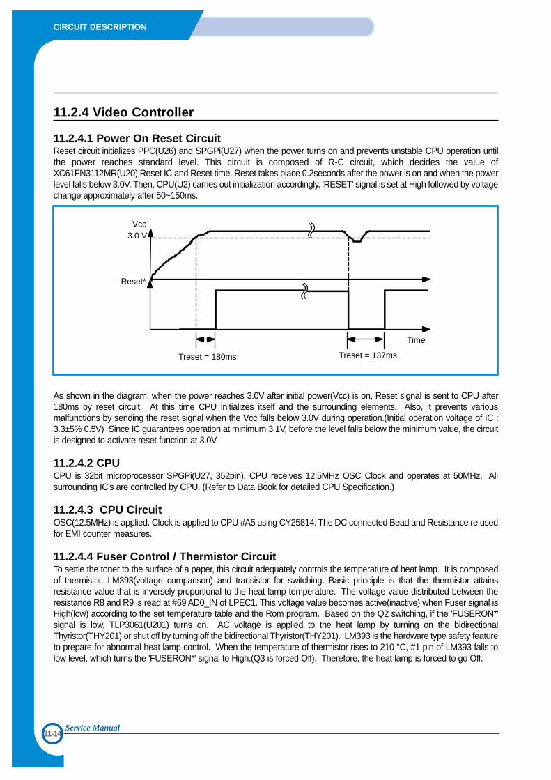
11-14
CIRCUIT DESCRIPTION
Service Manual
11.2.4 Video Controller
11.2.4.1 Power On Reset CircuitReset circuit initializes PPC(U26) and SPGPi(U27) when the power turns on and prevents unstable CPU operation untilthe power reaches standard level. This circuit is composed of R-C circuit, which decides the value ofXC61FN3112MR(U20) Reset IC and Reset time. Reset takes place 0.2seconds after the power is on and when the powerlevel falls below 3.0V. Then, CPU(U2) carries out initialization accordingly. 'RESET' signal is set at High followed by voltagechange approximately after 50~150ms.
As shown in the diagram, when the power reaches 3.0V after initial power(Vcc) is on, Reset signal is sent to CPU after180ms by reset circuit. At this time CPU initializes itself and the surrounding elements. Also, it prevents variousmalfunctions by sending the reset signal when the Vcc falls below 3.0V during operation.(Initial operation voltage of IC :3.3±5% 0.5V) Since IC guarantees operation at minimum 3.1V, before the level falls below the minimum value, the circuitis designed to activate reset function at 3.0V.
11.2.4.2 CPUCPU is 32bit microprocessor SPGPi(U27, 352pin). CPU receives 12.5MHz OSC Clock and operates at 50MHz. Allsurrounding IC's are controlled by CPU. (Refer to Data Book for detailed CPU Specification.)
11.2.4.3 CPU CircuitOSC(12.5MHz) is applied. Clock is applied to CPU #A5 using CY25814. The DC connected Bead and Resistance re usedfor EMI counter measures.
11.2.4.4 Fuser Control / Thermistor CircuitTo settle the toner to the surface of a paper, this circuit adequately controls the temperature of heat lamp. It is composedof thermistor, LM393(voltage comparison) and transistor for switching. Basic principle is that the thermistor attainsresistance value that is inversely proportional to the heat lamp temperature. The voltage value distributed between theresistance R8 and R9 is read at #69 AD0_IN of LPEC1. This voltage value becomes active(inactive) when Fuser signal isHigh(low) according to the set temperature table and the Rom program. Based on the Q2 switching, if the 'FUSERON*'signal is low, TLP3061(U201) turns on. AC voltage is applied to the heat lamp by turning on the bidirectionalThyristor(THY201) or shut off by turning off the bidirectional Thyristor(THY201). LM393 is the hardware type safety featureto prepare for abnormal heat lamp control. When the temperature of thermistor rises to 210 °C, #1 pin of LM393 falls tolow level, which turns the 'FUSERON*' signal to High.(Q3 is forced Off). Therefore, the heat lamp is forced to go Off.
Vcc3.0 V
Reset*
Treset = 180ms Treset = 137ms
Time
11-15
CIRCUIT DESCRIPTION
11.2.4.5 Sensing Circuit1) Cover Open SensingCover Open Sensor is located on the top right side of the Cover Open Board. When the front cover opens, it shuts off+24V(DC fan, Solenoid, Main Motor, LSU Polygon Motor and HVPS) supplied to each unit. B2 Bit of U4 senses cover openby sensing the developing section with B111 Bit of U18. In this case, the red LED, which is located on top of the OP Panelinforms the user of the situation.
2) Paper Exit SensingThe exit sensor assembled on the engine board and the actuator attached to the frame detect the paper exiting the printer.The paper recognizes the On/Off time of the exit sensor through B5 Bit of U4 and notifies the normal operation or jaminformation to the CPU. Paper JAM2 is also notified.(Both Red & Yellow LED from OP Panel Let go on)
11.2.4.6 LSU Circuit1) Polygon Motor (+24V) Polygon motor inside the LSU rotates by 'PMOTOR*' signal. It passes Transient section and reaches the motor section,'LREADY*' signal is notified to U18 #115 pin. When LSU uses external clock for the motor rotation frequency, 'CLOCK' pinaccepts the necessary frequency. Clock circuit is composed inside the engine. Crystal frequency of 58.36 MHz is activatedby Engine CPU and uses 3562Hz for the rotation frequency of the polygon motor.
2) Laser (+5V)When the laser is turned on by 'LDON*' signal, horizontal scan takes place due to the 6 sided reflection mirror(Polygonmirror) attached to the polygon motor, which rotates in clockwise direction. At this time, when the laser beam reaches thestarting corner of each surface, 'HSYNC*' signal(pulse) is activated. The video controller uses 'HSYNC*' signal to form leftmargin of the image.(horizontal synchronous signal) When the 'Vdout*' signal in inputted to the LSU, it becomes 'LDON*'and ANDring to investigate suitable laser beam(Vdout data contained).(ON/OFF switching)
11.2.4.7 Clock CircuitClock uses 4 X-Tal. CPU is operated by 50MHz. USB is operated by 30MHz X-tal. Video Clock is operated by 23.88MHz.
11.2.4.8 Memory CircuitCPU initialization is composed of Flash-Rom capable of PGM, DRAM capable of reading and writing data and the FontRom, which supports font in PCL6 operation. Due to the variation of Flash and Font Rom by models, basic control of 16Bitfor Rom and 32Bit for Ram is necessary. Domain of Flash Rom is divided into Boot and PGM. PGM can be changed bydownload. The storage RAM for the data download from PC is composed of 2MByte * 2.
11.2.4.9 DCU Interface CircuitDCU(Diagnostic Control Unit) tests the LBP and used as a tool in Trouble-shooting and according to it's purpose,Diagnostic code, Normal Status code and Error Status code can be applied. At this time, Diagnostic Test takes placethrough 'DCU-DIN' signal and the Normal/Error status check takes place through 'DCU_DOUT' signal. 'DCU_CLK' is theDCU clock input unit.(CLK Frequency : approximately 17.6KHz)
11.2.4.10 HVPS Interface CircuitHVPS Interface section is composed of various control areas. When high voltage on signal is received from the engineCPU, each high voltage turns on according to the electric photo process. The signals that turn on the high voltage are'THV_EN', 'DEV_PWM', 'MHV_PWM', 'THV_PW,M' and the 'THV_READ, which feedback the results of transferenvironment to the CPU.
11-16
CIRCUIT DESCRIPTION
11.2.4.11 PTL CircuitPTL circuit is located in the Video Controller Board and applies NPN type TR for drive
11.2.4.12 Panel CircuitPanel is consisted of 2*16 LCD(with back lite), 1 LED, and 6 keys. It has HT48C5Athat is 8bit I/O control MCU, it suppliesclock (7.37MHz), and it controls data with CPU by UART method. LCD back lite for supply needs +5V, and logic for control needs +3.3V. TXD, RXD, and Reset signal are used. Back liteis operated with 240mA, and LCD dot is controlled by VEE voltage.
11.2.4.13 SCF CircuitIn SCF circuit, 6.9MHz clock is supplied to 8bit CPU 4616. SCF circuit controls step motor, solenoid clutch, Regi. clutch,and paper size function & empty function. It operates with controller and SIO method. PPS controls motor speed and it is downloaded to RAM to operate and controlthe circuit in controller. U18 9/10/11/116 pin signal, control signal, make it to operate.
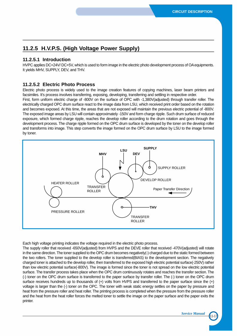
11-17
CIRCUIT DESCRIPTION
Service Manual
11.2.5 H.V.P.S. (High Voltage Power Supply)
11.2.5.1 IntroductionHVPC applies DC+24V/ DC+5V, which is used to form image in the electric photo development process of OAequipments.It yields MHV, SUPPLY, DEV, and THV.
11.2.5.2 Electric Photo Process Electric photo process is widely used to the image creation features of copying machines, laser beam printers andfacsimiles. It’s process involves transferring, exposing, developing, transferring and settling in respective order.First, form uniform electric charge of -800V on the surface of OPC with -1,380V(adjusted) through transfer roller. Theelectrically charged OPC drum surface react to the image data from LSU, which received print order based on the rotationand becomes exposed. At this time, the areas that are not exposed will maintain the previous electric potential of -800V.The exposed image areas by LSU will contain approximately -150V and form charge ripple. Such drum surface of reducedexposure, which formed charge ripple, reaches the develop roller according to the drum rotation and goes through thedevelopment process. The charge ripple formed on the OPC drum surface is developed by the toner on the develop rollerand transforms into image. This step converts the image formed on the OPC drum surface by LSU to the image formedby toner.
Each high voltage printing indicates the voltage required in the electric photo process. The supply roller that received -650V(adjusted) from HVPS and the DEVE roller that received -470V(adjusted) will rotatein the same direction. The toner supplied to the OPC drum becomes negatively(-) charged due to the static formed betweenthe two rollers. The toner supplied to the develop roller is transferred(BIAS) to the development section. The negativelycharged toner is attached to the develop roller, then transferred to the exposed high electric potential surface(-250V) ratherthan low electric potential surface(-800V). The image is formed since the toner is not spread on the low electric potentialsurface. The transfer process takes place when the OPC drum continuously rotates and reaches the transfer section. The(-) toner on the OPC drum surface is transferred to the paper surface by transfer roller. The (-) toner on the OPC drumsurface receives hundreds up to thousands of (+) volts from HVPS and transferred to the paper surface since the (+)voltage is larger than the (-) toner on the OPC. The toner with weak static energy settles on the paper by pressure andheat from the pressure roller and heat roller. The printing process is completed when the pressure from the pressure rollerand the heat from the heat roller forces the melted toner to settle the image on the paper surface and the paper exits theprinter.
HEATER ROLLER
PRESSURE ROLLER
TRANSFERROLLER
MHVLSU
DEV
SUPPLY
SUPPLY ROLLER
DEVELOP ROLLER
THV
TRANSFERROLLER
Paper Transfer Direction
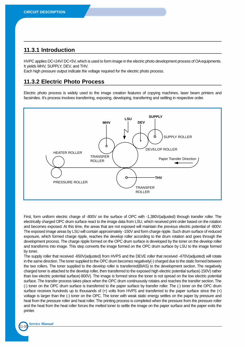
11-18
CIRCUIT DESCRIPTION
Service Manual
11.3.1 Introduction
HVPC applies DC+24V/ DC+5V, which is used to form image in the electric photo development process of OAequipments.It yields MHV, SUPPLY, DEV, and THV.Each high pressure output indicate the voltage required for the electric photo process.
11.3.2 Electric Photo Process
Electric photo process is widely used to the image creation features of copying machines, laser beam printers andfacsimiles. It’s process involves transferring, exposing, developing, transferring and settling in respective order.
First, form uniform electric charge of -800V on the surface of OPC with -1,380V(adjusted) through transfer roller. Theelectrically charged OPC drum surface react to the image data from LSU, which received print order based on the rotationand becomes exposed. At this time, the areas that are not exposed will maintain the previous electric potential of -800V.The exposed image areas by LSU will contain approximately -150V and form charge ripple. Such drum surface of reducedexposure, which formed charge ripple, reaches the develop roller according to the drum rotation and goes through thedevelopment process. The charge ripple formed on the OPC drum surface is developed by the toner on the develop rollerand transforms into image. This step converts the image formed on the OPC drum surface by LSU to the image formedby toner. The supply roller that received -650V(adjusted) from HVPS and the DEVE roller that received -470V(adjusted) will rotatein the same direction. The toner supplied to the OPC drum becomes negatively(-) charged due to the static formed betweenthe two rollers. The toner supplied to the develop roller is transferred(BIAS) to the development section. The negativelycharged toner is attached to the develop roller, then transferred to the exposed high electric potential surface(-150V) ratherthan low electric potential surface(-800V). The image is formed since the toner is not spread on the low electric potentialsurface. The transfer process takes place when the OPC drum continuously rotates and reaches the transfer section. The(-) toner on the OPC drum surface is transferred to the paper surface by transfer roller. The (-) toner on the OPC drumsurface receives hundreds up to thousands of (+) volts from HVPS and transferred to the paper surface since the (+)voltage is larger than the (-) toner on the OPC. The toner with weak static energy settles on the paper by pressure andheat from the pressure roller and heat roller. The printing process is completed when the pressure from the pressure rollerand the heat from the heat roller forces the melted toner to settle the image on the paper surface and the paper exits theprinter.
HEATER ROLLER
PRESSURE ROLLER
TRANSFERROLLER
MHVLSU
DEV
SUPPLY
SUPPLY ROLLER
DEVELOP ROLLER
THV
TRANSFERROLLER
Paper Transfer Direction
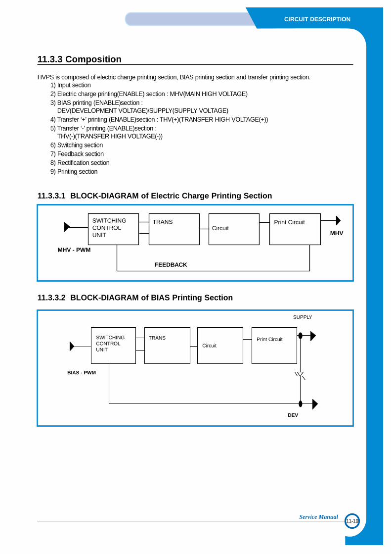
11-19
CIRCUIT DESCRIPTION
Service Manual
11.3.3 Composition
HVPS is composed of electric charge printing section, BIAS printing section and transfer printing section.1) Input section 2) Electric charge printing(ENABLE) section : MHV(MAIN HIGH VOLTAGE)3) BIAS printing (ENABLE)section :
DEV(DEVELOPMENT VOLTAGE)/SUPPLY(SUPPLY VOLTAGE)4) Transfer ‘+’ printing (ENABLE)section : THV(+)(TRANSFER HIGH VOLTAGE(+))5) Transfer ‘-’ printing (ENABLE)section :
THV(-)(TRANSFER HIGH VOLTAGE(-))6) Switching section7) Feedback section8) Rectification section9) Printing section
11.3.3.1 BLOCK-DIAGRAM of Electric Charge Printing Section
11.3.3.2 BLOCK-DIAGRAM of BIAS Printing Section
MHV - PWM
FEEDBACK
MHV
Print CircuitCircuit
TRANSSWITCHINGCONTROLUNIT
BIAS - PWM
SWITCHINGCONTROL UNIT
TRANS
CircuitPrint Circuit
SUPPLY
DEV
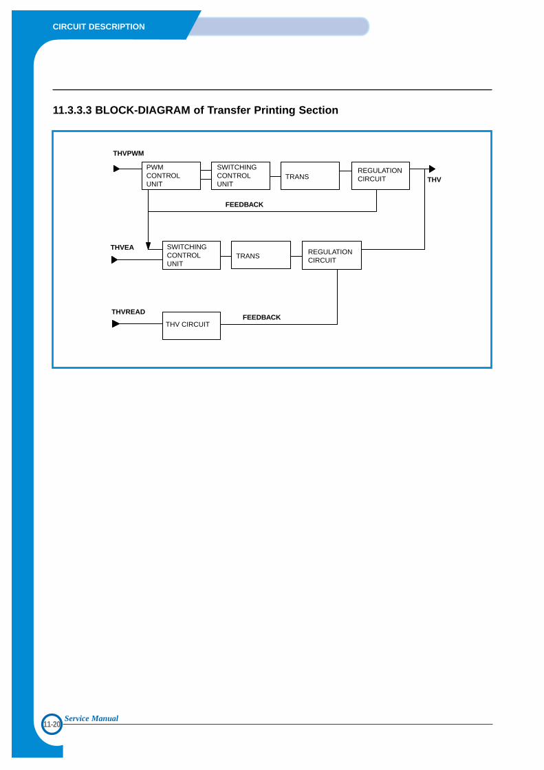
11-20
CIRCUIT DESCRIPTION
Service Manual
11.3.3.3 BLOCK-DIAGRAM of Transfer Printing Section
THVPWM
THVEA
THVREAD
FEEDBACK
FEEDBACK
THV
PWMCONTROLUNIT
SWITCHINGCONTROLUNIT
TRANSREGULATIONCIRCUIT
SWITCHINGCONTROLUNIT
TRANSREGULATIONCIRCUIT
THV CIRCUIT
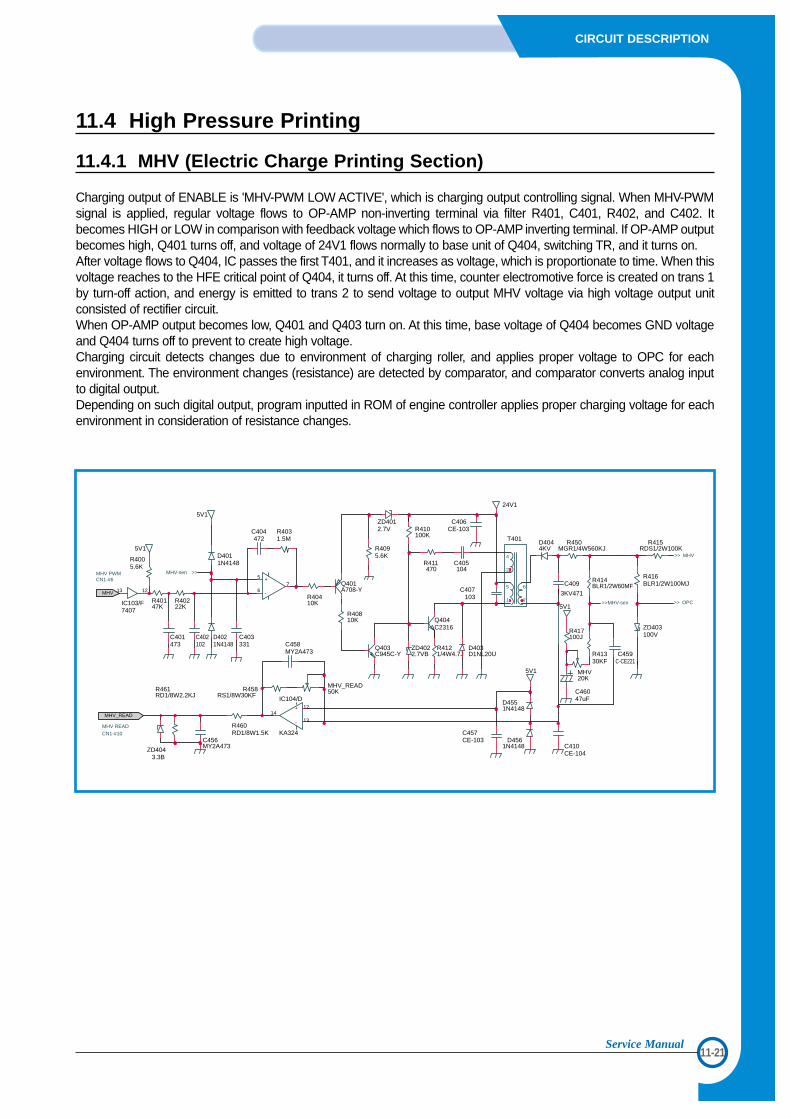
11-21
CIRCUIT DESCRIPTION
Service Manual
11.4 High Pressure Printing
11.4.1 MHV (Electric Charge Printing Section)
Charging output of ENABLE is 'MHV-PWM LOW ACTIVE', which is charging output controlling signal. When MHV-PWMsignal is applied, regular voltage flows to OP-AMP non-inverting terminal via filter R401, C401, R402, and C402. Itbecomes HIGH or LOW in comparison with feedback voltage which flows to OP-AMP inverting terminal. If OP-AMP outputbecomes high, Q401 turns off, and voltage of 24V1 flows normally to base unit of Q404, switching TR, and it turns on.After voltage flows to Q404, IC passes the first T401, and it increases as voltage, which is proportionate to time. When thisvoltage reaches to the HFE critical point of Q404, it turns off. At this time, counter electromotive force is created on trans 1by turn-off action, and energy is emitted to trans 2 to send voltage to output MHV voltage via high voltage output unitconsisted of rectifier circuit. When OP-AMP output becomes low, Q401 and Q403 turn on. At this time, base voltage of Q404 becomes GND voltageand Q404 turns off to prevent to create high voltage. Charging circuit detects changes due to environment of charging roller, and applies proper voltage to OPC for eachenvironment. The environment changes (resistance) are detected by comparator, and comparator converts analog inputto digital output. Depending on such digital output, program inputted in ROM of engine controller applies proper charging voltage for eachenvironment in consideration of resistance changes.
R4095.6K
R40810K
R410100K
R416BLR1/2W100MJ
ZD403100VD402
1N4148C403331
C404472
R4031.5M
R40410K
C402102
R40147K
R40222K
C401473
D4044KV
C405104
R411470
Q403C945C-Y
R4121/4W4.7J
Q404C2316
ZD4022.7VB
D403D1NL20U
D4011N4148
ZD4012.7V
Q401A708-Y
R415RDS1/2W100K
T401
24V1
5V1
D4551N4148
R460RD1/8W1.5K
C456MY2A473
13 12
IC103/F7407
MHV_READ50KR458
RS1/8W30KF
C458MY2A473
D4561N4148
5V1
R4005.6K
+ 12
- 1314
IC104/D
KA324
+5
-67
C406CE-103
C407103
C457CE-103
R414BLR1/2W60MF
R461RD1/8W2.2KJ
C459C-CE221
R450MGR1/4W560KJ
5V1
C410CE-104
C46047uF
R41330KF
MHV20K
R417100J
5V1
ZD4043.3B
C409
3KV471MHV
MHV_READ
>>MHV-sen
>>MHV-sen >> OPC
>> MHV
MHV PWMCN1-#6
MHV READCN1-#10
4
2
1
5 6
7
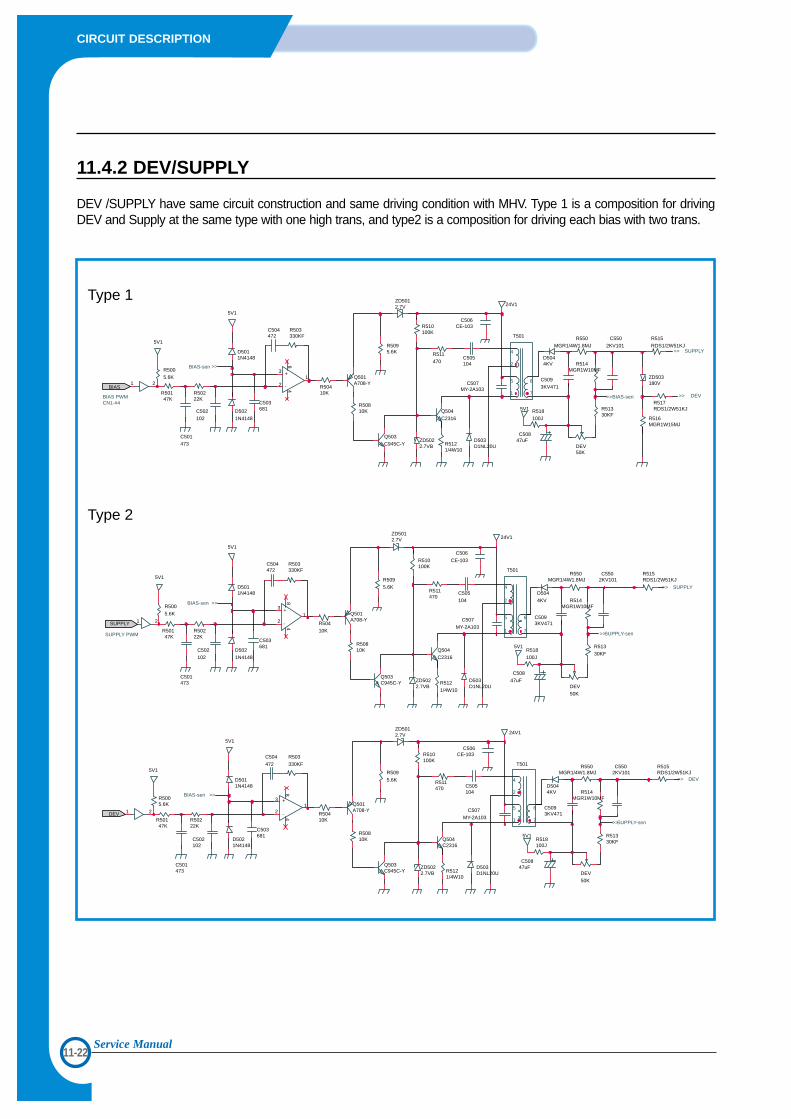
11-22
CIRCUIT DESCRIPTION
Service Manual
11.4.2 DEV/SUPPLY
DEV /SUPPLY have same circuit construction and same driving condition with MHV. Type 1 is a composition for drivingDEV and Supply at the same type with one high trans, and type2 is a composition for driving each bias with two trans.
R5095.6K
DEV50K
R51330KF
R516MGR1W15MJ
R510100K
Q504C2316
Q503C945C-Y
ZD5022.7VB
R511470
ZD5012.7V
R50810K
R50410K
R503330KF
C504472
Q501A708-Y
D5044KV
D503D1NL20U
C507MY-2A103
C505104
R515RDS1/2W51KJ
R517RDS1/2W51KJ
ZD503180V
T501
C5093KV471
C5502KV101
R514MGR1W10MF
R5121/4W10
D5011N4148
R50147K
R50222K
5V1
1 2
+3
-21
84
R5005.6K
C501473
C506CE-103
5V1
C50847uF
C502102
C503681D502
1N4148R518100J
5V1
24V1
R550MGR1/4W1.8MJ
BIAS
>>BIAS-sen >> DEV
>> SUPPLY
>>BIAS-sen
CN1-#4BIAS PWM
4
2
5
1
6
7
R5095.6K
DEV50K
R51330KF
R510100K
Q504C2316
Q503C945C-Y ZD502
2.7VB
R511470
ZD5012.7V
R50810K
R50410K
R503330KF
C504472
Q501A708-Y
D5044KV
D503D1NL20U
C507
MY-2A103
C505104
R515RDS1/2W51KJ
T501
C5093KV471
C5502KV101
R514MGR1W10MF
R5121/4W10
D5011N4148
R50147K
R50222K
5V1
1 2
+3
-21
84
R5005.6K
C501473
C506
CE-103
5V1
C50847uF
C502102
C503681
D5021N4148
R518100J
5V1
24V1
R550MGR1/4W1.8MJ
SUPPLY
>>SUPPLY-sen
>> SUPPLY
>>BIAS-sen
SUPPLY PWM
4
2
5
1
6
7
R509
5.6K
DEV50K
R51330KF
R510100K
Q504C2316
Q503C945C-Y
ZD5022.7VB
R511470
ZD5012.7V
R50810K
R50410K
R503330KF
C504472
Q501A708-Y
D5044KV
D503D1NL20U
C507MY-2A103
C505104
R515RDS1/2W51KJ
T501
C5093KV471
C5502KV101
R514MGR1W10MF
R5121/4W10
D5011N4148
R50147K
R50222K
5V1
1 2
+3
-21
84
R5005.6K
C501473
C506CE-103
5V1
C50847uF
C502102
C503681
D5021N4148
R518100J
5V1
24V1
R550MGR1/4W1.8MJ
DEV
>>SUPPLY-sen
>> DEV
>>BIAS-sen
4
2
5
1
6
7
Type 1
Type 2
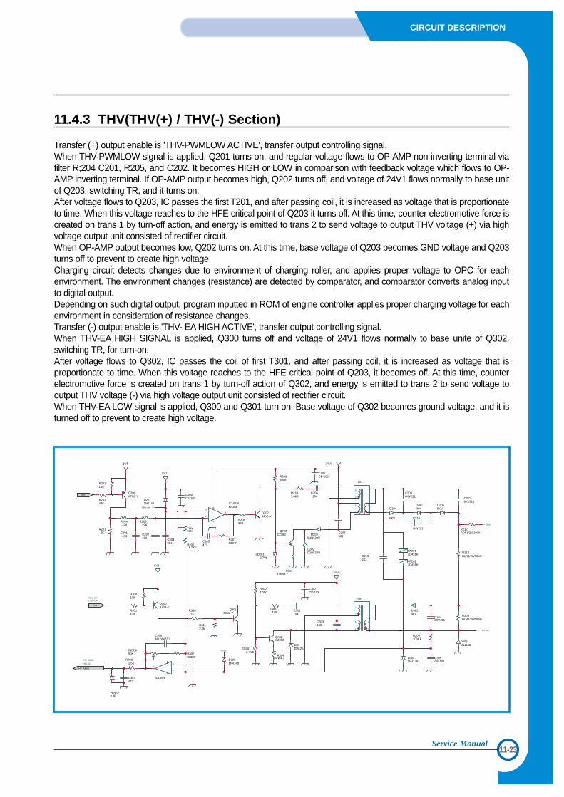
11-23
CIRCUIT DESCRIPTION
Service Manual
11.4.3 THV(THV(+) / THV(-) Section)
Transfer (+) output enable is 'THV-PWMLOW ACTIVE', transfer output controlling signal. When THV-PWMLOW signal is applied, Q201 turns on, and regular voltage flows to OP-AMP non-inverting terminal viafilter R;204 C201, R205, and C202. It becomes HIGH or LOW in comparison with feedback voltage which flows to OP-AMP inverting terminal. If OP-AMP output becomes high, Q202 turns off, and voltage of 24V1 flows normally to base unitof Q203, switching TR, and it turns on.After voltage flows to Q203, IC passes the first T201, and after passing coil, it is increased as voltage that is proportionateto time. When this voltage reaches to the HFE critical point of Q203 it turns off. At this time, counter electromotive force iscreated on trans 1 by turn-off action, and energy is emitted to trans 2 to send voltage to output THV voltage (+) via highvoltage output unit consisted of rectifier circuit. When OP-AMP output becomes low, Q202 turns on. At this time, base voltage of Q203 becomes GND voltage and Q203turns off to prevent to create high voltage. Charging circuit detects changes due to environment of charging roller, and applies proper voltage to OPC for eachenvironment. The environment changes (resistance) are detected by comparator, and comparator converts analog inputto digital output. Depending on such digital output, program inputted in ROM of engine controller applies proper charging voltage for eachenvironment in consideration of resistance changes.Transfer (-) output enable is 'THV- EA HIGH ACTIVE', transfer output controlling signal. When THV-EA HIGH SIGNAL is applied, Q300 turns off and voltage of 24V1 flows normally to base unite of Q302,switching TR, for turn-on. After voltage flows to Q302, IC passes the coil of first T301, and after passing coil, it is increased as voltage that isproportionate to time. When this voltage reaches to the HFE critical point of Q203, it becomes off. At this time, counterelectromotive force is created on trans 1 by turn-off action of Q302, and energy is emitted to trans 2 to send voltage tooutput THV voltage (-) via high voltage output unit consisted of rectifier circuit.When THV-EA LOW signal is applied, Q300 and Q301 turn on. Base voltage of Q302 becomes ground voltage, and it isturned off to prevent to create high voltage.
R302470K
C302CE-103
R213BLR1/2W30MF
R20810K
ZD2012.7VB
Q203C2383
D202D1NL20U
D203D1NL20U
ZD3012.7VB
D301D1NL20U
Q302C2383
C3043KV151
R305BLR1/2W50MF
C305CE-104
D3041N4148
Q202945C-Y
C208681
R212RDS1/2W100K
D3031N4148
D3024KV
24V1
24V1
INDEX50K
C207CE-103R209
100K
5V1
D2011N4148
C204CE-103
R20522K
C202102
T301
C206104
THV50K
R20616.2KF
C203681
T201
C301104
R3041/4W4.7
C306MY2A473J
D3051N4148
R307330KF
+ 5
- 6
7
IC105/B
5V1
R203100
R202430
Q201A708-Y
R300100
R301430
Q300A708-Y
R2111/4W4.7J
Q301945C-Y
+3
-2
1
114
IC105/AKA358
R2105.6KJ
5V1
R3112.2k
R3101K
D204
6KV C210
6KV221
C2116KV221
C2096KV221
D2056KV
D2066KV
C205471
R207330KF
C307473
ZD3023.3B
VA2017D431K
VA2027D431K
C213221
C303103
R3081.5K
C201473
R303470
R306100KF
R2012K
R20447K
THV_READ
THV
THV
>> THV-sen
THV READ
CN1-#12
>> THV
>>THV-sen
4
2
5
1
4
2
5
1
6
7
+5V1
CN1-#14THV -EA
7
6
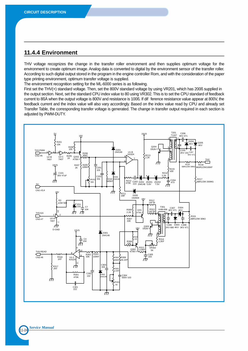
11-24
CIRCUIT DESCRIPTION
Service Manual
11.4.4 Environment
THV voltage recognizes the change in the transfer roller environment and then supplies optimum voltage for theenvironment to create optimum image. Analog data is converted to digital by the environment sensor of the transfer roller.According to such digital output stored in the program in the engine controller Rom, and with the consideration of the papertype printing environment, optimum transfer voltage is supplied. The environment recognition setting for the ML-6000 series is as following. First set the THV(+) standard voltage. Then, set the 800V standard voltage by using VR201, which has 200ß supplied inthe output section. Next, set the standard CPU index value to 80 using VR302. This is to set the CPU standard of feedbackcurrent to 8ßÀ when the output voltage is 800V and resistance is 100ß. If dif ference resistance value appear at 800V, thefeedback current and the index value will also vary accordingly. Based on the index value read by CPU and already setTransfer Table, the corresponding transfer voltage is generated. The change in transfer output required in each section isadjusted by PWM-DUTY.
5V18V
24VS
18V
18V
18V
24VS
24VS
D-GND
CN2-#6
CN2-#7
CN1-#3,4
CN2-#5
7407
U2-B U2-C7407 7407
R2051K
R206100
Q203A708-Y
R2072K
R20830KF
R209100KF
VR20150K
C201103
C202331 R210
845KF
D2021N4148
D2011N4148
R2111MF
R212470K
C203223
D2031N4148
ZD2015.6V
ZD2027.5V
R2132.2K
R2142.2K
R215430
Q204D526-Y
C2066KV 471
D2054KV
C2076KV 471
R216SBR1/2W 30MJ
R217SBR1/2W 200MG
R218MGR1/2W100KF
C204473
C3062KV 680
C3073KV 471
D3034KV
C3083KV 471Q303
D526-Y
R3142.2KF
VR3025K
C305333
R311110KFQ302
A708-Y
R3102.2K
R30833K
R3121W 56
R3131W 56
Q301A708-Y
R30733K
R3092.2K
R30626.1KF
R304200KF
R3056.2KF
VR3015K
C304500V 103
C303333
D3021N4148
D3011N4148
R303100KF
R30233K
C302102
R301470K
C301222
C4104
R31/2W 560
ZD15.6V C7
104
C10135V 47uF
+
R315SBR1/2W 30MJ
C2052KV 101
D3044KV
D2044KV
U1-BKA324
+
-
5
67
R3161KF
R3172KF
3 4 5 6
T201T1167
1
4
25
7
6
T301KAB-006
1
4
25
6
7
R20110K
U2-A
1 2
147
U1-CKA324
+
-
10
98
411
D2001N4004
THV-PWM
5V
THV-EA
THV
THV-READ