printer presenter unit - cgp electronics kft
TRANSCRIPT
PRINTER PRESENTER UNITMODEL PMU2300III
User’s Manual

WEEE MARK
En
Wenn Sie dieses Produkt entsorgen wollen, dann tun Sie dies bitte nicht zusammen mit demHaushaltsmüll. Es gibt im Rahmen der WEEE-Direktive innerhalb der Europäischen Union(Direktive 2002/96/EC) gesetzliche Bestimmungen für separate Sammelsysteme für gebrauchteelektronische Geräte und Produkte.
Ge
Si vous souhaitez vous débarrasser de cet appareil, ne le mettez pas à la poubelle avec vosordures ménagères. Il existe un système de récupération distinct pour les vieux appareilsélectroniques conformément à la législation WEEE sur le recyclage des déchets deséquipements électriques et électroniques (Directive 2002/96/EC) qui est uniquement valabledans les pays de l’Union européenne.Les appareils et les machines électriques et électroniques contiennent souvent des matièresdangereuses pour l’homme et l’environnement si vous les utilisez et vous vous en débarrassezde façon inappropriée.
Fr
Si desea deshacerse de este producto, no lo mezcle con residuos domésticos de caráctergeneral. Existe un sistema de recogida selectiva de aparatos electrónicos usados, segúnestablece la legislación prevista por la Directiva 2002/96/CE sobre residuos de aparatoseléctricos y electrónicos (RAEE), vigente únicamente en la Unión Europea.
Sp
Se desiderate gettare via questo prodotto, non mescolatelo ai rifiuti generici di casa. Esisteun sistema di raccolta separato per i prodotti elettronici usati in conformità alla legislazioneRAEE (Direttiva 2002/96/CE), valida solo all’interno dell’Unione Europea.
It
Deponeer dit product niet bij het gewone huishoudelijk afval wanneer u het wilt verwijderen. Erbestaat ingevolge de WEEE-richtlijn (Richtlijn 2002/96/EG) een speciaal wettelijkvoorgeschreven verzamelsysteem voor gebruikte elektronische producten, welk alleen geldtbinnen de Europese Unie.
Du
Hvis du vil skille dig af med dette produkt, må du ikke smide det ud sammen med dit almindeligehusholdningsaffald. Der findes et separat indsamlingssystem for udtjente elektroniske produkteri overensstemmelse med lovgivningen under WEEE-direktivet (direktiv 2002/96/EC), somkun er gældende i den Europæiske Union.
Da
Se quiser deitar fora este produto, não o misture com o lixo comum. De acordo com a legislaçãoque decorre da Directiva REEE – Resíduos de Equipamentos Eléctricos e Electrónicos (2002/96/CE), existe um sistema de recolha separado para os equipamentos electrónicos fora deuso, em vigor apenas na União Europeia.
Por
Pol Jeżeli zamierzasz pozbyć się tego produktu, nie wyrzucaj go razem ze zwykłymidomowymi odpadkami. Według dyrektywy WEEE (Dyrektywa 2002/96/EC)obowiązującej w Unii Europejskiej dla używanych produktów elektronicznychnależy stosować oddzielne sposoby utylizacji.
If you want to dispose of this product, do not mix it with general household waste. There is a separate collection systems for used electronics products in accordance with legislation under the WEEE Directive (Directive 2002/96/EC) and is effective only within European Union.
— 1 —
Declaration of ConformityThis printer conforms to the following Standards:
The Low Voltage Directive 2006/95/EC, the EMC Directive 2004/108/EC, the RoHSDirective 2002/95/EC, and the WEEE Directive 2002/96/EC.
LVD : EN60950-1
EMC: EN55022 Class AEN61000-3-2EN61000-3-3EN55024
This declaration applies only to the 230-V model.
IMPORTANT: This equipment generates, uses, and can radiate radio frequencyenergy and if not installed and used in accordance with the instruction manual, maycause interference to radio communications. It has been tested and found to complywith the limits for a Class A computing device pursuant to Subpart J of Part 15 of FCCRules, which are designed to provide reasonable protection against such interferencewhen operated in a commercial environment. Operation of this equipment in aresidential area is likely to cause interference, in which case the user at his ownexpense will be required to take whatever measures may be necessary to correct theinterference.CAUTION: Use shielded cable for this equipment.
Sicherheitshinweis Die Steckdose zum Anschluß dieses Druckers muß nahe dem Gerät angebracht undleicht zugänglich sein.
For Uses in Canada This Class A digital apparatus complies with Canadian ICES-003.This digital apparatus does not exceed the Class A limits for radio noise emissionsfrom digital apparatus, as set out in the radio interference regulations of the Canadiandepartment of communications.
Pour L’utilisateurs Canadiens Cet appareil numérique de la Classe A est conforme à la norme NMB-003 du Canada.Cet appareil numérique ne dépasse pas les limites de carégorie a pour les émissionsde bruit radio émanant d’appareils numériques, tel que prévu dans les réglements surl’interférence radio du départment Canadien des communications.
— 2 —

GENERAL PRECAUTIONS Before using this product, be sure to read through this manual. After
having read this manual, keep it in a safe, readily accessible place forfuture reference.
The information contained herein is subject to change without priornotice.
Reproduction or transfer of part or all of this document in any means isprohibited without permission from Citizen Systems.
Note that Citizen Systems is not responsible for any operation resultsregardless of omissions, errors, or misprints in this manual.
Note that Citizen Systems is not responsible for any trouble caused as aresult of using options or consumables that are not specified in thismanual.
Except explained elsewhere in this manual, do not attempt to service,disassemble, or repair this product.
Note that Citizen Systems is not responsible for any damage attributableto incorrect operation/handling or improper operating environments thatare not specified in this manual.
Data is basically for temporary use and not stored for an extended periodof time or permanently. Please note that Citizen Systems is notresponsible for damage or lost profit resulting from the loss of datacaused by accidents, repairs, tests or other occurrences.
If you find omissions, errors, or have questions, please contact yourCitizen Systems dealer.
If you find any pages missing or out of order, contact your Citizen Systemsdealer for a replacement.
— 3 —
Before using this product for the first time, carefully read these SAFETY PRECAUTIONS.Improper handling may result in accidents (fire, electric shock or injury).In order to prevent injury to operators, third parties, or damage to property, specialwarning symbols are used in the User’s Manual to indicate important items to be strictlyobserved.
After having read this Manual, keep it in a safe, readily accessible place for futurereference.
Some of the descriptions contained in this manual may not be relevant to some printermodels.
The following describes the degree of hazard and damage that could occur if the printeris improperly operated by ignoring the instructions indicated by the warning symbols.
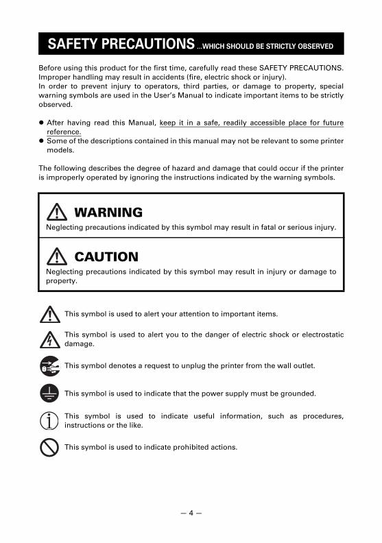
SAFETY PRECAUTIONS ...WHICH SHOULD BE STRICTLY OBSERVED
WARNINGNeglecting precautions indicated by this symbol may result in fatal or serious injury.
CAUTIONNeglecting precautions indicated by this symbol may result in injury or damage toproperty.
This symbol is used to alert your attention to important items.
This symbol is used to alert you to the danger of electric shock or electrostaticdamage.
This symbol denotes a request to unplug the printer from the wall outlet.
This symbol is used to indicate that the power supply must be grounded.
This symbol is used to indicate useful information, such as procedures,instructions or the like.
This symbol is used to indicate prohibited actions.
— 4 —
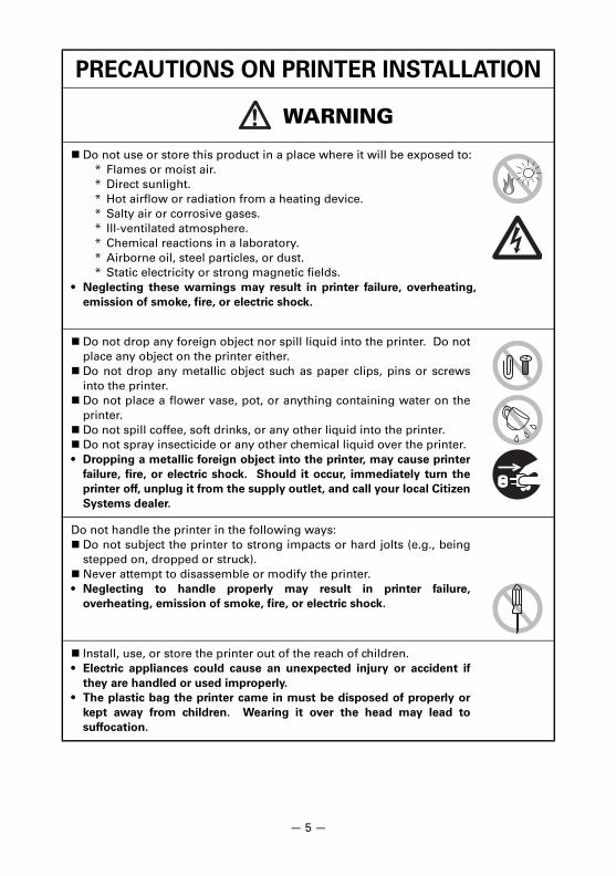
PRECAUTIONS ON PRINTER INSTALLATION
WARNING
Do not use or store this product in a place where it will be exposed to:* Flames or moist air.* Direct sunlight.* Hot airflow or radiation from a heating device.* Salty air or corrosive gases.* Ill-ventilated atmosphere.* Chemical reactions in a laboratory.* Airborne oil, steel particles, or dust.* Static electricity or strong magnetic fields.
• Neglecting these warnings may result in printer failure, overheating,
emission of smoke, fire, or electric shock.
Do not drop any foreign object nor spill liquid into the printer. Do notplace any object on the printer either.
Do not drop any metallic object such as paper clips, pins or screwsinto the printer.
Do not place a flower vase, pot, or anything containing water on theprinter.
Do not spill coffee, soft drinks, or any other liquid into the printer. Do not spray insecticide or any other chemical liquid over the printer.• Dropping a metallic foreign object into the printer, may cause printer
failure, fire, or electric shock. Should it occur, immediately turn the
printer off, unplug it from the supply outlet, and call your local Citizen
Systems dealer.
Do not handle the printer in the following ways: Do not subject the printer to strong impacts or hard jolts (e.g., being
stepped on, dropped or struck). Never attempt to disassemble or modify the printer.• Neglecting to handle properly may result in printer failure,
overheating, emission of smoke, fire, or electric shock.
Install, use, or store the printer out of the reach of children.• Electric appliances could cause an unexpected injury or accident if
they are handled or used improperly.
• The plastic bag the printer came in must be disposed of properly or
kept away from children. Wearing it over the head may lead to
suffocation.
— 5 —
CAUTION
Do not use the printer under the following conditions. Avoid locations subject to vibration or instability. Avoid locations where the printer is not level.• The printer may fall and cause an injury.
• The quality of printing may deteriorate.
Do not place anything on the printer. Do not cover or wrap the printer in cloth or blankets.• Doing so could cause heat to build up and deform the case or start a
fire.
Avoid using the printer with a device that is a strong source of noise.• The printer may have an adverse effect on nearby radio or TV
transmissions. There may also be cases when nearby electrical
appliances adversely influence the printer, causing data errors or
malfunction.
Installed in any orientation other than those specified.• Malfunction, failure, or electric shock may result.
Connect the printer to a ground.• Electric leakage may cause an electric shock.
Before connecting or disconnecting the grounding lead to or from theprinter, always unplug it from the electric outlet.
— 6 —
PRECAUTIONS IN HANDLING THE PRINTER
WARNING
Please observe the following precautions for power source and powercord: Use the printer only at the specified supply voltage and frequency. Check to make sure that the supply outlet from which the printer is
powered has a sufficient capacity. Do not use a deformed or damaged power cord. Do not attempt to modify the power cord unnecessarily.
— 7 —
CAUTION
To prevent possible malfunction or failure observe the following. Avoid operating the printer without paper properly loaded. Avoid the use of paper not complying with specifications.• May result in poor print quality.
Avoid using torn pieces of paper or paper spliced with plastic adhesivetape.
Avoid forcibly pulling already loaded paper by hand.
Be sure to firmly insert the cable plugs into their mating sockets.• A cross connection may damage the printer’s internal electronics or
the host system’s hardware.
— 8 —
CAUTION
To prevent injury and printer failures from worsening, observe the following: Do not touch the printing surface of the thermal head. Do not touch any of the moving parts (e.g., paper cutter, gears, active
electric parts) while the printer is working. In case of trouble do not attempt to repair the printer. Ask Citizen
Systems service for repair. Be careful of the sharp edges on the printer. Do not allow them to
injure you or damage property.• May result in electric shock, burn, or injury.
DAILY MAINTENANCE
Observe the following precautions for daily maintenance.When cleaning the printer, always turn it off and unplug it from the
electric outlet. Use a soft, dry cloth for cleaning the surface of the printer case.
For severe stains, use a soft cloth slightly dampened with water.Never use organic cleaning solvent, paint thinner, trichloroethylene,benzene, or ketone. Never use a chemically processed cleaning cloth.For cleaning the presenter and platen, wet a towel with a small amountof ethanol and wipe the dirt on the roller.
To remove paper dust, use a soft brush.
CAUTION• The thermal head is at a dangerously high temperature immediately after printing.
Allow it to cool off before starting maintenance work.
If the printer emits smoke, an odd smell, or unusual noise while
printing, immediately abort the current print session and
unplug the printer from the electric outlet.
Visit the following site to get documentation, drivers, utilities, and otherinformation.http://www.citizen-systems.co.jp/english/support/index.html
— 9 —
— 10 —
1. GENERAL OUTLINE..................................................................111.1 Features ........................................................................................ 111.2 Unpacking .................................................................................... 121.3 Model Classification .................................................................... 131.4 Basic Specifications..................................................................... 14
2. EXPLANATION OF PRINTER PARTS .......................................152.1 Printer Appearance...................................................................... 152.2 PMU2300III Series........................................................................ 182.3 Options ......................................................................................... 21
3. SETUP........................................................................................223.1 Paper Holder Attachment Position............................................. 223.2 How to set the paper holder ....................................................... 233.3 Connecting Interface Cables ....................................................... 273.4 Precautions for Installing the Printer ......................................... 293.5 Setting the DIP Switch on the Serial Interface Board ............... 313.6 Adjusting the Paper Near-end Sensor ....................................... 32
4. MAINTENANCE AND TROUBLESHOOTING...........................344.1 How to Set Paper (Replacement) ............................................... 344.2 How to Release Cutter Lock (Cutter Error)................................. 364.3 How to Remove Paper Jam ........................................................ 374.4 Self-printing ................................................................................. 404.5 Hexadecimal Dump Printing....................................................... 414.6 Error Messages ............................................................................ 42
5. OTHER .......................................................................................445.1 External Views and Dimensions................................................. 445.2 Printing Paper .............................................................................. 505.3 Setting of Memory Switches ...................................................... 51
THE TABLE OF CONTENTS
The PMU2300III is a printer designed for use with a broad array of terminalequipment including data, measuring instruments, outdoor information, or as apresenter for issuing various kinds of tickets and coupon tickets.With extensive features, it can be used in a wide range of applications.To obtain the best results from the PMU2300III printers, please read theinstructions in this manual thoroughly.
(1) The down-sizing is realized.(2) High-speed 150mm/s printing(3) High resolution printing with 8 dots/mm(4) Supports paper width of 80mm(5) Supports long life printer head, highly-reliable simple mechanism (6) Operating temperature range -10°C to +60°C(7) Simple head / paper maintenance by adopting the new head open
mechanism.(8) Interface serial, parallel, USB (printer class, virtual COM).(9) OEM available(10) Black mark (factory option)(11) Equipped with presenter function that enables the discharge / recovery of
printed or cut paper.(12) Lights up printing paper discharge port by bezel LED display.(13) Supports paper holder with a large diameter (ø203mm)
1. GENERAL OUTLINE
1.1 Features
— 11 —
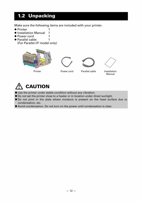
Make sure the following items are included with your printer.
1.2 Unpacking
Printer 1 Installation Manual 1 Power cord 1 Parallel cable 1
(For Parallel I/F model only)
CAUTION Use the printer under stable condition without any vibration. Do not set the printer close to a heater or in location under direct sunlight. Do not print in the state where moisture is present on the head surface due to
condensation, etc. Avoid condensation. Do not turn on the power until condensation is clear.
Installation Manual
Power cord Parallel cablePrinter
— 12 —
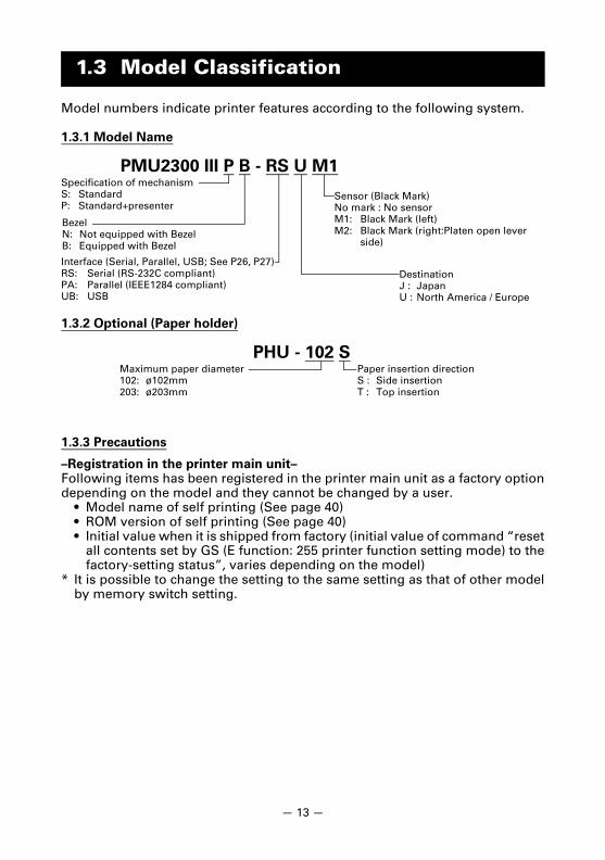
Model numbers indicate printer features according to the following system.
1.3.1 Model Name
1.3.2 Optional (Paper holder)
1.3.3 Precautions
–Registration in the printer main unit–Following items has been registered in the printer main unit as a factory optiondepending on the model and they cannot be changed by a user.
• Model name of self printing (See page 40)• ROM version of self printing (See page 40)• Initial value when it is shipped from factory (initial value of command “reset
all contents set by GS (E function: 255 printer function setting mode) to thefactory-setting status”, varies depending on the model)
* It is possible to change the setting to the same setting as that of other modelby memory switch setting.
1.3 Model Classification
PMU2300 III P B - RS U M1 Specification of mechanismS: StandardP: Standard+presenter
Interface (Serial, Parallel, USB; See P26, P27)RS: Serial (RS-232C compliant)PA: Parallel (IEEE1284 compliant)UB: USB
BezelN: Not equipped with BezelB: Equipped with Bezel
DestinationJ : JapanU : North America / Europe
Sensor (Black Mark)No mark : No sensorM1: Black Mark (left)M2: Black Mark (right:Platen open lever
side)
PHU - 102 SMaximum paper diameter102: ø102mm203: ø203mm
Paper insertion directionS : Side insertionT : Top insertion
— 13 —
— 14 —
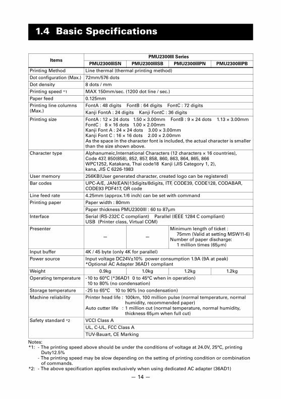
Notes:*1: - The printing speed above should be under the conditions of voltage at 24.0V, 25°C, printing
Duty12.5%- The printing speed may be slow depending on the setting of printing condition or combination
of commands.*2: - The above specification applies exclusively when using dedicated AC adapter (36AD1)
1.4 Basic Specifications
ItemsPMU2300III Series
PMU2300IIISN PMU2300IIISB PMU2300IIIPN PMU2300IIIPB
Printing Method Line thermal (thermal printing method)Dot configuration (Max.) 72mm/576 dotsDot density 8 dots / mm
Printing speed *1 MAX 150mm/sec. (1200 dot line / sec.)Paper feed 0.125mmPrinting line columns (Max.)
FontA : 48 digits FontB : 64 digits FontC : 72 digits
Kanji FontA : 24 digits Kanji FontC : 36 digitsPrinting size FontA : 12 × 24 dots 1.50 × 3.00mm FontB : 9 × 24 dots 1.13 × 3.00mm
FontC : 8 × 16 dots 1.00 × 2.00mmKanji Font A : 24 × 24 dots 3.00 × 3.00mmKanji Font C : 16 × 16 dots 2.00 × 2.00mmAs the space in the character font is included, the actual character is smaller than the size shown above.
Character type Alphanumeic,International Characters (12 characters × 16 countries),Code 437, 850(858), 852, 857, 858, 860, 863, 864, 865, 866WPC1252, Katakana, Thai code18 Kanji (JIS Category 1, 2), kana, JIS C 6226-1983
User memory 256KB(User generated character, created logo can be registered)Bar codes UPC-A/E, JAN(EAN)13digits/8digits, ITF, CODE39, CODE128, CODABAR,
CODE93 PDF417, QR code
Line feed rate 4.25mm (approx.1/6 inch) can be set with commandPrinting paper Paper width : 80mm
Paper thickness PMU2300III : 60 to 87µm
Interface Serial (RS-232C C compliant) Parallel (IEEE 1284 C compliant) USB (Printer class, Virtual COM)
Presenter
— —
Minimum length of ticket :75mm (Valid at setting MSW11-6)
Number of paper discharge:1 million times (65µm)
Input buffer 4K / 45 byte (only 4K for parallel)Power source Input voltage DC24V±10% power consumption 1.9A (9A at peak)
*Optional AC Adapter 36AD1 compliant
Weight 0.9kg 1.0kg 1.2kg 1.2kgOperating temperature -10 to 60°C (*36AD1 0 to 45°C when in operation)
10 to 80% (no condensation)
Storage temperature -25 to 65°C 10 to 90% (no condensation)Machine reliability Printer head life : 100km, 100 million pulse (normal temperature, normal
humidity, recommended paper)Auto cutter life : 1 million cut (normal temperature, normal humidity,
thickness 65µm when full cut)Safety standard *2 VCCI Class A
UL, C-UL, FCC Class ATUV-Bauart, CE Marking
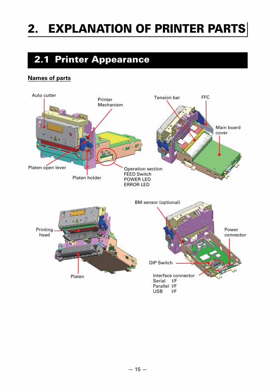
Names of parts
2. EXPLANATION OF PRINTER PARTS
2.1 Printer Appearance
Auto cutterPrinter Mechanism
Platen open lever
Platen holder
Operation sectionFEED SwitchPOWER LEDERROR LED
Tension bar FFC
Main boardcover
Printing head
Platen
BM sensor (optional)
DIP Switch
Interface connectorSerial I/FParallel I/FUSB I/F
Power connector
— 15 —
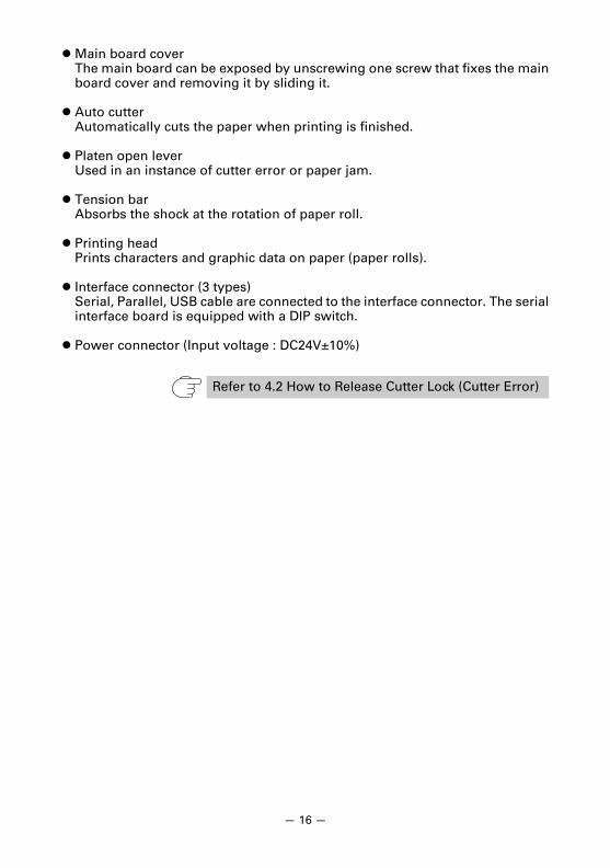
Main board coverThe main board can be exposed by unscrewing one screw that fixes the mainboard cover and removing it by sliding it.
Auto cutterAutomatically cuts the paper when printing is finished.
Platen open leverUsed in an instance of cutter error or paper jam.
Tension barAbsorbs the shock at the rotation of paper roll.
Printing headPrints characters and graphic data on paper (paper rolls).
Interface connector (3 types)Serial, Parallel, USB cable are connected to the interface connector. The serialinterface board is equipped with a DIP switch.
Power connector (Input voltage : DC24V±10%)
Refer to 4.2 How to Release Cutter Lock (Cutter Error)
— 16 —
— 17 —
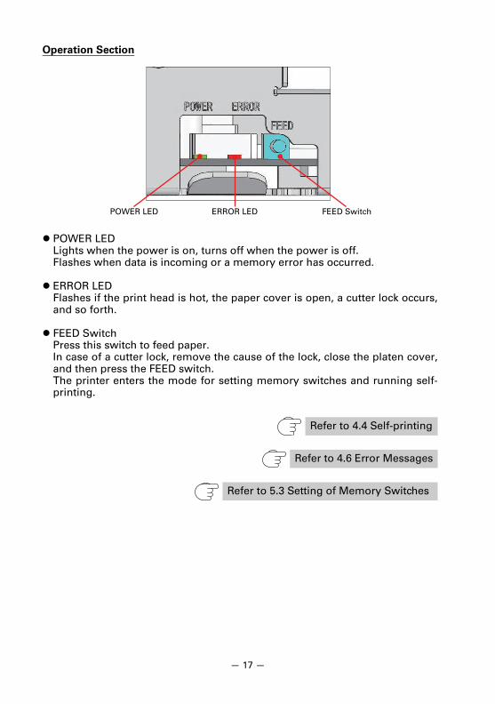
Operation Section
POWER LEDLights when the power is on, turns off when the power is off.Flashes when data is incoming or a memory error has occurred.
ERROR LED Flashes if the print head is hot, the paper cover is open, a cutter lock occurs,and so forth.
FEED SwitchPress this switch to feed paper.In case of a cutter lock, remove the cause of the lock, close the platen cover,and then press the FEED switch.The printer enters the mode for setting memory switches and running self-printing.
Refer to 4.4 Self-printing
Refer to 4.6 Error Messages
Refer to 5.3 Setting of Memory Switches
POWER LED ERROR LED FEED Switch
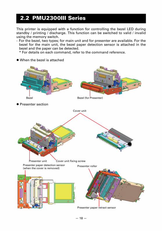
This printer is equipped with a function for controlling the bezel LED duringstandby / printing / discharge. This function can be switched to valid / invalidusing the memory switch.- For the bezel, two types; for main unit and for presenter are available. For the
bezel for the main unit, the bezel paper detection sensor is attached in thebezel and the paper can be detected.* For details on each command, refer to the command reference.
When the bezel is attached
Presenter section
2.2 PMU2300III Series
Bezel Bezel (for Presenter)
Presenter unit
Cover unit
Cover unit fixing screw
Presenter paper detection sensor(when the cover is removed)
Presenter roller
Presenter paper retract sensor
— 18 —
2.2.1 Memory switch setting (Presenter function)
The presenter function can be set with MSW11.
1. MSW11-1: PresenterFunction : Validity/invalidity of presenter function is selected.
Operation at OFF (Invalid): The presenter function is disabled.The setting of MSW11-2~MSW11-6 is disabled.
Operation at ON (Valid): The Presenter function is enabled.The setting of MSW11-2~MSW11-6 is enabled.
2. MSW11-2: Retract FunctionFunction : Validity/invalidity of recovery operation is selected.
Operation at OFF (Invalid): The recovery operation is disabled.Operation at ON (Valid): The recovery operation is enabled.
After ejecting paper, the function performspaper recovery either in forward ejection or rearside recovery after a certain time passed withthe setting of MSW11-3 (Retract Direction).By the execution of Retracting receiptimmediately Command GS R 0, conductsinstant recovery operation.
- The recovery time can be set with the Setting Command, GS ( E, ofcustomized value. Also, the recovery time until power being OFF ischangeable with the setting command, GS R 1, of the Receipt RecoveryTimer value.Initial Value of Recovery Time: 5s
3. MSW11-3: Retract DirectionFunction : Selects recovery direction at Retract Function Valid (MSW11-2 = ON)
Operation at OFF (Rear): Recovers paper from rear side.Operation at ON (Forward): Ejects paper forward.
4. MSW11-4: Store and ejectFunction : Selects valid/invalid of ejection after accumulation.
Operation at OFF (Invalid): When paper is reached to Presenter Roller,synchronizes with printing line-feed withoutpaper sagging and conducts paper ejection.
Operation at ON (Valid): Paper ejection does not occur even when thepaper reaches to the Presenter Roller andconducts paper ejection after paper saggingof maximum 220 mm.
5. MSW11-5: No print with paperFunction : When recovery sensor is detecting paper, selects valid/invalid of the next
printing/ejecting operation.
Operation at OFF (Invalid): Even when the recovery sensor detects paper,conducts the next printing/ejection operation.
Operation at ON (Valid): When the recovery sensor is detecting paper,waits the next printing/ejection operationuntil the sensor fails to detect paper.
6. MSW11-6: Min Receipt LengthFunction : Selects minimum receipt length.
Operation at OFF (75mm): Sets the minimum length at 75mm.Operation at ON (120mm): Sets the minimum length at 120mm.
— 19 —
2.2.2 Memory switch setting (Bezel function)
The bezel function can be set by MSW12.
1. MSW12-1: Bezel FunctionFunction : Validity / invalidity of bezel function is selected.
OFF operation at (invalid) :The bezel function is disabledSetting of MSW12-2 to MSW12-6 is disabled.
ON operation at (valid) : The bezel function is enabled.Setting of MSW12-2 to MSW12-6 is enabled.
2. MSW12-2: LED ControlFunction : Validity / invalidity of bezel LED control (during standby / during printing /
during discharge) is selected.
OFF operation at (invalid): The bezel LED control is disabled.ON operation at (valid) : The bezel LED control is enabled.
- The bezel LED display status, bezel lighting time during standby, andbezel blinking time can be set by setting of customized value GS ( ECommand.Initial value of bezel LED display During standby : OFF
During printing : lights upDuring discharge : blinks
Initial value of bezel lighting time during standby0: continuously lights up
Initial value of bezel blinking ON/OFF time5: 500ms
- The bezel LED display can be changed by controlling bezel LEDcommand GS R 2 regardless of setting of MSW12-2.
3. MSW12-5: Show Error by LEDFunction : Validity / invalidity of LED abnormal display is selected.
When an error is generated, the bezel LED is displayed by synchronizing itwith the error LED
OFF operation at (invalid):LED abnormal display is disabled.ON operation at (valid): LED abnormal display is enabled.
4. MSW12-6: No print with paperFunction : When the bezel paper detection sensor detects the paper, validity /
invalidity of next printing / discharge operation is selected.This function becomes effective only when the bezel for the main unit isattached.
OFF operation at (invalid):Even if the bezel paper detection sensordetects the paper, the next printing /discharge operation is carried out.
ON operation at (valid): If the bezel paper detection sensor detects thepaper, the next printing / discharge operationis carried out after the sensor does not detectthe paper.
— 20 —
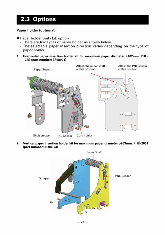
Paper holder (optional)
Paper holder unit / kit: option- There are two types of paper holder as shown below.- The selectable paper insertion direction varies depending on the type of
paper holder.
1. Horizontal paper insertion holder kit for maximum paper diameter ø102mm: PHU-102S (part number: ZF98901)
2. Vertical paper insertion holder kit for maximum paper diameter ø203mm: PHU-203T(part number: ZF98903)
2.3 Options
Attach the paper shaft at this position
Attach the PNE sensor at this positionPaper Shaft
PNE Sensor Cord holderShaft stopper
Paper Shaft
PNE SensorDumper
— 21 —
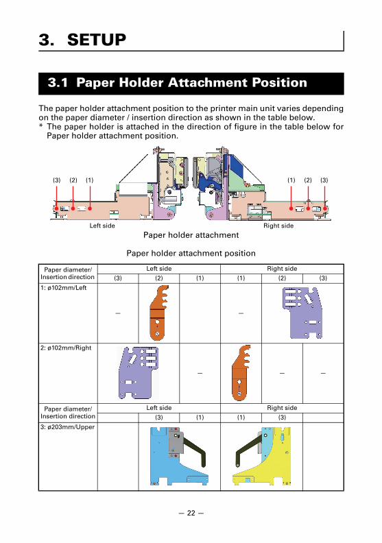
The paper holder attachment position to the printer main unit varies dependingon the paper diameter / insertion direction as shown in the table below.* The paper holder is attached in the direction of figure in the table below for
Paper holder attachment position.
Paper holder attachment
Paper holder attachment position
3. SETUP
3.1 Paper Holder Attachment Position
Paper diameter/Insertion direction
Left side Right side
(3) (2) (1) (1) (2) (3)
1: ø102mm/Left
— —
2: ø102mm/Right
— — —
Paper diameter/Insertion direction
Left side Right side
(3) (1) (1) (3)
3: ø203mm/Upper
(3) (2) (1) (1) (2) (3)
Left side Right side
— 22 —
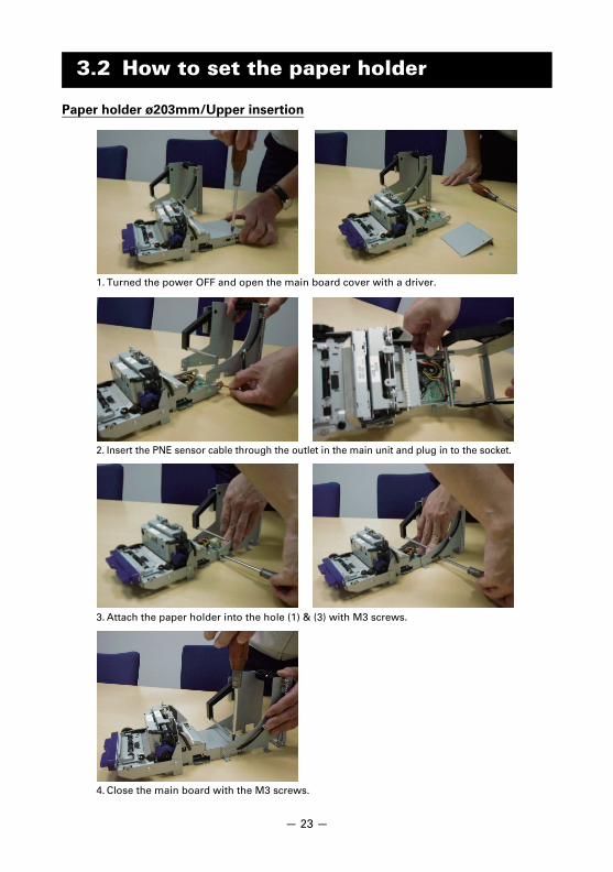
Paper holder ø203mm/Upper insertion
3.2 How to set the paper holder
1. Turned the power OFF and open the main board cover with a driver.
2. Insert the PNE sensor cable through the outlet in the main unit and plug in to the socket.
3. Attach the paper holder into the hole (1) & (3) with M3 screws.
4. Close the main board with the M3 screws.
— 23 —
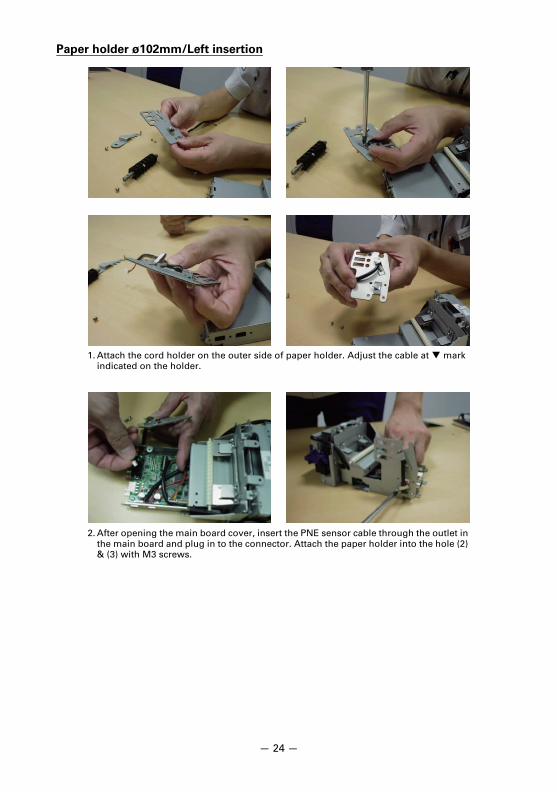
Paper holder ø102mm/Left insertion
1. Attach the cord holder on the outer side of paper holder. Adjust the cable at mark indicated on the holder.
2. After opening the main board cover, insert the PNE sensor cable through the outlet in the main board and plug in to the connector. Attach the paper holder into the hole (2) & (3) with M3 screws.
— 24 —

3. Place the paper shaft onto the holder hole and attach it in the uppermost hole with M4 screw.
5. Close the main board with the M3 screws.
4. Attach the shaft stopper through (2) hole in the main unit with M3 screw.
— 2
5 —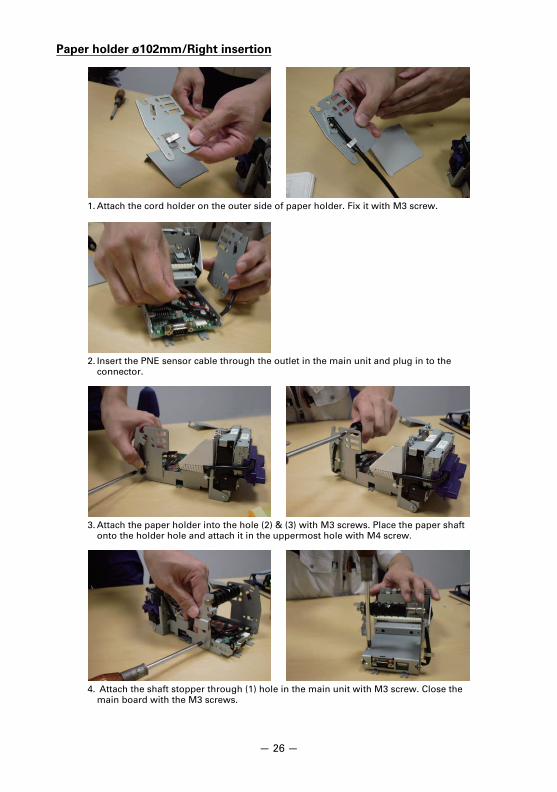
Paper holder ø102mm/Right insertion
1. Attach the cord holder on the outer side of paper holder. Fix it with M3 screw.
2. Insert the PNE sensor cable through the outlet in the main unit and plug in to the connector.
3. Attach the paper holder into the hole (2) & (3) with M3 screws. Place the paper shaft onto the holder hole and attach it in the uppermost hole with M4 screw.
4. Attach the shaft stopper through (1) hole in the main unit with M3 screw. Close the main board with the M3 screws.
— 26 —
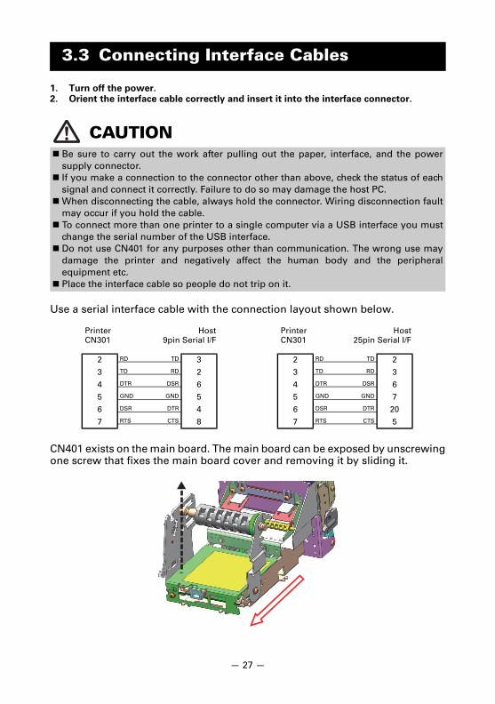
1. Turn off the power.2. Orient the interface cable correctly and insert it into the interface connector.
Use a serial interface cable with the connection layout shown below.
CN401 exists on the main board. The main board can be exposed by unscrewingone screw that fixes the main board cover and removing it by sliding it.
3.3 Connecting Interface Cables
CAUTION Be sure to carry out the work after pulling out the paper, interface, and the power
supply connector. If you make a connection to the connector other than above, check the status of each
signal and connect it correctly. Failure to do so may damage the host PC.When disconnecting the cable, always hold the connector. Wiring disconnection fault
may occur if you hold the cable. To connect more than one printer to a single computer via a USB interface you must
change the serial number of the USB interface. Do not use CN401 for any purposes other than communication. The wrong use may
damage the printer and negatively affect the human body and the peripheralequipment etc.
Place the interface cable so people do not trip on it.
PrinterCN301
Host9pin Serial I/F
PrinterCN301
Host25pin Serial I/F
2 RD TD 3
3 TD RD 2
4 DTR DSR 6
5 GND GND 5
6 DSR DTR 4
7 RTS CTS 8
2 RD TD 2
3 TD RD 3
4 DTR DSR 6
5 GND GND 7
6 DSR DTR 20
7 RTS CTS 5
— 27 —
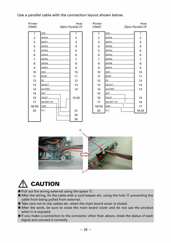
Use a parallel cable with the connection layout shown below.
CAUTION Pull out the wiring external using the space . After the wiring, fix the cable with a cord keeper etc. using the hole preventing the
cable from being pulled from external. Take care not to clip cables etc. when the main board cover is closed. After the work, be sure to close the main board cover and do not use the product
when it is exposed. If you make a connection to the connector other than above, check the status of each
signal and connect it correctly.
PrinterCN401
Host36pin Parallel I/F
1 STB 1
2 DATA0 2
3 DATA1 3
4 DATA2 4
5 DATA3 5
6 DATA4 6
7 DATA5 7
8 DATA6 8
9 DATA7 9
10 ACK 10
11 BUSY 11
12 PE 12
13 SELECT 13
14 AUTOFD 14
15 INIT
16 FAULT 19-30
17 SELSECT IN
18(19) GND
20 N.C 31
32
36
PrinterCN401
Host25pin Parallel I/F
1 STB 1
2 DATA0 2
3 DATA1 3
4 DATA2 4
5 DATA3 5
6 DATA4 6
7 DATA5 7
8 DATA6 8
9 DATA7 9
10 ACK 10
11 BUSY 11
12 PE 12
13 SELECT 13
14 AUTOFD 14
15 INIT
16 FAULT 15
17 SELSECT IN 16
18(19) GND 17
20 N.C 18-25
— 28 —
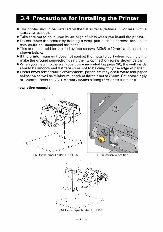
The printer should be installed on the flat surface (flatness 0.3 or less) with asufficient strength.
Take care not to be injured by an edge of plate when you install the printer. Do not move the printer by holding a weak part such as harness because it
may cause an unexpected accident. This printer should be secured by four screws (M3x6 to 10mm) at the position
shown below. If the printer main unit does not contact the metallic part when you install it,
make the ground connection using the FG connection screw shown below.When you install to the wall (position A indicated Fig page 30), the wall inside
should be smooth and flat face so as not to be caught by the edge of paper. Under lower temperature environment, paper jam may occur while rear paper
collection as well as minimum length of ticket is set at 75mm. Set accordinglyat 120mm. (Refer to 2.2.1 Memory switch setting (Presenter function))
Installation example
3.4 Precautions for Installing the Printer
PMU with Paper holder: PHU-102S FG fixing screw position
PMU with Paper holder: PHU-203T
— 29 —
CAUTIONDo not use the printer under the following conditions.
Locations subject to vibration or instability. Locations that are very dirty or dusty Locations where the printer is not level.• The printer may fall and cause an injury.
• The quality of printing may deteriorate.
Oriented other than as specified.• The printer may malfunction, be damaged, or cause an electric shock.
Precautions for model with no Presenter
Do not set cutting to full cut. Doing so may cause cutter jams.
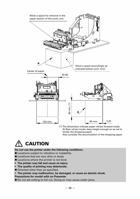
Allow a space for removal in the upper section of the cover unit.
Allow a space accordingly as indicated below (unit: mm)
Center of paper
62.90
120 min.
90 m
in. (
*)
95 min. 3.20
(*) The dimension indicate paper retract forward mode.At Rear retract mode, keep height enough so as not to hinder the dropping paper.Also consider the accumulation of the dropping paper.
A
A
— 30 —
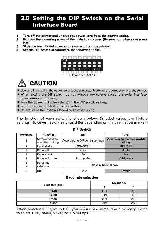
1. Turn off the printer and unplug the power cord from the electric outlet.2. Remove the mounting screw of the main board cover. (Be sure not to have the screw
lost)3. Slide the main board cover and remove it from the printer.4. Set the DIP switch according to the following table.
The function of each switch is shown below. (Shaded values are factorysettings. However, factory settings differ depending on the destination market.)
DIP Switch
Baud rate selection
When switch no. 1 is set to OFF, you can use a command or a memory switchto select 1200, 38400, 57600, or 115200 bps.
3.5 Setting the DIP Switch on the SerialInterface Board
CAUTION Use care in handling the edged part (especially cutter blade) of the components of the printer.When setting the DIP switch, do not remove any screws except the serial interface
board mounting screws. Turn the power OFF when changing the DIP switch setting. Do not use any pointed object for setting. Do not leave the interface board open when using.
Switch no. Function ON OFF
1 Communication condition setting According to DIP switch settings According to memory switch
settings
2 Hand shake XON/XOFF DTR/DSR
3 Bit length 7 bits 8 bits
4 Parity check Yes No
5 Parity selection Even parity Odd parity
6 Baud rate selection Refer to table below.
7
8 INIT Reset Invalid
Baud rate (bps)Switch no.
6 7
2400 OFF OFF
4800 ON OFF
9600 OFF ON
19200 ON ON
DIP switch (SW301)
— 31 —
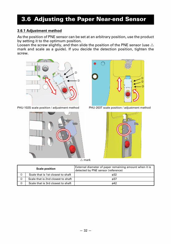
3.6.1 Adjustment method
As the position of PNE sensor can be set at an arbitrary position, use the productby setting it to the optimum position.Loosen the screw slightly, and then slide the position of the PNE sensor (use mark and scale as a guide). If you decide the detection position, tighten thescrew.
3.6 Adjusting the Paper Near-end Sensor
Scale positionExternal diameter of paper remaining amount when it is detected by PNE sensor (reference)
Scale that is 1st closest to shaft ø32
Scale that is 2nd closest to shaft ø37
Scale that is 3rd closest to shaft ø42
PHU-203T scale position / adjustment method
mark
PHU-102S scale position / adjustment method
— 32 —

3.6.2 Precautions
- The PNE sensor may malfunction due to ambient light, so when you usethe PNE sensor, consider the installation of light shielding cover etc. forpreventing the ambient light from entering.
- The value of "external diameter of roll paper when it is detected by PNEsensor" varies depending on the model and the type of roll paper, so useit as a referential value.
- Do not use the PNE sensor other than that is made by our company. Thewrong use may damage the printer and negatively affect the human bodyand peripheral equipment etc.
— 33 —
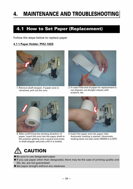
Follow the steps below to replace paper
4.1.1 Paper Holder: PHU-102S
4. MAINTENANCE AND TROUBLESHOOTING
4.1 How to Set Paper (Replacement)
CAUTION Be sure to use designated paper If you use paper other than designated, there may be the case of printing quality and
life, etc, are not guaranteed. Set paper straight without any slackness
1. Remove shaft stopper. If paper core is remained, pull out the core.
2. In case if the end of paper for replacement is not aligned, cut straight cleanly with scissors, etc.
3. After confirming the winding direction of paper, insert the core into the paper shaft to the position getting over a guard and press-in shaft stopper securely until it is locked.
4. Insert the paper end into paper inlet. Automatic loading is started. (Automatic loading does not start when MSW4-2 is OFF)
— 3
4 —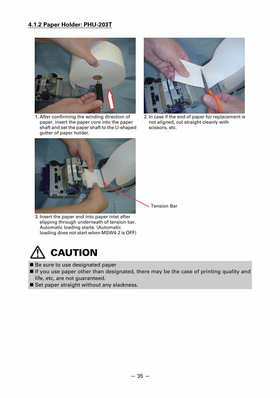
4.1.2 Paper Holder: PHU-203T
CAUTION Be sure to use designated paper If you use paper other than designated, there may be the case of printing quality and
life, etc, are not guaranteed. Set paper straight without any slackness.
1. After confirming the winding direction of paper, insert the paper core into the paper shaft and set the paper shaft to the U-shaped gutter of paper holder.
2. In case if the end of paper for replacement is not aligned, cut straight cleanly with scissors, etc.
3. Insert the paper end into paper inlet after slipping through underneath of tension bar. Automatic loading starts. (Automatic loading does not start when MSW4-2 is OFF)
Tension Bar
— 3
5 —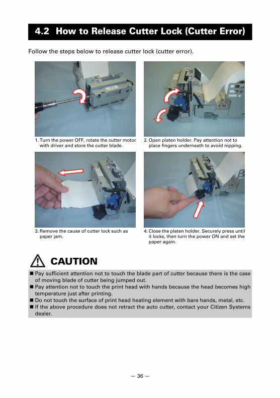
Follow the steps below to release cutter lock (cutter error).
4.2 How to Release Cutter Lock (Cutter Error)
CAUTION Pay sufficient attention not to touch the blade part of cutter because there is the case
of moving blade of cutter being jumped out. Pay attention not to touch the print head with hands because the head becomes high
temperature just after printing. Do not touch the surface of print head heating element with bare hands, metal, etc. If the above procedure does not retract the auto cutter, contact your Citizen Systems
dealer.
1. Turn the power OFF, rotate the cutter motor with driver and store the cutter blade.
2. Open platen holder. Pay attention not to place fingers underneath to avoid nipping.
3. Remove the cause of cutter lock such as paper jam.
4. Close the platen holder. Securely press until it locks, then turn the power ON and set the paper again.
— 3
6 —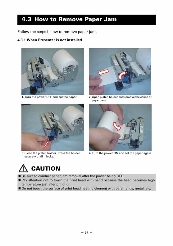
Follow the steps below to remove paper jam.
4.3.1 When Presenter is not installed
4.3 How to Remove Paper Jam
CAUTION Be sure to conduct paper jam removal after the power being OFF. Pay attention not to touch the print head with hand because the head becomes high
temperature just after printing. Do not touch the surface of print head heating element with bare hands, metal, etc.
1. Turn the power OFF and cut the paper 2. Open platen holder and remove the cause of paper jam.
3. Close the platen holder. Press the holder securely until it locks.
4. Turn the power ON and set the paper again
— 3
7 —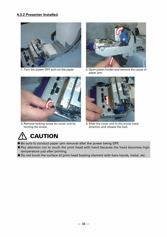
4.3.2 Presenter Installed
CAUTION Be sure to conduct paper jam removal after the power being OFF. Pay attention not to touch the print head with hand because the head becomes high
temperature just after printing. Do not touch the surface of print head heating element with bare hands, metal, etc.
1. Turn the power OFF and cut the paper 2. Open platen holder and remove the cause of paper jam.
3. Remove locking screw for cover unit by turning the screw.
4. Slide the cover unit to the arrow mark direction and release the lock.
— 3
8 —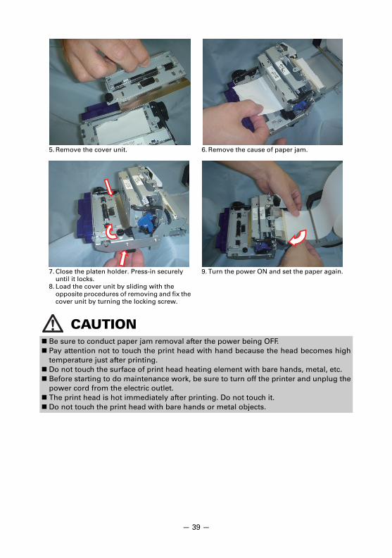
CAUTION Be sure to conduct paper jam removal after the power being OFF. Pay attention not to touch the print head with hand because the head becomes high
temperature just after printing. Do not touch the surface of print head heating element with bare hands, metal, etc. Before starting to do maintenance work, be sure to turn off the printer and unplug the
power cord from the electric outlet. The print head is hot immediately after printing. Do not touch it. Do not touch the print head with bare hands or metal objects.
5. Remove the cover unit. 6. Remove the cause of paper jam.
7. Close the platen holder. Press-in securely until it locks.
8. Load the cover unit by sliding with the opposite procedures of removing and fix the cover unit by turning the locking screw.
9. Turn the power ON and set the paper again.
— 3
9 —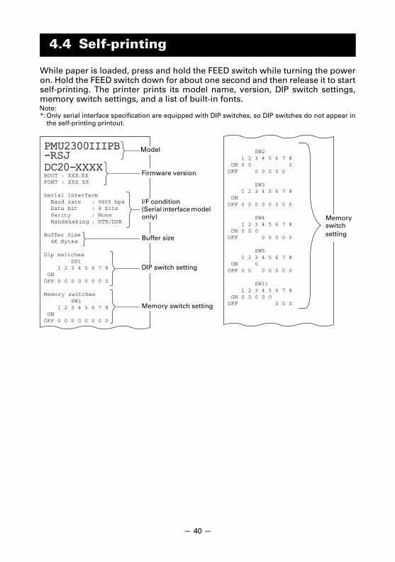
While paper is loaded, press and hold the FEED switch while turning the poweron. Hold the FEED switch down for about one second and then release it to startself-printing. The printer prints its model name, version, DIP switch settings,memory switch settings, and a list of built-in fonts. Note:*: Only serial interface specification are equipped with DIP switches, so DIP switches do not appear in
the self-printing printout.
4.4 Self-printing
PMU2300IIIPBPMU2300IIIPB-RSJ-RSJDC20-XXXXDC20-XXXXBOOT : XXX.XXFONT : XXX XX
Serial Interface Baud rate : 9600 bps Data bit : 8 bits Parity : None Handshaking : DTR/DSR
Buffer Size 4K Bytes
Dip switches DS1 1 2 3 4 5 6 7 8 ONOFF 0 0 0 0 0 0 0 0
Memory switches SW1 1 2 3 4 5 6 7 8 ONOFF 0 0 0 0 0 0 0 0
SW2 1 2 3 4 5 6 7 8 ON 0 0 0OFF 0 0 0 0 0
SW3 1 2 3 4 5 6 7 8 ON OFF 0 0 0 0 0 0 0 0
SW4 1 2 3 4 5 6 7 8 ON 0 0 0 OFF 0 0 0 0 0
SW5 1 2 3 4 5 6 7 8 ON 0 OFF 0 0 0 0 0 0 0
SW11 1 2 3 4 5 6 7 8 ON 0 0 0 0 0 OFF 0 0 0Memory switch setting
Model
Memory switch setting
Buffer size
I/F condition(Serial interface model only)
Firmware version
DIP switch setting
— 40 —
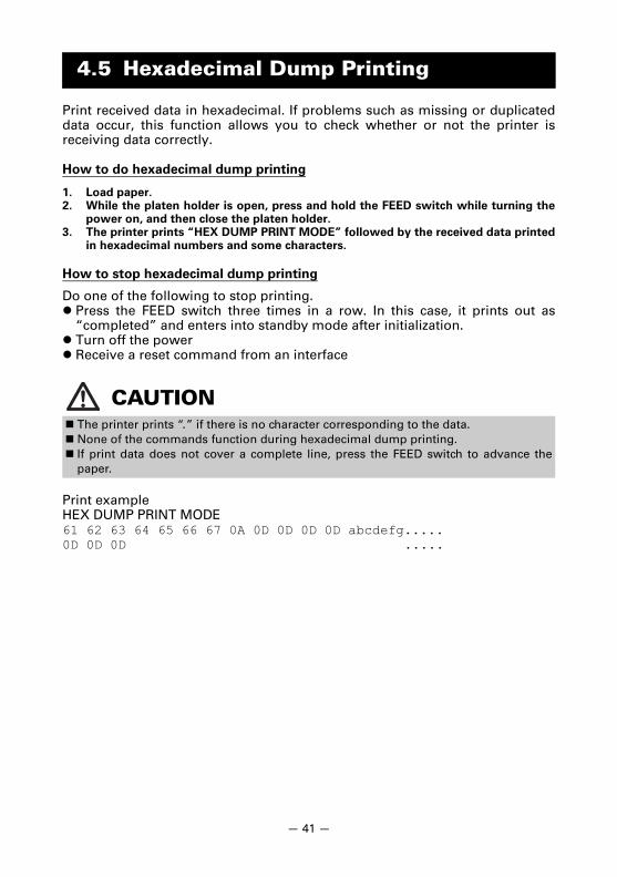
Print received data in hexadecimal. If problems such as missing or duplicateddata occur, this function allows you to check whether or not the printer isreceiving data correctly.
How to do hexadecimal dump printing
1. Load paper.2. While the platen holder is open, press and hold the FEED switch while turning the
power on, and then close the platen holder.3. The printer prints “HEX DUMP PRINT MODE” followed by the received data printed
in hexadecimal numbers and some characters.
How to stop hexadecimal dump printing
Do one of the following to stop printing. Press the FEED switch three times in a row. In this case, it prints out as
“completed” and enters into standby mode after initialization. Turn off the power Receive a reset command from an interface
Print exampleHEX DUMP PRINT MODE61 62 63 64 65 66 67 0A 0D 0D 0D 0D abcdefg.....0D 0D 0D .....
4.5 Hexadecimal Dump Printing
CAUTION The printer prints “.” if there is no character corresponding to the data. None of the commands function during hexadecimal dump printing. If print data does not cover a complete line, press the FEED switch to advance the
paper.
— 41 —
Paper-endThe end of the roll of paper is detected at two stages, paper near-end andpaper-end.
Paper near-endWhen paper near-end is detected, the POWER LED lights. Prepare a newpaper roll.
Platen openDo not open the platen cover during platen feeding or printing. If the platencover is opened, the ERROR LED lights or flashes.
Cutter lockedIf the auto cutter cannot move because of a paper jam or something else, theERROR LED flashes. Remove the cause of the trouble and press the FEEDswitch. If the auto cutter still does not operate and the paper cover does notopen, refer to “4.2 How to Release Cutter Lock (Cutter Error)”.
Presenter errorThis error occurs when the presenter cannot eject paper or it cannot collectthe ejected paper.
Print head hotWhen you print dense characters, dark images, or for an extended time in ahot environment, the print head temperature increases. If the print headexceeds a specified temperature, the printer stops printing and waits for theprint head to cool. When this happens, the ERROR LED flashes. Printingresumes automatically when the print head cools.
4.6 Error Messages
Refer to 4.2 How to Release Cutter Lock (Cutter Error)
Refer to 4.3 How to Remove Paper Jam
— 42 —
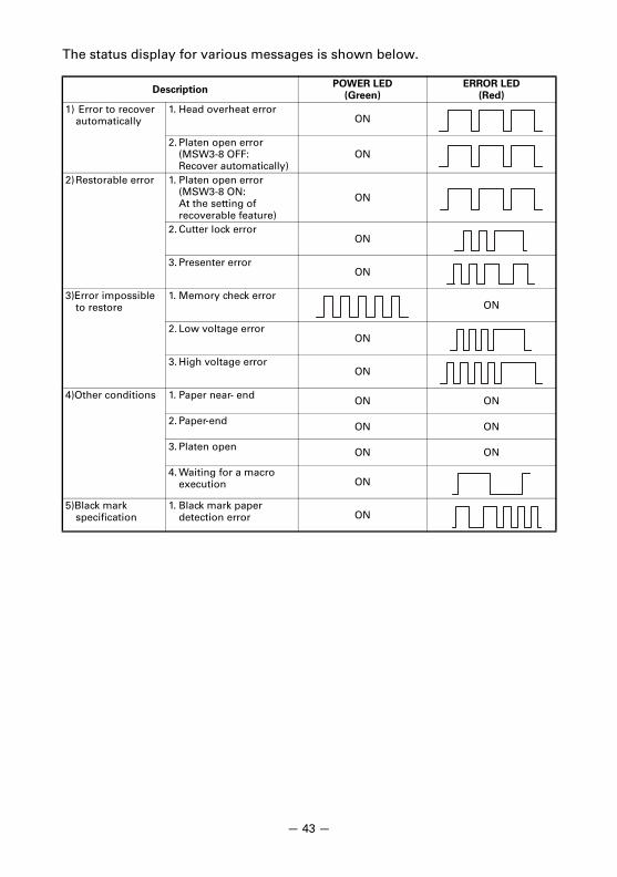
The status display for various messages is shown below.
DescriptionPOWER LED
(Green)
ERROR LED
(Red)
1) Error to recover automatically
1. Head overheat errorON
2. Platen open error(MSW3-8 OFF:Recover automatically)
ON
2)Restorable error 1. Platen open error(MSW3-8 ON: At the setting of recoverable feature)
ON
2. Cutter lock errorON
3. Presenter errorON
3)Error impossible to restore
1. Memory check errorON
2. Low voltage errorON
3. High voltage errorON
4)Other conditions 1. Paper near- end ON ON
2. Paper-end ON ON
3. Platen open ON ON
4. Waiting for a macro execution ON
5)Black mark specification
1. Black mark paper detection error ON
— 43 —
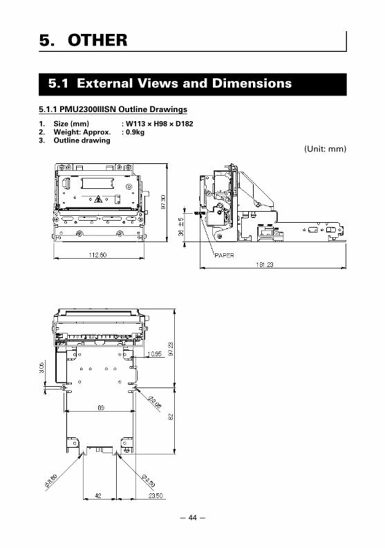
5.1.1 PMU2300IIISN Outline Drawings
1. Size (mm) : W113 × H98 × D1822. Weight: Approx. : 0.9kg3. Outline drawing
(Unit: mm)
5. OTHER
5.1 External Views and Dimensions
— 44 —
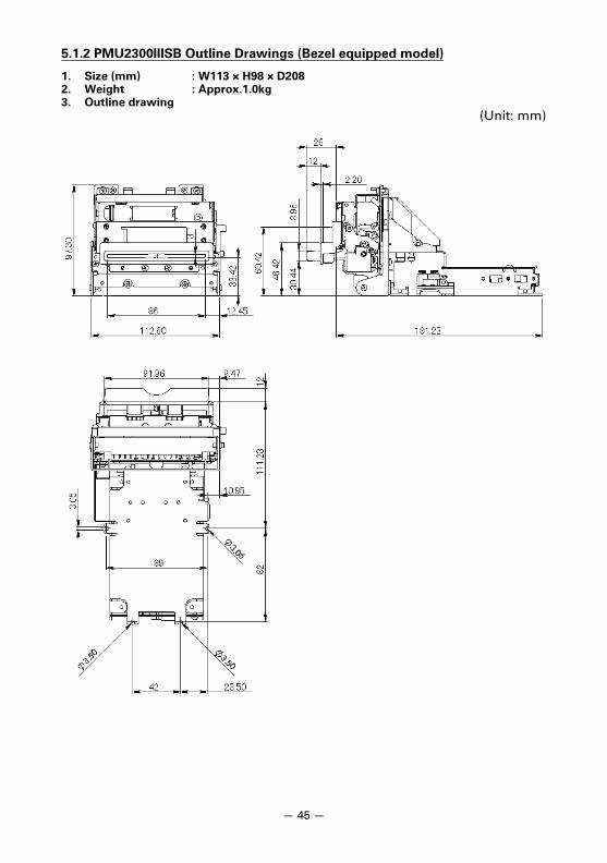
5.1.2 PMU2300IIISB Outline Drawings (Bezel equipped model)
1. Size (mm) : W113 × H98 × D2082. Weight : Approx.1.0kg3. Outline drawing
(Unit: mm)
— 45 —
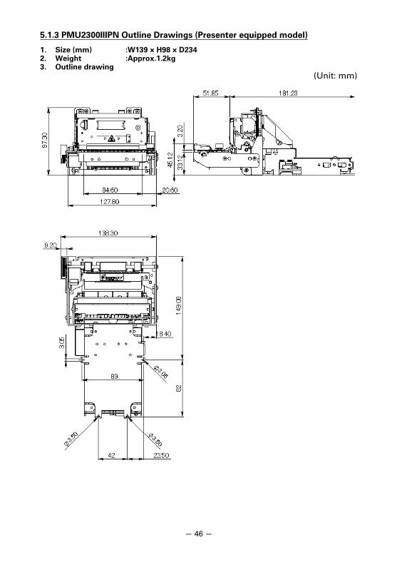
5.1.3 PMU2300IIIPN Outline Drawings (Presenter equipped model)
1. Size (mm) :W139 × H98 × D2342. Weight :Approx.1.2kg3. Outline drawing
(Unit: mm)
— 46 —
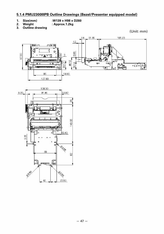
5.1.4 PMU2300IIIPB Outline Drawings (Bezel/Presenter equipped model)
1. Size(mm) :W139 × H98 × D2602. Weight : Approx.1.2kg3. Outline drawing
(Unit: mm)
— 47 —
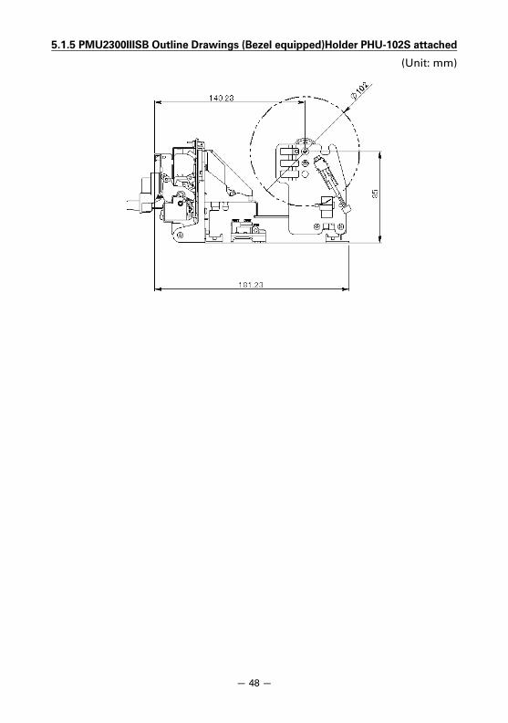
5.1.5 PMU2300IIISB Outline Drawings (Bezel equipped)Holder PHU-102S attached
(Unit: mm)
— 48 —
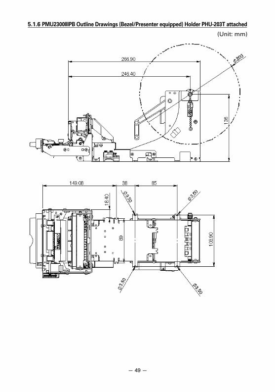
5.1.6 PMU2300IIIPB Outline Drawings (Bezel/Presenter equipped) Holder PHU-203T attached
(Unit: mm)
— 49 —
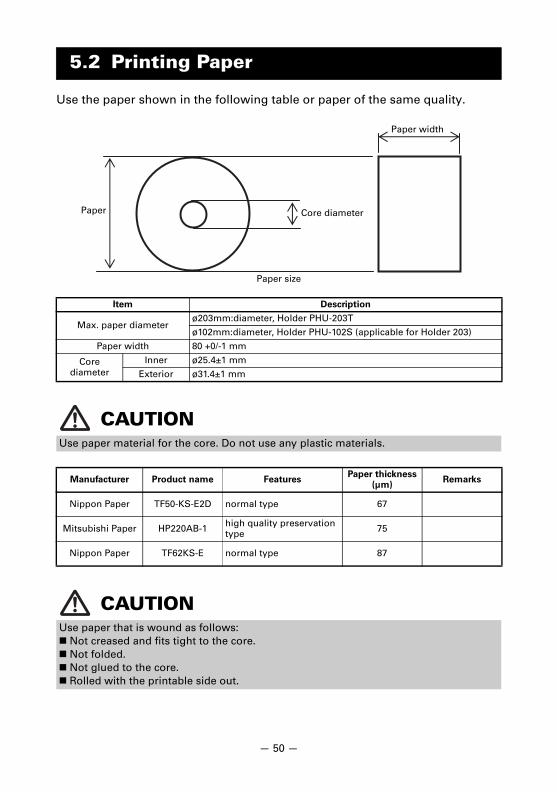
Use the paper shown in the following table or paper of the same quality.
5.2 Printing Paper
Item Description
Max. paper diameterø203mm:diameter, Holder PHU-203T
ø102mm:diameter, Holder PHU-102S (applicable for Holder 203)
Paper width 80 +0/-1 mm
Core diameter
Inner ø25.4±1 mm
Exterior ø31.4±1 mm
CAUTIONUse paper material for the core. Do not use any plastic materials.
Manufacturer Product name FeaturesPaper thickness
(µm)Remarks
Nippon Paper TF50-KS-E2D normal type 67
Mitsubishi Paper HP220AB-1 high quality preservation type 75
Nippon Paper TF62KS-E normal type 87
CAUTIONUse paper that is wound as follows: Not creased and fits tight to the core. Not folded. Not glued to the core. Rolled with the printable side out.
Paper
Paper width
Core diameter
Paper size
— 50 —

Memory switches are used to set various printer settings. The memory switchescan be set manually (set by hand on the printer) or by commands. This sectionexplains how to perform manual settings.For information on how to set the memory switches using commands, pleaserefer to the Command Reference.
Entering the memory switch setting mode
Set the memory switches individually.Do the settings while confirming the memory switch function and settings onthe printout.
1. Load paper.2. While the platen holder is open, press and hold the FEED switch while turning the
power on.3. Press the FEED switch twice and close the platen holder.
The printer enters the mode for setting memory switches individually.The printer prints “Memory SW (1)” and the current setting, 0 (off) or 1 (on).
4. Press the FEED switch.The list of memory switches cycles through in order from “Memory SW (1)” “Memory SW (2)” ... “Memory SW (12)” “Save To Memory” “Memory SW(1)” each time the FEED switch is pressed.Press the FEED switch until the number for the memory switch you want to change isprinted.
Moreover, by detecting the paper by applying the paper to the recovery sensor andpressing the FEED switch short in a same way, the memory switches to be set shift inthe reverse order of order shown below. At that time, the status of the selectedmemory switch is printed. When “Save To Memory” is selected, the confirmation offlash memory writing is printed.
5.3 Setting of Memory Switches
Current memory switchCurrent setting
— 51 —

5. Press the FEED switch for at least two seconds.A setting for the memory switch is printed, through the cycle, each time the FEEDswitch is pressed for at least two seconds.Press the FEED switch for at least two seconds to cycle through the list until thefunction of the memory switch you want to change is printed.
6. Press the FEED switch.A setting is printed each time the FEED switch is pressed in order through the cycle.When the current settings are printed, the ERROR LED lights.Press the FEED switch until the setting you want is printed.
7. Press the FEED switch for at least two seconds.The selected settings are set.The next memory switch function and settings are printed.
8. Repeat steps 5 to 7 to change different functions for the current memory switchnumber.
9. Open the platen holder and close it.The changed memory switch settings are printed.
10. Repeat steps 4 to 9 to change functions for a different memory switch number.11. Press the FEED switch until “Save To Memory” is printed.12. Press the FEED switch for at least two seconds.
The changed memory switch settings are saved and a list of them is printed.The printer exits memory switch setting mode when printing is finished.
Memory switch initialization
Set all the memory switches to the factory settings.
1. Do steps 1 through 3 of the procedure to enter individual setting mode.2. Press the FEED switch until “Save To Memory” is printed.3. Open the platen holder.4. Press the FEED switch for at least two seconds.
All memory switches change to the factory settings.5. Close the platen holder.
Memory switch functionCurrent setting
— 52 —

The function of each memory switch is shown in the following table. (Shadedvalues are factory settings.)
No. Function OFF ON
MSW1-1 Power ON Info Valid Not Send
MSW1-2 Buffer Size 4K bytes 45 bytes
MSW1-3 Busy Condition Full/Err Full
MSW1-4 Receive Error Print “?” No Print
MSW1-5 CR Mode Ignored LF
MSW1-6 Reserved Fixed —
MSW1-7 DSR Signal Invalid Valid
MSW1-8 Reserved Fixed —
MSW2-1 Reserved — Fixed
MSW2-2 Auto Cutter *1 Invalid Valid
MSW2-3 Spool Print Invalid Valid
MSW2-4 Full Col Print Line Feed Wait Data
MSW2-5 Resume aft PE Next Top
MSW2-6 Reserved Fixed —
MSW2-7 Reserved Fixed —
MSW2-8 PNE Sensor Valid Invalid
MSW3-1 Resume Cttr Err Valid Invalid
MSW3-2 Reserved Fixed —
MSW3-3 Parallel 31 Pin Valid Invalid
MSW3-4 Paper Select *2 Thermal Black MK
MSW3-5 Column Number 48 col 42 col
MSW3-6 Reserved Fixed —
MSW3-7 CBM1000 Mode Invalid Valid
MSW3-8 Resume Open Err Close Command
MSW4-1 Auto Length Invalid Valid
MSW4-2 Auto Loading Invalid Valid
MSW4-3 Feed & Cut at TOF Invalid Valid
MSW4-4 Reserved — —
MSW4-5 Reserved Fixed —
MSW4-6 Reserved Fixed —
MSW4-7 Reserved Fixed —
MSW4-8 Partial Only *3 Invalid Valid
MSW5-1 Reserved Fixed —
MSW5-2 Reserved Fixed —
MSW5-3 USB Mode Virtual COM Printer Class
MSW5-4 Reserved Fixed —
MSW5-5 Reserved Fixed —
MSW5-6 Speed / Quality Speed Quality
MSW5-7 Reserved Fixed —
MSW5-8 Reserved Fixed —
— 53 —
…Default(factory setting)
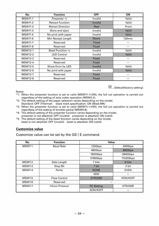
Notes:*1: When the presenter function is set to valid (MSW11-1=ON), the full cut operation is carried out
regardless of the setting of auto cutter operation (MSW2-2).*2: The default setting of the paper selection varies depending on the model.
Standard: OFF (Thermal) black mark specification: ON (Black MK)*3: When the presenter function is set to valid (MSW11-1=ON), the full cut operation is carried out
regardless of the setting of forcible partial (MSW4-8).*4: The default setting of the presenter function varies depending on the model.
presenter is not attached: OFF (invalid) presenter is attached: ON (valid)*5: The default setting of the bezel function varies depending on the model.
bezel is not attached: OFF (invalid) bezel is attached: ON (valid)
Customize value
Customize value can be set by the GS ( E command.
MSW11-1 Presenter *4 Invalid Valid
MSW11-2 Retract Function Invalid Valid
MSW11-3 Retract Direction Rear Front
MSW11-4 Store and eject Invalid Valid
MSW11-5 No print with paper Invalid Valid
MSW11-6 Min Receipt Length 75mm 120mm
MSW11-7 Reserved Fixed —
MSW11-8 Reserved Fixed —
MSW12-1 Bezel Function *5 Invalid Valid
MSW12-2 LED Control Invalid Valid
MSW12-3 Reserved Fixed —
MSW12-4 Reserved Fixed —
MSW12-5 Show Error by LED Invalid Valid
MSW12-6 No print with paper Invalid Valid
MSW12-7 Reserved Fixed —
MSW12-8 Reserved Fixed —
No. Function Value
MSW7-1 Baud Rate 1200bps 2400bps
4800bps 9600bps
19200bps 38400bps
57600bps 115200bps
MSW7-2 Data Length 7 bits 8 bits
MSW7-3 Stop Bit 1 bit 2 bit
MSW7-4 Parity NONE EVEN
ODD —
MSW7-5 Flow Control DTR/DSR XON/XOFF
MSW7-6 Reserved —
MSW7-7 VCom Protocol PC Setting DTR/DSR
XON/XOFF —
No. Function OFF ON
— 54 —
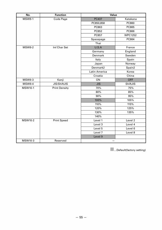
…Default(factory setting)
MSW9-1 Code Page PC437 Katakana
PC850,858 PC860
PC863 PC865
PC852 PC866
PC857 WPC1252
Spacepage PC864
Thai
MSW9-2 Int'Char Set U.S.A France
Germany England
Denmark Sweden
Italy Spain
Japan Norway
Denmark2 Spain2
Latin America Korea
Croatia China
MSW9-3 Kanji ON OFF
MSW9-4 JIS/ShiftJIS JIS ShiftJIS
MSW10-1 Print Density 70% 75%
80% 85%
90% 95%
100% 105%
110% 115%
120% 125%
130% 135%
140%
MSW10-2 Print Speed Level 1 Level 2
Level 3 Level 4
Level 5 Level 6
Level 7 Level 8
Level 9
MSW10-3 Reserved —
No. Function Value
— 55 —

ZF74903-00F0413-30468_2_E_G