laboratory assessment of a self-healing cementitious composite
TRANSCRIPT
Autonomic repairing at room temperature yields as much as 45%recovery of virgin interlaminar fracture toughness, and repairing at80°C increases the recovery to more than 80% (7 ). This concept hasalso been demonstrated for reinforced plastics (8, 9) by dispersingthe microencapsulated repairing agent and catalyst within the polymermatrix phase or by a bleeding action from filled hollow fibers (10).As a response to applied heat or vacuum (active mode) or to mechan-ical loading (passive mode), the repairing chemicals (monomers) arereleased and repair the cracks or fill the voids, often through poly-merization (11). Another interesting controlled-release techniqueinvolves a response to environmental loading, as in an anticorrosionsystem in which porous fibers were filled with a corrosion inhibitorand coated with a salt-sensitive substance (12).
Much of the self-healing concrete research has been limited tohealing at the macroscopic level. This paper presents work in thelaboratory assessment of a new family of self-healing materials thatare cost-effective and also confer to concrete and other cementitiousmaterials the ability to heal microcracks. The healing is designed tooccur in a just-in-time manner through a passive mode (i.e., as aresponse to crack propagation caused by cement hydration or exter-nal mechanical stimuli). This innovative system features the useof passive smart microcapsules (PSMs) with oil core and silica gelshell, prepared through an interfacial self-assembly process andsol–gel reaction. The proof-of-concept system used herein con-sisted of methylmethacrylate (MMA) as the healing monomer andan initiator (catalyst) containing triethylborane (TEB), and theywere microencapsulated. The microcapsules were dispersed in freshcement mortar along with carbon microfibers to explore potentialsynergy between fibers and microcapsules in arresting concretecracks. Carbon microfibers were chosen for two reasons: they areexpected to mitigate cracking at the microscale, and they can effec-tively reduce the electric resistivity of the cementitious compositeand thus facilitate its electrochemical characterization by readilyavailable instruments.
For the hardened mortar, self-healing can be triggered by crackpropagation through the microcapsules, which then releases thehealing agent and the catalyst from their respective stress-rupturedreservoir upon crack intrusion. The monomer and its initiator haveviscosity similar to that of water, so they can easily migrate into themicrocracks through capillary action. Polymerization of the heal-ing agent is then initiated by contact with the catalyst, bonding thecrack faces.
In this study, a field emission scanning electron microscope(FESEM) was used to examine the morphology of the microcapsules.Mechanical tests as well as electrochemical impedance spectroscopy(EIS) measurements were carried out to evaluate the self-healing effectof PSMs and the possible physicochemical changes or interactionsin the carbon microfiber–reinforced mortar matrix.
Laboratory Assessment of a Self-HealingCementitious Composite
Zhengxian Yang, John Hollar, Xiaodong He, and Xianming Shi
9
This paper presents work in the laboratory assessment of a new familyof self-healing materials that hold promise for “crack-free” concrete orother cementitious composites. This innovative system features thedesign of passive smart microcapsules (PSMs) with oil core and silica gelshell, prepared through an interfacial self-assembly process and sol–gelreaction. Methylmethacrylate monomer and triethylborane were chosenas the healing agent and the catalyst for use in the system and weremicroencapsulated. The microcapsules were subsequently dispersed infresh cement mortar along with carbon microfibers. The morphology ofthe microcapsules was examined by using a field emission scanning elec-tron microscope. Mechanical tests and electrochemical impedance spec-troscopy measurements were carried out to evaluate the self-healingeffect of PSMs and the possible physicochemical changes or interactionsin the carbon microfiber–reinforced mortar matrix.
Concrete has been used in architecture for millennia and is themost widely applied building material in the world (1). Crackingcompromises the integrity and durability of concrete. Microcracksoften develop in cementitious composite during the hydration ofcementitious materials or as a result of mechanical loadings (staticor cyclic), environmental loadings (e.g., freezing and thawing, rebarcorrosion, alkali aggregate reactions, sulfate attack), and volumetricinstability (e.g., shrinkage in fresh or hardened concrete, thermalcontraction). Once microcracks have formed within concrete,they are extremely difficult to detect and repair by conventionalmethods. Over time, they will lead to significant cracking andspalling of concrete and subsequent reduction in the strength, ser-viceability, and aesthetics of the structures (2). Although betterstructural design, material selection and proportioning, and con-struction practices can help control concrete cracking, continuedresearch in the domain of materials science (e.g., application ofvarious fibers) is crucial to improve the service life of concretestructures and to design for sustainable infrastructure with minimalmaintenance needs.
Recently, the biomimetic concept of self-healing has been demon-strated for cementitious materials through incorporation of heal-ing agents in hollow porous fibers or in hollow glass tubes with abrittle breakable sealer (3–6). Self-healing was demonstrated onwidth-tapered double cantilever beam fracture specimens in whicha midplane delamination was introduced and then allowed to heal.
Western Transportation Institute, Montana State University, P.O. Box 174250,Bozeman, MT 59717. Corresponding author: X. Shi, [email protected].
Transportation Research Record: Journal of the Transportation Research Board,No. 2142, Transportation Research Board of the National Academies, Washington,D.C., 2010, pp. 9–17.DOI: 10.3141/2142-02
EXPERIMENTAL
Material Properties
Commercially available monomers styrene and MMA, poly (vinyl-polypyrrolidone), tetraethyl orthosilicate (TEOS), and concentratedsulfuric acid (98%) were obtained from Fisher Scientific Inc. A TEBsolution (1.0 M in hexanes) was obtained from Sigma-Aldrich, Inc.All the solvents were of analytical grade and were used as received.Deionized water was used for all experiments. The carbon microfiberswere KRECA chop C-103T, 3 mm in length with a filament diameterof 18 µm, as obtained from Kureha Company (Tokyo). In light of pub-lished work by other researchers, ASTM C1240 silica fume obtainedfrom BASF/MB admixtures, Inc. (Henderson, Nev.), was used as adispersant for the fibers in the mixes. ASTM C150-07 Type I/II low-alkali portland cement (ASH Grove Cement Company, Clancy,Mont.) was used in this study. The chemical composition and physi-cal properties of the cement were presented by Yang et al. (13). Thefine aggregate used was river sand sifted to allow a maximum aggre-gate size of 1.18 mm. Before the proportioning and admixing steps,the aggregate was pretreated and taken to a saturated surface drycondition.
Preparation of the PSMs
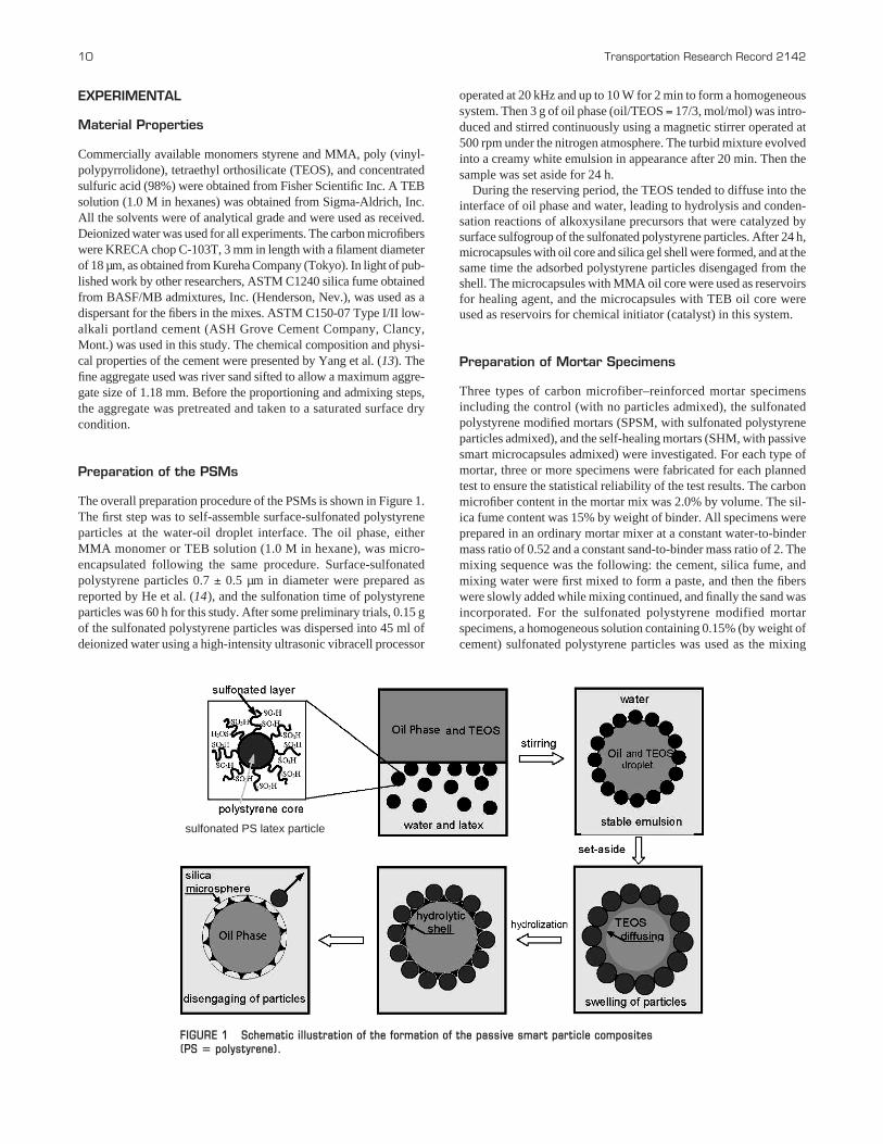
The overall preparation procedure of the PSMs is shown in Figure 1.The first step was to self-assemble surface-sulfonated polystyreneparticles at the water-oil droplet interface. The oil phase, eitherMMA monomer or TEB solution (1.0 M in hexane), was micro-encapsulated following the same procedure. Surface-sulfonatedpolystyrene particles 0.7 ± 0.5 µm in diameter were prepared asreported by He et al. (14), and the sulfonation time of polystyreneparticles was 60 h for this study. After some preliminary trials, 0.15 gof the sulfonated polystyrene particles was dispersed into 45 ml ofdeionized water using a high-intensity ultrasonic vibracell processor
10 Transportation Research Record 2142
operated at 20 kHz and up to 10 W for 2 min to form a homogeneoussystem. Then 3 g of oil phase (oil/TEOS = 17/3, mol/mol) was intro-duced and stirred continuously using a magnetic stirrer operated at500 rpm under the nitrogen atmosphere. The turbid mixture evolvedinto a creamy white emulsion in appearance after 20 min. Then thesample was set aside for 24 h.
During the reserving period, the TEOS tended to diffuse into theinterface of oil phase and water, leading to hydrolysis and conden-sation reactions of alkoxysilane precursors that were catalyzed bysurface sulfogroup of the sulfonated polystyrene particles. After 24 h,microcapsules with oil core and silica gel shell were formed, and at thesame time the adsorbed polystyrene particles disengaged from theshell. The microcapsules with MMA oil core were used as reservoirsfor healing agent, and the microcapsules with TEB oil core wereused as reservoirs for chemical initiator (catalyst) in this system.
Preparation of Mortar Specimens
Three types of carbon microfiber–reinforced mortar specimensincluding the control (with no particles admixed), the sulfonatedpolystyrene modified mortars (SPSM, with sulfonated polystyreneparticles admixed), and the self-healing mortars (SHM, with passivesmart microcapsules admixed) were investigated. For each type ofmortar, three or more specimens were fabricated for each plannedtest to ensure the statistical reliability of the test results. The carbonmicrofiber content in the mortar mix was 2.0% by volume. The sil-ica fume content was 15% by weight of binder. All specimens wereprepared in an ordinary mortar mixer at a constant water-to-bindermass ratio of 0.52 and a constant sand-to-binder mass ratio of 2. Themixing sequence was the following: the cement, silica fume, andmixing water were first mixed to form a paste, and then the fiberswere slowly added while mixing continued, and finally the sand wasincorporated. For the sulfonated polystyrene modified mortar specimens, a homogeneous solution containing 0.15% (by weight ofcement) sulfonated polystyrene particles was used as the mixing
sulfonated PS latex particle
FIGURE 1 Schematic illustration of the formation of the passive smart particle composites (PS � polystyrene).
water. For the self-healing mortar specimens, a freshly preparedsolution containing 1.5% (by weight of cement) microcapsules withMMA oil core was mixed into the cement and then stirred thor-oughly for 5 min. Afterward, a freshly prepared solution containing0.03% (by weight of cement) microcapsules with TEB oil core wasadded into the mixture and stirred thoroughly for another 5 min. Thetotal content of sulfonated polystyrene particles dispersed in the twosolutions for preparing PSMs was 0.15% by weight of cement.Because the amount of sulfonated polystyrene particles admixed inSPSM and SHM mortar specimens was kept consistent, the SPSMspecimens were used as control relative to the SHM specimens.After mixing, the fresh mixture was cast into molds to form cylin-ders of 50 mm × 100 mm and was carefully compacted to minimizethe amount of entrapped air. The mortar specimens were demoldedafter 24 h and then cured in a wet chamber (relative humidity morethan 95%, temperature 20°C ± 2°C) for 27 additional days.
Characterization and Testing of Materials
FESEM Imaging of the PSMs and Sulfonated Polystyrene Particles
To allow visualization of the microcapsules, a Zeiss Supra 55VPPGT/HKL FESEM system was used to examine the morphologyof the PSMs and surface-sulfonated polystyrene particles at thecompletion of the PSMs fabrication.
Compressive Strength Testing of Mortar Specimens
The compressive strength test was carried out by breaking cylindri-cal mortar specimens in a hydraulic material testing system (MTSModel 880) using a loading rate of 64 lbf/s, and the load and dis-placement data were automatically recorded. The ultimate compres-sive strength was then calculated by dividing the load at failure bythe cross-sectional area resisting the load and reported in units ofpounds force per square inch (psi). In this study, the specimenscured for 1 day and 28 days after casting were surface ground to
Yang, Hollar, He, and Shi 11
ensure their square dimensions and then polished with fine siliconcarbide paper before being subjected to the compressive strengthtest to ensure a uniform surface finish (and thus a uniformly distrib-uted load). The test results are the average of at least three specimensmade from the same batch mixture and tested at the same age.
Electrochemical Impedance Measurements of Mortar Specimens
A Gamry Reference 600 Potentiostat/Galvanostat/ZRA instrumentwas used to measure electrochemical impedance spectra of mortarspecimens to characterize their microstructural properties. Forevaluation of the self-healing effect of the PSMs in mortar, electro-chemical impedance measurements were performed at 28 days, justafter being loaded under 80% of compressive strength, 24 h after beingloaded under 80% of compressive strength, and 7 days after beingloaded under 80% of compressive strength using the same specimensprepared from the same batch of mixture. The EIS measurementswere carried out in a local room-air environment (relative humidityaround 15% to 20%, temperature 20°C ± 2°C). The experimentalsetup is shown in Figure 2.
Before the EIS measurements were performed, the ends of thespecimen were carefully polished and coated with a layer of silverpaint, and then a carbon conductive sheet was adhered to eliminatepossible errors resulting from poor contact between the specimenand electrodes. The EIS measurements were taken by polarizing theworking electrode at ±10 mV around its open circuit potential, usingsinusoidal perturbations with a frequency between 1 MHz and 0.01 Hz(10 points per decade). The Gamry Echem Analyst software was usedto plot and fit the data.
RESULTS AND DISCUSSION
Morphology of the PSMs and Particles
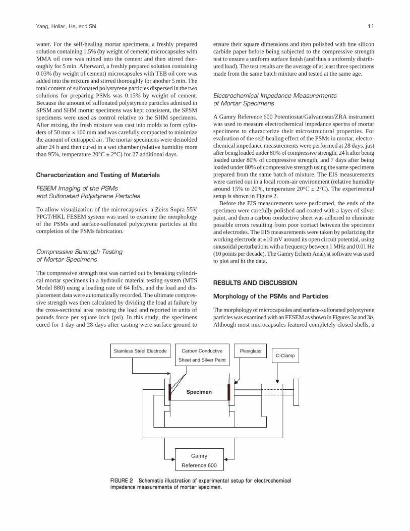
The morphology of microcapsules and surface-sulfonated polystyreneparticles was examined with an FESEM as shown in Figures 3a and 3b.Although most microcapsules featured completely closed shells, a
Specimen
Gamry
Reference 600
Carbon Conductive
Sheet and Silver Paint
Stainless Steel Electrode PlexiglassC-Clamp
FIGURE 2 Schematic illustration of experimental setup for electrochemicalimpedance measurements of mortar specimen.
small amount of microcapsules with open pores on the shell wasalso observed. The closed and open state of the pores was adjustedusing polystyrene particles subjected to different durations of sul-fonation. The increase in sulfonation time increased the polarity ofthe microspheres surface, which in turn decreased the contact areaof the latex particles at the surface of the oil droplet. When the latexparticles disengaged from the silica gel shell, they left behind moreclosed microcapsules. In this study, the microcapsules with closedshells were successfully obtained using polystyrene particles sul-fonated for 60 h. The authors used Adobe Photoshop CS4 softwareto measure at least 100 droplets in the FESEM photos; the diameterof PSMs featured an average value of 4.15 µm.
Compressive Strength of Cement Mortars
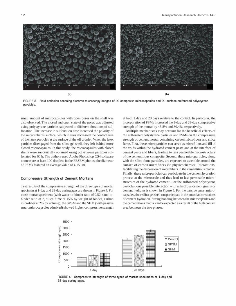
Test results of the compressive strength of the three types of mortarspecimen at 1-day and 28-day curing ages are shown in Figure 4. Forthese mortar specimens (with water-to-binder ratio of 0.52, sand-to-binder ratio of 2, silica fume at 15% by weight of binder, carbonmicrofiber at 2% by volume), the SPSM and the SHM (with passivesmart microcapsules admixed) showed higher compressive strength
12 Transportation Research Record 2142
at both 1 day and 28 days relative to the control. In particular, theincorporation of PSMs increased the 1-day and 28-day compressivestrength of the mortar by 45.8% and 30.4%, respectively.
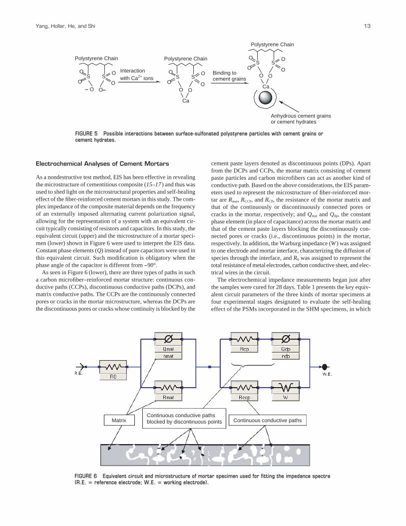
Multiple mechanisms may account for the beneficial effects ofthe sulfonated polystyrene particles and PSMs on the compressivestrength of cement mortar containing carbon microfibers and silicafume. First, these microparticles can serve as microfillers and fill inthe voids within the hydrated cement paste and at the interface ofcement paste and fibers, leading to less permeable microstructureof the cementitious composite. Second, these microparticles, alongwith the silica fume particles, are expected to assemble around thesurface of carbon microfibers via physicochemical interactions,facilitating the dispersion of microfibers in the cementitious matrix.Finally, these microparticles can participate in the cement hydrationprocess at the microscale and thus lead to less permeable micro-structure of the hydrated cement. For the sulfonated polystyreneparticles, one possible interaction with anhydrous cement grains orcement hydrates is shown in Figure 5. For the passive smart micro-capsules, their silica gel shell can participate in the pozzolanic reactionsof cement hydration. Strong bonding between the microcapsules andthe cementitious matrix can be expected as a result of the high contactarea between the two phases.
(a) (b)
FIGURE 3 Field emission scanning electron microscopy images of (a) composite microcapsules and (b) surface-sulfonated polystyreneparticles.
0
500
1000
1500
2000
2500
3000
3500
1 day 28 days
Com
pres
sive
str
engt
h (p
si)
Control
SPSM
SHM
FIGURE 4 Compressive strength of three types of mortar specimens at 1-day and 28-day curing ages.
Electrochemical Analyses of Cement Mortars
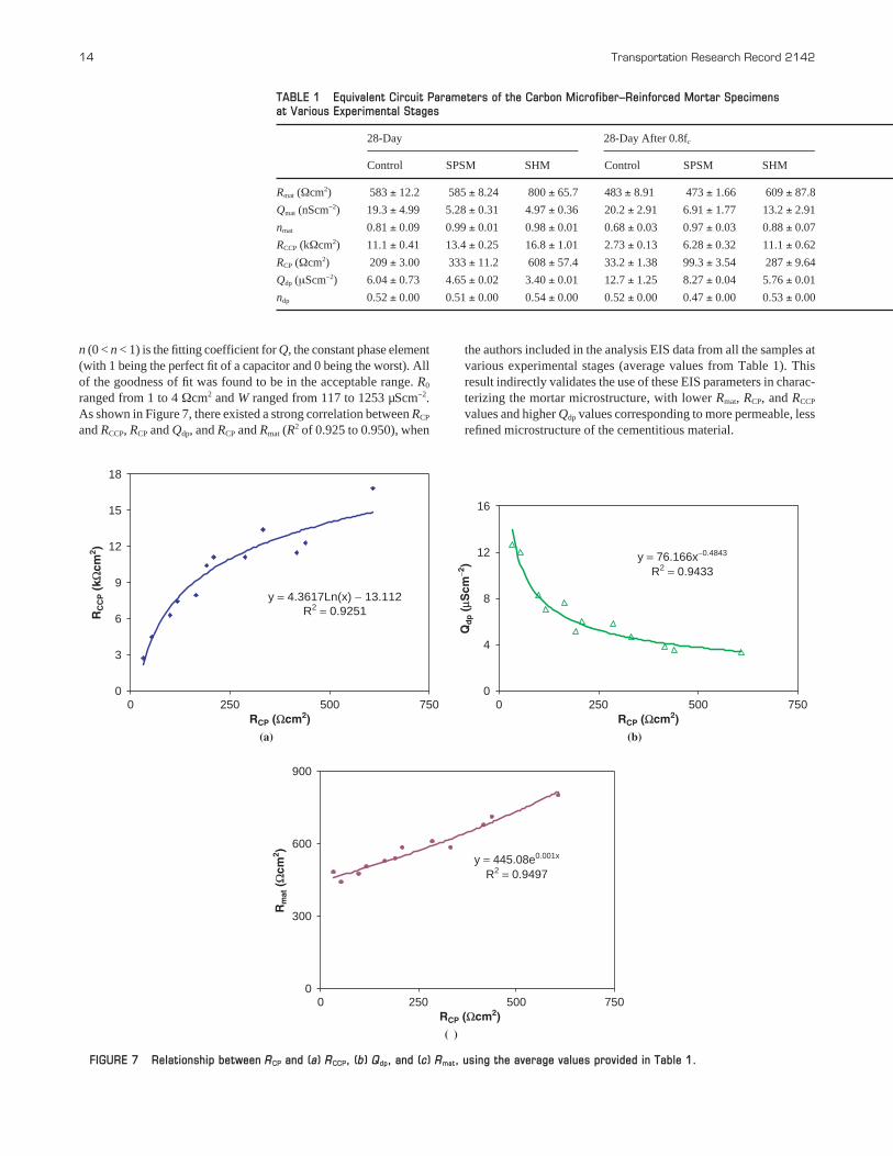
As a nondestructive test method, EIS has been effective in revealingthe microstructure of cementitious composite (15–17 ) and thus wasused to shed light on the microstructural properties and self-healingeffect of the fiber-reinforced cement mortars in this study. The com-plex impedance of the composite material depends on the frequencyof an externally imposed alternating current polarization signal,allowing for the representation of a system with an equivalent cir-cuit typically consisting of resistors and capacitors. In this study, theequivalent circuit (upper) and the microstructure of a mortar speci-men (lower) shown in Figure 6 were used to interpret the EIS data.Constant phase elements (Q) instead of pure capacitors were used inthis equivalent circuit. Such modification is obligatory when thephase angle of the capacitor is different from −90°.
As seen in Figure 6 (lower), there are three types of paths in sucha carbon microfiber–reinforced mortar structure: continuous con-ductive paths (CCPs), discontinuous conductive paths (DCPs), andmatrix conductive paths. The CCPs are the continuously connectedpores or cracks in the mortar microstructure, whereas the DCPs arethe discontinuous pores or cracks whose continuity is blocked by the
Yang, Hollar, He, and Shi 13
cement paste layers denoted as discontinuous points (DPs). Apartfrom the DCPs and CCPs, the mortar matrix consisting of cementpaste particles and carbon microfibers can act as another kind ofconductive path. Based on the above considerations, the EIS param-eters used to represent the microstructure of fiber-reinforced mor-tar are Rmat, RCCP, and RCP, the resistance of the mortar matrix andthat of the continuously or discontinuously connected pores orcracks in the mortar, respectively; and Qmat and Qdp, the constantphase element (in place of capacitance) across the mortar matrix andthat of the cement paste layers blocking the discontinuously con-nected pores or cracks (i.e., discontinuous points) in the mortar,respectively. In addition, the Warburg impedance (W) was assignedto one electrode and mortar interface, characterizing the diffusion ofspecies through the interface, and R0 was assigned to represent thetotal resistance of metal electrodes, carbon conductive sheet, and elec-trical wires in the circuit.
The electrochemical impedance measurements began just afterthe samples were cured for 28 days. Table 1 presents the key equiv-alent circuit parameters of the three kinds of mortar specimens atfour experimental stages designated to evaluate the self-healingeffect of the PSMs incorporated in the SHM specimens, in which
SO
S
O O
Ca
Anhydrous cement grainsor cement hydrates
Interactionwith Ca2+ ions
Binding tocement grains
Polystyrene Chain
O
O
OS
OS
O O
Polystyrene Chain
O
O
O Ca
SO
S
O O
Polystyrene Chain
O
O
O
FIGURE 5 Possible interactions between surface-sulfonated polystyrene particles with cement grains orcement hydrates.
Continuous conductive pathsblocked by discontinuous points Continuous conductive pathsMatrix
FIGURE 6 Equivalent circuit and microstructure of mortar specimen used for fitting the impedance spectra(R.E. � reference electrode; W.E. � working electrode).
n (0 < n < 1) is the fitting coefficient for Q, the constant phase element(with 1 being the perfect fit of a capacitor and 0 being the worst). Allof the goodness of fit was found to be in the acceptable range. R0
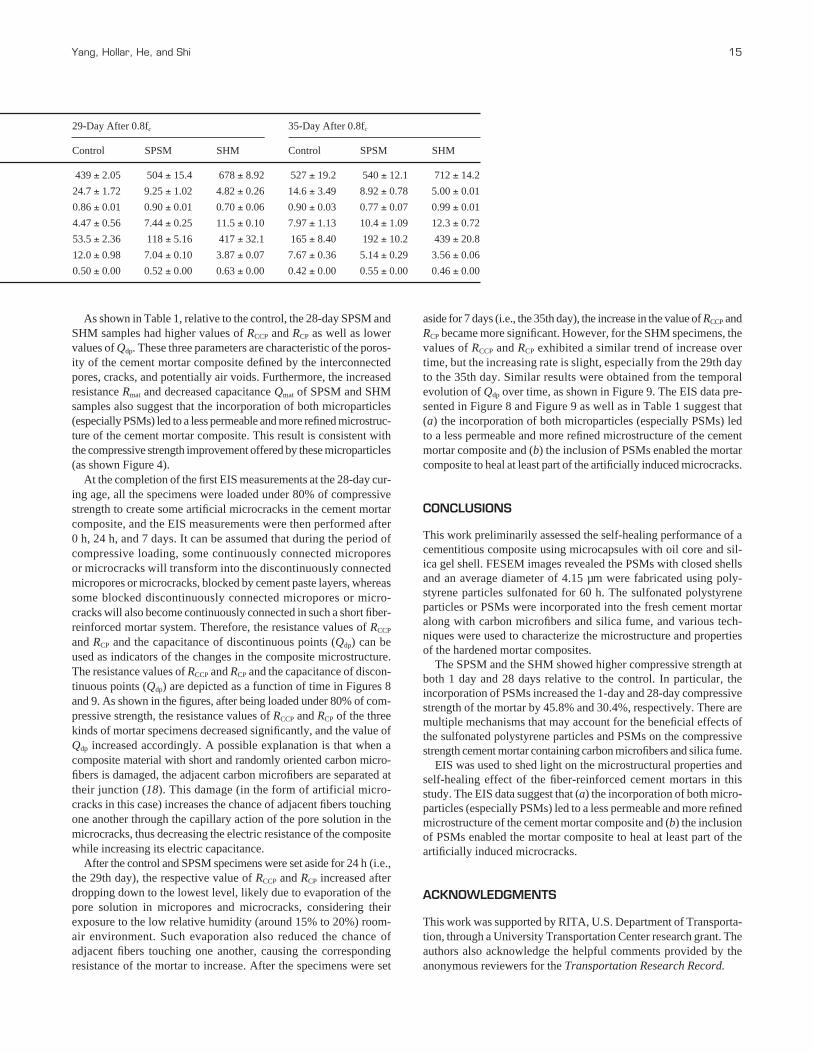
ranged from 1 to 4 Ωcm2 and W ranged from 117 to 1253 µScm−2.As shown in Figure 7, there existed a strong correlation between RCP
and RCCP, RCP and Qdp, and RCP and Rmat (R2 of 0.925 to 0.950), when
14 Transportation Research Record 2142
the authors included in the analysis EIS data from all the samples atvarious experimental stages (average values from Table 1). Thisresult indirectly validates the use of these EIS parameters in charac-terizing the mortar microstructure, with lower Rmat, RCP, and RCCP
values and higher Qdp values corresponding to more permeable, lessrefined microstructure of the cementitious material.
TABLE 1 Equivalent Circuit Parameters of the Carbon Microfiber–Reinforced Mortar Specimens at Various Experimental Stages
28-Day 28-Day After 0.8fc
Control SPSM SHM Control SPSM SHM
Rmat (Ωcm2) 583 ± 12.2 585 ± 8.24 800 ± 65.7 483 ± 8.91 473 ± 1.66 609 ± 87.8
Qmat (nScm−2) 19.3 ± 4.99 5.28 ± 0.31 4.97 ± 0.36 20.2 ± 2.91 6.91 ± 1.77 13.2 ± 2.91
nmat 0.81 ± 0.09 0.99 ± 0.01 0.98 ± 0.01 0.68 ± 0.03 0.97 ± 0.03 0.88 ± 0.07
RCCP (kΩcm2) 11.1 ± 0.41 13.4 ± 0.25 16.8 ± 1.01 2.73 ± 0.13 6.28 ± 0.32 11.1 ± 0.62
RCP (Ωcm2) 209 ± 3.00 333 ± 11.2 608 ± 57.4 33.2 ± 1.38 99.3 ± 3.54 287 ± 9.64
Qdp (μScm−2) 6.04 ± 0.73 4.65 ± 0.02 3.40 ± 0.01 12.7 ± 1.25 8.27 ± 0.04 5.76 ± 0.01
ndp 0.52 ± 0.00 0.51 ± 0.00 0.54 ± 0.00 0.52 ± 0.00 0.47 ± 0.00 0.53 ± 0.00
y = 4.3617Ln(x) − 13.112R2 = 0.9251
0
3
6
9
12
15
18
0 250 500 750RCP (Ωcm2)
RC
CP (
kΩcm
2 )
(a)
0
4
8
12
16
0 250 500 750RCP (Ωcm2)
(b)
Qd
p (
μScm
−2) y = 76.166x−0.4843
R2 = 0.9433
0
300
600
900
0 250 500 750RCP (Ωcm2)
Rm
at (
Ωcm
2 )
(c)
y = 445.08e0.001x
R2 = 0.9497
FIGURE 7 Relationship between RCP and (a) RCCP, (b) Qdp, and (c) Rmat, using the average values provided in Table 1.
As shown in Table 1, relative to the control, the 28-day SPSM andSHM samples had higher values of RCCP and RCP as well as lowervalues of Qdp. These three parameters are characteristic of the poros-ity of the cement mortar composite defined by the interconnectedpores, cracks, and potentially air voids. Furthermore, the increasedresistance Rmat and decreased capacitance Qmat of SPSM and SHMsamples also suggest that the incorporation of both microparticles(especially PSMs) led to a less permeable and more refined microstruc-ture of the cement mortar composite. This result is consistent withthe compressive strength improvement offered by these microparticles(as shown Figure 4).
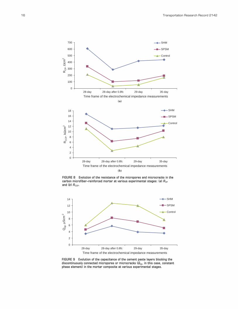
At the completion of the first EIS measurements at the 28-day cur-ing age, all the specimens were loaded under 80% of compressivestrength to create some artificial microcracks in the cement mortarcomposite, and the EIS measurements were then performed after0 h, 24 h, and 7 days. It can be assumed that during the period ofcompressive loading, some continuously connected microporesor microcracks will transform into the discontinuously connectedmicropores or microcracks, blocked by cement paste layers, whereassome blocked discontinuously connected micropores or micro-cracks will also become continuously connected in such a short fiber-reinforced mortar system. Therefore, the resistance values of RCCP
and RCP and the capacitance of discontinuous points (Qdp) can beused as indicators of the changes in the composite microstructure.The resistance values of RCCP and RCP and the capacitance of discon-tinuous points (Qdp) are depicted as a function of time in Figures 8and 9. As shown in the figures, after being loaded under 80% of com-pressive strength, the resistance values of RCCP and RCP of the threekinds of mortar specimens decreased significantly, and the value ofQdp increased accordingly. A possible explanation is that when acomposite material with short and randomly oriented carbon micro-fibers is damaged, the adjacent carbon microfibers are separated attheir junction (18). This damage (in the form of artificial micro-cracks in this case) increases the chance of adjacent fibers touchingone another through the capillary action of the pore solution in themicrocracks, thus decreasing the electric resistance of the compositewhile increasing its electric capacitance.
After the control and SPSM specimens were set aside for 24 h (i.e.,the 29th day), the respective value of RCCP and RCP increased afterdropping down to the lowest level, likely due to evaporation of thepore solution in micropores and microcracks, considering theirexposure to the low relative humidity (around 15% to 20%) room-air environment. Such evaporation also reduced the chance ofadjacent fibers touching one another, causing the correspondingresistance of the mortar to increase. After the specimens were set
Yang, Hollar, He, and Shi 15
aside for 7 days (i.e., the 35th day), the increase in the value of RCCP andRCP became more significant. However, for the SHM specimens, thevalues of RCCP and RCP exhibited a similar trend of increase overtime, but the increasing rate is slight, especially from the 29th dayto the 35th day. Similar results were obtained from the temporalevolution of Qdp over time, as shown in Figure 9. The EIS data pre-sented in Figure 8 and Figure 9 as well as in Table 1 suggest that(a) the incorporation of both microparticles (especially PSMs) ledto a less permeable and more refined microstructure of the cementmortar composite and (b) the inclusion of PSMs enabled the mortarcomposite to heal at least part of the artificially induced microcracks.
CONCLUSIONS
This work preliminarily assessed the self-healing performance of acementitious composite using microcapsules with oil core and sil-ica gel shell. FESEM images revealed the PSMs with closed shellsand an average diameter of 4.15 µm were fabricated using poly-styrene particles sulfonated for 60 h. The sulfonated polystyreneparticles or PSMs were incorporated into the fresh cement mortaralong with carbon microfibers and silica fume, and various tech-niques were used to characterize the microstructure and propertiesof the hardened mortar composites.
The SPSM and the SHM showed higher compressive strength atboth 1 day and 28 days relative to the control. In particular, theincorporation of PSMs increased the 1-day and 28-day compressivestrength of the mortar by 45.8% and 30.4%, respectively. There aremultiple mechanisms that may account for the beneficial effects ofthe sulfonated polystyrene particles and PSMs on the compressivestrength cement mortar containing carbon microfibers and silica fume.
EIS was used to shed light on the microstructural properties andself-healing effect of the fiber-reinforced cement mortars in thisstudy. The EIS data suggest that (a) the incorporation of both micro-particles (especially PSMs) led to a less permeable and more refinedmicrostructure of the cement mortar composite and (b) the inclusionof PSMs enabled the mortar composite to heal at least part of theartificially induced microcracks.
ACKNOWLEDGMENTS
This work was supported by RITA, U.S. Department of Transporta-tion, through a University Transportation Center research grant. Theauthors also acknowledge the helpful comments provided by theanonymous reviewers for the Transportation Research Record.
29-Day After 0.8fc 35-Day After 0.8fc
Control SPSM SHM Control SPSM SHM
439 ± 2.05 504 ± 15.4 678 ± 8.92 527 ± 19.2 540 ± 12.1 712 ± 14.2
24.7 ± 1.72 9.25 ± 1.02 4.82 ± 0.26 14.6 ± 3.49 8.92 ± 0.78 5.00 ± 0.01
0.86 ± 0.01 0.90 ± 0.01 0.70 ± 0.06 0.90 ± 0.03 0.77 ± 0.07 0.99 ± 0.01
4.47 ± 0.56 7.44 ± 0.25 11.5 ± 0.10 7.97 ± 1.13 10.4 ± 1.09 12.3 ± 0.72
53.5 ± 2.36 118 ± 5.16 417 ± 32.1 165 ± 8.40 192 ± 10.2 439 ± 20.8
12.0 ± 0.98 7.04 ± 0.10 3.87 ± 0.07 7.67 ± 0.36 5.14 ± 0.29 3.56 ± 0.06
0.50 ± 0.00 0.52 ± 0.00 0.63 ± 0.00 0.42 ± 0.00 0.55 ± 0.00 0.46 ± 0.00
16 Transportation Research Record 2142
0
2
4
6
8
10
12
14
28-day 28-day after 0.8fc 29-day 35-day
Time frame of the electrochemical impedance measurements
SHM
SPSM
Control
Qdp
, μS
cm-2
FIGURE 9 Evolution of the capacitance of the cement paste layers blocking thediscontinuously connected micropores or microcracks (Qdp, in this case, constantphase element) in the mortar composite at various experimental stages.
0
100
200
300
400
500
600
700 SHM
SPSM
Control
0
2
4
6
8
10
12
14
16
18
28-day 28-day after 0.8fc 29-day 35-day
Time frame of the electrochemical impedance measurements
28-day 28-day after 0.8fc 29-day 35-day
Time frame of the electrochemical impedance measurements
(b)
(a)
SHM
SPSM
Control
RC
P, Ω
cm2
RC
CP, k
Ωcm
2
FIGURE 8 Evolution of the resistance of the micropores and microcracks in thecarbon microfiber–reinforced mortar at various experimental stages: (a) RCP
and (b) RCCP.
REFERENCES
1. Aïtcin, P.-C. Cements of Yesterday and Today: Concrete of Tomorrow.Cement and Concrete Research, Vol. 30, No. 9, 1998, pp. 1349–1359.
2. Samaha, H. R., and K. C. Hover. Influence of Microcracking on theMass Transport Properties of Concrete. ACI Materials Journal, Vol. 89,No. 4, 1992, pp. 416–424.
3. Dry, C. Alteration of Matrix Permeability, Pore and Crack Structure bythe Time Release of Internal Chemicals. Proc., Advances in CementitiousMaterials, Gaithersburg, Md. American Ceramic Society, Westerville,Ohio, 1990, pp. 729–768.
4. Dry, C. Three-Part Methylmethacrylate Adhesive System as an InternalDelivery System for Smart Responsive Concrete. Smart Materials andStructures, Vol. 5, No. 3, 1996, pp. 297–300.
5. Dry, C. Three Designs for the Internal Release of Sealants, Adhesives,and Waterproofing Chemicals into Concrete to Reduce Permeability.Cement and Concrete Research, Vol. 30, No. 12, 2000, pp. 1969–1977.
6. Bleay, S. M., C. B. Loader, V. J. Hawyes, L. Humberstone, and P. T.Curtis. Smart Repair System for Polymer Matrix Composites. Compos-ite Part A: Applied Science and Manufacturing, Vol. 32, No. 12, 2001,pp. 1767–1776.
7. Kessler, M. R., N. R. Sottos, and S. R. White. Self-Healing StructuralComposite Materials. Composite Part A: Applied Science and Manufacturing, Vol. 34, No. 8, 2003, pp. 743–753.
8. White, S. R., N. R. Sottos, P. H. Geubelle, J. S. Moore, M. R. Kessler,S. R. Sriram, E. N. Brown, and S. Viswanathan. Autonomic Healing ofPolymer Composites. Nature, Vol. 409, No. 6822, 2001, pp. 794–797.
9. Brown, E. N., S. R. White, and N. R. Sottos. Microcapsule InducedToughening in a Self-Healing Polymer Composite. Journal of MaterialsScience, Vol. 39, No. 5, 2004, pp. 1703–1710.
10. Pang, J. W. C., and I. P. Bond. A Hollow Fiber Reinforced PolymerComposite Encompassing Self-Healing and Enhanced Damage Visibility.
Yang, Hollar, He, and Shi 17
Composite Science and Technology, Vol. 65, No. 11–12, 2005, pp. 1791–1799.
11. Dry, C. Matrix Cracking Repair and Filling Using Active and PassiveModes for Smart Timed Release of Chemicals from Fibers intoCement Matrices. Smart Materials and Structure, Vol. 3, No. 2, 1994,pp. 118–123.
12. Dry, C., and M. J. T. Corsaw. A Time-Release Technique for CorrosionPrevention. Cement and Concrete Research, Vol. 28, No. 8, 1998, pp. 1133–1140.
13. Yang, Z., X. Shi, A. T. Creighton, and M. M. Peterson. Effect ofStyrene-Butadiene Rubber Latex on the Chloride Permeability andMicrostructure of Portland Cement Mortar. Construction and BuildingMaterials, Vol. 23, No. 6, 2009, pp. 2283–2290.
14. He, X., X. Ge, H. Liu, M. Wang, and Z. Zhang. Cagelike Polymer Micro-spheres with Hollow Core/Porous Shell Structures. Journal of PolymerScience Part A: Polymer Chemistry, Vol. 45, No. 5, 2007, pp. 933–941.
15. Song, G. Equivalent Circuit Model for AC Electrochemical ImpedanceSpectroscopy of Concrete. Cement and Concrete Research, Vol. 30,No. 11, 2000, pp. 1723–1730.
16. Torrents, J. M., T. O. Mason, A. Peled, S. P. Shah, and E. J. Garboczi.Analysis of the Impedance Spectra of Short Conductive Fiber-ReinforcedComposites. Journal of Materials Science, Vol. 36, No. 16, 2001, pp. 4003–4012.
17. Cabeza, M., P. Merino, A. Miranda, X. R. Nóvoa, and I. Sanchez.Impedance Spectroscopy Study of Hardened Portland Cement Paste.Cement and Concrete Research, Vol. 32, No. 6, 2002, pp. 881–891.
18. Fu, X., and D. D. L. Chung. Self-Monitoring of Fatigue Damage inCarbon Fiber Reinforced Cement. Cement and Concrete Research,Vol. 26, No. 1, 1996, pp. 15–20.
The Nanotechnology-Based Concrete Materials Task Force peer-reviewed thispaper.