lab manual
TRANSCRIPT
1 | P a g e
LAB MANUAL
GE-104
(Basics of Engineering Drawing)
2 | P a g e
Grading
Please see the course specification for the grading scheme and policy
Requirements for the Engineering Drawing laboratory.
This Lab manual was prepared with the help of “Beginner’s guide to Engineering Drawing”. Students should
submit the drawing sheets every exercise.
Engineering Drawing Lab. Policy
and Safety
3 | P a g e
Jouf University Academic Dishonesty Policy
Student Conduct: Penalties for academic dishonesty will be severe. Academic dishonesty includes
cheating, plagiarism or sabotage. Cheating includes but is not limited to: (i) unauthorized assistance in
taking quizzes, tests or examinations; (ii) dependence upon the aid of sources beyond those authorized by
the instructor in solving problems or carrying out other assignments; (iii) acquisition or possession without
permission of tests or other academic material belonging to a member of the faculty or staff; (iv)
knowingly providing any unauthorized assistance to another student on quizzes, tests or examinations.
Plagiarism includes, but is not limited to: (i) use by paraphrase or direct quotation of the published or
unpublished work of another person without fully and properly crediting the author with references; (ii)
unacknowledged use of materials prepared by another person or agency engaged in the selling of term
papers or other academic materials; or (iii) unacknowledged use of original work/material that has been
produced through collaboration with others without release in writing from collaborators.
Sabotage includes but is not limited to, the unauthorized interference with, modification of, or destruction
of the work or intellectual property of another member of the University community.
Other conduct that is subject to disciplinary action includes the actual or attempted theft or other abuse of
computer time, including but not limited to: (i) unauthorized entry into a file to use, read or change the
contents, or for any other purpose; (ii) unauthorized transfer of a file; (iii) unauthorized use of another
individual's identification and password; (iv) use of computing facilities to interfere with the work of
another student, faculty member or University official; (v) use of computing facilities to interfere with
normal operation of the University computing system; (vi) knowingly causing a computer virus to become
installed in a computer system or file.
For this class, work turned in must be original and represent an individual effort unless otherwise
indicated. IF DUPLICATE COPIES OF PROJECTS OR HOMEWORKS ARE RECEIVED, AN
AUTOMATIC GRADE OF ZERO WILL BE GIVEN TO ALL PARTIES INVOLVED. Code which is
not your own must be referenced (e.g. when using code libraries). Persons observed cheating on tests will
forfeit the test and receive a zero for that test. Names of persons involved in any of these incidents will be
forwarded to the Head of the Department. Those students will be subject to sanctions as outlined in the
general catalog. Sanctions may result in dismissal from the University.
I have read and I understand the Class Policies regarding Student Conduct. I agree to abide by these
policies.
Signed Date:
4 | P a g e
GENERAL GUIDELINES AND SAFETY INSTRUCTIONS
Engineering Drawing laboratory Environment and Conduct
Laboratory must be kept clean at all times.
Eating or drinking in the laboratory is not allowed.
Working alone in the laboratory is not permitted.
A student must be accompanied by laboratory partners and/or an instructor.
Handling Drawing tools
Strictly follow the instructions provided in the laboratory manual and those given by the
supervisor. If you do not understand any of the instructions make sure you ask the
supervisor.
Fire, First Aid, and Emergency Numbers
Make sure you are aware of the location of fire exits, fire extinguisher, and first aid kit in
your Lab.
In case of emergency, call campus security or 911.
5 | P a g e
S. No. Date List of Exercises Page
1. Engineering Drawing Tools
2. Types of Lines
3. Geometry Construction
4. Isometric Drawing
5. Isometric Projection
CONTENTS
6 | P a g e
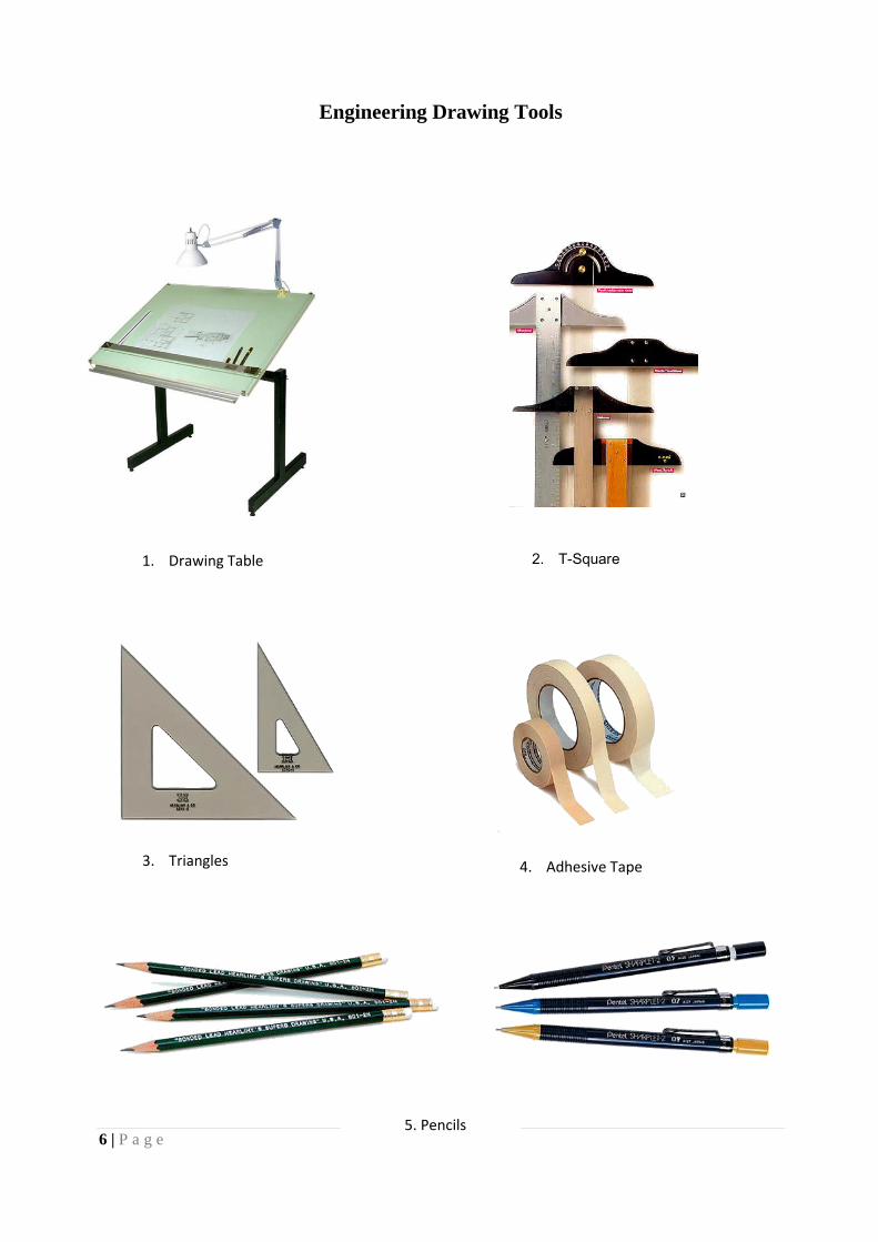
Engineering Drawing Tools
1. Drawing Table 2. T-Square
3. Triangles 4. Adhesive Tape
5. Pencils
7 | P a g e
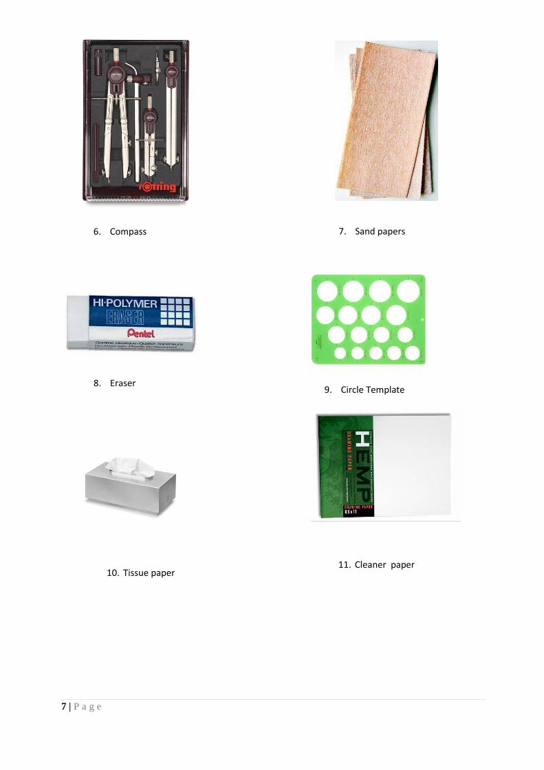
6. Compass 7. Sand papers
8. Eraser 9. Circle Template
10. Tissue paper 11. Cleaner paper
8 | P a g e
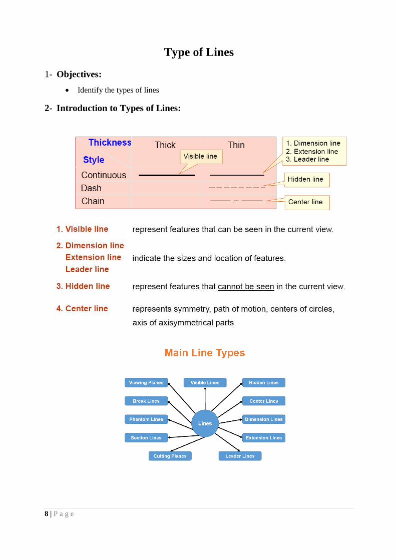
Type of Lines
1- Objectives:
Identify the types of lines
2- Introduction to Types of Lines:
9 | P a g e
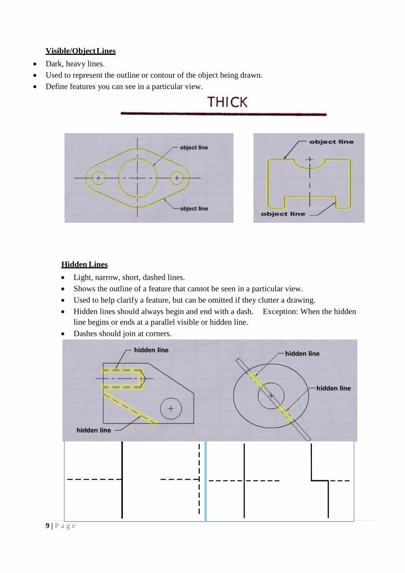
Visible/Object Lines
Dark, heavy lines.
Used to represent the outline or contour of the object being drawn.
Define features you can see in a particular view.
Hidden Lines
Light, narrow, short, dashed lines.
Shows the outline of a feature that cannot be seen in a particular view.
Used to help clarify a feature, but can be omitted if they clutter a drawing.
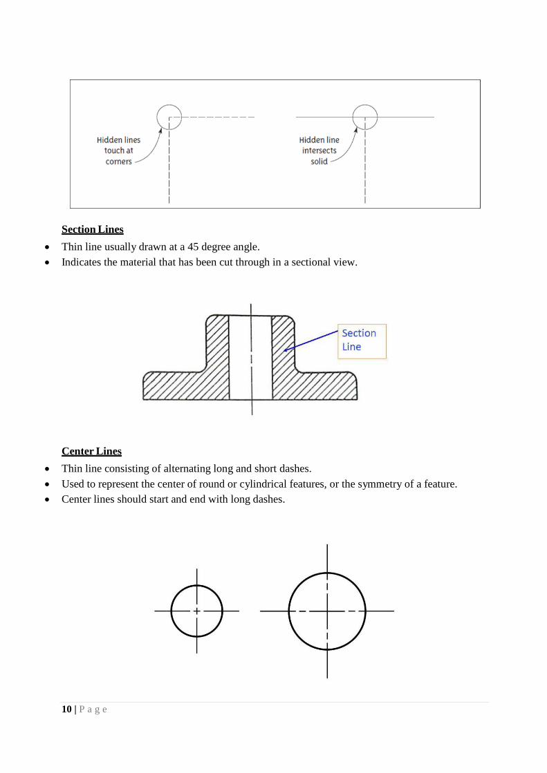
Hidden lines should always begin and end with a dash. Exception: When the hidden
line begins or ends at a parallel visible or hidden line.
Dashes should join at corners.
10 | P a g e
Section Lines
Thin line usually drawn at a 45 degree angle.
Indicates the material that has been cut through in a sectional view.
Center Lines
Thin line consisting of alternating long and short dashes.
Used to represent the center of round or cylindrical features, or the symmetry of a feature.
Center lines should start and end with long dashes.
11 | P a g e
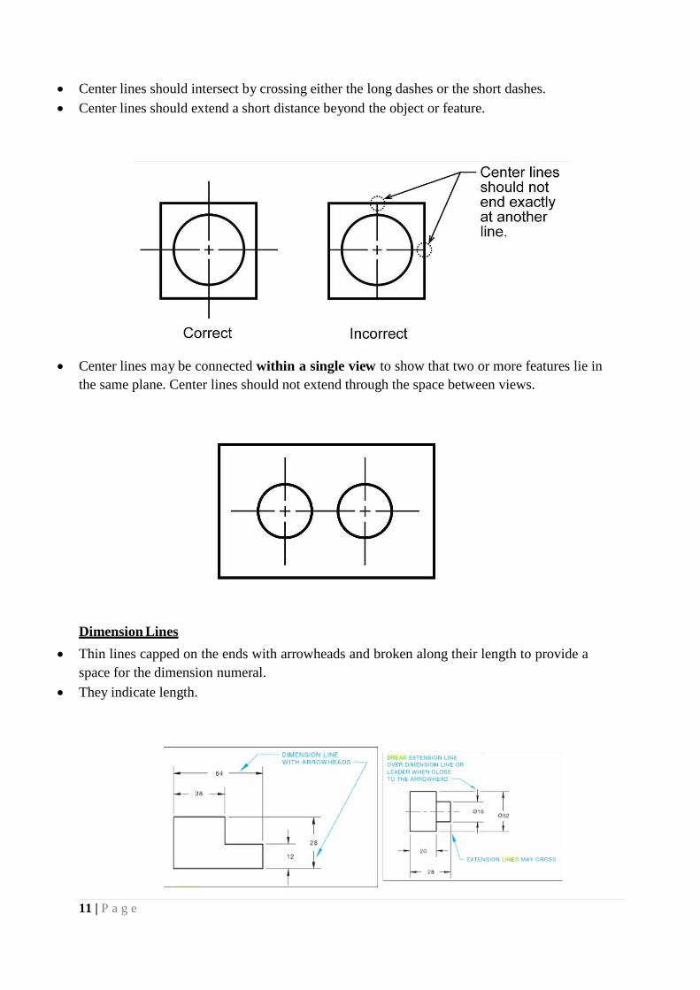
Center lines should intersect by crossing either the long dashes or the short dashes.
Center lines should extend a short distance beyond the object or feature.
Center lines may be connected within a single view to show that two or more features lie in
the same plane. Center lines should not extend through the space between views.
Dimension Lines
Thin lines capped on the ends with arrowheads and broken along their length to provide a
space for the dimension numeral.
They indicate length.
12 | P a g e
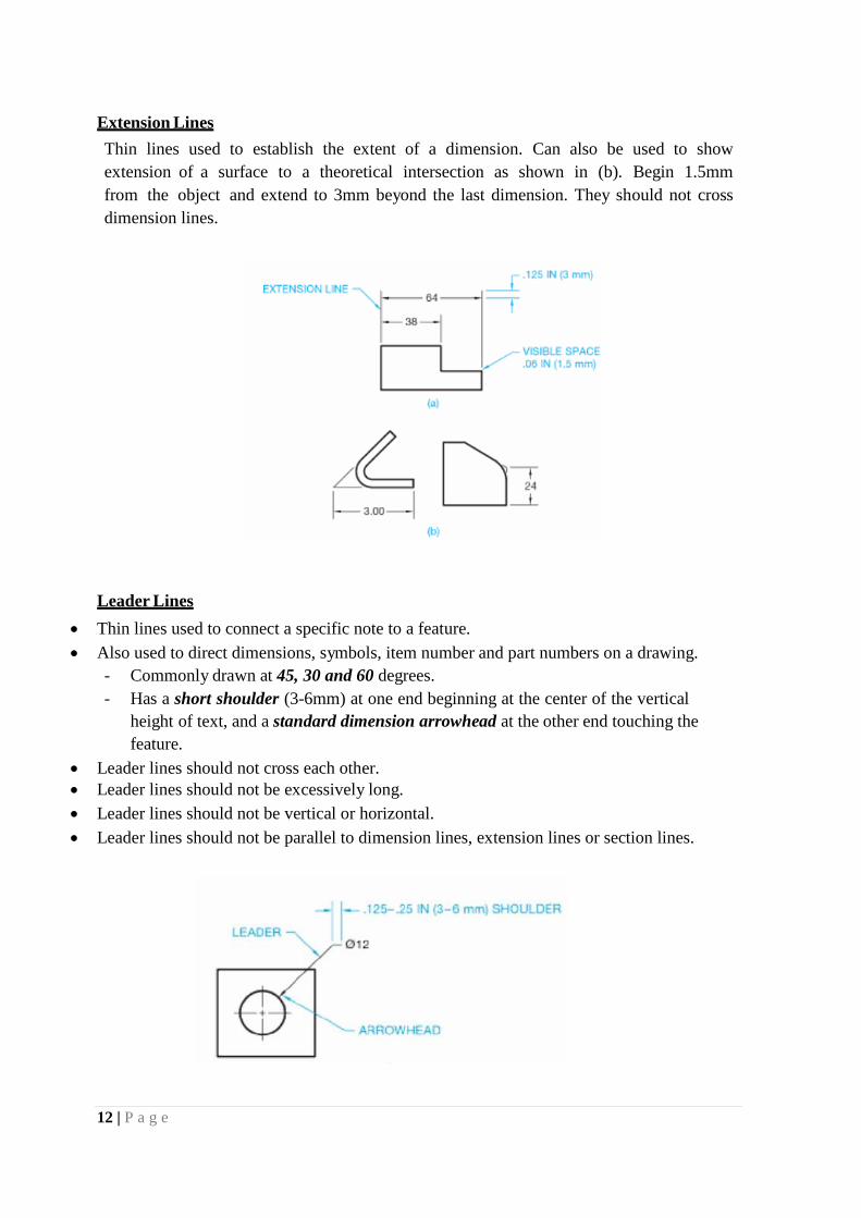
Extension Lines
Thin lines used to establish the extent of a dimension. Can also be used to show
extension of a surface to a theoretical intersection as shown in (b). Begin 1.5mm
from the object and extend to 3mm beyond the last dimension. They should not cross
dimension lines.
Leader Lines
Thin lines used to connect a specific note to a feature.
Also used to direct dimensions, symbols, item number and part numbers on a drawing.
- Commonly drawn at 45, 30 and 60 degrees.
- Has a short shoulder (3-6mm) at one end beginning at the center of the vertical
height of text, and a standard dimension arrowhead at the other end touching the
feature.
Leader lines should not cross each other.
Leader lines should not be excessively long.
Leader lines should not be vertical or horizontal.
Leader lines should not be parallel to dimension lines, extension lines or section lines.
13 | P a g e
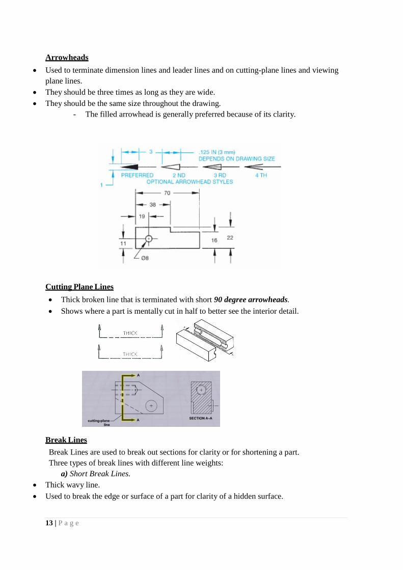
Arrowheads
Used to terminate dimension lines and leader lines and on cutting-plane lines and viewing
plane lines.
They should be three times as long as they are wide.
They should be the same size throughout the drawing.
- The filled arrowhead is generally preferred because of its clarity.
Cutting Plane Lines
Thick broken line that is terminated with short 90 degree arrowheads.
Shows where a part is mentally cut in half to better see the interior detail.
Break Lines
Break Lines are used to break out sections for clarity or for shortening a part.
Three types of break lines with different line weights:
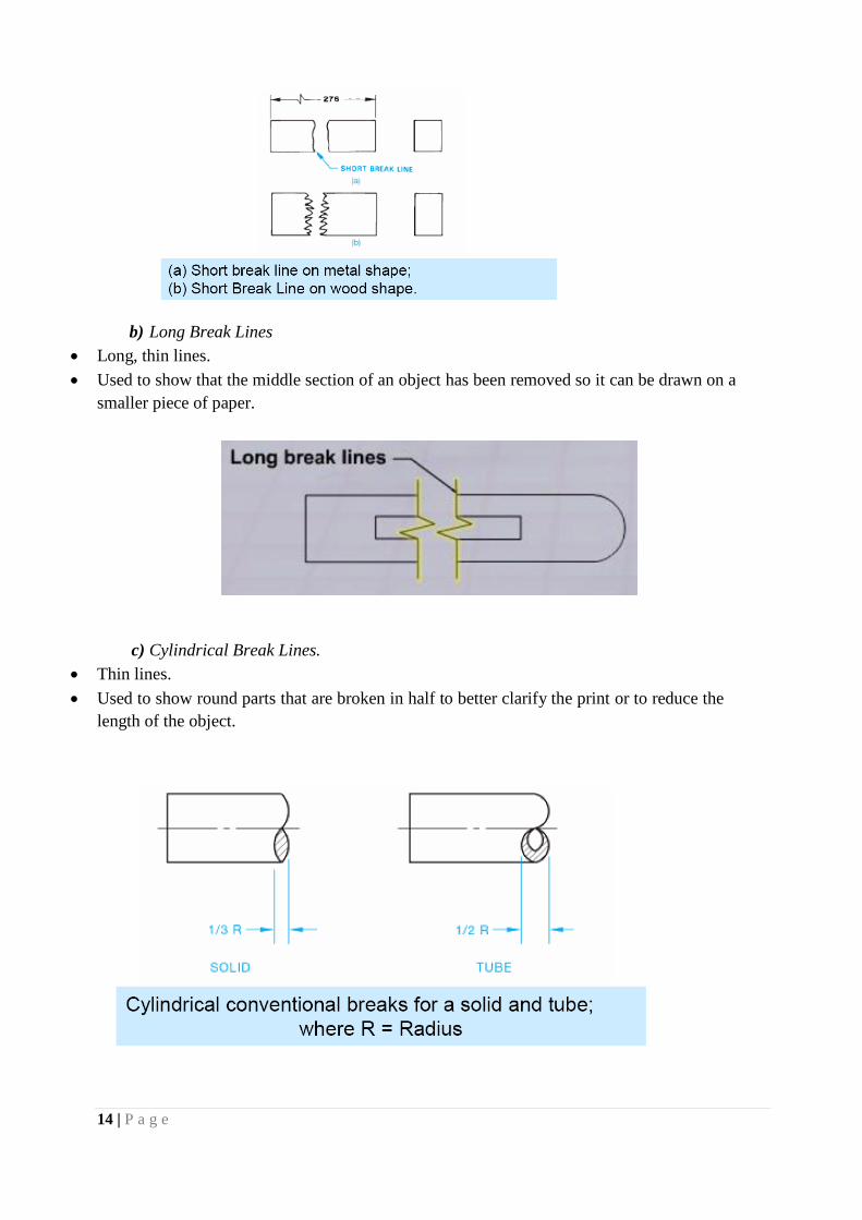
a) Short Break Lines.
Thick wavy line.
Used to break the edge or surface of a part for clarity of a hidden surface.
14 | P a g e
b) Long Break Lines
Long, thin lines.
Used to show that the middle section of an object has been removed so it can be drawn on a
smaller piece of paper.
c) Cylindrical Break Lines.
Thin lines.
Used to show round parts that are broken in half to better clarify the print or to reduce the
length of the object.
15 | P a g e
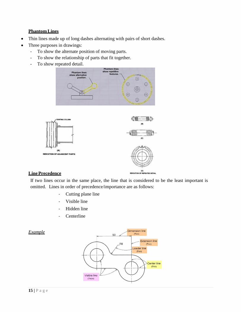
Phantom Lines
Thin lines made up of long dashes alternating with pairs of short dashes.
Three purposes in drawings:
- To show the alternate position of moving parts.
- To show the relationship of parts that fit together.
- To show repeated detail.
Line Precedence
If two lines occur in the same place, the line that is considered to be the least important is
omitted. Lines in order of precedence/importance are as follows:
- Cutting plane line
- Visible line
- Hidden line
- Centerline
Example
16 | P a g e
Geometry Construction
Objectives
• Describe the importance of engineering geometry in the design process.
• List the major categories of geometric entities.
• To construct basic sketching with instrument, T-square and triangles.
• List and describe surface geometric forms.
• Describe engineering applications of geometry
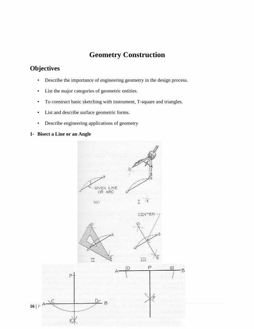
1- Bisect a Line or an Angle
17 | P a g e
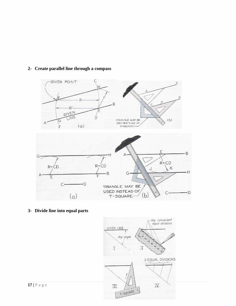
2- Create parallel line through a compass
3- Divide line into equal parts
18 | P a g e
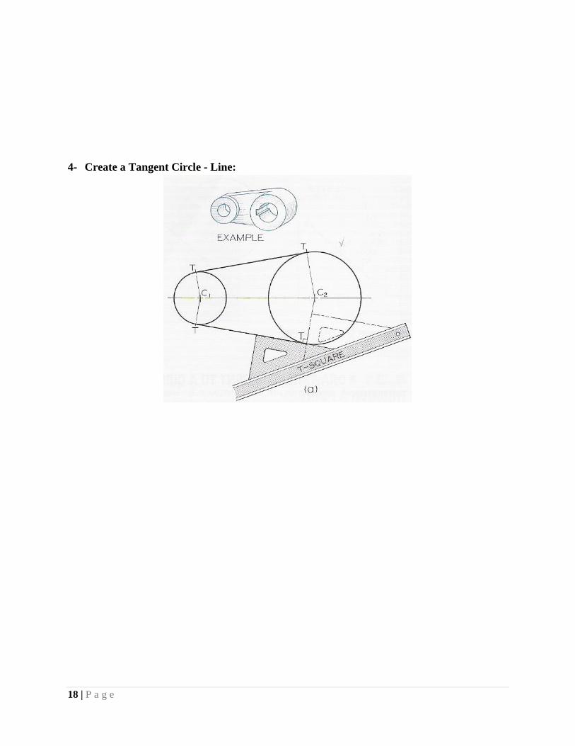
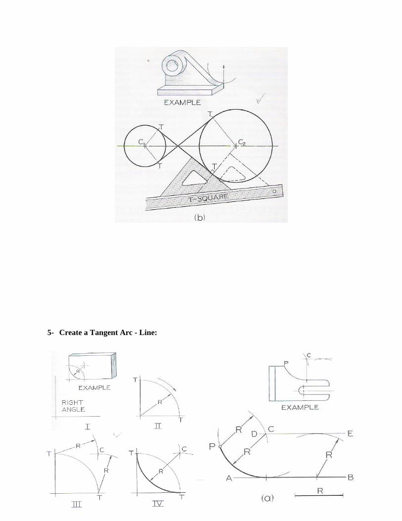
4- Create a Tangent Circle - Line:
19 | P a g e
5- Create a Tangent Arc - Line:
20 | P a g e
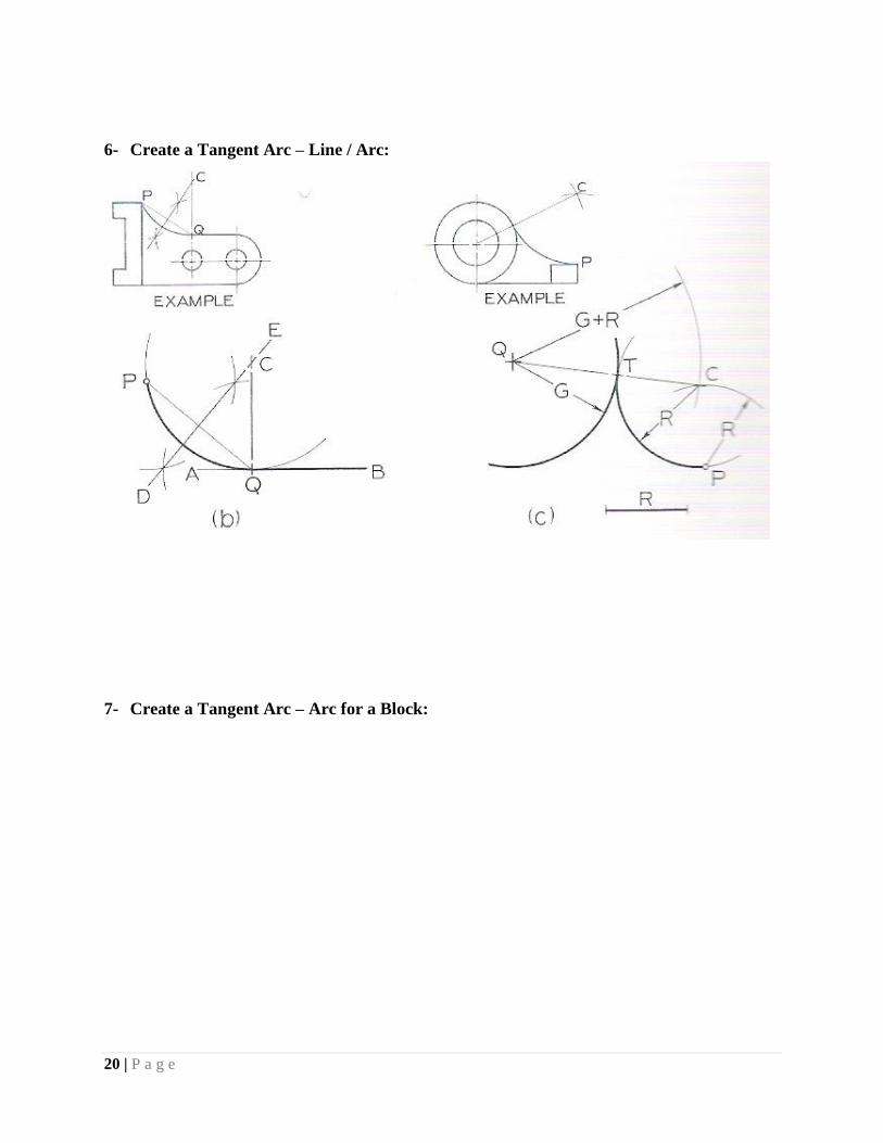
6- Create a Tangent Arc – Line / Arc:
7- Create a Tangent Arc – Arc for a Block:
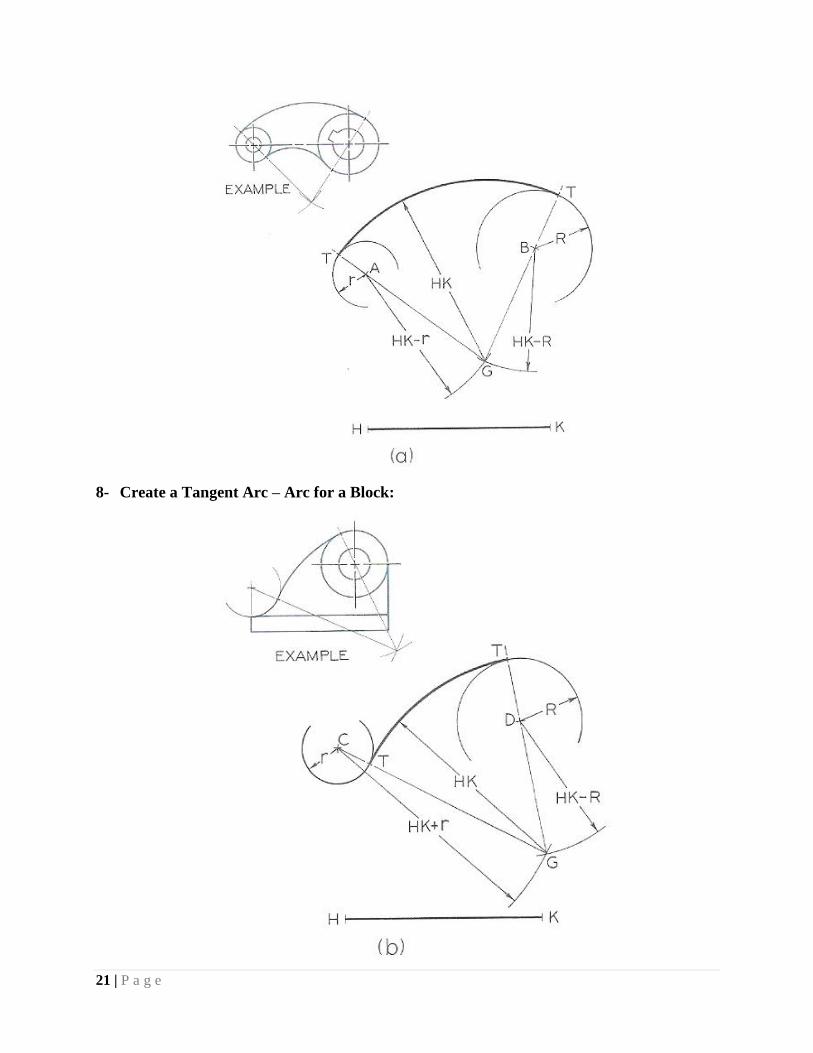
21 | P a g e
8- Create a Tangent Arc – Arc for a Block:
22 | P a g e
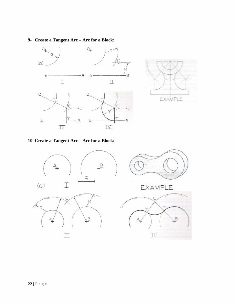
9- Create a Tangent Arc – Arc for a Block:
10- Create a Tangent Arc – Arc for a Block:
Isometric Drawing
23 | P a g e
Isometric Drawing
Objectives
Know how to set up and use a drawing board to effectively draw 3D shapes>
Know the principals and how to draw a single point perspective drawing.
Know how to render to make an objective more realistic.
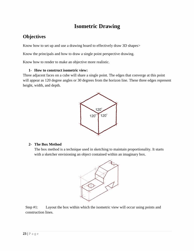
1- How to construct isometric view:
Three adjacent faces on a cube will share a single point. The edges that converge at this point
will appear as 120 degree angles or 30 degrees from the horizon line. These three edges represent
height, width, and depth.
2- The Box Method
The box method is a technique used in sketching to maintain proportionality. It starts
with a sketcher envisioning an object contained within an imaginary box.
Step #1: Layout the box within which the isometric view will occur using points and
construction lines.
24 | P a g e
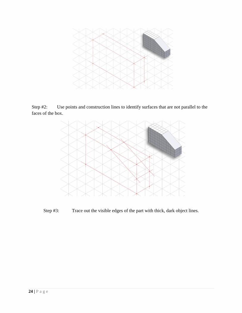
Step #2: Use points and construction lines to identify surfaces that are not parallel to the
faces of the box.
Step #3: Trace out the visible edges of the part with thick, dark object lines.
25 | P a g e
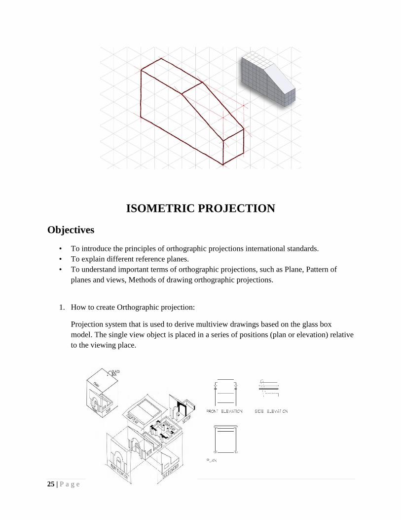
ISOMETRIC PROJECTION
Objectives
• To introduce the principles of orthographic projections international standards.
• To explain different reference planes.
• To understand important terms of orthographic projections, such as Plane, Pattern of
planes and views, Methods of drawing orthographic projections.
1. How to create Orthographic projection:
Projection system that is used to derive multiview drawings based on the glass box
model. The single view object is placed in a series of positions (plan or elevation) relative
to the viewing place.
26 | P a g e
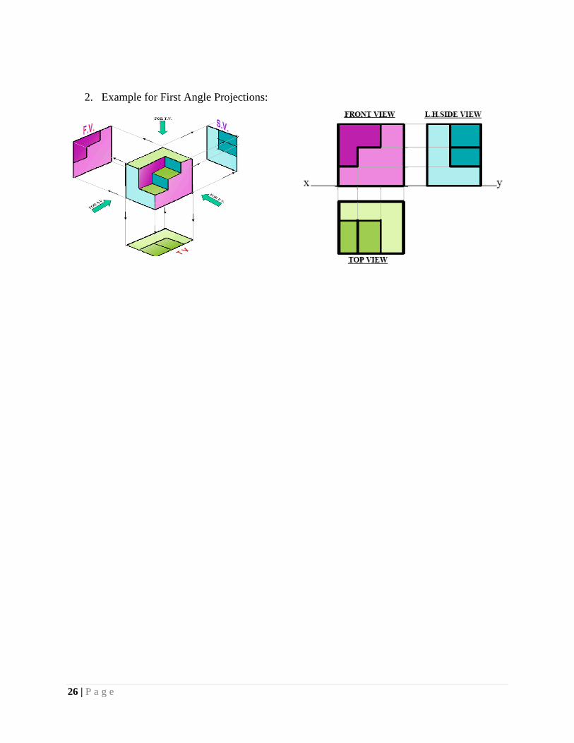
2. Example for First Angle Projections:

27 | P a g e