kiot / mech / finite element analysis - wordpress.com
TRANSCRIPT

KIOT / MECH / FINITE ELEMENT ANALYSIS
KNOWLEDGE INSTITUTE OF TECHNOLOGY (Approved by AICTE, New Delhi and Affiliated to Anna University, Chennai)
Kakapalayam (PO), Salem – 637504.
Department of Mechanical Engineering
COURSE PLAN
FINITE ELEMENT ANALYSIS
Department of Mechanical Engineering
KIOT / MECH / FINITE ELEMENT ANALYSIS
FINITE ELEMENT ANALYSIS
TWO MARK QUESTIONS
UNIT 1- INTRODUCTION
1. Name the variational methods.
1. Ritz method
2. Rayleigh –Ritz method
2. Name the weighted residual methods.
Point collocation method
Sub-domain collocation method
Least squares method
Galerkin’s method.
3. What is Raleigh – Ritz method?
Rayleigh-Ritz method is an integral method which is useful for solving complex structural
problems, encountered in finite element analysis. This method is possible only if a suitable
functional is available.
4.What is meant by discretization and assembly?
The art of sub dividing the structure into a convenient number of smaller components is
known as discretisation. The smaller components are put together and this process of combining
all the elements together is known as assemblage.
5. What is aspects ratio?
Aspect ratio is the ratio of the largest dimension of the element to the smallest dimension
of the element. In many cases, if the aspect ratio increases the inaccuracy of the solution
increases. The aspect ratio should be close to unity as for as possible.
6. What is meant by finite element analysis?
Finite element methods is a numerical method for solving problems of engineering and
mathematical physics.
In this method, instead of solving the problem for the entire body in one operation, we
formulate equations for each element and combine them to obtain the solution for the
whole body.

KIOT / MECH / FINITE ELEMENT ANALYSIS
7.What are the types of boundary condition?
There are two types of boundary condition. They are:
1. Primary boundary condition
2. Secondary boundary condition
8. What are the methods generally associated with the finite element analysis?
Force method and Displacement or stiffness method are the two methods.
9. Explain force method.
In force method, internal forces are considered as unknowns of the problem. In
Displacement or stiffness method, the displacements are considered as unknowns of the
problem. Among the two methods, displacement method is desirable.
10. Why polynomial type of interpolation functions are mostly used due to the following
Reasons:
1. It is easy to formulate and computerize the finite element equations
2. It is easy to perform differentiation or integration
3. The accuracy of the results can be improved by increasing the order of the polynomial.
11. What are ‘h’ and ‘p’ versions of finite element method?
In ‘h’ version, the order of the polynomial approximation for all elements is kept constant
and the number of elements increased.
In ‘p’ version the number of elements is maintained constant and the order of polynomial
approximation of element is increased.
12. Name any four FEA software’s.
1. Ansys 2.NASTRAN 3. COSMOS 4. NISA
13. Differentiate between global and local axes.
Local axes are established in an element, they change with change in orientation of the
element. The direction differs from element to element.
Global axes are defined for the entire system. They have the same direction for all the
elements even though the elements are differently oriented.
UNIT 2- ONE-DIMENSIONAL PROBLEMS
1. What are the types loading acting on a structure?
There are three type of loading acting on a structure. They are,
a. Body force (f)
b. Traction force (T)
c. Point load (P)
2. Define body force.
A body force is distributed force acting on every elemental volume of the body.
Unit: force per unit volume

KIOT / MECH / FINITE ELEMENT ANALYSIS
3. Define traction force.
Traction force is defined as distributed force acting on the surface of the body.
Unit: Force per unit area
Examples: Frictional resistance, viscous
4. What is a point load?
Point load is load acting at a particular point which causes displacement.
5. What are the basic steps involved in the finite element modeling.
Finite element modeling consists of the following:
1. Discretisation of the structure
2. Numbering of the nodes.
6. What are the classifications of the co-ordinates?
The co-ordinates are generally classified as ,
1. Global co-coordinates
2. Local Co-ordinates
3. Natural co-ordinates
7. What is natural co-ordinates?
A natural co-ordinate system is used to define any point inside the element by a set of
dimensionless numbers, whose magnitude never exceeds unity. This system is useful in
assembling of stiffness matrices.
8. Define shape function.
In finite element method, field variables within an element are generally expressed by the
following approximate relation: (x,y) = N 1 (x,y) 1 +N 2(x,y) 2 + N 3 (x,y) 3 where 1 2 3 4are
the values of the field variable at the nodes and N 1 N 2 N 3N 4 are interpolation function. N
1 N 2 N 3 N 4 are called shape functions because they are used to express the geometry or
shape of the element.
9. What are the characteristics of shape function?
The characteristics of the shape functions are follows:
1. The shape function has unit value at one nodal point and zero value at the other nodes.

KIOT / MECH / FINITE ELEMENT ANALYSIS
2. The sum of the shape function is equal to one.
10. Why polynomials are generally used as shape function?
Polynomials are generally used as shape functions due to the following reasons:
1. Differentiation and integration of polynomials are quite easy.
2. The accuracy of the results can be improved by increasing the order of the
polynomial.
3. It is easy to formulate and computerize the finite element equations.
11. Give the expression for element stiffness matrix.
Stiffness matrix [K] = [B] [D][B]d v
Where, [B] matrix is a strain displacement matrix
[D] matrix is stress, strain relationship matrix
12. Write down the expression of stiffness matrix for one dimensional element bar
element.
Where, A is the area of the bar element
E is the young’s modulus of the bar element
L is the length of the bar element
13. State the properties of a stiffness matrix.
The properties of the stiffness matrix [K] are,
1. It is a symmetric matrix
2. The sum of the elements in any column must be equal to zero.
3. It is an unstable element, so the determinant is equal to zero.
14. Write down the general finite element equation.
General finite element equation is,
{F} = [K] {u}
Where, {F} is a force vector
[K] is the stiffness matrix

KIOT / MECH / FINITE ELEMENT ANALYSIS
{u} is the degrees of freedom
15. State the assumptions made in the case of truss element.
The following assumptions are made in the case of truss element,
1. All the members are pin jointed.
2. The truss is loaded only at the joints
3. The self weight of the members are neglected unless stated.
16. Write down the expression of stiffness matrix for a truss element.
17. Write down the expression of shape function N and displacement u for one dimensional
bar element.
For on dimensional bar element,
18. State the principle of minimum potential energy.
The total potential energy of an elastic body is defined as the sum of total strain energy
U and the potential energy of the external forces, (W)
19. Distinguish between essential boundary condition and natural boundary condition.
There are two type of boundary conditions. They are,

KIOT / MECH / FINITE ELEMENT ANALYSIS
1. Primary boundary condition (or) essential boundary condition:
The boundary condition which in terms of the field variables is known as primary
boundary condition
2. Secondary boundary condition or natural boundary condition:
The boundary conditions which are in the differential form of field variables is
known as secondary boundary condition.
20. What are the difference between boundary value problem and initial value problem?
The solution of differential equation obtained for physical problems which satisfies some
specified conditions known as boundary conditions.
If the solution of differential equation is obtained together with initial conditions then it is
known as initial value problem. If the solution of differential equation is obtained together with
boundary conditions then it is known as boundary value problem.
UNIT 3- TWO DIMENSIONAL SCALAR VARIABLE PROBLEMS
1. What is a CST element?
Three nodded triangular element is known as constant strain triangular elelment. It has 6
unknown degrees of freedom called u1, v1, u2, v2, u3, v3. The element is called CST
because it has constant strain throughout it.
2. What is LST element?
Six nodded triangular element is known as Linear Strain Triangular element. It has 12
unknown displacement degrees of freedom. The displacement function for the element
are quadratic instead of linear as in the CST.
3. What is a QST element?
Ten nodded triangular element is known as Quadratic Strain Triangle.
4. What is meant by plane stress analysis?
Plane stress is defined as a state of stress in which the normal stress (?) and the shear
stress () directed perpendicular to the plane are zero.

KIOT / MECH / FINITE ELEMENT ANALYSIS
5. Define plane strain.
Plane strain is defined to be a state of strain in which the strain normal to the xy palne
and the shear strains are assumed to be zero.
6. Write the displacement function for a CST element.
7. Write a strain displacement matrix for CST element.
Strain displacement equation for CST element is,
8. Write down the stress –strain relationship matrix for plane stress condition.
For plane stress problems, stress –strain relationship matrix is ,
KIOT / MECH / FINITE ELEMENT ANALYSIS
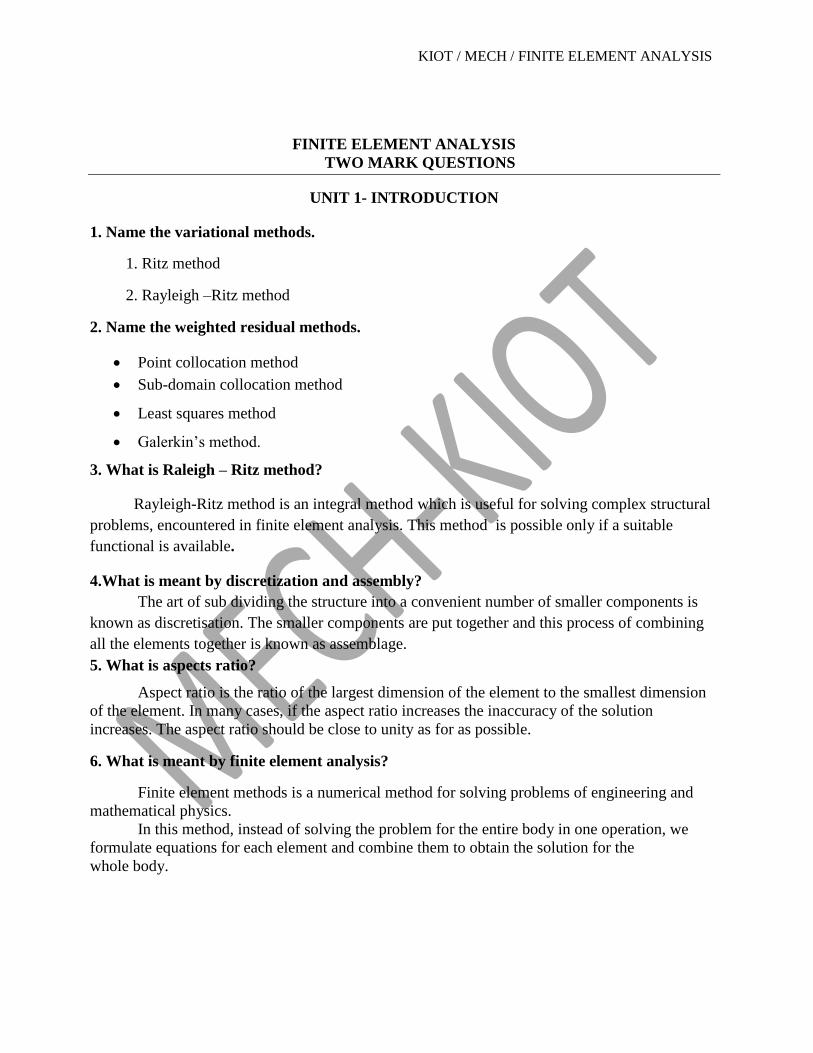
9. Write down the stress-strain relationship matrix for plane strain condition.
For plane strain problems, stress – strain relationship matrix is,
UNIT 4- TWO DIMENSIONAL VECTOR VARIABLE PROBLEMS
1. Define Quasi static response.
When the excitations are varying slowly with time then it is called quasi static response.
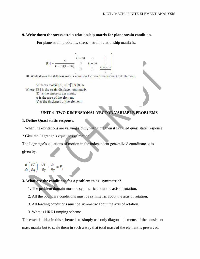
2 Give the Lagrange’s equations of motion.
The Lagrange’s equations of motion in the independent generalized coordinates q is
given by,
3. What are the conditions for a problem to axi symmetric?
1. The problem domain must be symmetric about the axis of rotation.
2. All the boundary conditions must be symmetric about the axis of rotation.
3. All loading conditions must be symmetric about the axis of rotation.
3. What is HRZ Lumping scheme.
The essential idea in this scheme is to simply use only diagonal elements of the consistent
mass matrix but to scale them in such a way that total mass of the element is preserved.

KIOT / MECH / FINITE ELEMENT ANALYSIS
4. Give the consistent mass matrix for bar element:
5. State the methods of solution to eigen value problems.
There are essentially three groups of methods of solution of eigen value problems.
i) Determinent based methods
ii) Transformation based method
iii) Vector iteration based method
6. Give the stiffness matrix equation for an axi-symmetric triangular element.
7. What are the ways in which a three dimensional problem can be reduced to a two
dimensional approach.
1. Plane Stress: on dimension is too small when compared to other two
dimensions. Example: Gear – thickness is small
2. Plane Strain: one dimension is too large when compared to other two
dimensions. Examples: Long Pipe (length is long compared to diameter)
UNIT 5- ISOPARAMETRIC FORMULATION
1. What is the purpose of Iso parametric elements?
It is difficult to represent the curved boundaries by straight edges finite elements. A large
number of finite elements may be used to obtain reasonable resemblance between
original body and assemblage. In order to overcome this drawback, iso parametric
elements are used i.e for problems involving curved boundaries, a family of elements
known as ‘iso parametric elements are used.

KIOT / MECH / FINITE ELEMENT ANALYSIS
2. Write down the element level heat transfer equation for bar element with heat
conduction.
3. Write down the equation for the Jcobian matrix for four nodded quadrilateral element.
4. Write down the stiffness matrix equation for four nodded iso parametric quadrilateral
element.
Where, t is the thickness of the element
J is the determinant of the Jacobian., are natural co-ordinates
Matrix B is strain-Displacement matrix and matrix D is the atress-strain
relationship matrix
KIOT / MECH / FINITE ELEMENT ANALYSIS
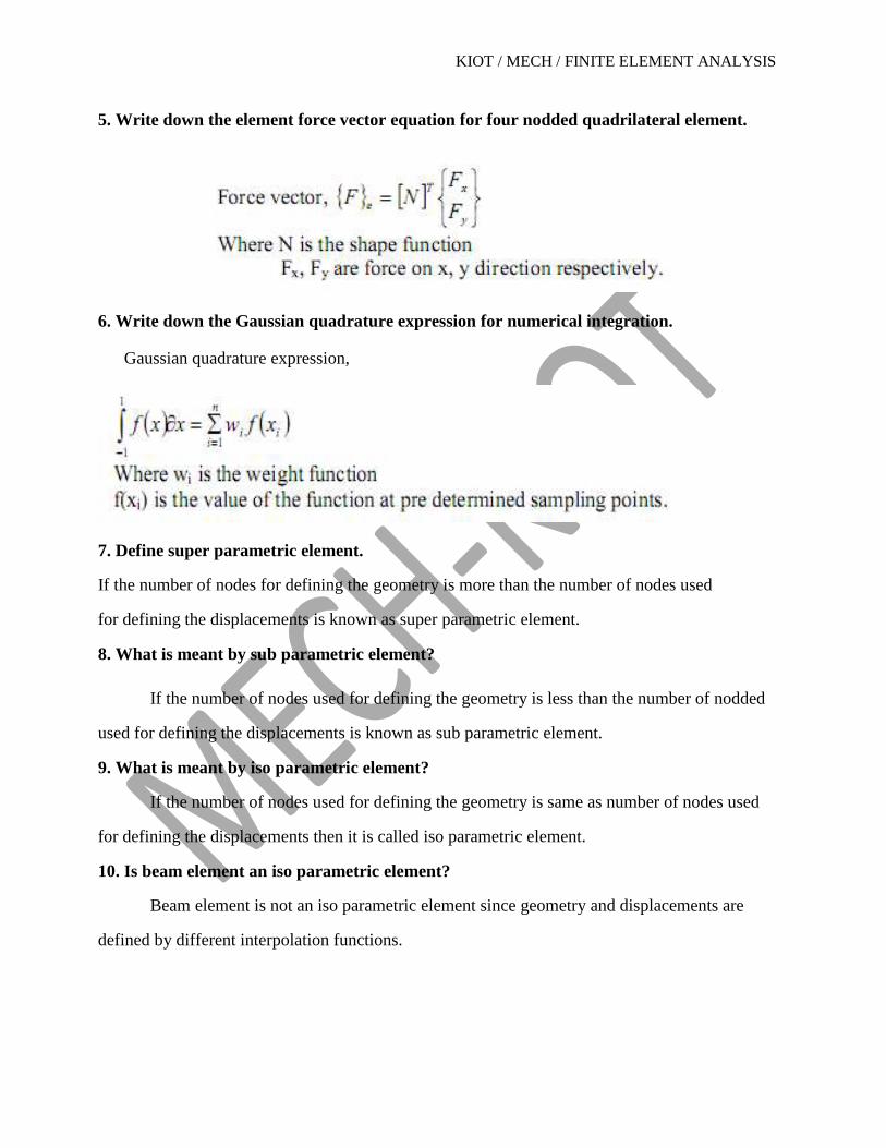
5. Write down the element force vector equation for four nodded quadrilateral element.
6. Write down the Gaussian quadrature expression for numerical integration.
Gaussian quadrature expression,
7. Define super parametric element.
If the number of nodes for defining the geometry is more than the number of nodes used
for defining the displacements is known as super parametric element.
8. What is meant by sub parametric element?
If the number of nodes used for defining the geometry is less than the number of nodded
used for defining the displacements is known as sub parametric element.
9. What is meant by iso parametric element?
If the number of nodes used for defining the geometry is same as number of nodes used
for defining the displacements then it is called iso parametric element.
10. Is beam element an iso parametric element?
Beam element is not an iso parametric element since geometry and displacements are
defined by different interpolation functions.

KIOT / MECH / FINITE ELEMENT ANALYSIS
FEA QUESTION BANK UNIT 1- INTRODUCTION
PART –A (2 Marks)
1. What is meant by finite element analysis?
2. Name any four applications of FEA.
3. What is the concept of matrix algebra and in what way it is used in FEA?
4. Briefly explain Gaussion elimination method.
5. Why polynomial type interpolation functions are preferred over trigonometric functions?
6. What is meant by ‘descretization’?
7. List out the various weighted-residual methods.
8. Define the concept of potential energy
9. List out any four advantages of using FEA.
10. What is the need for FEA?
11. List out FEM software packages
12. Name the different modules of FEM and their function
13. What are ‘h’ and ‘p’ versions of Finite Element method?
14. Name the vibrational methods.
15. What is meant by post processing?
16. Distinguish between essential boundary conditions and natural boundary conditions.
17. What are the general constituents of finite element software?
18. What is Rayleigh-Ritz method?
19. During discretization, mention the places where it is necessary to place a node?.
20. What is meant by node?
KIOT / MECH / FINITE ELEMENT ANALYSIS
UNIT I PART –B(16 Marks)
1. A simply supported beam is subjected to uniformly distributed load over entire span
Determine the bending moment and deflection at the mid span using Rayleigh-Ritz method and
compare with exact solution. Use a two term trial function y= a 1 sin(πx/l)+ a 2 sin(3πx/l)
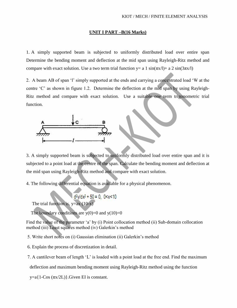
2. A beam AB of span ‘l’ simply supported at the ends and carrying a concentrated load ‘W at the
centre ‘C’ as shown in figure 1.2. Determine the deflection at the mid span by using Rayleigh-
Ritz method and compare with exact solution. Use a suitable one term trigonometric trial
function.
3. A simply supported beam is subjected to uniformly distributed load over entire span and it is
subjected to a point load at the centre of the span. Calculate the bending moment and deflection at
the mid span using Rayleigh-Ritz method and compare with exact solution.
4. The following differential equation is available for a physical phenomenon.
The trial function is, y=ax (10-x)
The boundary conditions are y(0)=0 and y(10)=0
Find the value of the parameter ‘a’ by (i) Point collocation method (ii) Sub-domain collocation
method (iii) Least squares method (iv) Galerkin’s method
5. Write short notes on (i) Gaussian elimination (ii) Galerkin’s method
6. Explain the process of discretization in detail.
7. A cantilever beam of length ‘L’ is loaded with a point load at the free end. Find the maximum
deflection and maximum bending moment using Rayleigh-Ritz method using the function
y=a{1-Cos (πx/2L)}.Given EI is constant.
KIOT / MECH / FINITE ELEMENT ANALYSIS
8. Solve the simultaneous systems of equation using Gauss-Elimination method.
3x + y –z = 3 ; 2x – 8y + z = 3 ; x – 2y + 9z = 8
9. The following differential equation is available for a physical phenomenon:
d2y/dx
2 – 10x2 = 5 ; 0 = x = 1
The boundary conditions are: y(0) = 0 and y(1) = 0.By using Galerkin’s method of weighted
residuals, find an approximate solution of the above differential equation.
10. A simply supported beam subjected to uniformly distributed load ‘qo’ over entire span and
also point load of magnitude ‘P’ at the centre of the span. Calculate the bending moment and
deflection at mid span by using Rayleigh-Ritz method and compare with the exact solution.
11. Solve the following equation using a 2 parameter trial solution by:
a) Point collocation method.
b) Galerkin’s method.
dy/dx + y = 0, 0=x=1, y(0) = 1
12. The following differential equation is available for a physical phenomenon.
d2y/dx
2 +50 = 0, 0=x=10, Trial function is y = a1x (10-x), y (0) = 0, y(10) = 0. Find the value of
a1 using all the weighted residual techniques and compare the solutions.
13. Solve the given equations by Gauss-Elimination method.
2x + 4y + 2z = 15 ; 2x + y + 2z = -5 ; 4x + y – 2z = 0
14. List the advantages, disadvantages and applications of FEM.
15. Explain the various weighted residual techniques.

KIOT / MECH / FINITE ELEMENT ANALYSIS
UNIT 2 - ONE -DIMENSIONAL PROBLEM
PART A
1. List out the properties of stiffness matrix
2. What are the different coordinate systems used in FEM?
3. Define a simplex, complex and multiplex element
4. What are shape functions and what are their properties?
5. Define ‘Natural coordinate system’
6. What are the advantages of natural coordinate system?
7. What are 1-Dimensional scalar and vector variable problems?
8. What types of problems are treated as one-dimensional problems?
9. Write down the expressions for shape functions of 1-D bar element.
10. Define aspect ratio. State its significance.
11. Write down the expressions for the element stiffness matrix of a beam element.
12. What is a higher order element? Give an example
13. Define shape function.
14. How do you calculate the size of the global stiffness matrix?
15. What are the characteristics of shape function?
16. What is truss?
17. Define total potential energy.
18. State the principle of minimum potential energy.
19. Write down the expression of shape function N and displacement u for 1-D bar element.
20. Write down the expression of stiffness matrix for a truss element.
UNIT 2 PART –B (16 Marks)
1. i) Derive the shape functions for a 2-D beam element
ii) Derive the stiffness matrix of a 2-D truss element

KIOT / MECH / FINITE ELEMENT ANALYSIS
2. Derive the shape functions for a 2 noded beam element and a 3 noded bar element
3. Derive the stiffness matrix of a 3 noded bar element using the principle of potential energy
4. Calculate the nodal displacements and forces for the bar loaded as shown in figure.
5. A stepped bar is subjected to an axial load of 200 KN at the place of change of cross section
and material as shown in figure 2.5. Find (a) The nodal displacements (b) the reaction forces (c)
the induced stresses in each material
6. For a tapered bar of uniform thickness t=10mm as shown in figure 2.6. Find the displacements
at the nodes by forming into two element model. The bar has a mass density = 7800 Kg/M ,
young’s modulus E = 2x10 MN/m . In addition to self-weight, the bar is subjected to a point load
P= 1 KN at its centre. Also determine the reaction forces at the support.
7. Consider a 4-bar truss as shown in figure. It is given that
E = 200 GPa and A= 500 mm2 for all the elements.
Determine (a) Nodal displacements (b) Support reactions (c)
Element stresses.
KIOT / MECH / FINITE ELEMENT ANALYSIS
8. Derive an expression for shape function and assemble the stiffness matrix for bending in
beam elements.
9. Derive an expression of shape functions and the stiffness matrix for one dimensional bar
element based on global co-ordinate approach.
10. A two noded truss element is shown in the fig. The nodal displacements are u1=5 mm and
u2 = 8 mm. Calculate the displacements at x = L/4, L/3 and L/2.
11. A steel plate of uniform thickness 25 mm is subjected to a point load of 420 N at mid depth
as shown in fig. The plate is also subjected to self-weight. If E = 2*105 N/mm2 and density =
0.8*10-4 N/mm3. Calculate the displacement at each nodal point and stresses in each element.
12. An axial load of 4*105 N is applied at 30°C to the rod as shown in fig. The temperature is
then raised to 60°C. Calculate nodal displacements, stresses in each material and reactions at
each nodal point. Take Eal = 0.7*105 N/mm2; Esteel = 2*105 N/mm2 ; aal = 23*10-6 /°C ;
asteel = 12*10-6 /°C.
13.Why higher order elements are needed? Determine the shape functions of an eight noded
rectangular element.
14.Derive the stiffness matrix for two dimensional truss elements.
15.Determine the slope and deflection of a cantilever beam subjected to a uniformly distributed
load q over the entire span and a point load P acting on its free end.
16) Consider a steel column subjected to load as shown in following figure. assuming axial
loading, determine a) Vertical displacement at all nodes and stress in each element. Take
E=2.5 x 10⁵N/mm
2; A=2500mm
2Divide the column into 4 equal length elements.

KIOT / MECH / FINITE ELEMENT ANALYSIS
17) A steel plate is subjected to an axial load as shown in following figure. Find the approximate
deflection and average stress along the plate by using direct formulate method. The plate is
1.5mm thick and has modulus of elasticity E=2 x 10⁵ N/mm
2.
18) Find a) Nodal displacement b) stress c) Reaction at each node for the bar as shown in
following figure
A= 250mm2 ; E=2 x 10
5 N/mm
2 ; P=600 x 10
3 N.

KIOT / MECH / FINITE ELEMENT ANALYSIS
19) Consider the shown in following figure. an axial load p=200 x 103
N is applied as shown.
Using the penalty approach for handling boundary conditions, find the following:
a. Determine the nodal displacements.
b. Determine the stress in each material.
c. Determine the reaction forces.
A1=2400mm2
A2=600mm2
E1=70 x 109
E2=200 x 103N
In following figure, a load p =60x103N is applied as shown. Determine the displacement field,
stress and support reactions in the body. Take E = 20 x 103
N/mm2.
20. An axial load P= 300 x 103
N is applied at 20Ċ to the rod as shown in following figure. the
temperature is the Raised to 60 Ċ
a. Assemble the stiffness matrix and force vector
b. Determine the nodal displacement and element stresses.
21. Consider the bar in following figure. C/S area A = 1.22 in and E = 30 x 10
6 psi.If q1=0.02 in
and q2=0.02 in. Determine (by manual method):
a. The displacement at point P
b. The strain € and stress ∂
c. the element stiffness matrix
d. The strain energy in the element

KIOT / MECH / FINITE ELEMENT ANALYSIS
22. Consider the bar in following figure. Determine the nodal displacement, element stresses and
support reactions.
UNIT 3- TWO DIMENSIONAL PROBLEMS-SCALAR VARIABLE PROBLEMS
PART A (2 Marks)
1. Write down the shape functions for a ‘Rectangular element.
2. State a two dimensional scalar variable problem with an example.
3. What is meant by a CST element? State its properties.
4. In what way a bilinear element is different from simplex and complex element?
5. Define ‘Plane stresses and ‘Plane strain’ with suitable example
6. Differentiate between a CST and LST element
7. What are the differences between uses of linear triangular element?
8. What is meant by a two dimensional vector variable problem?
9. Write down the expression for the stress-strain relationship matrix for a 2-D system.
10. State the expression for stiffness matrix for a bar element subjected to torsion
11. Write down the finite element equation for one-dimensional heat conduction
12. Specify the various elasticity equations.
13. Write down the expression for shape functions for a constant strain triangular element

KIOT / MECH / FINITE ELEMENT ANALYSIS
14. Write a strain displacement matrix for CST element
15. What is LST element?
16. What is QST element?
17. What is meant by plane stress analysis?
18. Write down the stiffness matrix equation for 2-D CST element.
19. Define plane stress analysis.
20. Write a displacement function equation for CST element.
UNIT 3PART B (16 Marks)
1. Find the temperature at a point P(1,1.5) inside a triangular element shown with nodal
temperatures given as T i= 40°C, T j= 34°C and T k = 46°C. Also determine the location of
the 42°C contour line for the triangular element shown in figure 3.1.
2. Calculate the element stiffness matrix and thermal
force vector for the plane stress element shown in figure
3.2. The element experiences a rise of 10°C.
3. Derive the stiffness matrix and equations for a CST element.
4. Derive the stiffness matrix and equations for a LST element
5. Derive the shape functions for a bilinear rectangular element .
6. For a 4-noded rectangular element shown in figure 3.6. Determine the temperature at the
point (7,4). The nodal values of the temperatures are T 1 = 42°C, T 2 = 54°C and T 3 = 56°C
and T 4 = 46°C. Also determine the three points on the 50°C contour line.
KIOT / MECH / FINITE ELEMENT ANALYSIS
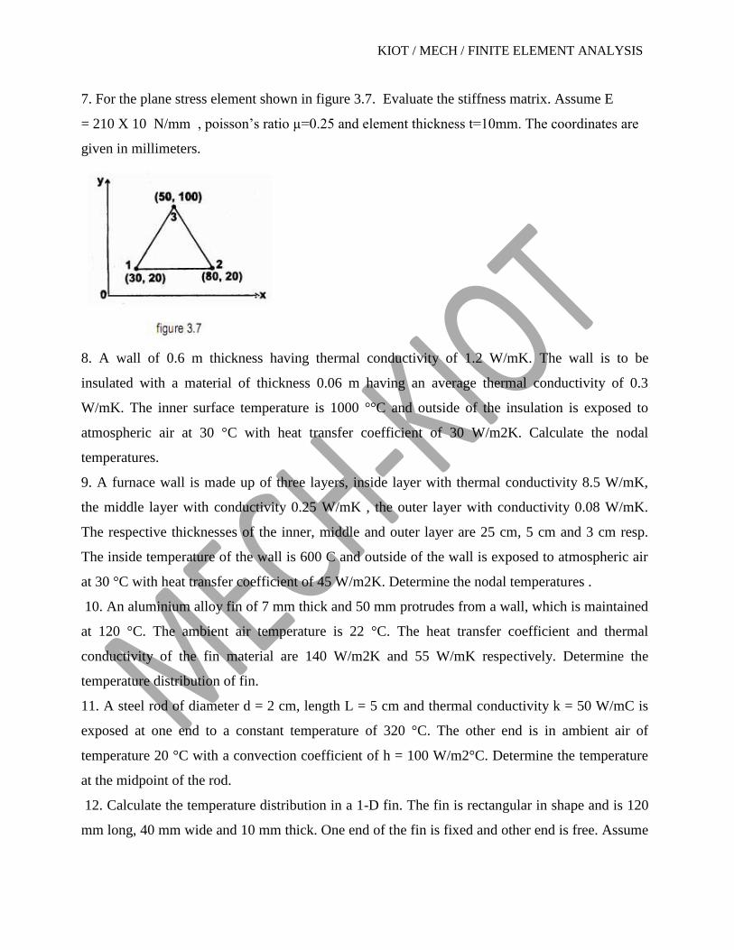
7. For the plane stress element shown in figure 3.7. Evaluate the stiffness matrix. Assume E
= 210 X 10 N/mm , poisson’s ratio µ=0.25 and element thickness t=10mm. The coordinates are
given in millimeters.
8. A wall of 0.6 m thickness having thermal conductivity of 1.2 W/mK. The wall is to be
insulated with a material of thickness 0.06 m having an average thermal conductivity of 0.3
W/mK. The inner surface temperature is 1000 °°C and outside of the insulation is exposed to
atmospheric air at 30 °C with heat transfer coefficient of 30 W/m2K. Calculate the nodal
temperatures.
9. A furnace wall is made up of three layers, inside layer with thermal conductivity 8.5 W/mK,
the middle layer with conductivity 0.25 W/mK , the outer layer with conductivity 0.08 W/mK.
The respective thicknesses of the inner, middle and outer layer are 25 cm, 5 cm and 3 cm resp.
The inside temperature of the wall is 600 C and outside of the wall is exposed to atmospheric air
at 30 °C with heat transfer coefficient of 45 W/m2K. Determine the nodal temperatures .
10. An aluminium alloy fin of 7 mm thick and 50 mm protrudes from a wall, which is maintained
at 120 °C. The ambient air temperature is 22 °C. The heat transfer coefficient and thermal
conductivity of the fin material are 140 W/m2K and 55 W/mK respectively. Determine the
temperature distribution of fin.
11. A steel rod of diameter d = 2 cm, length L = 5 cm and thermal conductivity k = 50 W/mC is
exposed at one end to a constant temperature of 320 °C. The other end is in ambient air of
temperature 20 °C with a convection coefficient of h = 100 W/m2°C. Determine the temperature
at the midpoint of the rod.
12. Calculate the temperature distribution in a 1-D fin. The fin is rectangular in shape and is 120
mm long, 40 mm wide and 10 mm thick. One end of the fin is fixed and other end is free. Assume

KIOT / MECH / FINITE ELEMENT ANALYSIS
that convection heat loss occurs from the end of the fin. Use 2 elements. The temperature at fixed
end is 120 °C. Take k = 0.3 W/mm°C ; h = 10-3 W/mm2C ; T(amb) = 20 °C.
13. A metallic fin, with thermal conductivity k = 360 W/mc, 0.1 cm thick and 10 cm long, extends
from a plane wall whose temperature is 235C. Determine the temperature distribution and amount
of heat transferred from the fin to the air at 20C with h = 9 W/m2C. Take width of the fin to be 1
m.
14. Evaluate the stiffness matrix for the CST element shown in fig. Assume plane stress
condition. Take, t = 20 mm, E = 2*105 N/mm2 and m = 0.25. The coordinates are given in mm.
15. Assemble the strain-displacement matrix for the CST element shown in fig. Take, t = 25 mm
and E = 210 Gpa.
UNIT 4- TWO DIMENSIONAL PROBLEMS-VECTOR VARIABLE PROBLEMS
PART A (2 Marks)
1. What are the ways by which a 3-dimensional problem can be reduced to a 2-D problem?
2. What is meant by axisymmetric solid?
3. Write down the expression for shape functions for a axisymmetric triangular element
4. State the conditions to be satisfied in order to use axisymmetric elements
5. State the expression used for ‘gradient matrix’ for axisymmetric triangular element
6. State the constitutive law for axisymmetric problems.
7. Sketch ring shaped axisymmetric solid formed by a triangular and quadrilateral element
8. Write down the expression for stiffness matrix for an axisymmetric triangular element
9. Distinguish between plane stress, plane strain and axisymmetric analysis in solid
Mechanics.
10. Sketch an one-dimensional axisymmetric (shell) element and two-dimensional
axisymmetric element.
11. What are the conditions for a problem to be axisymmetric.
12. Give the strain-displacement matrix equation for an axisymmetric triangular element
13. Write down the stress-strain relationship matrix for an axisymmetric triangular element.

KIOT / MECH / FINITE ELEMENT ANALYSIS
15. What are the ways in which a 3-D problem can be reduced to a 2-D approach.
UNIT 4 PART B (16 Marks)
1. Derive the shape functions for an axisymmetric triangular element
2. Derive an expression for the strain-displacement matrix for an axisymmetric triangular
Element.
3. For the axisymmetric element shown in figure, determine the stiffness matrix. Let E = 2.1X10⁵
MN/m2 and µ=0.25. The coordinates are in mm.
4. Determine the element strains for an axisymmetric triangular element shown in figure 4.4.
The nodal displacements are u 1 = 0.001, u 2 = 0.002, u 3 = - 0.003, w 1 = 0.002, w 2 = 0.001, w
3 = 0.004. All dimensions are in cm.
5. The nodal coordinates for an axisymmetric triangular element at its three nodes are (r 1 , z 1 )
= (30,10), (r 2 , z 2 ) = (50,10), (r 3 , z 3 ) = (40,60). Determine the strain displacement matrix
for that element.

KIOT / MECH / FINITE ELEMENT ANALYSIS
6. A long hollow cylinder of inside dia 80 mm and outside dia 120 mm is subjected to an
internal pressure of 40 bar as shown in figure. By using two elements pin the 20 mm
length, calculate the displacements at the inner radius.
7. Derive the expression for the stiffness matrix for an axisymmetric shell element.
8. The nodal co-ordinates for an axisymmetric triangular are given below: r1 = 15 mm, z1 = 15
mm ; r2 = 25 mm , z2 = 15 mm ; r3 = 35 mm , z3 = 50 mm. Determine [B] matrix for that
element.
9. Evaluate the temperature force vector for the axisymmetric triangular element shown in the fig.
The element experiencies a 15°C increases in temperature. Take α = 10*10-6/°C, E = 2*105
N/mm2, m = 0.25.
10. Determine the stiffness matrix for the element shown in fig. The co-ordinates are in mm. Take
E = 2*105 N/mm2 and m = 0.25.
11. Derive the expression for the element stiffness matrix for an axisymmetric shell element.
12. For the axisymmetric elements shown in fig, determine the element stresses. Let E = 210Gpa
and m = 0.25. The co-ordinates are in mm.
u1 = 0.05 mm; w1 = 0.03 mm
u2 = 0.02 mm; w2 = 0.02 mm
u3 = 0 mm ; w3 = 0 mm
13. Derive the strain – displacement matrix [B] for axisymmetric triangular element.
14. Derive the stress-strain relationship matrix [D] for the axisymmetric triangular element.
15. Calculate the element stiffness matrix and the thermal force vector for the axisymmetric
triangular element shown in fig. The element experiences a 15°C increase in temperature. The
coordinates are in mm. Take α = 10*10-6/°C; E = 2*105 N/mm2; m = 0.25

KIOT / MECH / FINITE ELEMENT ANALYSIS
UNIT 5- ISOPARAMETRIC ELEMENT FORMULATIONS
PART-A (2 Marks)
1. What is an ‘Iso-parametric element’?
2. Differentiate between Isoparametric, super parametric and sub parametric elements.
3. Write down the shape functions for 4-noded linear quadrilateral element using
natural coordinate system.
4. What is a ‘Jacobian transformation’?
5. What are the advantages of ‘Gaussian quadrature’ numerical integration for
isoparametric elements??
6. How do you calculate the number of Gaussian points in Gaussian quadrature method?
7. Find out the number Gaussian points to be considered for ? (x +3x -x) dx
8. What is the Jacobian transformation fro a two nodded isoparametric element?
9. What is meant by isoparametric formulation?
10. Sketch an general quadrilateral element and an isoparametric quadrilateral element.
11. How do you convert Cartesian coordinates into natural coordinates?
12. Write down the expression for strain-displacement for a four-noded quadrilateral element
using natural coordinates.
UNIT 5 PART-B (16 Marks)
1. Integrate
between 8 and 12.Use Gaussian quadrature rule.
2. Derive the stiffness matrix for a linear isoparametric element.
3. Establish the strain displacement matrix for the linear quadrilateral element as shown in
figure at Gauss point r= 0.57735 and s= -0.57735

KIOT / MECH / FINITE ELEMENT ANALYSIS
4. Write short notes on (a) Uniqueness of mapping of isoparametric elements. (b) Jacobian matrix
(c) Gaussian quadrature integration technique
5. (a) Use Gaussian quadrature rule (n=2) to numerically integrate
(b) Using natural coordinates derive the shape function for a linear quadrilateral element
6. Evaluate the integral using one point and two point Gauss- quadrature. Compare this with
exact solution.
7. Derive the element stiffness matrix for a linear isoparametric quadrilateral element.
8. Establish the strain – displacement function matrix for the linear quadrilateral element as
shown in fig at gauss point r = 0.57735 and s = -0.57735.
9. The integral ∫1-1 ( r3 + 2r
2 + 1) dr can be evaluated exactly by two point gaussian quadrature.
Examine the effect on the result if three point integration is applied.
10. For a 4 noded rectangular element shown in fig, determine the following:
Jacobian matrix Strain displacement matrix Element stresses. Take E = 2*105 N/mm2 ; m = 0.25
u = [0,0,0.002,0.003,0.005,0.003,0,0 ] ; ε = 0 ; η = 0. Assume plane stress condition
11. Evaluate the integral I = ∫1-1 (2 + x + x2) dx using gauss quadrature method and compare
with exact solution.
12. Evaluate the integral, I = ∫1-1 cos πx/2 dx by applying 3 point Gaussian quadrature and
compare with exact solution.
13. Evaluate the integral I = ∫1-1 [3ex + x2 +1/x+2] dx using one point and two point gauss
quadrature. Compare with exact solution.
14. For the element shown in following figure determine, the Jacobian matrix
KIOT / MECH / FINITE ELEMENT ANALYSIS
15. Evaluate the following integrals using one point and two point gauss quadrature.
1
I= ∫[3ex
+x2+1/(x+2)]dx
-1
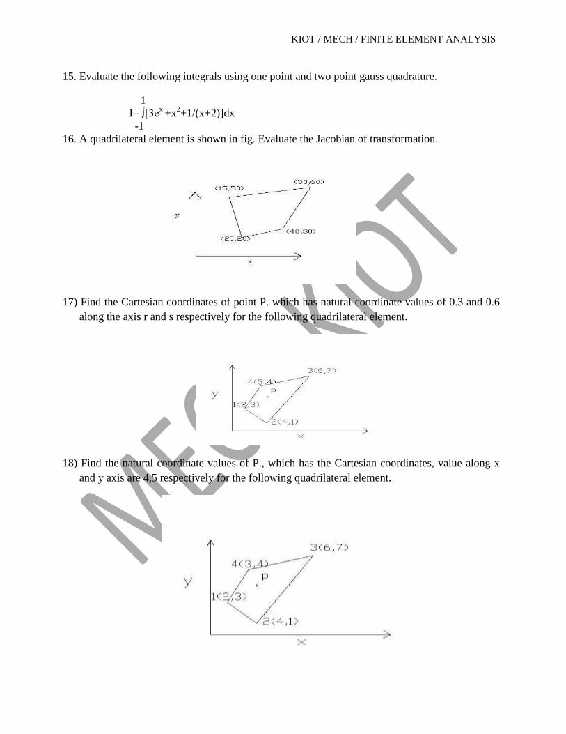
16. A quadrilateral element is shown in fig. Evaluate the Jacobian of transformation.
17) Find the Cartesian coordinates of point P. which has natural coordinate values of 0.3 and 0.6
along the axis r and s respectively for the following quadrilateral element.
18) Find the natural coordinate values of P., which has the Cartesian coordinates, value along x
and y axis are 4,5 respectively for the following quadrilateral element.

KIOT / MECH / FINITE ELEMENT ANALYSIS
19) Find the Jacobian matrix for the following quadrilateral elements