kato 253 - nekos srl
TRANSCRIPT

4420052 – Rev 2110
KATO 253
MANUALE ISTRUZIONI ATTUATORE A CATENA Forza 250N – Corsa massima 360 mm Alimentazione elettrica 110-230V~ 50/60Hz e 24V
INSTRUCTION MANUAL
CHAIN ACTUATOR Force 250N – Maximum stroke 360 mm Electrical feeding 110-230V~ 50/60Hz and 24V
BETRIEBSANLEITUNG
KETTENANTRIEB Kraft 250N – Maximalhub 360 mm Spannungsversorgung 110-230V~ 50/60Hz und 24V
NEKOS S.r.l. - Via Capitoni, 7/5 - 36064 Colceresa – VI – ITALY
+39 0424 411011 – +39 0424 411013 - www.nekos.it - [email protected]
DE
IT
EN
3
USER INSTRUCTIONS
CAUTION. Carefully observe all the following installation instructions to ensure personal safety.
The device is not intended for use by persons (including children) with reduced physical, sensory or mental capabilities, or lacking experience and knowledge. Do not allow children to play with the fixed controls and keep any remote-control units out of their reach.
Have installation checks performed periodically by qualified personnel from a service centre authorised by the manufacturer. Do not use if repair or adjustment is required.
CAUTION: if the power cable is damaged, it must be replaced by qualified personnel from a service centre authorised by the manufacturer.
CAUTION. Disconnect the power supply during cleaning or maintenance operations. Do not use solvents or jets of water to wash the appliance; the appliance should not be submerged in water.
In the event of fault or malfunction, switch off the device at the main switch. All repairs and adjustments (e.g. setting the stroke) must only be performed by qualified personnel from a service centre authorised by the manufacturer.
Always request exclusive use of original spare parts. Failure to respect this condition could compromise safety and invalidate the benefits contained in the warranty for the appliance. In the event of any problems or queries, consult your agent or contact the manufacturer directly.
The A-weighted sound pressure level is less than 70dB(A).
Carefully preserve these instructions after installation.

17
INSTALLER INSTRUCTIONS
nekos products have been manufactured in accordance with safety standards and conforms to the stipulations of current standards in force. When correctly assembled, installed and used according to the present instructions, they will not generate any danger for persons, animals or items. Symbols used in the manual
DANGER This indication draw the attention about potential dangers for safety and health of peoples and animals.
Contents
1. Security rules ............................................................................................................................ 18 2. Formulas and recommendations for installation ...................................................................... 19 3. Technical information about function ........................................................................................ 19 4. Technical data .......................................................................................................................... 20 5. Manufacture and applicable standards or regulations .............................................................. 20 6. Id plate and marking data ......................................................................................................... 21 7. Electrical power supply ............................................................................................................. 21 8. Instructions for assembly .......................................................................................................... 22 9. Electrical connections ............................................................................................................... 25 10. Programming the actuator ........................................................................................................ 25 11. Checking for correct assembly ................................................................................................. 26 12. Emergency manoeuvres, maintenance or cleaning .................................................................. 26 13. Troubleshooting ........................................................................................................................ 26 14. Environmental protection .......................................................................................................... 27 15. Certificate of guarantee ............................................................................................................ 27 16. Declaration of incorporation (for a partly completed machine) and EC declaration of
conformity ................................................................................................................................. 28
18
1. SECURITY RULES
CAREFULLY OBSERVE ALL THE FOLLOWING INSTALLATION INSTRUCTIONS TO ENSURE
PERSONAL SAFETY. IMPROPER INSTALLATION CAN SERIOUSLY ENDANGER SAFETY.
MANDATORY RISK ANALYSIS AND PROTECTION MEASURES.
The Nekos electrical actuators comply with the Machinery Directive (2006/42/EC), Standard IEC 60335-2-103 (Particular requirements for drives for gates, doors and windows) and other directives and regulations indicated in the attached Declarations of Incorporation and CE Conformity (at the end of the manual). According to the Machinery Directive, actuators are “partly completed machinery” intended for incorporation into doors and windows. The manufacturer/supplier of the window is required, with exclusive responsibility, to ensure the compliance of the entire system with the applicable standards and to issue CE certification. We strongly discourage any use of the actuators other than that specified and therefore, in any case, the supplier of the complete system retains full liability.
For systems installed at a height of less than 2.5 m above floor level or other levels accessible to users, the manufacturer/supplier of the window must conduct risk analysis regarding potential harm (violent blows, crushing, wounds) caused to people by normal use or possible malfunction or accidental breakage of the automated windows, and to implement suitable protective measures in view of these. Such measures include those recommended by the specified standard: - controlling the actuators via a “deadman’s button” placed near the system and within the
operator’s field of view, to ensure that people are out of the way during operation. The button must be placed at a height of 1.5 m and operated by key if accessible to the public; or:
- use of contact safety systems (also included in the actuators) that ensure a maximum closing force of 400/150/25 N, measured in accordance with paragraph BB.20.107.2 of IEC 60335-2-103; or:
- use of non-contact safety systems (lasers, light grids); or: - use of fixed safety barriers that prevent access to moving parts. Automated windows are deemed adequately protected if they: - are installed at a height of >2.5 m; or:
- have a leading-edge opening of <200 mm and a closing speed of <15 mm/s; or: - are part of a smoke and heat evacuation system for emergency use only.
In any case, moving parts of windows that could fall below 2.5 m following breakage of a system component need to be fixed or secured in order to prevent them from suddenly falling or collapsing: e.g. the use of safety arms on bottom-hung windows.
The device is not intended for use by persons (including children) with reduced physical, sensory or mental capabilities, or lacking experience and knowledge. Do not allow children to play with the fixed controls and keep any remote-control units out of their reach. The actuator is destined exclusively for installation indoors. For any special application we recommend you consult the manufacturer beforehand. After removing packaging, check for any damage on the appliance. Always request exclusive use of original spare parts. Failure to respect this condition could compromise safety and invalidate the benefits contained in the warranty for the appliance. In the event of any problems or queries, consult your agent or contact the manufacturer directly.
English

19
2. FORMULAS AND RECOMMENDATIONS FOR INSTALLATION
2.1. Calculation of opening / closure force
Using the formulas on this page, approximate calculations can be made for the force required to open or close the window considering all the factors that determine the calculation.
Symbols used for the calculation
F (Kg) = Force for opening or closing P (Kg) = Weight of the window (mobile sash only)
C (cm) = Opening stroke (actuator stroke) H (cm) = Height of the mobile sash
For horizontal light domes or skylights
F = 0.54 x P
(Eventual weight of snow or wind on the cupola should be calculated separately).
For vertical windows
TOP HUNG WINDOWS, OUTWARD OPENING (A) BOTTOM HUNG WINDOWS (B)
F = 0.54 x P x C : H
(Eventual load of favourable or unfavourable wind on the sash should be calculated separately.)
2.2. Maximum opening according to height of sash
The actuator stroke is in accordance with the height of the sash and its application. Check that the actuator stroke does not touch the profile of the sash and that the chain does not exert force on the window frame (measurements in mm). ATTENTION. For safety reasons the actuator should not be assembled if dimensions are inferior to those indicated in the table below. In the event that the height of the sash should be lower, call on the manufacturer to check the appliance.
Mode of installation Selection of actuator stroke
240 360 Light domes, skylights or vertical top hung windows opening outwards with frontal assembly
400 550
Top hung windows opening outwards with horizontal assembly 400 550
Bottom hung windows (motor on frame) 400 550
Bottom hung windows (motor on sash) Consult manufacturer
3. TECHNICAL INFORMATION ABOUT FUNCTION
The chain actuator opens and closes the window using a double row steel chain inside a sheath. Movement is generated using electrical energy that powers a reduction motor
20
controlled by a functional electrical device. Windows can be programmed to open and the device allows chain opening at 240 and 360 mm. When the window returns to start position, that is during closure, the stroke-end uses an electronic self regulating process with absorption of energy and no regulation is therefore required. The actuator is produced by the factory with the chain 1 cm out. This allows the actuator to be assembled without electrical energy powering movement and means that the window remains closed after assembly. The joint between actuator and support brackets is quick, requires no fixing screws (NEKOS patent) and allows the actuator to rotate to follow the track of the chain even on shorter windows.
4. TECHNICAL DATA
Model KATO 253/230V KATO 253/24V Force exerted by thrust and traction (FN) 250 N Strokes (SV) 240, 360 mm Power supply voltage (UN) 110-230V~ 50/60Hz 24V Rated absorbed current (IN) 0,42 A - 0,21 A 0,78 A Power absorbed at nominal load (PN) ~ 23-20 W ~ 19 W No load speed 15 mm/s 13,3 mm/s Duration of no load stroke (360 mm) 24 s 27 s Electrical insulation Class II Class III (Selv) Type of service (DR) 2 cycles 5 cycles Operating temperature - 5 + 65 ºC Protection index for electrical devices IP40 Adjustment of connection to window frame Automatic definition of position Parallel powering of two or more motors YES (max 30 actuators) Synchronised function Not foreseen Holding nominal force (it can vary according to the chosen brackets)
1500N
Stroke-end at opening At absorption of power Stroke-end at closing At absorption of power Length of power cable 1 m Dimensions 356x56x33,5 mm Weight 0,83 Kg 0,80 Kg
The data indicated in these figures is not binding and is subject to variation without notification.
5. MANUFACTURE AND APPLICABLE STANDARDS OR REGULATIONS
INTENDED USE. The chain operated series KATO 253 actuator has been designed and manufactured to open and close top hung windows, bottom hung windows, dormer windows, light domes and skylights. It has been specifically designed for ventilation and climate control; any other use is strongly discouraged, with the supplier of the entire system in any case retaining sole liability. The actuator is manufactured in accordance with the Directives and following Regulations listed in the attached Declaration of Incorporation and Conformity . Electrical connections must conform to regulations in force for the design and set up of electrical equipment. To ensure efficient separation from the grid, an approved type of bipolar “dead-man” switch should be used. An omnipolar general power switch with minimum distance of 3 mm between contacts should be installed upstream of the control line.

21
The actuator is packaged in cardboard boxing and each package contains:
Electrical actuator with either 110-230V~ 50/60Hz or 24V with electrical cable directly connected to the machine.
Drilling template.
Standard support brackets (A).
Bracket for bottom hung window (C).
Bracket for top hung window (D).
Instructions manual.
6. ID PLATE AND MARKING DATA
The KATO 253 actuators have CE marking and comply with the Standards listed in the Declaration of Conformity. They also come with a Declaration of Incorporation, due to their classification by the Machinery Directive as “partly completed machines”. Both declarations are included in the final pages of this manual. The plate data is displayed on an adhesive label placed on the outside of the casing, which must remain intact and visible. The main information it displays includes: manufacturer's address, product name - model number, technical characteristics, production date and serial number. In the event of a complaint, please indicate the serial number (SN) displayed on the label. An explanation of the symbols used on the label to abbreviate the technical characteristics is given in the table in the chapter on “TECHNICAL DATA”.
7. ELECTRICAL POWER SUPPLY
The KATO 253 actuator is commercially available in two versions:
1. KATO 253 230V~: runs on grid tension of 110-230V~, 50/60Hz, with a three wire cable (LIGHT BLUE, common neutral; BLACK, phase open; BROWN, phase closed).
2. KATO 253 24V: runs on 24V , with two wire cable, LIGHT BLUE, connected to the + (positive) opens; Brown, connected to the + (positive) closes.
24V low voltage actuators can be powered using a station with emergency battery or security power supply unit with an output voltage of 24V (min. 20,4V, max. 28,8V).
7.1. Selection of power cable section
For 24V power supply cable section must be checked and calculated according to cable length. The following table indicates maximum cable lengths for connection to motors.
CABLE SECTION Actuator fed at
24V 110V~ 230V~ 0.50 mmq ~20 m ~300 m ~1400 m 0.75 mmq ~30 m ~450 m ~2100 m 1.00 mmq ~40 m ~600 m ~2800 m 1.50 mmq ~60 m ~900 m ~4000 m 2.50 mmq ~100 m ~1500 m ~6800 m 4.00 mmq ~160 m ~2500 m ~11000 m 6.00 mmq ~240m ~3700 m ~15000 m
22
8. INSTRUCTIONS FOR ASSEMBLY
These indications are for specialised technical personnel and basic work and safety techniques are not indicated.
All preparatory, assembly and electrical connection operations must be performed by specialised technical personnel to guarantee optimal function and service of the actuator.
Check that the following fundamental conditions have been met:
Before installing the actuator, check that the moving parts of the window on which it is to be installed are in perfect working condition and that they open and close properly and are well balanced (where applicable).
Actuator specifications must be sufficient for movement of the window without encountering any obstacle. The limits indicated in the technical data table must not be superseded (page 20) and the most appropriate stroke should be selected. Calculations should be checked using the formula indicated on page 19.
Attention. Check that the electrical power supply corresponds to that indicated on the TECHNICAL DATA label on the machine.
Ensure that the actuator has not been damaged during transport, first visually and then by powering in both directions.
Check that the width of the inside of the window (where the actuator is to be assembled) is over 375 mm, otherwise the actuator should not be installed.
Check that once the actuator has been installed the distance between the fixed part of the window frame (where the actuator is to be assembled) and the mobile part of the window frame (where the bracket is to be fixed) is greater than or equal to 0 mm. If this is not the case the actuator will not function correctly as the window will not close correctly. If required, add additional thickness below the support brackets to reset the quota.
For bottom hung window frames injury could be caused by accidental falls of the window. An appropriately sized flexible link arm or fall prevention safety system designed to resist a force equal to at least three times the total weight of the window MUST be installed.
8.1. Preparation of actuator for assembly
Before starting assembly of the actuator, prepare the following material for completion, equipment and tools.
For fixing onto metal window frames: M5 threaded inserts (6 pieces), M5x12 flat headed metric screws (6 pieces).
For fixing onto wooden window frames: self threading screws for wood Ø4.5 (6 pieces).
For fixing onto PVC window frames: self threading screws for metal Ø4.8 (6 pieces).
Equipment and tools: measuring tape, pencil, drill/screwdriver, set of drill heads for metal, insert for screwing in, electricians pliers, screwdrivers.
23
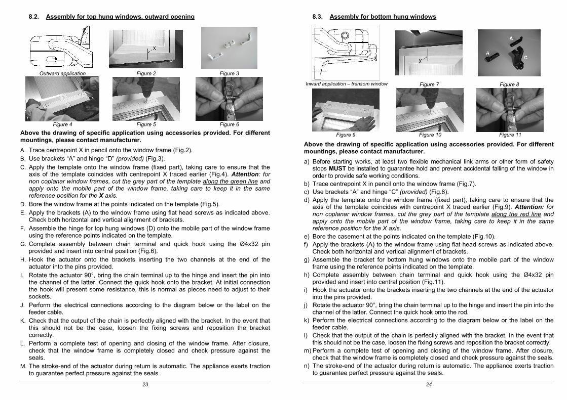
8.2. Assembly for top hung windows, outward opening
Outward application Figure 2 Figure 3
Figure 4 Figure 5 Figure 6
Above the drawing of specific application using accessories provided. For different mountings, please contact manufacturer.
A. Trace centrepoint X in pencil onto the window frame (Fig.2). B. Use brackets “A” and hinge “D” (provided) (Fig.3).
C. Apply the template onto the window frame (fixed part), taking care to ensure that the axis of the template coincides with centrepoint X traced earlier (Fig.4). Attention: for non coplanar window frames, cut the grey part of the template along the green line and apply onto the mobile part of the window frame, taking care to keep it in the same reference position for the X axis.
D. Bore the window frame at the points indicated on the template (Fig.5). E. Apply the brackets (A) to the window frame using flat head screws as indicated above.
Check both horizontal and vertical alignment of brackets. F. Assemble the hinge for top hung windows (D) onto the mobile part of the window frame
using the reference points indicated on the template. G. Complete assembly between chain terminal and quick hook using the Ø4x32 pin
provided and insert into central position (Fig.6). H. Hook the actuator onto the brackets inserting the two channels at the end of the
actuator into the pins provided. I. Rotate the actuator 90°, bring the chain terminal up to the hinge and insert the pin into
the channel of the latter. Connect the quick hook onto the bracket. At initial connection the hook will present some resistance, this is normal as pieces need to adjust to their sockets.
J. Perform the electrical connections according to the diagram below or the label on the feeder cable.
K. Check that the output of the chain is perfectly aligned with the bracket. In the event that this should not be the case, loosen the fixing screws and reposition the bracket correctly.
L. Perform a complete test of opening and closing of the window frame. After closure, check that the window frame is completely closed and check pressure against the seals.
M. The stroke-end of the actuator during return is automatic. The appliance exerts traction to guarantee perfect pressure against the seals.
24
8.3. Assembly for bottom hung windows
Inward application – transom window Figure 7 Figure 8
Figure 9 Figure 10 Figure 11
Above the drawing of specific application using accessories provided. For different mountings, please contact manufacturer.
a) Before starting works, at least two flexible mechanical link arms or other form of safety stops MUST be installed to guarantee hold and prevent accidental falling of the window in order to provide safe working conditions.
b) Trace centrepoint X in pencil onto the window frame (Fig.7). c) Use brackets “A” and hinge “C” (provided) (Fig.8). d) Apply the template onto the window frame (fixed part), taking care to ensure that the
axis of the template coincides with centrepoint X traced earlier (Fig.9). Attention: for non coplanar window frames, cut the grey part of the template along the red line and apply onto the mobile part of the window frame, taking care to keep it in the same reference position for the X axis.
e) Bore the casement at the points indicated on the template (Fig.10). f) Apply the brackets (A) to the window frame using flat head screws as indicated above.
Check both horizontal and vertical alignment of brackets. g) Assemble the bracket for bottom hung windows onto the mobile part of the window
frame using the reference points indicated on the template. h) Complete assembly between chain terminal and quick hook using the Ø4x32 pin
provided and insert into central position (Fig.11). i) Hook the actuator onto the brackets inserting the two channels at the end of the actuator
into the pins provided. j) Rotate the actuator 90°, bring the chain terminal up to the hinge and insert the pin into the
channel of the latter. Connect the quick hook onto the rod. k) Perform the electrical connections according to the diagram below or the label on the
feeder cable. l) Check that the output of the chain is perfectly aligned with the bracket. In the event that
this should not be the case, loosen the fixing screws and reposition the bracket correctly. m) Perform a complete test of opening and closing of the window frame. After closure,
check that the window frame is completely closed and check pressure against the seals. n) The stroke-end of the actuator during return is automatic. The appliance exerts traction
to guarantee perfect pressure against the seals.

25
9. ELECTRICAL CONNECTIONS
Machines have been equipped with a power connection cable which complies with safety regulations and protection against radio disturbance. Before performing the electrical connection consult the table below and check correspondence between the feeder cable and the tension data on the actuator label.
Voltage Cable length Number of wires Colour of wires
110-230V~ 50/60Hz 1 m 3 LIGHT BLUE
BLACK BROWN
24V 1 m 2 LIGHT BLUE
BROWN
If feeder cables require extending to the control button for low voltage actuators (24V ), cable sections should be selected accordingly. Conductor sections are indicated in the table on page 21 (Selection of cable section). For cabling, follow the diagrams below.
110-230V~ 50/60Hz 24V
10. PROGRAMMING THE ACTUATOR
10.1. Stroke-end at opening
At one end of the actuator is a pin which can be adjusted using a screwdriver and an indicator arrow (see photo) to set stroke length (240 or 360 mm). The actuator cover has two reference marks:
1 mark (240 mm stroke); 2 marks (360 mm stroke).
Attention: never select 360 stroke when actuator is at 240 end stroke; inner selector can irremediably brakes.
10.2. Stroke-end at closure
The stroke-end at closure is automatic and cannot be programmed. The actuator stops when the power encountered by the actuator when the window reaches complete closure is absorbed and the seals are pressed right in. After each closure or intervention of
360 mm
240 mm
26
electronic protection devices, the chain will move about 1 mm in the opposite direction to give correct compression to the seals and release the mechanical parts. Check that hinges and support brackets are rigidly attached to the window frame and all screws correctly fixed into position. For aluminium window frames, do not use self threading or self perforating screws as these will tear the profile after a few manoeuvre; use metric screws with threaded inserts (see indication on page 22).
11. CHECKING FOR CORRECT ASSEMBLY
Check that the window is perfectly closed at corners and that there are no obstacles caused by incorrect positioning during assembly.
Check that when the window frame is closed the chain terminal is at least a few millimetres away from the actuator body. This will ensure the window is properly closed and seals are correctly compressed. In the event that this should not be the case there is no guarantee that the window is closed correctly.
Check that hinges and support brackets are aligned to each other and tightly fixed against the window frame with screws fixed correctly into position.
Check that the window reaches the desired position according to the stroke-end selected.
12. EMERGENCY MANOEUVRES, MAINTENANCE OR CLEANING
In the event that the window frame should require manual opening due to power failure or problem with the mechanism or for normal maintenance or external cleaning of the window frame, the NEKOS patent allows rapid unhooking of the chain. To perform this operation, proceed as follows:
1. Unhook the flap of the quick hook locking the chain terminal to the bracket.
2. Hold the window in one hand and remove the pin of the chain terminal from the two u channels on the bracket with the other. (This operation should be performed with the window open at least 10 cm to facilitate unhooking of the chain).
3. Manually open the window frame.
ATTENTION: DANGER – the window could fall as the sash is no longer held in position by the chain.
4. After maintenance and/or cleaning repeat points 1 and 2 in reverse order.
13. TROUBLESHOOTING
Possible causes of malfunction during installation or use.
Problem Possible cause Solution
Actuator does not work
No electricity at feeder Check status of circuit
breaker or safety switch
Cable not connected or wire disconnected.
Check electrical connections at reduction motor
27
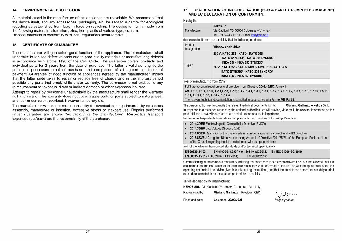
14. ENVIRONMENTAL PROTECTION
All materials used in the manufacture of this appliance are recyclable. We recommend that the device itself, and any accessories, packaging, etc. be sent to a centre for ecological recycling as established from laws in force on recycling. The device is mainly made from the following materials: aluminium, zinc, iron, plastic of various type, cuprum. Dispose materials in conformity with local regulations about removal.
15. CERTIFICATE OF GUARANTEE
The manufacturer will guarantee good function of the appliance. The manufacturer shall undertake to replace defective parts due to poor quality materials or manufacturing defects in accordance with article 1490 of the Civil Code. The guarantee covers products and individual parts for 2 years from the date of purchase. The latter is valid as long as the purchaser possesses proof of purchase and completion of all agreed conditions of payment. Guarantee of good function of appliances agreed by the manufacturer implies that the latter undertakes to repair or replace free of charge and in the shortest period possible any parts that break while under warranty. The purchaser is not entitled to any reimbursement for eventual direct or indirect damage or other expenses incurred. Attempt to repair by personnel unauthorised by the manufacture shall render the warranty null and invalid. The warranty does not cover fragile parts or parts subject to natural wear and tear or corrosion, overload, however temporary etc. The manufacturer will accept no responsibility for eventual damage incurred by erroneous assembly, manoeuvre or insertion, excessive stress or inexpert use. Repairs performed under guarantee are always "ex factory of the manufacturer". Respective transport expenses (out/back) are the responsibility of the purchaser.
28
16. DECLARATION OF INCORPORATION (FOR A PARTLY COMPLETED MACHINE) AND EC DECLARATION OF CONFORMITY.
Hereby the
Manufacturer: Nekos Srl Via Capitoni 7/5- 36064 Colceresa – VI – Italy Tel +39 0424 411011 – Email [email protected]
declare under its own responsibility that the following products:
Product Designation:
Window chain drive
Type :
230 V: KATO 253 - KATO - KATO 305 KATO SYNCRO3 - KATO 305 SYNCRO3 INKA 356 - INKA 356 SYNCRO3 24 V: KATO 253 - KATO - KIMO - KIMO 202 - KATO 305 KATO SYNCRO3 - KATO 305 SYNCRO3 INKA 356 - INKA 356 SYNCRO3
Year of manufacturing from: 2017
Fulfil the essential requirements of the Machinery Directive 2006/42/EC, Annex I, Art. 1.1.2, 1.1.3, 1.1.5, 1.2.1,1.2.3, 1.2.6; 1.3.2, 1.3.4, 1.3.9, 1.5.1, 1.5.2, 1.5.6, 1.5.7, 1.5.8, 1.5.9, 1.5.10, 1.5.11, 1.7.1, 1.7.1.1, 1.7.3, 1.7.4.2, 1.7.4.3 The relevant technical documentation is compiled in accordance with Annex VII, Part B
The person authorised to compile the relevant technical documentation is: Giuliano Galliazzo – Nekos S.r.l. In response to a reasoned request by the national authorities, we will provide, via e-mail, the relevant information on the product listed above within an adequate period proportional to its importance. Furthermore the products listed above complies with the provisions of followings Directives :
2014/30/EU ElectroMagnetic Compatibility Directive (EMCD) 2014/35/EU Low Voltage Directive (LVD) 2011/65/EU Restriction of the use of certain hazardous substances Directive (RoHS Directive) 2015/863/EU Delegated Directive amending Annex II of Directive 2011/65/EU of the European Parliament and
of the Council regarding the list of substances with usage restrictions
and of the following harmonised standards and/or technical specifications:
EN 60335-2-103; EN 61000-6-3:2007 + A1:2011 + AC:2012; EN IEC 61000-6-2:2019 EN 60335-1:2012 + AC:2014 + A11:2014; EN 50581:2012;
Commissioning of the complete machinery including the above mentioned drives delivered by us is not allowed until it is ascertained that the installation of the complete machinery was performed in accordance with the specifications and the operating and installation advice given in our Mounting Instructions, and that the acceptance procedure was duly carried out and documented in an acceptance protocol by a specialist.
This is declared by the manufacturer:
NEKOS SRL - Via Capitoni 7/5 - 36064 Colceresa – VI – Italy
Represented by: Giuliano Galliazzo – President CEO
Place and date: Colceresa 22/09/2021 Valid signature

29
Notes
30
NEKOS S.r.l. - Via Capitoni, 7/5 36064 Colceresa – VI – ITALY
+39 0424 411011 – Fax +39 0424 411013 www.nekos.it [email protected]