kac esp unit - cadexair
TRANSCRIPT

KAC ESP Unit Version: 1.0
2019-07-23
ESP Installation & Operation Manual
Foreword
Thank you very much for your trust on Cadexair KAC series ESP. Before a
proper installation and operation of the ESP, please carefully read this manu
al, where detailed installation, operation and maintenance guidelines are given
hl Special Explanation
1) This manu al is written for the standard model of KAC series ESP.
2) Due to a policy of continuous product improvement, Cadexair reserves the right
to change specifications and appearance without notice.
3) If there is anything incorrect or misleading, please contact us directly and inform
us of the produ et seri al nu m ber i mpri nted on the n am epl ate and the manu al serial
nu mber pri nted on the I ower ri ght corner of the corner.
4) Without the written permission of Cadexair any copy or adaptation of all or part of
the contents of this manual would be considered a serious violation.
& Special Announcement
User should choose the appropriate model and install it according to the manu al, and should have qualified and trained personnel to operate the ESP and keep it in normal working condition. The manufacture shall not be held responsible for any damages or losses caused by the user's failure to observe the precautions and provisions stated in th is manu al.
The products meet the standards
Cadexair
( ( Security Certificate ISO9001 2008 Certificate
1O1O Boulevard Lionel Boulet Varennes QC Canada J3X 1P7
TEL 45O-652-O668 1-8OO-461-O668 Website www.cadexair.corn
ESP Installation & Operation Manual
Security Symbol
Symbols are applied to highlight some of the precautions and provisions stated
in this manual that have something to do with the safety and soundness of the
operator and the equipment.
&, Danger
Warning: potential risks of persona! or property losses!
/1 Requirement
Caution: potential influence on the persona! or property safety if the requirements are
not observed strictly!
e Remind
Advise: more attentions to pay or more clarifications to make.
ESP Installation & Operation Manual
Contents
1 Introduction.... ..................... ..... ............. .... . ... ... .... ........................... ..... ........ ..... ........... .. . .... 2
1.1 Purpose ............ ........................................... ............... ........................................................... ................ 2
1.2 Basic Features ..
1 .3 Parameter. ........ .
. .. 2
. ... 2
2 Structure......... .. . ... . .. ... ............. ..... .... .... .. .... .... ..... .... ......... .... ......... .... ..... .... .... .. . .. 3
2.1 Working Theor .................................................................................................................................... .... .4
3 Installation ................................................ .................................................................. . . ................... . .4
3.1 General Installation Guidelines ........................................................................................ ............... .... 4
3.2 Evaluation of Loca....... ............................................ . ............................................. ............. ...... 5
3.3 ESP Mainframe Installation ......................... .
3.4 Connecting Air Duct ...................................... .
4 Debugging ...
. .. 6
. .... 7
. .. 9
4.1 Inspection before Power Up ....................................... . ............................................. .... 9
4.2 Power Supply lnspectionU ........................................................................................................ 9
4.3 Adjust Airflow . .. .. . .. . .. .. . .. . . . .. ... ............ .... .. . . ....... 9
4.4 Commissioning.. ..... ............. ..... .... ..... .... .... .... ... . . . .. .. .. . .... .... ..... .... ..... ............ ..... .... .... ..... .... ... . ..... 9
5 Operation ............................. ..................................... .......................... .................................................. . 1 O
5.1 Contrai Panel Introduction . ............................................................................................................... . 1 O
5.2 Operation Guidelines .............................................................................................................. 11
5.3 Operation of Power on Start-up and Fan Linkage Start-up ..................................................... 11
5.4 Notes . ... .......... .. . .. .. . .. .. . ................. .... .. .... .. .. . .. .... .. 12
6 Maintenance .............................................................. ..... 12
6.1 Maintenance Checklist .. ... ... ..................... . . ................................ ......... 12
6.2 Maintenance Guidelines ..... ....... .. ....... ...... .... ........ ... . . . ...... .. ...... .. .......... .............. .. 12
7 Trouble Shooting . . .. ................................................................................................................... 16
7.1 Phenomenon and Solution ................................................................. ........................................... .... 16
7.2 Troubleshooting diagnostic code table of digital power supply .. ... ... ...... ................... .. 17
7.3 Notes .. .. .. .. ... .............. . .. .. .. ............................ .. ... . ........ 20
8 Miscellaneous ........................................................... .. ............................................ .... 20
8.1 Unpacking ................................................................ ... ............................................................... ...... .. 20
ESP Installation & Operation Manual
1 Introduction
1.1 Application
As a specially designed cooking fume capturing and grease vapor collecting device, a
Electrostatic Precipitator (ESP) can always corne in handy, particularly for food premises where
cooking fume and grease vapor is more likely to be generated, such as restaurants with wok
burners, or western restaurants with deep-fryers, broilers, griddles, and grills. Processed air
should be vented out into well-ventilated open areas. Do not use the catering electrostatic
precipitator to purify the indu striai oil mist which is normally combustible, corrosive or explosive.
1.2 Basic Features
* High Efficiency in electrostatic precipitation of cooking fume and oil mist. Nice performance in
deodorization
* User friendly instruction and malfunction self-diagnosing system, en su ring the ease of
operation and maintenance for users.
* Modular design, ensuring easy assembly of our Electrostatic Precipitator for total operation
and easy removal of the electric fields and other major components for maintenance and
cleaning.
1 .3 Parameters & Specifications
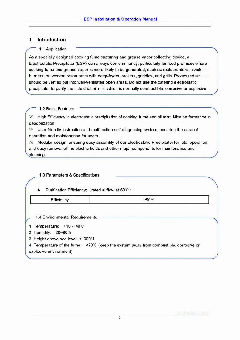
A. Purification Efficiency: (rated airflow at 60"C)
Efficiency
1.4 Environmental Requirements
1. Temperature: +10~+40"C
2. Humidity: 20~90%
3. Height above sea level: <1000M
�90%
4. Temperature of the fume: <70°
C (keep the system away from combustible, corrosive or
explosive environment)
2
ESP Installation & Operation Manual
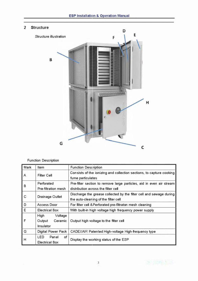
2 Structure
Structure illustration F E
B
H
G
C
Function Description
Mark Item Function Description
A Filter Cell Consists of thie ionizing and collection sections, to capture cooking
fume particulates
B Perforated Pre-filter section to remove large particles, aid in even air stream
Pre-filtration mesh distribution across the filter cell
C Drainage Outlet Discharge the grease collected by the filter cell and sewage during
the auto-cleaning of the filter cell
D Access Door For filter cell 8,Perforated pre-filtraton mesh cleaning
E Electrical Box With built-in high voltage high frequency power supply
High Voltage
F Output Ceramic Output high voltage to the filter cell
lnsulator
G Digital Power Pack CADEXAIR Patented High-voltage High-frequency type
H LED Panel
Electrical Box
of Display the working status of the ESP
3
ESP Installation & Operation Manual
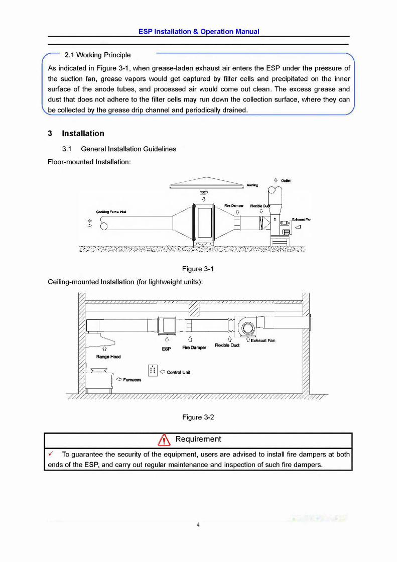
2.1 Working Principle
As indicated in Figure 3-1, when grease-laden exhaust air enters the ESP under the pressure of the suction fan, grease vapors would get captured by filter cells and precipitated on the inner surface of the anode tubes, and processed air would corne out clean. The excess grease and dust that does not adhere to the filter cells may run down the collection surface, where they can be collected by the grease drip channel and periodically drained.
3 Installation
3.1 General Installation Guidelines
Floor-mounted Installation:
� 1 j Awnttg
Figure 3-1
Ceiling-mounted Installation (for lightweight units):
RangeHood
0 Fumaœs [I]
ESP Fire Damper
0 Control Unit
Figure 3-2
Flexible Duel
& Requirement
✓ To guarantee the security of the equipment, users are advised to install fire dampers at bothends of the ESP, and carry out regular maintenance and inspection of such fire dampers.
4
ESP lns1allation & Operation Manual
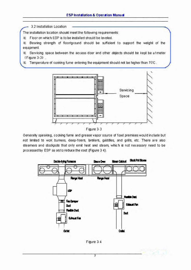
3.2 1 nstallation Location
The in stallation location should meet the following requirements:
* F loor on which ESP is to be installed should be leveled.
* Bearing strength of floor/ground should be sufficient to support the weight of the
equi
pment.
* Servicing space between the access door and other abjects should be kept be a,1 meter
(Figure 3-3)
* Temperature of cooking fume entering the equipment should not be higherthan 7o·c.
'
Servicing ---<
Space
Figure 3-3
Generally speaking, cooking fume and grease vapor source of food premises would include but
not limited to wok burners, deep-fryers, broilers, griddles, and grills, etc. There are also
steamers and stockpots that only emit heat and steam, whic h is not necessary need to be
processed by ESP so as to redu ce the cost (Figure 3-4).
-Hllll Ra'$11Htal
111P
lllllllllll
F;.Dt..-M �Ali
[R_ .. Durt
E:dalllFa
B,1111
Figure 3-4
ESP Installation & Operation Manual
Requirements
✓ Air leakage-proof measurement should be done at the connection points of the ducting system to
en sure a better purification efficiency of the ESP.
✓ Use very smooth duct reducers at the inlet and outlet of ESP, and connect them with very smooth
ducts with a length that is at least 4 times longer than the diameter of the reducers to ensure a better
purification efficiency of the ESP.
✓ Flexible duct connector should be applied in the connection between the ESP and the fan, to
eliminate influence of vibration of the fan on the ESP unit.
✓ Users should choose a fan with an airflow rate capacity that is bigger than the rated exhaust capacity
of the ESP. Users can use inverter to contrai the fan or install adjustable air valve at the outlet of fan, to
make sure that the ESP works at the rated exhaust airflow capacity.
✓ Users are suggested to keep a 1-2m long straight air duct after the outlet of the fan to reduce the
additional resistance.
✓ Users should better make sure that the ESP is working under the influence of the negative pressure
created by the exhaust fan, which means that it should be installed in front of an exhaust fan.
✓ When several ESP's are put into use in a parallel connection pattern, and all of them share the same
exhaust fan, make sure that the proportion among actual airflow rate distributed to each ESP is similar to
the proportion among rated exhaust capacity of each ESP.
✓ Weather protection measurement, e.g. an awning, is required for the ESP unit if it is to be installed
outdoors, to maximize the service life of the unit and minimize the unnecessary maintenance fees.
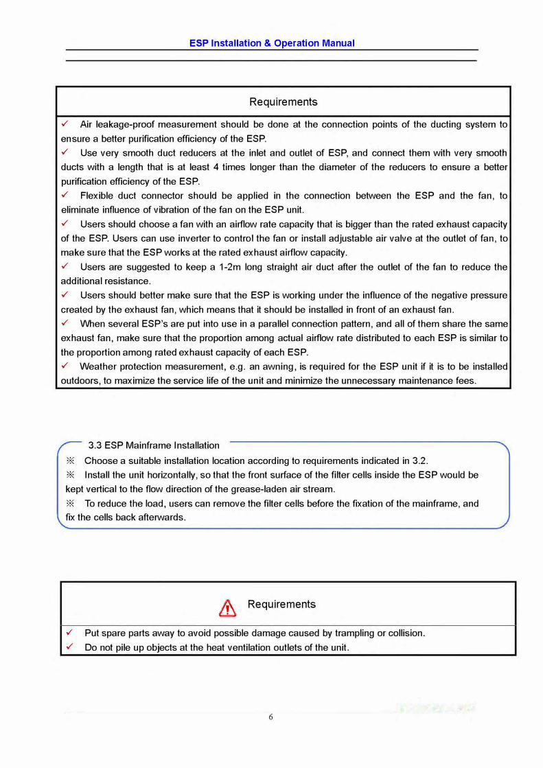
3.3 ESP Mainframe Installation
* Choose a suitable installation location according to requirements indicated in 3.2.
* lnstall the unit horizontally, so that the front surface of the filter cells inside the ESP would be
kept vertical to the flow direction of the grease-laden air stream.
* To reduce the load, users can remove the filter cells before the fixation of the mainframe, and
fix the cells back afterwards.
& Requirements
✓ Put spare parts away to avoid possible damage caused by trampling or collision.
✓ Do not pile up abjects at the heat ventilation outlets of the unit.
6
ESP Installation & Operation Manual
3 .4 Duct Connection
* To connect ESP, air duct, fire damper, flexible duct & fan, see figures 3-1 and 3-2.
* Flange connections should be sealed against air leakage try continuous perim eter gaskets of
therm al-resistant oil-proof mate ri ais.
* M ake sure that screw ho les of the flanges match each other during the installation of the fire
dampers, in case the fire dam pers would not react and function norm ally due to deform ation
caused on the outer-frames.
* M ake sure the section of flexible duct between air ducts is not shorter than 5Dmm-long.
* Air duct should be sufficiently sloped to minim ize the accumulation of excess grease insidethe ducting.
* 1 nstall vibration dam per at the support rack of the fan.
* No corn bustible item is allowed to be put at the outl et of the fan. When the fan outlet is
located within a 5-meter radius from the ESP, the height of the outlet should be kept 1.5-meter
higher than the ESP.
& Requirements
✓ The height of the drain line to be connected to the drain outlet of the ESP, if any, should be
lower than the hei ght of drain outlet, and the less el bows/bending of the drain li ne, the more
sm ooth the drainage effect would be.
✓ A fire damper should be installed at the outlet of the ESP, and each section of the air ducts
should incorporate an access door perm itting access for cleani ng and servicing.✓ The perforated pre-filter should be placed at the air inlet of the ESP.✓ Drainage from the ES P unit should corn ply with ail state and local codes.
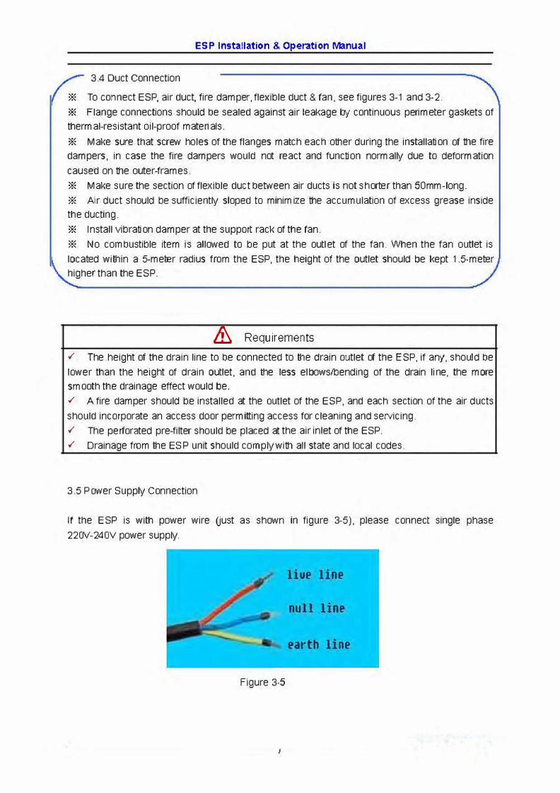
3 .5 Power Supply Connection
If the E SP is with power wire uust as shown in figure 3-5), please connect single phase
220V-240V power supply.
liue line
null line
earth line
Figure 3-5
ESP Installation & Operation Manual
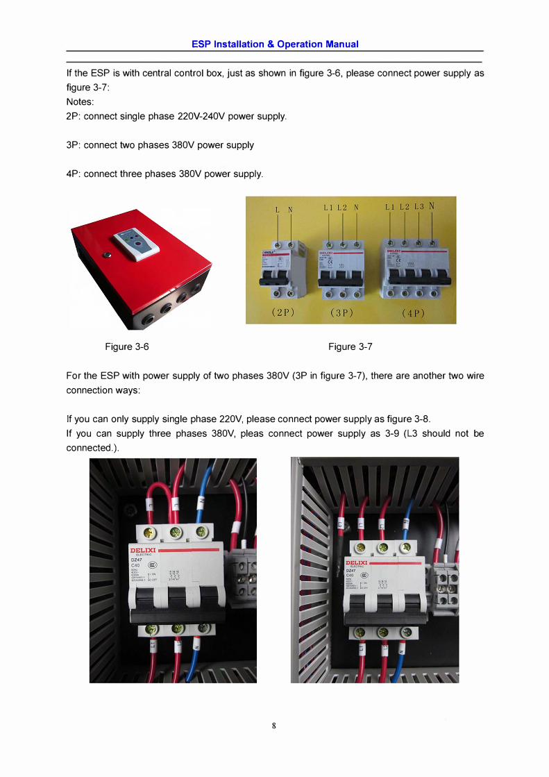
If the ESP is with central contrai box, just as shown in figure 3-6, please connect power supply as
figure 3-7:
Notes:
2P: connect single phase 220V-240V power supply.
3P: connect two phases 380V power supply
4P: connect three phases 380V power supply.
Figure 3-6 Figure 3-7
For the ESP with power supply of two phases 380V (3P in figure 3-7), there are another two wire
connection ways:
If you can only supply single phase 220V, please connect power supply as figure 3-8.
If you can supply three phases 380V, pleas connect power supply as 3-9 (L3 should not be
connected.).
8
ESP Installation & Operation Manual
& Requirements
✓ The design and installation of the ESP unit should be handled by qualified professionals.
✓ Do not power up the ESP before the completion of the system installation. There is extremely
high voltage generated inside ESP when it is in full operation.
✓ Do not install ESP near any facility that produces flammable or explosive gases.
✓ An electrical leakage protection device should be installed between the main power supply
line and the power source to eliminate risks of electrical shock.
✓ The ground lead should be reliable and the resistance should be less than 0.50.
✓ ESP should be kept in a stably horizontal position during the whole process of installation.
✓ A maintenance platform with an appropriate height and guard rails should be built for the
security of the maintainer.
✓ ln regions with low temperatures, heat insulation measurement should be done on the
exposed drain lines.
4 Debugging
4.1 Inspection before Power-up
Check each instruction stated above to see if there is any discrepancy between the system
described in the guidelines and the system installed. If so, improvement should be done to make
sure that every requirement is met before the debugging. Make sure that each part/ accessory
has been installed correctly and firmly before power-up.
4.2 Power Supply Inspection
Before power on, please use the volt meter to check if the power supply meets the specifications
indicated on the nameplate of the ESP and exhaust fan, and make sure that the earth resistance
of the ground lead is less than 0.50.
4.3 Airflow Adjustment
Power up, switch on the exhaust fan and make sure that its rotation direction is correct. Adjust the
airflow rate to the extent that the actual airflow rate through each ESP is equal to or smaller than
the rated exhaust capacity by using airflow rate measuring device and airflow rate controlling
device. Meanwhile, check if there is any air leakage from the ducts and take leak-mending
measures when necessary.
4.4 Commissioning
Refer to Chapter 5 for a checklist of various functions of the ESP. Observe whether the
corresponding indicator reacts normally while running each function. Refer to Chapter 7 for
trouble shooting measures when something wrong happens.
e Remind
✓ When the operation fails, do refer to Article 7 for trouble shooting measures.
9
ESP Installation & Operation Manual
5 Operation
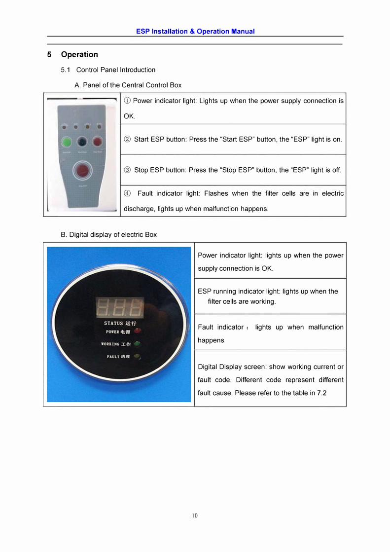
5.1 Control Panel Introduction
A. Panel of the Central Control Box
• • • •
CD Power indicator light: Lights up when the power supply connection is
OK.
® Start ESP button: Press the "Start ESP" button, the "ESP" light is on.
@ Stop ESP button: Press the "Stop ESP" button, the "ESP" light is off.
© Fault indicator light: Flashes when the filter cells are in electric
discharge, lights up when malfunction happens.
B. Digital display of electric Box
Power indicator light: lights up when the power
supply connection is OK.
ESP running indicator light: lights up when the
filter cells are working.
Fault indicator : lights up when malfunction
happens
Digital Display screen: show working current or
fault code. Different code represent different
fault cause. Please refer to the table in 7.2
10
ESP Installation & Operation Manual
5.2 Operation Guidelines
A. Start ESP: Power up, switch "ROTARY ISOLATOR" on the electrical box to "ON" and
press the "Start ESP" button on the central control box.
B. Normal Running Status: "POWER ON" and "ESP CELLS ON" indicator lights on LED
panel of electric box would stay lit constantly, while "FAULT' indicator light would be un lit.
C. Stop ESP: Press the "Stop ESP" button on the central control box while the ESP is still
running, "ESP CELLS ON" indicator light is unlit.
D. If electric discharge twice in 5 seconds, the electric current will be reduced by a level
automatically (the lowest current is down to 10MA). And if there is no electric discharge in 5
minutes, the electric current will be increased by a level automatically (the highest current
value is according to factory defaults).
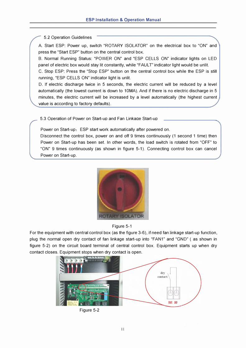
5.3 Ooeration of Power on Start-uo and Fan Linkaoe Start-uo
Power on Start-up: ESP start work automatically after powered on.
Disconnect the control box, power on and off 9 times continuously (1 second 1 time) then
Power on Start-up has been set. ln other words, the load switch is rotated from "OFF" to
"ON" 9 times continuously (as shown in figure 5-1). Connecting control box can cancel
Power on Start-up.
Figure 5-1
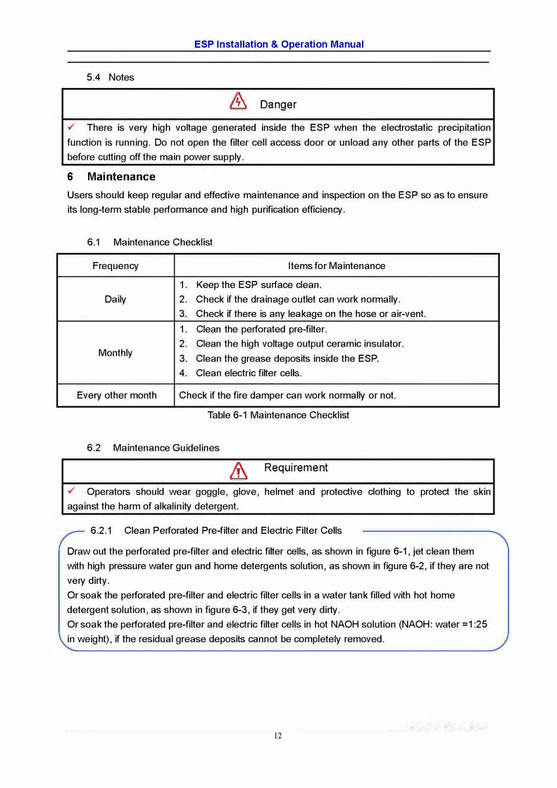
For the equipment with central control box (as the figure 3-6), if need fan linkage start-up function,
plug the normal open dry contact of fan linkage start-up into "FAN1" and "GND" ( as shown in
figure 5-2) on the circuit board terminal of central control box. Equipment starts up when dry
contact closes. Equipment stops when dry contact is open. r
FAN! GliD
Figure 5-2
11
ESP Installation & Operation Manual
5.4 Notes
& Danger
✓ There is very high voltage generated inside the ESP when the electrostatic precipitation
function is running. Do not open the filter cell access door or unload any other parts of the ESP
before cutting off the main power supply.
6 Maintenance
Users should keep regular and effective maintenance and inspection on the ESP so as to ensure
its long-term stable performance and high purification efficiency.
6.1 Maintenance Checklist
Frequency Items for Maintenance
1. Keep the ESP surface clean.
Daily 2. Check if the drainage outlet can work normally.
3. Check if there is any leakage on the hase or air-vent.
1. Clean the perforated pre-filter.
2. Clean the high voltage output ceramic insulator.Monthly
3. Clean the grease deposits inside the ESP.
4. Clean electric filter cells.
Every other month Check if the fire damper can work normally or not.
Table 6-1 Maintenance Checklist
6.2 Maintenance Guidelines
& Requirement
✓ Operators should wear goggle, glove, helmet and protective clothing to protect the skin
against the harm of alkalinity detergent.
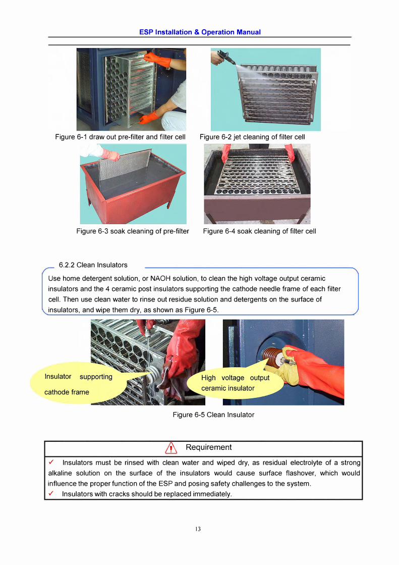
6.2 .1 Clean Perforated Pre-filter and Electric Filter Cells
Draw out the perforated pre-filter and electric filter cells, as shown in figure 6-1, jet clean them
with high pressure water gun and home detergents solution, as shown in figure 6-2, if they are not
very dirty.
Or soak the perforated pre-filter and electric filter cells in a water tank filled with hot home
detergent solution, as shown in figure 6-3, if they get very dirty.
Or soak the perforated pre-filter and electric filter cells in hot NAOH solution (NAOH: water =1 :25
in weight), if the residual grease deposits cannot be completely removed.
12
ESP Installation & Operation Manual
Figure 6-1 draw out pre-filter and filter cell Figure 6-2 jet cleaning of filter cell
Figure 6-3 soak cleaning of pre-filter Figure 6-4 soak cleaning of filter cell
6.2.2 Clean lnsulators
Use home detergent solution, or NAOH solution, to clean the high voltage output ceramic
insulators and the 4 ceramic post insulators supporting the cathode needle frame of each filter
cell. Then use clean water to rinse out residue solution and detergents on the surface of
insulators, and wipe them dry, as shown as Figure 6-5.
lnsulator
cathode frame
Figure 6-5 Clean lnsulator
& Requirement
✓ lnsulators must be rinsed with clean water and wiped dry, as residual electrolyte of a strong
alkaline solution on the surface of the insulators would cause surface flashover, which would
influence the proper function of the ESP and posing safety challenges to the system.
✓ lnsulators with cracks should be replaced immediately.
13
ESP Installation & Operation Manual
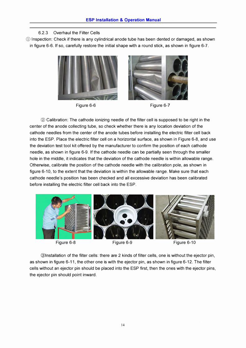
6.2.3 Overhaul the Filter Cells
CD Inspection: Check if there is any cylindrical anode tube has been dented or damaged, as shown
in figure 6-6. If so, carefully restore the initial shape with a round stick, as shown in figure 6-7.
Figure 6-6 Figure 6-7
® Calibration: The cathode ionizing needle of the filter cell is supposed to be right in the
center of the anode collecting tube, so check whether there is any location deviation of the
cathode needles from the center of the anode tubes before installing the electric filter cell back
into the ESP. Place the electric filter cell on a horizontal surface, as shown in Figure 6-8, and use
the deviation test tool kit offered by the manufacturer to confirm the position of each cathode
needle, as shown in figure 6-9. If the cathode needle can be partially seen through the smaller
hole in the middle, it indicates that the deviation of the cathode needle is within allowable range.
Otherwise, calibrate the position of the cathode needle with the calibration pole, as shown in
figure 6-10, to the extent that the deviation is within the allowable range. Make sure that each
cathode needle's position has been checked and all excessive deviation has been calibrated
before installing the electric filter cell back into the ESP.
Figure 6-8 Figure 6-9 Figure 6-10
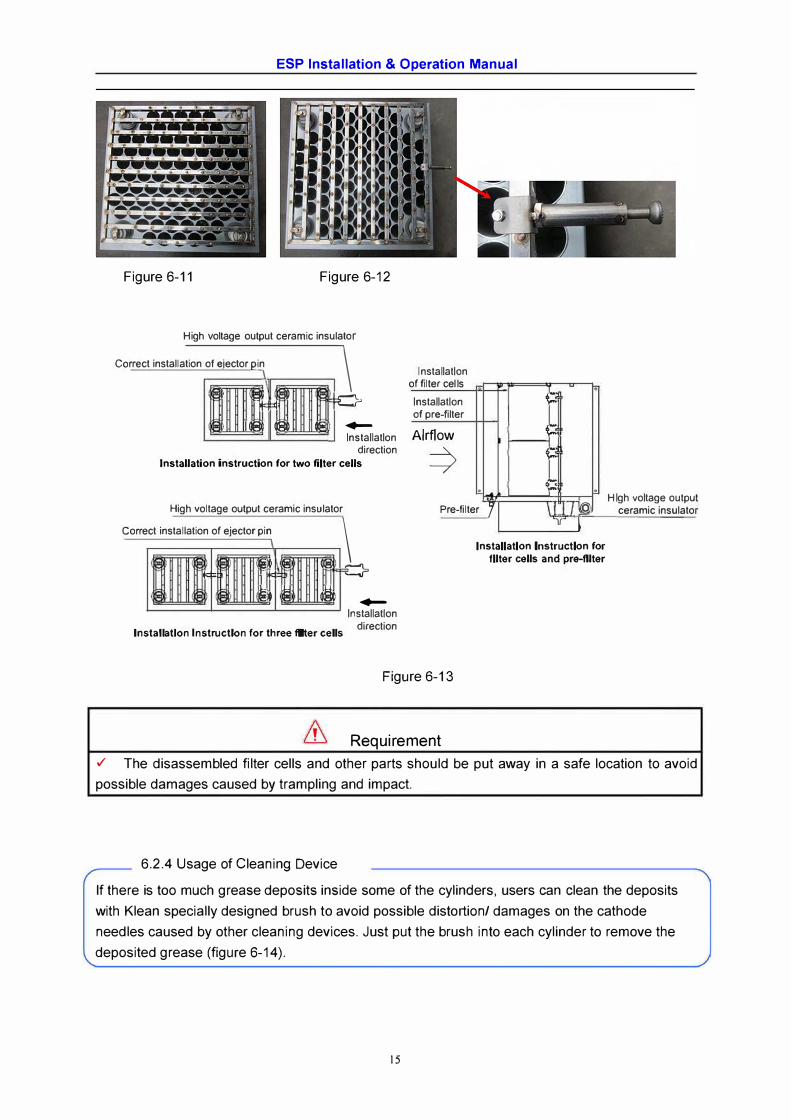
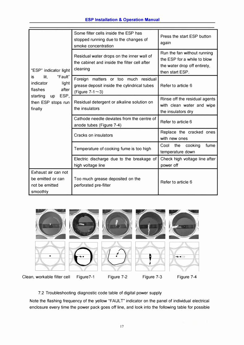
@Installation of the filter cells: there are 2 kinds of filter cells, one is without the ejector pin,
as shown in figure 6-11, the other one is with the ejector pin, as shown in figure 6-12. The filter
cells without an ejector pin should be placed into the ESP first, then the ones with the ejector pins,
the ejector pin should point inward.
14
ESP Installation & Operation Manual
Figure 6-11 Figure 6-12
High voltage output ceramic insulator
Co rrect installation of elector oin 1
1 � 1 1 w ��
\ 111 Il 1 11 Il Il 1 Il D
lnst .,_
allatlon direction
Installation instruction for two filter cells
Installation of filter oel ls Installation ,--of pre-filter
Alrflow ,--
⇒ ,--
. ,;: .
High voltage output ceramic insulator Pre-filter / 1 l /1@. C orrect installation of ejector pin
iL 1 . ' • 1•
�= � � :a�
; 1 ; 1 � Il .,_
Installation directionlnstallatlon Instruction for three fllter cells
Figure 6-13
Requirement
u 1lnstallatlon Instruction for
fllter cells and pre-fllter
H lgh voltage outpu ceramic insulato
✓ The disassembled filter cells and other parts should be put away in a safe location to avoid
possible damages caused by trampling and impact.
6.2.4 Usage of Cleaning Device
If there is too much grease deposits inside some of the cylinders, users can clean the deposits
with Klean specially designed brush to avoid possible distortion/ damages on the cathode
needles caused by other cleaning devices. Just put the brush into each cylinder to remove the
deposited grease (figure 6-14).
15
ESP Installation & Operation Manual
Sorne filter cells inside the ESP has Press the start ESP button
stopped running due to the changes of again
smoke concentration
Residual water drops on the inner wall of Run the fan without running
the ESP for a while to blow the cabinet and inside the filter cell after
cleaning the water drop off entirely,
"ESP" indicator light then start ESP. is lit, "Fault"
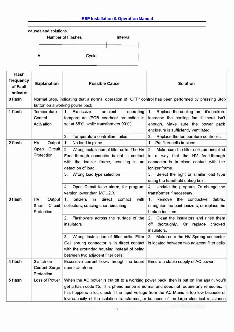
Foreign matters or too much residual indicator light
grease deposit inside the cylindrical tubes Refer to article 6 flashes after
(Figure 7-1 ~3) starting up ESP,
Rinse off the residual agents then ESP stops run Residual detergent or alkaline solution on
with clean water and wipe finally the insulators
the insulators dry
Cathode needle deviates from the centre of
anode tubes (Figure 7-4) Refer to article 6
Replace the cracked ones Cracks on insulators
with new ones
Cool the cooking fume Temperature of cooking fume is too high
temperature down
Electric discharge due to the breakage of Check high voltage line after
high voltage line power off
Exhaust air can not
be emitted or can Too much grease deposited on the
not be emitted perforated pre-filter Refer to article 6
smoothly
Clean, workable filter cell Figure7-1 Figure 7-2 Figure 7-3 Figure 7-4
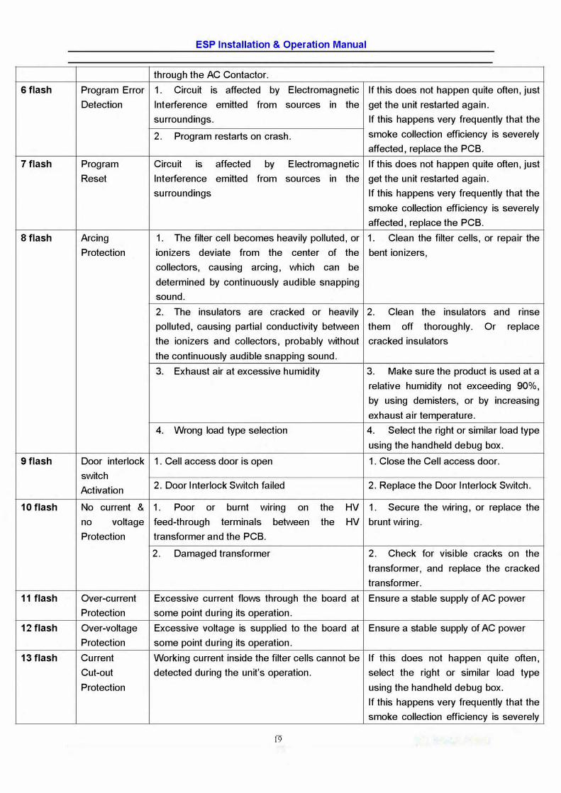
7.2 Troubleshooting diagnostic code table of digital power supply
Note the flashing frequency of the yellow "FAULT" indicator on the panel of individual electrical
enclosure every time the power pack goes off line, and look into the following table for possible
17
Flash
ESP Installation & Operation Manual
causes and solutions.
Number of Flashes lnterval
t Cycle
frequency Expia nation Possible Cause Solution
of Fault
indicator
O flash
1 flash
2 flash
3 flash
4 flash
5 flash
Normal Stop, indicating that a normal operation of "OFF" contrai has been performed by pressing Stop
button on a working power pack.
Temperature 1. Excessive ambient operating 1. Replace the cooling fan if it's broken.
Contrai temperature (PCB overheat protection is 1 ncrease the cooling fan if there isn't
Activation set at 85°
C, while transformers 90"C) enough. Make sure the power pack
enclosure is sufficiently ventilated.
2. Temperature controllers failed 2. Replace the temperature controller.
HV Output 1. No load in place. 1. Put filter cells in place
Open Circuit 2. Wrong installation of filter cells. The HV 2. Make sure the filter cells are installed
Protection Feed-through connector is not in contact in a way that the HV feed-throug h
with the ionizer frame, resulting in no connector is in close contact with the
detection of load. ionizer frame.
3. Wrong load type selection 3. Select the right or similar load type
using the handheld debug box.
4. Open Circuit taise alarm, for program 4. Update the program. Or change the
version lower than MCU2.3. transformer if necessary.
HV Output 1. lonizers in direct contact with 1. Remove the conductive debris,
Short Circuit collectors, causing short-circuiting. straighten the bent ionizers, or replace the
Protection broken ionizers.
2. Flashovers across the surface of the 2. Clean the insulators and rinse them
insulators off thoroughly. Or replace cracked
insulators.
3. Wrong installation of filter cells. Filter 3. Make sure the HV Sprung connector
Cell sprung connector is in direct contact is located between two adjacent filter cells
with the grounded housing instead of being
between two adjacent filter cells.
Switch-on Excessive current flows through the board Ensure a stable supply of AC power.
Current Surge upon switch-on.
Protection
Lass of Power When the AC power is eut off to a working power pack, then is put on line again, you'II
get a flash code #5. This phenomenon is normal and does not require any remedies. If
this happens a lot, check if the input voltage from the AC Mains is too low because of
low capacity of the isolation transformer, or because of too large electrical resistance
18
ESP Installation & Operation Manual
through the AC Contactor.
6 flash Program Error 1. Circuit is affected by E lectromag netic If this does not happen quite often, just
Detection lnterference emitted from sources in the get the unit restarted again.
surroundings. If this happens very frequently that the
2. Program restarts on crash. smoke collection efficiency is severely
affected, replace the PCB.
7 flash Program Circuit is affected by E lectromag netic If this does not happen quite often, just
Reset lnterference emitted from sources in the get the unit restarted again.
surroundings If this happens very frequently that the
smoke collection efficiency is severely
affected, replace the PCB.
8 flash Arcing 1. The filter cell becomes heavily polluted, or 1. Clean the filter cells, or repair the
Protection ionizers deviate from the center of the bent ionizers,
collectors, causing arcing, which can be
determined by continuously audible snapping
sound.
2. The insulators are cracked or heavily 2. Clean the insulators and rinse
polluted, causing partial conductivity between them off thoroughly. Or replace
the ionizers and collectors, probably without cracked insulators
the continuously audible snapping sound.
3. Exhaust air at excessive humidity 3. Make sure the product is used at a
relative humidity not exceeding 90%,
by using demisters, or by increasing
exhaust air temperature.
4. Wrong load type selection 4. Select the right or similar load type
using the handheld debug box.
9 flash Door interlock 1 . Cell access door is open 1. Close the Cell access door.
switch
Activation 2. Door Interlock Switch failed 2. Replace the Door Interlock Switch.
10 flash No current & 1. Poor or burnt wiring on the HV 1. Secure the wiring, or replace the
no voltage feed-through terminais between the HV brunt wiring.
Protection transformer and the PCB.
2. Damaged transformer 2. Check for visible cracks on the
transformer, and replace the cracked
transformer.
11 flash Over-current Excessive current flows through the board at Ensure a stable supply of AC power
Protection some point during its operation.
12 flash Over-voltage Excessive voltage is supplied to the board at Ensure a stable supply of AC power
Protection some point during its operation.
13 flash Current Working current inside the filter cells cannot be If this does not happen quite often,
Cut-out detected during the unit's operation. select the right or similar load type
Protection using the handheld debug box.
If this happens very frequently that the
smoke collection efficiency is severely
,=9
14 flash
ESP Installation & Operation Manual
affected, replace the PCB.
Flashover (a 1. Filter cell is dirty 1. Clean the filter cell
special form 2. insulators are cracked or heavily polluted 2. Clean the insulators and rinse
of arcing) them off thoroughly. Or replace
Protection, cracked insulators
3. Poor connection between the HV 3. Make sure the HV feed-through
feed-through insulator and the ionizer frame. connecter is in close contact with the
ionizer frame.
4. Wrong load time selection 4. Select the right or similar load type
using the handheld debug box.
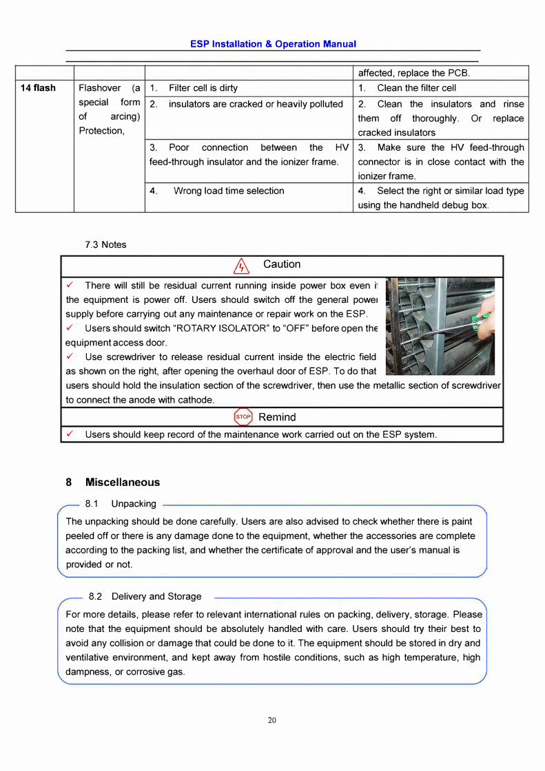
7.3 Notes
ill Caution
✓ There will still be residual current running inside power box even i•
the equipment is power off. Users should switch off the general poweI
supply before carrying out any maintenance or repair work on the ESP.
✓ Users should switch "ROTARY ISOLATOR" to "OFF" before open the
equipment access door.
✓ Use screwdriver to release residual current inside the electric field
as shown on the right, after opening the overhaul door of ESP. To do that
users should hold the insulation section of the screwdriver, then use the metallic section of screwdriver
to connect the anode with cathode.
srop Remind
✓ Users should keep record of the maintenance work carried out on the ESP system.
8 Miscellaneous
8.1 Unpacking
The unpacking should be done carefully. Users are also advised to check whether there is paint
peeled off or there is any damage done to the equipment, whether the accessories are complete
according to the packing list, and whether the certificate of approval and the user's manual is
provided or not.
8.2 Delivery and Storage
For more details, please refer to relevant international rules on packing, delivery, storage. Please
note that the equipment should be absolutely handled with care. Users should try their best to
avoid any collision or damage that could be done to it. The equipment should be stored in dry and
ventilative environment, and kept away from hostile conditions, such as high temperature, high
dampness, or corrosive gas.
20