jet joint undertaking : annual report 1998
TRANSCRIPT

JOINT EUROPEAN TORUS
JET JOINT
UNDERTAKING ANNUAL
REPORT 1998


EUR 19252-EN-C EUR-JET-AR21
JET JOINT
UNDERTAKING
ANNUAL REPORT
1998
SEPTEMBER 1999
LEGAL NOTICE:
Neither the Commission of the European Communities nor any person acting on behalf of the Commission is responsible for the use which might be made of the following information.
Catalogue number: CD-NA-19252-EN-C
for the report EUR 19252 (EUR-JET-AR21)
This document is intended for information only and should not be used as a technical reference.
Editorial work on this report was carried out by M.L. Watkins.
Prepared and produced by JET Publications Group.
©Copyright ECSC/EEC/EURATOM, Luxembourg 1999
Enquiries about copyright and reproduction should be addressed to:
The Publications Officer, JET Joint Undertaking, Abingdon, Oxon, 0X14 3EA, U.K.
Printed in England
Preface
Introduct ion, Summary and Background
Introduction 1
Report Summary 1
Background 2
Objectives of JET 3
JET, Euratom and other Fusion Programmes
The Joint European Torus 7
Controlled Thermonuclear Fusion 9
Large International Tokamaks 16
Technical Status of JET
Introduction 19
Technical Achievements 20
Technical Developments to Enhance Performance 38
Scientific Advances dur ing 1998
Introduction 45
Main Scientific Results 47
Progress towards a Reactor 64
Programme Overview
Background 67
Future Plans 70
Members and Organisation
Members 75
Host Organisation 77
Project Team Structure 78
Administrat ion
Introduction 81
Finance 81
Contracts Service 84
Personnel Service 86
Press and Public Relations 90
Publications Group 90
Appendices
I The JET Council 93
li The JET Executive Committee 94
III The JET Scientific Council 95
i i i

W j « r
-ƒ«
ι \
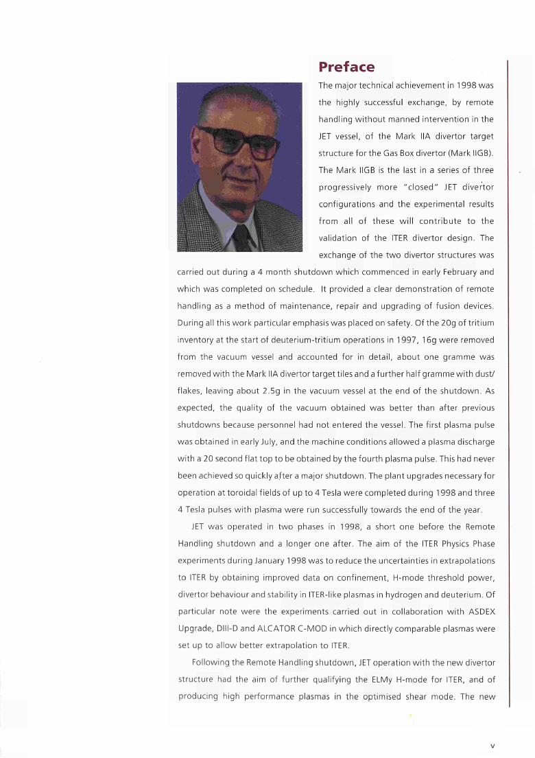
Preface The major technical achievement in 1998 was
the highly successful exchange, by remote
handling without manned intervention in the
JET vessel, of the Mark HA divertor target
structure for the Gas Box divertor (Mark IIGB).
The Mark IIGB is the last in a series of three
progressively more "closed" JET divertor
configurations and the experimental results
from all of these will contribute to the
validation of the ITER divertor design. The
exchange of the two divertor structures was
carried out during a 4 month shutdown which commenced in early February and
which was completed on schedule. It provided a clear demonstration of remote
handling as a method of maintenance, repair and upgrading of fusion devices.
During all this work particular emphasis was placed on safety. Of the 20g of tritium
inventory at the start of deuterium-tritium operations in 1997, 16g were removed
from the vacuum vessel and accounted for in detail, about one gramme was
removed with the Mark HA divertor target tiles anda further half gramme with dust/
flakes, leaving about 2.5g in the vacuum vessel at the end of the shutdown. As
expected, the quality of the vacuum obtained was better than after previous
shutdowns because personnel had not entered the vessel. The first plasma pulse
was obtained in early July, and the machine conditions allowed a plasma discharge
with a 20 second flat top to be obtained by the fourth plasma pulse. This had never
been achieved so quickly after a major shutdown. The plant upgrades necessary for
operation at toroidal fields of up to 4 Tesla were completed during 1998 and three
4 Tesla pulses with plasma were run successfully towards the end of the year.
JET was operated in two phases in 1998, a short one before the Remote
Handling shutdown and a longer one after. The aim of the ITER Physics Phase
experiments during January 1998 was to reduce the uncertainties in extrapolations
to ITER by obtaining improved data on confinement, Η-mode threshold power,
divertor behaviour and stability in ITER-like plasmas in hydrogen and deuterium. Of
particular note were the experiments carried out in collaboration with ASDEX
Upgrade, Dlll-D and ALCATOR C-MOD in which directly comparable plasmas were
set up to allow better extrapolation to ITER.
Following the Remote Handling shutdown, JET operation with the new divertor
structure had the aim of further qualifying the ELMy Η-mode for ITER, and of
producing high performance plasmas in the optimised shear mode. The new

divertor geometry produces many of the expected results, such as improved
deuterium exhaust, more symmetric detachment and a somewhat higher density
limit. In addition, access to the Ηmode is found to be dependent on divertor
geometry. The fuelling efficiency with pellets injected from a centrifuge injector at
250ms' into ELMy Ηmodes is higher than with gas puffing, but the tradeoff
between density and confinement is not substantially changed. The removal of
helium from the plasma, necessary in a power plant, has been demonstrated with
the ratio of the helium replacement time to the energy confinement time as low as
4 in ELMy Ηmodes, which easily meets the requirements of a reactor.
High fusion performance in the optimised shear mode of operation results from
the formation of an Internal Transport Barrier in which the confinement in the core
plasma is much improved. With the Mark IIGB divertor, transiently high performance
has been more difficult to achieve largely due to the earlier onset of an Ηmode. On
the other hand, steady state operation has been easier to establish. Profile control
techniques have been used in this advanced mode of tokamak operation to
engineer high fusion performance and to develop these conditions into steady
state. In particular, current profile control using lower hybrid current drive and
plasma density profile control using pellet injection have been used. In addition to
the control of current and density profiles, the duration of the high performance
phase has been extended by preventing excessive edge pressures using impurities
to increase the edge radiation. In this way, steady state plasmas with good
confinement have been achieved for 45 seconds, showing promise for the
development of such plasmas for use in a future power plant.
A number of organisational changes occurred in 1998. In October, the Council
of the European Union approved the necessary amendment of the JET Statutes
which enabled the Austrian Academy of Sciences to become a member of the JET
Joint Undertaking. The same approval covered amendments which enabled the
Dublin City University (replacing Ireland), the Forschungszentrum Karlsruhe (replacing
the Forschungszentrum Jülich) and the Instituto de Cooperação Cientifica e
Tecnológica Internacional (replacing the Junta Nacional de Investigação Cientifica)
to become members of the JET Joint Undertaking. Following on from the judgement
in December 1996 of the European Court of First Instance concerning the status of
the UKAEA employees assigned to JET, the JET Council's proposals for modification
to the "illegal" provisions of the JET Statutes were approved by the Council of the
European Union in October 1998. In March 1998 the JET Council appointed a firm
of lawyers to provide legal advice on matters relating to further actions by the JET
UKAEA Team staff in the European Court of First Instance which remained
unresolved at the end of 1998.
During the year the JET management began to consider arrangements for the
winding up of the JET Joint Undertaking which will commence when its existing
legal mandate expires in 1999. A report on the matter was presented in October
1998 to the JET Council who then appointed a Working Group, chaired by Dr. G.
Leman, to oversee completion of the work on the preparation of instructions for the
appointment of a Liquidator. Dr. Mancini's Group continued working on the
administrative and structural options for operating the JET facilities following the
winding up of the Joint Undertaking. Much progress was made but the final
decisions on this topic belong to 1999. The adoption of the Fifth Framework
Programme on Research and Technological Development, by the Council of the
European Union in December 1998, provided some optimism for the continued use
of the JET facilities beyond 1999.
On behalf of my colleagues on the JET Council, I congratulate the Director,
Professor Dr. Martin Keilhacker and the staff for their dedication and hard work,
and for again achieving such excellent results. These achievements were especially
remarkable since 1998 saw the loss of a significant body of expertise with the
departure of more than half of the Euratom staff who mainly took up new posts in
the Commission. 1998 also saw the untimely deaths of Drs. David Start and Brian
Keen whose respective contributions to RF and fast particle physics and to the JET
Committees and Publications (including the preparation of the JET Annual and
Progress Reports for over ten years) were immeasurable. I thank the members of the
JET Council for their constant support throughout the year, the members of the JET
Scientific Council for their sound advice, the members of the JET Executive
Committee for continuing to monitor financial, contractual, and personnel aspects
of the Project, and the Members of the various working groups and sub-committees
set up during the year for carrying out the special tasks which were delegated to
them. Dr. Alan Gibson who had been Deputy Director at J ET for many years and who
had been at JET since the beginning of the design phase in 1973 retired in May
1998. His significant contributions and wide experience were of great benefit to the
Project. On behalf of the JET Council, I wish him well in his retirement.
F. Troyon
Chairman of the JET Council
September 1999
V I I
4 *»
v - ^
M
•
•
•
•
•
•
β
•
•
•
*^\
i «en
\ ι
ν <
~ 1 <
[Ν
SULKJF^^ ■<ÌH
:
•
•
•
• *ν
t
^ ^ ^ * t ' .
-—-*_ fc>BM
•
•
•
if*
J; I.
m* m\ "Ν : N
«■J! Tu·
.y

I N T R O D U C T I O N , S U M M A R Y A N D B A C K G R O U N D
Introduction, Summary and Background
Introduction The Joint European Torus (JET) is the largest project in the fusion programme of the
European Atomic Energy Community (EURATOM), whose long term objective is the
joint creation of safe environmentally sound prototype fusion reactors.
The Statutes setting up the JET Project include a requirement for an Annual
Report to be produced which:
" . . . shall show the current status of the Project, in particular with regard to
timetables, cost, performance of the scientific programme and its position
in the Euratom Fusion Programme and in the world-wide development of
fusion research. "
This Report is designed to meet this requirement. It provides an overview of the
scientific, technical and administrative status of the JET programme, which is intended
to be comprehensible to the average member of the public. Where appropriate,
descriptive sections (in italics and boxed) are included to aid the reader's understanding
of particular technical terms used throughout the Report.
A more detailed and comprehensive description of the technical aspects of the JET
Project can be found in the JET Progress Report.
Report Summary The Report is essentially divided into two main parts:
• the scientific and technical programme of the Project;
• the administration and organisation of the Project.
The first part of the Report includes a brief introduction, provides an overview
of the planning of the Report and sets the background to the Project. This is
followed by a description of JET and its experimental programme and explains its
position in the overall Euratom and International Fusion Programmes. In addition,
it relates and compares JET to other large fusion devices throughout the world and
confirms its pre-eminent position in fusion research.
I N T R O D U C T I O N , S U M M A R Y A N D B A C K G R O U N D
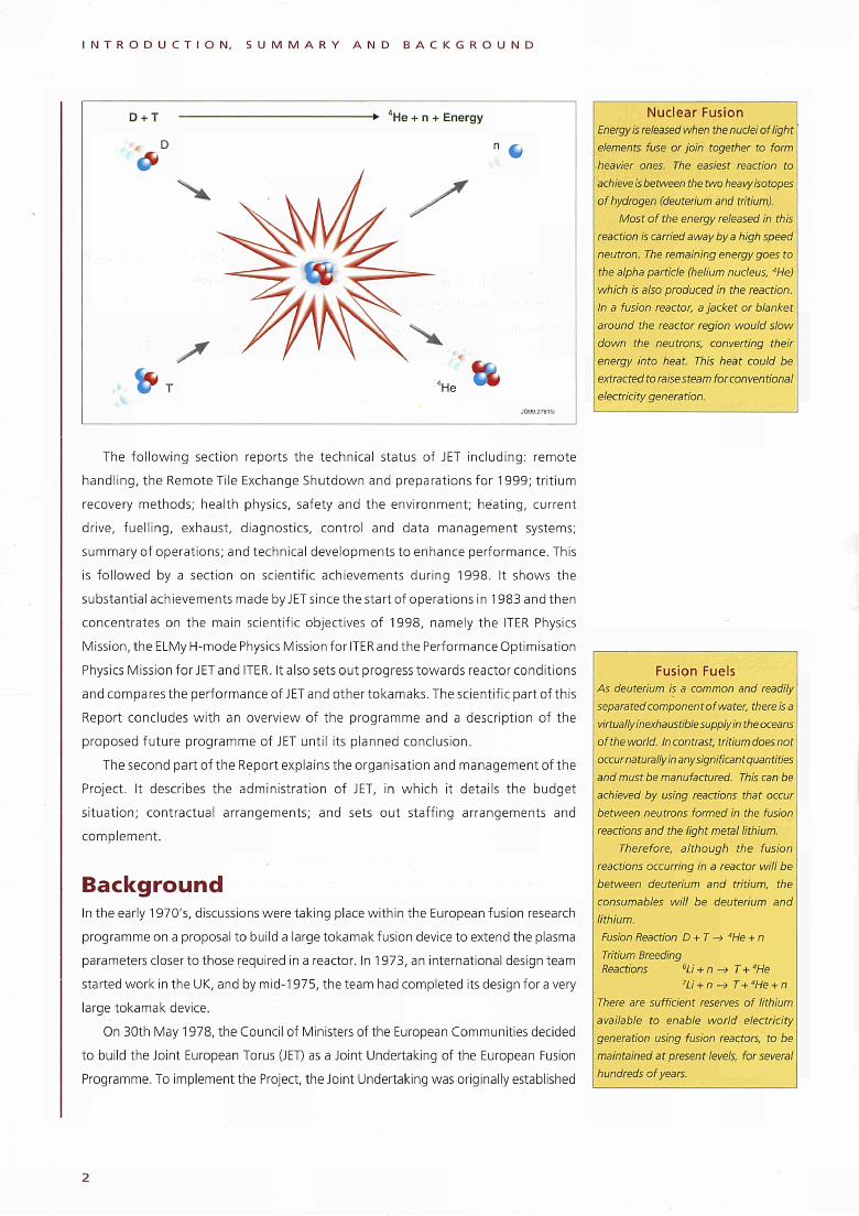
D + T
■a D
->■ He + n + Energy
JG99.27ai/c
Nuclear Fusion
Energy is released when the nuclei of light
elements fuse or join together to form
heavier ones. The easiest reaction to
achieve is between the two heavy isotopes
of hydrogen (deuterium and tritium).
Most of the energy released in this
reaction is carried away by a high speed
neutron. The remaining energy goes to
the alpha particle (helium nucleus, 4
He)
which is also produced in the reaction.
In a fusion reactor, a jacket or blanket
around the reactor region would slow
down the neutrons, converting their
energy into heat. This heat could be
extracted to raise steam for conventional
electricity generation.
The following section reports the technical status of JET including: remote
handling, the Remote Tile Exchange Shutdown and preparations for 1999; tritium
recovery methods; health physics, safety and the environment; heating, current
drive, fuelling, exhaust, diagnostics, control and data management systems;
summary of operations; and technical developments to enhance performance. This
is followed by a section on scientific achievements during 1998. It shows the
substantial achievements made by J ET si nee the start of operations i n 1983 and then
concentrates on the main scientific objectives of 1998, namely the ITER Physics
Mission, the ELMy Η-mode Physics Mission for ITER and the Performance Optimisation
Physics Mission for JET and ITER. It also sets out progress towards reactor conditions
and compares the performance of JET and other tokamaks. The scientific part of this
Report concludes with an overview of the programme and a description of the
proposed future programme of JET until its planned conclusion.
The second part of the Report explains the organisation and management of the
Project. It describes the administration of JET, in which it details the budget
situation; contractual arrangements; and sets out staffing arrangements and
complement.
Background In the early 1970's, discussions were taking place within the European fusion research
programme on a proposal to build a large tokamak fusion device to extend the plasma
parameters closer to those required in a reactor. In 1973, an international design team
started work in the UK, and by mid-1975, the team had completed its design for a very
large tokamak device.
On 30th May 1978, the Council of Ministers of the European Communities decided
to build the Joint European Torus (JET) as a Joint Undertaking of the European Fusion
Programme. To implement the Project, the Joint Undertaking was originally established
Fusion Fuels
As deuterium is a common and readily
separated component ofwater, there is a
virtually inexhaustible supply in the oceans
of the world. Incontrasi, tritium does not
occur naturally in any significant quantities
and must be manufactured. This can be
achieved by using reactions that occur
between neutrons formed in the fusion
reactions and the light metal lithium.
Therefore, although the fusion
reactions occurring in a reactor will be
between deuterium and tritium, the
consumables will be deuterium and
lithium.
Fusion Reaction D + T -> "He + n
Tritium Breeding
Reactions 6
Li + n -> T + "He 7Li + n -> T+ "He + n
There are sufficient reserves of lithium
available to enable world electricity
generation using fusion reactors, to be
maintained at present levels, for several
hundreds of years.
I N T R O D U C T I O N , S U M M A R Y A N D B A C K G R O U N D
fora period of 12 years, beginning on 1st June 1978. The device would be built on a site
adjacent to Culham Laboratory, the nuclear fusion research laboratory of the United
Kingdom Atomic Energy Authority (UKAEA), and that the UKAEA would act as Host
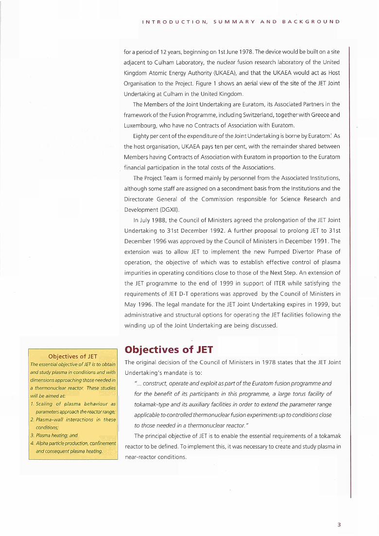
Organisation to the Project. Figure 1 shows an aerial view of the site of the JET Joint
Undertaking at Culham in the United Kingdom.
The Members of the Joint Undertaking are Euratom, its Associated Partners in the
framework of the Fusion Programme, including Switzerland, together with Greece and
Luxembourg, who have no Contracts of Association with Euratom.
Eighty per cent of the expenditure of the Joint Undertaking is borne by Euratom.' As
the host organisation, UKAEA pays ten per cent, with the remainder shared between
Members having Contracts of Association with Euratom in proportion to the Euratom
financial participation in the total costs of the Associations.
The Project Team is formed mainly by personnel from the Associated Institutions,
although some staff are assigned on a secondment basis from the Institutions and the
Directorate General of the Commission responsible for Science Research and
Development (DGXII).
In July 1988, the Council of Ministers agreed the prolongation of the JET Joint
Undertaking to 31st December 1992. A further proposal to prolong JET to 31st
December 1996 was approved by the Council of Ministers in December 1991. The
extension was to allow JET to implement the new Pumped Divertor Phase of
operation, the objective of which was to establish effective control of plasma
impurities in operating conditions close to those of the Next Step. An extension of
the JET programme to the end of 1999 in support of ITER while satisfying the
requirements of JET D-T operations was approved by the Council of Ministers in
May 1996. The legal mandate for the JET Joint Undertaking expires in 1999, but
administrative and structural options for operating the JET facilities following the
winding up of the Joint Undertaking are being discussed.
Objectives of JET The essential objective of JET is to obtain and study plasma in conditions and with dimensions approaching those needed in a thermonuclear reactor. These studies will be aimed at: 1. Scaling of plasma behaviour as
parameters approach the reactor range; 2. Plasma-wall interactions in these
conditions; 3. Plasma heating; and 4. Alpha panicle production, confinement
and consequent plasma heating.
Objectives of JET The original decision of the Council of Ministers in 1978 states that the JET Joint
Undertaking's mandate is to:
"... construct, operate and exploit as part of the Euratom fusion programme and
for the benefit of its participants in this programme, a large torus facility of
tokamak-type and its auxiliary facilities in order to extend the parameter range
applicable to controlled thermonuclear fusion experiments up to conditions close
to those needed in a thermonuclear reactor. "
The principal objective of JET is to enable the essential requirements of a tokamak
reactor to be defined. To implement this, it was necessary to create and study plasma in
near-reactor conditions.
I N T R O D U C T I O N , S U M M A R Y A N D B A C K G R O U N D
Fig. 1 : Aerial view of the JET Joint Undertaking, situated near Oxford in the United Kingdom
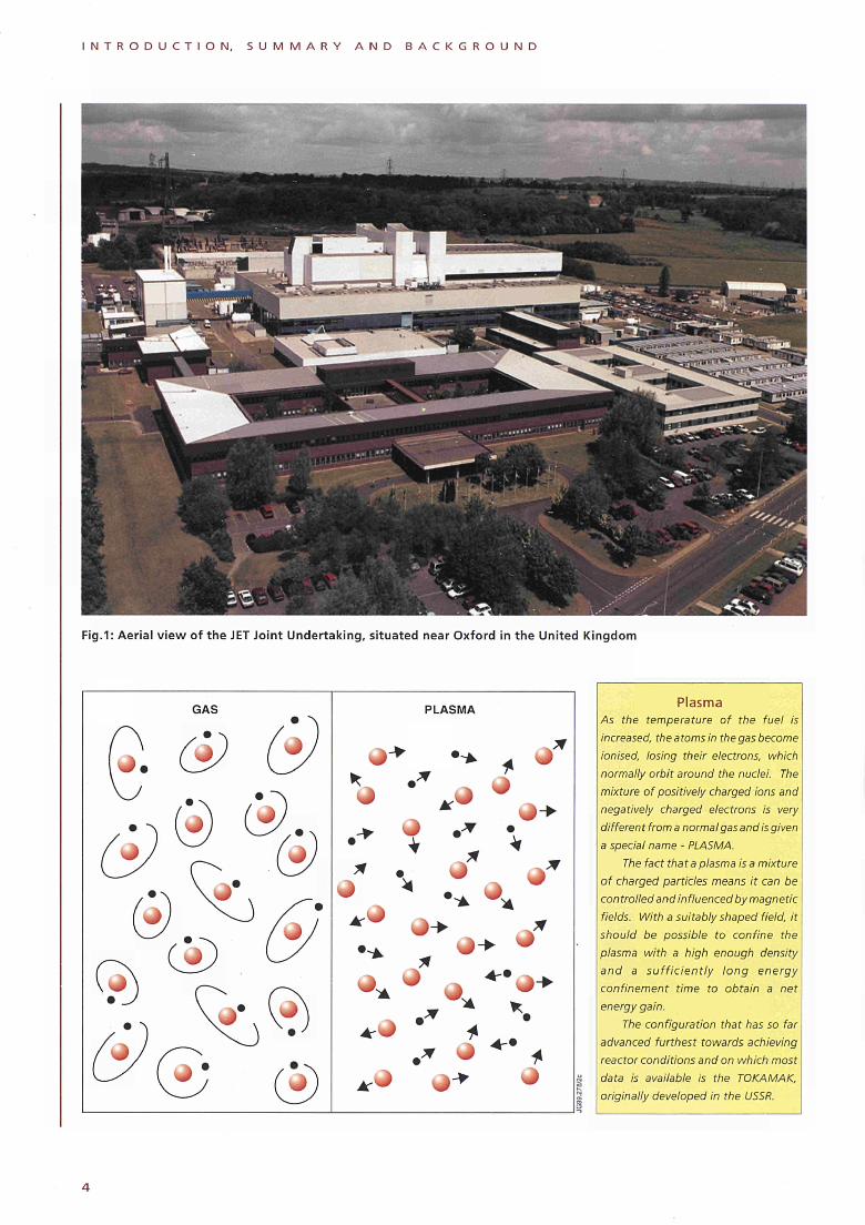
GAS PLASMA Plasma As the temperature of the fuel is increased, the atoms in the gas become ionised, losing their electrons, which normally orbit around the nuclei. The mixture of positively charged ions and negatively charged electrons is very differen t from a normal gas and is given a special name - PLASMA.
The fact that a plasma is a mixture of charged particles means it can be controlled and influenced by magnetic fields. With a suitably shaped field, it should be possible to confine the plasma with a high enough density and a sufficiently long energy confinement time to obtain a net energy gain.
The configuration that has so far advanced furthest towards achieving reactor conditions and on which most data is available is the TOKAMAK, originally developed in the USSR.
I N T R O D U C T I O N , S U M M A R Y A N D B A C K G R O U N D
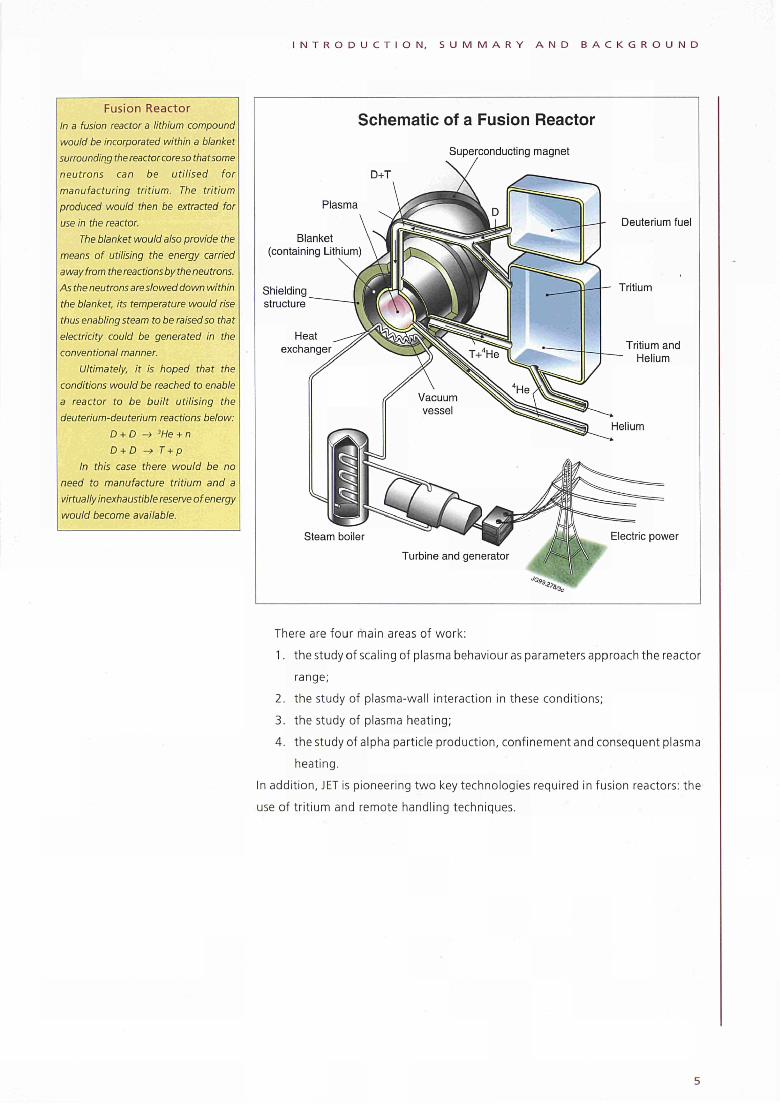
Fusion Reactor In a fusion reactor a lithium compound would be incorporated within a blanket surrounding the reactor core so that some neutrons can be utilised for manufacturing tritium. The tritium produced would then be extracted for use in the reactor.
The blanket would also provide the means of utilising the energy carried away from the reactions by the neutrons. As the neutrons are slowed down within the blanket, its temperature would rise thus enabling steam to be raised so that electricity could be generated in the conventional manner.
Ultimately, it is hoped that the conditions would be reached to enable a reactor to be built utilising the deuterium-deuterium reactions below:
D + D -> 3He + n D + D -> T + p
In this case there would be no need to manufacture tritium and a virtually inexhaustible reserve of energy would become available.
Schematic of a Fusion Reactor Superconducting magnet
Plasma
Blanket (containing Lithium)
Shielding structure
Heat exchanger
Steam boiler
Turbine and generator
Deuterium fuel
Tritium
Tritium and Helium
Electric power
There are four main areas of work:
1. the study of scaling of plasma behaviour as parameters approach the reactor
range;
2. the study of plasma-wall interaction in these conditions;
3. the study of plasma heating;
4. the study of alpha particle production, confinement and consequent plasma
heating.
In addition, JET is pioneering two key technologies required in fusion reactors: the
use of tritium and remote handling techniques.
fiteA
JET, E U R A T O M A N D O T H E R F U S I O N P R O G R A M M E S
JET, Euratom and other Fusion Programmes
Λ
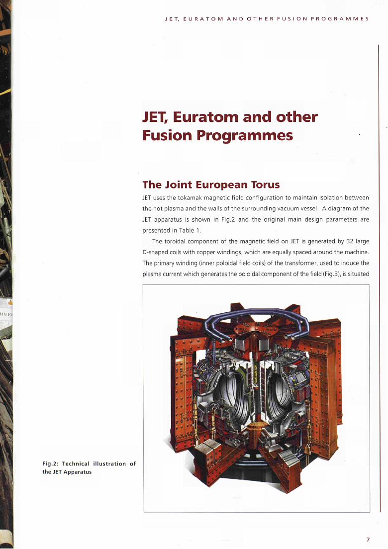
The Joint European Torus JET uses the tokamak magnetic field configuration to maintain isolation between
the hot plasma and the walls of the surrounding vacuum vessel. A diagram of the
JET apparatus is shown in Fig.2 and the original main design parameters are
presented in Table 1.
The toroidal component of the magnetic field on JET is generated by 32 large
D-shaped coils with copper windings, which are equally spaced around the machine.
The primary winding (inner poloidal field coils) of the transformer, used to induce the
plasma current which generates the poloidal component of the field (Fig.3), is situated
Fig.2: Technical illustration of the JET Apparatus
J E T , E U R A T O M A N D O T H E R F U S I O N P R O G R A M M E S
PARAMETER SIZE
PLASMA MINOR RADIUS:
HORIZONTAL
VERTICAL
PLASMA MAJOR RADIUS
FLAT-TOP PULSE LENGTH
WEIGHT OF THE IRON CORE
TOROIDAL FIELD COIL POWER (PEAK ON 13s RISE)
TOROIDAL MAGNETIC FIELD AT PLASMA CENTRE
PLASMA CURRENT:
CIRCULAR PLASMA
D-SHAPE PLASMA
VOLT-SECONDS TO DRIVE PLASMA CURRENT
ADDITIONAL HEATING POWER
1.25m
2.10m
2.96m
20s
2800t
3 8 0 M W
3.45T
3 .2MA
4 .8MA
34Vs
2 5 M W
at the centre of the machine. Coupling between the primary winding and the toroidal
plasma, acting as the single turn secondary, is provided by the massive eight limbed
transformer core. Around the outside of the machine, but within the confines of the
transformer limbs, is the set of six field coils (outer poloidal field coils) used for
positioning, shaping and stabilising the position of the plasma inside the vessel.
During operation large forces are produced due to interactions between the currents
and magnetic fields. These forces are constrained by the mechanical structure which
encloses the central components of the machine. The use of transformer action for
producing the large plasma current means that the JET machine operates in a pulsed
mode. Pulses can be produced at a maximum rate of about one every twenty minutes,
and each one can last for up to 60 seconds in duration. The plasma is enclosed within
the doughnut shaped vacuum vessel which has a major radius of 2.96m and a
D-shaped cross-section of 4.2m by 2.5m. The amount of gas introduced into the
vessel for an experimental pulse amounts to less than one tenth of a gramme.
Table 1: Original JET parameters
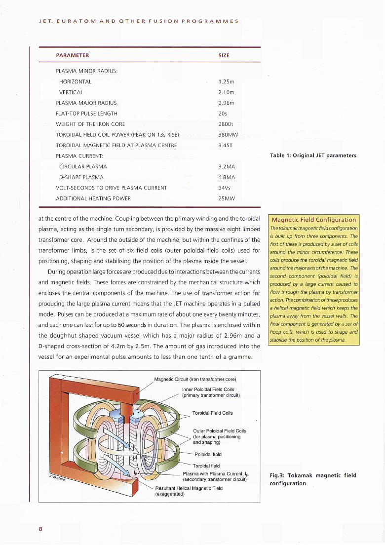
Magnetic Field Configuration The tokamak magnetic field configuration
is built up from three components. The
first of these is produced by a set of coils
around the minor circumference. These
coils produce the toroidal magnetic field
around the major axis of the machine. The
second component (poloidal field) is
produced by a large current caused to
flow through the plasma by transformer
action. The combination of these produces
a helical magnetic field which keeps the
plasma away from the vessel walls. The
final component is generated by a set of
hoop coils, which is used to shape and
stabilise the position of the plasma.
Magnetic Circuit (iron transformer core)
Inner Poloidal Field Coils (primary transformer circuit)
Toroidal Field Coils
Outer Poloidal Field Coils (for plasma positioning and shaping)
- Poloidal field
Toroidal field
Plasma with Plasma Current, l p (secondary transformer circuit)
Resultant Helical Magnetic Field (exaggerated)
Fig.3: Tokamak magnet ic f ie ld
configurat ion
J E T , E U R A T O M A N D O T H E R F U S I O N P R O G R A M M E S
Power Supplies The electric power to the JET device during an experimental pulse is counted in hundreds of megawatts.
An agreementwith the Generating Boards allows up to 575MW of pulse power to be taken directly from the 400kVghd, which after transformation down to 33kV is fed to the JET loads.
Two flywheel generators are used to provide the peak power for the toroidal magnetic field coils and ohmic heating circuit. Each of the generators has a rotor 9m in diameter weighing 775 tonnes. Between pulses, 8.8MW pony motors are used to increase the speed of rotation.When power is required for a JET pulse, the rotor windings are energised and the rotational energy of the flywheel is converted into electrical energy.On slowing down from the maximum speed of225rpm to half speed, the generators can each deliver 2.6QJ of energy with a peak power output of 400MW.
The construction phase of the Project, from 1978 to 1983, was completed
successfully within the scheduled period and within 8% of the projected cost of 184.6
MioECU at January 1977 values. The first plasma pulse was achieved on 25 June 1983
with a plasma current of 17000A lasting for about one tenth of a second. Thisf irst phase
of operation was carried out using only the large plasma current to heat the gas. In
1985, the first additional heating system, employing radio frequency heating, came
into operation and during 1991 reached 22MVV of power into the plasma. The neutral
beam heating system was brought into operation in 1986, and exceeded its design
capability in 1988, with 21.6MW of power injected into the torus.
Experiments have been carried out mainly using hydrogen or deuterium plasmas.
However, during 1991, experiments were performed with helium-3 and helium-4 and
a preliminary experiment was performed using 10% tritium in deuterium. The production
of energy in the megawatt range in a controlled fusion device was achieved for the first
time in the world. The JET Programme then turned to the effective control of plasma
impurities in operating conditions close to those of the Next Step. This required the
construction of divertor coils, target structure and cryopump inside the vacuum vessel.
Operations resumed in 1994 to study the central problems of the ITER divertor (efficient
dissipation of the exhausted power, control of particle fluxes and effective impurity
screening) were studied in the operating mode forseen for ITER with a series of divertors
and other modes of high fusion performance were also developed. During 1997 a series
of experiments (DTE 1) was undertaken with deuterium-tritium plasmas so that abundant
fusion reactions occurred. The alpha particles liberated from the reactions produced
significant heating of the plasma. During this phase, the machine structure became
radioactive to the extent that the in-vessel work required to install the third in the series
of divertors was carried out during 1998 using remote handling systems.
Controlled Thermonuclear Fusion: A Key Action in the Nuclear Energy Programme of Euratom Objective, Strategy and Priorities The long-term objective of the fusion activities, embracing all the research activities
undertaken in the Member States (plus Switzerland and other Associated States
which have joined the programme) aimed at harnessing fusion, is the jo int creation
of prototype reactors for power stations to meet the needs of society: operational
safety, environmental compatibil i ty, economic viability. The proposed strategy to
achieve this long-term objective includes the development of an experimental
reactor (the Next Step) fol lowed by a demonstration reactor (DEMO), accompanied
by physics and technology R&D activities, also involving European industry. In the
context of this strategy, construction of an experimental reactor is necessary and,
in the light of progress to date, seems technically feasible during the next decade.
This should take place wi th in the framework of international co-operation, such as
the International Thermonuclear Experimental Reactor (ITER). For the period 1998-

J E T , E U R A T O M A N D O T H E R F U S I O N P R O G R A M M E S
2002, the "key action" on fusion should enhance the Community's preparedness,
from a scientific, technical, financial and organisational point of view, to decide on
and support such a future experimental reactor. The contribution of fusion to safe
and clean baseload electricity generation will be investigated in the wider context
of studies on the socioeconomic aspects of fusion. The mobility and training of
scientific and technical personnel, the dissemination of results and the diffusion of
information to the public will be an integral part of this key action.
This strategy entails three main lines:
• Nextstep activities: fusion physics and technology activities to develop the
capacity to construct and operate an experimental reactor;
• Concept improvements: structured physics activities to improve basic concepts
of fusion devices, towards preparing the Next Step and the conceptual
definition of a demonstration reactor, DEMO;
• Longterm technology: structured technology activities towards preparing,
in the longer term, for DEMO and then a prototype reactor.
1998 Achievements
European fusion activities remained concentrated on the most successful toroidal
magnetic confinement line, the tokamak, and on a few promising lines akin to it.
In addition, in the context of a keepintouch activity, coordination of the national
civil research activities on ¡nerbai confinement and possible alternative concepts
was ensured.
Next Step Activities
The programme has continued to focus its activities on the preparation for a long
pulse burning fusion plasma device, particularly in the frame of the Engineering
Design Activities (EDA) of ITER, the overall programmatic objective of which is to
demonstrate the scientific and technological feasibility of fusion energy f or peaceful
purposes. The ITEREDA is carried out by a Joint Central Team (JCT) located in three
internationally staffed Joint Work Sites in Garching (EU), Naka (Japan) and San
Diego (US, until the end of 1998) and by three (plus the US until the beginning of
1999) Home Teams (HT).
Efficient collaboration has been achieved between the ITER JCT and Home
teams, which has successfully delivered the products requested of them:
• a complete, fully integrated design for the ITER machine is available;
• the major validating technology R&D projects are now in their concluding
stages for the purpose of confirming performance and understanding
operating margins;
• the safety and reliability analyses have shown that ITER can be built and
safely and reliably operated and would indeed demonstrate the safety and
environmental potential of fusion as an energy source;
• cost studies from industries throughout the the parties confirm that the total
estimated costs have remained within the targets set at the start of the EDA.
Conditions for Fusion
Fusion reactions can only take place if the
nuclei are brought close to one another.
However, all nuclei carry a positive charge
and therefore repel each other. By heating
the gaseous fuels to very high
temperatures, sufficient energy can be
given to the nuclei that the repulsive
force can be overcome and they fuse
together. In the deuterium-tritium
reaction, temperatures in excess of 100
million degrees Kelvin are required -
several times hotter than the centre of
the sun. Below 100 million degrees, the
deuterium-tritium reaction rate falls off
very rapidly: to one-tenth at 50 million
degrees, and 20,000 times lower at 10
million degrees.
A reactor must obtain more energy
from the fusion reactions than is put in
to heat the fuels and run the system.
Reactor power output depends on the
square of the number (n) of nuclei per
unit volume (density) and the volume
of gas.
Power losses must also be kept to
a minimum acceptable level by holding
the hot gases in thermal isolation from
their surroundings. The effectiveness
of this isolation can be measured by
the energy confinement time (τ) - the
time taken for the system to cool down
once all external forms of heating are
switched off.
In a fusion reactor the values of
temperature, density and energy
confinement time must be such that
their product (ητ^Τ), exceeds the figure
of 5x10² 'm
3skeV. Typical values for the
parameters that must be attained
simultaneously for a reactor are:
Central ion temperature, Γ
10-20keV
Central ion density, nt
2.5x10²°m-
3
Energy confinement time, rf
725
The temperature is expressedas the
average energy of the nuclei (IkeV is
approximately equal to 10 million
degrees K).
1 0
JET, E U R A T O M A N D O T H E R F U S I O N P R O G R A M M E S
Heating Initial production and heating of the plasma is produced by the large electric current flowing in the plasma itself (ohmic heating) used to generate the poloidal magnetic field.
The heating effect of this current is reduced as the plasma gets hotter as the electrical resistance of the plasma decreases with increasing temperature. Therefore, it is necessary to provide additional means of heating if the temperatures needed for a reactor are to be reached.
Two main additional heating methods are in general use: (1) Neutral Beam Heating:
In this method, a beam of charged hydrogen or deuterium ions is accelerated to high energies and directed towards the plasma. As charged particles cannot cross the magnetic field confining the plasma, the beam must be neutralised. The resulting neutral atoms cross the magnetic field and give up their energy through collisions to the plasma, thereby raising its temperature.
(2) Radio Frequency Heating: Energycan be absorbed by the plasma from high power radio-frequency waves. The frequency of operation is chosen to be close to that at which the ions or electrons orbit or gyrate in the magnetic field.
Following the presentation of the ITER Final Design Report (FDR) in January
1998, the ITER Parties reconfirmed the feasibility of the design, its quality and the
fact that it stayed within the original cost estimate. Due to financial considerations,
the ITER Council charged the JCT to address a Reduced Technical Objectives/
Reduced Cost version of the device: for this purpose, a Special Working Group was
set up with the task to propose technical guidelines for possible changes (detailed
technical objectives, overall margins, ..) as compared to ITER-FDR and to provide
information on broader concepts as a basis for the justification of these guidelines.
Concerning the ITER-EDA Agreement, initially foreseen to expire by July 1998, a 3
year extension was agreed by three ITER parties (EU, Japan and Russia) while the
fourth one (US) committed itself unilaterally to one year only.
In 1998, the work of the (European) ITER Home Central Team continued to be
co-ordinated by the NET (Next European Torus) Team in the framework of the NET
Agreement which expired bythe end of theyear(the European contribution to ITER
from 1999 onwards will be carried out in the frame of the new European Fusion
Development Agreement). The major part of the work on JET and in the Associations
has been directed towards key areas relevant to the Next Step. A series of "urgent
ITER Physics Tasks" was undertaken on the ITER-like tokamaks JET, ASDEX-
Upgrade, Compass-D and the other medium-sized tokamaks, focusing on
confinement scaling in order to increase confidence in the predictions for ITER. In
the first part of 1998, JET was in shutdown in order to replace its previous divertor
by the "gas box" configuration (Mark IIGB): for the first time, modifications of the
(radioactive) interior of the JET device were successfully achieved by means of
remote handling techniques. Operation of JET restarted in June 1998 and first
results confirmed the expectations for a more closed divertor.
In the Associations, during 1998, the following improvements and upgrades
have been proposed or decided as priority actions: tangential neutral beam
injection and reactive power compensation for the ASDEX-Upgrade tokamak
(Association Euratom-IPP); 2MW neutral beam injection in the TJ-II stellerator
(Association Euratom-CIEMAT); advanced FOM diagnostics for TEXTOR-94 (jointly
exploited by the trilateral Euregio cluster, Associations Euratom Belgian State, FOM,
FZJ); ECRH studies using gyrotrons and developments for a free electron maser for
use on TEXTOR-94 (FOM). On ASDEX Upgrade, operation continued with the so-
called Lyra-divertor. Quasi-stationary H-mode (CDH) operation with large radiated
powerfraction and good powerand particleexhaustwasachieved. Radiative power
limits of more than 80% (JET 65%) could be obtained. Tungsten as divertor coating
was investigated in ASDEX-Upgrade in parallel with studies of limiter materials,
ranging from Silicon to refractive metals in FTU showing advantages for high Ζ
materials with respect to low core impurities and high density limits. Limits of edge
density and its scaling with plasma size and heating power were studied on the
above devices as well as, in collaboration with JET, impurity release mechanisms for
impurity control. On TORE SUPRA plasma control for ergodic divertor operation
with highly radiating plasmas and low core impurity content was a key focus of the
1 1
J E T , E U R A T O M A N D O T H E R F U S I O N P R O G R A M M E S
1998 programme. "Windtunnel" confinement studies on TCV on the impact of
plasma elongation and shaping provided further improvement of the scaling
database for the Next Step. Theoretical models and codes for studying the
accessible operational space and regimes as well as control algorithms were further
developed in collaborations of several Associations supporting the physics arguments
for ITER design choices. Disruption mitigation and operational control were studied
on the smaller devices (COMPASSD, RTP, and ISTTOK) which are particularly suited
for these studies but also e.g. on TCV and ASDEXUpgrade (impurity injection).
Error field studies on ASDEXUpgrade and COMPASSD showed weaker dependence
on size than inferred from earlier work. Plasma engineering developments concerned
developments of highpower windows for ECRH (Associations Euratom FZK,
CIEMAT, and UKAEA)and 118167GHz gyrotrons(Association EuratomFZK reaching
1.2MW, 0.5ms 140165GHz, Suisse, CEA, and industry), for 118GHz the nominal
performance (0.5MW, 5s) was demonstrated. The prototype free electron maser
(Association EuratomFOM) has reached its first milestone (pulses of 0.7MW and
10μ5, tuneable over the range 130260GHz). For ICRH power densities of 18MW/
m2 were reached on TORE SUPRA and for Lower Hybrid heating and current drive
launcher concepts were studied at the Associations EuratomCEA and ENEA.
Development of neutral beam injection sources demonstrated the ITER specification
of 22 M A/cm2 (Association EuratomCEA in collaboration with Japan) and progressed
in the development of ion RF sources (Associations EuratomIPP, CEA, and DCU).
Diagnostics were developed and implemented on all larger devices, with a strong
involvement of the Associations EURATOMIST, DCU, FOM, NFR, RISO and TEKES.
Concept Improvements
Research on concept improvements is essential for extending the possible modes
of operation of the Next Step and, in the longer term, for the definition of DEMO.
On ASDEX Upgrade, quasistationary (6s pulse length) discharges were obtained
with negative shear and using Divertor II. This considerable progress was linked to
the exploitation of bootstrap currents and the generation of internal transport
barriers (which could also be seen in the electron temperature profile by high
resolution Thomson scattering on RTP). This work links closely to the exploration of
advanced enhanced performance regimes and stationary operation in the Next
Step. Contributions are provided by JET, the specialised devices (TORE SUPRA,
ASDEXUpgrade, TEXTOR, FTU, TCV, COMPASS, START, RTP, and ISTTOK) and in
the accompanying theoretical and computational programmes. The successful low
aspect ratio physics and spherical tokamak studies (ß>40%) in START were
concluded. This tokamak is being replaced by a larger one, MAST (MegaAmpere
Spherical Tokamak) for which commissioning was approached by the end of 1998.
The toroidal confinement data basis is complemented through contributions
from stellarators and reversed field pinches (W7AS, TJII, RFX, and EXTRAPT2).
Like the tokamaks these devices also serve for fundamental fusion physics studies,
1 2
J E T , E U R A T O M A N D O T H E R F U S I O N P R O G R A M M E S
for the development of diagnostics, for innovative studies and for the training of
young professionals and the smaller ones also for the preparation of collaboration
on larger devices. Work on these devices is accompanied by theoretical, numerical
or diagnostic activities with active incorporation of University research in many
places.
The development of the Stellarator physics has been pursued at Madrid
(Association Euratom-CIEMAT) where the TJ-II flexible stellarator started scientific
experiments by successfully obtaining bean-shaped plasmas. In Wendelstein 7-AS
(Association Euratom-IPP, Garching) 5.5keV (Te) plasmas were obtained with
neoclassical confinement; the approach of the theoretical beta limit was
demonstrated with NB heating; the expansion of the accessible plasma density
range studied for ECRH and the project for the assessment of the magnetic island
divertor for Wendelstein 7-X continued. For this project in Greifswald (Association
Euratom-IPP) civil engineering works proceeded as foreseen (buildings up to the
roof by the end of August); the series production of the advanced conductor
(following its successful testing) was launched; the cryostat module was assembled
and the demonstration coil moved to the Toska facility (FZK) for testing. Contributions
to the toroidal confinement data base were also provided by the reversed field
pinch: work on RFX (ENEA/CNR) and EXTRAP-T2 (NFR) concentrated on issues of
achieving high plasma performance operation (1,2MA operation has been reached)
and improvement of confinement by assisting inductive poloidal current drive and
spontaneous single helicity mode operation was attained. Finally, the keep-in-
touch activity in inertial confinement including the co-ordination of European
civilian activities in this field continued.
Long-term Technology The effort in long-term technology in the Associations was pursued in the
Associations, the Joint Research Centre and industry. Progress for 1998 can be
reported on the European Blanket Project blanket: for the two specific (water-
cooled lithium-lead and helium-cooled pebble bed) blanket concepts, the detailed
design documents and test programmes (developed for blanket module testing in
ITER) were completed; good results have been achieved in all the main technical
issues, including fabrication techniques and functional materials (beryllium, ceramic
breeders) behaviour in pile and out of pile; for structural materials, a contract was
placed for the production of a first batch of reduced activation ferritic martensitic
steel (delivery by end 1998). For power reactors, it was concluded that the reference
structural material was ferritic martensitic steels; for more advanced materials,
European efforts should be focused on SiCf/SiC, with keep-in-touch activities on
other possible materials. On safety and environment, work has addressed issues
such as improved containment concepts, cumulative production of activated
materials and its possible reduction as well as the impact of these constraints on the
economic aspects of a fusion power plant in order to define boundary conditions
1 3
J E T , E U R A T O M A N D O T H E R F U S I O N P R O G R A M M E S
for initiating a Power Plant Conceptual Study. In Socio-Economie Research on
Fusion (SERF), long-term scenarios have been developed which include fusion as a
source of electricity and plant availability and volumic power density have been
identified as important factors for production costs.
Involvement of Industry in the Programme European industry continues to play a key role in the EU Fusion Programme. Areas
of involvement include the supply of components, scientific equipment and
materials as well as services for the construction and exploitation of Fusion Facilities
in the EU as well as for the EU contributions to the detailed engineering design of
ITER.
Implementation All magnetic fusion R&D is fully integrated into a single Community action which
is represented as a single body in its relations with other fusion programmes
throughout the world. The European Commission - assisted by the Consultative
Committee for the Fusion Programme (CCFP) which was replaced (end 1998) by the
Consultative Committee for the Euratom specific research and training programme
in the field of nuclear energy-Fusion (CCE-FU), composed of national representatives
- is responsible for implementation of the key action on Controlled Thermonuclear
Fusion. The action is implemented within the framework of: agreements of
association with Member States of the European Union (and Associated States
participating in the action) or organisations in the Member States for activities in
physics, plasma engineering and technology; other contracts of limited duration (in
particular with organisations in Member States without Association); the JET Joint
Undertaking (until end 1999); the NET Agreement which was replaced (end 1998)
by the European Fusion Development Agreement (EFDA, incorporating technology
activities in the Associations and European industry, the collective use of the JET
facilities for the period beyond 1999, as well as the European contribution to
international collaborations such as ITER); and industrial contracts. Through the
multipartite Agreement for "Promotion of Staff Mobility", the mobility of scientists
and engineers was developed (300 to 400 secondments per year). In coordination
with the "Human Capitaland Mobility" programme, fellowships were awarded (10
to 1 5 per year). Nevertheless, in view of the decreasing number of physics students
in some countries and considering the loss of a larger number of professional staff
from JET which started in 1998 and continues in 1999, increased active measures
for maintaining the necessary professional staff potential in the coming years are
needed.
Dissemination of information and exploitation of results was performed through
laboratory reports, publications in scientific journals, workshops and conferences.
The itinerant fusion exhibition, run by the "Fusion EXPO" consortium (till end
1998), was displayed during long periods on the occasion of conferences/fairs
1 4
J E T , E U R A T O M A N D O T H E R F U S I O N P R O G R A M M E S
(Rome, Barcelone, Terrassa, Prague); another, smaller exhibition was presented
during short periods in different places (Washington DC, Marseilles, Helsinki,
Toulouse, Lisbon and 7 towns in the UK); also, 3-D immersive visualisation systems
("virtual reality") were developed for education purposes.
The Community financial participation amounts to about 25% of the running
expenditure of the Associations, 45% of capital cost of projects having been
awarded priority status by the CCFP, and 80% of JET expenditure. The overall
expenditure on fusion research in Europe amounts to 450-500MioECU per annum,
of which about 200MioECU come from the Community budget. About 2,000
professional scientists and engineers are currently engaged in fusion R&D in
Europe. In its Report, the external Monitoring Panel for 1998 expresses its global
satisfaction and considers that "the whole fusion programme is a very convincing
example of continuously growing and well implemented successful European
cooperation".
Fusion R&D in the Fifth Euratom Framework Programme The 5th Framework Programme - FP 5 with an overall budget of 14,960MioECU -
defines the Community activities within the EC and Euratom treaties in research,
technological development and demonstration for the period 1998-2002. Within
FP 5, an amount of 1,260MioECU is allocated to the Euratom Framework Programme
which includes both thematic and horizontal aspects and covers the area of
controlled thermonuclear fusion and energy systems related to nuclear fission, as
well as that of industrial and medical uses of radiation and natural sources of
radiation.
Within the Euratom Framework Programme, 979MioECU are allocated to the
nuclear energy programme, the aim of which is to help exploit the full potential of
nuclear energy, both fission and fusion, in a sustainable manner, by making current
technologies even safer and more economical, and by exploring promising new
concepts. Within the nuclear energy programme, 788MioECU are allotted to the
key action on controlled thermonuclear fusion, the aim of which is to further
develop the necessary basis for a decision on and the possible construction of an
experimental reactor, as well as basic concepts and technologies required in the
longer term.
European and International Collaboration The integrated nature of European fusion activities has led to extensive collaborations.
All Associations have undertaken work for, or in collaboration with, other
Associations; also, they were partners in JET and NET, and carried out work for
them through various contracts and notifications. Across Europe there exists a
genuine scientific and technical community of large and small laboratories directed
towards a common programmatic objective.
1 5
J E T , E U R A T O M A N D O T H E R F U S I O N P R O G R A M M E S
Internationally, the most important collaboration was the ITER EDA under the
auspices of the International Atomic Energy Agency (IAEA, Vienna). Also, eight
Implementing Agreements in the frame of the International Energy Agency (IEA,
Paris) have continued to serve as the frame for collaborations to pool expertise and
joint scientific interests. Bilateral or multilateral agreements for collaborations
between European and non-European laboratories have assisted the exchange of
information, common developments and the definition of complementary scientific
investigations.
Large International Tokamaks On 4th April 1997, the US tokamak, TFTR, produced its last plasma after its excellent
fusion power programme with 50:50 D-T fuelled plasmas that had started in 1993.
A fusion power of 10.7MW over an effective time of 0. is with a fusion efficiency
QDT of 0.27 had been produced.
Over this period, TFTR produced about 1090 D-T plasmas using 100g of
tritium and producing 1.6GJ of D-T fusion energy. These discharges had
significant populations of 3.5MeV alpha particles (the charged D-T fusion
product). TFTR research focussed on alpha particle confinement, alpha particle
driven instability modes and alpha particle heating studies. Also, apartfrom the
so-called "Super-shot" regime, other operating regimes were explored. In
particular, high beta poloidal (β ) and negative central magnetic shear regimes
with very high fusion performance were obtained. It was shown that in the
relatively quiescent phases of these discharges, the alpha particles behaved
classically and no anomalous losses occurred. The effect of sawteeth and ELMs
on alpha particles were also studied. The principal limitation to the TFTR fusion
power production was the disruptive stability limit. Secondary limitations were
the confinement time and limiter power handling capability.
High-performance experiments with the aim of establishing a physics base for
advanced steady state tokamak reactors have been carried out in the Japanese
JT-60U using two approaches: high β H-mode and reversed magnetic shear mode
discharges. In both types of discharge, an internal transport barrier built up inside
the plasma, which yielded very high performance with neoclassical transport coefficients
but with L-mode confinement at the edge which prevented the density build-up that
occurs in ELM-free Η-modes that have the transport barrier at the edge. In the reversed
shear discharge, the barrier built up at the qmin~2 surface. This discharge reached the
highest fusion performance with an equivalent QDT of 1.25 with plasma parameters of
ne(0) = 8.5x10,9nr3and T(0) « 16keV. The discharges were very dynamic and volatile
to MHD instabilities, but could, in principle, be controlled, although no steady state was
achieved in JT-60U. Further experiments are foreseen with the newly installed negative
ion Neutral Beam injector of 10MW.
JET broke all fusion records in 1997, not only in the highest fusion power but
also in fusion energy in a quasi steady state discharge, promising steady state
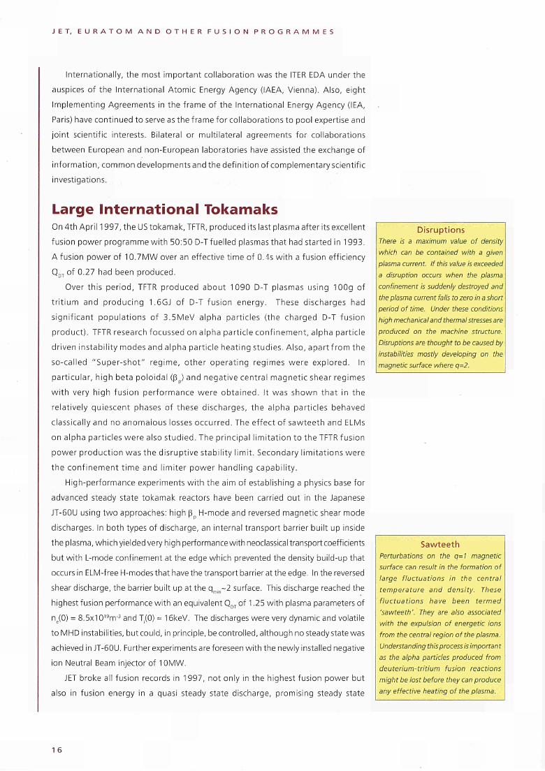
Disruptions There is a maximum value of density
which can be contained with a given
plasma current. If this value is exceeded
a disruption occurs when the plasma
confinement is suddenly destroyed and
the plasma current falls to zero in a short
period of time. Under these conditions
high mechanical and thermal stresses are
produced on the machine structure.
Disruptions are thought to be caused by
instabilities mostly developing on the
magnetic surface where q=2.
Sawteeth Perturbations on the q=l magnetic
surface can result in the formation of
large fluctuations in the central
temperature and density. These
fluctuations have been termed
'sawteeth'. They are also associated
with the expulsion of energetic ions
from the central region of the plasma.
Understanding this process is importan t
as the alpha particles produced from
deuterium-tritium fusion reactions
might be lost before they can produce
any effective heating of the plasma.
1 6
J E T , E U R A T O M A N D O T H E R F U S I O N P R O G R A M M E S
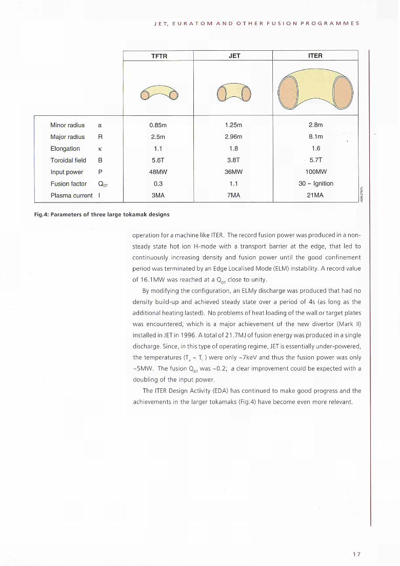
TFTR JET ITER
Minor radius
Major radius
Elongation
Toroidal field
Input power
Fusion factor
a
R
κ
Β
Ρ
QDT
Plasma current I
0.85m
2.5m
1.1
5.6T
48MW
0.3
3MA
1.25m
2.96m
1.8
3.8T
36MW
1.1
7MA
2.8m
8.1m
1.6
5.7T
100MW
30 - Ignition
21 MA
Fig.4: Parameters of three large tokamak designs
operation for a machine like ITER. The record fusion power was produced in a non-
steady state hot ion Η-mode with a transport barrier at the edge, that led to
continuously increasing density and fusion power until the good confinement
period was terminated by an Edge Localised Mode (ELM) instability. A record value
of 16.1 MW was reached at a QDT close to unity.
By modifying the configuration, an ELMy discharge was produced that had no
density build-up and achieved steady state over a period of 4s (as long as the
additional heating lasted). No problems of heat loading of the wall or target plates
was encountered; which is a major achievement of the new divertor (Mark II)
installed in JET in 1996. A total of 21.7MJ of fusion energy was produced in a single
discharge. Since, in this type of operating regime, JET is essentially under-powered,
the temperatures (Te ~ T, ) were only ~7keV and thus the fusion power was only
~5MW. The fusion QDT was -0.2; a clear improvement could be expected with a
doubling of the input power.
The ITER Design Activity (EDA) has continued to make good progress and the
achievements in the larger tokamaks (Fig.4) have become even more relevant.
17
O t
I « ν /
Jt .3k
f
•'Ί Ί " "Τ M
*" », ν ·
tøj-JL·
^
«
. gra* -
F ^
cFQ .5.1 c * ^
-,>.." l i
¿¿tr
ν
T E C H N I C A L S T A T U S O F J E T
Technical Status of JET
Introduction Following the highly successful series of experiments using the DeuteriumTritium
(DT) fuel mixture of a reactor (DTE1) in late 1997, JET started 1998 with a month
of operations to complete ITER urgent physics studies in hydrogen and deuterium
which the JET Council had agreed should be undertaken before the third stage of
the JET divertor programme.
At the beginning of February a four month shutdown commenced for the
exchange, by Remote Handling (RH) without manned intervention in the vessel, of
the Mark IIA divertor target structure for a second target structure, the Gas Box
divertor (Mark IIGB). This RemoteTile Exchange (RTE) shutdown was highly successful
and provided a clear demonstration of RH as a method of maintenance, repair and
upgrading of fusion devices. All the ¡ηvessel work was accomplished in the time
planned, all the RH equipment operated without failure, and all new components
fitted without significant interface problems.
The primary purpose of the RTE was to remove all 144 Mark MA divertor modules
and to replace them with the 192 Mark IIGB divertor modules. A number of related
or dependent tasks were also identified; various first wall protective tiles and
diagnostics systems were removed and replaced, surfaces of the tiles were vacuum
cleaned and the position and shape of the divertor structure was measured using
a remotely deployed 3dimensional photogrammetry system. In total, 38 different
major tasks were planned and successfully executed during the shutdown.
During all this work particular emphasis was placed on safety. Careful planning
resulted in low exposure of the workforce to radiation. Most individuals received
doses of less than 0.1 mSv, and the highest dose was 0.4mSv, significantly lower
than in some previous shutdowns. The tritium emanating from the JET vessel was
closely controlled using specially designed Contamination Enclosures and Ventilation
Systems, in conjunction with the Exhaust Detritiation (ED) System of the Active Gas
Handling System (AGHS). Exposure to tritium and beryllium contamination in the
form of dust and flakes from the vessel was controlled in the same way. The success
of these measures meant that the tritium levels in the Torus Hall were extremely low
1 9
T E C H N I C A L S T A T U S O F J E T
and caused no access difficulties, and that the discharge of liquids, particulates and
gas were all kept well below the Authorised Discharge Levels.
Of the20g of tritium inventory at the start of DTE 1, 16g were removed from the
vacuum vessel and accounted for in detail, with 12.5g being recovered to uranium
beds. About 1g was removed with the Mark IIA divertor target tiles and about a
further 0.5g with dust/flakes, all to separate storage. About 2.5g still remained in
the vessel at the end of the RTE.
The RTE was completed as planned at the end of May. The vessel pumpdown
proceeded with only minor problems, and the quality of the vacuum obtained was
better than after previous shutdowns because no personnel had entered the vessel.
The first plasma pulse was obtained as scheduled in early July, and the machine
conditions enabled a 2MA/2.5T X-point discharge with a 10s current flat top to be
obtained already in the fourth plasma pulse. This had never been achieved so rapidly
after a major shutdown.
A power outage in August planned by National Grid to refurbish their power
distribution system was used to re-install a number of diagnostic systems onto the
machine. An unexpected power cut just prior to the outage resulted in the cooling
of the machine, which in turn caused a crack and leak to occur on the Octant 4
Middle Port Adaptor. The leak was successfully repaired by re-welding the cracked
weld on the lip where the leak had occurred, and operations restarted as planned
at the end of August.
The experimental campaign with the Mark IIGB divertor commenced under Task
Force structure in early September and will continue into 1999.
Installation work associated with the upgrade of the Toroidal Field Static Units
for operation of JET at toroidal fields of up to 4T was also completed during 1998
and three 4T pulses with plasma were successfully run towards the end of the year.
The following sections detail notable technical achievements during 1998.
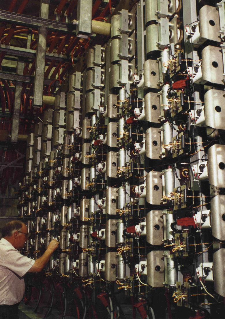
Technical Achievements Remote Handling Since the Mark II divertor was expected to become active during its use with
D-T plasmas, JET had incorporated an important feature in its design - it was
engineered to allow replacement of the divertor target structure by full Remote
Handling (RH) techniques. Such techniques need to be well established before
routine repair and maintenance of fusion power reactors can be envisaged and JET
is the only fusion device which was designed from the outset with RH in mind. ·
In 1998, JET carried out major work using the RH equipment developed over the
years. The experience gained at JET is invaluable for the conceptual design and
realisation of a next step fusion device. It has shown that RH, when included as one
of the basic design requirements from the start of the conceptual design, isa viable
technology. The experience extends from the basic philosophy of the approach to
RH, to the overall design requirements of the fusion device and to the design details
20
T E C H N I C A L S T A T U S O F J E T
of each and every component which may require RH. The JET experience also
extends to the important areas of the organisation and management of a project
which successfully integrates engineering aspects (including the RH requirements)
into the physics and operational requirements of the device. These include not only
the concepts and implementation of the hardware (including standardisation and
documentation), but also the operational, maintenance and repair procedures; the
facilities required for mock-up and the training of personnel; the methodology for
failure recovery and its implementation; the control of hardware and software
reliability; the spares policy; the planning and management of shutdowns; and the
facilities and procedures developed to ensure the control of radiation exposure and
contamination.
The Remote Tile Exchange Shutdown The major technical activity of the year was the RTE. This was the first fully remote
shutdown at JET and was successfully completed during a 15 week period from
February to May 1998.
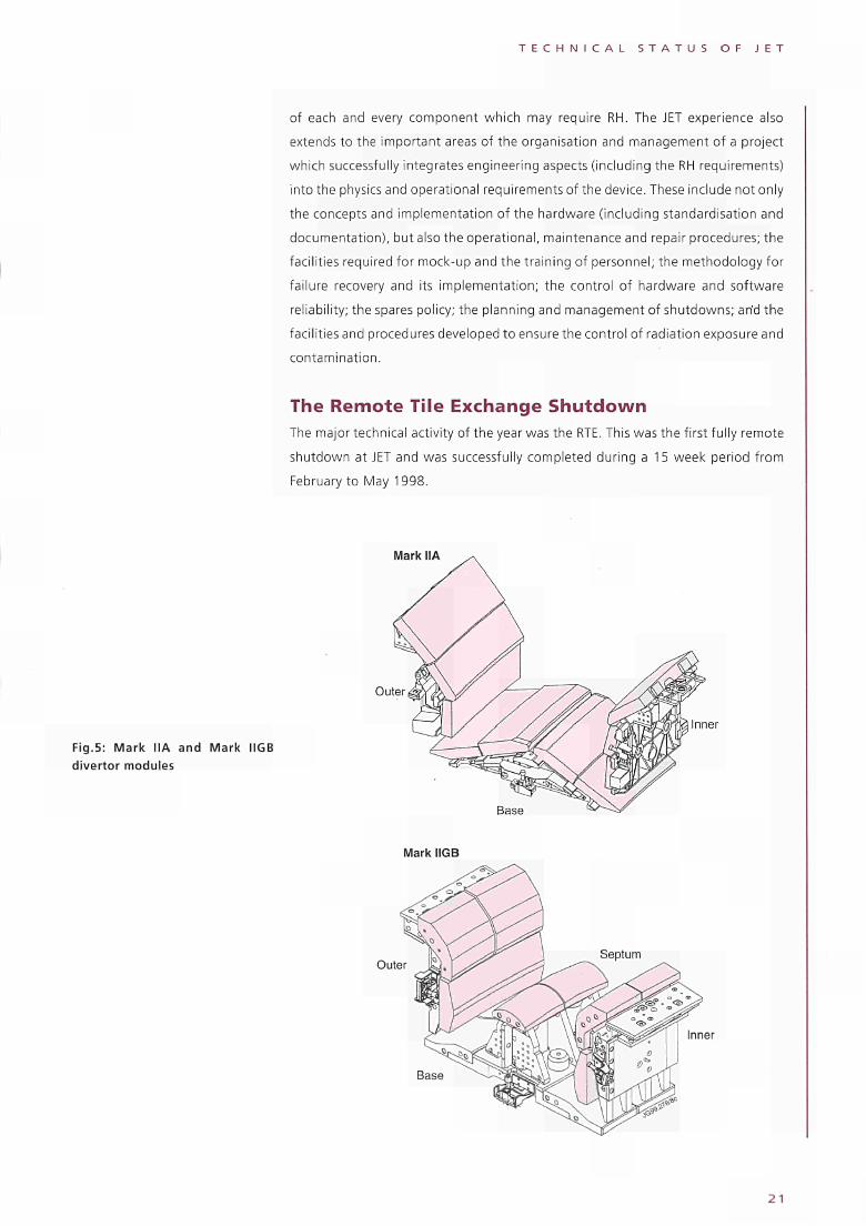
Mark IIA
Fig.5: Mark IIA and Mark IIGB divertor modules
Outer
Inner
Base
Mark IIGB
Outer
Inner
2 1
T E C H N I C A L S T A T U S O F J E T
The work planned for the shutdown included:
• the fully remote removal of the 144 modules of the Mark IIA divertor and the
remote installation of the 196 Mark IIGB divertor base, outer and inner carriers
(Fig.5);
• the vacuum cleaning of the i ηvessel components and the collection of dust and
flakes from the divertor region for future analysis;
• the removal and reinstallation of a number of divertor diagnostics; and
• the first remote, high precision (0.3mm accuracy) dimensional survey of the
divertor support structure using digital photogrammetry.
The flexible approach which had been adopted in preparing for the RTE also
enabled a number of unexpected and unplanned tasks to be undertaken,
including:
• seven pairs of poloidal limiter tiles, which had shown the first indications of
cracking, were removed and replaced remotely;
• a diagnostic wave guide was found to be displaced by 40mm from the expected
position and could not be removed by the established procedure. Using the
manipulator it was possible to deflect the wave guide, free the RH bolt, remove
the diagnostic and remove the trapped tile carriers. The displaced wave guide
support was surveyed using digital photogrammetry and the results used to
manufacture a new wave guide which was then installed;
• two diagnostic windows on the bottom of the vacuum vessel were covered with
carbon flakes and dust and required cleaning. Using the servomanipulator a
2.5m long, 11mm diameter stainless steel tube was passed though the 12mm
wide slot in the divertor support structure. A vacuum cleaner was then attached
to the tube and all the debris was removed successfully.
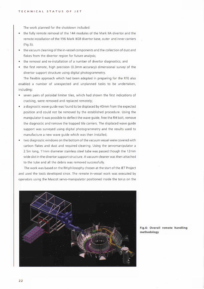
The work was based on the RH philosophy chosen at the start of the JET Project
and used the tools developed since. The remote ¡ηvessel work was executed by
operators using the Mascot servomanipulator positioned inside the torus on the
Fig.6: Overall remote handl ing
methodology
2 2
T E C H N I C A L S T A T U S O F J E T
end of the JET Articulated Boom (Fig.6). This articulated boom, housed within a
specially designed contamination control enclosure sealed from the torus, entered
the torus at the Octant 5 main horizontal port.
The components of the Mark IIA divertor were unbolted and removed from the
supporting structure with the help of the manipulator and transported by the boom
to Octant 1, directly opposite the main boom entry port in Octant 5. The
components were then transferred to an end effector attached to a second shorter
boom (of otherwise identical design to the main boom) which removed the
components from the vessel and manoeuvred them, without manned intervention,
onto trolleys for storage in a removable ISO container. The ISO container was
attached to the Tile Carrier Transfer Facility (TCTF), a contamination control
enclosure located at Octant 1 and housing the second short boom (Fig.6). The two
contamination control enclosures, as well as the ISO containers, were kept at a
depression relative to the surrounding Torus Hall and ventilated at a rate of 1020
air changes per hour by the Exhaust Detritiation (ED) System of the AGHS.
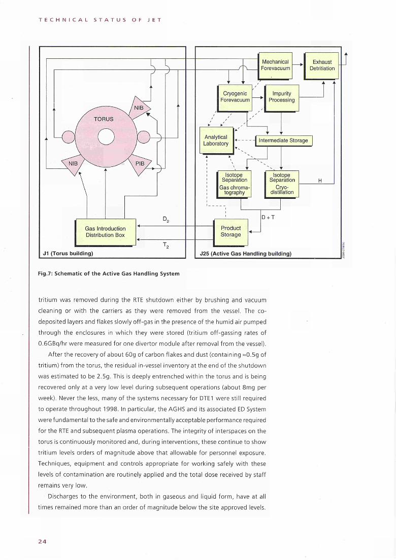
DTE1 Tritium Recovery
The Active Gas Handling System (AGHS) is a full gas reprocessing plant, which
collects gas from the torus, removes impurities from hydrogen, ¡sotopically separates
the hydrogen gas into streams of protium, deuterium and tritium, stores the
deuterium and tritium in Ubeds for reuse, and injects deuterium and tritium back
into the torus. Isotope separation makes use of cryodistillation and gas
chromatography. The system is located in a separate building with its own
ventilation system and is connected to the JET machine via 100m long pumping
lines and transfer lines. A schematic of the system is shown in Fig.7. It was designed
fora maximum daily throughput of up to 5 moles of tritium, 15 moles of deuterium
and 150 moles of protium. It was installed in compliance with a strict quality
assurance programme and went through an extensive phase of inactive testing.
Tritium commissioning was performed in two steps. Trace tritium commissioning
with about 0.8g was performed with a tritiumhydrogen gas mixture. Full tritium
commissioning with about 3g of tritium tested the complete process using all sub
systems and showed the system was ready for full tritium operation (DTE1 in 1997).
DTE1 ended in November 1997 with about 11 g of tritium retained in the torus
after the regeneration of all cryopumps. An extended campaign of tritium recovery
resulted in the reduction of the ¡ηvessel inventory to 6.2g (corresponding to 17%
of the tritium introduced into the vessel during DTE1) by the start of the RTE
shutdown in February 1998. This was in itself of considerable technical interest for
a Next Step machine and was essential for minimising the ¡ηvessel tritium
concentration during the RTE.
Most of this tritium was bound in codeposited layers of carbon and hydrogen
isotopes which adhered mainly to the cooler surfaces on the inner side of the
divertor or fell off in the form of 4050mm thick flakes. Much of the codeposited
2 3
T E C H N I C A L S T A T U S O F J E T
Fig.7: Schematic of the Active Gas Handling System
tritium was removed during the RTE shutdown either by brushing and vacuum
cleaning or with the carriers as they were removed from the vessel. The co-
deposited layers and flakes slowly off-gas in the presence of the humid air pumped
through the enclosures in which they were stored (tritium off-gassing rates of
0.6GBq/hr were measured for one divertor module after removal from the vessel).
After the recovery of about 60g of carbon flakes and dust (containing =0.5g of
tritium) from the torus, the residual in-vessel inventory at the end of the shutdown
was estimated to be 2.5g. This is deeply entrenched within the torus and is being
recovered only at a very low level during subsequent operations (about 8mg per
week). Never the less, many of the systems necessary for DTE1 were still required
to operate throughout 1998. In particular, the AGHS and its associated ED System
were fundamental to the safe and environmentally acceptable performance required
for the RTE and subsequent plasma operations. The integrity of interspaces on the
torus is continuously monitored and, during interventions, these continue to show
tritium levels orders of magnitude above that allowable for personnel exposure.
Techniques, equipment and controls appropriate for working safely with these
levels of contamination are routinely applied and the total dose received by staff
remains very low.
Discharges to the environment, both in gaseous and liquid form, have at all
times remained more than an order of magnitude below the site approved levels.
2 4
T E C H N I C A L S T A T U S O F J E T
Preparations for the 1999 Shutdown In the foreseeable future, access to the vacuum vessel will be accomplished either
fully remotely or with a mixture of remote and personnel access. The TCTF is being
modified to support personnel wearing full pressurised suits to enter the vessel, and
will supply all standard and emergency services required, as well as all requirements
for remote work.
The installation of the inboard pellet launch, planned for June 1999, will be
carried out mostly using RH equipment and will include the first RH welding carried
out at JET. A new suite of RH tooling has been defined. Over 25 new tools have been
designed and are being procured. The RH welding of small support rails onto the
torus wall requires detailed development; its feasibility using the JET RH equipment
has already been proven.
Remote photogrammetry surveying is being developed further and integrated
into CATIA as well as the manufacturing cycle. Following the RH welding of the
support rails, a survey will determine the precise three-dimensional rail positions so
that the pellet flig ht tubes, which will use these as attachments, can be manufactured
exactly for the support rail positions. Measuring, analysing and transferring the
data will require less than a week between completing the survey and installing the
first pellet flight tube.
Health Physics, Safety and the Environment The Director is responsible for safety and is required by the JET Statutes to
undertake all organisational measures to satisfy relevant safety requirements. JET
continues to meet all the requirements of relevant UK and EC legislation and, in
accordance with the Host Support Agreement, JET complies with the safety
regulations of the Host Organisation. Responsibilities for Safety and Health Physics
are discharged by the Health Physics and Safety Sections, which are part of the
Safety and Environment.Unit within the Directorate.
Health Physics Health Physics provides a complete radiological protection and occupational
hygiene service to the Project, including advice on radioactive and hazardous
materials handling, dosimetry, radioactive discharge and environmental monitoring,
beryllium analysis and exposure record keeping.
The RTE dominated the year, together with operations in the tritium and
beryllium handling areas. DTE1 had left levels of tritium in the torus which, after
clean-up at the start of the year, was estimated to be more than 2000TBq absorbed
on vessel components. A controlled sequence of purging of the torus volume
reduced these concentrations to a few GBq/m3, allowing the opening of the torus
containment. Personnel entries to the TCTF and Boom enclosure were made in full-
pressurised suits to guard against airborne tritium and particulate forms of tritiated
25
T E C H N I C A L S T A T U S O F J E T
dust and beryllium. The tritiated Mark IIA divertor modules were removed and
replaced by new Mark IIGB divertor modules. Tritium doses to suited workers were
very low due to the high level of protection. The TCTF and Boom enclosures were
later decontaminated, allowing entry in respirator protection. Health Physics was
required to advise on radiological protection measures, and to assess and monitor
tritium and radiation levels in the workplace.
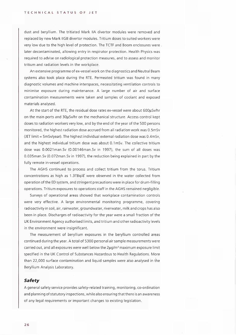
An extensive programme of ex-vessel work on the diagnostics and Neutral Beam
systems also took place during the RTE. Permeated tritium was found in many
diagnostic volumes and machine interspaces, necessitating ventilation controls to
minimise exposure during maintenance. A large number of air and surface
contamination measurements were taken and samples of coolant and exposed
materials analysed.
At the start of the RTE, the residual dose rates ex-vessel were about 600μ5ν/ΙΐΓ
on the main ports and 30μ5ν/τΐΓ on the mechanical structure. Access control kept
doses to radiation workers very low, and by the end of the year of the 500 persons
monitored, the highest radiation dose accrued from all radiation work was 0.5mSv
(JET limit = 5mSv/year). The highest individual external radiation dose was 0.4mSv,
and the highest individual tritium dose was about 0.1 mSv. The collective tritium
dose was 0.0021 man.Sv (0.00146man.Sv in 1997), the sum of all doses was
0.035man.Sv (0.072man.Sv in 1997), the reduction being explained in part by the
fully remote in-vessel operations.
The AGHS continued to process and collect tritium from the torus. Tritium
concentrations as high as 1.3TBq/£ were observed in the water collected from
operation of the ED system, and stringent precautions were in place for drum-fill ing
operations. Tritium exposures to operations staff in the AGHS remained negligible.
Surveys of operational areas showed that workplace contamination controls
were very effective. A large environmental monitoring programme, covering
radioactivity in soil, air, rainwater, groundwater, riverwater, milk and crops has also
been in place. Discharges of radioactivity for the year were a small fraction of the
UK Environment Agency authorised limits, and tritium and other radioactivity levels
in the environment were insignificant.
The measurement of beryllium exposures in the beryllium controlled areas
continued during the year. A total of 5300 personal air sample measurements were
carried out, and all exposures were well below the 2μg/m3 maximum exposure limit
specified in the UK Control of Substances Hazardous to Health Regulations. More
than 22,000 surface contamination and liquid samples were also analysed in the
Beryllium Analysis Laboratory.
Safety A general safety service provides safety-related training, monitoring, co-ordination
and planning of statutory inspections, while also ensuring that there is an awareness
of any legal requirements or important changes to existing legislation.
2 6
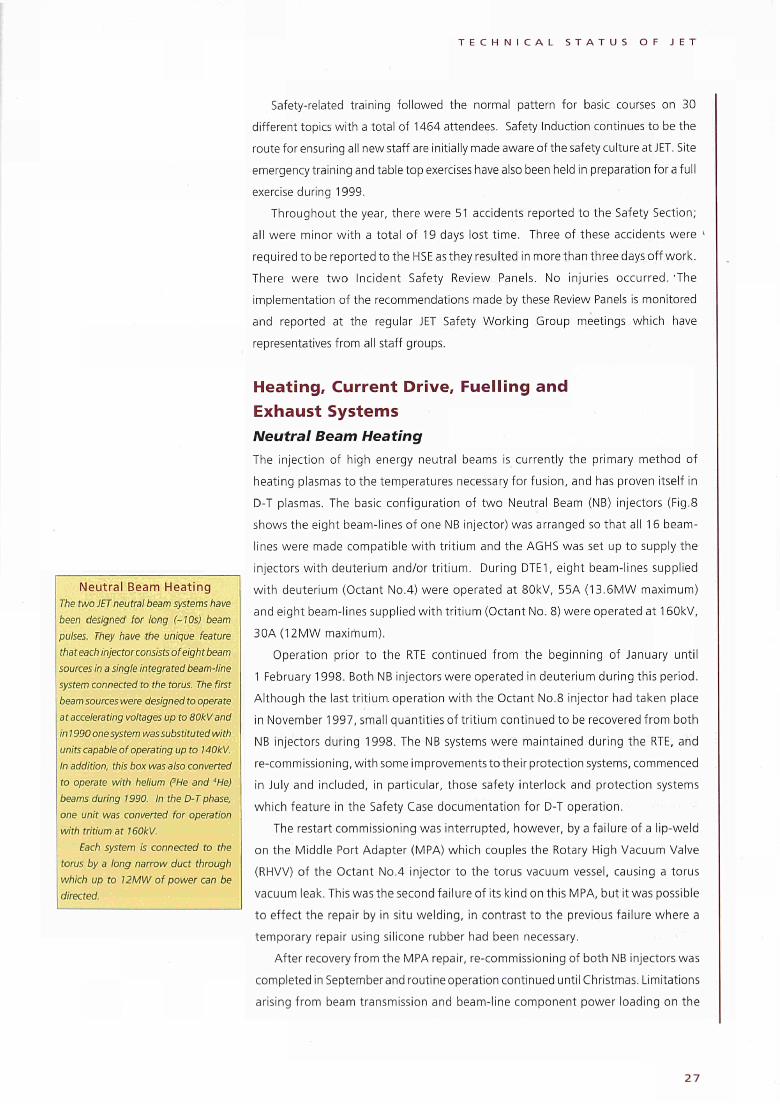
T E C H N I C A L S T A T U S O F J E T
Safety-related training followed the normal pattern for basic courses on 30
different topics with a total of 1464 attendees. Safety Induction continues to be the
route for ensuring all new staff are initially made aware of the safety culture at JET. Site
emergency training and table top exercises have also been held in preparation for a full
exercise during 1999.
Throughout the year, there were 51 accidents reported to the Safety Section;
all were minor with a total of 19 days lost time. Three of these accidents were »
required to be reported to the HSE as they resulted in more than three days off work.
There were two Incident Safety Review Panels. No injuries occurred. 'The
implementation of the recommendations made by these Review Panels is monitored
and reported at the regular JET Safety Working Group meetings which have
representatives from all staff groups.
Neutral Beam Heating The two JET neutral beam systems have been designed for long (~10s) beam pulses. They have the unique feature that each injector consists of eight beam sources in a single integrated beam-line system connected to the torus. The first beam sources were designed to operate at accelerating voltages up to SOkVand in 1990 one system was substituted with units capable of operating up to 140kV. In addition, this box was also converted to operate with helium ('He and "He) beams during 1990. In the D-T phase, one unit was converted for operation with tritium at 160kV.
Each system is connected to the torus by a long narrow duct through which up to 12MW of power can be directed.
Heating, Current Drive, Fuelling and Exhaust Systems Neutral Beam Heating The injection of high energy neutral beams is currently the primary method of
heating plasmas to the temperatures necessary for fusion, and has proven itself in
D-T plasmas. The basic configuration of two Neutral Beam (NB) injectors (Fig.8
shows the eight beam-lines of one NB injector) was arranged so that all 16 beam-
lines were made compatible with tritium and the AGHS was set up to supply the
injectors with deuterium and/or tritium. During DTE1, eight beam-lines supplied
with deuterium (Octant No.4) were operated at 80kV, 55A (13.6MW maximum)
and eight beam-lines supplied with tritium (Octant No. 8) were operated at 160kV,
30A(12MW maximum).
Operation prior to the RTE continued from the beginning of January until
1 February 1998. Both NB injectors were operated in deuterium during this period.
Although the last tritium operation with the Octant No.8 injector had taken place
in November 1997, small quantities of tritium continued to be recovered from both
NB injectors during 1998. The NB systems were maintained during the RTE, and
re-commissioning, with some improvements to their protection systems, commenced
in July and included, in particular, those safety interlock and protection systems
which feature in the Safety Case documentation for D-T operation.
The restart commissioning was interrupted, however, by a failure of a lip-weld
on the Middle Port Adapter (MPA) which couples the Rotary High Vacuum Valve
(RHVV) of the Octant No.4 injector to the torus vacuum vessel, causing a torus
vacuum leak. This was the second failure of its kind on this MPA, but it was possible
to effect the repair by in situ welding, in contrast to the previous failure where a
temporary repair using silicone rubber had been necessary.
After recovery from the MPA repair, re-commissioning of both NB injectors was
completed in September and routine operation continued until Christmas. Limitations
arising from beam transmission and beam-line component power loading on the
2 7
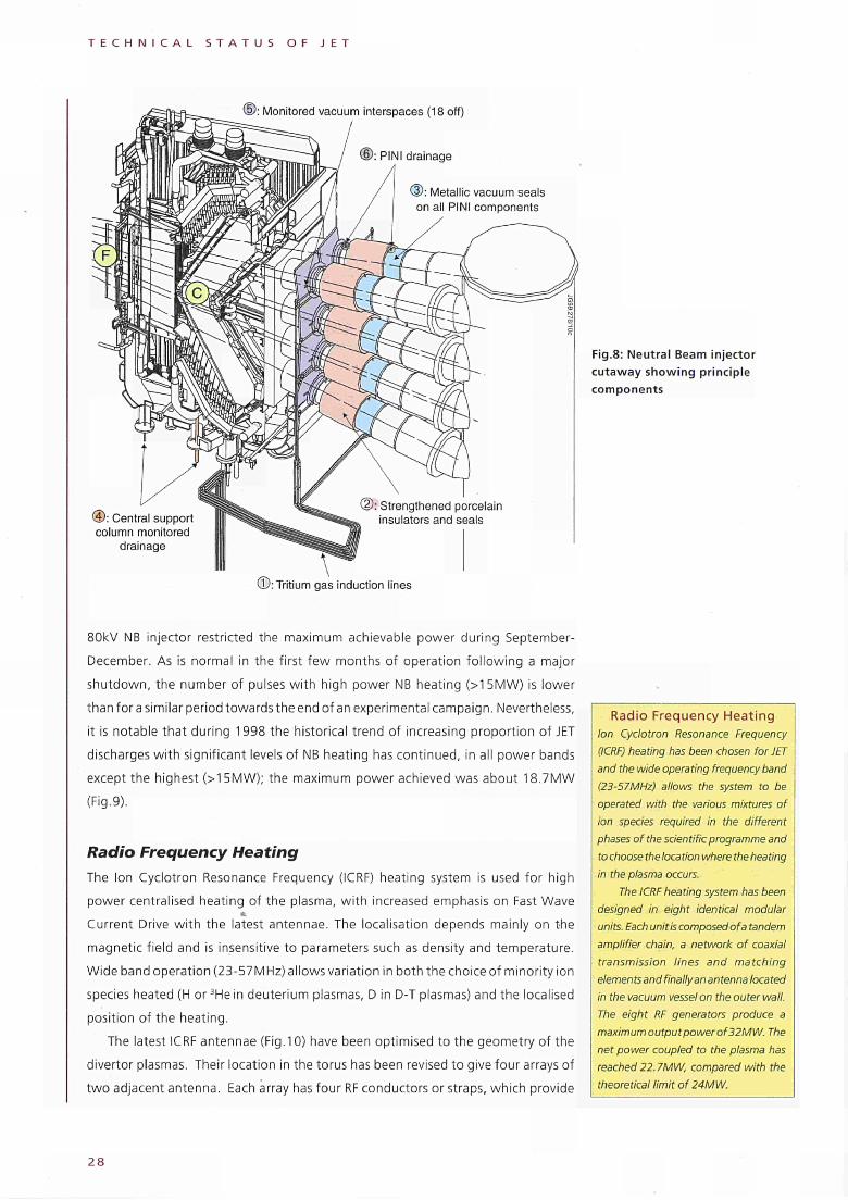
T E C H N I C A L S T A T U S O F J E T
Monitored vacuum interspaces (18 off)
Metallic vacuum seals on all PINI components
® : Central support column monitored
drainage
Fig.8: Neutral Beam injector cutaway showing principle components
© : Tritium gas induction lines
80kV NB injector restricted the maximum achievable power during September-
December. As is normal in the first few months of operation following a major
shutdown, the number of pulses with high power NB heating (>1 5MW) is lower
than for a similar period towards the end of an experimental campaign. Nevertheless,
it is notable that during 1998 the historical trend of increasing proportion of JET
discharges with significant levels of NB heating has continued, in all power bands
except the highest (>15MW); the maximum power achieved was about 18.7MW
(Fig.9).
Radio Frequency Heating The Ion Cyclotron Resonance Frequency (ICRF) heating system is used for high
power centralised heating of the plasma, with increased emphasis on Fast Wave
Current Drive with the latest antennae. The localisation depends mainly on the
magnetic field and is insensitive to parameters such as density and temperature.
Wide band operation (23-57MHz) allows variation in both the choice of minority ion
species heated (H or 3He in deuterium plasmas, D in D-T plasmas) and the localised
position of the heating.
The latest ICRF antennae (Fig.10) have been optimised to the geometry of the
divertor plasmas. Their location in the torus has been revised to give four arrays of
two adjacent antenna. Each array has four RF conductors or straps, which provide
Radio Frequency Heating Ion Cyclotron Resonance Frequency (ICRF) heating has been chosen for JET and the wide operating frequency band (23-57MHz) allows the system to be operated with the various mixtures of ion species required in the different phases of the scientific programme and to choose the location where the heating in the plasma occurs.
The ICRF heating system has been designed in eight identical modular units. Each unit is composed of a tandem amplifier chain, a network of coaxial transmission lines and matching elements and finallyan antenna located in the vacuum vessel on the outer wall. The eight RF generators produce a maximum output powerof32MW. The net power coupled to the plasma has reached 22.7MW, compared with the theoretical limit of 24MW.
2 8
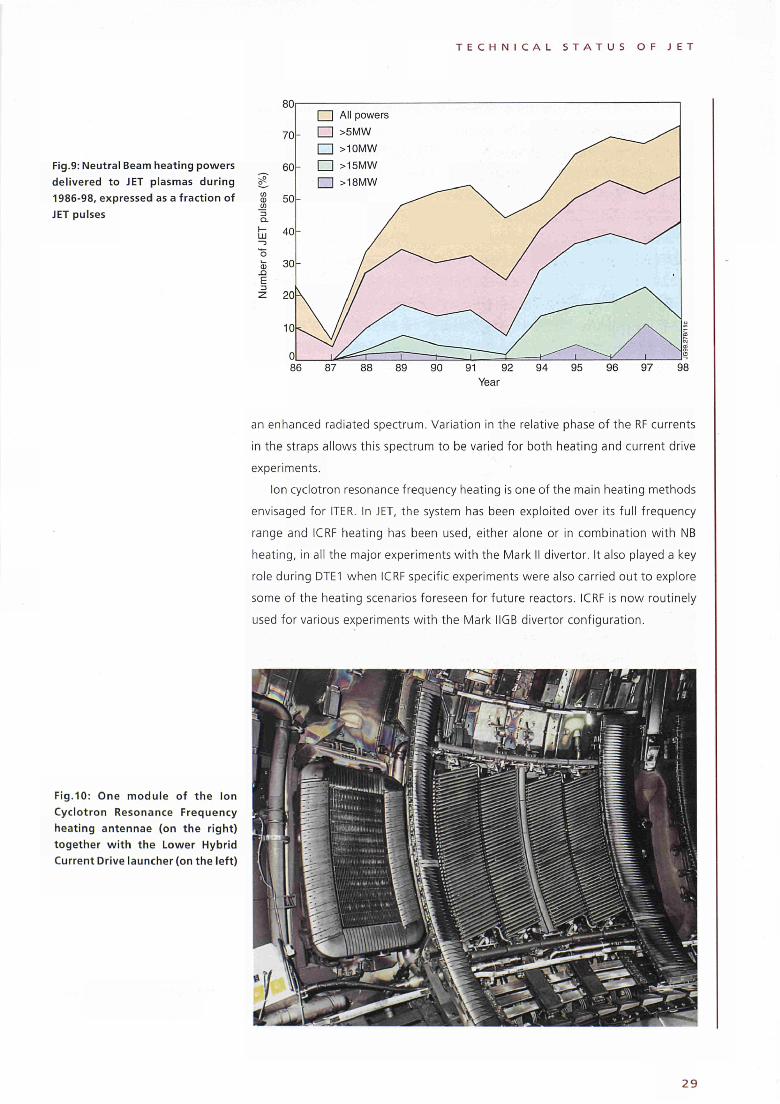
T E C H N I C A L S T A T U S O F J E T
Fig.9: Neutral Beam heating powers delivered to JET plasmas during 1986-98, expressed as a fraction of JET pulses
ω -Q
E
an enhanced radiated spectrum. Variation in the relative phase of the RF currents
in the straps allows this spectrum to be varied for both heating and current drive
experiments.
Ion cyclotron resonance frequency heating is one of the main heating methods
envisaged for ITER. In JET, the system has been exploited over its full frequency
range and ICRF heating has been used, either alone or in combination with NB
heating, in all the major experiments with the Mark II divertor. It also played a key
role during DTE1 when ICRF specific experiments were also carried out to explore
some of the heating scenarios foreseen for future reactors. ICRF is now routinely
used for various experiments with the Mark IIGB divertor configuration.
Fig.10: One module of the Ion Cyclotron Resonance Frequency heating antennae (on the right) together with the Lower Hybrid Current Drive launcher (on the left)
2 9
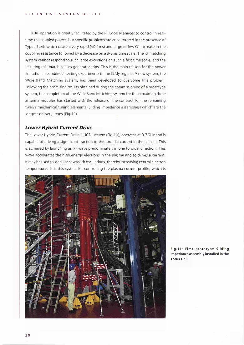
T E C H N I C A L S T A T U S O F J E T
ICRF operation is greatly facilitated by the RF Local Manager to control in real
time the coupled power, but specific problems are encountered in the presence of
Type I ELMs which cause a very rapid (=0.1ms) and large (= fewQ) increase in the
coupling resistance followed by a decrease on a 3-5ms time scale. The RF matching
system cannot respond to such large excursions on such a fast time scale, and the
resulting mis-match causes generator trips. This is the main reason for the power
limitation in combined heating experiments in the ELMy regime. A new system, the
Wide Band Matching system, has been developed to overcome this problem.
Following the promising results obtained during the commissioning of a prototype
system, the completion of the Wide Band Matching system for the remaining three
antenna modules has started with the release of the contract for the remaining
twelve mechanical tuning elements (Sliding Impedance assemblies) which are the
longest delivery items (Fig.11).
Lower Hybrid Current Drive The Lower Hybrid Current Drive (LHCD) system (Fig. 10), operates at 3.7GHzand is
capable of driving a significant fraction of the toroidal current in the plasma. This
is achieved by launching an RF wave predominately in one toroidal direction. This
wave accelerates the high energy electrons in the plasma and so drives a current.
It may be used to stabilise sawtooth oscillations, thereby increasing central electron
temperature. It is this system for controlling the plasma current profile, which is
Fig.11: First prototype Sliding Impedance assembly installed in the Torus Hall
30
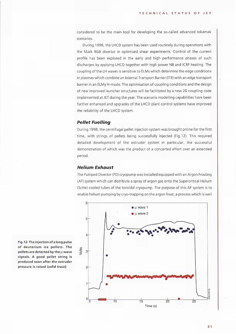
Fig.12:The injection of a long pulse
of d e u t e r i u m ice pe l le ts . The
pellets are detected by the μ w a v e
signals. A good pellet string is
produced soon after the extruder
pressure is raised (solid trace)
T E C H N I C A L S T A T U S O F J E T
considered to be the main tool for developing the socalled advanced tokamak
scenarios.
During 1998, the LHCD system has been used routinely during operations with
the Mark IIGB divertor in optimised shear experiments. Control of the current
profile has been explored in the early and high performance phases of such
discharges by applying LHCD together with high power NB and ICRF heating. The
coupling of the LH waves is sensitive to ELMs which determine the edge conditions
in plasmas which combine an Internal Transport Barrier (ITB) with an edge transport
barrier in an ELMy Ηmode. The optimisation of coupling conditions and the design
of new improved launcher structures will be facilitated by a new 2D coupling code
implemented at JET during the year. The scenario modelling capabilities have been
further enhanced and upgrades of the LHCD plant control systems have improved
the reliability of the LHCD system.
Pellet Fuelling
During 1998, the centrifugal pellet injection system was brought online for the first
time, with strings of pellets being successfully injected (Fig.12). This required
detailed development of the extruder system in particular, the successful
demonstration of which was the product of a concerted effort over an extended
period.
Helium Exhaust
The Pumped Divertor (PD) cryopump was installed equipped with an Argon Frosting
(AF) system which can distribute a spray of argon gas onto the Supercritical Helium
(ScHe) cooled tubes of the toroidal cryopump. The purpose of this AF system is to
enable helium pumping by cryotrapping on the argon frost, a process which is well
5
co
Î
μ wave 1
μ wave 2
* ■ — \
7 -Í^^^Wrf
ï«r"w»'W<M ■ « & * · $ U V V
10 15 20 25
Time (s)
3 1
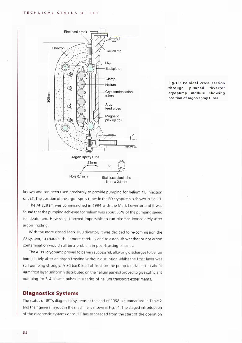
T E C H N I C A L S T A T U S O F J E T
Electrical break
Argon spray tube 23mm
0« K> 0
Hole 0.1mm Stainless steel tube 8mm χ 0.1mm
Fig.13: Poloidal cross section through pumped divertor cryopump module showing position of argon spray tubes
known and has been used previously to provide pumping for helium NB injection
on JET. The position of the argon spray tubes in the PD cryopump is shown in Fig. 13.
The AF system was commissioned in 1994 with the Mark I divertor and it was
found that the pumping achieved for helium was about 85% of the pumping speed
for deuterium. However, it proved impossible to run plasmas immediately after
argon frosting.
With the more closed Mark IIGB divertor, it was decided to re-commission the
AF system, to characterise it more carefully and to establish whether or not argon
contamination would still be a problem in post-frosting plasmas.
The AF PD cryopump proved to be very successful, allowing discharges to be run
immediately after an argon frosting without disruption whilst the frost layer was
still pumping strongly. A 30 ban£ load of frost on the pump (equivalent to about
4μηπ frost layer uniformly distributed on the helium panels) proved to give sufficient
pumping for 3-4 plasma pulses in a series of helium transport experiments.
Diagnostics Systems The status of JET's diagnostic systems at the end of 1998 is summarised in Table 2
and their general layout in the machine is shown in Fig. 14. The staged introduction
of the diagnostic systems onto JET has proceeded from the start of the operation
3 2
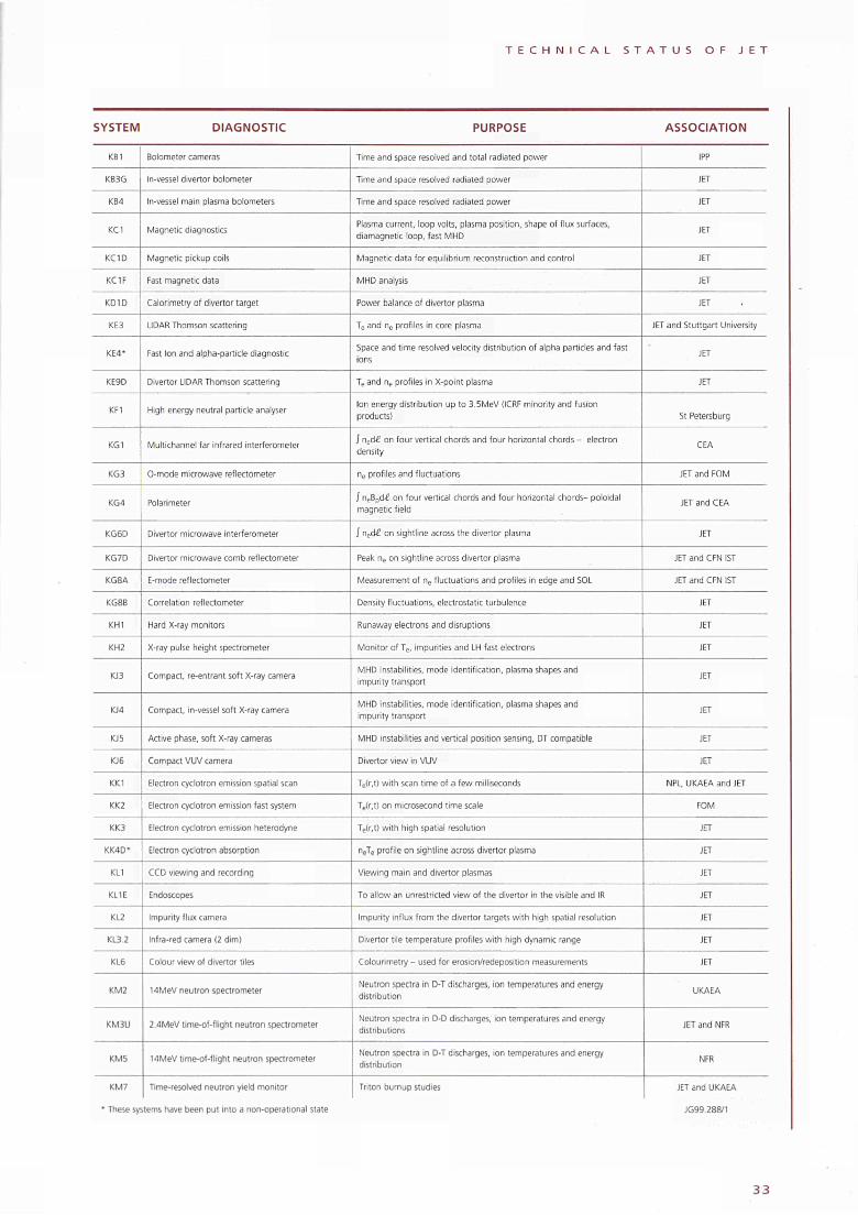
T E C H N I C A L S T A T U S O F J E T
SYSTEM DIAGNOSTIC PURPOSE ASSOCIATION
KB1
KB3G
KB4
KCl
KC1D
KC1F
KD1D
KE3
KE4*
KE9D
KF1
KG1
KG3
KG4
KG6D
KG7D
KG8A
KG8B
KH1
KH2
KJ3
KJ4
KJ5
KJ6
KKI
KK2
KK3
KK4D*
KL1
KL1E
KL2
KL3.2
KL6
KM2
KM3U
KM5
KM7
Bolometer cameras
Ιπ-vessel divertor bolometer
In-vessel main plasma bolometers
Magnetic diagnostics
Magnetic pickup coils
Fast magnetic data
Calorimetry of divertor target
LIDAR Thomson scattering
Fast Ion and alpha-particle diagnostic
Divertor LIDAR Thomson scattering
High energy neutral particle analyser
Multichannel far infrared interferometer
O-mode microwave reflectometer
Polarimeter
Divertor microwave interferometer
Divertor microwave comb reflectometer
Ε-mode reflectometer
Correlation reflectometer
Hard X-ray monitors
X-ray pulse height spectrometer
Compact, re-entrant soft X-ray camera
Compact, in-vessel soft X-ray camera
Active phase, soft X-ray cameras
Compact VUV camera
Electron cyclotron emission spatial scan
Electron cyclotron emission fast system
Electron cyclotron emission heterodyne
Electron cyclotron absorption
CCD viewing and recording
Endoscopes
Impurity flux camera
Infra-red camera (2 dim)
Colour view of divertor tiles
14MeV neutron spectrometer
2.4MeV time-of-flight neutron spectrometer
14MeV time-of-flight neutron spectrometer
Time-resolved neutron yield monitor
Time and space resolved and total radiated power
Time and space resolved radiated power
Time and space resolved radiated power
Plasma current, loop volts, plasma position, shape of flux surfaces, diamagnetic loop, fast MHD
Magnetic data for equilibrium reconstruction and control
MHD analysis
Power balance of divertor plasma
Te and ne profiles in core plasma
Space and time resolved velocity distribution of alpha particles and fast ions
Teand ne profiles in X-point plasma
Ion energy distribution up to 3.5MeV (ICRF minority and fusion products)
ƒ ned£ on four vertical chords and four horizontal chords - electron density
ne profiles and fluctuations
ƒ neBpd£ on four vertical chords and four horizontal chords- poloidal magnetic field
1 ned£ on sightline across the divertor plasma
Peak ne on sightline across divertor plasma
Measurement of ne fluctuations and profiles in edge and SOL
Density fluctuations, electrostatic turbulence
Runaway electrons and disruptions
Monitor of Te, impurities and LH fast electrons
MHD instabilities, mode identification, plasma shapes and impurity transport
MHD instabilities, mode identification, plasma shapes and impurity transport
MHD instabilities and vertical position sensing, DT compatible
Divertor view in VUV
Te(r,t) with scan time of a few milliseconds
Te(r,t) on microsecond time scale
Te(r,t) with high spatial resolution
neTe profile on sightline across divertor plasma
Viewing main and divertor plasmas
To allow an unrestricted view of the divertor in the visible and IR
Impurity influx from the divertor targets with high spatial resolution
Divertor tile temperature profiles with high dynamic range
Colourimetry - used for erosion/redeposition measurements
Neutron spectra in D-T discharges, ¡on temperatures and energy distribution
Neutron spectra in D-D discharges, ion temperatures and energy distributions
Neutron spectra in D-T discharges, ion temperatures and energy distribution
Triton burnup studies
IPP
JET
JET
JET
JET
JET
JET
JET and Stuttgart University
JET
JET
St Petersburg
CEA
JET and FOM
JET and CEA
JET
JET and CFN 1ST
JET and CFN 1ST
JET
JET
JET
JET
JET
JET
JET
NPL, UKAEA and JET
FOM
JET
JET
JET
JET
JET
JET
JET
UKAEA
JET and NFR
NFR
JET and UKAEA
' These systems have been put into a non-operational state
3 3
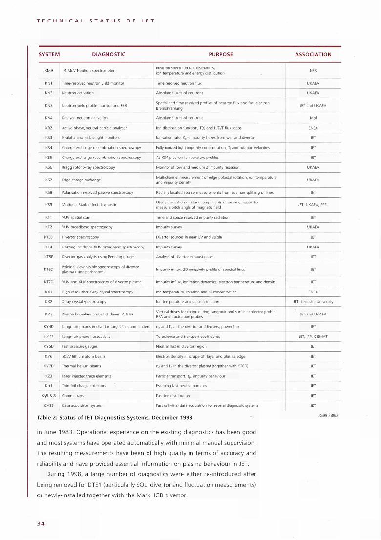
T E C H N I C A L S T A T U S O F J E T
SYSTEM DIAGNOSTIC PURPOSE
Table 2: Status of JET Diagnostics Systems, December 1998
in June 1983. Operational experience on the existing diagnostics has been good
and most systems have operated automatically w i th minimal manual supervision.
The resulting measurements have been of high quality in terms of accuracy and
reliability and have provided essential information on plasma behaviour in JET.
During 1998, a large number of diagnostics were either reintroduced after
being removed for DTE1 (particularly SOL, divertor and f luctuat ion measurements)
or newlyinstalled together wi th the Mark IIGB divertor.
ASSOCIATION
KM9
KN1
KN2
KN3
KN4
KR2
KS3
KS4
KS5
KS6
KS7
KSS
KS9
KT1
KT2
KT3D
KT4
KT5P
KT6D
KT7D
KX1
KX2
KY3
KY4D
KY4F
KY5D
KY6
KY7D
KZ3
Kal
Κγ5 S 8
CATS
14 MeV Neutron spectrometer
Timeresolved neutron yield monitor
Neutron activation
Neutron yield profile monitor and FEB
Delayed neutron activation
Active phase, neutral particle analyser
Ηalpha and visible light monitors
Charge exchange recombination spectroscopy
Charge exchange recombination spectroscopy
Bragg rotor Xray spectroscopy
Edge charge exchange
Polarisation resolved passive spectroscopy
Motional Stark effect diagnostic
VUV spatial scan
VUV broadband spectroscopy
Divertor spectroscopy
Grazing incidence XUV broadband spectroscopy
Divertor gas analysis using Penning gauge
Poloidal view, visible spectroscopy of divertor
plasma using periscopes
VUV and XUV spectroscopy of divertor plasma
High resolution Xray crystal spectroscopy
Xray crystal spectroscopy
Plasma boundary probes (2 drives: A & B)
Langmuir probes in divertor target tiles and limiters
Langmuir probe fluctuations
Fast pressure gauges
50kV lithium atom beam
Thermal helium beams
Laser injected trace elements
Thin foil charge collectors
Gamma rays
Data acquisition system
Neutron spectra in DT discharges,
¡on temperature and energy distribution
Time resolved neutron flux
Absolute fluxes of neutrons
Spatial and time resolved profiles of neutron flux and fast electron
Bremsstrahlung
Absolute fluxes of neutrons
Ion distribution function, T(r) and H/D/T flux ratios
Ionisation rate, Zeff, impurity fluxes from wall and divertor
Fully ionized light impurity concentration, T, and rotation velocities
As KS4 plus ¡on temperature profiles
Monitor of low and medium Ζ impurity radiation
Multichannel measurement of edge poloidal rotation, ion temperature
and impurity density
Radially located source measurements from Zeeman splitting of lines
Uses polarisation of Stark components of beam emission to
measure pitch angle of magnetic field
Time and space resolved impurity radiation
Impurity survey
Divertor sources in near UV and visible
Impurity survey
Analysis of divertor exhaust gases
Impurity influx, 2D emissivity profile of spectral lines
Impurity influx, ionization dynamics, electron temperature and density
Ion temperature, rotation and Ni concentration
Ion temperature and plasma rotation
Vertical drives for reciprocating Langmuir and surface collector probes,
RFA and fluctuation probes
ne and Te at the divertor and limiters, power flux
Turbulence and transport coefficients
Neutral flux in divertor region
Electron density in scrapeoff layer and plasma edge
ne and Te in the divertor plasma (together with KT6D)
Particle transport, τρ, impurity behaviour
Escaping fast neutral particles
Fast ion distribution
Fast (<1 MHz) data acquisition for several diagnostic systems
NFR
UKAEA
UKAEA
JET and UKAEA
Mol
ENEA
JET
JET
JET
UKAEA
UKAEA
JET
JET, UKAEA, PPPL
JET
UKAEA
JET
UKAEA
JET
JET
JET
ENEA
JET, Leicester University
JET and UKAEA
JET
JET, IPP, CIEMAT
JET
JET
JET
JET
JET
JET
JET
34
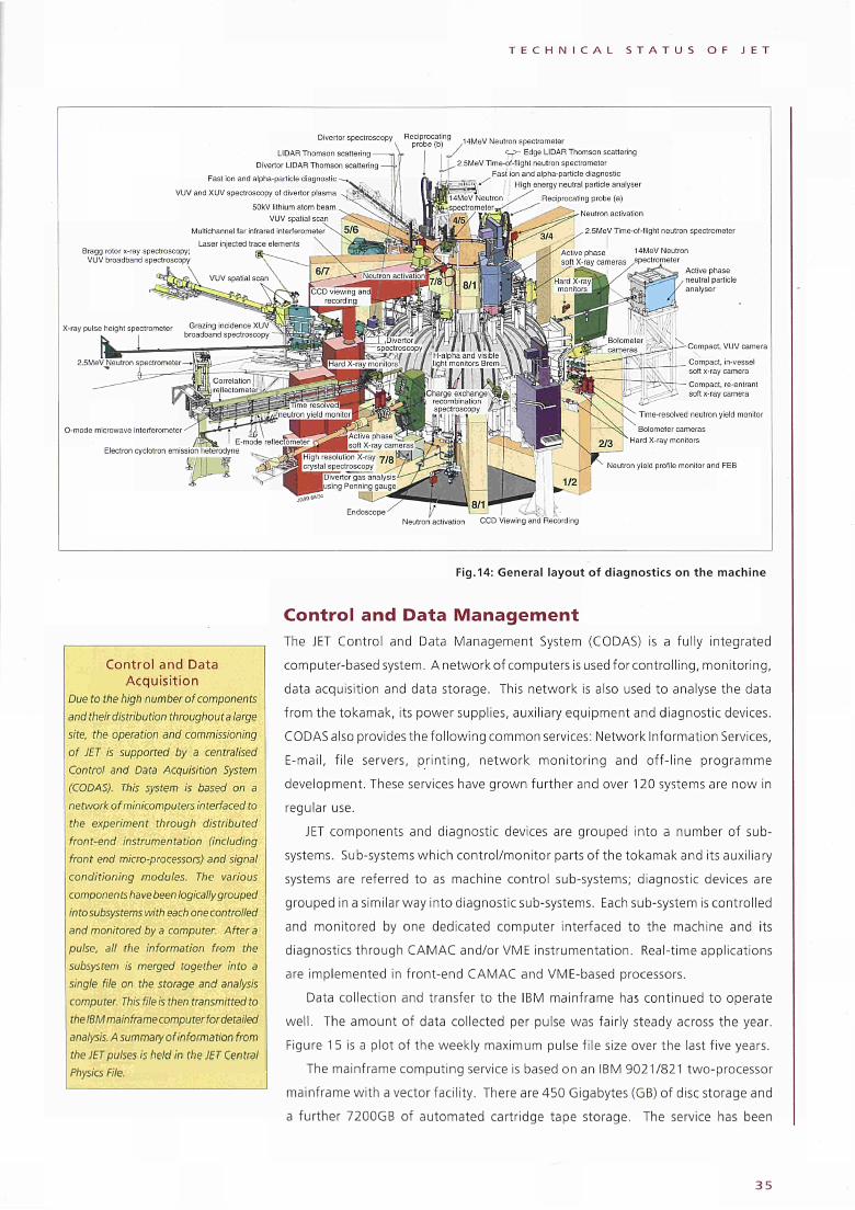
T E C H N I C A L S T A T U S O F J E T
Divertor spectroscopy " « £ ™ * « " 8 , 4 M e V Neutron spectrometer
LIDAR Thomson scattering
Divertor LIDAR Thomson scattering
Fast ion and alpha-particle diagnostic
VUV and XUV spectroscopy ot divertor plasma
50kV lithium atom beam
VUV spatial scan
Multichannel far infrared in ter ferometer^^ 5 / 6
Laser injected trace elements
Edge LIDAR Thomson scattering 2.5MeV Tlme-of-flight neutron spectrometer
Fast ¡on and alpha-particle diagnostic
High energy neutral panicle analyser
Reciprocating probe (a)
Neutron activation
2.5MeV Time-of-flight neutron spectrometer
O-mode microwave interferometer
Compact, VUV camera
Compact, ¡n-vessel soft x-ray camera
Compact, re-entrant soft x-ray camera
Time-resolved neutron yield monitor
Bolometer cameras
Hard X-ray monitors
Neutron yield profile monitor and FEB
Endoscope Neutron activation CCD Viewing and Recording
Fig.14: General layout of diagnostics on the machine
Control and Data Acquisition
Due to the high number of components and their distribution throughout a large site, the operation and commissioning of JET is supported by a centralised Control and Data Acquisition System (CODAS). This system is based on a network of minicomputers interfaced to the experiment through distributed front-end instrumentation (including front end micro-processors) and signal conditioning modules. The various components have been logically grouped into subsystems with each one controlled and monitored by a computer. After a pulse, all the information from the subsystem is merged together into a single file on the storage and analysis computer. This fileis then transmitted to the IBM mainframe computer for detailed analysis. A summary of information from the JET pulses is held in the JET Central Physics File.
Control and Data Management The JET Control and Data Management System (CODAS) is a fully integrated
computer-based system. A network of computers is used for controlling, monitoring,
data acquisition and data storage. This network is also used to analyse the data
from the tokamak, its power supplies, auxiliary equipment and diagnostic devices.
CODAS also provides the following common services: Network Information Services,
E-mail, file servers, printing, network monitoring and off-line programme
development. These services have grown further and over 120 systems are now in
regular use.
JET components and diagnostic devices are grouped into a number of sub
systems. Sub-systems which control/monitor parts of the tokamak and its auxiliary
systems are referred to as machine control sub-systems; diagnostic devices are
grouped in a similar way into diagnostic sub-systems. Each sub-system is controlled
and monitored by one dedicated computer interfaced to the machine and its
diagnostics through CAMAC and/or VME instrumentation. Real-time applications
are implemented in front-end CAMAC and VME-based processors.
Data collection and transfer to the IBM mainframe has continued to operate
well. The amount of data collected per pulse was fairly steady across the year.
Figure 1 5 is a plot of the weekly maximum pulse file size over the last five years.
The mainframe computing service is based on an IBM 9021/821 two-processor
mainframe with a vector facility. There are 450 Gigabytes (GB) of disc storage and
a further 7200GB of automated cartridge tape storage. The service has been
3 5
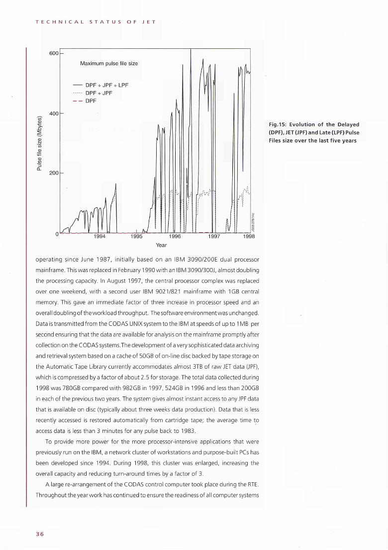
T E C H N I C A L S T A T U S O F J E T
600
Maximum pulse file size
— DPF + JPF + LPF -·· DPF + JPF - DPF
400-Q)
5, -Q
CD ti 'm ω
200-
1994 1995 1996 1997 1998
Year
operating since June 1987, initially based on an IBM 3090/200E dual processor
mainframe. This was replaced in February 1990 with an IBM 3090/300J, almost doubling
the processing capacity. In August 1997, the central processor complex was replaced
over one weekend, with a second user IBM 9021/821 mainframe with 1GB central
memory. This gave an immediate factor of three increase in processor speed and an
overall doubling of the workload throughput. The software environment was unchanged.
Data is transmitted from the CODAS UNIX system to the IBM at speeds of up to 1 MB per
second ensuring that the data are available for analysis on the mainframe promptly after
collection on the CODAS systems.The development of a very sophisticated data archiving
and retrieval system based on a cache of 50GB of on-line disc backed by tape storage on
the Automatic Tape Library currently accommodates almost 3TB of raw JET data (JPF),
which is compressed by a factor of about 2.5 for storage. The total data collected during
1998 was 780GB compared with 982GB in 1997, 524GB in 1996 and less than 200GB
in each of the previous two years. The system gives almost instant access to any JPF data
that is available on disc (typically about three weeks data production). Data that is less
recently accessed is restored automatically from cartridge tape; the average time to
access data is less than 3 minutes for any pulse back to 1983.
To provide more power for the more processor-intensive applications that were
previously run on the IBM, a network cluster of workstations and purpose-built PCs has
been developed since 1994. During 1998, this cluster was enlarged, increasing the
overall capacity and reducing turn-around times by a factor of 3.
A large re-arrangement of the CODAS control computer took place during the RTE.
Throughout the year work has continued to ensure the readiness of all computer systems
Fig.15: Evolution of the Delayed (DPF), JET (JPF) and Late (LPF) Pulse Files size over the last five years
36
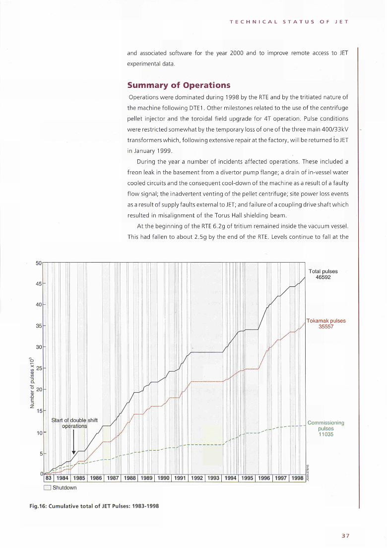
50
45
40
35
30
25
° 20 ω η
ε
15
10
Start of double shift operations
0<Ξ»
T E C H N I C A L S T A T U S O F J E T
and associated software for the year 2000 and to improve remote access to JET
experimental data.
Summary of Operations
Operations were dominated during 1998 by the RTE and by the tritiated nature of
the machine following DTE1. Other milestones related to the use of the centrifuge
pellet injector and the toroidal field upgrade for 4T operation. Pulse conditions
were restricted somewhat by the temporary loss of one of the three main 400/33kV
transformers which, following extensive repa ir at the factory, will be returned to JET
in January 1999.
During the year a number of incidents affected operations. These included a
freon leak in the basement from a divertor pump flange; a drain of ¡ηvessel water
cooled circuits and the consequent cooldown of the machine as a result of a faulty
flow signal; the inadvertent venting of the pellet centrifuge; site power loss events
asa result of supply faults external to JET; and failure of a coupling drive shaft which
resulted in misalignment of the Torus Hall shielding beam.
At the beginning of the RTE 6.2g of tritium remained inside the vacuum vessel.
This had fallen to about 2.5g by the end of the RTE. Levels continue to fall at the
83 1984 1985 1986 1987 1988 1989 1990 1991 1992 1993 1994 1995 1996 1997 1998
Total pulses 46592
Tokamak pulses 35557
Commissioning pulses 11035
□ Shutdown
Fig.16: Cumulative total of JET Pulses: 19831998
37
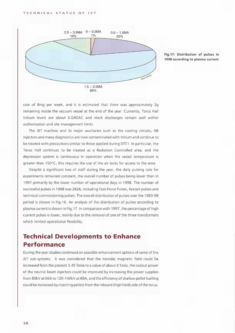
T E C H N I C A L S T A T U S O F J E T
2.5 - 3.5MA 0 - 0-5MA 10% 1%
0.5- 1.5MA 20%
1.5-2.5MA 69%
rate of 8mg per week, and it is estimated that there was approximately 2g
remaining inside the vacuum vessel at the end of the year. Currently, Torus Hall
tritium levels are about 0.04DAC and stack discharges remain well within
authorisation and site management limits.
The JET machine and its major auxiliaries such as the cooling circuits, NB
injectors and many diagnostics are now contaminated with tritium and continue to
be treated with precautions similar to those applied during DTE1. In particular, the
Torus Hall continues to be treated as a Radiation Controlled area, and the
depression system is continuous in operation when the vessel temperature is
greater than 1 50°C; this requires the use of the air locks for access to the area.
Despite a significant loss of staff during the year, the daily pulsing rate for
experiments remained constant, the overall number of pulses being lower than in
1997 primarily by the lower number of operational days in 1998. The number of
successful pulses in 1998 was 2826, including Task Force Pulses, Restart pulses and
technical commissioning pulses. The overall distribution of pulses over the 1983-98
period is shown in Fig.16. An analysis of the distribution of pulses according to
plasma current is shown in Fig. 17. In comparison with 1997, the percentage of high
current pulses is lower, mainly due to the removal of one of the three transformers
which limited operational flexibility.
Technical Developments to Enhance Performance During the year studies continued on possible enhancement options of some of the
JET sub-systems. It was considered that the toroidal magnetic field could be
increased from the present 3.45 Tesla to a value of about 4 Tesla, the output power
of the neutral beam injectors could be improved by increasing the power supplies
from 80kV at 60A to 120-140kV at 60A, and the efficiency of shallow pellet fuelling
could be increased by injecting pelletsfrom the inboard (high field) side of the torus.
Fig.17: Distribution of pulses in 1998 according to plasma current
38
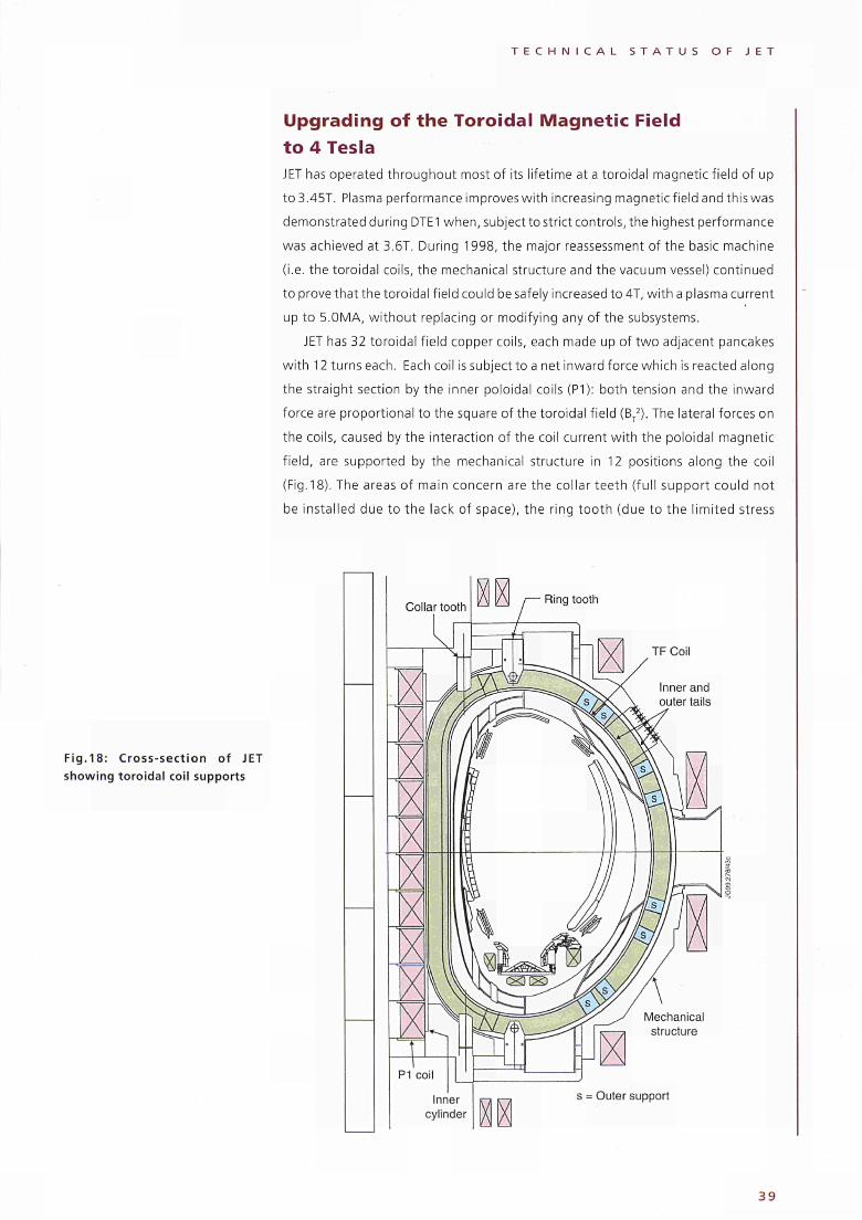
T E C H N I C A L S T A T U S O F J E T
Upgrading of the Toroidal Magnetic Field to 4 Tesla JET has operated throughout most of its lifetime at a toroidal magnetic field of up
to3.45T. Plasma performance im proves with increasing magnetic field and this was
demonstrated during DTE1 when, subject to strict controls, the highest performance
was achieved at 3.6T. During 1998, the major reassessment of the basic machine
(i.e. the toroidal coils, the mechanical structure and the vacuum vessel) continued
to prove that the toroidal field could be safely increased to 4T, with a plasma current
up to 5.OMA, without replacing or modifying any of the subsystems.
JET has 32 toroidal field copper coils, each made up of two adjacent pancakes
with 12 turns each. Each coil is subject to a net inward force which is reacted along
the straight section by the inner poloidal coils (P1): both tension and the inward
force are proportional to the square of the toroidal field (BT2). The lateral forces on
the coils, caused by the interaction of the coil current with the poloidal magnetic
field, are supported by the mechanical structure in 12 positions along the coil
(Fig.18). The areas of main concern are the collar teeth (full support could not
be installed due to the lack of space), the ring tooth (due to the limited stress
Fig.18: Cross-section of JET showing toroidal coil supports
Ring tooth
TF Coil
Inner and outer tails
Mechanical structure
s = Outer support
3 9
T E C H N I C A L S T A T U S O F J E T
capability of the teeth bolts) and the coil "tails" (where the windings cross over
from in-going to out-going pancakes). The forces on the mechanical supports
of the coils and the stresses on the coils, generally reach maximum values in
equilibrium and decay during disruption.
Forces and stresses have been calculated for the reference combination of 4.0T/
5MA, for the main operating scenarios, in equilibrium and following a disruption
event. Analysis and testing has now demonstrated that stresses arising in all areas
of the coils, apart from the coil tails, are safely within the allowable stresses derived
from tests on samples cut from the used coil for a range of interesting scenarios.
All scenarios are assessed before being approved for operation and protective
hardwired limits are maintained for the transverse and in-plane forces on the coils.
The coil tails, rather than the winding itself, support the hoop stress at the cross
over. The coil tails carry no current and thus remain cold during the pulse. The
resulting thermal stress combines with the mechanical stresses to produce a local
concentration of shear stress in the epoxy at the tail tip. The mechanical stress
depends on the TF field, whilst the thermal stress depends on the total energy
dissipated in the coil. Thus, the increased mechanical stress at 4Tcan be compensated
by reducing flattop duration and thus the energy dissipation. The stress, nonetheless
remains close to the allowable. As a result, only a limited number of 4T pulses is
presently foreseen, equivalent in fatigue to 10% of the total operation of JET to
date. Further analysis and modelling of the tails is continuing.
Another area of concern is the interpancake transition element. Several models
have been developed to determine the copper and the butt brazed joint tensile
stresses, and the epoxy shear stresses up to 4T. These models gave consistent
results, showing acceptable stresses.
Unlike the TF coils, where forces and stresses mainly arise in equilibrium, in the
vacuum vessel, major forces and stresses arise as a consequence of plasma
disruptions. Therefore, the allowable stresses can be set for a limited number of
disruptions. During such events, the vacuum vessel demonstrates essentially two
kinds of oscillatory movements: a rolling motion (at about 15Hz) around the
toroidal axis and a sideways motion (at about 5Hz). The rolling motion is due to the
centre of force being inboard of the vessel vertical supports and scales approximately
as the square of the plasma current. Extrapolating the worst case disruptions to
date gives a displacement of 6.5mm at 5MA/4T. The sideways motion of the vessel
is caused by a net radial force. The maximum force and the consequent displacement
scale essentially as BTlpand it is transferred from the plasma to the vessel by eddy
and halo currents. Extrapolation to 5MA/4T gives a worse case displacement of
15mm.
Detailed modelling of the geometry of the vessel and its supports have been
made and used to calculate the stress distribution in critical areas. The most critical
area is predicted to be the weld joining the Main Vertical Ports (MVPs) with the outer
shell of the vacuum vessel. Fatigue testing of the material and detailed computer
40
T E C H N I C A L S T A T U S O F J E T
analysis have given the relationship between measured displacements, applied
loads and number of cycles to failure.
The finite element model used to predict the critical stress has been improved
by inclusion of the webs between the shells of the vessel. This stiffens the port,
reducing the displacement due the radial force by a factor two, and the peak stress
controlled by this displacement by a similar amount. This strongly reduces the
fatigue of the port to a level which is not important for the few worst case
disruptions which would be allowed.
Design studies have also been carried out into additional supports for' the
vacuum vessel which would reduce the movement in asymmetric disruptions. In
particular, additional dampers could be fitted to allow the vacuum vessel to be
locked to the mechanical structure during installation. Dampers using highly
viscous material rather than oil have been tested and demonstrated to have the
required performance.
During the RTE, the toroidal magnetic field power supplies were upgraded for
operation at 4T and, towards the end of the year, three 4T pulses with plasma were
run successfully.
Enhancement of the Neutral Beam Heating System Experiments conducted in the Neutral Beam Test-bed, using a prototype
modified accelerator structure have demonstrated the capability of increasing
the ion beam current from the present 30A to 60A at 120-140kV. This would
lead to an enhancement of injected power, delivering up to 15.4MW to the plasma.
While minor modifications would be required to the NB injectors, additional power
supplies would be required, since the present supplies are for 60A at 80kV or for
30A at 160kV. In view of costs, it has been decided to consider upgrading the
power supplies to 60A at 120-140kV.
An extensive engineering analysis has shown that the PINI Ion Source and the
Full Energy Ion dumps, both of which would receive increased power loadings in an
upgraded injector, are capable of handling the power without being upgraded
themselves. On the other hand, design limits for the Box (or exit beam) Scrapers in
the Neutral Injector Box would be exceeded for both power density normal to the
surface of the hypervapotron elements (1 OMWnr2) and intercepted power per PINI
(250kW). During 1998, new Box Scrapers, designed to accommodate an injector
power of 15.4MW, have been maunfactured for delivery in 1999.
In addition, the high current PINIs, already in use on the Octant No.4 injector
(injecting 13MW of deuterium at 80kV), will be refurbished with new components
to correct a "cross-eyed" effect beginning to develop in some PINIs. These will be
introduced in a staged programme starting in 1999 and, in conjunction with the
new Box Scraper, should permit use of the full available power.
Finally, two PINIs will be modified in 1999 by raising their operating voltage to
85kV to permit a better diagnosis of the plasma current profile using the Motional
Stark Effect.
4 1
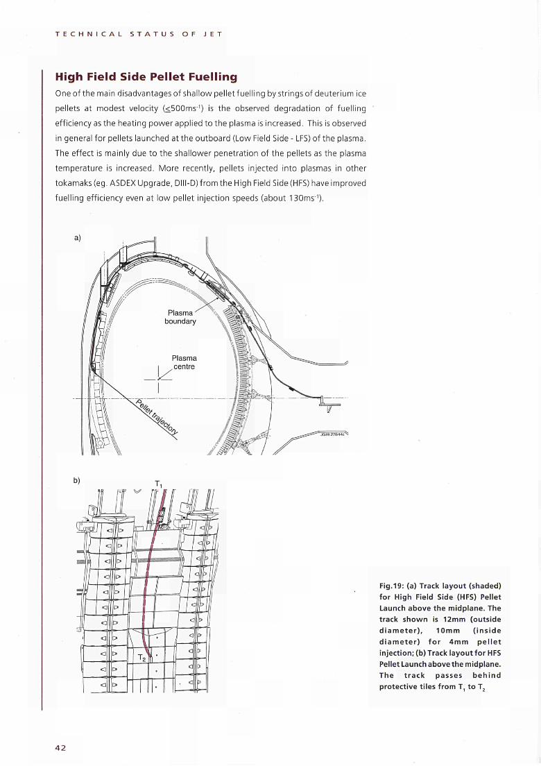
T E C H N I C A L S T A T U S O F J E T
High Field Side Pellet Fuelling Oneof the main disadvantages of shallow pellet fuelling by stringsof deuterium ice
pellets at modest velocity (<500ms·') is the observed degradation of fuelling
efficiency as the heating power applied to the plasma is increased. This is observed
in general for pellets launched at the outboard (Low Field Side- LFS)of the plasma.
The effect is mainly due to the shallower penetration of the pellets as the plasma
temperature is increased. More recently, pellets injected into plasmas in other
tokamaks (eg. ASDEX Upgrade, DIII-D)from the High Field Side (HFS) have improved
fuelling efficiency even at low pellet injection speeds (about 130ms'1).
Fig.19: (a) Track layout (shaded) for High Field Side (HFS) Pellet Launch above the midplane. The track shown is 12mm (outside d i a m e t e r ) , 10mm ( ins ide d iame te r ) f o r 4mm pe l le t injection; (b) Track layout for HFS Pellet Launch above the midplane. The t rack passes beh ind protective tiles f rom Τη to T2
4 2
T E C H N I C A L S T A T U S O F J E T
Subsequent to the RTE, JET technical effort concentrated on the preparation for
the installation of an in-board pellet injection system. The JET Pellet centrifuge will
be used as the pellet source and a track will be installed to run poloidally around
the torus in-vessel from themain horizontal porton the outer wall to the inner wall,
where it will inject the pellets near radially (Fig.19). In addition, a new electro
mechanical pellet selector (part of a new external flight tube) will allow selection
between HFS and LFS injection. Radiation levels in the torus require the bulk of the
installation to be carried out remotely, although the levels will have dropped
sufficiently (350μ5ν/(ΐΓ) by the end of the 1999 shutdown to allow manned access
for about 1 week for final connection in-vessel. In many respects this is a more
challenging operation than the RTE as this work had not been conceived previously
and no provision had been made in-vessel for this RH operation. This again
representsan important demonstration of a RH technology which could be used for
unplanned interventions in future devices.
43
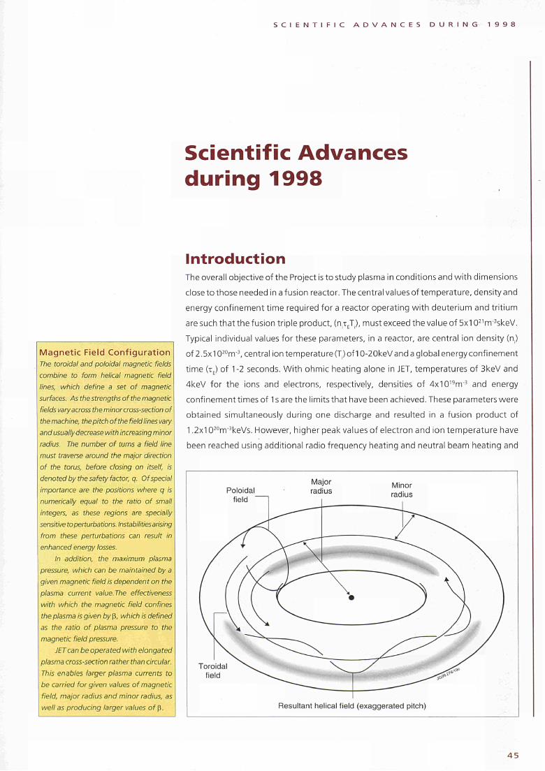
S C I E N T I F I C A D V A N C E S D U R I N G 1 9 9 8
Scientific Advances
during 1998
Magnetic Field Configuration
The toroidal and poloidal magnetic fields
combine to form helical magnetic field
lines, which define a set of magnetic
surfaces. As the strengths of the magnetic
fields vary across the minorcross-section of
the machine, the pitch of the field lines vary
and usually decrease with increasing minor
radius. The number of turns a field line
must traverse around the major direction
of the torus, before closing on itself, is
denoted by the safety factor, q. Of special
importance are the positions where q is
numerically equal to the ratio of small
integers, as these regions are specially
sensitive to perturbations. Instabilities arising
from these perturbations can result in
enhanced energy losses.
In addition, the maximum plasma
pressure, which can be maintained by a
given magnetic field is dependent on the
plasma current value. The effectiveness
with which the magnetic field confines
the plasma is given by β, which is defined
as the ratio of plasma pressure to the
magnetic field pressure.
JET can be operated with elongated
plasma cross-section ra ther than circular.
This enables larger plasma currents to
be carried forgiven values of magnetic
field, major radius and minor radius, as
well as producing larger values of β.
Introduction The overall objective of the Project is to study plasma in conditions and with dimensions
close to those needed in a fusion reactor. The central values of temperature, density and
energy confinement time required for a reactor operating with deuterium and tritium
are such that the fusion triple product, (n^T), must exceed the value of 5x10²¹
m~3skeV.
Typical individual values for these parameters, in a reactor, are central ¡on density (a)
of 2.5x10²⁰
nr3, central ion temperature (T) of 1020keVand a global energy confinement
time (τΕ) of 12 seconds. With ohmic heating alone in JET, temperatures of 3keV and
4keV for the ions and electrons, respectively, densities of 4x10¹⁹
m3 and energy
confinement times of 1 s are the limits that have been achieved. These parameters were
obtained simultaneously during one discharge and resulted in a fusion product of
1.2x10²⁰
iTr3keVs. However, higher peak values of electron and ion temperature have
been reached using additional radio frequency heating and neutral beam heating and
Poloidal
field "
Major
radius Minor
radius
Toroidal
field
Resultant helical field (exaggerated pitch)
4 5
S C I E N T I F I C A D V A N C E S D U R I N G 1 9 9 8
combinations of these methods. Even so, these substantial increases in temperature
were associated with a reduction in energy confinement time as the heating power was
increased. Thus, gains in plasma temperature have been partly offset by degradation
in energy confinement time. The fusion product values obtained have not shown the
full gains anticipated over conditions with ohmic heating alone. However, a substantial
increase in the values of the fusion product has been achieved, by operating in the so-
called magnetic limiter (X-point) configuration. During the 1991/92 campaign, values
of 9-10x1020nrr3skeV were obtained using up to 16MW of additional heating.
Higher values of temperature, density and energy confinement have been
obtained individually in separate experiments, but not simultaneously during one
discharge. These include peak ion temperatures up to 38keV, energy confinement
times up to 1.8s and central densities up to 4x10²⁰rrr3.
The strategy of JET is to optimise the fusion product by building up a high
density, high temperature plasma in the centre of the discharge, while still
maintaining an acceptably high confinement time. These conditions should ensure
that sufficient alpha particles are produced during deuterium-tritium operation so
that their confinement and subsequent heating of the plasma can be studied.
The original scientific programme of JET was divided into four phases. The
Ohmic Heating, Phase I, was completed in September 1984 and Phase II -Additional
Heating Studies - started early in 1985. By December 1986, the first part. Phase IIA,
had been completed. The machine then entered a planned shutdown for extensive
modifications and enhancements before the second part of the Additional Heating
Studies, Phase IIB, which started in June 1987. The objective of this phase, from
mid-1987 until late-1988, was to explore the most promising regimes for energy
confinement and high fusion yield and to optimise conditions with full additional
heating in the plasma. Experiments were carried out with plasma currents up to
7MA in the material limiter mode and up to 5MA in the magnetic limiter (X-point)
mode and with increased radio frequency heating power up to 18MW and neutral
beam heating power exceeding 20MW at 80kV.
The ultimate objective was to achieve full performancewith all systems operating
simultaneously. Phase III of the programme on Full Power Optimisation Studies
started in 1989 and was completed in early 1992. In 1991, JET's lifetime was
prolonged by four years until the end of 1996. The extension was to allow JET to
implement the new Pumped Divertor Phase of operation, the objective of which
was to establish effective control of plasma impurities in operating conditions close
to those of the Next Step. In mid-1996, the lifetime of the Project was further
extended to the end of 1999 to enable significant contributions to be made to the
development and demonstration of a viable divertor concept for ITER and to
undertake experiments using D-T plasmas in an ITER-like configuration. The centre
piece of operations in 1997 was a period of D-T operation (DTE1 ) during which JET
carried out a broad-based series of D-T experiments, setting new world records for
fusion power production (16.1 MW), fusion energy (22MJ), fusion duration (4MW
for about 4s) and Q, the ratio of fusion power produced to input power (0.62, and
Breakeven This condition is reached when the power
produced from fusion reactions is equal
to that necessary for maintaining the
required temperature and density in the
plasma volume.
Ignition Ignition of a mixture of deuterium and
tritium would be reached if the power
produced by the alpha particles (20% of
the total thermonuclear power) released
from the fusion reactions is sufficient to
maintain the temperature oftheplasma.
4 6
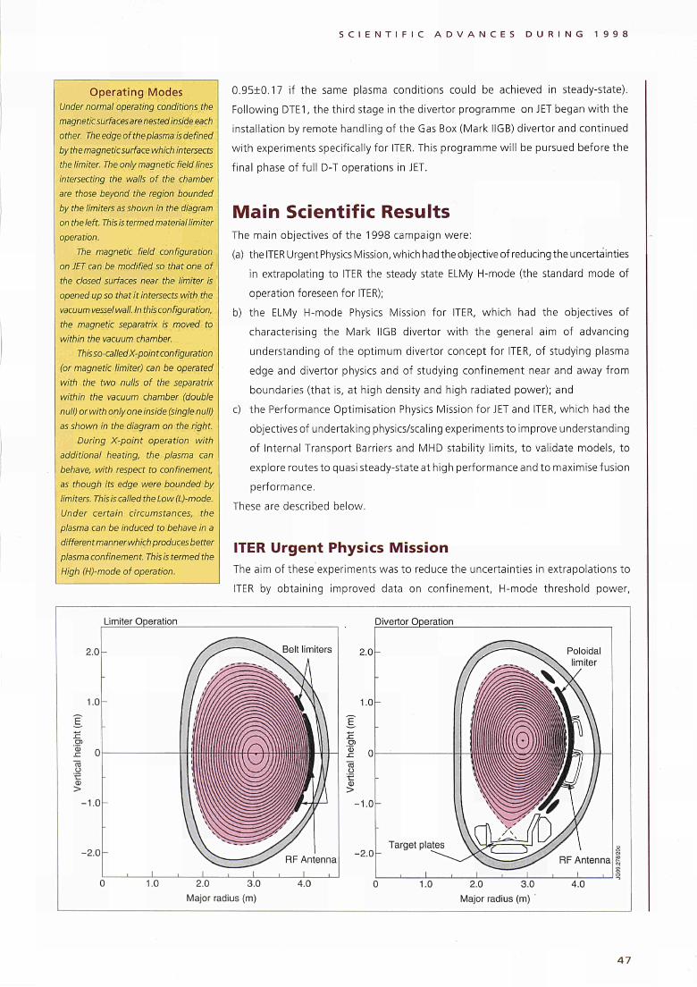
S C I E N T I F I C A D V A N C E S D U R I N G 1 9 9 8
Operating Modes Under normal operating conditions the
magnetic surfaces are nested inside each
other. The edge of the plasma is defined
by the magnetic surface which intersects
the limiter. The only magnetic field lines
intersecting the walls of the chamber
are those beyond the region bounded
by the limiters as shown in the diagram
on the left. This is termed material limiter
operation.
The magnetic field configuration
on JET can be modified so that one of
the closed surfaces near the limiter is
opened up so that it intersects with the
vacuum vesselwall. In this configuration,
the magnetic separatrix is moved to
within the vacuum chamber.
This so-called X-point configuration
(or magnetic limiter) can be operated
with the two nulls of the separatrix
within the vacuum chamber (double
null) or with only one inside (single null)
as shown in the diagram on the right.
During X-point operation with
additional heating, the plasma can
behave, with respect to confinement,
as though its edge were bounded by
limiters. This is called the Low (L)-mode.
Under certain circumstances, the
plasma can be induced to behave in a
differen t manner which produces better
plasma confinement. This is termed the
High (H)-mode of operation.
0.9510.17 if the same plasma conditions could be achieved in steady-state).
Following DTE1, the third stage in the divertor programme on JET began with the
installation by remote handling of the Gas Box (Mark IIGB) divertor and continued
with experiments specifically for ITER. This programme will be pursued before the
final phase of full D-T operations in JET.
Main Scientific Results The main objectives of the 1998 campaign were:
(a) the ITER Urgent Physics Mission, which had the objective of reducing the uncertainties
in extrapolating to ITER the steady state ELMy Η-mode (the standard mode of
operation foreseen for ITER);
b) the ELMy Η-mode Physics Mission for ITER, which had the objectives of
characterising the Mark IIGB divertor with the general aim of advancing
understanding of the optimum divertor concept for ITER, of studying plasma
edge and divertor physics and of studying confinement near and away from
boundaries (that is, at high density and high radiated power); and
c) the Performance Optimisation Physics Mission for JET and ITER, which had the
objectivesof undertaking physics/scaling experimentsto improve understanding
of Internal Transport Barriers and MHD stability limits, to validate models, to
explore routes to quasi steady-state at high performance and to maximise fusion
performance.
These are described below.
ITER Urgent Physics Mission The aim of these experiments was to reduce the uncertainties in extrapolations to
ITER by obtaining improved data on confinement, Η-mode threshold power,
2.0
1.0
'ω -C "S o fe ω >
-1.0
- 2 . 0
Limiter Operation
Belt limiters
1.0
RF Antenna
Divertor Operation
2.0
1.0
σι 'Φ -C "S o -c O) >
-1.0
-2.0
Poloidal limiter
Target plates
2.0 3.0
Major radius (m)
RF Antenna
2.0 3.0
Major radius (m)
4 7
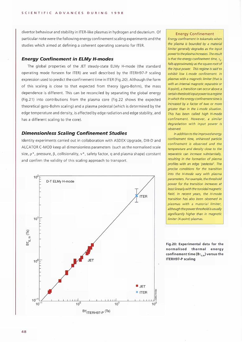
S C I E N T I F I C A D V A N C E S D U R I N G 1 9 9 8
divertor behaviour and stability in ITERlike plasmas in hydrogen and deuterium. Of
particular note were the fol lowing energy confinement scaling experiments and the
studies which aimed at defining a coherent operating scenario for ITER.
Energy Confinement in ELMy H-modes
The global properties of the JET steadystate ELMy Ηmode (the standard
operating mode forseen for ITER) are well described by the ITERH97P scaling
expression used to predict the confinement time in ITER (Fig.20). Although the form
of this scaling is close to that expected from theory (gyroBohm), the mass
dependence is different. This can be reconciled by separating the global energy
(Fig.21) into contributions from the plasma core (Fig.22 shows the expected
theoretical gyroBohm scaling) and a plasma pedestal (which is determined by the
edge temperature and density, is affected by edge radiation and edge stability, and
has a different scaling to the core).
Dimensionless Scaling Confinement Studies
Identity experiments carried out in collaboration with ASDEX Upgrade, DlllD and
ALCATOR CMOD keep all dimensionless parameters (such as the normalised scale
size, p*, pressure, β, collisionality, v*, safety factor, q and plasma shape) constant
and confirm the validity of this scaling approach to transport.
DT ELMy Hmode
ω
■ J E T
ITER
Energy Confinement
Energy confinement in tokamaks when
the plasma is bounded by a material
' limiter generally degrades as the input
powerto the plasma increases. Theresult
is that the energy confinement time, rp
falls approximately as the square root of
the input power. This regime is said to
exhibit low L-mode confinement. In
plasmas with a magnetic limiter (that is
with an internal magnetic separatrix or
X-point), a transition can occur above a
certain threshold input power to a regime
in which the energy confinement time is
increased by a factor of two or more
greater than in the L-mode situation.
This has been called high H-mode
confinement. However, a similar
degradation with input power is
observed.
In addition to the improved energy
confinement time, enhanced particle
confinement is observed and the
temperature and density close to the
separatrix can increase substantially,
resulting in the formation of plasma
profiles with an edge 'pedestal'. The
precise conditions for the transition
into the H-mode vary with plasma
parameters. For example, the threshold
power for the transition increases at
least linearly with the toroidal magnetic
field. In recent years, the H-mode
transition has also been observed in
plasmas with a material limiter,
although the power threshold is usually
significantly higher than in magnetic
limiter (X-point) plasmas.
Fig.20: Experimental data for the
n o r m a l i s e d t h e r m a l e n e r g y
con f inement t ime (B i E t h ) versus the
ITERH97-P scaling
10¿
Βτ ITERH97P (Ts)
4 8
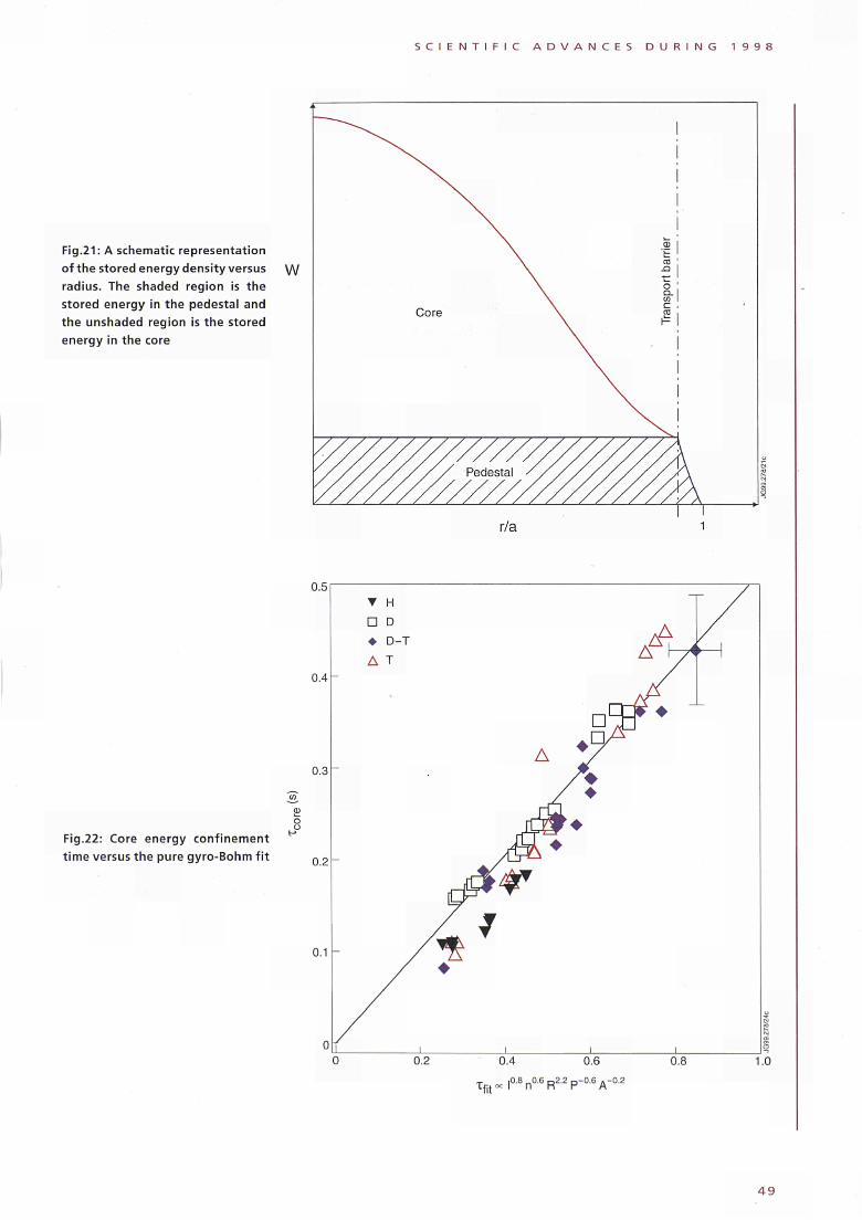
S C I E N T I F I C A D V A N C E S D U R I N G 1 9 9 8
Fig.21: A schematic representation
of the stored energy density versus
radius. The shaded region is the
stored energy in the pedestal and
the unshaded region is the stored
energy in the core
W
Fig.22: Core energy confinement
time versus the pure gyroBohm f i t
(0
Φ
δ o
u.o
0.4
0.3
0.2
0.1
0
Τ Η
D D
♦ DT
Δ Τ
—
-
y
I
¿k ♦
Δ y
/ ♦
Α ^φ
Jj¿ ♦
tår 7
ι ι
AA ¿Λ Ι Λ
F 4
I
0.2
Tfit
0.4
„ |0.f
0.6 0.8 1.0
4 9
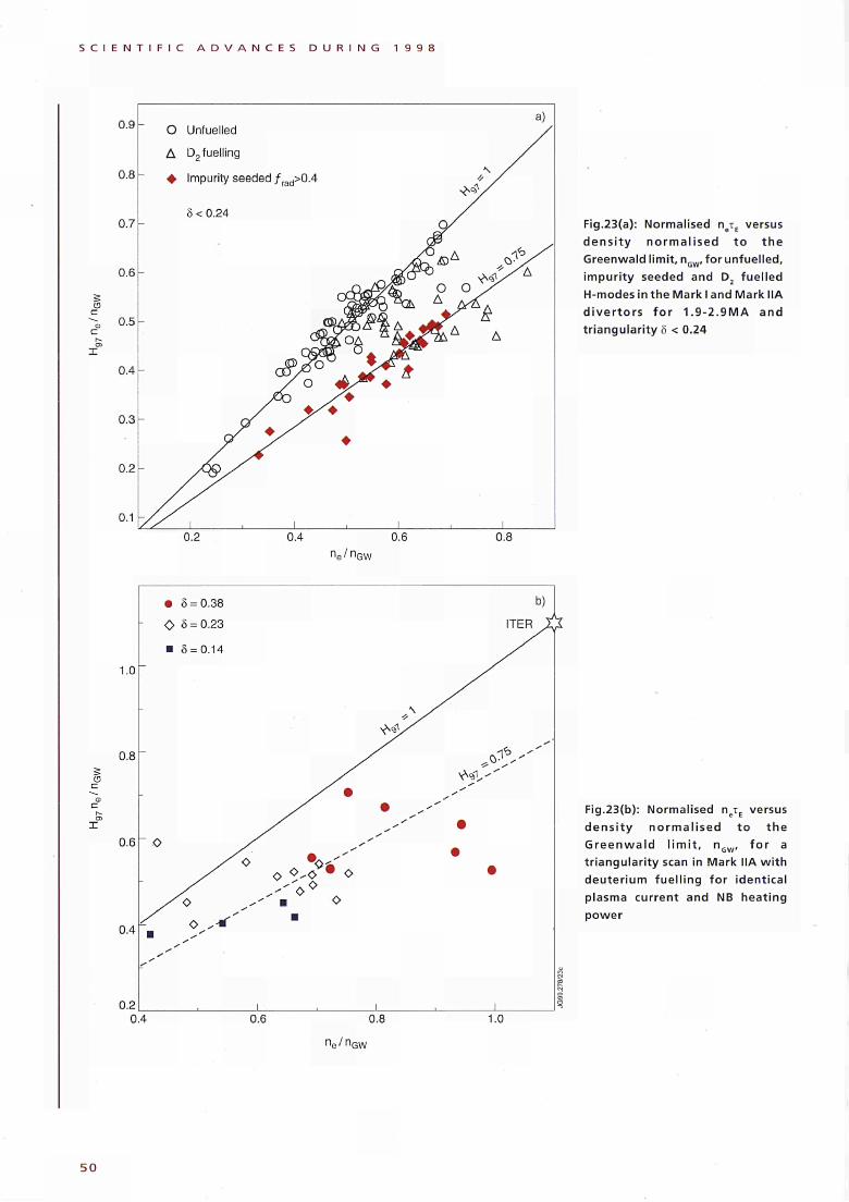
S C I E N T I F I C A D V A N C E S D U R I N G 1 9 9 8
0.9 -
0 .6
S
C
O Unfuelled
Δ û 2 fuelling
φ Impurity seeded ƒ rad>0.4
δ < 0.24 Fig.23(a): Normalised ηβτΕ versus dens i t y no rma l i sed to t h e Greenwald limit, n.„„ for unfuelled, impuri ty seeded and D, fuel led H-modesinthe Mark I and Mark MA d i ve r t o r s f o r 1.9-2.9MA and tr iangular i ty δ < 0.24
n e /n G W
1.0
0.8
CD
0.2
• δ = 0.38 Ο δ = 0.23
■ δ = 0.14
r̂H
ITER
Ο Ο , ν · O
O
0.4 0.6 0.8 1.0
Fig.23(b): Normalised ηβτΕ versus
dens i t y no rma l i sed t o the
Greenwa ld l i m i t , η f o r a
tr iangulari ty scan in Mark IIA w i th
deuter ium fuel l ing for identical
plasma current and NB heating
power
5 0
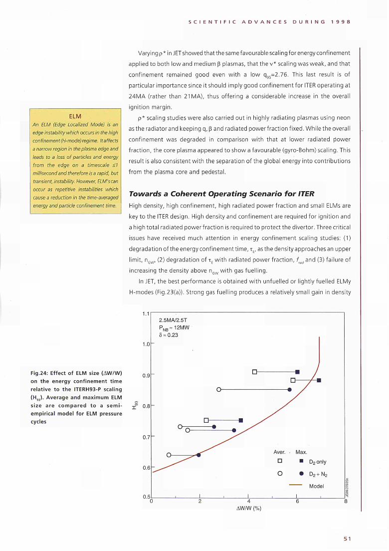
S C I E N T I F I C A D V A N C E S D U R I N G 1 9 9 8
ELM
An ELM (Edge Localized Mode) is an
edge instability which occurs in the high
confinement (H-mode) regime. It affects
a narrow region in the plasma edge and
leads to a loss of particles and energy
from the edge on a timescale <1
millisecond and therefore is a rapid, but
transient, instability. However, ELM's can
occur as repetitive instabilities which
cause a reduction in the time-averaged
energy and particle confinement time.
Varying ρ * in JET showed that the same favourable scaling for energy confinement
applied to both low and medium β plasmas, that the v * scaling was weak, and that
confinement remained good even w i th a low q95=2.76. This last result is of
particular importance since it should imply good confinement for ITER operating at
24MA (rather than 21 MA), thus offering a considerable increase in the overall
ignit ion margin.
p* scaling studies were also carried out in highly radiating plasmas using neon
as the radiatorand keeping q,ß and radiated powerfract ion f ixed. While the overall
confinement was degraded in comparison wi th that at lower radiated power
fract ion, the core plasma appeared to show a favourable (gyroBohm) scaling. This
result is also consistent w i th the separation of the global energy into contributions
f rom the plasma core and pedestal.
Towards a Coherent Operating Scenario for ITER
High density, high confinement, high radiated power fraction and small ELMs are
key to the ITER design. High density and confinement are required for ignit ion and
a high total radiated powerfract ion is required to protect the divertor. Three critical
issues have received much attention in energy confinement scaling studies: (1)
degradation of the energy confinement t ime, τΕ, as the density approaches an upper
l imit, nGW, (2) degradation of τΕ w i th radiated power fract ion, frad and (3) failure of
increasing the density above nGW w i th gas fuell ing.
In JET, the best performance is obtained wi th unfuelled or lightly fuelled ELMy
Ηmodes (Fig.23(a)). Strong gas fuell ing produces a relatively small gain in density
Fig.24: Effect of ELM size (AW/W)
on the energy confinement time
relative to the ITERH93-P scaling
(H93). Average and maximum ELM
size are compared to a semi-
empirical model for ELM pressure
cycles
1.1
1.0
0.9
0.8
0.7
0.6
n s
2.5MA/2.5T
PNB=12MW
δ = 0.23
u η
υ
Γ\ ^"^
ι
VJ
LI
I
Β
Γ-ι
LI η / ■
/
Aver. Max.
□ ■ D2 only
O · D2 + N2
Model
1 4
AW/W (%)
51
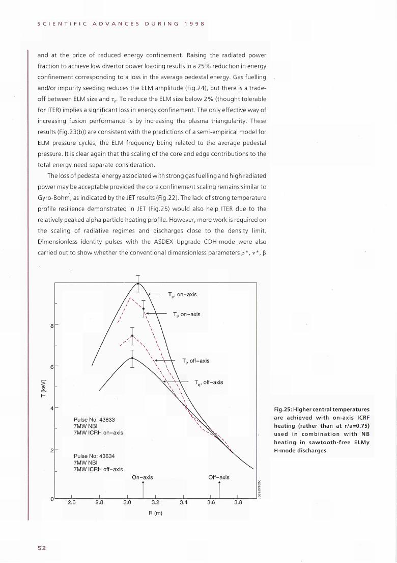
S C I E N T I F I C A D V A N C E S D U R I N G 1 9 9 8
and at the price of reduced energy conf inement. Raising the radiated power
fract ion to achieve low divertor power loading results in a 2 5 % reduction in energy
conf inement corresponding to a loss in the average pedestal energy. Gas fuell ing
and/or impurity seeding reduces the ELM amplitude (Fig.24), but there is a trade
off between ELM size and rE. To reduce the ELM size below 2% ( thought tolerable
for ITER) implies a significant loss in energy confinement. The only effective way of
increasing fusion performance is by increasing the plasma triangularity. These
results (Fig.23(b)) are consistent w i th the predictions of a semi-empirical model for
ELM pressure cycles, the ELM frequency being related to the average pedestal
pressure. It is clear again that the scaling of the core and edge contributions to the
total energy need separate consideration.
The loss of pedestal energy associated wi th strong gas fuell ing and high radiated
power may be acceptable provided the core confinement scaling remains similar to
Gyro-Bohm, as indicated by the JET results (Fig.22). The lack of strong temperature
profile resilience demonstrated in JET (Fig.25) wou ld also help ITER due to the
relatively peaked alpha particle heating profi le. However, more work is required on
the scaling of radiative regimes and discharges close to the density l imit.
Dimensionless identity pulses w i th the ASDEX Upgrade CDH-mode were also
carried out to show whether the conventional dimensionless parameters ρ* , ν * , β
6 -
> Φ
4 -
2 "
^ Tp, on-axis
T., on-axis
Pulse No: 43633 7MWNBI 7MW ICRH on-axis
Pulse No: 43634 7MW NBI 7MW ICRH off-axis
On-axis Off-axis
J_ _L J_ 2.6 2.8 3.0 3.2 3.4
R(m)
3.6 3.8
Fig.25: Higher central temperatures are achieved with on-axis ICRF heating (rather than at r/a=0.75) used in combination w i t h NB heating in sawtooth-free ELMy H-mode discharges
5 2
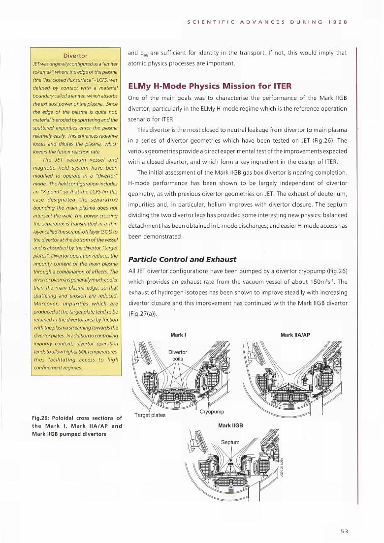
S C I E N T I F I C A D V A N C E S D U R I N G 1 9 9 8
Divertor JET was originally configured as a "limiter tokamak " where the edge of the plasma (the "lastclosedfluxsurface"- LCFS) was defined by contact with a material boundary called a limiter, which absorbs the exhaust power of the plasma. Since the edge of the plasma is quite hot, material is eroded by sputtering and the sputtered impurities enter the plasma relatively easily. This enhances radiative losses and dilutes the plasma, which lowers the fusion reaction rate.
The JET vacuum vessel and magnetic field system have been modified to operate in a "divertor" mode. The field configuration includes an "X-point" so that the LCFS (in this case designated the separatrix) bounding the main plasma does not intersect the wall. The power crossing the separatrix is transmitted in a thin layer called the scrape-off layer (SOL) to the divertor at the bottom of the vessel and is absorbed by the divertor "target plates". Divertor operation reduces the impurity content of the main plasma through a combination of effects. The divertor plasma is generally much cooler than the main plasma edge, so that sputtering and erosion are reduced. Moreover, impurities which are produced at the target plate tend tobe retained in the divertor area by friction with the plasma streaming towards the divertor plates. In addition to controlling impurity content, divertor operation tends to allow higher SOL temperatures, thus facilitating access to high confinement regimes.
Fig.26: Poloidal cross sections of the Mark I, Mark IIA/AP and Mark IIGB pumped divertors
and q95 are sufficient for identity in the transport. If not, this would imply that
atomic physics processes are important.
ELMy Η-Mode Physics Mission fo r ITER One of the main goals was to characterise the performance of the Mark IIGB
divertor, particularly in the ELMy H-mode regime which is the reference operation
scenario for ITER.
This divertor is the most closed to neutral leakage from divertor to main plasma
in a series of divertor geometries which have been tested on JET (Fig.26). The
various geometries provide a direct experimental test of the improvements expected
with a closed divertor, and which form a key ingredient in the design of ITER.
The initial assessment of the Mark IIGB gas box divertor is nearing completion.
H-mode performance has been shown to be largely independent of divertor
geometry, as with previous divertor geometries on JET. The exhaust of deuterium,
impurities and, in particular, helium improves with divertor closure. The septum
dividing the two divertor legs has provided some interesting new physics: balanced
detachment has been obtained in L-mode discharges; and easier H-mode access has
been demonstrated.
Particle Control and Exhaust All JET divertor configurations have been pumped by a divertor cryopump (Fig.26)
which provides an exhaust rate from the vacuum vessel of about 150m3s"'. The
exhaust of hydrogen isotopes has been shown to improve steadily with increasing
divertor closure and this improvement has continued with the Mark IIGB divertor
(Fig.27(a)).
Mark I Mark IIA/AP
Target plates Cryopump
Mark IIGB
5 3
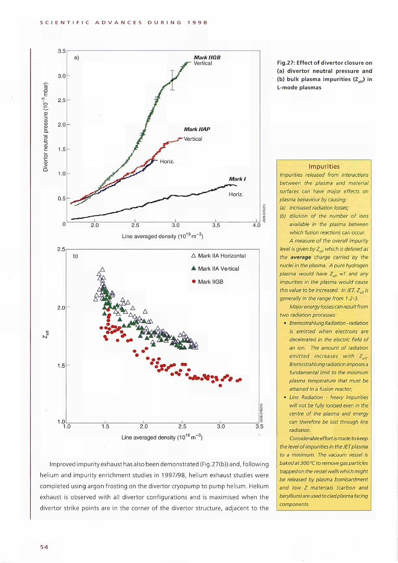
S C I E N T I F I C A D V A N C E S D U R I N G 1 9 9 8
ro .O E
Φ Q. ro
Φ > b
3.5
3.0
2.5
2 . 0 -
1.5
1.0
0.5
2.5
2.0
1.5
1.0
b)
1.0
Mark IIGB Vertical
4.0
Line averaged density (1019 m 3)
Δ Mark IIA Horizontal
A Mark MA Vertical
• Mark IIGB
·*·*;% Λ *
1.5 2.0 2.5 3.0 3.5
Line averaged density (1019 m 3)
Improved impurity exhaust has also been demonstrated (Fig.27(b)) and, fo l lowing
helium and impurity enrichment studies in 1997/98, helium exhaust studies were
completed using argon frost ing on the divertor cryopump to pump helium. Helium
exhaust is observed w i th all divertor configurations and is maximised when the
divertor strike points are in the corner of the divertor structure, adjacent to the
Fig.27: Effect of divertor closure on (a) divertor neutral pressure and (b) bulk plasma impurities (Zef() in L-mode plasmas
Impurities Impurities released from interactions between the plasma and material surfaces can have major effects on plasma behaviour by causing: (a) increased radiation losses; (b) dilution of the number of ions
available in the plasma between which fusion reactions can occur. A measure of the overall impurity
level is given by Zelf which is defined as the average charge carried by the nuclei in the plasma. A pure hydrogen plasma would have Zefl =1 and any impurities in the plasma would cause this value to be increased. In JET, Ζ „ is
' en
generally In the range from 1.2-3. Major energy losses can result from
two radiation processes: • Bremsstrahlung Radiation - radiation
is emitted when electrons are decelerated in the electric field of an ion. The amount of radiation emitted increases with Zeff. Bremsstrahlung radiation imposesa fundamental limit to the minimum plasma temperature that must be attained in a fusion reactor;
• Line Radiation - heavy impurities will not be fully ionised even in the centre of the plasma and energy can therefore be lost through line radiation. Considerable effort is made to keep
the level of impurities in the JET plasma to a minimum. The. vacuum vessel is baked at 300"Cto remove gas particles trappedon the vessel walls which might be released by plasma bombardment and low Ζ materials (carbon and beryllium) are used to clad plasma facing components.
54
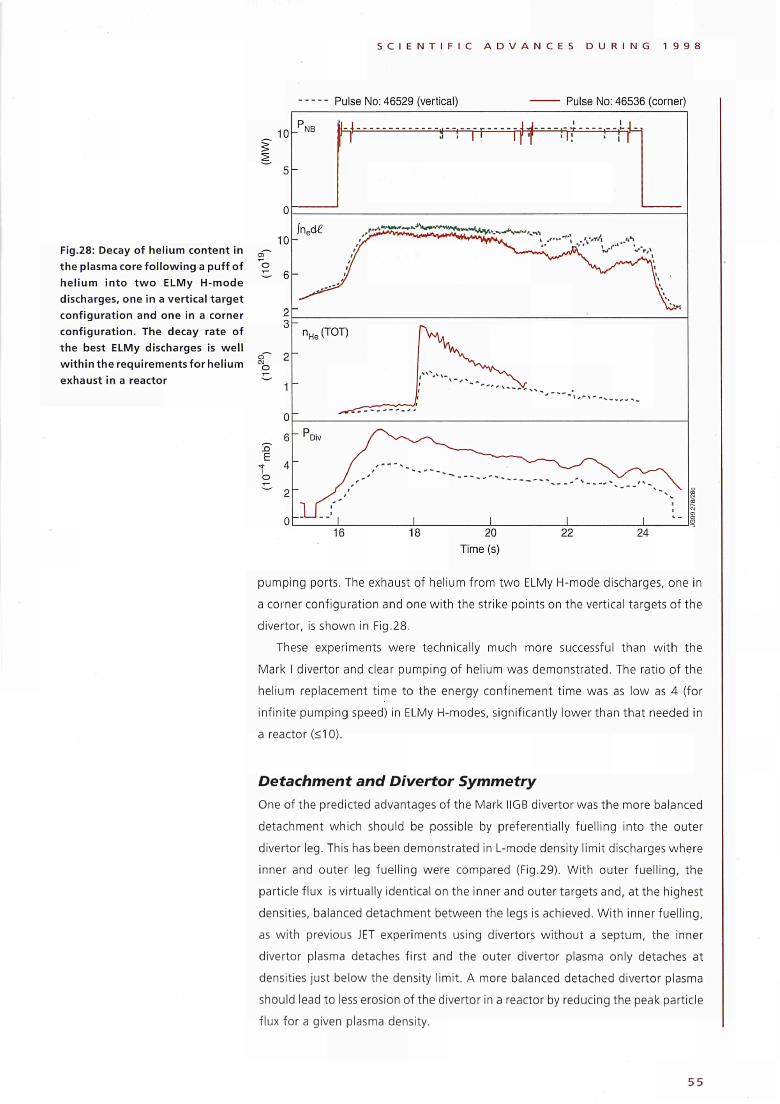
S C I E N T I F I C A D V A N C E S D U R I N G 1 9 9 8
Pulse No: 46529 (vertical) Pulse No: 46536 (corner)
Fig.28: Decay of helium content in
the plasma core fo l lowing a puff of
hel ium into t w o ELMy Hmode
discharges, one in a vertical target
configuration and one in a corner
configuration. The decay rate of
the best ELMy discharges is wel l
w i th in the requirements for helium
exhaust in a reactor
1 0 -
1 0 -
E
NB t TT τ Γ ft -*=r^ ■^ft
¡ned£
nHe(TOT)
pumping ports. The exhaust of helium from two ELMy Hmode discharges, one in
a corner configuration and one wi th the strike points on the vertical targets of the
divertor, is shown in Fig.28.
These experiments were technically much more successful than wi th the
Mark I divertor and clear pumping of helium was demonstrated. The ratio of the
helium replacement t ime to the energy confinement t ime was as low as 4 (for
infinite pumping speed) in ELMy Ηmodes, significantly lower than that needed in
a reactor (<10).
Detachment and Divertor Symmetry
One of the predicted advantages of the Mark IIGB divertor was the more balanced
detachment which should be possible by preferentially fuell ing into the outer
divertor leg. This has been demonstrated in Lmode density limit discharges where
inner and outer leg fuell ing were compared (Fig.29). With outer fuel l ing, the
particle flux is virtually identical on the inner and outer targets and, at the highest
densities, balanced detachment between the legs is achieved. Wi th inner fuel l ing,
as wi th previous JET experiments using divertors wi thout a septum, the inner
divertor plasma detaches first and the outer divertor plasma only detaches at
densities just below the density limit. A more balanced detached divertor plasma
should lead to less erosion of the divertor in a reactor by reducing the peak particle
flux for a given plasma density.
55
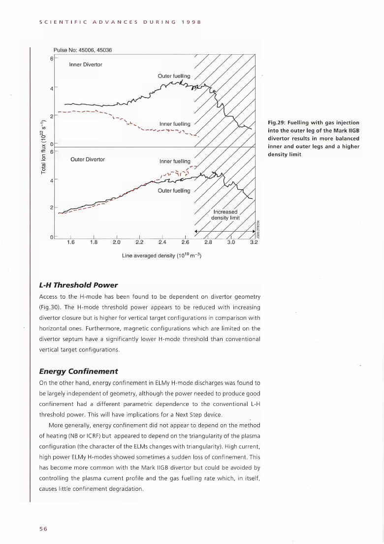
S C I E N T I F I C A D V A N C E S D U R I N G 1 9 9 8
Pulse No: 45006, 45036
co o
r-
Inner Divertor
2.0 2.2 2.4 2.6 2.8
Line averaged density (1019 m"3)
Fig.29: Fuelling with gas injection into the outer leg of the Mark IIGB divertor results in more balanced inner and outer legs and a higher density limit
L-H Threshold Power Access to the H-mode has been found to be dependent on divertor geometry
(Fig.30). The H-mode threshold power appears to be reduced w i th increasing
divertor closure but is higher for vertical target configurations in comparison wi th
horizontal ones. Furthermore, magnetic configurations which are limited on the
divertor septum have a significantly lower H-mode threshold than conventional
vertical target configurations.
Energy Confinement On the other hand, energy confinement in ELMy H-mode discharges was found to
be largely independent of geometry, al though the power needed to produce good
conf inement had a different parametric dependence to the conventional L-H
threshold power. This wil l have implications for a Next Step device.
More generally, energy conf inement did not appear to depend on the method
of heating (NB or ICRF) but appeared to depend on the triangularity of the plasma
configurat ion (the character of the ELMs changes w i th triangularity). High current,
high power ELMy Η-modes showed sometimes a sudden loss of conf inement. This
has become more common wi th the Mark IIGB divertor but could be avoided by
control l ing the plasma current profi le and the gas fuell ing rate which, in itself,
causes little conf inement degradation.
5 6
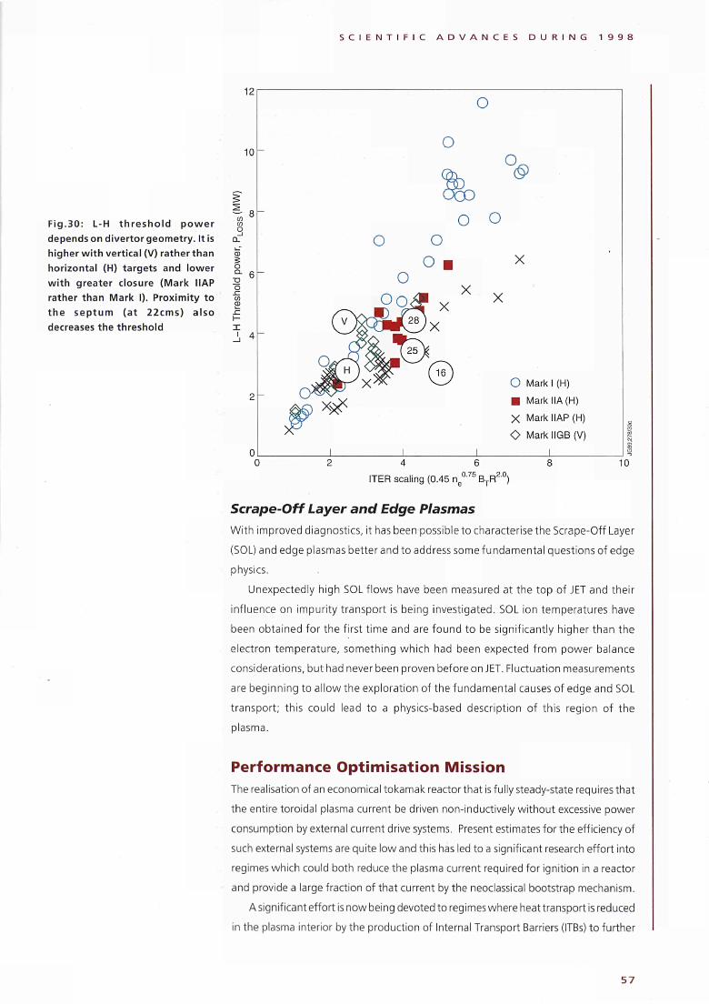
S C I E N T I F I C A D V A N C E S D U R I N G 1 9 9 8
Fig.30: L-H threshold power
depends on divertor geometry. It is
higher with vertical (V) rather than
horizontal (H) targets and lower
with greater closure (Mark HAP
rather than Mark I). Proximity to
the septum (at 22cms) also
decreases the threshold
12
10
co ω O _ι
Q.
ω S o Q .
o
I ι
o
o o
<§>
o o
X
X χ
O Mark I (H)
■ Mark IIA (Η)
χ Mark MAP (Η)
O Mark IIGB (V)
I 8 10
ITER scaling (0.45 ne°·75
BTR20
)
Scrape-Off Layer and Edge Plasmas
With improved diagnostics, it has been possible to characterise the Scrape-Off Layer
(SOL) and edge plasmas better and to address some fundamental questions of edge
physics.
Unexpectedly high SOL flows have been measured at the top of JET and their
influence on impurity transport is being investigated. SOL ion temperatures have
been obtained for the first time and are found to be significantly higher than the
electron temperature, something which had been expected from power balance
considerations, but had never been proven before on JET. Fluctuation measurements
are beginning to allow the exploration of the fundamental causes of edge and SOL
transport; this could lead to a physics-based description of this region of the
plasma.
Performance Optimisation Mission
The realisation of an economical tokamak reactor that is fully steady-state requires that
the entire toroidal plasma current be driven non-inductively without excessive power
consumption by external current drive systems. Present estimates for the efficiency of
such external systems are quite low and this has led to a significant research effort into
regimes which could both reduce the plasma current required for ignition in a reactor
and provide a large fraction of that current by the neoclassical bootstrap mechanism.
A significant effort is now being devoted to regimes where heat transport is reduced
in the plasma interior by the production of Internal Transport Barriers (ITBs) to further
57
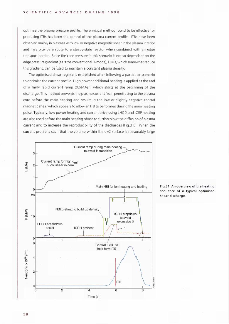
S C I E N T I F I C A D V A N C E S D U R I N G 1 9 9 8
optimise the plasma pressure profile. The principal method found to be effective for
producing ITBs has been the control of the plasma current profile. ITBs have been
observed mainly in plasmas with low or negative magnetic shear in the plasma interior,
and may provide a route to a steadystate reactor when combined wi th an edge
transport barrier. Since the core pressure in this scenario is not so dependent on the
edge pressure gradient (as is the conventional Hmode), ELMs, which somewhat reduce
this gradient, can be used to maintain a constant plasma density.
The optimised shear regime is established after fo l lowing a particular scenario
to optimise the current profi le. High power addit ional heating is applied at the end
of a fairly rapid current ramp (0.5MAS"1) which starts at the beginning of the
discharge. This method prevents the plasma current f rom penetrating to the plasma
core before the main heating and results in the low or slightly negative central
magnetic shear which appears to allow an ITB to be formed during the main heating
pulse. Typically, low power heating and current drive using LHCD and ICRF heating
are also used before the main heating phase to further slow the diffusion of plasma
current and to increase the reproducibil ity of the discharges (Fig.31). When the
current profi le is such that the volume wi th in the q=2 surface is reasonably large
3
0
20
10
Current ramp during main heating ■
to avoid H transition
Current ramp for high q m ¡ n
& low shear in core
Main NBI for ¡on heating and fuelling
J I
NBI preheat to build up density
LHCD breakdown
assist
1
u — n
ICRH stepdown
to avoid excessive β
Fig.31: An overview of the heating
sequence of a typical optimised
shear discharge
58
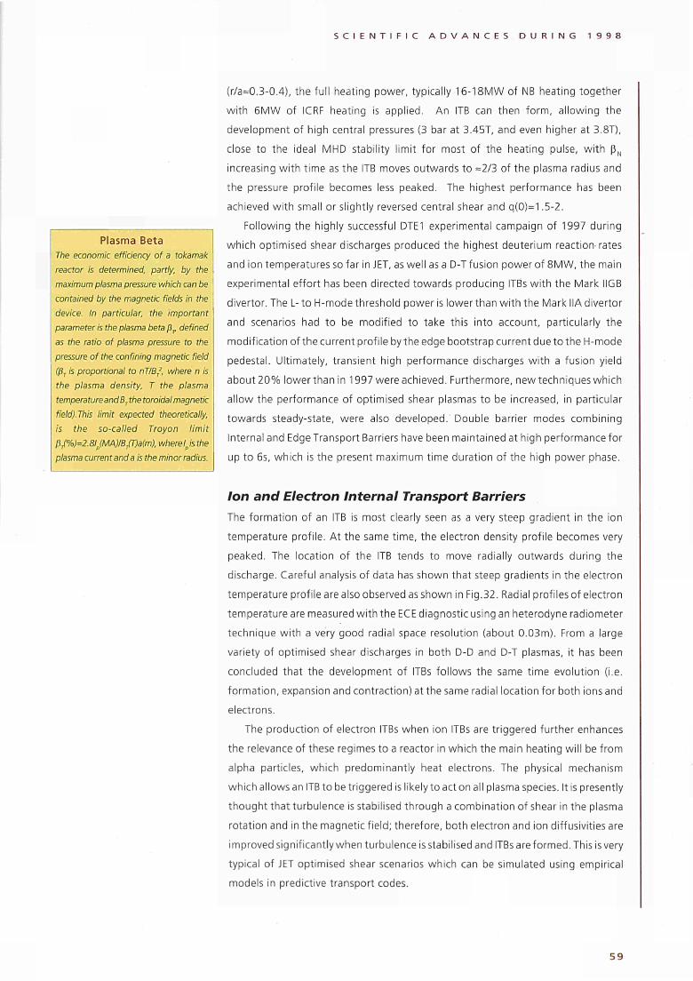
S C I E N T I F I C A D V A N C E S D U R I N G 1 9 9 8
Plasma Beta
The economic efficiency of a tokamak
reactor is determined, partly, by the
maximum plasma pressure which can be
contained by the magnetic fields in the
device. In particular, the important
parameter is the plasma beta βΓ defined
as the ratio of plasma pressure to the
pressure of the confining magnetic field
(βj is proportional to nT/BT2, where η is
the plasma density, Τ the plasma
temperature and Β Tthe toroidal magnetic
field).This limit expected theoretically,
is the so-called Troyon limit
ßJ?A)=2.8lp(MA)/B/r)a(m), where lp is the
plasma current and a is the minor radius.
(r/a=0.30.4), the full heating power, typically 1618MW of NB heating together
with 6MW of ICRF heating is applied. An ITB can then form, allowing the
development of high central pressures (3 bar at 3.45T, and even higher at 3.8T),
close to the ideal MHD stability limit for most of the heating pulse, with βΝ
increasing with time as the ITB moves outwards to =2/3 of the plasma radius and
the pressure profile becomes less peaked. The highest performance has been
achieved with small or slightly reversed central shear and q(0)=1.52.
Following the highly successful DTE1 experimental campaign of 1997 during
which optimised shear discharges produced the highest deuterium reaction· rates
and ¡on temperatures so far in JET, as well as a DT fusion power of 8MW, the main
experimental effort has been directed towards producing ITBs with the Mark IIGB
divertor. The Lto Hmode threshold power is lower than with the Mark IIA divertor
and scenarios had to be modified to take this into account, particularly the
modification of the current profile by the edge bootstrap current due to the Hmode
pedestal. Ultimately, transient high performance discharges with a fusion yield
about 20% lower than in 1997 were achieved. Furthermore, new techniques which
allow the performance of optimised shear plasmas to be increased, in particular
towards steadystate, were also developed. Double barrier modes combining
Internal and Edge Transport Barriers have been maintained at high performance for
up to 6s, which is the present maximum time duration of the high power phase.
Ion and Electron Internal Transport Barriers
The formation of an ITB is most clearly seen as a very steep gradient in the ion
temperature profile. At the same time, the electron density profile becomes very
peaked. The location of the ITB tends to move radially outwards during the
discharge. Careful analysis of data has shown that steep gradients in the electron
temperature profile are also observed as shown in Fig.32. Radial profiles of electron
temperature are measured with the ECE diagnostic using an heterodyne radiometer
technique with a very good radial space resolution (about 0.03m). From a large
variety of optimised shear discharges in both DD and DT plasmas, it has been
concluded that the development of ITBs follows the same time evolution (i.e.
formation, expansion and contraction) at the same radial location for both ions and
electrons.
The production of electron ITBs when ion ITBs are triggered further enhances
the relevance of these regimes to a reactor in which the main heating will be from
alpha particles, which predominantly heat electrons. The physical mechanism
which allows an ITB to be triggered is likely to act on all plasma species. It is presently
thought that turbulence is stabilised through a combination of shear in the plasma
rotation and in the magnetic field; therefore, both electron and ion diffusivities are
improved significantly when turbulence is stabilised and ITBs are formed. This is very
typical of JET optimised shear scenarios which can be simulated using empirical
models in predictive transport codes.
5 9
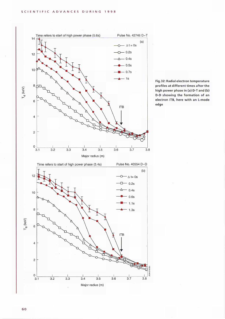
S C I E N T I F I C A D V A N C E S D U R I N G 1 9 9 8
> ω
Time refers to start of high power phase (5.6s)
14
12
10^
8 [
6
4
2
0
Ν" τ
^ -J.
n ,
■L ^ s . -^ _
I I I I
Pulse No. 42746 D-T
(a) — O — At = 0s
— D — 0.2s
— Δ — 0.4s
• 0 5"
— ▲ — 1s
\ ITB
I i . ▼
I I
3.1 3.2 3.3 3.4 3.5
Major radius (m)
3.6 3.7
Fig.32: Radial electron temperature
profiles at dif ferent times after the
high power phase in (a) D-T and (b)
D-D showing the formation of an
electron ITB, here w i th an L-mode
edge
3.8
>
3.1 3.2 3.3
12
10
8
6
4
2
0
Time refers to start of high power phase (5.4s)
T
T~̂
I I I I
Pulse No. 40554 D-D
(b)
— O — Δ t= 0s
— □ — 0.2s
— Δ — o.4s
• 0.6s
■ 1.3s
1 ITB
\ V f
1 1 1
3.4 3.5
Major radius (m)
3.6 3.7 3.8
6 0
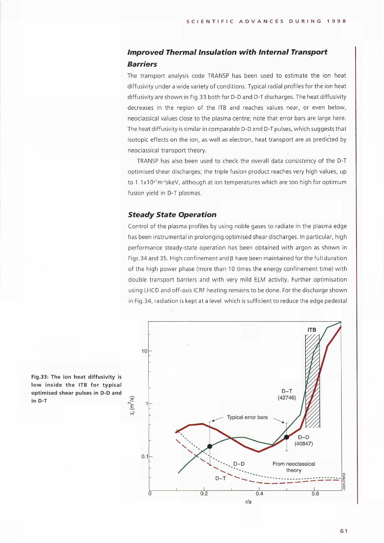
Fig.33: The ¡on heat diffusivity is
low inside the ITB for typical
optimised shear pulses in DD and
in DT
S C I E N T I F I C A D V A N C E S D U R I N G 1 9 9 8
Improved Thermal Insulation with Internal Transport
Barriers
The transport analysis code TRANSP has been used to estimate the ¡on heat
diffusivity under a wide variety of conditions. Typical radial profiles for the ¡on heat
diffusivity are shown in Fig.33 both for DD and DT discharges. The heat diffusivity
decreases in the region of the ITB and reaches values near, or even below,
neoclassical values close to the plasma centre; note that error bars are large here.
The heat diffusivity is similar in comparable DD and DT pulses, which suggests that
isotopie effects on the ¡on, as well as electron, heat transport are as predicted by
neoclassical transport theory.
TRANSP has also been used to check the overall data consistency of the DT
optimised shear discharges; the triple fusion product reaches very high values, up
to 1.1x10²¹
nr3skeV, although at ¡on temperatures which are too high for optimum
fusion yield in DT plasmas.
Steady State Operation
Control of the plasma profiles by using noble gases to radiate in the plasma edge
has been instrumental in prolonging optimised shear discharges. In particular, high
performance steadystate operation has been obtained with argon as shown in
Figs.34 and 35. High confinement and β have been maintained for the fuII duration
of the high power phase (more than 10 times the energy confinement time) with
double transport barriers and with very mild ELM activity. Further optimisation
using LHCD and offaxis ICRF heating remains to be done. For the discharge shown
in Fig.34, radiation is kept at a level which is sufficient to reduce the edge pedestal
10
ε ST
0.1-
;
•
-
-
-
ITB / /
:
DT j
(42746) /
W
.^ Typical error bars ^ ^ / ÊYV//
^
ι 1
/ J v/// ^ — ^ ^ yVr
D_D
γ ^ ^ ^ ^ / ^ " ~ ~ ^ ^ ^ | (40847)
> * * · . , DD From neoclassical
«^ * * * · · . theory
ι ι , I
1
0.2 0.4 0.6
r/a
61
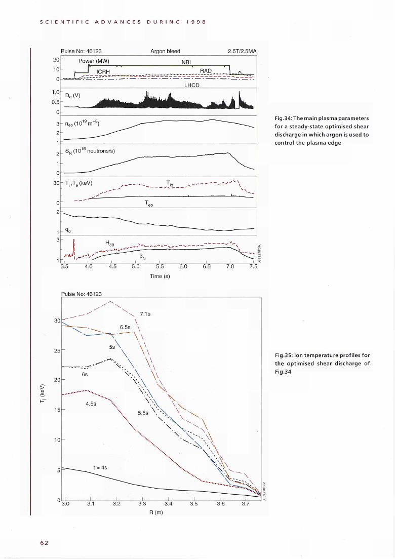
S C I E N T I F I C A D V A N C E S D U R I N G 1 9 9 8
Pulse No: 46123 Argon bleed 2.5T/2.5MA 20
10
0
1.0
0.5
0
3
2
1
2
1
0
30
0
2
_ SN(10 neutrons/s)
Power (MW) NBI
ICRH RAD I—_ _ jyHr~> ™.?.̂ . ι,.,.Λ..
LHCD
Da(V)
neo(1019nrT3)
T, ,Te (keV) io . .^-
rJ\ 3.5 4.0 4.5 5.0 5.5 6.0
Time (s)
6.5 7.0 7.5
Fig.34: The main plasma parameters for a steady-state optimised shear discharge in which argon is used to control the plasma edge
Pulse No: 46123
>
Fig.35: Ion temperature profiles for the optimised shear discharge of Fig.34
3.0 3.1
6 2
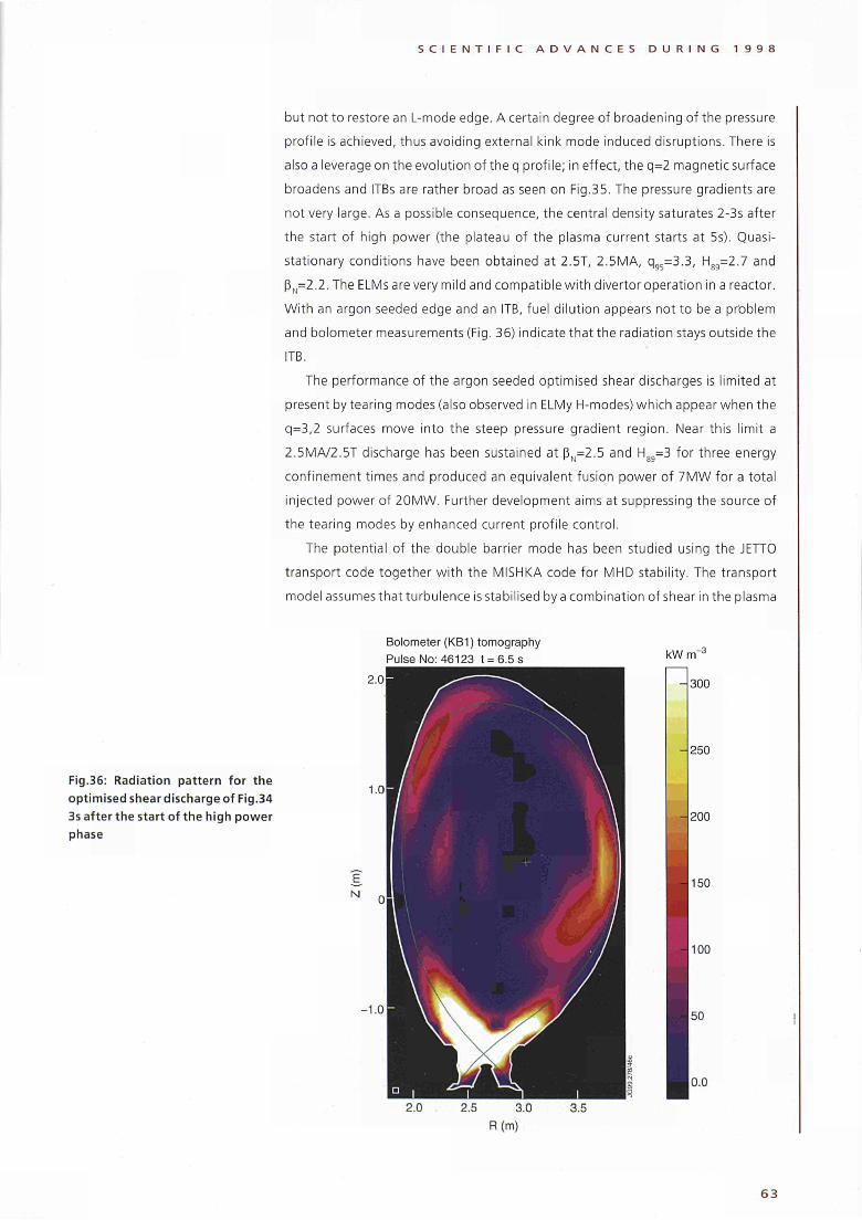
S C I E N T I F I C A D V A N C E S D U R I N G 1 9 9 8
but not to restore an Lmode edge. A certain degree of broadening of the pressure
profile is achieved, thus avoiding external kink mode induced disruptions. There is
also a leverage on the evolution of the q profile; in effect, the q=2 magnetic surface
broadens and ITBs are rather broad as seen on Fig.35. The pressure gradients are
not very large. As a possible consequence, the central density saturates 23s after
the start of high power (the plateau of the plasma current starts at 5s). Quasi
stationary conditions have been obtained at 2.5T, 2.5MA, q95=3.3, H89=2.7 and
ßN=2.2.The ELMs are very mild and compatible with divertor operation in a reactor.
With an argon seeded edge and an ITB, fuel dilution appears not to be a problem
and bolometer measurements (Fig. 36) indicate that the radiation stays outside the
ITB.
The performance of the argon seeded optimised shear discharges is limited at
present by tearing modes (also observed in ELMy Ηmodes) which appear when the
q=3,2 surfaces move into the steep pressure gradient region. Near this limit a
2.5MA/2.5T discharge has been sustained at ßN=2.5 and Hgg=3 for three energy
confinement times and produced an equivalent fusion power of 7MW for a total
injected power of 20MW. Further development aims at suppressing the source of
the tearing modes by enhanced current profile control.
The potential of the double barrier mode has been studied using the JETTO
transport code together with the MISHKA code for MHD stability. The transport
model assumes that turbulence is stabilised by a combination of shear in the plasma
Bolometer (KB1) tomography
Pulse No: 46123 t = 6.5 s
Fig.36: Radiation pattern for the
optimised shear discharge of Fig.34
3s after the start of the high power
phase
kWm"J
300
250
- 2 0 0
150
100
50
0.0
63
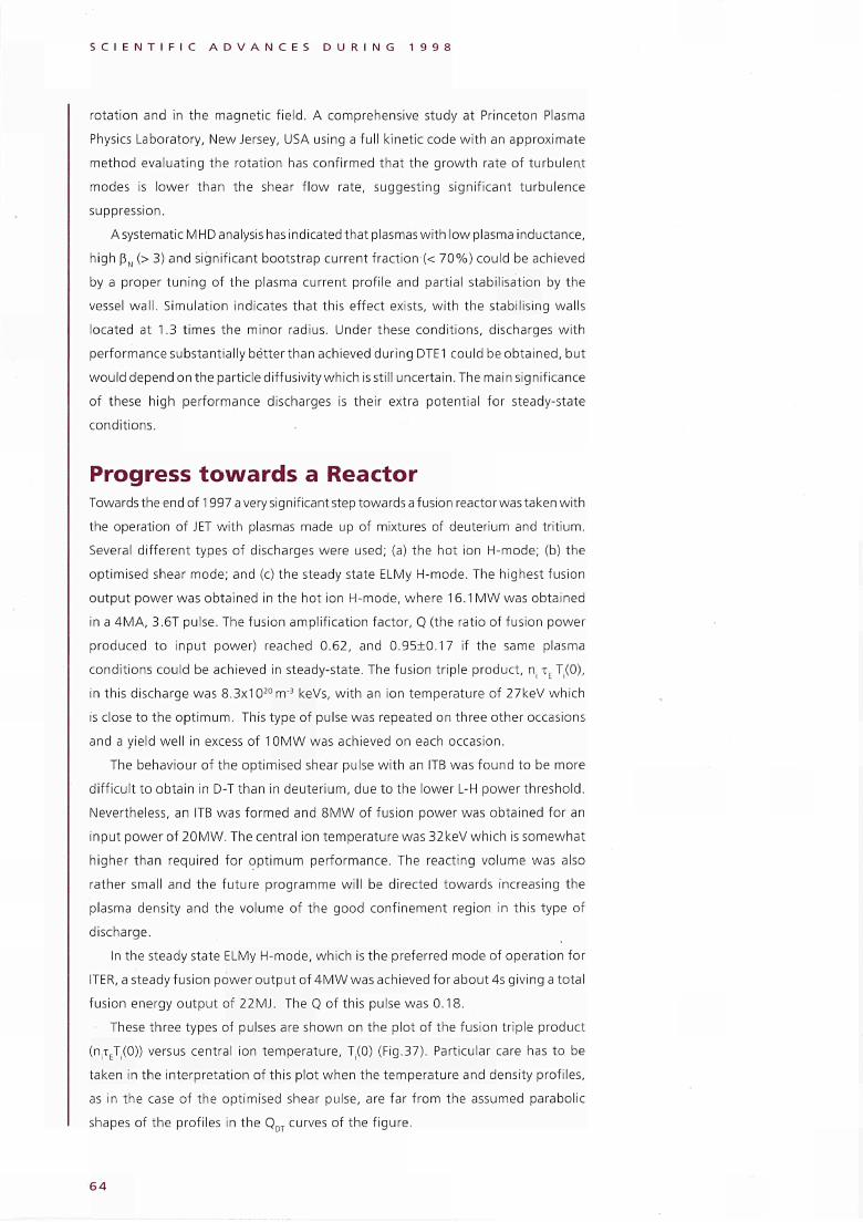
S C I E N T I F I C A D V A N C E S D U R I N G 1 9 9 8
rotation and in the magnetic field. A comprehensive study at Princeton Plasma
Physics Laboratory, New Jersey, USA using a full kinetic code with an approximate
method evaluating the rotation has confirmed that the growth rate of turbulent
modes is lower than the shear flow rate, suggesting significant turbulence
suppression.
A systematic M HD analysis has indicated that plasmas with low plasma inductance,
high ßN (> 3) and significant bootstrap current fraction (< 70%) could be achieved
by a proper tuning of the plasma current profile and partial stabilisation by the
vessel wall. Simulation indicates that this effect exists, with the stabilising walls
located at 1.3 times the minor radius. Under these conditions, discharges with
performance substantially better than achieved d uring DTE1 could be obtained, but
would depend on the particle diffusivity which is still uncertain. The main significance
of these high performance discharges is their extra potential for steadystate
conditions.
Progress towards a Reactor Towards the end of 1997 a very significant step towards a fusion reactor was taken with
the operation of JET with plasmas made up of mixtures of deuterium and tritium.
Several different types of discharges were used; (a) the hot ion Hmode; (b) the
optimised shear mode; and (c) the steady state ELMy Hmode. The highest fusion
output power was obtained in the hot ¡on Hmode, where 16.1 MW was obtained
in a 4MA, 3.6T pulse. The fusion amplification factor, Q (the ratio of fusion power
produced to input power) reached 0.62, and 0.95±0.17 if the same plasma
conditions could be achieved in steadystate. The fusion triple product, η τΕ T(0),
in this discharge was 8.3x10²⁰
irr3 keVs, with an ion temperature of 27keV which
is close to the optimum. This type of pulse was repeated on three other occasions
and a yield well in excess of 10MW was achieved on each occasion.
The behaviour of the optimised shear pulse with an ITB was found to be more
difficult to obtain in DT than in deuterium, due to the lower LH power threshold.
Nevertheless, an ITB was formed and 8MW of fusion power was obtained for an
input power of 20MW. The central ¡on temperature was 32keV which is somewhat
higher than required for optimum performance. The reacting volume was also
rather small and the future programme will be directed towards increasing the
plasma density and the volume of the good confinement region in this type of
discharge.
In the steady state ELMy Hmode, which is the preferred mode of operation for
ITER, a steady fusion power output of 4MW was achieved for about 4s giving a total
fusion energy output of 22MJ. The Q of this pulse was 0.18.
These three types of pulses are shown on the plot of the fusion triple product
(ητΕΤ(0)) versus central ¡on temperature, T(0) (Fig.37). Particular care has to be
taken in the interpretation of this plot when the temperature and density profiles,
as in the case of the optimised shear pulse, are far from the assumed parabolic
shapes of the profiles in the QDT curves of the figure.
6 4
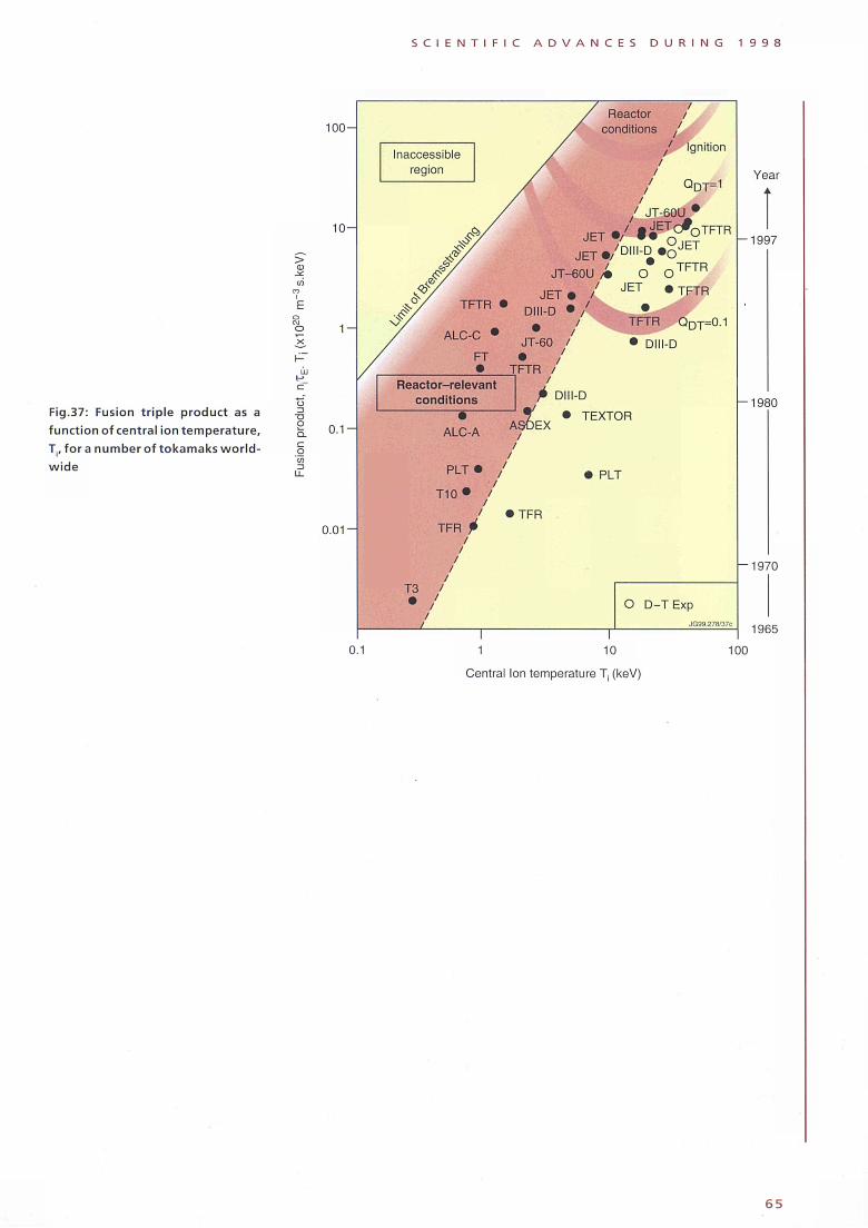
S C I E N T I F I C A D V A N C E S D U R I N G 1 9 9 8
Fig.37: Fusion triple product as a function of central ion temperature, T., fora number of tokamaks worldwide
* ^
LU
Ό O
1 0 0 -
1 0 -
1 -
0.1·
0.01 ■
0.1
Reactor
conditions
/ Ignition
QD T=1
JT60U
JETZt i^OTFTR
J E T # / D I I I D « oJ E T
/ TFTR
JT60U / · O O
J E T · / J E T
»TFTR
TFTR QDT=0.1
• DlllD
Reactor-relevant
conditions
ALCA
PLT ·
T 1 0 *
ι
TFR i I
I I
I I
T3 /
• /
t DlllD
? ' · TEXTOR ASDEX
'TFR
PLT
O D-T Exp
JG99.278/37C
Year
■1997
■1980
■1970
1965
1 10
Central Ion temperature T, (keV)
100
6 5
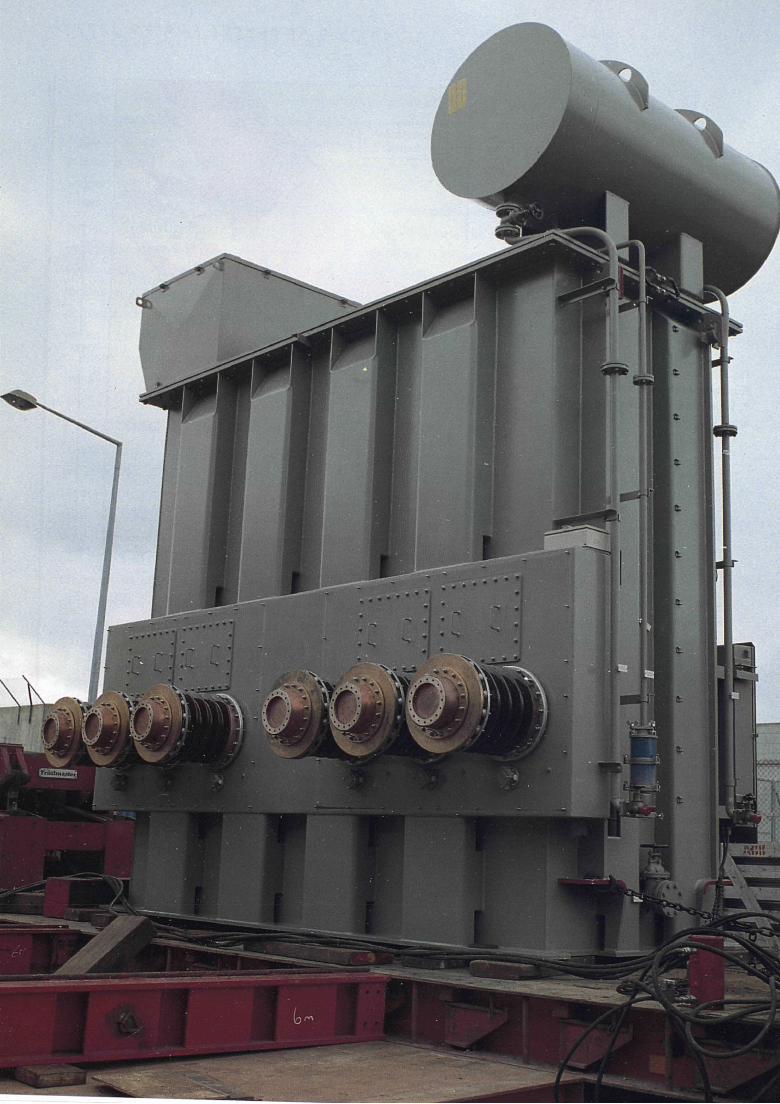
Ι . . ·Ί ·Ί»»|
-
P R O G R A M M E O V E R V I E W
Programme Overview
Background In 1978, the original objectives of JET were set out in the JET Design Proposal, EUR-
JET-R5, as follows:
"The essential objective of J ET is to obtain and study a plasma in conditions and
dimensions approaching those needed in a thermonuclear reactor. These
studies will be aimed at defining the parameters, the size and the working
conditions of a Tokamak reactor. The realisation of this objective involves four
main areas of work:
i) the scaling of plasma behaviour as parameters approach the reactor
range;
ii) the plasma-wall interaction in these conditions;
iii) the study of plasma heating; and
iv) the study of alpha particle production, confinement and consequent
plasma heating.
The problems of plasma-wall interaction and of heating the plasma must, in
any case, be solved'in order to approach the conditions of interest.
An important part of the experimental programme will be to use JET to extend
to a reactor-like plasma, results obtained and innovations made in smaller
apparatus as a part of the general tokamak programme. These would include:
various additional heating methods, first wall materials, the control of the
plasma profiles and plasma formation. "
Since the beginning of its experimental campaign in 1983, extensive studies had
been made in the first and third areas of work of JET's objectives: reactor relevant
temperatures (up to 38keV), densities (up to 4x10²⁰nr3) and energy confinement
times (up to 1.7s) had been achieved in separate discharges. The second area of
work had been well covered in the limiter configuration for which JET was originally
designed. However, the highest performance JET discharges had been obtained with
a "magnetic limiter" (or X-point configuration).The duration of the high performance
phase of these discharges exceeded 1.5s; this was achieved by careful design of the
targets and specific operation techniques, but was limited, ultimately, by an unacceptably
6 7
P R O G R A M M E O V E R V I E W
high influx of impurities, characterised by a rapid increase in electron density, effective
ionic charge and radiated power (referred to as the "bloom").
The fourth area of work had been started by earlier studies of energetic particles
produced as fusion products or by ¡on cyclotron resonance heating. It was
addressed further during 1991 by the first tokamak experiments in deuterium-
tritium mixtures. During 1991, the JET Council had approved the policy of a step
wise approach to the introduction of tritium in advance of the full D-T phase of JET
operations. As a first such step, JET successfully carried out the preliminary tritium
experiment in November 1991, using about 10% tritium in the plasma. A release
of fusion energy in the megawatt range in a controlled fusion device had been
achieved for the first time in the world.
In the 1991/92 campaign, JET achieved plasma parameters approaching
breakeven values for about a second, resulting in large bursts of neutrons.
However, in spite of the plasma pulse continuing for many seconds after reaching
peak plasma values, the neutron count fell away rapidly as impurities entered the
plasma and lowered Its performance. This limitation on the ti me for which the near-
breakeven conditions could be maintained was due to the poisoning of the plasma
by impurities (the "bloom"). This further emphasised the need to providea scheme
of impurity control suitable for a Next Step device.
In late 1991, the Council of Ministers approved a modification to the JET
Statutes, which prolonged its lifetime by four years until 31 st December 1996. The
extension was to allow JET to implement the new Pumped Divertor Phase of
operation, the objective of which was to establish the effective control of plasma
impurities in operating conditions close to those of the Next Step. This programme
of studies was to be pursued before the final phase of full D-T operations in JET.
During 1993, a large proportion of JET's effort was devoted to shutdown work
for the pumped divertor phase of operations, and was successfully completed
in January 1994. The first plasma in the Pumped Divertor Characterisation Phase
was produced in mid-February and by mid-March successful 2MA diverted plasmas
had been established. During 1994, the plasma current was increased to 5MA, the
total heating power to 26MW, the stored energy to 11.3MJ and the neutron rate
to 4x10 , 6s' .
1994 saw significant progress in optimising peak fusion performance and
extending operation to the reactor relevant steady-state ELMy H-mode, which was
obtained under a variety of conditions (plasma currents up to 4MA, power levels up
to 26MW, in the high ßp regime, in discharges with negative central magnetic shear,
and at high ßN). The high power handling capability of the Mark I divertor target was
demonstrated and the severe impurity influxes (the"bloom"), which previously
terminated high performance plasmas, was eliminated. The cryopump reduced
recycling, eliminated the effects of wall saturation (observed in previous long pulse
operation), allowed effective particle control, and generally allowed higher performance.
The 1995 programme addressed the central problems of the ITER divertor:
6 8
P R O G R A M M E O V E R V I E W
efficient dissipation of the exhausted power, control of particle fluxes and effective
impurity screening, using both carbon fibre composite and beryllium as the power
handling material. During this phase, the plasma current was increased to 6MA (a
world record in an X-point configuration), the total heating power to 32MW,
plasma stored energy to 13.5MJ and the neutron rate to a new JET record in
deuterium of 4.7 χ 10^s'1 (comparable to the best achieved prior to installation of the
pumped divertor and achieved even though the plasma volume was 20% smaller).
At the beginning of 1996, JET entered a new Phase of ITER Support, and started
the year in shutdown for the installation of the Mark II divertor support structure.
This formed the basis for all subsequent divertor work at JET. In addition, the
"more-closed" Mark IIA divertor target assembly was installed.
In 1996, the Mark IIA divertor was found to behave as expected. It offered
improved power handling over the Mark I divertor, pumped the plasma 2-3 times
more rapidly and showed signs of increased neutral recycling in the divertor region.
The 1996 experimental campaign then concentrated on specific ITER-relevant
issues related to the more closed Mark IIA divertor and, due to their importance for
predicting ITER'S ignition margin and fusion power output, the scaling of the
H-mode threshold powerand theenergyconfinementtime. Inaddition, preparation
of high performance scenarios for a further phase of deuterium-tritium operation
(DTE1) was a high priority.
In mid-1996, the lifetime of the Project was extended to the end of 1999, to
enable the Project to provide further data of direct relevance to ITER. In particular,
the Project was expected to contribute significantly to the development and
demonstration of a viable divertor concept for ITER and to undertake experiments
using D-T plasmas in an ITER like configuration, which should provide a sound basis
for the D-T operation of ITER. In addition, the extension would permit key ITER-
relevant technology activities to be carried out, including the demonstration of
remote handling and tritium handling.
1997 was a year of JET operations, whose centrepiece was DTE1 during which
JET carried out a broad-based series of D-T experiments, setting new world records
for fusion power production (16.1 MW), fusion energy (22MJ), fusion duration
(4MW for about 4s) and fusion amplification factor, Q (the ratio of fusion power
produced to input power) of 0.62 and 0.95+0.17, if the same plasma conditions
could be acheived in steady-state. These experiments also addressed crucial issues
of D-T physics and technology for ITER.
Following the tritium clean up experiments at the end of DTE1, a series of ITER
Urgent Physics Tasks was undertaken with hydrogen and deuterium plasmas. These
tasks focussed on confinement scaling experiments to increase confidence in the
predictions for ITER. The third stage in the divertor programme on JET then began
with the installation fully by remote handling of the Gas Box (Mark IIGB) divertor
during the RTE shutdown. The subsequent experimental campaign concentrated on
ELMy H-mode and performance optimisation studies.
6 9

P R O G R A M M E O V E R V I E W
Future Plans The JET Programme was divided into phases governed by the availability of new
equipment and fitting within the accepted life of the Project. Phase I (Ohm.ic
Heating Studies) was completed in September 1984, and Phase II (Additional
Heating Studies) in October 1988. Phase III (Full Power Optimisation Studies) ended
in February 1992. The scientific aims of Phase III were to obtain maximum
performance in the limiter configuration (currents up to 7MA) and to optimise
X-point Operation (currents up to 6MA) including a comparison of Η-modes in the
X-point configuration using beryllium (lower X-point) with carbon (upper X-point)
dump plates.
The JET programme was then dominated by the insertion of a new phase, Phase
IV: the Pumped Divertor Characterisation Phase, which began in February 1994 and
ended in June 1995.
In mid-1996, the lifetime of the Project was further extended to the end of 1999,
to enable the Project to carry out an ITER Support Programme.
Objectives in Support of ITER The purpose of the extension of JET to the end of 1999 was to provide further data
of direct relevance to ITER, especially for the ITER-EDA, before entering into a final
phase of D-T operation. In particular, the extension:
i) was to make essential contributions to the development and demonstration
of a viable divertor concept for ITER, and
ii) carry out experiments using D-T plasmas in an ITER-like configuration, which
will provide a firm basis for the D-T operation of ITER;
while allowing key ITER-relevant technology activities, such as the demonstration
of remote handling and tritium handling, to be carried out.
Divertor Studies The divertor must fulfil three main functions:
(i) exhaust plasma power at acceptable erosion rates;
(ii) control plasma purity; and
(iii) exhaust helium "ash" and provide density control.
For ITER, successful divertor operation must also be compatible with H-mode
operation with Edge Localised Modes (ELMs), which could lead to high local heat
deposition.
Erosion can be reduced by decreasing the plasma temperature at the target
plates which can be achieved with high density and high recycling near the targets.
However, the exhausted plasma power conducted to the target plates in this high
recycling regime is not reduced and has to be distributed over a large surface area.
To some extent, this can be achieved by inclining the target plates so as to project
a larger surface area to the conducted heat flux which flows along the magnetic
field.
70
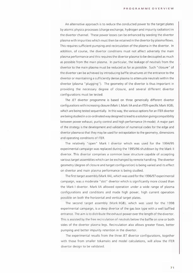
P R O G R A M M E O V E R V I E W
An alternative approach is to reduce the conducted power to the target plates
by atomic physics processes (charge exchange, hydrogen and impurity radiation) in
the divertor channel. These power losses can be enhanced by seeding the divertor
plasma with impurities which must then be retained in the divertor by plasma flows.
This requires sufficient pumping and recirculation of the plasma in the divertor. In
addition, of course, the divertor conditions must not affect adversely the main
plasma performance and this requires the divertor plasma to be decoupled as much
as possible from the main plasma. In particular, the leakage of neutrals from the
divertor to the main plasma must be reduced as far as possible. Such "closure" of
the divertor can be achieved by introducing baffle structures at the entrance to the
divertor or maintaining a sufficiently dense plasma to attenuate neutrals within the
divertor (plasma "plugging"). The geometry of the divertor is thus important in
providing the necessary degree of closure, and several different divertor
configurations must be tested.
The JET divertor programme is based on three generically different divertor
configurations with increasing closure (Mark I, Mark HA and an ITER-specific Mark IIGB),
which are being tested sequentially. In this way, the various options for an ITER divertor
are being studied in a co-ordinated way designed to lead to a solution giving compatibility
between power exhaust, purity control and high performance (H-mode). A major part
of the strategy is the development and validation of numerical codes for the edge and
divertor plasma so that they may be used for extrapolation to the geometry, dimensions
and operating conditions of ITER.
The relatively "open" Mark I divertor which was used for the 1994/95
experimental campaign was replaced during the 1995/96 shutdown by the Mark II
divertor. This divertor comprises a common base structure capable of accepting
various target assemblies which can be exchanged by remote handling. The divertor
geometry (degree of closure and target configuration) is being varied and its effect
on divertor and main plasma performance is being studied.
The first target assembly (Mark IIA), which was used for the 1996/97 experimental
campaign, was a moderate "slot" divertor which is significantly more closed than
the Mark I divertor. Mark IIA allowed operation under a wide range of plasma
configurations and conditions and made high power, high current operation
possible on both the horizontal and vertical target plates.
The second target assembly (Mark IIGB), which was used for the 1998
experimental campaign, is a deep divertor of the gas box type with a well baffled
entrance. The aim is to distribute the exhaust power over the length of the divertor.
This is assisted by the free recirculation of neutrals below the baffle on one or both
sides of the divertor plasma legs. Recirculation also allows greater flows, better
pumping and better impurity retention in the divertor.
The experimental results from the three JET divertor configurations, together
with those from smaller tokamaks and model calculations, will allow the ITER
divertor design to be validated.
7 1
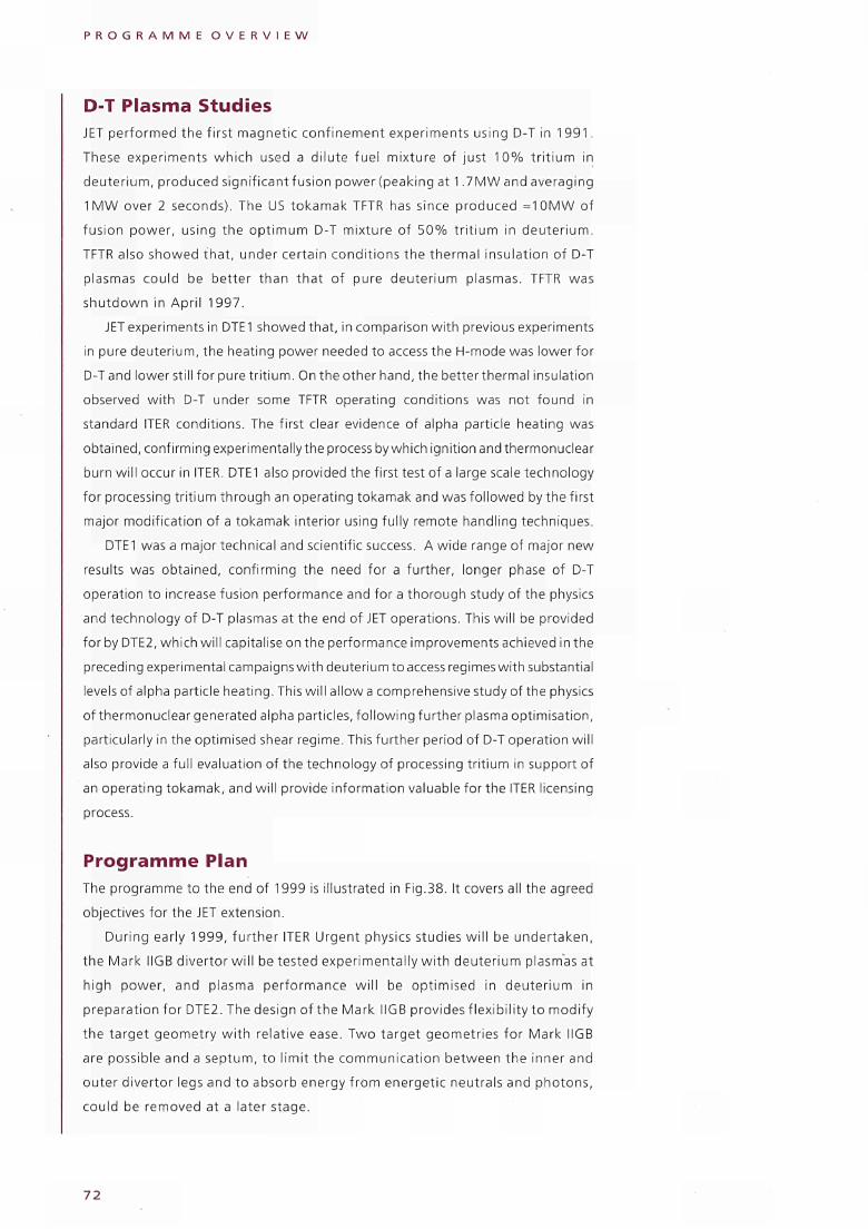
P R O G R A M M E O V E R V I E W
D-T Plasma Studies JET performed the first magnetic confinement experiments using D-T in 1 991.
These experiments which used a dilute fuel mixture of just 10% trit ium in
deuterium, produced significantfusion power (peaking at 1.7MW and averaging
1MW over 2 seconds). The US tokamak TFTR has since produced =10MW of
fusion power, using the optimum D-T mixture of 50% trit ium in deuterium.
TFTR also showed that, under certain conditions the thermal insulation of D-T
plasmas could be better than that of pure deuterium plasmas. TFTR was
shutdown in April 1997.
JET experiments in DTE1 showed that, in comparison with previous experiments
in pure deuterium, the heating power needed to access the H-mode was lower for
D-T and lower still for pure tritium. On the other hand, the better thermal insulation
observed with D-T under some TFTR operating conditions was not found in
standard ITER conditions. The first clear evidence of alpha particle heating was
obtained, confirming experimentally the process by which ignition and thermonuclear
burn will occur in ITER. DTE1 also provided the first test of a large scale technology
for processing tritium through an operating tokamak and was followed by the first
major modification of a tokamak interior using fully remote handling techniques.
DTE1 was a major technical and scientific success. A wide range of major new
results was obtained, confirming the need for a further, longer phase of D-T
operation to increase fusion performance and for a thorough study of the physics
and technology of D-T plasmas at the end of JET operations. This will be provided
for by DTE2, which will capitalise on the performance improvements achieved in the
preceding experimental campaigns with deuterium to access regimes with substantial
levels of alpha particle heating. This will allow a comprehensive study of the physics
of thermonuclear generated alpha particles, fol lowing further plasma optimisation,
particularly in the optimised shear regime. This further period of D-T operation will
also provide a full evaluation of the technology of processing tritium in support of
an operating tokamak, and will provide information valuable for the ITER licensing
process.
Programme Plan The programme to the end of 1999 is illustrated in Fig.38. It covers all the agreed
objectives for the JET extension.
During early 1999, further ITER Urgent physics studies will be undertaken,
the Mark IIGB divertor will betested experimentally with deuterium plasmas at
high power, and plasma performance will be optimised in deuterium in
preparation for DTE2. The design of the Mark IIGB provides flexibility to modify
the target geometry with relative ease. Two target geometries for Mark IIGB
are possible and a septum, to limit the communication between the inner and
outer divertor legs and to absorb energy from energetic neutrals and photons,
could be removed at a later stage.
7 2
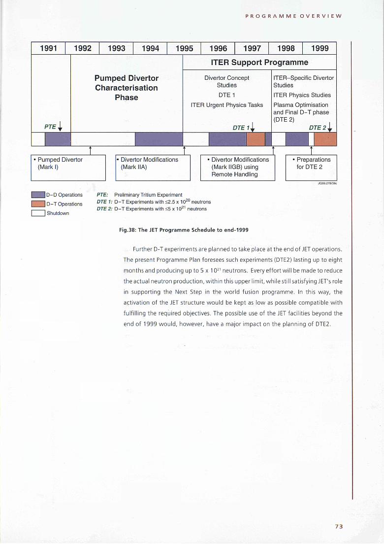
P R O G R A M M E O V E R V I E W
1991 1992
P 7 / = |
1993 1994 1995
Pumped Divertor
Characterisation
Phase
• Pumped Divertor
(Mark I)
1996 1997 1998 1999
ITER Support Programme
Divertor Concept
Studies
DTE1
ITER Urgent Physics Tasks
DTEll
• Divertor Modifications
(Mark IIA)
• Divertor Modifications
(Mark IIGB) using
Remote Handling
ITER-Specific Divertor
Studies
ITER Physics Studies
Plasma Optimisation
and Final D-T phase
(DTE 2)
■
DTE 2^
• Preparations
for DTE 2
JG99.278/39C
| D-D Operations
| D-T Operations
I Shutdown
PTE: Preliminary Tritium Experiment
DTE 1: D-T Experiments with <2.5 χ 1020
neutrons
DTE 2: D-T Experiments with <5 χ 1021
neutrons
Fig.38: The JET Programme Schedule to end-1999
Further D-T experiments are planned to take place at the end of JET operations.
The present Programme Plan foresees such experiments (DTE2) lasting up to eight
months and producing up to 5 χ 102' neutrons. Every effort wil l be made to reduce
the actual neutron production, wi th in this upper limit, whi le still satisfying JET's role
in supporting the Next Step in the wor ld fusion programme. In this way, the
activation of the JET structure would be kept as low as possible compatible w i th
fulf i l l ing the required objectives. The possible use of the JET facilities beyond the
end of 1999 wou ld , however, have a major impact on the planning of DTE2.
7 3
> * /
M E M B E R S A N D O R G A N I S A T I O N
Members and Organisation
Members The JET Joint Undertaking had the following Members at the end of 1998:
The European Atomic Energy Community (EURATOM);
The Belgian State, acting for its own part ('Laboratoire de Physique des Plasmas
de l'École Royale Militaire - Laboratorium voor plasma-physica van de
Koninklijke Militaire School') and on behalf of the Université Libre de
Bruxelles' ('Service de physique statistique, plasmas et optique non-linéaire
de l'ULB'); and of the 'Centre d'Études de l'Energie Nucléaire (CEN)/
'Studiecentrum voor Kernenergie' (SCK);
The Centro de Investigaciones Energéticas Medioambientales y Tecnológicas
(CIEMAT), Spain;
The Commissariat à l'Énergie Atomique (CEA), France;
The 'Ente per le Nuova Tecnologie, l'Energia e l'Ambiente' ('ENEA') representing
all Italian activities falling within the Euratom Fusion Programme including
that of the 'Consiglio Nazionale delle Ricerche', (CNR);
The Hellenic Republic, Greece;
The Forskningscenter Risø (Risø), Denmark;
The Grand Duchy of Luxembourg, Luxembourg;
The Austrian Academy of Sciences;
The Instituto de Cooperação Cientifica e Tecnológica Internacional (ICCTI),
Portugal;
Dublin City University (DCU), Ireland;
The Forschungszentrum Karlsruhe (FZK), Germany;
The Max-Planck-Gesellschaft zur Förderung der Wissenschaften e.V. Institut für
Plasmaphysik (IPP), Germany;
The Swedish Natural Science Research Council (NFR), Sweden;
The Swiss Confederation, Switzerland;
The Stichting voor Fundamenteel Onderzoek der Materie (FOM), The Netherlands;
The Technology Development Centre Finland (TEKES);
The United Kingdom Atomic Energy Authority (UKAEA), Host Organisation.
7 5

M E M B E R S A N D O R G A N I S A T I O N
EXECUTIVE COMMITTEE
Chairman G. Leman
Associate Director, Head of Administration
Department
L. Byrne
COUNCIL
Chairman F. Troyon
DIRECTOR
M. Keilhacker
Deputy Director, Head of Torus and
Measurements Department
A. Gibson (to 11.5.98)
SCIENTIFIC COUNCIL
Chairman K. Lackner
Associate Director, Head of Heating and
Operations Department
J. Jacquinot JG98 204/IC
Fig.39: Overall Project Structure
Management The JET Joint Undertaking is governed by Statutes which were adopted by the
Council of the European Communities on 30 May 1978. The organs of the Joint
Undertaking are the JET Council and the Director of the Project. The JET Council is
assisted by the JET Executive Committee and is advised by the JET Scientific Council
(Fig.39).
JET Council Each member of the Joint Undertaking is represented on the JET Council, which is
required to meet at least twice yearly. The Council is responsible for the management
of the Joint Undertaking and for:
• Nomination of the Director and Senior Staff of the Project with a view to their
appointment by the Commission or the Host Organisation as appropriate;
• Approval of the annual budget, including staffing, the Project Development
Plan and the Project Cost Estimates;
• Ensuring collaboration between the Associated Laboratories and the Joint
Undertaking in the execution of the Project, including the establishment of rules
on the operation and exploitation of JET.
Three meetings of the JET Council were held during the year: on 18th-19th
March, 18th-19th June and 14th-15th October 1998. The membership of the JET
Council is shown in Appendix I.
76

M E M B E R S A N D O R G A N I S A T I O N
JET Executive Committee The JET Executive Committee is required to meet at least six times a year. Its
functions include:
• Advising the JET Council and the Director of the Project on the status of the
Project on the basis of regular reports;
• Commenting and making recommendations to the JET Council on the Project
Cost Estimates and the Draft Budget, including the establishment of staff,
drawn up by the Director of the Project;
• Approving, in accordance with the rules on the award of contracts established
by the JET Council, the tendering procedure and the award of contracts;
• Promoting and developing collaboration between the Associated Laboratories
and the Joint Undertaking in the execution of the Project.
The membership of the JET Executive Committee is shown in Appendix II. The
Committee met six times during 1998: on 5th-6th February, 14th-15th May, 9th July,
16th-17th September, 5th November and 3rd December 1998.
JET Scientific Council The Statutes confer the following functions on the JET Scientific Council:
• Upon the request of the JET Council, to advise on scientific and technical
matters, including proposals involving a significant change in the design of JET,
its exploitation, and its long-term scientific implications;
• To perform such other tasks as the JET Council may request it to undertake.
The JET Scientific Council met twice during the year: on 3rd-4th June and
29th-30th September 1998.
The JET-SC Chairman reported to the JET Council, on two occasions, on:
Results from the DTE1, ITER Urgent Physics and Mark IIGB Divertor Campaigns;
JET operation at 4T;
JET Programme to end-1998;
JET Programme Options to end-1999; and
Access to JET data for those participating in approved collaboration agreements.
During 1 998, the Joint JET and JET Scientific Council Reliability Assessment
Group continued to assess the technical risks of JET operation at toroidal fields
above 3.45 Tesla.
The membership of the JET Scientific Council is shown in Appendix III.
Host Organisation The United Kingdom Atomic Energy Authority, as the Host Organisation for the JET
Joint Undertaking, has made available to the Joint Undertaking, the land, buildings,
goods and services required for the implementation of the Project. The details of
such support, as well as the procedures for co-operation between the Joint
Undertaking and the Host Organisation, are covered by a "Support Agreement"
7 7

M E M B E R S A N D O R G A N I S A T I O N
Data Analysis and Modelling Division: J.G. Cordey
Safety and Environment Unit: A.C.Bell
Next Step Unit: D.J.Ward
I Torus & Measurements Department
Associate Director & Head of Department:
A. Gibson (To 11.
I D m ■ρ- χ
Í2. Φ
=> Η CD D
-
D O
D <
II En »
I o m ï"
χ
S (D
=> H CD D
■ Ö D
m<
en o'
3 I
Q.
I □ "Π
< s Ç Í => fc
< u >*= T J O
0 =
Q.
o
).98)
τι <tñ
I I J H
3
O
O (O
> o OS.
CD O
CU Q.
D Q)
5
D
O
DIRECTOR:
M. Keilhacker
Deputy Director: A. Gibson (To 11.5.98)
Directorate
Counsellor: G. Vlases (To 30.9.98)
Principal Engineer: A.S. Kaye
Engineering Analysis Unit: S. Papastergiou (To 13.6.98)
Heating & Operations Department
Associate Director & Head of Department:
J. Jacquinot
π o n < O (Λ D
õ'>
κ! Ξ
D)
3 -n
OD
si S õ' 3
s
2 I
2 5 ? 3
ΓΠ □ O « <'S ï? ã τ3 -δ'SI = i
Ι
Administration Department
Associate Director & Head of Department:
L Byrne
I Ω o D
O
(Λ
CO
CD
<!
ι - ω
m ° Ι Φ DJ
"Π
3
CO CD
? O
CD
"o 3
Q) i .
(D * » χ
Q.
I "0
(0
3
CO
2
Φ
σ ω
"D 2
si I φ (D S
f
Fig.40: JET Departmental and Divisional Structure
between both parties. In addition to providing staff to the JET Team, the Host
Organisation provides support staff and services, at proven cost, to meet the
requirements of the JET Project.
Project Team Structure
The Director of the Project
The Director of the Project, Dr. M. Keilhacker, is the chief executive of the Joint
Undertaking and its legal representative. He is responsible to the JET Council for
the execution of the Project Development Plan, which specifies the programme,
and for the execution of all elements of the Project. The Project Development Plan
covers the whole term of the Joint Undertaking and is regularly updated. The
Director is also required to provide the JET Council and other subsidiary bodies with
all information necessary for the performance of their functions.
Internal Organisation
The internal organisation of the Project consists of three Departments and the
Directorate. The three Departments are: Torus and Measurements Department;
Heating and Operations Department; and Administration Department. The Project
Departmental and Divisional structure is shown in Fig.40. Further details of the
Technical Departments are given in the 1998 JET Progress Report.
78
M E M B E R S A N D O R G A N I S A T I O N
Directorate The Heads of the Departments report to the Director of the Project and together
with the Director form the JET Directorate. Various special functions are carried out
by the Director's Office. The Internal Audit Office monitors the financial activities
and provides advice on accounting and control procedures as well as maintaining
links with the Court of Auditors. The Project Control Office is responsible for
financial planning and for the preparation of the Project Development Plan and
Project Cost Estimates. The JET Council Secretariat provides Secretarial Services to
the JET Council and to the Executive Committee and also to the JET Project Board.
Within the Directorate are three technical units (The Next Step Unit, Safety and
Environment Unit, and Engineering and Analysis Unit) and one Division (The Data
Analysis and Modelling Division).
Torus and Measurements Department TheTorus and Measurements Department has overall responsibility for the performance
capacity of the machine: this includes enhancements directly related to this (excluding
heating) and the long term planning associated with integration of these elements to
achieve ultimate performance. The Department is also responsible: for fusion technology
requirements for the active phase, including tritium handling and processing; for
construction and operation of necessary measurement diagnostic systems and the
interpretation of experiment data; for maintaining high vacuum conditions; for
enhancements to the JET device; and for providing remote handling. The main
functions of the Department are:
• to design, procure and implement enhancements to the JET device;
• to provide and maintain clean conditions inside the vessel which lead to high
quality plasma discharges;
• to conceive and define a set of coherent measurements;
• to be responsible for construction of necessary diagnostics;
• to be responsible for diagnostics operation, quality of measurements and
definition of plasma parameters;
• to design and develop remote handling methods and tools to cope with JET
requirements;
• to design and construct facilities for handling tritium and for waste management.
The Department consists of four Divisions (First Wall Division, Fusion Technology
Division, Experimental Division 1 (ED1) and Experimental Division 2 (ED2)) and one
Group (Drawing Office).
Heating and Operations Department The overall responsibility of the Heating and Operations Department is for the
efficient and effective day-to-day operation of the machine. In addition, the
Department has responsibility for plasma heating and auxiliary equipment and
related physics; the design and operation of power supplies; the data systems
79

M E M B E R S A N D O R G A N I S A T I O N
comprising data control, acquisition and management, as well as contributing to the
execution and evaluation of JET's experimental programme. The main functions of
the Department are:
• preparing and co-ordinating operation of the machine across Departments and
Divisions;
• heating and current drive and analysis of its effects in the plasma;
• plasma fuelling, including pellet injection;
• designing and employing power supplies for ensuring efficient operation and
control of the machine; and
• to organise and implement data acquisition and computing.
The Department consist of five Divisions (Operations Division, Neutral Beam
Heating Division, Radio Frequency Heating Division, Magnet and Power Supplies
Division and Control and Data Acquisition System Division (CODAS)).
Project Management The internal organisation of the Project (Fig.40) is enhanced by a matrix managerial
structure which functions through Committees and Task Forces led by the Director
and other senior staff.
The JET Project Board is responsible to the Director for the overall management
of the Project while the Technical Project Board addresses issues of a technical and
scientific nature. Both are chaired by the Director and attended by Division and
Service Heads. The Experiments Committee, also chaired by the Director, establishes
and monitors the Experimental Programme within the broad outline set by the
Project Development Plan. Detailed technical appraisals of the Programme are
made by the Co-ordination Meetings (Commissioning/Operations, Design/Assembly
and Data Evaluation). The formulation, execution and review of the Programme is
carried out by Task Forces (there were four during 1998), the leaders of which
report at the Experiments Committee. Science Meetings are held on a weekly basis
to subject experimental proposals and results to discussion and peer review.
Administration Department The Administration Department is responsible for providing Contracts, Finance and
Personnel services to the Project. In addition, the Department is responsible for the
administration of the Publications and Public Relations Groups.
8 0

A D M I N I S T R A T I O N
Administration
Introduction The three main aspects of JET's administration - Finance, Contracts and Personnel
- are reported in this section. There are also contributions on the Public Relations
and Publications Groups.
Finance The initial budgets for 1998 were approved at 75.05MioECU for Commitments and
79.56MioECU for both Income and Payments. The Commitments and Payments
Budgets included an Operations Reserve of 5.80MioECU. The JET Council agreed the
release from the Commitments Budget of 4.50MioECU for use in 1998 and the balance
of 1.30MÍOECU to be carried forward to 1999. The Payments Operations Reserve was
also released in full but 4.50MioECU has been reserved against the 9.00MioECU
commitment provision made in 1997 in line with the ex-gratia payment envisaged as
part of the out-of-court settlement of the JET UKAEA staff case proposed by the
European Parliament.
The Commitments.and Payments Budgets each are divided into two phases of
the Project - Extension to Full Performance and the Operational Phase; subdivisions
distinguish between investment, operating, and personnel costs, each with further
detailed cost codes. The Extension to Full Performance Phase was closed during
1998.
Commitments Of the total final appropriations in 1998 of 78.14MioECU (including 3.09MioECU
brought forward from previous years), 65.85MioECU was committed and the
balance of 12.29MioECU was available for carrying forward to 1999. The details
of the commitment appropriations available and of the amounts committed in the
Operational Phase during the year are shown in Tables 3 and 4.
8 1
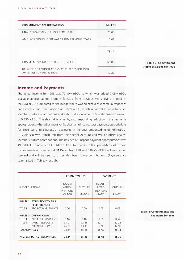
A D M I N I S T R A T I O N
COMMITMENT APPROPRIATIONS MioECU
FINAL COMMITMENTS BUDGET FOR 1998
AMOUNTS BROUGHT FORWARD FROM PREVIOUS YEARS.
COMMITMENTS MADE DURING THE YEAR
BALANCE OF APPROPRIATIONS AT 31 DECEMBER 1998 AVAILABLE FOR USE IN 1999
75.05
3.09
78.14
65.85
12.29
Table 3: Commitment Appropriations for 1998
Income and Payments The actual income for 1998 was 77.10MioECU to which was added 2.05MioECU
available appropriations brought forward from previous years giving a total of
79.15MioECU. Compared to the budget there was an excess of income in respect of
bank interest and other income of 0.02MioECU, which is carried forward to offset
Members' future contributions and a shortfall in income for Specific Fusion Research
of 0.43MioECU. This shortfall ¡s offset by a corresponding reduction in the payments
appropriations. Afteradjustmentfortheshortfall in income, total paymentappropriatlons
for 1998 were 85.65MioECU; payments in the year amounted to 65.79MioECU;
0.17MioECU was transferred from the Special Account and will be offset against
Members' future contributions. The balance of unspent payment appropriations was
19.69MioECU,ofwhich 13.80MioECU was transferred to the Special Account to meet
commitments outstanding at 31 December 1998 and 5.89MioECU has been carried
forward and will be used to offset Members' future contributions. (Payments are
summarised in Tables 4 and 5).
BUDGET HEADING
PHASE 2 EXTENSION TO FULL PERFORMANCE
TITLE 1 PROJECT INVESTMENTS
PHASE 3 OPERATIONAL TITLE 1 PROJECT INVESTMENTS TITLE 2 OPERATING COSTS TITLE 3 PERSONNEL COSTS TOTAL PHASE 3
PROJECT TOTAL - ALL PHASES
COMMITMENTS
BUDGET APPRO
PRIATIONS MioECU
0.00
0.16 31.01 46.97 78.14
78.14
OUTTURN
MioECU
0.00
0.10 22.45 43.30 65.85
65.85
PAYMENTS
BUDGET APPRO
PRIATIONS MioECU
0.03
0.55 32.14 52.93 85.62
85.65
OUTTURN
MioECU
0.03
0.52 22.26 42.98 65.76
65.79
Table 4: Commitments and Payments for 1998
82
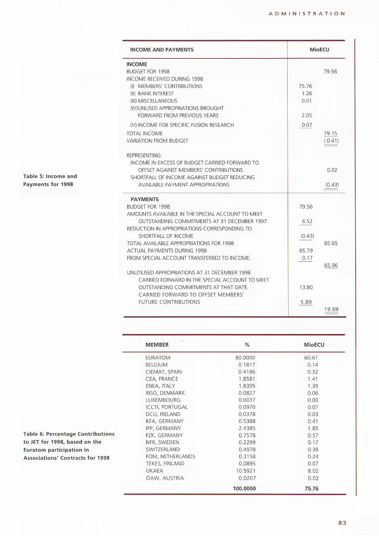
A D M I N I S T R A T I O N
INCOME AND PAYMENTS
Table 5: Income and Payments for 1998
MioECU
INCOME BUDGET FOR 1998 INCOME RECEIVED DURING 1998
(I) MEMBERS' CONTRIBUTIONS (II) BANK INTEREST (III) MISCELLANEOUS (IV)UNUSED APPROPRIATIONS BROUGHT
FORWARD FROM PREVIOUS YEARS
(V) INCOME FOR SPECIFIC FUSION RESEARCH TOTAL INCOME VARIATION FROM BUDGET
REPRESENTING: INCOME IN EXCESS OF BUDGET CARRIED FORWARD TO
OFFSET AGAINST MEMBERS' CONTRIBUTIONS SHORTFALL OF INCOME AGAINST BUDGET REDUCING
AVAILABLE PAYMENT APPROPRIATIONS
PAYMENTS BUDGET FOR 1998 AMOUNTS AVAILABLE IN THE SPECIAL ACCOUNT TO MEET
OUTSTANDING COMMITMENTS AT 31 DECEMBER 1997. REDUCTION IN APPROPRIATIONS CORRESPONDING TO
SHORTFALL OF INCOME TOTAL AVAILABLE APPROPRIATIONS FOR 1998 ACTUAL PAYMENTS DURING 1998 FROM SPECIAL ACCOUNT TRANSFERRED TO INCOME.
UNUTILISED APPROPRIATIONS AT 31 DECEMBER 1998 CARRIED FORWARD IN THE SPECIAL ACCOUNT TO MEET OUTSTANDING COMMITMENTS AT THAT DATE. CARRIED FORWARD TO OFFSET MEMBERS' FUTURE CONTRIBUTIONS
75.76 1.26 0.01
2.05
0.07
79.56
6.52
(0.43)
65.79 0.17
13.80
5.89
79.56
79.15 (0.41)
0.02
(0.43)
85.65
65.96
19.69
MEMBER % MioECU
Table 6: Percentage Contributions to JET for 1998, based on the Euratom participation in Associations' Contracts for 1998
EURATOM BELGIUM CIEMAT, SPAIN CEA, FRANCE ENEA, ITALY RISO, DENMARK LUXEMBOURG ICCTI, PORTUGAL DCU, IRELAND KFA, GERMANY IPP, GERMANY FZK, GERMANY NFR, SWEDEN SWITZERLAND FOM, NETHERLANDS TEKES, FINLAND UKAEA ÖAW, AUSTRIA
80.0000 0.1817 0.4186 1.8581 1.8395 0.0827 0.0037 0.0970 0.0378 0.5388 2.4385 0.7578 0.2299 0.4978 0.3158 0.0895
10.5921 0.0207
100.0000
60.61 0.14 0.32 1.41 1.39 0.06 0.00 0.07 0.03 0.41 1.85 0.57 0.17 0.38 0.24 0.07 8.02 0.02
75.76
8 3

A D M I N I S T R A T I O N
FINANCIAL TRANSACTIONS MioECU
CUMULATIVE COMMITMENTS
CUMULATIVE PAYMENTS
UNPAID COMMITMENTS
AMOUNT CARRIED FORWARD IN THE SPECIAL ACCOUNT
AMOUNT AVAILABLE FROM 1997 AND 1998 TO SET OFF
AGAINST FUTURE CONTRIBUTIONS FROM MEMBERS
1,787.5
1,764.9
22.6
13.8
6.1
Table 7: Summary of Financial Transactions at 31 December 1998
Contributions f rom Members The budget for Members ' contr ibut ions was 77.76MioECU (Table 6) funded as
fo l lows:
8 0 % f rom the general budget of the European Atomic Energy Communi ty
(Euratom);
1 0 % f rom the UK Atomic Energy Author i ty as Host Organisat ion;
1 0 % f r om members w h o have Contracts of Association w i t h Euratom in
propor t ion to the previous year's cont r ibut ion f rom Euratom towards the cost
of their Association Contracts.
Bank Interest During the year, funds are normally received on a quarterly basis in respect of
Members ' contr ibut ions and intermit tent ly for other items. Therefore, the Project
has funds not immediately required for the discharge of its commi tments ; these
funds are p lacedon deposit accounts at market interest rates. During 1998, earned
interest amounted to 1.26MioECU.
Appropriat ions f rom Earlier Years Unused payment appropr iat ions and excess income over budget of 2.05MioECU
arising in 1996 were transferred to income in 1998.
Summary Table 7 summarises the f inancial transactions of the JET Joint Undertaking as at
31 December 1998. These have yet to be audi ted. The f inal audi ted accounts wi l l
be published in due course.
Contracts Service Contracts Activity The contract activity for 1998 is summarised in Table 8. Many of the larger contracts
involved advance and retent ion payments for which bank guarantees were required
by JET. The total value of guarantees held as at 31 December 1998 was 187,100ECU.
8 4
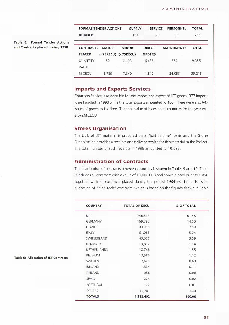
A D M I N I S T R A T I O N
Table 8: Formal Tender Actions and Contracts placed dur ing 1998
FORMAL TENDER ACTIONS SUPPLY SERVICE PERSONNEL TOTAL
NUMBER 153 29 71 253
CONTRACTS MAJOR MINOR DIRECT AMENDMENTS TOTAL
PLACED (>75KECU) (<75KECU) ORDERS
QUANTITY 52 2,103 6,636 564 9,355
VALUE
MIOECU 5.789 7.849 1.519 24.058 39.215
Imports and Exports Services Contracts Service is responsible for the import and export of JET goods. 377 imports
were handled in 1998 while the total exports amounted to 186. There were also 647
issues of goods to UK firms. The total value of issues to all countries for the year was
2.672MÌ0ECU.
Stores Organisation The bulk of JET material is procured on a " just in t ime " basis and the Stores
Organisation provides a receipts and delivery service for this material to the Project.
The total number of such receipts in 1998 amounted to 10,023.
Administration of Contracts The distr ibut ion of contracts between countries is shown in Tables 9 and 10. Table
9 includes all contracts w i th a value of 10,000 ECU and above placed prior to 1984,
together w i th all contracts placed dur ing the period 1984-98. Table 10 is an
al location of "h igh - tech " contracts, which is based on the figures shown in Table
Table 9: Allocation of JET Contracts
COUNTRY
UK
GERMANY
FRANCE
ITALY
SWITZERLAND
DENMARK
NETHERLANDS
BELGIUM
SWEDEN
IRELAND
FINLAND
SPAIN
PORTUGAL
OTHERS
TOTALS
TOTAL OF KECU
746,594
169,792
93,315
61,085
43,526
13,812
18,746
13,580
7,623
1,334
958
224
122
41,781
1,212,492
% OF TOTAL
61.58
14.00
7.69
5.04
3.59
1.14
1.55
1.12
0.63
0.11
0.08
0.02
0.01
3.44
100.00
8 5
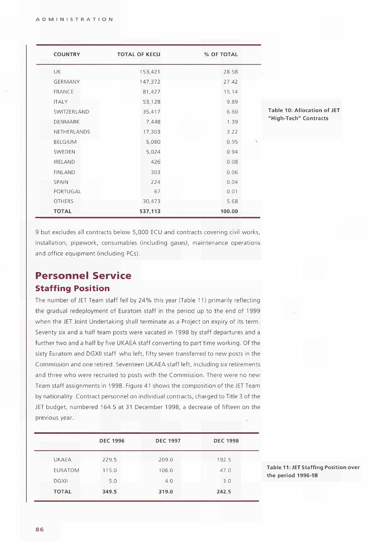
A D M I N I S T R A T I O N
COUNTRY
UK
GERMANY
FRANCE
ITALY
SWITZERLAND
DENMARK
NETHERLANDS
BELGIUM
SWEDEN
IRELAND
FINLAND
SPAIN
PORTUGAL
OTHERS
TOTAL
TOTAL OF KECU
153,421
147,372
81,427
53,128
35,417
7,448
17,303
5,080
5,024
426
303
224
67
30,473
537,113
% OF TOTAL
28.58
27.42
15.14
9.89
6.60
1.39
3.22
0.95
0.94
0.08
0.06
0.04
0.01
5.68
100.00
9 but excludes all contracts below 5,000 ECU and contracts covering civil works,
instal lat ion, p ipework, consumables (including gases), maintenance operations
and off ice equipment ( including PCs).
Personnel Service Staffing Position The number of JET Team staff fell by 2 4 % this year (Table 11 ) primarily reflecting
the gradual redeployment of Euratom staff in the period up to the end of 1999
when the JET Joint Undertaking shall terminate as a Project on expiry of its term.
Seventy six and a half team posts were vacated in 1998 by staff departures and a
fur ther t w o and a half by five UKAEA staff convert ing to part t ime work ing . Of the
sixty Euratom and DGXII staff who left, f i f ty seven transferred to new posts in the
Commission and one retired. Seventeen UKAEA staff left, including six retirements
and three w h o were recruited to posts w i th the Commission. There were no new
Team staff assignments in 1998. Figure 41 shows the composit ion of the JET Team
by nationality. Contract personnel on individual contracts, charged to Title 3 of the
JET budget, numbered 164.5 at 31 December 1998, a decrease of f i f teen on the
previous year.
Table 10: Al location of JET "High-Tech" Contracts
UKAEA
EURATOM
DGXII
TOTAL
DEC 1996
229.5
115.0
5.0
349.5
DEC 1997
209.0
106.0
4 0
319.0
DEC 1998
192.5
47.0
3.0
242.5
Table 11: JET Staff ing Position over the period 1996-98
8 6
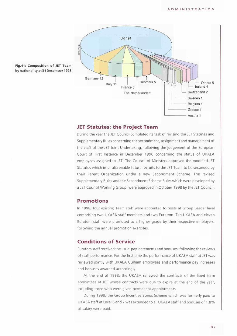
A D M I N I S T R A T I O N
Fig.41: Composition of JET Team by nationality at 31 December 1998
Germany 12 Italy 11
France 8 The Netherlands 5
Others 5
Greece 1 Austria 1
JET Statutes: the Project Team During the year the JET Council completed its task of revising the JET Statutes and
Supplementary Rules concerning the secondment, assignment and management of
the staff of the JET Joint Undertaking, following the judgement of the European
Court of First Instance in December 1996 concerning the status of UKAEA
employees assigned to JET. The Council of Ministers approved the modified JET
Statutes which inter alia enable future recruits to the JET Team to be seconded by
their Parent Organization under a new Secondment Scheme. The revised
Supplementary Rules and the Secondment Scheme Rules which were developed by
a JET Council Working Group, were approved in October 1998 by the JET Council.
Promotions In 1998, four existing Team staff were appointed to posts at Group Leader level
comprising two UKAEA staff members and two Euratom. Ten UKAEA and eleven
Euratom staff were promoted to a higher grade by their respective employers,
following the annual promotion exercises.
Conditions of Service Euratom staff received the usual pay increments and bonuses, following the reviews
of staff performance. For the first time the performance of UKAEA staff at JET was
reviewed jointly with UKAEA Culham employees and performance pay increases
and bonuses awarded accordingly.
At the end of 1998, the UKAEA renewed the contracts of the fixed term
appointees at JET whose contracts were due to expire at the end of the year,
including three who were given permanent appointments.
During 1998, the Group Incentive Bonus Scheme which was formerly paid to
UKAEA staff at Level 6 and 7 was extended to all UKAEA staff and bonuses of 1.8%
of salary were paid.
S 7

A D M I N I S T R A T I O N
JET has reviewed its working arrangements and documentation in the light of
the UK Working Time Regulations and has implemented a number of measures to
ensure that JET's arrangements are compliant. JET has also updated and renewed
its registration under the UK Data Protection Act to ensure that personal data
continuing to be held during the winding up period is properly registered.
The UKAEA Retention of Experience Allowance was paid to all 197 UKAEA staff
in post on 31 December 1998, at a cost of 1.27MioECU.
Staff Relations At the beginning of the year there were several meetings between members of the
JET Management and the Staff Representatives Committee. Subjects discussed
included the JET budget and programme to the end of 1999, the Project's future
thereafter, the working pattern for JET operations in 1998 and Sunday working.
Following difficulties in securing nominations for the Staff Representatives
Committee, in May 1998 the staff decided not to elect an SRC.
The JET UKAEA Team Staff dispute concerning the status of the UKAEA staff
assigned to JET continued during the year, with cases proceeding through the
European Court of First Instance.
In 1994, the European Parliament formally voted to make available from the
Community budget 2MioECU for disbursement to UKAEA staff assigned to JET. In
October 1997 the Secretary of State for Social Security turned down the UKAEA's
appeal against the UK Department of Social Security's ruling that there was a
liability for National Insurance contributions associated with this payment. In
October 1998 the statement of grounds for this decision was formally notified to
the UKAEA and JET and was not contested further, but the issue of whether the
employer's NI contributions owing to the Contributions Agency could be taken
from the original 2MioECU remained unclear. Payment was made from JET funds
as an interim measure, with JET Council agreement, while further legal advice was
sought on the status of the 2MioECU, 10.2% of which had been witheid from the
initial disbursements in 1994.
JET supports social activities among the staff by subsidising events and
activities. The Social Sports and Cultural Committee was awarded £18,300 in 1998
to allocate to staff activities and clubs.
Assigned Associate Staff The Associations provided a total of 27.7 man-years of effort to JET during 1998.
Tables 12 and 13 show contributions made by the Associations in 1997 - 8 and the
distribution of Assigned Associate Staff within the Project.
Consultants Two consultants contributed 66 man-days of scientific/technical support work to the
Project.
8 8
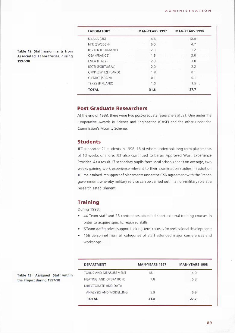
A D M I N I S T R A T I O N
Table 12: Staff assignments from Associated Laboratories during 1997-98
LABORATORY MAN-YEARS 1997 MAN-YEARS 1998
UKAEA (UK)
NFR (SWEDEN)
IPP/KFK (GERMANY)
CEA (FRANCE)
ENEA (ITALY)
ICCTI (PORTUGAL)
CRPP (SWITZERLAND)
CIEMAT (SPAIN)
TEKES (FINLAND)
TOTAL
14.8
6.0
2.3
1.5
2.3
2.0
1.8
0.1
1.0
31.8
12.9
4.7
1.2
2.0
3.0
2.2
0.1
0.1
1.5
27.7
Post Graduate Researchers At the end of 1998, there were two post-graduate researchers at JET. One under the
Cooperative Awards in Science and Engineering (CASE) and the other under the
Commission's Mobility Scheme.
Students JET supported 21 students in 1998, 18 of whom undertook long term placements
of 13 weeks or more. JET also continued to be an Approved Work Experience
Provider. As a result 17 secondary pupils f rom local schools spent on average, two
weeks gaining work experience relevant to their examination studies. In addit ion
JET maintained its support of placements under the C SN agreement wi th the French
government, whereby military service can be carried out in a non-military role at a
research establishment.
Training During 1998:
• 44 Team staff and 28 contractors attended short external training courses in
order to acquire specific required skills;
• 6 Team staff received support for long-term courses for professional development;
• 156 personnel f rom all categories of staff attended major conferences and
workshops.
Table 13: Assigned Staff within the Project during 1997-98
DEPARTMENT MAN-YEARS 1997
TORUS AND MEASUREMENT
HEATING AND OPERATIONS
DIRECTORATE AND DATA
ANALYSIS AND MODELLING
TOTAL
18.1
7.8
5.9
31.8
MAN-YEARS 1998
14.0
6.8
6.9
27.7
8 9
A D M I N I S T R A T I O N
Approximately 75 Team staff received language tuition in French, German and
Italian. 15 candidates sat the London Chamber of Commerce and Industry
examinations in the relevant language.
Press and Public Relations In 1998 it was important to maintain the good level of public visibility that JET had
achieved during the DTE1 experiments in 1997. The Remote Tile Exchange (RTE)
provided an opportunity for maintaining a reasonable level of input to science
journalists. The RTE was covered in a new video that has proven extremely popular
called "Reaching Ahead, A Man-Machine System at JET". There was also a
successful press visit to see the work as it proceeded. Subsequently, there was
considerable TV coverage, including an episode of BBC TV's "Tomorrow's World"
centred around several reports from JET, and including an interview with the
Director enabling him to state his confidence in the future of fusion as a power
source.
A new public relations venture started at the SOFT Conference in Marseille,
France in September and was followed up at the IAEA Conference in Yokohama,
Japan in October. This was an exhibit entitled "25 Years of JET" giving a detailed
account of the scientific and technical history of JET. In addition the travelling local
exhibition continued its tour of the Oxfordshire County Museums receiving a
further 13,000 visitors by the end of the year.
Exhibitions and videos are useful and powerful public relations tools but nothing
is better than a visit to see JET and to feel the enthusiasm and commitment of the
staff. In 1998, despite resource limitations, over 1,200 people visited the site.
These included three UK MPs (Norman Baker, Michael Heseltine and Andrew
Stunnell), one UK MEP (Gordon Adam), delegations from the Finnish and Dutch
Nuclear Societies and M. René Pellai, Haut Commissionaire of the CEA.
Publications Group The Publications Group provides a Graphics, Phototypesetting, Photographic and
Reprographics service for the Project. The Group is led by the Publications Officer,
who is also responsible for the clearance, production and distribution of all JET
documents. In addition, the Group arranges attendance at major international
Conferences, and prepares posters for these Conferences and Meetings.
Conferences JET provided contributions to a number of major meetings, as follows:
• 13th International Conference on Plasma Surface Interactions, San Diego, USA
(May 1998) (5 Invited Papers and 11 Posters);
• 25th European Physical Society Conference on Plasma Physics and Controlled
Fusion, Prague, Czechoslovakia (June 1998) (2 Invited Papers and 33 Posters);
9 0
A D M I N I S T R A T I O N
• 20th Symposium on Fusion Technology, Marseilles, France (September 1998)
(2 Invited Papers and 26 Posters);
• 17th IAEA Fusion Energy Conference, Yokohama, Japan (October 1998)
(11 Invited Papers and 14 Posters); and
• 40th Annual Meeting of the American Physical Society - Division of Plasma
Physics, New Orleans, USA (November 1998) (1 Invited Paper and 4 Posters).
In total, the Group prepared 129 Papers and 98 Posters for presentations to about
twenty different Conferences throughout the world. Arrangements were also made by
the Group for 100 participants to attend these major meetings during the year.
Publications The Publications Office is responsible for the clearance and production of all JET
presentations (including Journal Papers, Reports, Conference Papers, Poster
Contributions, Lectures, etc). Throughout 1998, over 216 publications were cleared
for external presentation.
During the year, 253 documents were published from the Project and the full
list is included as an Appendix to the 1998 JET Progress Report. This total included
11 JET Reports, 89 JET Preprints, 6 JET Internal Reports and 6 JET Divisional Notes.
All these documents are produced and disseminated by the Group on a wide
international distribution. In addition, 101 papers were published in scientific
Journals.
In total, the Group produced 4934 new illustrations and figures and took 2400
new photographs for publications and other disseminated material during 1998.
9 1
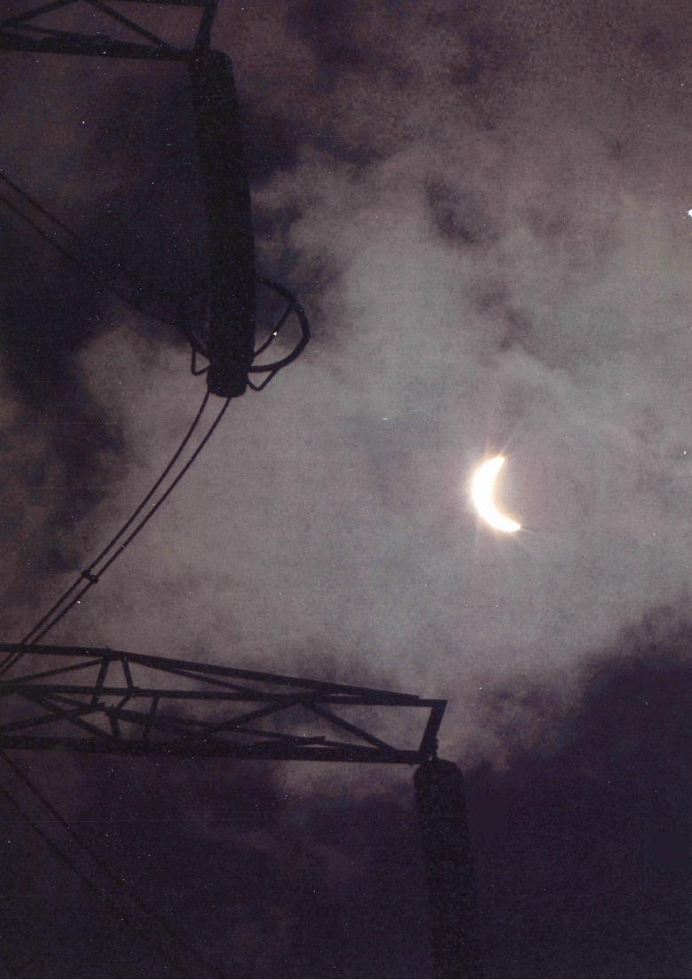
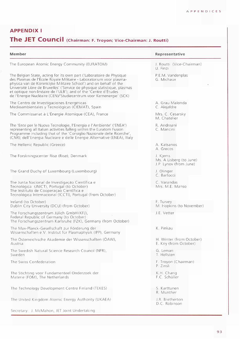
A P P E N D I C E S
A P P E N D I X I
T h e J E T C O U n c i l ( C h a i r m a n : F. T r o y o n ; V i c e C h a i r m a n : J. R o u t t i )
Member Representative
The European Atomic Energy Community (EURATOM)
The Belgian State, acting for its own part ('Laboratoire de Physique des Plasmas de l'École Royale Militaire Laboratorium voor plasmaphysica van de Koninklijke Militaire School') and on behalf of the Université Libre de Bruxelles' ('Service de physique statistique, plasmas et optique nonlinéaire de l'ULB'); and of the 'Centre d'Études de l'Energie Nucléaire (CENV'Studiecentrum voor Kernenergie' (SCK)
The Centro de Investigaciones Energéticas Medioambientales y Tecnológicas (CIEMAT), Spain
The Commissariat à L'Énergie Atomique (CEA), France
The 'Ente per le Nuova Tecnologie, l'Energia e l'Ambiente' ('ENEA') representing all Italian activities falling within the Euratom Fusion Programme including that of the 'Consiglio Nazionale delle Ricerche', (CNR); dell'Energia Nucleare e delle Energie Alternative (ENEA), Italy
The Hellenic Republic (Greece)
The Forskningscenter Risø (Risø), Denmark
The Grand Duchy of Luxembourg (Luxembourg)
The Junta Nacional de Investigação Científica e Tecnológica (JNICT), Portugal (to October) The Instituto de Cooperação Científica e Tecnològica Internacional (ICCTI), Portugal (from October)
Ireland (to October) Dublin City University (DCU) (from October)
The Forschungszentrum Jülich GmbH(KFJ), Federal Republic of Germany (to October) The Forschungszentrum Karlsruhe (FZK), Germany (from October)
The MaxPlanckGesellschaft zur Förderung der Wissenschaften e.V. Institut für Plasmaphysik (IPP), Germany
The Österreichische Akademie der Wissenschaften (ÖAW), Austria
The Swedish Natural Science Research Council (NFR), Sweden
The Swiss Confederation
The Stichting voor Fundamenteel Onderzoek der Materie (FOM), The Netherlands
J. Routti (ViceChairman) U. Finzi
P.E.M. Vandenpias G. Michaux
Α. Grau Malonda C. Alejaldre
Mrs. C. Cesarsky M. Chateller
R. Andreani C. Mancini
A. Katsanos A. Grecos
J. Kjems Ms. A Lisberg (to June) J.P. Lynov (from June)
J. Ollnger C. Bartocci
C. Varandas Mrs. M.E. Manso
F. Turvey M. Hopkins (to November)
J.E. Vetter
Κ. Pinkau
Η. Winter (from October) E. Kny (from October)
G. Leman T. Hellsten
F. Troyon (Chairman) P. Zinsli
K.H. Chang F.C. Schüller
The Technology Development Centre Finland (TEKES)
The United Kingdom Atomic Energy Authority (UKAEA)
Secretary: J. McMahon, JET Joint Undertaking
S. Karttunen R. Munther
J.R. Bretherton D.C. Robinson
9 3
A P P E N D I C E S
APPENDIX M
T H e J E T E x e c u t i v e C o m m i t t e e (Chairman: G. Leman; ViceChairman: JP. Rager)
Member Representative
The European Atomic Energy Community (EURATOM)
The Belgian State, acting for its own part ('Laboratoire de Physique des Plasmas de l'École Royale Militaire Laboratorium voor plasmaphysica van de Koninklijke Militaire School') and on behalf of the Université Libre de Bruxelles' ('Service de physique statistique, plasmas et optique nonlinéaire de l'ULB'); and of the 'Centre d'Études de l'Energie Nucléaire (CEN)/'Studiecentrum voor Kernenergie' (SCK)
The Centro de Investigaciones Energéticas Medioambientales y Tecnológicas (CIEMAT), Spain
The Commissariat à L'Énergie Atomique (CEA), France
The 'Ente per le Nuova Tecnologie, l'Energia e l'Ambiente' ('ENEA') representing all Italian activities falling within the Euratom Fusion Programme including that of the 'Consiglio Nazionale delle Ricerche', (CNR); dell'Energia Nucleare e delle Energie Alternative (ENEA), Italy
The Hellenic Republic (Greece)
The Forskningscenter Risø (Risø), Denmark
The Grand Duchy of Luxembourg (Luxembourg)
The Junta Nacional de Investigação Científica e
Tecnológica (JNICT), Portugal (to October) The Instituto de Cooperação Científica e Tecnológica Internacional (ICCTI), Portugal (from October) Ireland (to October) Dublin City University (DCU) (from October)
The Forschungszentrum Jülich GmbH(KFJ), Federal Republic of Germany (to October) The Forschungszentrum Karlsruhe (FZK), Germany (from October)
The MaxPlanckGesellschaft zur Förderung der Wissenschaften e.V. Institut für Plasmaphysik (IPP), Germany
The Österreichische Akademie der Wissenschaften (ÖAW), Austria
The Swedish Natural Science Research Council (NFR),
The Swiss Confederation
The Stichting voor Fundamenteel Onderzoek der Materie (FOM), The Netherlands
The Technology Development Centre Finland (TEKES)
The United Kingdom Atomic Energy Authority (UKAEA)
Secretary: J. McMahon, JET Joint Undertaking
JP. Rager (ViceChairman) U. Finzi
R. Vanhaelewyn P.E.M. Vandenpias
F. Mañero (to January) Α. Grau Malonda E. Ascasibar (from January)
Mrs. P. Livanos B. Goudal (to July) B. Franel (from July)
A. Coletti F. Pecorella
N. Chrysochoides
Mrs. L. Grønberg V.O.Jensen
C. Bartocci M. Hoffman
J. da Costa Cabral F. Serra
F. Turvey Ms. S. Fahy
U. Nobbe (to May)
A. Kurz (from May)
Mrs. I. ZilkerKramer (to October) Mrs. S. Agnoli (from October)
G. Leman (Chairman) L. Gidefeldt
M. Tran S. Berthet
Α. Verhoeven
R. Salomaa R. Munther
F. Briscoe M. Cox
9 4
A P P E N D I C E S
APPENDIX III
T h e JET S c i e n t i f i c C O U n c i l (Chairman: K. Lackner)
Members appointed by the JET Council
K. Lackner (Chairman)
EURATOMIPP Association
MaxPlanckInstitut für Plasmaphysik
Boltzmannstraße 2
D85748 Garching bei München
Germany
C. Alejaldre
Centro de Investigaciones Energéticas
Medioambientales y Tecnológicas (CIEMAT)
Avenida Complutense 22
E28040 Madrid 3, Spain
Η. Bruhns
DGXII, European Commission
200, Rue de la Loi
B1049 Brussels, Belgium
M. Gasparotto
EURATOMENEA Association
ENEA Centro di Frascati
Casella Postale 65
I00044 Frascati/Roma, Italy
A. Grosman
EURATOMCEA Association
Département de Recherches sur la Fusion Contrôlée
Centre d'Études Nucléaires de Cadarache
Boîte Postale No.1
F13108 St. Paul lez Durance, France
T. Hellsten
EURATOMNFR Association
Royal Institute of Technology
Alfvén Laboratory
Department of Fusion Plasma Physics
S10044 Stockholm, Sweden
F. Hofmann
EURATOMSUISSE Association
Centre de Recherches en Physique des Plasmas
Ecole Polytechnique Fédérale
de Lausanne
CH1015 Lausanne, Switzerland
D. Moreau
EURATOMCEA Association
Département de Recherches sur la Fusion Contrôlée
Centre d'Études Nucléaires de Cadarache
Boîte Postale No.1
F13108 St. Paul lez Durance, France
Staff Secretary: M.L. Watkins, JET Joint Undertaking
A.W. Morris (Honorary Secretary)
EURATOMUKAEA Association
UKAEA Government Division, Fusion
Culham Science and Technology Centre
Abingdon, Oxfordshire, 0X14 3DB
United Kingdom
D.C. Robinson, FRS
EURATOMUKAEA Association
UKAEA Government Division, Fusion
Culham Science and Technology Centre
Abingdon, Oxfordshire, 0X14 3DB
United Kingdom
F. Romanelli
EURATOMENEA Association
ENEA Centro di Frascati
Casella Postale 65
I00044 Frascati/Roma, Italy
E. Salpietro
NET Team
MaxPlanckInstitut für Plasmaphysik
Boltzmannstraße 2
D85748 Garching bei München
Germany
F.C. Schüller
EURATOMFOM Association
FOM Instituut voor Plasmafysica 'Rijnhuizen'
Postbus 1207 Edisonbaan 14
NL3430 BE Nieuwegein, The Netherlands
F. Wagner
EURATOMIPP Association
MaxPlanck Institut für Plasmaphysik
Boltzmannstraße 2
D85748 Garching bei München
Germany
R. Weynants
EURATOMEB:BS Association
Laboratoire de Physique des Plasmas/
Laboratorium voor Plasmafysica
Ecole Royale Militaire/Koninklijke Militaire School
Avenue de la Renaissancelaan, 30
B1040 Brussels, Belgium
G. Wolf
EURATOMKFA Association
Forschungszentrum Jülich GmbH
Institut für Plasmaphysik, Postfach 1913
D52425 Jülich 1,
Germany
9 5