iwb guide - iwb aircraft weight & balance - aviation acronyms
TRANSCRIPT
IWB Guide
IWB Load Control application © 2017, Author Vladimir Zivkovic 8/16/2014
1
TTTaaabbbllleee ooofff CCCooonnnttteeennntttsss INTRODUCTION ................................................................................................................................... 2 INTRODUCTION
WORKING SCREENS ............................................................................................................................ 2 WORKING SCREENS
1. EZFW - ESTIMATING ZERO FUEL WEIGHT .............................................................................................................. 2 1. EZFW - ESTIMATING ZERO FUEL WEIGHT
TRIM TABLE ................................................................................................................................................................................................................. 5 ITL GRAPHIC DIAGRAM ............................................................................................................................................................................................. 5 TERMS AND DEFINITIONS ............................................................................................................................................................................................ 8
2. P1 – PLANNING EDP - LOADSHEET ............................................................................................................................. 9 2. P1 – PLANNING EDP - LOADSHEET
P1 - L O A D S H E E T P L A N N I N G enter following figures: ................................................................................................................................... 10 P1
BALANCE AND SEATING CONDITIONS .................................................................................................................................................................. 11 COMPARISON OF ESTIMATING AND ACTUAL FIGURES ......................................................................................................................................... 11 STRETCHER INSTALLED (UNMANIFESTED) ............................................................................................................................................................. 12 SOC - SEATS OCCUPIED BY BAGGAGE, CARGO. ...................................................................................................................................................... 12 SI – SUPPLEMENTARY INFORMATION ...................................................................................................................................................................... 12
3. LDI - LOADING DISTRIBUTION INSTRUCTIONS ........................................................................................................ 13 3. LDI - LOADING DISTRIBUTION INSTRUCTIONS
OFFLOAD - ONLOAD PLANNING TABLE ................................................................................................................................................................... 13 EST. LOADING INSTRUCTION .................................................................................................................................................................................... 14 LOADING REPORT ....................................................................................................................................................................................................... 15 SI – SUPPLEMENTARY INFORMATION ...................................................................................................................................................................... 15
4. LIR1 – LOADING INSTRUCTION REPORT ................................................................................................................... 16 LIR1 – LOADING INSTRUCTION REPORT
DESCRIPTION OF LIR1 is self - explanatory ................................................................................................................................................................... 16
5. LIR2 – LOADING INSTRUCTION REPORT THIS IS AN EXAMPLE ONLY WITHOUT COMPLETE EXPLANATION ........................ 18 LIR2 – LOADING INSTRUCTION REPORT
6. STAB & CENTRE OF GRAVITY MAC % ........................................................................................................................ 19 6. STAB & CENTRE OF GRAVITY MAC %
7. BAL – BALANCE CONTROL TABLE ............................................................................................................................. 20 7. BAL – BALANCE CONTROL TABLE
8. LDS – FINAL EDP LOADSHEET ..................................................................................................................................... 21 8. LDS – FINAL EDP LOADSHEET
STANDARD EDP LOADSHEET ................................................................................................................................................................................... 22 SUMMARY OF WARNING INDICATORS .................................................................................................................................................................... 23 SUMMARY OF WARNING INDICATORS
IWB Guide
IWB Load Control application © 2017, Author Vladimir Zivkovic 8/16/2014
2
IINNTTRROODDUUCCTTIIOONN This guide explains Weight & Balance project system through three steps:
a) Working screens EZFW, P1, LDI and STAB b) Display Mask LIR1, LIR2 and LDS. Documents ready for printing. c) Control screen BAL
WWOORRKKIINNGG SSCCRREEEENNSS 1.1. EZFW - ESTIMATING ZERO FUEL WEIGHT EZFW - ESTIMATING ZERO FUEL WEIGHT
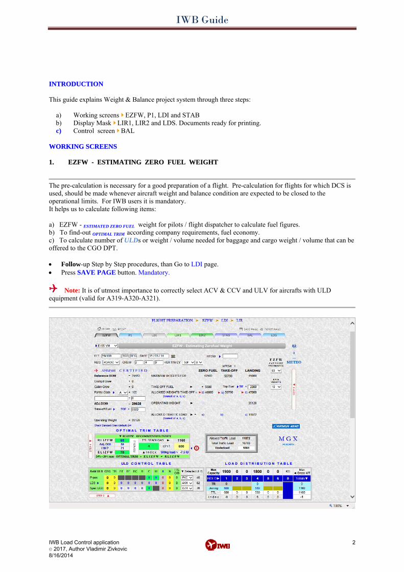
The pre-calculation is necessary for a good preparation of a flight. Pre-calculation for flights for which DCS is used, should be made whenever aircraft weight and balance condition are expected to be closed to the operational limits. For IWB users it is mandatory. It helps us to calculate following items: a) EZFW - ESTIMATED ZERO FUEL weight for pilots / flight dispatcher to calculate fuel figures. b) To find-out OPTIMAL TRIM according company requirements, fuel economy. c) To calculate number of ULDs or weight / volume needed for baggage and cargo weight / volume that can be offered to the CGO DPT. • Follow-up Step by Step procedures, than Go to LDI page. • Press SAVE PAGE button. Mandatory.
Note: It is of utmost importance to correctly select ACV & CCV and ULV for aircrafts with ULD equipment (valid for A319-A320-A321).
IWB Guide
IWB Load Control application © 2017, Author Vladimir Zivkovic 8/16/2014
3
STEP 1 • Select ACV - Aircraft Configuration & Version. • Select CCV - Cabin configuration version and ULV - Unit Load version, if applicable. • Select REG - Aircraft Registration. • Enter Flight Origin Destination Date. • Enter RTOW-Regulated (Operational) Take-off Weight, if at departure airport operations restriction is
imposed. • Select average passenger and baggage weight for EZFW, 2nd option is default.
Enter number of C & Y passenger, their weight is calculated based on aavveerraaggee wweeiigghhtt ooff PPAAXX 8833kkgg oorr 7788kkgg as gender of PAX is unknown. For charter flights average weight of 75 kg is set for EZFW only. Note: IATA PAX weights are used on P1 page for LDS. For selection of BAG weights three options are available » EU-15kg » Intl.-18kg » Domestic flights – 13kg or 10kg per passenger.
Baggage weight is automatically calculated, average bag weight per PAX 10, 13, 15 or 18 kg will be applied, depending of selected option.
• Enter Cockpit and Cabin crew figures. • Enter Adjustment weight (stretcher), if any. Rmks: If NIL deadload, number 0 must be entered instead of
blank field. • Select Pantry Group Code. Verify Pantry Code on P1 page than return to EZFW page. • Enter TOF - Take-off Fuel. Optional. • Enter Trip Fuel. Optional.
STEP 2 • Enter ULD configuration into Avlb box- available number of Containers & Pallets. • Select ULD types on A/C • Enter number of used ULDs for transit load into TR box.
Note: For BULK load configuration skip STEP 2.
Legend: RLIZFW - Recommended Loading Index for ZFW. IWP - Index with Passengers (DOI + Pax Index influence). ELIZFW - Estimated Loading Index for ZFW. ACV - Aircraft Configuration / Version CCV - Cabin Configuration Version ULV - Unit Load Version IU - Index unit
Note: IWB AVIATION ABBREVIATIONS you will find on following links: http://www.internetweightbalance.com/aero.php http://www.aircraftweightbalance.com/aero.php
IWB Guide
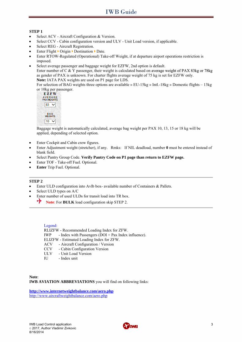
STEP 3 ACV BULK LOAD configuration. • Enter 2nd and 3rd DEST city code, if applicable. • Enter TR - transit load F/C/Y and deadload per DEST, if applicable. • Enter Joining load F / C / Y per DEST. • Enter approximate numberof PAX distribution per Zone - CABIN AREA TRIM. Apply uniform PAX
seating. • Enter BT SHORT and BT - weight of transfer baggage, if applicable.
Note: IWB system automatically calculates blue cells. • SPEC C - enter sum of un-manifested equipment - special load BEH CSU FKT BAL or EIC. • Enter booked Cargo weight. • Enter booked Mail weight. ACV with ULD configuration. • Enter number of planned LD3 containers into gray box. • Enter number of planned Pallet into green box. • Enter number of special ULDs. • Enter weight of X - empty ULD, if applicable. • Enter weight of LMC ULD change, if applicable. • N - NOFIT position option may be selected instead of X -empty ULD. Enter number of nofit ULD position
in ULD table, into N box.
STEP 4 - To find-out OPTIMAL TRIM according company requirements. OPTIMAL TRIM - FUEL ECONOMY & LOAD DISTRIBUTION TABLE • Enter TR load distribution according LDM, if applicable. • Enter approximate number of passengers per ZONE - Trim by Cabin Area.
Tips: Wrongly entered figures, overloads are indicated by RED color in the respective field.
IWB Load Control application © 2017, Author Vladimir Zivkovic 8/16/2014
4
IWB Guide
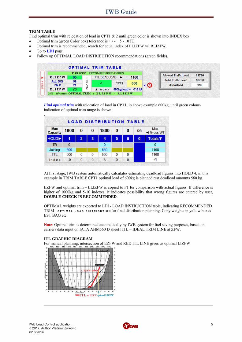
TRIM TABLE Find optimal trim with relocation of load in CPT1 & 2 until green color is shown into INDEX box. • Optimal trim (green Color box) tolerance is + / - 5 - 10 IU. • Optimal trim is recommended, search for equal index of ELIZFW vs. RLIZFW. • Go to LDI page. • Follow up OPTIMAL LOAD DISTRIBUTION recommendations (green fields).
Find optimal trim with relocation of load in CPT1, in above example 600kg, until green colour-indication of optimal trim range is shown. .
At first stage, IWB system automatically calculates estimating deadload figures into HOLD 4, in this example in TRIM TABLE CPT1 optimal load of 600kg is planned rest deadload amounts 560 kg. EZFW and optimal trim – ELIZFW is copied to P1 for comparison with actual figures. If difference is higher of 1000kg and 5-10 indexes, it indicates possibility that wrong figures are entered by user, DOUBLE CHECK IS RECOMMENDED. OPTIMAL weights are exported to LDI - LOAD INSTRUCTION table, indicating RECOMMENDED TRIM - O P T I M A L L O A D D I S T R I B U T I O N for final distribution planning. Copy weights in yellow boxes EST BAG etc. Note: Optimal trim is determined automatically by IWB system for fuel saving purposes, based on carriers data input on IATA AHM560 D sheet1 ITL – IDEAL TRIM LINE at ZFW. ITL GRAPHIC DIAGRAM For manual planning, intersection of EZFW and RED ITL LINE gives us optimal LIZFW
IWB Load Control application © 2017, Author Vladimir Zivkovic 8/16/2014
5
IWB Guide
IWB Load Control application © 2017, Author Vladimir Zivkovic 8/16/2014
6
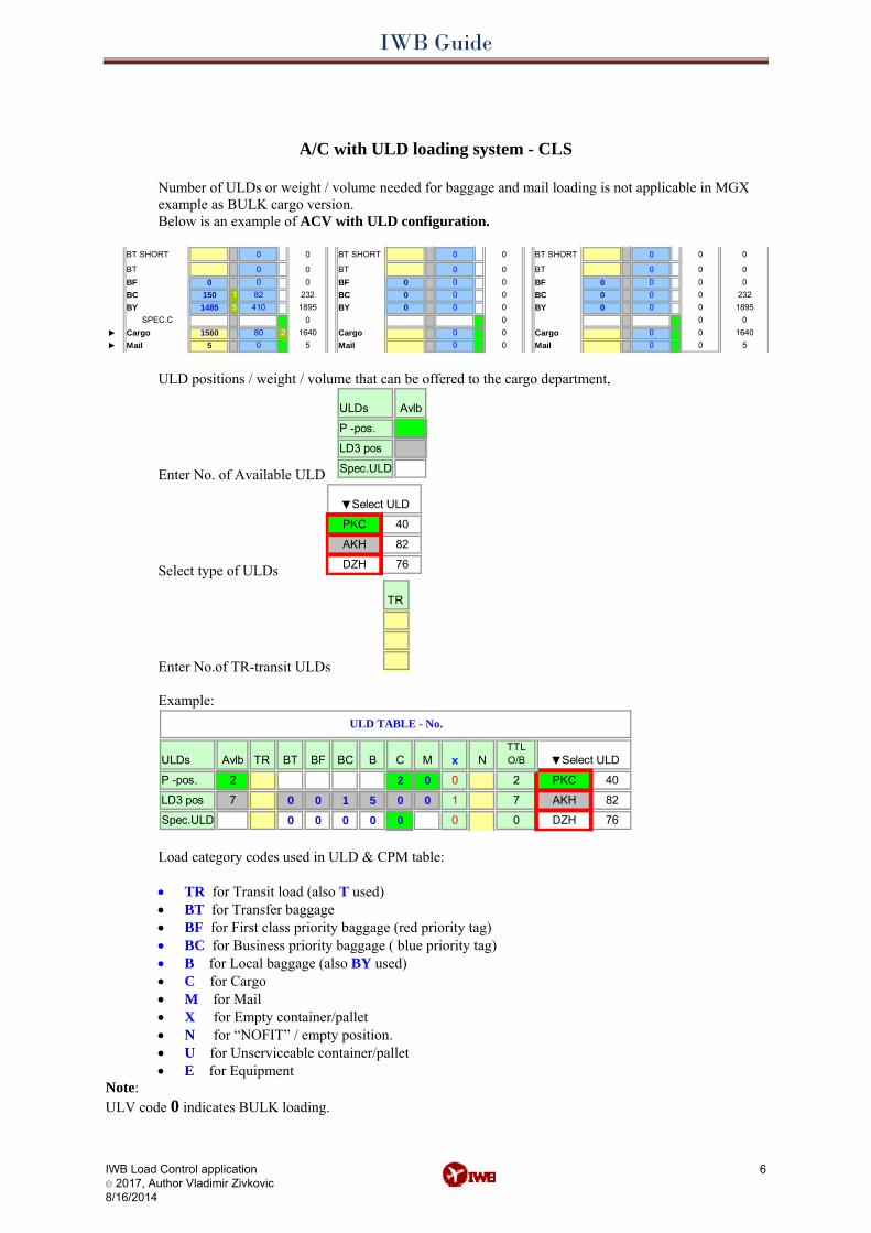
A/C with ULD loading system - CLS
Number of ULDs or weight / volume needed for baggage and mail loading is not applicable in MGX example as BULK cargo version. Below is an example of ACV with ULD configuration.
BT SHORT BT SHORT BT SHORT
BT BT BTBF BF BFBC 1 BC BCBY 5 BY BY
► 2►
1640
0
232
5
0
18950
00
00
000
0
00SPEC.C
0082410
01895232
0
0 0
Mail1560Cargo
5
0
0
0
00
15000
Cargo
1485
800
00 0
00
0Mail000
Cargo
00
0
0
0 0
0
Mail1640
5
00 0
00
0
ULD positions / weight / volume that can be offered to the cargo department,
Enter No. of Available ULD
ULDs
Spec.ULD
P -pos.
Avlb
LD3 pos
Select type of ULDs
82AKH
DZH
PKC
▼Select ULD
76
40
Enter No.of TR-transit ULDs
TR
Example:
ULDs
2
Spec.ULD
51
B CTR BT
0
7
BF BC
0 00
7
0
1
0
0 82AKH
DZH0 0
M N
PKC2P -pos.
TTL O/B ▼Select ULD
ULD TABLE - No.
Avlb x
000LD3 pos
2 0
76
40
Load category codes used in ULD & CPM table:
• TR for Transit load (also T used) • BT for Transfer baggage • BF for First class priority baggage (red priority tag) • BC for Business priority baggage ( blue priority tag) • B for Local baggage (also BY used) • C for Cargo • M for Mail • X for Empty container/pallet • N for “NOFIT” / empty position. • U for Unserviceable container/pallet • E for Equipment
Note: ULV code 0 indicates BULK loading.
IWB Guide
IWB Load Control application © 2017, Author Vladimir Zivkovic 8/16/2014
7
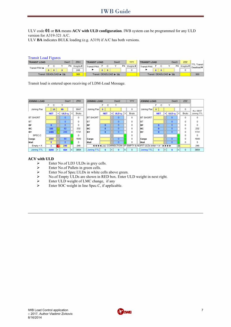
ULV code 01 or BA means ACV with ULD configuration. IWB system can be programmed for any ULD version for A319-321 A/C. ULV BA indicates BULK loading (e.g. A319) if A/C has both versions. Transit Load Figures TRANSIT LOAD TRANSIT LOAD Dest2 TRANSIT LOAD Dest3
Transit DEADLOAD ► TR
PX
300
Weights▼
0
FF C Y
0 3
Transit DEADLOAD ► TR
0Transit PAX ►
Dest1
249
Weights▼
ZRH
PX C
0 0
Y
YYY
Transit PAX ►0
Weights▼PXTransit PAX ►
F
ZZZTTL Transit Deadload▼Y
00
300
C
Transit DEADLOAD ► TR Transit load is entered upon receiving of LDM-Load Message. JOINING LOAD JOINING LOAD Dest2 JOINING LOAD
+ = + = + =
BT SHORT BT SHORT BT SHORT
BT BT BTBF BF BFBC 1 BC BCBY 3 BY BY
2
3 3
+ = + = + =
1640
0
232
5246
3854
0
17310
00
00
000
ZZZ
ALL DEST Joining TTLBruto
0
00
0
SPEC.C
10
NET
Joining Pax
F C
0082246
01731232
Dest1
246
0
ULD kg
99
0
Y
Bruto
0
Joining Pax
F
0
9047
Mail1560Cargo
5
0
FC
NET
0
ULD kg
00 0
Joining Pax 0
Joining TTL
15000
Cargo
1485
246
800
Y
0 0
NET
00
0
Joining TTL 0
0Mail0
0
0
0
0Cargo
YYY
ULD kg
C
ZRH Dest3
00
0
0
0
0
0
0
Y
x
3200Joining TTL 654
0
Empty = X
3854
Mail1640
5
0
00
◄◄◄◄LMC CORRECTION OF EMPTY & NOFIT ULDs enter + or - ►►►►
0
00
Bruto
0
0
AACCVV wwiitthh UULLDD
Enter No.of LD3 ULDs in grey cells. Enter No.of Pallets in green cells. Enter No.of Spec.ULDs in white cells above green. No.of Empty ULDs are shown in RED box. Enter ULD weight in next right. Enter ULD weight of LMC change, if any Enter SOC weight in line Spec.C, if applicable.
IWB Guide
IWB Load Control application © 2017, Author Vladimir Zivkovic 8/16/2014
8
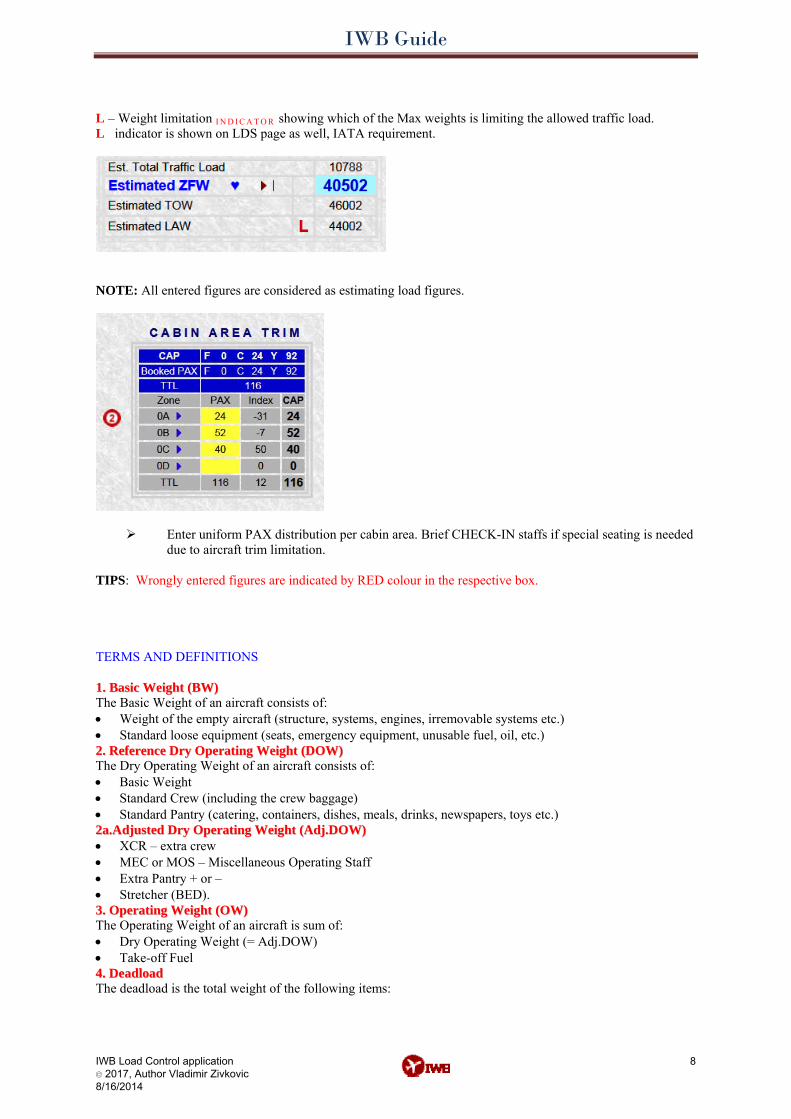
L – Weight limitation I N D I C A T O R showing which of the Max weights is limiting the allowed traffic load. L indicator is shown on LDS page as well, IATA requirement.
NOTE: All entered figures are considered as estimating load figures.
Enter uniform PAX distribution per cabin area. Brief CHECK-IN staffs if special seating is needed due to aircraft trim limitation.
TIPS: Wrongly entered figures are indicated by RED colour in the respective box. TERMS AND DEFINITIONS 11.. BBaassiicc WWeeiigghhtt ((BBWW)) The Basic Weight of an aircraft consists of: • Weight of the empty aircraft (structure, systems, engines, irremovable systems etc.) • Standard loose equipment (seats, emergency equipment, unusable fuel, oil, etc.) 22.. RReeffeerreennccee DDrryy OOppeerraattiinngg WWeeiigghhtt ((DDOOWW)) The Dry Operating Weight of an aircraft consists of: • Basic Weight • Standard Crew (including the crew baggage) • Standard Pantry (catering, containers, dishes, meals, drinks, newspapers, toys etc.) 22aa..AAddjjuusstteedd DDrryy OOppeerraattiinngg WWeeiigghhtt ((AAddjj..DDOOWW)) • XCR – extra crew • MEC or MOS – Miscellaneous Operating Staff • Extra Pantry + or – • Stretcher (BED). 33.. OOppeerraattiinngg WWeeiigghhtt ((OOWW)) The Operating Weight of an aircraft is sum of: • Dry Operating Weight (= Adj.DOW) • Take-off Fuel 44.. DDeeaaddllooaadd The deadload is the total weight of the following items:
IWB Guide
IWB Load Control application © 2017, Author Vladimir Zivkovic 8/16/2014
9
• Passenger’s checked baggage (BAG, or BT, BF, BC, BY). Average weight per baggage (13kg) is applied in ZFW calculation.
• Cargo (CGO, or C). Manifested Cargo weight* is used for calculation EZFW.ref.BDI. • Mail (M) * • If loaded in Unit Load Devices, the weight of the ULDs is also added to the deadload. 55.. AAlllloowweedd TTrraaffffiicc LLooaadd The Allowed Traffic Load is the maximum load capacity (weight) that may be accepted on a flight. It depends on the structural and operational maximum weights of an aircraft and also depends on the quantity of fuel needed for a flight. 66.. TToottaall TTrraaffffiicc LLooaadd ((aaccttuuaall ttrraaffffiicc llooaadd)) The Total Traffic Load consists of: • Passengers (PAX).
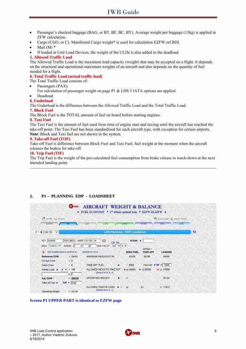
For calculation of passenger weight on page P1 & LDS 3 IATA options are applied. • Deadload 66.. UUnnddeerrllooaadd The Underload is the difference between the Allowed Traffic Load and the Total Traffic Load. 77.. BBlloocckk FFuueell The Block Fuel is the TOTAL amount of fuel on board before starting engines. 88.. TTaaxxii FFuueell The Taxi Fuel is the amount of fuel used from time of engine start and taxiing until the aircraft has reached the take-off point. The Taxi Fuel has been standardized for each aircraft type, with exception for certain airports. Note: Block and Taxi fuel are not shown in the system. 99.. TTaakkee--ooffff FFuueell ((TTOOFF)) Take-off Fuel is difference between Block Fuel and Taxi Fuel, fuel weight at the moment when the aircraft releases the brakes for take-off. 1100.. TTrriipp FFuueell ((TTIIFF)) The Trip Fuel is the weight of the pre-calculated fuel consumption from brake release to touch-down at the next intended landing point.
2.2. P1 – PLANNING EDP - LOADSHEET P1 – PLANNING EDP - LOADSHEET
Screen P1 UPPER PART is identical to EZFW page
IWB Guide
IWB Load Control application © 2017, Author Vladimir Zivkovic 8/16/2014
10
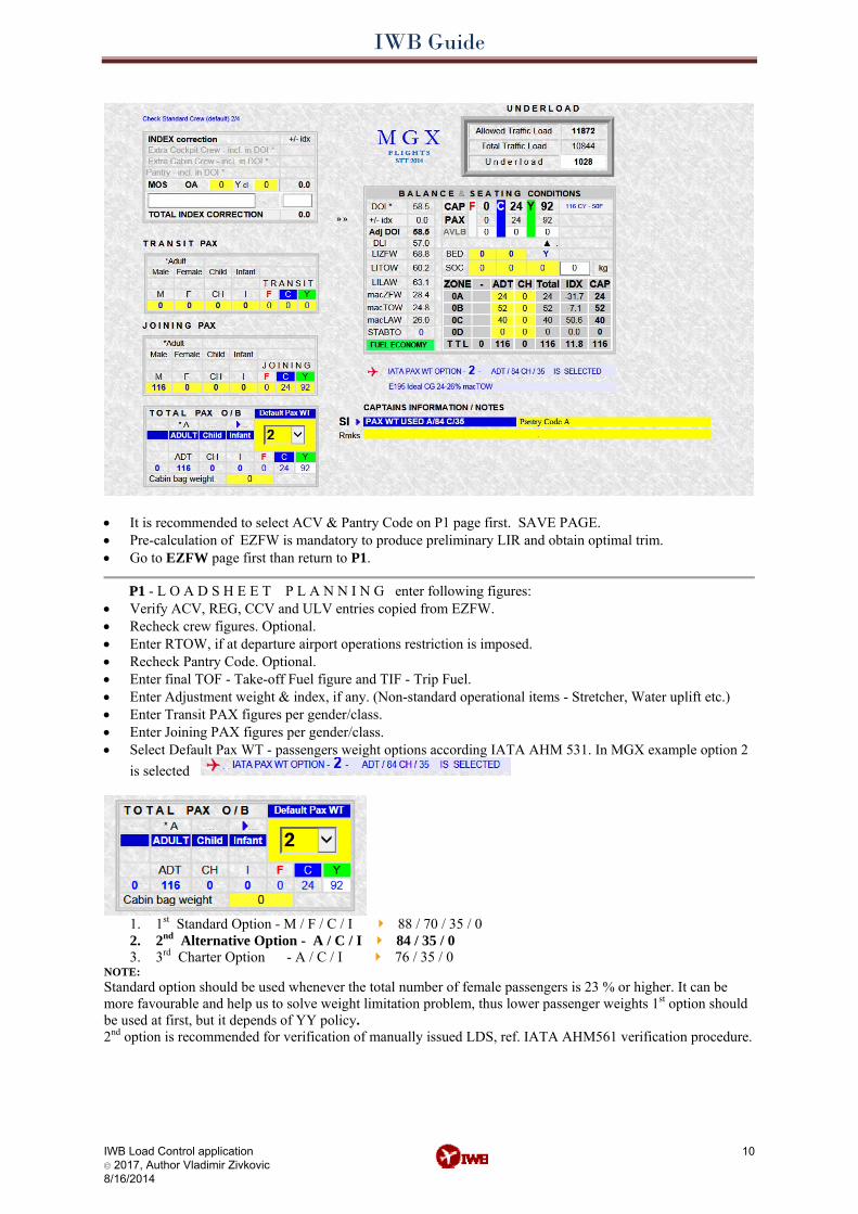
• It is recommended to select ACV & Pantry Code on P1 page first. SAVE PAGE. • Pre-calculation of EZFW is mandatory to produce preliminary LIR and obtain optimal trim. • Go to EZFW page first than return to P1.
PP11 - L O A D S H E E T P L A N N I N G enter following figures: • Verify ACV, REG, CCV and ULV entries copied from EZFW. • Recheck crew figures. Optional. • Enter RTOW, if at departure airport operations restriction is imposed. • Recheck Pantry Code. Optional. • Enter final TOF - Take-off Fuel figure and TIF - Trip Fuel. • Enter Adjustment weight & index, if any. (Non-standard operational items - Stretcher, Water uplift etc.) • Enter Transit PAX figures per gender/class. • Enter Joining PAX figures per gender/class. • Select Default Pax WT - passengers weight options according IATA AHM 531. In MGX example option 2
is selected
1. 1st Standard Option - M / F / C / I 88 / 70 / 35 / 0 2. 2nd Alternative Option - A / C / I 84 / 35 / 0 3. 3rd Charter Option - A / C / I 76 / 35 / 0
NOTE: Standard option should be used whenever the total number of female passengers is 23 % or higher. It can be more favourable and help us to solve weight limitation problem, thus lower passenger weights 1st option should be used at first, but it depends of YY policy. 2nd option is recommended for verification of manually issued LDS, ref. IATA AHM561 verification procedure.
IWB Guide
• Enter weight of cabin baggage, if carriers require it. CAB weight is automatically added to LDS – Passenger / Cabin Bag and CAB fields.
• Enter additional pilots Notes. (PANTRY CODE used, Capt. name, etc.) • Enter RMKS - standard AHM abbreviations for LDS. (AVI, PAD, BED, BEH, MOS, EIC . . etc.) • Enter BED figures, installed stretcher followed by the total number of seats blocked by the stretcher
arrangement and the number of PAX traveling on these seats (patient and accompanying persons i.e. BED/9/2Y). The PAX are included in the F C Y distribution.
• Enter number of SOC – seat occupied by class and fill-in the weight of SOC. SOC figures are not included in the F C Y distribution and weight is automatically added to B field in LDI.
• Enter number of PAX per Zone - Cabin Area distribution. Add SOC into F / ADT column or CH column depending of SOC weight.
• Press SAVE PAGE button. Mandatory. • Go to LDI page.
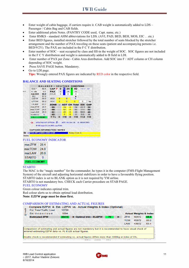
Tips: Wrongly entered PAX figures are indicated by RED color in the respective field. BALANCE AND SEATING CONDITIONS
FUEL ECONOMY INDICATOR
STABTO The MAC is the “magic number” for the commander; he types it in the computer (FMS-Flight Management System) of the aircraft and adjusting horizontal stabilizers in order to have a favourable flying position. STABTO index is set to BLANK option as it is not required by YM airline. STABTO is not mandatory box. CHECK each Carrier procedure on STAB PAGE. FUEL ECONOMY Green colour indicates optimal trim. Red colour alerts us to obtain optimal load distribution. Note: EZFW page must be done first. COMPARISON OF ESTIMATING AND ACTUAL FIGURES
IWB Load Control application © 2017, Author Vladimir Zivkovic 8/16/2014
11
IWB Guide
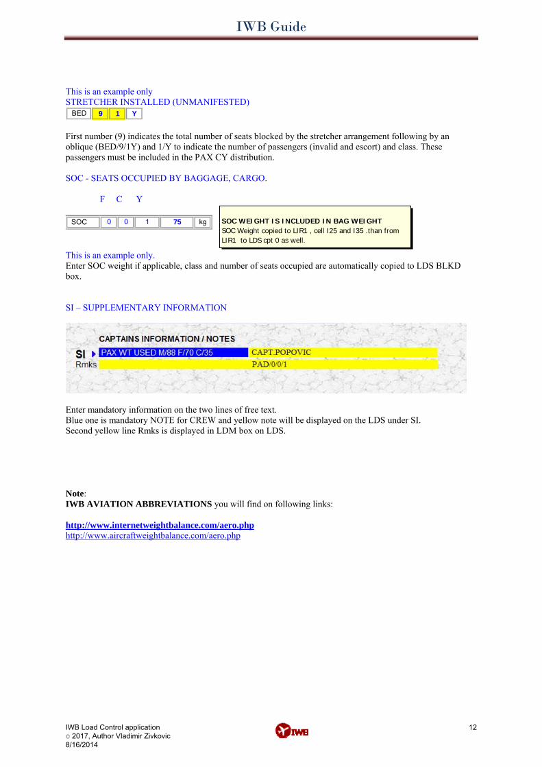
This is an example only STRETCHER INSTALLED (UNMANIFESTED)
BED 1 Y9 First number (9) indicates the total number of seats blocked by the stretcher arrangement following by an oblique (BED/9/1Y) and 1/Y to indicate the number of passengers (invalid and escort) and class. These passengers must be included in the PAX CY distribution. SOC - SEATS OCCUPIED BY BAGGAGE, CARGO. F C Y
75 kgSOC 0 0 1 SOC WEIGHT IS INCLUDED IN BAG WEIGHTSOC Weight copied to LIR1 , cell I25 and I35 .than from LIR1 to LDS cpt 0 as well.
This is an example only. Enter SOC weight if applicable, class and number of seats occupied are automatically copied to LDS BLKD box. SI – SUPPLEMENTARY INFORMATION
Enter mandatory information on the two lines of free text. Blue one is mandatory NOTE for CREW and yellow note will be displayed on the LDS under SI. Second yellow line Rmks is displayed in LDM box on LDS. Note: IWB AVIATION ABBREVIATIONS you will find on following links: http://www.internetweightbalance.com/aero.php http://www.aircraftweightbalance.com/aero.php
IWB Load Control application © 2017, Author Vladimir Zivkovic 8/16/2014
12
IWB Guide
IWB Load Control application © 2017, Author Vladimir Zivkovic 8/16/2014
13
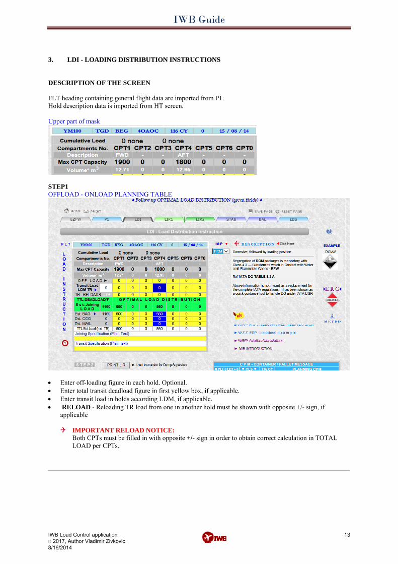
3.3. LDI - LOADING DISTRIBUTION INSTRUCTIONS LDI - LOADING DISTRIBUTION INSTRUCTIONS DESCRIPTION OF THE SCREEN FLT heading containing general flight data are imported from P1. Hold description data is imported from HT screen. Upper part of mask
STEP1 OFFLOAD - ONLOAD PLANNING TABLE
• Enter off-loading figure in each hold. Optional. • Enter total transit deadload figure in first yellow box, if applicable. • Enter transit load in holds according LDM, if applicable. • RELOAD - Reloading TR load from one in another hold must be shown with opposite +/- sign, if
applicable
IMPORTANT RELOAD NOTICE: Both CPTs must be filled in with opposite +/- sign in order to obtain correct calculation in TOTAL LOAD per CPTs.
IWB Guide
• Follow-up OPTIMAL LOAD DISTRIBUTION recommendations (green fields), imported from EZFW
page. • Enter estimating joining load (Est. BAG, Est. CGO and Est. Mail) per compartments, just copy from above
(green fields) recommendations. • Enter Joining & Transit specification, if applicable.
Note: Load in CPT4 is automatically calculated. Joining Specification (Free text) In this box enter special handling information per BAG category (BF BC BT B short, door section loading etc) and special cargo loading information. Transit Specification (Free text) Self-explanatory. This information is copied to LIR1 & LIR2.
• Go to LIR1 or LIR2 to PRINT preliminary LIR- Loading Instruction Report
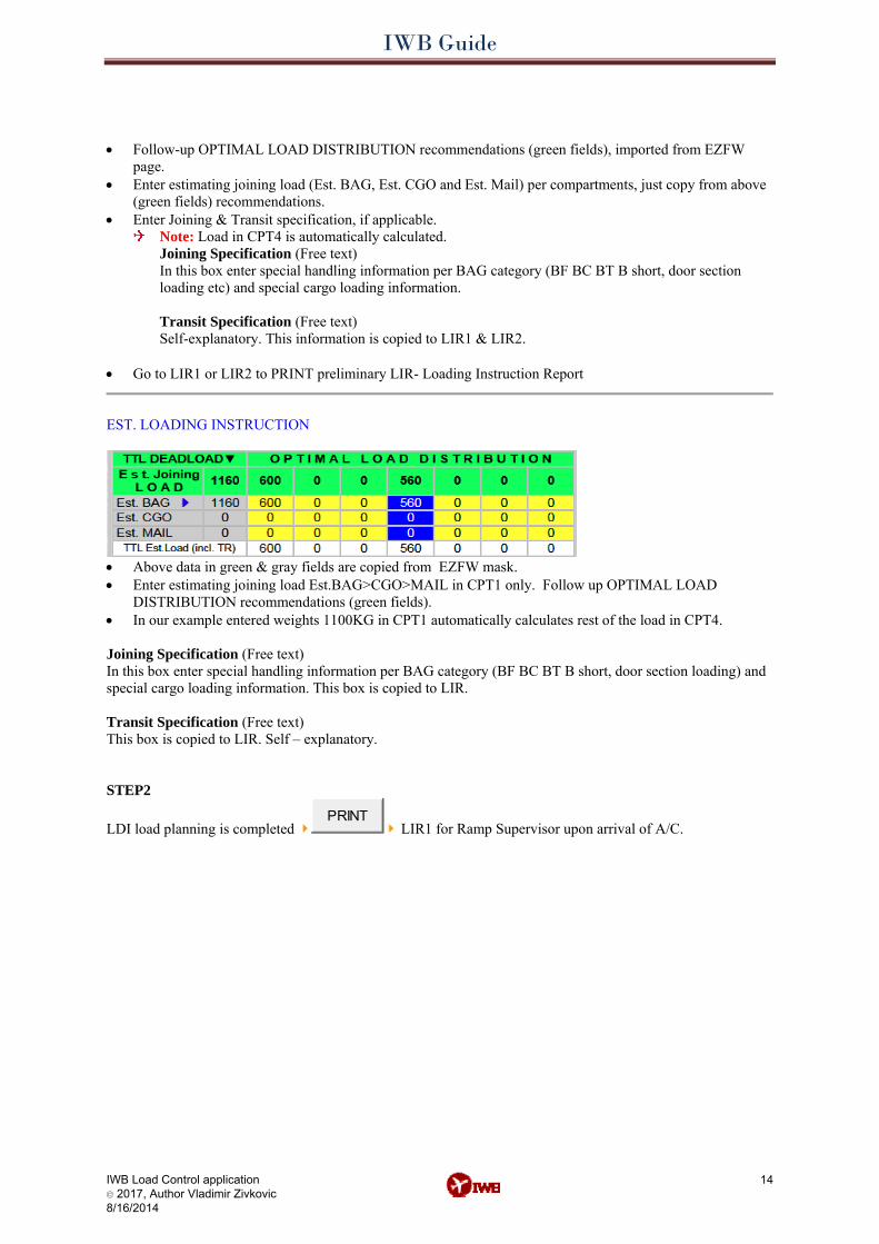
EST. LOADING INSTRUCTION
• Above data in green & gray fields are copied from EZFW mask. • Enter estimating joining load Est.BAG>CGO>MAIL in CPT1 only. Follow up OPTIMAL LOAD
DISTRIBUTION recommendations (green fields). • In our example entered weights 1100KG in CPT1 automatically calculates rest of the load in CPT4. Joining Specification (Free text) In this box enter special handling information per BAG category (BF BC BT B short, door section loading) and special cargo loading information. This box is copied to LIR. Transit Specification (Free text) This box is copied to LIR. Self – explanatory. STEP2
LDI load planning is completed PRINT
LIR1 for Ramp Supervisor upon arrival of A/C.
IWB Load Control application © 2017, Author Vladimir Zivkovic 8/16/2014
14
IWB Guide
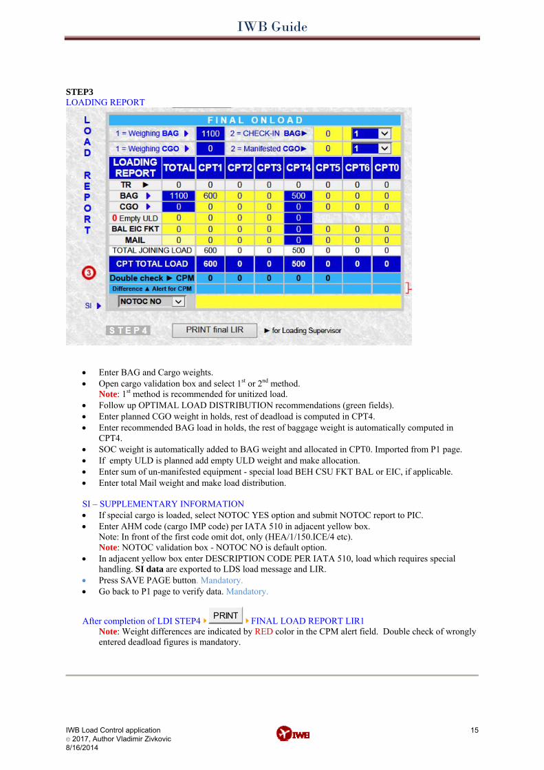
STEP3 LOADING REPORT
• Enter BAG and Cargo weights. • Open cargo validation box and select 1st or 2nd method.
Note: 1st method is recommended for unitized load. • Follow up OPTIMAL LOAD DISTRIBUTION recommendations (green fields). • Enter planned CGO weight in holds, rest of deadload is computed in CPT4. • Enter recommended BAG load in holds, the rest of baggage weight is automatically computed in
CPT4. • SOC weight is automatically added to BAG weight and allocated in CPT0. Imported from P1 page. • If empty ULD is planned add empty ULD weight and make allocation. • Enter sum of un-manifested equipment - special load BEH CSU FKT BAL or EIC, if applicable. • Enter total Mail weight and make load distribution.
SI – SUPPLEMENTARY INFORMATION • If special cargo is loaded, select NOTOC YES option and submit NOTOC report to PIC. • Enter AHM code (cargo IMP code) per IATA 510 in adjacent yellow box.
Note: In front of the first code omit dot, only (HEA/1/150.ICE/4 etc). Note: NOTOC validation box - NOTOC NO is default option.
• In adjacent yellow box enter DESCRIPTION CODE PER IATA 510, load which requires special handling. SI data are exported to LDS load message and LIR.
• Press SAVE PAGE button. Mandatory. • Go back to P1 page to verify data. Mandatory.
After completion of LDI STEP4 PRINT FINAL LOAD REPORT LIR1 Note: Weight differences are indicated by RED color in the CPM alert field. Double check of wrongly entered deadload figures is mandatory.
IWB Load Control application © 2017, Author Vladimir Zivkovic 8/16/2014
15
IWB Guide
IWB Load Control application © 2017, Author Vladimir Zivkovic 8/16/2014
16
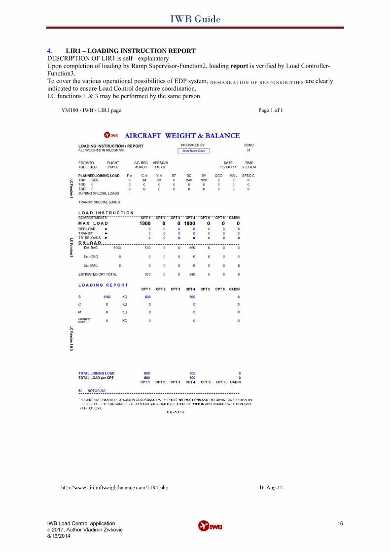
4. LIR1 – LOADING INSTRUCTION REPORT LIR1 – LOADING INSTRUCTION REPORTDESCRIPTION OF LIR1 is self - explanatory Upon completion of loading by Ramp Supervisor-Function2, loading report is verified by Load Controller-Function3. To cover the various operational possibilities of EDP system, D E M A R K A T I O N O F R E S P O N S I B I T I I E S are clearly indicated to ensure Load Control departure coordination. LC functions 1 & 3 may be performed by the same person.
IWB Guide
IWB Load Control application © 2017, Author Vladimir Zivkovic 8/16/2014
17
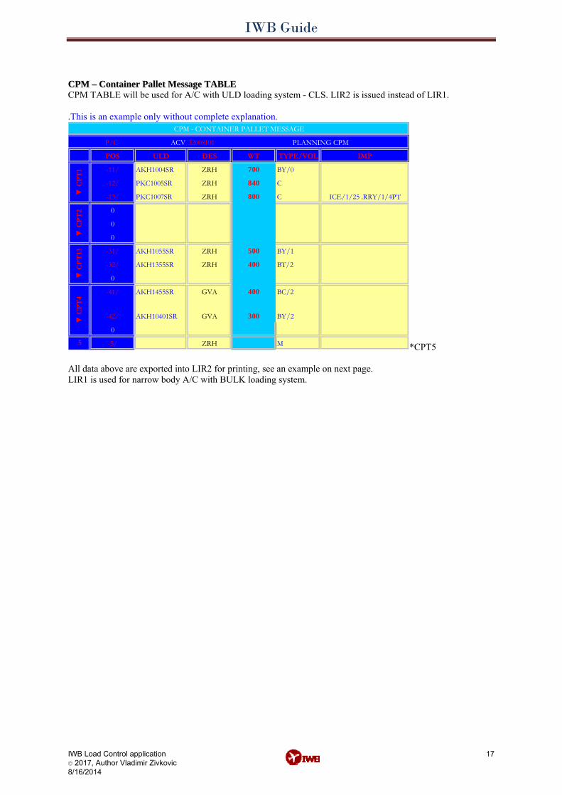
CCPPMM –– CCoonnttaaiinneerr PPaalllleett MMeessssaaggee TTAABBLLEE CPM TABLE will be used for A/C with ULD loading system - CLS. LIR2 is issued instead of LIR1. .This is an example only without complete explanation.
P/C- 32008I01
POS ULD DES WT TYPE/VOL
-11/ 700
-12/ 840
-13/ 800
-31/ 500
-32/ 400
-41/ 400
-42/ 300
5 -5/
IMP
▼ C
PT
1▼
CP
T2
▼ C
PT
13▼
CP
T4
ACV
AKH1004SR ZRH BY/0
PKC1005SR ZRH C
PKC1007SR ZRH C
0
0
0
AKH1055SR ZRH BY/1
AKH1355SR ZRH BT/2
0
AKH1455SR GVA BC/2
AKH10401SR GVA BY/2
0
ZRH M
CPM - CONTAINER PALLET MESSAGE
PLANNING CPM
ICE/1/25 .RRY/1/4PT
*CPT5 All data above are exported into LIR2 for printing, see an example on next page. LIR1 is used for narrow body A/C with BULK loading system.
IWB Guide
IWB Load Control application © 2017, Author Vladimir Zivkovic 8/16/2014
18
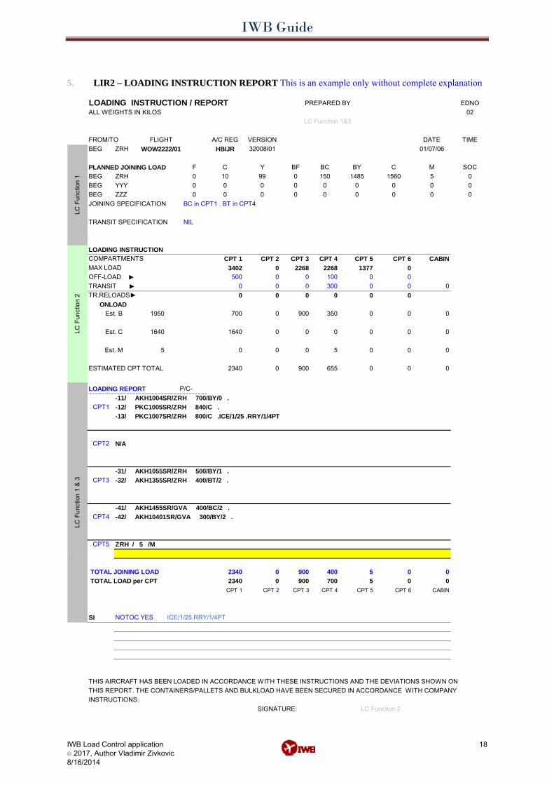
5. LIR2 – LOADING INSTRUCTION REPORT This is an example only without complete explanation LIR2 – LOADING INSTRUCTION REPORT
LOADING INSTRUCTION / REPORT EDNOALL WEIGHTS IN KILOS 02
A/C REG VERSION DATE TIMEBEG ZRH WOW2222/01 HBIJR 32008I01 01/07/06
PLANNED JOINING LOAD F C Y BF BC BY C M SOCBEG ZRH 0 10 99 0 150 1485 1560 5 0BEG YYY 0 0 0 0 0 0 0 0 0BEG ZZZ 0 0 0 0 0 0 0 0 0
LOADING INSTRUCTIONCOMPARTMENTS CPT 1 CPT 2 CPT 3 CPT 4 CPT 5 CPT 6 CABINMAX LOAD 3402 0 2268 2268 1377 0
500 0 0 100 0 00 0 0 300 0 0 0
TR.RELOADS► 0 0 0 0 0 0
1950 700 0 900 350 0 0 0
1640 1640 0 0 0 0 0 0
5 0 0 0 5 0 0 0
ESTIMATED CPT TOTAL 2340 0 900 655 0 0 0
LOADING REPORT
CPT5
TOTAL JOINING LOAD 2340 0 900 400 5 0 0 TOTAL LOAD per CPT 2340 0 900 700 5 0 0
CPT 1 CPT 2 CPT 3 CPT 4 CPT 5 CPT 6 CABIN
SI NOTOC YES
THIS AIRCRAFT HAS BEEN LOADED IN ACCORDANCE WITH THESE INSTRUCTIONS AND THE DEVIATIONS SHOWN ON THIS REPORT. THE CONTAINERS/PALLETS AND BULKLOAD HAVE BEEN SECURED IN ACCORDANCE WITH COMPANYINSTRUCTIONS.
CPT3
CPT4 -42/ AKH10401SR/GVA 300/BY/2 .
LC F
unct
ion
1LC
Fun
ctio
n 2
LC F
unct
ion
1 &
3
TRANSIT ►
ONLOAD Est. B
OFF-LOAD ►
Est. C
CPT1
CPT2
PREPARED BY
LC Function 1&3
JOINING SPECIFICATION
TRANSIT SPECIFICATION
FROM/TO FLIGHT
BC in CPT1 . BT in CPT4
NIL
-13/ PKC1007SR/ZRH 800/C .ICE/1/25 .RRY/1/4PT-12/ PKC1005SR/ZRH 840/C .-11/ AKH1004SR/ZRH 700/BY/0 .
Est. M
P/C-
SIGNATURE: LC Function 2
ICE/1/25.RRY/1/4PT
N/A
-31/ AKH1055SR/ZRH 500/BY/1 .-32/ AKH1355SR/ZRH 400/BT/2 .
ZRH / 5 /M
-41/ AKH1455SR/GVA 400/BC/2 .
IWB Guide
IWB Load Control application © 2017, Author Vladimir Zivkovic 8/16/2014
19
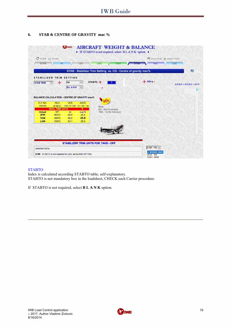
6.6. STAB & CENTRE OF GRAVITY mac % STAB & CENTRE OF GRAVITY mac %
STABTO Index is calculated according STABTO table, self-explanatory. STABTO is not mandatory box in the loadsheet, CHECK each Carrier procedure. If STABTO is not required, select B L A N K option.
IWB Guide
IWB Load Control application © 2017, Author Vladimir Zivkovic 8/16/2014
20
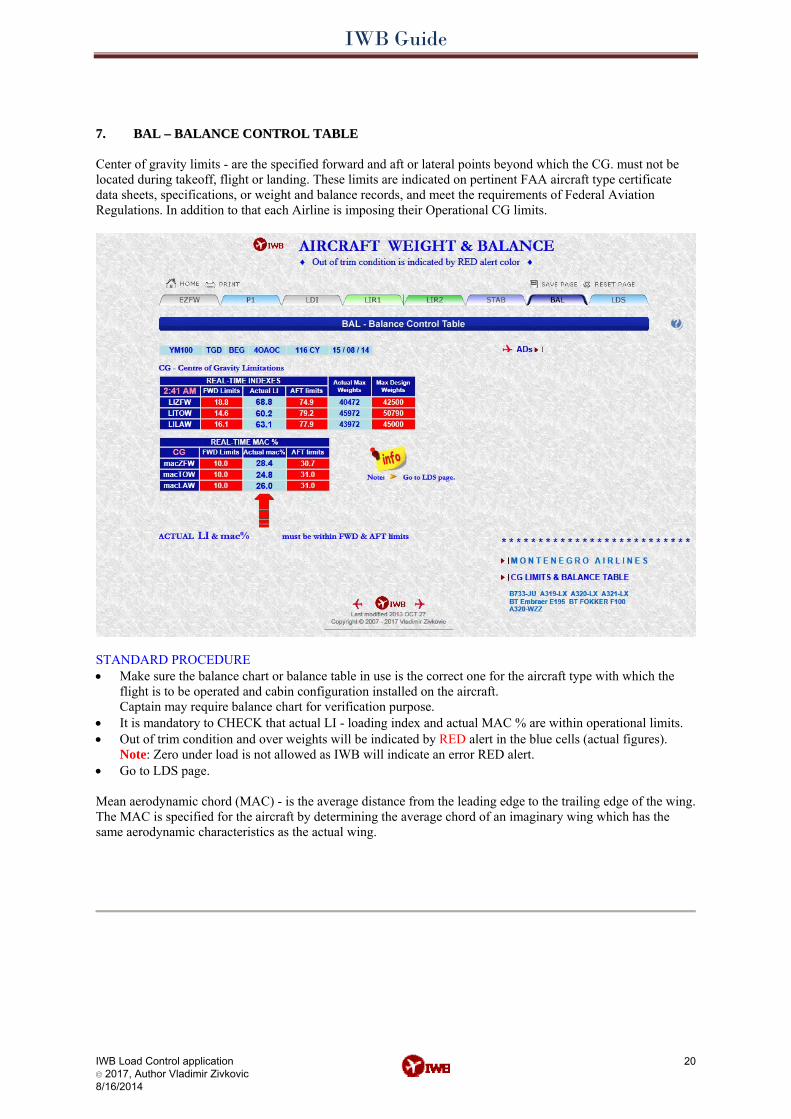
7.7. BAL – BALANCE CONTROL TABLE BAL – BALANCE CONTROL TABLE Center of gravity limits - are the specified forward and aft or lateral points beyond which the CG. must not be located during takeoff, flight or landing. These limits are indicated on pertinent FAA aircraft type certificate data sheets, specifications, or weight and balance records, and meet the requirements of Federal Aviation Regulations. In addition to that each Airline is imposing their Operational CG limits.
STANDARD PROCEDURE • Make sure the balance chart or balance table in use is the correct one for the aircraft type with which the
flight is to be operated and cabin configuration installed on the aircraft. Captain may require balance chart for verification purpose.
• It is mandatory to CHECK that actual LI - loading index and actual MAC % are within operational limits. • Out of trim condition and over weights will be indicated by RED alert in the blue cells (actual figures).
Note: Zero under load is not allowed as IWB will indicate an error RED alert. • Go to LDS page.
Mean aerodynamic chord (MAC) - is the average distance from the leading edge to the trailing edge of the wing. The MAC is specified for the aircraft by determining the average chord of an imaginary wing which has the same aerodynamic characteristics as the actual wing.
IWB Guide
IWB Load Control application © 2017, Author Vladimir Zivkovic 8/16/2014
21
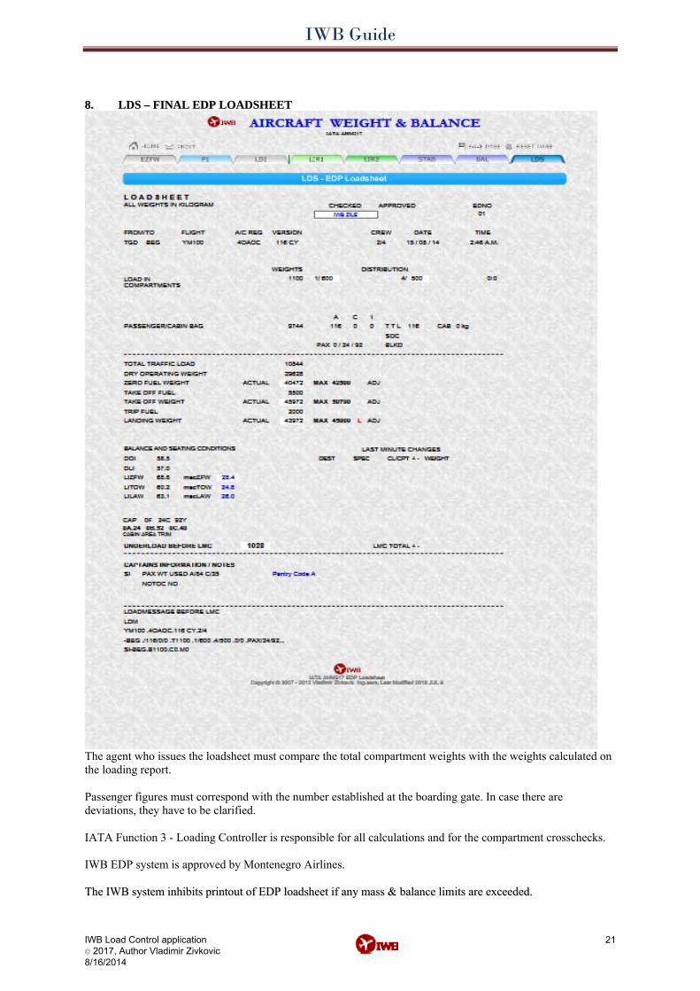
8.8. LDS – FINAL EDP LOADSHEET LDS – FINAL EDP LOADSHEET
The agent who issues the loadsheet must compare the total compartment weights with the weights calculated on the loading report. Passenger figures must correspond with the number established at the boarding gate. In case there are deviations, they have to be clarified. IATA Function 3 - Loading Controller is responsible for all calculations and for the compartment crosschecks. IWB EDP system is approved by Montenegro Airlines. TThhee IIWWBB ssyysstteemm iinnhhiibbiittss pprriinnttoouutt ooff EEDDPP llooaaddsshheeeett iiff aannyy mmaassss && bbaallaannccee lliimmiittss aarree eexxcceeeeddeedd..
IWB Guide
STANDARD EDP LOADSHEET By initiating print-out of the loadsheet or by releasing the loadsheet for printout, the loadsheet agent confirms that the following data are correct:
a. Flight number according to flight schedule or special advice from operations control. b. Aircraft registration. c. Aircraft version number according to aircraft type, cabin configuration and ULD
configuration, if applicable. d. Number of crew according to information from crew control, flight dispatch, or PIC. e. DOW/DOI and pantry group code according to the data published in YY AHM. f. Take-off and trip fuel figures according to information from crew or flight dispatch. g. Maximum gross weights of the aircraft according to published data or information from flight
crew or flight dispatch. h. Transit load data according to LDM/CPM. i. Cargo and mail according to cargo manifest and CN38. j. Number of passengers and weight of baggage load as released from check-in. k. Distribution of the load according to loading instruction/report.
Corrections of loadsheet data must be carried out by the:
a. Loadsheet agent ( LC Function 1), or b. Load controller, (LC Function3).
If done by the load controller, he becomes fully responsible for items corrected. The load controller must check and, if necessary, correct the loadsheet in accordance with the regulations in Section- “Last Minute Changes”. The load controller must ensure that:
a. Passenger figures correspond with the figures established at the gate check. b. Load distribution figures correspond with the equivalent figures on the loading report. c. Fuel figures correspond with the final quantities stated on the fuelling order.
To carry out the prescribed checks, the load controller needs, in addition to the loadsheet check:
a. To verify loading instruction/report. By signing the loadsheet, the load controller confirms that the:
a. Compartment totals of the loading report have been compared with the corresponding figures of the loadsheet.
b. Reasons for significant differences have been clarified in accordance with instructions in Section- “Last Minute Changes”.
The loadsheet shall be presented to the Commander at the latest 5 minutes before STD or ETD of the flight. The load controller must accurately inform the loadsheet agent of any LMC made at the aircraft. An EDP loadsheet must be signed by the load controller. The signature does not cover the area of responsibility of the loadsheet agent. The manual signature may be replaced by an electronic signature based on the load controller’s personal user identification and password.
IWB Load Control application © 2017, Author Vladimir Zivkovic 8/16/2014
22
IWB Guide
IWB Load Control application © 2017, Author Vladimir Zivkovic 4/19/2015
23
SSUUMMMMAARRYY OOFF WWAARRNNIINNGG IINNDDIICCAATTOORRSS The loadsheet can be printed once there are no more blocking alerts. IWB EDP loadsheet comply with IATA AHM517 AHM504 PT.5. - LOAD CONTROL. All necessary CrossChecks are made automatically: • the maximum gross weights valid for the flight shall not be exceeded • in all cases the appropriate weights capacity limitations for each compartment shall not be exceeded • the centre of gravity of the aircraft, if calculated by the system, shall be within limits • Essential information for safe operation of a flight is inserted. • Re-check RED alerts WARNINGS - CAUTION - ADVISORY information’s in the gray field, if any. Note: IWB AVIATION ABBREVIATIONS you will find on following links: http://www.internetweightbalance.com/aero.php http://www.aircraftweightbalance.com/aero.php
Important notes:
ENTERING DATA Instead of ENTER key use TAB key or C L I C K on the left mouse button anywhere on the screen. FLIGHT PREPARATION steps: EZFW LDI LIR EDP - L O A D S H E E T steps: P1 LDI P1 LIR STAB BAL LDS
It is mandatory to follow above steps. Warning! IWB application is prepared for Internet Explorer users.