itu-t rec. g.861 (08/96) principles and guidelines for the
TRANSCRIPT
INTERNATIONAL TELECOMMUNICATION UNION
)45 4 '����TELECOMMUNICATIONSTANDARDIZATION SECTOROF ITU
(08/96)
SERIES G: TRANSMISSION SYSTEMS AND MEDIA,DIGITAL SYSTEMS AND NETWORKS
Digital transmission systems – Digital networks – SDHnetwork characteristics
0RINCIPLES�AND�GUIDELINES�FOR�THE�INTEGRATION�OFSATELLITE�AND�RADIO�SYSTEMS�IN�3$(�TRANSPORTNETWORKS
ITU-T Recommendation G.861(Previously CCITT Recommendation)
ITU-T G-SERIES RECOMMENDATIONS
42!.3-)33)/.�3934%-3�!.$�-%$)!��$)')4!,�3934%-3�!.$�.%47/2+3
For further details, please refer to ITU-T List of Recommendations.
INTERNATIONAL TELEPHONE CONNECTIONS AND CIRCUITS G.100–G.199
).4%2.!4)/.!,�!.!,/'5%�#!22)%2�3934%-
GENERAL CHARACTERISTICS COMMON TO ALL ANALOGUE CARRIER-TRANSMISSION SYSTEMS
G.200–G.299
INDIVIDUAL CHARACTERISTICS OF INTERNATIONAL CARRIER TELEPHONESYSTEMS ON METALLIC LINES
G.300–G.399
GENERAL CHARACTERISTICS OF INTERNATIONAL CARRIER TELEPHONESYSTEMS ON RADIO-RELAY OR SATELLITE LINKS AND INTERCONNECTIONWITH METALLIC LINES
G.400–G.449
42!.3-)33)/.�-%$)!�#(!2!#4%2)34)#3
$)')4!,�42!.3-)33)/.�3934%-3
TERMINAL EQUIPMENTS G.700–G.799
DIGITAL NETWORKS G.800–G.899
General aspects G.800–G.809
Design objectives for digital networks G.810–G.819
Quality and availability targets G.820–G.829
Network capabilities and functions G.830–G.839
3$(�NETWORK�CHARACTERISTICS '���� '����
DIGITAL SECTIONS AND DIGITAL LINE SYSTEM G.900–G.999
ITU-T RECOMMENDATION G.861
PRINCIPLES AND GUIDELINES FOR THE INTEGRATION OF SATELLITE ANDRADIO SYSTEMS IN SDH TRANSPORT NETWORKS
Summary
This Recommendation provides guidelines and principles for the integration of digital radio-relayand satellite systems into SDH based transport networks. It focuses on the functional andarchitectural aspects of the integration from a network perspective, with the objective of ensuringcompatibility in terms of the information transfer capability of SDH signal elements and inter-systemmanagement commonality. It does not consider the internal composition, or implementation specificdetails of digital radio-relay and satellite systems, which are the subject of the relevant ITU-RRecommendations.
Source
ITU-T Recommendation G.861 was prepared by ITU-T Study Group 13 (1993-1996) and wasapproved under the WTSC Resolution No. 1 procedure on the 27th of August 1996.
ii Recommendation G.861 (08/96)
FOREWORD
ITU (International Telecommunication Union) is the United Nations Specialized Agency in the field oftelecommunications. The ITU Telecommunication Standardization Sector (ITU-T) is a permanent organ ofthe ITU. The ITU-T is responsible for studying technical, operating and tariff questions and issuingRecommendations on them with a view to standardizing telecommunications on a worldwide basis.
The World Telecommunication Standardization Conference (WTSC), which meets every four years,establishes the topics for study by the ITU-T Study Groups which, in their turn, produce Recommendationson these topics.
The approval of Recommendations by the Members of the ITU-T is covered by the procedure laid down inWTSC Resolution No. 1.
In some areas of information technology which fall within ITU-T’s purview, the necessary standards areprepared on a collaborative basis with ISO and IEC.
NOTE
In this Recommendation, the expression "Administration" is used for conciseness to indicate both atelecommunication administration and a recognized operating agency.
INTELLECTUAL PROPERTY RIGHTS
The ITU draws attention to the possibility that the practice or implementation of this Recommendation mayinvolve the use of a claimed Intellectual Property Right. The ITU takes no position concerning the evidence,validity or applicability of claimed Intellectual Property Rights, whether asserted by ITU members or othersoutside of the Recommendation development process.
As of the date of approval of this Recommendation, the ITU had/had not received notice of intellectualproperty, protected by patents, which may be required to implement this Recommendation. However,implementors are cautioned that this may not represent the latest information and are therefore strongly urgedto consult the TSB patent database.
ITU 1997
All rights reserved. No part of this publication may be reproduced or utilized in any form or by any means,electronic or mechanical, including photocopying and microfilm, without permission in writing from the ITU.
Recommendation G.861 (08/96) iii
CONTENTS
Page
1 Introduction................................................................................................................. 1
1.1 Scope........................................................................................................................... 1
1.2 Structure of this Recommendation ............................................................................. 1
1.3 References................................................................................................................... 1
1.4 Definitions .................................................................................................................. 2
1.5 Abbreviations.............................................................................................................. 3
2 Scenarios for radio digital section integration into SDH............................................ 4
2.1 Architecture description.............................................................................................. 4
2.2 Architectural principles............................................................................................... 5
2.3 Digital sections at 51.84 Mbit/s and other sub-STM-1 bit rates................................. 7
3 Satellite system as a wide-area SDH network node.................................................... 7
3.1 Architecture description.............................................................................................. 7
3.2 Architectural principles............................................................................................... 9
3.3 Examples of satellite-system based digital cross-connects......................................... 9
3.3.1 Wide-area cross-connect with various S-IOS rates ....................................... 9
3.3.2 Wide-area cross-connect with 51.84 Mbit/s S-IOS....................................... 11
4 Guidelines for constructing sub-STM-1 multiplex structures and radio section layers 11
4.1 General........................................................................................................................ 11
4.2 SDH multiplex conversion.......................................................................................... 11
4.3 Functions of radio section overhead (SOH)................................................................ 11
4.4 Media specific equipment interfaces (REI, SEI)......................................................... 13
5 SDH management aspects........................................................................................... 13
5.1 Network layer management principles........................................................................ 13
5.2 General requirements.................................................................................................. 14
5.3 NE layer management facilities.................................................................................. 14
5.4 Bandwidth efficiency.................................................................................................. 15
5.5 Management communications and interfaces............................................................. 15

Recommendation G.861 (08/96) 1
Recommendation G.861
PRINCIPLES AND GUIDELINES FOR THE INTEGRATION OF SATELLITEAND RADIO SYSTEMS IN SDH TRANSPORT NETWORKS
(Geneva, 1996)
1 Introduction
1.1 Scope
This Recommendation provides guidelines and principles for integrating digital radio-relay andsatellite systems and equipment in SDH transport networks. It focuses on functional and architecturalaspects of the integration from a G.803 network perspective. The objective is to ensure compatibilityin terms of information transfer capability of SDH signal elements and inter-system managementcommonality.
A number of integration scenarios of radio/satellite systems with different roles and functions in theSDH transport network are described. They vary in transparency to G.707 synchronous transportmodule signals, or their payload (VCs) signals between the radio system interfaces.
This Recommendation addresses management aspects, including provision of and accessrequirements to SDH management facilities for radio and satellite systems in the G.784 SDHmanagement subnetworks (SMS).
This Recommendation does not consider the internal composition, make-up and implementationspecific details of the satellite and radio systems, which are the subject of pertinent ITU-RRecommendations.
1.2 Structure of this Recommendation
Clause 2 describes scenarios and architectural principles for the integration of radio systems as point-to-point digital sections in SDH. Clause 3 describes a scenario for satellite systems emulatingsynchronous Network Element (NE) functions at SDH network nodes, and utilizes the satelliteunique capability of supporting multipoint configurations to client connections of SDH elementalsignal(s) (VCs or TUs). Clause 4 provides guidelines for constructing sub-STM-1 signal multiplexstructures, new degenerate HOVC and direct mapping of LOVCs in sub-STM-1 radio sections.Clause 5 addresses SDH management aspects to be taken into account in multiple transmissionmedia SDH systems.
1.3 References
The following ITU-T Recommendations and other references contain provisions which, throughreference in this text, constitute provisions of this Recommendation. At the time of publication, theeditions indicated were valid. All Recommendations and other references are subject to revision; allusers of this Recommendation are therefore encouraged to investigate the possibility of applying themost recent edition of the Recommendations and other references listed below. A list of the currentlyvalid ITU-T Recommendations is regularly published.
– ITU-R Recommendation F.750-2 (1995), Architectures and functional aspects of radio-relaysystems for SDH-based networks.
2 Recommendation G.861 (08/96)
– ITU-R Recommendation F.751-1 (1994), Transmission characteristics and performancerequirements of radio-relay systems for SDH-based networks.
– CCITT Recommendation G.703 (1991), Physical/electrical characteristics of hierarchicaldigital interfaces.
– ITU-T Recommendation G.707 (1996), Network node interface for the Synchronous DigitalHierarchy (SDH).
– ITU-T Recommendation G.774 (1996), Synchronous Digital Hierarcy (SDH) managementinformation model for the network element view.
– ITU-T Recommendation G.774.1 (1996), Synchronous Digital Hierarchy (SDH)performance monitoring for the network element view.
– ITU-T Recommendation G.774.2 (1996), Synchronous Digital Hierarchy (SDH)configuration of the payload structure for the network element view.
– ITU-T Recommendation G.774.3 (1996), Synchronous Digital Hierarchy (SDH)management of multiplex-section protection for the network element view.
– ITU-T Recommendation G.774.4 (1996), Synchronous Digital Hierarchy (SDH)management of subnetwork connection protection for the network element view.
– ITU-T Recommendation G.784 (1994), Synchronous Digital Hierarchy management.
– ITU-T Recommendation G.803 (1993), Architectures of transport networks based on theSynchronous Digital Hierarchy (SDH).
– ITU-T Recommendation G.831 (1996), Management capabilities of transport networksbased on the Synchronous Digital Hierarchy (SDH).
– ITU-T Recommendation G.832 (1995), Transport of SDH elements on PDH networks –Frame and multiplexing structures.
– CCITT Recommendation M.1520 (1992), Standardized information exchange betweenAdministrations.
– ITU-T Recommendation M.3010 (1996), Principles for a telecommunications managementnetwork.
– ITU-T Recommendation M.3020 (1995), TMN interface specification methodology.
– CCITT Recommendation M.3300 (1992), TMN management capabilities presented at theF interface.
– CCITT Recommendation X.722 (1992), Information technology – Open SystemsInterconnection – Structure of management information: Guidelines for the definition ofmanaged objects.
– ITU-R Recommendation S.1149 (1997), Network architecture and equipment functionalaspects of digital satellite systems in the FSS forming part of SDH transport networks.
1.4 Definitions
This Recommendation defines the following terms.
1.4.1 line termination (LT): Access to both standard MSOH and RSOH.
1.4.2 multiplex section (MS): Access to standard RSOH and MSOH.
1.4.3 network node interface (NNI): The basic, fully standardized open interface in the SDH.The NNI is a physical interface and can be associated with an Intra-Office Section (IOS), which is
Recommendation G.861 (08/96) 3
broadly equivalent to the existing G.703 interfaces. The basic description of the NNI is given inFigure 3-1/G.707.
1.4.4 network node reference point (NNRP): A reference point between the termination of anMS and an HOVC connection function, or between two directly connected MSs. The NNRP may ormay not have an associated NNI.
1.4.5 optical line interface (OLI): An interconnection between optical line system regeneratorsand between optical line terminals and optical regenerators.
1.4.6 optical line termination (OLT): Access to both standard MSOH and RSOH.
1.4.7 radio-relay air interface (RRAI): An air interface between two radio terminals.
1.4.8 radio-relay equipment interface (RREI): An open interface between elements of the radio-relay system, which may either be electrical or optical.
1.4.9 radio-relay line termination (RRLT): A radio-relay line termination which may performnon-hierarchical MS signal generation (e.g. STM-N/51.84 Mbit/s conversion, G.832 SDH/PDHinterworking equipment). Media specific additional section overhead functions may be definedacross the associated RRRP or RREI.
1.4.10 radio-relay reference point (RRRP): The radio-relay equivalent of the NNRP, butinternally defined between the radio-relay system equipment. The associated bit rate may be atsub-STM-1.
1.4.11 satellite air interface (SAI): An air interface between two satellite earth stations, and/orbetween the earth station and the satellite.
1.4.12 satellite equipment interface (SEI): An interface between elements of the satellite system,which may either be electrical or optical. The topology may be asymmetrical.
NOTE – SEI may or may not be an open interface.
1.4.13 satellite line termination (SLT): A satellite line termination which may performnon-hierarchical S-IOS signal generation (e.g. STM-N/51.84 Mbit/s conversion, G.832 SDH/PDHinterworking equipment), and reconciliation of internal section and path asymmetric connectiontopologies. Media specific section overhead functions may be defined across the associated SRPor SEI.
1.4.14 satellite reference point (SRP): The satellite equivalent of the NNRP, but internally definedbetween the satellite earth station equipment. The associated bit rate may be at sub-STM-1. Thetopology may be asymmetrical.
1.4.15 satellite regenerator terminal (SRT): Terminal which broadly covers satellite modem andmultiple access equipment.
1.5 Abbreviations
This Recommendation uses the following abbreviations.
DCC Data Communication Channel
DXC Digital Cross Connect
EI Equipment Interface
HOVC Higher Order Virtual Container
IOS Intra-Office Section
LOVC Lower Order Virtual Container
4 Recommendation G.861 (08/96)
LT Line Termination
MS Multiplex Section
MSOH Multiplex Section Overhead
NNI Network Node Interface
NNRP Network Node Reference Point
OLI Optical Line Interface
OLT Optical Line Termination
OR Optical Regenerator
RRAI Radio-Relay Air Interface
RREI Radio-Relay Equipment Interface
RRLT Radio-Relay Line Termination
RRRP Radio-Relay reference Point
RRRT Radio-Relay Regenerator Terminal
RS Regenerator Section
RSOH Regenerator Section Overhead
SAI Satellite Air Interface
SDH Synchronous Digital Hierarchy
SEI Satellite Equipment Interface
S-IOS Satellite Intra-Office Section
SLT Satellite Line Termination
SOH Section Overhead
SRP Satellite Reference Point
SRT Satellite Regenerator Terminal
SSTM-ij Satellite Synchronous Transport Module level-ij
STM-N Synchronous Transport Module level-N
TMN Telecommunications Management Network
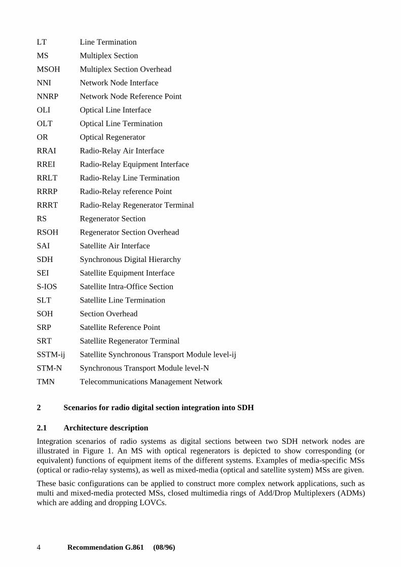
2 Scenarios for radio digital section integration into SDH
2.1 Architecture description
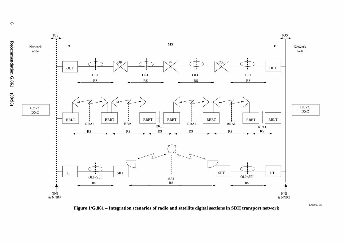
Integration scenarios of radio systems as digital sections between two SDH network nodes areillustrated in Figure 1. An MS with optical regenerators is depicted to show corresponding (orequivalent) functions of equipment items of the different systems. Examples of media-specific MSs(optical or radio-relay systems), as well as mixed-media (optical and satellite system) MSs are given.
These basic configurations can be applied to construct more complex network applications, such asmulti and mixed-media protected MSs, closed multimedia rings of Add/Drop Multiplexers (ADMs)which are adding and dropping LOVCs.
Recommendation G.861 (08/96) 5
2.2 Architectural principles
The following SDH architectural principles apply for the radio digital sections:
i) Standard RSOH and MSOH functions defined in Recommendation G.707 should besupported. Further media specific functions may be added, using unused OH bytes, ifavailable.
ii) Radio systems may constitute either an MS (between NNIs) or an RS (between EIs) as partof an MS.
iii) As an RS, basic RSOH functions described in Recommendation G.707 should be supportedto give management commonality, and transparent transport of MS together with MS framephase should be assured.
iv) As an MS, basic SOH (RSOH and MSOH) functions described in Recommendation G.707should be supported to give management commonality, and transparent transport of HOVCsand/or LOVC together with VC frame phase (TUs, TUGs) should be assured.
v) The RREI and SEI must have their own OH and must be at least an RS with basic RSOHfunctions described in Recommendation G.707. They can transport an MS transparently,however they cannot carry an RS transparently. The same rules apply to RRAI and SAI.
vi) If media specific OH bytes are added to the standard SOH, BIP-N needs to be recalculated atinsertion and extraction points, or the additional bytes must have even parity.
vii) Direct support of LOVCs in media-specific (lower bit rate) MS with new degenerate HOVCor non-standard TUG is allowed (e.g. through synchronous signal conversion/interworkingfunctions performed in LT, RRLT or SLT), but this will restrict application in more complexstructures.
viii) Mixed media protection at MSs is feasible with compatible MSs and if there are no mediaspecific MSOH functions. IOS cannot be used between the protection switch and thedifferent line terminals.
ix) Mixed media protection at HOVCs (and/or LOVCs) is feasible with dissimilar MS bit rates,and/or if media specific MSs are used. The different line terminals can be connected to theprotection switch with IOSs.
6R
ecomm
endation G.861 (08/96)
T1306690-95
OR OROR
OLT OLT
IOS IOS
MS
OLI OLI OLI OLI
RS RS RS RS
Networknode
RRRT RRRT RRRT
RREIRRAI RRAI
RRLTRRAI
RRRTRRAI
RRRT RRLT
HOVCDXC
HOVCDXC
RREIRS
LT LTSRTOLI=SEI OLI=SEI
SRT
RSRS RSSAI
RSRS RSRS RS
NNI & NNRP
NNI & NNRP
Networknode
Figure 1/G.861 – Integration scenarios of radio and satellite digital sections in SDH transport network
Recommendation G.861 (08/96) 7
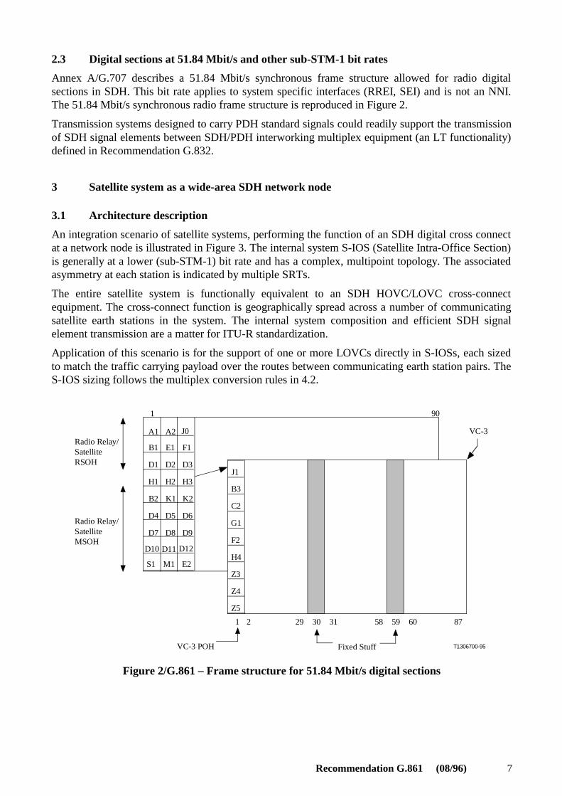
2.3 Digital sections at 51.84 Mbit/s and other sub-STM-1 bit rates
Annex A/G.707 describes a 51.84 Mbit/s synchronous frame structure allowed for radio digitalsections in SDH. This bit rate applies to system specific interfaces (RREI, SEI) and is not an NNI.The 51.84 Mbit/s synchronous radio frame structure is reproduced in Figure 2.
Transmission systems designed to carry PDH standard signals could readily support the transmissionof SDH signal elements between SDH/PDH interworking multiplex equipment (an LT functionality)defined in Recommendation G.832.
3 Satellite system as a wide-area SDH network node
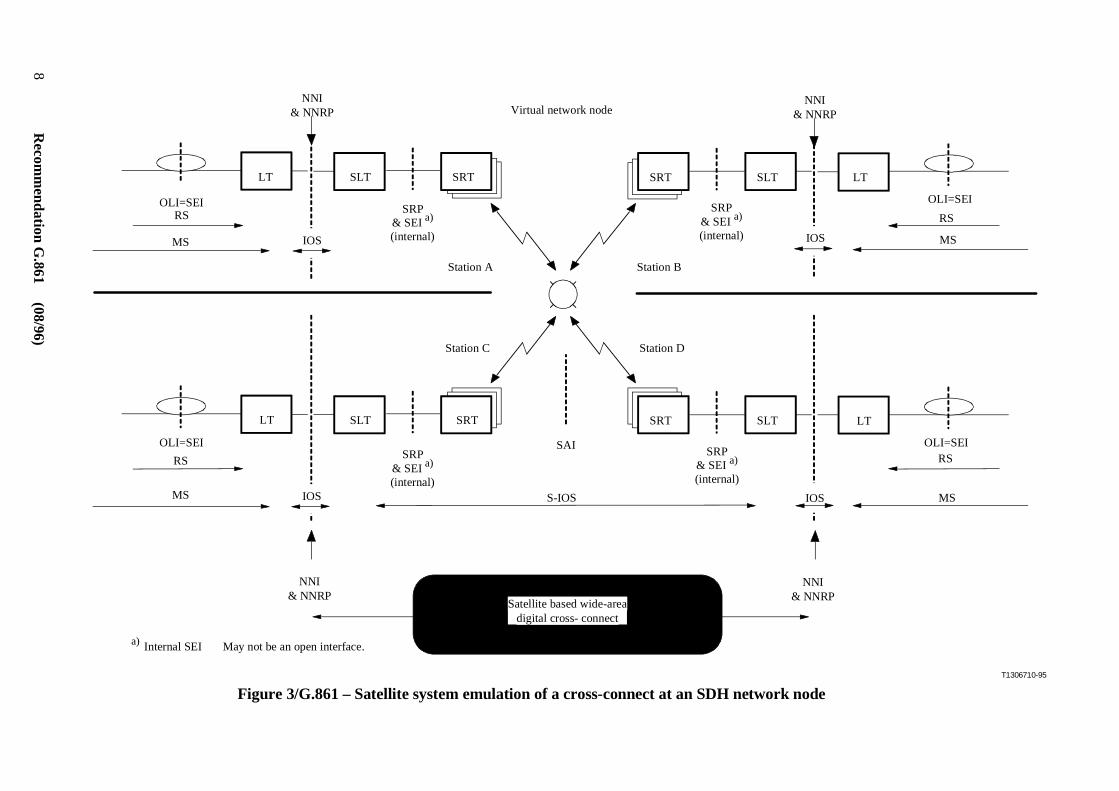
3.1 Architecture description
An integration scenario of satellite systems, performing the function of an SDH digital cross connectat a network node is illustrated in Figure 3. The internal system S-IOS (Satellite Intra-Office Section)is generally at a lower (sub-STM-1) bit rate and has a complex, multipoint topology. The associatedasymmetry at each station is indicated by multiple SRTs.
The entire satellite system is functionally equivalent to an SDH HOVC/LOVC cross-connectequipment. The cross-connect function is geographically spread across a number of communicatingsatellite earth stations in the system. The internal system composition and efficient SDH signalelement transmission are a matter for ITU-R standardization.
Application of this scenario is for the support of one or more LOVCs directly in S-IOSs, each sizedto match the traffic carrying payload over the routes between communicating earth station pairs. TheS-IOS sizing follows the multiplex conversion rules in 4.2.
D10 D11 D12
A1 A2
B1 E1 F1
D1 D2
H3
D3
H1 H2
B2 K1 K2
D6D5D4
D7 D8 D9
E2
J1
B3
C2
G1
F2
H4
Z3
Z4
Z5
3029 31 58 59 60
90 1
1 2 87
J0
S1 M1
T1306700-95VC-3 POH
VC-3
Fixed Stuff
Radio Relay/SatelliteRSOH
Radio Relay/SatelliteMSOH
Figure 2/G.861 – Frame structure for 51.84 Mbit/s digital sections
8R
ecomm
endation G.861 (08/96)
T1306710-95
LT
OLI=SEIRS
MS
OLI=SEI
MS
LTSLT SRT SLTSRT
IOS IOS
Virtual network nodeNNI
& NNRPNNI
& NNRP
S-IOS
SAI
MS
OLI=SEIRS
LTLT
OLI=SEI
RS
MS
SLTSRTSLT SRT
IOS
a) Internal SEI May not be an open interface.
NNI & NNRP
Satellite based wide-areadigital cross- connect
NNI & NNRP
RS
IOS
Station C Station D
Station A Station B
SRP& SEI a)
(internal)
SRP& SEI a)
(internal)
SRP& SEI a)
(internal)
SRP& SEI a)
(internal)
Figure 3/G.861 – Satellite system emulation of a cross-connect at an SDH network node
Recommendation G.861 (08/96) 9
3.2 Architectural principles
The following SDH architectural principles apply for this satellite system scenario:
i) The satellite system is functionally equivalent to synchronous Network Elements (NEs) atnetwork nodes in the SDH network infrastructure.
ii) The satellite system external interfaces should be compliant with SDH network nodeinterfaces (Recommendation G.707) (STM-N).
iii) The internal interfaces (SEIs) and S-IOS overhead functionality are specific to the satellitesystem. However, for management commonality the minimum OH functions given inTable 1 (4.3) should be supported.
iv) The satellite system should ensure transparency to VC signal elements as a minimum.
v) The satellite system should normally appear symmetrical when viewed externally, andcapable of supporting bidirectional symmetric VC path connections.
vi) Direct support of LOVCs in media-specific (lower bit rate) S-IOS with new degenerateHOVC or non-standard TUG is allowed (e.g. through synchronous signalconversion/interworking functions performed in SLT).
vii) The multiplex functionality includes G.784-type management facilities, with internal systemDCC capacity tailored to the satellite route size.
viii) Any non-hierarchical section layers for synchronous transport of LOVCs or their integermultiples (TUGs) should be confined within the satellite system, and only partially visiblefrom the external SDH transport network through management interfaces; the degree ofvisibility and accessibility for management control are for further study.
ix) Asymmetrical connection topologies (unidirectional, bidirectional asymmetric, point-to-multipoint), satellite system efficient multidestination at S-IOS, and degenerate HOVClayers should be confined within the satellite system, and only partially visible from theexternal SDH transport network through management interfaces. Extension of multipointtopologies of client connections in the served path layer networks beyond the satellite systemboundaries is for further study.
3.3 Examples of satellite-system based digital cross-connects
3.3.1 Wide-area cross-connect with various S-IOS rates
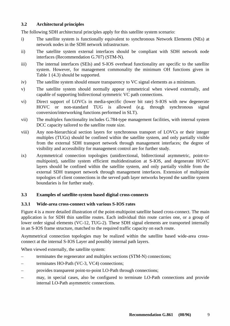
Figure 4 is a more detailed illustration of the point-multipoint satellite based cross-connect. The mainapplication is for SDH thin satellite routes. Each individual thin route carries one, or a group oflower order signal elements (VC-12, TUG-2). These SDH signal elements are transported internallyin an S-IOS frame structure, matched to the required traffic capacity on each route.
Asymmetrical connection topologies may be realized within the satellite based wide-area cross-connect at the internal S-IOS Layer and possibly internal path layers.
When viewed externally, the satellite system:
– terminates the regenerator and multiplex sections (STM-N) connections;
– terminates HO-Path (VC-3, VC4) connections;
– provides transparent point-to-point LO-Path through connections;
– may, in special cases, also be configured to terminate LO-Path connections and provideinternal LO-Path asymmetric connections.
10R
ecomm
endation G.861 (08/96)
SDH
demultiplex/rem
ultiplex interworking is perform
ed in the satellite system baseband equipm
ent(SL
T functionality). G
uidelines and principles for the "interworking" m
ultiplexing paths to extractSD
H V
C signal elem
ents, or combinations thereof, are given in clause 4.
T1306720-95
NNI
LO path [& possibly HO path (VC-3)]link connections realized:AB, AC, AD, BC, BD, CD
E/S D SLT
S-IOS E/S C
SLT
E/S A
SLT
E/S BSLT
NNI
NNI
SatelliteSDH system LOP/HOP
MCa)
SEI
MS
Layerboundary
NNI
NNI
SEI Satellite Equipment Interface
a) Any asymmetry reconciliation.
Figure 4/G.861 – Wide-area satellite-based cross-connect with internal point-multipoint connection topoloyg and sub-STM-1 section layer
Recommendation G.861 (08/96) 11
3.3.2 Wide-area cross-connect with 51.84 Mbit/s S-IOS
The same network view given in Figure 4 applies, except that all internal S-IOSs are at a single bitrate of 51.84 Mbit/s (STM-0). The possible application is "medium" satellite routes. The equipmentfor conversion between symmetrical STM-N NNIs to STM-0 (51.84 Mbit/s), possibly withasymmetrical SEIs is performed in the satellite system baseband equipment (SLT functionality). Themultiplexer function includes G.784-type management facilities, with internal system DCC capacityavailable in the 51.84 Mbit/s SOH.
As an SDH cross-connect NE at a network node, the satellite system terminates regenerator andmultiplex sections connections. If section termination is at STM-1, the satellite system:
– terminates HO-Path (VC-3, VC4) connections;
– provides transparent point-to-point LO-Path through connections;
– may, in special cases, also be configured to terminate LO-Path connections and provideinternal LO-Path asymmetric connections.
If section termination is at STM-N, the satellite system may:
– provide transparent point-to-point LO-Path through connections;
– provide transparent point-to-point HO-Path through connections (requires internal STM-0section layer parallel subnetworks);
– in special cases, also be configured to terminate HO-Path connections and provide internalHO-Path asymmetric connections.
4 Guidelines for constructing sub-STM-1 multiplex structures and radio section layers
4.1 General
The basic SDH signal elements to be transported are the various VCs with their associated pointers,adapted within radio and satellite synchronous section layers. As the pointer requirements depend onthe radio system RRRT/SRT functions, its structure may be different from pointer structures utilizedin standard SDH frame structures.
Management commonality is facilitated by the inclusion of selected SOH functions in the radiodigital section. When a certain number of VCs and/or TUs are grouped together (degenerate HOVC),some overhead functionalities, if required, could be specified within the newly generated radiosystem paths. This is for further study.
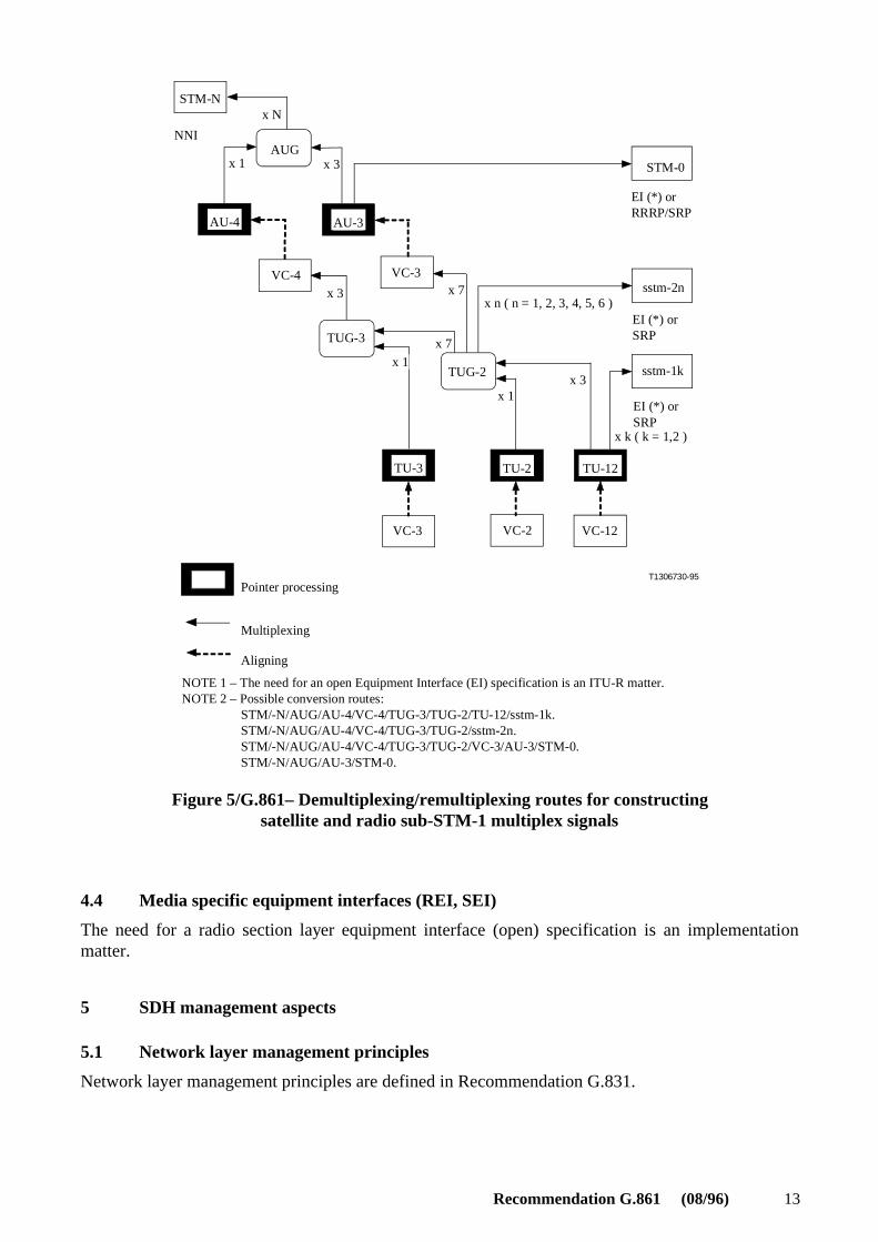
4.2 SDH multiplex conversion
SDH standard signal elements/modules (TU-12, TUG-2, AU-3) should be used in defining thepayload of new non-hierarchical radio section layers. The possible demultiplexing/remultiplexing(interworking) paths are indicated in Figure 5.
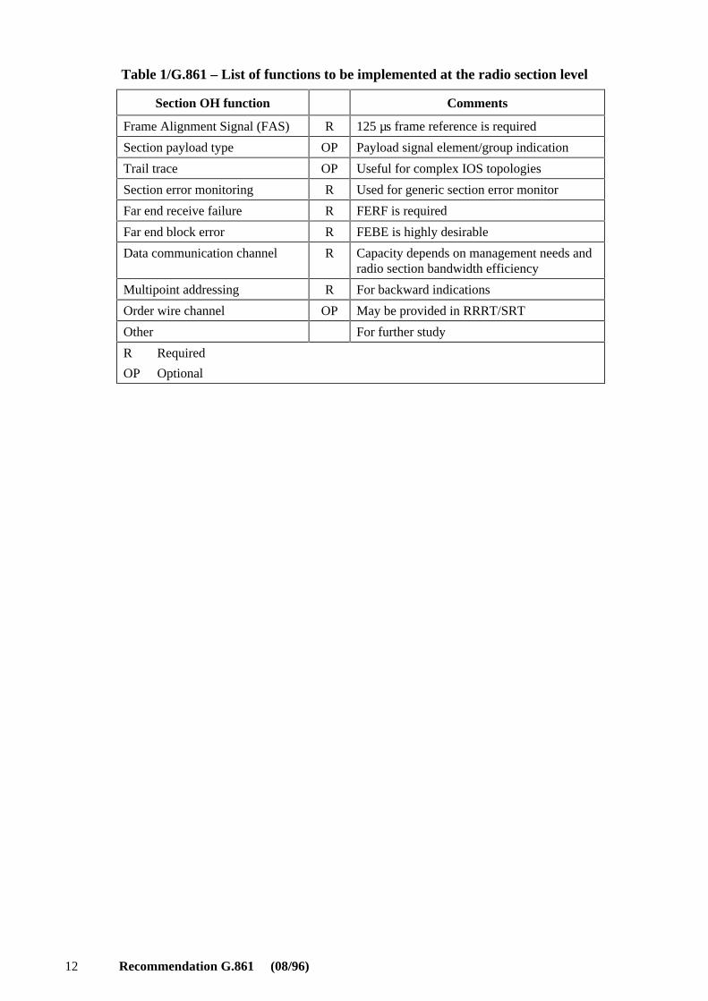
4.3 Functions of radio section overhead (SOH)
Efficient use of radio transmission bandwidth requires reduced SOH functionalities compared to thestandard SDH SOH.
NOTE – Subclause 9.2.3/G.707 provides some guidelines for reduced SOH for intra-station interfaces.
As a minimum, the SOH functionalities identified as R (Required) in Table 1 should beaccommodated in the radio sections. The byte allocation of radio SOH functions is a matter ofITU-R.
12 Recommendation G.861 (08/96)
Table 1/G.861 – List of functions to be implemented at the radio section level
Section OH function Comments
Frame Alignment Signal (FAS) R 125 µs frame reference is required
Section payload type OP Payload signal element/group indication
Trail trace OP Useful for complex IOS topologies
Section error monitoring R Used for generic section error monitor
Far end receive failure R FERF is required
Far end block error R FEBE is highly desirable
Data communication channel R Capacity depends on management needs andradio section bandwidth efficiency
Multipoint addressing R For backward indications
Order wire channel OP May be provided in RRRT/SRT
Other For further study
R Required
OP Optional
Recommendation G.861 (08/96) 13
x k ( k = 1,2 )
x 7
x 1
x 3
x 7x n ( n = 1, 2, 3, 4, 5, 6 )
x 3
x 3
x 1
x 1
T1306730-95
VC-12VC-2
TUG-2
VC-3
AUG
STM-N
NNI
x N
STM-0
sstm-1k
sstm-2n
TUG-3
VC-4
VC-3
Pointer processing
Multiplexing
Aligning
NOTE 1 – The need for an open Equipment Interface (EI) specification is an ITU-R matter.NOTE 2 – Possible conversion routes: STM/-N/AUG/AU-4/VC-4/TUG-3/TUG-2/TU-12/sstm-1k. STM/-N/AUG/AU-4/VC-4/TUG-3/TUG-2/sstm-2n. STM/-N/AUG/AU-4/VC-4/TUG-3/TUG-2/VC-3/AU-3/STM-0. STM/-N/AUG/AU-3/STM-0.
EI (*) or SRP
EI (*) or SRP
EI (*) or RRRP/SRP
AU-4 AU-3
TU-3 TU-2 TU-12
Figure 5/G.861– Demultiplexing/remultiplexing routes for constructingsatellite and radio sub-STM-1 multiplex signals
4.4 Media specific equipment interfaces (REI, SEI)
The need for a radio section layer equipment interface (open) specification is an implementationmatter.
5 SDH management aspects
5.1 Network layer management principles
Network layer management principles are defined in Recommendation G.831.
14 Recommendation G.861 (08/96)
5.2 General requirements
In mixed and multi-transmission-media SDH transport networks, inter-system and inter-operatormanagement is facilitated by support of the mandatory SOH bytes across the NNI, and theirassociated functions as defined in Recommendation G.784, plus the provision of one or moremanagement communication ports to give access to managed objects within the radio and/or satellitesystem.
Recommendation G.783 (1994) indicates the general relationship of management functions to SDHNetwork Elements, and Recommendation G.774 defines the management information model forSDH Network Elements and the managed objects found in cable transmission systems.
Radio and satellite systems should have management capabilities:
a) to manage their SDH section and path connections and other internal functions;
b) to provide a degree of management message processing capability (e.g. message filtering,routing, and partial DCC capacity);
c) to provide partial and controlled access for external management systems to internal radioand satellite system functions and objects.
5.3 NE layer management facilities
SDH compatible radio and satellite systems should include SDH management facilities to meet theG.784 list of minimum management functions for single-ended SDH NE and inter-vendor networkmanagement communications. These are:
– fault management, performance management, configuration management, securitymanagement and general management communications functions.
Establishment of a degree of common management across mixed and multi-transmission-media SDHsystems provided by multiple vendors but all based upon G.803 architecture involves:
a) The adoption of a common information model for the network elements, i.e. adopting therequirements of Recommendation G.774 – "SDH Management Information Model for theNetwork Element view". Recommendation G.774 defines the managed objects and theirassociated attributes for SDH NEs. The guidelines for defining managed objects aredescribed in Recommendation X.722 – "Guidelines for Definition of Managed Objects"GDMO.
b) The adoption of common monitoring techniques using SDH error monitoring bytes (B1, B2)and the requirements of Recommendation G.774.1 – "SDH Performance Monitoring for theNetwork element View" to ensure uniformity of performance data characteristics beingexchanged across SDH management domain boundaries.
c) The adoption of the requirements of Recommendation G.774.2 – "SDH Configuration of thePayload Structure for the Network Element View".
d) The adoption of the requirements of Recommendation G.774.3 – "SDH Management ofMultiplex-Section Protection for the Network Element View".
e) The adoption of the requirements of Recommendation G.774.4 – "SDH Management ofSubnetwork Connection Protection for the Network Element View".
f) The adoption of the message filtering, alarm threshold setting and integration periodsfunctions to support performance monitoring detailed in Recommendation G.784 – "SDHManagement".
Recommendation G.861 (08/96) 15
5.4 Bandwidth efficiency
The management message communications capability, especially for the thin route satelliteapplications described in 3.3.1, should be a balance between the route size and the amount ofessential management information requiring transport. To improve bandwidth efficiency over thesatellite transmission medium, a statistical multiplexing technique may be employed to achieveefficient transport of management information together with other sporadic information via a singlesection overhead byte operating as a lower rate S-IOS DCC.
To reduce the bandwidth needed to support SDH on satellite systems generally it will be necessary toreduce the number of bytes carried by the SOH. Thus bytes which are not critical to the operation ofSDH systems will possibly not be transported. This applies to the unallocated bytes and the nationaluse bytes. Other bytes may be transported slightly more slowly as they may be carried on a serialchannel rather than on their own dedicated byte.
5.5 Management communications and interfaces
For integration with TMN networks, the functionality of the communication ports provided formanagement communications on SDH equipment may be of the Q3 interface type as defined inRecommendations M.3010 – "Principles for a Telecommunications Management Network" andM.3020 – "TMN Interface Specification Methodology" or the X interface type as defined inRecommendation M.1520 – "Standardized Information Exchange between Administrations".
The implementation requirements of these interfaces are not defined.
For access by a management system which is fully integrated with the radio system then a proprietaryinterface may be employed. Several types of management interface may be provided on some piecesof equipment.
For access to management information by local staff, a TMN F type interface may be used asfunctionally defined in Recommendation M.3300 – "TMN Capabilities at the F Interface".
ITU-T RECOMMENDATIONS SERIES
Series A Organization of the work of the ITU-T
Series B Means of expression: definitions, symbols, classification
Series C General telecommunication statistics
Series D General tariff principles
Series E Overall network operation, telephone service, service operation and human factors
Series F Non-telephone telecommunication services
Series G Transmission systems and media, digital systems and networks
Series H Audiovisual and multimedia systems
Series I Integrated services digital network
Series J Transmission of television, sound programme and other multimedia signals
Series K Protection against interference
Series L Construction, installation and protection of cables and other elements of outside plant
Series M Maintenance: international transmission systems, telephone circuits, telegraphy,facsimile and leased circuits
Series N Maintenance: international sound programme and television transmission circuits
Series O Specifications of measuring equipment
Series P Telephone transmission quality, telephone installations, local line networks
Series Q Switching and signalling
Series R Telegraph transmission
Series S Telegraph services terminal equipment
Series T Terminals for telematic services
Series U Telegraph switching
Series V Data communication over the telephone network
Series X Data networks and open system communication
Series Z Programming languages