itu-t rec. use of virtual trunks for atm/mpls client/server
TRANSCRIPT
I n t e r n a t i o n a l T e l e c o m m u n i c a t i o n U n i o n
ITU-T Y.1416/Q.3150TELECOMMUNICATION STANDARDIZATION SECTOR OF ITU
(06/2007)
SERIES Y: GLOBAL INFORMATION INFRASTRUCTURE, INTERNET PROTOCOL ASPECTS AND NEXT-GENERATION NETWORKS Internet protocol aspects – Interworking SERIES Q: SWITCHING AND SIGNALLING Signalling requirements and protocols for the NGN – Bearer control signalling
Use of virtual trunks for ATM/MPLS client/server control plane interworking
ITU-T Recommendation Y.1416/Q.3150

ITU-T Y-SERIES RECOMMENDATIONS
GLOBAL INFORMATION INFRASTRUCTURE, INTERNET PROTOCOL ASPECTS AND NEXT-GENERATION NETWORKS
GLOBAL INFORMATION INFRASTRUCTURE
General Y.100–Y.199 Services, applications and middleware Y.200–Y.299 Network aspects Y.300–Y.399 Interfaces and protocols Y.400–Y.499 Numbering, addressing and naming Y.500–Y.599 Operation, administration and maintenance Y.600–Y.699 Security Y.700–Y.799 Performances Y.800–Y.899
INTERNET PROTOCOL ASPECTS General Y.1000–Y.1099 Services and applications Y.1100–Y.1199 Architecture, access, network capabilities and resource management Y.1200–Y.1299 Transport Y.1300–Y.1399 Interworking Y.1400–Y.1499 Quality of service and network performance Y.1500–Y.1599 Signalling Y.1600–Y.1699 Operation, administration and maintenance Y.1700–Y.1799 Charging Y.1800–Y.1899
NEXT GENERATION NETWORKS Frameworks and functional architecture models Y.2000–Y.2099 Quality of Service and performance Y.2100–Y.2199 Service aspects: Service capabilities and service architecture Y.2200–Y.2249 Service aspects: Interoperability of services and networks in NGN Y.2250–Y.2299 Numbering, naming and addressing Y.2300–Y.2399 Network management Y.2400–Y.2499 Network control architectures and protocols Y.2500–Y.2599 Security Y.2700–Y.2799 Generalized mobility Y.2800–Y.2899
For further details, please refer to the list of ITU-T Recommendations.
ITU-T Rec. Y.1416/Q.3150 (06/2007) i
ITU-T Recommendation Y.1416/Q.3150
Use of virtual trunks for ATM/MPLS client/server control plane interworking
Summary The virtual trunk approach provides a mechanism in which pseudo wires function as trunks through which ATM switches can transparently establish and maintain virtual channel connections (VCCs) and virtual path connections (VPCs). The virtual trunk approach decouples control plane activity in the ATM and MPLS control planes, and pseudo wire setup or teardown is requested explicitly.
Source ITU-T Recommendation Y.1416/Q.3150 was approved on 13 June 2007 by ITU-T Study Group 13 (2005-2008) under the ITU-T Recommendation A.8 procedure.
ii ITU-T Rec. Y.1416/Q.3150 (06/2007)
FOREWORD
The International Telecommunication Union (ITU) is the United Nations specialized agency in the field of telecommunications. The ITU Telecommunication Standardization Sector (ITU-T) is a permanent organ of ITU. ITU-T is responsible for studying technical, operating and tariff questions and issuing Recommendations on them with a view to standardizing telecommunications on a worldwide basis.
The World Telecommunication Standardization Assembly (WTSA), which meets every four years, establishes the topics for study by the ITU-T study groups which, in turn, produce Recommendations on these topics.
The approval of ITU-T Recommendations is covered by the procedure laid down in WTSA Resolution 1.
In some areas of information technology which fall within ITU-T's purview, the necessary standards are prepared on a collaborative basis with ISO and IEC.
NOTE
In this Recommendation, the expression "Administration" is used for conciseness to indicate both a telecommunication administration and a recognized operating agency.
Compliance with this Recommendation is voluntary. However, the Recommendation may contain certain mandatory provisions (to ensure e.g. interoperability or applicability) and compliance with the Recommendation is achieved when all of these mandatory provisions are met. The words "shall" or some other obligatory language such as "must" and the negative equivalents are used to express requirements. The use of such words does not suggest that compliance with the Recommendation is required of any party.
INTELLECTUAL PROPERTY RIGHTS
ITU draws attention to the possibility that the practice or implementation of this Recommendation may involve the use of a claimed Intellectual Property Right. ITU takes no position concerning the evidence, validity or applicability of claimed Intellectual Property Rights, whether asserted by ITU members or others outside of the Recommendation development process.
As of the date of approval of this Recommendation, ITU had not received notice of intellectual property, protected by patents, which may be required to implement this Recommendation. However, implementers are cautioned that this may not represent the latest information and are therefore strongly urged to consult the TSB patent database at http://www.itu.int/ITU-T/ipr/.
© ITU 2008
All rights reserved. No part of this publication may be reproduced, by any means whatsoever, without the prior written permission of ITU.
ITU-T Rec. Y.1416/Q.3150 (06/2007) iii
CONTENTS
Page 1 Scope ............................................................................................................................ 1
2 References..................................................................................................................... 1
3 Definitions .................................................................................................................... 1 3.1 Terms defined elsewhere................................................................................ 1 3.2 Terms defined in this Recommendation......................................................... 2
4 Abbreviations and acronyms ........................................................................................ 2
5 Conventions .................................................................................................................. 3
6 Requirements ................................................................................................................ 3
7 Introduction to virtual trunks ........................................................................................ 3 7.1 Pseudo wire emulation and related terminology ............................................ 3 7.2 Virtual trunks.................................................................................................. 4 7.3 Implementation options .................................................................................. 6
8 Virtual trunk procedures – distributed implementation................................................ 7 8.1 Definition of virtual trunks on an ATM interface .......................................... 7 8.2 ME procedures................................................................................................ 8 8.3 Simplified assignments................................................................................... 9 8.4 QoS ................................................................................................................. 11
9 Virtual trunk data plane procedures – integrated implementation................................ 12 9.1 Encapsulation ................................................................................................. 12 9.2 ATM control interface.................................................................................... 12 9.3 QoS ................................................................................................................. 12 9.4 Usable VPIs within a VT................................................................................ 12
10 Signalling procedures between ATM switches connected through a virtual trunk ...... 13
11 Virtual trunk setup and maintenance ............................................................................ 13 11.1 Virtual trunk configuration............................................................................. 13
12 Virtual trunk OAM ....................................................................................................... 14 12.1 Defects and consequent actions...................................................................... 14
Annex A – Support of both virtual trunks and individual VCs on the same ATM interface .. 16
Appendix I – VPI range as local parameter ............................................................................. 17
Bibliography............................................................................................................................. 18
iv ITU-T Rec. Y.1416/Q.3150 (06/2007)
Introduction Many network providers are offering and delivering VC-based services across dedicated frame relay and ATM networks. Many of these same providers have embarked upon a strategy of convergence where many per-service networks and their attendant technologies and services are migrated to a single IP/MPLS packet-switched network (PSN). It is envisaged that existing network services such as frame relay and ATM and emerging new services including IP VPN will operate over this multi-service converged PSN.
ATM networks employ dynamic signalling and routing protocols to expedite connection setup and recovery. PNNI is an example of one such protocol used to dynamically set up switched ATM connections across a native ATM network [ATM pnni-0055]. When transitioning to a PSN, service providers will expect their existing ATM operations infrastructure to work with minimal modification. In particular, control protocols for routing and signalling must continue to work end-to-end.
The Internet Engineering Task Force (IETF) has developed pseudo wire (PW) technology [b-IETF RFC 3985] to emulate services over a PSN. Specifically, [IETF RFC 4717] defines how to emulate ATM connections over a PSN. These specifications, however, only describe the data plane behaviour. They do not define how an ATM connection setup interacts with PW setup.
The virtual trunk approach provides a mechanism in which pseudo wires function as trunks through which ATM switches can transparently establish and maintain virtual channel connections (VCCs) and virtual path connections (VPCs). The virtual trunk approach decouples control plane activity in the ATM and MPLS control planes, and pseudo-wire setup or teardown is requested explicitly.
Other methods enabling switched connection setup across an MPLS network have been defined in [b-ITU-T Y.1417] and [b-ATM cs-0197]. In these approaches, each connection setup or teardown in the client control plane triggers the setup or teardown of a corresponding pseudo wire.
The terminology used in this Recommendation is based upon the terminology associated with the control and user plane protocols of the organization responsible for them. For example, within the MPLS core network IETF terminology is used (e.g., pseudo wire, PE).
This Recommendation covers issues with virtual trunks. It is one of a set of documents addressing control plane interworking of MPLS with ATM and frame relay. See also [b-ITU-T Y.1417].
ITU-T Rec. Y.1416/Q.3150 (06/2007) 1
ITU-T Recommendation Y.1416/Q.3150
Use of virtual trunks for ATM/MPLS client/server control plane interworking
1 Scope This Recommendation defines virtual trunks, their mapping to pseudo wires, and the way ATM switches establish connections through them.
The virtual trunk approach provides a mechanism in which pseudo wires function as trunks through which ATM switches can transparently establish and maintain virtual channel connections (VCCs) and virtual path connections (VPCs). This approach has two objectives: • Minimize the amount of interactions between the ATM control plane and the MPLS control
plane. • Enable a distributed interworking approach in which ATM control plane and PW control
plane may be on different interworking devices. This enables separation of the MPLS network routing domains and the ATM routing domains.
The following items are not within the scope of this Recommendation: • Peer-partition interworking between ATM and frame relay control planes. • Peer-partition interworking between ATM (or frame relay) and IP/MPLS control planes for
setting up and managing switched connections between ATM (or frame relay) and IP/MPLS end-points.
• L2TPv3 pseudo wires [b-IETF RFC 3931]. • Signalling to establish virtual trunks.
2 References The following ITU-T Recommendations and other references contain provisions which, through reference in this text, constitute provisions of this Recommendation. At the time of publication, the editions indicated were valid. All Recommendations and other references are subject to revision; users of this Recommendation are therefore encouraged to investigate the possibility of applying the most recent edition of the Recommendations and other references listed below. A list of the currently valid ITU-T Recommendations is regularly published. The reference to a document within this Recommendation does not give it, as a stand-alone document, the status of a Recommendation.
[ATM cs-0125] ATM Forum af-cs-0125.001 (2002), ATM Inter-Network Interface (AINI) Specification Version 1.1.
[ATM pnni-0055] ATM Forum af-pnni-0055.002 (2002), Private Network-Network Interface Specification Version 1.1.
[ATM tm-0121] ATM Forum af-tm-0121.000 (1999), Traffic Management 4.1.
[IETF RFC 4447] IETF RFC 4447 (2006), Pseudowire Setup and Maintenance using the Label Distribution Protocol (LDP).
[IETF RFC 4717] IETF RFC 4717 (2006), Encapsulation Methods for Transport of Asynchronous Transfer Mode (ATM) over MPLS Networks.
3 Definitions
3.1 Terms defined elsewhere None.
2 ITU-T Rec. Y.1416/Q.3150 (06/2007)
3.2 Terms defined in this Recommendation This Recommendation defines the following term:
3.2.1 virtual trunk: A virtual trunk is a logical connection between two client networks.
4 Abbreviations and acronyms This Recommendation uses the following abbreviations and acronyms:
AC Attachment Circuit
AINI ATM Inter-Network Interface
ATM Asynchronous Transfer Mode
BFD Bidirectional Forwarding Detection
CCA Client Connection Aggregation
IP Internet Protocol
L2E Layer 2 Edge
LDP Label Distribution Protocol
LER Label Edge Router
LSP Label Switched Path
ME MPLS Edge
MPLS Multi-Protocol Label Switching
NNI Network Node Interface
OAM Operations, Administration and Management
PE Provider Edge
PNNI Private Network-Network Interface
PSN Packet Switched Network
PW Pseudo Wire
PWE Pseudo Wire Emulation
PWE3 Pseudo Wire Emulation Edge-to-Edge (an IETF working group)
RSVP-TE Resource Reservation Protocol – Traffic Engineering
RVPI Relative VPI
UNI User Network Interface
VC Virtual Connection
VCC Virtual Channel Connection
VCI Virtual Connection Identifier
VP Virtual Path
VPC Virtual Path Connection
VPI Virtual Path Identifier
VPN Virtual Private Network
ITU-T Rec. Y.1416/Q.3150 (06/2007) 3
VT Virtual Trunk
VTid Virtual Trunk Identifier
5 Conventions
None.
6 Requirements The requirements for the use of virtual trunks consist of: • The architecture should allow and support a wide range of ATM and frame relay control
plane protocols, including intra-network and inter-network (NNI) protocols such as PNNI, AINI, IISP, X.76, etc., and UNI protocols such as ATM Forum UNI 3.1 and 4.0, Q.2931, and X.36. – Support for these protocols should not be reduced to subsets of functionality.
• This approach needs to be scalable in a number of dimensions, to allow it to be effectively used in service provider networks, to support signalling rates commonly found in today's ATM networks, and to allow network growth and expansion. These dimensions include: – Performance: This approach should not reduce the signalling capabilities required in
current client networks. – Network resources: This approach must make effective use of network resources.
• This architecture should allow to the greatest extent possible the reuse of existing specifications and implementations. In particular: – Minimal changes to current ATM and frame relay networks should be required to
support the architecture. – Existing IETF mechanisms should be used whenever possible. – The use of MPLS network resilience mechanisms is encouraged to allow ATM and FR
VCs to survive switch or link outages within the MPLS network if at all possible. ATM and FR-layer VC clearing should be avoided if at all possible.
• Support multiple ATM services classes efficiently. • Establishment of virtual trunks by provisioning or signalling.
7 Introduction to virtual trunks
This clause introduces virtual trunks. It illustrates the control planes that play a role in the virtual trunk architecture. Finally, it provides reference models for two implementation options.
7.1 Pseudo wire emulation and related terminology In the pseudo wire architecture ([b-IETF RFC 3985]), provider edge (PE) nodes encapsulate traffic received over an attachment circuit (AC) into a pseudo wire (PW) for transport over a packet-switched network (PSN). PEs aggregate one or more PWs into a PSN Tunnel. In this architecture, the client protocol is the protocol that is emulated over the PW.
A control plane is the combination of routing and signalling protocols that switches use to determine how to forward traffic. In the case of a connection-oriented protocol like ATM, the control plane is used to set up, maintain and tear down connections.
The client control plane is the control plane used to manage the client protocol.
4 ITU-T Rec. Y.1416/Q.3150 (06/2007)
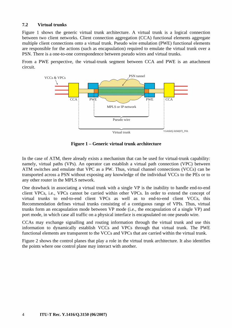
7.2 Virtual trunks Figure 1 shows the generic virtual trunk architecture. A virtual trunk is a logical connection between two client networks. Client connection aggregation (CCA) functional elements aggregate multiple client connections onto a virtual trunk. Pseudo wire emulation (PWE) functional elements are responsible for the actions (such as encapsulation) required to emulate the virtual trunk over a PSN. There is a one-to-one correspondence between pseudo wires and virtual trunks.
From a PWE perspective, the virtual-trunk segment between CCA and PWE is an attachment circuit.
Y.1416/Q.3150(07)_F01
VCCs & VPCs PSN tunnel
CCACCA PWE PWE
MPLS or IP network
Pseudo wire
Virtual trunk
Figure 1 – Generic virtual trunk architecture
In the case of ATM, there already exists a mechanism that can be used for virtual-trunk capability: namely, virtual paths (VPs). An operator can establish a virtual path connection (VPC) between ATM switches and emulate that VPC as a PW. Thus, virtual channel connections (VCCs) can be transported across a PSN without exposing any knowledge of the individual VCCs to the PEs or to any other router in the MPLS network.
One drawback in associating a virtual trunk with a single VP is the inability to handle end-to-end client VPCs, i.e., VPCs cannot be carried within other VPCs. In order to extend the concept of virtual trunks to end-to-end client VPCs as well as to end-to-end client VCCs, this Recommendation defines virtual trunks consisting of a contiguous range of VPIs. Thus, virtual trunks form an encapsulation mode between VP mode (i.e., the encapsulation of a single VP) and port mode, in which case all traffic on a physical interface is encapsulated on one pseudo wire.
CCAs may exchange signalling and routing information through the virtual trunk and use this information to dynamically establish VCCs and VPCs through that virtual trunk. The PWE functional elements are transparent to the VCCs and VPCs that are carried within the virtual trunk.
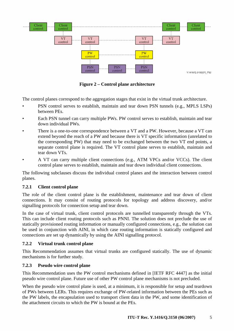
Figure 2 shows the control planes that play a role in the virtual trunk architecture. It also identifies the points where one control plane may interact with another.
ITU-T Rec. Y.1416/Q.3150 (06/2007) 5
Figure 2 – Control plane architecture
The control planes correspond to the aggregation stages that exist in the virtual trunk architecture. • PSN control serves to establish, maintain and tear down PSN tunnels (e.g., MPLS LSPs)
between PEs. • Each PSN tunnel can carry multiple PWs. PW control serves to establish, maintain and tear
down individual PWs. • There is a one-to-one correspondence between a VT and a PW. However, because a VT can
extend beyond the reach of a PW and because there is VT specific information (unrelated to the corresponding PW) that may need to be exchanged between the two VT end points, a separate control plane is required. The VT control plane serves to establish, maintain and tear down VTs.
• A VT can carry multiple client connections (e.g., ATM VPCs and/or VCCs). The client control plane serves to establish, maintain and tear down individual client connections.
The following subclauses discuss the individual control planes and the interaction between control planes.
7.2.1 Client control plane The role of the client control plane is the establishment, maintenance and tear down of client connections. It may consist of routing protocols for topology and address discovery, and/or signalling protocols for connection setup and tear down.
In the case of virtual trunk, client control protocols are tunnelled transparently through the VTs. This can include client routing protocols such as PNNI. The solution does not preclude the use of statically provisioned routing information or manually configured connections, e.g., the solution can be used in conjunction with AINI, in which case routing information is statically configured and connections are set up dynamically by using the AINI signalling protocol.
7.2.2 Virtual trunk control plane This Recommendation assumes that virtual trunks are configured statically. The use of dynamic mechanisms is for further study.
7.2.3 Pseudo wire control plane This Recommendation uses the PW control mechanisms defined in [IETF RFC 4447] as the initial pseudo wire control plane. Future use of other PW control plane mechanisms is not precluded.
When the pseudo wire control plane is used, at a minimum, it is responsible for setup and teardown of PWs between LERs. This requires exchange of PW-related information between the PEs such as the PW labels, the encapsulation used to transport client data in the PW, and some identification of the attachment circuits to which the PW is bound at the PEs.
6 ITU-T Rec. Y.1416/Q.3150 (06/2007)
7.2.4 PSN control plane The PSN control plane is outside the scope of this Recommendation.
7.2.5 Interaction between control planes The VT architecture is designed with the basic principle of keeping the control planes independent. Therefore, one control plane could evolve without any implications for the other control planes. Nevertheless, at various points in the network, one control plane may interact with the control plane above or below itself. For example, based on traffic demands in the client control plane, an ATM switch that functions as an endpoint of a VT could request the VT control plane to allocate more bandwidth.
7.3 Implementation options The CCA and PWE functionality introduced above could be located in two physically separate devices or as two logical components in a single physical device.
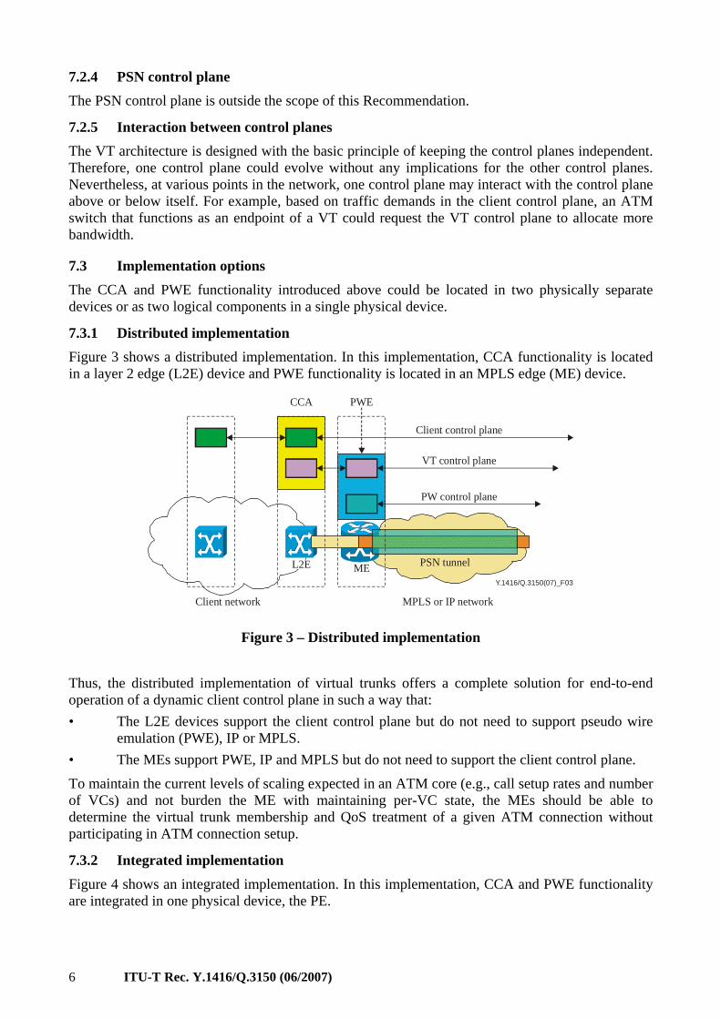
7.3.1 Distributed implementation Figure 3 shows a distributed implementation. In this implementation, CCA functionality is located in a layer 2 edge (L2E) device and PWE functionality is located in an MPLS edge (ME) device.
Y.1416/Q.3150(07)_F03
CCA PWE
Client control plane
VT control plane
PW control plane
Client network MPLS or IP network
MEL2E PSN tunnel
Figure 3 – Distributed implementation
Thus, the distributed implementation of virtual trunks offers a complete solution for end-to-end operation of a dynamic client control plane in such a way that: • The L2E devices support the client control plane but do not need to support pseudo wire
emulation (PWE), IP or MPLS. • The MEs support PWE, IP and MPLS but do not need to support the client control plane.
To maintain the current levels of scaling expected in an ATM core (e.g., call setup rates and number of VCs) and not burden the ME with maintaining per-VC state, the MEs should be able to determine the virtual trunk membership and QoS treatment of a given ATM connection without participating in ATM connection setup.
7.3.2 Integrated implementation Figure 4 shows an integrated implementation. In this implementation, CCA and PWE functionality are integrated in one physical device, the PE.

ITU-T Rec. Y.1416/Q.3150 (06/2007) 7
Y.1416/Q.3150(07)_F04
CCA & PWE
Client control plane
VT control plane
PW control plane
Client network MPLS or IP network
PE1 PSN tunnel
Figure 4 – Integrated implementation
The two implementations are interoperable. A virtual trunk can be established between a PE, which supports both CCA and PWE functionality, and an ME-L2E pair where the functionality is distributed, as shown in Figure 5.
Y.1416/Q.3150(07)_F05
PE
Client network MPLS or IP network
ME1L2E
Client network
Figure 5 – Combination of a distributed and an integrated implementation
8 Virtual trunk procedures – distributed implementation This clause defines virtual trunks and associated mechanisms for mapping identifiers and QoS treatment in the case of a distributed implementation (see 7.3.1) where the interface between the L2E and ME is an ATM interface.
8.1 Definition of virtual trunks on an ATM interface
On an ATM interface, a virtual trunk is a contiguous set of VPIs. Thus, the VPI space on an ATM physical interface is divided into sub-sets, each representing a VT. Two parameters are required: virtual trunk identifier (VTid) and relative VPI (RVPI).
The VTid identifies the range of VPIs that constitute the VT. The RVPI identifies a "relative" VPI within that range. That is, if a certain VT is defined as the range of VPIs between a lower bound L and an upper bound U, i.e., VT = {L, U}, then for a VP, with VPI = K, within that trunk, RVPI = K – L. For example, if a virtual trunk is defined as the set of VPIs {32, 63}, then VPI = 39 corresponds with RVPI = 7.
If client control protocols are carried within a VT, they are transported in the lowest VPI within the range of VPIs that constitute a VT. If x is the lowest VPI within the VT's range of VPIs, then VPI/VCI = x/5 is used for ATM signalling and VPI/VCI = x/18 for PNNI routing. By definition, the RVPI of the VP with the lowest VPI equals 0. Therefore, expressed in terms of RVPI, the ATM signalling channel is 0/5 and the PNNI routing channel is 0/18.
8 ITU-T Rec. Y.1416/Q.3150 (06/2007)
Note that PW emulation of a single VP is a special case of a virtual trunk where the VPI range consists of only one value. All mechanisms defined for virtual trunks also apply to this case.
8.2 ME procedures
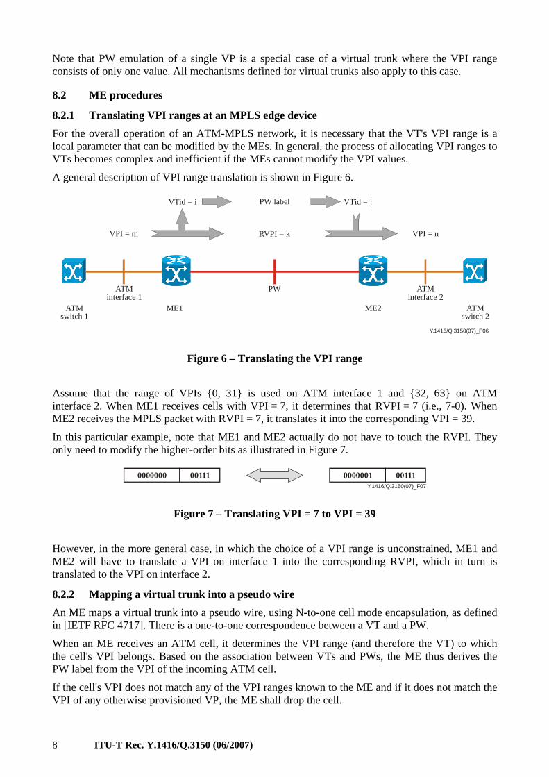
8.2.1 Translating VPI ranges at an MPLS edge device For the overall operation of an ATM-MPLS network, it is necessary that the VT's VPI range is a local parameter that can be modified by the MEs. In general, the process of allocating VPI ranges to VTs becomes complex and inefficient if the MEs cannot modify the VPI values.
A general description of VPI range translation is shown in Figure 6.
Y.1416/Q.3150(07)_F06
VTid = i VTid = jPW label
VPI = m RVPI = k VPI = n
ATMinterface 1
ATMinterface 2
PW
ATMswitch 1
ATMswitch 2
ME1 ME2
Figure 6 – Translating the VPI range
Assume that the range of VPIs {0, 31} is used on ATM interface 1 and {32, 63} on ATM interface 2. When ME1 receives cells with VPI = 7, it determines that RVPI = 7 (i.e., 7-0). When ME2 receives the MPLS packet with RVPI = 7, it translates it into the corresponding VPI = 39.
In this particular example, note that ME1 and ME2 actually do not have to touch the RVPI. They only need to modify the higher-order bits as illustrated in Figure 7.
Y.1416/Q.3150(07)_F07
0000000 00111 0000001 00111
Figure 7 – Translating VPI = 7 to VPI = 39
However, in the more general case, in which the choice of a VPI range is unconstrained, ME1 and ME2 will have to translate a VPI on interface 1 into the corresponding RVPI, which in turn is translated to the VPI on interface 2.
8.2.2 Mapping a virtual trunk into a pseudo wire An ME maps a virtual trunk into a pseudo wire, using N-to-one cell mode encapsulation, as defined in [IETF RFC 4717]. There is a one-to-one correspondence between a VT and a PW.
When an ME receives an ATM cell, it determines the VPI range (and therefore the VT) to which the cell's VPI belongs. Based on the association between VTs and PWs, the ME thus derives the PW label from the VPI of the incoming ATM cell.
If the cell's VPI does not match any of the VPI ranges known to the ME and if it does not match the VPI of any otherwise provisioned VP, the ME shall drop the cell.
ITU-T Rec. Y.1416/Q.3150 (06/2007) 9
As explained in [b-ITU-T Y.1411], for efficiency reasons, the ME may encapsulate multiple ATM cells in a single MPLS packet. The ME shall only concatenate cells that belong to the same ATM service category and, in cases where the cell loss priority (CLP) bit is significant, that have the same CLP. ME may reorder cells belonging to different service categories due to parallel (per service category) concatenation of cells into MPLS packets. Cells belonging to any one particular client VPC or client VCC shall remain in order with respect to other cells belonging to the same client VPC or client VCC.
Sequence numbers shall not be used in case of virtual trunk encapsulation.
8.2.3 Procedures at the ingress ME When ME1 receives ATM cells from ATM switch 1, it must do the following: • Derive VTid and RVPI from the VPI in the ATM cell header. • Select the PW label based on the VTid. • Replace the original VPI value with the RVPI value.
8.2.4 Procedures at the egress ME When ME2 receives an MPLS packet from ME1, it must do the following: • From the PW label, derives the VTid that is to be used on the interface with ATM switch 2. • Based on VTid and RVPI value (which is the VPI value of the de-capsulated ATM cells), it
calculates the VPI value that is to be used on interface 2. It writes this value into the VPI field(s) of the header(s) of the ATM cell(s) it sends to ATM switch 2.
• The VCI, payload type identifier (PTI) and CLP are those obtained from the encapsulated cell.
• The cell payload is that of encapsulated one.
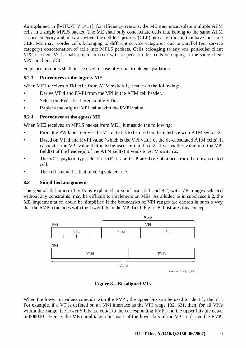
8.3 Simplified assignments The general definition of VTs as explained in subclauses 8.1 and 8.2, with VPI ranges selected without any constraints, may be difficult to implement on MEs. As alluded to in subclause 8.2, the ME implementation could be simplified if the boundaries of VPI ranges are chosen in such a way that the RVPI coincides with the lower bits in the VPI field. Figure 8 illustrates this concept.
Figure 8 – Bit-aligned VTs
When the lower bit values coincide with the RVPI, the upper bits can be used to identify the VT. For example, if a VT is defined on an NNI interface as the VPI range {32, 63}, then, for all VPIs within this range, the lower 5 bits are equal to the corresponding RVPI and the upper bits are equal to 0000001. Hence, the ME could take a bit mask of the lower bits of the VPI to derive the RVPI
10 ITU-T Rec. Y.1416/Q.3150 (06/2007)
and a bit mask of the upper bits of the VPI to derive the VTid. Since the VTid maps directly to a PW label, the process of mapping ATM cells to VTs and subsequently to PWs becomes straightforward.
Bit-aligned VTs in which the lower k bits coincide with the RVPI result in a division of the VPI space on a specific interface in blocks of size 2k. The lower bound of each range equals n*2k, the upper bound ((n + 1)*2k)–1 (where n is an integer).
An ME must support bit-aligned VTs. An ME may be able to support VTs that consist of more flexible ranges of VPIs. • What this means for the operator: The operator decides per physical interface how many VPs need to be supported on virtual
trunks. For example, if VTs should support 32 VPs, the operator would provision the ME to recognize the lower 5 bits as RVPI and the upper 7 bits (or 3 in the case of a UNI interface) as VTid. The operator would provision the ATM switch to allocate 32 VPs to each virtual trunk.
• What it means for the ME: The operator configures the ME to interpret the lower 5 bits as RVPI and the upper bits as
VTid. For each ATM cell it receives from its adjacent ATM switch, it performs a bit mask to derive the VTid and maps that to the PW label. Similarly, for each (encapsulated) ATM cell the ME receives through the MPLS core, it maps the PW label to the VTid and writes this value in the corresponding bits of the VPI of the cell it sends to its adjacent ATM switch.
• What it means for the ATM switch: The ATM switch is not aware of the notion of bit masks. It should be possible for the
operator to configure the ATM switch with VPI ranges in chunks chosen by the operator. For example, the operator should be able to force the ATM switch to choose the following ranges: {0, 31}, {32, 63}, {64, 95}, etc. Apart from this, the ATM switch behaves in the exact same way as described in the previous subclauses.
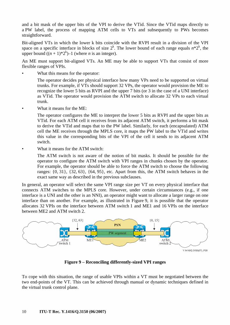
In general, an operator will select the same VPI range size per VT on every physical interface that connects ATM switches to the MPLS core. However, under certain circumstances (e.g., if one interface is a UNI and the other is an NNI), an operator might want to allocate a larger range on one interface than on another. For example, as illustrated in Figure 9, it is possible that the operator allocates 32 VPIs on the interface between ATM switch 1 and ME1 and 16 VPIs on the interface between ME2 and ATM switch 2.
Figure 9 – Reconciling differently-sized VPI ranges
To cope with this situation, the range of usable VPIs within a VT must be negotiated between the two end-points of the VT. This can be achieved through manual or dynamic techniques defined in the virtual trunk control plane.
ITU-T Rec. Y.1416/Q.3150 (06/2007) 11
8.4 QoS A standard VPC has a traffic contract that includes a service category and a conformance definition [ATM tm-0121]. In this Recommendation, the combination of a service category and conformance definition is referred to as a "service class". The QoS treatment1 provided to a packet as it traverses the MPLS core must be sufficient to meet the packet's QoS requirements. A VT may have one of two QoS characteristics: single-QoS or multi-QoS.
8.4.1 Single-QoS VTs Support for Single-QoS virtual trunks is mandatory.
A Single-QoS VT is one in which all constituent VPCs receive the same QoS treatment in the MPLS core. Through provisioning or otherwise, the ME will associate a VT with a certain QoS treatment and it will map the corresponding PW to a PSN tunnel that provides the required QoS treatment.
An operator deploying a single-QoS VT has two options: 1) Combine VPCs of more than one service class into the VT. In this case, the operator shall
associate a QoS behaviour to the VT that is sufficient to meet the most stringent QoS requirements of any constituent VPC even if some of the VPCs or VCCs on that VT have less stringent needs, e.g., treat the entire VT as if it carries CBR traffic even if that is true for only a subset of the VPCs.
2) Associate a VT with a specific service class and force the ATM switch to transport only VPCs and VCCs with that service class on the VT.
Option 2 results in more efficient use of the MPLS core. However, it may require the operator to set up multiple VTs between two ATM switches and allocate VPI ranges per class of service.
8.4.2 Multi-QoS VT
8.4.2.1 Definition Support for multi-QoS virtual trunks is optional.
A Multi-QoS VT is a VT whose constituent VPCs do not all share the same service class, and in which VPCs of different service classes receive appropriately different QoS treatment in the MPLS core. Within a multi-QoS VT, the QoS treatment that a packet receives depends on the service class of the VPC to which it belongs.
In multi-QoS VTs, contiguous ranges of RVPI per service class are established (i.e., provisioned or signalled). The association between a range of RVPI and a service class is established at the ATM edge. The association between a range of RVPI and an MPLS network QoS treatment is established at the MPLS edge. In the extreme, a range could be as small as a single RVPI.
This Recommendation places no restrictions on the partitioning of the RVPI space within a multi-QoS VT. For example, an RVPI range need not be a power of 2, and two RVPI ranges need not be equal in size. Following the initial partitioning of the VT's RVPI space, it is allowable to provision additional ranges from the unused RVPI space as required. A given service class may be associated with more than one RVPI range.
____________________ 1 The term "QoS Treatment" does not include drop precedence. Individual packets accorded the same QoS
Treatment may be differentiated on the basis of drop precedence.
12 ITU-T Rec. Y.1416/Q.3150 (06/2007)
8.4.2.2 Mechanisms at the ingress ATM edge (L2E) The ATM edge shall switch ATM VPCs, originating in the ATM network, of a given service class and PNNI designated transit list (DTL) onto an available VPI within the RVPI range supporting that service class for the appropriate VT. The mechanism for selecting the appropriate RVPI and VT is device specific.
8.4.2.3 Mechanisms at the ingress ME The ME shall map VPCs falling within a particular RVPI range to the appropriate MPLS network QoS treatment.
9 Virtual trunk data plane procedures – integrated implementation In the case of an integrated implementation (see clause 7.3.2), the interface between CCA and PWE is internal to a PE. Since there is not an ATM interface carrying multiple virtual trunks in this configuration, there is no need to partition VPI address space. This has the following consequences: • The number of VPs per VT that a PE can support is only limited by the size of the VPI
space or by internal limitations of the PE itself. • There is no need for VPI translation between CCA and PWE. Therefore, RVPI = VPI.
9.1 Encapsulation The procedures defined in clause 8.2.2 apply.
9.2 ATM control interface ATM signalling and routing channels are carried in VPI = 0.
9.3 QoS In case a PE that supports both CCA and PWE functionality interfaces with an L2E – ME pair in which the functionality is distributed, the QoS procedures defined in clause 8.4 apply, i.e., the VT is either a single-QoS VT or a multi-QoS VT, in which case the different service classes are identified by specific RVPI (i.e., VPI) ranges.
In case both end-points of a VT are PEs that support both CCA and PWE functionality, the PEs could carry multiple service classes over a VT in a more flexible fashion. Since each PE supports both client control plane and pseudo wire emulation, it is, in contrast to clause 8.4.2.1, not necessary to use contiguous ranges of RVPIs per service class. Instead, the service class of each individual VCC or VPC (as negotiated during client connection setup) can be directly mapped to the appropriate MPLS network QoS treatment. Support of this functionality is optional.
9.4 Usable VPIs within a VT
The range of usable VPIs within a VT is negotiated between the two end-points of the VT (refer to the last paragraph of clause 8.3). In case a PE that supports both CCA and PWE functionality interfaces with an L2E – ME pair in which the functionality is distributed (as shown in Figure 5), the range of VPIs that can be used to establish VCCs and VPCs through the VT is limited by the size of the VPI range configured for the distributed side of the VT. The VPI range on the integrated side of the VT should always start at 0.
ITU-T Rec. Y.1416/Q.3150 (06/2007) 13
10 Signalling procedures between ATM switches connected through a virtual trunk When a VT is established between two ATM switches, these switches can use the standard routing and signalling channels in the VP with RVPI = 0 to exchange ATM routing and signalling information. They use the signalling channel to set up and/or release VPCs and VCCs in the virtual trunk.
Since the VPI range assigned to a VT is a local parameter, the VPI value used for a specific connection on one switch may differ from the VPI value used on the other switch. However, the corresponding RVPI value is identical on both switches. Therefore, the two ATM switches shall use the RVPI value when setting up specific VPC or VCC.
The PNNI specification [ATM pnni-0055] introduces the virtual path connection identifier. As explained in 6.5.2.2.3 of [ATM pnni-0055], the VPCI only has significance with regard to a given signalling virtual channel. Its value is not necessarily equal to the actual VPI of the connection, but the two interfacing ATM switches understand the relationship between the VPCI and the actual VPI values. AINI is similar to PNNI in most respects and uses the VPCI in the same way [ATM cs-0125].
Therefore, when ATM switches use PNNI or AINI to set up VPCs and VCCs through a VT, they shall use standard signalling procedures with the RVPI as VPCI. If signalling protocols other than PNNI or AINI are used, similar mechanisms shall be used. The exact definition is protocol dependent and not covered in this Recommendation.
Upon connection establishment, each ATM switch shall translate – as described in clause 8.2 – the RVPI into the actual VPI value that it will use in the data plane.
11 Virtual trunk setup and maintenance This Recommendation assumes that virtual trunks are configured statically. The use of dynamic mechanisms is for further study.
11.1 Virtual trunk configuration In the case of manual configuration, the operator needs to provision the following parameters for each VT.
11.1.1 Parameters relevant to an L2E and its adjacent ME in the case of a distributed implementation
• VPI range (lower-bound VPI and upper-bound VPI): – In case an ME supports only bit-aligned VTs, it might need to be provisioned with the
VTid (see clause 8.3).
11.1.2 Parameters relevant to the CCA functional elements at either end of a VT • The maximum number of VPs that can be established on the VT:
– It is possible that for a specific VT the actual maximum number is lower than the difference between upper-bound VPI and lower-bound VPI. (See clauses 8.3 and 9.4.)
• If applicable, the ATM routing and signalling protocols to be used on the VT.
11.1.3 Parameters relevant to the PWE functional elements The two PWE functional elements need to establish a pseudo wire to carry the VT. The PWEs shall use the procedures defined in [IETF RFC 4447] as follows. • The MEs shall use the PWid FEC element in the LDP signalling messages. • The MEs shall use a PW Type value 0x001E (ATM virtual trunk).
14 ITU-T Rec. Y.1416/Q.3150 (06/2007)
The operator shall provision each PWE functional element with: • the loopback address of its peer; • the PWid value that identifies the PW.
11.1.4 Parameters relevant to both the CCA and the PWE functional elements • QoS parameters associated with the virtual trunk.
12 Virtual trunk OAM Virtual trunks emulate a direct interface between two switches. If two ATM switches are connected through a direct connection, e.g., a SONET or SDH path, a failure in the SONET/SDH layer will result in a failure notification (Path AIS) to the ATM switch downstream of the failure. In turn, the ATM switch will generate F4 AIS for all affected VPCs and F5 AIS for all affected VCCs. In addition, in case a signalling protocol, such as PNNI, was used for connection establishment, the ATM switch will perform the actions specified by that protocol in order to restore or release the affected connections.
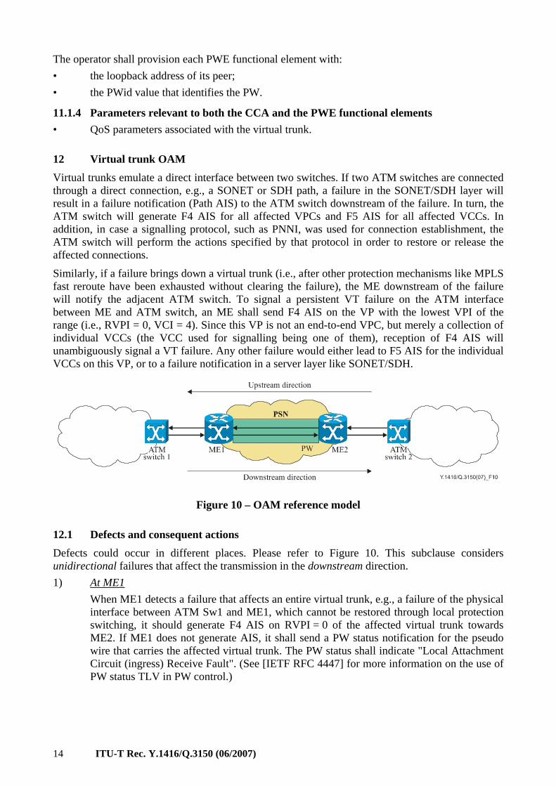
Similarly, if a failure brings down a virtual trunk (i.e., after other protection mechanisms like MPLS fast reroute have been exhausted without clearing the failure), the ME downstream of the failure will notify the adjacent ATM switch. To signal a persistent VT failure on the ATM interface between ME and ATM switch, an ME shall send F4 AIS on the VP with the lowest VPI of the range (i.e., RVPI = 0, VCI = 4). Since this VP is not an end-to-end VPC, but merely a collection of individual VCCs (the VCC used for signalling being one of them), reception of F4 AIS will unambiguously signal a VT failure. Any other failure would either lead to F5 AIS for the individual VCCs on this VP, or to a failure notification in a server layer like SONET/SDH.
Figure 10 – OAM reference model
12.1 Defects and consequent actions Defects could occur in different places. Please refer to Figure 10. This subclause considers unidirectional failures that affect the transmission in the downstream direction. 1) At ME1 When ME1 detects a failure that affects an entire virtual trunk, e.g., a failure of the physical
interface between ATM Sw1 and ME1, which cannot be restored through local protection switching, it should generate F4 AIS on RVPI = 0 of the affected virtual trunk towards ME2. If ME1 does not generate AIS, it shall send a PW status notification for the pseudo wire that carries the affected virtual trunk. The PW status shall indicate "Local Attachment Circuit (ingress) Receive Fault". (See [IETF RFC 4447] for more information on the use of PW status TLV in PW control.)
ITU-T Rec. Y.1416/Q.3150 (06/2007) 15
2) At ME2 When ME2 detects a defect that affects the pseudo wire related to a specific virtual trunk,
which cannot be restored through local protection switching, ME2 shall generate F4 AIS on RVPI = 0 towards ATM switch 2.
ME2 could detect the defect itself, e.g., when it detects a SONET failure; when it receives a PathErr for the PSN tunnel (RSVP-TE built LSP) that carries the PW; or when it detects a PW failure. Alternatively, ME2 might be informed about the defect by ME1 through a PW Status message. Finally, ME1 and ME2 might run a continuity verification protocol like BFD or ITU-T Rec. Y.1711 through the PW. Failure to receive the respective periodic messages will lead ME2 to declare a defect. NOTE – ME2 transparently forwards all ATM cells carried over the VT. Therefore, if ME1 inserts F4 AIS on RVPI = 0, ME2 transparently forwards it to ATM switch 2.
3) At ATM switch 2 Upon reception of F4 AIS on RVPI = 0, or if ATM switch 2 detects a failure on the
interface between ME2 and ATM switch 2 that affects an entire virtual trunk and which cannot be restored through local protection switching, ATM switch 2 shall consider the VT to be down. It shall generate, in the downstream direction, F4 AIS for all affected VPCs and F5 AIS for all affected VCCs. In addition, it shall generate F4 RDI on RVPI = 0 in the reverse (upstream) direction. Finally, in case a signalling protocol (such as PNNI) was used for connection establishment, the ATM switch will perform the actions specified by that protocol in order to restore or release the affected connections.
Upon the reception of F4 RDI on RVPI = 0, ATM switch 1 shall not inject an ATM fault notification like AIS or RDI on the VPCs and VCCs that are affected by the VT failure. Instead, the downstream end-point of each affected VCC or VPC is expected to generate an upstream RDI in response to the downstream AIS signal generated by ATM switch 2.
In the case of an integrated implementation, where ME2 and ATM switch 2 are integrated into a single network element, that network element shall be able to interpret both F4 AIS on RVPI = 0 and PW status notification, indicating "Local Attachment Circuit (ingress) Receive Fault", as indications that the virtual trunk is down. It shall generate, in the downstream direction, F4 AIS for all affected VPCs, and F5 AIS for all affected VCCs. In addition, it shall generate F4 RDI on RVPI = 0 in the reverse (upstream) direction. Finally, in case a signalling protocol (such as PNNI) was used for connection establishment, the ATM switch will perform the actions specified by that protocol in order to restore or release the affected connections.
In case a failure causes transmission in both directions of a VT to be interrupted, the F4 RDI on RVPI = 0 sent by one ATM switch will obviously not be received by its peer. However, in that case both ATM switches will detect the VT failure independently. They shall both act as described above.
16 ITU-T Rec. Y.1416/Q.3150 (06/2007)
Annex A
Support of both virtual trunks and individual VCs on the same ATM interface
(This annex forms an integral part of this Recommendation)
Support of this annex is optional.
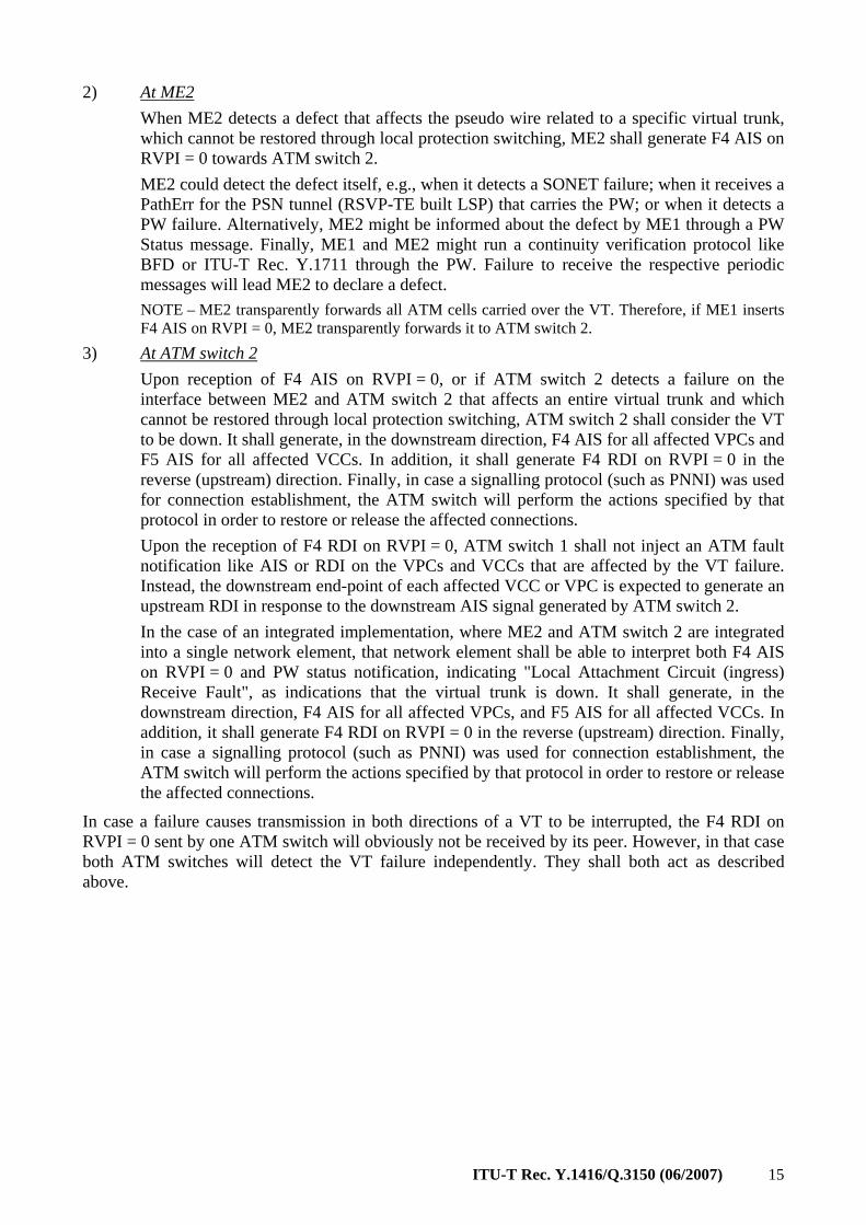
In certain network configurations, it may be advantageous if an ATM switch can support both virtual trunks and traditional VCs on the same ATM interface. An example is shown in Figure A.1
Figure A.1 – Network configuration
If MPLS edge device 1 in Figure A.1 supports PNNI, it could support one-to-one encapsulation. To support both virtual trunks and traditional VCs on the same ATM interface, the following conditions must be met by ATM switch 1 and MPLS edge device 1: 1) VPI = 0 may not be part of any of the VPI ranges allocated to the virtual trunks on the
interface. Instead, VPI = 0/VCI = 18 is used to carry PNNI routing information and VPI = 0/VCI = 5 is used for PNNI signalling messages related to the establishment of individual VPCs and VCCs.
2) When assigning a VPI value to an individual VPC or VCC, both ATM switch 1 and MPLS edge device 1 must avoid the ranges that have been assigned to virtual trunks or that have been reserved for VT use.
Figure A.1 shows two VCs. The red squares identify the nodes that participate in the establishment of each VC.
VC1 is an individual VC. To establish VC1, signalling messages are exchanged between ATM switch 1, MPLS edge device 1, and MPLS edge device 3. As part of the establishment of VC1, a pseudo wire is set up between MPLS edge device 1 and MPLS edge device 3 so that there is a 1-1 mapping between VC and PW.
VC2 is set up through a virtual trunk. To establish VC2, ATM switch 1 and ATM switch 2 exchange signalling messages. These signalling messages are transported over the signalling channel that is embedded in the VT (i.e., over RVPI = 0). Setup of VC2 is transparent to MPLS edge device 1 and MPLS edge device 2.
ITU-T Rec. Y.1416/Q.3150 (06/2007) 17
Appendix I
VPI range as local parameter (This appendix does not form an integral part of this Recommendation)
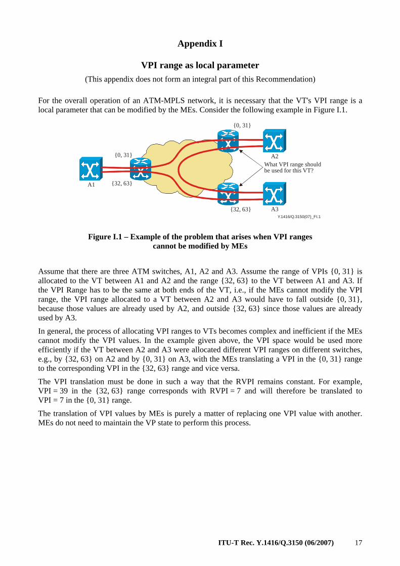
For the overall operation of an ATM-MPLS network, it is necessary that the VT's VPI range is a local parameter that can be modified by the MEs. Consider the following example in Figure I.1.
Y.1416/Q.3150(07)_FI.1
A1
A2
A3
What VPI range shouldbe used for this VT?
{0, 31}
{32, 63}
{32, 63}
{0, 31}
Figure I.1 – Example of the problem that arises when VPI ranges cannot be modified by MEs
Assume that there are three ATM switches, A1, A2 and A3. Assume the range of VPIs {0, 31} is allocated to the VT between A1 and A2 and the range {32, 63} to the VT between A1 and A3. If the VPI Range has to be the same at both ends of the VT, i.e., if the MEs cannot modify the VPI range, the VPI range allocated to a VT between A2 and A3 would have to fall outside {0, 31}, because those values are already used by A2, and outside {32, 63} since those values are already used by A3.
In general, the process of allocating VPI ranges to VTs becomes complex and inefficient if the MEs cannot modify the VPI values. In the example given above, the VPI space would be used more efficiently if the VT between A2 and A3 were allocated different VPI ranges on different switches, e.g., by {32, 63} on A2 and by {0, 31} on A3, with the MEs translating a VPI in the {0, 31} range to the corresponding VPI in the {32, 63} range and vice versa.
The VPI translation must be done in such a way that the RVPI remains constant. For example, VPI = 39 in the {32, 63} range corresponds with RVPI = 7 and will therefore be translated to VPI = 7 in the {0, 31} range.
The translation of VPI values by MEs is purely a matter of replacing one VPI value with another. MEs do not need to maintain the VP state to perform this process.
18 ITU-T Rec. Y.1416/Q.3150 (06/2007)
Bibliography
[b-ITU-T Y.1411] ITU-T Recommendation Y.1411 (2003), ATM-MPLS network interworking – Cell mode user plane interworking.
[b-ITU-T Y.1417] ITU-T Recommendation Y.1417/Q.3151 (2007), ATM and frame relay/MPLS control plane interworking: Client-server.
[b-ATM cs-0197] ATM Forum, af-cs-0197.000.pdf, ATM-MPLS Network Interworking Signalling Specification Version 1.0, August 2003.
[b-IETF RFC 3931] IETF RFC 3931 (2005), Layer Two Tunneling Protocol – Version 3 (L2TPv3).
[b-IETF RFC 3985] IETF RFC 3985 (2005), Pseudo Wire Emulation Edge-to-Edge (PWE3) Architecture.
ITU-T Q-SERIES RECOMMENDATIONS SWITCHING AND SIGNALLING
SIGNALLING IN THE INTERNATIONAL MANUAL SERVICE Q.1–Q.3 INTERNATIONAL AUTOMATIC AND SEMI-AUTOMATIC WORKING Q.4–Q.59 FUNCTIONS AND INFORMATION FLOWS FOR SERVICES IN THE ISDN Q.60–Q.99 CLAUSES APPLICABLE TO ITU-T STANDARD SYSTEMS Q.100–Q.119 SPECIFICATIONS OF SIGNALLING SYSTEMS No. 4, 5, 6, R1 AND R2 Q.120–Q.499 DIGITAL EXCHANGES Q.500–Q.599 INTERWORKING OF SIGNALLING SYSTEMS Q.600–Q.699 SPECIFICATIONS OF SIGNALLING SYSTEM No. 7 Q.700–Q.799 Q3 INTERFACE Q.800–Q.849 DIGITAL SUBSCRIBER SIGNALLING SYSTEM No. 1 Q.850–Q.999 PUBLIC LAND MOBILE NETWORK Q.1000–Q.1099 INTERWORKING WITH SATELLITE MOBILE SYSTEMS Q.1100–Q.1199 INTELLIGENT NETWORK Q.1200–Q.1699 SIGNALLING REQUIREMENTS AND PROTOCOLS FOR IMT-2000 Q.1700–Q.1799 SPECIFICATIONS OF SIGNALLING RELATED TO BEARER INDEPENDENT CALL CONTROL (BICC)
Q.1900–Q.1999
BROADBAND ISDN Q.2000–Q.2999 SIGNALLING REQUIREMENTS AND PROTOCOLS FOR THE NGN Q.3000–Q.3999
General Q.3000–Q.3029 Network signalling and control functional architecture Q.3030–Q.3099 Network data organization within the NGN Q.3100–Q.3129 Bearer control signalling Q.3130–Q.3179 Signalling and control requirements and protocols to support attachment in NGN environments Q.3200–Q.3249 Resource control protocols Q.3300–Q.3369 Service and session control protocols Q.3400–Q.3499 Service and session control protocols – supplementary services Q.3600–Q.3649 NGN applications Q.3700–Q.3849 Testing for NGN networks Q.3900–Q.3999
For further details, please refer to the list of ITU-T Recommendations.
Printed in Switzerland Geneva, 2008
SERIES OF ITU-T RECOMMENDATIONS
Series A Organization of the work of ITU-T
Series D General tariff principles
Series E Overall network operation, telephone service, service operation and human factors
Series F Non-telephone telecommunication services
Series G Transmission systems and media, digital systems and networks
Series H Audiovisual and multimedia systems
Series I Integrated services digital network
Series J Cable networks and transmission of television, sound programme and other multimedia signals
Series K Protection against interference
Series L Construction, installation and protection of cables and other elements of outside plant
Series M Telecommunication management, including TMN and network maintenance
Series N Maintenance: international sound programme and television transmission circuits
Series O Specifications of measuring equipment
Series P Telephone transmission quality, telephone installations, local line networks
Series Q Switching and signalling
Series R Telegraph transmission
Series S Telegraph services terminal equipment
Series T Terminals for telematic services
Series U Telegraph switching
Series V Data communication over the telephone network
Series X Data networks, open system communications and security
Series Y Global information infrastructure, Internet protocol aspects and next-generation networks
Series Z Languages and general software aspects for telecommunication systems