isro system manual - hobi labs
TRANSCRIPT

HydroRad Radiometers andController / Logging System
Prepared ForIndian Space Research Organisation
Space Application Centre
SYSTEM USER’S MANUAL
Revision C2: March 2011
Hydro-Optics, Biology & InstrumentationLaboratoriesLighting the Way in Aquatic Sciencewww.hobilabs.com [email protected]
ii
Revision C2, March 2011: FormattingRevision C, October 2006:
Remove post-processing software section to separate manual.Section 7.6, add details about packet format and correct byte addresses.Section 6: update description of HydroDAS Console to reflect version 1.21 (add
file capture and expand file transfer functions).
Revision B, July 2006:Add section on post-processing software; minor editorial changes
iii
Table of Contents
1 SYSTEM OVERVIEW ........................................................................................................................ 1
2 PRECAUTIONS................................................................................................................................... 3
2.1 OVERALL......................................................................................................................................... 32.2 HYDRORADS — FIBER OPTICS........................................................................................................ 32.3 SHUTTERS ....................................................................................................................................... 32.4 HYDRODAS .................................................................................................................................... 3
3 HYDRORAD SPECTRORADIOMETERS....................................................................................... 4
3.1 INTRODUCTION................................................................................................................................ 43.1.1 HydroRad Configurations ...................................................................................................... 43.1.2 Anti-fouling shutters ............................................................................................................... 43.1.3 Mounting cages....................................................................................................................... 53.1.4 RadSoft Software .................................................................................................................... 5
3.2 SETUP.............................................................................................................................................. 53.2.1 HydroRad-2 Handling and Mounting..................................................................................... 53.2.2 HydroRad-ES1 Handling and Mounting ................................................................................ 53.2.3 Cable routing.......................................................................................................................... 63.2.4 Mounting of Light Collectors and Shutters............................................................................. 63.2.5 HydroRad Firmware Settings ................................................................................................. 6
3.3 MAINTENANCE ................................................................................................................................ 6
4 HYDRODAS CONTROLLER/PROCESSOR................................................................................... 7
4.1 INTRODUCTION................................................................................................................................ 74.2 DESCRIPTION................................................................................................................................... 7
4.2.1 System Components ................................................................................................................ 74.2.2 Enclosure and Mounting......................................................................................................... 84.2.3 Connections ............................................................................................................................ 9
4.3 COMMUNICATING WITH THE HYDRODAS ..................................................................................... 104.3.1 Console Port: Primary Connection ...................................................................................... 104.3.2 USB Port: Data Offload ....................................................................................................... 104.3.3 Host Port: Secondary Functions........................................................................................... 11
4.4 SOFTWARE .................................................................................................................................... 114.4.1 Windows Software ................................................................................................................ 114.4.2 HydroDAS Firmware and Operating System ....................................................................... 114.4.3 HydroDAS Scripts................................................................................................................. 114.4.4 Custom Firmware Modifications .......................................................................................... 12
4.5 SOFTWARE CONFIGURATION ......................................................................................................... 124.5.1 Required Files....................................................................................................................... 124.5.2 System Variables................................................................................................................... 13
5 QUICK START .................................................................................................................................. 15
5.1 HYDRODAS QUICK START ........................................................................................................... 155.1.1 Requirements:....................................................................................................................... 155.1.2 Procedure ............................................................................................................................. 15
5.2 SYSTEM QUICK START .................................................................................................................. 175.2.1 Requirements ........................................................................................................................ 175.2.2 Procedure ............................................................................................................................. 17
6 HYDRODAS CONSOLE SOFTWARE ............................................................................................. 19
6.1 HYDRODAS CONNECTION ............................................................................................................ 196.1.1 Connection Troubleshooting ................................................................................................ 20
iv
6.1.2 Disconnect ............................................................................................................................ 206.1.3 Show Terminal...................................................................................................................... 206.1.4 Activate/Deactivate USB ...................................................................................................... 20
6.2 AVERAGING BANDS ...................................................................................................................... 216.2.1 Editing Bands ....................................................................................................................... 216.2.2 Loading and Saving Bands ................................................................................................... 21
6.3 DATA COLLECTION CONTROLS ..................................................................................................... 216.3.1 Maximum Tilt Settings .......................................................................................................... 216.3.2 Schedule................................................................................................................................ 216.3.3 Mode ..................................................................................................................................... 226.3.4 Information Level ................................................................................................................. 226.3.5 Loading and Saving Settings ................................................................................................ 226.3.6 Loading Scripts..................................................................................................................... 22
6.4 REPROCESSING.............................................................................................................................. 236.5 DAS SETUP CONTROLS ................................................................................................................. 24
6.5.1 Clock Setting......................................................................................................................... 246.5.2 Saving Files to the HydroDAS.............................................................................................. 24
6.6 FILE CAPTURE ............................................................................................................................... 25
7 DATA COLLECTION AND PROCESSING .................................................................................. 26
7.1 AUTONOMOUS MODE .................................................................................................................... 267.2 COMMANDED MODE ..................................................................................................................... 267.3 DATA COLLECTION PROCEDURE ................................................................................................... 277.4 DATA PROCESSING PROCEDURE.................................................................................................... 277.5 INTERFACE WITH SATELLITE TRANSCEIVER .................................................................................. 277.6 TRANSMITTED DATA FORMAT ...................................................................................................... 28
8 USB OFFLOAD.................................................................................................................................. 33
8.1 USB DRIVER INSTALLATION......................................................................................................... 338.2 HYDRODAS USBLINK................................................................................................................... 35
9 SPECIAL PROCEDURES ................................................................................................................ 36
9.1 FIRMWARE INSTALLATION ............................................................................................................ 369.1.1 Requirements ........................................................................................................................ 369.1.2 Procedure ............................................................................................................................. 36
9.2 AUTO-START OVERRIDE ............................................................................................................... 389.2.1 Purpose................................................................................................................................. 389.2.2 Requirements ........................................................................................................................ 389.2.3 Procedure ............................................................................................................................. 38
9.3 UPDATING HYDRORAD CALIBRATION FILES ON HYDRODAS....................................................... 409.3.1 Preparations on the PC ........................................................................................................ 409.3.2 Installation............................................................................................................................ 41
1
1 SYSTEM OVERVIEW
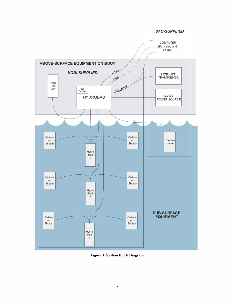
This document describes a hyperspectral radiometer system designed for the SpaceApplications Centre of the Indian Space Research Organisation. It is to be deployed on abuoy in the Indian Ocean, in order to collect long-term time series data on the spectralproperties of light at and near the ocean’s surface.
The system is based on HOBI Labs’ HydroRad radiometers, and a customizedHydroDAS data acquisition and logging controller. Figure 1 shows a block diagram ofthe major components of the system.
The HydroRads, described further in Section 2, measure downwelling irradiance onthe surface and at three depths under the surface, and upwelling radiance at the samethree depths. They are equipped with anti-fouling shutters to provide accurate resultsover long periods in the water.
The HydroDAS controls all the instruments and collects, archives and processestheir data. It transfers the processed data to a customer-designed satellite transceiver forrelaying to shore. In addition, archive data can be processed on shore after theHydroDAS is retrieved.
2
ABOVE-SURFACE EQUIPMENT ON BUOY
SUB-SURFACE
Hydro-Rad-
2
Hydro-Rad-
2
Hydro-Rad-
2
Collect-or/
ShutterFluoro-meter
Hydro-Rad-ES1
12V DCPOWER SOURCE
SATELLITETRANSCEIVER
SAC-SUPPLIED
HOBI-SUPPLIED
Collect-or/
Shutter
Collect-or/
Shutter
Collect-or/
Shutter
Collect-or/
Shutter
Collect-or/
Shutter
EQUIPMENT
HOST
USB
CONSOLE
COMPUTER
HYDRODAS
TiltSensor
(For setup andoffload)
Figure 1 System Block Diagram
3
2 PRECAUTIONS
2.1 OVERALL Protect the equipment from mechanical shocks and severe vibration Use redundant attachments to buoy structure Do not attempt to open any equipment cases
2.2 HYDRORADS — FIBER OPTICS Avoid long-term bends of radius less than 10cm Secure the cables against repetitive motions that could occur due to waves,
wind and weather at sea. Do not apply force to the penetrators where the fiber optic cables enter the
HydroRad housings
2.3 SHUTTERS Never force the shutter blades to move, or prevent them from moving when
powered. Corrosion of the copper parts is normal and not harmful
2.4 HYDRODAS Do not apply more than 16V to power supply input.
4
3 HYDRORAD SPECTRORADIOMETERS
3.1 INTRODUCTIONThe primary measurements of the SAC system are made by four HydroRad multi-
channel hyperspectral radiometers. A HydroRad-ES1 on the surface measures incidentsolar irradiance, and three HydroRad-2s measure downwelling irradiance (Ed) andupwelling radiance (Lu) at different depths in the water. Except as noted below, theseinstruments are in standard configurations and the reader is referred to the HydroRadUser’s Manual for further details.
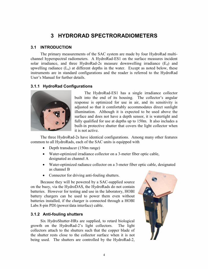
3.1.1 HydroRad ConfigurationsThe HydroRad-ES1 has a single irradiance collector
built into the end of its housing. The collector’s angularresponse is optimized for use in air, and its sensitivity isadjusted so that it comfortably accommodates direct sunlightillumination. Although it is expected to be used above thesurface and does not have a depth sensor, it is watertight andfully qualified for use at depths up to 150m. It also includes abuilt-in protective shutter that covers the light collector whenit is not active.
The three HydroRad-2s have identical configurations. Among many other featurescommon to all HydroRads, each of the SAC units is equipped with
Depth transducer (150m range) Water-optimized irradiance collector on a 3-meter fiber optic cable,
designated as channel A Water-optimized radiance collector on a 3-meter fiber optic cable, designated
as channel B Connector for driving anti-fouling shutters.
Because they will be powered by a SAC-supplied sourceon the buoy, via the HydroDAS, the HydroRads do not containbatteries. However for testing and use in the laboratory, HOBIbattery chargers can be used to power them even withoutbatteries installed, if the charger is connected through a HOBILabs 8-pin PDI (power/data interface) cable.
3.1.2 Anti-fouling shuttersSix HydroShutter-HRs are supplied, to retard biological
growth on the HydroRad-2’s light collectors. The lightcollectors attach to the shutters such that the copper blade ofthe shutter rests close to the collector surface when it is notbeing used. The shutters are controlled by the HydroRad-2,
5
which switches on the power to open them before collecting data, and to close themafterward. For further details, see the HydroShutter-HR User’s Manual.
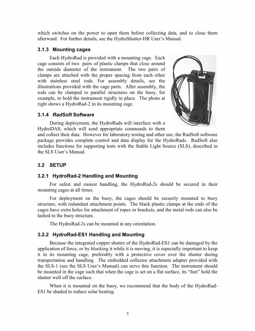
3.1.3 Mounting cagesEach HydroRad is provided with a mounting cage. Each
cage consists of two pairs of plastic clamps that close aroundthe outside diameter of the instrument. The two pairs ofclamps are attached with the proper spacing from each otherwith stainless steel rods. For assembly details, see theillustrations provided with the cage parts. After assembly, therods can be clamped to parallel structures on the buoy, forexample, to hold the instrument rigidly in place. The photo atright shows a HydroRad-2 in its mounting cage.
3.1.4 RadSoft SoftwareDuring deployment, the HydroRads will interface with a
HydroDAS, which will send appropriate commands to themand collect their data. However for laboratory testing and other use, the RadSoft softwarepackage provides complete control and data display for the HydroRads. RadSoft alsoincludes functions for supporting tests with the Stable Light Source (SLS), described inthe SLS User’s Manual.
3.2 SETUP
3.2.1 HydroRad-2 Handling and MountingFor safest and easiest handling, the HydroRad-2s should be secured in their
mounting cages at all times.
For deployment on the buoy, the cages should be securely mounted to buoystructure, with redundant attachment points. The black plastic clamps at the ends of thecages have extra holes for attachment of ropes or brackets, and the metal rods can also belashed to the buoy structure.
The HydroRad-2s can be mounted in any orientation.
3.2.2 HydroRad-ES1 Handling and MountingBecause the integrated copper shutter of the HydroRad-ES1 can be damaged by the
application of force, or by blocking it while it is moving, it is especially important to keepit in its mounting cage, preferably with a protective cover over the shutter duringtransportation and handling. The embedded collector attachment adapter provided withthe SLS-1 (see the SLS User’s Manual) can serve this function. The instrument shouldbe mounted in the cage such that when the cage is set on a flat surface, its “feet” hold theshutter well off the surface.
When it is mounted on the buoy, we recommend that the body of the HydroRad-ES1 be shaded to reduce solar heating.
6
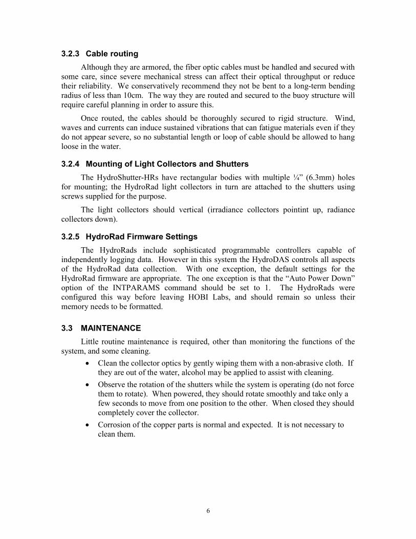
3.2.3 Cable routingAlthough they are armored, the fiber optic cables must be handled and secured with
some care, since severe mechanical stress can affect their optical throughput or reducetheir reliability. We conservatively recommend they not be bent to a long-term bendingradius of less than 10cm. The way they are routed and secured to the buoy structure willrequire careful planning in order to assure this.
Once routed, the cables should be thoroughly secured to rigid structure. Wind,waves and currents can induce sustained vibrations that can fatigue materials even if theydo not appear severe, so no substantial length or loop of cable should be allowed to hangloose in the water.
3.2.4 Mounting of Light Collectors and ShuttersThe HydroShutter-HRs have rectangular bodies with multiple ¼” (6.3mm) holes
for mounting; the HydroRad light collectors in turn are attached to the shutters usingscrews supplied for the purpose.
The light collectors should vertical (irradiance collectors pointint up, radiancecollectors down).
3.2.5 HydroRad Firmware SettingsThe HydroRads include sophisticated programmable controllers capable of
independently logging data. However in this system the HydroDAS controls all aspectsof the HydroRad data collection. With one exception, the default settings for theHydroRad firmware are appropriate. The one exception is that the “Auto Power Down”option of the INTPARAMS command should be set to 1. The HydroRads wereconfigured this way before leaving HOBI Labs, and should remain so unless theirmemory needs to be formatted.
3.3 MAINTENANCELittle routine maintenance is required, other than monitoring the functions of the
system, and some cleaning. Clean the collector optics by gently wiping them with a non-abrasive cloth. If
they are out of the water, alcohol may be applied to assist with cleaning. Observe the rotation of the shutters while the system is operating (do not force
them to rotate). When powered, they should rotate smoothly and take only afew seconds to move from one position to the other. When closed they shouldcompletely cover the collector.
Corrosion of the copper parts is normal and expected. It is not necessary toclean them.
7
4 HYDRODAS CONTROLLER/PROCESSOR
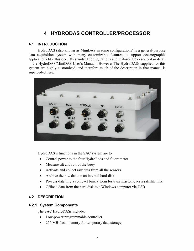
4.1 INTRODUCTIONHydroDAS (also known as MiniDAS in some configurations) is a general-purpose
data acquisition system with many customizable features to support oceanographicapplications like this one. Its standard configurations and features are described in detailin the HydroDAS/MiniDAS User’s Manual. However The HydroDASs supplied for thissystem are highly customized, and therefore much of the description in that manual issuperceded here.
HydroDAS’s functions in the SAC system are to Control power to the four HydroRads and fluorometer Measure tilt and roll of the buoy Activate and collect raw data from all the sensors Archive the raw data on an internal hard disk Process data into a compact binary form for transmission over a satellite link. Offload data from the hard disk to a Windows computer via USB
4.2 DESCRIPTION
4.2.1 System ComponentsThe SAC HydroDASs include: Low-power programmable controller, 256 MB flash memory for temporary data storage,
8
8-GB hard disk for archiving raw data, Six software-controlled power switches, Six RS-232 serial ports, Two RS-232 ports for communication with external PCs and the SAC satellite
transceiver, USB port for offloading data from the hard disk, A tilt/roll/compass sensor for measuring buoy orientation during data
collection.
Because it is intended for remote and autonomous use, the SAC HydroDAS doesnot have the external switch referred to in the HydroDAS manual.
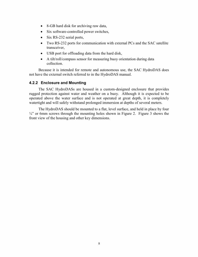
4.2.2 Enclosure and MountingThe SAC HydroDASs are housed in a custom-designed enclosure that provides
rugged protection against water and weather on a buoy. Although it is expected to beoperated above the water surface and is not operated at great depth, it is completelywatertight and will safely withstand prolonged immersion at depths of several meters.
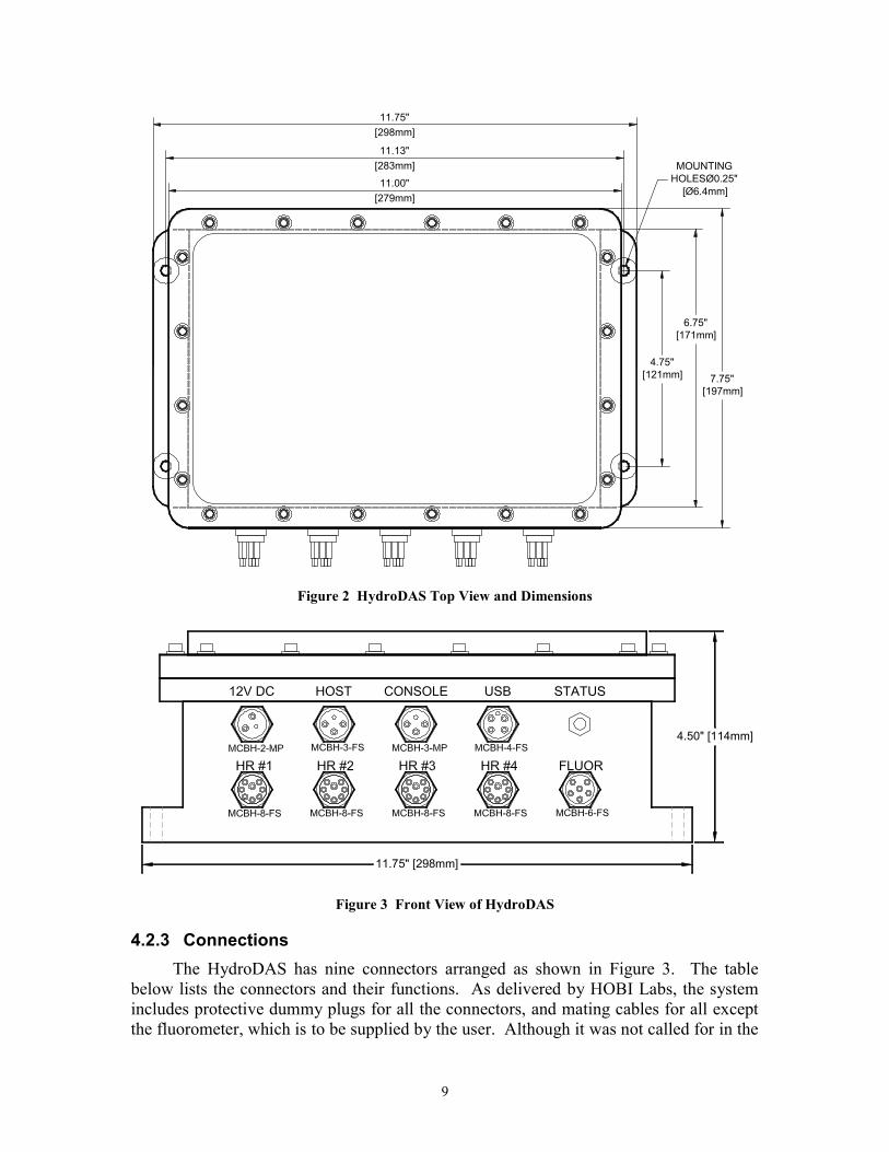
The HydroDAS should be mounted to a flat, level surface, and held in place by four¼” or 6mm screws through the mounting holes shown in Figure 2. Figure 3 shows thefront view of the housing and other key dimensions.
9
6.75"[171mm]
7.75"[197mm]
11.00"[279mm]
11.13"[283mm]
11.75"[298mm]
4.75"[121mm]
MOUNTINGHOLESØ0.25"
[Ø6.4mm]
Figure 2 HydroDAS Top View and Dimensions
4.50" [114mm]
11.75" [298mm]
Figure 3 Front View of HydroDAS
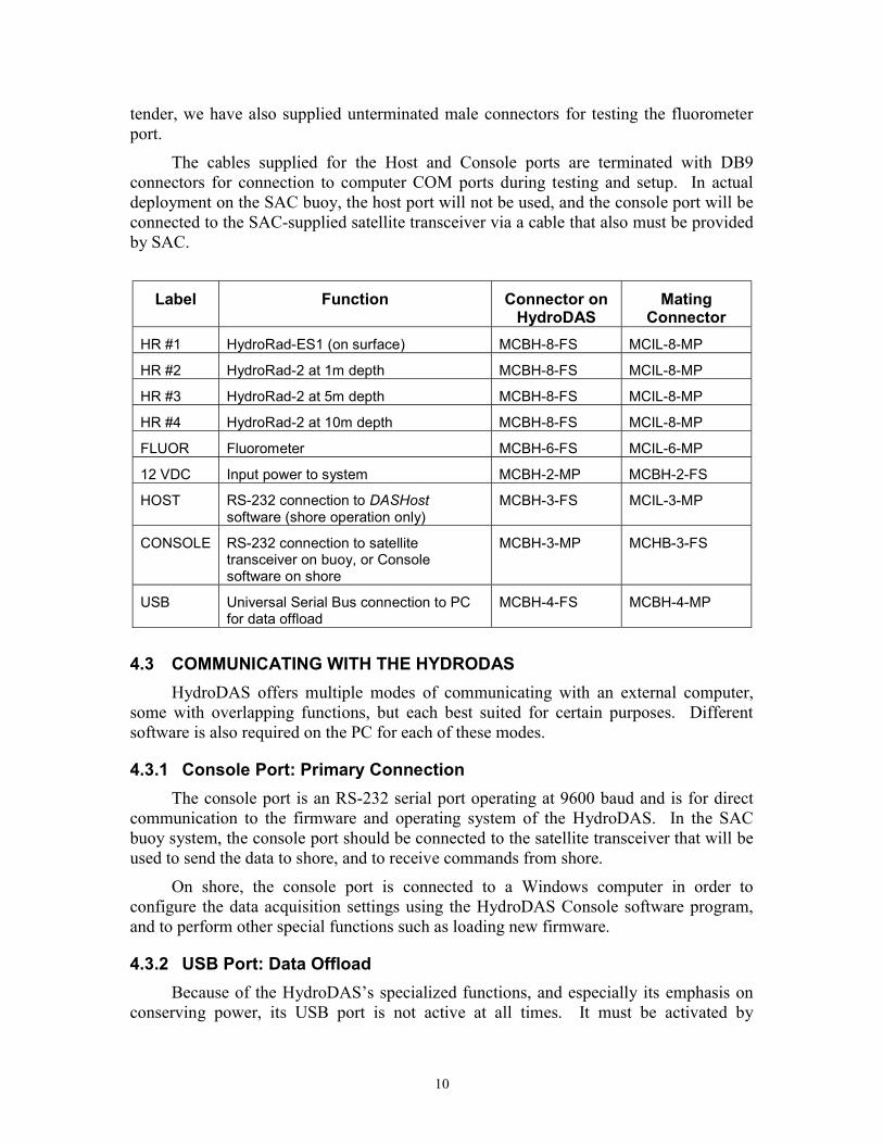
4.2.3 ConnectionsThe HydroDAS has nine connectors arranged as shown in Figure 3. The table
below lists the connectors and their functions. As delivered by HOBI Labs, the systemincludes protective dummy plugs for all the connectors, and mating cables for all exceptthe fluorometer, which is to be supplied by the user. Although it was not called for in the
10
tender, we have also supplied unterminated male connectors for testing the fluorometerport.
The cables supplied for the Host and Console ports are terminated with DB9connectors for connection to computer COM ports during testing and setup. In actualdeployment on the SAC buoy, the host port will not be used, and the console port will beconnected to the SAC-supplied satellite transceiver via a cable that also must be providedby SAC.
Label Function Connector onHydroDAS
MatingConnector
HR #1 HydroRad-ES1 (on surface) MCBH-8-FS MCIL-8-MP
HR #2 HydroRad-2 at 1m depth MCBH-8-FS MCIL-8-MP
HR #3 HydroRad-2 at 5m depth MCBH-8-FS MCIL-8-MP
HR #4 HydroRad-2 at 10m depth MCBH-8-FS MCIL-8-MP
FLUOR Fluorometer MCBH-6-FS MCIL-6-MP
12 VDC Input power to system MCBH-2-MP MCBH-2-FS
HOST RS-232 connection to DASHostsoftware (shore operation only)
MCBH-3-FS MCIL-3-MP
CONSOLE RS-232 connection to satellitetransceiver on buoy, or Consolesoftware on shore
MCBH-3-MP MCHB-3-FS
USB Universal Serial Bus connection to PCfor data offload
MCBH-4-FS MCBH-4-MP
4.3 COMMUNICATING WITH THE HYDRODASHydroDAS offers multiple modes of communicating with an external computer,
some with overlapping functions, but each best suited for certain purposes. Differentsoftware is also required on the PC for each of these modes.
4.3.1 Console Port: Primary ConnectionThe console port is an RS-232 serial port operating at 9600 baud and is for direct
communication to the firmware and operating system of the HydroDAS. In the SACbuoy system, the console port should be connected to the satellite transceiver that will beused to send the data to shore, and to receive commands from shore.
On shore, the console port is connected to a Windows computer in order toconfigure the data acquisition settings using the HydroDAS Console software program,and to perform other special functions such as loading new firmware.
4.3.2 USB Port: Data OffloadBecause of the HydroDAS’s specialized functions, and especially its emphasis on
conserving power, its USB port is not active at all times. It must be activated by
11
connecting the console port to a PC (normally, but not necessarily, the same one to whichthe USB is connected) and running the HydroDAS Console software.
4.3.3 Host Port: Secondary FunctionsThe host port is not used during deployment on the buoy, but is useful for some
special functions in the laboratory. It is an RS-232 serial port normally operating at115200 kBaud, although this rate can be changed, and supporting a special protocol thatis compatible only with the DASHost software.
4.4 SOFTWARE
4.4.1 Windows SoftwareSeveral software programs that run on the Windows operating system are used to
support the HydroDAS. HydroDAS Console is the primary means of setting up the HydroDAS for
logging in the SAC buoy system. It is described in Section 6. HydroDAS USBLink is for offloading and deleting data via the HydroDAS
USB port. It is described in Section 8.2. DASHost provides complete access to all HydroDAS functions, but requires a
high-baud-rate connection that is not practical over the satellite link in theSAC system. DASHost’s primary function for this system is to provideadditional monitoring of the system during testing on shore.
4.4.2 HydroDAS Firmware and Operating SystemThe processor in the HydroDAS is a computer in its own right, with an operating
system called PicoDOS, and application programs to perform its various functions. Theapplication programs that run on the HydroDAS are collectively referred to as firmware.At most times, the program running on the HydroDAS is the main firmware, which isloaded permanently in its flash memory and starts automatically when the HydroDAS ispowered up.
In addition to the normal main firmware, it is also possible (though not normallynecessary) to exit the firmware and communicate directly to PicoDOS. A separatefirmware program is also used during USB offloads. The HydroDAS Console Windowsapplication properly handles these different programs when necessary.
4.4.3 HydroDAS ScriptsHydroDAS’s firmware supports a programming language of its own called
HydroScript. Full details of HydroScript are contained in the HydroDAS User’s Manual.In the SAC system, the main activities of data collection—turning on the instruments,saving their data and so on—are controlled by a script. Two different but similar scriptsare supplied with the system, to support the two modes: autonomous and commanded.These are described in Section 6.5.
12
Scripts can be loaded into the HydroDAS with the HydroDAS Console software(Section 6). They can also be edited and loaded into the HydroDAS, with the DASHostWindows software.
4.4.4 Custom Firmware ModificationsTo support the specific requirements of the SAC system, two commands have been
added to the HydroDAS firmware, and are also accessible from within HydroScript:ISROProcess, and Archive.
Archive mounts the HydroDAS’s internal hard disk, then copies all the files froma given directory in its flash memory to one of the disk volumes. In order to conservepower during scripted logging, the disk is only powered long enough to perform thisfunction.
ISROProcess performs the full processing described in Section 7.4.
4.5 SOFTWARE CONFIGURATION
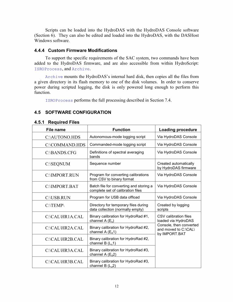
4.5.1 Required FilesFile name Function Loading procedure
C:\AUTONO.HDS Autonomous-mode logging script Via HydroDAS Console
C:\COMMAND.HDS Commanded-mode logging script Via HydroDAS Console
C:\BANDS.CFG Definitions of spectral averagingbands
Via HydroDAS Console
C:\SEQNUM Sequence number Created automaticallyby HydroDAS firmware
C:\IMPORT.RUN Program for converting calibrationsfrom CSV to binary format
Via HydroDAS Console
C:\IMPORT.BAT Batch file for converting and storing acomplete set of calibration files
Via HydroDAS Console
C:\USB.RUN Program for USB data offload Via HydroDAS Console
C:\TEMP\ Directory for temporary files duringdata collection (normally empty)
Created by loggingscripts
C:\CAL\HR1A.CAL Binary calibration for HydroRad #1,channel A (Es)
C:\CAL\HR2A.CAL Binary calibration for HydroRad #2,channel A (Ed1)
C:\CAL\HR2B.CAL Binary calibration for HydroRad #2,channel B (Lu1)
C:\CAL\HR3A.CAL Binary calibration for HydroRad #3,channel A (Ed2)
C:\CAL\HR3B.CAL Binary calibration for HydroRad #3,channel B (Lu2)
CSV calibration filesloaded via HydroDASConsole, then convertedand moved to C:\CAL\by IMPORT.BAT
13
File name Function Loading procedure
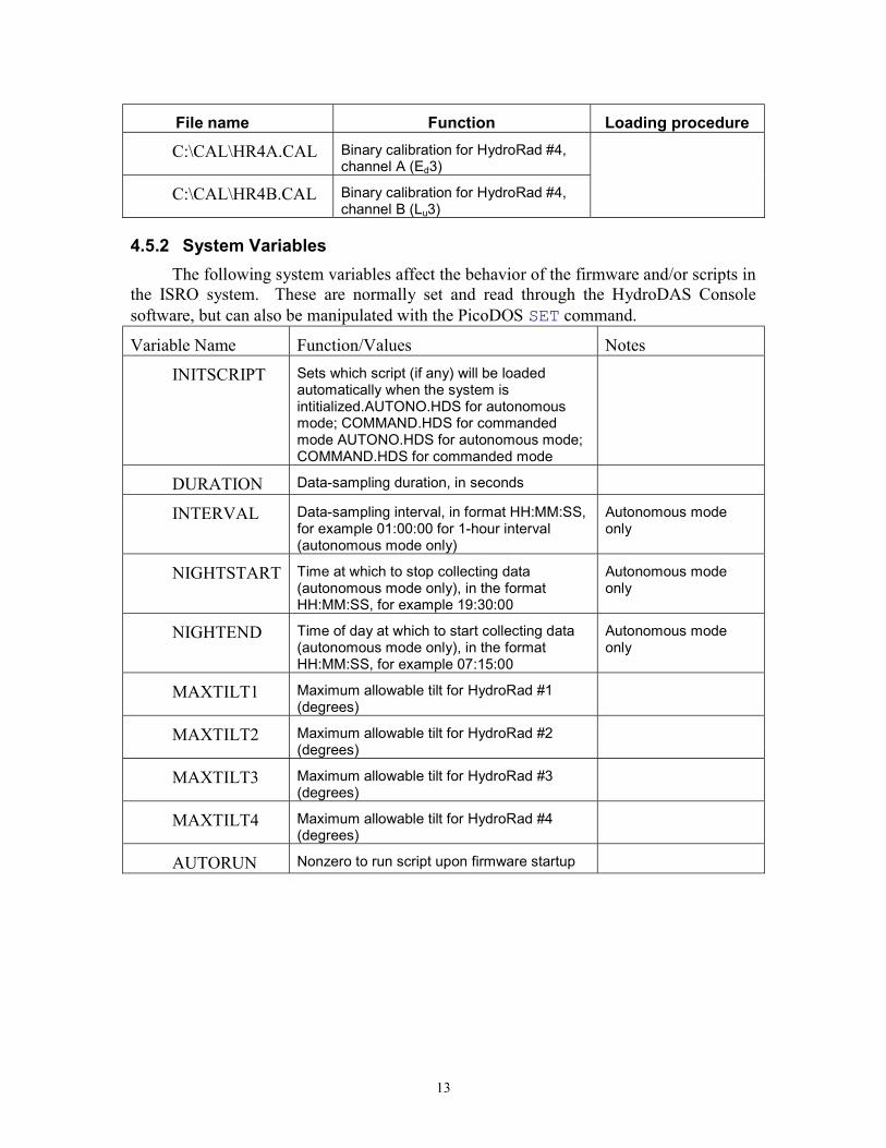
C:\CAL\HR4A.CAL Binary calibration for HydroRad #4,channel A (Ed3)
C:\CAL\HR4B.CAL Binary calibration for HydroRad #4,channel B (Lu3)
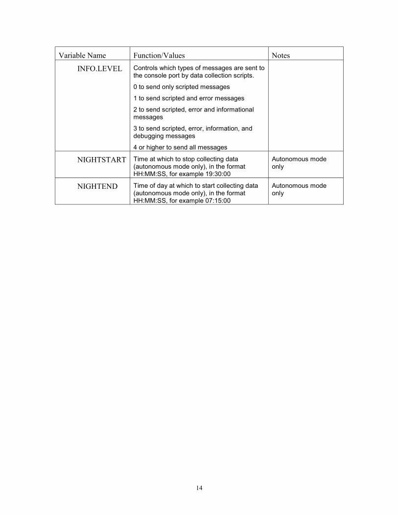
4.5.2 System VariablesThe following system variables affect the behavior of the firmware and/or scripts in
the ISRO system. These are normally set and read through the HydroDAS Consolesoftware, but can also be manipulated with the PicoDOS SET command.
Variable Name Function/Values Notes
INITSCRIPT Sets which script (if any) will be loadedautomatically when the system isintitialized.AUTONO.HDS for autonomousmode; COMMAND.HDS for commandedmode AUTONO.HDS for autonomous mode;COMMAND.HDS for commanded mode
DURATION Data-sampling duration, in seconds
INTERVAL Data-sampling interval, in format HH:MM:SS,for example 01:00:00 for 1-hour interval(autonomous mode only)
Autonomous modeonly
NIGHTSTART Time at which to stop collecting data(autonomous mode only), in the formatHH:MM:SS, for example 19:30:00
Autonomous modeonly
NIGHTEND Time of day at which to start collecting data(autonomous mode only), in the formatHH:MM:SS, for example 07:15:00
Autonomous modeonly
MAXTILT1 Maximum allowable tilt for HydroRad #1(degrees)
MAXTILT2 Maximum allowable tilt for HydroRad #2(degrees)
MAXTILT3 Maximum allowable tilt for HydroRad #3(degrees)
MAXTILT4 Maximum allowable tilt for HydroRad #4(degrees)
AUTORUN Nonzero to run script upon firmware startup
14
Variable Name Function/Values Notes
INFO.LEVEL Controls which types of messages are sent tothe console port by data collection scripts.
0 to send only scripted messages
1 to send scripted and error messages
2 to send scripted, error and informationalmessages
3 to send scripted, error, information, anddebugging messages
4 or higher to send all messages
NIGHTSTART Time at which to stop collecting data(autonomous mode only), in the formatHH:MM:SS, for example 19:30:00
Autonomous modeonly
NIGHTEND Time of day at which to start collecting data(autonomous mode only), in the formatHH:MM:SS, for example 07:15:00
Autonomous modeonly
15
5 QUICK START
5.1 HYDRODAS QUICK STARTUse this procedure to test and familiarize yourself with the basic functions of the
HydroDAS.
5.1.1 Requirements: Windows PC with one available serial port (or a USB-to-serial port adapter) 12V nominal power supply (10V minimum, 16V maximum). Start with the
12V supply turned off. Console port cable (supplied with system): 3-conductor female underwater
connector to female DB9 serial port. Power cable (supplied with system): 2-pin male underwater connector to red
and black wires. HydroDAS Console Windows program installed on the PC.
5.1.2 Procedure Connect the console port on the HydroDAS to a serial port on a Windows PC,
using the supplied cable. Verify that the power supply produces no more than 16V, including any
transients when it is turned on. Turn it off. Connect the red wire from the power cable to the positive terminal of the
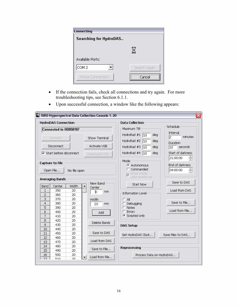
power supply and the black wire to the negative. Turn on the power supply. Start HydroDAS Console The following dialog box should appear briefly, and disappear when the
connection is completed.
16
If the connection fails, check all connections and try again. For moretroubleshooting tips, see Section 6.1.1.
Upon successful connection, a window like the following appears:
17
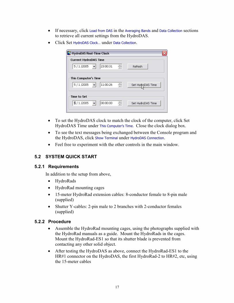
If necessary, click Load from DAS in the Averaging Bands and Data Collection sectionsto retrieve all current settings from the HydroDAS.
Click Set HydroDAS Clock… under Data Collection.
To set the HydroDAS clock to match the clock of the computer, click SetHydroDAS Time under This Computer’s Time. Close the clock dialog box.
To see the text messages being exchanged between the Console program andthe HydroDAS, click Show Terminal under HydroDAS Connection.
Feel free to experiment with the other controls in the main window.
5.2 SYSTEM QUICK START
5.2.1 RequirementsIn addition to the setup from above, HydroRads HydroRad mounting cages 15-meter HydroRad extension cables: 8-conductor female to 8-pin male
(supplied) Shutter Y-cables: 2-pin male to 2 branches with 2-conductor females
(supplied)
5.2.2 Procedure Assemble the HydroRad mounting cages, using the photographs supplied with
the HydroRad manuals as a guide. Mount the HydroRads in the cages.Mount the HydroRad-ES1 so that its shutter blade is prevented fromcontacting any other solid object.
After testing the HydroDAS as above, connect the HydroRad-ES1 to theHR#1 connector on the HydroDAS, the first HydroRad-2 to HR#2, etc, usingthe 15-meter cables
18
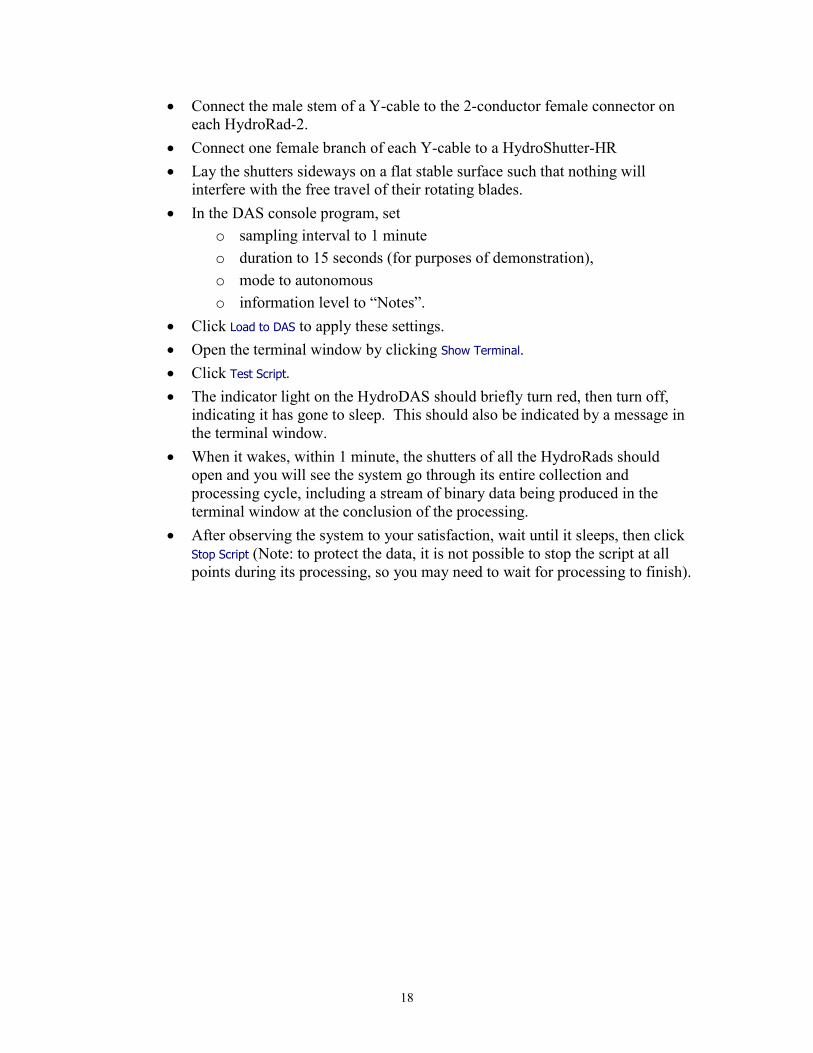
Connect the male stem of a Y-cable to the 2-conductor female connector oneach HydroRad-2.
Connect one female branch of each Y-cable to a HydroShutter-HR Lay the shutters sideways on a flat stable surface such that nothing will
interfere with the free travel of their rotating blades. In the DAS console program, set
o sampling interval to 1 minuteo duration to 15 seconds (for purposes of demonstration),o mode to autonomous o information level to “Notes”.
Click Load to DAS to apply these settings. Open the terminal window by clicking Show Terminal. Click Test Script.
The indicator light on the HydroDAS should briefly turn red, then turn off,indicating it has gone to sleep. This should also be indicated by a message inthe terminal window.
When it wakes, within 1 minute, the shutters of all the HydroRads shouldopen and you will see the system go through its entire collection andprocessing cycle, including a stream of binary data being produced in theterminal window at the conclusion of the processing.
After observing the system to your satisfaction, wait until it sleeps, then clickStop Script (Note: to protect the data, it is not possible to stop the script at allpoints during its processing, so you may need to wait for processing to finish).
19
6 HYDRODAS CONSOLE SOFTWARE
The HydroDAS Console application for Windows communicates through theHydroDAS’s console port, via an RS-232 COM port on the PC. If the PC is not equippedwith COM ports, a USB-to-serial port adapter should serve equally well. The onlyrestriction is that the COM port must be numbered in the range 1 to 16.
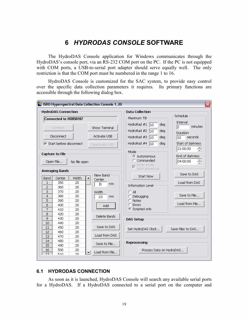
HydroDAS Console is customized for the SAC system, to provide easy controlover the specific data collection parameters it requires. Its primary functions areaccessible through the following dialog box.
6.1 HYDRODAS CONNECTIONAs soon as it is launched, HydroDAS Console will search any available serial ports
for a HydroDAS. If a HydroDAS connected to a serial port on the computer and
20
powered up, it should be detected automatically. If no HydroDAS is available at the timethe software is launched, you can click the connect button after connecting one.
6.1.1 Connection TroubleshootingIf the Console program cannot connect to the HydroDAS, check the following: Check that the HydroDAS is properly powered and connected. Click Search Again, if it is enabled. Occasionally the first connection attempt
may not work if the HydroDAS is in its “sleep” state. If there are no available ports listed in the connect dialog box, check whether
other programs are using the computer’s ports. If you are using a USB-to-serial adapter, check its driver software to see what
COM numbers are being assigned to its ports. Console can only detect portsnumbered 1 through 16.
6.1.2 DisconnectClick Disconnect to close the COM port being used for the HydroDAS. Typically
you should select the Start Before Disconnect option. This option ensures that any settingsyou saved to the HydroDAS will take immediate effect, and it will be ready to collectdata in the mode you selected. This will introduce a delay of about 5 seconds to thedisconnection process.
The HydroDAS will automatically be disconnected, including a reset if that optionis selected, when you quit the Console program (by clicking the close box of the mainwindow).
6.1.3 Show TerminalThe terminal window (accessible by clicking Show Terminal) provides a direct view
of the commands and responses exchanged between the console software andHydroDAS. It also allows directly typing commands for special situations that are notaccommodated by the standard controls.
Starting with version 1.20, you can use the File Capture function to record allterminal communications in a file on the PC. See Section 6.6 for details. The terminalwindow is not required to be open in order to use the File Capture function.
6.1.4 Activate/Deactivate USBIn order to conserve electrical power, memory, and processing speed, HydroDAS’s
USB port is active only when specifically enabled, and during that time some otherfunctions are inhibited. Therefore to perform USB transfers you must use connect to theHydroDAS Console and click the Activate USB button. The separate USBLink softwaremust also be started. Normally HydroDAS Console will start USBLink automaticallywhen it activates the USB interface. While the USB is active, most of the other consolecontrols are disabled. Click Deactivate USB to restore the console functions. For moreabout USB functions, see Section 8.
21
6.2 AVERAGING BANDSThe HydroRad data collected by this system are extensively processed before
transmission to the satellite transceiver (see Section 7.4), and one of the key steps in thisprocessing is averaging the data within a user-defined set of spectral bands.
6.2.1 Editing BandsTo add bands to the table, enter the desired center wavelength and width in the New
Band fields and click Add. Up to 50 bands will be accepted, and they will automatically besorted by ascending center wavelength.
To delete a band, click on it in the table and click Delete Bands. You may select anumber of contiguous bands for simultaneous deletion by click-dragging or shift-clickingin the table.
6.2.2 Loading and Saving BandsYou can save the entire set of bands to, or load them from, either the HydroDAS or
to a file on the PC by clicking the appropriate button next to the band table.
6.3 DATA COLLECTION CONTROLS
6.3.1 Maximum Tilt SettingsIt is desirable for data quality to exclude data collected when the buoy is
undergoing excessive tilt. Depending on the physical configuration of the sub-surfaceHydroRads, however, a given tilt will not affect all them equally. Therefore the softwaresupports a separate tilt limit for each of the instruments. HydroRad #1 is the HR-ES1 onthe surface (the instrument most sensitive to tilt); HydroRad #4 is the deepest underwaterinstruments.
The tilt limit may be effectively turned off by setting it to 90 degrees.
6.3.2 ScheduleIn autonomous mode, data are collected at a regular interval, set in minutes. If for
example the interval is set to 30 minutes, and the HydroDAS is started at 08:40:00, itwould go to sleep until 09:00:00, collect and process data, and then go to sleep until09:30:00 for the next sample time.
The duration of sample is set in seconds and may take any value although 20 to 30seconds is a practical minimum for the HydroRads to achieve their full sensitivity.
The autonomous mode also includes provision for a “dark” time during which nodata will be collected. The Console allows the user to enter times for the start and end ofthis dark period. The times are in 24-hour format. This feature may be disabled bysetting the start and end to the same time.
In commanded mode, only the duration parameter takes effect.
22
6.3.3 ModeThe Mode setting controls how each sample period is initiated. In autonomous
mode the HydroDAS runs strictly according to its own clock and the schedulingparameters.
In commanded mode, it initiates each collection cycle only upon receipt of a signalfrom the satellite transceiver or other device connected to the console port. In this mode,Duration is the only schedule parameter that has any effect.
The Enter mode upon power-up option determines what state the HydroDAS assumeswhen power is first applied to it. If the option is not checked, the HydroDAS will simplystart its full-power mode and be ready to accept commands. If it is checked, it willimmediately run the script that is appropriate to the selected mode, which typically meansit will go to sleep and await a wake-up signal either from its own clock or from anexternal command.
The Start Now button starts the script that corresponds to the selected mode, fortesting purposes. When the script is started, the name of this button changes to Stop, andclicking it will halt the script. While the script is running, none of the other functions thatinvolve writing to or reading from the HydroDAS are accessible.
6.3.4 Information LevelIn the SAC system the HydroDAS sends processed binary data through the console
port to the satellite transceiver. It is also capable of sending informational and debuggingmessages. While these messages can be useful diagnostics and state of health indicators,they may also consume bandwidth. Therefore we allow the user to control the quantity ofmessages sent. At the lowest setting, only processed binary data, and messages that areexplicitly included in the data processing script are sent (and as delivered, the onlyscripted message is one at the very start of the autonomous mode).
Note that the Console software automatically sets the information level to itsmaximum during its communication with the HydroDAS, but it will return to specifiedlevel when the HydroDAS is reset, either by turning off its power, or by disconnecting itwith the Start before Disconnect option selected.
6.3.5 Loading and Saving SettingsAll the data collection settings may be saved or loaded as a group, to and from
either the HydroDAS or the PC, using the Load from DAS…, Save to DAS…, Load from File…, andSave to File… buttons.
6.3.6 Loading ScriptsThe modes described in Section 6.3.3 are controlled by scripts (programs written in
the HydroDAS’s HydroScript command language—also see Section 4.4.3). These scriptsare stored as files on the HydroDAS, and the appropriate files must be loaded in order forthe data collection to function properly. Each time you change modes within HydroDASConsole, it checks that the appropriate script file is present. However in order to rebuild
23
or upgrade the system, you can install new or upgraded scripts using the Save Files toHydroDAS… button. See Section 6.5.2 for details on this command.
Normally you should install new or upgraded scripts only with instructions fromHOBI Labs.
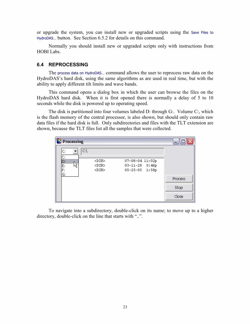
6.4 REPROCESSINGThe process data on HydroDAS… command allows the user to reprocess raw data on the
HydroDAS’s hard disk, using the same algorithms as are used in real time, but with theability to apply different tilt limits and wave bands.
This command opens a dialog box in which the user can browse the files on theHydroDAS hard disk. When it is first opened there is normally a delay of 5 to 10seconds while the disk is powered up to operating speed.
The disk is partitioned into four volumes labeled D: through G:. Volume C:, whichis the flash memory of the central processor, is also shown, but should only contain rawdata files if the hard disk is full. Only subdirectories and files with the TLT extension areshown, because the TLT files list all the samples that were collected.
To navigate into a subdirectory, double-click on its name; to move up to a higherdirectory, double-click on the line that starts with “..”.
24
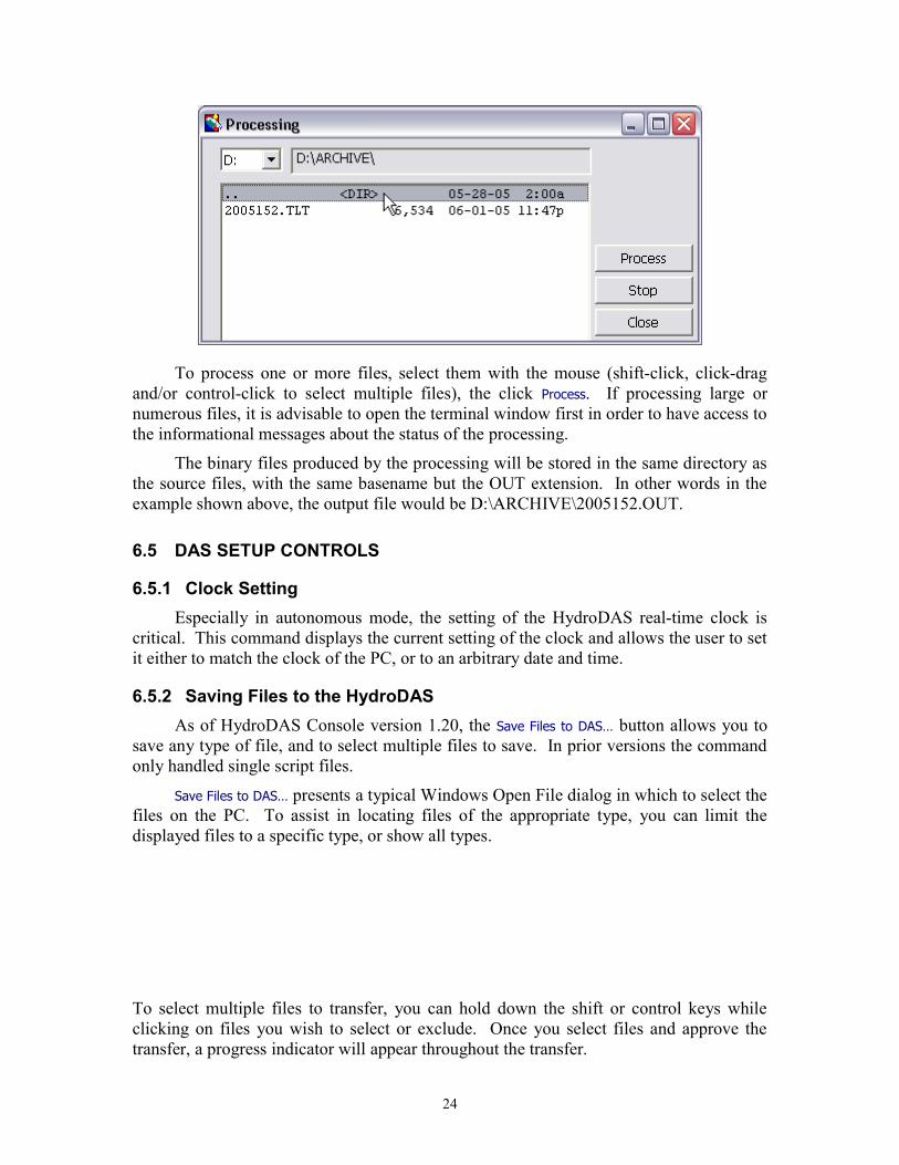
To process one or more files, select them with the mouse (shift-click, click-dragand/or control-click to select multiple files), the click Process. If processing large ornumerous files, it is advisable to open the terminal window first in order to have access tothe informational messages about the status of the processing.
The binary files produced by the processing will be stored in the same directory asthe source files, with the same basename but the OUT extension. In other words in theexample shown above, the output file would be D:\ARCHIVE\2005152.OUT.
6.5 DAS SETUP CONTROLS
6.5.1 Clock SettingEspecially in autonomous mode, the setting of the HydroDAS real-time clock is
critical. This command displays the current setting of the clock and allows the user to setit either to match the clock of the PC, or to an arbitrary date and time.
6.5.2 Saving Files to the HydroDASAs of HydroDAS Console version 1.20, the Save Files to DAS… button allows you to
save any type of file, and to select multiple files to save. In prior versions the commandonly handled single script files.
Save Files to DAS… presents a typical Windows Open File dialog in which to select thefiles on the PC. To assist in locating files of the appropriate type, you can limit thedisplayed files to a specific type, or show all types.
To select multiple files to transfer, you can hold down the shift or control keys whileclicking on files you wish to select or exclude. Once you select files and approve thetransfer, a progress indicator will appear throughout the transfer.
25
Files are always transferred to the C:\ directory on the HydroDAS. Files aretransferred at the normal console baud rate of 9600, or about 1 kByte per second.Calibration files may therefore take several minutes each to transfer.
NOTE: If files of the same name already exist on the HydroDAS, they will beoverwritten.
6.6 FILE CAPTUREThe File Capture function, if you choose, stores all console port communications in
a file on the PC. This is useful for troubleshooting, testing, and recordkeeping. Forexample, you may wish to capture a record of changes you make to the DASconfiguration. This is often used in conjunction with the Terminal Window (Section6.1.3), although that is not required. File Capture was not present in HydroDAS Consoleversions prior to 1.20.
To start file capture, click on the Open File… button under Capture to File.
This will open a standard Windows File dialog box, allowing you to select a nameand location for the captured file. If you specify the name and location of a file thatalready exists, you will be warned that that file will be overwritten. After the file is open,its name will appear under Capture to File, and the button name will change to Close. Tostop capture, simply click the Close button.
26
7 DATA COLLECTION AND PROCESSING
Data are collected and processed by the HydroDAS, and the processed datatransmitted to a SAC-supplied satellite transmitter or transceiver. In the transmitter case,data can only be sent from the buoy to shore and the HydroDAS must operateautonomously. In the transceiver case, commands can be sent to the HydroDAS forgreater control over its activities.
In either case, the HydroDAS operates primarily under the control of one of twoprograms written in its HydroScript language. HydroScript is described in full detail inthe HydroDAS User’s Manual.
Data collection proceeds in one of two modes, autonomous or commanded,depending whether a satellite transmitter or transceiver is available in the system. In eachcase, the HydroDAS is responsible for turning on power to the instruments, collectingtheir data for a specified length of time, then archiving, processing and sending the data,and going back to sleep until the next sample data collection even.
The parameters for data collection are set through the HydroDAS Consoleprogram, as described in Section 6.3.
7.1 AUTONOMOUS MODEIn autonomous mode, the data collection is timed strictly by the HydroDAS’s on-
board real-time clock. The HydroDAS wakes at each integral multiple of the designateddata collection interval, and collects data for the designated duration. If the interval is setto 30 minutes, for example, the HydroDAS would wake and collect data at the beginningof each hour and half-hour. It collects data for the specified duration, which does notinclude processing time.
The script for autonomous mode also provides for a period of darkness duringwhich no data will be collected. If a dark period is specified (which is not required), thesystem will remain in low-power sleep through that period.
In autonomous mode the HydroDAS is normally configured to initialize its scriptas soon as power is applied, but not to collect data until the next integral multiple of thesampling interval.
Even in autonomous mode, it is possible to wake the HydroDAS from sleep bysending it two or more control-C characters approximately 1 second apart, and in thatcase it would immediately sample, then return to its regular schedule.
7.2 COMMANDED MODECommanded mode is appropriate to the case in which bidirectional communication
is available and commands can be sent to the HydroDAS. The data collection sequenceis identical to that of autonomous mode, but does not start until the HydroDAS iswakened by two control-C characters sent to the console port. When thus wakened, itwill execute one data collection sequence, then return to sleep until wakened again.
27
7.3 DATA COLLECTION PROCEDUREIn either mode, each sample proceeds as follows: Apply power to HydroRads and allow them to initialize Apply power to the tilt/roll/heading sensor and fluorometer Send commands to the HydroRads to open their shutters Open files to collect data from all instruments Send commands to the HydroRads to start data collection While the HydroRads are collecting, sample the tilt/roll/heading once per
second After the specified interval has passed, stop data from all sensors and close
their files. Send shutter-close commands to the HydroRads Turn off power to all instruments Process HydroRad data (as described in Section 7.4) Send processed data to the transceiver/transmitter Archive raw and processed data to hard disk. Go to sleep.
7.4 DATA PROCESSING PROCEDURERaw data are processed as follows: Full calibration to radiometric units on all channels Average and maximum tilt (and heading) are calculated for each spectrum Spectra within the tilt limits are averaged together Averaged spectra are averaged within the user-specified wavebands Spectral magnitudes at different depths are compared for quality control Data are saved in a binary file The file is transmitted to the console port.
7.5 INTERFACE WITH SATELLITE TRANSCEIVERThe Satellite transmitter or transceiver interfaces with the HydroDAS via a 9600-
baud RS-232 interface with 8 data bits, 1 stop bit, no parity and no flow control.
In autonomous mode, the satellite transmitter must be prepared to accept data fromthe HydroDAS at any time, as it proceeds on its own schedule.
In commanded mode, the HydroDAS waits to be wakened by the transceiver, andperforms the data collection and processing procedure each time it wakes. To wake theHydroDAS, the transceiver only has to send 2 control-C characters 1 second apart. TheHydroDAS will transmit data after the suitable sampling duration and processing. Notethat, depending on the sampling duration and the light levels (because low light levels
28
dictate longer integration times, fewer spectra will be collected), the processing of datacould take several minutes.
The HydroDAS console port may produce various informational and debuggingmessages in addition to the raw data, depending on the setting of its “information level”(see also Section 6.3.4). If the satellite transmitter/transceiver cannot tolerate additionalinformation being sent via the console port, the information level can be set to zero.However the extra messages can be very useful for diagnostic purposes, so a non-zeroinformation level is recommended if possible within the constraints of the system.
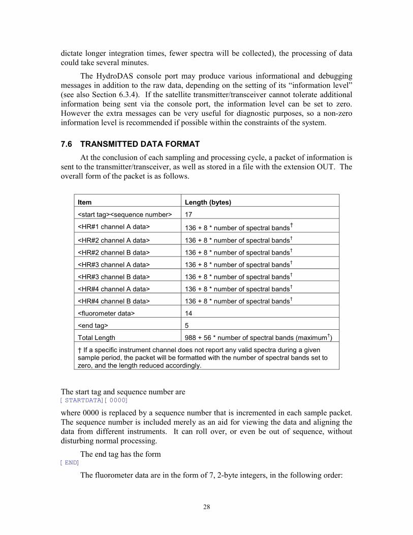
7.6 TRANSMITTED DATA FORMATAt the conclusion of each sampling and processing cycle, a packet of information is
sent to the transmitter/transceiver, as well as stored in a file with the extension OUT. Theoverall form of the packet is as follows.
Item Length (bytes)
<start tag><sequence number> 17
<HR#1 channel A data> 136 + 8 * number of spectral bands†
<HR#2 channel A data> 136 + 8 * number of spectral bands†
<HR#2 channel B data> 136 + 8 * number of spectral bands†
<HR#3 channel A data> 136 + 8 * number of spectral bands†
<HR#3 channel B data> 136 + 8 * number of spectral bands†
<HR#4 channel A data> 136 + 8 * number of spectral bands†
<HR#4 channel B data> 136 + 8 * number of spectral bands†
<fluorometer data> 14
<end tag> 5
Total Length 988 + 56 * number of spectral bands (maximum†)
† If a specific instrument channel does not report any valid spectra during a givensample period, the packet will be formatted with the number of spectral bands set tozero, and the length reduced accordingly.
The start tag and sequence number are[STARTDATA][0000]where 0000 is replaced by a sequence number that is incremented in each sample packet.The sequence number is included merely as an aid for viewing the data and aligning thedata from different instruments. It can roll over, or even be out of sequence, withoutdisturbing normal processing.
The end tag has the form[END]
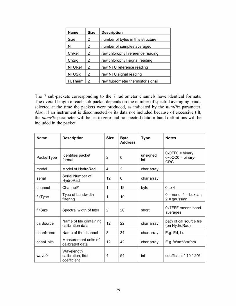
The fluorometer data are in the form of 7, 2-byte integers, in the following order:
29
Name Size Description
Size 2 number of bytes in this structure
N 2 number of samples averaged
ChRef 2 raw chlorophyll reference reading
ChSig 2 raw chlorophyll signal reading
NTURef 2 raw NTU reference reading
NTUSig 2 raw NTU signal reading
FLTherm 2 raw fluorometer thermistor signal
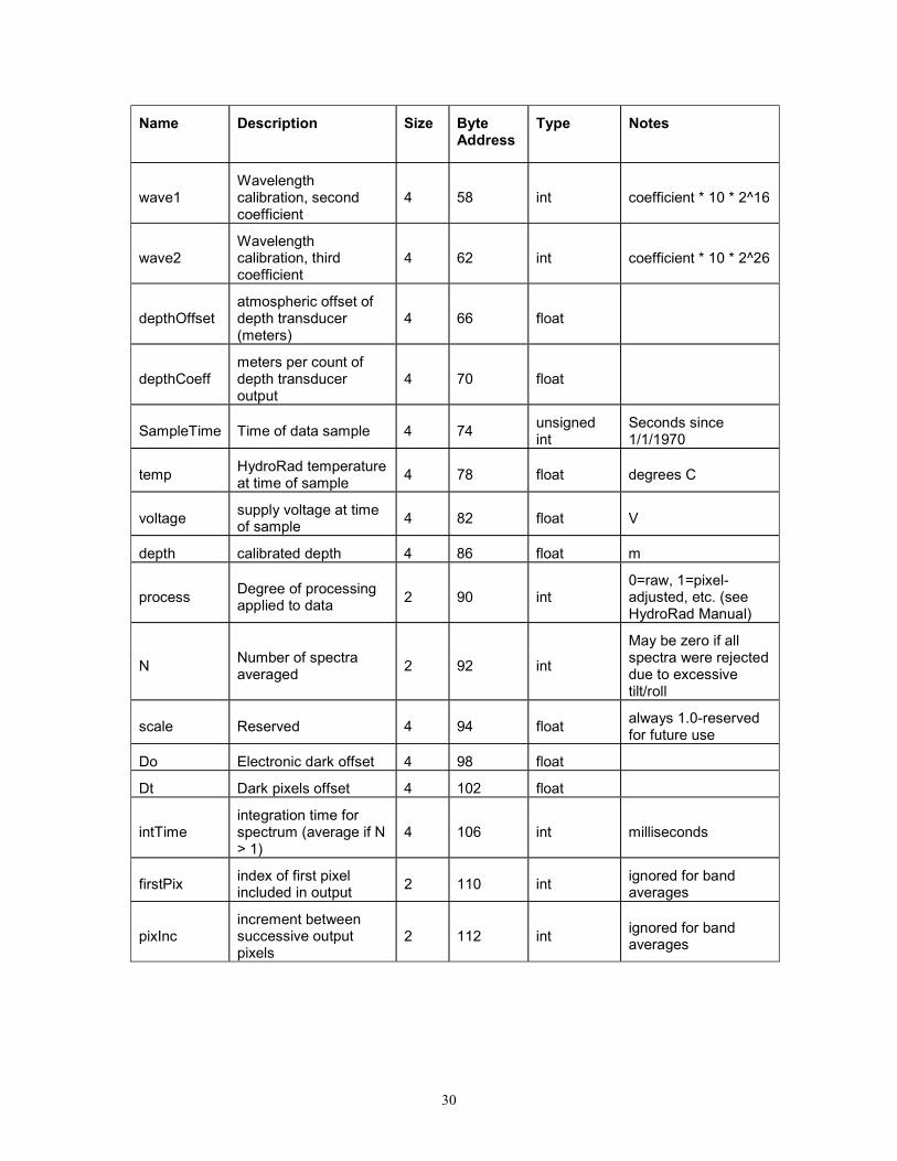
The 7 sub-packets corresponding to the 7 radiometer channels have identical formats.The overall length of each sub-packet depends on the number of spectral averaging bandsselected at the time the packets were produced, as indicated by the numPix parameter.Also, if an instrument is disconnected or its data not included because of excessive tilt,the numPix parameter will be set to zero and no spectral data or band definitions will beincluded in the packet.
Name Description Size ByteAddress
Type Notes
PacketType Identifies packetformat 2 0 unsigned
int
0x0FF0 = binary,0x0CC0 = binary-CRC
model Model of HydroRad 4 2 char array
serial Serial Number ofHydroRad 12 6 char array
channel Channel# 1 18 byte 0 to 4
filtType Type of bandwidthfiltering 1 19 0 = none, 1 = boxcar,
2 = gaussian
filtSize Spectral width of filter 2 20 short 0x7FFF means bandaverages
calSource Name of file containingcalibration data 12 22 char array path of cal source file
(on HydroRad)
chanName Name of the channel 8 34 char array E.g. Ed, Lu
chanUnits Measurement units ofcalibrated data 12 42 char array E.g. W/m^2/sr/nm
wave0Wavelengthcalibration, firstcoefficient
4 54 int coefficient * 10 * 2^6
30
Name Description Size ByteAddress
Type Notes
wave1Wavelengthcalibration, secondcoefficient
4 58 int coefficient * 10 * 2^16
wave2Wavelengthcalibration, thirdcoefficient
4 62 int coefficient * 10 * 2^26
depthOffsetatmospheric offset ofdepth transducer(meters)
4 66 float
depthCoeffmeters per count ofdepth transduceroutput
4 70 float
SampleTime Time of data sample 4 74 unsignedint
Seconds since1/1/1970
temp HydroRad temperatureat time of sample 4 78 float degrees C
voltage supply voltage at timeof sample 4 82 float V
depth calibrated depth 4 86 float m
process Degree of processingapplied to data 2 90 int
0=raw, 1=pixel-adjusted, etc. (seeHydroRad Manual)
N Number of spectraaveraged 2 92 int
May be zero if allspectra were rejecteddue to excessivetilt/roll
scale Reserved 4 94 float always 1.0-reservedfor future use
Do Electronic dark offset 4 98 float
Dt Dark pixels offset 4 102 float
intTimeintegration time forspectrum (average if N> 1)
4 106 int milliseconds
firstPix index of first pixelincluded in output 2 110 int ignored for band
averages
pixIncincrement betweensuccessive outputpixels
2 112 int ignored for bandaverages
31
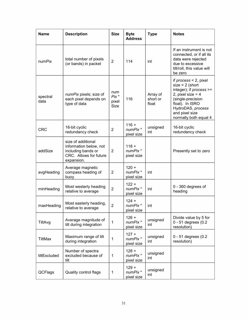
Name Description Size ByteAddress
Type Notes
numPix total number of pixels(or bands) in packet 2 114 int
If an instrument is notconnected, or if all itsdata were rejecteddue to excessivetilt/roll, this value willbe zero
spectraldata
numPix pixels; size ofeach pixel depends ontype of data
numPix *pixelSize
116Array ofshort orfloat
if process < 2, pixelsize = 2 (shortinteger); if process >=2, pixel size = 4(single-precisionfloat). In ISROHydroDAS, processand pixel sizenormally both equal 4
CRC 16-bit cyclicredundancy check 2
116 +numPix *pixel size
unsignedint
16-bit cyclicredundancy check
addSize
size of additionalinformation below, notincluding bands orCRC. Allows for futureexpansion.
2118 +numPix *pixel size
Presently set to zero
avgHeadingAverage magneticcompass heading ofbuoy
2120 +numPix *pixel size
int
minHeading Most westerly headingrelative to average 2
122 +numPix *pixel size
int 0 - 360 degrees ofheading
maxHeading Most easterly heading,relative to average 2
124 +numPix *pixel size
int
TiltAvg Average magnitude oftilt during integration 1
126 +numPix *pixel size
unsignedint
Divide value by 5 for0 - 51 degrees (0.2resolution)
TiltMax Maximum range of tiltduring integration 1
127 +numPix *pixel size
unsignedint
0 - 51 degrees (0.2resolution)
tiltExcludedNumber of spectraexcluded because oftilt
1128 +numPix *pixel size
unsignedint
QCFlags Quality control flags 1129 +numPix *pixel size
unsignedint
32
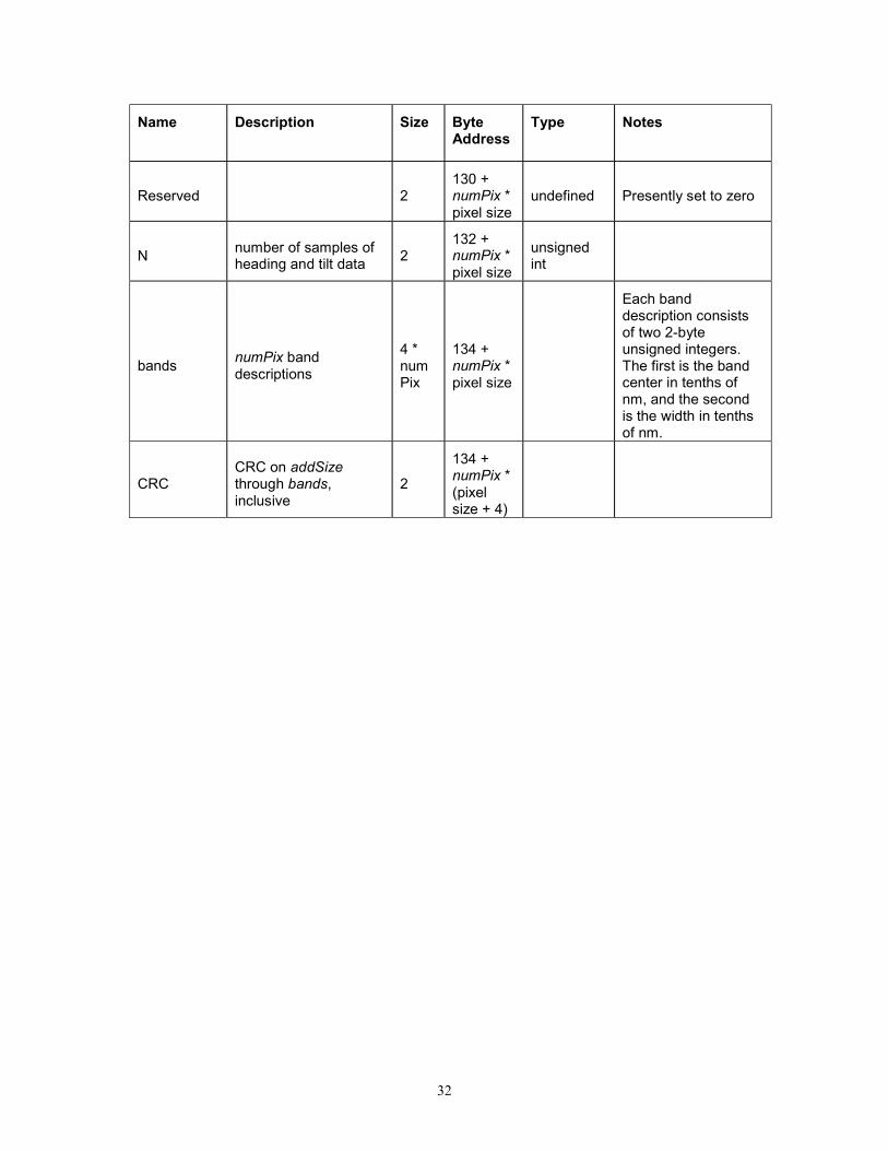
Name Description Size ByteAddress
Type Notes
Reserved 2130 +numPix *pixel size
undefined Presently set to zero
N number of samples ofheading and tilt data 2
132 +numPix *pixel size
unsignedint
bands numPix banddescriptions
4 *numPix
134 +numPix *pixel size
Each banddescription consistsof two 2-byteunsigned integers.The first is the bandcenter in tenths ofnm, and the secondis the width in tenthsof nm.
CRCCRC on addSizethrough bands,inclusive
2
134 +numPix *(pixelsize + 4)
33
8 USB OFFLOAD
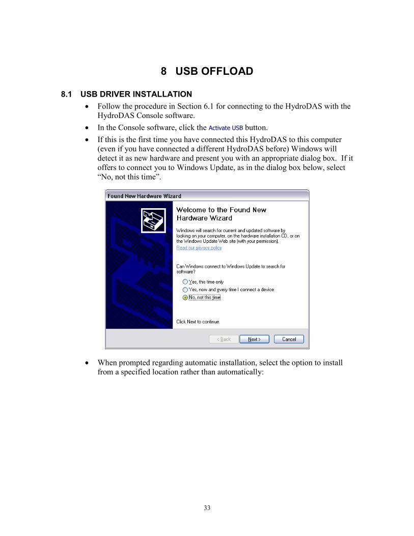
8.1 USB DRIVER INSTALLATION Follow the procedure in Section 6.1 for connecting to the HydroDAS with the
HydroDAS Console software. In the Console software, click the Activate USB button. If this is the first time you have connected this HydroDAS to this computer
(even if you have connected a different HydroDAS before) Windows willdetect it as new hardware and present you with an appropriate dialog box. If itoffers to connect you to Windows Update, as in the dialog box below, select“No, not this time”.
When prompted regarding automatic installation, select the option to installfrom a specified location rather than automatically:
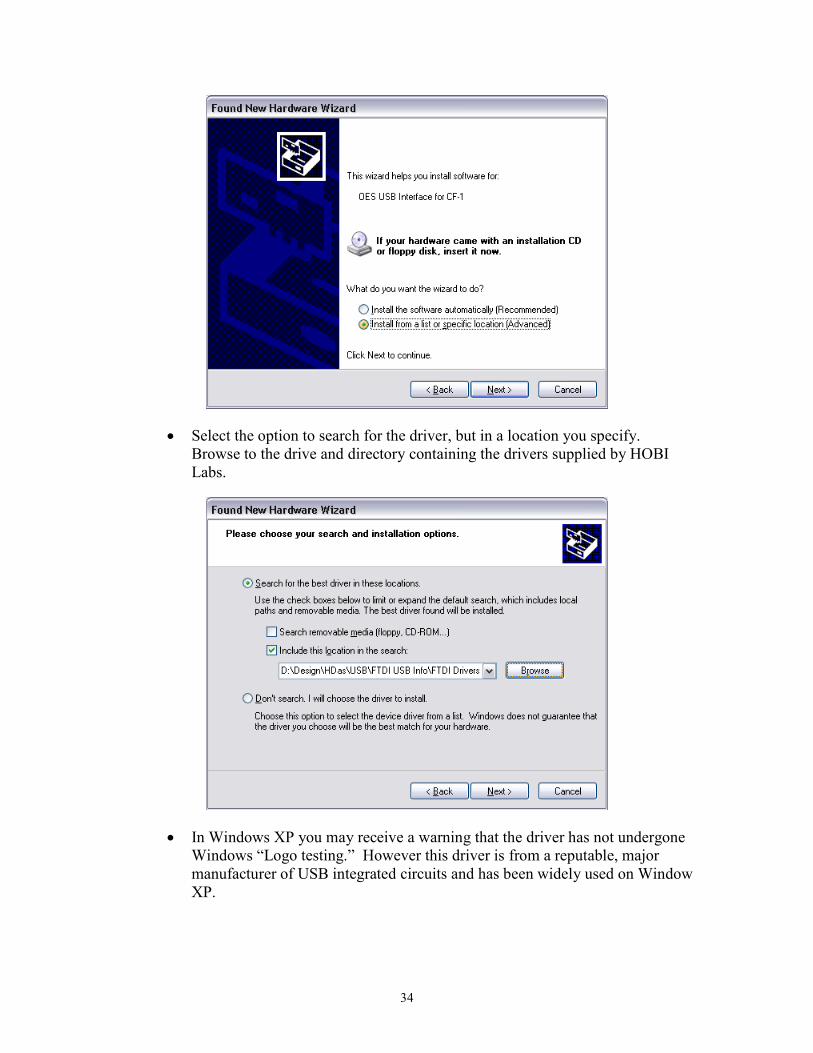
34
Select the option to search for the driver, but in a location you specify.Browse to the drive and directory containing the drivers supplied by HOBILabs.
In Windows XP you may receive a warning that the driver has not undergoneWindows “Logo testing.” However this driver is from a reputable, majormanufacturer of USB integrated circuits and has been widely used on WindowXP.
35
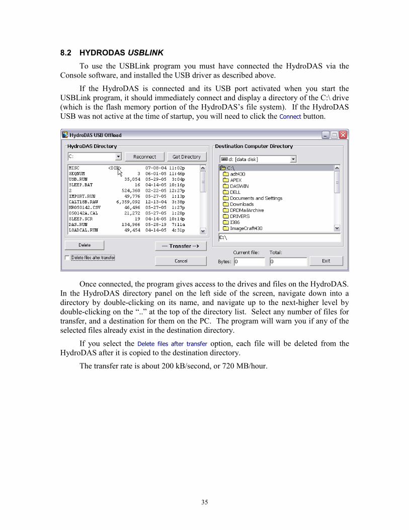
8.2 HYDRODAS USBLINKTo use the USBLink program you must have connected the HydroDAS via the
Console software, and installed the USB driver as described above.
If the HydroDAS is connected and its USB port activated when you start theUSBLink program, it should immediately connect and display a directory of the C:\ drive(which is the flash memory portion of the HydroDAS’s file system). If the HydroDASUSB was not active at the time of startup, you will need to click the Connect button.
Once connected, the program gives access to the drives and files on the HydroDAS.In the HydroDAS directory panel on the left side of the screen, navigate down into adirectory by double-clicking on its name, and navigate up to the next-higher level bydouble-clicking on the “..” at the top of the directory list. Select any number of files fortransfer, and a destination for them on the PC. The program will warn you if any of theselected files already exist in the destination directory.
If you select the Delete files after transfer option, each file will be deleted from theHydroDAS after it is copied to the destination directory.
The transfer rate is about 200 kB/second, or 720 MB/hour.
36
9 SPECIAL PROCEDURES
9.1 FIRMWARE INSTALLATION
9.1.1 Requirements HydroDAS Console, HydroDAS Firmware, and Motocross installed on your
computer Familiarity with the basic operation of the HydroDAS and Console software.
For details, see the System Manual. One COM port available on your computer 12V power source for the HydroDAS Power cable (supplied with HydroDAS) Host port connector (supplied with HydroDAS)
9.1.2 Procedure If not already installed, install HydroDAS Console, HydroDAS Firmware, and
Motocross on your computer Connect the power source to the HydroDAS Connect the HydroDAS console port to the COM port on your computer Turn on the 12V power source Start HydroDAS Console After HydroDAS Console has established a connection, uncheck the Start
before disconnect option, and click Disconnect:
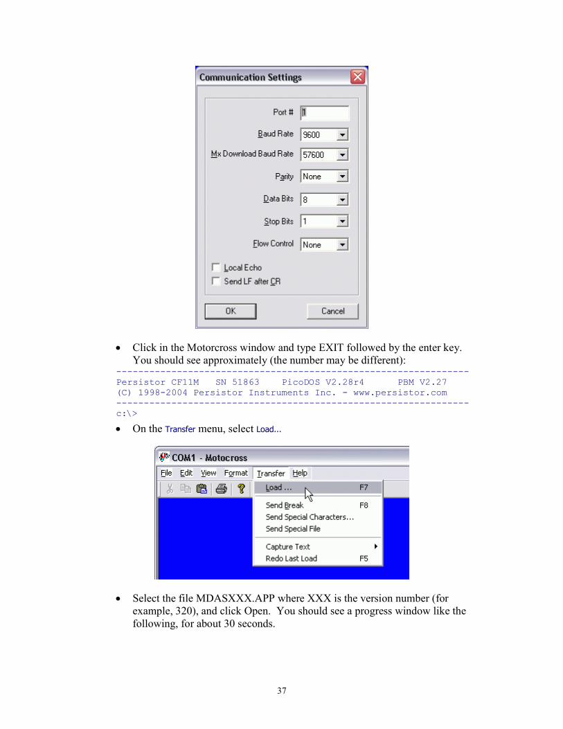
Open Motocross Select Communication Settings from the File menu, and enter the following
settings (except the port number, which may not be 1 on your computer).
37
Click in the Motorcross window and type EXIT followed by the enter key.You should see approximately (the number may be different):
----------------------------------------------------------------Persistor CF11M SN 51863 PicoDOS V2.28r4 PBM V2.27(C) 1998-2004 Persistor Instruments Inc. - www.persistor.com----------------------------------------------------------------c:\>
On the Transfer menu, select Load...
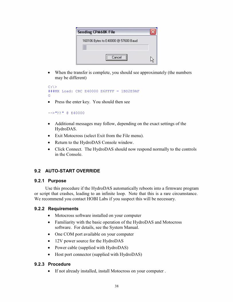
Select the file MDASXXX.APP where XXX is the version number (forexample, 320), and click Open. You should see a progress window like thefollowing, for about 30 seconds.
38
When the transfer is complete, you should see approximately (the numbersmay be different)
C:\>###MX Load: CRC E40000 E6FFFF = 1BD2E9AFG
Press the enter key. You should then see
-->"??" @ E40000
Additional messages may follow, depending on the exact settings of theHydroDAS.
Exit Motocross (select Exit from the File menu). Return to the HydroDAS Console window. Click Connect. The HydroDAS should now respond normally to the controls
in the Console.
9.2 AUTO-START OVERRIDE
9.2.1 PurposeUse this procedure if the HydroDAS automatically reboots into a firmware program
or script that crashes, leading to an infinite loop. Note that this is a rare circumstance.We recommend you contact HOBI Labs if you suspect this will be necessary.
9.2.2 Requirements Motocross software installed on your computer Familiarity with the basic operation of the HydroDAS and Motocross
software. For details, see the System Manual. One COM port available on your computer 12V power source for the HydroDAS Power cable (supplied with HydroDAS) Host port connector (supplied with HydroDAS)
9.2.3 Procedure If not already installed, install Motocross on your computer .
39
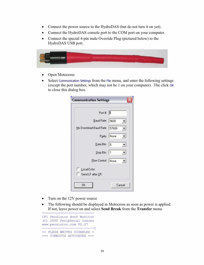
Connect the power source to the HydroDAS (but do not turn it on yet). Connect the HydroDAS console port to the COM port on your computer. Connect the special 4-pin male Override Plug (pictured below) to the
HydroDAS USB port.
Open Motocross Select Communication Settings from the File menu, and enter the following settings
(except the port number, which may not be 1 on your computer). The click OKto close this dialog box.
Turn on the 12V power source The following should be displayed in Motocross as soon as power is applied.
If not, leave power on and select Send Break from the Transfer menu.--------------------------CF1 Persistor Boot Monitor(C) 2000 Peripheral Issueswww.persistor.com V2.27--------------------------I== FLASH WRITES DISABLED ==== TIMEOUTS ACTIVATED ===
40
PBM>60>50
The numbers after the PBM> prompt show a 60-second countdown. At anytime during the countdown, type PICO followed by the Enter key. Youshould see approximately the following (the numbers may be different):
----------------------------------------------------------------Persistor CF11M SN 51863 PicoDOS V2.28r4 PBM V2.27(C) 1998-2004 Persistor Instruments Inc. - www.persistor.com----------------------------------------------------------------c:\>
To turn off automatic running of a script, type SET AUTORUN=0 followedby the enter key, then type SET INITSCRIPT= followed by the enter key.
Disconnect the Override Plug from the HydroDAS USB port. To turn off automatic running of the HydroDAS firmware porgram, type
BOOT PICO followed by the enter key. Remove power from the HydroDAS. Consult HOBI Labs on how to restore the correct firmware and scripts.
9.3 UPDATING HYDRORAD CALIBRATION FILES ON HYDRODASThis procedure assumes you will install a complete set of 4 calibration files, and
that the four HydroRad serial numbers are HR050142, HR050143, HR050144 andHR050145. If different instruments are to be used, the serial numbers must be changedaccordingly in the procedure.
9.3.1 Preparations on the PCMake copies of the appropriate CSV calibration files and place them together in a
folder on the PC. If necessary, shorten their names to [serial number].CSV, for exampleHR050142.CSV.
In the same folder, make a copy of the file IMPORT.BAT, or create one with thefollowing contents (where the serial numbers match those of the instruments to be used).
del *.calimport hr050142.csvren 050142a.cal HR1A.calimport hr050143.csvren 050143a.cal HR2A.calren 050143b.cal HR2B.calimport HR050144.csvren 050144a.cal HR3A.calren 050144b.cal HR3B.calimport HR050145.csvren 050145a.cal HR4A.calren 050145B.cal HR4B.calmkdir caldel c:\cal\*.caldel c:\cal\*.csvcopy *.cal c:\cal\copy *.csv c:\cal\
41
del *.caldel *.csv
9.3.2 InstallationConnect the HydroDAS console port to a serial port on your computer, and
connect a 12V power supply to the HydroDAS. Start the HydroDAS Console software.HydroDAS Console should automatically connect to the HydroDAS. If not, see Section6.1.1 for troubleshooting help.
Click Save Files to DAS…, and select the following files to download:
HR050142.CSV HR050143.CSV HR050144.CSV HR050145.CSV IMPORT.BAT IMPORT.RUN
The download process will take several minutes.
After the download completes, click Show Terminal. In the terminal window, typeexit followed by the enter key. You should see a prompt similar to
----------------------------------------------------------------Persistor CF11M SN 51863 PicoDOS V2.28r4 PBM V2.27(C) 1998-2004 Persistor Instruments Inc. - www.persistor.com
----------------------------------------------------------------C:\>
Type IMPORT.BAT followed by the enter key. This will start a series of actions thattake about 6 minutes. Status messages will be displayed in the terminal windowthroughout the process, concluding with the following lines:
del *.caldel *.csv
C:\>
In the HydroDAS Console window, uncheck the Start before disconnect option. ClickDisconnect, then click Connect. The HydroDAS is now ready for use.