iris blue user manual - variadores
TRANSCRIPT
• 15R1102B200 •
IRIS BLUE AC DRIVE
Specific for Water, Fan and Compressor Applications
USER MANUAL - Programming Instructions -
Issued on 11/09/17 R. 02 Software Version 4.13x
• This manual is integrant and essential to the product. Carefully read the instructions contained herein as they provide important hints for use and maintenance safety. • This device is to be used only for the purposes it has been designed to. Other uses should be considered improper and dangerous. The manufacturer is not responsible for possible damages caused by improper, erroneous and irrational uses. • Elettronica Santerno is responsible for the device in its original setting. • Any changes to the structure or operating cycle of the device must be performed or authorized by the Engineering Department of Elettronica Santerno. • Elettronica Santerno assumes no responsibility for the consequences resulting by the use of non-original spare-parts. • Elettronica Santerno reserves the right to make any technical changes to this manual and to the device without prior notice. If printing errors or similar are detected, the corrections will be included in the new releases of the manual. • The information contained herein is the property of Elettronica Santerno and cannot be reproduced. Elettronica Santerno enforces its rights on the drawings and catalogues according to the law.
Elettronica Santerno S.p.A. Via della Concia, 7 – 40023 Castel Guelfo (BO) Italy
Tel. +39 0542 489711 – Fax +39 0542 489722 santerno.com [email protected]
E n g l i s h
IRIS BLUE
PROGRAMMING GUIDE
2/471
REVISION INDEX
Modifications with respect to Programming Guide 15R1102B200, release R.00, SW version 4.06x dated
15/09/2015 and release R.01, SW version 4.11x dated 07/04/2016. The following subjects covered in this Programming Guide R.02 (SW version 4.13x) have been added, changed or suppressed with respect to the previous version R.00 (SW version 4.06x) or R.01 (SW version 4.11x). ENERTRONICA GROUP logo added. The following parameters have been added to the [CFG] MOTOR CONFIGURATION MENU
• C030 (Field Weakening Speed)
• C030a (Field Weakening Time Constant)
The following parameters have been added to the [CFG] DIGITAL INPUTS MENU
• C151 (REVERSE)
• C154a (Enable Signal from Terminal Board only)
• C159 (CW/CCW)
• C179a, C179b (Selection of Commands and References) The picture related to the ENABLE control has been changed.
D74 selection added: kWh pulse in Table 46: List of the selectable digital inputs and analog outputs.
The description of custom PID Measurements M023/023a/024/024a has been rectified.
Measurement M051 (Frequency Input) has been removed along with all the references to FINA and FINB inputs. The MODBUS address of the Texas SW version has been rectified. The MODBUS addresses in the [CFG] DATE AND TIME MENU have been rectified. The VTC procedure has been integrated with a new procedure to get equal estimated torque and generated torque. Table 57: List of the programmable measurements in P330 to P331 has been split from Table 23: List of the programmable measurements in P268, P268a, P268b, P268c, P268d, P268e. The First Start Up section has been added to the MULTIMOTOR CONTROL (MMC) menu.
Alarms A100 Illegal MDI6 Configuration and A101 Illegal MDI8 Configuration have been removed.
Alarms A110 Fieldbus Board Alarm, A136 Dry Run Alarm and A137 Pressure Loss Alarm have been added. The “Side A” wording has been removed from the description of the alarms related to the IGBTs.
The 06h: Write Single Register function has been added to the MODBUS-RTU Protocol.
USER MANUALS MENTIONED IN THIS PROGRAMMING GUIDE
The following User Manuals from Elettronica Santerno are mentioned throughout this Programming Guide:
- 15P0102B200 IRIS BLUE – Installation Guide
- 15W0102B300 Safe Torque Off Function – Application Manual
- 15G0010B1 PROFIdrive COMMUNICATIONS BOARD – User Manual
- 15G0851B100 DATA LOGGER ES851 – Programming Guide
- 15J1102B100 IrisControl – User Manual
- 15W0102B500 Motor Drives Accessories – User Manual
- 15J0901B100 Iris Control DRIVE REMOTE CONTROL – User Manual
PROGRAMMING GUIDE
IRIS BLUE
3/471
0. TABLE OF CONTENTS
0.1. Chapters REVISION INDEX ........................................................................................................................................................... 2 0. TABLE OF CONTENTS ......................................................................................................................................... 3
0.1. Chapters ...................................................................................................................................................... 3 0.2. Figures ......................................................................................................................................................... 8 0.3. Tables .......................................................................................................................................................... 9
1. scope of this manual ........................................................................................................................................... 12 2. HOW THIS MANUAL IS ORGANISED ................................................................................................................. 12
2.1. Overview .................................................................................................................................................... 12 2.2. Menus and Submenus ............................................................................................................................... 12
2.2.1. M Measurements ................................................................................................................................... 12 2.2.2. Parameters P, R, I, C ............................................................................................................................ 13 2.2.3. Alarms and Warnings ............................................................................................................................ 13
3. USING THE DISPLAY/kEYPAD UNIT .................................................................................................................. 14 3.1. Overview .................................................................................................................................................... 14 3.2. Menu Tree and Navigation Mode ................................................................................................................ 14 3.3. Menu Tree ................................................................................................................................................. 15 3.4. Navigation Mode ........................................................................................................................................ 17 3.5. Altering Parameter Values .......................................................................................................................... 18 3.6. Programming the Root Page ...................................................................................................................... 18 3.7. MENU Key ................................................................................................................................................. 19 3.8. ESC Key .................................................................................................................................................... 20 3.9. RESET Key (Alarm and Control Board Reset) ............................................................................................ 21 3.10. TX/RX Key (Download/Upload from/to the Keypad) .................................................................................... 21 3.11. LOC/REM Key (Keypad Pages) .................................................................................................................. 22 3.12. SAVE/ENTER Key ..................................................................................................................................... 22 3.13. START-UP Key .......................................................................................................................................... 22 3.14. Indicator LEDs of the Display/Keypad ......................................................................................................... 23
4. SERIAL LINKS .................................................................................................................................................... 24 4.1. Overview .................................................................................................................................................... 24 4.2. MODBUS-RTU Protocol ............................................................................................................................. 24
5. DESCRIPTION OF INPUT AND OUTPUT SIGNALS............................................................................................ 27 6. REFERENCES AND FEEDBACK ........................................................................................................................ 28
6.1. Main Speed Reference ............................................................................................................................... 28 6.2. PID Reference............................................................................................................................................ 28 6.3. PID Feedback ............................................................................................................................................ 28
7. PROGRAMMABLE FUNCTIONS ......................................................................................................................... 29 7.1. Voltage/Frequency Pattern ......................................................................................................................... 29 7.2. Slip Compensation ..................................................................................................................................... 29 7.3. Speed Searching ........................................................................................................................................ 29 7.4. DC Braking ................................................................................................................................................. 29 7.5. Motor Thermal Protection ........................................................................................................................... 29 7.6. Prohibit Speeds .......................................................................................................................................... 29 7.7. PID Digital Regulator .................................................................................................................................. 29 7.8. Dry-Run Control ......................................................................................................................................... 30 7.9. Pressure Loss Control ................................................................................................................................ 30 7.10. Pipe Fill Control .......................................................................................................................................... 30 7.11. Multimotor Control ...................................................................................................................................... 30 7.12. Setting Two Alternative Command Sources and Reference Sources .......................................................... 31 7.13. Fire Mode ................................................................................................................................................... 32
8. PROGRAMMING EXAMPLES ............................................................................................................................. 33 8.1. Overview .................................................................................................................................................... 33 8.2. Programming a Reference ......................................................................................................................... 33 8.3. Programming the Drive for PID Pressure Control ........................................................................................ 37
9. START-UP MENU ............................................................................................................................................... 39 9.1. Overview .................................................................................................................................................... 39
10. FIRST STARTUP ............................................................................................................................................ 41 10.1. “IFD” Control Algorithm ............................................................................................................................... 41 10.2. “VTC” Control Algorithm ............................................................................................................................. 43
11. [MEA] MEASUREMENTS MENU .................................................................................................................... 47 11.1. Overview .................................................................................................................................................... 47 11.2. Motor Measurements Menu ........................................................................................................................ 48 11.3. Water Measurements Menu ....................................................................................................................... 51 11.4. PID Regulator Menu ................................................................................................................................... 52
IRIS BLUE
PROGRAMMING GUIDE
4/471
11.5. Digital Inputs Menu..................................................................................................................................... 56 11.6. References Menu ....................................................................................................................................... 58 11.7. Outputs Menu ............................................................................................................................................ 62 11.8. Temperature Measurements from PT100 Menu ......................................................................................... 64 11.9. Autodiagnostics Menu ................................................................................................................................ 65 11.10. Data Logger Measurement Menu ........................................................................................................... 67 11.11. Digital Input Settings Menu .................................................................................................................... 69 11.12. Fault List Menu (Fault List) .................................................................................................................... 70 11.13. Power Off List Menu (Power Off List) ..................................................................................................... 73
12. [IDP] PRODUCT MENU .................................................................................................................................. 76 12.1. Overview .................................................................................................................................................... 76 12.2. List of Parameters P263 and Fire Mode Enable Password ......................................................................... 76
13. [PAR] PASSWORD AND USER LEVEL MENU ............................................................................................... 80 13.1. Overview .................................................................................................................................................... 80 13.2. List of Parameters P000 to P003 ................................................................................................................ 80
14. [PAR] DISPLAY/KEYPAD MENU .................................................................................................................... 82 14.1. Overview .................................................................................................................................................... 82 14.2. Status Page ............................................................................................................................................... 82 14.3. Keypad Page and Local Mode .................................................................................................................... 83 14.4. List of Parameters P264 to P269b .............................................................................................................. 84
15. [PAR] RAMPS MENU ..................................................................................................................................... 93 15.1. Overview .................................................................................................................................................... 93
15.1.1. Description of the Speed Ramps ....................................................................................................... 93 15.2. List of Parameters P009 to P033 ................................................................................................................ 94
16. [PAR] INPUTS FOR REFERENCES MENU .................................................................................................... 98 16.1. Processing Speed/Torque References ....................................................................................................... 98 16.2. Scaling Analog Inputs REF, AIN1, AIN2.................................................................................................... 100 16.3. List of Parameters P050 to P069 .............................................................................................................. 104
17. [PAR] MULTISPEED MENU .......................................................................................................................... 114 17.1. Overview .................................................................................................................................................. 114 17.2. List of Parameters P080 to P100 .............................................................................................................. 114
18. [PAR] PID MULTIREFERENCES MENU ....................................................................................................... 117 18.1. Overview .................................................................................................................................................. 117 18.2. List of Parameters P080a to P099a .......................................................................................................... 118
19. [PAR] PROHIBIT SPEED MENU ................................................................................................................... 120 19.1. Overview .................................................................................................................................................. 120 19.2. List of Parameters P105 to P108 .............................................................................................................. 121
20. [PAR] SPEED LOOP AND CURRENT BALANCING MENU........................................................................... 122 20.1. Overview .................................................................................................................................................. 122 20.2. List of Parameters P125 to P153 .............................................................................................................. 123
21. [PAR] VTC – VECTOR TORQUE CONTROL MENU ..................................................................................... 126 21.1. Overview .................................................................................................................................................. 126 21.2. List of Parameters P175h to P175w ......................................................................................................... 126
22. [PAR] ANALOG AND FREQUENCY OUTPUTS MENU ................................................................................. 130 22.1. Overview .................................................................................................................................................. 130
22.1.1. Factory-setting of the Analog Outputs ............................................................................................. 130 22.1.2. Analog Outputs ............................................................................................................................... 130 22.1.3. Frequency Output ........................................................................................................................... 132
22.2. Variables .................................................................................................................................................. 133 22.2.1. Operating Mode of Analog and Frequency Outputs ......................................................................... 134 22.2.2. Analog Output Programming Examples ........................................................................................... 135
22.3. List of Parameters P176 to P214 .............................................................................................................. 139 23. [PAR] TIMERS MENU ................................................................................................................................... 148
23.1. Overview .................................................................................................................................................. 148 23.2. List of Parameters P216 to P229 .............................................................................................................. 150
24. [PAR] PID PARAMETERS MENU ................................................................................................................. 154 24.1. Overview .................................................................................................................................................. 154 24.2. PID Regulator Tuning – Method of Ziegler and Nichols ............................................................................. 155 24.3. Manual Tuning of the PI Regulator ........................................................................................................... 156
24.3.1. Proportional Action (P) .................................................................................................................... 156 24.3.2. Integral Action (I)............................................................................................................................. 158 24.3.3. Derivative Action (D) ....................................................................................................................... 160 24.3.1. Tuning Actions at Constant Speed .................................................................................................. 160
24.4. Anti Windup ............................................................................................................................................. 160 24.5. Sleep and Wake-up Mode ........................................................................................................................ 161 24.6. List of Parameters P236 to P260 .............................................................................................................. 165
25. [PAR] PID2 PARAMETERS MENU ............................................................................................................... 174 25.1. Overview .................................................................................................................................................. 174 25.2. List of Parameters P436 to P460 .............................................................................................................. 175
PROGRAMMING GUIDE
IRIS BLUE
5/471
26. [PAR] DIGITAL OUTPUTS MENU ................................................................................................................. 176 26.1. Overview .................................................................................................................................................. 176
26.1.1. Factory Settings .............................................................................................................................. 176 26.1.2. Structure of the Digital Outputs ....................................................................................................... 176
26.2. Programmable Operating Modes (Diagrams) ............................................................................................ 184 26.3. Examples ................................................................................................................................................. 187 26.4. List of Parameters P270 to P305 .............................................................................................................. 190
27. [PAR] AUXILIARY DIGITAL OUTPUTS MENU .............................................................................................. 204 27.1. Overview .................................................................................................................................................. 204 27.2. List of Parameters P306 to P317 .............................................................................................................. 204
28. [PAR] MEASUREMENT CONTROL FROM PT100 MENU ............................................................................. 208 28.1. Overview .................................................................................................................................................. 208 28.2. List of Parameters P318 to P325 .............................................................................................................. 208
29. [PAR] FIELDBUS PARAMETERS MENU ...................................................................................................... 211 29.1. Overview .................................................................................................................................................. 211 29.2. List of Parameters P330 to P331 .............................................................................................................. 211
30. [PAR] VIRTUAL DIGITAL OUTPUTS (MPL) MENU ....................................................................................... 214 30.1. Overview .................................................................................................................................................. 214
30.1.1. Factory Setting ................................................................................................................................ 214 30.1.2. Structure of the Virtual Digital Outputs ............................................................................................ 214
30.2. Operating Diagram of the Virtual Digital Outputs ...................................................................................... 220 30.2.1. List of Parameters P350 to P385..................................................................................................... 221
31. [PAR] INPUTS FOR REFERENCES FROM OPTION BOARD MENU ............................................................ 235 31.1. Scaling Analog Inputs XAIN4, XAIN5 ........................................................................................................ 235 31.2. List of Parameters P390 to P399 .............................................................................................................. 236
32. [PAR] DRY-RUN CONTROL MENU .............................................................................................................. 240 32.1. Calibration ................................................................................................................................................ 240 32.2. Dry-run Activation ..................................................................................................................................... 241 32.3. List of Parameters P710 to P716 .............................................................................................................. 242
33. [PAR] PRESSURE LOSS CONTROL MENU ................................................................................................. 246 33.1. List of Parameters P720 to P723 .............................................................................................................. 247
34. [PAR] PIPE FILL CONTROL MENU .............................................................................................................. 249 34.1. List of Parameters P730 to P734 .............................................................................................................. 250
35. [CFG] AUTOTUNE MENU............................................................................................................................. 252 35.1. Overview .................................................................................................................................................. 252
35.1.1. Motor Autotune and Adjusting Loops ............................................................................................... 252 35.2. List of Inputs I073 to I074 ......................................................................................................................... 254
36. [CFG] CARRIER FREQUENCY MENU .......................................................................................................... 255 36.1. Overview .................................................................................................................................................. 255
36.1.1. Example.......................................................................................................................................... 255 36.1.2. Maximum Programmable Speed Value ........................................................................................... 256
36.2. List of Parameters C001 to C004 ............................................................................................................. 257 37. [CFG] MOTOR CONFIGURATION MENU ..................................................................................................... 259
37.1. Overview .................................................................................................................................................. 259 37.1.1. Electric Motor Ratings ..................................................................................................................... 260 37.1.2. Motor Ratings ................................................................................................................................. 260 37.1.3. Parameters of the Equivalent Circuit of the Asynchronous Machine ................................................ 261 37.1.4. V/f Pattern (IFD only) ...................................................................................................................... 262 37.1.5. Example 1 - V/f Pattern Parameterization ........................................................................................ 263 37.1.6. Example 2 - V/f Pattern Parameterization ........................................................................................ 264 37.1.7. Slip Compensation (IFD Only) ......................................................................................................... 264 37.1.8. Torque Control (VTC Only) .............................................................................................................. 265 37.1.9. Field Weakening (VTC Only) ........................................................................................................... 265
37.2. List of Parameters C010 to C042 ............................................................................................................. 268 37.3. Tables Including the Parameters Depending on the Drive Model .............................................................. 279
38. [CFG] LIMITS MENU .................................................................................................................................... 283 38.1. Overview .................................................................................................................................................. 283 38.2. List of Parameters C043 to C050 ............................................................................................................. 285
39. [CFG] CONTROL METHOD MENU ............................................................................................................... 288 39.1. Overview .................................................................................................................................................. 288
39.1.1. Command Sources ......................................................................................................................... 289 39.1.2. Speed/Torque Reference Sources .................................................................................................. 291 39.1.3. Alternative Command and Reference Sources ................................................................................ 293 39.1.4. Remote/Local.................................................................................................................................. 293
39.2. How to Manage the Reference Sources ................................................................................................... 294 39.3. List of Parameters C140 to C148 ............................................................................................................. 296
40. [CFG] DIGITAL INPUTS MENU..................................................................................................................... 298 40.1. Overview .................................................................................................................................................. 298
40.1.1. START ............................................................................................................................................ 300
IRIS BLUE
PROGRAMMING GUIDE
6/471
40.1.2. ENABLE (Terminals 15:MDI2 and S) ............................................................................................... 301 40.1.3. RESET (Terminal 16:MDI3) ............................................................................................................. 303
40.2. Factory-setting of the Digital Inputs .......................................................................................................... 303 40.3. List of Parameters C149 to C188c and I006 ............................................................................................. 304
41. [CFG] RAMP EXTENSION MENU ................................................................................................................. 321 41.1. Overview .................................................................................................................................................. 321
41.1.1. Ramp Extension.............................................................................................................................. 321 41.1.2. Torque Limit and Frequency Increase Due to Overvoltage – SVC (Smart Voltage Control) .............. 321
41.2. List of Parameters C210 to C213d............................................................................................................ 321 42. [CFG] DC BRAKING MENU .......................................................................................................................... 324
42.1. Overview .................................................................................................................................................. 324 42.1.1. DC Braking at Start and Non-condensing Function .......................................................................... 324 42.1.2. DC Braking at Stop ......................................................................................................................... 326 42.1.3. DC Braking Command Sent from Digital Input ................................................................................. 327
42.2. List of Parameters C215 to C222 ............................................................................................................. 330 43. [CFG] SPEED SEARCHING.......................................................................................................................... 333
43.1. Overview .................................................................................................................................................. 333 43.2. List of Parameters C245 to C250 ............................................................................................................. 336
44. [CFG] AUTORESET MENU .......................................................................................................................... 339 44.1. Overview .................................................................................................................................................. 339 44.2. List of Parameters C255 to C258a............................................................................................................ 339
45. [CFG] MOTOR THERMAL PROTECTION MENU .......................................................................................... 341 45.1. Overview .................................................................................................................................................. 341 45.2. Choosing the Characteristic Parameters .................................................................................................. 342
45.2.1. IEC Class ........................................................................................................................................ 342 45.2.2. Maximum Locked Rotor Time – Basic ............................................................................................. 342 45.2.3. Maximum Locked Rotor Time – Enhanced ...................................................................................... 344
45.3. Thermal Protection Trip Delay .................................................................................................................. 345 45.4. List of Parameters C264 to C274 ............................................................................................................. 346
46. [CFG] MAINTENANCE MENU....................................................................................................................... 348 46.1. Overview .................................................................................................................................................. 348 46.2. List of Parameters C275 to C278 ............................................................................................................. 348
47. [CFG] PID CONFIGURATION MENU ............................................................................................................ 350 47.1. Overview .................................................................................................................................................. 350 47.2. Operation and Structure of the PID Regulator ........................................................................................... 350 47.3. List of Parameters C285 to C294 ............................................................................................................. 353 47.4. Keeping Fluid Level Constant (Example) .................................................................................................. 359
48. [CFG] DATE AND TIME MENU ..................................................................................................................... 362 48.1. Overview .................................................................................................................................................. 362 48.2. List of Parameters C310 to C316 ............................................................................................................. 365
49. [CFG] TIMED FLAGS MENU......................................................................................................................... 368 49.1. Overview .................................................................................................................................................. 368 49.2. Examples ................................................................................................................................................. 368 49.3. List of Parameters C330 to C357 ............................................................................................................. 369
50. [CFG] SERIAL LINKS ................................................................................................................................... 372 50.1. Overview .................................................................................................................................................. 372
50.1.1. Watchdog Alarms ........................................................................................................................... 372 50.2. List of Parameters R001 to R013 ............................................................................................................. 373
51. [CFG] FIELDBUS CONFIGURATION MENU ................................................................................................. 377 51.1. Overview .................................................................................................................................................. 377
51.1.1. Alarm A070 (Communication Suspended) ....................................................................................... 377 51.2. List of Parameters R016 to R018b and I080 ............................................................................................. 378 51.3. Exchanged Parameters ............................................................................................................................ 380
51.3.1. From the Master to the IRIS BLUE .................................................................................................. 380 51.3.2. From the IRIS BLUE to the Master .................................................................................................. 384
52. [CFG] EXPANSION BOARD CONFIGURATION MENU................................................................................. 386 52.1. Overview .................................................................................................................................................. 386 52.2. List of Parameters R021 to R023 ............................................................................................................. 386
53. [CFG] PROFIDRIVE BOARD CONFIGURATION MENU ................................................................................ 387 53.1. Overview .................................................................................................................................................. 387 53.2. List of Parameters R025 to R045 ............................................................................................................. 387
54. [CFG] DAYLIGHT SAVING TIME .................................................................................................................. 390 54.1. Overview .................................................................................................................................................. 390 54.2. List of Parameters R050 to R053 ............................................................................................................. 390
55. [CFG] DATA LOGGER MENU....................................................................................................................... 392 55.1. Overview .................................................................................................................................................. 392 55.2. List of Parameters R115 to R116 ............................................................................................................. 392
56. [CFG] EEPROM MENU ................................................................................................................................. 394 56.1. Overview .................................................................................................................................................. 394
PROGRAMMING GUIDE
IRIS BLUE
7/471
56.2. List of Inputs I009 to I012 ......................................................................................................................... 395 57. MULTIMOTOR CONTROL (MMC) ................................................................................................................ 397
57.1. Master Drive............................................................................................................................................. 398 57.2. System Operating Mode ........................................................................................................................... 400
57.2.1. Fixed-Speed Mode .......................................................................................................................... 400 57.2.2. Variable-speed Mode ...................................................................................................................... 402
57.3. Wiring Diagrams ...................................................................................................................................... 405 57.3.1. Power Wiring Diagram when using Slave Fixed-Speed Motors ........................................................ 405 57.3.2. Signal Wiring Diagram when using Slave Fixed-Speed Motors ........................................................ 409 57.3.3. Power Wiring Diagram when using Slave Variable-Speed Motors ................................................... 410 57.3.4. Signal Wiring Diagram when using Slave Variable-Speed Motors .................................................... 411 57.3.5. Wiring Diagram when using the Master Serial Port .......................................................................... 413 57.3.6. Multimaster Wiring Diagram (n.2 IRIS BLUE Drives) ....................................................................... 414 57.3.7. Slave Modbus/RS485 Wiring Connection ........................................................................................ 416
57.4. First Start Up ............................................................................................................................................ 417 57.5. [MEA] Multimotor Control Measurements Menu ........................................................................................ 419 57.6. [MEA] Motor Working Time ...................................................................................................................... 421 57.7. [CFG] Motor Power Ratings Menu ............................................................................................................ 422
57.7.1. Description ...................................................................................................................................... 422 57.7.2. List of Parameters C600 to C607 .................................................................................................... 422
57.8. [CFG] By-Pass Master Menu .................................................................................................................... 425 57.8.1. Overview ........................................................................................................................................ 425 57.8.2. List of Parameters C610 to C611 .................................................................................................... 425
57.9. [CFG] MMC Digital Inputs Menu ............................................................................................................... 426 57.9.1. Overview ........................................................................................................................................ 426 57.9.2. List of Parameters C615 to C623 .................................................................................................... 426
57.10. [CFG] Motor Working Time Settings Menu ........................................................................................... 428 57.10.1. Overview ........................................................................................................................................ 428 57.10.2. List of Inputs I021 to I022 ................................................................................................................ 428
57.11. [CFG] Master Serial Link Menu ............................................................................................................ 429 57.11.1. Overview ........................................................................................................................................ 429 57.11.2. List of Parameters C650 to C695 .................................................................................................... 430
57.12. [PAR] Adjusting Range Menu .............................................................................................................. 434 57.12.1. Overview ........................................................................................................................................ 434 57.12.2. List of Parameters P600 to P602..................................................................................................... 434
57.13. [PAR] Adjusting Error Menu ................................................................................................................. 437 57.13.1. Overview ........................................................................................................................................ 437 57.13.2. List of Parameters P605 to P612..................................................................................................... 437
57.14. [PAR] Adjusting Timeout Menu ............................................................................................................ 439 57.14.1. Overview ........................................................................................................................................ 439 57.14.2. List of Parameters P615 to P617..................................................................................................... 439
57.15. [PAR] Special Functions Menu ............................................................................................................ 440 57.15.1. Overview ........................................................................................................................................ 440 57.15.2. List of Parameters P620 to P625..................................................................................................... 440
57.16. [PAR] MMC Digital Outputs Menu ........................................................................................................ 442 57.16.1. Overview ........................................................................................................................................ 442 57.16.2. List of Parameters P630 to P637..................................................................................................... 442
58. LIST OF ALARMS AND WARNINGS ............................................................................................................ 446 58.1. What Happens When a Protection Trips ................................................................................................... 446 58.2. What to Do When an Alarm Trips ............................................................................................................. 447 58.3. Alarm List ................................................................................................................................................. 448 58.4. List of the DRIVECOM Alarm Codes ........................................................................................................ 464 58.5. Warnings ................................................................................................................................................. 466 58.6. Warning List ............................................................................................................................................. 467 58.7. State List .................................................................................................................................................. 469
59. INDEX .......................................................................................................................................................... 470
IRIS BLUE
PROGRAMMING GUIDE
8/471
0.2. Figures
Figure 1: Menu tree ...................................................................................................................................................... 16 Figure 2: Navigation example........................................................................................................................................ 17 Figure 3: Display/keypad ............................................................................................................................................... 23 Figure 4: Speed Reference computing .......................................................................................................................... 99 Figure 5: Computing Speed Analog Reference from terminal board: AIN1 ................................................................... 101 Figure 6: Computing Inputs REF (1) and (2) (examples).............................................................................................. 102 Figure 7: Computing REF Input (Example 3) ............................................................................................................... 103 Figure 8: Prohibit speed ranges .................................................................................................................................. 120 Figure 9: Dual Parameterization function (example) .................................................................................................... 122 Figure 10: Typical structure of the Analog Outputs ...................................................................................................... 131 Figure 11: Structure of the Frequency Output ............................................................................................................. 132 Figure 12: Curve (voltage; speed) implemented by AO1 (Example 1) .......................................................................... 135 Figure 13: Curve (voltage; speed) implemented by AO1 (Example 2) .......................................................................... 136 Figure 14: Curve (voltage; speed) implemented by AO1 (Example 3) .......................................................................... 137 Figure 15: Curve (voltage; speed) implemented by AO1 (Example 4) .......................................................................... 137 Figure 16: Curve (voltage; speed) implemented by AO1 (Example 5) .......................................................................... 138 Figure 17: Using Timers (example) ............................................................................................................................. 149 Figure 18: PID Block diagram ..................................................................................................................................... 154 Figure 19: Permanent oscillation with Kpc critical gain ................................................................................................. 155 Figure 20: Response to a system tuned with the method of Ziegler and Nichols .......................................................... 156 Figure 21: Response to the step based on the value of Kp when Ti is kept constant ................................................... 157 Figure 22: Response to the step when Kp is too large ................................................................................................ 158 Figure 23: Response to the step based on the value of Ti when Kp is kept constant ................................................... 159 Figure 24: Response to the step when the values of Kp and Ti are too small .............................................................. 159 Figure 25: PID Disable threshold................................................................................................................................. 161 Figure 26: Head/flow rate characteristic when varying the frequency and the Sleep mode parameters ........................ 163 Figure 27: Sleep and Wake-up mode activation example ............................................................................................ 164 Figure 28: PID Sleep and Wake-up Mode when P237a is set to 1 ............................................................................... 167 Figure 29: MDO block-diagram ................................................................................................................................... 176 Figure 30: DIGITAL Mode ........................................................................................................................................... 184 Figure 31: ANALOG Mode .......................................................................................................................................... 185 Figure 32: DOUBLE DIGITAL Mode ............................................................................................................................ 185 Figure 33: General structure of a digital output parameterization ................................................................................. 186 Figure 34: Digital output for speed thresholds (example) ............................................................................................. 188 Figure 35: Block diagram of the virtual digital outputs (MPL) ....................................................................................... 214 Figure 36: Example of MPL functionality ..................................................................................................................... 220 Figure 37: Dry-run zone .............................................................................................................................................. 240 Figure 38: Setting P720 for pressure loss detection .................................................................................................... 246 Figure 39: Ramp example – filling vertical pipes.......................................................................................................... 249 Figure 40: Ramp example – filling horizontal pipes ...................................................................................................... 249 Figure 41: Carrier frequency (example) ....................................................................................................................... 255 Figure 42: Equivalent circuit of the asynchronous machine ......................................................................................... 261 Figure 43: Types of programmable V/f curves ............................................................................................................. 262 Figure 44: Comparing the static field weakening to the automatic field weakening ...................................................... 266 Figure 45: Torque limit for VTC control in field weakening mode ................................................................................. 283 Figure 46: Current limit reduction based on carrier frequency ...................................................................................... 284 Figure 47: Selecting the command sources ................................................................................................................ 289 Figure 48: Selecting the source references ................................................................................................................. 292 Figure 49: Inputs that can be selected to implement control functions ......................................................................... 298 Figure 50: The ENABLE function ................................................................................................................................ 301 Figure 51: DCB Hold and DCB At Start ....................................................................................................................... 324 Figure 52: DCB at Start with VTC control .................................................................................................................... 325 Figure 53: DCB At Stop .............................................................................................................................................. 326 Figure 54: Manual DCB (Example 1) ........................................................................................................................... 327 Figure 55: Manual DCB (Example 2) ........................................................................................................................... 328 Figure 56: Manual DCB (Example 3) ........................................................................................................................... 329 Figure 57: Speed Searching (Example 1) .................................................................................................................... 334 Figure 58: Speed Searching (Example 2) .................................................................................................................... 335 Figure 59: Trip current drop depending on speed values ............................................................................................. 341 Figure 60: Set up of parameter C267 depending on the LRC/FLC ratio ....................................................................... 344 Figure 61: Trip delay of alarm A075 based on the IEC Class ....................................................................................... 345 Figure 62: Structure of the PID Regulator ................................................................................................................... 350 Figure 63: Reference source and feedback source selection....................................................................................... 351 Figure 64: PID ramp reference .................................................................................................................................... 352 Figure 65: Details of the PID regulator structure .......................................................................................................... 352 Figure 66: Keeping fluid level constant (example) ....................................................................................................... 359
PROGRAMMING GUIDE
IRIS BLUE
9/471
Figure 67: Block diagram – Master drive ..................................................................................................................... 398 Figure 68: Block diagram of the IRIS BLUE operating in Master mode ........................................................................ 399 Figure 69: Block diagram of MMC operating mode – Direct On Line ............................................................................ 400 Figure 70: Block diagram of MMC operating mode – Direct On Line – Controlled start through a Soft Starter .............. 401 Figure 71: Example of configuration with different motor power ratings ....................................................................... 402 Figure 72: Block diagram of MMC operating mode – variable-speed motors ............................................................... 403 Figure 73: Block diagram - variable-speed operating mode with a Backup Master ....................................................... 404 Figure 74: Wiring diagram for the Master drive............................................................................................................ 405 Figure 75: Power wiring for slave motors M2 and M3 .................................................................................................. 406 Figure 76: Power wiring for slave motors M4 and M5 with direct starting ..................................................................... 407 Figure 77: Wiring diagram for digital outputs MDO1 and MDO2 used to control the two auxiliary relays (Start Slave M4
and Start Slave M5 commands) .......................................................................................................................... 408 Figure 78: Wiring diagram of the signals sent to the Master drive when slave fixed-speed motors are used and when
digital outputs MDO1 and MDO2 are powered through internal 24V power supply ............................................... 409 Figure 79: Power wiring of the drives controlling a Multimotor installation .................................................................... 410 Figure 80: Signal wiring for the Master drive handling slave motors operating at variable speed ................................. 411 Figure 81: Signal wiring for the slave drive with Auto./Man. selector switch allowing selecting the type of automatic or
manual control and forcing a speed reference through MDI4 set as Multireference.............................................. 412 Figure 82: Wiring diagram of the Master drive when the slave motors are controlled via serial link .............................. 413 Figure 83: Wiring diagram in Multimaster configuration ............................................................................................... 414 Figure 84: Connection of the reference from Multimaster to Slave controlled via digital outputs and analog reference. 415 Figure 85: Typical Modbus wiring connections for Multimaster IRIS BLUE and Sinus M and N slave devices .............. 416
0.3. Tables Table 1: Coding of M700 ............................................................................................................................................... 51 Table 2: Coding of M031, M032 .................................................................................................................................... 56 Table 3: Coding of M033 ............................................................................................................................................... 56 Table 4: Coding of M034, M035 .................................................................................................................................... 57 Table 5: Coding of M036, M036a, M036b...................................................................................................................... 57 Table 6: Coding of M056 ............................................................................................................................................... 62 Table 7: Coding of M056a ............................................................................................................................................. 62 Table 8: Coding of M056b ............................................................................................................................................. 62 Table 9: Coding of M061 ............................................................................................................................................... 63 Table 10: Data Logger connection status ...................................................................................................................... 68 Table 11: Coding of the functions assigned to the digital inputs .................................................................................... 69 Table 12: Modbus base addresses in the Fault Lists ..................................................................................................... 72 Table 13: List of the measurements in the Fault Lists ................................................................................................... 72 Table 14: List of the measurements in the Power Off List ............................................................................................. 75 Table 15: List of Parameter P263 and Fire Mode Enable Password .............................................................................. 76 Table 16: Indexes corresponding to the different models (sizes) of the IRIS BLUE Drive ............................................... 77 Table 17: Voltage classes ............................................................................................................................................. 77 Table 18: Fan control modes ........................................................................................................................................ 78 Table 19: Coding for fan activation................................................................................................................................ 78 Table 20: List of Parameters P000 to P003 ................................................................................................................... 80 Table 21: List of Parameters P264 to P269b ................................................................................................................. 84 Table 22: Preset PID Units of Measurement ................................................................................................................. 89 Table 23: List of the programmable measurements in P268, P268a, P268b, P268c, P268d, P268e .............................. 91 Table 24: Example of a speed ramp ............................................................................................................................. 93 Table 25: List of Parameters P009 to P033 ................................................................................................................... 94 Table 26: Parameters used for references .................................................................................................................... 98 Table 27: Analog Input Hardware Mode ...................................................................................................................... 100 Table 28: List of Parameters P050 to P069 ................................................................................................................. 104 Table 29: List of Parameters P080 to P100 ................................................................................................................. 114 Table 30: List of Parameters P080a to P099a ............................................................................................................. 118 Table 31: List of Parameters P105 to P108 ................................................................................................................. 121 Table 32: List of Parameters P125 to P153 ................................................................................................................. 123 Table 33: List of Parameters P175h to P175w ............................................................................................................ 126 Table 34: Selectable variables for the Analog and Frequency Outputs ........................................................................ 133 Table 35: Programming AO1 (0 ÷ 10V) ....................................................................................................................... 135 Table 36: Programming AO1 (ABS 0 ÷ 10V) ............................................................................................................... 136 Table 37: Programming AO1 (ABS 0 ÷ 10V) ............................................................................................................... 136 Table 38: Programming AO1 (ABS 0 ÷ 10V) ............................................................................................................... 137 Table 39: Programming AO1 (± 10V) .......................................................................................................................... 138 Table 40: List of Parameters P176 to P214 ................................................................................................................. 139 Table 41: List of Parameters P216 to P229 ................................................................................................................. 150 Table 42: Coding of P226: Timers assigned to digital inputs MDI 1÷4 ......................................................................... 152
IRIS BLUE
PROGRAMMING GUIDE
10/471
Table 43: List of Parameters P236 to P260 ................................................................................................................. 165 Table 44: List of Parameters P436 to P460 ................................................................................................................. 175 Table 45: Digital Output Mode .................................................................................................................................... 177 Table 46: List of the selectable digital inputs and analog outputs ................................................................................ 178 Table 47: Test Functions ............................................................................................................................................ 181 Table 48: MDO parameterization for Drive Status OK ................................................................................................. 187 Table 49: MDO parameterization for drive Run OK ..................................................................................................... 187 Table 50: MDO parameterization for speed thresholds ................................................................................................ 188 Table 51: MDO parameterization for the Ready state of a PLC supervisor .................................................................. 189 Table 52: Lis of Parameters P270 to P305 .................................................................................................................. 190 Table 53: List of the additional digital signals selectable for the auxiliary digital outputs .............................................. 204 Table 54: List of Parameters P306 to P317 ................................................................................................................. 204 Table 55: List of Parameters P318 to P325 ................................................................................................................. 208 Table 56: List of Parameters P330 to P331 ................................................................................................................. 211 Table 57: List of the programmable measurements in P330 to P331 ........................................................................... 212 Table 58: Virtual digital output modes ......................................................................................................................... 215 Table 59: Test functions ............................................................................................................................................. 216 Table 60: List of Parameters P350 to P385 ................................................................................................................. 221 Table 61: Analog input hardware mode ....................................................................................................................... 235 Table 62: List of Parameters P390 to P399 ................................................................................................................. 236 Table 63: List of Parameters P710 to P716 ................................................................................................................. 242 Table 64: List of Parameters P720 to P723 ................................................................................................................. 247 Table 65: List of Parameters P730 to P734 ................................................................................................................. 250 Table 66: Type of programmable “Motor Tune” functions ............................................................................................ 253 Table 67: List of Inputs I073 to I074 ............................................................................................................................ 254 Table 68: Maximum value of the output frequency depending on the drive size ........................................................... 256 Table 69: List of Parameters C001 to C004 ................................................................................................................ 257 Table 70: Description of the parameters classified by motor........................................................................................ 259 Table 71: Motor ratings ............................................................................................................................................... 260 Table 72: Parameters of the equivalent circuit of the asynchronous machine .............................................................. 261 Table 73: Motor parameters used by control algorithms .............................................................................................. 261 Table 74: IFD control parameters for the connected motors ........................................................................................ 263 Table 75: Parameters setting Slip Compensation (IFD Control) ................................................................................... 264 Table 76: List of Parameters C010 to C042 ................................................................................................................ 268 Table 77: Parameters depending on the drive model .................................................................................................. 279 Table 78: Parameters depending on the drive model .................................................................................................. 280 Table 79: Parameters depending on the drive model .................................................................................................. 281 Table 80: Parameters depending on the drive model and voltage class ...................................................................... 282 Table 81: List of Parameters C043 to C050 ................................................................................................................ 285 Table 82: Activation conditions of the command sources ............................................................................................ 289 Table 83: Remote Command inputs from serial link .................................................................................................... 290 Table 84: Activation condition of the reference sources .............................................................................................. 291 Table 85: Reference Inputs from serial link ................................................................................................................. 291 Table 86: List of Parameters C140 to C148 ................................................................................................................ 296 Table 87: Unprogrammable functions ......................................................................................................................... 299 Table 88: Terminal board: Factory-setting ................................................................................................................... 303 Table 89: List of Parameters C149 to C188c and I006 ................................................................................................ 304 Table 90: Coding of Parameters C154 and C154a ...................................................................................................... 309 Table 91: Multispeed selection .................................................................................................................................... 310 Table 92: Selected speed reference ........................................................................................................................... 310 Table 93: Multiramp selection ..................................................................................................................................... 313 Table 94: Selected ramp ............................................................................................................................................. 313 Table 95: Selection of PID Multireferences ................................................................................................................. 320 Table 96: List of Parameters C210 to C213d .............................................................................................................. 321 Table 97: List of Parameters C215 to C222 ................................................................................................................ 330 Table 98: List of Parameters C245 to C250 ................................................................................................................ 336 Table 99: List of Parameters C255 to C258a .............................................................................................................. 339 Table 100: Suggested values for the motor thermal time constant .............................................................................. 342 Table 101: Typical datasheet for 4-pole, 50Hz-400V motors ....................................................................................... 343 Table 102: List of Parameters C264 to C274 .............................................................................................................. 346 Table 103: List of Parameters C275 to C278 .............................................................................................................. 348 Table 104: Reference sources from serial link............................................................................................................. 353 Table 105: List of Parameters C285 to C294 .............................................................................................................. 353 Table 106: List of Parameters C310 to C316 .............................................................................................................. 365 Table 107: List of Parameters C330 to C357 .............................................................................................................. 369 Table 108: List of Parameters R001 to R013 .............................................................................................................. 373 Table 109: List of Parameters R016 to R018b and I080 .............................................................................................. 378 Table 110: Coding of parameters R018, R018a and R018b ........................................................................................ 379 Table 111: List of Parameters R021 to R023 .............................................................................................................. 386
PROGRAMMING GUIDE
IRIS BLUE
11/471
Table 112: List of Parameters R025 to R045 .............................................................................................................. 387 Table 113: List of Parameters R050 to R053 .............................................................................................................. 390 Table 114: List of parameters R115 and R116 ............................................................................................................ 392 Table 115: Preset connections.................................................................................................................................... 393 Table 116: List of programmable inputs I009 to I013 ................................................................................................... 395 Table 117: List of Parameters C600 to C607 .............................................................................................................. 422 Table 118: List of Parameters C610 to C611 .............................................................................................................. 425 Table 119: List of Parameters C615 to C623 .............................................................................................................. 426 Table 120: List of Inputs I021 to I022 .......................................................................................................................... 428 Table 121: List of Parameters C650 to C695 .............................................................................................................. 430 Table 122: List of Parameters P600 to P602 ............................................................................................................... 434 Table 123: List of Parameters P605 to P612 ............................................................................................................... 437 Table 124: List of Parameters P615 to P617 ............................................................................................................... 439 Table 125: List of Parameters P620 to P625 ............................................................................................................... 440 Table 126: List of Parameters P630 to P637 ............................................................................................................... 442 Table 127: List of the selectable signals for the MMC digital outputs ........................................................................... 442 Table 128: List of the possible alarms ......................................................................................................................... 448 Table 129: List of the DRIVECOM alarm codes........................................................................................................... 464 Table 130: Warning list ............................................................................................................................................... 467 Table 131: State list .................................................................................................................................................... 469
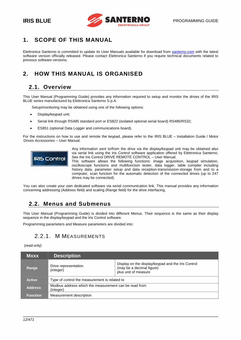
IRIS BLUE
PROGRAMMING GUIDE
12/471
1. SCOPE OF THIS MANUAL
Elettronica Santerno is committed to update its User Manuals available for download from santerno.com with the latest software version officially released. Please contact Elettronica Santerno if you require technical documents related to previous software versions.
2. HOW THIS MANUAL IS ORGANISED
2.1. Overview This User Manual (Programming Guide) provides any information required to setup and monitor the drives of the IRIS BLUE series manufactured by Elettronica Santerno S.p.A.
Setup/monitoring may be obtained using one of the following options:
• Display/keypad unit;
• Serial link through RS485 standard port or ES822 (isolated optional serial board) RS485/RS32;
• ES851 (optional Data Logger and communications board).
For the instructions on how to use and remote the keypad, please refer to the IRIS BLUE – Installation Guide / Motor Drives Accessories – User Manual.
Any information sent to/from the drive via the display/keypad unit may be obtained also via serial link using the Iris Control software application offered by Elettronica Santerno. See the Iris Control DRIVE REMOTE CONTROL – User Manual. This software allows the following functions: image acquisition, keypad simulation, oscilloscope functions and multifunction tester, data logger, table compiler including history data, parameter setup and data reception-transmission-storage from and to a computer, scan function for the automatic detection of the connected drives (up to 247 drives may be connected).
You can also create your own dedicated software via serial communication link. This manual provides any information concerning addressing (Address field) and scaling (Range field) for the drive interfacing.
2.2. Menus and Submenus This User Manual (Programming Guide) is divided into different Menus. Their sequence is the same as their display sequence in the display/keypad and the Iris Control software.
Programming parameters and Measure parameters are divided into:
2.2.1. M MEASUREMENTS (read-only)
Mxxx Description
Range Drive representation (integer)
Display on the display/keypad and the Iris Control (may be a decimal figure) plus unit of measure
Active Type of control the measurement is related to
Address Modbus address which the measurement can be read from (integer)
Function Measurement description
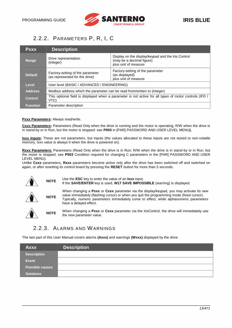
PROGRAMMING GUIDE
IRIS BLUE
13/471
2.2.2. PARAMETERS P, R, I, C
Pxxx Description
Range Drive representation (integer)
Display on the display/keypad and the Iris Control (may be a decimal figure) plus unit of measure
Default Factory-setting of the parameter (as represented for the drive)
Factory-setting of the parameter (as displayed) plus unit of measure
Level User level (BASIC / ADVANCED / ENGINEERING)
Address Modbus address which the parameter can be read from/written to (integer)
Control This optional field is displayed when a parameter is not active for all types of motor controls (IFD / VTC)
Function Parameter description
Pxxx Parameters: Always read/write.
Cxxx Parameters: Parameters (Read Only when the drive is running and the motor is operating; R/W when the drive is
in stand-by or in Run, but the motor is stopped: see P003 in [PAR] PASSWORD AND USER LEVEL MENU).
Ixxx Inputs: These are not parameters, but inputs (the values allocated to these inputs are not stored to non-volatile memory. Ixxx value is always 0 when the drive is powered on).
Rxxx Parameters: Parameters (Read Only when the drive is in Run; R/W when the drive is in stand-by or in Run, but
the motor is stopped: see P003 Condition required for changing C parameters in the [PAR] PASSWORD AND USER LEVEL MENU).
Unlike Cxxx parameters, Rxxx parameters become active only after the drive has been switched off and switched on
again, or after resetting its control board by pressing the RESET button for more than 5 seconds.
NOTE Use the ESC key to enter the value of an Ixxx input.
If the SAVE/ENTER key is used, W17 SAVE IMPOSSIBLE (warning) is displayed.
NOTE
When changing a Pxxx or Cxxx parameter via the display/keypad, you may activate its new value immediately (flashing cursor) or when you quit the programming mode (fixed cursor). Typically, numeric parameters immediately come to effect, while alphanumeric parameters have a delayed effect.
NOTE When changing a Pxxx or Cxxx parameter via the IrisControl, the drive will immediately use the new parameter value.
2.2.3. ALARMS AND W ARNINGS
The last part of this User Manual covers alarms (Axxx) and warnings (Wxxx) displayed by the drive:
Axxx Description
Description
Event
Possible causes
Solutions
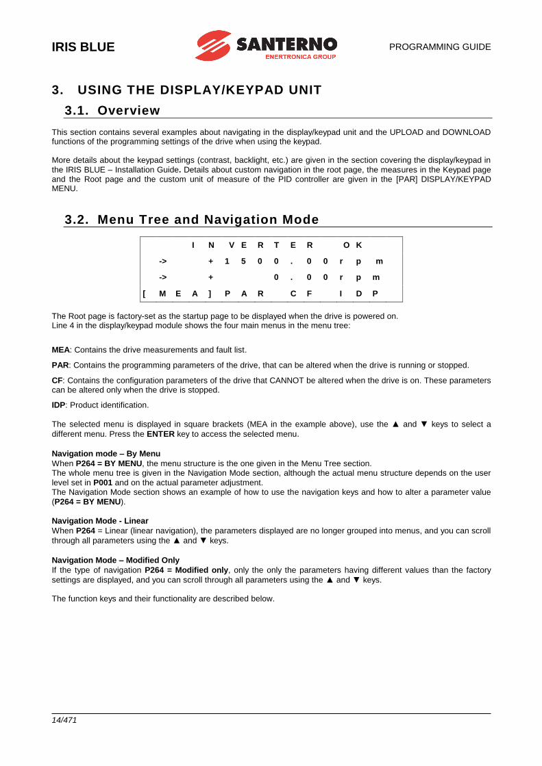
IRIS BLUE
PROGRAMMING GUIDE
14/471
3. USING THE DISPLAY/KEYPAD UNIT
3.1. Overview This section contains several examples about navigating in the display/keypad unit and the UPLOAD and DOWNLOAD functions of the programming settings of the drive when using the keypad. More details about the keypad settings (contrast, backlight, etc.) are given in the section covering the display/keypad in
the IRIS BLUE – Installation Guide. Details about custom navigation in the root page, the measures in the Keypad page and the Root page and the custom unit of measure of the PID controller are given in the [PAR] DISPLAY/KEYPAD MENU.
3.2. Menu Tree and Navigation Mode
I N V E R T E R O K
-> + 1 5 0 0 . 0 0 r p m -> + 0 . 0 0 r p m [ M E A ] P A R C F I D P
The Root page is factory-set as the startup page to be displayed when the drive is powered on. Line 4 in the display/keypad module shows the four main menus in the menu tree:
MEA: Contains the drive measurements and fault list.
PAR: Contains the programming parameters of the drive, that can be altered when the drive is running or stopped.
CF: Contains the configuration parameters of the drive that CANNOT be altered when the drive is on. These parameters can be altered only when the drive is stopped.
IDP: Product identification.
The selected menu is displayed in square brackets (MEA in the example above), use the ▲ and ▼ keys to select a
different menu. Press the ENTER key to access the selected menu.
Navigation mode – By Menu
When P264 = BY MENU, the menu structure is the one given in the Menu Tree section. The whole menu tree is given in the Navigation Mode section, although the actual menu structure depends on the user
level set in P001 and on the actual parameter adjustment. The Navigation Mode section shows an example of how to use the navigation keys and how to alter a parameter value
(P264 = BY MENU).
Navigation Mode - Linear
When P264 = Linear (linear navigation), the parameters displayed are no longer grouped into menus, and you can scroll
through all parameters using the ▲ and ▼ keys.
Navigation Mode – Modified Only
If the type of navigation P264 = Modified only, only the only the parameters having different values than the factory
settings are displayed, and you can scroll through all parameters using the ▲ and ▼ keys. The function keys and their functionality are described below.
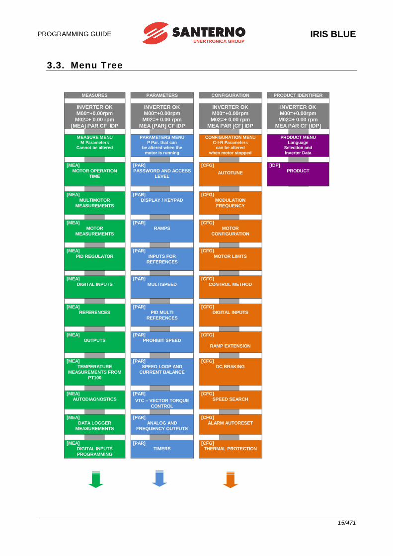
PROGRAMMING GUIDE
IRIS BLUE
15/471
3.3. Menu Tree
MEASURES
PARAMETERS
CONFIGURATION
PRODUCT IDENTIFIER
INVERTER OK
M00=+0.00rpm
M02=+ 0.00 rpm
[MEA] PAR CF IDP
INVERTER OK
M00=+0.00rpm
M02=+ 0.00 rpm
MEA [PAR] CF IDP
INVERTER OK
M00=+0.00rpm
M02=+ 0.00 rpm
MEA PAR [CF] IDP
INVERTER OK
M00=+0.00rpm
M02=+ 0.00 rpm
MEA PAR CF [IDP]
MEASURE MENU
M Parameters
Cannot be altered
PARAMETERS MENU
P Par. that can
be altered when the
motor is running
CONFIGURATION MENU
C-I-R Parameters
can be altered
when motor stopped
PRODUCT MENU
Language
Selection and
Inverter Data
[MEA]
MOTOR OPERATION
TIME
[PAR]
PASSWORD AND ACCESS
LEVEL
[CFG]
AUTOTUNE
[IDP]
PRODUCT
[MEA]
MULTIMOTOR
MEASUREMENTS
[PAR]
DISPLAY / KEYPAD
[CFG]
MODULATION
FREQUENCY
[MEA]
MOTOR
MEASUREMENTS
[PAR]
RAMPS
[CFG]
MOTOR
CONFIGURATION
[MEA]
PID REGULATOR [PAR]
INPUTS FOR
REFERENCES
[CFG]
MOTOR LIMITS
[MEA]
DIGITAL INPUTS [PAR]
MULTISPEED
[CFG]
CONTROL METHOD
[MEA]
REFERENCES
[PAR]
PID MULTI
REFERENCES
[CFG]
DIGITAL INPUTS
[MEA]
OUTPUTS
[PAR]
PROHIBIT SPEED
[CFG]
RAMP EXTENSION
[MEA]
TEMPERATURE
MEASUREMENTS FROM
PT100
[PAR]
SPEED LOOP AND
CURRENT BALANCE
[CFG]
DC BRAKING
[MEA]
AUTODIAGNOSTICS
[PAR]
VTC – VECTOR TORQUE
CONTROL
[CFG]
SPEED SEARCH
[MEA]
DATA LOGGER
MEASUREMENTS
[PAR]
ANALOG AND
FREQUENCY OUTPUTS
[CFG]
ALARM AUTORESET
[MEA]
DIGITAL INPUTS
PROGRAMMING
[PAR]
TIMERS
[CFG]
THERMAL PROTECTION
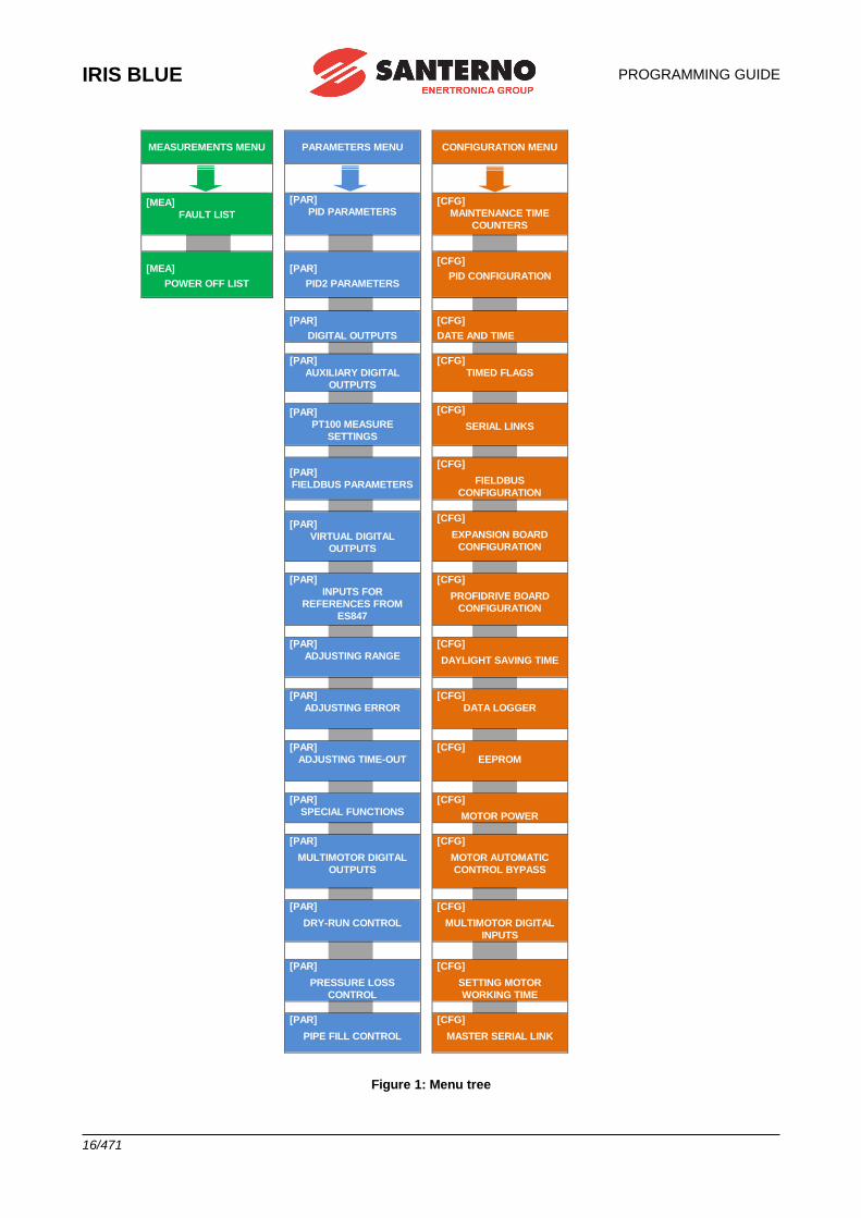
IRIS BLUE
PROGRAMMING GUIDE
16/471
MEASUREMENTS MENU
PARAMETERS MENU
I
T
O
[
CONFIGURATION MENU
MENU
[MEA]
FAULT LIST
[PAR]
PID PARAMETERS [CFG]
MAINTENANCE TIME
COUNTERS
[MEA]
POWER OFF LIST
[PAR]
PID2 PARAMETERS
[CFG]
PID CONFIGURATION
[IDP]
PRODOTTO
[PAR]
DIGITAL OUTPUTS
[CFG]
DATE AND TIME
[PAR]
AUXILIARY DIGITAL
OUTPUTS
[CFG]
TIMED FLAGS
[PAR]
PT100 MEASURE
SETTINGS
[CFG]
SERIAL LINKS
[PAR]
FIELDBUS PARAMETERS
[CFG]
FIELDBUS
CONFIGURATION
[PAR]
VIRTUAL DIGITAL
OUTPUTS
[CFG]
EXPANSION BOARD
CONFIGURATION
[PAR]
INPUTS FOR
REFERENCES FROM
ES847
[CFG]
PROFIDRIVE BOARD
CONFIGURATION
[PAR]
ADJUSTING RANGE
[CFG]
DAYLIGHT SAVING TIME
[PAR]
ADJUSTING ERROR
[CFG]
DATA LOGGER
[PAR]
ADJUSTING TIME-OUT
[CFG]
EEPROM
[PAR]
SPECIAL FUNCTIONS
[CFG]
MOTOR POWER
[PAR]
MULTIMOTOR DIGITAL
OUTPUTS
[CFG]
MOTOR AUTOMATIC
CONTROL BYPASS
[PAR]
DRY-RUN CONTROL
[CFG]
MULTIMOTOR DIGITAL
INPUTS
[PAR]
PRESSURE LOSS
CONTROL
[CFG]
SETTING MOTOR
WORKING TIME
[PAR]
PIPE FILL CONTROL
[CFG]
MASTER SERIAL LINK
Figure 1: Menu tree
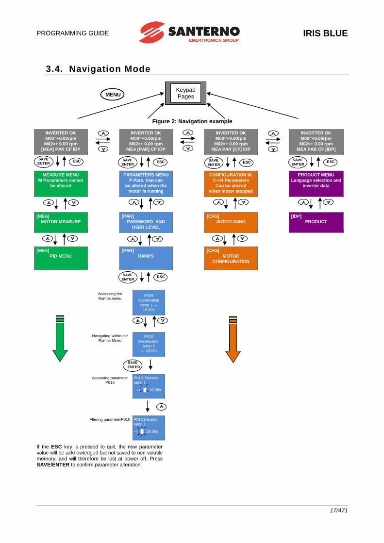
PROGRAMMING GUIDE
IRIS BLUE
17/471
3.4. Navigation Mode
Figure 2: Navigation example
INVERTER OK
M00=+0.00rpm
M02=+ 0.00 rpm
[MEA] PAR CF IDP
INVERTER OK
M00=+0.00rpm
M02=+ 0.00 rpm
MEA [PAR] CF IDP
INVERTER OK
M00=+0.00rpm
M02=+ 0.00 rpm
MEA PAR [CF] IDP
INVERTER OK
M00=+0.00rpm
M02=+ 0.00 rpm
MEA PAR CF [IDP]
MEASURE MENU
M Parameters cannot
be altered
PARAMETERS MENU
P Pars. that can
be altered when the
motor is running
CONFIGURATION M.
C-I-R Parameters
Can be altered
when motor stopped
PRODUCT MENU
Language selection and
inverter data
[MEA]
MOTOR MEASURE
[PAR]
PASSWORD AND
USER LEVEL
[CFG]
AUTOTUNING
[IDP]
PRODUCT
[MEA]
PID MENU
[PAR]
RAMPS
[CFG]
MOTOR
CONFIGURATION
Accessing the
Ramps menu
P009
Acceleration
ramp 1
10.00s
Navigating within the
Ramps Menu
P010
Deceleration
ramp 1
10.00s
Accessing parameter
P010
P010 Deceler.
ramp 1
█ 10.00s
Altering parameterP010 P010 Deceler.
ramp 1
█ 20.00s
If the ESC key is pressed to quit, the new parameter value will be acknowledged but not saved to non-volatile memory, and will therefore be lost at power off. Press
SAVE/ENTER to confirm parameter alteration.
Keypad Pages MENU
ESC SAVE
ENTER
ESC SAVE
ENTER
ESC SAVE
ENTER
ESC SAVE
ENTER
ESC SAVE
ENTER
SAVE
ENTER
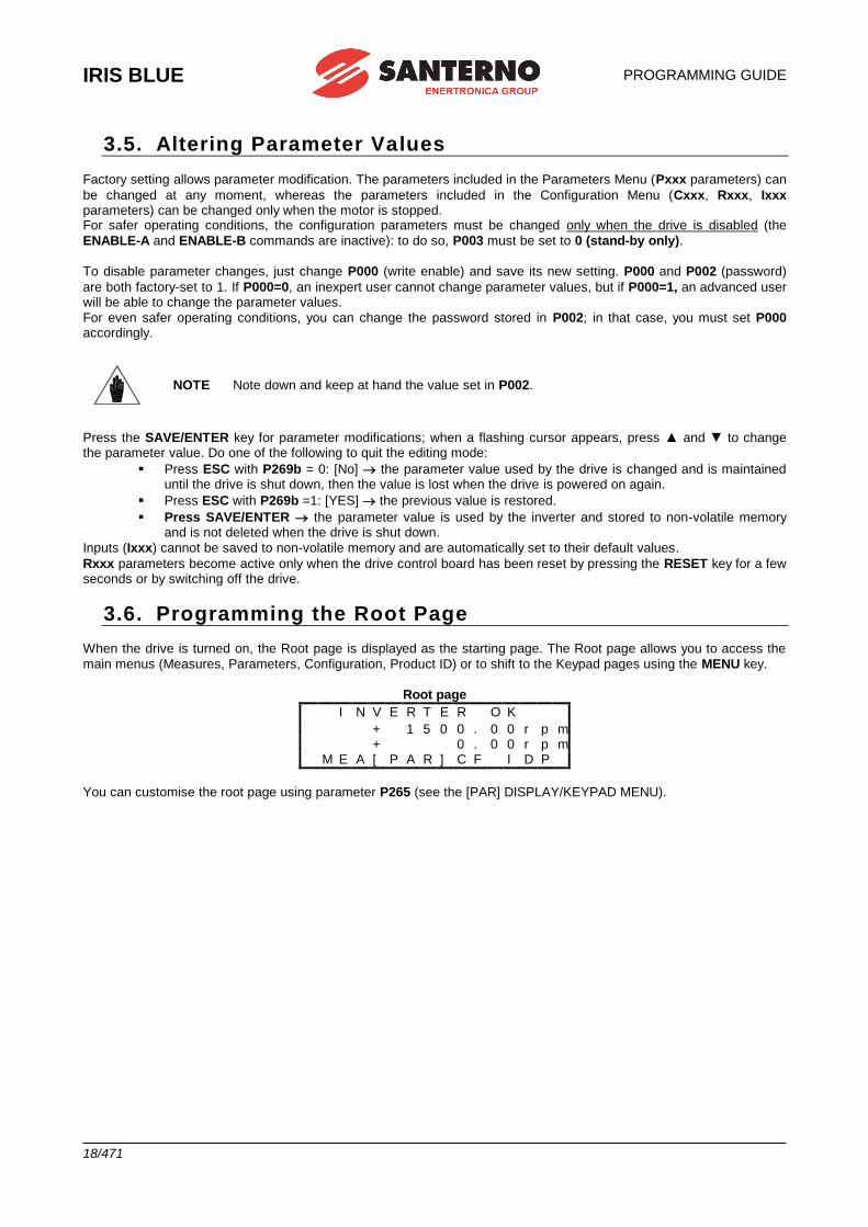
IRIS BLUE
PROGRAMMING GUIDE
18/471
3.5. Altering Parameter Values
Factory setting allows parameter modification. The parameters included in the Parameters Menu (Pxxx parameters) can
be changed at any moment, whereas the parameters included in the Configuration Menu (Cxxx, Rxxx, Ixxx parameters) can be changed only when the motor is stopped. For safer operating conditions, the configuration parameters must be changed only when the drive is disabled (the
ENABLE-A and ENABLE-B commands are inactive): to do so, P003 must be set to 0 (stand-by only).
To disable parameter changes, just change P000 (write enable) and save its new setting. P000 and P002 (password)
are both factory-set to 1. If P000=0, an inexpert user cannot change parameter values, but if P000=1, an advanced user will be able to change the parameter values.
For even safer operating conditions, you can change the password stored in P002; in that case, you must set P000 accordingly.
NOTE Note down and keep at hand the value set in P002.
Press the SAVE/ENTER key for parameter modifications; when a flashing cursor appears, press ▲ and ▼ to change the parameter value. Do one of the following to quit the editing mode:
▪ Press ESC with P269b = 0: [No] the parameter value used by the drive is changed and is maintained until the drive is shut down, then the value is lost when the drive is powered on again.
▪ Press ESC with P269b =1: [YES] the previous value is restored.
▪ Press SAVE/ENTER the parameter value is used by the inverter and stored to non-volatile memory and is not deleted when the drive is shut down.
Inputs (Ixxx) cannot be saved to non-volatile memory and are automatically set to their default values.
Rxxx parameters become active only when the drive control board has been reset by pressing the RESET key for a few seconds or by switching off the drive.
3.6. Programming the Root Page When the drive is turned on, the Root page is displayed as the starting page. The Root page allows you to access the
main menus (Measures, Parameters, Configuration, Product ID) or to shift to the Keypad pages using the MENU key.
Root page I N V E R T E R O K + 1 5 0 0 . 0 0 r p m + 0 . 0 0 r p m M E A [ P A R ] C F I D P
You can customise the root page using parameter P265 (see the [PAR] DISPLAY/KEYPAD MENU).
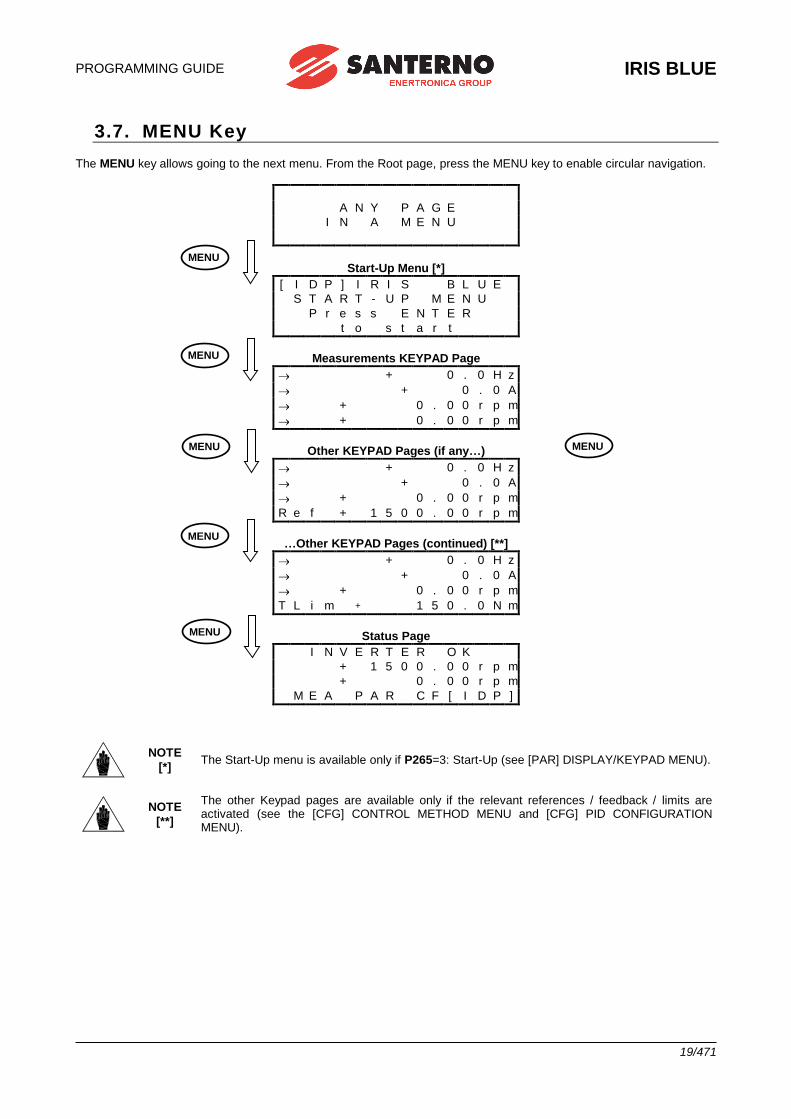
PROGRAMMING GUIDE
IRIS BLUE
19/471
3.7. MENU Key
The MENU key allows going to the next menu. From the Root page, press the MENU key to enable circular navigation.
A N Y P A G E
I N A M E N U
Start-Up Menu [*]
[ I D P ] I R I S B L U E
S T A R T - U P M E N U
P r e s s E N T E R
t o s t a r t
Measurements KEYPAD Page
+ 0 . 0 H z
+ 0 . 0 A
+ 0 . 0 0 r p m
+ 0 . 0 0 r p m
Other KEYPAD Pages (if any…)
+ 0 . 0 H z
+ 0 . 0 A
+ 0 . 0 0 r p m
R e f + 1 5 0 0 . 0 0 r p m
…Other KEYPAD Pages (continued) [**]
+ 0 . 0 H z
+ 0 . 0 A
+ 0 . 0 0 r p m
T L i m + 1 5 0 . 0 N m
Status Page I N V E R T E R O K
+ 1 5 0 0 . 0 0 r p m + 0 . 0 0 r p m M E A P A R C F [ I D P ]
NOTE
[*] The Start-Up menu is available only if P265=3: Start-Up (see [PAR] DISPLAY/KEYPAD MENU).
NOTE
[**]
The other Keypad pages are available only if the relevant references / feedback / limits are activated (see the [CFG] CONTROL METHOD MENU and [CFG] PID CONFIGURATION MENU).
MENU
MENU
MENU
MENU
MENU
MENU
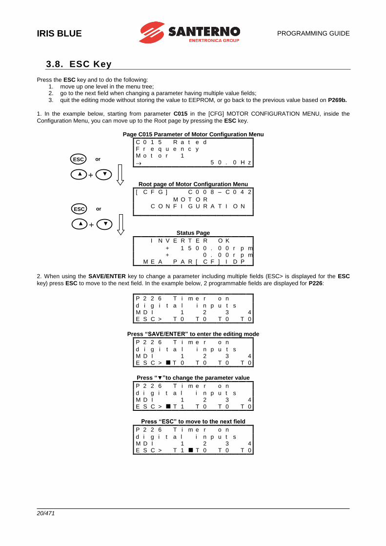
IRIS BLUE
PROGRAMMING GUIDE
20/471
3.8. ESC Key
Press the ESC key and to do the following: 1. move up one level in the menu tree; 2. go to the next field when changing a parameter having multiple value fields;
3. quit the editing mode without storing the value to EEPROM, or go back to the previous value based on P269b.
1. In the example below, starting from parameter C015 in the [CFG] MOTOR CONFIGURATION MENU, inside the
Configuration Menu, you can move up to the Root page by pressing the ESC key.
Page C015 Parameter of Motor Configuration Menu
C 0 1 5 R a t e d F r e q u e n c y M o t o r 1
5 0 . 0 H z
Root page of Motor Configuration Menu
[ C F G ] C 0 0 8 – C 0 4 2
M O T O R
C O N F I G U R A T I O N
Status Page I N V E R T E R O K
+ 1 5 0 0 . 0 0 r p m + 0 . 0 0 r p m M E A P A R [ C F ] I D P
2. When using the SAVE/ENTER key to change a parameter including multiple fields (ESC> is displayed for the ESC
key) press ESC to move to the next field. In the example below, 2 programmable fields are displayed for P226:
P 2 2 6 T i m e r o n
d i g i t a l i n p u t s M D I 1 2 3 4 E S C > T 0 T 0 T 0 T 0
Press “SAVE/ENTER” to enter the editing mode
P 2 2 6 T i m e r o n
d i g i t a l i n p u t s M D I 1 2 3 4 E S C > T 0 T 0 T 0 T 0
Press “▼”to change the parameter value
P 2 2 6 T i m e r o n
d i g i t a l i n p u t s M D I 1 2 3 4 E S C > T 1 T 0 T 0 T 0
Press “ESC” to move to the next field
P 2 2 6 T i m e r o n
d i g i t a l i n p u t s M D I 1 2 3 4 E S C > T 1 T 0 T 0 T 0
▲ ▼
ESC or
▲ ▼
ESC or
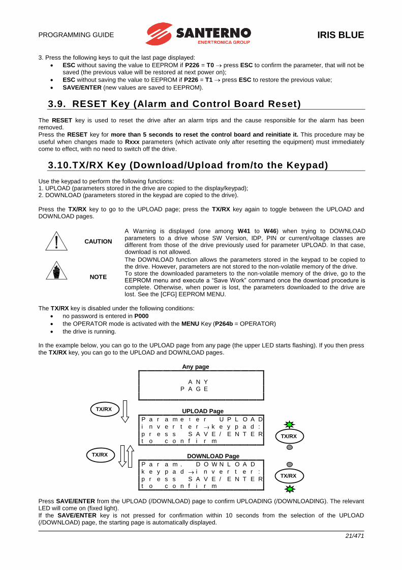
PROGRAMMING GUIDE
IRIS BLUE
21/471
3. Press the following keys to quit the last page displayed:
• ESC without saving the value to EEPROM if P226 = T0 press ESC to confirm the parameter, that will not be saved (the previous value will be restored at next power on);
• ESC without saving the value to EEPROM if P226 = T1 press ESC to restore the previous value;
• SAVE/ENTER (new values are saved to EEPROM).
3.9. RESET Key (Alarm and Control Board Reset)
The RESET key is used to reset the drive after an alarm trips and the cause responsible for the alarm has been removed.
Press the RESET key for more than 5 seconds to reset the control board and reinitiate it. This procedure may be
useful when changes made to Rxxx parameters (which activate only after resetting the equipment) must immediately come to effect, with no need to switch off the drive.
3.10.TX/RX Key (Download/Upload from/to the Keypad) Use the keypad to perform the following functions: 1. UPLOAD (parameters stored in the drive are copied to the display/keypad); 2. DOWNLOAD (parameters stored in the keypad are copied to the drive).
Press the TX/RX key to go to the UPLOAD page; press the TX/RX key again to toggle between the UPLOAD and DOWNLOAD pages.
CAUTION
A Warning is displayed (one among W41 to W46) when trying to DOWNLOAD parameters to a drive whose SW Version, IDP, PIN or current/voltage classes are different from those of the drive previously used for parameter UPLOAD. In that case, download is not allowed.
NOTE
The DOWNLOAD function allows the parameters stored in the keypad to be copied to the drive. However, parameters are not stored to the non-volatile memory of the drive. To store the downloaded parameters to the non-volatile memory of the drive, go to the EEPROM menu and execute a “Save Work” command once the download procedure is complete. Otherwise, when power is lost, the parameters downloaded to the drive are lost. See the [CFG] EEPROM MENU.
The TX/RX key is disabled under the following conditions:
• no password is entered in P000
• the OPERATOR mode is activated with the MENU Key (P264b = OPERATOR)
• the drive is running. In the example below, you can go to the UPLOAD page from any page (the upper LED starts flashing). If you then press
the TX/RX key, you can go to the UPLOAD and DOWNLOAD pages.
Any page
. A N Y P A G E
UPLOAD Page
P a r a m e t e r U P L O A D
i n v e r t e r k e y p a d :
p r e s s S A V E / E N T E R t o c o n f i r m
DOWNLOAD Page
P a r a m . D O W N L O A D
k e y p a d i n v e r t e r :
p r e s s S A V E / E N T E R t o c o n f i r m
Press SAVE/ENTER from the UPLOAD (/DOWNLOAD) page to confirm UPLOADING (/DOWNLOADING). The relevant LED will come on (fixed light).
If the SAVE/ENTER key is not pressed for confirmation within 10 seconds from the selection of the UPLOAD (/DOWNLOAD) page, the starting page is automatically displayed.
TX/RX
TX/RX
TX/RX
TX/RX
IRIS BLUE
PROGRAMMING GUIDE
22/471
While UPLOADING, W08 UPLOADING (flashing warning) appears. If parameters are successfully uploaded, the following warning appears:
W11 UPLOAD OK
If not, the W12 UPLOAD KO warning appears. Retry parameter upload.
While DOWNLOADING, W07 DOWNLOADING (flashing warning) appears. If parameters are successfully downloaded, the following warning appears:
W09 DOWNLOAD OK
If not, alarm A073 trips, and download must be retried before restarting the drive.
3.11.LOC/REM Key (Keypad Pages) To enable the Local/Remote operating mode (Remote sources are command and/or reference sources other than the
display/keypad) press the LOC/REM key in the display/keypad, or use a digital input configured as Loc/Rem (see C180).
NOTE
The LOC/REM key is enabled when no digital input is configured as Loc/Rem, or when a digital
input is configured as a Loc/Rem button (see C180a).
The LOC/REM key is disabled when a digital input is configured as a Loc/Rem selector switch
(see C180a).
C148 sets whether toggling between Remote mode and Local mode is activated only when the drive is disabled, or whether toggling from Remote to Local mode does not affect the drive running conditions (bumpless commands), but it does affect the reference. You can also choose to keep running conditions and reference unaffected (any command is
bumpless). For more details, please refer to the description of parameter C148 ([CFG] CONTROL METHOD MENU). In LOCAL mode (the L-CMD and L-REF LEDs come on), when drive references and commands are sent via
display/keypad, the Keypad page allows changing the given reference using the ▲ and ▼ keys (see P266 in the [PAR] DISPLAY/KEYPAD MENU).
When not in LOCAL mode, press the MENU key to access the Keypad pages from the root page. Only the Keypad pages relating to the Keypad source will be displayed along with the Measure Keypad page.
Example: Parameter C146 (Reference Selection) is set to Keypad. From the root page, press the MENU key once to
display the Measure Keypad page, and press the MENU key twice to display the Keypad page relating to Reference
Selection allowing changing the reference using the ▲ and ▼ keys.
The Keypad page allows entering custom measures (see parameters P268b to P268e in the ([PAR] DISPLAY/KEYPAD MENU).
From the Keypad pages, press the SAVE/ENTER key to access the Keypad Help page containing any details about the measures displayed in the Keypad page.
3.12.SAVE/ENTER Key
The SAVE/ENTER key allows selecting a lower level when navigating within the programming menus. It also allows
changing a parameter value (to change a parameter value, press the SAVE/ENTER key from the page of the parameter you want to change). An example is given in Figure 2. From the Keypad pages, the SAVE/ENTER key allows accessing the Keypad Help page containing any details about the measures displayed in the Keypad page.
3.13.START-UP Key
In order to make programming easier, the START-UP key allows reactivating the START-UP Menu at any time; this is a wizard to program the main parameters for the motor control and the PID control. See the START-UP MENU.
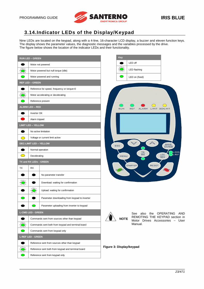
PROGRAMMING GUIDE
IRIS BLUE
23/471
3.14.Indicator LEDs of the Display/Keypad Nine LEDs are located on the keypad, along with a 4-line, 16-character LCD display, a buzzer and eleven function keys. The display shows the parameter values, the diagnostic messages and the variables processed by the drive. The figure below shows the location of the indicator LEDs and their functionality.
Figure 3: Display/keypad
RUN LED – GREEN
Motor not powered
Motor powered but null torque (idle)
Motor powered and running
REF LED – GREEN
Reference for speed, frequency or torque=0
Motor accelerating or decelerating
Reference present
ALARM LED – RED
Inverter OK
Alarm tripped
LIMIT LED – YELLOW
No active limitation
Voltage or current limit active
DEC-LIMIT LED – YELLOW
Normal operation
Decelerating
TX and RX LEDs - GREEN
TX RX
No parameter transfer
Download: waiting for confirmation
Upload: waiting for confirmation
Parameter downloading from keypad to inverter
Parameter uploading from inverter to keypad
L-CMD LED - GREEN
Commands sent from sources other than keypad
Commands sent both from keypad and terminal board
Commands sent from keypad only
L-REF LED - GREEN
Reference sent from sources other than keypad
Reference sent both from keypad and terminal board
Reference sent from keypad only
Key
LED off
LED flashing
LED on (fixed)
NOTE
See also the OPERATING AND REMOTING THE KEYPAD section in Motor Drives Accessories – User Manual.
IRIS BLUE
PROGRAMMING GUIDE
24/471
4. SERIAL LINKS
4.1. Overview The IRIS BLUE drives may be connected to other devices through a serial link. This allows reading and writing the parameters accessed through the remotable display/keypad.
Elettronica Santerno also supplies the IrisControl software package allowing controlling the drive through a computer connected via serial link. The IrisControl offers the following functionality: image copy, keypad emulation, oscilloscope functions and multifunction tester, data logger, history data table compiler, parameter setting and data reception–transmission–storage from and to a computer, scan function for the automatic detection of the connected inverters (up to 247 connected inverters).
4.2. MODBUS-RTU Protocol Messages and data are sent by means of standard protocol MODBUS in RTU mode. This standard protocol performs control procedures using an 8–bit binary representation. In RTU mode, a message begins with a silence interval equal to 3.5 times the transmission time of a character. If the character transmission stops for a time equal to 3.5 times the transmission time of a character, the controller will consider this time interval as the end of the message. Similarly, a message starting with a shorter silence time is considered as part of the previous message.
Message
beginning
Address Function Data Error control End of message
T1–T2–T3–T4 8 bits 8 bits n x 8 bits 16 bits T1–T2–T3–T4
Use parameter R004 (TimeOut) to increase the silence time interval up to max. 10000ms for the systems that do not recognize standard timeouts.
Address The address field acknowledges any value ranging from 1 to 247 as the address of the slave peripheral device. The master device queries the peripheral device specified in the address field; the peripheral device will respond with a message containing its address to let the master device know which the slave source of the response is. A master device query with a 0 address is addressed to all slave devices, which will not respond at all (broadcast mode).
Function The function related to the message may be chosen within the legal field ranging from 0 to 255. A response of the slave device to a message of the master device will simply return the function code to the master device if no error took place; otherwise, the most significant bit in this field is set to 1.
The only functions allowed are 03h: Read Holding Register, 06h Write Single Register and 10h: Preset Multiple
Register (see below).
Data The data field contains any additional information for the function being used.
Error Control The error control is performed through the CRC (Cyclical Redundancy Check) method. The16–bit value of the relevant field is computed when the message is sent by the transmitter and is then re–computed and checked by the receiver. CRC Register is computed as follows: 1. CRC Register is set to FFFFh 2. Exclusive OR is executed between CRC register and the first 8 bits of the message; the result is saved to a 16–bit register. 3. This register is right–shifted of one place. 4. If the right bit is 1, exclusive OR is executed between the 16–bit register and value 1010000000000001b. 5. Steps 3 and 4 are repeated until 8 shifts are performed. 6. Exclusive OR is performed between the 16–bit register and the next 8 bits of the message. 7. Steps 3 to 6 are repeated until all message bytes are processed. 8. The result is a CRC, that is attached to the message by sending the less significant byte as the first byte.
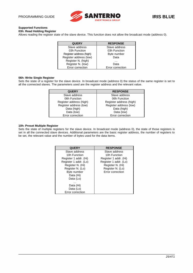
PROGRAMMING GUIDE
IRIS BLUE
25/471
Supported Functions
03h: Read Holding Register Allows reading the register state of the slave device. This function does not allow the broadcast mode (address 0).
QUERY RESPONSE
Slave address Slave address 03h Function 03h Function
Register address (high) Byte number Register address (low) Data
Register N. (high) … Register N. (low) Data Error correction Error correction
06h: Write Single Register Sets the state of a register for the slave device. In broadcast mode (address 0) the status of the same register is set to all the connected slaves. The parameters used are the register address and the relevant value.
QUERY RESPONSE
Slave address Slave address 06h Function 06h Function
Register address (high) Register address (high) Register address (low) Register address (low)
Data (high) Data (high) Data (low) Data (low)
Error correction Error correction
10h: Preset Multiple Register Sets the state of multiple registers for the slave device. In broadcast mode (address 0), the state of those registers is set in all the connected slave devices. Additional parameters are the basic register address, the number of registers to be set, the relevant value and the number of bytes used for the data items.
QUERY RESPONSE
Slave address Slave address 10h Function 10h Function
Register 1 addr. (Hi) Register 1 addr. (Hi) Register 1 addr. (Lo) Register 1 addr. (Lo)
Register N. (Hi) Register N. (Hi) Register N. (Lo) Register N. (Lo)
Byte number Error correction Data (Hi) Data (Lo)
… Data (Hi) Data (Lo)
Error correction
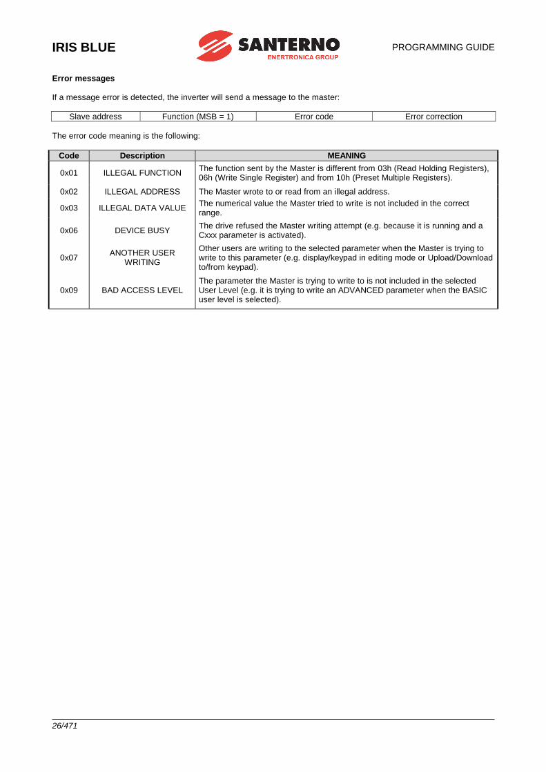
IRIS BLUE
PROGRAMMING GUIDE
26/471
Error messages If a message error is detected, the inverter will send a message to the master:
Slave address Function (MSB = 1) Error code Error correction
The error code meaning is the following:
Code Description MEANING
0x01 ILLEGAL FUNCTION The function sent by the Master is different from 03h (Read Holding Registers), 06h (Write Single Register) and from 10h (Preset Multiple Registers).
0x02 ILLEGAL ADDRESS The Master wrote to or read from an illegal address.
0x03 ILLEGAL DATA VALUE The numerical value the Master tried to write is not included in the correct range.
0x06 DEVICE BUSY The drive refused the Master writing attempt (e.g. because it is running and a Cxxx parameter is activated).
0x07 ANOTHER USER
WRITING
Other users are writing to the selected parameter when the Master is trying to write to this parameter (e.g. display/keypad in editing mode or Upload/Download to/from keypad).
0x09 BAD ACCESS LEVEL The parameter the Master is trying to write to is not included in the selected User Level (e.g. it is trying to write an ADVANCED parameter when the BASIC user level is selected).
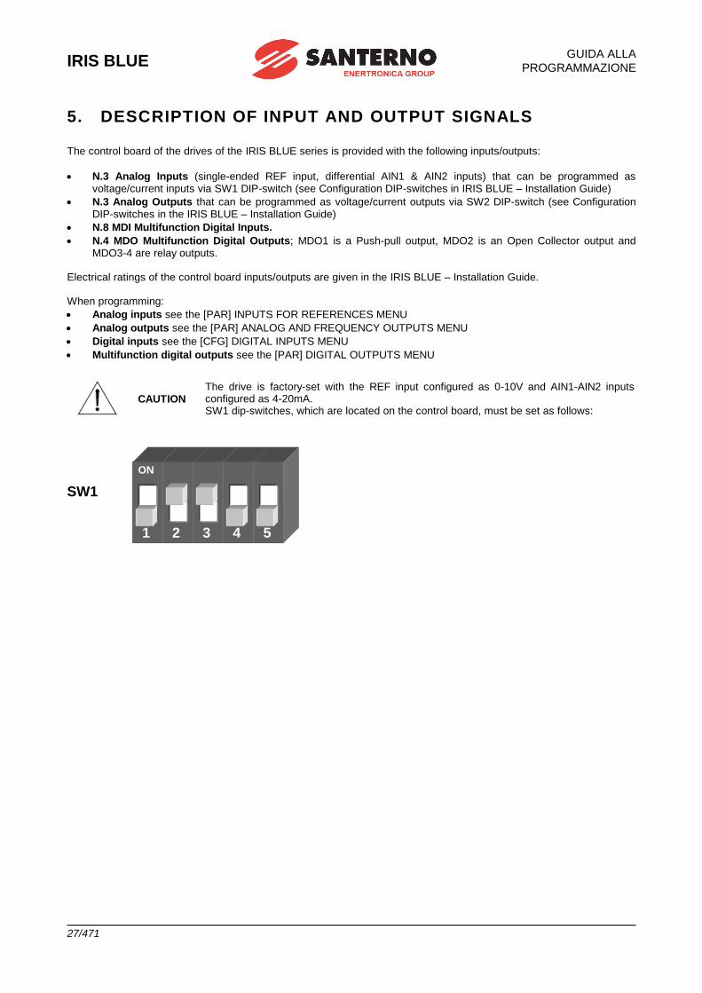
IRIS BLUE
GUIDA ALLA
PROGRAMMAZIONE
27/471
5. DESCRIPTION OF INPUT AND OUTPUT SIGNALS
The control board of the drives of the IRIS BLUE series is provided with the following inputs/outputs:
• N.3 Analog Inputs (single-ended REF input, differential AIN1 & AIN2 inputs) that can be programmed as voltage/current inputs via SW1 DIP-switch (see Configuration DIP-switches in IRIS BLUE – Installation Guide)
• N.3 Analog Outputs that can be programmed as voltage/current outputs via SW2 DIP-switch (see Configuration DIP-switches in the IRIS BLUE – Installation Guide)
• N.8 MDI Multifunction Digital Inputs.
• N.4 MDO Multifunction Digital Outputs; MDO1 is a Push-pull output, MDO2 is an Open Collector output and MDO3-4 are relay outputs.
Electrical ratings of the control board inputs/outputs are given in the IRIS BLUE – Installation Guide. When programming:
• Analog inputs see the [PAR] INPUTS FOR REFERENCES MENU
• Analog outputs see the [PAR] ANALOG AND FREQUENCY OUTPUTS MENU
• Digital inputs see the [CFG] DIGITAL INPUTS MENU
• Multifunction digital outputs see the [PAR] DIGITAL OUTPUTS MENU
CAUTION The drive is factory-set with the REF input configured as 0-10V and AIN1-AIN2 inputs configured as 4-20mA. SW1 dip-switches, which are located on the control board, must be set as follows:
SW1
ON
1 2 3 4 5
IRIS BLUE
GUIDA ALLA
PROGRAMMAZIONE
28/471
6. REFERENCES AND FEEDBACK
The drive references are the following:
• Main speed reference
• PID reference
• PID feedback
6.1. Main Speed Reference
If a speed control (e.g. C011 = Speed) is used, the main reference is a speed reference, while if a torque control is used
(e.g. C011=Torque), but the digital input is closed for the Slave programmed with C170), the main reference of the drive is a torque reference. The main reference can be one of the following:
• Analog/digital inputs programmed as sources (see parameters C143-C146).
• PID output if C294 PID Action = Reference
• Digital inputs programmed as Multispeed (see [PAR] MULTISPEED MENU) only when the main reference is a speed reference.
6.2. PID Reference
If the internal PID regulator is enabled (C291 different from Disabled), its reference is given by default by the sum of
the three sources programmed as references (see parameters C285-C287 in the [CFG] PID CONFIGURATION MENU
parameters C285-C287). Different types of PID reference control (Two PIDs and 2-zone mode) are available based on the setting in parameter
C291a (PID Control Mode).
6.3. PID Feedback
The PID feedback by default is the sum of the three sources programmed as feedback (see parameters C288-C290 in
the (see [CFG] PID CONFIGURATION MENU parameters C288-C290). Different types of PID feedback control (Two PIDs and 2-zone mode) are available based on the setting in parameter
C291a (PID Control Mode).
PROGRAMMING GUIDE
IRIS BLUE
29/471
7. PROGRAMMABLE FUNCTIONS
7.1. Voltage/Frequency Pattern
When using the Volt/Freq IFD control algorithm (e.g. C010 = IFD Volt/Freq), you can select different types of V/f patterns (see the V/f Pattern (IFD only) section in the [CFG] MOTOR CONFIGURATION MENU).
7.2. Slip Compensation
When using the Volt/Freq IFD control algorithm (C010 = IFD Volt/Freq), you can set the slip compensation function for a
more accurate speed control (see the Slip Compensation (IFD Only) in the [CFG] MOTOR CONFIGURATION MENU).
7.3. Speed Searching
When using the Volt/Freq IFD (e.g. C010 = IFD Volt/Freq) or the VTC VectorTorque control algorithm (C010 = VTC
VectorTorque), you can set the speed searching function for the motor speed of rotation, which is useful when the drive controls a motor which is already running (as for motors connected to fans). See the [CFG] SPEED SEARCHING.
7.4. DC Braking When using the Volt/Freq IFD or Vector Torque VTC control algorithm, you can set DC braking at start or at stop. The DCB Hold function can be set for the Volt/Freq IFD function. See the [CFG] MOTOR CONFIGURATION MENU.
7.5. Motor Thermal Protection The Motor Thermal Protection function protects the motor against possible overloads. This function can be obtained via a PTC acquired in AIN2 analog input—up to 6 PTCs can be series-connected—or it can be a software protection implemented through an algorithm reproducing the motor thermal image. See the [CFG] MOTOR THERMAL PROTECTION MENU for more details. For more details about using AIN2 input, please refer to the IRIS BLUE – Installation Guide.
7.6. Prohibit Speeds Prohibit speeds are speed ranges corresponding to mechanical resonance frequencies. They prevent the drive from running at the preset speed ranges. See the [PAR] PROHIBIT SPEED MENU for more details.
7.7. PID Digital Regulator The IRIS BLUE drive is provided with a digital PID (proportional, integral, derivative) regulator that can be used to implement the following:
• Analog output
• Main reference of the drive (Speed/Torque reference)
• Correction of the main reference
• Correction of the output voltage (only for Volt/Freq IFD control) See the [PAR] PID PARAMETERS MENU and the [CFG] PID CONFIGURATION MENU.
IRIS BLUE
PROGRAMMING GUIDE
30/471
7.8. Dry-Run Control The Dry-run function detects when water is running out in the system o when cavitation is about to occur. More details are given in the [PAR] DRY-RUN CONTROL MENU.
7.9. Pressure Loss Control The Pressure Loss control detects losses or failures in the water system. Using the PID pressure regulator is required. The pressure loss control detection is based on PID measurements, errors or feedback, depending on the parameter settings. Please refer to [PAR] PRESSURE LOSS CONTROL MENU.
7.10.Pipe Fill Control The Pipe Fill Control allows preventing water hammer in pipes, failures and faults in the hydraulic joints (such as watering nozzles), and limits the pipe filling rate. Please refer to [PAR] PIPE FILL CONTROL MENU.
7.11.Multimotor Control The Multimotor Control functionality integrated into the IRIS BLUE drive allows controlling multiple motors in parallel (maximum 5 motors). This function allows controlling motors in two different modes:
▪ Fixed speed: n.1 Master motor at variable speed and up to n.4 slave motors at fixed speed.
▪ Variable speed: up to n.5 variable speed motors (drive-controlled).
Please refer to the MULTIMOTOR CONTROL (MMC) section.
PROGRAMMING GUIDE
IRIS BLUE
31/471
7.12.Setting Two Alternative Command Sources and
Reference Sources You can set a digital input as a selector switch allowing selecting two alternative control sources and reference sources. Example:
A selector switch is required to select control mode B (the drive references and commands are sent via fieldbus) and
control mode A (the drive reference is sent via AIN1 analog input and commands are sent via keypad). The following parameters shall be set up accordingly:
C179 MDI for source selection= MDI6
C140 Selection of control source n. 1 = Keypad
C141 Selection of control source n. 2 = Fieldbus
C143 Selection of reference n. 1 = AIN1
C144 Selection of reference n. 2 = Fieldbus When MDI6 digital input in the terminal board is open (terminal 19), the command sources and reference sources n. 1 are selected (Keypad and AIN1 analog input, control mode A). When MDI6 is closed, the command sources and reference sources n. 2 are selected (Fieldbus, control mode B).
CAUTION In the example above, if C179 = Disable, the OR logic for the Keypad and Fieldbus is considered, whereas the Fieldbus and AIN1 control sources are considered as summed up.
As an alternative to C179, it is possible to set, via parameters C179a and C179b, two digital inputs as independent selectors for the commands and the reference.
See also parameter C179, C179a, C179b in the [CFG] DIGITAL INPUTS MENU.
IRIS BLUE
PROGRAMMING GUIDE
32/471
7.13.Fire Mode When the digital input programmed as FIRE MODE is activated, all the protecting functions of the drive are ignored, so that no alarm trips when the drive is operating.
CAUTION
The Fire Mode function must be used only when it is strictly necessary, such as in
fire pumps, to protect human lives.
This function must never be used to prevent alarms from tripping in domestic or
industrial applications.
NOTE
To activate the parameters relating to the Fire Mode, enter the Password in the [IDP] PRODUCT MENU. This Password is provided by Elettronica Santerno’s Service Department. The drive Serial Number is required (see the Serial Number parameter in the [IDP] PRODUCT MENU).
The following parameters can be accessed only after entering the Password enabling the Fire Mode:
• P032 Acceleration ramp in Fire Mode (see [PAR] RAMPS MENU)
• P033 Deceleration ramp in Fire Mode (see [PAR] RAMPS MENU)
• P099 Fire Mode speed (see [PAR] MULTISPEED MENU)
• C186 MDI for Fire Mode enable (see [CFG] DIGITAL INPUTS MENU)
The Fire Mode is enabled when closing the MDI set through C186. The drive will use the speed reference set in P099
and the ramp times set in P032, P033. All alarms will be ignored, except for the following:
A041 IGBT FAULT Side A IGBT Hardware, general alarm
A044 OVERLOAD SW Software Overcurrent
A048 OVER VOLTAGE DC-bus voltage exceeding Vdc_max
A050 IGBT FAULT A Hardware Fault from IGBT Converter
A051 OVERLOAD HW A Hardware Overcurrent
A053 PWMA Not ON Hardware Failure, IGBT cannot be fired
Control Board Failure
When the Fire Mode is active, innumerable alarm autoresets are automatically enabled.
CAUTION
If an asterisk (*) appears next to INVERTER OK on the display, the product guarantee
is no longer valid.
The asterisk appears if at least one condition requiring the activation of a protection
feature occurs when the inverter is running in Fire Mode.
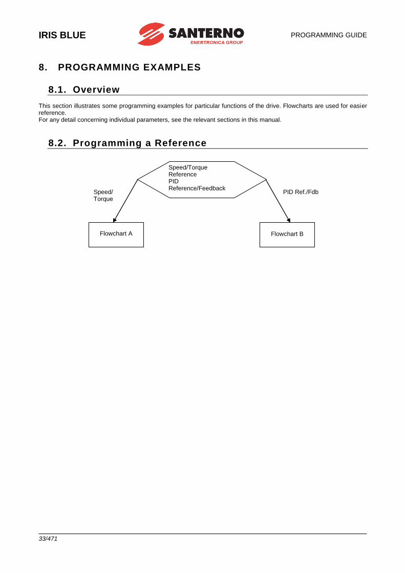
IRIS BLUE
PROGRAMMING GUIDE
33/471
8. PROGRAMMING EXAMPLES
8.1. Overview This section illustrates some programming examples for particular functions of the drive. Flowcharts are used for easier reference. For any detail concerning individual parameters, see the relevant sections in this manual.
8.2. Programming a Reference
PID Ref./Fdb Speed/ Torque
Flowchart A
Flowchart B
Speed/Torque Reference PID Reference/Feedback
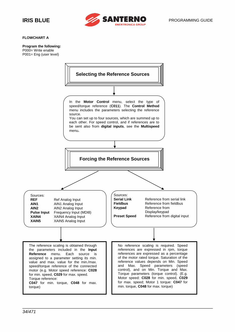
IRIS BLUE
PROGRAMMING GUIDE
34/471
FLOWCHART A
Program the following: P000= Write enable P001= Eng (user level)
DIAGRAMMA DI FLUSSO B
Selecting the Reference Sources
In the Motor Control menu, select the type of
speed/torque reference (C011). The Control Method menu includes the parameters selecting the reference source. You can set up to four sources, which are summed up to each other. For speed control, and if references are to
be sent also from digital inputs, see the Multispeed
menu.
Forcing the Reference Sources
Sources:
REF Ref Analog Input
AIN1 AIN1 Analog Input
AIN2 AIN2 Analog Input
Pulse Input Frequency Input (MDI8)
XAIN4 XAIN4 Analog Input
XAIN5 XAIN5 Analog Input
Sources:
Serial Link Reference from serial link
Fieldbus Reference from fieldbus
Keypad Reference from Display/keypad
Preset Speed Reference from digital input
The reference scaling is obtained through
the parameters included in the Input
Reference menu. Each source is assigned to a parameter setting its min. value and max. value for the min./max. speed/torque reference of the connected
motor (e.g. Motor speed reference: C028
for min. speed, C029 for max. speed. Torque reference:
C047 for min. torque, C048 for max. torque)
No reference scaling is required. Speed references are expressed in rpm, torque references are expressed as a percentage of the motor rated torque. Saturation of the reference values depends on Min. Speed and Max. Speed parameters (speed control), and on Min. Torque and Max. Torque parameters (torque control). (E.g.
Motor speed: C028 for min. speed, C029
for max. speed; Motor 1 torque: C047 for
min. torque, C048 for max. torque)
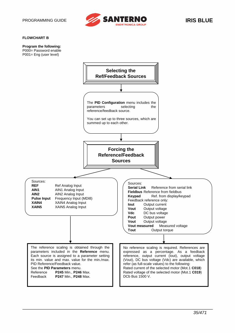
PROGRAMMING GUIDE
IRIS BLUE
35/471
FLOWCHART B
Program the following: P000= Password enable P001= Eng (user level)
Sources:
Serial Link Reference from serial link
Fieldbus Reference from fieldbus
Keypad Ref. from display/keypad Feedback reference only:
Iout Output current
Vout Output voltage
Vdc DC bus voltage
Pout Output power
Vout Output voltage
Vout measured Measured voltage
Tout Output torque
Selecting the
Ref/Feedback Sources
Selecting the
Ref/Feedback Sources
The PID Configuration menu includes the parameters selecting the reference/feedback source. You can set up to three sources, which are summed up to each other.
Sources:
REF Ref Analog Input
AIN1 AIN1 Analog Input
AIN2 AIN2 Analog Input
Pulse Input Frequency Input (MDI8)
XAIN4 XAIN4 Analog Input
XAIN5 XAIN5 Analog Input
The reference scaling is obtained through the
parameters included in the Reference menu. Each source is assigned to a parameter setting its min. value and max. value for the min./max. PID Reference/Feedback value.
See the PID Parameters menu.
Reference P245 Min., P246 Max.
Feedback P247 Min., P248 Max.
No reference scaling is required. References are expressed as a percentage. As a feedback reference, output current (Iout), output voltage (Vout), DC bus voltage (Vdc) are available, which refer (as full-scale values) to the following:
Rated current of the selected motor (Mot.1 C018)
Rated voltage of the selected motor (Mot.1 C019) DCb Bus 1500 V.
Forcing the
Reference/Feedback
Sources
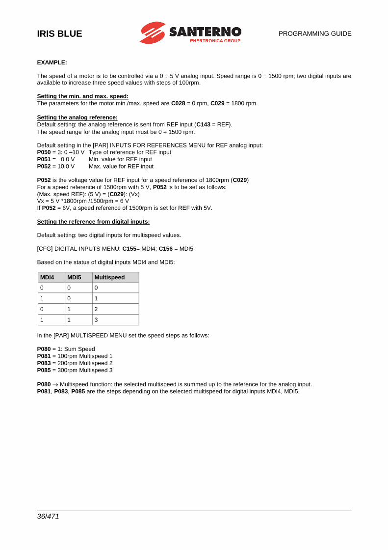
IRIS BLUE
PROGRAMMING GUIDE
36/471
EXAMPLE: The speed of a motor is to be controlled via a 0 ÷ 5 V analog input. Speed range is 0 ÷ 1500 rpm; two digital inputs are available to increase three speed values with steps of 100rpm.
Setting the min. and max. speed:
The parameters for the motor min./max. speed are C028 = 0 rpm, C029 = 1800 rpm.
Setting the analog reference:
Default setting: the analog reference is sent from REF input (C143 = REF).
The speed range for the analog input must be 0 1500 rpm. Default setting in the [PAR] INPUTS FOR REFERENCES MENU for REF analog input:
P050 = 3: 0 –10 V Type of reference for REF input
P051 = 0.0 V Min. value for REF input
P052 = 10.0 V Max. value for REF input
P052 is the voltage value for REF input for a speed reference of 1800rpm (C029)
For a speed reference of 1500rpm with 5 V, P052 is to be set as follows:
(Max. speed REF): (5 V) = (C029): (Vx) Vx = 5 V *1800rpm /1500rpm = 6 V
If P052 = 6V, a speed reference of 1500rpm is set for REF with 5V.
Setting the reference from digital inputs: Default setting: two digital inputs for multispeed values.
[CFG] DIGITAL INPUTS MENU: C155= MDI4; C156 = MDI5 Based on the status of digital inputs MDI4 and MDI5:
MDI4 MDI5 Multispeed
0 0 0
1 0 1
0 1 2
1 1 3
In the [PAR] MULTISPEED MENU set the speed steps as follows:
P080 = 1: Sum Speed
P081 = 100rpm Multispeed 1
P083 = 200rpm Multispeed 2
P085 = 300rpm Multispeed 3
P080 Multispeed function: the selected multispeed is summed up to the reference for the analog input.
P081, P083, P085 are the steps depending on the selected multispeed for digital inputs MDI4, MDI5.
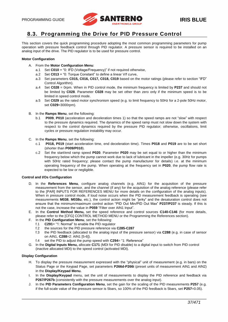
PROGRAMMING GUIDE
IRIS BLUE
37/471
8.3. Programming the Drive for PID Pressure Control This section covers the quick programming procedure adopting the most common programming parameters for pump operation with pressure feedback control through PID regulator. A pressure sensor is required to be installed on an analog input of the drive. The PID regulator is to be used for pressure control.
Motor Configuration
A. From the Motor Configuration Menu:
a.1 Set C010 = “0: IFD (Voltage/Frequency)” if not required otherwise,
a.2 Set C013 = “0: Torque Constant” to define a linear V/f curve,
a.3 Set parameters C015, C016, C017, C018, C019 based on the motor ratings (please refer to section “IFD”
Control Algorithm).
a.4 Set C028 = 0rpm. When in PID control mode, the minimum frequency is limited by P237 and should not
be limited by C028. Parameter C028 may be set other than zero only if the minimum speed is to be
limited in speed control mode.
a.5 Set C029 as the rated motor synchronism speed (e.g. to limit frequency to 50Hz for a 2-pole 50Hz motor,
set C029=3000rpm).
B. In the Ramps Menu, set the following:
b.1 P009, P010 (acceleration and deceleration times 1) so that the speed ramps are not “slow” with respect
to the pressure dynamics required. The dynamics of the speed ramp must not slow down the system with
respect to the control dynamics required by the pressure PID regulator; otherwise, oscillations, limit
cycles or pressure regulation instability may occur.
C. In the Ramps Menu, set the following:
c.1 P018, P019 (start acceleration time, end deceleration time). Times P018 and P019 are to be set short
(shorter than P009/P010).
c.2 Set the start/end ramp speed P020. Parameter P020 may be set equal to or higher than the minimum
frequency below which the pump cannot work due to lack of lubricant in the impeller (e.g. 30Hz for pumps
with 50Hz rated frequency; please contact the pump manufacturer for details) i.e. at the minimum
operating frequency of the pump. When operating at the frequency set in P020, the pump flow rate is
expected to be low or negligible.
Control and I/Os Configuration
D. In the References Menu, configure analog channels (e.g. AIN1) for the acquisition of the pressure measurement from the sensor, and the channel (if any) for the acquisition of the analog reference (please refer to the [PAR] INPUTS FOR REFERENCES MENU for more details on the configuration of the analog inputs). When in pressure control mode, if loud noise occurs when the PID measurement feedback is operating (see
measurements M038, M038u, etc.), the control action might be “jerky” and the desaturation control does not
ensure that the minimum/maximum control action “PID Out Min/PID Out Max” P237/P237 is steady. If this is
not the case, increase the value in P059 “Filter over AIN1 Input”.
E. In the Control Method Menu, set the speed reference and control sources C140-C146 (for more details, please refer to the [CFG] CONTROL METHOD MENU or the Programming the References section).
F. In the PID Configuration Menu, set the following:
f.1 C291= “1: Normal” to enable the PID regulator
f.2 the sources for the PID pressure reference via C285-C287
f.3 the PID feedback (allocated to the analog input of the pressure sensor) via C288 (e.g. in case of sensor
on AIN1, C288=2: AIN1 [5-6]).
f.4 set the PID to adjust the pump speed with C294= “1: Reference”
G. In the Digital Inputs Menu, allocate C171 (MDI for PID disable) to a digital input to switch from PID control (inactive allocated MDI) to the speed control (activated MDI).
Display Configuration
H. To display the pressure measurement expressed with the “physical” unit of measurement (e.g. in bars) on the
Status Page or the Keypad Page, set parameters P266d-P266i (preset units of measurement AIN1 and AIN2)
in the Display/Keypad Menu.
I. In the Display/Keypad menu, set the unit of measurements to display the PID reference and feedback via
P267/P267b (consistently with the pressure measurements over the analog input).
J. In the PID Parameters Configuration Menu, set the gain for the scaling of the PID measurements P257 (e.g.
if the full-scale value of the pressure sensor is 5bars, so 100% of the PID feedback is 5bars, set P257=0.05).
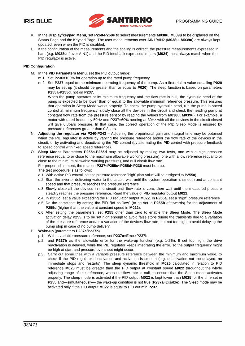
IRIS BLUE
PROGRAMMING GUIDE
38/471
K. In the Display/keypad Menu, set P268-P268e to select measurements M038u, M039u to be displayed on the
Status Page and the Keypad Page. The user measurements over AIN1/AIN2 (M038u, M039u) are always kept
updated, even when the PID is disabled.
L. If the configuration of the measurements and the scaling is correct, the pressure measurements expressed in
bars (e.g. M038u if over AIN1) and the PID feedback expressed in bars (M024) must always match when the
PID regulator is active.
PID Configuration
M. In the PID Parameters Menu, set the PID output range:
m.1 Set P236=100% for operation up to the rated pump frequency
m.2 Set P237 equal to the minimum operating frequency of the pump. As a first trial, a value equalling P020
may be set up (it should be greater than or equal to P020). The sleep function is based on parameters
P255a-P255d, not on P237.
When the pump operates at its minimum frequency and the flow rate is null, the hydraulic head of the
pump is expected to be lower than or equal to the allowable minimum reference pressure. This ensures
that operation in Sleep Mode works properly. To check the pump hydraulic head, run the pump in speed
control at minimum frequency, slowly close all the devices in the circuit and check the heading pump at
constant flow rate from the pressure sensor by reading the values from M038u, M039u). For example, a
motor with rated frequency 50Hz and P237=60% running at 30Hz with all the devices in the circuit closed
will give 0.8bars pressure. In that case, the correct operation of the PID Sleep Mode is ensured by
pressure references greater than 0.8bars.
N. Adjusting the regulator via P240-P243 – Adjusting the proportional gain and integral time may be obtained
when the PID regulator is active by varying the pressure reference and/or the flow rate of the devices in the
circuit, or by activating and deactivating the PID control (by alternating the PID control with pressure feedback
to speed control with fixed speed reference).
O. Sleep Mode: Parameters P255a-P255d may be adjusted by making two tests, one with a high pressure
reference (equal to or close to the maximum allowable working pressure), one with a low reference (equal to or
close to the minimum allowable working pressure), and null circuit flow rate.
For proper adjustment, the relation P237<P255c<P255d<P236 must be true.
The test procedure is as follows:
o.1 With active PID control, set the pressure reference “high” (that value will be assigned to P255a)
o.2 Start the inverter delivering water to the circuit, wait until the system operation is smooth and at constant
speed and that pressure reaches the pressure reference
o.3 Slowly close all the devices in the circuit until flow rate is zero, then wait until the measured pressure
steadily reaches the pressure reference. Read the value of PID regulator output M022.
o.4 In P255c, set a value exceeding the PID regulator output M022. In P255a, set a “high” pressure reference
o.5 Do the same test by setting the PID Ref as “low” (to be set in P255b afterwards) for the adjustment of
P255d (higher than the value at constant speed in M022).
o.6 After setting the parameters, set P255 other than zero to enable the Sleep Mode. The Sleep Mode
activation delay P255 is to be set high enough to avoid false stops during the transients due to a variation
of the pressure reference and/or a variation of the devices flow rate, but not too high to avoid delaying the
pump stop in case of no pump delivery.
P. Wake-up (parameters P237a/P237b).
p.1 With a variable pressure reference, set P237a=Error>P237b
p.2 and P237b as the allowable error for the wake-up function (e.g. 1-2%). If set too high, the drive
reactivation is delayed, while the PID regulator keeps integrating the error, so the output frequency might
be high at start and pressure overshoot might occur.
p.3 Carry out some tries with a variable pressure reference between the minimum and maximum value, to
check if the PID regulator deactivation and activation is smooth (e.g. deactivation not too delayed, no
immediate stops and restarts). The sleep dynamic threshold in M025 calculated in relation to PID
reference M023 must be greater than the PID output at constant speed M022 throughout the whole
adjusting range of the reference, when the flow rate is null, to ensure that the Sleep mode activates
properly. The sleep mode is activated if the PID output M022 is kept lower than M025 for the time set in
P255 and—simultaneously— the wake-up condition is not true (P237a=Disable). The Sleep mode may be
activated only if the PID output M022 is equal to PID out min P237.
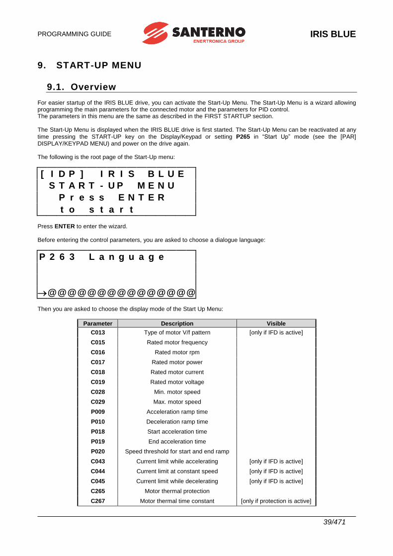
PROGRAMMING GUIDE
IRIS BLUE
39/471
9. START-UP MENU
9.1. Overview For easier startup of the IRIS BLUE drive, you can activate the Start-Up Menu. The Start-Up Menu is a wizard allowing programming the main parameters for the connected motor and the parameters for PID control. The parameters in this menu are the same as described in the FIRST STARTUP section. The Start-Up Menu is displayed when the IRIS BLUE drive is first started. The Start-Up Menu can be reactivated at any
time pressing the START-UP key on the Display/Keypad or setting P265 in “Start Up” mode (see the [PAR] DISPLAY/KEYPAD MENU) and power on the drive again. The following is the root page of the Start-Up menu:
[ I D P ] I R I S B L U E
S T A R T - U P M E N U
P r e s s E N T E R
t o s t a r t
Press ENTER to enter the wizard. Before entering the control parameters, you are asked to choose a dialogue language:
P 2 6 3 L a n g u a g e
@ @ @ @ @ @ @ @ @ @ @ @ @ @ @ Then you are asked to choose the display mode of the Start Up Menu:
Parameter Description Visible
C013 Type of motor V/f pattern [only if IFD is active]
C015 Rated motor frequency
C016 Rated motor rpm
C017 Rated motor power
C018 Rated motor current
C019 Rated motor voltage
C028 Min. motor speed
C029 Max. motor speed
P009 Acceleration ramp time
P010 Deceleration ramp time
P018 Start acceleration time
P019 End acceleration time
P020 Speed threshold for start and end ramp
C043 Current limit while accelerating [only if IFD is active]
C044 Current limit at constant speed [only if IFD is active]
C045 Current limit while decelerating [only if IFD is active]
C265 Motor thermal protection
C267 Motor thermal time constant [only if protection is active]

IRIS BLUE
PROGRAMMING GUIDE
40/471
After setting the last parameter and moving the cursor forward, the following page will appear:
P r e s s U P A R R O W
t o q u i t
D O W N A R R O W
t o c o n t i n u e
Press ▲ to quit the Start-up menu. The default page of the system will be displayed.
IRIS BLUE
PROGRAMMING GUIDE
41/471
10. FIRST STARTUP
For the signal wiring and power wiring, please refer to the IRIS BLUE – Installation Guide. Parameter programming is detailed in the START-UP MENU.
10.1.“IFD” Control Algorithm
The IRIS BLUE drives are factory set with the IFD (C010) control algorithm for the first startup of the equipment. The default functions of the drive terminals are given in the table below. For more details, please refer to the IRIS BLUE’s IRIS BLUE – Installation Guide.
.
1) Wiring: Follow the instructions stated in the “Caution Statements” and “Installation” sections (IRIS BLUE – Installation Guide).
2) Power on: Power on the drive and do not close the link to the ENABLE-A and ENABLE-B inputs to prevent the motor from running. Check if the display/keypad turns on.
3) Parameter setting:
The equipment startup is made easier by the START-UP MENU, which is a wizard for the setup of the main motor control parameters.
From the START-UP MENU, set the following: 1. The motor ratings by way of:
• C015 (fmot1) rated frequency
• C016 (rpmnom1) rated rpm
• C017 (Pmot1) rated power
• C018 (Imot1) rated current
• C019 (Vmot1) rated voltage
The motor V/f pattern may be programmed in C013.
4) Autotune (motor
stopped):
In case of IFD motor control when slip compensation is inactive (C039=0%) no autotune is required. On the other hand, when slip compensation is active, it is recommended to compute
stator resistance C022.
The steps to take to perform motor autotune are the following:
With the ENABLE-A and ENABLE-B commands open, access the [CFG] AUTOTUNE MENU
and set I073 = [1: Motor Tune] and I074 = [0: All Ctrl no rotation]. Use the ESC key to accept changes.
Close the ENABLE-A and ENABLE-B commands and wait until tune is complete (Warning
“W32 Open Enable” is displayed). The drive has computed and saved the values for C022 (stator resistance).
If alarm “A097 Motor Wires KO” trips, check the motor wiring. If alarm “A065 Autotune KO”
trips, this means that the ENABLE command has opened before autotune was complete. In
this case, reset the drive by sending a command from terminal MDI3, or press the RESET key in the display/keypad and perform the autotune procedure again.
5) Overload: Set parameters C043, C044 and C045 as the maximum desired overload current.
6) Startup: Activate the ENABLE-A input (terminal 15), ENABLE-B input (terminal S) and the START input
(terminal 14) and send a speed reference: the RUN LED and REF LEDs will come on and the motor will start running. Make sure that the motor is rotating in the correct direction. If not, set
parameter C014 (Phase Rotation) to [1:Yes], or open the ENABLE-A, ENABLE-B and START inputs, remove voltage from the drive and, after waiting at least 20 minutes, swap two of the motor phases.
7) Possible failures: If no failure occurred, go to step 8. Otherwise, check the drive connections paying particular attention to supply voltages, DC link and input reference. Also check if alarm messages are
displayed. In the [MEA] MEASUREMENTS MENU, check the reference speed (M001), the
supply voltage to the control section (M030), the DC link voltage (M029), and the condition of
control terminals (M033). Check to see if these readouts match with the measured values.
IRIS BLUE
PROGRAMMING GUIDE
42/471
8) Additional
parameter
modifications:
When parameter P003 = Standby Only (condition required for changing C parameters), you can
change Cxxx parameters in the CONFIGURATION menu only when the drive is DISABLED or
STOPPED, whereas if P003 = Standby + Fluxing, you can change Cxxx parameters when the motor is stopped but the drive is enabled.
9) Reset: If an alarm trips, find the cause responsible for the alarm and reset the drive. Enable input
MDI3 (terminal 16) for some time, or press the RESET key on the display/keypad.
NOTE When the IFD control algorithm is used, only speed references can be set up.
NOTE
The ENABLE-A and ENABLE-B inputs are allocated to the STO function. If this safety functionality is to be adopted, the control mode and the control circuit of these signals must
be accomplished as per the Safe Torque Off Function – Application Manual. That manual also includes a detailed validation procedure of the control configuration of the STO function to be executed upon first start-up and also periodically at yearly intervals.
PROGRAMMING GUIDE
IRIS BLUE
43/471
10.2.“VTC” Control Algorithm
1) Wiring: Follow the instructions stated in the “Caution Statements” and “Installation” sections in the IRIS BLUE – Installation Guide.
2) Power on: Power on the drive and do not close the link to the ENABLE-A and ENABLE-B inputs to prevent the motor from running. Check if the display/keypad turns on.
3) Parameter
setting:
The equipment startup is made easier by the START-UP MENU, which is a wizard for the setup of the main motor control parameters.
From the START-UP MENU, set the following:
1. The control algorithm as VTC (Vector Torque Control) in C010; 2. The motor ratings by way of:
• C015 (fmot1) rated frequency
• C016 (rpmnom1) rated rpm
• C017 (Pmot1) rated power
• C018 (Imot1) rated current
• C019 (Vmot1) rated voltage
• C029 (Speedmax1) max. allowable speed
4) Setting no-load
current C021
If the motor current is known, set C021 (I0) to the value of I0 expressed as a percentage of the rated motor current. If the no-load current of the motor is not known but the motor can rotate freely without any connected load, start the motor in IFD mode at nominal rpm, read out the current value from the
Motor Measurements Menu and use that value as the first trial value for I0. For example, if the
rated motor current is C018 = 133A and M026 = 36A, set C021= 36/133=27%.
NOTE: If the motor must run at a higher speed than the rated speed (field weakening mode) read out the no-load current value at rated speed in any case. Lastly, if the no-load current of the motor is not known and the motor cannot rotate under no-load
conditions, you can use the first I0 trial value automatically computed by the IRIS BLUE drive during the tuning procedure described in step 5).
NOTE: Each time the tuning procedure in step 5) is carried out with no-load current
parameter C021 (I0) = 0, the IRIS BLUE drive will automatically enter a value based on the motor current ratings.
5) Autotune of
motor parameters
(motor stopped)
With the ENABLE-A and ENABLE-B commands open, access the [CFG] AUTOTUNE MENU and
set I073=[1: Motor Tune] and I074=[0: Motor Params]. Press ESC to confirm the new values.
Close the ENABLE-A and ENABLE-B commands and wait until tune is complete (Warning “W32 Open Enable” is displayed). The drive has now computed and saved the following parameter values:
- C022 (stator resistance) through motor measurements
- C023 (leakage inductance) through motor measurements
- If C021=0, a first trial value for no-load current C021 is computed based on the motor ratings
- C024 (mutual inductance)
- If C025=0, a first trial value for rotor time constant C025 is computed based on the motor ratings
If alarm “A097 Motor Wires KO” trips, check the motor wiring. If alarm “A065 Autotune KO” trips,
this means that the ENABLE-A and ENABLE-B commands have opened before autotune was complete. In that case, reset the drive sending a command from terminal MDI3, or press the
RESET key in the display/keypad and perform the autotune procedure again. If the motor can rotate with no connected load, carry out the autotune procedure for the rotor time
constant and the current loop of the VTC regulator as detailed in step 6a, otherwise carry out only
the current loop tuning as detailed in step 6b (in that case, the rotor time constant C025 is not computed based on the motor measurements).
IRIS BLUE
PROGRAMMING GUIDE
44/471
6a) Autotune for
rotor time
constant and
current loop
(rotor free)
CAUTION: This type of tuning requires that the motor is free to rotate with no connected load. During autotune, current is first applied to the motor when the rotor is not running, then the motor is operated to run at approx. 70% of its rated speed.
If the motor can rotate with no connected load, with the ENABLE-A and ENABLE-B commands
open, access the [CFG] AUTOTUNE MENU and set I073= [1: Motor Tune] e I074= [2: Control YES
rot]. Press ESC to confirm the new values.
Close the ENABLE-A and ENABLE-B commands and wait until tune is complete (Warning “W32 Open Enable” is displayed). The drive has now computed and saved the following parameter values:
- C025 (rotor time constant) through motor measurements
- P175t1 (proportional gain of the current control) and P175u1 (integral time of the current control) through motor measurements.
If alarm “A065 Autotune KO” trips, this means either that the ENABLE-A and ENABLE-B commands have opened before autotune was complete, or that the available timeout has elapsed.
In either case, reset the drive sending a command from terminal MDI3, or press the RESET key on the display/keypad and perform the autotune procedure again.
NOTE: If autotune has not been interrupted by opening the ENABLE-A and ENABLE-B
commands, decrease no-load current value C021 by 5% before performing the autotune procedure again.
6b) Current loop
autotune (motor
stopped):
If the motor cannot rotate with any connected load, it is not possible to estimate the rotor time constant by way of the autotune procedure. Therefore, only the VTC current loop is tuned.
With the ENABLE-A and ENABLE-B commands open, access the [CFG] AUTOTUNE MENU and
set I073= [1: Motor Tune] and I074= [1: Control NO rot]. Press ESC to confirm the new changes.
Close the ENABLE-A and ENABLE-B commands and wait until tune is complete (Warning “W32 Open Enable” is displayed). The drive has now computed and saved the following parameter values:
- P175t1 (proportional gain of the current control) through motor measurements.
- P175u1 (integral time of the current control) through motor measurements.
If alarm “A065 Autotune KO” trips, this means that the ENABLE-A and ENABLE-B commands have opened before autotune was complete or the autotune algorithm has failed within the preset
timeout. In that case, reset the drive sending a command from terminal MDI3, or press the RESET key in the display/keypad and perform the autotune procedure again.
7) Overload: Set parameter C048 in the [CFG] LIMITS MENU based on the maximum torque that can be generated expressed as a percentage of the motor rated torque.
8) Start up: Activate the ENABLE-A input (terminal 15), ENABLE-B (terminal S) and the START input
(terminal 14) and send a speed reference. The RUN LED and REF LED will come on and the motor will start. Make sure that the motor is rotating in the correct direction. If not, set parameter
C014 (Phase Rotation) = [1:Yes], or open the ENABLE-A, ENABLE-B and START inputs, remove voltage from the drive and, after waiting at least 20 minutes, swap two of the motor phases.
9) Speed
regulator
adjustment:
If overshoot occurs when the speed setpoint is attained or if a system instability is detected (jerking), adjust the parameters relating to the speed loop ([PAR] SPEED LOOP AND CURRENT
BALANCING MENU). Set the two parameters relating to integral time (P125, P126) as [Disabled]
and set low values for the parameters relating to proportional gain (P128, P129). Set equal values
for P128 and P129 and increase them equally until overshoot takes place when the setpoint is
attained. Decrease P128 and P129 by approx. 30%, then decrease the high values set for integral
time in P125 and P126 (keep both values equal) until an acceptable setpoint response is obtained. Check to see if the motor runs smoothly at constant speed.
PROGRAMMING GUIDE
IRIS BLUE
45/471
10) Possible
failures:
If no failure occurred, go to step 11. Otherwise, check the drive connections paying particular attention to supply voltages, DC link and input reference. Also check if alarm messages are
displayed. In the [MEA] MEASUREMENTS MENU, check the reference speed (M000), the
reference speed processed by the ramps (M002), the supply voltage of the control section (M030),
the DC-link voltage (M029), the condition of the control terminals (M033). Check to see if these readouts match with the measured values.
11) Additional
parameter
modifications:
If the motor control is underperforming, make sure that the following measurements are consistent with the expected motor operation:
- estimated speed M004 with respect to speed ramp M002,
- output frequency M006,
- generated torque M012 and torque demand M011,
- output current M026,
- output voltage M027.
Proceed as follows:
Issue What to do
Generation of weak torque or inaccurate torque delivery
Increase the flux boost at low frequency P175h1 and adjust the
frequency range for the boost to occur via parameters P175i1
and P175j1. The magnetization current at low frequency with
active current boost equals the no-load current value in C021
increased by the value in P175h1 (for example, if C021=27% and
P175h1=30%, the magnetization current is 27%x1.3=35.1%). Up
to the frequency value in P175i1, the magnetization current is
C021 x (1+P175h1); at a frequency higher than P175j1, the
magnetization current is C021; at intermediate frequency values, the magnetization current follows a linear pattern. Too high magnetization current values may lead to saturation of the motor flux, lower efficiency due to greater no-load current, inaccurate torque adjustment or controller instability. It is suggested that
P175j1 be applied at its maximum value up to 50% of the rated
frequency. Also, set P175i1 in such a way so as to obtain a
rather smooth pattern (for example, P175i1 set to half the value
in P175j1). In case P175i1 and P175j1 are not correctly adjusted, torque adjustment may be uneven or current variations may occur.
Generation of weak torque at high speed
If the motor is not capable of delivering high torque at high speed (close to rated torque or field weakening torque) or requires excessive current with respect to the expected current, it is
possible to adjust rotor time constant C025.
Generation of weak torque at low speed or in regenerative mode
Change current distortion compensation parameters in VTC
control P175a, P175b, P175c. Change current distortion
compensation P175b first, then change positive and negative
current split P175c.
For high values in P175b, also increase the linear pattern
threshold in P175a. If parameter P175b is set too high or P175a is set too low, rotor oscillations may occur, or it may happen that the rotor is not kept standstill even in no-load conditions. If this is the case, set lower values for the parameters above.
Low output voltage or weak torque in field weakening mode
Disable static field weakening by setting C030 = Disable and
enable automatic field weakening by setting C030a >0. In that way, the field weakening amplitude is automatically adjusted to ensure adjusting the required speed at the maximum allowable voltage fitting the rated motor voltage and the available DC voltage.
IRIS BLUE
PROGRAMMING GUIDE
46/471
Torque demand
(measurement M011) different from generated torque (measurement
M012)
Certain applications require that the generated torque be as close as possible to the torque demand; this is due to the fact
that the torque limit (parameters C047 and C048) affects the torque demand, so it is important that the actual generated torque is correctly limited. To do so, proceed as follows:
• Check M011 and M012 under normal operating conditions of the motor and, in any case, at at least 75% of the rated speed and at least 75% of the rated load. If the motor has to operate under field weakening conditions (higher speed than the nominal speed) also this condition is to be checked.
• If M011>M012, gradually increase C023 by steps of about 10%.
• If M011<M012, gradually decrease C023 by steps of about 10%.
• In case start up is difficult when increasing C023, gradually
decrease C024 by steps of about 10% and find a new value
for C023 that makes M011 and M012 equal.
When parameter P003 = Standby Only (condition required for changing Cxxx parameters), you
can change Cxxx parameters only when the drive is DISABLED or STOPPED, whereas if P003 =
Standby + Fluxing, you can change Cxxx parameters when the motor is stopped but the drive is enabled.
Before changing any parameters, remember that the correct code for parameter P000 must be previously set up.
12) Reset:
If an alarm trips, find the cause responsible for the alarm and reset the drive. Enable input MDI3
(terminal 16) for some time, or press the RESET key on the display/keypad.
NOTE
The ENABLE-A and ENABLE-B inputs are allocated to the STO function. If this safety functionality is to be adopted, the control mode and the control circuit of these signals must
be accomplished as per the Safe Torque Off Function – Application Manual. That manual also includes a detailed validation procedure of the control configuration of the STO function to be executed upon first start-up and also periodically at yearly intervals.
PROGRAMMING GUIDE
IRIS BLUE
47/471
11. [MEA] MEASUREMENTS MENU
11.1.Overview The Measures Menu contains the variables measured by the drive that can be used by the user. In the display/keypad, measures are divided into subgroups. The measure subgroups are the following:
Motor Measurements Menu This menu contains: the values of the speed reference at constant rpm, the values of the reference being used and the speed values of the connected motor expressed in rpm; the drive rated frequency; the torque reference at constant rpm, the torque demand and the motor torque output, the torque limit reference at constant speed and the torque limit being used expressed both in Nm and as a percentage of the rated torque of the connected motor; the flux reference and the electrical variables measured by the drive mains side, the DC-bus and output.
Hydraulic Measurements Menu This menu contains the measurements specific to water applications (dry-run detection, pressure loss control).
PID Controller Menu This menu contains the values relating to the PID controller of the IRIS BLUE drive.
Digital Inputs Menu This menu contains the state of the drive digital inputs and the indication of the functions programmed for the digital inputs of the IRIS BLUE drive.
References Menu This menu contains the following values: the analog references and the frequency input references, the speed/torque or reference/feedback values of the PID coming from serial link or fieldbus.
Outputs Menu This menu contains the state of the drive digital outputs, analog outputs and frequency outputs.
Temperatures from PT100 Menu This menu contains the temperature values detected in the first four analog channels of ES847 I/O expansion board (this menu is available only if ES847 is fitted).
Autodiagnostics Menu This menu contains the temperature values, the operation time counter and the supply time counter, the active alarm and the drive status.
Data Logger Measurements Menu This menu contains the status of the type of connections (serial links, Ethernet and modem) supported by ES851 Data Logger board (this menu is available only if the Data Logger ES851 is fitted).
Digital Input Settings Menu This menu contains the functions assigned to the digital inputs.
Fault List Menu This menu contains the trip log of the last eight alarms tripped and the values of some measurements being used when the alarm trip was stored.
PowerOff Log Menu This menu contains the value of some measurements being used at the drive power off.
Multimotor Measurements Menu This menu contains the measurements specific to equipment operation in Multimotor mode (available motors, running motors, references to motors, serial communications status, power required to the plant, etc.). This menu is active in Multimotor mode only.
Motor Running Time Menu This menu displays the motors running time computed by the drive based on controlled duty cycles in Multimotor mode. This menu is active in Multimotor mode only.
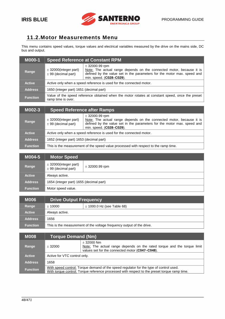
IRIS BLUE
PROGRAMMING GUIDE
48/471
11.2.Motor Measurements Menu This menu contains speed values, torque values and electrical variables measured by the drive on the mains side, DC bus and output.
M000-1 Speed Reference at Constant RPM
Range 32000(integer part)
99 (decimal part)
32000.99 rpm Note: The actual range depends on the connected motor, because it is defined by the value set in the parameters for the motor max. speed and
min. speed. (C028–C029).
Active Active only when a speed reference is used for the connected motor.
Address 1650 (integer part) 1651 (decimal part)
Function Value of the speed reference obtained when the motor rotates at constant speed, once the preset ramp time is over.
M002-3 Speed Reference after Ramps
Range 32000(integer part)
99 (decimal part)
32000.99 rpm Note: The actual range depends on the connected motor, because it is defined by the value set in the parameters for the motor max. speed and
min. speed. (C028–C029).
Active Active only when a speed reference is used for the connected motor.
Address 1652 (integer part) 1653 (decimal part)
Function This is the measurement of the speed value processed with respect to the ramp time.
M004-5 Motor Speed
Range 32000(integer part)
99 (decimal part) 32000.99 rpm
Active Always active.
Address 1654 (integer part) 1655 (decimal part)
Function Motor speed value.
M006 Drive Output Frequency
Range 10000 1000.0 Hz (see Table 68)
Active Always active.
Address 1656
Function This is the measurement of the voltage frequency output of the drive.
M008 Torque Demand (Nm)
Range 32000 32000 Nm Note: The actual range depends on the rated torque and the torque limit
values set for the connected motor (C047–C048).
Active Active for VTC control only.
Address 1658
Function With speed control: Torque demand of the speed regulator for the type of control used. With torque control: Torque reference processed with respect to the preset torque ramp time.
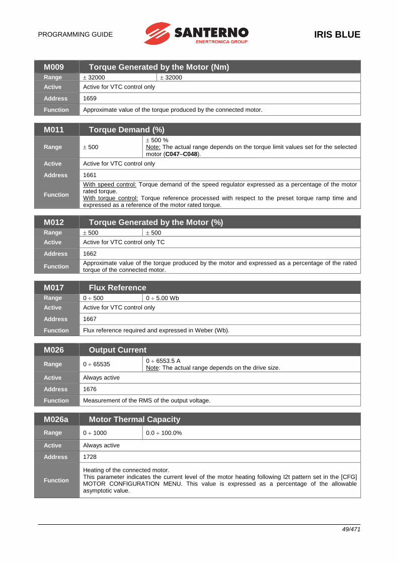
PROGRAMMING GUIDE
IRIS BLUE
49/471
M009 Torque Generated by the Motor (Nm)
Range 32000 32000
Active Active for VTC control only
Address 1659
Function Approximate value of the torque produced by the connected motor.
M011 Torque Demand (%)
Range 500 500 % Note: The actual range depends on the torque limit values set for the selected
motor (C047–C048).
Active Active for VTC control only
Address 1661
Function
With speed control: Torque demand of the speed regulator expressed as a percentage of the motor rated torque. With torque control: Torque reference processed with respect to the preset torque ramp time and expressed as a reference of the motor rated torque.
M012 Torque Generated by the Motor (%)
Range 500 500
Active Active for VTC control only TC
Address 1662
Function Approximate value of the torque produced by the motor and expressed as a percentage of the rated torque of the connected motor.
M017 Flux Reference
Range 0 500 0 5.00 Wb
Active Active for VTC control only
Address 1667
Function Flux reference required and expressed in Weber (Wb).
M026 Output Current
Range 0 65535 0 6553.5 A Note: The actual range depends on the drive size.
Active Always active
Address 1676
Function Measurement of the RMS of the output voltage.
M026a Motor Thermal Capacity
Range 0 1000 0.0 100.0%
Active Always active
Address 1728
Function
Heating of the connected motor. This parameter indicates the current level of the motor heating following I2t pattern set in the [CFG] MOTOR CONFIGURATION MENU. This value is expressed as a percentage of the allowable asymptotic value.
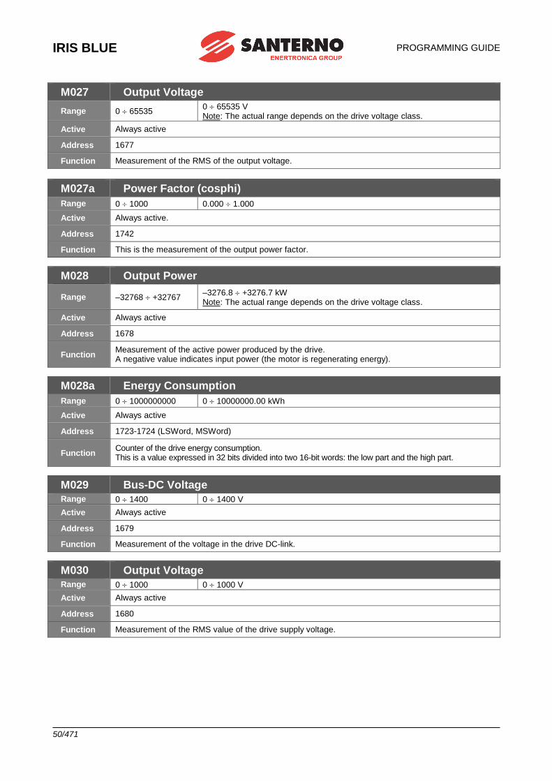
IRIS BLUE
PROGRAMMING GUIDE
50/471
M027 Output Voltage
Range 0 65535 0 65535 V Note: The actual range depends on the drive voltage class.
Active Always active
Address 1677
Function Measurement of the RMS of the output voltage.
M027a Power Factor (cosphi)
Range 0 1000 0.000 1.000
Active Always active.
Address 1742
Function This is the measurement of the output power factor.
M028 Output Power
Range –32768 +32767 –3276.8 +3276.7 kW Note: The actual range depends on the drive voltage class.
Active Always active
Address 1678
Function Measurement of the active power produced by the drive. A negative value indicates input power (the motor is regenerating energy).
M028a Energy Consumption
Range 0 1000000000 0 10000000.00 kWh
Active Always active
Address 1723-1724 (LSWord, MSWord)
Function Counter of the drive energy consumption. This is a value expressed in 32 bits divided into two 16-bit words: the low part and the high part.
M029 Bus-DC Voltage
Range 0 1400 0 1400 V
Active Always active
Address 1679
Function Measurement of the voltage in the drive DC-link.
M030 Output Voltage
Range 0 1000 0 1000 V
Active Always active
Address 1680
Function Measurement of the RMS value of the drive supply voltage.
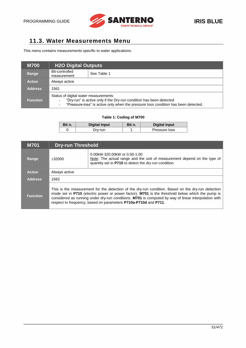
PROGRAMMING GUIDE
IRIS BLUE
51/471
11.3. Water Measurements Menu This menu contains measurements specific to water applications.
M700 H2O Digital Outputs
Range Bit-controlled measurement
See Table 1
Active Always active
Address 1561
Function
Status of digital water measurements
- “Dry-run” is active only if the Dry-run condition has been detected
- “Pressure-loss” is active only when the pressure loss condition has been detected.
Table 1: Coding of M700
Bit n. Digital Input Bit n. Digital Input
0 Dry-run 1 Pressure loss
M701 Dry-run Threshold
Range 32000
0.00kW-320.00kW or 0.00-1.00 Note: The actual range and the unit of measurement depend on the type of
quantity set in P710 to detect the dry run condition
Active Always active
Address 1562
Function
This is the measurement for the detection of the dry-run condition. Based on the dry-run detection
mode set in P710 (electric power or power factor). M701 is the threshold below which the pump is
considered as running under dry-run conditions. M701 is computed by way of linear interpolation with
respect to frequency, based on parameters P710a-P710d and P711.
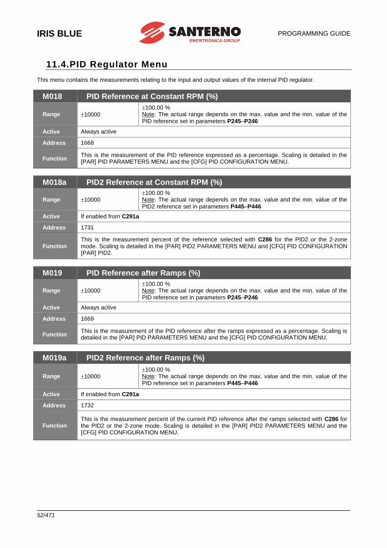
IRIS BLUE
PROGRAMMING GUIDE
52/471
11.4.PID Regulator Menu This menu contains the measurements relating to the input and output values of the internal PID regulator.
M018 PID Reference at Constant RPM (%)
Range 10000
100.00 % Note: The actual range depends on the max. value and the min. value of the
PID reference set in parameters P245–P246
Active Always active
Address 1668
Function This is the measurement of the PID reference expressed as a percentage. Scaling is detailed in the [PAR] PID PARAMETERS MENU and the [CFG] PID CONFIGURATION MENU.
M018a PID2 Reference at Constant RPM (%)
Range 10000 100.00 % Note: The actual range depends on the max. value and the min. value of the
PID2 reference set in parameters P445–P446
Active If enabled from C291a
Address 1731
Function This is the measurement percent of the reference selected with C286 for the PID2 or the 2-zone mode. Scaling is detailed in the [PAR] PID2 PARAMETERS MENU and [CFG] PID CONFIGURATION [PAR] PID2.
M019 PID Reference after Ramps (%)
Range 10000 100.00 % Note: The actual range depends on the max. value and the min. value of the
PID reference set in parameters P245–P246
Active Always active
Address 1669
Function This is the measurement of the PID reference after the ramps expressed as a percentage. Scaling is detailed in the [PAR] PID PARAMETERS MENU and the [CFG] PID CONFIGURATION MENU.
M019a PID2 Reference after Ramps (%)
Range 10000 100.00 % Note: The actual range depends on the max. value and the min. value of the
PID reference set in parameters P445–P446
Active If enabled from C291a
Address 1732
Function This is the measurement percent of the current PID reference after the ramps selected with C286 for the PID2 or the 2-zone mode. Scaling is detailed in the [PAR] PID2 PARAMETERS MENU and the [CFG] PID CONFIGURATION MENU.
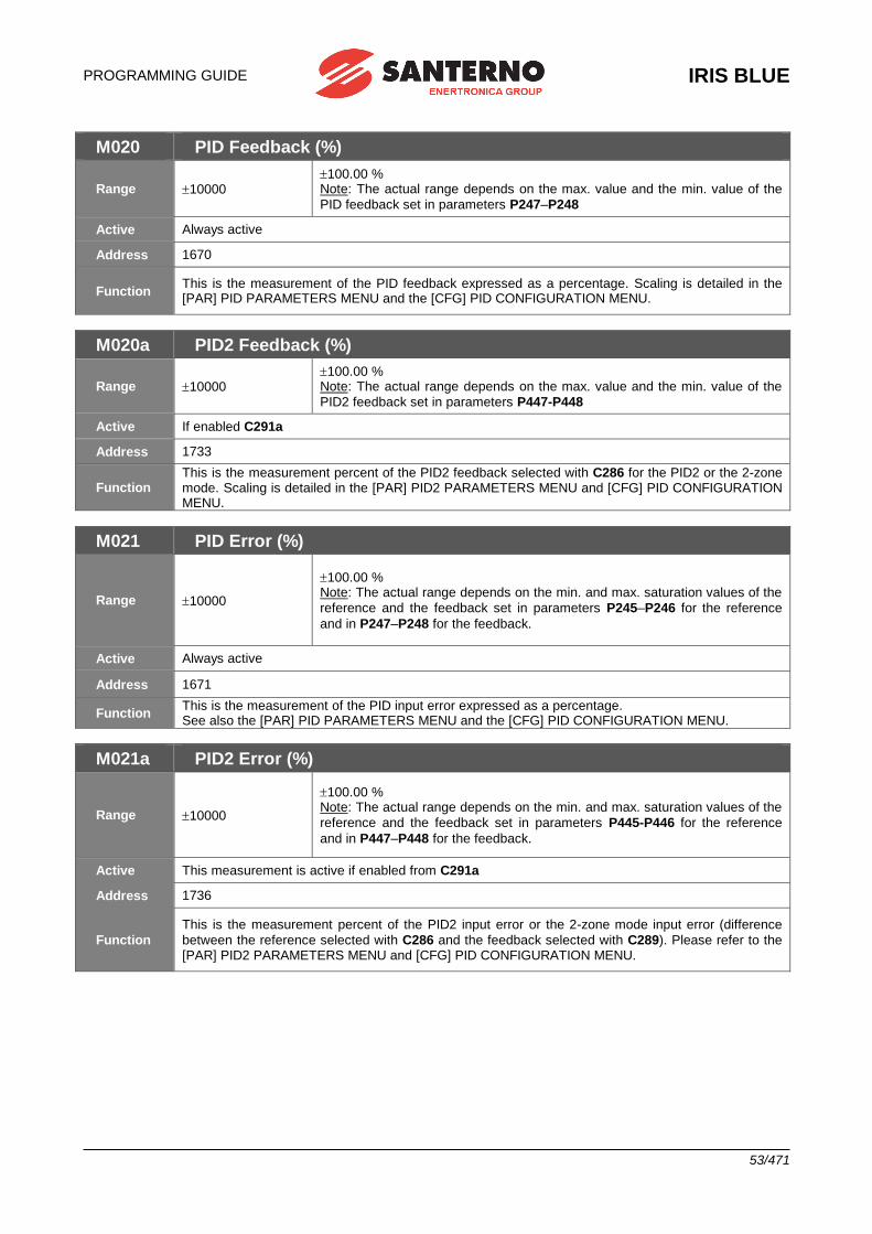
PROGRAMMING GUIDE
IRIS BLUE
53/471
M020 PID Feedback (%)
Range 10000 100.00 % Note: The actual range depends on the max. value and the min. value of the
PID feedback set in parameters P247–P248
Active Always active
Address 1670
Function This is the measurement of the PID feedback expressed as a percentage. Scaling is detailed in the [PAR] PID PARAMETERS MENU and the [CFG] PID CONFIGURATION MENU.
M020a PID2 Feedback (%)
Range 10000 100.00 % Note: The actual range depends on the max. value and the min. value of the
PID2 feedback set in parameters P447-P448
Active If enabled C291a
Address 1733
Function This is the measurement percent of the PID2 feedback selected with C286 for the PID2 or the 2-zone mode. Scaling is detailed in the [PAR] PID2 PARAMETERS MENU and [CFG] PID CONFIGURATION MENU.
M021 PID Error (%)
Range 10000
100.00 % Note: The actual range depends on the min. and max. saturation values of the
reference and the feedback set in parameters P245–P246 for the reference
and in P247–P248 for the feedback.
Active Always active
Address 1671
Function This is the measurement of the PID input error expressed as a percentage. See also the [PAR] PID PARAMETERS MENU and the [CFG] PID CONFIGURATION MENU.
M021a PID2 Error (%)
Range 10000
100.00 % Note: The actual range depends on the min. and max. saturation values of the
reference and the feedback set in parameters P445-P446 for the reference
and in P447–P448 for the feedback.
Active This measurement is active if enabled from C291a
Address 1736
Function
This is the measurement percent of the PID2 input error or the 2-zone mode input error (difference
between the reference selected with C286 and the feedback selected with C289). Please refer to the [PAR] PID2 PARAMETERS MENU and [CFG] PID CONFIGURATION MENU.
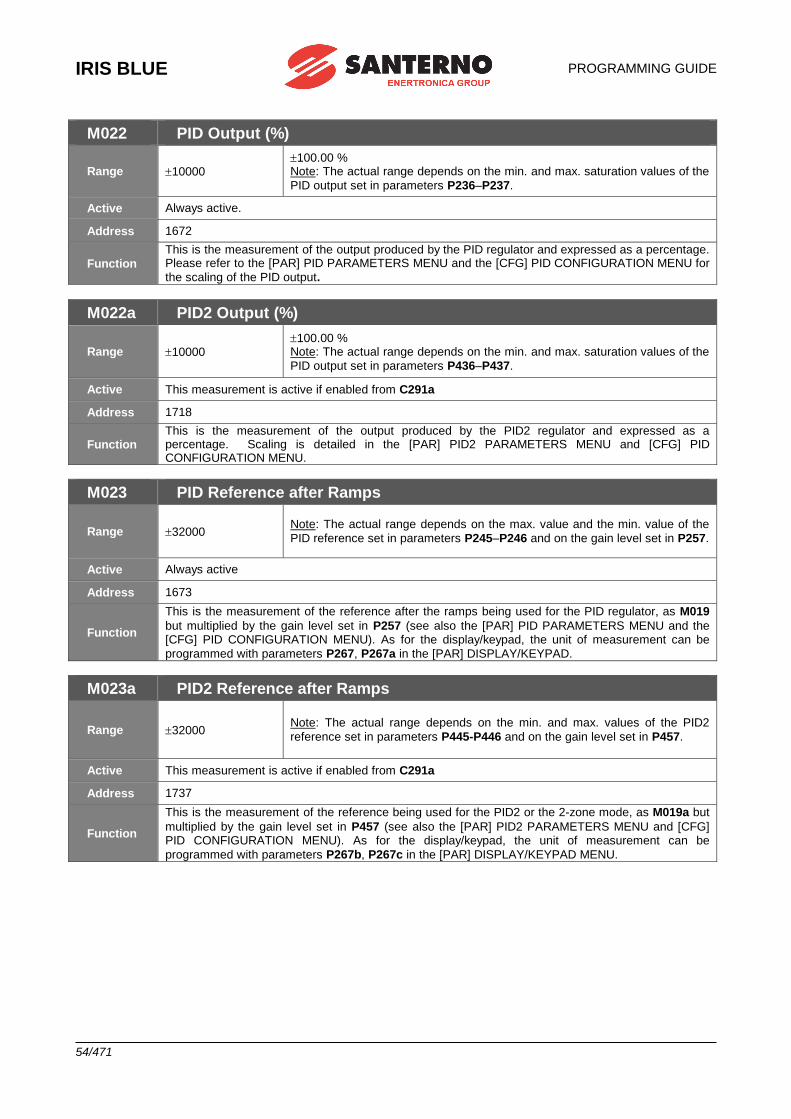
IRIS BLUE
PROGRAMMING GUIDE
54/471
M022 PID Output (%)
Range 10000 100.00 % Note: The actual range depends on the min. and max. saturation values of the
PID output set in parameters P236–P237.
Active Always active.
Address 1672
Function
This is the measurement of the output produced by the PID regulator and expressed as a percentage. Please refer to the [PAR] PID PARAMETERS MENU and the [CFG] PID CONFIGURATION MENU for
the scaling of the PID output.
M022a PID2 Output (%)
Range 10000 100.00 % Note: The actual range depends on the min. and max. saturation values of the
PID output set in parameters P436–P437.
Active This measurement is active if enabled from C291a
Address 1718
Function This is the measurement of the output produced by the PID2 regulator and expressed as a percentage. Scaling is detailed in the [PAR] PID2 PARAMETERS MENU and [CFG] PID CONFIGURATION MENU.
M023 PID Reference after Ramps
Range 32000 Note: The actual range depends on the max. value and the min. value of the
PID reference set in parameters P245–P246 and on the gain level set in P257.
Active Always active
Address 1673
Function
This is the measurement of the reference after the ramps being used for the PID regulator, as M019
but multiplied by the gain level set in P257 (see also the [PAR] PID PARAMETERS MENU and the [CFG] PID CONFIGURATION MENU). As for the display/keypad, the unit of measurement can be
programmed with parameters P267, P267a in the [PAR] DISPLAY/KEYPAD.
M023a PID2 Reference after Ramps
Range 32000 Note: The actual range depends on the min. and max. values of the PID2
reference set in parameters P445-P446 and on the gain level set in P457.
Active This measurement is active if enabled from C291a
Address 1737
Function
This is the measurement of the reference being used for the PID2 or the 2-zone mode, as M019a but
multiplied by the gain level set in P457 (see also the [PAR] PID2 PARAMETERS MENU and [CFG] PID CONFIGURATION MENU). As for the display/keypad, the unit of measurement can be
programmed with parameters P267b, P267c in the [PAR] DISPLAY/KEYPAD MENU.

PROGRAMMING GUIDE
IRIS BLUE
55/471
M024 PID Feedback
Range 32000 Note: The actual range depends on the max. value and the min. value of the
PID feedback set in parameters P247–P248 and on the gain level set in P257.
Active Always active.
Address 1674
Function
This is the measurement of the feedback being used for the PID regulator, as M020 but multiplied by
the gain level set in P257 (see also the [PAR] PID PARAMETERS MENU and the [CFG] PID CONFIGURATION MENU). As for the display/keypad, the unit of measurement can be programmed
with parameters P267, P267a in the [PAR] DISPLAY/KEYPAD MENU.
M024a PID2 Feedback
Range 32000
Note: The actual range depends on the max. value and the min. value of the
PID2 feedback set in parameters P447–P448 and on the gain level set in
P457.
Active If enabled from C291a
Address 1738
Function
This is the measurement of the feedback being used for the PID2 regulator or the 2-zone mode as
M020a but multiplied by the gain level set in P457 (see also the [PAR] PID2 PARAMETERS MENU and the [CFG] PID CONFIGURATION MENU). As for the display/keypad, the unit of measurement
can be programmed with parameters P267b, P267c in the [PAR] DISPLAY/KEYPAD MENU.
M025 PID Disable Threshold
Range 32000
Note: The actual range depends on the max. value and the min. value of the
PID2 feedback set in parameters P247–P248 and on the gain level set in
P257.
Active Always active
Address 3307
Function This is the measurement of the PID disable threshold (Sleep mode activation). For more details, please refer to the [PAR] PID2 PARAMETERS MENU and the [CFG] PID CONFIGURATION MENU).
M025a PID2 Disable Threshold
Range 32000
Note: The actual range depends on the max. value and the min. value of the
PID2 feedback set in parameters P447–P448 and on the gain level set in
P457.
Active If enabled from C291a
Address 3308
Function This is the measurement of the PID disable threshold (Sleep mode activation). For more details, please refer to the [PAR] PID2 PARAMETERS MENU and [CFG] PID CONFIGURATION MENU).
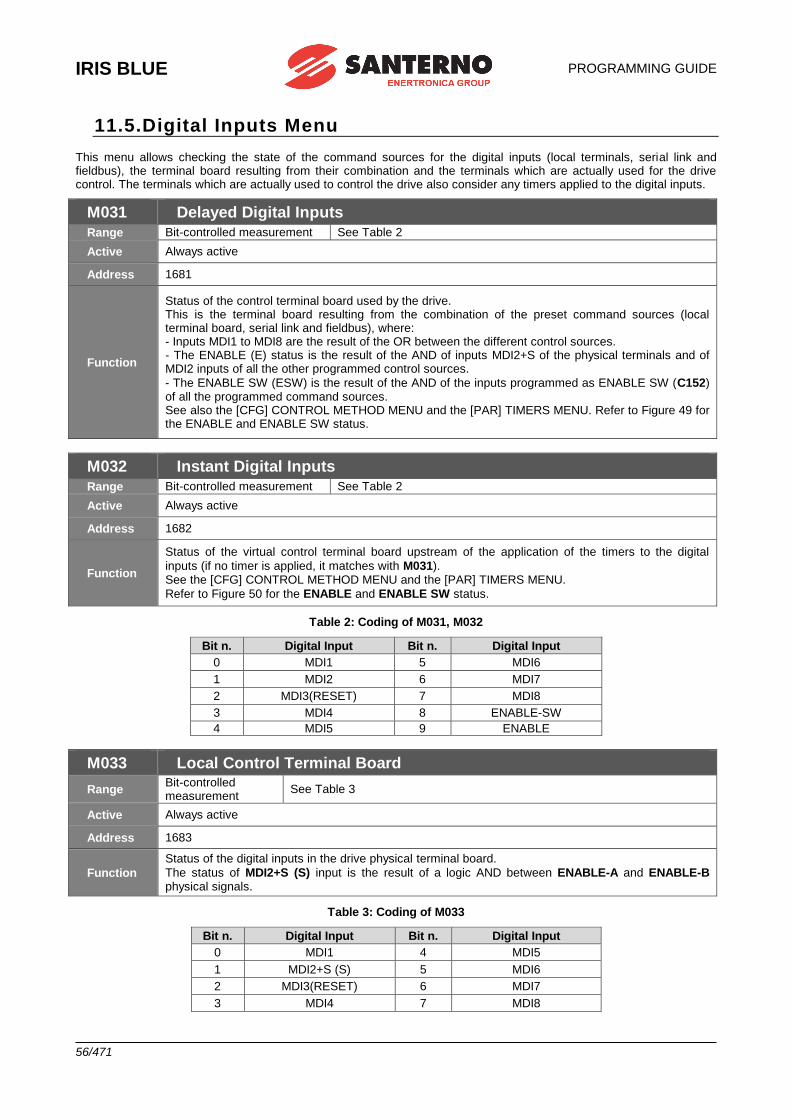
IRIS BLUE
PROGRAMMING GUIDE
56/471
11.5.Digital Inputs Menu This menu allows checking the state of the command sources for the digital inputs (local terminals, serial link and fieldbus), the terminal board resulting from their combination and the terminals which are actually used for the drive control. The terminals which are actually used to control the drive also consider any timers applied to the digital inputs.
M031 Delayed Digital Inputs
Range Bit-controlled measurement See Table 2
Active Always active
Address 1681
Function
Status of the control terminal board used by the drive. This is the terminal board resulting from the combination of the preset command sources (local terminal board, serial link and fieldbus), where: - Inputs MDI1 to MDI8 are the result of the OR between the different control sources. - The ENABLE (E) status is the result of the AND of inputs MDI2+S of the physical terminals and of MDI2 inputs of all the other programmed control sources.
- The ENABLE SW (ESW) is the result of the AND of the inputs programmed as ENABLE SW (C152) of all the programmed command sources. See also the [CFG] CONTROL METHOD MENU and the [PAR] TIMERS MENU. Refer to Figure 49 for the ENABLE and ENABLE SW status.
M032 Instant Digital Inputs
Range Bit-controlled measurement See Table 2
Active Always active
Address 1682
Function
Status of the virtual control terminal board upstream of the application of the timers to the digital
inputs (if no timer is applied, it matches with M031). See the [CFG] CONTROL METHOD MENU and the [PAR] TIMERS MENU.
Refer to Figure 50 for the ENABLE and ENABLE SW status.
Table 2: Coding of M031, M032
Bit n. Digital Input Bit n. Digital Input
0 MDI1 5 MDI6
1 MDI2 6 MDI7
2 MDI3(RESET) 7 MDI8
3 MDI4 8 ENABLE-SW
4 MDI5 9 ENABLE
M033 Local Control Terminal Board
Range Bit-controlled measurement
See Table 3
Active Always active
Address 1683
Function
Status of the digital inputs in the drive physical terminal board.
The status of MDI2+S (S) input is the result of a logic AND between ENABLE-A and ENABLE-B physical signals.
Table 3: Coding of M033
Bit n. Digital Input Bit n. Digital Input
0 MDI1 4 MDI5
1 MDI2+S (S) 5 MDI6
2 MDI3(RESET) 6 MDI7
3 MDI4 7 MDI8
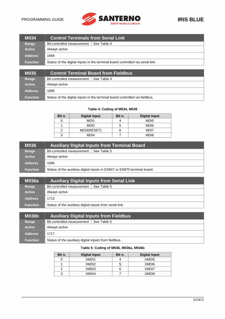
PROGRAMMING GUIDE
IRIS BLUE
57/471
M034 Control Terminals from Serial Link
Range Bit-controlled measurement See Table 4
Active Always active
Address 1684
Function Status of the digital inputs in the terminal board controlled via serial link.
M035 Control Terminal Board from Fieldbus
Range Bit-controlled measurement See Table 4
Active Always active
Address 1685
Function Status of the digital inputs in the terminal board controlled via fieldbus.
Table 4: Coding of M034, M035
Bit n. Digital Input Bit n. Digital Input
0 MDI1 4 MDI5
1 MDI2 5 MDI6
2 MDI3(RESET) 6 MDI7
3 MDI4 7 MDI8
M036 Auxiliary Digital Inputs from Terminal Board
Range Bit-controlled measurement See Table 5
Active Always active
Address 1686
Function Status of the auxiliary digital inputs in ES847 or ES870 terminal board.
M036a Auxiliary Digital Inputs from Serial Link
Range Bit-controlled measurement See Table 5
Active Always active
Address 1713
Function Status of the auxiliary digital inputs from serial link.
M036b Auxiliary Digital Inputs from Fieldbus
Range Bit-controlled measurement See Table 5
Active Always active
Address 1717
Function Status of the auxiliary digital inputs from fieldbus.
Table 5: Coding of M036, M036a, M036b
Bit n. Digital Input Bit n. Digital Input
0 XMDI1 4 XMDI5
1 XMDI2 5 XMDI6
2 XMDI3 6 XMDI7
3 XMDI4 7 XMDI8
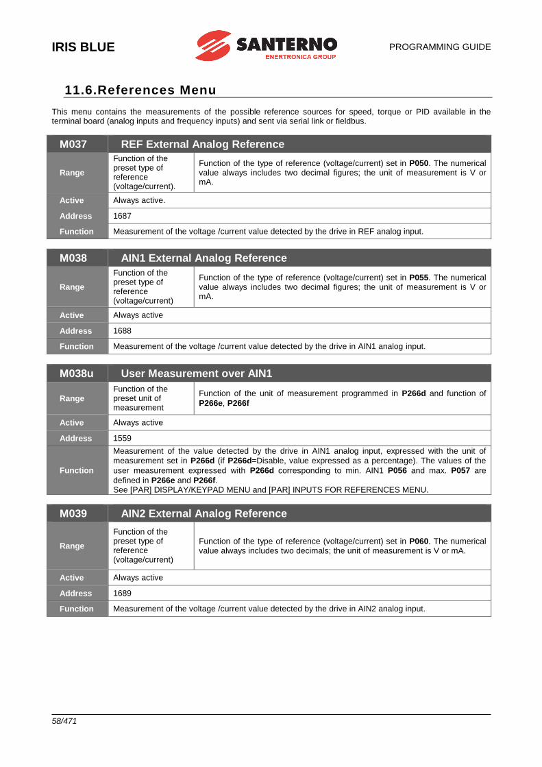
IRIS BLUE
PROGRAMMING GUIDE
58/471
11.6.References Menu This menu contains the measurements of the possible reference sources for speed, torque or PID available in the terminal board (analog inputs and frequency inputs) and sent via serial link or fieldbus.
M037 REF External Analog Reference
Range
Function of the preset type of reference (voltage/current).
Function of the type of reference (voltage/current) set in P050. The numerical value always includes two decimal figures; the unit of measurement is V or mA.
Active Always active.
Address 1687
Function Measurement of the voltage /current value detected by the drive in REF analog input.
M038 AIN1 External Analog Reference
Range
Function of the preset type of reference (voltage/current)
Function of the type of reference (voltage/current) set in P055. The numerical value always includes two decimal figures; the unit of measurement is V or mA.
Active Always active
Address 1688
Function Measurement of the voltage /current value detected by the drive in AIN1 analog input.
M038u User Measurement over AIN1
Range Function of the preset unit of measurement
Function of the unit of measurement programmed in P266d and function of
P266e, P266f
Active Always active
Address 1559
Function
Measurement of the value detected by the drive in AIN1 analog input, expressed with the unit of
measurement set in P266d (if P266d=Disable, value expressed as a percentage). The values of the
user measurement expressed with P266d corresponding to min. AIN1 P056 and max. P057 are
defined in P266e and P266f. See [PAR] DISPLAY/KEYPAD MENU and [PAR] INPUTS FOR REFERENCES MENU.
M039 AIN2 External Analog Reference
Range
Function of the preset type of reference (voltage/current)
Function of the type of reference (voltage/current) set in P060. The numerical value always includes two decimals; the unit of measurement is V or mA.
Active Always active
Address 1689
Function Measurement of the voltage /current value detected by the drive in AIN2 analog input.
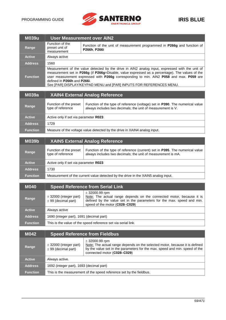
PROGRAMMING GUIDE
IRIS BLUE
59/471
M039u User Measurement over AIN2
Range Function of the preset unit of measurement
Function of the unit of measurement programmed in P266g and function of
P266h, P266i
Active Always active
Address 1560
Function
Measurement of the value detected by the drive in AIN2 analog input, expressed with the unit of
measurement set in P266g (if P266g=Disable, value expressed as a percentage). The values of the
user measurement expressed with P266g corresponding to min. AIN2 P058 and max. P059 are
defined in P266h and P266i. See [PAR] DISPLAY/KEYPAD MENU and [PAR] INPUTS FOR REFERENCES MENU.
M039a XAIN4 External Analog Reference
Range Function of the preset type of reference
Function of the type of reference (voltage) set in P390. The numerical value always includes two decimals; the unit of measurement is V.
Active Active only if set via parameter R023
Address 1729
Function Measure of the voltage value detected by the drive in XAIN4 analog input.
M039b XAIN5 External Analog Reference
Range Function of the preset type of reference
Function of the type of reference (current) set in P395. The numerical value always includes two decimals; the unit of measurement is mA.
Active Active only if set via parameter R023
Address 1730
Function Measurement of the current value detected by the drive in the XAIN5 analog input.
M040 Speed Reference from Serial Link
Range 32000 (integer part)
99 (decimal part)
32000.99 rpm Note: The actual range depends on the connected motor, because it is defined by the value set in the parameters for the max. speed and min.
speed of the motor (C028–C029)
Active Always active
Address 1690 (integer part), 1691 (decimal part)
Function This is the value of the speed reference set via serial link.
M042 Speed Reference from Fieldbus
Range 32000 (integer part)
99 (decimal part)
32000.99 rpm Note: The actual range depends on the selected motor, because it is defined by the value set in the parameters for the max. speed and min. speed of the
connected motor (C028–C029)
Active Always active.
Address 1692 (integer part), 1693 (decimal part)
Function This is the measurement of the speed reference set by the fieldbus.
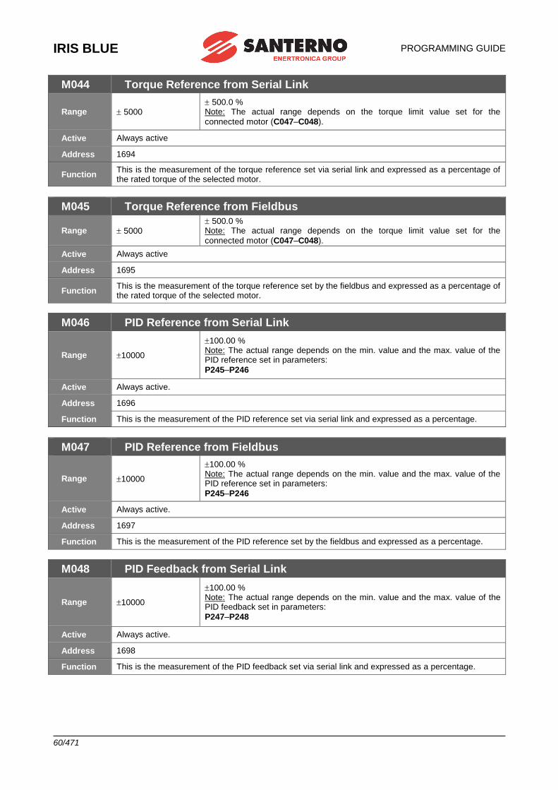
IRIS BLUE
PROGRAMMING GUIDE
60/471
M044 Torque Reference from Serial Link
Range 5000 500.0 % Note: The actual range depends on the torque limit value set for the
connected motor (C047–C048).
Active Always active
Address 1694
Function This is the measurement of the torque reference set via serial link and expressed as a percentage of the rated torque of the selected motor.
M045 Torque Reference from Fieldbus
Range 5000 500.0 % Note: The actual range depends on the torque limit value set for the
connected motor (C047–C048).
Active Always active
Address 1695
Function This is the measurement of the torque reference set by the fieldbus and expressed as a percentage of the rated torque of the selected motor.
M046 PID Reference from Serial Link
Range 10000
100.00 % Note: The actual range depends on the min. value and the max. value of the PID reference set in parameters:
P245–P246
Active Always active.
Address 1696
Function This is the measurement of the PID reference set via serial link and expressed as a percentage.
M047 PID Reference from Fieldbus
Range 10000
100.00 % Note: The actual range depends on the min. value and the max. value of the PID reference set in parameters:
P245–P246
Active Always active.
Address 1697
Function This is the measurement of the PID reference set by the fieldbus and expressed as a percentage.
M048 PID Feedback from Serial Link
Range 10000
100.00 % Note: The actual range depends on the min. value and the max. value of the PID feedback set in parameters:
P247–P248
Active Always active.
Address 1698
Function This is the measurement of the PID feedback set via serial link and expressed as a percentage.
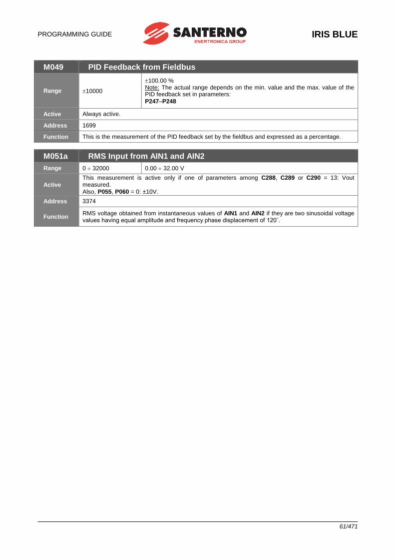
PROGRAMMING GUIDE
IRIS BLUE
61/471
M049 PID Feedback from Fieldbus
Range 10000
100.00 % Note: The actual range depends on the min. value and the max. value of the PID feedback set in parameters:
P247–P248
Active Always active.
Address 1699
Function This is the measurement of the PID feedback set by the fieldbus and expressed as a percentage.
M051a RMS Input from AIN1 and AIN2
Range 0 32000 0.00 32.00 V
Active
This measurement is active only if one of parameters among C288, C289 or C290 = 13: Vout measured.
Also, P055, P060 = 0: ±10V.
Address 3374
Function RMS voltage obtained from instantaneous values of AIN1 and AIN2 if they are two sinusoidal voltage values having equal amplitude and frequency phase displacement of 120˚.
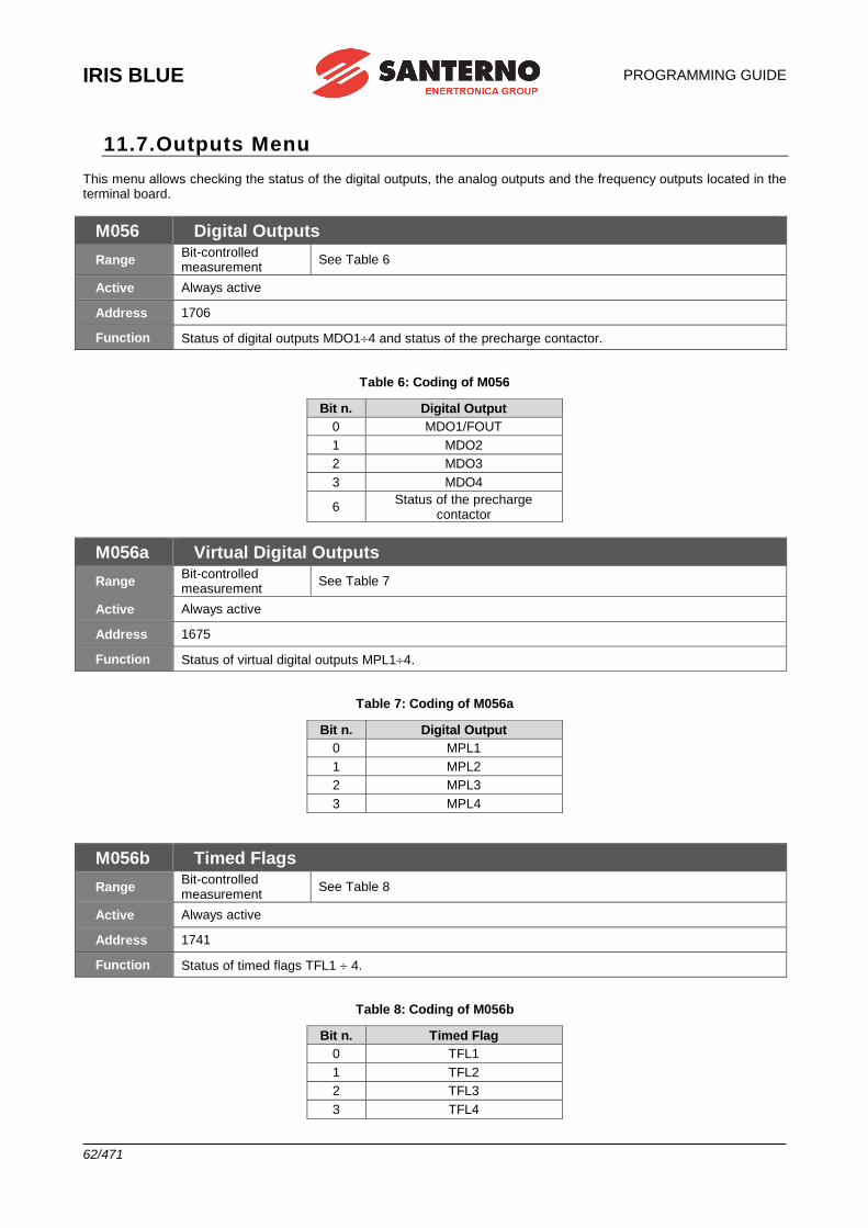
IRIS BLUE
PROGRAMMING GUIDE
62/471
11.7.Outputs Menu This menu allows checking the status of the digital outputs, the analog outputs and the frequency outputs located in the terminal board.
M056 Digital Outputs
Range Bit-controlled measurement
See Table 6
Active Always active
Address 1706
Function Status of digital outputs MDO14 and status of the precharge contactor.
Table 6: Coding of M056
Bit n. Digital Output
0 MDO1/FOUT
1 MDO2
2 MDO3
3 MDO4
6 Status of the precharge
contactor
M056a Virtual Digital Outputs
Range Bit-controlled measurement
See Table 7
Active Always active
Address 1675
Function Status of virtual digital outputs MPL14.
Table 7: Coding of M056a
Bit n. Digital Output
0 MPL1
1 MPL2
2 MPL3
3 MPL4
M056b Timed Flags
Range Bit-controlled measurement
See Table 8
Active Always active
Address 1741
Function Status of timed flags TFL1 4.
Table 8: Coding of M056b
Bit n. Timed Flag
0 TFL1
1 TFL2
2 TFL3
3 TFL4
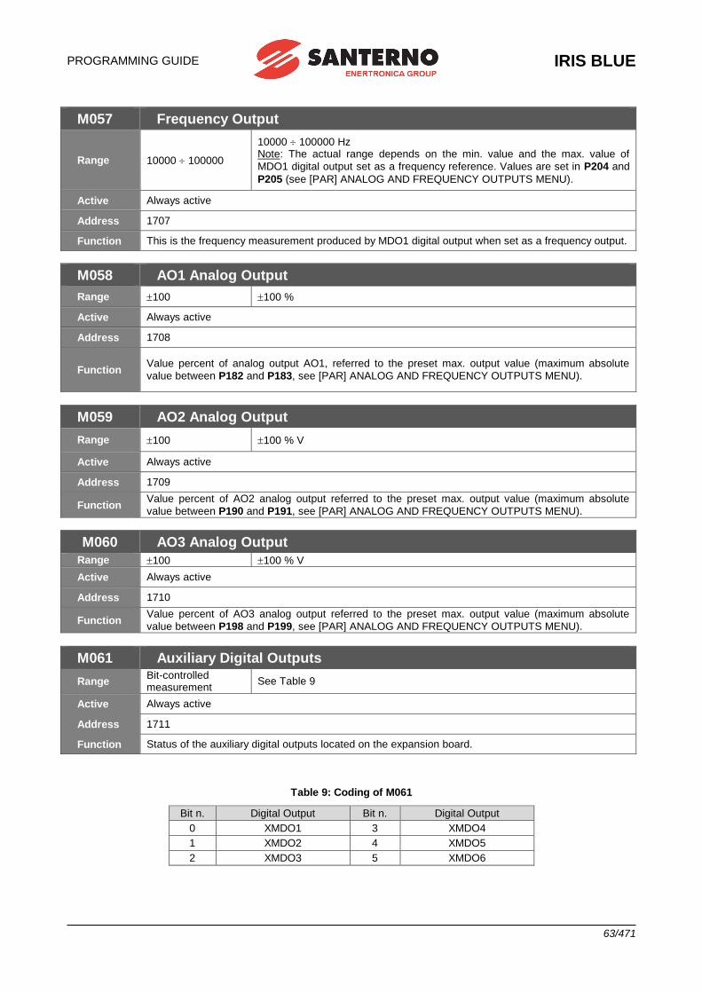
PROGRAMMING GUIDE
IRIS BLUE
63/471
M057 Frequency Output
Range 10000 100000
10000 100000 Hz Note: The actual range depends on the min. value and the max. value of
MDO1 digital output set as a frequency reference. Values are set in P204 and
P205 (see [PAR] ANALOG AND FREQUENCY OUTPUTS MENU).
Active Always active
Address 1707
Function This is the frequency measurement produced by MDO1 digital output when set as a frequency output.
M058 AO1 Analog Output
Range 100 100 %
Active Always active
Address 1708
Function Value percent of analog output AO1, referred to the preset max. output value (maximum absolute
value between P182 and P183, see [PAR] ANALOG AND FREQUENCY OUTPUTS MENU).
M059 AO2 Analog Output
Range 100 100 % V
Active Always active
Address 1709
Function Value percent of AO2 analog output referred to the preset max. output value (maximum absolute
value between P190 and P191, see [PAR] ANALOG AND FREQUENCY OUTPUTS MENU).
M060 AO3 Analog Output
Range 100 100 % V
Active Always active
Address 1710
Function Value percent of AO3 analog output referred to the preset max. output value (maximum absolute
value between P198 and P199, see [PAR] ANALOG AND FREQUENCY OUTPUTS MENU).
M061 Auxiliary Digital Outputs
Range Bit-controlled measurement
See Table 9
Active Always active
Address 1711
Function Status of the auxiliary digital outputs located on the expansion board.
Table 9: Coding of M061
Bit n. Digital Output Bit n. Digital Output
0 XMDO1 3 XMDO4
1 XMDO2 4 XMDO5
2 XMDO3 5 XMDO6
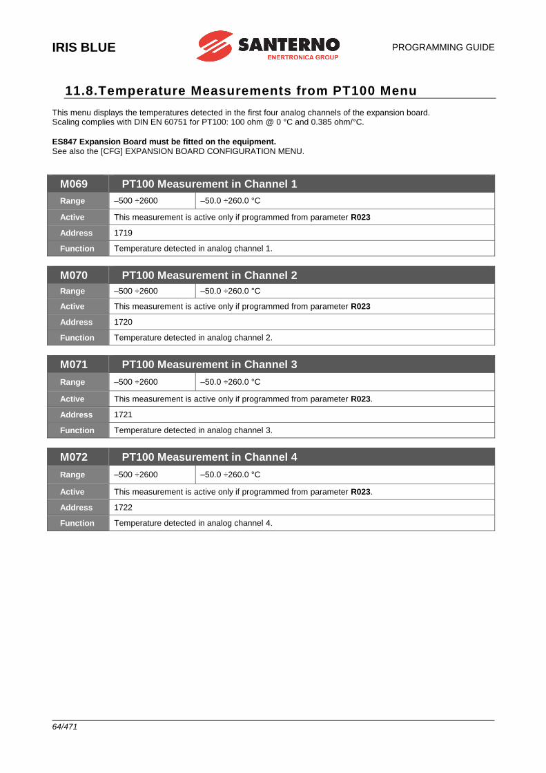
IRIS BLUE
PROGRAMMING GUIDE
64/471
11.8.Temperature Measurements from PT100 Menu This menu displays the temperatures detected in the first four analog channels of the expansion board. Scaling complies with DIN EN 60751 for PT100: 100 ohm @ 0 °C and 0.385 ohm/°C.
ES847 Expansion Board must be fitted on the equipment. See also the [CFG] EXPANSION BOARD CONFIGURATION MENU.
M069 PT100 Measurement in Channel 1
Range –500 ÷2600 –50.0 ÷260.0 °C
Active This measurement is active only if programmed from parameter R023
Address 1719
Function Temperature detected in analog channel 1.
M070 PT100 Measurement in Channel 2
Range –500 ÷2600 –50.0 ÷260.0 °C
Active This measurement is active only if programmed from parameter R023
Address 1720
Function Temperature detected in analog channel 2.
M071 PT100 Measurement in Channel 3
Range –500 ÷2600 –50.0 ÷260.0 °C
Active This measurement is active only if programmed from parameter R023.
Address 1721
Function Temperature detected in analog channel 3.
M072 PT100 Measurement in Channel 4
Range –500 ÷2600 –50.0 ÷260.0 °C
Active This measurement is active only if programmed from parameter R023.
Address 1722
Function Temperature detected in analog channel 4.
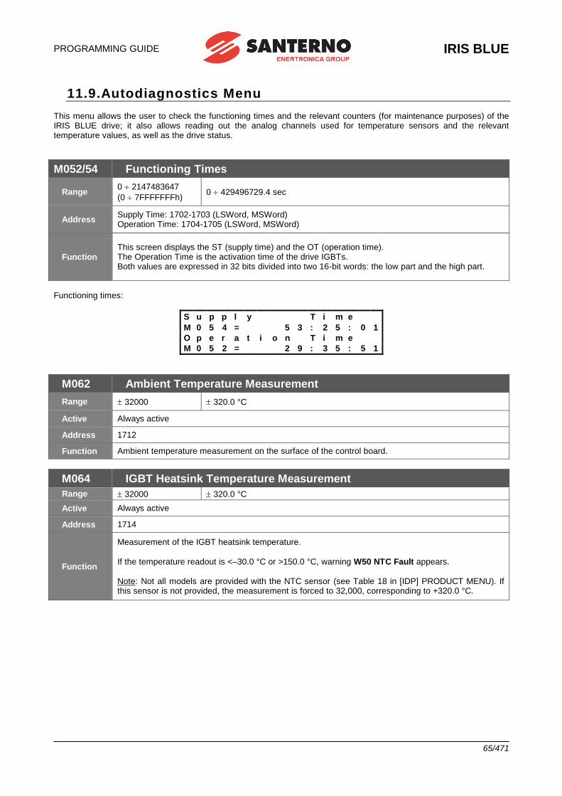
PROGRAMMING GUIDE
IRIS BLUE
65/471
11.9.Autodiagnostics Menu This menu allows the user to check the functioning times and the relevant counters (for maintenance purposes) of the IRIS BLUE drive; it also allows reading out the analog channels used for temperature sensors and the relevant temperature values, as well as the drive status.
M052/54 Functioning Times
Range 0 2147483647
(0 7FFFFFFFh) 0 429496729.4 sec
Address Supply Time: 1702-1703 (LSWord, MSWord) Operation Time: 1704-1705 (LSWord, MSWord)
Function This screen displays the ST (supply time) and the OT (operation time). The Operation Time is the activation time of the drive IGBTs. Both values are expressed in 32 bits divided into two 16-bit words: the low part and the high part.
Functioning times:
S u p p l y T i m e
M 0 5 4 = 5 3 : 2 5 : 0 1
O p e r a t i o n T i m e
M 0 5 2 = 2 9 : 3 5 : 5 1
M062 Ambient Temperature Measurement
Range 32000 320.0 °C
Active Always active
Address 1712
Function Ambient temperature measurement on the surface of the control board.
M064 IGBT Heatsink Temperature Measurement
Range 32000 320.0 °C
Active Always active
Address 1714
Function
Measurement of the IGBT heatsink temperature.
If the temperature readout is <–30.0 °C or >150.0 °C, warning W50 NTC Fault appears. Note: Not all models are provided with the NTC sensor (see Table 18 in [IDP] PRODUCT MENU). If this sensor is not provided, the measurement is forced to 32,000, corresponding to +320.0 °C.
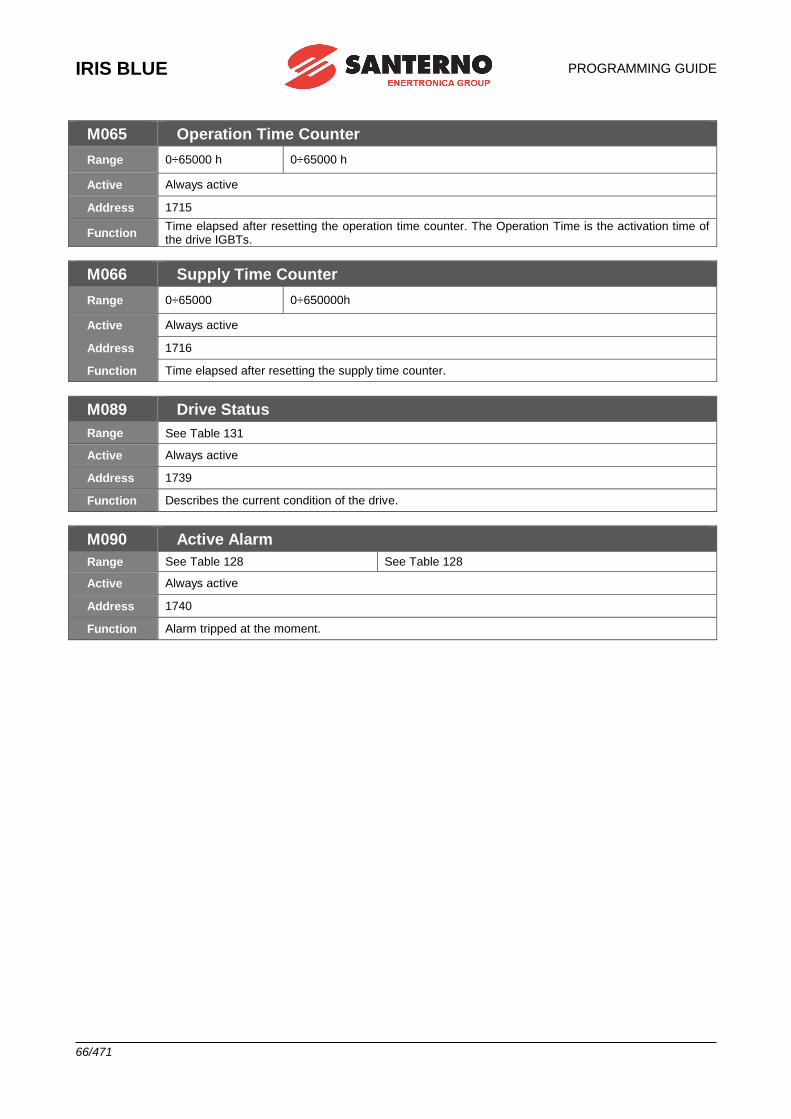
IRIS BLUE
PROGRAMMING GUIDE
66/471
M065 Operation Time Counter
Range 0÷65000 h 0÷65000 h
Active Always active
Address 1715
Function Time elapsed after resetting the operation time counter. The Operation Time is the activation time of the drive IGBTs.
M066 Supply Time Counter
Range 0÷65000 0÷650000h
Active Always active
Address 1716
Function Time elapsed after resetting the supply time counter.
M089 Drive Status
Range See Table 131
Active Always active
Address 1739
Function Describes the current condition of the drive.
M090 Active Alarm
Range See Table 128 See Table 128
Active Always active
Address 1740
Function Alarm tripped at the moment.
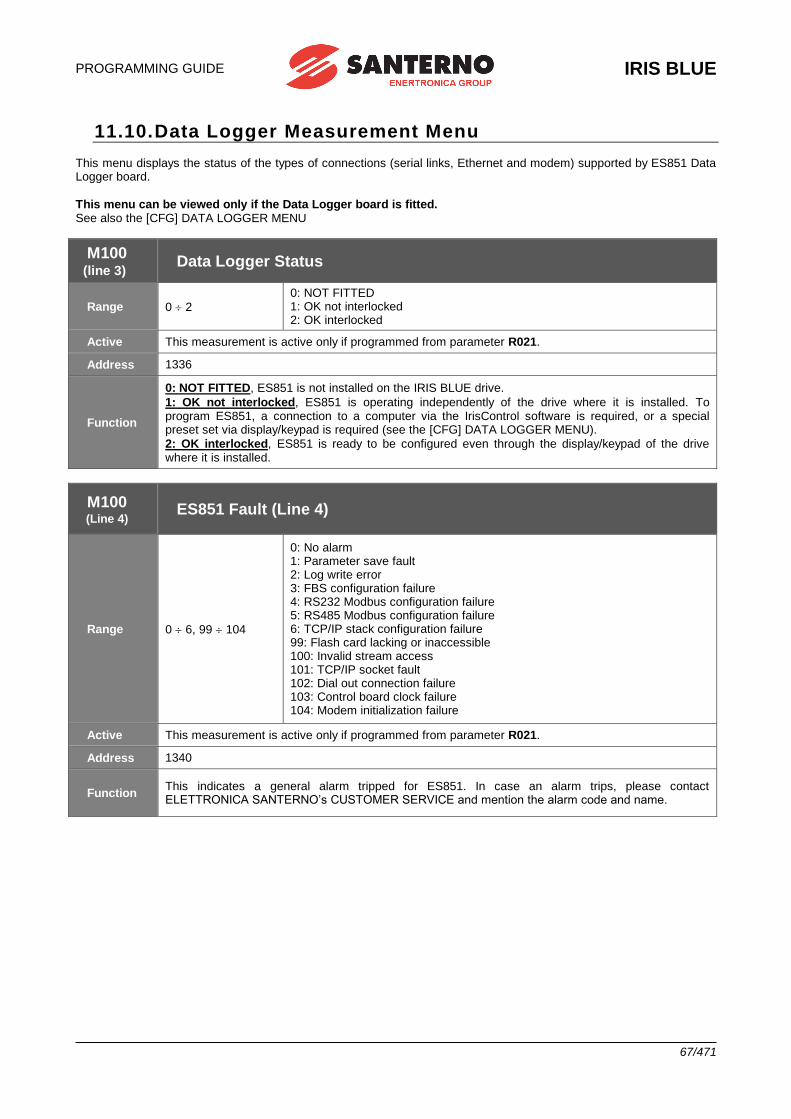
PROGRAMMING GUIDE
IRIS BLUE
67/471
11.10. Data Logger Measurement Menu This menu displays the status of the types of connections (serial links, Ethernet and modem) supported by ES851 Data Logger board.
This menu can be viewed only if the Data Logger board is fitted. See also the [CFG] DATA LOGGER MENU
M100 (line 3)
Data Logger Status
Range 0 2
0: NOT FITTED 1: OK not interlocked 2: OK interlocked
Active This measurement is active only if programmed from parameter R021.
Address 1336
Function
0: NOT FITTED, ES851 is not installed on the IRIS BLUE drive.
1: OK not interlocked, ES851 is operating independently of the drive where it is installed. To program ES851, a connection to a computer via the IrisControl software is required, or a special preset set via display/keypad is required (see the [CFG] DATA LOGGER MENU).
2: OK interlocked, ES851 is ready to be configured even through the display/keypad of the drive where it is installed.
M100 (Line 4)
ES851 Fault (Line 4)
Range 0 6, 99 104
0: No alarm 1: Parameter save fault 2: Log write error 3: FBS configuration failure 4: RS232 Modbus configuration failure 5: RS485 Modbus configuration failure 6: TCP/IP stack configuration failure 99: Flash card lacking or inaccessible 100: Invalid stream access 101: TCP/IP socket fault 102: Dial out connection failure 103: Control board clock failure 104: Modem initialization failure
Active This measurement is active only if programmed from parameter R021.
Address 1340
Function This indicates a general alarm tripped for ES851. In case an alarm trips, please contact ELETTRONICA SANTERNO’s CUSTOMER SERVICE and mention the alarm code and name.
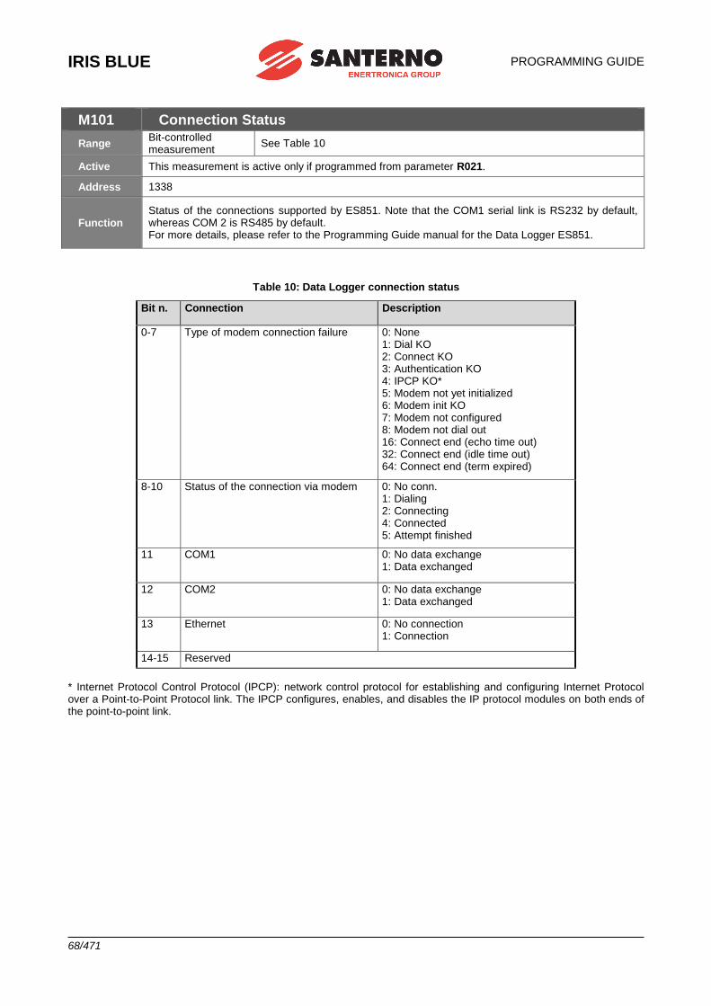
IRIS BLUE
PROGRAMMING GUIDE
68/471
M101 Connection Status
Range Bit-controlled measurement
See Table 10
Active This measurement is active only if programmed from parameter R021.
Address 1338
Function Status of the connections supported by ES851. Note that the COM1 serial link is RS232 by default, whereas COM 2 is RS485 by default. For more details, please refer to the Programming Guide manual for the Data Logger ES851.
Table 10: Data Logger connection status
Bit n. Connection Description
0-7 Type of modem connection failure 0: None 1: Dial KO 2: Connect KO 3: Authentication KO 4: IPCP KO* 5: Modem not yet initialized 6: Modem init KO 7: Modem not configured 8: Modem not dial out 16: Connect end (echo time out) 32: Connect end (idle time out) 64: Connect end (term expired)
8-10 Status of the connection via modem 0: No conn. 1: Dialing 2: Connecting 4: Connected 5: Attempt finished
11 COM1 0: No data exchange 1: Data exchanged
12 COM2 0: No data exchange 1: Data exchanged
13 Ethernet 0: No connection 1: Connection
14-15 Reserved
* Internet Protocol Control Protocol (IPCP): network control protocol for establishing and configuring Internet Protocol over a Point-to-Point Protocol link. The IPCP configures, enables, and disables the IP protocol modules on both ends of the point-to-point link.
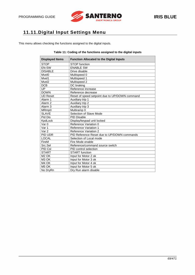
PROGRAMMING GUIDE
IRIS BLUE
69/471
11.11. Digital Input Settings Menu This menu allows checking the functions assigned to the digital inputs.
Table 11: Coding of the functions assigned to the digital inputs
Displayed Items Function Allocated to the Digital Inputs
STOP STOP function
EN-SW ENABLE SW
DISABLE Drive disable
Mvel0 Multispeed 0
Mvel1 Multispeed 1
Mvel2 Multispeed 2
DCB DC braking
UP Reference increase
DOWN Reference decrease
UD Reset Reset of speed setpoint due to UP/DOWN command
Alarm 1 Auxiliary trip 1
Alarm 2 Auxiliary trip 2
Alarm 3 Auxiliary trip 3
MRmp0 Multiramp 0
SLAVE Selection of Slave Mode
Pid Dis PID Disable
KpdLock Display/keypad unit locked
Var 0 Reference Variation 0
Var 1 Reference Variation 1
Var 2 Reference Variation 2
PID UDR PID Reference Reset due to UP/DOWN commands
LOCAL Selection of Local mode
FireM Fire Mode enable
Src.Sel Reference/command source switch
PID Csl PID control selection
START START function
M2 OK Input for Motor 2 ok
M3 OK Input for Motor 3 ok
M4 OK Input for Motor 4 ok
M5 OK Input for Motor 5 ok
No DryRn Dry Run alarm disable
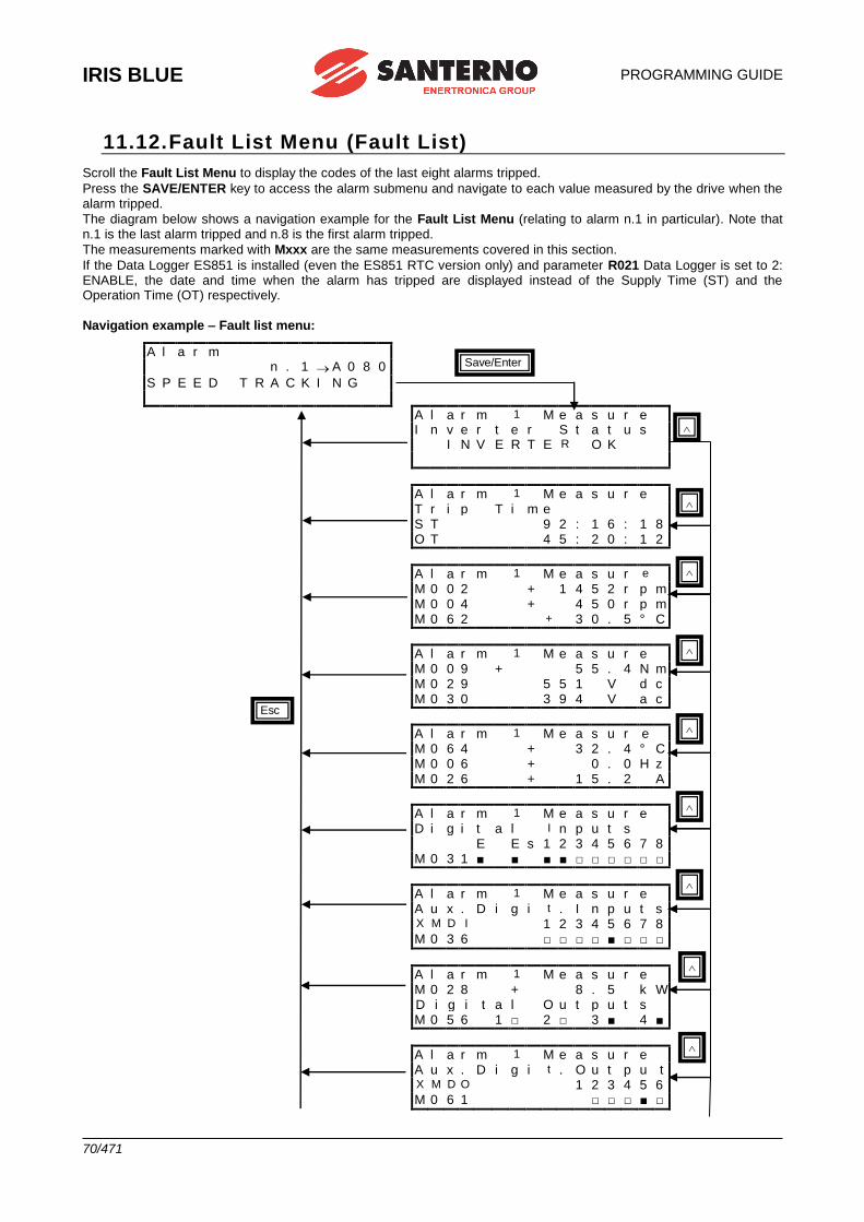
IRIS BLUE
PROGRAMMING GUIDE
70/471
11.12. Fault List Menu (Fault List)
Scroll the Fault List Menu to display the codes of the last eight alarms tripped.
Press the SAVE/ENTER key to access the alarm submenu and navigate to each value measured by the drive when the alarm tripped.
The diagram below shows a navigation example for the Fault List Menu (relating to alarm n.1 in particular). Note that n.1 is the last alarm tripped and n.8 is the first alarm tripped.
The measurements marked with Mxxx are the same measurements covered in this section.
If the Data Logger ES851 is installed (even the ES851 RTC version only) and parameter R021 Data Logger is set to 2: ENABLE, the date and time when the alarm has tripped are displayed instead of the Supply Time (ST) and the Operation Time (OT) respectively.
Navigation example – Fault list menu:
A l a r m
n . 1 A 0 8 0
S P E E D T R A C K I N G
A l a r m 1 M e a s u r e I n v e r t e r S t a t u s
I N V E R T E R O K
A l a r m 1 M e a s u r e T r i p T i m e S T 9 2 : 1 6 : 1 8 O T 4 5 : 2 0 : 1 2
A l a r m 1 M e a s u r e M 0 0 2 + 1 4 5 2 r p m M 0 0 4 + 4 5 0 r p m M 0 6 2 + 3 0 . 5 ° C
A l a r m 1 M e a s u r e M 0 0 9 + 5 5 . 4 N m M 0 2 9 5 5 1 V d c M 0 3 0 3 9 4 V a c
A l a r m 1 M e a s u r e M 0 6 4 + 3 2 . 4 ° C M 0 0 6 + 0 . 0 H z M 0 2 6 + 1 5 . 2 A
A l a r m 1 M e a s u r e D i g i t a l I n p u t s
E E s 1 2 3 4 5 6 7 8 M 0 3 1 ■ ■ ■ ■ □ □ □ □ □ □
A l a r m 1 M e a s u r e A u x . D i g i t . I n p u t s X M D I 1 2 3 4 5 6 7 8 M 0 3 6 □ □ □ □ ■ □ □ □
A l a r m 1 M e a s u r e M 0 2 8 + 8 . 5 k W D i g i t a l O u t p u t s
M 0 5 6 1 □ 2 □ 3 ■ 4 ■
A l a r m 1 M e a s u r e A u x . D i g i t . O u t p u t X M D O 1 2 3 4 5 6 M 0 6 1 □ □ □ ■ □
Save/Enter
Esc
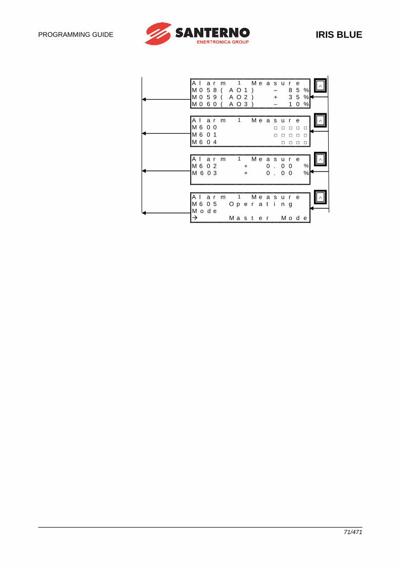
PROGRAMMING GUIDE
IRIS BLUE
71/471
A l a r m 1 M e a s u r e M 0 5 8 ( A O 1 ) – 8 5 % M 0 5 9 ( A O 2 ) + 3 5 % M 0 6 0 ( A O 3 ) – 1 0 %
A l a r m 1 M e a s u r e M 6 0 0 □ □ □ □ □
M 6 0 1 □ □ □ □ □
M 6 0 4 □ □ □ □
A l a r m 1 M e a s u r e M 6 0 2 + 0 . 0 0 %
M 6 0 3 + 0 . 0 0 %
A l a r m 1 M e a s u r e M 6 0 5 O p e r a t i n g
M o d e M a s t e r M o d e
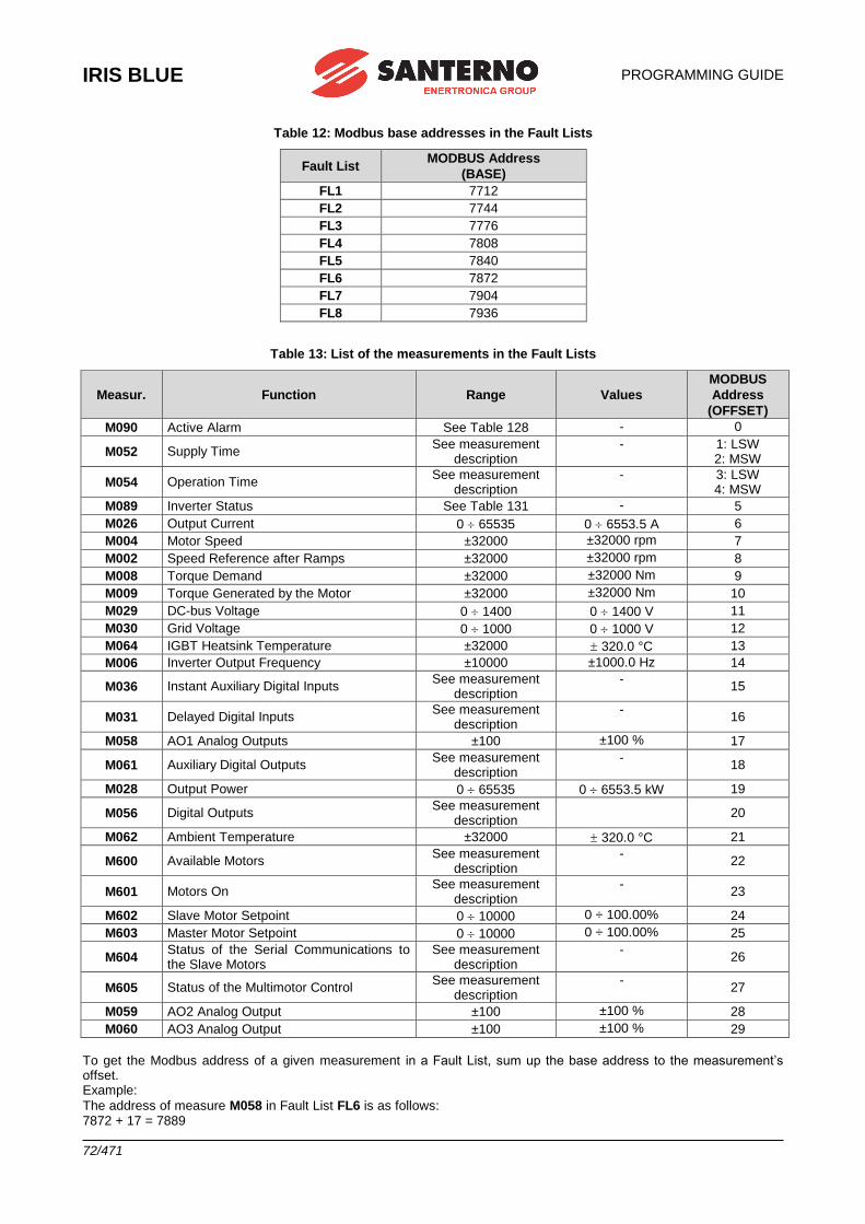
IRIS BLUE
PROGRAMMING GUIDE
72/471
Table 12: Modbus base addresses in the Fault Lists
Fault List MODBUS Address
(BASE)
FL1 7712
FL2 7744
FL3 7776
FL4 7808
FL5 7840
FL6 7872
FL7 7904
FL8 7936
Table 13: List of the measurements in the Fault Lists
Measur. Function Range Values
MODBUS
Address
(OFFSET)
M090 Active Alarm See Table 128 - 0
M052 Supply Time See measurement
description - 1: LSW
2: MSW
M054 Operation Time See measurement
description - 3: LSW
4: MSW
M089 Inverter Status See Table 131 - 5
M026 Output Current 0 65535 0 6553.5 A 6
M004 Motor Speed ±32000 ±32000 rpm 7
M002 Speed Reference after Ramps ±32000 ±32000 rpm 8
M008 Torque Demand ±32000 ±32000 Nm 9
M009 Torque Generated by the Motor ±32000 ±32000 Nm 10
M029 DC-bus Voltage 0 1400 0 1400 V 11
M030 Grid Voltage 0 1000 0 1000 V 12
M064 IGBT Heatsink Temperature ±32000 320.0 °C 13
M006 Inverter Output Frequency ±10000 ±1000.0 Hz 14
M036 Instant Auxiliary Digital Inputs See measurement
description -
15
M031 Delayed Digital Inputs See measurement
description -
16
M058 AO1 Analog Outputs ±100 ±100 % 17
M061 Auxiliary Digital Outputs See measurement
description -
18
M028 Output Power 0 65535 0 6553.5 kW 19
M056 Digital Outputs See measurement
description
20
M062 Ambient Temperature ±32000 320.0 °C 21
M600 Available Motors See measurement
description -
22
M601 Motors On See measurement
description -
23
M602 Slave Motor Setpoint 0 10000 0 ÷ 100.00% 24
M603 Master Motor Setpoint 0 10000 0 ÷ 100.00% 25
M604 Status of the Serial Communications to the Slave Motors
See measurement description
- 26
M605 Status of the Multimotor Control See measurement
description -
27
M059 AO2 Analog Output ±100 ±100 % 28
M060 AO3 Analog Output ±100 ±100 % 29
To get the Modbus address of a given measurement in a Fault List, sum up the base address to the measurement’s offset. Example:
The address of measure M058 in Fault List FL6 is as follows: 7872 + 17 = 7889
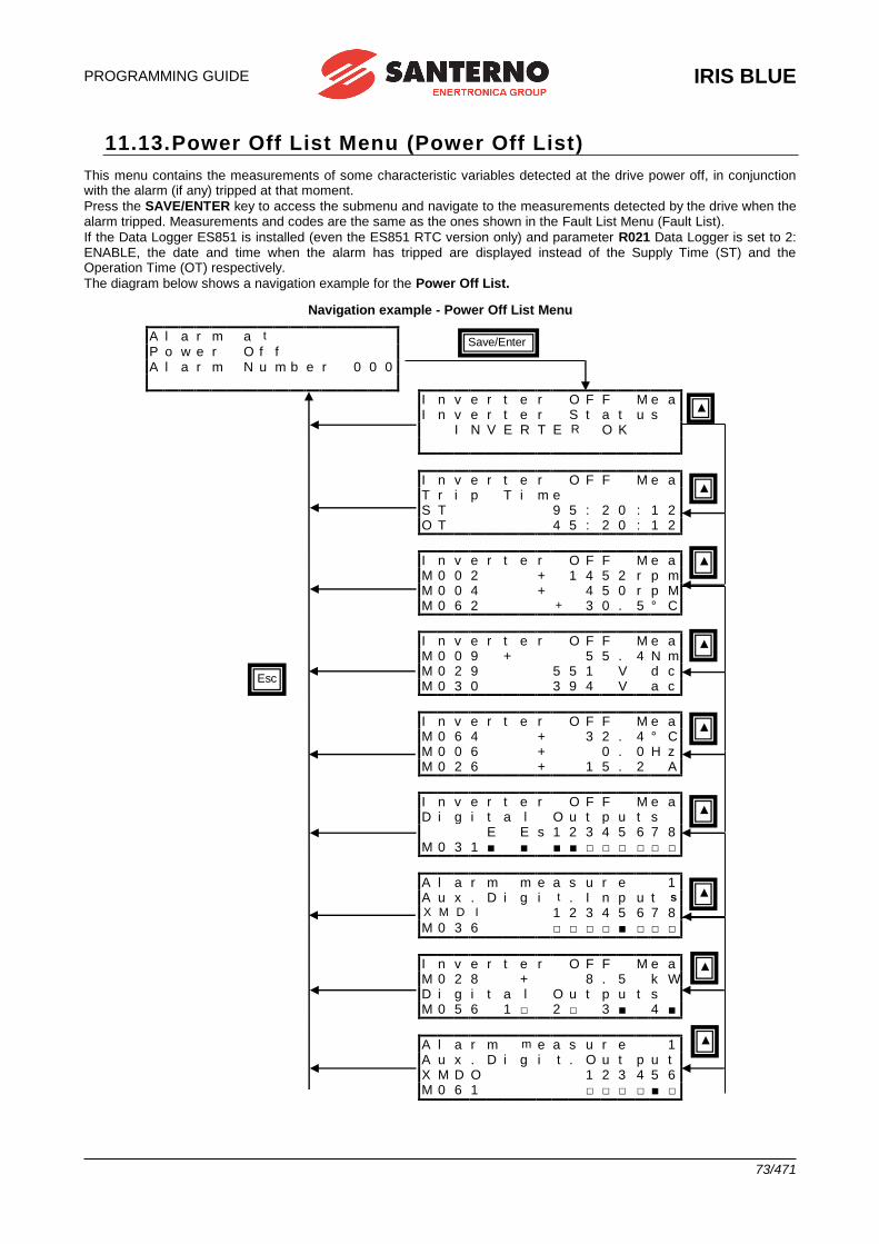
PROGRAMMING GUIDE
IRIS BLUE
73/471
11.13. Power Off List Menu (Power Off List)
This menu contains the measurements of some characteristic variables detected at the drive power off, in conjunction with the alarm (if any) tripped at that moment.
Press the SAVE/ENTER key to access the submenu and navigate to the measurements detected by the drive when the alarm tripped. Measurements and codes are the same as the ones shown in the Fault List Menu (Fault List).
If the Data Logger ES851 is installed (even the ES851 RTC version only) and parameter R021 Data Logger is set to 2: ENABLE, the date and time when the alarm has tripped are displayed instead of the Supply Time (ST) and the Operation Time (OT) respectively.
The diagram below shows a navigation example for the Power Off List.
Navigation example - Power Off List Menu
A l a r m a t P o w e r O f f
A l a r m N u m b e r 0 0 0
I n v e r t e r O F F M e a I n v e r t e r S t a t u s
I N V E R T E R O K
I n v e r t e r O F F M e a T r i p T i m e S T 9 5 : 2 0 : 1 2 O T 4 5 : 2 0 : 1 2
I n v e r t e r O F F M e a M 0 0 2 + 1 4 5 2 r p m M 0 0 4 + 4 5 0 r p M M 0 6 2 + 3 0 . 5 ° C
I n v e r t e r O F F M e a M 0 0 9 + 5 5 . 4 N m M 0 2 9 5 5 1 V d c M 0 3 0 3 9 4 V a c
I n v e r t e r O F F M e a M 0 6 4 + 3 2 . 4 ° C M 0 0 6 + 0 . 0 H z M 0 2 6 + 1 5 . 2 A
I n v e r t e r O F F M e a D i g i t a l O u t p u t s E E s 1 2 3 4 5 6 7 8
M 0 3 1 ■ ■ ■ ■ □ □ □ □ □ □
A l a r m m e a s u r e 1 A u x . D i g i t . I n p u t s
X M D I 1 2 3 4 5 6 7 8 M 0 3 6 □ □ □ □ ■ □ □ □
I n v e r t e r O F F M e a M 0 2 8 + 8 . 5 k W D i g i t a l O u t p u t s
M 0 5 6 1 □ 2 □ 3 ■ 4 ■
A l a r m m e a s u r e 1 A u x . D i g i t . O u t p u t X M D O 1 2 3 4 5 6 M 0 6 1 □ □ □ □ ■ □
Save/Enter
Esc
▲
▲
▲
▲
▲
▲
▲
▲
▲
▲
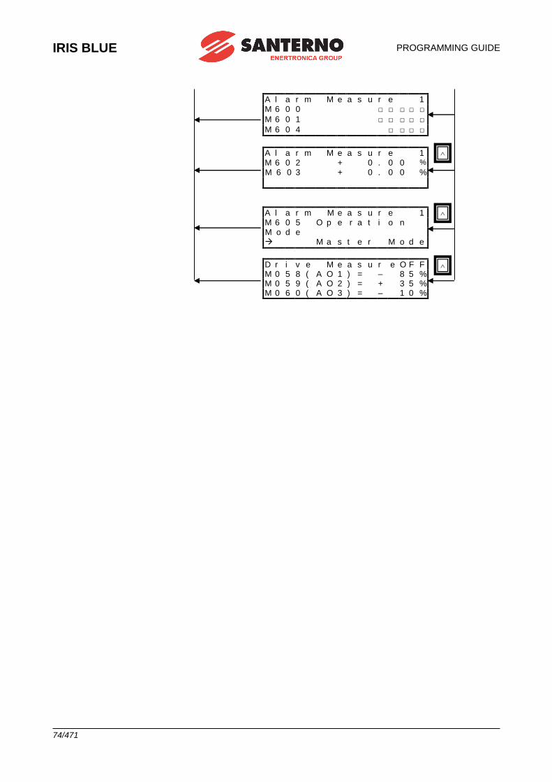
IRIS BLUE
PROGRAMMING GUIDE
74/471
A l a r m M e a s u r e 1 M 6 0 0 □ □ □ □ □
M 6 0 1 □ □ □ □ □
M 6 0 4 □ □ □ □
A l a r m M e a s u r e 1 M 6 0 2 + 0 . 0 0 %
M 6 0 3 + 0 . 0 0 %
A l a r m M e a s u r e 1 M 6 0 5 O p e r a t i o n M o d e M a s t e r M o d e
D r i v e M e a s u r e O F F M 0 5 8 ( A O 1 ) = – 8 5 % M 0 5 9 ( A O 2 ) = + 3 5 % M 0 6 0 ( A O 3 ) = – 1 0 %
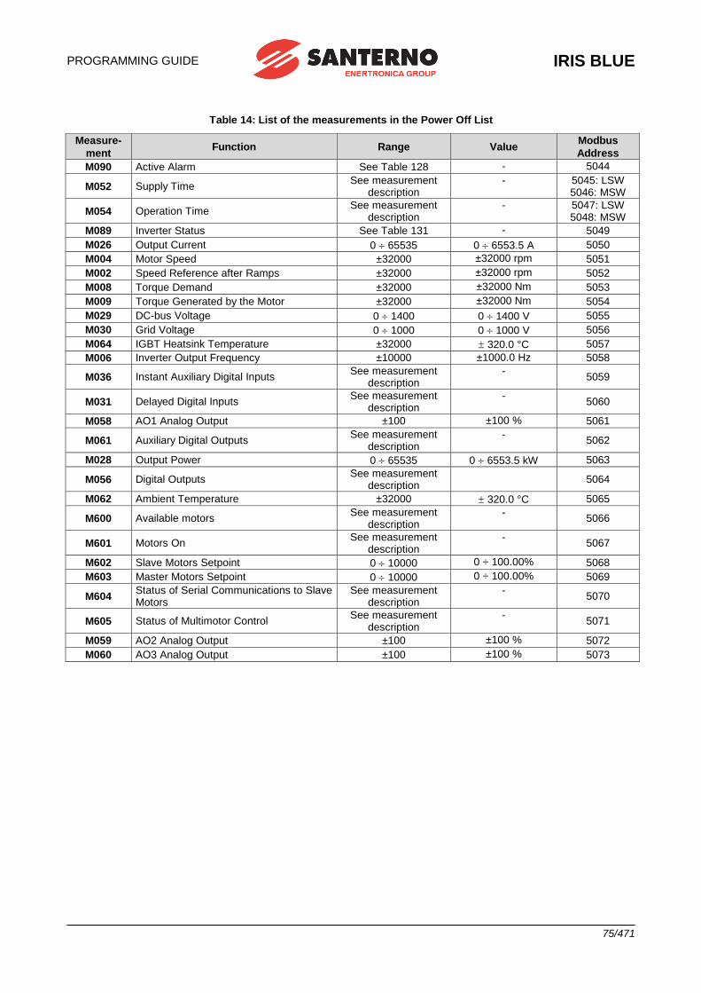
PROGRAMMING GUIDE
IRIS BLUE
75/471
Table 14: List of the measurements in the Power Off List
Measure-
ment Function Range Value
Modbus
Address
M090 Active Alarm See Table 128 - 5044
M052 Supply Time See measurement
description - 5045: LSW
5046: MSW
M054 Operation Time See measurement
description - 5047: LSW
5048: MSW
M089 Inverter Status See Table 131 - 5049
M026 Output Current 0 65535 0 6553.5 A 5050
M004 Motor Speed ±32000 ±32000 rpm 5051
M002 Speed Reference after Ramps ±32000 ±32000 rpm 5052
M008 Torque Demand ±32000 ±32000 Nm 5053
M009 Torque Generated by the Motor ±32000 ±32000 Nm 5054
M029 DC-bus Voltage 0 1400 0 1400 V 5055
M030 Grid Voltage 0 1000 0 1000 V 5056
M064 IGBT Heatsink Temperature ±32000 320.0 °C 5057
M006 Inverter Output Frequency ±10000 ±1000.0 Hz 5058
M036 Instant Auxiliary Digital Inputs See measurement
description -
5059
M031 Delayed Digital Inputs See measurement
description -
5060
M058 AO1 Analog Output ±100 ±100 % 5061
M061 Auxiliary Digital Outputs See measurement
description -
5062
M028 Output Power 0 65535 0 6553.5 kW 5063
M056 Digital Outputs See measurement
description
5064
M062 Ambient Temperature ±32000 320.0 °C 5065
M600 Available motors See measurement
description -
5066
M601 Motors On See measurement
description -
5067
M602 Slave Motors Setpoint 0 10000 0 ÷ 100.00% 5068
M603 Master Motors Setpoint 0 10000 0 ÷ 100.00% 5069
M604 Status of Serial Communications to Slave Motors
See measurement description
- 5070
M605 Status of Multimotor Control See measurement
description -
5071
M059 AO2 Analog Output ±100 ±100 % 5072
M060 AO3 Analog Output ±100 ±100 % 5073
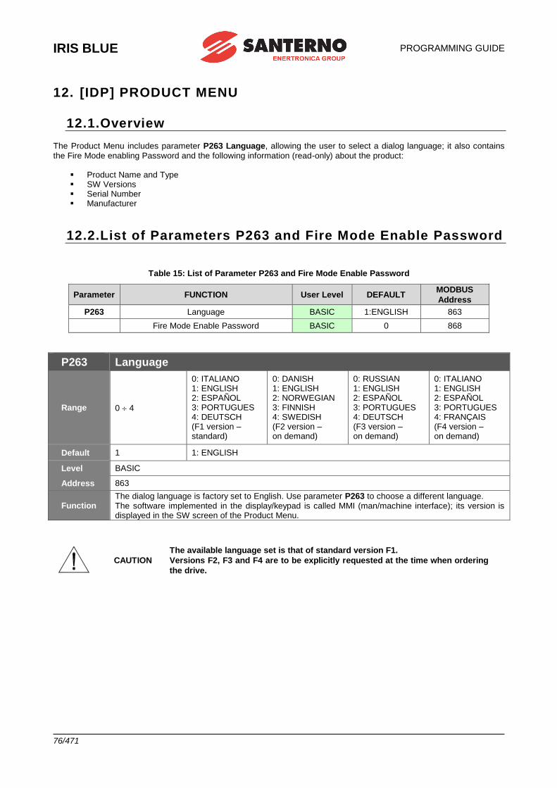
IRIS BLUE
PROGRAMMING GUIDE
76/471
12. [IDP] PRODUCT MENU
12.1.Overview
The Product Menu includes parameter P263 Language, allowing the user to select a dialog language; it also contains the Fire Mode enabling Password and the following information (read-only) about the product:
▪ Product Name and Type ▪ SW Versions ▪ Serial Number ▪ Manufacturer
12.2.List of Parameters P263 and Fire Mode Enable Password
Table 15: List of Parameter P263 and Fire Mode Enable Password
Parameter FUNCTION User Level DEFAULT MODBUS
Address
P263 Language BASIC 1:ENGLISH 863
Fire Mode Enable Password BASIC 0 868
P263 Language
Range 0 4
0: ITALIANO 1: ENGLISH 2: ESPAÑOL 3: PORTUGUES 4: DEUTSCH (F1 version – standard)
0: DANISH 1: ENGLISH 2: NORWEGIAN 3: FINNISH 4: SWEDISH (F2 version – on demand)
0: RUSSIAN 1: ENGLISH 2: ESPAÑOL 3: PORTUGUES 4: DEUTSCH (F3 version – on demand)
0: ITALIANO 1: ENGLISH 2: ESPAÑOL 3: PORTUGUES 4: FRANÇAIS (F4 version – on demand)
Default 1 1: ENGLISH
Level BASIC
Address 863
Function The dialog language is factory set to English. Use parameter P263 to choose a different language. The software implemented in the display/keypad is called MMI (man/machine interface); its version is displayed in the SW screen of the Product Menu.
CAUTION
The available language set is that of standard version F1.
Versions F2, F3 and F4 are to be explicitly requested at the time when ordering
the drive.
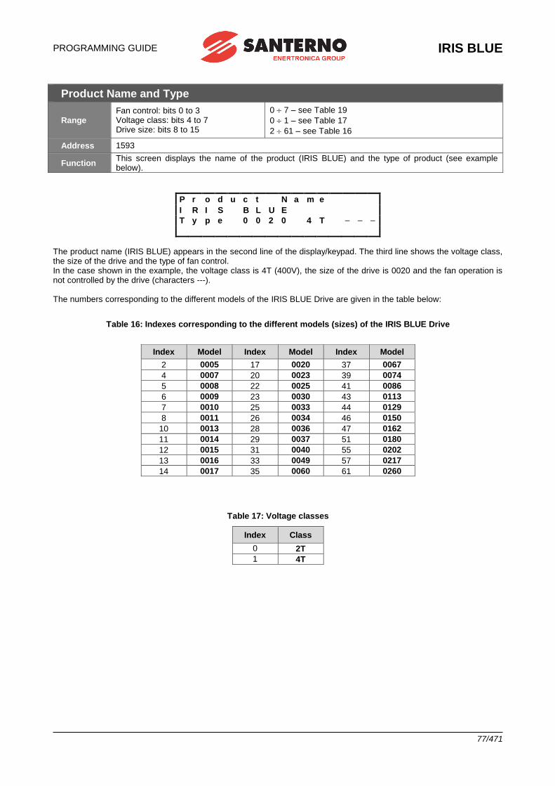
PROGRAMMING GUIDE
IRIS BLUE
77/471
Product Name and Type
Range Fan control: bits 0 to 3 Voltage class: bits 4 to 7 Drive size: bits 8 to 15
0 7 – see Table 19
0 1 – see Table 17
2 61 – see Table 16
Address 1593
Function This screen displays the name of the product (IRIS BLUE) and the type of product (see example below).
P r o d u c t N a m e
I R I S B L U E
T y p e 0 0 2 0 4 T – – –
The product name (IRIS BLUE) appears in the second line of the display/keypad. The third line shows the voltage class, the size of the drive and the type of fan control. In the case shown in the example, the voltage class is 4T (400V), the size of the drive is 0020 and the fan operation is not controlled by the drive (characters ---). The numbers corresponding to the different models of the IRIS BLUE Drive are given in the table below:
Table 16: Indexes corresponding to the different models (sizes) of the IRIS BLUE Drive
Index Model Index Model Index Model
2 0005 17 0020 37 0067
4 0007 20 0023 39 0074
5 0008 22 0025 41 0086
6 0009 23 0030 43 0113
7 0010 25 0033 44 0129
8 0011 26 0034 46 0150
10 0013 28 0036 47 0162
11 0014 29 0037 51 0180
12 0015 31 0040 55 0202
13 0016 33 0049 57 0217
14 0017 35 0060 61 0260
Table 17: Voltage classes
Index Class
0 2T
1 4T
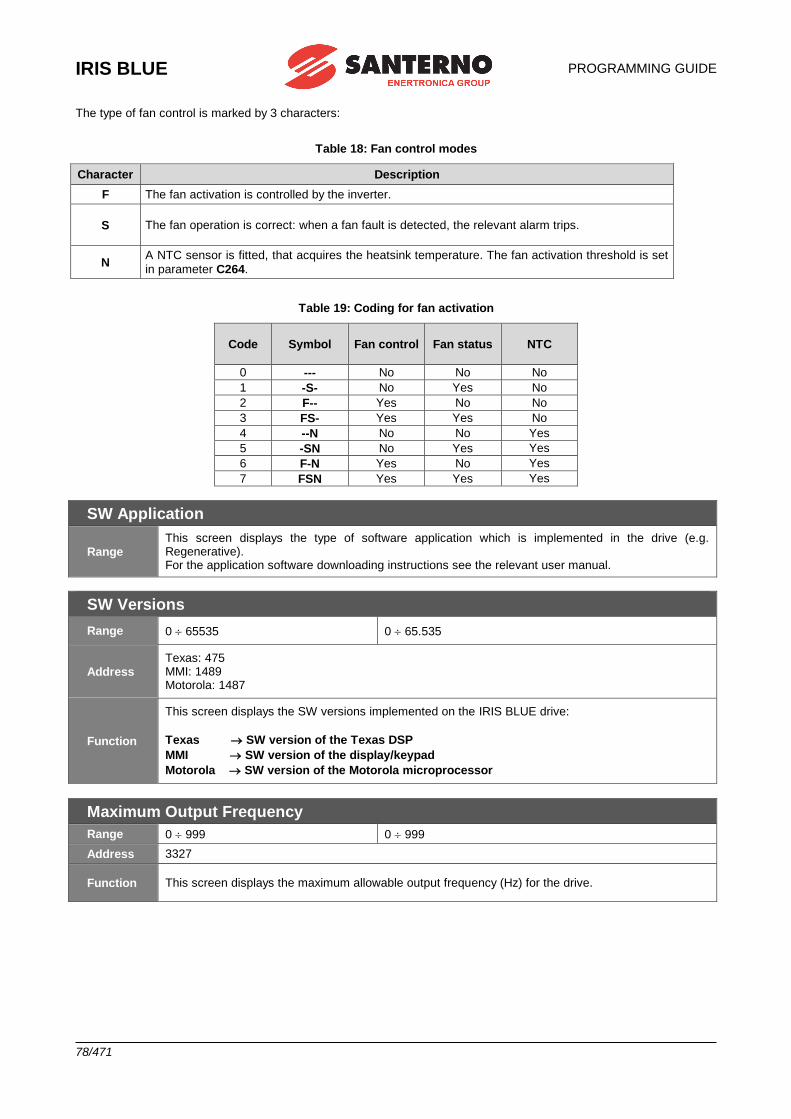
IRIS BLUE
PROGRAMMING GUIDE
78/471
The type of fan control is marked by 3 characters:
Table 18: Fan control modes
Character Description
F The fan activation is controlled by the inverter.
S The fan operation is correct: when a fan fault is detected, the relevant alarm trips.
N A NTC sensor is fitted, that acquires the heatsink temperature. The fan activation threshold is set
in parameter C264.
Table 19: Coding for fan activation
Code Symbol Fan control Fan status NTC
0 --- No No No
1 -S- No Yes No
2 F-- Yes No No
3 FS- Yes Yes No
4 --N No No Yes
5 -SN No Yes Yes
6 F-N Yes No Yes
7 FSN Yes Yes Yes
SW Application
Range This screen displays the type of software application which is implemented in the drive (e.g. Regenerative). For the application software downloading instructions see the relevant user manual.
SW Versions
Range 0 65535 0 65.535
Address Texas: 475 MMI: 1489 Motorola: 1487
Function
This screen displays the SW versions implemented on the IRIS BLUE drive:
Texas SW version of the Texas DSP
MMI SW version of the display/keypad
Motorola SW version of the Motorola microprocessor
Maximum Output Frequency
Range 0 999 0 999
Address 3327
Function This screen displays the maximum allowable output frequency (Hz) for the drive.
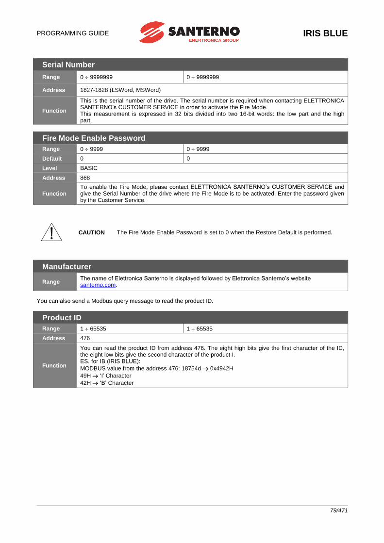
PROGRAMMING GUIDE
IRIS BLUE
79/471
Serial Number
Range 0 9999999 0 9999999
Address 1827-1828 (LSWord, MSWord)
Function
This is the serial number of the drive. The serial number is required when contacting ELETTRONICA SANTERNO’s CUSTOMER SERVICE in order to activate the Fire Mode. This measurement is expressed in 32 bits divided into two 16-bit words: the low part and the high part.
Fire Mode Enable Password
Range 0 9999 0 9999
Default 0 0
Level BASIC
Address 868
Function To enable the Fire Mode, please contact ELETTRONICA SANTERNO’s CUSTOMER SERVICE and give the Serial Number of the drive where the Fire Mode is to be activated. Enter the password given by the Customer Service.
CAUTION The Fire Mode Enable Password is set to 0 when the Restore Default is performed.
Manufacturer
Range The name of Elettronica Santerno is displayed followed by Elettronica Santerno’s website santerno.com.
You can also send a Modbus query message to read the product ID.
Product ID
Range 1 65535 1 65535
Address 476
Function
You can read the product ID from address 476. The eight high bits give the first character of the ID, the eight low bits give the second character of the product I. ES. for IB (IRIS BLUE):
MODBUS value from the address 476: 18754d 0x4942H
49H ‘I’ Character
42H ‘B’ Character
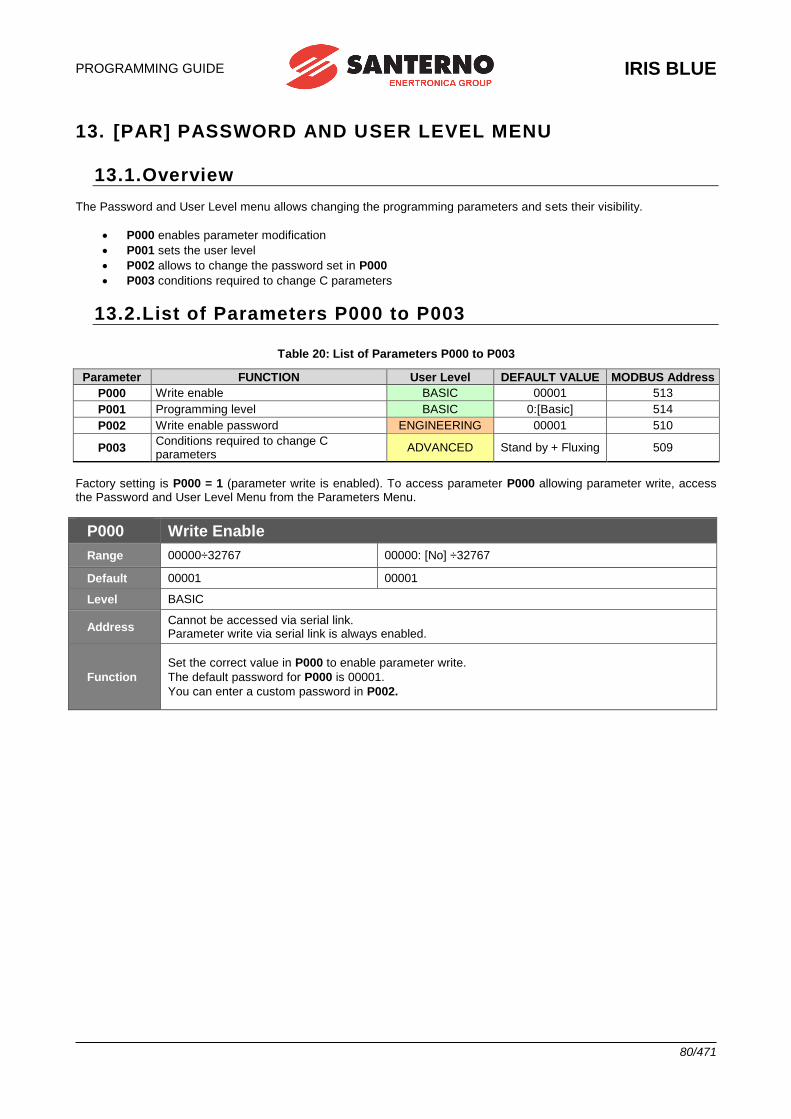
PROGRAMMING GUIDE
IRIS BLUE
80/471
13. [PAR] PASSWORD AND USER LEVEL MENU
13.1.Overview The Password and User Level menu allows changing the programming parameters and sets their visibility.
• P000 enables parameter modification
• P001 sets the user level
• P002 allows to change the password set in P000
• P003 conditions required to change C parameters
13.2.List of Parameters P000 to P003
Table 20: List of Parameters P000 to P003
Parameter FUNCTION User Level DEFAULT VALUE MODBUS Address
P000 Write enable BASIC 00001 513
P001 Programming level BASIC 0:[Basic] 514
P002 Write enable password ENGINEERING 00001 510
P003 Conditions required to change C parameters
ADVANCED Stand by + Fluxing 509
Factory setting is P000 = 1 (parameter write is enabled). To access parameter P000 allowing parameter write, access the Password and User Level Menu from the Parameters Menu.
P000 Write Enable
Range 00000÷32767 00000: [No] ÷32767
Default 00001 00001
Level BASIC
Address Cannot be accessed via serial link. Parameter write via serial link is always enabled.
Function
Set the correct value in P000 to enable parameter write.
The default password for P000 is 00001.
You can enter a custom password in P002.
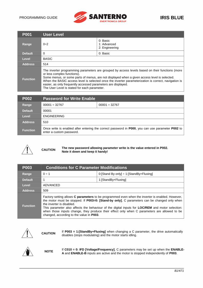
PROGRAMMING GUIDE
IRIS BLUE
81/471
P001 User Level
Range 0÷2 0: Basic 1: Advanced 2: Engineering
Default 0 0: Basic
Level BASIC
Address 514
Function
The inverter programming parameters are grouped by access levels based on their functions (more or less complex functions). Some menus, or some parts of menus, are not displayed when a given access level is selected. When the BASIC access level is selected once the inverter parameterization is correct, navigation is easier, as only frequently accessed parameters are displayed. The User Level is stated for each parameter.
P002 Password for Write Enable
Range 00001 ÷ 32767 00001 ÷ 32767
Default 00001
Level ENGINEERING
Address 510
Function Once write is enabled after entering the correct password in P000, you can use parameter P002 to enter a custom password.
CAUTION The new password allowing parameter write is the value entered in P002.
Note it down and keep it handy!
P003 Conditions for C Parameter Modifications
Range 0 ÷ 1 0:[Stand By only] ÷ 1:[StandBy+Fluxing]
Default 1 1:[StandBy+Fluxing]
Level ADVANCED
Address 509
Function
Factory setting allows C parameters to be programmed even when the inverter is enabled. However,
the motor must be stopped. If P003=0: [Stand-by only], C parameters can be changed only when the inverter is disabled.
This parameter also affects the behaviour of the digital inputs for LOC/REM and motor selection: when those inputs change, they produce their effect only when C parameters are allowed to be
changed, according to the value in P003.
CAUTION If P003 = 1:[StandBy+Fluxing] when changing a C parameter, the drive automatically disables (stops modulating) and the motor starts idling.
NOTE If C010 = 0: IFD [Voltage/Frequency], C parameters may be set up when the ENABLE-
A and ENABLE-B inputs are active and the motor is stopped independently of P003.
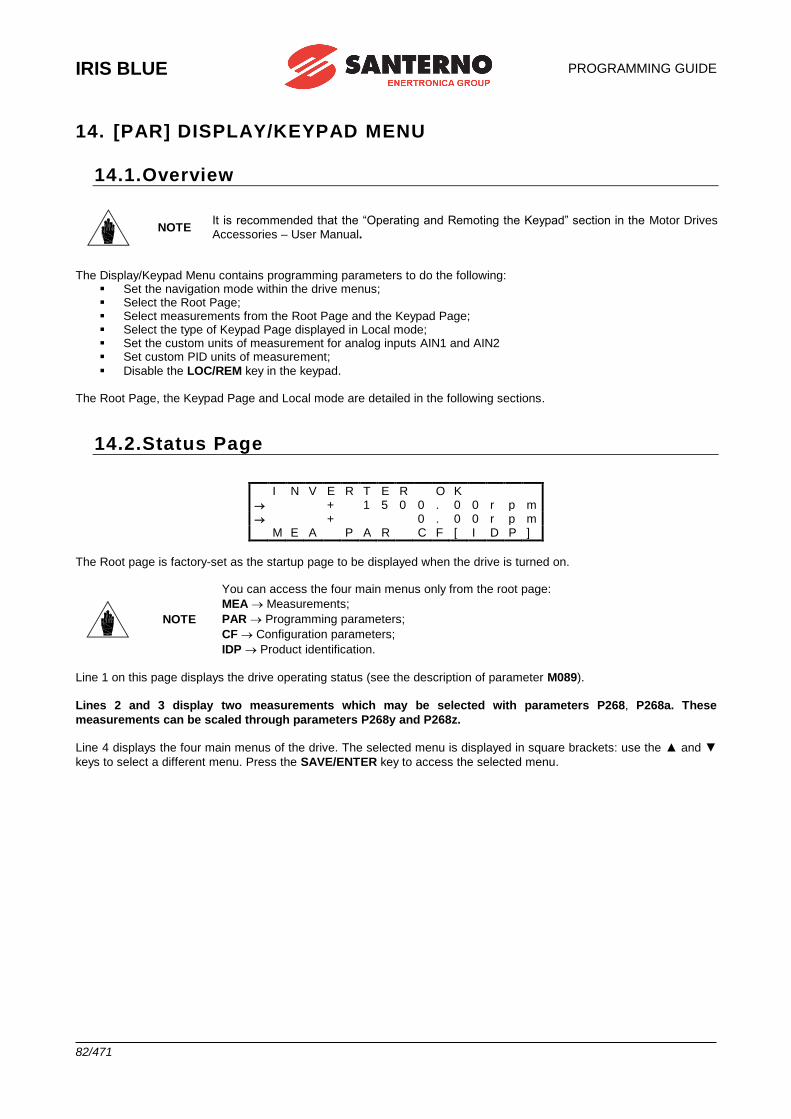
IRIS BLUE
PROGRAMMING GUIDE
82/471
14. [PAR] DISPLAY/KEYPAD MENU
14.1.Overview
NOTE It is recommended that the “Operating and Remoting the Keypad” section in the Motor Drives
Accessories – User Manual.
The Display/Keypad Menu contains programming parameters to do the following:
▪ Set the navigation mode within the drive menus; ▪ Select the Root Page; ▪ Select measurements from the Root Page and the Keypad Page; ▪ Select the type of Keypad Page displayed in Local mode; ▪ Set the custom units of measurement for analog inputs AIN1 and AIN2 ▪ Set custom PID units of measurement;
▪ Disable the LOC/REM key in the keypad. The Root Page, the Keypad Page and Local mode are detailed in the following sections.
14.2.Status Page
I N V E R T E R O K
+ 1 5 0 0 . 0 0 r p m + 0 . 0 0 r p m M E A P A R C F [ I D P ]
The Root page is factory-set as the startup page to be displayed when the drive is turned on.
NOTE
You can access the four main menus only from the root page:
MEA Measurements;
PAR Programming parameters;
CF Configuration parameters;
IDP Product identification.
Line 1 on this page displays the drive operating status (see the description of parameter M089).
Lines 2 and 3 display two measurements which may be selected with parameters P268, P268a. These
measurements can be scaled through parameters P268y and P268z.
Line 4 displays the four main menus of the drive. The selected menu is displayed in square brackets: use the ▲ and ▼
keys to select a different menu. Press the SAVE/ENTER key to access the selected menu.
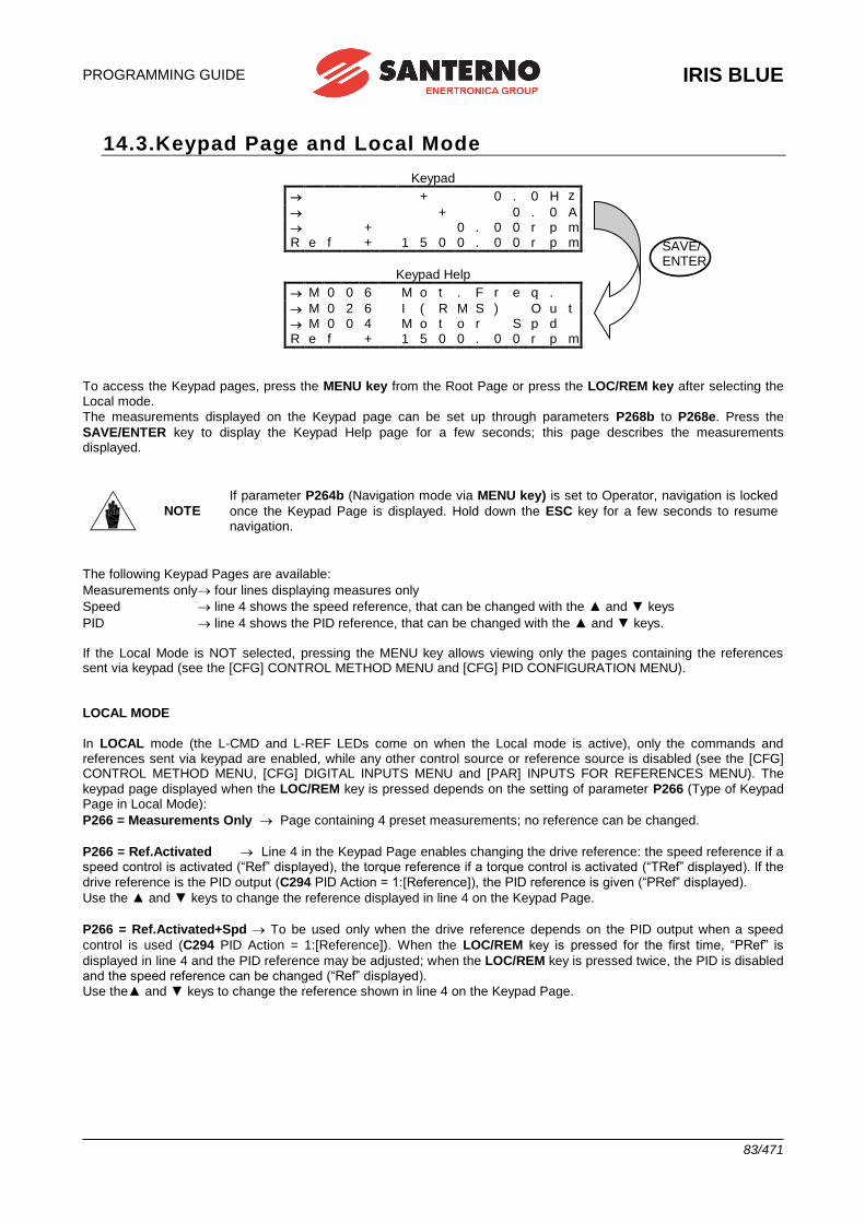
PROGRAMMING GUIDE
IRIS BLUE
83/471
14.3.Keypad Page and Local Mode
Keypad
+ 0 . 0 H z
+ 0 . 0 A + 0 . 0 0 r p m R e f + 1 5 0 0 . 0 0 r p m
Keypad Help
M 0 0 6 M o t . F r e q .
M 0 2 6 I ( R M S ) O u t M 0 0 4 M o t o r S p d
R e f + 1 5 0 0 . 0 0 r p m
To access the Keypad pages, press the MENU key from the Root Page or press the LOC/REM key after selecting the Local mode.
The measurements displayed on the Keypad page can be set up through parameters P268b to P268e. Press the
SAVE/ENTER key to display the Keypad Help page for a few seconds; this page describes the measurements displayed.
NOTE
If parameter P264b (Navigation mode via MENU key) is set to Operator, navigation is locked
once the Keypad Page is displayed. Hold down the ESC key for a few seconds to resume navigation.
The following Keypad Pages are available:
Measurements only four lines displaying measures only
Speed line 4 shows the speed reference, that can be changed with the ▲ and ▼ keys
PID line 4 shows the PID reference, that can be changed with the ▲ and ▼ keys. If the Local Mode is NOT selected, pressing the MENU key allows viewing only the pages containing the references sent via keypad (see the [CFG] CONTROL METHOD MENU and [CFG] PID CONFIGURATION MENU).
LOCAL MODE
In LOCAL mode (the L-CMD and L-REF LEDs come on when the Local mode is active), only the commands and references sent via keypad are enabled, while any other control source or reference source is disabled (see the [CFG] CONTROL METHOD MENU, [CFG] DIGITAL INPUTS MENU and [PAR] INPUTS FOR REFERENCES MENU). The
keypad page displayed when the LOC/REM key is pressed depends on the setting of parameter P266 (Type of Keypad Page in Local Mode):
P266 = Measurements Only Page containing 4 preset measurements; no reference can be changed.
P266 = Ref.Activated Line 4 in the Keypad Page enables changing the drive reference: the speed reference if a speed control is activated (“Ref” displayed), the torque reference if a torque control is activated (“TRef” displayed). If the
drive reference is the PID output (C294 PID Action = 1:[Reference]), the PID reference is given (“PRef” displayed).
Use the ▲ and ▼ keys to change the reference displayed in line 4 on the Keypad Page.
P266 = Ref.Activated+Spd To be used only when the drive reference depends on the PID output when a speed
control is used (C294 PID Action = 1:[Reference]). When the LOC/REM key is pressed for the first time, “PRef” is
displayed in line 4 and the PID reference may be adjusted; when the LOC/REM key is pressed twice, the PID is disabled and the speed reference can be changed (“Ref” displayed).
Use the▲ and ▼ keys to change the reference shown in line 4 on the Keypad Page.
SAVE/ ENTER
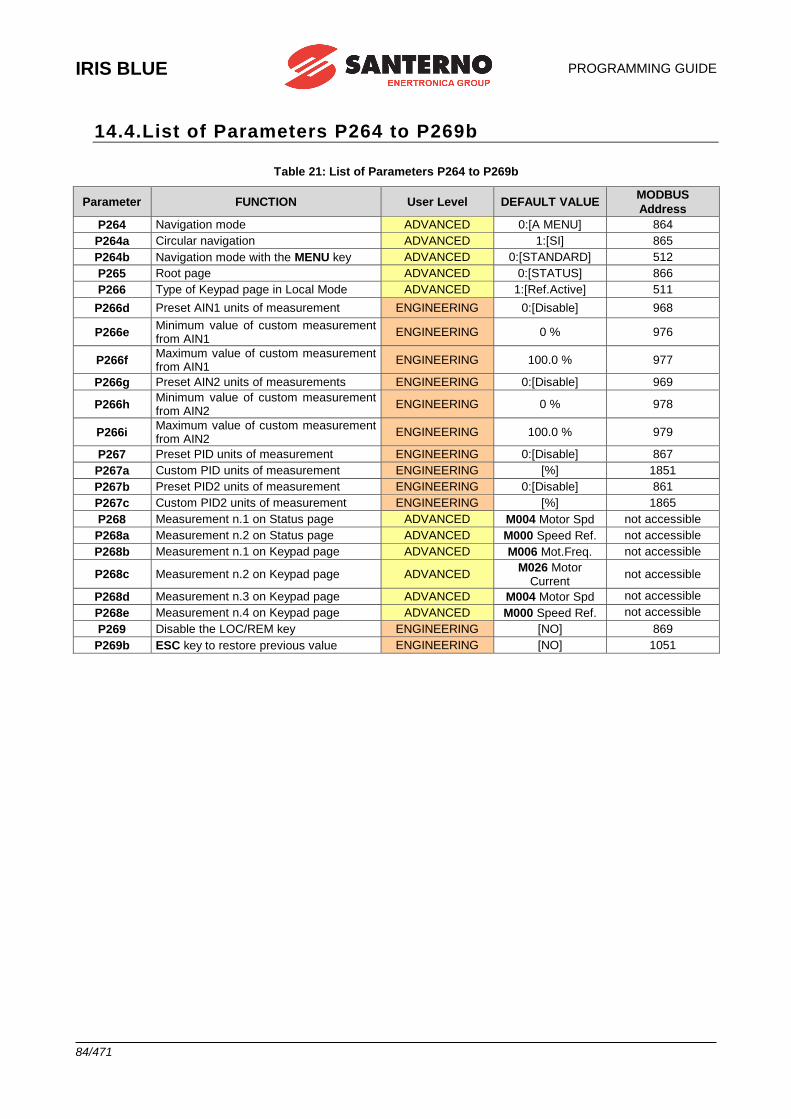
IRIS BLUE
PROGRAMMING GUIDE
84/471
14.4.List of Parameters P264 to P269b
Table 21: List of Parameters P264 to P269b
Parameter FUNCTION User Level DEFAULT VALUE MODBUS
Address
P264 Navigation mode ADVANCED 0:[A MENU] 864
P264a Circular navigation ADVANCED 1:[SI] 865
P264b Navigation mode with the MENU key ADVANCED 0:[STANDARD] 512
P265 Root page ADVANCED 0:[STATUS] 866
P266 Type of Keypad page in Local Mode ADVANCED 1:[Ref.Active] 511
P266d Preset AIN1 units of measurement ENGINEERING 0:[Disable] 968
P266e Minimum value of custom measurement from AIN1
ENGINEERING 0 % 976
P266f Maximum value of custom measurement from AIN1
ENGINEERING 100.0 % 977
P266g Preset AIN2 units of measurements ENGINEERING 0:[Disable] 969
P266h Minimum value of custom measurement from AIN2
ENGINEERING 0 % 978
P266i Maximum value of custom measurement from AIN2
ENGINEERING 100.0 % 979
P267 Preset PID units of measurement ENGINEERING 0:[Disable] 867
P267a Custom PID units of measurement ENGINEERING [%] 1851
P267b Preset PID2 units of measurement ENGINEERING 0:[Disable] 861
P267c Custom PID2 units of measurement ENGINEERING [%] 1865
P268 Measurement n.1 on Status page ADVANCED M004 Motor Spd not accessible
P268a Measurement n.2 on Status page ADVANCED M000 Speed Ref. not accessible
P268b Measurement n.1 on Keypad page ADVANCED M006 Mot.Freq. not accessible
P268c Measurement n.2 on Keypad page ADVANCED M026 Motor
Current not accessible
P268d Measurement n.3 on Keypad page ADVANCED M004 Motor Spd not accessible
P268e Measurement n.4 on Keypad page ADVANCED M000 Speed Ref. not accessible
P269 Disable the LOC/REM key ENGINEERING [NO] 869
P269b ESC key to restore previous value ENGINEERING [NO] 1051
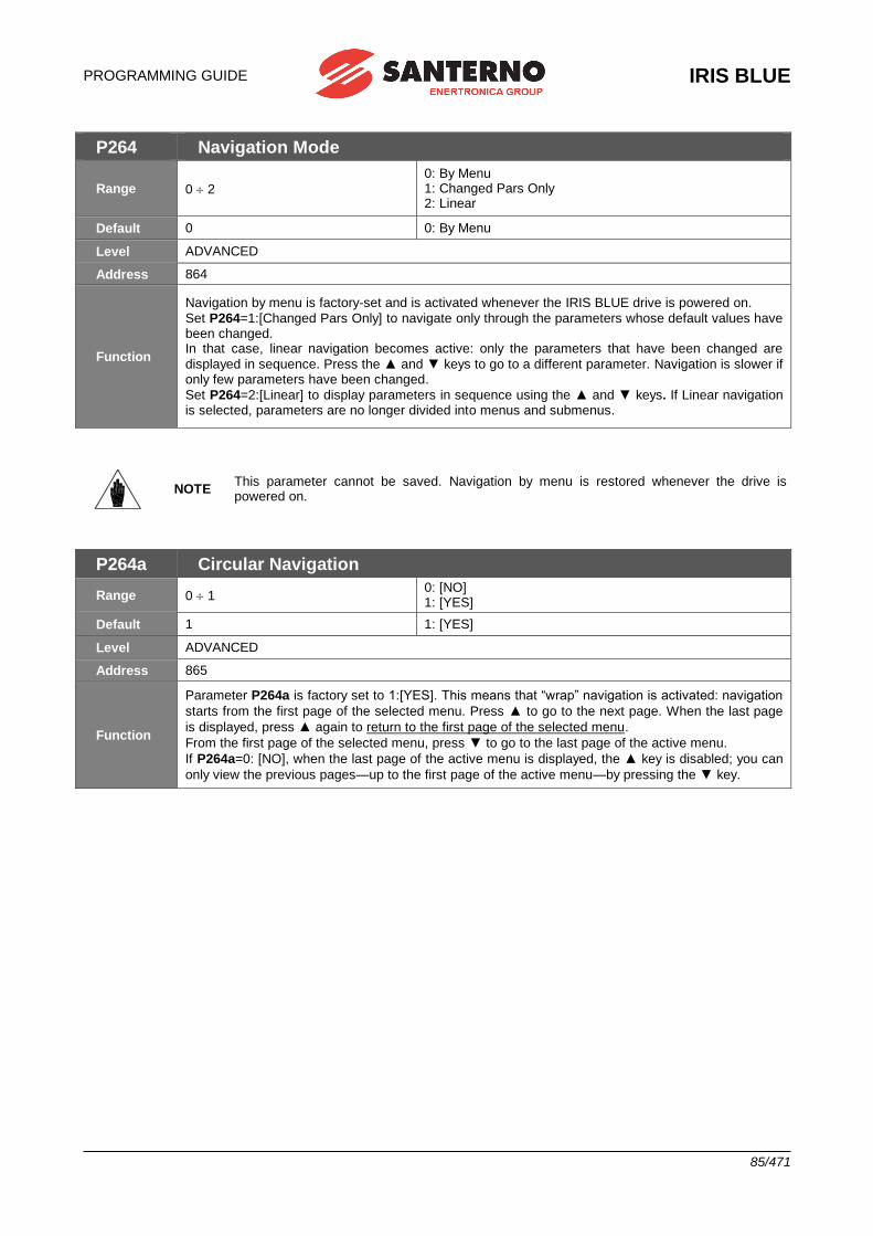
PROGRAMMING GUIDE
IRIS BLUE
85/471
P264 Navigation Mode
Range 0 2
0: By Menu 1: Changed Pars Only 2: Linear
Default 0 0: By Menu
Level ADVANCED
Address 864
Function
Navigation by menu is factory-set and is activated whenever the IRIS BLUE drive is powered on.
Set P264=1:[Changed Pars Only] to navigate only through the parameters whose default values have been changed. In that case, linear navigation becomes active: only the parameters that have been changed are
displayed in sequence. Press the ▲ and ▼ keys to go to a different parameter. Navigation is slower if only few parameters have been changed.
Set P264=2:[Linear] to display parameters in sequence using the ▲ and ▼ keys. If Linear navigation is selected, parameters are no longer divided into menus and submenus.
NOTE This parameter cannot be saved. Navigation by menu is restored whenever the drive is powered on.
P264a Circular Navigation
Range 0 1 0: [NO] 1: [YES]
Default 1 1: [YES]
Level ADVANCED
Address 865
Function
Parameter P264a is factory set to 1:[YES]. This means that “wrap” navigation is activated: navigation
starts from the first page of the selected menu. Press ▲ to go to the next page. When the last page
is displayed, press ▲ again to return to the first page of the selected menu.
From the first page of the selected menu, press ▼ to go to the last page of the active menu.
If P264a=0: [NO], when the last page of the active menu is displayed, the ▲ key is disabled; you can
only view the previous pages—up to the first page of the active menu—by pressing the ▼ key.
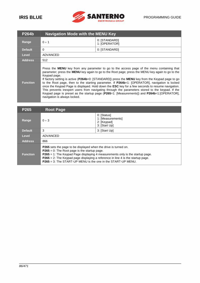
IRIS BLUE
PROGRAMMING GUIDE
86/471
P264b Navigation Mode with the MENU Key
Range 0 1 0: [STANDARD] 1: [OPERATOR]
Default 0 0: [STANDARD]
Level ADVANCED
Address 512
Function
Press the MENU key from any parameter to go to the access page of the menu containing that
parameter; press the MENU key again to go to the Root page; press the MENU key again to go to the Keypad page.
If factory setting is active (P264b=0: [STANDARD]) press the MENU key from the Keypad page to go
to the Root page, then to the starting parameter. If P264b=1: [OPERATOR], navigation is locked
once the Keypad Page is displayed. Hold down the ESC key for a few seconds to resume navigation. This prevents inexpert users from navigating through the parameters stored to the keypad. If the
Keypad page is preset as the startup page (P265=1: [Measurements]) and P264b=1:[OPERATOR], navigation is always locked.
P265 Root Page
Range 0 3
0: [Status] 1: [Measurements] 2: [Keypad] 3: [Start Up]
Default 3 3: [Start Up]
Level ADVANCED
Address 866
Function
P265 sets the page to be displayed when the drive is turned on.
P265 = 0: The Root page is the startup page.
P265 = 1: The Keypad Page displaying 4 measurements only is the startup page.
P265 = 2: The Keypad page displaying a reference in line 4 is the startup page.
P265 = 3: The START-UP MENU is the one in the START-UP MENU.
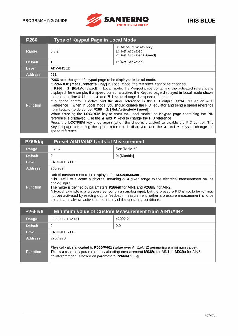
PROGRAMMING GUIDE
IRIS BLUE
87/471
P266 Type of Keypad Page in Local Mode
Range 0 2
0: [Measurements only] 1: [Ref.Activated] 2: [Ref.Activated+Speed]
Default 1 1: [Ref.Activated]
Level ADVANCED
Address 511
Function
P266 sets the type of keypad page to be displayed in Local mode.
If P266 = 0: [Measurements Only] in Local mode, the reference cannot be changed.
If P266 = 1: [Ref.Activated] in Local mode, the Keypad page containing the activated reference is displayed; for example, if a speed control is active, the Keypad page displayed in Local mode shows
the speed in line 4. Use the ▲ and ▼ keys to change the speed reference.
If a speed control is active and the drive reference is the PID output (C294 PID Action = 1: [Reference]), when in Local mode, you should disable the PID regulator and send a speed reference
from keypad (to do so, set P266 = 2: [Ref.Activated+Speed]).
When pressing the LOC/REM key to enter the Local mode, the Keypad page containing the PID
reference is displayed. Use the ▲ and ▼ keys to change the PID reference.
Press the LOC/REM key once again (when the drive is disabled) to disable the PID control. The
Keypad page containing the speed reference is displayed. Use the ▲ and ▼ keys to change the speed reference.
P266d/g Preset AIN1/AIN2 Units of Measurement
Range 0 39 See Table 22
Default 0 0: [Disable]
Level ENGINEERING
Address 968/969
Function
Unit of measurement to be displayed for M038u/M039u. It is useful to allocate a physical meaning of a given range to the electrical measurement on the analog input.
The range is defined by parameters P266e/f for AIN1 and P266h/i for AIN2. A typical example is a pressure sensor on an analog input, but the pressure PID is not to be (or may not be) activated by reading out its feedback measurement, rather a pressure measurement is to be used, that is always active independently of the operating conditions.
P266e/h Minimum Value of Custom Measurement from AIN1/AIN2
Range –32000 +32000 ±3200.0
Default 0 0.0
Level ENGINEERING
Address 976 / 978
Function
Physical value allocated to P056/P061 (value over AIN1/AIN2 generating a minimum value).
This is a read-only parameter only affecting measurement M038u for AIN1 or M039u for AIN2.
Its interpretation is based on parameters P266d/P266g.
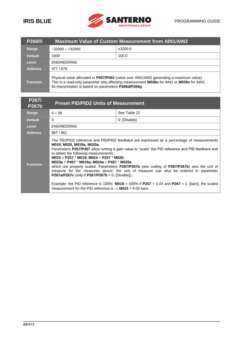
IRIS BLUE
PROGRAMMING GUIDE
88/471
P266f/i Maximum Value of Custom Measurement from AIN1/AIN2
Range –32000 +32000 ±3200.0
Default 1000 100.0
Level ENGINEERING
Address 977 / 979
Function
Physical value allocated to P057/P062 (value over AIN1/AIN2 generating a maximum value).
This is a read-only parameter only affecting measurement M038u for AIN1 or M039u for AIN2.
Its interpretation is based on parameters P266d/P266g.
P267/
P267b Preset PID/PID2 Units of Measurement
Range 0 39 See Table 22
Default 0 0: [Disable]
Level ENGINEERING
Address 867 / 861
Function
The PID/PID2 reference and PID/PID2 feedback are expressed as a percentage of measurements
M019, M020, M019a, M020a.
Parameters P257/P457 allow setting a gain value to “scale” the PID reference and PID feedback and to obtain the following measurements:
M023 = P257 * M019; M024 = P257 * M020;
M023a = P457 * M019a; M024a = P457 * M020a
which are properly scaled. Parameters P267/P267b (see coding of P267/P267b) sets the unit of measure for the measures above; the unit of measure can also be entered in parameter
P267a/P267c (only if P267/P267b = 0: [Disable]).
Example: the PID reference is 100%; M019 = 100% if P257 = 0.04 and P267 = 1: [bars], the scaled
measurement for the PID reference is M023 = 4.00 bars.
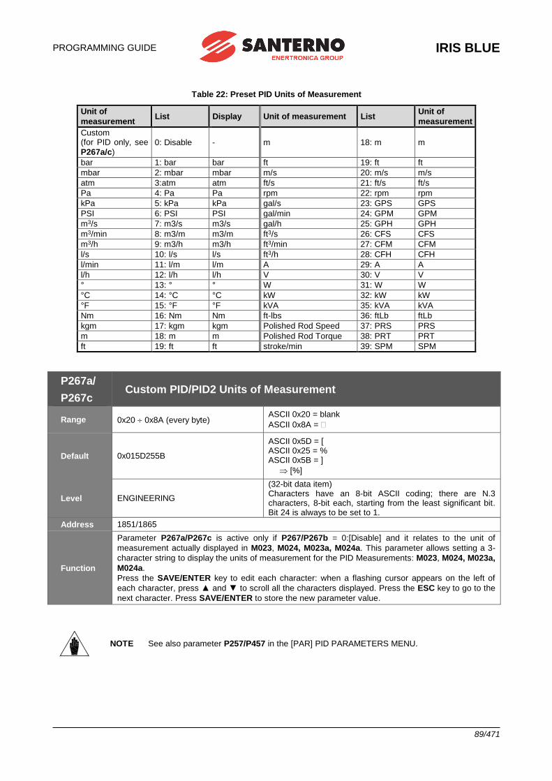
PROGRAMMING GUIDE
IRIS BLUE
89/471
Table 22: Preset PID Units of Measurement
Unit of
measurement List Display Unit of measurement List
Unit of
measurement
Custom (for PID only, see
P267a/c) 0: Disable - m 18: m m
bar 1: bar bar ft 19: ft ft
mbar 2: mbar mbar m/s 20: m/s m/s
atm 3:atm atm ft/s 21: ft/s ft/s
Pa 4: Pa Pa rpm 22: rpm rpm
kPa 5: kPa kPa gal/s 23: GPS GPS
PSI 6: PSI PSI gal/min 24: GPM GPM
m3/s 7: m3/s m3/s gal/h 25: GPH GPH
m3/min 8: m3/m m3/m ft3/s 26: CFS CFS
m3/h 9: m3/h m3/h ft3/min 27: CFM CFM
l/s 10: l/s l/s ft3/h 28: CFH CFH
l/min 11: l/m l/m A 29: A A
l/h 12: l/h l/h V 30: V V
° 13: ° ° W 31: W W
°C 14: °C °C kW 32: kW kW
°F 15: °F °F kVA 35: kVA kVA
Nm 16: Nm Nm ft-lbs 36: ftLb ftLb
kgm 17: kgm kgm Polished Rod Speed 37: PRS PRS
m 18: m m Polished Rod Torque 38: PRT PRT
ft 19: ft ft stroke/min 39: SPM SPM
P267a/
P267c Custom PID/PID2 Units of Measurement
Range 0x20 0x8A (every byte) ASCII 0x20 = blank
ASCII 0x8A =
Default 0x015D255B
ASCII 0x5D = [ ASCII 0x25 = % ASCII 0x5B = ]
[%]
Level ENGINEERING
(32-bit data item) Characters have an 8-bit ASCII coding; there are N.3 characters, 8-bit each, starting from the least significant bit. Bit 24 is always to be set to 1.
Address 1851/1865
Function
Parameter P267a/P267c is active only if P267/P267b = 0:[Disable] and it relates to the unit of
measurement actually displayed in M023, M024, M023a, M024a. This parameter allows setting a 3-
character string to display the units of measurement for the PID Measurements: M023, M024, M023a,
M024a.
Press the SAVE/ENTER key to edit each character: when a flashing cursor appears on the left of
each character, press ▲ and ▼ to scroll all the characters displayed. Press the ESC key to go to the
next character. Press SAVE/ENTER to store the new parameter value.
NOTE See also parameter P257/P457 in the [PAR] PID PARAMETERS MENU.
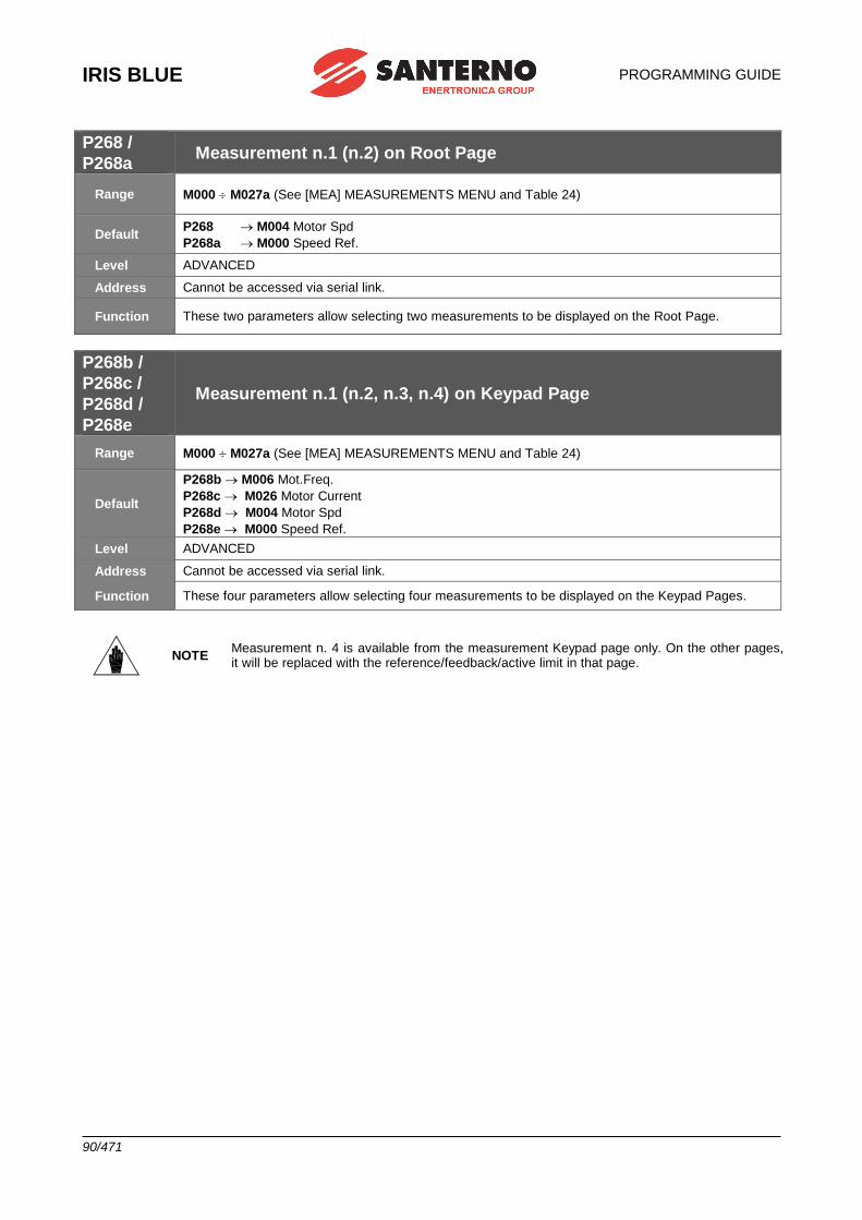
IRIS BLUE
PROGRAMMING GUIDE
90/471
P268 /
P268a Measurement n.1 (n.2) on Root Page
Range M000 M027a (See [MEA] MEASUREMENTS MENU and Table 24)
Default P268 M004 Motor Spd
P268a M000 Speed Ref.
Level ADVANCED
Address Cannot be accessed via serial link.
Function These two parameters allow selecting two measurements to be displayed on the Root Page.
P268b /
P268c /
P268d /
P268e
Measurement n.1 (n.2, n.3, n.4) on Keypad Page
Range M000 M027a (See [MEA] MEASUREMENTS MENU and Table 24)
Default
P268b M006 Mot.Freq.
P268c M026 Motor Current
P268d M004 Motor Spd
P268e M000 Speed Ref.
Level ADVANCED
Address Cannot be accessed via serial link.
Function These four parameters allow selecting four measurements to be displayed on the Keypad Pages.
NOTE Measurement n. 4 is available from the measurement Keypad page only. On the other pages, it will be replaced with the reference/feedback/active limit in that page.
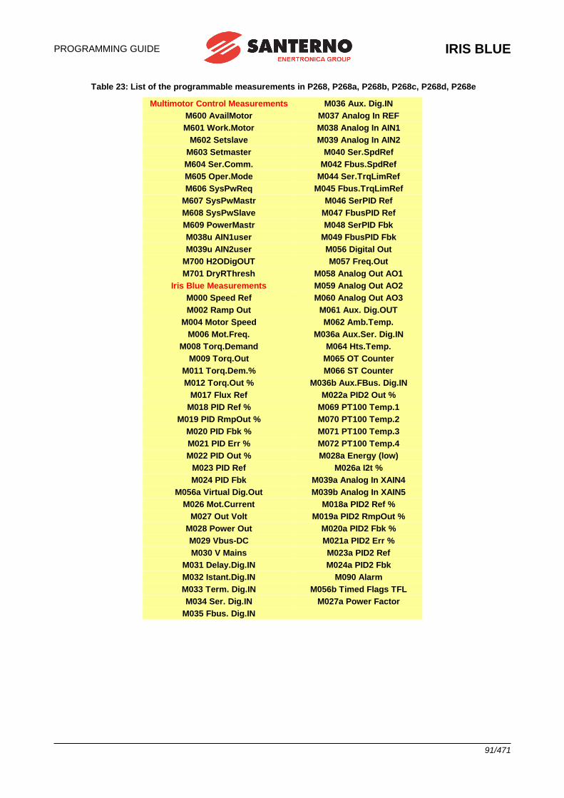
PROGRAMMING GUIDE
IRIS BLUE
91/471
Table 23: List of the programmable measurements in P268, P268a, P268b, P268c, P268d, P268e
Multimotor Control Measurements M036 Aux. Dig.IN
M600 AvailMotor M037 Analog In REF
M601 Work.Motor M038 Analog In AIN1
M602 Setslave M039 Analog In AIN2
M603 Setmaster M040 Ser.SpdRef
M604 Ser.Comm. M042 Fbus.SpdRef
M605 Oper.Mode M044 Ser.TrqLimRef
M606 SysPwReq M045 Fbus.TrqLimRef
M607 SysPwMastr M046 SerPID Ref
M608 SysPwSlave M047 FbusPID Ref
M609 PowerMastr M048 SerPID Fbk
M038u AIN1user M049 FbusPID Fbk
M039u AIN2user M056 Digital Out
M700 H2ODigOUT M057 Freq.Out
M701 DryRThresh M058 Analog Out AO1
Iris Blue Measurements M059 Analog Out AO2
M000 Speed Ref M060 Analog Out AO3
M002 Ramp Out M061 Aux. Dig.OUT
M004 Motor Speed M062 Amb.Temp.
M006 Mot.Freq. M036a Aux.Ser. Dig.IN
M008 Torq.Demand M064 Hts.Temp.
M009 Torq.Out M065 OT Counter
M011 Torq.Dem.% M066 ST Counter
M012 Torq.Out % M036b Aux.FBus. Dig.IN
M017 Flux Ref M022a PID2 Out %
M018 PID Ref % M069 PT100 Temp.1
M019 PID RmpOut % M070 PT100 Temp.2
M020 PID Fbk % M071 PT100 Temp.3
M021 PID Err % M072 PT100 Temp.4
M022 PID Out % M028a Energy (low)
M023 PID Ref M026a I2t %
M024 PID Fbk M039a Analog In XAIN4
M056a Virtual Dig.Out M039b Analog In XAIN5
M026 Mot.Current M018a PID2 Ref %
M027 Out Volt M019a PID2 RmpOut %
M028 Power Out M020a PID2 Fbk %
M029 Vbus-DC M021a PID2 Err %
M030 V Mains M023a PID2 Ref
M031 Delay.Dig.IN M024a PID2 Fbk
M032 Istant.Dig.IN M090 Alarm
M033 Term. Dig.IN M056b Timed Flags TFL
M034 Ser. Dig.IN M027a Power Factor
M035 Fbus. Dig.IN
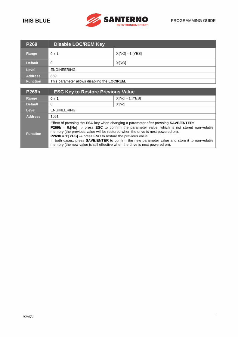
IRIS BLUE
PROGRAMMING GUIDE
92/471
P269 Disable LOC/REM Key
Range 0 1 0:[NO] - 1:[YES]
Default 0 0:[NO]
Level ENGINEERING
Address 869
Function This parameter allows disabling the LOC/REM.
P269b ESC Key to Restore Previous Value
Range 0 1 0:[No] - 1:[YES]
Default 0 0:[No]
Level ENGINEERING
Address 1051
Function
Effect of pressing the ESC key when changing a parameter after pressing SAVE/ENTER:
P269b = 0:[No] press ESC to confirm the parameter value, which is not stored non-volatile memory (the previous value will be restored when the drive is next powered on).
P269b = 1:[YES] press ESC to restore the previous value.
In both cases, press SAVE/ENTER to confirm the new parameter value and store it to non-volatile memory (the new value is still effective when the drive is next powered on).
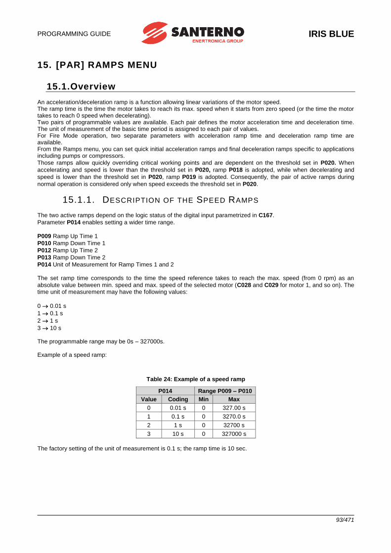
PROGRAMMING GUIDE
IRIS BLUE
93/471
15. [PAR] RAMPS MENU
15.1.Overview An acceleration/deceleration ramp is a function allowing linear variations of the motor speed. The ramp time is the time the motor takes to reach its max. speed when it starts from zero speed (or the time the motor takes to reach 0 speed when decelerating). Two pairs of programmable values are available. Each pair defines the motor acceleration time and deceleration time. The unit of measurement of the basic time period is assigned to each pair of values. For Fire Mode operation, two separate parameters with acceleration ramp time and deceleration ramp time are available. From the Ramps menu, you can set quick initial acceleration ramps and final deceleration ramps specific to applications including pumps or compressors.
Those ramps allow quickly overriding critical working points and are dependent on the threshold set in P020. When
accelerating and speed is lower than the threshold set in P020, ramp P018 is adopted, while when decelerating and
speed is lower than the threshold set in P020, ramp P019 is adopted. Consequently, the pair of active ramps during
normal operation is considered only when speed exceeds the threshold set in P020.
15.1.1. DESCRIPTION OF THE SPEED RAMPS
The two active ramps depend on the logic status of the digital input parametrized in C167.
Parameter P014 enables setting a wider time range.
P009 Ramp Up Time 1
P010 Ramp Down Time 1
P012 Ramp Up Time 2
P013 Ramp Down Time 2
P014 Unit of Measurement for Ramp Times 1 and 2 The set ramp time corresponds to the time the speed reference takes to reach the max. speed (from 0 rpm) as an
absolute value between min. speed and max. speed of the selected motor (C028 and C029 for motor 1, and so on). The time unit of measurement may have the following values:
0 0.01 s
1 0.1 s
2 1 s
3 10 s The programmable range may be 0s – 327000s. Example of a speed ramp:
Table 24: Example of a speed ramp
P014 Range P009 – P010
Value Coding Min Max
0 0.01 s 0 327.00 s
1 0.1 s 0 3270.0 s
2 1 s 0 32700 s
3 10 s 0 327000 s
The factory setting of the unit of measurement is 0.1 s; the ramp time is 10 sec.
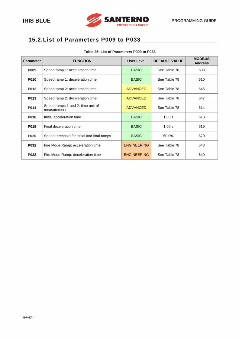
IRIS BLUE
PROGRAMMING GUIDE
94/471
15.2.List of Parameters P009 to P033
Table 25: List of Parameters P009 to P033
Parameter FUNCTION User Level DEFAULT VALUE MODBUS
Address
P009 Speed ramp 1: acceleration time BASIC See Table 78 609
P010 Speed ramp 1: deceleration time BASIC See Table 78 610
P012 Speed ramp 2: acceleration time ADVANCED See Table 78 646
P013 Speed ramp 2: deceleration time ADVANCED See Table 78 647
P014 Speed ramps 1 and 2: time unit of measurement
ADVANCED See Table 78 614
P018 Initial acceleration time BASIC 1.00 s 618
P019 Final deceleration time BASIC 1.00 s 619
P020 Speed threshold for initial and final ramps BASIC 50.0% 670
P032 Fire Mode Ramp: acceleration time ENGINEERING See Table 78 648
P033 Fire Mode Ramp: deceleration time ENGINEERING See Table 78 649
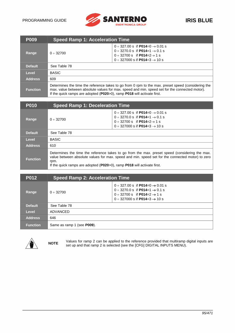
PROGRAMMING GUIDE
IRIS BLUE
95/471
P009 Speed Ramp 1: Acceleration Time
Range 0 32700
0 327.00 s if P014=0 0.01 s
0 3270.0 s if P014=1 0.1 s
0 32700 s if P014=2 1 s
0 327000 s if P014=3 10 s
Default See Table 78
Level BASIC
Address 609
Function
Determines the time the reference takes to go from 0 rpm to the max. preset speed (considering the max. value between absolute values for max. speed and min. speed set for the connected motor).
If the quick ramps are adopted (P020>0), ramp P018 will activate first.
P010 Speed Ramp 1: Deceleration Time
Range 0 32700
0 327.00 s if P014=0 0.01 s
0 3270.0 s if P014=1 0.1 s
0 32700 s if P014=2 1 s
0 327000 s if P014=3 10 s
Default See Table 78
Level BASIC
Address 610
Function
Determines the time the reference takes to go from the max. preset speed (considering the max. value between absolute values for max. speed and min. speed set for the connected motor) to zero rpm.
If the quick ramps are adopted (P020>0), ramp P018 will activate first.
P012 Speed Ramp 2: Acceleration Time
Range 0 32700
0 327.00 s if P014=0 0.01 s
0 3270.0 s if P014=1 0.1 s
0 32700 s if P014=2 1 s
0 327000 s if P014=3 10 s
Default See Table 78
Level ADVANCED
Address 646
Function Same as ramp 1 (see P009).
NOTE Values for ramp 2 can be applied to the reference provided that multiramp digital inputs are set up and that ramp 2 is selected (see the [CFG] DIGITAL INPUTS MENU).
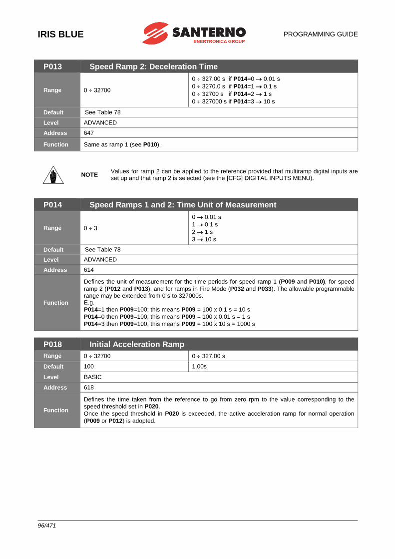
IRIS BLUE
PROGRAMMING GUIDE
96/471
P013 Speed Ramp 2: Deceleration Time
Range 0 32700
0 327.00 s if P014=0 0.01 s
0 3270.0 s if P014=1 0.1 s
0 32700 s if P014=2 1 s
0 327000 s if P014=3 10 s
Default See Table 78
Level ADVANCED
Address 647
Function Same as ramp 1 (see P010).
NOTE Values for ramp 2 can be applied to the reference provided that multiramp digital inputs are set up and that ramp 2 is selected (see the [CFG] DIGITAL INPUTS MENU).
P014 Speed Ramps 1 and 2: Time Unit of Measurement
Range 0 3
0 0.01 s
1 0.1 s
2 1 s
3 10 s
Default See Table 78
Level ADVANCED
Address 614
Function
Defines the unit of measurement for the time periods for speed ramp 1 (P009 and P010), for speed
ramp 2 (P012 and P013), and for ramps in Fire Mode (P032 and P033). The allowable programmable range may be extended from 0 s to 327000s. E.g.
P014=1 then P009=100; this means P009 = 100 x 0.1 s = 10 s
P014=0 then P009=100; this means P009 = 100 x 0.01 s = 1 s
P014=3 then P009=100; this means P009 = 100 x 10 s = 1000 s
P018 Initial Acceleration Ramp
Range 0 32700 0 327.00 s
Default 100 1.00s
Level BASIC
Address 618
Function
Defines the time taken from the reference to go from zero rpm to the value corresponding to the
speed threshold set in P020.
Once the speed threshold in P020 is exceeded, the active acceleration ramp for normal operation
(P009 or P012) is adopted.
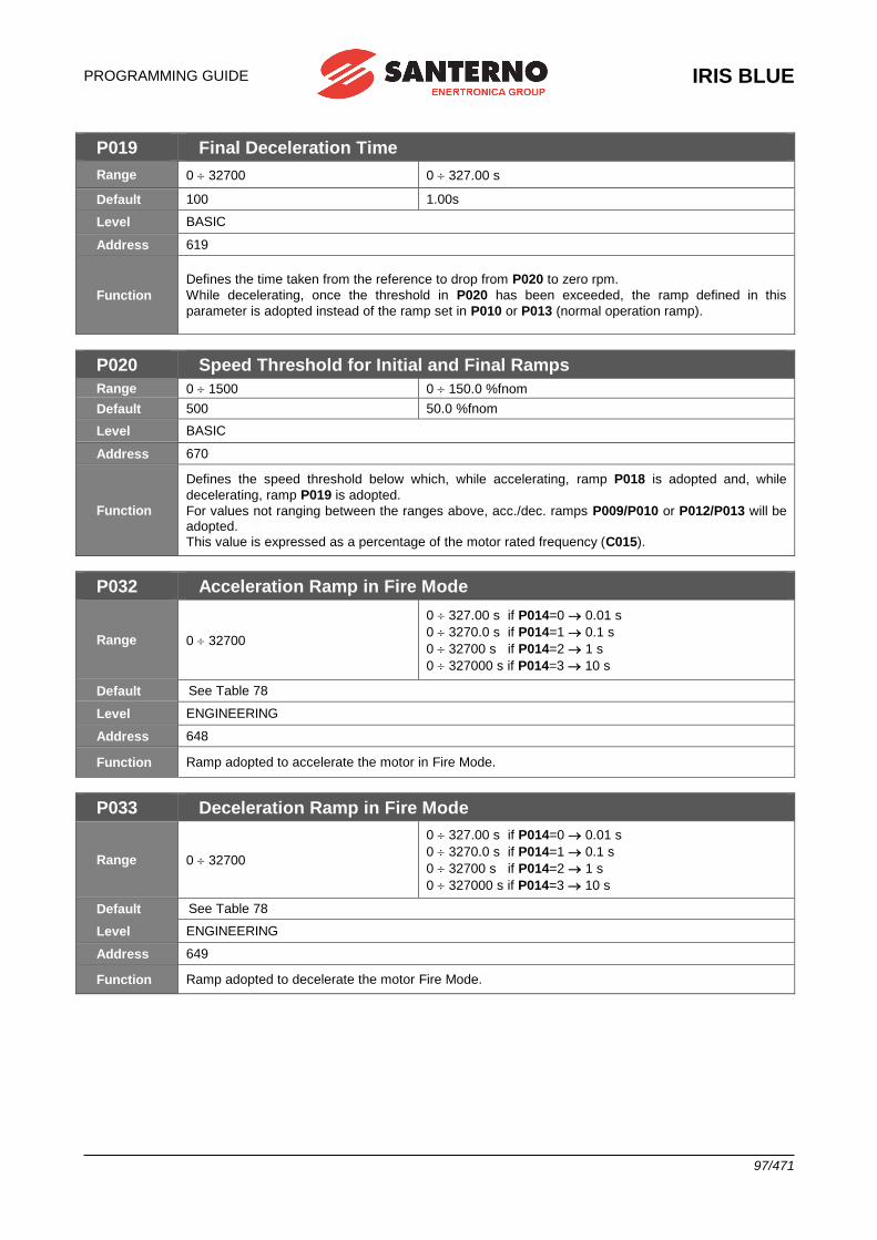
PROGRAMMING GUIDE
IRIS BLUE
97/471
P019 Final Deceleration Time
Range 0 32700 0 327.00 s
Default 100 1.00s
Level BASIC
Address 619
Function
Defines the time taken from the reference to drop from P020 to zero rpm.
While decelerating, once the threshold in P020 has been exceeded, the ramp defined in this
parameter is adopted instead of the ramp set in P010 or P013 (normal operation ramp).
P020 Speed Threshold for Initial and Final Ramps
Range 0 1500 0 150.0 %fnom
Default 500 50.0 %fnom
Level BASIC
Address 670
Function
Defines the speed threshold below which, while accelerating, ramp P018 is adopted and, while
decelerating, ramp P019 is adopted.
For values not ranging between the ranges above, acc./dec. ramps P009/P010 or P012/P013 will be adopted.
This value is expressed as a percentage of the motor rated frequency (C015).
P032 Acceleration Ramp in Fire Mode
Range 0 32700
0 327.00 s if P014=0 0.01 s
0 3270.0 s if P014=1 0.1 s
0 32700 s if P014=2 1 s
0 327000 s if P014=3 10 s
Default See Table 78
Level ENGINEERING
Address 648
Function Ramp adopted to accelerate the motor in Fire Mode.
P033 Deceleration Ramp in Fire Mode
Range 0 32700
0 327.00 s if P014=0 0.01 s
0 3270.0 s if P014=1 0.1 s
0 32700 s if P014=2 1 s
0 327000 s if P014=3 10 s
Default See Table 78
Level ENGINEERING
Address 649
Function Ramp adopted to decelerate the motor Fire Mode.
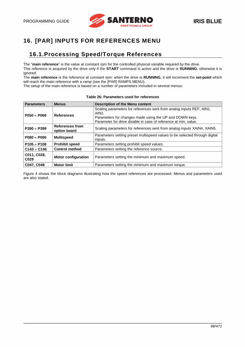
PROGRAMMING GUIDE
IRIS BLUE
98/471
16. [PAR] INPUTS FOR REFERENCES MENU
16.1.Processing Speed/Torque References
The “main reference” is the value at constant rpm for the controlled physical variable required by the drive.
This reference is acquired by the drive only if the START command is active and the drive is RUNNING, otherwise it is ignored.
The main reference is the reference at constant rpm: when the drive is RUNNING, it will increment the set-point which will reach the main reference with a ramp (see the [PAR] RAMPS MENU). The setup of the main reference is based on a number of parameters included in several menus:
Table 26: Parameters used for references
Parameters Menus Description of the Menu content
P050 P069 References
Scaling parameters for references sent from analog inputs REF, AIN1, AIN2. Parameters for changes made using the UP and DOWN keys. Parameter for drive disable in case of reference at min. value.
P390 P399 References from
option board Scaling parameters for references sent from analog inputs XAIN4, XAIN5.
P080 P090 Multispeed Parameters setting preset multispeed values to be selected through digital inputs.
P105 P108 Prohibit speed Parameters setting prohibit speed values.
C143 C146 Control method Parameters setting the reference source.
C011, C028,
C029 Motor configuration Parameters setting the minimum and maximum speed.
C047, C048 Motor limit Parameters setting the minimum and maximum torque.
Figure 4 shows the block diagrams illustrating how the speed references are processed. Menus and parameters used are also stated.
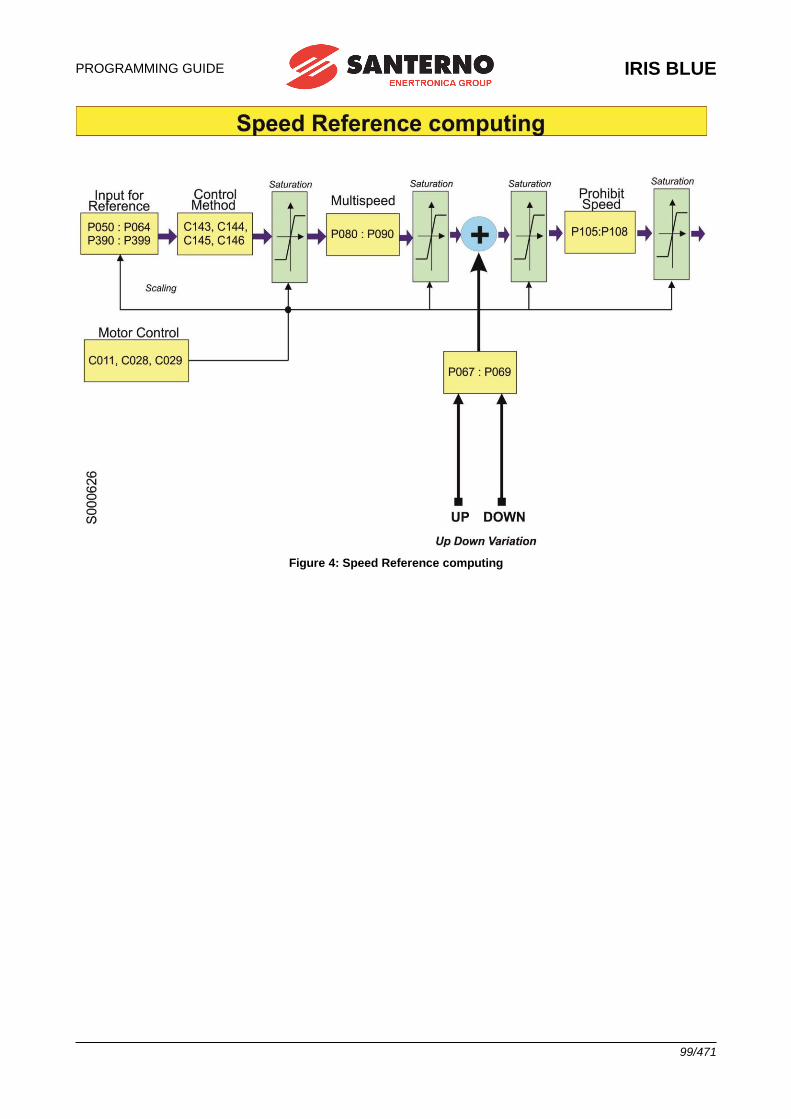
PROGRAMMING GUIDE
IRIS BLUE
99/471
Figure 4: Speed Reference computing
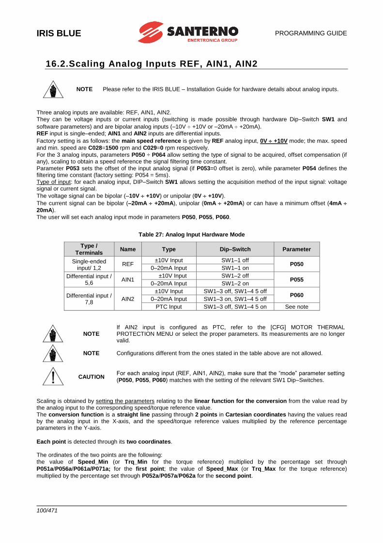
IRIS BLUE
PROGRAMMING GUIDE
100/471
16.2.Scaling Analog Inputs REF, AIN1, AIN2
NOTE Please refer to the IRIS BLUE – Installation Guide for hardware details about analog inputs.
Three analog inputs are available: REF, AIN1, AIN2.
They can be voltage inputs or current inputs (switching is made possible through hardware Dip–Switch SW1 and
software parameters) and are bipolar analog inputs (–10V +10V or –20mA +20mA).
REF input is single–ended; AIN1 and AIN2 inputs are differential inputs.
Factory setting is as follows: the main speed reference is given by REF analog input, 0V +10V mode; the max. speed
and min. speed are C028=1500 rpm and C029=0 rpm respectively.
For the 3 analog inputs, parameters P050 ÷ P064 allow setting the type of signal to be acquired, offset compensation (if any), scaling to obtain a speed reference the signal filtering time constant.
Parameter P053 sets the offset of the input analog signal (if P053=0 offset is zero), while parameter P054 defines the filtering time constant (factory setting: P054 = 5ms).
Type of input: for each analog input, DIP–Switch SW1 allows setting the acquisition method of the input signal: voltage signal or current signal.
The voltage signal can be bipolar (–10V +10V) or unipolar (0V +10V).
The current signal can be bipolar (–20mA +20mA), unipolar (0mA +20mA) or can have a minimum offset (4mA
20mA).
The user will set each analog input mode in parameters P050, P055, P060.
Table 27: Analog Input Hardware Mode
Type /
Terminals Name Type Dip–Switch Parameter
Single-ended input/ 1,2
REF ±10V Input SW1–1 off
P050 0–20mA Input SW1–1 on
Differential input / 5,6
AIN1 ±10V Input SW1–2 off
P055 0–20mA Input SW1–2 on
Differential input / 7,8
AIN2
±10V Input SW1–3 off, SW1–4 5 off P060
0–20mA Input SW1–3 on, SW1–4 5 off
PTC Input SW1–3 off, SW1–4 5 on See note
NOTE If AIN2 input is configured as PTC, refer to the [CFG] MOTOR THERMAL PROTECTION MENU or select the proper parameters. Its measurements are no longer valid.
NOTE Configurations different from the ones stated in the table above are not allowed.
CAUTION For each analog input (REF, AIN1, AIN2), make sure that the “mode” parameter setting
(P050, P055, P060) matches with the setting of the relevant SW1 Dip–Switches.
Scaling is obtained by setting the parameters relating to the linear function for the conversion from the value read by the analog input to the corresponding speed/torque reference value.
The conversion function is a straight line passing through 2 points in Cartesian coordinates having the values read by the analog input in the X-axis, and the speed/torque reference values multiplied by the reference percentage parameters in the Y-axis.
Each point is detected through its two coordinates. The ordinates of the two points are the following:
the value of Speed_Min (or Trq_Min for the torque reference) multiplied by the percentage set through
P051a/P056a/P061a/P071a; for the first point; the value of Speed_Max (or Trq_Max for the torque reference)
multiplied by the percentage set through P052a/P057a/P062a for the second point.
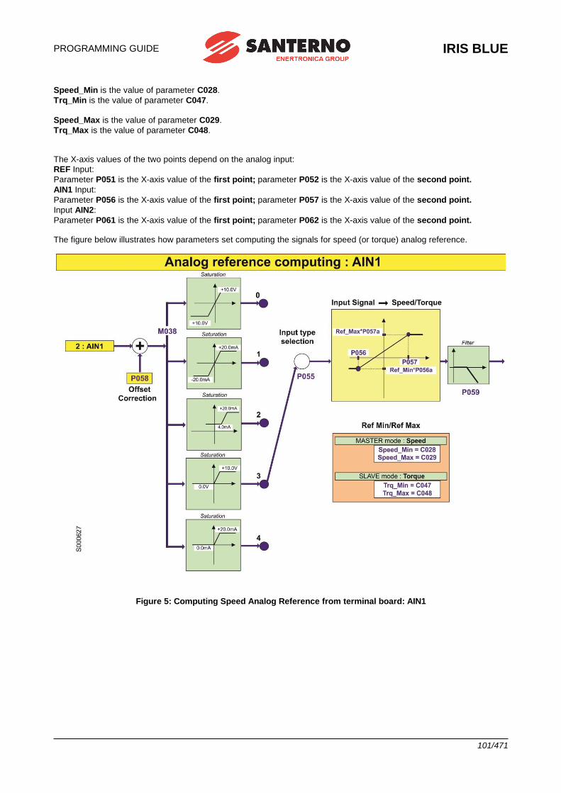
PROGRAMMING GUIDE
IRIS BLUE
101/471
Speed_Min is the value of parameter C028.
Trq_Min is the value of parameter C047.
Speed_Max is the value of parameter C029.
Trq_Max is the value of parameter C048. The X-axis values of the two points depend on the analog input:
REF Input:
Parameter P051 is the X-axis value of the first point; parameter P052 is the X-axis value of the second point.
AIN1 Input:
Parameter P056 is the X-axis value of the first point; parameter P057 is the X-axis value of the second point.
Input AIN2:
Parameter P061 is the X-axis value of the first point; parameter P062 is the X-axis value of the second point. The figure below illustrates how parameters set computing the signals for speed (or torque) analog reference.
Figure 5: Computing Speed Analog Reference from terminal board: AIN1
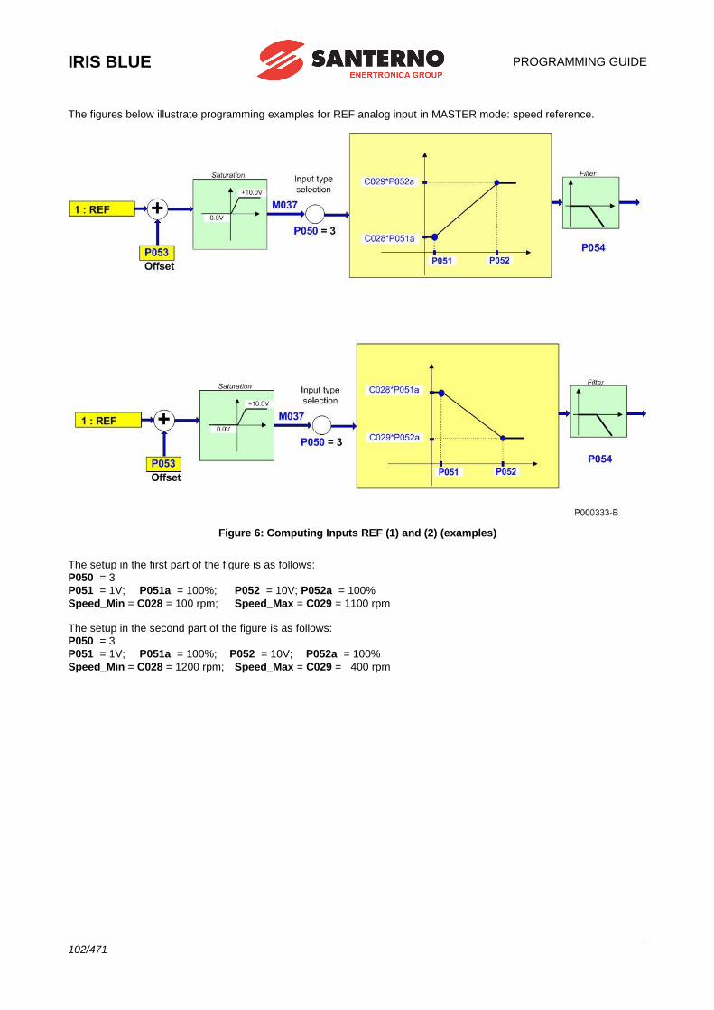
IRIS BLUE
PROGRAMMING GUIDE
102/471
The figures below illustrate programming examples for REF analog input in MASTER mode: speed reference.
Figure 6: Computing Inputs REF (1) and (2) (examples)
The setup in the first part of the figure is as follows:
P050 = 3
P051 = 1V; P051a = 100%; P052 = 10V; P052a = 100%
Speed_Min = C028 = 100 rpm; Speed_Max = C029 = 1100 rpm The setup in the second part of the figure is as follows:
P050 = 3
P051 = 1V; P051a = 100%; P052 = 10V; P052a = 100%
Speed_Min = C028 = 1200 rpm; Speed_Max = C029 = 400 rpm
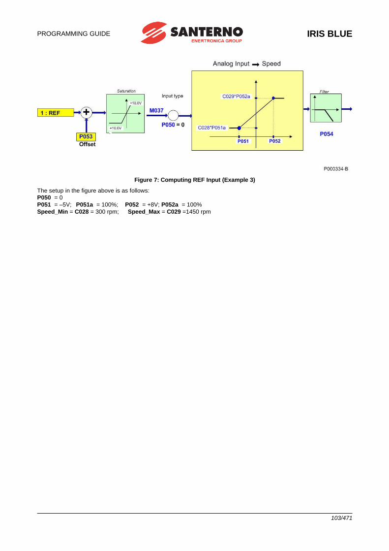
PROGRAMMING GUIDE
IRIS BLUE
103/471
Figure 7: Computing REF Input (Example 3)
The setup in the figure above is as follows:
P050 = 0
P051 = –5V; P051a = 100%; P052 = +8V; P052a = 100%
Speed_Min = C028 = 300 rpm; Speed_Max = C029 =1450 rpm
-
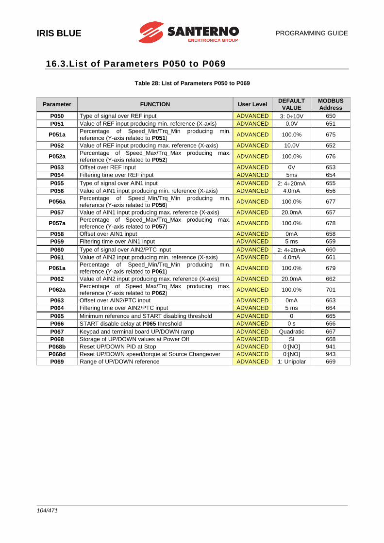
IRIS BLUE
PROGRAMMING GUIDE
104/471
16.3.List of Parameters P050 to P069
Table 28: List of Parameters P050 to P069
Parameter FUNCTION User Level DEFAULT
VALUE
MODBUS
Address
P050 Type of signal over REF input ADVANCED 3: 010V 650
P051 Value of REF input producing min. reference (X-axis) ADVANCED 0.0V 651
P051a Percentage of Speed_Min/Trq_Min producing min.
reference (Y-axis related to P051) ADVANCED 100.0% 675
P052 Value of REF input producing max. reference (X-axis) ADVANCED 10.0V 652
P052a Percentage of Speed_Max/Trq_Max producing max.
reference (Y-axis related to P052) ADVANCED 100.0% 676
P053 Offset over REF input ADVANCED 0V 653
P054 Filtering time over REF input ADVANCED 5ms 654
P055 Type of signal over AIN1 input ADVANCED 2: 420mA 655
P056 Value of AIN1 input producing min. reference (X-axis) ADVANCED 4.0mA 656
P056a Percentage of Speed_Min/Trq_Min producing min.
reference (Y-axis related to P056) ADVANCED 100.0% 677
P057 Value of AIN1 input producing max. reference (X-axis) ADVANCED 20.0mA 657
P057a Percentage of Speed_Max/Trq_Max producing max.
reference (Y-axis related to P057) ADVANCED 100.0% 678
P058 Offset over AIN1 input ADVANCED 0mA 658
P059 Filtering time over AIN1 input ADVANCED 5 ms 659
P060 Type of signal over AIN2/PTC input ADVANCED 2: 420mA 660
P061 Value of AIN2 input producing min. reference (X-axis) ADVANCED 4.0mA 661
P061a Percentage of Speed_Min/Trq_Min producing min.
reference (Y-axis related to P061) ADVANCED 100.0% 679
P062 Value of AIN2 input producing max. reference (X-axis) ADVANCED 20.0mA 662
P062a Percentage of Speed_Max/Trq_Max producing max.
reference (Y-axis related to P062) ADVANCED 100.0% 701
P063 Offset over AIN2/PTC input ADVANCED 0mA 663
P064 Filtering time over AIN2/PTC input ADVANCED 5 ms 664
P065 Minimum reference and START disabling threshold ADVANCED 0 665
P066 START disable delay at P065 threshold ADVANCED 0 s 666
P067 Keypad and terminal board UP/DOWN ramp ADVANCED Quadratic 667
P068 Storage of UP/DOWN values at Power Off ADVANCED SI 668
P068b Reset UP/DOWN PID at Stop ADVANCED 0:[NO] 941
P068d Reset UP/DOWN speed/torque at Source Changeover ADVANCED 0:[NO] 943
P069 Range of UP/DOWN reference ADVANCED 1: Unipolar 669
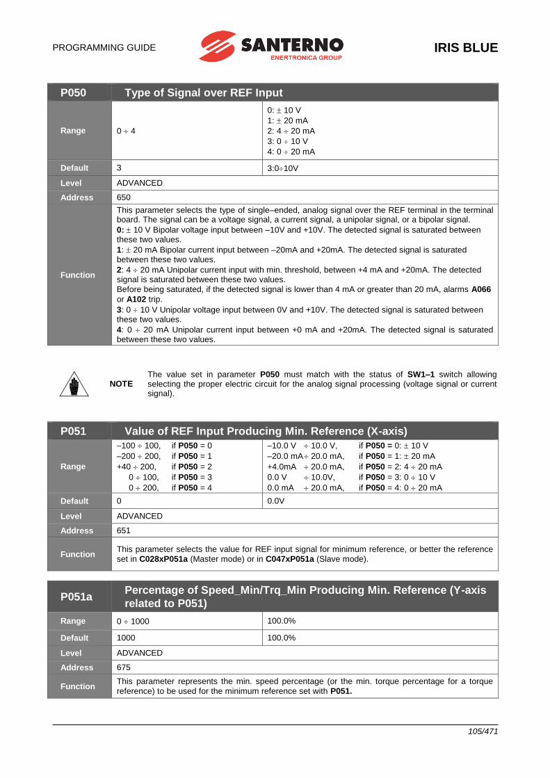
PROGRAMMING GUIDE
IRIS BLUE
105/471
P050 Type of Signal over REF Input
Range 0 4
0: 10 V
1: 20 mA
2: 4 20 mA
3: 0 10 V
4: 0 20 mA
Default 3 3:010V
Level ADVANCED
Address 650
Function
This parameter selects the type of single–ended, analog signal over the REF terminal in the terminal board. The signal can be a voltage signal, a current signal, a unipolar signal, or a bipolar signal.
0: 10 V Bipolar voltage input between –10V and +10V. The detected signal is saturated between these two values.
1: 20 mA Bipolar current input between –20mA and +20mA. The detected signal is saturated between these two values.
2: 4 20 mA Unipolar current input with min. threshold, between +4 mA and +20mA. The detected signal is saturated between these two values.
Before being saturated, if the detected signal is lower than 4 mA or greater than 20 mA, alarms A066
or A102 trip.
3: 0 10 V Unipolar voltage input between 0V and +10V. The detected signal is saturated between these two values.
4: 0 20 mA Unipolar current input between +0 mA and +20mA. The detected signal is saturated between these two values.
NOTE The value set in parameter P050 must match with the status of SW1–1 switch allowing selecting the proper electric circuit for the analog signal processing (voltage signal or current signal).
P051 Value of REF Input Producing Min. Reference (X-axis)
Range
–100 100, if P050 = 0
–200 200, if P050 = 1
+40 200, if P050 = 2
0 100, if P050 = 3
0 200, if P050 = 4
–10.0 V 10.0 V, if P050 = 0: 10 V
–20.0 mA 20.0 mA, if P050 = 1: 20 mA
+4.0mA 20.0 mA, if P050 = 2: 4 20 mA
0.0 V 10.0V, if P050 = 3: 0 10 V
0.0 mA 20.0 mA, if P050 = 4: 0 20 mA
Default 0 0.0V
Level ADVANCED
Address 651
Function This parameter selects the value for REF input signal for minimum reference, or better the reference
set in C028xP051a (Master mode) or in C047xP051a (Slave mode).
P051a Percentage of Speed_Min/Trq_Min Producing Min. Reference (Y-axis
related to P051)
Range 0 1000 100.0%
Default 1000 100.0%
Level ADVANCED
Address 675
Function This parameter represents the min. speed percentage (or the min. torque percentage for a torque
reference) to be used for the minimum reference set with P051.
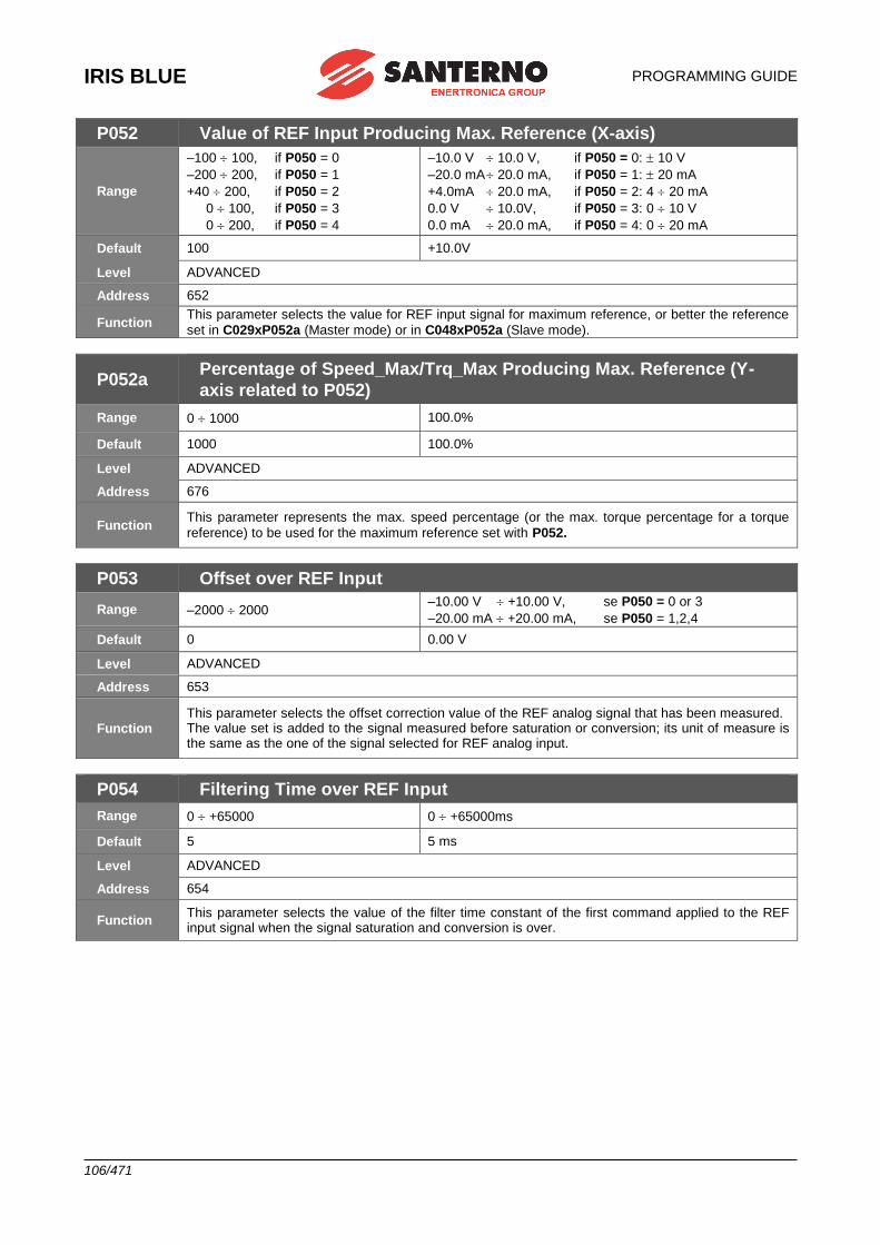
IRIS BLUE
PROGRAMMING GUIDE
106/471
P052 Value of REF Input Producing Max. Reference (X-axis)
Range
–100 100, if P050 = 0
–200 200, if P050 = 1
+40 200, if P050 = 2
0 100, if P050 = 3
0 200, if P050 = 4
–10.0 V 10.0 V, if P050 = 0: 10 V
–20.0 mA 20.0 mA, if P050 = 1: 20 mA
+4.0mA 20.0 mA, if P050 = 2: 4 20 mA
0.0 V 10.0V, if P050 = 3: 0 10 V
0.0 mA 20.0 mA, if P050 = 4: 0 20 mA
Default 100 +10.0V
Level ADVANCED
Address 652
Function This parameter selects the value for REF input signal for maximum reference, or better the reference
set in C029xP052a (Master mode) or in C048xP052a (Slave mode).
P052a Percentage of Speed_Max/Trq_Max Producing Max. Reference (Y-
axis related to P052)
Range 0 1000 100.0%
Default 1000 100.0%
Level ADVANCED
Address 676
Function This parameter represents the max. speed percentage (or the max. torque percentage for a torque
reference) to be used for the maximum reference set with P052.
P053 Offset over REF Input
Range –2000 2000 –10.00 V +10.00 V, se P050 = 0 or 3
–20.00 mA +20.00 mA, se P050 = 1,2,4
Default 0 0.00 V
Level ADVANCED
Address 653
Function This parameter selects the offset correction value of the REF analog signal that has been measured. The value set is added to the signal measured before saturation or conversion; its unit of measure is the same as the one of the signal selected for REF analog input.
P054 Filtering Time over REF Input
Range 0 +65000 0 +65000ms
Default 5 5 ms
Level ADVANCED
Address 654
Function This parameter selects the value of the filter time constant of the first command applied to the REF input signal when the signal saturation and conversion is over.
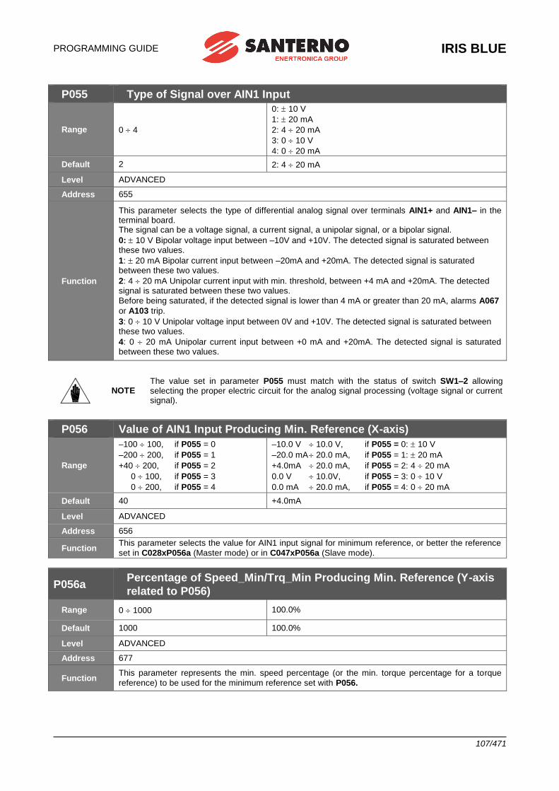
PROGRAMMING GUIDE
IRIS BLUE
107/471
P055 Type of Signal over AIN1 Input
Range 0 4
0: 10 V
1: 20 mA
2: 4 20 mA
3: 0 10 V
4: 0 20 mA
Default 2 2: 4 20 mA
Level ADVANCED
Address 655
Function
This parameter selects the type of differential analog signal over terminals AIN1+ and AIN1– in the terminal board. The signal can be a voltage signal, a current signal, a unipolar signal, or a bipolar signal.
0: 10 V Bipolar voltage input between –10V and +10V. The detected signal is saturated between these two values.
1: 20 mA Bipolar current input between –20mA and +20mA. The detected signal is saturated between these two values.
2: 4 20 mA Unipolar current input with min. threshold, between +4 mA and +20mA. The detected signal is saturated between these two values.
Before being saturated, if the detected signal is lower than 4 mA or greater than 20 mA, alarms A067
or A103 trip.
3: 0 10 V Unipolar voltage input between 0V and +10V. The detected signal is saturated between these two values.
4: 0 20 mA Unipolar current input between +0 mA and +20mA. The detected signal is saturated between these two values.
NOTE The value set in parameter P055 must match with the status of switch SW1–2 allowing selecting the proper electric circuit for the analog signal processing (voltage signal or current signal).
P056 Value of AIN1 Input Producing Min. Reference (X-axis)
Range
–100 100, if P055 = 0
–200 200, if P055 = 1
+40 200, if P055 = 2
0 100, if P055 = 3
0 200, if P055 = 4
–10.0 V 10.0 V, if P055 = 0: 10 V
–20.0 mA 20.0 mA, if P055 = 1: 20 mA
+4.0mA 20.0 mA, if P055 = 2: 4 20 mA
0.0 V 10.0V, if P055 = 3: 0 10 V
0.0 mA 20.0 mA, if P055 = 4: 0 20 mA
Default 40 +4.0mA
Level ADVANCED
Address 656
Function This parameter selects the value for AIN1 input signal for minimum reference, or better the reference
set in C028xP056a (Master mode) or in C047xP056a (Slave mode).
P056a Percentage of Speed_Min/Trq_Min Producing Min. Reference (Y-axis
related to P056)
Range 0 1000 100.0%
Default 1000 100.0%
Level ADVANCED
Address 677
Function This parameter represents the min. speed percentage (or the min. torque percentage for a torque
reference) to be used for the minimum reference set with P056.
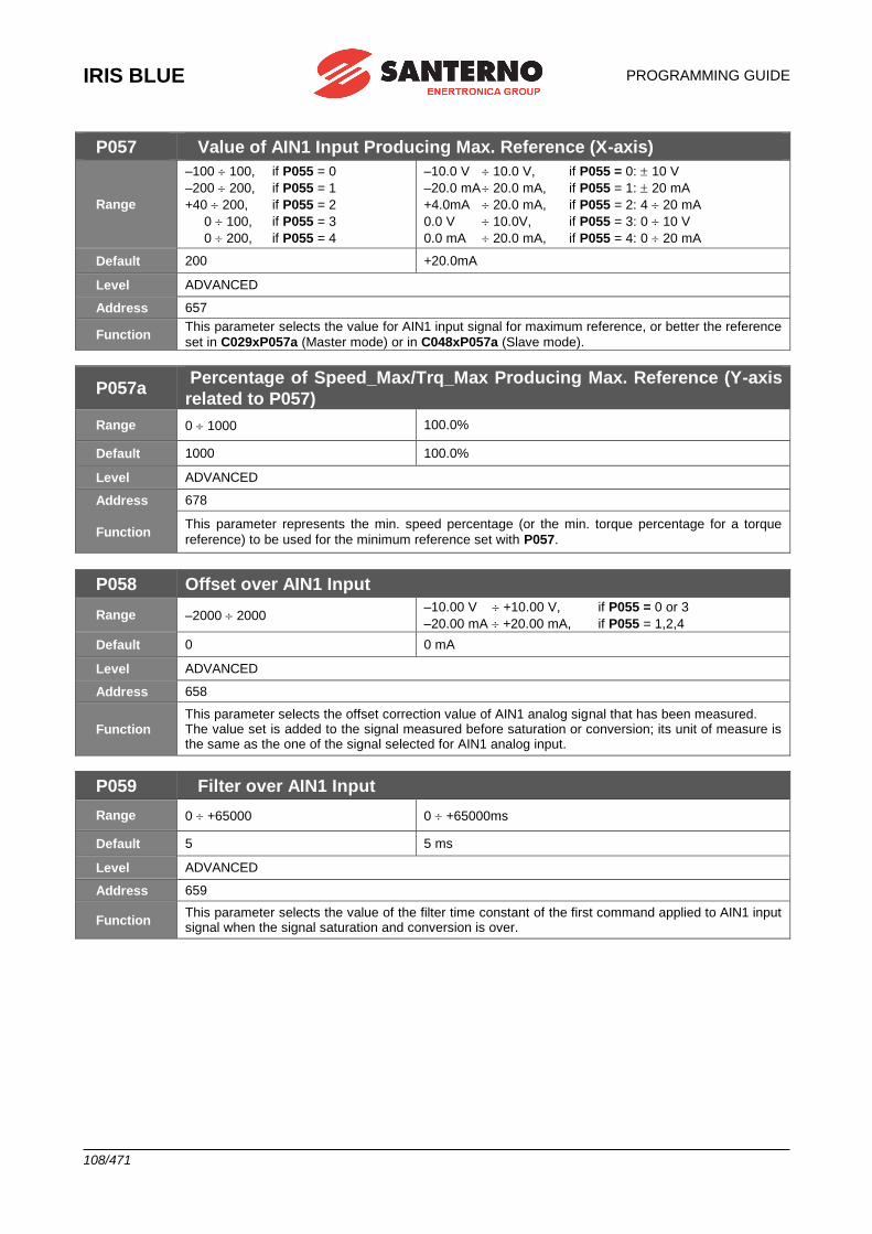
IRIS BLUE
PROGRAMMING GUIDE
108/471
P057 Value of AIN1 Input Producing Max. Reference (X-axis)
Range
–100 100, if P055 = 0
–200 200, if P055 = 1
+40 200, if P055 = 2
0 100, if P055 = 3
0 200, if P055 = 4
–10.0 V 10.0 V, if P055 = 0: 10 V
–20.0 mA 20.0 mA, if P055 = 1: 20 mA
+4.0mA 20.0 mA, if P055 = 2: 4 20 mA
0.0 V 10.0V, if P055 = 3: 0 10 V
0.0 mA 20.0 mA, if P055 = 4: 0 20 mA
Default 200 +20.0mA
Level ADVANCED
Address 657
Function This parameter selects the value for AIN1 input signal for maximum reference, or better the reference
set in C029xP057a (Master mode) or in C048xP057a (Slave mode).
P057a Percentage of Speed_Max/Trq_Max Producing Max. Reference (Y-axis
related to P057)
Range 0 1000 100.0%
Default 1000 100.0%
Level ADVANCED
Address 678
Function This parameter represents the min. speed percentage (or the min. torque percentage for a torque
reference) to be used for the minimum reference set with P057.
P058 Offset over AIN1 Input
Range –2000 2000 –10.00 V +10.00 V, if P055 = 0 or 3
–20.00 mA +20.00 mA, if P055 = 1,2,4
Default 0 0 mA
Level ADVANCED
Address 658
Function This parameter selects the offset correction value of AIN1 analog signal that has been measured. The value set is added to the signal measured before saturation or conversion; its unit of measure is the same as the one of the signal selected for AIN1 analog input.
P059 Filter over AIN1 Input
Range 0 +65000 0 +65000ms
Default 5 5 ms
Level ADVANCED
Address 659
Function This parameter selects the value of the filter time constant of the first command applied to AIN1 input signal when the signal saturation and conversion is over.
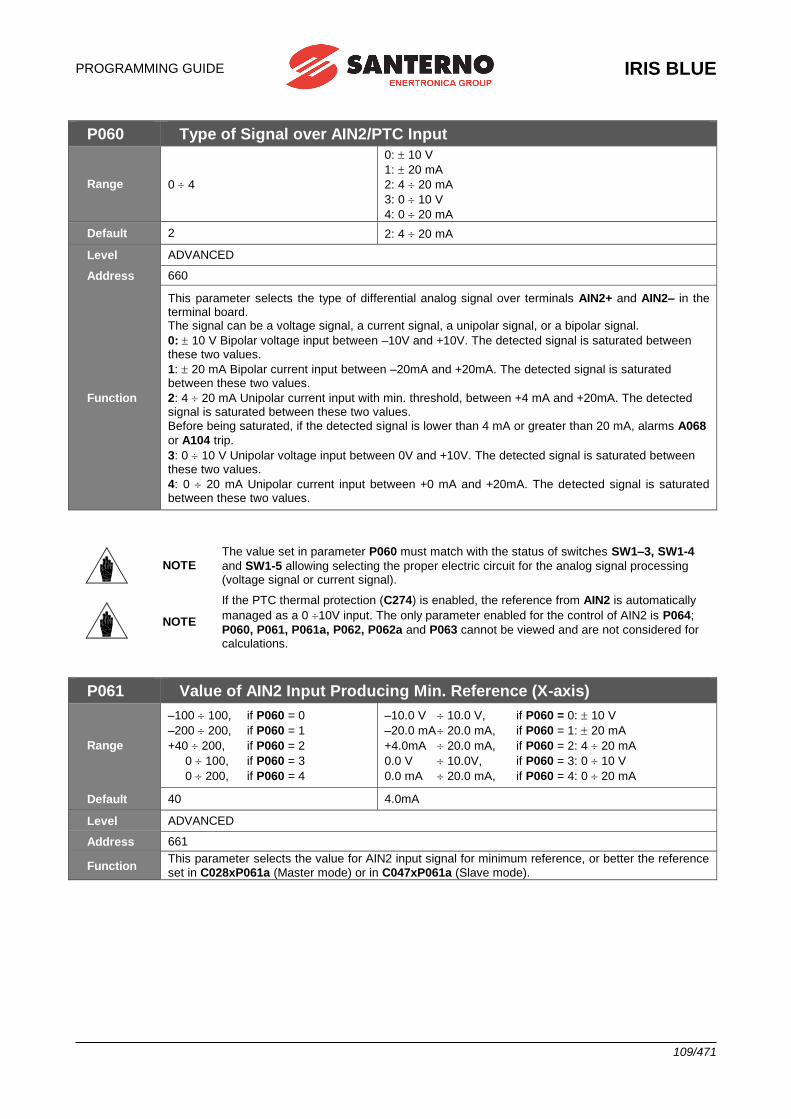
PROGRAMMING GUIDE
IRIS BLUE
109/471
P060 Type of Signal over AIN2/PTC Input
Range 0 4
0: 10 V
1: 20 mA
2: 4 20 mA
3: 0 10 V
4: 0 20 mA
Default 2 2: 4 20 mA
Level ADVANCED
Address 660
Function
This parameter selects the type of differential analog signal over terminals AIN2+ and AIN2– in the terminal board. The signal can be a voltage signal, a current signal, a unipolar signal, or a bipolar signal.
0: 10 V Bipolar voltage input between –10V and +10V. The detected signal is saturated between these two values.
1: 20 mA Bipolar current input between –20mA and +20mA. The detected signal is saturated between these two values.
2: 4 20 mA Unipolar current input with min. threshold, between +4 mA and +20mA. The detected signal is saturated between these two values.
Before being saturated, if the detected signal is lower than 4 mA or greater than 20 mA, alarms A068
or A104 trip.
3: 0 10 V Unipolar voltage input between 0V and +10V. The detected signal is saturated between these two values.
4: 0 20 mA Unipolar current input between +0 mA and +20mA. The detected signal is saturated between these two values.
NOTE The value set in parameter P060 must match with the status of switches SW1–3, SW1-4
and SW1-5 allowing selecting the proper electric circuit for the analog signal processing (voltage signal or current signal).
NOTE
If the PTC thermal protection (C274) is enabled, the reference from AIN2 is automatically
managed as a 0 10V input. The only parameter enabled for the control of AIN2 is P064;
P060, P061, P061a, P062, P062a and P063 cannot be viewed and are not considered for calculations.
P061 Value of AIN2 Input Producing Min. Reference (X-axis)
Range
–100 100, if P060 = 0
–200 200, if P060 = 1
+40 200, if P060 = 2
0 100, if P060 = 3
0 200, if P060 = 4
–10.0 V 10.0 V, if P060 = 0: 10 V
–20.0 mA 20.0 mA, if P060 = 1: 20 mA
+4.0mA 20.0 mA, if P060 = 2: 4 20 mA
0.0 V 10.0V, if P060 = 3: 0 10 V
0.0 mA 20.0 mA, if P060 = 4: 0 20 mA
Default 40 4.0mA
Level ADVANCED
Address 661
Function This parameter selects the value for AIN2 input signal for minimum reference, or better the reference
set in C028xP061a (Master mode) or in C047xP061a (Slave mode).
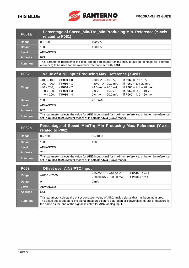
IRIS BLUE
PROGRAMMING GUIDE
110/471
P061a Percentage of Speed_Min/Trq_Min Producing Min. Reference (Y-axis
related to P061)
Range 0 1000 100.0%
Default 1000 100.0%
Level ADVANCED
Address 679
Function This parameter represents the min. speed percentage (or the min. torque percentage for a torque
reference) to be used for the minimum reference set with P061.
P062 Value of AIN2 Input Producing Max. Reference (X-axis)
Range
–100 100, if P060 = 0
–200 200, if P060 = 1
+40 200, if P060 = 2
0 100, if P060 = 3
0 200, if P060 = 4
–10.0 V 10.0 V, if P060 = 0: 10 V
–20.0 mA 20.0 mA, if P060 = 1: 20 mA
+4.0mA 20.0 mA, if P060 = 2: 4 20 mA
0.0 V 10.0V, if P060 = 3: 0 10 V
0.0 mA 20.0 mA, if P060 = 4: 0 20 mA
Default 100 20.0 mA
Level ADVANCED
Address 662
Function This parameter selects the value for AIN2 input signal for maximum reference, or better the reference
set in C029xP062a (Master mode) or in C048xP062a (Slave mode).
P062a Percentage of Speed_Min/Trq_Min Producing Max. Reference (Y-axis
related to P062)
Range 0 1000 0 1000
Default 1000 1000
Level ADVANCED
Address 701
Function This parameter selects the value for AIN2 input signal for maximum reference, or better the reference
set in C029xP062a (Master mode) or in C048xP062a (Slave mode).
P063 Offset over AIN2/PTC Input
Range –2000 2000 –10.00 V +10.00 V, if P060 = 0 or 3
–20.00 mA +20.00 mA, if P060 = 1,2,4
Default 0 0 mA
Level ADVANCED
Address 663
Function This parameter selects the offset correction value of AIN2 analog signal that has been measured. The value set is added to the signal measured before saturation or conversion; its unit of measure is the same as the one of the signal selected for AIN2 analog input.
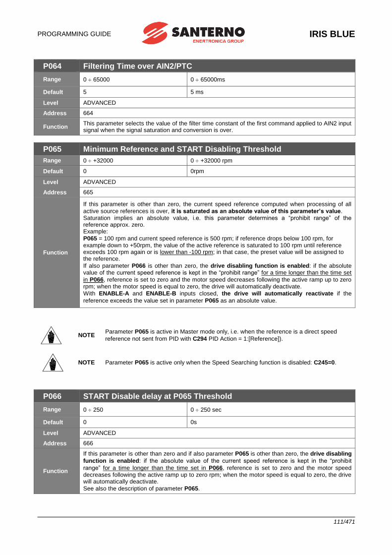
PROGRAMMING GUIDE
IRIS BLUE
111/471
P064 Filtering Time over AIN2/PTC
Range 0 65000 0 65000ms
Default 5 5 ms
Level ADVANCED
Address 664
Function This parameter selects the value of the filter time constant of the first command applied to AIN2 input signal when the signal saturation and conversion is over.
P065 Minimum Reference and START Disabling Threshold
Range 0 +32000 0 +32000 rpm
Default 0 0rpm
Level ADVANCED
Address 665
Function
If this parameter is other than zero, the current speed reference computed when processing of all
active source references is over, it is saturated as an absolute value of this parameter’s value. Saturation implies an absolute value, i.e. this parameter determines a “prohibit range” of the reference approx. zero. Example:
P065 = 100 rpm and current speed reference is 500 rpm; if reference drops below 100 rpm, for example down to +50rpm, the value of the active reference is saturated to 100 rpm until reference exceeds 100 rpm again or is lower than -100 rpm; in that case, the preset value will be assigned to the reference.
If also parameter P066 is other than zero, the drive disabling function is enabled: if the absolute value of the current speed reference is kept in the “prohibit range” for a time longer than the time set
in P066, reference is set to zero and the motor speed decreases following the active ramp up to zero rpm; when the motor speed is equal to zero, the drive will automatically deactivate.
With ENABLE-A and ENABLE-B inputs closed, the drive will automatically reactivate if the
reference exceeds the value set in parameter P065 as an absolute value.
NOTE Parameter P065 is active in Master mode only, i.e. when the reference is a direct speed
reference not sent from PID with C294 PID Action = 1:[Reference]).
NOTE Parameter P065 is active only when the Speed Searching function is disabled: C245=0.
P066 START Disable delay at P065 Threshold
Range 0 250 0 250 sec
Default 0 0s
Level ADVANCED
Address 666
Function
If this parameter is other than zero and if also parameter P065 is other than zero, the drive disabling
function is enabled: if the absolute value of the current speed reference is kept in the “prohibit
range” for a time longer than the time set in P066, reference is set to zero and the motor speed decreases following the active ramp up to zero rpm; when the motor speed is equal to zero, the drive will automatically deactivate.
See also the description of parameter P065.
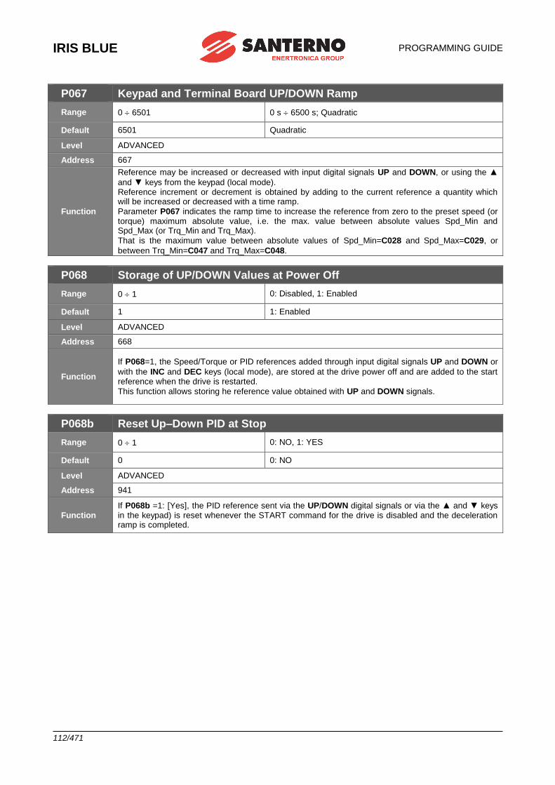
IRIS BLUE
PROGRAMMING GUIDE
112/471
P067 Keypad and Terminal Board UP/DOWN Ramp
Range 0 6501 0 s 6500 s; Quadratic
Default 6501 Quadratic
Level ADVANCED
Address 667
Function
Reference may be increased or decreased with input digital signals UP and DOWN, or using the ▲
and ▼ keys from the keypad (local mode). Reference increment or decrement is obtained by adding to the current reference a quantity which will be increased or decreased with a time ramp.
Parameter P067 indicates the ramp time to increase the reference from zero to the preset speed (or torque) maximum absolute value, i.e. the max. value between absolute values Spd_Min and Spd_Max (or Trq_Min and Trq_Max).
That is the maximum value between absolute values of Spd_Min=C028 and Spd_Max=C029, or
between Trq_Min=C047 and Trq_Max=C048.
P068 Storage of UP/DOWN Values at Power Off
Range 0 1 0: Disabled, 1: Enabled
Default 1 1: Enabled
Level ADVANCED
Address 668
Function
If P068=1, the Speed/Torque or PID references added through input digital signals UP and DOWN or
with the INC and DEC keys (local mode), are stored at the drive power off and are added to the start reference when the drive is restarted.
This function allows storing he reference value obtained with UP and DOWN signals.
P068b Reset Up–Down PID at Stop
Range 0 1 0: NO, 1: YES
Default 0 0: NO
Level ADVANCED
Address 941
Function If P068b =1: [Yes], the PID reference sent via the UP/DOWN digital signals or via the ▲ and ▼ keys in the keypad) is reset whenever the START command for the drive is disabled and the deceleration ramp is completed.
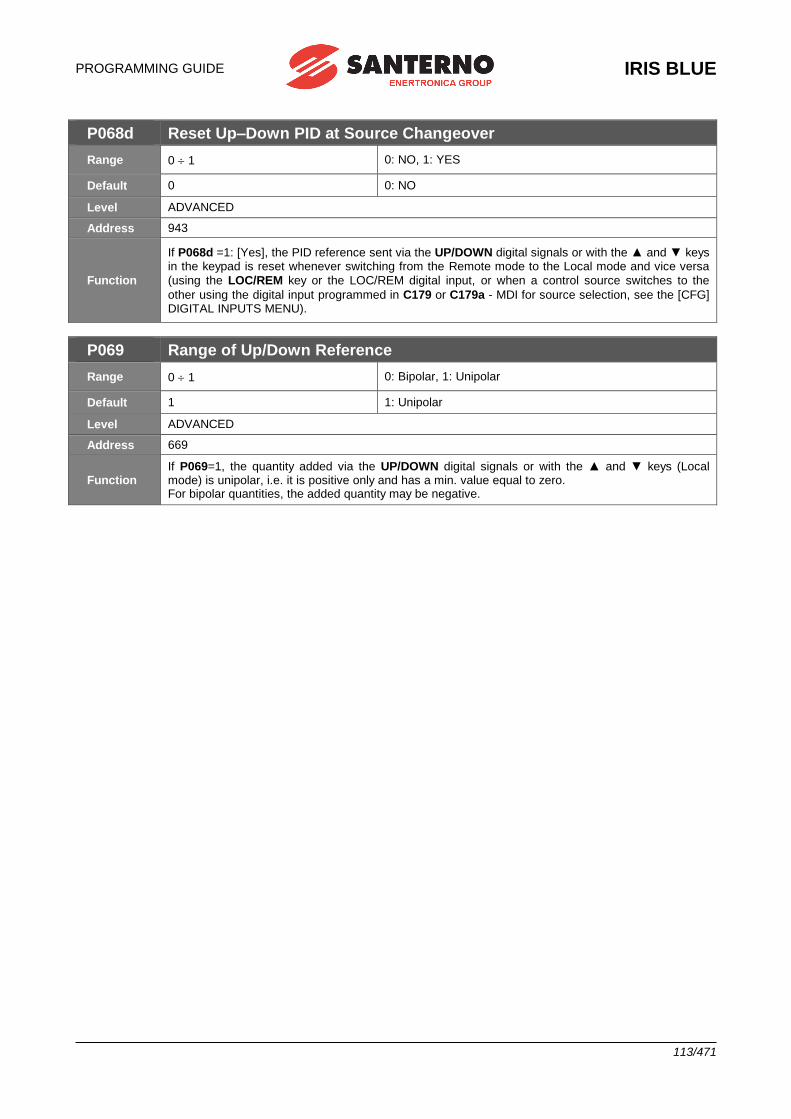
PROGRAMMING GUIDE
IRIS BLUE
113/471
P068d Reset Up–Down PID at Source Changeover
Range 0 1 0: NO, 1: YES
Default 0 0: NO
Level ADVANCED
Address 943
Function
If P068d =1: [Yes], the PID reference sent via the UP/DOWN digital signals or with the ▲ and ▼ keys in the keypad is reset whenever switching from the Remote mode to the Local mode and vice versa
(using the LOC/REM key or the LOC/REM digital input, or when a control source switches to the
other using the digital input programmed in C179 or C179a - MDI for source selection, see the [CFG] DIGITAL INPUTS MENU).
P069 Range of Up/Down Reference
Range 0 1 0: Bipolar, 1: Unipolar
Default 1 1: Unipolar
Level ADVANCED
Address 669
Function If P069=1, the quantity added via the UP/DOWN digital signals or with the ▲ and ▼ keys (Local mode) is unipolar, i.e. it is positive only and has a min. value equal to zero. For bipolar quantities, the added quantity may be negative.
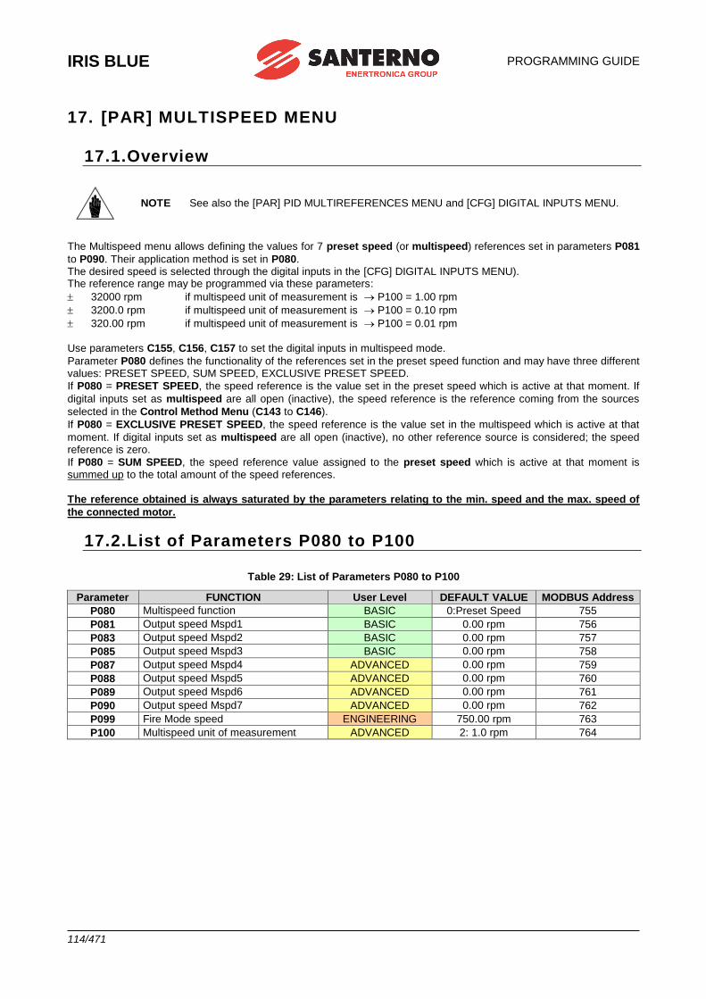
IRIS BLUE
PROGRAMMING GUIDE
114/471
17. [PAR] MULTISPEED MENU
17.1.Overview
NOTE See also the [PAR] PID MULTIREFERENCES MENU and [CFG] DIGITAL INPUTS MENU.
The Multispeed menu allows defining the values for 7 preset speed (or multispeed) references set in parameters P081
to P090. Their application method is set in P080. The desired speed is selected through the digital inputs in the [CFG] DIGITAL INPUTS MENU). The reference range may be programmed via these parameters:
32000 rpm if multispeed unit of measurement is P100 = 1.00 rpm
3200.0 rpm if multispeed unit of measurement is P100 = 0.10 rpm
320.00 rpm if multispeed unit of measurement is P100 = 0.01 rpm
Use parameters C155, C156, C157 to set the digital inputs in multispeed mode.
Parameter P080 defines the functionality of the references set in the preset speed function and may have three different values: PRESET SPEED, SUM SPEED, EXCLUSIVE PRESET SPEED.
If P080 = PRESET SPEED, the speed reference is the value set in the preset speed which is active at that moment. If
digital inputs set as multispeed are all open (inactive), the speed reference is the reference coming from the sources
selected in the Control Method Menu (C143 to C146).
If P080 = EXCLUSIVE PRESET SPEED, the speed reference is the value set in the multispeed which is active at that
moment. If digital inputs set as multispeed are all open (inactive), no other reference source is considered; the speed reference is zero.
If P080 = SUM SPEED, the speed reference value assigned to the preset speed which is active at that moment is summed up to the total amount of the speed references.
The reference obtained is always saturated by the parameters relating to the min. speed and the max. speed of
the connected motor.
17.2.List of Parameters P080 to P100
Table 29: List of Parameters P080 to P100
Parameter FUNCTION User Level DEFAULT VALUE MODBUS Address
P080 Multispeed function BASIC 0:Preset Speed 755
P081 Output speed Mspd1 BASIC 0.00 rpm 756
P083 Output speed Mspd2 BASIC 0.00 rpm 757
P085 Output speed Mspd3 BASIC 0.00 rpm 758
P087 Output speed Mspd4 ADVANCED 0.00 rpm 759
P088 Output speed Mspd5 ADVANCED 0.00 rpm 760
P089 Output speed Mspd6 ADVANCED 0.00 rpm 761
P090 Output speed Mspd7 ADVANCED 0.00 rpm 762
P099 Fire Mode speed ENGINEERING 750.00 rpm 763
P100 Multispeed unit of measurement ADVANCED 2: 1.0 rpm 764
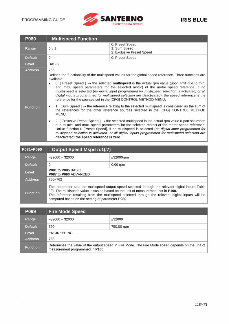
PROGRAMMING GUIDE
IRIS BLUE
115/471
P080 Multispeed Function
Range 0 2
0: Preset Speed, 1: Sum Speed, 2: Exclusive Preset Speed
Default 0 0: Preset Speed
Level BASIC
Address 755
Function
Defines the functionality of the multispeed values for the global speed reference. Three functions are available:
• 0: [ Preset Speed ] the selected multispeed is the actual rpm value (upon limit due to min. and max. speed parameters for the selected motor) of the motor speed reference. If no
multispeed is selected (no digital input programmed for multispeed selection is activated, or all
digital inputs programmed for multispeed selection are deactivated), the speed reference is the
reference for the sources set in the [CFG] CONTROL METHOD MENU.
• 1: [ Sum Speed ] the reference relating to the selected multispeed is considered as the sum of the references for the other reference sources selected in the [CFG] CONTROL METHOD
MENU.
• 2: [ Exclusive Preset Speed ] the selected multispeed is the actual rpm value (upon saturation due to min. and max. speed parameters for the selected motor) of the motor speed reference. Unlike function 0 [Preset Speed], if no multispeed is selected (no digital input programmed for
multispeed selection is activated, or all digital inputs programmed for multispeed selection are
deactivated) the speed reference is zero.
P081÷P090 Output Speed Mspd n.1(/7)
Range –32000 32000 32000rpm
Default 0 0.00 rpm
Level P081 to P085 BASIC
P087 to P090 ADVANCED
Address 756÷762
Function
This parameter sets the multispeed output speed selected through the relevant digital inputs Table
92). The multispeed value is scaled based on the unit of measurement set in P100. The reference resulting from the multispeed selected through the relevant digital inputs will be
computed based on the setting of parameter P080.
P099 Fire Mode Speed
Range –32000 32000 32000
Default 750 750.00 rpm
Level ENGINEERING
Address 763
Function Determines the value of the output speed in Fire Mode. The Fire Mode speed depends on the unit of
measurement programmed in P100.
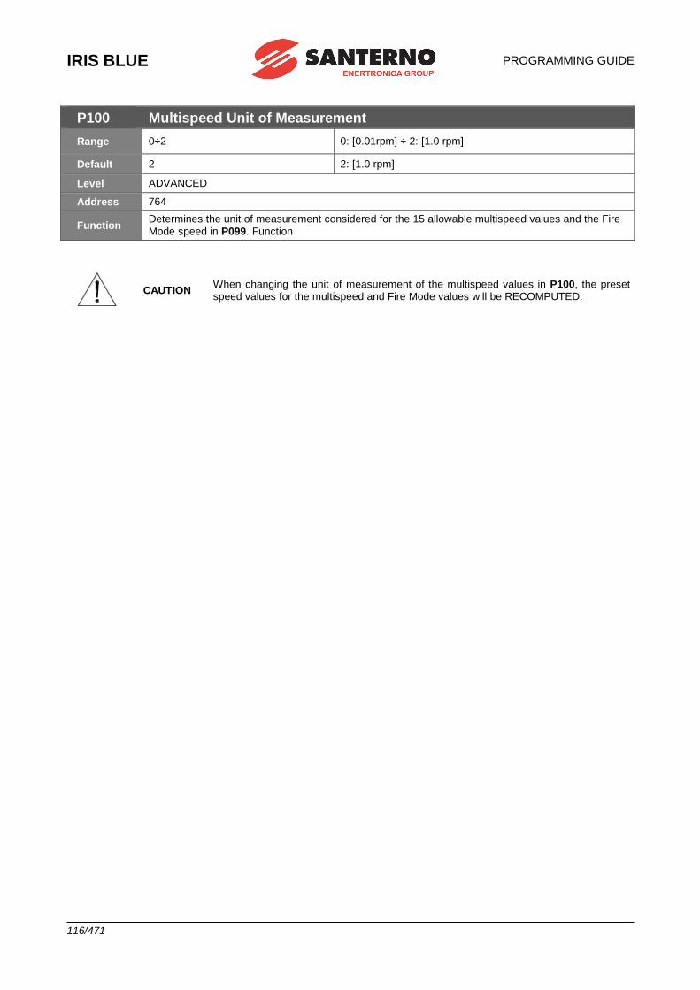
IRIS BLUE
PROGRAMMING GUIDE
116/471
P100 Multispeed Unit of Measurement
Range 0÷2 0: [0.01rpm] ÷ 2: [1.0 rpm]
Default 2 2: [1.0 rpm]
Level ADVANCED
Address 764
Function Determines the unit of measurement considered for the 15 allowable multispeed values and the Fire
Mode speed in P099. Function
CAUTION When changing the unit of measurement of the multispeed values in P100, the preset speed values for the multispeed and Fire Mode values will be RECOMPUTED.
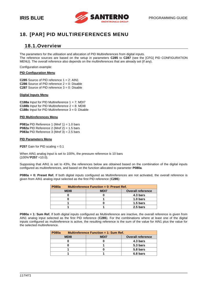
IRIS BLUE
PROGRAMMING GUIDE
117/471
18. [PAR] PID MULTIREFERENCES MENU
18.1.Overview The parameters for the utilisation and allocation of PID Multireferences from digital inputs.
The reference sources are based on the setup in parameters C285 to C287 (see the [CFG] PID CONFIGURATION MENU). The overall reference also depends on the multireferences that are already set (if any).
Configuration example:
PID Configuration Menu
C285 Source of PID reference 1 = 2: AIN1
C286 Source of PID reference 2 = 0: Disable
C287 Source of PID reference 3 = 0: Disable
Digital Inputs Menu
C188a Input for PID Multireference 1 = 7: MDI7
C188b Input for PID Multireference 2 = 8: MDI8
C188c Input for PID Multireference 3 = 0: Disable
PID Multireferences Menu
P081a PID Reference 1 (Mref 1) = 1.0 bars
P082a PID Reference 2 (Mref 2) = 1.5 bars
P083a PID Reference 3 (Mref 3) = 2.5 bars
PID Parameters Menu
P257 Gain for PID scaling = 0.1 When AIN1 analog input is set to 100%, the pressure reference is 10 bars
(100%*P257 =10.0).
Supposing that AIN1 is set to 43%, the references below are obtained based on the combination of the digital inputs
configured as multireferences, and based on the function allocated to parameter P080a.
P080a = 0: Preset Ref. If both digital inputs configured as Multireferences are not activated, the overall reference is
given from AIN1 analog input selected as the first PID reference (C285):
P080a Multireference Function = 0: Preset Ref.
MDI8 MDI7 Overall reference
0 0 4.3 bars
0 1 1.0 bars
1 0 1.5 bars
1 1 2.5 bars
P080a = 1: Sum Ref. If both digital inputs configured as Multireference are inactive, the overall reference is given from
AIN1 analog input selected as the first PID reference (C285). For the combinations where at least one of the digital inputs configured as multireference is active, the resulting reference is the sum of the value for AIN1 plus the value for the selected multireference.
P080a Multireference Function = 1: Sum Ref.
MDI8 MDI7 Overall reference
0 0 4.3 bars
0 1 5.3 bars
1 0 5.8 bars
1 1 6.8 bars
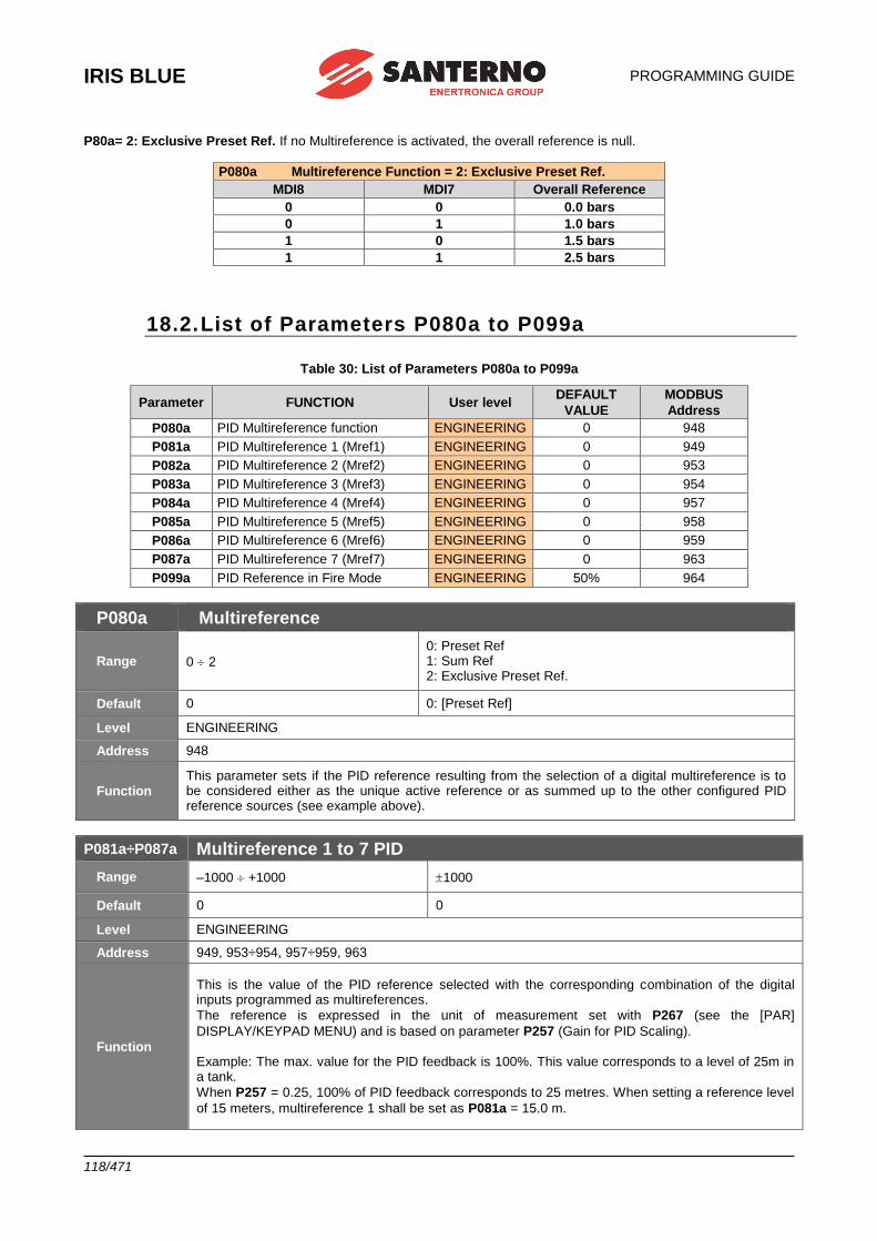
IRIS BLUE
PROGRAMMING GUIDE
118/471
P80a= 2: Exclusive Preset Ref. If no Multireference is activated, the overall reference is null.
P080a Multireference Function = 2: Exclusive Preset Ref.
MDI8 MDI7 Overall Reference
0 0 0.0 bars
0 1 1.0 bars
1 0 1.5 bars
1 1 2.5 bars
18.2. List of Parameters P080a to P099a
Table 30: List of Parameters P080a to P099a
Parameter FUNCTION User level DEFAULT
VALUE
MODBUS
Address
P080a PID Multireference function ENGINEERING 0 948
P081a PID Multireference 1 (Mref1) ENGINEERING 0 949
P082a PID Multireference 2 (Mref2) ENGINEERING 0 953
P083a PID Multireference 3 (Mref3) ENGINEERING 0 954
P084a PID Multireference 4 (Mref4) ENGINEERING 0 957
P085a PID Multireference 5 (Mref5) ENGINEERING 0 958
P086a PID Multireference 6 (Mref6) ENGINEERING 0 959
P087a PID Multireference 7 (Mref7) ENGINEERING 0 963
P099a PID Reference in Fire Mode ENGINEERING 50% 964
P080a Multireference
Range 0 2
0: Preset Ref 1: Sum Ref 2: Exclusive Preset Ref.
Default 0 0: [Preset Ref]
Level ENGINEERING
Address 948
Function This parameter sets if the PID reference resulting from the selection of a digital multireference is to be considered either as the unique active reference or as summed up to the other configured PID reference sources (see example above).
P081a÷P087a Multireference 1 to 7 PID
Range –1000 +1000 1000
Default 0 0
Level ENGINEERING
Address 949, 953÷954, 957÷959, 963
Function
This is the value of the PID reference selected with the corresponding combination of the digital inputs programmed as multireferences.
The reference is expressed in the unit of measurement set with P267 (see the [PAR]
DISPLAY/KEYPAD MENU) and is based on parameter P257 (Gain for PID Scaling). Example: The max. value for the PID feedback is 100%. This value corresponds to a level of 25m in a tank.
When P257 = 0.25, 100% of PID feedback corresponds to 25 metres. When setting a reference level
of 15 meters, multireference 1 shall be set as P081a = 15.0 m.

PROGRAMMING GUIDE
IRIS BLUE
119/471
P099a PID Reference in Fire Mode
Range –1000 1000 1000
Default 500 50.0 %
Level ENGINEERING
Address 964
Function This parameter sets the value of the PID reference when in Fire Mode. The value of the PID
reference depends on the scale factor set in P257.
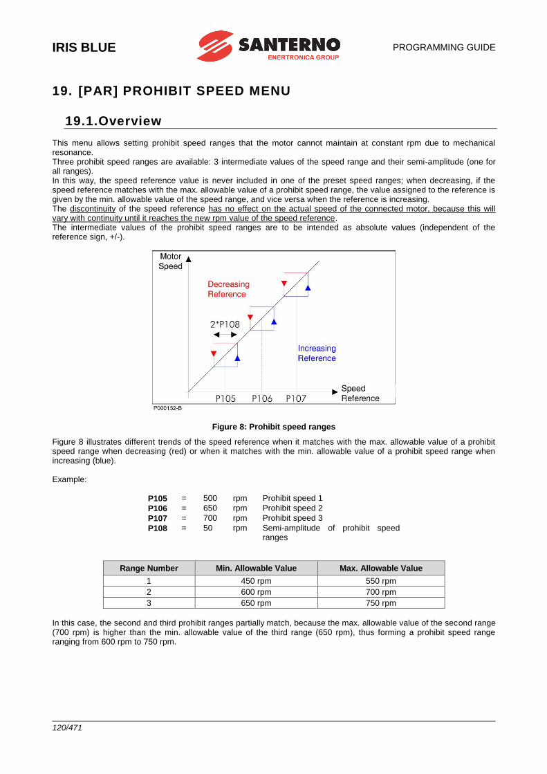
IRIS BLUE
PROGRAMMING GUIDE
120/471
19. [PAR] PROHIBIT SPEED MENU
19.1.Overview This menu allows setting prohibit speed ranges that the motor cannot maintain at constant rpm due to mechanical resonance. Three prohibit speed ranges are available: 3 intermediate values of the speed range and their semi-amplitude (one for all ranges). In this way, the speed reference value is never included in one of the preset speed ranges; when decreasing, if the speed reference matches with the max. allowable value of a prohibit speed range, the value assigned to the reference is given by the min. allowable value of the speed range, and vice versa when the reference is increasing. The discontinuity of the speed reference has no effect on the actual speed of the connected motor, because this will vary with continuity until it reaches the new rpm value of the speed reference. The intermediate values of the prohibit speed ranges are to be intended as absolute values (independent of the reference sign, +/-).
Figure 8: Prohibit speed ranges
Figure 8 illustrates different trends of the speed reference when it matches with the max. allowable value of a prohibit speed range when decreasing (red) or when it matches with the min. allowable value of a prohibit speed range when increasing (blue). Example:
P105 = 500 rpm Prohibit speed 1
P106 = 650 rpm Prohibit speed 2
P107 = 700 rpm Prohibit speed 3
P108 = 50 rpm Semi-amplitude of prohibit speed ranges
Range Number Min. Allowable Value Max. Allowable Value
1 450 rpm 550 rpm
2 600 rpm 700 rpm
3 650 rpm 750 rpm
In this case, the second and third prohibit ranges partially match, because the max. allowable value of the second range (700 rpm) is higher than the min. allowable value of the third range (650 rpm), thus forming a prohibit speed range ranging from 600 rpm to 750 rpm.
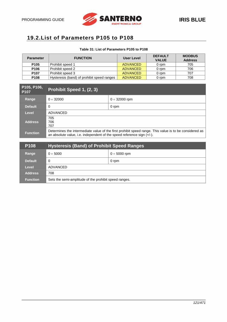
PROGRAMMING GUIDE
IRIS BLUE
121/471
19.2.List of Parameters P105 to P108
Table 31: List of Parameters P105 to P108
Parameter FUNCTION User Level DEFAULT
VALUE
MODBUS
Address
P105 Prohibit speed 1 ADVANCED 0 rpm 705
P106 Prohibit speed 2 ADVANCED 0 rpm 706
P107 Prohibit speed 3 ADVANCED 0 rpm 707
P108 Hysteresis (band) of prohibit speed ranges ADVANCED 0 rpm 708
P105, P106,
P107 Prohibit Speed 1, (2, 3)
Range 0 32000 0 32000 rpm
Default 0 0 rpm
Level ADVANCED
Address 705 706 707
Function Determines the intermediate value of the first prohibit speed range. This value is to be considered as an absolute value, i.e. independent of the speed reference sign (+/-).
P108 Hysteresis (Band) of Prohibit Speed Ranges
Range 0 5000 0 5000 rpm
Default 0 0 rpm
Level ADVANCED
Address 708
Function Sets the semi-amplitude of the prohibit speed ranges.
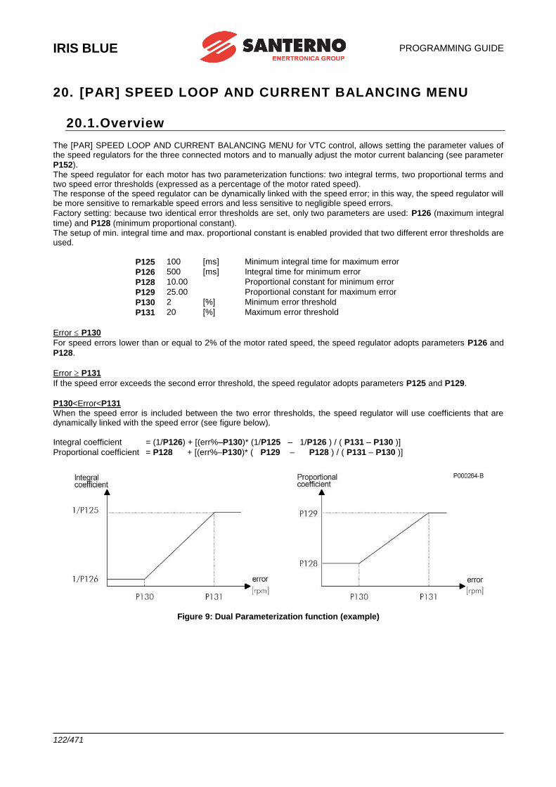
IRIS BLUE
PROGRAMMING GUIDE
122/471
20. [PAR] SPEED LOOP AND CURRENT BALANCING MENU
20.1.Overview The [PAR] SPEED LOOP AND CURRENT BALANCING MENU for VTC control, allows setting the parameter values of the speed regulators for the three connected motors and to manually adjust the motor current balancing (see parameter
P152). The speed regulator for each motor has two parameterization functions: two integral terms, two proportional terms and two speed error thresholds (expressed as a percentage of the motor rated speed). The response of the speed regulator can be dynamically linked with the speed error; in this way, the speed regulator will be more sensitive to remarkable speed errors and less sensitive to negligible speed errors.
Factory setting: because two identical error thresholds are set, only two parameters are used: P126 (maximum integral
time) and P128 (minimum proportional constant). The setup of min. integral time and max. proportional constant is enabled provided that two different error thresholds are used.
P125 100 [ms] Minimum integral time for maximum error
P126 500 [ms] Integral time for minimum error
P128 10.00 Proportional constant for minimum error
P129 25.00 Proportional constant for maximum error
P130 2 [%] Minimum error threshold
P131 20 [%] Maximum error threshold
Error P130
For speed errors lower than or equal to 2% of the motor rated speed, the speed regulator adopts parameters P126 and
P128.
Error P131
If the speed error exceeds the second error threshold, the speed regulator adopts parameters P125 and P129.
P130<Error<P131 When the speed error is included between the two error thresholds, the speed regulator will use coefficients that are dynamically linked with the speed error (see figure below).
Integral coefficient = (1/P126) + [(err%–P130)* (1/P125 – 1/P126 ) / ( P131 – P130 )]
Proportional coefficient = P128 + [(err%–P130)* ( P129 – P128 ) / ( P131 – P130 )]
Figure 9: Dual Parameterization function (example)
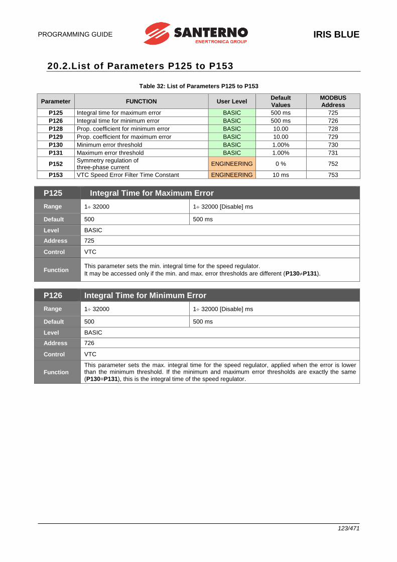
PROGRAMMING GUIDE
IRIS BLUE
123/471
20.2.List of Parameters P125 to P153
Table 32: List of Parameters P125 to P153
Parameter FUNCTION User Level Default
Values
MODBUS
Address
P125 Integral time for maximum error BASIC 500 ms 725
P126 Integral time for minimum error BASIC 500 ms 726
P128 Prop. coefficient for minimum error BASIC 10.00 728
P129 Prop. coefficient for maximum error BASIC 10.00 729
P130 Minimum error threshold BASIC 1.00% 730
P131 Maximum error threshold BASIC 1.00% 731
P152 Symmetry regulation of three-phase current
ENGINEERING 0 % 752
P153 VTC Speed Error Filter Time Constant ENGINEERING 10 ms 753
P125 Integral Time for Maximum Error
Range 1 32000 1 32000 [Disable] ms
Default 500 500 ms
Level BASIC
Address 725
Control VTC
Function This parameter sets the min. integral time for the speed regulator.
It may be accessed only if the min. and max. error thresholds are different (P130P131).
P126 Integral Time for Minimum Error
Range 1 32000 1 32000 [Disable] ms
Default 500 500 ms
Level BASIC
Address 726
Control VTC
Function
This parameter sets the max. integral time for the speed regulator, applied when the error is lower than the minimum threshold. If the minimum and maximum error thresholds are exactly the same
(P130=P131), this is the integral time of the speed regulator.
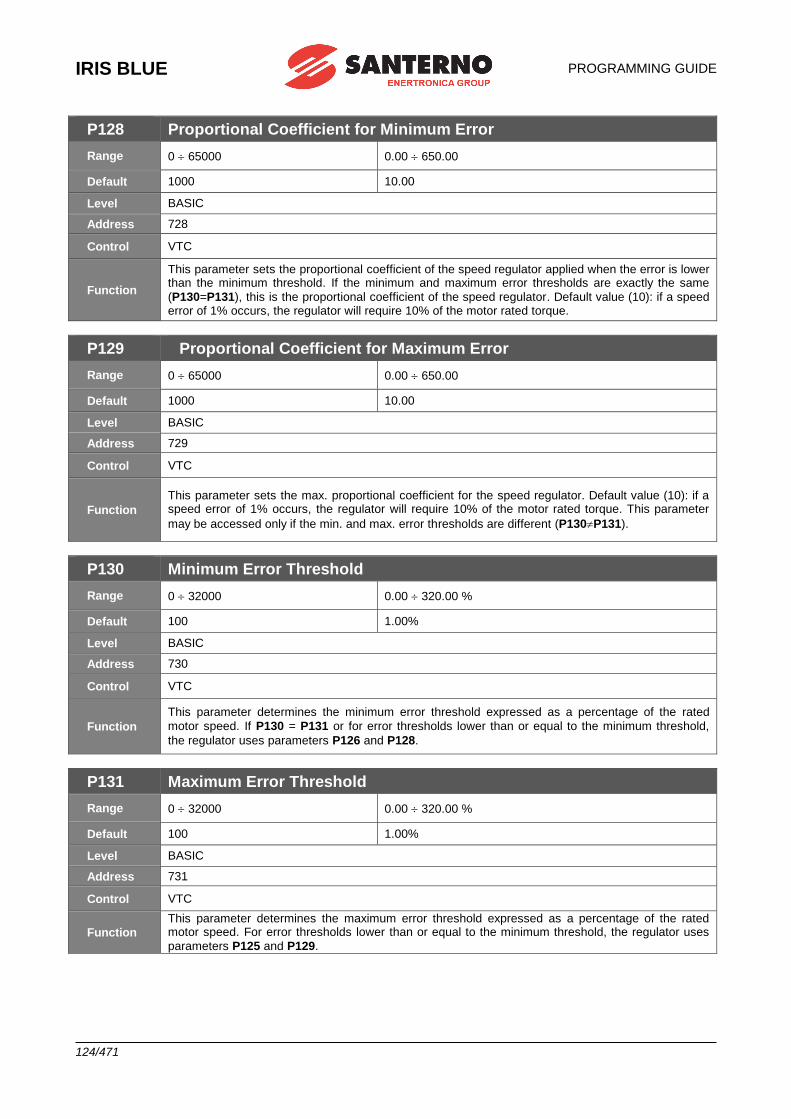
IRIS BLUE
PROGRAMMING GUIDE
124/471
P128 Proportional Coefficient for Minimum Error
Range 0 65000 0.00 650.00
Default 1000 10.00
Level BASIC
Address 728
Control VTC
Function
This parameter sets the proportional coefficient of the speed regulator applied when the error is lower than the minimum threshold. If the minimum and maximum error thresholds are exactly the same
(P130=P131), this is the proportional coefficient of the speed regulator. Default value (10): if a speed error of 1% occurs, the regulator will require 10% of the motor rated torque.
P129 Proportional Coefficient for Maximum Error
Range 0 65000 0.00 650.00
Default 1000 10.00
Level BASIC
Address 729
Control VTC
Function
This parameter sets the max. proportional coefficient for the speed regulator. Default value (10): if a speed error of 1% occurs, the regulator will require 10% of the motor rated torque. This parameter
may be accessed only if the min. and max. error thresholds are different (P130P131).
P130 Minimum Error Threshold
Range 0 32000 0.00 320.00 %
Default 100 1.00%
Level BASIC
Address 730
Control VTC
Function
This parameter determines the minimum error threshold expressed as a percentage of the rated
motor speed. If P130 = P131 or for error thresholds lower than or equal to the minimum threshold,
the regulator uses parameters P126 and P128.
P131 Maximum Error Threshold
Range 0 32000 0.00 320.00 %
Default 100 1.00%
Level BASIC
Address 731
Control VTC
Function
This parameter determines the maximum error threshold expressed as a percentage of the rated motor speed. For error thresholds lower than or equal to the minimum threshold, the regulator uses
parameters P125 and P129.
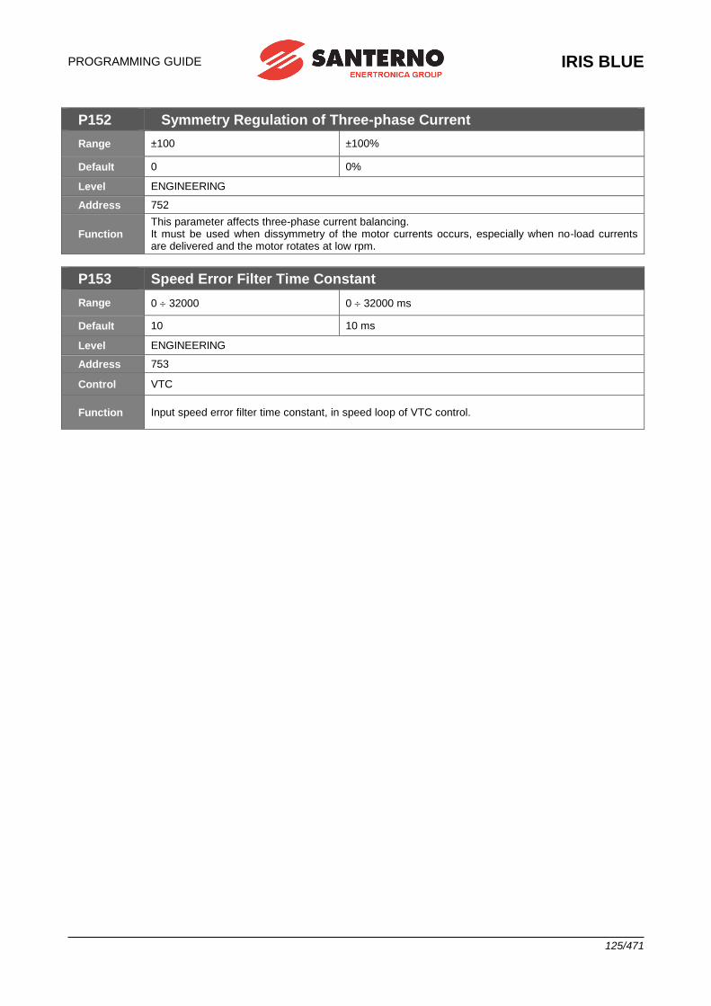
PROGRAMMING GUIDE
IRIS BLUE
125/471
P152 Symmetry Regulation of Three-phase Current
Range ±100 ±100%
Default 0 0%
Level ENGINEERING
Address 752
Function This parameter affects three-phase current balancing. It must be used when dissymmetry of the motor currents occurs, especially when no-load currents are delivered and the motor rotates at low rpm.
P153 Speed Error Filter Time Constant
Range 0 32000 0 32000 ms
Default 10 10 ms
Level ENGINEERING
Address 753
Control VTC
Function Input speed error filter time constant, in speed loop of VTC control.
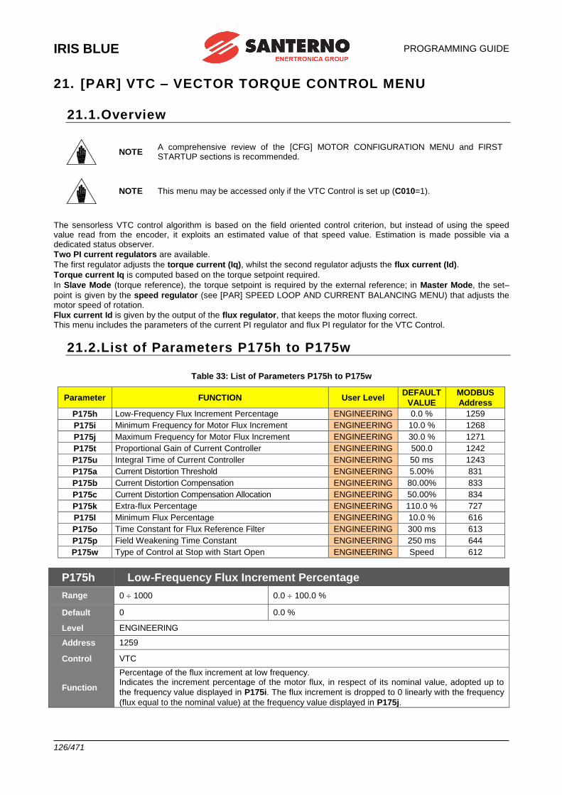
IRIS BLUE
PROGRAMMING GUIDE
126/471
21. [PAR] VTC – VECTOR TORQUE CONTROL MENU
21.1.Overview
NOTE A comprehensive review of the [CFG] MOTOR CONFIGURATION MENU and FIRST STARTUP sections is recommended.
NOTE This menu may be accessed only if the VTC Control is set up (C010=1).
The sensorless VTC control algorithm is based on the field oriented control criterion, but instead of using the speed value read from the encoder, it exploits an estimated value of that speed value. Estimation is made possible via a dedicated status observer.
Two PI current regulators are available.
The first regulator adjusts the torque current (Iq), whilst the second regulator adjusts the flux current (Id).
Torque current Iq is computed based on the torque setpoint required.
In Slave Mode (torque reference), the torque setpoint is required by the external reference; in Master Mode, the set–
point is given by the speed regulator (see [PAR] SPEED LOOP AND CURRENT BALANCING MENU) that adjusts the motor speed of rotation.
Flux current Id is given by the output of the flux regulator, that keeps the motor fluxing correct. This menu includes the parameters of the current PI regulator and flux PI regulator for the VTC Control.
21.2.List of Parameters P175h to P175w
Table 33: List of Parameters P175h to P175w
Parameter FUNCTION User Level DEFAULT
VALUE
MODBUS
Address
P175h Low-Frequency Flux Increment Percentage ENGINEERING 0.0 % 1259
P175i Minimum Frequency for Motor Flux Increment ENGINEERING 10.0 % 1268
P175j Maximum Frequency for Motor Flux Increment ENGINEERING 30.0 % 1271
P175t Proportional Gain of Current Controller ENGINEERING 500.0 1242
P175u Integral Time of Current Controller ENGINEERING 50 ms 1243
P175a Current Distortion Threshold ENGINEERING 5.00% 831
P175b Current Distortion Compensation ENGINEERING 80.00% 833
P175c Current Distortion Compensation Allocation ENGINEERING 50.00% 834
P175k Extra-flux Percentage ENGINEERING 110.0 % 727
P175l Minimum Flux Percentage ENGINEERING 10.0 % 616
P175o Time Constant for Flux Reference Filter ENGINEERING 300 ms 613
P175p Field Weakening Time Constant ENGINEERING 250 ms 644
P175w Type of Control at Stop with Start Open ENGINEERING Speed 612
P175h Low-Frequency Flux Increment Percentage
Range 0 1000 0.0 100.0 %
Default 0 0.0 %
Level ENGINEERING
Address 1259
Control VTC
Function
Percentage of the flux increment at low frequency. Indicates the increment percentage of the motor flux, in respect of its nominal value, adopted up to
the frequency value displayed in P175i. The flux increment is dropped to 0 linearly with the frequency
(flux equal to the nominal value) at the frequency value displayed in P175j.
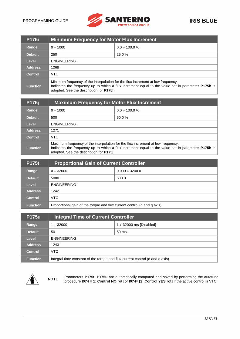
PROGRAMMING GUIDE
IRIS BLUE
127/471
P175i Minimum Frequency for Motor Flux Increment
Range 0 1000 0.0 100.0 %
Default 250 25.0 %
Level ENGINEERING
Address 1268
Control VTC
Function
Minimum frequency of the interpolation for the flux increment at low frequency.
Indicates the frequency up to which a flux increment equal to the value set in parameter P175h is
adopted. See the description for P175h.
P175j Maximum Frequency for Motor Flux Increment
Range 0 1000 0.0 100.0 %
Default 500 50.0 %
Level ENGINEERING
Address 1271
Control VTC
Function
Maximum frequency of the interpolation for the flux increment at low frequency.
Indicates the frequency up to which a flux increment equal to the value set in parameter P175h is
adopted. See the description for P175j.
P175t Proportional Gain of Current Controller
Range 0 32000 0.000 3200.0
Default 5000 500.0
Level ENGINEERING
Address 1242
Control VTC
Function Proportional gain of the torque and flux current control (d and q axis).
P175u Integral Time of Current Controller
Range 1 32000 1 32000 ms [Disabled]
Default 50 50 ms
Level ENGINEERING
Address 1243
Control VTC
Function Integral time constant of the torque and flux current control (d and q axis).
NOTE Parameters P175t, P175u are automatically computed and saved by performing the autotune
procedure I074 = 1: Control NO rot] or I074= [2: Control YES rot] if the active control is VTC.
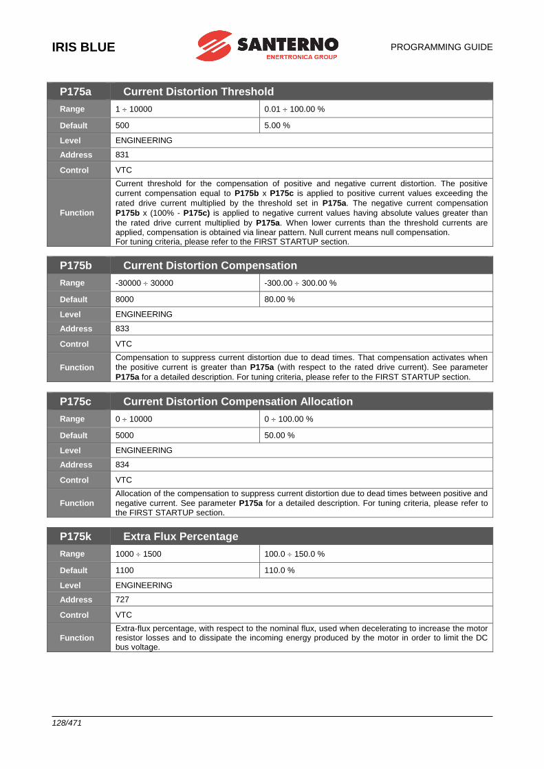
IRIS BLUE
PROGRAMMING GUIDE
128/471
P175a Current Distortion Threshold
Range 1 10000 0.01 100.00 %
Default 500 5.00 %
Level ENGINEERING
Address 831
Control VTC
Function
Current threshold for the compensation of positive and negative current distortion. The positive
current compensation equal to P175b x P175c is applied to positive current values exceeding the
rated drive current multiplied by the threshold set in P175a. The negative current compensation
P175b x (100% - P175c) is applied to negative current values having absolute values greater than
the rated drive current multiplied by P175a. When lower currents than the threshold currents are applied, compensation is obtained via linear pattern. Null current means null compensation. For tuning criteria, please refer to the FIRST STARTUP section.
P175b Current Distortion Compensation
Range -30000 30000 -300.00 300.00 %
Default 8000 80.00 %
Level ENGINEERING
Address 833
Control VTC
Function
Compensation to suppress current distortion due to dead times. That compensation activates when
the positive current is greater than P175a (with respect to the rated drive current). See parameter
P175a for a detailed description. For tuning criteria, please refer to the FIRST STARTUP section.
P175c Current Distortion Compensation Allocation
Range 0 10000 0 100.00 %
Default 5000 50.00 %
Level ENGINEERING
Address 834
Control VTC
Function
Allocation of the compensation to suppress current distortion due to dead times between positive and
negative current. See parameter P175a for a detailed description. For tuning criteria, please refer to the FIRST STARTUP section.
P175k Extra Flux Percentage
Range 1000 1500 100.0 150.0 %
Default 1100 110.0 %
Level ENGINEERING
Address 727
Control VTC
Function Extra-flux percentage, with respect to the nominal flux, used when decelerating to increase the motor resistor losses and to dissipate the incoming energy produced by the motor in order to limit the DC bus voltage.
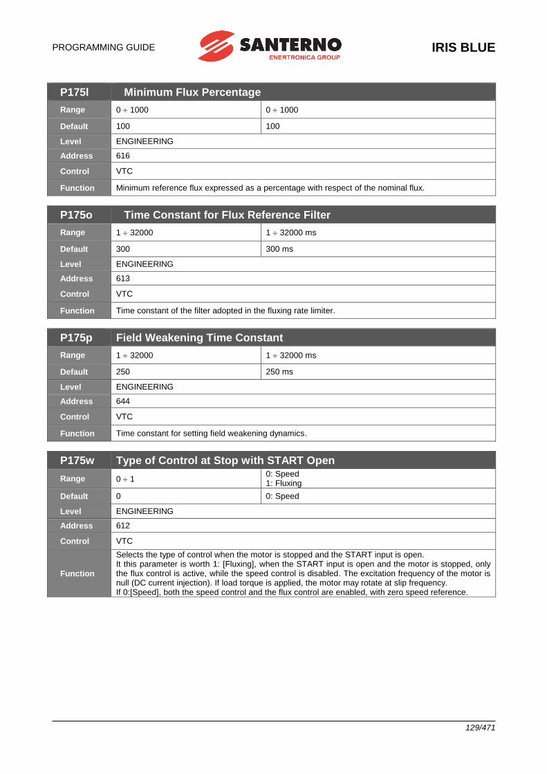
PROGRAMMING GUIDE
IRIS BLUE
129/471
P175l Minimum Flux Percentage
Range 0 1000 0 1000
Default 100 100
Level ENGINEERING
Address 616
Control VTC
Function Minimum reference flux expressed as a percentage with respect of the nominal flux.
P175o Time Constant for Flux Reference Filter
Range 1 32000 1 32000 ms
Default 300 300 ms
Level ENGINEERING
Address 613
Control VTC
Function Time constant of the filter adopted in the fluxing rate limiter.
P175p Field Weakening Time Constant
Range 1 32000 1 32000 ms
Default 250 250 ms
Level ENGINEERING
Address 644
Control VTC
Function Time constant for setting field weakening dynamics.
P175w Type of Control at Stop with START Open
Range 0 1 0: Speed 1: Fluxing
Default 0 0: Speed
Level ENGINEERING
Address 612
Control VTC
Function
Selects the type of control when the motor is stopped and the START input is open. It this parameter is worth 1: [Fluxing], when the START input is open and the motor is stopped, only the flux control is active, while the speed control is disabled. The excitation frequency of the motor is null (DC current injection). If load torque is applied, the motor may rotate at slip frequency. If 0:[Speed], both the speed control and the flux control are enabled, with zero speed reference.
IRIS BLUE
PROGRAMMING GUIDE
130/471
22. [PAR] ANALOG AND FREQUENCY OUTPUTS MENU
22.1.Overview
NOTE Please refer to the IRIS BLUE – Installation Guide for the hardware description of the analog output and the frequency output or for the configuration of the dip-switches for voltage/current outputs.
NOTE MDO1 digital output is used when the frequency output is enabled (P200 other than Disabled). Any configuration set in the [PAR] DIGITAL OUTPUTS MENU will have no effect.
The IRIS BLUE drive allows configuring three programmable analog outputs as voltage outputs or current outputs, as well as one frequency output.
22.1.1. FACTORY-SETTING OF THE ANALOG OUTPUTS Analog outputs are factory set to voltage values ranging from ± 10V and the following variables are selected:
TERMINAL OUTPUT SELECTED VARIABLE OUTPUT
RANGE
MIN
VALUE
MAX
VALUE
10 AO1 Speed (speed of the connected motor) ±10V –1500 1500
11 AO2 Speed Ref.
(speed reference at constant rpm) ±10V –1500 1500
12 AO3 Current of the connected motor ±10V 0 Imax *
* Depending on the inverter size.
22.1.2. ANALOG OUTPUTS As per the analog outputs, the [PAR] ANALOG AND FREQUENCY OUTPUTS MENU allows selecting the variable to be represented, its range, its acquisition mode (± or as an absolute value), the type of analog output (voltage/current) and the output values corresponding to the min. value and the max. value of the selected variable. An offset value and a filtering function may also be applied to the analog outputs. For the frequency output, this menu contains the parameters for the selection of the represented variable, its acquisition mode (± or as an absolute value), its min. value and max. value and the corresponding output frequency value, and a filtering function. The figure below shows the typical structure of the analog outputs; in particular, AO1 analog output and its parameter set are illustrated.
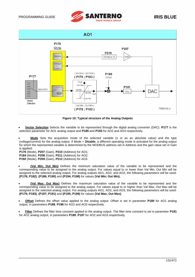
PROGRAMMING GUIDE
IRIS BLUE
131/471
Figure 10: Typical structure of the Analog Outputs
• Vector Selection Selects the variable to be represented through the digital analog converter (DAC). P177 is the
selection parameter for AO1 analog output and P185 and P193 for AO2 and AO3 respectively.
• Mode Sets the acquisition mode of the selected variable (± or as an absolute value) and the type
(voltage/current) for the analog output. If Mode = Disable, a different operating mode is activated for the analog output for which the represented variable is determined by the MODBUS address set in Address and the gain value set in Gain is applied:
P176 (Mode), P207 (Gain), P210 (Address) for AO1;
P184 (Mode), P208 (Gain), P211 (Address) for AO2;
P192 (Mode), P209 (Gain), P212 (Address) for AO3.
• (Val Min; Out Min) Defines the minimum saturation value of the variable to be represented and the corresponding value to be assigned to the analog output. For values equal to or lower than Val Min, Out Min will be assigned to the selected analog output. For analog outputs AO1, AO2, and AO3, the following parameters will be used:
(P178; P182), (P186; P190) and (P194; P198) for values (Val Min; Out Min).
• (Val Max; Out Max) Defines the maximum saturation value of the variable to be represented and the corresponding value to be assigned to the analog output. For values equal to or higher than Val Max, Out Max will be assigned to the selected analog output. For analog outputs AO1, AO2, and AO3, the following parameters will be used:
(P179; P183), (P187; P191) and (P195; P199) for values (Val Max; Out Max).
• Offset Defines the offset value applied to the analog output. Offset is set in parameter P180 for AO1 analog
output, in parameters P188, P196 for AO2 and AO3 respectively.
• Filter Defines the filter time constant applied to the analog output. The filter time constant is set in parameter P181
for AO1 analog output, in parameters P189, P197 for AO2 and AO3 respectively.
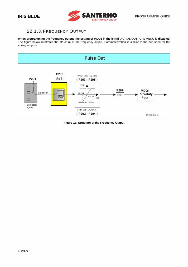
IRIS BLUE
PROGRAMMING GUIDE
132/471
22.1.3. FREQUENCY OUTPUT
When programming the frequency output, the setting of MDO1 in the [PAR] DIGITAL OUTPUTS MENU is disabled. The figure below illustrates the structure of the frequency output. Parameterization is similar to the one used for the analog outputs.
Figure 11: Structure of the Frequency Output
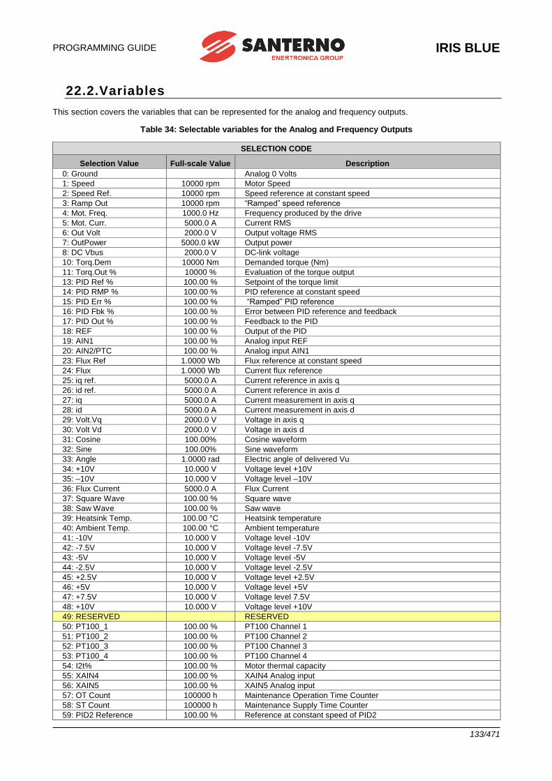
PROGRAMMING GUIDE
IRIS BLUE
133/471
22.2.Variables
This section covers the variables that can be represented for the analog and frequency outputs.
Table 34: Selectable variables for the Analog and Frequency Outputs
SELECTION CODE
Selection Value Full-scale Value Description
0: Ground Analog 0 Volts
1: Speed 10000 rpm Motor Speed
2: Speed Ref. 10000 rpm Speed reference at constant speed
3: Ramp Out 10000 rpm “Ramped” speed reference
4: Mot. Freq. 1000.0 Hz Frequency produced by the drive
5: Mot. Curr. 5000.0 A Current RMS
6: Out Volt 2000.0 V Output voltage RMS
7: OutPower 5000.0 kW Output power
8: DC Vbus 2000.0 V DC-link voltage
10: Torq.Dem 10000 Nm Demanded torque (Nm)
11: Torq.Out % 10000 % Evaluation of the torque output
13: PID Ref % 100.00 % Setpoint of the torque limit
14: PID RMP % 100.00 % PID reference at constant speed
15: PID Err % 100.00 % “Ramped” PID reference
16: PID Fbk % 100.00 % Error between PID reference and feedback
17: PID Out % 100.00 % Feedback to the PID
18: REF 100.00 % Output of the PID
19: AIN1 100.00 % Analog input REF
20: AIN2/PTC 100.00 % Analog input AIN1
23: Flux Ref 1.0000 Wb Flux reference at constant speed
24: Flux 1.0000 Wb Current flux reference
25: iq ref. 5000.0 A Current reference in axis q
26: id ref. 5000.0 A Current reference in axis d
27: iq 5000.0 A Current measurement in axis q
28: id 5000.0 A Current measurement in axis d
29: Volt.Vq 2000.0 V Voltage in axis q
30: Volt Vd 2000.0 V Voltage in axis d
31: Cosine 100.00% Cosine waveform
32: Sine 100.00% Sine waveform
33: Angle 1.0000 rad Electric angle of delivered Vu
34: +10V 10.000 V Voltage level +10V
35: –10V 10.000 V Voltage level –10V
36: Flux Current 5000.0 A Flux Current
37: Square Wave 100.00 % Square wave
38: Saw Wave 100.00 % Saw wave
39: Heatsink Temp. 100.00 °C Heatsink temperature
40: Ambient Temp. 100.00 °C Ambient temperature
41: -10V 10.000 V Voltage level -10V
42: -7.5V 10.000 V Voltage level -7.5V
43: -5V 10.000 V Voltage level -5V
44: -2.5V 10.000 V Voltage level -2.5V
45: +2.5V 10.000 V Voltage level +2.5V
46: +5V 10.000 V Voltage level +5V
47: +7.5V 10.000 V Voltage level 7.5V
48: +10V 10.000 V Voltage level +10V
49: RESERVED RESERVED
50: PT100_1 100.00 % PT100 Channel 1
51: PT100_2 100.00 % PT100 Channel 2
52: PT100_3 100.00 % PT100 Channel 3
53: PT100_4 100.00 % PT100 Channel 4
54: I2t% 100.00 % Motor thermal capacity
55: XAIN4 100.00 % XAIN4 Analog input
56: XAIN5 100.00 % XAIN5 Analog input
57: OT Count 100000 h Maintenance Operation Time Counter
58: ST Count 100000 h Maintenance Supply Time Counter
59: PID2 Reference 100.00 % Reference at constant speed of PID2
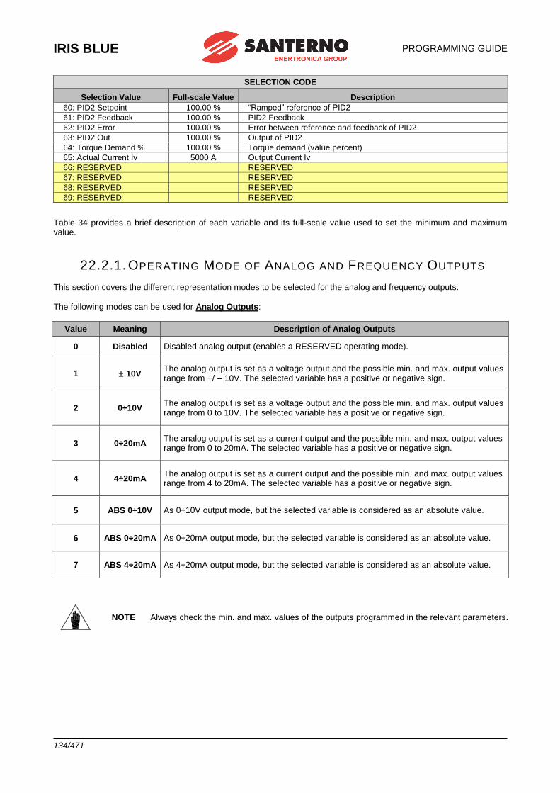
IRIS BLUE
PROGRAMMING GUIDE
134/471
SELECTION CODE
Selection Value Full-scale Value Description
60: PID2 Setpoint 100.00 % “Ramped” reference of PID2
61: PID2 Feedback 100.00 % PID2 Feedback
62: PID2 Error 100.00 % Error between reference and feedback of PID2
63: PID2 Out 100.00 % Output of PID2
64: Torque Demand % 100.00 % Torque demand (value percent)
65: Actual Current Iv 5000 A Output Current Iv
66: RESERVED RESERVED
67: RESERVED RESERVED
68: RESERVED RESERVED
69: RESERVED RESERVED
Table 34 provides a brief description of each variable and its full-scale value used to set the minimum and maximum value.
22.2.1. OPERATING MODE OF ANALOG AND FREQUENCY OUTPUTS This section covers the different representation modes to be selected for the analog and frequency outputs.
The following modes can be used for Analog Outputs:
Value Meaning Description of Analog Outputs
0 Disabled Disabled analog output (enables a RESERVED operating mode).
1 10V The analog output is set as a voltage output and the possible min. and max. output values range from +/ – 10V. The selected variable has a positive or negative sign.
2 0÷10V The analog output is set as a voltage output and the possible min. and max. output values range from 0 to 10V. The selected variable has a positive or negative sign.
3 0÷20mA The analog output is set as a current output and the possible min. and max. output values range from 0 to 20mA. The selected variable has a positive or negative sign.
4 4÷20mA The analog output is set as a current output and the possible min. and max. output values range from 4 to 20mA. The selected variable has a positive or negative sign.
5 ABS 0÷10V As 0÷10V output mode, but the selected variable is considered as an absolute value.
6 ABS 0÷20mA As 0÷20mA output mode, but the selected variable is considered as an absolute value.
7 ABS 4÷20mA As 4÷20mA output mode, but the selected variable is considered as an absolute value.
NOTE Always check the min. and max. values of the outputs programmed in the relevant parameters.
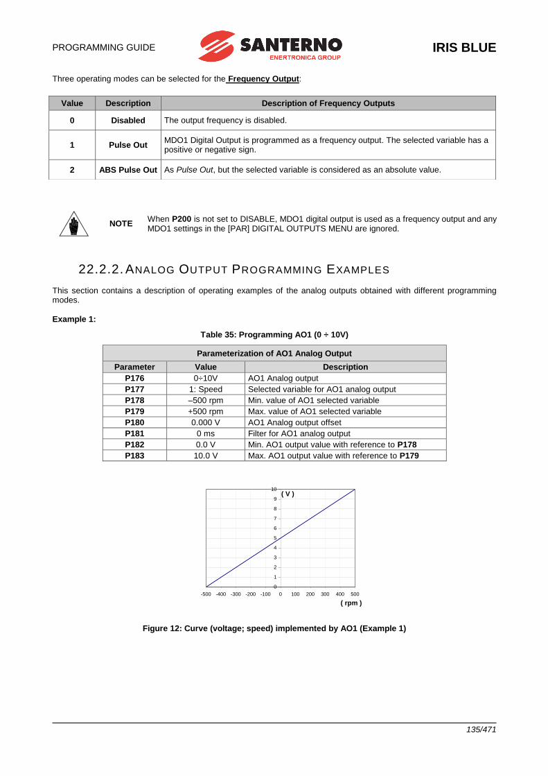
PROGRAMMING GUIDE
IRIS BLUE
135/471
Three operating modes can be selected for the Frequency Output:
NOTE When P200 is not set to DISABLE, MDO1 digital output is used as a frequency output and any MDO1 settings in the [PAR] DIGITAL OUTPUTS MENU are ignored.
22.2.2. ANALOG OUTPUT PROGRAMMING EXAMPLES This section contains a description of operating examples of the analog outputs obtained with different programming modes.
Example 1:
Table 35: Programming AO1 (0 ÷ 10V)
Parameterization of AO1 Analog Output
Parameter Value Description
P176 0÷10V AO1 Analog output
P177 1: Speed Selected variable for AO1 analog output
P178 –500 rpm Min. value of AO1 selected variable
P179 +500 rpm Max. value of AO1 selected variable
P180 0.000 V AO1 Analog output offset
P181 0 ms Filter for AO1 analog output
P182 0.0 V Min. AO1 output value with reference to P178
P183 10.0 V Max. AO1 output value with reference to P179
0
1
2
3
4
5
6
7
8
9
10
-500 -400 -300 -200 -100 0 100 200 300 400 500
( rpm )
( V )
Figure 12: Curve (voltage; speed) implemented by AO1 (Example 1)
Value Description Description of Frequency Outputs
0 Disabled The output frequency is disabled.
1 Pulse Out MDO1 Digital Output is programmed as a frequency output. The selected variable has a positive or negative sign.
2 ABS Pulse Out As Pulse Out, but the selected variable is considered as an absolute value.
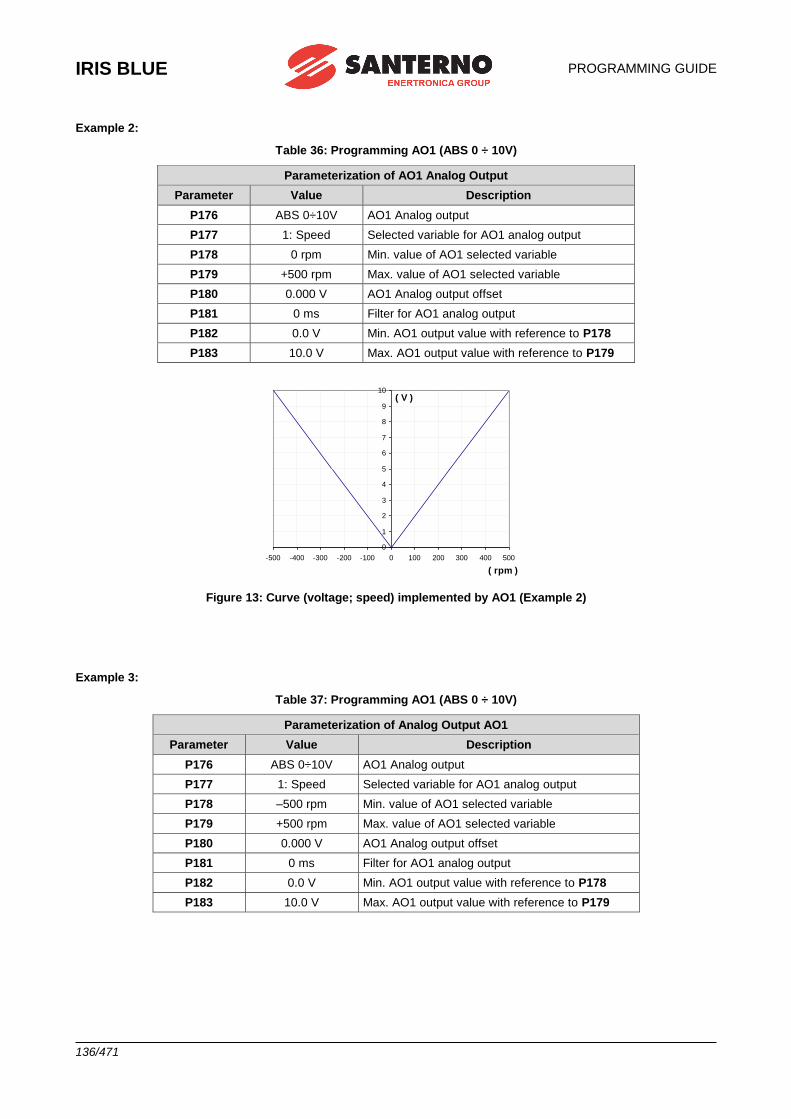
IRIS BLUE
PROGRAMMING GUIDE
136/471
Example 2:
Table 36: Programming AO1 (ABS 0 ÷ 10V)
Parameterization of AO1 Analog Output
Parameter Value Description
P176 ABS 0÷10V AO1 Analog output
P177 1: Speed Selected variable for AO1 analog output
P178 0 rpm Min. value of AO1 selected variable
P179 +500 rpm Max. value of AO1 selected variable
P180 0.000 V AO1 Analog output offset
P181 0 ms Filter for AO1 analog output
P182 0.0 V Min. AO1 output value with reference to P178
P183 10.0 V Max. AO1 output value with reference to P179
0
1
2
3
4
5
6
7
8
9
10
-500 -400 -300 -200 -100 0 100 200 300 400 500
( rpm )
( V )
Figure 13: Curve (voltage; speed) implemented by AO1 (Example 2)
Example 3:
Table 37: Programming AO1 (ABS 0 ÷ 10V)
Parameterization of Analog Output AO1
Parameter Value Description
P176 ABS 0÷10V AO1 Analog output
P177 1: Speed Selected variable for AO1 analog output
P178 –500 rpm Min. value of AO1 selected variable
P179 +500 rpm Max. value of AO1 selected variable
P180 0.000 V AO1 Analog output offset
P181 0 ms Filter for AO1 analog output
P182 0.0 V Min. AO1 output value with reference to P178
P183 10.0 V Max. AO1 output value with reference to P179
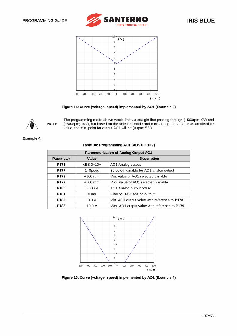
PROGRAMMING GUIDE
IRIS BLUE
137/471
0
1
2
3
4
5
6
7
8
9
10
-500 -400 -300 -200 -100 0 100 200 300 400 500
( rpm )
( V )
Figure 14: Curve (voltage; speed) implemented by AO1 (Example 3)
NOTE The programming mode above would imply a straight line passing through (–500rpm; 0V) and (+500rpm; 10V), but based on the selected mode and considering the variable as an absolute value, the min. point for output AO1 will be (0 rpm; 5 V).
Example 4:
Table 38: Programming AO1 (ABS 0 ÷ 10V)
Parameterization of Analog Output AO1
Parameter Value Description
P176 ABS 0÷10V AO1 Analog output
P177 1: Speed Selected variable for AO1 analog output
P178 +100 rpm Min. value of AO1 selected variable
P179 +500 rpm Max. value of AO1 selected variable
P180 0.000 V AO1 Analog output offset
P181 0 ms Filter for AO1 analog output
P182 0.0 V Min. AO1 output value with reference to P178
P183 10.0 V Max. AO1 output value with reference to P179
0
1
2
3
4
5
6
7
8
9
10
-500 -400 -300 -200 -100 0 100 200 300 400 500
( rpm )
( V )
Figure 15: Curve (voltage; speed) implemented by AO1 (Example 4)
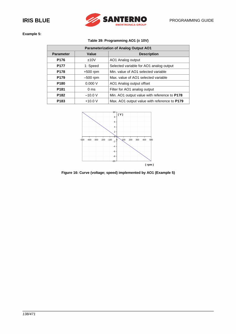
IRIS BLUE
PROGRAMMING GUIDE
138/471
Example 5:
Table 39: Programming AO1 (± 10V)
Parameterization of Analog Output AO1
Parameter Value Description
P176 ±10V AO1 Analog output
P177 1: Speed Selected variable for AO1 analog output
P178 +500 rpm Min. value of AO1 selected variable
P179 –500 rpm Max. value of AO1 selected variable
P180 0.000 V AO1 Analog output offset
P181 0 ms Filter for AO1 analog output
P182 –10.0 V Min. AO1 output value with reference to P178
P183 +10.0 V Max. AO1 output value with reference to P179
-10
-8
-6
-4
-2
0
2
4
6
8
10
-500 -400 -300 -200 -100 0 100 200 300 400 500
( rpm )
( V )
Figure 16: Curve (voltage; speed) implemented by AO1 (Example 5)
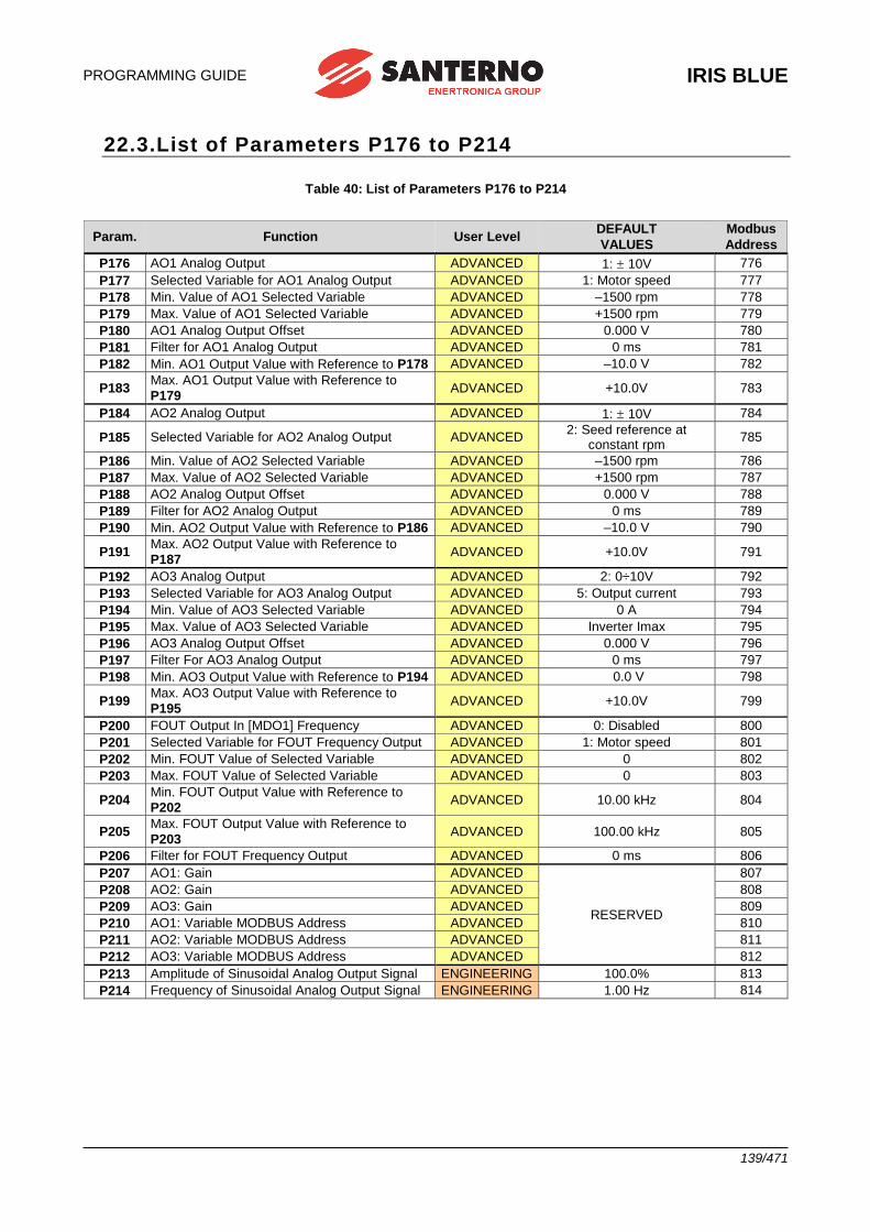
PROGRAMMING GUIDE
IRIS BLUE
139/471
22.3.List of Parameters P176 to P214
Table 40: List of Parameters P176 to P214
Param. Function User Level DEFAULT
VALUES
Modbus
Address
P176 AO1 Analog Output ADVANCED 1: 10V 776
P177 Selected Variable for AO1 Analog Output ADVANCED 1: Motor speed 777
P178 Min. Value of AO1 Selected Variable ADVANCED –1500 rpm 778
P179 Max. Value of AO1 Selected Variable ADVANCED +1500 rpm 779
P180 AO1 Analog Output Offset ADVANCED 0.000 V 780
P181 Filter for AO1 Analog Output ADVANCED 0 ms 781
P182 Min. AO1 Output Value with Reference to P178 ADVANCED –10.0 V 782
P183 Max. AO1 Output Value with Reference to
P179 ADVANCED +10.0V 783
P184 AO2 Analog Output ADVANCED 1: 10V 784
P185 Selected Variable for AO2 Analog Output ADVANCED 2: Seed reference at
constant rpm 785
P186 Min. Value of AO2 Selected Variable ADVANCED –1500 rpm 786
P187 Max. Value of AO2 Selected Variable ADVANCED +1500 rpm 787
P188 AO2 Analog Output Offset ADVANCED 0.000 V 788
P189 Filter for AO2 Analog Output ADVANCED 0 ms 789
P190 Min. AO2 Output Value with Reference to P186 ADVANCED –10.0 V 790
P191 Max. AO2 Output Value with Reference to
P187 ADVANCED +10.0V 791
P192 AO3 Analog Output ADVANCED 2: 0÷10V 792
P193 Selected Variable for AO3 Analog Output ADVANCED 5: Output current 793
P194 Min. Value of AO3 Selected Variable ADVANCED 0 A 794
P195 Max. Value of AO3 Selected Variable ADVANCED Inverter Imax 795
P196 AO3 Analog Output Offset ADVANCED 0.000 V 796
P197 Filter For AO3 Analog Output ADVANCED 0 ms 797
P198 Min. AO3 Output Value with Reference to P194 ADVANCED 0.0 V 798
P199 Max. AO3 Output Value with Reference to
P195 ADVANCED +10.0V 799
P200 FOUT Output In [MDO1] Frequency ADVANCED 0: Disabled 800
P201 Selected Variable for FOUT Frequency Output ADVANCED 1: Motor speed 801
P202 Min. FOUT Value of Selected Variable ADVANCED 0 802
P203 Max. FOUT Value of Selected Variable ADVANCED 0 803
P204 Min. FOUT Output Value with Reference to
P202 ADVANCED 10.00 kHz 804
P205 Max. FOUT Output Value with Reference to
P203 ADVANCED 100.00 kHz 805
P206 Filter for FOUT Frequency Output ADVANCED 0 ms 806
P207 AO1: Gain ADVANCED
RESERVED
807
P208 AO2: Gain ADVANCED 808
P209 AO3: Gain ADVANCED 809
P210 AO1: Variable MODBUS Address ADVANCED 810
P211 AO2: Variable MODBUS Address ADVANCED 811
P212 AO3: Variable MODBUS Address ADVANCED 812
P213 Amplitude of Sinusoidal Analog Output Signal ENGINEERING 100.0% 813
P214 Frequency of Sinusoidal Analog Output Signal ENGINEERING 1.00 Hz 814
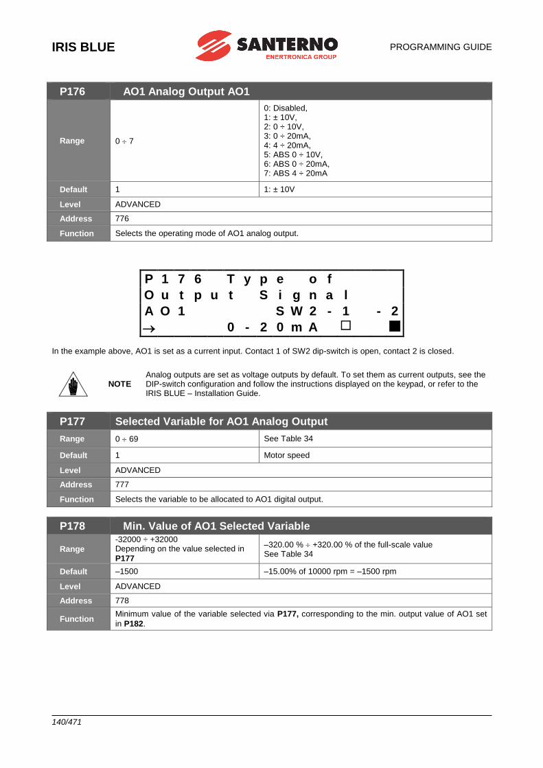
IRIS BLUE
PROGRAMMING GUIDE
140/471
P176 AO1 Analog Output AO1
Range 0 7
0: Disabled, 1: ± 10V, 2: 0 ÷ 10V, 3: 0 ÷ 20mA, 4: 4 ÷ 20mA, 5: ABS 0 ÷ 10V, 6: ABS 0 ÷ 20mA, 7: ABS 4 ÷ 20mA
Default 1 1: ± 10V
Level ADVANCED
Address 776
Function Selects the operating mode of AO1 analog output.
P 1 7 6 T y p e o f
O u t p u t S i g n a l
A O 1 S W 2 - 1 - 2
0 - 2 0 m A In the example above, AO1 is set as a current input. Contact 1 of SW2 dip-switch is open, contact 2 is closed.
NOTE Analog outputs are set as voltage outputs by default. To set them as current outputs, see the DIP-switch configuration and follow the instructions displayed on the keypad, or refer to the IRIS BLUE – Installation Guide.
P177 Selected Variable for AO1 Analog Output
Range 0 69 See Table 34
Default 1 Motor speed
Level ADVANCED
Address 777
Function Selects the variable to be allocated to AO1 digital output.
P178 Min. Value of AO1 Selected Variable
Range
-32000 ÷ +32000 Depending on the value selected in
P177
–320.00 % +320.00 % of the full-scale value See Table 34
Default –1500 –15.00% of 10000 rpm = –1500 rpm
Level ADVANCED
Address 778
Function Minimum value of the variable selected via P177, corresponding to the min. output value of AO1 set
in P182.
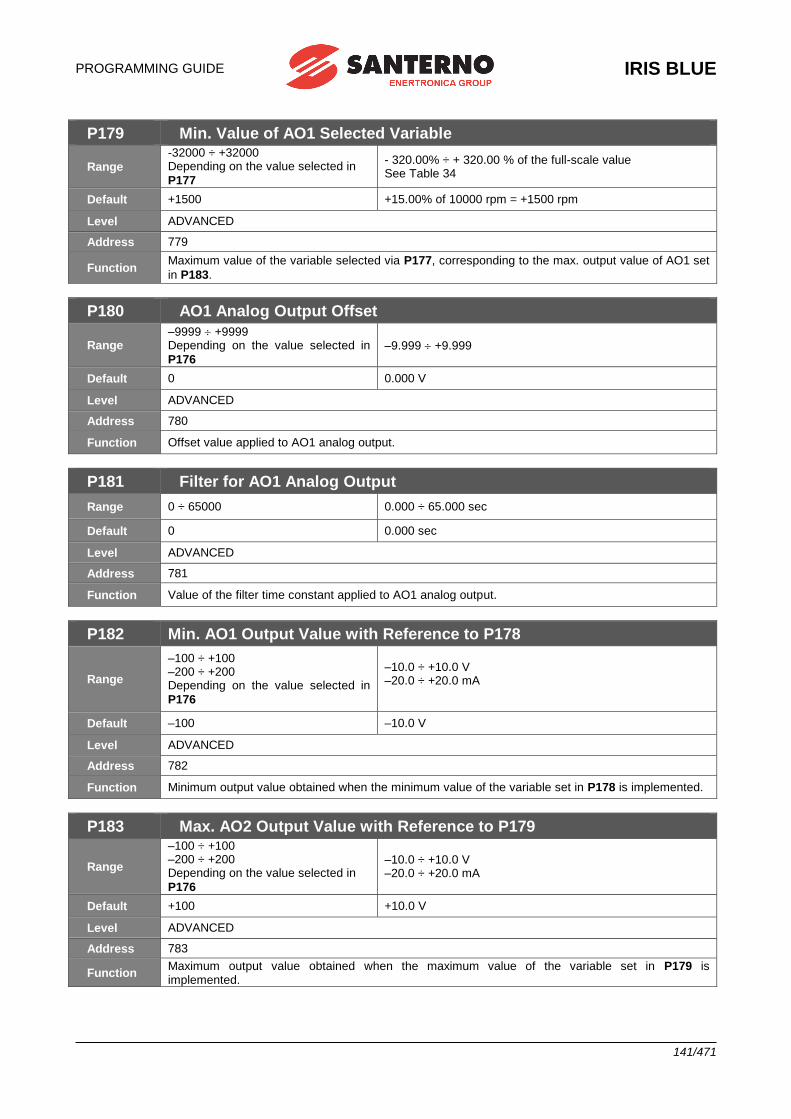
PROGRAMMING GUIDE
IRIS BLUE
141/471
P179 Min. Value of AO1 Selected Variable
Range
-32000 ÷ +32000 Depending on the value selected in
P177
- 320.00% ÷ + 320.00 % of the full-scale value See Table 34
Default +1500 +15.00% of 10000 rpm = +1500 rpm
Level ADVANCED
Address 779
Function Maximum value of the variable selected via P177, corresponding to the max. output value of AO1 set
in P183.
P180 AO1 Analog Output Offset
Range –9999 +9999 Depending on the value selected in
P176 –9.999 +9.999
Default 0 0.000 V
Level ADVANCED
Address 780
Function Offset value applied to AO1 analog output.
P181 Filter for AO1 Analog Output
Range 0 ÷ 65000 0.000 ÷ 65.000 sec
Default 0 0.000 sec
Level ADVANCED
Address 781
Function Value of the filter time constant applied to AO1 analog output.
P182 Min. AO1 Output Value with Reference to P178
Range
–100 ÷ +100 –200 ÷ +200 Depending on the value selected in
P176
–10.0 ÷ +10.0 V –20.0 ÷ +20.0 mA
Default –100 –10.0 V
Level ADVANCED
Address 782
Function Minimum output value obtained when the minimum value of the variable set in P178 is implemented.
P183 Max. AO2 Output Value with Reference to P179
Range
–100 ÷ +100 –200 ÷ +200 Depending on the value selected in
P176
–10.0 ÷ +10.0 V –20.0 ÷ +20.0 mA
Default +100 +10.0 V
Level ADVANCED
Address 783
Function Maximum output value obtained when the maximum value of the variable set in P179 is implemented.
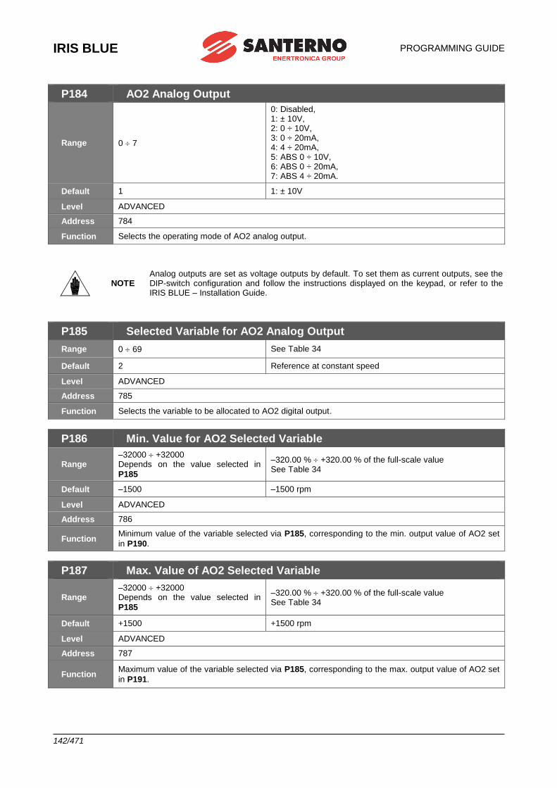
IRIS BLUE
PROGRAMMING GUIDE
142/471
P184 AO2 Analog Output
Range 0 7
0: Disabled, 1: ± 10V, 2: 0 ÷ 10V, 3: 0 ÷ 20mA, 4: 4 ÷ 20mA, 5: ABS 0 ÷ 10V, 6: ABS 0 ÷ 20mA, 7: ABS 4 ÷ 20mA.
Default 1 1: ± 10V
Level ADVANCED
Address 784
Function Selects the operating mode of AO2 analog output.
NOTE Analog outputs are set as voltage outputs by default. To set them as current outputs, see the DIP-switch configuration and follow the instructions displayed on the keypad, or refer to the IRIS BLUE – Installation Guide.
P185 Selected Variable for AO2 Analog Output
Range 0 69 See Table 34
Default 2 Reference at constant speed
Level ADVANCED
Address 785
Function Selects the variable to be allocated to AO2 digital output.
P186 Min. Value for AO2 Selected Variable
Range –32000 +32000 Depends on the value selected in
P185
–320.00 % +320.00 % of the full-scale value See Table 34
Default –1500 –1500 rpm
Level ADVANCED
Address 786
Function Minimum value of the variable selected via P185, corresponding to the min. output value of AO2 set
in P190.
P187 Max. Value of AO2 Selected Variable
Range –32000 +32000 Depends on the value selected in
P185
–320.00 % +320.00 % of the full-scale value See Table 34
Default +1500 +1500 rpm
Level ADVANCED
Address 787
Function Maximum value of the variable selected via P185, corresponding to the max. output value of AO2 set
in P191.
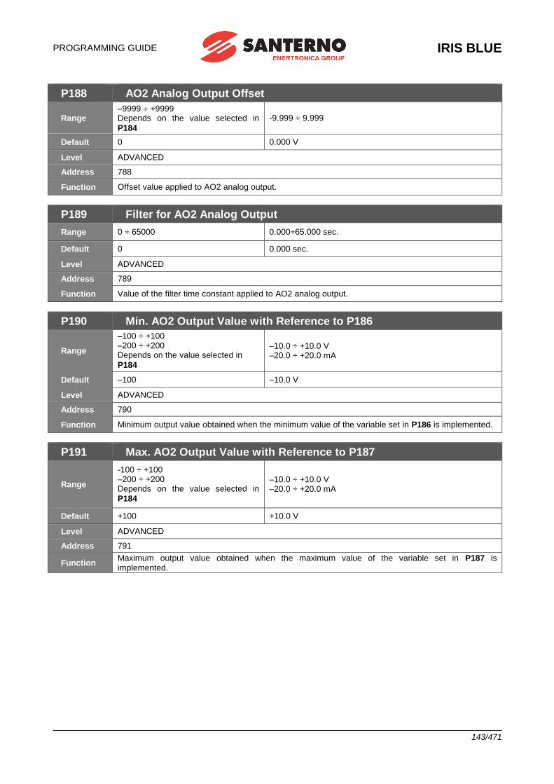
PROGRAMMING GUIDE
IRIS BLUE
143/471
P188 AO2 Analog Output Offset
Range –9999 +9999 Depends on the value selected in
P184
-9.999 ÷ 9.999
Default 0 0.000 V
Level ADVANCED
Address 788
Function Offset value applied to AO2 analog output.
P189 Filter for AO2 Analog Output
Range 0 ÷ 65000 0.000÷65.000 sec.
Default 0 0.000 sec.
Level ADVANCED
Address 789
Function Value of the filter time constant applied to AO2 analog output.
P190 Min. AO2 Output Value with Reference to P186
Range
–100 ÷ +100 –200 ÷ +200 Depends on the value selected in
P184
–10.0 ÷ +10.0 V –20.0 ÷ +20.0 mA
Default –100 –10.0 V
Level ADVANCED
Address 790
Function Minimum output value obtained when the minimum value of the variable set in P186 is implemented.
P191 Max. AO2 Output Value with Reference to P187
Range
-100 ÷ +100 –200 ÷ +200 Depends on the value selected in
P184
–10.0 ÷ +10.0 V –20.0 ÷ +20.0 mA
Default +100 +10.0 V
Level ADVANCED
Address 791
Function Maximum output value obtained when the maximum value of the variable set in P187 is implemented.

IRIS BLUE
PROGRAMMING GUIDE
144/471
P192 AO3 Analog Output
Range 0 7
0: Disabled, 1: ± 10V, 2: 0 ÷ 10V, 3: 0 ÷ 20mA, 4: 4 ÷ 20mA, 5: ABS 0 ÷ 10V, 6: ABS 0 ÷ 20mA, 7: ABS 4 ÷ 20mA.
Default 2 2: 0 ÷ 10V
Level ADVANCED
Address 792
Function Selects the operating mode of AO3 analog output.
NOTE Analog outputs are set as voltage outputs by default. To set them as current outputs, see the DIP-switch configuration and follow the instructions displayed on the keypad, or refer to the IRIS BLUE – Installation Guide.
P193 Selected variable for AO3 Analog Output
Range 0 69 See Table 34
Default 5 5: Motor current
Level ADVANCED
Address 793
Function Selects the variable to be allocated to AO3 analog output.
P194 Min. Value of AO3 Selected Variable
Range
–320.00 % +320.00 % of the full-scale value Depends on the value selected
through P193
–320.00 % +320.00 % of the full-scale value See Table 34
Default 0 0 A
Level ADVANCED
Address 794
Function Minimum value of the variable selected via P193, corresponding to the min. output value of AO3 set
in P198.
P195 Max. Value of AO3 Selected Variable
Range –320.00 % +320.00 % Depends on the value selected
through P193
–320.00 % +320.00 % of the full-scale value See Table 34
Default Imax Inverter Max. drive current depending on the drive size – see Table 77
Level ADVANCED
Address 795
Function Maximum value of the variable selected via P193, corresponding to the max. output value of AO3 set
in P199.
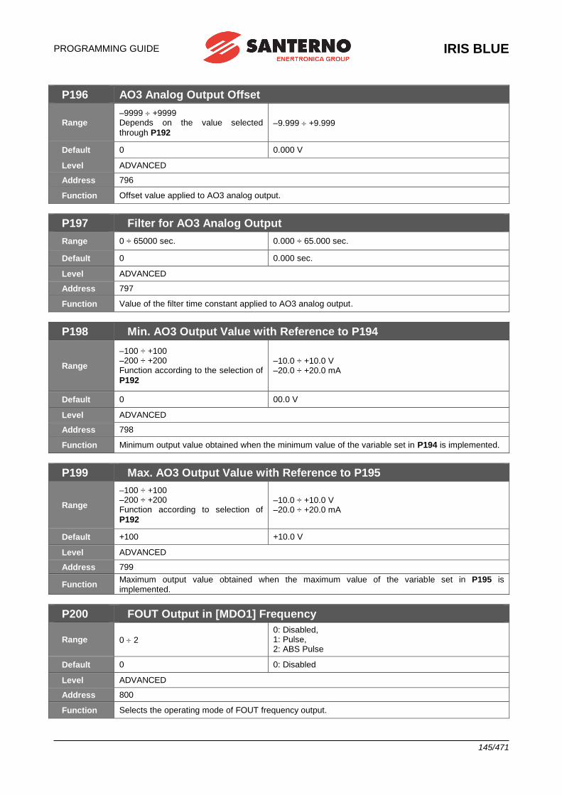
PROGRAMMING GUIDE
IRIS BLUE
145/471
P196 AO3 Analog Output Offset
Range –9999 +9999 Depends on the value selected
through P192 –9.999 +9.999
Default 0 0.000 V
Level ADVANCED
Address 796
Function Offset value applied to AO3 analog output.
P197 Filter for AO3 Analog Output
Range 0 ÷ 65000 sec. 0.000 ÷ 65.000 sec.
Default 0 0.000 sec.
Level ADVANCED
Address 797
Function Value of the filter time constant applied to AO3 analog output.
P198 Min. AO3 Output Value with Reference to P194
Range
–100 ÷ +100 –200 ÷ +200 Function according to the selection of
P192
–10.0 ÷ +10.0 V –20.0 ÷ +20.0 mA
Default 0 00.0 V
Level ADVANCED
Address 798
Function Minimum output value obtained when the minimum value of the variable set in P194 is implemented.
P199 Max. AO3 Output Value with Reference to P195
Range
–100 ÷ +100 –200 ÷ +200 Function according to selection of
P192
–10.0 ÷ +10.0 V –20.0 ÷ +20.0 mA
Default +100 +10.0 V
Level ADVANCED
Address 799
Function Maximum output value obtained when the maximum value of the variable set in P195 is implemented.
P200 FOUT Output in [MDO1] Frequency
Range 0 2
0: Disabled, 1: Pulse, 2: ABS Pulse
Default 0 0: Disabled
Level ADVANCED
Address 800
Function Selects the operating mode of FOUT frequency output.
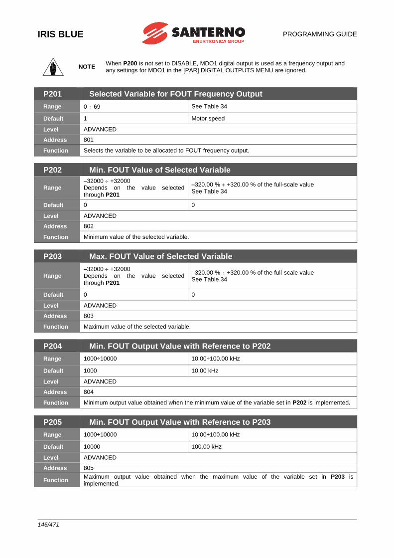
IRIS BLUE
PROGRAMMING GUIDE
146/471
NOTE When P200 is not set to DISABLE, MDO1 digital output is used as a frequency output and any settings for MDO1 in the [PAR] DIGITAL OUTPUTS MENU are ignored.
P201 Selected Variable for FOUT Frequency Output
Range 0 69 See Table 34
Default 1 Motor speed
Level ADVANCED
Address 801
Function Selects the variable to be allocated to FOUT frequency output.
P202 Min. FOUT Value of Selected Variable
Range –32000 +32000 Depends on the value selected
through P201
–320.00 % +320.00 % of the full-scale value See Table 34
Default 0 0
Level ADVANCED
Address 802
Function Minimum value of the selected variable.
P203 Max. FOUT Value of Selected Variable
Range –32000 +32000 Depends on the value selected
through P201
–320.00 % +320.00 % of the full-scale value See Table 34
Default 0 0
Level ADVANCED
Address 803
Function Maximum value of the selected variable.
P204 Min. FOUT Output Value with Reference to P202
Range 1000÷10000 10.00÷100.00 kHz
Default 1000 10.00 kHz
Level ADVANCED
Address 804
Function Minimum output value obtained when the minimum value of the variable set in P202 is implemented.
P205 Min. FOUT Output Value with Reference to P203
Range 1000÷10000 10.00÷100.00 kHz
Default 10000 100.00 kHz
Level ADVANCED
Address 805
Function Maximum output value obtained when the maximum value of the variable set in P203 is implemented.
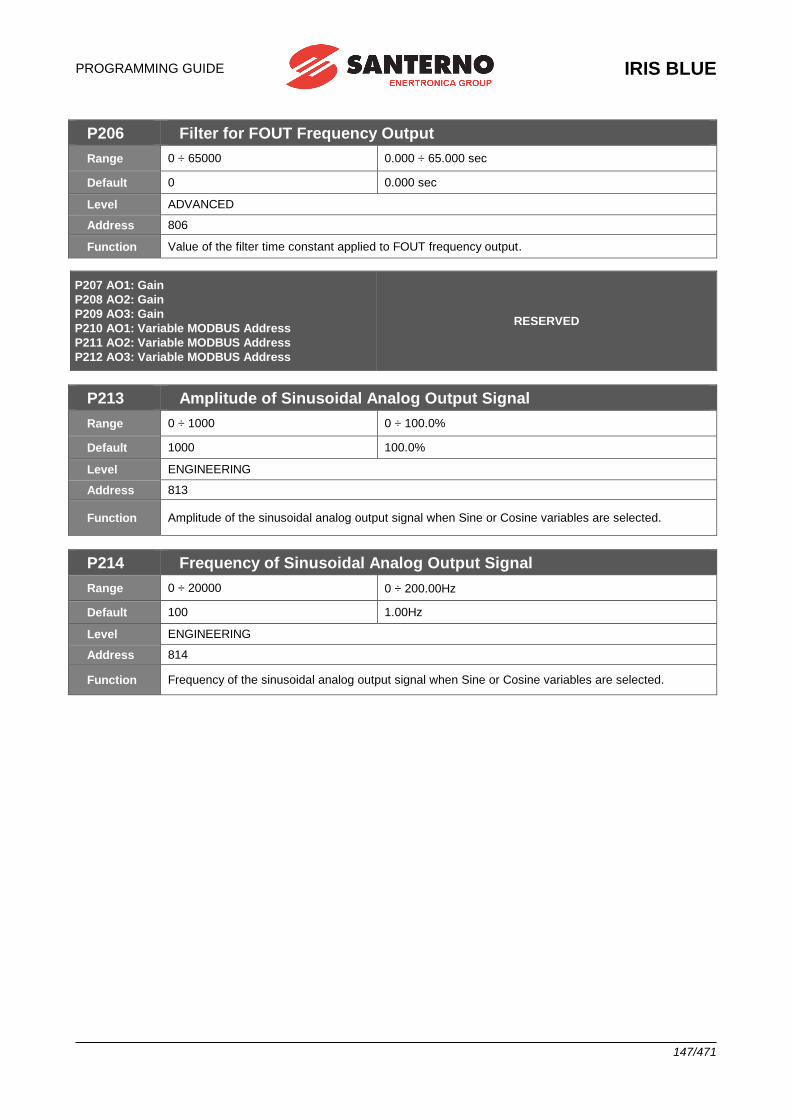
PROGRAMMING GUIDE
IRIS BLUE
147/471
P206 Filter for FOUT Frequency Output
Range 0 ÷ 65000 0.000 ÷ 65.000 sec
Default 0 0.000 sec
Level ADVANCED
Address 806
Function Value of the filter time constant applied to FOUT frequency output.
P207 AO1: Gain
P208 AO2: Gain
P209 AO3: Gain
P210 AO1: Variable MODBUS Address
P211 AO2: Variable MODBUS Address
P212 AO3: Variable MODBUS Address
RESERVED
P213 Amplitude of Sinusoidal Analog Output Signal
Range 0 ÷ 1000 0 ÷ 100.0%
Default 1000 100.0%
Level ENGINEERING
Address 813
Function Amplitude of the sinusoidal analog output signal when Sine or Cosine variables are selected.
P214 Frequency of Sinusoidal Analog Output Signal
Range 0 ÷ 20000 0 ÷ 200.00Hz
Default 100 1.00Hz
Level ENGINEERING
Address 814
Function Frequency of the sinusoidal analog output signal when Sine or Cosine variables are selected.
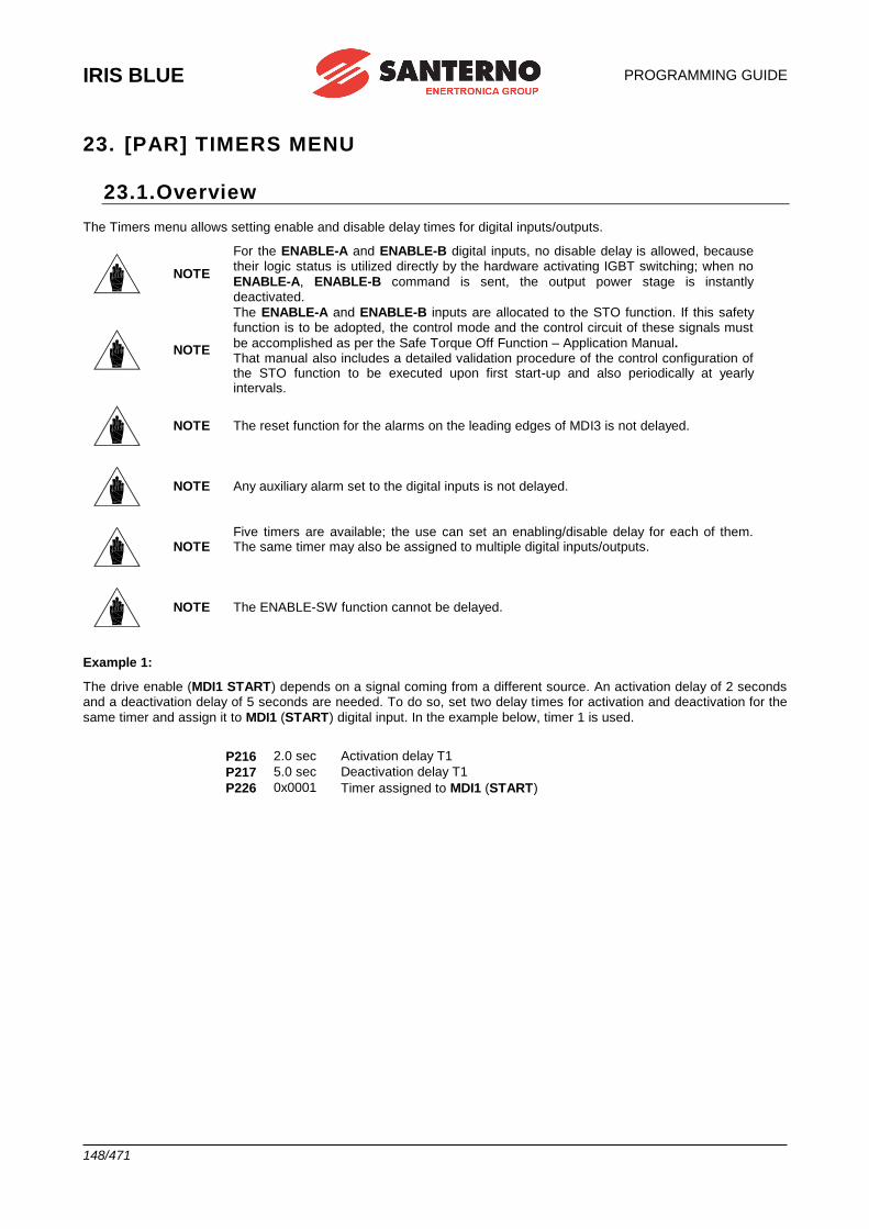
IRIS BLUE
PROGRAMMING GUIDE
148/471
23. [PAR] TIMERS MENU
23.1.Overview The Timers menu allows setting enable and disable delay times for digital inputs/outputs.
NOTE
For the ENABLE-A and ENABLE-B digital inputs, no disable delay is allowed, because their logic status is utilized directly by the hardware activating IGBT switching; when no
ENABLE-A, ENABLE-B command is sent, the output power stage is instantly deactivated.
NOTE
The ENABLE-A and ENABLE-B inputs are allocated to the STO function. If this safety function is to be adopted, the control mode and the control circuit of these signals must
be accomplished as per the Safe Torque Off Function – Application Manual. That manual also includes a detailed validation procedure of the control configuration of the STO function to be executed upon first start-up and also periodically at yearly intervals.
NOTE The reset function for the alarms on the leading edges of MDI3 is not delayed.
NOTE Any auxiliary alarm set to the digital inputs is not delayed.
NOTE Five timers are available; the use can set an enabling/disable delay for each of them. The same timer may also be assigned to multiple digital inputs/outputs.
NOTE The ENABLE-SW function cannot be delayed.
Example 1:
The drive enable (MDI1 START) depends on a signal coming from a different source. An activation delay of 2 seconds and a deactivation delay of 5 seconds are needed. To do so, set two delay times for activation and deactivation for the
same timer and assign it to MDI1 (START) digital input. In the example below, timer 1 is used.
P216 2.0 sec Activation delay T1
P217 5.0 sec Deactivation delay T1
P226 0x0001 Timer assigned to MDI1 (START)
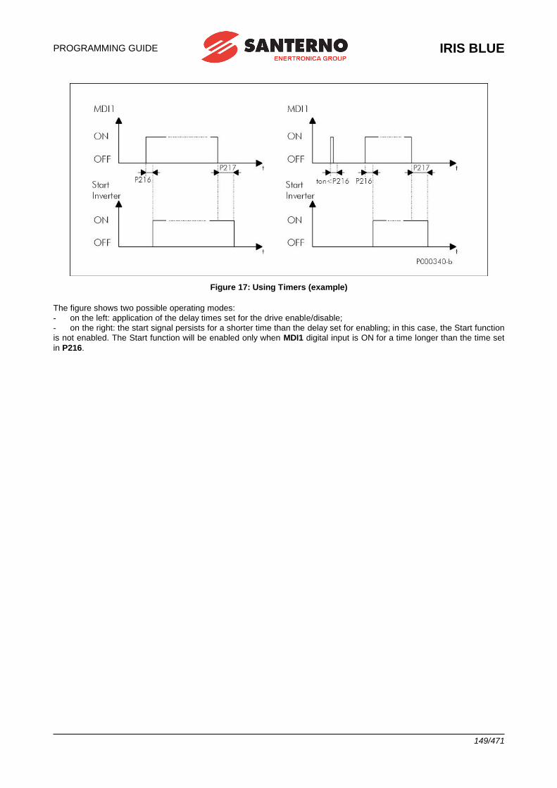
PROGRAMMING GUIDE
IRIS BLUE
149/471
Figure 17: Using Timers (example)
The figure shows two possible operating modes:
- on the left: application of the delay times set for the drive enable/disable;
- on the right: the start signal persists for a shorter time than the delay set for enabling; in this case, the Start function
is not enabled. The Start function will be enabled only when MDI1 digital input is ON for a time longer than the time set
in P216.
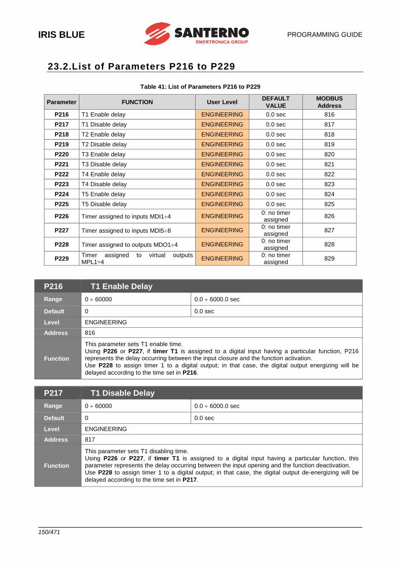
IRIS BLUE
PROGRAMMING GUIDE
150/471
23.2.List of Parameters P216 to P229
Table 41: List of Parameters P216 to P229
Parameter FUNCTION User Level DEFAULT
VALUE
MODBUS
Address
P216 T1 Enable delay ENGINEERING 0.0 sec 816
P217 T1 Disable delay ENGINEERING 0.0 sec 817
P218 T2 Enable delay ENGINEERING 0.0 sec 818
P219 T2 Disable delay ENGINEERING 0.0 sec 819
P220 T3 Enable delay ENGINEERING 0.0 sec 820
P221 T3 Disable delay ENGINEERING 0.0 sec 821
P222 T4 Enable delay ENGINEERING 0.0 sec 822
P223 T4 Disable delay ENGINEERING 0.0 sec 823
P224 T5 Enable delay ENGINEERING 0.0 sec 824
P225 T5 Disable delay ENGINEERING 0.0 sec 825
P226 Timer assigned to inputs MDI14 ENGINEERING 0: no timer assigned
826
P227 Timer assigned to inputs MDI58 ENGINEERING 0: no timer assigned
827
P228 Timer assigned to outputs MDO14 ENGINEERING 0: no timer assigned
828
P229 Timer assigned to virtual outputs MPL1÷4
ENGINEERING 0: no timer assigned
829
P216 T1 Enable Delay
Range 0 60000 0.0 6000.0 sec
Default 0 0.0 sec
Level ENGINEERING
Address 816
Function
This parameter sets T1 enable time.
Using P226 or P227, if timer T1 is assigned to a digital input having a particular function, P216 represents the delay occurring between the input closure and the function activation.
Use P228 to assign timer 1 to a digital output; in that case, the digital output energizing will be
delayed according to the time set in P216.
P217 T1 Disable Delay
Range 0 60000 0.0 6000.0 sec
Default 0 0.0 sec
Level ENGINEERING
Address 817
Function
This parameter sets T1 disabling time.
Using P226 or P227, if timer T1 is assigned to a digital input having a particular function, this parameter represents the delay occurring between the input opening and the function deactivation.
Use P228 to assign timer 1 to a digital output; in that case, the digital output de-energizing will be
delayed according to the time set in P217.
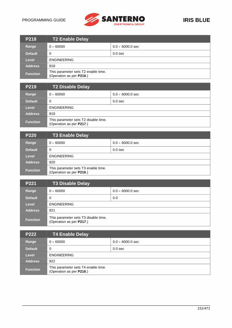
PROGRAMMING GUIDE
IRIS BLUE
151/471
P218 T2 Enable Delay
Range 0 60000 0.0 6000.0 sec
Default 0 0.0 sec
Level ENGINEERING
Address 818
Function This parameter sets T2 enable time.
(Operation as per P216.)
P219 T2 Disable Delay
Range 0 60000 0.0 6000.0 sec
Default 0 0.0 sec
Level ENGINEERING
Address 819
Function This parameter sets T2 disable time.
(Operation as per P217.)
P220 T3 Enable Delay
Range 0 60000 0.0 6000.0 sec
Default 0 0.0 sec
Level ENGINEERING
Address 820
Function This parameter sets T3 enable time.
(Operation as per P216.)
P221 T3 Disable Delay
Range 0 60000 0.0 6000.0 sec
Default 0 0.0
Level ENGINEERING
Address 821
Function This parameter sets T3 disable time.
(Operation as per P217.)
P222 T4 Enable Delay
Range 0 60000 0.0 6000.0 sec
Default 0 0.0 sec
Level ENGINEERING
Address 822
Function This parameter sets T4 enable time.
(Operation as per P216.)
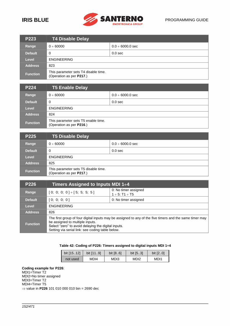
IRIS BLUE
PROGRAMMING GUIDE
152/471
P223 T4 Disable Delay
Range 0 60000 0.0 6000.0 sec
Default 0 0.0 sec
Level ENGINEERING
Address 823
Function This parameter sets T4 disable time.
(Operation as per P217.)
P224 T5 Enable Delay
Range 0 60000 0.0 6000.0 sec
Default 0 0.0 sec
Level ENGINEERING
Address 824
Function This parameter sets T5 enable time.
(Operation as per P216.)
P225 T5 Disable Delay
Range 0 60000 0.0 6000.0 sec
Default 0 0.0 sec
Level ENGINEERING
Address 825
Function This parameter sets T5 disable time.
(Operation as per P217.)
P226 Timers Assigned to Inputs MDI 14
Range [ 0; 0; 0; 0 ] [ 5; 5; 5; 5 ] 0: No timer assigned
1 5: T1 T5
Default [ 0; 0; 0; 0 ] 0: No timer assigned
Level ENGINEERING
Address 826
Function
The first group of four digital inputs may be assigned to any of the five timers and the same timer may be assigned to multiple inputs. Select “zero” to avoid delaying the digital inputs. Setting via serial link: see coding table below.
Table 42: Coding of P226: Timers assigned to digital inputs MDI 1÷4
bit [15..12] bit [11..9] bit [8..6] bit [5..3] bit [2..0]
not used MDI4 MDI3 MDI2 MDI1
Coding example for P226: MDI1=Timer T2 MDI2=No timer assigned MDI3=Timer T2 MDI4=Timer T5
value in P226 101 010 000 010 bin = 2690 dec
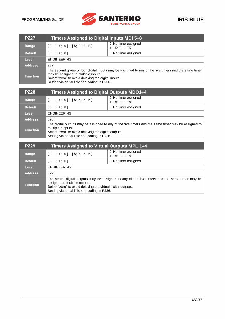
PROGRAMMING GUIDE
IRIS BLUE
153/471
P227 Timers Assigned to Digital Inputs MDI 58
Range [ 0; 0; 0; 0 ] [ 5; 5; 5; 5 ] 0: No timer assigned
1 5: T1 T5
Default [ 0; 0; 0; 0 ] 0: No timer assigned
Level ENGINEERING
Address 827
Function
The second group of four digital inputs may be assigned to any of the five timers and the same timer may be assigned to multiple inputs. Select “zero” to avoid delaying the digital inputs.
Setting via serial link: see coding in P226.
P228 Timers Assigned to Digital Outputs MDO14
Range [ 0; 0; 0; 0 ] [ 5; 5; 5; 5 ] 0: No timer assigned
1 5: T1 T5
Default [ 0; 0; 0; 0 ] 0: No timer assigned
Level ENGINEERING
Address 828
Function
The digital outputs may be assigned to any of the five timers and the same timer may be assigned to multiple outputs. Select “zero” to avoid delaying the digital outputs.
Setting via serial link: see coding in P226.
P229 Timers Assigned to Virtual Outputs MPL 14
Range [ 0; 0; 0; 0 ] [ 5; 5; 5; 5 ] 0: No timer assigned
1 5: T1 T5
Default [ 0; 0; 0; 0 ] 0: No timer assigned
Level ENGINEERING
Address 829
Function
The virtual digital outputs may be assigned to any of the five timers and the same timer may be assigned to multiple outputs. Select “zero” to avoid delaying the virtual digital outputs.
Setting via serial link: see coding in P226.
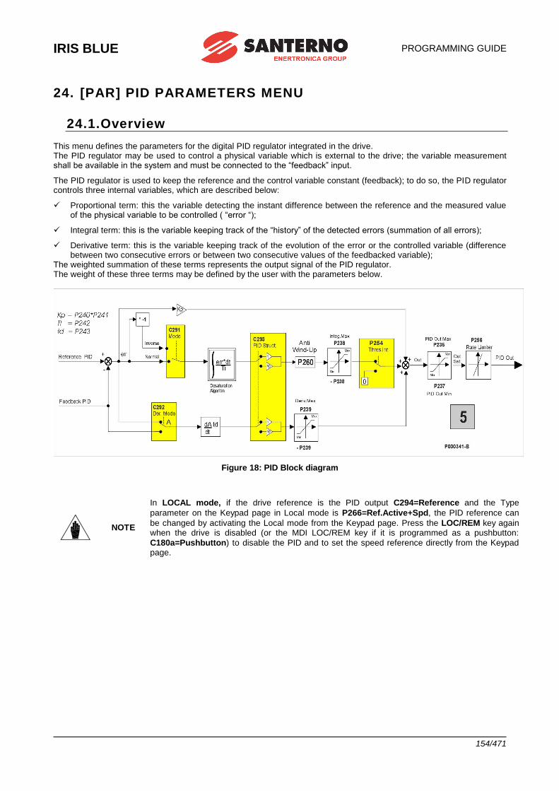
IRIS BLUE
PROGRAMMING GUIDE
154/471
24. [PAR] PID PARAMETERS MENU
24.1.Overview This menu defines the parameters for the digital PID regulator integrated in the drive. The PID regulator may be used to control a physical variable which is external to the drive; the variable measurement shall be available in the system and must be connected to the “feedback” input.
The PID regulator is used to keep the reference and the control variable constant (feedback); to do so, the PID regulator controls three internal variables, which are described below:
✓ Proportional term: this the variable detecting the instant difference between the reference and the measured value of the physical variable to be controlled ( “error “);
✓ Integral term: this is the variable keeping track of the “history” of the detected errors (summation of all errors);
✓ Derivative term: this is the variable keeping track of the evolution of the error or the controlled variable (difference between two consecutive errors or between two consecutive values of the feedbacked variable);
The weighted summation of these terms represents the output signal of the PID regulator. The weight of these three terms may be defined by the user with the parameters below.
Figure 18: PID Block diagram
NOTE
In LOCAL mode, if the drive reference is the PID output C294=Reference and the Type
parameter on the Keypad page in Local mode is P266=Ref.Active+Spd, the PID reference can
be changed by activating the Local mode from the Keypad page. Press the LOC/REM key again when the drive is disabled (or the MDI LOC/REM key if it is programmed as a pushbutton:
C180a=Pushbutton) to disable the PID and to set the speed reference directly from the Keypad page.
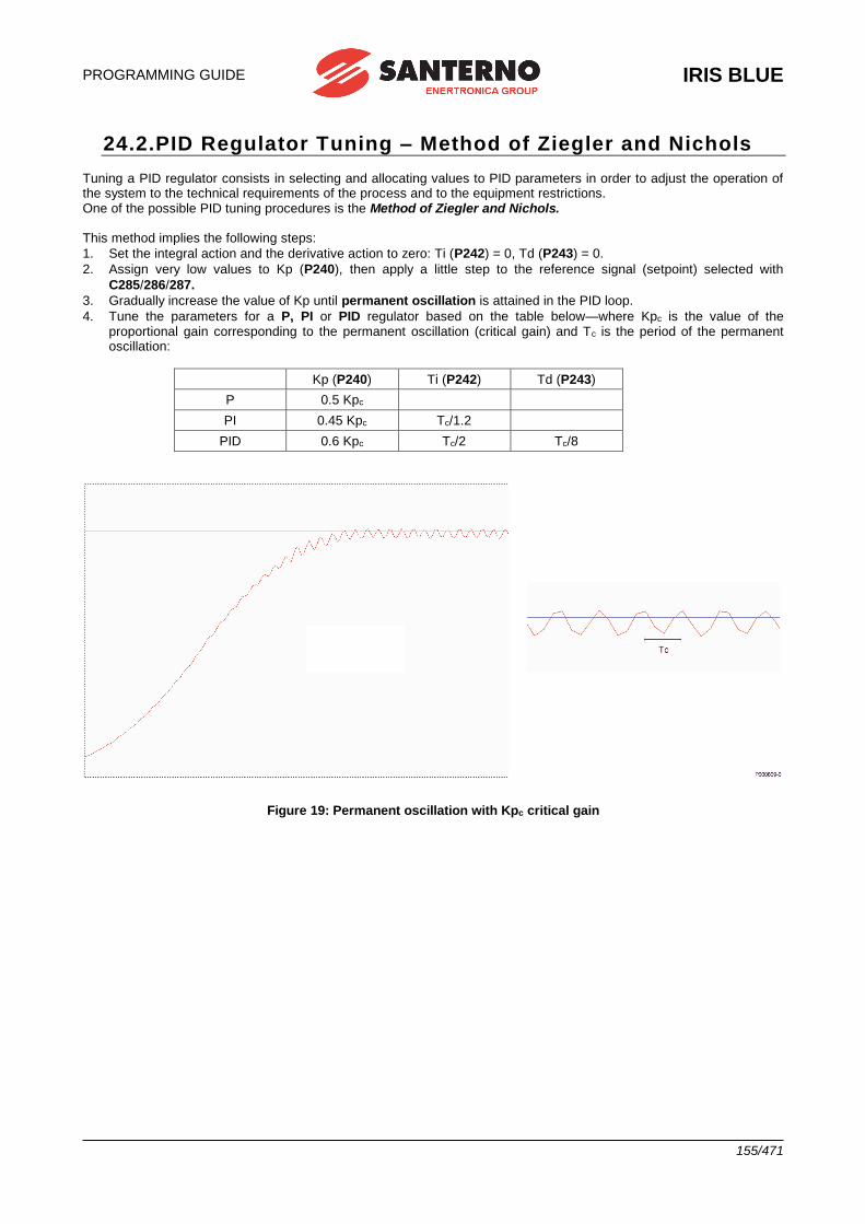
PROGRAMMING GUIDE
IRIS BLUE
155/471
24.2.PID Regulator Tuning – Method of Ziegler and Nichols Tuning a PID regulator consists in selecting and allocating values to PID parameters in order to adjust the operation of the system to the technical requirements of the process and to the equipment restrictions. One of the possible PID tuning procedures is the Method of Ziegler and Nichols. This method implies the following steps:
1. Set the integral action and the derivative action to zero: Ti (P242) = 0, Td (P243) = 0.
2. Assign very low values to Kp (P240), then apply a little step to the reference signal (setpoint) selected with
C285/286/287.
3. Gradually increase the value of Kp until permanent oscillation is attained in the PID loop.
4. Tune the parameters for a P, PI or PID regulator based on the table below—where Kpc is the value of the proportional gain corresponding to the permanent oscillation (critical gain) and Tc is the period of the permanent oscillation:
Kp (P240) Ti (P242) Td (P243)
P 0.5 Kpc
PI 0.45 Kpc Tc/1.2
PID 0.6 Kpc Tc/2 Tc/8
Figure 19: Permanent oscillation with Kpc critical gain
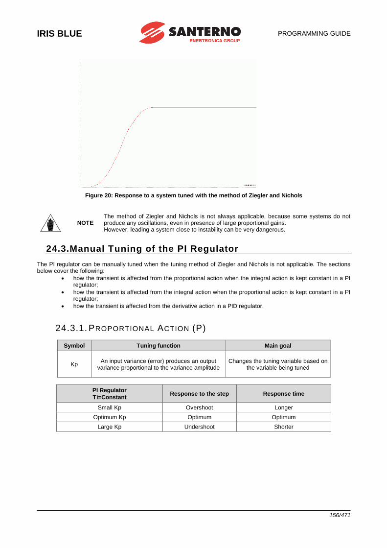
IRIS BLUE
PROGRAMMING GUIDE
156/471
Figure 20: Response to a system tuned with the method of Ziegler and Nichols
NOTE The method of Ziegler and Nichols is not always applicable, because some systems do not produce any oscillations, even in presence of large proportional gains. However, leading a system close to instability can be very dangerous.
24.3.Manual Tuning of the PI Regulator The PI regulator can be manually tuned when the tuning method of Ziegler and Nichols is not applicable. The sections below cover the following:
• how the transient is affected from the proportional action when the integral action is kept constant in a PI regulator;
• how the transient is affected from the integral action when the proportional action is kept constant in a PI regulator;
• how the transient is affected from the derivative action in a PID regulator.
24.3.1. PROPORTIONAL ACTION (P)
Symbol Tuning function Main goal
Kp An input variance (error) produces an output
variance proportional to the variance amplitude Changes the tuning variable based on
the variable being tuned
PI Regulator
Ti=Constant Response to the step Response time
Small Kp Overshoot Longer
Optimum Kp Optimum Optimum
Large Kp Undershoot Shorter
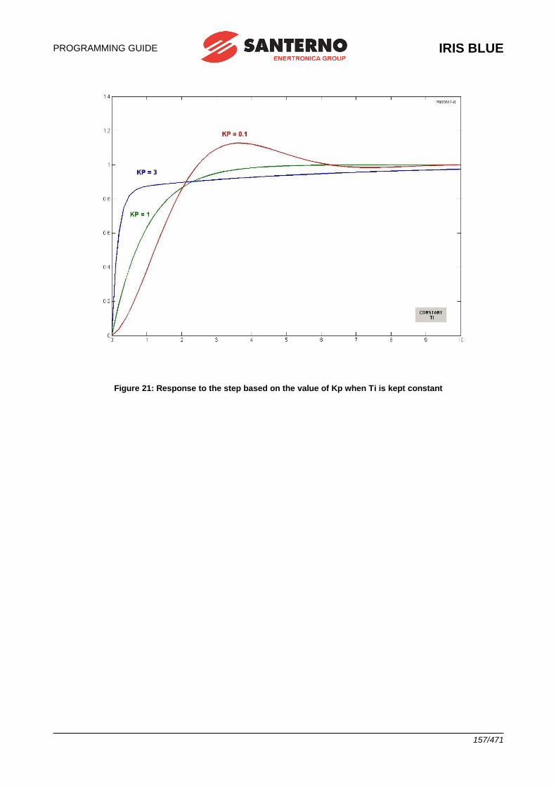
PROGRAMMING GUIDE
IRIS BLUE
157/471
Figure 21: Response to the step based on the value of Kp when Ti is kept constant
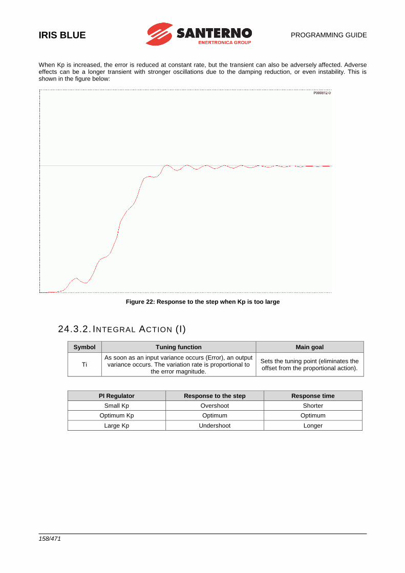
IRIS BLUE
PROGRAMMING GUIDE
158/471
When Kp is increased, the error is reduced at constant rate, but the transient can also be adversely affected. Adverse effects can be a longer transient with stronger oscillations due to the damping reduction, or even instability. This is shown in the figure below:
Figure 22: Response to the step when Kp is too large
24.3.2. INTEGRAL ACTION (I)
Symbol Tuning function Main goal
Ti As soon as an input variance occurs (Error), an output variance occurs. The variation rate is proportional to
the error magnitude.
Sets the tuning point (eliminates the offset from the proportional action).
PI Regulator Response to the step Response time
Small Kp Overshoot Shorter
Optimum Kp Optimum Optimum
Large Kp Undershoot Longer
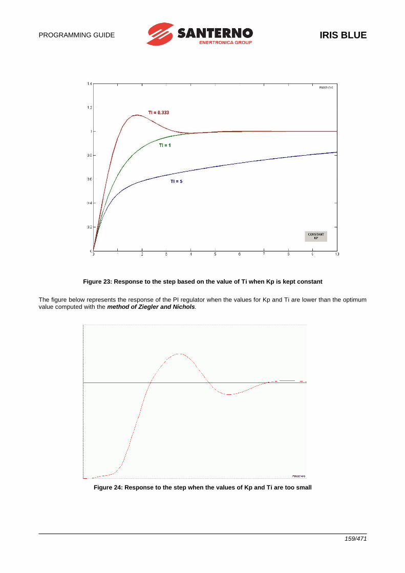
PROGRAMMING GUIDE
IRIS BLUE
159/471
Figure 23: Response to the step based on the value of Ti when Kp is kept constant
The figure below represents the response of the PI regulator when the values for Kp and Ti are lower than the optimum value computed with the method of Ziegler and Nichols.
Figure 24: Response to the step when the values of Kp and Ti are too small
IRIS BLUE
PROGRAMMING GUIDE
160/471
24.3.3. DERIVATIVE ACTION (D)
Symbol Tuning function Main goal
Td An input variance (error) generates an output
variance proportional to the variance rate
Decreases the response time for the return to the tuning
point
The derivative action set with Td increases the stability of the system, thus increasing the transient response. The derivative action tends to get an earlier response, but it increases the system sensitivity to the disturbance overriding the error signal.
24.3.1. TUNING ACTIONS AT CONSTANT SPEED When the system is operating at constant speed, the system response shall be the most accurate as possible (minimum error) and shall adjust any little reference variations. When at constant speed, if the system does not promptly respond to little reference variations, a shorter integral time may solve this problem. Otherwise, when little and long-lasting oscillations affect the reference value, setting a longer integral time could be the right solution.
24.4.Anti Windup The major benefit of the integral action is to ensure null errors at steady speed. However, just like the derivative action, the integral action shall be applied with caution to avoid worse performance. A case in point is the output saturation occurring at the same time as an excessive integral action. When the output saturates, the control action is limited, so the error is still remarkable. If the error persists, the actuator will saturate, because the longer the time the error persists, the stronger the integral action is; this phenomenon is called “windup”. In case of output saturation, the integral term can reach very high values; as a result, the error shall have opposite sign for a long period before exiting from saturation. The PID regulator of the IRIS BLUE drive is provided with an Anti-windup function which compensates the effect described above. This Anti-windup action is described below (P=proportional term; I=integral term; D=derivative term). The output is always calculated as follows:
OUT P + I + D When output saturation occurs:
OUT OUTsat The integral term is forced based on the following:
I OUTsat – P – D (which is the Anti-windup function). This prevents the integral term from reaching very high values; the integral term is then kept constantly in line with the saturated output value OUTsat that is present at each moment; any variations of the error (i.e. the P) that allows exiting from saturation have immediate effect to the output, without having to wait for a long time before discharging the integral term itself.
The effect of the Anti-windup can be adjusted with parameter P260; if P260<1, the effect is reduced and the system is
less sensitive to error variations; if P260=0, the effect is cancelled.
The value of P260=1 is correct for the applications requiring to quickly exit from saturation.
On the other hand, reducing P260 can be useful when output variations are to be avoided for negligible error variations.
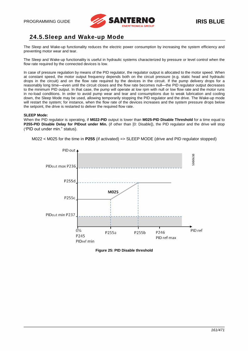
PROGRAMMING GUIDE
IRIS BLUE
161/471
24.5.Sleep and Wake-up Mode The Sleep and Wake-up functionality reduces the electric power consumption by increasing the system efficiency and preventing motor wear and tear. The Sleep and Wake-up functionality is useful in hydraulic systems characterized by pressure or level control when the flow rate required by the connected devices is low. In case of pressure regulation by means of the PID regulator, the regulator output is allocated to the motor speed. When at constant speed, the motor output frequency depends both on the circuit pressure (e.g. static head and hydraulic drops in the circuit) and on the flow rate required by the devices in the circuit. If the pump delivery drops for a reasonably long time—even until the circuit closes and the flow rate becomes null—the PID regulator output decreases to the minimum PID output. In that case, the pump will operate at low rpm with null or low flow rate and the motor runs in no-load conditions. In order to avoid pump wear and tear and consumptions due to weak lubrication and cooling down, the Sleep Mode may be used, allowing temporarily stopping the PID regulator and the drive. The Wake-up mode will restart the system; for instance, when the flow rate of the devices increases and the system pressure drops below the setpoint, the drive is restarted to deliver the required flow rate.
SLEEP Mode:
When the PID regulator is operating, if M022-PID output is lower than M025-PID Disable Threshold for a time equal to
P255-PID Disable Delay for PIDout under Min. (if other than [0: Disable]), the PID regulator and the drive will stop
(“PID out under min.” status).
M022 < M025 for the time in P255 (if activated) => SLEEP MODE (drive and PID regulator stopped)
Figure 25: PID Disable threshold
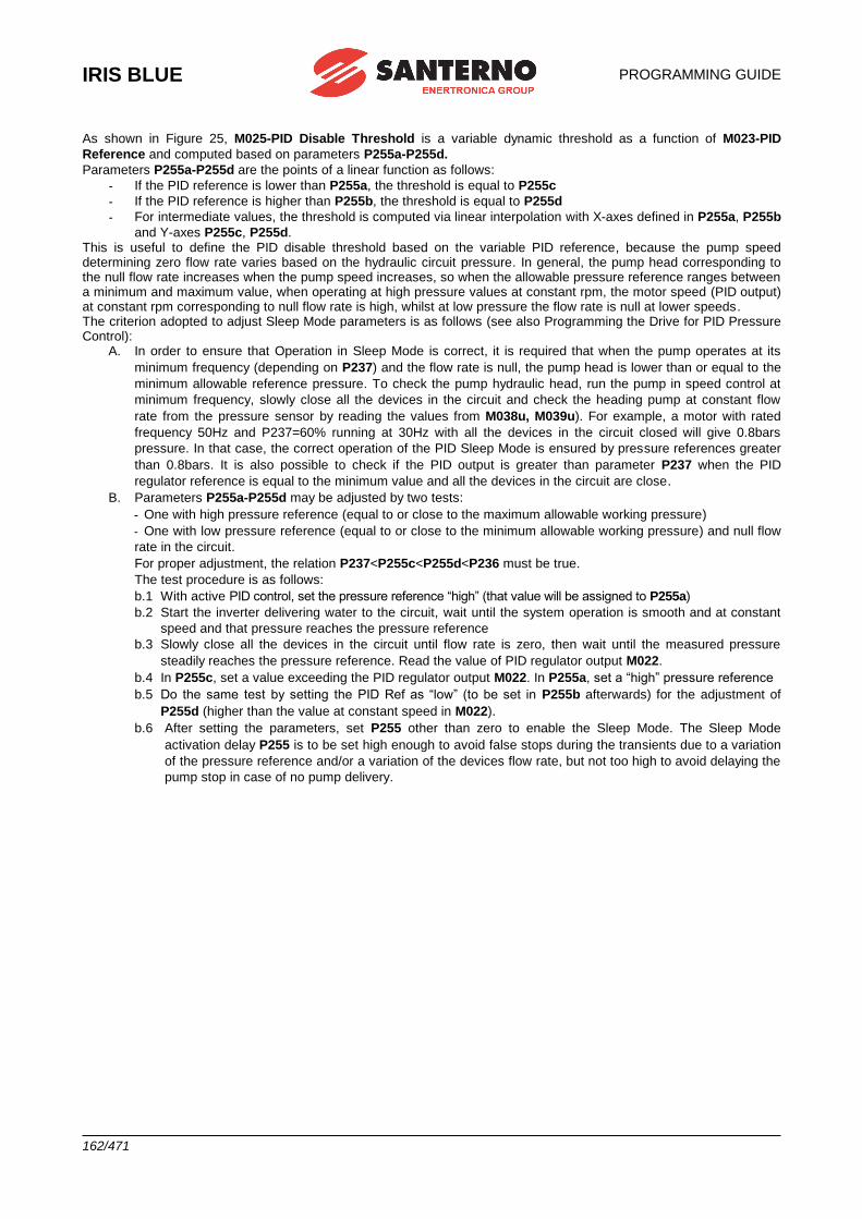
IRIS BLUE
PROGRAMMING GUIDE
162/471
As shown in Figure 25, M025-PID Disable Threshold is a variable dynamic threshold as a function of M023-PID
Reference and computed based on parameters P255a-P255d.
Parameters P255a-P255d are the points of a linear function as follows:
- If the PID reference is lower than P255a, the threshold is equal to P255c
- If the PID reference is higher than P255b, the threshold is equal to P255d
- For intermediate values, the threshold is computed via linear interpolation with X-axes defined in P255a, P255b
and Y-axes P255c, P255d. This is useful to define the PID disable threshold based on the variable PID reference, because the pump speed determining zero flow rate varies based on the hydraulic circuit pressure. In general, the pump head corresponding to the null flow rate increases when the pump speed increases, so when the allowable pressure reference ranges between a minimum and maximum value, when operating at high pressure values at constant rpm, the motor speed (PID output) at constant rpm corresponding to null flow rate is high, whilst at low pressure the flow rate is null at lower speeds. The criterion adopted to adjust Sleep Mode parameters is as follows (see also Programming the Drive for PID Pressure Control):
A. In order to ensure that Operation in Sleep Mode is correct, it is required that when the pump operates at its
minimum frequency (depending on P237) and the flow rate is null, the pump head is lower than or equal to the
minimum allowable reference pressure. To check the pump hydraulic head, run the pump in speed control at
minimum frequency, slowly close all the devices in the circuit and check the heading pump at constant flow
rate from the pressure sensor by reading the values from M038u, M039u). For example, a motor with rated
frequency 50Hz and P237=60% running at 30Hz with all the devices in the circuit closed will give 0.8bars
pressure. In that case, the correct operation of the PID Sleep Mode is ensured by pressure references greater
than 0.8bars. It is also possible to check if the PID output is greater than parameter P237 when the PID
regulator reference is equal to the minimum value and all the devices in the circuit are close.
B. Parameters P255a-P255d may be adjusted by two tests:
- One with high pressure reference (equal to or close to the maximum allowable working pressure)
- One with low pressure reference (equal to or close to the minimum allowable working pressure) and null flow
rate in the circuit.
For proper adjustment, the relation P237<P255c<P255d<P236 must be true.
The test procedure is as follows:
b.1 With active PID control, set the pressure reference “high” (that value will be assigned to P255a)
b.2 Start the inverter delivering water to the circuit, wait until the system operation is smooth and at constant
speed and that pressure reaches the pressure reference
b.3 Slowly close all the devices in the circuit until flow rate is zero, then wait until the measured pressure
steadily reaches the pressure reference. Read the value of PID regulator output M022.
b.4 In P255c, set a value exceeding the PID regulator output M022. In P255a, set a “high” pressure reference
b.5 Do the same test by setting the PID Ref as “low” (to be set in P255b afterwards) for the adjustment of
P255d (higher than the value at constant speed in M022).
b.6 After setting the parameters, set P255 other than zero to enable the Sleep Mode. The Sleep Mode
activation delay P255 is to be set high enough to avoid false stops during the transients due to a variation
of the pressure reference and/or a variation of the devices flow rate, but not too high to avoid delaying the
pump stop in case of no pump delivery.
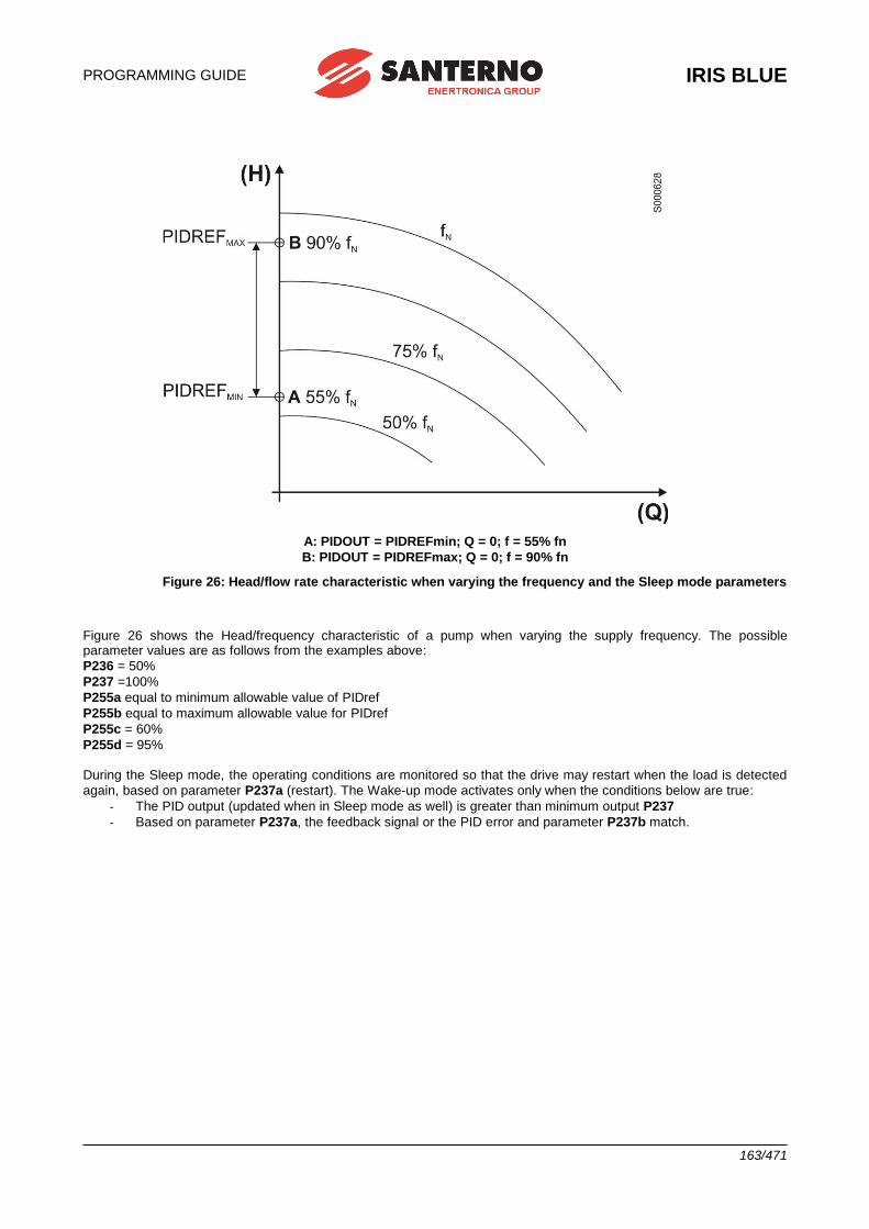
PROGRAMMING GUIDE
IRIS BLUE
163/471
A: PIDOUT = PIDREFmin; Q = 0; f = 55% fn
B: PIDOUT = PIDREFmax; Q = 0; f = 90% fn
Figure 26: Head/flow rate characteristic when varying the frequency and the Sleep mode parameters
Figure 26 shows the Head/frequency characteristic of a pump when varying the supply frequency. The possible parameter values are as follows from the examples above:
P236 = 50%
P237 =100%
P255a equal to minimum allowable value of PIDref
P255b equal to maximum allowable value for PIDref
P255c = 60%
P255d = 95% During the Sleep mode, the operating conditions are monitored so that the drive may restart when the load is detected
again, based on parameter P237a (restart). The Wake-up mode activates only when the conditions below are true:
- The PID output (updated when in Sleep mode as well) is greater than minimum output P237
- Based on parameter P237a, the feedback signal or the PID error and parameter P237b match.
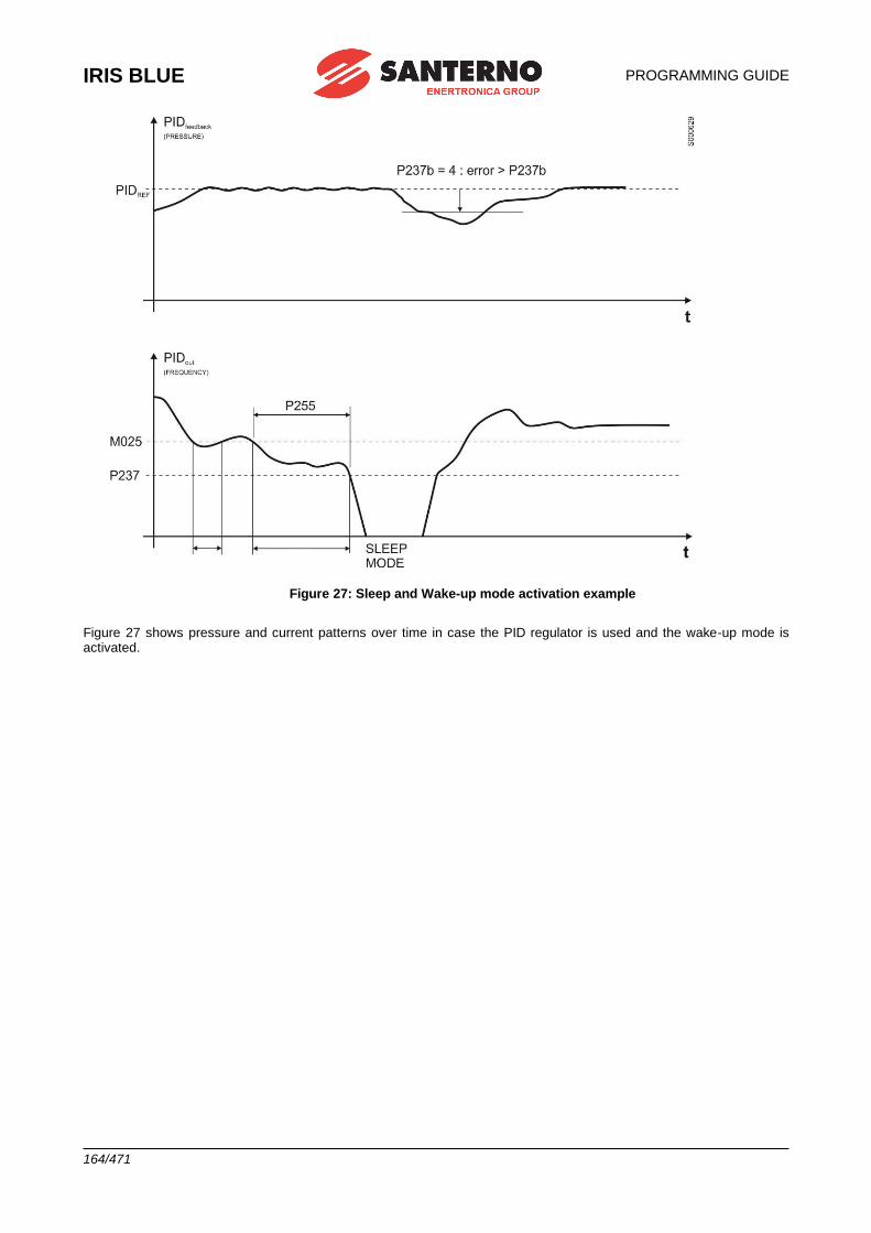
IRIS BLUE
PROGRAMMING GUIDE
164/471
Figure 27: Sleep and Wake-up mode activation example
Figure 27 shows pressure and current patterns over time in case the PID regulator is used and the wake-up mode is activated.
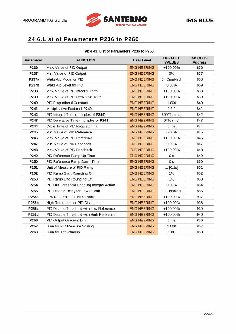
PROGRAMMING GUIDE
IRIS BLUE
165/471
24.6.List of Parameters P236 to P260
Table 43: List of Parameters P236 to P260
Parameter FUNCTION User Level DEFAULT
VALUES
MODBUS
Address
P236 Max. Value of PID Output ENGINEERING +100.00% 836
P237 Min. Value of PID Output ENGINEERING 0% 837
P237a Wake-Up Mode for PID ENGINEERING 0: [Disabled] 858
P237b Wake-Up Level for PID ENGINEERING 0.00% 859
P238 Max. Value of PID Integral Term ENGINEERING +100.00% 838
P239 Max. Value of PID Derivative Term ENGINEERING +100.00% 839
P240 PID Proportional Constant ENGINEERING 1.000 840
P241 Multiplicative Factor of P240 ENGINEERING 0:1.0 841
P242 PID Integral Time (multiples of P244) ENGINEERING 500*Tc (ms) 842
P243 PID Derivative Time (multiples of P244) ENGINEERING 0*Tc (ms) 843
P244 Cycle Time of PID Regulator: Tc ENGINEERING 5 ms 844
P245 Min. Value of PID Reference ENGINEERING 0.00% 845
P246 Max. Value of PID Reference ENGINEERING +100.00% 846
P247 Min. Value of PID Feedback ENGINEERING 0.00% 847
P248 Max. Value of PID Feedback ENGINEERING +100.00% 848
P249 PID Reference Ramp Up Time ENGINEERING 0 s 849
P250 PID Reference Ramp Down Time ENGINEERING 0 s 850
P251 Unit of Measure of PID Ramp ENGINEERING 1: [0.1s] 851
P252 PID Ramp Start Rounding Off ENGINEERING 1% 852
P253 PID Ramp End Rounding Off ENGINEERING 1% 853
P254 PID Out Threshold Enabling Integral Action ENGINEERING 0.00% 854
P255 PID Disable Delay for Low PIDout ENGINEERING 0: [Disabled] 855
P255a Low Reference for PID Disable ENGINEERING +100.00% 937
P255b High Reference for PID Disable ENGINEERING +100.00% 938
P255c PID Disable Threshold with Low Reference ENGINEERING +100.00% 939
P255d PID Disable Threshold with High Reference ENGINEERING +100.00% 940
P256 PID Output Gradient Limit ENGINEERING 1 ms 856
P257 Gain for PID Measure Scaling ENGINEERING 1.000 857
P260 Gain for Anti-Windup ENGINEERING 1.00 860
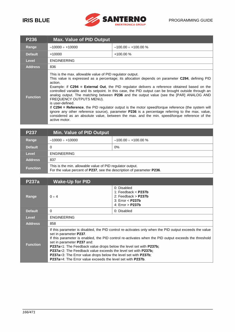
IRIS BLUE
PROGRAMMING GUIDE
166/471
P236 Max. Value of PID Output
Range –10000 +10000 –100.00 +100.00 %
Default +10000 +100.00 %
Level ENGINEERING
Address 836
Function
This is the max. allowable value of PID regulator output.
This value is expressed as a percentage; its allocation depends on parameter C294, defining PID action.
Example: if C294 = External Out, the PID regulator delivers a reference obtained based on the controlled variable and its setpoint. In this case, the PID output can be brought outside through an
analog output. The matching between P236 and the output value (see the [PAR] ANALOG AND FREQUENCY OUTPUTS MENU). is user-defined.
If C294 = Reference, the PID regulator output is the motor speed/torque reference (the system will
ignore any other reference source), parameter P236 is a percentage referring to the max. value, considered as an absolute value, between the max. and the min. speed/torque reference of the active motor.
P237 Min. Value of PID Output
Range –10000 +10000 –100.00 +100.00 %
Default 0 0%
Level ENGINEERING
Address 837
Function This is the min. allowable value of PID regulator output.
For the value percent of P237, see the description of parameter P236.
P237a Wake-Up for PID
Range 0 4
0: Disabled
1: Feedback < P237b
2: Feedback > P237b
3: Error < P237b
4: Error > P237b
Default 0 0: Disabled
Level ENGINEERING
Address 858
Function
If this parameter is disabled, the PID control re-activates only when the PID output exceeds the value
set in parameter P237. If this parameter is enabled, the PID control re-activates when the PID output exceeds the threshold
set in parameter P237 and:
P237a=1: The Feedback value drops below the level set with P237b;
P237a=2: The Feedback value exceeds the level set with P237b;
P237a=3: The Error value drops below the level set with P237b;
P237a=4: The Error value exceeds the level set with P237b.
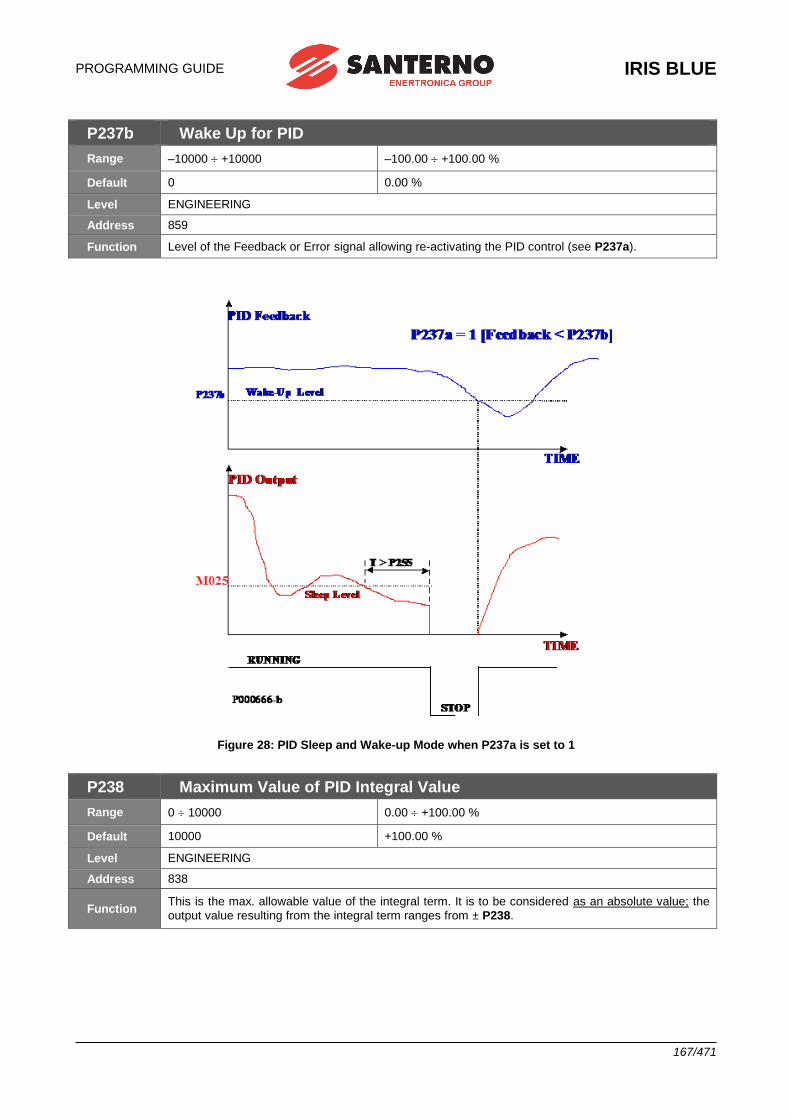
PROGRAMMING GUIDE
IRIS BLUE
167/471
P237b Wake Up for PID
Range –10000 +10000 –100.00 +100.00 %
Default 0 0.00 %
Level ENGINEERING
Address 859
Function Level of the Feedback or Error signal allowing re-activating the PID control (see P237a).
Figure 28: PID Sleep and Wake-up Mode when P237a is set to 1
P238 Maximum Value of PID Integral Value
Range 0 10000 0.00 +100.00 %
Default 10000 +100.00 %
Level ENGINEERING
Address 838
Function This is the max. allowable value of the integral term. It is to be considered as an absolute value; the
output value resulting from the integral term ranges from ± P238.
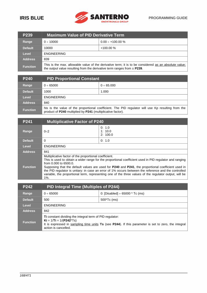
IRIS BLUE
PROGRAMMING GUIDE
168/471
P239 Maximum Value of PID Derivative Term
Range 0 10000 0.00 +100.00 %
Default 10000 +100.00 %
Level ENGINEERING
Address 839
Function This is the max. allowable value of the derivative term; it is to be considered as an absolute value;
the output value resulting from the derivative term ranges from ± P239.
P240 PID Proportional Constant
Range 0 65000 0 65.000
Default 1000 1.000
Level ENGINEERING
Address 840
Function his is the value of the proportional coefficient. The PID regulator will use Kp resulting from the
product of P240 multiplied by P241 (multiplicative factor).
P241 Multiplicative Factor of P240
Range 02
0: 1.0 1: 10.0 2: 100.0
Default 0 0: 1.0
Level ENGINEERING
Address 841
Function
Multiplicative factor of the proportional coefficient. This is used to obtain a wider range for the proportional coefficient used in PID regulator and ranging from 0.000 to 6500.0.
Supposing that the default values are used for P240 and P241, the proportional coefficient used in the PID regulator is unitary: in case an error of 1% occurs between the reference and the controlled variable, the proportional term, representing one of the three values of the regulator output, will be 1%.
P242 PID Integral Time (Multiples of P244)
Range 0 65000 0: [Disabled] 65000 * Tc (ms)
Default 500 500*Tc (ms)
Level ENGINEERING
Address 842
Function
Ti constant dividing the integral term of PID regulator:
Ki = 1/Ti = 1/(P242*Ts)
It is expressed in sampling time units Ts (see P244). If this parameter is set to zero, the integral action is cancelled.
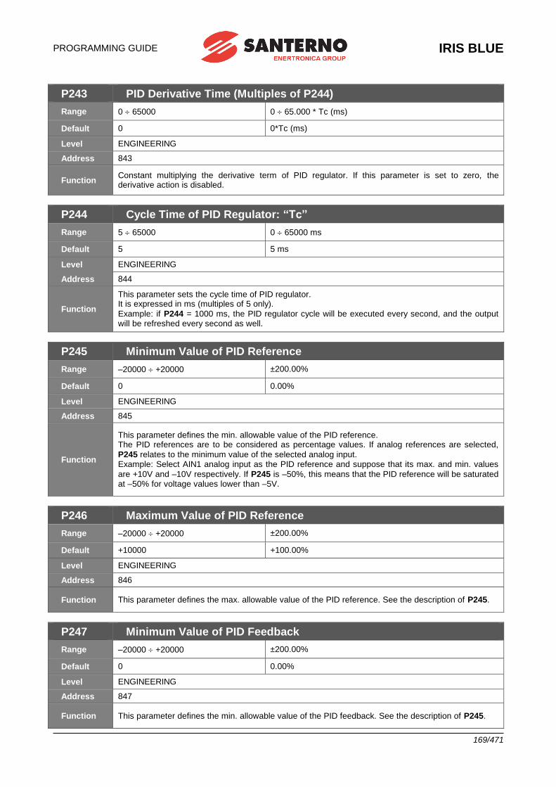
PROGRAMMING GUIDE
IRIS BLUE
169/471
P243 PID Derivative Time (Multiples of P244)
Range 0 65000 0 65.000 * Tc (ms)
Default 0 0*Tc (ms)
Level ENGINEERING
Address 843
Function Constant multiplying the derivative term of PID regulator. If this parameter is set to zero, the derivative action is disabled.
P244 Cycle Time of PID Regulator: “Tc”
Range 5 65000 0 65000 ms
Default 5 5 ms
Level ENGINEERING
Address 844
Function
This parameter sets the cycle time of PID regulator. It is expressed in ms (multiples of 5 only).
Example: if P244 = 1000 ms, the PID regulator cycle will be executed every second, and the output will be refreshed every second as well.
P245 Minimum Value of PID Reference
Range –20000 +20000 ±200.00%
Default 0 0.00%
Level ENGINEERING
Address 845
Function
This parameter defines the min. allowable value of the PID reference. The PID references are to be considered as percentage values. If analog references are selected,
P245 relates to the minimum value of the selected analog input. Example: Select AIN1 analog input as the PID reference and suppose that its max. and min. values
are +10V and –10V respectively. If P245 is –50%, this means that the PID reference will be saturated at –50% for voltage values lower than –5V.
P246 Maximum Value of PID Reference
Range –20000 +20000 ±200.00%
Default +10000 +100.00%
Level ENGINEERING
Address 846
Function This parameter defines the max. allowable value of the PID reference. See the description of P245.
P247 Minimum Value of PID Feedback
Range –20000 +20000 ±200.00%
Default 0 0.00%
Level ENGINEERING
Address 847
Function This parameter defines the min. allowable value of the PID feedback. See the description of P245.
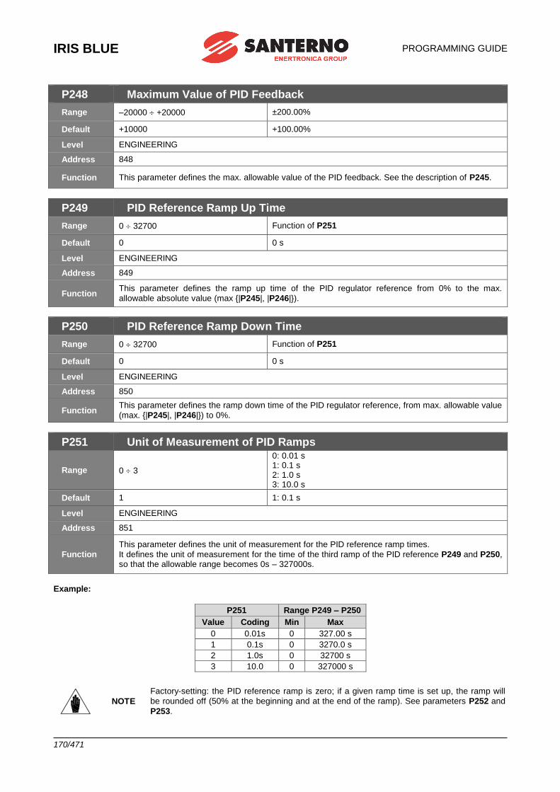
IRIS BLUE
PROGRAMMING GUIDE
170/471
P248 Maximum Value of PID Feedback
Range –20000 +20000 ±200.00%
Default +10000 +100.00%
Level ENGINEERING
Address 848
Function This parameter defines the max. allowable value of the PID feedback. See the description of P245.
P249 PID Reference Ramp Up Time
Range 0 32700 Function of P251
Default 0 0 s
Level ENGINEERING
Address 849
Function This parameter defines the ramp up time of the PID regulator reference from 0% to the max.
allowable absolute value (max {|P245|, |P246|}).
P250 PID Reference Ramp Down Time
Range 0 32700 Function of P251
Default 0 0 s
Level ENGINEERING
Address 850
Function This parameter defines the ramp down time of the PID regulator reference, from max. allowable value
(max. {|P245|, |P246|}) to 0%.
P251 Unit of Measurement of PID Ramps
Range 0 3
0: 0.01 s 1: 0.1 s 2: 1.0 s 3: 10.0 s
Default 1 1: 0.1 s
Level ENGINEERING
Address 851
Function
This parameter defines the unit of measurement for the PID reference ramp times.
It defines the unit of measurement for the time of the third ramp of the PID reference P249 and P250, so that the allowable range becomes 0s – 327000s.
Example:
P251 Range P249 – P250
Value Coding Min Max
0 0.01s 0 327.00 s
1 0.1s 0 3270.0 s
2 1.0s 0 32700 s
3 10.0 0 327000 s
NOTE
Factory-setting: the PID reference ramp is zero; if a given ramp time is set up, the ramp will
be rounded off (50% at the beginning and at the end of the ramp). See parameters P252 and
P253.
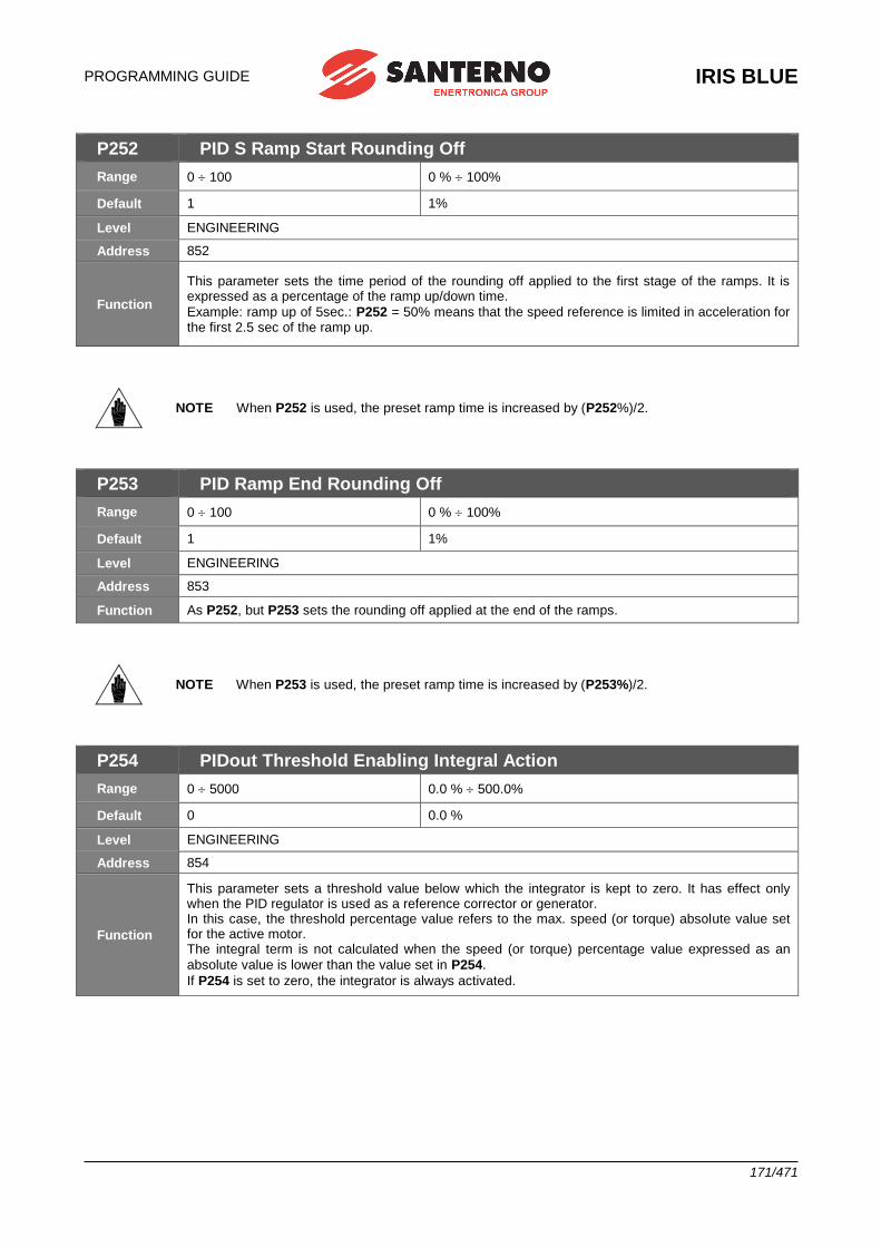
PROGRAMMING GUIDE
IRIS BLUE
171/471
P252 PID S Ramp Start Rounding Off
Range 0 100 0 % 100%
Default 1 1%
Level ENGINEERING
Address 852
Function
This parameter sets the time period of the rounding off applied to the first stage of the ramps. It is expressed as a percentage of the ramp up/down time.
Example: ramp up of 5sec.: P252 = 50% means that the speed reference is limited in acceleration for the first 2.5 sec of the ramp up.
NOTE When P252 is used, the preset ramp time is increased by (P252%)/2.
P253 PID Ramp End Rounding Off
Range 0 100 0 % 100%
Default 1 1%
Level ENGINEERING
Address 853
Function As P252, but P253 sets the rounding off applied at the end of the ramps.
NOTE When P253 is used, the preset ramp time is increased by (P253%)/2.
P254 PIDout Threshold Enabling Integral Action
Range 0 5000 0.0 % 500.0%
Default 0 0.0 %
Level ENGINEERING
Address 854
Function
This parameter sets a threshold value below which the integrator is kept to zero. It has effect only when the PID regulator is used as a reference corrector or generator. In this case, the threshold percentage value refers to the max. speed (or torque) absolute value set for the active motor. The integral term is not calculated when the speed (or torque) percentage value expressed as an
absolute value is lower than the value set in P254.
If P254 is set to zero, the integrator is always activated.
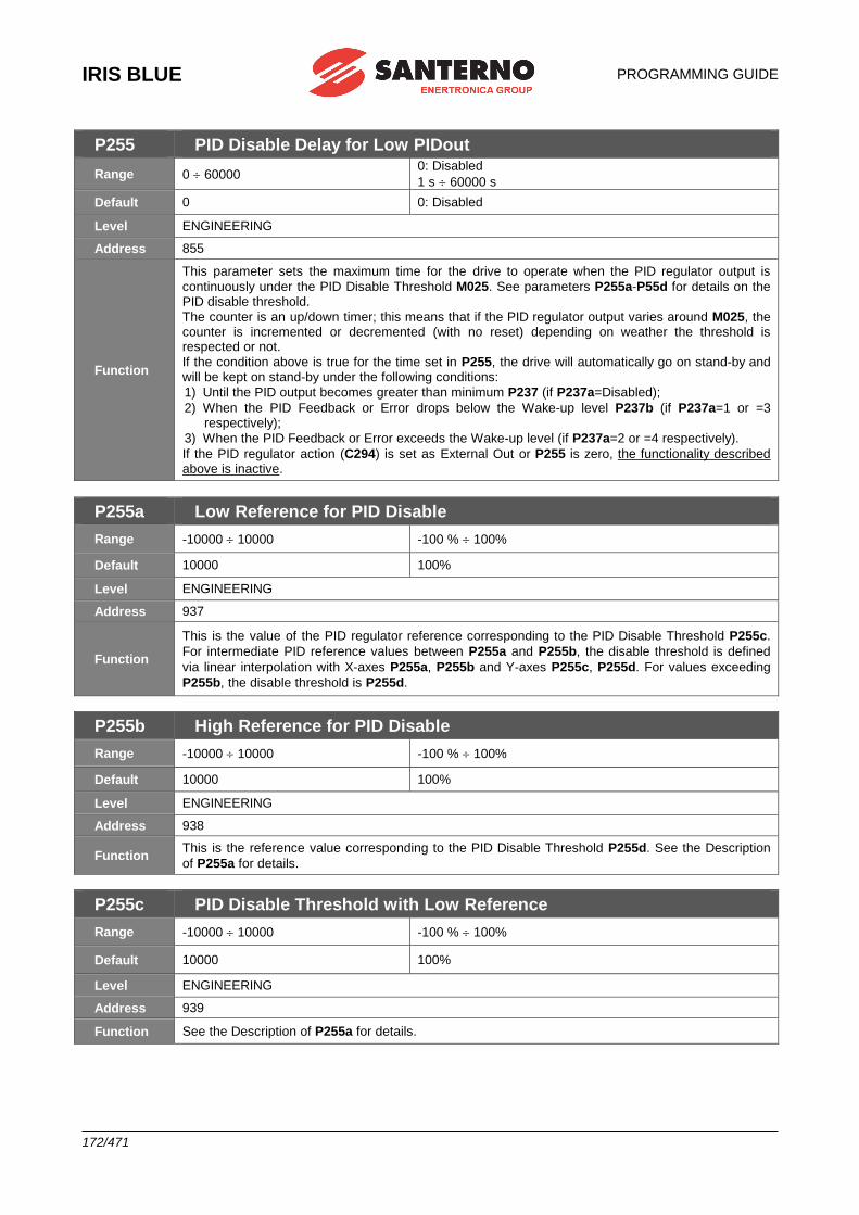
IRIS BLUE
PROGRAMMING GUIDE
172/471
P255 PID Disable Delay for Low PIDout
Range 0 60000 0: Disabled
1 s 60000 s
Default 0 0: Disabled
Level ENGINEERING
Address 855
Function
This parameter sets the maximum time for the drive to operate when the PID regulator output is
continuously under the PID Disable Threshold M025. See parameters P255a-P55d for details on the PID disable threshold.
The counter is an up/down timer; this means that if the PID regulator output varies around M025, the counter is incremented or decremented (with no reset) depending on weather the threshold is respected or not.
If the condition above is true for the time set in P255, the drive will automatically go on stand-by and will be kept on stand-by under the following conditions:
1) Until the PID output becomes greater than minimum P237 (if P237a=Disabled);
2) When the PID Feedback or Error drops below the Wake-up level P237b (if P237a=1 or =3 respectively);
3) When the PID Feedback or Error exceeds the Wake-up level (if P237a=2 or =4 respectively).
If the PID regulator action (C294) is set as External Out or P255 is zero, the functionality described above is inactive.
P255a Low Reference for PID Disable
Range -10000 10000 -100 % 100%
Default 10000 100%
Level ENGINEERING
Address 937
Function
This is the value of the PID regulator reference corresponding to the PID Disable Threshold P255c.
For intermediate PID reference values between P255a and P255b, the disable threshold is defined
via linear interpolation with X-axes P255a, P255b and Y-axes P255c, P255d. For values exceeding
P255b, the disable threshold is P255d.
P255b High Reference for PID Disable
Range -10000 10000 -100 % 100%
Default 10000 100%
Level ENGINEERING
Address 938
Function This is the reference value corresponding to the PID Disable Threshold P255d. See the Description
of P255a for details.
P255c PID Disable Threshold with Low Reference
Range -10000 10000 -100 % 100%
Default 10000 100%
Level ENGINEERING
Address 939
Function See the Description of P255a for details.
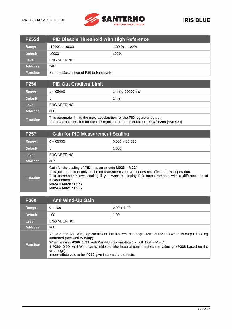
PROGRAMMING GUIDE
IRIS BLUE
173/471
P255d PID Disable Threshold with High Reference
Range -10000 10000 -100 % 100%
Default 10000 100%
Level ENGINEERING
Address 940
Function See the Description of P255a for details.
P256 PID Out Gradient Limit
Range 1 65000 1 ms 65000 ms
Default 1 1 ms
Level ENGINEERING
Address 856
Function This parameter limits the max. acceleration for the PID regulator output.
The max. acceleration for the PID regulator output is equal to 100% / P256 [%/msec].
P257 Gain for PID Measurement Scaling
Range 0 65535 0.000 65.535
Default 1 1.000
Level ENGINEERING
Address 857
Function
Gain for the scaling of PID measurements M023 ÷ M024. This gain has effect only on the measurements above. It does not affect the PID operation. This parameter allows scaling if you want to display PID measurements with a different unit of measurement:
M023 = M020 * P257
M024 = M021 * P257
P260 Anti Wind-Up Gain
Range 0 100 0.00 1.00
Default 100 1.00
Level ENGINEERING
Address 860
Function
Value of the Anti Wind-Up coefficient that freezes the integral term of the PID when its output is being saturated (see Anti Windup).
When leaving P260=1.00, Anti Wind-Up is complete (I OUTsat – P – D).
If P260=0.00, Anti Wind-Up is inhibited (the integral term reaches the value of ±P238 based on the error sign).
Intermediate values for P260 give intermediate effects.
IRIS BLUE
PROGRAMMING GUIDE
174/471
25. [PAR] PID2 PARAMETERS MENU
25.1.Overview This menu defines the parameters of the digital regulator PID2 as well as the parameters used in 2-zone mode.
To activate the PID2 regulator, set C291a = 7: 2 PID (see [CFG] PID CONFIGURATION MENU). Once activated, the PID2 regulator has the same functionality and operates in line with the standard PID (see [PAR] PID PARAMETERS MENU). The output of the standard PID regulator is algebraically summed with the output of the PID2 regulator. Add “200” to the parameter codes pertaining to the standard PID to obtain the relevant parameter codes for PID2.
Example: P236 for standard PID corresponds to P436 for PID2.
To enable the 2-zone mode, set C291a = 5: 2-Zone MIN or 6: 2-Zone MAX ([CFG] PID CONFIGURATION MENU). Once the 2-zone mode is enabled, the standard PID regulator operates on the system with the larger error (minimum
feedback with respect to its reference, 2-Zone MIN) or with the smaller error (maximum feedback with respect to its
reference, 2-Zone MAX).
In 2-zone mode, parameters P236..P260 pertain to the system where the error results from the reference selected with
C285 and from the feedback selected with C288, whilst parameters P436..P460 pertain to the system where the error
results from the reference selected with C286 and from the feedback selected with C289.
NOTE The PID2 regulator is disabled when operating in 2-zone mode.
Please refer to the block diagram in Figure 62.
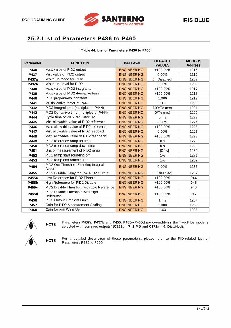
PROGRAMMING GUIDE
IRIS BLUE
175/471
25.2.List of Parameters P436 to P460
Table 44: List of Parameters P436 to P460
Parameter FUNCTION User Level DEFAULT
VALUES
MODBUS
Address
P436 Max. value of PID2 output ENGINEERING +100.00% 1215
P437 Min. value of PID2 output ENGINEERING 0.00% 1216
P437a Wake-up Mode for PID2 ENGINEERING 0: [Disabled] 1237
P437b Wake-up Level for PID2 ENGINEERING 0.00% 1238
P438 Max. value of PID2 integral term ENGINEERING +100.00% 1217
P439 Max. value of PID2 derivative term ENGINEERING +100.00% 1218
P440 PID2 proportional constant ENGINEERING 1.000 1219
P441 Multiplicative factor of P440 ENGINEERING 0:1.0 1220
P442 PID2 Integral time (multiples of P444) ENGINEERING 500*Tc (ms) 1221
P443 PID2 Derivative time (multiples of P444) ENGINEERING 0*Tc (ms) 1222
P444 Cycle time of PID2 regulator: Tc ENGINEERING 5 ms 1223
P445 Min. allowable value of PID2 reference ENGINEERING 0.00% 1224
P446 Max. allowable value of PID2 reference ENGINEERING +100.00% 1225
P447 Min. allowable value of PID2 feedback ENGINEERING 0.00% 1226
P448 Max. allowable value of PID2 feedback ENGINEERING +100.00% 1227
P449 PID2 reference ramp up time ENGINEERING 0 s 1228
P450 PID2 reference ramp down time ENGINEERING 0 s 1229
P451 Unit of measurement of PID2 ramp ENGINEERING 1: [0.1s] 1230
P452 PID2 ramp start rounding off ENGINEERING 1% 1231
P453 PID2 ramp end rounding off ENGINEERING 1% 1232
P454 PID2 Out Threshold Enabling Integral Action
ENGINEERING 0.00% 1233
P455 PID2 Disable Delay for Low PID2 Output ENGINEERING 0: [Disabled] 1239
P455a Low Reference for PID2 Disable ENGINEERING +100.00% 944
P455b High Reference for PID2 Disable ENGINEERING +100.00% 945
P455c PID2 Disable Threshold with Low Reference ENGINEERING +100.00% 946
P455d PID2 Disable Threshold with High Reference
ENGINEERING +100.00% 947
P456 PID2 Output Gradient Limit ENGINEERING 1 ms 1234
P457 Gain for PID2 Measurement Scaling ENGINEERING 1.000 1235
P460 Gain for Anti Wind-Up ENGINEERING 1.00 1236
NOTE Parameters P437a, P437b and P455, P455a-P455d are overridden if the Two PIDs mode is
selected with “summed outputs” (C291a = 7: 2 PID and C171a = 0: Disabled).
NOTE For a detailed description of these parameters, please refer to the PID-related List of Parameters P236 to P260.
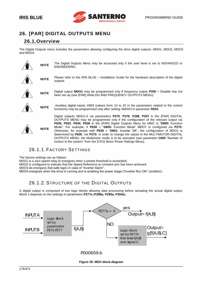
IRIS BLUE
PROGRAMMING GUIDE
176/471
26. [PAR] DIGITAL OUTPUTS MENU
26.1.Overview The Digital Outputs menu includes the parameters allowing configuring the drive digital outputs: MDO1, MDO2, MDO3 and MDO4.
NOTE The Digital Outputs Menu may be accessed only if the user level is set to ADVANCED or ENGINEERING.
NOTE Please refer to the IRIS BLUE – Installation Guide for the hardware description of the digital outputs.
NOTE Digital output MDO1 may be programmed only if frequency output P200 = Disable has not been set up (see [PAR] ANALOG AND FREQUENCY OUTPUTS MENU).
NOTE Auxiliary digital inputs XMDI (values from 13 to 20 in the parameters related to the control
functions) may be programmed only after setting XMDI/O in parameter R023.
NOTE
Digital outputs MDO1-4 via parameters P270, P279, P288, P297 in the [PAR] DIGITAL OUTPUTS MENU may be programmed only if the configuration of the relevant output via
P630, P632, P634, P636 in the [PAR] Digital Outputs Menu for MMC is “D600: Function
Mode”. For example, if P630 = “D600: Function Mode” MDO1 is configured via P270.
Otherwise, for example with P630 = “D601: Inverter OK”, the configuration of MDO1 is
determined by P630, not P270. In order to change the values in the MULTIMOTOR DIGITAL
OUTPUTS MENU, the Multimotor mode is to be activated (see parameter C600 “Number of motors in the system” from the [CFG] Motor Power Ratings Menu).
26.1.1. FACTORY SETTINGS The factory settings are as follows: MDO1 is a zero speed relay (it energizes when a preset threshold is exceeded). MDO2 is configured to indicate that the Speed Reference at constant rpm has been achieved. MDO3 de-energizes (fail-safe logic) in case of “Inverter Alarm”. MDO4 energizes when the drive is running and is enabling the power stage (“Inverter Run OK” condition).
26.1.2. STRUCTURE OF THE D IGITAL OUTPUTS A digital output is composed of two logic blocks allowing data processing before actuating the actual digital output.
Block 2 depends on the settings in parameters P277a (P286a, P295a, P304a).
Logic Block
set by
parameters
P271-P277
INPUT A
INPUT B f(A,B)
P277a = 0yes
Output= f(A,B)
NO
Logic block
set by P277b
that tests f(A,B)
and signal C
Output=
g[f(A,B),C]
P000659-b
Figure 29: MDO block-diagram
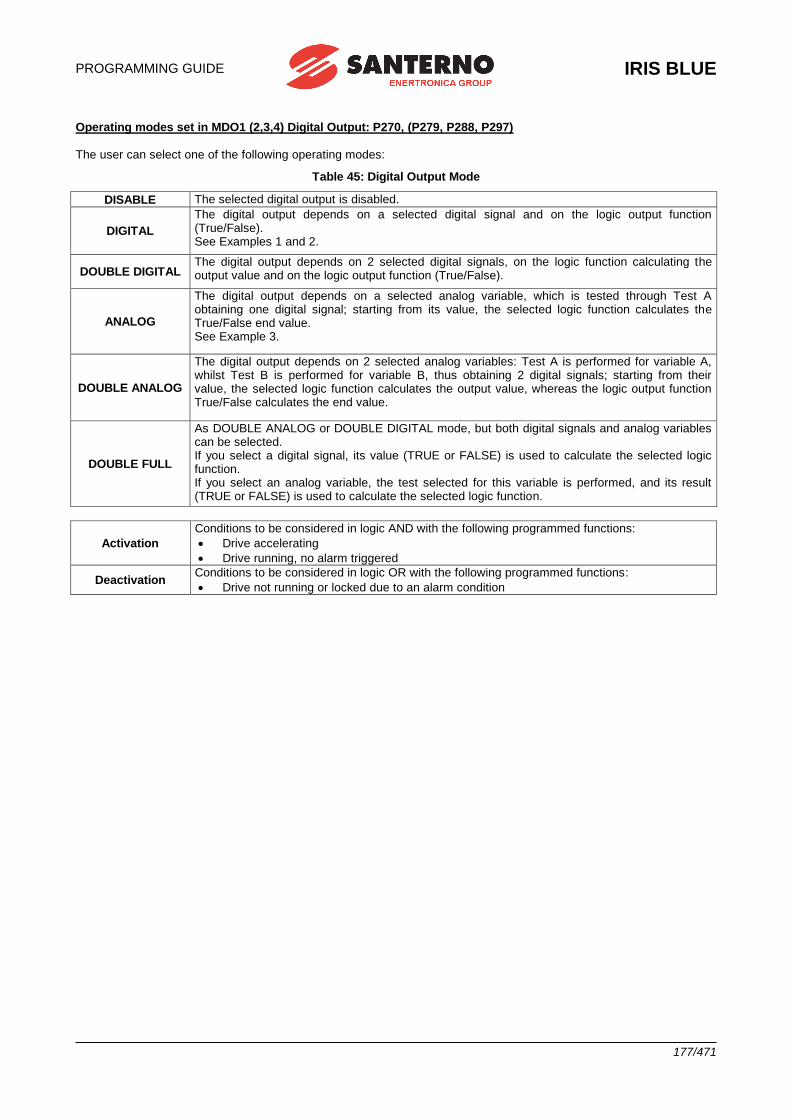
PROGRAMMING GUIDE
IRIS BLUE
177/471
Operating modes set in MDO1 (2,3,4) Digital Output: P270, (P279, P288, P297) The user can select one of the following operating modes:
Table 45: Digital Output Mode
DISABLE The selected digital output is disabled.
DIGITAL
The digital output depends on a selected digital signal and on the logic output function (True/False). See Examples 1 and 2.
DOUBLE DIGITAL The digital output depends on 2 selected digital signals, on the logic function calculating the output value and on the logic output function (True/False).
ANALOG
The digital output depends on a selected analog variable, which is tested through Test A obtaining one digital signal; starting from its value, the selected logic function calculates the True/False end value. See Example 3.
DOUBLE ANALOG
The digital output depends on 2 selected analog variables: Test A is performed for variable A, whilst Test B is performed for variable B, thus obtaining 2 digital signals; starting from their value, the selected logic function calculates the output value, whereas the logic output function True/False calculates the end value.
DOUBLE FULL
As DOUBLE ANALOG or DOUBLE DIGITAL mode, but both digital signals and analog variables can be selected. If you select a digital signal, its value (TRUE or FALSE) is used to calculate the selected logic function. If you select an analog variable, the test selected for this variable is performed, and its result (TRUE or FALSE) is used to calculate the selected logic function.
Activation
Conditions to be considered in logic AND with the following programmed functions:
• Drive accelerating
• Drive running, no alarm triggered
Deactivation Conditions to be considered in logic OR with the following programmed functions:
• Drive not running or locked due to an alarm condition
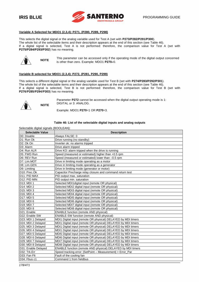
IRIS BLUE
PROGRAMMING GUIDE
178/471
Variable A Selected for MDO1 (2,3,4): P271, (P280, P289, P298)
This selects the digital signal or the analog variable used for Test A (set with P273/P282/P291/P300). The whole list of the selectable items and their description appears at the end of this section (see Table 46). If a digital signal is selected, Test A is not performed: therefore, the comparison value for Test A (set with
P275/P284/P293/P302) has no meaning.
NOTE This parameter can be accessed only if the operating mode of the digital output concerned
is other than zero. Example: MDO1 P2700.
Variable B selected for MDO1 (2,3,4): P272, (P281, P290, P299)
This selects a different digital signal or the analog variable used for Test B (set with P274/P283/P292/P301). The whole list of the selectable items and their description appears at the end of this section (see Table 46). If a digital signal is selected, Test B is not performed: therefore, the comparison value for Test B (set with
P276/P285/P294/P303) has no meaning.
NOTE
Parameter P272 cannot be accessed when the digital output operating mode is 1: DIGITAL or 3: ANALOG.
Example: MDO1 P270=1 OR P270=3.
Table 46: List of the selectable digital inputs and analog outputs
Selectable digital signals (BOOLEAN):
Selectable Value Description
D0: Disable Always FALSE: 0
D1: Run Ok Drive running (no standby)
D2: Ok On Inverter ok: no alarms tripped
D3: Alarm Drive alarm tripped
D4: Run ALR Drive KO: alarm tripped when the drive is running
D5: FWD Run Speed (measured or estimated) higher than +0.5 rpm
D6: REV Run Speed (measured or estimated) lower than –0.5 rpm
D7: Lim.MOT Drive in limiting mode operating as a motor
D8: Lim.GEN Drive in limiting mode operating as a generator
D9: Limiting Drive in limiting mode (generator or motor)
D10: Prec.Ok Capacitor Precharge relay closure and command return test
D11: PID MAX PID output max. saturation
D12: PID MIN PID output min. saturation
D13: MDI 1 Selected MDI1digital input (remote OR physical)
D14: MDI 2 Selected MDI2 digital input (remote OR physical)
D15: MDI 3 Selected MDI3 digital input (remote OR physical)
D16: MDI 4 Selected MDI4 digital input (remote OR physical)
D17: MDI 5 Selected MDI5 digital input (remote OR physical)
D18: MDI 6 Selected MDI6 digital input (remote OR physical)
D19: MDI 7 Selected MDI7 digital input (remote OR physical)
D20: MDI 8 Selected MDI8 digital input (remote OR physical)
D21: Enable ENABLE function (remote AND physical)
D22: Enable SW ENABLE-SW function (remote AND physical)
D23: MDI 1 Delayed MDI1 Digital input (remote OR physical) DELAYED by MDI timers
D24: MDI 2 Delayed MDI1 Digital input (remote OR physical) DELAYED by MDI timers
D25: MDI 3 Delayed MDI1 Digital input (remote OR physical) DELAYED by MDI timers
D26: MDI 4 Delayed MDI1 Digital input (remote OR physical) DELAYED by MDI timers
D27: MDI 5 Delayed MDI5 Digital input (remote OR physical) DELAYED by MDI timers
D28: MDI 6 Delayed MDI6 Digital input (remote OR physical) DELAYED by MDI timers
D29: MDI 7 Delayed MDI7 Digital input (remote OR physical) DELAYED by MDI timers
D30: MDI 8 Delayed MDI8 Digital input (remote OR physical) DELAYED by MDI timers
D31: Enable Delayed ENABLE function (remote AND physical) DELAYED by MDI timers
D32: Trk.Err Speed tracking error: |SetPoint – Measurement| > Error_Par
D33: Fan Flt Fault of the cooling fan
D34: Fbus c1 Command 1 from fieldbus
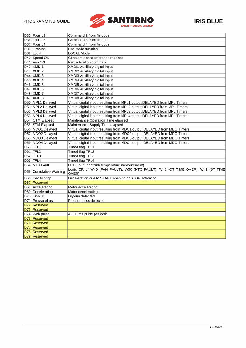
PROGRAMMING GUIDE
IRIS BLUE
179/471
D35: Fbus c2 Command 2 from fieldbus
D36: Fbus c3 Command 3 from fieldbus
D37: Fbus c4 Command 4 from fieldbus
D38: FireMod Fire Mode function
D39: Local LOCAL Mode
D40: Speed OK Constant speed reference reached
D41: Fan ON Fan activation command
D42: XMDI1 XMDI1 Auxiliary digital input
D43: XMDI2 XMDI2 Auxiliary digital input
D44: XMDI3 XMDI3 Auxiliary digital input
D45: XMDI4 XMDI4 Auxiliary digital input
D46: XMDI5 XMDI5 Auxiliary digital input
D47: XMDI6 XMDI6 Auxiliary digital input
D48: XMDI7 XMDI7 Auxiliary digital input
D49: XMDI8 XMDI8 Auxiliary digital input
D50: MPL1 Delayed Virtual digital input resulting from MPL1 output DELAYED from MPL Timers
D51: MPL2 Delayed Virtual digital input resulting from MPL2 output DELAYED from MPL Timers
D52: MPL3 Delayed Virtual digital input resulting from MPL3 output DELAYED from MPL Timers
D53: MPL4 Delayed Virtual digital input resulting from MPL4 output DELAYED from MPL Timers
D54: OTM Elapsed Maintenance Operation Time elapsed
D55: STM Elapsed Maintenance Supply Time elapsed
D56: MDO1 Delayed Virtual digital input resulting from MDO1 output DELAYED from MDO Timers
D57: MDO2 Delayed Virtual digital input resulting from MDO2 output DELAYED from MDO Timers
D58: MDO3 Delayed Virtual digital input resulting from MDO3 output DELAYED from MDO Timers
D59: MDO4 Delayed Virtual digital input resulting from MDO4 output DELAYED from MDO Timers
D60: TFL1 Timed flag TFL1
D61: TFL2 Timed flag TFL2
D62: TFL3 Timed flag TFL3
D63: TFL4 Timed flag TFL4
D64: NTC Fault NTC Fault (heatsink temperature measurement)
D65: Cumulative Warning Logic OR of W40 (FAN FAULT), W50 (NTC FAULT), W48 (OT TIME OVER), W49 (ST TIME OVER)
D66: Dec to Stop Deceleration due to START opening or STOP activation
D67: Reserved
D68: Accelerating Motor accelerating
D69: Decelerating Motor decelerating
D70: DryRun Dry-run detected
D71: PressureLoss Pressure loss detected
D72: Reserved
D73: Reserved
D74: kWh pulse A 500 ms pulse per kWh
D75: Reserved
D76: Reserved
D77: Reserved
D78: Reserved
D79: Reserved
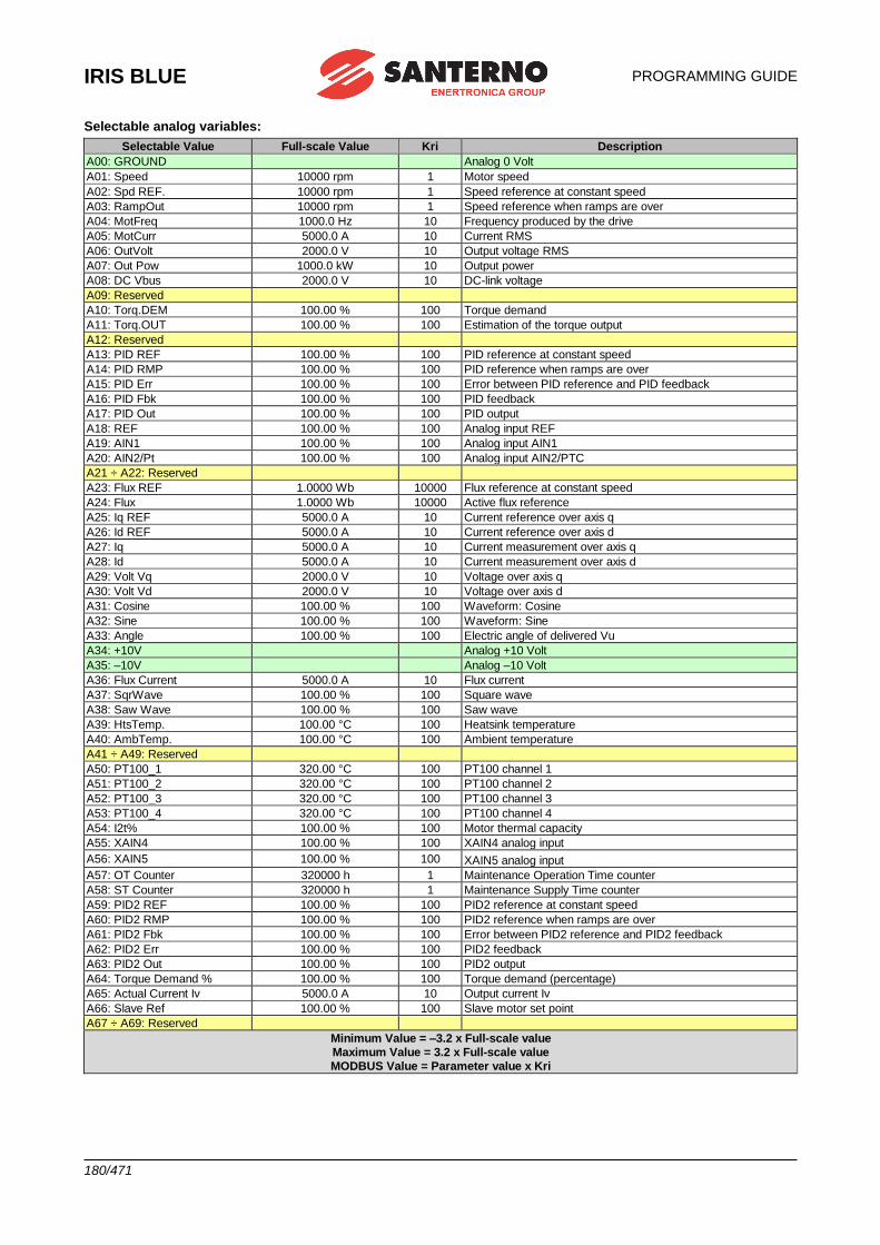
IRIS BLUE
PROGRAMMING GUIDE
180/471
Selectable analog variables:
Selectable Value Full-scale Value Kri Description
A00: GROUND Analog 0 Volt
A01: Speed 10000 rpm 1 Motor speed
A02: Spd REF. 10000 rpm 1 Speed reference at constant speed
A03: RampOut 10000 rpm 1 Speed reference when ramps are over
A04: MotFreq 1000.0 Hz 10 Frequency produced by the drive
A05: MotCurr 5000.0 A 10 Current RMS
A06: OutVolt 2000.0 V 10 Output voltage RMS
A07: Out Pow 1000.0 kW 10 Output power
A08: DC Vbus 2000.0 V 10 DC-link voltage
A09: Reserved
A10: Torq.DEM 100.00 % 100 Torque demand
A11: Torq.OUT 100.00 % 100 Estimation of the torque output
A12: Reserved
A13: PID REF 100.00 % 100 PID reference at constant speed
A14: PID RMP 100.00 % 100 PID reference when ramps are over
A15: PID Err 100.00 % 100 Error between PID reference and PID feedback
A16: PID Fbk 100.00 % 100 PID feedback
A17: PID Out 100.00 % 100 PID output
A18: REF 100.00 % 100 Analog input REF
A19: AIN1 100.00 % 100 Analog input AIN1
A20: AIN2/Pt 100.00 % 100 Analog input AIN2/PTC
A21 ÷ A22: Reserved
A23: Flux REF 1.0000 Wb 10000 Flux reference at constant speed
A24: Flux 1.0000 Wb 10000 Active flux reference
A25: Iq REF 5000.0 A 10 Current reference over axis q
A26: Id REF 5000.0 A 10 Current reference over axis d
A27: Iq 5000.0 A 10 Current measurement over axis q
A28: Id 5000.0 A 10 Current measurement over axis d
A29: Volt Vq 2000.0 V 10 Voltage over axis q
A30: Volt Vd 2000.0 V 10 Voltage over axis d
A31: Cosine 100.00 % 100 Waveform: Cosine
A32: Sine 100.00 % 100 Waveform: Sine
A33: Angle 100.00 % 100 Electric angle of delivered Vu
A34: +10V Analog +10 Volt
A35: –10V Analog –10 Volt
A36: Flux Current 5000.0 A 10 Flux current
A37: SqrWave 100.00 % 100 Square wave
A38: Saw Wave 100.00 % 100 Saw wave
A39: HtsTemp. 100.00 °C 100 Heatsink temperature
A40: AmbTemp. 100.00 °C 100 Ambient temperature
A41 ÷ A49: Reserved
A50: PT100_1 320.00 °C 100 PT100 channel 1
A51: PT100_2 320.00 °C 100 PT100 channel 2
A52: PT100_3 320.00 °C 100 PT100 channel 3
A53: PT100_4 320.00 °C 100 PT100 channel 4
A54: I2t% 100.00 % 100 Motor thermal capacity
A55: XAIN4 100.00 % 100 XAIN4 analog input
A56: XAIN5 100.00 % 100 XAIN5 analog input
A57: OT Counter 320000 h 1 Maintenance Operation Time counter
A58: ST Counter 320000 h 1 Maintenance Supply Time counter
A59: PID2 REF 100.00 % 100 PID2 reference at constant speed
A60: PID2 RMP 100.00 % 100 PID2 reference when ramps are over
A61: PID2 Fbk 100.00 % 100 Error between PID2 reference and PID2 feedback
A62: PID2 Err 100.00 % 100 PID2 feedback
A63: PID2 Out 100.00 % 100 PID2 output
A64: Torque Demand % 100.00 % 100 Torque demand (percentage)
A65: Actual Current Iv 5000.0 A 10 Output current Iv
A66: Slave Ref 100.00 % 100 Slave motor set point
A67 ÷ A69: Reserved
Minimum Value = –3.2 x Full-scale value
Maximum Value = 3.2 x Full-scale value
MODBUS Value = Parameter value x Kri
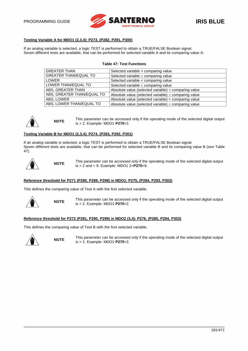
PROGRAMMING GUIDE
IRIS BLUE
181/471
Testing Variable A for MDO1 (2,3,4): P273, (P282, P291, P300) If an analog variable is selected, a logic TEST is performed to obtain a TRUE/FALSE Boolean signal. Seven different tests are available, that can be performed for selected variable A and its comparing value A:
Table 47: Test Functions
GREATER THAN Selected variable > comparing value
GREATER THAN/EQUAL TO Selected variable comparing value
LOWER Selected variable < comparing value
LOWER THAN/EQUAL TO Selected variable comparing value
ABS, GREATER THAN Absolute value (selected variable) > comparing value
ABS, GREATER THAN/EQUAL TO Absolute value (selected variable) comparing value
ABS, LOWER Absolute value (selected variable) < comparing value
ABS, LOWER THAN/EQUAL TO Absolute value (selected variable) comparing value
NOTE This parameter can be accessed only if the operating mode of the selected digital output
is > 2. Example: MDO1 P270>2.
Testing Variable B for MDO1 (2,3,4): P274, (P283, P292, P301) If an analog variable is selected, a logic TEST is performed to obtain a TRUE/FALSE Boolean signal. Seven different tests are available, that can be performed for selected variable B and its comparing value B (see Table 47).
NOTE This parameter can be accessed only if the operating mode of the selected digital output
is > 2 and < 9. Example: MDO1 2<P270<9.
Reference threshold for P271 (P280, P289, P298) in MDO1: P275, (P284, P293, P302) This defines the comparing value of Test A with the first selected variable.
NOTE This parameter can be accessed only if the operating mode of the selected digital output
is > 2. Example: MDO1 P270>2.
Reference threshold for P272 (P281, P290, P299) in MDO2 (3,4): P276, (P285, P294, P303) This defines the comparing value of Test B with the first selected variable.
NOTE This parameter can be accessed only if the operating mode of the selected digital output
is > 2. Example: MDO1 P270>2.
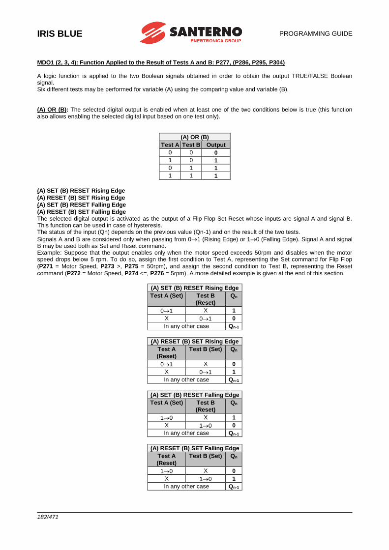
IRIS BLUE
PROGRAMMING GUIDE
182/471
MDO1 (2, 3, 4): Function Applied to the Result of Tests A and B: P277, (P286, P295, P304) A logic function is applied to the two Boolean signals obtained in order to obtain the output TRUE/FALSE Boolean signal. Six different tests may be performed for variable (A) using the comparing value and variable (B).
(A) OR (B): The selected digital output is enabled when at least one of the two conditions below is true (this function also allows enabling the selected digital input based on one test only).
(A) OR (B)
Test A Test B Output
0 0 0
1 0 1
0 1 1
1 1 1
(A) SET (B) RESET Rising Edge
(A) RESET (B) SET Rising Edge
(A) SET (B) RESET Falling Edge
(A) RESET (B) SET Falling Edge The selected digital output is activated as the output of a Flip Flop Set Reset whose inputs are signal A and signal B. This function can be used in case of hysteresis. The status of the input (Qn) depends on the previous value (Qn-1) and on the result of the two tests.
Signals A and B are considered only when passing from 01 (Rising Edge) or 10 (Falling Edge). Signal A and signal B may be used both as Set and Reset command. Example: Suppose that the output enables only when the motor speed exceeds 50rpm and disables when the motor speed drops below 5 rpm. To do so, assign the first condition to Test A, representing the Set command for Flip Flop
(P271 = Motor Speed, P273 >, P275 = 50rpm), and assign the second condition to Test B, representing the Reset
command (P272 = Motor Speed, P274 <=, P276 = 5rpm). A more detailed example is given at the end of this section.
(A) SET (B) RESET Rising Edge
Test A (Set) Test B
(Reset)
Qn
01 X 1
X 01 0
In any other case Qn-1
(A) RESET (B) SET Rising Edge
Test A
(Reset)
Test B (Set) Qn
01 X 0
X 01 1
In any other case Qn-1
(A) SET (B) RESET Falling Edge
Test A (Set) Test B
(Reset)
Qn
10 X 1
X 10 0
In any other case Qn-1
(A) RESET (B) SET Falling Edge
Test A
(Reset)
Test B (Set) Qn
10 X 0
X 10 1
In any other case Qn-1
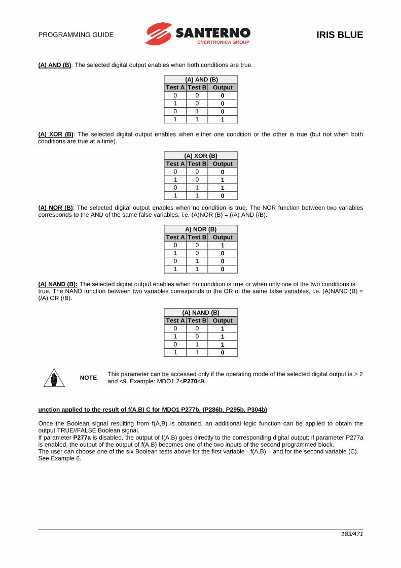
PROGRAMMING GUIDE
IRIS BLUE
183/471
(A) AND (B): The selected digital output enables when both conditions are true.
(A) AND (B)
Test A Test B Output
0 0 0
1 0 0
0 1 0
1 1 1
(A) XOR (B): The selected digital output enables when either one condition or the other is true (but not when both conditions are true at a time).
(A) XOR (B)
Test A Test B Output
0 0 0
1 0 1
0 1 1
1 1 0
(A) NOR (B): The selected digital output enables when no condition is true. The NOR function between two variables corresponds to the AND of the same false variables, i.e. (A)NOR (B) = (/A) AND (/B).
A) NOR (B)
Test A Test B Output
0 0 1
1 0 0
0 1 0
1 1 0
(A) NAND (B): The selected digital output enables when no condition is true or when only one of the two conditions is true. The NAND function between two variables corresponds to the OR of the same false variables, i.e. (A)NAND (B) = (/A) OR (/B).
(A) NAND (B)
Test A Test B Output
0 0 1
1 0 1
0 1 1
1 1 0
NOTE This parameter can be accessed only if the operating mode of the selected digital output is > 2
and <9. Example: MDO1 2<P270<9.
unction applied to the result of f(A,B) C for MDO1 P277b, (P286b, P295b, P304b) Once the Boolean signal resulting from f(A,B) is obtained, an additional logic function can be applied to obtain the output TRUE//FALSE Boolean signal.
If parameter P277a is disabled, the output of f(A,B) goes directly to the corresponding digital output; if parameter P277a is enabled, the output of the output of f(A,B) becomes one of the two inputs of the second programmed block. The user can choose one of the six Boolean tests above for the first variable - f(A,B) – and for the second variable (C). See Example 6.
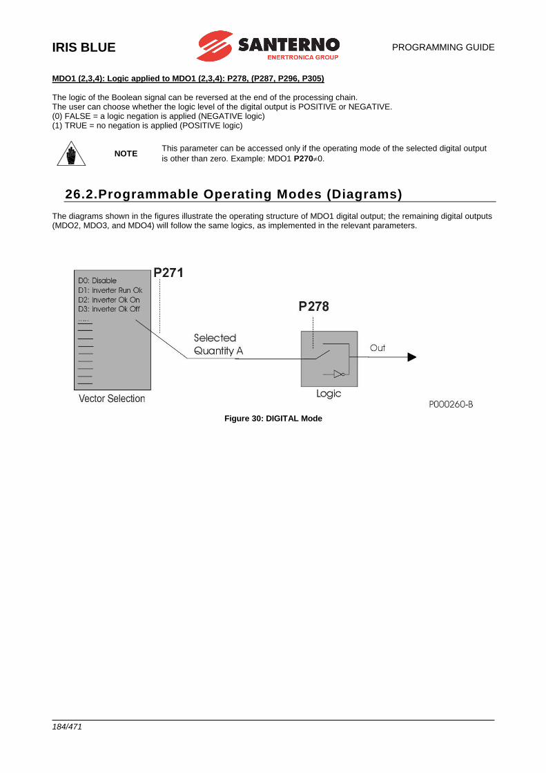
IRIS BLUE
PROGRAMMING GUIDE
184/471
MDO1 (2,3,4): Logic applied to MDO1 (2,3,4): P278, (P287, P296, P305) The logic of the Boolean signal can be reversed at the end of the processing chain. The user can choose whether the logic level of the digital output is POSITIVE or NEGATIVE. (0) FALSE = a logic negation is applied (NEGATIVE logic) (1) TRUE = no negation is applied (POSITIVE logic)
NOTE This parameter can be accessed only if the operating mode of the selected digital output
is other than zero. Example: MDO1 P2700.
26.2.Programmable Operating Modes (Diagrams) The diagrams shown in the figures illustrate the operating structure of MDO1 digital output; the remaining digital outputs (MDO2, MDO3, and MDO4) will follow the same logics, as implemented in the relevant parameters.
Figure 30: DIGITAL Mode
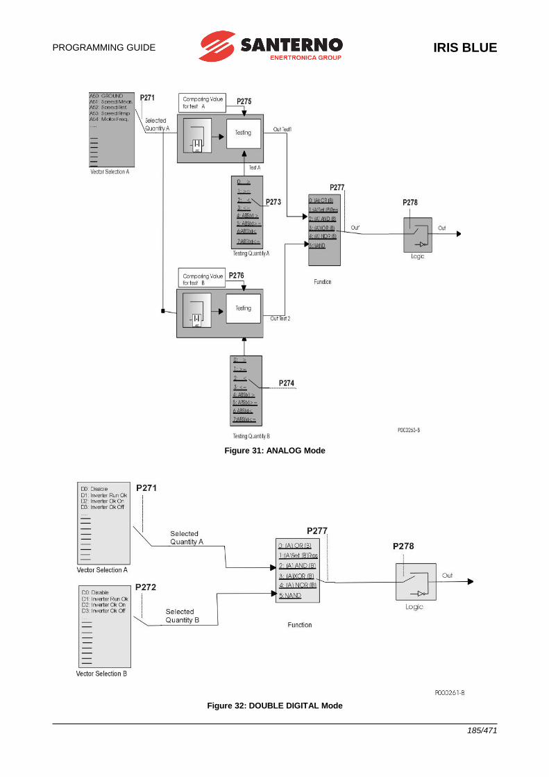
PROGRAMMING GUIDE
IRIS BLUE
185/471
Figure 31: ANALOG Mode
Figure 32: DOUBLE DIGITAL Mode
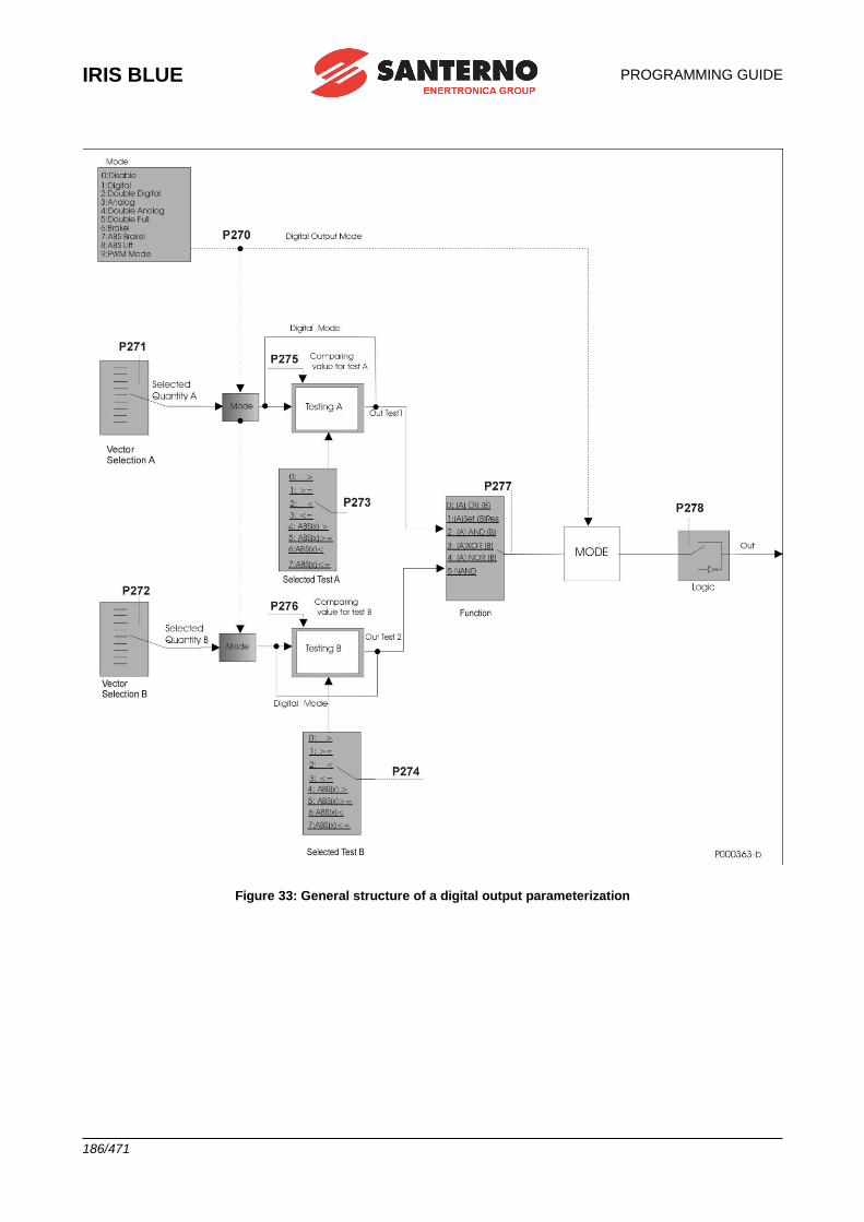
IRIS BLUE
PROGRAMMING GUIDE
186/471
Figure 33: General structure of a digital output parameterization
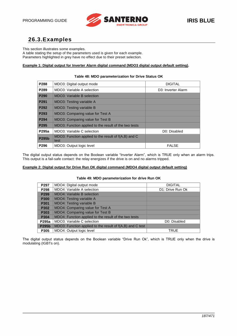
PROGRAMMING GUIDE
IRIS BLUE
187/471
26.3.Examples This section illustrates some examples. A table stating the setup of the parameters used is given for each example. Parameters highlighted in grey have no effect due to their preset selection.
Example 1: Digital output for Inverter Alarm digital command (MDO3 digital output default setting).
Table 48: MDO parameterization for Drive Status OK
P288 MDO3: Digital output mode DIGITAL
P289 MDO3: Variable A selection D3: Inverter Alarm
P290 MDO3: Variable B selection
P291 MDO3: Testing variable A
P292 MDO3: Testing variable B
P293 MDO3: Comparing value for Test A
P294 MDO3: Comparing value for Test B
P295 MDO3: Function applied to the result of the two tests
P295a MDO3: Variable C selection D0: Disabled
P295b MDO3: Function applied to the result of f(A,B) and C test
P296 MDO3: Output logic level FALSE
The digital output status depends on the Boolean variable “Inverter Alarm”, which is TRUE only when an alarm trips. This output is a fail-safe contact: the relay energizes if the drive is on and no alarms tripped.
Example 2: Digital output for Drive Run OK digital command (MDO4 digital output default setting)
Table 49: MDO parameterization for drive Run OK
P297 MDO4: Digital output mode DIGITAL
P298 MDO4: Variable A selection D1: Drive Run Ok
P299 MDO4: Variable B selection
P300 MDO4: Testing variable A
P301 MDO4: Testing variable B
P302 MDO4: Comparing value for Test A
P303 MDO4: Comparing value for Test B
P304 MDO4: Function applied to the result of the two tests
P295a MDO3: Variable C selection D0: Disabled
P295b MDO3: Function applied to the result of f(A,B) and C test
P305 MDO4: Output logic level TRUE
The digital output status depends on the Boolean variable “Drive Run Ok”, which is TRUE only when the drive is modulating (IGBTs on).
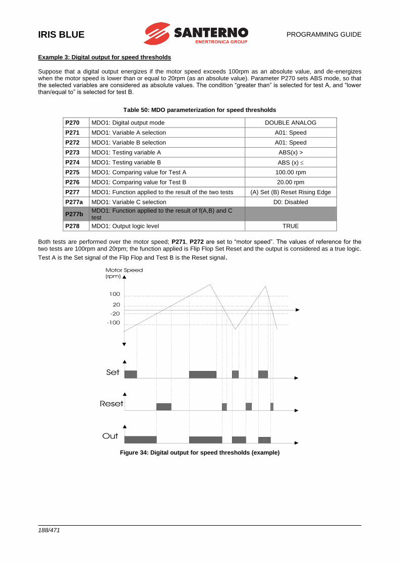
IRIS BLUE
PROGRAMMING GUIDE
188/471
Example 3: Digital output for speed thresholds
Suppose that a digital output energizes if the motor speed exceeds 100rpm as an absolute value, and de-energizes when the motor speed is lower than or equal to 20rpm (as an absolute value). Parameter P270 sets ABS mode, so that the selected variables are considered as absolute values. The condition “greater than” is selected for test A, and “lower than/equal to” is selected for test B.
Table 50: MDO parameterization for speed thresholds
P270 MDO1: Digital output mode DOUBLE ANALOG
P271 MDO1: Variable A selection A01: Speed
P272 MDO1: Variable B selection A01: Speed
P273 MDO1: Testing variable A ABS(x) >
P274 MDO1: Testing variable B ABS (x)
P275 MDO1: Comparing value for Test A 100.00 rpm
P276 MDO1: Comparing value for Test B 20.00 rpm
P277 MDO1: Function applied to the result of the two tests (A) Set (B) Reset Rising Edge
P277a MDO1: Variable C selection D0: Disabled
P277b MDO1: Function applied to the result of f(A,B) and C test
P278 MDO1: Output logic level TRUE
Both tests are performed over the motor speed; P271, P272 are set to “motor speed”. The values of reference for the two tests are 100rpm and 20rpm; the function applied is Flip Flop Set Reset and the output is considered as a true logic.
Test A is the Set signal of the Flip Flop and Test B is the Reset signal.
Figure 34: Digital output for speed thresholds (example)
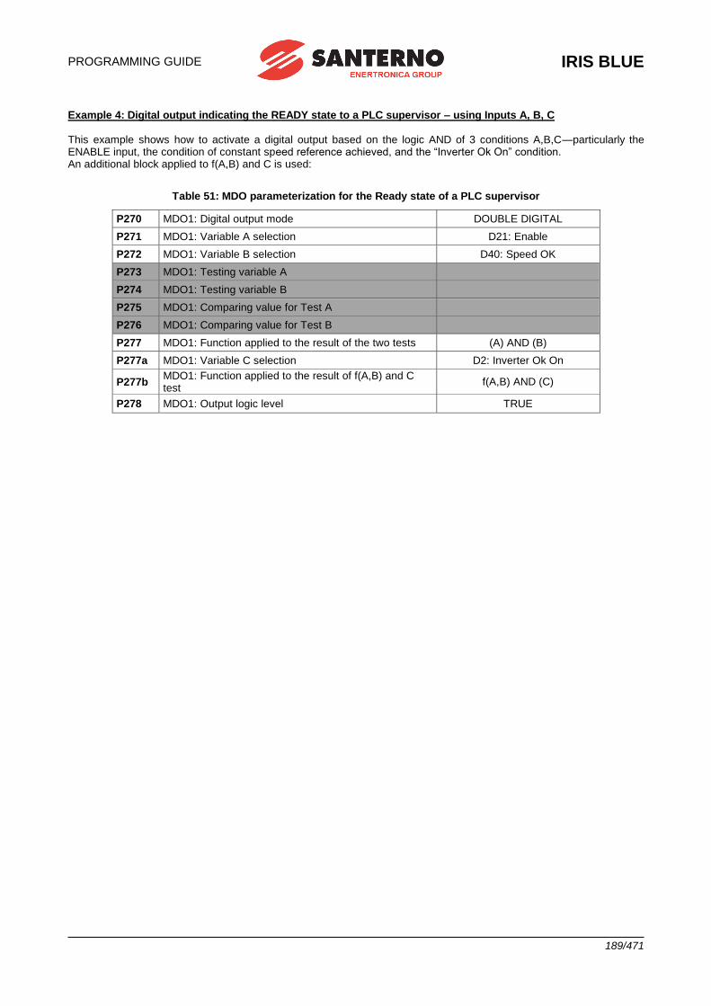
PROGRAMMING GUIDE
IRIS BLUE
189/471
Example 4: Digital output indicating the READY state to a PLC supervisor – using Inputs A, B, C This example shows how to activate a digital output based on the logic AND of 3 conditions A,B,C—particularly the ENABLE input, the condition of constant speed reference achieved, and the “Inverter Ok On” condition. An additional block applied to f(A,B) and C is used:
Table 51: MDO parameterization for the Ready state of a PLC supervisor
P270 MDO1: Digital output mode DOUBLE DIGITAL
P271 MDO1: Variable A selection D21: Enable
P272 MDO1: Variable B selection D40: Speed OK
P273 MDO1: Testing variable A
P274 MDO1: Testing variable B
P275 MDO1: Comparing value for Test A
P276 MDO1: Comparing value for Test B
P277 MDO1: Function applied to the result of the two tests (A) AND (B)
P277a MDO1: Variable C selection D2: Inverter Ok On
P277b MDO1: Function applied to the result of f(A,B) and C test
f(A,B) AND (C)
P278 MDO1: Output logic level TRUE
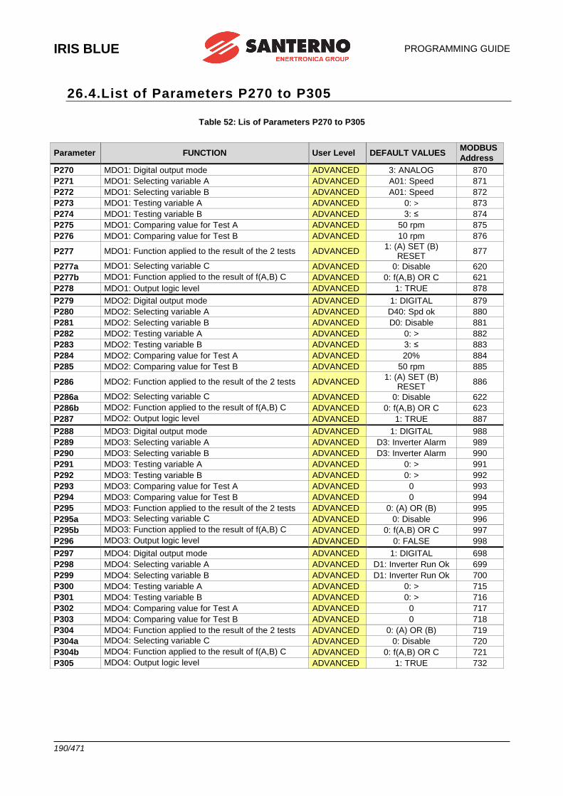
IRIS BLUE
PROGRAMMING GUIDE
190/471
26.4.List of Parameters P270 to P305
Table 52: Lis of Parameters P270 to P305
Parameter FUNCTION User Level DEFAULT VALUES MODBUS
Address
P270 MDO1: Digital output mode ADVANCED 3: ANALOG 870
P271 MDO1: Selecting variable A ADVANCED A01: Speed 871
P272 MDO1: Selecting variable B ADVANCED A01: Speed 872
P273 MDO1: Testing variable A ADVANCED 0: > 873
P274 MDO1: Testing variable B ADVANCED 3: ≤ 874
P275 MDO1: Comparing value for Test A ADVANCED 50 rpm 875
P276 MDO1: Comparing value for Test B ADVANCED 10 rpm 876
P277 MDO1: Function applied to the result of the 2 tests ADVANCED 1: (A) SET (B)
RESET 877
P277a MDO1: Selecting variable C ADVANCED 0: Disable 620
P277b MDO1: Function applied to the result of f(A,B) C ADVANCED 0: f(A,B) OR C 621
P278 MDO1: Output logic level ADVANCED 1: TRUE 878
P279 MDO2: Digital output mode ADVANCED 1: DIGITAL 879
P280 MDO2: Selecting variable A ADVANCED D40: Spd ok 880
P281 MDO2: Selecting variable B ADVANCED D0: Disable 881
P282 MDO2: Testing variable A ADVANCED 0: > 882
P283 MDO2: Testing variable B ADVANCED 3: ≤ 883
P284 MDO2: Comparing value for Test A ADVANCED 20% 884
P285 MDO2: Comparing value for Test B ADVANCED 50 rpm 885
P286 MDO2: Function applied to the result of the 2 tests ADVANCED 1: (A) SET (B)
RESET 886
P286a MDO2: Selecting variable C ADVANCED 0: Disable 622
P286b MDO2: Function applied to the result of f(A,B) C ADVANCED 0: f(A,B) OR C 623
P287 MDO2: Output logic level ADVANCED 1: TRUE 887
P288 MDO3: Digital output mode ADVANCED 1: DIGITAL 988
P289 MDO3: Selecting variable A ADVANCED D3: Inverter Alarm 989
P290 MDO3: Selecting variable B ADVANCED D3: Inverter Alarm 990
P291 MDO3: Testing variable A ADVANCED 0: > 991
P292 MDO3: Testing variable B ADVANCED 0: > 992
P293 MDO3: Comparing value for Test A ADVANCED 0 993
P294 MDO3: Comparing value for Test B ADVANCED 0 994
P295 MDO3: Function applied to the result of the 2 tests ADVANCED 0: (A) OR (B) 995
P295a MDO3: Selecting variable C ADVANCED 0: Disable 996
P295b MDO3: Function applied to the result of f(A,B) C ADVANCED 0: f(A,B) OR C 997
P296 MDO3: Output logic level ADVANCED 0: FALSE 998
P297 MDO4: Digital output mode ADVANCED 1: DIGITAL 698
P298 MDO4: Selecting variable A ADVANCED D1: Inverter Run Ok 699
P299 MDO4: Selecting variable B ADVANCED D1: Inverter Run Ok 700
P300 MDO4: Testing variable A ADVANCED 0: > 715
P301 MDO4: Testing variable B ADVANCED 0: > 716
P302 MDO4: Comparing value for Test A ADVANCED 0 717
P303 MDO4: Comparing value for Test B ADVANCED 0 718
P304 MDO4: Function applied to the result of the 2 tests ADVANCED 0: (A) OR (B) 719
P304a MDO4: Selecting variable C ADVANCED 0: Disable 720
P304b MDO4: Function applied to the result of f(A,B) C ADVANCED 0: f(A,B) OR C 721
P305 MDO4: Output logic level ADVANCED 1: TRUE 732
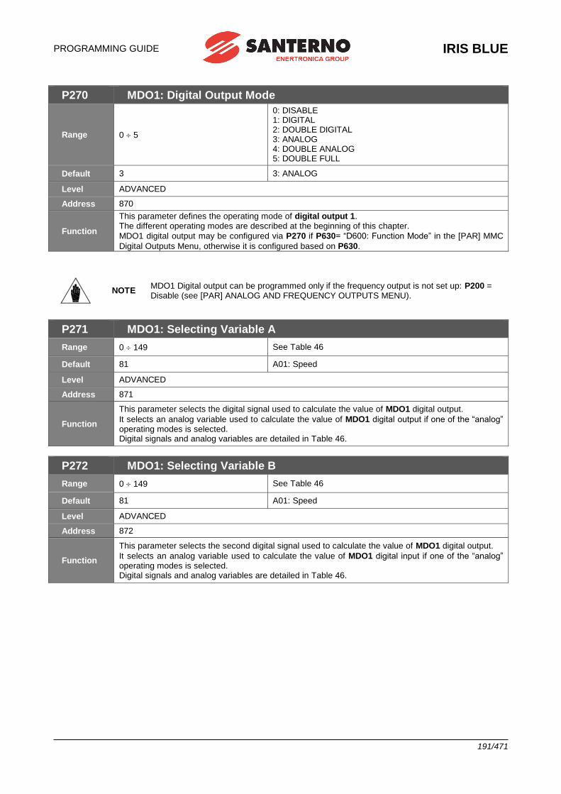
PROGRAMMING GUIDE
IRIS BLUE
191/471
P270 MDO1: Digital Output Mode
Range 0 5
0: DISABLE 1: DIGITAL 2: DOUBLE DIGITAL 3: ANALOG 4: DOUBLE ANALOG 5: DOUBLE FULL
Default 3 3: ANALOG
Level ADVANCED
Address 870
Function
This parameter defines the operating mode of digital output 1. The different operating modes are described at the beginning of this chapter.
MDO1 digital output may be configured via P270 if P630= “D600: Function Mode” in the [PAR] MMC
Digital Outputs Menu, otherwise it is configured based on P630.
NOTE MDO1 Digital output can be programmed only if the frequency output is not set up: P200 = Disable (see [PAR] ANALOG AND FREQUENCY OUTPUTS MENU).
P271 MDO1: Selecting Variable A
Range 0 149 See Table 46
Default 81 A01: Speed
Level ADVANCED
Address 871
Function
This parameter selects the digital signal used to calculate the value of MDO1 digital output.
It selects an analog variable used to calculate the value of MDO1 digital output if one of the “analog” operating modes is selected. Digital signals and analog variables are detailed in Table 46.
P272 MDO1: Selecting Variable B
Range 0 149 See Table 46
Default 81 A01: Speed
Level ADVANCED
Address 872
Function
This parameter selects the second digital signal used to calculate the value of MDO1 digital output.
It selects an analog variable used to calculate the value of MDO1 digital input if one of the “analog” operating modes is selected. Digital signals and analog variables are detailed in Table 46.
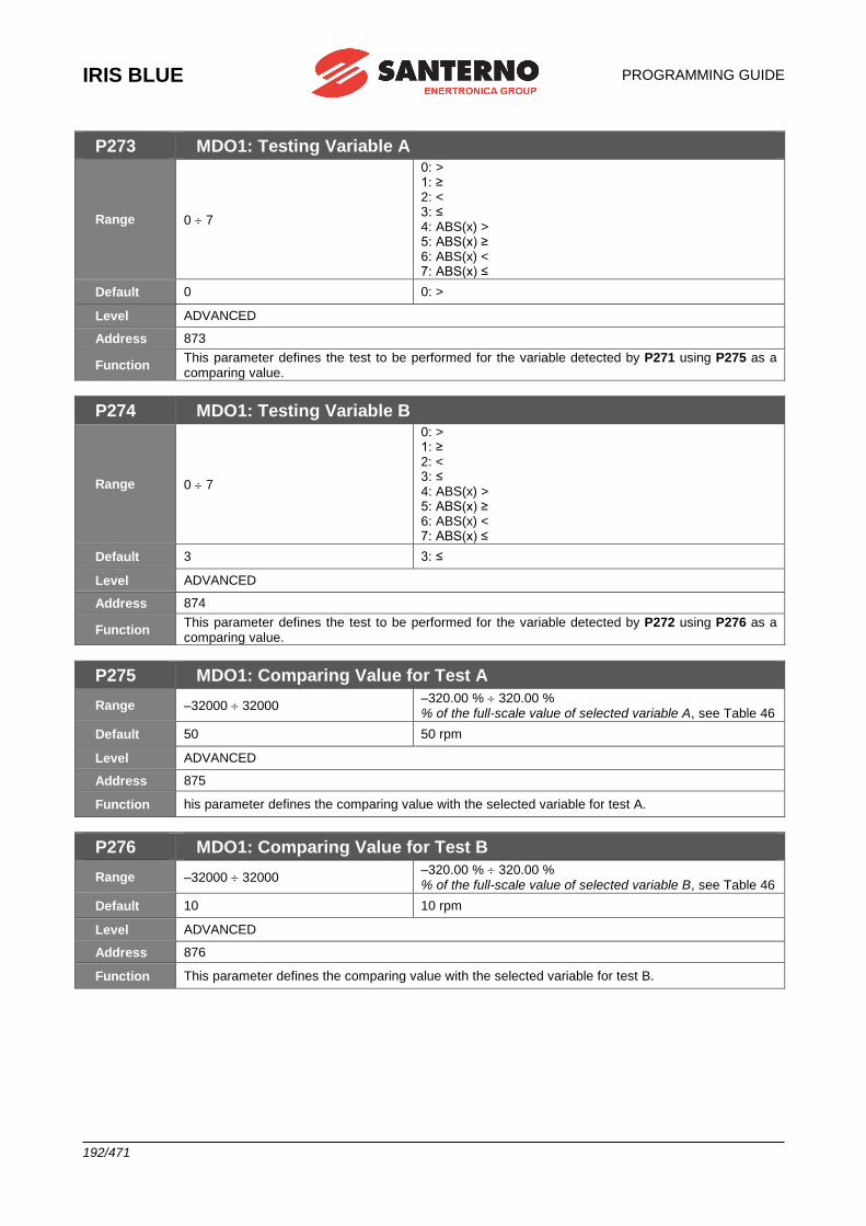
IRIS BLUE
PROGRAMMING GUIDE
192/471
P273 MDO1: Testing Variable A
Range 0 7
0: > 1: ≥ 2: < 3: ≤ 4: ABS(x) > 5: ABS(x) ≥ 6: ABS(x) < 7: ABS(x) ≤
Default 0 0: >
Level ADVANCED
Address 873
Function This parameter defines the test to be performed for the variable detected by P271 using P275 as a comparing value.
P274 MDO1: Testing Variable B
Range 0 7
0: > 1: ≥ 2: < 3: ≤ 4: ABS(x) > 5: ABS(x) ≥ 6: ABS(x) < 7: ABS(x) ≤
Default 3 3: ≤
Level ADVANCED
Address 874
Function This parameter defines the test to be performed for the variable detected by P272 using P276 as a comparing value.
P275 MDO1: Comparing Value for Test A
Range –32000 32000 –320.00 % 320.00 % % of the full-scale value of selected variable A, see Table 46
Default 50 50 rpm
Level ADVANCED
Address 875
Function his parameter defines the comparing value with the selected variable for test A.
P276 MDO1: Comparing Value for Test B
Range –32000 32000 –320.00 % 320.00 % % of the full-scale value of selected variable B, see Table 46
Default 10 10 rpm
Level ADVANCED
Address 876
Function This parameter defines the comparing value with the selected variable for test B.

PROGRAMMING GUIDE
IRIS BLUE
193/471
P277 MDO1: Function Applied to the Result of the 2 Tests
Range 0 12
0: (A) OR (B) 1: (A) SET (B) RESET RISING EDGE 2: (A) AND (B) 3: (A) XOR (B) 4: (A) NOR (B) 5: (A) NAND (B) 6: (A\) OR (B) 7: (A) OR (B\) 8: (A\) AND (B) 9: (A) AND (B\) 10: (A) RESET (B) SET RISING EDGE 11: (A) SET (B) RESET FALLING EDGE 12: (A) RESET (B) SET FALLING EDGE
Default 1 1: (A) SET (B) RESET
Level ADVANCED
Address 877
Function This parameter determines the logic function applied to the result of the two tests allowing calculating the output value.
P277a MDO1: Selecting Variable C
Range 0 79 See Table 46
Default 0 D0: Disable
Level ADVANCED
Address 620
Function This parameter selects the digital signal used to calculate the value of MDO1 digital output. The digital signals that can be selected are given in Table 46.
P277b MDO1: Function Applied to the Result of f(A,B) C
Range 0 12
0: f(A,B) OR (C) 1: f(A,B) SET (C) RESET RISING EDGE 2: f(A,B) AND (C) 3: f(A,B) XOR (C) 4: f(A,B) NOR (C) 5: f(A,B) NAND (C) 6: f(A,B)\ OR (C) 7: f(A,B) OR (C\) 8: f(A,B)\ AND (C) 9: f(A,B) AND (C\) 10: f(A,B) RESET (C) SET RISING EDGE 11: f(A,B) SET (C) RESET FALLING EDGE 12: f(A,B) RESET (C) SET FALLING EDGE
Default 0 0: f(A,B) OR (C)
Level ADVANCED
Address 621
Function This parameter determines the logic function applied to the result of the two tests allowing calculating the output value.
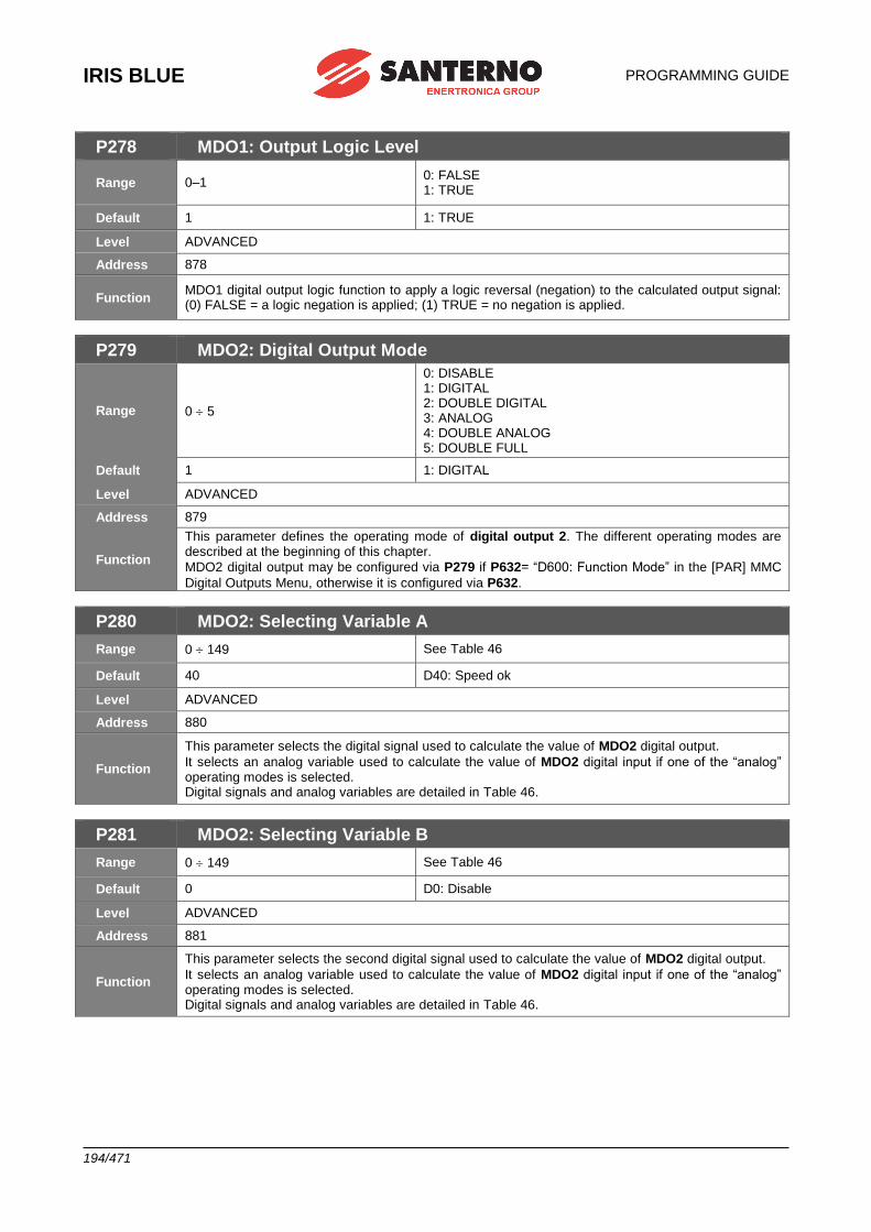
IRIS BLUE
PROGRAMMING GUIDE
194/471
P278 MDO1: Output Logic Level
Range 0–1 0: FALSE 1: TRUE
Default 1 1: TRUE
Level ADVANCED
Address 878
Function MDO1 digital output logic function to apply a logic reversal (negation) to the calculated output signal: (0) FALSE = a logic negation is applied; (1) TRUE = no negation is applied.
P279 MDO2: Digital Output Mode
Range 0 5
0: DISABLE 1: DIGITAL 2: DOUBLE DIGITAL 3: ANALOG 4: DOUBLE ANALOG 5: DOUBLE FULL
Default 1 1: DIGITAL
Level ADVANCED
Address 879
Function
This parameter defines the operating mode of digital output 2. The different operating modes are described at the beginning of this chapter.
MDO2 digital output may be configured via P279 if P632= “D600: Function Mode” in the [PAR] MMC
Digital Outputs Menu, otherwise it is configured via P632.
P280 MDO2: Selecting Variable A
Range 0 149 See Table 46
Default 40 D40: Speed ok
Level ADVANCED
Address 880
Function
This parameter selects the digital signal used to calculate the value of MDO2 digital output.
It selects an analog variable used to calculate the value of MDO2 digital input if one of the “analog” operating modes is selected. Digital signals and analog variables are detailed in Table 46.
P281 MDO2: Selecting Variable B
Range 0 149 See Table 46
Default 0 D0: Disable
Level ADVANCED
Address 881
Function
This parameter selects the second digital signal used to calculate the value of MDO2 digital output.
It selects an analog variable used to calculate the value of MDO2 digital input if one of the “analog” operating modes is selected. Digital signals and analog variables are detailed in Table 46.
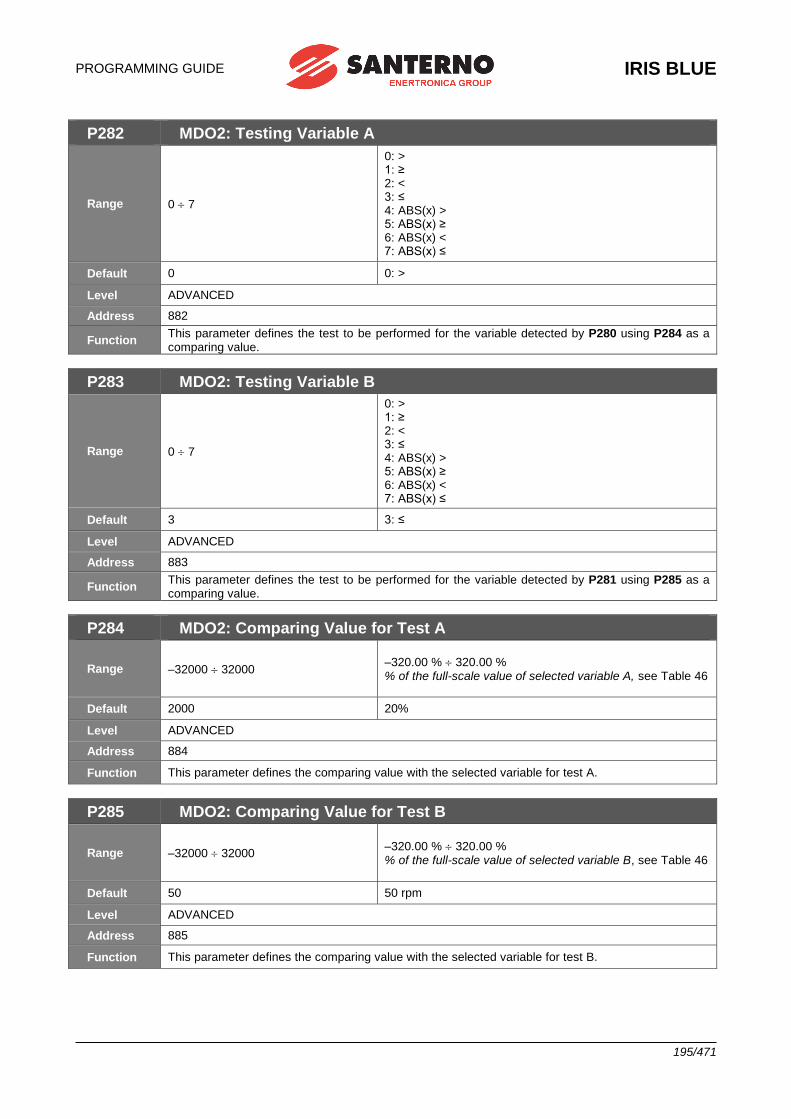
PROGRAMMING GUIDE
IRIS BLUE
195/471
P282 MDO2: Testing Variable A
Range 0 7
0: > 1: ≥ 2: < 3: ≤ 4: ABS(x) > 5: ABS(x) ≥ 6: ABS(x) < 7: ABS(x) ≤
Default 0 0: >
Level ADVANCED
Address 882
Function This parameter defines the test to be performed for the variable detected by P280 using P284 as a comparing value.
P283 MDO2: Testing Variable B
Range 0 7
0: > 1: ≥ 2: < 3: ≤ 4: ABS(x) > 5: ABS(x) ≥ 6: ABS(x) < 7: ABS(x) ≤
Default 3 3: ≤
Level ADVANCED
Address 883
Function This parameter defines the test to be performed for the variable detected by P281 using P285 as a comparing value.
P284 MDO2: Comparing Value for Test A
Range –32000 32000 –320.00 % 320.00 % % of the full-scale value of selected variable A, see Table 46
Default 2000 20%
Level ADVANCED
Address 884
Function This parameter defines the comparing value with the selected variable for test A.
P285 MDO2: Comparing Value for Test B
Range –32000 32000 –320.00 % 320.00 % % of the full-scale value of selected variable B, see Table 46
Default 50 50 rpm
Level ADVANCED
Address 885
Function This parameter defines the comparing value with the selected variable for test B.
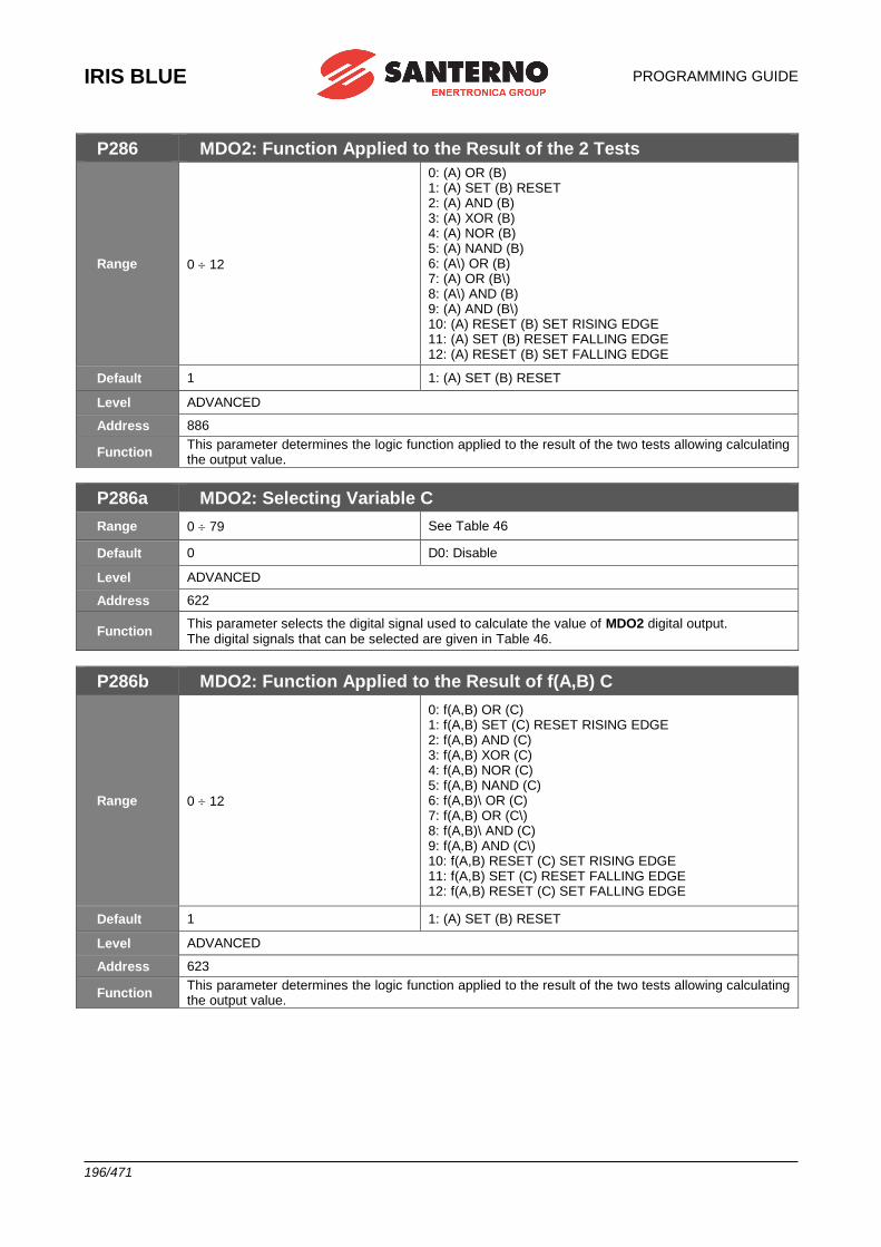
IRIS BLUE
PROGRAMMING GUIDE
196/471
P286 MDO2: Function Applied to the Result of the 2 Tests
Range 0 12
0: (A) OR (B) 1: (A) SET (B) RESET 2: (A) AND (B) 3: (A) XOR (B) 4: (A) NOR (B) 5: (A) NAND (B) 6: (A\) OR (B) 7: (A) OR (B\) 8: (A\) AND (B) 9: (A) AND (B\) 10: (A) RESET (B) SET RISING EDGE 11: (A) SET (B) RESET FALLING EDGE 12: (A) RESET (B) SET FALLING EDGE
Default 1 1: (A) SET (B) RESET
Level ADVANCED
Address 886
Function This parameter determines the logic function applied to the result of the two tests allowing calculating the output value.
P286a MDO2: Selecting Variable C
Range 0 79 See Table 46
Default 0 D0: Disable
Level ADVANCED
Address 622
Function This parameter selects the digital signal used to calculate the value of MDO2 digital output. The digital signals that can be selected are given in Table 46.
P286b MDO2: Function Applied to the Result of f(A,B) C
Range 0 12
0: f(A,B) OR (C) 1: f(A,B) SET (C) RESET RISING EDGE 2: f(A,B) AND (C) 3: f(A,B) XOR (C) 4: f(A,B) NOR (C) 5: f(A,B) NAND (C) 6: f(A,B)\ OR (C) 7: f(A,B) OR (C\) 8: f(A,B)\ AND (C) 9: f(A,B) AND (C\) 10: f(A,B) RESET (C) SET RISING EDGE 11: f(A,B) SET (C) RESET FALLING EDGE 12: f(A,B) RESET (C) SET FALLING EDGE
Default 1 1: (A) SET (B) RESET
Level ADVANCED
Address 623
Function This parameter determines the logic function applied to the result of the two tests allowing calculating the output value.
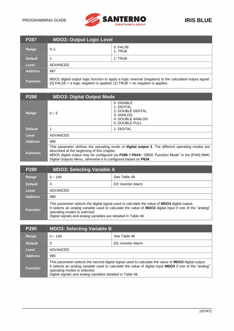
PROGRAMMING GUIDE
IRIS BLUE
197/471
P287 MDO2: Output Logic Level
Range 0–1 0: FALSE 1: TRUE
Default 1 1: TRUE
Level ADVANCED
Address 887
Function MDO2 digital output logic function to apply a logic reversal (negation) to the calculated output signal: (0) FALSE = a logic negation is applied; (1) TRUE = no negation is applied.
P288 MDO3: Digital Output Mode
Range 0 5
0: DISABLE 1: DIGITAL 2: DOUBLE DIGITAL 3: ANALOG 4: DOUBLE ANALOG 5: DOUBLE FULL
Default 1 1: DIGITAL
Level ADVANCED
Address 988
Function
This parameter defines the operating mode of digital output 3. The different operating modes are described at the beginning of this chapter.
MDO3 digital output may be configured via P288 if P634= “D600: Function Mode” in the [PAR] MMC
Digital Outputs Menu, otherwise it is configured based on P634.
P289 MDO3: Selecting Variable A
Range 0 149 See Table 46
Default 3 D3: Inverter Alarm
Level ADVANCED
Address 989
Function
This parameter selects the digital signal used to calculate the value of MDO3 digital output.
It selects an analog variable used to calculate the value of MDO3 digital input if one of the “analog” operating modes is selected. Digital signals and analog variables are detailed in Table 46.
P290 MDO3: Selecting Variable B
Range 0 149 See Table 46
Default 3 D3: Inverter Alarm
Level ADVANCED
Address 990
Function
This parameter selects the second digital signal used to calculate the value of MDO3 digital output.
It selects an analog variable used to calculate the value of digital input MDO3 if one of the “analog” operating modes is selected. Digital signals and analog variables detailed in Table 46.
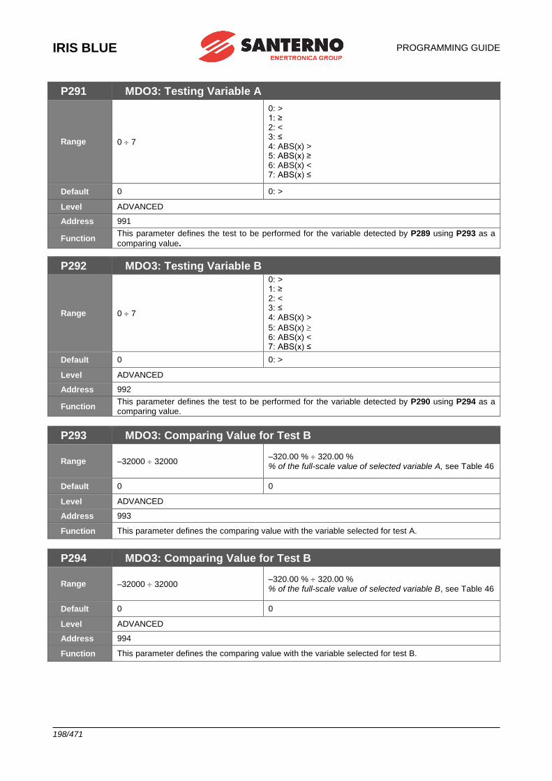
IRIS BLUE
PROGRAMMING GUIDE
198/471
P291 MDO3: Testing Variable A
Range 0 7
0: > 1: ≥ 2: < 3: ≤ 4: ABS(x) > 5: ABS(x) ≥ 6: ABS(x) < 7: ABS(x) ≤
Default 0 0: >
Level ADVANCED
Address 991
Function This parameter defines the test to be performed for the variable detected by P289 using P293 as a
comparing value.
P292 MDO3: Testing Variable B
Range 0 7
0: > 1: ≥ 2: < 3: ≤ 4: ABS(x) >
5: ABS(x) 6: ABS(x) < 7: ABS(x) ≤
Default 0 0: >
Level ADVANCED
Address 992
Function This parameter defines the test to be performed for the variable detected by P290 using P294 as a comparing value.
P293 MDO3: Comparing Value for Test B
Range –32000 32000 –320.00 % 320.00 % % of the full-scale value of selected variable A, see Table 46
Default 0 0
Level ADVANCED
Address 993
Function This parameter defines the comparing value with the variable selected for test A.
P294 MDO3: Comparing Value for Test B
Range –32000 32000 –320.00 % 320.00 % % of the full-scale value of selected variable B, see Table 46
Default 0 0
Level ADVANCED
Address 994
Function This parameter defines the comparing value with the variable selected for test B.

PROGRAMMING GUIDE
IRIS BLUE
199/471
P295 MDO3: Function Applied to the Result of the 2 Tests
Range 0 12
0: (A) OR (B) 1: (A) SET (B) RESET 2: (A) AND (B) 3: (A) XOR (B) 4: (A) NOR (B) 5: (A) NAND (B) 6: (A\) OR (B) 7: (A) OR (B\) 8: (A\) AND (B) 9: (A) AND (B\) 10: (A) RESET (B) SET RISING EDGE 11: (A) SET (B) RESET FALLING EDGE 12: (A) RESET (B) SET FALLING EDGE
Default 0 0: (A) OR (B)
Level ADVANCED
Address 995
Function This parameter determines the logic function applied to the result of the two tests allowing calculating the output value.
P295a MDO3: Selecting Variable C
Range 0 79 See Table 46
Default 0 D0: Disable
Level ADVANCED
Address 996
Function This parameter selects the digital signal used to calculate the value of MDO3 digital output. The digital signals that can be selected are given in Table 46.
P295b MDO3: Function Applied to the Result f(A,B) C
Range 0 12
0: f(A,B) OR (C) 1: f(A,B) SET (C) RESET RISING EDGE 2: f(A,B) AND (C) 3: f(A,B) XOR (C) 4: f(A,B) NOR (C) 5: f(A,B) NAND (C) 6: f(A,B)\ OR (C) 7: f(A,B) OR (C\) 8: f(A,B)\ AND (C) 9: f(A,B) AND (C\) 10: f(A,B) RESET (C) SET RISING EDGE 11: f(A,B) SET (C) RESET FALLING EDGE 12: f(A,B) RESET (C) SET FALLING EDGE
Default 1 1: (A) SET (B) RESET
Level ADVANCED
Address 997
Function This parameter determines the logic function applied to the result of the two tests allowing calculating the output value.
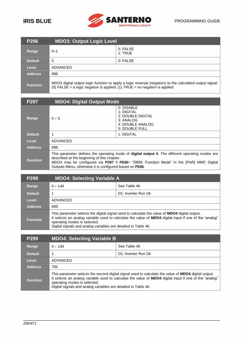
IRIS BLUE
PROGRAMMING GUIDE
200/471
P296 MDO3: Output Logic Level
Range 0–1 0: FALSE 1: TRUE
Default 0 0: FALSE
Level ADVANCED
Address 998
Function MDO3 digital output logic function to apply a logic reversal (negation) to the calculated output signal: (0) FALSE = a logic negation is applied; (1) TRUE = no negation is applied.
P297 MDO4: Digital Output Mode
Range 0 5
0: DISABLE 1: DIGITAL 2: DOUBLE DIGITAL 3: ANALOG 4: DOUBLE ANALOG 5: DOUBLE FULL
Default 1 1: DIGITAL
Level ADVANCED
Address 698
Function
This parameter defines the operating mode of digital output 4. The different operating modes are described at the beginning of this chapter.
MDO4 may be configured via P297 if P636= “D600: Function Mode” in the [PAR] MMC Digital
Outputs Menu, otherwise it is configured based on P636.
P298 MDO4: Selecting Variable A
Range 0 149 See Table 46
Default 1 D1: Inverter Run Ok
Level ADVANCED
Address 699
Function
This parameter selects the digital signal used to calculate the value of MDO4 digital output.
It selects an analog variable used to calculate the value of MDO4 digital input if one of the “analog” operating modes is selected. Digital signals and analog variables are detailed in Table 46.
P299 MDO4: Selecting Variable B
Range 0 149 See Table 46
Default 1 D1: Inverter Run Ok
Level ADVANCED
Address 700
Function
This parameter selects the second digital signal used to calculate the value of MDO4 digital output.
It selects an analog variable used to calculate the value of MDO4 digital input if one of the “analog” operating modes is selected. Digital signals and analog variables are detailed in Table 46.
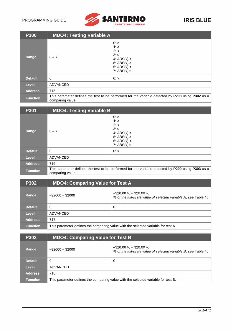
PROGRAMMING GUIDE
IRIS BLUE
201/471
P300 MDO4: Testing Variable A
Range 0 7
0: > 1: ≥ 2: < 3: ≤ 4: ABS(x) > 5: ABS(x) ≥ 6: ABS(x) < 7: ABS(x) ≤
Default 0 0: >
Level ADVANCED
Address 715
Function This parameter defines the test to be performed for the variable detected by P298 using P302 as a
comparing value.
P301 MDO4: Testing Variable B
Range 0 7
0: > 1: ≥ 2: < 3: ≤ 4: ABS(x) > 5: ABS(x) ≥ 6: ABS(x) < 7: ABS(x) ≤
Default 0 0: >
Level ADVANCED
Address 716
Function This parameter defines the test to be performed for the variable detected by P299 using P303 as a comparing value.
P302 MDO4: Comparing Value for Test A
Range –32000 32000 –320.00 % 320.00 % % of the full-scale value of selected variable A, see Table 46
Default 0 0
Level ADVANCED
Address 717
Function This parameter defines the comparing value with the selected variable for test A.
P303 MDO4: Comparing Value for Test B
Range –32000 32000 –320.00 % 320.00 % % of the full-scale value of selected variable B, see Table 46
Default 0 0
Level ADVANCED
Address 718
Function This parameter defines the comparing value with the selected variable for test B.

IRIS BLUE
PROGRAMMING GUIDE
202/471
P304 MDO4: Function Applied to the Result of the 2 Tests
Range 0 12
0: (A) OR (B) 1: (A) SET (B) RESET 2: (A) AND (B) 3: (A) XOR (B) 4: (A) NOR (B) 5: (A) NAND (B) 6: (A\) OR (B) 7: (A) OR (B\) 8: (A\) AND (B) 9: (A) AND (B\) 10: (A) RESET (B) SET RISING EDGE 11: (A) SET (B) RESET FALLING EDGE 12: (A) RESET (B) SET FALLING EDGE
Default 0 0: (A) OR (B)
Level ADVANCED
Address 719
Function This parameter determines the logic function applied to the result of the two tests allowing calculating the output value.
P304a MDO4: Selecting Variable C
Range 0 79 See Table 46
Default 0 D0: Disable
Level ADVANCED
Address 720
Function This parameter selects the digital signal used to calculate the value of MDO4 digital output. The digital signals that can be selected are given in Table 46.
P304b MDO4: Function Applied to the Result of f(A,B) C
Range 0 12
0: f(A,B) OR (C) 1: f(A,B) SET (C) RESET RISING EDGE 2: f(A,B) AND (C) 3: f(A,B) XOR (C) 4: f(A,B) NOR (C) 5: f(A,B) NAND (C) 6: f(A,B)\ OR (C) 7: f(A,B) OR (C\) 8: f(A,B)\ AND (C) 9: f(A,B) AND (C\) 10: f(A,B) RESET (C) SET RISING EDGE 11: f(A,B) SET (C) RESET FALLING EDGE 12: f(A,B) RESET (C) SET FALLING EDGE
Default 1 1: (A) SET (B) RESET
Level ADVANCED
Address 721
Function This parameter determines the logic function applied to the result of the two tests allowing calculating the output value.

PROGRAMMING GUIDE
IRIS BLUE
203/471
P305 MDO4: Output Logic Level
Range 0–1 0: FALSE 1: TRUE
Default 1 1: TRUE
Level ADVANCED
Address 732
Function MDO4 digital output logic function to apply a logic reversal (negation) to the calculated output signal: (0) FALSE = a logic negation is applied; (1) TRUE = no negation is applied.
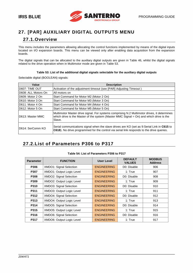
IRIS BLUE
PROGRAMMING GUIDE
204/471
27. [PAR] AUXILIARY DIGITAL OUTPUTS MENU
27.1.Overview This menu includes the parameters allowing allocating the control functions implemented by means of the digital inputs located on I/O expansion boards. This menu can be viewed only after enabling data acquisition from the expansion boards. The digital signals that can be allocated to the auxiliary digital outputs are given in Table 46, whilst the digital signals related to the drive operation when in Multimotor mode are given in Table 53.
Table 53: List of the additional digital signals selectable for the auxiliary digital outputs
Selectable digital (BOOLEAN) signals:
Value Description
D607: TIME OUT Activation of the adjustment timeout (see [PAR] Adjusting Timeout )
D608: ALL Motors On All motors on
D609: Motor 2 On Start Command for Motor M2 (Motor 2 On)
D610: Motor 3 On Start Command for Motor M3 (Motor 3 On)
D611: Motor 4 On Start Command for Motor M4 (Motor 4 On)
D612: Motor 5 On Start Command for Motor M5 (Motor 5 On)
D613: Master MMC Multimotor Master drive signal. For systems comprising N.2 Multimotor drives, it determines which drive is the Master of the system (Master MMC Signal = On) and which drive is the Slave.
D614: SerComm KO Serial communications signal when the slave drives are KO (set as 9:Serial Link in C615 to
C618). No drive programmed for the control via serial link responds to the drive queries.
27.2.List of Parameters P306 to P317
Table 54: List of Parameters P306 to P317
Parameter FUNCTION User Level DEFAULT
VALUES
MODBUS
Address
P306 XMDO1: Signal Selection ENGINEERING D0: Disable 906
P307 XMDO1: Output Logic Level ENGINEERING 1: True 907
P308 XMDO2: Signal Selection ENGINEERING D0: Disable 908
P309 XMDO2: Output Logic Level ENGINEERING 1: True 909
P310 XMDO3: Signal Selection ENGINEERING D0: Disable 910
P311 XMDO3: Output Logic Level ENGINEERING 1: True 911
P312 XMDO4: Signal Selection ENGINEERING D0: Disable 912
P313 XMDO4: Output Logic Level ENGINEERING 1: True 913
P314 XMDO5: Signal Selection ENGINEERING D0: Disable 914
P315 XMDO5: Output Logic Level ENGINEERING 1: True 915
P316 XMDO6: Signal Selection ENGINEERING D0: Disable 916
P317 XMDO6: Output Logic Level ENGINEERING 1: True 917
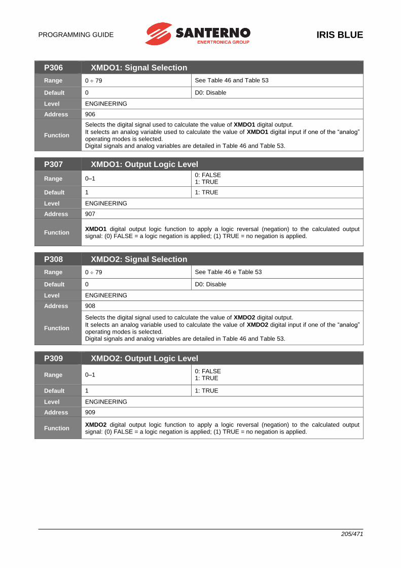
PROGRAMMING GUIDE
IRIS BLUE
205/471
P306 XMDO1: Signal Selection
Range 0 79 See Table 46 and Table 53
Default 0 D0: Disable
Level ENGINEERING
Address 906
Function
Selects the digital signal used to calculate the value of XMDO1 digital output.
It selects an analog variable used to calculate the value of XMDO1 digital input if one of the “analog” operating modes is selected. Digital signals and analog variables are detailed in Table 46 and Table 53.
P307 XMDO1: Output Logic Level
Range 0–1 0: FALSE 1: TRUE
Default 1 1: TRUE
Level ENGINEERING
Address 907
Function XMDO1 digital output logic function to apply a logic reversal (negation) to the calculated output signal: (0) FALSE = a logic negation is applied; (1) TRUE = no negation is applied.
P308 XMDO2: Signal Selection
Range 0 79 See Table 46 e Table 53
Default 0 D0: Disable
Level ENGINEERING
Address 908
Function
Selects the digital signal used to calculate the value of XMDO2 digital output.
It selects an analog variable used to calculate the value of XMDO2 digital input if one of the “analog” operating modes is selected. Digital signals and analog variables are detailed in Table 46 and Table 53.
P309 XMDO2: Output Logic Level
Range 0–1 0: FALSE 1: TRUE
Default 1 1: TRUE
Level ENGINEERING
Address 909
Function XMDO2 digital output logic function to apply a logic reversal (negation) to the calculated output signal: (0) FALSE = a logic negation is applied; (1) TRUE = no negation is applied.
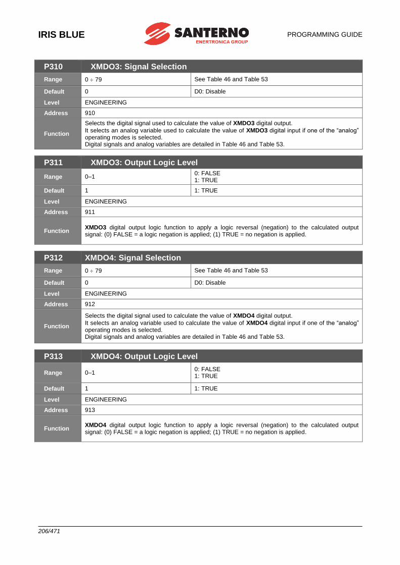
IRIS BLUE
PROGRAMMING GUIDE
206/471
P310 XMDO3: Signal Selection
Range 0 79 See Table 46 and Table 53
Default 0 D0: Disable
Level ENGINEERING
Address 910
Function
Selects the digital signal used to calculate the value of XMDO3 digital output.
It selects an analog variable used to calculate the value of XMDO3 digital input if one of the “analog” operating modes is selected. Digital signals and analog variables are detailed in Table 46 and Table 53.
P311 XMDO3: Output Logic Level
Range 0–1 0: FALSE 1: TRUE
Default 1 1: TRUE
Level ENGINEERING
Address 911
Function XMDO3 digital output logic function to apply a logic reversal (negation) to the calculated output signal: (0) FALSE = a logic negation is applied; (1) TRUE = no negation is applied.
P312 XMDO4: Signal Selection
Range 0 79 See Table 46 and Table 53
Default 0 D0: Disable
Level ENGINEERING
Address 912
Function
Selects the digital signal used to calculate the value of XMDO4 digital output.
It selects an analog variable used to calculate the value of XMDO4 digital input if one of the “analog” operating modes is selected. Digital signals and analog variables are detailed in Table 46 and Table 53.
P313 XMDO4: Output Logic Level
Range 0–1 0: FALSE 1: TRUE
Default 1 1: TRUE
Level ENGINEERING
Address 913
Function XMDO4 digital output logic function to apply a logic reversal (negation) to the calculated output signal: (0) FALSE = a logic negation is applied; (1) TRUE = no negation is applied.

PROGRAMMING GUIDE
IRIS BLUE
207/471
P314 XMDO5: Signal Selection
Range 0 79 See Table 46 and Table 53
Default 0 D0: Disable
Level ENGINEERING
Address 914
Function
Selects the digital signal used to calculate the value of XMDO5 digital output.
It selects an analog variable used to calculate the value of XMDO5 digital input if one of the “analog” operating modes is selected. Digital signals and analog variables are detailed in Table 46 and Table 53.
P315 XMDO5: Output Logic Level
Range 0–1 0: FALSE 1: TRUE
Default 1 1: TRUE
Level ENGINEERING
Address 915
Function XMDO5 digital output logic function to apply a logic reversal (negation) to the calculated output signal: (0) FALSE = a logic negation is applied; (1) TRUE = no negation is applied.
P316 XMDO6: Signal Selection
Range 0 79 See Table 46 and Table 53
Default 0 D0: Disable
Level ENGINEERING
Address 916
Function
Selects the digital signal used to calculate the value of XMDO6 digital output.
It selects an analog variable used to calculate the value of XMDO6 digital input if one of the “analog” operating modes is selected. Digital signals and analog variables are detailed in Table 46 and Table 53.
P317 XMDO6: Output Logic Level
Range 0–1 0: FALSE 1: TRUE
Default 1 1: TRUE
Level ENGINEERING
Address 917
Function XMDO6 digital output logic function to apply a logic reversal (negation) to the calculated output signal: (0) FALSE = a logic negation is applied; (1) TRUE = no negation is applied.
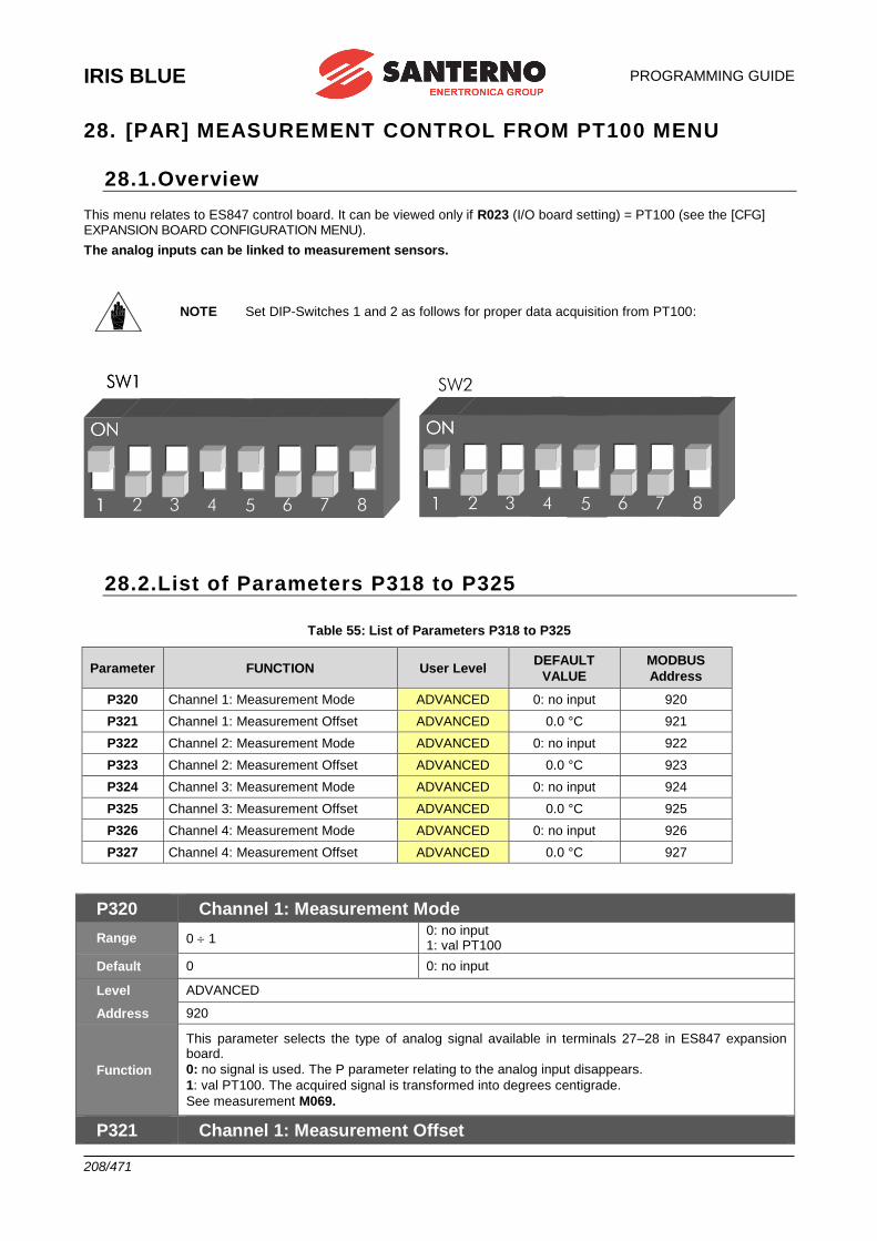
IRIS BLUE
PROGRAMMING GUIDE
208/471
28. [PAR] MEASUREMENT CONTROL FROM PT100 MENU
28.1.Overview
This menu relates to ES847 control board. It can be viewed only if R023 (I/O board setting) = PT100 (see the [CFG] EXPANSION BOARD CONFIGURATION MENU).
The analog inputs can be linked to measurement sensors.
NOTE Set DIP-Switches 1 and 2 as follows for proper data acquisition from PT100:
ON
1
SW1
2 3
ON
1
4
5 6 7
ON
1
8
ON
1
SW1
2 3
ON
1
4
5 6 7
ON
1
8
ON
1 2 3
ON
1
4
5 6 7
ON
1
8
ON
1 2 3
ON
1
4
5 6 7
ON
1
8
SW2
28.2.List of Parameters P318 to P325
Table 55: List of Parameters P318 to P325
Parameter FUNCTION User Level DEFAULT
VALUE
MODBUS
Address
P320 Channel 1: Measurement Mode ADVANCED 0: no input 920
P321 Channel 1: Measurement Offset ADVANCED 0.0 °C 921
P322 Channel 2: Measurement Mode ADVANCED 0: no input 922
P323 Channel 2: Measurement Offset ADVANCED 0.0 °C 923
P324 Channel 3: Measurement Mode ADVANCED 0: no input 924
P325 Channel 3: Measurement Offset ADVANCED 0.0 °C 925
P326 Channel 4: Measurement Mode ADVANCED 0: no input 926
P327 Channel 4: Measurement Offset ADVANCED 0.0 °C 927
P320 Channel 1: Measurement Mode
Range 0 1 0: no input 1: val PT100
Default 0 0: no input
Level ADVANCED
Address 920
Function
This parameter selects the type of analog signal available in terminals 27–28 in ES847 expansion board.
0: no signal is used. The P parameter relating to the analog input disappears.
1: val PT100. The acquired signal is transformed into degrees centigrade.
See measurement M069.
P321 Channel 1: Measurement Offset
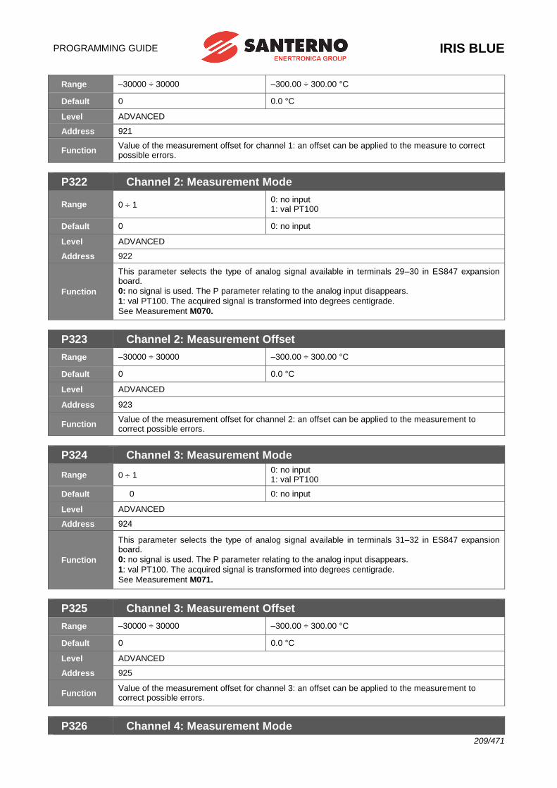
PROGRAMMING GUIDE
IRIS BLUE
209/471
Range –30000 ÷ 30000 –300.00 ÷ 300.00 °C
Default 0 0.0 °C
Level ADVANCED
Address 921
Function Value of the measurement offset for channel 1: an offset can be applied to the measure to correct possible errors.
P322 Channel 2: Measurement Mode
Range 0 1 0: no input 1: val PT100
Default 0 0: no input
Level ADVANCED
Address 922
Function
This parameter selects the type of analog signal available in terminals 29–30 in ES847 expansion board.
0: no signal is used. The P parameter relating to the analog input disappears.
1: val PT100. The acquired signal is transformed into degrees centigrade.
See Measurement M070.
P323 Channel 2: Measurement Offset
Range –30000 ÷ 30000 –300.00 ÷ 300.00 °C
Default 0 0.0 °C
Level ADVANCED
Address 923
Function Value of the measurement offset for channel 2: an offset can be applied to the measurement to correct possible errors.
P324 Channel 3: Measurement Mode
Range 0 1 0: no input 1: val PT100
Default 0 0: no input
Level ADVANCED
Address 924
Function
This parameter selects the type of analog signal available in terminals 31–32 in ES847 expansion board.
0: no signal is used. The P parameter relating to the analog input disappears.
1: val PT100. The acquired signal is transformed into degrees centigrade.
See Measurement M071.
P325 Channel 3: Measurement Offset
Range –30000 ÷ 30000 –300.00 ÷ 300.00 °C
Default 0 0.0 °C
Level ADVANCED
Address 925
Function Value of the measurement offset for channel 3: an offset can be applied to the measurement to correct possible errors.
P326 Channel 4: Measurement Mode
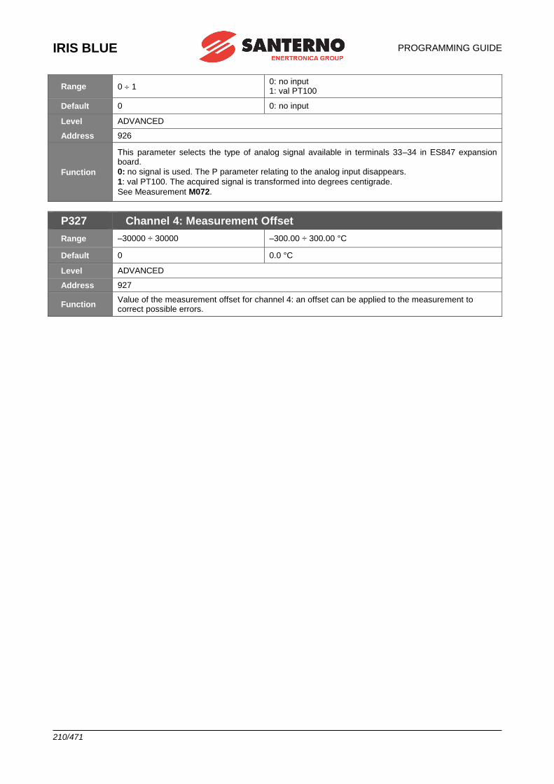
IRIS BLUE
PROGRAMMING GUIDE
210/471
Range 0 1 0: no input 1: val PT100
Default 0 0: no input
Level ADVANCED
Address 926
Function
This parameter selects the type of analog signal available in terminals 33–34 in ES847 expansion board.
0: no signal is used. The P parameter relating to the analog input disappears.
1: val PT100. The acquired signal is transformed into degrees centigrade.
See Measurement M072.
P327 Channel 4: Measurement Offset
Range –30000 ÷ 30000 –300.00 ÷ 300.00 °C
Default 0 0.0 °C
Level ADVANCED
Address 927
Function Value of the measurement offset for channel 4: an offset can be applied to the measurement to correct possible errors.
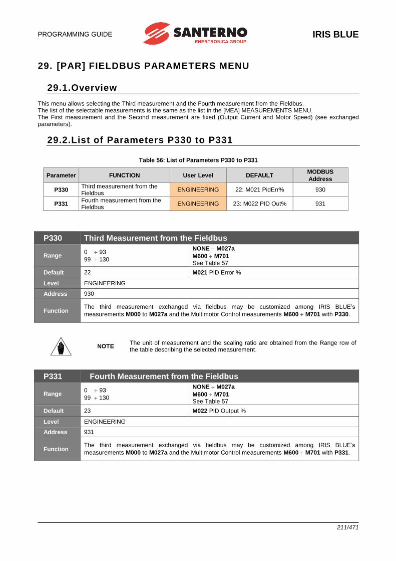
PROGRAMMING GUIDE
IRIS BLUE
211/471
29. [PAR] FIELDBUS PARAMETERS MENU
29.1.Overview This menu allows selecting the Third measurement and the Fourth measurement from the Fieldbus. The list of the selectable measurements is the same as the list in the [MEA] MEASUREMENTS MENU. The First measurement and the Second measurement are fixed (Output Current and Motor Speed) (see exchanged parameters).
29.2.List of Parameters P330 to P331
Table 56: List of Parameters P330 to P331
Parameter FUNCTION User Level DEFAULT MODBUS
Address
P330 Third measurement from the Fieldbus
ENGINEERING 22: M021 PidErr% 930
P331 Fourth measurement from the Fieldbus
ENGINEERING 23: M022 PID Out% 931
P330 Third Measurement from the Fieldbus
Range 0 93
99 130
NONE M027a
M600 M701 See Table 57
Default 22 M021 PID Error %
Level ENGINEERING
Address 930
Function The third measurement exchanged via fieldbus may be customized among IRIS BLUE’s
measurements M000 to M027a and the Multimotor Control measurements M600 M701 with P330.
NOTE The unit of measurement and the scaling ratio are obtained from the Range row of the table describing the selected measurement.
P331 Fourth Measurement from the Fieldbus
Range 0 93
99 130
NONE M027a
M600 M701 See Table 57
Default 23 M022 PID Output %
Level ENGINEERING
Address 931
Function The third measurement exchanged via fieldbus may be customized among IRIS BLUE’s
measurements M000 to M027a and the Multimotor Control measurements M600 M701 with P331.
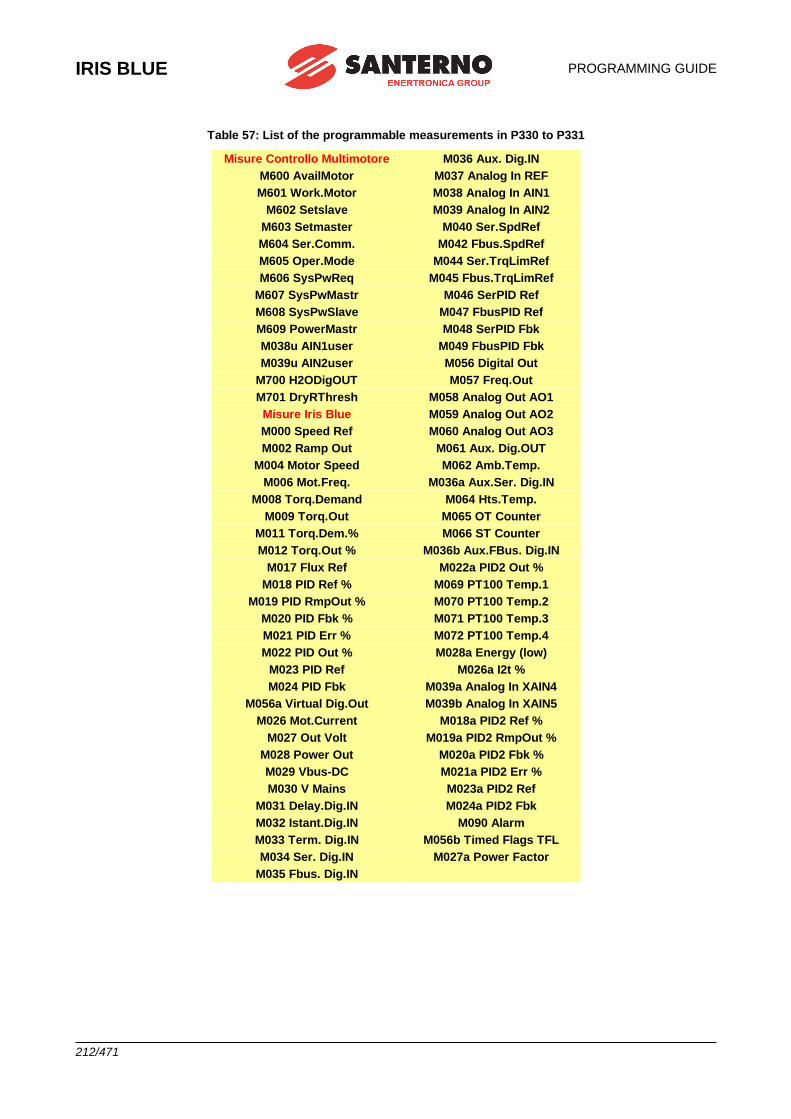
IRIS BLUE
PROGRAMMING GUIDE
212/471
Table 57: List of the programmable measurements in P330 to P331
Misure Controllo Multimotore M036 Aux. Dig.IN
M600 AvailMotor M037 Analog In REF
M601 Work.Motor M038 Analog In AIN1
M602 Setslave M039 Analog In AIN2
M603 Setmaster M040 Ser.SpdRef
M604 Ser.Comm. M042 Fbus.SpdRef
M605 Oper.Mode M044 Ser.TrqLimRef
M606 SysPwReq M045 Fbus.TrqLimRef
M607 SysPwMastr M046 SerPID Ref
M608 SysPwSlave M047 FbusPID Ref
M609 PowerMastr M048 SerPID Fbk
M038u AIN1user M049 FbusPID Fbk
M039u AIN2user M056 Digital Out
M700 H2ODigOUT M057 Freq.Out
M701 DryRThresh M058 Analog Out AO1
Misure Iris Blue M059 Analog Out AO2
M000 Speed Ref M060 Analog Out AO3
M002 Ramp Out M061 Aux. Dig.OUT
M004 Motor Speed M062 Amb.Temp.
M006 Mot.Freq. M036a Aux.Ser. Dig.IN
M008 Torq.Demand M064 Hts.Temp.
M009 Torq.Out M065 OT Counter
M011 Torq.Dem.% M066 ST Counter
M012 Torq.Out % M036b Aux.FBus. Dig.IN
M017 Flux Ref M022a PID2 Out %
M018 PID Ref % M069 PT100 Temp.1
M019 PID RmpOut % M070 PT100 Temp.2
M020 PID Fbk % M071 PT100 Temp.3
M021 PID Err % M072 PT100 Temp.4
M022 PID Out % M028a Energy (low)
M023 PID Ref M026a I2t %
M024 PID Fbk M039a Analog In XAIN4
M056a Virtual Dig.Out M039b Analog In XAIN5
M026 Mot.Current M018a PID2 Ref %
M027 Out Volt M019a PID2 RmpOut %
M028 Power Out M020a PID2 Fbk %
M029 Vbus-DC M021a PID2 Err %
M030 V Mains M023a PID2 Ref
M031 Delay.Dig.IN M024a PID2 Fbk
M032 Istant.Dig.IN M090 Alarm
M033 Term. Dig.IN M056b Timed Flags TFL
M034 Ser. Dig.IN M027a Power Factor
M035 Fbus. Dig.IN
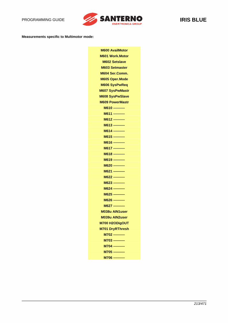
PROGRAMMING GUIDE
IRIS BLUE
213/471
Measurements specific to Multimotor mode:
M600 AvailMotor
M601 Work.Motor
M602 Setslave
M603 Setmaster
M604 Ser.Comm.
M605 Oper.Mode
M606 SysPwReq
M607 SysPwMastr
M608 SysPwSlave
M609 PowerMastr
M610 ----------
M611 ----------
M612 ----------
M613 ----------
M614 ----------
M615 ----------
M616 ----------
M617 ----------
M618 ----------
M619 ----------
M620 ----------
M621 ----------
M622 ----------
M623 ----------
M624 ----------
M625 ----------
M626 ----------
M627 ----------
M038u AIN1user
M039u AIN2user
M700 H2ODigOUT
M701 DryRThresh
M702 ----------
M703 ----------
M704 ----------
M705 ----------
M706 ----------
IRIS BLUE
PROGRAMMING GUIDE
214/471
30. [PAR] VIRTUAL DIGITAL OUTPUTS (MPL) MENU
30.1.Overview The Virtual Digital Outputs menu includes the parameters allowing configuring the virtual digital outputs (MPL1..4) of the IRIS BLUE drive. Virtual digital outputs are logic blocks (no hardware output is provided) allocating more complex logic functions to outputs MDO1..4: MPL virtual outputs can be feedbacked at the input of a new block (hardware or virtual block), thus allowing implementing more complex functionality.
NOTE The Virtual Digital Outputs menu may be accessed only if the user level is ADVANCED or ENGINEERING.
NOTE XMDI auxiliary digital outputs (values from 13 to 20 in the parameters relating to the control
functions) can be set up only after setting XMDI/O in parameter R023.
30.1.1. FACTORY SETTING The four virtual digital outputs are disabled as a factory setting.
30.1.2. STRUCTURE OF THE V IRTUAL D IGITAL OUTPUTS A virtual digital output is composed of two logic blocks allowing data processing before actuating the actual digital
output. Block 2 depends on the settings in parameters P357a (P366a, P375a, P384a). .
Logic Block
set by
parameters
P351-P357
INPUT A
INPUT B f(A,B)
P357a = 0yes
Output= f(A,B)
NO
Logic block
set by P357b
that tests f(A,B)
and signal C
Output=
g[f(A,B),C]
P000658-b
Figure 35: Block diagram of the virtual digital outputs (MPL)
Operating modes set in MPL1 (2, 3, 4): P350, (P359, P368, P377)
The user can select one of the following operating modes:
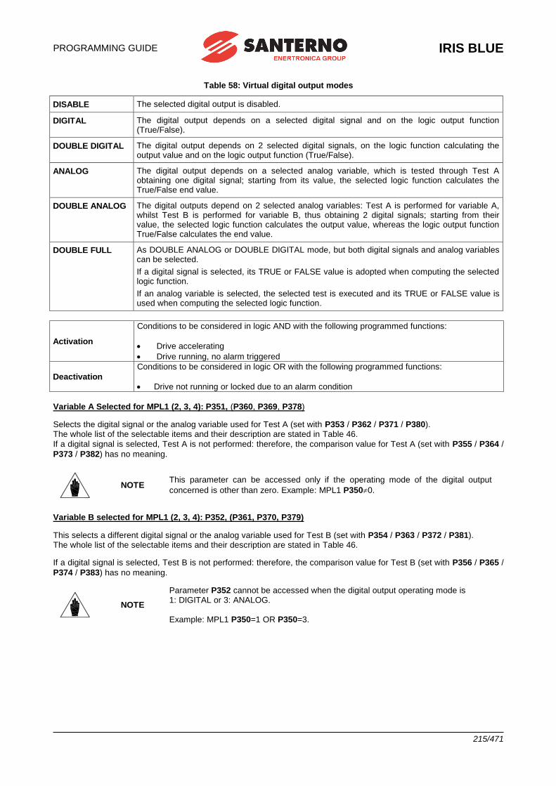
PROGRAMMING GUIDE
IRIS BLUE
215/471
Table 58: Virtual digital output modes
DISABLE The selected digital output is disabled.
DIGITAL The digital output depends on a selected digital signal and on the logic output function (True/False).
DOUBLE DIGITAL The digital output depends on 2 selected digital signals, on the logic function calculating the output value and on the logic output function (True/False).
ANALOG The digital output depends on a selected analog variable, which is tested through Test A obtaining one digital signal; starting from its value, the selected logic function calculates the True/False end value.
DOUBLE ANALOG The digital outputs depend on 2 selected analog variables: Test A is performed for variable A, whilst Test B is performed for variable B, thus obtaining 2 digital signals; starting from their value, the selected logic function calculates the output value, whereas the logic output function True/False calculates the end value.
DOUBLE FULL As DOUBLE ANALOG or DOUBLE DIGITAL mode, but both digital signals and analog variables can be selected.
If a digital signal is selected, its TRUE or FALSE value is adopted when computing the selected logic function.
If an analog variable is selected, the selected test is executed and its TRUE or FALSE value is used when computing the selected logic function.
Activation
Conditions to be considered in logic AND with the following programmed functions:
• Drive accelerating
• Drive running, no alarm triggered
Deactivation
Conditions to be considered in logic OR with the following programmed functions:
• Drive not running or locked due to an alarm condition
Variable A Selected for MPL1 (2, 3, 4): P351, (P360, P369, P378)
Selects the digital signal or the analog variable used for Test A (set with P353 / P362 / P371 / P380). The whole list of the selectable items and their description are stated in Table 46.
If a digital signal is selected, Test A is not performed: therefore, the comparison value for Test A (set with P355 / P364 /
P373 / P382) has no meaning.
NOTE This parameter can be accessed only if the operating mode of the digital output
concerned is other than zero. Example: MPL1 P3500.
Variable B selected for MPL1 (2, 3, 4): P352, (P361, P370, P379)
This selects a different digital signal or the analog variable used for Test B (set with P354 / P363 / P372 / P381). The whole list of the selectable items and their description are stated in Table 46.
If a digital signal is selected, Test B is not performed: therefore, the comparison value for Test B (set with P356 / P365 /
P374 / P383) has no meaning.
NOTE
Parameter P352 cannot be accessed when the digital output operating mode is 1: DIGITAL or 3: ANALOG.
Example: MPL1 P350=1 OR P350=3.
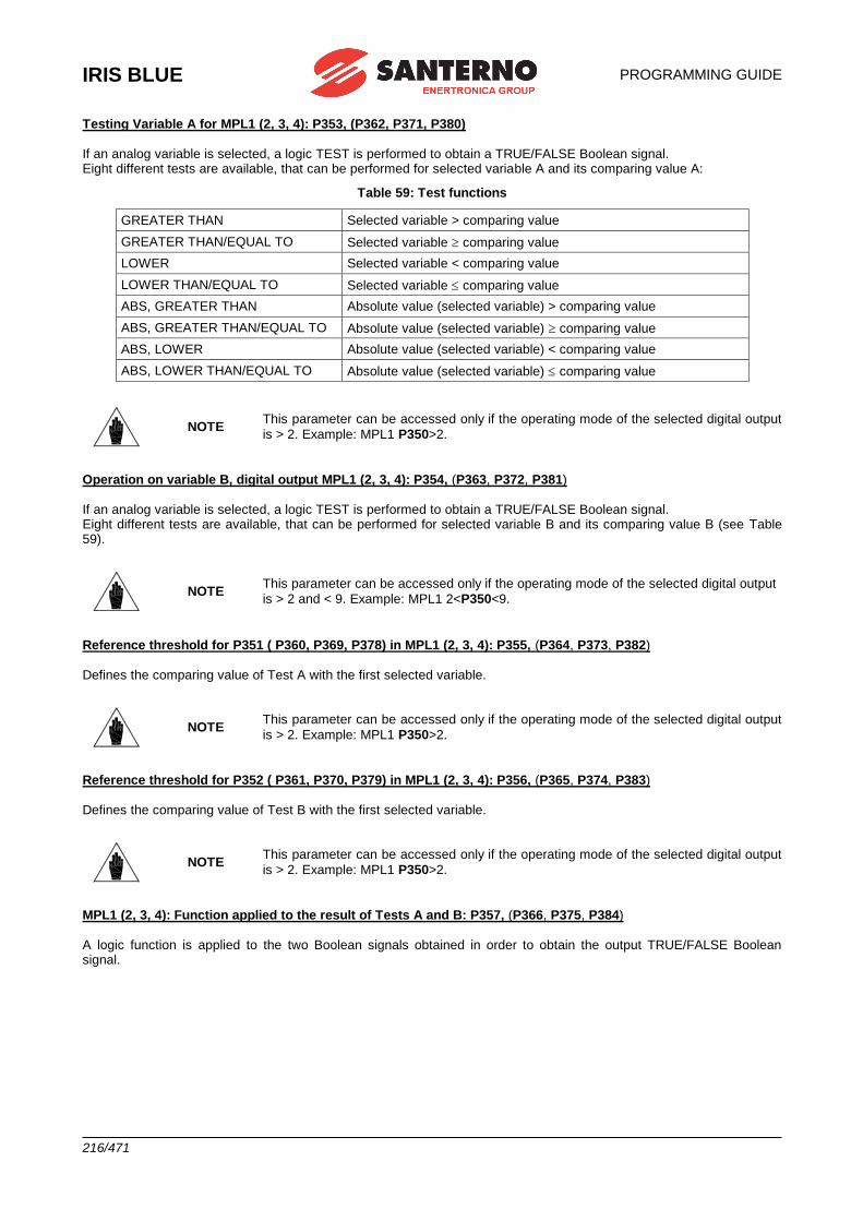
IRIS BLUE
PROGRAMMING GUIDE
216/471
Testing Variable A for MPL1 (2, 3, 4): P353, (P362, P371, P380) If an analog variable is selected, a logic TEST is performed to obtain a TRUE/FALSE Boolean signal. Eight different tests are available, that can be performed for selected variable A and its comparing value A:
Table 59: Test functions
GREATER THAN Selected variable > comparing value
GREATER THAN/EQUAL TO Selected variable comparing value
LOWER Selected variable < comparing value
LOWER THAN/EQUAL TO Selected variable comparing value
ABS, GREATER THAN Absolute value (selected variable) > comparing value
ABS, GREATER THAN/EQUAL TO Absolute value (selected variable) comparing value
ABS, LOWER Absolute value (selected variable) < comparing value
ABS, LOWER THAN/EQUAL TO Absolute value (selected variable) comparing value
NOTE This parameter can be accessed only if the operating mode of the selected digital output
is > 2. Example: MPL1 P350>2.
Operation on variable B, digital output MPL1 (2, 3, 4): P354, (P363, P372, P381) If an analog variable is selected, a logic TEST is performed to obtain a TRUE/FALSE Boolean signal. Eight different tests are available, that can be performed for selected variable B and its comparing value B (see Table 59).
NOTE This parameter can be accessed only if the operating mode of the selected digital output
is > 2 and < 9. Example: MPL1 2<P350<9.
Reference threshold for P351 ( P360, P369, P378) in MPL1 (2, 3, 4): P355, (P364, P373, P382) Defines the comparing value of Test A with the first selected variable.
NOTE This parameter can be accessed only if the operating mode of the selected digital output
is > 2. Example: MPL1 P350>2.
Reference threshold for P352 ( P361, P370, P379) in MPL1 (2, 3, 4): P356, (P365, P374, P383) Defines the comparing value of Test B with the first selected variable.
NOTE This parameter can be accessed only if the operating mode of the selected digital output
is > 2. Example: MPL1 P350>2.
MPL1 (2, 3, 4): Function applied to the result of Tests A and B: P357, (P366, P375, P384) A logic function is applied to the two Boolean signals obtained in order to obtain the output TRUE/FALSE Boolean signal.
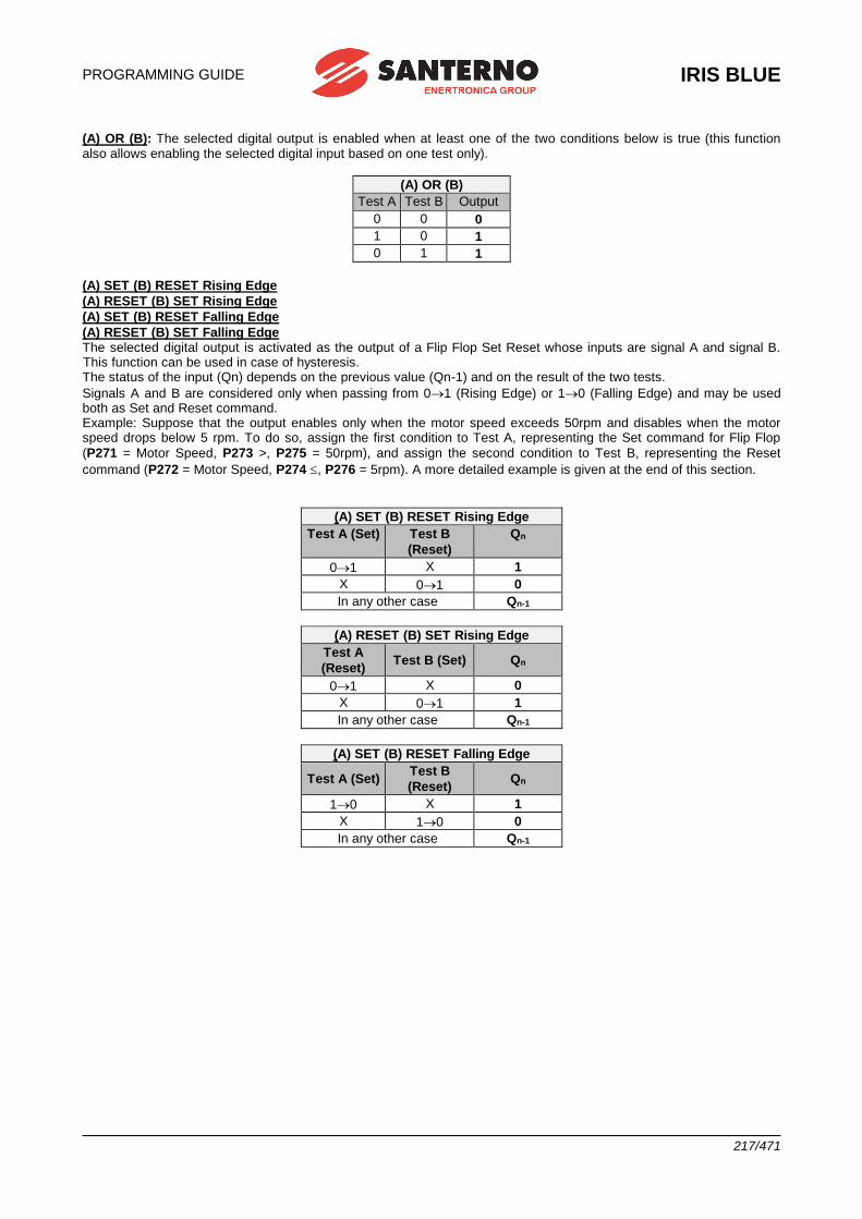
PROGRAMMING GUIDE
IRIS BLUE
217/471
(A) OR (B): The selected digital output is enabled when at least one of the two conditions below is true (this function also allows enabling the selected digital input based on one test only).
(A) OR (B)
Test A Test B Output
0 0 0
1 0 1
0 1 1
(A) SET (B) RESET Rising Edge
(A) RESET (B) SET Rising Edge
(A) SET (B) RESET Falling Edge
(A) RESET (B) SET Falling Edge The selected digital output is activated as the output of a Flip Flop Set Reset whose inputs are signal A and signal B. This function can be used in case of hysteresis. The status of the input (Qn) depends on the previous value (Qn-1) and on the result of the two tests.
Signals A and B are considered only when passing from 01 (Rising Edge) or 10 (Falling Edge) and may be used both as Set and Reset command. Example: Suppose that the output enables only when the motor speed exceeds 50rpm and disables when the motor speed drops below 5 rpm. To do so, assign the first condition to Test A, representing the Set command for Flip Flop
(P271 = Motor Speed, P273 >, P275 = 50rpm), and assign the second condition to Test B, representing the Reset
command (P272 = Motor Speed, P274 , P276 = 5rpm). A more detailed example is given at the end of this section.
(A) SET (B) RESET Rising Edge
Test A (Set) Test B
(Reset)
Qn
01 X 1
X 01 0
In any other case Qn-1
(A) RESET (B) SET Rising Edge
Test A
(Reset) Test B (Set) Qn
01 X 0
X 01 1
In any other case Qn-1
(A) SET (B) RESET Falling Edge
Test A (Set) Test B
(Reset) Qn
10 X 1
X 10 0
In any other case Qn-1
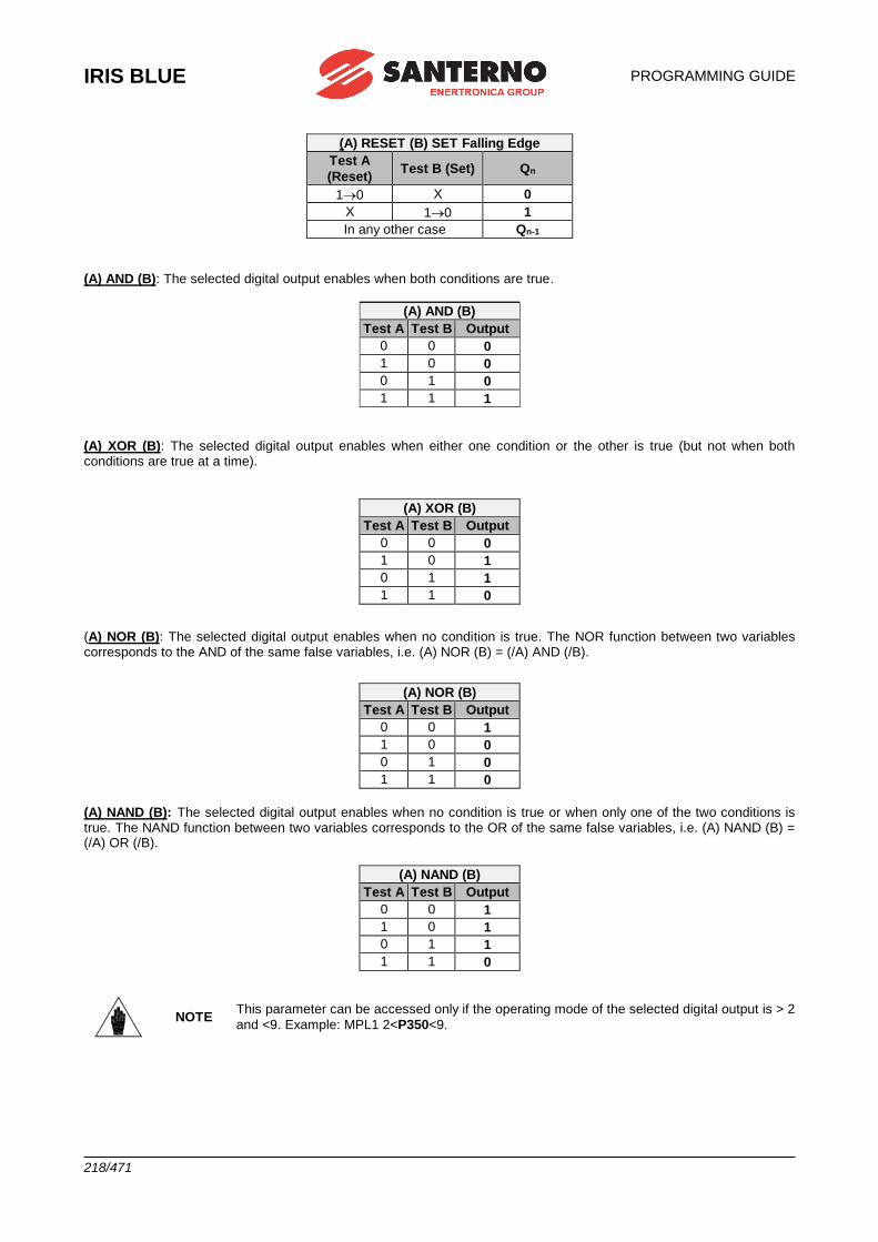
IRIS BLUE
PROGRAMMING GUIDE
218/471
(A) RESET (B) SET Falling Edge
Test A
(Reset) Test B (Set) Qn
10 X 0
X 10 1
In any other case Qn-1
(A) AND (B): The selected digital output enables when both conditions are true.
(A) AND (B)
Test A Test B Output
0 0 0
1 0 0
0 1 0
1 1 1
(A) XOR (B): The selected digital output enables when either one condition or the other is true (but not when both conditions are true at a time).
(A) XOR (B)
Test A Test B Output
0 0 0
1 0 1
0 1 1
1 1 0
(A) NOR (B): The selected digital output enables when no condition is true. The NOR function between two variables corresponds to the AND of the same false variables, i.e. (A) NOR (B) = (/A) AND (/B).
(A) NOR (B)
Test A Test B Output
0 0 1
1 0 0
0 1 0
1 1 0
(A) NAND (B): The selected digital output enables when no condition is true or when only one of the two conditions is true. The NAND function between two variables corresponds to the OR of the same false variables, i.e. (A) NAND (B) = (/A) OR (/B).
(A) NAND (B)
Test A Test B Output
0 0 1
1 0 1
0 1 1
1 1 0
NOTE This parameter can be accessed only if the operating mode of the selected digital output is > 2
and <9. Example: MPL1 2<P350<9.
PROGRAMMING GUIDE
IRIS BLUE
219/471
Function applied to the result of f(A,B) C for MPL1: P357b, (P366b, P375b, P384b) Once the Boolean signal resulting from f(A,B) is obtained, an additional logic function can be applied to obtain the output TRUE//FALSE Boolean signal.
If parameter P357a is disabled, the output of f(A,B) goes directly to the corresponding digital output; if parameter P357a is enabled, the output of the output of f(A,B) becomes one of the two inputs of the second programmed block. The user can choose one of the six Boolean tests above for the first variable—f(A,B)—and for the second variable (C).
Logic applied to MPL1 (2, 3,4): P358, (P367, P376, P385) The logic of the Boolean signal can be reversed at the end of the processing chain. The user can choose whether the logic level of the digital output is POSITIVE or NEGATIVE. (0) FALSE = a logic negation is applied (NEGATIVE logic). (1) TRUE = no negation is applied (POSITIVE logic).
NOTE This parameter can be accessed only if the operating mode of the selected digital output is
other than zero. Example: MPL1 P3500.
NOTE Please refer to the Programmable Operating Modes (Diagrams) of the digital outputs.
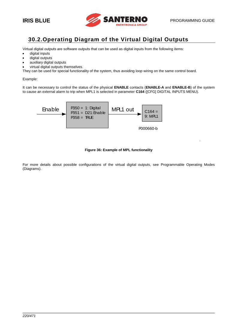
IRIS BLUE
PROGRAMMING GUIDE
220/471
30.2.Operating Diagram of the Virtual Digital Outputs
Virtual digital outputs are software outputs that can be used as digital inputs from the following items:
• digital inputs
• digital outputs
• auxiliary digital outputs
• virtual digital outputs themselves. They can be used for special functionality of the system, thus avoiding loop wiring on the same control board. Example:
It can be necessary to control the status of the physical ENABLE contacts (ENABLE-A and ENABLE-B) of the system
to cause an external alarm to trip when MPL1 is selected in parameter C164 ([CFG] DIGITAL INPUTS MENU).
Enable P350 = 1: Digital
P351 = D21:Enable
P358 = TRUE
MPL1 out C164 =
9: MPL1
.
P000660-b
Figure 36: Example of MPL functionality
For more details about possible configurations of the virtual digital outputs, see Programmable Operating Modes (Diagrams).
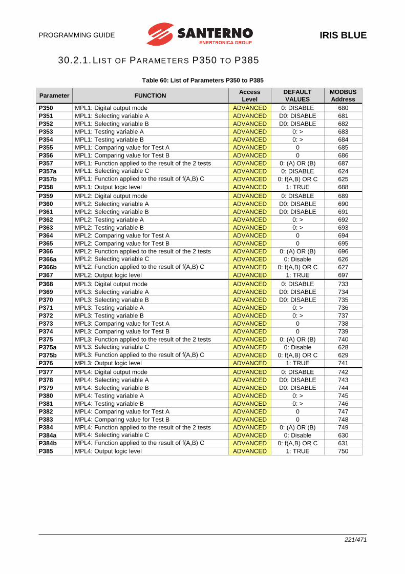
PROGRAMMING GUIDE
IRIS BLUE
221/471
30.2.1. L IST OF PARAMETERS P350 TO P385
Table 60: List of Parameters P350 to P385
Parameter FUNCTION Access
Level
DEFAULT
VALUES
MODBUS
Address
P350 MPL1: Digital output mode ADVANCED 0: DISABLE 680
P351 MPL1: Selecting variable A ADVANCED D0: DISABLE 681
P352 MPL1: Selecting variable B ADVANCED D0: DISABLE 682
P353 MPL1: Testing variable A ADVANCED 0: > 683
P354 MPL1: Testing variable B ADVANCED 0: > 684
P355 MPL1: Comparing value for Test A ADVANCED 0 685
P356 MPL1: Comparing value for Test B ADVANCED 0 686
P357 MPL1: Function applied to the result of the 2 tests ADVANCED 0: (A) OR (B) 687
P357a MPL1: Selecting variable C ADVANCED 0: DISABLE 624
P357b MPL1: Function applied to the result of f(A,B) C ADVANCED 0: f(A,B) OR C 625
P358 MPL1: Output logic level ADVANCED 1: TRUE 688
P359 MPL2: Digital output mode ADVANCED 0: DISABLE 689
P360 MPL2: Selecting variable A ADVANCED D0: DISABLE 690
P361 MPL2: Selecting variable B ADVANCED D0: DISABLE 691
P362 MPL2: Testing variable A ADVANCED 0: > 692
P363 MPL2: Testing variable B ADVANCED 0: > 693
P364 MPL2: Comparing value for Test A ADVANCED 0 694
P365 MPL2: Comparing value for Test B ADVANCED 0 695
P366 MPL2: Function applied to the result of the 2 tests ADVANCED 0: (A) OR (B) 696
P366a MPL2: Selecting variable C ADVANCED 0: Disable 626
P366b MPL2: Function applied to the result of f(A,B) C ADVANCED 0: f(A,B) OR C 627
P367 MPL2: Output logic level ADVANCED 1: TRUE 697
P368 MPL3: Digital output mode ADVANCED 0: DISABLE 733
P369 MPL3: Selecting variable A ADVANCED D0: DISABLE 734
P370 MPL3: Selecting variable B ADVANCED D0: DISABLE 735
P371 MPL3: Testing variable A ADVANCED 0: > 736
P372 MPL3: Testing variable B ADVANCED 0: > 737
P373 MPL3: Comparing value for Test A ADVANCED 0 738
P374 MPL3: Comparing value for Test B ADVANCED 0 739
P375 MPL3: Function applied to the result of the 2 tests ADVANCED 0: (A) OR (B) 740
P375a MPL3: Selecting variable C ADVANCED 0: Disable 628
P375b MPL3: Function applied to the result of f(A,B) C ADVANCED 0: f(A,B) OR C 629
P376 MPL3: Output logic level ADVANCED 1: TRUE 741
P377 MPL4: Digital output mode ADVANCED 0: DISABLE 742
P378 MPL4: Selecting variable A ADVANCED D0: DISABLE 743
P379 MPL4: Selecting variable B ADVANCED D0: DISABLE 744
P380 MPL4: Testing variable A ADVANCED 0: > 745
P381 MPL4: Testing variable B ADVANCED 0: > 746
P382 MPL4: Comparing value for Test A ADVANCED 0 747
P383 MPL4: Comparing value for Test B ADVANCED 0 748
P384 MPL4: Function applied to the result of the 2 tests ADVANCED 0: (A) OR (B) 749
P384a MPL4: Selecting variable C ADVANCED 0: Disable 630
P384b MPL4: Function applied to the result of f(A,B) C ADVANCED 0: f(A,B) OR C 631
P385 MPL4: Output logic level ADVANCED 1: TRUE 750

IRIS BLUE
PROGRAMMING GUIDE
222/471
P350 MPL1: Digital Output Mode
Range 0 5
0: DISABLE 1: DIGITAL 2: DOUBLE DIGITAL 3: ANALOG 4: DOUBLE ANALOG 5: DOUBLE FULL
Default 0 0: DISABLE
Level ADVANCED
Address 680
Function This parameter defines the operating mode of virtual digital output 1. The different operating modes are described at the beginning of this chapter.
P351 MPL1: Selecting Variable A
Range 0 149 See Table 46
Default 21 D21: Enable
Level ADVANCED
Address 681
Function
This parameter selects the digital signal used to calculate the value of MPL1 digital output.
It selects an analog variable used to calculate the value of MPL1 digital output if one of the “analog” operating modes is selected. Digital signals and analog variables are detailed in Table 46.
P352 MPL1: Selecting Variable B
Range 0 149 See Table 46
Default 0 D0: Disable
Level ADVANCED
Address 682
Function
This parameter selects the second digital signal used to calculate the value of MPL1 digital output.
It selects an analog variable used to calculate the value of MPL1 digital input if one of the “analog” operating modes is selected. Digital signals and analog variables are detailed in Table 46.
P353 MPL1: Testing Variable A
Range 0 7
0: > 1: ≥ 2: < 3: ≤ 4: ABS(x) > 5: ABS(x) ≥ 6: ABS(x) < 7: ABS(x) ≤
Default 0 0: >
Level ADVANCED
Address 683
Function This parameter defines the test to be performed for the variable detected by P351 using P355 as a comparing value.
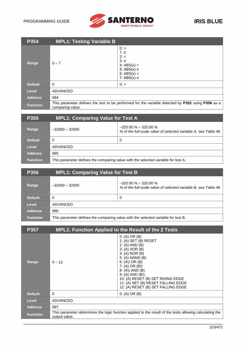
PROGRAMMING GUIDE
IRIS BLUE
223/471
P354 MPL1: Testing Variable B
Range 0 7
0: > 1: ≥ 2: < 3: ≤ 4: ABS(x) > 5: ABS(x) ≥ 6: ABS(x) < 7: ABS(x) ≤
Default 0 0: >
Level ADVANCED
Address 684
Function This parameter defines the test to be performed for the variable detected by P352 using P356 as a comparing value.
P355 MPL1: Comparing Value for Test A
Range –32000 32000 –320.00 % 320.00 % % of the full-scale value of selected variable A, see Table 46
Default 0 0
Level ADVANCED
Address 685
Function This parameter defines the comparing value with the selected variable for test A.
P356 MPL1: Comparing Value for Test B
Range –32000 32000 –320.00 % 320.00 % % of the full-scale value of selected variable B, see Table 46
Default 0 0
Level ADVANCED
Address 686
Function This parameter defines the comparing value with the selected variable for test B.
P357 MPL1: Function Applied to the Result of the 2 Tests
Range 0 12
0: (A) OR (B) 1: (A) SET (B) RESET 2: (A) AND (B) 3: (A) XOR (B) 4: (A) NOR (B) 5: (A) NAND (B) 6: (A\) OR (B) 7: (A) OR (B\) 8: (A\) AND (B) 9: (A) AND (B\) 10: (A) RESET (B) SET RISING EDGE 11: (A) SET (B) RESET FALLING EDGE 12: (A) RESET (B) SET FALLING EDGE
Default 0 0: (A) OR (B)
Level ADVANCED
Address 687
Function This parameter determines the logic function applied to the result of the tests allowing calculating the output value.
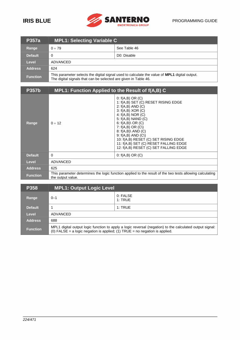
IRIS BLUE
PROGRAMMING GUIDE
224/471
P357a MPL1: Selecting Variable C
Range 0 79 See Table 46
Default 0 D0: Disable
Level ADVANCED
Address 624
Function This parameter selects the digital signal used to calculate the value of MPL1 digital output. The digital signals that can be selected are given in Table 46.
P357b MPL1: Function Applied to the Result of f(A,B) C
Range 0 12
0: f(A,B) OR (C) 1: f(A,B) SET (C) RESET RISING EDGE 2: f(A,B) AND (C) 3: f(A,B) XOR (C) 4: f(A,B) NOR (C) 5: f(A,B) NAND (C) 6: f(A,B)\ OR (C) 7: f(A,B) OR (C\) 8: f(A,B)\ AND (C) 9: f(A,B) AND (C\) 10: f(A,B) RESET (C) SET RISING EDGE 11: f(A,B) SET (C) RESET FALLING EDGE 12: f(A,B) RESET (C) SET FALLING EDGE
Default 0 0: f(A,B) OR (C)
Level ADVANCED
Address 625
Function This parameter determines the logic function applied to the result of the two tests allowing calculating the output value.
P358 MPL1: Output Logic Level
Range 0–1 0: FALSE 1: TRUE
Default 1 1: TRUE
Level ADVANCED
Address 688
Function MPL1 digital output logic function to apply a logic reversal (negation) to the calculated output signal: (0) FALSE = a logic negation is applied; (1) TRUE = no negation is applied.

PROGRAMMING GUIDE
IRIS BLUE
225/471
P359 MPL2: Digital Output Mode
Range 0 5
0: DISABLE 1: DIGITAL 2: DOUBLE DIGITAL 3: ANALOG 4: DOUBLE ANALOG 5: DOUBLE FULL
Default 0 0: DISABLE
Level ADVANCED
Address 689
Function This parameter defines the operating mode of virtual digital output 2. The different operating modes are described at the beginning of this chapter.
P360 MPL2: Selecting Variable A
Range 0 149 See Table 46
Default 33 D33: Fan Fault
Level ADVANCED
Address 690
Function
This parameter selects the digital signal used to calculate the value of MPL2 digital output.
It selects an analog variable used to calculate the value of MPL2 digital input if one of the “analog” operating modes is selected. Digital signals and analog variables are detailed in Table 46.
P361 MPL2: Selecting Variable B
Range 0 149 See Table 46
Default 0 D0: Disable
Level ADVANCED
Address 691
Function
This parameter selects the second digital signal used to calculate the value of MPL2 digital output.
It selects an analog variable used to calculate the value of MPL2 digital input if one of the “analog” operating modes is selected. Digital signals and analog variables are detailed in Table 46.
P362 MPL2: Testing Variable A
Range 0 7
0: > 1: ≥ 2: < 3: ≤ 4: ABS(x) > 5: ABS(x) ≥ 6: ABS(x) < 7: ABS(x) ≤
Default 0 0: >
Level ADVANCED
Address 692
Function This parameter defines the test to be performed for the variable detected by P360 using P364 as a comparing value.
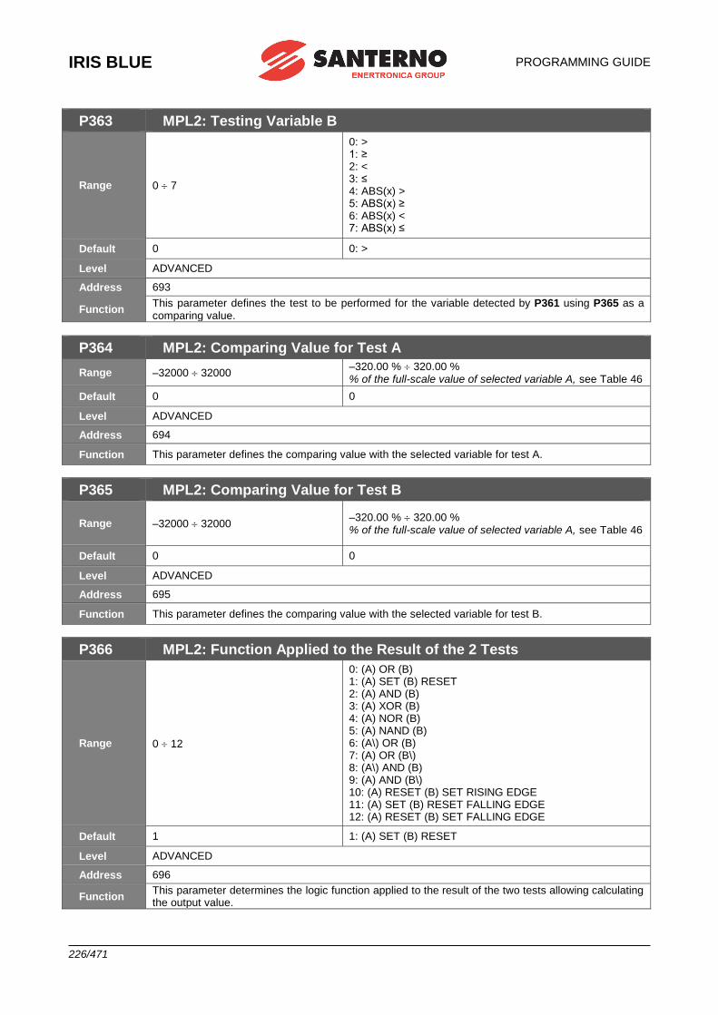
IRIS BLUE
PROGRAMMING GUIDE
226/471
P363 MPL2: Testing Variable B
Range 0 7
0: > 1: ≥ 2: < 3: ≤ 4: ABS(x) > 5: ABS(x) ≥ 6: ABS(x) < 7: ABS(x) ≤
Default 0 0: >
Level ADVANCED
Address 693
Function This parameter defines the test to be performed for the variable detected by P361 using P365 as a comparing value.
P364 MPL2: Comparing Value for Test A
Range –32000 32000 –320.00 % 320.00 % % of the full-scale value of selected variable A, see Table 46
Default 0 0
Level ADVANCED
Address 694
Function This parameter defines the comparing value with the selected variable for test A.
P365 MPL2: Comparing Value for Test B
Range –32000 32000 –320.00 % 320.00 % % of the full-scale value of selected variable A, see Table 46
Default 0 0
Level ADVANCED
Address 695
Function This parameter defines the comparing value with the selected variable for test B.
P366 MPL2: Function Applied to the Result of the 2 Tests
Range 0 12
0: (A) OR (B) 1: (A) SET (B) RESET 2: (A) AND (B) 3: (A) XOR (B) 4: (A) NOR (B) 5: (A) NAND (B) 6: (A\) OR (B) 7: (A) OR (B\) 8: (A\) AND (B) 9: (A) AND (B\) 10: (A) RESET (B) SET RISING EDGE 11: (A) SET (B) RESET FALLING EDGE 12: (A) RESET (B) SET FALLING EDGE
Default 1 1: (A) SET (B) RESET
Level ADVANCED
Address 696
Function This parameter determines the logic function applied to the result of the two tests allowing calculating the output value.
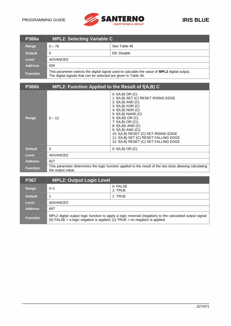
PROGRAMMING GUIDE
IRIS BLUE
227/471
P366a MPL2: Selecting Variable C
Range 0 79 See Table 46
Default 0 D0: Disable
Level ADVANCED
Address 626
Function This parameter selects the digital signal used to calculate the value of MPL2 digital output. The digital signals that can be selected are given in Table 46.
P366b MPL2: Function Applied to the Result of f(A,B) C
Range 0 12
0: f(A,B) OR (C) 1: f(A,B) SET (C) RESET RISING EDGE 2: f(A,B) AND (C) 3: f(A,B) XOR (C) 4: f(A,B) NOR (C) 5: f(A,B) NAND (C) 6: f(A,B)\ OR (C) 7: f(A,B) OR (C\) 8: f(A,B)\ AND (C) 9: f(A,B) AND (C\) 10: f(A,B) RESET (C) SET RISING EDGE 11: f(A,B) SET (C) RESET FALLING EDGE 12: f(A,B) RESET (C) SET FALLING EDGE
Default 0 0: f(A,B) OR (C)
Level ADVANCED
Address 627
Function This parameter determines the logic function applied to the result of the two tests allowing calculating the output value.
P367 MPL2: Output Logic Level
Range 0–1 0: FALSE 1: TRUE
Default 1 1: TRUE
Level ADVANCED
Address 697
Function MPL2 digital output logic function to apply a logic reversal (negation) to the calculated output signal: (0) FALSE = a logic negation is applied; (1) TRUE = no negation is applied.
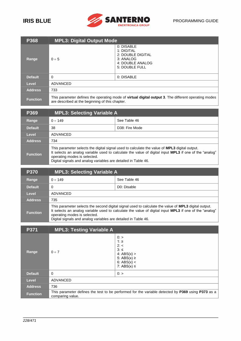
IRIS BLUE
PROGRAMMING GUIDE
228/471
P368 MPL3: Digital Output Mode
Range 0 5
0: DISABLE 1: DIGITAL 2: DOUBLE DIGITAL 3: ANALOG 4: DOUBLE ANALOG 5: DOUBLE FULL
Default 0 0: DISABLE
Level ADVANCED
Address 733
Function This parameter defines the operating mode of virtual digital output 3. The different operating modes are described at the beginning of this chapter.
P369 MPL3: Selecting Variable A
Range 0 149 See Table 46
Default 38 D38: Fire Mode
Level ADVANCED
Address 734
Function
This parameter selects the digital signal used to calculate the value of MPL3 digital output.
It selects an analog variable used to calculate the value of digital input MPL3 if one of the “analog” operating modes is selected. Digital signals and analog variables are detailed in Table 46.
P370 MPL3: Selecting Variable A
Range 0 149 See Table 46
Default 0 D0: Disable
Level ADVANCED
Address 735
Function
This parameter selects the second digital signal used to calculate the value of MPL3 digital output.
It selects an analog variable used to calculate the value of digital input MPL3 if one of the “analog” operating modes is selected. Digital signals and analog variables are detailed in Table 46.
P371 MPL3: Testing Variable A
Range 0 7
0: > 1: ≥ 2: < 3: ≤ 4: ABS(x) > 5: ABS(x) ≥ 6: ABS(x) < 7: ABS(x) ≤
Default 0 0: >
Level ADVANCED
Address 736
Function This parameter defines the test to be performed for the variable detected by P369 using P373 as a comparing value.
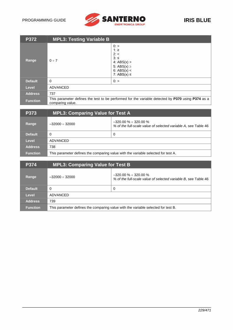
PROGRAMMING GUIDE
IRIS BLUE
229/471
P372 MPL3: Testing Variable B
Range 0 7
0: > 1: ≥ 2: < 3: ≤ 4: ABS(x) >
5: ABS(x) 6: ABS(x) < 7: ABS(x) ≤
Default 0 0: >
Level ADVANCED
Address 737
Function This parameter defines the test to be performed for the variable detected by P370 using P374 as a comparing value.
P373 MPL3: Comparing Value for Test A
Range –32000 32000 –320.00 % 320.00 % % of the full-scale value of selected variable A, see Table 46
Default 0 0
Level ADVANCED
Address 738
Function This parameter defines the comparing value with the variable selected for test A.
P374 MPL3: Comparing Value for Test B
Range –32000 32000 –320.00 % 320.00 % % of the full-scale value of selected variable B, see Table 46
Default 0 0
Level ADVANCED
Address 739
Function This parameter defines the comparing value with the variable selected for test B.

IRIS BLUE
PROGRAMMING GUIDE
230/471
P375 MPL3: Function Applied to the Result of the 2 Tests
Range 0 12
0: (A) OR (B) 1: (A) SET (B) RESET 2: (A) AND (B) 3: (A) XOR (B) 4: (A) NOR (B) 5: (A) NAND (B) 6: (A\) OR (B) 7: (A) OR (B\) 8: (A\) AND (B) 9: (A) AND (B\) 10: (A) RESET (B) SET RISING EDGE 11: (A) SET (B) RESET FALLING EDGE 12: (A) RESET (B) SET FALLING EDGE
Default 0 0: (A) OR (B)
Level ADVANCED
Address 740
Function This parameter determines the logic function applied to the result of the two tests allowing calculating the output value.
P375a MPL3: Selecting Variable C
Range 0 79 See Table 46
Default 0 D0: Disable
Level ADVANCED
Address 628
Function This parameter selects the digital signal used to calculate the value of MPL3 digital output. The digital signals that can be selected are given in Table 46.
P375b MPL3: Function Applied to the Result of f(A,B) C
Range 0 12
0: f(A,B) OR (C) 1: f(A,B) SET (C) RESET RISING EDGE 2: f(A,B) AND (C) 3: f(A,B) XOR (C) 4: f(A,B) NOR (C) 5: f(A,B) NAND (C) 6: f(A,B)\ OR (C) 7: f(A,B) OR (C\) 8: f(A,B)\ AND (C) 9: f(A,B) AND (C\) 10: f(A,B) RESET (C) SET RISING EDGE 11: f(A,B) SET (C) RESET FALLING EDGE 12: f(A,B) RESET (C) SET FALLING EDGE
Default 0 0: f(A,B) OR (C)
Level ADVANCED
Address 629
Function This parameter determines the logic function applied to the result of the two tests allowing calculating the output value.
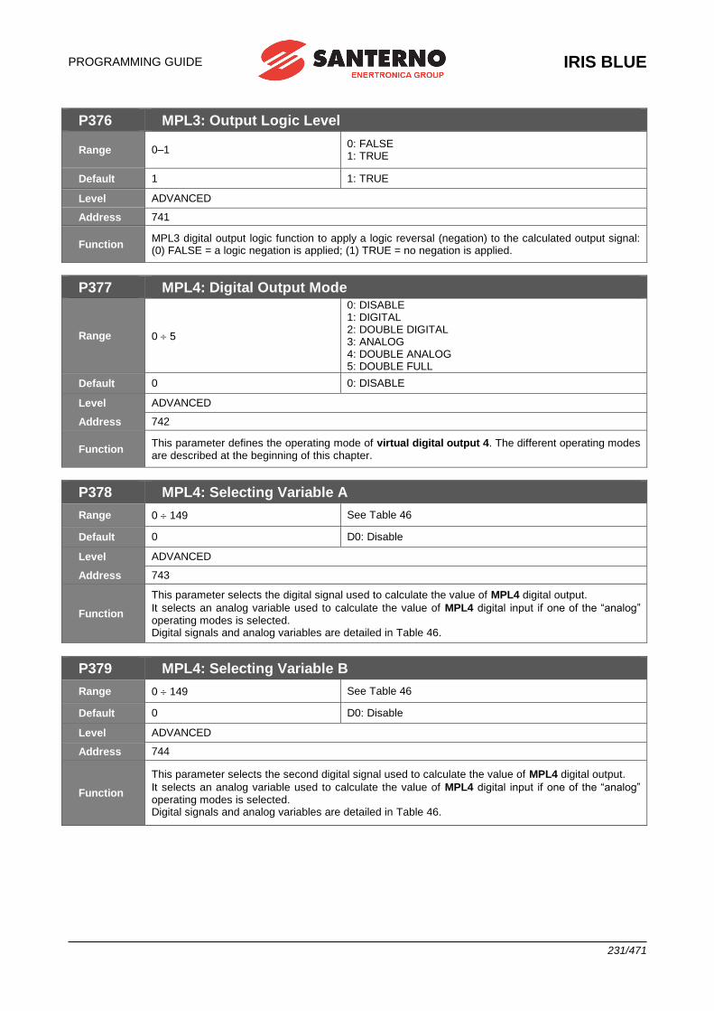
PROGRAMMING GUIDE
IRIS BLUE
231/471
P376 MPL3: Output Logic Level
Range 0–1 0: FALSE 1: TRUE
Default 1 1: TRUE
Level ADVANCED
Address 741
Function MPL3 digital output logic function to apply a logic reversal (negation) to the calculated output signal: (0) FALSE = a logic negation is applied; (1) TRUE = no negation is applied.
P377 MPL4: Digital Output Mode
Range 0 5
0: DISABLE 1: DIGITAL 2: DOUBLE DIGITAL 3: ANALOG 4: DOUBLE ANALOG 5: DOUBLE FULL
Default 0 0: DISABLE
Level ADVANCED
Address 742
Function This parameter defines the operating mode of virtual digital output 4. The different operating modes are described at the beginning of this chapter.
P378 MPL4: Selecting Variable A
Range 0 149 See Table 46
Default 0 D0: Disable
Level ADVANCED
Address 743
Function
This parameter selects the digital signal used to calculate the value of MPL4 digital output.
It selects an analog variable used to calculate the value of MPL4 digital input if one of the “analog” operating modes is selected. Digital signals and analog variables are detailed in Table 46.
P379 MPL4: Selecting Variable B
Range 0 149 See Table 46
Default 0 D0: Disable
Level ADVANCED
Address 744
Function
This parameter selects the second digital signal used to calculate the value of MPL4 digital output.
It selects an analog variable used to calculate the value of MPL4 digital input if one of the “analog” operating modes is selected. Digital signals and analog variables are detailed in Table 46.
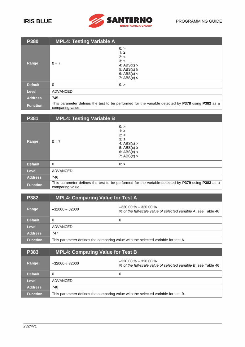
IRIS BLUE
PROGRAMMING GUIDE
232/471
P380 MPL4: Testing Variable A
Range 0 7
0: > 1: ≥ 2: < 3: ≤ 4: ABS(x) > 5: ABS(x) ≥ 6: ABS(x) < 7: ABS(x) ≤
Default 0 0: >
Level ADVANCED
Address 745
Function This parameter defines the test to be performed for the variable detected by P378 using P382 as a comparing value.
P381 MPL4: Testing Variable B
Range 0 7
0: > 1: ≥ 2: < 3: ≤ 4: ABS(x) > 5: ABS(x) ≥ 6: ABS(x) < 7: ABS(x) ≤
Default 0 0: >
Level ADVANCED
Address 746
Function This parameter defines the test to be performed for the variable detected by P379 using P383 as a comparing value.
P382 MPL4: Comparing Value for Test A
Range –32000 32000 –320.00 % 320.00 % % of the full-scale value of selected variable A, see Table 46
Default 0 0
Level ADVANCED
Address 747
Function This parameter defines the comparing value with the selected variable for test A.
P383 MPL4: Comparing Value for Test B
Range –32000 32000 –320.00 % 320.00 % % of the full-scale value of selected variable B, see Table 46
Default 0 0
Level ADVANCED
Address 748
Function This parameter defines the comparing value with the selected variable for test B.
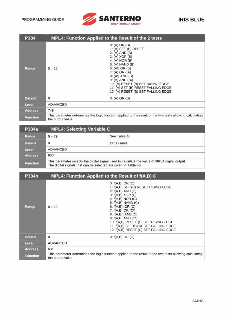
PROGRAMMING GUIDE
IRIS BLUE
233/471
P384 MPL4: Function Applied to the Result of the 2 tests
Range 0 12
0: (A) OR (B) 1: (A) SET (B) RESET 2: (A) AND (B) 3: (A) XOR (B) 4: (A) NOR (B) 5: (A) NAND (B) 6: (A\) OR (B) 7: (A) OR (B\) 8: (A\) AND (B) 9: (A) AND (B\) 10: (A) RESET (B) SET RISING EDGE 11: (A) SET (B) RESET FALLING EDGE 12: (A) RESET (B) SET FALLING EDGE
Default 0 0: (A) OR (B)
Level ADVANCED
Address 749
Function This parameter determines the logic function applied to the result of the two tests allowing calculating the output value.
P384a MPL4: Selecting Variable C
Range 0 79 See Table 46
Default 0 D0: Disable
Level ADVANCED
Address 630
Function This parameter selects the digital signal used to calculate the value of MPL4 digital output. The digital signals that can be selected are given in Table 46.
P384b MPL4: Function Applied to the Result of f(A,B) C
Range 0 12
0: f(A,B) OR (C) 1: f(A,B) SET (C) RESET RISING EDGE 2: f(A,B) AND (C) 3: f(A,B) XOR (C) 4: f(A,B) NOR (C) 5: f(A,B) NAND (C) 6: f(A,B)\ OR (C) 7: f(A,B) OR (C\) 8: f(A,B)\ AND (C) 9: f(A,B) AND (C\) 10: f(A,B) RESET (C) SET RISING EDGE 11: f(A,B) SET (C) RESET FALLING EDGE 12: f(A,B) RESET (C) SET FALLING EDGE
Default 0 0: f(A,B) OR (C)
Level ADVANCED
Address 631
Function This parameter determines the logic function applied to the result of the two tests allowing calculating the output value.
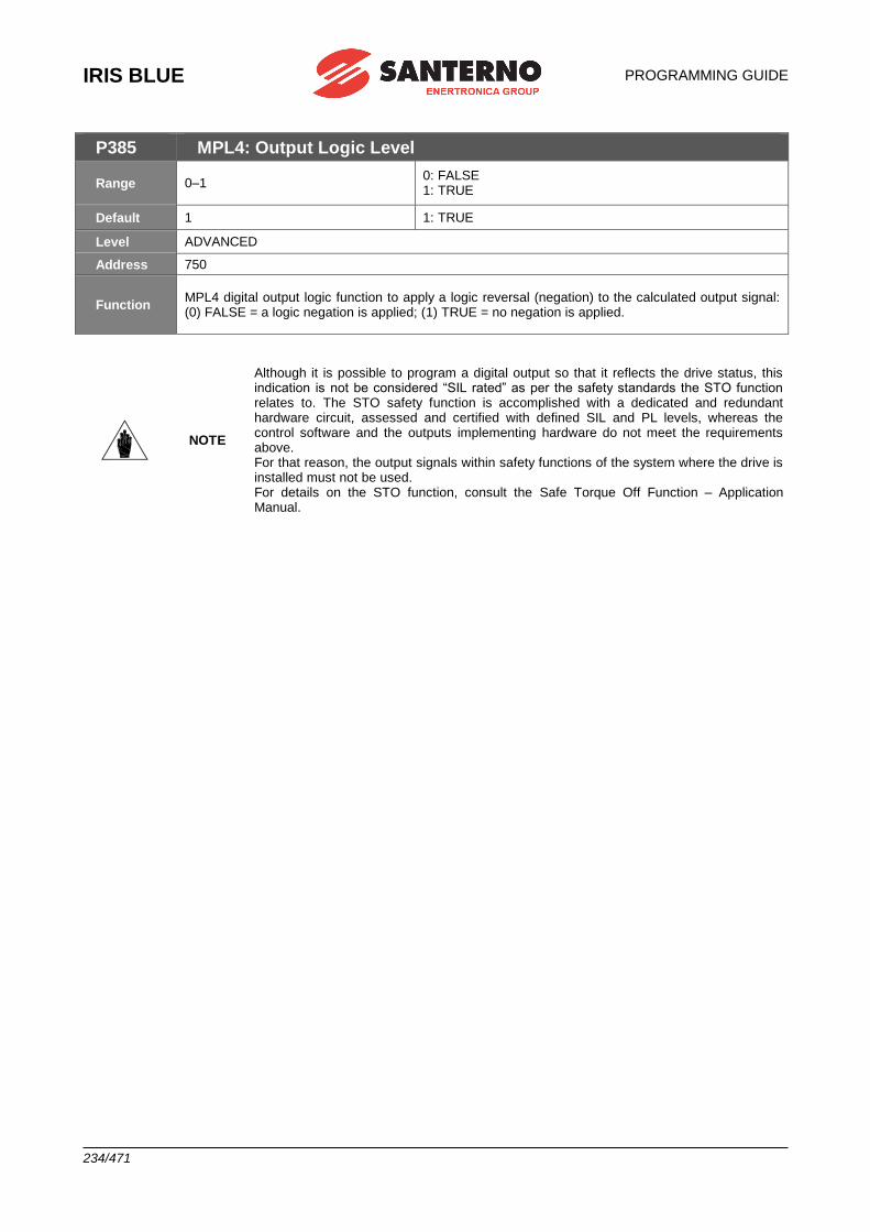
IRIS BLUE
PROGRAMMING GUIDE
234/471
P385 MPL4: Output Logic Level
Range 0–1 0: FALSE 1: TRUE
Default 1 1: TRUE
Level ADVANCED
Address 750
Function MPL4 digital output logic function to apply a logic reversal (negation) to the calculated output signal: (0) FALSE = a logic negation is applied; (1) TRUE = no negation is applied.
NOTE
Although it is possible to program a digital output so that it reflects the drive status, this indication is not be considered “SIL rated” as per the safety standards the STO function relates to. The STO safety function is accomplished with a dedicated and redundant hardware circuit, assessed and certified with defined SIL and PL levels, whereas the control software and the outputs implementing hardware do not meet the requirements above. For that reason, the output signals within safety functions of the system where the drive is installed must not be used. For details on the STO function, consult the Safe Torque Off Function – Application Manual.
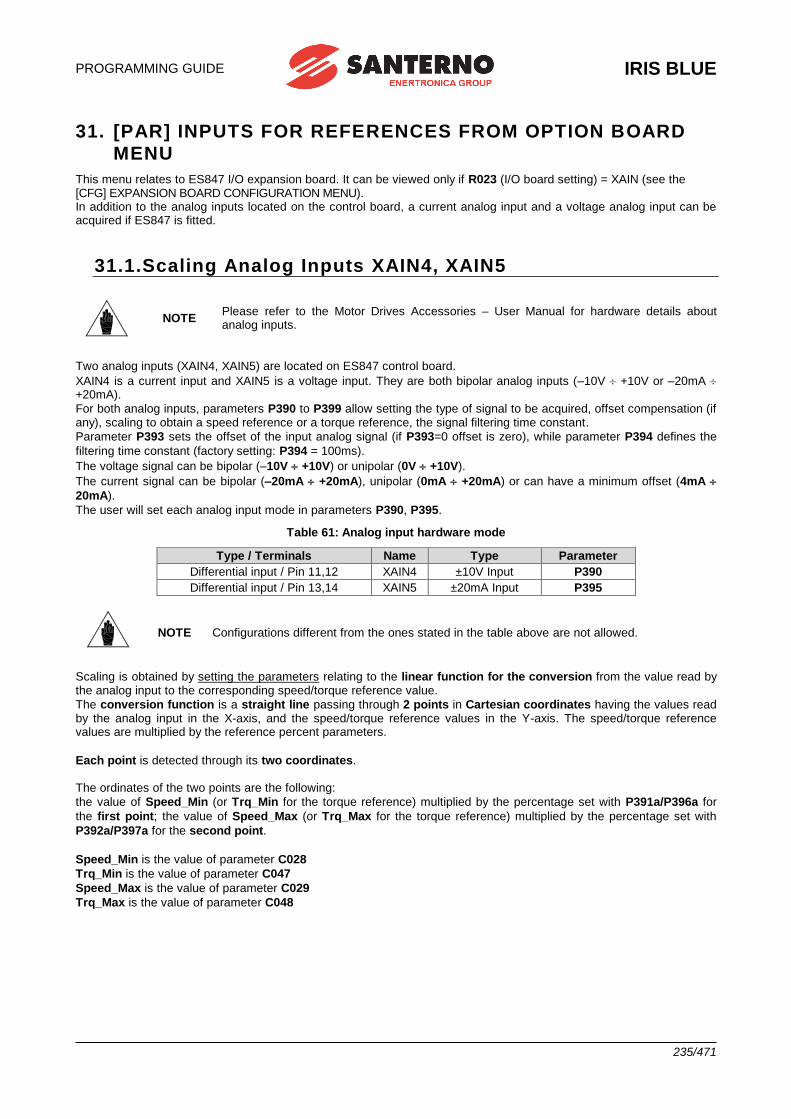
PROGRAMMING GUIDE
IRIS BLUE
235/471
31. [PAR] INPUTS FOR REFERENCES FROM OPTION BOARD
MENU
This menu relates to ES847 I/O expansion board. It can be viewed only if R023 (I/O board setting) = XAIN (see the [CFG] EXPANSION BOARD CONFIGURATION MENU). In addition to the analog inputs located on the control board, a current analog input and a voltage analog input can be acquired if ES847 is fitted.
31.1.Scaling Analog Inputs XAIN4, XAIN5
NOTE Please refer to the Motor Drives Accessories – User Manual for hardware details about analog inputs.
Two analog inputs (XAIN4, XAIN5) are located on ES847 control board.
XAIN4 is a current input and XAIN5 is a voltage input. They are both bipolar analog inputs (–10V +10V or –20mA +20mA).
For both analog inputs, parameters P390 to P399 allow setting the type of signal to be acquired, offset compensation (if any), scaling to obtain a speed reference or a torque reference, the signal filtering time constant.
Parameter P393 sets the offset of the input analog signal (if P393=0 offset is zero), while parameter P394 defines the
filtering time constant (factory setting: P394 = 100ms).
The voltage signal can be bipolar (–10V +10V) or unipolar (0V +10V).
The current signal can be bipolar (–20mA +20mA), unipolar (0mA +20mA) or can have a minimum offset (4mA
20mA).
The user will set each analog input mode in parameters P390, P395.
Table 61: Analog input hardware mode
Type / Terminals Name Type Parameter
Differential input / Pin 11,12 XAIN4 ±10V Input P390
Differential input / Pin 13,14 XAIN5 ±20mA Input P395
NOTE Configurations different from the ones stated in the table above are not allowed.
Scaling is obtained by setting the parameters relating to the linear function for the conversion from the value read by the analog input to the corresponding speed/torque reference value.
The conversion function is a straight line passing through 2 points in Cartesian coordinates having the values read by the analog input in the X-axis, and the speed/torque reference values in the Y-axis. The speed/torque reference values are multiplied by the reference percent parameters.
Each point is detected through its two coordinates. The ordinates of the two points are the following:
the value of Speed_Min (or Trq_Min for the torque reference) multiplied by the percentage set with P391a/P396a for
the first point; the value of Speed_Max (or Trq_Max for the torque reference) multiplied by the percentage set with
P392a/P397a for the second point.
Speed_Min is the value of parameter C028
Trq_Min is the value of parameter C047
Speed_Max is the value of parameter C029
Trq_Max is the value of parameter C048
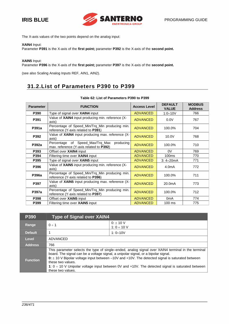
IRIS BLUE
PROGRAMMING GUIDE
236/471
The X-axis values of the two points depend on the analog input:
XAIN4 Input:
Parameter P391 is the X-axis of the first point; parameter P392 is the X-axis of the second point.
XAIN5 Input:
Parameter P396 is the X-axis of the first point; parameter P397 is the X-axis of the second point.
(see also Scaling Analog Inputs REF, AIN1, AIN2).
31.2.List of Parameters P390 to P399
Table 62: List of Parameters P390 to P399
Parameter FUNCTION Access Level DEFAULT
VALUE
MODBUS
Address
P390 Type of signal over XAIN4 input ADVANCED 1:010V 766
P391 Value of XAIN4 input producing min. reference (X-axis)
ADVANCED 0.0V 767
P391a Percentage of Speed_Min/Trq_Min producing min.
reference (Y-axis related to P391) ADVANCED 100.0% 704
P392 Value of XAIN4 input producing max. reference (X-axis)
ADVANCED 10.0V 768
P392a Percentage of Speed_Max/Trq_Max producing
max. reference (Y-axis related to P392) ADVANCED 100.0% 710
P393 Offset over XAIN4 input ADVANCED 0V 769
P394 Filtering time over XAIN4 input ADVANCED 100ms 770
P395 Type of signal over XAIN5 input ADVANCED 3: 420mA 771
P396 Value of XAIN5 input producing min. reference (X-axis)
ADVANCED 4.0mA 772
P396a Percentage of Speed_Min/Trq_Min producing min.
reference (Y-axis related to P396) ADVANCED 100.0% 711
P397 Value of XAIN5 input producing max. reference (X-axis)
ADVANCED 20.0mA 773
P397a Percentage of Speed_Min/Trq_Min producing min.
reference (Y-axis related to P397) ADVANCED 100.0% 712
P398 Offset over XAIN5 input ADVANCED 0mA 774
P399 Filtering time over XAIN5 input ADVANCED 100 ms 775
P390 Type of Signal over XAIN4
Range 0 1 0: 10 V
1: 0 10 V
Default 1 1: 010V
Level ADVANCED
Address 766
Function
This parameter selects the type of single–ended, analog signal over XAIN4 terminal in the terminal board. The signal can be a voltage signal, a unipolar signal, or a bipolar signal.
0: 10 V Bipolar voltage input between –10V and +10V. The detected signal is saturated between these two values.
1: 0 10 V Unipolar voltage input between 0V and +10V. The detected signal is saturated between these two values.
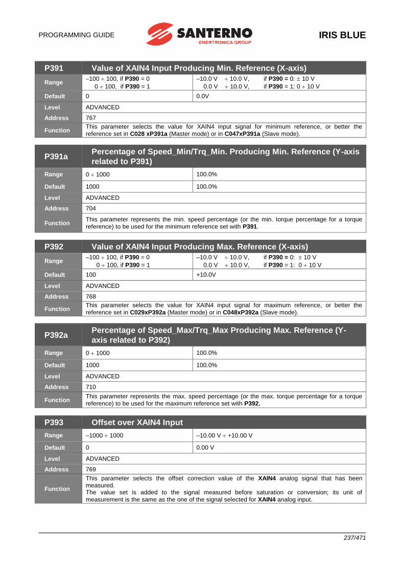
PROGRAMMING GUIDE
IRIS BLUE
237/471
P391 Value of XAIN4 Input Producing Min. Reference (X-axis)
Range –100 100, if P390 = 0
0 100, if P390 = 1
–10.0 V 10.0 V, if P390 = 0: 10 V
0.0 V 10.0 V, if P390 = 1: 0 10 V
Default 0 0.0V
Level ADVANCED
Address 767
Function This parameter selects the value for XAIN4 input signal for minimum reference, or better the
reference set in C028 xP391a (Master mode) or in C047xP391a (Slave mode).
P391a Percentage of Speed_Min/Trq_Min. Producing Min. Reference (Y-axis
related to P391)
Range 0 1000 100.0%
Default 1000 100.0%
Level ADVANCED
Address 704
Function This parameter represents the min. speed percentage (or the min. torque percentage for a torque
reference) to be used for the minimum reference set with P391.
P392 Value of XAIN4 Input Producing Max. Reference (X-axis)
Range –100 100, if P390 = 0
0 100, if P390 = 1
–10.0 V 10.0 V, if P390 = 0: 10 V
0.0 V 10.0 V, if P390 = 1: 0 10 V
Default 100 +10.0V
Level ADVANCED
Address 768
Function This parameter selects the value for XAIN4 input signal for maximum reference, or better the
reference set in C029xP392a (Master mode) or in C048xP392a (Slave mode).
P392a Percentage of Speed_Max/Trq_Max Producing Max. Reference (Y-
axis related to P392)
Range 0 1000 100.0%
Default 1000 100.0%
Level ADVANCED
Address 710
Function This parameter represents the max. speed percentage (or the max. torque percentage for a torque
reference) to be used for the maximum reference set with P392.
P393 Offset over XAIN4 Input
Range –1000 1000 –10.00 V +10.00 V
Default 0 0.00 V
Level ADVANCED
Address 769
Function
This parameter selects the offset correction value of the XAIN4 analog signal that has been measured. The value set is added to the signal measured before saturation or conversion; its unit of
measurement is the same as the one of the signal selected for XAIN4 analog input.
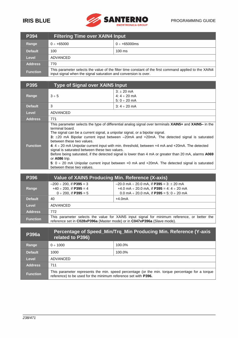
IRIS BLUE
PROGRAMMING GUIDE
238/471
P394 Filtering Time over XAIN4 Input
Range 0 +65000 0 +65000ms
Default 100 100 ms
Level ADVANCED
Address 770
Function This parameter selects the value of the filter time constant of the first command applied to the XAIN4 input signal when the signal saturation and conversion is over.
P395 Type of Signal over XAIN5 Input
Range 3 5
3: 20 mA
4: 4 20 mA
5: 0 20 mA
Default 3 3: 4 20 mA
Level ADVANCED
Address 771
Function
This parameter selects the type of differential analog signal over terminals XAIN5+ and XAIN5– in the terminal board. The signal can be a current signal, a unipolar signal, or a bipolar signal.
3: 20 mA Bipolar current input between –20mA and +20mA. The detected signal is saturated between these two values.
4: 4 20 mA Unipolar current input with min. threshold, between +4 mA and +20mA. The detected signal is saturated between these two values.
Before being saturated, if the detected signal is lower than 4 mA or greater than 20 mA, alarms A069
or A086 trip.
5: 0 20 mA Unipolar current input between +0 mA and +20mA. The detected signal is saturated between these two values.
P396 Value of XAIN5 Producing Min. Reference (X-axis)
Range
–200 200, if P395 = 3
+40 200, if P395 = 4
0 200, if P395 = 5
–20.0 mA 20.0 mA, if P395 = 3: 20 mA
+4.0 mA 20.0 mA, if P395 = 4: 4 20 mA
0.0 mA 20.0 mA, if P395 = 5: 0 20 mA
Default 40 +4.0mA
Level ADVANCED
Address 772
Function This parameter selects the value for XAIN5 input signal for minimum reference, or better the
reference set in C028xP396a (Master mode) or in C047xP396a (Slave mode).
P396a Percentage of Speed_Min/Trq_Min Producing Min. Reference (Y-axis
related to P396)
Range 0 1000 100.0%
Default 1000 100.0%
Level ADVANCED
Address 711
Function This parameter represents the min. speed percentage (or the min. torque percentage for a torque
reference) to be used for the minimum reference set with P396.
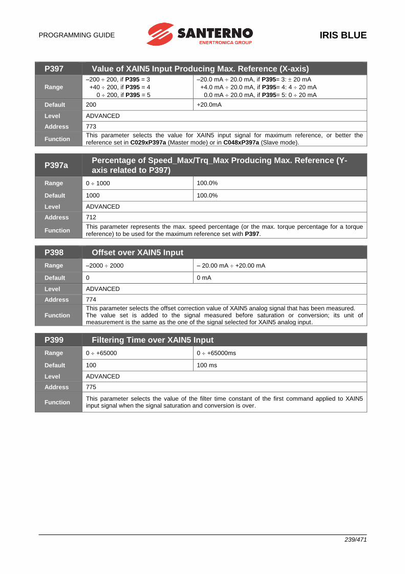
PROGRAMMING GUIDE
IRIS BLUE
239/471
P397 Value of XAIN5 Input Producing Max. Reference (X-axis)
Range
–200 200, if P395 = 3
+40 200, if P395 = 4
0 200, if P395 = 5
–20.0 mA 20.0 mA, if P395= 3: 20 mA
+4.0 mA 20.0 mA, if P395= 4: 4 20 mA
0.0 mA 20.0 mA, if P395= 5: 0 20 mA
Default 200 +20.0mA
Level ADVANCED
Address 773
Function This parameter selects the value for XAIN5 input signal for maximum reference, or better the
reference set in C029xP397a (Master mode) or in C048xP397a (Slave mode).
P397a Percentage of Speed_Max/Trq_Max Producing Max. Reference (Y-
axis related to P397)
Range 0 1000 100.0%
Default 1000 100.0%
Level ADVANCED
Address 712
Function This parameter represents the max. speed percentage (or the max. torque percentage for a torque
reference) to be used for the maximum reference set with P397.
P398 Offset over XAIN5 Input
Range –2000 2000 – 20.00 mA +20.00 mA
Default 0 0 mA
Level ADVANCED
Address 774
Function This parameter selects the offset correction value of XAIN5 analog signal that has been measured. The value set is added to the signal measured before saturation or conversion; its unit of measurement is the same as the one of the signal selected for XAIN5 analog input.
P399 Filtering Time over XAIN5 Input
Range 0 +65000 0 +65000ms
Default 100 100 ms
Level ADVANCED
Address 775
Function This parameter selects the value of the filter time constant of the first command applied to XAIN5 input signal when the signal saturation and conversion is over.
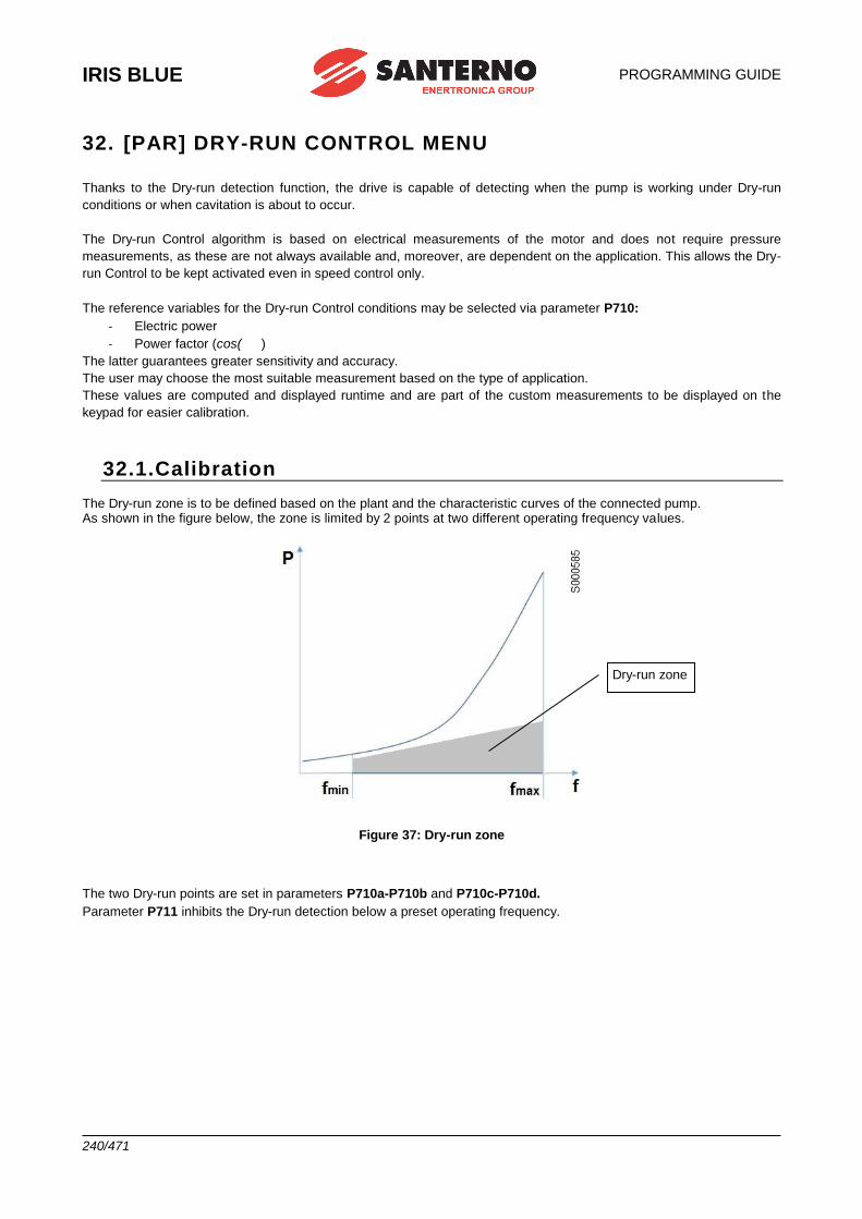
IRIS BLUE
PROGRAMMING GUIDE
240/471
32. [PAR] DRY-RUN CONTROL MENU
Thanks to the Dry-run detection function, the drive is capable of detecting when the pump is working under Dry-run
conditions or when cavitation is about to occur.
The Dry-run Control algorithm is based on electrical measurements of the motor and does not require pressure
measurements, as these are not always available and, moreover, are dependent on the application. This allows the Dry-
run Control to be kept activated even in speed control only.
The reference variables for the Dry-run Control conditions may be selected via parameter P710:
- Electric power
- Power factor (cos( )
The latter guarantees greater sensitivity and accuracy.
The user may choose the most suitable measurement based on the type of application.
These values are computed and displayed runtime and are part of the custom measurements to be displayed on the
keypad for easier calibration.
32.1.Calibration The Dry-run zone is to be defined based on the plant and the characteristic curves of the connected pump. As shown in the figure below, the zone is limited by 2 points at two different operating frequency values.
Figure 37: Dry-run zone
The two Dry-run points are set in parameters P710a-P710b and P710c-P710d.
Parameter P711 inhibits the Dry-run detection below a preset operating frequency.
Dry-run zone
PROGRAMMING GUIDE
IRIS BLUE
241/471
The calibration guidelines for two different applications are given below:
1) Speed control, without pressure PID
- Stop water flow from the plant (valve closure).
- Reach maximum speed and set P710c.
- Set P710d to a value lower than the selected Dry-run measurement (electric power or power factor).
- Repeat the steps above by adopting a low speed reference.
2) When using active PID pressure
- Stop water flow from the plant (valve closure).
- Set the pressure reference at maximum desired plant pressure.
- From the speed measurement, set P710c.
- Set P710d to a value lower than the selected Dry-run measurement (electric power or power factor).
- Repeat the steps above by adopting a low speed reference.
NOTE
A simplified procedure, where the same value is entered (e.g. minimum power factor
detected at low rpm reference) both in parameter P710a Low Frequency for Dry-run
Threshold and in parameter P710c High Frequency for Dry-run Threshold, is generally acceptable for most applications.
32.2.Dry-run Activation
The Dry-run function activates if both the following conditions are true:
▪ Operation in Dry-run zone (see Figure 37)
▪ Speed reference greater than the minimum value between P711 and C029 (with suitable adjustment of the
units of measurement controlled internally to the drive)
If the Dry-run condition persists for a time longer than P712, the action defined in P716 is carried out.
To facilitate testing or expand activation logics, parameter P715 is available, allowing allocating an MDI to the
deactivation of the Dry-run function.
If the Dry-run function is active, resetting its activation is possible
▪ either manually (by pressing the reset button on the keypad)
▪ or automatically if the system quits the Dry-run detection mode for a time longer than P713. The automatic
reset allows for the service re-activation without manual activation after a transient condition has occurred,
such as a transient lower level of water in a well.
When P716 is set as Alarm or Warning, the autoreset countdown is shown on the keypad.
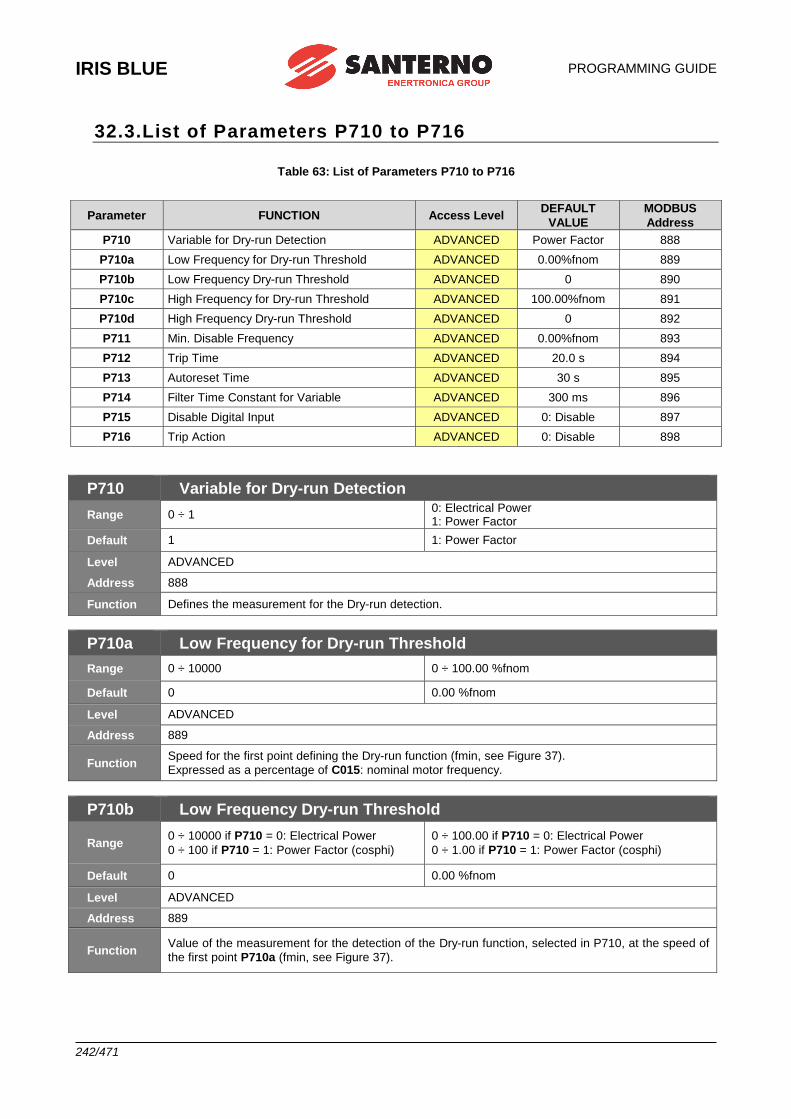
IRIS BLUE
PROGRAMMING GUIDE
242/471
32.3.List of Parameters P710 to P716
Table 63: List of Parameters P710 to P716
Parameter FUNCTION Access Level DEFAULT
VALUE
MODBUS
Address
P710 Variable for Dry-run Detection ADVANCED Power Factor 888
P710a Low Frequency for Dry-run Threshold ADVANCED 0.00%fnom 889
P710b Low Frequency Dry-run Threshold ADVANCED 0 890
P710c High Frequency for Dry-run Threshold ADVANCED 100.00%fnom 891
P710d High Frequency Dry-run Threshold ADVANCED 0 892
P711 Min. Disable Frequency ADVANCED 0.00%fnom 893
P712 Trip Time ADVANCED 20.0 s 894
P713 Autoreset Time ADVANCED 30 s 895
P714 Filter Time Constant for Variable ADVANCED 300 ms 896
P715 Disable Digital Input ADVANCED 0: Disable 897
P716 Trip Action ADVANCED 0: Disable 898
P710 Variable for Dry-run Detection
Range 0 ÷ 1 0: Electrical Power 1: Power Factor
Default 1 1: Power Factor
Level ADVANCED
Address 888
Function Defines the measurement for the Dry-run detection.
P710a Low Frequency for Dry-run Threshold
Range 0 ÷ 10000 0 ÷ 100.00 %fnom
Default 0 0.00 %fnom
Level ADVANCED
Address 889
Function Speed for the first point defining the Dry-run function (fmin, see Figure 37).
Expressed as a percentage of C015: nominal motor frequency.
P710b Low Frequency Dry-run Threshold
Range 0 ÷ 10000 if P710 = 0: Electrical Power
0 ÷ 100 if P710 = 1: Power Factor (cosphi)
0 ÷ 100.00 if P710 = 0: Electrical Power
0 ÷ 1.00 if P710 = 1: Power Factor (cosphi)
Default 0 0.00 %fnom
Level ADVANCED
Address 889
Function Value of the measurement for the detection of the Dry-run function, selected in P710, at the speed of
the first point P710a (fmin, see Figure 37).
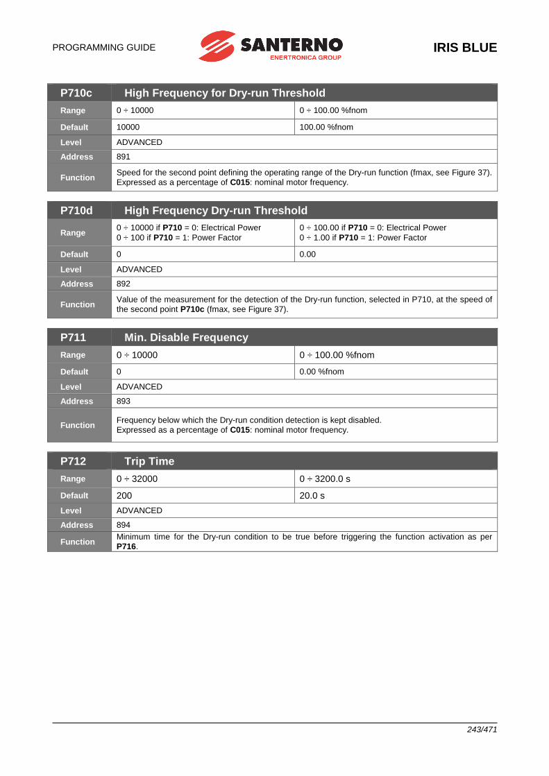
PROGRAMMING GUIDE
IRIS BLUE
243/471
P710c High Frequency for Dry-run Threshold
Range 0 ÷ 10000 0 ÷ 100.00 %fnom
Default 10000 100.00 %fnom
Level ADVANCED
Address 891
Function Speed for the second point defining the operating range of the Dry-run function (fmax, see Figure 37).
Expressed as a percentage of C015: nominal motor frequency.
P710d High Frequency Dry-run Threshold
Range 0 ÷ 10000 if P710 = 0: Electrical Power
0 ÷ 100 if P710 = 1: Power Factor
0 ÷ 100.00 if P710 = 0: Electrical Power
0 ÷ 1.00 if P710 = 1: Power Factor
Default 0 0.00
Level ADVANCED
Address 892
Function Value of the measurement for the detection of the Dry-run function, selected in P710, at the speed of
the second point P710c (fmax, see Figure 37).
P711 Min. Disable Frequency
Range 0 ÷ 10000 0 ÷ 100.00 %fnom
Default 0 0.00 %fnom
Level ADVANCED
Address 893
Function Frequency below which the Dry-run condition detection is kept disabled.
Expressed as a percentage of C015: nominal motor frequency.
P712 Trip Time
Range 0 ÷ 32000 0 ÷ 3200.0 s
Default 200 20.0 s
Level ADVANCED
Address 894
Function Minimum time for the Dry-run condition to be true before triggering the function activation as per
P716.
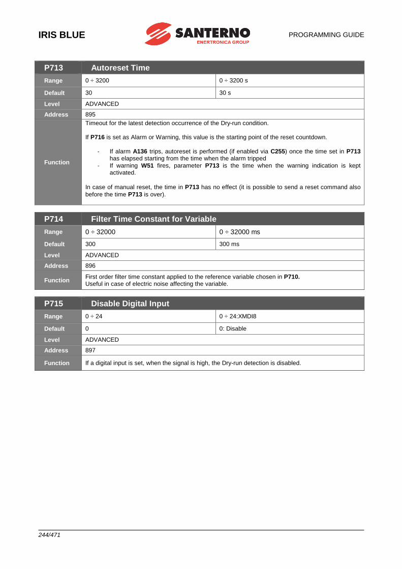
IRIS BLUE
PROGRAMMING GUIDE
244/471
P713 Autoreset Time
Range 0 ÷ 3200 0 ÷ 3200 s
Default 30 30 s
Level ADVANCED
Address 895
Function
Timeout for the latest detection occurrence of the Dry-run condition.
If P716 is set as Alarm or Warning, this value is the starting point of the reset countdown.
- If alarm A136 trips, autoreset is performed (if enabled via C255) once the time set in P713 has elapsed starting from the time when the alarm tripped
- If warning W51 fires, parameter P713 is the time when the warning indication is kept activated.
In case of manual reset, the time in P713 has no effect (it is possible to send a reset command also
before the time P713 is over).
P714 Filter Time Constant for Variable
Range 0 ÷ 32000 0 ÷ 32000 ms
Default 300 300 ms
Level ADVANCED
Address 896
Function First order filter time constant applied to the reference variable chosen in P710. Useful in case of electric noise affecting the variable.
P715 Disable Digital Input
Range 0 ÷ 24 0 ÷ 24:XMDI8
Default 0 0: Disable
Level ADVANCED
Address 897
Function If a digital input is set, when the signal is high, the Dry-run detection is disabled.
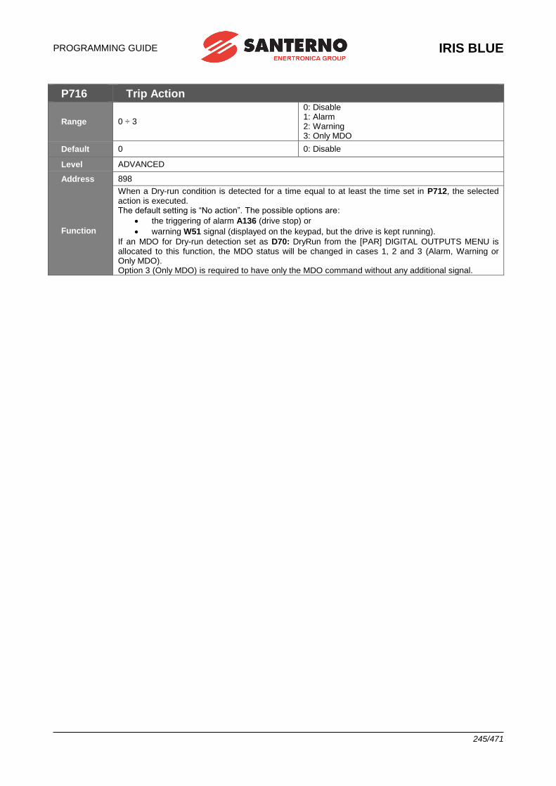
PROGRAMMING GUIDE
IRIS BLUE
245/471
P716 Trip Action
Range 0 ÷ 3
0: Disable 1: Alarm 2: Warning 3: Only MDO
Default 0 0: Disable
Level ADVANCED
Address 898
Function
When a Dry-run condition is detected for a time equal to at least the time set in P712, the selected action is executed. The default setting is “No action”. The possible options are:
• the triggering of alarm A136 (drive stop) or
• warning W51 signal (displayed on the keypad, but the drive is kept running).
If an MDO for Dry-run detection set as D70: DryRun from the [PAR] DIGITAL OUTPUTS MENU is allocated to this function, the MDO status will be changed in cases 1, 2 and 3 (Alarm, Warning or Only MDO). Option 3 (Only MDO) is required to have only the MDO command without any additional signal.
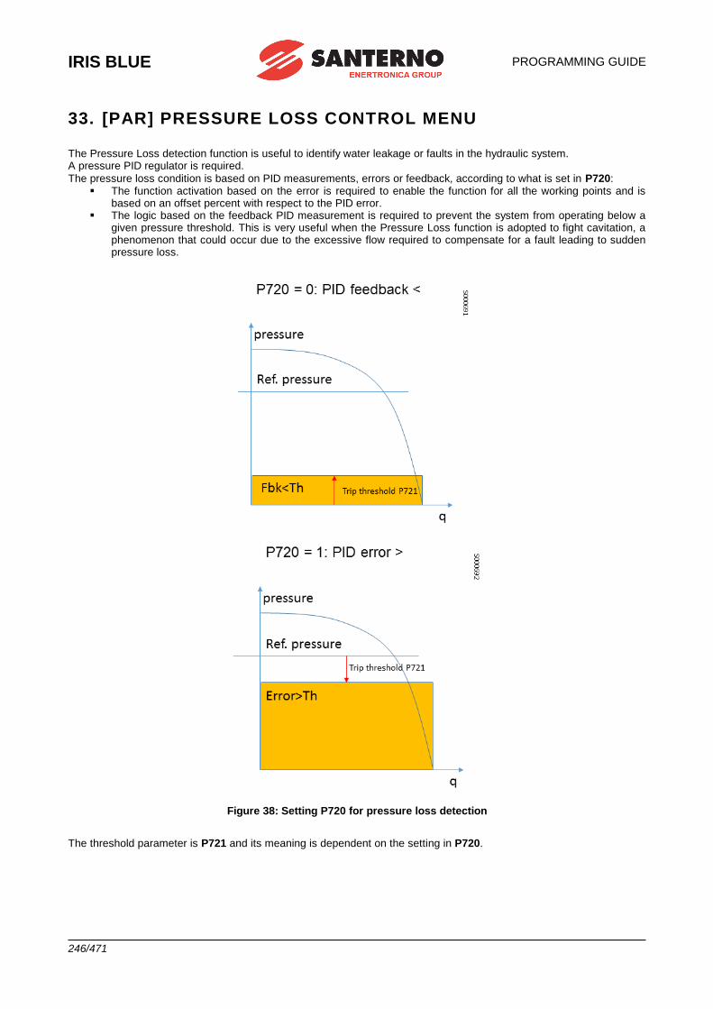
IRIS BLUE
PROGRAMMING GUIDE
246/471
33. [PAR] PRESSURE LOSS CONTROL MENU
The Pressure Loss detection function is useful to identify water leakage or faults in the hydraulic system. A pressure PID regulator is required.
The pressure loss condition is based on PID measurements, errors or feedback, according to what is set in P720: ▪ The function activation based on the error is required to enable the function for all the working points and is
based on an offset percent with respect to the PID error. ▪ The logic based on the feedback PID measurement is required to prevent the system from operating below a
given pressure threshold. This is very useful when the Pressure Loss function is adopted to fight cavitation, a phenomenon that could occur due to the excessive flow required to compensate for a fault leading to sudden pressure loss.
Figure 38: Setting P720 for pressure loss detection
The threshold parameter is P721 and its meaning is dependent on the setting in P720.
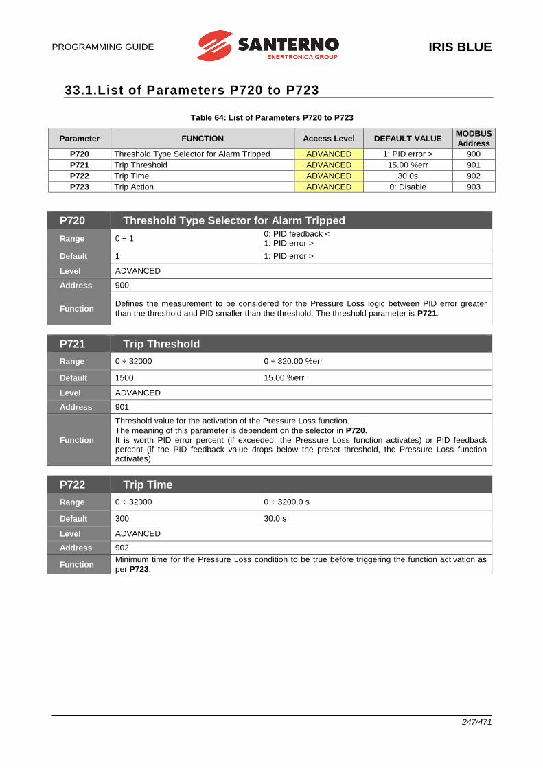
PROGRAMMING GUIDE
IRIS BLUE
247/471
33.1.List of Parameters P720 to P723
Table 64: List of Parameters P720 to P723
Parameter FUNCTION Access Level DEFAULT VALUE MODBUS
Address
P720 Threshold Type Selector for Alarm Tripped ADVANCED 1: PID error > 900
P721 Trip Threshold ADVANCED 15.00 %err 901
P722 Trip Time ADVANCED 30.0s 902
P723 Trip Action ADVANCED 0: Disable 903
P720 Threshold Type Selector for Alarm Tripped
Range 0 ÷ 1 0: PID feedback < 1: PID error >
Default 1 1: PID error >
Level ADVANCED
Address 900
Function Defines the measurement to be considered for the Pressure Loss logic between PID error greater
than the threshold and PID smaller than the threshold. The threshold parameter is P721.
P721 Trip Threshold
Range 0 ÷ 32000 0 ÷ 320.00 %err
Default 1500 15.00 %err
Level ADVANCED
Address 901
Function
Threshold value for the activation of the Pressure Loss function.
The meaning of this parameter is dependent on the selector in P720. It is worth PID error percent (if exceeded, the Pressure Loss function activates) or PID feedback percent (if the PID feedback value drops below the preset threshold, the Pressure Loss function activates).
P722 Trip Time
Range 0 ÷ 32000 0 ÷ 3200.0 s
Default 300 30.0 s
Level ADVANCED
Address 902
Function Minimum time for the Pressure Loss condition to be true before triggering the function activation as
per P723.
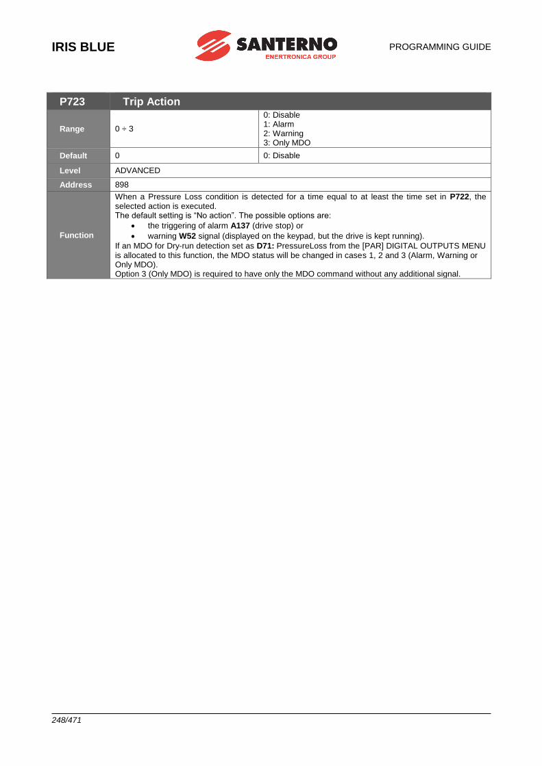
IRIS BLUE
PROGRAMMING GUIDE
248/471
P723 Trip Action
Range 0 ÷ 3
0: Disable 1: Alarm 2: Warning 3: Only MDO
Default 0 0: Disable
Level ADVANCED
Address 898
Function
When a Pressure Loss condition is detected for a time equal to at least the time set in P722, the selected action is executed. The default setting is “No action”. The possible options are:
• the triggering of alarm A137 (drive stop) or
• warning W52 signal (displayed on the keypad, but the drive is kept running).
If an MDO for Dry-run detection set as D71: PressureLoss from the [PAR] DIGITAL OUTPUTS MENU is allocated to this function, the MDO status will be changed in cases 1, 2 and 3 (Alarm, Warning or Only MDO). Option 3 (Only MDO) is required to have only the MDO command without any additional signal.
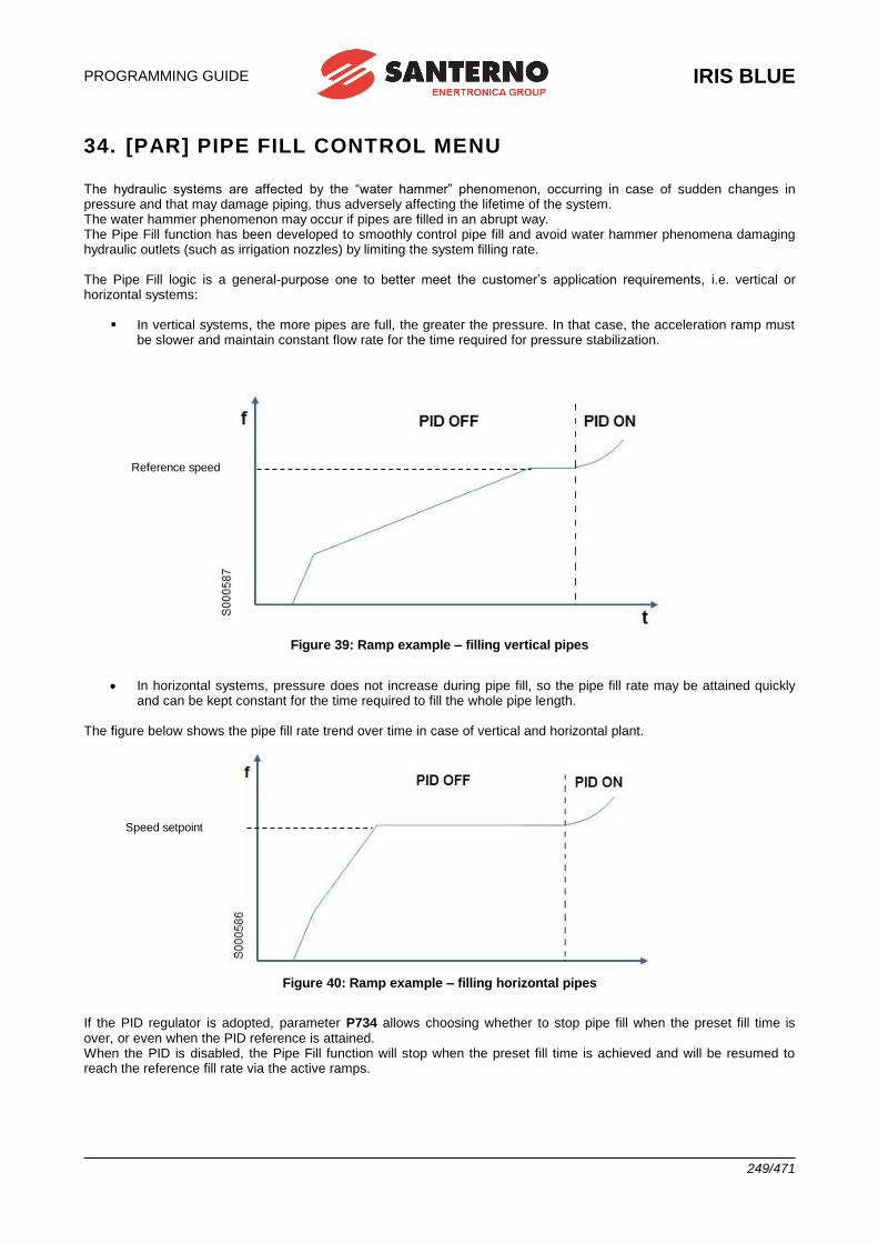
PROGRAMMING GUIDE
IRIS BLUE
249/471
34. [PAR] PIPE FILL CONTROL MENU
The hydraulic systems are affected by the “water hammer” phenomenon, occurring in case of sudden changes in pressure and that may damage piping, thus adversely affecting the lifetime of the system. The water hammer phenomenon may occur if pipes are filled in an abrupt way. The Pipe Fill function has been developed to smoothly control pipe fill and avoid water hammer phenomena damaging hydraulic outlets (such as irrigation nozzles) by limiting the system filling rate. The Pipe Fill logic is a general-purpose one to better meet the customer’s application requirements, i.e. vertical or horizontal systems:
▪ In vertical systems, the more pipes are full, the greater the pressure. In that case, the acceleration ramp must be slower and maintain constant flow rate for the time required for pressure stabilization.
Figure 39: Ramp example – filling vertical pipes
• In horizontal systems, pressure does not increase during pipe fill, so the pipe fill rate may be attained quickly and can be kept constant for the time required to fill the whole pipe length.
The figure below shows the pipe fill rate trend over time in case of vertical and horizontal plant.
Figure 40: Ramp example – filling horizontal pipes
If the PID regulator is adopted, parameter P734 allows choosing whether to stop pipe fill when the preset fill time is over, or even when the PID reference is attained. When the PID is disabled, the Pipe Fill function will stop when the preset fill time is achieved and will be resumed to reach the reference fill rate via the active ramps.
Reference speed
Speed setpoint
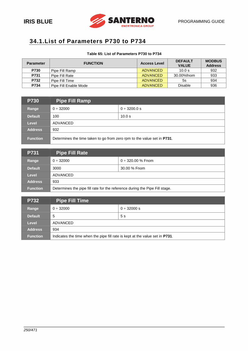
IRIS BLUE
PROGRAMMING GUIDE
250/471
34.1.List of Parameters P730 to P734
Table 65: List of Parameters P730 to P734
Parameter FUNCTION Access Level DEFAULT
VALUE MODBUS
Address P730 Pipe Fill Ramp ADVANCED 10.0 s 932 P731 Pipe Fill Rate ADVANCED 30.00%fnom 933 P732 Pipe Fill Time ADVANCED 5s 934 P734 Pipe Fill Enable Mode ADVANCED Disable 936
P730 Pipe Fill Ramp
Range 0 ÷ 32000 0 ÷ 3200.0 s
Default 100 10.0 s
Level ADVANCED
Address 932
Function Determines the time taken to go from zero rpm to the value set in P731.
P731 Pipe Fill Rate
Range 0 ÷ 32000 0 ÷ 320.00 % Fnom
Default 3000 30.00 % Fnom
Level ADVANCED
Address 933
Function Determines the pipe fill rate for the reference during the Pipe Fill stage.
P732 Pipe Fill Time
Range 0 ÷ 32000 0 ÷ 32000 s
Default 5 5 s
Level ADVANCED
Address 934
Function Indicates the time when the pipe fill rate is kept at the value set in P731.

PROGRAMMING GUIDE
IRIS BLUE
251/471
P734 Pipe Fill Enable Mode
Range 0 ÷ 2 0: Disabled 1: Enabled 2: Enabled + PID feedback
Default 0 0: Disabled
Level ADVANCED
Address 936
Function
0: Disabled The Pipe Fill function is inactive and the active ramps are implemented. 1: Enabled The function is active; exiting the Pipe Fill mode is conditioned only when the preset times are over 2: Enabled + PID feedback The function is active; exiting the Pipe Fill mode is conditioned when the preset times are over or when the PID reference is attained.
IRIS BLUE
PROGRAMMING GUIDE
252/471
35. [CFG] AUTOTUNE MENU
35.1.Overview
NOTE See the FIRST STARTUP section for tuning based on the control algorithm to be used.
NOTE At the end of the Autotune procedure, the system automatically saves the whole parameter set of the drive.
NOTE Autotune must be performed only after entering the motor ratings. Please refer to the [CFG] MOTOR CONFIGURATION MENU.
The motor may be tuned in order to obtain the machine ratings or the parameterization required for the correct functioning of the control algorithms.
The Autotune menu includes two programming inputs, I073 and I074. Input I073 allows enabling and selecting the
type of autotune. Input I074 - which can be programmed only if I073 = Motor Tune - describes the type of autotune
which is performed. Because the values set in I073 and I074 cannot be changed once for all and are automatically
reset after autotune, the ENABLE-A ENABLE-B signals must be disabled and the ESC key must be used to accept the new value.
35.1.1. MOTOR AUTOTUNE AND ADJUSTING LOOPS
Set I073 as Motor Tune to enable autotune functions that can be selected with I074.
NOTE
For the correct operation of the tuning algorithms, enter the motor ratings.
If carrier frequency is changed via parameters C001 and C002, the current control loop of the VTC regulator is to be adjusted again (see “VTC” Control Algorithm). The autotune procedure computes the motor parameters and the regulators parameters
regardless of the control algorithm selected via C010. Therefore, it is possible to perform the autotune procedure before selecting the type of motor control to be applied. Please refer to the [CFG] MOTOR CONFIGURATION MENU.
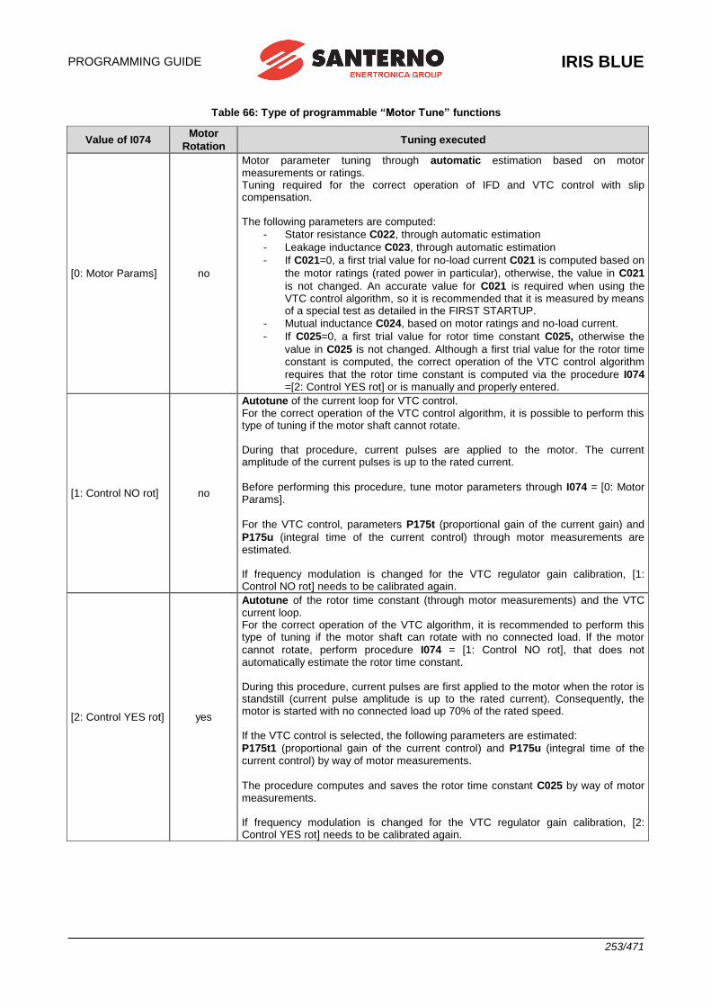
PROGRAMMING GUIDE
IRIS BLUE
253/471
Table 66: Type of programmable “Motor Tune” functions
Value of I074 Motor
Rotation Tuning executed
[0: Motor Params] no
Motor parameter tuning through automatic estimation based on motor measurements or ratings. Tuning required for the correct operation of IFD and VTC control with slip compensation. The following parameters are computed:
- Stator resistance C022, through automatic estimation
- Leakage inductance C023, through automatic estimation
- If C021=0, a first trial value for no-load current C021 is computed based on
the motor ratings (rated power in particular), otherwise, the value in C021
is not changed. An accurate value for C021 is required when using the VTC control algorithm, so it is recommended that it is measured by means of a special test as detailed in the FIRST STARTUP.
- Mutual inductance C024, based on motor ratings and no-load current.
- If C025=0, a first trial value for rotor time constant C025, otherwise the
value in C025 is not changed. Although a first trial value for the rotor time constant is computed, the correct operation of the VTC control algorithm
requires that the rotor time constant is computed via the procedure I074 =[2: Control YES rot] or is manually and properly entered.
[1: Control NO rot] no
Autotune of the current loop for VTC control. For the correct operation of the VTC control algorithm, it is possible to perform this type of tuning if the motor shaft cannot rotate. During that procedure, current pulses are applied to the motor. The current amplitude of the current pulses is up to the rated current.
Before performing this procedure, tune motor parameters through I074 = [0: Motor Params].
For the VTC control, parameters P175t (proportional gain of the current gain) and
P175u (integral time of the current control) through motor measurements are estimated. If frequency modulation is changed for the VTC regulator gain calibration, [1: Control NO rot] needs to be calibrated again.
[2: Control YES rot] yes
Autotune of the rotor time constant (through motor measurements) and the VTC current loop. For the correct operation of the VTC algorithm, it is recommended to perform this type of tuning if the motor shaft can rotate with no connected load. If the motor
cannot rotate, perform procedure I074 = [1: Control NO rot], that does not automatically estimate the rotor time constant. During this procedure, current pulses are first applied to the motor when the rotor is standstill (current pulse amplitude is up to the rated current). Consequently, the motor is started with no connected load up 70% of the rated speed. If the VTC control is selected, the following parameters are estimated:
P175t1 (proportional gain of the current control) and P175u (integral time of the current control) by way of motor measurements.
The procedure computes and saves the rotor time constant C025 by way of motor measurements. If frequency modulation is changed for the VTC regulator gain calibration, [2: Control YES rot] needs to be calibrated again.
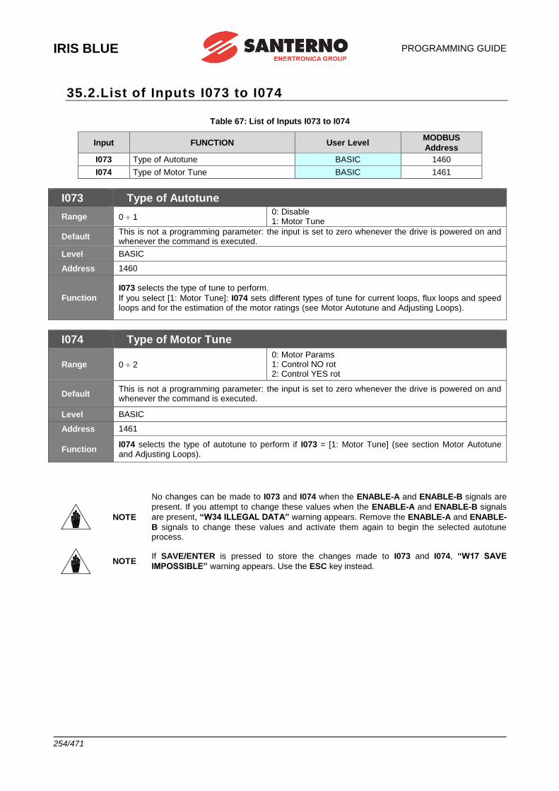
IRIS BLUE
PROGRAMMING GUIDE
254/471
35.2.List of Inputs I073 to I074
Table 67: List of Inputs I073 to I074
Input FUNCTION User Level MODBUS
Address
I073 Type of Autotune BASIC 1460
I074 Type of Motor Tune BASIC 1461
I073 Type of Autotune
Range 0 1 0: Disable 1: Motor Tune
Default This is not a programming parameter: the input is set to zero whenever the drive is powered on and whenever the command is executed.
Level BASIC
Address 1460
Function
I073 selects the type of tune to perform.
If you select [1: Motor Tune]: I074 sets different types of tune for current loops, flux loops and speed loops and for the estimation of the motor ratings (see Motor Autotune and Adjusting Loops).
I074 Type of Motor Tune
Range 0 2
0: Motor Params 1: Control NO rot 2: Control YES rot
Default This is not a programming parameter: the input is set to zero whenever the drive is powered on and whenever the command is executed.
Level BASIC
Address 1461
Function I074 selects the type of autotune to perform if I073 = [1: Motor Tune] (see section Motor Autotune and Adjusting Loops).
NOTE
No changes can be made to I073 and I074 when the ENABLE-A and ENABLE-B signals are
present. If you attempt to change these values when the ENABLE-A and ENABLE-B signals
are present, “W34 ILLEGAL DATA” warning appears. Remove the ENABLE-A and ENABLE-
B signals to change these values and activate them again to begin the selected autotune process.
NOTE If SAVE/ENTER is pressed to store the changes made to I073 and I074, “W17 SAVE
IMPOSSIBLE” warning appears. Use the ESC key instead.
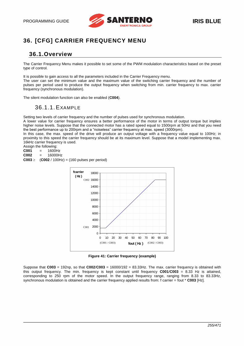
PROGRAMMING GUIDE
IRIS BLUE
255/471
36. [CFG] CARRIER FREQUENCY MENU
36.1.Overview The Carrier Frequency Menu makes it possible to set some of the PWM modulation characteristics based on the preset type of control. It is possible to gain access to all the parameters included in the Carrier Frequency menu. The user can set the minimum value and the maximum value of the switching carrier frequency and the number of pulses per period used to produce the output frequency when switching from min. carrier frequency to max. carrier frequency (synchronous modulation).
The silent modulation function can also be enabled (C004).
36.1.1. EXAMPLE Setting two levels of carrier frequency and the number of pulses used for synchronous modulation. A lower value for carrier frequency ensures a better performance of the motor in terms of output torque but implies higher noise levels. Suppose that the connected motor has a rated speed equal to 1500rpm at 50Hz and that you need the best performance up to 200rpm and a “noiseless” carrier frequency at max. speed (3000rpm). In this case, the max. speed of the drive will produce an output voltage with a frequency value equal to 100Hz; in proximity to this speed the carrier frequency should be at its maximum level. Suppose that a model implementing max. 16kHz carrier frequency is used. Assign the following:
C001 = 1600Hz
C002 = 16000Hz
C003 (C002 / 100Hz) = (160 pulses per period)
0
2000
4000
6000
8000
10000
12000
14000
16000
18000
0 10 20 30 40 50 60 70 80 90 100
fout ( Hz )
fcarrier
( Hz )C002
C001
(C001 / C003) (C002 / C003)
Figure 41: Carrier frequency (example)
Suppose that C003 = 192np, so that C002/C003 = 16000/192 = 83.33Hz. The max. carrier frequency is obtained with
this output frequency. The min. frequency is kept constant until frequency C001/C003 = 8.33 Hz is attained, corresponding to 250 rpm of the motor speed. In the output frequency range, ranging from 8.33 to 83.33Hz,
synchronous modulation is obtained and the carrier frequency applied results from: f carrier = fout * C003 [Hz].
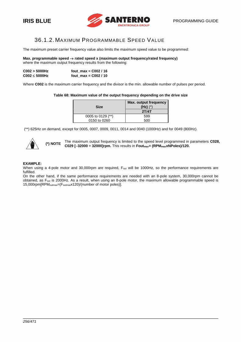
IRIS BLUE
PROGRAMMING GUIDE
256/471
36.1.2. MAXIMUM PROGRAMMABLE SPEED VALUE The maximum preset carrier frequency value also limits the maximum speed value to be programmed:
Max. programmable speed rated speed x (maximum output frequency/rated frequency) where the maximum output frequency results from the following:
C002 > 5000Hz fout_max = C002 / 16
C002 5000Hz fout_max = C002 / 10
Where C002 is the maximum carrier frequency and the divisor is the min. allowable number of pulses per period.
Table 68: Maximum value of the output frequency depending on the drive size
Size
Max. output frequency
(Hz) (*)
2T/4T
0005 to 0129 (**) 599 0150 to 0260 500
(**) 625Hz on demand, except for 0005, 0007, 0009, 0011, 0014 and 0040 (1000Hz) and for 0049 (800Hz).
(*) NOTE The maximum output frequency is limited to the speed level programmed in parameters C028,
C029 [–32000 ÷ 32000]rpm. This results in Foutmax= (RPMmaxxNPoles)/120.
EXAMPLE: When using a 4-pole motor and 30,000rpm are required, Fout will be 1000Hz, so the performance requirements are fulfilled. On the other hand, if the same performance requirements are needed with an 8-pole system, 30,000rpm cannot be obtained, as Fout is 2000Hz. As a result, when using an 8-pole motor, the maximum allowable programmable speed is 15,000rpm[RPMoutmax=(Foutmaxx120)/(number of motor poles)].
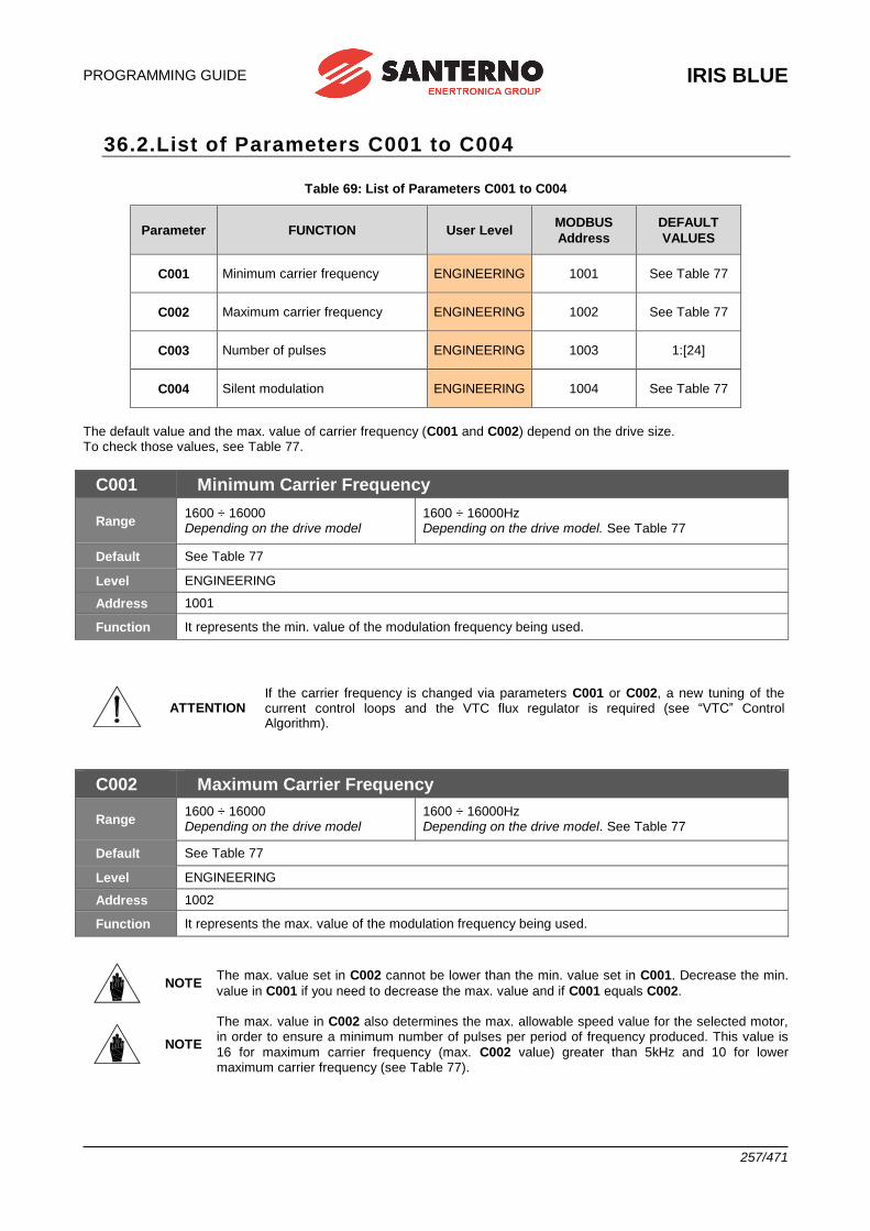
PROGRAMMING GUIDE
IRIS BLUE
257/471
36.2.List of Parameters C001 to C004
Table 69: List of Parameters C001 to C004
Parameter FUNCTION User Level MODBUS
Address
DEFAULT
VALUES
C001 Minimum carrier frequency ENGINEERING 1001 See Table 77
C002 Maximum carrier frequency ENGINEERING 1002 See Table 77
C003 Number of pulses ENGINEERING 1003 1:[24]
C004 Silent modulation ENGINEERING 1004 See Table 77
The default value and the max. value of carrier frequency (C001 and C002) depend on the drive size. To check those values, see Table 77.
C001 Minimum Carrier Frequency
Range 1600 ÷ 16000 Depending on the drive model
1600 ÷ 16000Hz Depending on the drive model. See Table 77
Default See Table 77
Level ENGINEERING
Address 1001
Function It represents the min. value of the modulation frequency being used.
ATTENTION If the carrier frequency is changed via parameters C001 or C002, a new tuning of the current control loops and the VTC flux regulator is required (see “VTC” Control Algorithm).
C002 Maximum Carrier Frequency
Range 1600 ÷ 16000 Depending on the drive model
1600 ÷ 16000Hz Depending on the drive model. See Table 77
Default See Table 77
Level ENGINEERING
Address 1002
Function It represents the max. value of the modulation frequency being used.
NOTE The max. value set in C002 cannot be lower than the min. value set in C001. Decrease the min.
value in C001 if you need to decrease the max. value and if C001 equals C002.
NOTE
The max. value in C002 also determines the max. allowable speed value for the selected motor, in order to ensure a minimum number of pulses per period of frequency produced. This value is
16 for maximum carrier frequency (max. C002 value) greater than 5kHz and 10 for lower maximum carrier frequency (see Table 77).
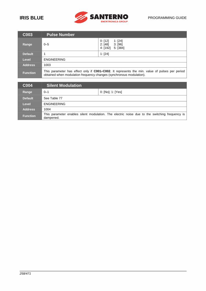
IRIS BLUE
PROGRAMMING GUIDE
258/471
C003 Pulse Number
Range 0–5 0: [12] 1: [24] 2: [48] 3: [96] 4: [192] 5: [384]
Default 1 1: [24]
Level ENGINEERING
Address 1003
Function This parameter has effect only if C001C002. It represents the min. value of pulses per period obtained when modulation frequency changes (synchronous modulation).
C004 Silent Modulation
Range 0–1 0: [No]; 1: [Yes]
Default See Table 77
Level ENGINEERING
Address 1004
Function This parameter enables silent modulation. The electric noise due to the switching frequency is dampened.
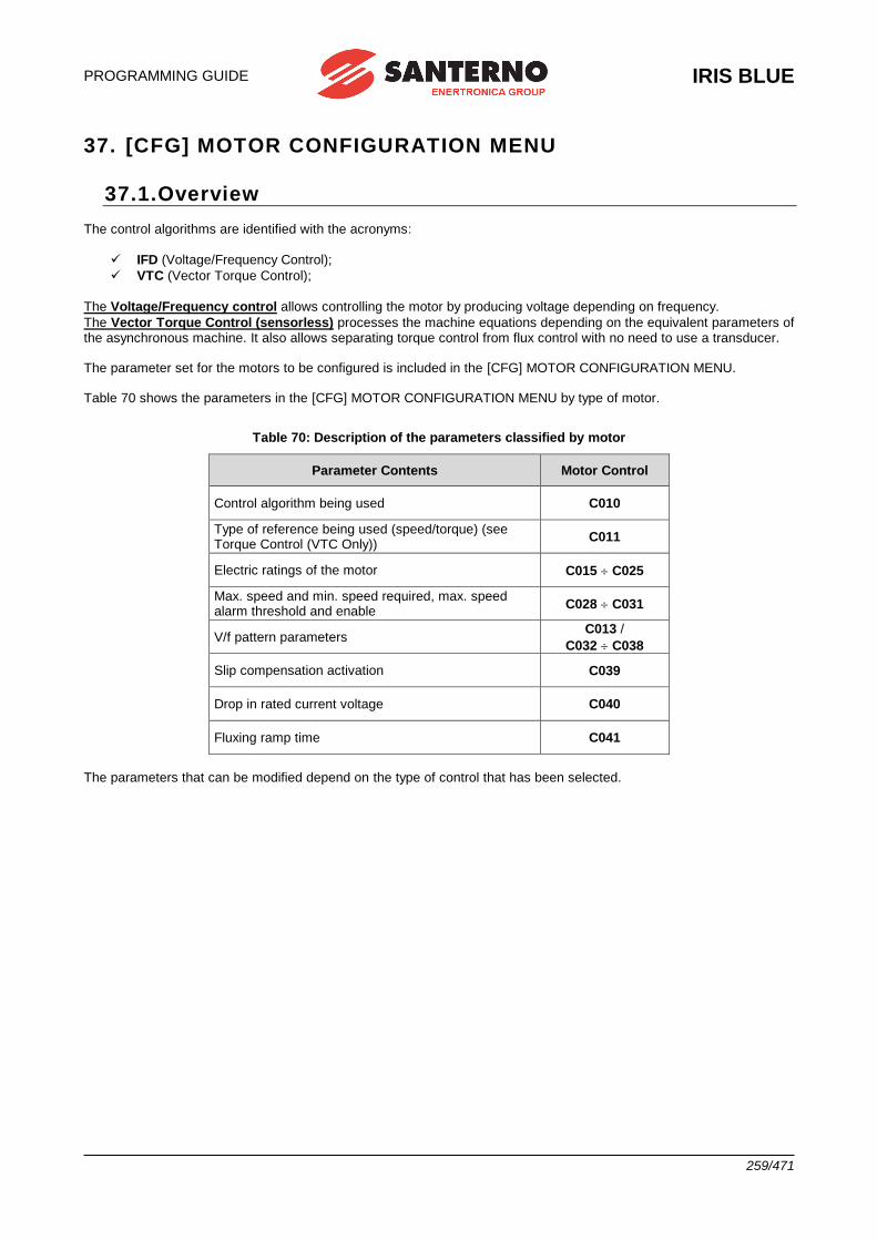
PROGRAMMING GUIDE
IRIS BLUE
259/471
37. [CFG] MOTOR CONFIGURATION MENU
37.1.Overview The control algorithms are identified with the acronyms:
✓ IFD (Voltage/Frequency Control);
✓ VTC (Vector Torque Control);
The Voltage/Frequency control allows controlling the motor by producing voltage depending on frequency.
The Vector Torque Control (sensorless) processes the machine equations depending on the equivalent parameters of the asynchronous machine. It also allows separating torque control from flux control with no need to use a transducer. The parameter set for the motors to be configured is included in the [CFG] MOTOR CONFIGURATION MENU. Table 70 shows the parameters in the [CFG] MOTOR CONFIGURATION MENU by type of motor.
Table 70: Description of the parameters classified by motor
Parameter Contents Motor Control
Control algorithm being used C010
Type of reference being used (speed/torque) (see Torque Control (VTC Only))
C011
Electric ratings of the motor C015 C025
Max. speed and min. speed required, max. speed alarm threshold and enable
C028 C031
V/f pattern parameters C013 /
C032 C038
Slip compensation activation C039
Drop in rated current voltage C040
Fluxing ramp time C041
The parameters that can be modified depend on the type of control that has been selected.
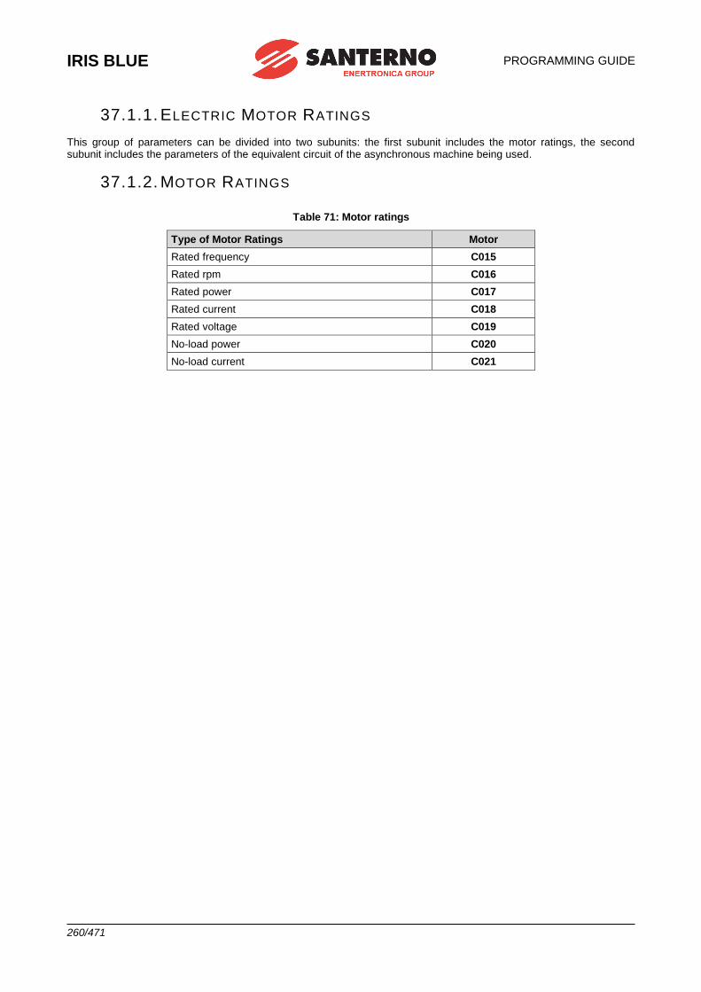
IRIS BLUE
PROGRAMMING GUIDE
260/471
37.1.1. ELECTRIC MOTOR RATINGS
This group of parameters can be divided into two subunits: the first subunit includes the motor ratings, the second subunit includes the parameters of the equivalent circuit of the asynchronous machine being used.
37.1.2. MOTOR RATINGS
Table 71: Motor ratings
Type of Motor Ratings Motor
Rated frequency C015
Rated rpm C016
Rated power C017
Rated current C018
Rated voltage C019
No-load power C020
No-load current C021
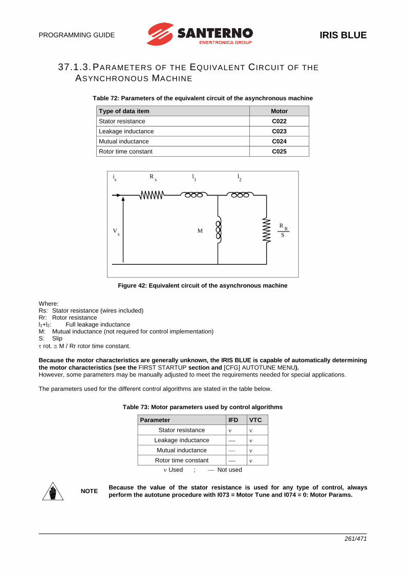
PROGRAMMING GUIDE
IRIS BLUE
261/471
37.1.3. PARAMETERS OF THE EQUIVALENT C IRCUIT OF THE
ASYNCHRONOUS MACHINE
Table 72: Parameters of the equivalent circuit of the asynchronous machine
Type of data item Motor
Stator resistance C022
Leakage inductance C023
Mutual inductance C024
Rotor time constant C025
l 2
l 1
R s
i s
V s
M R
R S
Figure 42: Equivalent circuit of the asynchronous machine
Where: Rs: Stator resistance (wires included) Rr: Rotor resistance l1+l2: Full leakage inductance M: Mutual inductance (not required for control implementation) S: Slip
rot. M / Rr rotor time constant.
Because the motor characteristics are generally unknown, the IRIS BLUE is capable of automatically determining
the motor characteristics (see the FIRST STARTUP section and [CFG] AUTOTUNE MENU). However, some parameters may be manually adjusted to meet the requirements needed for special applications. The parameters used for the different control algorithms are stated in the table below.
Table 73: Motor parameters used by control algorithms
Parameter IFD VTC
Stator resistance
Leakage inductance
Mutual inductance
Rotor time constant
Used ; Not used
NOTE Because the value of the stator resistance is used for any type of control, always
perform the autotune procedure with I073 = Motor Tune and I074 = 0: Motor Params.
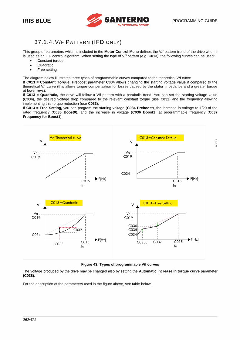
IRIS BLUE
PROGRAMMING GUIDE
262/471
37.1.4. V/F PATTERN (IFD ONLY)
This group of parameters which is included in the Motor Control Menu defines the V/f pattern trend of the drive when it
is used as an IFD control algorithm. When setting the type of V/f pattern (e.g. C013), the following curves can be used:
• Constant torque
• Quadratic
• Free setting The diagram below illustrates three types of programmable curves compared to the theoretical V/f curve.
If C013 = Constant Torque, Preboost parameter C034 allows changing the starting voltage value if compared to the theoretical V/f curve (this allows torque compensation for losses caused by the stator impedance and a greater torque at lower revs).
If C013 = Quadratic, the drive will follow a V/f pattern with a parabolic trend. You can set the starting voltage value
(C034), the desired voltage drop compared to the relevant constant torque (use C032) and the frequency allowing
implementing this torque reduction (use C033).
If C013 = Free Setting, you can program the starting voltage (C034 Preboost), the increase in voltage to 1/20 of the
rated frequency (C035 Boost0), and the increase in voltage (C036 Boost1) at programmable frequency (C037
Frequency for Boost1).
Figure 43: Types of programmable V/f curves
The voltage produced by the drive may be changed also by setting the Automatic increase in torque curve parameter
(C038). For the description of the parameters used in the figure above, see table below.
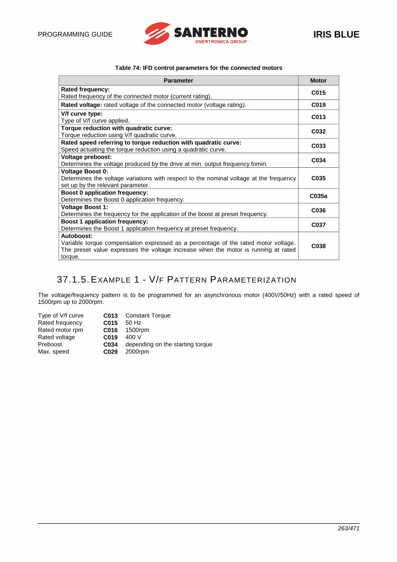
PROGRAMMING GUIDE
IRIS BLUE
263/471
Table 74: IFD control parameters for the connected motors
Parameter Motor
Rated frequency: Rated frequency of the connected motor (current rating).
C015
Rated voltage: rated voltage of the connected motor (voltage rating). C019
V/f curve type: Type of V/f curve applied.
C013
Torque reduction with quadratic curve: Torque reduction using V/f quadratic curve.
C032
Rated speed referring to torque reduction with quadratic curve: Speed actuating the torque reduction using a quadratic curve.
C033
Voltage preboost: Determines the voltage produced by the drive at min. output frequency fomin.
C034
Voltage Boost 0: Determines the voltage variations with respect to the nominal voltage at the frequency set up by the relevant parameter.
C035
Boost 0 application frequency: Determines the Boost 0 application frequency.
C035a
Voltage Boost 1: Determines the frequency for the application of the boost at preset frequency.
C036
Boost 1 application frequency: Determines the Boost 1 application frequency at preset frequency.
C037
Autoboost: Variable torque compensation expressed as a percentage of the rated motor voltage. The preset value expresses the voltage increase when the motor is running at rated torque.
C038
37.1.5. EXAMPLE 1 - V/F PATTERN PARAMETERIZATION
The voltage/frequency pattern is to be programmed for an asynchronous motor (400V/50Hz) with a rated speed of 1500rpm up to 2000rpm. Type of V/f curve C013 Constant Torque
Rated frequency C015 50 Hz
Rated motor rpm C016 1500rpm
Rated voltage C019 400 V
Preboost C034 depending on the starting torque
Max. speed C029 2000rpm
IRIS BLUE
PROGRAMMING GUIDE
264/471
37.1.6. EXAMPLE 2 - V/F PATTERN PARAMETERIZATION
The voltage/frequency pattern is to be programmed for an asynchronous motor (400V/50Hz) having a rated power of 7.5 kW and a rated speed of 1420 rpm with a voltage compensation depending on the motor torque:
Type of V/f pattern C013 = Constant Torque
Rated frequency C015 = 50 Hz
Motor rpm C016 = 1420rpm
Rated power C017 = 7.5kW
Rated voltage C019 = 400 V
Preboost C034 = depending on the starting torque
Autoboost C038 = 4%
Voltage compensation (AutoBoost) results from the formula below:
V = C019 x (C038/100) x (T/Tn) Where T is the estimated motor torque and Tn is the rated motor torque. Tn is calculated as follows:
Tn = (Pn x pole pairs/2f = (C017 x pole pairs)/(2 x C015)
“Pole pairs” is the integer number obtained by rounding down (60* C015/C016).
The programmable parameters relating to the AutoBoost functions are the following:
C038 (AutoBoost): variable torque compensation expressed as a percentage of the motor rated voltage (C019). The
value set in C038 is the voltage increase when the motor is running at its rated torque.
C017 (Pn): rated power of the connected motor.
37.1.7. SLIP COMPENSATION (IFD ONLY) This function allows compensating the speed decrease of the asynchronous motor when the mechanical load increases (slip compensation). This is available for IFD control only. The parameters relating to this function are included in the Motor Control Menu (Configuration Menu).
Table 75: Parameters setting Slip Compensation (IFD Control)
Parameter Motor
Rated voltage: Rated voltage of the connected motor (voltage rating).
C019
No-load power: Power absorbed by the motor when no load is connected to the motor; it is expressed as a percentage of the motor rated power.
C020
Stator resistance: Determines the resistance of the stator phases used to compute the power consumption due to Joule effect.
C022
Activation of slip compensation: If other than zero, this parameter enables slip compensation and defines its relevant value.
C039
Once the drive output power has been estimated and the power losses due to the Joule effect and to the mechanical parts (depending on output voltage and no-load power) have been subtracted, mechanical power is obtained. Starting
from mechanical power and the value set for slip compensation (C039), you can obtain the increase of the output frequency limiting the error between the desired speed value and the actual speed value of the connected motor.
PROGRAMMING GUIDE
IRIS BLUE
265/471
37.1.8. TORQUE CONTROL (VTC ONLY) The VTC control algorithm allows controlling the drive with a torque reference instead of a speed reference.
To do so, set C011 to [1: Torque].
In this way, the main reference corresponds to the motor torque demand and may range from C047 to C048 (see [PAR] MULTISPEED MENU), minimum and maximum torque expressed as a percentage of the motor rated torque respectively.
When using a 0020 drive connected to a 15kW motor, C048 is factory-set to 120% of the motor rated torque. If the max.
reference is applied (C143 = REF), the torque reference will be 120%.
If a 7.5kW motor is connected, C048 may exceed 200%; torque values exceeding 200% may be obtained based on the
value set in C048. The motor rated torque results from the following formula:
C=P/
where P is the rated power expressed in W and is the rated speed of rotation expressed in radiants/sec. Example: the rated torque of a 15kW motor at 1420rpm is equal to:
15000 C = –––––––––––– = 100.9 Nm
14202/60 The starting torque is:
rated torque * 120% = 121.1 Nm
37.1.9. F IELD W EAKENING (VTC ONLY) When operating in field weakening mode, the asynchronous motor runs at a higher speed than its rated speed. In field weakening mode, it is required to limit mechanical power not to exceed the motor ratings. In VTC mode, the maximum motor torque is limited as detailed in the [CFG] LIMITS MENU based on the external torque limit (defined in
the [CFG] CONTROL METHOD MENU) and on the torque limit defined by parameters C047/C048. Also, the field weakening mode requires limiting the maximum voltage required to the motor, mainly due to the back electromotive force, depending on the motor flux and the electric frequency. When in field weakening mode, the motor flux is to be properly reduced in order to limit output voltage.
Output voltage M027 must be lower than the rated motor voltage (C019) not to exceed the motor ratings—at DC bus
Vdc (M029) actually available—and not to introduce voltage harmonic distortion and current distortion. The phase-to-phase RMS voltage actually available is Vdc/√2. Two field weakening modes are available for the VTC control mode and may be activated also simultaneously:
- “static” field weakening: configured via parameter C030 (field weakening speed).
If C030 = “0: Disable”, the static field weakening is disabled.
If C030 > 0, the magnetization current is decreased with respect to the rated value set in C021 with inversely
proportional pattern to speed (1/n) at a speed higher than the rated speed (C016) scaled by C030. For example, a motor
with rated speed C016=1480rpm and C030=100%, with rated current C018=100A and C021=25%, up to 1480rpm, the
magnetization current is C018 * C021 = 100A * 25% = 25A; at 3000rpm the magnetization current is reduced by C018 *
C021 / 3000 * (C1016 * C030) = 12.3A
- “automatic” field weakening: configured via parameter C030a (field weakening time constant).
If C030a = “0: Disable”, the automatic field weakening is disabled.
If C030a > 0, the magnetization current and flux M017 are automatically decreased so that output voltage M027 is lower
than rated motor voltage (C019) both at DC-link voltage divided by √2 and scaled by C042. In case the motor voltage exceeds the limits above, the automatic field weakening reduces the magnetization current until the output voltage equals the voltage limit.
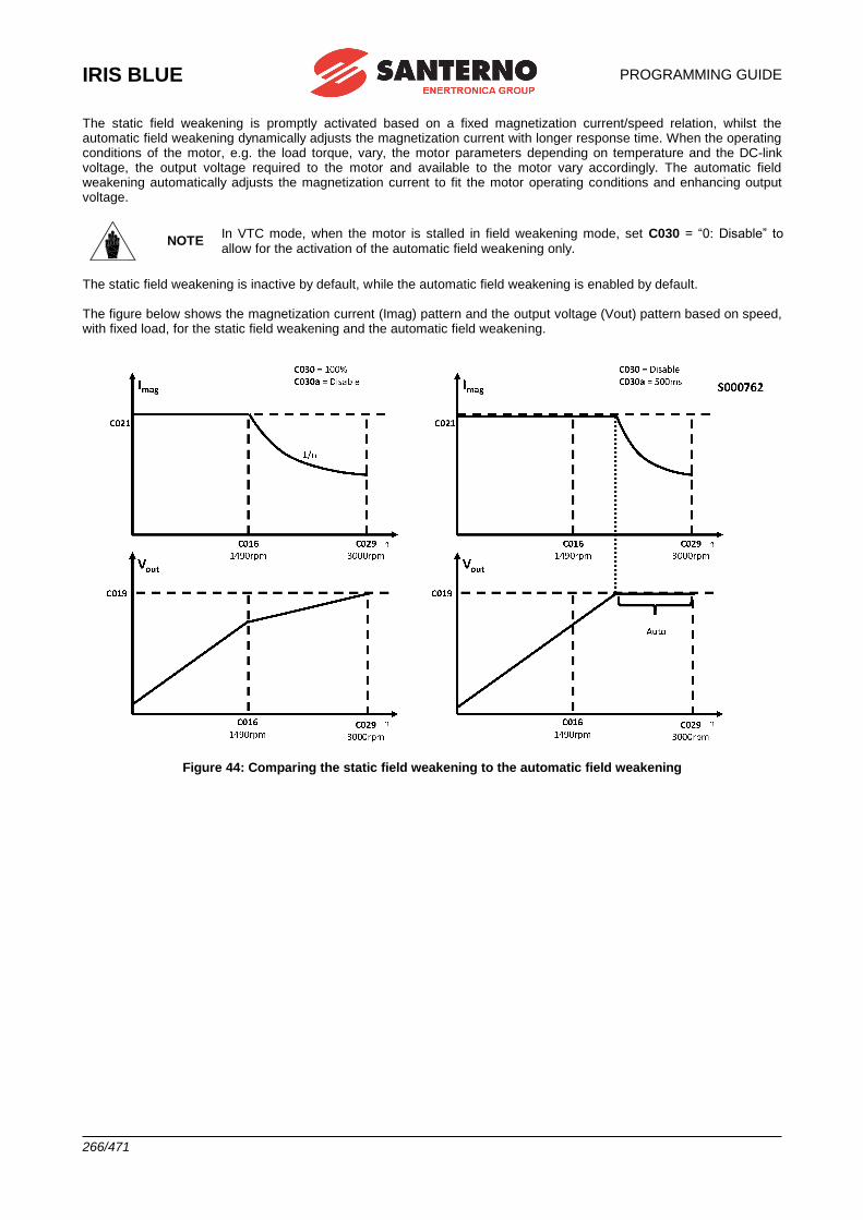
IRIS BLUE
PROGRAMMING GUIDE
266/471
The static field weakening is promptly activated based on a fixed magnetization current/speed relation, whilst the automatic field weakening dynamically adjusts the magnetization current with longer response time. When the operating conditions of the motor, e.g. the load torque, vary, the motor parameters depending on temperature and the DC-link voltage, the output voltage required to the motor and available to the motor vary accordingly. The automatic field weakening automatically adjusts the magnetization current to fit the motor operating conditions and enhancing output voltage.
NOTE In VTC mode, when the motor is stalled in field weakening mode, set C030 = “0: Disable” to allow for the activation of the automatic field weakening only.
The static field weakening is inactive by default, while the automatic field weakening is enabled by default. The figure below shows the magnetization current (Imag) pattern and the output voltage (Vout) pattern based on speed, with fixed load, for the static field weakening and the automatic field weakening.
Figure 44: Comparing the static field weakening to the automatic field weakening
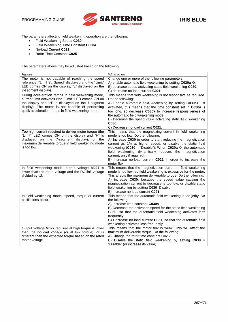
PROGRAMMING GUIDE
IRIS BLUE
267/471
The parameters affecting field weakening operation are the following:
• Field Weakening Speed C030
• Field Weakening Time Constant C030a
• No-load Current C021
• Rotor Time Constant C025
The parameters above may be adjusted based on the following:
Failure What to do
The motor is not capable of reaching the speed reference (“Limit St. Speed” displayed and the “Limit” LED comes ON on the display; “L” displayed on the 7-segment display)
Change one or more of the following parameters:
A) enable automatic field weakening by setting C030a>0.
B) decrease speed activating static field weakening C030.
C) decrease no-load current C021.
During acceleration ramps in field weakening mode, current limit activates (the “Limit” LED comes ON on the display and “H” is displayed on the 7-segment display). The motor is not capable of performing quick acceleration ramps in field weakening mode.
This means that field weakening is not responsive as required. Do the following:
A) Enable automatic field weakening by setting C030a>0. If
activated, this means that the time constant set in C030a is
too long, so decrease C030a to increase responsiveness of the automatic field weakening mode. B) Decrease the speed value activating static field weakening
C030.
C) Decrease no-load current C021.
Too high current required to deliver motor torque (the “Limit” LED comes ON on the display and “H” is displayed on the 7-segment display), or the maximum deliverable torque in field weakening mode is too low.
This means that the magnetizing current in field weakening mode is too low. Do the following:
A) Increase C030 in order to start reducing the magnetization current as 1/n at higher speed, or disable the static field
weakening (C030 = “Disable”). When C030a>0, the automatic field weakening dynamically reduces the magnetization current, only if required.
B) Increase no-load current C021 in order to increase the motor flux.
In field weakening mode, output voltage M027 is lower than the rated voltage and the DC-link voltage divided by √2.
This means that the magnetization current in field weakening mode is too low, so field weakening is excessive for the motor. This affects the maximum deliverable torque. Do the following:
A) Increase C030, because the speed value causing the magnetization current to decrease is too low, or disable static
field weakening by setting C030=Disable.
B) Increase no-load current C021.
In field weakening mode, speed, torque or current oscillations occur.
This means that the automatic field weakening is too jerky. Do the following:
A) Increase time constant C030a
B) Decrease the activation speed for the static field weakening
C030, so that the automatic field weakening activates less frequently
C) Decrease no-load current C021, so that the automatic field weakening activates less frequently
Output voltage M027 required at high torque is lower than the no-load voltage (or at low torque), or is different than the expected torque based on the rated motor voltage.
This means that the motor flux is weak. This will affect the maximum deliverable torque. Do the following:
A) Change the rotor time constant C025.
B) Disable the static field weakening by setting C030 = “Disable” (or increase its value)
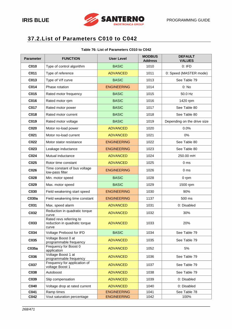
IRIS BLUE
PROGRAMMING GUIDE
268/471
37.2.List of Parameters C010 to C042
Table 76: List of Parameters C010 to C042
Parameter FUNCTION User Level MODBUS
Address
DEFAULT
VALUES
C010 Type of control algorithm BASIC 1010 0: IFD
C011 Type of reference ADVANCED 1011 0: Speed (MASTER mode)
C013 Type of V/f curve BASIC 1013 See Table 79
C014 Phase rotation ENGINEERING 1014 0: No
C015 Rated motor frequency BASIC 1015 50.0 Hz
C016 Rated motor rpm BASIC 1016 1420 rpm
C017 Rated motor power BASIC 1017 See Table 80
C018 Rated motor current BASIC 1018 See Table 80
C019 Rated motor voltage BASIC 1019 Depending on the drive size
C020 Motor no-load power ADVANCED 1020 0.0%
C021 Motor no-load current ADVANCED 1021 0%
C022 Motor stator resistance ENGINEERING 1022 See Table 80
C023 Leakage inductance ENGINEERING 1023 See Table 80
C024 Mutual inductance ADVANCED 1024 250.00 mH
C025 Rotor time constant ADVANCED 1025 0 ms
C026 Time constant of bus voltage low-pass filter
ENGINEERING 1026 0 ms
C028 Min. motor speed BASIC 1028 0 rpm
C029 Max. motor speed BASIC 1029 1500 rpm
C030 Field weakening start speed ENGINEERING 1030 90%
C030a Field weakening time constant ENGINEERING 1137 500 ms
C031 Max. speed alarm ADVANCED 1031 0: Disabled
C032 Reduction in quadratic torque curve
ADVANCED 1032 30%
C033 Rated revs referring to reduction in quadratic torque curve
ADVANCED 1033 20%
C034 Voltage Preboost for IFD BASIC 1034 See Table 79
C035 Voltage Boost 0 at programmable frequency
ADVANCED 1035 See Table 79
C035a Frequency for Boost 0 application
ADVANCED 1052 5%
C036 Voltage Boost 1 at programmable frequency
ADVANCED 1036 See Table 79
C037 Frequency for application of voltage Boost 1
ADVANCED 1037 See Table 79
C038 Autoboost ADVANCED 1038 See Table 79
C039 Slip compensation ADVANCED 1039 0: Disabled
C040 Voltage drop at rated current ADVANCED 1040 0: Disabled
C041 Ramp times ENGINEERING 1041 See Table 78
C042 Vout saturation percentage ENGINEERING 1042 100%
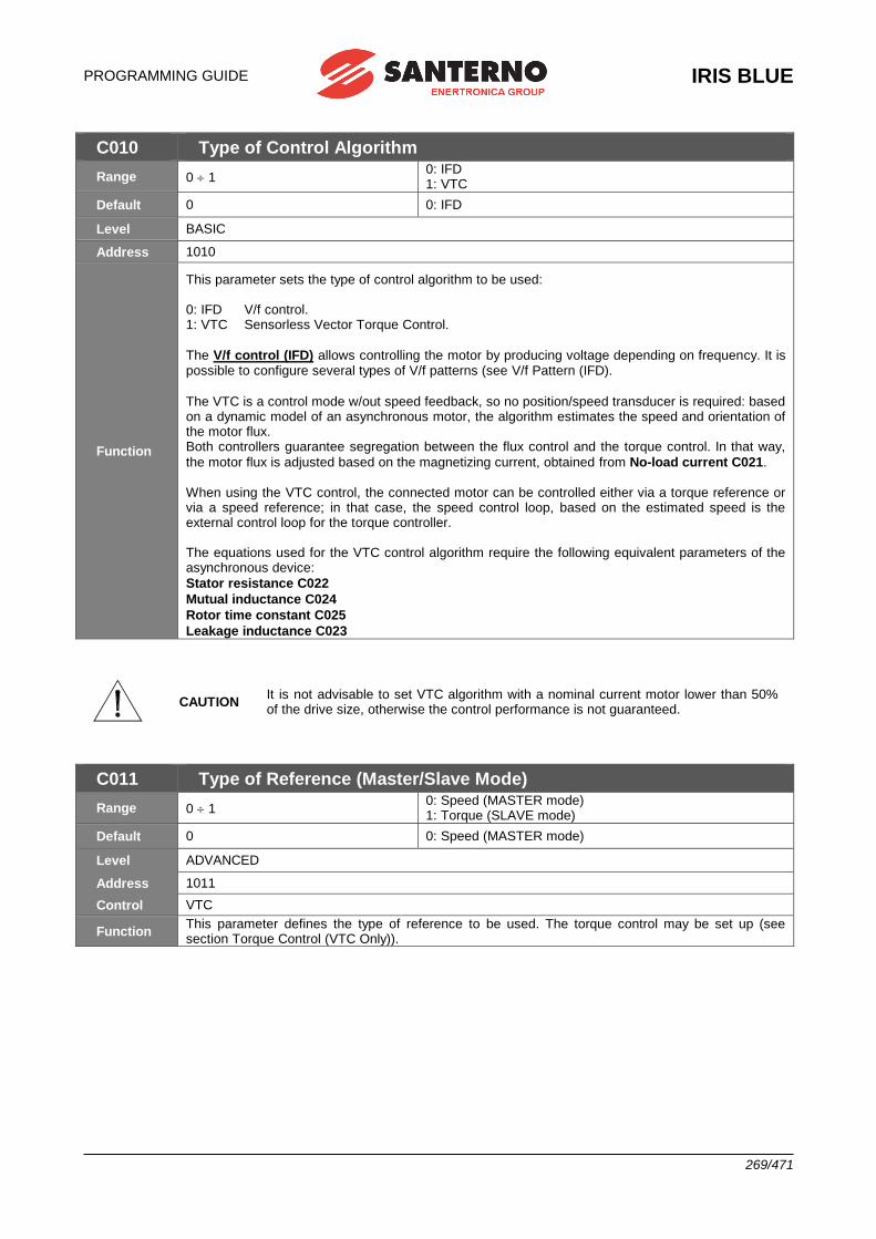
PROGRAMMING GUIDE
IRIS BLUE
269/471
C010 Type of Control Algorithm
Range 0 1 0: IFD 1: VTC
Default 0 0: IFD
Level BASIC
Address 1010
Function
This parameter sets the type of control algorithm to be used: 0: IFD V/f control. 1: VTC Sensorless Vector Torque Control.
The V/f control (IFD) allows controlling the motor by producing voltage depending on frequency. It is possible to configure several types of V/f patterns (see V/f Pattern (IFD).
The VTC is a control mode w/out speed feedback, so no position/speed transducer is required: based on a dynamic model of an asynchronous motor, the algorithm estimates the speed and orientation of the motor flux. Both controllers guarantee segregation between the flux control and the torque control. In that way,
the motor flux is adjusted based on the magnetizing current, obtained from No-load current C021. When using the VTC control, the connected motor can be controlled either via a torque reference or via a speed reference; in that case, the speed control loop, based on the estimated speed is the external control loop for the torque controller. The equations used for the VTC control algorithm require the following equivalent parameters of the asynchronous device:
Stator resistance C022
Mutual inductance C024
Rotor time constant C025
Leakage inductance C023
CAUTION It is not advisable to set VTC algorithm with a nominal current motor lower than 50% of the drive size, otherwise the control performance is not guaranteed.
C011 Type of Reference (Master/Slave Mode)
Range 0 1 0: Speed (MASTER mode) 1: Torque (SLAVE mode)
Default 0 0: Speed (MASTER mode)
Level ADVANCED
Address 1011
Control VTC
Function This parameter defines the type of reference to be used. The torque control may be set up (see section Torque Control (VTC Only)).
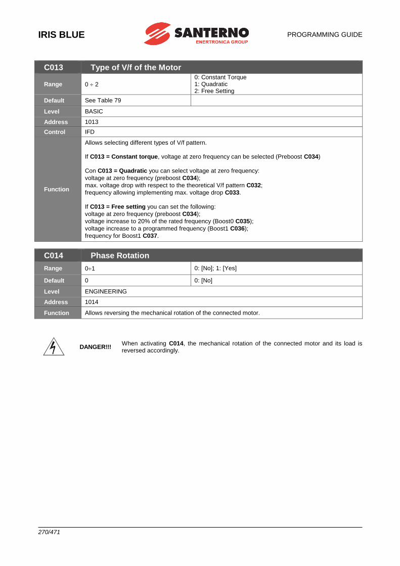
IRIS BLUE
PROGRAMMING GUIDE
270/471
C013 Type of V/f of the Motor
Range 0 2
0: Constant Torque 1: Quadratic 2: Free Setting
Default See Table 79
Level BASIC
Address 1013
Control IFD
Function
Allows selecting different types of V/f pattern.
If C013 = Constant torque, voltage at zero frequency can be selected (Preboost C034)
Con C013 = Quadratic you can select voltage at zero frequency:
voltage at zero frequency (preboost C034);
max. voltage drop with respect to the theoretical V/f pattern C032;
frequency allowing implementing max. voltage drop C033.
If C013 = Free setting you can set the following:
voltage at zero frequency (preboost C034);
voltage increase to 20% of the rated frequency (Boost0 C035);
voltage increase to a programmed frequency (Boost1 C036);
frequency for Boost1 C037.
C014 Phase Rotation
Range 01 0: [No]; 1: [Yes]
Default 0 0: [No]
Level ENGINEERING
Address 1014
Function Allows reversing the mechanical rotation of the connected motor.
DANGER!!! When activating C014, the mechanical rotation of the connected motor and its load is reversed accordingly.
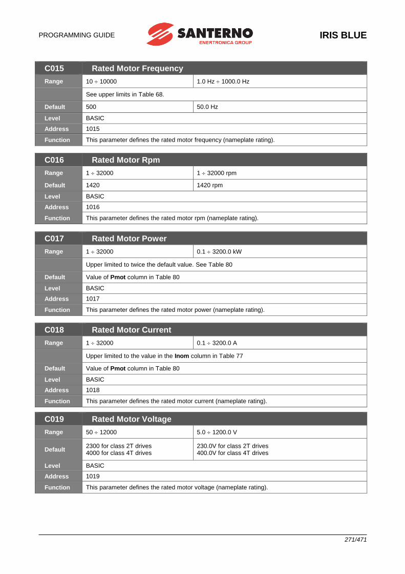
PROGRAMMING GUIDE
IRIS BLUE
271/471
C015 Rated Motor Frequency
Range 10 10000 1.0 Hz 1000.0 Hz
See upper limits in Table 68.
Default 500 50.0 Hz
Level BASIC
Address 1015
Function This parameter defines the rated motor frequency (nameplate rating).
C016 Rated Motor Rpm
Range 1 32000 1 32000 rpm
Default 1420 1420 rpm
Level BASIC
Address 1016
Function This parameter defines the rated motor rpm (nameplate rating).
C017 Rated Motor Power
Range 1 32000 0.1 3200.0 kW
Upper limited to twice the default value. See Table 80
Default Value of Pmot column in Table 80
Level BASIC
Address 1017
Function This parameter defines the rated motor power (nameplate rating).
C018 Rated Motor Current
Range 1 32000 0.1 3200.0 A
Upper limited to the value in the Inom column in Table 77
Default Value of Pmot column in Table 80
Level BASIC
Address 1018
Function This parameter defines the rated motor current (nameplate rating).
C019 Rated Motor Voltage
Range 50 12000 5.0 1200.0 V
Default 2300 for class 2T drives 4000 for class 4T drives
230.0V for class 2T drives 400.0V for class 4T drives
Level BASIC
Address 1019
Function This parameter defines the rated motor voltage (nameplate rating).
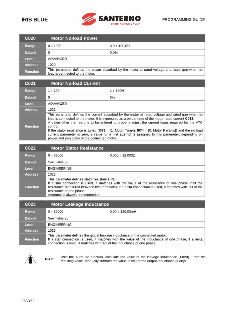
IRIS BLUE
PROGRAMMING GUIDE
272/471
C020 Motor No-load Power
Range 0 1000 0.0 100.0%
Default 0 0.0%
Level ADVANCED
Address 1020
Function This parameter defines the power absorbed by the motor at rated voltage and rated rpm when no load is connected to the motor.
C021 Motor No-load Current
Range 1 100 1 100%
Default 0 0%
Level ADVANCED
Address 1021
Function
This parameter defines the current absorbed by the motor at rated voltage and rated rpm when no
load is connected to the motor. It is expressed as a percentage of the motor rated current C018. A value other than zero is to be entered to properly adjust the current loops required for the VTC control.
If the stator resistance is tuned (I073 = [1: Motor Tune]); I074 = [0: Motor Params]) and the no load current parameter is zero, a value for a first attempt is assigned to this parameter, depending on power and pole pairs of the connected motor.
C022 Motor Stator Resistance
Range 0 32000 0.000 32.000
Default See Table 80
Level ENGINEERING
Address 1022
Function
This parameter defines stator resistance Rs. If a star connection is used, it matches with the value of the resistance of one phase (half the resistance measured between two terminals); if a delta connection is used, it matches with 1/3 of the resistance of one phase. Autotune is always recommended.
C023 Motor Leakage Inductance
Range 0 32000 0.00 320.00mH
Default See Table 80
Level ENGINEERING
Address 1023
Function This parameter defines the global leakage inductance of the connected motor. If a star connection is used, it matches with the value of the inductance of one phase; if a delta connection is used, it matches with 1/3 of the inductance of one phase.
NOTE With the Autotune function, calculate the value of the leakage inductance (C023). From the resulting value, manually subtract the value in mH of the output inductance (if any).
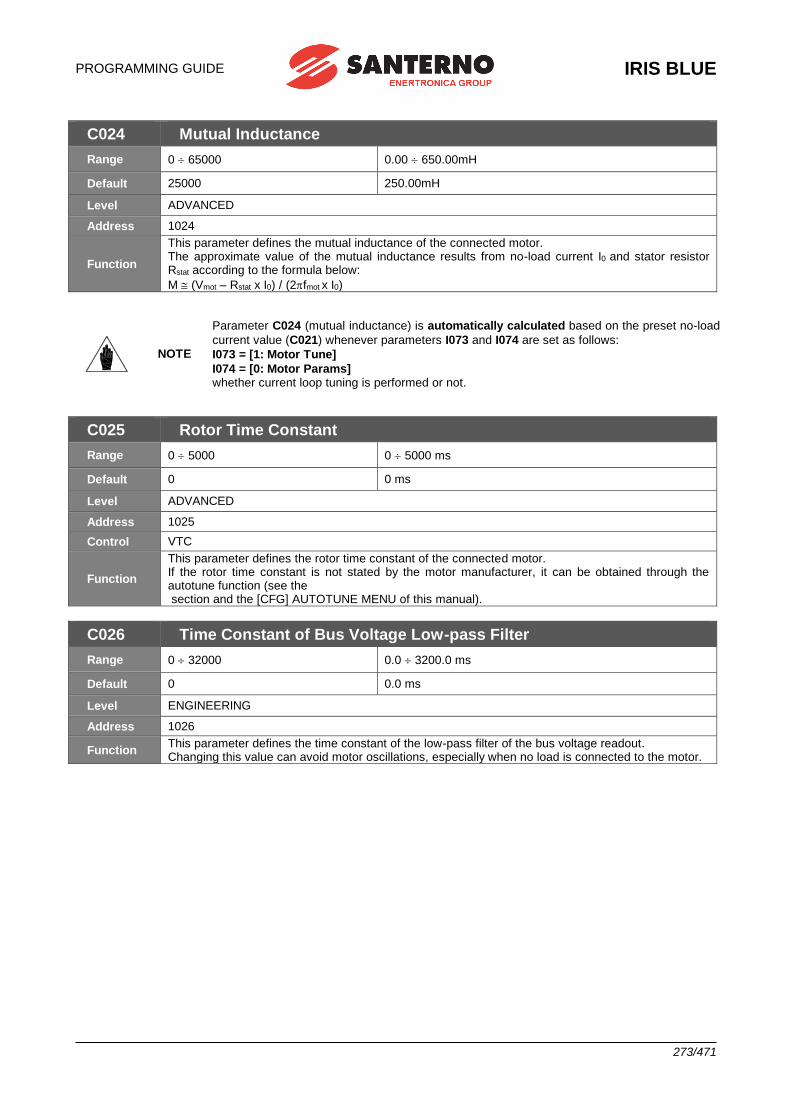
PROGRAMMING GUIDE
IRIS BLUE
273/471
C024 Mutual Inductance
Range 0 65000 0.00 650.00mH
Default 25000 250.00mH
Level ADVANCED
Address 1024
Function
This parameter defines the mutual inductance of the connected motor. The approximate value of the mutual inductance results from no-load current I0 and stator resistor Rstat according to the formula below:
M (Vmot – Rstat x I0) / (2fmot x I0)
NOTE
Parameter C024 (mutual inductance) is automatically calculated based on the preset no-load
current value (C021) whenever parameters I073 and I074 are set as follows:
I073 = [1: Motor Tune]
I074 = [0: Motor Params] whether current loop tuning is performed or not.
C025 Rotor Time Constant
Range 0 5000 0 5000 ms
Default 0 0 ms
Level ADVANCED
Address 1025
Control VTC
Function
This parameter defines the rotor time constant of the connected motor. If the rotor time constant is not stated by the motor manufacturer, it can be obtained through the autotune function (see the section and the [CFG] AUTOTUNE MENU of this manual).
C026 Time Constant of Bus Voltage Low-pass Filter
Range 0 32000 0.0 3200.0 ms
Default 0 0.0 ms
Level ENGINEERING
Address 1026
Function This parameter defines the time constant of the low-pass filter of the bus voltage readout. Changing this value can avoid motor oscillations, especially when no load is connected to the motor.
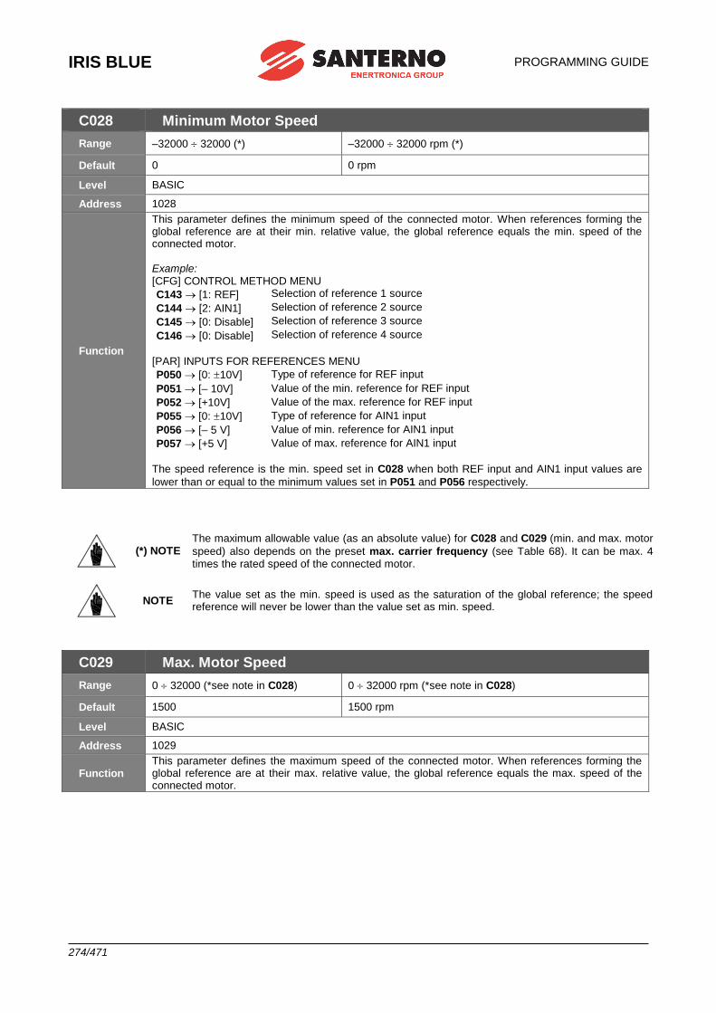
IRIS BLUE
PROGRAMMING GUIDE
274/471
C028 Minimum Motor Speed
Range –32000 32000 (*) –32000 32000 rpm (*)
Default 0 0 rpm
Level BASIC
Address 1028
Function
This parameter defines the minimum speed of the connected motor. When references forming the global reference are at their min. relative value, the global reference equals the min. speed of the connected motor. Example: [CFG] CONTROL METHOD MENU
C143 [1: REF] Selection of reference 1 source
C144 [2: AIN1] Selection of reference 2 source
C145 [0: Disable] Selection of reference 3 source
C146 [0: Disable] Selection of reference 4 source
[PAR] INPUTS FOR REFERENCES MENU
P050 [0: 10V] Type of reference for REF input
P051 [– 10V] Value of the min. reference for REF input
P052 [+10V] Value of the max. reference for REF input
P055 [0: 10V] Type of reference for AIN1 input
P056 [– 5 V] Value of min. reference for AIN1 input
P057 [+5 V] Value of max. reference for AIN1 input
The speed reference is the min. speed set in C028 when both REF input and AIN1 input values are
lower than or equal to the minimum values set in P051 and P056 respectively.
(*) NOTE The maximum allowable value (as an absolute value) for C028 and C029 (min. and max. motor
speed) also depends on the preset max. carrier frequency (see Table 68). It can be max. 4 times the rated speed of the connected motor.
NOTE The value set as the min. speed is used as the saturation of the global reference; the speed reference will never be lower than the value set as min. speed.
C029 Max. Motor Speed
Range 0 32000 (*see note in C028) 0 32000 rpm (*see note in C028)
Default 1500 1500 rpm
Level BASIC
Address 1029
Function This parameter defines the maximum speed of the connected motor. When references forming the global reference are at their max. relative value, the global reference equals the max. speed of the connected motor.
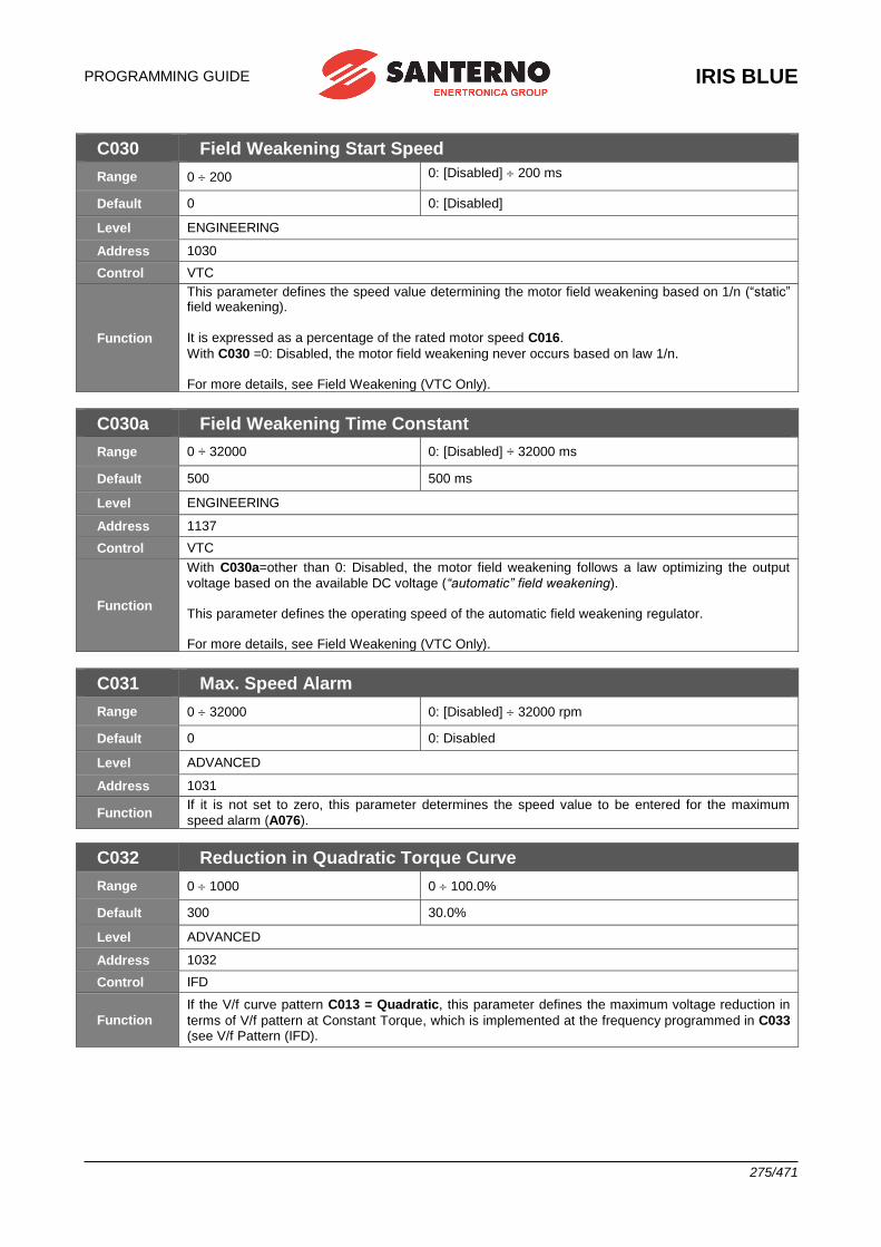
PROGRAMMING GUIDE
IRIS BLUE
275/471
C030 Field Weakening Start Speed
Range 0 200 0: [Disabled] 200 ms
Default 0 0: [Disabled]
Level ENGINEERING
Address 1030
Control VTC
Function
This parameter defines the speed value determining the motor field weakening based on 1/n (“static” field weakening).
It is expressed as a percentage of the rated motor speed C016.
With C030 =0: Disabled, the motor field weakening never occurs based on law 1/n. For more details, see Field Weakening (VTC Only).
C030a Field Weakening Time Constant
Range 0 ÷ 32000 0: [Disabled] ÷ 32000 ms
Default 500 500 ms
Level ENGINEERING
Address 1137
Control VTC
Function
With C030a=other than 0: Disabled, the motor field weakening follows a law optimizing the output
voltage based on the available DC voltage (“automatic” field weakening). This parameter defines the operating speed of the automatic field weakening regulator. For more details, see Field Weakening (VTC Only).
C031 Max. Speed Alarm
Range 0 32000 0: [Disabled] 32000 rpm
Default 0 0: Disabled
Level ADVANCED
Address 1031
Function If it is not set to zero, this parameter determines the speed value to be entered for the maximum
speed alarm (A076).
C032 Reduction in Quadratic Torque Curve
Range 0 1000 0 100.0%
Default 300 30.0%
Level ADVANCED
Address 1032
Control IFD
Function
If the V/f curve pattern C013 = Quadratic, this parameter defines the maximum voltage reduction in
terms of V/f pattern at Constant Torque, which is implemented at the frequency programmed in C033 (see V/f Pattern (IFD).
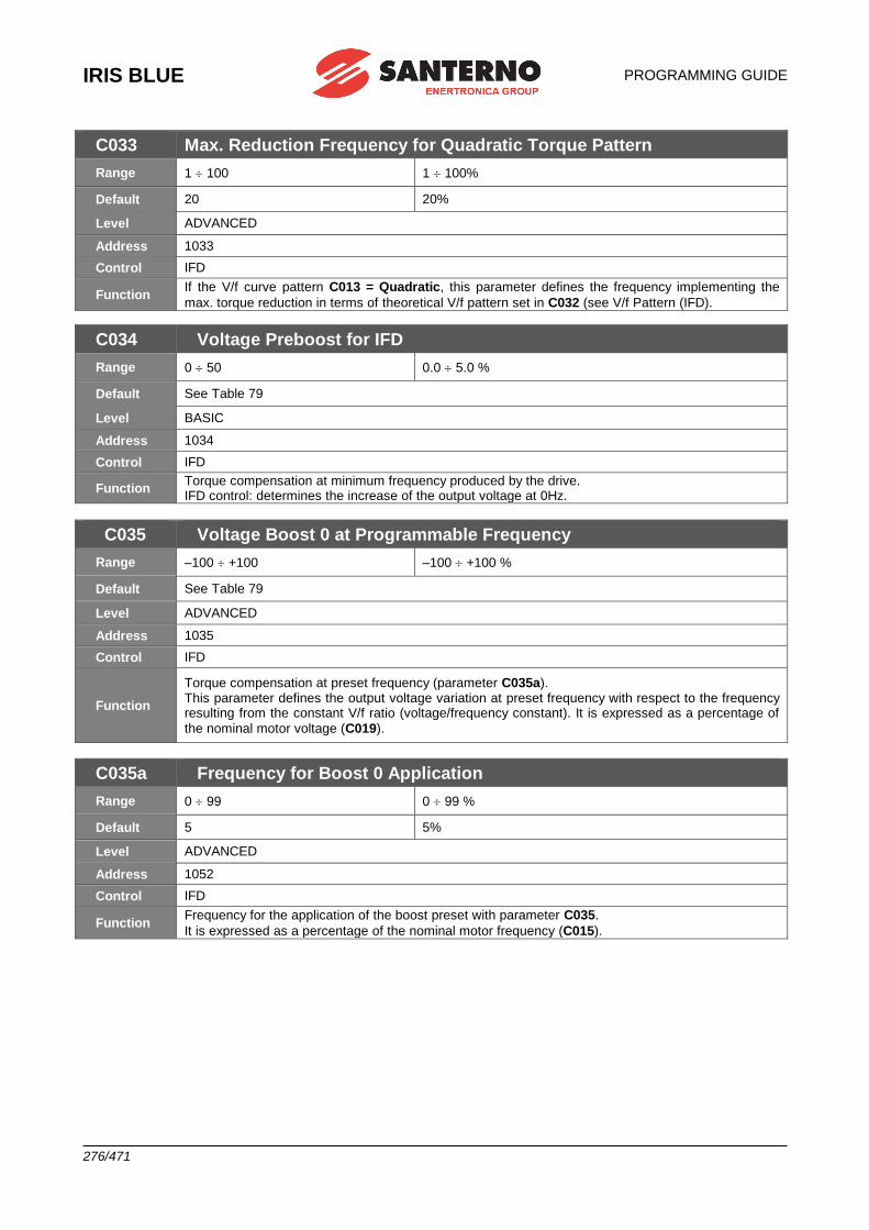
IRIS BLUE
PROGRAMMING GUIDE
276/471
C033 Max. Reduction Frequency for Quadratic Torque Pattern
Range 1 100 1 100%
Default 20 20%
Level ADVANCED
Address 1033
Control IFD
Function If the V/f curve pattern C013 = Quadratic, this parameter defines the frequency implementing the
max. torque reduction in terms of theoretical V/f pattern set in C032 (see V/f Pattern (IFD).
C034 Voltage Preboost for IFD
Range 0 50 0.0 5.0 %
Default See Table 79
Level BASIC
Address 1034
Control IFD
Function Torque compensation at minimum frequency produced by the drive. IFD control: determines the increase of the output voltage at 0Hz.
C035 Voltage Boost 0 at Programmable Frequency
Range –100 +100 –100 +100 %
Default See Table 79
Level ADVANCED
Address 1035
Control IFD
Function
Torque compensation at preset frequency (parameter C035a). This parameter defines the output voltage variation at preset frequency with respect to the frequency resulting from the constant V/f ratio (voltage/frequency constant). It is expressed as a percentage of
the nominal motor voltage (C019).
C035a Frequency for Boost 0 Application
Range 0 99 0 99 %
Default 5 5%
Level ADVANCED
Address 1052
Control IFD
Function Frequency for the application of the boost preset with parameter C035.
It is expressed as a percentage of the nominal motor frequency (C015).
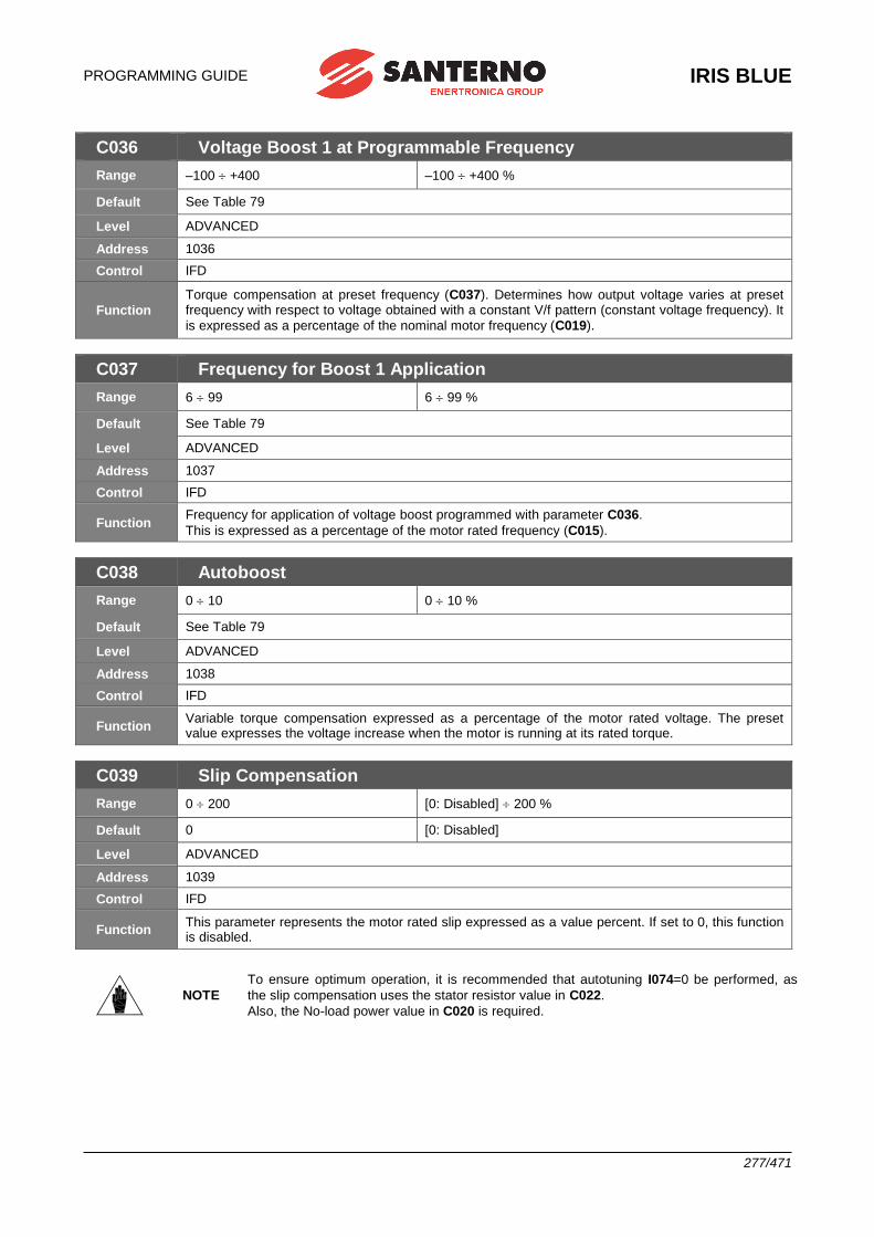
PROGRAMMING GUIDE
IRIS BLUE
277/471
C036 Voltage Boost 1 at Programmable Frequency
Range –100 +400 –100 +400 %
Default See Table 79
Level ADVANCED
Address 1036
Control IFD
Function
Torque compensation at preset frequency (C037). Determines how output voltage varies at preset frequency with respect to voltage obtained with a constant V/f pattern (constant voltage frequency). It
is expressed as a percentage of the nominal motor frequency (C019).
C037 Frequency for Boost 1 Application
Range 6 99 6 99 %
Default See Table 79
Level ADVANCED
Address 1037
Control IFD
Function Frequency for application of voltage boost programmed with parameter C036.
This is expressed as a percentage of the motor rated frequency (C015).
C038 Autoboost
Range 0 10 0 10 %
Default See Table 79
Level ADVANCED
Address 1038
Control IFD
Function Variable torque compensation expressed as a percentage of the motor rated voltage. The preset value expresses the voltage increase when the motor is running at its rated torque.
C039 Slip Compensation
Range 0 200 [0: Disabled] 200 %
Default 0 [0: Disabled]
Level ADVANCED
Address 1039
Control IFD
Function This parameter represents the motor rated slip expressed as a value percent. If set to 0, this function is disabled.
NOTE
To ensure optimum operation, it is recommended that autotuning I074=0 be performed, as
the slip compensation uses the stator resistor value in C022.
Also, the No-load power value in C020 is required.
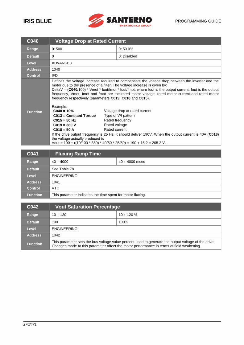
IRIS BLUE
PROGRAMMING GUIDE
278/471
C040 Voltage Drop at Rated Current
Range 0500 050.0%
Default 0 0: Disabled
Level ADVANCED
Address 1040
Control IFD
Function
Defines the voltage increase required to compensate the voltage drop between the inverter and the motor due to the presence of a filter. The voltage increase is given by:
DeltaV = (C040/100) * Vmot * Iout/Imot * fout/fmot, where Iout is the output current, fout is the output frequency, Vmot, Imot and fmot are the rated motor voltage, rated motor current and rated motor
frequency respectively (parameters C019, C018 and C015). Example:
C040 = 10% Voltage drop at rated current
C013 = Constant Torque Type of V/f pattern
C015 = 50 Hz Rated frequency
C019 = 380 V Rated voltage
C018 = 50 A Rated current
If the drive output frequency is 25 Hz, it should deliver 190V. When the output current is 40A (C018) the voltage actually produced is Vout = 190 + ((10/100 * 380) * 40/50 * 25/50) = 190 + 15.2 = 205.2 V.
C041 Fluxing Ramp Time
Range 40 4000 40 4000 msec
Default See Table 78
Level ENGINEERING
Address 1041
Control VTC
Function This parameter indicates the time spent for motor fluxing.
C042 Vout Saturation Percentage
Range 10 120 10 120 %
Default 100 100%
Level ENGINEERING
Address 1042
Function This parameter sets the bus voltage value percent used to generate the output voltage of the drive. Changes made to this parameter affect the motor performance in terms of field weakening.
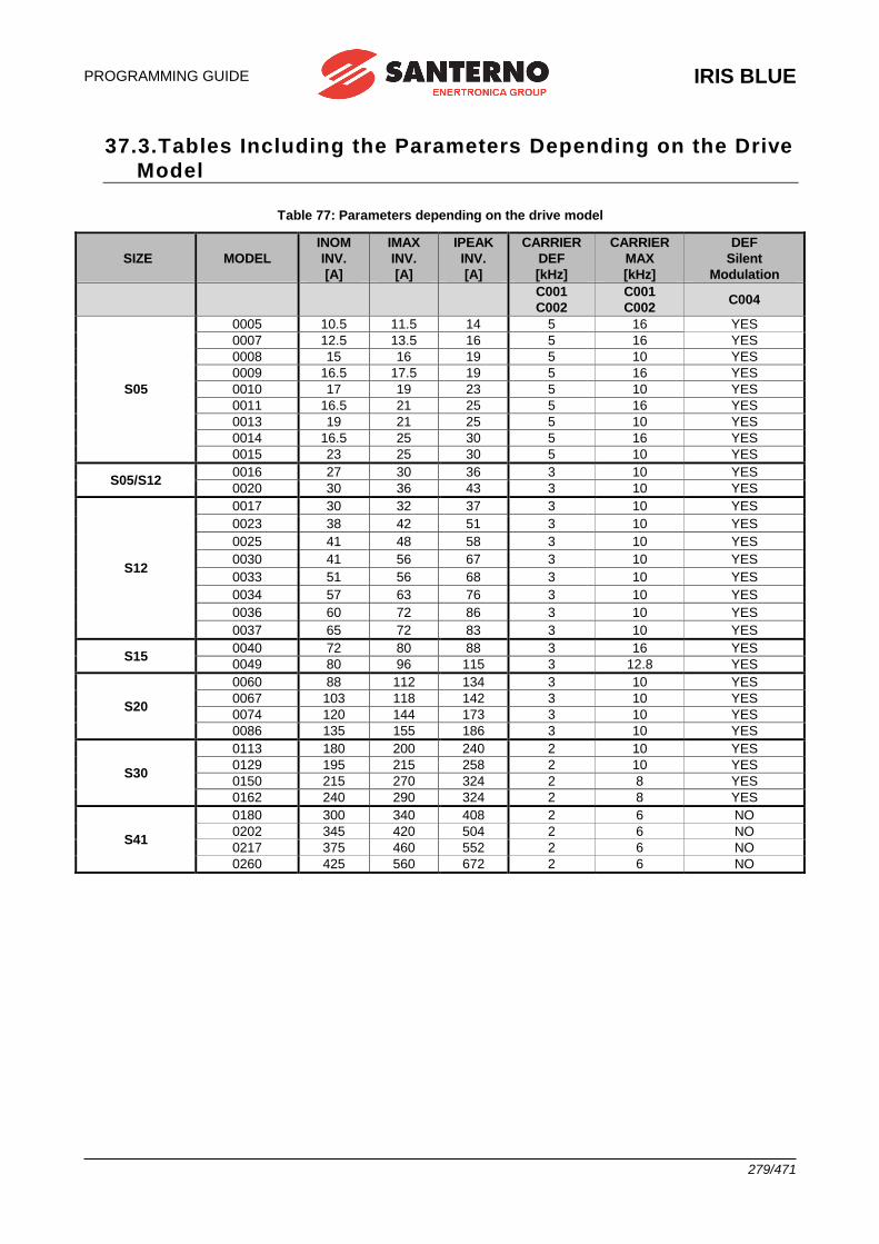
PROGRAMMING GUIDE
IRIS BLUE
279/471
37.3.Tables Including the Parameters Depending on the Drive
Model
Table 77: Parameters depending on the drive model
SIZE MODEL
INOM
INV.
[A]
IMAX
INV.
[A]
IPEAK
INV.
[A]
CARRIER
DEF
[kHz]
CARRIER
MAX
[kHz]
DEF
Silent
Modulation
C001
C002
C001
C002 C004
S05
0005 10.5 11.5 14 5 16 YES
0007 12.5 13.5 16 5 16 YES
0008 15 16 19 5 10 YES
0009 16.5 17.5 19 5 16 YES
0010 17 19 23 5 10 YES
0011 16.5 21 25 5 16 YES
0013 19 21 25 5 10 YES
0014 16.5 25 30 5 16 YES
0015 23 25 30 5 10 YES
S05/S12 0016 27 30 36 3 10 YES
0020 30 36 43 3 10 YES
S12
0017 30 32 37 3 10 YES
0023 38 42 51 3 10 YES
0025 41 48 58 3 10 YES
0030 41 56 67 3 10 YES
0033 51 56 68 3 10 YES
0034 57 63 76 3 10 YES
0036 60 72 86 3 10 YES
0037 65 72 83 3 10 YES
S15 0040 72 80 88 3 16 YES
0049 80 96 115 3 12.8 YES
S20
0060 88 112 134 3 10 YES
0067 103 118 142 3 10 YES
0074 120 144 173 3 10 YES
0086 135 155 186 3 10 YES
S30
0113 180 200 240 2 10 YES
0129 195 215 258 2 10 YES
0150 215 270 324 2 8 YES
0162 240 290 324 2 8 YES
S41
0180 300 340 408 2 6 NO
0202 345 420 504 2 6 NO
0217 375 460 552 2 6 NO
0260 425 560 672 2 6 NO
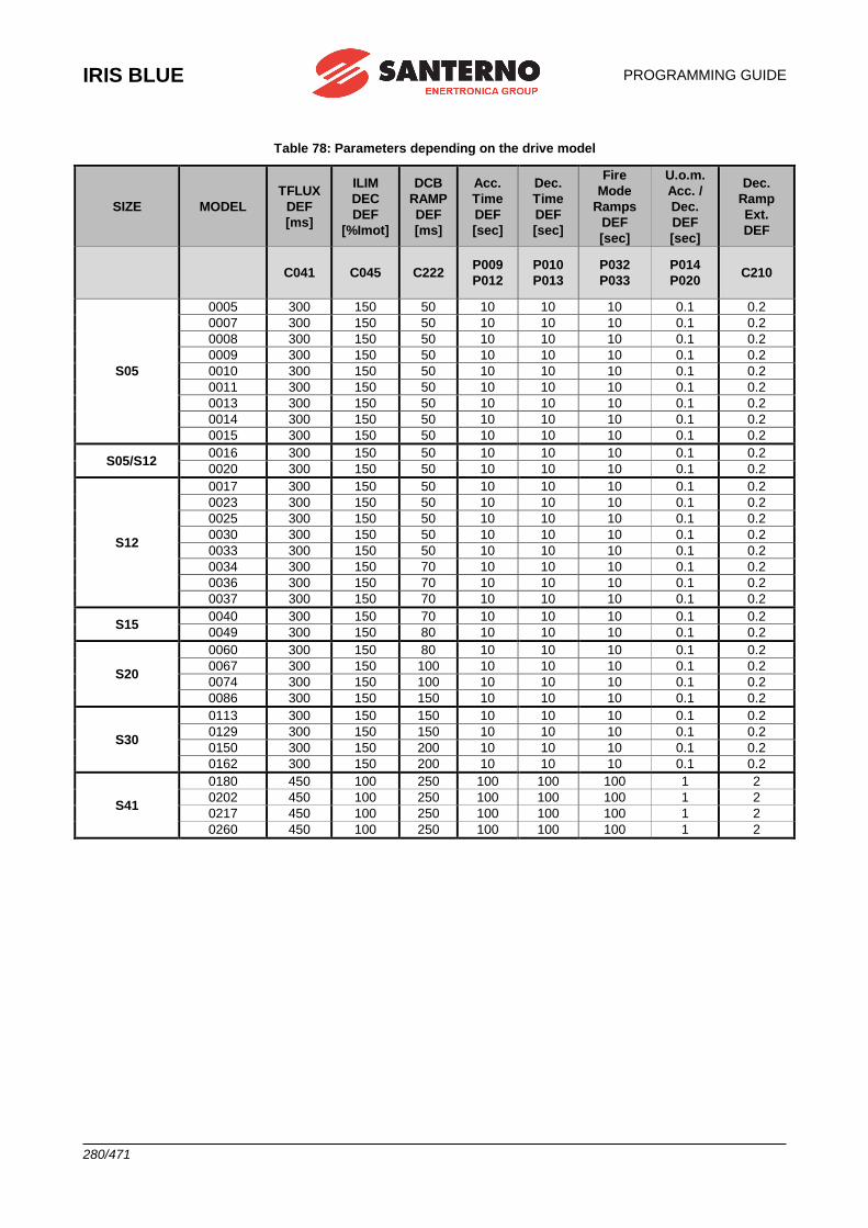
IRIS BLUE
PROGRAMMING GUIDE
280/471
Table 78: Parameters depending on the drive model
SIZE MODEL
TFLUX
DEF
[ms]
ILIM
DEC
DEF
[%Imot]
DCB
RAMP
DEF
[ms]
Acc.
Time
DEF
[sec]
Dec.
Time
DEF
[sec]
Fire
Mode
Ramps
DEF
[sec]
U.o.m.
Acc. /
Dec.
DEF
[sec]
Dec.
Ramp
Ext.
DEF
C041 C045 C222 P009
P012
P010
P013
P032
P033
P014
P020 C210
S05
0005 300 150 50 10 10 10 0.1 0.2
0007 300 150 50 10 10 10 0.1 0.2
0008 300 150 50 10 10 10 0.1 0.2
0009 300 150 50 10 10 10 0.1 0.2
0010 300 150 50 10 10 10 0.1 0.2
0011 300 150 50 10 10 10 0.1 0.2
0013 300 150 50 10 10 10 0.1 0.2
0014 300 150 50 10 10 10 0.1 0.2
0015 300 150 50 10 10 10 0.1 0.2
S05/S12 0016 300 150 50 10 10 10 0.1 0.2
0020 300 150 50 10 10 10 0.1 0.2
S12
0017 300 150 50 10 10 10 0.1 0.2
0023 300 150 50 10 10 10 0.1 0.2
0025 300 150 50 10 10 10 0.1 0.2
0030 300 150 50 10 10 10 0.1 0.2
0033 300 150 50 10 10 10 0.1 0.2
0034 300 150 70 10 10 10 0.1 0.2
0036 300 150 70 10 10 10 0.1 0.2
0037 300 150 70 10 10 10 0.1 0.2
S15 0040 300 150 70 10 10 10 0.1 0.2
0049 300 150 80 10 10 10 0.1 0.2
S20
0060 300 150 80 10 10 10 0.1 0.2
0067 300 150 100 10 10 10 0.1 0.2
0074 300 150 100 10 10 10 0.1 0.2
0086 300 150 150 10 10 10 0.1 0.2
S30
0113 300 150 150 10 10 10 0.1 0.2
0129 300 150 150 10 10 10 0.1 0.2
0150 300 150 200 10 10 10 0.1 0.2
0162 300 150 200 10 10 10 0.1 0.2
S41
0180 450 100 250 100 100 100 1 2
0202 450 100 250 100 100 100 1 2
0217 450 100 250 100 100 100 1 2
0260 450 100 250 100 100 100 1 2
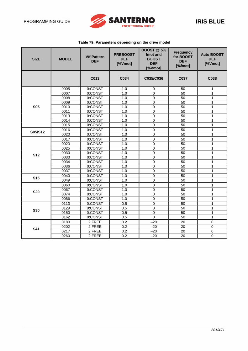
PROGRAMMING GUIDE
IRIS BLUE
281/471
Table 79: Parameters depending on the drive model
SIZE MODEL V/f Pattern
DEF
PREBOOST
DEF
[%Vmot]
BOOST @ 5%
fmot and
BOOST
DEF
[%Vmot]
Frequency
for BOOST
DEF
[%fmot]
Auto BOOST
DEF
[%Vmot]
C013 C034 C035/C036 C037 C038
S05
0005 0:CONST 1.0 0 50 1
0007 0:CONST 1.0 0 50 1
0008 0:CONST 1.0 0 50 1
0009 0:CONST 1.0 0 50 1
0010 0:CONST 1.0 0 50 1
0011 0:CONST 1.0 0 50 1
0013 0:CONST 1.0 0 50 1
0014 0:CONST 1.0 0 50 1
0015 0:CONST 1.0 0 50 1
S05/S12 0016 0:CONST 1.0 0 50 1
0020 0:CONST 1.0 0 50 1
S12
0017 0:CONST 1.0 0 50 1
0023 0:CONST 1.0 0 50 1
0025 0:CONST 1.0 0 50 1
0030 0:CONST 1.0 0 50 1
0033 0:CONST 1.0 0 50 1
0034 0:CONST 1.0 0 50 1
0036 0:CONST 1.0 0 50 1
0037 0:CONST 1.0 0 50 1
S15 0040 0:CONST 1.0 0 50 1
0049 0:CONST 1.0 0 50 1
S20
0060 0:CONST 1.0 0 50 1
0067 0:CONST 1.0 0 50 1
0074 0:CONST 1.0 0 50 1
0086 0:CONST 1.0 0 50 1
S30
0113 0:CONST 0.5 0 50 1
0129 0:CONST 0.5 0 50 1
0150 0:CONST 0.5 0 50 1
0162 0:CONST 0.5 0 50 1
S41
0180 2:FREE 0.2 –20 20 0
0202 2:FREE 0.2 –20 20 0
0217 2:FREE 0.2 –20 20 0
0260 2:FREE 0.2 –20 20 0
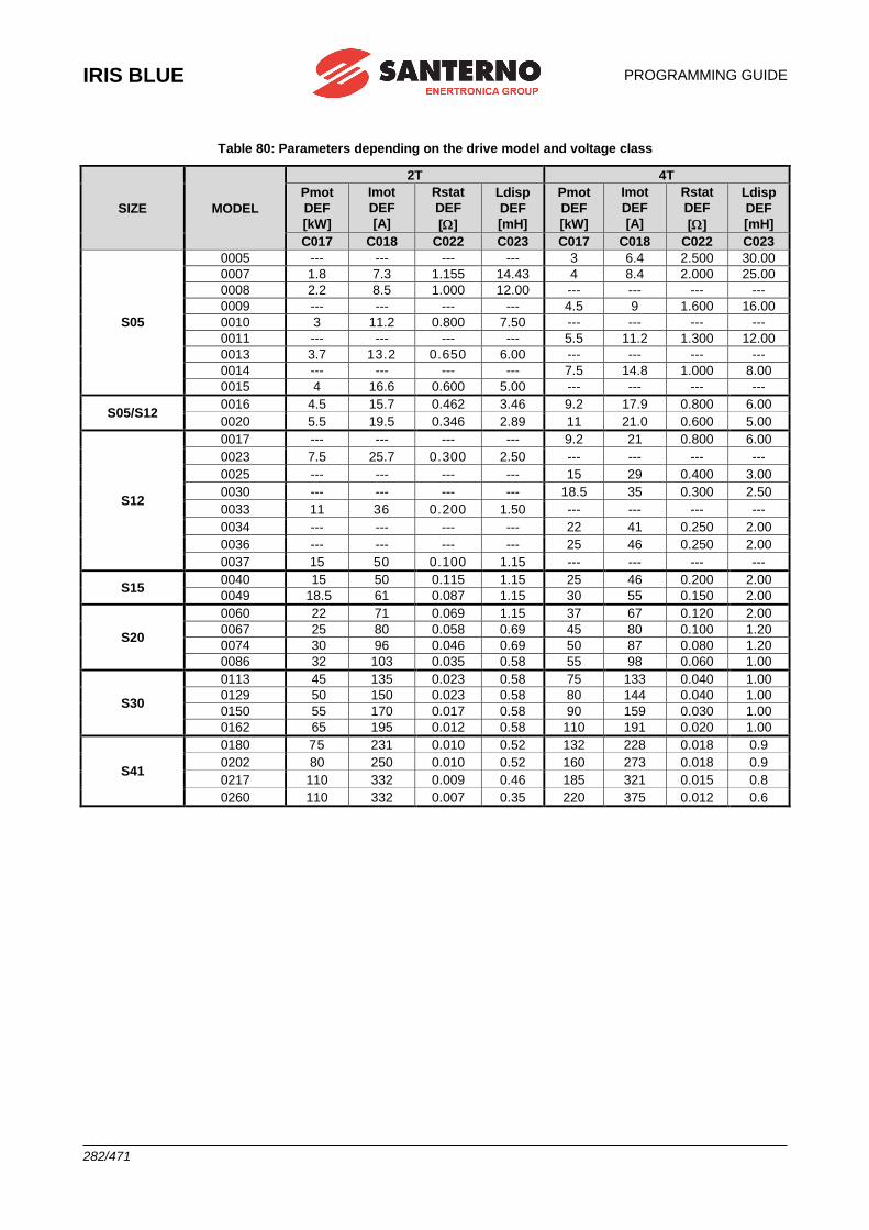
IRIS BLUE
PROGRAMMING GUIDE
282/471
Table 80: Parameters depending on the drive model and voltage class
SIZE MODEL
2T 4T
Pmot
DEF
[kW]
Imot
DEF
[A]
Rstat
DEF
[]
Ldisp
DEF
[mH]
Pmot
DEF
[kW]
Imot
DEF
[A]
Rstat
DEF
[]
Ldisp
DEF
[mH]
C017 C018 C022 C023 C017 C018 C022 C023
S05
0005 --- --- --- --- 3 6.4 2.500 30.00
0007 1.8 7.3 1.155 14.43 4 8.4 2.000 25.00
0008 2.2 8.5 1.000 12.00 --- --- --- ---
0009 --- --- --- --- 4.5 9 1.600 16.00
0010 3 11.2 0.800 7.50 --- --- --- ---
0011 --- --- --- --- 5.5 11.2 1.300 12.00
0013 3.7 13.2 0.650 6.00 --- --- --- ---
0014 --- --- --- --- 7.5 14.8 1.000 8.00
0015 4 16.6 0.600 5.00 --- --- --- ---
S05/S12 0016 4.5 15.7 0.462 3.46 9.2 17.9 0.800 6.00
0020 5.5 19.5 0.346 2.89 11 21.0 0.600 5.00
S12
0017 --- --- --- --- 9.2 21 0.800 6.00
0023 7.5 25.7 0.300 2.50 --- --- --- ---
0025 --- --- --- --- 15 29 0.400 3.00
0030 --- --- --- --- 18.5 35 0.300 2.50
0033 11 36 0.200 1.50 --- --- --- ---
0034 --- --- --- --- 22 41 0.250 2.00
0036 --- --- --- --- 25 46 0.250 2.00
0037 15 50 0.100 1.15 --- --- --- ---
S15 0040 15 50 0.115 1.15 25 46 0.200 2.00
0049 18.5 61 0.087 1.15 30 55 0.150 2.00
S20
0060 22 71 0.069 1.15 37 67 0.120 2.00
0067 25 80 0.058 0.69 45 80 0.100 1.20
0074 30 96 0.046 0.69 50 87 0.080 1.20
0086 32 103 0.035 0.58 55 98 0.060 1.00
S30
0113 45 135 0.023 0.58 75 133 0.040 1.00
0129 50 150 0.023 0.58 80 144 0.040 1.00
0150 55 170 0.017 0.58 90 159 0.030 1.00
0162 65 195 0.012 0.58 110 191 0.020 1.00
S41
0180 75 231 0.010 0.52 132 228 0.018 0.9
0202 80 250 0.010 0.52 160 273 0.018 0.9
0217 110 332 0.009 0.46 185 321 0.015 0.8
0260 110 332 0.007 0.35 220 375 0.012 0.6
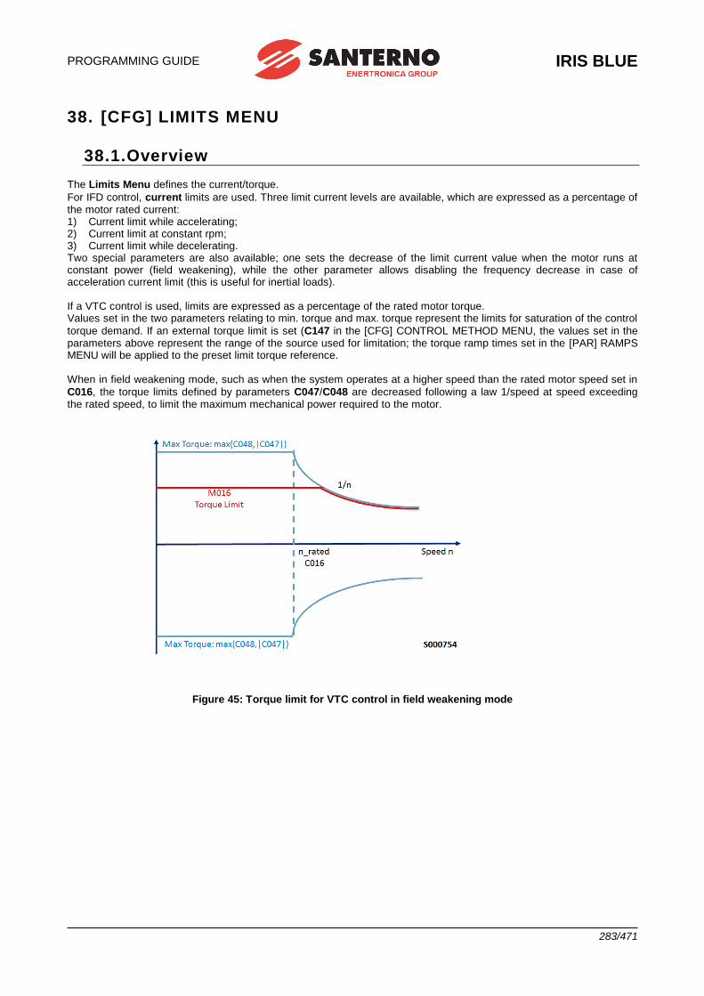
PROGRAMMING GUIDE
IRIS BLUE
283/471
38. [CFG] LIMITS MENU
38.1.Overview
The Limits Menu defines the current/torque.
For IFD control, current limits are used. Three limit current levels are available, which are expressed as a percentage of the motor rated current: 1) Current limit while accelerating; 2) Current limit at constant rpm; 3) Current limit while decelerating. Two special parameters are also available; one sets the decrease of the limit current value when the motor runs at constant power (field weakening), while the other parameter allows disabling the frequency decrease in case of acceleration current limit (this is useful for inertial loads). If a VTC control is used, limits are expressed as a percentage of the rated motor torque. Values set in the two parameters relating to min. torque and max. torque represent the limits for saturation of the control
torque demand. If an external torque limit is set (C147 in the [CFG] CONTROL METHOD MENU, the values set in the parameters above represent the range of the source used for limitation; the torque ramp times set in the [PAR] RAMPS MENU will be applied to the preset limit torque reference. When in field weakening mode, such as when the system operates at a higher speed than the rated motor speed set in
C016, the torque limits defined by parameters C047/C048 are decreased following a law 1/speed at speed exceeding the rated speed, to limit the maximum mechanical power required to the motor.
Figure 45: Torque limit for VTC control in field weakening mode
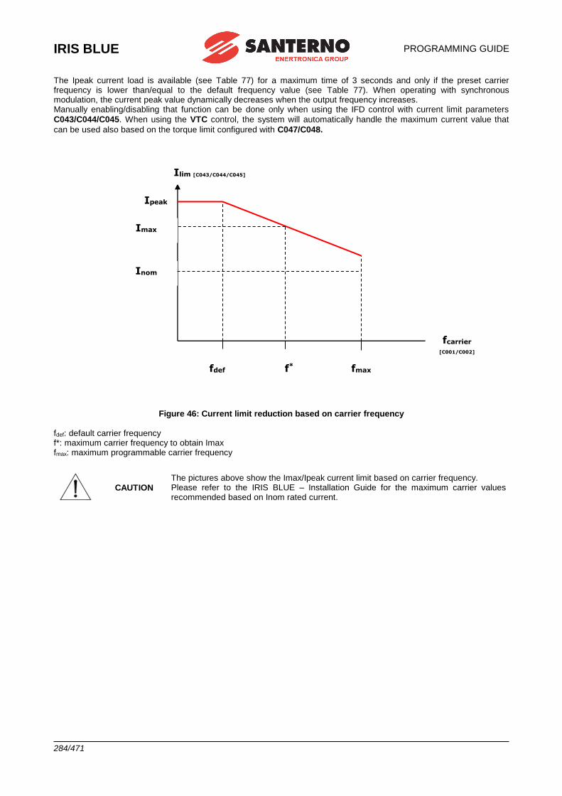
IRIS BLUE
PROGRAMMING GUIDE
284/471
The Ipeak current load is available (see Table 77) for a maximum time of 3 seconds and only if the preset carrier frequency is lower than/equal to the default frequency value (see Table 77). When operating with synchronous modulation, the current peak value dynamically decreases when the output frequency increases. Manually enabling/disabling that function can be done only when using the IFD control with current limit parameters
C043/C044/C045. When using the VTC control, the system will automatically handle the maximum current value that
can be used also based on the torque limit configured with C047/C048.
Figure 46: Current limit reduction based on carrier frequency fdef: default carrier frequency f*: maximum carrier frequency to obtain Imax fmax: maximum programmable carrier frequency
CAUTION The pictures above show the Imax/Ipeak current limit based on carrier frequency. Please refer to the IRIS BLUE – Installation Guide for the maximum carrier values recommended based on Inom rated current.
fdef f* fmax
Ipeak
Imax
Inom
Ilim [C043/C044/C045]
fcarrier
[C001/C002]
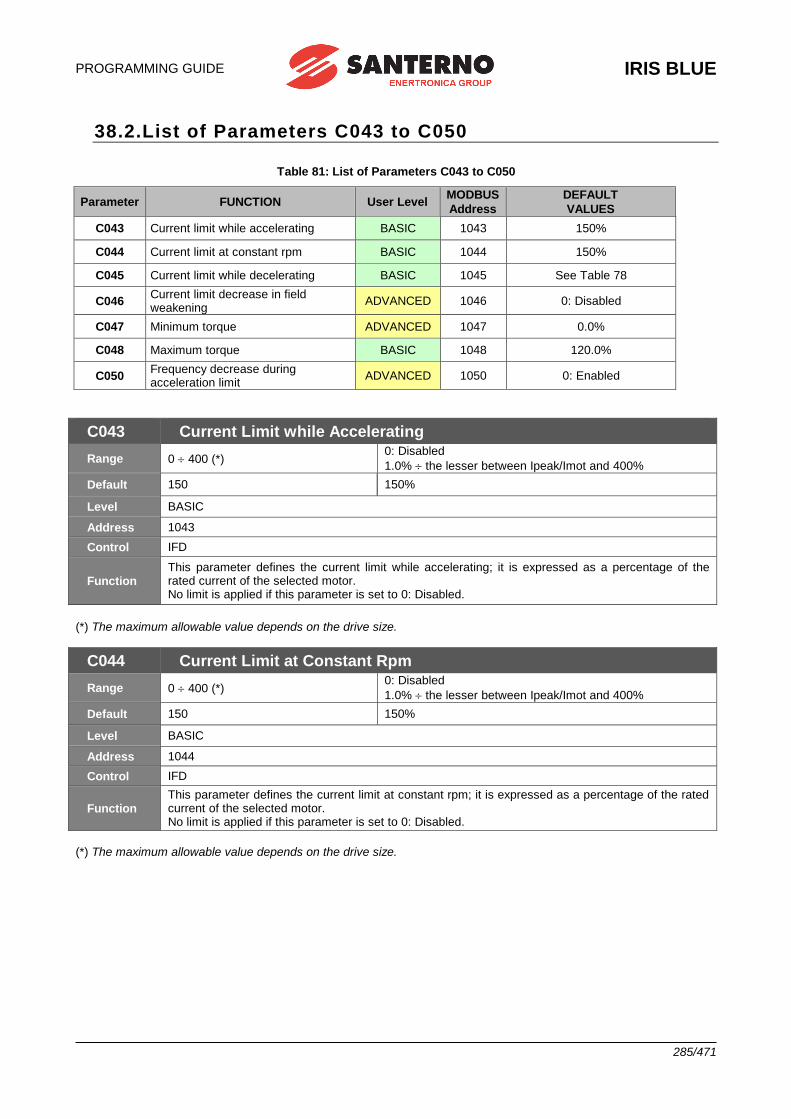
PROGRAMMING GUIDE
IRIS BLUE
285/471
38.2.List of Parameters C043 to C050
Table 81: List of Parameters C043 to C050
Parameter FUNCTION User Level MODBUS
Address
DEFAULT
VALUES
C043 Current limit while accelerating BASIC 1043 150%
C044 Current limit at constant rpm BASIC 1044 150%
C045 Current limit while decelerating BASIC 1045 See Table 78
C046 Current limit decrease in field weakening
ADVANCED 1046 0: Disabled
C047 Minimum torque ADVANCED 1047 0.0%
C048 Maximum torque BASIC 1048 120.0%
C050 Frequency decrease during acceleration limit
ADVANCED 1050 0: Enabled
C043 Current Limit while Accelerating
Range 0 400 (*) 0: Disabled
1.0% the lesser between Ipeak/Imot and 400%
Default 150 150%
Level BASIC
Address 1043
Control IFD
Function This parameter defines the current limit while accelerating; it is expressed as a percentage of the rated current of the selected motor. No limit is applied if this parameter is set to 0: Disabled.
(*) The maximum allowable value depends on the drive size.
C044 Current Limit at Constant Rpm
Range 0 400 (*) 0: Disabled
1.0% the lesser between Ipeak/Imot and 400%
Default 150 150%
Level BASIC
Address 1044
Control IFD
Function This parameter defines the current limit at constant rpm; it is expressed as a percentage of the rated current of the selected motor. No limit is applied if this parameter is set to 0: Disabled.
(*) The maximum allowable value depends on the drive size.
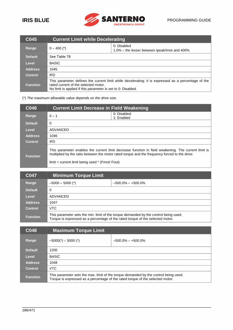
IRIS BLUE
PROGRAMMING GUIDE
286/471
C045 Current Limit while Decelerating
Range 0 400 (*) 0: Disabled
1.0% the lesser between Ipeak/Imot and 400%
Default See Table 78
Level BASIC
Address 1045
Control IFD
Function This parameter defines the current limit while decelerating; it is expressed as a percentage of the rated current of the selected motor. No limit is applied if this parameter is set to 0: Disabled.
(*) The maximum allowable value depends on the drive size.
C046 Current Limit Decrease in Field Weakening
Range 0 1 0: Disabled 1: Enabled
Default 0
Level ADVANCED
Address 1046
Control IFD
Function
This parameter enables the current limit decrease function in field weakening. The current limit is multiplied by the ratio between the motor rated torque and the frequency forced to the drive: limit = current limit being used * (Fmot/ Fout)
C047 Minimum Torque Limit
Range –5000 5000 (*) –500.0% +500.0%
Default 0
Level ADVANCED
Address 1047
Control VTC
Function This parameter sets the min. limit of the torque demanded by the control being used. Torque is expressed as a percentage of the rated torque of the selected motor.
C048 Maximum Torque Limit
Range –5000(*) 5000 (*)
–500.0% +500.0%
Default 1200
Level BASIC
Address 1048
Control VTC
Function This parameter sets the max. limit of the torque demanded by the control being used. Torque is expressed as a percentage of the rated torque of the selected motor.
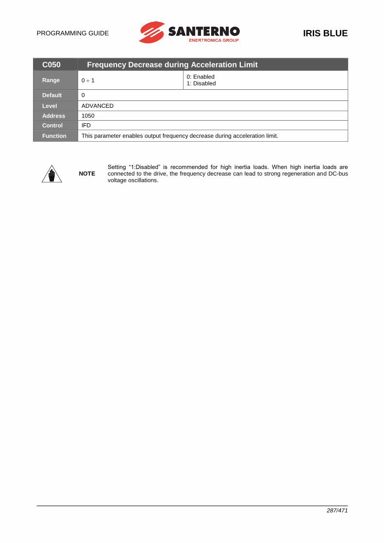
PROGRAMMING GUIDE
IRIS BLUE
287/471
C050 Frequency Decrease during Acceleration Limit
Range 0 1 0: Enabled 1: Disabled
Default 0
Level ADVANCED
Address 1050
Control IFD
Function This parameter enables output frequency decrease during acceleration limit.
NOTE Setting “1:Disabled” is recommended for high inertia loads. When high inertia loads are connected to the drive, the frequency decrease can lead to strong regeneration and DC-bus voltage oscillations.
IRIS BLUE
PROGRAMMING GUIDE
288/471
39. [CFG] CONTROL METHOD MENU
39.1.Overview
NOTE Please refer to IRIS BLUE – Installation Guide or the hardware description of digital inputs (COMMANDS) and analog inputs (REFERENCES). See also the [PAR] INPUTS FOR REFERENCES MENU and [CFG] DIGITAL INPUTS MENU.
The drive is factory set to receive digital commands via the terminal board; the main speed reference is sent from the REF analog input, and no external limit for torque limitation is enabled. The parameters in this menu allow selecting the following:
• The source of the drive commands (digital inputs) from three signal sources (through parameters C140, C141,
C142) which are logically matched so as to obtain an active M031 command set. For each of these 3 parameters
you can select the source of the command signals from 4 different sources;
• The source of the speed reference (or torque reference) from 4 different sources (that can be selected with
parameters C143, C144, C145, C146) that can be summed up together.
For each of these 4 parameters, you can select the source of the reference signals from 9 different sources;
• The source of the torque limit reference (through parameter C147, allowing selecting the reference source from 9
different sources).
Therefore, you can select and enable different command sources (hardware or virtual sources), different speed (or
torque) references (hardware or virtual sources) and enable an external torque limit.
The drive commands may be sent from:
• The hardware terminal board (terminal board on the control board), which is logically separated into terminal board A and terminal board B;
• The keypad;
• The virtual remote terminal board: through serial link with MODBUS communications protocol;
• The virtual remote terminal board: through Fieldbus (optional board).
Multiple terminal boards may also be enabled (up to 3 terminal boards with parameters C140, C141, C142); in this case,
the drive will apply logic functions OR or AND to the different terminals to obtain the activated terminal board (see Command Sources).
The following references and torque limit signals may be sent:
• Three analog inputs acquired to the hardware terminal board (REF, AIN1, AIN2), plus two analog inputs (XAIN4, XAIN5) acquired to the hardware terminal board located on ES847 optional board;
• Keypad;
• Serial link with MODBUS communications protocol;
• Fieldbus (optional board);
• Up/Down from MDI (Up and Down digital inputs).
Multiple reference sources may be enabled at the same time (up to 4 reference sources with parameters C143, C144,
C145, C146); in this case, the drive will consider the sum of all active reference as the main reference. Finally, a dynamic selection between two command sources and two reference sources is allowed when using the
digital input configured as Source Selection (see C179) or, alternatively, of the inputs configured as Commands
Selection and Reference Selection (C179a and C179b).
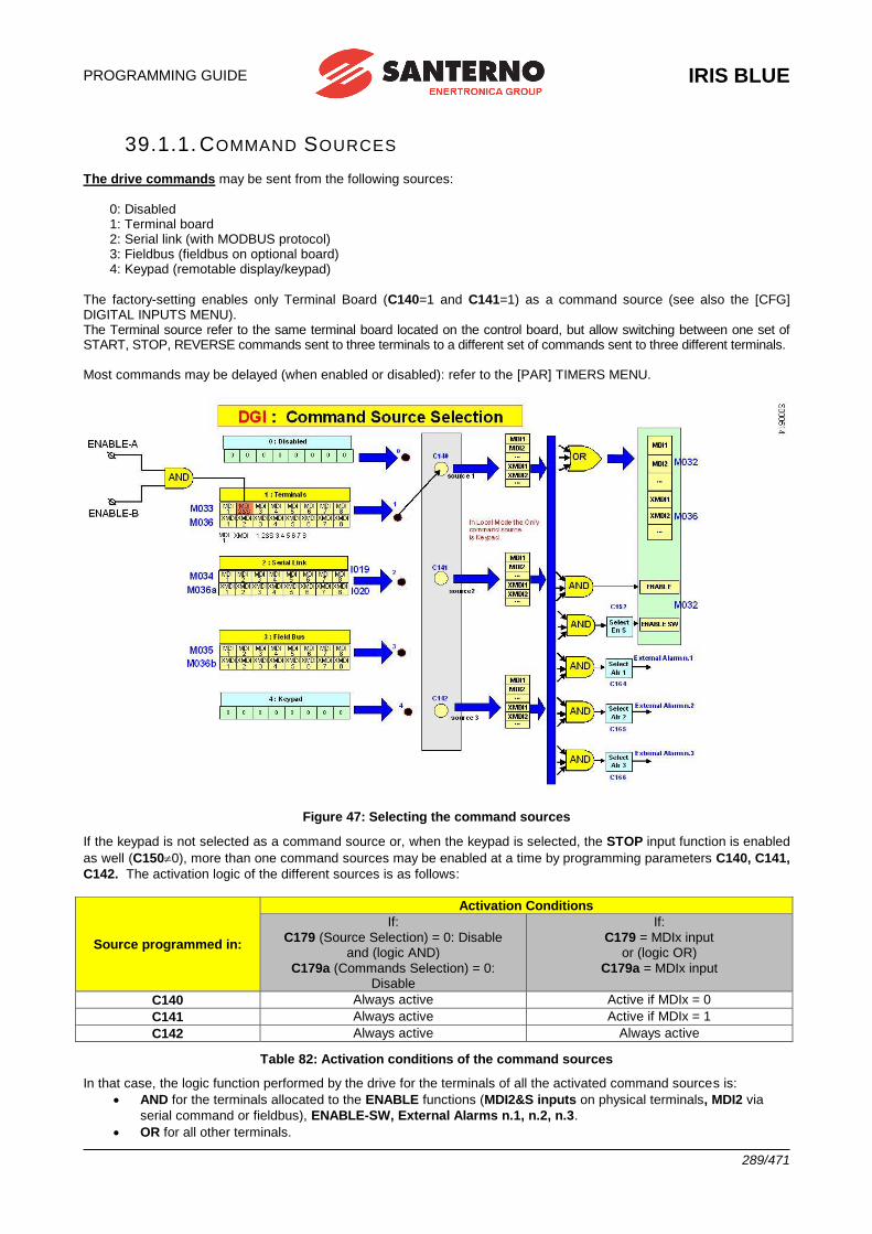
PROGRAMMING GUIDE
IRIS BLUE
289/471
39.1.1. COMMAND SOURCES
The drive commands may be sent from the following sources:
0: Disabled 1: Terminal board 2: Serial link (with MODBUS protocol) 3: Fieldbus (fieldbus on optional board) 4: Keypad (remotable display/keypad)
The factory-setting enables only Terminal Board (C140=1 and C141=1) as a command source (see also the [CFG] DIGITAL INPUTS MENU). The Terminal source refer to the same terminal board located on the control board, but allow switching between one set of START, STOP, REVERSE commands sent to three terminals to a different set of commands sent to three different terminals. Most commands may be delayed (when enabled or disabled): refer to the [PAR] TIMERS MENU.
Figure 47: Selecting the command sources
If the keypad is not selected as a command source or, when the keypad is selected, the STOP input function is enabled
as well (C1500), more than one command sources may be enabled at a time by programming parameters C140, C141,
C142. The activation logic of the different sources is as follows:
Source programmed in:
Activation Conditions
If:
C179 (Source Selection) = 0: Disable and (logic AND)
C179a (Commands Selection) = 0: Disable
If:
C179 = MDIx input or (logic OR)
C179a = MDIx input
C140 Always active Active if MDIx = 0
C141 Always active Active if MDIx = 1
C142 Always active Always active
Table 82: Activation conditions of the command sources
In that case, the logic function performed by the drive for the terminals of all the activated command sources is:
• AND for the terminals allocated to the ENABLE functions (MDI2&S inputs on physical terminals, MDI2 via
serial command or fieldbus), ENABLE-SW, External Alarms n.1, n.2, n.3.
• OR for all other terminals.
IRIS BLUE
PROGRAMMING GUIDE
290/471
NOTE
If the keypad is enabled as a command source, the START, STOP, RESET, LOC/REM
functions are enabled (to disable LOC/REM see parameter P269). The keypad is ignored for the processing of logic functions (AND/OR) of the other command sources that are enabled at that moment.
NOTE
As the ENABLE-A and ENABLE-B commands of the physical terminal board are a hardware safety device (they enable the drive) they are always active, even when none of
parameters C140, C141 or C142 selects the terminal board (=1). If the STO function is to be adopted, the control mode and the control circuit of these signals
must be accomplished as per the Safe Torque Off Function – Application Manual. That manual also includes a detailed validation procedure of the control configuration of the STO function to be executed upon first start-up and also periodically at yearly intervals.
NOTE The commands for the External Alarm n.1, n.2, n.3 functions are always considered for the
drive terminal board only.
NOTE
The LOCAL mode, that can be enabled with the LOC/REM key from the keypad or with the
LOCAL command function from the terminal board (see C180), forces the keypad as the only
command source, thus ignoring the values set in parameters C140, C141, C142.
The following functions are however enabled for the hardware terminal board: External
Alarm n.,1 n.2, n.3 (C164, C165, C166), Motor Sel. n.2 (C173), Motor Sel. n.3 (C174),
SLAVE (C170), Source Selection (C179, C179a, C179b), LOCAL (C180) and the ENABLE-
A and ENABLE-B and RESET functions are always enabled for terminals MDI2, S and MDI3.
The ENABLE-SW and DISABLE functions are enabled in LOCAL mode if at least one of
parameters C140, C141, C142 is set to 1 (terminal board).
NOTE
If C179 (Source Selection) and C179a (Command Selection) are deactivated, it is not
possible to program 4: Keypad source and a different source in C140 and C141. This
will avoid conflicts in controlling the Start and Stop signals based on the logic level (1:
Terminal Board and other sources) or rising edge signals (4: Keypad).
The only exception occurs if C150-MDI for the Stop function is set up. In that case, the
conflict is resolved because rising edge signal management is active from 1: Terminal
Board as well.
NOTE
If C140 or C141 are programmed to 1: Terminal Board, it is not possible to set 4: Keypad as a
source for C142 regardless of the programming in C179/C179a. This is because C142 is always considered in OR and, again, conflicts would arise for the logic level or rising edge
signals. Also in this case, if C150 is programmed, C142 may be set to 4: Keypad.
Table 83: Remote Command inputs from serial link
MODBUS
Address Input User Level Description Range
1406 I019 BASIC Remote, virtual terminal board from serial link
Bit input: 01 for 8 bits corresponding
to MDI1 MDI8
1407 I020 BASIC Auxiliary, virtual terminal board from serial link
Bit input: 01 for 8 bits corresponding
to XMDI1 XMDI8
Example:
If C140 = 3 (Fieldbus) and C141 = 2 (Serial link), the ENABLE command is sent by closing terminals ENABLE-A and
ENABLE-B on the terminal board and (AND) by forcing bit MDI2 from the serial link on input I019 (MODBUS address:
1406) and bit MDI2 from Fieldbus (see the [CFG] FIELDBUS CONFIGURATION MENU).
The START command may also be sent (OR) by forcing bit MDI1 from serial link on input I019 or by forcing bit MDI1 from Fieldbus for the relevant variable.
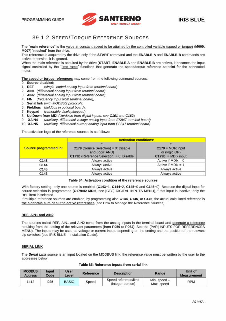
PROGRAMMING GUIDE
IRIS BLUE
291/471
39.1.2. SPEED/TORQUE REFERENCE SOURCES
The “main reference” is the value at constant speed to be attained by the controlled variable (speed or torque) (M000,
M007) “required” from the drive.
This reference is acquired by the drive only if the START command and the ENABLE-A and ENABLE-B commands are active; otherwise, it is ignored.
When the main reference is acquired by the drive (START, ENABLE-A and ENABLE-B are active), it becomes the input signal controlled by the “time ramp” functions that generate the speed/torque reference setpoint for the connected motor.
The speed or torque references may come from the following command sources:
0. Source disabled;
1. REF (single–ended analog input from terminal board);
2. AIN1 (differential analog input from terminal board);
3. AIN2 (differential analog input from terminal board);
4. FIN (frequency input from terminal board);
5. Serial link (with MODBUS protocol);
6. Fieldbus (fieldbus in optional board);
7. Keypad (remotable display/keypad);
8. Up Down from MDI (Up/down from digital inputs, see C161 and C162)
9. XAIN4 (auxiliary, differential voltage analog input from ES847 terminal board)
10. XAIN5 (auxiliary, differential current analog input from ES847 terminal board) The activation logic of the reference sources is as follows:
Source programmed in:
Activation conditions:
If:
C179 (Source Selection) = 0: Disable and (logic AND)
C179b (Reference Selection) = 0: Disable
If:
C179 = MDIx input or (logic OR)
C179b = MDIx input
C143 Always active Active if MDIx = 0
C144 Always active Active if MDIx = 1
C145 Always active Always active
C146 Always active Always active
Table 84: Activation condition of the reference sources
With factory-setting, only one source is enabled (C143=1, C144=2, C145=0 and C146=0). Because the digital input for
source selection is programmed (C179=6: MDI6, see [CFG] DIGITAL INPUTS MENU), f this input is inactive, only the REF item is selected.
If multiple reference sources are enabled, by programming also C144, C145, or C146, the actual calculated reference is
the algebraic sum of all the active references (see How to Manage the Reference Sources).
REF, AIN1 and AIN2
The sources called REF, AIN1 and AIN2 come from the analog inputs in the terminal board and generate a reference
resulting from the setting of the relevant parameters (from P050 to P064). See the [PAR] INPUTS FOR REFERENCES MENU). The inputs may be used as voltage or current inputs depending on the setting and the position of the relevant dip-switches (see IRIS BLUE – Installation Guide).
SERIAL LINK
The Serial Link source is an input located on the MODBUS link: the reference value must be written by the user to the addresses below:
Table 85: Reference Inputs from serial link
MODBUS
Address
Input
Code
User
Level Reference Description Range
Unit of
Measurement
1412 I025 BASIC Speed Speed reference/limit
(integer portion) Min. speed Max. speed
RPM
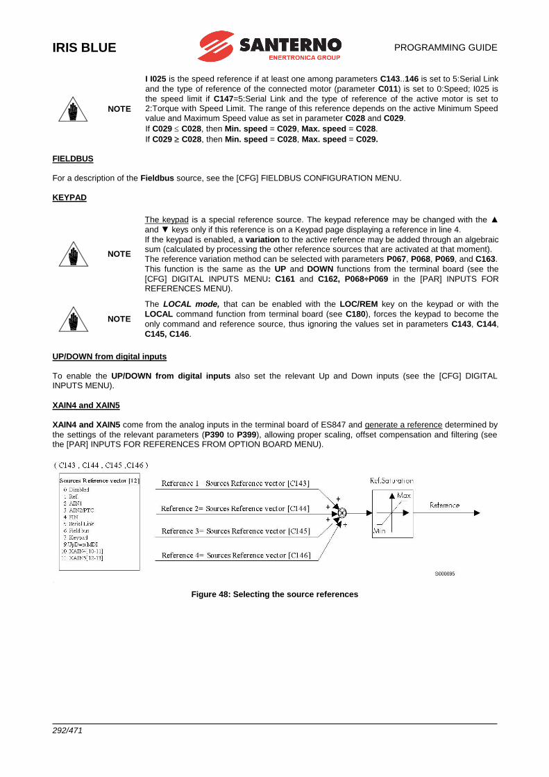
IRIS BLUE
PROGRAMMING GUIDE
292/471
NOTE
I I025 is the speed reference if at least one among parameters C143..146 is set to 5:Serial Link
and the type of reference of the connected motor (parameter C011) is set to 0:Speed; I025 is
the speed limit if C147=5:Serial Link and the type of reference of the active motor is set to 2:Torque with Speed Limit. The range of this reference depends on the active Minimum Speed
value and Maximum Speed value as set in parameter C028 and C029.
If C029 C028, then Min. speed = C029, Max. speed = C028.
If C029 C028, then Min. speed = C028, Max. speed = C029.
FIELDBUS
For a description of the Fieldbus source, see the [CFG] FIELDBUS CONFIGURATION MENU.
KEYPAD
NOTE
The keypad is a special reference source. The keypad reference may be changed with the ▲
and ▼ keys only if this reference is on a Keypad page displaying a reference in line 4.
If the keypad is enabled, a variation to the active reference may be added through an algebraic sum (calculated by processing the other reference sources that are activated at that moment).
The reference variation method can be selected with parameters P067, P068, P069, and C163.
This function is the same as the UP and DOWN functions from the terminal board (see the
[CFG] DIGITAL INPUTS MENU: C161 and C162, P068÷P069 in the [PAR] INPUTS FOR REFERENCES MENU).
NOTE
The LOCAL mode, that can be enabled with the LOC/REM key on the keypad or with the
LOCAL command function from terminal board (see C180), forces the keypad to become the
only command and reference source, thus ignoring the values set in parameters C143, C144,
C145, C146.
UP/DOWN from digital inputs
To enable the UP/DOWN from digital inputs also set the relevant Up and Down inputs (see the [CFG] DIGITAL INPUTS MENU).
XAIN4 and XAIN5
XAIN4 and XAIN5 come from the analog inputs in the terminal board of ES847 and generate a reference determined by
the settings of the relevant parameters (P390 to P399), allowing proper scaling, offset compensation and filtering (see the [PAR] INPUTS FOR REFERENCES FROM OPTION BOARD MENU).
Figure 48: Selecting the source references
PROGRAMMING GUIDE
IRIS BLUE
293/471
39.1.3. ALTERNATIVE COMMAND AND REFERENCE SOURCES A digital input can be set as a selector between 2 alternative command and reference sources. Example:
C179 MDI to select sources = MDI6
C140 to select command source number 1 = Keypad
C141 to select command source number 2 = Fieldbus
C143 to select reference source number 1 = AIN1
C144 to select reference source number 2 = Fieldbus
If MD16 (in the drive terminal board) set as a selector is open, the drive will consider number 1 as reference and
command sources (that is C140 = Keypad and C143 = AIN1); if it is closed, number 2 will be considered (C141 =
Fieldbus and C144 = Fieldbus). See also How to Manage the Reference Sources.
If reference sources 3 and 4 (C145 and C146) are not set to Disable, the reference sent for these sources shall be a sum of the source selected by MD16 vector.
Please refer to C179 in the [CFG] DIGITAL INPUTS MENU.
39.1.4. REMOTE/LOCAL
According to factory-setting, switching over from the Remote mode to the Local mode can only be made when the drive
is disabled. The reference and command sources for the Remote mode depend on the settings of parameters C140 to
C146 in the [CFG] CONTROL METHOD MENU and C285÷C287 in the [CFG] PID CONFIGURATION MENU. When switching over from the Remote mode to the Local mode, the command and reference can be sent via keypad only.
This is true for the switch over from the Local to the Remote mode as well.
Parameter C148 allows customizing the Loc/Rem function so that it can be performed even when the drive is running.
Parameter C148 also allows setting whether the same running condition and the same reference must be maintained when switching over from the Remote to the Local mode.
NOTE For more details on the Loc/Rem function, see LOC/REM Key (Keypad Pages) and the [CFG] DIGITAL INPUTS MENU.
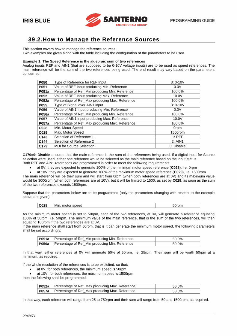
IRIS BLUE
PROGRAMMING GUIDE
294/471
39.2.How to Manage the Reference Sources This section covers how to manage the reference sources. Two examples are given along with the table including the configuration of the parameters to be used.
Example 1: The Speed Reference is the algebraic sum of two references Analog inputs REF and AIN1 (that are supposed to be 0-10V voltage inputs) are to be used as speed references. The main reference will be the sum of the two references being used. The end result may vary based on the parameters concerned.
P050 Type of Reference for REF Input 3: 0-10V
P051 Value of REF Input producing Min. Reference 0.0V
P051a Percentage of Ref_Min producing Min. Reference 100.0%
P052 Value of REF Input producing Max. Reference 10.0V
P052a Percentage of Ref_Max producing Max. Reference 100.0%
P055 Type of Signal over AIN1 input 3: 0-10V
P056 Value of AIN1 Input producing Min. Reference 0.0V
P056a Percentage of Ref_Min producing Min. Reference 100.0%
P057 Value of AIN1 input producing Max. Reference 10.0V
P057a Percentage of Ref_Max producing Max. Reference 100.0%
C028 Min. Motor Speed 0rpm
C029 Max. Motor Speed 1500rpm
C143 Selection of Reference 1 1: REF
C144 Selection of Reference 2 2: AIN1
C179 MDI for Source Selection 0: Disable
C179=0: Disable ensures that the main reference is the sum of the references being used. If a digital input for Source selection were used, either one reference would be selected as the main reference based on the input status. Both REF and AIN1 references are programmed in order to meet the following requirements:
• at 0V, they are expected to generate 100% of the minimum motor speed reference (C028), i.e. 0rpm
• at 10V, they are expected to generate 100% of the maximum motor speed reference (C029), i.e. 1500rpm The main reference will be their sum and will start from 0rpm (when both references are at 0V) and its maximum value
would be 3000rpm (when both references are at 10V), but it will be limited to 1500, as set by C029, as soon as the sum of the two references exceeds 1500rpm. Suppose that the parameters below are to be programmed (only the parameters changing with respect to the example above are given):
C028 Min. motor speed 50rpm
As the minimum motor speed is set to 50rpm, each of the two references, at 0V, will generate a reference equating 100% of 50rpm, i.e. 50rpm. The minimum value of the main reference, that is the sum of the two references, will then equating 100rpm if the two references are at 0V. If the main reference shall start from 50rpm, that is it can generate the minimum motor speed, the following parameters shall be set accordingly:
P051a Percentage of Ref_Min producing Min. Reference 50.0%
P056a Percentage of Ref_Min producing Min. Reference 50.0%
In that way, either references at 0V will generate 50% of 50rpm, i.e. 25rpm. Their sum will be worth 50rpm at a minimum, as required. If the whole resolution of the references is to be exploited, so that:
• at 0V, for both references, the minimum speed is 50rpm
• at 10V, for both references, the maximum speed is 1500rpm then the following shall be programmed:
P052a Percentage of Ref_Max producing Max. Reference 50.0%
P057a Percentage of Ref_Max producing Max. Reference 50.0%
In that way, each reference will range from 25 to 750rpm and their sum will range from 50 and 1500rpm, as required.
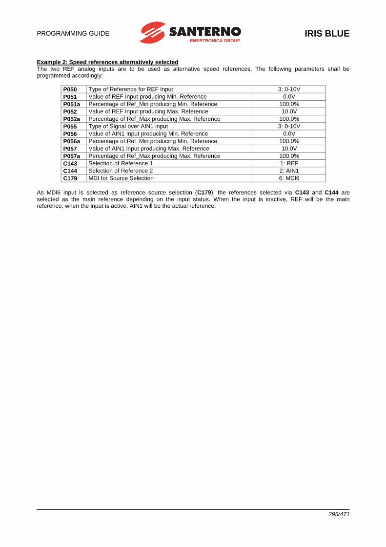
PROGRAMMING GUIDE
IRIS BLUE
295/471
Example 2: Speed references alternatively selected The two REF analog inputs are to be used as alternative speed references. The following parameters shall be programmed accordingly:
P050 Type of Reference for REF Input 3: 0-10V
P051 Value of REF Input producing Min. Reference 0.0V
P051a Percentage of Ref_Min producing Min. Reference 100.0%
P052 Value of REF Input producing Max. Reference 10.0V
P052a Percentage of Ref_Max producing Max. Reference 100.0%
P055 Type of Signal over AIN1 input 3: 0-10V
P056 Value of AIN1 Input producing Min. Reference 0.0V
P056a Percentage of Ref_Min producing Min. Reference 100.0%
P057 Value of AIN1 input producing Max. Reference 10.0V
P057a Percentage of Ref_Max producing Max. Reference 100.0%
C143 Selection of Reference 1 1: REF
C144 Selection of Reference 2 2: AIN1
C179 MDI for Source Selection 6: MDI6
As MDI6 input is selected as reference source selection (C179), the references selected via C143 and C144 are selected as the main reference depending on the input status. When the input is inactive, REF will be the main reference; when the input is active, AIN1 will be the actual reference.
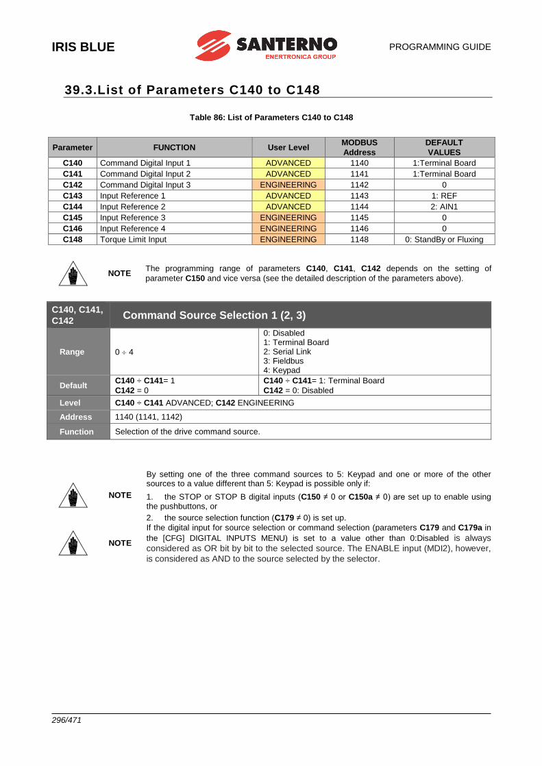
IRIS BLUE
PROGRAMMING GUIDE
296/471
39.3.List of Parameters C140 to C148
Table 86: List of Parameters C140 to C148
Parameter FUNCTION User Level MODBUS
Address
DEFAULT
VALUES
C140 Command Digital Input 1 ADVANCED 1140 1:Terminal Board
C141 Command Digital Input 2 ADVANCED 1141 1:Terminal Board
C142 Command Digital Input 3 ENGINEERING 1142 0
C143 Input Reference 1 ADVANCED 1143 1: REF
C144 Input Reference 2 ADVANCED 1144 2: AIN1
C145 Input Reference 3 ENGINEERING 1145 0
C146 Input Reference 4 ENGINEERING 1146 0
C148 Torque Limit Input ENGINEERING 1148 0: StandBy or Fluxing
NOTE The programming range of parameters C140, C141, C142 depends on the setting of
parameter C150 and vice versa (see the detailed description of the parameters above).
C140, C141,
C142 Command Source Selection 1 (2, 3)
Range 0 4
0: Disabled 1: Terminal Board 2: Serial Link 3: Fieldbus 4: Keypad
Default C140 ÷ C141= 1
C142 = 0
C140 ÷ C141= 1: Terminal Board
C142 = 0: Disabled
Level C140 ÷ C141 ADVANCED; C142 ENGINEERING
Address 1140 (1141, 1142)
Function Selection of the drive command source.
NOTE
By setting one of the three command sources to 5: Keypad and one or more of the other sources to a value different than 5: Keypad is possible only if:
1. the STOP or STOP B digital inputs (C150 ≠ 0 or C150a ≠ 0) are set up to enable using the pushbuttons, or
2. the source selection function (C179 ≠ 0) is set up.
NOTE
If the digital input for source selection or command selection (parameters C179 and C179a in
the [CFG] DIGITAL INPUTS MENU) is set to a value other than 0:Disabled is always
considered as OR bit by bit to the selected source. The ENABLE input (MDI2), however,
is considered as AND to the source selected by the selector.
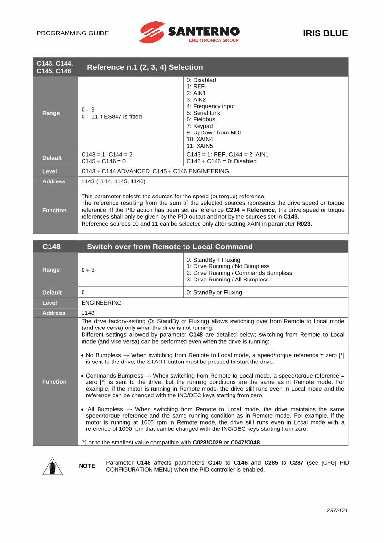
PROGRAMMING GUIDE
IRIS BLUE
297/471
C143, C144,
C145, C146 Reference n.1 (2, 3, 4) Selection
Range 0 9
0 11 if ES847 is fitted
0: Disabled 1: REF 2: AIN1 3: AIN2 4: Frequency input 5: Serial Link 6: Fieldbus 7: Keypad 9: UpDown from MDI 10: XAIN4 11: XAIN5
Default C143 = 1, C144 = 2 C145 ÷ C146 = 0
C143 = 1: REF, C144 = 2: AIN1 C145 ÷ C146 = 0: Disabled
Level C143 ÷ C144 ADVANCED; C145 ÷ C146 ENGINEERING
Address 1143 (1144, 1145, 1146)
Function
This parameter selects the sources for the speed (or torque) reference. The reference resulting from the sum of the selected sources represents the drive speed or torque
reference. If the PID action has been set as reference C294 = Reference, the drive speed or torque
references shall only be given by the PID output and not by the sources set in C143.
Reference sources 10 and 11 can be selected only after setting XAIN in parameter R023.
C148 Switch over from Remote to Local Command
Range 0 3
0: StandBy + Fluxing 1: Drive Running / No Bumpless 2: Drive Running / Commands Bumpless 3: Drive Running / All Bumpless
Default 0 0: StandBy or Fluxing
Level ENGINEERING
Address 1148
Function
The drive factory-setting (0: StandBy or Fluxing) allows switching over from Remote to Local mode (and vice versa) only when the drive is not running.
Different settings allowed by parameter C148 are detailed below; switching from Remote to Local mode (and vice versa) can be performed even when the drive is running:
• No Bumpless → When switching from Remote to Local mode, a speed/torque reference = zero [*] is sent to the drive; the START button must be pressed to start the drive.
• Commands Bumpless → When switching from Remote to Local mode, a speed/torque reference = zero [*] is sent to the drive, but the running conditions are the same as in Remote mode. For example, if the motor is running in Remote mode, the drive still runs even in Local mode and the reference can be changed with the INC/DEC keys starting from zero.
• All Bumpless → When switching from Remote to Local mode, the drive maintains the same speed/torque reference and the same running condition as in Remote mode. For example, if the motor is running at 1000 rpm in Remote mode, the drive still runs even in Local mode with a reference of 1000 rpm that can be changed with the INC/DEC keys starting from zero.
[*] or to the smallest value compatible with C028/C029 or C047/C048.
NOTE Parameter C148 affects parameters C140 to C146 and C285 to C287 (see [CFG] PID CONFIGURATION MENU) when the PID controller is enabled.
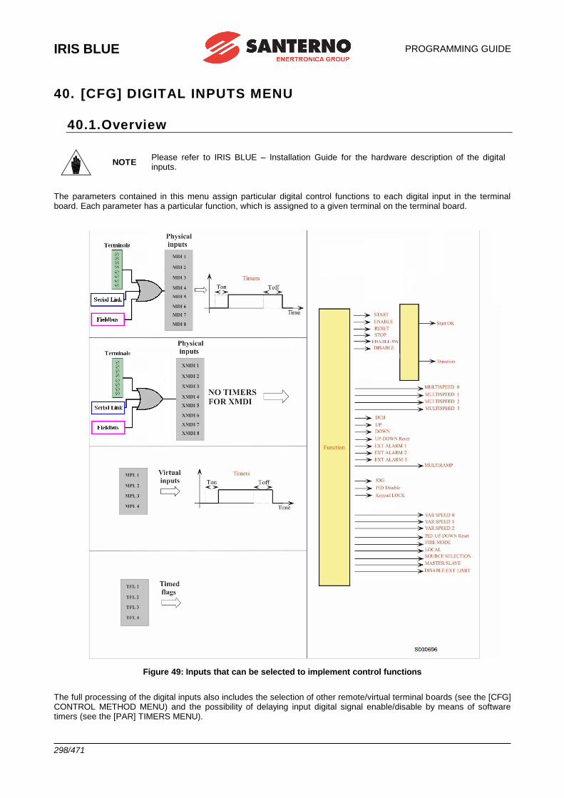
IRIS BLUE
PROGRAMMING GUIDE
298/471
40. [CFG] DIGITAL INPUTS MENU
40.1.Overview
NOTE Please refer to IRIS BLUE – Installation Guide for the hardware description of the digital inputs.
The parameters contained in this menu assign particular digital control functions to each digital input in the terminal board. Each parameter has a particular function, which is assigned to a given terminal on the terminal board.
Figure 49: Inputs that can be selected to implement control functions
The full processing of the digital inputs also includes the selection of other remote/virtual terminal boards (see the [CFG] CONTROL METHOD MENU) and the possibility of delaying input digital signal enable/disable by means of software timers (see the [PAR] TIMERS MENU).
PROGRAMMING GUIDE
IRIS BLUE
299/471
The digital input status is displayed in measurements M031, M032, M033, M034, M035.
Measurement M033 shows the current status of the 8 inputs in the local hardware terminals in the drive board.
The input called MDI2&S (“S” on the display keypad) is active only if both physical inputs ENABLE-A and
ENABLE-B are active.
The symbol displays the logic levels for terminals M033 for inactive inputs; the active inputs are marked with .
Measurements M034 and M035 show the status of the terminal boards that can be activated via serial link and fieldbus respectively.
Measurement M032 shows the current status of the virtual terminal board obtained by processing all active terminal boards. It includes 10 signals, with two additional signals with respect to the local hardware terminal board:
• Inputs MDI1 to MDI8 are obtained with the logic OR of the input signals for all active terminals;
• The ENABLE function is obtained with the logic AND of the input signals for terminal MDI2&S (physical
terminal board) and terminals MDI2 (serial link and fieldbus) in all active terminal boards, unless parameter C154a is inactive;
• The ENABLE–SW function is obtained with the logic AND of the terminals selected for this function in all active terminal boards.
Measurement M031 is similar to M032, but it displays the status of the terminal board obtained after delaying the input signals of M032 using special timers. The drive uses this terminal board to acquire digital commands. Some functions cannot be programmed, but they are assigned to special terminals:
Table 87: Unprogrammable functions
Function Terminal
ENABLE MDI2
RESET MDI3 (can be disabled if C154 = Yes)
IRIS BLUE
PROGRAMMING GUIDE
300/471
40.1.1. START
The START function may be assigned to a digital input (MDI1..8); to an auxiliary digital input (XMDI1..8); to a virtual
auxiliary digital output (MPL1..4) or to a timed flag (TFL1..4). The input programming is set via parameter C149.
To enable the Start input, set the control modes via terminal board (factory setting). The START command can also be sent from the display/keypad. The programmed input Enable/Disable can be delayed via special timers.
The START input function is assigned to MDI1 terminal by default, but it can be assigned to other terminals as well. The
same terminal programmed as START may be allocated to different functions as well.
The motor stop mode (C185) can be programmed. When removing the START command, the following motor stop modes can activate:
the motor stops following a deceleration ramp or starts idling; the motor is fluxed (VTC) only when the START command
is shut down and the ENABLE is not active (C184).
When START is active (and when the ENABLE function is active as well), the RUN command is enabled: the speed (or
torque) setpoint increases proportionally to the preset ramp until it reaches the active reference. (IFD control: in order to enable the RUN command, the main speed reference must be other than zero).
When START is inactive (also when the ENABLE is active), the RUN command is disabled: the reference is set to zero and the speed (or torque) setpoint decreases down to zero depending on the preset deceleration ramp.
NOTE
The way for the START function to enable or disable the drive RUN is also dependent on the
programming of other functions, particularly the STOP and REVERSE functions (see
parameters C150, C151).
If the REVERSE function is activated (C1510) this may cause RUN disable and enable;
however, if the START and REVERSE functions are simultaneously active, the RUN is disabled. In that case, indeed, START is considered as FOWARD RUN and REVERSE as REVERSE
RUN. When they are both active the system cannot interpret the query to be FORWARD or
REVERSE.
If the STOP function is enabled (C1500), the RUN command may be enabled/disabled only
by pressing the relevant “key”: see the description of the STOP function (C150).
NOTE If only the keypad is enabled as the command source, press the START key located on the
keypad to enable the drive RUN and press the STOP key to disable the drive RUN.
NOTE If C185 = Free Wheel when removing the START command, the drive will not carry out the deceleration ramp and will be put on stand-by.
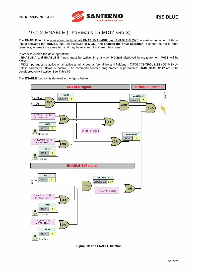
PROGRAMMING GUIDE
IRIS BLUE
301/471
40.1.2. ENABLE (TERMINALS 15:MDI2 AND S)
The ENABLE function is assigned to terminals ENABLE-A (MDI2) and ENABLE-B (S) (the series-connection of those
inputs activates the MDI2&S input as displayed in M033) and enables the drive operation. It cannot be set to other terminals, whereas the same terminal may be assigned to different functions. In order to enable the drive operation:
- ENABLE-A and ENABLE-B inputs must be active. In that way, MDI2&S displayed in measurement M033 will be active;
- MDI2 input must be active on all active terminal boards (serial link and fieldbus – [CFG] CONTROL METHOD MENU),
unless parameter C154a is inactive. The command sources programmed in parameters C140, C141, C142 are to be considered only if active. See Table 82.
The ENABLE function is detailed in the figure below:
Figure 50: The ENABLE function
IRIS BLUE
PROGRAMMING GUIDE
302/471
NOTE
If the STO function is to be adopted, the control mode and the control circuit of the ENABLE-
A and ENABLE-B signals must be accomplished as per the Safe Torque Off Function –
Application Manual. That manual also includes a detailed validation procedure of the control configuration of the STO function to be executed upon first start-up and also periodically at yearly intervals.
If the ENABLE input is disabled, the drive output voltage is always set to zero, so the connected motor starts idling (the motor idles and stops due to friction or the mechanical load). In case of pulled loads, when the motor is idling, the mechanical load could cause the motor to run at uncontrolled speed!
If the ENABLE input is disabled when the drive is controlling the motor, it is closed with a delay time depending on the
drive size. This ENABLE delay starts from the instant when the input is disabled irrespective of the enable delay (if any)
set through a software timer in MDI2.
The operating mode and the logic used by the ENABLE input to enable/disable the drive also depends on the
programming of the DISABLE and ENABLE-SW functions described below.
If the IFD control is used, the drive enabling also depends on the START input and the current value of the active
reference: if the START command is active but the reference is lower than the preset threshold, the drive operation is
disabled. To enable this operating mode with other types of control, parameters P065 and P066 must be set accordingly.
The drive may also be disabled by the PID regulator (see parameter P255).
DANGER!!!
The deactivation of the ENABLE-SW signal, the activation of the DISABLE signal, the
deactivation of MDI2 inputs from serial link or fieldbus DO NOT GUARANTEE that the Safe Torque Off – STO function is removed from the motor connected to the drive.
Safety stop conditions are guaranteed only when at least one of the two ENABLE-A and
ENABLE-B inputs are opened. For more details, consult the Safe Torque Off Function – Application Manual.
CAUTION If the MDI2 inputs are disabled for one of the active terminal boards, the drive is instantly disabled and the motor starts idling! If so, the mechanical load could cause uncontrolled acceleration/slowing down of the connected motor!
CAUTION If the physical ENABLE-A or ENABLE-B inputs are opened, the drive is disabled and the motor starts idling! If this is the case, the mechanical load can cause uncontrolled acceleration/slowing down of the connected motor.
CAUTION If a protection/alarm trips, the drive disables and the motor starts idling!
NOTE
If software timers are enabled for digital inputs, the timer for the MDI2 input delays the
signal enabling. The ENABLE signal is always instantly disabled (for the ENABLE
function, Toff in MDI2 is ignored).
NOTE The activation of the ENABLE command enables the alarms controlling the configuration consistency of certain parameters.
NOTE When the ENABLE function is active, C parameters cannot be changed (factory-
setting). If P003 Condition required for changing C parameters = Standby+Fluxing, the parameters may be changed even if the drive is enabled but the motor is not running.
NOTE When the ENABLE function is active for the VTC control, the motor is fluxed by the
drive. Motor fluxing is allowed only if the START contact is shut down and C184 = Yes.
NOTE If set accordingly, safety parameter C181 prevents the drive from starting if the ENABLE function is already active when the drive is powered on.
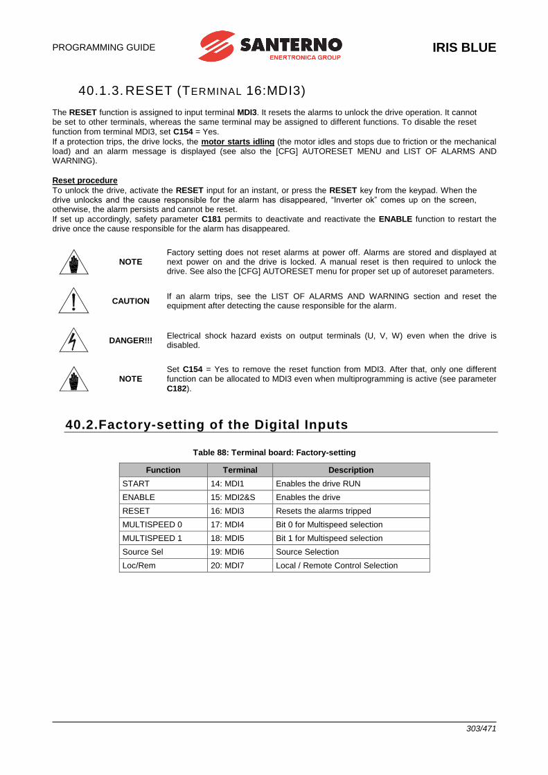
PROGRAMMING GUIDE
IRIS BLUE
303/471
40.1.3. RESET (TERMINAL 16:MDI3)
The RESET function is assigned to input terminal MDI3. It resets the alarms to unlock the drive operation. It cannot be set to other terminals, whereas the same terminal may be assigned to different functions. To disable the reset
function from terminal MDI3, set C154 = Yes.
If a protection trips, the drive locks, the motor starts idling (the motor idles and stops due to friction or the mechanical load) and an alarm message is displayed (see also the [CFG] AUTORESET MENU and LIST OF ALARMS AND WARNING).
Reset procedure
To unlock the drive, activate the RESET input for an instant, or press the RESET key from the keypad. When the drive unlocks and the cause responsible for the alarm has disappeared, “Inverter ok” comes up on the screen, otherwise, the alarm persists and cannot be reset.
If set up accordingly, safety parameter C181 permits to deactivate and reactivate the ENABLE function to restart the drive once the cause responsible for the alarm has disappeared.
NOTE Factory setting does not reset alarms at power off. Alarms are stored and displayed at next power on and the drive is locked. A manual reset is then required to unlock the drive. See also the [CFG] AUTORESET menu for proper set up of autoreset parameters.
CAUTION If an alarm trips, see the LIST OF ALARMS AND WARNING section and reset the equipment after detecting the cause responsible for the alarm.
DANGER!!! Electrical shock hazard exists on output terminals (U, V, W) even when the drive is disabled.
NOTE Set C154 = Yes to remove the reset function from MDI3. After that, only one different function can be allocated to MDI3 even when multiprogramming is active (see parameter
C182).
40.2.Factory-setting of the Digital Inputs
Table 88: Terminal board: Factory-setting
Function Terminal Description
START 14: MDI1 Enables the drive RUN
ENABLE 15: MDI2&S Enables the drive
RESET 16: MDI3 Resets the alarms tripped
MULTISPEED 0 17: MDI4 Bit 0 for Multispeed selection
MULTISPEED 1 18: MDI5 Bit 1 for Multispeed selection
Source Sel 19: MDI6 Source Selection
Loc/Rem 20: MDI7 Local / Remote Control Selection
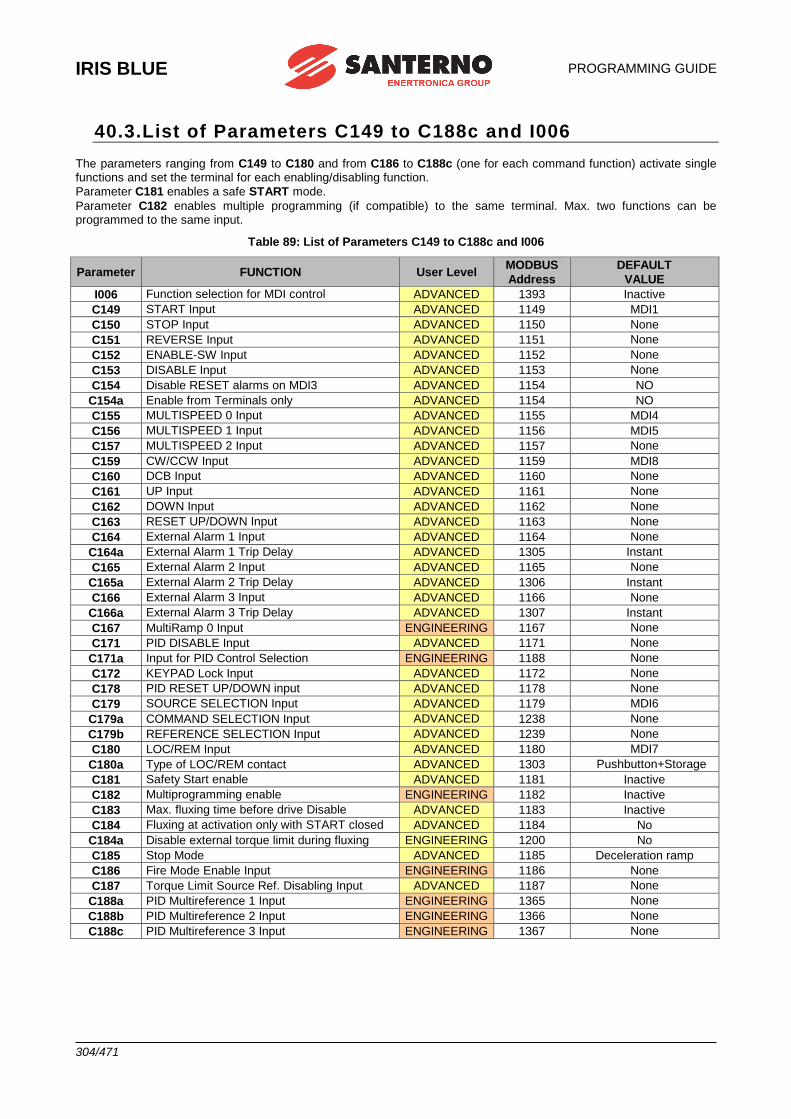
IRIS BLUE
PROGRAMMING GUIDE
304/471
40.3.List of Parameters C149 to C188c and I006
The parameters ranging from C149 to C180 and from C186 to C188c (one for each command function) activate single functions and set the terminal for each enabling/disabling function.
Parameter C181 enables a safe START mode.
Parameter C182 enables multiple programming (if compatible) to the same terminal. Max. two functions can be programmed to the same input.
Table 89: List of Parameters C149 to C188c and I006
Parameter FUNCTION User Level MODBUS
Address
DEFAULT
VALUE
I006 Function selection for MDI control ADVANCED 1393 Inactive
C149 START Input ADVANCED 1149 MDI1
C150 STOP Input ADVANCED 1150 None
C151 REVERSE Input ADVANCED 1151 None
C152 ENABLE-SW Input ADVANCED 1152 None
C153 DISABLE Input ADVANCED 1153 None
C154 Disable RESET alarms on MDI3 ADVANCED 1154 NO
C154a Enable from Terminals only ADVANCED 1154 NO
C155 MULTISPEED 0 Input ADVANCED 1155 MDI4
C156 MULTISPEED 1 Input ADVANCED 1156 MDI5
C157 MULTISPEED 2 Input ADVANCED 1157 None
C159 CW/CCW Input ADVANCED 1159 MDI8
C160 DCB Input ADVANCED 1160 None
C161 UP Input ADVANCED 1161 None
C162 DOWN Input ADVANCED 1162 None
C163 RESET UP/DOWN Input ADVANCED 1163 None
C164 External Alarm 1 Input ADVANCED 1164 None
C164a External Alarm 1 Trip Delay ADVANCED 1305 Instant
C165 External Alarm 2 Input ADVANCED 1165 None
C165a External Alarm 2 Trip Delay ADVANCED 1306 Instant
C166 External Alarm 3 Input ADVANCED 1166 None
C166a External Alarm 3 Trip Delay ADVANCED 1307 Instant
C167 MultiRamp 0 Input ENGINEERING 1167 None
C171 PID DISABLE Input ADVANCED 1171 None
C171a Input for PID Control Selection ENGINEERING 1188 None
C172 KEYPAD Lock Input ADVANCED 1172 None
C178 PID RESET UP/DOWN input ADVANCED 1178 None
C179 SOURCE SELECTION Input ADVANCED 1179 MDI6
C179a COMMAND SELECTION Input ADVANCED 1238 None
C179b REFERENCE SELECTION Input ADVANCED 1239 None
C180 LOC/REM Input ADVANCED 1180 MDI7
C180a Type of LOC/REM contact ADVANCED 1303 Pushbutton+Storage
C181 Safety Start enable ADVANCED 1181 Inactive
C182 Multiprogramming enable ENGINEERING 1182 Inactive
C183 Max. fluxing time before drive Disable ADVANCED 1183 Inactive
C184 Fluxing at activation only with START closed ADVANCED 1184 No
C184a Disable external torque limit during fluxing ENGINEERING 1200 No
C185 Stop Mode ADVANCED 1185 Deceleration ramp
C186 Fire Mode Enable Input ENGINEERING 1186 None
C187 Torque Limit Source Ref. Disabling Input ADVANCED 1187 None
C188a PID Multireference 1 Input ENGINEERING 1365 None
C188b PID Multireference 2 Input ENGINEERING 1366 None
C188c PID Multireference 3 Input ENGINEERING 1367 None
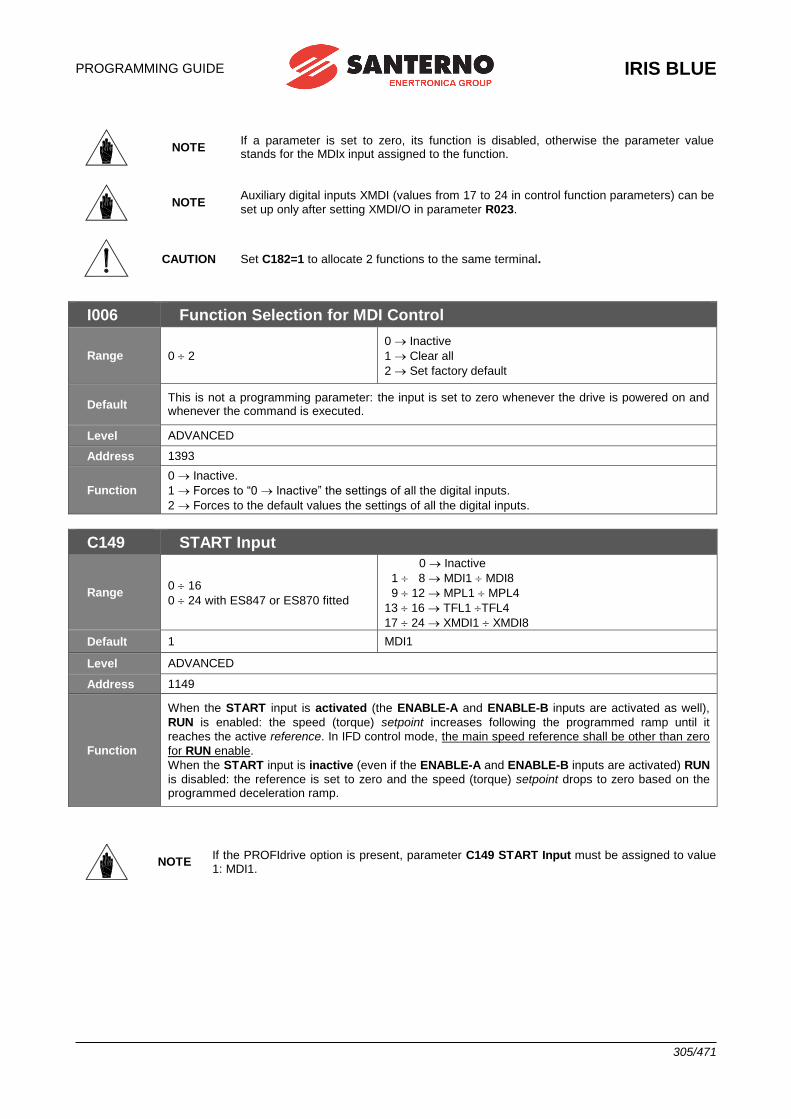
PROGRAMMING GUIDE
IRIS BLUE
305/471
NOTE If a parameter is set to zero, its function is disabled, otherwise the parameter value stands for the MDIx input assigned to the function.
NOTE Auxiliary digital inputs XMDI (values from 17 to 24 in control function parameters) can be
set up only after setting XMDI/O in parameter R023.
CAUTION Set C182=1 to allocate 2 functions to the same terminal.
I006 Function Selection for MDI Control
Range 0 2
0 Inactive
1 Clear all
2 Set factory default
Default This is not a programming parameter: the input is set to zero whenever the drive is powered on and whenever the command is executed.
Level ADVANCED
Address 1393
Function
0 Inactive.
1 Forces to “0 Inactive” the settings of all the digital inputs.
2 Forces to the default values the settings of all the digital inputs.
C149 START Input
Range 0 16
0 24 with ES847 or ES870 fitted
0 Inactive
1 8 MDI1 MDI8
9 12 MPL1 MPL4
13 16 TFL1 TFL4
17 24 XMDI1 XMDI8
Default 1 MDI1
Level ADVANCED
Address 1149
Function
When the START input is activated (the ENABLE-A and ENABLE-B inputs are activated as well),
RUN is enabled: the speed (torque) setpoint increases following the programmed ramp until it
reaches the active reference. In IFD control mode, the main speed reference shall be other than zero
for RUN enable.
When the START input is inactive (even if the ENABLE-A and ENABLE-B inputs are activated) RUN
is disabled: the reference is set to zero and the speed (torque) setpoint drops to zero based on the programmed deceleration ramp.
NOTE If the PROFIdrive option is present, parameter C149 START Input must be assigned to value 1: MDI1.
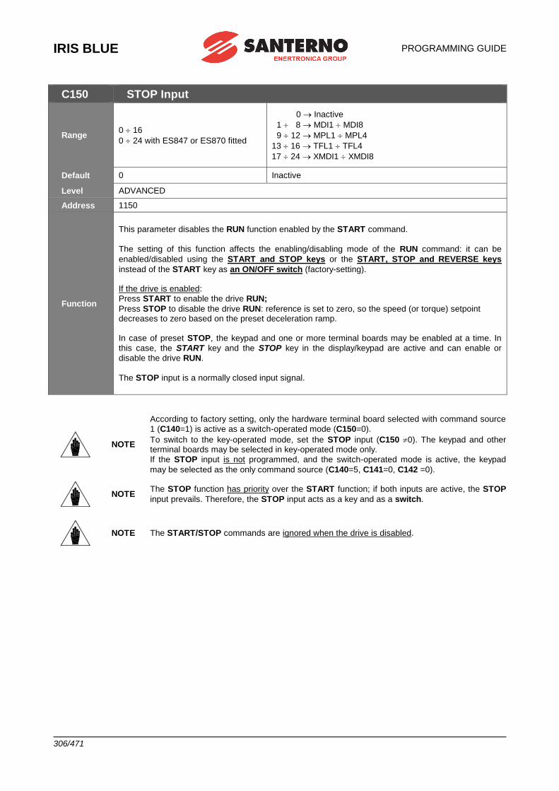
IRIS BLUE
PROGRAMMING GUIDE
306/471
C150 STOP Input
Range 0 16
0 24 with ES847 or ES870 fitted
0 Inactive
1 8 MDI1 MDI8
9 12 MPL1 MPL4
13 16 TFL1 TFL4
17 24 XMDI1 XMDI8
Default 0 Inactive
Level ADVANCED
Address 1150
Function
This parameter disables the RUN function enabled by the START command.
The setting of this function affects the enabling/disabling mode of the RUN command: it can be
enabled/disabled using the START and STOP keys or the START, STOP and REVERSE keys
instead of the START key as an ON/OFF switch (factory-setting). If the drive is enabled:
Press START to enable the drive RUN;
Press STOP to disable the drive RUN: reference is set to zero, so the speed (or torque) setpoint decreases to zero based on the preset deceleration ramp.
In case of preset STOP, the keypad and one or more terminal boards may be enabled at a time. In
this case, the START key and the STOP key in the display/keypad are active and can enable or
disable the drive RUN.
The STOP input is a normally closed input signal.
NOTE
According to factory setting, only the hardware terminal board selected with command source
1 (C140=1) is active as a switch-operated mode (C150=0).
To switch to the key-operated mode, set the STOP input (C150 0). The keypad and other terminal boards may be selected in key-operated mode only.
If the STOP input is not programmed, and the switch-operated mode is active, the keypad
may be selected as the only command source (C140=5, C141=0, C142 =0).
NOTE The STOP function has priority over the START function; if both inputs are active, the STOP
input prevails. Therefore, the STOP input acts as a key and as a switch.
NOTE The START/STOP commands are ignored when the drive is disabled.
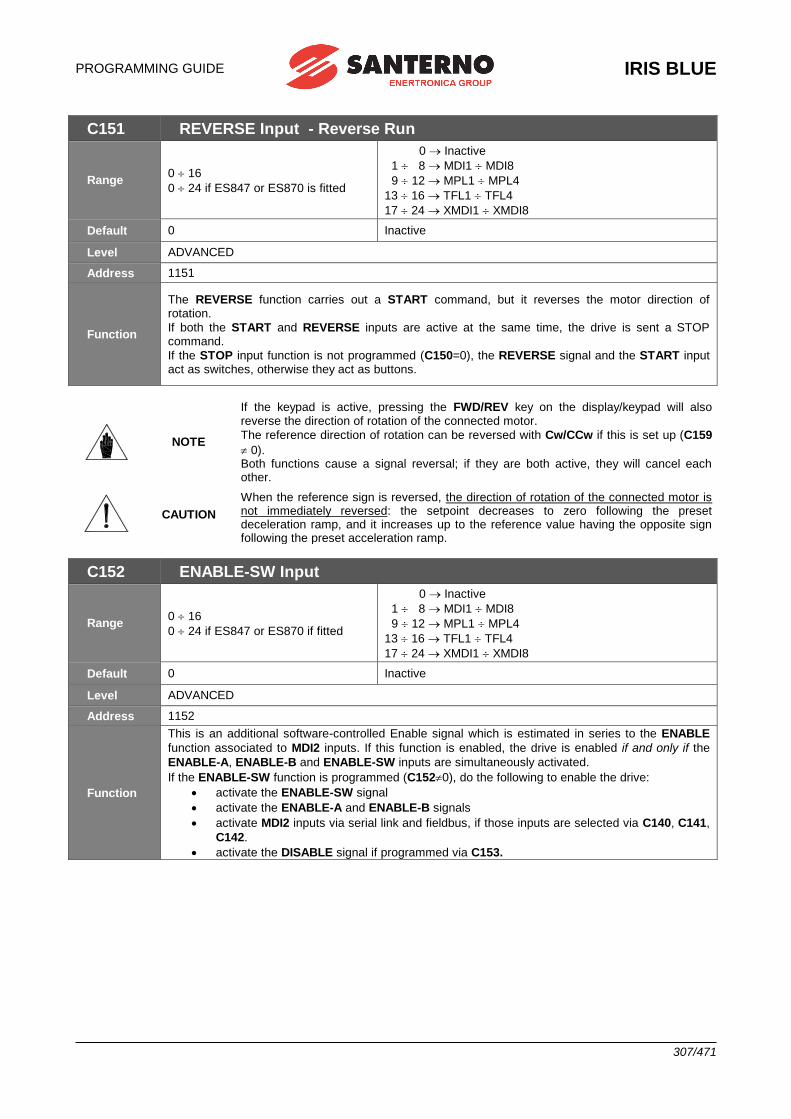
PROGRAMMING GUIDE
IRIS BLUE
307/471
C151 REVERSE Input - Reverse Run
Range 0 16
0 24 if ES847 or ES870 is fitted
0 Inactive
1 8 MDI1 MDI8
9 12 MPL1 MPL4
13 16 TFL1 TFL4
17 24 XMDI1 XMDI8
Default 0 Inactive
Level ADVANCED
Address 1151
Function
The REVERSE function carries out a START command, but it reverses the motor direction of rotation.
If both the START and REVERSE inputs are active at the same time, the drive is sent a STOP command.
If the STOP input function is not programmed (C150=0), the REVERSE signal and the START input act as switches, otherwise they act as buttons.
NOTE
If the keypad is active, pressing the FWD/REV key on the display/keypad will also reverse the direction of rotation of the connected motor.
The reference direction of rotation can be reversed with Cw/CCw if this is set up (C159
0). Both functions cause a signal reversal; if they are both active, they will cancel each other.
CAUTION
When the reference sign is reversed, the direction of rotation of the connected motor is not immediately reversed: the setpoint decreases to zero following the preset deceleration ramp, and it increases up to the reference value having the opposite sign following the preset acceleration ramp.
C152 ENABLE-SW Input
Range 0 16
0 24 if ES847 or ES870 if fitted
0 Inactive
1 8 MDI1 MDI8
9 12 MPL1 MPL4
13 16 TFL1 TFL4
17 24 XMDI1 XMDI8
Default 0 Inactive
Level ADVANCED
Address 1152
Function
This is an additional software-controlled Enable signal which is estimated in series to the ENABLE
function associated to MDI2 inputs. If this function is enabled, the drive is enabled if and only if the
ENABLE-A, ENABLE-B and ENABLE-SW inputs are simultaneously activated.
If the ENABLE-SW function is programmed (C1520), do the following to enable the drive:
• activate the ENABLE-SW signal
• activate the ENABLE-A and ENABLE-B signals
• activate MDI2 inputs via serial link and fieldbus, if those inputs are selected via C140, C141,
C142.
• activate the DISABLE signal if programmed via C153.
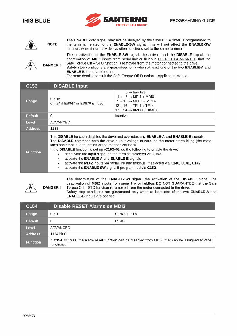
IRIS BLUE
PROGRAMMING GUIDE
308/471
NOTE The ENABLE-SW signal may not be delayed by the timers: if a timer is programmed to
the terminal related to the ENABLE-SW signal, this will not affect the ENABLE-SW function, while it normally delays other functions set to the same terminal.
DANGER!!!
The deactivation of the ENABLE-SW signal, the activation of the DISABLE signal, the
deactivation of MDI2 inputs from serial link or fieldbus DO NOT GUARANTEE that the Safe Torque Off – STO function is removed from the motor connected to the drive.
Safety stop conditions are guaranteed only when at least one of the two ENABLE-A and
ENABLE-B inputs are opened. For more details, consult the Safe Torque Off Function – Application Manual.
C153 DISABLE Input
Range 0 16
0 24 if ES847 or ES870 is fitted
0 Inactive
1 8 MDI1 MDI8
9 12 MPL1 MPL4
13 16 TFL1 TFL4
17 24 XMDI1 XMDI8
Default 0 Inactive
Level ADVANCED
Address 1153
Function
The DISABLE function disables the drive and overrides any ENABLE-A and ENABLE-B signals.
The DISABLE command sets the drive output voltage to zero, so the motor starts idling (the motor idles and stops due to friction or the mechanical load).
If the DISABLE function is set up (C1530), do the following to enable the drive:
• deactivate the input signal on the terminal selected via C153
• activate the ENABLE-A and ENABLE-B signals
• activate the MDI2 inputs via serial link and fieldbus, if selected via C140, C141, C142
• activate the ENABLE-SW signal if programmed via C152.
DANGER!!!
The deactivation of the ENABLE-SW signal, the activation of the DISABLE signal, the
deactivation of MDI2 inputs from serial link or fieldbus DO NOT GUARANTEE that the Safe Torque Off – STO function is removed from the motor connected to the drive.
Safety stop conditions are guaranteed only when at least one of the two ENABLE-A and
ENABLE-B inputs are opened.
C154 Disable RESET Alarms on MDI3
Range 0 1 0: NO; 1: Yes
Default 0 0: NO
Level ADVANCED
Address 1154 bit 0
Function If C154 =1: Yes, the alarm reset function can be disabled from MDI3, that can be assigned to other functions.
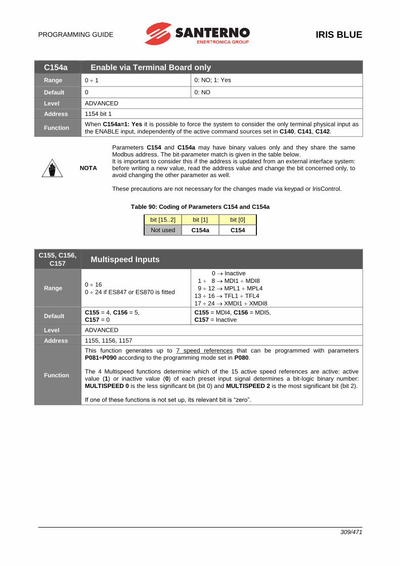
PROGRAMMING GUIDE
IRIS BLUE
309/471
C154a Enable via Terminal Board only
Range 0 1 0: NO; 1: Yes
Default 0 0: NO
Level ADVANCED
Address 1154 bit 1
Function When C154a=1: Yes it is possible to force the system to consider the only terminal physical input as
the ENABLE input, independently of the active command sources set in C140, C141, C142.
NOTA
Parameters C154 and C154a may have binary values only and they share the same Modbus address. The bit-parameter match is given in the table below. It is important to consider this if the address is updated from an external interface system: before writing a new value, read the address value and change the bit concerned only, to avoid changing the other parameter as well. These precautions are not necessary for the changes made via keypad or IrisControl.
Table 90: Coding of Parameters C154 and C154a
bit [15..2] bit [1] bit [0]
Not used C154a C154
C155, C156,
C157 Multispeed Inputs
Range 0 16
0 24 if ES847 or ES870 is fitted
0 Inactive
1 8 MDI1 MDI8
9 12 MPL1 MPL4
13 16 TFL1 TFL4
17 24 XMDI1 XMDI8
Default C155 = 4, C156 = 5,
C157 = 0
C155 = MDI4, C156 = MDI5,
C157 = Inactive
Level ADVANCED
Address 1155, 1156, 1157
Function
This function generates up to 7 speed references that can be programmed with parameters
P081÷P090 according to the programming mode set in P080. The 4 Multispeed functions determine which of the 15 active speed references are active: active
value (1) or inactive value (0) of each preset input signal determines a bit-logic binary number:
MULTISPEED 0 is the less significant bit (bit 0) and MULTISPEED 2 is the most significant bit (bit 2). If one of these functions is not set up, its relevant bit is “zero”.
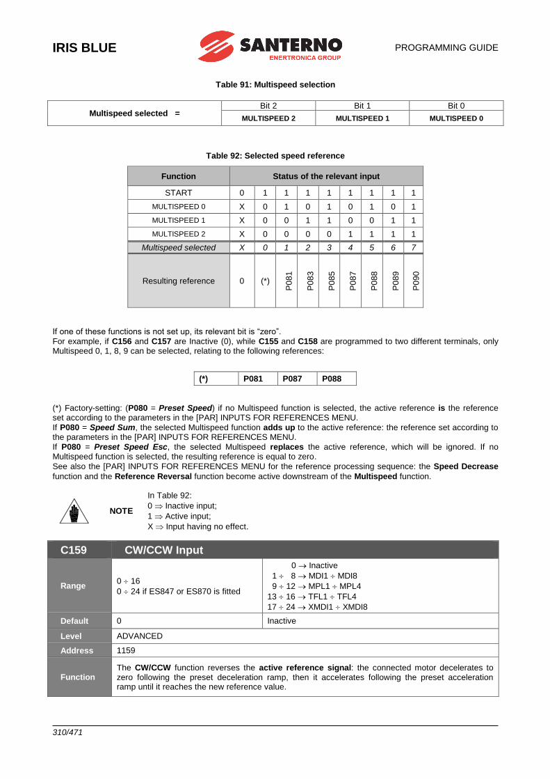
IRIS BLUE
PROGRAMMING GUIDE
310/471
Table 91: Multispeed selection
Multispeed selected = Bit 2 Bit 1 Bit 0
MULTISPEED 2 MULTISPEED 1 MULTISPEED 0
Table 92: Selected speed reference
Function Status of the relevant input
START 0 1 1 1 1 1 1 1 1
MULTISPEED 0 X 0 1 0 1 0 1 0 1
MULTISPEED 1 X 0 0 1 1 0 0 1 1
MULTISPEED 2 X 0 0 0 0 1 1 1 1
Multispeed selected X 0 1 2 3 4 5 6 7
Resulting reference 0 (*) P
081
P083
P085
P087
P088
P089
P090
If one of these functions is not set up, its relevant bit is “zero”.
For example, if C156 and C157 are Inactive (0), while C155 and C158 are programmed to two different terminals, only Multispeed 0, 1, 8, 9 can be selected, relating to the following references:
(*) Factory-setting: (P080 = Preset Speed) if no Multispeed function is selected, the active reference is the reference set according to the parameters in the [PAR] INPUTS FOR REFERENCES MENU.
If P080 = Speed Sum, the selected Multispeed function adds up to the active reference: the reference set according to the parameters in the [PAR] INPUTS FOR REFERENCES MENU.
If P080 = Preset Speed Esc, the selected Multispeed replaces the active reference, which will be ignored. If no Multispeed function is selected, the resulting reference is equal to zero.
See also the [PAR] INPUTS FOR REFERENCES MENU for the reference processing sequence: the Speed Decrease
function and the Reference Reversal function become active downstream of the Multispeed function.
NOTE
In Table 92:
0 Inactive input;
1 Active input;
X Input having no effect.
C159 CW/CCW Input
Range 0 16
0 24 if ES847 or ES870 is fitted
0 Inactive
1 8 MDI1 MDI8
9 12 MPL1 MPL4
13 16 TFL1 TFL4
17 24 XMDI1 XMDI8
Default 0 Inactive
Level ADVANCED
Address 1159
Function The CW/CCW function reverses the active reference signal: the connected motor decelerates to zero following the preset deceleration ramp, then it accelerates following the preset acceleration ramp until it reaches the new reference value.
(*) P081 P087 P088
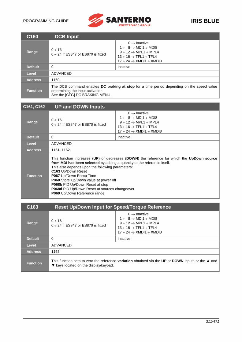
PROGRAMMING GUIDE
IRIS BLUE
311/471
C160 DCB Input
Range 0 16
0 24 if ES847 or ES870 is fitted
0 Inactive
1 8 MDI1 MDI8
9 12 MPL1 MPL4
13 16 TFL1 TFL4
17 24 XMDI1 XMDI8
Default 0 Inactive
Level ADVANCED
Address 1160
Function The DCB command enables DC braking at stop for a time period depending on the speed value determining the input activation. See the [CFG] DC BRAKING MENU.
C161, C162 UP and DOWN Inputs
Range 0 16
0 24 if ES847 or ES870 is fitted
0 Inactive
1 8 MDI1 MDI8
9 12 MPL1 MPL4
13 16 TFL1 TFL4
17 24 XMDI1 XMDI8
Default 0 Inactive
Level ADVANCED
Address 1161, 1162
Function
This function increases (UP) or decreases (DOWN) the reference for which the UpDown source
from MDI has been selected by adding a quantity to the reference itself. This also depends upon the following parameters:
C163 Up/Down Reset
P067 Up/Down Ramp Time
P068 Store Up/Down value at power off
P068b PID Up/Down Reset at stop
P068d PID Up/Down Reset at sources changeover
P069 Up/Down Reference range
C163 Reset Up/Down Input for Speed/Torque Reference
Range 0 16
0 24 if ES847 or ES870 is fitted
0 Inactive
1 8 MDI1 MDI8
9 12 MPL1 MPL4
13 16 TFL1 TFL4
17 24 XMDI1 XMDI8
Default 0 Inactive
Level ADVANCED
Address 1163
Function This function sets to zero the reference variation obtained via the UP or DOWN inputs or the ▲ and
▼ keys located on the display/keypad.
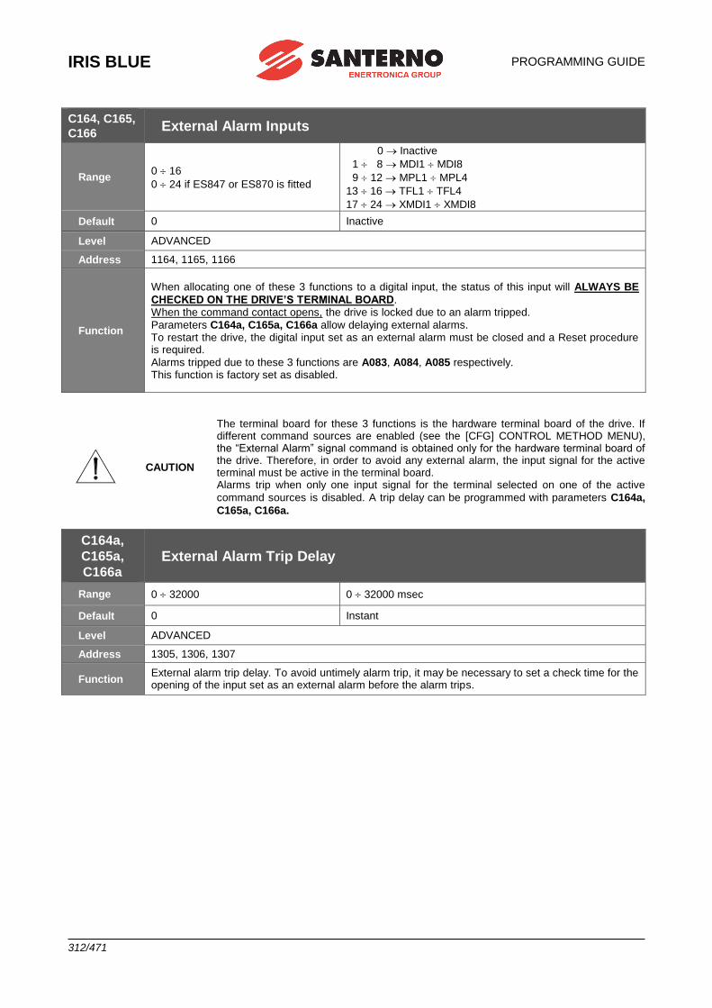
IRIS BLUE
PROGRAMMING GUIDE
312/471
C164, C165,
C166 External Alarm Inputs
Range 0 16
0 24 if ES847 or ES870 is fitted
0 Inactive
1 8 MDI1 MDI8
9 12 MPL1 MPL4
13 16 TFL1 TFL4
17 24 XMDI1 XMDI8
Default 0 Inactive
Level ADVANCED
Address 1164, 1165, 1166
Function
When allocating one of these 3 functions to a digital input, the status of this input will ALWAYS BE
CHECKED ON THE DRIVE’S TERMINAL BOARD. When the command contact opens, the drive is locked due to an alarm tripped.
Parameters C164a, C165a, C166a allow delaying external alarms. To restart the drive, the digital input set as an external alarm must be closed and a Reset procedure is required.
Alarms tripped due to these 3 functions are A083, A084, A085 respectively. This function is factory set as disabled.
CAUTION
The terminal board for these 3 functions is the hardware terminal board of the drive. If different command sources are enabled (see the [CFG] CONTROL METHOD MENU), the “External Alarm” signal command is obtained only for the hardware terminal board of the drive. Therefore, in order to avoid any external alarm, the input signal for the active terminal must be active in the terminal board. Alarms trip when only one input signal for the terminal selected on one of the active
command sources is disabled. A trip delay can be programmed with parameters C164a,
C165a, C166a.
C164a,
C165a,
C166a External Alarm Trip Delay
Range 0 32000 0 32000 msec
Default 0 Instant
Level ADVANCED
Address 1305, 1306, 1307
Function External alarm trip delay. To avoid untimely alarm trip, it may be necessary to set a check time for the opening of the input set as an external alarm before the alarm trips.
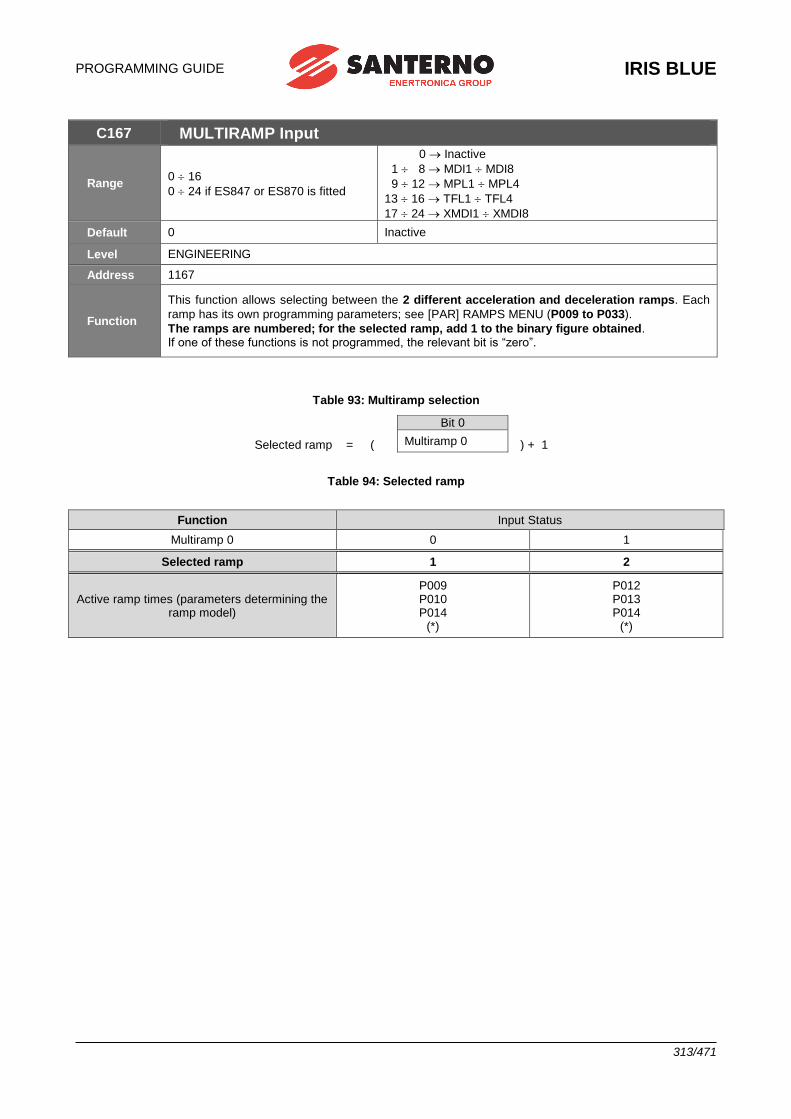
PROGRAMMING GUIDE
IRIS BLUE
313/471
C167 MULTIRAMP Input
Range 0 16
0 24 if ES847 or ES870 is fitted
0 Inactive
1 8 MDI1 MDI8
9 12 MPL1 MPL4
13 16 TFL1 TFL4
17 24 XMDI1 XMDI8
Default 0 Inactive
Level ENGINEERING
Address 1167
Function
This function allows selecting between the 2 different acceleration and deceleration ramps. Each
ramp has its own programming parameters; see [PAR] RAMPS MENU (P009 to P033).
The ramps are numbered; for the selected ramp, add 1 to the binary figure obtained. If one of these functions is not programmed, the relevant bit is “zero”.
Table 93: Multiramp selection
Selected ramp = (
Bit 0
) + 1 Multiramp 0
Table 94: Selected ramp
Function Input Status
Multiramp 0 0 1
Selected ramp 1 2
Active ramp times (parameters determining the ramp model)
P009 P010 P014
(*)
P012 P013 P014
(*)
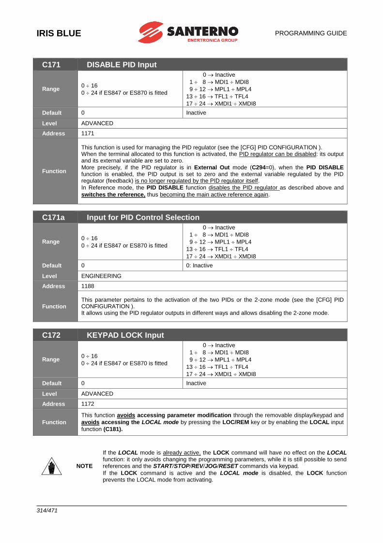
IRIS BLUE
PROGRAMMING GUIDE
314/471
C171 DISABLE PID Input
Range 0 16
0 24 if ES847 or ES870 is fitted
0 Inactive
1 8 MDI1 MDI8
9 12 MPL1 MPL4
13 16 TFL1 TFL4
17 24 XMDI1 XMDI8
Default 0 Inactive
Level ADVANCED
Address 1171
Function
This function is used for managing the PID regulator (see the [CFG] PID CONFIGURATION ). When the terminal allocated to this function is activated, the PID regulator can be disabled: its output and its external variable are set to zero.
More precisely, if the PID regulator is in External Out mode (C294=0), when the PID DISABLE function is enabled, the PID output is set to zero and the external variable regulated by the PID regulator (feedback) is no longer regulated by the PID regulator itself.
In Reference mode, the PID DISABLE function disables the PID regulator as described above and
switches the reference, thus becoming the main active reference again.
C171a Input for PID Control Selection
Range 0 16
0 24 if ES847 or ES870 is fitted
0 Inactive
1 8 MDI1 MDI8
9 12 MPL1 MPL4
13 16 TFL1 TFL4
17 24 XMDI1 XMDI8
Default 0 0: Inactive
Level ENGINEERING
Address 1188
Function This parameter pertains to the activation of the two PIDs or the 2-zone mode (see the [CFG] PID CONFIGURATION ). It allows using the PID regulator outputs in different ways and allows disabling the 2-zone mode.
C172 KEYPAD LOCK Input
Range 0 16
0 24 if ES847 or ES870 is fitted
0 Inactive
1 8 MDI1 MDI8
9 12 MPL1 MPL4
13 16 TFL1 TFL4
17 24 XMDI1 XMDI8
Default 0 Inactive
Level ADVANCED
Address 1172
Function
This function avoids accessing parameter modification through the removable display/keypad and
avoids accessing the LOCAL mode by pressing the LOC/REM key or by enabling the LOCAL input
function (C181).
NOTE
If the LOCAL mode is already active, the LOCK command will have no effect on the LOCAL function: it only avoids changing the programming parameters, while it is still possible to send references and the START/STOP/REV/JOG/RESET commands via keypad.
If the LOCK command is active and the LOCAL mode is disabled, the LOCK function prevents the LOCAL mode from activating.
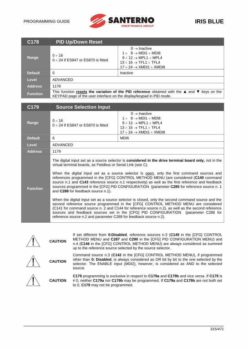
PROGRAMMING GUIDE
IRIS BLUE
315/471
C178 PID Up/Down Reset
Range 0 16
0 24 if ES847 or ES870 is fitted
0 Inactive
1 8 MDI1 MDI8
9 12 MPL1 MPL4
13 16 TFL1 TFL4
17 24 XMDI1 XMDI8
Default 0 Inactive
Level ADVANCED
Address 1178
Function This function resets the variation of the PID reference obtained with the ▲ and ▼ keys on the KEYPAD page of the user interface on the display/keypad in PID mode.
C179 Source Selection Input
Range 0 16
0 24 if ES847 or ES870 is fitted
0 Inactive
1 8 MDI1 MDI8
9 12 MPL1 MPL4
13 16 TFL1 TFL4
17 24 XMDI1 XMDI8
Default 6 MDI6
Level ADVANCED
Address 1179
Function
The digital input set as a source selector is considered in the drive terminal board only, not in the virtual terminal boards, as Fieldbus or Serial Link (see C). When the digital input set as a source selector is open, only the first command sources and
references programmed in the [CFG] CONTROL METHOD MENU (are considered (C140 command
source n.1 and C143 reference source n.1 respectively) as well as the first reference and feedback
sources programmed in the [CFG] PID CONFIGURATION (parameter C285 for reference source n. 1
and C288 for feedback source n.1). When the digital input set as a source selector is closed, only the second command source and the second reference source programmed in the [CFG] CONTROL METHOD MENU are considered (C141 for command source n. 2 and C144 for reference source n.2), as well as the second reference sources and feedback sources set in the [CFG] PID CONFIGURATION (parameter C286 for reference source n.2 and parameter C289 for feedback source n.2).
CAUTION
If set different from 0:Disabled, reference sources n.3 (C145 in the [CFG] CONTROL
METHOD MENU and C287 and C290 in the [CFG] PID CONFIGURATION MENU) and
n.4 (C146 in the [CFG] CONTROL METHOD MENU) are always considered as summed up to the reference source selected by the source selector.
CAUTION
Command source n.3 (C142 in the [CFG] CONTROL METHOD MENU), if programmed
other than 0: Disabled, is always considered as OR bit by bit to the one selected by the selector. The ENABLE input (MDI2), however, is considered as AND to the selected source.
CAUTION
C179 programming is exclusive in respect to C179a and C179b and vice versa. If C179 is
≠ 0, neither C179a nor C179b may be programmed. If C179a and C179b are not both set
to 0, C179 may not be programmed.
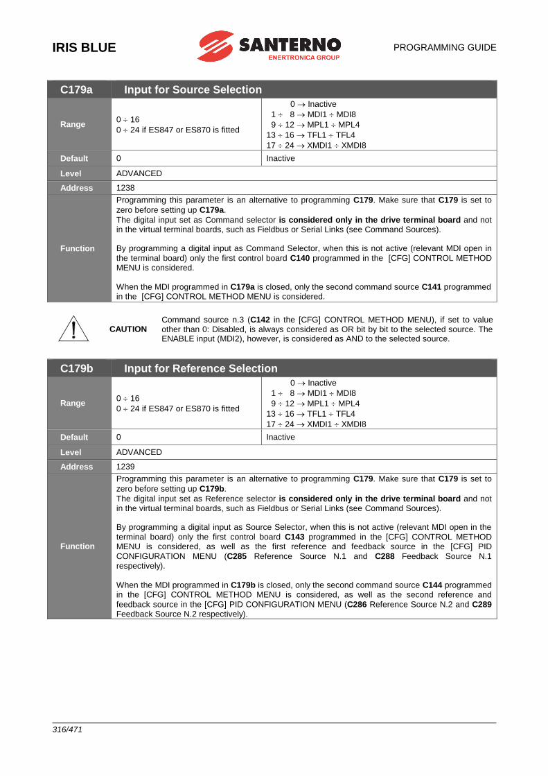
IRIS BLUE
PROGRAMMING GUIDE
316/471
C179a Input for Source Selection
Range 0 16
0 24 if ES847 or ES870 is fitted
0 Inactive
1 8 MDI1 MDI8
9 12 MPL1 MPL4
13 16 TFL1 TFL4
17 24 XMDI1 XMDI8
Default 0 Inactive
Level ADVANCED
Address 1238
Function
Programming this parameter is an alternative to programming C179. Make sure that C179 is set to
zero before setting up C179a.
The digital input set as Command selector is considered only in the drive terminal board and not in the virtual terminal boards, such as Fieldbus or Serial Links (see Command Sources). By programming a digital input as Command Selector, when this is not active (relevant MDI open in
the terminal board) only the first control board C140 programmed in the [CFG] CONTROL METHOD MENU is considered.
When the MDI programmed in C179a is closed, only the second command source C141 programmed in the [CFG] CONTROL METHOD MENU is considered.
CAUTION Command source n.3 (C142 in the [CFG] CONTROL METHOD MENU), if set to value other than 0: Disabled, is always considered as OR bit by bit to the selected source. The ENABLE input (MDI2), however, is considered as AND to the selected source.
C179b Input for Reference Selection
Range 0 16
0 24 if ES847 or ES870 is fitted
0 Inactive
1 8 MDI1 MDI8
9 12 MPL1 MPL4
13 16 TFL1 TFL4
17 24 XMDI1 XMDI8
Default 0 Inactive
Level ADVANCED
Address 1239
Function
Programming this parameter is an alternative to programming C179. Make sure that C179 is set to
zero before setting up C179b.
The digital input set as Reference selector is considered only in the drive terminal board and not in the virtual terminal boards, such as Fieldbus or Serial Links (see Command Sources). By programming a digital input as Source Selector, when this is not active (relevant MDI open in the
terminal board) only the first control board C143 programmed in the [CFG] CONTROL METHOD MENU is considered, as well as the first reference and feedback source in the [CFG] PID
CONFIGURATION MENU (C285 Reference Source N.1 and C288 Feedback Source N.1 respectively).
When the MDI programmed in C179b is closed, only the second command source C144 programmed in the [CFG] CONTROL METHOD MENU is considered, as well as the second reference and
feedback source in the [CFG] PID CONFIGURATION MENU (C286 Reference Source N.2 and C289 Feedback Source N.2 respectively).
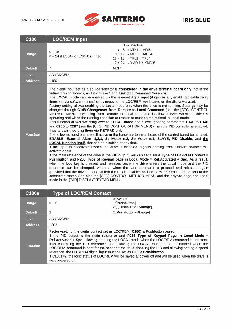
PROGRAMMING GUIDE
IRIS BLUE
317/471
C180 LOC/REM Input
Range 0 16
0 24 if ES847 or ES870 is fitted
0 Inactive
1 8 MDI1 MDI8
9 12 MPL1 MPL4
13 16 TFL1 TFL4
17 24 XMDI1 XMDI8
Default 7 MDI7
Level ADVANCED
Address 1180
Function
The digital input set as a source selector is considered in the drive terminal board only, not in the virtual terminal boards, as Fieldbus or Serial Link (see Command Sources).
The LOCAL mode can be enabled via the relevant digital input (it ignores any enabling/disable delay
times set via software timers) or by pressing the LOC/REM key located on the display/keypad. Factory setting allows enabling the Local mode only when the drive is not running. Settings may be
changed through C148 Changeover from Remote to Local Command (see the [CFG] CONTROL METHOD MENU); switching from Remote to Local command is allowed even when the drive is operating and when the running condition or reference must be maintained in Local mode.
This function allows switching over to LOCAL mode and allows ignoring parameters C140 to C146
and C285 to C287 (see the [CFG] PID CONFIGURATION MENU) when the PID controller is enabled,
thus allowing setting them via KEYPAD only. The following functions are still active in the hardware terminal board of the control board being used:
ENABLE, External Alarm 1,2,3, Sel.Motor n.2, Sel.Motor n.3, SLAVE, PID Disable, and the
LOCAL function itself, that can be disabled at any time. If the input is deactivated when the drive is disabled, signals coming from different sources will activate again.
If the main reference of the drive is the PID output, you can set C180a Type of LOC/REM Contact =
Pushbutton and P266 Type of Keypad page in Local Mode = Ref.Activated + Spd. As a result,
when the Loc key is pressed and released once, the drive enters the Local mode and the PID
reference can be changed, whereas when the Loc command is pressed and released again (provided that the drive is not enabled) the PID is disabled and the RPM reference can be sent to the connected motor. See also the [CFG] CONTROL METHOD MENU and the Keypad page and Local mode in the [PAR] DISPLAY/KEYPAD MENU.
C180a Type of LOC/REM Contact
Range 0 2
0:[Switch] 1:[Pushbutton] 2:[ [Pushbutton+Storage]
Default 2 2:[Pushbutton+Storage]
Level ADVANCED
Address 1303
Function
Factory-setting: the digital contact set as LOC/REM (C180) is Pushbutton based.
If the PID output is the main reference and P266 Type of Keypad Page in Local Mode =
Ref.Activated + Spd, allowing entering the LOCAL mode when the LOC/REM command is first sent, thus controlling the PID reference, and allowing the LOCAL mode to be maintained when the LOC/REM command is sent for the second time, thus disabling the PID and allowing setting a speed
reference, the LOC/REM digital input must be set as C180a=Pushbutton.
If C180a=2, the logic status of LOC/REM will be saved at power off and will be used when the drive is next powered on.
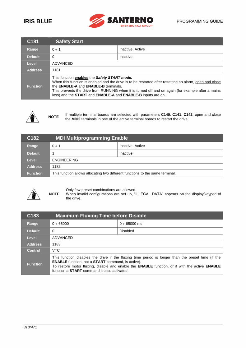
IRIS BLUE
PROGRAMMING GUIDE
318/471
C181 Safety Start
Range 0 1 Inactive, Active
Default 0 Inactive
Level ADVANCED
Address 1181
Function
This function enables the Safety START mode. When this function is enabled and the drive is to be restarted after resetting an alarm, open and close
the ENABLE-A and ENABLE-B terminals. This prevents the drive from RUNNING when it is turned off and on again (for example after a mains
loss) and the START and ENABLE-A and ENABLE-B inputs are on.
NOTE If multiple terminal boards are selected with parameters C140, C141, C142, open and close
the MDI2 terminals in one of the active terminal boards to restart the drive.
C182 MDI Multiprogramming Enable
Range 0 1 Inactive, Active
Default 1 Inactive
Level ENGINEERING
Address 1182
Function This function allows allocating two different functions to the same terminal.
NOTE Only few preset combinations are allowed. When invalid configurations are set up, “ILLEGAL DATA” appears on the display/keypad of the drive.
C183 Maximum Fluxing Time before Disable
Range 0 65000 0 65000 ms
Default 0 Disabled
Level ADVANCED
Address 1183
Control VTC
Function
This function disables the drive if the fluxing time period is longer than the preset time (if the
ENABLE function, not a START command, is active).
To restore motor fluxing, disable and enable the ENABLE function, or if with the active ENABLE
function a START command is also activated.
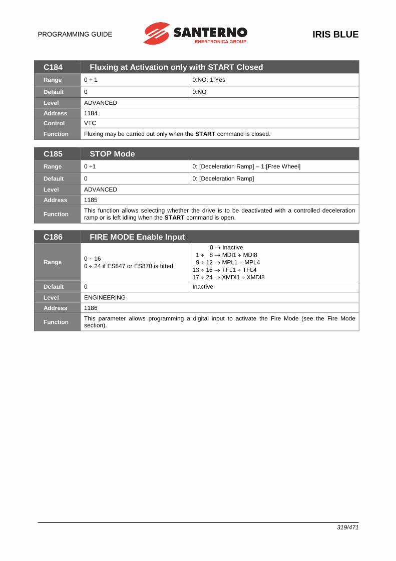
PROGRAMMING GUIDE
IRIS BLUE
319/471
C184 Fluxing at Activation only with START Closed
Range 0 ÷ 1 0:NO; 1:Yes
Default 0 0:NO
Level ADVANCED
Address 1184
Control VTC
Function Fluxing may be carried out only when the START command is closed.
C185 STOP Mode
Range 0 ÷1 0: [Deceleration Ramp] – 1:[Free Wheel]
Default 0 0: [Deceleration Ramp]
Level ADVANCED
Address 1185
Function This function allows selecting whether the drive is to be deactivated with a controlled deceleration
ramp or is left idling when the START command is open.
C186 FIRE MODE Enable Input
Range 0 16
0 24 if ES847 or ES870 is fitted
0 Inactive
1 8 MDI1 MDI8
9 12 MPL1 MPL4
13 16 TFL1 TFL4
17 24 XMDI1 XMDI8
Default 0 Inactive
Level ENGINEERING
Address 1186
Function This parameter allows programming a digital input to activate the Fire Mode (see the Fire Mode section).
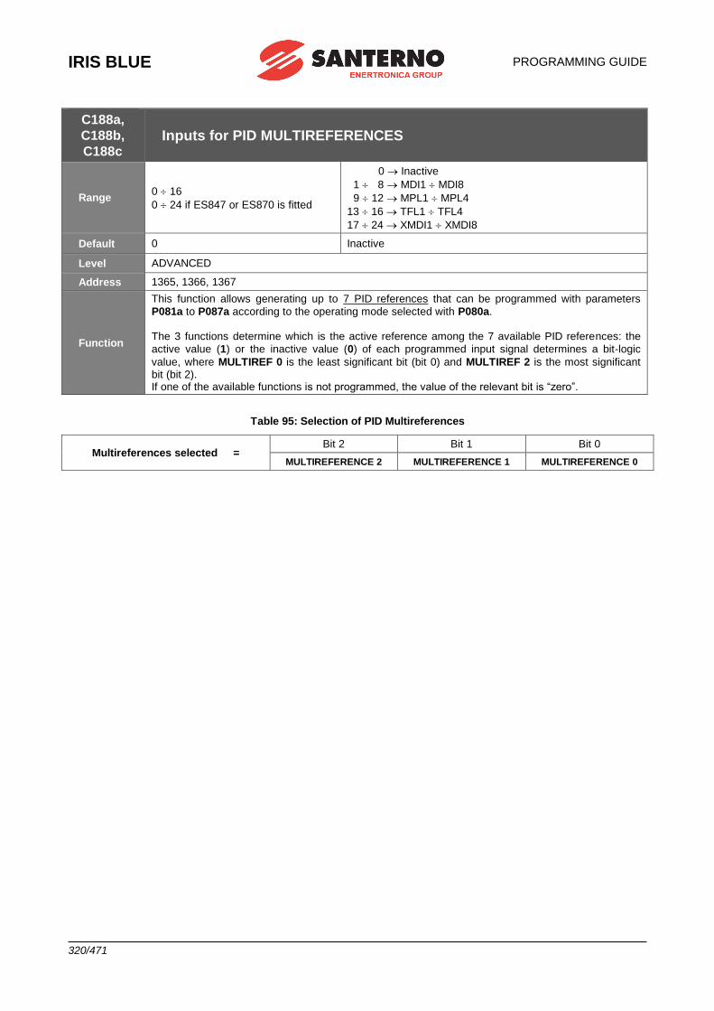
IRIS BLUE
PROGRAMMING GUIDE
320/471
C188a,
C188b,
C188c Inputs for PID MULTIREFERENCES
Range 0 16
0 24 if ES847 or ES870 is fitted
0 Inactive
1 8 MDI1 MDI8
9 12 MPL1 MPL4
13 16 TFL1 TFL4
17 24 XMDI1 XMDI8
Default 0 Inactive
Level ADVANCED
Address 1365, 1366, 1367
Function
This function allows generating up to 7 PID references that can be programmed with parameters
P081a to P087a according to the operating mode selected with P080a. The 3 functions determine which is the active reference among the 7 available PID references: the
active value (1) or the inactive value (0) of each programmed input signal determines a bit-logic
value, where MULTIREF 0 is the least significant bit (bit 0) and MULTIREF 2 is the most significant bit (bit 2). If one of the available functions is not programmed, the value of the relevant bit is “zero”.
Table 95: Selection of PID Multireferences
Multireferences selected = Bit 2 Bit 1 Bit 0
MULTIREFERENCE 2 MULTIREFERENCE 1 MULTIREFERENCE 0
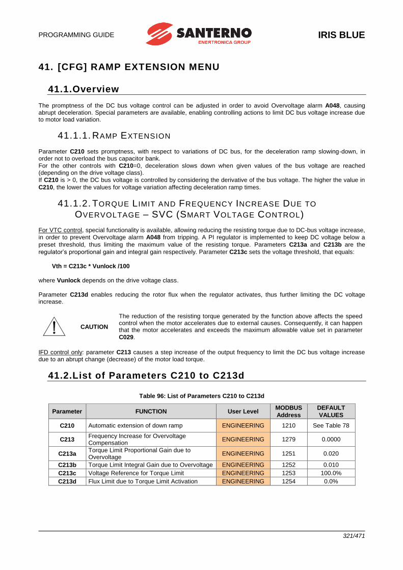
PROGRAMMING GUIDE
IRIS BLUE
321/471
41. [CFG] RAMP EXTENSION MENU
41.1.Overview
The promptness of the DC bus voltage control can be adjusted in order to avoid Overvoltage alarm A048, causing abrupt deceleration. Special parameters are available, enabling controlling actions to limit DC bus voltage increase due to motor load variation.
41.1.1. RAMP EXTENSION
Parameter C210 sets promptness, with respect to variations of DC bus, for the deceleration ramp slowing-down, in order not to overload the bus capacitor bank.
For the other controls with C210=0, deceleration slows down when given values of the bus voltage are reached (depending on the drive voltage class).
If C210 is > 0, the DC bus voltage is controlled by considering the derivative of the bus voltage. The higher the value in
C210, the lower the values for voltage variation affecting deceleration ramp times.
41.1.2. TORQUE L IMIT AND FREQUENCY INCREASE DUE TO
OVERVOLTAGE – SVC (SMART VOLTAGE CONTROL) For VTC control, special functionality is available, allowing reducing the resisting torque due to DC-bus voltage increase,
in order to prevent Overvoltage alarm A048 from tripping. A PI regulator is implemented to keep DC voltage below a
preset threshold, thus limiting the maximum value of the resisting torque. Parameters C213a and C213b are the
regulator’s proportional gain and integral gain respectively. Parameter C213c sets the voltage threshold, that equals:
Vth = C213c * Vunlock /100
where Vunlock depends on the drive voltage class.
Parameter C213d enables reducing the rotor flux when the regulator activates, thus further limiting the DC voltage increase.
CAUTION
The reduction of the resisting torque generated by the function above affects the speed control when the motor accelerates due to external causes. Consequently, it can happen that the motor accelerates and exceeds the maximum allowable value set in parameter
C029.
IFD control only: parameter C213 causes a step increase of the output frequency to limit the DC bus voltage increase due to an abrupt change (decrease) of the motor load torque.
41.2.List of Parameters C210 to C213d
Table 96: List of Parameters C210 to C213d
Parameter FUNCTION User Level MODBUS
Address
DEFAULT
VALUES
C210 Automatic extension of down ramp ENGINEERING 1210 See Table 78
C213 Frequency Increase for Overvoltage Compensation
ENGINEERING 1279 0.0000
C213a Torque Limit Proportional Gain due to Overvoltage
ENGINEERING 1251 0.020
C213b Torque Limit Integral Gain due to Overvoltage ENGINEERING 1252 0.010
C213c Voltage Reference for Torque Limit ENGINEERING 1253 100.0%
C213d Flux Limit due to Torque Limit Activation ENGINEERING 1254 0.0%
IRIS BLUE
PROGRAMMING GUIDE
322/471
C210 Automatic Extension of Down Ramp
Range 0 ÷ 32000 0; 320.00
Default See Table 78
Level ENGINEERING
Address 1210
Function
The down ramp is extended if the variation in DC bus voltage is too rapid or exceeds certain
threshold values. Set a higher value in parameter C210 for a more sensitive ramp extension (a lower rating of regenerated power allows obtaining longer ramps), thus avoiding overvoltage.
NOTE
Parameter C210 decreases the DC bus voltage threshold setting the ramp extension. The k factor is as follows:
k = Pout/(Pmax*100*C210), k ranges from 1.0 to 1.3 The greater the k factor, the lower the DC bus level setting the ramp extension.
For example, when C210=0.2, power Pout shall exceed 5% of Pmax in order to obtain k>1.
When C210=2, 0.5% of Pmax is required to obtain k>1.
C213 Frequency Increase for Overvoltage Compensation – Smart Voltage
Control
Range 0 ÷ 1000 0 ÷ 0.1000
Default 0 0.0000
Level ENGINEERING
Address 1279
Control IFD
Function
If this parameter is set > 0, a value given by C213 * derivative_voltage_DC (expressed in V/s) is summed up to the frequency currently set for the motor. In that way, when DC voltage abruptly changes due to sudden variations of the load torque, the output frequency is promptly adjusted to compensate for voltage increase and avoid overvoltage conditions. A value equal to 0.0200 ensures optimum operation in most applications; however, the optimum value for this parameter is to be found by trial and error.
C213a Torque Decrease Proportional Gain due to Overvoltage
Range 0 ÷ 32000 0.000 ÷ 32.000
Default 20 0.020
Level ENGINEERING
Address 1251
Control VTC
Function
This function is available only when the VTC control is activated. This is the proportional gain of the DC-bus voltage regulator adjusting the resisting torque limit when
voltage exceeds the value set in parameter C213c.
PROGRAMMING GUIDE
IRIS BLUE
323/471
C213b Torque Decrease Integral Gain due to Overvoltage
Range 0 ÷ 32000 0.000 ÷ 32.000
Default 10 0.010
Level ENGINEERING
Address 1252
Control VTC
Function
This function is available only when the VTC control is activated. This is the integral gain of the DC-bus voltage regulator adjusting the resisting torque limit when
voltage exceeds the value set in parameter C213c.
C213c Voltage Reference for Torque Decrease
Range 0 ÷ 1200 0.0 ÷ 120.0%
Default 1000 100.0%
Level ENGINEERING
Address 1253
Control VTC
Function
This function is available only when the VTC control is activated. It sets the reference value for the regulator DC voltage adjusting the resisting torque limit. The limiting function activates when voltage exceeds the value below:
Vth = C213c * Vunlock /100
where Vunlock is based on the drive voltage class.
C213d Flux Limit due to Torque Decrease Activation
Range 0 ÷ 1000 0.0 ÷ 100.0%
Default 0 0.0%
Level ENGINEERING
Address 1254
Control VTC
Function
This function is available only when the VTC control is activated. If the torque limit is adjusted by the DC bus voltage regulator, the rotor flux is decreased by the same value of the torque limit multiplied by the value of this parameter. Example: If the regulator generates
a 50% instant torque limit and C213d is worth 30%, the flux will be decreased by 50 * 30 / (100 * 100) = 15%, and will be increased to 85% of the value that should be adopted under normal operating conditions. This parameter keeps DC voltage low when the motor acceleration due to external causes continues over time. Low parameter values (< 50%) may cause uncontrolled rotation of the motor.
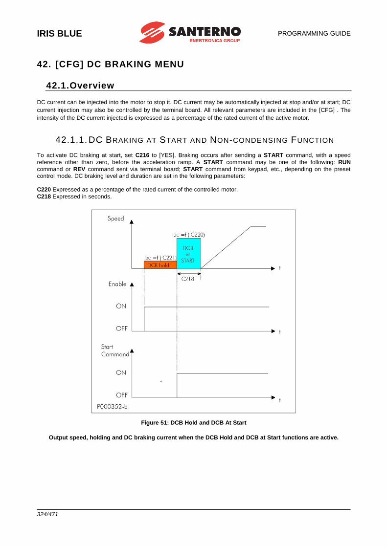
IRIS BLUE
PROGRAMMING GUIDE
324/471
42. [CFG] DC BRAKING MENU
42.1.Overview
DC current can be injected into the motor to stop it. DC current may be automatically injected at stop and/or at start; DC
current injection may also be controlled by the terminal board. All relevant parameters are included in the [CFG] . The
intensity of the DC current injected is expressed as a percentage of the rated current of the active motor.
42.1.1. DC BRAKING AT START AND NON-CONDENSING FUNCTION
To activate DC braking at start, set C216 to [YES]. Braking occurs after sending a START command, with a speed
reference other than zero, before the acceleration ramp. A START command may be one of the following: RUN
command or REV command sent via terminal board; START command from keypad, etc., depending on the preset control mode. DC braking level and duration are set in the following parameters:
C220 Expressed as a percentage of the rated current of the controlled motor.
C218 Expressed in seconds.
Figure 51: DCB Hold and DCB At Start
Output speed, holding and DC braking current when the DCB Hold and DCB at Start functions are active.
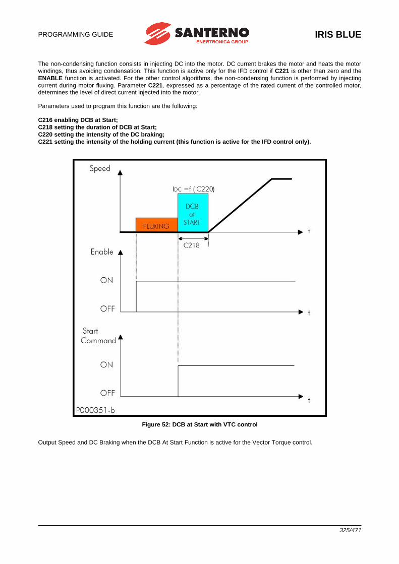
PROGRAMMING GUIDE
IRIS BLUE
325/471
The non-condensing function consists in injecting DC into the motor. DC current brakes the motor and heats the motor
windings, thus avoiding condensation. This function is active only for the IFD control if C221 is other than zero and the
ENABLE function is activated. For the other control algorithms, the non-condensing function is performed by injecting
current during motor fluxing. Parameter C221, expressed as a percentage of the rated current of the controlled motor, determines the level of direct current injected into the motor. Parameters used to program this function are the following:
C216 enabling DCB at Start;
C218 setting the duration of DCB at Start;
C220 setting the intensity of the DC braking;
C221 setting the intensity of the holding current (this function is active for the IFD control only).
Figure 52: DCB at Start with VTC control
Output Speed and DC Braking when the DCB At Start Function is active for the Vector Torque control.
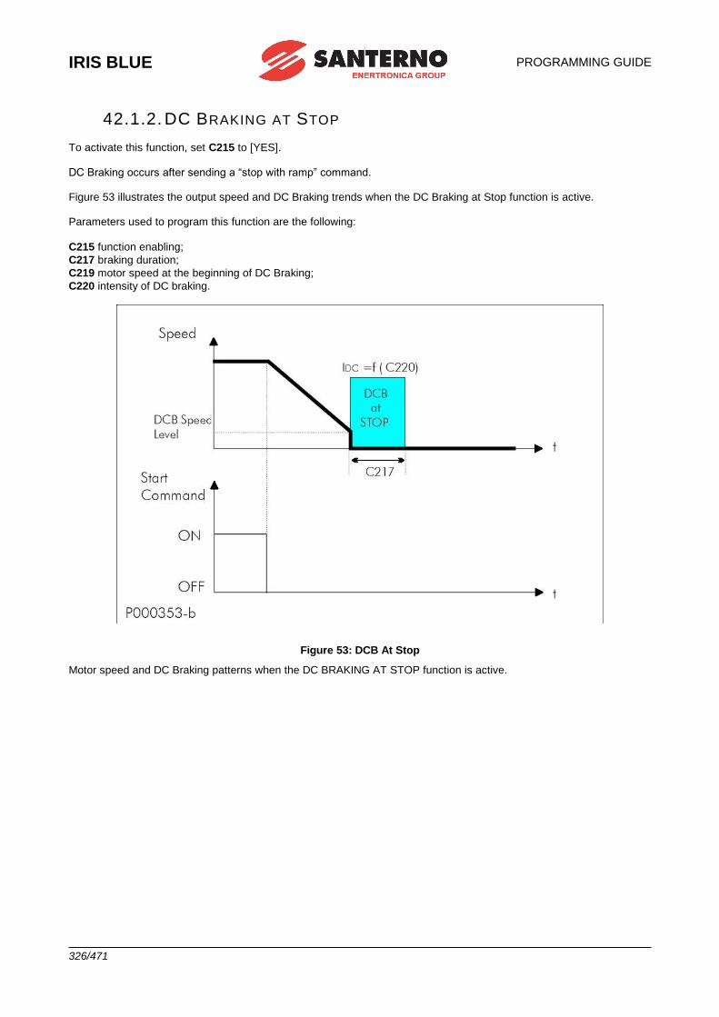
IRIS BLUE
PROGRAMMING GUIDE
326/471
42.1.2. DC BRAKING AT STOP
To activate this function, set C215 to [YES]. DC Braking occurs after sending a “stop with ramp” command. Figure 53 illustrates the output speed and DC Braking trends when the DC Braking at Stop function is active. Parameters used to program this function are the following:
C215 function enabling;
C217 braking duration;
C219 motor speed at the beginning of DC Braking;
C220 intensity of DC braking.
Figure 53: DCB At Stop
Motor speed and DC Braking patterns when the DC BRAKING AT STOP function is active.
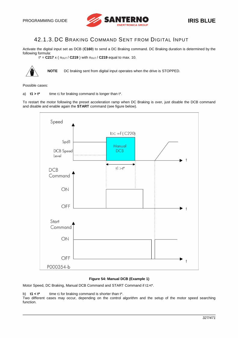
PROGRAMMING GUIDE
IRIS BLUE
327/471
42.1.3. DC BRAKING COMMAND SENT FROM D IGITAL INPUT
Activate the digital input set as DCB (C160) to send a DC Braking command. DC Braking duration is determined by the following formula:
t* = C217 x ( nOUT / C219 ) with nOUT / C219 equal to max. 10.
Possible cases:
a) t1 > t* time t1 for braking command is longer than t*. To restart the motor following the preset acceleration ramp when DC Braking is over, just disable the DCB command
and disable and enable again the START command (see figure below).
Figure 54: Manual DCB (Example 1)
Motor Speed, DC Braking, Manual DCB Command and START Command if t1>t*.
b) t1 < t* time t1 for braking command is shorter than t*. Two different cases may occur, depending on the control algorithm and the setup of the motor speed searching function.
NOTE DC braking sent from digital input operates when the drive is STOPPED.
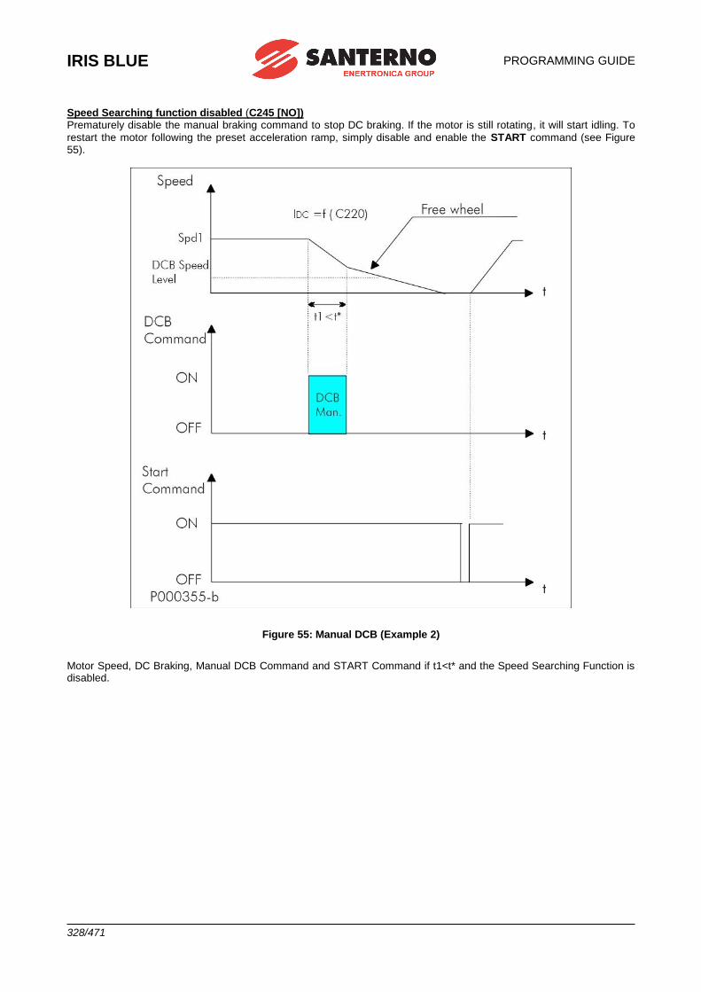
IRIS BLUE
PROGRAMMING GUIDE
328/471
Speed Searching function disabled (C245 [NO]) Prematurely disable the manual braking command to stop DC braking. If the motor is still rotating, it will start idling. To
restart the motor following the preset acceleration ramp, simply disable and enable the START command (see Figure 55).
Figure 55: Manual DCB (Example 2)
Motor Speed, DC Braking, Manual DCB Command and START Command if t1<t* and the Speed Searching Function is disabled.
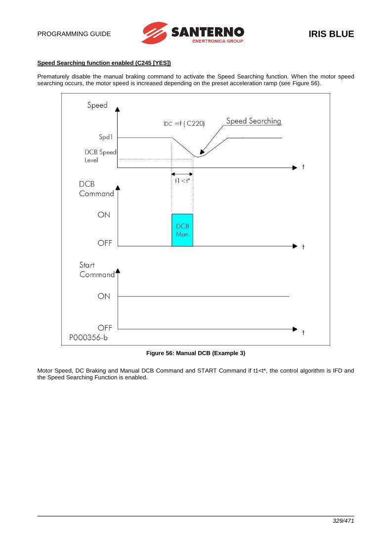
PROGRAMMING GUIDE
IRIS BLUE
329/471
Speed Searching function enabled (C245 [YES]) Prematurely disable the manual braking command to activate the Speed Searching function. When the motor speed searching occurs, the motor speed is increased depending on the preset acceleration ramp (see Figure 56).
Figure 56: Manual DCB (Example 3)
Motor Speed, DC Braking and Manual DCB Command and START Command if t1<t*, the control algorithm is IFD and the Speed Searching Function is enabled.
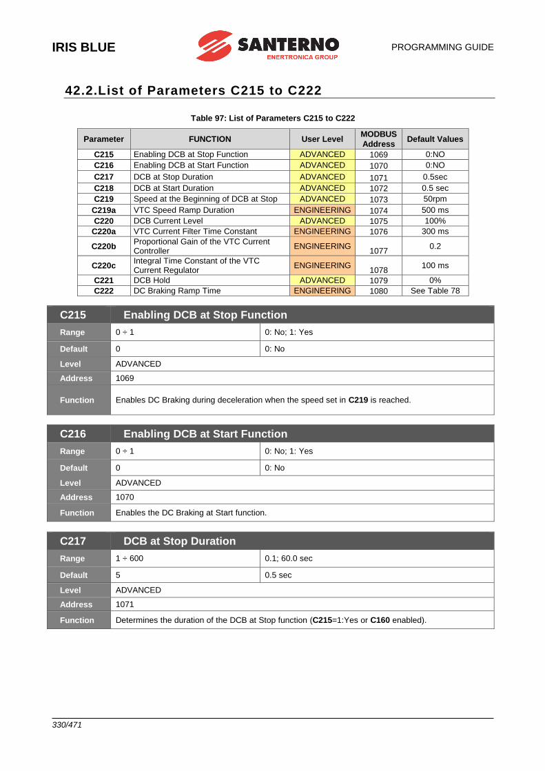
IRIS BLUE
PROGRAMMING GUIDE
330/471
42.2.List of Parameters C215 to C222
Table 97: List of Parameters C215 to C222
Parameter FUNCTION User Level MODBUS
Address Default Values
C215 Enabling DCB at Stop Function ADVANCED 1069 0:NO
C216 Enabling DCB at Start Function ADVANCED 1070 0:NO
C217 DCB at Stop Duration ADVANCED 1071 0.5sec
C218 DCB at Start Duration ADVANCED 1072 0.5 sec
C219 Speed at the Beginning of DCB at Stop ADVANCED 1073 50rpm
C219a VTC Speed Ramp Duration ENGINEERING 1074 500 ms
C220 DCB Current Level ADVANCED 1075 100%
C220a VTC Current Filter Time Constant ENGINEERING 1076 300 ms
C220b Proportional Gain of the VTC Current Controller
ENGINEERING 1077
0.2
C220c Integral Time Constant of the VTC Current Regulator
ENGINEERING 1078
100 ms
C221 DCB Hold ADVANCED 1079 0%
C222 DC Braking Ramp Time ENGINEERING 1080 See Table 78
C215 Enabling DCB at Stop Function
Range 0 ÷ 1 0: No; 1: Yes
Default 0 0: No
Level ADVANCED
Address 1069
Function Enables DC Braking during deceleration when the speed set in C219 is reached.
C216 Enabling DCB at Start Function
Range 0 ÷ 1 0: No; 1: Yes
Default 0 0: No
Level ADVANCED
Address 1070
Function Enables the DC Braking at Start function.
C217 DCB at Stop Duration
Range 1 ÷ 600 0.1; 60.0 sec
Default 5 0.5 sec
Level ADVANCED
Address 1071
Function Determines the duration of the DCB at Stop function (C215=1:Yes or C160 enabled).
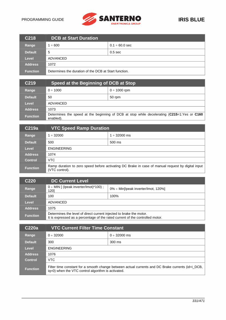
PROGRAMMING GUIDE
IRIS BLUE
331/471
C218 DCB at Start Duration
Range 1 ÷ 600 0.1 ÷ 60.0 sec
Default 5 0.5 sec
Level ADVANCED
Address 1072
Function Determines the duration of the DCB at Start function.
C219 Speed at the Beginning of DCB at Stop
Range 0 ÷ 1000 0 ÷ 1000 rpm
Default 50 50 rpm
Level ADVANCED
Address 1073
Function Determines the speed at the beginning of DCB at stop while decelerating (C215=1:Yes or C160 enabled).
C219a VTC Speed Ramp Duration
Range 1 ÷ 32000 1 ÷ 32000 ms
Default 500 500 ms
Level ENGINEERING
Address 1074
Control VTC
Function Ramp duration to zero speed before activating DC Brake in case of manual request by digital input (VTC control).
C220 DC Current Level
Range 0 MIN [ (Ipeak inverter/Imot)*100) ; 120]
0% Min[Ipeak inverter/Imot, 120%]
Default 100 100%
Level ADVANCED
Address 1075
Function Determines the level of direct current injected to brake the motor. It is expressed as a percentage of the rated current of the controlled motor.
C220a VTC Current Filter Time Constant
Range 0 32000 0 32000 ms
Default 300 300 ms
Level ENGINEERING
Address 1076
Control VTC
Function Filter time constant for a smooth change between actual currents and DC Brake currents (id=i_DCB, iq=0) when the VTC control algorithm is activated.
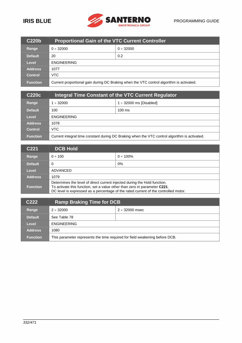
IRIS BLUE
PROGRAMMING GUIDE
332/471
C220b Proportional Gain of the VTC Current Controller
Range 0 32000 0 32000
Default 20 0.2
Level ENGINEERING
Address 1077
Control VTC
Function Current proportional gain during DC Braking when the VTC control algorithm is activated.
C220c Integral Time Constant of the VTC Current Regulator
Range 1 32000 1 32000 ms [Disabled]
Default 100 100 ms
Level ENGINEERING
Address 1078
Control VTC
Function Current integral time constant during DC Braking when the VTC control algorithm is activated.
C221 DCB Hold
Range 0 ÷ 100 0 ÷ 100%
Default 0 0%
Level ADVANCED
Address 1079
Function
Determines the level of direct current injected during the Hold function.
To activate this function, set a value other than zero in parameter C221. DC level is expressed as a percentage of the rated current of the controlled motor.
C222 Ramp Braking Time for DCB
Range 2 32000 2 32000 msec
Default See Table 78
Level ENGINEERING
Address 1080
Function This parameter represents the time required for field weakening before DCB.
PROGRAMMING GUIDE
IRIS BLUE
333/471
43. [CFG] SPEED SEARCHING
43.1.Overview
When a command is sent to disable the drive, the motor idles. When the drive activates again, the Speed Searching function allows the drive to reach the motor speed. All parameters relating to this function are included in the Speed Searching submenu in the Configuration menu.
The Speed Searching function activates when C245 is set to [YES]:
– When C245 is set to [YES], do the following to activate the Speed Searching function:
– deactivate and reactivate the ENABLE function before tSSdis
is over (C246);
– if C185 = 1:[Free wheel], open and close the START command before tSSdis
(C246) is over;
– disable the DC Braking command before the DC braking preset time is over (see the [CFG] DC BRAKING MENU); – reset any alarm tripped (with reference other than 0) before t
SSdis is over.
If C250 ≠ 0 [Disable], the Speed Searching function activates only if the programmed input is active. Speed searching does not take place when the drive turns off due to mains loss.
If the drive restarts after a time longer than tSSdis
(C246), frequency output is generated following the acceleration ramp,
and no speed searching takes place.
If C246 0: (Always On), speed searching (if enabled with C245) occurs when the drive restarts (RUN), irrespective of the time elapsed from disabling. The figures below show output frequency and motor rpm during speed searching. After time t
0 for rotor demagnetization, speed searching occurs as follows (see 3 steps below):
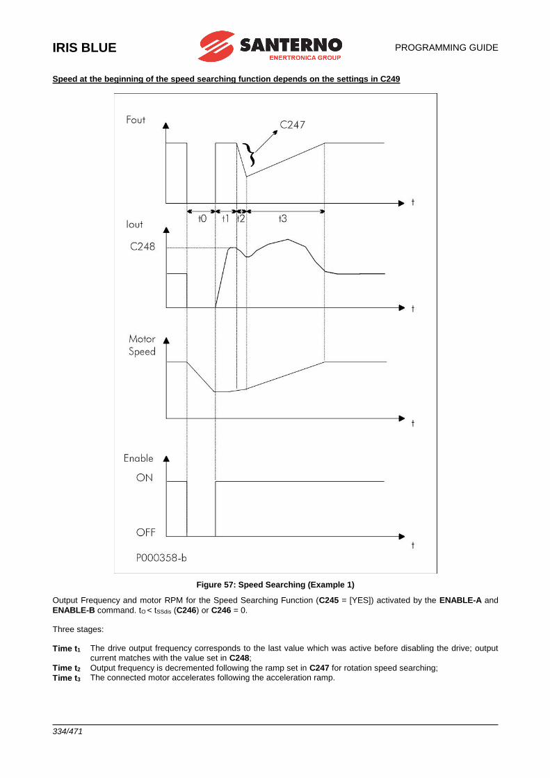
IRIS BLUE
PROGRAMMING GUIDE
334/471
Speed at the beginning of the speed searching function depends on the settings in C249
Figure 57: Speed Searching (Example 1)
Output Frequency and motor RPM for the Speed Searching Function (C245 = [YES]) activated by the ENABLE-A and
ENABLE-B command. tO < tSSdis (C246) or C246 = 0. Three stages:
Time t1 The drive output frequency corresponds to the last value which was active before disabling the drive; output
current matches with the value set in C248;
Time t2 Output frequency is decremented following the ramp set in C247 for rotation speed searching;
Time t3 The connected motor accelerates following the acceleration ramp.
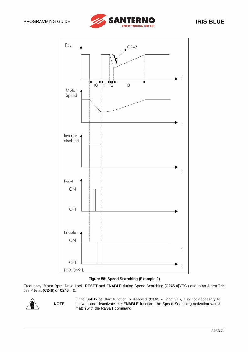
PROGRAMMING GUIDE
IRIS BLUE
335/471
Figure 58: Speed Searching (Example 2)
Frequency, Motor Rpm, Drive Lock, RESET and ENABLE during Speed Searching (C245 =[YES]) due to an Alarm Trip
tOFF < tSSdis (C246) or C246 = 0.
NOTE
If the Safety at Start function is disabled (C181 = [Inactive]), it is not necessary to
activate and deactivate the ENABLE function; the Speed Searching activation would
match with the RESET command.
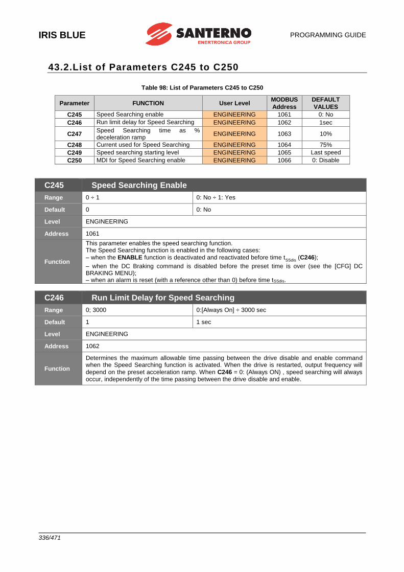
IRIS BLUE
PROGRAMMING GUIDE
336/471
43.2.List of Parameters C245 to C250
Table 98: List of Parameters C245 to C250
Parameter FUNCTION User Level MODBUS
Address
DEFAULT
VALUES
C245 Speed Searching enable ENGINEERING 1061 0: No
C246 Run limit delay for Speed Searching ENGINEERING 1062 1sec
C247 Speed Searching time as % deceleration ramp
ENGINEERING 1063 10%
C248 Current used for Speed Searching ENGINEERING 1064 75%
C249 Speed searching starting level ENGINEERING 1065 Last speed
C250 MDI for Speed Searching enable ENGINEERING 1066 0: Disable
C245 Speed Searching Enable
Range 0 ÷ 1 0: No ÷ 1: Yes
Default 0 0: No
Level ENGINEERING
Address 1061
Function
This parameter enables the speed searching function. The Speed Searching function is enabled in the following cases:
– when the ENABLE function is deactivated and reactivated before time tSSdis
(C246);
– when the DC Braking command is disabled before the preset time is over (see the [CFG] DC BRAKING MENU); – when an alarm is reset (with a reference other than 0) before time tSSdis.
C246 Run Limit Delay for Speed Searching
Range 0; 3000 0:[Always On] ÷ 3000 sec
Default 1 1 sec
Level ENGINEERING
Address 1062
Function
Determines the maximum allowable time passing between the drive disable and enable command when the Speed Searching function is activated. When the drive is restarted, output frequency will
depend on the preset acceleration ramp. When C246 = 0: (Always ON) , speed searching will always occur, independently of the time passing between the drive disable and enable.
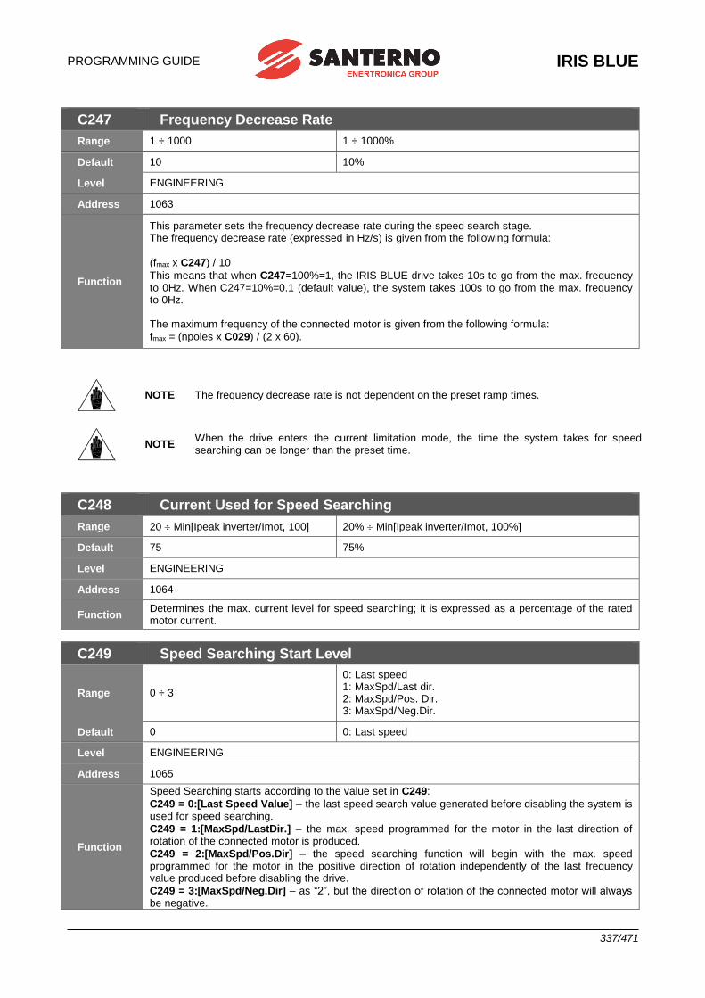
PROGRAMMING GUIDE
IRIS BLUE
337/471
C247 Frequency Decrease Rate
Range 1 ÷ 1000 1 ÷ 1000%
Default 10 10%
Level ENGINEERING
Address 1063
Function
This parameter sets the frequency decrease rate during the speed search stage. The frequency decrease rate (expressed in Hz/s) is given from the following formula:
(fmax x C247) / 10
This means that when C247=100%=1, the IRIS BLUE drive takes 10s to go from the max. frequency to 0Hz. When C247=10%=0.1 (default value), the system takes 100s to go from the max. frequency to 0Hz. The maximum frequency of the connected motor is given from the following formula:
fmax = (npoles x C029) / (2 x 60).
NOTE The frequency decrease rate is not dependent on the preset ramp times.
NOTE When the drive enters the current limitation mode, the time the system takes for speed searching can be longer than the preset time.
C248 Current Used for Speed Searching
Range 20 Min[Ipeak inverter/Imot, 100] 20% Min[Ipeak inverter/Imot, 100%]
Default 75 75%
Level ENGINEERING
Address 1064
Function Determines the max. current level for speed searching; it is expressed as a percentage of the rated motor current.
C249 Speed Searching Start Level
Range 0 ÷ 3
0: Last speed 1: MaxSpd/Last dir. 2: MaxSpd/Pos. Dir. 3: MaxSpd/Neg.Dir.
Default 0 0: Last speed
Level ENGINEERING
Address 1065
Function
Speed Searching starts according to the value set in C249:
C249 = 0:[Last Speed Value] – the last speed search value generated before disabling the system is used for speed searching.
C249 = 1:[MaxSpd/LastDir.] – the max. speed programmed for the motor in the last direction of rotation of the connected motor is produced.
C249 = 2:[MaxSpd/Pos.Dir] – the speed searching function will begin with the max. speed programmed for the motor in the positive direction of rotation independently of the last frequency value produced before disabling the drive.
C249 = 3:[MaxSpd/Neg.Dir] – as “2”, but the direction of rotation of the connected motor will always be negative.
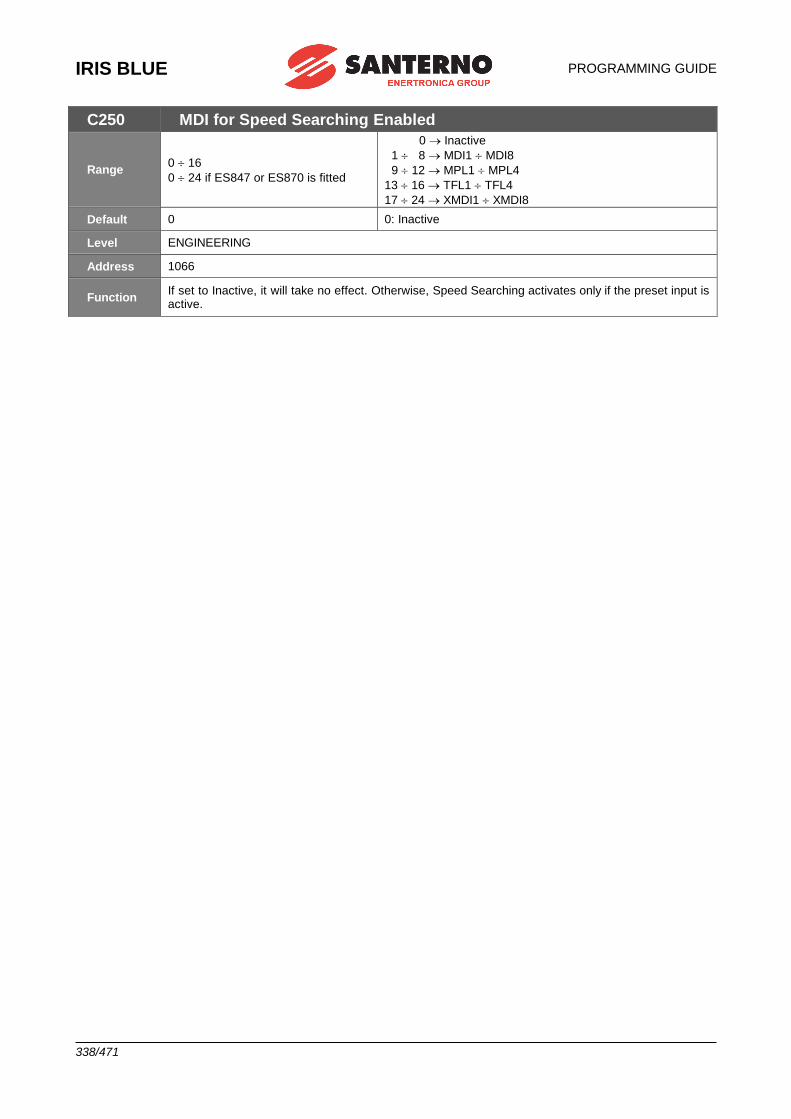
IRIS BLUE
PROGRAMMING GUIDE
338/471
C250 MDI for Speed Searching Enabled
Range 0 16
0 24 if ES847 or ES870 is fitted
0 Inactive
1 8 MDI1 MDI8
9 12 MPL1 MPL4
13 16 TFL1 TFL4
17 24 XMDI1 XMDI8
Default 0 0: Inactive
Level ENGINEERING
Address 1066
Function If set to Inactive, it will take no effect. Otherwise, Speed Searching activates only if the preset input is active.
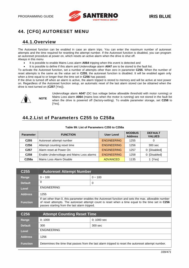
PROGRAMMING GUIDE
IRIS BLUE
339/471
44. [CFG] AUTORESET MENU
44.1.Overview The Autoreset function can be enabled in case an alarm trips. You can enter the maximum number of autoreset attempts and the time required for resetting the attempt number. If the Autoreset function is disabled, you can program an autoreset procedure at power on, which resets an active alarm when the drive is shut off. Always in this menu
• It is possible to enable Mains Loss alarm A064 tripping when this event is detected and
• It is possible to define if this alarm and Undervoltage alarm A047 are to be stored to the fault list.
To activate the Autoreset function, set a number of attempts other than zero in parameter C255. When the number of
reset attempts is the same as the value set in C255, the autoreset function is disabled. It will be enabled again only
when a time equal to or longer than the time set in C256 has passed. If the drive is turned off when an alarm is active, the alarm tripped is stored to memory and will be active at next power on. Regardless of the Autoreset function setup, an automatic reset of the last alarm stored can be obtained when the
drive is next turned on (C257 [Yes]).
NOTE
Undervoltage alarm A047 (DC bus voltage below allowable threshold with motor running) or
Mains Loss alarm A064 (mains loss when the motor is running) are not stored in the fault list
when the drive is powered off (factory-setting). To enable parameter storage, set C258 to [Yes].
44.2.List of Parameters C255 to C258a
Table 99: List of Parameters C255 to C258a
Parameter FUNCTION User Level MODBUS
Address
DEFAULT
VALUES
C255 Autoreset attempt number ENGINEERING 1255 0
C256 Attempt counting reset time ENGINEERING 1256 300 sec
C257 Alarm reset at Power On ENGINEERING 1257 0: [Disabled]
C258 Enable Undervoltage and Mains Loss alarms ENGINEERING 1258 0: [Disabled]
C258a Mains Loss Alarm Disable ADVANCED 1135 1: [Yes]
C255 Autoreset Attempt Number
Range 0 ÷ 100 0 ÷ 100
Default 0 0
Level ENGINEERING
Address 1255
Function
If set other than 0, this parameter enables the Autoreset function and sets the max. allowable number
of reset attempts. The autoreset attempt count is reset when a time equal to the time set in C256 passes starting from the last alarm tripped.
C256 Attempt Counting Reset Time
Range 0; 1000 0; 1000 sec
Default 300 300 sec
Level ENGINEERING
Address 1256
Function Determines the time that passes from the last alarm tripped to reset the autoreset attempt number.
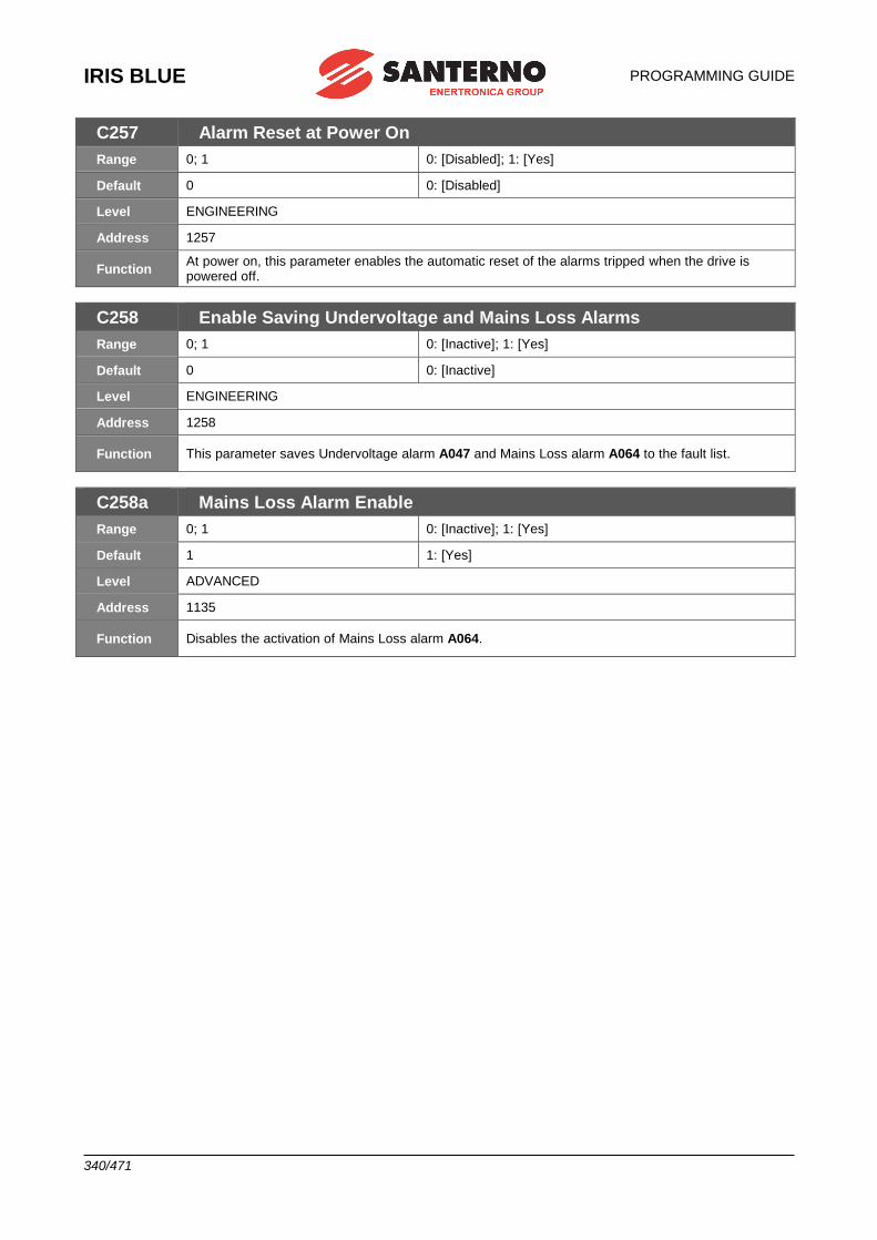
IRIS BLUE
PROGRAMMING GUIDE
340/471
C257 Alarm Reset at Power On
Range 0; 1 0: [Disabled]; 1: [Yes]
Default 0 0: [Disabled]
Level ENGINEERING
Address 1257
Function At power on, this parameter enables the automatic reset of the alarms tripped when the drive is powered off.
C258 Enable Saving Undervoltage and Mains Loss Alarms
Range 0; 1 0: [Inactive]; 1: [Yes]
Default 0 0: [Inactive]
Level ENGINEERING
Address 1258
Function This parameter saves Undervoltage alarm A047 and Mains Loss alarm A064 to the fault list.
C258a Mains Loss Alarm Enable
Range 0; 1 0: [Inactive]; 1: [Yes]
Default 1 1: [Yes]
Level ADVANCED
Address 1135
Function Disables the activation of Mains Loss alarm A064.
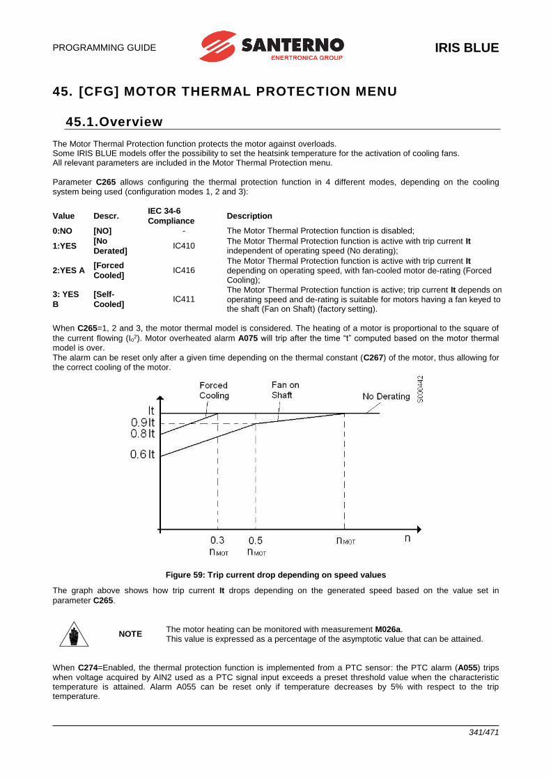
PROGRAMMING GUIDE
IRIS BLUE
341/471
45. [CFG] MOTOR THERMAL PROTECTION MENU
45.1.Overview The Motor Thermal Protection function protects the motor against overloads. Some IRIS BLUE models offer the possibility to set the heatsink temperature for the activation of cooling fans. All relevant parameters are included in the Motor Thermal Protection menu.
Parameter C265 allows configuring the thermal protection function in 4 different modes, depending on the cooling system being used (configuration modes 1, 2 and 3):
Value Descr. IEC 34-6
Compliance Description
0:NO [NO] - The Motor Thermal Protection function is disabled;
1:YES [No
Derated] IC410
The Motor Thermal Protection function is active with trip current It independent of operating speed (No derating);
2:YES A [Forced
Cooled] IC416
The Motor Thermal Protection function is active with trip current It depending on operating speed, with fan-cooled motor de-rating (Forced Cooling);
3: YES
B
[Self-
Cooled] IC411
The Motor Thermal Protection function is active; trip current It depends on operating speed and de-rating is suitable for motors having a fan keyed to the shaft (Fan on Shaft) (factory setting).
When C265=1, 2 and 3, the motor thermal model is considered. The heating of a motor is proportional to the square of
the current flowing (Io2). Motor overheated alarm A075 will trip after the time “t” computed based on the motor thermal model is over.
The alarm can be reset only after a given time depending on the thermal constant (C267) of the motor, thus allowing for the correct cooling of the motor.
Figure 59: Trip current drop depending on speed values
The graph above shows how trip current It drops depending on the generated speed based on the value set in
parameter C265.
NOTE The motor heating can be monitored with measurement M026a. This value is expressed as a percentage of the asymptotic value that can be attained.
When C274=Enabled, the thermal protection function is implemented from a PTC sensor: the PTC alarm (A055) trips when voltage acquired by AIN2 used as a PTC signal input exceeds a preset threshold value when the characteristic temperature is attained. Alarm A055 can be reset only if temperature decreases by 5% with respect to the trip temperature.
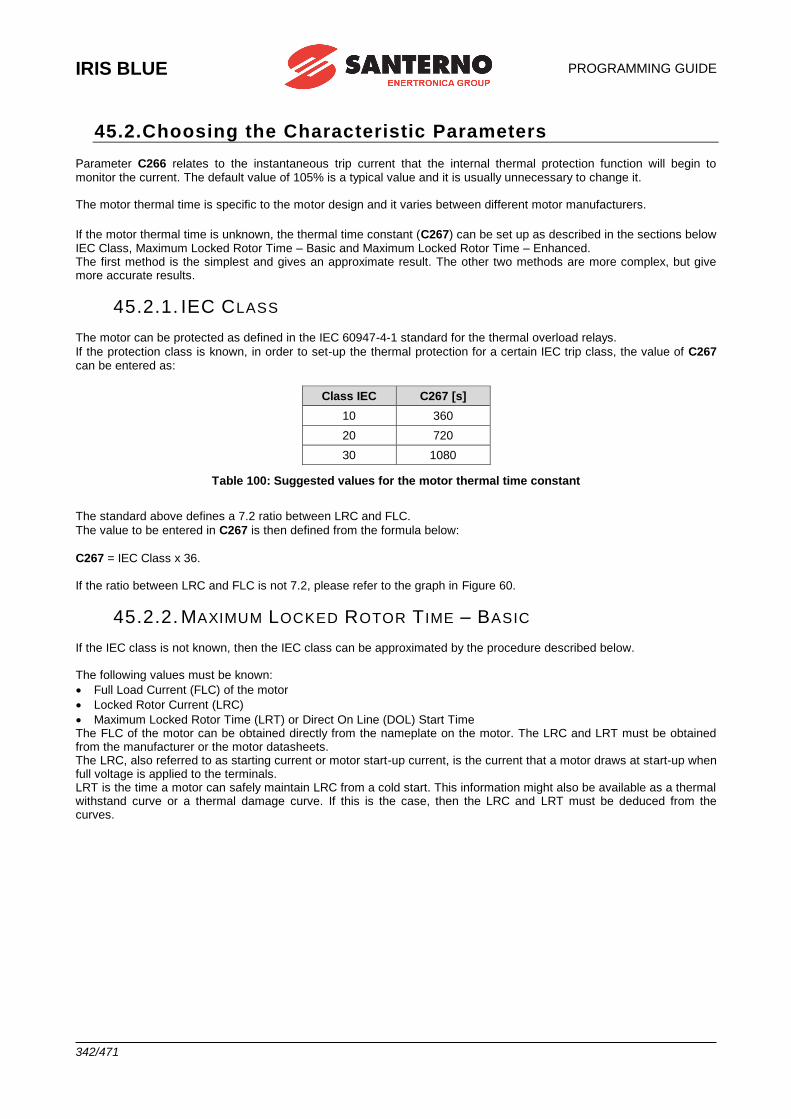
IRIS BLUE
PROGRAMMING GUIDE
342/471
45.2.Choosing the Characteristic Parameters
Parameter C266 relates to the instantaneous trip current that the internal thermal protection function will begin to monitor the current. The default value of 105% is a typical value and it is usually unnecessary to change it. The motor thermal time is specific to the motor design and it varies between different motor manufacturers.
If the motor thermal time is unknown, the thermal time constant (C267) can be set up as described in the sections below IEC Class, Maximum Locked Rotor Time – Basic and Maximum Locked Rotor Time – Enhanced. The first method is the simplest and gives an approximate result. The other two methods are more complex, but give more accurate results.
45.2.1. IEC CLASS The motor can be protected as defined in the IEC 60947-4-1 standard for the thermal overload relays.
If the protection class is known, in order to set-up the thermal protection for a certain IEC trip class, the value of C267 can be entered as:
Class IEC C267 [s]
10 360
20 720
30 1080
Table 100: Suggested values for the motor thermal time constant
The standard above defines a 7.2 ratio between LRC and FLC.
The value to be entered in C267 is then defined from the formula below:
C267 = IEC Class x 36. If the ratio between LRC and FLC is not 7.2, please refer to the graph in Figure 60.
45.2.2. MAXIMUM LOCKED ROTOR T IME – BASIC If the IEC class is not known, then the IEC class can be approximated by the procedure described below. The following values must be known:
• Full Load Current (FLC) of the motor
• Locked Rotor Current (LRC)
• Maximum Locked Rotor Time (LRT) or Direct On Line (DOL) Start Time The FLC of the motor can be obtained directly from the nameplate on the motor. The LRC and LRT must be obtained from the manufacturer or the motor datasheets. The LRC, also referred to as starting current or motor start-up current, is the current that a motor draws at start-up when full voltage is applied to the terminals. LRT is the time a motor can safely maintain LRC from a cold start. This information might also be available as a thermal withstand curve or a thermal damage curve. If this is the case, then the LRC and LRT must be deduced from the curves.
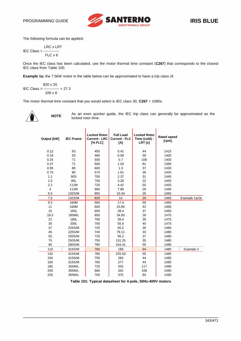
PROGRAMMING GUIDE
IRIS BLUE
343/471
The following formula can be applied: LRC x LRT IEC Class = ------------- FLC x 6
Once the IEC class has been calculated, use the motor thermal time constant (C267) that corresponds to the closest IEC class from Table 100.
Example 1a: the 7.5kW motor in the table below can be approximated to have a trip class of: 820 x 20 IEC Class = ------------- = 27.3 100 x 6
The motor thermal time constant that you would select is IEC class 30, C267 = 1080s.
NOTE As an even quicker guide, the IEC trip class can generally be approximated as the locked rotor time.
Output [kW] IEC Frame
Locked Rotor
Current - LRC
[% FLC]
Full Load
Current - FLC
[A]
Locked Rotor
Time (cold) -
LRT [s]
Rated speed
[rpm]
0.12 63 450 0.41 44 1415
0.18 63 460 0.58 59 1400
0.25 71 500 0.7 106 1400
0.37 71 500 1.03 81 1395
0.55 80 600 1.3 37 1430
0.75 80 570 1.61 35 1420
1.1 90S 700 2.37 31 1445
1.5 90L 750 3.28 22 1450
2.2 112M 720 4.42 55 1455
4 112M 660 7.85 26 1445
5.5 132S/M 850 10.34 26 1465
7.5 132S/M 820 14 20 1465 Example 1a/1b
9.2 160M 560 17.4 59 1460
11 160M 600 20.84 42 1465
15 160L 650 28.4 37 1465
18.5 180M/L 800 34.83 26 1470
22 180L 790 39.4 35 1475
30 200L 700 55.6 40 1475
37 225S/M 720 65.2 35 1480
45 225S/M 740 78.11 33 1480
55 250S/M 720 95.2 37 1480
75 250S/M 750 131.25 35 1480
90 280S/M 780 154.41 55 1485
110 315S/M 760 189 64 1485 Example 2
132 315S/M 780 225.53 55 1485
150 315S/M 750 260 44 1485
160 315S/M 760 277 44 1485
185 355M/L 720 320 117 1490
200 355M/L 660 342 108 1490
220 355M/L 700 375 84 1490
Table 101: Typical datasheet for 4-pole, 50Hz-400V motors
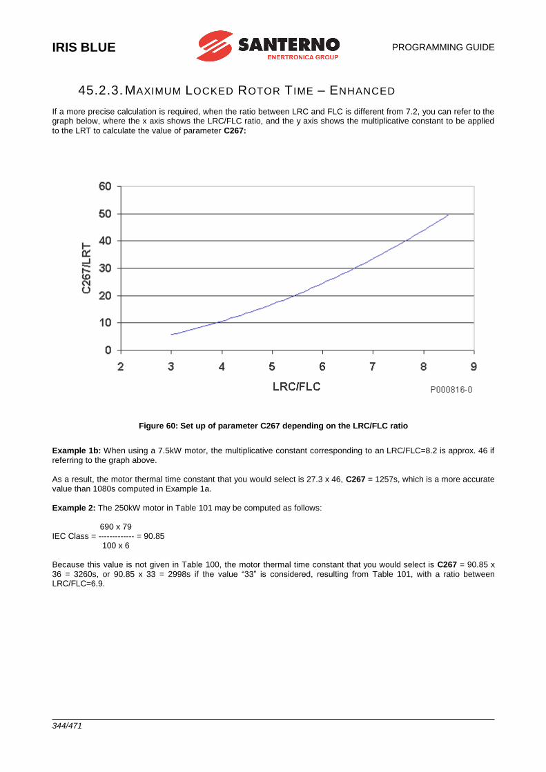
IRIS BLUE
PROGRAMMING GUIDE
344/471
45.2.3. MAXIMUM LOCKED ROTOR T IME – ENHANCED
If a more precise calculation is required, when the ratio between LRC and FLC is different from 7.2, you can refer to the graph below, where the x axis shows the LRC/FLC ratio, and the y axis shows the multiplicative constant to be applied
to the LRT to calculate the value of parameter C267:
Figure 60: Set up of parameter C267 depending on the LRC/FLC ratio
Example 1b: When using a 7.5kW motor, the multiplicative constant corresponding to an LRC/FLC=8.2 is approx. 46 if referring to the graph above.
As a result, the motor thermal time constant that you would select is 27.3 x 46, C267 = 1257s, which is a more accurate value than 1080s computed in Example 1a.
Example 2: The 250kW motor in Table 101 may be computed as follows: 690 x 79 IEC Class = ------------- = 90.85 100 x 6
Because this value is not given in Table 100, the motor thermal time constant that you would select is C267 = 90.85 x 36 = 3260s, or 90.85 x 33 = 2998s if the value “33” is considered, resulting from Table 101, with a ratio between LRC/FLC=6.9.
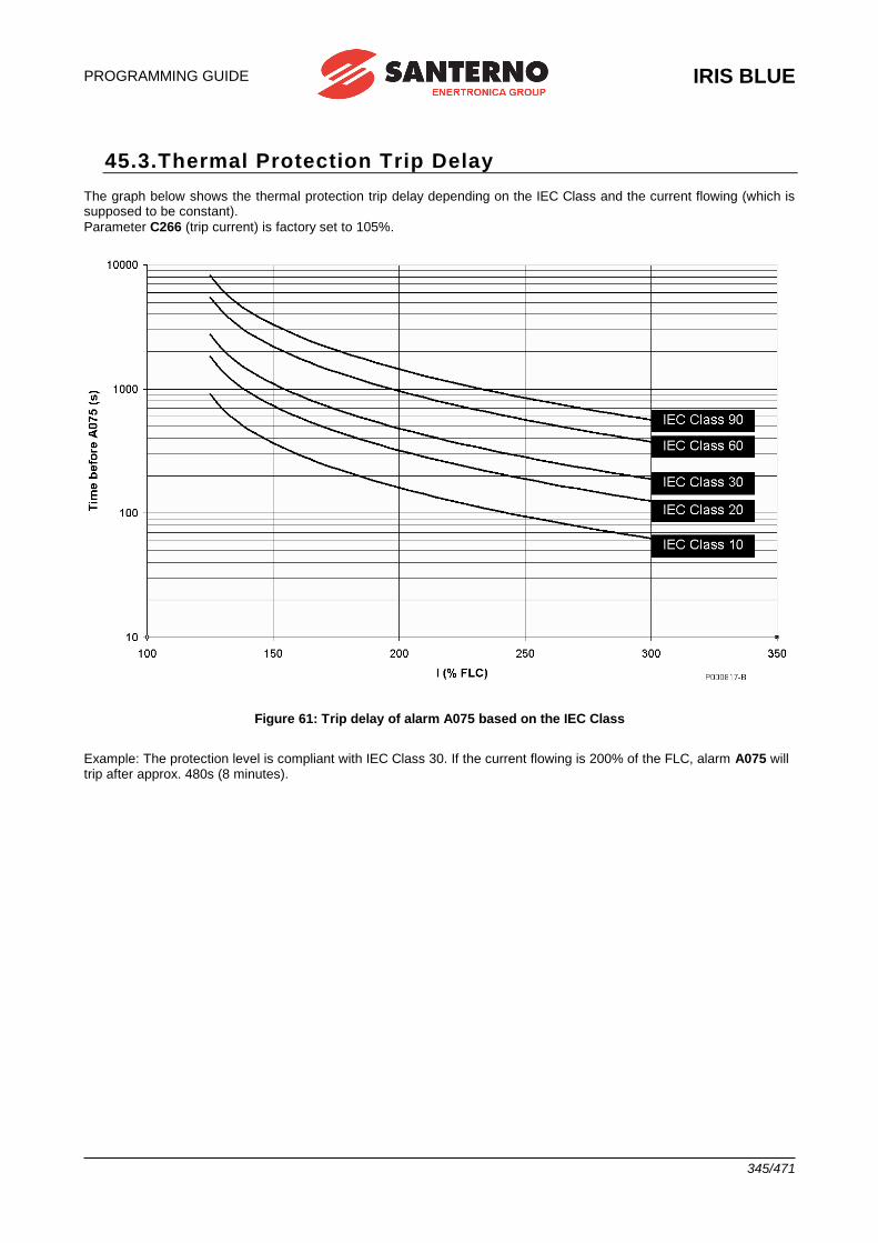
PROGRAMMING GUIDE
IRIS BLUE
345/471
45.3.Thermal Protection Trip Delay The graph below shows the thermal protection trip delay depending on the IEC Class and the current flowing (which is supposed to be constant).
Parameter C266 (trip current) is factory set to 105%.
Figure 61: Trip delay of alarm A075 based on the IEC Class
Example: The protection level is compliant with IEC Class 30. If the current flowing is 200% of the FLC, alarm A075 will trip after approx. 480s (8 minutes).
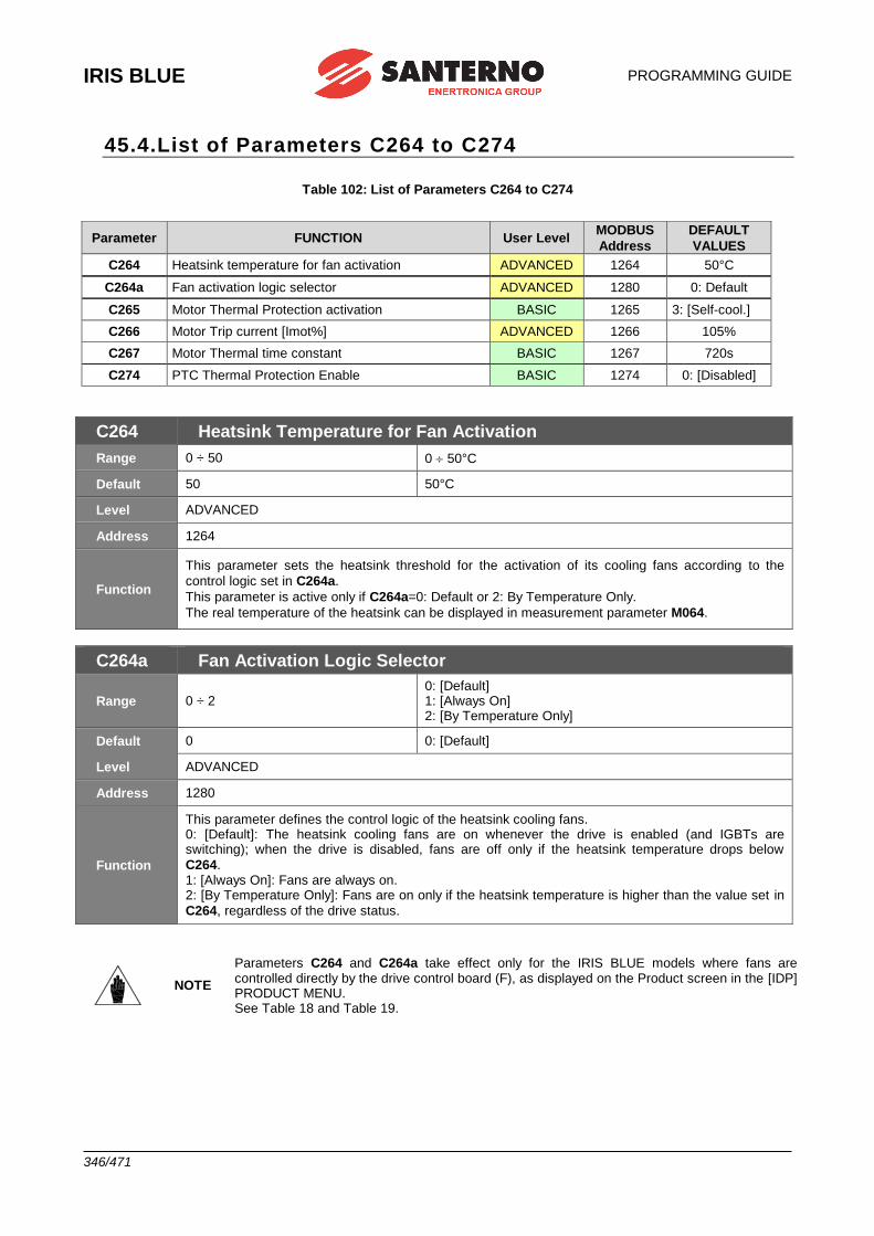
IRIS BLUE
PROGRAMMING GUIDE
346/471
45.4.List of Parameters C264 to C274
Table 102: List of Parameters C264 to C274
Parameter FUNCTION User Level MODBUS
Address
DEFAULT
VALUES
C264 Heatsink temperature for fan activation ADVANCED 1264 50°C
C264a Fan activation logic selector ADVANCED 1280 0: Default
C265 Motor Thermal Protection activation BASIC 1265 3: [Self-cool.]
C266 Motor Trip current [Imot%] ADVANCED 1266 105%
C267 Motor Thermal time constant BASIC 1267 720s
C274 PTC Thermal Protection Enable BASIC 1274 0: [Disabled]
C264 Heatsink Temperature for Fan Activation
Range 0 ÷ 50 0 50°C
Default 50 50°C
Level ADVANCED
Address 1264
Function
This parameter sets the heatsink threshold for the activation of its cooling fans according to the
control logic set in C264a.
This parameter is active only if C264a=0: Default or 2: By Temperature Only.
The real temperature of the heatsink can be displayed in measurement parameter M064.
C264a Fan Activation Logic Selector
Range 0 ÷ 2 0: [Default] 1: [Always On] 2: [By Temperature Only]
Default 0 0: [Default]
Level ADVANCED
Address 1280
Function
This parameter defines the control logic of the heatsink cooling fans. 0: [Default]: The heatsink cooling fans are on whenever the drive is enabled (and IGBTs are switching); when the drive is disabled, fans are off only if the heatsink temperature drops below
C264. 1: [Always On]: Fans are always on. 2: [By Temperature Only]: Fans are on only if the heatsink temperature is higher than the value set in
C264, regardless of the drive status.
NOTE
Parameters C264 and C264a take effect only for the IRIS BLUE models where fans are controlled directly by the drive control board (F), as displayed on the Product screen in the [IDP] PRODUCT MENU. See Table 18 and Table 19.
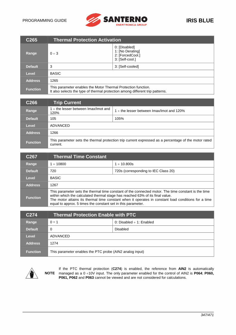
PROGRAMMING GUIDE
IRIS BLUE
347/471
C265 Thermal Protection Activation
Range 0 3
0: [Disabled] 1: [No Derating] 2: [ForcedCool.] 3: [Self-cool.]
Default 3 3: [Self-cooled]
Level BASIC
Address 1265
Function This parameter enables the Motor Thermal Protection function. It also selects the type of thermal protection among different trip patterns.
C266 Trip Current
Range 1 the lesser between Imax/Imot and 120%
1 the lesser between Imax/Imot and 120%
Default 105 105%
Level ADVANCED
Address 1266
Function This parameter sets the thermal protection trip current expressed as a percentage of the motor rated current.
C267 Thermal Time Constant
Range 1 10800 1 10.800s
Default 720 720s (corresponding to IEC Class 20)
Level BASIC
Address 1267
Function
This parameter sets the thermal time constant of the connected motor. The time constant is the time within which the calculated thermal stage has reached 63% of its final value. The motor attains its thermal time constant when it operates in constant load conditions for a time equal to approx. 5 times the constant set in this parameter.
C274 Thermal Protection Enable with PTC
Range 0 ÷ 1 0: Disabled 1: Enabled
Default 0 Disabled
Level ADVANCED
Address 1274
Function This parameter enables the PTC probe (AIN2 analog input)
NOTE
If the PTC thermal protection (C274) is enabled, the reference from AIN2 is automatically
managed as a 0 10V input. The only parameter enabled for the control of AIN2 is P064; P060,
P061, P062 and P063 cannot be viewed and are not considered for calculations.
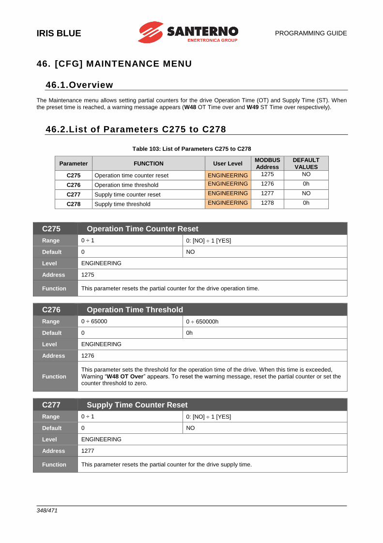
IRIS BLUE
PROGRAMMING GUIDE
348/471
46. [CFG] MAINTENANCE MENU
46.1.Overview The Maintenance menu allows setting partial counters for the drive Operation Time (OT) and Supply Time (ST). When
the preset time is reached, a warning message appears (W48 OT Time over and W49 ST Time over respectively).
46.2.List of Parameters C275 to C278
Table 103: List of Parameters C275 to C278
Parameter FUNCTION User Level MODBUS
Address
DEFAULT
VALUES
C275 Operation time counter reset ENGINEERING 1275 NO
C276 Operation time threshold ENGINEERING 1276 0h
C277 Supply time counter reset ENGINEERING 1277 NO
C278 Supply time threshold ENGINEERING 1278 0h
C275 Operation Time Counter Reset
Range 0 ÷ 1 0: [NO] 1 [YES]
Default 0 NO
Level ENGINEERING
Address 1275
Function This parameter resets the partial counter for the drive operation time.
C276 Operation Time Threshold
Range 0 ÷ 65000 0 650000h
Default 0 0h
Level ENGINEERING
Address 1276
Function
This parameter sets the threshold for the operation time of the drive. When this time is exceeded,
Warning “W48 OT Over” appears. To reset the warning message, reset the partial counter or set the counter threshold to zero.
C277 Supply Time Counter Reset
Range 0 ÷ 1 0: [NO] 1 [YES]
Default 0 NO
Level ENGINEERING
Address 1277
Function This parameter resets the partial counter for the drive supply time.

PROGRAMMING GUIDE
IRIS BLUE
349/471
C278 Supply Time Threshold
Range 0 ÷ 65000 0 650000h
Default 0 0h
Level ENGINEERING
Address 1278
Function
This parameter sets the threshold for the supply time of the drive. When this time is exceeded,
Warning “W49 ST Over” appears. To reset the warning message, reset the partial counter or set the counter threshold to zero.
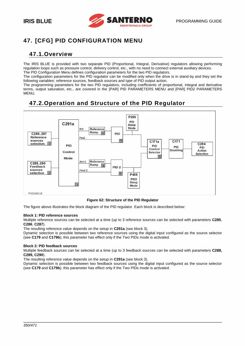
IRIS BLUE
PROGRAMMING GUIDE
350/471
47. [CFG] PID CONFIGURATION MENU
47.1.Overview The IRIS BLUE is provided with two separate PID (Proportional, Integral, Derivative) regulators allowing performing regulation loops such as pressure control, delivery control, etc., with no need to connect external auxiliary devices. The PID Configuration Menu defines configuration parameters for the two PID regulators. The configuration parameters for the PID regulator can be modified only when the drive is in stand-by and they set the following variables: reference sources, feedback sources and type of PID output action. The programming parameters for the two PID regulators, including coefficients of proportional, integral and derivative terms, output saturation, etc., are covered in the [PAR] PID PARAMETERS MENU and [PAR] PID2 PARAMETERS MENU.
47.2.Operation and Structure of the PID Regulator
Figure 62: Structure of the PID Regulator
The figure above illustrates the block diagram of the PID regulator. Each block is described below:
Block 1: PID reference sources
Multiple reference sources can be selected at a time (up to 3 reference sources can be selected with parameters C285,
C286, C287).
The resulting reference value depends on the setup in C291a (see block 3). Dynamic selection is possible between two reference sources using the digital input configured as the source selector
(see C179 and C179b); this parameter has effect only if the Two PIDs mode is activated.
Block 2: PID feedback sources
Multiple feedback sources can be selected at a time (up to 3 feedback sources can be selected with parameters C288,
C289, C290).
The resulting reference value depends on the setup in C291a (see block 3). Dynamic selection is possible between two feedback sources using the digital input configured as the source selector
(see C179 and C179b); this parameter has effect only if the Two PIDs mode is activated.
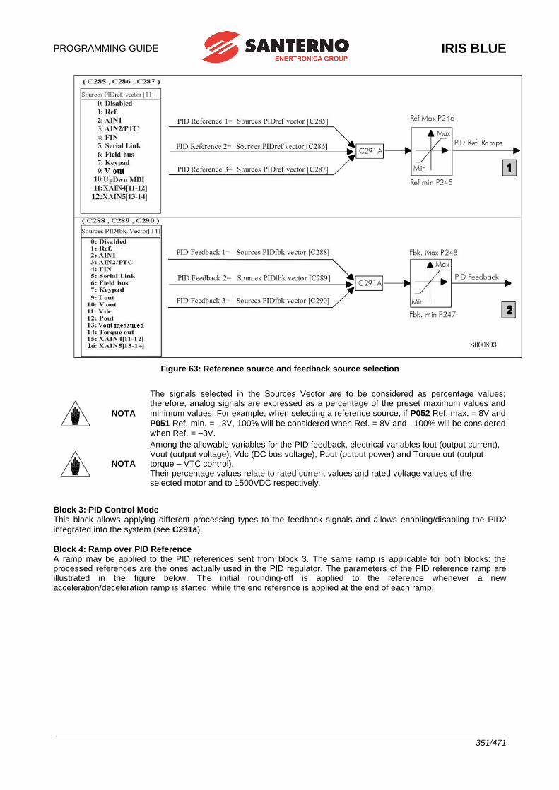
PROGRAMMING GUIDE
IRIS BLUE
351/471
Figure 63: Reference source and feedback source selection
NOTA
The signals selected in the Sources Vector are to be considered as percentage values; therefore, analog signals are expressed as a percentage of the preset maximum values and
minimum values. For example, when selecting a reference source, if P052 Ref. max. = 8V and
P051 Ref. min. = –3V, 100% will be considered when Ref. = 8V and –100% will be considered when Ref. = –3V.
NOTA
Among the allowable variables for the PID feedback, electrical variables Iout (output current), Vout (output voltage), Vdc (DC bus voltage), Pout (output power) and Torque out (output torque – VTC control). Their percentage values relate to rated current values and rated voltage values of the selected motor and to 1500VDC respectively.
Block 3: PID Control Mode This block allows applying different processing types to the feedback signals and allows enabling/disabling the PID2
integrated into the system (see C291a).
Block 4: Ramp over PID Reference A ramp may be applied to the PID references sent from block 3. The same ramp is applicable for both blocks: the processed references are the ones actually used in the PID regulator. The parameters of the PID reference ramp are illustrated in the figure below. The initial rounding-off is applied to the reference whenever a new acceleration/deceleration ramp is started, while the end reference is applied at the end of each ramp.
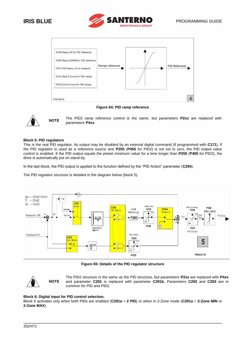
IRIS BLUE
PROGRAMMING GUIDE
352/471
Figure 64: PID ramp reference
NOTE The PID2 ramp reference control is the same, but parameters P2xx are replaced with
parameters P4xx.
Block 5: PID regulators
This is the real PID regulator. Its output may be disabled by an external digital command (if programmed with C171). If
the PID regulator is used as a reference source and P255 (P455 for PID2) is not set to zero, the PID output value
control is enabled. If the PID output equals the preset minimum value for a time longer than P255 (P455 for PID2), the drive is automatically put on stand-by.
In the last block, the PID output is applied to the function defined by the “PID Action” parameter (C294). The PID regulator structure is detailed in the diagram below (block 5).
Figure 65: Details of the PID regulator structure
NOTE The PID2 structure is the same as the PID structure, but parameters P2xx are replaced with P4xx
and parameter C291 is replaced with parameter C291b. Parameters C292 and C293 are in common for PID and PID2.
Block 6: Digital input for PID control selection.
Block 6 activates only when both PIDs are enabled (C291a = 2 PID) or when in 2-Zone mode (C291a = 2-Zone MIN or
2-Zone MAX).
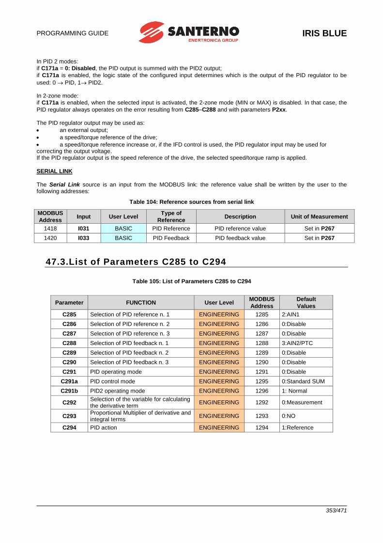
PROGRAMMING GUIDE
IRIS BLUE
353/471
In PID 2 modes:
if C171a = 0: Disabled, the PID output is summed with the PID2 output;
if C171a is enabled, the logic state of the configured input determines which is the output of the PID regulator to be
used: 0 PID, 1 PID2. In 2-zone mode:
if C171a is enabled, when the selected input is activated, the 2-zone mode (MIN or MAX) is disabled. In that case, the
PID regulator always operates on the error resulting from C285–C288 and with parameters P2xx. The PID regulator output may be used as:
• an external output;
• a speed/torque reference of the drive;
• a speed/torque reference increase or, if the IFD control is used, the PID regulator input may be used for correcting the output voltage. If the PID regulator output is the speed reference of the drive, the selected speed/torque ramp is applied.
SERIAL LINK
The Serial Link source is an input from the MODBUS link: the reference value shall be written by the user to the following addresses:
Table 104: Reference sources from serial link
MODBUS
Address Input User Level
Type of
Reference Description Unit of Measurement
1418 I031 BASIC PID Reference PID reference value Set in P267
1420 I033 BASIC PID Feedback PID feedback value Set in P267
47.3.List of Parameters C285 to C294
Table 105: List of Parameters C285 to C294
Parameter FUNCTION User Level MODBUS
Address
Default
Values
C285 Selection of PID reference n. 1 ENGINEERING 1285 2:AIN1
C286 Selection of PID reference n. 2 ENGINEERING 1286 0:Disable
C287 Selection of PID reference n. 3 ENGINEERING 1287 0:Disable
C288 Selection of PID feedback n. 1 ENGINEERING 1288 3:AIN2/PTC
C289 Selection of PID feedback n. 2 ENGINEERING 1289 0:Disable
C290 Selection of PID feedback n. 3 ENGINEERING 1290 0:Disable
C291 PID operating mode ENGINEERING 1291 0:Disable
C291a PID control mode ENGINEERING 1295 0:Standard SUM
C291b PID2 operating mode ENGINEERING 1296 1: Normal
C292 Selection of the variable for calculating the derivative term
ENGINEERING 1292 0:Measurement
C293 Proportional Multiplier of derivative and integral terms
ENGINEERING 1293 0:NO
C294 PID action ENGINEERING 1294 1:Reference
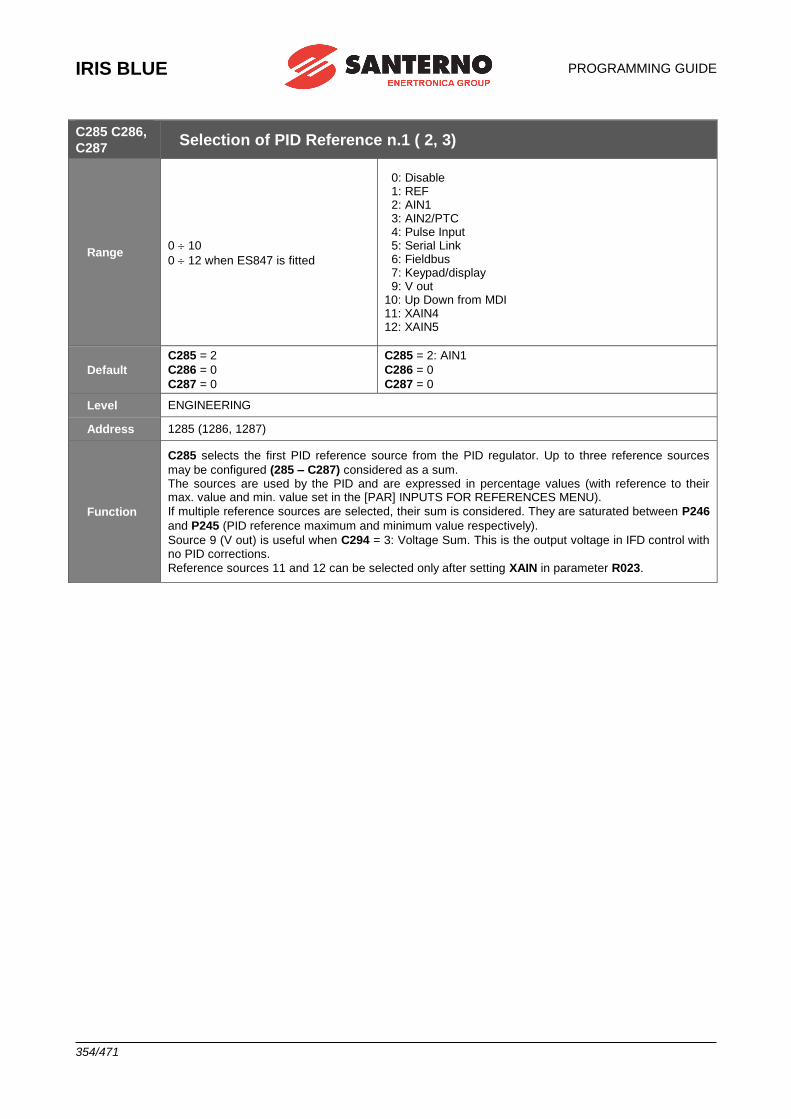
IRIS BLUE
PROGRAMMING GUIDE
354/471
C285 C286,
C287 Selection of PID Reference n.1 ( 2, 3)
Range 0 10
0 12 when ES847 is fitted
0: Disable 1: REF 2: AIN1 3: AIN2/PTC 4: Pulse Input 5: Serial Link 6: Fieldbus 7: Keypad/display 9: V out 10: Up Down from MDI 11: XAIN4 12: XAIN5
Default
C285 = 2
C286 = 0
C287 = 0
C285 = 2: AIN1
C286 = 0
C287 = 0
Level ENGINEERING
Address 1285 (1286, 1287)
Function
C285 selects the first PID reference source from the PID regulator. Up to three reference sources
may be configured (285 – C287) considered as a sum. The sources are used by the PID and are expressed in percentage values (with reference to their max. value and min. value set in the [PAR] INPUTS FOR REFERENCES MENU).
If multiple reference sources are selected, their sum is considered. They are saturated between P246
and P245 (PID reference maximum and minimum value respectively).
Source 9 (V out) is useful when C294 = 3: Voltage Sum. This is the output voltage in IFD control with no PID corrections.
Reference sources 11 and 12 can be selected only after setting XAIN in parameter R023.
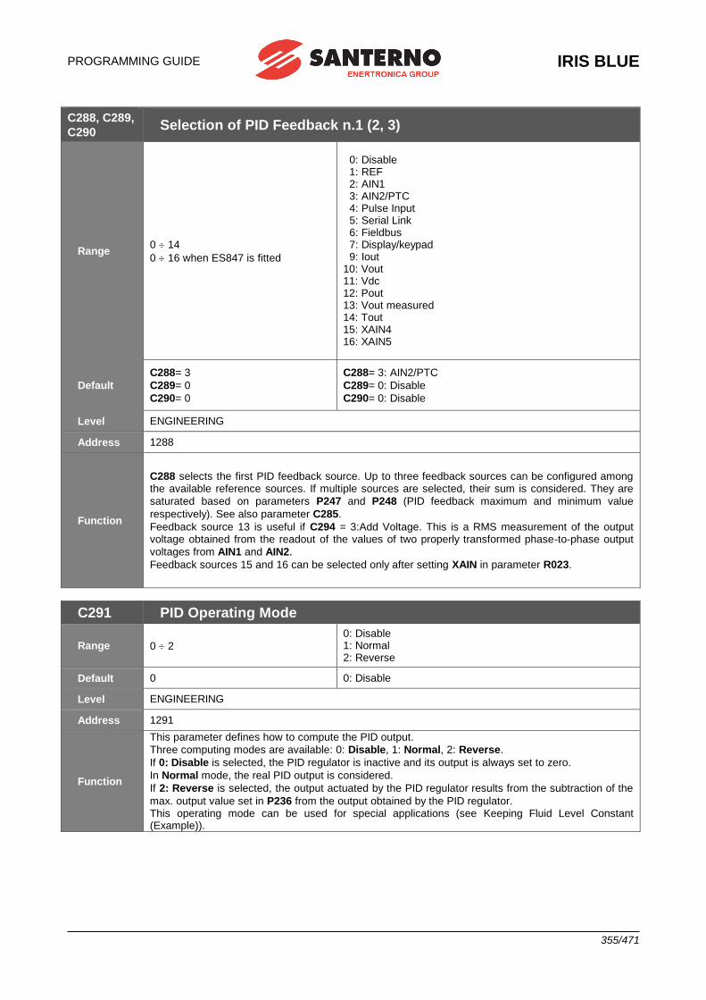
PROGRAMMING GUIDE
IRIS BLUE
355/471
C288, C289,
C290 Selection of PID Feedback n.1 (2, 3)
Range 0 14
0 16 when ES847 is fitted
0: Disable 1: REF 2: AIN1 3: AIN2/PTC 4: Pulse Input 5: Serial Link 6: Fieldbus 7: Display/keypad 9: Iout 10: Vout 11: Vdc 12: Pout 13: Vout measured 14: Tout 15: XAIN4 16: XAIN5
Default
C288= 3
C289= 0
C290= 0
C288= 3: AIN2/PTC
C289= 0: Disable
C290= 0: Disable
Level ENGINEERING
Address 1288
Function
C288 selects the first PID feedback source. Up to three feedback sources can be configured among the available reference sources. If multiple sources are selected, their sum is considered. They are
saturated based on parameters P247 and P248 (PID feedback maximum and minimum value
respectively). See also parameter C285.
Feedback source 13 is useful if C294 = 3:Add Voltage. This is a RMS measurement of the output voltage obtained from the readout of the values of two properly transformed phase-to-phase output
voltages from AIN1 and AIN2.
Feedback sources 15 and 16 can be selected only after setting XAIN in parameter R023.
C291 PID Operating Mode
Range 0 2
0: Disable 1: Normal 2: Reverse
Default 0 0: Disable
Level ENGINEERING
Address 1291
Function
This parameter defines how to compute the PID output.
Three computing modes are available: 0: Disable, 1: Normal, 2: Reverse.
If 0: Disable is selected, the PID regulator is inactive and its output is always set to zero.
In Normal mode, the real PID output is considered.
If 2: Reverse is selected, the output actuated by the PID regulator results from the subtraction of the
max. output value set in P236 from the output obtained by the PID regulator. This operating mode can be used for special applications (see Keeping Fluid Level Constant (Example)).
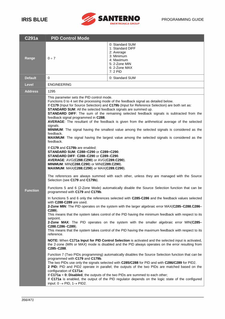
IRIS BLUE
PROGRAMMING GUIDE
356/471
C291a PID Control Mode
Range 0 7
0: Standard SUM 1: Standard DIFF 2: Average 3: Minimum 4: Maximum 5: 2-Zone MIN 6: 2-Zone MAX 7: 2 PID
Default 0 0: Standard SUM
Level ENGINEERING
Address 1295
Function
This parameter sets the PID control mode. Functions 0 to 4 set the processing mode of the feedback signal as detailed below.
If C179 (Input for Source Selection) and C179b (Input for Reference Selection) are both set as:
STANDARD SUM: All the selected feedback signals are summed up.
STANDARD DIFF: The sum of the remaining selected feedback signals is subtracted from the
feedback signal programmed in C288.
AVERAGE: The resultant of the feedback is given from the arithmetical average of the selected signals.
MINIMUM: The signal having the smallest value among the selected signals is considered as the feedback.
MAXIMUM: The signal having the largest value among the selected signals is considered as the feedback.
If C179 and C179b are enabled:
STANDARD SUM: C288+C290 or C289+C290.
STANDARD DIFF: C288–C290 or C289–C290.
AVERAGE: AVG(C288,C290) or AVG(C289,C290).
MINIMUM: MIN(C288,C290) or MIN(C289,C290).
MAXIMUM: MAX(C288,C290) or MAX(C289,C290). The references are always summed with each other, unless they are managed with the Source
Selection (see C179 and C179b). Functions 5 and 6 (2-Zone Mode) automatically disable the Source Selection function that can be
programmed with C179 and C179b.
In functions 5 and 6 only the references selected with C285-C286 and the feedback values selected
with C288-C289 are used.
2-Zone MIN: The PID operates on the system with the larger algebraic error MAX(C285–C288,C286–
C289). This means that the system takes control of the PID having the minimum feedback with respect to its setpoint.
2-Zone MAX: The PID operates on the system with the smaller algebraic error MIN(C285–
C288,C286–C289). This means that the system takes control of the PID having the maximum feedback with respect to its reference.
NOTE: When C171a Input for PID Control Selection is activated and the selected input is activated, the 2-zone (MIN or MAX) mode is disabled and the PID always operates on the error resulting from
C285–C288.
Function 7 (Two PIDs programming) automatically disables the Source Selection function that can be
programmed with C179 and C179b.
The two PIDs use only the signals selected with C285/C288 for PID and with C286/C289 for PID2.
2 PID: PID and PID2 operate in parallel; the outputs of the two PIDs are matched based on the
configuration of C171a:
If C171a = 0: Disabled, the outputs of the two PIDs are summed to each other;
If C171a is enabled, the output of the PID regulator depends on the logic state of the configured
input: 0 PID, 1 PID2.
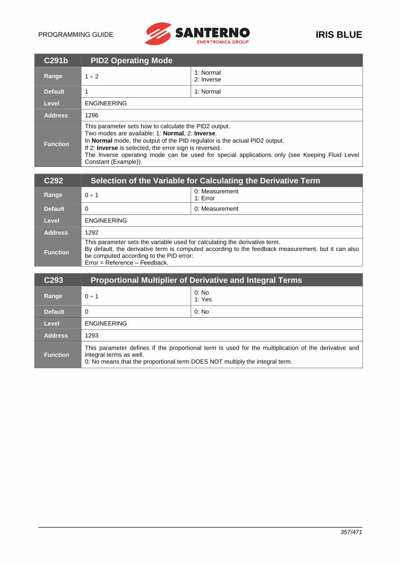
PROGRAMMING GUIDE
IRIS BLUE
357/471
C291b PID2 Operating Mode
Range 1 2 1: Normal 2: Inverse
Default 1 1: Normal
Level ENGINEERING
Address 1296
Function
This parameter sets how to calculate the PID2 output.
Two modes are available: 1: Normal, 2: Inverse.
In Normal mode, the output of the PID regulator is the actual PID2 output.
If 2: Inverse is selected, the error sign is reversed. The Inverse operating mode can be used for special applications only (see Keeping Fluid Level Constant (Example)).
C292 Selection of the Variable for Calculating the Derivative Term
Range 0 1 0: Measurement 1: Error
Default 0 0: Measurement
Level ENGINEERING
Address 1292
Function
This parameter sets the variable used for calculating the derivative term. By default, the derivative term is computed according to the feedback measurement, but it can also be computed according to the PID error: Error = Reference – Feedback.
C293 Proportional Multiplier of Derivative and Integral Terms
Range 0 1 0: No 1: Yes
Default 0 0: No
Level ENGINEERING
Address 1293
Function This parameter defines if the proportional term is used for the multiplication of the derivative and integral terms as well. 0: No means that the proportional term DOES NOT multiply the integral term.
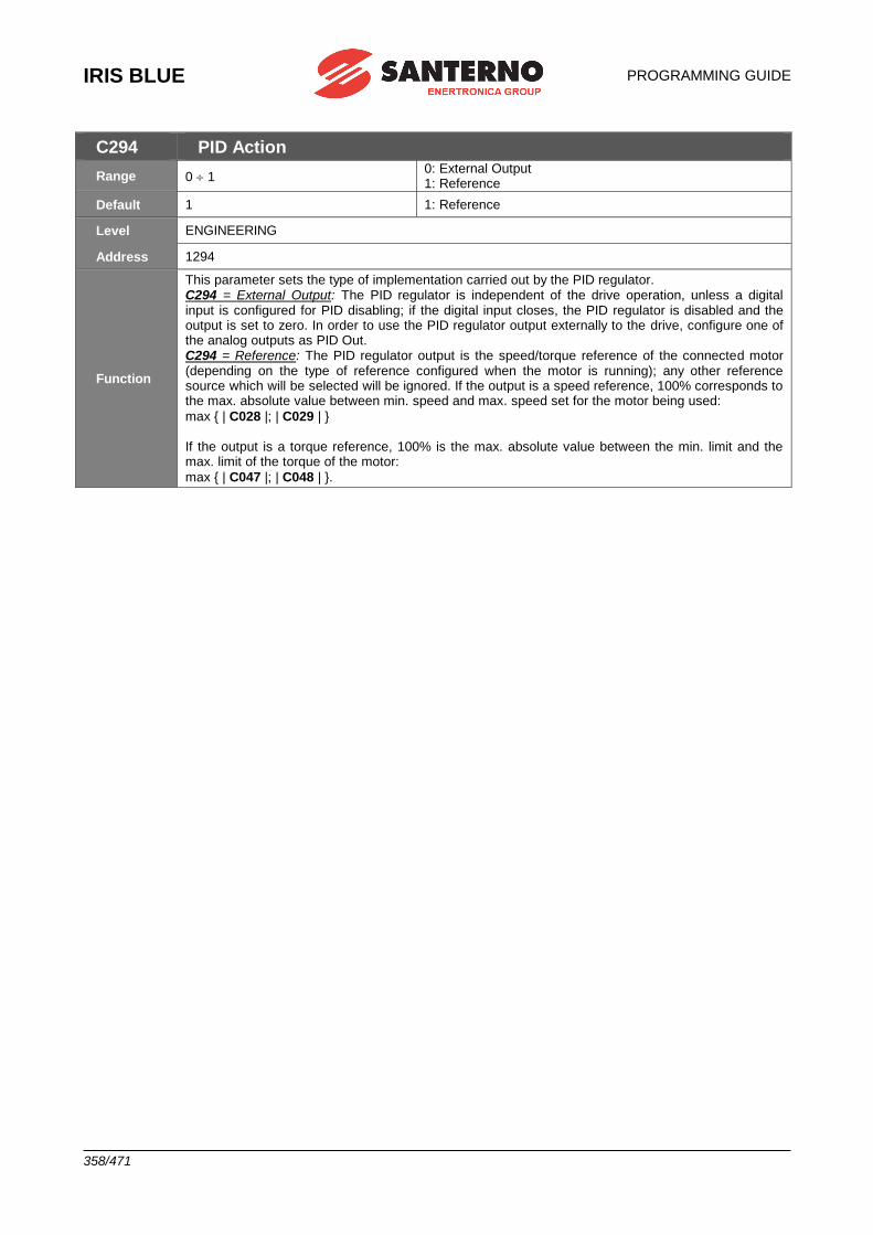
IRIS BLUE
PROGRAMMING GUIDE
358/471
C294 PID Action
Range 0 1 0: External Output 1: Reference
Default 1 1: Reference
Level ENGINEERING
Address 1294
Function
This parameter sets the type of implementation carried out by the PID regulator. C294 = External Output: The PID regulator is independent of the drive operation, unless a digital input is configured for PID disabling; if the digital input closes, the PID regulator is disabled and the output is set to zero. In order to use the PID regulator output externally to the drive, configure one of the analog outputs as PID Out. C294 = Reference: The PID regulator output is the speed/torque reference of the connected motor (depending on the type of reference configured when the motor is running); any other reference source which will be selected will be ignored. If the output is a speed reference, 100% corresponds to the max. absolute value between min. speed and max. speed set for the motor being used:
max { | C028 |; | C029 | } If the output is a torque reference, 100% is the max. absolute value between the min. limit and the max. limit of the torque of the motor:
max { | C047 |; | C048 | }.
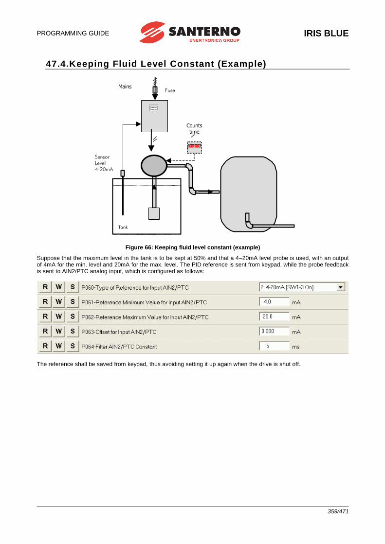
PROGRAMMING GUIDE
IRIS BLUE
359/471
47.4.Keeping Fluid Level Constant (Example)
Mains
Tank
1.2 1.1.1 U
Fuse
Sensor
Level
4-20mA
Counts time
Figure 66: Keeping fluid level constant (example)
Suppose that the maximum level in the tank is to be kept at 50% and that a 4–20mA level probe is used, with an output of 4mA for the min. level and 20mA for the max. level. The PID reference is sent from keypad, while the probe feedback is sent to AIN2/PTC analog input, which is configured as follows:
The reference shall be saved from keypad, thus avoiding setting it up again when the drive is shut off.
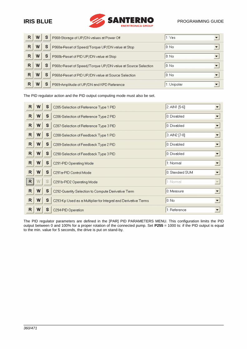
IRIS BLUE
PROGRAMMING GUIDE
360/471
The PID regulator action and the PID output computing mode must also be set.
The PID regulator parameters are defined in the [PAR] PID PARAMETERS MENU. This configuration limits the PID
output between 0 and 100% for a proper rotation of the connected pump. Set P255 = 1000 ts: if the PID output is equal to the min. value for 5 seconds, the drive is put on stand-by.
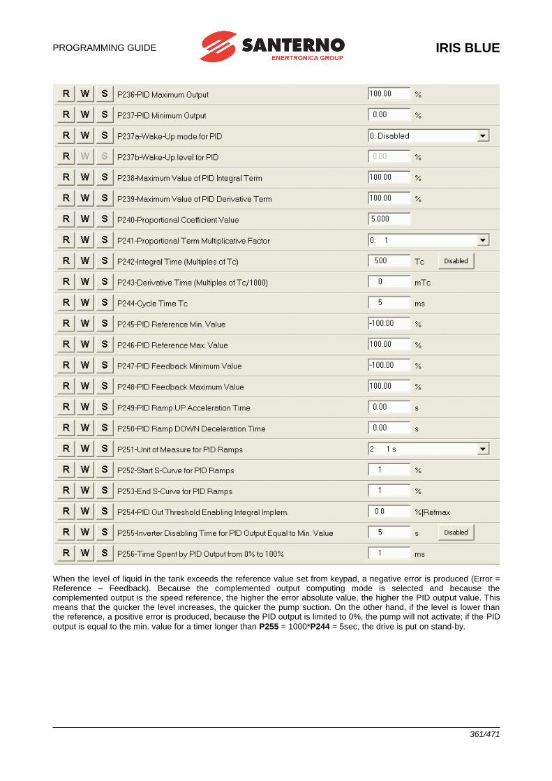
PROGRAMMING GUIDE
IRIS BLUE
361/471
When the level of liquid in the tank exceeds the reference value set from keypad, a negative error is produced (Error = Reference – Feedback). Because the complemented output computing mode is selected and because the complemented output is the speed reference, the higher the error absolute value, the higher the PID output value. This means that the quicker the level increases, the quicker the pump suction. On the other hand, if the level is lower than the reference, a positive error is produced, because the PID output is limited to 0%, the pump will not activate; if the PID
output is equal to the min. value for a timer longer than P255 = 1000*P244 = 5sec, the drive is put on stand-by.
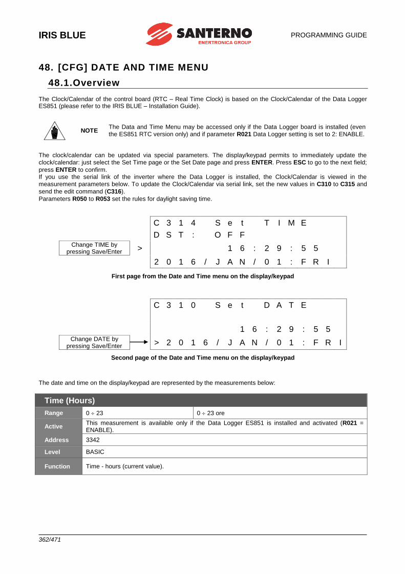
IRIS BLUE
PROGRAMMING GUIDE
362/471
48. [CFG] DATE AND TIME MENU
48.1.Overview The Clock/Calendar of the control board (RTC – Real Time Clock) is based on the Clock/Calendar of the Data Logger ES851 (please refer to the IRIS BLUE – Installation Guide).
NOTE The Data and Time Menu may be accessed only if the Data Logger board is installed (even
the ES851 RTC version only) and if parameter R021 Data Logger setting is set to 2: ENABLE.
The clock/calendar can be updated via special parameters. The display/keypad permits to immediately update the
clock/calendar: just select the Set Time page or the Set Date page and press ENTER. Press ESC to go to the next field;
press ENTER to confirm. If you use the serial link of the inverter where the Data Logger is installed, the Clock/Calendar is viewed in the
measurement parameters below. To update the Clock/Calendar via serial link, set the new values in C310 to C315 and
send the edit command (C316).
Parameters R050 to R053 set the rules for daylight saving time.
C 3 1 4 S e t T I M E
D S T : O F F Change TIME by
pressing Save/Enter > 1 6 : 2 9 : 5 5
2 0 1 6 / J A N / 0 1 : F R I
First page from the Date and Time menu on the display/keypad
C 3 1 0 S e t D A T E
1 6 : 2 9 : 5 5 Change DATE by
pressing Save/Enter > 2 0 1 6 / J A N / 0 1 : F R I
Second page of the Date and Time menu on the display/keypad
The date and time on the display/keypad are represented by the measurements below:
Time (Hours)
Range 0 23 0 23 ore
Active This measurement is available only if the Data Logger ES851 is installed and activated (R021 = ENABLE).
Address 3342
Level BASIC
Function Time - hours (current value).
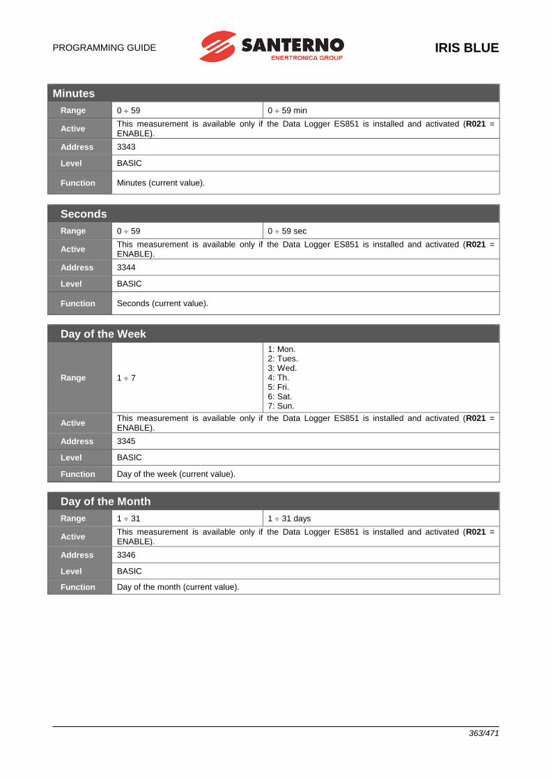
PROGRAMMING GUIDE
IRIS BLUE
363/471
Minutes
Range 0 59 0 59 min
Active This measurement is available only if the Data Logger ES851 is installed and activated (R021 = ENABLE).
Address 3343
Level BASIC
Function Minutes (current value).
Seconds
Range 0 59 0 59 sec
Active This measurement is available only if the Data Logger ES851 is installed and activated (R021 = ENABLE).
Address 3344
Level BASIC
Function Seconds (current value).
Day of the Week
Range 1 7
1: Mon. 2: Tues. 3: Wed. 4: Th. 5: Fri. 6: Sat. 7: Sun.
Active This measurement is available only if the Data Logger ES851 is installed and activated (R021 = ENABLE).
Address 3345
Level BASIC
Function Day of the week (current value).
Day of the Month
Range 1 31 1 31 days
Active This measurement is available only if the Data Logger ES851 is installed and activated (R021 = ENABLE).
Address 3346
Level BASIC
Function Day of the month (current value).
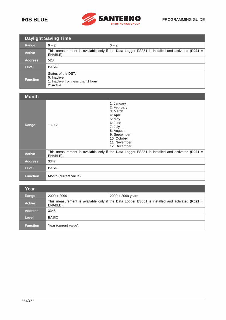
IRIS BLUE
PROGRAMMING GUIDE
364/471
Daylight Saving Time
Range 0 2 0 2
Active This measurement is available only if the Data Logger ES851 is installed and activated (R021 = ENABLE).
Address 528
Level BASIC
Function
Status of the DST: 0: Inactive 1: Inactive from less than 1 hour 2: Active
Month
Range 1 12
1: January 2. February 3: March 4: April 5: May 6: June 7: July 8: August 9: September 10: October 11: November 12: December
Active This measurement is available only if the Data Logger ES851 is installed and activated (R021 = ENABLE).
Address 3347
Level BASIC
Function Month (current value).
Year
Range 2000 2099 2000 2099 years
Active This measurement is available only if the Data Logger ES851 is installed and activated (R021 = ENABLE).
Address 3348
Level BASIC
Function Year (current value).
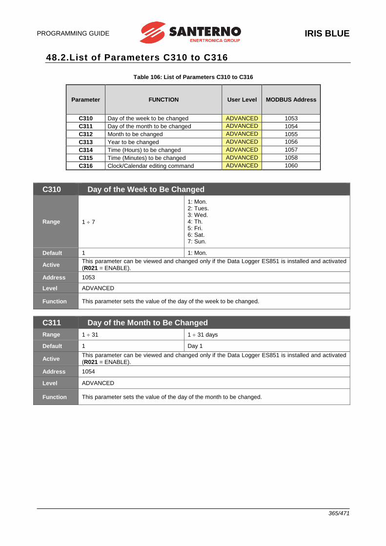
PROGRAMMING GUIDE
IRIS BLUE
365/471
48.2.List of Parameters C310 to C316
Table 106: List of Parameters C310 to C316
Parameter FUNCTION User Level MODBUS Address
C310 Day of the week to be changed ADVANCED 1053
C311 Day of the month to be changed ADVANCED 1054
C312 Month to be changed ADVANCED 1055
C313 Year to be changed ADVANCED 1056
C314 Time (Hours) to be changed ADVANCED 1057
C315 Time (Minutes) to be changed ADVANCED 1058
C316 Clock/Calendar editing command ADVANCED 1060
C310 Day of the Week to Be Changed
Range 1 7
1: Mon. 2: Tues. 3: Wed. 4: Th. 5: Fri. 6: Sat. 7: Sun.
Default 1 1: Mon.
Active This parameter can be viewed and changed only if the Data Logger ES851 is installed and activated
(R021 = ENABLE).
Address 1053
Level ADVANCED
Function This parameter sets the value of the day of the week to be changed.
C311 Day of the Month to Be Changed
Range 1 31 1 31 days
Default 1 Day 1
Active This parameter can be viewed and changed only if the Data Logger ES851 is installed and activated
(R021 = ENABLE).
Address 1054
Level ADVANCED
Function This parameter sets the value of the day of the month to be changed.
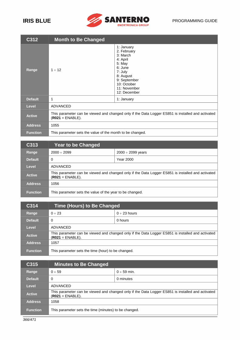
IRIS BLUE
PROGRAMMING GUIDE
366/471
C312 Month to Be Changed
Range 1 12
1: January 2. February 3: March 4: April 5: May 6: June 7: July 8: August 9: September 10: October 11: November 12: December
Default 1 1: January
Level ADVANCED
Active This parameter can be viewed and changed only if the Data Logger ES851 is installed and activated
(R021 = ENABLE).
Address 1055
Function This parameter sets the value of the month to be changed.
C313 Year to be Changed
Range 2000 2099 2000 2099 years
Default 0 Year 2000
Level ADVANCED
Active This parameter can be viewed and changed only if the Data Logger ES851 is installed and activated
(R021 = ENABLE).
Address 1056
Function This parameter sets the value of the year to be changed.
C314 Time (Hours) to Be Changed
Range 0 23 0 23 hours
Default 0 0 hours
Level ADVANCED
Active This parameter can be viewed and changed only if the Data Logger ES851 is installed and activated
(R021 = ENABLE).
Address 1057
Function This parameter sets the time (hour) to be changed.
C315 Minutes to Be Changed
Range 0 59 0 59 min.
Default 0 0 minutes
Level ADVANCED
Active This parameter can be viewed and changed only if the Data Logger ES851 is installed and activated
(R021 = ENABLE).
Address 1058
Function This parameter sets the time (minutes) to be changed.
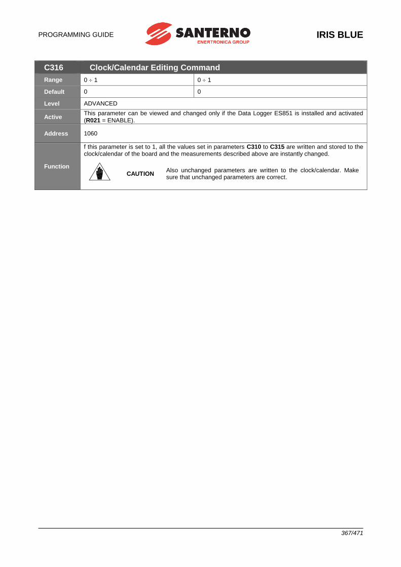
PROGRAMMING GUIDE
IRIS BLUE
367/471
C316 Clock/Calendar Editing Command
Range 0 1 0 1
Default 0 0
Level ADVANCED
Active This parameter can be viewed and changed only if the Data Logger ES851 is installed and activated
(R021 = ENABLE).
Address 1060
Function
f this parameter is set to 1, all the values set in parameters C310 to C315 are written and stored to the clock/calendar of the board and the measurements described above are instantly changed.
CAUTION
Also unchanged parameters are written to the clock/calendar. Make sure that unchanged parameters are correct.
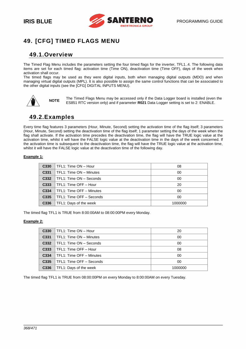
IRIS BLUE
PROGRAMMING GUIDE
368/471
49. [CFG] TIMED FLAGS MENU
49.1.Overview The Timed Flag Menu includes the parameters setting the four timed flags for the inverter, TFL1..4. The following data items are set for each timed flag: activation time (Time ON), deactivation time (Time OFF), days of the week when activation shall occur. The timed flags may be used as they were digital inputs, both when managing digital outputs (MDO) and when managing virtual digital outputs (MPL). It is also possible to assign the same control functions that can be associated to the other digital inputs (see the [CFG] DIGITAL INPUTS MENU).
NOTE The Timed Flags Menu may be accessed only if the Data Logger board is installed (even the
ES851 RTC version only) and if parameter R021 Data Logger setting is set to 2: ENABLE.
49.2.Examples Every time flag features 3 parameters (Hour, Minute, Second) setting the activation time of the flag itself; 3 parameters (Hour, Minute, Second) setting the deactivation time of the flag itself; 1 parameter setting the days of the week when the flag shall activate. If the activation time precedes the deactivation time, the flag will have the TRUE logic value at the activation time, whilst it will have the FALSE logic value at the deactivation time in the days of the week concerned. If the activation time is subsequent to the deactivation time, the flag will have the TRUE logic value at the activation time, whilst it will have the FALSE logic value at the deactivation time of the following day.
Example 1:
C330 TFL1: Time ON – Hour 08
C331 TFL1: Time ON – Minutes 00
C332 TFL1: Time ON – Seconds 00
C333 TFL1: Time OFF – Hour 20
C334 TFL1: Time OFF – Minutes 00
C335 TFL1: Time OFF – Seconds 00
C336 TFL1: Days of the week 1000000
The timed flag TFL1 is TRUE from 8:00:00AM to 08:00:00PM every Monday.
Example 2:
C330 TFL1: Time ON – Hour 20
C331 TFL1: Time ON – Minutes 00
C332 TFL1: Time ON – Seconds 00
C333 TFL1: Time OFF – Hour 08
C334 TFL1: Time OFF – Minutes 00
C335 TFL1: Time OFF – Seconds 00
C336 TFL1: Days of the week 1000000
The timed flag TFL1 is TRUE from 08:00:00PM on every Monday to 8:00:00AM on every Tuesday.
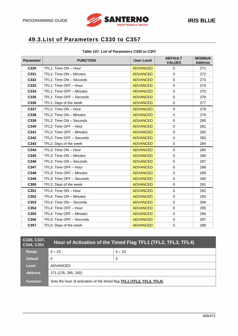
PROGRAMMING GUIDE
IRIS BLUE
369/471
49.3.List of Parameters C330 to C357
Table 107: List of Parameters C330 to C357
Parameter FUNCTION User Level DEFAULT
VALUES
MODBUS
Address
C330 TFL1: Time ON – Hour ADVANCED 0 271
C331 TFL1: Time ON – Minutes ADVANCED 0 272
C332 TFL1: Time ON – Seconds ADVANCED 0 273
C333 TFL1: Time OFF – Hour ADVANCED 0 274
C334 TFL1: Time OFF – Minutes ADVANCED 0 275
C335 TFL1: Time OFF – Seconds ADVANCED 0 276
C336 TFL1: Days of the week ADVANCED 0 277
C337 TFL2: Time ON – Hour ADVANCED 0 278
C338 TFL2: Time ON – Minutes ADVANCED 0 279
C339 TFL2: Time ON – Seconds ADVANCED 0 280
C340 TFL2: Time OFF – Hour ADVANCED 0 281
C341 TFL2: Time OFF – Minutes ADVANCED 0 282
C342 TFL2: Time OFF – Seconds ADVANCED 0 283
C343 TFL2: Days of the week ADVANCED 0 284
C344 TFL3: Time ON – Hour ADVANCED 0 285
C345 TFL3: Time ON – Minutes ADVANCED 0 286
C346 TFL3: Time ON – Seconds ADVANCED 0 287
C347 TFL3: Time OFF – Hour ADVANCED 0 288
C348 TFL3: Time OFF – Minutes ADVANCED 0 289
C349 TFL3: Time OFF – Seconds ADVANCED 0 290
C350 TFL3: Days of the week ADVANCED 0 291
C351 TFL4: Time ON – Hour ADVANCED 0 292
C352 TFL4: Time ON – Minutes ADVANCED 0 293
C353 TFL4: Time ON – Seconds ADVANCED 0 294
C354 TFL4: Time OFF – Hour ADVANCED 0 295
C355 TFL4: Time OFF – Minutes ADVANCED 0 296
C356 TFL4: Time OFF – Seconds ADVANCED 0 297
C357 TFL4: Days of the week ADVANCED 0 298
C330, C337,
C344, C351 Hour of Activation of the Timed Flag TFL1 (TFL2, TFL3, TFL4)
Range 0 23 0 23
Default 0 0
Level ADVANCED
Address 271 (278, 285, 292)
Function Sets the hour of activation of the timed flag TFL1 (TFL2, TFL3, TFL4).
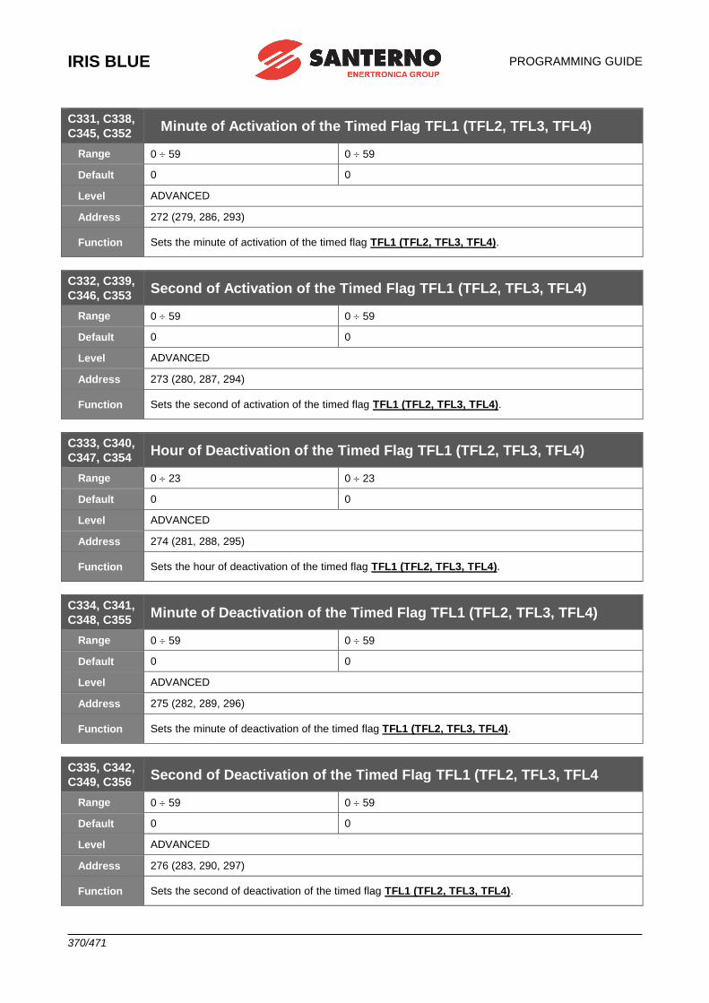
IRIS BLUE
PROGRAMMING GUIDE
370/471
C331, C338,
C345, C352 Minute of Activation of the Timed Flag TFL1 (TFL2, TFL3, TFL4)
Range 0 59 0 59
Default 0 0
Level ADVANCED
Address 272 (279, 286, 293)
Function Sets the minute of activation of the timed flag TFL1 (TFL2, TFL3, TFL4).
C332, C339,
C346, C353 Second of Activation of the Timed Flag TFL1 (TFL2, TFL3, TFL4)
Range 0 59 0 59
Default 0 0
Level ADVANCED
Address 273 (280, 287, 294)
Function Sets the second of activation of the timed flag TFL1 (TFL2, TFL3, TFL4).
C333, C340,
C347, C354 Hour of Deactivation of the Timed Flag TFL1 (TFL2, TFL3, TFL4)
Range 0 23 0 23
Default 0 0
Level ADVANCED
Address 274 (281, 288, 295)
Function Sets the hour of deactivation of the timed flag TFL1 (TFL2, TFL3, TFL4).
C334, C341,
C348, C355 Minute of Deactivation of the Timed Flag TFL1 (TFL2, TFL3, TFL4)
Range 0 59 0 59
Default 0 0
Level ADVANCED
Address 275 (282, 289, 296)
Function Sets the minute of deactivation of the timed flag TFL1 (TFL2, TFL3, TFL4).
C335, C342,
C349, C356 Second of Deactivation of the Timed Flag TFL1 (TFL2, TFL3, TFL4
Range 0 59 0 59
Default 0 0
Level ADVANCED
Address 276 (283, 290, 297)
Function Sets the second of deactivation of the timed flag TFL1 (TFL2, TFL3, TFL4).
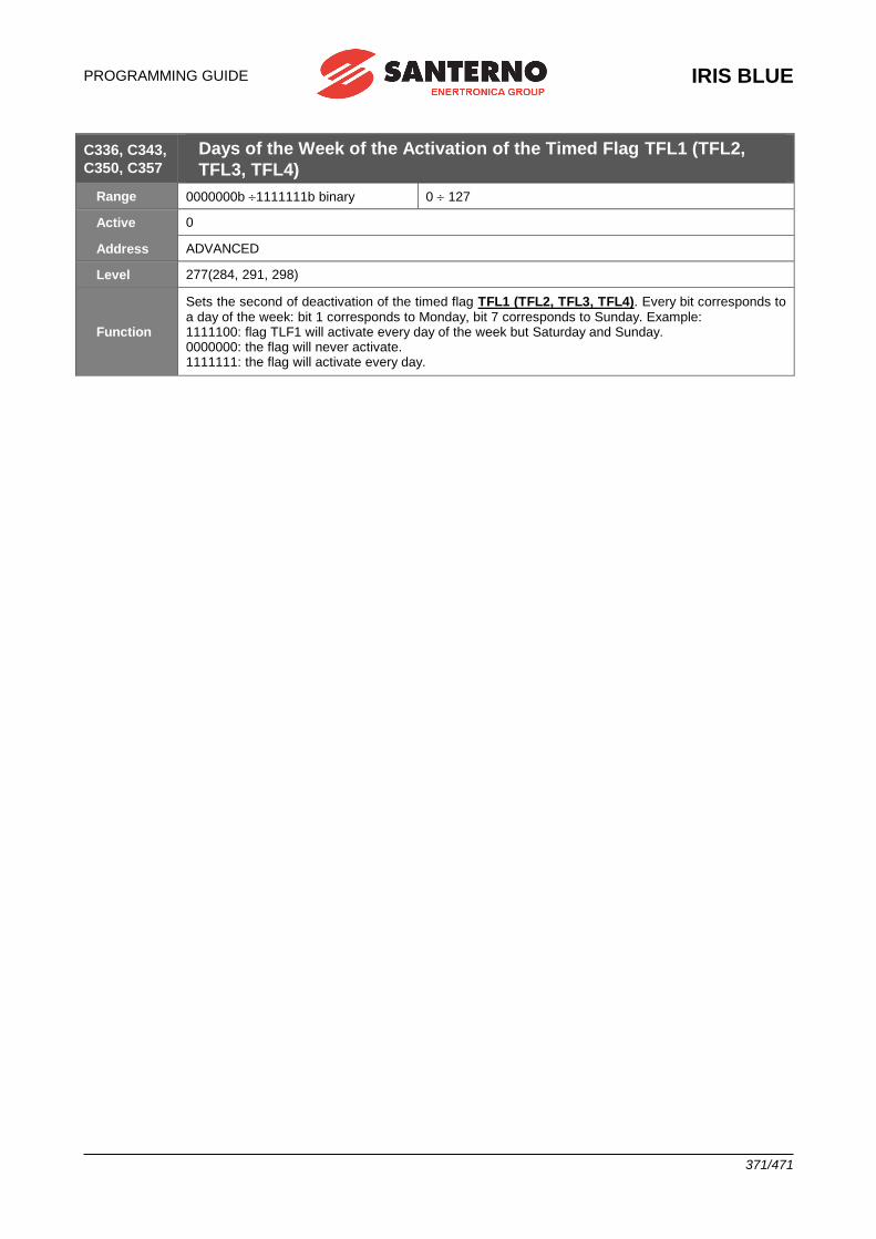
PROGRAMMING GUIDE
IRIS BLUE
371/471
C336, C343,
C350, C357 Days of the Week of the Activation of the Timed Flag TFL1 (TFL2,
TFL3, TFL4)
Range 0000000b 1111111b binary 0 127
Active 0
Address ADVANCED
Level 277(284, 291, 298)
Function
Sets the second of deactivation of the timed flag TFL1 (TFL2, TFL3, TFL4). Every bit corresponds to a day of the week: bit 1 corresponds to Monday, bit 7 corresponds to Sunday. Example: 1111100: flag TLF1 will activate every day of the week but Saturday and Sunday. 0000000: the flag will never activate. 1111111: the flag will activate every day.
IRIS BLUE
PROGRAMMING GUIDE
372/471
50. [CFG] SERIAL LINKS
50.1.Overview
NOTE Please refer to the IRIS BLUE – Installation Guide for the description of the serial links and connections.
NOTE
For a greater immunity against communication interference, an optional optoisolated serial board (ES822) may be used instead of RS485 serial link. Serial links RS232 and RS485 can interface with ES822 board. Please refer to the IRIS BLUE – Installation Guide for the description of the optional optoisolated board.
NOTE The parameters described in this menu are Rxxx parameters. Once changed and saved, they become active only when the drive is next switched on or
when the control board is reset (by holding down the RESET key for more than 5 secs).
The drives of the IRIS BLUE series may be connected to peripheral devices through a serial link. This enables both reading and writing of all parameters normally accessed through the display/keypad. Two-wire RS485 is used, which ensures better immunity against disturbance even on long cable paths, thus reducing the communication errors.
Two serial links are available. Serial Link 0 is provided with a 9-pole, male D connector; Serial Link 1 is provided with an RJ45 connector (or a three-phone connector) connected to the display/keypad.
NOTE The display/keypad connected through RJ45 connector dialogues correctly with the drive using the default values preset in the parameter set for serial link 1.
The drive will typically behave as a slave device (i.e. it only answers to queries sent by another device). A master device (typically a computer) is then needed to start serial communications. The following items may be configured for both serial links:
1. The drive MODBUS address. 2. The drive response delay to a Master query. 3. The baud rate of the serial link (expressed in bits per second); 4. The time added to the 4 byte–time; 5. The serial link watchdog (which is active if the relevant parameter is not set at 0); 6. The type of parity used for serial communications.
50.1.1. W ATCHDOG ALARMS
The Watchdog alarms determined by the serial link may be the following:
• A061 Serial alarm n.0 WDG
• A062 Serial alarm n.1 WDG
• A081 Keypad Watchdog The first two alarms trip when no legal message is sent from the serial link to the drive for a time longer than the time
set in the relevant watchdog parameters; these alarms are active only if parameters R005 or R012 are set other
than zero.
NOTE
Alarms A061 and A062 do not trip if, due to the parameters in the [CFG] CONTROL METHOD MENU or due to the status of the SOURCE SELECTION or LOC/REM inputs (see the [CFG] DIGITAL INPUTS MENU), the information sent via serial link is not currently used for the commands or the references.
The third alarm trips only if the display/keypad used as a reference/command source detects a communication loss for a time longer than 2 seconds.
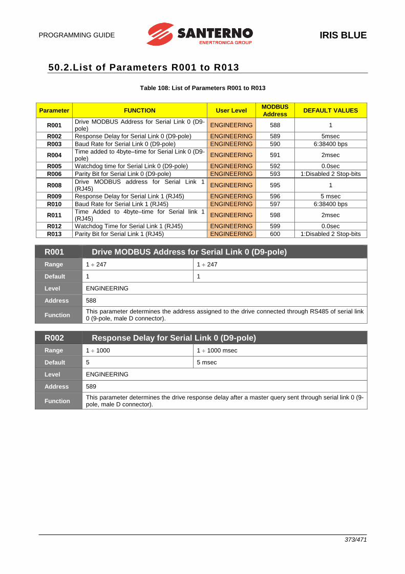
PROGRAMMING GUIDE
IRIS BLUE
373/471
50.2.List of Parameters R001 to R013
Table 108: List of Parameters R001 to R013
Parameter FUNCTION User Level MODBUS
Address DEFAULT VALUES
R001 Drive MODBUS Address for Serial Link 0 (D9-pole)
ENGINEERING 588 1
R002 Response Delay for Serial Link 0 (D9-pole) ENGINEERING 589 5msec
R003 Baud Rate for Serial Link 0 (D9-pole) ENGINEERING 590 6:38400 bps
R004 Time added to 4byte–time for Serial Link 0 (D9-pole)
ENGINEERING 591 2msec
R005 Watchdog time for Serial Link 0 (D9-pole) ENGINEERING 592 0.0sec
R006 Parity Bit for Serial Link 0 (D9-pole) ENGINEERING 593 1:Disabled 2 Stop-bits
R008 Drive MODBUS address for Serial Link 1 (RJ45)
ENGINEERING 595 1
R009 Response Delay for Serial Link 1 (RJ45) ENGINEERING 596 5 msec
R010 Baud Rate for Serial Link 1 (RJ45) ENGINEERING 597 6:38400 bps
R011 Time Added to 4byte–time for Serial link 1 (RJ45)
ENGINEERING 598 2msec
R012 Watchdog Time for Serial Link 1 (RJ45) ENGINEERING 599 0.0sec
R013 Parity Bit for Serial Link 1 (RJ45) ENGINEERING 600 1:Disabled 2 Stop-bits
R001 Drive MODBUS Address for Serial Link 0 (D9-pole)
Range 1 247 1 247
Default 1 1
Level ENGINEERING
Address 588
Function This parameter determines the address assigned to the drive connected through RS485 of serial link 0 (9-pole, male D connector).
R002 Response Delay for Serial Link 0 (D9-pole)
Range 1 1000 1 1000 msec
Default 5 5 msec
Level ENGINEERING
Address 589
Function This parameter determines the drive response delay after a master query sent through serial link 0 (9-pole, male D connector).
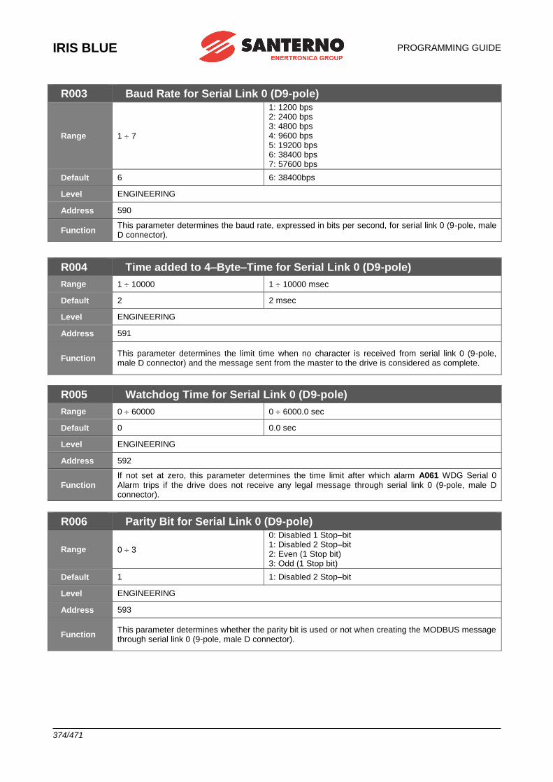
IRIS BLUE
PROGRAMMING GUIDE
374/471
R003 Baud Rate for Serial Link 0 (D9-pole)
Range 1 7
1: 1200 bps 2: 2400 bps 3: 4800 bps 4: 9600 bps 5: 19200 bps 6: 38400 bps 7: 57600 bps
Default 6 6: 38400bps
Level ENGINEERING
Address 590
Function This parameter determines the baud rate, expressed in bits per second, for serial link 0 (9-pole, male D connector).
R004 Time added to 4–Byte–Time for Serial Link 0 (D9-pole)
Range 1 10000 1 10000 msec
Default 2 2 msec
Level ENGINEERING
Address 591
Function This parameter determines the limit time when no character is received from serial link 0 (9-pole, male D connector) and the message sent from the master to the drive is considered as complete.
R005 Watchdog Time for Serial Link 0 (D9-pole)
Range 0 60000 0 6000.0 sec
Default 0 0.0 sec
Level ENGINEERING
Address 592
Function If not set at zero, this parameter determines the time limit after which alarm A061 WDG Serial 0 Alarm trips if the drive does not receive any legal message through serial link 0 (9-pole, male D connector).
R006 Parity Bit for Serial Link 0 (D9-pole)
Range 0 3
0: Disabled 1 Stop–bit 1: Disabled 2 Stop–bit 2: Even (1 Stop bit) 3: Odd (1 Stop bit)
Default 1 1: Disabled 2 Stop–bit
Level ENGINEERING
Address 593
Function This parameter determines whether the parity bit is used or not when creating the MODBUS message through serial link 0 (9-pole, male D connector).
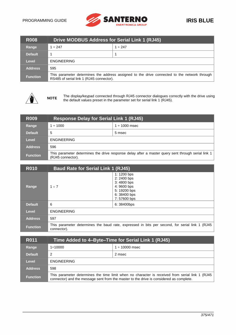
PROGRAMMING GUIDE
IRIS BLUE
375/471
R008 Drive MODBUS Address for Serial Link 1 (RJ45)
Range 1 ÷ 247 1 ÷ 247
Default 1 1
Level ENGINEERING
Address 595
Function This parameter determines the address assigned to the drive connected to the network through RS485 of serial link 1 (RJ45 connector).
NOTE The display/keypad connected through RJ45 connector dialogues correctly with the drive using the default values preset in the parameter set for serial link 1 (RJ45).
R009 Response Delay for Serial Link 1 (RJ45)
Range 1 ÷ 1000 1 ÷ 1000 msec
Default 5 5 msec
Level ENGINEERING
Address 596
Function This parameter determines the drive response delay after a master query sent through serial link 1 (RJ45 connector).
R010 Baud Rate for Serial Link 1 (RJ45)
Range 1 7
1: 1200 bps 2: 2400 bps 3: 4800 bps 4: 9600 bps 5: 19200 bps 6: 38400 bps 7: 57600 bps
Default 6 6: 38400bps
Level ENGINEERING
Address 597
Function This parameter determines the baud rate, expressed in bits per second, for serial link 1 (RJ45 connector).
R011 Time Added to 4–Byte–Time for Serial Link 1 (RJ45)
Range 1÷10000 1 ÷ 10000 msec
Default 2 2 msec
Level ENGINEERING
Address 598
Function This parameter determines the time limit when no character is received from serial link 1 (RJ45 connector) and the message sent from the master to the drive is considered as complete.
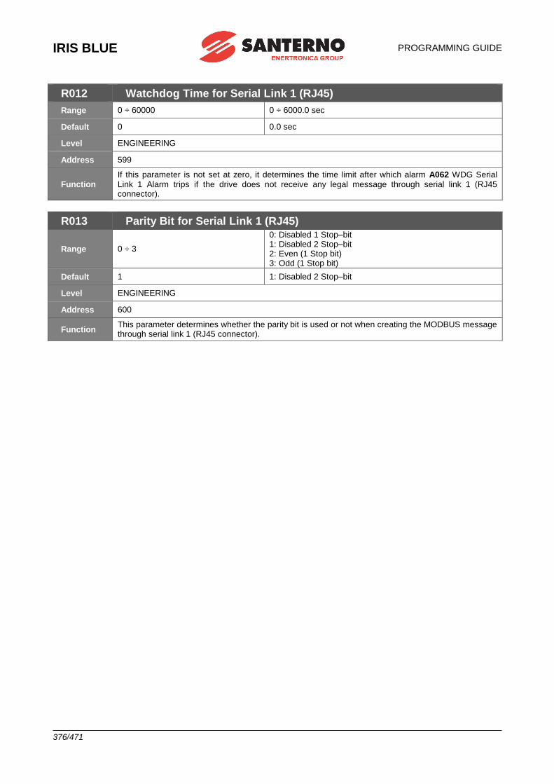
IRIS BLUE
PROGRAMMING GUIDE
376/471
R012 Watchdog Time for Serial Link 1 (RJ45)
Range 0 ÷ 60000 0 ÷ 6000.0 sec
Default 0 0.0 sec
Level ENGINEERING
Address 599
Function If this parameter is not set at zero, it determines the time limit after which alarm A062 WDG Serial Link 1 Alarm trips if the drive does not receive any legal message through serial link 1 (RJ45 connector).
R013 Parity Bit for Serial Link 1 (RJ45)
Range 0 ÷ 3
0: Disabled 1 Stop–bit 1: Disabled 2 Stop–bit 2: Even (1 Stop bit) 3: Odd (1 Stop bit)
Default 1 1: Disabled 2 Stop–bit
Level ENGINEERING
Address 600
Function This parameter determines whether the parity bit is used or not when creating the MODBUS message through serial link 1 (RJ45 connector).
PROGRAMMING GUIDE
IRIS BLUE
377/471
51. [CFG] FIELDBUS CONFIGURATION MENU
51.1.Overview
NOTE See the OPTIONAL BOARDS FOR FIELDBUS section in the IRIS BLUE – Installation Guide for the description of the optional board required.
NOTE The parameters included in this menu are Rxxx parameters. Once saved, they are active only when the drive is next switched on or when the control
board is reset (by holding down the RESET key for more than 5 secs).
CAUTION
This menu is not applicable to ES919 communications boards (see relevant section in the IRIS BLUE – Installation Guide). ES919 boards act as gateways and change the
MODBUS RS485 packets into the packets of each protocol being used.
The exchanged parameters are all the Mxxx measurements from the IRIS BLUE to the
Master and all the Ixxx inputs from the Master to the IRIS BLUE (as detailed in the [MEA] MEASUREMENTS MENU, Table 83 and Table 85).
51.1.1. ALARM A070 (COMMUNICATION SUSPENDED)
Alarm A070 trips if the IRIS BLUE is not sent any legal message via FIELDBUS within the timeout set in parameter
R016. Set parameter R016 = 0 to disable alarm A070. A legal message is as follows:
- PROFIdrive: The master drive writes bit 11=1 of the Control Word (see PROFIdrive COMMUNICATIONS BOARD – User Manual).
- Other Fieldbuses: The master drive writes the digital input word (word 5 - M035) with bit 15=1 or as set in
parameter R018b.
NOTE This is enabled only when the drive receives the first message with this bit =1.
Do the following to reset alarm A070, if tripped: - restore legal communications between the Master and the IRIS BLUE; - reactivate control of bit 15 in the word of the digital inputs as above (bit 11 of the Control Word when the PROFIdrive is used); - reset the board.
NOTE
Alarm A070 does not trip if, due to the parameters in the [CFG] CONTROL METHOD MENU or due to the status of the SOURCE SELECTION or LOC/REM inputs (see the [CFG] DIGITAL INPUTS MENU), the information sent via serial link is not currently used for the commands or the references.
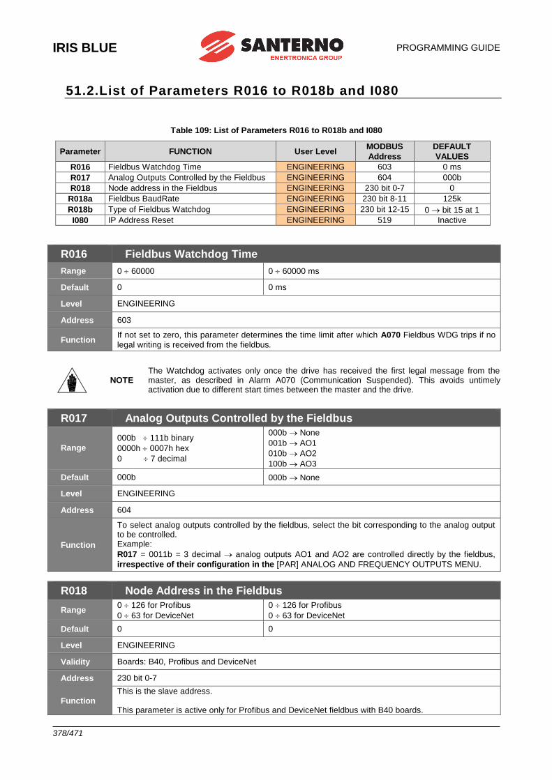
IRIS BLUE
PROGRAMMING GUIDE
378/471
51.2.List of Parameters R016 to R018b and I080
Table 109: List of Parameters R016 to R018b and I080
Parameter FUNCTION User Level MODBUS
Address
DEFAULT
VALUES
R016 Fieldbus Watchdog Time ENGINEERING 603 0 ms
R017 Analog Outputs Controlled by the Fieldbus ENGINEERING 604 000b
R018 Node address in the Fieldbus ENGINEERING 230 bit 0-7 0
R018a Fieldbus BaudRate ENGINEERING 230 bit 8-11 125k
R018b Type of Fieldbus Watchdog ENGINEERING 230 bit 12-15 0 bit 15 at 1
I080 IP Address Reset ENGINEERING 519 Inactive
R016 Fieldbus Watchdog Time
Range 0 60000 0 60000 ms
Default 0 0 ms
Level ENGINEERING
Address 603
Function If not set to zero, this parameter determines the time limit after which A070 Fieldbus WDG trips if no
legal writing is received from the fieldbus.
NOTE The Watchdog activates only once the drive has received the first legal message from the master, as described in Alarm A070 (Communication Suspended). This avoids untimely activation due to different start times between the master and the drive.
R017 Analog Outputs Controlled by the Fieldbus
Range
000b 111b binary
0000h 0007h hex
0 7 decimal
000b None
001b AO1
010b AO2
100b AO3
Default 000b 000b None
Level ENGINEERING
Address 604
Function
To select analog outputs controlled by the fieldbus, select the bit corresponding to the analog output to be controlled. Example:
R017 = 0011b = 3 decimal analog outputs AO1 and AO2 are controlled directly by the fieldbus,
irrespective of their configuration in the [PAR] ANALOG AND FREQUENCY OUTPUTS MENU.
R018 Node Address in the Fieldbus
Range 0 126 for Profibus
0 63 for DeviceNet
0 126 for Profibus
0 63 for DeviceNet
Default 0 0
Level ENGINEERING
Validity Boards: B40, Profibus and DeviceNet
Address 230 bit 0-7
Function This is the slave address. This parameter is active only for Profibus and DeviceNet fieldbus with B40 boards.
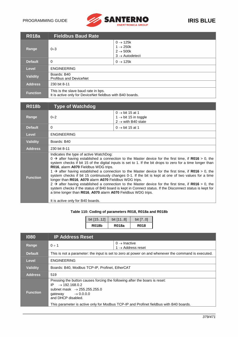
PROGRAMMING GUIDE
IRIS BLUE
379/471
R018a Fieldbus Baud Rate
Range 03
0 125k
1 250k
2 500k
3 Autodetect
Default 0 0 125k
Level ENGINEERING
Validity Boards: B40 Profibus and DeviceNet
Address 230 bit 8-11
Function This is the slave baud rate in bps. It is active only for DeviceNet fieldbus with B40 boards.
R018b Type of Watchdog
Range 02
0 bit 15 at 1
1 bit 15 in toggle
2 with B40 state
Default 0 0 bit 15 at 1
Level ENGINEERING
Validity Boards: B40
Address 230 bit 8-11
Function
Indicates the type of active WatchDog:
0 after having established a connection to the Master device for the first time, if R016 > 0, the system checks if bit 15 of the digital inputs is set to 1. If the bit drops to zero for a time longer than
R016, alarm A070 Fieldbus WDG trips.
1 after having established a connection to the Master device for the first time, if R016 > 0, the system checks if bit 15 continuously changes 0-1. If the bit is kept at one of two values for a time
longer than R016, A070 alarm A070 Fieldbus WDG trips.
2 after having established a connection to the Master device for the first time, if R016 > 0, the system checks if the status of B40 board is kept in Connect status. If the Disconnect status is kept for
a time longer than R016, A070 alarm A070 Fieldbus WDG trips. It is active only for B40 boards.
Table 110: Coding of parameters R018, R018a and R018b
bit [15..12] bit [11..8] bit [7..0]
R018b R018a R018
I080 IP Address Reset
Range 0 1 0 Inactive
1 Address reset
Default This is not a parameter: the input is set to zero at power on and whenever the command is executed.
Level ENGINEERING
Validity Boards: B40, Modbus TCP-IP, Profinet, EtherCAT
Address 519
Function
Pressing the button causes forcing the following after the boars is reset:
IP 192.168.0.2
subnet mask 255.255.255.0
gateway 0.0.0.0 and DHCP disabled.
This parameter is active only for Modbus TCP-IP and Profinet fieldbus with B40 boards.
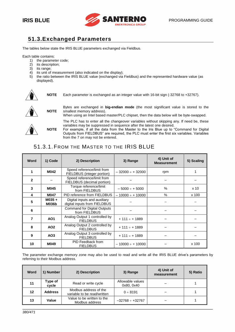
IRIS BLUE
PROGRAMMING GUIDE
380/471
51.3.Exchanged Parameters The tables below state the IRIS BLUE parameters exchanged via Fieldbus. Each table contains:
1) the parameter code; 2) its description; 3) its range; 4) its unit of measurement (also indicated on the display); 5) the ratio between the IRIS BLUE value (exchanged via Fieldbus) and the represented hardware value (as
displayed).
NOTE Each parameter is exchanged as an integer value with 16-bit sign (-32768 to +32767).
NOTE Bytes are exchanged in big-endian mode (the most significant value is stored to the smallest memory address). When using an Intel based master/PLC chipset, then the data below will be byte-swapped.
NOTE
The PLC has to enter all the changeover variables without skipping any. If need be, these variables may be suppressed in sequence after the latest one desired. For example, if all the data from the Master to the Iris Blue up to “Command for Digital Outputs from FIELDBUS” are required, the PLC must enter the first six variables. Variables from the 7 on may not be entered.
51.3.1. FROM THE MASTER TO THE IRIS BLUE
Word 1) Code 2) Description 3) Range 4) Unit of
Measurement 5) Scaling
1 M042 Speed reference/limit from FIELDBUS (integer portion)
– 32000 + 32000 rpm 1
2 – Speed reference/limit from
FIELDBUS (decimal portion) – – –
3 M045 Torque reference/limit
from FIELDBUS – 5000 + 5000 % x 10
4 M047 PID reference from FIELDBUS – 10000 + 10000 % x 100
5 M035 +
M036b
Digital inputs and auxiliary digital inputs from FIELDBUS
– – –
6 Command for Digital Outputs
from FIELDBUS – – –
7 AO1 Analog Output 1 controlled by
FIELDBUS + 111 + 1889 – –
8 AO2 Analog Output 2 controlled by
FIELDBUS + 111 + 1889 – –
9 AO3 Analog Output 3 controlled by
FIELDBUS + 111 + 1889 – –
10 M049 PID Feedback from
FIELDBUS – 10000 + 10000 – x 100
The parameter exchange memory zone may also be used to read and write all the IRIS BLUE drive’s parameters by referring to their Modbus address.
Word 1) Number 2) Description 3) Range 4) Unit of
measurement 5) Ratio
11 Type of
cycle Read or write cycle
Allowable values 0x80, 0x40
– 1
12 Address Modbus address of the
variable to be read/written 0 8191 – 1
13 Value Value to be written to the
Modbus address –32768 +32767 – 1
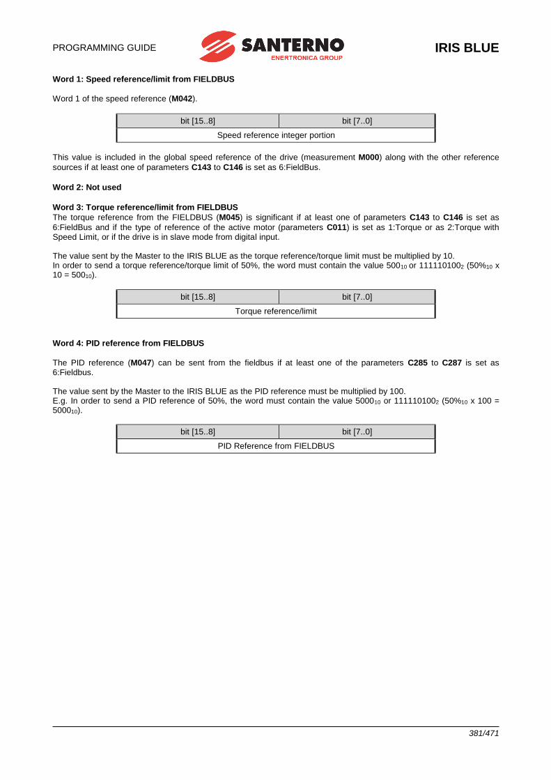
PROGRAMMING GUIDE
IRIS BLUE
381/471
Word 1: Speed reference/limit from FIELDBUS
Word 1 of the speed reference (M042).
bit [15..8] bit [7..0]
Speed reference integer portion
This value is included in the global speed reference of the drive (measurement M000) along with the other reference
sources if at least one of parameters C143 to C146 is set as 6:FieldBus.
Word 2: Not used
Word 3: Torque reference/limit from FIELDBUS
The torque reference from the FIELDBUS (M045) is significant if at least one of parameters C143 to C146 is set as
6:FieldBus and if the type of reference of the active motor (parameters C011) is set as 1:Torque or as 2:Torque with Speed Limit, or if the drive is in slave mode from digital input. The value sent by the Master to the IRIS BLUE as the torque reference/torque limit must be multiplied by 10. In order to send a torque reference/torque limit of 50%, the word must contain the value 50010 or 1111101002 (50%10 x 10 = 50010).
bit [15..8] bit [7..0]
Torque reference/limit
Word 4: PID reference from FIELDBUS
The PID reference (M047) can be sent from the fieldbus if at least one of the parameters C285 to C287 is set as 6:Fieldbus. The value sent by the Master to the IRIS BLUE as the PID reference must be multiplied by 100. E.g. In order to send a PID reference of 50%, the word must contain the value 500010 or 1111101002 (50%10 x 100 = 500010).
bit [15..8] bit [7..0]
PID Reference from FIELDBUS
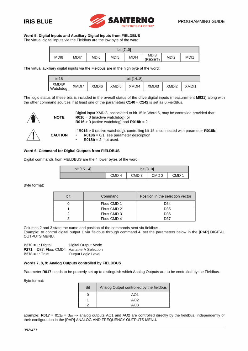
IRIS BLUE
PROGRAMMING GUIDE
382/471
Word 5: Digital Inputs and Auxiliary Digital Inputs from FIELDBUS The virtual digital inputs via the Fieldbus are the low byte of the word:
bit [7..0]
MDI8 MDI7 MDI6 MDI5 MDI4 MDI3
(RESET) MDI2 MDI1
The virtual auxiliary digital inputs via the Fieldbus are in the high byte of the word:
bit15 bit [14..8]
XMDI8/ Watchdog
XMDI7 XMDI6 XMDI5 XMDI4 XMDI3 XMDI2 XMDI1
The logic status of these bits is included in the overall status of the drive digital inputs (measurement M031) along with
the other command sources if at least one of the parameters C140 C142 is set as 6:FieldBus.
NOTE
Digital input XMDI8, associated to bit 15 in Word 5, may be controlled provided that:
R016 = 0 (inactive watchdog), or
R016 > 0 (active watchdog) and R018b = 2.
CAUTION
If R016 > 0 (active watchdog), controlling bit 15 is connected with parameter R018b:
• R018b = 0/1: see parameter description
• R018b = 2: not used.
Word 6: Command for Digital Outputs from FIELDBUS Digital commands from FIELDBUS are the 4 lower bytes of the word:
bit [15...4] bit [3..0]
CMD 4 CMD 3 CMD 2 CMD 1
Byte format:
bit Command Position in the selection vector
0 Fbus CMD 1 D34
1 Fbus CMD 2 D35
2 Fbus CMD 3 D36
3 Fbus CMD 4 D37
Columns 2 and 3 state the name and position of the commands sent via fieldbus. Example: to control digital output 1 via fieldbus through command 4, set the parameters below in the [PAR] DIGITAL OUTPUTS MENU.
P270 = 1: Digital Digital Output Mode
P271 = D37: Fbus CMD4 Variable A Selection
P278 = 1: True Output Logic Level
Words 7, 8, 9: Analog Outputs controlled by FIELDBUS
Parameter R017 needs to be properly set up to distinguish which Analog Outputs are to be controlled by the Fieldbus. Byte format:
Bit Analog Output controlled by the fieldbus
0 AO1
1 AO2
2 AO3
Example: R017 = 0112 = 310 analog outputs AO1 and AO2 are controlled directly by the fieldbus, independently of
their configuration in the [PAR] ANALOG AND FREQUENCY OUTPUTS MENU.
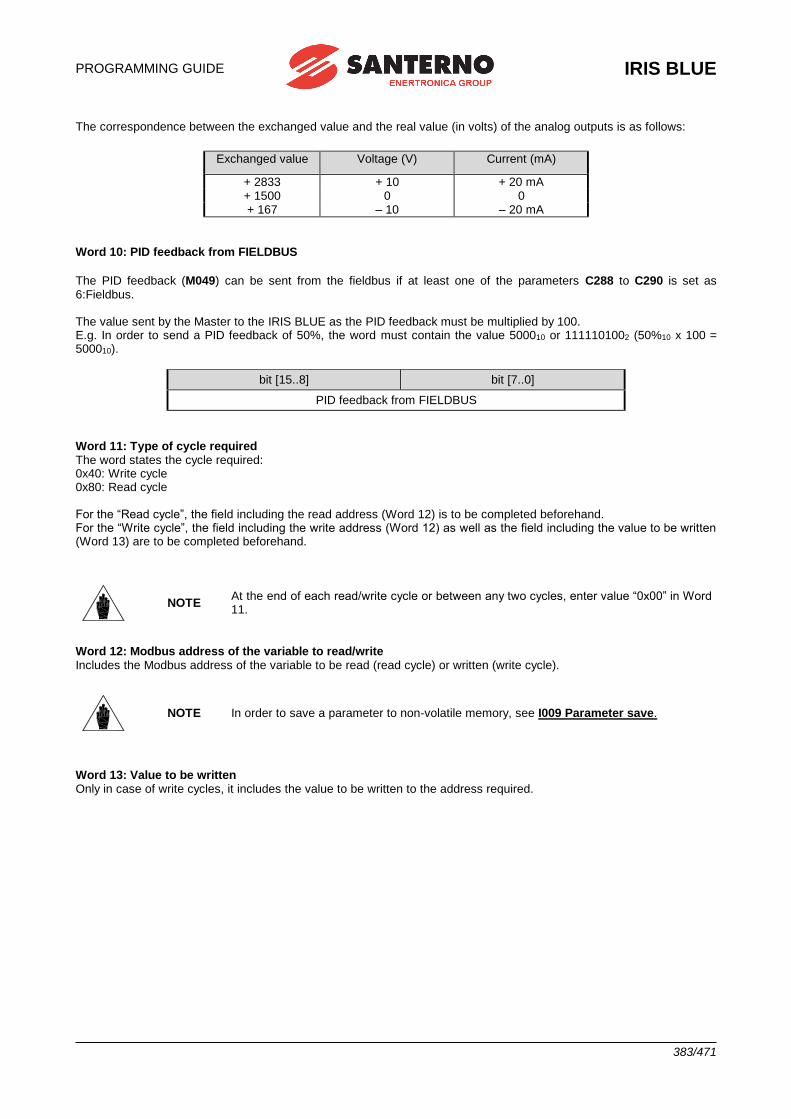
PROGRAMMING GUIDE
IRIS BLUE
383/471
The correspondence between the exchanged value and the real value (in volts) of the analog outputs is as follows:
Exchanged value Voltage (V) Current (mA)
+ 2833 + 10 + 20 mA + 1500 0 0 + 167 – 10 – 20 mA
Word 10: PID feedback from FIELDBUS
The PID feedback (M049) can be sent from the fieldbus if at least one of the parameters C288 to C290 is set as 6:Fieldbus. The value sent by the Master to the IRIS BLUE as the PID feedback must be multiplied by 100. E.g. In order to send a PID feedback of 50%, the word must contain the value 500010 or 1111101002 (50%10 x 100 = 500010).
bit [15..8] bit [7..0]
PID feedback from FIELDBUS
Word 11: Type of cycle required The word states the cycle required: 0x40: Write cycle 0x80: Read cycle For the “Read cycle”, the field including the read address (Word 12) is to be completed beforehand. For the “Write cycle”, the field including the write address (Word 12) as well as the field including the value to be written (Word 13) are to be completed beforehand.
NOTE At the end of each read/write cycle or between any two cycles, enter value “0x00” in Word 11.
Word 12: Modbus address of the variable to read/write Includes the Modbus address of the variable to be read (read cycle) or written (write cycle).
NOTE In order to save a parameter to non-volatile memory, see I009 Parameter save.
Word 13: Value to be written Only in case of write cycles, it includes the value to be written to the address required.
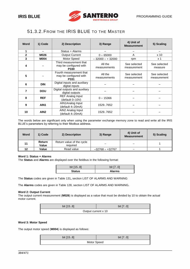
IRIS BLUE
PROGRAMMING GUIDE
384/471
51.3.2. FROM THE IRIS BLUE TO THE MASTER
Word 1) Code 2) Description 3) Range 4) Unit of
Measurement 5) Scaling
1 – Status + Alarms – – –
2 M026 Output Current 0 65000 A x 10
3 M004 Motor Speed – 32000 + 32000 rpm x 1
4 – Third measurement that may be configured with
P330
All the measurements
See selected measurement
See selected measure
5 – Fourth measurement that may be configured with
P331
All the measurements
See selected measurement
See selected measurement
6 DIN Digital inputs and auxiliary
digital inputs – – –
7 DOU Digital outputs and auxiliary
digital outputs – – –
8 REF REF Analog Input
(default 010V) 0 15366 – –
9 AIN1 AIN1Analog Input
(default 420mA) 1529..7652 – –
10 AIN2 AIN2 Analog Input
(default 420mA) 1529..7652 – –
The words below are significant only when using the parameter exchange memory zone to read and write all the IRIS BLUE’s parameters by referring to their Modbus address.
Word 1) Code 2) Description 3) Range 4) Unit of
Measurement 5) Scaling
11 Return
Value
Return value of the cycle required
– – 1
12 Value Read value –32768 +32767 – 1
Word 1: Status + Alarms
The Status and Alarms are displayed over the fieldbus in the following format:
bit [15..8] bit [7..0]
Status Alarms
The Status codes are given in Table 131, section LIST OF ALARMS AND WARNING
The Alarms codes are given in Table 128, section LIST OF ALARMS AND WARNING.
Word 2: Output Current
The output current measurement (M026) is displayed as a value that must be divided by 10 to obtain the actual motor current.
bit [15..8] bit [7..0]
Output current x 10
Word 3: Motor Speed
The output motor speed (M004) is displayed as follows:
bit [15..8] bit [7..0]
Motor Speed
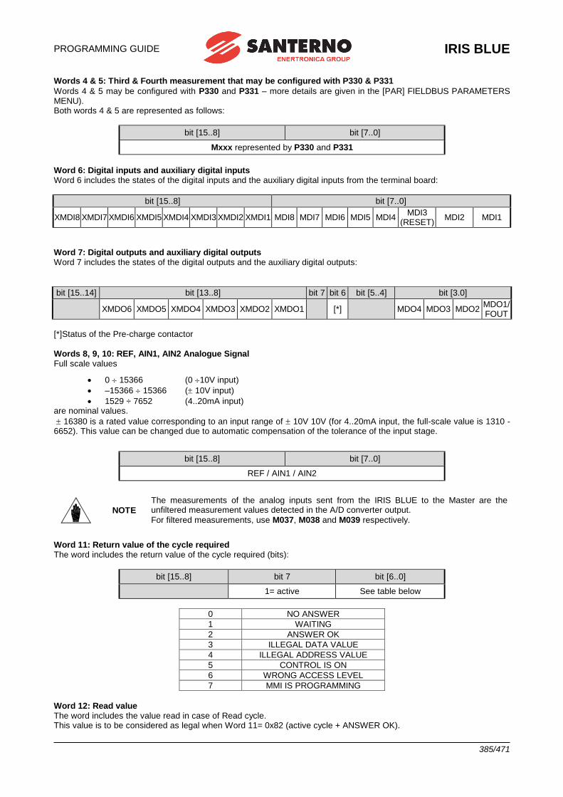
PROGRAMMING GUIDE
IRIS BLUE
385/471
Words 4 & 5: Third & Fourth measurement that may be configured with P330 & P331
Words 4 & 5 may be configured with P330 and P331 – more details are given in the [PAR] FIELDBUS PARAMETERS MENU). Both words 4 & 5 are represented as follows:
bit [15..8] bit [7..0]
Mxxx represented by P330 and P331
Word 6: Digital inputs and auxiliary digital inputs Word 6 includes the states of the digital inputs and the auxiliary digital inputs from the terminal board:
bit [15..8] bit [7..0]
XMDI8 XMDI7 XMDI6 XMDI5 XMDI4 XMDI3 XMDI2 XMDI1 MDI8 MDI7 MDI6 MDI5 MDI4 MDI3
(RESET) MDI2 MDI1
Word 7: Digital outputs and auxiliary digital outputs Word 7 includes the states of the digital outputs and the auxiliary digital outputs:
bit [15..14] bit [13..8] bit 7 bit 6 bit [5..4] bit [3.0]
XMDO6 XMDO5 XMDO4 XMDO3 XMDO2 XMDO1 [*] MDO4 MDO3 MDO2 MDO1/FOUT
[*]Status of the Pre-charge contactor
Words 8, 9, 10: REF, AIN1, AIN2 Analogue Signal Full scale values
• 0 15366 (0 10V input)
• –15366 15366 ( 10V input)
• 1529 ÷ 7652 (4..20mA input) are nominal values.
16380 is a rated value corresponding to an input range of 10V 10V (for 4..20mA input, the full-scale value is 1310 - 6652). This value can be changed due to automatic compensation of the tolerance of the input stage.
bit [15..8] bit [7..0]
REF / AIN1 / AIN2
NOTE
The measurements of the analog inputs sent from the IRIS BLUE to the Master are the unfiltered measurement values detected in the A/D converter output.
For filtered measurements, use M037, M038 and M039 respectively.
Word 11: Return value of the cycle required The word includes the return value of the cycle required (bits):
bit [15..8] bit 7 bit [6..0]
1= active See table below
0 NO ANSWER
1 WAITING
2 ANSWER OK
3 ILLEGAL DATA VALUE
4 ILLEGAL ADDRESS VALUE
5 CONTROL IS ON
6 WRONG ACCESS LEVEL
7 MMI IS PROGRAMMING
Word 12: Read value The word includes the value read in case of Read cycle. This value is to be considered as legal when Word 11= 0x82 (active cycle + ANSWER OK).
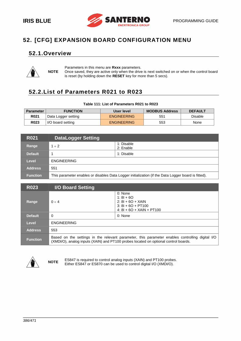
IRIS BLUE
PROGRAMMING GUIDE
386/471
52. [CFG] EXPANSION BOARD CONFIGURATION MENU
52.1.Overview
NOTE Parameters in this menu are Rxxx parameters. Once saved, they are active only when the drive is next switched on or when the control board
is reset (by holding down the RESET key for more than 5 secs).
52.2.List of Parameters R021 to R023
Table 111: List of Parameters R021 to R023
Parameter FUNCTION User level MODBUS Address DEFAULT
R021 Data Logger setting ENGINEERING 551 Disable
R023 I/O board setting ENGINEERING 553 None
R021 DataLogger Setting
Range 1 2 1: Disable 2: Enable
Default 1 1: Disable
Level ENGINEERING
Address 551
Function This parameter enables or disables Data Logger initialization (if the Data Logger board is fitted).
R023 I/O Board Setting
Range 0 4
0: None 1: 8I + 6O 2: 8I + 6O + XAIN 3: 8I + 6O + PT100 4: 8I + 6O + XAIN + PT100
Default 0 0: None
Level ENGINEERING
Address 553
Function Based on the settings in the relevant parameter, this parameter enables controlling digital I/O (XMDI/O), analog inputs (XAIN) and PT100 probes located on optional control boards.
NOTE ES847 is required to control analog inputs (XAIN) and PT100 probes. Either ES847 or ES870 can be used to control digital I/O (XMDI/O).
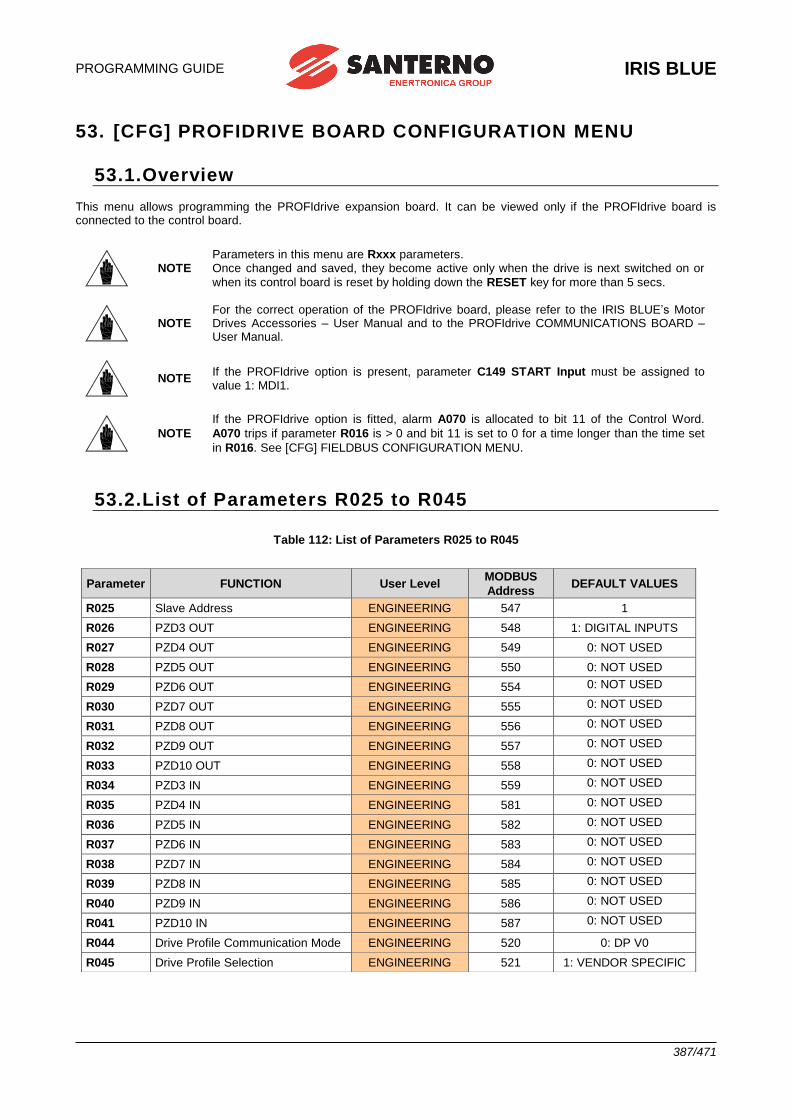
PROGRAMMING GUIDE
IRIS BLUE
387/471
53. [CFG] PROFIDRIVE BOARD CONFIGURATION MENU
53.1.Overview This menu allows programming the PROFIdrive expansion board. It can be viewed only if the PROFIdrive board is connected to the control board.
NOTE Parameters in this menu are Rxxx parameters. Once changed and saved, they become active only when the drive is next switched on or
when its control board is reset by holding down the RESET key for more than 5 secs.
NOTE For the correct operation of the PROFIdrive board, please refer to the IRIS BLUE’s Motor Drives Accessories – User Manual and to the PROFIdrive COMMUNICATIONS BOARD – User Manual.
NOTE If the PROFIdrive option is present, parameter C149 START Input must be assigned to value 1: MDI1.
NOTE
If the PROFIdrive option is fitted, alarm A070 is allocated to bit 11 of the Control Word.
A070 trips if parameter R016 is > 0 and bit 11 is set to 0 for a time longer than the time set
in R016. See [CFG] FIELDBUS CONFIGURATION MENU.
53.2.List of Parameters R025 to R045
Table 112: List of Parameters R025 to R045
Parameter FUNCTION User Level MODBUS
Address DEFAULT VALUES
R025 Slave Address ENGINEERING 547 1
R026 PZD3 OUT ENGINEERING 548 1: DIGITAL INPUTS
R027 PZD4 OUT ENGINEERING 549 0: NOT USED
R028 PZD5 OUT ENGINEERING 550 0: NOT USED
R029 PZD6 OUT ENGINEERING 554 0: NOT USED
R030 PZD7 OUT ENGINEERING 555 0: NOT USED
R031 PZD8 OUT ENGINEERING 556 0: NOT USED
R032 PZD9 OUT ENGINEERING 557 0: NOT USED
R033 PZD10 OUT ENGINEERING 558 0: NOT USED
R034 PZD3 IN ENGINEERING 559 0: NOT USED
R035 PZD4 IN ENGINEERING 581 0: NOT USED
R036 PZD5 IN ENGINEERING 582 0: NOT USED
R037 PZD6 IN ENGINEERING 583 0: NOT USED
R038 PZD7 IN ENGINEERING 584 0: NOT USED
R039 PZD8 IN ENGINEERING 585 0: NOT USED
R040 PZD9 IN ENGINEERING 586 0: NOT USED
R041 PZD10 IN ENGINEERING 587 0: NOT USED
R044 Drive Profile Communication Mode ENGINEERING 520 0: DP V0
R045 Drive Profile Selection ENGINEERING 521 1: VENDOR SPECIFIC
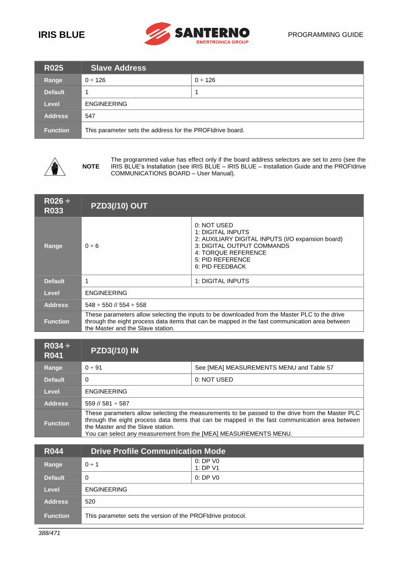
IRIS BLUE
PROGRAMMING GUIDE
388/471
R025 Slave Address
Range 0 ÷ 126 0 ÷ 126
Default 1 1
Level ENGINEERING
Address 547
Function This parameter sets the address for the PROFIdrive board.
NOTE The programmed value has effect only if the board address selectors are set to zero (see the IRIS BLUE’s Installation (see IRIS BLUE – IRIS BLUE – Installation Guide and the PROFIdrive COMMUNICATIONS BOARD – User Manual).
R026 ÷
R033 PZD3(/10) OUT
Range 0 ÷ 6
0: NOT USED 1: DIGITAL INPUTS 2: AUXILIARY DIGITAL INPUTS (I/O expansion board) 3: DIGITAL OUTPUT COMMANDS 4: TORQUE REFERENCE 5: PID REFERENCE 6: PID FEEDBACK
Default 1 1: DIGITAL INPUTS
Level ENGINEERING
Address 548 ÷ 550 // 554 ÷ 558
Function These parameters allow selecting the inputs to be downloaded from the Master PLC to the drive through the eight process data items that can be mapped in the fast communication area between the Master and the Slave station.
R034 ÷
R041 PZD3(/10) IN
Range 0 ÷ 91 See [MEA] MEASUREMENTS MENU and Table 57
Default 0 0: NOT USED
Level ENGINEERING
Address 559 // 581 ÷ 587
Function
These parameters allow selecting the measurements to be passed to the drive from the Master PLC through the eight process data items that can be mapped in the fast communication area between the Master and the Slave station. You can select any measurement from the [MEA] MEASUREMENTS MENU.
R044 Drive Profile Communication Mode
Range 0 ÷ 1 0: DP V0 1: DP V1
Default 0 0: DP V0
Level ENGINEERING
Address 520
Function This parameter sets the version of the PROFIdrive protocol.
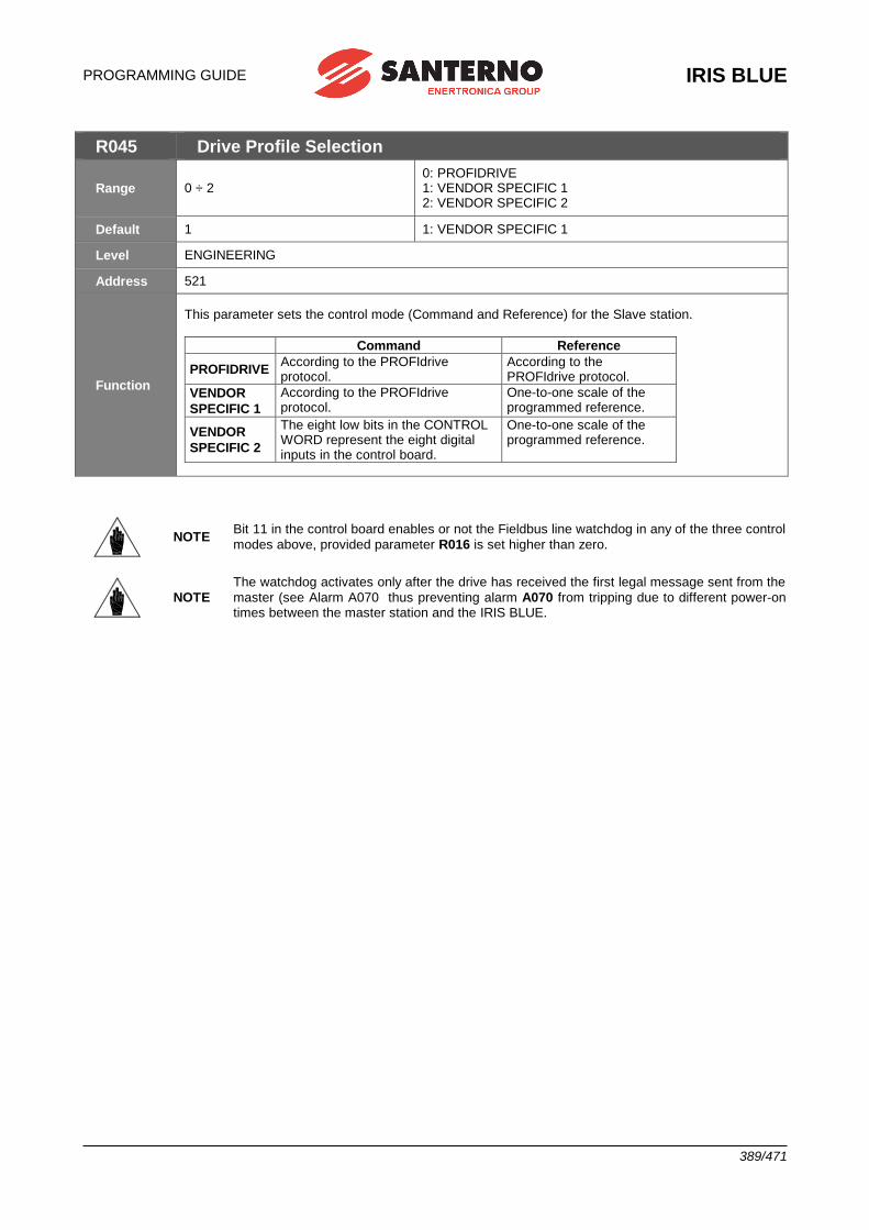
PROGRAMMING GUIDE
IRIS BLUE
389/471
R045 Drive Profile Selection
Range 0 ÷ 2 0: PROFIDRIVE 1: VENDOR SPECIFIC 1 2: VENDOR SPECIFIC 2
Default 1 1: VENDOR SPECIFIC 1
Level ENGINEERING
Address 521
Function
This parameter sets the control mode (Command and Reference) for the Slave station.
Command Reference
PROFIDRIVE According to the PROFIdrive protocol.
According to the PROFIdrive protocol.
VENDOR
SPECIFIC 1
According to the PROFIdrive protocol.
One-to-one scale of the programmed reference.
VENDOR
SPECIFIC 2
The eight low bits in the CONTROL WORD represent the eight digital inputs in the control board.
One-to-one scale of the programmed reference.
NOTE Bit 11 in the control board enables or not the Fieldbus line watchdog in any of the three control
modes above, provided parameter R016 is set higher than zero.
NOTE
The watchdog activates only after the drive has received the first legal message sent from the
master (see Alarm A070 thus preventing alarm A070 from tripping due to different power-on times between the master station and the IRIS BLUE.
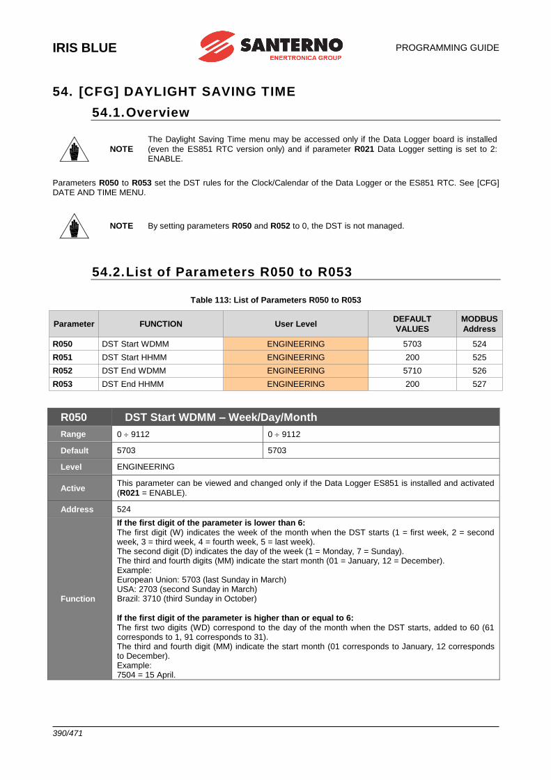
IRIS BLUE
PROGRAMMING GUIDE
390/471
54. [CFG] DAYLIGHT SAVING TIME
54.1. Overview
NOTE
The Daylight Saving Time menu may be accessed only if the Data Logger board is installed
(even the ES851 RTC version only) and if parameter R021 Data Logger setting is set to 2: ENABLE.
Parameters R050 to R053 set the DST rules for the Clock/Calendar of the Data Logger or the ES851 RTC. See [CFG] DATE AND TIME MENU.
NOTE By setting parameters R050 and R052 to 0, the DST is not managed.
54.2. List of Parameters R050 to R053
Table 113: List of Parameters R050 to R053
Parameter FUNCTION User Level DEFAULT
VALUES
MODBUS
Address
R050 DST Start WDMM ENGINEERING 5703 524
R051 DST Start HHMM ENGINEERING 200 525
R052 DST End WDMM ENGINEERING 5710 526
R053 DST End HHMM ENGINEERING 200 527
R050 DST Start WDMM – Week/Day/Month
Range 0 9112 0 9112
Default 5703 5703
Level ENGINEERING
Active This parameter can be viewed and changed only if the Data Logger ES851 is installed and activated
(R021 = ENABLE).
Address 524
Function
If the first digit of the parameter is lower than 6: The first digit (W) indicates the week of the month when the DST starts (1 = first week, 2 = second week, 3 = third week, 4 = fourth week, 5 = last week). The second digit (D) indicates the day of the week (1 = Monday, 7 = Sunday). The third and fourth digits (MM) indicate the start month (01 = January, 12 = December). Example: European Union: 5703 (last Sunday in March) USA: 2703 (second Sunday in March) Brazil: 3710 (third Sunday in October)
If the first digit of the parameter is higher than or equal to 6: The first two digits (WD) correspond to the day of the month when the DST starts, added to 60 (61 corresponds to 1, 91 corresponds to 31). The third and fourth digit (MM) indicate the start month (01 corresponds to January, 12 corresponds to December). Example: 7504 = 15 April.
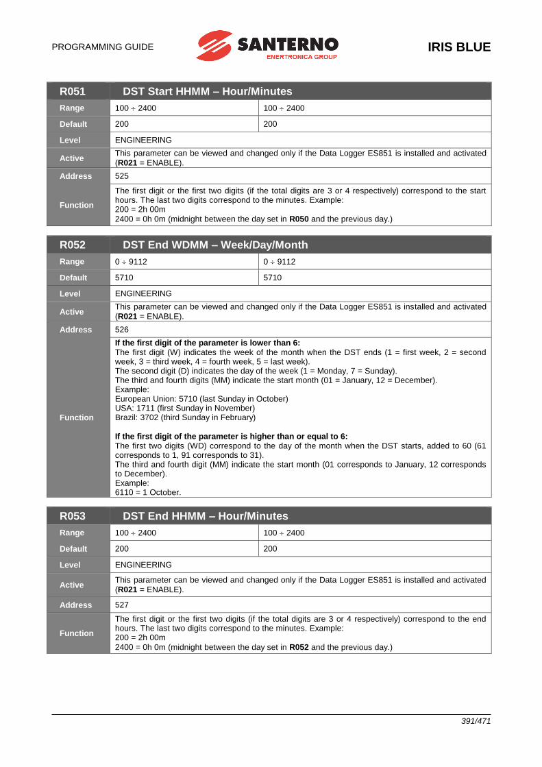
PROGRAMMING GUIDE
IRIS BLUE
391/471
R051 DST Start HHMM – Hour/Minutes
Range 100 2400 100 2400
Default 200 200
Level ENGINEERING
Active This parameter can be viewed and changed only if the Data Logger ES851 is installed and activated
(R021 = ENABLE).
Address 525
Function
The first digit or the first two digits (if the total digits are 3 or 4 respectively) correspond to the start hours. The last two digits correspond to the minutes. Example: 200 = 2h 00m
2400 = 0h 0m (midnight between the day set in R050 and the previous day.)
R052 DST End WDMM – Week/Day/Month
Range 0 9112 0 9112
Default 5710 5710
Level ENGINEERING
Active This parameter can be viewed and changed only if the Data Logger ES851 is installed and activated
(R021 = ENABLE).
Address 526
Function
If the first digit of the parameter is lower than 6: The first digit (W) indicates the week of the month when the DST ends (1 = first week, 2 = second week, 3 = third week, 4 = fourth week, 5 = last week). The second digit (D) indicates the day of the week (1 = Monday, 7 = Sunday). The third and fourth digits (MM) indicate the start month (01 = January, 12 = December). Example: European Union: 5710 (last Sunday in October) USA: 1711 (first Sunday in November) Brazil: 3702 (third Sunday in February)
If the first digit of the parameter is higher than or equal to 6: The first two digits (WD) correspond to the day of the month when the DST starts, added to 60 (61 corresponds to 1, 91 corresponds to 31). The third and fourth digit (MM) indicate the start month (01 corresponds to January, 12 corresponds to December). Example: 6110 = 1 October.
R053 DST End HHMM – Hour/Minutes
Range 100 2400 100 2400
Default 200 200
Level ENGINEERING
Active This parameter can be viewed and changed only if the Data Logger ES851 is installed and activated
(R021 = ENABLE).
Address 527
Function
The first digit or the first two digits (if the total digits are 3 or 4 respectively) correspond to the end hours. The last two digits correspond to the minutes. Example: 200 = 2h 00m
2400 = 0h 0m (midnight between the day set in R052 and the previous day.)
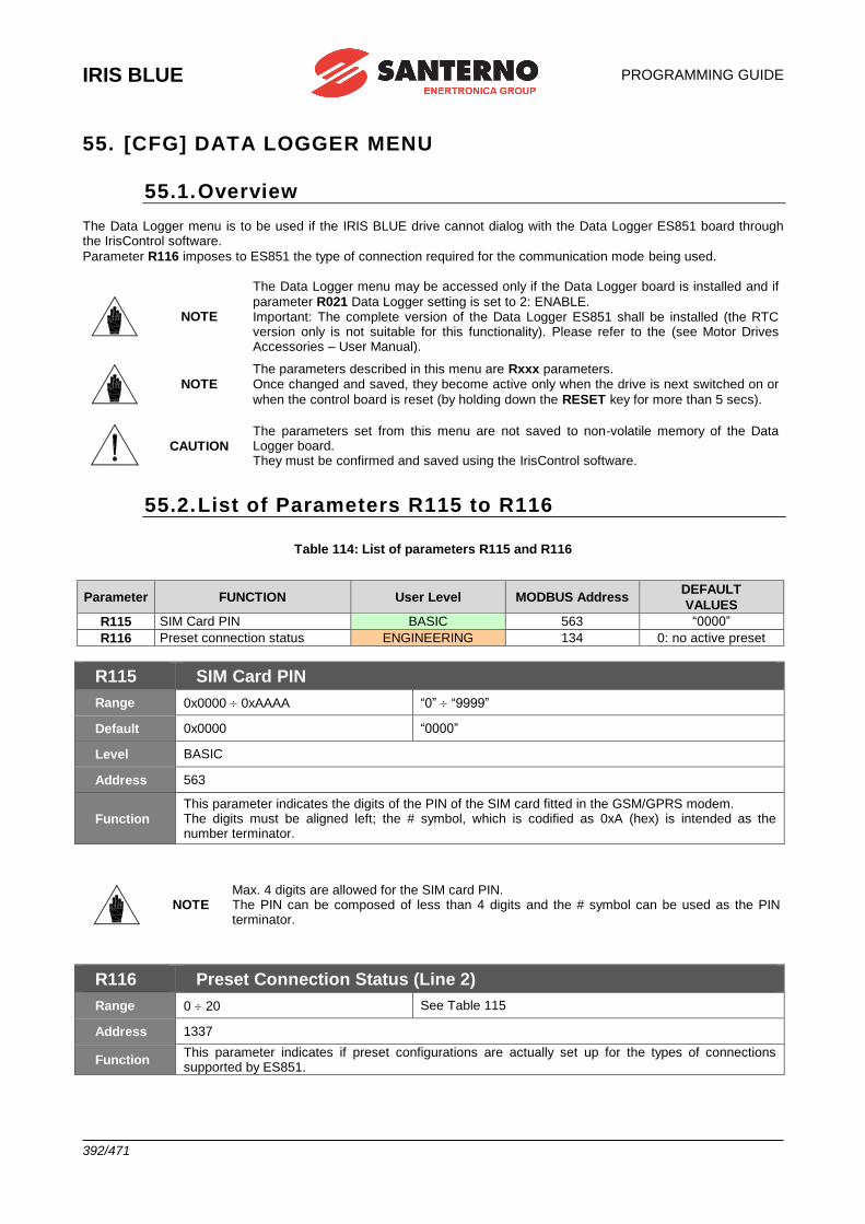
IRIS BLUE
PROGRAMMING GUIDE
392/471
55. [CFG] DATA LOGGER MENU
55.1. Overview The Data Logger menu is to be used if the IRIS BLUE drive cannot dialog with the Data Logger ES851 board through the IrisControl software.
Parameter R116 imposes to ES851 the type of connection required for the communication mode being used.
NOTE
The Data Logger menu may be accessed only if the Data Logger board is installed and if
parameter R021 Data Logger setting is set to 2: ENABLE. Important: The complete version of the Data Logger ES851 shall be installed (the RTC version only is not suitable for this functionality). Please refer to the (see Motor Drives Accessories – User Manual).
NOTE The parameters described in this menu are Rxxx parameters. Once changed and saved, they become active only when the drive is next switched on or
when the control board is reset (by holding down the RESET key for more than 5 secs).
CAUTION The parameters set from this menu are not saved to non-volatile memory of the Data Logger board. They must be confirmed and saved using the IrisControl software.
55.2. List of Parameters R115 to R116
Table 114: List of parameters R115 and R116
Parameter FUNCTION User Level MODBUS Address DEFAULT
VALUES
R115 SIM Card PIN BASIC 563 “0000”
R116 Preset connection status ENGINEERING 134 0: no active preset
R115 SIM Card PIN
Range 0x0000 0xAAAA “0” “9999”
Default 0x0000 “0000”
Level BASIC
Address 563
Function This parameter indicates the digits of the PIN of the SIM card fitted in the GSM/GPRS modem. The digits must be aligned left; the # symbol, which is codified as 0xA (hex) is intended as the number terminator.
NOTE Max. 4 digits are allowed for the SIM card PIN. The PIN can be composed of less than 4 digits and the # symbol can be used as the PIN terminator.
R116 Preset Connection Status (Line 2)
Range 0 20 See Table 115
Address 1337
Function This parameter indicates if preset configurations are actually set up for the types of connections supported by ES851.
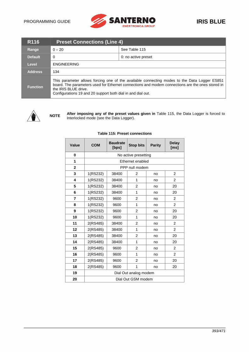
PROGRAMMING GUIDE
IRIS BLUE
393/471
R116 Preset Connections (Line 4)
Range 0 20 See Table 115
Default 0 0: no active preset
Level ENGINEERING
Address 134
Function
This parameter allows forcing one of the available connecting modes to the Data Logger ES851 board. The parameters used for Ethernet connections and modem connections are the ones stored in the IRIS BLUE drive. Configurations 19 and 20 support both dial in and dial out.
NOTE After imposing any of the preset values given in Table 115, the Data Logger is forced to Interlocked mode (see the Data Logger).
Table 115: Preset connections
Value COM Baudrate
[bps] Stop bits Parity
Delay
[ms]
0 No active presetting
1 Ethernet enabled
2 PPP null modem
3 1(RS232) 38400 2 no 2
4 1(RS232) 38400 1 no 2
5 1(RS232) 38400 2 no 20
6 1(RS232) 38400 1 no 20
7 1(RS232) 9600 2 no 2
8 1(RS232) 9600 1 no 2
9 1(RS232) 9600 2 no 20
10 1(RS232) 9600 1 no 20
11 2(RS485) 38400 2 no 2
12 2(RS485) 38400 1 no 2
13 2(RS485) 38400 2 no 20
14 2(RS485) 38400 1 no 20
15 2(RS485) 9600 2 no 2
16 2(RS485) 9600 1 no 2
17 2(RS485) 9600 2 no 20
18 2(RS485) 9600 1 no 20
19 Dial Out analog modem
20 Dial Out GSM modem
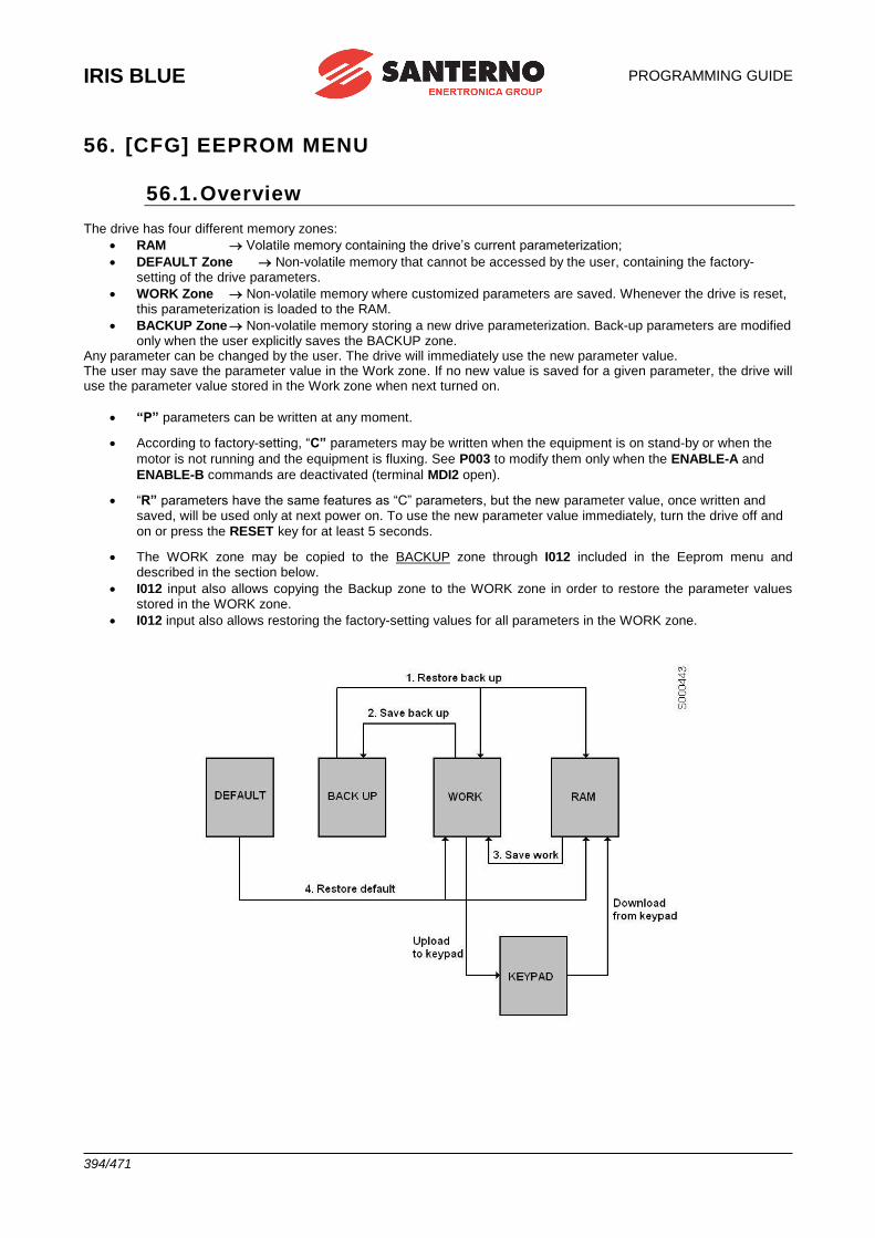
IRIS BLUE
PROGRAMMING GUIDE
394/471
56. [CFG] EEPROM MENU
56.1. Overview The drive has four different memory zones:
• RAM Volatile memory containing the drive’s current parameterization;
• DEFAULT Zone Non-volatile memory that cannot be accessed by the user, containing the factory-setting of the drive parameters.
• WORK Zone Non-volatile memory where customized parameters are saved. Whenever the drive is reset, this parameterization is loaded to the RAM.
• BACKUP Zone Non-volatile memory storing a new drive parameterization. Back-up parameters are modified only when the user explicitly saves the BACKUP zone.
Any parameter can be changed by the user. The drive will immediately use the new parameter value. The user may save the parameter value in the Work zone. If no new value is saved for a given parameter, the drive will use the parameter value stored in the Work zone when next turned on.
• “P” parameters can be written at any moment.
• According to factory-setting, “C” parameters may be written when the equipment is on stand-by or when the
motor is not running and the equipment is fluxing. See P003 to modify them only when the ENABLE-A and
ENABLE-B commands are deactivated (terminal MDI2 open).
• “R” parameters have the same features as “C” parameters, but the new parameter value, once written and saved, will be used only at next power on. To use the new parameter value immediately, turn the drive off and
on or press the RESET key for at least 5 seconds.
• The WORK zone may be copied to the BACKUP zone through I012 included in the Eeprom menu and described in the section below.
• I012 input also allows copying the Backup zone to the WORK zone in order to restore the parameter values stored in the WORK zone.
• I012 input also allows restoring the factory-setting values for all parameters in the WORK zone.
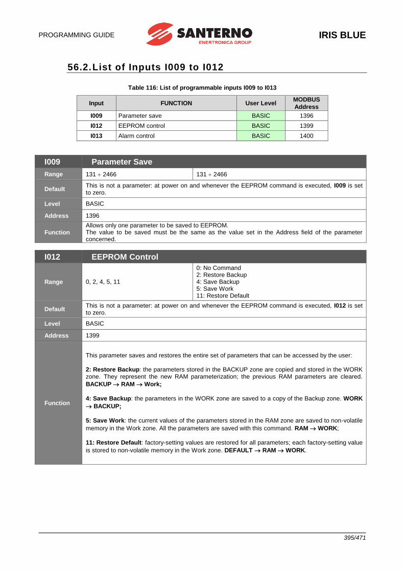
PROGRAMMING GUIDE
IRIS BLUE
395/471
56.2. List of Inputs I009 to I012
Table 116: List of programmable inputs I009 to I013
Input FUNCTION User Level MODBUS
Address
I009 Parameter save BASIC 1396
I012 EEPROM control BASIC 1399
I013 Alarm control BASIC 1400
I009 Parameter Save
Range 131 2466 131 2466
Default This is not a parameter: at power on and whenever the EEPROM command is executed, I009 is set to zero.
Level BASIC
Address 1396
Function Allows only one parameter to be saved to EEPROM. The value to be saved must be the same as the value set in the Address field of the parameter concerned.
I012 EEPROM Control
Range 0, 2, 4, 5, 11
0: No Command 2: Restore Backup 4: Save Backup 5: Save Work 11: Restore Default
Default This is not a parameter: at power on and whenever the EEPROM command is executed, I012 is set to zero.
Level BASIC
Address 1399
Function
This parameter saves and restores the entire set of parameters that can be accessed by the user:
2: Restore Backup: the parameters stored in the BACKUP zone are copied and stored in the WORK zone. They represent the new RAM parameterization; the previous RAM parameters are cleared.
BACKUP RAM Work;
4: Save Backup: the parameters in the WORK zone are saved to a copy of the Backup zone. WORK
BACKUP;
5: Save Work: the current values of the parameters stored in the RAM zone are saved to non-volatile
memory in the Work zone. All the parameters are saved with this command. RAM WORK;
11: Restore Default: factory-setting values are restored for all parameters; each factory-setting value
is stored to non-volatile memory in the Work zone. DEFAULT RAM WORK.

IRIS BLUE
PROGRAMMING GUIDE
396/471
I013 Alarm Control
Range 1, 777 1: Trips alarm A040 777: Resets the alarms tripped
Default This is not a programming parameter: the input is set to zero whenever the drive is powered on and whenever the command is executed.
Level BASIC
Address 1400
Function 1: Trips alarm A040 (User alarm). It may be helpful to test the system.
777: Resets the alarms tripped. Resets any alarm tripped (not only A040).
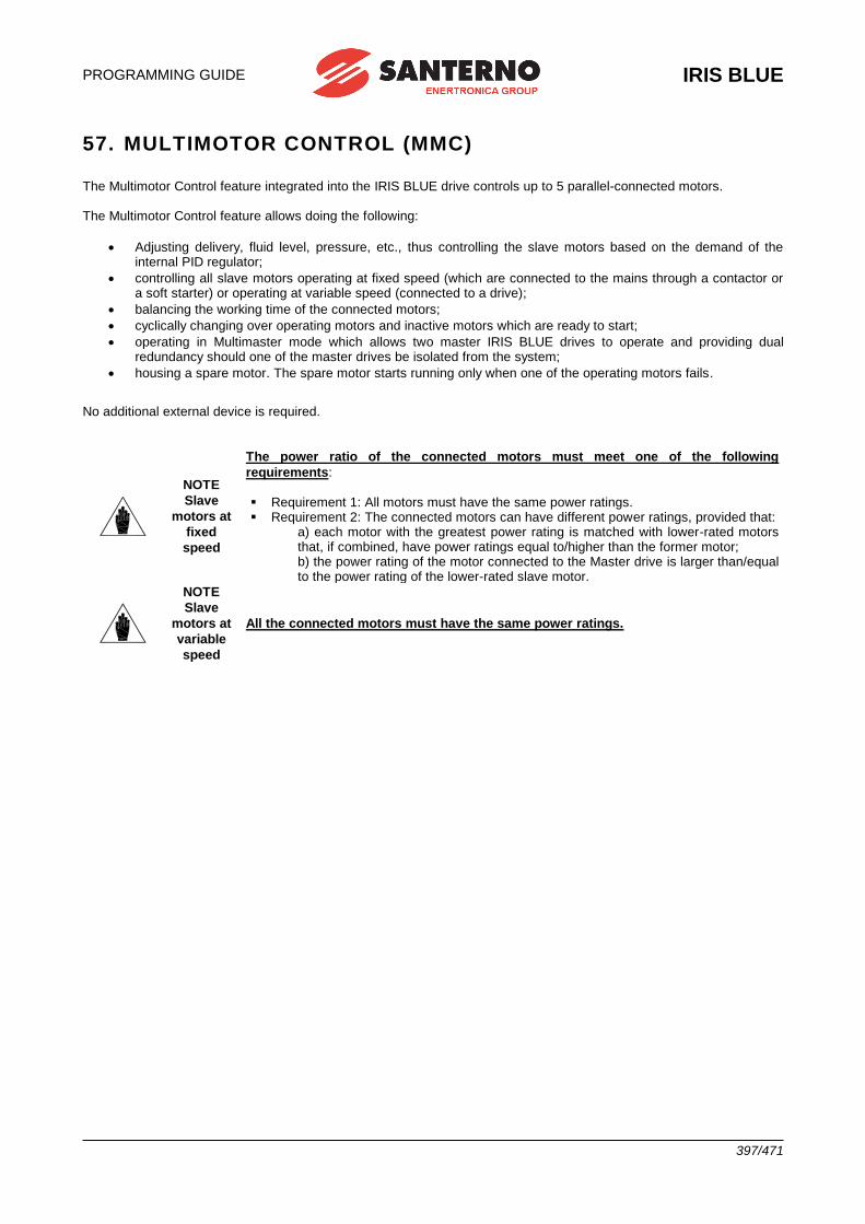
PROGRAMMING GUIDE
IRIS BLUE
397/471
57. MULTIMOTOR CONTROL (MMC)
The Multimotor Control feature integrated into the IRIS BLUE drive controls up to 5 parallel-connected motors. The Multimotor Control feature allows doing the following:
• Adjusting delivery, fluid level, pressure, etc., thus controlling the slave motors based on the demand of the internal PID regulator;
• controlling all slave motors operating at fixed speed (which are connected to the mains through a contactor or a soft starter) or operating at variable speed (connected to a drive);
• balancing the working time of the connected motors;
• cyclically changing over operating motors and inactive motors which are ready to start;
• operating in Multimaster mode which allows two master IRIS BLUE drives to operate and providing dual redundancy should one of the master drives be isolated from the system;
• housing a spare motor. The spare motor starts running only when one of the operating motors fails.
No additional external device is required.
NOTE
Slave
motors at
fixed
speed
The power ratio of the connected motors must meet one of the following
requirements: ▪ Requirement 1: All motors must have the same power ratings. ▪ Requirement 2: The connected motors can have different power ratings, provided that:
a) each motor with the greatest power rating is matched with lower-rated motors that, if combined, have power ratings equal to/higher than the former motor; b) the power rating of the motor connected to the Master drive is larger than/equal to the power rating of the lower-rated slave motor.
NOTE
Slave
motors at
variable
speed
All the connected motors must have the same power ratings.
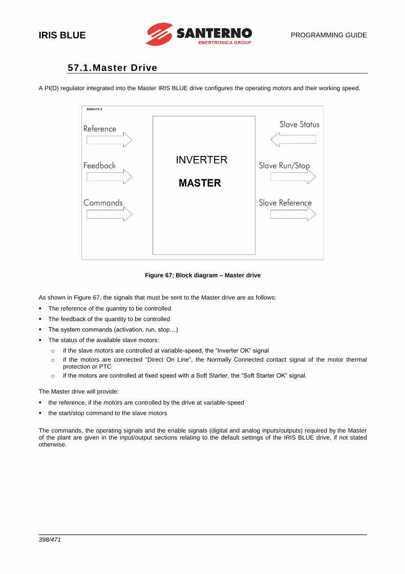
IRIS BLUE
PROGRAMMING GUIDE
398/471
57.1. Master Drive
A PI(D) regulator integrated into the Master IRIS BLUE drive configures the operating motors and their working speed.
Figure 67: Block diagram – Master drive
As shown in Figure 67, the signals that must be sent to the Master drive are as follows:
▪ The reference of the quantity to be controlled
▪ The feedback of the quantity to be controlled
▪ The system commands (activation, run, stop…)
▪ The status of the available slave motors:
o if the slave motors are controlled at variable-speed, the “Inverter OK” signal
o if the motors are connected “Direct On Line”, the Normally Connected contact signal of the motor thermal protection or PTC
o if the motors are controlled at fixed speed with a Soft Starter, the “Soft Starter OK” signal.
The Master drive will provide:
▪ the reference, if the motors are controlled by the drive at variable-speed
▪ the start/stop command to the slave motors
The commands, the operating signals and the enable signals (digital and analog inputs/outputs) required by the Master of the plant are given in the input/output sections relating to the default settings of the IRIS BLUE drive, if not stated otherwise.
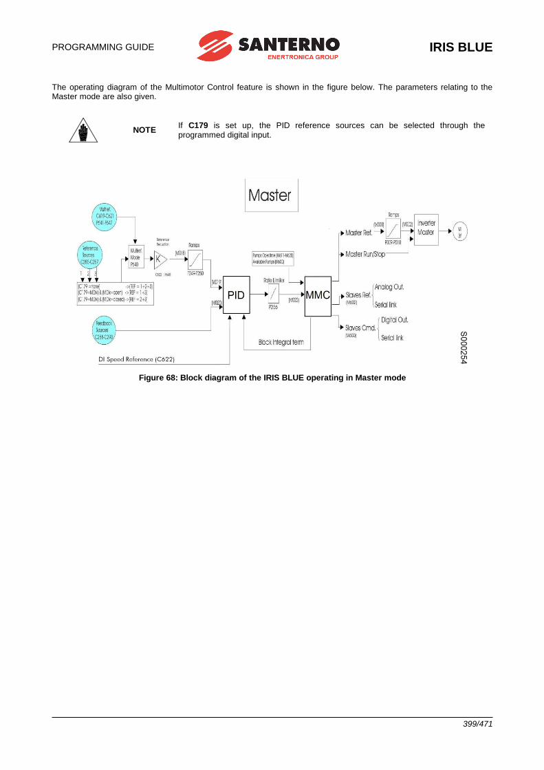
PROGRAMMING GUIDE
IRIS BLUE
399/471
The operating diagram of the Multimotor Control feature is shown in the figure below. The parameters relating to the Master mode are also given.
NOTE If C179 is set up, the PID reference sources can be selected through the programmed digital input.
Figure 68: Block diagram of the IRIS BLUE operating in Master mode
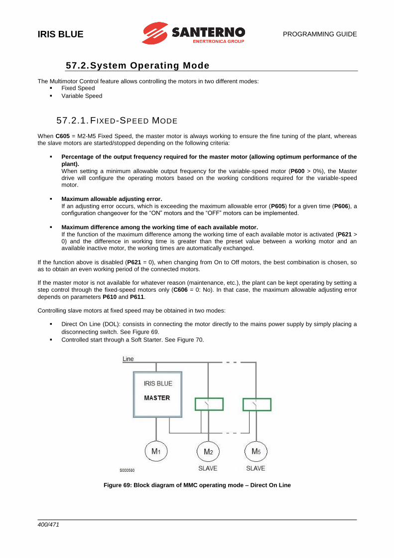
IRIS BLUE
PROGRAMMING GUIDE
400/471
57.2. System Operating Mode The Multimotor Control feature allows controlling the motors in two different modes:
▪ Fixed Speed
▪ Variable Speed
57.2.1. F IXED-SPEED MODE
When C605 = M2-M5 Fixed Speed, the master motor is always working to ensure the fine tuning of the plant, whereas the slave motors are started/stopped depending on the following criteria:
▪ Percentage of the output frequency required for the master motor (allowing optimum performance of the
plant).
When setting a minimum allowable output frequency for the variable-speed motor (P600 > 0%), the Master drive will configure the operating motors based on the working conditions required for the variable-speed motor.
▪ Maximum allowable adjusting error.
If an adjusting error occurs, which is exceeding the maximum allowable error (P605) for a given time (P606), a configuration changeover for the “ON” motors and the “OFF” motors can be implemented.
▪ Maximum difference among the working time of each available motor.
If the function of the maximum difference among the working time of each available motor is activated (P621 > 0) and the difference in working time is greater than the preset value between a working motor and an available inactive motor, the working times are automatically exchanged.
If the function above is disabled (P621 = 0), when changing from On to Off motors, the best combination is chosen, so as to obtain an even working period of the connected motors. If the master motor is not available for whatever reason (maintenance, etc.), the plant can be kept operating by setting a
step control through the fixed-speed motors only (C606 = 0: No). In that case, the maximum allowable adjusting error
depends on parameters P610 and P611. Controlling slave motors at fixed speed may be obtained in two modes:
▪ Direct On Line (DOL): consists in connecting the motor directly to the mains power supply by simply placing a
disconnecting switch. See Figure 69.
▪ Controlled start through a Soft Starter. See Figure 70.
Figure 69: Block diagram of MMC operating mode – Direct On Line
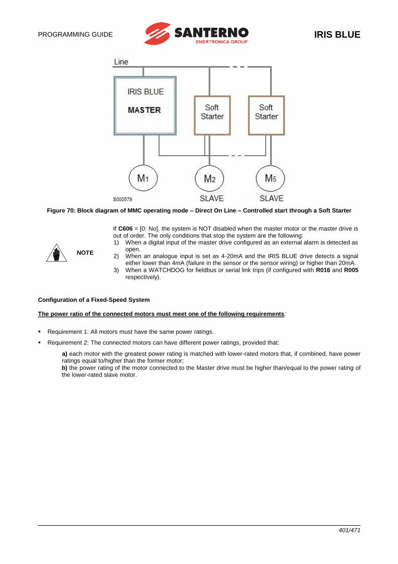
PROGRAMMING GUIDE
IRIS BLUE
401/471
Figure 70: Block diagram of MMC operating mode – Direct On Line – Controlled start through a Soft Starter
NOTE
If C606 = [0: No], the system is NOT disabled when the master motor or the master drive is out of order. The only conditions that stop the system are the following: 1) When a digital input of the master drive configured as an external alarm is detected as
open. 2) When an analogue input is set as 4-20mA and the IRIS BLUE drive detects a signal
either lower than 4mA (failure in the sensor or the sensor wiring) or higher than 20mA.
3) When a WATCHDOG for fieldbus or serial link trips (if configured with R016 and R005 respectively).
Configuration of a Fixed-Speed System
The power ratio of the connected motors must meet one of the following requirements:
▪ Requirement 1: All motors must have the same power ratings.
▪ Requirement 2: The connected motors can have different power ratings, provided that:
a) each motor with the greatest power rating is matched with lower-rated motors that, if combined, have power ratings equal to/higher than the former motor;
b) the power rating of the motor connected to the Master drive must be higher than/equal to the power rating of the lower-rated slave motor.
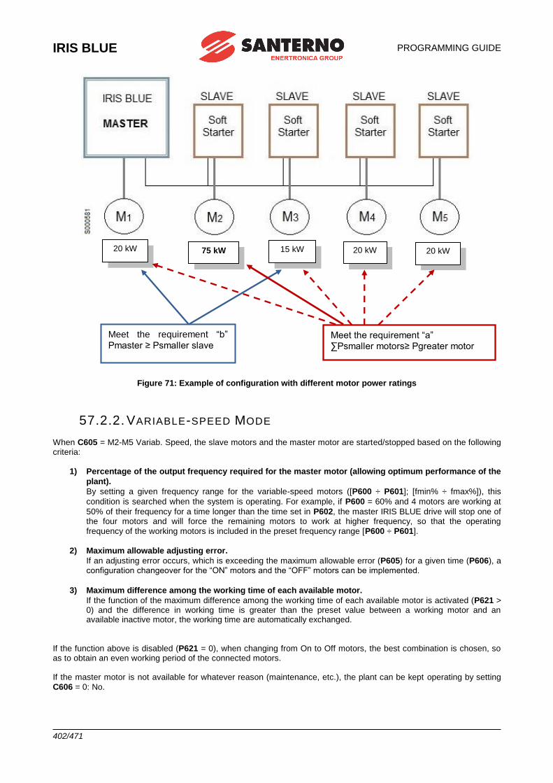
IRIS BLUE
PROGRAMMING GUIDE
402/471
Figure 71: Example of configuration with different motor power ratings
57.2.2. VARIABLE-SPEED MODE
When C605 = M2-M5 Variab. Speed, the slave motors and the master motor are started/stopped based on the following criteria:
1) Percentage of the output frequency required for the master motor (allowing optimum performance of the
plant).
By setting a given frequency range for the variable-speed motors ([P600 ÷ P601]; [fmin% ÷ fmax%]), this
condition is searched when the system is operating. For example, if P600 = 60% and 4 motors are working at
50% of their frequency for a time longer than the time set in P602, the master IRIS BLUE drive will stop one of the four motors and will force the remaining motors to work at higher frequency, so that the operating
frequency of the working motors is included in the preset frequency range [P600 ÷ P601].
2) Maximum allowable adjusting error.
If an adjusting error occurs, which is exceeding the maximum allowable error (P605) for a given time (P606), a configuration changeover for the “ON” motors and the “OFF” motors can be implemented.
3) Maximum difference among the working time of each available motor.
If the function of the maximum difference among the working time of each available motor is activated (P621 > 0) and the difference in working time is greater than the preset value between a working motor and an available inactive motor, the working time are automatically exchanged.
If the function above is disabled (P621 = 0), when changing from On to Off motors, the best combination is chosen, so as to obtain an even working period of the connected motors. If the master motor is not available for whatever reason (maintenance, etc.), the plant can be kept operating by setting
C606 = 0: No.
20 kW 75 kW 15 kW 20 kW 20 kW
Meet the requirement “b”
Pmaster ≥ Psmaller slave
Meet the requirement “a”
∑Psmaller motors≥ Pgreater motor
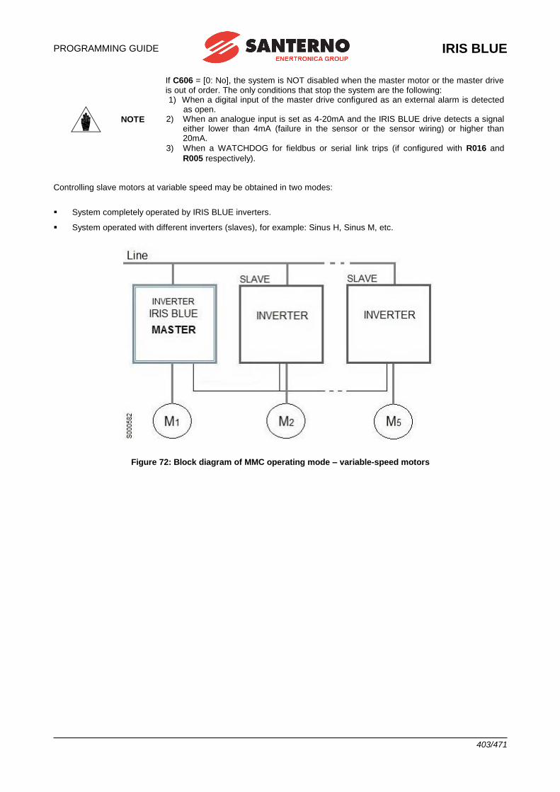
PROGRAMMING GUIDE
IRIS BLUE
403/471
NOTE
If C606 = [0: No], the system is NOT disabled when the master motor or the master drive is out of order. The only conditions that stop the system are the following: 1) When a digital input of the master drive configured as an external alarm is detected
as open. 2) When an analogue input is set as 4-20mA and the IRIS BLUE drive detects a signal
either lower than 4mA (failure in the sensor or the sensor wiring) or higher than 20mA.
3) When a WATCHDOG for fieldbus or serial link trips (if configured with R016 and
R005 respectively). Controlling slave motors at variable speed may be obtained in two modes:
▪ System completely operated by IRIS BLUE inverters.
▪ System operated with different inverters (slaves), for example: Sinus H, Sinus M, etc.
Figure 72: Block diagram of MMC operating mode – variable-speed motors
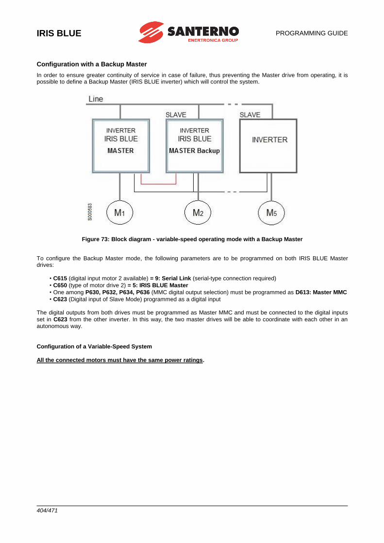
IRIS BLUE
PROGRAMMING GUIDE
404/471
Configuration with a Backup Master
In order to ensure greater continuity of service in case of failure, thus preventing the Master drive from operating, it is possible to define a Backup Master (IRIS BLUE inverter) which will control the system.
Figure 73: Block diagram - variable-speed operating mode with a Backup Master
To configure the Backup Master mode, the following parameters are to be programmed on both IRIS BLUE Master drives:
• C615 (digital input motor 2 available) = 9: Serial Link (serial-type connection required)
• C650 (type of motor drive 2) = 5: IRIS BLUE Master
• One among P630, P632, P634, P636 (MMC digital output selection) must be programmed as D613: Master MMC
• C623 (Digital input of Slave Mode) programmed as a digital input The digital outputs from both drives must be programmed as Master MMC and must be connected to the digital inputs
set in C623 from the other inverter. In this way, the two master drives will be able to coordinate with each other in an autonomous way.
Configuration of a Variable-Speed System
All the connected motors must have the same power ratings.
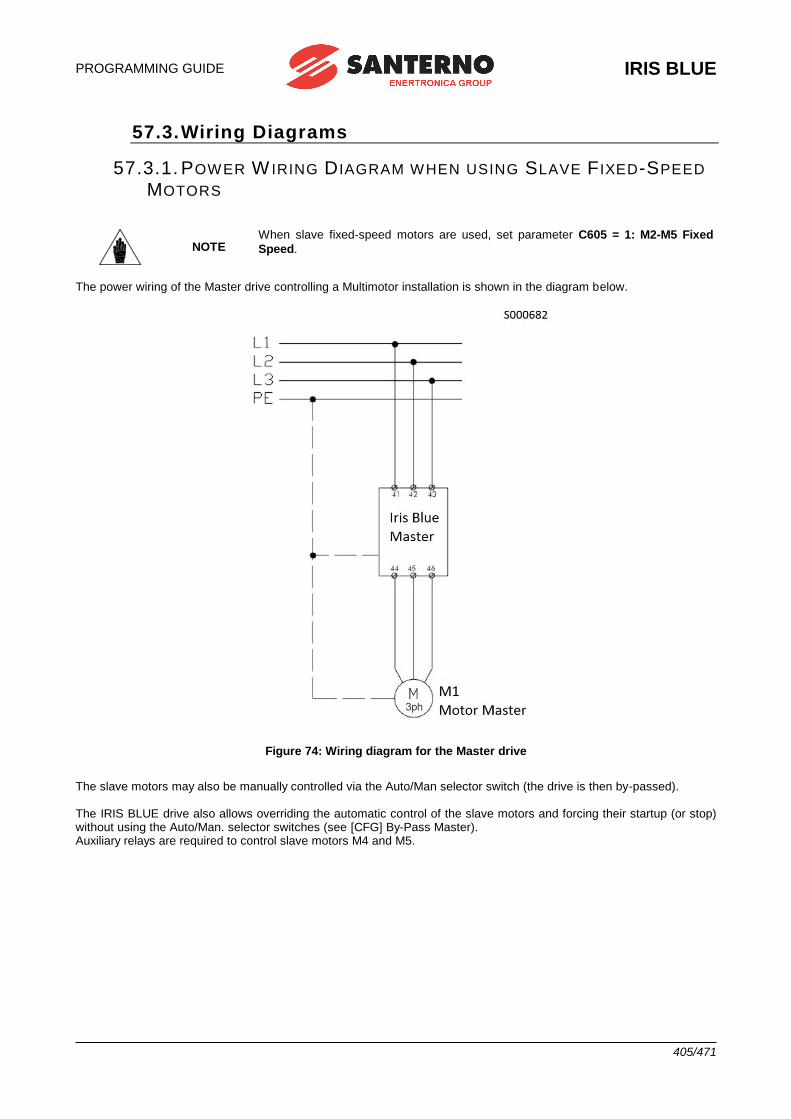
PROGRAMMING GUIDE
IRIS BLUE
405/471
57.3. Wiring Diagrams
57.3.1. POWER W IRING D IAGRAM WHEN USING SLAVE F IXED-SPEED
MOTORS
NOTE When slave fixed-speed motors are used, set parameter C605 = 1: M2-M5 Fixed
Speed.
The power wiring of the Master drive controlling a Multimotor installation is shown in the diagram below.
Figure 74: Wiring diagram for the Master drive
The slave motors may also be manually controlled via the Auto/Man selector switch (the drive is then by-passed). The IRIS BLUE drive also allows overriding the automatic control of the slave motors and forcing their startup (or stop) without using the Auto/Man. selector switches (see [CFG] By-Pass Master). Auxiliary relays are required to control slave motors M4 and M5.
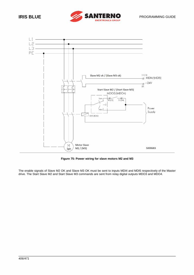
IRIS BLUE
PROGRAMMING GUIDE
406/471
Figure 75: Power wiring for slave motors M2 and M3
The enable signals of Slave M2 OK and Slave M3 OK must be sent to inputs MDI4 and MDI5 respectively of the Master drive. The Start Slave M2 and Start Slave M3 commands are sent from relay digital outputs MDO3 and MDO4.
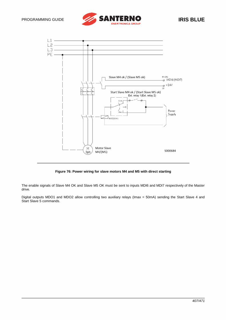
PROGRAMMING GUIDE
IRIS BLUE
407/471
Figure 76: Power wiring for slave motors M4 and M5 with direct starting
The enable signals of Slave M4 OK and Slave M5 OK must be sent to inputs MDI6 and MDI7 respectively of the Master drive. Digital outputs MDO1 and MDO2 allow controlling two auxiliary relays (Imax = 50mA) sending the Start Slave 4 and Start Slave 5 commands.
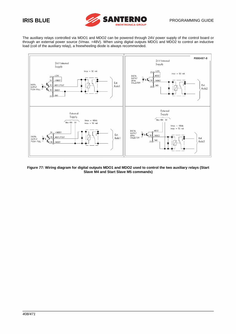
IRIS BLUE
PROGRAMMING GUIDE
408/471
The auxiliary relays controlled via MDO1 and MDO2 can be powered through 24V power supply of the control board or through an external power source (Vmax. =48V). When using digital outputs MDO1 and MDO2 to control an inductive load (coil of the auxiliary relay), a freewheeling diode is always recommended.
Figure 77: Wiring diagram for digital outputs MDO1 and MDO2 used to control the two auxiliary relays (Start
Slave M4 and Start Slave M5 commands)
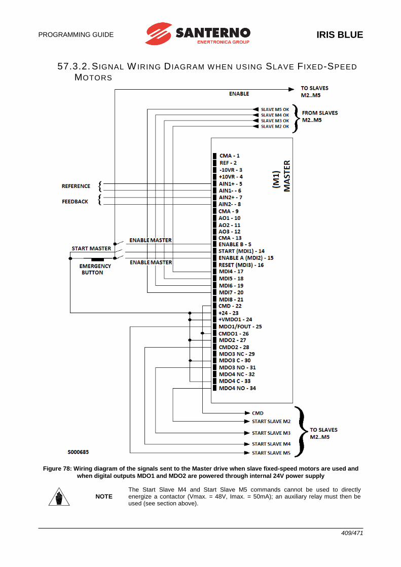
PROGRAMMING GUIDE
IRIS BLUE
409/471
57.3.2. S IGNAL W IRING D IAGRAM WHEN USING SLAVE F IXED-SPEED
MOTORS
Figure 78: Wiring diagram of the signals sent to the Master drive when slave fixed-speed motors are used and
when digital outputs MDO1 and MDO2 are powered through internal 24V power supply
NOTE The Start Slave M4 and Start Slave M5 commands cannot be used to directly energize a contactor (Vmax. = 48V, Imax. = 50mA); an auxiliary relay must then be used (see section above).
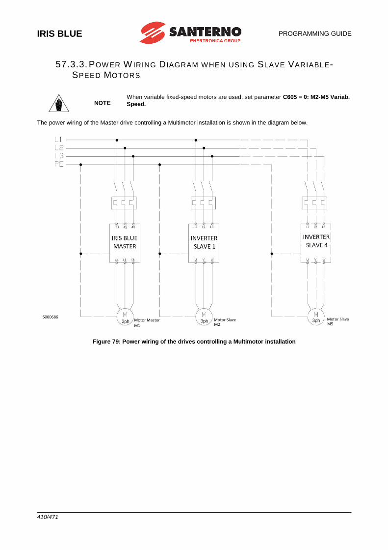
IRIS BLUE
PROGRAMMING GUIDE
410/471
57.3.3. POWER W IRING D IAGRAM WHEN USING SLAVE VARIABLE-SPEED MOTORS
NOTE When variable fixed-speed motors are used, set parameter C605 = 0: M2-M5 Variab.
Speed.
The power wiring of the Master drive controlling a Multimotor installation is shown in the diagram below.
Figure 79: Power wiring of the drives controlling a Multimotor installation
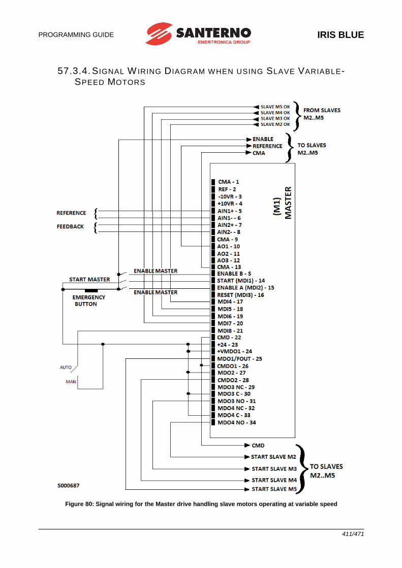
PROGRAMMING GUIDE
IRIS BLUE
411/471
57.3.4. S IGNAL W IRING D IAGRAM WHEN USING SLAVE VARIABLE-SPEED MOTORS
Figure 80: Signal wiring for the Master drive handling slave motors operating at variable speed
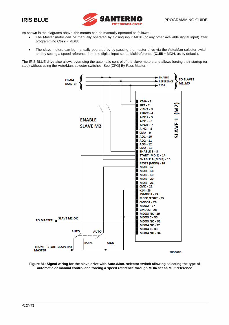
IRIS BLUE
PROGRAMMING GUIDE
412/471
As shown in the diagrams above, the motors can be manually operated as follows:
• The Master motor can be manually operated by closing input MDI8 (or any other available digital input) after
programming C622 = MDI8;
• The slave motors can be manually operated by by-passing the master drive via the Auto/Man selector switch
and by setting a speed reference from the digital input set as Multireference (C155 = MDI4, as by default). The IRIS BLUE drive also allows overriding the automatic control of the slave motors and allows forcing their startup (or stop) without using the Auto/Man. selector switches. See [CFG] By-Pass Master.
Figure 81: Signal wiring for the slave drive with Auto./Man. selector switch allowing selecting the type of
automatic or manual control and forcing a speed reference through MDI4 set as Multireference
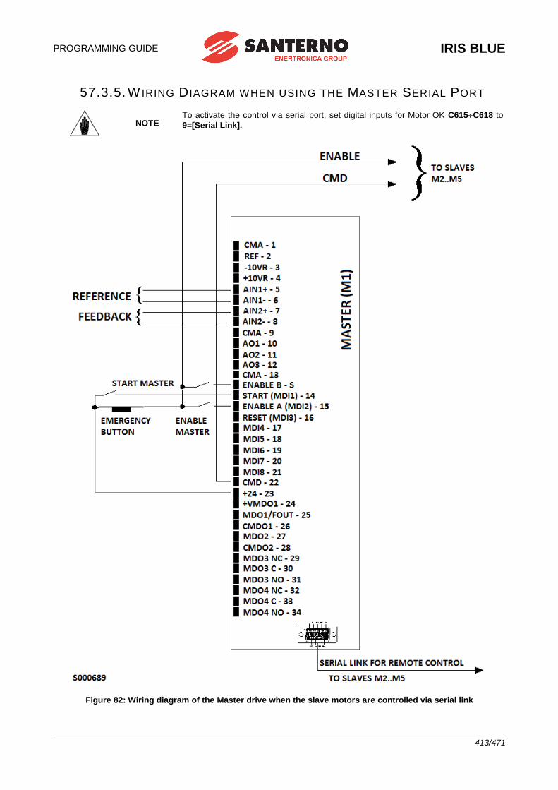
PROGRAMMING GUIDE
IRIS BLUE
413/471
57.3.5. W IRING D IAGRAM WHEN USING THE MASTER SERIAL PORT
NOTE To activate the control via serial port, set digital inputs for Motor OK C615C618 to
9=[Serial Link].
Figure 82: Wiring diagram of the Master drive when the slave motors are controlled via serial link
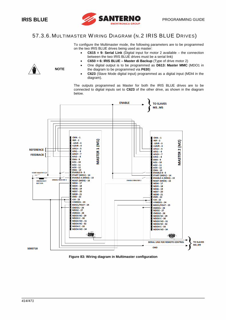
IRIS BLUE
PROGRAMMING GUIDE
414/471
57.3.6. MULTIMASTER W IRING D IAGRAM (N.2 IRIS BLUE DRIVES)
NOTE
To configure the Multimaster mode, the following parameters are to be programmed on the two IRIS BLUE drives being used as master:
• C615 = 9: Serial Link (Digital input for motor 2 available – the connection between the two IRIS BLUE drives must be a serial link)
• C650 = 6: IRIS BLUE – Master di Backup (Type of drive motor 2)
• One digital output is to be programmed as D613: Master MMC (MDO1 in
the diagram to be programmed via P630)
• C623 (Slave Mode digital input) programmed as a digital input (MDI4 in the diagram).
The outputs programmed as Master for both the IRIS BLUE drives are to be
connected to digital inputs set to C623 of the other drive, as shown in the diagram below.
Figure 83: Wiring diagram in Multimaster configuration
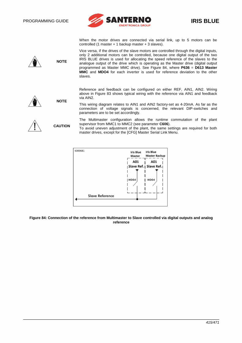
PROGRAMMING GUIDE
IRIS BLUE
415/471
NOTE
When the motor drives are connected via serial link, up to 5 motors can be controlled (1 master + 1 backup master + 3 slaves).
Vice versa, if the drives of the slave motors are controlled through the digital inputs, only 2 additional motors can be controlled, because one digital output of the two IRIS BLUE drives is used for allocating the speed reference of the slaves to the analogue output of the drive which is operating as the Master drive (digital output
programmed as Master MMC drive). See Figure 84, where P636 = D613 Master
MMC and MDO4 for each inverter is used for reference deviation to the other slaves.
NOTE
Reference and feedback can be configured on either REF, AIN1, AIN2. Wiring above in Figure 83 shows typical wiring with the reference via AIN1 and feedback via AIN2.
This wiring diagram relates to AIN1 and AIN2 factory-set as 4-20mA. As far as the connection of voltage signals is concerned, the relevant DIP-switches and parameters are to be set accordingly.
CAUTION
The Multimaster configuration allows the runtime commutation of the plant
supervisor from MMC1 to MMC2 (see parameter C606). To avoid uneven adjustment of the plant, the same settings are required for both master drives, except for the [CFG] Master Serial Link Menu.
Figure 84: Connection of the reference from Multimaster to Slave controlled via digital outputs and analog
reference
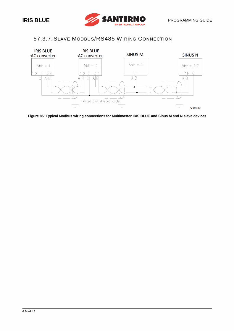
IRIS BLUE
PROGRAMMING GUIDE
416/471
57.3.7. SLAVE MODBUS/RS485 W IRING CONNECTION
Figure 85: Typical Modbus wiring connections for Multimaster IRIS BLUE and Sinus M and N slave devices
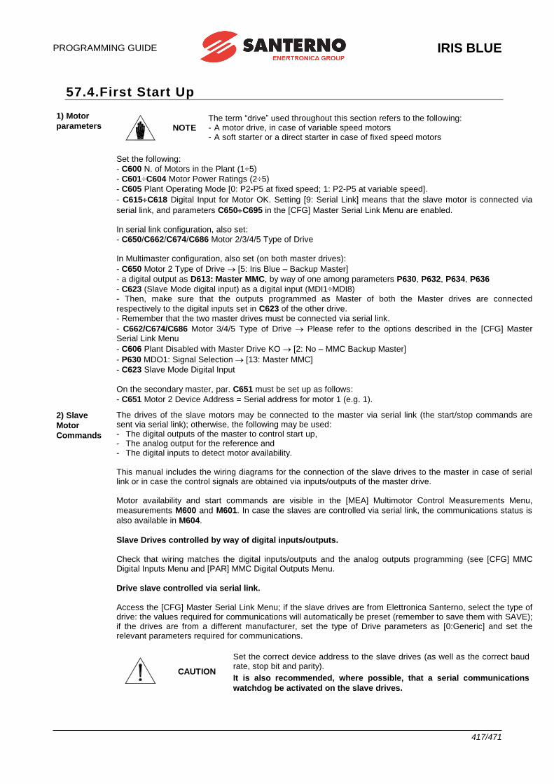
PROGRAMMING GUIDE
IRIS BLUE
417/471
57.4.First Start Up
1) Motor
parameters
NOTE The term “drive” used throughout this section refers to the following: - A motor drive, in case of variable speed motors - A soft starter or a direct starter in case of fixed speed motors
Set the following:
- C600 N. of Motors in the Plant (1÷5)
- C601÷C604 Motor Power Ratings (2÷5)
- C605 Plant Operating Mode [0: P2-P5 at fixed speed; 1: P2-P5 at variable speed].
- C615C618 Digital Input for Motor OK. Setting [9: Serial Link] means that the slave motor is connected via
serial link, and parameters C650C695 in the [CFG] Master Serial Link Menu are enabled. In serial link configuration, also set:
- C650/C662/C674/C686 Motor 2/3/4/5 Type of Drive In Multimaster configuration, also set (on both master drives):
- C650 Motor 2 Type of Drive [5: Iris Blue – Backup Master]
- a digital output as D613: Master MMC, by way of one among parameters P630, P632, P634, P636
- C623 (Slave Mode digital input) as a digital input (MDI1÷MDI8) - Then, make sure that the outputs programmed as Master of both the Master drives are connected
respectively to the digital inputs set in C623 of the other drive. - Remember that the two master drives must be connected via serial link.
- C662/C674/C686 Motor 3/4/5 Type of Drive Please refer to the options described in the [CFG] Master Serial Link Menu
- C606 Plant Disabled with Master Drive KO [2: No – MMC Backup Master]
- P630 MDO1: Signal Selection [13: Master MMC]
- C623 Slave Mode Digital Input
On the secondary master, par. C651 must be set up as follows:
- C651 Motor 2 Device Address = Serial address for motor 1 (e.g. 1).
2) Slave
Motor
Commands
The drives of the slave motors may be connected to the master via serial link (the start/stop commands are sent via serial link); otherwise, the following may be used: - The digital outputs of the master to control start up, - The analog output for the reference and - The digital inputs to detect motor availability. This manual includes the wiring diagrams for the connection of the slave drives to the master in case of serial link or in case the control signals are obtained via inputs/outputs of the master drive. Motor availability and start commands are visible in the [MEA] Multimotor Control Measurements Menu,
measurements M600 and M601. In case the slaves are controlled via serial link, the communications status is
also available in M604.
Slave Drives controlled by way of digital inputs/outputs. Check that wiring matches the digital inputs/outputs and the analog outputs programming (see [CFG] MMC Digital Inputs Menu and [PAR] MMC Digital Outputs Menu.
Drive slave controlled via serial link. Access the [CFG] Master Serial Link Menu; if the slave drives are from Elettronica Santerno, select the type of drive: the values required for communications will automatically be preset (remember to save them with SAVE); if the drives are from a different manufacturer, set the type of Drive parameters as [0:Generic] and set the relevant parameters required for communications.
CAUTION
Set the correct device address to the slave drives (as well as the correct baud rate, stop bit and parity).
It is also recommended, where possible, that a serial communications
watchdog be activated on the slave drives.

IRIS BLUE
PROGRAMMING GUIDE
418/471
3) Serial
Links Menu
If required, access the [CFG] SERIAL LINKS menu and proceed as follows: Check that the serial address parameters of the slave devices are unique (changes will take effect after resetting the slave drives).
Check that the baud rate (R003), parity and stop bit (R006) are the same for all the drives. Check that for all the slave drives, “Command Source Selection” = Serial Link/RS485. Check that for all the slave drives, “Reference” = Serial Link/RS485
For the slave drives connected to a serial link, also set C655/C667/C679/C691 Motor 2/3/4/5 Value for Maximum Reference. See [CFG] Master Serial Link Menu for the selection modes.
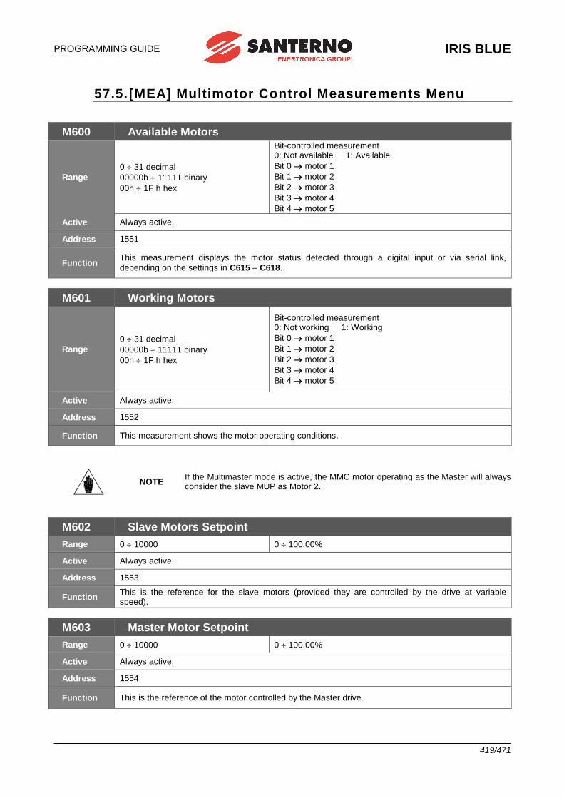
PROGRAMMING GUIDE
IRIS BLUE
419/471
57.5. [MEA] Multimotor Control Measurements Menu
M600 Available Motors
Range
0 31 decimal
00000b 11111 binary
00h 1F h hex
Bit-controlled measurement 0: Not available 1: Available
Bit 0 motor 1
Bit 1 motor 2
Bit 2 motor 3
Bit 3 motor 4
Bit 4 motor 5
Active Always active.
Address 1551
Function This measurement displays the motor status detected through a digital input or via serial link,
depending on the settings in C615 – C618.
M601 Working Motors
Range
0 31 decimal
00000b 11111 binary
00h 1F h hex
Bit-controlled measurement 0: Not working 1: Working
Bit 0 motor 1
Bit 1 motor 2
Bit 2 motor 3
Bit 3 motor 4
Bit 4 motor 5
Active Always active.
Address 1552
Function This measurement shows the motor operating conditions.
NOTE If the Multimaster mode is active, the MMC motor operating as the Master will always consider the slave MUP as Motor 2.
M602 Slave Motors Setpoint
Range 0 10000 0 100.00%
Active Always active.
Address 1553
Function This is the reference for the slave motors (provided they are controlled by the drive at variable speed).
M603 Master Motor Setpoint
Range 0 10000 0 100.00%
Active Always active.
Address 1554
Function This is the reference of the motor controlled by the Master drive.
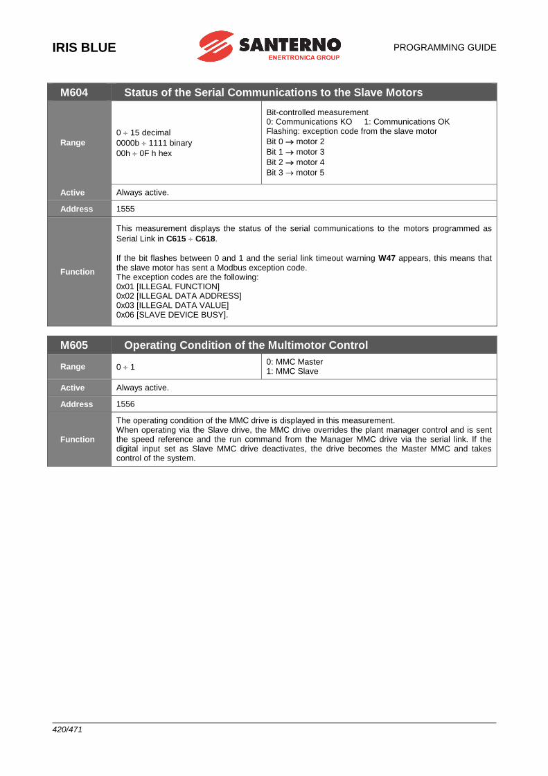
IRIS BLUE
PROGRAMMING GUIDE
420/471
M604 Status of the Serial Communications to the Slave Motors
Range
0 15 decimal
0000b 1111 binary
00h 0F h hex
Bit-controlled measurement 0: Communications KO 1: Communications OK Flashing: exception code from the slave motor
Bit 0 motor 2
Bit 1 motor 3
Bit 2 motor 4
Bit 3 motor 5
Active Always active.
Address 1555
Function
This measurement displays the status of the serial communications to the motors programmed as
Serial Link in C615 C618.
If the bit flashes between 0 and 1 and the serial link timeout warning W47 appears, this means that the slave motor has sent a Modbus exception code. The exception codes are the following: 0x01 [ILLEGAL FUNCTION] 0x02 [ILLEGAL DATA ADDRESS] 0x03 [ILLEGAL DATA VALUE] 0x06 [SLAVE DEVICE BUSY].
M605 Operating Condition of the Multimotor Control
Range 0 1 0: MMC Master 1: MMC Slave
Active Always active.
Address 1556
Function
The operating condition of the MMC drive is displayed in this measurement. When operating via the Slave drive, the MMC drive overrides the plant manager control and is sent the speed reference and the run command from the Manager MMC drive via the serial link. If the digital input set as Slave MMC drive deactivates, the drive becomes the Master MMC and takes control of the system.
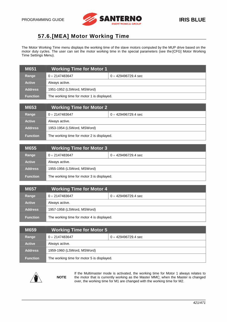
PROGRAMMING GUIDE
IRIS BLUE
421/471
57.6. [MEA] Motor Working Time
The Motor Working Time menu displays the working time of the slave motors computed by the MUP drive based on the motor duty cycles. The user can set the motor working time in the special parameters (see the [CFG] Motor Working Time Settings Menu).
M651 Working Time for Motor 1
Range 0 2147483647 0 429496729.4 sec
Active Always active.
Address 1951-1952 (LSWord, MSWord)
Function The working time for motor 1 is displayed.
M653 Working Time for Motor 2
Range 0 2147483647 0 429496729.4 sec
Active Always active.
Address 1953-1954 (LSWord, MSWord)
Function The working time for motor 2 is displayed.
M655 Working Time for Motor 3
Range 0 2147483647 0 429496729.4 sec
Active Always active.
Address 1955-1956 (LSWord, MSWord)
Function The working time for motor 3 is displayed.
M657 Working Time for Motor 4
Range 0 2147483647 0 429496729.4 sec
Active Always active.
Address 1957-1958 (LSWord, MSWord)
Function The working time for motor 4 is displayed.
M659 Working Time for Motor 5
Range 0 2147483647 0 429496729.4 sec
Active Always active.
Address 1959-1960 (LSWord, MSWord)
Function The working time for motor 5 is displayed.
NOTE If the Multimaster mode is activated, the working time for Motor 1 always relates to the motor that is currently working as the Master MMC; when the Master is changed over, the working time for M1 are changed with the working time for M2.
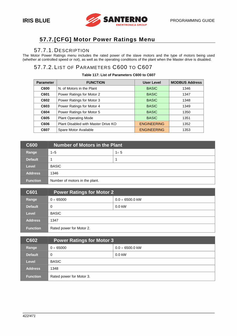
IRIS BLUE
PROGRAMMING GUIDE
422/471
57.7. [CFG] Motor Power Ratings Menu
57.7.1. DESCRIPTION The Motor Power Ratings menu includes the rated power of the slave motors and the type of motors being used (whether at controlled speed or not), as well as the operating conditions of the plant when the Master drive is disabled.
57.7.2. L IST OF PARAMETERS C600 TO C607
Table 117: List of Parameters C600 to C607
Parameter FUNCTION User Level MODBUS Address
C600 N. of Motors in the Plant BASIC 1346
C601 Power Ratings for Motor 2 BASIC 1347
C602 Power Ratings for Motor 3 BASIC 1348
C603 Power Ratings for Motor 4 BASIC 1349
C604 Power Ratings for Motor 5 BASIC 1350
C605 Plant Operating Mode BASIC 1351
C606 Plant Disabled with Master Drive KO ENGINEERING 1352
C607 Spare Motor Available ENGINEERING 1353
C600 Number of Motors in the Plant
Range 15 1 5
Default 1 1
Level BASIC
Address 1346
Function Number of motors in the plant.
C601 Power Ratings for Motor 2
Range 0 65000 0.0 6500.0 kW
Default 0 0.0 kW
Level BASIC
Address 1347
Function Rated power for Motor 2.
C602 Power Ratings for Motor 3
Range 0 65000 0.0 6500.0 kW
Default 0 0.0 kW
Level BASIC
Address 1348
Function Rated power for Motor 3.
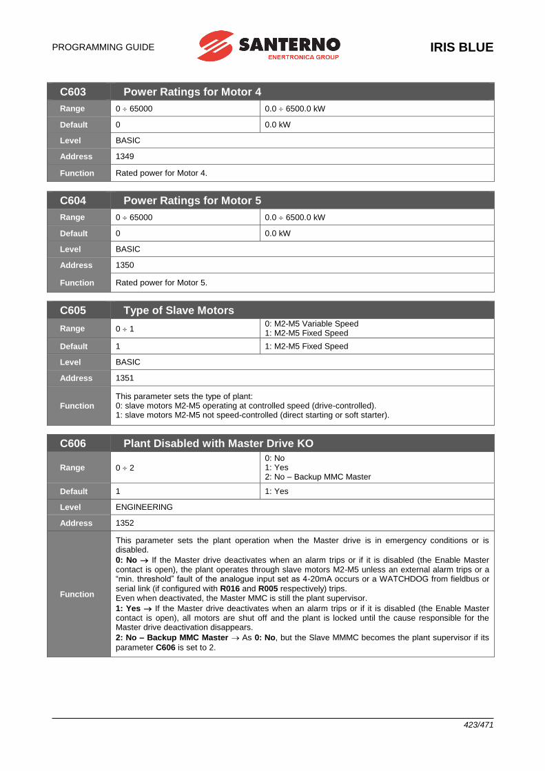
PROGRAMMING GUIDE
IRIS BLUE
423/471
C603 Power Ratings for Motor 4
Range 0 65000 0.0 6500.0 kW
Default 0 0.0 kW
Level BASIC
Address 1349
Function Rated power for Motor 4.
C604 Power Ratings for Motor 5
Range 0 65000 0.0 6500.0 kW
Default 0 0.0 kW
Level BASIC
Address 1350
Function Rated power for Motor 5.
C605 Type of Slave Motors
Range 0 1 0: M2-M5 Variable Speed 1: M2-M5 Fixed Speed
Default 1 1: M2-M5 Fixed Speed
Level BASIC
Address 1351
Function This parameter sets the type of plant: 0: slave motors M2-M5 operating at controlled speed (drive-controlled). 1: slave motors M2-M5 not speed-controlled (direct starting or soft starter).
C606 Plant Disabled with Master Drive KO
Range 0 2
0: No 1: Yes 2: No – Backup MMC Master
Default 1 1: Yes
Level ENGINEERING
Address 1352
Function
This parameter sets the plant operation when the Master drive is in emergency conditions or is disabled.
0: No If the Master drive deactivates when an alarm trips or if it is disabled (the Enable Master contact is open), the plant operates through slave motors M2-M5 unless an external alarm trips or a “min. threshold” fault of the analogue input set as 4-20mA occurs or a WATCHDOG from fieldbus or
serial link (if configured with R016 and R005 respectively) trips. Even when deactivated, the Master MMC is still the plant supervisor.
1: Yes If the Master drive deactivates when an alarm trips or if it is disabled (the Enable Master contact is open), all motors are shut off and the plant is locked until the cause responsible for the Master drive deactivation disappears.
2: No – Backup MMC Master As 0: No, but the Slave MMMC becomes the plant supervisor if its
parameter C606 is set to 2.
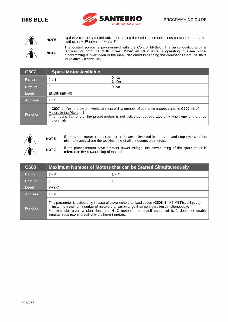
IRIS BLUE
PROGRAMMING GUIDE
424/471
NOTE Option 2 can be selected only after setting the serial communications parameters and after setting an MUP drive as “Motor 2”.
NOTE
The control source is programmed with the Control Method. The same configuration is required for both the MUP drives. When an MUP drive is operating in slave mode, programming is overridden in the menu dedicated to sending the commands from the slave MUP drive via serial link.
C607 Spare Motor Available
Range 0 1 0: No 1: Yes
Default 0 0: No
Level ENGINEERING
Address 1353
Function
If C607=1: Yes, the system works at most with a number of operating motors equal to C600 [N. of Motors in the Plant] – 1. This means that one of the preset motors is not activated, but operates only when one of the three motors fails.
NOTE If the spare motor is present, this is however involved in the start and stop cycles of the plant to evenly share the working time of all the connected motors.
NOTE If the preset motors have different power ratings, the power rating of the spare motor is referred to the power rating of motor 1.
C608 Maximum Number of Motors that can be Started Simultaneously
Range 1 4 1 4
Default 1 1
Level BASIC
Address 1354
Function
This parameter is active only in case of slave motors at fixed speed (C605=1: M2-M5 Fixed Speed). It limits the maximum number of motors that can change their configuration simultaneously. For example, given a plant featuring N. 3 motors, the default value set to 1 does not enable simultaneous power on/off of two different motors.
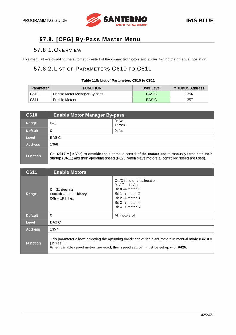
PROGRAMMING GUIDE
IRIS BLUE
425/471
57.8. [CFG] By-Pass Master Menu
57.8.1. OVERVIEW This menu allows disabling the automatic control of the connected motors and allows forcing their manual operation.
57.8.2. L IST OF PARAMETERS C610 TO C611
Table 118: List of Parameters C610 to C611
Parameter FUNCTION User Level MODBUS Address
C610 Enable Motor Manager By-pass BASIC 1356
C611 Enable Motors BASIC 1357
C610 Enable Motor Manager By-pass
Range 01 0: No 1: Yes
Default 0 0: No
Level BASIC
Address 1356
Function Set C610 = [1: Yes] to override the automatic control of the motors and to manually force both their
startup (C611) and their operating speed (P625, when slave motors at controlled speed are used).
C611 Enable Motors
Range
0 31 decimal
00000b 11111 binary
00h 1F h hex
On/Off motor bit allocation 0: Off 1: On
Bit 0 motor 1
Bit 1 motor 2
Bit 2 motor 3
Bit 3 motor 4
Bit 4 motor 5
Default 0 All motors off
Level BASIC
Address 1357
Function
This parameter allows selecting the operating conditions of the plant motors in manual mode (C610 = [1: Yes ]).
When variable speed motors are used, their speed setpoint must be set up with P625.
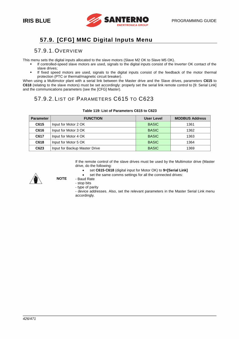
IRIS BLUE
PROGRAMMING GUIDE
426/471
57.9. [CFG] MMC Digital Inputs Menu
57.9.1. OVERVIEW This menu sets the digital inputs allocated to the slave motors (Slave M2 OK to Slave M5 OK).
▪ If controlled-speed slave motors are used, signals to the digital inputs consist of the Inverter OK contact of the slave drives;
▪ If fixed speed motors are used, signals to the digital inputs consist of the feedback of the motor thermal protection (PTC or thermal/magnetic circuit breaker).
When using a Multimotor plant with a serial link between the Master drive and the Slave drives, parameters C615 to
C618 (relating to the slave motors) must be set accordingly: properly set the serial link remote control to [9: Serial Link] and the communications parameters (see the [CFG] Master).
57.9.2. L IST OF PARAMETERS C615 TO C623
Table 119: List of Parameters C615 to C623
Parameter FUNCTION User Level MODBUS Address
C615 Input for Motor 2 OK BASIC 1361
C616 Input for Motor 3 OK BASIC 1362
C617 Input for Motor 4 OK BASIC 1363
C618 Input for Motor 5 OK BASIC 1364
C623 Input for Backup Master Drive BASIC 1369
NOTE
If the remote control of the slave drives must be used by the Multimotor drive (Master drive, do the following:
• set C615-C618 (digital input for Motor OK) to 9=[Serial Link]
• set the same comms settings for all the connected drives: - Baud Rate - stop bits - type of parity - device addresses. Also, set the relevant parameters in the Master Serial Link menu accordingly.
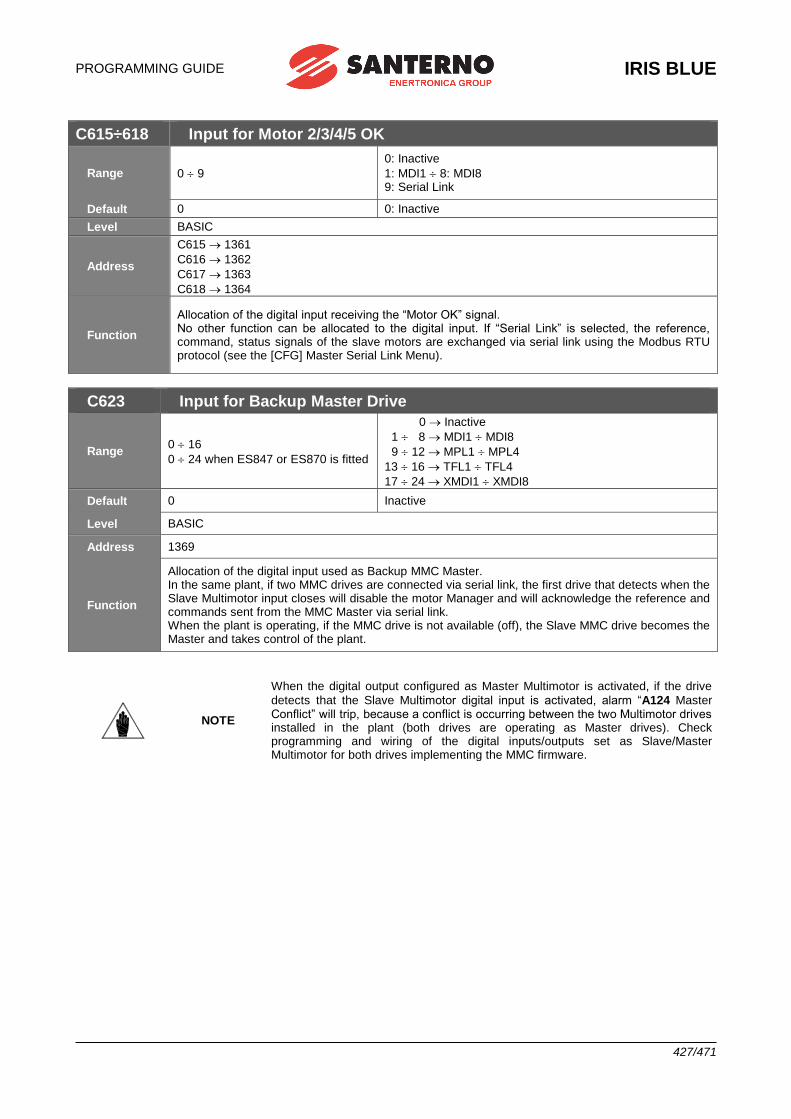
PROGRAMMING GUIDE
IRIS BLUE
427/471
C615÷618 Input for Motor 2/3/4/5 OK
Range 0 9
0: Inactive
1: MDI1 8: MDI8 9: Serial Link
Default 0 0: Inactive
Level BASIC
Address
C615 1361
C616 1362
C617 1363
C618 1364
Function
Allocation of the digital input receiving the “Motor OK” signal. No other function can be allocated to the digital input. If “Serial Link” is selected, the reference, command, status signals of the slave motors are exchanged via serial link using the Modbus RTU protocol (see the [CFG] Master Serial Link Menu).
C623 Input for Backup Master Drive
Range 0 16
0 24 when ES847 or ES870 is fitted
0 Inactive
1 8 MDI1 MDI8
9 12 MPL1 MPL4
13 16 TFL1 TFL4
17 24 XMDI1 XMDI8
Default 0 Inactive
Level BASIC
Address 1369
Function
Allocation of the digital input used as Backup MMC Master. In the same plant, if two MMC drives are connected via serial link, the first drive that detects when the Slave Multimotor input closes will disable the motor Manager and will acknowledge the reference and commands sent from the MMC Master via serial link. When the plant is operating, if the MMC drive is not available (off), the Slave MMC drive becomes the Master and takes control of the plant.
NOTE
When the digital output configured as Master Multimotor is activated, if the drive
detects that the Slave Multimotor digital input is activated, alarm “A124 Master Conflict” will trip, because a conflict is occurring between the two Multimotor drives installed in the plant (both drives are operating as Master drives). Check programming and wiring of the digital inputs/outputs set as Slave/Master Multimotor for both drives implementing the MMC firmware.
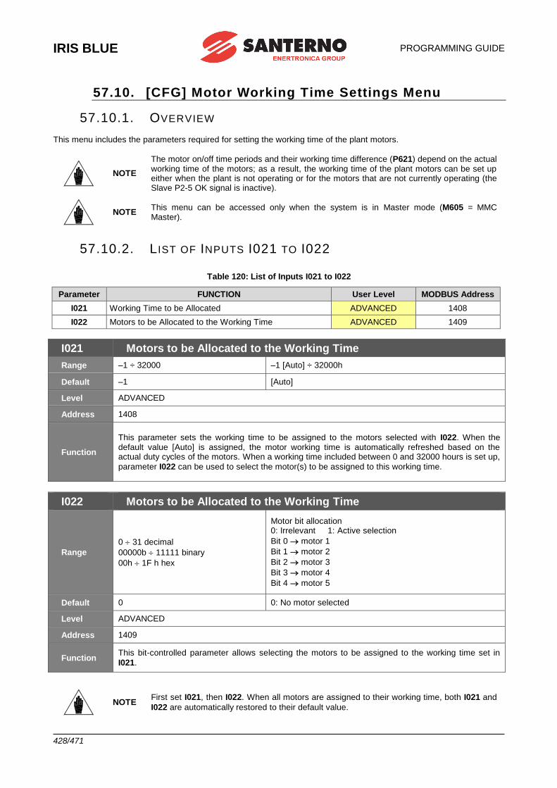
IRIS BLUE
PROGRAMMING GUIDE
428/471
57.10. [CFG] Motor Working Time Settings Menu
57.10.1. OVERVIEW This menu includes the parameters required for setting the working time of the plant motors.
NOTE
The motor on/off time periods and their working time difference (P621) depend on the actual working time of the motors; as a result, the working time of the plant motors can be set up either when the plant is not operating or for the motors that are not currently operating (the Slave P2-5 OK signal is inactive).
NOTE This menu can be accessed only when the system is in Master mode (M605 = MMC Master).
57.10.2. L IST OF INPUTS I021 TO I022
Table 120: List of Inputs I021 to I022
Parameter FUNCTION User Level MODBUS Address
I021 Working Time to be Allocated ADVANCED 1408
I022 Motors to be Allocated to the Working Time ADVANCED 1409
I021 Motors to be Allocated to the Working Time
Range –1 ÷ 32000 –1 [Auto] ÷ 32000h
Default –1 [Auto]
Level ADVANCED
Address 1408
Function
This parameter sets the working time to be assigned to the motors selected with I022. When the default value [Auto] is assigned, the motor working time is automatically refreshed based on the actual duty cycles of the motors. When a working time included between 0 and 32000 hours is set up,
parameter I022 can be used to select the motor(s) to be assigned to this working time.
I022 Motors to be Allocated to the Working Time
Range
0 31 decimal
00000b 11111 binary
00h 1F h hex
Motor bit allocation 0: Irrelevant 1: Active selection
Bit 0 motor 1
Bit 1 motor 2
Bit 2 motor 3
Bit 3 motor 4
Bit 4 motor 5
Default 0 0: No motor selected
Level ADVANCED
Address 1409
Function This bit-controlled parameter allows selecting the motors to be assigned to the working time set in
I021.
NOTE First set I021, then I022. When all motors are assigned to their working time, both I021 and
I022 are automatically restored to their default value.
PROGRAMMING GUIDE
IRIS BLUE
429/471
57.11. [CFG] Master Serial Link Menu
57.11.1. OVERVIEW This menu defines the parameters to be set up in order to control the slave drives/soft starters via serial link. If the drives/soft starters being used are manufactured by Elettronica Santerno, the system will use preset parameter values required for serial communications. The user will only have to set the value to be exchanged via serial link and corresponding to the maximum setpoint for the slave motor. Also, the serial address of the drive is to be set up. On the other hand, if the drives/soft starters being used are not produced by Elettronica Santerno, set the Type of Drive
as Generic and set the specific parameters for reference control, state control, RUN/STOP command. The plant wiring is simpler when a serial link is used.
NOTE
Do the following when using the Multimotor drive (Master drive) for the remote control of the slave drives:
• set C615÷C618 (digital input for Motor OK) to 9=[Serial Link];
• set the same Baud Rate, stop bit number and parity for all the connected drives; set the correct device addresses for all the connected drives.
CAUTION
If serial communications is configured for the system control (Motor OK, C615 to
C618 = 9 [Serial Link]) the control board will use the MODBUS communications protocol in MASTER mode. This will prevent the system from communicating with the serial link concerned, e.g. with the Iris Control. To disable the MODBUS Master mode (and to enable serial communications again),
deactivate the Serial Link mode in parameters C615 to C618.
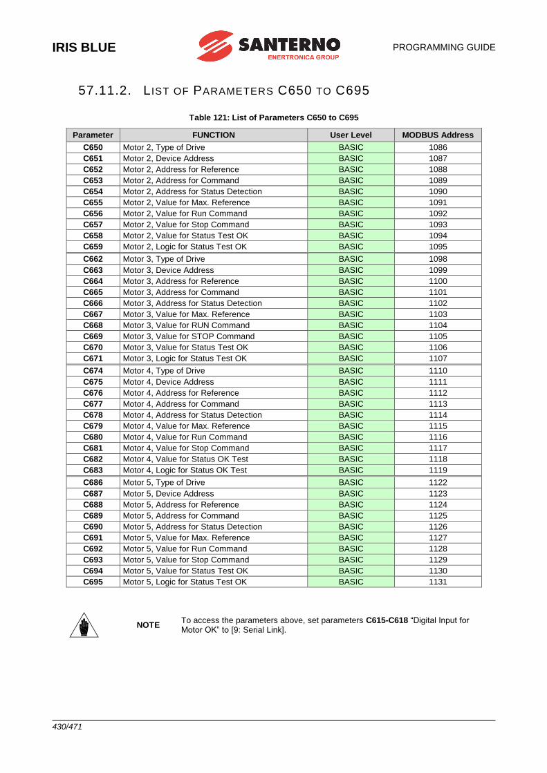
IRIS BLUE
PROGRAMMING GUIDE
430/471
57.11.2. L IST OF PARAMETERS C650 TO C695
Table 121: List of Parameters C650 to C695
Parameter FUNCTION User Level MODBUS Address
C650 Motor 2, Type of Drive BASIC 1086
C651 Motor 2, Device Address BASIC 1087
C652 Motor 2, Address for Reference BASIC 1088
C653 Motor 2, Address for Command BASIC 1089
C654 Motor 2, Address for Status Detection BASIC 1090
C655 Motor 2, Value for Max. Reference BASIC 1091
C656 Motor 2, Value for Run Command BASIC 1092
C657 Motor 2, Value for Stop Command BASIC 1093
C658 Motor 2, Value for Status Test OK BASIC 1094
C659 Motor 2, Logic for Status Test OK BASIC 1095
C662 Motor 3, Type of Drive BASIC 1098
C663 Motor 3, Device Address BASIC 1099
C664 Motor 3, Address for Reference BASIC 1100
C665 Motor 3, Address for Command BASIC 1101
C666 Motor 3, Address for Status Detection BASIC 1102
C667 Motor 3, Value for Max. Reference BASIC 1103
C668 Motor 3, Value for RUN Command BASIC 1104
C669 Motor 3, Value for STOP Command BASIC 1105
C670 Motor 3, Value for Status Test OK BASIC 1106
C671 Motor 3, Logic for Status Test OK BASIC 1107
C674 Motor 4, Type of Drive BASIC 1110
C675 Motor 4, Device Address BASIC 1111
C676 Motor 4, Address for Reference BASIC 1112
C677 Motor 4, Address for Command BASIC 1113
C678 Motor 4, Address for Status Detection BASIC 1114
C679 Motor 4, Value for Max. Reference BASIC 1115
C680 Motor 4, Value for Run Command BASIC 1116
C681 Motor 4, Value for Stop Command BASIC 1117
C682 Motor 4, Value for Status OK Test BASIC 1118
C683 Motor 4, Logic for Status OK Test BASIC 1119
C686 Motor 5, Type of Drive BASIC 1122
C687 Motor 5, Device Address BASIC 1123
C688 Motor 5, Address for Reference BASIC 1124
C689 Motor 5, Address for Command BASIC 1125
C690 Motor 5, Address for Status Detection BASIC 1126
C691 Motor 5, Value for Max. Reference BASIC 1127
C692 Motor 5, Value for Run Command BASIC 1128
C693 Motor 5, Value for Stop Command BASIC 1129
C694 Motor 5, Value for Status Test OK BASIC 1130
C695 Motor 5, Logic for Status Test OK BASIC 1131
NOTE To access the parameters above, set parameters C615-C618 “Digital Input for Motor OK” to [9: Serial Link].
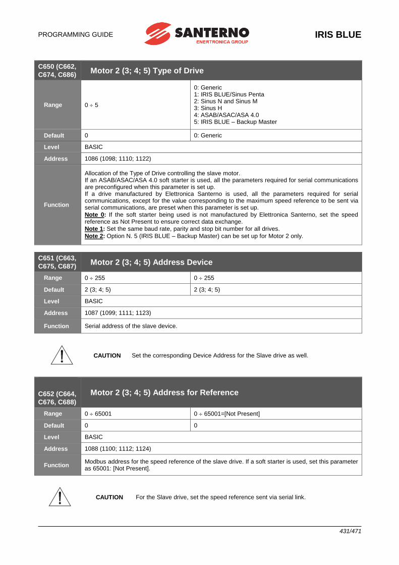
PROGRAMMING GUIDE
IRIS BLUE
431/471
C650 (C662,
C674, C686) Motor 2 (3; 4; 5) Type of Drive
Range 0 5
0: Generic 1: IRIS BLUE/Sinus Penta 2: Sinus N and Sinus M 3: Sinus H 4: ASAB/ASAC/ASA 4.0 5: IRIS BLUE – Backup Master
Default 0 0: Generic
Level BASIC
Address 1086 (1098; 1110; 1122)
Function
Allocation of the Type of Drive controlling the slave motor. If an ASAB/ASAC/ASA 4.0 soft starter is used, all the parameters required for serial communications are preconfigured when this parameter is set up. If a drive manufactured by Elettronica Santerno is used, all the parameters required for serial communications, except for the value corresponding to the maximum speed reference to be sent via serial communications, are preset when this parameter is set up.
Note 0: If the soft starter being used is not manufactured by Elettronica Santerno, set the speed reference as Not Present to ensure correct data exchange.
Note 1: Set the same baud rate, parity and stop bit number for all drives.
Note 2: Option N. 5 (IRIS BLUE – Backup Master) can be set up for Motor 2 only.
C651 (C663,
C675, C687) Motor 2 (3; 4; 5) Address Device
Range 0 255 0 255
Default 2 (3; 4; 5) 2 (3; 4; 5)
Level BASIC
Address 1087 (1099; 1111; 1123)
Function Serial address of the slave device.
CAUTION Set the corresponding Device Address for the Slave drive as well.
C652 (C664,
C676, C688)
Motor 2 (3; 4; 5) Address for Reference
Range 0 65001 0 65001=[Not Present]
Default 0 0
Level BASIC
Address 1088 (1100; 1112; 1124)
Function Modbus address for the speed reference of the slave drive. If a soft starter is used, set this parameter as 65001: [Not Present].
CAUTION For the Slave drive, set the speed reference sent via serial link.
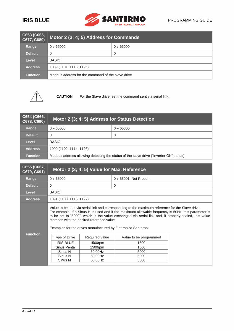
IRIS BLUE
PROGRAMMING GUIDE
432/471
C653 (C665,
C677, C689) Motor 2 (3; 4; 5) Address for Commands
Range 0 65000 0 65000
Default 0 0
Level BASIC
Address 1089 (1101; 1113; 1125)
Function Modbus address for the command of the slave drive.
CAUTION For the Slave drive, set the command sent via serial link.
C654 (C666,
C678, C690) Motor 2 (3; 4; 5) Address for Status Detection
Range 0 65000 0 65000
Default 0 0
Level BASIC
Address 1090 (1102; 1114; 1126)
Function Modbus address allowing detecting the status of the slave drive (“Inverter OK” status).
C655 (C667,
C679, C691) Motor 2 (3; 4; 5) Value for Max. Reference
Range 0 65000 0 65001: Not Present
Default 0 0
Level BASIC
Address 1091 (1103; 1115; 1127)
Function
Value to be sent via serial link and corresponding to the maximum reference for the Slave drive. For example: if a Sinus H is used and if the maximum allowable frequency is 50Hz, this parameter is to be set to “5000”, which is the value exchanged via serial link and, if properly scaled, this value matches with the desired reference value. Examples for the drives manufactured by Elettronica Santerno:
Type of Drive Required value Value to be programmed
IRIS BLUE 1500rpm 1500
Sinus Penta 1500rpm 1500
Sinus H 50.00Hz 5000
Sinus N 50.00Hz 5000
Sinus M 50.00Hz 5000
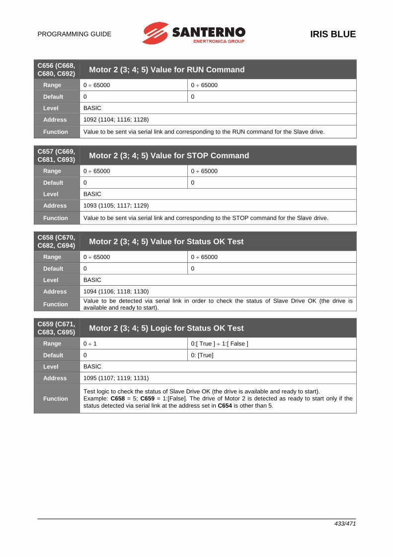
PROGRAMMING GUIDE
IRIS BLUE
433/471
C656 (C668,
C680, C692) Motor 2 (3; 4; 5) Value for RUN Command
Range 0 65000 0 65000
Default 0 0
Level BASIC
Address 1092 (1104; 1116; 1128)
Function Value to be sent via serial link and corresponding to the RUN command for the Slave drive.
C657 (C669,
C681, C693) Motor 2 (3; 4; 5) Value for STOP Command
Range 0 65000 0 65000
Default 0 0
Level BASIC
Address 1093 (1105; 1117; 1129)
Function Value to be sent via serial link and corresponding to the STOP command for the Slave drive.
C658 (C670,
C682, C694) Motor 2 (3; 4; 5) Value for Status OK Test
Range 0 65000 0 65000
Default 0 0
Level BASIC
Address 1094 (1106; 1118; 1130)
Function Value to be detected via serial link in order to check the status of Slave Drive OK (the drive is available and ready to start).
C659 (C671,
C683, C695) Motor 2 (3; 4; 5) Logic for Status OK Test
Range 0 1 0:[ True ] 1:[ False ]
Default 0 0: [True]
Level BASIC
Address 1095 (1107; 1119; 1131)
Function
Test logic to check the status of Slave Drive OK (the drive is available and ready to start).
Example: C658 = 5; C659 = 1:[False]. The drive of Motor 2 is detected as ready to start only if the
status detected via serial link at the address set in C654 is other than 5.
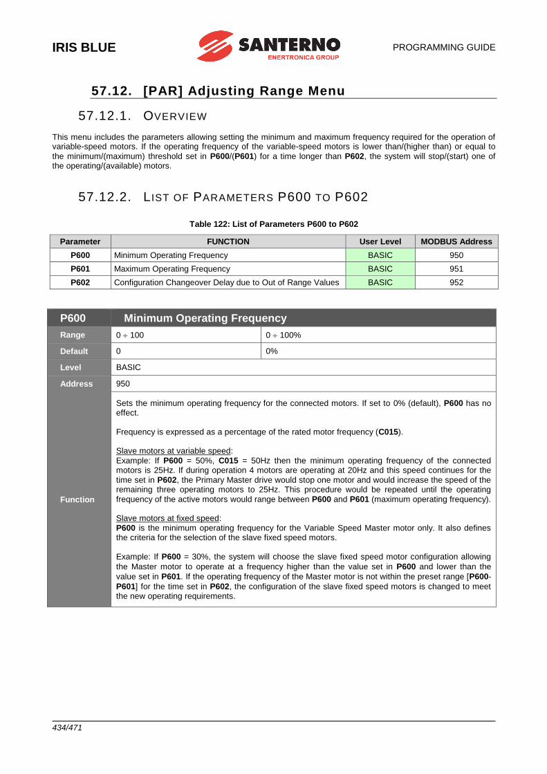
IRIS BLUE
PROGRAMMING GUIDE
434/471
57.12. [PAR] Adjusting Range Menu
57.12.1. OVERVIEW This menu includes the parameters allowing setting the minimum and maximum frequency required for the operation of variable-speed motors. If the operating frequency of the variable-speed motors is lower than/(higher than) or equal to
the minimum/(maximum) threshold set in P600/(P601) for a time longer than P602, the system will stop/(start) one of the operating/(available) motors.
57.12.2. L IST OF PARAMETERS P600 TO P602
Table 122: List of Parameters P600 to P602
Parameter FUNCTION User Level MODBUS Address
P600 Minimum Operating Frequency BASIC 950
P601 Maximum Operating Frequency BASIC 951
P602 Configuration Changeover Delay due to Out of Range Values BASIC 952
P600 Minimum Operating Frequency
Range 0 100 0 100%
Default 0 0%
Level BASIC
Address 950
Function
Sets the minimum operating frequency for the connected motors. If set to 0% (default), P600 has no effect.
Frequency is expressed as a percentage of the rated motor frequency (C015). Slave motors at variable speed:
Example: If P600 = 50%, C015 = 50Hz then the minimum operating frequency of the connected motors is 25Hz. If during operation 4 motors are operating at 20Hz and this speed continues for the
time set in P602, the Primary Master drive would stop one motor and would increase the speed of the remaining three operating motors to 25Hz. This procedure would be repeated until the operating
frequency of the active motors would range between P600 and P601 (maximum operating frequency). Slave motors at fixed speed:
P600 is the minimum operating frequency for the Variable Speed Master motor only. It also defines the criteria for the selection of the slave fixed speed motors.
Example: If P600 = 30%, the system will choose the slave fixed speed motor configuration allowing
the Master motor to operate at a frequency higher than the value set in P600 and lower than the
value set in P601. If the operating frequency of the Master motor is not within the preset range [P600-
P601] for the time set in P602, the configuration of the slave fixed speed motors is changed to meet the new operating requirements.
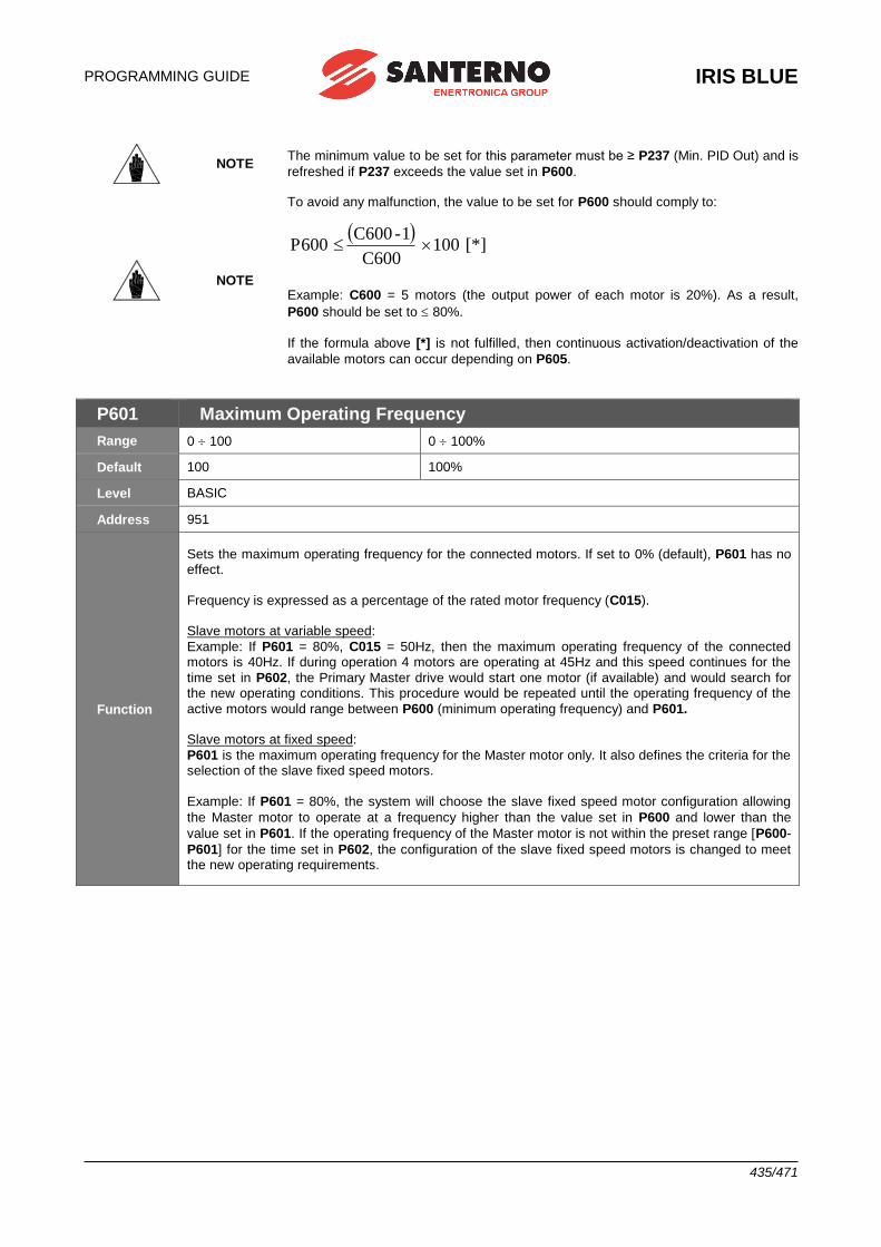
PROGRAMMING GUIDE
IRIS BLUE
435/471
NOTE The minimum value to be set for this parameter must be ≥ P237 (Min. PID Out) and is
refreshed if P237 exceeds the value set in P600.
NOTE
To avoid any malfunction, the value to be set for P600 should comply to:
[*] 100
C600
1- C600 P600
Example: C600 = 5 motors (the output power of each motor is 20%). As a result,
P600 should be set to 80%.
If the formula above [*] is not fulfilled, then continuous activation/deactivation of the
available motors can occur depending on P605.
P601 Maximum Operating Frequency
Range 0 100 0 100%
Default 100 100%
Level BASIC
Address 951
Function
Sets the maximum operating frequency for the connected motors. If set to 0% (default), P601 has no effect.
Frequency is expressed as a percentage of the rated motor frequency (C015). Slave motors at variable speed:
Example: If P601 = 80%, C015 = 50Hz, then the maximum operating frequency of the connected motors is 40Hz. If during operation 4 motors are operating at 45Hz and this speed continues for the
time set in P602, the Primary Master drive would start one motor (if available) and would search for the new operating conditions. This procedure would be repeated until the operating frequency of the
active motors would range between P600 (minimum operating frequency) and P601. Slave motors at fixed speed:
P601 is the maximum operating frequency for the Master motor only. It also defines the criteria for the selection of the slave fixed speed motors.
Example: If P601 = 80%, the system will choose the slave fixed speed motor configuration allowing
the Master motor to operate at a frequency higher than the value set in P600 and lower than the
value set in P601. If the operating frequency of the Master motor is not within the preset range [P600-
P601] for the time set in P602, the configuration of the slave fixed speed motors is changed to meet the new operating requirements.

IRIS BLUE
PROGRAMMING GUIDE
436/471
P602 Configuration Changeover Delay due to Out of Range Values
Range 0 65000 0.0 6500.0sec
Default 100 10.0sec
Level BASIC
Address 952
Function Delay time for the configuration changeover of On/Off motors when the frequency of the active variable-speed motors is not included in the preset frequency range.
NOTE The time set in parameter P602 must be shorter than the time set in parameter
P255, thus preventing the system from stopping the motors before changing their current ON/OFF configuration.
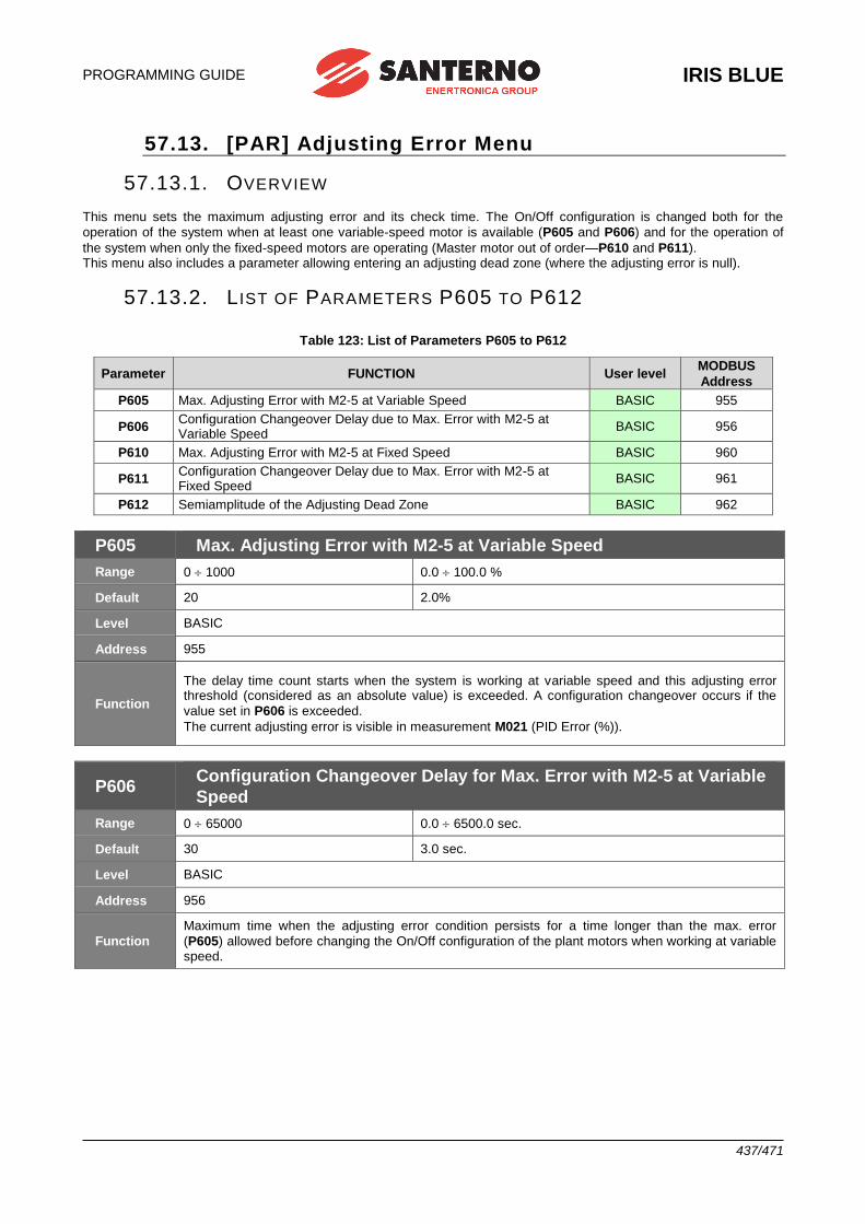
PROGRAMMING GUIDE
IRIS BLUE
437/471
57.13. [PAR] Adjusting Error Menu
57.13.1. OVERVIEW This menu sets the maximum adjusting error and its check time. The On/Off configuration is changed both for the
operation of the system when at least one variable-speed motor is available (P605 and P606) and for the operation of
the system when only the fixed-speed motors are operating (Master motor out of order—P610 and P611). This menu also includes a parameter allowing entering an adjusting dead zone (where the adjusting error is null).
57.13.2. L IST OF PARAMETERS P605 TO P612
Table 123: List of Parameters P605 to P612
Parameter FUNCTION User level MODBUS
Address
P605 Max. Adjusting Error with M2-5 at Variable Speed BASIC 955
P606 Configuration Changeover Delay due to Max. Error with M2-5 at Variable Speed
BASIC 956
P610 Max. Adjusting Error with M2-5 at Fixed Speed BASIC 960
P611 Configuration Changeover Delay due to Max. Error with M2-5 at Fixed Speed
BASIC 961
P612 Semiamplitude of the Adjusting Dead Zone BASIC 962
P605 Max. Adjusting Error with M2-5 at Variable Speed
Range 0 1000 0.0 100.0 %
Default 20 2.0%
Level BASIC
Address 955
Function
The delay time count starts when the system is working at variable speed and this adjusting error threshold (considered as an absolute value) is exceeded. A configuration changeover occurs if the
value set in P606 is exceeded.
The current adjusting error is visible in measurement M021 (PID Error (%)).
P606 Configuration Changeover Delay for Max. Error with M2-5 at Variable
Speed
Range 0 65000 0.0 6500.0 sec.
Default 30 3.0 sec.
Level BASIC
Address 956
Function
Maximum time when the adjusting error condition persists for a time longer than the max. error
(P605) allowed before changing the On/Off configuration of the plant motors when working at variable speed.
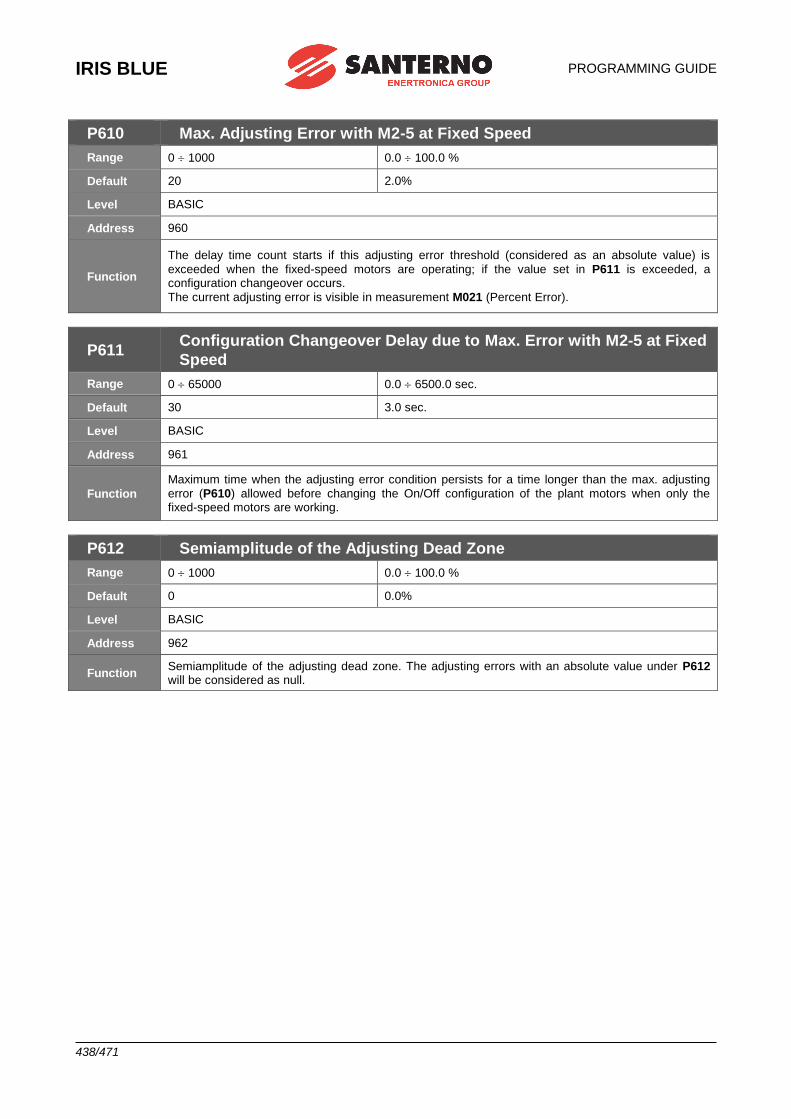
IRIS BLUE
PROGRAMMING GUIDE
438/471
P610 Max. Adjusting Error with M2-5 at Fixed Speed
Range 0 1000 0.0 100.0 %
Default 20 2.0%
Level BASIC
Address 960
Function
The delay time count starts if this adjusting error threshold (considered as an absolute value) is
exceeded when the fixed-speed motors are operating; if the value set in P611 is exceeded, a configuration changeover occurs.
The current adjusting error is visible in measurement M021 (Percent Error).
P611 Configuration Changeover Delay due to Max. Error with M2-5 at Fixed
Speed
Range 0 65000 0.0 6500.0 sec.
Default 30 3.0 sec.
Level BASIC
Address 961
Function
Maximum time when the adjusting error condition persists for a time longer than the max. adjusting
error (P610) allowed before changing the On/Off configuration of the plant motors when only the fixed-speed motors are working.
P612 Semiamplitude of the Adjusting Dead Zone
Range 0 1000 0.0 100.0 %
Default 0 0.0%
Level BASIC
Address 962
Function Semiamplitude of the adjusting dead zone. The adjusting errors with an absolute value under P612 will be considered as null.
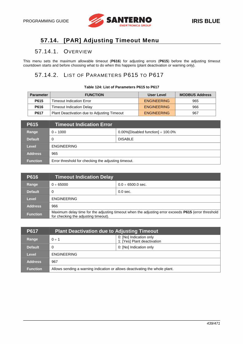
PROGRAMMING GUIDE
IRIS BLUE
439/471
57.14. [PAR] Adjusting Timeout Menu
57.14.1. OVERVIEW
This menu sets the maximum allowable timeout (P616) for adjusting errors (P615) before the adjusting timeout countdown starts and before choosing what to do when this happens (plant deactivation or warning only).
57.14.2. L IST OF PARAMETERS P615 TO P617
Table 124: List of Parameters P615 to P617
Parameter FUNCTION User Level MODBUS Address
P615 Timeout Indication Error ENGINEERING 965
P616 Timeout Indication Delay ENGINEERING 966
P617 Plant Deactivation due to Adjusting Timeout ENGINEERING 967
P615 Timeout Indication Error
Range 0 1000 0.00%[Disabled function] 100.0%
Default 0 DISABLE
Level ENGINEERING
Address 965
Function Error threshold for checking the adjusting timeout.
P616 Timeout Indication Delay
Range 0 65000 0.0 6500.0 sec.
Default 0 0.0 sec.
Level ENGINEERING
Address 966
Function Maximum delay time for the adjusting timeout when the adjusting error exceeds P615 (error threshold for checking the adjusting timeout).
P617 Plant Deactivation due to Adjusting Timeout
Range 0 1 0: [No] Indication only 1: [Yes] Plant deactivation
Default 0 0: [No] Indication only
Level ENGINEERING
Address 967
Function Allows sending a warning indication or allows deactivating the whole plant.
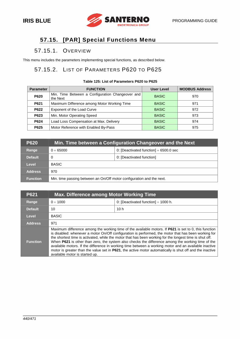
IRIS BLUE
PROGRAMMING GUIDE
440/471
57.15. [PAR] Special Functions Menu
57.15.1. OVERVIEW This menu includes the parameters implementing special functions, as described below.
57.15.2. L IST OF PARAMETERS P620 TO P625
Table 125: List of Parameters P620 to P625
Parameter FUNCTION User Level MODBUS Address
P620 Min. Time Between a Configuration Changeover and the Next
BASIC 970
P621 Maximum Difference among Motor Working Time BASIC 971
P622 Exponent of the Load Curve BASIC 972
P623 Min. Motor Operating Speed BASIC 973
P624 Load Loss Compensation at Max. Delivery BASIC 974
P625 Motor Reference with Enabled By-Pass BASIC 975
P620 Min. Time between a Configuration Changeover and the Next
Range 0 65000 0: [Deactivated function] 6500.0 sec
Default 0 0: [Deactivated function]
Level BASIC
Address 970
Function Min. time passing between an On/Off motor configuration and the next.
P621 Max. Difference among Motor Working Time
Range 0 1000 0: [Deactivated function] 1000 h.
Default 10 10 h
Level BASIC
Address 971
Function
Maximum difference among the working time of the available motors. If P621 is set to 0, this function is disabled: whenever a motor On/Off configuration is performed, the motor that has been working for the shortest time is activated, while the motor that has been working for the longest time is shut off.
When P621 is other than zero, the system also checks the difference among the working time of the available motors. If the difference in working time between a working motor and an available inactive
motor is greater than the value set in P621, the active motor automatically is shut off and the inactive available motor is started up.
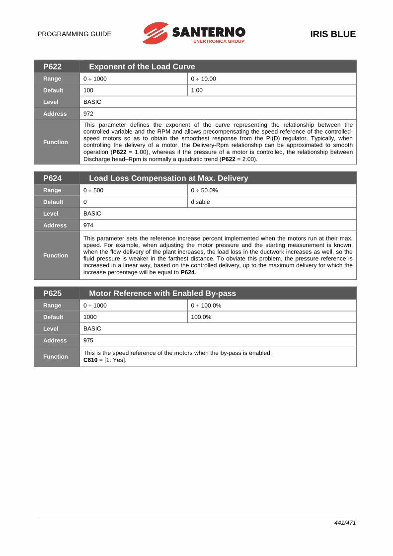
PROGRAMMING GUIDE
IRIS BLUE
441/471
P622 Exponent of the Load Curve
Range 0 1000 0 10.00
Default 100 1.00
Level BASIC
Address 972
Function
This parameter defines the exponent of the curve representing the relationship between the controlled variable and the RPM and allows precompensating the speed reference of the controlled-speed motors so as to obtain the smoothest response from the PI(D) regulator. Typically, when controlling the delivery of a motor, the Delivery-Rpm relationship can be approximated to smooth
operation (P622 = 1.00), whereas if the pressure of a motor is controlled, the relationship between
Discharge head–Rpm is normally a quadratic trend (P622 = 2.00).
P624 Load Loss Compensation at Max. Delivery
Range 0 500 0 50.0%
Default 0 disable
Level BASIC
Address 974
Function
This parameter sets the reference increase percent implemented when the motors run at their max. speed. For example, when adjusting the motor pressure and the starting measurement is known, when the flow delivery of the plant increases, the load loss in the ductwork increases as well, so the fluid pressure is weaker in the farthest distance. To obviate this problem, the pressure reference is increased in a linear way, based on the controlled delivery, up to the maximum delivery for which the
increase percentage will be equal to P624.
P625 Motor Reference with Enabled By-pass
Range 0 1000 0 100.0%
Default 1000 100.0%
Level BASIC
Address 975
Function This is the speed reference of the motors when the by-pass is enabled:
C610 = [1: Yes].
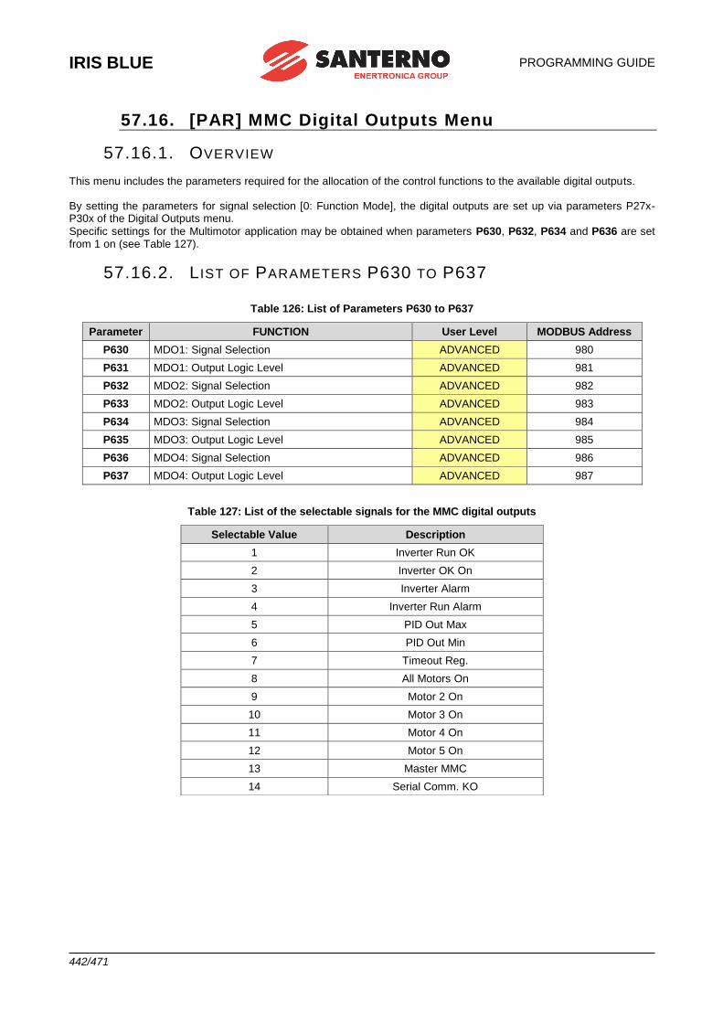
IRIS BLUE
PROGRAMMING GUIDE
442/471
57.16. [PAR] MMC Digital Outputs Menu
57.16.1. OVERVIEW This menu includes the parameters required for the allocation of the control functions to the available digital outputs. By setting the parameters for signal selection [0: Function Mode], the digital outputs are set up via parameters P27x-P30x of the Digital Outputs menu.
Specific settings for the Multimotor application may be obtained when parameters P630, P632, P634 and P636 are set from 1 on (see Table 127).
57.16.2. L IST OF PARAMETERS P630 TO P637
Table 126: List of Parameters P630 to P637
Parameter FUNCTION User Level MODBUS Address
P630 MDO1: Signal Selection ADVANCED 980
P631 MDO1: Output Logic Level ADVANCED 981
P632 MDO2: Signal Selection ADVANCED 982
P633 MDO2: Output Logic Level ADVANCED 983
P634 MDO3: Signal Selection ADVANCED 984
P635 MDO3: Output Logic Level ADVANCED 985
P636 MDO4: Signal Selection ADVANCED 986
P637 MDO4: Output Logic Level ADVANCED 987
Table 127: List of the selectable signals for the MMC digital outputs
Selectable Value Description
1 Inverter Run OK
2 Inverter OK On
3 Inverter Alarm
4 Inverter Run Alarm
5 PID Out Max
6 PID Out Min
7 Timeout Reg.
8 All Motors On
9 Motor 2 On
10 Motor 3 On
11 Motor 4 On
12 Motor 5 On
13 Master MMC
14 Serial Comm. KO
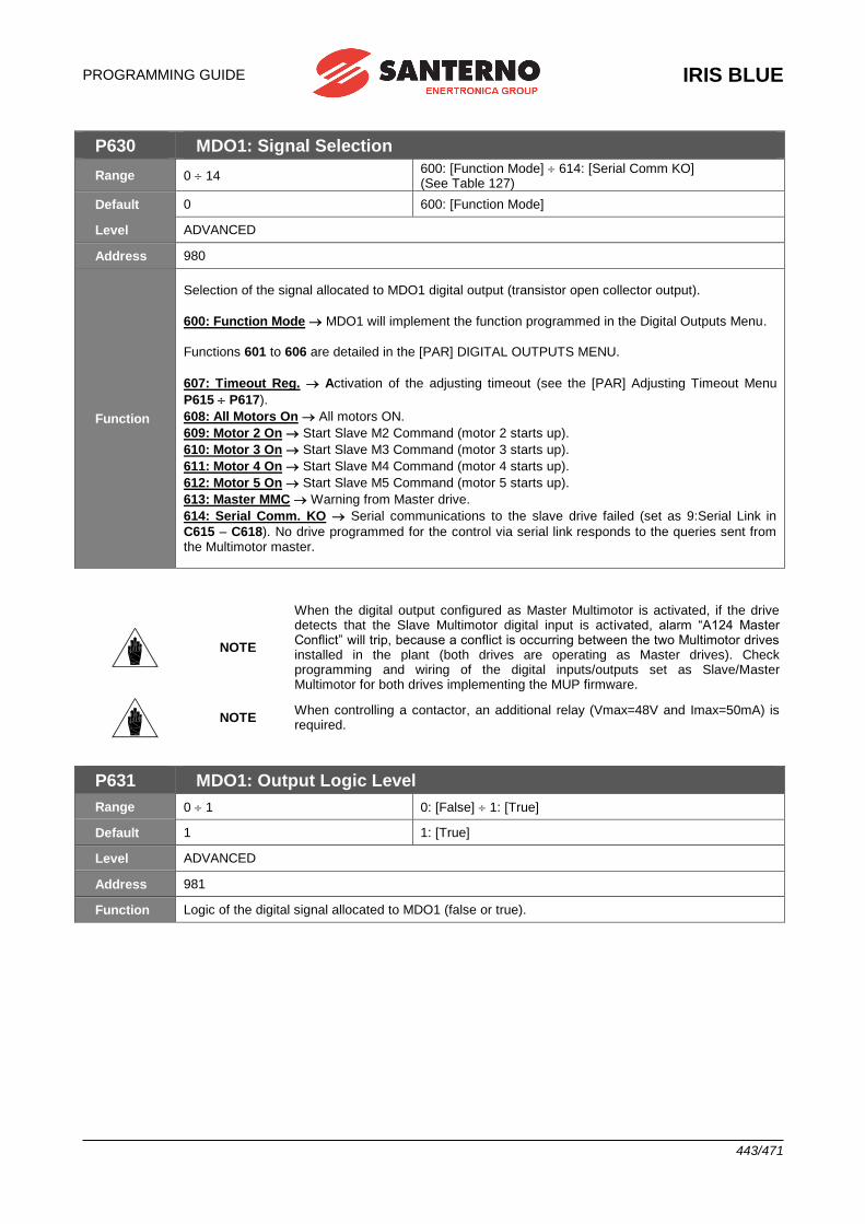
PROGRAMMING GUIDE
IRIS BLUE
443/471
P630 MDO1: Signal Selection
Range 0 14 600: [Function Mode] 614: [Serial Comm KO] (See Table 127)
Default 0 600: [Function Mode]
Level ADVANCED
Address 980
Function
Selection of the signal allocated to MDO1 digital output (transistor open collector output).
600: Function Mode MDO1 will implement the function programmed in the Digital Outputs Menu.
Functions 601 to 606 are detailed in the [PAR] DIGITAL OUTPUTS MENU.
607: Timeout Reg. Activation of the adjusting timeout (see the [PAR] Adjusting Timeout Menu
P615 P617).
608: All Motors On All motors ON.
609: Motor 2 On Start Slave M2 Command (motor 2 starts up).
610: Motor 3 On Start Slave M3 Command (motor 3 starts up).
611: Motor 4 On Start Slave M4 Command (motor 4 starts up).
612: Motor 5 On Start Slave M5 Command (motor 5 starts up).
613: Master MMC Warning from Master drive.
614: Serial Comm. KO Serial communications to the slave drive failed (set as 9:Serial Link in
C615 – C618). No drive programmed for the control via serial link responds to the queries sent from the Multimotor master.
NOTE
When the digital output configured as Master Multimotor is activated, if the drive detects that the Slave Multimotor digital input is activated, alarm “A124 Master Conflict” will trip, because a conflict is occurring between the two Multimotor drives installed in the plant (both drives are operating as Master drives). Check programming and wiring of the digital inputs/outputs set as Slave/Master Multimotor for both drives implementing the MUP firmware.
NOTE When controlling a contactor, an additional relay (Vmax=48V and Imax=50mA) is required.
P631 MDO1: Output Logic Level
Range 0 1 0: [False] 1: [True]
Default 1 1: [True]
Level ADVANCED
Address 981
Function Logic of the digital signal allocated to MDO1 (false or true).
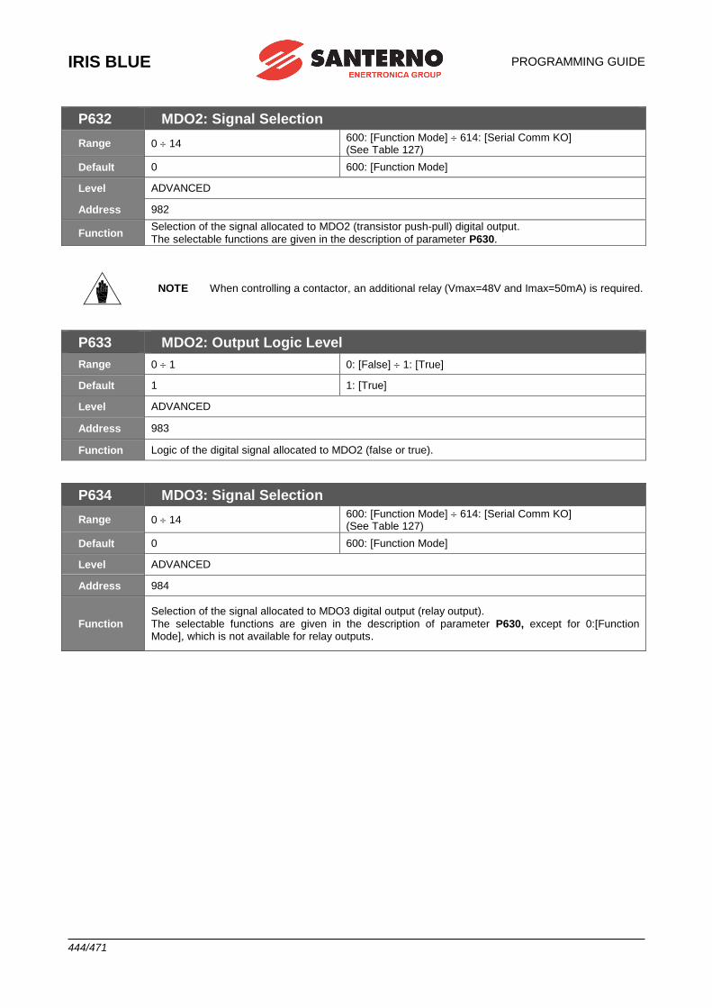
IRIS BLUE
PROGRAMMING GUIDE
444/471
P632 MDO2: Signal Selection
Range 0 14 600: [Function Mode] 614: [Serial Comm KO] (See Table 127)
Default 0 600: [Function Mode]
Level ADVANCED
Address 982
Function Selection of the signal allocated to MDO2 (transistor push-pull) digital output.
The selectable functions are given in the description of parameter P630.
NOTE When controlling a contactor, an additional relay (Vmax=48V and Imax=50mA) is required.
P633 MDO2: Output Logic Level
Range 0 1 0: [False] 1: [True]
Default 1 1: [True]
Level ADVANCED
Address 983
Function Logic of the digital signal allocated to MDO2 (false or true).
P634 MDO3: Signal Selection
Range 0 14 600: [Function Mode] 614: [Serial Comm KO] (See Table 127)
Default 0 600: [Function Mode]
Level ADVANCED
Address 984
Function
Selection of the signal allocated to MDO3 digital output (relay output).
The selectable functions are given in the description of parameter P630, except for 0:[Function Mode], which is not available for relay outputs.
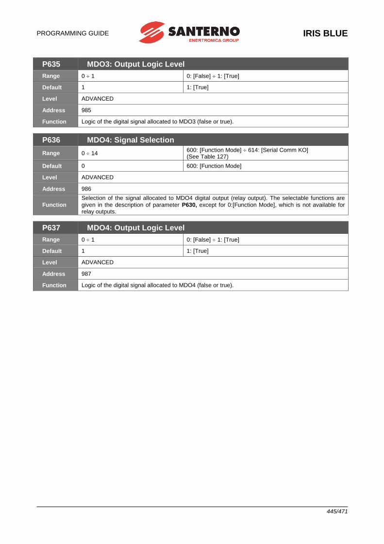
PROGRAMMING GUIDE
IRIS BLUE
445/471
P635 MDO3: Output Logic Level
Range 0 1 0: [False] 1: [True]
Default 1 1: [True]
Level ADVANCED
Address 985
Function Logic of the digital signal allocated to MDO3 (false or true).
P636 MDO4: Signal Selection
Range 0 14 600: [Function Mode] 614: [Serial Comm KO] (See Table 127)
Default 0 600: [Function Mode]
Level ADVANCED
Address 986
Function
Selection of the signal allocated to MDO4 digital output (relay output). The selectable functions are
given in the description of parameter P630, except for 0:[Function Mode], which is not available for relay outputs.
P637 MDO4: Output Logic Level
Range 0 1 0: [False] 1: [True]
Default 1 1: [True]
Level ADVANCED
Address 987
Function Logic of the digital signal allocated to MDO4 (false or true).
IRIS BLUE
PROGRAMMING GUIDE
446/471
58. LIST OF ALARMS AND WARNINGS
CAUTION If a protection trips or the drive enters the emergency mode, the drive is locked and the motor starts idling!
58.1. What Happens When a Protection Trips
NOTE Before operating the drive in emergency conditions, carefully read this section and the following section “What to Do When an Alarm Trips”.
The drive alarms are detailed below. When a protection / alarm trips:
1) the ALARM LED on the keypad comes on;
2) the page displayed on the keypad is the root page of the FAULT LIST;
3) the FAULT LIST is refreshed; 4) when using the Drive Profile board, the drive reports faults as hexadecimal values, which are assigned and
coded according to the DRIVECOM specification. See Table 131). In factory-setting, when the drive is switched on after an alarm has tripped—which has not been reset—it is kept in emergency condition.
If the drive is in emergency mode when switched on, this could be due to an alarm tripped before the drive was
reset.
To avoid storing the alarms tripped before the drive is switched off, set parameter C257 in the [CFG] AUTORESET MENU.
The drive stores the moment when an alarm trips to the FAULT LIST (supply–time and operation–time). The drive status when the alarm tripped and some measurements sampled when the alarm tripped are also stored to the Fault List. The readout and storage of the fault list can be very useful to detect the cause responsible for the alarm and its possible solution (see also the Fault List Menu (Fault List)).
NOTE
Alarms A001 to A039 relate to the main microcontroller (DSP Motorola) of the control board, which detected a fault on the control board itself. No fault list is available for
Alarms A001 to A039 and no Reset command can be sent via serial link; alarms can be
reset through the RESET terminal on the terminal board or the RESET key on the keypad. No software for the keypad interface is available; the drive parameters and measurements cannot be accessed via serial link.
Avoid resetting alarms A033 and A039, as they trip when the flash memory is not
provided with its correct software. Alarms A033 and A039 can be reset only when proper software is downloaded for the the inverter flash memory.
CAUTION
Before resetting an alarm, deactivate the ENABLE-A and ENABLE-B signals on
terminal MDI2 to disable the inverter and prevent the connected motor from running at
uncontrolled speed, unless parameter C181=1 (the Safety Start function is active): after
resetting an alarm or after supplying the inverter, this will start only if the ENABLE-A and
ENABLE-B contacts are opened and closed again.
PROGRAMMING GUIDE
IRIS BLUE
447/471
58.2. What to Do When an Alarm Trips
CAUTION If a protection trips or the drive is in emergency condition, the drive is locked and the motor starts idling!
CAUTION
Before resetting an alarm, disable the ENABLE-A and ENABLE-B signals on terminal
MDI2 to disable the drive and to prevent the connected motor from running at uncontrolled speed.
Proceed as follows:
1. Disable the ENABLE-A and ENABLE-B signals on terminal MDI2 to disable the drive and to lock the motor,
unless parameter C181=1 (the Safety Start function is active): after resetting an alarm or after supplying the drive,
this will start only if the ENABLE-A and ENABLE-B contacts are open and closed.
2. If the motor is idling, wait until it stops.
Check the FAULT LIST carefully for any information about the alarm tripped, in order to determine the cause responsible for the alarm and its possible solutions.
Any information stored to the FAULT LIST is also required when contacting Elettronica Santerno’s Customer
Service.
3. In the following sections, find the relative alarm code and follow the instructions.
4. Solve any external problems that may have been responsible for the protection trip.
5. If the alarm tripped due to the entry of wrong parameter values, set new correct values and save them.
6. Reset the alarm.
7. If the alarm condition persists, please contact Elettronica Santerno Customer Service.
A RESET command must be sent to reset the alarms tripped. Do one of the following:
• Enable the RESET signal in MDI3 terminal in the hardware terminal board;
• Press the RESET key on the keypad;
• Enable the RESET MDI3 signal in one of the virtual terminal boards enabled as remote control sources (see the [CFG] CONTROL METHOD MENU).
To activate the Autoreset function, enable parameter C255 (see the [CFG] AUTORESET MENU); the drive will automatically try to reset the alarms tripped.
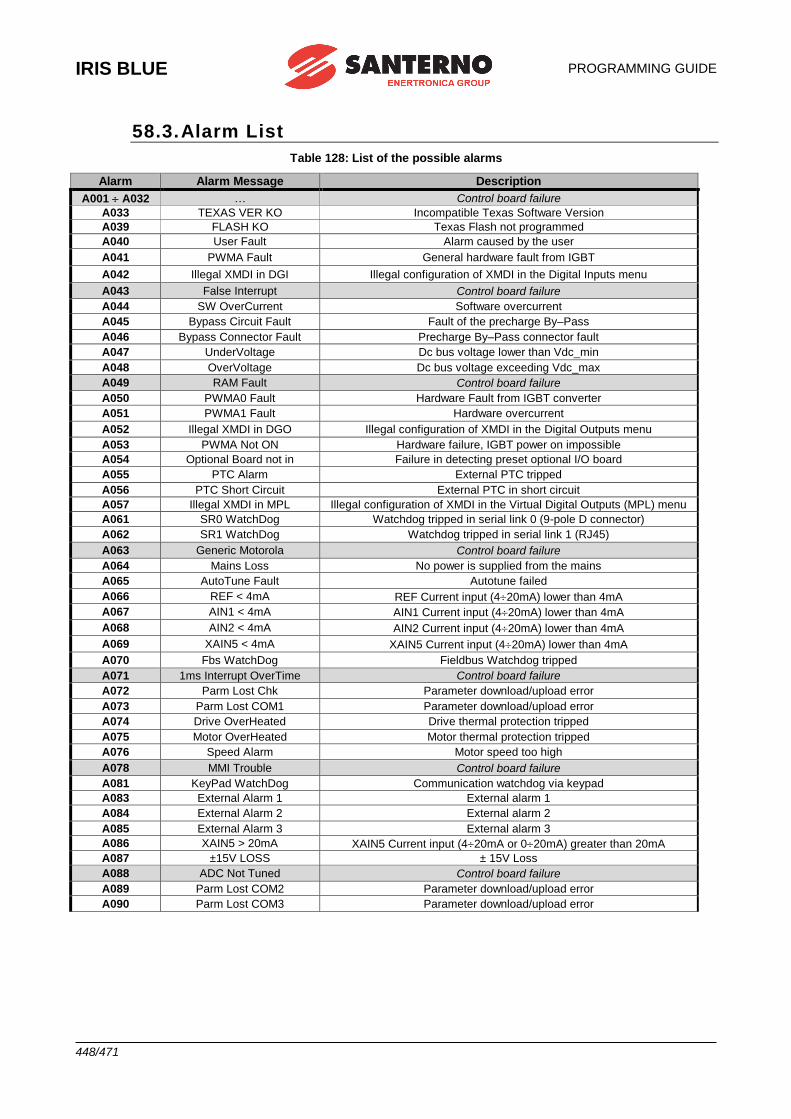
IRIS BLUE
PROGRAMMING GUIDE
448/471
58.3. Alarm List
Table 128: List of the possible alarms
Alarm Alarm Message Description
A001 A032 … Control board failure
A033 TEXAS VER KO Incompatible Texas Software Version
A039 FLASH KO Texas Flash not programmed
A040 User Fault Alarm caused by the user
A041 PWMA Fault General hardware fault from IGBT
A042 Illegal XMDI in DGI Illegal configuration of XMDI in the Digital Inputs menu
A043 False Interrupt Control board failure
A044 SW OverCurrent Software overcurrent
A045 Bypass Circuit Fault Fault of the precharge By–Pass
A046 Bypass Connector Fault Precharge By–Pass connector fault
A047 UnderVoltage Dc bus voltage lower than Vdc_min
A048 OverVoltage Dc bus voltage exceeding Vdc_max
A049 RAM Fault Control board failure
A050 PWMA0 Fault Hardware Fault from IGBT converter
A051 PWMA1 Fault Hardware overcurrent
A052 Illegal XMDI in DGO Illegal configuration of XMDI in the Digital Outputs menu
A053 PWMA Not ON Hardware failure, IGBT power on impossible
A054 Optional Board not in Failure in detecting preset optional I/O board
A055 PTC Alarm External PTC tripped
A056 PTC Short Circuit External PTC in short circuit
A057 Illegal XMDI in MPL Illegal configuration of XMDI in the Virtual Digital Outputs (MPL) menu
A061 SR0 WatchDog Watchdog tripped in serial link 0 (9-pole D connector)
A062 SR1 WatchDog Watchdog tripped in serial link 1 (RJ45)
A063 Generic Motorola Control board failure
A064 Mains Loss No power is supplied from the mains
A065 AutoTune Fault Autotune failed
A066 REF < 4mA REF Current input (420mA) lower than 4mA
A067 AIN1 < 4mA AIN1 Current input (420mA) lower than 4mA
A068 AIN2 < 4mA AIN2 Current input (420mA) lower than 4mA
A069 XAIN5 < 4mA XAIN5 Current input (420mA) lower than 4mA
A070 Fbs WatchDog Fieldbus Watchdog tripped
A071 1ms Interrupt OverTime Control board failure
A072 Parm Lost Chk Parameter download/upload error
A073 Parm Lost COM1 Parameter download/upload error
A074 Drive OverHeated Drive thermal protection tripped
A075 Motor OverHeated Motor thermal protection tripped
A076 Speed Alarm Motor speed too high
A078 MMI Trouble Control board failure
A081 KeyPad WatchDog Communication watchdog via keypad
A083 External Alarm 1 External alarm 1
A084 External Alarm 2 External alarm 2
A085 External Alarm 3 External alarm 3
A086 XAIN5 > 20mA XAIN5 Current input (420mA or 020mA) greater than 20mA
A087 ±15V LOSS ± 15V Loss
A088 ADC Not Tuned Control board failure
A089 Parm Lost COM2 Parameter download/upload error
A090 Parm Lost COM3 Parameter download/upload error
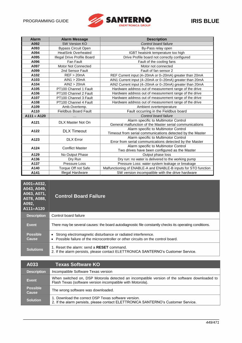
PROGRAMMING GUIDE
IRIS BLUE
449/471
Alarm Alarm Message Description
A092 SW Version KO Control board failure
A093 Bypass Circuit Open By-Pass relay open
A094 HeatSink Overheated IGBT heatsink temperature too high
A095 Illegal Drive Profile Board Drive Profile board not correctly configured
A096 Fan Fault Fault of the cooling fans
A097 Motor Not Connected Motor not connected
A099 2nd Sensor Fault Fault of fan sensor 2
A102 REF > 20mA REF Current input (420mA or 020mA) greater than 20mA
A103 AIN1 > 20mA AIN1 Current input (420mA or 020mA) greater than 20mA
A104 AIN2 > 20mA AIN2 Current input (420mA or 020mA) greater than 20mA
A105 PT100 Channel 1 Fault Hardware address out of measurement range of the drive
A106 PT100 Channel 2 Fault Hardware address out of measurement range of the drive
A107 PT100 Channel 3 Fault Hardware address out of measurement range of the drive
A108 PT100 Channel 4 Fault Hardware address out of measurement range of the drive
A109 Amb.Overtemp. Ambient overtemperature
A110 Fieldbus Board Fault Fault occurring in the Fieldbus board
A111 A120 … Control board failure
A121 DLX Master Not On Alarm specific to Multimotor Control
General malfunction of the Master serial communications
A122 DLX Timeout Alarm specific to Multimotor Control
Timeout from serial communications detected by the Master
A123 DLX Error Alarm specific to Multimotor Control
Error from serial communications detected by the Master
A124 Conflict Master Alarm specific to Multimotor Control
Two drives have been configured as the Master
A129 No Output Phase Output phase loss
A136 Dry Run Dry run: no water is delivered to the working pump
A137 Pressure Loss Pressure Loss: water system leakage or breakage
A140 Torque Off not Safe Malfunctioning of ENABLE-A and ENABLE-B inputs for STO function
A141 Illegal Hardware SW version incompatible with the drive hardware
A001A032,
A043, A049,
A063, A071,
A078, A088,
A092,
A111A120
Control Board Failure
Description Control board failure
Event There may be several causes: the board autodiagnostic file constantly checks its operating conditions.
Possible
Cause
• Strong electromagnetic disturbance or radiated interference.
• Possible failure of the microcontroller or other circuits on the control board.
Solutions 1. Reset the alarm: send a RESET command. 2. If the alarm persists, please contact ELETTRONICA SANTERNO’s Customer Service.
A033 Texas Software KO
Description Incompatible Software Texas version
Event When switched on, DSP Motorola detected an incompatible version of the software downloaded to Flash Texas (software version incompatible with Motorola).
Possible
Cause The wrong software was downloaded.
Solution 1. Download the correct DSP Texas software version. 2. If the alarm persists, please contact ELETTRONICA SANTERNO’s Customer Service.
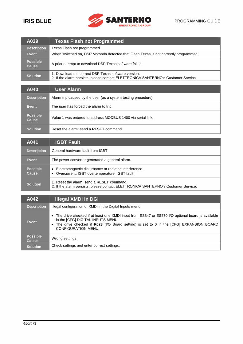
IRIS BLUE
PROGRAMMING GUIDE
450/471
A039 Texas Flash not Programmed
Description Texas Flash not programmed
Event When switched on, DSP Motorola detected that Flash Texas is not correctly programmed.
Possible
Cause A prior attempt to download DSP Texas software failed.
Solution 1. Download the correct DSP Texas software version. 2. If the alarm persists, please contact ELETTRONICA SANTERNO’s Customer Service.
A040 User Alarm
Description Alarm trip caused by the user (as a system testing procedure)
Event The user has forced the alarm to trip.
Possible
Cause Value 1 was entered to address MODBUS 1400 via serial link.
Solution Reset the alarm: send a RESET command.
A041 IGBT Fault
Description General hardware fault from IGBT
Event The power converter generated a general alarm.
Possible
Cause
• Electromagnetic disturbance or radiated interference.
• Overcurrent, IGBT overtemperature, IGBT fault.
Solution 1. Reset the alarm: send a RESET command. 2. If the alarm persists, please contact ELETTRONICA SANTERNO’s Customer Service.
A042 Illegal XMDI in DGI
Description Illegal configuration of XMDI in the Digital Inputs menu
Event
• The drive checked if at least one XMDI input from ES847 or ES870 I/O optional board is available in the [CFG] DIGITAL INPUTS MENU.
• The drive checked if R023 (I/O Board setting) is set to 0 in the [CFG] EXPANSION BOARD CONFIGURATION MENU.
Possible
Cause Wrong settings.
Solution Check settings and enter correct settings.
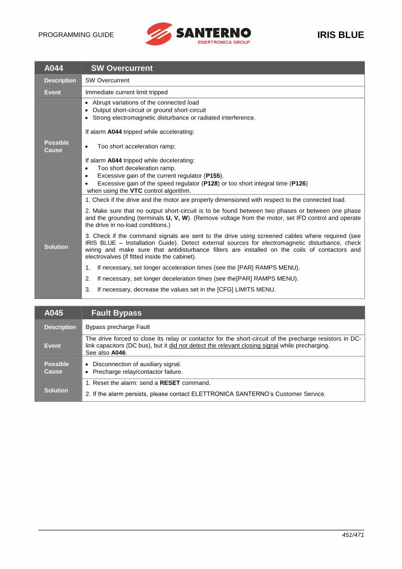
PROGRAMMING GUIDE
IRIS BLUE
451/471
A044 SW Overcurrent
Description SW Overcurrent
Event Immediate current limit tripped
Possible
Cause
• Abrupt variations of the connected load
• Output short-circuit or ground short-circuit
• Strong electromagnetic disturbance or radiated interference.
If alarm A044 tripped while accelerating:
• Too short acceleration ramp;
If alarm A044 tripped while decelerating:
• Too short deceleration ramp.
• Excessive gain of the current regulator (P155).
• Excessive gain of the speed regulator (P128) or too short integral time (P126)
when using the VTC control algorithm.
Solution
1. Check if the drive and the motor are properly dimensioned with respect to the connected load.
2. Make sure that no output short-circuit is to be found between two phases or between one phase
and the grounding (terminals U, V, W). (Remove voltage from the motor, set IFD control and operate the drive in no-load conditions.)
3. Check if the command signals are sent to the drive using screened cables where required (see IRIS BLUE – Installation Guide). Detect external sources for electromagnetic disturbance, check wiring and make sure that antidisturbance filters are installed on the coils of contactors and electrovalves (if fitted inside the cabinet).
1. If necessary, set longer acceleration times (see the [PAR] RAMPS MENU).
2. If necessary, set longer deceleration times (see the[PAR] RAMPS MENU).
3. If necessary, decrease the values set in the [CFG] LIMITS MENU.
A045 Fault Bypass
Description Bypass precharge Fault
Event
The drive forced to close its relay or contactor for the short-circuit of the precharge resistors in DC-link capacitors (DC bus), but it did not detect the relevant closing signal while precharging.
See also A046.
Possible
Cause
• Disconnection of auxiliary signal.
• Precharge relay/contactor failure.
Solution
1. Reset the alarm: send a RESET command.
2. If the alarm persists, please contact ELETTRONICA SANTERNO’s Customer Service.
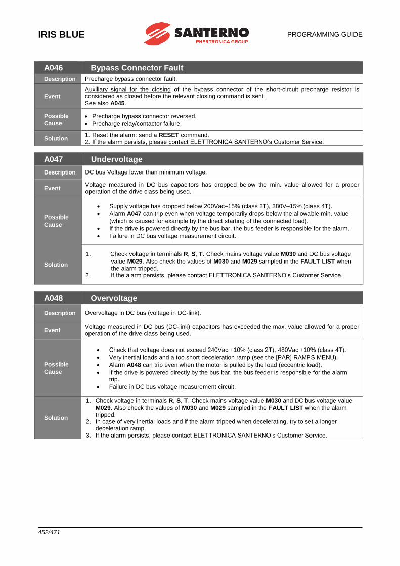
IRIS BLUE
PROGRAMMING GUIDE
452/471
A046 Bypass Connector Fault
Description Precharge bypass connector fault.
Event
Auxiliary signal for the closing of the bypass connector of the short-circuit precharge resistor is considered as closed before the relevant closing command is sent.
See also A045.
Possible
Cause
• Precharge bypass connector reversed.
• Precharge relay/contactor failure.
Solution 1. Reset the alarm: send a RESET command. 2. If the alarm persists, please contact ELETTRONICA SANTERNO’s Customer Service.
A047 Undervoltage
Description DC bus Voltage lower than minimum voltage.
Event Voltage measured in DC bus capacitors has dropped below the min. value allowed for a proper operation of the drive class being used.
Possible
Cause
• Supply voltage has dropped below 200Vac–15% (class 2T), 380V–15% (class 4T).
• Alarm A047 can trip even when voltage temporarily drops below the allowable min. value (which is caused for example by the direct starting of the connected load).
• If the drive is powered directly by the bus bar, the bus feeder is responsible for the alarm.
• Failure in DC bus voltage measurement circuit.
Solution
1. Check voltage in terminals R, S, T. Check mains voltage value M030 and DC bus voltage
value M029. Also check the values of M030 and M029 sampled in the FAULT LIST when the alarm tripped.
2. If the alarm persists, please contact ELETTRONICA SANTERNO’s Customer Service.
A048 Overvoltage
Description Overvoltage in DC bus (voltage in DC-link).
Event Voltage measured in DC bus (DC-link) capacitors has exceeded the max. value allowed for a proper operation of the drive class being used.
Possible
Cause
• Check that voltage does not exceed 240Vac +10% (class 2T), 480Vac +10% (class 4T).
• Very inertial loads and a too short deceleration ramp (see the [PAR] RAMPS MENU).
• Alarm A048 can trip even when the motor is pulled by the load (eccentric load).
• If the drive is powered directly by the bus bar, the bus feeder is responsible for the alarm trip.
• Failure in DC bus voltage measurement circuit.
Solution
1. Check voltage in terminals R, S, T. Check mains voltage value M030 and DC bus voltage value
M029. Also check the values of M030 and M029 sampled in the FAULT LIST when the alarm tripped.
2. In case of very inertial loads and if the alarm tripped when decelerating, try to set a longer deceleration ramp.
3. If the alarm persists, please contact ELETTRONICA SANTERNO’s Customer Service.
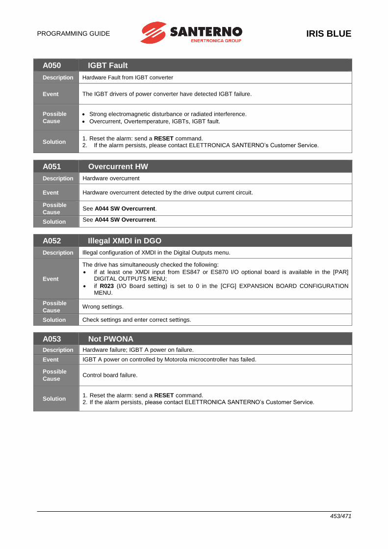
PROGRAMMING GUIDE
IRIS BLUE
453/471
A050 IGBT Fault
Description Hardware Fault from IGBT converter
Event The IGBT drivers of power converter have detected IGBT failure.
Possible
Cause
• Strong electromagnetic disturbance or radiated interference.
• Overcurrent, Overtemperature, IGBTs, IGBT fault.
Solution 1. Reset the alarm: send a RESET command. 2. If the alarm persists, please contact ELETTRONICA SANTERNO’s Customer Service.
A051 Overcurrent HW
Description Hardware overcurrent
Event Hardware overcurrent detected by the drive output current circuit.
Possible
Cause See A044 SW Overcurrent.
Solution See A044 SW Overcurrent.
A052 Illegal XMDI in DGO
Description Illegal configuration of XMDI in the Digital Outputs menu.
Event
The drive has simultaneously checked the following:
• if at least one XMDI input from ES847 or ES870 I/O optional board is available in the [PAR] DIGITAL OUTPUTS MENU;
• if R023 (I/O Board setting) is set to 0 in the [CFG] EXPANSION BOARD CONFIGURATION MENU.
Possible
Cause Wrong settings.
Solution Check settings and enter correct settings.
A053 Not PWONA
Description Hardware failure; IGBT A power on failure.
Event IGBT A power on controlled by Motorola microcontroller has failed.
Possible
Cause Control board failure.
Solution 1. Reset the alarm: send a RESET command. 2. If the alarm persists, please contact ELETTRONICA SANTERNO’s Customer Service.
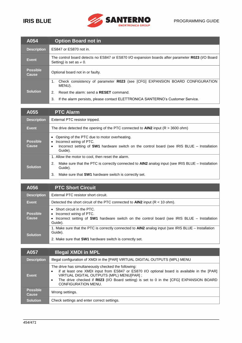
IRIS BLUE
PROGRAMMING GUIDE
454/471
A054 Option Board not in
Description ES847 or ES870 not in.
Event The control board detects no ES847 or ES870 I/O expansion boards after parameter R023 (I/O Board
Setting) is set as 0.
Possible
Cause Optional board not in or faulty.
Solution
1. Check consistency of parameter R023 (see [CFG] EXPANSION BOARD CONFIGURATION MENU).
2. Reset the alarm: send a RESET command.
3. If the alarm persists, please contact ELETTRONICA SANTERNO’s Customer Service.
A055 PTC Alarm
Description External PTC resistor tripped.
Event The drive detected the opening of the PTC connected to AIN2 input (R > 3600 ohm)
Possible
Cause
• Opening of the PTC due to motor overheating.
• Incorrect wiring of PTC.
• Incorrect setting of SW1 hardware switch on the control board (see IRIS BLUE – Installation Guide).
Solution
1. Allow the motor to cool, then reset the alarm.
2. Make sure that the PTC is correctly connected to AIN2 analog input (see IRIS BLUE – Installation Guide).
3. Make sure that SW1 hardware switch is correctly set.
A056 PTC Short Circuit
Description External PTC resistor short circuit.
Event Detected the short circuit of the PTC connected to AIN2 input (R < 10 ohm).
Possible
Cause
• Short circuit in the PTC.
• Incorrect wiring of PTC.
• Incorrect setting of SW1 hardware switch on the control board (see IRIS BLUE – Installation Guide).
Solution
1. Make sure that the PTC is correctly connected to AIN2 analog input (see IRIS BLUE – Installation Guide).
2. Make sure that SW1 hardware switch is correctly set.
A057 Illegal XMDI in MPL
Description Illegal configuration of XMDI in the [PAR] VIRTUAL DIGITAL OUTPUTS (MPL) MENU
Event
The drive has simultaneously checked the following:
• if at least one XMDI input from ES847 or ES870 I/O optional board is available in the [PAR] VIRTUAL DIGITAL OUTPUTS (MPL) MENU[PAR] ;
• The drive checked if R023 (I/O Board setting) is set to 0 in the [CFG] EXPANSION BOARD CONFIGURATION MENU.
Possible
Cause Wrong settings.
Solution Check settings and enter correct settings.
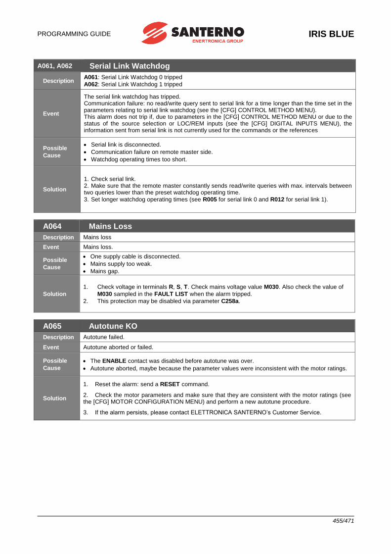
PROGRAMMING GUIDE
IRIS BLUE
455/471
A061, A062 Serial Link Watchdog
Description A061: Serial Link Watchdog 0 tripped
A062: Serial Link Watchdog 1 tripped
Event
The serial link watchdog has tripped. Communication failure: no read/write query sent to serial link for a time longer than the time set in the parameters relating to serial link watchdog (see the [CFG] CONTROL METHOD MENU). This alarm does not trip if, due to parameters in the [CFG] CONTROL METHOD MENU or due to the status of the source selection or LOC/REM inputs (see the [CFG] DIGITAL INPUTS MENU), the information sent from serial link is not currently used for the commands or the references
Possible
Cause
• Serial link is disconnected.
• Communication failure on remote master side.
• Watchdog operating times too short.
Solution
1. Check serial link. 2. Make sure that the remote master constantly sends read/write queries with max. intervals between two queries lower than the preset watchdog operating time.
3. Set longer watchdog operating times (see R005 for serial link 0 and R012 for serial link 1).
A064 Mains Loss
Description Mains loss
Event Mains loss.
Possible
Cause
• One supply cable is disconnected.
• Mains supply too weak.
• Mains gap.
Solution
1. Check voltage in terminals R, S, T. Check mains voltage value M030. Also check the value of
M030 sampled in the FAULT LIST when the alarm tripped.
2. This protection may be disabled via parameter C258a.
A065 Autotune KO
Description Autotune failed.
Event Autotune aborted or failed.
Possible
Cause
• The ENABLE contact was disabled before autotune was over.
• Autotune aborted, maybe because the parameter values were inconsistent with the motor ratings.
Solution
1. Reset the alarm: send a RESET command.
2. Check the motor parameters and make sure that they are consistent with the motor ratings (see the [CFG] MOTOR CONFIGURATION MENU) and perform a new autotune procedure.
3. If the alarm persists, please contact ELETTRONICA SANTERNO’s Customer Service.
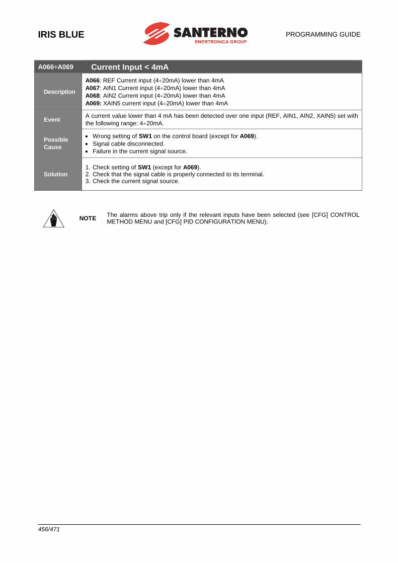
IRIS BLUE
PROGRAMMING GUIDE
456/471
A066÷A069 Current Input < 4mA
Description
A066: REF Current input (420mA) lower than 4mA
A067: AIN1 Current input (420mA) lower than 4mA
A068: AIN2 Current input (420mA) lower than 4mA
A069: XAIN5 current input (420mA) lower than 4mA
Event A current value lower than 4 mA has been detected over one input (REF, AIN1, AIN2, XAIN5) set with
the following range: 420mA.
Possible
Cause
• Wrong setting of SW1 on the control board (except for A069).
• Signal cable disconnected.
• Failure in the current signal source.
Solution 1. Check setting of SW1 (except for A069). 2. Check that the signal cable is properly connected to its terminal. 3. Check the current signal source.
NOTE The alarms above trip only if the relevant inputs have been selected (see [CFG] CONTROL METHOD MENU and [CFG] PID CONFIGURATION MENU).
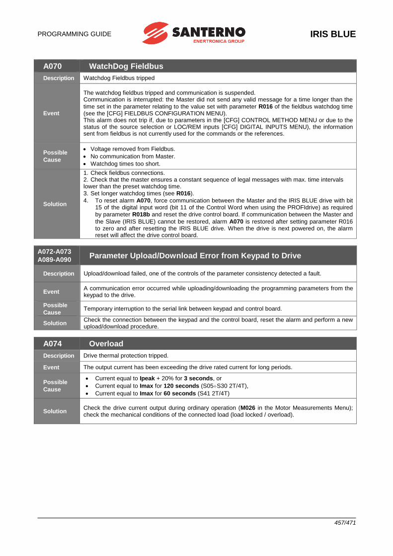
PROGRAMMING GUIDE
IRIS BLUE
457/471
A070 WatchDog Fieldbus
Description Watchdog Fieldbus tripped
Event
The watchdog fieldbus tripped and communication is suspended. Communication is interrupted: the Master did not send any valid message for a time longer than the
time set in the parameter relating to the value set with parameter R016 of the fieldbus watchdog time (see the [CFG] FIELDBUS CONFIGURATION MENU). This alarm does not trip if, due to parameters in the [CFG] CONTROL METHOD MENU or due to the status of the source selection or LOC/REM inputs [CFG] DIGITAL INPUTS MENU), the information sent from fieldbus is not currently used for the commands or the references.
Possible
Cause
• Voltage removed from Fieldbus.
• No communication from Master.
• Watchdog times too short.
Solution
1. Check fieldbus connections. 2. Check that the master ensures a constant sequence of legal messages with max. time intervals lower than the preset watchdog time.
3. Set longer watchdog times (see R016).
4. To reset alarm A070, force communication between the Master and the IRIS BLUE drive with bit 15 of the digital input word (bit 11 of the Control Word when using the PROFIdrive) as required
by parameter R018b and reset the drive control board. If communication between the Master and
the Slave (IRIS BLUE) cannot be restored, alarm A070 is restored after setting parameter R016 to zero and after resetting the IRIS BLUE drive. When the drive is next powered on, the alarm reset will affect the drive control board.
A072-A073
A089-A090 Parameter Upload/Download Error from Keypad to Drive
Description Upload/download failed, one of the controls of the parameter consistency detected a fault.
Event A communication error occurred while uploading/downloading the programming parameters from the keypad to the drive.
Possible
Cause Temporary interruption to the serial link between keypad and control board.
Solution Check the connection between the keypad and the control board, reset the alarm and perform a new upload/download procedure.
A074 Overload
Description Drive thermal protection tripped.
Event The output current has been exceeding the drive rated current for long periods.
Possible
Cause
• Current equal to Ipeak + 20% for 3 seconds, or
• Current equal to Imax for 120 seconds (S05S30 2T/4T),
• Current equal to Imax for 60 seconds (S41 2T/4T)
Solution Check the drive current output during ordinary operation (M026 in the Motor Measurements Menu); check the mechanical conditions of the connected load (load locked / overload).
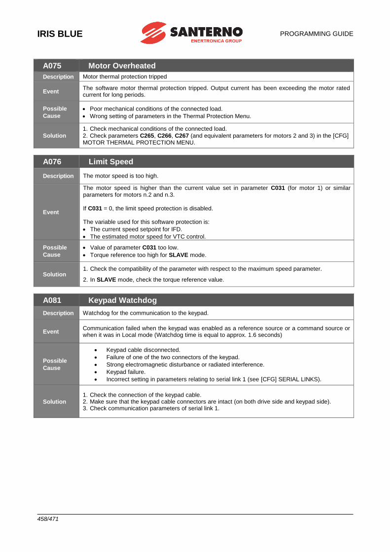
IRIS BLUE
PROGRAMMING GUIDE
458/471
A075 Motor Overheated
Description Motor thermal protection tripped
Event The software motor thermal protection tripped. Output current has been exceeding the motor rated current for long periods.
Possible
Cause
• Poor mechanical conditions of the connected load.
• Wrong setting of parameters in the Thermal Protection Menu.
Solution
1. Check mechanical conditions of the connected load.
2. Check parameters C265, C266, C267 (and equivalent parameters for motors 2 and 3) in the [CFG] MOTOR THERMAL PROTECTION MENU.
A076 Limit Speed
Description The motor speed is too high.
Event
The motor speed is higher than the current value set in parameter C031 (for motor 1) or similar parameters for motors n.2 and n.3.
If C031 = 0, the limit speed protection is disabled. The variable used for this software protection is:
• The current speed setpoint for IFD.
• The estimated motor speed for VTC control.
Possible
Cause
• Value of parameter C031 too low.
• Torque reference too high for SLAVE mode.
Solution 1. Check the compatibility of the parameter with respect to the maximum speed parameter.
2. In SLAVE mode, check the torque reference value.
A081 Keypad Watchdog
Description Watchdog for the communication to the keypad.
Event Communication failed when the keypad was enabled as a reference source or a command source or when it was in Local mode (Watchdog time is equal to approx. 1.6 seconds)
Possible
Cause
• Keypad cable disconnected.
• Failure of one of the two connectors of the keypad.
• Strong electromagnetic disturbance or radiated interference.
• Keypad failure.
• Incorrect setting in parameters relating to serial link 1 (see [CFG] SERIAL LINKS).
Solution 1. Check the connection of the keypad cable. 2. Make sure that the keypad cable connectors are intact (on both drive side and keypad side). 3. Check communication parameters of serial link 1.
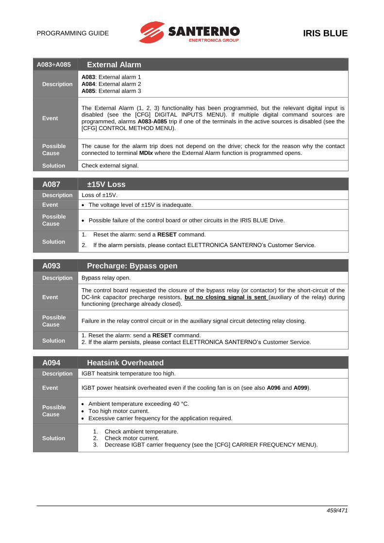
PROGRAMMING GUIDE
IRIS BLUE
459/471
A083÷A085 External Alarm
Description
A083: External alarm 1
A084: External alarm 2
A085: External alarm 3
Event
The External Alarm (1, 2, 3) functionality has been programmed, but the relevant digital input is disabled (see the [CFG] DIGITAL INPUTS MENU). If multiple digital command sources are
programmed, alarms A083-A085 trip if one of the terminals in the active sources is disabled (see the [CFG] CONTROL METHOD MENU).
Possible
Cause
The cause for the alarm trip does not depend on the drive; check for the reason why the contact
connected to terminal MDIx where the External Alarm function is programmed opens.
Solution Check external signal.
A087 ±15V Loss
Description Loss of ±15V.
Event • The voltage level of ±15V is inadequate.
Possible
Cause • Possible failure of the control board or other circuits in the IRIS BLUE Drive.
Solution
1. Reset the alarm: send a RESET command.
2. If the alarm persists, please contact ELETTRONICA SANTERNO’s Customer Service.
A093 Precharge: Bypass open
Description Bypass relay open.
Event
The control board requested the closure of the bypass relay (or contactor) for the short-circuit of the
DC-link capacitor precharge resistors, but no closing signal is sent (auxiliary of the relay) during functioning (precharge already closed).
Possible
Cause Failure in the relay control circuit or in the auxiliary signal circuit detecting relay closing.
Solution 1. Reset the alarm: send a RESET command. 2. If the alarm persists, please contact ELETTRONICA SANTERNO’s Customer Service.
A094 Heatsink Overheated
Description IGBT heatsink temperature too high.
Event IGBT power heatsink overheated even if the cooling fan is on (see also A096 and A099).
Possible
Cause
• Ambient temperature exceeding 40 °C.
• Too high motor current.
• Excessive carrier frequency for the application required.
Solution 1. Check ambient temperature. 2. Check motor current. 3. Decrease IGBT carrier frequency (see the [CFG] CARRIER FREQUENCY MENU).
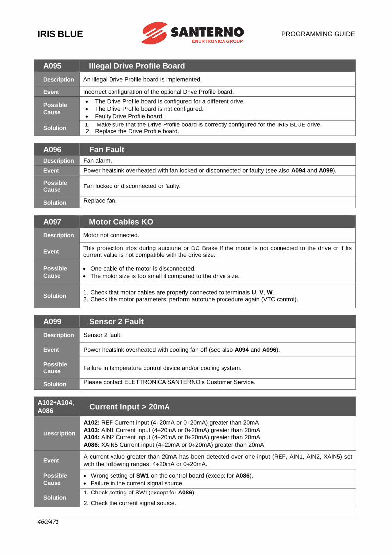
IRIS BLUE
PROGRAMMING GUIDE
460/471
A095 Illegal Drive Profile Board
Description An illegal Drive Profile board is implemented.
Event Incorrect configuration of the optional Drive Profile board.
Possible
Cause
• The Drive Profile board is configured for a different drive.
• The Drive Profile board is not configured.
• Faulty Drive Profile board.
Solution 1. Make sure that the Drive Profile board is correctly configured for the IRIS BLUE drive. 2. Replace the Drive Profile board.
A096 Fan Fault
Description Fan alarm.
Event Power heatsink overheated with fan locked or disconnected or faulty (see also A094 and A099).
Possible
Cause Fan locked or disconnected or faulty.
Solution Replace fan.
A097 Motor Cables KO
Description Motor not connected.
Event This protection trips during autotune or DC Brake if the motor is not connected to the drive or if its current value is not compatible with the drive size.
Possible
Cause
• One cable of the motor is disconnected.
• The motor size is too small if compared to the drive size.
Solution 1. Check that motor cables are properly connected to terminals U, V, W. 2. Check the motor parameters; perform autotune procedure again (VTC control).
A099 Sensor 2 Fault
Description Sensor 2 fault.
Event Power heatsink overheated with cooling fan off (see also A094 and A096).
Possible
Cause Failure in temperature control device and/or cooling system.
Solution Please contact ELETTRONICA SANTERNO’s Customer Service.
A102÷A104,
A086 Current Input > 20mA
Description
A102: REF Current input (420mA or 020mA) greater than 20mA
A103: AIN1 Current input (420mA or 020mA) greater than 20mA
A104: AIN2 Current input (420mA or 020mA) greater than 20mA
A086: XAIN5 Current input (420mA or 020mA) greater than 20mA
Event A current value greater than 20mA has been detected over one input (REF, AIN1, AIN2, XAIN5) set
with the following ranges: 420mA or 020mA.
Possible
Cause
• Wrong setting of SW1 on the control board (except for A086).
• Failure in the current signal source.
Solution 1. Check setting of SW1(except for A086).
2. Check the current signal source.
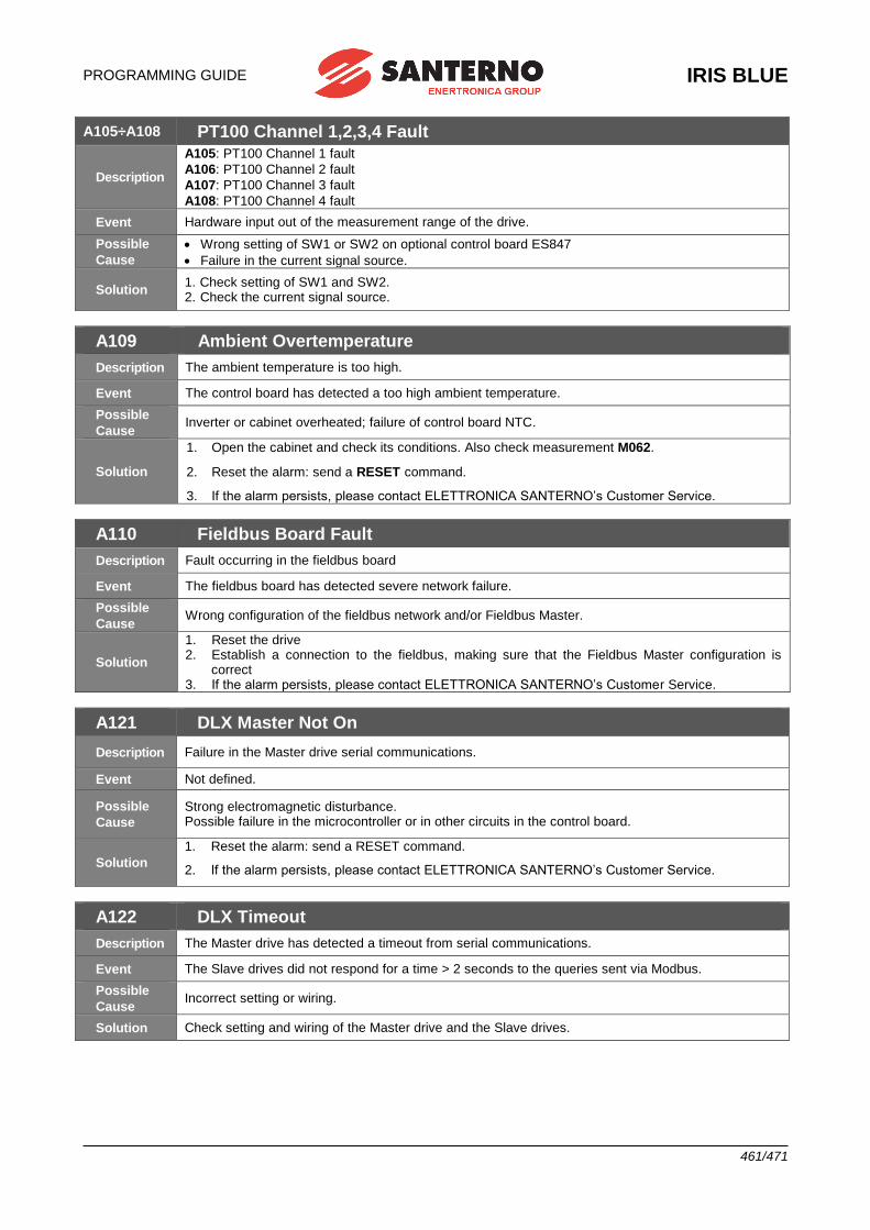
PROGRAMMING GUIDE
IRIS BLUE
461/471
A105÷A108 PT100 Channel 1,2,3,4 Fault
Description
A105: PT100 Channel 1 fault
A106: PT100 Channel 2 fault
A107: PT100 Channel 3 fault
A108: PT100 Channel 4 fault
Event Hardware input out of the measurement range of the drive.
Possible
Cause
• Wrong setting of SW1 or SW2 on optional control board ES847
• Failure in the current signal source.
Solution 1. Check setting of SW1 and SW2. 2. Check the current signal source.
A109 Ambient Overtemperature
Description The ambient temperature is too high.
Event The control board has detected a too high ambient temperature.
Possible
Cause Inverter or cabinet overheated; failure of control board NTC.
Solution
1. Open the cabinet and check its conditions. Also check measurement M062.
2. Reset the alarm: send a RESET command.
3. If the alarm persists, please contact ELETTRONICA SANTERNO’s Customer Service.
A110 Fieldbus Board Fault
Description Fault occurring in the fieldbus board
Event The fieldbus board has detected severe network failure.
Possible
Cause Wrong configuration of the fieldbus network and/or Fieldbus Master.
Solution
1. Reset the drive 2. Establish a connection to the fieldbus, making sure that the Fieldbus Master configuration is
correct 3. If the alarm persists, please contact ELETTRONICA SANTERNO’s Customer Service.
A121 DLX Master Not On
Description Failure in the Master drive serial communications.
Event Not defined.
Possible
Cause
Strong electromagnetic disturbance. Possible failure in the microcontroller or in other circuits in the control board.
Solution
1. Reset the alarm: send a RESET command.
2. If the alarm persists, please contact ELETTRONICA SANTERNO’s Customer Service.
A122 DLX Timeout
Description The Master drive has detected a timeout from serial communications.
Event The Slave drives did not respond for a time > 2 seconds to the queries sent via Modbus.
Possible
Cause Incorrect setting or wiring.
Solution Check setting and wiring of the Master drive and the Slave drives.
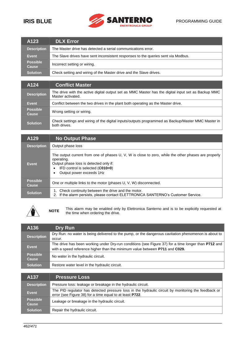
IRIS BLUE
PROGRAMMING GUIDE
462/471
A123 DLX Error
Description The Master drive has detected a serial communications error.
Event The Slave drives have sent inconsistent responses to the queries sent via Modbus.
Possible
Cause Incorrect setting or wiring.
Solution Check setting and wiring of the Master drive and the Slave drives.
A124 Conflict Master
Description The drive with the active digital output set as MMC Master has the digital input set as Backup MMC Master activated.
Event Conflict between the two drives in the plant both operating as the Master drive.
Possible
Cause Wrong setting or wiring.
Solution Check settings and wiring of the digital inputs/outputs programmed as Backup/Master MMC Master in both drives.
A129 No Output Phase
Description Output phase loss
Event
The output current from one of phases U, V, W is close to zero, while the other phases are properly operating. Output phase loss is detected only if:
• IFD control is selected (C010=0)
• Output power exceeds 1Hz
Possible
Cause One or multiple links to the motor (phases U, V, W) disconnected.
Solution 1. Check continuity between the drive and the motor. 2. If the alarm persists, please contact ELETTRONICA SANTERNO’s Customer Service.
NOTE This alarm may be enabled only by Elettronica Santerno and is to be explicitly requested at the time when ordering the drive.
A136 Dry Run
Description Dry Run: no water is being delivered to the pump, or the dangerous cavitation phenomenon is about to
occur.
Event The drive has been working under Dry-run conditions (see Figure 37) for a time longer than P712 and
with a speed reference higher than the minimum value between P711 and C029.
Possible
Cause No water in the hydraulic circuit.
Solution Restore water level in the hydraulic circuit.
A137 Pressure Loss
Description Pressure loss: leakage or breakage in the hydraulic circuit.
Event The PID regulator has detected pressure loss in the hydraulic circuit by monitoring the feedback or
error (see Figure 38) for a time equal to at least P722.
Possible
Cause Leakage or breakage in the hydraulic circuit.
Solution Repair the hydraulic circuit.
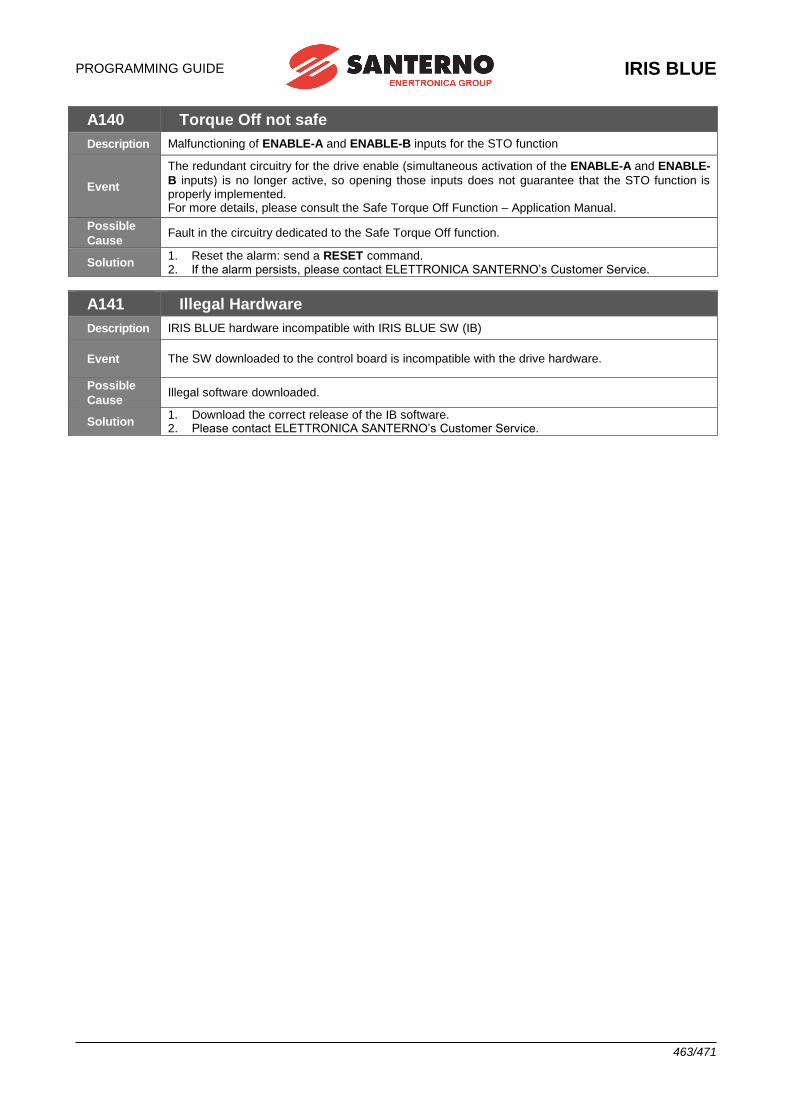
PROGRAMMING GUIDE
IRIS BLUE
463/471
A140 Torque Off not safe
Description Malfunctioning of ENABLE-A and ENABLE-B inputs for the STO function
Event
The redundant circuitry for the drive enable (simultaneous activation of the ENABLE-A and ENABLE-
B inputs) is no longer active, so opening those inputs does not guarantee that the STO function is properly implemented. For more details, please consult the Safe Torque Off Function – Application Manual.
Possible
Cause Fault in the circuitry dedicated to the Safe Torque Off function.
Solution 1. Reset the alarm: send a RESET command. 2. If the alarm persists, please contact ELETTRONICA SANTERNO’s Customer Service.
A141 Illegal Hardware
Description IRIS BLUE hardware incompatible with IRIS BLUE SW (IB)
Event The SW downloaded to the control board is incompatible with the drive hardware.
Possible
Cause Illegal software downloaded.
Solution 1. Download the correct release of the IB software. 2. Please contact ELETTRONICA SANTERNO’s Customer Service.
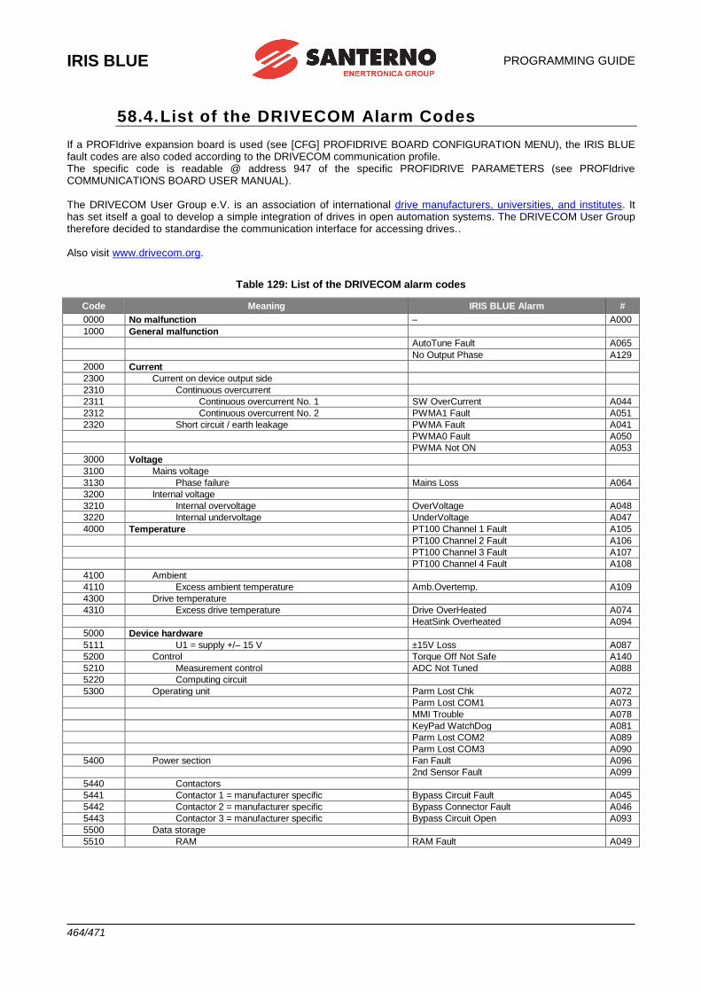
IRIS BLUE
PROGRAMMING GUIDE
464/471
58.4. List of the DRIVECOM Alarm Codes If a PROFIdrive expansion board is used (see [CFG] PROFIDRIVE BOARD CONFIGURATION MENU), the IRIS BLUE fault codes are also coded according to the DRIVECOM communication profile. The specific code is readable @ address 947 of the specific PROFIDRIVE PARAMETERS (see PROFIdrive COMMUNICATIONS BOARD USER MANUAL). The DRIVECOM User Group e.V. is an association of international drive manufacturers, universities, and institutes. It has set itself a goal to develop a simple integration of drives in open automation systems. The DRIVECOM User Group therefore decided to standardise the communication interface for accessing drives.. Also visit www.drivecom.org.
Table 129: List of the DRIVECOM alarm codes
Code Meaning IRIS BLUE Alarm #
0000 No malfunction – A000
1000 General malfunction
AutoTune Fault A065
No Output Phase A129
2000 Current
2300 Current on device output side
2310 Continuous overcurrent
2311 Continuous overcurrent No. 1 SW OverCurrent A044
2312 Continuous overcurrent No. 2 PWMA1 Fault A051
2320 Short circuit / earth leakage PWMA Fault A041
PWMA0 Fault A050
PWMA Not ON A053
3000 Voltage
3100 Mains voltage
3130 Phase failure Mains Loss A064
3200 Internal voltage
3210 Internal overvoltage OverVoltage A048
3220 Internal undervoltage UnderVoltage A047
4000 Temperature PT100 Channel 1 Fault A105
PT100 Channel 2 Fault A106
PT100 Channel 3 Fault A107
PT100 Channel 4 Fault A108
4100 Ambient
4110 Excess ambient temperature Amb.Overtemp. A109
4300 Drive temperature
4310 Excess drive temperature Drive OverHeated A074
HeatSink Overheated A094
5000 Device hardware
5111 U1 = supply +/– 15 V ±15V Loss A087
5200 Control Torque Off Not Safe A140
5210 Measurement control ADC Not Tuned A088
5220 Computing circuit
5300 Operating unit Parm Lost Chk A072
Parm Lost COM1 A073
MMI Trouble A078
KeyPad WatchDog A081
Parm Lost COM2 A089
Parm Lost COM3 A090
5400 Power section Fan Fault A096
2nd Sensor Fault A099
5440 Contactors
5441 Contactor 1 = manufacturer specific Bypass Circuit Fault A045
5442 Contactor 2 = manufacturer specific Bypass Connector Fault A046
5443 Contactor 3 = manufacturer specific Bypass Circuit Open A093
5500 Data storage
5510 RAM RAM Fault A049
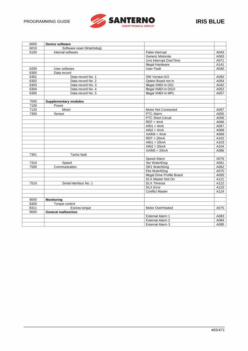
PROGRAMMING GUIDE
IRIS BLUE
465/471
6000 Device software
6010 Software reset (Watchdog)
6100 Internal software False Interrupt A043
Generic Motorola A063
1ms Interrupt OverTime A071
Illegal Hardware A141
6200 User software User Fault A040
6300 Data record
6301 Data record No. 1 SW Version KO A092
6302 Data record No. 2 Option Board not in A054
6303 Data record No. 3 Illegal XMDI in DGI A042
6304 Data record No. 4 Illegal XMDI in DGO A052
6305 Data record No. 5 Illegal XMDI in MPL A057
7000 Supplementary modules
7100 Power
7120 Motor Motor Not Connected A097
7300 Sensor PTC Alarm A055
PTC Short Circuit A056
REF < 4mA A066
AIN1 < 4mA A067
AIN2 < 4mA A068
XAIN5 < 4mA A069
REF > 20mA A102
AIN1 > 20mA A103
AIN2 > 20mA A104
XAIN5 > 20mA A086
7301 Tacho fault
Speed Alarm A076
7310 Speed Ser WatchDog A061
7500 Communication SR1 WatchDog A062
Fbs WatchDog A070
Illegal Drive Profile Board A095
DLX Master Not On A121
7510 Serial interface No. 1 DLX Timeout A122
DLX Error A123
Conflict Master A124
8000 Monitoring
8300 Torque control
8311 Excess torque Motor OverHeated A075
9000 General malfunction
External Alarm 1 A083
External Alarm 2 A084
External Alarm 3 A085
IRIS BLUE
PROGRAMMING GUIDE
466/471
58.5. Warnings
Warning messages are displayed on the display/keypad. They are flashing messages that usually appear in line 1 or 2 of the first three lines of the display.
NOTE Warnings are neither protections nor alarms, and are not stored to the fault list.
Some warnings simply state what’s happening or suggest what to do when using the keypad.
However, most of the warning messages are Coded warnings: they are displayed with letter “W” followed by two
digits stating which warning is active at that moment. Example: Warning messages are detailed in the following section.
W 3 2 O P E N E N A B L E
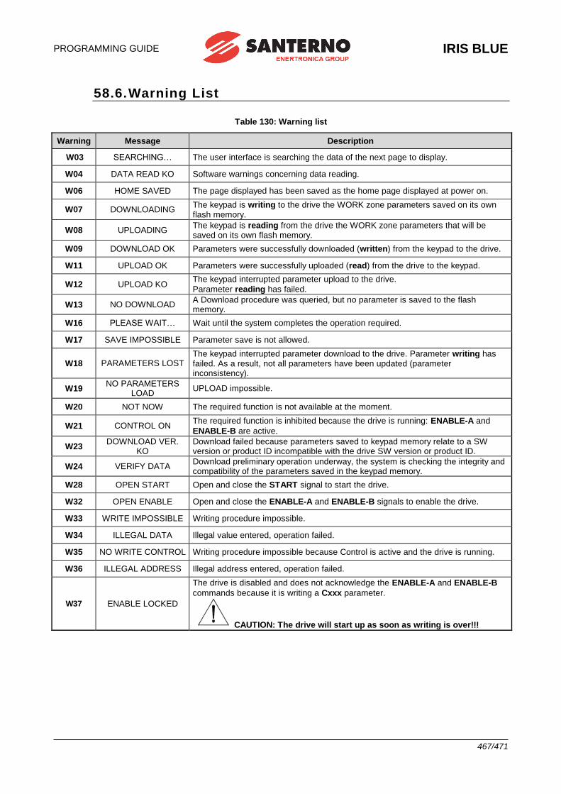
PROGRAMMING GUIDE
IRIS BLUE
467/471
58.6. Warning List
Table 130: Warning list
Warning Message Description
W03 SEARCHING… The user interface is searching the data of the next page to display.
W04 DATA READ KO Software warnings concerning data reading.
W06 HOME SAVED The page displayed has been saved as the home page displayed at power on.
W07 DOWNLOADING The keypad is writing to the drive the WORK zone parameters saved on its own flash memory.
W08 UPLOADING The keypad is reading from the drive the WORK zone parameters that will be saved on its own flash memory.
W09 DOWNLOAD OK Parameters were successfully downloaded (written) from the keypad to the drive.
W11 UPLOAD OK Parameters were successfully uploaded (read) from the drive to the keypad.
W12 UPLOAD KO The keypad interrupted parameter upload to the drive.
Parameter reading has failed.
W13 NO DOWNLOAD A Download procedure was queried, but no parameter is saved to the flash memory.
W16 PLEASE WAIT… Wait until the system completes the operation required.
W17 SAVE IMPOSSIBLE Parameter save is not allowed.
W18 PARAMETERS LOST The keypad interrupted parameter download to the drive. Parameter writing has failed. As a result, not all parameters have been updated (parameter inconsistency).
W19 NO PARAMETERS
LOAD UPLOAD impossible.
W20 NOT NOW The required function is not available at the moment.
W21 CONTROL ON The required function is inhibited because the drive is running: ENABLE-A and
ENABLE-B are active.
W23 DOWNLOAD VER.
KO Download failed because parameters saved to keypad memory relate to a SW version or product ID incompatible with the drive SW version or product ID.
W24 VERIFY DATA Download preliminary operation underway, the system is checking the integrity and compatibility of the parameters saved in the keypad memory.
W28 OPEN START Open and close the START signal to start the drive.
W32 OPEN ENABLE Open and close the ENABLE-A and ENABLE-B signals to enable the drive.
W33 WRITE IMPOSSIBLE Writing procedure impossible.
W34 ILLEGAL DATA Illegal value entered, operation failed.
W35 NO WRITE CONTROL Writing procedure impossible because Control is active and the drive is running.
W36 ILLEGAL ADDRESS Illegal address entered, operation failed.
W37 ENABLE LOCKED
The drive is disabled and does not acknowledge the ENABLE-A and ENABLE-B
commands because it is writing a Cxxx parameter.
CAUTION: The drive will start up as soon as writing is over!!!
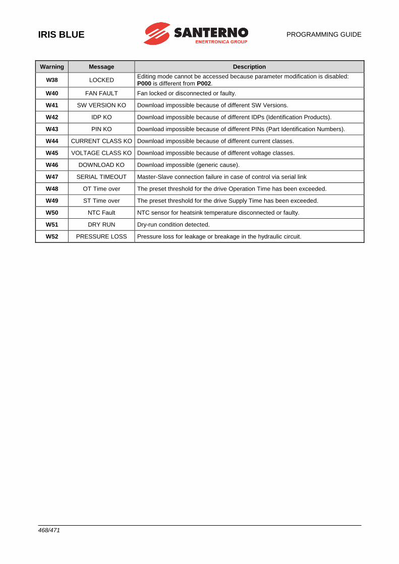
IRIS BLUE
PROGRAMMING GUIDE
468/471
Warning Message Description
W38 LOCKED Editing mode cannot be accessed because parameter modification is disabled:
P000 is different from P002.
W40 FAN FAULT Fan locked or disconnected or faulty.
W41 SW VERSION KO Download impossible because of different SW Versions.
W42 IDP KO Download impossible because of different IDPs (Identification Products).
W43 PIN KO Download impossible because of different PINs (Part Identification Numbers).
W44 CURRENT CLASS KO Download impossible because of different current classes.
W45 VOLTAGE CLASS KO Download impossible because of different voltage classes.
W46 DOWNLOAD KO Download impossible (generic cause).
W47 SERIAL TIMEOUT Master-Slave connection failure in case of control via serial link
W48 OT Time over The preset threshold for the drive Operation Time has been exceeded.
W49 ST Time over The preset threshold for the drive Supply Time has been exceeded.
W50 NTC Fault NTC sensor for heatsink temperature disconnected or faulty.
W51 DRY RUN Dry-run condition detected.
W52 PRESSURE LOSS Pressure loss for leakage or breakage in the hydraulic circuit.
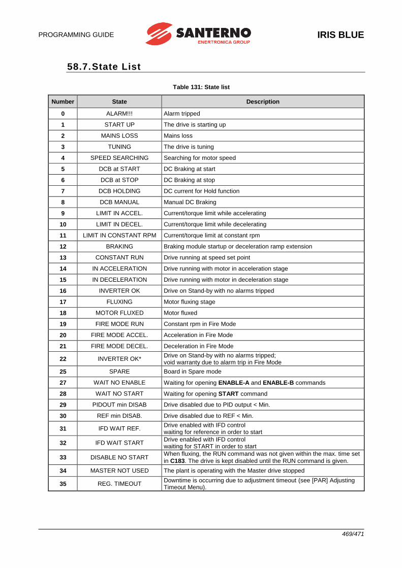
PROGRAMMING GUIDE
IRIS BLUE
469/471
58.7. State List
Table 131: State list
Number State Description
0 ALARM!!! Alarm tripped
1 START UP The drive is starting up
2 MAINS LOSS Mains loss
3 TUNING The drive is tuning
4 SPEED SEARCHING Searching for motor speed
5 DCB at START DC Braking at start
6 DCB at STOP DC Braking at stop
7 DCB HOLDING DC current for Hold function
8 DCB MANUAL Manual DC Braking
9 LIMIT IN ACCEL. Current/torque limit while accelerating
10 LIMIT IN DECEL. Current/torque limit while decelerating
11 LIMIT IN CONSTANT RPM Current/torque limit at constant rpm
12 BRAKING Braking module startup or deceleration ramp extension
13 CONSTANT RUN Drive running at speed set point
14 IN ACCELERATION Drive running with motor in acceleration stage
15 IN DECELERATION Drive running with motor in deceleration stage
16 INVERTER OK Drive on Stand-by with no alarms tripped
17 FLUXING Motor fluxing stage
18 MOTOR FLUXED Motor fluxed
19 FIRE MODE RUN Constant rpm in Fire Mode
20 FIRE MODE ACCEL. Acceleration in Fire Mode
21 FIRE MODE DECEL. Deceleration in Fire Mode
22 INVERTER OK* Drive on Stand-by with no alarms tripped; void warranty due to alarm trip in Fire Mode
25 SPARE Board in Spare mode
27 WAIT NO ENABLE Waiting for opening ENABLE-A and ENABLE-B commands
28 WAIT NO START Waiting for opening START command
29 PIDOUT min DISAB Drive disabled due to PID output < Min.
30 REF min DISAB. Drive disabled due to REF < Min.
31 IFD WAIT REF. Drive enabled with IFD control waiting for reference in order to start
32 IFD WAIT START Drive enabled with IFD control waiting for START in order to start
33 DISABLE NO START When fluxing, the RUN command was not given within the max. time set
in C183. The drive is kept disabled until the RUN command is given.
34 MASTER NOT USED The plant is operating with the Master drive stopped
35 REG. TIMEOUT Downtime is occurring due to adjustment timeout (see [PAR] Adjusting Timeout Menu).
IRIS BLUE
PROGRAMMING GUIDE
470/471
59. INDEX
2
2-ZONE .................................................................. 174
A
AIN1/AIN2 UNITS OF MEASUREMENT.................... 87 ALARM CODES LIST ............................................. 448 ALARMS AND WARNINGS .................................... 446 ALTERING PARAMETER VALUES .......................... 18 ALTERNATIVE COMMAND AND REFERENCE
SOURCES .................................................... 31; 293 ANALOG AND FREQUENCY OUTPUTS ................ 130 ANTI WINDUP ........................................................ 160 AUTORESET ......................................................... 339 AUTOTUNE ................................................ 41; 43; 252 AUXILIARY DIGITAL OUTPUTS ............................. 204 AUXILIARY REFERENCES .................................... 235
C
CARRIER FREQUENCY ......................................... 255 COMMAND SOURCES........................................... 289 CONTROL METHOD MENU ................................... 288 CURRENT BALANCING ......................................... 122 CW/CCW INPUT .................................................... 310
D
DATA LOGGER ................................................ 67; 392 DAYLIGHT SAVING TIME ...................................... 390 DC BRAKING ................................................... 29; 324 DC BRAKING AT START AND NON-CONDENSING
FUNCTION ......................................................... 324 DC BRAKING AT STOP ......................................... 326 DC BRAKING COMMAND SENT FROM DIGITAL
INPUT ................................................................. 327 DCB INPUT ............................................................ 311 DIGITAL INPUTS .................................................... 298 DIGITAL OUTPUT MODE ....................................... 177 DIGITAL OUTPUTS ................................................ 176 DISABLE ................................................................ 314 DISABLE INPUT ..................................................... 308 DISABLE RESET ALARMS ON MDI3 ..................... 308 DISPLAY/KEYPAD ... 14; 18; 19; 22; 39; 54; 55; 58; 59;
82; 118; 317 DOWNLOAD/UPLOAD FROM THE KEYPAD ........... 21 DRIVECOM ............................................................ 464 DRY-RUN ................................................................. 30 DRY-RUN CONTROL ............................................. 240
E
EEPROM ................................................................ 394 ELECTRIC MOTOR RATINGS ............................... 260 ENABLE ................................................................. 301 ENABLE-SW INPUT ............................................... 307 EQUIVALENT CIRCUIT OF THE ASYNCHRONOUS
MACHINE ........................................................... 261 ES847 ............................................................ 235; 292 ES851 .............................................................. 67; 392
F
FAULT LIST ............................................................. 70 FIELD WEAKENING ....................................... 265; 275 FIELDBUS .............................................................. 377
FIRE MODE ........................................................ 32; 76 FIRE MODE ENABLE INPUT .................................. 319 FIRST STARTUP ...................................................... 41 FREQUENCY OUTPUT .......................................... 132
I
I/O OPTION BOARD ....................................... 235; 292 IFD .................................................................... 41; 259 INDICATOR LEDS .................................................... 23 INPUT FOR REFERENCE SELECTION .................. 316 INPUT FOR SOURCE SELECTION ........................ 316 INPUTS FOR REFERENCES .................................... 98 IPEAK ..................................................................... 284
L
LANGUAGE .............................................................. 76 LIMITS .................................................................... 283 LOC/REM ......................................................... 22; 293 LOC/REM INPUT .................................................... 317 LOCAL MODE .......................................................... 83 LOCK INPUT .......................................................... 314
M
MAIN SPEED REFERENCE ...................................... 28 MAINTENANCE ...................................................... 348 MAXIMUM FLUXING TIME ...................................... 318 MDI MULTIPROGRAMMING ENABLE .................... 318 METHOD OF ZIEGLER AND NICHOLS .................. 155 MOTOR CONFIGURATION .................................... 259 MOTOR THERMAL PROTECTION ........................... 29 MOTOR THERMAL PROTECTION ......................... 341 MOTOR TUNE .................................................... 41; 43 MPL ........................................................................ 214 MULTIMOTOR .......................................................... 30 MULTIRAMP INPUT................................................ 313 MULTISPEED ......................................................... 114 MULTISPEED INPUTS ........................................... 309
N
NAVIGATION MODE................................................. 17
O
OUTPUT FREQUENCY .......................................... 256
P
PASSWORD ............................................................. 80 PID CONFIGURATION ............................................ 350 PID DIGITAL REGULATOR....................................... 29 PID FEEDBACK ........................................................ 28 PID MULTIREFERENCES INPUTS ......................... 320 PID MULTIRIFERENCES ........................................ 117 PID PARAMETERS ................................................. 154 PID PRESSURE CONTROL ...................................... 37 PID REFERENCE ..................................................... 28 PID UNITS OF MEASUREMENT............................... 88 PID UP/DOWN RESET ........................................... 315 PID2 PARAMETERS ............................................... 174 PIPE FILL ................................................................. 30 PIPE FILL CONTROL.............................................. 249 POWER OFF LIST .................................................... 73 PRESSURE ............................................................ 246 PRESSURE LOSS CONTROL .................................. 30
PROGRAMMING GUIDE
IRIS BLUE
471/471
PROFIDRIVE .......................................................... 387 PROHIBIT SPEED .................................................. 120 PROHIBIT SPEEDS ................................................. 29 PT100 .............................................................. 64; 208 PTC ........................................................................ 341
R
REAL TIME CLOCK (RTC) ..................................... 362 REMOTE/LOCAL.................................................... 293 RESET ................................................................... 303 REVERSE INPUT ................................................... 307
S
SERIAL LINKS ....................................................... 372 SLEEP AND WAKE-UP .......................................... 161 SLIP COMPENSATION ............................................ 29 SOURCE SELECTION INPUT ................................ 315 SPEED LOOP ........................................................ 122 SPEED RAMPS ........................................................ 93 SPEED SEARCHING........................................ 29; 333 SPEED SEARCHING................................................ 29 SPEED/TORQUE REFERENCE SOURCES ........... 291 START ................................................................... 300 START INPUT ........................................................ 305 START-UP ............................................................... 39 STATUS LIST ......................................................... 469 STATUS PAGE ........................................................ 82 STOP ..................................................................... 319 STOP INPUT .......................................................... 306
SWITCH OVER FROM REMOTE TO LOCAL COMMAND.......................................................... 297
T
TIMERS ............................................ 56; 148; 289; 298 TORQUE CONTROL .............................. 259; 265; 269 TYPE OF LOC/REM CONTACT .............................. 317
U
UP AND DOWN INPUTS ........................................ 311 UP/DOWN .............................................................. 113 USER LEVEL ............................................................ 80
V
VIRTUAL DIGITAL OUTPUTS ................................. 214 VOLTAGE/FREQUENCY PATTERN ................. 29; 262 VTC .................................................................. 43; 259
W
WARNING LIST ...................................................... 467 WATCHDOG .......................................................... 372
X
XAIN4 ..................................................................... 235 XAIN5 ..................................................................... 235