ipv6: theory, protocol, and practice - x-files
TRANSCRIPT

IPv6:Theory,
Protocol,and
PracticeSECOND EDITION

This Page Intentionally Left Blank
IPv6:Theory,Protocol,
andPracticeSECOND EDITION
Pete LoshinInternet-Standard.com
AMSTERDAM • BOSTON • HEIDELBERG • LONDON
NEW YORK • OXFORD • PARIS • SAN DIEGO
SAN FRANCISCO • SINGAPORE • SYDNEY • TOKYO
Morgan Kaufmann Publishers is an imprint of Elsevier
Senior Editor Rick AdamsPublishing Services Manager Simon CrumpProduction Editor Troy LillyAssociate Editor Karyn JohnsonCover Design Cate Rickard BarrCover Illustrator Yvo Riezebos DesignCover Image Cydney CongerComposition Cepha Imaging Pvt. Ltd.Copyeditor Deborah PratoProofreader Phyllis Coyne et al. Proofreading ServiceIndexer Northwind Editorial ServicesInterior printer The Maple-Vail Book Manufacturing GroupCover printer Phoenix Color Corp.
Morgan Kaufmann Publishers is an Imprint of Elsevier500 Sansome Street, Suite 400, San Francisco, CA 94111
This book is printed on acid-free paper.
© 2004 by Elsevier, Inc. All rights reserved.
Designations used by companies to distinguish their products are often claimed as trademarks or registeredtrademarks. In all instances in which Morgan Kaufmann Publishers is aware of a claim, the product names appearin initial capital or all capital letters. Readers, however, should contact the appropriate companies for morecomplete information regarding trademarks and registration.
No part of this publication may be reproduced, stored in a retrieval system, or transmitted in any form or by anymeans—electronic, mechanical, photocopying, or otherwise—without written permission of the publishers.
Permissions may be sought directly from Elsevier’s Science & Technology Rights Department in Oxford, UK:phone: (+44) 1865 843830, fax: (+44) 1865 853333, e-mail: [email protected]. You may also completeyour request on-line via the Elsevier homepage (http://elsevier.com) by selecting “Customer Support” and then“Obtaining Permissions.”
Library of Congress Cataloging-in-Publication Data
Loshin, Peter.IPv6 : theory, protocol, and practice/Pete Loshin.—2nd ed.p. cm.
Rev. ed. of: IPv6 clearly explained. c1999Includes bibliographical references and index.ISBN 1-55860-810-9 (pbk. : alk. paper)1. TCP/IP (Computer network protocol) I. Loshin, Peter. IPv6 clearly explained. II. Title
TK5105.585.L66 2003004.6’2—dc22
2003058303
ISBN: 1-55860-810-9
For information on all Morgan Kaufmann publications,visit our website at www.mkp.com
Printed in the United States of America04 05 06 07 08 5 4 3 2 1

Contents
Preface . . . . . . . . . . . . . . . . . . . . . . . . . . . . . . . . . . . . . . . . . . . . . . . . . . . . . . . . . . . . . xvii
I Theory . . . . . . . . . . . . . . . . . . . . . . . . . . . . . . . . . . . . . . . . . . . 1
1 The Disruptive Protocol . . . . . . . . . . . . . . . . . . . . . . . . . . . . . . . . . . . . . . . . 51.1 Disruptive Technologies . . . . . . . . . . . . . . . . . . . . . . . . . . . . . . . . . . . 61.2 IPv6: Disruptive or Sustaining? . . . . . . . . . . . . . . . . . . . . . . . . . . . . 81.3 The Value of the Network. . . . . . . . . . . . . . . . . . . . . . . . . . . . . . . . . . 111.4 Driving IPv6 Growth . . . . . . . . . . . . . . . . . . . . . . . . . . . . . . . . . . . . . . 13
1.4.1 Crisis or Boondoggle? . . . . . . . . . . . . . . . . . . . . . . . . . . . . . 131.4.2 Killer Applications . . . . . . . . . . . . . . . . . . . . . . . . . . . . . . . . 141.4.3 Products and Technologies . . . . . . . . . . . . . . . . . . . . . . . . 151.4.4 IPv6 as a Sustaining Technology . . . . . . . . . . . . . . . . . . . 16
1.5 A Possible IPv6 Future . . . . . . . . . . . . . . . . . . . . . . . . . . . . . . . . . . . . . 17
2 What’s Wrong with IPv4? . . . . . . . . . . . . . . . . . . . . . . . . . . . . . . . . . . . . . . . 192.1 Protocol Life Expectancy . . . . . . . . . . . . . . . . . . . . . . . . . . . . . . . . . . . 202.2 What’s Wrong with IPv4 . . . . . . . . . . . . . . . . . . . . . . . . . . . . . . . . . . . 212.3 IPv4 Addressing Crisis . . . . . . . . . . . . . . . . . . . . . . . . . . . . . . . . . . . . . 252.4 The IPv4 Routing Crisis . . . . . . . . . . . . . . . . . . . . . . . . . . . . . . . . . . . . 29
v
vi Contents
2.4.1 IPv4 Internet Routing . . . . . . . . . . . . . . . . . . . . . . . . . . . . . . 302.4.2 IPv4 Route Aggregation . . . . . . . . . . . . . . . . . . . . . . . . . . . 302.4.3 IPv4 Routing Scalability . . . . . . . . . . . . . . . . . . . . . . . . . . . 32
2.5 The End-to-End Problem. . . . . . . . . . . . . . . . . . . . . . . . . . . . . . . . . . . 332.6 Summary . . . . . . . . . . . . . . . . . . . . . . . . . . . . . . . . . . . . . . . . . . . . . . . . . . 35
3 Patching IPv4 . . . . . . . . . . . . . . . . . . . . . . . . . . . . . . . . . . . . . . . . . . . . . . . . . . . 373.1 Network Address Rationing . . . . . . . . . . . . . . . . . . . . . . . . . . . . . . . 393.2 IP Subnetting . . . . . . . . . . . . . . . . . . . . . . . . . . . . . . . . . . . . . . . . . . . . . . 403.3 Classless Inter-Domain Routing (CIDR) . . . . . . . . . . . . . . . . . . . . 443.4 Dynamic Host Configuration Protocol (DHCP) . . . . . . . . . . . . . 463.5 Recycling Unused IP Networks . . . . . . . . . . . . . . . . . . . . . . . . . . . . 473.6 Subnetting Class A Networks . . . . . . . . . . . . . . . . . . . . . . . . . . . . . . 483.7 Network Address Translation (NAT). . . . . . . . . . . . . . . . . . . . . . . 49
3.7.1 Reasons for NAT . . . . . . . . . . . . . . . . . . . . . . . . . . . . . . . . . . 503.7.2 NAT Basics . . . . . . . . . . . . . . . . . . . . . . . . . . . . . . . . . . . . . . . . 513.7.3 NAT Issues and Misconceptions . . . . . . . . . . . . . . . . . . . 523.7.4 NAT and Related RFCs . . . . . . . . . . . . . . . . . . . . . . . . . . . . 53
3.8 Realm-Specific IP (RSIP) . . . . . . . . . . . . . . . . . . . . . . . . . . . . . . . . . . . 553.9 Summary . . . . . . . . . . . . . . . . . . . . . . . . . . . . . . . . . . . . . . . . . . . . . . . . . . 56
4 The Road to Next Generation . . . . . . . . . . . . . . . . . . . . . . . . . . . . . . . . . . . 594.1 Early Assumptions About the Internet Environment . . . . . . . 594.2 Designated Areas for Internet Evolution . . . . . . . . . . . . . . . . . . . 61
4.2.1 Addressing and Routing . . . . . . . . . . . . . . . . . . . . . . . . . . . 624.2.2 Multiprotocol Architecture . . . . . . . . . . . . . . . . . . . . . . . . 634.2.3 Security Architecture . . . . . . . . . . . . . . . . . . . . . . . . . . . . . . 634.2.4 Traffic Control and State . . . . . . . . . . . . . . . . . . . . . . . . . . . 644.2.5 Advanced Applications . . . . . . . . . . . . . . . . . . . . . . . . . . . . 64
4.3 Room for Improvement . . . . . . . . . . . . . . . . . . . . . . . . . . . . . . . . . . . . 654.3.1 Network Administration and Configuration . . . . . . . 654.3.2 Type of Service (ToS) . . . . . . . . . . . . . . . . . . . . . . . . . . . . . . 674.3.3 IP Options . . . . . . . . . . . . . . . . . . . . . . . . . . . . . . . . . . . . . . . . . 68
4.4 IPng Candidates . . . . . . . . . . . . . . . . . . . . . . . . . . . . . . . . . . . . . . . . . . . 684.5 IPv6, The Next Generation . . . . . . . . . . . . . . . . . . . . . . . . . . . . . . . . . 724.6 Summary . . . . . . . . . . . . . . . . . . . . . . . . . . . . . . . . . . . . . . . . . . . . . . . . . . 73
5 IPv6 Transition Issues . . . . . . . . . . . . . . . . . . . . . . . . . . . . . . . . . . . . . . . . . . 755.1 Upgrading IP . . . . . . . . . . . . . . . . . . . . . . . . . . . . . . . . . . . . . . . . . . . . . . 755.2 The IPv6 Protocol Tunneling Approach . . . . . . . . . . . . . . . . . . . . 77
5.2.1 IPv6 Tunnel Types . . . . . . . . . . . . . . . . . . . . . . . . . . . . . . . . . 795.2.2 Explicit Tunneling . . . . . . . . . . . . . . . . . . . . . . . . . . . . . . . . . 80
Contents vii
5.2.3 IPv6 over IPv4 Without Explicit Tunnels . . . . . . . . . . . 815.2.4 The Trouble with Tunnels . . . . . . . . . . . . . . . . . . . . . . . . . 81
5.3 IPv4/IPv6 Dual-Stack . . . . . . . . . . . . . . . . . . . . . . . . . . . . . . . . . . . . . . 825.4 Connecting IPv6 Domains via IPv4 Clouds . . . . . . . . . . . . . . . . . 835.5 Summary . . . . . . . . . . . . . . . . . . . . . . . . . . . . . . . . . . . . . . . . . . . . . . . . . . 84
II IPv6 Protocols . . . . . . . . . . . . . . . . . . . . . . . . . . . . . . . . . . . 85
6 The IP Security Protocol (IPsec) . . . . . . . . . . . . . . . . . . . . . . . . . . . . . . . . 896.1 IP Security Issues . . . . . . . . . . . . . . . . . . . . . . . . . . . . . . . . . . . . . . . . . . 906.2 Security Goals . . . . . . . . . . . . . . . . . . . . . . . . . . . . . . . . . . . . . . . . . . . . . 936.3 Encryption and Authentication Algorithms . . . . . . . . . . . . . . . . 97
6.3.1 Symmetric Encryption . . . . . . . . . . . . . . . . . . . . . . . . . . . . . 986.3.2 Public Key Encryption . . . . . . . . . . . . . . . . . . . . . . . . . . . . . 1006.3.3 Key Management . . . . . . . . . . . . . . . . . . . . . . . . . . . . . . . . . . 1006.3.4 Secure Hashes . . . . . . . . . . . . . . . . . . . . . . . . . . . . . . . . . . . . . 1026.3.5 Digital Signature . . . . . . . . . . . . . . . . . . . . . . . . . . . . . . . . . . 103
6.4 IPsec: The Protocols . . . . . . . . . . . . . . . . . . . . . . . . . . . . . . . . . . . . . . . . 1046.5 IP and IPsec . . . . . . . . . . . . . . . . . . . . . . . . . . . . . . . . . . . . . . . . . . . . . . . 106
6.5.1 Security Associations . . . . . . . . . . . . . . . . . . . . . . . . . . . . . . 1076.5.2 Using Security Associations. . . . . . . . . . . . . . . . . . . . . . . . 1086.5.3 Tunnel and Transport Mode . . . . . . . . . . . . . . . . . . . . . . . 1096.5.4 Encapsulating Security Payload (ESP) . . . . . . . . . . . . . . 1106.5.5 Authentication Header . . . . . . . . . . . . . . . . . . . . . . . . . . . . 1146.5.6 Calculating the Integrity Check Value (ICV). . . . . . . . 1176.5.7 IPsec Headers in Action . . . . . . . . . . . . . . . . . . . . . . . . . . . 118
6.6 Implementing and Deploying IPsec . . . . . . . . . . . . . . . . . . . . . . . . 1196.7 Summary . . . . . . . . . . . . . . . . . . . . . . . . . . . . . . . . . . . . . . . . . . . . . . . . . . 120
7 IPv6 Protocol Basics . . . . . . . . . . . . . . . . . . . . . . . . . . . . . . . . . . . . . . . . . . . . 1237.1 The IPv6 Address Space . . . . . . . . . . . . . . . . . . . . . . . . . . . . . . . . . . . 124
7.1.1 Provider-Based Aggregation . . . . . . . . . . . . . . . . . . . . . . . 1247.1.2 Geographic-Based Aggregation . . . . . . . . . . . . . . . . . . . . 1257.1.3 IPv6 Aggregation . . . . . . . . . . . . . . . . . . . . . . . . . . . . . . . . . . 126
7.2 IPv6 Header Format . . . . . . . . . . . . . . . . . . . . . . . . . . . . . . . . . . . . . . . 1267.3 IPv4 Versus IPv6. . . . . . . . . . . . . . . . . . . . . . . . . . . . . . . . . . . . . . . . . . . 1287.4 IPv6 Header Fields. . . . . . . . . . . . . . . . . . . . . . . . . . . . . . . . . . . . . . . . . 1307.5 Option Headers . . . . . . . . . . . . . . . . . . . . . . . . . . . . . . . . . . . . . . . . . . . . 1327.6 IPv6 Packet Size Limits . . . . . . . . . . . . . . . . . . . . . . . . . . . . . . . . . . . . 134
7.6.1 IPv6 MTU Requirements. . . . . . . . . . . . . . . . . . . . . . . . . . . 1347.6.2 Fragmentation . . . . . . . . . . . . . . . . . . . . . . . . . . . . . . . . . . . . . 1357.6.3 Jumbograms . . . . . . . . . . . . . . . . . . . . . . . . . . . . . . . . . . . . . . . 135
viii Contents
7.7 Other IPv6 Features . . . . . . . . . . . . . . . . . . . . . . . . . . . . . . . . . . . . . . . . 1357.7.1 Autoconfiguration . . . . . . . . . . . . . . . . . . . . . . . . . . . . . . . . . 1367.7.2 Network Renumbering . . . . . . . . . . . . . . . . . . . . . . . . . . . . 1377.7.3 Neighbor Discovery . . . . . . . . . . . . . . . . . . . . . . . . . . . . . . . 1387.7.4 Anycast . . . . . . . . . . . . . . . . . . . . . . . . . . . . . . . . . . . . . . . . . . . 1387.7.5 Mobile IPv6 . . . . . . . . . . . . . . . . . . . . . . . . . . . . . . . . . . . . . . . 139
7.8 Summary . . . . . . . . . . . . . . . . . . . . . . . . . . . . . . . . . . . . . . . . . . . . . . . . . . 140
8 IPv6 Addressing . . . . . . . . . . . . . . . . . . . . . . . . . . . . . . . . . . . . . . . . . . . . . . . . 1418.1 IPv6 Address Types . . . . . . . . . . . . . . . . . . . . . . . . . . . . . . . . . . . . . . . 142
8.1.1 Network and Node Addressing . . . . . . . . . . . . . . . . . . . . 1438.1.2 Aggregatable Addressing . . . . . . . . . . . . . . . . . . . . . . . . . . 1438.1.3 IPv6 Address Representation . . . . . . . . . . . . . . . . . . . . . . 144
8.2 Unicast Address Types . . . . . . . . . . . . . . . . . . . . . . . . . . . . . . . . . . . . 1468.3 Special Unicast Address Types . . . . . . . . . . . . . . . . . . . . . . . . . . . . . 147
8.3.1 Unspecified Address . . . . . . . . . . . . . . . . . . . . . . . . . . . . . . 1478.3.2 Loopback . . . . . . . . . . . . . . . . . . . . . . . . . . . . . . . . . . . . . . . . . . 1478.3.3 Encoded NSAP Addresses . . . . . . . . . . . . . . . . . . . . . . . . . 148
8.4 IPv6 Address Format . . . . . . . . . . . . . . . . . . . . . . . . . . . . . . . . . . . . . . 1488.4.1 IPv6 Address Aggregation Fields . . . . . . . . . . . . . . . . . . 1498.4.2 Global Routing Prefix and Subnet ID . . . . . . . . . . . . . . . 1518.4.3 Modified EUI-64 Interface Addressing . . . . . . . . . . . . . 1528.4.4 IPv4-Compatible Addresses . . . . . . . . . . . . . . . . . . . . . . . 156
8.5 IPv6 Node Self-Awareness . . . . . . . . . . . . . . . . . . . . . . . . . . . . . . . . . 1568.6 Summary . . . . . . . . . . . . . . . . . . . . . . . . . . . . . . . . . . . . . . . . . . . . . . . . . . 158
9 IPv6 Options and Extension Headers . . . . . . . . . . . . . . . . . . . . . . . . . . . 1599.1 IPv6 Options and Extension Headers . . . . . . . . . . . . . . . . . . . . . . . 160
9.1.1 Adding Extensions to IPv6 Headers . . . . . . . . . . . . . . . . 1609.1.2 Extension Header Ordering . . . . . . . . . . . . . . . . . . . . . . . . 1629.1.3 IPv6-in-IPv6 Tunneling . . . . . . . . . . . . . . . . . . . . . . . . . . . . 1649.1.4 IPv6 Extension Headers and Options . . . . . . . . . . . . . . 165
9.2 Routing Header. . . . . . . . . . . . . . . . . . . . . . . . . . . . . . . . . . . . . . . . . . . . 1659.2.1 IPv6 Routing Header Format . . . . . . . . . . . . . . . . . . . . . . 1669.2.2 Source Route (Type 0) . . . . . . . . . . . . . . . . . . . . . . . . . . . . . 167
9.3 Fragment Header . . . . . . . . . . . . . . . . . . . . . . . . . . . . . . . . . . . . . . . . . . 1709.3.1 IPv4 Fragmentation . . . . . . . . . . . . . . . . . . . . . . . . . . . . . . . . 1709.3.2 IPv6 Fragmentation Header Fields . . . . . . . . . . . . . . . . . 1719.3.3 Packet Fragmentation. . . . . . . . . . . . . . . . . . . . . . . . . . . . . . 173
9.4 Hop-by-Hop and Destination Options Headers . . . . . . . . . . . . 1749.4.1 Options Headers Format . . . . . . . . . . . . . . . . . . . . . . . . . . . 1749.4.2 Destination Options Functions . . . . . . . . . . . . . . . . . . . . . 175
Contents ix
9.4.3 Options Specification and Encoding. . . . . . . . . . . . . . . . 1759.4.4 Option Padding . . . . . . . . . . . . . . . . . . . . . . . . . . . . . . . . . . . 1779.4.5 Current Valid Options . . . . . . . . . . . . . . . . . . . . . . . . . . . . . 178
9.5 Summary . . . . . . . . . . . . . . . . . . . . . . . . . . . . . . . . . . . . . . . . . . . . . . . . . . 180
10 IPv6 Multicast . . . . . . . . . . . . . . . . . . . . . . . . . . . . . . . . . . . . . . . . . . . . . . . . . . 18310.1 IPv6 Multicast Address Format . . . . . . . . . . . . . . . . . . . . . . . . . . . . 18410.2 Multicast Scope Definitions . . . . . . . . . . . . . . . . . . . . . . . . . . . . . . . . 18510.3 Reserved and Permanent Multicast Addresses . . . . . . . . . . . . . 18610.4 Solicited-Node Multicast . . . . . . . . . . . . . . . . . . . . . . . . . . . . . . . . . . . 18910.5 Multicast Listener Discovery (MLD) for IPv6 . . . . . . . . . . . . . . . 19210.6 Summary . . . . . . . . . . . . . . . . . . . . . . . . . . . . . . . . . . . . . . . . . . . . . . . . . . 194
11 IPv6 Anycast . . . . . . . . . . . . . . . . . . . . . . . . . . . . . . . . . . . . . . . . . . . . . . . . . . . . 19511.1 Anycast Overview . . . . . . . . . . . . . . . . . . . . . . . . . . . . . . . . . . . . . . . . . 19611.2 Anycast Motivations . . . . . . . . . . . . . . . . . . . . . . . . . . . . . . . . . . . . . . . 19611.3 Anycast Architectural Issues . . . . . . . . . . . . . . . . . . . . . . . . . . . . . . . 197
11.3.1 IPv4 Anycast Issues. . . . . . . . . . . . . . . . . . . . . . . . . . . . . . . . 19811.3.2 IPv6 Anycast Issues. . . . . . . . . . . . . . . . . . . . . . . . . . . . . . . . 19811.3.3 IPsec and Anycast . . . . . . . . . . . . . . . . . . . . . . . . . . . . . . . . . 19911.3.4 Anycast Address Assignment . . . . . . . . . . . . . . . . . . . . . . 199
11.4 IPv6 Anycast Specification . . . . . . . . . . . . . . . . . . . . . . . . . . . . . . . . . 20011.5 Reserved IPv6 Anycast Addresses . . . . . . . . . . . . . . . . . . . . . . . . . 20111.6 Making Anycast Work . . . . . . . . . . . . . . . . . . . . . . . . . . . . . . . . . . . . . 203
11.6.1 Anycast Routing . . . . . . . . . . . . . . . . . . . . . . . . . . . . . . . . . . . 20311.6.2 Responding to Anycast Packets . . . . . . . . . . . . . . . . . . . . 20411.6.3 Identifying Unicast Addresses . . . . . . . . . . . . . . . . . . . . . 20411.6.4 The Future of Anycast . . . . . . . . . . . . . . . . . . . . . . . . . . . . . 206
11.7 Summary . . . . . . . . . . . . . . . . . . . . . . . . . . . . . . . . . . . . . . . . . . . . . . . . . . 208
12 IPv6 Internet Control Message Protocol (ICMPv6) . . . . . . . . . . . . . . 20912.1 A New Control Message Protocol . . . . . . . . . . . . . . . . . . . . . . . . . . 209
12.1.1 ICMPv6 . . . . . . . . . . . . . . . . . . . . . . . . . . . . . . . . . . . . . . . . . . . 21012.1.2 Internet Control Messages . . . . . . . . . . . . . . . . . . . . . . . . . 211
12.2 ICMPv6 Messages . . . . . . . . . . . . . . . . . . . . . . . . . . . . . . . . . . . . . . . . . 21312.2.1 Packet Too Big . . . . . . . . . . . . . . . . . . . . . . . . . . . . . . . . . . . . . 21512.2.2 Time Exceeded . . . . . . . . . . . . . . . . . . . . . . . . . . . . . . . . . . . . 21512.2.3 Parameter Problem . . . . . . . . . . . . . . . . . . . . . . . . . . . . . . . . 21612.2.4 ICMPv6 Echo Function . . . . . . . . . . . . . . . . . . . . . . . . . . . . 216
12.3 Fragmentation and Path MTU . . . . . . . . . . . . . . . . . . . . . . . . . . . . . 21712.3.1 Fragmentation and Path MTU Discovery. . . . . . . . . . . 218
x Contents
12.3.2 IPv6 Path MTU Discovery . . . . . . . . . . . . . . . . . . . . . . . . . 22012.3.3 PMTU Implementation Issues . . . . . . . . . . . . . . . . . . . . . 220
12.4 Other ICMPv6 Functions. . . . . . . . . . . . . . . . . . . . . . . . . . . . . . . . . . . 22112.5 Summary . . . . . . . . . . . . . . . . . . . . . . . . . . . . . . . . . . . . . . . . . . . . . . . . . . 221
13 IPv6 Neighbor Discovery . . . . . . . . . . . . . . . . . . . . . . . . . . . . . . . . . . . . . . . 22313.1 The Neighbor Discovery Protocol . . . . . . . . . . . . . . . . . . . . . . . . . . 22413.2 Solving Networking Problems . . . . . . . . . . . . . . . . . . . . . . . . . . . . . 22513.3 IPv6 Neighbor Discovery Compared with IPv4 . . . . . . . . . . . . . 22713.4 Router Solicitation . . . . . . . . . . . . . . . . . . . . . . . . . . . . . . . . . . . . . . . . . 230
13.4.1 Router Solicitation Message . . . . . . . . . . . . . . . . . . . . . . . . 23013.4.2 Router Advertisement Message . . . . . . . . . . . . . . . . . . . . 231
13.5 Summary . . . . . . . . . . . . . . . . . . . . . . . . . . . . . . . . . . . . . . . . . . . . . . . . . . 233
14 IPv6 Routing . . . . . . . . . . . . . . . . . . . . . . . . . . . . . . . . . . . . . . . . . . . . . . . . . . . 23514.1 IP Routing Fundamentals . . . . . . . . . . . . . . . . . . . . . . . . . . . . . . . . . . 235
14.1.1 Routed Networks . . . . . . . . . . . . . . . . . . . . . . . . . . . . . . . . . . 23614.1.2 Interior and Exterior Routing Protocols . . . . . . . . . . . . 23814.1.3 Routing Algorithms . . . . . . . . . . . . . . . . . . . . . . . . . . . . . . . 23914.1.4 Exterior Gateway Protocols . . . . . . . . . . . . . . . . . . . . . . . . 24014.1.5 Routing in IPv6 . . . . . . . . . . . . . . . . . . . . . . . . . . . . . . . . . . . . 241
14.2 RIP and RIPng . . . . . . . . . . . . . . . . . . . . . . . . . . . . . . . . . . . . . . . . . . . . . 24214.2.1 The Distance-Vector Algorithm . . . . . . . . . . . . . . . . . . . . 24214.2.2 Basic RIP . . . . . . . . . . . . . . . . . . . . . . . . . . . . . . . . . . . . . . . . . . 24414.2.3 Routing with RIP . . . . . . . . . . . . . . . . . . . . . . . . . . . . . . . . . . 24514.2.4 RIPng . . . . . . . . . . . . . . . . . . . . . . . . . . . . . . . . . . . . . . . . . . . . . 248
14.3 OSPF and OSPFng . . . . . . . . . . . . . . . . . . . . . . . . . . . . . . . . . . . . . . . . . 25114.3.1 Differences from OSPF for IPv4 . . . . . . . . . . . . . . . . . . . . 253
14.4 IPv6 and BGP . . . . . . . . . . . . . . . . . . . . . . . . . . . . . . . . . . . . . . . . . . . . . . 25314.4.1 BGP Basics . . . . . . . . . . . . . . . . . . . . . . . . . . . . . . . . . . . . . . . . 25414.4.2 BGP Multiprotocol Extensions . . . . . . . . . . . . . . . . . . . . . 25614.4.3 IPv6 Inter-Domain Routing with BGP . . . . . . . . . . . . . . 257
14.5 IPv6 Routing Issues . . . . . . . . . . . . . . . . . . . . . . . . . . . . . . . . . . . . . . . . 25714.6 Summary . . . . . . . . . . . . . . . . . . . . . . . . . . . . . . . . . . . . . . . . . . . . . . . . . . 258
15 IPv6 Quality of Service (QoS) . . . . . . . . . . . . . . . . . . . . . . . . . . . . . . . . . . . 25915.1 QoS Basics . . . . . . . . . . . . . . . . . . . . . . . . . . . . . . . . . . . . . . . . . . . . . . . . . 260
15.1.1 Approaches to Quality . . . . . . . . . . . . . . . . . . . . . . . . . . . . . 26215.1.2 Reserving Resources . . . . . . . . . . . . . . . . . . . . . . . . . . . . . . . 26215.1.3 Intserv in a Nutshell . . . . . . . . . . . . . . . . . . . . . . . . . . . . . . . 26315.1.4 Diffserv in a Nutshell . . . . . . . . . . . . . . . . . . . . . . . . . . . . . . 26415.1.5 Diffserv Versus Intserv? . . . . . . . . . . . . . . . . . . . . . . . . . . . 265
Contents xi
15.2 Differentiated Services and IPv6 . . . . . . . . . . . . . . . . . . . . . . . . . . . 26615.3 IPv6 Flows. . . . . . . . . . . . . . . . . . . . . . . . . . . . . . . . . . . . . . . . . . . . . . . . . 26615.4 Explicit Congestion Notification in IPv6 . . . . . . . . . . . . . . . . . . . . 26815.5 Summary . . . . . . . . . . . . . . . . . . . . . . . . . . . . . . . . . . . . . . . . . . . . . . . . . . 269
16 IPv6 Autoconfiguration . . . . . . . . . . . . . . . . . . . . . . . . . . . . . . . . . . . . . . . . . 27116.1 Stateful and Stateless Autoconfiguration . . . . . . . . . . . . . . . . . . . 27216.2 IPv6 Stateful Autoconfiguration: DHCPv6 . . . . . . . . . . . . . . . . . 273
16.2.1 DHCP Messages . . . . . . . . . . . . . . . . . . . . . . . . . . . . . . . . . . . 27416.2.2 Client-Server Exchanges Involving Two Messages . 27616.2.3 Client-Server Exchanges Involving Four Messages . 277
16.3 IPv6 Stateless Autoconfiguration . . . . . . . . . . . . . . . . . . . . . . . . . . . 27816.3.1 Design Goals . . . . . . . . . . . . . . . . . . . . . . . . . . . . . . . . . . . . . . 27916.3.2 Creating a Link-Local Address . . . . . . . . . . . . . . . . . . . . . 28016.3.3 Collision Detection . . . . . . . . . . . . . . . . . . . . . . . . . . . . . . . . 28116.3.4 Router Advertisements . . . . . . . . . . . . . . . . . . . . . . . . . . . . 28116.3.5 Privacy Issues . . . . . . . . . . . . . . . . . . . . . . . . . . . . . . . . . . . . . 282
16.4 Renumbering . . . . . . . . . . . . . . . . . . . . . . . . . . . . . . . . . . . . . . . . . . . . . . 28416.4.1 Site Renumbering . . . . . . . . . . . . . . . . . . . . . . . . . . . . . . . . . 28516.4.2 Router Renumbering for IPv6 . . . . . . . . . . . . . . . . . . . . . . 28616.4.3 Renumbering an IPv6 Network Without a Flag Day 287
16.5 Summary . . . . . . . . . . . . . . . . . . . . . . . . . . . . . . . . . . . . . . . . . . . . . . . . . . 289
17 Mobile IPv6 . . . . . . . . . . . . . . . . . . . . . . . . . . . . . . . . . . . . . . . . . . . . . . . . . . . . 29117.1 IP Mobility . . . . . . . . . . . . . . . . . . . . . . . . . . . . . . . . . . . . . . . . . . . . . . . . 29217.2 Mobility Support in IPv6 . . . . . . . . . . . . . . . . . . . . . . . . . . . . . . . . . . . 296
17.2.1 IPv6 Mobility Basics . . . . . . . . . . . . . . . . . . . . . . . . . . . . . . . 29617.2.2 Mobile/Correspondent Node Modes . . . . . . . . . . . . . . 297
17.3 Mobile IPv6 Versus Mobile IPv4 . . . . . . . . . . . . . . . . . . . . . . . . . . . 29817.4 Summary . . . . . . . . . . . . . . . . . . . . . . . . . . . . . . . . . . . . . . . . . . . . . . . . . . 298
18 IPv6 and DNS . . . . . . . . . . . . . . . . . . . . . . . . . . . . . . . . . . . . . . . . . . . . . . . . . . 30118.1 DNS Resource Records . . . . . . . . . . . . . . . . . . . . . . . . . . . . . . . . . . . . 30218.2 DNS Extensions for IPv6 . . . . . . . . . . . . . . . . . . . . . . . . . . . . . . . . . . . 304
18.2.1 The AAAA Resource Record . . . . . . . . . . . . . . . . . . . . . . . 30418.2.2 Reverse Lookup Domain . . . . . . . . . . . . . . . . . . . . . . . . . . 30518.2.3 Modified Queries . . . . . . . . . . . . . . . . . . . . . . . . . . . . . . . . . . 305
18.3 DNS and IPv6 Aggregation . . . . . . . . . . . . . . . . . . . . . . . . . . . . . . . . 30618.3.1 A6 Resource Record . . . . . . . . . . . . . . . . . . . . . . . . . . . . . . . 30618.3.2 A6 Domain Name Resolution . . . . . . . . . . . . . . . . . . . . . . 30718.3.3 AAAA Versus A6. . . . . . . . . . . . . . . . . . . . . . . . . . . . . . . . . . 308
18.4 Choosing the Next Generation DNS RR . . . . . . . . . . . . . . . . . . . . 308
xii Contents
18.4.1 Advantage: A6 . . . . . . . . . . . . . . . . . . . . . . . . . . . . . . . . . . . . 30918.4.2 Advantage: AAAA . . . . . . . . . . . . . . . . . . . . . . . . . . . . . . . . 309
18.5 Naming IPv6 Domains . . . . . . . . . . . . . . . . . . . . . . . . . . . . . . . . . . . . . 31018.6 Summary . . . . . . . . . . . . . . . . . . . . . . . . . . . . . . . . . . . . . . . . . . . . . . . . . . 310
19 Next Generation Protocols . . . . . . . . . . . . . . . . . . . . . . . . . . . . . . . . . . . . . . 31319.1 IPv6 and Transport Layer Protocols . . . . . . . . . . . . . . . . . . . . . . . . 31419.2 IPv6 and Link Layer Protocols . . . . . . . . . . . . . . . . . . . . . . . . . . . . . 31419.3 IPv6-Enabled Applications . . . . . . . . . . . . . . . . . . . . . . . . . . . . . . . . . 316
19.3.1 Other Applications . . . . . . . . . . . . . . . . . . . . . . . . . . . . . . . . 31719.4 Adding IPv6 Support . . . . . . . . . . . . . . . . . . . . . . . . . . . . . . . . . . . . . . 31719.5 Summary . . . . . . . . . . . . . . . . . . . . . . . . . . . . . . . . . . . . . . . . . . . . . . . . . . 318
III IPv6 Practice . . . . . . . . . . . . . . . . . . . . . . . . . . . . . . . . . . . . 319
20 IPv6 Transition Planning and Strategies . . . . . . . . . . . . . . . . . . . . . . . . 32320.1 Start Now . . . . . . . . . . . . . . . . . . . . . . . . . . . . . . . . . . . . . . . . . . . . . . . . . 324
20.1.1 The IPv6 Discovery Lab. . . . . . . . . . . . . . . . . . . . . . . . . . . . 32420.1.2 Transition Project Management . . . . . . . . . . . . . . . . . . . . 32520.1.3 The Transition Toolbox . . . . . . . . . . . . . . . . . . . . . . . . . . . . 32520.1.4 Native IPv6 Connectivity . . . . . . . . . . . . . . . . . . . . . . . . . . 326
20.2 IPv6 Tunneling . . . . . . . . . . . . . . . . . . . . . . . . . . . . . . . . . . . . . . . . . . . . 32720.2.1 Static Tunneling . . . . . . . . . . . . . . . . . . . . . . . . . . . . . . . . . . . 32720.2.2 Automatic Tunneling (6to4) . . . . . . . . . . . . . . . . . . . . . . . . 32920.2.3 6to4 Network to 6to4 Network . . . . . . . . . . . . . . . . . . . . . 33120.2.4 6to4 Node to Native-IPv6 . . . . . . . . . . . . . . . . . . . . . . . . . . 33220.2.5 6to4 Scalability . . . . . . . . . . . . . . . . . . . . . . . . . . . . . . . . . . . . 333
20.3 ISATAP . . . . . . . . . . . . . . . . . . . . . . . . . . . . . . . . . . . . . . . . . . . . . . . . . . . 33520.4 Preparing for Transition . . . . . . . . . . . . . . . . . . . . . . . . . . . . . . . . . . . 337
20.4.1 IPv6 Training . . . . . . . . . . . . . . . . . . . . . . . . . . . . . . . . . . . . . . 33720.4.2 The Learning Lab . . . . . . . . . . . . . . . . . . . . . . . . . . . . . . . . . . 338
20.5 Planning . . . . . . . . . . . . . . . . . . . . . . . . . . . . . . . . . . . . . . . . . . . . . . . . . . . 33920.5.1 Plan Capital Purchases . . . . . . . . . . . . . . . . . . . . . . . . . . . . 34020.5.2 Translation . . . . . . . . . . . . . . . . . . . . . . . . . . . . . . . . . . . . . . . . 34020.5.3 Applications . . . . . . . . . . . . . . . . . . . . . . . . . . . . . . . . . . . . . . . 34120.5.4 Public Internet Sites Will Lag . . . . . . . . . . . . . . . . . . . . . . 34120.5.5 IPv6 Routing . . . . . . . . . . . . . . . . . . . . . . . . . . . . . . . . . . . . . . 34220.5.6 Obtaining and Planning for IPv6 Addresses . . . . . . . . 343
20.6 Migration . . . . . . . . . . . . . . . . . . . . . . . . . . . . . . . . . . . . . . . . . . . . . . . . . . 34420.6.1 Upgrade Your DNS Environment . . . . . . . . . . . . . . . . . . 34420.6.2 Upgrade the Network Fabric . . . . . . . . . . . . . . . . . . . . . . . 345
Contents xiii
20.6.3 Outline the Plan . . . . . . . . . . . . . . . . . . . . . . . . . . . . . . . . . . . 34520.6.4 Obtain Upgrade Components . . . . . . . . . . . . . . . . . . . . . . 346
20.7 Transition . . . . . . . . . . . . . . . . . . . . . . . . . . . . . . . . . . . . . . . . . . . . . . . . . 34620.7.1 Dual-Stack the Servers . . . . . . . . . . . . . . . . . . . . . . . . . . . . . 34720.7.2 Deploy IPv6-Capable Clients . . . . . . . . . . . . . . . . . . . . . . 34720.7.3 Phase Out IPv4 . . . . . . . . . . . . . . . . . . . . . . . . . . . . . . . . . . . . 347
20.8 Summary . . . . . . . . . . . . . . . . . . . . . . . . . . . . . . . . . . . . . . . . . . . . . . . . . . 347
21 Configuring IPv6 on Server Operating Systems . . . . . . . . . . . . . . . . . 34921.1 Configuring IPv6 on Windows NT . . . . . . . . . . . . . . . . . . . . . . . . . 349
21.1.1 Microsoft Support . . . . . . . . . . . . . . . . . . . . . . . . . . . . . . . . . 34921.1.2 Microsoft IPv6 Technology Preview. . . . . . . . . . . . . . . . 35021.1.3 Microsoft Windows Integrated IPv6 Release . . . . . . . 35121.1.4 Installer Comments . . . . . . . . . . . . . . . . . . . . . . . . . . . . . . . . 352
21.2 Configuring IPv6 on FreeBSD . . . . . . . . . . . . . . . . . . . . . . . . . . . . . . 35221.2.1 Kernel Configuration . . . . . . . . . . . . . . . . . . . . . . . . . . . . . . 35421.2.2 Auto-Configuration . . . . . . . . . . . . . . . . . . . . . . . . . . . . . . . 35421.2.3 Static Configuration . . . . . . . . . . . . . . . . . . . . . . . . . . . . . . . 35621.2.4 DNS Configuration . . . . . . . . . . . . . . . . . . . . . . . . . . . . . . . . 35921.2.5 Troubleshooting . . . . . . . . . . . . . . . . . . . . . . . . . . . . . . . . . . . 359
21.3 Configuring Solaris 8 for IPv6 . . . . . . . . . . . . . . . . . . . . . . . . . . . . . . 35921.3.1 Auto-Configuration . . . . . . . . . . . . . . . . . . . . . . . . . . . . . . . 36021.3.2 Defining a Static IPv6 Address . . . . . . . . . . . . . . . . . . . . . 36121.3.3 DNS Configuration . . . . . . . . . . . . . . . . . . . . . . . . . . . . . . . . 363
21.4 Other Resources . . . . . . . . . . . . . . . . . . . . . . . . . . . . . . . . . . . . . . . . . . . 36421.5 Summary . . . . . . . . . . . . . . . . . . . . . . . . . . . . . . . . . . . . . . . . . . . . . . . . . . 364
22 Configuring IPv6 Routers . . . . . . . . . . . . . . . . . . . . . . . . . . . . . . . . . . . . . . . 36522.1 Configuring a Cisco 2611 Router for IPv4/v6 . . . . . . . . . . . . . . . 365
22.1.1 Gathering the Pieces . . . . . . . . . . . . . . . . . . . . . . . . . . . . . . . 36622.1.2 Planning Your Network . . . . . . . . . . . . . . . . . . . . . . . . . . . 36722.1.3 Installing the IOS Image . . . . . . . . . . . . . . . . . . . . . . . . . . . 36922.1.4 Configuring the Router . . . . . . . . . . . . . . . . . . . . . . . . . . . . 36922.1.5 Site-Specific and IPv6-Specific Router Configuration 37122.1.6 Testing Connectivity . . . . . . . . . . . . . . . . . . . . . . . . . . . . . . . 37222.1.7 Testing DNS Operation . . . . . . . . . . . . . . . . . . . . . . . . . . . . 37422.1.8 Tests from Inside Your Network . . . . . . . . . . . . . . . . . . . 37522.1.9 Closing Topics . . . . . . . . . . . . . . . . . . . . . . . . . . . . . . . . . . . . . 376
22.2 Configuring a Cisco 7200 Router . . . . . . . . . . . . . . . . . . . . . . . . . . . 37622.2.1 Gathering the Pieces . . . . . . . . . . . . . . . . . . . . . . . . . . . . . . . 37622.2.2 Auto-Configuration . . . . . . . . . . . . . . . . . . . . . . . . . . . . . . . 37722.2.3 Tunnel Configuration . . . . . . . . . . . . . . . . . . . . . . . . . . . . . . 379
xiv Contents
22.2.4 BGP4+. . . . . . . . . . . . . . . . . . . . . . . . . . . . . . . . . . . . . . . . . . . . . 38022.2.5 Static Routing . . . . . . . . . . . . . . . . . . . . . . . . . . . . . . . . . . . . . 381
22.3 Configuring IPv6 on Hitachi GR2000 Series Routers . . . . . . . . 38222.3.1 Gathering the Pieces . . . . . . . . . . . . . . . . . . . . . . . . . . . . . . . 38222.3.2 Background . . . . . . . . . . . . . . . . . . . . . . . . . . . . . . . . . . . . . . . 38222.3.3 Required IOS Image . . . . . . . . . . . . . . . . . . . . . . . . . . . . . . . 38322.3.4 Defining the Ethernet Line . . . . . . . . . . . . . . . . . . . . . . . . . 38322.3.5 Defining a Static IPv6 Address to the Line. . . . . . . . . . 38422.3.6 Defining an IPv6 Static Route . . . . . . . . . . . . . . . . . . . . . . 38522.3.7 Defining a Static Neighbor Discovery Entry . . . . . . . . 38522.3.8 Defining an IPv6 Router Advertisement . . . . . . . . . . . . 38622.3.9 Defining a Configured 6over4 Tunnel Interface . . . . 38722.3.10 Enabling the RIPng Protocol . . . . . . . . . . . . . . . . . . . . . . . 38922.3.11 Enabling the BGP4+ Protocol . . . . . . . . . . . . . . . . . . . . . . 389
22.4 Configuring NEC IX5010 Series Routers for IPv6 . . . . . . . . . . . 39022.4.1 Gathering the Pieces . . . . . . . . . . . . . . . . . . . . . . . . . . . . . . . 39122.4.2 Background . . . . . . . . . . . . . . . . . . . . . . . . . . . . . . . . . . . . . . . 39122.4.3 Defining VLAN Configuration . . . . . . . . . . . . . . . . . . . . . 39122.4.4 Enabling IPv6 on a Configured VLAN . . . . . . . . . . . . . 39222.4.5 Defining a Static IPv6 Address to the Interface . . . . . 39322.4.6 Defining an IPv6 Static Route . . . . . . . . . . . . . . . . . . . . . . 39422.4.7 Defining a Static Neighbor Discovery Entry . . . . . . . . 39522.4.8 Defining an IPv6 Router Advertisement . . . . . . . . . . . . 39622.4.9 Defining a Configured 6over4 Tunnel Interface . . . . 39722.4.10 Enabling the RIPng Protocol . . . . . . . . . . . . . . . . . . . . . . . 39822.4.11 Enabling the BGP4+ Protocol . . . . . . . . . . . . . . . . . . . . . . 39922.4.12 Conclusion . . . . . . . . . . . . . . . . . . . . . . . . . . . . . . . . . . . . . . . . 401
22.5 Summary . . . . . . . . . . . . . . . . . . . . . . . . . . . . . . . . . . . . . . . . . . . . . . . . . . 401
23 Practical IPv6 Security Solutions . . . . . . . . . . . . . . . . . . . . . . . . . . . . . . . 40323.1 IPv6/v4 IP Filtering Firewall on Solaris 8. . . . . . . . . . . . . . . . . . . 403
23.1.1 Components You’ll Need . . . . . . . . . . . . . . . . . . . . . . . . . . 40423.1.2 Configuring IPv6/IPv4 Interfaces . . . . . . . . . . . . . . . . . . 40523.1.3 Configure Neighbor Discovery Advertisements
for the Internal Interface . . . . . . . . . . . . . . . . . . . . . . . . . . . 40623.1.4 Make Sure the Machine Is Routing Packets . . . . . . . . . 40923.1.5 Obtaining, Building, and Installing IPF. . . . . . . . . . . . . 41023.1.6 Configuring IPF Rules for IPv4 and IPv6 . . . . . . . . . . . 41123.1.7 Configuring IPF NAT for IPv4 . . . . . . . . . . . . . . . . . . . . . 41223.1.8 Testing IPv6 Rules . . . . . . . . . . . . . . . . . . . . . . . . . . . . . . . . . 41423.1.9 Closing Topics . . . . . . . . . . . . . . . . . . . . . . . . . . . . . . . . . . . . . 417
23.2 IPv6/v4 IP Filtering Firewall on FreeBSD . . . . . . . . . . . . . . . . . . 418
Contents xv
23.2.1 Gathering the Pieces . . . . . . . . . . . . . . . . . . . . . . . . . . . . . . . 41823.2.2 Building and Installing IPF . . . . . . . . . . . . . . . . . . . . . . . . 41923.2.3 Rebuilding a Kernel with IPF . . . . . . . . . . . . . . . . . . . . . . 42123.2.4 Configure IPF Rules . . . . . . . . . . . . . . . . . . . . . . . . . . . . . . . 42223.2.5 Configuring Syslog for IPF Logging . . . . . . . . . . . . . . . . 42323.2.6 Start and Test IPF . . . . . . . . . . . . . . . . . . . . . . . . . . . . . . . . . . 42323.2.7 Configure FreeBSD to Boot IPF . . . . . . . . . . . . . . . . . . . . 42523.2.8 Troubleshooting . . . . . . . . . . . . . . . . . . . . . . . . . . . . . . . . . . . 426
23.3 Implementing IPsec on Sun Solaris (IPv4) . . . . . . . . . . . . . . . . . . 42623.3.1 Key IPsec Concepts in a Nutshell . . . . . . . . . . . . . . . . . . 42723.3.2 Establish a Baseline . . . . . . . . . . . . . . . . . . . . . . . . . . . . . . . . 42823.3.3 Collect the Components You’ll Need . . . . . . . . . . . . . . . 42823.3.4 Installing the IPsec Components . . . . . . . . . . . . . . . . . . . 42823.3.5 Configuring IPsec . . . . . . . . . . . . . . . . . . . . . . . . . . . . . . . . . 42923.3.6 Create the Security Associations . . . . . . . . . . . . . . . . . . . 43023.3.7 Create the Security Policies . . . . . . . . . . . . . . . . . . . . . . . . 43123.3.8 Give It a Try . . . . . . . . . . . . . . . . . . . . . . . . . . . . . . . . . . . . . . . 437
23.4 Building TCP Wrapper for IPv6 on Solaris 8 . . . . . . . . . . . . . . . . 44023.4.1 Gathering the Pieces . . . . . . . . . . . . . . . . . . . . . . . . . . . . . . . 44023.4.2 Building TCP Wrapper . . . . . . . . . . . . . . . . . . . . . . . . . . . . 44023.4.3 Installation . . . . . . . . . . . . . . . . . . . . . . . . . . . . . . . . . . . . . . . . 44223.4.4 Configuration . . . . . . . . . . . . . . . . . . . . . . . . . . . . . . . . . . . . . 444
23.5 Summary . . . . . . . . . . . . . . . . . . . . . . . . . . . . . . . . . . . . . . . . . . . . . . . . . . 447
24 Email and DNS Under IPv6 . . . . . . . . . . . . . . . . . . . . . . . . . . . . . . . . . . . . . 44924.1 Building BIND 9 with OpenSSL Support . . . . . . . . . . . . . . . . . . . 449
24.1.1 Gathering the Pieces . . . . . . . . . . . . . . . . . . . . . . . . . . . . . . . 45024.1.2 Building OpenSSL . . . . . . . . . . . . . . . . . . . . . . . . . . . . . . . . . 450
24.2 Configuring an IPv4/IPv6 DNS . . . . . . . . . . . . . . . . . . . . . . . . . . . . 45524.2.1 Gathering the Pieces . . . . . . . . . . . . . . . . . . . . . . . . . . . . . . . 45524.2.2 Configuring Your Master DNS . . . . . . . . . . . . . . . . . . . . . 45624.2.3 Configuring Your “localhost“ Zone . . . . . . . . . . . . . . . . 46024.2.4 Configuring Forward and Reverse DNS Lookups . . 46424.2.5 Starting and Testing Your Master DNS. . . . . . . . . . . . . 46624.2.6 Configuring Your Slave DNS . . . . . . . . . . . . . . . . . . . . . . 47024.2.7 Example named.conf Options . . . . . . . . . . . . . . . . . . . . . . 473
24.3 Designing and Implementing an IPv6 Email Server . . . . . . . . . 48124.3.1 Gathering the Pieces . . . . . . . . . . . . . . . . . . . . . . . . . . . . . . . 48124.3.2 “Pre-Courier” Software Installation . . . . . . . . . . . . . . . . 48124.3.3 Installing Apache . . . . . . . . . . . . . . . . . . . . . . . . . . . . . . . . . . 48224.3.4 Preparing to Install Courier Mail Server . . . . . . . . . . . . 48324.3.5 Passing Options: the conf.script File . . . . . . . . . . . . . . . . 484
xvi Contents
24.3.6 Building Courier Mail Server . . . . . . . . . . . . . . . . . . . . . . 48424.3.7 Postinstallation/etc File Configuration . . . . . . . . . . . . . 48424.3.8 Postinstallation Scripts . . . . . . . . . . . . . . . . . . . . . . . . . . . . . 48624.3.9 Final Configuration Checks . . . . . . . . . . . . . . . . . . . . . . . . 48724.3.10 Adding Courier and Apache to the Startup
Services in/etc/rc . . . . . . . . . . . . . . . . . . . . . . . . . . . . . . . . . 48824.3.11 Configuring the FreeBSD Kernel for Filesystem
Quota Support . . . . . . . . . . . . . . . . . . . . . . . . . . . . . . . . . . . . . 48824.3.12 Setting Quota Limits . . . . . . . . . . . . . . . . . . . . . . . . . . . . . . . 48924.3.13 Troubleshooting . . . . . . . . . . . . . . . . . . . . . . . . . . . . . . . . . . . 491
24.4 Summary . . . . . . . . . . . . . . . . . . . . . . . . . . . . . . . . . . . . . . . . . . . . . . . . . . 491
25 The Present and the Future of IPv6 . . . . . . . . . . . . . . . . . . . . . . . . . . . . . 49325.1 IPv6 and 3GPP. . . . . . . . . . . . . . . . . . . . . . . . . . . . . . . . . . . . . . . . . . . . . 49325.2 Live IPv6 Networks . . . . . . . . . . . . . . . . . . . . . . . . . . . . . . . . . . . . . . . . 49425.3 The Problems with IPv6. . . . . . . . . . . . . . . . . . . . . . . . . . . . . . . . . . . . 49625.4 IPv6 Promise and Potential . . . . . . . . . . . . . . . . . . . . . . . . . . . . . . . . 49625.5 IPv6 Resources . . . . . . . . . . . . . . . . . . . . . . . . . . . . . . . . . . . . . . . . . . . . 49725.6 Summary . . . . . . . . . . . . . . . . . . . . . . . . . . . . . . . . . . . . . . . . . . . . . . . . . . 497
IV Appendix . . . . . . . . . . . . . . . . . . . . . . . . . . . . . . . . . . . . . . . 501
IPv6 RFCs . . . . . . . . . . . . . . . . . . . . . . . . . . . . . . . . . . . . . . . . . . . . . . . . . . . . . . 503
Index . . . . . . . . . . . . . . . . . . . . . . . . . . . . . . . . . . . . . . . . . . . . . . . . . . 523
Preface
“To boldly go where no man has gone before.”Mission statement for Star Trek, the original television series (TOS).
“To boldly go where no one has gone before.”Mission statement for Star Trek, the Next Generation television series (NG).
Early in the history of the development of IPv6, before a version numberhad even been chosen—about the time the original Star Trek televi-sion series was being resurrected with a new series, Star Trek, the NextGeneration—members of the informally constituted Internet standardsbody, the Internet Engineering Task Force (IETF), dubbed the workinggroup charged with designing a new version of the Internet Protocol IPng,with the “ng” standing for “next generation.”
Then, as now, most everyone used IP version 4; the first three versionnumbers had apparently been expended in the research and developmentprocess that resulted in IPv4, published as a standard in 1981. Version 5 hadbeen reserved for use with another protocol,1 so once the broad outlinesof IPng were settled, so too was the version number.
1The Internet Stream Protocol, Version 2 (ST-II), an experimental protocol that is describedin RFC 1190, “Experimental Internet Stream Protocol, Version 2 (ST-II).” Because this protocoloperated at the Internet layer (layer 3 in the OSI model), it required its own protocol versionto interoperate within TCP/IP networks.
xvii
xviii Preface
IPv6 can be considered an upgrade to IPv4 in the same sense that per-sonal computing was an upgrade to mainframe computing. IPv4 is suchan integral part of global networking, so entrenched both in organizationalinfrastructures and the products they use, that there will be no massive shiftfrom support to IPv6 from IPv4. Nor will there be any thought of tossingout the older protocol entirely and replacing it with the new. Just as largecompanies continue to rely on their mainframes for mission critical com-puting facilities, so too will organizations continue to depend on IPv4 fortheir networks as time goes on.
This book will help anyone involved in the process of evaluating, deploy-ing, implementing, maintaining, or managing IPv6 for their own networksor for network products or services. The book is divided into threeparts, the first outlining the insurmountable problems with IPv4 and thesolutions that IPv6 provides; the second, outlining the protocols that havebeen devised to solve those problems; and the third, providing practi-cal information and hands-on instructions for setting up and managingIPv6-capable systems and networks.
About the Reader
This book is written for readers who already know something about IPv4and TCP/IP networking in general. Although a brief refresher section onIPv4 is included in Chapter 2, if you don’t already understand the funda-mentals you may want to build an understanding of TCP/IP networkingusing some other resource.2 Rather than attempt to recapitulate such abroad topic here, this book focuses on IPv6, how it works, and how touse it.
It is also assumed that the reader knows what a Request for Comments(RFC) document is3; if you don’t already know how to read RFCs, thismay be a good opportunity to learn. Although books and articles provideimportant tools for understanding Internet protocols, there is no substitutefor reading the source documents such as RFCs, Internet-Drafts (works-in-progress that may eventually be published as RFCs), and even workinggroup mailing lists.
2“TCP/IP Clearly Explained” by Pete Loshin provides a good introduction.3See Appendix for more details about RFCs as well as resources for finding, reading, and
understanding them.
Preface xix
About the Book
Rather than concentrating on protocol specifications, this book presents inits first half the argument for IPv6 and shortcomings of IPv4, and only thendoes it present the new and updated protocols. The second half shouldprove helpful for those in the process of deploying IPv6, with chapterson planning and using IPv6 on production networks. John Spence andTK contribute their expertise in designing and implementing actual IPv6networks.
For a complete introduction to the theory and history behind the need forIPv6 networking, read Part I. For a complete introduction to IPv6 protocols,read Part II. For a practical hands-on guide to running IPv6, read Part III.
PART I: THEORY
1: The Disruptive Protocol. Disruptive technologies, as described byChristensen in The Innovator’s Dilemma, are sometimes characterizedas brilliant solutions to problems that don’t yet exist, but that becomeenormously successful despite the lack of existing market opportuni-ties. This chapter explores the question of whether and how IPv6 mightcome to succeed despite years of indifference from existing networkmarkets.
2: What’s Wrong with IPv4. Over a quarter century, the Internet Protocolas we know it (IPv4) has enabled growth of as much as seven or eightorders of magnitude. Today’s global and commercial Internet dwarfsthe original U.S. Department of Defense–funded ur-Internet. This chap-ter highlights the reasons IPv4 is approaching the end of its useful life.The very short answer—lack of address space and explosion of non-default routing table—summarizes a quarter century of unprecedentedscalability.
3: Patching IPv4. For the IETF, patching IPv4 has been a priority, alongsidethe priority of developing a successor protocol, since the early 1990s.The efforts to extend IPv4’s useful life may have been too successful,having pushed the imminent demise of the IPv4 addressing space from1994 to as far out as 2011 or even further. A variety of strategies, includ-ing conservation, rationing, and replacement, have been used over the
xx Preface
years, and for many network experts these efforts have succeeded farbeyond their goals of stopgap, short-term, solutions.
4: The Road to Next Generation. This chapter highlights the process by whichIPv6 has taken shape within the Internet community. From the time theneed for a new version of IP was first recognized to the most recentrefinement of the current Draft Standard protocols, choices have beenmade in the shaping of that new protocol. This chapter examines thoseoptions and explains why IPv6 looks the way it does now.
5: IPv6 Transition Issues. The Internet has always been a multiprotocolnetwork, being shared by systems transporting packets across a varietyof networks. This chapter examines migration and transition scenariosas proposed in IETF working groups and RFCs.
PART II: IPV6 PROTOCOLS
6: The IP Security Protocol (IPsec). Claims that IPv4 security was neglectedby the founders are based on the argument that early IPv4 networkswere insecure things strung together on trust between naive but ulti-mately honorable academicians. However, at the very start the InternetProtocol was defined as a DoD Standard, and security was certainlya consideration. Nevertheless, the IETF has given considerably moreexplicit attention to IPv6 security than was accorded to IPv4 duringits development. This chapter provides an overview to the securityissues that are, and can be, addressed within the IP Security Protocolframework.
7: IPv6 Protocol Basics. What does IPv6 look like? This chapter introducesthe new protocol, its features, and its functions.
8: IPv6 Addressing. The most obvious difference between IPv4 and IPv6is in their addressing formats. IPv4 uses 32-bit (4-byte) addresses touniquely identify nodes within the global Internet; IPv6 uses 128-bit(16-byte) addresses to uniquely identify nodes within the globalInternet. This chapter examines the IPv6 address space, how it is allo-cated, how it is used, different types of addresses, and how to workwith them.
9: IPv6 Options and Extension Headers. One option open to IPng develop-ers was to simply expand the IP address space and leave the rest of
Preface xxi
IPv4 alone—but that approach was rejected. As long as such a majorchange was necessary, it was reasoned, why not fix some of the thingsthat needed fixing in IPv4? This chapter describes how the IPv6 packetheaders differ from IPv4’s. Inasmuch as the protocols themselves pro-cess data in those headers, the behavior of the protocols are definedby the protocol headers, so this chapter also introduces IPv6 protocolchanges.
10: IPv6 Multicast. Although the fundamentals of multicast are unchanged,IPv6 offers significant improvements in the way multicast is speci-fied and implemented. In this chapter, IPv6 multicast addressing isexamined in detail, as are the mechanisms such as Multicast ListenerDiscovery (MLD) that have been introduced to improve multicastunder IPv6.
11: IPv6 Anycast. Something new in IPv6 is the inclusion of anycast, a typeof address that is like multicast in that more than one node can respondto packets sent to the anycast address. The difference is that packetssent to multicast addresses are delivered to all the nodes listening tothose addresses; nodes send packets to an anycast address when theyonly need one of a group of nodes to respond. This chapter introducesthe IPv6 anycast address type as well as examines how anycast worksand what anycast can be used for.
12: IPv6 Internet Control Message Protocol (ICMPv6). Simpler is better, andICMPv6 represents a significant change in the way network meta-data is exchanged among IPv6 nodes. This chapter introduces ICMPv6and discusses how it differs from the versions of ICMP specified forIPv4. ICMPv6 incorporates functions that were formerly performed bythe Internet Group Management Protocol (IGMP), Address ResolutionProtocol (ARP), and other protocols or mechanisms, and these newfunctions are introduced in this chapter.
13: IPv6 Neighbor Discovery. One of the most important changes in IPv6 isthe inclusion of the Neighbor Discovery (ND) protocol. Using ICMPv6messages, ND allows nodes to discover not just what nodes are onthe same local link network as themselves, but also determine whennodes are unreachable, values for Internet parameters on their link, andmuch more. This chapter introduces ND and examines how it worksand what it does.
14: IPv6 Routing. Scalability issues have long driven development of newtechniques for Internet routing, and some of those existing solutions
xxii Preface
have been designed for use with IPv6. This chapter discusses howinternal and external routing protocols can be used with IPv6, as wellas issues of routing within a multiprotocol Internet.
15: IPv6 Quality of Service. One of the more intractable of problems withIPv4 has been the question of how to provide different treatment to dif-ferent packets as they are forwarded through internetworks. While anegalitarian approach, in which all packets are treated identically, may bephilosophically appealing, in practice network service providers needmechanisms that can allow them to assign priority (or at least mandatelevels of service) to certain subsets of the packets they handle. Despitemany years of working the problem for IPv4, IPv6 is, by design, betteradapted to provide Quality of Service differentiation—as is explainedin this chapter.
16: IPv6 Autoconfiguration. Network scalability requires the use of auto-matic mechanisms rather than manual procedures for configuring andupdating the configuration of IP nodes. Again, the IPv6 specificationsprovide an inherently easier approach to doing autoconfiguration thanIPv4. As will be explained in this chapter, special features of IPv6make autoconfiguration easier.
17: Mobile IPv6. Nodes, whether laptop computers or devices such asPDAs and mobile telephones, often move from network to network.As these devices, and the networks, become more ubiquitous, the abil-ity to transit from network to network without dropping connectivityto a specific IP address becomes more and more useful. Mobility underIPv6 is made simpler than under IPv4 through the use of IPv6 headerextensions and Neighbor Discovery.
18: IPv6 and DNS. To avoid extensive updates to related protocols, IPv6relies on DNS to link domain names with IPv6 addresses. Despitetwo different approaches to adapting DNS to work with IPv6, eachof which has a loyal following, the current status of DNS for IPv6 isstable and reliable—and straightforward, as will be seen after readingthis chapter.
19: Next Generation Protocols. Some Internet protocols will have to beadapted for use with IPv6; others can be used without any modifi-cation. This chapter introduces the so-called next-generation protocolsand discusses how Internet protocols in general will interoperatewith IPv6.
Preface xxiii
PART III: PRACTICE
20: IPv6 Transition Tactics and Strategies. The theory behind the knottyproblem of IPv4/IPv6 coexistence, migration, and transition was dis-cussed in Chapter 5. This chapter offers real-world blueprints for IPv6planning. Contributed by IPv6 and IP security expert John Spence,this chapter gives you practical, no-nonsense approaches to supportingIPv6 in the enterprise.
21: Configuring IPv6 on Server Operating Systems. This chapter provideshands-on instructions for configuring IPv6 on your organization’s oryour testing lab’s server operating systems, including Windows NT,FreeBSD, and Solaris 8.
22: Configuring IPv6 Routers. This chapter provides hands-on instruc-tions for configuring IPv6 on your organization’s or your testing lab’srouters, including Cisco 2611, Cisco 7200, Hitachi GR2000 series, andNEC IX5010 series routers.
23: Practical IPv6 Security Solutions. This chapter provides hands-oninstructions for setting up working IPv6 security solutions, fromIPv4/IPv6 packet-filtering firewalls on Solaris and FreeBSD to config-uring IPsec support and TCP wrappers on Solaris.
24: Email and DNS Under IPv6 . This chapter provides hands-on instructionsfor setting up IPv6 applications, including installing and configuringBIND, configuring a DNS server for an IPv6 networks, and setting upan IPv6-compatible email server.
25: The Present and the Future of IPv6. Crystal ball gazing is a risky proposi-tion at best, but it becomes even riskier the nearer you get to the future.In this brief chapter, we’ll look at existing IPv6 implementations andapplications and at some possible futures for IPv6.
PART IV: APPENDIX
IPv6 RFCs and other Resources

xxiv Preface
Acknowledgments
This book would literally not have been possible without John Spence,CISSP and Senior IPv6 Engineer at Native6 Inc. (www.native6.com).Not only did he actually write important chapters, but he also helpedby making accessible work done by former Zama Networks employeesRobert C. Zilbauer, Jr., Grant Furness, Gerald R Crow, IV, Megan EwersRoede, Jim Van Gemert, Brian Skeen, and Steve Smith.
Thanks go also to Morgan Kaufmann staff including Karyn Johnson,Rick Adams, Troy Lilly, and all the others who helped put this booktogether. Likewise, thanks go to manuscript reviewers Adrian Farrel,Dale Finkelson, Richard Nieporent and Peter Samuelson for their pungentand timely comments.
I
Theory

This Page Intentionally Left Blank
Part One • Theory 3
Part I introduces the challenges facing IPv4 and the forces at work in thedevelopment of a successor protocol. The reader should understand thefollowing topics after reading Chapters 1 through 5.
• How new technologies can overshadow strongly entrenchedexisting technologies without ever seeming to present anydirect competition.
• The problems inherent in IPv4 and why they herald an end toInternet growth.
• The mechanisms already designed and deployed to extendIPv4’s useful life, and the problems those mechanisms haveintroduced.
• The steps taken in the development of IPv6.

This Page Intentionally Left Blank
11
The Disruptive Protocol
This chapter discusses one of the greatest challenges facing IPv6: marketacceptance. That this problem is economic rather than technical may besurprising, but as technologies and the markets for them mature, thosemarkets start to behave just like any other commodity market. As foundersof so many Internet companies discovered in the first year or so of thisdecade, it is just not possible to build a sustainable business unless thebusiness generates more in revenue than it costs to run.
At the same time, every once in a while the big companies manage tomiss out on a key new technology because it doesn’t fit into any exist-ing market. IPv6 may be an example of just such a disruptive technology inlarge part because it meets a need that consumers are not demanding.A discussion of disruptive technologies and IPv6 is, therefore, appro-priate before delving into the technical details of IPv6. Understanding firstwhat IPv6 will eventually make possible helps focus on the relevant partsof the technology.
5
6 Part One • Theory
1.1 Disruptive Technologies
The term disruptive technology comes from Clayton Christensen’s book TheInnovator’s Dilemma.1 It seems as if every high-tech industry marketeerimmediately latched onto the new phrase, hoping to link their productswith the excitement that Christensen’s ideas generated. Unfortunately formost, disruptiveness is rarely recognizable except in hindsight: Disruptivetechnologies are not always recognizable until after the fact, and for thevery good reason that disruptive technologies are most often adopted forapplications different from those originally intended.
Anyone working with technology can benefit from a quick read ofChristensen’s book if only to better understand how technical develop-ments can have economic impact. In large part based on studies of the harddisk drive industry over several years and several generations of drivetechnologies, the book presents a compelling argument that when engi-neers develop a new technology they cannot always anticipate how thattechnology will be used. Over and over, Christensen found, serious dis-ruptions in the disk drive markets occurred when products were improvedin ways that previously would not have been viewed as key to increasingsales.
For example, a hard drive manufacturer with a new, smaller disk drivewith lower power requirements would have a hard time selling it toa workstation manufacturer—especially if the price per megabyte washigher. But that same drive might be just the thing for someone whois thinking about designing a powerful laptop computer. And, in fact,the development of small, sturdy, low-power-consumption hard drivesmade explosive growth in the previously nonexistent laptop marketpossible.
That particular train has already left the station, but as barriers of perfor-mance and price are broken, technologies developed for one market oftenfind their greatest success in some entirely different market. And manydisruptive technologies were not even developed for any existing market,which means many will at first look just like conventional flops. Thesetechnologies cause market disruption because they essentially create vastnew markets out of what were previously insignificant niche markets, anddisrupt the business of most of the leading firms in the industry. If your
1Harvard Business School Press, 1997.
Chapter 1 • The Disruptive Protocol 7
business plan depends on building and selling millions of 8-inch floppydiskette drives just as 5.25-inch drives become popular, your business willbe in serious trouble.
However, most technologies can be considered sustaining rather thandisruptive. A sustaining technology is one that, instead of disruptingthings, helps sustain the status quo. Established firms spend millions onresearch and development in order to generate incremental improvementsin their products that will make them more profitable in several ways.
• By reducing cost of production. The same products become avail-able at a lower cost to the manufacturer, who can either gainmarket share by lowering prices or increase profit by keepingprices steady and pocketing the savings. Sustaining technolo-gies don’t generally introduce trade-offs, such as very lowprice in exchange for reduced performance, although disrup-tive technologies may do so. Automobile manufacturers haveincreasingly incorporated plastics and recycled materials innew vehicles, thereby incrementally reducing their own costs ofproduction. These technologies are sustaining. A new processfor building cars for one-tenth the current cost, using inexpen-sive plastic injection mold technologies, would be considereddisruptive.
• By improving performance. If 50 Mhz is good, then 100 Mhz istwice as good and worth three times the price. Hardware,software, and network vendors are constantly seeking ways toimprove performance that matter to customers; performanceimprovements don’t always matter. For example, vendors ofmilitary GNC (guidance, navigation, and control) systemsdiscovered that there was little enthusiasm for enhancingthe accuracy with which nuclear missiles could be targeted.A big one dead center on the Kremlin, they reasoned, willbe only marginally more effective than a big one that missesby 50 yards. Yet, improved guidance systems have foundapplications both in the military, which uses them for precisiontargeting of conventional weapons, and in the civilian world,where GPS systems are used for driver assistance systems,navigation aids for back-country hikers and skiers, and dozensof other applications.
• By adding features. The better a software company is at addingfeatures or locking in users for successive upgrades, the morelikely they are to be successful; Microsoft is superb. The more
8 Part One • Theory
features, the more likely the product will meet your needs.And if you bought the first version because it met 80% of yourneeds and the closest competitor met only 75% of those needs,then when the upgrade comes around you’ll be likely to go forit as long as the feature list continues to expand. At the sametime, feature-rich software that uses proprietary standards isvulnerable to software that is disruptive in supporting openstandards and allowing users to choose their own features.By gaining early control of the operating system for computersbased on the Intel 8086/08x86 processor family, Microsoft’sDisk Operating System (MS-DOS) disrupted the way AppleComputer did business. Apple has always been, fundamen-tally, a software company that uses its own hardware as itspackage. It took Microsoft over 10 years to offer the sameOS features that Apple did in 1983, but by then Microsoftdominated the industry.
Thus, disruptiveness does not always mean a product that is better thanwhat is already offered by the leading firms in the industry. IPv6 mayvery well be a far better protocol for the Internet as we know it now andas we hope it continues to grow over the coming years. But barring somecompelling new application that requires IPv6 rather than IPv4 for use onconventional routers, workstations, or servers, we will likely not see IPv6used in any significant way on the Internet or out of North America for atleast a few years.
And that is the best news possible, because that’s the way a truly disrup-tive technology behaves. And disruptive technologies don’t just changethe dynamics of a market, making and breaking individual companies,but they often create great big new markets that can dwarf the originalmarket.
1.2 IPv6: Disruptive or Sustaining?
Sustaining technologies advance the state of the art without radicallychanging the way the state of the art is implemented. For example,Intel and AMD keep enhancing the design of CPUs to make them fasterand faster—but the basic way computers are made and sold doesn’tchange. Improving CPU performance is a sustaining technology forcomputers.
Chapter 1 • The Disruptive Protocol 9
On the other hand, some new technology—let’s say biologicalcomputing—that offers no significant economic or performance advan-tage over microprocessor would likely be a disruptive technology. Afterall, why would anyone go to the trouble of creating a computer based onthis new technology when doing so would only invite trouble? You don’thave any existing infrastructure to support such computers (and you dohave a massive infrastructure for the mainstream microprocessor-basedcomputers). And there’s no real benefit from building that infrastructure.
But let’s say this biological computing technology can be used elsewhere—not for computers but maybe some small niche. Let’s say it works greatfor controlling in-ground sprinkler systems because it interfaces directlyto the grass and can tell when it needs water.
Now, Intel, Microsoft, AMD, Apple, Compaq, and Gateway (among manyothers) will get very interested and sponsor research into how to incorpo-rate it into their product lines. But while the big guys are studying anddeveloping, the sprinkler guys are going to be actually selling it and maybeeven expanding into houseplant watering systems and from there intohousehold environmental control systems.
And while the big guys are still trying to figure out how to make thesethings work in desktop computers or servers, the sprinkler guys will havealready created an entirely new market. And they’ll have squeezed out thebig guys in the process.
At the same time, the upstart sprinkler guys may have turned these house-hold controllers into devices that don’t just keep the temperature just rightbut also manage complex communications networks within and outsidethe household. This is pretty much what most computing technology is allabout these days, and that means that by then the sprinkler company willbe bigger than Intel, Microsoft, et al. combined.
That’s a disruptive technology.
How does IPv6 fit in? It’s kind of like that brand new technology thatdoesn’t really provide any significant advantage over the existing state ofthe art IPv4 but that can probably do lots of things you can’t do with IPv4.We don’t know exactly what they are, but the one thing we do know is thatIPv6 networks can be immensely huge—so big as to almost be beyond theimagination. This is not the same thing as the IPv4 Internet, which is quitebig, but at least we can still get our arms around the concept.
10 Part One • Theory
Even if everyone on earth owned a home and work PC, personal lap-top, and a dozen or so other high-tech gadgets with connectivity, thereis no intrinsic reason we couldn’t use various workarounds (such asNetwork Address Translation and Realm-Specific IP, to be discussed inChapter 3) to keep IPv4 going. It might be messy, but it’s pretty safe tosuggest that the majority of the world’s population is too poor for thatscenario.
But as the cost of building a networkable device continues to drop, thepotential for really big networks becomes more interesting. Computersand other devices for which IPv6 is most often suggested (the most ridicu-lous being, perhaps, the Internet Refrigerator) are expensive. There isprobably a practical ceiling on the number of networked “things”2 theworld’s economies can produce and maintain, based on the added cost ofnetwork-enabling those things.
If the cost to network-enable a thing falls to the $100 level, $600 billionwould be sufficient to network-enable every individual in the world—quite a lot, but not an unprecedented sum to spend on such a huge project.Drop the price to $1 per thing and you can network-enable everyone inthe world for the quite reasonable sum of $6 billion. A single organizationcould conceivably underwrite such a venture on its own, or at least forma consortium to do so.
But things get really interesting the more the price drops. At the $0.01level, all of a sudden you can start network-enabling some very interestingthings, depending on form factors and processing capabilities. Wiring theworld’s population now costs only $60 million, well within the reach ofhundreds and perhaps even thousands of individuals.
At that price, though, there is almost no manufactured product that canafford to not be wired, from produce to pencils.
The implications are staggering: Antitheft applications would not onlyeliminate traditional shoplifting but would also eliminate employee
2A networked “thing” being anything to which a working network interface can begrafted. Mostly, we think of networked things as computers cabled to a LAN or a telephoneline; increasingly, networked things can be wireless devices such as pagers, PDAs, and cellphones. For now, though, the cost of adding connectivity hardware, software, and servicesis still prohibitively expensive to consider for most of the things we use daily.
Chapter 1 • The Disruptive Protocol 11
“borrowing” of corporate-owned pencils. Inventory and package trackingsystems could enable frighteningly accurate global just-in-time manufac-turing applications. You don’t need very much CPU to tell whether anorange is ripe or rotten, to activate a radio beacon printed on the back of apostage stamp to locate lost mail, or to arm (or disarm) a piece of militaryordnance.
Researchers continue to progress in developing devices that are cheap(printed on paper instead of printed circuit boards), powerful enough to dosimple processing and store data statically, and small enough to be incor-porated into almost any product or device. That’s what I call a disruptivetechnology.
1.3 The Value of the Network
As of early 2003, the first IPv6 production deployments have been in the3G or third generation wireless mobile phone system. Early estimates ofthe size of that network predicted hundreds of millions to a billion or morenodes, or roughly an order of magnitude larger than the IPv4 Internet,although so far those predictions are proving too optimistic. However,IPv4 cannot support such large networks, and indications are that wirelesscommunications will only get bigger with time.
But after all, how many wireless devices can one person use? And whereelse could we see IPv6 deployed any time soon? IPv6-capable toothbrushesare still in the science fiction phase, after all. And how can we evaluatethe opportunity that IPv6 represents? Ethernet inventor and former 3Comchief Robert Metcalfe has written, “The value of a network grows by thesquare of the size of the network.” Like Moore’s Law, this is more of a ruleof thumb, but it can still be quite useful in determining the relative worthof two networks. Here’s this conjecture expressed as an equation.
Network value of X − node network = X2
Let’s say the Internet has 100,000,000 nodes and is worth X, whichaccording to Metcalfe’s Conjecture is actually a value that equals
X = Y ∗ 100,000,0002
12 Part One • Theory
Let’s assign Y the arbitrary value of 1 IVU (Internet Value Unit), and we’vegot a value to place on the IPv4 Internet.
10,000,000,000,000,000
or, to make it easier, 10 million billion IVU.
Let’s also posit 100,000 nodes on IPv6 networks around the world today,which, using the same formula, yields a total value for the IPv6 Internet of10 billion (10,000,000,000) IVU, or one millionth the value of the existingIPv4 Internet.
What happens when the 3G networks come up with 100 million users?The value of the two networks, according to Metcalfe, would be moreor less equivalent. Although one could argue that unless IPv6 enablesmore valuable communication among those nodes than is already beingtransacted pre-IPv6, there has been no real value added at all.
Nevertheless, in 2002 the impact of IPv6 on existing network markets isstill negligible. The opportunities become clear only by looking to futuregrowth. IPv4 won’t support much more growth, and it certainly won’tsupport scalability beyond the current types of network applications.Apply the network value conjecture to a future IPv6 network to get anidea of the magnitude of the opportunity.
IPv6 enables much larger networks than the Internet—larger on almostunimaginable scales. For example, individuals and small business receiv-ing the smallest IPv6 address allocation could easily manage networkswith 100 billion times as many nodes (and much bigger, perhaps) as theInternet does now. And billions upon billions of organizations andindividuals could be accommodated with those network allocations.
A 10-billion-node IPv6 network uses only a minuscule fraction of the totalavailable IPv6 address space; its value would be roughly 10,000 timesgreater than today’s IPv4 Internet. Every time the IPv6 Internet growsby a factor of ten, it becomes 100 times as valuable.
What would a 1-trillion-node (the equivalent of 10,000 Internets) networkbe worth? The answer is 1,000,000,000,000,000,000,000,000 IVU, or 100million times today’s Internet.
At some point it becomes economically feasible to spend the money tonetwork-enable everything, even if the cost is more than $0.01 or even $1.
Chapter 1 • The Disruptive Protocol 13
1.4 Driving IPv6 Growth
Since 1994, IPv6-related hype has been accelerating. It would be hard toimagine anyone in the networking business who has not at least heardsomething about IPv6 by now. The reports never question why organiza-tions would make the move to support IPv6, but concentrate on how IPv6will differ from IPv4, how the technology will change, and how to go aboutinstalling and configuring the technology.
Far less frequently does anyone talk about why an organization couldgain competitive advantage over others by migrating sooner. Not only donetwork buyers fail to see any pressing need for IPv6, but the vendorshave only recently recognized that the time has come to stop stringingalong the IPv6 community with beta, evaluation, and research versions oftheir products.
What will drive IPv6 growth? Organizations that migrate to IPv6 will doso out of either fear or greed—fear of IPv4 address space exhaustion andInternet backbone meltdowns, and greed for the new killer applicationthat makes IPv6 worth all the trouble it will take to deploy.
1.4.1 CRISIS OR BOONDOGGLE?
Migrating to an IPv4/IPv6 world implies that IPv6 offers something spe-cial, something unavailable with IPv4. Sometime soon, the Cassandras ofIT exclaim, the IPv4 Internet will run out of address space. But even if youhave enough IP addresses, you’re still facing a future where the balloon-ing of the nondefault routing tables cause the Internet backbone routers tomelt down.
For those who believe in an IPv6 future, that is enough to start work on anIPv6 plan. But anyone bamboozled by the drivers of the Y2K consultinggravy train needs more than doubtful claims about falling skies. With costsof IPv6 migrations expected to dwarf the Y2K expenditures, CIOs are goingto demand that IPv6 bring more to the table than the prospect of fendingoff yet another vague threat.
IPv4 is unlikely to be sufficient to carry the Internet very far into the future.Yet, few IT departments are embracing IPv6 to coexist with IPv4. ChoosingIPv6 as an enterprise solution offers organizations all the address spacethey can handle, but they must still deal with IPv4 somehow. IPv6 then
14 Part One • Theory
either functions as a network address translator (NAT), isolating an IPv6-only organization network behind a protocol translator, or else requiresthat all systems support not just IPv6 but also IPv4.
1.4.2 KILLER APPLICATIONS
No sane person buys something he or she doesn’t need, at least not usually.Why buy IPv6 if it doesn’t do any more than you can do with IPv4? Peoplebought into IPv4 because it allowed them to access the Internet and theWeb. Those were killer applications, and it is the applications that drivedemand for new technologies. Demand is just a nicer word that economistsuse instead of greed.
There is no killer app for IPv6 in the enterprise—not yet anyway. Not onlyisn’t there any demand, but there is also the strong desire to keep whatyou’ve got by not spending it on foolish things—another manifestation ofgreed.
What benefits does IPv6 bring? Perhaps, it might possibly just help withperformance; maybe, it could conceivably cut down somewhat on admin-istrative costs. Those rather vague and plausibly deniable assertions comefrom experts within the IPv6 community who would rather not take theheat when a CIO complains that she spent $100 million on IPv6 and all shegot was a lousy 4% improvement in throughput.
IPv6 is unlikely to lower costs over any but the longest time frames bymigrating, and perhaps costs will rise.
• Implementing IPv6 may require significant changes andupgrades to existing systems and infrastructure.
• Supporting IPv4 and IPv6 during migration (perhaps over thecourse of decades) is expensive.
• Technical staffs that are already strained must allocate time andresources for training.
What about security? Is that the killer app for IPv6? Hardly: IPv6 is seen asan improvement largely because the use of the IP Security Protocol (IPsec)is mandatory for IPv6 but optional for IPv4. IPv4 can be made just assecure simply by updating all nodes to include IPsec support.
Stateless autoconfiguration (see Chapter 16) has also been proposedas candidate for killer IPv6 application. Although certainly useful and
Chapter 1 • The Disruptive Protocol 15
worthwhile, stateless autoconfiguration is hardly sufficient on its own todrive acceptance. Clearly, some other IPv6 application that does somethingunimaginably great must surface eventually or else IPv6 may be doomed.
1.4.3 PRODUCTS AND TECHNOLOGIES
It’s easy for engineers and managers at leading networking vendors toconfuse technologies with products, since so many of them have beeninvolved in the business from the early days when the product was thetechnology. As new technologies come to market, they often do start out asexplicit products like steam engines, electric motors, and even computers.General-purpose implementations of new technologies are marketed asproducts, to be bought and adapted for specialized or personal uses.
Until Microsoft bundled IP support into Windows 95, TCP/IP was treatedas a product too. There were a dozen or more companies selling theirown implementations of the protocol suite to be installed on Windows,DOS, Macintosh, and other platforms. As Microsoft and other networksoftware vendors increasingly built their business on IP, it stopped beinga product and became a feature of other products. Although vendors stillsell IP stacks as standalone products, most people are happy to use whatcomes with Windows or Linux or MacOS or Solaris or whatever OS they’reusing. If you buy a box, it’s almost assumed that it will run IP. Eventually,IP support will be an assumed part of networkable devices in the sameway that optical media manufacturers don’t list “electric motor included”or “with LASER light!” on their features lists.
Distinguishing between product and technology is important becausebrand new technologies are often packaged as products for early imple-menters: Electric motors were originally sold by themselves, and you couldeither build your own application or buy products into which your motorwould fit. Over time, the cost of the motors dropped and manufacturersrealized that it would be much easier to sell appliances with the motorsbuilt in—and invisible.
Early implementers were happy to install TCP/IP stacks on their own upthrough the mid-1990s because they got a real benefit: IP-enabled platformindependent interoperability, and it enabled the Internet.
However, once that killer app—the Internet, and particularly the Web—came on the scene, IPv4 changed. At first a disruptive technology, it
16 Part One • Theory
morphed into a sustaining technology. While IP was percolating alongits little academic research/university niche, IBM, Microsoft, Novell,and many others were moving proprietary network products into themarketplace. Those companies all eventually had to seriously modifytheir businesses and products in order to catch up with IP. Now, thosecompanies all support IP in their network products; can they be blamedfor not wanting to add support for IPv6, a new protocol?
As IPv4 products started entering the marketplace, the network busi-ness was in its infancy. Many companies had not yet added Local AreaNetworks (LANs) to their IT infrastructure, and there was plenty of roomfor growth. As IPv4 gained penetration, companies could build their firstnetworks with it at a lower cost than converting large networks to it.
Networking vendors, focused on their own existing product lines, areincorporating IPv6 into IPv4 products. IP is a computer networking pro-tocol, so IPv6 should, vendors seem to be reasoning, be a simple upgradeto existing IPv4 products. Vendors should focus on their products, butIPv6 is a hard sell. Most network vendors have not yet promoted IPv6 asa realistic tool for production networks. Most customers are not interestedin IPv6 either, and they’re certainly put off by the thought of having toreplace their already extensive infrastructure, or at least build a parallelinfrastructure to coexist with IPv4.
1.4.4 IPV6 AS A SUstaining TECHNOLOGY
One possibility unmentioned so far is that maybe IPv6 is a sustaining tech-nology, something that will somehow expand and extend the embrace ofnetwork industry giants. Some experts prefer to call IPv6 a revision orupdate or upgrade of IPv4, with the implication being that it is still IP nomatter what version, and it still works the same way (more or less). Thatposition is at best disingenuous. Version numbers to the contrary, IPv6really is a different protocol from IPv4; it’s got a different address space,a different header format, a different set of rules on how to handle packets,and much more.
IPv6 could be a sustaining technology only if it met a currently unmet needin IPv4. Need being the operative word. Customers who do not perceiveany need for IPv6 will be unlikely to buy it.
Even so, IPv6 may ultimately be viewed as a sustaining technology—if itsuse extends the life of the Internet Protocol.
Chapter 1 • The Disruptive Protocol 17
1.5 A Possible IPv6 Future
As a classic disruptive technology, applications for IPv6 should beexpected to crop up unexpectedly; that means leading network industrycompanies can be expected to completely overlook those applications.
One good candidate is everywhere in the world except North America.With more than enough IPv4 address-allocated space for NorthAmerica, there is little frustration there when it comes to getting IPv4network addresses. The rest of the world is not so fortunate, with Asiaparticularly affected by the address shortage. As China continues tocomputerize, it will be hard-pressed to effectively network with themeager portion of IPv4 address space that it is likely to be granted. IPv6,therefore, could be a crucial enabler to modernizing much of the world.
At the same time, until these often poorer nations can pay for expensiverouters and servers or else generate demand for lower-cost alternativesin sufficient volume, the big vendors will continue to concentrate ontheir high-ticket, high-margin products. Introduction of low-cost networkcomputers could spur demand in the developing areas of the world andcreate greater need for IP addresses.
The result could be creation of a new, IPv6-based Internet serving the restof the world, working in parallel with the existing IPv4 Internet servingthe developed nations.
Perhaps mobile wireless devices will develop to the point at which they arecheap enough to be everywhere and smart enough to give users reason tointeract with them over an IPv6 Internet. Or maybe something else entirelywill come along: small and cheap inventory tags that can display pricesand interface directly with a store’s database system, massively parallelnanocomputers, or smart paper.
Whatever the killer app turns out to be, the end result will be that theniche-based IPv6 application will grow into a mainstream market beforethe IPv4 network is eventually enfolded by it.
Right now, IPv6’s best bet is to be treated as a disruptive, rather thana sustaining, technology. Expecting existing IPv4 users to upgrade theirnetworks to support IPv6 without providing significant benefits is prob-ably unreasonable. And although many organizations may actually reap

18 Part One • Theory
benefits through lowered costs of support (from continually fixing brokenNATs, for example), IPv6 is still more likely to gain ground through theniches than by frontal assault.
One time line for IPv6 allows a transition period of 10 to15 years (from themid-1990s when the first IPv6 RFCs were first getting published). By thattimetable, something should happen between 2004 and 2009.
I plan on being ready.
22
What’s Wrong with IPv4?
It almost, but not quite, goes without saying: Within the Internet, everyhost must have access to at least one interface to the network that canbe uniquely identified through a globally unique IP address. Once yourun out of IP addresses, you can’t add any more nodes to the network.IPv4 has a theoretical upper limit of about 4 billion (4,000,000,000) uniqueaddresses—but in practice IPv4 is unlikely to support a sustainable pop-ulation of no more than about 250 million uniquely addressed nodes. Tomany of those who fear the possibility that we will eventually have to dowithout the Internet, IPv6 represents the last and best hope for continued,unencumbered Internet growth; even those who prefer the status quo willacknowledge that something must be done.
This chapter takes a look at the problems with IPv4 for which IPv6 isconsidered a solution.
• The imminent exhaustion of the IPv4 addressing space.• The imminent collapse of the Internet routing structure due to
explosive growth of the nondefault routing table.
19
20 Part One • Theory
• The problem of end-to-end interoperability across routingdomains in which IP addresses may not be globally unique.
A working understanding of TCP/IP networking fundamentals is aprerequisite for understanding these issues; the Appendix should helpwhether you need a crash course or a quick refresher.
2.1 Protocol Life Expectancy
Despite an active development community and enthusiastic supporters forover a decade, as of 2002 the vast majority of Internet traffic continues torely on the version (version 4) of the Internet Protocol (IP) published in 1981in RFC 791, “Internet Protocol.” Despite the rapid product lifecycles we’vebecome accustomed to as a result of Moore’s Law and software vendorswho rely on it to inflate their products, network administrators wouldmuch rather find a good protocol and stick with it. Patching or tweaking aprotocol makes far more sense than trying on a new one every few years.
Internet protocols tend to be long-lived, with many of the most importantones still going strong after close to 20 years, including SMTP, TCP, UDP,ICMP, FTP, Telnet, and others. Many implementations of those protocolscurrent in 1984 would likely still work in the Internet of today.
Software and hardware vendors depend on rapid change and Moore’sLaw to drive a continuous cycle of highly profitable upgrades, but suchrecklessness is not practical for network protocols. Although networkscannot do without protocols, they can certainly make the ones we’ve gotcontinue to work. When some part of any Internet protocol doesn’t workas it is supposed to, the IETF is far more likely to create a workaroundthan to replace it. That is why so many of these venerable specificationsare updated over the years but not entirely replaced.
For various reasons, IPv4 is approaching the end of useful life. It stillworks and should continue to work for the foreseeable future—as long asthe Internet stops growing. IPv4 is bumping against the upper limits ofits capacity. Despite (and in part because of) the best efforts of the IETFto extend IPv4’s useful life through various workarounds, patches, andadministrative efforts, the only way the Internet can continue to grow is tointroduce a new Internet layer protocol that will support growth.
Chapter 2 • What’s Wrong with IPv4? 21
Most of the people who oppose IPv6 believe the status quo, IPv4, is just finefor now and perfectly adequate going forward as long as proper precau-tions are taken, and there is no good reason to change. As a result, there isno other candidate internetwork protocol capable of supporting the kindof growth the Internet has long experienced. If you don’t like IPv6, it’sbecause you don’t want to change from IPv4, not because you like someother option.
IPv6 is the only practical and sustainable option.
At the same time, IPv6 will likely never replace IPv4. It must somehowcoexist with IPv4 as it gains ground. There will be no cutover date, withall IP nodes switching from IPv4 to IPv6; IPv4 and IPv6 will likely alwayscoexist. The question is what share each protocol holds. While the Internetwill never cutover from v4 to v6, there will certainly be smaller networksthat do change all at once, and others that will make the complete switchmore slowly. As that happens, those networks will either maintain a con-nection to the IPv4 Internet or just go on their own separate way. Shouldthat happen, parallel IPv4 and IPv6 Internets could replace today’s singleinteroperable and universal Internet.
Any organization that relies on the Internet for any reason should be pre-pared for an IPv6 future. With the Internet, as well as untold numbersof smaller, private networks using IP for its basic network infrastructure,everyone should at least be aware of what IPv6 brings to the table and whatsteps must be taken to interoperate with, implement, deploy, and supportIPv6.
IPv4 has been an incredibly successful protocol, able to scale from connect-ing hundreds of hosts on handfuls of networks to linking the hundreds ofmillions of hosts estimated to be part of the global Internet. First designedin the mid-1970s, IP is showing its age in several ways, to be introducedlater in this chapter and examined in greater detail throughout this book.Like a heavily used highway or bridge, IPv4 is reaching the end of its usefullifespan and must be upgraded soon.
2.2 What’s Wrong with IPv4
Saying that IPv4 has limitations and shortcomings is very much like say-ing that the internal combustion engine is a flawed power source for cars
22 Part One • Theory
and trucks. Certainly, there are flaws: expensive, wasteful of nonrenewableresources, dangerous. Yet, there is no denying that internal combustionengines power a significant portion of the developed and undevelopedworld.
IP is an incredibly scalable protocol that has proved itself on count-less hosts connected to networks ranging in size from two nodes tohundreds of millions in the global Internet. However, consumers arefree to choose alternatives to internal combustion-based vehicles withoutadversely affecting anyone else; a change in IP has the potential to affecteveryone connected to the Internet.
The Internet community recognized the imminent need for a revision toIPv4 as early as the late 1980s, when it became apparent that the exist-ing IP address space would support continued Internet growth for only arelatively short time. This section introduces the reasons that IP must beupgraded; the next section addresses the measures that have been taken tofix these problems in the short-term at least. The last section of this chapterexamines why some of these measures must be considered stopgaps asopposed to long-term fixes.
Most discussions about IPv6 focus on a laundry list of problems with IPv4and benefits of IPv6 that should motivate everyone to demand IPv6 supportfrom all their vendors. Yet, if you hold their feet to a fire, IPv6 experts willadmit that there are really only three, maybe four, issues that make IPv6inevitable.
Addresses IPv4 addresses have been in short supply since the early1990s, when then-current growth curves showed them being de-pleted before the end of the decade. A variety of short-term, stopgap,and temporary measures have been instituted over the years tosuccessfully (so far) forestall such a depletion, but some experts havesuggested that the need to employ these measures itself is an indi-cation that the address space has been exhausted for all practicalpurposes.
Routing Although IPv4 continues to hold up well under considerablepressures of growth, the routing tables of the Internet’s nonde-fault routers have been growing at alarming rates. These are thebackbone routers whose routing tables must reflect routing informa-tion for every connected network in the world, and some expertshave suggested that more than any address shortage, the size of
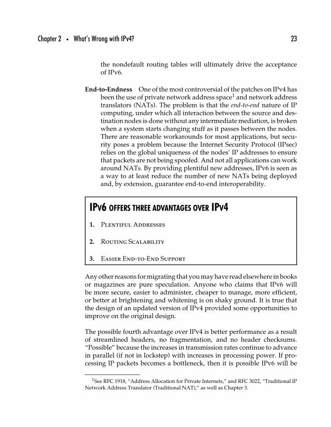
Chapter 2 • What’s Wrong with IPv4? 23
the nondefault routing tables will ultimately drive the acceptanceof IPv6.
End-to-Endness One of the most controversial of the patches on IPv4 hasbeen the use of private network address space1 and network addresstranslators (NATs). The problem is that the end-to-end nature of IPcomputing, under which all interaction between the source and des-tination nodes is done without any intermediate mediation, is brokenwhen a system starts changing stuff as it passes between the nodes.There are reasonable workarounds for most applications, but secu-rity poses a problem because the Internet Security Protocol (IPsec)relies on the global uniqueness of the nodes’ IP addresses to ensurethat packets are not being spoofed. And not all applications can workaround NATs. By providing plentiful new addresses, IPv6 is seen asa way to at least reduce the number of new NATs being deployedand, by extension, guarantee end-to-end interoperability.
IPV6 OFFERS THREE ADVANTAGES OVER IPV4
1. Plentiful Addresses
2. Routing Scalability
3. Easier End-to-End Support
Any other reasons for migrating that you may have read elsewhere in booksor magazines are pure speculation. Anyone who claims that IPv6 willbe more secure, easier to administer, cheaper to manage, more efficient,or better at brightening and whitening is on shaky ground. It is true thatthe design of an updated version of IPv4 provided some opportunities toimprove on the original design.
The possible fourth advantage over IPv4 is better performance as a resultof streamlined headers, no fragmentation, and no header checksums.“Possible” because the increases in transmission rates continue to advancein parallel (if not in lockstep) with increases in processing power. If pro-cessing IP packets becomes a bottleneck, then it is possible IPv6 will be
1See RFC 1918, “Address Allocation for Private Internets,” and RFC 3022, “Traditional IPNetwork Address Translator (Traditional NAT),” as well as Chapter 3.
24 Part One • Theory
required to speed things up. However, the performance advantage mayalso be solvable by upgrading system processing power.
Some of the issues that IPv6 promoters point to include the following.
Security The IPv6 specification mandates that IPv6-enabled nodessupport the IP Security Protocol (IPsec), thus making IPv6 nodesmore secure than IPv4 nodes. Although this appears to be a reason-able argument, IPsec is specified to work with both IPv4 and IPv6(and, presumably, other versions of IP to come in the future). IPsecis widely implemented under IPv4 and works the same under anyversion of IP.
Autoconfiguration IPv4 provides two mechanisms for configur-ing nodes: static configuration under which nodes are assignedIP addresses that they “own” and that don’t change over time;and dynamic configuration under which previously recognized andauthorized nodes are given IP addresses as they request them andthat may vary from session to session. Dynamic autoconfigurationfor IPv4 is sometimes referred to as stateful autoconfiguration becausesome status information about configured nodes must be main-tained (especially IEEE media access control or MAC addresses).IPv6 includes a feature called stateless autoconfiguration that lets usersplug-and-play in networks without prior contact with the networkadministrator. Although this is a powerful tool, the savings possi-ble from stateless autoconfiguration are hardly likely to convinceany CIO to underwrite the astronomical expense of adding IPv6 to alarge network.
Mobility Another very nice feature of IPv6 is its improved handling ofmobile IP nodes, but as with stateless autoconfiguration this maynot be enough to convince anyone to migrate to IPv6.
Performance IPv4 header options vary the size of the packet header andhave often been avoided or ignored in the past. The conventionalwisdom said these oddly sized (at least, odd relative to the standard20-octet header without options) packets would be shunted to theside by busy routers, only to be ignored until the router is caught upwith normal traffic. In practice, however, this has not been the caseand it has not deterred anyone from deploying IPsec over IPv4 forvirtual private networks (VPNs).
Chapter 2 • What’s Wrong with IPv4? 25
Some supporters point to improved performance in IPv6 routers overIPv4 routers due to differences in the way addresses and routes arehandled. In fact, this is probably one area where IPv6 will provide anadvantage—but this is still speculative inasmuch as no IPv6 networkhas as many routes as are found in the Internet’s backbone networks.
Cost IPv6 supporters have suggested that IPv6 will reduce costs in var-ious ways, including the reduced costs of administration, improvedsecurity, better performance, and lower cost for actual registrationof IP addresses. Any savings would have to be balanced against theadded costs of hiring and educating staff to support organizationsduring their addition of IPv6 connectivity, the costs of upgradingand replacing hardware and software, and the unexpected costs thatinvariably occur during such large projects. Perhaps IPv6 will reducecosts over the very long term, but that is far from clear.
These areas may indeed prove to be strong selling points for IPv6; but thereis currently no evidence that IPv6 will offer significant improvements overIPv4 in any of them.
However, IPv6 does provide relief for IPv4 networks groaning under ashortage of addresses, an explosion in routing tables, and concerns aboutend-to-end interoperability.
2.3 IPv4 Addressing Crisis
It never hurts to understand how things got to be the way they are,and IPv4’s address space is no exception. RFC 33, “New HOST-HOSTProtocol,” published in 1970, described an early precursor to the InternetProtocol that used only 8 bits for the host address but used 24 bits for the“user number,” which seems to have been used similarly to today’s trans-port layer ports. Such a small addressing space was just fine for 1970, giventhe relative handful of large mainframes available to the researchers.
By the time that IP took its modern form, network addresses ranged fromfairly short (8 bits) to fairly long (48 bits or longer). Only a year or so beforeRFC 791 describing this modern IPv4 was published, IPv4 used a 32-bitaddress that allocated only 8 bits to the network identifier—meaning thatno more than 256 networks could be linked in an RFC 760 IP Internet.
26 Part One • Theory
But RFC 790, “Assigned Numbers,” added the concept of networkclasses, permitting many little networks and a few very big ones. Quitepossibly the change was made to accommodate the potentially largenew networks built from the newest technologies: personal computersand Ethernet networks. In any case, the decision to go with a 32-bitaddress space was discussed in the 1978 document “The Catenet Model forInternetworking,” in which Vint Cerf2 described the immediate predeces-sor to modern IP, using 32-bit addresses. According to Cerf, the notion ofvariable-length addresses had been given serious consideration but wasrejected.
At one point, it appeared that addresses might be as long as 120 bitseach for source and destination. The overhead in the higher level pro-tocols for maintaining tables capable of dealing with the maximumpossible address sizes was considered excessive.3
At the same time, the first octet of the 32-bit addresses was used to identifythe network on which the source and destination hosts were connected,with the remaining 24 bits used to identify hosts on individual networks.This protocol could link no more than 256 different networks. This address-ing scheme was carried forward into the subsequent versions of the U.S.Department of Defense specifications for the Internet Protocol, includingRFC 760; only with the publication of the spec for the IPv4 we know andlove in RFC 791 was the notion of network classes introduced.
Figure 2–1 shows how the IP network classes were depicted in RFC 791. Theobjective was to provide some mechanism for aggregation similar to thatdescribed in IEN 46, “A PROPOSAL FOR ADDRESSING AND ROUTINGIN THE INTERNET,” by David Clark and Danny Cohen, published in1978.
Rather than insist on limiting the number of permitted networks in an Inter-net to only 256, the proposal suggested a future in which there were manymore than 256 networks connected to a single Internet, with some of themvery large and others much smaller. The report even pointed to poten-tial routing issues related to larger numbers of interconnected networks:When there are only 256 or fewer networks, all routers can easily managethe nondefault routing tables. But when there are many more networks,
2Internet Engineering Note (IEN) 48, published July 1978 and available at http://www.isi.edu/in-notes/ien/ien48.txt
3IEN 48, p. 7.
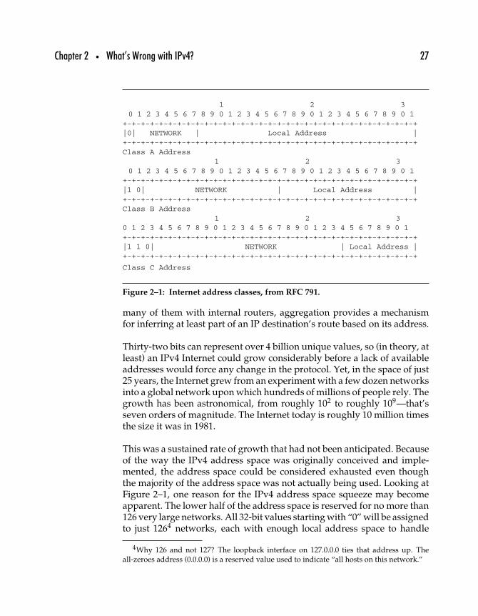
Chapter 2 • What’s Wrong with IPv4? 27
1 2 30 1 2 3 4 5 6 7 8 9 0 1 2 3 4 5 6 7 8 9 0 1 2 3 4 5 6 7 8 9 0 1
+-+-+-+-+-+-+-+-+-+-+-+-+-+-+-+-+-+-+-+-+-+-+-+-+-+-+-+-+-+-+-+-+|0| NETWORK | Local Address |
+-+-+-+-+-+-+-+-+-+-+-+-+-+-+-+-+-+-+-+-+-+-+-+-+-+-+-+-+-+-+-+-+
Class A Address1 2 3
0 1 2 3 4 5 6 7 8 9 0 1 2 3 4 5 6 7 8 9 0 1 2 3 4 5 6 7 8 9 0 1
+-+-+-+-+-+-+-+-+-+-+-+-+-+-+-+-+-+-+-+-+-+-+-+-+-+-+-+-+-+-+-+-+|1 0| NETWORK | Local Address |+-+-+-+-+-+-+-+-+-+-+-+-+-+-+-+-+-+-+-+-+-+-+-+-+-+-+-+-+-+-+-+-+Class B Address
1 2 30 1 2 3 4 5 6 7 8 9 0 1 2 3 4 5 6 7 8 9 0 1 2 3 4 5 6 7 8 9 0 1+-+-+-+-+-+-+-+-+-+-+-+-+-+-+-+-+-+-+-+-+-+-+-+-+-+-+-+-+-+-+-+-+|1 1 0| NETWORK | Local Address |
+-+-+-+-+-+-+-+-+-+-+-+-+-+-+-+-+-+-+-+-+-+-+-+-+-+-+-+-+-+-+-+-+
Class C Address
Figure 2–1: Internet address classes, from RFC 791.
many of them with internal routers, aggregation provides a mechanismfor inferring at least part of an IP destination’s route based on its address.
Thirty-two bits can represent over 4 billion unique values, so (in theory, atleast) an IPv4 Internet could grow considerably before a lack of availableaddresses would force any change in the protocol. Yet, in the space of just25 years, the Internet grew from an experiment with a few dozen networksinto a global network upon which hundreds of millions of people rely. Thegrowth has been astronomical, from roughly 102 to roughly 109—that’sseven orders of magnitude. The Internet today is roughly 10 million timesthe size it was in 1981.
This was a sustained rate of growth that had not been anticipated. Becauseof the way the IPv4 address space was originally conceived and imple-mented, the address space could be considered exhausted even thoughthe majority of the address space was not actually being used. Looking atFigure 2–1, one reason for the IPv4 address space squeeze may becomeapparent. The lower half of the address space is reserved for no more than126 very large networks. All 32-bit values starting with “0” will be assignedto just 1264 networks, each with enough local address space to handle
4Why 126 and not 127? The loopback interface on 127.0.0.0 ties that address up. Theall-zeroes address (0.0.0.0) is a reserved value used to indicate “all hosts on this network.”
28 Part One • Theory
224 nodes—no more than 16,777,216 globally unique addresses within eachClass A network.
Assume for the moment that this is the correct size network address allo-cation for very large organizations (of which, presumably, no more thanabout 100 or so were expected in the foreseeable future). Once you’vehanded out half of the Class A networks, you’ve pulled a full 25% of theentire address space out of circulation. Not only that, but even if thesehuge organizations each managed to field a million nodes on every one oftheir Class A nets, they would still be leaving each Class A network 94%vacant.
By 1991, the IETF had already begun actively looking “Towards the FutureInternet Architecture” in RFC 1287. In August 1990, during the VancouverInternet Engineering Task Force (IETF) meeting, attendees projected thatthe current rate of assignment would exhaust the Class B space by Marchof 1994.5 One result of that warning was the creation of the ClasslessInter-Domain Routing specification (CIDR) to replace the old Class A/B/C
categories6 with a more flexible system that increased the efficiency withwhich IP addresses could be allocated as well as reduced some of the bur-den on routers as the number of Class C networks exploded. However,attendees at the July 1994 Toronto meeting of the IETF predicted thateven with CIDR the IPv4 address space would still be exhausted sometimebetween 2005 and 2011.
Class A recipients include MIT, Apple Computer Inc., General ElectricCompany, Ford Motor Company, IBM, Xerox, Boeing Computer Services,and even pharmaceutical firms Eli Lilly and Company, and Merck andCompany, Inc. By May 1993, 38% of the Class A networks had been allo-cated, as well as 45% of the Class Bs; Class C was relatively untouched,with only 2% of the total space allocated (over 44,000 networks).7
Note: RFC 1715, “The H Ratio for Address Assignment Efficiency,” anInformational RFC published in 1994 by Christian Huitema, discussedthe creation of a ratio for determining how efficiently an address space isbeing used; the IPv4 space was even then rapidly approaching saturation.RFC 3194, “The Host-Density Ratio for Address Assignment Efficiency:An update on the H ratio,” revises that document with a refinement on
5RFC 1752, p. 3.6Class D was allocated for IP multicast addresses, and Class E was reserved for future use.7RFC 1466, “Guidelines for Management of IP Address Space,” p. 3.
Chapter 2 • What’s Wrong with IPv4? 29
the calculation of address density, reaching the conclusion that the IPv4address space continues to draw near to practical exhaustion. Both of thesedocuments provide excellent insight into the growth of the Internet andthe difficulty of efficiently using the IPv4 address space.
Class A networks accounted for half of the entire IPv4 address space; ClassB networks accounted for 25% and Class C networks for 12.5%. A full one-eighth of the address space was reserved for future use (with half of thatlater allocated for IP multicast addresses), right off the top. Most firms ofany size at all wanted Class B networks, and up until the early 1990s theycould justify one as long as they had several hundred hosts, more thancould fit in a single Class C network.
But Class B networks were almost as underutilized as the Class As, andwith only 16,383 available, fully 45% had been allocated. With over twomillion Class C nets available, 44,000 or so networks barely made a dent inthe total. Although the Class C allocation accounted for one-eighth of thetotal space, it was likely the most densely populated with hosts.
The year 1993 was pivotal: the U.S. government started the process ofprivatizing the Internet and making possible endless commercial possibil-ities. The land rush for IP address space (not to mention domain names)was about to begin, and IETF leaders knew that something drastic wouldhave to be done—but the problem was clear well before that.
The strategy for dealing with the address space crisis included two urgentmissions: First, design and deploy short-term, stopgap mechanisms thatcould be used to immediately and easily slow down the rapid rate of IPv4address consumption; and second, design and deploy a successor protocolthat would ultimately replace IPv4.
2.4 The IPv4 Routing Crisis
Although the imminent exhaustion of the IPv4 address space poses adevastating challenge, all the IP addresses in the world will not forestallanother potential showstopper: ballooning default routing tables. IPv6experts suggest that IPv4 routing scalability presents a more disturbingproblem than address space issues.
30 Part One • Theory
2.4.1 IPV4 INTERNET ROUTING
Routers determine the paths by which IPv4 packets arrive at theirdestinations. IP routing protocols may use dynamic mechanisms for main-taining information about available routes or may depend on staticallyconfigured tables, but any packets intended for destinations across anInternet backbone must eventually be routed through a nondefault router,8
a router that uses a master list of all known Internet routes. These routersrun Border Gateway Protocol version 4 (BGP-4), and the nondefault rout-ing table, referred to as the Routing Information Base (RIB), effectivelydescribes the topology of the Internet.
Each RIB entry describes a single route, a BGP route being defined as “aunit of information that pairs a destination with the attributes of a path tothat destination”,9 and as the number of entries in the RIB increases, so toodoes the complexity of the router’s task.
Most organizations use default routers, routers to which packets are sentif they are not destined for local delivery; these routers usually have theirown default routers to fall back on when handling nonlocal packets. TheBGP routers have no fall-back position: If a packet’s destination networkis not in the RIB, then the packet cannot be routed.
More networks means more routes. Classless Inter-Domain Routing(CIDR) was instituted in the early 1990s to address the problem of misalign-ment between the Internet address class structure. As will be discussed inChapter 3, CIDR allows more granularity in the assignment of networkaddress space.
2.4.2 IPV4 ROUTE AGGREGATION
Instead of being locked into assigning Class A (8-bit network addresswith 24-bit host addresses), Class B (16-bit network addresses, 16-bit hostaddresses), or Class C (24-bit network, 8-bit host addresses), CIDR allowedthe aggregation of Class C addresses to provide variable network addressallocations. In other words, with CIDR you can make allocations of anynumber of bits of network space, from a single Class A on up. A 23-bit
8Also known as exterior or BGP routers, the Border Gateway Protocol being the protocolused to route packets outside the local autonomous system.
9RFC 1771, “A Border Gateway Protocol 4 (BGP-4),” Yakov Rekhter and Tony Li, 1995.
Chapter 2 • What’s Wrong with IPv4? 31
allocation gives you the equivalent of two Class C networks; a 22-bitallocation gives you four Class C’s; and an 18-bit allocation gives youthe equivalent of 64 Class C networks (or the equivalent of one quarterof a Class B network). Instead of allocating network address space in onlythree sizes (Classes A, B, and C), CIDR supports up to 16 different allocationsizes, from a single Class C up to half of a Class A.
The happy result was that now a company with 400 nodes to support couldmanage without getting two separate Class C networks (adding complex-ity all around) or trying to get a Class B network address. Less salutarywas the resulting complexity added to the routing task: When all networkaddresses were 8, 16, or 24 bits long, routers could more easily identifythe network portion of an address just by looking at the first few bits ofeach address that indicate the network class. The network mask indicateshow much of the address is to be considered the network and how muchis reserved for local assignment to host addressing.
By the mid-1990s, the convention of expressing network addresses in theform of 192.168.0.0/22, where the first part represents an IP address andthe second part indicates how much of that address should be treated as anetwork address (the rest being reserved for host identification within thatnetwork), came about. That network includes the four Class C networks192.168.0.0, 192.168.1.0, 192.168.2.0, and 192.168.3.0.
This formulation allows routers to more quickly compare the relevantpieces of the address to its routing table.
Aggregation improves matters considerably, but the situation continuesto deteriorate as more of the IPv4 address space is assigned and putinto service. The more networks there are, the longer the routing listbecomes. And the longer the routing list, the longer (on average) itwill take the router to figure out where to send the packet. This is nota problem if you have 10, or 100, or 1000 networks to keep track of.But when you get into the higher numbers, as we have now withthe Internet, with backbone routers routinely carrying explicit routesfor over 110,000 different network addresses,10 routing can become anightmare.
10The Asia Pacific Network Information Centre (APNIC) maintains graphical reports on thestate of the BGP routing table at http://www.apnic.net/stats/bgp/; ARIN provides weeklyASCII reports on its mailing list at http://www.arin.net/mailinglists/rtma/.
32 Part One • Theory
2.4.3 IPV4 ROUTING SCALABILITY
RFC 3221, “Commentary on Inter-Domain Routing in the Internet,” pro-vides detailed discussion of the problem. As the routing table grew fromabout 60,000 entries in early 1999 to as many as 110,000 to120,000 entriesin 2002, the problem became more than simply handling the number ofentries. Geoff Huston, member of the Internet Architecture Board (IAB),cites several disturbing trends in RFC 3221, including the following.
• Growth in route announcements. Measured from January 1999through December 2000, the routing table increased at a rate of42% per year. Drops in the size of the table during 2001 can beattributed to instances where large numbers of more specificnetwork routes were aggregated into more general routes—forexample, when several contiguous Class C (/24) addresses areaggregated into a single /20 route.
• The 16-bit address space for autonomous system (AS) numbering,uniquely identifying discrete networks connected to the Inter-net, supports only 65,535 unique values. Although work is inprogress to increase the AS address space to 32-bits, Hustonreported over 10,000 autonomous systems across the Internetas of May 2001—then growing at a rate of 51% per year. Thisrate of growth would exhaust the 16-bit numbering space byAugust of 2005.
• IPv4 address consumption, measured strictly in terms of howmuch of the address space is being advertised as routable, hasbeen leveling off at a bit more than a quarter of the entireaddress space. Recent growth reported by Huston showed a7% annual increase in total address space consumption. Seenin light of the growth in both routes and ASs, this may indi-cate that most IP host growth is being hidden behind NATs.Alternatively, this data can be explained by organizationsapplying more specific policies on their exterior routing (i.e.,rather than using a single exterior router to mediate all Inter-net traffic, a multinational might have separate routers servingseparate ASs on different continents).
• Increasing granularity of routing entries. The amount of IPv4address space served within the average AS or the averageBGP route is dropping. An average route in September 2001served networks with total capacity of 10,700 IP addresses—aconsiderable drop from the average 16,000 in November 1999.The average AS in December 1999 had a capacity of 161,900 IP
Chapter 2 • What’s Wrong with IPv4? 33
addresses; by January 2001, the average had dropped to115,800. Increasingly detailed routing data is being pumpedinto the global routing domain, in part due to an increase incomplexity resulting from decreased reliance on hierarchicalrouting and increased use of multi-homing (linking to multiplenetworks).
• Prefix length distribution is increasing. The prefix length is a func-tion of the specificity of the network address; a /24 (24-bit)prefix is far more specific than a /8 (8-bit) prefix. Huston reportssignificant increases in the number of routes with a prefix lengthof /24 or more over recent years. This ties in with the increasedgranularity of routing entries.
• Exceptions to aggregations, or holes in an aggregation, occurwhen all of the networks within a particular prefix are routed inthe same way except for one or more subsets of the aggregatednetwork. Huston reports that 55% of the then-current routingtable entries were of this type, and over two-thirds of thoseroutes used distinct AS paths.
It is not even clear that IPv6 will solve all these problems: BGP is intendedfor exterior routing with IPv6 as well as IPv4, and fragmentation of aggre-gates can occur in the IPv6 address space as easily as in the IPv4 space.However, IPv6 does provide a better framework for aggregation than IPv4,as we’ll see later.
2.5 The End-to-End Problem
End-to-endness or transparency is what you get when endpoints in a networkare able to interoperate without any knowledge of the intervening networkand without any intervention or interference from intermediate systems.Transparency makes network application development much simpler, forone thing. The developer need only program an application to interfacewith the network cloud; when transparency is absent, the developer mustdeal with intermediate systems such as firewalls, NATs (network addresstranslators, see Chapter 3), and caching proxies. Security, in particular, issensitive to transparency.
NATs compromise end-to-endness because they modify inbound andoutbound packet headers. When packet headers are modified, networklayer security protocols become useless. There is no qualitative difference
34 Part One • Theory
between a NAT modifying packet headers on a secured packet and anattacker modifying packet headers in order to spoof (send packets fromone host that purport to be from another host) the recipient. Both appearto be attacks. In practice, the growth of the NAT-ed Internet has slowedgrowth of applications that require transparency.
The reason NATs modify packet headers is that the original headers, frominside the NAT-ed network, use the private (NET-10) addresses that are notunique across the global Internet. Using globally unique addresses meansthat there is an unambiguous way to address each and every network node,no matter where the node is. Once you start numbering nodes ambigu-ously, NATs and other intermediary systems must be used to preventconfusion and allow nodes with the same addresses to communicate.
Transparency guarantees that communicating nodes communicatedirectly, no matter what happens within the network cloud. When a NATor other intermediate system fails, the sessions it mediates also fail. Thereis no easy way for hosts communicating through that NAT to route aroundthe failure, as there would be in the event that some intermediate routerfailed.
End-to-end interoperability was a key design feature of the original Inter-net. As the IPv4 address pool dries up and more networks rely on NAT,proxies, and other gateway devices, the nature of the Internet is changing.Rather than being a robust network, able to route around failures, today’sInternet is becoming less reliable while performance degrades. Rather thanbeing a scalable network, capable of supporting new applications with-out requiring network infrastructure upgrades, today’s Internet tends tolimit applications to piggybacking on Web services—and at the same time,changes in the network infrastructure sometimes necessitate changes innode software and configuration.
RFC 3424, “IAB Considerations for UNilateral Self-Address Fixing(UNSAF) Across Network Address Translation,” discusses the issuesraised when network traffic must traverse multiple NAT domains,particularly as they relate to network transparency.
As we’ll see later on, IPv6 eliminates NAT and replaces it with a con-cept of link-local and site-local network addresses. These local addressescan be thought of (for now) in the same way as telephone extensionsmight be: Callers from outside may have to dial a country code, areacode, exchange, and extension, while callers from inside a single office
Chapter 2 • What’s Wrong with IPv4? 35
(link-local) or organization (site-local) can reach the same destination bydialing an extension.
It should be noted that the loss of transparency is only a symptom ofthe disease—if the Internet had not grown so fast and so large, it wouldstill be a transparent network with end-to-end interoperability the norm.The threat to transparency is due to the same growth that has causedthe shortage in IPv4 addresses and the increasing reliance on NAT as aconservation tool.
2.6 Summary
There are many reasons cited by IPv6 supporters for migrating from IPv4to IPv6, from general ones—such as reduced costs of operation, improvedperformance, and increased security—to specific ones—such as supportfor some “killer app” like mobile IP or plug-and-play interoperability.However, all of them can be directly linked either to the huge demandfor and dwindling supply of IPv4 network addresses or to the problemsassociated with creating a scalable routing infrastructure. The next chapterillustrates the approaches over the past decades as short-term fixes for theIPv4 address shortage; Part II will show how IPv6 resolves these problemsmore permanently.

This Page Intentionally Left Blank
33
Patching IPv4
Large networks with many endpoints, such as the Internet, are economi-cally viable only if the cost of maintaining those endpoints is manageable.Network upgrades that require modification of the endpoints are to beavoided at all costs, if only because of the difficulty of tracking downevery node. Backward compatibility in the Internet is mandatory to avoidthe cost of maintaining IP implementations on obsolete or custom-builtcomputers. Even if all nodes ran the same operating system, attempting toupgrade all of them at once with network stack updates is a daunting task.
Protocol designers, whether they’ve designed protocols for transmission ofelectricity, telecommunications, or the Internet, must live with the shape oftheir networks. That means a minimal number of options for the designersof electrical appliance plugs, telephone cabling, or Internet applications.If the basic interface is not suitable, the application must be adapted tothe interface rather than vice versa. To the extent that changes have beenmade to IPv4 over the years, most of the changes have been in the networkrouting infrastructure rather than in the way IPv4 has been implementedon network endpoints.
37
38 Part One • Theory
In this chapter, we examine four basic strategies that have been used toallow IPv4 to cope with its unprecedented growth and then look at howthose strategies have been implemented.
Many of the key features of today’s Internet landscape owe their origins toinitiatives intended to extend the usable lifetime of IPv4. These measuresfall into one or another of these four categories of responses to shortagesof limited resources.
Rationing When a shortage in a particular resource becomes apparent,rationing is often the first response. Survivors on a lifeboat are welladvised to identify all their food and water resources and impose areasonable rationing regime on all. Once it became clear that IPv4addresses would soon be in short supply, the IETF recommendedthat regional Internet registries (RIRs) imposed more stringent con-trols over assignment of large blocks of IP addresses. Until 1992,organizations could relatively easily justify a Class B network allo-cation as long as they had (or expected to have) more than a fewhundred hosts. Since then the IETF and RIRs have repeatedly raisedthe bar for justification of IPv4 assignments.
Rethinking Conservation efforts are the result of rethinking the wayresources are used. Carpools are one response to gasoline shortages;people must rethink the way they solve the problem of getting toand from their workplaces. The IETF, network managers, and ven-dors have all applied their creative powers to rethinking their use ofIP addresses and coming up with ways to conserve the resource.These efforts yielded the use of subnets,1 Classless Inter-DomainRouting (CIDR), the Dynamic Host Configuration Protocol (DHCP),and several versions of network address translation (NAT).
Recycling The allocation of IPv4 network addresses by class left a legacyof vastly underutilized Class A networks. The IETF put out a callto organizations with unused or underused network addresses toreturn them for reuse in 1996,2 many cable broadband providersuse such space for their home-based customers. Recycling addresses
1Arguably, the use of subnetting was instituted more as a way to improve routingefficiency, but routing and address space exhaustion are two faces of the same coin.
2In RFC 1917 (BCP 4), “An Appeal to the Internet Community to Return Unused IPNetworks (Prefixes) to the IANA.”
Chapter 3 • Patching IPv4 39
in this way can never offer more than a marginal improvement inthe address shortage situation. One potential problem with recyclingaddresses derives from the practice of hard-coding IP addresses intoapplications, rather than relying on DNS. If clients always use DNS toreach host hostname.example.com, they’ll always reach that host; if theyuse an IP address that someday is recycled, the application will fail.This problem should be insignificant unless developers try to bypassDNS to improve performance at the cost of standards compliance.
Replacement Usually, a piece of infrastructure is replaced entirely onlyafter all other remedies are exhausted. It is just too expensive andcumbersome to pull out the old and put in the new and make sureit all works. However, IPv6 is, ultimately, a replacement for IPv4.We’ll touch on options, other than IPv6, that have been proposed toreplace IPv4.
The rest of this chapter introduces the most important responses to theIPv4 address space shortage made by the Internet community. It is tempt-ing to put these efforts in chronological order, but doing so can be difficult.For example, not only was Classless Inter-Domain Routing (CIDR) devel-oped roughly in parallel with new rationing policies, but CIDR made suchrationing more feasible.
3.1 Network Address Rationing
When demand for a necessity increases suddenly but supply stays inflex-ibly the same with no change in sight, rationing kicks in. This was oneof the first steps taken to address address space shortage, and it resultedin the creation of the three regional Internet registries (RIRs), which wereadvised to clamp down on who gets IP address space and who doesn’t.Published in 1990, RFC 1174, “IAB Recommended Policy on DistributingInternet Identifier Assignment and IAB Recommended Policy Change toInternet ‘Connected’ Status,” called for the Internet registry (IR) functionto be delegated by the IANA, so as to better manage distribution of Internetaddresses.
Further modifications—in particular the call for creation of RegionalInternet Registries (RIRs)—followed in 1992, when RFC 1366, “Guidelinesfor Management of IP Address Space,” was published. RFC 1367,“Schedule for IP Address Space Management Guidelines,” was published
40 Part One • Theory
at the same time and defined a schedule as well as a set of guidelines foraddress allocation.
RFC 1366 recommended that the remaining Class A network addresses (77)be assigned only by the IANA and that all Class A network addressesover 64/8 be frozen. At the time, it was expected that no Class Aaddresses would be granted to anyone, but if an organization wanted one,they would have to provide technical details of their proposed networkin their petition. As for Class B addresses, the recommendation was togrant them only to organizations that required at least 32 subnets and over4096 nodes.
Prior to the early 1990s, network address assignment was done on a lessformal basis; subsequent to the implementation of the RIRs and the addressspace management guidelines, address space allocation followed a moreformal process under which requesting organizations were required tojustify their requests. RIRs also currently assess fees for the use of net-work address space, adding a market-driven form of rationing. Unlike theearly days, holders of large portions of the network address space are nowunder increasing financial pressure to either use their addresses or tradethem in.
3.2 IP Subnetting
The original standard for IPv4 as defined in RFC 791, “Internet Protocol:DARPA Internet Program Protocol Specification,” doesn’t mention theterm subnet. As originally defined, the Internet was to be a two-level hier-archy, in which individual nodes (the bottom level) were connected tovarious networks (the upper level). The Internet was a classful network,with smallish networks to be assigned Class C network addresses, largenetworks assigned Class B network addresses, and the very largestnetworks assigned Class A network addresses.
It wasn’t long after RFC 791 was implemented that the flaws in this address-ing approach became evident. Networks that used different media neededto be treated differently; not all nodes within a network would fit on a sin-gle cable; organizations spread across large physical plants often requiredmore than one physical LAN; and popular networking technologies suchas Ethernet placed limits on the number of nodes on the same network.It was all very well to allow Class B networks 16 bits of address space
Chapter 3 • Patching IPv4 41
and over 65,000 uniquely addressable nodes, but the LAN technologiesmost often used (Ethernet and Token Ring) limited the practical numberof nodes on a network to well under 1000.
The solution was to provide a way to subdivide Internet addresses in sucha way that a large network could be made to appear to consist of severalsmaller subnetworks or subnets. As originally defined in RFC 791, IP nodesinterpreted IP addresses by comparing the higher-order bits to determinewhat address class the address belonged to. Class A addresses have theirhighest-order bit set to 0 (first octet is in the range of 0 to 127), Class Baddresses have their two highest-order bits set to 10 (first octet is in therange of 128 to 191), and Class C addresses have their three highest orderbits set to 110 (first octet is in the range of 192 to 223).
Early IP routing depended on nodes interpreting IP addresses classfullyso that routers would consider only the first octet of an address as the net-work and treat the rest of the address as a unique identifier for nodeson that network. Clearly this approach could complicate matters forClass A networks with many thousands of nodes, because routers withinthe organization would be required to keep track of the locations of all ofthem.
By 1984, when RFC 917, “Internet Subnets,” was published, the two-levelapproach to internetworking was proving insufficient. RFC 917 docu-mented an approach that was being taken within larger networks, whereClass A and Class B networks were using artificial subdivisions to improveinternal routing. Published a year later, RFC 950, “Internet Standard Sub-netting Procedure,” codified an approach to subnetting based on RFC 917.
Although Internet addresses are not, strictly speaking, hierarchical, theyare interpreted as if they are. In other words, addresses sharing somenumber of higher-order bits can be considered to be on the same network.Thus, as just noted, classful network addresses sharing the first three octets,with the first octet in the range of 192 to 223, are treated as being on thesame Class C network; network addresses sharing a first octet in the rangeof 0 to 127 are treated as being on the same Class A network. Figure 3–1shows how routing occurs to a typical Class B address: 172.16.0.0. Theexternal router accepts all packets destined for any node with an addressstarting with 172.16.x.x.
The practice of subnetting allows the owner of a Class A address to partitionthat address space and create logical subnets. A typical use of subnetting,
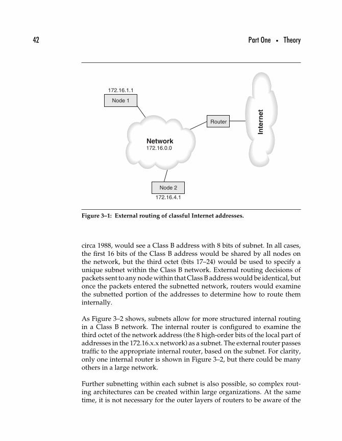
42 Part One • Theory
Network
Router
Node 1
172.16.1.1
Node 2
172.16.4.1
172.16.0.0
Inte
rnet
Figure 3–1: External routing of classful Internet addresses.
circa 1988, would see a Class B address with 8 bits of subnet. In all cases,the first 16 bits of the Class B address would be shared by all nodes onthe network, but the third octet (bits 17–24) would be used to specify aunique subnet within the Class B network. External routing decisions ofpackets sent to any node within that Class B address would be identical, butonce the packets entered the subnetted network, routers would examinethe subnetted portion of the addresses to determine how to route theminternally.
As Figure 3–2 shows, subnets allow for more structured internal routingin a Class B network. The internal router is configured to examine thethird octet of the network address (the 8 high-order bits of the local part ofaddresses in the 172.16.x.x network) as a subnet. The external router passestraffic to the appropriate internal router, based on the subnet. For clarity,only one internal router is shown in Figure 3–2, but there could be manyothers in a large network.
Further subnetting within each subnet is also possible, so complex rout-ing architectures can be created within large organizations. At the sametime, it is not necessary for the outer layers of routers to be aware of the
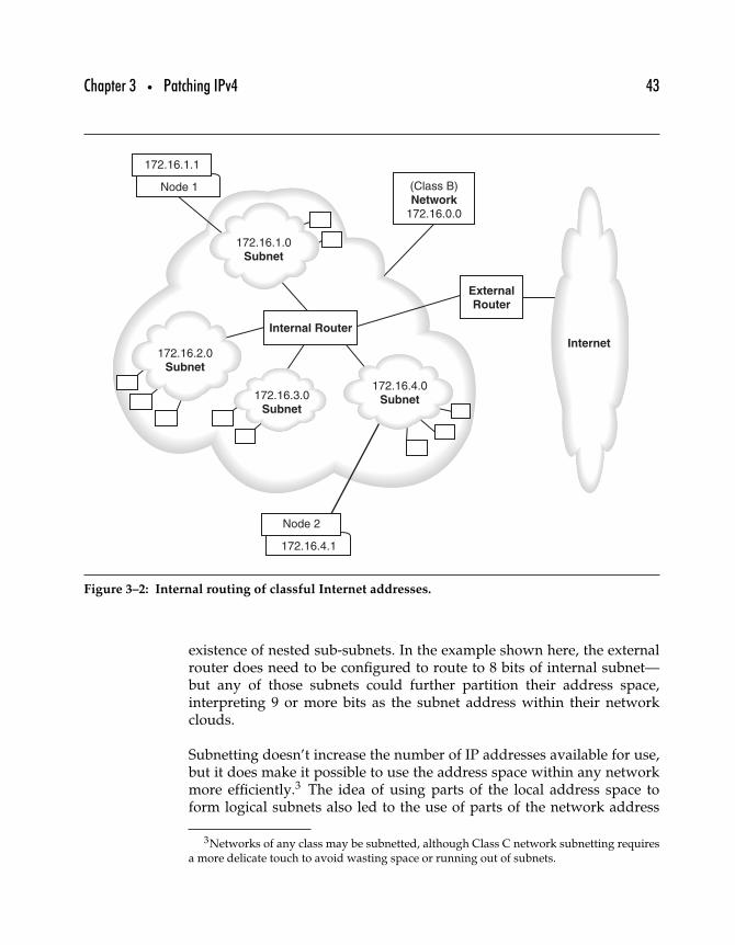
Chapter 3 • Patching IPv4 43
(Class B)Network
172.16.0.0
Internal Router
ExternalRouter
Internet
172.16.1.0Subnet
172.16.2.0Subnet
Node 2
172.16.4.1
172.16.1.1
Node 1
172.16.4.0Subnet172.16.3.0
Subnet
Figure 3–2: Internal routing of classful Internet addresses.
existence of nested sub-subnets. In the example shown here, the externalrouter does need to be configured to route to 8 bits of internal subnet—but any of those subnets could further partition their address space,interpreting 9 or more bits as the subnet address within their networkclouds.
Subnetting doesn’t increase the number of IP addresses available for use,but it does make it possible to use the address space within any networkmore efficiently.3 The idea of using parts of the local address space toform logical subnets also led to the use of parts of the network address
3Networks of any class may be subnetted, although Class C network subnetting requiresa more delicate touch to avoid wasting space or running out of subnets.
44 Part One • Theory
space to combine Class C networks to simplify networking in organiza-tions too large for a single Class C but not large enough for a Class Bnetwork.
3.3 Classless Inter-Domain Routing (CIDR)
When most computers in use were mainframes costing at least tens or hun-dreds of thousands of dollars, Class C networks capable of supporting upto 254 uniquely addressed nodes were originally viewed as sufficient forall but the largest corporations. But starting in the early 1980s the growthin popularity of networked PCs within even moderate-sized organiza-tions meant that the concept of “large-” and “moderate-sized” networkschanged radically. A Class C network could easily accommodate mostsmaller businesses, but demand for Class B addresses skyrocketed throughthe 1980s, and the small supply (just over 16,000) meant that rationing ofClass B addresses started very early.
During the early 1990s, experts were concerned about rapid growth innondefault routing tables, and RFC 1519 includes a discussion of the impactCIDR could have on nondefault routing tables. For example, the authorscite a backbone router (on NSFNET) with approximately 4700 routing tableentries as of January 1992—a number that grew to roughly 8500 routes byDecember 1992.
Subnetting was one way to increase efficiency in the allocation of networkaddresses within large networks by partitioning large chunks of networkaddress space. By the time the Class B network supply was clearly beingrapidly depeleted, Class C networks were (and still are, for the most part)plentiful. What would happen if small chunks of network address space—for example, contiguous Class C networks—were aggregated together andtreated as if they were a single network?
The result is called Classless Inter-Domain Routing (CIDR), sometimes calledsupernetting (in contrast to subnetting). CIDR has become a key mechanismfor moderating the effects of Internet growth, and it is defined in RFC1519, “Class Inter-Domain Routing (CIDR): an Address Assignment andAggregation Strategy.” Rather than specifying some number of bits ofsubnet to be considered as the network part of an address in addition tothe official, classful, network address, CIDR masks specify how many bits
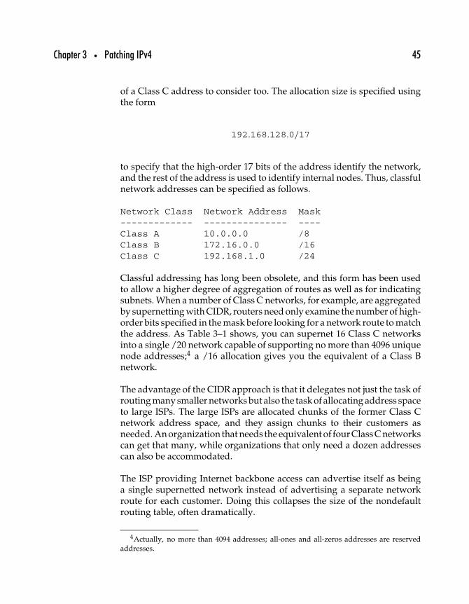
Chapter 3 • Patching IPv4 45
of a Class C address to consider too. The allocation size is specified usingthe form
192.168.128.0/17
to specify that the high-order 17 bits of the address identify the network,and the rest of the address is used to identify internal nodes. Thus, classfulnetwork addresses can be specified as follows.
Network Class Network Address Mask------------- --------------- ----Class A 10.0.0.0 /8Class B 172.16.0.0 /16Class C 192.168.1.0 /24
Classful addressing has long been obsolete, and this form has been usedto allow a higher degree of aggregation of routes as well as for indicatingsubnets. When a number of Class C networks, for example, are aggregatedby supernetting with CIDR, routers need only examine the number of high-order bits specified in the mask before looking for a network route to matchthe address. As Table 3–1 shows, you can supernet 16 Class C networksinto a single /20 network capable of supporting no more than 4096 uniquenode addresses;4 a /16 allocation gives you the equivalent of a Class Bnetwork.
The advantage of the CIDR approach is that it delegates not just the task ofrouting many smaller networks but also the task of allocating address spaceto large ISPs. The large ISPs are allocated chunks of the former Class Cnetwork address space, and they assign chunks to their customers asneeded. An organization that needs the equivalent of four Class C networkscan get that many, while organizations that only need a dozen addressescan also be accommodated.
The ISP providing Internet backbone access can advertise itself as beinga single supernetted network instead of advertising a separate networkroute for each customer. Doing this collapses the size of the nondefaultrouting table, often dramatically.
4Actually, no more than 4094 addresses; all-ones and all-zeros addresses are reservedaddresses.
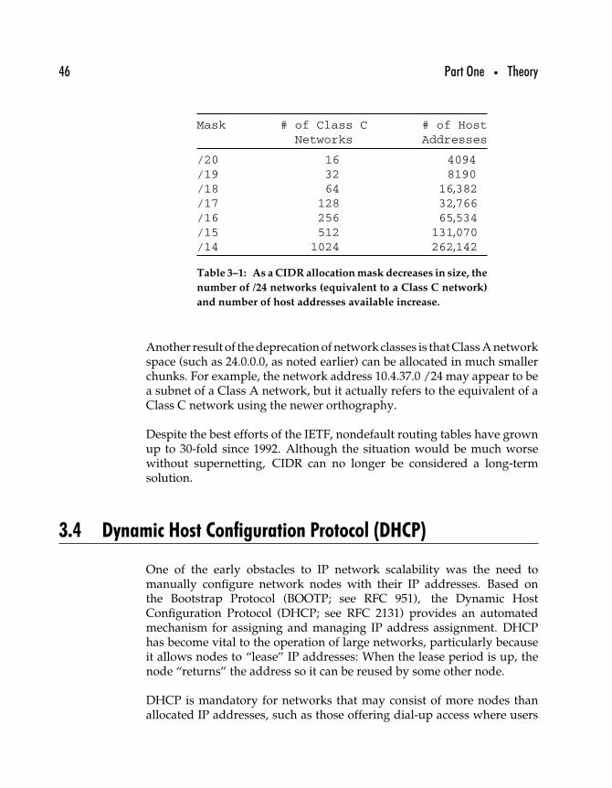
46 Part One • Theory
Mask # of Class C # of HostNetworks Addresses
/20 16 4094/19 32 8190/18 64 16,382/17 128 32,766/16 256 65,534/15 512 131,070/14 1024 262,142
Table 3–1: As a CIDR allocation mask decreases in size, the
number of /24 networks (equivalent to a Class C network)
and number of host addresses available increase.
Another result of the deprecation of network classes is that Class A networkspace (such as 24.0.0.0, as noted earlier) can be allocated in much smallerchunks. For example, the network address 10.4.37.0 /24 may appear to bea subnet of a Class A network, but it actually refers to the equivalent of aClass C network using the newer orthography.
Despite the best efforts of the IETF, nondefault routing tables have grownup to 30-fold since 1992. Although the situation would be much worsewithout supernetting, CIDR can no longer be considered a long-termsolution.
3.4 Dynamic Host Configuration Protocol (DHCP)
One of the early obstacles to IP network scalability was the need tomanually configure network nodes with their IP addresses. Based onthe Bootstrap Protocol (BOOTP; see RFC 951), the Dynamic HostConfiguration Protocol (DHCP; see RFC 2131) provides an automatedmechanism for assigning and managing IP address assignment. DHCPhas become vital to the operation of large networks, particularly becauseit allows nodes to “lease” IP addresses: When the lease period is up, thenode “returns” the address so it can be reused by some other node.
DHCP is mandatory for networks that may consist of more nodes thanallocated IP addresses, such as those offering dial-up access where users
Chapter 3 • Patching IPv4 47
log on and off the network regularly. For example, if an ISP offers dial-upaccess to its Class C network with DHCP, and the average user connectsfor only two hours a day (distributed evenly, an admittedly unreasonableexpectation in real life), the ISP could support roughly 3000 users with only254 IP addresses.
Although DHCP is also an important tool for providers of “always-on”services such as broadband Internet connectivity, it does not do anythingto improve address utilization efficiency in those networks. Every userwhose computer is always connected to the network ties up a single IPaddress; there can be no sharing of addresses as with the more fleetingconnections common to dial-up users.
3.5 Recycling Unused IP Networks
RFC 1917 (BCP 4) “An Appeal to the Internet Community to Return UnusedIP Networks (Prefixes) to the IANA,” demonstrates a slightly differentapproach to shortage: recycling. Many large chunks of the IPv4 addressspace have been allocated to organizations that no longer exist or that couldnever use all of their allocations. Several of these pieces have been recov-ered, since their previous owners have done the right thing and allowedsome or all of their allocation to revert to the registries.
Over the years, Class A networks have been returned to IANA, some ofwhich have simply changed hands (in the 1980s), but mostly as they comein, they are reserved. Some networks of note include the following.
10/8: originally assigned to DARPANET31/8: originally assigned to University of California36/8: originally assigned to Stanford University49/8: Joint Technical Command50/8: Joint Technical Command
The 024/8 network, at one time administered by Bolt, Beranek, and New-man (the firm responsible for much of the original work on the Internet),was reregistered to the IANA in 1995 and has been recovered for use asthe “ARIN Cable Block.” North American cable network ISPs are now ableto assign numbers out of the subnetted 024/8 block, demonstrating boththe use of subnetted Class A network addresses and successful recyclingof underused addresses.
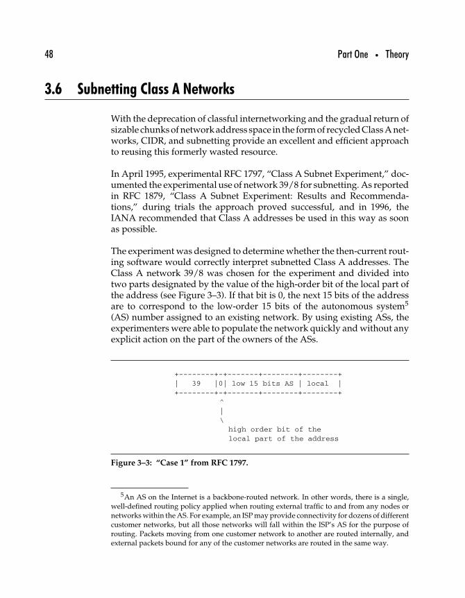
48 Part One • Theory
3.6 Subnetting Class A Networks
With the deprecation of classful internetworking and the gradual return ofsizable chunks of network address space in the form of recycled Class A net-works, CIDR, and subnetting provide an excellent and efficient approachto reusing this formerly wasted resource.
In April 1995, experimental RFC 1797, “Class A Subnet Experiment,” doc-umented the experimental use of network 39/8 for subnetting. As reportedin RFC 1879, “Class A Subnet Experiment: Results and Recommenda-tions,” during trials the approach proved successful, and in 1996, theIANA recommended that Class A addresses be used in this way as soonas possible.
The experiment was designed to determine whether the then-current rout-ing software would correctly interpret subnetted Class A addresses. TheClass A network 39/8 was chosen for the experiment and divided intotwo parts designated by the value of the high-order bit of the local part ofthe address (see Figure 3–3). If that bit is 0, the next 15 bits of the addressare to correspond to the low-order 15 bits of the autonomous system5
(AS) number assigned to an existing network. By using existing ASs, theexperimenters were able to populate the network quickly and without anyexplicit action on the part of the owners of the ASs.
+--------+-+-------+--------+--------+| 39 |0| low 15 bits AS | local |+--------+-+-------+--------+--------+
^|\
high order bit of thelocal part of the address
Figure 3–3: “Case 1” from RFC 1797.
5An AS on the Internet is a backbone-routed network. In other words, there is a single,well-defined routing policy applied when routing external traffic to and from any nodes ornetworks within the AS. For example, an ISP may provide connectivity for dozens of differentcustomer networks, but all those networks will fall within the ISP’s AS for the purpose ofrouting. Packets moving from one customer network to another are routed internally, andexternal packets bound for any of the customer networks are routed in the same way.
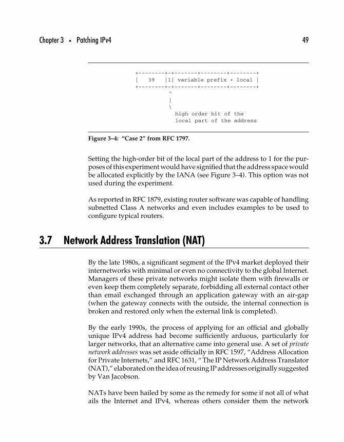
Chapter 3 • Patching IPv4 49
+--------+-+-------+--------+--------+| 39 |1| variable prefix + local |+--------+-+-------+--------+--------+
^|\
high order bit of thelocal part of the address
Figure 3–4: “Case 2” from RFC 1797.
Setting the high-order bit of the local part of the address to 1 for the pur-poses of this experiment would have signified that the address space wouldbe allocated explicitly by the IANA (see Figure 3–4). This option was notused during the experiment.
As reported in RFC 1879, existing router software was capable of handlingsubnetted Class A networks and even includes examples to be used toconfigure typical routers.
3.7 Network Address Translation (NAT)
By the late 1980s, a significant segment of the IPv4 market deployed theirinternetworks with minimal or even no connectivity to the global Internet.Managers of these private networks might isolate them with firewalls oreven keep them completely separate, forbidding all external contact otherthan email exchanged through an application gateway with an air-gap(when the gateway connects with the outside, the internal connection isbroken and restored only when the external link is completed).
By the early 1990s, the process of applying for an official and globallyunique IPv4 address had become sufficiently arduous, particularly forlarger networks, that an alternative came into general use. A set of privatenetwork addresses was set aside officially in RFC 1597, “Address Allocationfor Private Internets,” and RFC 1631, “ The IP Network Address Translator(NAT),” elaborated on the idea of reusing IP addresses originally suggestedby Van Jacobson.
NATs have been hailed by some as the remedy for some if not all of whatails the Internet and IPv4, whereas others consider them the network
50 Part One • Theory
equivalent of kudzu: a hardy and fast-growing plant that was imported toparts of the southeast United States to alleviate soil erosion earlier in the20th century. Despite the lofty goals, kudzu turned out to be a superweed,and with no natural checks on its growth, kudzu has displaced almosteverything in its path. It grows so quickly that visitors may be cautionednot to nap on the porch unless they want to wake up tangled in the vinesthat are known to grow as much as a foot or more in a day.
3.7.1 REASONS FOR NAT
There are times when it is preferable for packets not to be forwardeddirectly from inside an internetwork. Network address translation (NAT)is an approach used for those instances. The two most commonly citedreasons for using NAT are for security and to map a large network onto asmall IP address space.
Perhaps more common is the use of NATs to preserve IP address space.As the IP address space is depleted, more and more organizations havebeen denied Class B or even Class C networks. One solution is to usethe private network space allocation to set up a private network with aClass A, B, or C network address. Routers within the private networkcan route packets within the network, and packets destined for the globalInternet are passed through a network address translator that acts on behalfof the internal systems when interacting with Internet hosts.
NATs were originally introduced to help alleviate network address allo-cation shortages so organizations could build their intranets as large asthey wanted without going through a lengthy and largely pointless pro-cess of trying to get an appropriate allocation from a service provideror regional registry. In the meantime, they have propagated across theInternet and have been incorporated into networks as simple and small assingle-system home networks and as complicated as any that requires afull Class A–equivalent network address.
Much of the controversy over the need for IPv6 revolves around the ques-tion of whether NATs make things better or worse. In the meantime, peoplecontinue to deploy private networks and NAT boxes of various types,while the IETF continues to publish RFCs that attempt to clarify mattersor even to solve the entire problem with ever more end-to-end friendlyversions of NAT.
Chapter 3 • Patching IPv4 51
3.7.2 NAT BASICS
Whether you call it a network address translator or NAT box, a NAT acts asan old-fashioned telephone operator, mediating all inbound and outboundtraffic through a switchboard. Inside the NAT, private IP addresses areused for all internal communications; outside the NAT, standard globalInternet addresses are used. The NAT box has one interface on the internalnetwork with a private IP address and another interface on the globalInternet with a globally unique IP address.
When a node in the private network wants to send a packet to a nodeon the outside, it creates a packet with its own private IP address as thesource and the remote node’s IP address as the destination. Followingthe rules of IP routing, the privately addressed node will determine thatthe destination is on a different network and therefore the packet must besent to a router.
NAT boxes often double as routers, to both reduce costs and simplifytheir function. When the NAT box/router receives the outbound packet, ittakes that packet and rewrites it so that the original source address (whichwill not be usable outside the private network) is replaced with the NATbox’s own global Internet IP address. The packet is then sent along to itsdestination. The destination node perceives the packet as originating withthe NAT box.
Any response to the packet is addressed to the NAT box, which keeps trackof the internal hosts for which it is serving as go-between. When a packetcomes in, the NAT box accepts it, repackages the packet for delivery onthe private network, and sends it along to the original source node.
Basic NAT poses difficulties when it is necessary to host Internet serverswithin the private network: There is only one well-known port for eachservice available on the NAT box, which makes it difficult when more thanone Web server is inside the network. All NAT boxes map the ports aswell as IP addresses from the external session onto appropriate ports andaddresses for the internal network.
There is another problem: dealing with a network in which more thanone server responding to requests on the same well-known port. Whenthere is a single NAT box in front of those servers, the Network AddressTranslation/Port Translation (NAT/PT) adds a port translator moduleonto the NAT box so it can differentiate requests to the different servers.
52 Part One • Theory
Various other developments and proposals to make NAT friendlier havebeen considered and implemented over the years, more or less successfully.Some indication of these developments can be inferred from the quantityand titles of the NAT-related RFCs listed later in this section.
3.7.3 NAT ISSUES AND MISCONCEPTIONS
Rather than attempting to cover NATs exhaustively here, we list relevantand current RFCs after a short list of NAT-related problems and concerns.
NATs break IPsec IPsec (see Chapter 6) is not made any easier by NATs,but it is still often usable. When packets from inside the privatenetwork are tunneled securely with IPsec (that is, IPsec secures pack-ets, which are then encapsulated in unsecured IP packets), NATsdo not modify the tunneled packets and thus do not harm them.However, end-to-end, untunneled authenticated packets cannot becarried intact across a NAT. Another area where NATs affect IPsecis in the reuse of the private IP addresses. Nonunique addresses canresult in confusion, at the least, especially when security informationis linked with IP addresses.
NATs complicate organization change NATs provide a limited numberof options for network addressing to the network designer. The oddsof having address space collisions are great. Most people naturallyassign the network address 192.168.0.0 to their small private net-work and assign hosts to IP addresses starting at 192.168.0.1 andincreasing by one. When two such networks are merged, pandemo-nium ensues as networked systems stop working and network engi-neers rush madly to renumber at least one of the original networks.
NATs break applications Most NAT-related problems with Internetapplications are manageable and have been or will be imminentlyresolved through one fix or another. One notorious applicationbroken by NAT so far has been the multiplayer game, Quake. Morerelevant to corporate network administrators, FTP was originallyspecified to allow inbound connections from servers to clients, andin so doing, has broken in that type of implementation used acrossa NAT.
NATs improve security IP routers are not supposed to forward data-grams addressed in the private address ranges. If a backbone routerreceives a datagram bound for one of these addresses, it is sup-posed to drop it. However, these addresses can be used within an
Chapter 3 • Patching IPv4 53
organizational internetwork. Allowing outsiders access to informa-tion about a network’s host names and IP addresses can expose thatnetwork to security risks. Some network administrators prefer toput their entire network behind a network address translator, whichaccepts datagrams from outside the internetwork and translates themto the NAT addresses used by the hosts inside the private network.However, NATs can often open more holes than they close, especiallywhen routers are not properly configured to drop packets addressedfrom or to private networks—or when routers can be reconfigured byan attacker. Likewise, network administrators typically use a fairlypredictable set of addresses for NAT-ed networks, so attackers mayhave an easier time locating sensitive systems.
NATs are easy Solid-state NAT/router/hub/firewall/Internet appli-ances capable of linking small numbers of systems in home office/small office environments are widely available at reasonable prices.These devices often include a Dynamic Host Configuration Protocol(DHCP) server, making the NAT a plug-and-play as well as aninstall-and-forget proposition.
NATs are complicated Deploying NATs in complex Internet environ-ments, can generate network administration nightmares, particularlyif there are other NATs already in the network (such as in branchoffices). Some engineers have reported that the actual cost of main-taining such a network far exceeds the cost of paying for enoughglobally unique Internet address space to serve the organization’sneeds—if that address space were available.
All NATs are pretty much the same As already noted, there are basicnetwork address-only translators as well as network and port trans-lators; a NAT box may be an inexpensive solid-state appliance, a pieceof software running on a PC, or a dedicated router. There are manydifferent types of NATs, and there are many of each type already inuse throughout the world.
3.7.4 NAT AND RELATED RFCS
As of 2002, these RFCs had been published about NAT and the issuesrelated to its use. A good place to start is RFC 3022, “Traditional IPNetwork Address Translator (Traditional NAT),” defining traditionalNAT functions. RFC 2663, “IP Network Address Translator (NAT)

54 Part One • Theory
Terminology and Considerations,” is another good basis for discussion ofNAT issues, as are RFC 3027, “Protocol Complications with the IP NetworkAddress Translator,” and RFC 2993 “Architectural Implications of NAT.”
RFC 1631 The IP Network Address Translator (NAT)INFORMATIONAL (obsoleted by RFC 3022)
RFC 2391 Load Sharing Using IP Network Address Translation (LSNAT)INFORMATIONAL
RFC 2663 IP Network Address Translator (NAT) Terminology andConsiderations INFORMATIONAL
RFC 2709 Security Model with Tunnel-Mode IPsec for NAT DomainsINFORMATIONAL
RFC 2766 Network Address Translation—Protocol Translation(NAT-PT) PROPOSED STANDARD
RFC 2962 An SNMP Application Level Gateway for Payload AddressTranslation INFORMATIONAL
RFC 2993 Architectural Implications of NAT INFORMATIONALRFC 3022 Traditional IP Network Address Translator (Traditional NAT)
INFORMATIONALRFC 3027 Protocol Complications with the IP Network Address
Translator INFORMATIONALRFC 3102 Realm Specific IP: Framework EXPERIMENTALRFC 3103 Realm Specific IP: Protocol Specification
EXPERIMENTALRFC 3104 RSIP Support for End-to-End IPsec EXPERIMENTALRFC 3105 Finding an RSIP Server with SLP EXPERIMENTALRFC 3235 Network Address Translator (NAT)—Friendly Application
Design Guidelines INFORMATIONALRFC 3257 Stream Control Transmission Protocol Applicability Statement
INFORMATIONAL
This list does not necessarily include every RFC that mentions NAT, onlythose that are particularly relevant. Only one of these, RFC 2766, is pub-lished as a proposed standard; that the rest are all either experimental orinformational RFCs shows the degree to which NAT is still very much atopic of research and discussion.
3.8 Realm-Specific IP (RSIP)
The greatest problem with NAT is that lacking a globally unique addressto link to a privately addressed node, “end-to-endness”—the quality of
Chapter 3 • Patching IPv4 55
having data transmitted directly, without modification, and with assur-ance of data integrity from source node to destination node—becomesdifficult to impossible.
Having been proposed as a method to avoid depleting the IPv4 addressspace, NAT has been an easy and safe answer for some years now. The onlyalternatives for much of the late 1990s seemed to be either further rationingof IPv4 addresses or a rapid migration to IPv6 support. Neither of thoseoptions is particularly appealing, but there was no other mechanism bywhich the existing IPv4 Internet infrastructure could be preserved whileat the same time relieving the address squeeze by adding new globallyunique addresses.
That is, until the Realm-Specific IP (RSIP) protocol arrived, published inlate 2001 in a series of four experimental RFCs (see the RFC list for the titlesof RFCs 3102 through 3105). As explained in RFC 3102, “Realm SpecificIP: Framework,” NAT “has become a popular mechanism of enabling theseparation of addressing spaces. A NAT router must examine and changethe network layer, (and possibly the transport layer) header of each packetcrossing the addressing domains that the NAT router is connecting. Thiscauses the mechanism of NAT to violate the end-to-end nature of the Inter-net connectivity and disrupts protocols requiring or enforcing end-to-endintegrity of packets.”
Rather than depending on an artificial pool of nonunique IP addressesand the NAT to interoperate with the global Internet from inside a privatenetwork, RSIP defines a mechanism by which a host in one addressingrealm (that is, a private network) can be allowed to use network resourcesfrom a second addressing realm (that is, the global Internet).
RSIP gateways, which replace the NAT boxes, must have the ability topermit the use of those resources—“addresses and other routing parame-ters,” according to RFC 3102—and the (private) RSIP node can interoperatedirectly with an Internet node without any lower-layer protocol tinkering,as is done by a NAT. An added benefit is that using RSIP depends on thenetwork edges (the RSIP gateways) rather than the interior of the network.Nodes need not be updated to support RSIP as long as RSIP is added tothe internetworking infrastructures.
In other words, there is no longer any single, global, IPv4 networkbut rather a set of networks using IPv4 addresses. Each network usesthe standard IPv4 address space, so there may be as many nodes
56 Part One • Theory
assigned to a single IPv4 address as there are realms (separate IPv4networks).
On the global IPv4 Internet, any given network interface can be accessedwith the 32-bit IPv4 address assigned to that interface. On an RSIP-enabledIPv4 Internet, two or more routing realms can be defined. In any givenrealm, the 32-bit IPv4 address will be sufficient to uniquely identify anygiven interface. For the interface to be globally targeted, however, requiresthe use of the address of the node plus the RSIP realm identifier.
This turns out to be a possible solution to some of the problems that NATspose in terms of end-to-end interoperability. However, as the authors ofthe specification make quite clear, RSIP is not intended to replace NAT orto solve the IPv4 address shortage. At best, they write, RSIP is a stopgapmeasure (as NAT was when it was first proposed).
However, RSIP does offer an interesting solution to the problem of interop-erating between networks using different Internet layer protocols, such asIPv4 and IPv6, or even IPv4 and some other as yet undetermined protocol.
When petroleum-based fuel runs out, we’ll have to find a replacement.When IPv4 stops working, we’ll have to replace it too. Right now, the onlytwo viable options are IPv6 and, maybe, Realm-Specific IP (RSIP).
3.9 Summary
The true cost of IPv6-enabling any particular server, host, router, or net-work is difficult if not impossible to calculate. However, experts havepredicted that enterprises can anticipate price tags for the task to be asmuch as 10 times greater than the cost of their Y2K preparations. As timegoes on, the costs will only increase, yet few if any organizations have com-mitted themselves to migrating to IPv6 support—at least not publicly. AndIPv6 is not the only possible response to the problems posed by continueduse of IPv4, just the most widely known.
Organizations have limited options as they plan for the future.
• Do nothing. Continue to use IPv4, along with all its fixes andpatches, and any additional ones that come out in the future.
Chapter 3 • Patching IPv4 57
NATs will help enable continued growth, and work on main-taining end-to-end networking through NATs should yieldsolutions to that problem soon enough.
• Plan to deploy RSIP as a replacement for IPv4 NATs, andcontinue to rely on IPv4 within internal networks.
• Develop a plan for migrating to IPv6 support in a multiprotocolenvironment, with the goal being to bring new networks onlinethat support IPv6.
• Do nothing and plan on using some other protocol that willcome along to replace IPv4 (this is not recommended, consid-ering that there aren’t really any alternatives to IPv6 at thispoint).
Quite a few short-term approaches to the continuing shortage of IPv4 net-work addresses have been taken since the problem was first recognizedin the late 1980s. In this chapter, we’ve examined the most important ofthem, including the following.
• Tightening of requirements for network address allocation,effectively imposing rationingonconsumers of thoseaddresses.
• IP subnetting• CIDR• NAT• Subnetting of Class A networks• Recycling of underused/returned allocations
The degree to which each of those strategies has been successful is atestament to the ingenuity of the implementers and deployers of the tech-nologies as well as an indication of how well IPv4 has scaled beyond thewildest imaginings of the early Internet engineers. At this point, however,the only long-term solutions to Internet growth are to replace IPv4 withIPv6 or to devise mechanisms such as RSIP to avoid wholesale systemupgrades.
At the same time Internet engineers were grappling with technologiesintended to extend the lifetime of IPv4, others were working on the nextgeneration of the Internet Protocol: IPv6. IPv6 is the next step for growingIP networks, and the next chapter highlights the process by which IPv6was created.

This Page Intentionally Left Blank
44
The Road to NextGeneration
No matter how successful IPv4 has been, in hindsight there’s no denyingthat it could have been a better protocol. As its popularity increased,replacing or updating it has become increasingly more problematic. Lackof network address space is very likely the engine driving adoption ofIPv6, but there are other reasons being proposed for moving to supportIPv6. This chapter opens with a discussion of some of the improvementsthat have been proposed for the next generation of IP, followed by a briefhistory of the development effort for IP Next Generation (IPng).
4.1 Early Assumptions About the Internet Environment
Once it became clear that the Internet would soon grow beyond thecapacity of IPv4, RFC 1287, “Towards the Future Internet Architecture,”was published (December 1991). This document outlined the results of
59
60 Part One • Theory
a January 1991 meeting of the Internet Activities Board (IAB)1 and theInternet Engineering Steering Group (IESG), including the basic assump-tions that could (it was thought) be made about the future of the Internetand what were the most important areas for development of the Internetprotocols.
The group’s four broad assumptions were meant to characterize the bestguess about what networking would be like during the next 5 to 10 years.Agreement on what the networking environment would be like led toappropriate planning for the future. The assumptions (and the eventualrealities) were as follows.
• The TCP/IP protocol suite would coexist with its mainrival, OSI, for some time. The International Organization forStandardization (ISO) developed the Open Systems Inter-connection (OSI) architecture (source of the famous seven-layer OSI network protocol model). In fact, TCP/IP quicklygained the lion’s share of the internetworking market. OSI con-tinued to have influence only insofar as it had been chosen foruse by government organizations.
• The Internet itself would become more complex, incorporatingmore diverse and a greater number of different types of net-working technologies. In other words, instead of settling onone or a handful of network connectivity media, an increasingpopulation of network connectivity media would becomeavailable and used over time. In fact, this is the case—sort of. Ethernet has come to dominate the LAN market, whilea handful of other networking technologies (*ATM, FrameRelay, wireless Ethernet) have become dominant in othersegments of the market.
• Access to the Internet would be provided by a variety ofdifferent carriers, including both public and private providers,for a wide variety of different networks. In other words, net-works for many different types of organizations, includingcorporations, government agencies, educational institutions,and public services, will be connected through common carrierservice providers as well as by privately maintained net-work connections. In fact, this assumption has also proven
1The IAB was later renamed the Internet Architecture Board, allowing the acronym toremain unchanged.
Chapter 4 • The Road to Next Generation 61
itself with some qualification. What might be called ad hoc inter-networking—where one organization provided connectivity toone or more other organizations or individuals by routingthose others’ packets—was common in the early days ofthe Internet. However, by the mid-1990s backbone-orientedrouting—where global Internet connectivity is offered to con-sumers, whether individuals, organizations, or governmentagencies—became the dominant model.
• The Internet must be able to interconnect as many as one bil-lion (109) networks, although the consensus seemed to encom-pass a relatively broad range of anywhere from ten million toten billion networks.
Even before NATs began masking untold numbers of hosts from any auto-mated surveys, estimates of the global number of TCP/IP nodes werebest-guesses. Organizations rarely advertise host IP numbers anymore,and with most new computers shipping with TCP/IP installed (whetherMicrosoft Windows, Apple, or *nix operating systems), the numberof TCP/IP nodes can be assumed to approach the number of computerscurrently in use. By 2004, I doubt anyone would argue that there are fewerthan 100 million or more than 1 billion IP nodes currently in operation.Thus, this assumption (the need to support as many as 1 billion networksor more) is clearly still within range.
The number of networks to be interconnected is still not entirely clear,although it has become clear that the IPv4 address space is insufficient. Onthe one hand, we could allot one network address to every computer in theworld and still be well under the high-end estimate of networks needed.On the other hand, further rapid decreases in cost and size coupled withincreases in the distribution of personal computers could create demandas high as (or higher than) one network for every human in the world, thusrequiring on the order of at least 10 billion networks just to be assigned toindividual people. Factoring in unforeseeable circumstances such as theseled some to call for an address space that can handle at least a trillionglobally unique networks.
4.2 Designated Areas for Internet Evolution
The January 1991 IAB/IESG meeting generated another list, this one of theareas that were deemed most important to further architectural growth.
62 Part One • Theory
The intention was to identify the areas on which development effortsshould be focused. These included the following.
• Routing and addressing concerns• Multiprotocol architecture• Security architecture• Traffic control and state• Advanced applications
These areas, approaches to development, and other issues arediscussed next.
4.2.1 ADDRESSING AND ROUTING
The address space was already clearly a problem, but the issue ofballooning routing tables was also of great concern. Another RFC pub-lished at about the same time cited routing tables with 5000 and 7000 entriesas a looming impediment to performance on networks that were still grow-ing rapidly. The authors of RFC 1287 suggest not only that the IPv4 addressspace will be depleted but also that at some point before then IPv4 routingalgorithms will fail due to the large number of networks. They also suggestthat multiple routes between sources and destinations will make possibletype of service (ToS) variations and therefore require some mechanisms tocontrol route selection.
Aggregation of network routes, through some mechanism to be deter-mined, is suggested as one possible solution to the explosion of routes.Using some method of defining boundaries between large routing domainswould help improve routing efficiency. Another suggestion solicits someefficient mechanism for the computation of network routes, as well as somemechanism for routers to maintain state associated with specific streamsthat are routed in some special way.
Potential addressing fixes include the use of the existing 32-bit addressspace as a nonglobally unique identifier. In other words, addresses mightbe reused in different parts of the network that don’t interoperate directly.For example, dividing the world into different routing domains wouldallow a host address to be used once in each domain, with interopera-tion between the domains mediated by protocol gateways that rewrite theaddresses as they pass over domain boundaries.
Chapter 4 • The Road to Next Generation 63
Another suggestion for addressing simply increased the size of the hostaddress. A third suggestion expands the host address field and uses theentire field as a nonhierarchical address space, with a connection setup thatgives routers the opportunity to map a host address to an administrativedomain.
4.2.2 MULTIPROTOCOL ARCHITECTURE
Support for interoperable transmission of OSI as well as TCP/IP trafficwas thought to be an important criterion for further development.The perception at the time (up to 1991) was that Internet connectivity meanta host had an Internet address. If you didn’t have an IP address and weren’trunning IP, you weren’t connected. This viewpoint was already erodingby 1991, with the authors of RFC 1287 suggesting that connectivity couldbe based on access to the Internet through email gateways or, more simply,through some application. For example, users on NetWare networks at thetime could run Internet applications like web browsers and email clientson their systems but use the Internetwork Packet eXchange (IPX) protocolto transport the data on their local Novell NetWare networks.
In practice, acceptance of TCP/IP as an internetworking protocol suiteby most software and hardware vendors during the 1990s has largelydriven out competing internetworking protocol suites. Even Novell finallydeployed its NetWare network operating system as a native TCP/IPproduct by 1998.
More important, at least in hindsight, was the comment that TCP/IPcould integrate or cross-pollinate with other application protocols. Inter-operability, particularly between applications rather than at the lowerlayers of the protocol stack, was deemed to be a good thing.
4.2.3 SECURITY ARCHITECTURE
Department of Defense funding of significant research and developmentwork that produced IP meant that the protocols were (at least accordingto the authors of RFC 1287) built with military security in mind. Althougha set of vaguely military priority levels were defined for a first pass atquality of service at the IP layer (in RFC 791), there are no mechanismsfor strong cryptographic authentication, access control, authorization,
64 Part One • Theory
or confidentiality evident at the IP layer until the early 1990s, when workon the IP Security Architecture (IPsec, see Chapter 6) began.
One specific suggestion for a desired security service is the use ofdistinguished names (an OSI construct used in X.500 directory specifications)that can be authenticated in order to implement access controls. Integrityenforcement was also suggested, with mechanisms to prevent modifica-tion of transmissions, spoofing of transmission origins, and defense againstreplay attacks (attacks in which an interceptor replays data stolen froman authorized stream). Other services include confidentiality (encryptedtransmission), nonrepudiation (use of digital signature algorithms toprevent a sender from denying having sent a message), and protectionfrom denial of service (DoS) attacks.
Other security issues raised in RFC 1287 include router/gateway protocolfiltering (in other words, packet filtering firewalls) and encryption keymanagement/storage.
4.2.4 TRAFFIC CONTROL AND STATE
IPv4 is a connectionless protocol, but some applications—audio and video,for example—depend on some degree of traffic control to work properly.A video stream must arrive at its destination at a relatively dependableand predictable rate, not too fast (which might overwhelm the recipientnode’s buffers) and not too slow (which would degrade the quality of thetransmission).
The authors of RFC 1287 suggest the need for some sort of packet queuingmechanims to provide traffic control; they also state that there shouldbe some mechanism by which nodes can maintain status information fordifferent streams of packets to more readily enable real-time applicationsto be carried over IP packets.
Noting that IPv4 implements a Type of Service (ToS) field, the authorsalso note that not only is ToS not generally implemented, it is not evenclear how it could be implemented.
4.2.5 ADVANCED APPLICATIONS
Rather than suggesting new applications, the authors of RFC 1287 sug-gest that improving and simplifying the processes involved in developing
Chapter 4 • The Road to Next Generation 65
new and advanced applications would be a more productive path. Asa starting point, they suggest that the creation of common data formats fordifferent types of data, particularly text, images and graphics, audio andvideo, workstation displays, and data objects. Also important to devel-oping advanced applications are mechanisms for the exchange of thesedifferent types of data.
Suggested mechanisms include store and forward services, global file sys-tems, interprocess communications, data broadcast, and a standardizedmethod for accessing databases.
4.3 Room for Improvement
Other areas in which IPv4 could stand some improvement have been citedover the years as providing good reasons to upgrade the protocol. As itbecame more apparent that IPv4 could use some additional, or at leastdifferent, functionality, upgraders were faced with the opportunity toenhance IP in ways that go beyond adding network addressing capacity.This section highlights some of the areas where there is room for improve-ment, from network administration and automatic node configuration torethinking ToS and IP options.
4.3.1 NETWORK ADMINISTRATION AND CONFIGURATION
IPv4 and most of the rest of the TCP/IP application protocol suite werenever designed, by themselves, to be easy to use. For example, raw FTP(File Transfer Protocol) depends on what appear to be very arcane requestand reply codes and uses a set of cryptic-seeming commands. Why do Imention this? Simply because these apparently complicated command andcontrol mechanisms are actually designed to be standard across all plat-forms and to simplify access to software that understands the protocols.A system running IPv4 must be configured, correctly, with an appar-ently complicated set of parameters. These usually include a host name,IP address, subnet mask, default router, and some others (depending onthe implementation). This is complicated—it means that the person whodoes the configuration must understand all these parameters or at leastbe given them by someone who does understand. What it means is thatgetting a system connected to an IPv4 network can be very complicated,time-consuming, and costly.
66 Part One • Theory
The Boot Protocol (BOOTP) took a first step toward simplifying the processof connecting a host to a network. This relatively simply protocol provideda mechanism for a host with minimal preconfiguration (often simply aterminal) to query a BOOTP server to get its IP configuration parameters.This approach failed to solve the entire problem because it only provideda mechanism for the BOOTP server to map IP address and other configu-ration information to a link layer address (for example, an Ethernet cardinterface address). To manage 100 hosts with BOOTP, you must assigneach host its own IP address.
Address management and host configuration pose at least two big prob-lems. First, if it is difficult to configure hosts, it costs money; second, ifeach host must tie up an IP address, whether or not it is connected, itcosts address space. It would be nice if we could make host configurationa plug-and-play operation—in other words, so simple that you simply plugthe system into the network and it is automatically configured. It wouldalso be nice if we could figure out a way to share IP addresses among manyhosts, so that if no more than half of our 100 hosts were connected at anygiven time, we could get away with sharing 50 IP addresses among them.
As it turns out, another protocol, called the Dynamic Host ConfigurationProtocol (DHCP), was built on top of the BOOTP framework in an attemptto address these issues. Still using a client/server model, clients can useDHCP to query a server for configuration information, just as with BOOTP.However, DHCP adds more flexibility in terms of what kind of configura-tion information can be provided as well as how IP addresses are allocated.There are three mechanisms for allocating addresses.
• Using automatic allocation, hosts request an IP address and aregiven a permanent one that they use each time they connect tothe network.
• Using manual allocation, the server assigns specific IP addressesto individual hosts based on a list provided by a networkadministrator. These IP addresses are reserved, whether or notthe hosts request them.
• Using dynamic allocation, the server doles out IP addresses ona first-come, first-served basis; hosts are allowed to use theaddresses for a specific time period after which the address“lease” expires.
Both automatic and manual allocation will tend to inefficiently distributeIP addresses; using automatic allocation may tend to tie up IP addresses.
Chapter 4 • The Road to Next Generation 67
If an organization has more hosts than users, it could burn up as many IPaddresses as it has hosts with this scheme. Manual allocation means net-work administrators must configure an IP address for each host, whetherit connects once an hour or once a year to the network. Dynamic allocation,however, enables a relatively large population to share a relatively smallnumber of IP addresses.
Unfortunately, DHCP falls short of enabling true plug-and-play configu-ration because it is stateful. That is, DHCP maintains the status of differentIP addresses and the hosts using them. You have to explicitly set up aDHCP server that knows about your hosts, and the host to be configuredwith DHCP must know about the nearest DHCP server. True plug-and-play, which is a big part of the portability issue, doesn’t happen with IPv4.As we’ll see following, the inability of IPv4 to adequately support por-tability and network administration issues helps prompt the calls forupgrade to IPv6.
4.3.2 TYPE OF SERVICE (ToS)
IP uses a packet-switched network architecture. This means that a packetmight take any of a number of different routes to reach its destination.Those routes differ: Some might cost more, some might allow greaterthroughput, some might have lower latency, and some might be morereliable than others. IPv4 provides a mechanism, the Type of Service field(ToS) that allows applications to tell IP how to handle their data streams.An application that needs lots of throughput—for example, FTP—mightforce the ToS to favor routes that have lots of bandwidth; an applicationthat needs fast responses—for example, Telnet—might force the ToS tofavor routes that have low delays.
This was a good idea that never really caught on that well withimplementers. For one thing, it requires routing protocols to incorporatenotions of preferential routes based on costs as well as the need totrack values for latency, throughput, and reliability for available routes.For another thing, it requires that developers implement a function intheir application that might request service that, ultimately, could affectperformance. ToS is a choice of one, so if you decide that low latencyis most important to your application, it might affect your ability toget higher bandwidth or more reliable routes for your application’spackets.
68 Part One • Theory
4.3.3 IP OPTIONS
The IPv4 header includes a variable-length options field. IP options weremeant to be the way to handle certain special functions. The original speci-fications left these options undefined, but eventually options for things likesecurity as well as certain routing functions were added. Routing optionsinclude one (record route) to have each router handling the packet to recordits address and another (timestamp) to have each router record its ownaddress as well as the time it handles the packet. Source routing optionsare also available: Loose source routing specifies a list of routers that thepacket must pass through on its way to the packet’s destination, whereasstrict source routing requires that the packet be routed only by the routerslisted.
Options are an important part of IP, but the IPv4 implementation is notideal. Although they are not often used, it is not because they are not usefulso much as that the specification is suboptimal. Rather than throw optionsout, IPv6 improves the way they are used.
The problem with options is that they are special cases. IP datagramswithout options are the vast majority and are the type of datagrams ven-dors optimize their routers to handle. The IP header without options isalways five bytes long and is easy to process—especially when the routerdesign optimizes for the processing of such headers. Performance is key torouter sales, and because most traffic does not use IP options, the routerstend to handle those packets as exceptions, shunting them off to the sideto be handled when it is convenient—and when it won’t affect the router’soverall performance.
Despite the benefits of using IPv4 options, the cost in terms of performancehas been enough to keep them from being used very often.
4.4 IPng Candidates
Up to 1994, quite a few different proposals were made for the successor toIPv4. By 1992, the three dominant proposal families that would eventuallybe considered by the IETF in 1994 had already taken shape. RFC 1347, “TCPand UDP with Bigger Addresses (TUBA), A Simple Proposal for InternetAddressing and Routing,” outlines one. TUBA can be characterized as
Chapter 4 • The Road to Next Generation 69
simply replacing IP with the OSI internetwork protocol, Connection-Less Network Protocol (CLNP). CLNP uses Network Service Access (NSAP)addresses that can be any length but that are often implemented in 20 bytes,providing more than enough address space. Furthermore, using CLNPwould help IP and OSI to converge, while at the same time eliminating theneed to build an entirely new protocol.
Another proposed IPng candidate was first known as IPv7 in 1992, and in1993 was described in detail in RFC 1475 under the title “TP/IXTP/IX: TheNext Internet.” It is not clear what TP/IX stands for; according to ChristianHuitema in IPv6: The New Internet Protocol (Prentice Hall PTR, 1998), thename expresses the desire of its proposer, Robert Ullman, to change notonly IP but also TCP with the upgrade. TP/IX uses 64-bit addressesand adds an addressing layer to the hierarchy, above organizations, foradministrations.
Under IPv7, eight-byte addresses are used to allocate three bytes to admin-istrative domain, three to the organization’s network, and two bytes forthe host identifier. The IPv7 datagram header simplifies the IPv4 header,while adding a forward route identifier to be used by intermediate routersto determine how to handle datagrams. For example, the forward routeidentifier may be associated with a particular route based on certain val-ues relating to the route itself (throughput or value) or to be associatedwith a particular datagram stream or even to be associated with data froma mobile host—that is, a host that moves from one network to anotherwhile maintaining open TCP connections. TP/IX not only modified TCPand UDP, but it also included a new routing protocol called RAP.
TP/IX later evolved into another proposal, described in RFC 1707,“CATNIP: Common Architecture for the Internet.” CATNIP seems tohave little in common with TP/IX, however, except that it retains theIPv7 designation. In its goal of providing a common architecture, theCATNIP specification makes allowances for the three most commonlyused internetwork architectures: TCP/IP, OSI, and IPX, as well as dis-cussion of how to integrate a competing proposed standard for the nextgeneration of IP. The stated objective is to make it possible for all exist-ing systems to continue to interoperate with **/no/** modifications,no changes in address, and no software upgrades for individual hosts.By making allowance for different network architectures, the CATNIPproposal meant to minimize impact on the actual infrastructure; how-ever, it meant adding a layer of complexity in order to implement trueinteroperable internetworking.
70 Part One • Theory
The third proposal stream started out as something called IP in IP, or IPEncaps (for IP encapsulation). Under this proposal, there would be twolayers of IP: One would be used for a global backbone, while the otherwould be used in more limited areas. The IP to be used in limited areascould continue to be IPv4, while the backbone would use a new layerwith different addressing. Ultimately, this evolved and merged with otherproposals to become the Simple Internet Protocol Plus (SIPP) proposal.
As explained in RFC 1710, “Simple Internet Protocol Plus White Paper,”the SIPP working group grew from three different IETF working groupsfocused on developing an IPng. The first group was working on a ver-sion called IP Address Encapsulation (IPAE); the working group, chaired byDave Crocker and Robert Hinden, proposed extensions to IPv4 that wouldcarry larger addresses, and the group focused on developing transitionmechanisms.
Somewhat later, Steve Deering proposed a new protocol evolved from IPv4called the Simple Internet Protocol (SIP). A working group was formed towork on this proposal, which was chaired by Steve Deering and ChristianHuitema. SIP used 64-bit addresses, a simplified header, and options inseparate extension headers. After lengthy interaction between the twoworking groups and the realization that IPAE and SIP had a numberof common elements and the transition mechanisms developed for IPAEwould apply to SIP, the groups decided to merge and concentrate theirefforts. The chairs of the new SIP working group were Steve Deering andRobert Hinden.
In parallel to SIP, Paul Francis (formerly Paul Tsuchiya) had founded aworking group to develop the “P” Internet Protocol (Pip). Pip was a newInternet protocol based on a new architecture. The motivation behind Pipwas that the opportunity for introducing a new Internet protocol does notcome very often and given that opportunity important new features shouldbe introduced. Pip supported variable-length addressing in 16-bit units,separation of addresses from identifiers, support for provider selection,mobility, and efficient forwarding. It included a transition scheme similarto IPAE.
After considerable discussionamong the leaders of thePipandSIP workinggroups, they came to realize that the advanced features in Pip could beaccomplished in SIP without changing the base SIP protocol as well askeeping the IPAE transition mechanisms. In essence, it was possible tokeep the best features of each protocol. Based on this, the groups decided
Chapter 4 • The Road to Next Generation 71
to merge their efforts. The new protocol was called Simple Internet ProtocolPlus (SIPP). The chairs of the merged working group are Steve Deering,Paul Francis, and Robert Hinden.
Briefly, SIPP offers several changes from IPv4, including the following.
Routing and addressing expansion SIPP specifies 64-bit addresses,double the size of IPv4. The intention is to provide greater degreesof hierarchy within which routing can be accomplished. Anotherfeature is the addition of cluster addresses, which identify regions ofthe network topology. SIPP address extensions, available in unitsof 64 bits, work with the cluster addresses to create the possibilityof a much larger address space.
IP header simplification SIPP does away with some IPv4 header fields,while streamlining the structure to help improve routing efficiency.
Improvement in option implementation SIPP uses a more flexibleapproach to encoding and implementing IP options.
Quality of service SIPP makes it possible to label datagrams as belong-ing to specific data flows. Hosts can request special handling forthe routing of these flows, especially useful for applications thatdepend on real-time delivery like that required by video or audiotransmission.
Authentication and privacy SIPP adds extensions for authentication,data integrity, and confidentiality.
SIPP was the result of many people from several different groups workingtogether. The finished specification includes many interesting new mech-anisms, while still not straying too far from the goal of being an upgradeto IPv4 rather than an entirely new protocol built from the ground up.Notable is the use of routing similar to that in IPv4, still using CIDR toadd flexibility and improve routing performance. Also important are newrouting extensions that allow choice of routes from different providersbased on various criteria (including performance, cost, provider policiesfor traffic, and so on). Other routing extensions include support for mobilehosts as well as automatic readdressing and extended addressing.
One other notable mechanism is the SIPP approach to IP options: Ratherthan including them as part of the basic IP header, SIPP segregates any
72 Part One • Theory
IP options from the main header. The options headers, if any, are simplyinserted into the datagram after the header and before the transport layerprotocol header. This way, routers can process datagrams without havingto process the options headers unless it is necessary—thus improvingperformance overall for all datagrams.
RFC 1710 provides both a technical overview to the SIPP specification anda readable justification and narrative of the protocol. It is worth a look, ifonly to see how IPv6 as we know it came to be—because SIPP, with somemodifications, was the specification recommended to and accepted by theIESG as the basis for IPng.
4.5 IPv6, The Next Generation
RFC 1752, “The Recommendation for the IP Next Generation Protocol,”published in January 1995, is a fascinating document that outlines clearlywhat was needed and what was available, in terms of the candidate pro-posals for successors to IPv4. In its summary, the authors of RFC 1752describe what IPng would look like.
This protocol recommendation includes a simplified header witha hierarchical address structure that permits rigorous route aggregationand is also large enough to meet the needs of the Internet for the fore-seeable future. The protocol also includes packet-level authenticationand encryption along with plug-and-play autoconfiguration. The designchanges the way IP header options are encoded to increase the flexibilityof introducing new options in the future while improving performance.It also includes the ability to label traffic flows.
The fifth item in a long list of specific recommendations is that IPng bebased on SIPP with 128-bit addresses. The rest of the RFC provides anexcellent resource for further historical background on how the Internetresearch community identified and approached the problems associatedwith IPv4, as well as detailed analysis of the three contenders, TUBA,CATNIP, and SIPP. The RFC examines each proposal and discusses howit meets (or fails to meet) the requirements and also presents the results ofthe proposal review process.
All three proposals are praised in some way, and all ultimately con-tributed something to the final recommendation. For example, SIPP did
Chapter 4 • The Road to Next Generation 73
not include a strong transition plan or a totally acceptable mechanism forautoconfiguration, so the recommendation draws on the TUBA proposalfor those areas. And SIPP was not accepted in all its glory: The concept ofaddress extensions was ultimately considered too experimental and poten-tially risky to incorporate into the IPng work, while the 64-bit addressspace was replaced with a 128-bit address space to cope with any futureuncertainties.
The recommendations described in RFC 1752 include a variety of fur-ther tasks related to the actual design of the IPng and related protocols.SIPP and the others could be considered only as starting points, particu-larly if IPng were to be sufficiently robust to serve the Internet for yearsto come.
The first proposed standard RFCs (RFCs 1883 through 1887) to describeIPv6 and supporting protocols were published by early 1996, but theywere not entirely complete and were soon followed by various additionsand some slight modifications. By the end of the summer of 1998, newIPv6 RFCs were being approved for publication. In particular, RFC 2373,“IP Version 6 Addressing Architecture,” replaced RFC 1883 and RFC2374, “An IPv6 Aggregatable Global Unicast Address Format,” replacedRFC 2073. Other newer RFCs approved for publication describe ICMPv6,neighbor discovery, and stateless autoconfiguration for IPv6.
Even as this book is going to press, the second round of IPv6 RFCs arebeing updated and in some cases replaced by a third wave of specifications.For example, RFC 2373 has been replaced with RFC 3513; other updatesare still works-in-progress but can be expected to further hone IPv6 andrelated specifications over the coming years.
4.6 Summary
Few, if any, efforts in Internet engineering history have taken so longand involved so many different ideas, people, and groups as the projectto upgrade the Internet Protocol. The process is instructive for studentsof networking history, network protocols, and the network protocolspecification process. The result, IPv6, may ultimately be consideredan improvement over IPv4—but as the product of many committees,there will invariably be those who feel that IPv6 could have been betterthan it is.

74 Part One • Theory
However, before IPv6 can be fully judged, it must be implemented.IPv6-related working groups have come up with a variety of approachesto the process of migrating from IPv4-only environments to networkscapable of supporting IPv6. The next chapter discusses how IPv6 supportmay be deployed in existing networks.
55
IPv6 Transition Issues
The Internet has always been a multiprotocol network, shared by systemstransporting packets across a variety of networks. This chapter examinesmigration and transition scenarios as proposed in IETF working groupsand RFCs. These transition scenarios are largely theoretical in nature andreflect proposed solutions more than reality. We will discuss the practicalaspects of rolling out support for IPv6 later in Part III.
5.1 Upgrading IP
One might imagine that moving to support IPv6 would require thatall hosts on a network be upgraded—a daunting challenge to networkmanagers responsible for global corporate internetworks with tens ofthousands of hosts in hundreds of networks. However, this is not thecase. Migration to IPv6 support is anticipated to be a gradual process, andmechanisms to gracefully support IPv6 in IPv4 networks have been animportant part of the IPv6 development project from the start.
75
76 Part One • Theory
RFC # Title
2071 Network Renumbering Overview: Why would Iwant it and what is it anyway?
2072 Router Renumbering Guide2185 Routing Aspects of IPv6 Transition2529 Transmission of IPv6 over IPv4 Domains
without Explicit Tunnels2767 Dual Stack Hosts Using the Bump-in-the-Stack
Technique (BIS)2893 Transition Mechanisms for IPv6 Hosts and
Routers3056 Connection of IPv6 Domains via IPv4 Clouds3142 An IPv6-to-IPv4 Transport Relay Translator
Table 5–1: RFCs Addressing the IPv6 transition process.
Table 5–1 lists some of the key source documents for transition andmigration to IPv6 support.
The IPv6 transition will by necessity be gradual and not just because thereare many who believe it will be unnecessary. A massive, cutover-styleupgrade would not only be unacceptable, considering the huge numbersof networks and nodes already connected to the Internet—it would beimpossible. It would require network administrators to find and installnew versions of networking software for every host and router on theInternet. Considering the number of different platforms running IPv4, plusthe number of nodes connecting using IP and the lack of any central author-ity to mandate and oversee such a transition, IPv6 is by necessity a protocolthat can be implemented only in stages and only in tandem with existingIPv4 implementations.
The transition to IPv6 is taking place slowly, as vendors and developersgradually introduce versions of IPv6 for different platforms and as networkmanagers determine that they need the functions IPv6 provides. IPv4 andIPv6 will have to coexist for a long time, perhaps forever. Most strategiesfor the transition rely on the two-pronged approach of protocol tunneling,where IPv6 packets are encapsulated within IPv4 packets for transmissionfrom IPv6 islands through IPv4 oceans. At least at first—after the earlystages of the transition period—more and more of the IP population will beIPv6-capable. Even in the later stages of the transition, IPv6 encapsulation
Chapter 5 • IPv6 Transition Issues 77
will continue to be useful for connectivity across IPv4-only backbones andother holdout networks.
The other prong of the strategy is the dual-stack approach, in which hostsand routers run IPv4 and IPv6 stacks on the same network interfaces. Thisway, a dual-stack node can accept and transmit both IPv4 and IPv6 packets,so the two protocols can coexist on the same networks.
5.2 The IPv6 Protocol Tunneling Approach
Tunneling requires that an IPv6 node at one end of the tunnel be capable oftransmitting IPv4 packets (dual-stack node, see next section) and that therebe another dual-stack node at the other end of the tunnel. EncapsulatingIPv6 within IPv4 is a similar process to any other protocol encapsulation:A node at one end of the tunnel takes the IPv6 datagrams and treats them aspayload data intended to be sent to the node at the other end of the tunnel.The result is a stream of IPv4 datagrams that contain IPv6 datagrams. Asshown in Figure 5–1, node A and node B are both IPv6-only nodes. Toget an IPv6 packet from A to B, node A simply addresses the packet tonode B’s IPv6 address and passes it to router X. This router encapsulatesthe IPv6 packet intended for node B and sends it to the IPv4 address ofrouter Y. Router Y receives the IPv4 packet or packets and unwraps them.On finding the encapsulated IPv6 packet intended for node B, router Yforwards the packet appropriately.
There is a set of IPv6 addresses that contain IPv4 addresses (seeChapter 8 for details). One is the IPv4-compatible address and the other isthe IPv4-mapped address.
IPv4-compatible addresses are 128-bit addresses, of which the highest-order 96 bits are set to zero and the last 32 bits contain an IPv4 address.These addresses are intended to be used by dual-stack IPv4/IPv6 nodescapable of automatically tunneling IPv6 packets through IPv4 networks.
The dual-stack node thus is able to use the “same” address for both IPv4and IPv6 packets. IPv4-only nodes can send packets to the dual-stacknode using its IPv4 address, whereas IPv6-only nodes can send packetsto the IPv6 address (the IPv4 address padded out with zeros to make it128 bits long).
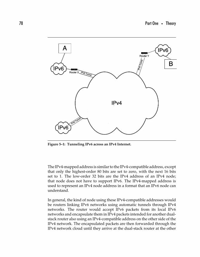
78 Part One • Theory
Figure 5–1: Tunneling IPv6 across an IPv4 Internet.
The IPv4-mapped address is similar to the IPv4-compatible address, exceptthat only the highest-order 80 bits are set to zero, with the next 16 bitsset to 1. The low-order 32 bits are the IPv4 address of an IPv4 node;that node does not have to support IPv6. The IPv4-mapped address isused to represent an IPv4 node address in a format that an IPv6 node canunderstand.
In general, the kind of node using these IPv4-compatible addresses wouldbe routers linking IPv6 networks using automatic tunnels through IPv4networks. The router would accept IPv6 packets from its local IPv6networks and encapsulate them in IPv4 packets intended for another dual-stack router also using an IPv4-compatible address on the other side of theIPv4 network. The encapsulated packets are then forwarded through theIPv4 network cloud until they arrive at the dual-stack router at the other
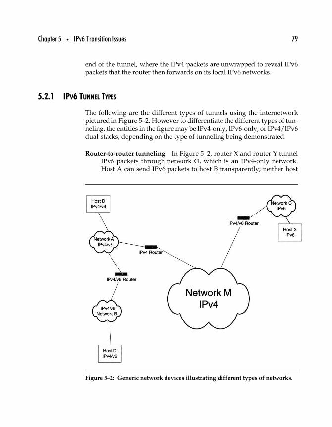
Chapter 5 • IPv6 Transition Issues 79
end of the tunnel, where the IPv4 packets are unwrapped to reveal IPv6packets that the router then forwards on its local IPv6 networks.
5.2.1 IPV6 TUNNEL TYPES
The following are the different types of tunnels using the internetworkpictured in Figure 5–2. However to differentiate the different types of tun-neling, the entities in the figure may be IPv4-only, IPv6-only, or IPv4/IPv6dual-stacks, depending on the type of tunneling being demonstrated.
Router-to-router tunneling In Figure 5–2, router X and router Y tunnelIPv6 packets through network O, which is an IPv4-only network.Host A can send IPv6 packets to host B transparently; neither host
Figure 5–2: Generic network devices illustrating different types of networks.
80 Part One • Theory
needs to be concerned with the existence of an intervening IPv4network (network O). In this case, both host A and host B areIPv6-only nodes.
Router-to-host tunneling In this case, network N in Figure 5–2 is anIPv4-only network, but host B runs IPv4 and IPv6; the rest of thenetwork is IPv6-only. In this case, the tunneling takes place betweenrouter Y and host B. IPv6 packets flow freely along the rest of thenetwork, but router Y must encapsulate them in IPv4 in order todeliver them across network N, which is IPv4-only.
Host-to-host tunneling In this case, only host A and host B supportIPv6 (they are dual-stack IPv4/IPv6 nodes). The rest of the enti-ties in Figure 5–2 for this illustration are IPv4-only. The tunnelingoccurs between host A and host B, the two hosts encapsulating theirIPv6 packets in IPv4 so as to pass through the IPv4-only routers andnetworks.
Host-to-router tunneling Finally, consider what happens when host Aand router X are dual-stack IPv4/IPv6 nodes, network M is an IPv4-only network, and the rest of the networks support IPv6 only. In thiscase, host A must tunnel its packets only to router X; once past theIPv4-only network M, router X can unwrap the tunneled packets andforward them normally across the IPv6 networks.
5.2.2 EXPLICIT TUNNELING
Explicit tunneling of IPv6 through IPv4 occurs when the IPv6 packetsare encapsulated in IPv4 packets that are addressed using either IPv4-compatible addresses or by configuring a set of IPv4 addresses (indicatingthe two IPv4 endpoints of the tunnel). The first approach is called automatictunneling because there is no need to configure anything—IPv6-capablenodes will automatically encapsulate IPv6 packets with IPv4-compatibleaddresses.
When IPv4-compatible addresses are not being used, IPv6 nodes can com-municate using a configured tunnel. The endpoints of the tunnel must beconfigured so that the nodes doing the IPv6 encapsulation will be able toproperly address the resulting IPv4 packets. Configured tunneling requiresthat the tunnel endpoint nodes acquire their IPv4 address through some
Chapter 5 • IPv6 Transition Issues 81
other mechanism (for example, through DHCP, manual configuration, orany other IPv4 configuration mechanism).
5.2.3 IPV6 OVER IPV4 WITHOUT EXPLICIT TUNNELS
The problem with tunneling is that in either case (configured or auto-matic) some special case support must be built into the nodes linkingthe IPv6 domains across the IPv4 domain. Configured tunnels requirea mechanism to configure the tunnel, whereas automatic tunnels requireIPv4-compatible IPv6 addresses. A different way to tunnel IPv6 over,described in RFC 2529, “Transmission of IPv6 over IPv4 Domains with-out Explicit Tunnels,” requires only that IPv4 multicast be supported inthe infrastructure.
Known as 6over4, this approach allows IPv6 nodes to treat IPv4 as a linklayer protocol for the purpose of locating other IPv6 nodes. In the sameway that nodes on an Ethernet network emit broadcast or multicast pack-ets to identify themselves or locate other nodes, an IPv6 node using 6over4transmits IPv6 packets encapsulated in IPv4 to a multicast group whosemembers are IPv6 nodes. The encapsulated packets are treated much thesame way as an IPv4 node’s packets that have been encapsulated in anEthernet frame. Members of the IPv6 multicast group would be the onlyones accepting those packets, and they would respond (or ignore) theencapsulated data, as appropriate.
5.2.4 THE TROUBLE WITH TUNNELS
None of the approaches to tunneling described so far is perfect.
Automatic tunnels require IPv4-compatible addresses, requiring IPv6network administrators to acquire at least one such address for eachtunnel.
Configured tunnels require some mechanism to keep tunnel endpoints’configurations up to date and working. They also require humans toconfigure them at some level and thus are not expected to scale well.
6over4 tunnels require that the IPv4 infrastructure through which theyoperate support IPv4 multicast, a specification that is often notimplemented in the public Internet. Another problem is scalability,
82 Part One • Theory
inasmuch as these tunnels treat the global IPv4 Internet as a broadcastmedium. Any significant deployment is likely to affect performanceon the IPv4 Internet.
In addition to tunnels, IPv6/IPv4 interoperability requires the use of nodesthat can handle both protocols at the same time, as discussed next.
5.3 IPv4/IPv6 Dual-Stack
The tenacity of legacy systems, as demonstrated by the years of prepara-tion required to allay Year 2000 fears, should be underestimated at ourperil. IPv4 will be with us for a long time, even as some or all of the restof the networked world upgrades to IPv6. During that time, the upgradedsystems will need to maintain interoperability with IPv4 systems; as timegoes on, the burden of interoperability will be shifted from the early imple-menters to the maintainers of legacy systems. In any case, systems capableof supporting both IPv4 and IPv6 will be necessary.
The concept of dual-stack nodes is not new. Many, if not most, corporatehosts that support connectivity to the Internet as well as connectivity tocorporate LANs using older versions of Novell’s NetWare (in NetWare 5,IP replaces IPX as the native network layer protocol), for example, alreadysupport two disparate network stacks. Internet connectivity is providedthrough the TCP/IP stack, whereas the NetWare connectivity is providedby an IPX stack. As segments are received at the link layer and unwrapped,the headers indicate whether the datagram is intended for the TCP/IP stackor the IPX stack—and the packet is then passed to the appropriate stackfor processing.
IPv4/IPv6 dual-stack nodes can work much the same as other types ofmultiple-stack nodes. The data link layer header contains a field in whichan ethertype (a value specifying network protocol) indicates the type ofprotocol being carried in the link layer protocol data unit’s payload. Justas Novell IPX/IPv4 dual-stacks differentiated between the two protocolsby ethertype (the IPX ethertype value is 0x8137; IPv4 ethertype is 0x0800;and IPv6 ethertype is 0x86DD).
Figure 5–3 shows an example in which dual-stack node D can interoperatewith IPv4 or IPv6 nodes on networks A and B and all IPv4 nodes on networkM, but not with any nodes on network C, which is strictly IPv6. There is
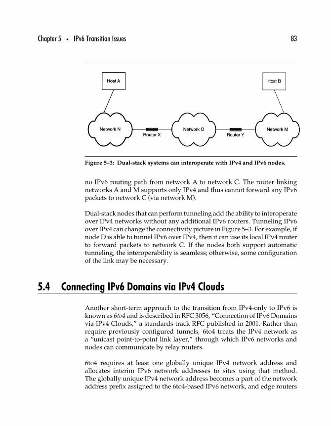
Chapter 5 • IPv6 Transition Issues 83
Figure 5–3: Dual-stack systems can interoperate with IPv4 and IPv6 nodes.
no IPv6 routing path from network A to network C. The router linkingnetworks A and M supports only IPv4 and thus cannot forward any IPv6packets to network C (via network M).
Dual-stack nodes that can perform tunneling add the ability to interoperateover IPv4 networks without any additional IPv6 routers. Tunneling IPv6over IPv4 can change the connectivity picture in Figure 5–3. For example, ifnode D is able to tunnel IPv6 over IPv4, then it can use its local IPv4 routerto forward packets to network C. If the nodes both support automatictunneling, the interoperability is seamless; otherwise, some configurationof the link may be necessary.
5.4 Connecting IPv6 Domains via IPv4 Clouds
Another short-term approach to the transition from IPv4-only to IPv6 isknown as 6to4 and is described in RFC 3056, “Connection of IPv6 Domainsvia IPv4 Clouds,” a standards track RFC published in 2001. Rather thanrequire previously configured tunnels, 6to4 treats the IPv4 network asa “unicast point-to-point link layer,” through which IPv6 networks andnodes can communicate by relay routers.
6to4 requires at least one globally unique IPv4 network address andallocates interim IPv6 network addresses to sites using that method.The globally unique IPv4 network address becomes a part of the networkaddress prefix assigned to the 6to4-based IPv6 network, and edge routers
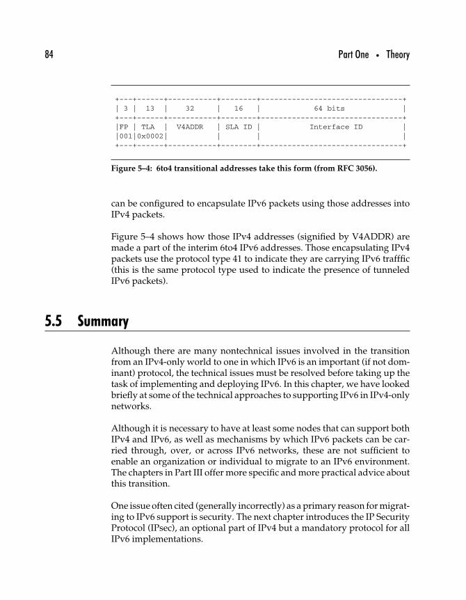
84 Part One • Theory
+---+------+-----------+--------+--------------------------------+| 3 | 13 | 32 | 16 | 64 bits |+---+------+-----------+--------+--------------------------------+|FP | TLA | V4ADDR | SLA ID | Interface ID ||001|0x0002| | | |+---+------+-----------+--------+--------------------------------+
Figure 5–4: 6to4 transitional addresses take this form (from RFC 3056).
can be configured to encapsulate IPv6 packets using those addresses intoIPv4 packets.
Figure 5–4 shows how those IPv4 addresses (signified by V4ADDR) aremade a part of the interim 6to4 IPv6 addresses. Those encapsulating IPv4packets use the protocol type 41 to indicate they are carrying IPv6 trafffic(this is the same protocol type used to indicate the presence of tunneledIPv6 packets).
5.5 Summary
Although there are many nontechnical issues involved in the transitionfrom an IPv4-only world to one in which IPv6 is an important (if not dom-inant) protocol, the technical issues must be resolved before taking up thetask of implementing and deploying IPv6. In this chapter, we have lookedbriefly at some of the technical approaches to supporting IPv6 in IPv4-onlynetworks.
Although it is necessary to have at least some nodes that can support bothIPv4 and IPv6, as well as mechanisms by which IPv6 packets can be car-ried through, over, or across IPv6 networks, these are not sufficient toenable an organization or individual to migrate to an IPv6 environment.The chapters in Part III offer more specific and more practical advice aboutthis transition.
One issue often cited (generally incorrectly) as a primary reason for migrat-ing to IPv6 support is security. The next chapter introduces the IP SecurityProtocol (IPsec), an optional part of IPv4 but a mandatory protocol for allIPv6 implementations.
II
IPv6 Protocols

This Page Intentionally Left Blank
Part Two • IPv6 Protocols 87
IPv6, like IPv4, is a protocol defined by a set of addressing protocols,a set of protocol headers, and a set of protocol behaviors. Part II beginswith a chapter on the Internet Protocol Security Architecture (IPsec),a protocol that is defined for use with both IPv4 and IPv6. The rest ofthis section of the book details IPv6 by first defining the rules for IPv6addressing in Chapter 7; defining the protocol headers in Chapter 8;and discussing additional protocol behaviors as represented by routingprotocols in Chapter 9. Chapter 10 discusses the changes and additionsnecessary for making existing upper- and lower-layer protocols work wellwith IPv6.
After reading Part II, you will be able to do the following.
• Understand IP security issues and explain how IPsec works• Discuss and differentiate IPv6 address types• Refer to IPv6 nodes and networks by their addresses• Identify IPv6 packets and use packet header information for
troubleshooting purposes• Understand how the new features of IPv6 work, from Neighbor
Discovery to IPv6 autoconfiguration• Understand IPv6 routing behavior• Identify modifications and additions to existing protocols
necessary for IPv6 support
If you don’t have the time (or need) to understand the precise differencesbetween IPv6 and IPv4, it is possible to summarize IPv6 as being an updateof IPv4 with 128-bit addresses, streamlined headers, and a few changes inthe information contained in the headers and the functions possible withthe protocol. However, some of the changes noted in the next chapter havesignificant implications, as the remainder of Part II will demonstrate.

This Page Intentionally Left Blank
66
The IP Security Protocol(IPsec)∗
Claims that IPv4 security was neglected by the founders are based on theargument that early IPv4 networks were insecure things strung togetheron trust between naive but ultimately honorable academicians. However,at the very start the Internet Protocol was defined as a U.S. Departmentof Defense (DoD) standard, and security was certainly a consideration.Nevertheless, the IETF has given considerably more explicit attention toIPv6 security than was accorded to IPv4 during its early development.
The desirability and utility of authentication and security features at theIP layer have been debated for years. This chapter discusses how authenti-cation and security, including secure password transmission, encryption,and digital signatures on datagrams, are implemented under IP throughthe Authentication Header (AH) and Encapsulating Security Payload (ESP)options. Before examining the IP Security Protocol (IPsec), however, wewill take a look at the IP security architecture described in RFC 2401,
∗This chapter is adapted from Chapter 26 of TCP/IP Clearly Explained (4th edition).
89
90 Part Two • IPv6 Protocols
“Security Architecture for the Internet Protocol,” and the different piecesof that architecture.
IPv4 as originally designed offered no real security features; it wasintended simply as an internetworking protocol. While not necessarilya problem for a networking protocol used largely in research and academicsettings, the increase in importance of IP networking to the general busi-ness and consumer networking environments makes the potential harmresulting from attacks more devastating than ever. This section examinesthe following.
• Issues of security for IP• Security goals defined for IP• Cryptographic elements of IPsec• Protocol elements of IPsec• Implementing IPsec
The next section takes a look at the specifics of IPsec, as well as some of thetools being assembled to achieve these goals.
6.1 IP Security Issues
IPsec as defined in RFC 2401 provides a security architecture for theInternet Protocol—not a security architecture for the Internet. The distinc-tion is important: IPsec defines security services to be used at the IP layer,both for IPv4 and IPv6. It is often said that IPv6 is “more secure” than IPv4,but the difference is that IPsec is required for all IPv6, whereas it is optionalfor IPv4 nodes.
The IP Security Protocol (IPsec) provides an interoperable and openstandard for building security into the network layer rather than at theapplication or transport layer. Although applications can benefit from net-work layer security, the most important application IPsec enables is thecreation of virtual private networks (VPNs) capable of securely carryingenterprise data across the open Internet.
IPsec is often used in conjunction with tunnel management protocols,including the Layer 2 Tunneling Protocol (L2TP), the Layer 2 Forwarding(L2F) protocol designed by Cisco Systems, and Microsoft’s Point to Point
Chapter 6 • The IP Security Protocol (IPsec) 91
Tunneling Protocol (PPTP). RFC 2661, “Layer Two Tunneling Protocol‘L2TP,’ ” defines L2TP as a standards track specification for tunnelingpackets sent over a PPP link.
While the tunnel management protocols offer access security services, theydon’t provide authentication or privacy services, so they are often usedin conjunction with IPsec—which does provide those services. However,saying that IPsec specifies protocols for encrypting and authenticating datasent within IP packets is an oversimplification and even obscures IPsec’sfull potential. IPsec enables the following.
Encryption of data passing between two nodes, using strongpublic and private key cryptographic algorithms
Authentication of data and its source, using strong authenticationmechanisms
Control over access to sensitive data and private networksIntegrity verification of data carried by a connectionless proto-
col (IP)Protection against replay attacks, in which an intruder inter-
cepts packets sent between two IP nodes and resends them afterdecrypting or modifying them
Limitation of traffic analysis attacks, in which an intruder inter-cepts protected data and analyzes source and destination infor-mation, size and type of packets, and other aspects of the data,including header contents that might not otherwise be protectedby encryption
End-to-end security for IP packets, providing assurance tousers of end-point nodes of the privacy and integrity of theirtransmissions.
Secure tunneling through insecure networks such as the globalInternet and other public networks
Integration of algorithms, protocols, and security infrastructuresinto an overarching security architecture
As defined in RFC 2401, “Security Architecture for the Internet Protocol,”the goal of the IP security architecture is “to provide various securityservices for traffic at the IP layer, in both the IPv4 and IPv6 environments.”This means security services that have the following features.
Interoperable As with all Internet protocols, interoperability is a fun-damental goal. This means that any IP node supporting IPsec cancommunicate with any other node supporting IPsec. There is a basic

92 Part Two • IPv6 Protocols
set of cryptographic algorithms for encryption and integrity check-ing, which all IPsec nodes must support, although individual nodesand implementations may support many more, optional, algorithms.Although some nodes are configured to prefer newer or less openalgorithms, all nodes are required to support the basic ones.
High quality The baseline for security through IPsec must be sethigh enough to guarantee a reasonable degree of actual security.Algorithms and key lengths that are to be vulnerable to attack are notacceptable. For example, data encrypted with 40-bit encryption keyscan be brute-forced or successfully and quickly decrypted by tryingevery combination. The number of possible keys is 240
−1, or roughly1000 billion; on average, the correct key will be discovered after tryinghalf (about 500 billion) of those combinations. Such attacks are almosttrivially easy with commercial off-the-shelf hardware, and thus 40-bitkeys are not considered to provide “high-quality” security.
Cryptographically based Cryptographers work with algorithms forencryption, secure hashing, and authentication. Encryption algo-rithms allow regular data to be transformed into cyphertext, datascrambled so that only the entity holding an appropriate key candecrypt it. Secure hash algorithms operate on any size chunk of datato generate a fixed-length sequence of bits (the hash). An entity canconfirm the integrity of the data by running the hashing algorithm onreceived data; if the transmitted hash and the calculated hash agree,the data is verified as having been sent without change. Authentica-tion of entities through the use of digital signatures depends on publickey algorithms. Data encrypted with the public key of a public/private key pair can be decrypted only by an entity with access tothe private key; likewise, if an entity encrypts something (such as thetext of a message) with their private key, then anyone with access tothe public key can decrypt the message and confirm that the senderhas access to that key.
By basing IPsec on cryptography rather than on any other mecha-nisms for security, the protocol designers place limits on the securitygoals possible to attain through its use while at the same time ensur-ing that those security goals will be achieved through the use ofverifiable and reliable mechanisms.
The IP security architecture allows systems to choose the required secu-rity protocols, identify the cryptographic algorithms to use with those
Chapter 6 • The IP Security Protocol (IPsec) 93
protocols, and exchange any keys or other material or informationnecessary to provide security services.
As may be evident from its highly qualified description, public keycryptography-based mechanisms require that all participants can be con-fident that public keys are issued only to the entities identified with thosekeys. When a public key is published purporting to represent MicrosoftCorporation, the possibility that the key has been properly issued toMicrosoft and not to a computer criminal should approach 100% certainty.Unfortunately, as was demonstrated in early 2001 when it was reportedthat leading public key infrastructure vendor Verisign, Inc., issued twopublic key certificates to an impostor claiming to represent Microsoft, thisis not always possible.
As a network layer protocol, IPsec provides security only at the networklayer. This means that packets can be protected from the point at whichthey enter the IP network (the source node’s IP interface) to the pointat which they leave the IP network (the destination node’s IP interface).IPsec cannot substitute for proper application or transport layer securitymechanisms, and IPsec cannot protect against attackers taking control ofthe source or destination nodes or processes.
6.2 Security Goals
Computer security can be said to embody three general goals.
Authentication The ability to reliably determine that data has beenreceived as it was sent and to verify that the entity that sent the datais what it claims to be. Successful authentication means preventingattackers from impersonating an authorized entity.
Integrity The ability to reliably determine that the data has not been modi-fied during transit from its source to its destination. Successfullymaintaining data integrity means preventing an attacker from modi-fying authentic data without detection as well as preventing theacceptance of data that has been corrupted somewhere in the networkclouds (as happens occasionally).
Confidentiality The ability to transmit data that can be used orread only by its intended recipient and not by any other entity.
94 Part Two • IPv6 Protocols
Successfully maintaining data confidentiality means preventing any-one other than the intended recipient(s) from being able to accessprivate data.
Developments in modern cryptography, specifically in the use of publickey cryptography (discussed in the next section), make possible the combi-nation of these three goals in one set of functions. These goals—authenti-cation, integrity, and confidentiality—are achieved through three relatedfunctions.
Digital signatures unequivocably link the holder of a particular secretwith data represented as having been signed by that entity.
Secure hashes digitally “summarize” a sequence of data using a repeat-able process that will produce identical results only if the datasequence being verified matches the data sequence produced by thesender.
Encryption is the process of performing a reversible transformation onreadable data so as to render it unreadable by anyone other than theholder of the appropriate decryption key.
Some or all of these functions are possible in combination or individuallyin protocols at every layer of the TCP/IP stack, from IP (through IPsec) tothe transport layer (through TLS, the Transport Layer Security protocol)to security functions provided through applications.
The goal of IPsec is to provide security mechanisms for all versions of IP.1
IPsec provides security services at the IP layer, and systems may requireother systems to interact with it securely with IPsec and a particular setof security algorithms and protocols. While IPsec mandates support fora basic set of algorithms, it also allows nodes to negotiate acceptably secureinteraction with other systems with optional algorithms. IPsec providesthe framework within which nodes can negotiate appropriate algorithms,protocols, key lengths, and other aspects of secure communication.
IPsec allows maintenance of the following.
Access control IPsec allows security protocols to be invoked governingthe secure exchange of keys, allowing authentication of users foraccess control purposes.
1IPsec support is mandatory for IPv6 nodes, but optional for IPv4 nodes.
Chapter 6 • The IP Security Protocol (IPsec) 95
Connectionless integrity IPsec allows nodes to validate each IP packetindependent of any other packet. There is no need to verify sequencesof packets or even to have access to other packets exchanged bythe same nodes. Connectionless integrity is enabled through use ofsecure hashing techniques, similar to the use of check digits but withgreater reliability and less likelihood of tampering from unauthorizedentities.
Data origin authentication Identifying the source of the data containedin an IP packet is another security service provided by IPsec.This function is accomplished through the use of digital signatures.
Defense against packet replay attacks As a connectionless protocol, IPis subject to the threat of replay attacks, where an attacker sendsa packet that has already been received by the destination host.Replay attacks can harm system availability by tying up receivingsystem resources. IPsec provides a packet countermechanism thatprotects against this ploy.
Encryption Data confidentiality—keeping access to data from anyonebut those with proper authorization—is provided through the use ofencryption.
Limited traffic flow confidentiality Encrypting data is not always suffi-cient to protect systems; merely knowing the endpoints of anencrypted exchange, the frequency of such interaction, or other infor-mation about the transmissions can provide a determined attackerwith enough information to disrupt or subvert systems. IPsec pro-vides some limited traffic flow confidentiality through the use of IPtunneling, especially when coupled with security gateways.
All of these functions are possible through proper use of the EncapsulatingSecurity Payload (ESP) Header and the Authentication Header (AH).A handful of cryptographic functions is specified for IPsec and is describedbriefly in the next section.
Public key encryption provides a mechanism for performing almost all ofthese functions with a single set of processes. AH provides mechanisms forapplying authentication algorithms to an IP packet, whereas ESP providesmechanisms for applying any kind of cryptographic algorithm to an IPpacket including encryption, digital signature, and/or secure hashes.
96 Part Two • IPv6 Protocols
IPsec is aimed at eliminating certain types of attacks, including thefollowing.
Denial of service (DoS) attacks These occur when an entity uses net-work transmissions to prevent legitimate users from using networkresources. For example, an attacker may flood a host with TCP SYNrequests and thereby crash a system, or the attack may consist ofrepeated transmission of long mail messages with the intention offilling up a user’s or site’s bandwidth with nuisance traffic.
Spoofing attacks These occur when an entity transmits packets that mis-represent the packets’ origins. For example, one type of spoofingattack occurs when the attacker sends a mail message with the From:header indicating the source of the message as, say, the president ofthe United States. More insidious and almost as easy to engineer arethose attacks that occur when packets are sent out with an incorrectsource address in the headers.
Man-in-the-middle attacks (MITMs) These occur when an attacker(Alice) positions herself between two communicating entities (callthem Bob and Carol) and intercepts all their transmissions. Aliceposes as Bob when communicating with Carol, and as Carol whencommunicating with Bob. Alice, as a result, is able to send what-ever data she wants to Bob instead of what Carol wants to send toBob. MITM attacks are relatively easy when transmissions are notencrypted or authenticated. However, Alice can successfully attackeven a protected data stream if she is able to either gain access toCarol’s secret keys (or be issued a set of her own public/secret keypairs that is sufficiently similar to Carol’s that Bob will be fooled).
This last attack is important because it raises the issue of handling keys.As just noted, encryption and digital signature functions require the useof keys to decrypt and/or verify data, and digital certificates are one mecha-nism by which public keys can be distributed. Although all public keyinfrastructure (PKI) providers, including Verisign, make their own effortsto validate all applications, the problem is not a matter of technology.As noted earlier, Verisign issued two digital certificates to someone whoimproperly posed as a representative of Microsoft; a sufficiently motivatedattacker will presumably use every possible tactic to get a desired certifica-tion. An attacker’s ability to forge credentials (from letterhead on which totype a request for a corporate digital certificate to passport, birth certificate,
Chapter 6 • The IP Security Protocol (IPsec) 97
or other documents submitted to support a fraudulent application) mayexceed the ability of the PKI provider to detect them.
As a result of this potential vulnerability, IPsec requires a mechanism bywhich keys can be securely administered and distributed in a way thatassociates public keys with the entities that are supposed to own them.
As just noted, IPsec secures IP—not the Internet and certainly not the sys-tems connected to the Internet or the processes running on those systems.IPsec must be considered only one part of the organizational securitystrategy. While IPsec-protected traffic may pass unscathed across theglobal Internet, before it leaves its source and after it arrives at its destina-tion, that traffic will be vulnerable to attacks on local links, local systems,processes, and the protocols used there.
6.3 Encryption and Authentication Algorithms
Rather than relying on secrecy to protect an encryption or authenticationscheme (an approach known as “security through obscurity”), TCP/IPsecurity protocols always specify that cryptographic algorithms be wellknown and accessible. This is done for several reasons, not the least ofwhich is that as an open protocol suite, TCP/IP protocol specificationsmust be published freely. The most important reason, however, is thatsecrecy is a poor safeguard over security.
Attempting to keep an encryption algorithm secret is almost impossible,particularly if it is being used by anyone other than the person who knowsthe secret. Attackers have many cryptanalysis tools at their disposal forbreaking codes, and they need only have access to ciphertexts to breakthem. Having access to the software used to encrypt and/or decrypt datawith the secret algorithm makes the task much easier: the attacker mustonly determine what the software does to the data to figure out how toreverse the operation.
The greatest advantage that published algorithms provide is the benefit ofscrutiny by researchers and others seeking to find ways to further improveor break the algorithms. The more trained experts examine an algorithm,the less likely they are to overlook an “obvious” attack.
98 Part Two • IPv6 Protocols
Security algorithms and protocols are hard to design because there are somany different ways to attack them—and designers can’t always imaginethem all. Although national security organizations as well as corpora-tions may have their own top-secret codes, secrets are hard to keep. Spiesand other criminals are well known for their skill at motivating (throughbribery, extortion, or other means) people who know secrets to share them.
The prevailing wisdom in security holds that a good encryption orauthentication algorithm should be secure even if an attacker knows whatalgorithm is being used. This is particularly important for Internet secu-rity, since an attacker with a sniffer will often be able to determine exactlywhat kind of algorithm is being used by listening as systems negotiate theirconnections.
In this section we’ll cover five types of important cryptographic functions.
• Symmetric encryption• Public key encryption• Key exchange• Secure hashes (message digests)• Digital signature
6.3.1 SYMMETRIC ENCRYPTION
Most people are familiar with symmetric encryption, if only at a visceral,intuitive level: Plaintexts are encrypted with a secret key and some set ofprocedures, and they are decrypted with the same key and the same setof procedures. If you have the key, you can decrypt all data that has beenencrypted with that key. Sometimes known as secret key encryption, sym-metric encryption is computationally efficient and it is the most frequenttype of encryption for network transmission of volumes of data.
In October 2000, the National Institute of Standards and Technology (NIST)announced that the Rijndael2 data encryption algorithm had been selectedfor the Advanced Encryption Standard (AES), replacing the outdated DataEncryption Standard (DES) algorithm originally developed during the 1970sby IBM. DES uses 56-bit keys, although a variation called triple DES
2According to an FAQ at the NIST Web site, “The algorithm’s developers have suggestedthe following pronunciation alternatives: ‘Reign Dahl,’ ‘Rain Doll,’ and ’Rhine Dahl.’ ” TheAES home page is http://csrc.nist.gov/encryption/aes/.
Chapter 6 • The IP Security Protocol (IPsec) 99
encrypts data three times with the DES algorithm, providing improvedsecurity.
Using a secure encryption requires using sufficiently long keys. Shorterkeys are vulnerable to brute-force attacks, in which an attacker usesa computer to try all the different possible keys. Key lengths on the order of40 bits, for example, are considered insecure because they can be broken bybrute-force attacks in very short order by relatively inexpensive computers.Single-DES has been brute-forced as well; in general, 128-bit and longerkeys are likely to be secure against such attacks for the immediate future.
Symmetric encryption algorithms can be vulnerable to other types ofattacks. Most applications that use symmetric encryption for Internetcommunications use session keys, meaning that the key is used for onlya single-session data transmission (sometimes several keys are used in onesession). Loss of a session key thus compromises only the data that wassent during that session or portion of a session.
These are some of the other symmetric encryption algorithms that havebeen or are currently being used for Internet applications.
RC2/RC4 These commercial symmetric encryption algorithms weredeveloped and marketed by cryptography firm RSA.
CAST Developed in Canada and used by Nortel’s Entrust products,CAST supports up to 128-bit keys.
IDEA The International Data Encryption Algorithm supports 128-bitkeys. It was patented by Swiss firm Ascom, which granted permis-sion for IDEA to be used for free noncommercial use in the seminaland open source encryption program Pretty Good Privacy (PGP),written by Philip Zimmermann and published for a time by NetworkAssociates, Inc.
GOST This algorithm was reportedly developed by a Soviet securityagency.
Blowfish This algorithm was developed by Bruce Schneier and releasedto the public domain.
Twofish This was Bruce Schneier’s submission to the AES competition.
100 Part Two • IPv6 Protocols
Skipjack This algorithm was developed by the National Security Agencyfor use with the Clipper chip’s escrowed key system.
6.3.2 PUBLIC KEY ENCRYPTION
Public key encryption, also called asymmetric encryption, uses pairs of keys:One, the public key, is associated with the other, the secret key. The publickey is intended to be made public. Any data encrypted with the public keycan only be decrypted with the secret key and any data encrypted with thesecret key can be decrypted with the public key.
Anyone can get a public key and encrypt some data with it. That data canbe decrypted only by the holder of the secret key. As long as an entitycan keep its secret key a secret, other entities can be sure that any dataencrypted with the public key will be accessible only to the holder of theassociated secret key. The holder of the secret key can encrypt somethingusing that secret key and make it available to another entity. That entitycan verify the first entity as holding the secret key of a particular publickey pair by decrypting the data with the public key.
Public key encryption tends to be computationally intensive and is mostoften used to encrypt session keys for network transmissions as well as fordigital signatures.
The most commonly used type of public key encryption is the RSA algo-rithm developed by Ron Rivest, Adi Shamir, and Len Adleman. RSAdefines a mechanism for choosing and generating the secret/public keypairs, as well as for the actual mathematical function to be used forencryption.
6.3.3 KEY MANAGEMENT
One of the most complex issues facing Internet security professionals ishow to manage keys. This includes not only the actual distribution ofkeys through a key exchange protocol but also the negotiation of keylength, lifetime, and cryptographic algorithms between communicatingsystems.
An open channel (an open communication medium over which transmis-sions can be overheard) like the global Internet complicates the process of
Chapter 6 • The IP Security Protocol (IPsec) 101
sharing a secret. This process is necessary when two entities need to sharea key to be used for encryption. Some of the most important cryptographicalgorithms relate to the process of sharing a key over an open channelsecurely, in a way that keeps the secret from anyone but the intendedrecipients.
Diffie-Hellman key exchange is an algorithm that allows entities to exchangeenough information to derive a session encryption key. Alice (the cus-tomary entity name for the first participant in a cryptographic protocol)calculates a value using Bob’s public value and her own secret value (Bobis the second participant in cryptographic protocols). Bob calculates hisown value and sends it to Alice; they each then use their secret valuesto calculate their shared key. The mathematics are relatively simple (butoutside the scope of this book); the bottom line is that Bob and Alice cansend each other enough information to calculate their shared key but notenough for an attacker to be able to figure it out.
Diffie-Hellman is often called a public key algorithm, but it is not a publickey encryption algorithm. Diffie-Hellman is used to calculate a key, but thatkey must be used with some other encryption algorithm. Diffie-Hellmancan be used for authentication, though, and is also used by PGP.
Key exchange is integral to any Internet security architecture, and candi-dates for the IPsec security architecture include the Internet Key Exchange(IKE) protocol and the Internet Security Association and Key ManagementProtocol (ISAKMP).
ISAKMP is an application protocol, using UDP as its transport, whichdefines different types of messages that systems send to each other tonegotiate the exchange of keys. The mechanisms and algorithms for doingthe actual exchanges, however, are not defined in ISAKMP—it is a frame-work to be used by the specific mechanisms. The mechanisms, oftenbased on Diffie-Hellman key exchange, have been defined in a numberof different proposals over the years. These are some of them.
Photuris Based on Diffie-Hellman, Photuris adds the requirement thatthe requesting node send a cookie, a random number that is used asa sort of session identifier. The cookie is sent first, and the serveracknowledges the request by returning the cookie. This reduces therisk from denial-of-service attacks made by attackers forging theirsource addresses. Photuris also requires all parties to sign their nego-tiated key to reduce the risk of a man-in-the-middle attack (in which

102 Part Two • IPv6 Protocols
an attacker pretends to be Bob to one system’s Alice, while pretendingto be Alice to the other system’s Bob).
SKIP Sun Microsystems’ Simple Key-management for Internet Protocols(SKIP) is also based on Diffie-Hellman key exchange, but rather thanrequiring parties to use random values to calculate their keys, SKIPcalls for the use of a secret table that remains static. The parties look upsecret values in this table and then transmit calculated values basedon some secret value from the table.
OAKLEY Although this mechanism shares some features with Photuris,it provides different modes of key exchange for situations wheredenial-of-service attacks are not a concern.
By defining a separate protocol, ISAKMP, for the generalized formatsrequired to do key and Security Association exchanges, it can be used asa base to build specific key exchange protocols. The foundation protocolcan be used for any security protocol, and it does not have to be replacedif an existing key exchange protocol is replaced.
It should be noted that manual key management is an important optionand in many cases is the only option. This approach requires individuals topersonally deliver keys and configure network devices to use them. Evenafter open standards have been firmly determined and implemented, par-ticularly as commercial products, manual key management will continueto be an important choice.
As more research is done with IPsec, work on an IKE successor proto-col (sometimes called Son-of-IKE) is ongoing, with IKEv2 one candidateprotocol that (as of 2002) is a work-in-progress.
6.3.4 SECURE HASHES
A hash is a digital summary of a chunk of data of any size. Simple typesof hashes include check digits; secure hashes produce longer results (often128 bits or longer). Good secure hashes are extremely difficult for attackersto reverse-engineer or subvert in other ways. Secure hashes can be usedwith keys or without, but their purpose is to provide a digital summaryof a message that can be used to verify whether some data that has beenreceived is the same as the data sent. The sender calculates the hash and
Chapter 6 • The IP Security Protocol (IPsec) 103
includes that value with the data; the recipient calculates the hash on thedata received. If the results match the attached hash value, the recipientcan be confident in the data’s integrity.
Commonly used hashes include the MD2, MD4, and MD5 message digestfunctions published by Network Associates. The Secure Hash Algorithm(SHA) is a digest function developed as a standard by NIST. Hashes maybe used on their own or as part of digital signatures.
6.3.5 DIGITAL SIGNATURE
Public key encryption, as noted previously, relies on key pairs. Digitalsignatures rely on the property of public key encryption that allows dataencrypted with an entity’s secret key to be decrypted with the public keyof the pair. The sender calculates a secure hash on the data to be signedand then encrypts the result using a secret key. The recipient calculates thesame hash and then decrypts the encrypted value attached by the sender.If the two values match, the recipient knows that the owner of the publickey was the entity that signed the message and that the message was notmodified during transmission.
The RSA public key encryption algorithm can be used for digital signatures:The signing entity creates a hash of the data to be signed and then encryptsthat hash with its own secret key. The certifying entity then calculatesthe same hash on the data being received, decrypts the signature using thesigning entity’s public key, and compares the two values. If the hash is thesame as the decrypted signature, then the data is certified.
Digital signatures carry with them several implications.
• A signature that can be certified indicates that the message wasreceived without any alteration from the time it was signed tothe time it was received.
• If a signature cannot be certified, then the message was cor-rupted or tampered with in transit, the signature was calculatedincorrectly, or the signature was corrupted or tampered with intransit. In any case, an uncertifiable signature does not neces-sarily imply any wrongdoing but does require that the messagebe resigned and resent in order to be accepted.
• If a signature is certified, it means that the entity associatedwith the public key was the only entity that could have signed it.
104 Part Two • IPv6 Protocols
In other words, the entity associated with the public key cannotdeny having signed the message. This is called nonrepudiationand is an important feature of digital signatures.
There are other mechanisms for doing digital signatures, but RSA is prob-ably the most widely used one and is implemented in the most popularInternet products.
6.4 IPsec: The Protocols
IPsec is a security tunneling protocol, defining a mechanism that allowsa node to encrypt and/or authenticate packets and encapsulate thesecured packets (which may now be literally indecipherable, having beenencrypted) into new packets. Figure 6–1 illustrates the basic idea behindIPsec and other security tunneling protocols.
IPsec depends on the use of security gateways, which encapsulate IP pack-ets on behalf of their clients. In Figure 6–1, the security gateway labeled“X” serves, among others, hosts A′, B′, and C′; “Y” serves hosts A,B, and C. The PC off on the side has its own, software, security gate-way. In this example, the tunnel from X to Y carries all secured trafficbetween the two pictured Internets. In this case, each security gatewayintegrates all traffic for its local network and encrypts and/or authenti-cates all of it between itself and the security gateway at the other end.If all traffic is being encrypted (a good bet), then any attacker sittinginside the public Internet could intercept these packets but would getrelatively little information from them. At best, the attacker would dis-cover that there is a secure tunnel between X and Y, but she would likelylearn only how much traffic was being sent between the two securitygateways.
The security gateways create secure tunnels, as shown in Figure 6–2, byaccepting IP packets sent from one node (A) to another (B). A sends offthe packets as if they were going to be delivered directly to B; the securitygateway X then takes those packets (along with any others from the samenetwork) and treats them as raw data to be sent to security gateway Y.The packets sent by A are shown as open envelopes to signify that theyhave not been encrypted, while the packets sent from X are shown as
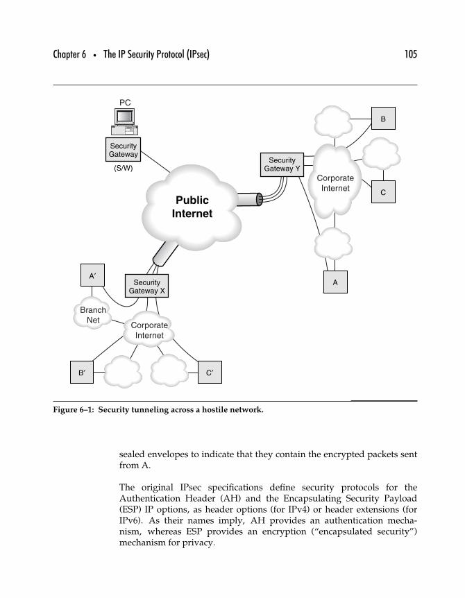
Chapter 6 • The IP Security Protocol (IPsec) 105
Public
Internet
PC
Corporate
Internet
Branch
Net
Corporate
Internet
A
C
B
B′ C′
A′
SecurityGateway Y
SecurityGateway
(S/W)
SecurityGateway X
Figure 6–1: Security tunneling across a hostile network.
sealed envelopes to indicate that they contain the encrypted packets sentfrom A.
The original IPsec specifications define security protocols for theAuthentication Header (AH) and the Encapsulating Security Payload(ESP) IP options, as header options (for IPv4) or header extensions (forIPv6). As their names imply, AH provides an authentication mecha-nism, whereas ESP provides an encryption (“encapsulated security”)mechanism for privacy.
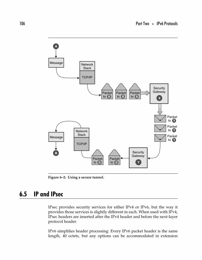
106 Part Two • IPv6 Protocols
SecurityGateway
NetworkStack
Message
TCP/IP
NetworkStack
TCP/IP
Packetto
X
SecurityGateway
Y
A
Message
B
B
Packetto Y
Packetto Y
Packetto Y
Packetto B
Packetto B
Packetto B
Packetto B
Figure 6–2: Using a secure tunnel.
6.5 IP and IPsec
IPsec provides security services for either IPv4 or IPv6, but the way itprovides those services is slightly different in each. When used with IPv4,IPsec headers are inserted after the IPv4 header and before the next-layerprotocol header.
IPv6 simplifies header processing: Every IPv6 packet header is the samelength, 40 octets, but any options can be accommodated in extension
Chapter 6 • The IP Security Protocol (IPsec) 107
headers that follow the IPv6 header. IPsec services are provided throughthese extensions.
The ordering of IPsec headers, whether within IPv4 or IPv6, has signi-ficance. For example, it makes sense to encrypt a payload with the ESPHeader and then use the Authentication Header to provide data integrityon the encrypted payload. In this case, the AH Header appears first,followed by the ESP Header and encrypted payload. Reversing the order,by doing data integrity first and then encrypting the whole lot, meansthat you can be sure of who originated the data but not necessarily certainof who did the encryption.
6.5.1 SECURITY ASSOCIATIONS
The Security Association (SA) is a fundamental element of IPsec. RFC 2401defines the SA as “a simplex ‘connection’ that affords security servicesto the traffic carried by it.” This rather murky definition is clarified bya description; an SA consists of three things.
• A Security Parameter Index (SPI)• An IP destination address• A security protocol (AH or ESP) identifier
As a simplex connection, the SA associates a single destination with theSPI; thus, for typical IP traffic there will be two SAs: one in each direc-tion that secure traffic flows (one each for source and destination host).SAs provide security services by using either AH or ESP but not both(if a traffic stream uses both AH and ESP, it has two—or more—SAs).
The Security Parameter Index (SPI) is an identifier indicating the type ofIP header the security association is being used for (AH or ESP). The SPIis a 32-bit value identifying the SA and differentiating it from other SAslinked to the same destination address. For secure communication betweentwo systems, there would be two different security associations, one foreach destination address.
Each security association includes more information related to the typeof security negotiated for that connection, so systems must keep track oftheir SAs and what type of encryption or authentication algorithms, keylengths, and key lifetimes have been negotiated with the SA destinationhosts.
108 Part Two • IPv6 Protocols
6.5.2 USING SECURITY ASSOCIATIONS
As mentioned earlier, ISAKMP provides a generalized protocol for estab-lishing SAs and managing cryptographic keys within an Internet environ-ment. The procedures and packet formats needed to establish, negotiate,modify, and delete SAs are defined within ISAKMP, which also definespayloads for exchanging key generation and authentication data. Theseformats provide a consistent framework for transferring this data, inde-pendent of how the key is generated or what type of encryption orauthentication algorithms are being used.
ISAKMP was designed to provide a framework that can be used by anysecurity protocols that use SAs, not just IPsec. To be useful for a particu-lar security protocol, a Domain of Interpretation, or DOI, must be defined.The DOI groups related protocols for the purpose of negotiating securityassociations—security protocols that share a DOI all choose protocol andcryptographic transforms from a common namespace. They also sharekey exchange protocol identifiers, as well as a common interpretation ofpayload data content.
While ISAKMP and the IPsec DOI provide a framework for authenticationand key exchange, ISAKMP does not actually define how those functionsare to be carried out. The IKE protocol, working within the frameworkdefined by ISAKMP, does define a mechanism for hosts to perform theseexchanges.
The sending host knows what kind of security to apply to the packet bylooking in a Security Policy Database (SPD). The sending host determineswhat policy is appropriate for the packet, depending on various selec-tors (for example, destination IP address and/or transport layer ports), bylooking in the SPD. The SPD indicates what the policy is for a particularpacket: Either the packet requires IPsec processing of some sort—in whichcase it is passed to the IPsec module for processing—or it does not—inwhich case it is simply passed along for normal IP processing.
Outbound packets must be checked against the SPD to see what kind (ifany) of IPsec processing to apply. Inbound packets are checked againstthe SPD to see what kind of IPsec service should be present in thosepackets.
Another database, called the Security Association Database (SAD), includesall security parameters associated with all active SAs. When an IPsec host
Chapter 6 • The IP Security Protocol (IPsec) 109
wants to send a packet, it checks the appropriate selectors to see whatthe SAD says is the security policy for that destination/port/application.The SPD may reference a particular SA, so the host can look up the SAin the SAD to identify appropriate security parameters for that packet.
6.5.3 TUNNEL AND TRANSPORT MODE
IPsec defines two modes for exchanging secured data: tunnel mode andtransport mode. IPsec transport mode protects upper-layer protocols andis used between end-nodes. This approach allows end-to-end securitybecause the host originating the packet is also securing it, and the des-tination host is able to verify the security, either by decrypting the packetor certifying the authentication.
Tunnel mode IPsec protects the entire contents of the tunneled packets. Thetunneled packets are accepted by a system acting as a security gateway,encapsulated inside a set of IPsec/IP headers, and forwarded to the otherend of the tunnel, where the original packets are extracted (after beingcertified or decrypted) and then passed along to their ultimate destination.
The packets are only secured as long as they are “inside” the tunnel,although the originating and destination hosts could be sending securedpackets themselves, so that the tunnel systems are encapsulating packetsthat have already been secured.
Transport mode is good for any two individual hosts that want to com-municate securely; tunnel mode is the foundation of the Virtual PrivateNetwork or VPN. Tunnel mode is also required anytime a security gateway(a device offering IPsec services to other systems) is involved at either endof an IPsec transmission. Two security gateways must always communi-cate by tunneling IP packets inside IPsec packets; the same goes for anindividual host communicating with a security gateway. This occurs any-time a mobile laptop user logs into a corporate VPN from the road, forexample.
Tunneling, shown in Figure 6–3, allows two systems to set up SAs to enablesecure communications over the Internet. Network traffic originates onone system, is encrypted and/or signed, and is then sent to the destinationsystem. On receipt, the datagram is decrypted or authenticated, and thepayload is passed along up the receiving system’s network stack where it
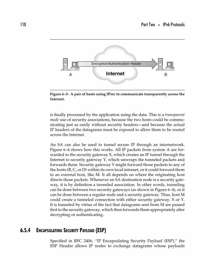
110 Part Two • IPv6 Protocols
Internet
Encryption/Authentication Header
A B
Figure 6–3: A pair of hosts using IPsec to communicate transparently across the
Internet.
is finally processed by the application using the data. This is a transparentmode use of security associations, because the two hosts could be commu-nicating just as easily without security headers—and because the actualIP headers of the datagrams must be exposed to allow them to be routedacross the Internet.
An SA can also be used to tunnel secure IP through an internetwork.Figure 6–4 shows how this works. All IP packets from system A are for-warded to the security gateway X, which creates an IP tunnel through theInternet to security gateway Y, which unwraps the tunneled packets andforwards them. Security gateway Y might forward those packets to any ofthe hosts (B, C, or D) within its own local intranet, or it could forward themto an external host, like M. It all depends on where the originating hostdirects those packets. Whenever an SA destination node is a security gate-way, it is by definition a tunneled association. In other words, tunnelingcan be done between two security gateways (as shown in Figure 6–4), or itcan be done between a regular node and a security gateway. Thus, host Mcould create a tunneled connection with either security gateway, X or Y.It is tunneled by virtue of the fact that datagrams sent from M are passedfirst to the security gateway, which then forwards them appropriately afterdecrypting or authenticating.
6.5.4 ENCAPSULATING SECURITY PAYLOAD (ESP)
Specified in RFC 2406, “IP Encapsulating Security Payload (ESP),” theESP Header allows IP nodes to exchange datagrams whose payloads
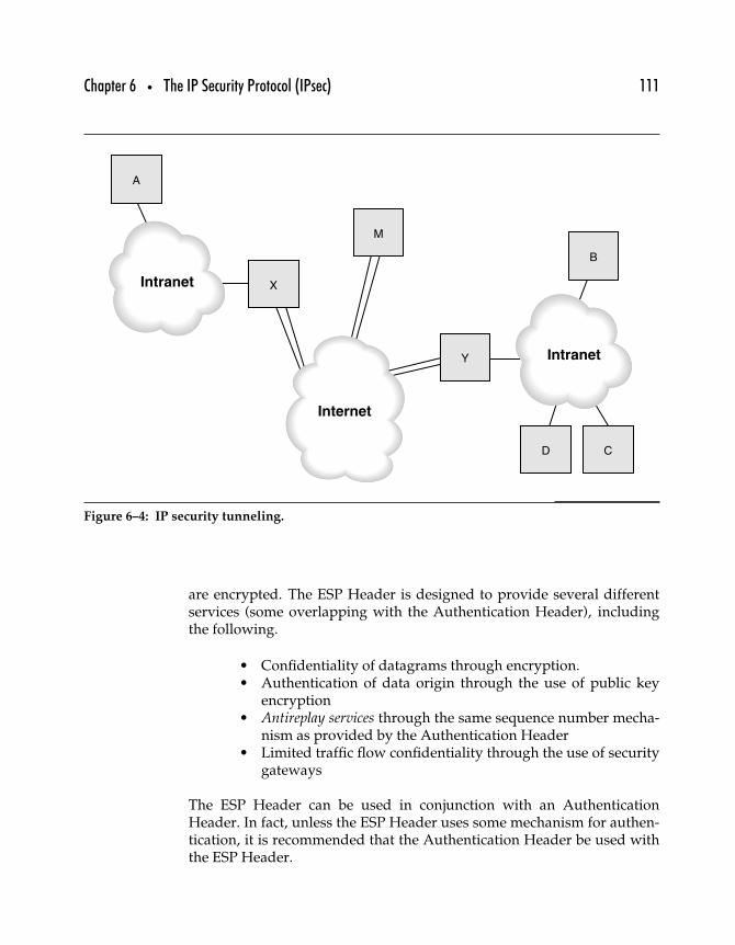
Chapter 6 • The IP Security Protocol (IPsec) 111
Intranet
Intranet
CD
B
A
X
Y
M
Internet
Figure 6–4: IP security tunneling.
are encrypted. The ESP Header is designed to provide several differentservices (some overlapping with the Authentication Header), includingthe following.
• Confidentiality of datagrams through encryption.• Authentication of data origin through the use of public key
encryption• Antireplay services through the same sequence number mecha-
nism as provided by the Authentication Header• Limited traffic flow confidentiality through the use of security
gateways
The ESP Header can be used in conjunction with an AuthenticationHeader. In fact, unless the ESP Header uses some mechanism for authen-tication, it is recommended that the Authentication Header be used withthe ESP Header.
112 Part Two • IPv6 Protocols
The ESP Header must follow any headers that need to be processed bynodes intermediate to the destination node—all data that follows the ESPHeader will be encrypted, with the encrypted payload beginning directlyafter the last ESP Header field (see following).
ESP can be used in tunnel or transport mode, similar to the AuthenticationHeader. In transport mode, the IP Header and any Hop-by-Hop, Routing,or Fragmentation Extension Headers precede the Authentication Header(if present), followed by the ESP Header. Any Destination OptionsHeaders can either precede or follow the ESP Header, or even both; anyHeaders that follow the ESP Header are encrypted.
The result appears, in many respects, to simply be a regular IP datagramtransmitted from source to destination, with an encrypted payload. Thisuse of ESP in transport mode is appropriate in some cases, but it allowsattackers to study traffic between the two nodes, noting which nodes arecommunicating, how much data they exchange, when they exchange it,and so forth. All this information may potentially provide the attacker withsome information that helps defeat the communicating parties.
An alternative is to use a security gateway, much as just described forthe Authentication Header. A security gateway can operate directly witha node or can link to another security gateway. A single node can use ESPin tunnel mode by encrypting all outbound packets and encapsulatingthem in a separate stream of IP datagrams that are sent to the securitygateway. That gateway then can decrypt the traffic and resend the originaldatagrams to their destinations.
When tunneling, the ESP Header encapsulates the entire tunneled IPdatagram and is an extension to the IP Header directing that data-gram to a security gateway. It is also possible to combine ESP Headerswith Authentication Headers in several different ways; for example,the tunneled datagram may have a Transport-Mode AuthenticationHeader.
The following ESP Header format (taken from RFC 2406) includes the NextHeader field, which appears near the end of the ESP Header and indicatesthe presence (and identity) of any other headers (such as AH) that mayfollow. The rest of the ESP Header consists of the following.
Security Parameter Index (SPI) This is the same 32-bit value referredto in the section on the Authentication Header. This value is used
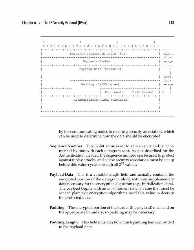
Chapter 6 • The IP Security Protocol (IPsec) 113
0 1 2 30 1 2 3 4 5 6 7 8 9 0 1 2 3 4 5 6 7 8 9 0 1 2 3 4 5 6 7 8 9 0 1
+-+-+-+-+-+-+-+-+-+-+-+-+-+-+-+-+-+-+-+-+-+-+-+-+-+-+-+-+-+-+-+-+ ----| Security Parameters Index (SPI) | ^Auth.+-+-+-+-+-+-+-+-+-+-+-+-+-+-+-+-+-+-+-+-+-+-+-+-+-+-+-+-+-+-+-+-+ |Cov-| Sequence Number | |erage+-+-+-+-+-+-+-+-+-+-+-+-+-+-+-+-+-+-+-+-+-+-+-+-+-+-+-+-+-+-+-+-+ | ----| Payload Data (variable) | | ^~ ~ | || | |Conf.+ +-+-+-+-+-+-+-+-+-+-+-+-+-+-+-+-+-+-+-+-+-+-+-+-+ |Cov-| | Padding (0-255 bytes) | |erage
+-+-+-+-+-+-+-+-+ +-+-+-+-+-+-+-+-+-+-+-+-+-+-+-+-+ | || | Pad Length | Next Header | v v+-+-+-+-+-+-+-+-+-+-+-+-+-+-+-+-+-+-+-+-+-+-+-+-+-+-+-+-+-+-+-+-+ ------| Authentication Data (variable) |~ ~| |+-+-+-+-+-+-+-+-+-+-+-+-+-+-+-+-+-+-+-+-+-+-+-+-+-+-+-+-+-+-+-+-+
by the communicating nodes to refer to a security association, whichcan be used to determine how the data should be encrypted.
Sequence Number This 32-bit value is set to zero to start and is incre-mented by one with each datagram sent. As just described for theAuthentication Header, the sequence number can be used to protectagainst replay attacks, and a new security association must be set upbefore this value cycles through all 232 values.
Payload Data This is a variable-length field and actually contains theencrypted portion of the datagram, along with any supplementarydata necessary for the encryption algorithm (e.g., initialization data).The payload begins with an initialization vector, a value that must besent in plaintext; encryption algorithms need this value to decryptthe protected data.
Padding The encrypted portion of the header (the payload) must end onthe appropriate boundary, so padding may be necessary.
Padding Length This field indicates how much padding has been addedto the payload data.
114 Part Two • IPv6 Protocols
Next Header This field operates as it normally does with other IPv6extension headers; it just appears near the end of the header (where itcan be given confidentiality protection) rather than at the beginningso that the next layer protocol can be hidden from any unauthorizedthird parties.
Authentication Data This is an Integrity Check Value (ICV) calculatedon the entire ESP Header (except for the authentication data). Thisauthentication calculation is optional. The ICV is discussed at greaterlength following.
6.5.5 AUTHENTICATION HEADER
The Authentication Header can be used to do the following.
• Provide strong integrity services for IP datagrams, whichmeans the AH can be used to carry content verification datafor the IP datagram.
• Provide strong authentication for IP datagrams, which meansthat the AH can be used to link an entity with the contents ofthe datagram.
• Provide nonrepudiation for IP datagrams, assuming thata public key digital signature algorithm is used for integrityservices.
• Protect against replay attacks through the use of the sequencenumber field.
The Authentication Header can be used in tunnel mode or in transportmode, which means that it can be used to authenticate and protect simple,direct datagram transfers between two nodes, or it can be used to encap-sulate an entire stream of datagrams that is sent to or from a securitygateway.
AH is specified in RFC 2402, “IP Authentication Header,” and the headeris shown on page 115 (taken from RFC 2402).
In transport mode, the Authentication Header protects the payload ofthe original IP datagram as well as the parts of the IP Header that do notchange from hop to hop (e.g., the Hop Limit field or Routing Headers).Figure 6–5 shows what happens to a transport-mode IP datagram asthe Authentication Header is calculated and added to it (the DestinationOptions Header may also appear before the Authentication Header).
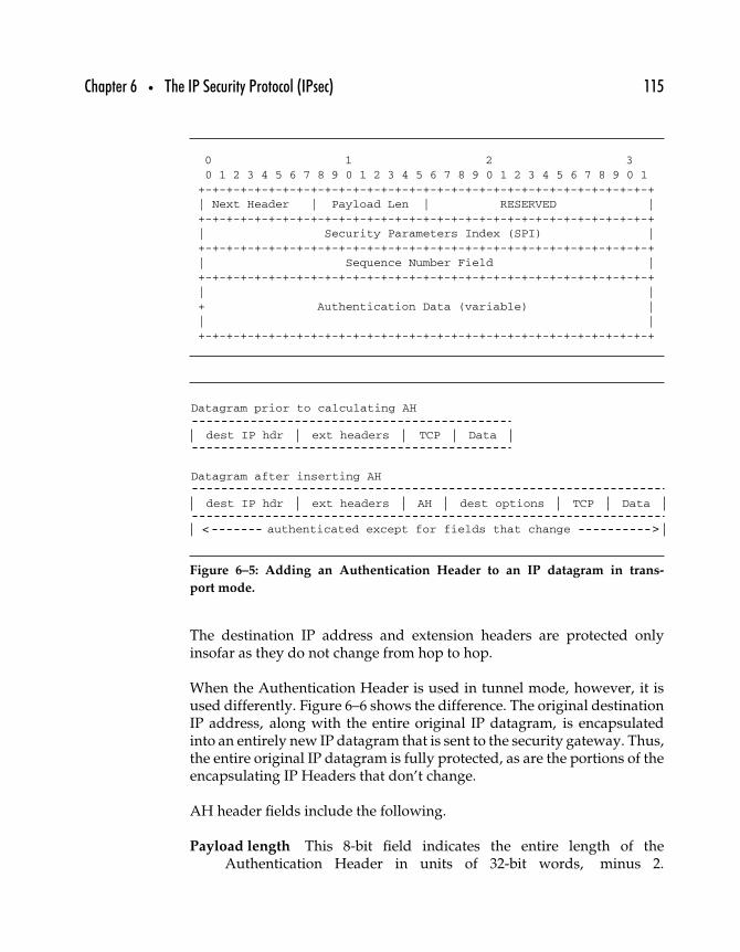
Chapter 6 • The IP Security Protocol (IPsec) 115
0 1 2 30 1 2 3 4 5 6 7 8 9 0 1 2 3 4 5 6 7 8 9 0 1 2 3 4 5 6 7 8 9 0 1+-+-+-+-+-+-+-+-+-+-+-+-+-+-+-+-+-+-+-+-+-+-+-+-+-+-+-+-+-+-+-+-+| Next Header | Payload Len | RESERVED |+-+-+-+-+-+-+-+-+-+-+-+-+-+-+-+-+-+-+-+-+-+-+-+-+-+-+-+-+-+-+-+-+| Security Parameters Index (SPI) |+-+-+-+-+-+-+-+-+-+-+-+-+-+-+-+-+-+-+-+-+-+-+-+-+-+-+-+-+-+-+-+-+| Sequence Number Field |+-+-+-+-+-+-+-+-+-+-+-+-+-+-+-+-+-+-+-+-+-+-+-+-+-+-+-+-+-+-+-+-+| |+ Authentication Data (variable) || |
+-+-+-+-+-+-+-+-+-+-+-+-+-+-+-+-+-+-+-+-+-+-+-+-+-+-+-+-+-+-+-+-+
dest IP hdr
authenticated except for fields that change
ext headers AH dest options TCP Data
Datagram after inserting AH
dest IP hdr ext headers TCP Data
Datagram prior to calculating AH
< >
Figure 6–5: Adding an Authentication Header to an IP datagram in trans-
port mode.
The destination IP address and extension headers are protected onlyinsofar as they do not change from hop to hop.
When the Authentication Header is used in tunnel mode, however, it isused differently. Figure 6–6 shows the difference. The original destinationIP address, along with the entire original IP datagram, is encapsulatedinto an entirely new IP datagram that is sent to the security gateway. Thus,the entire original IP datagram is fully protected, as are the portions of theencapsulating IP Headers that don’t change.
AH header fields include the following.
Payload length This 8-bit field indicates the entire length of theAuthentication Header in units of 32-bit words, minus 2.
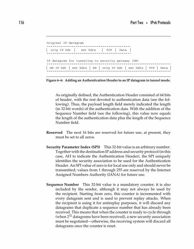
116 Part Two • IPv6 Protocols
GW IP hdr ext hdrs ext hdrsAH orig IP hdr TCP Data
IP datagram for tunneling to security gateway (GW)
orig IP hdr ext hdrs TCP Data
Original IP datagram
Figure 6–6: Adding an Authentication Header to an IP datagram in tunnel mode.
As originally defined, the Authentication Header consisted of 64 bitsof header, with the rest devoted to authentication data (see the fol-lowing). Thus, the payload length field merely indicated the length(in 32-bit words) of the authentication data. With the addition of theSequence Number field (see the following), this value now equalsthe length of the authentication data plus the length of the SequenceNumber field.
Reserved The next 16 bits are reserved for future use; at present, theymust be set to all zeros.
Security Parameter Index (SPI) This 32-bit value is an arbitrary number.Together with the destination IP address and security protocol (in thiscase, AH to indicate the Authentication Header), the SPI uniquelyidentifies the security association to be used for the AuthenticationHeader. An SPI value of zero is for local use only and should never betransmitted; values from 1 through 255 are reserved by the InternetAssigned Numbers Authority (IANA) for future use.
Sequence Number This 32-bit value is a mandatory counter; it is alsoincluded by the sender, although it may not always be used bythe recipient. Starting from zero, this counter is incremented withevery datagram sent and is used to prevent replay attacks. Whenthe recipient is using it for antireplay purposes, it will discard anydatagrams that duplicate a sequence number that has already beenreceived. This means that when the counter is ready to cycle through(when 232 datagrams have been received), a new security associationmust be negotiated—otherwise, the receiving system will discard alldatagrams once the counter is reset.
Chapter 6 • The IP Security Protocol (IPsec) 117
Authentication Data This field contains the Integrity Check Value (ICV),which is the heart of the Authentication Header. The contents mustbe a multiple of 32 bits in length and may contain padding toattain that length. Calculation of this value is discussed in the nextsection.
6.5.6 CALCULATING THE INTEGRITY CHECK VALUE (ICV)
The Authentication Data fields in the AH and ESP Headers are variable-length fields, each of which contains an Integrity Check Value (ICV). Thefield is variable length to accommodate variations from ICV algorithms,and the length is specified by the selected function. This is an optional field:It is included only when an authentication service is in use for the SA thatcorresponds to the header, and information about the ICV function in useis maintained along with the rest of the SA data.
The ICV calculation is a bit tricky in that some of the data being authenti-cated may be modified en route, such as IP header hop counts. Accordingto RFC 2402 the AH ICV is computed on the IP header fields that eitherdon’t change in transit or whose values on arrival can be predicted, theAH header itself (though the Authentication Data field is set to zero for thecalculation), and the upper-level protocol data that is being authenticated(this is assumed to be unchanged in transit).
The ESP ICV, according to RFC 2406, is computed on the entire ESPpacket, excluding the Authentication Data field. This includes the SPI,Sequence Number, Payload Data, Padding (if present), Pad Length, andNext Header; the last four fields will be in ciphertext form, since encryptionis performed prior to authentication.
These are the suggested algorithms for ICV.
Message Authentication Codes (MACs), the results of which are thenencrypted with an appropriate symmetric encryption algorithm (forexample, AES)
Secure hash functions, such as MD5 or SHA-1 (an updated versionof SHA)
To comply with the standard, implementations must support MD5 andSHA-1 keyed hashing, at least.
118 Part Two • IPv6 Protocols
6.5.7 IPSEC HEADERS IN ACTION
IPsec security services are provided through the AH and ESP Headers inconjunction, of course, with appropriate and relevant key managementprotocols. The AH protocol is specified in RFC 2402, “IP AuthenticationHeader”; ESP is specified in RFC 2406, “IP Encapsulating Security Payload(ESP).”
Either security header may be used by itself, or both may be used togetherin various combinations of transport or tunnel modes. When used togetherwith AH encapsulating ESP, packet authentication can be checked priorto decrypting the ESP Header payload. These headers can also be nestedwhen using IPsec tunneling: An originating node can encrypt and digi-tally sign a packet, and then send it to the local security gateway. Thatgateway may then reencrypt and resign the packet as it sends it off toanother security gateway.
The ESP and AH authentication services are slightly different: ESPauthentication services are ordinarily provided only on the packetpayload, whereas AH authenticates almost the entire packet includingheaders.
The Sequence Number field is mandatory for all AH and ESP Headers andis used to provide antireplay services. Every time a new packet is sent, theSequence Number is increased by one (the first packet sent with a givenSA will have a Sequence Number of 1).
When the receiving host elects to use the antireplay service for a par-ticular SA, the host checks the Sequence Number: if it receives a packetwith a Sequence Number value that it has already received, that packet isdiscarded.
The Authentication Data field contains whatever data is required by theauthentication mechanisms specified for that particular SA to authenti-cate the packet. The ICV may contain a keyed Message AuthenticationCode (MAC) based on a symmetric encryption algorithm (such as AES orTriple-DES) or a one-way hash function such as MD5 or SHA-1.
The most obvious difference between ESP and AH is that the ESP Header’sNext Header field appears at the end of the security payload. Of course,since the header may be encapsulating an encrypted payload, you don’tneed to know what next header to expect until after you’ve decrypted the
Chapter 6 • The IP Security Protocol (IPsec) 119
payload—thus, the ESP Next Header field is placed after rather than beforethe payload.
ESP’s authentication service covers only the payload itself, not the IPheaders of its own packet as with the Authentication Header. And theconfidentiality service covers only the payload itself; obviously, you can’tencrypt the IP headers of the packet intended to deliver the payload andstill expect any intermediate routers to be able to process the packet. Ofcourse, if you’re using tunneling, you can encrypt everything, but onlyeverything in the tunneled packet itself.
6.6 Implementing and Deploying IPsec
IP layer security protects IP datagrams. It does not necessarily have toinvolve the user or any applications. This means users may be merrilyusing all of their applications without ever being aware that all their data-grams are being encrypted or authenticated before being sent out to theInternet (of course, that situation will only occur as long as all the encrypteddatagrams are properly decrypted by hosts at the other end).
As a result, one question that comes up is how to implement IPsec. RFC2401 suggests several strategies for implementing IPsec in a host or inconjunction with a router or firewall.
Integrated implementation Integrate IPsec into the native IP implemen-tation. This approach is probably the best, but also the most difficult,as it requires rewriting the native IP implementation to includesupport for IPsec. Integrating IPsec into the IP stack adds securitynatively and makes it an integral part of any IP implementation.However, it also requires that the entire stack be updated to reflectthe changes.
“Bump-in-the-stack” (BITS) Implement IPsec “beneath” the IP stackand above the local network drivers. The IPsec implementationmonitors IP traffic as it is sent or received over the local link, andIPsec functions are performed on the packets before passing themup or down the stack. This works reasonably well for individualhosts doing IPsec.
This approach inserts special IPsec code into the network stackjust below the existing IP network software and just above the local
120 Part Two • IPv6 Protocols
link software. In other words, this approach implements securitythrough a piece of software that intercepts datagrams being passedfrom the existing IP stack to the local link layer interface. This soft-ware then does the necessary security processing for those datagramsand hands them off to the link layer. This approach can be used toupgrade systems to IPsec support without requiring that their IP stacksoftware be rewritten.
“Bump-in-the-wire” (BITW) Implement IPsec in a hardware crypto-graphic processor. The crypto processor gets its own IP address;when used for individual hosts, the bump-in-the-wire acts much likea BITS implementation, but when the same processor provides IPsecservices to a router or firewall, it must behave as a security gateway—meaning that it must do IPsec security protocols in tunnel mode.
This approach uses external cryptographic hardware to perform thesecurity processing. The device is usually an IP device that acts as asort of a router or, more accurately, security gateway for all IP data-grams from any system that sits behind it. When such a device isused for a single host, it works very much like the BITS approach,but implementation can be more complex when a single BITW deviceis used to screen more than one system.
These options differ more in terms of where they are appropriate than insubjective terms. Applications that require high levels of security may bebetter served with a hardware implementation. Applications that run onsystems for which new IPsec-compliant network stacks are not availablemay be better served by the BITS approach.
6.7 Summary
Network security is probably the subject of as many books and chapterswithin technical books as IP. This chapter provides a concise introductionto IP security issues and security goals, starting with the definition of thechallenges facing security managers and the tools at their disposal. IPsecprovides authentication services through the use of public key encryption,digital signature, and secure hashing tools; it provides privacy servicesthrough the use of public and secret key encryption as well.
On top of these cryptographic tools, however, IPsec requires additionalprotocols to handle the secure and verifiable distribution and management

Chapter 6 • The IP Security Protocol (IPsec) 121
of encryption keys. IPsec combines these cryptographic and security pro-tocols with IP, using security associations to link packets with hosts anda pair of optional IP security headers (ESP and AH) to transmit IP packetssecurely.
IPsec is often linked to IPv6 because while IPsec support in IPv4 is optional,it is mandatory for all IPv6-capable hosts. Although some cite “security”as a reason to prefer IPv6 over IPv4, to a great degree the same level ofsecurity is possible if IPsec were mandatory for all IPv4 nodes.
IPv6 protocols are introduced in the next chapter.

This Page Intentionally Left Blank
77
IPv6 Protocol Basics
IPv6 embodies change in several important areas.
• Expanded addressing• Simplified header format• Improved extension and option support
These changes to IP succeed at achieving most of the goals originallycharted by the IAB back in 1991 (see RFC 1287, “Toward the Future InternetArchitecture”). The expanded IPv6 address space means IP can continueto grow without concern about depletion of resources; the addressingarchitecture helps improve the situation for routing efficiency.
The simplified header format improves routing efficiency by requiringless processing of packets, whereas the improvements in extension andoption support mean that special needs can be accommodated withoutsignificantly affecting performance either of routing of normal packets orof the special-needs packets. Flow labeling provides another mechanismfor treating streams of packets efficiently, particularly useful for real-timeapplications. Required support of IPsec, providing authentication and
123
124 Part Two • IPv6 Protocols
privacy, also makes IPv6 a more desirable protocol for commercial usesthat require special treatment of sensitive information or resources.
7.1 The IPv6 Address Space
The designers of IPv6 could have simply grafted a larger address spaceonto the existing IPv4 addressing architecture—but doing so would causeus to miss out on a huge opportunity for improving IP. Changing theentire addressing architecture provides an incredible opportunity not onlyfor improving efficiency of address allocation but also for improving IProuting performance.
The IPv4 address space was divided into several different classes basedon the values of their high-order bits. The IPv6 address space is alsodivided into different categories based on high-order bits, as shown inTable 7–1, although most of the address space is unassigned as of yet. Theglobal unicast address space takes up fully one-eighth of the entire addressspace, with all global unicast addresses sharing the three high-orderbits 001. Other allocations are discussed later. All these allocations stillleave roughly 85% of the IPv6 address space unassigned, with no currentplans to assign them for now. At the same time, the allocations that havebeen made should be more than ample for the foreseeable future.
As of 2003, the Regional Internet Registries (RIRs) are allocating /32 net-work prefixes to organizations requesting them, and those allocations maybe expanded in the future if necessary. So far, there is no provision forsuballocations of network blocks smaller than /48, although there areproposals on the table that would permit such “micro-allocations.”
7.1.1 PROVIDER-BASED AGGREGATION
In 1995, RFC 1884, “IP Version 6 Addressing Architecture,” allocateda full quarter of the address space for two different types of unicastaddresses: one-eighth for provider-based unicast addresses and one-eighthfor geographic-based unicast addresses. The intent was to offer addressesthat could be assigned based either on who provided network service tothe address holder or where the subscribing network was located. Provider-based aggregation would have required networks to take on aggregatableIP addresses based on the source of their Internet access. However, this
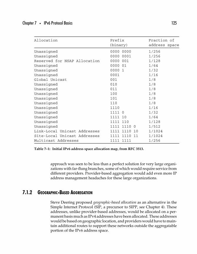
Chapter 7 • IPv6 Protocol Basics 125
Allocation Prefix Fraction of(binary) address space
Unassigned 0000 0000 1/256Unassigned 0000 0001 1/256Reserved for NSAP Allocation 0000 001 1/128Unassigned 0000 01 1/64Unassigned 0000 1 1/32Unassigned 0001 1/16Global Unicast 001 1/8Unassigned 010 1/8Unassigned 011 1/8Unassigned 100 1/8Unassigned 101 1/8Unassigned 110 1/8Unassigned 1110 1/16Unassigned 1111 0 1/32Unassigned 1111 10 1/64Unassigned 1111 110 1/128Unassigned 1111 1110 0 1/512Link-Local Unicast Addresses 1111 1110 10 1/1024Site-Local Unicast Addresses 1111 1110 11 1/1024Multicast Addresses 1111 1111 1/256
Table 7–1: Initial IPv6 address space allocation map, from RFC 3513.
approach was seen to be less than a perfect solution for very large organi-zations with far-flung branches, some of which would require service fromdifferent providers. Provider-based aggregation would add even more IPaddress management headaches for these large organizations.
7.1.2 GEOGRAPHIC-BASED AGGREGATION
Steve Deering proposed geographic-based allocation as an alternative in theSimple Internet Protocol (SIP, a precursor to SIPP, see Chapter 4). Theseaddresses, unlike provider-based addresses, would be allocated on a per-manent basis much as IPv4 addresses have been allocated. These addresseswould be based on geographic location, and providers would have to main-tain additional routes to support these networks outside the aggregatableportion of the IPv6 address space.
126 Part Two • IPv6 Protocols
The ISP community dislikes geographic-based allocations because it meanssignificantly more complexity (and cost) to manage geographic addressallocation. Since most objections to provider-based allocation grew out ofdifficulties of configuring and reconfiguring nodes with provider-basedaddresses, geographic address allocation has been dropped in favor ofdeveloping improved automatic and dynamic host configuration underIPv6—including the ability to automatically renumber entire networkswhen providers are changed.
7.1.3 IPV6 AGGREGATION
With the goal of avoiding complicating the IPv6 routing tables, the cur-rent approach to aggregation is based on having routes aggregated by theservice providers. The addition of stateless autoconfiguration and renum-bering protocols to IPv6 will serve to make some types of aggregationunnecessary.
7.2 IPv6 Header Format
Network protocols can be said to consist of the set of rules that governexchanges of information between nodes and the information itself. IPpacket headers contain the information and constrain that information inmost cases to valid values. Once it is clear what information is contained inthe headers and what values are valid, the rules of the exchanges becomeself-evident.
Figure 7–1 shows the IPv4 packet header structure, and Figure 7–2 showsthe IPv6 packet header structure. Compare the two, and it becomes clearthat IPv6 should be a simpler protocol if only because they carry less infor-mation. However, the fields that have been dispensed with are either nolonger needed or wanted, and IPv6 provides at least as much functionalityto network nodes as IPv4.
IPv6 headers consist of 8 fields (2 of which are source and destinationaddresses) spread over 40 bytes. Contrast this with IPv4 headers, whichcontain at least 12 different fields and may be as short as 20 bytes if nooptions are in use or as long as 60 bytes if options are being used. Routingis thought to be more efficient with a uniformly sized header and withfewer fields to examine and process.
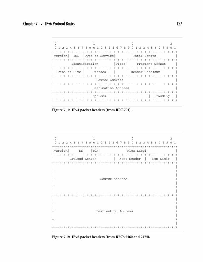
Chapter 7 • IPv6 Protocol Basics 127
0 1 2 30 1 2 3 4 5 6 7 8 9 0 1 2 3 4 5 6 7 8 9 0 1 2 3 4 5 6 7 8 9 0 1
+-+-+-+-+-+-+-+-+-+-+-+-+-+-+-+-+-+-+-+-+-+-+-+-+-+-+-+-+-+-+-+-+|Version| IHL |Type of Service| Total Length |+-+-+-+-+-+-+-+-+-+-+-+-+-+-+-+-+-+-+-+-+-+-+-+-+-+-+-+-+-+-+-+-+| Identification |Flags| Fragment Offset |+-+-+-+-+-+-+-+-+-+-+-+-+-+-+-+-+-+-+-+-+-+-+-+-+-+-+-+-+-+-+-+-+| Time to Live | Protocol | Header Checksum |+-+-+-+-+-+-+-+-+-+-+-+-+-+-+-+-+-+-+-+-+-+-+-+-+-+-+-+-+-+-+-+-+| Source Address |+-+-+-+-+-+-+-+-+-+-+-+-+-+-+-+-+-+-+-+-+-+-+-+-+-+-+-+-+-+-+-+-+| Destination Address |+-+-+-+-+-+-+-+-+-+-+-+-+-+-+-+-+-+-+-+-+-+-+-+-+-+-+-+-+-+-+-+-+| Options | Padding |+-+-+-+-+-+-+-+-+-+-+-+-+-+-+-+-+-+-+-+-+-+-+-+-+-+-+-+-+-+-+-+-+
Figure 7–1: IPv4 packet headers (from RFC 791).
0 1 2 30 1 2 3 4 5 6 7 8 9 0 1 2 3 4 5 6 7 8 9 0 1 2 3 4 5 6 7 8 9 0 1
+-+-+-+-+-+-+-+-+-+-+-+-+-+-+-+-+-+-+-+-+-+-+-+-+-+-+-+-+-+-+-+-+|Version| DS |ECN| Flow Label |+-+-+-+-+-+-+-+-+-+-+-+-+-+-+-+-+-+-+-+-+-+-+-+-+-+-+-+-+-+-+-+-+| Payload Length | Next Header | Hop Limit |+-+-+-+-+-+-+-+-+-+-+-+-+-+-+-+-+-+-+-+-+-+-+-+-+-+-+-+-+-+-+-+-+| |+ +| |+ Source Address +| |+ +| |+-+-+-+-+-+-+-+-+-+-+-+-+-+-+-+-+-+-+-+-+-+-+-+-+-+-+-+-+-+-+-+-+| |+ +| |+ Destination Address +| |+ +
| |+-+-+-+-+-+-+-+-+-+-+-+-+-+-+-+-+-+-+-+-+-+-+-+-+-+-+-+-+-+-+-+-+
Figure 7–2: IPv6 packet headers (from RFCs 2460 and 2474).
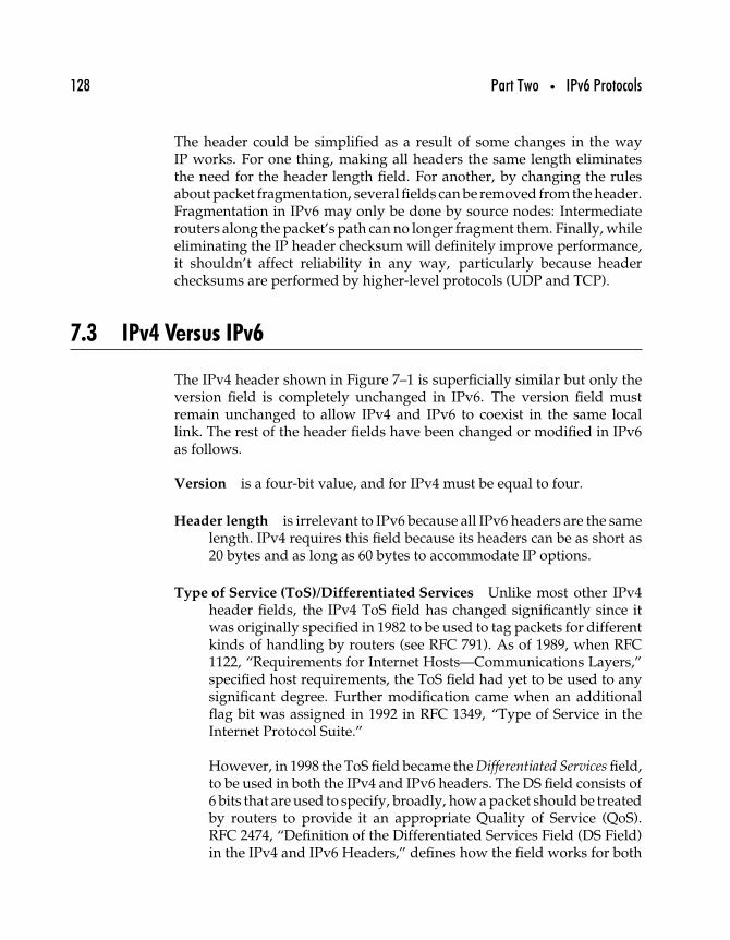
128 Part Two • IPv6 Protocols
The header could be simplified as a result of some changes in the wayIP works. For one thing, making all headers the same length eliminatesthe need for the header length field. For another, by changing the rulesabout packet fragmentation, several fields can be removed from the header.Fragmentation in IPv6 may only be done by source nodes: Intermediaterouters along the packet’s path can no longer fragment them. Finally, whileeliminating the IP header checksum will definitely improve performance,it shouldn’t affect reliability in any way, particularly because headerchecksums are performed by higher-level protocols (UDP and TCP).
7.3 IPv4 Versus IPv6
The IPv4 header shown in Figure 7–1 is superficially similar but only theversion field is completely unchanged in IPv6. The version field mustremain unchanged to allow IPv4 and IPv6 to coexist in the same locallink. The rest of the header fields have been changed or modified in IPv6as follows.
Version is a four-bit value, and for IPv4 must be equal to four.
Header length is irrelevant to IPv6 because all IPv6 headers are the samelength. IPv4 requires this field because its headers can be as short as20 bytes and as long as 60 bytes to accommodate IP options.
Type of Service (ToS)/Differentiated Services Unlike most other IPv4header fields, the IPv4 ToS field has changed significantly since itwas originally specified in 1982 to be used to tag packets for differentkinds of handling by routers (see RFC 791). As of 1989, when RFC1122, “Requirements for Internet Hosts—Communications Layers,”specified host requirements, the ToS field had yet to be used to anysignificant degree. Further modification came when an additionalflag bit was assigned in 1992 in RFC 1349, “Type of Service in theInternet Protocol Suite.”
However, in 1998 the ToS field became the Differentiated Services field,to be used in both the IPv4 and IPv6 headers. The DS field consists of6 bits that are used to specify, broadly, how a packet should be treatedby routers to provide it an appropriate Quality of Service (QoS).RFC 2474, “Definition of the Differentiated Services Field (DS Field)in the IPv4 and IPv6 Headers,” defines how the field works for both
Chapter 7 • IPv6 Protocol Basics 129
IPv4 and IPv6. This specification calls for replacing both the IPv4 ToSand the IPv6 Traffic Class fields with the DS field.1
Datagram length becomes the payload length field in IPv6. IPv4’s data-gram length field specifies the length of the entire datagram, includ-ing the IP headers. Thus, routers can calculate the length of the IPv4datagram payload by subtracting the header length from the data-gram length; this calculation is unnecessary in IPv6 because the IPv6payload length includes extension headers.
Datagram identification is used to identify a datagram as being part ofa fragmented source packet. This is useful only in instances wherepacket fragmentation is permitted, as in IPv4; because IPv6 does notpermit intermediate node fragmentation this field is unnecessary.
Flags are also used to enable fragmentation.
Fragment offset is also used to enable fragmentation.
Time-to-live (TTL) has morphed slightly into the IPv6 hop limit field. TTLwas originally meant to be an upper bound, in seconds, of the lifetimeof a packet in the Internet cloud. IP packets must be assigned a finitelifetime in order to avoid undeliverable packets clogging networksas they shuttle back and forth among routers. If the IPv4 time-to-livecounter reaches zero, the packet is discarded. The rationale was thatpackets might be caught in circular routes, and if they did not expirein some way, they would continue to be routed forever (or untilthe network crashed). The original specification called for routers todecrement this value by the number of seconds it took from receiptof a packet until the packet was forwarded. In practice, most routershave been implemented to simply decrement this value by 1 ratherthan attempting to measure the actual time spent in the router.
Protocol field refers to the next-higher-layer protocol encapsulatedwithin the IPv4 packet. The values for different protocols are avail-able through IANA. This field evolved into the next header field inIPv6, where it specifies the next header, whether an IPv6 extensionheader or another layer’s protocol header.
1RFC 3168, “The Addition of Explicit Congestion Notification (ECN) to IP,” traces thedevelopment of the ToS field.
130 Part Two • IPv6 Protocols
Header checksum is a reasonably robust approach to avoiding the pro-cessing of packets that have had their headers mangled en routeto their destination. However, with upper-layer protocols like TCPand UDP calculating their own checksums on headers, the IPv4header checksum was deemed superfluous. The cost of checkingthe checksum en route is outweighed by the ease with which thedestination node can quickly determine that a packet has beendamaged by using transport or application layer checks. For thoseapplications that do actually require content authentication at the net-work layer, the much more robust authentication header is availablein IPv6.
Source/destination addresses go from 32 bits for IPv4 packets to 128 bitseach for IPv6 packets.
IP options in IPv4 are replaced in IPv6. IPv6 options exist as separateheaders after the main IPv6 header but before the packet payload.
Although all the IPv4 header fields were thought to be useful as definedoriginally (and as tested in early experiments with IP networking), almostall of them have undergone changes of one kind or another in IPv6. Thefragmentation-related fields are out, as are the header checksum andIP options. Likewise, the TTL, protocol, and header length fields havemutated to a greater or lesser degree. And the rest have been modified tosupport IPv6 addresses and functions.
7.4 IPv6 Header Fields
The IPv6 header is clearly new and improved, if only because it has fewerfields. As just noted, the version field is unchanged from IPv4, and theDifferentiated Services field (which replaces the original IPv6 Traffic Classfield) is defined identically for IPv4 and IPv6.
IPv6 header fields include the following.
Version is a 4-bit value, and for IPv6 it must be equal to 6.
Differentiated Services (DS) contains a 6-bit value (2 bits are reservedfor future use). Since 1994, this field has evolved from the 4-bit
Chapter 7 • IPv6 Protocol Basics 131
Priority field; later, the name was changed to Traffic Class. SeeChapter 15 for more about differentiated services and IPv6.
ECN These 2 bits are used as Explicit Congestion Notification (ECN) flags(see Chapter 15 for more about ECN and IPv6).
Flow label is a 20-bit value used to identify packets that belong to thesame flow (see the next section for more about flows). A node can bethe source for more than one simultaneous flow. The flow label andthe address of the source node uniquely identify flows. This fieldwas originally (in RFC 1883) set to 24 bits, but when the DS fieldwas increased in size to 8 bits, the flow label field was decreased tocompensate (see Chapter 15 for more about IPv6 flows).
Payload length is a 16-bit field containing an integer value equal to thelength of the packet payload in bytes—in other words, the num-ber of bytes contained in the packet after the end of the main IPv6header, including any IPv6 extension headers. This means that IPv6extensions are included as part of the payload for the purposes ofcalculating this field.
Next Header indicates what protocol is in use in the header immediatelyfollowing the IPv6 packet. Protocols are identified with standard 8-bit values defined and managed by the IANA. The value of this fieldmay refer to a higher-layer protocol like TCP or UDP, or indicate theexistence of an IPv6 extension header.
The value 59 in the Next Header field of an IPv6 header or any exten-sion header indicates that there is nothing following that header.This field will otherwise contain ethertype values (see Chapter 5)specifying the next header’s protocol.
Hop limit Every time a node forwards a packet, it decrements this 8-bit field by 1. If the hop limit reaches zero, the packet is discarded.Unlike in IPv4, where the time-to-live field fulfills a similar purpose,sentiment is currently against putting a protocol-defined upper limiton packet lifetime for IPv6. That is not to say that packets with infinitelifetimes will be permitted, but rather that the maximum hop limitcan vary from network to network.
Source address is the 128-bit address of the node originating the IPv6packet.
132 Part Two • IPv6 Protocols
Destination address is the 128-bit address of the intended recipient ofthe IPv6 packet. This address may be a unicast, multicast, or anycastaddress. If a routing extension is being used (which specifies a partic-ular route that the packet must traverse), the destination address maybe one of those intermediate nodes instead of the ultimate destina-tion node.
The Differentiated Services field and the concept of IPv6 flows are dis-cussed in greater depth in Chapter 15. In the absence of support forintermediate IP fragmentation, determining the Path MTU becomes moreimportant than ever to ensuring that IPv6 packets are no bigger—andno smaller—than necessary. Path MTU discovery is discussed at greaterlength later in this chapter.
7.5 Option Headers
IPv4 options change the shape of the IP headers: A packet with an IPv4option has as much as 40 octets more data in its header than an unoptionedheader. This physical difference between regular packets and packets usingoptions means the optioned packets must be treated as special cases byrouters, which are usually optimized to handle standard packets. As aresult, datagrams with options tend to be delivered more slowly, not somuch because they require special processing as because they tend to beshunted off to the side to be handled when the router is not busy forwardingnormal packets.
IPv6 extension or option headers can drastically reduce the performance hiton packets that use options. Except for Hop-by-Hop Options, which bydefinition must be processed by each forwarding router, options on IPv6packets are hidden from intermediate routers and thus can have no effecton how the packets are forwarded.
Another of the benefits of IPv6 is that it simplifies the process of definingnew options. As of 2003, a number of options have been defined.
Hop-by-Hop Options Header This header always appears immediatelyafter the main IPv6 header and contains optional data that every nodeon the packets path must examine. So far, two Hop-by-Hop Optionshave been specified: the Jumbo Payload Option and the Router AlertOption.
Chapter 7 • IPv6 Protocol Basics 133
The Jumbo Payload Option identifies the payload of the packet asbeing longer than 65,535 octets (including the Hop-by-Hop OptionHeader). If a router is unable to handle a jumbogram, it returns anICMPv6 error message.
The other Hop-by-Hop Option is the Router Alert Option. This isused to notify routers that information inside the IPv6 datagram isintended to be viewed and processed by an intermediate router eventhough the datagram is addressed to some other node (for example,control datagrams that contain information pertaining to bandwidthreservation protocols).
Routing Header This header causes the packet to visit specific nodes,specified in the header, on its route to its destination. The initialdestination address of the IPv6 header is not the same as the ulti-mate destination of the packet, but rather the first address in thelist contained in the Routing Header. When that node receivesthe packet, it processes the IPv6 header and the Routing Headerand resends the packet to the second address listed in the RoutingHeader. This process continues until the packet reaches its ultimatedestination.
Fragment Header The Fragment Header contains all the informationabout IP fragments that formerly would be stored in the main IPv4header fields. This extension includes fields for a fragment offset, aMore Fragments flag, and an identification field; it is used to allow asource node to fragment a packet too large for the path MTU betweenthe source and the destination.
Destination Options Header This header stands in for the IPv4 optionsfield. At present, the only destination options specified are paddingoptions to fill out the header on a 64-bit boundary if the (future)options require it. The Destination Options Header is meant to carryinformation intended to be examined by the destination node.
Authentication Header (AH) This header provides a mechanism for cal-culating a cryptographic checksum on some parts of the IPv6 header,extension headers, and payload.
Encapsulating Security Payload Header (ESP) This header will alwaysbe the last, unencrypted header of any packet. It indicates the rest of

134 Part Two • IPv6 Protocols
the payload is encrypted, and provides enough information for theauthorized destination node to decrypt it.
Chapter 9 provides more complete details about what IPv6 options areand how they are used.
7.6 IPv4 Packet Size Limits
IPv4 packet size is restricted by a number of factors, including thefollowing.
Total length field This IPv4 header field is 16 bits, restricting the totalsize of any IPv4 packet to 65,575 octets or fewer.
Up to 576 octets The IPv4 specification in RFC 791 requires that all nodesbe capable of accepting packets of any size up to 576 octets. Thus,although there is an upper bound on packet size, very small packets(even packets with no payloads) are permitted. Packets with amaximum-sized IPv4 header (60 octets) are thus able to carry a512 octet payload, that number of octets representing a manageableblock of data (512 = 29 octets).
Over 576 octets RFC 791 recommends that datagrams larger than576 octets only be sent if the source is assured that the destinationwill accept larger datagrams.
While IPv4 packets are limited based on the length of the entire packet, IPv6packets are limited on the payload length. When IPv6 extension headersare present, the packet header can be considerably longer than the standardIPv6 header length (40 octets)—but the header extensions are consideredto be part of the payload when calculating payload length. A new set offactors govern the length of IPv6 payloads, as described next.
7.6.1 IPV6 MTU REQUIREMENTS
Requiring nodes to assume that the maximum transmission unit (MTU)of the Internet is 576 octets affects performance to the extent that systemscapable of handling more are forced to accept less. IPv6 changes that byrequiring every link in the Internet to have an MTU of 1280 octets or more.Where the MTU on a local link is less than 1280 octets, there must be some
Chapter 7 • IPv6 Protocol Basics 135
link-specific fragmentation and reassembly mechanism incorporated intoa link layer protocol.
While 1280 octets is the required minimum MTU for links carrying IPv6traffic, RFC 2460 recommends that wherever possible the MTU should beset to 1500 octets or more. The higher the MTU, the less likely the need forfragmentation will arise when IPv4 (or other protocols) are encapsulatedwithin IPv6 packets.
7.6.2 FRAGMENTATION
Although IPv6 forbids intermediate nodes from fragmenting packets thatare too large for the local link, end-to-end fragmentation is permitted.Source nodes may fragment packets that are reassembled only by therecipient when using the Fragment Header (see Chapter 9).
However, implementors are urged to use Path MTU discovery (PMTUD;see Chapter 12) to determine an appropriate MTU rather than fall back onfragmentation. Where minimal implementations are desired, such as forbooting a node from the network, RFC 2460 suggests using the minimumMTU of 1280 octets rather than attempt to implement either PMTUD orfragmentation support.
7.6.3 JUMBOGRAMS
IPv6 adds support for extra-large packets called jumbograms, having apayload larger than 65,575 octets. Documented in RFC 2675, “IPv6 Jum-bograms,” jumbograms are considered useful and relevant only for nodesconnected to local links whose MTU is 64K octets or larger. Jumbogramsare implemented in an IPv6 extension header (see Chapter 9).
7.7 Other IPv6 Features
The changes in IPv6 go beyond the larger address space and streamlinedpacket headers. As private IPv4 Internets as well as the global Internet havegrown, shortcomings in the ability of IPv4 to scale have arisen. The lackof automatic tools for configuring and maintaining IP nodes and networkshas held back IP deployment and required untold expenditures of networksupport time and effort.
136 Part Two • IPv6 Protocols
Although some of the updates to IPv6 have been tried in IPv4, the improve-ments in the base protocol mean that the new functions work better. Thissection introduces these functions, all of which will be discussed at greaterlength later on.
7.7.1 AUTOCONFIGURATION
The original automatic IP configuration protocol was the Boot Protocol(BOOTP), specified in RFC 951, “Bootstrap Protocol (BOOTP),” back in1985. This protocol defines a mechanism for nodes to query their locallink with broadcasts requesting an address from which they can loadboot images over from BOOTP servers. The Dynamic Host ConfigurationProtocol (DHCP), specified in RFC 2131, “Dynamic Host ConfigurationProtocol,” is based on BOOTP but provides a mechanism by which nodescan load their configurations from DHCP servers.
Both BOOTP and DHCP are considered stateful autoconfiguration protocolsbecause they require that nodes on a network be configured by aBOOTP/DHCP server that maintains state about the address allocationsit makes. In other words, the configuration server is allocated a block ofaddresses from which to assign addresses to nodes requesting them. If theconfiguration server offering IP addresses on a network is unavailable,hosts are not able to connect at all. As networks grow larger, redundantconfiguration servers must each be allocated its own block of addressesto assign, creating new problems of balancing demand across thoseservers.
A stateless autoconfiguration protocol, in which nodes can connect to a net-work without depending on any server, can permit much greater flexibilityand scalability as networks grow in size or as network nodes move aroundmore frequently.
As will be made clear in the next chapter and in Chapter 13, IPv6 addressesmake stateless autoconfiguration easier because node interface identifiersare unique on each link (as well as, usually, globally unique).
IPv6 features a Stateless Autoconfiguration Protocol, specified in RFC 2462,“IPv6 Stateless Address Autoconfiguration,” as well as an updated versionof DHCP, called DHCPv6, that is still (officially, at least) a work-in-progress.
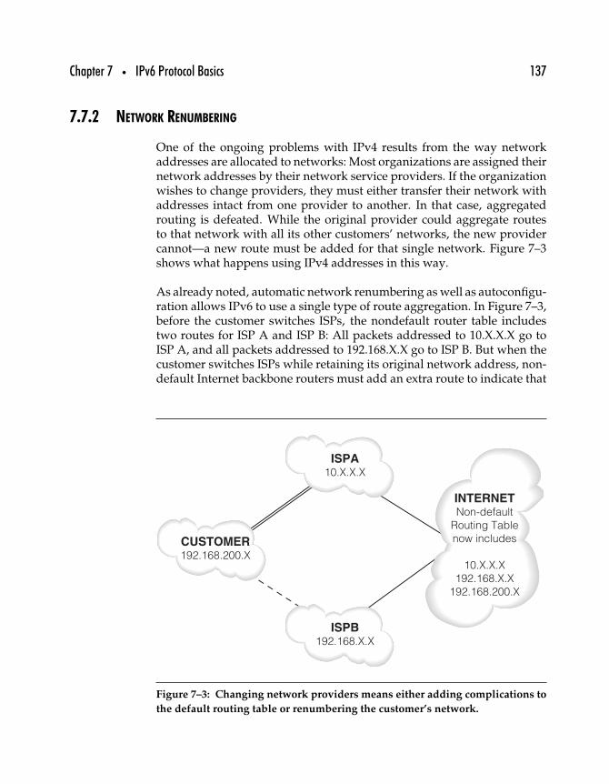
Chapter 7 • IPv6 Protocol Basics 137
7.7.2 NETWORK RENUMBERING
One of the ongoing problems with IPv4 results from the way networkaddresses are allocated to networks: Most organizations are assigned theirnetwork addresses by their network service providers. If the organizationwishes to change providers, they must either transfer their network withaddresses intact from one provider to another. In that case, aggregatedrouting is defeated. While the original provider could aggregate routesto that network with all its other customers’ networks, the new providercannot—a new route must be added for that single network. Figure 7–3shows what happens using IPv4 addresses in this way.
As already noted, automatic network renumbering as well as autoconfigu-ration allows IPv6 to use a single type of route aggregation. In Figure 7–3,before the customer switches ISPs, the nondefault router table includestwo routes for ISP A and ISP B: All packets addressed to 10.X.X.X go toISP A, and all packets addressed to 192.168.X.X go to ISP B. But when thecustomer switches ISPs while retaining its original network address, non-default Internet backbone routers must add an extra route to indicate that
CUSTOMER192.168.200.X
ISPA10.X.X.X
ISPB192.168.X.X
INTERNETNon-default
Routing Table
now includes
10.X.X.X
192.168.X.X
192.168.200.X
Figure 7–3: Changing network providers means either adding complications to
the default routing table or renumbering the customer’s network.
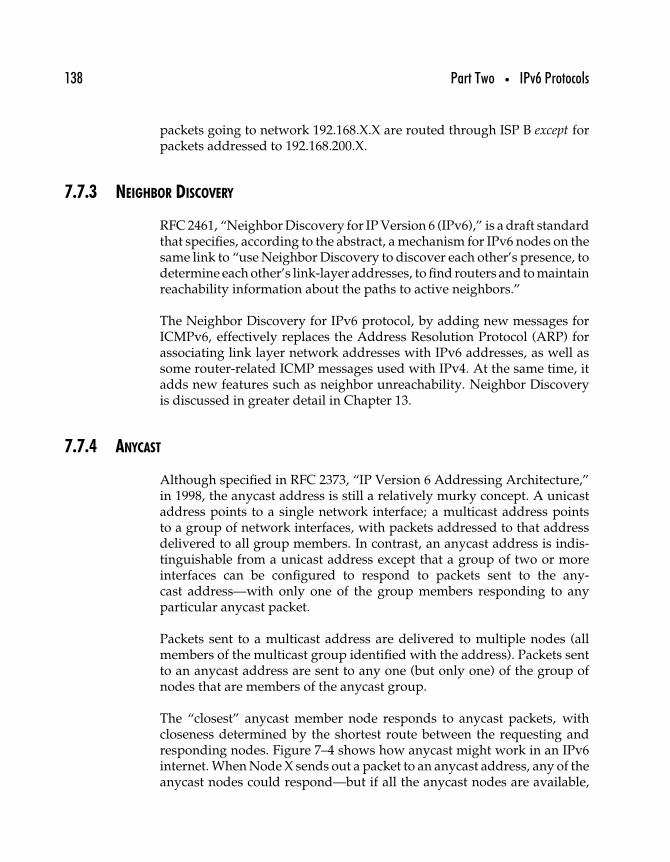
138 Part Two • IPv6 Protocols
packets going to network 192.168.X.X are routed through ISP B except forpackets addressed to 192.168.200.X.
7.7.3 NEIGHBOR DISCOVERY
RFC 2461, “Neighbor Discovery for IP Version 6 (IPv6),” is a draft standardthat specifies, according to the abstract, a mechanism for IPv6 nodes on thesame link to “use Neighbor Discovery to discover each other’s presence, todetermine each other’s link-layer addresses, to find routers and to maintainreachability information about the paths to active neighbors.”
The Neighbor Discovery for IPv6 protocol, by adding new messages forICMPv6, effectively replaces the Address Resolution Protocol (ARP) forassociating link layer network addresses with IPv6 addresses, as well assome router-related ICMP messages used with IPv4. At the same time, itadds new features such as neighbor unreachability. Neighbor Discoveryis discussed in greater detail in Chapter 13.
7.7.4 ANYCAST
Although specified in RFC 2373, “IP Version 6 Addressing Architecture,”in 1998, the anycast address is still a relatively murky concept. A unicastaddress points to a single network interface; a multicast address pointsto a group of network interfaces, with packets addressed to that addressdelivered to all group members. In contrast, an anycast address is indis-tinguishable from a unicast address except that a group of two or moreinterfaces can be configured to respond to packets sent to the any-cast address—with only one of the group members responding to anyparticular anycast packet.
Packets sent to a multicast address are delivered to multiple nodes (allmembers of the multicast group identified with the address). Packets sentto an anycast address are sent to any one (but only one) of the group ofnodes that are members of the anycast group.
The “closest” anycast member node responds to anycast packets, withcloseness determined by the shortest route between the requesting andresponding nodes. Figure 7–4 shows how anycast might work in an IPv6internet. When Node X sends out a packet to an anycast address, any of theanycast nodes could respond—but if all the anycast nodes are available,
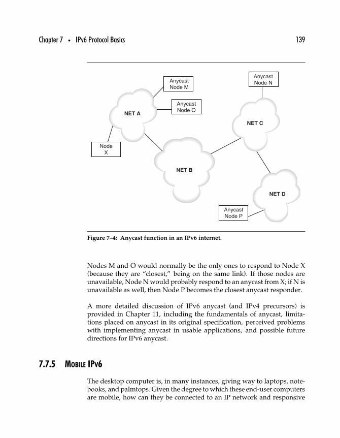
Chapter 7 • IPv6 Protocol Basics 139
NET A
NET B
AnycastNode M
AnycastNode N
AnycastNode O
AnycastNode P
NodeX
NET C
NET D
Figure 7–4: Anycast function in an IPv6 internet.
Nodes M and O would normally be the only ones to respond to Node X(because they are “closest,” being on the same link). If those nodes areunavailable, Node N would probably respond to an anycast from X; if N isunavailable as well, then Node P becomes the closest anycast responder.
A more detailed discussion of IPv6 anycast (and IPv4 precursors) isprovided in Chapter 11, including the fundamentals of anycast, limita-tions placed on anycast in its original specification, perceived problemswith implementing anycast in usable applications, and possible futuredirections for IPv6 anycast.
7.7.5 MOBILE IPV6
The desktop computer is, in many instances, giving way to laptops, note-books, and palmtops. Given the degree to which these end-user computersare mobile, how can they be connected to an IP network and responsive
140 Part Two • IPv6 Protocols
to a single IP address even as they are moved from one subnet to another?This problem is distinguishable from that of cellular mobile nodes, whichmust be capable of maintaining a virtual circuit as the nodes move fromone cell to another, in several important ways. First, the mobile IP nodemust be able to support a more formal definition of a virtual circuit, capa-ble of transmitting data with error detection. Also, the mobile IP node isnot expected to be quite as continuously or rapidly mobile as a mobiletelephone, for example.
The problem of mobility for IPv4 was first addressed in a standards trackspecification, RFC 2002, “IP Mobility Support,” in 1996. Not long after,work on extending IP mobility to IPv6 was begun—but as of early 2003,the IPv6 mobility specification, while considerably more mature, is still awork-in-progress.
In simple terms, the mobile IP node receives packets sent to its homeaddress from anywhere. When the mobile node is on its home network,it behaves like any other IP node. When the mobile node is “away,” themobile node stays in touch with its mobility agent, letting it know where it is(a care-of address) when it is not attached to the home network. The mobilityagent sits on the mobile node’s home network and resends packets sent tothe mobile node’s home address to the mobile node out on the road.
Unfortunately, IP mobility turns out to be somewhat more complicated,especially as requirements for performance, robustness, and securityincrease. IPv6 mobility is defined in a separate protocol, using IPv6 optionheaders, and will be discussed in greater detail in Chapter 17.
7.8 Summary
After reading this chapter, you should have a good overall picture of howIPv6 works, from its address space and architecture to special features andfunctions that have been added or updated in IPv6. Keeping in mind thisoverview of the IPv6 header, option headers, and the differences betweenIPv4 and IPv6, the next chapter probes more deeply into IPv6 addressing,from address representation to address types to the addresses each IPv6node must recognize.
88
IPv6 Addressing
One might suppose that the most obvious difference between IPv4 andIPv6 is the address space: IPv4 addresses are only 32 bits long, and IPv6addresses are 128 bits long. And there are more differences in the way IPv6uses those addresses. However, in another sense, address length will be theleast obvious change because it will be invisible to most users. Applicationscarried over IPv6 networks must rely completely on the Domain NameSystem (DNS) to correctly link IP host names to IPv6 addresses andnetworks. DNS and IPv6 will be discussed in detail in Chapter 18.
In this chapter, we begin with a discussion of the IPv6 addressing architec-ture, as designed by the original IPng working groups. Next, we look at theIPv6 address space, address formats, and the way in which addresses areintended to be allocated. IPv6 does away with broadcasts and relies insteadon unicast and multicast, and adds a new category: anycast addresses.
The IPv6 addressing architecture was first published as a proposed stan-dard in 1995, in RFC 1884, “IP Version 6 Addressing Architecture.”As originally formulated, IPv6 addresses were defined to be “128-bit
141
142 Part Two • IPv6 Protocols
identifiers for interfaces and sets of interfaces.” Three types of addresses—unicast, multicast, and anycast—were defined, with unicast defined as “anidentifier for a single interface. A packet sent to a unicast address is deliv-ered to the interface identified by that address.” Multicast and anycastaddressing will be discussed later in this chapter and in more detail inlater chapters.
Since 1995, the IPv6 addressing architecture specification has been updatedtwice, first in 1998, with the publication of RFC 2373, “IP Version 6 Address-ing Architecture,” and later with RFC 3513 in mid-2003. This section beginswith the basics as first defined in RFC 2373, followed by a discussion ofthe current standard as defined in RFC 3513.
8.1 IPv6 Address Types
There are three types of IPv6 address.
Unicast An identifier for a single interface. A packet sent to a unicastaddress is delivered to the interface identified by that address.
Multicast An identifier for a set of interfaces (typically belonging to dif-ferent nodes). A packet sent to a multicast address is delivered to allinterfaces identified by that address.
Anycast An identifier for a set of interfaces (typically belonging to differ-ent nodes). A packet sent to an anycast address is delivered to one ofthe interfaces identified by that address (the “nearest” one, accordingto the routing protocols’ measure of distance). Any unicast addresscould be specified as an anycast address, as long as all nodes con-figured to respond on that address are aware of its status as anycastrather than unicast.
Broadcast addresses have been deprecated, their functions having beenreplaced by multicast and anycast.
Broadcast created problems for IPv4 networks almost from the start.Intended to carry information destined for more than one node,1 broadcast
1As when a node attempts to request network booting information and has not beenconfigured for the local link.
Chapter 8 • IPv6 Addressing 143
can place a drag on network performance. As the number of broadcastson a local link increases, the burden on every node on the link to pro-cess all broadcasts also increases. And as networks become larger, thenumber of such burdened nodes not only increases but so too does thelikelihood that any individual node will ever have to actually process anyparticular broadcast packet. Finally, the practice of improperly forwardingbroadcasts across subnets can overwhelm routers.
With IPv6, the broadcast function is accomplished by sending packetsto the all nodes multicast address. More limited sets of multicast groups,such as “all routers on the local link,” provide broadcast functionalitymuch more efficiently. Nodes interested in the traffic formerly carriedin broadcasts can subscribe to a multicast address; all other uninterestednodes can ignore packets sent to that address. Broadcasts never adequatelysolved the problem of propagating information across the Internet—forexample, routing information—but multicast permits a more scalable, andacceptable, solution.
8.1.1 NETWORK AND NODE ADDRESSING
IPv6 addresses are usually divided into two equal parts with the high-order 64 bits usually identifying a network address and the low-order64 bits usually identifying the node with a modified EUI-64 address. Thisextended unique identifier is defined by (and is a trademark of) the IEEEand is based on the IEEE Registration Authority’s 24-bit OrganizationallyUnique Identifier (OUI), plus a 40-bit extension identifier assigned by theorganization assigned the OUI. These values are based on the same dataused to generate 48-bit Media Access Control (MAC) addresses associatedwith Ethernet and other LAN interface cards.
Interface addressing and the EUI-64 address are discussed in greater detaillater on in this chapter, as are IPv6 address types that don’t conform to thetypical 64/64 address division.
8.1.2 AGGREGATABLE ADDRESSING
IPv6 addresses are aggregatable in the same sense that ClasslessInterDomain Routing (CIDR) addresses are aggregatable: addressessharing the same prefixes can be forwarded over the same routes. RFC 2374
144 Part Two • IPv6 Protocols
defines a fairly strict regime for this aggregation, setting up three levelsat which aggregation can be accomplished (aggregation and aggregationentities will be discussed later in this chapter). However, these predefinedaggregation levels were made obsolete with publication of a revision toRFC 2374, RFC 3587, “IPv6 Global Unicast Address Format,” published asthis book went to press.
RFC 2374 also defines two types of aggregatable addresses. Provider-basedaggregatable addresses have to be changed when the provider is changed, butexchange-based addresses are allocated directly by an IPv6 exchange entitythat is independent of the network provider. The exchange entity providesan address block, while the subscriber contracts with a separate providerfor actual network access. The network access is provided either directly,through the provider, or indirectly, through the exchange, but routing isdone through the exchange. This makes possible arrangements by whichthe subscriber can change providers without address renumbering. It alsoallows the subscriber to use more than one Internet service provider tohandle a single block of network addresses.
As with the detailed aggregation entity layers, exchange-based addressesare likely to disappear in IPv6 standards after 2003.
8.1.3 IPv6 ADDRESS REPRESENTATION
IPv4 addresses are typically represented in dotted quad format, four decimalvalues (0 through 255) separated by periods, as in the following.
10.0.0.1
192.168.1.50
IPv6 addresses, four times as long as IPv4 addresses, are four times ascumbersome and potentially confusing. In RFC 3513, three approachesto representing IPv6 addresses are suggested. The preferred method is torepresent them as a sequence of eight 16-bit values, separated by colons.
XXXX:XXXX:XXXX:XXXX:XXXX:XXXX:XXXX:XXXX
Here is an example.
FEDC:BA98:7654:3210:FEDC:BA98:7654:3210
1080:0:0:0:8:800:200C:417
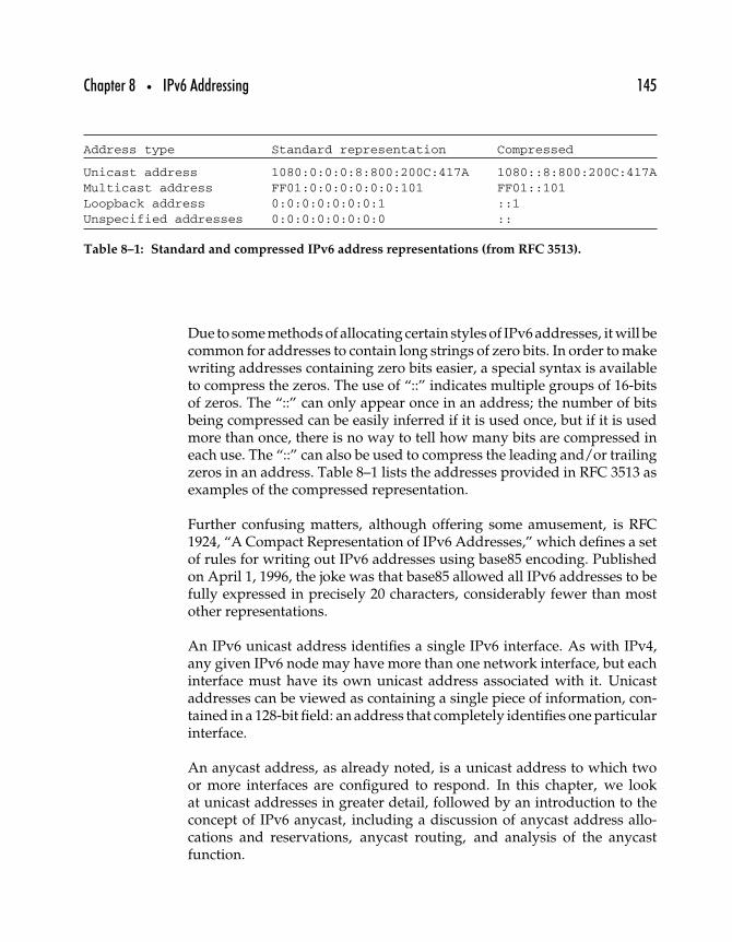
Chapter 8 • IPv6 Addressing 145
Address type Standard representation Compressed
Unicast address 1080:0:0:0:8:800:200C:417A 1080::8:800:200C:417AMulticast address FF01:0:0:0:0:0:0:101 FF01::101Loopback address 0:0:0:0:0:0:0:1 ::1Unspecified addresses 0:0:0:0:0:0:0:0 ::
Table 8–1: Standard and compressed IPv6 address representations (from RFC 3513).
Due to some methods of allocating certain styles of IPv6 addresses, it will becommon for addresses to contain long strings of zero bits. In order to makewriting addresses containing zero bits easier, a special syntax is availableto compress the zeros. The use of “::” indicates multiple groups of 16-bitsof zeros. The “::” can only appear once in an address; the number of bitsbeing compressed can be easily inferred if it is used once, but if it is usedmore than once, there is no way to tell how many bits are compressed ineach use. The “::” can also be used to compress the leading and/or trailingzeros in an address. Table 8–1 lists the addresses provided in RFC 3513 asexamples of the compressed representation.
Further confusing matters, although offering some amusement, is RFC1924, “A Compact Representation of IPv6 Addresses,” which defines a setof rules for writing out IPv6 addresses using base85 encoding. Publishedon April 1, 1996, the joke was that base85 allowed all IPv6 addresses to befully expressed in precisely 20 characters, considerably fewer than mostother representations.
An IPv6 unicast address identifies a single IPv6 interface. As with IPv4,any given IPv6 node may have more than one network interface, but eachinterface must have its own unicast address associated with it. Unicastaddresses can be viewed as containing a single piece of information, con-tained in a 128-bit field: an address that completely identifies one particularinterface.
An anycast address, as already noted, is a unicast address to which twoor more interfaces are configured to respond. In this chapter, we lookat unicast addresses in greater detail, followed by an introduction to theconcept of IPv6 anycast, including a discussion of anycast address allo-cations and reservations, anycast routing, and analysis of the anycastfunction.
146 Part Two • IPv6 Protocols
8.2 Unicast Address Types
Several types of unicast addresses have been defined for use with IPv6.
Global unicast Formerly known as aggregatable global unicast, theseaddresses can be routed across the global IPv6 Internet and areglobally unique.
Link local unicast These addresses are for addressing on a single link forpurposes such as auto-address configuration, neighbor discovery, orwhen no routers are present. Packets sent to this address are neversupposed to be forwarded across local links.
Site local unicast These addresses are for addressing packets within anentire site (or network or organization). Packets addressed to site-local addresses must never be forwarded outside the site. Althoughinternal network traffic routing can be done on complete IPv6addresses, allowing site-local unicast may allow greater routing effi-ciency. Site-local addresses may include up to 54 bits in the networkhalf of the address to indicate a subnet address.
Unicast addresses with embedded IPv4 addresses or encoded NSAPaddresses IPv6 supports interoperability with other network layerprotocols, not just IPv4. For example, a range of addresses was setaside for Novell’s NetWare/IPX addresses in RFC 2373. Although theIPX allocation has been dropped in RFC 3513, support for embeddingboth IPv4 and Network Service Access Point (NSAP) addresses usedwith the OSI Connectionless Network Protocol (CLNP) is provided inRFC 3513.
Table 8–2 shows how to identify different types of IPv6 addresses, includ-ing multicast and the unspecified and loopback address. The type of anIPv6 address is identified by the high-order bits of the address, as shown.
Unlike in IPv4, which usually works on one or two interface identifiers foreach network connection, in IPv6 a single interface may be required to haveseveral (sometimes many) interface identifiers to which it must respond.All interfaces must respond to a link local address as well as to a glob-ally unique address, and many will have to respond to a third, site-local,address. For systems that are subscribed to multicast or anycast groups,the number of identifiers can be significantly higher (see Chapter 10).
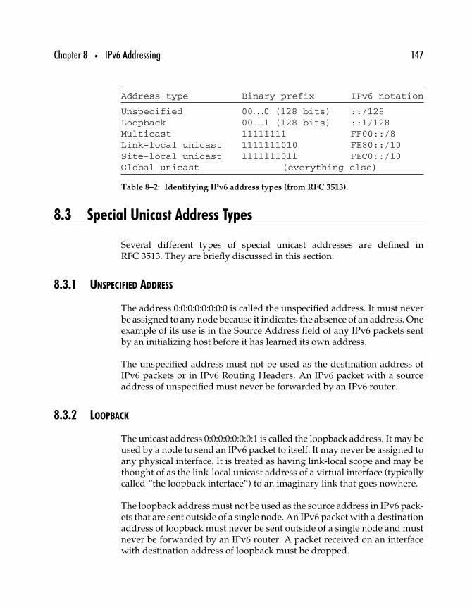
Chapter 8 • IPv6 Addressing 147
Address type Binary prefix IPv6 notation
Unspecified 00. . .0 (128 bits) ::/128Loopback 00. . .1 (128 bits) ::1/128Multicast 11111111 FF00::/8Link-local unicast 1111111010 FE80::/10Site-local unicast 1111111011 FEC0::/10Global unicast (everything else)
Table 8–2: Identifying IPv6 address types (from RFC 3513).
8.3 Special Unicast Address Types
Several different types of special unicast addresses are defined inRFC 3513. They are briefly discussed in this section.
8.3.1 UNSPECIFIED ADDRESS
The address 0:0:0:0:0:0:0:0 is called the unspecified address. It must neverbe assigned to any node because it indicates the absence of an address. Oneexample of its use is in the Source Address field of any IPv6 packets sentby an initializing host before it has learned its own address.
The unspecified address must not be used as the destination address ofIPv6 packets or in IPv6 Routing Headers. An IPv6 packet with a sourceaddress of unspecified must never be forwarded by an IPv6 router.
8.3.2 LOOPBACK
The unicast address 0:0:0:0:0:0:0:1 is called the loopback address. It may beused by a node to send an IPv6 packet to itself. It may never be assigned toany physical interface. It is treated as having link-local scope and may bethought of as the link-local unicast address of a virtual interface (typicallycalled “the loopback interface”) to an imaginary link that goes nowhere.
The loopback address must not be used as the source address in IPv6 pack-ets that are sent outside of a single node. An IPv6 packet with a destinationaddress of loopback must never be sent outside of a single node and mustnever be forwarded by an IPv6 router. A packet received on an interfacewith destination address of loopback must be dropped.
148 Part Two • IPv6 Protocols
8.3.3 ENCODED NSAP ADDRESSES
NSAP addressing is used for OSI CLNP networks, and a mechanism forencoding NSAP addresses into IPv6 addresses (as well as for encodingIPv6 addresses within NSAP addresses) is defined in the experimentalRFC 1888, “OSI NSAPs and IPv6.” However, due to the relative scarcityof CLNP networks and the recommendation that existing CLNP networksshould reimplement their addressing to support IPv6 directly, the NSAP-encoded IPv6 allocation may suffer the same fate as the IPX allocation.
8.4 IPv6 Address Format
At 128 bits, IPv6 addresses can carry much more information than 32-bitIPv4 addresses. An IPv4 address signifies little more than a unique networklayer interface; other than a unique local identifier coupled with a uniquenetwork identifier, there is no information implicit in the address. IPv6addresses, on the other hand, are capable of carrying more data.
The most basic representation of an IPv6 unicast address looks like this.
| 128 bits |+-----------------------------------------------------------------+| node address |+-----------------------------------------------------------------+
Any IPv6 node must be able to interpret an IPv6 address as a series of128 bits and determine whether the address refers to itself or not. EveryIPv6 unicast address is 128 bits long and represents a unique node networkinterface.
A slightly more sophisticated IPv6 implementation would be able toidentify IPv6 addresses as divisible into at least two separate parts.
| n bits | 128-n bits |+------------------------------------------------+----------------+| subnet prefix | interface ID |+------------------------------------------------+----------------+
In this case, the subnet prefix, defined by some number (“n”) of bits, isidentifiable as the local link to which the node is attached. A node capable
Chapter 8 • IPv6 Addressing 149
of making this distinction could perform a very simple routing function,transmitting packets destined for the local subnet locally and forwardingnonlocal packets to some default router.
A more detailed general representation of the IPv6 address providesthree parts: a global routing prefix (identifying a nondefault route for theaddress), a subnet ID, and an interface ID.
| n bits | m bits | 128-n-m bits |+------------------------+-----------+----------------------------+| global routing prefix | subnet ID | interface ID |
+------------------------+-----------+----------------------------+
This structure bears a superficial resemblance to the use of subnets in IPv4addresses, in which a single IPv4 network is subdivided into subnets.However, the IPv6 unicast addressing architecture was intended to bean aggregatable architecture. IPv6 network service providers maintainnondefault routers for their customers to handle external routing, accept-ing all packets whose addresses’ first n bits match the provider’s globalrouting prefix, the same prefix being incorporated into all their customers’IPv6 addresses. Within the service provider’s network, internal routersdistribute packets based on their destination address subnet ID.
8.4.1 IPv6 ADDRESS AGGREGATION FIELDS
In RFC 2374, the aggregatable unicast IPv6 address format is defined witha great deal of precision, splitting the 128-bit addresses in half, with thelow-order 64 bits representing the interface ID and the high-order 64 bitsdivided into several fields, in which routing structure information can berecorded.
| 3| 13 | 8 | 24 | 16 | 64 bits |+--+-----+---+--------+--------+--------------------------------+
|FP| TLA |RES| NLA | SLA | Interface ID || | ID | | ID | ID | |+--+-----+---+--------+--------+--------------------------------+
In this definition, taken from RFC 2374, the Format Prefix (FP) refers to thethree high-order bits of the address; when these bits are 001, the address isconsidered an aggregatable global unicast address. The other fields referto routing aggregation: Top Level, Next Level, and Site Level Aggregationidentifiers, with an octet reserved for future use.
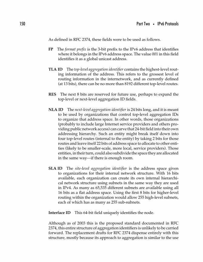
150 Part Two • IPv6 Protocols
As defined in RFC 2374, these fields were to be used as follows.
FP The format prefix is the 3-bit prefix to the IPv6 address that identifieswhere it belongs in the IPv6 address space. The value 001 in this fieldidentifies it as a global unicast address.
TLA ID The top-level aggregation identifier contains the highest-level rout-ing information of the address. This refers to the grossest level ofrouting information in the internetwork, and as currently defined(at 13 bits), there can be no more than 8192 different top-level routes.
RES The next 8 bits are reserved for future use, perhaps to expand thetop-level or next-level aggregation ID fields.
NLA ID The next-level aggregation identifier is 24 bits long, and it is meantto be used by organizations that control top-level aggregation IDsto organize that address space. In other words, those organizations(probably to include large Internet service providers and others pro-viding public network access) can carve that 24-bit field into their ownaddressing hierarchy. Such an entity might break itself down intofour top-level routes (internal to the entity) by taking 2 bits for thoseroutes and leave itself 22 bits of address space to allocate to other enti-ties (likely to be smaller-scale, more local, service providers). Thoseentities, in their turn, could also subdivide the space they are allocatedin the same way—if there is enough room.
SLA ID The site-level aggregation identifier is the address space givento organizations for their internal network structure. With 16 bitsavailable, each organization can create its own internal hierarchi-cal network structure using subnets in the same way they are usedin IPv4. As many as 65,535 different subnets are available using all16 bits as a flat address space. Using the first 8 bits for higher-levelrouting within the organization would allow 255 high-level subnets,each of which has as many as 255 sub-subnets.
Interface ID This 64-bit field uniquely identifies the node.
Although as of 2003 this is the proposed standard documented in RFC2374, this entire structure of aggregation identifiers is unlikely to be carriedforward. The replacement drafts for RFC 2374 dispense entirely with thisstructure, mostly because its approach to aggregation is similar to the use
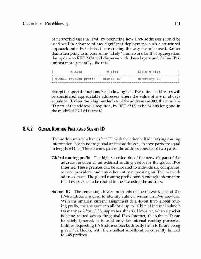
Chapter 8 • IPv6 Addressing 151
of network classes in IPv4. By restricting how IPv6 addresses should beused well in advance of any significant deployment, such a structuredapproach puts IPv6 at risk for restricting the way it can be used. Ratherthan attempting to impose some “likely” framework for IPv6 aggregation,the update to RFC 2374 will dispense with these layers and define IPv6unicast more generally, like this.
| n bits | m bits | 128-n-m bits |+------------------------+-----------+----------------------------+| global routing prefix | subnet ID | interface ID |+------------------------+-----------+----------------------------+
Except for special situations (see following), all IPv6 unicast addresses willbe considered aggregatable addresses where the value of n + m alwaysequals 64. (Unless the 3 high-order bits of the address are 000, the interfaceID part of the address is required, by RFC 3513, to be 64 bits long and inthe modified EUI-64 format.)
8.4.2 GLOBAL ROUTING PREFIX AND SUBNET ID
IPv6 addresses are half interface ID, with the other half identifying routinginformation. For standard global unicast addresses, the two parts are equalin length: 64 bits. The network part of the address consists of two parts.
Global routing prefix The highest-order bits of the network part of theaddress function as an external routing prefix for the global IPv6Internet. These prefixes can be allocated to individuals, companies,service providers, and any other entity requesting an IPv6 networkaddress space. The global routing prefix carries enough informationto allow packets to be routed to the site using the address.
Subnet ID The remaining, lower-order bits of the network part of theIPv6 address are used to identify subnets within an IPv6 network.With the smallest current assignment of a 48-bit IPv6 global rout-ing prefix, the assignee can allocate up to 16 bits of internal subnets
(as many as 216or 65,536 separate subnets). However, when a packetis being routed across the global IPv6 Internet, the subnet ID canbe safely ignored. It is used only for internal routing purposes.Entities requesting IPv6 address blocks directly from RIRs are beinggiven /32 blocks, with the smallest suballocation currently limitedto /48 prefixes.
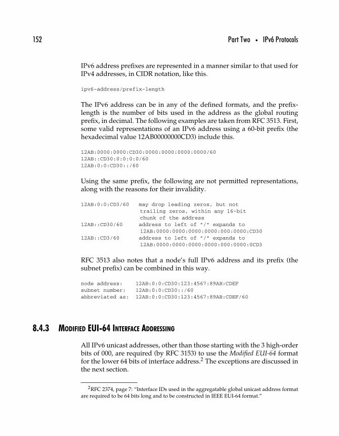
152 Part Two • IPv6 Protocols
IPv6 address prefixes are represented in a manner similar to that used forIPv4 addresses, in CIDR notation, like this.
ipv6-address/prefix-length
The IPv6 address can be in any of the defined formats, and the prefix-length is the number of bits used in the address as the global routingprefix, in decimal. The following examples are taken from RFC 3513. First,some valid representations of an IPv6 address using a 60-bit prefix (thehexadecimal value 12AB00000000CD3) include this.
12AB:0000:0000:CD30:0000:0000:0000:0000/6012AB::CD30:0:0:0:0/6012AB:0:0:CD30::/60
Using the same prefix, the following are not permitted representations,along with the reasons for their invalidity.
12AB:0:0:CD3/60 may drop leading zeros, but nottrailing zeros, within any 16-bitchunk of the address
12AB::CD30/60 address to left of "/" expands to12AB:0000:0000:0000:0000:000:0000:CD30
12AB::CD3/60 address to left of "/" expands to12AB:0000:0000:0000:0000:000:0000:0CD3
RFC 3513 also notes that a node’s full IPv6 address and its prefix (thesubnet prefix) can be combined in this way.
node address: 12AB:0:0:CD30:123:4567:89AB:CDEFsubnet number: 12AB:0:0:CD30::/60abbreviated as: 12AB:0:0:CD30:123:4567:89AB:CDEF/60
8.4.3 MODIFIED EUI-64 INTERFACE ADDRESSING
All IPv6 unicast addresses, other than those starting with the 3 high-orderbits of 000, are required (by RFC 3153) to use the Modified EUI-64 formatfor the lower 64 bits of interface address.2 The exceptions are discussed inthe next section.
2RFC 2374, page 7: “Interface IDs used in the aggregatable global unicast address formatare required to be 64 bits long and to be constructed in IEEE EUI-64 format.”
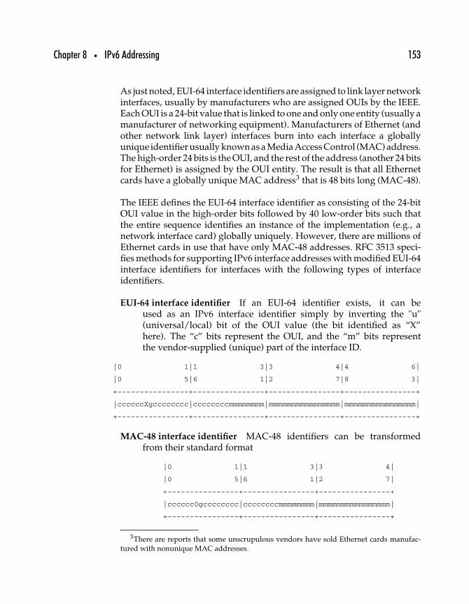
Chapter 8 • IPv6 Addressing 153
As just noted, EUI-64 interface identifiers are assigned to link layer networkinterfaces, usually by manufacturers who are assigned OUIs by the IEEE.Each OUI is a 24-bit value that is linked to one and only one entity (usually amanufacturer of networking equipment). Manufacturers of Ethernet (andother network link layer) interfaces burn into each interface a globallyunique identifier usually known as a Media Access Control (MAC) address.The high-order 24 bits is the OUI, and the rest of the address (another 24 bitsfor Ethernet) is assigned by the OUI entity. The result is that all Ethernetcards have a globally unique MAC address3 that is 48 bits long (MAC-48).
The IEEE defines the EUI-64 interface identifier as consisting of the 24-bitOUI value in the high-order bits followed by 40 low-order bits such thatthe entire sequence identifies an instance of the implementation (e.g., anetwork interface card) globally uniquely. However, there are millions ofEthernet cards in use that have only MAC-48 addresses. RFC 3513 speci-fies methods for supporting IPv6 interface addresses with modified EUI-64interface identifiers for interfaces with the following types of interfaceidentifiers.
EUI-64 interface identifier If an EUI-64 identifier exists, it can beused as an IPv6 interface identifier simply by inverting the "u"(universal/local) bit of the OUI value (the bit identified as “X”here). The “c” bits represent the OUI, and the “m” bits representthe vendor-supplied (unique) part of the interface ID.
|0 1|1 3|3 4|4 6|
|0 5|6 1|2 7|8 3|
+----------------+----------------+----------------+----------------+
|ccccccXgcccccccc|ccccccccmmmmmmmm|mmmmmmmmmmmmmmmm|mmmmmmmmmmmmmmmm|
+----------------+----------------+----------------+----------------+
MAC-48 interface identifier MAC-48 identifiers can be transformedfrom their standard format
|0 1|1 3|3 4|
|0 5|6 1|2 7|
+----------------+----------------+----------------+
|cccccc0gcccccccc|ccccccccmmmmmmmm|mmmmmmmmmmmmmmmm|
+----------------+----------------+----------------+
3There are reports that some unscrupulous vendors have sold Ethernet cards manufac-tured with nonunique MAC addresses.
154 Part Two • IPv6 Protocols
to this format
|0 1|1 3|3 4|4 6|
|0 5|6 1|2 7|8 3|
+----------------+----------------+----------------+----------------+
|cccccc1gcccccccc|cccccccc11111111|11111110mmmmmmmm|mmmmmmmmmmmmmmmm|
+----------------+----------------+----------------+----------------+
where the value 0xFF FE is inserted between the OUI and thevendor-supplied part of the interface identifier; the u bit is alsoinverted (from 0 to 1 in this case).
Nonglobal interface identifier Some link layer protocols, such as ARCnetand Apple’s LocalTalk, don’t use globally unique addresses butrather allow each link to assign whatever addresses it wants. AnEUI-64 formatted identifier can be generated by taking the linkaddress (unique only on that link) and prefix it with zero so that it is64 bits long. For example, an 8-bit node identifier whose hexadecimalvalue is 0x4F becomes the following.
|0 1|1 3|3 4|4 6|
|0 5|6 1|2 7|8 3|
+----------------+----------------+----------------+----------------+
|0000000000000000|0000000000000000|0000000000000000|0000000001001111|
+----------------+----------------+----------------+----------------+
Note that the universal/local bit (the seventh bit) will always beset to 0 in this type of identifier, resulting in clarification to otherIPv6 nodes that this node’s interface address is unique only on itsown link.
Security identifier RFC 3041, “Privacy Extensions for Stateless AddressAutoconfiguration in IPv6,” addresses the concerns of security andprivacy experts who point out that the permanent use of the sameinterface identifier, such as is done with IPv6 addresses based onIEEE MAC 48 addresses, can result in detailed mapping of a user’sInternet activities. Cross-referencing of Web server logs with existinginformation-gathering techniques can produce very precise profilesof these users, from their names, addresses, and credit card and otherpersonal information to inferences made about their personal inter-ests based on the Internet resources they use. Corporate users canalso be targeted by attackers seeking to track usage or map networksfor criminal activity.
Chapter 8 • IPv6 Addressing 155
In RFC 3041, a mechanism is defined for randomly generatingaddresses that conform to the modified EUI-64 format. Hosts usingthis mechanism may change their interface identifier every time theyconnect to the network or, more frequently, to thwart illicit (as wellas licit, but unwanted) information-gathering activities.
No interface identifier Point-to-point links and any other configuredtunnel links do not need interface identifiers (there are only two end-points, so each node can differentiate itself from the other end nodebased purely on whether data is going in or out). The only require-ment for interface identifiers in these cases is that they be unique onthe link. RFC 3513 suggests that in these cases the node assign anidentifier that is based on (but not the same as) a globally uniqueidentifier associated with the node in some way—either the identi-fier of another of that node’s interfaces or some identifier defined forthe node. Such identifiers may be configured manually, created witha random number generator, based on some other system identifier(serial number) or some other method.
The authors of RFC 3513 recommend strongly that to avoid dupli-cation of identifiers on a link, a collision detection algorithm beimplemented for links that do not use their own interface identifiers.Collision detection is a function of neighbor discovery, discussed inChapter 13.
RFCs specifying “IPv6 Over X” should be consulted for more detail abouthow to generate the IPv6 interface identifier for any particular link layerprotocol. Table 8–3 lists the link layer specifications current as of 2003.
RFC # Title
2590 Transmission of IPv6 Packets overFrame Relay Networks Specification
2497 Transmission of IPv6 Packets over ARCnet Networks2492 IPv6 over ATM Networks2491 IPv6 over Non-Broadcast Multiple Access (NBMA) Networks2472 IP Version 6 over PPP2470 Transmission of IPv6 Packets over Token Ring Networks2467 Transmission of IPv6 Packets over FDDI Networks2464 Transmission of IPv6 Packets over Ethernet Networks
Table 8–3: Specifications for transmitting IPv6 packets over various link layer protocols.
156 Part Two • IPv6 Protocols
8.4.4 IPv4-COMPATIBLE ADDRESSES
When IPv4 addresses are encapsulated within IPv6 addresses, a “mixed”format is allowed, in which the IPv4 portion of the address can berepresented in standard dotted quad form, while the rest of the address isformatted as a standard IPv6 address, resulting in this form.
XXXX:XXXX:XXXX:XXXX:XXXX:XXXX:ddd.ddd.ddd.ddd
These addresses were originally defined to fall into two categories.
IPv4-compatible IPv6 address The IPv6 transition mechanisms (see RFC2893, “Transition Mechanisms for IPv6 Hosts and Routers”) includea technique for hosts and routers to dynamically tunnel IPv6 packetsover IPv4 routing infrastructure. IPv6 nodes that use this techniqueare assigned special IPv6 unicast addresses that carry a global IPv4address in the low-order 32 bits.
IPv4-mapped IPv6 address A second type of IPv6 address that holds anembedded IPv4 address is also defined. This address type is used torepresent the addresses of IPv4 nodes as IPv6 addresses.
As of 2003, the IPv4-mapped address appears ready to be deprecated inresponse to work in progress being done by Jun-ichiro itojun Hagino andCraig Metz, both longtime contributors to the IPv6 effort. The two havedetermined that IPv4-mapped addresses can be subverted by attackers totrick IPv4 nodes into believing that an attacker’s packet actually originatedlocally.
8.5 IPv6 Node Self-Awareness
The IPv6 address architecture specification defines a set of addresses thatevery node must be able to recognize as referring to itself. The task issomewhat more complicated under IPv6 than IPv4 because IPv6 nodesmust be able to recognize every network interface as being a node ona link, a node within a site, and a node on the global IPv6 Internet.Under IPv4, nodes need only be able to recognize themselves by respond-ing to the loopback address and to addresses configured for any IPv4interface.
Chapter 8 • IPv6 Addressing 157
As defined in RFC 3513, a host is required to recognize the followingaddresses as identifying itself.
• A link-local address for each interface• All assigned unicast addresses• The loopback address• All all-nodes multicast addresses• Solicited-node multicast address for each of its assigned unicast
and anycast addresses• Multicast addresses of all other groups to which the host
belongs
A router is required to recognize all addresses that a host is required torecognize, plus the following addresses as identifying itself.
• The subnet-router anycast addresses for the interfaces it isconfigured to act as a router on
• All other anycast addresses with which the router has beenconfigured
• All-routers multicast addresses• Multicast addresses of all other groups to which the router
belongs
NOTE: Addressing and routing of multicast packets, including definitionsof the multicast-related addresses cited here, will be discussed at greaterlength in Chapter 10.
Another related issue is which addresses an IPv6 implementation shouldpredefine for all nodes. The specification makes clear that only thefollowing address prefixes should be predefined in an implementation.
• Unspecified address• Loopback address• Multicast prefix (FF)• Local-use prefixes (link-local and site-local)• Predefined multicast addresses• IPv4-compatible prefixes
All implementations should assume all other addresses are unicast unlessspecifically configured as anycast addresses.
158 Part Two • IPv6 Protocols
8.6 Summary
Although this chapter includes considerable detail about how to differen-tiate different types of special IPv6 addresses, as well as how to representthem in written documents, the most important facts relate to the way thatIPv6 addresses can be aggregated for routing purposes (see Chapter 14 formore on routing) and the general IPv6 unicast address format using theIEEE EUI-64 interface identifier.
The next chapter returns to the IPv6 header, specifically detailing the useof IPv6 header extensions to enable IP options. Unlike IPv4 options, whichare limited to no more than 40 octets of data in a special-case header field,IPv6 options work more efficiently and provide greater function than theirpredecessors.
99
IPv6 Options and ExtensionHeaders
This chapter discusses the implications of the IPv6 extension headers, howthey work, and how they differ from the IP option headers used with IPv4.Particular attention will be paid to the proper order and use of headerextensions, as well as discussion of the use of jumbograms, hop-by-hopoptions, destination options, routing, and fragmentation headers.
The most important IPv6 options, the IP Security Protocol (IPsec) headers,have already been introduced in Chapter 6. The ESP and AH headers lookthe same, whether used in IPv4 or IPv6, but the way those headers areattached to the IP header differs significantly. This chapter introducesthe concept of using extension headers to carry optional Internet-layer data—information about handling packets at the Internet layer that is not alwaysneeded but often required for particular applications. Security headersprovide one set of examples. Not all packets need to be authenticated orencrypted, but when nonrepudiation or privacy is required, packets mustcarry additional security information.
159
160 Part Two • IPv6 Protocols
Rather than making the length of the IPv6 headers variable, depending onwhether optional Internet-layer data must be carried along with the packet(as in IPv4), IPv6 optional data is carried in these supplementary extensionheaders that are inserted in the packet after the main IPv6 headers.
This chapter provides an introduction to the concept of extension headers,along with the following.
• IPv6 extension header placement in the packet• IPv6 extension header ordering in the packet• IPv6 extension header format• IPv6 extension header creation and modification• Current IPv6 extension headers
Because the IPv6 specification allows creation of new extension headers asthe need arises, the list of current extension headers may be incomplete.The interested reader should check the IANA Web site (www.iana.org) forcurrent values of available IPv6 options.
9.1 IPv6 Options and Extension Headers
RFC 2460 specifies IPv6 extension headers as the mechanism by which“optional Internet-layer information is encoded in separate headers thatmay be placed between the IPv6 header and the upper-layer header ina packet.” Each different type of extension header (the RFC defines fiveof them, and two others are defined for IPsec) is identified with an 8-bitprotocol identifier in the Next Header field of the previous header.1
As of early 2003, seven IPv6 extension headers have been defined. Table 9–1lists all of the valid values for IPv6 Next Header fields. Extension headeridentifiers are listed in the table along with other valid values.
9.1.1 ADDING EXTENSIONS TO IPv6 HEADERS
Figure 9–1 (from RFC 2460) shows how IPv6 extension headers are incor-porated into the packet. The first example shows a TCP/IPv6 packet with
1If there is only one extension header, the type of header is identified in the Next Headerfield of the IPv6 packet; if there are two or more extension headers, the second extensionheader is identified in the Next Header field of the first extension header.
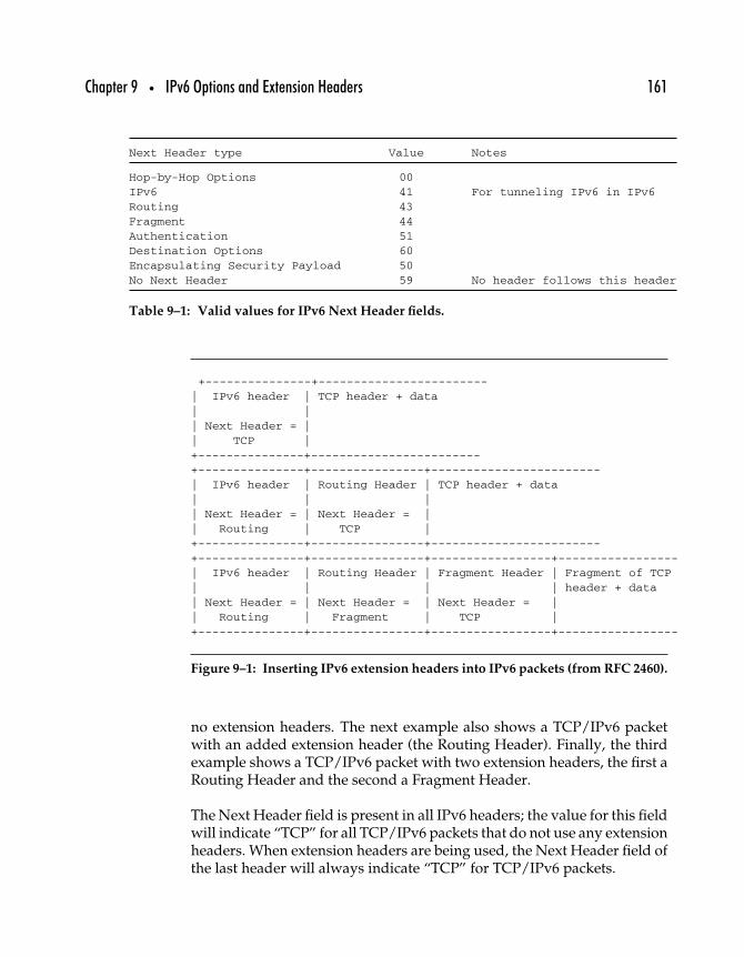
Chapter 9 • IPv6 Options and Extension Headers 161
Next Header type Value Notes
Hop-by-Hop Options 00IPv6 41 For tunneling IPv6 in IPv6Routing 43
Fragment 44
Authentication 51Destination Options 60Encapsulating Security Payload 50No Next Header 59 No header follows this header
Table 9–1: Valid values for IPv6 Next Header fields.
+---------------+------------------------| IPv6 header | TCP header + data
| |
| Next Header = || TCP |+---------------+------------------------+---------------+----------------+------------------------| IPv6 header | Routing Header | TCP header + data| | || Next Header = | Next Header = || Routing | TCP |+---------------+----------------+------------------------+---------------+----------------+-----------------+-----------------| IPv6 header | Routing Header | Fragment Header | Fragment of TCP| | | | header + data| Next Header = | Next Header = | Next Header = || Routing | Fragment | TCP |+---------------+----------------+-----------------+-----------------
Figure 9–1: Inserting IPv6 extension headers into IPv6 packets (from RFC 2460).
no extension headers. The next example also shows a TCP/IPv6 packetwith an added extension header (the Routing Header). Finally, the thirdexample shows a TCP/IPv6 packet with two extension headers, the first aRouting Header and the second a Fragment Header.
The Next Header field is present in all IPv6 headers; the value for this fieldwill indicate “TCP” for all TCP/IPv6 packets that do not use any extensionheaders. When extension headers are being used, the Next Header field ofthe last header will always indicate “TCP” for TCP/IPv6 packets.
162 Part Two • IPv6 Protocols
These are some current (mid-2003) IPv6 extensions.
Routing Similar in purpose to the Loose Source and Record Route Optiondefined for IPv4, the Routing Option allows the node sending a packetto specify one or more routers that must process the packet en routeto its destination.
Hop-by-Hop Some IPv6 options are logically constrained to being usedonly by the source and destination nodes. For example, the ESPheader, which indicates that the rest of the packet is encrypted, can besafely ignored by intermediate routers. Likewise, other IPv6 optionsare logically required to be processed by intermediate nodes. Forexample, the Routing Header requires that at least some intermedi-ate routers examine it. The Hop-by-Hop Header is used when one ormore options are present that must be examined by every node in thedelivery path from source to destination.
Fragment Although IPv6 prohibits intermediate nodes from fragment-ing packets, end-to-end fragmentation is permitted when the sourcenode determines it needs to send packets that are larger than thepath MTU (see Chapter 12). The Fragment Header contains informa-tion regarding packet fragmentation, intended only for the packet’sdestination node.
Destination Just as the Hop-by-Hop Header is defined to specificallyrequire all intermediate nodes to process the header, the Destina-tion Header is defined to limit the use of the enclosed options to thedestination node only.
Authentication When strong (cryptographic quality) authentication isrequired, the Authentication Header is used (see Chapter 6).
Encapsulating Security Protocol When strong encryption is required,the ESP Header is used (see Chapter 6).
Clearly, there are issues related to the order in which extension headersare added to a packet header, to be discussed next.
9.1.2 EXTENSION HEADER ORDERING
When an IPv6 packet is transmitted with two or more extension headers,a choice must be made about the order in which the headers are placed
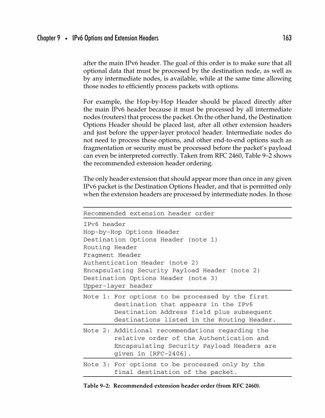
Chapter 9 • IPv6 Options and Extension Headers 163
after the main IPv6 header. The goal of this order is to make sure that alloptional data that must be processed by the destination node, as well asby any intermediate nodes, is available, while at the same time allowingthose nodes to efficiently process packets with options.
For example, the Hop-by-Hop Header should be placed directly afterthe main IPv6 header because it must be processed by all intermediatenodes (routers) that process the packet. On the other hand, the DestinationOptions Header should be placed last, after all other extension headersand just before the upper-layer protocol header. Intermediate nodes donot need to process these options, and other end-to-end options such asfragmentation or security must be processed before the packet’s payloadcan even be interpreted correctly. Taken from RFC 2460, Table 9–2 showsthe recommended extension header ordering.
The only header extension that should appear more than once in any givenIPv6 packet is the Destination Options Header, and that is permitted onlywhen the extension headers are processed by intermediate nodes. In those
Recommended extension header order
IPv6 headerHop-by-Hop Options HeaderDestination Options Header (note 1)Routing HeaderFragment HeaderAuthentication Header (note 2)Encapsulating Security Payload Header (note 2)Destination Options Header (note 3)Upper-layer header
Note 1: For options to be processed by the firstdestination that appears in the IPv6Destination Address field plus subsequentdestinations listed in the Routing Header.
Note 2: Additional recommendations regarding therelative order of the Authentication andEncapsulating Security Payload Headers aregiven in [RFC-2406].
Note 3: For options to be processed only by thefinal destination of the packet.
Table 9–2: Recommended extension header order (from RFC 2460).
164 Part Two • IPv6 Protocols
cases, a set of options can be attached for the intermediate “destinations”that the packet visits en route to its final destination—where a secondDestination Options Header can be processed only by the end-node.
Again, the recommended restriction on having only one of each extensionheader is based on logic. For example, all Hop-by-Hop Options should beincorporated into a single extension header for efficiency. Likewise, onlyone each of a Routing, Fragment, or Security Header makes sense for eachpacket.
It should be noted that the order specified in Table 9–2 is a recommendationand not a requirement.2 Although IPv6 implementations should 3 conformto these recommendations, they are not required to do so. And in keepingwith the fundamental Internet liberal/conservative principle (“Be liberalin what you accept, and conservative in what you send”; see RFC 791), IPv6nodes are required to accept and attempt to process whatever extensionheaders occur in a packet, whether in the recommended order or not andwhether there is only one of each type or more.
9.1.3 IPV6-IN-IPV6 TUNNELING
The IPv6 Next Header type is included in Table 9–1, and when it appears,it indicates that IPv6 packets are being tunneled within another stream ofIPv6 packets. Protocol tunneling happens when datagrams from one pro-tocol are encapsulated within datagrams of another protocol. A concreteexample of protocol tunneling might occur when a person has postal mailforwarded from her home office to her branch office by having each pieceof mail placed in a new envelope with the branch office address as the newdestination. The original piece of mail is unchanged, and it will eventuallybe delivered to the appropriate person, but it was wrapped (encapsulated)in a different packet before it arrived at its intended destination.
Conceptually, IP-in-IP tunneling is quite similar, and it is often linked withthe similar function of mobile IP delivery when a mobile node notifiesits home network of a forward-to address. Then, any packets sent to the
2The exception is the Hop-by-Hop Header, which must appear only immediately after themain IPv6 header. See section 9.4 for more about this type of header.
3The term should is defined for use in an RFC (see RFC 2119, “Key Words for Use in RFCsto Indicate Requirement Levels”) to indicate “that there may exist valid reasons in particularcircumstances to ignore a particular item, but the full implications must be understood andcarefully weighed before choosing a different course.”
Chapter 9 • IPv6 Options and Extension Headers 165
mobile node’s home address can be encapsulated in a new IP packet forredelivery to the mobile node’s current location (see Chapter 17 for moreabout Mobile IPv6).
When an IPv6 packet is encapsulated within another IPv6 packet, theencapsulated packet may have one set of extension headers that are pro-cessed only after the packet arrives at the other end of the tunnel. At thesame time, the encapsulating packet can have its own set of extensionheaders that are added by the node at the transmitting end of the tunneland processed only by intermediate nodes within the tunnel and/or bythe node at the receiving end of the tunnel.
9.1.4 IPv6 EXTENSION HEADERS AND OPTIONS
The IPv6 extension headers are intended to carry optional Internet-layerdata, so all extension headers are considered to be optional. Two ofthe originally defined extension headers—the Hop-by-Hop Options andDestination Options Headers—can carry one or more options to be inter-preted by the appropriate recipient(s). Unlike the other IPv6 extensionheaders, which enable specific functions (fragmentation, encryption, etc.)while at the same time being optional (there is no requirement to encryptpackets, for example), the Hop-by-Hop and Destination Option extensionsare generalized headers that are distinguished only by the way they areprocessed.
In other words, Hop-by-Hop Option Headers carry options that are pro-cessed at every hop; Destination Option Headers carry options that areprocessed only at the destination.
In some cases, there is confusion about the nomenclature of IPv6 extensionheaders. It should be noted here that extension headers contain optionaldata but are not necessarily options headers. Only the Hop-by-HopOptions and Destination Options Headers are actually “options headers”because they carry unspecified options to be processed by, respectively,nodes at each hop or the destination node(s).
9.2 Routing Header
The IP routing architecture is designed to allow interoperation amongnodes without having to program internetwork structure into those nodes.
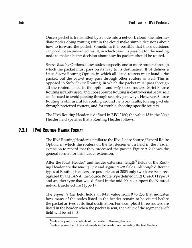
166 Part Two • IPv6 Protocols
Once a packet is transmitted by a node into a network cloud, the interme-diate nodes doing routing within the cloud make simple decisions abouthow to forward the packet. Sometimes it is possible that those decisionscan produce an unwanted result, in which case it is possible for the sendingnode to make a better decision about how its packets should be routed.
Source Routing Options allow nodes to specify one or more routers throughwhich the packet must pass on its way to its destination. IPv4 defines aLoose Source Routing Option, in which all listed routers must handle thepacket, but the packet may pass through other routers as well. This isopposed to Strict Source Routing, in which the packet must pass throughall the routers listed in the option and only those routers. Strict SourceRouting is rarely used, and Loose Source Routing is controversial because itcan be used to avoid passing through security gateways. However, SourceRouting is still useful for routing around network faults, forcing packetsthrough preferred routers, and for trouble-shooting specific routers.
The IPv6 Routing Header is defined in RFC 2460; the value 43 in the NextHeader field specifies that a Routing Header follows.
9.2.1 IPv6 ROUTING HEADER FORMAT
The IPv6 Routing Header is similar to the IPv4 Loose Source/Record RouteOption, in which the routers on the list decrement a field in the headerextension to record that they processed the packet. Figure 9–2 shows thegeneral format for this header extension.
After the Next Header4 and header extension length5 fields of the Rout-ing Header are the routing type and segments left fields. Although differenttypes of Routing Headers are possible, as of 2003 only two have been rec-ognized by the IANA: the Source Route type defined in RFC 2460 (Type 0)and another type that was defined in the mid-90s to support the Nimrodnetwork architecture (Type 1).
The Segments Left field holds an 8-bit value from 0 to 255 that indicateshow many of the nodes listed in the header remain to be visited beforethe packet arrives at its final destination. For example, if three routers arelisted in the header when the packet is sent, the value of the segment’s leftfield will be set to 3.
4Indicates protocol contents of the header following this one.5Indicates number of 8-octet words in the header, not including the first 8 octets.
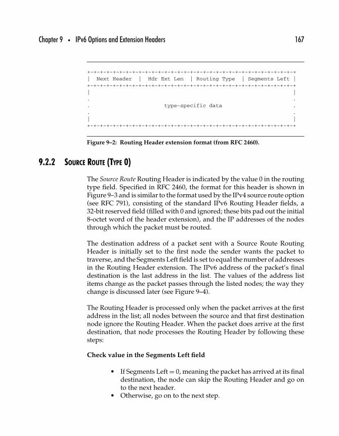
Chapter 9 • IPv6 Options and Extension Headers 167
+-+-+-+-+-+-+-+-+-+-+-+-+-+-+-+-+-+-+-+-+-+-+-+-+-+-+-+-+-+-+-+-+| Next Header | Hdr Ext Len | Routing Type | Segments Left |+-+-+-+-+-+-+-+-+-+-+-+-+-+-+-+-+-+-+-+-+-+-+-+-+-+-+-+-+-+-+-+-+| |. .. type-specific data .. .| |+-+-+-+-+-+-+-+-+-+-+-+-+-+-+-+-+-+-+-+-+-+-+-+-+-+-+-+-+-+-+-+-+
Figure 9–2: Routing Header extension format (from RFC 2460).
9.2.2 SOURCE ROUTE (TYPE 0)
The Source Route Routing Header is indicated by the value 0 in the routingtype field. Specified in RFC 2460, the format for this header is shown inFigure 9–3 and is similar to the format used by the IPv4 source route option(see RFC 791), consisting of the standard IPv6 Routing Header fields, a32-bit reserved field (filled with 0 and ignored; these bits pad out the initial8-octet word of the header extension), and the IP addresses of the nodesthrough which the packet must be routed.
The destination address of a packet sent with a Source Route RoutingHeader is initially set to the first node the sender wants the packet totraverse, and the Segments Left field is set to equal the number of addressesin the Routing Header extension. The IPv6 address of the packet’s finaldestination is the last address in the list. The values of the address listitems change as the packet passes through the listed nodes; the way theychange is discussed later (see Figure 9–4).
The Routing Header is processed only when the packet arrives at the firstaddress in the list; all nodes between the source and that first destinationnode ignore the Routing Header. When the packet does arrive at the firstdestination, that node processes the Routing Header by following thesesteps:
Check value in the Segments Left field
• If Segments Left = 0, meaning the packet has arrived at its finaldestination, the node can skip the Routing Header and go onto the next header.
• Otherwise, go on to the next step.
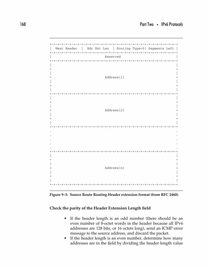
168 Part Two • IPv6 Protocols
+-+-+-+-+-+-+-+-+-+-+-+-+-+-+-+-+-+-+-+-+-+-+-+-+-+-+-+-+-+-+-+-+| Next Header | Hdr Ext Len | Routing Type=0| Segments Left |+-+-+-+-+-+-+-+-+-+-+-+-+-+-+-+-+-+-+-+-+-+-+-+-+-+-+-+-+-+-+-+-+| Reserved |+-+-+-+-+-+-+-+-+-+-+-+-+-+-+-+-+-+-+-+-+-+-+-+-+-+-+-+-+-+-+-+-+| |+ +| |+ Address[1] +| |+ +
| |+-+-+-+-+-+-+-+-+-+-+-+-+-+-+-+-+-+-+-+-+-+-+-+-+-+-+-+-+-+-+-+-+
| |+ +| |+ Address[2] +| |+ +| |+-+-+-+-+-+-+-+-+-+-+-+-+-+-+-+-+-+-+-+-+-+-+-+-+-+-+-+-+-+-+-+-+. .. .. .. .. .+-+-+-+-+-+-+-+-+-+-+-+-+-+-+-+-+-+-+-+-+-+-+-+-+-+-+-+-+-+-+-+-+| |+ +| |+ Address[n] +| |+ +| |+-+-+-+-+-+-+-+-+-+-+-+-+-+-+-+-+-+-+-+-+-+-+-+-+-+-+-+-+-+-+-+-+
Figure 9–3: Source Route Routing Header extension format (from RFC 2460).
Check the parity of the Header Extension Length field
• If the header length is an odd number (there should be aneven number of 8-octet words in the header because all IPv6addresses are 128 bits, or 16 octets long), send an ICMP errormessage to the source address, and discard the packet.
• If the header length is an even number, determine how manyaddresses are in the field by dividing the header length value
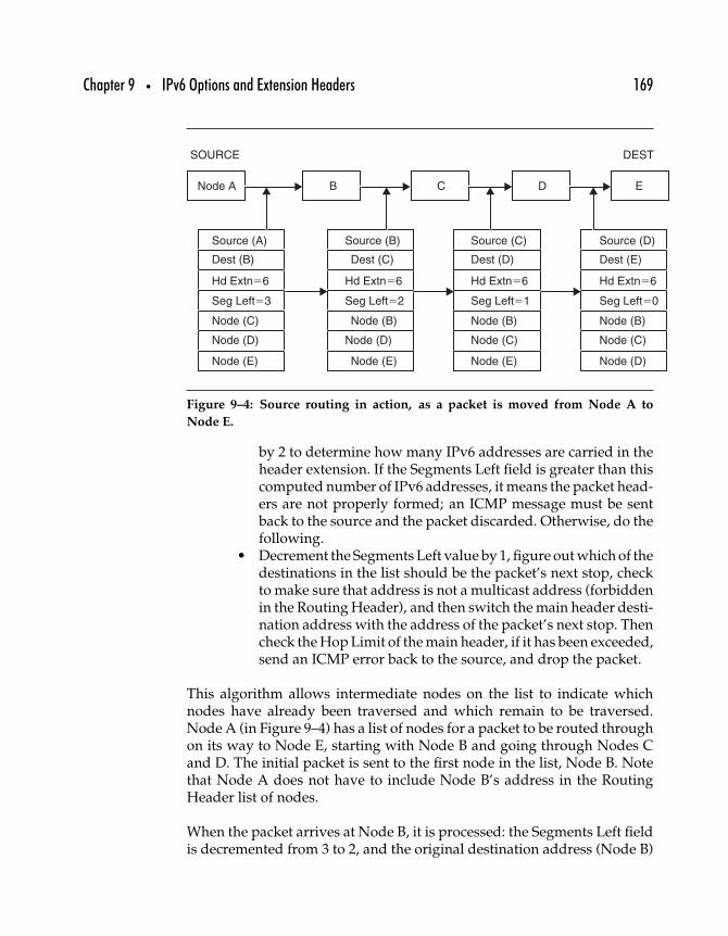
Chapter 9 • IPv6 Options and Extension Headers 169
Node A
SOURCE
Source (A)
Dest (B)
Hd Extn�6
Seg Left�3
Node (C)
Node (D)
Node (E)
Source (B)
Dest (C)
Hd Extn�6
Seg Left�2
Node (B)
Node (D)
Node (E)
Source (C)
Dest (D)
Hd Extn�6
Seg Left�1
Node (B)
Node (C)
Node (E)
Source (D)
Dest (E)
Hd Extn�6
Seg Left�0
Node (B)
Node (C)
Node (D)
DEST
B C D E
Figure 9–4: Source routing in action, as a packet is moved from Node A to
Node E.
by 2 to determine how many IPv6 addresses are carried in theheader extension. If the Segments Left field is greater than thiscomputed number of IPv6 addresses, it means the packet head-ers are not properly formed; an ICMP message must be sentback to the source and the packet discarded. Otherwise, do thefollowing.
• Decrement the Segments Left value by 1, figure out which of thedestinations in the list should be the packet’s next stop, checkto make sure that address is not a multicast address (forbiddenin the Routing Header), and then switch the main header desti-nation address with the address of the packet’s next stop. Thencheck the Hop Limit of the main header, if it has been exceeded,send an ICMP error back to the source, and drop the packet.
This algorithm allows intermediate nodes on the list to indicate whichnodes have already been traversed and which remain to be traversed.Node A (in Figure 9–4) has a list of nodes for a packet to be routed throughon its way to Node E, starting with Node B and going through Nodes Cand D. The initial packet is sent to the first node in the list, Node B. Notethat Node A does not have to include Node B’s address in the RoutingHeader list of nodes.
When the packet arrives at Node B, it is processed: the Segments Left fieldis decremented from 3 to 2, and the original destination address (Node B)
170 Part Two • IPv6 Protocols
trades places with the first node on the Routing Header list (Node C). Oncethis packet is received at Node C, the Segments Left field goes from 2 to 1,and Node C’s address goes back to the Routing Header to be replaced byNode D’s address. The process repeats for Node E, the final destination,where the Routing Header list contains just the nodes that were originallyspecified to be stops en route from Node A to Node E.
Routers may be required to modify Routing Headers of the packets theyprocess, but some header extensions may not be modified at all, like theFragment Header.
9.3 Fragment Header
To send a payload that is too large to be accommodated in a single packet(because the resulting packet would be larger than the path MTU fromsource to destination), IPv6 permits nodes to break up the packet into twoor more pieces and then send each piece (fragment) as a separate packet.
The Fragment Header in IPv6 allows only source nodes to fragment packetsfor reassembly only by the destination node—end-to-end fragmentation.It is useful to understand how IPv4 fragmentation works before lookingat IPv6 fragmentation.
9.3.1 IPv4 FRAGMENTATION
IPv4’s datagram Fragmentation Option has long caused controversy: Itsquanders IPv4 header real estate, accounting for 20% of the basic IPheader (the datagram ID, fragmentation flags, and fragment offset field).Fragmentation adds a computational burden on routers and destinationnodes. Fragmentation makes IPv4 more complicated to implement, as well.IPv6 permits only end-to-end fragmentation—in other words, the sourceand destination nodes that are communicating are permitted to negotiatethe use of fragmentation by the source only. In IPv4, packets could be frag-mented by intermediate routers to allow packets larger than the maximumtransmission unit or MTU for some link.
Ultimately, this kind of fragmentation in IPv4 was permitted because thealternatives seemed even less appealing. Placing an upper limit on IP data-gram size lower than the smallest allowed PDU on any network medium
Chapter 9 • IPv6 Options and Extension Headers 171
using IP would unreasonably limit the PDU size for media that can handlevery large chunks of data efficiently. Limiting the IP datagram length tounder 1500 octets (the maximum allowed size for Ethernet frames) or to576 octets (MTU for the X.25 wide area network protocol) would likewiselimit more efficient network media.
Alternatively, placing a lower limit on the size of PDU of any networkmedium using IP and thus requiring all network media to support someminimum PDU size determined by the IETF would unnecessarily restrictthe types of media capable of carrying IP. Since one of the most basic tenetsof IP networking is that it is a universally interoperable protocol, this optionis also unacceptable.
IPv4 packets can potentially be fragmented any time they cross differenttypes of network media. For example, a 1492-octet-long IP datagram isjust long enough to fit inside an Ethernet frame, but it would have tobe fragmented in order to cross an X.25 network, which can handle onlydatagrams as large as 576 octets.
A node sets the length of its datagrams based on its local MTU. IPv4 has anupper limit on datagram size of 65,535 octets, since the IP header fieldfor datagram length is 16 bits long. However, most common networkmedia have much smaller maximum network frame sizes, as discussedin the previous chapter. When there are several different networks acrosswhich network traffic passes, there will be a path MTU. This is the largestunit that can pass unfragmented across all the intervening networks ina datagrams route—in other words, the smallest MTU of any of thosenetworks.
9.3.2 IPv6 FRAGMENTATION HEADER FIELDS
The IPv6 header is considerably simplified by the absence offragmentation-related headers, thus simplifying the task of processingthe standard IPv6 header. When fragmentation occurs, the source nodeinserts a Fragmentation Header (signified by a value of 44 in the precedingheader’s Next Header field). Figure 9–5 shows the format for this headerextension.
The header extension carries the appropriate data for fragmentation butonly when it is needed. The fields in this header extension include thefollowing.
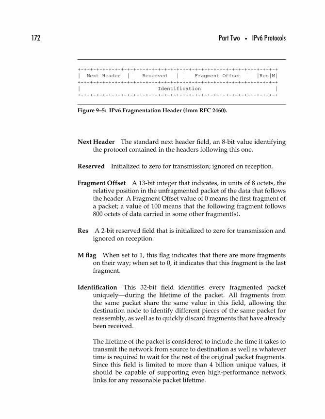
172 Part Two • IPv6 Protocols
+-+-+-+-+-+-+-+-+-+-+-+-+-+-+-+-+-+-+-+-+-+-+-+-+-+-+-+-+-+-+-+-+| Next Header | Reserved | Fragment Offset |Res|M|+-+-+-+-+-+-+-+-+-+-+-+-+-+-+-+-+-+-+-+-+-+-+-+-+-+-+-+-+-+-+-+-+| Identification |+-+-+-+-+-+-+-+-+-+-+-+-+-+-+-+-+-+-+-+-+-+-+-+-+-+-+-+-+-+-+-+-+
Figure 9–5: IPv6 Fragmentation Header (from RFC 2460).
Next Header The standard next header field, an 8-bit value identifyingthe protocol contained in the headers following this one.
Reserved Initialized to zero for transmission; ignored on reception.
Fragment Offset A 13-bit integer that indicates, in units of 8 octets, therelative position in the unfragmented packet of the data that followsthe header. A Fragment Offset value of 0 means the first fragment ofa packet; a value of 100 means that the following fragment follows800 octets of data carried in some other fragment(s).
Res A 2-bit reserved field that is initialized to zero for transmission andignored on reception.
M flag When set to 1, this flag indicates that there are more fragmentson their way; when set to 0, it indicates that this fragment is the lastfragment.
Identification This 32-bit field identifies every fragmented packetuniquely—during the lifetime of the packet. All fragments fromthe same packet share the same value in this field, allowing thedestination node to identify different pieces of the same packet forreassembly, as well as to quickly discard fragments that have alreadybeen received.
The lifetime of the packet is considered to include the time it takes totransmit the network from source to destination as well as whatevertime is required to wait for the rest of the original packet fragments.Since this field is limited to more than 4 billion unique values, itshould be capable of supporting even high-performance networklinks for any reasonable packet lifetime.
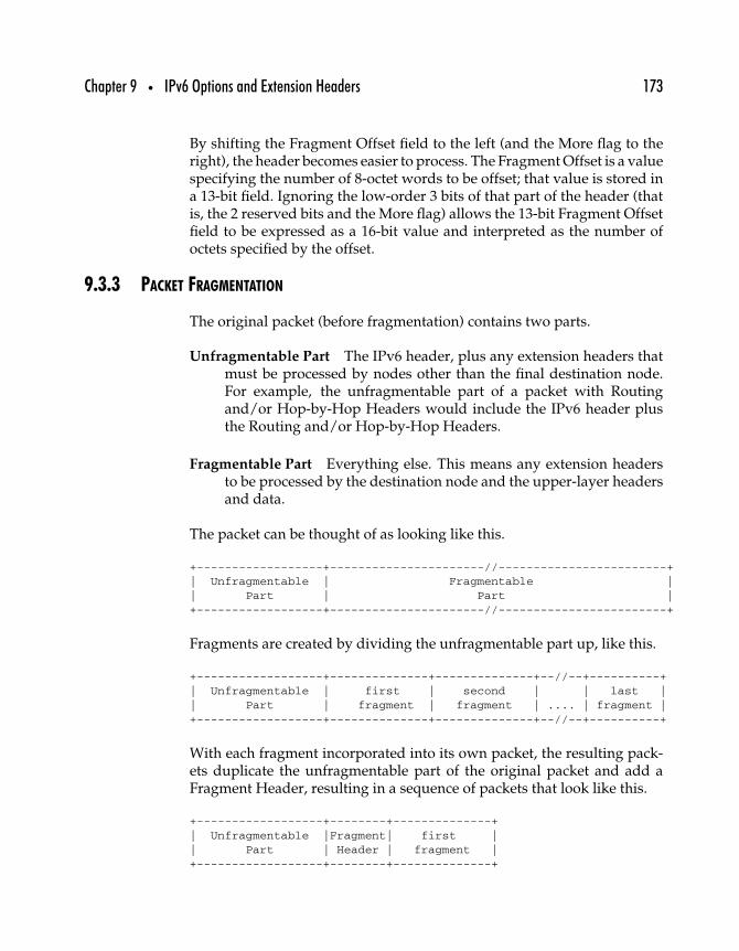
Chapter 9 • IPv6 Options and Extension Headers 173
By shifting the Fragment Offset field to the left (and the More flag to theright), the header becomes easier to process. The Fragment Offset is a valuespecifying the number of 8-octet words to be offset; that value is stored ina 13-bit field. Ignoring the low-order 3 bits of that part of the header (thatis, the 2 reserved bits and the More flag) allows the 13-bit Fragment Offsetfield to be expressed as a 16-bit value and interpreted as the number ofoctets specified by the offset.
9.3.3 PACKET FRAGMENTATION
The original packet (before fragmentation) contains two parts.
Unfragmentable Part The IPv6 header, plus any extension headers thatmust be processed by nodes other than the final destination node.For example, the unfragmentable part of a packet with Routingand/or Hop-by-Hop Headers would include the IPv6 header plusthe Routing and/or Hop-by-Hop Headers.
Fragmentable Part Everything else. This means any extension headersto be processed by the destination node and the upper-layer headersand data.
The packet can be thought of as looking like this.
+------------------+----------------------//------------------------+| Unfragmentable | Fragmentable || Part | Part |+------------------+----------------------//------------------------+
Fragments are created by dividing the unfragmentable part up, like this.
+------------------+--------------+--------------+--//--+----------+| Unfragmentable | first | second | | last || Part | fragment | fragment | .... | fragment |+------------------+--------------+--------------+--//--+----------+
With each fragment incorporated into its own packet, the resulting pack-ets duplicate the unfragmentable part of the original packet and add aFragment Header, resulting in a sequence of packets that look like this.
+------------------+--------+--------------+| Unfragmentable |Fragment| first || Part | Header | fragment |+------------------+--------+--------------+
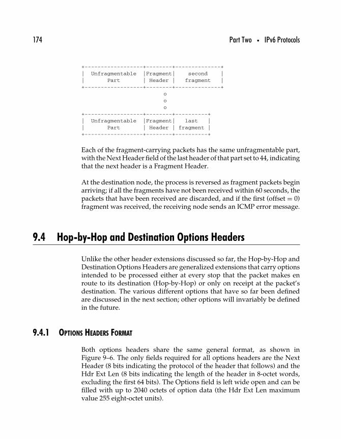
174 Part Two • IPv6 Protocols
+------------------+--------+--------------+| Unfragmentable |Fragment| second || Part | Header | fragment |+------------------+--------+--------------+
ooo
+------------------+--------+----------+| Unfragmentable |Fragment| last || Part | Header | fragment |+------------------+--------+----------+
Each of the fragment-carrying packets has the same unfragmentable part,with the Next Header field of the last header of that part set to 44, indicatingthat the next header is a Fragment Header.
At the destination node, the process is reversed as fragment packets beginarriving; if all the fragments have not been received within 60 seconds, thepackets that have been received are discarded, and if the first (offset = 0)fragment was received, the receiving node sends an ICMP error message.
9.4 Hop-by-Hop and Destination Options Headers
Unlike the other header extensions discussed so far, the Hop-by-Hop andDestination Options Headers are generalized extensions that carry optionsintended to be processed either at every stop that the packet makes enroute to its destination (Hop-by-Hop) or only on receipt at the packet’sdestination. The various different options that have so far been definedare discussed in the next section; other options will invariably be definedin the future.
9.4.1 OPTIONS HEADERS FORMAT
Both options headers share the same general format, as shown inFigure 9–6. The only fields required for all options headers are the NextHeader (8 bits indicating the protocol of the header that follows) and theHdr Ext Len (8 bits indicating the length of the header in 8-octet words,excluding the first 64 bits). The Options field is left wide open and can befilled with up to 2040 octets of option data (the Hdr Ext Len maximumvalue 255 eight-octet units).
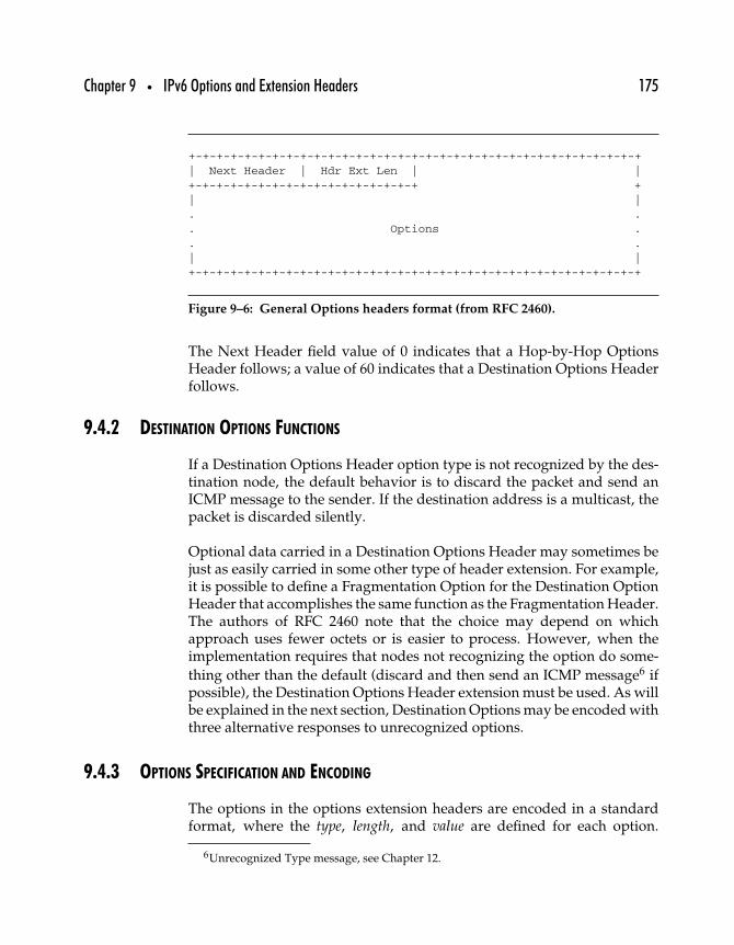
Chapter 9 • IPv6 Options and Extension Headers 175
+-+-+-+-+-+-+-+-+-+-+-+-+-+-+-+-+-+-+-+-+-+-+-+-+-+-+-+-+-+-+-+-+| Next Header | Hdr Ext Len | |+-+-+-+-+-+-+-+-+-+-+-+-+-+-+-+-+ +| |. .. Options .. .| |+-+-+-+-+-+-+-+-+-+-+-+-+-+-+-+-+-+-+-+-+-+-+-+-+-+-+-+-+-+-+-+-+
Figure 9–6: General Options headers format (from RFC 2460).
The Next Header field value of 0 indicates that a Hop-by-Hop OptionsHeader follows; a value of 60 indicates that a Destination Options Headerfollows.
9.4.2 DESTINATION OPTIONS FUNCTIONS
If a Destination Options Header option type is not recognized by the des-tination node, the default behavior is to discard the packet and send anICMP message to the sender. If the destination address is a multicast, thepacket is discarded silently.
Optional data carried in a Destination Options Header may sometimes bejust as easily carried in some other type of header extension. For example,it is possible to define a Fragmentation Option for the Destination OptionHeader that accomplishes the same function as the Fragmentation Header.The authors of RFC 2460 note that the choice may depend on whichapproach uses fewer octets or is easier to process. However, when theimplementation requires that nodes not recognizing the option do some-
thing other than the default (discard and then send an ICMP message6 ifpossible), the Destination Options Header extension must be used. As willbe explained in the next section, Destination Options may be encoded withthree alternative responses to unrecognized options.
9.4.3 OPTIONS SPECIFICATION AND ENCODING
The options in the options extension headers are encoded in a standardformat, where the type, length, and value are defined for each option.
6Unrecognized Type message, see Chapter 12.
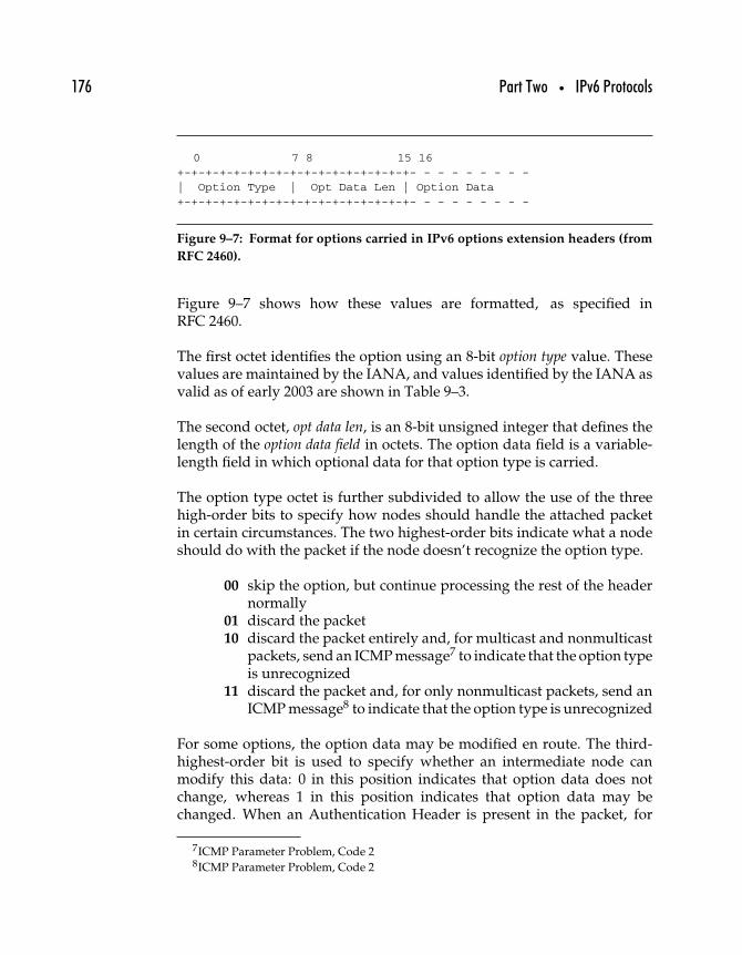
176 Part Two • IPv6 Protocols
0 7 8 15 16+-+-+-+-+-+-+-+-+-+-+-+-+-+-+-+-+- - - - - - - - -| Option Type | Opt Data Len | Option Data+-+-+-+-+-+-+-+-+-+-+-+-+-+-+-+-+- - - - - - - - -
Figure 9–7: Format for options carried in IPv6 options extension headers (from
RFC 2460).
Figure 9–7 shows how these values are formatted, as specified inRFC 2460.
The first octet identifies the option using an 8-bit option type value. Thesevalues are maintained by the IANA, and values identified by the IANA asvalid as of early 2003 are shown in Table 9–3.
The second octet, opt data len, is an 8-bit unsigned integer that defines thelength of the option data field in octets. The option data field is a variable-length field in which optional data for that option type is carried.
The option type octet is further subdivided to allow the use of the threehigh-order bits to specify how nodes should handle the attached packetin certain circumstances. The two highest-order bits indicate what a nodeshould do with the packet if the node doesn’t recognize the option type.
00 skip the option, but continue processing the rest of the headernormally
01 discard the packet10 discard the packet entirely and, for multicast and nonmulticast
packets, send an ICMP message7 to indicate that the option typeis unrecognized
11 discard the packet and, for only nonmulticast packets, send anICMP message8 to indicate that the option type is unrecognized
For some options, the option data may be modified en route. The third-highest-order bit is used to specify whether an intermediate node canmodify this data: 0 in this position indicates that option data does notchange, whereas 1 in this position indicates that option data may bechanged. When an Authentication Header is present in the packet, for
7ICMP Parameter Problem, Code 28ICMP Parameter Problem, Code 2
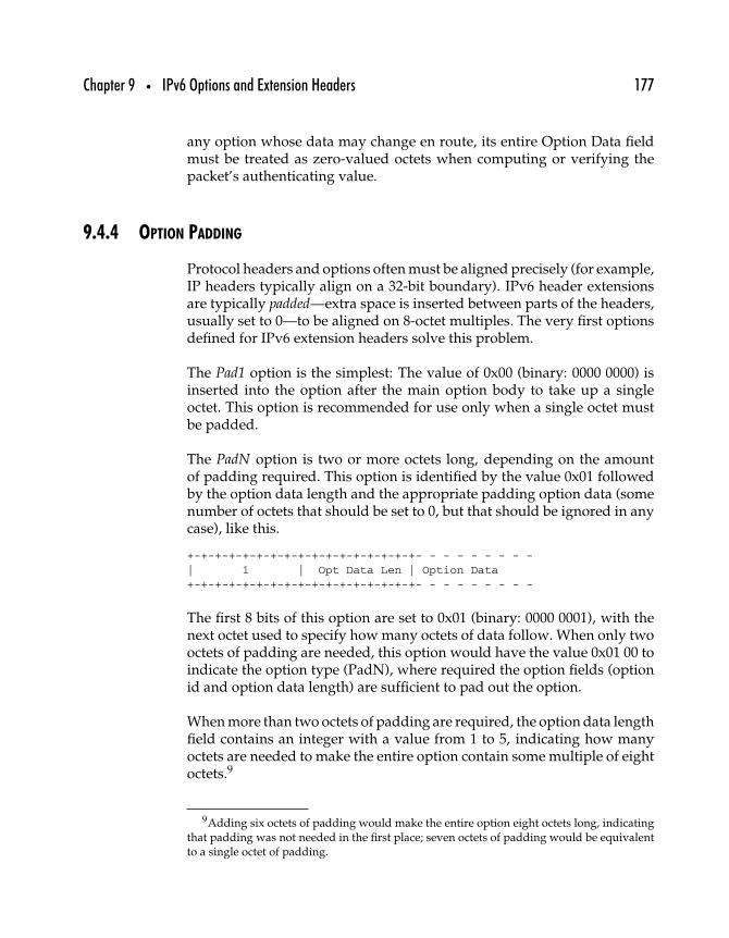
Chapter 9 • IPv6 Options and Extension Headers 177
any option whose data may change en route, its entire Option Data fieldmust be treated as zero-valued octets when computing or verifying thepacket’s authenticating value.
9.4.4 OPTION PADDING
Protocol headers and options often must be aligned precisely (for example,IP headers typically align on a 32-bit boundary). IPv6 header extensionsare typically padded—extra space is inserted between parts of the headers,usually set to 0—to be aligned on 8-octet multiples. The very first optionsdefined for IPv6 extension headers solve this problem.
The Pad1 option is the simplest: The value of 0x00 (binary: 0000 0000) isinserted into the option after the main option body to take up a singleoctet. This option is recommended for use only when a single octet mustbe padded.
The PadN option is two or more octets long, depending on the amountof padding required. This option is identified by the value 0x01 followedby the option data length and the appropriate padding option data (somenumber of octets that should be set to 0, but that should be ignored in anycase), like this.
+-+-+-+-+-+-+-+-+-+-+-+-+-+-+-+-+- - - - - - - - -
| 1 | Opt Data Len | Option Data+-+-+-+-+-+-+-+-+-+-+-+-+-+-+-+-+- - - - - - - - -
The first 8 bits of this option are set to 0x01 (binary: 0000 0001), with thenext octet used to specify how many octets of data follow. When only twooctets of padding are needed, this option would have the value 0x01 00 toindicate the option type (PadN), where required the option fields (optionid and option data length) are sufficient to pad out the option.
When more than two octets of padding are required, the option data lengthfield contains an integer with a value from 1 to 5, indicating how manyoctets are needed to make the entire option contain some multiple of eightoctets.9
9Adding six octets of padding would make the entire option eight octets long, indicatingthat padding was not needed in the first place; seven octets of padding would be equivalentto a single octet of padding.
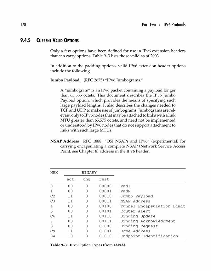
178 Part Two • IPv6 Protocols
9.4.5 CURRENT VALID OPTIONS
Only a few options have been defined for use in IPv6 extension headersthat can carry options. Table 9–3 lists those valid as of 2003.
In addition to the padding options, valid IPv6 extension header optionsinclude the following.
Jumbo Payload (RFC 2675) “IPv6 Jumbograms.”
A “jumbogram” is an IPv6 packet containing a payload longerthan 65,535 octets. This document describes the IPv6 JumboPayload option, which provides the means of specifying suchlarge payload lengths. It also describes the changes needed toTCP and UDP to make use of jumbograms. Jumbograms are rel-evant only to IPv6 nodes that may be attached to links with a linkMTU greater than 65,575 octets, and need not be implementedor understood by IPv6 nodes that do not support attachment tolinks with such large MTUs.
NSAP Address RFC 1888: “OSI NSAPs and IPv6” (experimental) forcarrying encapsulating a complete NSAP (Network Service AccessPoint, see Chapter 8) address in the IPv6 header.
HEX BINARY
act chg rest
0 00 0 00000 Pad11 00 0 00001 PadNC2 11 0 00010 Jumbo PayloadC3 11 0 00011 NSAP Address4 00 0 00100 Tunnel Encapsulation Limit5 00 0 00101 Router AlertC6 11 0 00110 Binding Update7 00 0 00111 Binding Acknowledgment8 00 0 01000 Binding RequestC9 11 0 01001 Home Address8A 10 0 01010 Endpoint Identification
Table 9–3: IPv6 Option Types (from IANA).
Chapter 9 • IPv6 Options and Extension Headers 179
Tunnel Encapsulation Limit RFC 2473, Generic Packet Tunneling inIPv6 Specification.
A tunnel entry-point node may be configured to include aTunnel Encapsulation Limit option as part of the informa-tion prepended to all packets entering a tunnel at that node.The Tunnel Encapsulaton Limit option is carried in a Destina-tion Options extension header [IPv6-Spec] placed between theencapsulating IPv6 header and the IPv6 header of the originalpacket. (Other IPv6 extension headers may also be present pre-ceding or following the Destination Options extension header,depending on configuration information at the tunnel entry-point node.)
The Tunnel Encapsulation Limit option specifies how manyadditional levels of encapsulation are permitted to be pre-pended to the packet—or, in other words, how many furtherlevels of nesting the packet is permitted to undergo—not count-ing the encapsulation in which the option itself is contained.For example, a Tunnel Encapsulation Limit option containinga limit value of zero means that a packet carrying that optionmay not enter another tunnel before exiting the current tunnel.
Router Alert RFC 2711 published in 1999.
New protocols, such as RSVP, use control datagrams which,while addressed to a particular destination, contain informa-tion that needs to be examined, and in some case updated, byrouters along the path between the source and destination. It isdesirable to forward regular datagrams as rapidly as possible,while ensuring that the router processes these special controldatagrams appropriately. Currently, however, the only wayfor a router to determine if it needs to examine a datagram is toat least partially parse upper-layer data in all datagrams. Thisparsing is expensive and slow. This situation is undesirable.
This document defines a new option within the IPv6 Hop-by-Hop Header. The presence of this option in an IPv6 datagraminforms the router that the contents of this datagram are of inter-est to the router and to handle any control data accordingly. Theabsence of this option in an IPv6 datagram informs the routerthat the datagram does not contain information needed by the
180 Part Two • IPv6 Protocols
router and hence can be safely routed without further data-gram parsing. Hosts originating IPv6 datagrams are requiredto include this option in certain circumstances.
Binding Update/Acknowledgment/Request Originally identified withIPv6 mobility support; see Chapter 17.
Home Address Mobile IPv6 defines a Home Address destination optionin a work-in-progress on IPv6 mobility.
The Home Address option is carried by the Destination Optionextension header (Next Header value = 60). It is used in a packetsent by a mobile node while away from home, to inform therecipient of the mobile node’s home address.
Endpoint Identification Based on a feature used with Nimrod (“a scal-able internetwork routing architecture” from the mid-1990s) todetermine endpoints in IPv4/v6 networks.
Others can be expected. One work-in-progress defines a new approach topath MTU discovery (see Chapter 12 for more on PMTU):
IPv6/PMTU Option Header Draft
This document presents a new method for the PMTU discoveryfor IPv6. To discover the PMTU of a path, a source node mea-sures its actual PMTU using the newly defined Hop-by-HopOption Header, whereas a source node initially assumes thatthe PMTU of a path is the known MTU of the first hop in thepath in the previous one [1981]. In order to measure the actualPMTU, the source node sends the IP packet with the newlydefined Hop-by-Hop Option Header to the destination nodewith the first data packet when the node is beginning. This caneliminate the chance of occurrence of several iterations of thesomewhat complex discovery cycle (sending a packet, receivinga Packet Too Big message, reducing a packet size). Most of all,since existing PMTU has a weak point for security and denial-of-service attacks, this document suggests a security functionwhen PMTU is going on.
Chapter 9 • IPv6 Options and Extension Headers 181
9.5 Summary
Although IPv4 options have been defined from the very beginning, theiruse has never been widespread. IPv6 option header extensions have beendesigned to remedy the flaws in IPv4 options, and, as demonstrated inthis chapter, should gain wider acceptance. Although so far only a fewoptions have been defined, they may be applied in a number of differentways to enable protocol tunneling, routing options, security options,fragmentation, and more.
As we’ll see in Chapter 17, the IPv6 mobility protocol uses an extensionheader, but in the next chapter we examine another function—multicast—that, while present in IPv4, is designed for greater effectiveness and easeof use under IPv6.

This Page Intentionally Left Blank
1010
IPv6 Multicast
Multicast for IPv6 is based on the same principles as multicast in IPv4 or,for that matter, multicast in link layer protocols like Ethernet.
• Nodes that are members of a multicast group receive packetstransmitted to the multicast group address.
• The original sender of a multicast packet sends it only once, butthe packet will be repeated so as to be delivered to all groupmembers.
• When a multicast packet is transmitted on a multiaccess net-work, in which all nodes can detect all transmissions but ignorethose addressed to nodes other than themselves, group mem-bers all process the same packet transmitted by the originalsender.
• When a multicast packet is transmitted on a nonbroadcast,multiaccess (NBMA) network like ATM or Frame Relay, anintermediary node accepts the multicast and then repeats it toall nodes subscribed on the network.
183
184 Part Two • IPv6 Protocols
Although the fundamentals are quite similar to multicast in IPv4, IPv6protocols depend to a great degree on the use of multicast for functionssuch as neighbor discovery (see Chapter 13), node autoconfiguration (seeChapter 16), mobile IPv6 (see Chapter 17), and more.
As part of the renovation and simplification of IPv4-generation protocols,and to improve the efficiency with which the functions just cited are per-formed, IPv6 multicast has also been streamlined. The Internet GroupManagement Protocol (IGMP) used in parallel with ICMP in IPv4 has beendropped for IPv6. Instead, IPv6 multicast recipients are detected with theMulticast Listener Discovery (MLD) protocol, which is actually a set ofICMPv6 messages.
This chapter provides a brief look at the IPv6 specifications for multi-cast, including the multicast address format, multicast scopes, transient/permanent multicast groups, and multicast address allocation. Alsocovered here are the Multicast Listener Discovery (MLD) protocol andmulticast routing under IPv6.
10.1 IPv6 Multicast Address Format
Like all IPv6 addresses, IPv6 multicast group addresses are 128 bits long,but multicast addresses are identifiable because the high-order 8 bits of theaddress are all 1s. The IPv6 multicast address format, shown in Figure 10–1,consists of four “fields.”
High-order octet This will always be 11111111 for multicast addresses.
Flags The first three of these four single-bit flags are reserved; the fourthbit specifies whether the multicast group is a well-known address(permanently assigned to a defined group of nodes) or transient(an address used temporarily with no permanently defined set ofmembers).
Scope This field contains a value from 0 through 0xF. The multicastaddress scope indicates the relative size of the domain over whichthe multicast packet should be propagated (see Table 10–1).
Group ID The remainder of the multicast address is given over to thegroup ID.
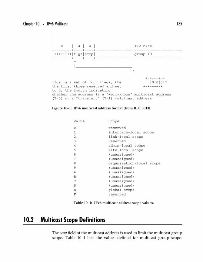
Chapter 10 • IPv6 Multicast 185
| 8 | 4 | 4 | 112 bits |+--------+----+----+---------------------------------------+|11111111|flgs|scop| group ID |+--------+----+----+---------------------------------------+
^|__________________________
\
+-+-+-+-+flgs is a set of four flags, the |0|0|0|T|the first three reserved and set +-+-+-+-+to 0; the fourth indicatingwhether the address is a “well-known” multicast address(T=0) or a “transient” (T=1) multicast address.
Figure 10–1: IPv6 multicast address format (from RFC 3513).
Value Scope
0 reserved1 interface-local scope2 link-local scope3 reserved4 admin-local scope5 site-local scope6 (unassigned)7 (unassigned)8 organization-local scope9 (unassigned)A (unassigned)B (unassigned)C (unassigned)D (unassigned)E global scopeF reserved
Table 10–1: IPv6 multicast address scope values.
10.2 Multicast Scope Definitions
The scop field of the multicast address is used to limit the multicast groupscope. Table 10–1 lists the values defined for multicast group scope.
186 Part Two • IPv6 Protocols
The most local scope, interface-local, specifies a single network interfaceto be used to transmit multicast packets over the loopback address. Thescope can expand to the local link, site, organization, or global IPv6 Inter-net. As shown in Table 10–1, the all-zeros (0) and all-ones (0xF) valuesare reserved, with half of the rest of the values unassigned (but availablefor administrators who want to assign their own regions). Site-local andlink-local scopes correspond to the unicast definitions for those scopes (seepreceding section).
Beyond the link- and site-local scopes that can be automatically definedby physical connectivity lie the admin-local and organization-local scopesthat are administratively configured and can span separate networks. Theorganization-local scope is meant to be able to cross site boundaries withina single organization.
Most important is the group ID field, which identifies the multicast groupwithin the group’s defined scope. As with IPv4 multicast groups, thereare permanently assigned IPv6 multicast groups whose IDs have specificmeaning. For instance, permanently assigned group IDs of the form ::2specify “all routers” within the defined scope. So the following addressesspecify three different multicast groups that consist of all the IPv6 routersin different scopes.
FF01:0:0:0:0:0:0:2
FF02:0:0:0:0:0:0:2
FF05:0:0:0:0:0:0:2
The first group includes IPv6 routers within scope 1 (the local interface),the second includes all routers within scope 2 (the local link), and thethird includes all routers within scope 5 (site-local). If the high-order octetswere FF0E, the group (if it was used) would consist of all IPv6 routers inthe global IPv6 Internet. Those packets, however, would not likely beforwarded throughout the IPv6 Internet.
10.3 Reserved and Permanent Multicast Addresses
The group ID has meaning for permanently assigned groups, but tran-sient group IDs have meaning only within their scope. The same transient,
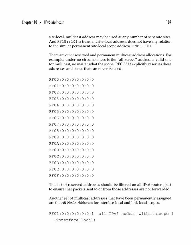
Chapter 10 • IPv6 Multicast 187
site-local, multicast address may be used at any number of separate sites.And FF15::101, a transient site-local address, does not have any relationto the similar permanent site-local scope address FF05::101.
There are other reserved and permanent multicast address allocations. Forexample, under no circumstances is the “all-zeroes” address a valid onefor multicast, no matter what the scope. RFC 3513 explicitly reserves theseaddresses and states that can never be used.
FF00:0:0:0:0:0:0:0
FF01:0:0:0:0:0:0:0
FF02:0:0:0:0:0:0:0
FF03:0:0:0:0:0:0:0
FF04:0:0:0:0:0:0:0
FF05:0:0:0:0:0:0:0
FF06:0:0:0:0:0:0:0
FF07:0:0:0:0:0:0:0
FF08:0:0:0:0:0:0:0
FF09:0:0:0:0:0:0:0
FF0A:0:0:0:0:0:0:0
FF0B:0:0:0:0:0:0:0
FF0C:0:0:0:0:0:0:0
FF0D:0:0:0:0:0:0:0
FF0E:0:0:0:0:0:0:0
FF0F:0:0:0:0:0:0:0
This list of reserved addresses should be filtered on all IPv6 routers, justto ensure that packets sent to or from those addresses are not forwarded.
Another set of multicast addresses that have been permanently assignedare the All Nodes Addresses for interface-local and link-local scopes.
FF01:0:0:0:0:0:0:1 all IPv6 nodes, within scope 1
(interface-local)
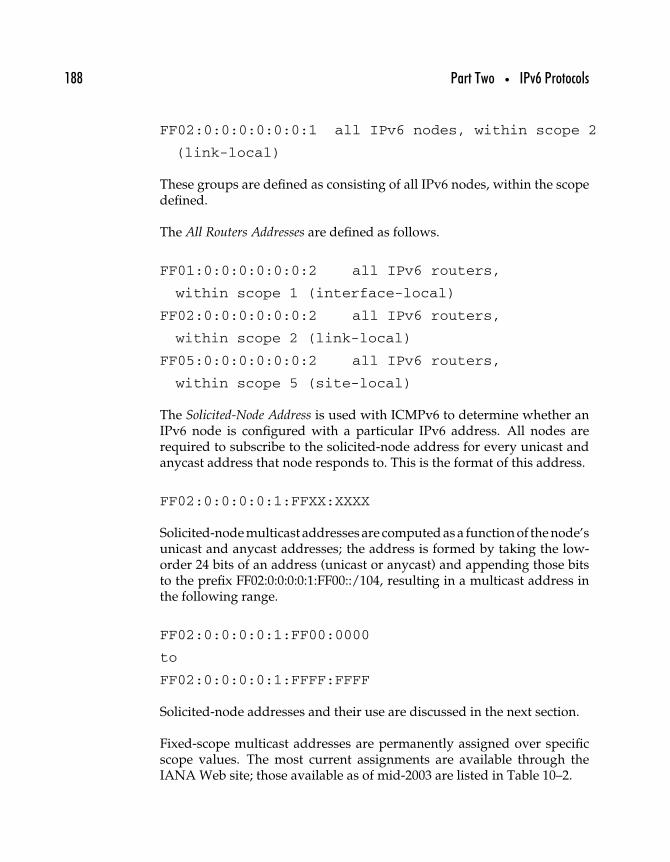
188 Part Two • IPv6 Protocols
FF02:0:0:0:0:0:0:1 all IPv6 nodes, within scope 2
(link-local)
These groups are defined as consisting of all IPv6 nodes, within the scopedefined.
The All Routers Addresses are defined as follows.
FF01:0:0:0:0:0:0:2 all IPv6 routers,
within scope 1 (interface-local)
FF02:0:0:0:0:0:0:2 all IPv6 routers,
within scope 2 (link-local)
FF05:0:0:0:0:0:0:2 all IPv6 routers,
within scope 5 (site-local)
The Solicited-Node Address is used with ICMPv6 to determine whether anIPv6 node is configured with a particular IPv6 address. All nodes arerequired to subscribe to the solicited-node address for every unicast andanycast address that node responds to. This is the format of this address.
FF02:0:0:0:0:1:FFXX:XXXX
Solicited-node multicast addresses are computed as a function of the node’sunicast and anycast addresses; the address is formed by taking the low-order 24 bits of an address (unicast or anycast) and appending those bitsto the prefix FF02:0:0:0:0:1:FF00::/104, resulting in a multicast address inthe following range.
FF02:0:0:0:0:1:FF00:0000
to
FF02:0:0:0:0:1:FFFF:FFFF
Solicited-node addresses and their use are discussed in the next section.
Fixed-scope multicast addresses are permanently assigned over specificscope values. The most current assignments are available through theIANA Web site; those available as of mid-2003 are listed in Table 10–2.
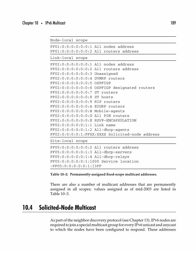
Chapter 10 • IPv6 Multicast 189
Node-local scope
FF01:0:0:0:0:0:0:1 All nodes addressFF01:0:0:0:0:0:0:2 All routers address
Link-local scope
FF02:0:0:0:0:0:0:1 All nodes addressFF02:0:0:0:0:0:0:2 All routers addressFF02:0:0:0:0:0:0:3 UnassignedFF02:0:0:0:0:0:0:4 DVMRP routersFF02:0:0:0:0:0:0:5 OSPFIGPFF02:0:0:0:0:0:0:6 OSPFIGP designated routersFF02:0:0:0:0:0:0:7 ST routersFF02:0:0:0:0:0:0:8 ST hostsFF02:0:0:0:0:0:0:9 RIP routersFF02:0:0:0:0:0:0:A EIGRP routersFF02:0:0:0:0:0:0:B Mobile-agentsFF02:0:0:0:0:0:0:D All PIM routersFF02:0:0:0:0:0:0:E RSVP-ENCAPSULATIONFF02:0:0:0:0:0:1:1 Link nameFF02:0:0:0:0:0:1:2 All-dhcp-agentsFF02:0:0:0:0:1:FFXX:XXXX Solicited-node address
Site-local scope
FF05:0:0:0:0:0:0:2 All routers addressFF05:0:0:0:0:0:1:3 All-dhcp-serversFF05:0:0:0:0:0:1:4 All-dhcp-relaysFF05:0:0:0:0:0:1:1000 Service location-FF05:0:0:0:0:0:1:13FF
Table 10–2: Permanently-assigned fixed-scope multicast addresses.
There are also a number of multicast addresses that are permanentlyassigned in all scopes; values assigned as of mid-2003 are listed inTable 10–3.
10.4 Solicited-Node Multicast
As part of the neighbor discovery protocol (see Chapter 13), IPv6 nodes arerequired to join a special multicast group for every IPv6 unicast and anycastto which the nodes have been configured to respond. These addresses
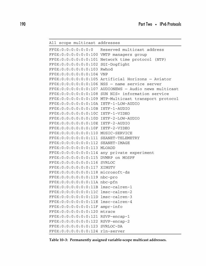
190 Part Two • IPv6 Protocols
All scope multicast addresses
FF0X:0:0:0:0:0:0:0 Reserved multicast addressFF0X:0:0:0:0:0:0:100 VMTP managers groupFF0X:0:0:0:0:0:0:101 Network time protocol (NTP)FF0X:0:0:0:0:0:0:102 SGI-DogfightFF0X:0:0:0:0:0:0:103 RwhodFF0X:0:0:0:0:0:0:104 VNPFF0X:0:0:0:0:0:0:105 Artificial Horizons — AviatorFF0X:0:0:0:0:0:0:106 NSS — name service serverFF0X:0:0:0:0:0:0:107 AUDIONEWS — Audio news multicastFF0X:0:0:0:0:0:0:108 SUN NIS+ information serviceFF0X:0:0:0:0:0:0:109 MTP—Multicast transport protocolFF0X:0:0:0:0:0:0:10A IETF-1-LOW-AUDIOFF0X:0:0:0:0:0:0:10B IETF-1-AUDIOFF0X:0:0:0:0:0:0:10C IETF-1-VIDEOFF0X:0:0:0:0:0:0:10D IETF-2-LOW-AUDIOFF0X:0:0:0:0:0:0:10E IETF-2-AUDIOFF0X:0:0:0:0:0:0:10F IETF-2-VIDEOFF0X:0:0:0:0:0:0:110 MUSIC-SERVICEFF0X:0:0:0:0:0:0:111 SEANET-TELEMETRYFF0X:0:0:0:0:0:0:112 SEANET-IMAGEFF0X:0:0:0:0:0:0:113 MLOADDFF0X:0:0:0:0:0:0:114 any private experimentFF0X:0:0:0:0:0:0:115 DVMRP on MOSPFFF0X:0:0:0:0:0:0:116 SVRLOCFF0X:0:0:0:0:0:0:117 XINGTVFF0X:0:0:0:0:0:0:118 microsoft-dsFF0X:0:0:0:0:0:0:119 nbc-proFF0X:0:0:0:0:0:0:11A nbc-pfnFF0X:0:0:0:0:0:0:11B lmsc-calren-1FF0X:0:0:0:0:0:0:11C lmsc-calren-2FF0X:0:0:0:0:0:0:11D lmsc-calren-3FF0X:0:0:0:0:0:0:11E lmsc-calren-4FF0X:0:0:0:0:0:0:11F ampr-infoFF0X:0:0:0:0:0:0:120 mtraceFF0X:0:0:0:0:0:0:121 RSVP-encap-1FF0X:0:0:0:0:0:0:122 RSVP-encap-2FF0X:0:0:0:0:0:0:123 SVRLOC-DAFF0X:0:0:0:0:0:0:124 rln-server
Table 10–3: Permanently assigned variable-scope multicast addresses.
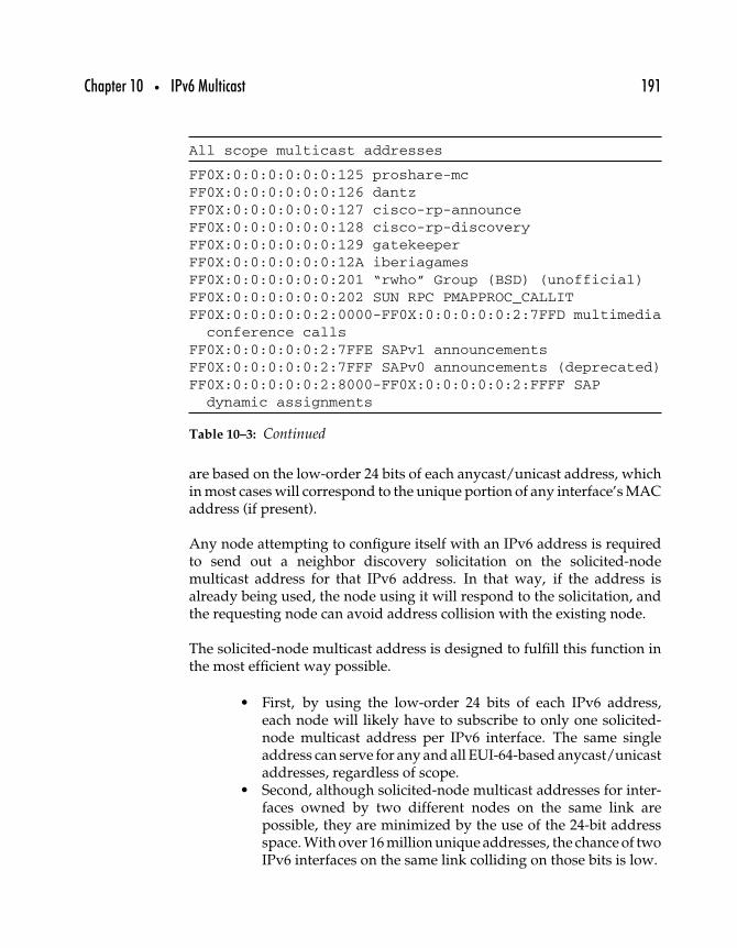
Chapter 10 • IPv6 Multicast 191
All scope multicast addresses
FF0X:0:0:0:0:0:0:125 proshare-mcFF0X:0:0:0:0:0:0:126 dantzFF0X:0:0:0:0:0:0:127 cisco-rp-announceFF0X:0:0:0:0:0:0:128 cisco-rp-discoveryFF0X:0:0:0:0:0:0:129 gatekeeperFF0X:0:0:0:0:0:0:12A iberiagamesFF0X:0:0:0:0:0:0:201 “rwho” Group (BSD) (unofficial)FF0X:0:0:0:0:0:0:202 SUN RPC PMAPPROC_CALLITFF0X:0:0:0:0:0:2:0000-FF0X:0:0:0:0:0:2:7FFD multimedia
conference callsFF0X:0:0:0:0:0:2:7FFE SAPv1 announcementsFF0X:0:0:0:0:0:2:7FFF SAPv0 announcements (deprecated)FF0X:0:0:0:0:0:2:8000-FF0X:0:0:0:0:0:2:FFFF SAP
dynamic assignments
Table 10–3: Continued
are based on the low-order 24 bits of each anycast/unicast address, whichin most cases will correspond to the unique portion of any interface’s MACaddress (if present).
Any node attempting to configure itself with an IPv6 address is requiredto send out a neighbor discovery solicitation on the solicited-nodemulticast address for that IPv6 address. In that way, if the address isalready being used, the node using it will respond to the solicitation, andthe requesting node can avoid address collision with the existing node.
The solicited-node multicast address is designed to fulfill this function inthe most efficient way possible.
• First, by using the low-order 24 bits of each IPv6 address,each node will likely have to subscribe to only one solicited-node multicast address per IPv6 interface. The same singleaddress can serve for any and all EUI-64-based anycast/unicastaddresses, regardless of scope.
• Second, although solicited-node multicast addresses for inter-faces owned by two different nodes on the same link arepossible, they are minimized by the use of the 24-bit addressspace. With over 16 million unique addresses, the chance of twoIPv6 interfaces on the same link colliding on those bits is low.
192 Part Two • IPv6 Protocols
The solicited-node multicast address is also used for other neighbordiscovery purposes, allowing nodes to more quickly map an IPv6 addressto a link layer network address.
10.5 Multicast Listener Discovery (MLD) for IPv6
IPv4 multicast group membership is managed through the use of aseparate protocol, the Internet Group Management Protocol (IGMP).Considered part of IPv4, IGMP works much like ICMP in that it permitsnodes to exchange network metainformation. IPv4 nodes exchange IGMPmessages, usually with routers, to indicate the multicast groups to whichthey wish to subscribe.
Under IPv6, multicast group management is accomplished with a set ofICMPv6 messages that comprise the Multicast Listener Discovery (MLD)protocol. Like Neighbor Discovery, MLD can be considered a subprotocolof ICMPv6. As stated in the introduction to RFC 2710, “Multicast ListenerDiscovery (MLD) for IPv6,” the purpose of the protocol is to allow a router“to discover the presence of multicast listeners (that is, nodes wishing toreceive multicast packets) on its directly attached links, and to discoverspecifically which multicast addresses are of interest to those neighboringnodes. This information is then provided to whichever multicast routingprotocol is being used by the router, in order to ensure that multicastpackets are delivered to all links where there are interested receivers.”
MLD uses three different types of messages.
Multicast Listener Query The Query message type has two subtypes.The General Query is used by routers to discover all the multicastgroups that listeners on the link are subscribed to; the Multicast-Address-Specific Query is used by routers to discover whether thereare any local link subscribers (listeners) to a particular multicastaddress. Only routers send queries, and usually there is only onerouter that acts as a querier on each link.
Multicast Listener Report An unsolicited Report message is sent by anynode when it begins listening to a multicast address; Report messagesare generated in response to a Query message sent by a router (eithera query for a specific multicast address or a general query).
Multicast Listener Done The Done message should be sent by a nodewhen it stops listening to a multicast address.
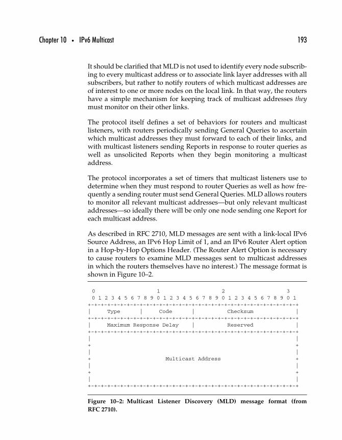
Chapter 10 • IPv6 Multicast 193
It should be clarified that MLD is not used to identify every node subscrib-ing to every multicast address or to associate link layer addresses with allsubscribers, but rather to notify routers of which multicast addresses areof interest to one or more nodes on the local link. In that way, the routershave a simple mechanism for keeping track of multicast addresses theymust monitor on their other links.
The protocol itself defines a set of behaviors for routers and multicastlisteners, with routers periodically sending General Queries to ascertainwhich multicast addresses they must forward to each of their links, andwith multicast listeners sending Reports in response to router queries aswell as unsolicited Reports when they begin monitoring a multicastaddress.
The protocol incorporates a set of timers that multicast listeners use todetermine when they must respond to router Queries as well as how fre-quently a sending router must send General Queries. MLD allows routersto monitor all relevant multicast addresses—but only relevant multicastaddresses—so ideally there will be only one node sending one Report foreach multicast address.
As described in RFC 2710, MLD messages are sent with a link-local IPv6Source Address, an IPv6 Hop Limit of 1, and an IPv6 Router Alert optionin a Hop-by-Hop Options Header. (The Router Alert Option is necessaryto cause routers to examine MLD messages sent to multicast addressesin which the routers themselves have no interest.) The message format isshown in Figure 10–2.
0 1 2 30 1 2 3 4 5 6 7 8 9 0 1 2 3 4 5 6 7 8 9 0 1 2 3 4 5 6 7 8 9 0 1
+-+-+-+-+-+-+-+-+-+-+-+-+-+-+-+-+-+-+-+-+-+-+-+-+-+-+-+-+-+-+-+-+| Type | Code | Checksum |+-+-+-+-+-+-+-+-+-+-+-+-+-+-+-+-+-+-+-+-+-+-+-+-+-+-+-+-+-+-+-+-+| Maximum Response Delay | Reserved |+-+-+-+-+-+-+-+-+-+-+-+-+-+-+-+-+-+-+-+-+-+-+-+-+-+-+-+-+-+-+-+-+| |+ +| |+ Multicast Address +| |+ +| |+-+-+-+-+-+-+-+-+-+-+-+-+-+-+-+-+-+-+-+-+-+-+-+-+-+-+-+-+-+-+-+-+
Figure 10–2: Multicast Listener Discovery (MLD) message format (from
RFC 2710).
194 Part Two • IPv6 Protocols
10.6 Summary
The use of scope, especially to differentiate between the local network andthe global IPv6 Internet, is an important reason why multicast can be somuch more useful in IPv6 networks than it has been in IPv4 networks.An integral part of IPv6 protocols, we will see how multicast performsimportant functions in ICMPv6 in Chapter 12, as well as related protocolssuch as Neighbor Discovery (Chapter 13), Mobile IPv6 (Chapter 17), andelsewhere.
Though related to multicast, IPv6 anycast addressing differs in importantways. As will become clear in the next chapter, anycast has the potentialto improve IPv6 network efficiency.
1111
IPv6 Anycast
One of the more surprising features of IPv6 was the inclusion of an entirelynew communication model, anycast, to join the existing unicast and mul-ticast models. Where unicast communication permits the transmission ofpackets to one specific node, and multicast permits transmission of thesame packet to one or more nodes, anycast adds the ability to send a packetto any one—and only one—of a group of one or more destination nodes.
Although first specified in the IPv6 specification in 1995 (RFC 1884, “IPVersion 6 Addressing Architecture”), the anycast concept had been aroundbefore then. However, despite the longevity of the idea, as of 2003 therehas been very little experience with anycast and related applications.
Starting with an overview, including a brief look at the history of anycast,this chapter introduces the current state of the IPv6 anycast specifica-tion, followed by summary of some of the work that is currently beingundertaken to make anycast work and to exploit anycast for usefulapplications.
195
196 Part Two • IPv6 Protocols
11.1 Anycast Overview
An experimental specification for IPv4 anycasting was defined in RFC 1546,“Host Anycasting Service,” in 1993. That document suggested that anotheraddress class could be carved out of the IPv4 address space for anycastaddresses. In that way, nodes could identify anycast packets simply bylooking at their destination addresses and treating them appropriately.
The motivation behind the RFC 1546 anycast experiment was to providenodes with a simpler way to reach any of a group of interchangeableapplication servers. For example, rather than requiring a user to choosea particular FTP server from a list, anycast (it was suggested) would allowthe user to simply specify the group of FTP servers, any of which wouldbe satisfactory.
Although an interesting idea, RFC 1546 anycast never gained much trac-tion, and it is unlikely that any networks currently support it (if any everdid). However the use of a single unicast address by two or more nodesis considered a type of pseudo-anycast, such as when multiple nodes areassigned the same address for the purpose of load balancing or for handlinghigh-demand applications.
Pseudo-anycast can be achieved by distributing servers across the Internetand assigning a provider-independent prefix to the address they all share.Routers local to each of the servers can then advertise different routes to thesame prefix, and routers delivering packets to the pseudo-anycast addresscan then choose the most appropriate route—the “nearest” route, usually.
There are significant differences between IPv6 anycast and pseudo-anycast, including a difference in the problem each tries to solve. Pseudo-anycast was devised as a way to distribute high-demand servers aroundthe global Internet in order to serve DNS data or HTTP content more effi-ciently using BGP. IPv6 anycast was devised to be a more general solutionto reaching any one of a group of servers that exist on the site or even thelink, a well as (perhaps) across the global Internet.
11.2 Anycast Motivations
To a certain extent, the problem of choosing the nearest server (describedas the motivation for RFC 1546 anycast) has been solved by using
Chapter 11 • IPv6 Anycast 197
pseudo-anycast to distribute servers for load-balancing and respondingto high-demand global applications. That did not end the interest in defin-ing an anycast service in IPv6, but it also took away one of the more obviousproblems to which anycast offered a potential solution. RFC 2373 states thefollowing.
One expected use of anycast addresses is to identify the set ofrouters belonging to an organization providing Internet service. Suchaddresses could be used as intermediate addresses in an IPv6 RoutingHeader, to cause a packet to be delivered via a particular serviceprovider or sequence of service providers.
Some other possible uses are to identify the set of routers attachedto a particular subnet, or the set of routers providing entry into aparticular routing domain.
These functions might be similar to those provided by multicast (seeChapter 10) groups, but there is no reason why anycast could not allowindividual nodes to send packets to the nearest gateway or DNS server.
Another suggested use for anycast is cited in RFC 2526, “Reserved IPv6Subnet Anycast Addresses.”
[A]n anycast address may be used in a source route to force routingthrough a specific Internet service provider, without limiting routingto a single specific router providing access to that ISP.
Whether or not anycast-based solutions are sufficiently compelling tomotivate their deployment for these purposes has yet to be seen.
11.3 Anycast Architectural Issues
IPv6 nodes can differentiate multicast addresses from unicast addresses,and as a result they are able to take certain actions that don’t make senseor are not permitted, like not attempting to open a TCP connection witha multicast address. Anycast addresses, when they are indistinguish-able from unicast addresses, provide the benefit of transparency to nodesattempting to open communications with anycast nodes—but they alsobear the burden of having to deal with the statelessness of the IPv6 (orIPv4) protocol.
198 Part Two • IPv6 Protocols
When a node sends an IPv6 packet to an anycast address, the packet will bedelivered to the nearest node configured to respond to that address. Whena node sends 10 or 100 or 1000 packets to an anycast address during anexchange of stateful higher-layer protocols (like TCP), there is always thepossibility that more than one node configured to respond to that anycastaddress will respond. For example, if one anycast node becomes congested,then another anycast node may be temporarily “nearer”; the same goes forcongestion over intermediate routes between the requesting node and theanycast nodes.
11.3.1 IPV4 ANYCAST ISSUES
The authors of RFC 1546 concluded that raw IPv4 anycasting should beused only by applications that were themselves stateless and sending pack-ets containing UDP messages. In that way, there would be no problemif one anycast node responded to an anycast packet from a client whileanother anycast node responded to the next request from the same client.For stateful interactions, the authors suggest adding a mechanism thatguides all subsequent anycast packets to the first node that responds to aTCP request by allowing only anycast packets carrying a TCP SYN (syn-chronize) segment requesting that a connection be opened. Once an anycastnode responds, it responds using its own unicast address.
The problem with this approach is that it only works when anycastaddresses are identifiable as such. The result is that IPv6 anycast facesthe same problems (having two different servers/routers responding totwo or more sequential packets addressed to a single address) with theadded limitation that the node sending those packets is not aware thatthere is anything special about the address to which it is sending.
11.3.2 IPV6 ANYCAST ISSUES
As with IPv4 anycast, IPv6 anycast is also hobbled by the nondeterministicdelivery of packets: An anycast packet can be delivered to any of thenodes configured to respond to the anycast address. As a result, all anycastnodes must provide a uniform service, including the same kind of perfor-mance as well as the same service. This makes anycast especially suitablefor load-balancing and other content delivery functions, but it also com-plicates matters by requiring that mechanisms be added to allow statefulhigher-layer protocols to operate across a group of servers.

Chapter 11 • IPv6 Anycast 199
Because IPv6 anycast addresses are drawn from the unicast allocation,nodes sending packets to anycast can’t tell when they are sending a singlepacket to a single, unique node (unicast) and when they are sending asingle packet to any single node of a group (anycast). As a result, fragmentreassembly, as well as any other end-to-end functions like encryption orauthentication, becomes all but impossible.
11.3.3 IPSEC AND ANYCAST
As with fragmentation, IPsec requires that the same two nodes be end-points: Security Associations are based on data exchanged by the sourceand destination nodes, and (by definition) that precludes the ability of twoor more anycast nodes to respond on each other’s behalf. All the samereasons that make it possible for IPsec to secure packets sent from nodeto node also make it extremely difficult if not impossible to secure packetssent from one node to any one of a group of nodes.
11.3.4 ANYCAST ADDRESS ASSIGNMENT
As currently specified, only routers should be configured to respond toanycast addresses. Maintaining this restriction simplifies the problem ofrouting anycast packets, because no additional routing entries are requiredand there will already be routes existing to the networks served by thoserouters. When an anycast packet is transmitted, it is simply processedby intermediate routers and forwarded on an appropriate route based onthe network prefix. Any router that has been configured to respond to aparticular anycast address will do so when it receives a packet sent to thataddress.
Thus, because global anycast addresses are likely to be restricted, if notforbidden entirely, there is little or no need for exterior routes to be addedfor anycast, either.
Allowing regular hosts to respond to anycast addresses would complicatematters. Not only would explicit routes to those nodes have to be addedto routers, but a new mechanism would have to be added to allow thehosts to advertise their willingness to accept anycast packets, while atthe same time prevent them from acting as or being perceived as routersthemselves.
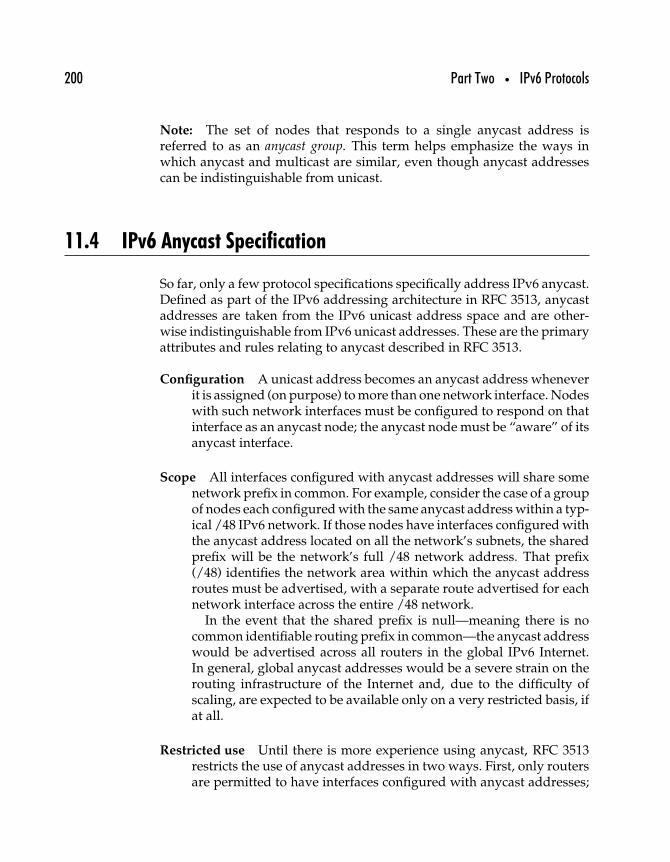
200 Part Two • IPv6 Protocols
Note: The set of nodes that responds to a single anycast address isreferred to as an anycast group. This term helps emphasize the ways inwhich anycast and multicast are similar, even though anycast addressescan be indistinguishable from unicast.
11.4 IPv6 Anycast Specification
So far, only a few protocol specifications specifically address IPv6 anycast.Defined as part of the IPv6 addressing architecture in RFC 3513, anycastaddresses are taken from the IPv6 unicast address space and are other-wise indistinguishable from IPv6 unicast addresses. These are the primaryattributes and rules relating to anycast described in RFC 3513.
Configuration A unicast address becomes an anycast address wheneverit is assigned (on purpose) to more than one network interface. Nodeswith such network interfaces must be configured to respond on thatinterface as an anycast node; the anycast node must be “aware” of itsanycast interface.
Scope All interfaces configured with anycast addresses will share somenetwork prefix in common. For example, consider the case of a groupof nodes each configured with the same anycast address within a typ-ical /48 IPv6 network. If those nodes have interfaces configured withthe anycast address located on all the network’s subnets, the sharedprefix will be the network’s full /48 network address. That prefix(/48) identifies the network area within which the anycast addressroutes must be advertised, with a separate route advertised for eachnetwork interface across the entire /48 network.
In the event that the shared prefix is null—meaning there is nocommon identifiable routing prefix in common—the anycast addresswould be advertised across all routers in the global IPv6 Internet.In general, global anycast addresses would be a severe strain on therouting infrastructure of the Internet and, due to the difficulty ofscaling, are expected to be available only on a very restricted basis, ifat all.
Restricted use Until there is more experience using anycast, RFC 3513restricts the use of anycast addresses in two ways. First, only routersare permitted to have interfaces configured with anycast addresses;
Chapter 11 • IPv6 Anycast 201
| n bits | 128-n bits |+------------------------------------------------+----------------+| subnet prefix | 00000000000000 |+------------------------------------------------+----------------+
Figure 11–1: Subnet-Router anycast address format (from RFC 3513).
second, anycast addresses may not be used as the source address ofa packet.
Required anycast address The Subnet-Router anycast address (seeFigure 11–1) is required to allow nodes to send out packets that areto be delivered to one router on the subnet indicated in the desti-nation address prefix. The format is shown in the Figure. Routersare required to be prepared to respond to anycasts sent to theSubnet-Router anycast address for any subnets to which they arelinked.
11.5 Reserved IPv6 Anycast Addresses
Although specifications for IPv6 anycast, from the original IPv6 address-ing architecture defined in RFC 1884 through to the current version inRFC 3513, define anycast addresses as being structurally identical to IPv6unicast addresses, several specifications define specific, reserved, anycastaddresses that have an explicit meaning and are not to be used for unicasttransmission.
The first such address, the Subnet-Router anycast address, is defined inRFC 3513 itself. One potential use for anycast is suggested for the Subnet-Router address, which allows a node to directly interact with one routerlocated on any specified subnet. When mobile nodes that are away fromtheir home networks need to get back in touch with their mobility agent,they can use this anycast address to send packets directly to any router ontheir home network.
Another anycast address has been reserved for Mobile IPv6 Home-Agents;this address and a group of other addresses that are being reserved foruse as anycast addresses are described in RFC 2526. When mobile IPv6nodes are away from their home network, they may need to discover the
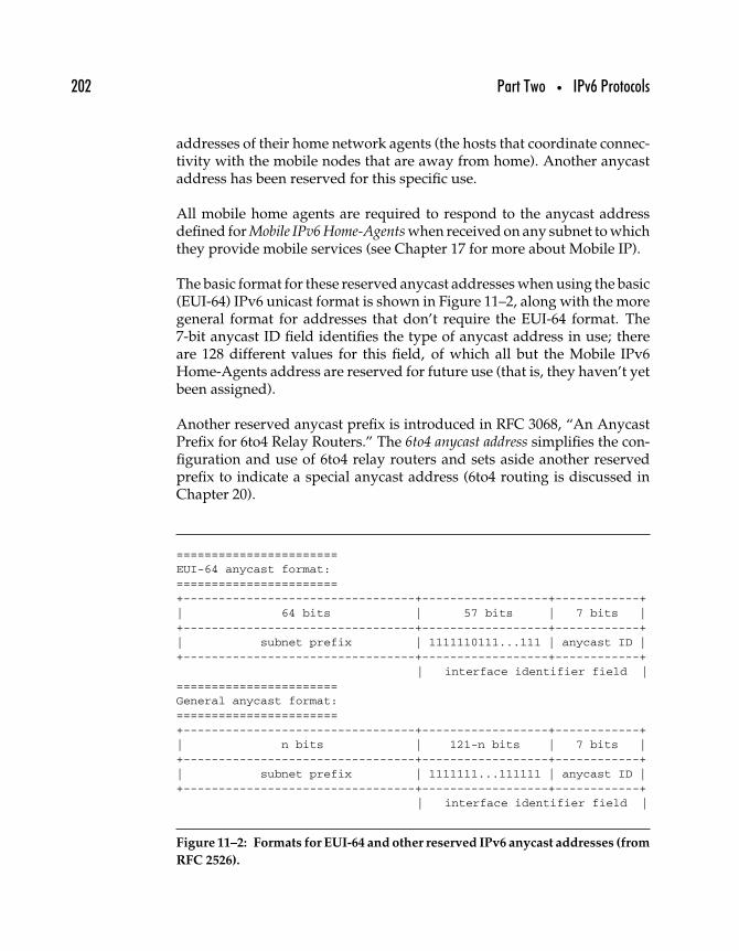
202 Part Two • IPv6 Protocols
addresses of their home network agents (the hosts that coordinate connec-tivity with the mobile nodes that are away from home). Another anycastaddress has been reserved for this specific use.
All mobile home agents are required to respond to the anycast addressdefined for Mobile IPv6 Home-Agents when received on any subnet to whichthey provide mobile services (see Chapter 17 for more about Mobile IP).
The basic format for these reserved anycast addresses when using the basic(EUI-64) IPv6 unicast format is shown in Figure 11–2, along with the moregeneral format for addresses that don’t require the EUI-64 format. The7-bit anycast ID field identifies the type of anycast address in use; thereare 128 different values for this field, of which all but the Mobile IPv6Home-Agents address are reserved for future use (that is, they haven’t yetbeen assigned).
Another reserved anycast prefix is introduced in RFC 3068, “An AnycastPrefix for 6to4 Relay Routers.” The 6to4 anycast address simplifies the con-figuration and use of 6to4 relay routers and sets aside another reservedprefix to indicate a special anycast address (6to4 routing is discussed inChapter 20).
=======================EUI-64 anycast format:=======================+---------------------------------+------------------+------------+| 64 bits | 57 bits | 7 bits |+---------------------------------+------------------+------------+| subnet prefix | 1111110111...111 | anycast ID |+---------------------------------+------------------+------------+
| interface identifier field |=======================General anycast format:=======================
+---------------------------------+------------------+------------+
| n bits | 121-n bits | 7 bits |+---------------------------------+------------------+------------+| subnet prefix | 1111111...111111 | anycast ID |+---------------------------------+------------------+------------+
| interface identifier field |
Figure 11–2: Formats for EUI-64 and other reserved IPv6 anycast addresses (from
RFC 2526).
Chapter 11 • IPv6 Anycast 203
11.6 Making Anycast Work
Anycast seems to be a fairly straightforward new service, until onerecalls that while a node can send a packet to an anycast address, nopackets whose source address is an anycast may be sent. Using anycastaddresses that cannot be distinguished from unicast further complicatesmatters.
As with unicast and multicast, anycast addresses must be routed fromsource to destination; anycast adds these further restrictions.
• Packets must be delivered to one, and only one, of the nodesaccepting packets at that anycast address.
• The node to which those packets are delivered must be the“closest” one to the sender.
Using an anycast address as the source of an IPv6 packet poses severaldifficulties, mostly derived from the need to differentiate “any one nodeof a group of nodes” from “one and only one specific node.” While thedestination node may be one of a number of interchangeable nodes, thesource (the originator of the packet) can be only the specific node that sentthe packet.
This section examines anycast implementation, from routing to determin-ing the appropriate response to anycast packets to using anycast withstateful upper-layer protocols (such as TCP) and stateless upper-layerprotocols (such as UDP).
11.6.1 ANYCAST ROUTING
The IPv6 specification suggests (strongly) that only routers be configuredto respond to anycast addresses. This restriction simplifies the problemof anycast routing: The packet will be routed as if it is a normal unicastaddress, and as soon as the packet arrives at a router that is a mem-ber of the anycast group (that is, the “nearest” router), it will have beendelivered.
No additional routing entries are required—the routers already advertisetheir willingness to accept packets, including anycast packets, sent to theirown network prefix.
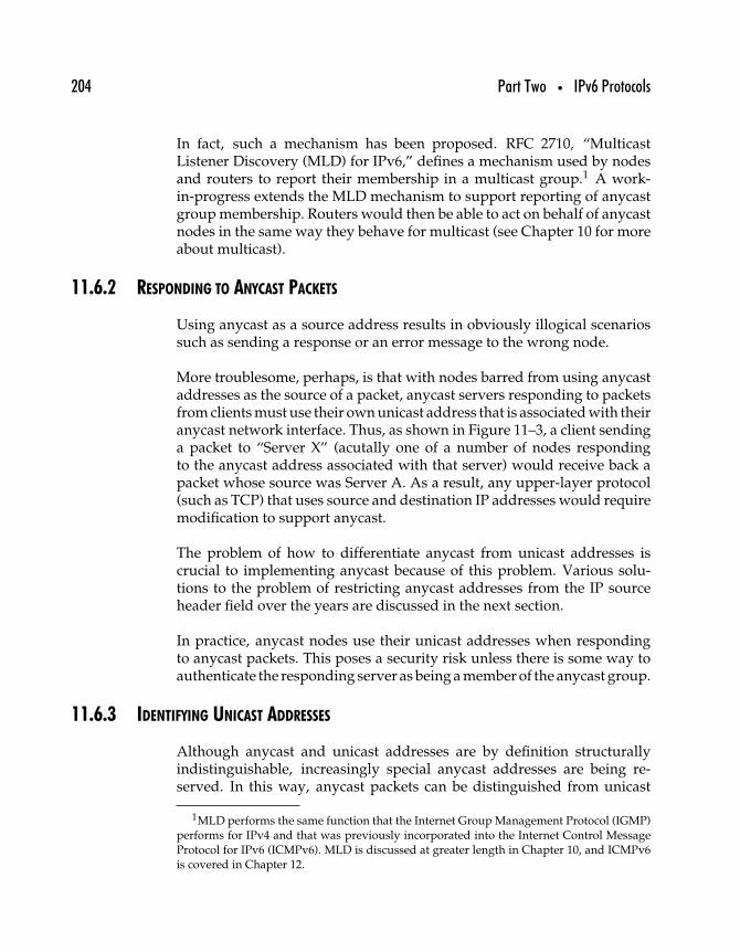
204 Part Two • IPv6 Protocols
In fact, such a mechanism has been proposed. RFC 2710, “MulticastListener Discovery (MLD) for IPv6,” defines a mechanism used by nodesand routers to report their membership in a multicast group.1 A work-in-progress extends the MLD mechanism to support reporting of anycastgroup membership. Routers would then be able to act on behalf of anycastnodes in the same way they behave for multicast (see Chapter 10 for moreabout multicast).
11.6.2 RESPONDING TO ANYCAST PACKETS
Using anycast as a source address results in obviously illogical scenariossuch as sending a response or an error message to the wrong node.
More troublesome, perhaps, is that with nodes barred from using anycastaddresses as the source of a packet, anycast servers responding to packetsfrom clients must use their own unicast address that is associated with theiranycast network interface. Thus, as shown in Figure 11–3, a client sendinga packet to “Server X” (acutally one of a number of nodes respondingto the anycast address associated with that server) would receive back apacket whose source was Server A. As a result, any upper-layer protocol(such as TCP) that uses source and destination IP addresses would requiremodification to support anycast.
The problem of how to differentiate anycast from unicast addresses iscrucial to implementing anycast because of this problem. Various solu-tions to the problem of restricting anycast addresses from the IP sourceheader field over the years are discussed in the next section.
In practice, anycast nodes use their unicast addresses when respondingto anycast packets. This poses a security risk unless there is some way toauthenticate the responding server as being a member of the anycast group.
11.6.3 IDENTIFYING UNICAST ADDRESSES
Although anycast and unicast addresses are by definition structurallyindistinguishable, increasingly special anycast addresses are being re-served. In this way, anycast packets can be distinguished from unicast
1MLD performs the same function that the Internet Group Management Protocol (IGMP)performs for IPv4 and that was previously incorporated into the Internet Control MessageProtocol for IPv6 (ICMPv6). MLD is discussed at greater length in Chapter 10, and ICMPv6is covered in Chapter 12.
Chapter 11 • IPv6 Anycast 205
client Y
to: X
REQUEST
RESPONSE
from: Y
to: Y
from: A
B C n. . .A
“SERVER X”
Figure 11–3: Responses from an anycast node arrive with a source address
different from what the sender might expect.
and treated appropriately. Already described in this chapter are the any-cast prefix for subnet routers, the set of reserved anycast addresses thatincludes the mobile IPv6 home agent anycast, and the 6to4 relay routeranycast.
Other alternatives that have been suggested include the following.
• Modifying the anycast definition so that anycast addressescan be differentiated from unicast addresses. That way, nodessending to those addresses will expect to receive a packet froman address different from the one they sent to.
206 Part Two • IPv6 Protocols
• Extend DNS to include resource records that identify anycastaddresses.
• Modify upper-layer transport protocols (such as TCP andSCTP) to accommodate unicast source addresses in reply torequests sent to anycast addresses.
• Add a mechanism that allows anycast nodes to respond toanycasts but transfer the session to a unicast interface address.
• Allow the client to continue using the anycast destinationaddress, but use the IPv6 Routing header to specify the addressof the server that initially responded.
So far the most manageable solution is to reserve anycast addresses andthereby identify them. It is possible that other protocols such as TCP, SCTP,or DNS will be extended (that is, have new options defined) to enableanycast, but that approach has not yet been specified in any RFC.
11.6.4 THE FUTURE OF ANYCAST
As of 2003, use of IPv6 anycast is limited not just by the difficulty ofapplying it to stateful upper-layer protocols, but also by a relative lackof infrastructure for deploying anycast applications—and a shortage ofapplications. A number of proposals have been drafted by individuals aswell as IETF working groups to help improve the situation.
Here are some suggestions for improving the way anycast is implemented.
Anycast binding In their draft “IPv6 Anycast Binding Using ReturnRoutability,” Brian Haberman and Eric Nordmark, two long-timecontributors to the development of IPv6 and related protocols, pro-posed using the Mobile IPv6 Return Routability and Binding Updatemechanism to allow TCP/SCTP and stateful protocols using UDP tomap a unicast address from the anycast address to which a node issending.
Anycast Address Resolving Protocol Another approach was outlined inthe draft “A Protocol for Anycast Address Resolving,” in which anAnycast Address Resolving Protocol (AARP) is defined to permit aunicast address to be mapped to an anycast address prior to begin-ning the communication. The goal of the protocol—to permit the useof anycast addresses without modifying any existing protocols—isaccomplished by having nodes begin all Internet communications
Chapter 11 • IPv6 Anycast 207
with an ICMPv6 probe to the destination address. The sender waitsfor a response, by which it determines the actual unicast address ofthe node responding.
Although this would permit nodes to identify themselves asanycast group members, it would likely open up vulnerabilities todenial of service and man-in-the-middle attacks by making it easierfor a hostile node to misrepresent itself as a legitimate member of ananycast group.
Furthermore, this approach would also tend to minimize thebenefits of using anycast in the first place, since it immediately shiftsanycast transmissions to a single unicast address.
Adapting multicast mechanisms to anycast A number of proposalshave been made to adapt mechanisms originally designed for mul-ticast for use with anycast. Doing so leverages extensive experiencewith multicast for use with the less familiar anycast. The differencebetween multicast and anycast lies mainly in that anycast packetsneed only be delivered to one node of a group, whereas multicastpackets need to be delivered to all members of a group. ProtocolIndependent Multicast-Sparse Mode (PIM-SM) mechanisms are readilyadapted for use with anycast.
In some ways more important than infrastructure, useful applications helpdrive demand for support of any new protocol. These are some otherworks-in-progress that define ways to use anycast.
Anycast and DNS Masataka Ohta, of the Graduate School of Informa-tion Science and Engineering of the Tokyo Institute of Technologyand working with the IETF working group on DNS operation,proposed using anycast (though not specifically IPv6 anycast) as asolution to reducing the demand on root DNS servers and allowingthe closest DNS server to respond on behalf of the root servers forsome requests.
Fault tolerance and load balancing Another work-in-progress, “FaultTolerance and Load Balance Services using IPv6 Anycast,” proposesan algorithm by which an anycast client node can maintain commu-nications with an anycast group without interruption by networkor system problems. Interestingly, the author, long-time IPv6 con-tributor and Intel employee Ettikan Kandasamy Karupiah, notesthat the application of this algorithm presupposes the existence ofsome mechanism for managing anycast group membership and that
208 Part Two • IPv6 Protocols
a mechanism is in place for mapping a unicast address to the closestmember of the anycast group.
Further work with anycast infrastructure and applications will likely con-tinue to grow, and the interested reader is urged to keep tabs on anycastby reading the latest Internet-Drafts and RFCs as they are published.
11.7 Summary
This chapter provided an overview to the history, use, and problemsrelated to the use of IPv6 anycast. Although widespread use of anycastin the global Internet is unlikely ever to happen, chances are good thatanycast will eventually become a useful mechanism within organizationsand service providers as support for it grows within IPv6. Fundamentalto that kind of support is the need for network control and packet routingmechanisms, such as those used for unicast as well as multicast. The nextchapter introduces IPv6 control messages and unicast routing.
1212
IPv6 Internet ControlMessage Protocol (ICMPv6)
Most networking protocols require some channel for the exchange ofnetwork meta-data, and IPv6 is no exception. The Internet Control MessageProtocol for IPv6 (ICMPv6) is built largely on ICMP as used with IPv4.Unlike ICMP for IPv4, ICMPv6 provides a more complete set of tools forthe exchange of meta-information about the Internet layer among nodes.This chapter outlines how ICMPv6 works and how it is used.
12.1 A New Control Message Protocol
IP nodes need a special protocol to exchange messages that pertain toIP-related conditions. The Internet Control Message Protocol (ICMP)defines a set of messages and requests used to report error and informa-tional conditions, as well as for use with diagnostic functions. ICMPv6 isbased on ICMP but adds new messages to support IPv6. The specification
209
210 Part Two • IPv6 Protocols
for ICMPv6 was first published in 1995 in RFC 1885, “Internet ControlMessage Protocol (ICMPv6) for the Internet Protocol Version 6 (IPv6)Specification,” and updated in 1998 with RFC 2463.
Originally, ICMPv6 incorporated IPv6 multicast group management func-tions provided in IPv4 by the Internet Group Management Protocol(IGMP), but these functions are now performed by the Multicast ListenerDiscovery (MLD) mechanism discussed in Chapter 10. This chapter focuseson ICMPv6 message definitions, requests and responses, and how ICMPv6is used.
ICMPv6 represents a fundamentally changed protocol from ICMP. Notonly is MLD implemented completely as a subprotocol of ICMPv6, butso is Neighbor Discovery (Chapter 13); many of the other features madepossible with IPv6, including stateless IPv6 addressing (Chapter 16) andMobile IPv6 (Chapter 17), are implemented through the judicious use ofICMPv6.
12.1.1 ICMPV6
IPv6 nodes use ICMPv6 messages to report error conditions encounteredwhen processing IPv6 packets or to solicit a response from a node togather information. Network diagnostic functions such as ping and trace-route are based on the use of ICMP messages,1 and other functions suchas Path MTU Discovery and Neighbor Discovery are also based on ICMP.Although not an explicit part of the ICMPv6 specification, these functionscan operate only with ICMPv6 and are discussed later.
ICMP is an integral part of IP insofar as it provides a channel for nodesto communicate about problems, but ICMP messages are encapsulatedwithin IP packets, and ICMPv6 messages are identified in the IPv6 NextHeader field by the value 58.2
The format for ICMPv6 messages is shown in Figure 12–1.
1Ping uses the ECHO and ECHO REPLY messages to determine whether a node is respond-ing on a particular IP address; traceroute depends on manipulating the Time to Live value ofa stream of packets to determine the path taken by those packets from source to destination.
2In contrast, ICMP for IPv4 is identified by the value 1.
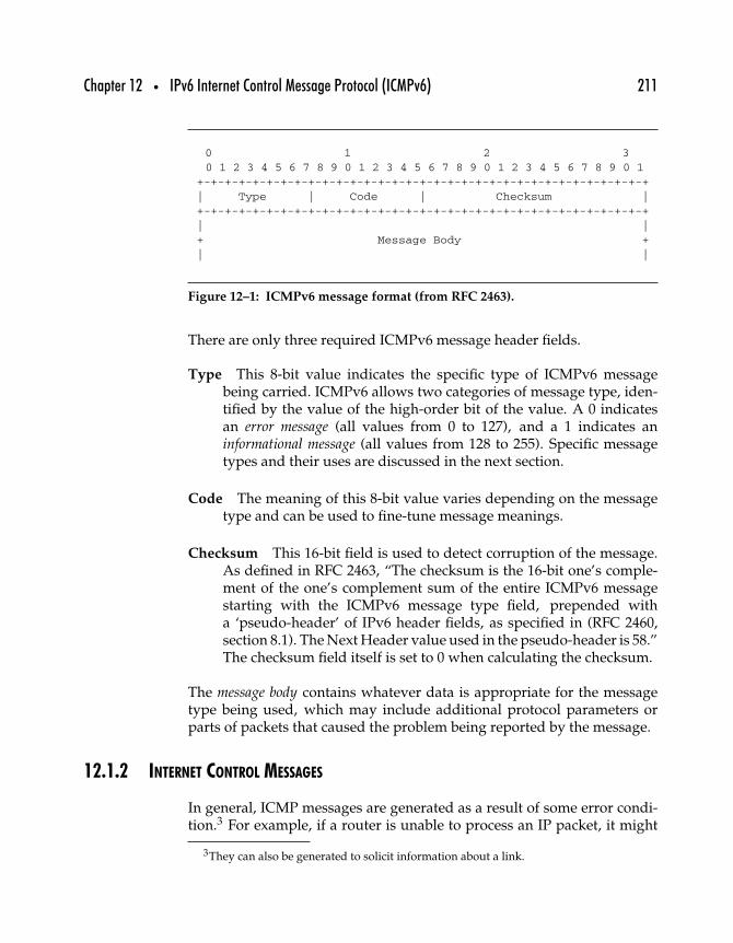
Chapter 12 • IPv6 Internet Control Message Protocol (ICMPv6) 211
0 1 2 30 1 2 3 4 5 6 7 8 9 0 1 2 3 4 5 6 7 8 9 0 1 2 3 4 5 6 7 8 9 0 1
+-+-+-+-+-+-+-+-+-+-+-+-+-+-+-+-+-+-+-+-+-+-+-+-+-+-+-+-+-+-+-+-+| Type | Code | Checksum |+-+-+-+-+-+-+-+-+-+-+-+-+-+-+-+-+-+-+-+-+-+-+-+-+-+-+-+-+-+-+-+-+| |+ Message Body +| |
Figure 12–1: ICMPv6 message format (from RFC 2463).
There are only three required ICMPv6 message header fields.
Type This 8-bit value indicates the specific type of ICMPv6 messagebeing carried. ICMPv6 allows two categories of message type, iden-tified by the value of the high-order bit of the value. A 0 indicatesan error message (all values from 0 to 127), and a 1 indicates aninformational message (all values from 128 to 255). Specific messagetypes and their uses are discussed in the next section.
Code The meaning of this 8-bit value varies depending on the messagetype and can be used to fine-tune message meanings.
Checksum This 16-bit field is used to detect corruption of the message.As defined in RFC 2463, “The checksum is the 16-bit one’s comple-ment of the one’s complement sum of the entire ICMPv6 messagestarting with the ICMPv6 message type field, prepended witha ‘pseudo-header’ of IPv6 header fields, as specified in (RFC 2460,section 8.1). The Next Header value used in the pseudo-header is 58.”The checksum field itself is set to 0 when calculating the checksum.
The message body contains whatever data is appropriate for the messagetype being used, which may include additional protocol parameters orparts of packets that caused the problem being reported by the message.
12.1.2 INTERNET CONTROL MESSAGES
In general, ICMP messages are generated as a result of some error condi-tion.3 For example, if a router is unable to process an IP packet, it might
3They can also be generated to solicit information about a link.
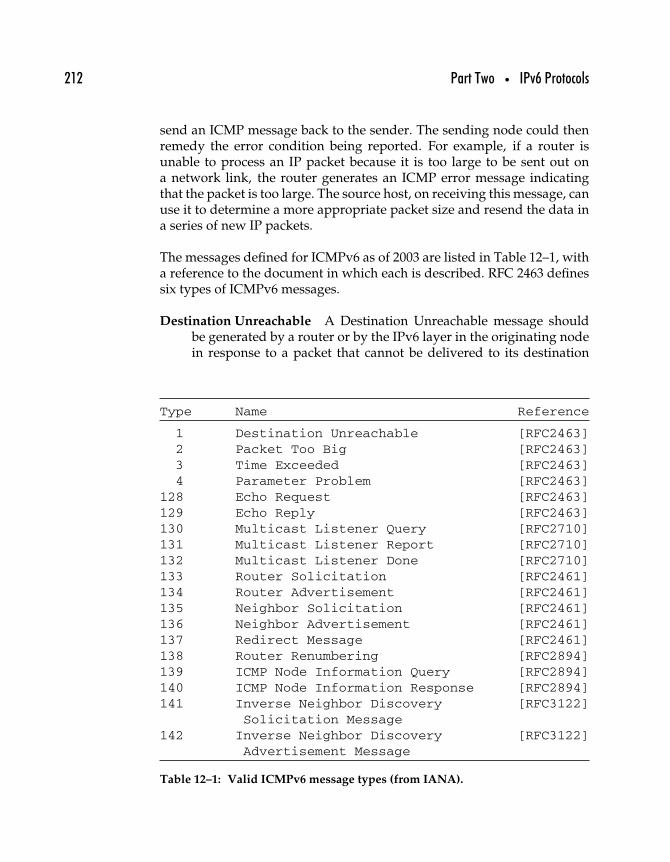
212 Part Two • IPv6 Protocols
send an ICMP message back to the sender. The sending node could thenremedy the error condition being reported. For example, if a router isunable to process an IP packet because it is too large to be sent out ona network link, the router generates an ICMP error message indicatingthat the packet is too large. The source host, on receiving this message, canuse it to determine a more appropriate packet size and resend the data ina series of new IP packets.
The messages defined for ICMPv6 as of 2003 are listed in Table 12–1, witha reference to the document in which each is described. RFC 2463 definessix types of ICMPv6 messages.
Destination Unreachable A Destination Unreachable message shouldbe generated by a router or by the IPv6 layer in the originating nodein response to a packet that cannot be delivered to its destination
Type Name Reference
1 Destination Unreachable [RFC2463]2 Packet Too Big [RFC2463]3 Time Exceeded [RFC2463]4 Parameter Problem [RFC2463]
128 Echo Request [RFC2463]129 Echo Reply [RFC2463]130 Multicast Listener Query [RFC2710]131 Multicast Listener Report [RFC2710]132 Multicast Listener Done [RFC2710]133 Router Solicitation [RFC2461]134 Router Advertisement [RFC2461]135 Neighbor Solicitation [RFC2461]136 Neighbor Advertisement [RFC2461]137 Redirect Message [RFC2461]138 Router Renumbering [RFC2894]139 ICMP Node Information Query [RFC2894]140 ICMP Node Information Response [RFC2894]141 Inverse Neighbor Discovery [RFC3122]
Solicitation Message142 Inverse Neighbor Discovery [RFC3122]
Advertisement Message
Table 12–1: Valid ICMPv6 message types (from IANA).
Chapter 12 • IPv6 Internet Control Message Protocol (ICMPv6) 213
address for reasons other than congestion. (An ICMPv6 messagemust not be generated if a packet is dropped due to congestion.)
Packet Too Big A Packet Too Big must be sent by a router in response toa packet that it cannot forward because the packet is larger than theMTU of the outgoing link. The information in this message is usedas part of the Path MTU Discovery process.
Time Exceeded If a router receives a packet with a Hop Limit of zero, ora router decrements a packet’s Hop Limit to zero, it must discard thepacket and send an ICMPv6 Time Exceeded message with Code 0 tothe source of the packet. This indicates either a routing loop or toosmall an initial Hop Limit value.
Parameter Problem If an IPv6 node processing a packet finds a prob-lem with a field in the IPv6 header or extension headers such that itcannot complete processing the packet, it must discard the packetand should send an ICMPv6 Parameter Problem message to thepacket’s source, indicating the type and location of the problem.
Echo Request Every node must implement an ICMPv6 Echo responderfunction that receives Echo Requests and sends corresponding EchoReplies. A node should also implement an application-layer interfacefor sending Echo Requests and receiving Echo Replies, for diagnosticpurposes.
Echo Reply Every node must implement an ICMPv6 Echo responderfunction that receives Echo Requests and sends corresponding EchoReplies. A node should also implement an application-layer interfacefor sending Echo Requests and receiving Echo Replies, for diagnosticpurposes.
12.2 ICMPv6 Messages
All ICMPv6 messages must be processed in much the same way as IPv4-based ICMP messages, and in this section we examine the six basicICMPv6 messages defined in RFC 2463. It should be noted that ICMPv6error messages should never be generated when a router or link iscongested because doing so could only make things worse (by tying up
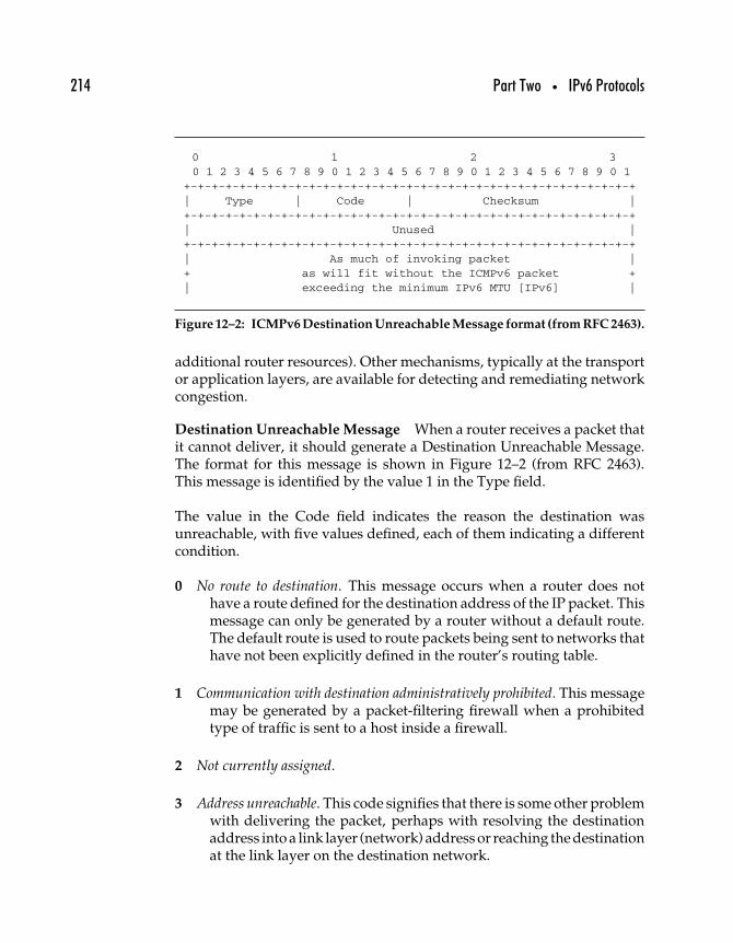
214 Part Two • IPv6 Protocols
0 1 2 30 1 2 3 4 5 6 7 8 9 0 1 2 3 4 5 6 7 8 9 0 1 2 3 4 5 6 7 8 9 0 1
+-+-+-+-+-+-+-+-+-+-+-+-+-+-+-+-+-+-+-+-+-+-+-+-+-+-+-+-+-+-+-+-+| Type | Code | Checksum |+-+-+-+-+-+-+-+-+-+-+-+-+-+-+-+-+-+-+-+-+-+-+-+-+-+-+-+-+-+-+-+-+| Unused |+-+-+-+-+-+-+-+-+-+-+-+-+-+-+-+-+-+-+-+-+-+-+-+-+-+-+-+-+-+-+-+-+| As much of invoking packet |+ as will fit without the ICMPv6 packet +| exceeding the minimum IPv6 MTU [IPv6] |
Figure 12–2: ICMPv6 Destination Unreachable Message format (from RFC 2463).
additional router resources). Other mechanisms, typically at the transportor application layers, are available for detecting and remediating networkcongestion.
Destination Unreachable Message When a router receives a packet thatit cannot deliver, it should generate a Destination Unreachable Message.The format for this message is shown in Figure 12–2 (from RFC 2463).This message is identified by the value 1 in the Type field.
The value in the Code field indicates the reason the destination wasunreachable, with five values defined, each of them indicating a differentcondition.
0 No route to destination. This message occurs when a router does nothave a route defined for the destination address of the IP packet. Thismessage can only be generated by a router without a default route.The default route is used to route packets being sent to networks thathave not been explicitly defined in the router’s routing table.
1 Communication with destination administratively prohibited. This messagemay be generated by a packet-filtering firewall when a prohibitedtype of traffic is sent to a host inside a firewall.
2 Not currently assigned.
3 Address unreachable. This code signifies that there is some other problemwith delivering the packet, perhaps with resolving the destinationaddress into a link layer (network) address or reaching the destinationat the link layer on the destination network.
Chapter 12 • IPv6 Internet Control Message Protocol (ICMPv6) 215
4 Port unreachable. This code is generated by the destination node whenan upper-layer protocol (e.g., DP) is not listening for traffic on thepacket’s destination port but only if the transport protocol doesn’thave some other mechanism for notifying the source of this problem.
The unused section of the message is padded out with zeros so that therest of the message begins on an eight-octet boundary.
12.2.1 PACKET TOO BIG
Routers are required to send a Packet Too Big message (identified by typevalue 2) whenever they receive a packet that cannot be forwarded becauseit is larger than the MTU of the link onto which it should be forwarded. Themessage format is similar to that of the Destination Unreachable message,except that the second four octets of the header contain the maximumtransmission unit (MTU) of the link for which the packet is too large.
12.2.2 TIME EXCEEDED
Two distinct types of Time Exceeded message (Type value 3) are definedfor ICMPv6. The first (defined by Code value 0) is for packets that havebeen bouncing around the network for too long; the second (definedby Code value 1) is for packets that have exceeded their fragmentreassembly time.
Stale packets are purged from the network when their hop limit isexceeded. Routers processing inbound packets whose hop limit fieldcontains a 1 (meaning they’ve just completed their last permitted hop)or 0 (meaning the packet has been mistakenly forwarded despite havingtimed out) must drop the packet and generate a Time Exceeded message.
Time Exceeded messages generally indicate either that the default hoplimit count is set too low for the network or that there is a routing loopcausing the packet to bounce from router to router without arriving at itsdestination address.
This message is useful for building the traceroute function. This functionallows a node to identify all routers along the path that a packet takesbetween the source and the destination. It works like this: First, a packet is
216 Part Two • IPv6 Protocols
sent to the destination with a hop limit of one. The first router it reaches willdecrement the hop limit and respond with a Time Exceeded message, andthe source node will have identified the first router in the path. The sourceresends the packet with a hop limit of two, and if the packet must passthrough a second router, that router will decrement the hop limit to zeroand generate another Time Exceeded message. This continues until thepacket eventually reaches its destination; in the meantime, the source nodehas received a Time Exceeded message from each intermediate router.
12.2.3 PARAMETER PROBLEM
When there is a problem with some part of the IPv6 header or extensionheaders that keeps a router from completing the processing of the packet,the router must discard the packet. It is recommended that the routerimplementation should generate an ICMP parameter problem messagethat indicates the type of problem (bad header field, unrecognized nextheader type, or unrecognized IPv6 option), with a pointer value thatindicates at which byte of the original packet the error condition wasencountered.
12.2.4 ICMPV6 ECHO FUNCTION
ICMPv6 includes a function that is not related to error conditions. Twotypes of messages, the Echo Request and Echo Reply, are required forall IPv6 nodes. The Echo Request message can be sent to any valid IPv6address and can include an echo request identifier, a sequence number,and some data. The Echo Request identifier and sequence may be usedto differentiate replies to different requests, although both are optional.The data is also optional and can be used for diagnostic purposes.
When an IPv6 node receives an Echo Request message, it is required torespond by sending an Echo Reply message. The reply must contain thesame request identifier, sequence number, and data as were contained inthe original request message.
The ICMP Echo Request/Reply message pair is the basis of the “ping”function. Ping is an important diagnostic function because it providesa method of determining whether a particular host is connected to thesame network as some other host.
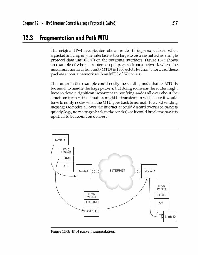
Chapter 12 • IPv6 Internet Control Message Protocol (ICMPv6) 217
12.3 Fragmentation and Path MTU
The original IPv4 specification allows nodes to fragment packets whena packet arriving on one interface is too large to be transmitted as a singleprotocol data unit (PDU) on the outgoing interfaces. Figure 12–3 showsan example of where a router accepts packets from a network where themaximum transmission unit (MTU) is 1500 octets but has to forward thosepackets across a network with an MTU of 576 octets.
The router in this example could notify the sending node that its MTU istoo small to handle the large packets, but doing so means the router mighthave to devote significant resources to notifying nodes all over about thesituation; further, the situation might be transient, in which case it wouldhave to notify nodes when the MTU goes back to normal. To avoid sendingmessages to nodes all over the Internet, it could discard oversized packetsquietly (e.g., no messages back to the sender), or it could break the packetsup itself to be rebuilt on delivery.
INTERNETNode B
Node A
IPv6Packet
ROUTING
PAYLOAD
IPv6Packet
FRAG
AH
IPv6Packet
FRAG
AH
Node C
Node D
Figure 12–3: IPv4 packet fragmentation.
218 Part Two • IPv6 Protocols
The process of determining a path MTU—to determine the largest packetthat can be carried intact from one node to another—is defined for IPv4 inRFC 1191, “Path MTU Discovery.”
12.3.1 FRAGMENTATION AND PATH MTU DISCOVERY
Fragmentation in IPv6 is permitted only between the originating nodeand the destination; this simplifies the header and reduces overhead forrouting. IPv6 nodes may, however, do end-to-end fragmentation if neces-sary, using the fragmentation option (see Chapter 9), but intermediaterouters (or other nodes) are not permitted to break up packets that are toolarge for their link.
Hop-by-hop fragmentation is considered harmful. For one thing, it cangenerate more fragments than end-to-end fragmentation. For another, theloss of a single fragment means all the fragments must be retransmitted.IPv6 does support fragmentation through an extension header, though, asdescribed next. Understanding how IPv4 fragmentation works will clarifywhy it has been changed in IPv6.
IPv4 packet fragmentation happens when the unfragmented packet is toolong to traverse a network link along its route from source to destination.To illustrate, a source node may create a packet of 1500 bytes and send itto a remote destination somewhere on the Internet. The packet is transmit-ted on the source’s link layer network to the default router for that node.This router forwards the packet on its link to the Internet, which may bea point-to-point connection with an Internet service provider. Somewhereinside the Internet cloud, or somewhere closer to the destination node,there may be a network link that cannot handle data in chunks that large.In that case, the router using that network link would have to break upthe 1500-byte datagram into fragments no larger than the next network’sMTU maximum transmission unit (MTU) size. So if the next link couldhandle packets no larger than, say, 1280 bytes, the router would break upthe original packet into two pieces. The first would be 1256 bytes long,leaving 24 bytes for the IPv4 header. The second fragment would be thelength of the remainder of the original packet, 244 bytes, plus another20 bytes for another IPv4 header (plus four octets for padding out thepacket to end on an eight-octet word boundary).
Fragmentation in IPv4 is done as needed by intermediate routers alonga packet’s path. The fragmenting router modifies the packet’s header
Chapter 12 • IPv6 Internet Control Message Protocol (ICMPv6) 219
as necessary to include the original packet’s datagram identification,as well as setting the fragmentation flags and the fragment offset fieldappropriately. When the resulting fragmented packets are received bythe destination node, that system must reassemble the packets using thefragmentation data in the IPv4 headers of each packet fragment.
Using fragmentation, it is possible to interoperate between nodes that existon very different types of networks, with any kind of network in between.The source node doesn’t need to know anything about the destinationnode’s network, nor does it need to know anything about the networks inbetween. This has always been considered a relatively good thing, sincenot requiring nodes or routers to store information or maps of the entireInternet helps make the Internet very scalable. On the other hand, it alsoposes a performance problem for routers: Fragmenting IP packets costsprocessing power and time along the route as well as at the destination.There is the overhead of keeping track of IP datagram identifiers, calcu-lating fragment offsets, and actually dividing up a packet into fragmentsand then reassembling it at its destination.
The problem is, although in any given route the source may know thelink MTU, it cannot know ahead of time the path MTU. The path MTU, ofcourse, is the size of the largest packet that can be carried over any networkalong the route between the source and the destination without having tofragment it.
There are, however, two ways to reduce or eliminate the need for frag-mentation. The first, which is available in IPv4, is to use a method calledpath MTU discovery. With this approach, a router can send out a packet thesize of the link MTU to the destination for the router. If the packet reachesa link at which it must be fragmented, the fragmenting router sends backan ICMP message indicating how much smaller the fragmenting router’slink MTU is. This process can be repeated until the router can determinethe path MTU.
The other way to cut down on the need for fragmentation is to requirethat all links supporting IP be able to handle packets of some reasonableminimum size. In other words, if a link MTU could be anything from20 bytes on up, then all nodes would have to be prepared to do a con-siderable amount of fragmenting of packets. On the other hand, if youcould come up with some reasonable size that all network links couldaccommodate and set that as the absolute minimum permitted packet size,you could eliminate fragmentation.
220 Part Two • IPv6 Protocols
12.3.2 IPV6 PATH MTU DISCOVERY
IPv6, in fact, uses both these approaches. In the original RFC, the IPv6specification calls for every link to support an MTU of at least 576 bytes.The resulting payloads for these packets would then be 536 bytes, allowing40 bytes for the IPv6 headers. Since RFC 1883 was published in 1995, com-pelling arguments have been made for a larger MTU. Christian Huitemareports (in “IPv6: The New Internet Protocol,” 2nd ed., Prentice-Hall) thatas of 1997, Steve Deering was campaigning for an MTU of 1500 bytes.By 1998, with publication of RFC 2460, the minimum MTU permitted forIPv6 was set at 1280 bytes.
In part to compensate for what may turn out to be a shorter MTU, the IPv6specification also strongly recommends that all IPv6 nodes implement pathMTU discovery. Described first in RFC 1191, “Path MTU Discovery,” thismechanism uses the Don’t Fragment bit in the fragment flags field to causeintermediate routers to return ICMP error messages indicating that thepacket is too large.
The IPv6 version of path MTU discovery is described in RFC 1981, “PathMTU Discovery for IP version 6.” This upgrade is largely based on the orig-inal RFC 1191 specification, but some changes have been made to makeit work with IPv6. Most important, because IPv6 doesn’t support frag-mentation in its header, there is no Don’t Fragment bit to set. The nodedoing the path MTU discovery simply transmits the largest packet per-missible on its own network link to the destination. If an intermediate linkcannot handle packets of that size, the router attempting to forward thepath MTU discovery packet will return an ICMPv6 error message backto the source node. The source node will then send another, smaller,packet. The process is repeated until no ICMPv6 error messages arereceived, and the source node then can use the most recent MTU as thepath MTU.
12.3.3 PMTU IMPLEMENTATION ISSUES
The path MTU between any two nodes on a network may vary dependingon the routes available and the conditions on those routes at any giventime. A path MTU calculated half an hour ago may have been significantlysmaller or larger than the value as calculated now. Although the protocolcan almost immediately precipitate a recalculation of the path MTU whenit becomes smaller (the node sending a packet will receive an ICMPv6
Chapter 12 • IPv6 Internet Control Message Protocol (ICMPv6) 221
“packet too big” message), there is no obvious way to detect a change thatincreases the path MTU.
To remedy the situation, RFC 1981 recommends that implementationscache PMTU values and have the values time out after some moderateamount of time (10 minutes is the duration suggested). At that point, thePMTU value can be recalculated.
In this way, packet size efficiency can be maximized. However, there aresome situations in which the path MTU value will never change. Forexample, a node connecting to an FDDI network that is attached to theglobal Internet through a small MTU fixed serial link will never discovera path MTU greater than the MTU of the serial link. As a result, implemen-tations should incorporate a mechanism for changing the maximum ageof cached PMTU values that includes an option for never timing them out.
12.4 Other ICMPv6 Functions
As already noted, ICMPv6 provides a framework for other protocols tooperate. The Multicast Listener Discovery (MLD) protocol uses ICMPv6messages, as discussed in Chapter 10; likewise, ICMPv6 messages areused to perform the functions defined under the Neighbor Discovery (ND)protocol, to be discussed in the next chapter.
12.5 Summary
Although it resembles ICMP in many ways, ICMPv6 has been made morepowerful than its predecessor at the same time it has been simplified. Thejudicious use of multicast, as defined for IPv6, and the elimination of IGMPas a separate protocol make ICMPv6 an even more important part of IPv6.Of particular note is the inclusion of the neighbor discovery protocol aspart of ICMPv6.

This Page Intentionally Left Blank
1313
IPv6 Neighbor Discovery
One area in which IPv4 networking is made more complicated is in locatingservers, routers, configuration data, and generally in making it possiblefor nodes to determine what other nodes are nearby (on the same link)and what nodes are remote (off-link). Neighbor Discovery (ND) for IPv6is defined in RFC 2461, “Neighbor Discovery for IPv6,” and it providesan important tool that not only simplifies network administration andmanagement but also enables a much greater degree of scaling in IPv6network size.
This chapter compares how ND is specified and implemented in IPv4 andIPv6, followed by a discussion of some of the roles that ND fulfills for IPv6.The rest of the chapter outlines how ND works, with some example NDmessages and protocol interactions.
223
224 Part Two • IPv6 Protocols
13.1 The Neighbor Discovery Protocol
As noted in the abstract of RFC 2461, “IPv6 nodes on the same linkuse Neighbor Discovery to discover each other’s presence, to determineeach other’s link layer addresses, to find routers and to maintain reach-ability information about the paths to active neighbors.” Five types ofICMPv6 messages to be used in neighbor discovery are defined in RFC2461, including a pair of messages for router solicitation and router adver-tisement, a pair for neighbor solicitation and advertisement, and a redirectmessage.
By defining neighbor discovery functions in terms of ICMPv6 messages,additional protocols (such as ARP) are unnecessary—and without a mech-anism for doing broadcast (as in IPv4), those protocols would not workanyway. As a mandatory part of any IPv6 implementation, ICMPv6 offersan ideal transport for neighbor discovery messages.
ICMPv6 messages, particularly requests, are usually multicast, whereasresponses may be unicast to the requesting node or multicast to theall-nodes multicast address group (equivalent, functionally, to the IPv4concept of broadcast). Although the neighbor discovery requests may bemulticast to the all-nodes group, they can also be restricted to subsets ofthe all-nodes group such as all-routers on the local link.
The messages defined in RFC 2461 for neighbor discovery are described inthat specification as having the following functions.
Router Solicitation When an interface becomes enabled, hosts may sendout Router Solicitations that request routers to generate RouterAdvertisements immediately rather than at their next scheduled time.
Router Advertisement Routers advertise their presence together withvarious link and Internet parameters eitherperiodicallyor in responseto a Router Solicitation message. Router Advertisements containprefixes that are used for on-link determination and/or addressconfiguration, a suggested hop limit value, and so forth.
Neighbor Solicitation Sent by a node to determine the link layer addressof a neighbor or to verify that a neighbor is still reachable via a cachedlink layer address. Neighbor Solicitations are also used for DuplicateAddress Detection.
Chapter 13 • IPv6 Neighbor Discovery 225
Neighbor Advertisement A response to a Neighbor Solicitation mes-sage. A node may also send unsolicited Neighbor Advertisementsto announce a link layer address change.
Redirect Used by routers to inform hosts of a better first hop fora destination.
These five sets of messages solve quite an array of networking problems,as discussed next.
13.2 Solving Networking Problems
IP nodes on the same local link are neighbors on two separate and distinctnetworks: the local link network, and the Internet on which the nodes aredistinguishable through their globally unique IP addresses. Under IPv4,the process of mapping an IP address to a local link layer address wasstraightforward, with ARP, but limited in scope.
The neighbor discovery protocol in IPv6 allows nodes on the same locallinks to map their IP addresses to their link layer addresses, but it alsoallows for the solution of more complicated problems, as described inRFC 2461.
Router Discovery Hosts need a mechanism for locating a local router.
Prefix Discovery Hosts need a mechanism for discovering the set ofaddress prefixes that define which destinations are on-link for anattached link. Nodes use prefixes to distinguish destinations thatreside on-link from those only reachable through a router.
Parameter Discovery Hosts need a mechanism for discovering local linknetwork parameters, such as the link MTU, or IP network parameters,such as the hop limit value, to place in outgoing packets.
Address Autoconfiguration Hosts need a mechanism for configuring anIPv6 network interface address automatically.
Address Resolution Hosts need a mechanism for determining a linklayer address of a neighboring host, given only the destination’s IPaddress. This function is performed by ARP in IPv4.
226 Part Two • IPv6 Protocols
Next-hop Determination When sending a packet, a host must determinewhere to send it. That decision is made based on the destination’s IPaddress; hosts need a way to decide whether the packet should besent to a router or directly to the destination. The packet is sent toa router if the destination is not local; otherwise, the packet is sentdirectly to its (local) destination.
Neighbor Unreachability Detection Hosts need a mechanism by whichthey can determine that a neighbor is no longer reachable. For neigh-bors used as routers, alternate default routers can be tried. For bothrouters and hosts, address resolution can be performed again.
Duplicate Address Detection Hosts need a mechanism by which theycan verify that an address is not already in use by another host.
Redirect Routers must have a mechanism by which they can notifya host that there is a better-positioned router to be used as thefirst-hop node to reach some particular destination.
In addition to these basic functions, IPv6 neighbor discovery can solvemore complicated problems, as described in RFC 2461.
Link layer address change A node that knows its link layer address haschanged can multicast a few (unsolicited) Neighbor Advertisementpackets to all nodes to quickly update cached link layer addressesthat have become invalid. Note that the sending of unsolicited adver-tisements is a performance enhancement only (e.g., unreliable). TheNeighbor Unreachability Detection algorithm ensures that all nodeswill reliably discover the new address, although the delay may besomewhat longer.
Inbound load balancing Nodes with replicated interfaces may want toload-balance the reception of incoming packets across multiple net-work interfaces on the same link. Such nodes have multiple linklayer addresses assigned to the same interface. For example, a singlenetwork driver could represent multiple network interface cards asa single logical interface having multiple link layer addresses.
Load balancing Handled by allowing routers to omit the source linklayer address from Router Advertisement packets, thereby forcingneighbors to use Neighbor Solicitation messages to learn link layer
Chapter 13 • IPv6 Neighbor Discovery 227
addresses of routers. Returned Neighbor Advertisement messagescan then contain link layer addresses that differ depending on whoissued the solicitation.
Anycast addresses Anycast addresses identify one of a set of nodes pro-viding an equivalent service, and multiple nodes on the same linkmay be configured to recognize the same anycast address. NeighborDiscovery handles anycasts by having nodes expect to receive multi-ple Neighbor Advertisements for the same target. All advertisementsfor anycast addresses are tagged as being nonoverride advertise-ments. This invokes specific rules to determine which of potentiallymultiple advertisements should be used.
Proxy advertisements A router willing to accept packets on behalf ofa target address that is unable to respond to Neighbor Solicitationscan issue nonoverride Neighbor Advertisements. There is currentlyno specified use of proxy, but proxy advertising could potentiallybe used to handle cases like mobile nodes that have moved off-link.However, it is not intended as a general mechanism to handle nodesthat, for example, do not implement this protocol.
13.3 IPv6 Neighbor Discovery Compared with IPv4
Strictly speaking, there is no single, explicit neighbor discovery protocoldefined for IPv4. A variety of protocols, including the Address ResolutionProtocol (ARP) and parts of the Internet Control Message Protocol (ICMP)for IPv4, serve the function of mapping local link addresses to IP addressesof neighboring nodes.
For example, the ICMP Router Discovery protocol defined in RFC 1256,“ICMP Router Discovery Messages,” specifies a mechanism by which IPv4nodes may multicast (or broadcast) a request on their local link to discoverlocal routers offering forwarding beyond the local link. IPv4 nodes withan IP address known to be local can map a local link network address byquerying the local link using an ARP request.
Having supplied such wants with a pastiche of protocols, protocolextensions, and protocol modifications, IPv4 still lacks a standard mech-anism for performing many basic functions. For example, no standardmechanism for detecting when a neighbor is unreachable has been defined
228 Part Two • IPv6 Protocols
for IPv4. Likewise, some reachability/unreachability functions can beaccomplished under IPv4 only by eavesdropping on routing protocolmessages exchanged by local routers.
As described in RFC 2461, Neighbor Discovery offers “a multitudeof improvements” over the existing solutions in IPv4, including thefollowing.
• Router Discovery is part of the base protocol set; there is noneed for hosts to “snoop” the routing protocols.
• Router Advertisements carry link layer addresses; no addi-tional packet exchange is needed to resolve the router’s linklayer address.
• Router Advertisements carry prefixes for a link; there is no needto have a separate mechanism to configure the “netmask.”
• Router Advertisements enable Address Autoconfiguration.• Routers can advertise an MTU for hosts to use on the link,
ensuring that all nodes use the same MTU value on links lackinga well-defined MTU.
• Address Resolution multicasts are “spread” over 4 billion(232) multicast addresses, greatly reducing address resolution-related interrupts on nodes other than the target. Moreover,non-IPv6 machines should not be interrupted at all.
• Redirects contain the link layer address of the new firsthop; separate address resolution is not needed upon receivinga redirect.
• Multiple prefixes can be associated with the same link. Bydefault, hosts learn all on-link prefixes from Router Advertise-ments. However, routers may be configured to omit some orall prefixes from Router Advertisements. In such cases, hostsassume that destinations are off-link and send traffic to routers.A router can then issue redirects as appropriate.
• Unlike IPv4, the recipient of an IPv6 redirect assumes thatthe new next-hop is on-link. In IPv4, a host ignores redirectsspecifying a next-hop that is not on-link according to the link’snetwork mask. The IPv6 redirect mechanism is expected to beuseful on nonbroadcast and shared media links in which it isundesirable or not possible for nodes to know all prefixes foron-link destinations.
• Neighbor Unreachability Detection is part of the base sig-nificantly improving the robustness of packet delivery in thepresence of failing routers, partially failing or partitioned links,
Chapter 13 • IPv6 Neighbor Discovery 229
and nodes that change their link layer addresses. For instance,mobile nodes can move off-link without losing any connectivitydue to stale ARP caches.
• Unlike ARP, Neighbor Discovery detects half-link failures(using Neighbor Unreachability Detection) and avoids send-ing traffic to neighbors with which two-way connectivity isabsent.
• Unlike in IPv4 Router Discovery the Router Advertisementmessages do not contain a preference field. The preferencefield is not needed to handle routers of different “stability”;the Neighbor Unreachability Detection will detect dead routersand switch to a working one.
• The use of link-local addresses to uniquely identify routers(for Router Advertisement and Redirect messages) makes itpossible for hosts to maintain the router associations in theevent of the site renumbering to use new global prefixes.
• By setting the Hop Limit equal to 255, Neighbor Discoverycan be made immune to off-link senders that accidentallyor intentionally send ND messages. In IPv4 off-link senderscan send both ICMP Redirects and Router Advertisementmessages.
• Placing address resolution at the ICMP layer makes the proto-col more media-independent than ARP and makes it possibleto use standard IP authentication and security mechanisms asappropriate.
As of mid-2003, the IANA reports 10 different ND option format types, asshown in Table 13–1. The complete specifications for each type of optioncan be found in the relevant protocol specifications.
• Types 1 through 5 are defined in RFC 2461.• Type 6, the NBMA Shortcut Limit option, is defined in RFC
2491, “IPv6 over Non-Broadcast Multiple Access (NBMA)networks.”
• Types 7 and 8 are defined in “Mobility Support in IPv6,”a work-in-progress.
• Types 9 and 10 are defined in RFC 3122, “Extensions to IPv6Neighbor Discovery for Inverse Discovery Specification.”
Rather than reproduce the complete specifications for all these messagetypes, the next section provides an example of a typical and representativeND message exchange: Router Solicitation.
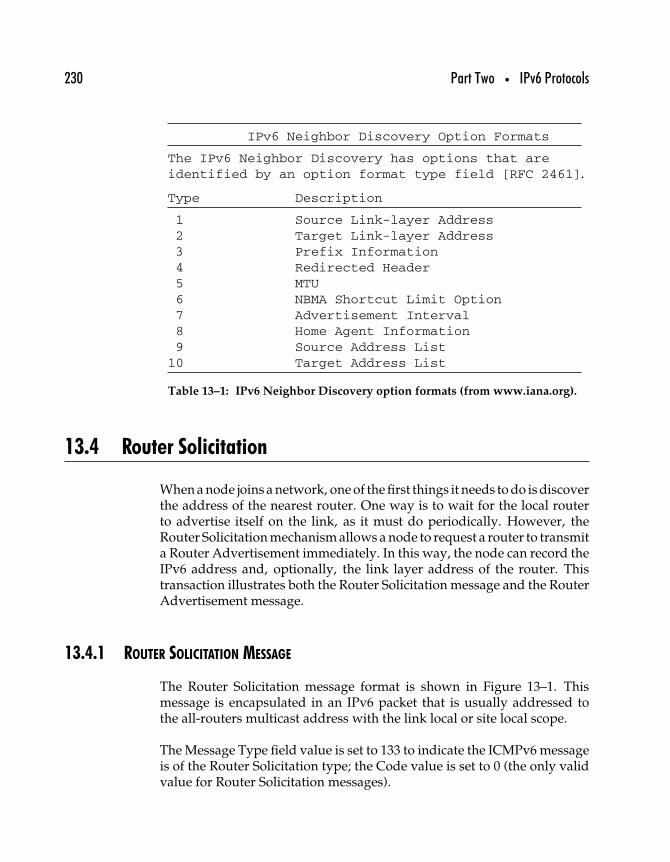
230 Part Two • IPv6 Protocols
IPv6 Neighbor Discovery Option Formats
The IPv6 Neighbor Discovery has options that areidentified by an option format type field [RFC 2461].
Type Description
1 Source Link-layer Address2 Target Link-layer Address3 Prefix Information4 Redirected Header5 MTU6 NBMA Shortcut Limit Option7 Advertisement Interval8 Home Agent Information9 Source Address List
10 Target Address List
Table 13–1: IPv6 Neighbor Discovery option formats (from www.iana.org).
13.4 Router Solicitation
When a node joins a network, one of the first things it needs to do is discoverthe address of the nearest router. One way is to wait for the local routerto advertise itself on the link, as it must do periodically. However, theRouter Solicitation mechanism allows a node to request a router to transmita Router Advertisement immediately. In this way, the node can record theIPv6 address and, optionally, the link layer address of the router. Thistransaction illustrates both the Router Solicitation message and the RouterAdvertisement message.
13.4.1 ROUTER SOLICITATION MESSAGE
The Router Solicitation message format is shown in Figure 13–1. Thismessage is encapsulated in an IPv6 packet that is usually addressed tothe all-routers multicast address with the link local or site local scope.
The Message Type field value is set to 133 to indicate the ICMPv6 messageis of the Router Solicitation type; the Code value is set to 0 (the only validvalue for Router Solicitation messages).
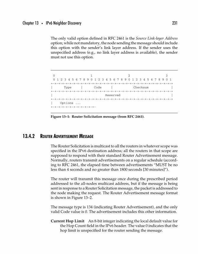
Chapter 13 • IPv6 Neighbor Discovery 231
The only valid option defined in RFC 2461 is the Source Link-layer Addressoption; while not mandatory, the node sending the message should includethis option with the sender’s link layer address. If the sender uses theunspecified address (e.g., no link layer address is available), the sendermust not use this option.
0 1 2 30 1 2 3 4 5 6 7 8 9 0 1 2 3 4 5 6 7 8 9 0 1 2 3 4 5 6 7 8 9 0 1
+-+-+-+-+-+-+-+-+-+-+-+-+-+-+-+-+-+-+-+-+-+-+-+-+-+-+-+-+-+-+-+-+| Type | Code | Checksum |+-+-+-+-+-+-+-+-+-+-+-+-+-+-+-+-+-+-+-+-+-+-+-+-+-+-+-+-+-+-+-+-+| Reserved |+-+-+-+-+-+-+-+-+-+-+-+-+-+-+-+-+-+-+-+-+-+-+-+-+-+-+-+-+-+-+-+-+| Options ...+-+-+-+-+-+-+-+-+-+-+-+-
Figure 13–1: Router Solicitation message (from RFC 2461).
13.4.2 ROUTER ADVERTISEMENT MESSAGE
The Router Solicitation is multicast to all the routers in whatever scope wasspecified in the IPv6 destination address; all the routers in that scope aresupposed to respond with their standard Router Advertisement message.Normally, routers transmit advertisements on a regular schedule (accord-ing to RFC 2461, the elapsed time between advertisements “MUST be noless than 4 seconds and no greater than 1800 seconds [30 minutes]”).
The router will transmit this message once during the prescribed periodaddressed to the all-nodes multicast address, but if the message is beingsent in response to a Router Solicitation message, the packet is addressed tothe node making the request. The Router Advertisement message formatis shown in Figure 13–2.
The message type is 134 (indicating Router Advertisement), and the onlyvalid Code value is 0. The advertisement includes this other information.
Current Hop Limit An 8-bit integer indicating the local default value forthe Hop Count field in the IPv6 header. The value 0 indicates that thehop limit is unspecified for the router sending the message.
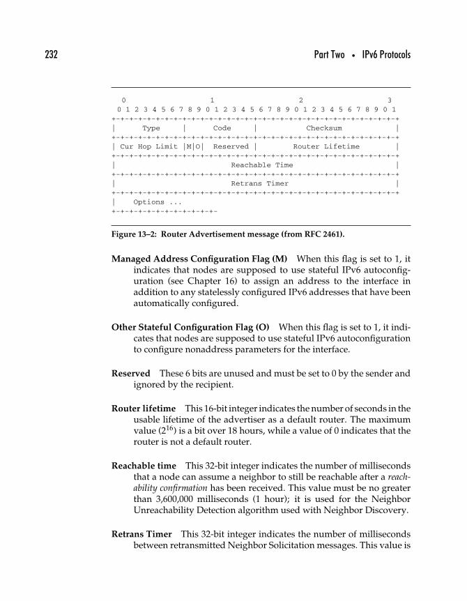
232 Part Two • IPv6 Protocols
0 1 2 30 1 2 3 4 5 6 7 8 9 0 1 2 3 4 5 6 7 8 9 0 1 2 3 4 5 6 7 8 9 0 1
+-+-+-+-+-+-+-+-+-+-+-+-+-+-+-+-+-+-+-+-+-+-+-+-+-+-+-+-+-+-+-+-+| Type | Code | Checksum |+-+-+-+-+-+-+-+-+-+-+-+-+-+-+-+-+-+-+-+-+-+-+-+-+-+-+-+-+-+-+-+-+| Cur Hop Limit |M|O| Reserved | Router Lifetime |+-+-+-+-+-+-+-+-+-+-+-+-+-+-+-+-+-+-+-+-+-+-+-+-+-+-+-+-+-+-+-+-+| Reachable Time |+-+-+-+-+-+-+-+-+-+-+-+-+-+-+-+-+-+-+-+-+-+-+-+-+-+-+-+-+-+-+-+-+| Retrans Timer |+-+-+-+-+-+-+-+-+-+-+-+-+-+-+-+-+-+-+-+-+-+-+-+-+-+-+-+-+-+-+-+-+| Options ...+-+-+-+-+-+-+-+-+-+-+-+-
Figure 13–2: Router Advertisement message (from RFC 2461).
Managed Address Configuration Flag (M) When this flag is set to 1, itindicates that nodes are supposed to use stateful IPv6 autoconfig-uration (see Chapter 16) to assign an address to the interface inaddition to any statelessly configured IPv6 addresses that have beenautomatically configured.
Other Stateful Configuration Flag (O) When this flag is set to 1, it indi-cates that nodes are supposed to use stateful IPv6 autoconfigurationto configure nonaddress parameters for the interface.
Reserved These 6 bits are unused and must be set to 0 by the sender andignored by the recipient.
Router lifetime This 16-bit integer indicates the number of seconds in theusable lifetime of the advertiser as a default router. The maximumvalue (216) is a bit over 18 hours, while a value of 0 indicates that therouter is not a default router.
Reachable time This 32-bit integer indicates the number of millisecondsthat a node can assume a neighbor to still be reachable after a reach-ability confirmation has been received. This value must be no greaterthan 3,600,000 milliseconds (1 hour); it is used for the NeighborUnreachability Detection algorithm used with Neighbor Discovery.
Retrans Timer This 32-bit integer indicates the number of millisecondsbetween retransmitted Neighbor Solicitation messages. This value is
Chapter 13 • IPv6 Neighbor Discovery 233
used for Neighbor Unreachability Detection as well as for addressresolution functions.
Options defined in RFC 2461 for the Router Advertisement messageinclude the source link layer address, the MTU value, and prefixinformation (indicating which prefixes are local and which are not).
13.5 Summary
An ongoing challenge for IP networking has always been the need todefine mechanisms to allow nodes to interoperate across local link net-works that are fundamentally different. The use of ARP and its variousdifferent flavors on broadcast and nonbroadcast media has required thecreation of a whole family of services on nonbroadcast networks.
With the creation of special ICMPv6 messages designed for neighbor dis-covery functions, IPv6 networking can be accomplished with significantlyless interaction between link layer and Internet layer protocols. Not onlyare there more functions possible using Neighbor Discovery in IPv6, butthe ones that have always been necessary for locating routers, neighbors,and configuration parameters are more easily accomplished.
Neighbor Discovery makes it possible for nodes to more easily determinewhich network prefixes should be considered local and which are not.When nodes send packets to any of the nonlocal prefixes, they must passthem along to a router for routing. As we’ll see in the next chapter, IPv6routing is very much like IPv4 routing—but with some twists.

This Page Intentionally Left Blank
1414
IPv6 Routing
The primary difference between an ordinary host and a router is that therouter is configured to accept packets intended for another destinationand to forward those packets to what the router determines is the bestnext hop. The router usually also supports at least one routing protocolthrough which it can acquire current information about network routes.In this chapter, after an overview of IP routing in general, we’ll introducethe changes necessary to support IPv6 routing.
14.1 IP Routing Fundamentals
The simplest of routers are those serving a single network with two inter-faces: one for the local network and the other for sending all other traffic.These routers function as gateways for the local network. Local hostsrecognize two types of destinations: those hosts that are on the local logicalIP subnet (LIS) and that can be reached directly over the local link andthose hosts that are not local (everywhere else). Hosts on this network
235
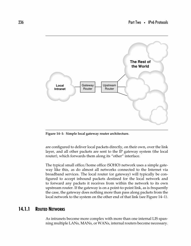
236 Part Two • IPv6 Protocols
LocalIntranet
The Rest of
the World
GatewayRouter
UpstreamRouter
Figure 14–1: Simple local gateway router architecture.
are configured to deliver local packets directly, on their own, over the linklayer, and all other packets are sent to the IP gateway system (the localrouter), which forwards them along its “other” interface.
The typical small office/home office (SOHO) network uses a simple gate-way like this, as do almost all networks connected to the Internet viabroadband services. The local router (or gateway) will typically be con-figured to accept inbound packets destined for the local network andto forward any packets it receives from within the network to its ownupstream router. If the gateway is on a point-to-point link, as is frequentlythe case, the gateway does nothing more than pass along packets from thelocal network to the system on the other end of that link (see Figure 14–1).
14.1.1 ROUTED NETWORKS
As intranets become more complex with more than one internal LIS span-ning multiple LANs, MANs, or WANs, internal routers become necessary.
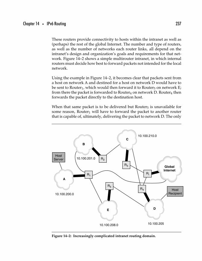
Chapter 14 • IPv6 Routing 237
These routers provide connectivity to hosts within the intranet as well as(perhaps) the rest of the global Internet. The number and type of routers,as well as the number of networks each router links, all depend on theintranet’s design and organization’s goals and requirements for that net-work. Figure 14–2 shows a simple multirouter intranet, in which internalrouters must decide how best to forward packets not intended for the localnetwork.
Using the example in Figure 14–2, it becomes clear that packets sent froma host on network A and destined for a host on network D would have tobe sent to Router1, which would then forward it to Router5 on network E;from there the packet is forwarded to Router4 on network D. Router4 thenforwards the packet directly to the destination host.
When that same packet is to be delivered but Router5 is unavailable forsome reason, Router1 will have to forward the packet to another routerthat is capable of, ultimately, delivering the packet to network D. The only
A
B
C
Global
Internet
DE
R1
R210.100.201.0
10.100.200.0
10.100.208.0
10.100.210.0
10.100.205
R3
Ri
R4
R5
HostServer
HostRecipient
Figure 14–2: Increasingly complicated intranet routing domain.
238 Part Two • IPv6 Protocols
other options open in that case are to forward the packet to the globalInternet (not acceptable) or to Router2 on network B. Router2 forwards thepacket to Router3, which forwards the packet to Router4, which deliversthe packet to its destination. Routeri is the Internet gateway, forward-ing packets to and from the global Internet; Router1 is a backup Internetgateway.
With five internal LISs, plus the global Internet, there are six differentLISs to contend with; fully interconnecting them all so that all networksare reachable from each other in one hop requires 15 dedicated links. Bypermitting more than one hop between local LISs, full interconnectivitycan be achieved with fewer links.
However, the routers need information—which of their own links are upand which down, what portions of the network the other routers can reach.The exchange and update of this information are the primary goals ofInternet routing protocols; in support of this goal is the corollary need toavoid propagating false information or acting on faulty information, whileat the same time optimizing performance (by minimizing the number ofhops it takes from source to destination).
The routers in Figure 14–2 are interior routers because they route packetsinside an AS or other routing domain; inside that domain, the LISs areseparate administrative domains (ADs). An AD is comparable to an AS,except on a smaller scale. As we’ll see, exterior routing, which occursbetween routers linking different ASs through a backbone, requires adifferent approach to the exchange of information and determination ofoptimal routes.
14.1.2 INTERIOR AND EXTERIOR ROUTING PROTOCOLS
The two basic routing tasks are, first, making sure that all networks withinInternets route traffic appropriately among themselves (interior routing)and second, making sure that all internetworks connected to a largeInternet (such as the global Internet) are able to route reliably betweeneach other (exterior routing). Simple routing strategies like default gate-ways and ICMP route advertising will be sufficient to move network trafficinside most intranets.
However, routing protocols do not define the routing process—they definethe process by which routers exchange information about the network.
Chapter 14 • IPv6 Routing 239
Routing table information must be kept current, and routers are constantlycommunicating with each other to announce their own connectivity.
Typically, hosts acquire routing information either as part of their staticconfiguration or through the Dynamic Host Configuration Protocol(DHCP). The host uses ARP to acquire a physical address for all localInternet traffic, and everything else is passed to the default gateway router.In smaller networks, that router connects directly to the ISP’s router, con-nected in turn to an Internet backbone, a network linking more than one AS.Routers on backbone networks must maintain far more comprehensiverouting tables because they must route between and among all networks.They don’t usually have a default gateway specified, and backbone routersare sometimes referred to as nondefault routers.
Exterior or backbone routing protocols must allow communicating routersto report frequent changes in conditions and connectivity, quickly andefficiently. An interior routing protocol enables routers within smallerInternets to report their own conditions and connectivity but generallysupport less complicated routing architectures. The interior routing proto-col supported by a router is often referred to as its Interior Gateway Protocol(IGP), where “gateway” is used as a synonym for router; an exterior routingprotocol is likewise called an Exterior Gateway Protocol (EGP).
14.1.3 ROUTING ALGORITHMS
The simplest formulation of a routing strategy is to opt for the shortest-pathroute whenever there is a choice. How to determine which is the shortestpath presents the greater challenge. There are two dominant strategiesfor determining the shortest path for interior routing, each of which isimplemented in its own protocol. The distance-vector routing algorithm1 isdescribed in RFC 1058, “Routing Information Protocol,” which also definesthe RIP routing protocol for IP networks. Another approach to interiorrouting is called Dijkstra’s Algorithm, and it is also known as the link stateor open shortest path first algorithm. Open Shortest Path First (OSPF) isalso the name of the interior routing protocol defined in RFC 2328, “OSPFVersion 2,” which is also STD 54.
1This algorithm may also be identified as Bellman-Ford or other combinations of the namesof the researchers who did the original work on it.
240 Part Two • IPv6 Protocols
Together, RIP and OSPF represent the IGPs you are most likely to find onan Internet or intranet.
14.1.4 EXTERIOR GATEWAY PROTOCOLS
In today’s global Internet, the most important exterior routing protocolis the Border Gateway Protocol (BGP), defined in RFC 1771 “A BorderGateway Protocol 4 (BGP-4).” Unlike interior routing, exterior routing iscomplicated by the need for backbone routers to connect many differentautonomous systems; if those routers were to advertise route availability,packets might be forwarded almost at random to a router connected toalmost any AS, whether or not the destination is actually within the AS.
Internet exterior routing protocols have evolved over the years to accom-modate increasingly large and complex routing environments. An earlysuch protocol, the Gateway to Gateway Protocol (GGP), was described inRFC 823, “The DARPA Internet Gateway,” in 1982. GGP uses a distance-vector routing algorithm similar to that incorporated in RIP: Gatewaysboot up assuming that all their links are down and no networks are reach-able, but as they test out their own links and receive routing updates fromother gateways, they are able to build up their routing tables to reflectthe current state of the Internet. RFC 823 has been assigned “Historic”status.
Also historic is the Exterior Gateway Protocol (EGP), formally specifiedin RFC 904, “Exterior Gateway Protocol Formal Specification,” in 1984.GGP failed to address the issue of organizational Internets that could notbe connected directly to a core or backbone router. Extra hops were oftenadded when noncore routers would send traffic to their own local defaultrouters instead of forwarding them to a more appropriate Internet routerthat might be closer to the destination. Figure 14–3 illustrates the problem.
The figure shows a noncore router that is connected to a backbone on whichvarious core routers are available. All of the core routers are, in theoryat least, equally capable of routing any packets from any other routersconnected to the backbone. Node X wants to communicate with node Y;ideally, the noncore router sends packets directly to Core Router C, butthat can only happen if there is a way for the core routers to advertise theirroutes directly to noncore routers. EGP provides such a mechanism, bywhich EGP routers, as they come online, attempt to acquire some otherrouter to act as a peer; peers exchange routing information about which
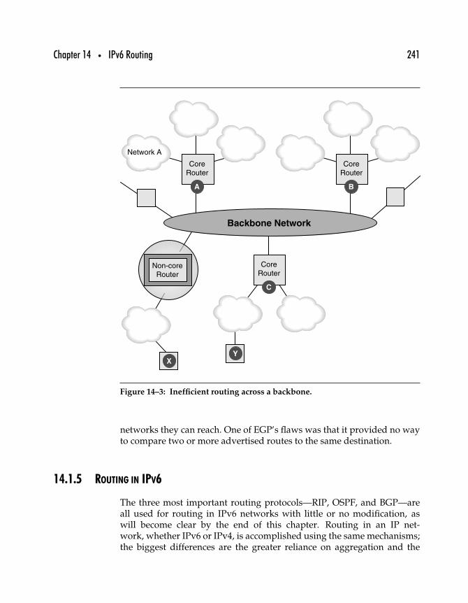
Chapter 14 • IPv6 Routing 241
Backbone Network
Network A
CoreRouter
A
CoreRouter
B
CoreRouter
Non-coreRouter
C
YX
Figure 14–3: Inefficient routing across a backbone.
networks they can reach. One of EGP’s flaws was that it provided no wayto compare two or more advertised routes to the same destination.
14.1.5 ROUTING IN IPV6
The three most important routing protocols—RIP, OSPF, and BGP—areall used for routing in IPv6 networks with little or no modification, aswill become clear by the end of this chapter. Routing in an IP net-work, whether IPv6 or IPv4, is accomplished using the same mechanisms;the biggest differences are the greater reliance on aggregation and the
242 Part Two • IPv6 Protocols
longer addresses. Once those two factors are accommodated by a routingprotocol, IPv6 routing can be accommodated.
14.2 RIP and RIPng
Routing protocols can use two basic methods to measure connectivityacross internetworks, as exemplified by the RIP and OSPF protocols.We begin with RIP, which uses the distance-vector approach: Routers sharetheir routing tables and make additions and corrections based on reportsfrom other routers.
The distance-vector algorithm takes its name from the way routers sharetheir routing tables. A router expresses each route as a pair of values,the vector or destination network, and the distance from that router to thatnetwork (usually measured in hops, or the number of intermediate routersa packet would have to traverse to arrive at the destination network).
A router sends advertisements of its routes, containing all the routes(vectors) and distances to those routes, to neighboring routers. In thisway, routes can be propagated across an Internet as can changes inavailable routes.
14.2.1 THE DISTANCE-VECTOR ALGORITHM
A distance-vector router begins with no knowledge of the Internet otherthan the networks to which it is directly connected. When it first boots, thisrouter will have a routing table that consists of only as many entries as therouter has network interfaces; it might look like this.
Destination Distance Route
10.0.0.0 0 direct
192.168.100.0 0 direct
The router then begins building up its routing table by listening to otherrouter announcements that are broadcast on whatever network interfaceseach router is connected to. In other words, routers advertise their routesto any neighboring router, where “neighboring” means connected to thesame link.
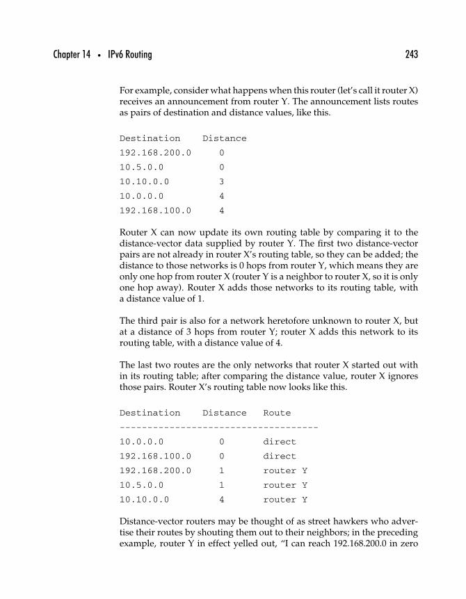
Chapter 14 • IPv6 Routing 243
For example, consider what happens when this router (let’s call it router X)receives an announcement from router Y. The announcement lists routesas pairs of destination and distance values, like this.
Destination Distance
192.168.200.0 0
10.5.0.0 0
10.10.0.0 3
10.0.0.0 4
192.168.100.0 4
Router X can now update its own routing table by comparing it to thedistance-vector data supplied by router Y. The first two distance-vectorpairs are not already in router X’s routing table, so they can be added; thedistance to those networks is 0 hops from router Y, which means they areonly one hop from router X (router Y is a neighbor to router X, so it is onlyone hop away). Router X adds those networks to its routing table, witha distance value of 1.
The third pair is also for a network heretofore unknown to router X, butat a distance of 3 hops from router Y; router X adds this network to itsrouting table, with a distance value of 4.
The last two routes are the only networks that router X started out within its routing table; after comparing the distance value, router X ignoresthose pairs. Router X’s routing table now looks like this.
Destination Distance Route
------------------------------------
10.0.0.0 0 direct
192.168.100.0 0 direct
192.168.200.0 1 router Y
10.5.0.0 1 router Y
10.10.0.0 4 router Y
Distance-vector routers may be thought of as street hawkers who adver-tise their routes by shouting them out to their neighbors; in the precedingexample, router Y in effect yelled out, “I can reach 192.168.200.0 in zero
244 Part Two • IPv6 Protocols
hops; I can reach 10.5.0.0 in zero hops; I can reach 10.10.0.0 in three hops;I can reach 10.0.0.0 in four hops; I can reach 192.168.100.0 in four hops!”
Router X, listening to this advertisement, could be anthropomorphized tobe thinking, “Y can reach 192.168.200.0 in zero hops, so now I can reach itin one hop; Y can reach 10.5.0.0 in zero hops, so now I can reach it in onehop; Y can reach 10.10.0.0 in three hops, so now I can reach it in four hops;Y can reach 10.0.0.0 in four hops, but I can reach it directly; Y can reach192.168.100.0 in four hops, but I can reach it directly.”
When Router X sends out its route advertisement, router Y will undoubt-edly amend its own routes for 10.0.0.0 and 192.168.100.0, changing thedistance from those networks from 4 to 1.
14.2.2 BASIC RIP
All systems on an internetwork can use RIP, but hosts generally arepassive participants, listening to the routing information and updatingtheir routing tables, whereas routers can both listen to routing broadcastsand transmit routing information. Routes can be propagated on requestby a router that has just booted up, although routers typically broadcasttheir routes every 30 seconds.
Routes are broadcast as distance-vector pairs: a network and a hop count.Other routing protocols use the convention that a hop indicates a trans-mission to another router, so the hop count from a gateway to a networkto which the gateway is connected directly would be 0. RIP counts that asone hop, so the lowest number of hops possible with RIP is one; with otherprotocols zero hops are possible.
The rules for RIP are fairly simple.
1. Active routers broadcast their routes every 30 seconds bydefault (although this may vary if the network administratorwishes).
2. All listening systems compare these broadcasts to their ownrouting tables and update their routing tables IF
(1) there are routes to new networks previously unlisted,(2) there are better (e.g., shorter) routes to existing networks,or (3) a route is reported unreachable (it should be removed).
3. A route is kept until a better route is reported.
Chapter 14 • IPv6 Routing 245
4. If there are two equivalent routes (same hop count), the firstreceived goes into the routing table.
5. Routes are timed out if they are not updated after three minutes;in other words, a route must be assumed down if it is not beingreported.
6. Routers broadcast route changes as they occur, without waiting(triggered updates).
7. A hop count of 16 is considered unreachable (which means RIPis unusable in any intranet wider than 15 hops).
RIP tends not to propagate corrections to routing tables very quickly,although errors are passed along more quickly. RIPs relatively low maxi-mum hop count and the use of triggered updates help minimize some ofthe inherent problems with the distance-vector method of sharing routinginformation as described in the next section.
14.2.3 ROUTING WITH RIP
Implemented for IP before any actual standard specifications had beenagreed upon, RIP is currently documented in RFC 2453, “RIP Version 2”(also published as STD 56). RIP’s success has more to do with the way itwas implemented—in the routed program that was a part of the originalBSD/UNIX distributions—than with its technical merits.
RIP is a protocol implementation of distance-vector routing: RIP messages,encapsulated in UDP datagrams, are sent out with a header and at leastone and no more than 25 RIP entries. The header has three fields (followedby 1 to 25 RIP entries).
Command A one-octet field, whose value may currently contain either1, indicating a request for all or part of a routing table; or 2, indicat-ing a response, containing all or part of a router’s routing table. Anadvertisement is a response, even though it may not have been sentin response to a particular request.
Version RIP versions 1 and 2 are valid values for this one-octet field.
The RIP entry itself is 20 octets and consists of the address family identifier,or AFI field, a two-octet value indicating the type of address family (that is,Internet addresses or some other type of address), and a second two-octet
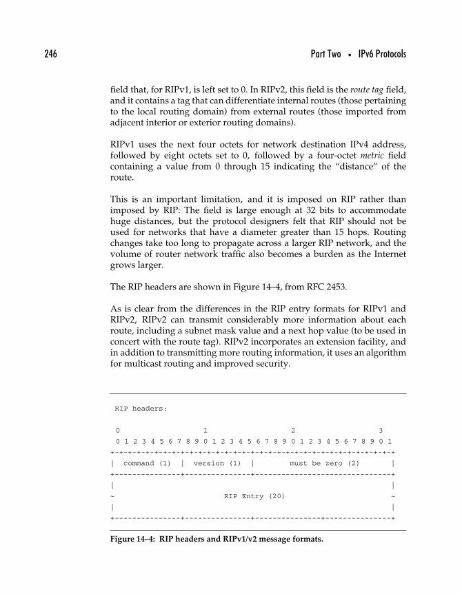
246 Part Two • IPv6 Protocols
field that, for RIPv1, is left set to 0. In RIPv2, this field is the route tag field,and it contains a tag that can differentiate internal routes (those pertainingto the local routing domain) from external routes (those imported fromadjacent interior or exterior routing domains).
RIPv1 uses the next four octets for network destination IPv4 address,followed by eight octets set to 0, followed by a four-octet metric fieldcontaining a value from 0 through 15 indicating the “distance” of theroute.
This is an important limitation, and it is imposed on RIP rather thanimposed by RIP: The field is large enough at 32 bits to accommodatehuge distances, but the protocol designers felt that RIP should not beused for networks that have a diameter greater than 15 hops. Routingchanges take too long to propagate across a larger RIP network, and thevolume of router network traffic also becomes a burden as the Internetgrows larger.
The RIP headers are shown in Figure 14–4, from RFC 2453.
As is clear from the differences in the RIP entry formats for RIPv1 andRIPv2, RIPv2 can transmit considerably more information about eachroute, including a subnet mask value and a next hop value (to be used inconcert with the route tag). RIPv2 incorporates an extension facility, andin addition to transmitting more routing information, it uses an algorithmfor multicast routing and improved security.
RIP headers:
0 1 2 3
0 1 2 3 4 5 6 7 8 9 0 1 2 3 4 5 6 7 8 9 0 1 2 3 4 5 6 7 8 9 0 1
+-+-+-+-+-+-+-+-+-+-+-+-+-+-+-+-+-+-+-+-+-+-+-+-+-+-+-+-+-+-+-+-+
| command (1) | version (1) | must be zero (2) |
+---------------+---------------+-------------------------------+
| |
~ RIP Entry (20) ~
| |
+---------------+---------------+---------------+---------------+
Figure 14–4: RIP headers and RIPv1/v2 message formats.
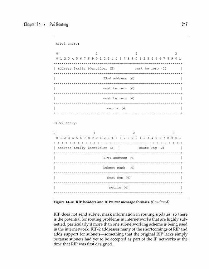
Chapter 14 • IPv6 Routing 247
RIPv1 entry:
0 1 2 3
0 1 2 3 4 5 6 7 8 9 0 1 2 3 4 5 6 7 8 9 0 1 2 3 4 5 6 7 8 9 0 1
+-+-+-+-+-+-+-+-+-+-+-+-+-+-+-+-+-+-+-+-+-+-+-+-+-+-+-+-+-+-+-+-+
| address family identifier (2) | must be zero (2) |
+-------------------------------+-------------------------------+
| IPv4 address (4) |
+---------------------------------------------------------------+
| must be zero (4) |
+---------------------------------------------------------------+
| must be zero (4) |
+---------------------------------------------------------------+
| metric (4) |
+---------------------------------------------------------------+
RIPv2 entry:
0 1 2 3
0 1 2 3 4 5 6 7 8 9 0 1 2 3 4 5 6 7 8 9 0 1 2 3 4 5 6 7 8 9 0 1
+-+-+-+-+-+-+-+-+-+-+-+-+-+-+-+-+-+-+-+-+-+-+-+-+-+-+-+-+-+-+-+-+
| address family identifier (2) | Route Tag (2) |
+-------------------------------+-------------------------------+
| IPv4 address (4) |
+---------------------------------------------------------------+
| Subnet Mask (4) |
+---------------------------------------------------------------+
| Next Hop (4) |
+---------------------------------------------------------------+
| metric (4) |
+---------------------------------------------------------------+
Figure 14–4: RIP headers and RIPv1/v2 message formats. (Continued)
RIP does not send subnet mask information in routing updates, so thereis the potential for routing problems in internetworks that are highly sub-netted, particularly if more than one subnetworking scheme is being usedin the internetwork. RIP-2 addresses many of the shortcomings of RIP andadds support for subnets—something that the original RIP lacks simplybecause subnets had yet to be accepted as part of the IP networks at thetime that RIP was first designed.
248 Part Two • IPv6 Protocols
Despite RIP’s flaws, development of RIP-2 continued for several reasons.RIP is widely implemented on many different platforms, partly becauseit is an easy protocol to implement. On small intranets, RIP can be a veryefficient routing protocol, making few demands on system overhead andbandwidth. Finally, RIP is relatively easy to configure and manage.
14.2.4 RIPNG
RFC 2080, “RIPng for IPv6,” defines the protocol for use in IPv6 networks.The RIPng routing table contains an entry for each reachable destination;each entry contains at least the following information (as defined in RFC2080).
• The IPv6 prefix of the destination.• A metric, which represents the total cost of getting a datagram
from the router to that destination. This metric is the sum ofthe costs associated with the networks that would be traversedto get to the destination.
• The IPv6 address of the next router along the path to thedestination (i.e., the next hop). If the destination is on one ofthe directly connected networks, this item is not needed.
• A flag to indicate that information about the route has changedrecently. This will be referred to as the “route change flag.”
• Various timers associated with the route, in particular relatedto when announcements should be sent out and when routesshould be timed out.
Routers using RIPng send and receive UDP messages on UDP port 521;the RIPng message is formatted as shown in Figure 14–5.
RIPng Route Table Entries (RTEs) take the format shown in Figure 14–6.These entries carry routing information, specifically the route tag, prefixlength, and routing metric for each routed IPv6 prefix. An RIPng messagecan carry as many RTEs as the local MTU permits. To determine the maxi-mum number of RTEs for a particular MTU, the following steps may betaken.
1. Take the MTU size, in octets.2. Subtract the IPv6 header size from that value.3. Subtract the UDP header size from that value.4. Subtract the RIPng header size from that value.
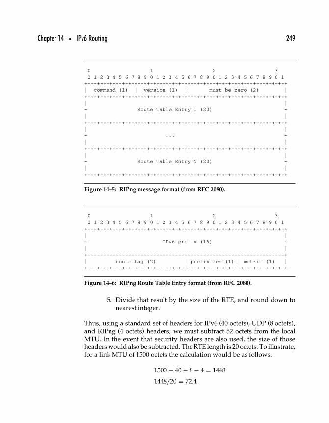
Chapter 14 • IPv6 Routing 249
0 1 2 30 1 2 3 4 5 6 7 8 9 0 1 2 3 4 5 6 7 8 9 0 1 2 3 4 5 6 7 8 9 0 1+-+-+-+-+-+-+-+-+-+-+-+-+-+-+-+-+-+-+-+-+-+-+-+-+-+-+-+-+-+-+-+-+| command (1) | version (1) | must be zero (2) |+-+-+-+-+-+-+-+-+-+-+-+-+-+-+-+-+-+-+-+-+-+-+-+-+-+-+-+-+-+-+-+-+| |
~ Route Table Entry 1 (20) ~| |+-+-+-+-+-+-+-+-+-+-+-+-+-+-+-+-+-+-+-+-+-+-+-+-+-+-+-+-+-+-+-+-+| |~ ... ~| |
+-+-+-+-+-+-+-+-+-+-+-+-+-+-+-+-+-+-+-+-+-+-+-+-+-+-+-+-+-+-+-+-+| |~ Route Table Entry N (20) ~| |+-+-+-+-+-+-+-+-+-+-+-+-+-+-+-+-+-+-+-+-+-+-+-+-+-+-+-+-+-+-+-+-+
Figure 14–5: RIPng message format (from RFC 2080).
0 1 2 30 1 2 3 4 5 6 7 8 9 0 1 2 3 4 5 6 7 8 9 0 1 2 3 4 5 6 7 8 9 0 1+-+-+-+-+-+-+-+-+-+-+-+-+-+-+-+-+-+-+-+-+-+-+-+-+-+-+-+-+-+-+-+-+| |~ IPv6 prefix (16) ~| |+---------------------------------------------------------------+| route tag (2) | prefix len (1)| metric (1) |+-+-+-+-+-+-+-+-+-+-+-+-+-+-+-+-+-+-+-+-+-+-+-+-+-+-+-+-+-+-+-+-+
Figure 14–6: RIPng Route Table Entry format (from RFC 2080).
5. Divide that result by the size of the RTE, and round down tonearest integer.
Thus, using a standard set of headers for IPv6 (40 octets), UDP (8 octets),and RIPng (4 octets) headers, we must subtract 52 octets from the localMTU. In the event that security headers are also used, the size of thoseheaders would also be subtracted. The RTE length is 20 octets. To illustrate,for a link MTU of 1500 octets the calculation would be as follows.
1500 − 40 − 8 − 4 = 1448
1448/20 = 72.4
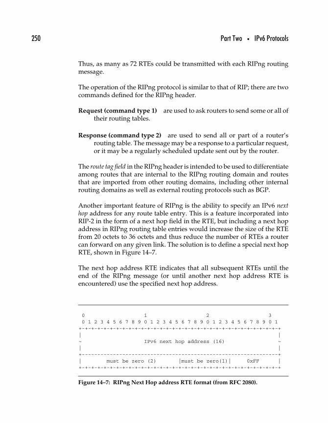
250 Part Two • IPv6 Protocols
Thus, as many as 72 RTEs could be transmitted with each RIPng routingmessage.
The operation of the RIPng protocol is similar to that of RIP; there are twocommands defined for the RIPng header.
Request (command type 1) are used to ask routers to send some or all oftheir routing tables.
Response (command type 2) are used to send all or part of a router’srouting table. The message may be a response to a particular request,or it may be a regularly scheduled update sent out by the router.
The route tag field in the RIPng header is intended to be used to differentiateamong routes that are internal to the RIPng routing domain and routesthat are imported from other routing domains, including other internalrouting domains as well as external routing protocols such as BGP.
Another important feature of RIPng is the ability to specify an IPv6 nexthop address for any route table entry. This is a feature incorporated intoRIP-2 in the form of a next hop field in the RTE, but including a next hopaddress in RIPng routing table entries would increase the size of the RTEfrom 20 octets to 36 octets and thus reduce the number of RTEs a routercan forward on any given link. The solution is to define a special next hopRTE, shown in Figure 14–7.
The next hop address RTE indicates that all subsequent RTEs until theend of the RIPng message (or until another next hop address RTE isencountered) use the specified next hop address.
0 1 2 30 1 2 3 4 5 6 7 8 9 0 1 2 3 4 5 6 7 8 9 0 1 2 3 4 5 6 7 8 9 0 1+-+-+-+-+-+-+-+-+-+-+-+-+-+-+-+-+-+-+-+-+-+-+-+-+-+-+-+-+-+-+-+-+| |~ IPv6 next hop address (16) ~| |+---------------------------------------------------------------+| must be zero (2) |must be zero(1)| 0xFF |+-+-+-+-+-+-+-+-+-+-+-+-+-+-+-+-+-+-+-+-+-+-+-+-+-+-+-+-+-+-+-+-+
Figure 14–7: RIPng Next Hop address RTE format (from RFC 2080).
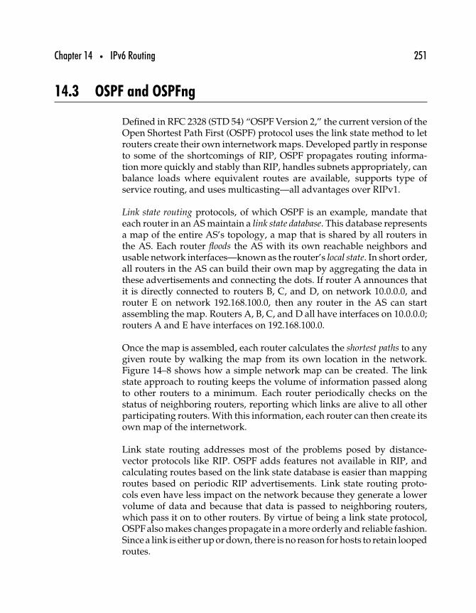
Chapter 14 • IPv6 Routing 251
14.3 OSPF and OSPFng
Defined in RFC 2328 (STD 54) “OSPF Version 2,” the current version of theOpen Shortest Path First (OSPF) protocol uses the link state method to letrouters create their own internetwork maps. Developed partly in responseto some of the shortcomings of RIP, OSPF propagates routing informa-tion more quickly and stably than RIP, handles subnets appropriately, canbalance loads where equivalent routes are available, supports type ofservice routing, and uses multicasting—all advantages over RIPv1.
Link state routing protocols, of which OSPF is an example, mandate thateach router in an AS maintain a link state database. This database representsa map of the entire AS’s topology, a map that is shared by all routers inthe AS. Each router floods the AS with its own reachable neighbors andusable network interfaces—known as the router’s local state. In short order,all routers in the AS can build their own map by aggregating the data inthese advertisements and connecting the dots. If router A announces thatit is directly connected to routers B, C, and D, on network 10.0.0.0, androuter E on network 192.168.100.0, then any router in the AS can startassembling the map. Routers A, B, C, and D all have interfaces on 10.0.0.0;routers A and E have interfaces on 192.168.100.0.
Once the map is assembled, each router calculates the shortest paths to anygiven route by walking the map from its own location in the network.Figure 14–8 shows how a simple network map can be created. The linkstate approach to routing keeps the volume of information passed alongto other routers to a minimum. Each router periodically checks on thestatus of neighboring routers, reporting which links are alive to all otherparticipating routers. With this information, each router can then create itsown map of the internetwork.
Link state routing addresses most of the problems posed by distance-vector protocols like RIP. OSPF adds features not available in RIP, andcalculating routes based on the link state database is easier than mappingroutes based on periodic RIP advertisements. Link state routing proto-cols even have less impact on the network because they generate a lowervolume of data and because that data is passed to neighboring routers,which pass it on to other routers. By virtue of being a link state protocol,OSPF also makes changes propagate in a more orderly and reliable fashion.Since a link is either up or down, there is no reason for hosts to retain loopedroutes.
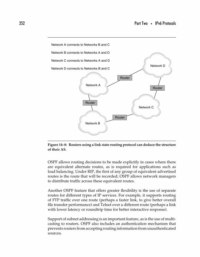
252 Part Two • IPv6 Protocols
Network A connects to Networks B and C
Network B connects to Networks A and D
Network C connects to Networks A and D
Network D connects to Networks B and C
Network C
Network A
Network B
Network D
Router
Router
Router
Router
Figure 14–8: Routers using a link state routing protocol can deduce the structure
of their AS.
OSPF allows routing decisions to be made explicitly in cases where thereare equivalent alternate routes, as is required for applications such asload balancing. Under RIP, the first of any group of equivalent advertisedroutes is the route that will be recorded; OSPF allows network managersto distribute traffic across these equivalent routes.
Another OSPF feature that offers greater flexibility is the use of separateroutes for different types of IP services. For example, it supports routingof FTP traffic over one route (perhaps a faster link, to give better overallfile transfer performance) and Telnet over a different route (perhaps a linkwith lower latency or roundtrip time for better interactive response).
Support of subnet addressing is an important feature, as is the use of multi-casting to routers. OSPF also includes an authentication mechanism thatprevents routers from accepting routing information from unauthenticatedsources.
Chapter 14 • IPv6 Routing 253
14.3.1 DIFFERENCES FROM OSPF FOR IPV4
RFC 2740, “OSPF for IPv6,” provides the specification for adapting OSPF touse with IPv6. For the most part, OSPF for IPv6 uses the same mechanismsused in OSPF for IPv4 (defined in RFC2328, “OSPF Version 2”). As with anyIP routing protocol, OSPF was modified for use with IPv6 to accommodate128-bit (rather than 32-bit) addresses; other changes were required as well.These differences are spelled out in RFC 2740 and include the following.
Link versus subnet processing Under IPv6, link means “a communica-tion facility or medium over which nodes can communicate at thelink layer” (RFC 2460). IPv4 routing protocols tend to operate ona per-subnet basis, even though a single link can comprise more thanone, unrelated, subnet. OSPF for IPv6 routers connect to the link, notthe subnet, so a single interface may suffice for more than one subnet.
Addressing semantics removed For the most part, IPv6 addresses donot appear in OSPF protocol packets. This allows routers to use OSPFwithout reference to the network layer protocol (IPv4 or IPv6) in use.Rather than identifying neighboring routers by IP address, they areidentified by a Router ID.
Flooding scope OSPF for IPv6 adds three different scopes for floods,including a link-local scope, an area scope that is valid across links,and an autonomous system (AS) scope, valid across an entire AS.
Several other changes listed in RFC 2740 refer to modification in the wayIPv6 works or to the modifications necessary to support IPv6 addresses,but otherwise the protocol works very similarly to OSPF for IPv4.
14.4 IPv6 and BGP
If routing across a single backbone can be complicated, imagine routingover multiple backbones—some of which overlap, and many of whichoffer routes to the same destination networks. Figure 14–9 illustrates someof the entities involved, as well as the problems.
RFC 2545, “Use of BGP-4 Multiprotocol Extensions for IPv6 Inter-DomainRouting,” is a brief document because BGP (and path vector routing proto-cols in general) is “mostly independent of the particular Address Family for
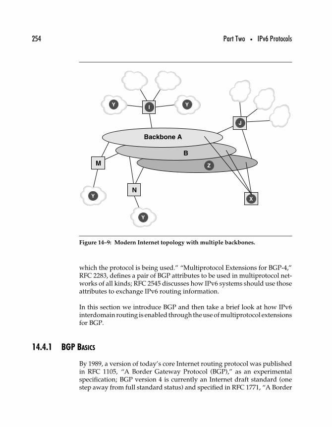
254 Part Two • IPv6 Protocols
Backbone A
B
N
M
J
I
Y
Y
Y Y
X
Z
Figure 14–9: Modern Internet topology with multiple backbones.
which the protocol is being used.” “Multiprotocol Extensions for BGP-4,”RFC 2283, defines a pair of BGP attributes to be used in multiprotocol net-works of all kinds; RFC 2545 discusses how IPv6 systems should use thoseattributes to exchange IPv6 routing information.
In this section we introduce BGP and then take a brief look at how IPv6interdomain routing is enabled through the use of multiprotocol extensionsfor BGP.
14.4.1 BGP BASICS
By 1989, a version of today’s core Internet routing protocol was publishedin RFC 1105, “A Border Gateway Protocol (BGP),” as an experimentalspecification; BGP version 4 is currently an Internet draft standard (onestep away from full standard status) and specified in RFC 1771, “A Border
Chapter 14 • IPv6 Routing 255
Gateway Protocol 4 (BGP-4),” and RFC 1772, “Application of the BorderGateway Protocol in the Internet.”
Backbone Z is operated by a backbone service provider and offers a transitservice, meaning that they carry packets to and from client networks, suchas the Internet service providers I and J. Backbone Z is called a transit AS,because it is an autonomous system that moves packets from one AS toanother. This implies that it has connections to at least two other ASs.Traffic from one AS to another is called transit traffic, to be distinguishedfrom local traffic, or traffic that remains within a single AS.
In the modern Internet topology, a routing entity may also be a multi-homed AS, which differs from a transit AS because it does not carry transittraffic but it does carry local traffic. For example, network X in Figure 14–9might represent a large organization that maintains connections to severalbackbone networks but that carries traffic only intended for network X.
Finally, a stub AS (like network Y in the figure) is one that can carry onlylocal traffic; a stub router connects a single AS to one other AS.
EGP worked reasonably well, but was unable to differentiate betweenadvertised routes: A router notified other routers only whether or not itcould reach an AS. With no basis for comparing directness of routes offeredby two or more routers, a border router could only guess at which routerwas better for a particular packet. Neither the link state nor the distance-vector routing approaches will work well for this kind of network. Thecomplexity is too great for any single router to handle all of the routesbetween all of the networks.
BGP addresses the problem by extracting the inter-AS routing issues fromthe intra-AS routing issues. In a BGP-routed network, each AS is connectedto the rest of the network by at least one each of two different entities.
BGP speaker Every AS in the network needs at least one BGP repre-sentative to exchange reachability information with speakers for theother ASs.
BGP gateway Every AS in the network needs to be connected to thenetwork through at least one BGP gateway.
A gateway and a speaker may be deployed on the same system, but theymay be deployed separately. And unlike RIP or OSPF routers, which
256 Part Two • IPv6 Protocols
exchange information about their own connectivity only, BGP routersexchange complete routes. With a RIP-like protocol, a router in network I(Figure 14–9) would have a routing table full of entries from every otherrouter it can reach directly for all the other networks on backbone A.Network X would be reachable in two hops through networks M and J,even though network I can reach X in a single hop on its own.
By including not just the number of hops but also the specific path for eachroute, BGP routers can eliminate routing loops. Using speakers, separatefrom routers, to communicate reachability information allows BGP net-work administrators to implement routing and forwarding policies thataffect how packets are routed to and from particular networks that wouldotherwise be indistinguishable.
The Border Gateway Protocol (BGP) replaced EGP as the current solutionto Internet routing. Routers pass along distance-vector reachability infor-mation, but instead of just including networks and distances, BGP includesthe actual route needed to reach each destination. This allows the routerto lay down the distance-vector routes into an actual map of the Internetand eliminate the routing loops to which distance-vector protocols areprone.
14.4.2 BGP MULTIPROTOCOL EXTENSIONS
Originally, BGP was designed to exchange IPv4 routing information only.RFC 2283, “Multiprotocol Extensions for BGP-4,” defined a type of datastructure that permitted the use of any network layer protocol, not justIPv4. The key is to define a set of network layer reachability information (NLRI)that specifies the following.
Address Family Information Which network layer protocol addressesare being indicated. This could be IPv4, IPv6, IPX, or some othernetwork layer network addressing scheme.
Next Hop Information The address of the appropriate next hop associ-ated with the BGP route for which the NLRI is being attached.
Network Layer Reachability Information One or more networkaddresses associated with the attribute for which the NLRI is beingused to advertise.
Chapter 14 • IPv6 Routing 257
The Multiprotocol Reachable NLRI and Multiprotocol Unreachable NLRIattributes contain one or more records that contain these three pieces ofinformation. BGP routers can use the Multiprotocol Reachable NLRI toadvertise the availability of a route to a BGP peer, to advertise a networklayer address for the router that should be used as the next hop for certaindestinations, or to report on Subnetwork Points of Attachment (SNPAsare basically link layer addresses associated with the network layeraddresses).
14.4.3 IPV6 INTER-DOMAIN ROUTING WITH BGP
BGP routing in IPv6 networks is accomplished, basically, in the same wayas in IPv4 (or any other type of) networks. Noting this, RFC 2545 addressesthe use of scoped IPv6 addresses—for BGP, the most significant differencebetween IPv4 and IPv6—with BGP.
Because BGP defines the exchange of routing information across domains,the use of link-local addresses is sometimes necessary but also potentiallydamagined. As a result, RFC 2545 defines rules to govern the use of link-local addresses when advertising connectivity for IPv6 network addresses.
14.5 IPv6 Routing Issues
Even though interior and exterior routing protocols have been adapted foruse in IPv6 networks, and even though there are decades of widespreadexperience with those protocols in their IPv4 incarnations, it would bepresumptuous to suppose that IPv6 routing will hold no surprises. Tothe contrary, experts anticipate that there will be significant issues tobe resolved with IPv6 routing; the unanticipated problems may be evengreater.
Subnetting Network managers must keep in mind that the smallest net-work allocation currently being made by RIRs is a /48 block. Thatmeans IPv6 networks will have 16 bits (or more) of subnet space toplay around with. Currently, in IPv4 networks, that much subnetspace is available only to networks with the equivalent of a ClassA network address block. With the potential for as many as 65,000or so subnets, network designers must be careful to build their net-works and subnetworks in a way that will keep the size of the routing
258 Part Two • IPv6 Protocols
table manageably small. If subnets are assigned haphazardly, theymay cause routing structures beyond the capacity of existing interiorrouting protocols to handle.
Hardware Many departmental and branch level routers are quite capableof handling typical IPv4 routing needs, but the possibility of havingvery large routing tables (as just noted) could overwhelm the routersthemselves as well as the interior routing protocols.
Multihoming When an organization receives two or more IPv6 net-work address allocations from different ISPs, they are said to bemultihomed. The goal is to have the network behave as if it isa single system, both when interacting with nodes within the networkand when interacting with nodes exterior to the network. A furthercomplication is the desire to minimize the number of routing tableentries for each network; solutions proposed so far focus on theuse of tunneling between the different allocated networks andincorporating alternate routes within each routing table entry.
As more IPv6 networks are joined together in a global IPv6 Internet,experience with these issues will suggest appropriate solutions.
14.6 Summary
In this chapter, we have introduced the basics of Internet routing, includinglink state and distance vector routing algorithms, interior and exteriorrouting, RIP, OSPF, and BGP routing, and how those protocols are adaptedfor use with IPv6.
In the next chapter we look at how Quality of Service (QoS) is implementedover IPv6 networks.
1515
IPv6 Quality of Service(QoS)
Providing Quality of Service (QoS) in IP networks has long been an impor-tant but elusive goal for IETF working groups. The original IPv4 headerspecification included a Type of Service (ToS) field that was rarely if everimplemented: It would have required implementers to make judgmentsabout which of their packets were to be given worse-than-normal treat-ment. This simplistic approach has been replaced over the years with theDifferentiated Services (Diffserv) approach, and the ToS field has beenrenamed the Differentiated Services (DS) field in RFC 2474, “Definition ofthe Differentiated Services Field (DS Field) in the IPv4 and IPv6 Headers.”
Diffserv allows the use of the DS field for data that indicates how a packetshould be treated by routers. Rather than assigning a priority, the DS fieldis used to assign membership in a group that has a set of policies associatedwith it. These diffserv behavior aggregates (groups of packets that are to betreated in the same way by a router at network boundary) work the sameway in both IPv4 and IPv6.
259
260 Part Two • IPv6 Protocols
In an effort to remedy the faults of the Type of Service approach usedin IPv4, an early goal of the IPv6 effort was to replace ToS with theconcept of flows, which were to behave somewhat like behavior aggre-gates. The Flow Label field in the IPv6 header was first discussed in theearly 1990s with RFC 1809, “Using the Flow Label Field in IPv6.” Thisspecification was published half a year before the original IPv6 specifica-tions in 1995. At that time, the field raised more questions than itanswered,1 including how to determine which packets should be assigneda flow and how routers should handle flows that they didn’t have flowrouting information for.
By 1998 and the revised IPv6 specification in RFC 2460, the Flow Label fieldwas still considered experimental as the questions regarding its use hadyet to be resolved through extensive implementation and experimentation.As of 2003, a new specification that explains appropriate use of the FlowLabel in IPv6 is still a work-in-progress but should be published soon asa proposed standard.
Up to the late 1990s, applications that depended on underlying networkprotocols relied on Transmission Control Protocol (TCP) to respond to net-work congestion. However, in January 1999, the experimental RFC 2481,“A Proposal to Add Explicit Congestion Notification (ECN) to IP,” waspublished detailing an approach to congestion management that couldinclude the network layer protocol, IP. Updated to proposed standardin September 2001, RFC 3168, “The Addition of Explicit CongestionNotification (ECN) to IP,” updates some of the mechanisms discussed inthis chapter.
In this chapter we cover the IPv6 approach to QoS, including the use ofthe diffserv field in IPv6, followed by discussion of IPv6 Flow Labels andthe use of Explicit Congestion Notification with IPv6.
15.1 QoS Basics
The IP model is a democratic one: All packets are (in theory) treatedequally, getting a “best effort” delivery service from the systems in
1Including length: Prior to 1995, the Flow Label field was 28 bits long; by 1995 it hadshrunk to 24 bits, and in 1998 it reached its current specified size of 20 bits.
Chapter 15 • IPv6 Quality of Service (QoS) 261
the Internet. This has several implications for application performance andin some cases limits applications in a number of ways.
1. Packets may be delivered in order or out of order.2. Packets may be delivered smoothly or in spurts.3. Packets may or may not be delivered.
In the case of real-time applications, this can require that receiving hostsbuffer data as it comes in, adding delay on top of whatever network delayexists. Instead of passing incoming network data directly to the application,the incoming data is stored temporarily as the host waits for all data, includ-ing out of order data and data that may be temporarily delayed, to arrive.
The unpredictability of the IP datagram service is due to the way routershandled traffic: Packets come in from various sources, arriving at the routeron different interfaces with different networks, and the router processesthose packets in the order they are received.
Despite the first pass at the problem through assignment of Type ofService values, IP as originally defined lacks mechanisms for differen-tiating between packets that have quality of service requirements and thosethat don’t.
• Transient congestion, such as caused by a surge of packetsfrom one source, can cause unpredictable results. A packetsurge may delay other traffic passing through a router. Or itmight not.
• All datagrams are created equal, which means that there is noway to give one datagram priority over another.
• Individual routers can be configured to favor packets beingsent to or from some particular network interface, but once thepacket is routed, it will be treated just like any other packet byother routers. IP lacks a mechanism for flagging packets at theirsource and indicating that they should be treated differently insome way from source to destination.
• Even if packets can be flagged for special treatment, IP lacks themechanisms for tracking packets and monitoring performanceand resource use.
QoS protocols are intended to differentiate between packets on an end-to-end basis and adding the mechanisms necessary to allocate resourcesthroughout a path for packets that require them.
262 Part Two • IPv6 Protocols
15.1.1 APPROACHES TO QUALITY
The two basic approaches to adding QoS to the Internet are the IntegratedServices (intserv) and Differentiated Services (diffserv) models. Introducedand defined in 1994 in RFC 1633, “Integrated Services in the InternetArchitecture: an Overview,” the intserv effort grew out of implementa-tion experience with multicast of IETF meetings. According to RFC 1633authors, real-time applications work poorly across the global Internet“because of variable queueing delays and congestion losses.”
In addition to QoS for real-time applications, the intserv model wouldallow network service providers control over how bandwidth is shared.Allowing all the available bandwidth to be allocated among differentclasses of traffic even when the network is under a heavy load meansthat applications can count on having a minimum amount of bandwidthto work with even when the network is congested—instead of beingsummarily cut off when packets are dropped silently and the hosts onthe other end drop the connections.
The ability to control which traffic categories are allowed how much of theavailable bandwidth is called controlled link sharing. The intserv approachdefines a service model in which best-effort and real-time services (servicesover which there is some control of end-to-end packet delay) coexist andare facilitated through controlled link sharing.
Whether or not overly influenced by their experiences with multicast,the intserv working group has agreed that any QoS solution would haveto support multicast: Real-time applications such as videoconferencingrequire the ability to handle multiple recipients of the same packets.
15.1.2 RESERVING RESOURCES
QoS generally requires network resources—specifically, network band-width and reliable routes—to ensure a uniform quality of service. Theprocess of provisioning circuits, as in ATM and other telecommunication-oriented network protocols, is necessary before any communication canoccur between a source and a destination. The Resource ReSerVationProtocol (RSVP), defined in RFC 2205, “Resource ReSerVation Protocol(RSVP)—Version 1 Functional Specification,” defines a mechanism bywhich hosts can, in effect, provision a connection across the connection-less IP Internet. RSVP, a required part of the intserv model, also requires
Chapter 15 • IPv6 Quality of Service (QoS) 263
intserv-capable routers in the network over which services are to beprovided.
This reservation infrastructure can be dispensed with when services areprovided to more general categories of packet, rather than the very spe-cific intserv flows. Diffserv does not specifically require any mechanismon hosts, but vests the responsibility for managing bandwidth with thenetwork itself. Diffserv packets are marked for special treatment by theirapplications, but the specific way in which those packets are treated is leftto routers.
15.1.3 INTSERV IN A NUTSHELL
Central to intserv is the concept of the flow: If packets share source anddestination IP addresses as well as source and destination ports, then onecan assume that those packets are all part of an application’s stream of dataflowing between source and destination, with all that entails.
The intserv approach requires that routers keep track of all these flows,examining each packet to determine whether it belongs in a flow and thencomputing whether there is enough available bandwidth to accept thepacket. In other words, intserv requires the following functions.
Admission control Can the router, or the network at large, provideservice to the flow? Can it provide service to the individual packetsthat comprise the flow? What about other, non-QoS packets?
Packet classification Every packet that is admitted must be classified.What flow does it belong to? What level of QoS does it get? Thethree options are to treat the packet “normally” giving it best-effort,controlled load for allocating some portion of an uncongested network,and guaranteed service for real-time delivery with delays minimizedto within preset levels of service.
Packet scheduling Once a packet is classified, how is it scheduled?Should some packets jump ahead of others? How are packets withina queue treated when the queue exceeds its limits?
Combined with RSVP, intserv tends to be cumbersome to implement andit certainly is not scalable to the global Internet—but it is quite good atmanaging flows of data within smaller networks.
264 Part Two • IPv6 Protocols
Ultimately, intserv has proven inadequate to the task of providing a singlesolution to the QoS problem: The intserv mechanisms are not seen as beingscalable to the global Internet, and they can be difficult to implement.
The next pass at the problem became known as diffserv to differentiateit from intserv. Cursory examination of the RFCs may not shed muchlight on the differences between the two, but there are considerable differ-ences. Where intserv is focused on ways of sharing available bandwidthamong unique flows (series of packets with the same source and destinationIP and port addresses), diffserv approached the problem by suggestingthat a less granular classification of packets could provide the desiredresult.
15.1.4 DIFFSERV IN A NUTSHELL
There is no way that Internet backbone routers could contend with thedemands of tracking individual flows in an intserv-enabled global Internet,but network customers and service providers both increasingly demandsome form of QoS that can scale well in the global Internet. Differentiatedservices, diffserv, answers the call by streamlining the process. Diffservover IP is documented in RFC 2474, “Definition of the DifferentiatedServices Field (DS Field) in the IPv4 and IPv6 Headers.”
Rather than building an elaborate infrastructure for emulating a circuit-based network on top of IP, diffserv allows communicating endpoints toclassify their packets into different treatment categories. These categoriesare identified with a per-hop behavior, or PHB. The PHB is the action thata diffserv routing node can be observed to take when it receives a packet.When a PHB is defined, diffserv routers are supposed to treat packetsmarked with that value in a certain way.
For example, the Expedited Forwarding (EF) PHB (specified in RFC 2598,“An Expedited Forwarding PHB”) is billed as “premium service” andindicates that the packets in that behavior aggregate (BA) should all beprocessed as they are received, rather than be queued or dropped. Unlikeintserv with its traffic flows, the diffserv model calls for the use of BAs ateach diffserv router: These are associated with a PHB that indicates howthe router will treat the packet.
Aggregates or aggregated flows may also be referred to as classes ofpackets; routers are configured to respond to these different classes in
Chapter 15 • IPv6 Quality of Service (QoS) 265
different (appropriate) ways. Routers may also be configured to breakup these classes into subaggregations to be treated slightly differently.For example, a router might be configured to forward premium-servicepackets from preferred customers over links that are more reliablethan premium-service packets coming from customers subscribing toa “budget-premium” service.
Diffserv brings with it the ability to create network service policies specificto a single router, some part of a network, or an entire diffserv routingdomain. As long as their policies don’t affect the ability to provide guar-anteed QoS, network providers can fine-tune their diffserv routers todifferentiate how they treat packets.
The diffserv model distributes the task of allocating resources to the routerswithin a diffserv domain, providing greater flexibility as well as moreefficient routing. A backbone router could process diffserv traffic far moreeasily than it can process intserv traffic: There is no need to negotiate RSVPreservations with all intermediary routers—and no overhead necessarilyassociated with failure to maintain an RSVP session with one particularrouter. With diffserv, the PHB mandates how the packet is treated, anddifferent routers can provide the same service without having to maintainstate for a particular connection, as with intserv.
15.1.5 DIFFSERV VERSUS INTSERV?
At first glance, diffserv and intserv may seem to be competing with eachother. However, the two models are complementary, with intserv work-ing best within smaller domains, whereas diffserv provides somewhatless precise handling of packets across much larger networks; the two caneven be used together, as documented in RFC 2998, “A Framework forIntegrated Services Operation over Diffserv Networks.”
In this informational document, the authors see intserv, RSVP, and diffservas “complementary technologies,” each of which is intended to achieveend-to-end quality of service. “Together,” they write, “these mechanismscan facilitate deployment of applications such as IP-telephony, video-on-demand, and various non-multimedia mission-critical applications.Intserv enables hosts to request per-flow, quantifiable resources, alongend-to-end data paths and to obtain feedback regarding admissibility ofthese requests. Diffserv enables scalability across large networks.”
266 Part Two • IPv6 Protocols
15.2 Differentiated Services and IPv6
The behavior defined for the Differentiated Services field in both IPv4and IPv6 is the same, so an understanding of diffserv for IPv4 shouldcarry over to diffserv for IPv6. In both protocols, the Differentiated Servicesfield is defined for the six bits following the version in the IP header.2
RFC 2474, “Definition of the Differentiated Services Field (DS Field) in theIPv4 and IPv6 Headers,” spells out how diffserv works for both protocols.The following are some other RFCs of interest for diffserv.
RFC 2963 “A Rate Adaptive Shaper for Differentiated Services”RFC 2998 “A Framework for Integrated Services Operation over
Diffserv Networks”RFC 3086 “Definition of Differentiated Services Per Domain Behav-
iors and Rules for their Specification”RFC 3260 “New Terminology and Clarifications for Diffserv”RFC 3290 “An Informal Management Model for Diffserv Routers”RFC 2430 “A Provider Architecture for Differentiated Services and
Traffic Engineering (PASTE)”RFC 2474 “Definition of the Differentiated Services Field (DS Field)
in the IPv4 and IPv6 Headers”RFC 2475 “An Architecture for Differentiated Service”RFC 2638 “A Two-bit Differentiated Services Architecture for the
Internet”RFC 2983 “Differentiated Services and Tunnels”
Closely related to the issue of differentiated services is the use of flowsin IPv6, as will be seen in the next section.
15.3 IPv6 Flows
The Flow Label field in the IPv6 header was originally designed as a 28-bitfield (see notes in RFC 1809), reduced to 24-bits by 1995, and ultimately to20 bits, as defined in RFC 2460. RFC 2460 states the following.
2Those bits were originally specified for IPv4 as the Type of Service field in RFC 791 andoriginally specified as Traffic Class field for IPv6 in RFC 2460.
Chapter 15 • IPv6 Quality of Service (QoS) 267
The 20-bit Flow Label field in the IPv6 header may be used by a sourceto label sequences of packets for which it requests special handling bythe IPv6 routers, such as non-default quality of service or “real-time”service. . .. Hosts or routers that do not support the functions of theFlow Label field are required to set the field to zero when originatinga packet, pass the field on unchanged when forwarding a packet, andignore the field when receiving a packet.
In an appendix to RFC 2460, a flow is defined as “a sequence of packets sentfrom a particular source to a particular (unicast or multicast) destination forwhich the source desires special handling by the intervening routers.” That“special handling” might be specified by a resource reservation protocolor by some data within the flow packet headers such as a hop-by-hopopction. As to the specifics of the implementation of flows, however, RFC2460 is silent other than to specify the characteristics of the value of theflow header field.
• Packets that don’t belong to flows must have the flow headerset to zero.
• Each flow is assigned in a random or pseudo-random man-ner and (in combination with source address) is uniquelyidentifiable.
• The flow label is assigned by the source of the flow.• Packets that belong to the same flow must all originate from
the same source address, must be addressed to the same des-tination, and must be sent with the same value in the flowlabel header field. Flows are traditionally also identified by thetransport layer protocol in use, as with TCP.
As of 1998, the flow label was considered an experimental portion of theIPv6 specification; five years after, the IETF had not yet published theIPv6 flow label specification as a proposed standard RFC. Although stillofficially a work-in-progress as of mid-2003, publication of an RFC titled“IPv6 Flow Label Specification” may already have occurred by the timethis volume is published.
The definition of a flow, meanwhile, has changed.
A flow is a sequence of packets sent from a particular source toa particular unicast, anycast, or multicast destination that the sourcedesires to label as a flow. A flow could consist of all packets in
268 Part Two • IPv6 Protocols
a specific transport connection or a media stream. However, a flowis not necessarily 1:1 mapped to a transport connection.
One change from RFC 2460 is that flows can be specified without referenceto the destination address or transport layer protocol type. These valuesmay not always be available in the IPv6 header, particularly if the packetis fragmented or encrypted.
The flow label may not be changed from the value assigned by the sender,unlike the diffserv value, which may be modified to reflect the appropriatebehavior aggregate for a particular router or network as it traverses theInternet. Routers that don’t offer flow-related handling are required toignore the flow label and treat the packet as any other.
IPv6 nodes that use flow labeling should assign separate flows for dif-ferent and unrelated transport layer connections as well as for differentand unrelated application layer data streams. Thus, a multi-user host withmultiple telnet sessions from different users to the same remote host shouldassign a separate flow to each of those sessions.
15.4 Explicit Congestion Notification in IPv6
Quality of Service specifications are largely intended to address the prob-lem of how to guarantee a particular level of service for a particular setof packets. For example, an ISP may want to offer its customers a levelof service that uses only their premium, high-performance networks. Toachieve that level of service, the ISP would need to be able to differentiatepackets coming from subscribers to that service and assign those packetsto a behavior aggregate for which the routing policy is to always route onthe most expensive link.
Network congestion can occur on any link as a result of high-demandconditions or router malfunctions, and in most cases nodes sendingpackets that encounter congestion are only able to detect the condi-tion as a result of some timer—usually in the transport or applicationlayer protocols—timing out. Explicit Congestion Notification was firstproposed as an experiment for the transport layer in RFC 2481, “A Proposalto Add Explicit Congestion Notification (ECN) to IP,” in 1999, and quicklymoved to the standards track in 2001 when it was published as RFC 3168,“The Addition of Explicit Congestion Notification (ECN) to IP.”
Chapter 15 • IPv6 Quality of Service (QoS) 269
Using ECN and a Congestion Manager implementation, nodes are ableto negotiate the use of ECN. The ECN field in the IPv6 (and IPv4 header,as well), consists of the two bits after the Differentiated Services field.Unlike in earlier proposals, the two bits are used together as codepointsrather than as separate flag bits. The four different values possible for thesetwo bits—00, 01, 10, and 11—indicate whether the end-nodes (sender anddestination) are using an ECN-Capable Transport as well as whether thereis congestion at the sender (though not so much congestion that wouldcause the node to have dropped the packet). These are the four codepointsand their uses.
00 When a node is not using ECN, it puts zeroes in the ECN field.
01/10 These two codepoints are treated in the same way and are alsocalled ECT(0) [for the value 01] and ECT(1) [for the value 10]. Thesevalues are set by the sender to indicate that ECN is supported atboth ends of the transmission.
11 Routers that are just beginning to experience congestion, or that areexperiencing mild congestion, can signal their state by setting thecodepoint to 11 in outgoing packets.
The following current RFCs provide more information about ExplicitCongestion Notification and congestion control in general.
RFC 2481 “A Proposal to Add Explicit Congestion Notification(ECN) to IP”
RFC 2914 “Congestion Control Principles”RFC 3124 “The Congestion Manager”RFC 3168 “The Addition of Explicit Congestion Notification (ECN)
to IP”RFC 2884 “Performance Evaluation of Explicit Congestion Notifica-
tion (ECN) in IP Networks”
15.5 Summary
Quality of Service, IPv6 Flows, and Explicit Congestion Notification areall related to the quest for better service over an Internet in which, bydefinition, all packets are supposed to be treated equally. As we’ve seen inthis chapter, Quality of Service is designed to offer consumers of Internet
270 Part Two • IPv6 Protocols
connectivity options for guaranteed levels of service, while IPv6 flows andExplicit Congestion Notification are designed to provide improved routingand connectivity for any nodes on the Internet.
Ultimately, the goal of providing improved performance becomes moreimportant as the network grows larger. An important part of networkmanagement that can grow unwieldy in larger networks is the task ofconfiguring nodes. As we’ll see in the next chapter, IPv6 provides somenew tools as well as improvements on existing tools for configuring andreconfiguring networks and nodes.
1616
IPv6 Autoconfiguration
Neighbor Discovery, as discussed in Chapter 13, coupled with the useof local- and site-scoped addresses, makes it possible for IPv6 nodes andnetworks to use a far wider set of autoconfiguration behaviors than withIPv4. As IPv6 makes it possible to network almost unimaginable numbersof nodes, the need for automated configuration tools becomes ever moreimportant. Anyone who has ever been involved in renumbering an IPnetwork by hand can attest to the difficulty.1
In this chapter, we will look at three sets of autoconfiguration tools.
Stateful autoconfiguration (DHCPv6) The Dynamic Host Configura-tion Protocol (DHCP) grew out of the Boot Protocol (BOOTP), whichallowed nodes (usually diskless nodes) to boot themselves from anetwork server. DHCP and DHCP for IPv6 (DHCPv6) allow nodes
1In the early 1990s, the author was one of about a dozen full- and part-time employeesat an organization who helped renumber an IP network of about 2000 IP nodes distributedacross two buildings and about a dozen subnets. All nodes had to be reconfigured by hand,and the entire project took approximately half a year to complete.
271
272 Part Two • IPv6 Protocols
to configure themselves using DHCP servers. The protocols are con-sidered stateful because the DHCP/DHCPv6 servers maintain tablescontaining the IP addresses and link layer addresses of all the nodesthat use their services. The servers use that state to prevent two ormore nodes from using the same IP address.
Stateless autoconfiguration In less formally composed networks, IPv6allows nodes to configure themselves—that is, assign themselvestheir own IPv6 addresses—without the aid of a server. There is nocentral or authoritative repository for IPv6 addresses assignedthrough stateless autoconfiguration.
Router and network renumbering The use of locally scoped networkaddresses means that networks can be shifted from one connectivityprovider to another—with new global IPv6 Internet addresses—relatively easily. Internal routing can be achieved using the site-localaddresses, while external routing can be accomplished by reconfig-uring gateway routers. The process is more easily said than done, aswill be seen.
In this chapter, we look at the difference between stateful and statelessautoconfiguration, how DHCPv6 works, how IPv6 stateless autoconfigu-ration works, and how router and network renumbering can be done inIPv6 networks.
16.1 Stateful and Stateless Autoconfiguration
With the wide deployment of DHCP clients, as well as the inclusion ofDHCP server software in virtually every kind of network server, from thesimplest home office firewall network appliance on up, it should be safeto say that the vast majority of IP nodes in use today are either configuredwith DHCP or could be configured with DHCP.
DHCP servers are crucial for any network in which the number of nodesthat must be concurrently connected at any given time approaches thenumber of available IP addresses. The DHCP server can allocate addressesin three ways.
Automatic allocation DHCP assigns a permanent IP address to aclient.
Chapter 16 • IPv6 Autoconfiguration 273
Dynamic allocation DHCP assigns an IP address to a client for a limitedperiod of time (or until the client explicitly relinquishes the address).
Manual allocation A client’s IP address is assigned by the networkadministrator, and DHCP is used simply to convey the assignedaddress to the client.
In all cases, the DHCP server maintains state about the clients that useDHCP to configure themselves. ISPs providing broadband services to con-sumers (and other network providers) may configure their DHCP serversto allocate addresses only to nodes with a particular link layer address toprevent unauthorized use of their service. However, DHCP can be used forad hoc networking, in which a node not previously known to the DHCPserver can be allocated an address.
Stateless autoconfiguration allows nodes to configure themselves com-pletely independently of any central authority because servers to maintainaddressing states are unnecessary.
This is not to say that stateful and stateless autoconfiguration are mutu-ally exclusive; quite the reverse is the case, in fact. Neighbor Discoveryincorporates features that allow the two types of autoconfiguration tocomplement each other in an IPv6 network. For example, stateless auto-configuration is useful because it permits a node to allocate its own IPv6address that is valid for local-scope network. At the same time, it canquery for stateful autoconfiguration services on the local network to allowit to determine its own global IPv6 address, network prefix, and defaultrouters.
16.2 IPv6 Stateful Autoconfiguration: DHCPv6
DHCPv6 is the latest iteration of an autoconfiguration protocol publishedin RFC 951, “Boot Protocol,” in 1985. The following are some RFCs thatcan provide further information about BOOTP, DHCP, and DHCPv6.
RFC 3397 “Dynamic Host Configuration Protocol (DHCP) DomainSearch Option”
RFC 3118 “Authentication for DHCP Messages”RFC 2132 “DHCP Options and BOOTP Vendor Extensions”RFC 2131 “Dynamic Host Configuration Protocol”
274 Part Two • IPv6 Protocols
RFC 1542 “Clarifications and Extensions for the Bootstrap Protocol”RFC 1534 “Interoperation Between DHCP and BOOTP”RFC 0951 “Bootstrap Protocol”
The specification for DHCPv6 is still, as of mid-2003, a work-in-progress.Although in many ways quite similar to DHCPv4, DHCPv6 is differentenough that the protocol specification does not include specific informationabout interoperability between the two.
16.2.1 DHCP MESSAGES
DHCP clients and servers communicate by sending DHCP protocol mes-sages using UDP. The client, which (at least to start with) has no valid IPaddress for itself or for the local DHCP server, sends DHCP requests to themulticast address reserved for DHCP servers in the link scope. These arethe two valid addresses for sending DHCPv6 queries.
All_DHCP_Relay_Agents_and_Servers (FF02::1:2) A link-scoped mul-ticast address used by a client to communicate with neighboring (i.e.,on-link) relay agents and servers. All servers and relay agents aremembers of this multicast group.
All_DHCP_Servers (FF05::1:3) A site-scoped multicast address used bya relay agent to communicate with servers, either because the relayagent wants to send messages to all servers or because it does notknow the unicast addresses of the servers. Note that in order for arelay agent to use this address, it must have an address of sufficientscope to be reachable by the servers. All servers within the site aremembers of this multicast group.
As long as these addresses are available to the DHCP client, it can configureitself with DHCP.
The client can send UDP messages without an IPv6 address but must pro-vide some link layer address (otherwise, the responses from the serverscan’t be delivered). The default behavior for DHCP clients is to continuesending all DHCP messages to the multicast addresses reserved for DHCPservices rather than directly to a specific DHCP server’s unicast address.The reason for this is to allow the use of DHCP relay agents to pass
Chapter 16 • IPv6 Autoconfiguration 275
messages from clients to a remote DHCP server; in certain cases, it maybe more efficient (faster, less overhead) to allow clients to send unicastmessages directly to a DHCP server. In those cases, a client unicast optionmay be enabled by the server.
Two types of exchanges are defined, those involving two messages andthose involving four messages exchanged between the client and theserver. These are the DHCPv6 message types.
SOLICIT Clients send this message to locate a DHCPv6 server.
ADVERTISE A server sends this message in response to a Solicitmessage to indicate it is offering DHCP service.
REQUEST A client sends this message to request configuration param-eters, including IP addresses, from a specific server.
CONFIRM A client sends this message to any available server to deter-mine whether the addresses it was assigned are still appropriate tothe link to which the client is connected.
RENEW A client sends this message to the server that originally providedthe client’s addresses and configuration parameters to extend thelifetimes on the addresses assigned to the client and to update otherconfiguration parameters.
REBIND A client sends this message to any available server to extend thelifetimes on the addresses assigned to the client and to update otherconfiguration parameters; this message is sent after a client receivesno response to a Renew message.
REPLY A server sends this message, which contains assigned addressesand configuration parameters, in response to a Solicit, Request,Renew, or Rebind message received from a client. A Reply messagewith configuration parameters is sent in response to any Information-request message. The server sends this message in response toConfirm messages, confirming or denying that the addressesassigned to the client are appropriate to the link to which the client isconnected. A server sends a Reply message to acknowledge receiptof a Release or Decline message.
276 Part Two • IPv6 Protocols
RELEASE A client sends this message to the server that assignedaddresses to the client to indicate that the client will no longer useone or more of the assigned addresses.
DECLINE A client sends this message to a server to indicate that theclient has determined that one or more addresses assigned by theserver are already in use on the link to which the client is connected.
RECONFIGURE A server sends this message to a client to inform theclient that the server has new or updated configuration parameters,and that the client is to initiate a Renew/Reply or Information-request/Reply transaction with the server in order to receive theupdated information.
INFORMATION-REQUEST A client sends this message to a server torequest configuration parameters without the assignment of any IPaddresses to the client.
RELAY-FORW A relay agent sends this message to relay messages toservers, either directly or through another relay agent. The receivedmessage, either a client message or a Relay-forward message fromanother relay agent, is encapsulated in an option in the Relay-forwardmessage.
RELAY-REPL A server sends this message to a relay agent containinga message that the relay agent delivers to a client. The Relay-replymessage may be relayed by other relay agents for delivery to thedestination relay agent. The server encapsulates the client message asan option in the Relay-reply message, which the relay agent extractsand relays to the client.
16.2.2 CLIENT-SERVER EXCHANGES INVOLVING TWo MESSAGES
A number of DHCP interactions can be completed with the exchange oftwo messages, a request from the client and a response from the server.
Request for configuration information The simplest interaction occurswhen a client does not need an IPv6 address from the server, butjust needs some other configuration information (for example, alist of DNS servers). The client sends a DHCP Request message
Chapter 16 • IPv6 Autoconfiguration 277
requesting the information it needs to the All_DHCP_Relay_Agents_and_Servers multicast address; the servers that are listening to thataddress respond with a DHCP reply that contains the requestedinformation.
Request to extend address lifetime The client sends a Renew message,and the server sends a Reply message, with the new lifetimesspecified so the client can continue using the address.
IPv6 address allocation Normally, this is a four-message interaction, butit is possible for a client and server to transact an IPv6 addressallocation in just two messages when the server already has con-figuration information assigned to the requesting client and storedin its database. The client can send a DHCP Solicit message to theAll_DHCP_Relay_Agents_and_Servers multicast address to requestboth an address assignment and configuration information, specify-ing that an immediate Reply message from the server is desired. Ifthere is a server listening to that multicast address that is capable ofcommitting an address in response to that request, it can reply withthe address and configuration information.
The more typical IPv6 address allocation process requires four messages,as described next.
16.2.3 CLIENT-SERVER EXCHANGES INVOLVING FOUR MESSAGES
When a node needs to request an IPv6 address as well as configurationinformation from a DHCP server, the process normally takes an exchangeof four messages from client to server, as follows.
Solicit The client sends a Solicit message to the All_DHCP_Relay_Agents_and_Servers multicast address to locate available DHCPservers.
Advertise Any server that is able to respond to the client Solicit does soby sending the Advertise message.
Request The client sends a Request message to the server it chooses.More than one server may respond to the original Solicit request, sothe client may have to choose one server in particular to respond to.
278 Part Two • IPv6 Protocols
The Request message indicates what configuration parameters theclient needs.
Reply The server responds to the Request message with a Reply messagecontaining the configuration parameters requested by the client.
16.3 IPv6 Stateless Autoconfiguration
Unlike IPv4 nodes, IPv6 nodes are capable of configuring themselvesentirely on their own. This is by design and is the result of a considerableamount of thought and effort.
First, the standard method of addressing an IPv6 interface uses the EUI-64mechanism to uniquely identify the node on the local link; the use of link-local unicast addressing means that all nodes will properly process packetssent to and from the link-local unicast address that a node assigns to itself.However, those packets cannot be forwarded outside the local link.
The use of Neighbor Discovery, however, means that individual nodes thatare configured on a link can solicit information about routers and serverson the link. Part of that discovery process can also include identifying theglobal IPv6 network prefix as well, so the node can, using basic IPv6 pro-tocols, discover all the information it needs to be fully configured withoutthe intervention of a stateful configuration server.
The process of self-configuring includes a number of different steps.
1. Creating a link-local address for the self-configuring node2. Verifying the uniqueness of the link-local address on the link3. Determining what information should be autoconfigured and
how that information should be obtained
The first and second steps of this process are described in RFC 2462, “IPv6Stateless Address Autoconfiguration.” The third step, that of determininghow further configuration information should be acquired, uses mech-anisms defined for Neighbor Discovery as well as DHCPv6. RFC 2462explains it this way.
Stateless autoconfiguration requires no manual configuration of hosts,minimal (if any) configuration of routers, and no additional servers.The stateless mechanism allows a host to generate its own addresses
Chapter 16 • IPv6 Autoconfiguration 279
using a combination of locally available information and informa-tion advertised by routers. Routers advertise prefixes that identify thesubnet(s) associated with a link, while hosts generate an “interfaceidentifier” that uniquely identifies an interface on a subnet. An addressis formed by combining the two. In the absence of routers, a host canonly generate link-local addresses. However, link-local addresses aresufficient for allowing communication among nodes attached to thesame link.
In the stateful autoconfiguration model, hosts obtain interfaceaddresses and/or configuration information and parameters froma server. Servers maintain a database that keeps track of whichaddresses have been assigned to which hosts. The stateful autoconfig-uration protocol allows hosts to obtain addresses, other configurationinformation, or both, from a server. Stateless and stateful autoconfig-uration complement each other. For example, a host can use statelessautoconfiguration to configure its own addresses but use stateful auto-configuration to obtain other information . . . .
The stateless approach is used when a site is not particularly concernedwith the exact addresses hosts use, so long as they are unique andproperly routable. The stateful approach is used when a site requirestighter control over exact address assignments. Both stateful and state-less address autoconfiguration may be used simultaneously. The siteadministrator specifies which type of autoconfiguration to use throughthe setting of appropriate fields in Router Advertisement messages . . . .
16.3.1 DESIGN GOALS
To some extent, stateless and stateful autoconfiguration can be used toachieve similar results. By looking at the design goals for IPv6 state-less autoconfiguration, as stated in RFC 2462, one can gain a betterunderstanding of the value added by the newer approach.
Eliminate manual configuration prior to connection Individual nodesshould not have to be preconfigured before they are connected inorder to be able to plug-and-play. An important goal is to provide amechanism “that allows a host to obtain or create unique addressesfor each of its interfaces. Address autoconfiguration assumes thateach interface can provide a unique identifier for that interface (i.e.,an ‘interface identifier’). In the simplest case, an interface identifierconsists of the interface’s link layer address. An interface identifiercan be combined with a prefix to form an address.”
280 Part Two • IPv6 Protocols
Eliminate stateful server/router requirement on small networksAlthough DHCP implementations are widely available, small net-works consisting of nodes on a single link should not be requiredrun a “stateful server or router” as a prerequisite to being connectedto an IPv6 internetwork. “Plug-and-play communication is achievedthrough the use of link-local addresses. Link-local addresses have awell-known prefix that identifies the (single) shared link to which aset of nodes attach. A host forms a link-local address by appendingits interface identifier to the link-local prefix.”
Eliminate stateful address configuration server requirement on largenetworks Multiple-network sites with multiple routers should notbe requried to maintain a special stateful configuration server unlessthey so desire. “In order to generate site-local or global addresses,hosts must determine the prefixes that identify the subnets to whichthey attach. Routers generate periodic Router Advertisements thatinclude options listing the set of active prefixes on a link.”
Facilitate graceful site renumbering Renumbering a network of anysize should be reasonably simple—for example, when “a site maywish to renumber all of its nodes when it switches to a new networkservice provider. Renumbering is achieved through the leasing ofaddresses to interfaces and the assignment of multiple addresses tothe same interface. Lease lifetimes provide the mechanism throughwhich a site phases out old prefixes. The assignment of multipleaddresses to an interface provides for a transition period duringwhich both a new address and the one being phased out worksimultaneously.”
Control over autoconfiguration method “System administrators needthe ability to specify whether stateless autoconfiguration, statefulautoconfiguration, or both, should be used. Router Advertisementsinclude flags specifying which mechanisms a host should use.”
These goals are intended to facilitate the use of IPv6 in networks thatcontinue to grow in size and scope.
16.3.2 CREATING A LINK-LOCAL ADDRESS
This part of the process of stateless autoconfiguration is simple: The nodesimply uses its own network interface link layer address (or other value, if
Chapter 16 • IPv6 Autoconfiguration 281
a link layer address is not appropriate or available) to generate a modifiedEUI-64 address (see Chapter 8). This value is then concatenated to thewell-known link-local prefix (1111 1110 10; see Chapter 8).
Before the node can use this address, however, it must determine that theaddress it has created is not already in use on the local link; if the addressis already being used by another node, there is an address collision andthe node must not attempt to use the address.
16.3.3 COLLISION DETECTION
Neighbor Discovery (Chapter 13) becomes important here: The processof checking for nodes already using the desired IPv6 address begins bysending a Neighbor Solicitation message to the address in question. Ifsome other node is using the address, it will respond to the configuringnode’s solicitation, and the process of autoconfiguration comes to an end.At that point, the node must be configured by hand (presumably, a systemadministrator will be able to provide an alternate, and unique, value for thelink layer address so that the node can autoconfigure without additionalassistance).
Once the node determines its proposed IPv6 address is unique on the link,it can configure its network interface with that address. The node can nowinteroperate with all other nodes on the same link.
16.3.4 ROUTER ADVERTISEMENTS
As noted in Chapter 14, routers are required to periodically announcethemselves through advertisement messages. These messages includeinformation about the router sending them as well as about how nodeson the link should configure themselves. In particular, routers advertiseto their link whether nodes are required to use stateful or stateless auto-configuration and for what portions of the configuration. For example,routers may specify that nodes are to use stateless autoconfiguration toobtain an IPv6 address but use stateful autoconfiguration (e.g., DHCPv6)to determine other network configuration data.
Although the routers advertise only periodically, a node in the processof autoconfiguring sends Router Solicitation messages to the all-routermulticast group. The Router Advertisement response(s) the node gets
282 Part Two • IPv6 Protocols
will indicate how the configuration should be completed. RFC 2462explains as follows.
A “managed address configuration” flag indicates whether hostsshould use stateful autoconfiguration to obtain addresses. An “otherstateful configuration” flag indicates whether hosts should use state-ful autoconfiguration to obtain additional information (excludingaddresses).
If no routers are responding on the local link, the node should attemptto invoke stateful autoconfiguration. The Router Advertisement messagemay also include network prefix information, in which case the node canstatelessly configure its own site-local and global addresses.
16.3.5 PRIVACY ISSUES
The use of IPv6 addresses that are based on the link layer MAC address ofa node’s network interface results in some interesting side effects.
1. Assuming that the MAC address is a valid Ethernet address(as most end user nodes are likely to be using), then the IPv6address that is based on that address is likely not only to beunique on the local link but also globally unique across theentire IPv6 Internet. The IEEE MAC addresses are designedto be globally unique, so therefore any address that uses themin their entirety will also be globally unique.
2. Assuming that any given IPv6 address is globally unique, pack-ets sent to and from the interface using that address can betraced unambiguously to a specific host. Unlike in IPv4, whereit is not easy to link IP addresses with link layer addresses out-side the local link, in IPv6, the link layer address is inseparablefrom the IP address.
Shortly after the use of modified EUI-64 addresses for IPv6 was decided,microprocessor vendor Intel announced that it would begin shipping CPUswith globally unique identifiers accessible to applications running on thoseprocessors. The step was taken for a number of reasons,2 including theability to trace stolen CPUs as well as to allow owners of intellectual prop-erty (such as software and content) to manage how their content was used
2Those reasons are unrelated to IPv6.
Chapter 16 • IPv6 Autoconfiguration 283
by linking their licenses to the CPU ID of a single computer. Microsofthas taken similar steps in terms of limiting how their software is installed,even when it is being installed to recover from disk crashes on the originallylicensed system.
A constituency of privacy advocates, possibly with reinforcements fromanti-IPv6 parties, noted that the same potential for misuse of any static andsystem-specific identifier, including the modified EUI-64 identifiers usedin IPv6, exists.
The resultant uproar, with headlines like “IPv6 Extinguishes Privacy,” gen-erated a response in the form of RFC 3041, “Privacy Extensions for StatelessAddress Autoconfiguration in IPv6,” which suggests an alternate methodfor generating interface identifiers that don’t uniquely and consistentlymap to the same link layer and global-scope addresses.
The privacy problem stems from the widespread practice of using Webcookies, especially when advertising, and Web tracking exchanges insertseemingly harmless cookies that permit the trackers to connect a singleuser to some or all of the Web sites she visits. Although it is possible todeny Web sites the ability to set cookies on a system, if the IP address itselfis uniquely identifiable with a node, it becomes impossible for a user tostop anyone with access to Web server logs from correlating visits acrossWeb sites.
To avoid the problem, the authors of the RFC suggest two approaches.
1. Use stateful autoconfiguration, by which a node is assigned anaddress by a central server. The server can be configured todeliver random or pseudo-randomly generated addresses thatchange periodically.
2. Use stateless autoconfiguration but generate a random/pseudo-random interface ID portion of the address, and periodicallychange it to a new value. The changed addresses should beselected randomly to prevent attackers from figuring out whichaddresses belong to the same node over time.
RFC 3041 “proposes the generation of a pseudo-random sequence of inter-face identifiers via an MD5 hash. Periodically, the next interface identifierin the sequence is generated, a new set of temporary addresses is cre-ated, and the previous temporary addresses are deprecated to discouragetheir further use. The precise pseudo-random sequence depends on both
284 Part Two • IPv6 Protocols
a random component and the globally unique interface identifier (whenavailable), to increase the likelihood that different nodes generate differentsequences.”
16.4 Renumbering
As we’ve seen in Part I, the practice of allocating addresses on a permanentor semipermanent basis, especially when allocations are made by ISPsrather than by central authorities, has caused an ongoing explosion inthe size of nondefault routing tables. When an ISP allocates a portion ofits own allocation, packets addressed to the ISP’s customers are easilyaggregatable. However, when a customer changes ISPs, the customer musteither give up his IPv4 address and renumber their entire network or havehis suballocation go with him to the new ISP. In the latter case, backbonerouters must now incorporate a separate route for that customer’s network,whereas before, packets addressed to the customer’s network would beaggregated into the route for the ISP.
Part of the solution in IPv6 is to make renumbering easier, whether renum-bering individual nodes, routes, or entire sites. The following protocolshave been proposed to simplify the process.
Site renumbering Discussed as part of IPv6 stateless autoconfigurationin RFC 2462, automatic site renumbering solves the problem of howto keep a lid on the expansion of nondefault routing tables as net-works move from one connectivity provider to another as well as theproblem of reducing (or even substantially eliminating) the costs ofrenumbering networks by hand when providers are changed.
DNS support for renumbering The controversial A6 resource record(see Chapter 18) constitutes an extension to DNS aimed at improvingsupport for renumbering of IPv6 networks. Although it is rela-tively easy to renumber nodes and routers, the propagation of DNSinformation that reflects the new IPv6 addresses associated with adomain name poses more of a problem. RFC 2874 “DNS Extensionsto Support IPv6 Address Aggregation and Renumbering,” althoughcurrently considered experimental, proposes one approach to solvingthe problem. This protocol is discussed in Chapter 18.
Router renumbering As long as only connectivity within the link-localscope address is required, nodes and routers can function fine
Chapter 16 • IPv6 Autoconfiguration 285
without any global IPv6 addresses or prefixes. However, externalrouting is almost always required, and any support for renumberingof networks must include a mechanism for rapidly updating routerprefix configurations at the same time that nodes are renumbered.RFC 2894, “Router Renumbering for IPv6,” defines a protocol thatallows routers to reconfigure themselves rapidly and with minimaldifficulty.
The last part of this section summarizes the approach to network renum-bering described in a work-in-progress titled “Procedures for Renumber-ing an IPv6 Network Without a Flag Day.” The term “flag day” is used torefer to the day (or moment) at which some aspect of an entire network (orany other system) is changed. Flag days imply that all changes are madesimultaneously because the configuration that works on F − 1 will notwork on F + 1, and vice versa. If your system is not changed prior to theflag day, your system will not work after the flag day; if your system ischanged before the flag day, it will not work until after the flag day.
With IPv6 deployment in production networks still far from widespread,the protocols for renumbering are bound to be changed as more experienceis gained in using them. For now, however, they offer a good starting pointfor experimentation.
16.4.1 SITE RENUMBERING
When addresses are leased (meaning, allocated for a discrete time periodrather than assigned for all time), sites can be renumbered more easily. Atthe end of a lease, interfaces must get new addresses at which time theycan be given addresses with a new network prefix. The length of time thatan address is valid can be specified in router advertisements, so that whena site is about to be renumbered, the routers can be configured to beginadvertising the new prefix at the same time specifying that the old prefixis to be deprecated.
As described in RFC 2460, if a node’s IP address changes during an inter-action with another node, there is no way for the transport layer to handlethe change gracefully. TCP circuits cannot survive such a change, and evenUDP exchanges usually require using the same IP address throughout.
By differentiating between preferred and deprecated addresses, upperlayers (transport and application protocols) can use the information.
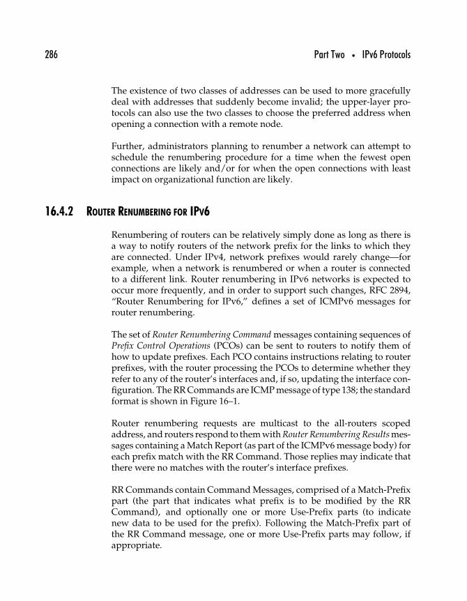
286 Part Two • IPv6 Protocols
The existence of two classes of addresses can be used to more gracefullydeal with addresses that suddenly become invalid; the upper-layer pro-tocols can also use the two classes to choose the preferred address whenopening a connection with a remote node.
Further, administrators planning to renumber a network can attempt toschedule the renumbering procedure for a time when the fewest openconnections are likely and/or for when the open connections with leastimpact on organizational function are likely.
16.4.2 ROUTER RENUMBERING FOR IPV6
Renumbering of routers can be relatively simply done as long as there isa way to notify routers of the network prefix for the links to which theyare connected. Under IPv4, network prefixes would rarely change—forexample, when a network is renumbered or when a router is connectedto a different link. Router renumbering in IPv6 networks is expected tooccur more frequently, and in order to support such changes, RFC 2894,“Router Renumbering for IPv6,” defines a set of ICMPv6 messages forrouter renumbering.
The set of Router Renumbering Command messages containing sequences ofPrefix Control Operations (PCOs) can be sent to routers to notify them ofhow to update prefixes. Each PCO contains instructions relating to routerprefixes, with the router processing the PCOs to determine whether theyrefer to any of the router’s interfaces and, if so, updating the interface con-figuration. The RR Commands are ICMP message of type 138; the standardformat is shown in Figure 16–1.
Router renumbering requests are multicast to the all-routers scopedaddress, and routers respond to them with Router Renumbering Results mes-sages containing a Match Report (as part of the ICMPv6 message body) foreach prefix match with the RR Command. Those replies may indicate thatthere were no matches with the router’s interface prefixes.
RR Commands contain Command Messages, comprised of a Match-Prefixpart (the part that indicates what prefix is to be modified by the RRCommand), and optionally one or more Use-Prefix parts (to indicatenew data to be used for the prefix). Following the Match-Prefix part ofthe RR Command message, one or more Use-Prefix parts may follow, ifappropriate.
Chapter 16 • IPv6 Autoconfiguration 287
+-+-+-+-+-+-+-+-+-+-+-+-+-+-+-+-+-+-+-+-+-+-+-+-+-+-+-+-+-+-+-+-+| |/ IPv6 header, extension headers /| |+-+-+-+-+-+-+-+-+-+-+-+-+-+-+-+-+-+-+-+-+-+-+-+-+-+-+-+-+-+-+-+-+| |/ ICMPv6 & RR Header (16 octets) /| |+-+-+-+-+-+-+-+-+-+-+-+-+-+-+-+-+-+-+-+-+-+-+-+-+-+-+-+-+-+-+-+-+| |/ RR Message Body /| |+-+-+-+-+-+-+-+-+-+-+-+-+-+-+-+-+-+-+-+-+-+-+-+-+-+-+-+-+-+-+-+-+
Figure 16–1: Router Renumbering Command format (from RFC 2894).
16.4.3 RENUMBERING AN IPV6 NETWORK WITHOUT A FLAG DAY
A work-in-progress, “Procedures for Renumbering an IPv6 Network With-out a Flag Day,” outlines some of the issues involved in renumbering IPv6networks without disrupting the operation of the networks and withoutrequiring an all-at-once procedure such as are involved with flag day con-versions. Rather than defining any specific protocols, the authors of thisdocument suggest a method of evaluating the progress of the process insix different stages, followed by a discussion of the difficulties that mayensue as well as security issues related to network renumbering.
The process of renumbering itself is accomplished using the mechanismsalready described to reconfigure router, node, and network. The phases ofrenumbering are as follows.
1. The network is using the old prefix and is currently stable.Everything works as it should in terms of routing, servers, andall other network nodes.
2. The new prefix is added while the old prefix is still in use. Bar-ring the ability to simultaneously and completely update allnodes with the new prefix, there will be parts of the networkthat correctly use the new prefix and other parts that will not beable to use the new prefix. Reconfiguring all routing to the newprefixes across all subprefixes (subnets) is estimated to take “aperiod of time varying from minutes to hours depending on
288 Part Two • IPv6 Protocols
the size of the network and the degree of automation used inreconfiguration.”
3. Once the network has been reconfigured with the new prefix,with all routing stabilized, every interface on the network willhave two valid addresses, one for the old and one for the newprefixes. At this point, the old addresses are still being usedas the default when opening new network sessions; the newaddresses are not yet being used.
4. The process of shutting down the old prefix begins. Thisincludes modifying DNS records to reflect the new prefix andreconfiguring by hand any nodes that still need to be changedto use the new prefix. As the old prefix is taken out of service,the individual nodes should be notified by the various autocon-figuration and neighbor discovery functions that the old prefixshould be replaced by the new one for new sessions.
5. The old prefix is removed. As all sessions that still use theold prefix are closed, the old prefix can be removed from eachnode’s configuration.
6. The network is using the new prefix and is currently stable.Everything works as it should in terms of routing, servers,and all other network nodes. Just as at the beginning, wheneverything was stable, but using the old prefix.
The devil is in the details, of course, and some difficulty, according tothe authors of this document, will arise from nodes that are not directlycontrolled by the network administrator or require manual configuration.These devices are likely to be “unusual” in that they are not typical end-userPCs but rather as follows.
VoIP telephones with static configuration of boot or name servers,scanning devices used by manufacturing partners in support of “justin time” purchasing, manufacturing, or shipping activities, the bootservers of routers and switches, and so on. Application designers fre-quently take short-cuts to save memory or increase responsiveness,and a common short-cut is to use static configuration of IP addressesrather than DNS translation to obtain the same. The downside of suchbehavior should be apparent; such a poorly designed application can-not even add or replace a server easily, much less change servers orreorganize its address space. The short-cut ultimately becomes veryexpensive to maintain and very hard to replace.
In addition to citing security-related problems that can arise when nodesare designed to use network addresses outside of the normal protocols
Chapter 16 • IPv6 Autoconfiguration 289
for acquiring addresses (that is, software or hardware that has beenhard-coded to use a particular network prefix or address), the authorsalso describe an attack that is possible during the renumbering process.
Attacks are also possible. Suppose, for example, that the new prefix hasbeen presented by a service provider, and the service provider startsadvertising the prefix before the customer network is ready. The newprefix might be targeted in a distributed denial of service attack, ora system might be broken into using an application that would notcross the firewall using the old prefix, before the network’s defenseshave been configured. Clearly, one wants to configure the defensesfirst and only then accessibility and routing.
Mostly, though, the authors suggest that while IPv6 network renumber-ing can be significantly easier than IPv4 network renumbering, it is notchild’s play, nor should it be undertaken without due consideration of thepotential problems that can arise in the process.
16.5 Summary
IPv6 protocols for renumbering networks, nodes, and routers withoutdoing it manually fulfill an important design goal of the next generationprotocol. More important is the ability to do renumbering using a small setof standard ICMPv6 messages and the standard tools provided by neigh-bor discovery, rather than devising any new client-server protocols, as isso often the solution chosen to provide new features or functions withinIP networks up to now.
Another important goal, and one that is related in a way to rapid renum-bering, has been the ability to network mobile nodes, to be discussed inthe next chapter.

This Page Intentionally Left Blank
1717
Mobile IPv6
When an IP node moves from one network to another, as when a notebookcomputer is used in more than one location, one way to accommodate thechanges in the network is to use two or more sets of network configurationto match each location. However, another solution is to use a mobile IP pro-tocol to allow the computer to use one IP address for all its communicationsacross any network to which it is attached.
Mobile IP, however, should not be confused with the mechanisms requiredto allow fast handovers in cellular wireless networks. In that type ofnetwork, the handovers are handled at the link layer rather than at thenetwork layer. With a rapidly moving node and a network using smallcels, the node would likely remain in the same link layer network even asit moved from one cel to another, thus obviating any need to change IPaddresses.
However, mobile IP is most useful for nodes that change location as well aslink layer network somewhat less rapidly. At the risk of oversimplifying,an IPv4 mobile node is configured with an IP address on its home network.When the mobile node connects to a network, it listens for a mobility agent
291
292 Part Two • IPv6 Protocols
advertisement to determine whether it is on its home network or someother network. If it is on a foreign network, it requests a care-of addressfrom the mobility agent and then notifies a mobility agent on its homenetwork of the care-of address. Communication to and from the mobilenode can then be accomplished by tunneling through the remote networkusing the care-of address.
As we’ll see, under IPv4 the process of enabling mobility requires addingspecial agents and servers, as described in RFC 3344, “IP Mobility Supportfor IPv4.” However, the careful design of IPv6 protocols, especially theuse of neighbor discovery functions, means that IPv6 mobility does notrequire any special infrastructure to be set up to enable mobility.
17.1 IP Mobility
Mobility was from the start an important part of the IPng effort, at leastjudging by the 1994 publication of RFC 1688, “IPng Mobility Consid-erations.” Here is a list of source documents on mobile IP; IP mobilityis still not widespread in part because it can be cumbersome to deployunder IPv4.
RFC 1688 “IPng Mobility Considerations”RFC 2005 “Applicability Statement for IP Mobility Support”RFC 2794 “Mobile IP Network Access Identifier Extension for
IPv4”RFC 2977 “Mobile IP Authentication, Authorization, and
Accounting Requirements”RFC 3012 “Mobile IPv4 Challenge/Response Extensions”RFC 3344 “IP Mobility Support for IPv4”RFC 3519 “Mobile IP Traversal of Network Address Translation
(NAT) Devices”
IPv4 mobility, as defined in RFC 3344, “IP Mobility Support for IPv4,”requires three things to work properly.
1. The mobile node must be able to move from one link layer net-work to another (that is, change link layer network addresses)without having to change its IP address.
2. The mobile node must be able to interoperate with all otherIP nodes, without any modifications required to communicate
Chapter 17 • Mobile IPv6 293
with a mobile node. In other words, the mobility-enabled nodemust be backward compatible with the rest of the Internet.
3. The mobile node must be authenticated whenever it tries toupdate its location. This is to prevent attackers from “imper-sonating” the mobile node in order to gain access to the mobilenode’s home network.
IPv4 mobility defines three entities, which exchange mobility informationin ICMP messages.
Mobile node A node (host or router) that can move from one networkor subnetwork to another without changing its IP address and thatcan maintain, without interruption, sessions that were begun whileconnected on one network after the node is moved to another network(with the assumption that there is no noticeable disruption to thenode’s connectivity during the shift).
Home agent A router that acts on behalf of the mobile node on its homenetwork. Packets sent to and from the mobile node when it is awayfrom the home network are tunneled through the home agent. Thehome agent also keeps track of the mobile node’s remote location(s).
Foreign agent A router that provides routing services to visiting mobilenodes. Mobile nodes must register with the foreign agent when theyfirst connect to the foreign network. The foreign agent router acts asthe other end of an IP tunnel for the mobile node, and the foreignagent is recommended for use as the default router for mobile nodesregistered on a network.
The IPv4 mobility protocol offers Agent Discovery services, with foreignand home agents periodically announcing their presence on a network aswell as responding to solicitations for agents sent by mobile nodes in theprocess of connecting to a network. The protocol also requires the mobilenode—when it first connects to a network—to register with its home agent(sometimes directly or sometimes through the foreign agent, dependingon how the connection is made).
Figure 17–1 shows how the IPv4 mobility protocol works. Mobility agentsperiodically transmit advertisements, addressed either to the all-nodesmulticast address or the limited broadcast address (255.255.255.255, mean-ing “all nodes on this subnet”). The advertisements include the agents’
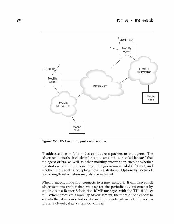
294 Part Two • IPv6 Protocols
INTERNET
HOMENETWORK
REMOTENETWORK
MobileNode
MobilityAgent
MobilityAgent
(ROUTER)
(ROUTER)
MobileNode
Figure 17–1: IPv4 mobility protocol operation.
IP addresses, so mobile nodes can address packets to the agents. Theadvertisements also include information about the care-of address(es) thatthe agent offers, as well as other mobility information such as whetherregistration is required, how long the registration is valid (lifetime), andwhether the agent is accepting new registrations. Optionally, networkprefix length information may also be included.
When a mobile node first connects to a new network, it can also solicitadvertisements (rather than waiting for the periodic advertisement) bysending out a Router Solicitation ICMP message, with the TTL field setto 1. When it receives a mobility advertisement, the mobile node checks tosee whether it is connected on its own home network or not; if it is on aforeign network, it gets a care-of address.
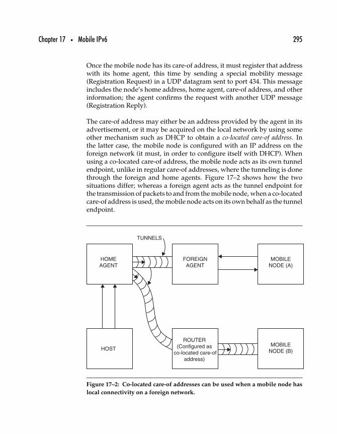
Chapter 17 • Mobile IPv6 295
Once the mobile node has its care-of address, it must register that addresswith its home agent, this time by sending a special mobility message(Registration Request) in a UDP datagram sent to port 434. This messageincludes the node’s home address, home agent, care-of address, and otherinformation; the agent confirms the request with another UDP message(Registration Reply).
The care-of address may either be an address provided by the agent in itsadvertisement, or it may be acquired on the local network by using someother mechanism such as DHCP to obtain a co-located care-of address. Inthe latter case, the mobile node is configured with an IP address on theforeign network (it must, in order to configure itself with DHCP). Whenusing a co-located care-of address, the mobile node acts as its own tunnelendpoint, unlike in regular care-of addresses, where the tunneling is donethrough the foreign and home agents. Figure 17–2 shows how the twosituations differ; whereas a foreign agent acts as the tunnel endpoint forthe transmission of packets to and from the mobile node, when a co-locatedcare-of address is used, the mobile node acts on its own behalf as the tunnelendpoint.
HOMEAGENT
FOREIGNAGENT
MOBILENODE (A)
HOST
TUNNELS
ROUTER(Configured as
co-located care-ofaddress)
MOBILENODE (B)
Figure 17–2: Co-located care-of addresses can be used when a mobile node has
local connectivity on a foreign network.
296 Part Two • IPv6 Protocols
This is merely an overview of the IPv4 mobility protocol, and it omitsdetails as well as important aspects of mobility security. It is providedpurely as background for discussion of mobility in IPv6.
17.2 Mobility Support in IPv6
As of mid-2003, the specification for mobility support in IPv6 is still a work-in-progress, even though it has been revised almost two dozen times. Theobjective of mobile IPv6 is still to allow a mobile node to move from link tolink while retaining the same, home, IPv6 address. This allows connectivityto the mobile node transparently, no matter where the node is linked tothe network.
Unlike in IPv4, where mobility registration uses a separate protocol carriedin UDP datagrams, IPv6 mobility is defined as a separate protocol carriedin IPv6 extension headers. Although similar to mobility support in IPv4,IPv6 mobility builds on the experiences of IPv4 mobility research as wellas new features of IPv6 itself (such as the reliance on extension headers forIP-layer applications like mobility).
The IPv6 approach uses concepts such as binding of a mobile node’shome address with its care-of address and more rigorous authorizationprocedures. The basics of the protocol are described in this section.
17.2.1 IPV6 MOBILITY BASICS
Mobile nodes attached to their home networks send and receive packetsjust as would any IPv6 node; there is no functional or observable differencebetween a mobile node on its home network and any other node. Whenthe mobile node moves, however, it needs to acquire one or more care-ofaddresses at which it can be reached. The care-of address is uniquely linkedto the mobile node, but it has the subnet prefix associated with the foreignnetwork to which the mobile node is attached.
As described in Chapter 16, IPv6 nodes of any kind can acquire valid IPv6addresses when they connect to a new network through standard IPv6procedures, whether stateful or stateless autoconfiguration. Mobile nodes,
Chapter 17 • Mobile IPv6 297
therefore, use these procedures to acquire local addresses that they thencan use as their care-of addresses.
To use a local address as a care-of address, the mobile node must be able tobind its home address and the care-of address together. The mobile noderegisters its care-of address by sending a Binding Update to its home agent,which responds by sending a Binding Acknowledgment message.
A big difference between IPv4 and IPv6 mobility occurs by the inclu-sion of the definition of a correspondent node: any node that communicateswith a mobile node (the correspondent node may also be a mobile nodeitself). Mobile IPv6 nodes can notify correspondent nodes of their currentlocations through a process of correspondent registration.
17.2.2 MOBILE/CORRESPONDENT NODE MODES
Two modes for mobility support are provided in the document “Mobil-ity Support in IPv6” for communication between a mobile node and acorrespondent node.
Bidirectional tunneling This mode is available for communicationbetween a mobile node and any IPv6 node, whether or not it hasexplicit support for IPv6 mobility. In addition, the mobile node doesnot have to register a binding, either. The mobile node tunnels pack-ets intended for the correspondent node through its home agent; thehome agent then intercepts packets addressed to the mobile node’shome address and tunnels those packets back to the mobile node viaits care-of address.
Route optimization This mode, so-called because it allows the optimalroute between mobile node and correspondent node, works by hav-ing the mobile node register its current address binding with thecorrespondent node. The correspondent node can thus send packetsdirectly to the mobile node’s care-of address. In addition to optimiz-ing the path between nodes, this option also reduces the possibilityof congestion at the mobile node’s home agent (which would other-wise have to mediate all traffic between the two) as well as any riskof connection failure due to circumstances in the mobile node’s homenetwork.
298 Part Two • IPv6 Protocols
Mobile IPv6 can be expected to support additional features such aspermitting mobile nodes to use more than one home network.
17.3 Mobile IPv6 Versus Mobile IPv4
These are some important differences between Mobile IPv4 and MobileIPv6, as cited in the draft specification for IPv6 mobility.
• There is no need for foreign agents; no special local support isnecessary to allow a mobile IPv6 node to operate correctly.
• IPv4 mobility defines the default mode of operation throughthe agency of the mobile node’s home network. This tends tostress the mobile node’s home agent; the ability to redirect acorrespondent node to the mobile node’s current address isimplemented only as an extension of the IPv4 mobility speci-fications. IPv6 mobility incorporates route optimization as afundamental aspect of the protocol.
• Rather than encapsulating packets in tunnels as in IPv4 mobil-ity, most IPv6 packets sent to a mobile node include IPv6 headerextensions—a significant difference in terms of processing (noneed to encapsulate/decapsulate packets for tunnels).
• Use of IPv6 Neighbor Discovery eliminates the need to rely onARP or other link layer mechanisms; it also enables functionssuch as unreachability detection and agent discovery.
Other differences include the way that authentication is accomplishedbetween mobile nodes and their agents or correspondents, as well as howmobile nodes can be accommodated even when they are attached to anetwork that is behind a firewall or NAT.
17.4 Summary
The early visions for mobile IP included millions of workers connectingtheir laptop PCs to geographically and organizationally distributed net-works, all able to interoperate as if they were still connected to their homenetworks. Even without mobility, business travelers as well as individualsenjoy relatively simple mobile interoperability, whether they connect viawireless networks in coffee shops or via broadband in hotels.
Chapter 17 • Mobile IPv6 299
The greater challenge for mobile IPv6 will undoubtedly prove to be inenabling mobility for non-PC devices, from allowing the use of mobiletelephones anywhere to serving Web data from highly mobile platforms.For example, automobile manufacturers might incorporate wireless Webservers to provide access to car diagnostics from anywhere in the world.
Another important aspect of portability is the close correlation betweenIPv6 and DNS. Where IPv4 nodes could, conceivably, operate withouta mechanism for linking domain names to IP addresses, IPv6 insists onapplications relying on DNS to translate the applications’ domain namesto IPv6 addresses, as will be seen in the next chapter.

This Page Intentionally Left Blank
1818
IPv6 and DNS
One of the most pressing challenges facing anyone who wishes to deployIPv6 is that of deploying Domain Name System (DNS) servers that areable to correctly respond to requests for domain name resolution for bothIPv6 and IPv4 nodes. As long as DNS can be relied on to provide accu-rate linking of IP addresses for domain names, IPv6 nodes can be linkedseamlessly and transparently to the application layer and the end user(and, to a great extent, to the transport layer).
DNS is a very distributed database system that defines a variety of differentresource records (RRs) to correspond to different types of data. For example,the A RR contains an address and the MX RR contains mail exchangeinformation. Two different RRs were defined for use with IPv6 addresses:the AAAA and A6 RRs.
In this chapter, we begin with a brief look at how DNS works, followed byan introduction to the two different IPv6 RR types and a discussion of thepros and cons of using each, including a look at the prospects for which ofthe two is likely to become prevalent in the IPv6 Internet.
301
302 Part Two • IPv6 Protocols
18.1 DNS Resource Records
No database can exist without records, and DNS was defined to storename and address information as well as provide the capacity to storeother information as well. DNS data is stored in resource records (RRs).As defined in the internet standard for DNS,1 “A domain name identi-fies a node. Each node has a set of resource information, which may beempty. The set of resource information associated with a particular nameis composed of separate resource records.”
In this section, we look at the basics of DNS RRs, including those origi-nally defined for use with IPv4, how new ones can be added, and the twodifferent RRs that have already been specified for use with IPv6.
Figure 18–1 is a graphical representation of the fields comprising an RR;those fields include the following.
NAME The domain name where the RR is found; the owner may beimplied by the contents of the RR.
TYPE An encoded 16-bit value specifying what kind of abstract resourceis referred to in the RR. RFC 1034 mentions several types, includingA to indicate a host address, CNAME for the canonical name of an aliasused to simplify access to the resource, HINFO for the CPU and OSused by the host, MX to identify the resource as a mail exchangefor the domain,2 NS to indicate the authoritative nameserver fora domain, PTR to indicate a pointer to another part of the domainname space, and SOA to indicate the start of a zone of authority.
CLASS Another encoded 16-bit value, the class specifies “a protocolfamily or instance of a protocol”—for example, the IN class,specifying the Internet system. This value is rarely used.
TTL The time to live of the RR. A 32-bit integer, TTL specifies the numberof seconds before the RR should expire. This is used mostly aftera resolver has retrieved an RR to indicate how long the cached valueshould be saved and used before discarding it as out of date.
1STD 13, which includes RFCs 1034 and 1035.2See Chapter 24 for more about how email works with DNS in IPv6.

Chapter 18 • IPv6 and DNS 303
1 1 1 1 1 1
0 1 2 3 4 5 6 7 8 9 0 1 2 3 4 5
+-+-+-+-+-+-+-+-+-+-+-+-+-+-+-+-+
| |
/ NAME /
| |
+-+-+-+-+-+-+-+-+-+-+-+-+-+-+-+-+
| TYPE |
+-+-+-+-+-+-+-+-+-+-+-+-+-+-+-+-+
| CLASS |
+-+-+-+-+-+-+-+-+-+-+-+-+-+-+-+-+
| TTL |
| |
+-+-+-+-+-+-+-+-+-+-+-+-+-+-+-+-+
| RDLENGTH |
+-+-+-+-+-+-+-+-+-+-+-+-+-+-+-+-+
/ RDATA /
/ /+-+-+-+-+-+-+-+-+-+-+-+-+-+-+-+-+
Figure 18–1: Layout of fields within an RR (from RFC 1034).
RDLENGTH A 16-bit value indicating the length of the resource data, inbytes, limiting the amount of data stored in any RR to no more than65,535 bytes.
RDATA The data associated with the RR. The composition and lengthof this field may vary, depending on the RR type.
Different types of RR have been defined for different purposes, althoughwe’ll look here only at the types defined in RFC 1034. Domain nameserversstore all their information in these RRs, making the definition of each RRroughly equivalent to a database’s design or schema.
Although DNS is most often associated with the process of matchinghostnames with IP addresses, DNS makes other data available, for otherpurposes. One of the most important of these other purposes is mak-ing mail exchange (MX) information available. MX records allow Internetmail addressed to one address to be redirected for delivery to some otheraddress for a variety of reasons: to keep private details of an organization’s
304 Part Two • IPv6 Protocols
intranet and internal mail systems, to avoid going through a securityfirewall, or to provide a standard corporate address format (e.g.,“[email protected]”) while allowing users to receive mailat other addresses.
A number of RRs have been defined for use with DNS security exten-sions; these include the SIG (security signature), KEY (security key), andNXT (next domain) RRs defined in RFC 2535. Other special purpose RRsinclude the NAPTR (naming authority pointer) type defined in RFCs 2168and 2915 and the AAAA and A6 types defined for IPv6 address resolution;there is even an RR defined simply for storing text strings (TXT).
18.2 DNS Extensions for IPv6
IPv6 support under DNS should be straightforward: define a new resourcerecord type for maintaining IPv6 addresses and linking them to domainnames. The first specification for DNS support of IPv6 published as RFC1886, “DNS Extensions to Support IP Version 6,” proposes these actions.
Add AAAA Resource Record The AAAA RR maps a domain name to anIPv6 address. The “quad A” designation is derived from the A RR,which maps a domain name to an IPv4 (32-bit) address; with IPv6addresses four times the length of IPv4 addresses, the correspondingresource record is four As.
New IPv6 Reverse Lookup Domain One of the functions of DNSenables reverse lookups, where an IP address is known rather thanthe domain name. DNS support for this function for IPv6 addressesrequires the addition of a similar reverse lookup domain.
Update Query formats Queries for IPv4 addresses are updated toperform additional processing to recover both IPv4 and IPv6addresses, if present. The details of the RFC 1886/AAAA proposalare examined in this section.
18.2.1 THE AAAA RESOURCE RECORD
The AAAA resource record stores a single 128-bit IPv6 address in theRDATA field. When a DNS AAAA query is made by a client node, the
Chapter 18 • IPv6 and DNS 305
DNS server responds with a list of all the AAAA resource recordsassociated with the domain name.
18.2.2 REVERSE LOOKUP DOMAIN
RFC 1886 specifies a reverse-lookup domain at IP6.INT (for looking upthe domain associated with a particular address rather than an address fora particular domain name). That domain (IP6.INT) has been deprecatedand replaced by the more standard IP6.ARPA, as defined in RFC 3152,“Delegation of IP6.ARPA.” The IP4.ARPA domain is used for finding adomain name to match an address, and ARPA is considered an acronymfor “Address and Routing Parameters Area”;3 thus, the change for IPv6 isto maintain consistency.
The IPv6 address to be looked up is converted into a name in the IP6.ARPAdomain by reversing the order of the hexadecimal digits of the address,separating each digit by a dot (“.”), and then adding the suffix “IP6.ARPA”to the end. RFC 1886 provides the example on which this one is based.
4321:0:1:2:3:4:567:89ab
becomes:
b.a.9.8.7.6.5.0.4.0.0.0.3.0.0.0.2.0.0.0.1.0.0.0.0.0.0.0.1.2.3.4.IP6.ARPA
18.2.3 MODIFIED QUERIES
DNS query types, such as name server (NS) and mail exchange (MX)queries, have to be modified to allow them to return both type A andtype AAAA results. Doing so allows name servers to send clients all therelevant results for a particular domain name request, including both IPv4and IPv6 addresses.
3The acronym ARPA originally derived from the Advanced Research Projects Agency,part of the Department of Defense and an original funding organization of much of the work,including the networks, supporting the original Internet Protocol. The IP4.ARPA domainwas originally intended for the use of that agency, but with the release of the program tothe public, the domain was already being used, and changing it would have been morecomplicated than changing the meaning of the acronym.
306 Part Two • IPv6 Protocols
18.3 DNS and IPv6 Aggregation
Controversy arose from the publication of RFC 2874, “DNS Extensionsto Support IPv6 Address Aggregation and Renumbering,” as a proposalstandard. Apparently, this new specification was to have been con-sidered an alternative to AAAA but in RFC 3363, “Representing InternetProtocol Version 6 (IPv6) Addresses in the Domain Name System (DNS),”the situation was clarified with the A6 proposal (as the protocol definedin RFC 2874 is known) reclassified as experimental.
The A6 resource record solves some problems but also creates other prob-lems as will be made clear in this section. By design, A6 allows thesegmentation of host addressing information into multiple A6 records,one of which contains only an IPv6 address, and the other(s) of whichspecify a domain name for which network prefix information is available.
The result is that any A6 query may require additional lookups: one lookupfor the specific host and one or more lookups for domains associated withthat host.
By separating the DNS records for node addresses from DNS recordsfor domain names, the A6 proposal makes it possible to more quicklypropagate changes in network numbering. If all nodes retain their64-bit host part addresses and only change the 64 high-order bits oftheir network addresses when a network is renumbered, then the splitmakes sense. DNS entries for individual nodes do not need to bechanged when the network is renumbered—just the parent domain nameentries.
18.3.1 A6 RESOURCE RECORD
The A6 resource record, shown in Figure 18–2 (along with field definitions),can, when combined with other A6 records, carry complete informationabout the address associated with a particular domain name. The pre-fix length indicates what portion of the address suffix is contained in therecord. If the prefix length is 64, it means that the address suffix field willcontain the low-order 8 octets of an address—in other words, the host-partof an IPv6 address. Following the address suffix field, the prefix namefield contains a domain name under whose A6 record more addressinginformation can be found.
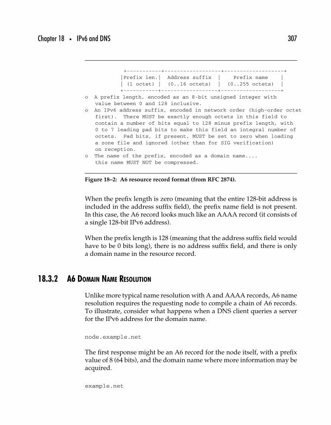
Chapter 18 • IPv6 and DNS 307
+-----------+------------------+-------------------+|Prefix len.| Address suffix | Prefix name || (1 octet) | (0..16 octets) | (0..255 octets) |+-----------+------------------+-------------------+
o A prefix length, encoded as an 8-bit unsigned integer withvalue between 0 and 128 inclusive.
o An IPv6 address suffix, encoded in network order (high-order octetfirst). There MUST be exactly enough octets in this field tocontain a number of bits equal to 128 minus prefix length, with0 to 7 leading pad bits to make this field an integral number ofoctets. Pad bits, if present, MUST be set to zero when loadinga zone file and ignored (other than for SIG verification)on reception.
o The name of the prefix, encoded as a domain name....this name MUST NOT be compressed.
Figure 18–2: A6 resource record format (from RFC 2874).
When the prefix length is zero (meaning that the entire 128-bit address isincluded in the address suffix field), the prefix name field is not present.In this case, the A6 record looks much like an AAAA record (it consists ofa single 128-bit IPv6 address).
When the prefix length is 128 (meaning that the address suffix field wouldhave to be 0 bits long), there is no address suffix field, and there is onlya domain name in the resource record.
18.3.2 A6 DOMAIN NAME RESOLUTION
Unlike more typical name resolution with A and AAAA records, A6 nameresolution requires the requesting node to compile a chain of A6 records.To illustrate, consider what happens when a DNS client queries a serverfor the IPv6 address for the domain name.
node.example.net
The first response might be an A6 record for the node itself, with a prefixvalue of 8 (64 bits), and the domain name where more information may beacquired.
example.net
308 Part Two • IPv6 Protocols
The next step would be to query the DNS for that domain name, in whichcase the response might be an A6 record containing just an IPv6 networkaddress; that is, the prefix length would be 0, and there would be nodomain name at all, and the address itself would be zeroed out in theless-significant 64 bits.
The client making the request could then concatenate the host part of theaddress (from the first A6 record) with the network part of the address(from the second A6 record), with the result being the proper IPv6 addressfor the node named node.example.net.
18.3.3 AAAA VERSUS A6
As already noted, the coexistence of the AAAA and A6 proposals onthe standards track was confusing, especially since the AAAA protocolhad been the only DNS solution that was widely implemented before A6came along. The situation was finally clarified with the publication of RFC3363, “Representing Internet Protocol Version 6 (IPv6) Addresses in theDomain Name System (DNS),” in which the A6 approach was reclassifiedas experimental. RFC 3364, “Tradeoffs in Domain Name System (DNS)Support for Internet Protocol Version 6 (IPv6),” is a companion documentthat explains why the choice was made for AAAA over A6, as summarizedin the next section.
18.4 Choosing the Next Generation DNS RR
As may be supposed from the two different proposals, the A6 protocolwas moved off the standards track at this time because, ultimately, it is toocomplicated. AAAA records allow simple request/response interactionsfor DNS clients and servers; the A6 record requires that DNS clients andservers interact more than once for each query, with clients required tocollect and verify A6 records as being part of a chain.
RFC 3364, “Tradeoffs in Domain Name System (DNS) Support for InternetProtocol Version 6 (IPv6),” goes into considerably more detail about thetrade-offs—including the potential benefits in terms of improved addressand domain name aggregation and faster network renumbering with A6.This section lists some of the criteria considered during the debate.
Chapter 18 • IPv6 and DNS 309
18.4.1 ADVANTAGE: A6
As explained in RFC 3364, A6 has one clear advantage over AAAA.
A6 RRs can represent addresses in which a prefix portion of theaddress can change without any action (or perhaps even knowledge)by the parties controlling the DNS zone containing the terminal por-tion (least significant bits) of the address. This includes both so-called“rapid renumbering” scenarios (where an entire network’s prefix maychange very quickly) and [some] routing architectures. . . (where the“routing goop” portion of an address may be subject to change with-out warning). A6 RRs do not completely remove the need to updateleaf zones during all renumbering events (for example, changing ISPswould usually require a change to the upward delegation pointer),but careful use of A6 RRs could keep the number of RRs that need tochange during such an event to a minimum.
Also, an A6 resource record of the zero-length prefix format is identical toan AAAA resource record for the same address. This means that anythingyou can do with AAAA, you can do with A6. Thus, AAAA shouldn’t haveany functions that are unavailable to A6, and thus A6 could easily replaceAAAA.
18.4.2 ADVANTAGE: AAAA
Although AAAA provides only a subset of the features supported by A6,there are some other considerations to contend with.
• The AAAA resource record differs from the A resource recordonly in the length of the addresses they contain. Having 15 ormore years of experience with what is essentially the sameprotocol is a considerable advantage for AAAA. A6, by com-parison, is an unknown quantity in terms of how it behaves,how it works, and how it fails in the field.
• AAAA resource records are designed for simplicity of dataretrieval. The DNS query transaction with AAAA records issimple and straightforward. While A6 records make it easier toupdate the DNS system with renumbered network data, AAAArecords make it easier to retrieve the data.
The RFC includes many other arguments, including less compelling onesin favor of and against each proposal, and discussion of the problems and
310 Part Two • IPv6 Protocols
potential problems inherent in A6. However, ultimately, the choice seemsclear: Since data retrieval is a much more frequent task than data update,and since AAAA simplifies retrieval, for the moment the IPv6 Internet willcontinue to support AAAA as the default resource record for DNS.
18.5 Naming IPv6 Domains
No discussion of IPv6 and DNS would be complete without a briefdiscussion of the issues of naming IPv6 domains. Depending on howthe domains are to be used, decisions must be made regarding howIPv6 domains should be named, particularly in relation to existing IP4domains.
One option is probably more appropriate if the domains will be IPv6-enabled to allow IPv6 nodes to access the same resources as IPv4 nodes—in other words, if all resources in the example.com domain are to remainaccessible both to IPv4 and IPv6 nodes. In those cases, AAAA resourcerecords for the existing domains should be added in parallel to the existingA records for those domains.
The other option is probably more appropriate when the IPv6-enableddomains are to host services and resources that are targeted only at IPv6nodes. In this case, a set of domains such as ipv6.example.com are set asidefor IPv6 use only. The IPv6-only domains would be entered into the DNSwith their own AAAA records, while the IPv4-only domains would remainunchanged.
When, and even if, such distinctions are best made will depend on whatyour networking goals are, as well as on further research into the operationof large IPv6 networks.
18.6 Summary
As often happens, the interoperation of IPv6 and DNS will rest on triedand true results and a straightforward protocol, AAAA, rather than themore feature-full but less-tested alternative, A6. Ultimately, IPv6 relies to

Chapter 18 • IPv6 and DNS 311
a great extent on the use of DNS to eliminate or at least minimize the impactit will have on other protocols.
Although some of these other protocol interactions with IPv6 have beenmentioned in previous chapters, the next chapter summarizes the workthat has been done to date on integrating IPv6 with the rest of the TCP/IPprotocol suite and other related protocols.

This Page Intentionally Left Blank
1919
Next Generation Protocols
Contrary to many expectations, IPv6 will have relatively little impact onother protocols considered to be a part of the TCP/IP network protocolsuite. That is by design: It is hard enough to update such a widely deployedprotocol as IPv4. Imposing the additional requirement of a whole set ofnew protocols to work with IPv6 would doom the project from the start.
Although there are over a dozen different specifications related to runningIPv6 over [something],1 those specifications largely explain the approachesimplementers should and/or must take when implementing IPv6 overthose link layer protocols.
In this chapter, we take a brief look at how IPv6 implementations inter-operate with related protocols, including the transport layer protocols,application layer protocols, and link layer protocols. We will also revisitthe modifications necessary to infrastructure-related protocols that will beaffected by IPv6, especially DNS and routing protocols.
1For example, “IPv6 over Ethernet,” “IPv6 over ATM,” and so on.
313
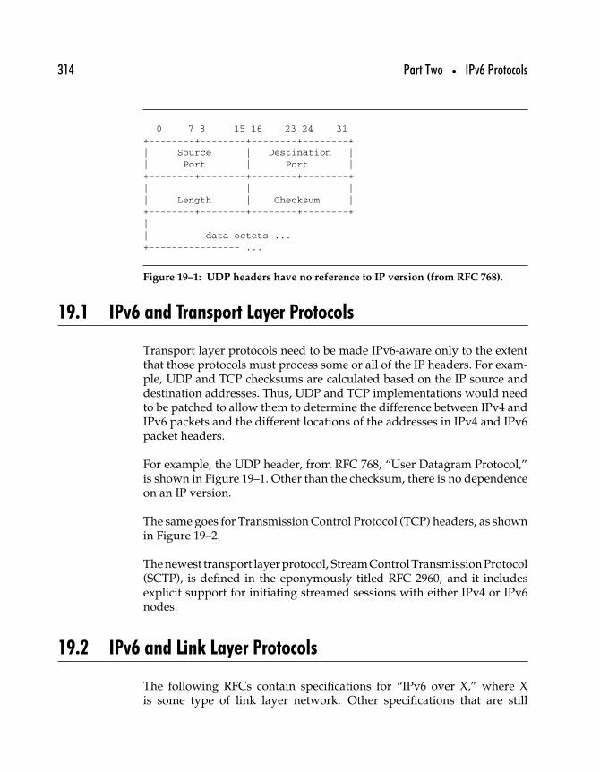
314 Part Two • IPv6 Protocols
0 7 8 15 16 23 24 31+--------+--------+--------+--------+| Source | Destination || Port | Port |+--------+--------+--------+--------+| | || Length | Checksum |+--------+--------+--------+--------+|| data octets ...+---------------- ...
Figure 19–1: UDP headers have no reference to IP version (from RFC 768).
19.1 IPv6 and Transport Layer Protocols
Transport layer protocols need to be made IPv6-aware only to the extentthat those protocols must process some or all of the IP headers. For exam-ple, UDP and TCP checksums are calculated based on the IP source anddestination addresses. Thus, UDP and TCP implementations would needto be patched to allow them to determine the difference between IPv4 andIPv6 packets and the different locations of the addresses in IPv4 and IPv6packet headers.
For example, the UDP header, from RFC 768, “User Datagram Protocol,”is shown in Figure 19–1. Other than the checksum, there is no dependenceon an IP version.
The same goes for Transmission Control Protocol (TCP) headers, as shownin Figure 19–2.
The newest transport layer protocol, Stream Control Transmission Protocol(SCTP), is defined in the eponymously titled RFC 2960, and it includesexplicit support for initiating streamed sessions with either IPv4 or IPv6nodes.
19.2 IPv6 and Link Layer Protocols
The following RFCs contain specifications for “IPv6 over X,” where Xis some type of link layer network. Other specifications that are still
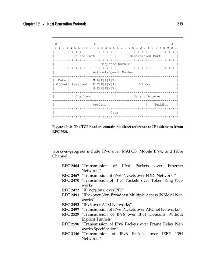
Chapter 19 • Next Generation Protocols 315
0 1 2 30 1 2 3 4 5 6 7 8 9 0 1 2 3 4 5 6 7 8 9 0 1 2 3 4 5 6 7 8 9 0 1
+-+-+-+-+-+-+-+-+-+-+-+-+-+-+-+-+-+-+-+-+-+-+-+-+-+-+-+-+-+-+-+-+| Source Port | Destination Port |+-+-+-+-+-+-+-+-+-+-+-+-+-+-+-+-+-+-+-+-+-+-+-+-+-+-+-+-+-+-+-+-+| Sequence Number |+-+-+-+-+-+-+-+-+-+-+-+-+-+-+-+-+-+-+-+-+-+-+-+-+-+-+-+-+-+-+-+-+| Acknowledgment Number |+-+-+-+-+-+-+-+-+-+-+-+-+-+-+-+-+-+-+-+-+-+-+-+-+-+-+-+-+-+-+-+-+| Data | |U|A|P|R|S|F| || Offset| Reserved |R|C|S|S|Y|I| Window || | |G|K|H|T|N|N| |+-+-+-+-+-+-+-+-+-+-+-+-+-+-+-+-+-+-+-+-+-+-+-+-+-+-+-+-+-+-+-+-+| Checksum | Urgent Pointer |+-+-+-+-+-+-+-+-+-+-+-+-+-+-+-+-+-+-+-+-+-+-+-+-+-+-+-+-+-+-+-+-+| Options | Padding |+-+-+-+-+-+-+-+-+-+-+-+-+-+-+-+-+-+-+-+-+-+-+-+-+-+-+-+-+-+-+-+-+| data |+-+-+-+-+-+-+-+-+-+-+-+-+-+-+-+-+-+-+-+-+-+-+-+-+-+-+-+-+-+-+-+-+
Figure 19–2: The TCP headers contain no direct reference to IP addresses (from
RFC 793).
works-in-progress include IPv6 over MAPOS, Mobile IPv4, and FibreChannel.
RFC 2464 “Transmission of IPv6 Packets over EthernetNetworks”
RFC 2467 “Transmission of IPv6 Packets over FDDI Networks”RFC 2470 “Transmission of IPv6 Packets over Token Ring Net-
works”RFC 2472 “IP Version 6 over PPP”RFC 2491 “IPv6 over Non-Broadcast Multiple Access (NBMA) Net-
works”RFC 2492 “IPv6 over ATM Networks”RFC 2497 “Transmission of IPv6 Packets over ARCnet Networks”RFC 2529 “Transmission of IPv6 over IPv4 Domains Without
Explicit Tunnels”RFC 2590 “Transmission of IPv6 Packets over Frame Relay Net-
works Specification”RFC 3146 “Transmission of IPv6 Packets over IEEE 1394
Networks”
316 Part Two • IPv6 Protocols
RFC 3572 “Internet Protocol Version 6 over MAPOS (MultipleAccess Protocol Over SONET/SDH)”
In general, these specifications define how IPv6 is expected to work overa specific link layer protocol. Key points include how IPv6 packets areencapsulated in the link layer protocol data unit, how IPv6 multicasts andunicasts are directed on the local link, and how IPv6 interface identifiers(e.g., the 64-bit host part of the IPv6 address) are derived from link layeraddresses.
19.3 IPv6-Enabled Applications
As of 2003, most IPv6-enabled applications are still oriented toward theUNIX/Linux/BSD world, although many have been ported to multipleplatforms. This section lists applications that have IPv6 support (or havebeen reported to have IPv6 support).
BitchX (http://www.bitchx.com/) This popular IRC client has beenported to Windows and Macintosh OSs as well as most popular *NIXplatforms.
BIND 9 (http://www.isc.org/products/BIND/bind9.html) The InternetSoftware Consortium (ISC) publishes the BIND software for DNSservers and includes support for IPv6 (with A6 RRs) as well asDNSSEC.
Trick or Treat Demon (http://www.vermicelli.pasta.cs.uit.no/ipv6/software.html) According to the Vermicelli Project (actually, FeicoDillema, its creator), “TOTD is a small DNS proxy nameserver thatsupports IPv6-only hosts/networks that communicate with the IPv4world using some translation mechanism.”
WWW6to4 (http://www.vermicelli.pasta.cs.uit.no/ipv6/software.html)This is a lightweight HTTP proxy for use as an IPv4/IPv6 applicationlayer gateway, also created by the Vermicelli Project (Feico Dillema).
IPFilter (http://cheops.anu.edu.au/∼avalon/ip-filter.html) IPFilter is asoftware package that can be used to provide network addresstranslation (NAT) or firewall services. It can either be used as aloadable kernel module or incorporated into your UNIX kernel;
Chapter 19 • Next Generation Protocols 317
using it as a loadable kernel module where possible is highly rec-ommended. Scripts are provided to install and patch system files, asrequired.
LFTP (http://lftp.yar.ru/) A command-line client for file download viaFTP and HTTP that supports IPv6.
Quake for IPv6 (http://www.viagenie.qc.ca/en/ipv6/quake/ipv6-quake.shtml) An IPv6-capable Quake client, published by the Canadianresearch and consulting firm, Viagenie.
FreeS/WAN with IPv6 support (http://www.ipv6.iabg.de/downloadframe/index.html) IPv6-enabled version of the FreeS/WAN IPsec-based VPN software for Linux.
Java for IPv6 (https://doc.telin.nl/dscgi/ds.py/View/Collection-188)Code that makes it possible to read and write in IPv6-sockets andIPv6-multicast sockets within Java, as long as you have IPv6 enabledon your Windows (9x/NT) computer.
19.3.1 OTHER APPLICATIONS
Many other applications are being adapted for use with IPv6, includingthe popular Apache Web server; Mozilla and Lynx browsers; mailagent programs Exim, qmail, Sendmail, and Fetchmail; as well as net-work monitoring and network conferencing programs. A good place tostart looking for IPv6-enabled applications is the IPv6 Forum Web site,www.ipv6forum.com. In addition to links to applications, the IPv6 Forumserves as a clearinghouse for information about IPv6 internationally.
19.4 Adding IPv6 Support
KAME is the premier IPv6 implementation (see Chapter 21), writtenfor the FreeBSD operating system, and used by Apple for their OS Xserver (Jaguar) that supports IPv6. The leader of the KAME project,Jun-ichiro itojun Itoh, is also a prolific developer and writer, and hewrote an excellent guide for programmers who’d like to add IPv6support to their network applications. The document is available at
318 Part Two • IPv6 Protocols
http://www.kame.net/newsletter/19980604/. Anyone interested in port-ing existing applications or writing new ones that support IPv6 should berequired to read this article.
19.5 Summary
To the greatest extent possible, IPv6 interactions with lower- and higher-layer protocols have been minimized to ease the process of migration tosupport for IPv6 in a global Internet. This chapter ends the “protocols”section of the book. The next chapters elucidate the “practice” of IPv6.
III
IPv6 Practice

This Page Intentionally Left Blank
Part Three • IPv6 Practice 321
This section provides real-life, hands-on guidance for using IPv6. Startingwith a chapter that covers strategies and tactics for planning the transi-tion to an IPv6-enabled network, Part III continues with a chapter offeringreal-life guidance on enabling IPv6 support on popular network and serveroperating systems including Windows, Solaris, FreeBSD, and Cisco’s IOS.Other chapters offer step-by-step instructions for deploying email andDNS servers under IPv6 and for implementing security through firewallsand IPsec.
The final chapter addresses the issues of the current and future state of theart and science of IPv6 networking.∗
∗Chapter 20 was written by John E. Spence. Chapters 21-24 are adapted from materialspublished by Zama Networks, Inc., and written by Robert C. Zilbauer, Jr., Grant Furness,Gerald R. Crow, IV, Megan Ewers Roede, Jim Van Gemert, Brian Skeen, and Steve Smith.

This Page Intentionally Left Blank
2020
IPv6 Transition Planning andStrategies
The IETF is putting almost as much effort into developing a smoothtransition process as they are into developing the protocol itself, and withgood reason. The IPv6-enabled networks of the near future will offer manyadvantages over today’s networks—advantages that are sorely needed asthe network platform takes on new applications and millions of new users.But with IPv4 widely deployed and running business-critical operationstoday, a smooth transition must be assured. Without a good transition toolset, IPv6 networks would not arrive until much later.
This chapter describes a general methodology for transitioning networksto IPv6, after considering many of the “high-level” considerations, andlooks at transition tools available to network professionals to get the jobdone. The chapter ends with a case study of a hypothetical enterprise andits course of action to manage the transition.
Although the case study offers an example, there is no “standard”transition—all enterprises are unique, and each will manage its transition
323
324 Part Three • IPv6 Practice
differently. Still, this simple example offers an idea of some of the majorsteps involved in moving to an IPv6-enabled world. Our hypotheticalenterprise is a multinational corporation with 4000 users spread acrosseight sites in the United States, Asia, and Europe, with a fully deployedIPv4 network. Although the specifics of each network are different, ourexample should offer something to which almost everyone can relate.
20.1 Start Now
IPv4 will be with us for a long time: The sheer number of IPv4 nodes in theworld ensures that we will live in an environment where interoperabilityis mandatory. Some enterprises will move early to IPv6—typically, thoseenterprises that can capitalize on the advanced features of IPv6. Otherenterprises will wait to let their peers work out the “transition kinks,” andthey will adopt later in the transition cycle and benefit from the experiencesof the early implementers.
Almost without exception, however, regardless of when you plan to tran-sition, today is the right time to start learning about IPv6, training yourstaff in v6 networking, and reviewing your capital equipment upgradeand service provider plans.
20.1.1 THE IPV6 DISCOVERY LAB
It is true that IPv6 is much like IPv4 in many aspects: Routing, routingprotocols, and steps for device configuration are logical extensions of well-understood IPv4 concepts. However, in IPv6 the address space is larger,the service set richer, and the on-link autoconfiguration and neighbor dis-covery processes are different. The ideal place to learn these new conceptsis in a test environment.
The first step that any IT department should take toward IPv6 supportis building an IPv6 “Discovery” lab modeled on the enterprise’s network.Network engineers and IT personnel can learn about the new protocols, thetransition tools and techniques, and practice the transition steps utilizedin migrating the enterprise’s production network.
The important thing is that you get started as soon as possible so you canplan and manage a transition that does not risk major self-inflicted networktrouble.
Chapter 20 • IPv6 Transition Planning and Strategies 325
20.1.2 TRANSITION PROJECT MANAGEMENT
Whoever manages the transition to an IPv6-enabled network must keep inmind the following series of goals and objectives.
• Set up a lab at the company’s technology headquarters, prefer-ably at the same site where network designers and managerswork. Fill the lab with network devices, servers, and clients thatare representative of the overall company to create a miniatureversion of the corporate network.
• Allow the technical staff to learn about IPv6 capabilities anddeploy them throughout the lab, use IPv6 transition tools, andstage mock transitions to get hands-on experience with theprocess of rolling out IPv6 support to corporate resources.
• Distribute IPv6 knowledge to technical staff, and work withthem to develop their transition strategy and processes.
• Upgrade DNS to support IPv6 addresses and (if possible)provide DNS resolution over an IPv6 transport.
• Enable IPv6 in the network fabric throughout the enterprise,making sure there is no impact on servers, clients, or currentbusiness processes.
• Install dual IPv4/IPv6 stacks on internal servers so they runboth protocols, and make sure all applications support IPv6.
• Install dual IPv4/IPv6 stacks on internal clients.• Deploy IPv6 internally with the aid of DNS records that allow
IPv6-capable clients to use IPv6 services. IPv4 will probably stillbe the most common protocol outside the firewall, so dual-stackIP will continue to be required for external communication.
• Once testing of applications, systems, and networks is com-plete, begin moving services to the IPv6-enabled infrastruc-ture. As acceptance generally increases, beyond-the-firewallsupport for IPv6 may also be expected.
• Remove remaining IPv4 configurations, support contracts, andenabling services and run on a pure IPv6 network.
The rest of the chapter provides more detail about the tools, strategies, andprocesses that will make for a smooth transition within your enterprise.
20.1.3 THE TRANSITION TOOLBOX
The set of tools available for transitioning to IPv6 support continues toexpand. Whether intended to solve general transition problems or to enable
326 Part Three • IPv6 Practice
nodes to communicate in a mixed IPv4/IPv6 environment, these tools canhelp make the task of supporting IPv6 easier.
• Native IPv6 connectivity• Tunnel-based IPv6 connectivity• Automatic tunnels (6to4)• Intra-site automatic tunnels (ISATAP)
Protocol tunneling has long been used to allow nodes and networks tobypass barriers to interoperability, and IPv6 tunneling is already helpingearly implementers to use the global IPv4 Internet as a transport for IPv6packets.
20.1.4 NATIVE IPV6 CONNECTIVITY
This is the simplest and most straightforward way to get IPv6 connectiv-ity: Choose a service provider that offers IPv6 addresses and upstreamconnectivity. Just as you might be assigned a block of IPv4 addresses withyour service, a native IPv6 connectivity provider would assign you a blockof IPv6 addresses. Unlike IPv4—under which sufficiently large blocks ofaddresses are rarely available—IPv6 providers can deliver sufficient IPv6address space for any foreseeable application.
For example, consider a new enterprise with 400 employees that has beenspun off from an established company. The new organization needs toinitiate its own connectivity: They could lease a T3 line from a provider,and they still might only get a /24 IPv4 address block (254 addresses).
If that company chooses to enable IPv6 natively, it can get a /48 alloca-tion, the standard for enterprises using IPv6. That allocation is enough
to address 216 (65,536) networks, with each network supporting up to 264
(over 1.8 ∗ 1019) devices.1 Each of these “/64” networks form the basicnetwork building block since they support autoconfiguration. The blockof IPv6 addresses will be “owned” by your ISP. Remember, IPv6 supportsonly hierarchical route aggregation, but network renumbering in the eventof a change in ISP is simplified under IPv6.
1At this time, there are no networks this large, let alone link layer protocols that couldsupport them. If they are ever built, however, IPv6 will be able to handle them.
Chapter 20 • IPv6 Transition Planning and Strategies 327
With native IPv6 connectivity and continuing IPv4 support, an organiza-tion would have direct connectivity for both IP protocols.
20.2 IPv6 Tunneling
As of 2003, most commercial ISPs claiming to offer IPv6 connectivity stilldo not offer native IPv6 connectivity, so for networks where such service isnot available, tunneling offers a next best choice. Tunneling allows isolatedIPv6 networks or IPv6 end nodes to communicate with other IPv6 nodesacross the IPv4 Internet. There are different types of tunneling, includingconfigured and automatic, but they all work in the same basic way as anytunneling protocol.
IPv6 tunneling is the process of encapsulating an IPv6 packet inside anIPv4 packet and forwarding it across the IPv4 Internet, where it is thendecapsulated and forwarded on to its IPv6 destination. Tunneling can alsowork in reverse to move IPv4 packets across an IPv6 Internet, with an edgegateway encapsulating IPv4 packets inside IPv6 packets and forwardingthem across the IPv6 infrastructure. However, given the relative rarity ofIPv6 Internets, this type of tunneling is much less common. Tunneling ofany form requires dual-stack routers at either end of the tunnel.
20.2.1 STATIC TUNNELING
Consider the scenario shown in Figure 20–1, with two isolated v6 endnodes, two dual-stack routers, a v4 infrastructure, and a tunnel. End nodesA and B, both IPv6 nodes, are separated by an IPv4-only network. For Aand B to exchange IPv6 packets, they would require a 6over4 static tunnelbetween the dual-stack routers located at either end of the IPv4 network.The term 6over4 refers to the process of tunneling IPv6 packets over anIPv4 infrastructure. Node A could then send IPv6 packets destined fornode B to the local dual-stack router, Y, which encapsulates A’s IPv6packets into IPv4 packets. These packets can then be routed across theIPv4 network to router Z, which strips off the IPv4 headers to restore theoriginal IPv6 packets and forward them to their original IPv6 destination(Node B).
Static tunnels require that the dual-stack routers be capable of encapsulat-ing and decapsulating IPv6 packets in IPv4 packets; for tunnels that cross
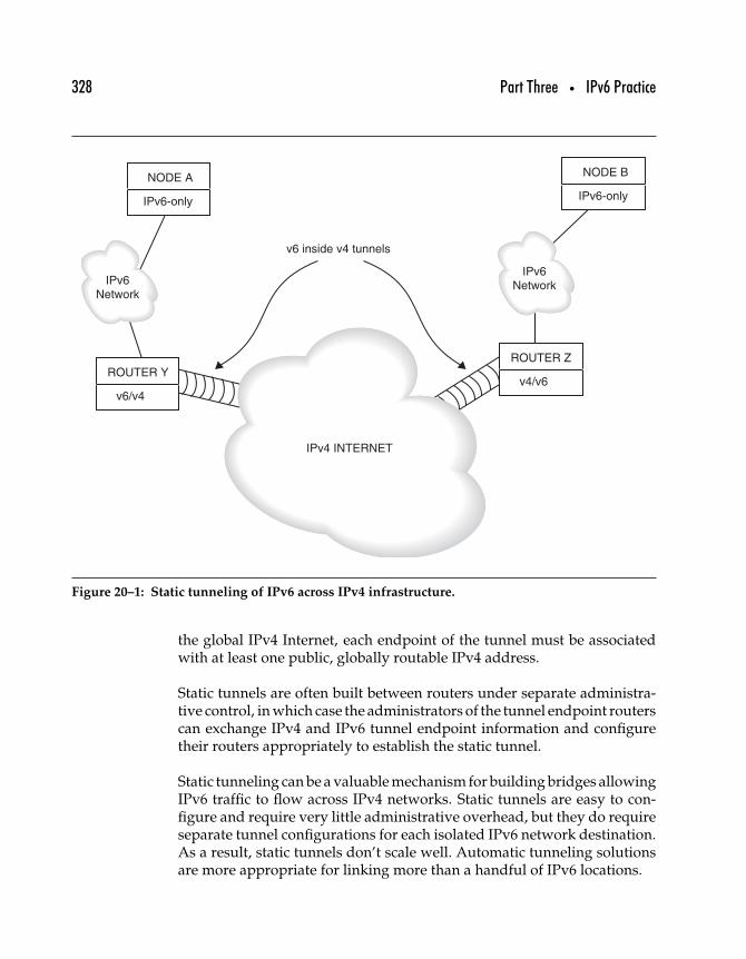
328 Part Three • IPv6 Practice
ROUTER Y
v6 inside v4 tunnels
IPv4 INTERNET
IPv6Network
IPv6Network
v6/v4
ROUTER Z
v4/v6
NODE B
IPv6-only
NODE A
IPv6-only
Figure 20–1: Static tunneling of IPv6 across IPv4 infrastructure.
the global IPv4 Internet, each endpoint of the tunnel must be associatedwith at least one public, globally routable IPv4 address.
Static tunnels are often built between routers under separate administra-tive control, in which case the administrators of the tunnel endpoint routerscan exchange IPv4 and IPv6 tunnel endpoint information and configuretheir routers appropriately to establish the static tunnel.
Static tunneling can be a valuable mechanism for building bridges allowingIPv6 traffic to flow across IPv4 networks. Static tunnels are easy to con-figure and require very little administrative overhead, but they do requireseparate tunnel configurations for each isolated IPv6 network destination.As a result, static tunnels don’t scale well. Automatic tunneling solutionsare more appropriate for linking more than a handful of IPv6 locations.
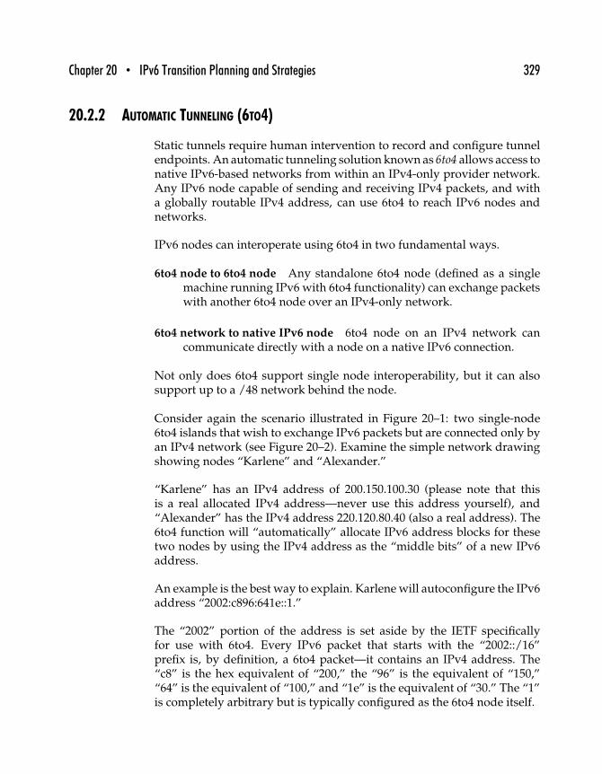
Chapter 20 • IPv6 Transition Planning and Strategies 329
20.2.2 AUTOMATIC TUNNELING (6TO4)
Static tunnels require human intervention to record and configure tunnelendpoints. An automatic tunneling solution known as 6to4 allows access tonative IPv6-based networks from within an IPv4-only provider network.Any IPv6 node capable of sending and receiving IPv4 packets, and witha globally routable IPv4 address, can use 6to4 to reach IPv6 nodes andnetworks.
IPv6 nodes can interoperate using 6to4 in two fundamental ways.
6to4 node to 6to4 node Any standalone 6to4 node (defined as a singlemachine running IPv6 with 6to4 functionality) can exchange packetswith another 6to4 node over an IPv4-only network.
6to4 network to native IPv6 node 6to4 node on an IPv4 network cancommunicate directly with a node on a native IPv6 connection.
Not only does 6to4 support single node interoperability, but it can alsosupport up to a /48 network behind the node.
Consider again the scenario illustrated in Figure 20–1: two single-node6to4 islands that wish to exchange IPv6 packets but are connected only byan IPv4 network (see Figure 20–2). Examine the simple network drawingshowing nodes “Karlene” and “Alexander.”
“Karlene” has an IPv4 address of 200.150.100.30 (please note that thisis a real allocated IPv4 address—never use this address yourself), and“Alexander” has the IPv4 address 220.120.80.40 (also a real address). The6to4 function will “automatically” allocate IPv6 address blocks for thesetwo nodes by using the IPv4 address as the “middle bits” of a new IPv6address.
An example is the best way to explain. Karlene will autoconfigure the IPv6address “2002:c896:641e::1.”
The “2002” portion of the address is set aside by the IETF specificallyfor use with 6to4. Every IPv6 packet that starts with the “2002::/16”prefix is, by definition, a 6to4 packet—it contains an IPv4 address. The“c8” is the hex equivalent of “200,” the “96” is the equivalent of “150,”“64” is the equivalent of “100,” and “1e” is the equivalent of “30.” The “1”is completely arbitrary but is typically configured as the 6to4 node itself.
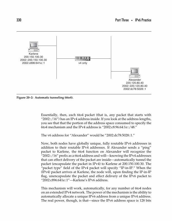
330 Part Three • IPv6 Practice
Karlene200.150.100.30
2002::200.150.100.302002:c896:641e::1
Alexander220.120.80.40
2002::220.120.80.402002:dc78:5028::1
v4 only
Figure 20–2: Automatic tunneling (6to4).
Essentially, then, each 6to4 packet (that is, any packet that starts with“2002::/16”) has an IPv4 address inside. If you look at the address lengths,you see that that the portion of the address space consumed to specify the6to4 mechanism and the IPv4 address is “2002:c8:96:64:1e::/48.”
The v6 address for “Alexander” would be ”2002:dc78:5028::1.”
Now, both nodes have globally unique, fully routable IPv6 addresses inaddition to their routable IPv4 addresses. If Alexander sends a “ping”packet to Karlene, the 6to4 function on Alexander will recognize the“2002::/16” prefix as a 6to4 address and will—knowing the IPv4 addressesthat can effect delivery of the packet are inside—automatically tunnel thepacket (encapsulate the packet in IPv4) to Karlene at 200.150.100.30. The“packet type” field of the IPv4 packet will specify “IP-in-IP.” When the(IPv4) packet arrives at Karlene, the node will, upon finding the IP-in-IPflag, unencapsulate the packet and effect delivery of the IPv6 packet to“2002:c896:641e::1”—Karlene’s IPv6 address.
This mechanism will work, automatically, for any number of 6to4 nodeson an extended IPv4 network. The power of the mechanism is the ability toautomatically allocate a unique IPv6 address from a unique IPv4 address.The real power, though, is that—since the IPv6 address space is 128 bits
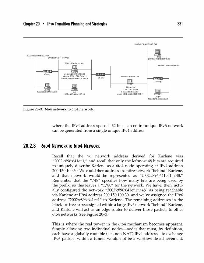
Chapter 20 • IPv6 Transition Planning and Strategies 331
2002:c896:641e:100::/64
2002:c896:641e::/48
Karlenev4-side 200.150.100.30
v4-side 2002:c896:641e::1inside 2002:c896:641e:100::1
Alexandero 220.120.80.40
o 2002:dc78:5028::1inside 2002:dc78:5028:300::1
2002:c896:641e:200::/64
Jackie2002:c896:641e:200::5 Kali
2002:c896:641e:100::10
2002:dc78:5028::/48
2002:dc78:5028:500::/64
Jeffry2002:dc78:5028:500::5
Bob2002:dc78:5028:300::15
2002:dc78:5028:300::/64
v6-only
v6-only
v4-only
Figure 20–3: 6to4 network to 6to4 network.
where the IPv4 address space is 32 bits—an entire unique IPv6 networkcan be generated from a single unique IPv4 address.
20.2.3 6TO4 NETWORK TO 6TO4 NETWORK
Recall that the v6 network address derived for Karlene was“2002:c896:641e::1,” and recall that only the leftmost 48 bits are requiredto uniquely describe Karlene as a 6to4 node operating at IPv4 address200.150.100.30. We could then address an entire network “behind” Karlene,and that network would be represented as “2002:c896:641e::1::/48.”Remember that the “/48” specifies how many bits are being used bythe prefix, so this leaves a “::/80” for the network. We have, then, actu-ally configured the network “2002:c896:641e::1::/48” as being reachablevia Karlene at IPv4 address 200.150.100.30, and we’ve assigned the IPv6address “2002:c896:641e::1” to Karlene. The remaining addresses in theblock are free to be assigned within a large IPv6 network “behind” Karlene,and Karlene will act as an edge-router to deliver those packets to other6to4 networks (see Figure 20–3).
This is where the real power in the 6to4 mechanism becomes apparent.Simply allowing two individual nodes—nodes that must, by definition,each have a globally routable (i.e., non-NAT) IPv4 address—to exchangeIPv6 packets within a tunnel would not be a worthwhile achievement.
332 Part Three • IPv6 Practice
But allowing two “::/48” IPv6 networks to be able to exchange packetsvia two IPv4 nodes is a powerful transition mechanism. Recall that a“::/80” network implies that each network can be made up of 216 individualnetworks, where each network can support 264
− 2 devices.
That’s a big network! At the time of this writing, the IETF IPv6 addressallocation plan is to allocate a “::/48”-size block to enterprises as a standardallocation. So an enterprise with a single routable IPv4 address can “self-allocate” the same size block for transition as they are likely to hold whenthey have moved to native v6 addresses.
20.2.4 6TO4 NODE TO NATIVE-IPV6
What about 6to4 nodes or 6to4 networks exchanging packets with nativeIPv6 nodes? Since native IPv6 nodes do not reside “behind” an IPv4-address and don’t use the 6to4-reserved address prefix “2002::/16,” howare packets delivered to those nodes? The IETF has designed that capa-bility in the 6to4 mechanism—native IPv6 packet delivery is provided bydevices called “6to4 relays” (6to4 relay).
A 6to4 relay is typically a dedicated machine with multiple networkinterfaces—one on the IPv4 network (where 6to4 nodes and networkswould be deployed) and one on the native IPv6 network. The 6to4 relaymust implement the 6to4 relay function. Here’s how it works.
6to4 relays are located at a well-known IPv4 address—“192.88.99.1” (pro-posed RFC—3068). We’ll see in a moment how this works, but there willbe many 6to4 relays operating during the transition. When the IPv6 stackon a 6to4 node (or network—our example uses the simple case) attemptsto send a packet to an address beginning with 2002::/16, the previouscase is used—the 6to4 function delivers the packet to the IPv4 addressencoded in the IPv6 destination address field. If the destination IPv6address is not in the 2002::/16 network—say the destination address is“2001:2d0:80:ee::6”—the 6to4 node’s 6to4 function will recognize that theaddress is not a 6to4 address, and assume that the address is reachable viaa 6to4 relay, and will deliver the packet—encapsulated in IPv4—to the 6to4relay at 192.88.99.1. The 6to4 relay unencapsulates the packet and sendsthe v6 packet to the native v6 host.
6to4 relays also provide packet transit from the v6 network to 6to4 nodesand networks located on the v4 network. A native v6 node will send all
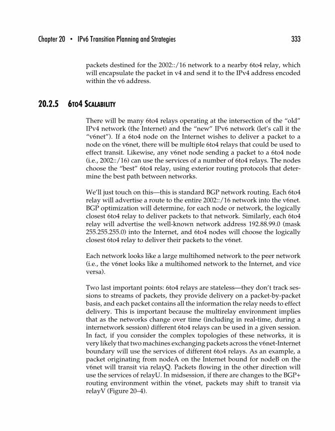
Chapter 20 • IPv6 Transition Planning and Strategies 333
packets destined for the 2002::/16 network to a nearby 6to4 relay, whichwill encapsulate the packet in v4 and send it to the IPv4 address encodedwithin the v6 address.
20.2.5 6TO4 SCALABILITY
There will be many 6to4 relays operating at the intersection of the “old”IPv4 network (the Internet) and the “new” IPv6 network (let’s call it the“v6net”). If a 6to4 node on the Internet wishes to deliver a packet to anode on the v6net, there will be multiple 6to4 relays that could be used toeffect transit. Likewise, any v6net node sending a packet to a 6to4 node(i.e., 2002::/16) can use the services of a number of 6to4 relays. The nodeschoose the “best” 6to4 relay, using exterior routing protocols that deter-mine the best path between networks.
We’ll just touch on this—this is standard BGP network routing. Each 6to4relay will advertise a route to the entire 2002::/16 network into the v6net.BGP optimization will determine, for each node or network, the logicallyclosest 6to4 relay to deliver packets to that network. Similarly, each 6to4relay will advertise the well-known network address 192.88.99.0 (mask255.255.255.0) into the Internet, and 6to4 nodes will choose the logicallyclosest 6to4 relay to deliver their packets to the v6net.
Each network looks like a large multihomed network to the peer network(i.e., the v6net looks like a multihomed network to the Internet, and viceversa).
Two last important points: 6to4 relays are stateless—they don’t track ses-sions to streams of packets, they provide delivery on a packet-by-packetbasis, and each packet contains all the information the relay needs to effectdelivery. This is important because the multirelay environment impliesthat as the networks change over time (including in real-time, during ainternetwork session) different 6to4 relays can be used in a given session.In fact, if you consider the complex topologies of these networks, it isvery likely that two machines exchanging packets across the v6net-Internetboundary will use the services of different 6to4 relays. As an example, apacket originating from nodeA on the Internet bound for nodeB on thev6net will transit via relayQ. Packets flowing in the other direction willuse the services of relayU. In midsession, if there are changes to the BGP+routing environment within the v6net, packets may shift to transit viarelayV (Figure 20–4).
BGP 192.88.99.0
BGP�2002::/16
BGP�2002::/16
BGP�2002::/16
relay U
BGP192.88.99.0
v6 network (6bone)
Node B2000:e892:247b:2ac::d
Node A200.150.100.30
6to4 2002:c896:641e:200::1
BGP 192.88.99.0
relay V
relay Q
v4 Internet
Figure 20–4: 6to4 coping with changing topologies.
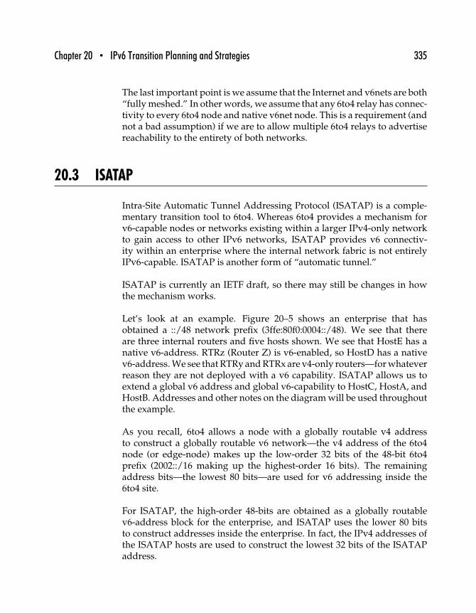
Chapter 20 • IPv6 Transition Planning and Strategies 335
The last important point is we assume that the Internet and v6nets are both“fully meshed.” In other words, we assume that any 6to4 relay has connec-tivity to every 6to4 node and native v6net node. This is a requirement (andnot a bad assumption) if we are to allow multiple 6to4 relays to advertisereachability to the entirety of both networks.
20.3 ISATAP
Intra-Site Automatic Tunnel Addressing Protocol (ISATAP) is a comple-mentary transition tool to 6to4. Whereas 6to4 provides a mechanism forv6-capable nodes or networks existing within a larger IPv4-only networkto gain access to other IPv6 networks, ISATAP provides v6 connectiv-ity within an enterprise where the internal network fabric is not entirelyIPv6-capable. ISATAP is another form of “automatic tunnel.”
ISATAP is currently an IETF draft, so there may still be changes in howthe mechanism works.
Let’s look at an example. Figure 20–5 shows an enterprise that hasobtained a ::/48 network prefix (3ffe:80f0:0004::/48). We see that thereare three internal routers and five hosts shown. We see that HostE has anative v6-address. RTRz (Router Z) is v6-enabled, so HostD has a nativev6-address. We see that RTRy and RTRx are v4-only routers—for whateverreason they are not deployed with a v6 capability. ISATAP allows us toextend a global v6 address and global v6-capability to HostC, HostA, andHostB. Addresses and other notes on the diagram will be used throughoutthe example.
As you recall, 6to4 allows a node with a globally routable v4 addressto construct a globally routable v6 network—the v4 address of the 6to4node (or edge-node) makes up the low-order 32 bits of the 48-bit 6to4prefix (2002::/16 making up the highest-order 16 bits). The remainingaddress bits—the lowest 80 bits—are used for v6 addressing inside the6to4 site.
For ISATAP, the high-order 48-bits are obtained as a globally routablev6-address block for the enterprise, and ISATAP uses the lower 80 bitsto construct addresses inside the enterprise. In fact, the IPv4 addresses ofthe ISATAP hosts are used to construct the lowest 32 bits of the ISATAPaddress.
336 Part Three • IPv6 Practice
RTRz
RTRx
RTRyISATAP Router
HostE172.16.10.10
Native-v6 3ffe:80f0:4::200
HostA172.16.13.5
ISATAP 3ffe:80f0:4:300:0:5efe:172.16.13.5
HostC172.16.12.30
ISATAP
EdgeRouter3ffe:80f0:4::/48
172.16.10.0/24 3ffe:80f0:4::/64
172.16.12.0/24ISATAP 3ffe:80f0:4::300/64
172.16.13.0/24ISATAP 3ffe:80f0:4::300/64
HostD172.16.11.20
Native-v6 3ffe:80f0:4:10::300
172.16.11.0/243ffe:80f0:4:10::/64
HostA
HostB172.16.13.6
ISATAP 3ffe:80f0:4:300:0:5efe:172.16.13.6
Figure 20–5: Deploying ISATAP.
The ISATAP host uses the services of an “ISATAP router”—typically arouter that has a native v6-interface and a v4-only interface designatedas the ISATAP interface. The network administrator assigns an “ISATAPprefix” to the router (in our case 3ffe:80f0:4:300::/64). The IPv4 addressof the router is also added to the enterprise DNS under the well-knownname “ISATAP.” The ISATAP router will then forward v6-packets ontothe native v6 network from ISATAP hosts using the router as its ISATAPtunnel-endpoint.
Here’s how it works. HostA is configured with an IPv4-address (youcan see that does not need to be routable) to run the ISATAP mecha-nism. When HostA enables its network link, seeing that it is an ISATAPhost, it asks the DNS for the address of “ISATAP.” The DNS replieswith the v4-address of RTRy. Next, HostA tunnels a router discoverypacket (IPv6-in-IPv4) to RTRy, and RTRy responds with a router advertise-ment (including the network prefix for HostA to use—3ffe:80f0:4:300::/64).Upon receipt of the prefix, HostA constructs its globally unique IPv6address, 3ffe:80f0:4:300:0:5efe:172.16.13.5 (the “0:5efe” in the address is areserved value that specifies an ISATAP address). At this point, HostAhas obtained full IPv6 capability via the services provided by the ISATAProuter RTRy.
The ISATAP specification makes arrangements for the graceful transitionto native v6 capability. Only ISATAP nodes that do not receive multicast
Chapter 20 • IPv6 Transition Planning and Strategies 337
router advertisements (RA) for IPv6 will configure and use ISATAP inter-faces. When an ISATAP machine receives its first unsolicited native RA, itwill deprecate the ISATAP interface in favor of its newly acquired nativev6 interface. In this fashion, ISATAP traffic will automatically give way tonative v6 traffic as additional enterprise routers are configured with v6.
Our example is for a simple enterprise network where all ISATAP hosts usethe same ISATAP router. In a larger enterprise, multiple ISATAP routerscan be deployed, and some scheme of load-balancing DNS can direct dif-ferent hosts to different ISATAP routers. One possibility would be simpleround-robin DNS processing, where the load would be balanced betweenhowever many ISATAP routers were configured on the network and inthe DNS. More effective techniques to distribute traffic between multipleISATAP routers may be introduced.
20.4 Preparing for Transition
The first steps to a successful transition is to make sure your staff is welltrained and that the enterprise has a place to test out equipment andconcepts. A little training will go a long way for IPv4-savvy engineers.
20.4.1 IPV6 TRAINING
IPv6 and IPv4 are alike in many ways, and learning IPv6 concepts nor-mally comes easily to current network practitioners. Conceptually, packetgeneration and formatting, routing, and packet handling are similar butnot identical.
It is time consuming, however, for network practitioners to make the leapto IPv6 without some formal training. New concepts, like autoconfig-uration, neighbor discovery, address planning and subnetting, and theextensions to the routing protocol are unfamiliar at first but are easily mas-tered when explained by an experienced IPv6 engineer. Reinforcing theseconcepts in a lab setting is critical, and having a “sandbox” environmentto experiment in back at the students home-enterprise is also important.
Training should span a number of different disciplines. Network engineersthat will be designing the IPv6 network need to understand it at all levels.This includes a general overview of the protocol, transition strategies and

338 Part Three • IPv6 Practice
methods, and any areas of specialty instruction appropriate for that engi-neer (i.e., routing protocols, DNS, address architecture). Like the networkengineer, network administrators will need general knowledge of IPv6mbut also hands-on experience with network devices’ (routers, switches,firewalls, servers, etc.) configuration and support procedures.
So whereas it is important that your network staff receive structured IPv6training, it is important not to overlook the large base of common groundupon which your existing engineers can build. They will quickly masterthe new protocol with some training and time to experiment.
20.4.2 THE LEARNING LAB
There are a number of things to consider when designing your IPv6Learning Lab. First and foremost is the requirement of knowing yourown business and building the lab to help your people understand thecomponents and architectures you’ll be dealing with most often. If yourorganization will be buying IPv6 technology and deploying it internally,your lab should reflect the products and services you will be purchasingas well as the internal network environment; if your organization will bereselling IPv6 technologies, your lab should incorporate the products andservices you intend to sell as well as the environments into which you willbe selling.
Here are some other suggestions for designing and building a learning lab.
Flexibility Build independent areas in the lab so different types of testing,on different components or software versions, can take place at thesame time. Some projects will be long lived, so make sure you don’thave to disrupt tests-in-progress for “right now” exercises.
Isolation The lab should always be separate from any production envi-ronment. Your lab is an environment for learning, and that meansbeing able to change configurations and try things that might notwork. Isolating the lab environment ensures that experiments willnot produce any problems on your organization’s productionnetwork, and vice versa.
Partnerships You can leverage your lab investment by offering to dotesting for companies with whom you have relationships, whetherthey be customers or suppliers. This is a great way to build a win-win
Chapter 20 • IPv6 Transition Planning and Strategies 339
relationship with a key provider and gives you the benefit of earlyinsight into their products and experience for your staff while givingthem early feedback on their products.
Interoperability IPv6 is a feature-rich protocol, and you’ll want to ensurethat all the components, particularly components from different ven-dors, all work smoothly together. Vendors tend to concentrate oninteroperability within their own product lines, so it is important tostock the same components that your organizational network uses soyou can test in your own lab.
The learning lab should incorporate testing facilities for three major areas.
Network Infrastructure The lab should, at a minimum, include core andedge routers, switches, firewalls, and other relevant devices. At thevery least, you should have one core router, one edge router, two orthree multilayer switches, and one v6-capable firewall.
Network Operating Systems In addition to the operating systemsalready in use in your network environment, you may want to con-sider adding other OSes to test for interoperability. A great deal ofexperimentation with IPv6 has been done with various flavors ofBSD and Linux; Microsoft’s IPv6 support under the latest versionsof Windows will undoubtedly be superior to that of earlier versions.
Network Services In addition to any network services DNS (Static andDynamic), DHCPv6 (HP-UX11i, W2K2), HTTP (Apache), Security(IPF, Checkpoint, Router ACL), Printing, Network Management(HPOV), and so on.
The key thing is to build a learning lab that fits your business needs.
20.5 Planning
Planning is critical for a trouble-free transition. There are many variables,but two are particularly important. One is planning for long-lived phys-ical and software assets that will affect the pace of transition, and theother is an architectural decision about traffic flows in your transitioningnetwork.
340 Part Three • IPv6 Practice
20.5.1 PLAN CAPITAL PURCHASES
Many network component providers are planning their IPv6 product line,and some are deploying products today that support IPv6—either betaor true production-ready versions. Several of these vendors (Cisco, forexample) have published “product roadmaps” that lay out their plans forIPv6 support. Some products will be “dead-ended” before v6 support isadded.
So an enterprise needs to carefully plan its network and system capitalpurchases to avoid a situation where a new component has been purchased(i.e., a core router) that has significant depreciable life left but does notsupport IPv6 when the enterprise is ready to transition.
These types of costly mistakes are easily avoided. Talk to your networkvendors, and ask to see their roadmaps, or be briefed by their productdevelopment people on their plans. Get firm commitments for productplans and milestone dates. The transition to IPv6 provides an excellentopportunity to review your network plans—and change strategies or yourfavored vendor providers—if that works to your advantage.
20.5.2 TRANSLATION
Whether or not an enterprise plans to use packet translation during thetransition has a major impact on how the new network is deployed.
A firm can choose to not use translation—you simply lose the ability forv4-only and v6-only nodes to talk to each other. If the network fabric isv6/v4 enabled, and the network servers (i.e., any machine that multipleclients exchange packets with) are v4/v6 enabled (i.e., running “dualstack”), then new computer clients can be deployed with only v6 con-nectivity, while “old” systems can continue to run IPv4. In this manner, noprotocol translation is needed—systems exchange packets via the “highestcommon denominator” protocol, choosing v6 if they both support it, andv4 if one endpoint is not v6-ready.
Alternatively, all new client systems can be deployed dual-stack. This givescomplete backward-compatibility with deployed systems that can onlysupport v4, and yet new applications that can take advantage of v6 canuse v6 when communicating with newly deployed systems. Typically, in
Chapter 20 • IPv6 Transition Planning and Strategies 341
environments where clients greatly outnumber servers, deploying bothprotocols on clients is not the best strategy.
The enterprise can also install a translator. Translators provide the mostcomplete interoperability for the network. Any machine can talk to anyother, and as more and more network nodes become v6-enabled, trafficmigrates to an all-v6 base. This is a good implementation choice for envi-ronments that are more peer-to-peer oriented than client-server oriented.The problem with translation is that it is slow (translation—especially soft-ware translation takes time) and can create a bottleneck in the network fortranslation traffic. Yet, the delay caused by translation may be offset by theability to access content or services that exist only in the v4 world.
Translation devices are not yet widely available, so it is hard to quantify thenetwork efficiency affects of translation on a network. Nonetheless, it is animportant consideration you will need to evaluate when your enterprisemakes the migration to v6.
20.5.3 APPLICATIONS
Applications must be v6-capable to support the enterprise transition.Although most v6 changes are isolated at the network layer, many appli-cations that use network services do validation checking on inputs (i.e.,when a node rejects an IPv6 address because the node has been configuredto allow only valid IPv4 addresses) or results from DNS.
At the least, any network application will need to be recompiled usingthe v6-capable link libraries. For purchased applications, make sure thevendor verifies v6-support before you buy.
20.5.4 PUBLIC INTERNET SITES WILL LAG
Commerce and nontechnology sites on the Internet will likely be midphaseadopters of IPv6. Much in the way that Web site builders optimize theirdesigns for the “middle” of the market in terms of browser compatibilityand bandwidth requirements, Internet sites that have a mass market appealwill not support IPv6 until there is a critical mass in the user community—especially if translation becomes a commonly deployed transition tool.Once critical mass is achieved, or as the volume of IPv4 packets diminish
342 Part Three • IPv6 Practice
in favor of an accelerating IPv6 packet count, network service providerswill move into the v6 environment in an effort to “chase the money.”
For these reasons, an enterprise may choose to deploy translation—notinside the network (which we described before as an option) but at thenetwork edge—to provide v4-capability for workstations to communicatewith lagging Internet-based systems. Proxy services, where your internalclients talk to the proxy via v6, but the proxy talks to the Internet site viav4, may also become available.
20.5.5 IPV6 ROUTING
While IPv6 has been under development for many years, it is only inthe recent few that support for v6 has been incorporated into the equip-ment that comprises the Internet’s infrastructure. Currently, IPv6 packetforwarding (routing) is being handled in two ways. The first, and mostcommon, is via “software-based forwarding.” In a software-based system,the network engineer or administrator downloads and installs a new image(operating system) onto the existing router (IPv4-only) that identifies howto handle IPv6 packets. When packets (IPv6) come through the router thatcannot be handled by the hardware, they are passed along to the operatingsystem and processed.
The second method is by hardware-based forwarding. Unlike software-based forwarding, the instructions for handling IPv6 packets are “hardcoded” into the chip sets on the routers (much like the CMOS on a PC).Almost all routers today do hardware-based forwarding for IPv4 packets.Hardware-based forwarding is very efficient and generally trouble free.
The significant difference between the two methods is in performance. In asoftware-based implementation, every IPv6 packet must be handled by theoperating system, which requires additional time. While that time maybe relatively small on a per-packet basis, it makes a dramatic differencein a production network. Production network routers may handle bil-lions of packets per day, making software-based forwarding inefficientfor practical purposes. Unfortunately, many of today’s routers cannotbe “upgraded” to handle IPv6 in the hardware and must be replaced tosupport IPv6.
Additionally, there are other factors that will affect the performance andefficiency of IPv6 routing. As previously mentioned, two IPv6-enabled
Chapter 20 • IPv6 Transition Planning and Strategies 343
routers can pass packets through an IPv4 cloud by utilizing tunnels.However, the process of encapsulation and decapsulation increases theamount of time it takes to handle each packet. And by encapsulating thepacket within an IPv4 packet, many of the improvements and benefits ofIPv6 are lost.
The actual protocols utilized to provide IPv6 packet routing are very sim-ilar to those available today for IPv4. Routing protocols, such as RIP andOSPF, are available, and at the time of this writing the following routingprotocols have been enhanced or developed for IPv6: RIPv2 to RIPng,OSPFv2 to OSPFv3, BGP4 to BGP4+, and ISIS. Other protocols, suchEIGRP, may be enhanced to support IPv6 in the future.
Of course, one of the most important aspects of the transition process is thateach piece of equipment handles the IPv6 packet uniformly. The IETF andthe IPv6 working groups have spent a great deal of time and energy stan-dardizing IPv6. However, not all equipment manufacturers will supportevery aspect of IPv6 at the same time. Many of today’s IPv6-enabled routermanufacturers support IPv6 at some level but don’t necessarily support allof the more advanced features or routing protocols. As IPv6 matures thelevel of interoperability between vendors will increase.
20.5.6 OBTAINING AND PLANNING FOR IPV6 ADDRESSES
Planning for IPv6 addressing is largely a matter of allocating addresseswisely throughout your enterprise. v6 addresses are made to summarizewell—that is, to be hierarchical. If your address blocks are well plannedfor summarization, your network will be more efficient, easier to manage,and cheaper to implement.
Plan for the future. Leave plenty of “reserved” space in your address-ing scheme to account for future growth. In this way you avoid havingto add noncontiguous blocks of addresses throughout the network as itgrows.
Use address scoping (link-local, site-local, global) where feasible. Forexample, for a directly connected Ethernet link between two routers, useonly the link-local addresses of the routers. Or for an isolated v6 networkthat does not need to route outside the “site,” utilize site-local addressingonly.
344 Part Three • IPv6 Practice
Most enterprises will obtain v6 allocations from your current v6 ISP(ISP would provide a block from their current v6 allocation). UnlikeIPv4 allocations, where enterprises can “own” their own addresses andmove them from ISP to ISP, v6 addressing—since it is designed to behierarchical—works differently. Large ISPs receive large IPv6 addressblocks and allocate them to smaller ISPs and large enterprises. Your v6addresses will almost always be part of a larger block allocated to your ISP.
You can also get a block for your enterprise from a test allocation. The6Bone (www.6bone.com—addresses in the 3ffe::/16 range) will provideaddresses to most any enterprise wanting to gain early experience withIPv6. This is, however, very much a “do-it-yourself” project, and it is amuch larger project recommended only for companies who want to be abit ahead of the leading edge.
Last, if your enterprise is going to be an ISP, after you’ve managed yourbusiness well with a test allocation from the 6Bone, you can seek a largeblock of production addresses from a public Internet registry like IANA,ARIN, or APNIC for production v6 address blocks.
20.6 Migration
At this point the enterprise is ready to begin the gradual transition to anall-IPv6 network. The goal is to migrate the network to IPv6 with nodisruption to current v4 operations. The following steps form a logicalprocess of enabling the base infrastructure, network fabric, and finally, theserver and client nodes on the network.
20.6.1 UPGRADE YOUR DNS ENVIRONMENT
Two important distinctions on v6 DNS functionality need to be made up-front. Some newer DNS implementations provide support for v6 addressrecords (AAAA and A6 records) but do not answer DNS queries viathe IPv6 protocol. Other implementations provide both—the v6 recordsand the ability to respond to queries via IPv6. We will not discuss DNSconfiguration in detail here.
A properly configured DNS can contain both v4 and v6 records for a givenhostname. For example, the host “bob.pretend.dog” (note that “dog” is
Chapter 20 • IPv6 Transition Planning and Strategies 345
not a real domain) can be resolved by the DNS as either 10.20.30.40 or3ffe:4b0::2. In fact, if both records are available, both are returned to theDNS client. The client then chooses which address to use, based on theprotocols available on the client.
You see that this is an ideal situation for transition. IPv6-capable clients,seeking access to IPv6-capable applications on the network will use the v6address returned by the DNS (we assume that the server in this exampleis dual-stacked). As long as there is also an IPv4 address associated withthe server, IPv4-only clients will access the application via IPv4—using thev4 address returned by the DNS. As the transition progresses and morenetwork services move to dual-stack (and more clients move to dual-stack),traffic will migrate to IPv6. Complete transition will be marked by theremoval of all v4 address records from the DNS.
20.6.2 UPGRADE THE NETWORK FABRIC
At this point, all the components that make up the fabric of your networkmust be upgraded to be IPv6 compatible—as well as IPv4 capable, sincethere will be a transition period during which both protocols will be activeon the network. The upgrade task can be divided into three steps.
1. Determine specifically how each component needs to beupgraded, and outline a detailed transition plan—including arecovery/backout procedure.
2. Obtain the hardware and software components needed, andtest them together in a nonproduction environment.
3. Complete the transition plan.
20.6.3 OUTLINE THE PLAN
Begin by outlining the transition plan. Consider the specific componentsthat will be upgraded, and consult the vendor on the proper procedures.Make sure a backout plan exists for each component in the network andfor the transition plan as a whole.
Consider the following for each component.
• Do the network routers support hardware- or software-basedIPv6 packet handling?
346 Part Three • IPv6 Practice
• If IPv6 is handled in software, what device image is requiredfor IPv6 support?
• Are there additional hardware requirements to support IPv6—or the new software image—like additional memory orstorage?
• If this is a multivendor network, carefully compare the compo-nents for hardware support capabilities (i.e., one vendor maysupport gigabit Ethernet for IPv6, whereas another vendor willnot).
• Verify that the routing scheme used on the network will sup-port IPv6. Verify that the layer 3 switches in the networksupport IPv6.
• Layer 2 switches, since they do not examine or act upon IPheaders, should support IPv6 without any modification.
• Examine the network edge devices like firewalls and intrusiondetection systems to ensure they support IPv6, and plan fortheir upgrade.
20.6.4 OBTAIN UPGRADE COMPONENTS
Once the plan is in place, collect the hardware components and softwareimages needed to begin the transition. In some cases, this will be as simpleas downloading a new device image from your vendor. In other cases, acomplete “forklift upgrade” will be required.
Test everything in a nonproduction environment. The learning labshould easily adapt to this new level of testing. Conduct a system—notcomponent—test before beginning the transition. Be systematic in testing,and remember to test for performance as well as for functionality and inter-operability. Make changes to the network under test as you would in yourproduction environment to ensure that the operational procedures in placeare also sufficient to support the new IPv6-capable network.
20.7 Transition
At this point, the network is ready to transition to dual-protocol capabil-ity. Plan the specific upgrades by scheduling network outages, and leaveyourself plenty of time to handle the unforeseen problems that inevitablyarise. If too many problems arise to complete the transition successfully,use the backout plan.
Chapter 20 • IPv6 Transition Planning and Strategies 347
20.7.1 DUAL-STACK THE SERVERS
Once you have completed these steps, you are ready to enable serverplatforms with IPv6 in addition to IPv4. The applications available at theserver must also be IPv6 compatible and configured properly.
In a typical enterprise, servers should be given assigned IPv6 addresses.Clients should autoconfigure—that feature is one of the great strengthsof IPv6. When the addressing scheme is developed, provisions should bemade to reserve consistent blocks for servers (i.e., in each ::/64 networkuse the addresses 200 to 2000 for servers).
The process, then, is simple. Configure IPv6 on each server, using a staticaddress from the block set aside for that purpose, and add that v6 addressto the DNS—in addition to the IPv4 address already associated with theserver name.
20.7.2 DEPLOY IPV6-CAPABLE CLIENTS
At this point, new client workstations can be deployed with v6-supportonly. v6-capable workstations will self-select v6 connectivity to v6-capablehosts in your network by choosing the v6-address returned by the DNS,while older v4-only workstations will continue to use IPv4 (assuming thatthe specific host has both IPv4 and IPv6 entries in the DNS).
20.7.3 PHASE OUT IPV4
Over time, as older workstations are retired, the enterprise will complete itstransition to IPv6. Network engineers monitoring the network will detectwhen IPv4 traffic is gone. At that time, new servers can be deployed asv6-only systems. Eventually, v4 support can be dropped at every point inthe network—servers, network devices, ISP upstream—everywhere.
20.8 Summary
The keys to a successful migration are preparing your staff, planningahead, starting early, and being patient. The transition for large enter-prises will take years, since new capital equipment purchases supplant

348 Part Three • IPv6 Practice
older systems, new application development and deployment takes place,and critical-but-not-upgradeable applications and systems are replaced.
IPv6 transition will follow the adoption path of network-effect systems. Itwill be slow at first, since there are few IPv6-enabled peer machines to talkto, but then, as the number of v6-capable machines increases, deploymentplans will “turn the corner” and proceed rapidly toward an all-IPv6 system.You don’t want your enterprise to be caught off guard.
2121
Configuring IPv6 on ServerOperating Systems
This chapter includes step-by-step instructions for configuring IPv6 on theWindows NT, FreeBSD, and Solaris operating systems.
21.1 Configuring IPv6 on Windows NT∗
This section provides step-by-step instructions for configuring IPv6 onWindows NT (versions 4.0, 5.0/2000, and 5.1/XP).
21.1.1 MICROSOFT SUPPORT
Microsoft first publicly released a technical preview IPv6 stack for devel-opment purposes in March 2000 to work with Windows NT 4.0 and
∗This section is adapted from a document written by Jim Van Gemert, © Zama Networks.
349
350 Part Three • IPv6 Practice
Windows 2000. Microsoft did not publish Windows 9x support and lateracknowledged it will only develop and support IPv6 for Windows NTreleases.
Microsoft has released three versions of IPv6 for Windows NT includ-ing “Research IPv6 Protocol,” “IPv6 Technology Preview,” and “IPv6Developer Edition.” Research IPv6 Protocol installs and works onWindows NT 4.0 and 5.0. IPv6 Technology Preview installs and worksonly on Windows NT 5.0 (2000). IPv6 Developer Edition is integrated withWindows NT 5.1 (XP) but not activated by default after install.
Microsoft has published a number of documents introducing IPv6 toWindows developers and early adopters, available at their IPv6 Websites.
21.1.2 MICROSOFT IPV6 TECHNOLOGY PREVIEW
Microsoft’s IPv6 Technology Preview1 can be obtained from msdn.microsoft.com/downloads/sdks/platform/tpipv6/download.asp.
System Requirements
• Windows 2000 SP1• Ethernet network adapter (any Ethernet adapter supported by
Windows 2000 shouldworkwith the IPv6TechnologyPreview)• IPv4 protocol (the Internet Protocol [TCP/IP] supplied with
Windows 2000 must be installed)
Installing the IPv6 Technology Preview for Windows 2000
1. Log on to the Windows 2000 computer with a user account thathas local administrator privileges.
2. Using Windows Explorer, run the Setup.exe program fromthe location where you extracted the IPv6 Technology Previewfiles.
1As of 2003, Microsoft incorporates IPv6 support in its Windows Server 2003 family,Windows XP, and Windows CE.NET version 4.1 operating systems. IPv6 support inWindows XP is a developer release version, whereas a production-quality version isincorporated into Windows XP Service Pack 1 (SP1).
Chapter 21 • Configuring IPv6 on Server Operating Systems 351
3. From the Windows 2000 desktop, click Start, point to Settings,and then click Network and Dial-up Connections. As analternative, you can right-click My Network Places, and thenclick Properties.
4. Right-click the Ethernet-based connection to which you want toadd the IPv6 protocol, and then click Properties. Typically, thisconnection is named Local Area Connection.
5. Click Install.6. In the Select Network Component Type dialog box, click
Protocol, and then click Add.7. In the Select Network Protocol dialog box, click Microsoft IPv6
Protocol, and then click OK.8. Click Close to close the Local Area Connection Properties
dialog box.
The Microsoft IPv6 Protocol is automatically added to all Ethernet inter-faces on your computer.
21.1.3 MICROSOFT WINDOWS INTEGRATED IPV6 RELEASE
Support for IPv6 was first incorporated into a production Microsoft prod-uct in Windows XP. To enable IPv6, the operating system must first beinstalled normally, with IPv6 support; then install the IPv6 DeveloperEdition from the Network Configuration, as follows.
1. Log on to the Windows XP computer with a user account thathas local administrator privileges.
2. From the Windows XP desktop, click Start, point to Settings,and then click Network and Dial-up Connections. As an alter-native, you can right-click My Network Places, and then clickProperties.
3. Right-click the Ethernet-based connection to which you want toadd the IPv6 protocol, and then click Properties. Typically, thisconnection is named Local Area Connection.
4. Click Install.5. In the Select Network Component Type dialog box, click
Protocol, and then click Add.6. In the Select Network Protocol dialog box, click Microsoft IPv6
Developer Edition Protocol, and then click OK.7. Click Close to close the Local Area Connection Properties
dialog box.
352 Part Three • IPv6 Practice
The Microsoft IPv6 Protocol is automatically added to all Ethernet inter-faces on your computer.
21.1.4 INSTALLER COMMENTS
At a command line enter IPv6 if to determine your IPv6 address. Sampleoutput from the IPv6 if command is shown in Table 16–1. Interface #1 isa pseudo-interface used for loopback. Interface #2 is a pseudo-interfaceused for configured tunneling, automatic tunneling, and 6to4 tunneling.Other interfaces are numbered sequentially in the order in which they arecreated. The number on your IPv6 network interface is not static and canbe any number above 2.
A key indicator is the link-level address of your NIC, with a MAC addresslike 00-01-02-e8-ec-31. In Table 21–1, Interface 3 is connected to an IPv6network. It has the preferred address 3ffe:80f0:10:2:201:2ff:fee8:ec31, acombination of site information (3ffe:80f0:10:2) and local information(201:2ff:fee8:ec31). If only one preferred address is supplied, your NIC hasnot received site broadcast information, and the preferred address will bestill set to default (fe80::201:2ff:fee8:ec31).
Internet Protocol (IPv4) is needed for name resolution even if an IPv6 DNSaddress can be supplied. (I have tested Internet Explorer 5.0 with SP1,5.5, and 6.0 Beta release on Windows 2000. I have also tested IE 5.6 onWindows XP Beta 1.) If Internet Explorer is updated, the Microsoft stackmust be reinstalled to access IPv6 sites.
21.2 Configuring IPv6 on FreeBSD∗∗
This section provides step-by-step instructions for configuring IPv6 on theFreeBSD operating system. Here’s a brief list of what you’ll need for thisproject.
• An Intel-based machine with network connectivity. My recom-mendation on bare minimum requirements would be a Pen-tium machine with 1GHz hard drive space and 64MB of RAM.
∗∗This section is adapted from a document written by Gerald R. Crow IV, © ZamaNetworks.
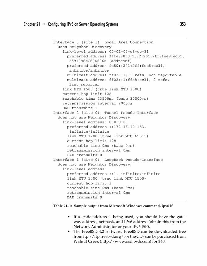
Chapter 21 • Configuring IPv6 on Server Operating Systems 353
Interface 3 (site 1): Local Area Connectionuses Neighbor Discovery
link-level address: 00-01-02-e8-ec-31preferred address 3ffe:80f0:10:2:201:2ff:fee8:ec31,2591896s/604696s (addrconf)preferred address fe80::201:2ff:fee8:ec31,infinite/infinitemulticast address ff02::1, 1 refs, not reportablemulticast address ff02::1:ffe8:ec31, 2 refs,last reporter
link MTU 1500 (true link MTU 1500)current hop limit 128reachable time 23500ms (base 30000ms)retransmission interval 2000msDAD transmits 1
Interface 2 (site 0): Tunnel Pseudo-Interfacedoes not use Neighbor Discovery
link-level address: 0.0.0.0preferred address ::172.16.12.183,infinite/infinitelink MTU 1280 (true link MTU 65515)current hop limit 128reachable time 0ms (base 0ms)retransmission interval 0msDAD transmits 0
Interface 1 (site 0): Loopback Pseudo-Interfacedoes not use Neighbor Discovery
link-level address:preferred address ::1, infinite/infinitelink MTU 1500 (true link MTU 1500)current hop limit 1reachable time 0ms (base 0ms)retransmission interval 0msDAD transmits 0
Table 21–1: Sample output from Microsoft Windows command, ipv6 if.
• If a static address is being used, you should have the gate-way address, netmask, and IPv6 address (obtain this from theNetwork Administrator or your IPv6 ISP).
• The FreeBSD 4.2 software. FreeBSD can be downloaded freefrom ftp://ftp.freebsd.org/, or the CDs can be purchased fromWalnut Creek (http://www.osd.bsdi.com) for $40.
354 Part Three • IPv6 Practice
21.2.1 KERNEL CONFIGURATION
Thanks to the KAME Project (http://www.kame.net), FreeBSD’s defaultinstallation comes with IPv6 support built into the kernel. If someone haschanged the kernel on your machine or you would like to enable moreoptions, here is a list of IPv6-related kernel entries (all kernel options canbe found in /sys/i386/conf/LINT).
. . .
options INET6 # IPv6 communications protocols
. . .
pseudo-device gif 4 # IPv6 and IPv4 tunneling
pseudo-device faith 1 # IPv6-to-IPv4 relaying (translation0
pseudo-device stf 1 # 6to4 IPV6 over IPv4 encapsulation
. . .
The default kernel configuration file is /sys/i386/conf/GENERIC andby default is configured with all the preceding options except 6to4encapsulation. For documentation on building a FreeBSD kernel, go tohttp://www.freebsd.org/handbook.
The first thing you need to decide is how to assign the IPv6 IP address. Staticrequires a little more configuration but will ensure our address informationnever changes. The automatic configuration is quite painless but shouldonly be done on a host machine where a change of IP address will not becatastrophic.
21.2.2 AUTO-CONFIGURATION
To obtain the IPv6 IP address through Auto-Configuration, merely followthis simple three-step procedure.
The first step will be to put an entry into the /etc/rc.conf file so FreeBSDknows at boot time to be on an IPv6 network. Make the following entrywith your favorite text editor into the /etc/rc.conf file.
ipv6_enable=“YES”
Step number 2 will be to insert any outside (if not using DNS) and localhost information. The /etc/hosts file is still being used for both IPv4/IPv6
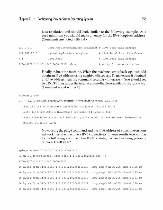
Chapter 21 • Configuring IPv6 on Server Operating Systems 355
host resolution and should look similar to the following example. At abare minimum you should make an entry for the IPv6 loopback address.(Comments are noted with a #.)
127.0.0.1 localhost.mydomain.com localhost # IPv4 loop back address
192.168.25.5 myhost.mydomain.com myhost # IPv4 local host IP address
::1 localhost # IPv6 loop back address
3ffe:80f0:1:1:201:2ff:fe00:2112 ahost # entry for an outside host
Finally, reboot the machine. When the machine comes back up, it shouldobtain an IPv6 address using neighbor discovery. To make sure it obtainedan IPv6 address, run the command ifconfig < interface >. You should seetwo INET6 lines under the interface name that look similar to the following.(Comment noted with a #.)
>ifconfig xl0
xl0: flags=8843<UP,BROADCAST,RUNNING,SIMPLEX,MULTICAST> mtu 1500
inet 192.168.25.5 netmask 0xffffffe0 broadcast 192.168.25.31
inet6 fe80::201:2ff:fe3b:a30%xl0 prefixlen 64 scopeid 0x2
inet6 3ffe:80f0:1:1:201:2ff:fe3b:a30 prefixlen 64 # IPv6 Network information
ether00:01:02:3b:0a:30
Now, using the ping6 command and the IPv6 address of a machine on yournetwork, test the machine’s IPv6 connectivity. If your results look similarto the following example, then IPv6 is configured and working properlyon your FreeBSD 4.2.
>ping6 3ffe:80f0:1:1:201:2ff:fe00:2112
PING6(56=40+8+8 bytes) 3ffe:80f0:1:1:201:2ff:fe3b:a30 -->
3ffe:80f0:1:1:201:2ff:fe00:2112
16 bytes from 3ffe:80f0:1:1:201:2ff:fe00:2112, icmp_seq=0 hlim=255 time=0.495 ms
16 bytes from 3ffe:80f0:1:1:201:2ff:fe00:2112, icmp_seq=1 hlim=255 time=0.335 ms
16 bytes from 3ffe:80f0:1:1:201:2ff:fe00:2112, icmp_seq=2 hlim=255 time=0.321 ms
16 bytes from 3ffe:80f0:1:1:201:2ff:fe00:2112, icmp_seq=3 hlim=255 time=0.338 ms
16 bytes from 3ffe:80f0:1:1:201:2ff:fe00:2112, icmp_seq=4 hlim=255 time=0.303 ms
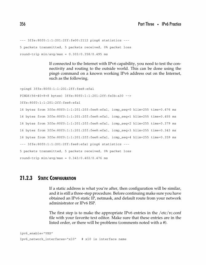
356 Part Three • IPv6 Practice
--- 3ffe:80f0:1:1:201:2ff:fe00:2112 ping6 statistics ---
5 packets transmitted, 5 packets received, 0% packet loss
round-trip min/avg/max = 0.303/0.358/0.495 ms
If connected to the Internet with IPv6 capability, you need to test the con-nectivity and routing to the outside world. This can be done using theping6 command on a known working IPv6 address out on the Internet,such as the following.
>ping6 3ffe:80f0:1:1:201:2ff:fee8:efa1
PING6(56=40+8+8 bytes) 3ffe:80f0:1:1:201:2ff:fe3b:a30 -->
3ffe:80f0:1:1:201:2ff:fee8:efa1
16 bytes from 3ffe:80f0:1:1:201:2ff:fee8:efa1, icmp_seq=0 hlim=255 time=0.476 ms
16 bytes from 3ffe:80f0:1:1:201:2ff:fee8:efa1, icmp_seq=1 hlim=255 time=0.455 ms
16 bytes from 3ffe:80f0:1:1:201:2ff:fee8:efa1, icmp_seq=2 hlim=255 time=0.379 ms
16 bytes from 3ffe:80f0:1:1:201:2ff:fee8:efa1, icmp_seq=3 hlim=255 time=0.343 ms
16 bytes from 3ffe:80f0:1:1:201:2ff:fee8:efa1, icmp_seq=4 hlim=255 time=0.359 ms
--- 3ffe:80f0:1:1:201:2ff:fee8:efa1 ping6 statistics ---
5 packets transmitted, 5 packets received, 0% packet loss
round-trip min/avg/max = 0.343/0.402/0.476 ms
21.2.3 STATIC CONFIGURATION
If a static address is what you’re after, then configuration will be similar,and it is still a three-step procedure. Before continuing make sure you haveobtained an IPv6 static IP, netmask, and default route from your networkadministrator or IPv6 ISP.
The first step is to make the appropriate IPv6 entries in the /etc/rc.conffile with your favorite text editor. Make sure that these entries are in thelisted order, or there will be problems (comments noted with a #).
ipv6_enable=“YES”
Ipv6_network_interfaces=“xl0” # xl0 is interface name
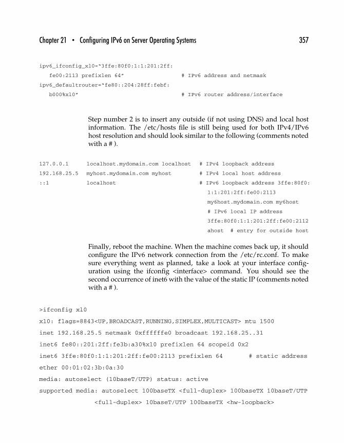
Chapter 21 • Configuring IPv6 on Server Operating Systems 357
ipv6_ifconfig_xl0=“3ffe:80f0:1:1:201:2ff:
fe00:2113 prefixlen 64” # IPv6 address and netmask
ipv6_defaultrouter=“fe80::204:28ff:febf:
b000%xl0” # IPv6 router address/interface
Step number 2 is to insert any outside (if not using DNS) and local hostinformation. The /etc/hosts file is still being used for both IPv4/IPv6host resolution and should look similar to the following (comments notedwith a # ).
127.0.0.1 localhost.mydomain.com localhost # IPv4 loopback address
192.168.25.5 myhost.mydomain.com myhost # IPv4 local host address
::1 localhost # IPv6 loopback address 3ffe:80f0:
1:1:201:2ff:fe00:2113
my6host.mydomain.com my6host
# IPv6 local IP address
3ffe:80f0:1:1:201:2ff:fe00:2112
ahost # entry for outside host
Finally, reboot the machine. When the machine comes back up, it shouldconfigure the IPv6 network connection from the /etc/rc.conf. To makesure everything went as planned, take a look at your interface config-uration using the ifconfig <interface> command. You should see thesecond occurrence of inet6 with the value of the static IP (comments notedwith a # ).
>ifconfig xl0
xl0: flags=8843<UP,BROADCAST,RUNNING,SIMPLEX,MULTICAST> mtu 1500
inet 192.168.25.5 netmask 0xffffffe0 broadcast 192.168.25..31
inet6 fe80::201:2ff:fe3b:a30%xl0 prefixlen 64 scopeid 0x2
inet6 3ffe:80f0:1:1:201:2ff:fe00:2113 prefixlen 64 # static address
ether 00:01:02:3b:0a:30
media: autoselect (10baseT/UTP) status: active
supported media: autoselect 100baseTX <full-duplex> 100baseTX 10baseT/UTP
<full-duplex> 10baseT/UTP 100baseTX <hw-loopback>

358 Part Three • IPv6 Practice
Next, make sure that the default route was configured correctly using thenetstat rn command. There will be much more information, but the IPv6default setting is all you should be concerned with.
>netstat -rn
Internet6:
Destination Gateway Flags Netif
default fe80::204:28ff:febf:b000%xl0 UGSc xl0
As a final test ping a remote machine that you know to be up and runningwith the ping6 command. If the output from the command looks similarto the following, IPv6 is configured and working properly.
>ping6 3ffe:80f0:1:1:201:2ff:fe00:2112
PING6(56=40+8+8 bytes) 3ffe:80f0:1:1:201:2ff:fe00:2113 -->
3ffe:80f0:1:1:201:2ff:fe00:2112
16 bytes from 3ffe:80f0:1:1:201:2ff:fe00:2112, icmp_seq=0 hlim=255 time=0.461 ms
16 bytes from 3ffe:80f0:1:1:201:2ff:fe00:2112, icmp_seq=1 hlim=255 time=0.357 ms
16 bytes from 3ffe:80f0:1:1:201:2ff:fe00:2112, icmp_seq=2 hlim=255 time=0.319 ms
16 bytes from 3ffe:80f0:1:1:201:2ff:fe00:2112, icmp_seq=3 hlim=255 time=0.478 ms
16 bytes from 3ffe:80f0:1:1:201:2ff:fe00:2112, icmp_seq=4 hlim=255 time=0.368 ms
--- 3ffe:80f0:1:1:201:2ff:fe00:2112 ping6 statistics ---
5 packets transmitted, 5 packets received, 0% packet loss round-trip
min/avg/max = 0.319/0.396/0.478 ms
If connected to the Internet with IPv6 capability, you need to test the con-nectivity and routing to the outside world. This can be done using theping6 command on a known working IPv6 address out on the internet,such as the following.
>ping6 3ffe:80f0:1:1:201:2ff:fee8:efa1
PING6(56=40+8+8 bytes) 3ffe:80f0:1:1:201:2ff:fe00:2113 -->
3ffe:80f0:1:1:201:2ff:fee8:efa1
16 bytes from 3ffe:80f0:1:1:201:2ff:fee8:efa1, icmp_seq=0 hlim=255 time=0.483 ms
16 bytes from 3ffe:80f0:1:1:201:2ff:fee8:efa1, icmp_seq=1 hlim=255 time=0.356 ms
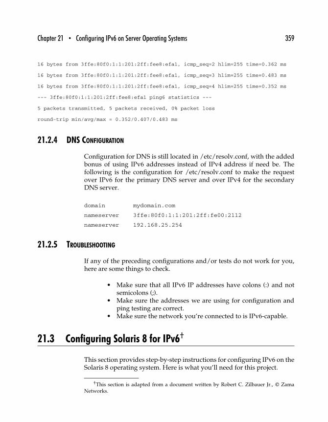
Chapter 21 • Configuring IPv6 on Server Operating Systems 359
16 bytes from 3ffe:80f0:1:1:201:2ff:fee8:efa1, icmp_seq=2 hlim=255 time=0.362 ms
16 bytes from 3ffe:80f0:1:1:201:2ff:fee8:efa1, icmp_seq=3 hlim=255 time=0.483 ms
16 bytes from 3ffe:80f0:1:1:201:2ff:fee8:efa1, icmp_seq=4 hlim=255 time=0.352 ms
--- 3ffe:80f0:1:1:201:2ff:fee8:efa1 ping6 statistics ---
5 packets transmitted, 5 packets received, 0% packet loss
round-trip min/avg/max = 0.352/0.407/0.483 ms
21.2.4 DNS CONFIGURATION
Configuration for DNS is still located in /etc/resolv.conf, with the addedbonus of using IPv6 addresses instead of IPv4 address if need be. Thefollowing is the configuration for /etc/resolv.conf to make the requestover IPv6 for the primary DNS server and over IPv4 for the secondaryDNS server.
domain mydomain.com
nameserver 3ffe:80f0:1:1:201:2ff:fe00:2112
nameserver 192.168.25.254
21.2.5 TROUBLESHOOTING
If any of the preceding configurations and/or tests do not work for you,here are some things to check.
• Make sure that all IPv6 IP addresses have colons (:) and notsemicolons (;).
• Make sure the addresses we are using for configuration andping testing are correct.
• Make sure the network you’re connected to is IPv6-capable.
21.3 Configuring Solaris 8 for IPv6†
This section provides step-by-step instructions for configuring IPv6 on theSolaris 8 operating system. Here is what you’ll need for this project.
†This section is adapted from a document written by Robert C. Zilbauer Jr., © ZamaNetworks.
360 Part Three • IPv6 Practice
• A platform capable of supporting Solaris 8. A Sun Sparc-basedsystem would work quite well. Also, most modern Intel orIntel-compatible systems will fit the bill. I’d recommend at least1.5GHz of disk space (for a comfortable OS install plus anythird-party niceties you may want) and at least 128MB of RAM.Of course, in the case of disk space and RAM, more is alwaysbetter.
• Network information such as gateway address, netmask, andthe IPv6 address assigned to your new system (if a staticaddress is desired), and so forth.
• Sun Solaris 8, available for download from Sun Microsystemsfor free (http://www.sun.com/software/solaris/binaries/get.html), or can be purchased for a media fee of $75 (as ofthis writing).
• Solaris 8 system correctly configured for use with IPv4.
At this point, we’ll assume you have Solaris 8 installed, you chose toenable the IPv6 stack during the OS installation, and your IPv4 networkconnectivity is configured and working.
The first thing you’ll need to decide is how you want your IPv6 addressdefined. You have two choices: You can either have it automatically con-figured via the Neighbor Discovery protocol or you can define your IPv6address statically. We’ll describe the automatic configuration method first,since that’s the easiest.
21.3.1 AUTOCONFIGURATION
On the Solaris side of things, this is the easiest way to configure yourIPv6 address. Of course, this presupposes that there’s a router on yournetwork running the Neighbor Discovery protocol and advertising thecorrect IPv6 address prefix. Assuming you have such a beast available,automatic configuration of your IP address is as simple as using the touchcommand.
You’ll need to know the name of the interface over which you want touse IPv6. The primary interface on a Sun machine is often hme0. On anIntel-based machine it is often elxl0. However, if you don’t know, you canusually use the ifconfig -a command to check. The output of that commandwill look something like this.
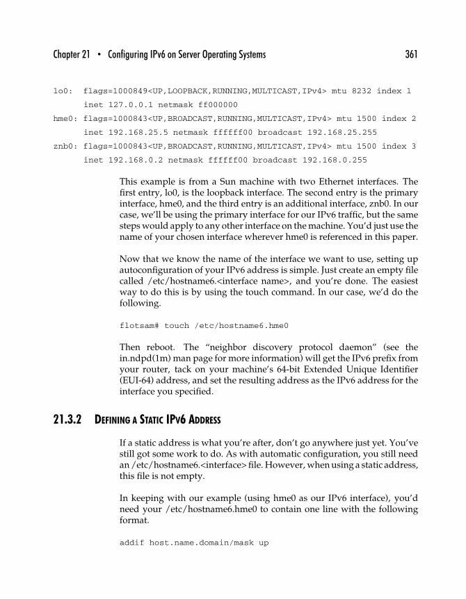
Chapter 21 • Configuring IPv6 on Server Operating Systems 361
lo0: flags=1000849<UP,LOOPBACK,RUNNING,MULTICAST,IPv4> mtu 8232 index 1
inet 127.0.0.1 netmask ff000000
hme0: flags=1000843<UP,BROADCAST,RUNNING,MULTICAST,IPv4> mtu 1500 index 2
inet 192.168.25.5 netmask ffffff00 broadcast 192.168.25.255
znb0: flags=1000843<UP,BROADCAST,RUNNING,MULTICAST,IPv4> mtu 1500 index 3
inet 192.168.0.2 netmask ffffff00 broadcast 192.168.0.255
This example is from a Sun machine with two Ethernet interfaces. Thefirst entry, lo0, is the loopback interface. The second entry is the primaryinterface, hme0, and the third entry is an additional interface, znb0. In ourcase, we’ll be using the primary interface for our IPv6 traffic, but the samesteps would apply to any other interface on the machine. You’d just use thename of your chosen interface wherever hme0 is referenced in this paper.
Now that we know the name of the interface we want to use, setting upautoconfiguration of your IPv6 address is simple. Just create an empty filecalled /etc/hostname6.<interface name>, and you’re done. The easiestway to do this is by using the touch command. In our case, we’d do thefollowing.
flotsam# touch /etc/hostname6.hme0
Then reboot. The “neighbor discovery protocol daemon” (see thein.ndpd(1m) man page for more information) will get the IPv6 prefix fromyour router, tack on your machine’s 64-bit Extended Unique Identifier(EUI-64) address, and set the resulting address as the IPv6 address for theinterface you specified.
21.3.2 DEFINING A STATIC IPV6 ADDRESS
If a static address is what you’re after, don’t go anywhere just yet. You’vestill got some work to do. As with automatic configuration, you still needan /etc/hostname6.<interface> file. However, when using a static address,this file is not empty.
In keeping with our example (using hme0 as our IPv6 interface), you’dneed your /etc/hostname6.hme0 to contain one line with the followingformat.
addif host.name.domain/mask up

362 Part Three • IPv6 Practice
In our case, we want our new machine, flotsam.mydomain.com, to comeup with the IPv6 address 3ffe:80f0:1:3:a00:20ff::5. To do this we would edit/etc/hostname6.hme0 and give it the following contents.
addif flotsam.mydomain.com/64 up
Then, in /etc/inet/ipnodes, we would add an entry for the static IP wewant our machine to be known by.
3ffe:80f0:1:3:a00:20ff::5 flotsam.mydomain.com flotsam
(Note: If you’re familiar with configuring an IPv4 interface, you’ll noticethat the relationship between /etc/hostname6.hme0 and /etc/inet/ipnodes is very similar to their IPv4 counterparts: /etc/hostname.hme0and /etc/hosts.)
Where your IPv6 default route is concerned, you should be fine with theautoconfigured value. Even though you have your IP address defined stat-ically, the Neighbor Discovery process should retrieve a valid IPv6 defaultroute from your properly configured router.
Finally, reboot the machine. When it comes up, you should have both yourIPv4 and your IPv6 interfaces configured. When you take a look at yourinterface configuration using ifconfig -a, you should see somethingsimilar to the following.
lo0: flags=1000849<UP,LOOPBACK,RUNNING,MULTICAST,IPv4> mtu 8232 index 1
inet 127.0.0.1 netmask ff000000
hme0: flags=1000843<UP,BROADCAST,RUNNING,MULTICAST,IPv4> mtu 1500 index 2
inet 192.168.25.5 netmask ffffff00 broadcast 192.168.25.255
ether 0:1:2:c4:d:ee
lo0: flags=2000849<UP,LOOPBACK,RUNNING,MULTICAST,IPv6> mtu 8252 index 1
inet6 ::1/128
hme0: flags=2000841<UP,RUNNING,MULTICAST,IPv6> mtu 1500 index 2
ether 0:1:2:c4:d:ee
inet6 fe80::201:2ff:fec4:dee/10
hme0:1: flags=2000841<UP,RUNNING,MULTICAST,IPv6> mtu 1500 index 2
inet6 3ffe:80f0:1:3:a00:20ff::5/64
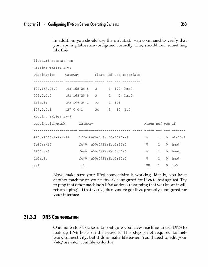
Chapter 21 • Configuring IPv6 on Server Operating Systems 363
In addition, you should use the netstat -rn command to verify thatyour routing tables are configured correctly. They should look somethinglike this.
flotsam# netstat -rn
Routing Table: IPv4
Destination Gateway Flags Ref Use Interface
--------------- -------------- ----- --- --- ---------
192.168.25.0 192.168.25.5 U 1 172 hme0
224.0.0.0 192.168.25.5 U 1 0 hme0
default 192.168.25.1 UG 1 545
127.0.0.1 127.0.0.1 UH 3 12 lo0
Routing Table: IPv6
Destination/Mask Gateway Flags Ref Use If
---------------------- -------------------------- ----- ----- --- --- -------
3ffe:80f0:1:3::/64 3ffe:80f0:1:3:a00:20ff::5 U 1 0 elxl0:1
fe80::/10 fe80::a00:20ff:fec5:6fa0 U 1 0 hme0
ff00::/8 fe80::a00:20ff:fec5:6fa0 U 1 0 hme0
default fe80::a00:20ff:fec5:6fa0 U 1 0 hme0
::1 ::1 UH 1 0 lo0
Now, make sure your IPv6 connectivity is working. Ideally, you haveanother machine on your network configured for IPv6 to test against. Tryto ping that other machine’s IPv6 address (assuming that you know it willreturn a ping). If that works, then you’ve got IPv6 properly configured foryour interface.
21.3.3 DNS CONFIGURATION
One more step to take is to configure your new machine to use DNS tolook up IPv6 hosts on the network. This step is not required for net-work connectivity, but it does make life easier. You’ll need to edit your/etc/nsswitch.conf file to do this.
364 Part Three • IPv6 Practice
Just like with IPv4 and the hosts entry, you should add dns to the ipnodesentry to allow DNS lookups for IPv6 addresses. After making that change,your hosts and ipnodes lines in /etc/nsswitch.conf will look like this.
hosts: files dns
ipnodes: files dns
You’ve just completed the configuration for an IPv6 interface on aSolaris 8 machine.
21.4 Other Resources
Increasingly, commercial operating systems ship with IPv6 support. Usersof Linux can find information about using IPv6 in the IPv6 HOWTO doc-ument at http://www.tldp.org/HOWTO/Linux+IPv6-HOWTO/. TheApple Macintosh OS X 10.2 server OS incorporates the KAME IPv6 stackas well.
21.5 Summary
Configuring an operating system for IPv6 support is just the first step inbuilding an IPv6 network. The next step, described in the next chapter, isto configure IPv6 routers to enable your network to connect to other IPv6networks.
2222
Configuring IPv6 Routers
This chapter includes step-by-step instructions for configuring IPv6 onCisco, Hitachi, and NEC routers.
22.1 Configuring a Cisco 2611 Router for IPv4/v6*
Cisco Systems is shipping IPv6-capable IOS versions, and now is the timeto get yourself an inexpensive Cisco router (such as a 2611) and learn theconfiguration techniques you’ll be using soon on your production routers.
This section describes the beta version of Cisco IPv6 support. Check withCisco for more current releases. You need to be a Cisco customer and haveaccess to “Cisco Connection Online” (CCO) to obtain the IOS images.
∗This section is adapted from a document written by John E. Spence, © Zama Networks.
365
366 Part Three • IPv6 Practice
This section provides instructions to configure a Cisco 2611 router, runningIOS “Version 12.2(0.5)T.” Our topology is fairly simple, but not trivial—about what one would expect for a medium- to large-size enterprise. Weassume that you’ll have an upstream connection from your router to theIPv4/IPv6 world, a small network directly connected to an internal firewalldevice, and a network (this might be a number of networks) that is insideyour firewall device (which is acting as a smart router). We use static routesin this example, and we focus on IPv6-related issues.
22.1.1 GATHERING THE PIECES
To complete this configuration, you’ll need a Cisco 2611 (or similar) routerwith at least two network interfaces, access to Cisco “beta” IOS images, aterminal for configuration, and a network into which to drop your router.One network is your “upstream” connection to an IPv6-capable device.Another network is the connection between your 2611 and your firewall (ifyou want to really emulate an enterprise network, you should implementan IPv6-enabled firewall, discussed in [ZAMAFW]). The last network is a“downstream” network—on the inside of your firewall (and therefore notconnected directly to your 2611) with an IPv6-capable device connected,from which you can test your router configuration.
The early images are pretty big. For the image we’ll use you need 16MB of“flash” memory (static memory that stores the image) and at least 32MB of“main” memory (in which to run the image). Many 2611s come with lessmemory than you’ll need.
You’ll need some specifics about the network topology you are going tobuild, as well as the topology you’ll be meshing with. Here’s what youneed to plan for ahead of time, starting with general network information.
• A physical connection to an upstream IPv6- and IPv4-capabledevice (router or switch) that is routing IPv6 and IPv4 packetsyour way.
• Primary and secondary DNS that serves IPv4 and IPv6 records.Assume we’re getting this service from our provider, andthey’ve specified 192.168.201.4 and 192.168.201.5 as primaryand secondary, respectively. Initially, you’ll want this service,but later you’ll want to experiment with building and runningyour own.
Chapter 22 • Configuring IPv6 Routers 367
• (Optional) primary and secondary NTP servers, also fromyour ISP.
You’ll also need IPv6 network configuration information.
• An IPv6 network to use behind your router. We’ll use3ffe:80f0:10::/48, which was allocated to us by our ISP. Thisis the recommended enterprise allocation, according to ARIN.We’ll subnet this in a moment for use for the connector-networkwith the firewall as well as behind the firewall.
• An IPv6 address to use at the outside interface of the router (theprovider will route all your v6 traffic via this address). Your ISPwill specify this as well; we’ll use 3ffe:80f0:1:2::101/64.
• An IPv6-address that will be your router’s default route, alsofrom your ISP. We’ll use 3ffe:80f0:1:2::1/64.
And you’ll need IPv4 network configuration information.
• Two IPv4 networks—both allocated by your ISP. First, a net-work to use behind your firewall. We’ll use 192.168.200.32/27(that’s mask 255.255.255.224—32 addresses). Let’s also assumewe’ve been given network 192.168.200.252/30 (mask255.255.255.252) to use. You’ll see these again shortly. You’llnotice that your ISP will allocate you quite a large number ofIPv6 addresses but not many IPv4 addresses.
• An IPv4 address to use at your router’s outside interface (aswith IPv6, your provider will send all your v4 traffic via this IPaddress). We’ll use 192.168.200.2/27.
• An IPv4 address that will be your router’s default route. We’lluse 192.168.200.1/27.
22.1.2 PLANNING YOUR NETWORK
Now that you’ve got the information you need from your IPv6-capable ISP,we can plan your network. Here, we’ll plan on having a network segment“downstream” from our router, directly attached, that connects to anotherdevice (this would be, typically, either a “core router” for your enterpriseor an IPv6-capable firewall). So both sides of the Cisco 2611 will be point-to-point networks. Beyond the firewall (I’m going to make that assumption)we’ll have an IPv6 network and an IPv4 network. The topology used forthis example is shown in Figure 22–1.
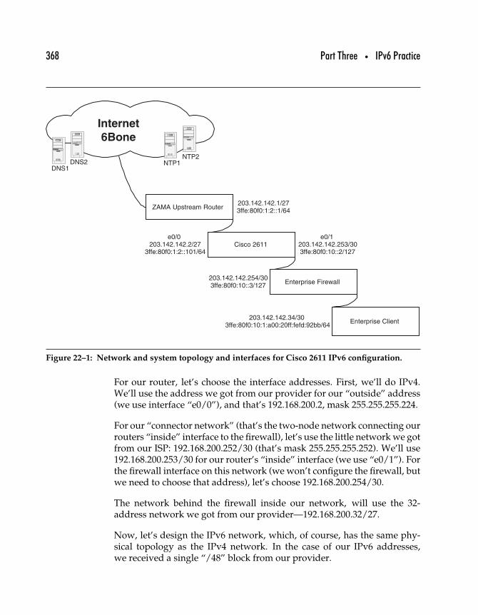
368 Part Three • IPv6 Practice
Internet
6Bone
Enterprise Client
203.142.142.1/273ffe:80f0:1:2::1/64
e0/0203.142.142.2/27
3ffe:80f0:1:2::101/64
203.142.142.254/303ffe:80f0:10::3/127
e0/1203.142.142.253/303ffe:80f0:10::2/127
203.142.142.34/303ffe:80f0:10:1:a00:20ff:fefd:92bb/64
DNS1DNS2
ZAMA Upstream Router
Enterprise Firewall
Cisco 2611
NTP1NTP2
Figure 22–1: Network and system topology and interfaces for Cisco 2611 IPv6 configuration.
For our router, let’s choose the interface addresses. First, we’ll do IPv4.We’ll use the address we got from our provider for our “outside” address(we use interface “e0/0”), and that’s 192.168.200.2, mask 255.255.255.224.
For our “connector network” (that’s the two-node network connecting ourrouters “inside” interface to the firewall), let’s use the little network we gotfrom our ISP: 192.168.200.252/30 (that’s mask 255.255.255.252). We’ll use192.168.200.253/30 for our router’s “inside” interface (we use “e0/1”). Forthe firewall interface on this network (we won’t configure the firewall, butwe need to choose that address), let’s choose 192.168.200.254/30.
The network behind the firewall inside our network, will use the 32-address network we got from our provider—192.168.200.32/27.
Now, let’s design the IPv6 network, which, of course, has the same phy-sical topology as the IPv4 network. In the case of our IPv6 addresses,we received a single “/48” block from our provider.
Chapter 22 • Configuring IPv6 Routers 369
Our “outside” interface is set by our provider. We’ll be using3ffe:80f0:1:2::101/64 on e0/0 (static, since we don’t want to have to changethe routes in the upstream router if we change our hardware).
Inside, we need to think about that “connector network.” The analogousIPv6 network would be 3ffe:80f0:10::2/127. Our e0/1 interface will be3ffe:80f0:10::2/127, and the same network interface at the firewall wouldbe 3ffe:80f0:10::3/127. Behind the firewall, we’ll assume we’ve allocatedpart of our huge /48 network—let’s say 3ffe:80f0:10:1::/64 (just perfect fora single network supporting IPv6 autoconfiguration).
22.1.3 INSTALLING THE IOS IMAGE
The first step is to get the IOS image. Connect to http://www.cisco.com/warp/public/732/ipv6/index.html, and click on “Obtain IOS IPv6 BetaSoftware.” Find the right image for your router—we’ll use “c2600-is-mz.122-0.5.T.” Click on the image name, review and approve the licenseagreement, and download the image. Put the image onto a TFYP serveryou can access from the current location of the 2611.
Assuming that you are bringing your 2611 to life from an unused state,you’ll need to use the “tftpdnld” facility to get the image onto the machinefrom your TFTP server. This is nothing special; it is very well coveredin the Cisco 2600 documentation. You can also use the image that comesinstalled on the device, put it on the network, and tftp the IPv6-capableimage to the machine.
22.1.4 CONFIGURING THE ROUTER
When you’ve got the image loaded on your router, you’ll finish up bydoing a “reload.” The router will ask you to confirm that you really wantto do that. Say “Yes.” The router will reload and come up with the basicdialog. This is where you answer basic questions about your router’s name,IP-address, netmask, and a couple of other things. This is a very standardCisco dialog, so we won’t go into it here.
Once you’ve run through the basic setup, get into the routers privi-leged level and run these commands. These are “best practice” settingsfor an early experience IPv6 router under test. You can review these
370 Part Three • IPv6 Practice
commands using the “Cisco Command Lookup Tool”; the output shouldlook something like this.
service timestamps debug uptime
service timestamps log datetime msec localtime
service password-encryption
logging buffered 16384 debugging
logging rate-limit console 10 except errors
logging console informational
clock timezone PDT -8
clock summer-time PDT recurring
no ip bootp server
no ip dhcp-client network-discovery
no ip finger
no ip http server
ip subnet-zero
no ip source-route
ip classless
The next step is to configure the interfaces. We’ve got two interfacesto configure on our router: the outside interface (e0/0) and the insideinterface (e0/1).
First, assign an IPv4 address to the outside interface, e0/0, by going intoconfiguration mode, accessing the interface, and entering the command toassign the v4 address.
cisco2611# config terminal
cisco2611 (config)# interface Ethernet0/0
cisco2611(config-if)# ip address 192.168.200.2
255.255.255.224
The Cisco 2611 only supports 10Mbit interfaces, but it can run at half-duplex or full-duplex. In our case, we were seeing errors on the interface,so we forced both sides (our router and the upstream ISP’s router) to half-duplex and eliminated IP-redirects with these commands.
cisco2611(config-if)# half-duplex
cisco2611(config-if)# no ip redirects
Chapter 22 • Configuring IPv6 Routers 371
Now we’ll configure the IPv6 capability and address, like this.
cisco2611(config-if)# ipv6 enable
cisco2611(config-if)# ipv6 address 3ffe:80f0:1:2::101/64
Exit this configuration level with the exit command.
cisco2611(config-if)# exit
Finally, copy the changes you’ve made to the startup configuration.
copy running-config startup-config
The external interface configuration is now complete, and the internal inter-face can be configured. Configuring the internal interface is different fromthe external configuration in two ways.
• The config command is unnecessary (the system is already inconfiguration mode, so we omit that command).
• The internal interface does accept “IP redirects,” so thatconfiguration command can be omitted.
The configuration session for interface e0/1, including saving and exitingthe configuration session, is as follows.
cisco2611 (config)# interface Ethernet0/1
cisco2611(config-if)# ip address 192.168.200.253
255.255.255.252
cisco2611(config-if)# ipv6 enable
cisco2611(config-if)# ipv6 address 3ffe:80f0:10::2/127
cisco2611(config-if)# exit
cisco2611 (config)# exit
cisco2611# copy running-config startup-config
22.1.5 SITE-SPECIFIC AND IPv6-SPECIFIC ROUTER CONFIGURATION
Let’s configure the site-specific parameters. You’ll need to specify yourdomain name.
ip domain-name zama6.com
372 Part Three • IPv6 Practice
You’ll need to specify your nameservers. These should return both IPv4and IPv6 records, although you’ll note that you must specify an IPv4address for the DNS servers at this time (with this version of IOS).
ip name-server 192.168.201.5
ip name-server 192.168.201.4
You need to enable unicast-routing for IPv6—this enables IPv6 routing.
ipv6 unicast-routing
As with any router, you need to specify your default route—or “route oflast resort” for the router. This is where any traffic for which the router hasno explicit routing information will be forwarded. Specify IPv4 and IPv6default routes.
ip route 0.0.0.0 0.0.0.0 192.168.200.1
ipv6 route ::/0 3FFE:80F0:1:2::1
You also need to specify the static route for the network behind yourfirewall, both IPv4 and IPv6.
ip route 192.168.200.32 255.255.255.224 192.168.200.254
ipv6 route 3FFE:80F0:10:1::/64 3FFE:80F0:10::3
Set your NTP servers. Set two; the router will use the first one that works.This is the only way to get time synchronized to the accuracy needed totroubleshoot networking issues.
ntp server 192.168.202.5
ntp server 192.168.202.4
22.1.6 TESTING CONNECTIVITY
Let’s make sure we can “ping” (IPv4 and IPv6) our upstream default routeand a known IPv6 address on the 6Bone—then our downstream explicitroute. You see we use “ping ip.” You can just say “ping” on a Cisco router,and it will assume you mean IPv4, but I’m explicitly telling the IOS I want
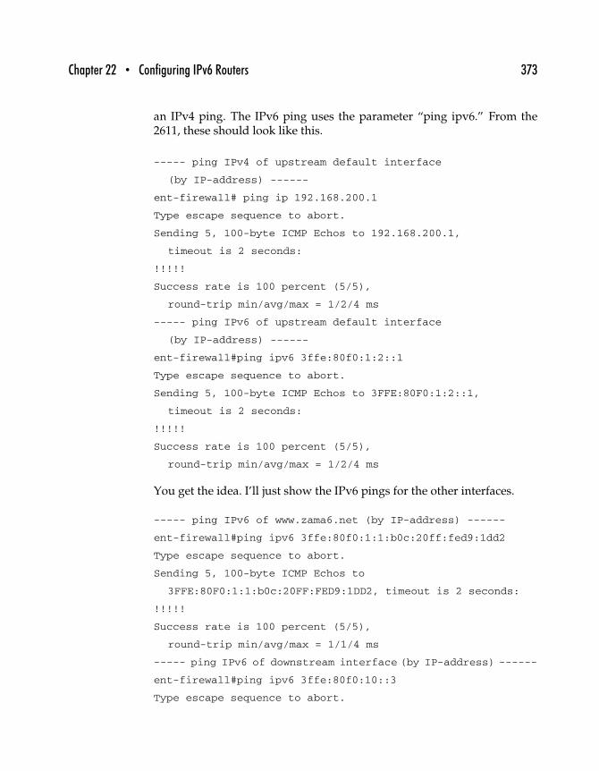
Chapter 22 • Configuring IPv6 Routers 373
an IPv4 ping. The IPv6 ping uses the parameter “ping ipv6.” From the2611, these should look like this.
----- ping IPv4 of upstream default interface
(by IP-address) ------
ent-firewall# ping ip 192.168.200.1
Type escape sequence to abort.
Sending 5, 100-byte ICMP Echos to 192.168.200.1,
timeout is 2 seconds:
!!!!!
Success rate is 100 percent (5/5),
round-trip min/avg/max = 1/2/4 ms
----- ping IPv6 of upstream default interface
(by IP-address) ------
ent-firewall#ping ipv6 3ffe:80f0:1:2::1
Type escape sequence to abort.
Sending 5, 100-byte ICMP Echos to 3FFE:80F0:1:2::1,
timeout is 2 seconds:
!!!!!
Success rate is 100 percent (5/5),
round-trip min/avg/max = 1/2/4 ms
You get the idea. I’ll just show the IPv6 pings for the other interfaces.
----- ping IPv6 of www.zama6.net (by IP-address) ------
ent-firewall#ping ipv6 3ffe:80f0:1:1:b0c:20ff:fed9:1dd2
Type escape sequence to abort.
Sending 5, 100-byte ICMP Echos to
3FFE:80F0:1:1:b0c:20FF:FED9:1DD2, timeout is 2 seconds:
!!!!!
Success rate is 100 percent (5/5),
round-trip min/avg/max = 1/1/4 ms
----- ping IPv6 of downstream interface (by IP-address) ------
ent-firewall#ping ipv6 3ffe:80f0:10::3
Type escape sequence to abort.
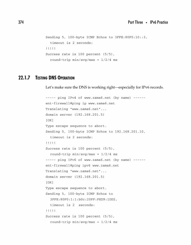
374 Part Three • IPv6 Practice
Sending 5, 100-byte ICMP Echos to 3FFE:80F0:10::3,
timeout is 2 seconds:
!!!!!
Success rate is 100 percent (5/5),
round-trip min/avg/max = 1/2/4 ms
22.1.7 TESTING DNS OPERATION
Let’s make sure the DNS is working right—especially for IPv6 records.
----- ping IPv4 of www.zama6.net (by name) ------
ent-firewall#ping ip www.zama6.net
Translating “www.zama6.net”...
domain server (192.168.201.5)
[OK]
Type escape sequence to abort.
Sending 5, 100-byte ICMP Echos to 192.168.201.10,
timeout is 2 seconds:
!!!!!
Success rate is 100 percent (5/5),
round-trip min/avg/max = 1/2/4 ms
----- ping IPv6 of www.zama6.net (by name) ------
ent-firewall#ping ipv6 www.zama6.net
Translating “www.zama6.net”...
domain server (192.168.201.5)
[OK]
Type escape sequence to abort.
Sending 5, 100-byte ICMP Echos to
3FFE:80F0:1:1:b0c:20FF:FED9:1DD2,
timeout is 2 seconds:
!!!!!
Success rate is 100 percent (5/5),
round-trip min/avg/max = 1/2/4 ms
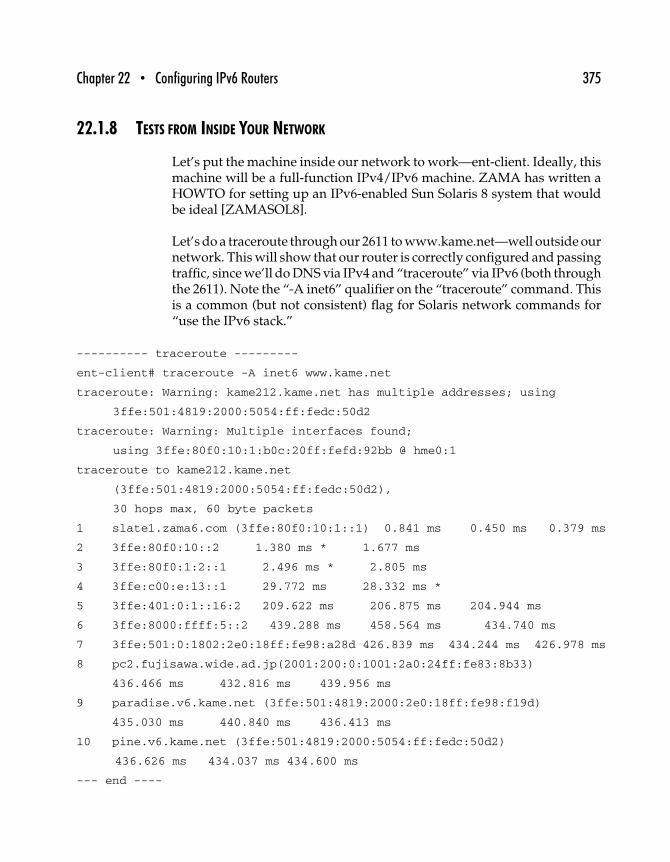
Chapter 22 • Configuring IPv6 Routers 375
22.1.8 TESTS FROM INSIDE YOUR NETWORK
Let’s put the machine inside our network to work—ent-client. Ideally, thismachine will be a full-function IPv4/IPv6 machine. ZAMA has written aHOWTO for setting up an IPv6-enabled Sun Solaris 8 system that wouldbe ideal [ZAMASOL8].
Let’s do a traceroute through our 2611 to www.kame.net—well outside ournetwork. This will show that our router is correctly configured and passingtraffic, since we’ll do DNS via IPv4 and “traceroute” via IPv6 (both throughthe 2611). Note the “-A inet6” qualifier on the “traceroute” command. Thisis a common (but not consistent) flag for Solaris network commands for“use the IPv6 stack.”
---------- traceroute ---------
ent-client# traceroute -A inet6 www.kame.net
traceroute: Warning: kame212.kame.net has multiple addresses; using
3ffe:501:4819:2000:5054:ff:fedc:50d2
traceroute: Warning: Multiple interfaces found;
using 3ffe:80f0:10:1:b0c:20ff:fefd:92bb @ hme0:1
traceroute to kame212.kame.net
(3ffe:501:4819:2000:5054:ff:fedc:50d2),
30 hops max, 60 byte packets
1 slate1.zama6.com (3ffe:80f0:10:1::1) 0.841 ms 0.450 ms 0.379 ms
2 3ffe:80f0:10::2 1.380 ms * 1.677 ms
3 3ffe:80f0:1:2::1 2.496 ms * 2.805 ms
4 3ffe:c00:e:13::1 29.772 ms 28.332 ms *
5 3ffe:401:0:1::16:2 209.622 ms 206.875 ms 204.944 ms
6 3ffe:8000:ffff:5::2 439.288 ms 458.564 ms 434.740 ms
7 3ffe:501:0:1802:2e0:18ff:fe98:a28d 426.839 ms 434.244 ms 426.978 ms
8 pc2.fujisawa.wide.ad.jp(2001:200:0:1001:2a0:24ff:fe83:8b33)
436.466 ms 432.816 ms 439.956 ms
9 paradise.v6.kame.net (3ffe:501:4819:2000:2e0:18ff:fe98:f19d)
435.030 ms 440.840 ms 436.413 ms
10 pine.v6.kame.net (3ffe:501:4819:2000:5054:ff:fedc:50d2)
436.626 ms 434.037 ms 434.600 ms
--- end ----
376 Part Three • IPv6 Practice
22.1.9 CLOSING TOPICS
That’s about it. We’ve built an IPv6-capable Cisco 2611 from the ground upand tested IPv4 and IPv6 functionality. It won’t be fast—yet—but now youcan get to work trying other IPv6 applications and utilities. The testbed isready.
Warning: Until you understand the various support protocols for IPv6(i.e., ndpd.conf), be careful about configuring ACL or firewalls. It issuggested you start with relatively “open” rules and watch how the sys-tem communicates using tools like “snoop” (Solaris) or “tcpdump,” thentighten down your security stance.
22.2 Configuring a Cisco 7200 Router∗∗
This section describes in detail how to configure the Cisco 7200 SeriesRouters for Native IPv6 and IPv6 tunneling.
22.2.1 GATHERING THE PIECES
Here’s a brief list of what you’ll need for this project.
• Cisco 7200 Series Router• Cisco IOS 12.1• IPv6 address space from your Internet Service Provider, native
or tunnel.
To run IPv6, either at the Enterprise or backbone level, it is necessary tohave IPV6-capable routers. Many organizations working with IPv6 areusing software-based routers built on the Solaris or BSDI UNIX OperatingSystems. While this is a workable solution for small networks, it is not ascalable solution that will grow with the users’ needs.
Cisco currently has production and beta IPv6 images for their 7200 seriesrouters, as well as several others. The 7200 is simple to configure for
∗∗This section is adapted from a document written by Grant Furness and Brian Skeen,© Zama Networks.
Chapter 22 • Configuring IPv6 Routers 377
IPv6, particularly if one is already familiar with the Cisco product lineand command line interface.
The Cisco IOS 12.1 image, which can be downloaded from CiscoConnection Online, is required to run IPv6. Several images can be foundat http://www.cisco.com/ipv6/. If you have any questions regarding theproper selection of an image or downloading the newest image, [email protected]. We are using the 12.1(20001029) beta image. Thisrelease is stable, sitting in front of our production IPv6 network. We havenot experienced any serious problems with routing or subnetting issues.
22.2.2 AUTOCONFIGURATION
IPv6 is simple to configure on the 7200, particularly if you are familiar withthe Cisco Command Line Interface. First, you must be in enable mode andthen configure terminal mode.
IPv6 on the Cisco product line is run at an interface level, meaning that youmust enable IPv6 on each interface you wish to operate an IPv6 network.From the command line, enter this interface to configure its address andnetwork information, and enter the command ipv6 enable to turn IPv6 on.The command ipv6 unicast-routing will enable IPv6 routing.
Once IPv6 is enabled, you can assign the interface’s address. Probably thesimplest way to do this is to assign the network portion that the router willbroadcast, followed by ::1. In the following example, the network portionof the address is 3FFE:80F0:1:1::/64. Simply place a value after the doublecolon (::) and before the /64 in the address assignment, and you now havean IPv6 address assigned to your interface.
ipv6 address 3FFE:80F0:1:1::1/64
With the address assigned, you can now configure the router discoveryprotocol information for the router to advertise to its clients. The followingcommand gives the router all the information it needs to broadcast networkinformation to the clients under it.
ipv6 nd prefix-advertisement 3FFE:80F0:1:1::/64
86400 86400 onlink autoconfig
378 Part Three • IPv6 Practice
The ipv6 nd prefix-advertisement is defining the function of the commandas broadcasting the network prefix information, 3FFE:80F0:1:1::/64. Notethat the network address being broadcast is a /64, which comprises halfof the 128-bit IPv6 address. The number following the / in a networkaddress broadcast refers to the number of bits in the network portion ofthe address, in this case 64 bits. The other half is composed of the client’sMAC address. This idea is analogous to 192.168.12 being the networkportion of a private Class C address space.
The next two fields indicate when the client is to check back for thenetwork information in case it has changed. The first is valid lifetime inseconds, here 86400, which is 24 hours. The client must check back with therouter within the timeframe to verify its network information. The secondis preferred lifetime, or when the router prefers that the clients check backto verify network information. This is also set to 86400 seconds, as indicatedby Cisco documentation.
According to RFC 2462, when the preferred lifetime of an IPv6 addressis expired, that address is deprecated, and “should not be used in anynew communications if an alternate (nondeprecated) address is availableand has sufficient scope.” However, the client should continue to use thedeprecated address for communications already under way. In no case canthe address be used for either outgoing or incoming new communicationsafter the valid lifetime is expired.
The onlink designation says that the IPv6 address allocation will only occuron nodes attached to that particular network link.
The autoconfig command tells the clients that their addresses are to beautomatically configured. The network portion of the address is to be takenexplicitly from the router, as just outlined. The host portion of the addresswill be derived from the MAC address.
The entire configuration looks like this.
cisco-router> enable
cisco-router# configure terminal
cisco-router# interface e2/1
cisco-router# ipv6 enable
cisco-router# ipv6 address 3FFE:80F0:1:1::1/64
Chapter 22 • Configuring IPv6 Routers 379
cisco-router# ipv6 nd prefix-advertisement
3FFE:80F0:1:1::/64 86400 86400
onlink autoconfig
22.2.3 TUNNEL CONFIGURATION
Cisco IOS 12.1 can also connect IPv6 devices via tunnels through IPv4.The information required to configure a static tunnel is different from theinformation required for a static network autoconfiguration. The admin-istrator will need to know the destination router’s IPv6 address and IPv4address, the client’s IPv4 address, and the tunnel mode.
Do not assign an IPv4 address directly to the interface for tunneled IPv6traffic. Instead, assign the IPv4 address to the tunnel endpoint, which istied to the interface.
As in the static network configuration, enable IPv6 on the tunnel interface.
cisco-router# int Tunnel10
cisco-router# ipv6 enable
cisco-router# ipv6 address 3FFE:80F0:2::8/126
Note that the address assignment being made here is a /126, meaning thatthe network portion of this address is comprised of 126 of the 128 bits ofthe address. The reason for this is that the tunnel is a PPP link, and onlytwo addresses are needed to form the link, and one is reserved for theanycast address. The IPv4 waste of two addresses, one for the networkand one for the broadcast, are no longer necessary with IPv6.
The addresses for both sides of the tunnel are statically configured, notautomatic. The router administrator will need to set aside the addressspace of this network to ensure that the tunnel recipient will have globallyunique addresses.
Now that the IPv6 information is configured in the Tunnel interface,the tunnel requires the IPv4 information. The tunnel will need to knowits source and destination addresses. From the viewpoint of the router,the source address will be applied to the router side of the tunnel and thedestination address will be applied to the client side of the tunnel. It is
380 Part Three • IPv6 Practice
also necessary to dictate what type of tunnel the interface is—ipv6ip inthis case.
cisco-router# tunnel source 192.142.129.2
cisco-router# tunnel destination 192.31.7.104
cisco-router# tunnel mode ipv6ip
The complete IPv6 through IPv4 tunnel configuration looks like thefollowing example.
interface Tunnel10
description connection to client’s side of tunnel
3ffe:80f0:f:4::/64
no ip address
ipv6 enable
ipv6 address 3FFE:80F0:2::8/127
tunnel source 192.142.129.2
tunnel destination 192.31.7.104
tunnel mode ipv6ip
The client side of the tunnel will need to be given an address range,preferably in the form of a network address assignment. In the precedingexample, the client’s network is 3ffe:80f0:f:4::/64. If the client side of thetunnel is a router or a UNIX computer, it can be configured to broadcast thisaddress range to the machines on his LAN, just as in the first section of thisdocument—exceptions being made for platform differences, of course. It isimportant to keep record of this address assignment to ensure the globaluniqueness of each address on that network (description connection toclient’s side of tunnel 3ffe:80f0:f:4::/64).
22.2.4 BGP4+
One of the more common ways to perform routing on the external side ofthe router is by using BGP with IPv6, or BGP4+. The first step is to identifythat BGP will be working on IPv6 with the command: no bgp default ipv4-unicast. Then, simply identify your AS number and your BGP neighbors’IPv6 addresses and AS numbers.
router bgp <your as number>
neighbor <neighbor’s IPv6 address> <neighbor’s as number>
Chapter 22 • Configuring IPv6 Routers 381
Here is an example of a BGP4+ configuration.
router bgp 9340
neighbor 3FFE:82E1:8000::12 remote-as 8102
This configuration shows one BGP entry, but having multiple entries issimply a matter of adding more entries to the configuration. You can alsolog all BGP neighbor changes with this command.
bgp log-neighbor-changes
22.2.5 STATIC ROUTING
The addition of static routes in IPv6 is as simple as in IPv4. This is thecommand.
ipv6 route <destination IPv6 network><IPv6 interface>
Here is an example from my routing table.
ipv6 route 3FFE:80F3:1:4::/64 3FFE:80F3:1:2:A01:20ff:FED9:52B4
Routing your tunnel clients’ networks is the same, only you need to directall traffic bound for the network through your end of the tunnel interface,which can be done by simply referring to the name of the tunnel.
ipv6 route 3FFE:80F0:F:4::/64 Tunnel10
Since we are connected to the 6Bone via a tunnel, we need a commandto direct all IPv6 traffic out through our end of the tunnel interface to ourupstream provider. This is done via the same static route command.
ipv6 route 3FFE::/16 Tunnel10 120
The number at the end of the command—120 in this case—is the Admin-istrative Distance. The Administrative Distance is the level of trust thatcan be placed on the source of routing information in the BGP and OSPFrouting protocols. The value is an integer between 1 and 255. The higherthe value, the lower the trust level to be placed on that source. A value of255 means the source should be ignored.
382 Part Three • IPv6 Practice
The preceding information is all that is necessary to configure a Cisco 7200router for IPv6. The configurations shown will enable users to communi-cate with both Native IPv6 and Tunneled IPv6.
22.3 Configuring IPv6 on Hitachi GR2000 Series Routers†
This section describes the necessary steps for configuring a Hitachi GR2000series router to communicate over IPv6. Many of the commonly used fea-tures of IPv6, including Static Neighbor Discovery (NDP) configuration,Address Auto-configuration, Ripng, BGP4+, and 6over4 tunneling, areincluded to provide configuration and command reference.
22.3.1 GATHERING THE PIECES
Here’s a brief list of what you’ll need for this project.
• Hitachi GR2000 Series Routers• Hitachi OS 05-00-AA/OS6• IPv6 address space from your Internet Service Provider, native
or tunnel.
22.3.2 BACKGROUND
To run IPv6 either at the Enterprise or Backbone level, it is necessary to haveIPv6-capable routers. The Hitachi GR2000 Series Router, built on the BSDIUNIX Operating Systems, currently supports software-based forwardingof all IPv6 packets. The procedures listed in this document were testedusing Fast Ethernet and Gigabit Ethernet interfaces, but Hitachi does cur-rently offer IPv6 support on their ATM and Packet Over Sonet (POS) linecards as well.
This router has a three-tier user interface to provide different levels ofadministrative security: Command, Admin, and Config. The Command-and Admin-level interfaces have read-only permission and are used forcommand verification and low-level troubleshooting. The Config-level
†This section is adapted from a document written by Brian Skeen, © 2001 Zama Networks.
Chapter 22 • Configuring IPv6 Routers 383
interface has read-write permission and is used to perform all routerconfiguration commands.
22.3.3 REQUIRED IOS IMAGE
The procedures listed here were tested on Hitachi OS release, 05-00-AA/OS6, which at the time of this writing, is the most current beta imageavailable for testing. We have found this release to be stable and have notexperienced any serious routing or subnetting issues related to the currentOS revision.
22.3.4 DEFINING THE ETHERNET LINE
Before any configuration can be assigned to a router interface, you mustfirst create the interface line configuration for the physical port to be used.
The following example shows how to define a 100MB, full-duplex Ethernetline named to_gr2000b. Note that you must first access the Config-level interface and open the configuration file prior to issuing the firstconfiguration command.
*** Welcome to the Router ***
GR2000A/command: admin
GR2000A/admin: config
GR2000A/config: open
GR2000A/config: set line to_gr2000b ethernet 1/2
GR2000A/config> line to_gr2000b ethernet 1/2 type 100m_full_duplex
GR2000A/config>apply
GR2000A/config>save
To verify the previous line configuration, the show line <linename>command is used as follows.
GR2000A/config: show line to_gr2000b
line to_gr2000b ethernet 1/2 {
type 100m_full_duplex;
};
384 Part Three • IPv6 Practice
22.3.5 DEFINING A STATIC IPv6 ADDRESS TO THE LINE
Now that the line configuration has been completed, the IP command canbe used to set an IPv6 address on the configured line. Once IPv6 has beenconfigured on the line, the router will also generate a link-local Unicastaddress on the line by prepending the predefined fe80::2 prefix with theinterface’s 64-bit interface identifier.
The following example shows how to define a static Unicast address witha 64-bit prefix length to the line to_gr2000b.
GR2000A/config: ip to_gr2000b 3ffe:80f0:3:3000::1 -prefixlen 64
GR2000A/config>apply
GR2000A/config>save
To verify the previous ip configuration, the show ip <linename> commandis used as follows.
GR2000A/config: show ip to_gr2000b
ip to_gr2000b {
3ffe:80f0:3:3000::1 prefixlen 64;
};
To verify the entire IPv6 interface configuration, the interface <linename>command is used at the Admin-level interface as follows.
GR2000A/admin: interface to_gr2000b
to_gr2000b:
flags=80e3<UP,BROADCAST,NOTRAILERS,RUNNING,NOARP,MULTICAST>
mtu 1500
inet6 3ffe:80f0:3:3000::1/64
inet6 fe80::240:66ff:fe10:8931%to_gr2000b/64
NIF1/Line2: UP media 100BASE-TX full 00:40:66:10:89:31
Time-since-last-status-change: 2,04:44:52
Last down at: 04/28 04:39:25
To verify that the interface is up and configured, the ping6 <IPv6 address>command can be used as follows.
GR2000A/admin: ping6 3ffe:80f0:3:3000::1
Chapter 22 • Configuring IPv6 Routers 385
PING6(56=40+8+8 bytes) 3ffe:80f0:3:3000::1 --> 3ffe:80f0:3:3000::1
16 bytes from 3ffe:80f0:3:3000::1, icmp_seq=0 hlim=64 time=0.42 ms
16 bytes from 3ffe:80f0:3:3000::1, icmp_seq=1 hlim=64 time=0.343 ms
^C
--- 3ffe:80f0:3:3000::1 ping6 statistics ---
2 packets transmitted, 2 packets received, 0% packet loss
round-trip min/avg/max = 0.343/0.381/0.42 ms
22.3.6 DEFINING AN IPv6 STATIC ROUTE
The static command is used to define a static IPv6 route on the GR2000series router. Static routes can be used instead of, or in addition to, adynamic routing protocol to specify the path to a destination network.
The following example shows how to define an IPv6 default route using anext-hop gateway address of 3ffe:80f0:3:3000::2.
GR2000A/admin:config
GR2000A/config: static :: prefixlen 0 gateway
3ffe:80f0:3:3000::2
GR2000A/config>apply
GR2000A/config>save
To verify the previous IPv6 Static Route configuration, the show staticcommand is used as follows.
GR2000A/config: show static
static {
:: prefixlen 0 gateway 3ffe:80f0:3:3000::2;
};
22.3.7 DEFINING A STATIC NEIGHBOR DISCOVERY ENTRY
The NDP command is used to define a static Neighbor Discovery (ND)entry in the router’s IPv6 neighbor cache table. The Neighbor Discov-ery protocol is used by nodes (hosts and routers) to determine the linklayer addresses for neighbors known to reside on attached links, to quicklypurge cached values that become invalid, to actively keep track of which
386 Part Three • IPv6 Practice
neighbors are reachable, and to detect changed link layer addresses withinthe network.
In most cases, the process of defining a static Neighbor Discovery entrywill not be required, but it has been included here as reference. Defining astatic ND entry in IPv6 is similar to defining a static ARP entry in IPv4 andmay be useful if you needed to create a virtual IPv6 address to virtual MACaddress mapping that could not otherwise be negotiated dynamically bythe router.
The following example shows how to define a permanent static entry thatmaps IPv6 address 3ffe:80f0:3:3000::3 to MAC address 00:0b:0c:0d:0e:03on line to_gr2000b.
GR2000A/config: ndp 3ffe:80f0:3:3000::3 to_gr2000b
-mac_address 00:0b:0c:0d:0e:03
GR2000A/config>apply
GR2000A/config>save
To verify the Static NDP Entry configuration, the ndp -a command is usedas follows.
GR2000A/admin: ndp -a
Neighbor Link layer Addr Netif Expire S Flgs P
3ffe:80f0:3:3000::3 0:b:c:d:e:3 to_gr2000b permanent R S
22.3.8 DEFINING AN IPv6 ROUTER ADVERTISEMENT
The RA command is used to define specific Router Advertisement param-eters on a given interface. Router Advertisements (RA) can be configuredto provide on-link prefix information to be used by local hosts for AddressAutoconfiguration and may also be used to define the amount of time, inseconds, that information on the reachability of adjacent nodes is valid.
The following example shows how to define a 64-bit prefix with lifetimevalues of 24 hours on interface gr_2000b. The valid-lifetime value speci-fies the length of time (in seconds) that the configured address remainsin the valid state. The preferred-lifetime value specifies the length oftime (in seconds) that the configured address is preferred, or the time
Chapter 22 • Configuring IPv6 Routers 387
until deprecation. The valid lifetime value must be greater than or equalto the preferred lifetime value.
GR2000A/config: ra interface to_gr2000b enable
GR2000A/config> ra interface to_gr2000b prefix 3FFE:80F0:3:3000::
prefixlen 64 valid-lifetime 86400 preferred-lifetime 86400
GR2000A/config>apply
GR2000A/config>save
To verify the Router Advertisement configuration, the show ra commandis used as follows.
GR2000A/config: show ra
ra yes {
interface to_gr2000b enable {
prefix {
3ffe:80f0:3:3000:: prefixlen 64 valid-lifetime 86400
preferred-lifetime 86400;
};
reachable-time 1800;
};
};
22.3.9 DEFINING A CONFIGURED 6OVER4 TUNNEL INTERFACE
Configured 6over4 tunneling is a transition mechanism that provides amethod for isolated IPv6 hosts to communicate across an IPv4 transportnetwork. With 6over4 tunneling, an IPv6 packet originating at one end ofthe tunnel is encapsulated within an IPv4 packet and transmitted acrossthe IPv4 network, where it is then decapsulated back to an IPv6 packetand forwarded to its IPv6 destination. A dual-stack router, one that cancommunicate both via IPv4 and IPv6, is required at each end of the tunnelto perform the encapsulation process.
The following example shows the router configuration steps requiredat both ends of the tunnel to define a 6over4 tunnel named test-6over4(Figure 22–2). An IPv4 address must first be assigned to the encapsulatinginterface on each router. A static route is also defined using a next-hopaddress of the remote tunnel endpoint.
388 Part Three • IPv6 Practice
************* ON GR2000A*************
GR2000A/config: ip to_gr2000b 172.16.16.2 mask 255.255.255.252
GR2000A/config> tunnel test-6over4 172.16.16.2 remote 172.16.16.1
GR2000A/config> ip test-6over4 3ffe:80f0:3:5000::2
destination_ip_address 3ffe:80f0:3:5000::1
GR2000A/config> static :: prefixlen 0 gateway 3ffe:80f0:3:5000::1
GR2000A/config> apply
GR2000A/config> save
************* ON GR2000B *************
GR2000B/config: ip to_gr2000a 172.16.16.1 mask 255.255.255.252
GR2000B/config> tunnel test-6over4 172.16.16.1 remote 172.16.16.2
GR2000B/config> ip test-6over4 3ffe:80f0:3:5000::1
destination_ip_address 3ffe:80f0:3:5000::2
GR2000B/config> static :: prefixlen 0 gateway 3ffe:80f0:3:5000::2
GR2000B/config> apply
GR2000B/config> save
To verify the 6over4 Tunnel Configuration on router GR2000A, the configshow tunnel and config show ip <tunnel name> commands are used asfollows.
GR2000A/admin: config show tunnel
tunnel test-6over4 {
172.16.16.2 remote 172.16.16.1;
};
GR2000A/admin: config show ip test-6over4
ip test-6over4 {
3ffe:80f0:3:5000::2 destination_ip_address 3ffe:80f0:3:5000::1;
};
To verify that the tunnel interface is up and configured, the ping6 <IPv6address> command can be used as follows.
GR2000A/admin: ping6 3ffe:80f0:3:5000::1
PING6(56=40+8+8 bytes) 3ffe:80f0:3:5000::1 --> 3ffe:80f0:3:5000::1
16 bytes from 3ffe:80f0:3:5000::1, icmp_seq=0 hlim=64 time=3.052 ms
Chapter 22 • Configuring IPv6 Routers 389
16 bytes from 3ffe:80f0:3:5000::1, icmp_seq=1 hlim=64 time=2.894 ms
^C
--- 3ffe:80f0:3:5000::1 ping6 statistics ---
2 packets transmitted, 2 packets received, 0% packet loss
round-trip min/avg/max = 2.894/2.973/3.052 ms
22.3.10 ENABLING THE RIPNG PROTOCOL
RIPng is an Interior Gateway routing protocol supported in IPv6 on theGR2000 series router. RIPng uses a hop count metric to determine the bestroute to a particular destination network.
The following example shows how to enable RIPng on the GR2000 routerand how to define RIPng routing updates to be sent and received oninterface to_gr2000b.
GR2000A/config: ripng yes
GR2000A/config> ripng interface to_gr2000b ripin ripout
GR2000A/config>apply
GR2000A/config>save
To verify the RIPng configuration, the show ripng command is used asfollows:
GR2000A/config: show ripng
ripng yes {
1 interface to_gr2000b ripin ripout;
};
22.3.11 ENABLING THE BGP4+ PROTOCOL
BGP4+ is an Exterior Gateway Routing Protocol supported in IPv6 on theGR2000 series router. BGP4+ is used to exchange loop-free routing tableinformation between routers located on different autonomous systems.
The following example shows how to enable BGP4+ on the router, howto set up a BGP4+ peering relationship with a remote router located inAS 65002, and how to export (advertise) all directly connected routesto AS 65001 via the BGP4+ protocol. Prior to BGP4+ configuration, the
390 Part Three • IPv6 Practice
autonomous system number and router-id for the local router must be spec-ified. Note that the configuration file is closed after the final configurationcommand has been entered.
GR2000A/config: autonomoussystem 65001
GR2000A/config>routerid 203.142.143.45
GR2000A/config> bgp4+ yes
GR2000A/config> bgp4+ externalpeeras 65002 peer 3ffe:80f0:3:4000::1
GR2000A/config>export proto bgp4+ as 65001 proto direct
GR2000A/config>apply
GR2000A/config>save
GR2000A/config:close
To verify the BGP4+ Configuration, the show bgp4+ and show exportcommands are used as follows.
GR2000A/config> show bgp4+
bgp4+ yes {
1 group type external peeras 65001 {
peer 3ffe:80f0:3:4000::1;
};
};
GR2000A/config> show export
export proto bgp4+ as 65001 {
proto direct;
};
The preceding information is all that is necessary to configure a HitachiGR2000 series router for IPv6. The configurations shown will enable usersto communicate with both Native IPv6 and Tunneled IPv6.
22.4 Configuring NEC IX5010 Series Routers for IPv6‡
This section describes the necessary steps for configuring a NEC IX5010series router to communicate over IPv6. Many of the commonly used
‡This section is adapted from a document written by Brian Skeen and Steve Smith, ©Zama Networks.
Chapter 22 • Configuring IPv6 Routers 391
features of IPv6, including Static Neighbor Discovery configuration,Address Autoconfiguration, Configured 6over4 tunneling, RIPng, andBGP4, are included to provide configuration and command reference.
22.4.1 GATHERING THE PIECES
Here’s a brief list of what you’ll need for this project.
• NEC IX5010 Routers• NEC OS 5.1.07• IPv6 address space from your Internet Service Provider, native
or tunnel.
22.4.2 BACKGROUND
To run IPv6 at the Enterprise or Backbone level, it is necessary to have IPv6-capable routers. The NEC IX5010 Router currently supports hardware-based forwarding of all IPv6 packets. The procedures listed in thisdocument were tested using Fast Ethernet interfaces, but NEC does cur-rently offer IPv6 support on their Gigabit Ethernet, ATM, and Packet OverSonet (POS) line cards as well.
This NEC router has a two-tier user interface to provide different levelsof administrative security: operator-mode and supervisor-mode. Theoperator mode has read-only permission and is used for command verifi-cation and low-level troubleshooting. The supervisor mode has read-writepermission and is used to perform all router configuration commands.
The procedures listed here were tested on NEC OS release 5.1.07, which atthe time of this writing is the most current beta image available for testing.We have found this release to be stable and have not experienced anyserious routing or subnetting issues related to the current OS revision.
22.4.3 DEFINING VLAN CONFIGURATION
Before any IPv6 configuration can be assigned to a router interface, youmust first configure the VLAN parameters for the specific port(s) to beused. By default, all ports on the NEC IX5010 router are assigned to adefault VLAN—in this case, VLAN 2. In order to assign a port currently
392 Part Three • IPv6 Practice
in the default VLAN to a new VLAN, it must first be removed from thedefault VLAN.
On the IX5010 router, there are two VLAN modes that allow you to changeand activate VLAN configuration parameters. The command vlan-modechange is used to change the VLAN status to permit configuration changes.Once configuration data has been changed, the command vlan-mode activeis used to activate the newly registered VLAN data.
The following example shows the necessary steps to define a new VLAN(VLAN-ID 200) named NEC1-to-NEC2; assign port 25 to the new VLAN,and then activate the VLAN for use. Note that you must first access thesupervisor mode prior to issuing the first configuration command. Alsonote that port 25 must be removed from the default VLAN (VLAN-ID 2)before it can be assigned to VLAN 200. The session should appear asfollows.
*** Welcome to the Router ***
· nec1> supervisor
· Password: **********
· nec1# vlan-mode change
· nec1# no vlan port 2 25
· nec1# vlan register 200 NEC1-to-NEC2 25
· nec1# vlan-mode active
· nec1# save configall
To verify the previous VLAN configuration, the show vlan registercommand is used as follows.
· nec1# show vlan reg
VLAN ID : 200
VLAN Name : NEC1-to-NEC2
Ethernet Port : 25
LEC ID :
PPP ID :
22.4.4 ENABLING IPv6 ON A CONFIGURED VLAN
Once the VLAN configuration has been completed, the IPv6 com-mand must be used to enable IPv6 functionality on the configured
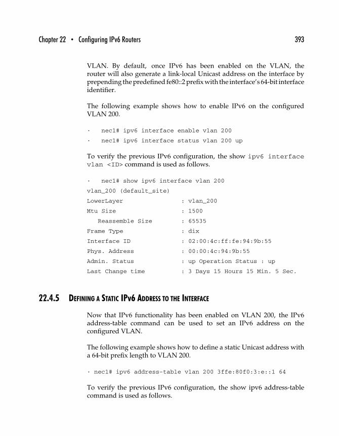
Chapter 22 • Configuring IPv6 Routers 393
VLAN. By default, once IPv6 has been enabled on the VLAN, therouter will also generate a link-local Unicast address on the interface byprepending the predefined fe80::2 prefix with the interface’s 64-bit interfaceidentifier.
The following example shows how to enable IPv6 on the configuredVLAN 200.
· nec1# ipv6 interface enable vlan 200
· nec1# ipv6 interface status vlan 200 up
To verify the previous IPv6 configuration, the show ipv6 interfacevlan <ID> command is used as follows.
· nec1# show ipv6 interface vlan 200
vlan_200 (default_site)
LowerLayer : vlan_200
Mtu Size : 1500
Reassemble Size : 65535
Frame Type : dix
Interface ID : 02:00:4c:ff:fe:94:9b:55
Phys. Address : 00:00:4c:94:9b:55
Admin. Status : up Operation Status : up
Last Change time : 3 Days 15 Hours 15 Min. 5 Sec.
22.4.5 DEFINING A STATIC IPv6 ADDRESS TO THE INTERFACE
Now that IPv6 functionality has been enabled on VLAN 200, the IPv6address-table command can be used to set an IPv6 address on theconfigured VLAN.
The following example shows how to define a static Unicast address witha 64-bit prefix length to VLAN 200.
· nec1# ipv6 address-table vlan 200 3ffe:80f0:3:e::1 64
To verify the previous IPv6 configuration, the show ipv6 address-tablecommand is used as follows.
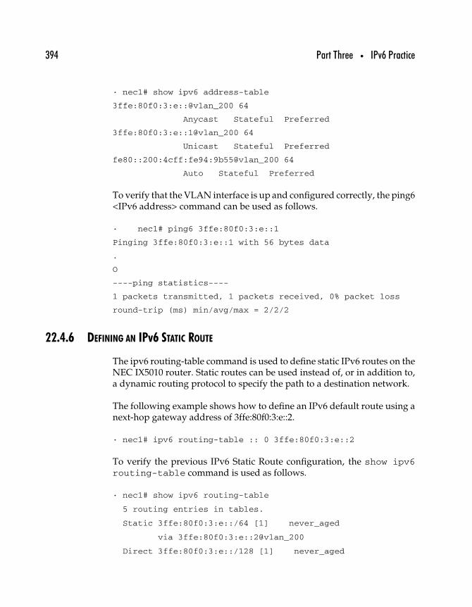
394 Part Three • IPv6 Practice
· nec1# show ipv6 address-table
3ffe:80f0:3:e::@vlan_200 64
Anycast Stateful Preferred
3ffe:80f0:3:e::1@vlan_200 64
Unicast Stateful Preferred
fe80::200:4cff:fe94:9b55@vlan_200 64
Auto Stateful Preferred
To verify that the VLAN interface is up and configured correctly, the ping6<IPv6 address> command can be used as follows.
· nec1# ping6 3ffe:80f0:3:e::1
Pinging 3ffe:80f0:3:e::1 with 56 bytes data
.
O
----ping statistics----
1 packets transmitted, 1 packets received, 0% packet loss
round-trip (ms) min/avg/max = 2/2/2
22.4.6 DEFINING AN IPv6 STATIC ROUTE
The ipv6 routing-table command is used to define static IPv6 routes on theNEC IX5010 router. Static routes can be used instead of, or in addition to,a dynamic routing protocol to specify the path to a destination network.
The following example shows how to define an IPv6 default route using anext-hop gateway address of 3ffe:80f0:3:e::2.
· nec1# ipv6 routing-table :: 0 3ffe:80f0:3:e::2
To verify the previous IPv6 Static Route configuration, the show ipv6routing-table command is used as follows.
· nec1# show ipv6 routing-table
5 routing entries in tables.
Static 3ffe:80f0:3:e::/64 [1] never_aged
via 3ffe:80f0:3:e::2@vlan_200
Direct 3ffe:80f0:3:e::/128 [1] never_aged
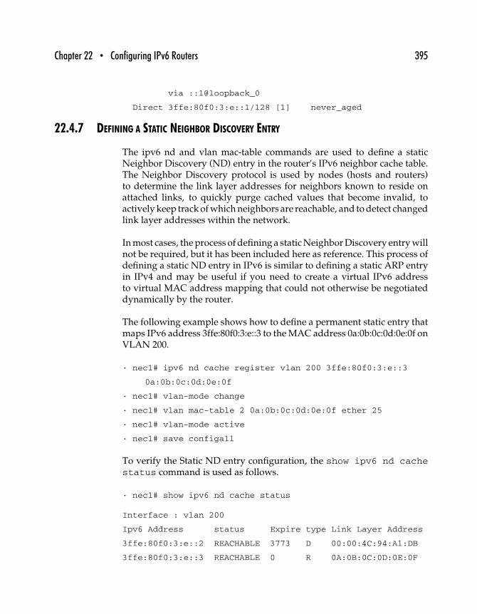
Chapter 22 • Configuring IPv6 Routers 395
via ::1@loopback_0
Direct 3ffe:80f0:3:e::1/128 [1] never_aged
22.4.7 DEFINING A STATIC NEIGHBOR DISCOVERY ENTRY
The ipv6 nd and vlan mac-table commands are used to define a staticNeighbor Discovery (ND) entry in the router’s IPv6 neighbor cache table.The Neighbor Discovery protocol is used by nodes (hosts and routers)to determine the link layer addresses for neighbors known to reside onattached links, to quickly purge cached values that become invalid, toactively keep track of which neighbors are reachable, and to detect changedlink layer addresses within the network.
In most cases, the process of defining a static Neighbor Discovery entry willnot be required, but it has been included here as reference. This process ofdefining a static ND entry in IPv6 is similar to defining a static ARP entryin IPv4 and may be useful if you need to create a virtual IPv6 addressto virtual MAC address mapping that could not otherwise be negotiateddynamically by the router.
The following example shows how to define a permanent static entry thatmaps IPv6 address 3ffe:80f0:3:e::3 to the MAC address 0a:0b:0c:0d:0e:0f onVLAN 200.
· nec1# ipv6 nd cache register vlan 200 3ffe:80f0:3:e::3
0a:0b:0c:0d:0e:0f
· nec1# vlan-mode change
· nec1# vlan mac-table 2 0a:0b:0c:0d:0e:0f ether 25
· nec1# vlan-mode active
· nec1# save configall
To verify the Static ND entry configuration, the show ipv6 nd cachestatus command is used as follows.
· nec1# show ipv6 nd cache status
Interface : vlan 200
Ipv6 Address status Expire type Link Layer Address
3ffe:80f0:3:e::2 REACHABLE 3773 D 00:00:4C:94:A1:DB
3ffe:80f0:3:e::3 REACHABLE 0 R 0A:0B:0C:0D:0E:0F
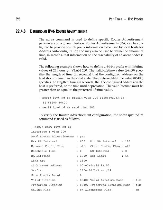
396 Part Three • IPv6 Practice
22.4.8 DEFINING AN IPv6 ROUTER ADVERTISEMENT
The nd ra command is used to define specific Router Advertisementparameters on a given interface. Router Advertisements (RA) can be con-figured to provide on-link prefix information to be used by local hosts forAddress Autoconfiguration and may also be used to define the amount oftime, in seconds, that information on the reachability of adjacent nodes isvalid.
The following example shows how to define a 64-bit prefix with lifetimevalues of 24 hours on VLAN 200. The valid-lifetime value (86400) spec-ifies the length of time (in seconds) that the configured address on thehost should remain in the valid state. The preferred-lifetime value (86400)specifies the length of time (in seconds) that the configured address on thehost is preferred, or the time until deprecation. The valid lifetime must begreater than or equal to the preferred lifetime value.
· nec1# ipv6 nd ra prefix vlan 200 3ffe:80f0:3:e::
64 86400 86400
· nec1# ipv6 nd ra send vlan 200
To verify the Router Advertisement configuration, the show ipv6 nd racommand is used as follows.
· nec1# show ipv6 nd ra
Interface : vlan 200
Send Router Advertisement : yes
Max RA Interval : 600 Min RA Interval : 198
Managed Config Flag : off Other Config Flag : off
Reachable Time : 0 NS Interval : 0
RA Lifetime : 1800 Hop Limit : 64
Link MTU : 1500
Link Layer Address : 00:00:4C:94:9B:55
Prefix : 3ffe:80f0:3:e::/64
Site Prefix Length : 0
Valid Lifetime : 86400 Valid Lifetime Mode : fix
Preferred Lifetime : 86400 Preferred Lifetime Mode : fix
OnLink Flag : on Autonomous Flag : on
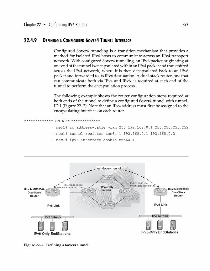
Chapter 22 • Configuring IPv6 Routers 397
22.4.9 DEFINING A CONFIGURED 6OVER4 TUNNEL INTERFACE
Configured 6over4 tunneling is a transition mechanism that provides amethod for isolated IPv6 hosts to communicate across an IPv4 transportnetwork. With configured 6over4 tunneling, an IPv6 packet originating atone end of the tunnel is encapsulated within an IPv4 packet and transmittedacross the IPv4 network, where it is then decapsulated back to an IPv6packet and forwarded to its IPv6 destination. A dual-stack router, one thatcan communicate both via IPv4 and IPv6, is required at each end of thetunnel to perform the encapsulation process.
The following example shows the router configuration steps required atboth ends of the tunnel to define a configured 6over4 tunnel with tunnel-ID 1 (Figure 22–2). Note that an IPv4 address must first be assigned to theencapsulating interface on each router.
************* ON NEC1*************
· nec1# ip address-table vlan 200 192.168.0.1 255.255.255.252
· nec1# tunnel register tun64 1 192.168.0.1 192.168.0.2
· nec1# ipv6 interface enable tun64 1
IPv4-OnlyHitachi GR2000A
Dual-Stack
Router
IPv6-Only EndStations IPv6-Only EndStations
IPv6 Link
IPv6 Network
IPv6 Link
Hitachi GR2000B
Dual-Stack
Router
IPv4 172.16.16.1/30
IPv6 3ffe:80f0:3:5000::2/126
test-6over4 tunnel
IPv4 172.16.16.2/30
IPv6 3ffe:80f0:3:5000::1/126
IPv6 Network
Network
Figure 22–2: Defining a 6over4 tunnel.
398 Part Three • IPv6 Practice
· nec1# ipv6 interface status tun64 1 up
· nec1# ipv6 address-table tun64 1 3ffe:80f0:3:f::1 126
************* ON NEC2 *************
· nec2# ip address-table vlan 200 192.168.0.2 255.255.255.252
· nec2# tunnel register tun64 1 192.168.0.2 192.168.0.1
· nec2# ipv6 interface enable tun64 1
· nec2# ipv6 interface status tun64 1 up
· nec2# ipv6 address-table tun64 1 3ffe:80f0:3:f::2 126
To verify the 6over4 tunnel configuration on router NEC1, the show tunnelregister command is used as follows.
· nec1# show tunnel register
tun64_1
IPsec : off MTU size : 1480
Eventlog : disable Reachability-monitor : enable
lowerlayer : vlan_200
ope status : UP
src addr : 192.168.0.1
dst addr : 192.168.0.2
To verify that the tunnel interface is up and configured, the ping6 <IPv6address> command can be used as follows.
· nec1# ping6 3ffe:80f0:3:f::2
Pinging 3ffe:80f0:3:f::2 with 56 bytes data .
o
----ping statistics----
1 packets transmitted, 1 packets received, 0% packet loss
round-trip (ms) min/avg/max = 8/8/8
22.4.10 ENABLING THE RIPNG PROTOCOL
RIPng is an interior gateway routing protocol supported in IPv6 on theIX5010 router. RIPng uses a hop count metric to dynamically determinethe best route to a particular destination network.
Chapter 22 • Configuring IPv6 Routers 399
The following example shows how to register (enable) RIPng on VLAN 200,how to enable RIPng routing updates to be sent and received on VLAN 200,and how to specify a default route to be sent from the VLAN 200 interface.Note that the receive default route parameter is disabled by default.
· nec1# ipv6 ripng register vlan 200 enable enable
· nec1# ipv6 ripng send default-route vlan 200
To verify the RIPng configuration, the show ipv6 ripng register commandis used as follows.
· nec1# show ipv6 ripng register
Interface : vlan 200
Send Config : Enable
Receive Config : Enable
Split Horizon Mode : Enable
Poisoned Reverse Mode : Enable
Send Metric Offset : 0
Receive Metric Offset : 1
Send Default Route : Enable
Receive Default Route : Disable
Default Route Nexthop : localhost
Inbound Distribute List : Not Set
Outbound Distribute List : Not Set
[Security Config]
Transport : (AH)None (ESP)None
Tunnel : (AH)None (ESP)None
22.4.11 ENABLING THE BGP4+ PROTOCOL
BGP4+ is an exterior gateway routing protocol supported in IPv6 onthe IX5010 router. BGP4+ is used to exchange loop-free routing tableinformation between routers located in different autonomous systems.
The following example shows thebasic steps toenable BGP4+ on the IX5010router, to set a BGP4+ neighbor peering relationship with a remote routerlocated in AS 65002, to advertise a specific network using BGP4+, and
400 Part Three • IPv6 Practice
finally, to advertise an IPv6 default route to a specific neighboring router.Note that the BGP4+ peering session is shut down and reset after finishingthe configuration to initialize BGP4+ routing.
· nec1# ipv6 bgp enable 65001 192.168.0.1
· nec1# ipv6 bgp neighbor remote-as 3ffe:80f0:3:e::2 65002
· nec1# ipv6 bgp network 2001:2d0::/35
· nec1# ipv6 bgp originate default 3ffe:80f0:3:e::2
Reset and shut down BGP sessions with a specific neighbor.
· nec1# ipv6 bgp neighbor shutdown 3ffe:80f0:3:e::2
· nec1# ipv6 bgp neighbor reset 3ffe:80f0:3:e::2
To verify the BGP4+ configuration, the show ipv6 bgp neighbor,show ipv6 bgp speaker and show ipv6 bgp network commandsare used as follows.
· nec1# show ipv6 bgp neighbor
Address State AS BGP-ID Up Time
3ffe:80f0:3:e::2 Established 65002 192.168.0.2 000-00:01:59
· nec1# show ipv6 bgp speaker
BGP Protocol: Enabled
AS Number: 65001
BGP Identifier: 192.168.0.1
TCP-Segment Size: 1024
BGP load-sharing: Disabled
Synchronization: Yes
Export-Internal: No
Default Local Preference: 100
Ignore AS-Path: No
Always-Compare-MED: No
Import routes: None
· nec1# show ipv6 bgp network
Network:
Index Network/Prefixlen
1 2001:2d0::/35
Chapter 22 • Configuring IPv6 Routers 401
22.4.12 CONCLUSION
The preceding information includes all the basic steps necessary to config-ure an NEC IX5010 router for IPv6. The configurations shown will enableusers to communicate with both native IPv6 and tunneled IPv6 hosts.
22.5 Summary
Although your router of choice may not have been included in this chap-ter, having configured several different routers for use with IPv6 youshould be able to extend the lessons to any other router that supports IPv6.In the next chapter, we look at some practical solutions to security problemsapplied to IPv6 networks.

This Page Intentionally Left Blank
2323
Practical IPv6 SecuritySolutions
This chapter includes step-by-step instructions for setting up an IP firewall,IPsec, and TCP wrappers for Solaris IPv6 systems. Pointers to other IPv6security resources are included at the end of the chapter.
23.1 IPv6/v4 IP Filtering Firewall on Solaris 8*
Commercial firewalls protecting network assets of companies and insti-tutions around the world are commonplace. In fact, few “interesting”network systems are not behind a firewall. Currently, there are no (at leastnone we could find) commercial firewalls that provide IPv6 support. Thisleaves an interesting dilemma; deploy systems undefended or restrict yourIPv6 test-and-deployment efforts to isolated internal test networks. Intoday’s connected world, neither of these options is acceptable.
∗This section is adapted from a document written by John E. Spence, © Zama Networks.
403
404 Part Three • IPv6 Practice
This section describes in detail how to obtain, build, install, configure,and operate an IPF-based IPv6-capable firewall on Sun Solaris 8 (SPARCarchitecture). IPv4 is also configured (routable IPv4 addresses have beenchanged to nonroutable addresses). As this machine will act as a “smartrouter,” IPv6 router concepts are discussed as well. With an IPF firewalldeployed, your enterprise will be enabled to join IPv6 networks (like the6bone).
23.1.1 COMPONENTS YOU’LL NEED
You’ll need a modern Sun Sparc-based system with at least two networkinterfaces. You’ll need information about your network and upstreamconnections.
• Routable IPv4 addresses for behind your IPF firewall.Alternatively, you can use nonroutable devices and use IPFNAT, but you won’t be able to connect into the network forservices (i.e., SSH to a specific address). You can skip IPv4support entirely if you wish.
• An IPv6 network for behind your firewall. In order to allowmachines inside your firewall to use the autoconfigure fea-ture to obtain their IPv6 addresses, this must be at least a/64 network (more information on this follows). The pointat which you’ll connect your firewall’s outside interface—whatever is “upstream” from your device—will supply thisblock of addresses.
• Obtain the IPv4 and IPv6 addresses for your outside (unpro-tected) interface. I’m assuming that you’ll have a staticIPv4 address and that you’ll autoconfigure the IPv6 addressof your outside interface. This means that your upstreamrouter must be running the “neighbor discovery” protocoland providing your firewall with the IPv6 prefix to use forautoconfiguration.
• Obtain the IPv4 and IPv6 (if available) DNS informationfor your network—your upstream provider usually suppliesthis.
You’ll need the Sun Solaris C compiler. The gcc compiler won’t work. Youmust obtain and license the real Sun C compiler. You’ll also need the gzipprogram.
Chapter 23 • Practical IPv6 Security Solutions 405
23.1.2 CONFIGURING IPV6/IPV4 INTERFACES
Sun Solaris 8 has native IPv6 support—you just have to select that “InstallIP Version 6 Support” feature at install time. If Solaris 8 is already installed,you can enable IPv6 support by creating the /etc/hostname6.<interfaceindex> file by using “touch /etc/hostname6.<interface index>.” When themachine is rebooted, it will boot up with IPv6 support enabled.
To install from scratch, load Sun Solaris 8 with IPv6 support enabled.Partway through the installation of Solaris, after you’ve entered some ofyour IPv4 information, the program will ask if you want IPv6 support.After installation completes, run the command “netstat -rn.” You shouldhave two routing tables—one for IPv4 and one for IPv6. If you do, you’vegot IPv6 support successfully installed.
Let’s enable the IPv6 interface and check the IPv4 interface. You needto know the names of your two interfaces. Let’s assume that the insideinterface is called “hme1” and the outside interface is called “hme0.” Createfour files.
“/etc/hostname.hme0”
ipfw-o
(That is, filename “/etc/hostname.hme0,” with the single line in it“ipfw-o”.)
“/etc/hostname.hme1”
ipfw-i
“/etc/hostname6.hme0” (empty file)
“/etc/hostname6.hme1” (empty file)
Now check the entries you have in your “/etc/hosts” file. You should havean entry for each of the lines that appear in your “/etc/hostname.hmeX”files—like this.
192.168.140.48 ipfw-o.zama6.net ipfw-o loghost
192.168.200.1 ipfw-i.zama6.net ipfw-i
Note that nonroutable addresses have been substituted for the public-sideroutable addresses.

406 Part Three • IPv6 Practice
This is what will tell your two interfaces how to configure themselves forIPv4. The empty “/etc/hostsname6.hmeX” files tell your two interfacesto autoconfigure from the neighbor discovery announcements from therouters.
Make sure you’ve got the right entries in your “/etc/netmask” file. Theyensure that the new interfaces have the right netmasks.
“/etc/netmasks”
192.168.200.0 255.255.255.0
192.168.140.32 255.255.255.224
At this point, reboot to have the interfaces configured for IPv4.
Make sure IPv4 is happy. Ideally, you have a machine on the inside of yournew network configured for IPv4 to test against. If you don’t, set up onenow. Try to “ping” a machine outside your interface that you know willreturn a ping. If that works, then you’ve got IPv4 properly configured foryour external interface (my ipfw-o interface). If you can ping internally,then that interface is properly configured (my ipfw-i interface).
23.1.3 CONFIGURE NEIGHBOR DISCOVERY ADVERTISEMENTS FOR THE INTERNAL INTERFACE
Your firewall is acting as a smart router, and it must be running the Neigh-bor Discovery protocol—and advertising the right IPv6 address prefix—toallow machines inside the firewall to autoconfigure their interfaces. Editthe “/etc/inet/ndpd.conf” file as shown.
ifdefault AdvReachableTime 30000 AdvRetransTimer 2000
if hme1 AdvSendAdvertisements on
prefix 3ffe:80f0:1:5::/64 hme1
This shows that our inside network is “3ffe:80f0:1:5::/64” on the “hme1”interface. That leaves 64 bits of the address for machines to autoconfiguretheir interfaces. So all machines inside this firewall will have addresses like“3ffe:80f0:1:5:a00:20ff:fed9:21ea/64,” which is the prefix we are advertisingplus the EUI-64 address based on the 48-bit MAC address of the host’sEthernet card.
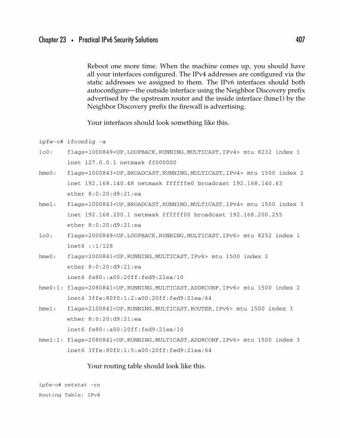
Chapter 23 • Practical IPv6 Security Solutions 407
Reboot one more time. When the machine comes up, you should haveall your interfaces configured. The IPv4 addresses are configured via thestatic addresses we assigned to them. The IPv6 interfaces should bothautoconfigure—the outside interface using the Neighbor Discovery prefixadvertised by the upstream router and the inside interface (hme1) by theNeighbor Discovery prefix the firewall is advertising.
Your interfaces should look something like this.
ipfw-o# ifconfig -a
lo0: flags=1000849<UP,LOOPBACK,RUNNING,MULTICAST,IPv4> mtu 8232 index 1
inet 127.0.0.1 netmask ff000000
hme0: flags=1000843<UP,BROADCAST,RUNNING,MULTICAST,IPv4> mtu 1500 index 2
inet 192.168.140.48 netmask ffffffe0 broadcast 192.168.140.63
ether 8:0:20:d9:21:ea
hme1: flags=1000843<UP,BROADCAST,RUNNING,MULTICAST,IPv4> mtu 1500 index 3
inet 192.168.200.1 netmask ffffff00 broadcast 192.168.200.255
ether 8:0:20:d9:21:ea
lo0: flags=2000849<UP,LOOPBACK,RUNNING,MULTICAST,IPv6> mtu 8252 index 1
inet6 ::1/128
hme0: flags=2000841<UP,RUNNING,MULTICAST,IPv6> mtu 1500 index 2
ether 8:0:20:d9:21:ea
inet6 fe80::a00:20ff:fed9:21ea/10
hme0:1: flags=2080841<UP,RUNNING,MULTICAST,ADDRCONF,IPv6> mtu 1500 index 2
inet6 3ffe:80f0:1:2:a00:20ff:fed9:21ea/64
hme1: flags=2100841<UP,RUNNING,MULTICAST,ROUTER,IPv6> mtu 1500 index 3
ether 8:0:20:d9:21:ea
inet6 fe80::a00:20ff:fed9:21ea/10
hme1:1: flags=2080841<UP,RUNNING,MULTICAST,ADDRCONF,IPv6> mtu 1500 index 3
inet6 3ffe:80f0:1:5:a00:20ff:fed9:21ea/64
Your routing table should look like this.
ipfw-o# netstat -rn
Routing Table: IPv4
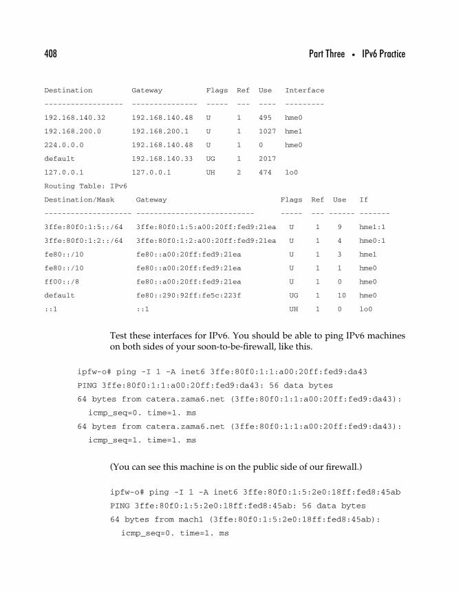
408 Part Three • IPv6 Practice
Destination Gateway Flags Ref Use Interface
------------------ --------------- ----- --- ---- ---------
192.168.140.32 192.168.140.48 U 1 495 hme0
192.168.200.0 192.168.200.1 U 1 1027 hme1
224.0.0.0 192.168.140.48 U 1 0 hme0
default 192.168.140.33 UG 1 2017
127.0.0.1 127.0.0.1 UH 2 474 lo0
Routing Table: IPv6
Destination/Mask Gateway Flags Ref Use If
-------------------- --------------------------- ----- --- ------ -------
3ffe:80f0:1:5::/64 3ffe:80f0:1:5:a00:20ff:fed9:21ea U 1 9 hme1:1
3ffe:80f0:1:2::/64 3ffe:80f0:1:2:a00:20ff:fed9:21ea U 1 4 hme0:1
fe80::/10 fe80::a00:20ff:fed9:21ea U 1 3 hme1
fe80::/10 fe80::a00:20ff:fed9:21ea U 1 1 hme0
ff00::/8 fe80::a00:20ff:fed9:21ea U 1 0 hme0
default fe80::290:92ff:fe5c:223f UG 1 10 hme0
::1 ::1 UH 1 0 lo0
Test these interfaces for IPv6. You should be able to ping IPv6 machineson both sides of your soon-to-be-firewall, like this.
ipfw-o# ping -I 1 -A inet6 3ffe:80f0:1:1:a00:20ff:fed9:da43
PING 3ffe:80f0:1:1:a00:20ff:fed9:da43: 56 data bytes
64 bytes from catera.zama6.net (3ffe:80f0:1:1:a00:20ff:fed9:da43):
icmp_seq=0. time=1. ms
64 bytes from catera.zama6.net (3ffe:80f0:1:1:a00:20ff:fed9:da43):
icmp_seq=1. time=1. ms
(You can see this machine is on the public side of our firewall.)
ipfw-o# ping -I 1 -A inet6 3ffe:80f0:1:5:2e0:18ff:fed8:45ab
PING 3ffe:80f0:1:5:2e0:18ff:fed8:45ab: 56 data bytes
64 bytes from mach1 (3ffe:80f0:1:5:2e0:18ff:fed8:45ab):
icmp_seq=0. time=1. ms

Chapter 23 • Practical IPv6 Security Solutions 409
64 bytes from mach1 (3ffe:80f0:1:5:2e0:18ff:fed8:45ab):
icmp_seq=1. time=0. ms
(You can see this machine is inside our network—by the “3ffe:80f0:1:5”part of the address.)
23.1.4 MAKE SURE THE MACHINE IS ROUTING PACKETS
The Sun machine may or may not think it is a router, and it should forwardpackets not addressed to itself. It’s supposed to make itself a router, bydefault, if it detects that it has multiple network interfaces. Mine didn’t,but you can check—and then make it. Use these commands to check thestatus of these settings.
ipfw-o# ndd -get /dev/ip ip6_forwarding
1
ipfw-o# ndd -get /dev/ip ip_forwarding
1
In each case, these are set to 1, which means “on.” If they had returned “0”they would have been off. To turn them on if they are off, use the command(use the similar form of the command for the other two settings).
ipfw-o# ndd -set /dev/ip ip6_forwarding 1
Now you should be routing. Go to the machine inside your network andsee if you can “ping” (or otherwise connect) to a machine outside yourfirewall, using IPv4 and IPv6. Here are my traceroutes.
mach1# traceroute -A inet6 www6.zama6.net
traceroute: Warning: Multiple interfaces found;
using 3ffe:80f0:1:5:2e0:18ff:fed8:45ab @ iprb0:1
traceroute to www6.zama6.net (3ffe:80f0:1:1:a00:20ff:fed9:da43), 30 hops max,
60 byte packets
1 3ffe:80f0:1:5:a00:20ff:fed9:21ea 0.681 ms 0.487 ms 0.374 ms
2 3ffe:80f0:1:2::1 0.987 ms * 1.678 ms
3 catera.zama6.net (3ffe:80f0:1:1:a00:20ff:fed9:da43) 1.943 ms 2.552 ms 1.916 ms

410 Part Three • IPv6 Practice
mach1# traceroute -A inet www.zama6.net
traceroute to catera.zama6.net (192.168.170.10), 30 hops max, 40 byte packets
1 192.168.200.1 (192.168.200.1) 0.535 ms 0.398 ms 0.310 ms
2 192.168.140.33 (192.168.140.33) 0.759 ms 0.781 ms 0.708 ms
3 catera.zama6.net (192.168.170.10) 1.207 ms 1.166 ms 1.069 ms
The system can now function as a router; the next step is to turn it into afirewall.
23.1.5 OBTAINING, BUILDING, AND INSTALLING IPF
Get the IPF package. Our firewall is built using IPF v3.4.16. The best place toget the source code (yep—no precompiled binaries—we’re going to buildthis from scratch) is from the genius that wrote (and still actively manages)the IPF effort: Darren Reed. Start with this page, and download the mostrecent software from http://coombs.anu.edu.au/∼avalon/.
Once you have the software, uncompress it using the “gzip” utility, andthen use the “tar” utility to expand the archive and make the directories.
gunzip ip-fil3.4.16.tar.gz
tar -xvf *.tar
To support IPv6, you must un-comment the line in the Makefile that readsthe following.
#INET6=-DUSE_INET6
Then make the software according to the directions in “INSTALL.Sol2.”Essentially, you run the “configure” script, then run “make solaris,” then“cd SunOS5,” then run “make package” (as root). This will end with aninstallation of the software.
make solaris cd SunOS5 make package
For me it worked very smoothly once I had the Solaris compiler. Whenyou are done, check to make sure it’s really there.
ipfw-o# pkginfo | grep ipf
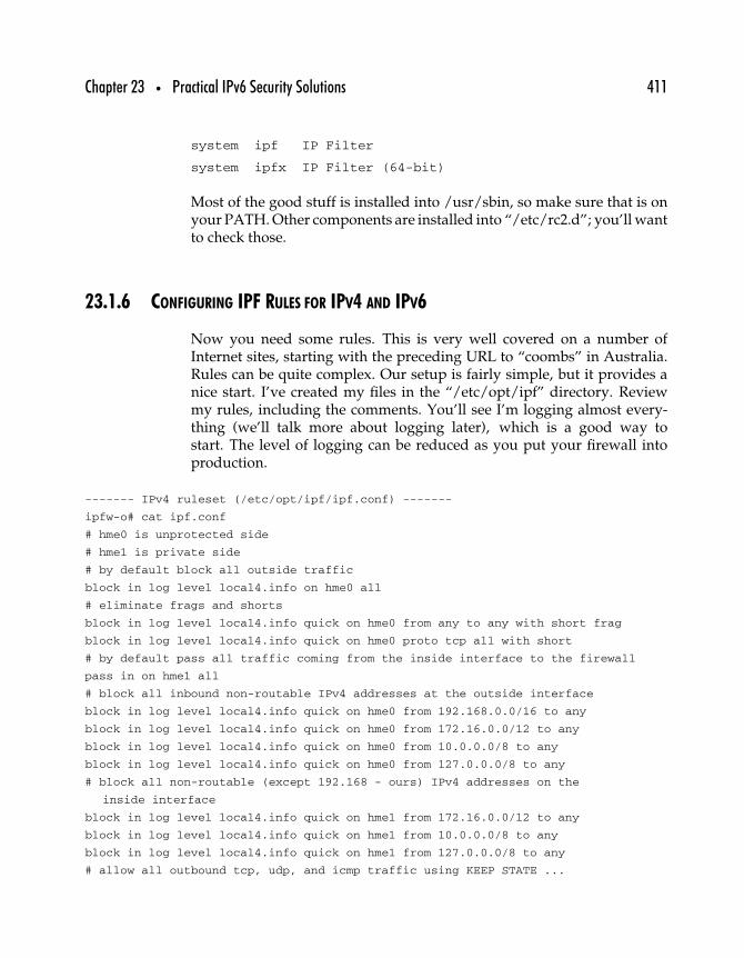
Chapter 23 • Practical IPv6 Security Solutions 411
system ipf IP Filter
system ipfx IP Filter (64-bit)
Most of the good stuff is installed into /usr/sbin, so make sure that is onyour PATH. Other components are installed into “/etc/rc2.d”; you’ll wantto check those.
23.1.6 CONFIGURING IPF RULES FOR IPV4 AND IPV6
Now you need some rules. This is very well covered on a number ofInternet sites, starting with the preceding URL to “coombs” in Australia.Rules can be quite complex. Our setup is fairly simple, but it provides anice start. I’ve created my files in the “/etc/opt/ipf” directory. Reviewmy rules, including the comments. You’ll see I’m logging almost every-thing (we’ll talk more about logging later), which is a good way tostart. The level of logging can be reduced as you put your firewall intoproduction.
------- IPv4 ruleset (/etc/opt/ipf/ipf.conf) -------
ipfw-o# cat ipf.conf
# hme0 is unprotected side
# hme1 is private side
# by default block all outside traffic
block in log level local4.info on hme0 all
# eliminate frags and shorts
block in log level local4.info quick on hme0 from any to any with short frag
block in log level local4.info quick on hme0 proto tcp all with short
# by default pass all traffic coming from the inside interface to the firewall
pass in on hme1 all
# block all inbound non-routable IPv4 addresses at the outside interface
block in log level local4.info quick on hme0 from 192.168.0.0/16 to any
block in log level local4.info quick on hme0 from 172.16.0.0/12 to any
block in log level local4.info quick on hme0 from 10.0.0.0/8 to any
block in log level local4.info quick on hme0 from 127.0.0.0/8 to any
# block all non-routable (except 192.168 - ours) IPv4 addresses on the
inside interface
block in log level local4.info quick on hme1 from 172.16.0.0/12 to any
block in log level local4.info quick on hme1 from 10.0.0.0/8 to any
block in log level local4.info quick on hme1 from 127.0.0.0/8 to any
# allow all outbound tcp, udp, and icmp traffic using KEEP STATE ...

412 Part Three • IPv6 Practice
pass out quick on hme0 proto tcp/udp from any to any keep state
pass out quick on hme0 proto icmp from any to any keep state
# allow inbound from the world these services - telnet, ssh, and ftp
pass in log level local4.info quick proto tcp from any to any port = 22
pass in log level local4.info quick proto tcp from any to any port = 23
pass in log level local4.info quick proto tcp from any to any port
= 21 flags S keep state
pass out log level local4.info quick proto tcp from any to any port
= 21 flags S keep state
------- end IPv4 ruleset -------
------- IPv6 ruleset (/etc/opt/ipf/ipf6.conf)-------
ipfw-o# cat ipf6.conf
# hme0 is outside
# hme1 is inside
block in log level local6.info on hme0 all
pass in log level local6.info on hme1 all
# anti-spoofing v6 style
block in log level local6.info quick on hme0 from 3ffe:80f0:1:5::/64 to any
# outbound - very permissive - use KEEP STATE
pass out log level local6.info quick on hme0 proto tcp from any to any keep state
pass out log level local6.info quick on hme0 proto udp from any to any keep state
pass out quick on hme0 proto icmp from any to any keep state
pass out quick on hme0 proto ipv6-icmp from any to any keep state
pass in quick on hme1 proto ipv6-icmp from any to any
# need rule below to make outbound IPv6 pings work - I think you should not need it
pass in quick on hme0 proto ipv6-icmp from any to any
# allow SSH and telnet
pass in log level local6.info quick proto tcp from any to any port = 22
pass in log level local6.info quick proto tcp from any to any port = 23
------- end IPv6 ruleset -------
23.1.7 CONFIGURING IPF NAT FOR IPV4
We want this to be an IPv4/IPv6 firewall, so we’ve configured both inter-faces for both protocols. I’ve configured IPv4 NAT (IPv6 NAT will rarely,if ever, be used—think about it) to support “one-to-many” NAT. You needthis if you want people inside your protected network to be able to get tosites on the public side. Your internal system (perhaps at 192.168.200.10)will hit Web sites on the Internet looking like it came from the outside IPv4address of your firewall (192.168.140.48).
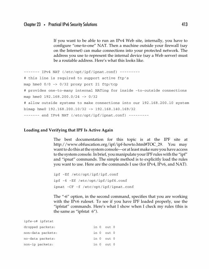
Chapter 23 • Practical IPv6 Security Solutions 413
If you want to be able to run an IPv4 Web site, internally, you have toconfigure “one-to-one” NAT. Then a machine outside your firewall (sayon the Internet) can make connections into your protected network. Theaddress you use to represent the internal device (say a Web server) mustbe a routable address. Here’s what this looks like.
------- IPv4 NAT (/etc/opt/ipf/ipnat.conf) ---------
# this line is required to support active ftp’s
map hme0 0/0 -> 0/32 proxy port 21 ftp/tcp
# provides one-to-many internal NATing for inside -to-outside connections
map hme0 192.168.200.0/24 -> 0/32
# allow outside systems to make connections into our 192.168.200.10 system
bimap hme0 192.168.200.10/32 -> 192.168.140.169/32
------- end IPv4 NAT (/etc/opt/ipf/ipnat.conf) ---------
Loading and Verifying that IPF Is Active Again
The best documentation for this topic is at the IPF site athttp://www.obfuscation.org/ipf/ipf-howto.html#TOC_29. You maywant to do this at the system console—or at least make sure you have accessto the system console. In brief, you manipulate your IPF rules with the “ipf”and “ipnat” commands. The simple method is to explicitly load the rulesyou want to use. Here are the commands I use (for IPv4, IPv6, and NAT).
ipf -Ef /etc/opt/ipf/ipf.conf
ipf -6 -Ef /etc/opt/ipf/ipf6.conf
ipnat -CF -f /etc/opt/ipf/ipnat.conf
The “-6” option, in the second command, specifies that you are workingwith the IPv6 ruleset. To see if you have IPF loaded properly, use the“ipfstat” commands. Here’s what I show when I check my rules (this isthe same as “ipfstat 6”).
ipfw-o# ipfstat
dropped packets: in 0 out 0
non-data packets: in 0 out 0
no-data packets: in 0 out 0
non-ip packets: in 0 out 0

414 Part Three • IPv6 Practice
bad packets: in 0 out 0
copied messages: in 0 out 3520
IPv6 packets: in 1468 out 1154
input packets: blocked 139 passed 165017 nomatch 36 counted 0
short 446
output packets: blocked 0 passed 162826 nomatch 386 counted 0
short 360
input packets logged: blocked 139 passed 5917
output packets logged: blocked 0 passed 5874
packets logged: input 0 output 0
log failures: input 42 output 49
fragment state(in): kept 0 lost 0
fragment state(out): kept 0 lost 0
packet state(in): kept 167 lost 0
packet state(out): kept 2062 lost 128
ICMP replies: 0
TCP RSTs sent: 0 Invalid source(in): 0
Result cache hits(in): 753 (out): 293
IN Pullups succeeded: 0 failed: 0
OUT Pullups succeeded: 5 failed: 0
Fastroute successes: 0 failures: 0
TCP cksum fails(in): 0 (out): 0
Packet log flags set: (0) none
23.1.8 TESTING IPV6 RULES
The best testing method is to get on your internal machine and work onthe Internet. See if you can still “ping,” ftp, and make telnet and Webconnections to external hosts. See if you can make TCP connections frommachines (i.e., see if you can hit a Web site) outside your firewall to internalmachines. Check the logfiles. Do all the tests for IPv4 and IPv6.
You can monitor the traffic to your site interactively by running the“ipmon” command. This command shows you traffic transiting the fire-wall. You can also set up ipmon to run in the background and capturepackets using the UNIX syslog facility, and that’s what I have done.

Chapter 23 • Practical IPv6 Security Solutions 415
My logging is done to two files—one for IPv4 packets and one for IPv6packets. This is accomplished by configuring the rule files with “loglevel” clauses, creating the target logfiles, and configuring the syslogconfiguration files. Specifically, follow these steps.
Make sure your “/etc/opt/ipf/ipf.conf” and “/etc/opt/ipf/ipf6.conf”rule files contain log statements that specify the log level and facility youwill use. Look back in this paper to the rule files. A typical statement lookslike this (IPv6).
pass in log level local6.info quick proto tcp from any to 3ffe:80f0:1:5:
2e0:18ff:fed8:45ab port = 80
This statement says “log this traffic using local6.info as the syslog facility.”
Next, decide where you want the IPF logfiles to live (mine are in“/var/log/ipfw”). Use the “touch” command to create the files.
“touch /var/log/ipfw/ipfw4.log”, then “touch /var/log/ipfw/ipfw6.log”
Now configure “/etc/syslog.conf.” This file can be pretty tricky; just copywhat I have here. Make sure you use TAB, not SPACE, between the fields,or it won’t work. The relevant part of my file is as follows. (You can putthese lines anywhere. Mine are in the middle.)
local4.info
/var/log/ipfw/ipfw4.log local6.info
/var/log/ipfw/ipfw6.log
We’re getting close. Now restart syslog. I just use the scripts already in“/etc/rc2.d.” Run these commands.
“/etc/rc2.d/S74syslog stop”, then “/etc/rc2.d/S74syslog start”
Now you need to start ipmon. I use the command “ipmon s.”
That should do it. Send some packets (for which you are logging) throughthe firewall, and check the files we set up. They should have lines inthem.
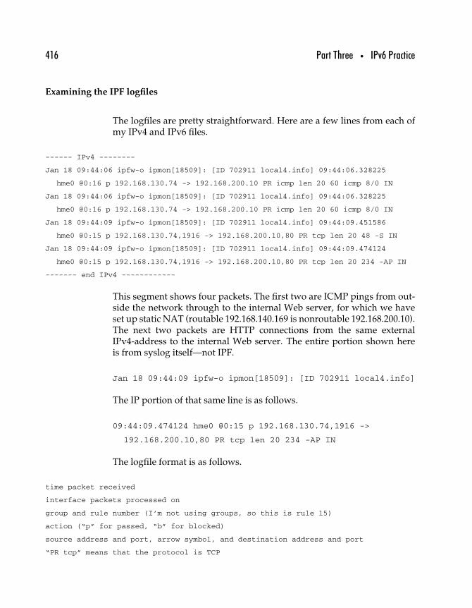
416 Part Three • IPv6 Practice
Examining the IPF logfiles
The logfiles are pretty straightforward. Here are a few lines from each ofmy IPv4 and IPv6 files.
------ IPv4 --------
Jan 18 09:44:06 ipfw-o ipmon[18509]: [ID 702911 local4.info] 09:44:06.328225
hme0 @0:16 p 192.168.130.74 -> 192.168.200.10 PR icmp len 20 60 icmp 8/0 IN
Jan 18 09:44:06 ipfw-o ipmon[18509]: [ID 702911 local4.info] 09:44:06.328225
hme0 @0:16 p 192.168.130.74 -> 192.168.200.10 PR icmp len 20 60 icmp 8/0 IN
Jan 18 09:44:09 ipfw-o ipmon[18509]: [ID 702911 local4.info] 09:44:09.451586
hme0 @0:15 p 192.168.130.74,1916 -> 192.168.200.10,80 PR tcp len 20 48 -S IN
Jan 18 09:44:09 ipfw-o ipmon[18509]: [ID 702911 local4.info] 09:44:09.474124
hme0 @0:15 p 192.168.130.74,1916 -> 192.168.200.10,80 PR tcp len 20 234 -AP IN
------- end IPv4 ------------
This segment shows four packets. The first two are ICMP pings from out-side the network through to the internal Web server, for which we haveset up static NAT (routable 192.168.140.169 is nonroutable 192.168.200.10).The next two packets are HTTP connections from the same externalIPv4-address to the internal Web server. The entire portion shown hereis from syslog itself—not IPF.
Jan 18 09:44:09 ipfw-o ipmon[18509]: [ID 702911 local4.info]
The IP portion of that same line is as follows.
09:44:09.474124 hme0 @0:15 p 192.168.130.74,1916 ->
192.168.200.10,80 PR tcp len 20 234 -AP IN
The logfile format is as follows.
time packet received
interface packets processed on
group and rule number (I’m not using groups, so this is rule 15)
action (“p” for passed, “b” for blocked)
source address and port, arrow symbol, and destination address and port
“PR tcp” means that the protocol is TCP

Chapter 23 • Practical IPv6 Security Solutions 417
“len 20 234” means that the packet header length is 20 bytes, and total packet
length is 234 bytes
“-AP” are flags set on the rule (A says this was an “ACK” packet)
“IN” means the packet was inbound on the interface
-------- IPv6 ------------
Jan 14 06:28:44 ipfw-o ipmon[16863]: [ID 702911 local6.info] 06:28:43.390833
hme0 @0:4 p fe80::290:92ff:fe5c:223f -> ff02::1 PR ipv6-icmp len 40 (56) IN
Jan 14 06:28:44 ipfw-o ipmon[16863]: [ID 702911 local6.info] 06:28:43.390833
hme0 @0:4 p fe80::290:92ff:fe5c:223f -> ff02::1 PR ipv6-icmp len 40 (56) IN
Jan 9 08:22:35 ipfw-o ipmon[16598]: [ID 702911 local6.info] 08:22:35.153816
hme1 @65535:0 p 3ffe:80f0:1:1:a00:20ff:fed9:da43,telnet ->
3ffe:80f0:1:5:2e0:18ff:fed8:45ab,32835 PR tcp len 40 20 -A K-S OUT
-------- end IPv6 ---------
Here we see three packets—two ICMP packets and a “telnet” packet.Except for the address format and length, the format is identical. Notethe “-A K-S OUT” ending. This was an ACK packet, for which we werekeeping state (via “keep state”) and was outbound on the interface.
23.1.9 CLOSING TOPICS
That pretty much completes your firewall build. There are a few morehousekeeping things to do, but just a few. The most important thingis to make sure that your firewall will restart upon reboot, and youshould test that now. First, consider some new “/etc/rc2.d” files thatwill run these commands upon startup, or consider putting them into“/etc/rc2.d/S69inet.”
ndd -set /dev/ip ip_forwarding 1
ndd -set /dev/ip ip6_forwarding 1
ndd -set /dev/ip ip_forward_directed_broadcasts 0
ndd -set /dev/ip ip_forward_src_routed 0
ndd -set /dev/ip ip_respond_to_echo_broadcast 0
Check the “/etc/rc2.d/S65ipfboot” file to make sure it points to yourruleset and that it does all the things you want it to do.
Play around with the ipfstat commands, using these parameters, to getuseful information.
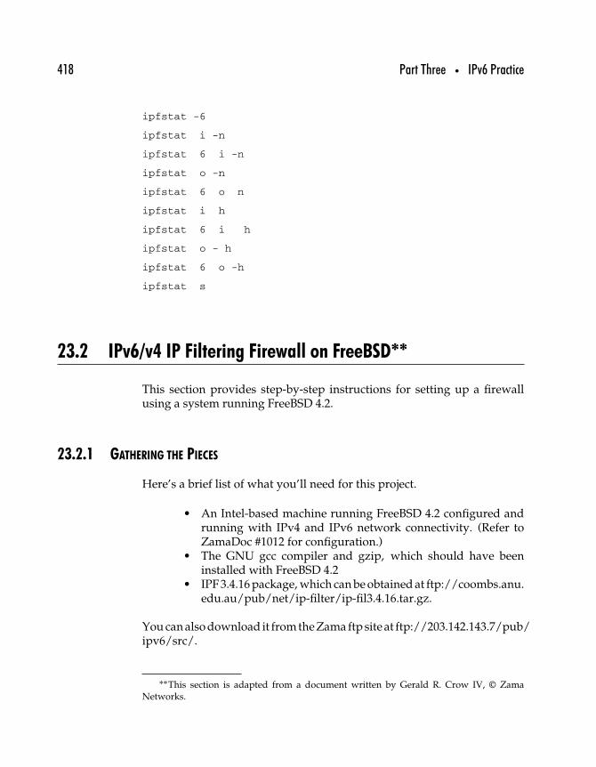
418 Part Three • IPv6 Practice
ipfstat -6
ipfstat i -n
ipfstat 6 i -n
ipfstat o -n
ipfstat 6 o n
ipfstat i h
ipfstat 6 i h
ipfstat o - h
ipfstat 6 o -h
ipfstat s
23.2 IPv6/v4 IP Filtering Firewall on FreeBSD∗∗
This section provides step-by-step instructions for setting up a firewallusing a system running FreeBSD 4.2.
23.2.1 GATHERING THE PIECES
Here’s a brief list of what you’ll need for this project.
• An Intel-based machine running FreeBSD 4.2 configured andrunning with IPv4 and IPv6 network connectivity. (Refer toZamaDoc #1012 for configuration.)
• The GNU gcc compiler and gzip, which should have beeninstalled with FreeBSD 4.2
• IPF 3.4.16 package, which can be obtained at ftp://coombs.anu.edu.au/pub/net/ip-filter/ip-fil3.4.16.tar.gz.
Youcanalso download it fromtheZamaftp site at ftp://203.142.143.7/pub/ipv6/src/.
∗∗This section is adapted from a document written by Gerald R. Crow IV, © ZamaNetworks.

Chapter 23 • Practical IPv6 Security Solutions 419
23.2.2 BUILDING AND INSTALLING IPF
Like most source packages, ipf comes compressed and bundled into a tarfile. If you’re using the GNU version of tar, you can un-tar the package atthe same time that you’re uncompressing it. The following command willaccomplish this.
>tar xvfz ip-fil3.4.16.tar.gz
Otherwise, change to the directory where you have placed the fileip-fil3.4.16.tar.gz and unzip it using the gzip command.
>gzip d ip-fil3.4.16.tar.gz
Use the tar command on the file ip-fil3.4.16.tar.
>tar xvf ip-fil3.4.16.tar
Change the directory to ./ip_fil3.4.16, and use your favorite text editor touncomment this line from the Makefile.
#INET6=-DUSE_INET6
Within the ./ip_fil3.4.16 directory, run these commands as root.
>make freebsd4 >make install-bsd
Change the directory to ./ip_fil3.4.16/FreeBSD-4.0/, and use the cp com-mand to copy the file ipv6-patch-4.1 to ipv6-patch-4.2. Even though thepatch in the following step is written for FreeBSD 4.1, there should beno issues using it for 4.2. What it does is patch the files ip6_input.c andip6_output.c.
>cd ./FreeBSD-4.0 >cp ipv6-patch-4.1 ipv6-patch-4.2
Now run the kinstall script in the current directory to apply the patchand update your kernel with IPF options. Substitute your kernel name forGENERIC if needed.
>./kinstall
Installing ip_fil.c ip_fil.h ip_nat.c ip_nat.h ip_frag.c ip_frag.h ip_state.c
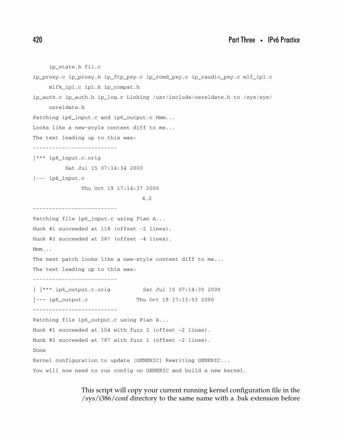
420 Part Three • IPv6 Practice
ip_state.h fil.c
ip_proxy.c ip_proxy.h ip_ftp_pxy.c ip_rcmd_pxy.c ip_raudio_pxy.c mlf_ipl.c
mlfk_ipl.c ipl.h ip_compat.h
ip_auth.c ip_auth.h ip_log.c Linking /usr/include/osreldate.h to /sys/sys/
osreldate.h
Patching ip6_input.c and ip6_output.c Hmm...
Looks like a new-style context diff to me...
The text leading up to this was:
--------------------------
|*** ip6_input.c.orig
Sat Jul 15 07:14:34 2000
|--- ip6_input.c
Thu Oct 19 17:14:37 2000
4.2
--------------------------
Patching file ip6_input.c using Plan A...
Hunk #1 succeeded at 118 (offset -2 lines).
Hunk #2 succeeded at 287 (offset -4 lines).
Hmm...
The next patch looks like a new-style context diff to me...
The text leading up to this was:
--------------------------
| |*** ip6_output.c.orig Sat Jul 15 07:14:35 2000
|--- ip6_output.c Thu Oct 19 17:13:53 2000
--------------------------
Patching file ip6_output.c using Plan A...
Hunk #1 succeeded at 104 with fuzz 2 (offset -2 lines).
Hunk #2 succeeded at 787 with fuzz 1 (offset -2 lines).
Done
Kernel configuration to update [GENERIC] Rewriting GENERIC...
You will now need to run config on GENERIC and build a new kernel.
This script will copy your current running kernel configuration file in the/sys/i386/conf directory to the same name with a .bak extension before
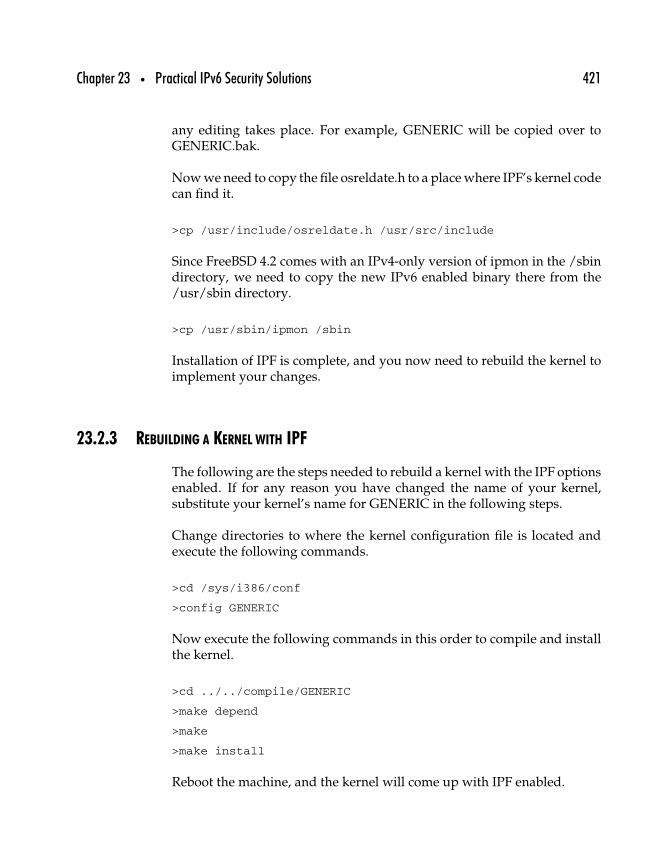
Chapter 23 • Practical IPv6 Security Solutions 421
any editing takes place. For example, GENERIC will be copied over toGENERIC.bak.
Now we need to copy the file osreldate.h to a place where IPF’s kernel codecan find it.
>cp /usr/include/osreldate.h /usr/src/include
Since FreeBSD 4.2 comes with an IPv4-only version of ipmon in the /sbindirectory, we need to copy the new IPv6 enabled binary there from the/usr/sbin directory.
>cp /usr/sbin/ipmon /sbin
Installation of IPF is complete, and you now need to rebuild the kernel toimplement your changes.
23.2.3 REBUILDING A KERNEL WITH IPF
The following are the steps needed to rebuild a kernel with the IPF optionsenabled. If for any reason you have changed the name of your kernel,substitute your kernel’s name for GENERIC in the following steps.
Change directories to where the kernel configuration file is located andexecute the following commands.
>cd /sys/i386/conf
>config GENERIC
Now execute the following commands in this order to compile and installthe kernel.
>cd ../../compile/GENERIC
>make depend
>make
>make install
Reboot the machine, and the kernel will come up with IPF enabled.

422 Part Three • IPv6 Practice
23.2.4 CONFIGURE IPF RULES
Now that the machine is up and running with IPF enabled, your nextstep will be to create the configuration files. A firewall is only as secureas you configure it, so if you have never configured your own firewall,good resources can be found at http://coombs.anu.edu.au/∼avalon/ andin Zama Doc #1008.
You need to create separate IPv4 and IPv6 configuration files for the twofirewalls to coexist. The following example is for a FreeBSD 4.2 machinewith one interface. This configuration will only allow SSH connections andICMP traffic from the outside world (comments noted with #s).
-----IPv4 rule set (/etc/ipf.rules)-----
# Block all by default.
block in log level local4.info all
# Eliminate frags and shorts
block in log level local4.info quick from any to any with short frag
block in log level local4.info quick proto tcp all with short
# Allow the following in through the filter: SSH and ICMP.
pass in proto tcp/udp from any to any port = 22 keep state
pass in proto icmp from any to any
# Allow all outbound TCP, UDP, and ICMP traffic.
pass out quick proto tcp/udp from any to any keep state
pass out quick proto icmp from any to any keep state
-----End of IPv4 rule set-----
-----IPv6 rule set (/etc/ipf6.rules)-----
# Block all by default.
block in log level local6.info on xl0 all
# Allow the following through the filter: SSH and ICMP.
pass in on xl0 proto tcp from any to any port = 22 keep state
pass in on xl0 proto ipv6-icmp from any to any
# Allow all outbound TCP, UDP, and ICMP traffic
pass out quick on xl0 proto tcp from any to any keep state
pass out quick on xl0 proto udp from any to any keep state
pass out quick on xl0 proto icmp from any to any keep state
-----End of IPv6 rule set-----
Chapter 23 • Practical IPv6 Security Solutions 423
23.2.5 CONFIGURING SYSLOG FOR IPF LOGGING
Using the ipmon command, you can specify where you would like IPF tolog activity. If you would like to use syslog to do all IPF logging, followthese steps.
Open /etc/syslog.conf with your favorite text editor and insert the follow-ing just above the line that says “!startslip.” Make sure all white spaces aretabs or syslog will not work.
# IPv4 IPF log local4.info
/var/log/ipf4.log
# IPv6 IPF log local6.info
/var/log/ipf6.log
Now that we have configured IPF logging to use syslog, all we haveto do is create the log files we will be using by running the followingcommands.
>touch /var/log/ipf4.log
>touch /var/log/ipf6.log
Restart the syslog process so it will reload the syslog.conf file.
23.2.6 START AND TEST IPF
The ipf command works with the same switches, except you need to usea “-6” before any commands that are pertaining to the IPv6 configuration.Now that everything is configured correctly, run the following commandsto start IPF with the IPv4 and IPv6 rules.
>ipf f /etc/ipf.rules
>ipf 6f /etc/ipf6.rules
Now we need to start IPF’s logging utility, ipmon. The D option tells it torun as a daemon, and the s option tells it to use syslog for logging.
>ipmon Ds

424 Part Three • IPv6 Practice
To make sure that the rules were loaded, run the following commands.I have included my machine’s output in the following examples.
>ipfstat io
-----IPv4 running rules output-----
pass out quick proto tcp/udp from any to any keep state
pass out quick proto icmp from any to any keep state
block in log level local4.info from any to any
block in log level local4.info quick from any to any with short frag
block in log level local4.info quick proto tcp from any to any with short
pass in proto tcp/udp from any to any port = ssh keep state
pass in proto icmp from any to any
>ipfstat 6io
-----IPv6 running rules output-----
pass out quick on xl0 proto tcp from any to any keep state
pass out quick on xl0 proto udp from any to any keep state
pass out quick on xl0 proto icmp from any to any keep state
block in log level local6.info on xl0 from any to any
pass in on xl0 proto tcp from any to any port = 22 keep state
pass in on xl0 proto ipv6-icmp from any to any
Testing the firewall configuration should be done to ensure everything isworking properly. The best way is from a remote machine. Make sureservices you have open are working and try to utilize services you haveblocked. The following is an example of blocked telnet attempts to mymachine over both IPv4 and IPv6.
>tail f /var/log/ipf4.log
Mar 27 05:52:22 news6 ipmon[50]: 05:52:22.331336 xl0 @0:1 b 192.168.25.5,32953 ->
192.168.25.6,23 PR tcp len 20 48 -S IN
Mar 27 05:52:26 news6 ipmon[50]: 05:52:25.692845 xl0 @0:1 b 192.168.25.5,32953 ->
192.168.25.6,23 PR tcp len 20 48 -S IN
Mar 27 05:52:32 news6 ipmon[50]: 05:52:32.442338 xl0 @0:1 b 192.168.25.5,32953 ->
192.168.25.6,23 PR tcp len 20 48 -S IN
>tail f /var/log/ipf6.log
Mar 27 06:09:44 news6 ipmon[50]: 06:09:44.772488 xl0 @0:1 b 3ffe:80f0:1:1:201:2ff:
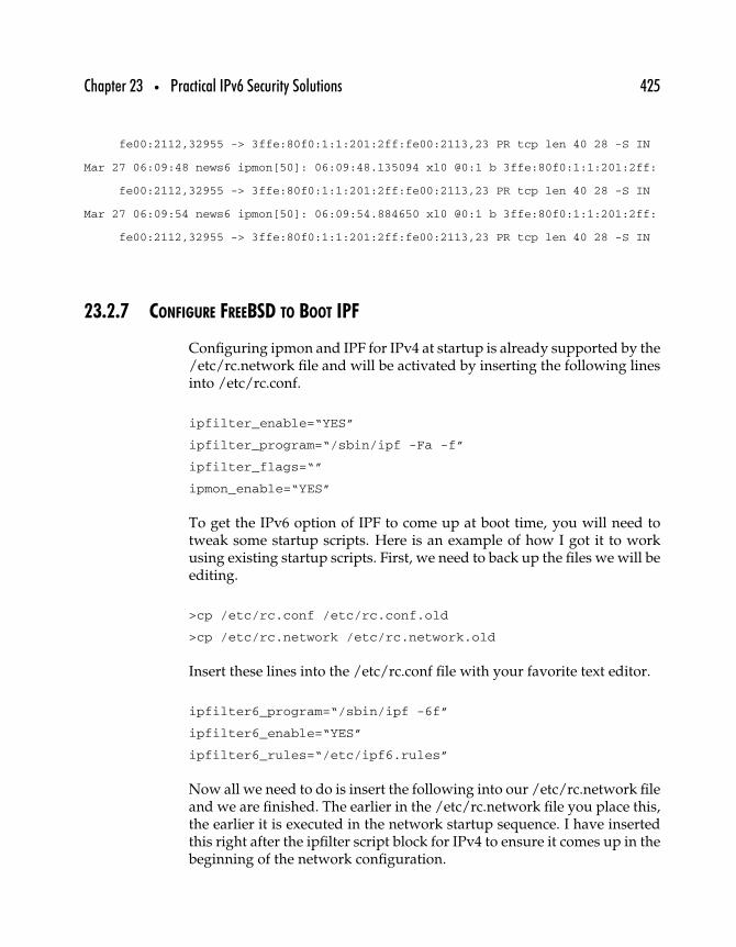
Chapter 23 • Practical IPv6 Security Solutions 425
fe00:2112,32955 -> 3ffe:80f0:1:1:201:2ff:fe00:2113,23 PR tcp len 40 28 -S IN
Mar 27 06:09:48 news6 ipmon[50]: 06:09:48.135094 xl0 @0:1 b 3ffe:80f0:1:1:201:2ff:
fe00:2112,32955 -> 3ffe:80f0:1:1:201:2ff:fe00:2113,23 PR tcp len 40 28 -S IN
Mar 27 06:09:54 news6 ipmon[50]: 06:09:54.884650 xl0 @0:1 b 3ffe:80f0:1:1:201:2ff:
fe00:2112,32955 -> 3ffe:80f0:1:1:201:2ff:fe00:2113,23 PR tcp len 40 28 -S IN
23.2.7 CONFIGURE FREEBSD TO BOOT IPF
Configuring ipmon and IPF for IPv4 at startup is already supported by the/etc/rc.network file and will be activated by inserting the following linesinto /etc/rc.conf.
ipfilter_enable=“YES”
ipfilter_program=“/sbin/ipf -Fa -f”
ipfilter_flags=“”
ipmon_enable=“YES”
To get the IPv6 option of IPF to come up at boot time, you will need totweak some startup scripts. Here is an example of how I got it to workusing existing startup scripts. First, we need to back up the files we will beediting.
>cp /etc/rc.conf /etc/rc.conf.old
>cp /etc/rc.network /etc/rc.network.old
Insert these lines into the /etc/rc.conf file with your favorite text editor.
ipfilter6_program=“/sbin/ipf -6f”
ipfilter6_enable=“YES”
ipfilter6_rules=“/etc/ipf6.rules”
Now all we need to do is insert the following into our /etc/rc.network fileand we are finished. The earlier in the /etc/rc.network file you place this,the earlier it is executed in the network startup sequence. I have insertedthis right after the ipfilter script block for IPv4 to ensure it comes up in thebeginning of the network configuration.
426 Part Three • IPv6 Practice
case “${ipfilter6_enable}” in [Yy][Ee][Ss])
if [ -r “${ipfilter6_rules}” ]; then
${ipfilter6_program} “${ipfilter6_rules}”
fi
;; esac
23.2.8 TROUBLESHOOTING
If the installation does not work or breaks your current kernel configu-ration, change directories to where you have IPF’s package source andfollow these steps to revert all changes made (substitute GENERIC withyour kernel name if needed).
>cd ip_fil3.4.16/FreeBSD-4.0/
>./kuninstall
>cd /sys/i386/conf
>cp GENERIC.bak GENERIC
Now rebuild the kernel with IPF.
23.3 Implementing IPsec on Sun Solaris (IPv4)†
IPsec provides IP-layer security for packets traversing a network—particularly useful when the network in question is insecure—like theInternet. The protection provided includes encryption (providing confi-dentiality), data-origin authentication (the receiving node can be sure thetraffic originated at the node shown in the source address), data integrity(the data was not changed in transit), and antireplay (the traffic cannot beregenerated later and accepted as current by the receiver).
Native IPsec support is a key advantage of IPv6 over IPv4. Whereas inIPv4 IPsec support was an option, it is mandated in IPv6. There willbe no IPv6-compliant (i.e., commercially marketable) network protocolimplementations that do not support IPsec.
†This section is adapted from a document written by John E. Spence, © Zama Networks.
Chapter 23 • Practical IPv6 Security Solutions 427
As we learned from the rapid adoption of the Internet—which followedthe widespread adoption of IP networking—when technology is widelysupported, the “network-effect” causes prolific growth in its use. I believethe growth of IPsec will be the same. Near-term future networks basedon IPv6 will make widespread use of IPsec-based data security. The dayswhere most traffic is carried unencrypted may, eventually, come to an end,and it will be a rare packet that will not be encrypted and authenticated. Justas you can’t imaging sending important (read “most all”) paper documentsin “postcard” form through the mail, data on networks will be treated inthe same way.
For now at least, most packets will still be transmitted in the clear. Althoughnot all network data is confidential, traffic analysis attacks depend on hav-ing some volume of encrypted and/or unencrypted data to analyze. Theabsence of certain types of data in the unencrypted flows can be used toinfer what the encrypted packets are carrying. Furthermore, encryptingonly the confidential data simplifies the task of any attackers: They don’thave to worry about trying to decrypt anything but the most valuablepackets.
This section describes in detail how to obtain, install, and configure IPsecon Sun Solaris 8 (SPARC and Intel architecture) over IPv4.
23.3.1 KEY IPSEC CONCEPTS IN A NUTSHELL
IPsec provides two major components, ESP and AH. ESP stands for“Encapsulating Security Payload,” which provides confidentiality, dataintegrity, and data source authentication of IP packets. AH stands for“Authentication Header,” which provides data integrity and data sourceauthentication of IP packets—but no confidentiality. We’ll use ESP so we’llget all the protection we can.
Also required for IPsec are “Security Associations” (SAs). These specifythe particular security association (called an SPI), packet destination, andprotocol. SAs are unidirectional, so each host participating in an IPsecconversation must have at least two (and sometimes more) SAs.
Sun’s current implementation only supports “manual SAs.” That meanswe must create the SAs manually and manage them manually. Futurereleases will incorporate automatic systems for key management (notablyInternet Key Exchange, or IKE).

428 Part Three • IPv6 Practice
23.3.2 ESTABLISH A BASELINE
We’ll use “telnet” to test our IPsec connection, so, before we start make sureyou can telnet in both directions between your machines. This will give usconfidence if we have problems later that there are no non-IPsec-relatedproblems with interface configurations, routes, cables, or anything else.
Set a performance baseline too. For my machines, I was able to achieve 3715Kbytes/second while ftp’ing a 98MB file “in the clear.” While using IPsec(DES encryption and MD5 authentication) my performance was reducedto 1601 KB/second.
23.3.3 COLLECT THE COMPONENTS YOU’LL NEED
You’ll need the following.
• “Solaris 8 Supplemental Encryption Packages” from Sun,www.sun.com/software/solaris/get.html get the distributionyou need for your platform.
• Regardless of which flavor of Solaris 8 you’re using (SPARC orIntel), we need two machines to set up IPSec. Throughout thisdocument we’ll call them “sea-mach1” and “sea-mach2.”
23.3.4 INSTALLING THE IPSEC COMPONENTS
After you have the packages on your machine, untar them. Change intothe local directory “sparc/Packages.” You’ll be left with a directory thatlooks like this.
sea-mach1# ls
NSCPcomdo SUNWamid SUNWcrman SUNWcry64 SUNWcryrx SUNWk5pkx SUNWk5pux
NSCPfrcdo SUNWamidx SUNWcry SUNWcryr SUNWk5pk SUNWk5pu
Run the “pkgadd” command as “pkgadd -d .,” and you’ll see this.
sea-mach1# pkgadd -d .
The following packages are available:
1 NSCPcomdo Netscape Communicator
(sparc) 20.4.70,REV=1999.10.13.17.55
Chapter 23 • Practical IPv6 Security Solutions 429
2 NSCPfrcdo French Netscape Communicator (U.S. security)
(sparc) 20.4.70,REV=1999.11.05.13.36
3 SUNWamid Authentication Management Infrastructure (domestic version)
(sparc) 11.8.0,REV=1999.12.07.04.22
4 SUNWamidx Authentication Management Infrastructure
(64 bit domestic version)
(sparc) 11.8.0,REV=1999.12.07.04.22
5 SUNWcrman Encryption Kit On-Line Manual Pages
(sparc) 6.0,REV=1
6 SUNWcry Crypt Utilities
(sparc) 11.8.0,REV=1999.12.07.04.22
7 SUNWcry64 Prototype package for Crypt Library (64-bit)
(sparc) 11.8.0,REV=1999.12.07.04.22
8 SUNWcryr Solaris Root Crypto
(sparc) 11.8.0,REV=1999.12.07.04.22
9 SUNWcryrx Solaris Root Crypto (64-bit)
(sparc) 11.8.0,REV=1999.12.07.04.22
10 SUNWk5pk kernel Kerberos V5 plug-in w/auth+privacy (32-bit)
(sparc) 11.8.0,REV=1999.12.07.04.22
... 3 more menu choices to follow;
<RETURN> for more choices, <CTRL-D> to stop display:
11 SUNWk5pkx kernel Kerberos V5 plug-in w/auth+privacy (64-bit)
(sparc) 11.8.0,REV=1999.12.07.04.22
12 SUNWk5pu user Kerberos V5 gss mechanism w/auth+privacy (32-bit)
(sparc) 11.8.0,REV=1999.12.07.04.22
13 SUNWk5pux user Kerberos V5 gss mechanism w/auth+privacy (64-bit)
(sparc) 11.8.0,REV=1999.12.07.04.22
Select package(s) you wish to process (or ’all’ to
process all packages). (default: all) [?,??,q]:
Choose 3, 4, 5, 6, 7, 8, and 9. We don’t need the Kerberos products forIPsec. All the packages should install fine.
23.3.5 CONFIGURING IPSEC
Initial configurations for both machines are identical. We’ll show detailsfor sea-mach1, but sea-mach2 is similar. Later, we’ll set up the

430 Part Three • IPv6 Practice
IPsec parameters and static SAs, and we’ll show both machines forclarity.
Let’s lay some groundwork. DNS can provide a security vulnerability. Ifa system relies on DNS to translate system names into IP addresses, andthat DNS has been compromised, all kinds of problems can occur. Forthis reason, it is usually best to put entries in “/etc/hosts” for machinesthat are using IPsec. You’ll also want to make sure that the machines“/etc/nsswitch.conf” file has this entry for “hosts.”
hosts: files dns
This means the machine will check the “/etc/hosts” records first whenmatching a name—before using DNS for address resolution. Here’s our“/etc/hosts” file.
sea-mach1# cat /etc/hosts
# Internet host table
127.0.0.1 localhost
192.168.210.34 sea-mach1.zama6.com sea-mach1 ipv6s1.zama6.com ipv6s1 loghost
192.168.210.51 sea-mach2.zama6.com sea-mach2
You’ll want a similar—but not identical—file on your IPsec partner system.
Next, we have to tell the machine to load the IPSec modules at boot-time.There should be a file in “/etc/inet” called “ipsecinit.sample.” Copy thisfile to “ipsecinit.conf.” To begin, the file can contain nothing (or nothingbut comments). Just the fact that it exists will get IPsec loaded.
Create a place to put your IPsec config files. I’m using “/etc/ipsec-conf.”You’ll need two files—one to contain the SAs and one to contain the IPsecconfiguration.
23.3.6 CREATE THE SECURITY ASSOCIATIONS
Create the file “keys-all” (this file should have permissions 600—the keysmust be kept private). This file will contain our SAs. Here’s what minelooks like.
sea-mach1# cat keys-all
add esp spi 0x4444 src sea-mach2.zama6.com dst ipv6s1.zama6.com auth_alg md5 encr_alg
des \

Chapter 23 • Practical IPv6 Security Solutions 431
authkey 1234567890abcdef1234567890abcdef encrkey 1234567890abcdef
add esp spi 0x5555 src ipv6s1.zama6.com dst sea-mach2.zama6.com auth_alg md5
encr_alg
des \
authkey 1234567890abcdef1234567890abcdef encrkey 1234567890abcdef
Let’s examine each line. The first line adds an SA for traffic headed for ourIPsec partner. Let’s look at each field in the first line—you can figure outthe second line.
add means we’re adding an SA.esp specifies that this is an ESP SA, as opposed to an
authentication-and-integrity (AH) SA.0x4444 is the “SPI,” which uniquely identifies this SA.src sea-mach2.zama6.com specifies the source for this SA is
sea-mach2.dst ipv6s1.zama6.com specifies the destination for this SA.auth_alg md5 specifies the authentication method we are
using—md5 in this case.encr_alg des specifies the encryption method we are using—des
(3des is also available).authkey 1234567890abcdef1234567890abcdef 128-bit md5 keyencrkey 1234567890abcdef 64-bit des key
Put this file on both machines—exactly like this. Each encrypted packetwill carry the “SPI” number used for the encryption/authentication, sothe recipient machine must have the same keys associated with the sameSPI. (By the way, these are lousy keys, used only for ease of demonstration.Choose a very random key.)
To enable these keys, use the command “ipseckey -f keys-all.” To flush thekeys, you can use “ipseckey flush” and then reload them.
23.3.7 CREATE THE SECURITY POLICIES
Now we’ll create our IPsec configuration. Create the file “both-all.” Here’swhat mine looks like.
sea-mach1# cat both-all
{
saddr ipv6s1.zama6.com
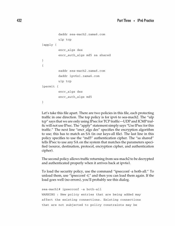
432 Part Three • IPv6 Practice
daddr sea-mach2.zama6.com
ulp tcp
}apply {
encr_algs des
encr_auth_algs md5 sa shared
}
{
saddr sea-mach2.zama6.com
daddr ipv6s1.zama6.com
ulp tcp
}permit {
encr_algs des
encr_auth_algs md5
}
Let’s take this file apart. There are two policies in this file, each protectingtraffic in one direction. The top policy is for ipv6 to sea-mach2. The “ulptcp” says that we are only using IPsec for TCP traffic—UDP and ICMP traf-fic will not use IPsec. The “apply” statement simply says “Use IPsec for thistraffic.” The next line “encr_algs des” specifies the encryption algorithmto use; this has to match an SA (in our keys-all file). The last line in thispolicy specifies to use the “md5” authentication cipher. The “sa shared”tells IPsec to use any SA on the system that matches the parameters speci-fied (source, destination, protocol, encryption cipher, and authenticationcipher).
The second policy allows traffic returning from sea-mach2 to be decryptedand authenticated properly when it arrives back at ipv6s1.
To load the security policy, use the command “ipsecconf -a both-all.” Tounload them, use “ipsecconf -f,” and then you can load them again. If theload goes well (no errors), you’ll probably see this dialog.
sea-mach1# ipsecconf -a both-all
WARNING : New policy entries that are being added may
affect the existing connections. Existing connections
that are not subjected to policy constraints may be
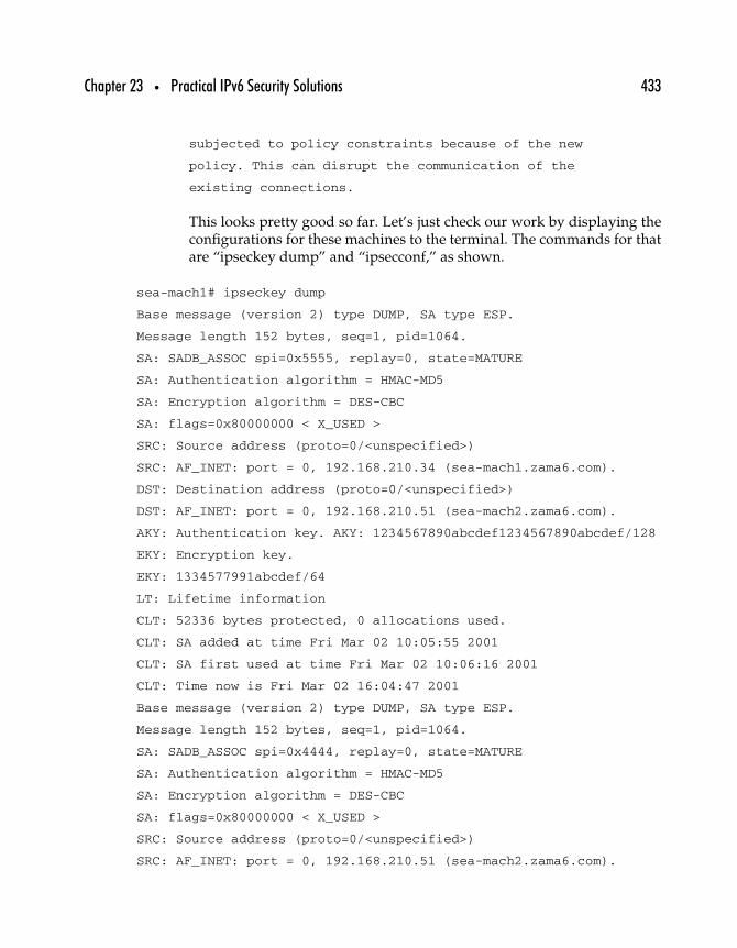
Chapter 23 • Practical IPv6 Security Solutions 433
subjected to policy constraints because of the new
policy. This can disrupt the communication of the
existing connections.
This looks pretty good so far. Let’s just check our work by displaying theconfigurations for these machines to the terminal. The commands for thatare “ipseckey dump” and “ipsecconf,” as shown.
sea-mach1# ipseckey dump
Base message (version 2) type DUMP, SA type ESP.
Message length 152 bytes, seq=1, pid=1064.
SA: SADB_ASSOC spi=0x5555, replay=0, state=MATURE
SA: Authentication algorithm = HMAC-MD5
SA: Encryption algorithm = DES-CBC
SA: flags=0x80000000 < X_USED >
SRC: Source address (proto=0/<unspecified>)
SRC: AF_INET: port = 0, 192.168.210.34 (sea-mach1.zama6.com).
DST: Destination address (proto=0/<unspecified>)
DST: AF_INET: port = 0, 192.168.210.51 (sea-mach2.zama6.com).
AKY: Authentication key. AKY: 1234567890abcdef1234567890abcdef/128
EKY: Encryption key.
EKY: 1334577991abcdef/64
LT: Lifetime information
CLT: 52336 bytes protected, 0 allocations used.
CLT: SA added at time Fri Mar 02 10:05:55 2001
CLT: SA first used at time Fri Mar 02 10:06:16 2001
CLT: Time now is Fri Mar 02 16:04:47 2001
Base message (version 2) type DUMP, SA type ESP.
Message length 152 bytes, seq=1, pid=1064.
SA: SADB_ASSOC spi=0x4444, replay=0, state=MATURE
SA: Authentication algorithm = HMAC-MD5
SA: Encryption algorithm = DES-CBC
SA: flags=0x80000000 < X_USED >
SRC: Source address (proto=0/<unspecified>)
SRC: AF_INET: port = 0, 192.168.210.51 (sea-mach2.zama6.com).
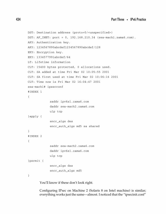
434 Part Three • IPv6 Practice
DST: Destination address (proto=0/<unspecified>)
DST: AF_INET: port = 0, 192.168.210.34 (sea-mach1.zama6.com).
AKY: Authentication key.
AKY: 1234567890abcdef1234567890abcdef/128
EKY: Encryption key.
EKY: 1334577991abcdef/64
LT: Lifetime information
CLT: 15400 bytes protected, 0 allocations used.
CLT: SA added at time Fri Mar 02 10:05:55 2001
CLT: SA first used at time Fri Mar 02 10:06:16 2001
CLT: Time now is Fri Mar 02 16:04:47 2001
sea-mach1# ipsecconf
#INDEX 1
{
saddr ipv6s1.zama6.com
daddr sea-mach2.zama6.com
ulp tcp
}apply {
encr_algs des
encr_auth_algs md5 sa shared
}
#INDEX 2
{
saddr sea-mach2.zama6.com
daddr ipv6s1.zama6.com
ulp tcp
}permit {
encr_algs des
encr_auth_algs md5
}
You’ll know if these don’t look right.
Configuring IPsec on Machine 2 (Solaris 8 on Intel machine) is similar;everything works just the same—almost. I noticed that the “ipsecinit.conf”
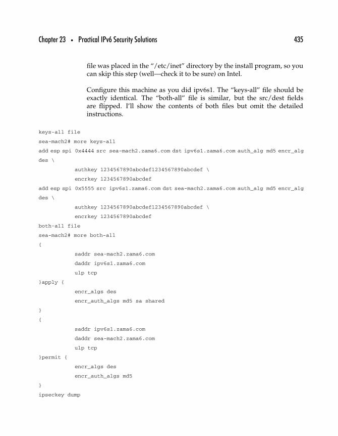
Chapter 23 • Practical IPv6 Security Solutions 435
file was placed in the “/etc/inet” directory by the install program, so youcan skip this step (well—check it to be sure) on Intel.
Configure this machine as you did ipv6s1. The “keys-all” file should beexactly identical. The “both-all” file is similar, but the src/dest fieldsare flipped. I’ll show the contents of both files but omit the detailedinstructions.
keys-all file
sea-mach2# more keys-all
add esp spi 0x4444 src sea-mach2.zama6.com dst ipv6s1.zama6.com auth_alg md5 encr_alg
des \
authkey 1234567890abcdef1234567890abcdef \
encrkey 1234567890abcdef
add esp spi 0x5555 src ipv6s1.zama6.com dst sea-mach2.zama6.com auth_alg md5 encr_alg
des \
authkey 1234567890abcdef1234567890abcdef \
encrkey 1234567890abcdef
both-all file
sea-mach2# more both-all
{
saddr sea-mach2.zama6.com
daddr ipv6s1.zama6.com
ulp tcp
}apply {
encr_algs des
encr_auth_algs md5 sa shared
}
{
saddr ipv6s1.zama6.com
daddr sea-mach2.zama6.com
ulp tcp
}permit {
encr_algs des
encr_auth_algs md5
}
ipseckey dump
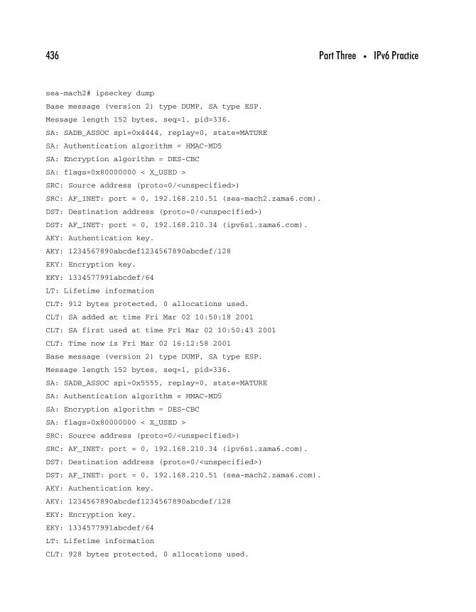
436 Part Three • IPv6 Practice
sea-mach2# ipseckey dump
Base message (version 2) type DUMP, SA type ESP.
Message length 152 bytes, seq=1, pid=336.
SA: SADB_ASSOC spi=0x4444, replay=0, state=MATURE
SA: Authentication algorithm = HMAC-MD5
SA: Encryption algorithm = DES-CBC
SA: flags=0x80000000 < X_USED >
SRC: Source address (proto=0/<unspecified>)
SRC: AF_INET: port = 0, 192.168.210.51 (sea-mach2.zama6.com).
DST: Destination address (proto=0/<unspecified>)
DST: AF_INET: port = 0, 192.168.210.34 (ipv6s1.zama6.com).
AKY: Authentication key.
AKY: 1234567890abcdef1234567890abcdef/128
EKY: Encryption key.
EKY: 1334577991abcdef/64
LT: Lifetime information
CLT: 912 bytes protected, 0 allocations used.
CLT: SA added at time Fri Mar 02 10:50:18 2001
CLT: SA first used at time Fri Mar 02 10:50:43 2001
CLT: Time now is Fri Mar 02 16:12:58 2001
Base message (version 2) type DUMP, SA type ESP.
Message length 152 bytes, seq=1, pid=336.
SA: SADB_ASSOC spi=0x5555, replay=0, state=MATURE
SA: Authentication algorithm = HMAC-MD5
SA: Encryption algorithm = DES-CBC
SA: flags=0x80000000 < X_USED >
SRC: Source address (proto=0/<unspecified>)
SRC: AF_INET: port = 0, 192.168.210.34 (ipv6s1.zama6.com).
DST: Destination address (proto=0/<unspecified>)
DST: AF_INET: port = 0, 192.168.210.51 (sea-mach2.zama6.com).
AKY: Authentication key.
AKY: 1234567890abcdef1234567890abcdef/128
EKY: Encryption key.
EKY: 1334577991abcdef/64
LT: Lifetime information
CLT: 928 bytes protected, 0 allocations used.

Chapter 23 • Practical IPv6 Security Solutions 437
CLT: SA added at time Fri Mar 02 10:50:18 2001
CLT: SA first used at time Fri Mar 02 10:50:43 2001
CLT: Time now is Fri Mar 02 16:12:58 2001
Dump succeeded for SA type 0.
ipsecconf
sea-mach2# ipsecconf
#INDEX 1
{
saddr sea-mach2.zama6.com
daddr ipv6s1.zama6.com
ulp tcp
}apply {
encr_algs des
encr_auth_algs md5 sa shared
}
#INDEX 2
{
saddr ipv6s1.zama6.com
daddr sea-mach2.zama6.com
ulp tcp
}permit {
encr_algs des
encr_auth_algs md5
}
23.3.8 GIVE IT A TRY
Let’s use “snoop” on the box that is the target of your telnet—just to con-vince ourselves IPsec is really working. Run the command “snoop hostsea-mach2” on the target machine.
Now, at the source machine, run the command “telnet ipv6s1.” If youget the telnet login herald, then it works. Here’s what you should see inyour “snoop” window (this is just for the login herald, not the whole loginprocess—I did a CNTRL-D).
sea-mach2.zama6.com -> sea-mach1.zama6.com ESP SPI=0x4444 Replay=53
sea-mach1.zama6.com -> sea-mach2.zama6.com ESP SPI=0x5555 Replay=389

438 Part Three • IPv6 Practice
sea-mach2.zama6.com -> sea-mach1.zama6.com ESP SPI=0x4444 Replay=54
sea-mach2.zama6.com -> sea-mach1.zama6.com ESP SPI=0x4444 Replay=55
sea-mach1.zama6.com -> sea-mach2.zama6.com ESP SPI=0x5555 Replay=390
sea-mach1.zama6.com -> sea-mach2.zama6.com ESP SPI=0x5555 Replay=391
sea-mach2.zama6.com -> sea-mach1.zama6.com ESP SPI=0x4444 Replay=56
sea-mach1.zama6.com -> sea-mach2.zama6.com ESP SPI=0x5555 Replay=392
sea-mach2.zama6.com -> sea-mach1.zama6.com ESP SPI=0x4444 Replay=57
sea-mach2.zama6.com -> sea-mach1.zama6.com ESP SPI=0x4444 Replay=58
sea-mach1.zama6.com -> sea-mach2.zama6.com ESP SPI=0x5555 Replay=393
You can see that the packets are tagged “ESP” and give the “SPI” numberin our “keys-all” file. You also see the “Replay” field—these are sequentialfor each machine’s source packets.
You learn even more if you use the command “snoop -v host sea-mach2.”This is the “verbose” output, and it gives you much more insight. Hereyou see the details of the IP Header, ESP (Payload), and Ethernet Header.Note the line that says “ ESP: . . . . ENCRYPTED DATA . . . .”—that’s whereyour encrypted data lives.
----- IP Header -----
IP:
IP: Version = 4
IP: Header length = 20 bytes
IP: Type of service = 0x00
IP: xxx. .... = 0 (precedence)
IP: ...0 .... = normal delay
IP: .... 0... = normal throughput
IP: .... .0.. = normal reliability
IP: Total length = 72 bytes
IP: Identification = 22733
IP: Flags = 0x4
IP: .1.. .... = do not fragment
IP: ..0. .... = last fragment
IP: Fragment offset = 0 bytes
IP: Time to live = 64 seconds/hops
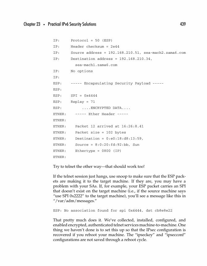
Chapter 23 • Practical IPv6 Security Solutions 439
IP: Protocol = 50 (ESP)
IP: Header checksum = 2e44
IP: Source address = 192.168.210.51, sea-mach2.zama6.com
IP: Destination address = 192.168.210.34,
sea-mach1.zama6.com
IP: No options
IP:
ESP: ----- Encapsulating Security Payload -----
ESP:
ESP: SPI = 0x4444
ESP: Replay = 71
ESP: ....ENCRYPTED DATA....
ETHER: ----- Ether Header -----
ETHER:
ETHER: Packet 12 arrived at 16:26:8.41
ETHER: Packet size = 102 bytes
ETHER: Destination = 0:e0:18:d8:13:59,
ETHER: Source = 8:0:20:fd:92:bb, Sun
ETHER: Ethertype = 0800 (IP)
ETHER:
Try to telnet the other way—that should work too!
If the telnet session just hangs, use snoop to make sure that the ESP pack-ets are making it to the target machine. If they are, you may have aproblem with your SAs. If, for example, your ESP packet carries an SPIthat doesn’t exist on the target machine (i.e., if the source machine says“use SPI 0x2222” to the target machine), you’ll see a message like this in“/var/adm/messages.”
ESP: No association found for spi 0x4444, dst cb8e8e22
That pretty much does it. We’ve collected, installed, configured, andenabled encrypted, authenticated telnet services machine-to-machine. Onething we haven’t done is to set this up so that the IPsec configuration isrecovered if you reboot your machine. The “ipseckey” and “ipsecconf”configurations are not saved through a reboot cycle.
440 Part Three • IPv6 Practice
To configure the security policy to rebuild at boot-time, create a file called“/etc/rc2.d/S99IPSec-configure” that looks like this.
#/bin/ksh
ipseckey -f /etc/ipsec-config/keys-all
ipsecconf -a /etc/ipsec-config/both-all
Reboot your machine to check that it works.
23.4 Building TCP Wrapper for IPv6 on Solaris 8‡
This section describes in detail how to obtain, compile, and configure TCPWrapper for use with IPv6.
23.4.1 Gathering the Pieces
Here’s a brief list of what you’ll need for this project.
• The ability to compile binaries from source code. This usuallymeans a working gcc installation coupled with the necessarycompilation utilities (e.g., make, ld, etc.).
• The ability to uncompress files with gzip.• The ability to un-bundle file packages with tar.• The IPv6-enabled TCP Wrapper source code. Version 7.6-ipv6.1
is the most recent version and can be found on Wietse Venema’sWeb site (http://www.porcupine.org).
23.4.2 BUILDING TCP WRAPPER
On the Internet today, whether you’re communicating over IPv4 or IPv6,installing additional security measures on your system is never a badthing. TCP Wrapper adds another layer of authentication to just aboutany service that’s controlled by inetd. In addition, TCP Wrapper makes
‡This section is adapted from a document written by Robert C. Zilbauer Jr., © ZamaNetworks.
Chapter 23 • Practical IPv6 Security Solutions 441
its authentication library available to any other application wishing to useWrapper-style access control.
The first thing you need to do is to obtain the latest TCP Wrapper sourcecode from the preceding Web site. For use with IPv6, you’ll need thesource package that contains the IPv6 modifications made by Casper Dik(version 7.6-ipv6.1).
Like most source packages, TCP Wrapper comes compressed and bundledinto a tar file. If you’re using the GNU version of tar, you can un-tar thepackage at the same time that you’re uncompressing it. The followingcommand will accomplish this.
% tar fxz tcp_wrappers_7.6-ipv6.1.tar.gz
Otherwise, you’ll have to uncompress the package first and then proceedwith the tar command.
% gzip d tcp_wrappers_7.6-ipv6.1.tar.gz
% tar fx tcp_wrappers_7.6-ipv6.1.tar
Once you’ve uncompressed and extracted the source from the tar file, theprocess of compiling the code may be a little different from what you’reused to. Unlike many source distributions, TCP Wrapper doesn’t comewith any automated configure script to set up your compilation environ-ment for you. All this means is that you have to edit the Makefile by handto suit your needs.
Drop down into the directory created by the preceding tar commandand, using your favorite text editor (e.g., emacs or vi - not pico!), openthe Makefile for editing. First, skip down to the “Advanced Installation”section and look for the “SysV.4 Solaris 2.x OSF AIX” definition. Uncom-ment (i.e., remove the # symbol from the beginning of the line) thedefinition for REAL_DAEMON_DIR so that it is set to /usr/sbin. Onceyou’ve made this change, your REAL_DAEMON_DIR line will look likethis.
REAL_DAEMON_DIR=/usr/sbin
Now, move down quite a ways in the file until you come to the sectionentitled “System dependencies: selection of non-default object libraries.”
442 Part Three • IPv6 Practice
Here, again, you’ll want to uncomment the “SysV.4 Solaris 2.x” definitionso that your LIBS looks like this.
LIBS = -lsocket lnsl # SysV.4 Solaris 2.x
This next step is the reason you started reading this document in the firstplace. Skip down another few sections until you get to the one labeled“System dependencies: whether or not your system has IPV6.” Since we’reworking with Solaris 8, uncomment the first definition of IPV6 so that itlooks like this.
IPV6 = -DHAVE_IPV6
As far as enabling IPv6 in the code, that’s all you have to do. As a matterof fact, you’re done with all of the necessary changes to the Makefile aswell. As a personal preference, I usually make one more change. In the“Optional: Changing the default disposition of logfile records” section, I’llchange the FACILITY definition to LOG_LOCAL0. What this allows youto do is add a line like this
local0.info /var/adm/tcpd.log
to your /etc/syslog.conf file which will then record all messages comingfrom TCP Wrapper in their own log file (/var/adm/tcpd.log). This makeschecking for security incidents a little easier. Of course, as the title of thesection says, this is just an optional change. If you don’t want to do it,I promise not to take it personally.
Once you’ve made all of the necessary, and any of the optional, changesto the Makefile, save the file and exit out of the text editor. Back at thecommand prompt, begin the compilation process with the appropriatemake command. Since we’re building the binaries for Solaris, you shoulduse this command.
% make sunos5
23.4.3 INSTALLATION
Assuming that all goes well during compilation, you’re ready to install theresulting binaries into their final resting places. The installation process,
Chapter 23 • Practical IPv6 Security Solutions 443
like the configuration you had to do, must be done by hand. Currently,there is no automated way to install the binaries after compiling. However,installation is as simple as a series of cp commands.
If you haven’t already done so you’ll have to become root to do theinstallation. First, install the actual executables in the standard directory,/usr/local/sbin. There are five executables that you’ll want to copy in thisstep: tcpd, tcpdmatch, try-from, safe_finger, and tcpdchk. The commandline to do this would look something like this.
# cp tcpd tcpdmatch try-from safe_finger tcpdchk /usr/local/sbin
tcpd is the actual wrapper program. tcpdmatch and try-from are bothused in testing your installation once you have TCP Wrapper fully con-figured. safe_finger is a wrapper for the finger command and can be usedif you want to do automatic fingering of questionable connections. Thesafe_finger wrapper makes the finger command more robust and securefor such use. Last, the tcpdchk program checks through your configurationfiles for errors.
Should another program wish to easily include TCP Wrapper–styleauthentication, it can use the libwrap.a library that was built during thecompilation process. To make this library available to other packages,you need to put it in a standard directory for libraries. A good choicewould be /usr/local/lib. To get the functionality out of this library thetcpd.h file must also be available. A standard place for header files like thisone is /usr/local/include. Therefore, your next two commands will looksomething like this.
# cp libwrap.a /usr/local/lib
# cp tcpd.h /usr/local/include
All that’s left to install are the documentation files. TCP Wrapper comeswith several pages that need to be copied into the appropriate directoriesfor the man command to use. The easiest way to install them is by manpage section. There are files available for sections 3, 5, and 8, so your nextthree commands will look like this.
# cp *.3 /usr/local/man/man3
# cp *.5 /usr/local/man/man5
# cp *.8 /usr/local/man/man8
444 Part Three • IPv6 Practice
And that’s that. You’ve just completed the installation of TCP Wrapperand all its man pages. All that remains is configuration. Luckily, that’s thevery next section.
23.4.4 CONFIGURATION
Before running recklessly into configuring your new software, you shouldmake some decisions regarding what services you wish to wrap and whatyour end result should be. For our example, we’ll assume we want thefollowing.
• Telnet access allowed for people coming from 192.168.3.8• Telnet access allowed for people coming from any IPv6 host
under the 3ffe:80f0:1:1:: prefix• FTP access allowed only for people coming from 3ffe:80f0:10:1:
201:2ff:dead:feed• Everyone else denied for all services
The first thing you’ll need to do is actually “wrap” the services in inetd.confthat you want wrapped. This is as simple as changing the value in thecolumn that tells inetd which daemon it should run. To wrap a service,substitute the path to tcpd for the path to the daemon. For example, withthe telnet service, the original line in /etc/inetd.conf looks like this.
telnet stream tcp6 nowait root /usr/sbin/in.telnetd in.telnetd
To wrap this service, you’d simply change the /usr/sbin/in.telnetd partto /usr/local/sbin/tcpd. Thus, the inetd.conf line for a wrapped telnetservice would look like this.
telnet stream tcp6 nowait root /usr/local/sbin/tcpd in.telnetd
Piece of cake. Now, according to what we decided earlier, we alsowant to wrap the FTP service, so do the same for the ftp entry in your/etc/inetd.conf file. Once that’s done, the inetd.conf lines for the telnetand FTP services will look like this.
ftp stream tcp6 nowait root /usr/local/sbin/tcpd in.ftpd
telnet stream tcp6 nowait root /usr/local/sbin/tcpd in.telnetd
Once you’ve made these changes, send the inetd process a HUP signal. Thistells inetd to reread its configuration file. First, determine what process ID

Chapter 23 • Practical IPv6 Security Solutions 445
the inetd process is running under. Then send that process ID the HUPsignal.
# ps -ef | grep inetd
root 164 1 0 Feb 05 ? 0:08 /usr/sbin/inetd-
s -t
# kill -HUP 164
You’ve just successfully wrapped ftp and telnet with TCP Wrapper.The last step is to set up the security rules that control connectionauthentication.
This part is accomplished using two different files: /etc/hosts.allow and/etc/hosts.deny. As the names suggest, the former indicates connectionsthat are permitted, while the latter controls the denial of unwanted con-nections. When a connection attempt is made, the first rule that matchesthe connection information is the one that applies. Also, the first file tobe checked is /etc/hosts.allow. Keep that in mind as you’re creating yoursecurity rules.
Using the example requirements we just set for ourselves, we’ll start withthe easiest rules file first: /etc/hosts.deny. Chances are you don’t havethis file yet, so you’ll have to create it. It’s in this file that we’ll specifyour default “deny everyone from everything” rule. To make this happen,create /etc/hosts.deny and give it the following contents.
#
# /etc/hosts.deny
#
ALL: ALL
As the rule says, deny ALL hosts (the entry after the colon) from ALLservices (the entry before the colon). While being very secure, it’s not aterribly productive configuration, so let’s continue. The next file you’llwant to create is /etc/hosts.allow. It’s in this file that you’ll start to punchholes in your default deny rule to allow your friends and colleagues intoyour new IPv6 system.
First, we’ll handle our telnet rules. Previously, we indicated that wewanted telnet open to people coming in from 192.168.3.8 as well as people
446 Part Three • IPv6 Practice
coming in from any IPv6 host under the 3ffe:80f0:1:1:: prefix. To start thingsoff, you need to indicate that this rule applies to the telnet service. Beginyour line in /etc/hosts.allow with the name of the daemon for which thisrule applies—in this case, the following.
in.telnetd:
Now follow that with the addresses of the hosts who should be allowedto use this service. In the case of IPv4 addresses, you can just enter themnormally.
in.telnetd: 192.168.3.8
IPv6 addresses, on the other hand, must be surrounded by square brackets([ ]). They can either be specified as a single IPv6 address, or you can specifya range of addresses by using a prefix/mask notation. In our case, we wanteveryone coming in from a host within the 3ffe:80f0:1:1:: network to be ableto connect, so we’ll be using the prefix/mask notation. Also, multiple hostson the same line must be separated by spaces. Therefore, the final line inthe rules file for telnet will look like this.
in.telnetd: 192.168.3.8 [3ffe:80f0:1:1::/64]
Our FTP rule will be much easier. As we defined earlier, we want anyonecoming from 3ffe:80f0:10:1:201:2ff:dead:feed to be able to connect to ourFTP service. Following the preceding format, the line in /etc/hosts.allowfor the FTP service will look like this.
in.ftpd: [3ffe:80f0:10:1:201:2ff:dead:feed]
There are more options available for use in the hosts.deny and hosts.allowfiles, but these are the basics. For more information, I recommend takinga look at the hosts_access(5) man page. What you have just accomplished,however, fulfills all of the security requirements we set forth at the begin-ning of this section. For the sake of easy visualization, here’s what thecompleted /etc/hosts.allow file looks like.
#
# /etc/hosts.allow
#
Chapter 23 • Practical IPv6 Security Solutions 447
in.telnetd: 192.168.3.8 [3ffe:80f0:1:1::/64]
in.ftpd: [3ffe:80f0:10:1:201:2ff:dead:feed]
Also, since TCP Wrapper is run each time a wrapped service is requested,there’s no need to start/stop a daemon or kill -HUP a process when youmake a change to the rules files.
23.5 Summary
No prudent network administrator would skimp on security systems,and the use of packet filtering firewalls, IPsec, and TCP Wrappers asdescribed here should be considered and adapted for any IPv6 network—even testbeds. Once the security systems are in place and routing is live,applications like DNS and email can be rolled out as described in the nextchapter.


This Page Intentionally Left Blank
2424
Email and DNSUnder IPv6
This chapter provides step-by-step instructions for setting up DNS servicesunder IPv6, including setting up BIND, as well as a section detailing theprocess of setting up an email server under IPv6.
24.1 Building BIND 9 with OpenSSL Support*
This section explains in detail how to obtain and compile both OpenSSLand BIND 9 for use with an IPv6 DNS system.
∗This section is adapted from a document written by Robert C. Zilbauer Jr., © ZamaNetworks.
449
450 Part Three • IPv6 Practice
24.1.1 GATHERING THE PIECES
Here’s a brief list of what you’ll need for this project.
• The ability to compile binaries from source code. This usuallymeans a working gcc installation coupled with the necessarycompilation utilities (e.g., make, ld, etc.).
• The ability to uncompress files with gzip.• The ability to un-bundle file packages with tar.• The latest version of the Berkeley Internet Name Domain
software (BIND). Currently, this is BIND 9.1.0(http://www.isc.org/products/BIND/).
• OpenSSL release 0.9.5a or newer (http://www.openssl.org).
24.1.2 BUILDING OPENSSL
Although BIND 9 comes with its own version of SSL (for use withDNSSEC), that version contains no architecture-dependent optimizations.By compiling OpenSSL on your own, you’ll be able to take advantage ofassembly code optimizations that can dramatically speed up BIND’s SSLoperations (particularly on Intel and Sparc architectures).
The first thing you need to do is obtain the latest OpenSSL source code.You can find this code and a great deal of information about OpenSSLitself at the main OpenSSL Web site (http://www.openssl.org). For usewith BIND 9, you’ll need OpenSSL version 0.9.5a or higher. As justmentioned, the latest source release of OpenSSL is also available fromhttp://www.zamanetworks.com.
Like most source packages, OpenSSL comes compressed and bundled intoa tar file. If you’re using the GNU version of tar, you can un-tar the packageat the same time that you’re uncompressing it. The following commandwill accomplish this.
% tar fxz openssl-0.9.6.tar.gz
Otherwise, you’ll have to uncompress the package first and then proceedwith the tar command.
% gzip d openssl-0.9.6.tar.gz
% tar fx openssl-0.9.6.tar
Chapter 24 • Email and DNS Under IPv6 451
Once you’ve uncompressed and extracted the source from the tar file,compiling the code is fairly straightforward. While in the directory createdby un-tarring the source, configure the compilation process by running thesupplied config script.
% cd openssl-0.9.6
% ./config
Once the configure script is finished, type “make” and the compilation ofthe source code into usable binaries will begin.
Once the make process is complete, test the resulting libraries and exe-cutables by doing a make test. Assuming everything goes well, do a makeinstall and allow OpenSSL to install itself into the default location. Thismeans that all of your OpenSSL libraries and executables will be foundunder /usr/local/ssl.
Building BIND The BIND software is the meat of your new domainname server. This is the software that will be responding to DNS queries.Not only will it supply DNS information about your domain to externalparties, but it will also resolve DNS information about external domainsfor you.
The first step is obtaining the source code. Currently, the package youwant to use is BIND Version 9.1.0 or later. You can get this from the InternetSoftware Consortium’s Web site (http://www.isc.org/products/BIND/).Just download the file and uncompress/un-tar it as you did with theOpenSSL software.
Once the source has been un-tarred, cd into the newly created directory andbegin configuring the source for compilation. You want to make sure BINDuses the OpenSSL libraries you compiled earlier, so begin the configurationwith the following command.
% cd bind-9.1.0
% ./configure with-openssl=/usr/local/ssl
The configure script will now check your system for the elementsrequired to build BIND and incorporate your previously compiledOpenSSL libraries.
Once the configure script is done, type make. This will start the compil-ation process. Assuming everything compiles correctly (i.e., you don’t get

452 Part Three • IPv6 Practice
any fatal errors), you should do a make check to run through the first partof the collection of test scripts that come with BIND. Check the output ofthese tests, and make sure there aren’t any grievous errors. Toward theend of the testing, you’ll get a number of errors regarding unconfiguredinterfaces, but you can ignore those. We’ll deal with them next.
As a matter of fact, we’ll deal with them now. If you’ve seen the uncon-figured interface errors, your make check is probably finished. To runthrough the rest of the tests, you’ll have to set up a bunch of virtual inter-faces for the test scripts to use. Fortunately, the BIND installation comeswith a script made to do just that. The script, ifconfig.sh, can be found inbin/tests/system/ from the top of the BIND 9 source tree. You may wantto cd into that directory for the next few steps.
% cd bin/tests/system/
Unfortunately, as of BIND Version 9.1.1rc2, the ifconfig.sh script doesn’twork at all for the Intel version of Solaris 8 and doesn’t work completelyfor the Sun version of Solaris 8. The code maintainers have been notified,but just in case you’re using unfixed code, you should be able to use thefollowing script.
#!/bin/sh
#
# Copyright (C) 2000, 2001 Internet Software Consortium.
#
# Permission to use, copy, modify, and distribute this software for any
# purpose with or without fee is hereby granted, provided that the above
# copyright notice and this permission notice appear in all copies.
#
# THE SOFTWARE IS PROVIDED “AS IS” AND INTERNET SOFTWARE CONSORTIUM
# DISCLAIMS ALL WARRANTIES WITH REGARD TO THIS SOFTWARE INCLUDING ALL
# IMPLIED WARRANTIES OF MERCHANTABILITY AND FITNESS. IN NO EVENT SHALL
# INTERNET SOFTWARE CONSORTIUM BE LIABLE FOR ANY SPECIAL, DIRECT,
# INDIRECT, OR CONSEQUENTIAL DAMAGES OR ANY DAMAGES WHATSOEVER RESULTING
# FROM LOSS OF USE, DATA OR PROFITS, WHETHER IN AN ACTION OF CONTRACT,
# NEGLIGENCE OR OTHER TORTIOUS ACTION, ARISING OUT OF OR IN CONNECTION
# WITH THE USE OR PERFORMANCE OF THIS SOFTWARE.

Chapter 24 • Email and DNS Under IPv6 453
# $Id: ifconfig.sh,v 1.25.4.1 2001/01/09 22:34:37 bwelling Exp $
#
# Set up interface aliases for bind9 system tests.
#
# If running on hp-ux, don’t even try to run config.guess.
# It will try to create a temporary file in the current directory,
# which fails when running as root with the current directory
# on a NFS mounted disk.
case ‘uname -a‘ in
*HP-UX*) sys=hpux ;;
*) sys=‘../../../config.guess‘ ;;
esac
case “$1” in
start|up)
for ns in 1 2 3 4 5
do
case “$sys” in
*-pc-solaris2.8)
ifconfig lo0:$ns plumb
ifconfig lo0:$ns 10.53.0.$ns up
;;
*-sun-solaris2.8)
ifconfig lo0:$ns plumb
ifconfig lo0:$ns 10.53.0.$ns up
;;
*)
echo “Don’t know how to set up interface.
Giving up.”
exit 1
esac
done
;;
stop|down)
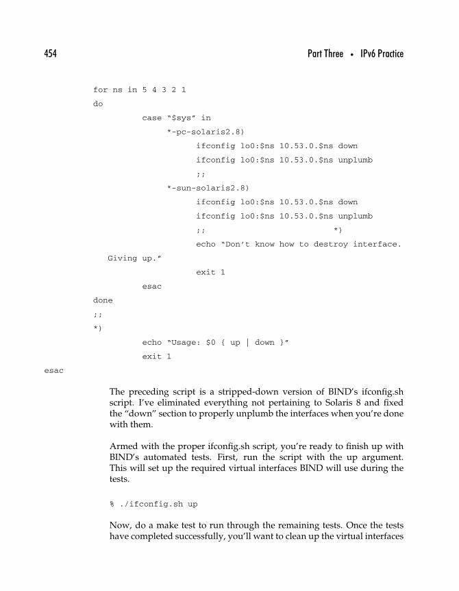
454 Part Three • IPv6 Practice
for ns in 5 4 3 2 1
do
case “$sys” in
*-pc-solaris2.8)
ifconfig lo0:$ns 10.53.0.$ns down
ifconfig lo0:$ns 10.53.0.$ns unplumb
;;
*-sun-solaris2.8)
ifconfig lo0:$ns 10.53.0.$ns down
ifconfig lo0:$ns 10.53.0.$ns unplumb
;; *)
echo “Don’t know how to destroy interface.
Giving up.”
exit 1
esac
done
;;
*)
echo “Usage: $0 { up | down }”
exit 1
esac
The preceding script is a stripped-down version of BIND’s ifconfig.shscript. I’ve eliminated everything not pertaining to Solaris 8 and fixedthe “down” section to properly unplumb the interfaces when you’re donewith them.
Armed with the proper ifconfig.sh script, you’re ready to finish up withBIND’s automated tests. First, run the script with the up argument.This will set up the required virtual interfaces BIND will use during thetests.
% ./ifconfig.sh up
Now, do a make test to run through the remaining tests. Once the testshave completed successfully, you’ll want to clean up the virtual interfaces
Chapter 24 • Email and DNS Under IPv6 455
used in the tests. The same script will do this. Just give it the downargument instead of up.
% ./ifconfig.sh down
Finally, your newly built BIND package has been tested and is readyfor installation. Move up to the top of the BIND source tree (assumingyou dropped into the bin/tests/system directory) and issue the installcommand.
% cd ../../..
% make install
Several BIND executables will be installed in /usr/local/bin. The nameserver binary itself, named, will be installed in /usr/local/sbin, andseveral name server-related libraries will be put in /usr/local/lib. Allthat’s left to do now is configure your new name server.
24.2 Configuring an IPv4/IPv6 DNS**
This section explains in detail how to configure BIND 9 for use as anIPv4/IPv6 domain name server. Configuration details will be given forboth a master (primary) and a slave (secondary) server. In addition,example configuration files and a current root server list will be includedat the end of this document.
24.2.1 GATHERING THE PIECES
Here’s a brief list of what you’ll need for this project.
• A working Solaris 8 (either Intel or Sun) machine for eachserver (master and slave).
• Both machines should have a correctly configured IPv4interface.
• Both machines should have a properly configured IPv6interface. It is recommended that both machines be configuredwith a static IPv6 address.
∗∗This section is adapted from a document written by Robert C. Zilbauer Jr., © ZamaNetworks.
456 Part Three • IPv6 Practice
• The servers should also have the OpenSSL and BIND 9packages compiled and installed on them.
24.2.2 CONFIGURING YOUR MASTER DNS
Once the preceding groundwork has been completed, you can move rightinto configuring your new DNS machines. By default BIND will look for itsconfiguration file, named.conf, in /etc. A sample named.conf file has beenincluded at the end of this document for your convenience. However, in thefollowing section, we’ll go over some of the highpoints of the configurationfile and explain why they’re in there.
All of the information that BIND will serve as your DNS (a.k.a., yourzone records) can be kept anywhere you’d like. In this case, we’ll createa directory, /var/named and instruct BIND to look there for its zonerecords. Also, we need to explicitly tell BIND to answer IPv6 queries.All of these things are done at the top of the named.conf file in an optionssection like this.
options
{
listen-on-v6
{
any;
};
directory “/var/named”;
notify yes;
provide-ixfr yes;
};
The first line of the options section tells BIND to listen for IPv6 queries.The directory option tells it where to find its zone records. The notify andprovide-ixfr options begin to define the relationship of your primary (ormaster) DNS with your secondary (or slave) DNS. The notify line saysyour master DNS should send notification to its slaves when a record hasbeen updated, and the provide-ixfr option allows your slaves to requestincremental updates (i.e., only the parts of the records that have beenchanged).
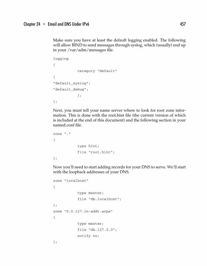
Chapter 24 • Email and DNS Under IPv6 457
Make sure you have at least the default logging enabled. The followingwill allow BIND to send messages through syslog, which (usually) end upin your /var/adm/messages file.
logging
{
category “default”
{
“default_syslog”;
“default_debug”;
};
};
Next, you must tell your name server where to look for root zone infor-mation. This is done with the root.hint file (the current version of whichis included at the end of this document) and the following section in yournamed.conf file.
zone “.”
{
type hint;
file “root.hint”;
};
Now you’ll need to start adding records for your DNS to serve. We’ll startwith the loopback addresses of your DNS.
zone “localhost”
{
type master;
file “db.localhost”;
};
zone “0.0.127.in-addr.arpa”
{
type master;
file “db.127.0.0”;
notify no;
};
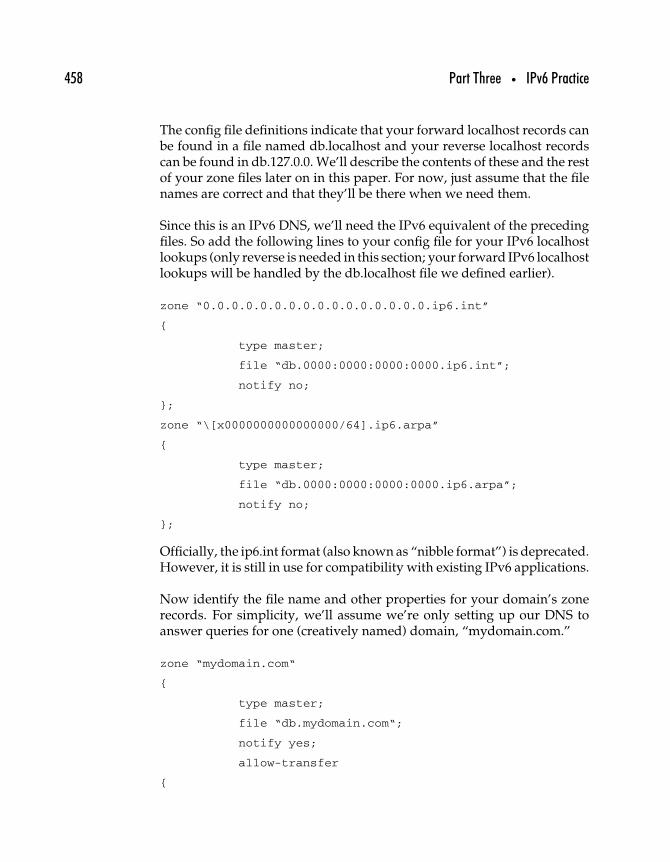
458 Part Three • IPv6 Practice
The config file definitions indicate that your forward localhost records canbe found in a file named db.localhost and your reverse localhost recordscan be found in db.127.0.0. We’ll describe the contents of these and the restof your zone files later on in this paper. For now, just assume that the filenames are correct and that they’ll be there when we need them.
Since this is an IPv6 DNS, we’ll need the IPv6 equivalent of the precedingfiles. So add the following lines to your config file for your IPv6 localhostlookups (only reverse is needed in this section; your forward IPv6 localhostlookups will be handled by the db.localhost file we defined earlier).
zone “0.0.0.0.0.0.0.0.0.0.0.0.0.0.0.0.ip6.int”
{
type master;
file “db.0000:0000:0000:0000.ip6.int”;
notify no;
};
zone “\[x0000000000000000/64].ip6.arpa”
{
type master;
file “db.0000:0000:0000:0000.ip6.arpa”;
notify no;
};
Officially, the ip6.int format (also known as “nibble format”) is deprecated.However, it is still in use for compatibility with existing IPv6 applications.
Now identify the file name and other properties for your domain’s zonerecords. For simplicity, we’ll assume we’re only setting up our DNS toanswer queries for one (creatively named) domain, “mydomain.com.”
zone “mydomain.com“
{
type master;
file “db.mydomain.com“;
notify yes;
allow-transfer
{
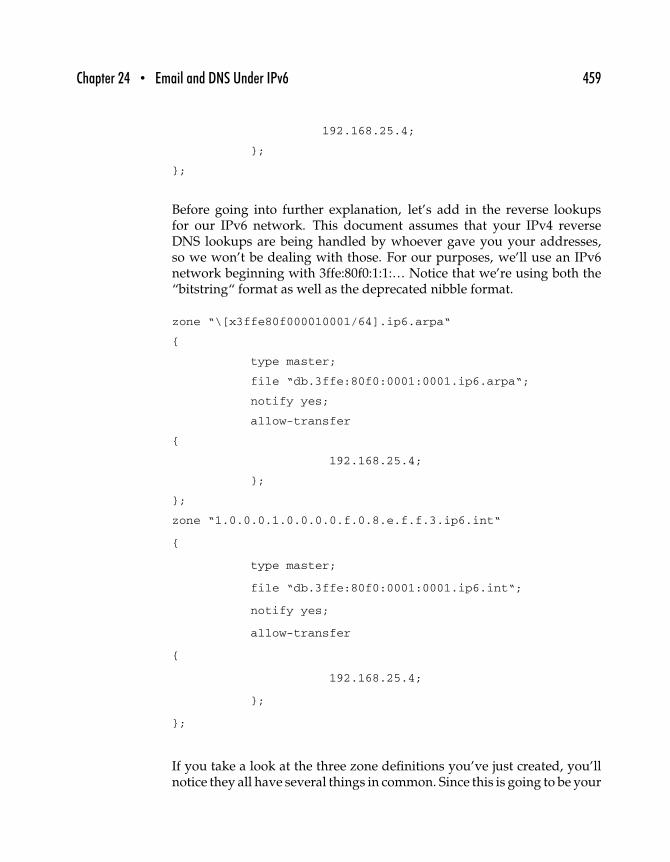
Chapter 24 • Email and DNS Under IPv6 459
192.168.25.4;
};
};
Before going into further explanation, let’s add in the reverse lookupsfor our IPv6 network. This document assumes that your IPv4 reverseDNS lookups are being handled by whoever gave you your addresses,so we won’t be dealing with those. For our purposes, we’ll use an IPv6network beginning with 3ffe:80f0:1:1:… Notice that we’re using both the“bitstring“ format as well as the deprecated nibble format.
zone “\[x3ffe80f000010001/64].ip6.arpa“
{
type master;
file “db.3ffe:80f0:0001:0001.ip6.arpa“;
notify yes;
allow-transfer
{
192.168.25.4;
};
};
zone “1.0.0.0.1.0.0.0.0.f.0.8.e.f.f.3.ip6.int“
{
type master;
file “db.3ffe:80f0:0001:0001.ip6.int“;
notify yes;
allow-transfer
{
192.168.25.4;
};
};
If you take a look at the three zone definitions you’ve just created, you’llnotice they all have several things in common. Since this is going to be your

460 Part Three • IPv6 Practice
primary (or “master“) DNS, each zone definition starts by indicating thatthis machine holds the master records for that zone (type master). Next,you’ve defined the name of the file in which the zone records will be kept.The notify yes line indicates that your master DNS should notify its slaveDNS whenever records are updated within the given zone. And, last, theallow-transfer definition tells your server which machine is allowed to dozone transfers. This should be the IP address of your slave DNS.
24.2.3 CONFIGURING YOUR “localhost“ ZONE
Now that your named.conf file is complete, it’s time to start creating yourzone files. Drop down into the directory you specified in your named.conffile as having your zone information. If you set up your named.conf filejust like our examples, that would be /var/named.
The first two files you’ll create are to facilitate lookups of your localhost.The info for your specific machine will (more than likely) be identical towhat you see here. First, we handle the forward lookups (both IPv4 andIPv6) for your localhost. Create the db.localhost file and fill it with thefollowing.
$ORIGIN localhost.
@ 4h IN SOA ns1.mydomain.com. dns.mydomain.com. (
2001012501 ; serial
28800 ; refresh
7200 ; retry
604800 ; expire
86400 ; minimum
)
;
IN NS ns1.mydomain.com.
IN NS ns2.mydomain.com.
;
$TTL 1h
;
localhost IN A 172.0.0.1
IN AAAA 0000:0000:0000:0000:0000:0000:0000:0001
IN A6 0 0000:0000:0000:0000:0000:0000:0000:0001

Chapter 24 • Email and DNS Under IPv6 461
At this point, we’ll go over some of the key elements to be aware of inthis file (as well as the other files you’ll be creating). You’ll notice the SOAindicator toward the top of the file. This stands for Start Of Authority. Themachine name immediately following the SOA indicates the name of themachine, which should be considered “authoritative” for the informationwithin the zone file. In all cases on your master DNS, this will be thename of your master DNS machine. The next element of the SOA line,“dns.mydomain.com,” is actually the email address of the maintainer ofthe zone records. While it’s written with periods as punctuation, it [email protected] is the email address of the maintainer of the recordswithin this zone file. This, too, will likely be the same throughout all ofyour zone files.
While we won’t be going over all of the numbers within the parenthesizedsection of the SOA record, we will discuss one of them. Whenever youmake updates to your zone records, you should adjust the serial numberaccordingly. As a general rule of thumb, use the current date as your serialnumber. Since you may be making more than one change to your fileson a particular day, add a two-digit revision number to the end of thedate. For example, the first change you make on March 23, 2001, wouldhave a serial number of “2001032301” (YYYYMMDDRR, where RR is thedouble-digit revision number). Consequently, when you make the secondchange to the file on the same day, you’d change the serial number to“2001032302.”
The reason for this has to do with the interaction between your masterDNS and your slave DNS. In order for your slave DNS to know that thereare new changes it needs to download from the master, the serial numbermust be incremented. If you’ve made changes to your master DNS andexpect to see the changes propagate to your slave DNS but they don’t, oneof the first things you should check is your serial number on the masterDNS. If you haven’t incremented the serial number, the changes won’t bereflected in your slave DNS’s records.
For an explanation of the other numbers within the SOA block(e.g., refresh, retry, etc.), see the BIND 9 Administrator Reference Manual.This manual is available in PDF format from Nominum, Inc. (http://www.nominum.com).
The IN NS records define the name servers responsible for this zone.Chances are good that these lines will also be the same across all of yourzone files.
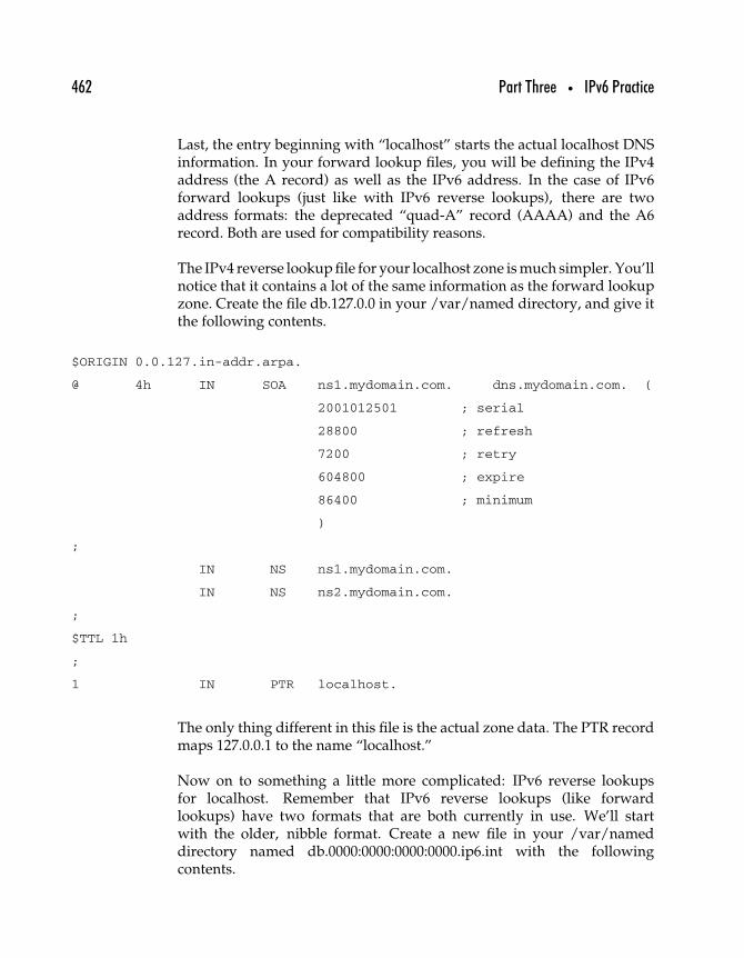
462 Part Three • IPv6 Practice
Last, the entry beginning with “localhost” starts the actual localhost DNSinformation. In your forward lookup files, you will be defining the IPv4address (the A record) as well as the IPv6 address. In the case of IPv6forward lookups (just like with IPv6 reverse lookups), there are twoaddress formats: the deprecated “quad-A” record (AAAA) and the A6record. Both are used for compatibility reasons.
The IPv4 reverse lookup file for your localhost zone is much simpler. You’llnotice that it contains a lot of the same information as the forward lookupzone. Create the file db.127.0.0 in your /var/named directory, and give itthe following contents.
$ORIGIN 0.0.127.in-addr.arpa.
@ 4h IN SOA ns1.mydomain.com. dns.mydomain.com. (
2001012501 ; serial
28800 ; refresh
7200 ; retry
604800 ; expire
86400 ; minimum
)
;
IN NS ns1.mydomain.com.
IN NS ns2.mydomain.com.
;
$TTL 1h
;
1 IN PTR localhost.
The only thing different in this file is the actual zone data. The PTR recordmaps 127.0.0.1 to the name “localhost.”
Now on to something a little more complicated: IPv6 reverse lookupsfor localhost. Remember that IPv6 reverse lookups (like forwardlookups) have two formats that are both currently in use. We’ll startwith the older, nibble format. Create a new file in your /var/nameddirectory named db.0000:0000:0000:0000.ip6.int with the followingcontents.
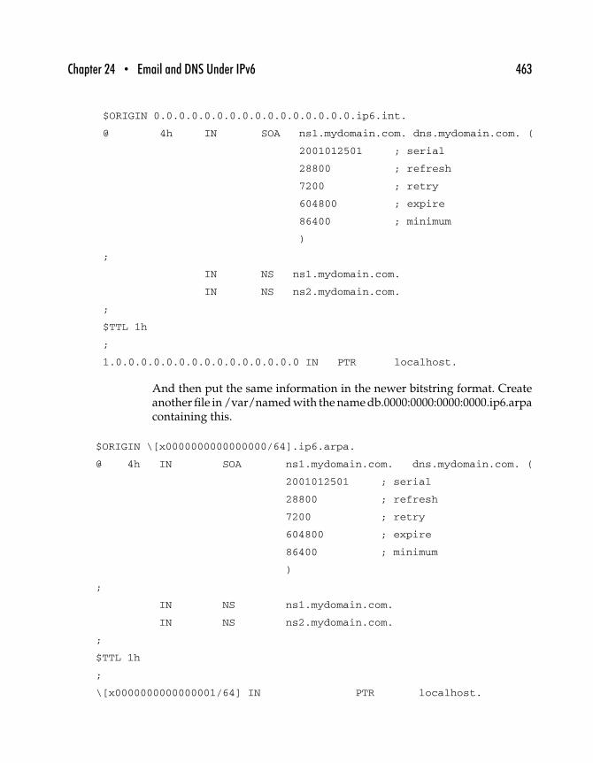
Chapter 24 • Email and DNS Under IPv6 463
$ORIGIN 0.0.0.0.0.0.0.0.0.0.0.0.0.0.0.0.ip6.int.
@ 4h IN SOA ns1.mydomain.com. dns.mydomain.com. (
2001012501 ; serial
28800 ; refresh
7200 ; retry
604800 ; expire
86400 ; minimum
)
;
IN NS ns1.mydomain.com.
IN NS ns2.mydomain.com.
;
$TTL 1h
;
1.0.0.0.0.0.0.0.0.0.0.0.0.0.0.0 IN PTR localhost.
And then put the same information in the newer bitstring format. Createanother file in /var/named with the name db.0000:0000:0000:0000.ip6.arpacontaining this.
$ORIGIN \[x0000000000000000/64].ip6.arpa.
@ 4h IN SOA ns1.mydomain.com. dns.mydomain.com. (
2001012501 ; serial
28800 ; refresh
7200 ; retry
604800 ; expire
86400 ; minimum
)
;
IN NS ns1.mydomain.com.
IN NS ns2.mydomain.com.
;
$TTL 1h
;
\[x0000000000000001/64] IN PTR localhost.
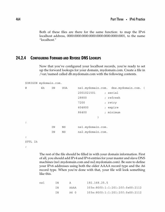
464 Part Three • IPv6 Practice
Both of these files are there for the same function: to map the IPv6localhost address, 0000:0000:0000:0000:0000:0000:0000:0001, to the name“localhost.”
24.2.4 CONFIGURING FORWARD AND REVERSE DNS LOOKUPS
Now that you’ve configured your localhost records, you’re ready to setup the forward lookups for your domain, mydomain.com. Create a file in/var/named called db.mydomain.com with the following contents.
$ORIGIN mydomain.com.
@ 4h IN SOA ns1.mydomain.com. dns.mydomain.com. (
2001021501 ; serial
28800 ; refresh
7200 ; retry
604800 ; expire
86400 ; minimum
)
;
IN NS ns1.mydomain.com.
IN NS ns2.mydomain.com.
;
$TTL 1h
;
The rest of the file should be filled in with your domain information. Firstof all, you should add IPv4 and IPv6 entries for your master and slave DNSmachines (ns1.mydomain.com and ns2.mydomain.com). Be sure to defineyour IPv6 addresses using both the older AAAA record type and the A6record type. When you’re done with that, your file will look somethinglike this.
ns1 IN A 192.168.25.5
IN AAAA 3ffe:80f0:1:1:201:2ff:fe00:2112
IN A6 0 3ffe:80f0:1:1:201:2ff:fe00:2112
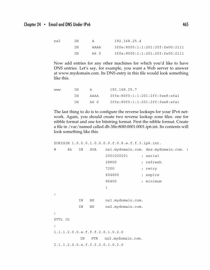
Chapter 24 • Email and DNS Under IPv6 465
ns2 IN A 192.168.25.4
IN AAAA 3ffe:80f0:1:1:201:2ff:fe00:2111
IN A6 0 3ffe:80f0:1:1:201:2ff:fe00:2111
Now add entries for any other machines for which you’d like to haveDNS entries. Let’s say, for example, you want a Web server to answerat www.mydomain.com. Its DNS entry in this file would look somethinglike this.
www IN A 192.168.25.7
IN AAAA 3ffe:80f0:1:1:201:2ff:fee8:efa1
IN A6 0 3ffe:80f0:1:1:201:2ff:fee8:efa1
The last thing to do is to configure the reverse lookups for your IPv6 net-work. Again, you should create two reverse lookup zone files: one fornibble format and one for bitstring format. First the nibble format. Createa file in /var/named called db.3ffe:80f0:0001:0001.ip6.int. Its contents willlook something like this.
$ORIGIN 1.0.0.0.1.0.0.0.0.f.0.8.e.f.f.3.ip6.int.
@ 4h IN SOA ns1.mydomain.com. dns.mydomain.com. (
2001020201 ; serial
28800 ; refresh
7200 ; retry
604800 ; expire
86400 ; minimum
)
;
IN NS ns1.mydomain.com.
IN NS ns2.mydomain.com.
;
$TTL 1h
;
1.1.1.2.0.0.e.f.f.f.2.0.1.0.2.0
IN PTR ns2.mydomain.com.
2.1.1.2.0.0.e.f.f.f.2.0.1.0.2.0
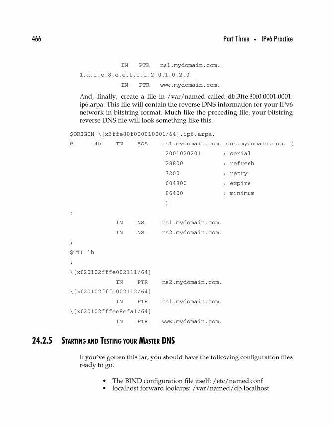
466 Part Three • IPv6 Practice
IN PTR ns1.mydomain.com.
1.a.f.e.8.e.e.f.f.f.2.0.1.0.2.0
IN PTR www.mydomain.com.
And, finally, create a file in /var/named called db.3ffe:80f0:0001:0001.ip6.arpa. This file will contain the reverse DNS information for your IPv6network in bitstring format. Much like the preceding file, your bitstringreverse DNS file will look something like this.
$ORIGIN \[x3ffe80f000010001/64].ip6.arpa.
@ 4h IN SOA ns1.mydomain.com. dns.mydomain.com. (
2001020201 ; serial
28800 ; refresh
7200 ; retry
604800 ; expire
86400 ; minimum
)
;
IN NS ns1.mydomain.com.
IN NS ns2.mydomain.com.
;
$TTL 1h
;
\[x020102fffe002111/64]
IN PTR ns2.mydomain.com.
\[x020102fffe002112/64]
IN PTR ns1.mydomain.com.
\[x020102fffee8efa1/64]
IN PTR www.mydomain.com.
24.2.5 STARTING AND TESTING YOUR MASTER DNS
If you’ve gotten this far, you should have the following configuration filesready to go.
• The BIND configuration file itself: /etc/named.conf• localhost forward lookups: /var/named/db.localhost
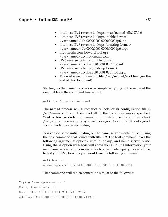
Chapter 24 • Email and DNS Under IPv6 467
• localhost IPv4 reverse lookups: /var/named/db.127.0.0• localhost IPv6 reverse lookups (nibble format):
/var/named/ db.0000:0000:0000:0000.ip6.int• localhost IPv6 reverse lookups (bitstring format):
/var/named/ db.0000:0000:0000:0000.ip6.arpa• mydomain.com forward lookups:
/var/named/db.mydomain.com• IPv6 reverse lookups (nibble format):
/var/named/db.3ffe:80f0:0001:0001.ip6.int• IPv6 reverse lookups (bitstring format):
/var/named/db.3ffe:80f0:0001:0001.ip6.arpa• The root zone information file: /var/named/root.hint (see the
end of this document)
Starting up the named process is as simple as typing in the name of theexecutable on the command line as root.
ns1# /usr/local/sbin/named
The named process will automatically look for its configuration file in/etc/named.conf and then load all of the zone files you’ve specified.Wait a few seconds for named to initialize itself and then check/var/adm/messages for any error messages. Assuming all looks good,you’re ready to do some testing.
You can do some initial testing on the name server machine itself usingthe host command that comes with BIND 9. The host command takes thefollowing arguments: options, item to lookup, and name server to use.Using the -a option with host will show you all of the information yournew name server returns in response to a particular query. For example,to test your IPv6 lookups you would use the following command.
ns1# host -
a www.mydomain.com 3ffe:80f0:1:1:201:2ff:fe00:2112
That command will return something similar to the following.
Trying “www.mydomain.com.”
Using domain server:
Name: 3ffe:80f0:1:1:201:2ff:fe00:2112
Address: 3ffe:80f0:1:1:201:2ff:fe00:2112#53
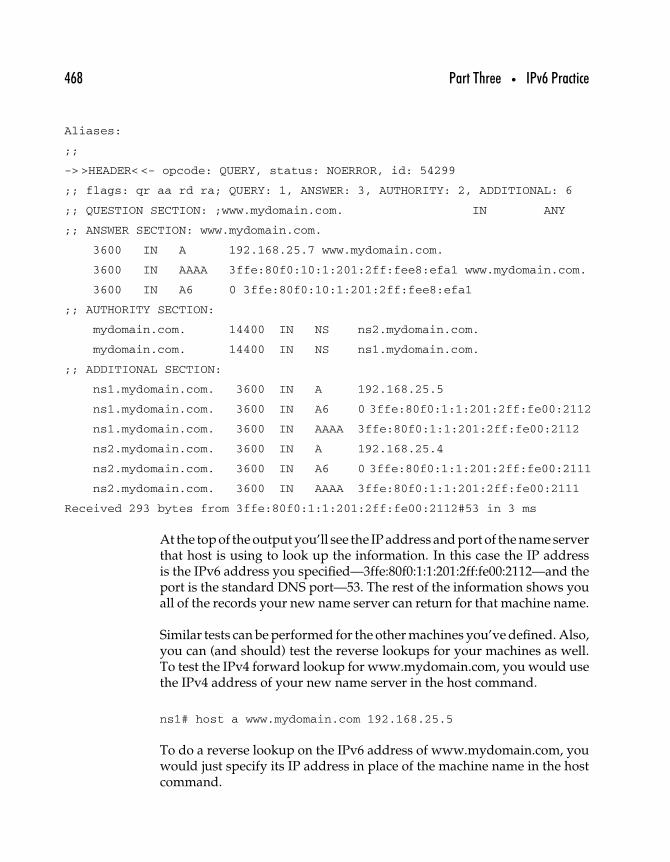
468 Part Three • IPv6 Practice
Aliases:
;;
-> >HEADER< <- opcode: QUERY, status: NOERROR, id: 54299
;; flags: qr aa rd ra; QUERY: 1, ANSWER: 3, AUTHORITY: 2, ADDITIONAL: 6
;; QUESTION SECTION: ;www.mydomain.com. IN ANY
;; ANSWER SECTION: www.mydomain.com.
3600 IN A 192.168.25.7 www.mydomain.com.
3600 IN AAAA 3ffe:80f0:10:1:201:2ff:fee8:efa1 www.mydomain.com.
3600 IN A6 0 3ffe:80f0:10:1:201:2ff:fee8:efa1
;; AUTHORITY SECTION:
mydomain.com. 14400 IN NS ns2.mydomain.com.
mydomain.com. 14400 IN NS ns1.mydomain.com.
;; ADDITIONAL SECTION:
ns1.mydomain.com. 3600 IN A 192.168.25.5
ns1.mydomain.com. 3600 IN A6 0 3ffe:80f0:1:1:201:2ff:fe00:2112
ns1.mydomain.com. 3600 IN AAAA 3ffe:80f0:1:1:201:2ff:fe00:2112
ns2.mydomain.com. 3600 IN A 192.168.25.4
ns2.mydomain.com. 3600 IN A6 0 3ffe:80f0:1:1:201:2ff:fe00:2111
ns2.mydomain.com. 3600 IN AAAA 3ffe:80f0:1:1:201:2ff:fe00:2111
Received 293 bytes from 3ffe:80f0:1:1:201:2ff:fe00:2112#53 in 3 ms
At the top of the output you’ll see the IP address and port of the name serverthat host is using to look up the information. In this case the IP addressis the IPv6 address you specified—3ffe:80f0:1:1:201:2ff:fe00:2112—and theport is the standard DNS port—53. The rest of the information shows youall of the records your new name server can return for that machine name.
Similar tests can be performed for the other machines you’ve defined. Also,you can (and should) test the reverse lookups for your machines as well.To test the IPv4 forward lookup for www.mydomain.com, you would usethe IPv4 address of your new name server in the host command.
ns1# host a www.mydomain.com 192.168.25.5
To do a reverse lookup on the IPv6 address of www.mydomain.com, youwould just specify its IP address in place of the machine name in the hostcommand.
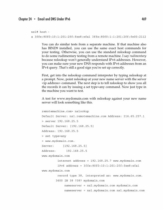
Chapter 24 • Email and DNS Under IPv6 469
ns1# host -
a 3ffe:80f0:10:1:201:2ff:fee8:efa1 3ffe:80f0:1:1:201:2ff:fe00:2112
You can do similar tests from a separate machine. If that machine alsohas BIND9 installed, you can use the same exact host commands foryour testing. Otherwise, you can use the standard nslookup commandto do some rudimentary testing from a remote machine. I say rudimentarybecause nslookup won’t generally understand IPv6 addresses. However,you can make sure your new DNS responds with IPv6 addresses from anIPv4 query. That’s still a good sign you’re set up correctly.
First, get into the nslookup command interpreter by typing nslookup ata prompt. Now, point nslookup at your new name server with the server<ip address> command. The next step is to tell nslookup to show you allthe records it can by issuing a set type=any command. Now just type inthe machine you want to test.
A test for www.mydomain.com with nslookup against your new nameserver will look something like this.
remotemachine.com> nslookup
Default Server: ns1.remotemachine.com Address: 216.65.257.1
> server 192.168.25.5
Default Server: [192.168.25.5]
Address: 192.168.25.5
> set type=any
> www.mydomain.com.
Server: [192.168.25.5]
Address: 192.168.25.5
www.mydomain.com
internet address = 192.168.25.7 www.mydomain.com
IPv6 address = 3ffe:80f0:10:1:201:2ff:fee8:efa1
www.mydomain.com
record type 38, interpreted as: www.mydomain.com.
3600 IN 38 ?38? mydomain.com
nameserver = ns2.mydomain.com mydomain.com
nameserver = ns1.mydomain.com ns1.mydomain.com
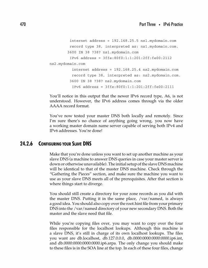
470 Part Three • IPv6 Practice
internet address = 192.168.25.5 ns1.mydomain.com
record type 38, interpreted as: ns1.mydomain.com.
3600 IN 38 ?38? ns1.mydomain.com
IPv6 address = 3ffe:80f0:1:1:201:2ff:fe00:2112
ns2.mydomain.com
internet address = 192.168.25.4 ns2.mydomain.com
record type 38, interpreted as: ns2.mydomain.com.
3600 IN 38 ?38? ns2.mydomain.com
IPv6 address = 3ffe:80f0:1:1:201:2ff:fe00:2111
You’ll notice in this output that the newer IPv6 record type, A6, is notunderstood. However, the IPv6 address comes through via the olderAAAA record format.
You’ve now tested your master DNS both locally and remotely. SinceI’m sure there’s no chance of anything going wrong, you now havea working master domain name server capable of serving both IPv4 andIPv6 addresses. You’re done!
24.2.6 CONFIGURING YOUR SLAVE DNS
Make that you’re done unless you want to set up another machine as yourslave DNS (a machine to answer DNS queries in case your master server isdown or otherwise unavailable). The initial setup of the slave DNS machinewill be identical to that of the master DNS machine. Check through the“Gathering the Pieces” section, and make sure the machine you want touse as your slave DNS meets all of the prerequisites. After that section iswhere things start to diverge.
You should still create a directory for your zone records as you did withthe master DNS. Putting it in the same place, /var/named, is alwaysa good idea. You should also copy over the root.hint file from your primaryDNS into the /var/named directory of your new secondary DNS. Both themaster and the slave need that file.
While you’re copying files over, you may want to copy over the fourfiles responsible for the localhost lookups. Although this machine isa slave DNS, it’s still in charge of its own localhost lookups. The filesyou want are db.localhost, db.127.0.0.0, db.0000:0000:0000:0000.ip6.int,and db.0000:0000:0000:0000.ip6.arpa. The only change you should maketo these files is in the SOA line at the top. In each of these four files, change
Chapter 24 • Email and DNS Under IPv6 471
the ns1.mydomain.com entry (immediately following the SOA element) tons2.mydomain.com.
The rest of the files in /var/named on your slave DNS machine will becreated automatically, however. So the only other file you need to changeis the main BIND configuration file, /etc/named.conf.
The options section of the configuration file is different on a slave DNSmachine. Basically, it doesn’t need any of the options regarding zonetransfers or slave notification. So the modified options section would looklike this.
options
{
listen-on-v6 {
any;
};
directory “/var/named”;
};
All of the following sections of the /etc/named.conf file on your slave DNSsystem will be identical to those on your master DNS machine.
• The “.” zone section (which indicates the name of the root.hintfile)
• The logging section• The localhost zone (for forward localhost lookups)• The zone responsible for reverse IPv4 localhost lookups• The two zones responsible for reverse IPv6 localhost lookups
(both the nibble and bitstring formats)
You can copy and paste those elements from your master DNS machine’s/etc/named.conf file into your slave’s. That sets up all of the basic BINDelements you need. Now, it’s just a matter of setting up slave zones for theforward and reverse lookups of mydomain.com.
To do that, just add three zone definitions to your /etc/named.conf file.They will look similar to the following.
zone “mydomain.com”
{
type slave;
472 Part Three • IPv6 Practice
file “bk.mydomain.com”;
masters
{
192.168.25.5;
};
};
zone “\[x3ffe80f000010001/64].ip6.arpa”
{
type slave;
file “bk.3ffe:80f0:0001:0001.ip6.arpa”;
masters
{
192.168.25.5;
};
};
zone “1.0.0.0.1.0.0.0.0.f.0.8.e.f.f.3.ip6.int”
{
type slave;
file “bk.3ffe:80f0:0001:0001.ip6.int”;
masters
{
192.168.25.5;
};
};
The first one handles the forward lookups for mydomain.com, while thelast two take care of the different formats of IPv6 reverse lookups. In eachcase, the type is set to slave, which indicates that this server should relyon another for its information about these zones. The file is where it willsave that information once it is obtained, and the masters section tells itfrom which machine it should get that information. The IP address in thatmasters sections should be the IP address of your master DNS.
Now start the name server process (named) as root just like you did onyour master DNS.
ns1# /usr/local/sbin/named
Chapter 24 • Email and DNS Under IPv6 473
After a few moments of initialization, you should see the three bk.* filesshow up in /var/named. Once they’re in there, you can run some DNSquery tests using the host command as you did with your master server.Just use the address of your slave server instead of the one for your master.
The final thing you should test is a zone transfer. Go over to your masterserver and make a change to one of your zone files. For example, add a testmachine entry to db.mydomain.com. Important: Make sure you incrementthe serial number at the top of the file or the slave won’t know the contentshave changed.
Once you’ve made the appropriate changes, send the named process onyour master server a HUP signal. This tells named to reread its configura-tion files. First, determine what process ID the named process is runningunder. Then send that process ID the HUP signal.
ns1:/var/named# ps -ef | grep named
root 164 1 0 Feb 05 ? 0:08 /usr/local/sbin/named
ns1:/var/named# kill -HUP 164
Shortly after sending the HUP signal, you should see the changespropagate over to the appropriate bk.* file on your slave server. In thiscase, since we made the change to db.mydomain.com, you’ll see thechange reflected in bk.mydomain.com.
Now that you know your secondary server is correctly responding toqueries and correctly handling zone transfers, you can pat yourself onthe back. You’ve successfully set up an IPv6 capable master/slave DNSsystem!
24.2.7 EXAMPLE named.conf OPTIONS
Example named.conf (master) options
{
listen-on-v6
{
any;
};

474 Part Three • IPv6 Practice
directory “/var/named”;
notify yes;
provide-ixfr yes;
};
logging
{
category “default”
{
“default_syslog”;
“default_debug”;
};
};
zone “.”
{
type hint;
file “root.hint”;
};
// IPv4 localhost and localhost reverse. zone “localhost”
{
type master;
file “db.localhost”;
};
zone “0.0.127.in-addr.arpa”
{
type master;
file “db.127.0.0”;
notify no;
};
// IPv6 localhost and localhost reverse.
// .ip6.int is deprecated but kept for compatibility for now.
zone “0.0.0.0.0.0.0.0.0.0.0.0.0.0.0.0.ip6.int“
{
type master;
Chapter 24 • Email and DNS Under IPv6 475
file “db.0000:0000:0000:0000.ip6.int”;
notify no;
};
zone “\[x0000000000000000/64].ip6.arpa”
{
type master;
file “db.0000:0000:0000:0000.ip6.arpa”;
notify no;
};
zone “mydomain.com”
{
type master;
file “db.mydomain.com”;
notify yes;
allow-transfer
{
192.168.25.4;
};
};
// Reverse lookups for 3ffe:80f0:0001:0001:
// ... zone “\[x3ffe80f000010001/64].ip6.arpa”
{
type master;
file “db.3ffe:80f0:0001:0001.ip6.arpa”;
notify yes;
allow-transfer
{
192.168.25.4;
};
};
zone “1.0.0.0.1.0.0.0.0.f.0.8.e.f.f.3.ip6.int”
{
type master;
file “db.3ffe:80f0:0001:0001.ip6.int”;

476 Part Three • IPv6 Practice
notify yes;
allow-transfer
{
192.168.25.4;
};
};
Example named.conf (slave) options
{
listen-on-v6
{
any;
};
directory “/var/named”;
};
logging
{
category “default”
{ “default_syslog“; “default_debug”;
};
};
zone “.“
{
type hint;
file “root.hint”;
};
// IPv4 localhost and localhost reverse.
zone “localhost“
{
type master;
file “db.localhost”;
};
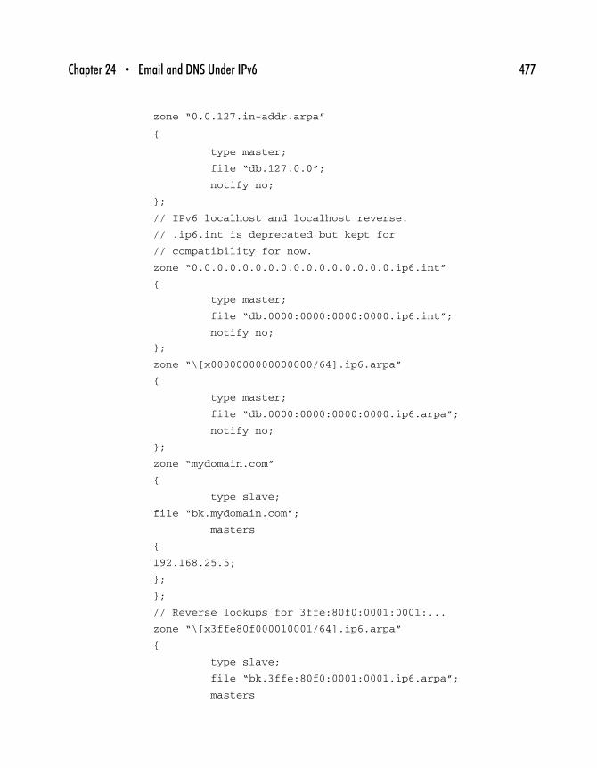
Chapter 24 • Email and DNS Under IPv6 477
zone “0.0.127.in-addr.arpa”
{
type master;
file “db.127.0.0”;
notify no;
};
// IPv6 localhost and localhost reverse.
// .ip6.int is deprecated but kept for
// compatibility for now.
zone “0.0.0.0.0.0.0.0.0.0.0.0.0.0.0.0.ip6.int”
{
type master;
file “db.0000:0000:0000:0000.ip6.int”;
notify no;
};
zone “\[x0000000000000000/64].ip6.arpa”
{
type master;
file “db.0000:0000:0000:0000.ip6.arpa”;
notify no;
};
zone “mydomain.com”
{
type slave;
file “bk.mydomain.com”;
masters
{
192.168.25.5;
};
};
// Reverse lookups for 3ffe:80f0:0001:0001:...
zone “\[x3ffe80f000010001/64].ip6.arpa”
{
type slave;
file “bk.3ffe:80f0:0001:0001.ip6.arpa”;
masters
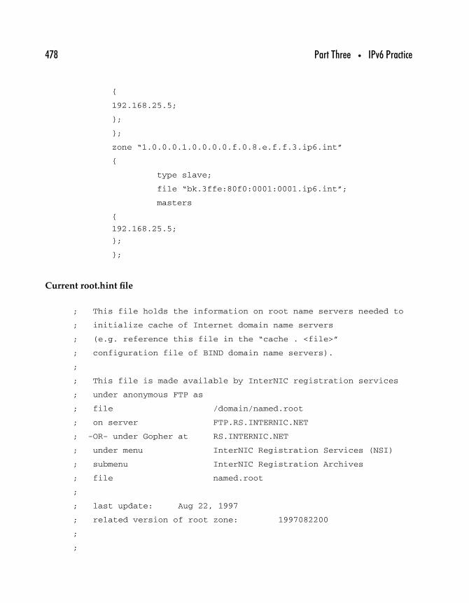
478 Part Three • IPv6 Practice
{
192.168.25.5;
};
};
zone “1.0.0.0.1.0.0.0.0.f.0.8.e.f.f.3.ip6.int”
{
type slave;
file “bk.3ffe:80f0:0001:0001.ip6.int”;
masters
{
192.168.25.5;
};
};
Current root.hint file
; This file holds the information on root name servers needed to
; initialize cache of Internet domain name servers
; (e.g. reference this file in the “cache . <file>”
; configuration file of BIND domain name servers).
;
; This file is made available by InterNIC registration services
; under anonymous FTP as
; file /domain/named.root
; on server FTP.RS.INTERNIC.NET
; -OR- under Gopher at RS.INTERNIC.NET
; under menu InterNIC Registration Services (NSI)
; submenu InterNIC Registration Archives
; file named.root
;
; last update: Aug 22, 1997
; related version of root zone: 1997082200
;
;

Chapter 24 • Email and DNS Under IPv6 479
; formerly NS.INTERNIC.NET
;
. 3600000 IN NS A.ROOT-SERVERS.NET.
A.ROOT-SERVERS.NET. 3600000 A 198.41.0.4
;
; formerly NS1.ISI.EDU
;
. 3600000 NS B.ROOT-SERVERS.NET.
B.ROOT-SERVERS.NET. 3600000 A 128.9.0.107
;
; formerly C.PSI.NET
;
. 3600000 NS C.ROOT-SERVERS.NET.
C.ROOT-SERVERS.NET. 3600000 A 192.33.4.12
;
; formerly TERP.UMD.EDU
;
. 3600000 NS D.ROOT-SERVERS.NET.
D.ROOT-SERVERS.NET. 3600000 A 128.8.10.90
;
; formerly NS.NASA.GOV
;
. 3600000 NS E.ROOT-SERVERS.NET.
E.ROOT-SERVERS.NET. 3600000 A 192.203.230.10
;
; formerly NS.ISC.ORG
;
. 3600000 NS F.ROOT-SERVERS.NET.
F.ROOT-SERVERS.NET. 3600000 A 192.5.5.241
;
; formerly NS.NIC.DDN.MIL
;
. 3600000 NS G.ROOT-SERVERS.NET.

480 Part Three • IPv6 Practice
G.ROOT-SERVERS.NET. 3600000 A 192.112.36.4
;
; formerly AOS.ARL.ARMY.MIL
;
. 3600000 NS H.ROOT-SERVERS.NET.
H.ROOT-SERVERS.NET. 3600000 A 128.63.2.53
;
; formerly NIC.NORDU.NET
;
. 3600000 NS I.ROOT-SERVERS.NET.
I.ROOT-SERVERS.NET. 3600000 A 192.36.148.17
;
; temporarily housed at NSI (InterNIC)
;
. 3600000 NS J.ROOT-SERVERS.NET.
J.ROOT-SERVERS.NET. 3600000 A 198.41.0.10
;
; housed in LINX, operated by RIPE NCC
;
. 3600000 NS K.ROOT-SERVERS.NET.
K.ROOT-SERVERS.NET. 3600000 A 193.0.14.129
;
; temporarily housed at ISI (IANA)
;
. 3600000 NS L.ROOT-SERVERS.NET.
L.ROOT-SERVERS.NET. 3600000 A 198.32.64.12
;
; housed in Japan, operated by WIDE
;
. 3600000 NS M.ROOT-SERVERS.NET.
M.ROOT-SERVERS.NET. 3600000 A 202.12.27.33
; End of File
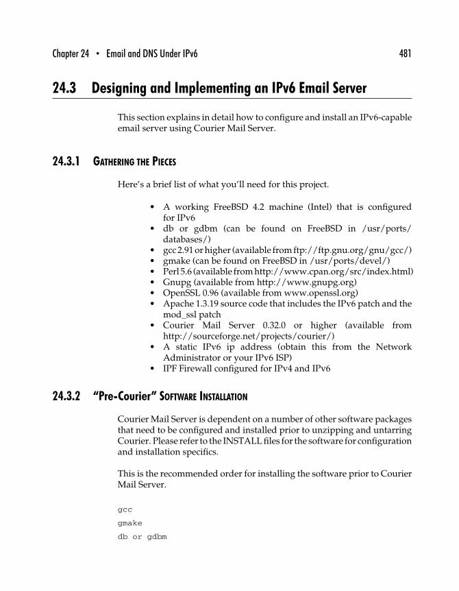
Chapter 24 • Email and DNS Under IPv6 481
24.3 Designing and Implementing an IPv6 Email Server
This section explains in detail how to configure and install an IPv6-capableemail server using Courier Mail Server.
24.3.1 GATHERING THE PIECES
Here’s a brief list of what you’ll need for this project.
• A working FreeBSD 4.2 machine (Intel) that is configuredfor IPv6
• db or gdbm (can be found on FreeBSD in /usr/ports/databases/)
• gcc 2.91 or higher (available from ftp://ftp.gnu.org/gnu/gcc/)• gmake (can be found on FreeBSD in /usr/ports/devel/)• Perl 5.6 (available fromhttp://www.cpan.org/src/index.html)• Gnupg (available from http://www.gnupg.org)• OpenSSL 0.96 (available from www.openssl.org)• Apache 1.3.19 source code that includes the IPv6 patch and the
mod_ssl patch• Courier Mail Server 0.32.0 or higher (available from
http://sourceforge.net/projects/courier/)• A static IPv6 ip address (obtain this from the Network
Administrator or your IPv6 ISP)• IPF Firewall configured for IPv4 and IPv6
24.3.2 “Pre-Courier” SOFTWARE INSTALLATION
Courier Mail Server is dependent on a number of other software packagesthat need to be configured and installed prior to unzipping and untarringCourier. Please refer to the INSTALL files for the software for configurationand installation specifics.
This is the recommended order for installing the software prior to CourierMail Server.
gcc
gmake
db or gdbm
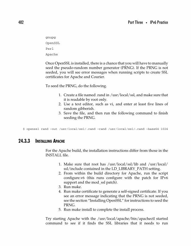
482 Part Three • IPv6 Practice
gnupg
OpenSSL
Perl
Apache
Once OpenSSL is installed, there is a chance that you will have to manuallyseed the pseudo-random number generator (PRNG). If the PRNG is notseeded, you will see error messages when running scripts to create SSLcertificates for Apache and Courier.
To seed the PRNG, do the following.
1. Create a file named .rand in /usr/local/ssl, and make sure thatit is readable by root only.
2. Use a text editor, such as vi, and enter at least five lines ofrandom gibberish.
3. Save the file, and then run the following command to finishseeding the PRNG.
$ openssl rand -out /usr/local/ssl/.rand -rand /usr/local/ssl/.rand -base64 1024
24.3.3 INSTALLING APACHE
For the Apache build, the installation instructions differ from those in theINSTALL file.
1. Make sure that root has /usr/local/ssl/lib and /usr/local/ssl/include contained in the LD_LIBRARY_PATH setting.
2. From within the build directory for Apache, run the scriptconfigure.v6 (this runs configure with the patch for IPv6support and the mod_ssl patch).
3. Run make.4. Run make certificate to generate a self-signed certificate. If you
see an error message indicating that the PRNG is not seeded,see the section “Installing OpenSSL” for instructions to seed thePRNG.
5. Run make install to complete the install process.
Try starting Apache with the /usr/local/apache/bin/apachectl startsslcommand to see if it finds the SSL libraries that it needs to run
Chapter 24 • Email and DNS Under IPv6 483
HTTPS connections. To avoid having to enter the passphrase each timeyou want to start Apache with SSL running (for instance, at boot up), youshould remove the encryption from the RSA private key (while preservingthe original file).
$ cp server.key server.key.org
$ openssl rsa -in server.key.org -out server.key
And also make sure the server.key file is now only readable by root.
$ chmod 400 server.key
Now server.key will contain an unencrypted copy of the key. If you pointyour server at this file it will not prompt you for a passphrase. However, ifanyone gets this key, he or she will be able to impersonate you on the net.Please make sure that the permissions on that file are really such that onlyroot or the Web server user can read it (preferably get your Web server tostart as root but run as another server, and have the key readable only byroot).
There will be modifications to the httpd.conf file, but that will be done onceCourier Mail Server has been installed.
24.3.4 PREPARING TO INSTALL COURIER MAIL SERVER
Be sure to read the Courier Mail Server INSTALL document in its entiretybefore running configure and make (a “reader-friendly“ version can befound on the Web at http://courier.sourceforge.net/install.html).
(Note: Keep in mind that configure and make are run as the user courier,whereas make install and make install-configure are run as root.)
Set up the PATH and LD_LIBRARY_PATH settings for both courier androot on your system in preparation for configuring and installing CourierMail Server. The paths should look like the following examples.
PATH=/usr/local/src:/sbin:/usr/sbin:/bin:/usr/bin:/
usr/local/sbin:/usr/local/bin:/usr/X11R6/bin:/
usr/lib/courier/bin:/usr/lib/courier:/
usr/lib/courier-0.3x.x.xxxxxx:/usr/lib/courier/share
484 Part Three • IPv6 Practice
LD_LIBRARY_PATH=/usr/lib:/usr/local/ssl/lib:/usr/local/
ssl/include:/usr/local/lib:/usr/local/bin
24.3.5 PASSING OPTIONS: THE conf.script FILE
Once the Courier source code is unzipped and un-tarred, cd into the builddirectory and create a shell script called conf.script. This script will set flagsfor OpenSSL support, execute configure, and pass the desired options toconfigure. Here is an example conf.script.
#!/bin/sh
CPPFLAGS=“-I/usr/local/ssl/include”
LDFLAGS=“-L/usr/local/ssl/lib”
export CPPFLAGS
export LDFLAGS
./configure --with-mailuser=courier --with-mailgroup=courier
--with-mailuid=xxxx --with-mailgid=xxxx --without-authpam
--without-authldap --with-authpwd --without-authmysql
--without-authuserdb --without-authvchkpw --without-authcram
--with-waitfunc=wait --enable-webpass=yes --with-ipv6
Make the script executable by the courier user and then run it.
24.3.6 BUILDING COURIER MAIL SERVER
Refer to the steps in the Installation document for Courier Mail Server.If you run into problems while running configure or any of the makes,please read the FAQ page (http://courier.sourceforge.net/FAQ.html) orsearch the Courier users’ mailing list (http://www.geocrawler.com/lists/3/SourceForge/3723/0/).
24.3.7 POSTINSTALLATION /etc FILE CONFIGURATION
Use a text editor, such as vi, to make configuration changes to thefollowing files.
/usr/lib/courier/etc/authmodulelist
authpwd
Chapter 24 • Email and DNS Under IPv6 485
/usr/lib/courier/etc/courierd
DEFAULTDELIVERY=“|/usr/lib/courier/bin/maildrop”
/usr/lib/courier/etc/esmtpd
AUTHMODULES=“authpwd”
...
ESMTPDSTART=YES
/usr/lib/courier/etc/esmtpd.cnf
RANDFILE = /usr/local/ssl.rnd
...
CN=mail.zama6.com
/usr/lib/courier/etc/imap
AUTHMODULES=“authpwd”
...
IMAPDSTART=YES
/usr/lib/courier/etc/imap.cnf
RANDFILE = /usr/local/ssl.rnd
...
CN=mail.zama6.com
/usr/lib/courier/etc/imap-ssl
IMAPDSSLSTART=YES
...
TLS_ALLOWSELFSIGNEDCERT=1 (uncomment this line)
/usr/lib/courier/etc/pop3d
AUTHMODULES=“authpwd”
...
POP3DSTART=YES
/usr/lib/courier/etc/pop3.cnf
RANDFILE = /usr/local/ssl.rnd
...
CN=mail.zama6.com
/usr/lib/courier/etc/pop3d-ssl
POP3DSSLSTART=YES
...
TLS_ALLOWSELFSIGNEDCERT=1 (uncomment this line)
486 Part Three • IPv6 Practice
/usr/lib/courier/etc/aliases/system
postmaster:mailadmin
/usr/lib/courier/etc/smtpaccess/default:
172.16.12 allow,RELAYCLIENT
203.142.132 allow,RELAYCLIENT
203.142.142 allow,RELAYCLIENT
203.142.143 allow,RELAYCLIENT
Create the following files using a text editor.
/usr/lib/courier/etc/locals:
fully qualified hostname
hostname
fully qualified email domain (if different
from hostname)
localhost
/usr/lib/courier/etc/esmtpdacceptmailfor.dir/default:
fully qualified email domain
email domain
localhost
24.3.8 POSTINSTALLATION SCRIPTS
Run the following scripts to read in the configuration changes madein the etc/esmtpacceptmailfor.dir/default, etc/aliases/system, andetc/smtpaccess/default files.
$ /usr/lib/courier/share/makeacceptmailfor
$ /usr/lib/courier/share/makealiases
$ /usr/lib/courier/share/makesmtpaccess
Run the following scripts to create the SSL certificate files for IMAP, POP3,and SMTP.
$/usr/lib/courier/share/mkesmtpdcert
Chapter 24 • Email and DNS Under IPv6 487
$/usr/lib/courier/share/mkeimapdcert
$/usr/lib/courier/share/mkepop3dcert
If these scripts fail, check them to verify that the path to the SSL executableis set to /usr/bin/openssl. If it is not, use vi to change the path in thescripts.
24.3.9 FINAL CONFIGURATION CHECKS
Set the directory permissions to 777 for each directory in the path tothe SqWebMail executable /usr/lib/courier/libexec/courier/webmail/.Otherwise, users attempting to open an HTTP or HTTPS connectionfrom their browsers will receive a message that they are forbidden fromexecuting the webmail script.
Set the Courier Mail Server executable to executable by root.
$ (/usr/lib/courier-0.3x.x.xxxxxx/courier.sysvinit).
cd to /var and use mkdir to create a directory called lock. cd into lock anduse mkdir to create a directory called subsys. cd into subsys and toucha file called courier. Set courier as the owner and group recursively for the/var/lock directory.
Use a text editor, such as vi, to make the following changes to/usr/local/apache/conf/httpd.conf.
ScriptAlias /cgi-bin/ “/usr/lib/courier/libexec/courier/webmail/”
...
<Directory “/usr/lib/courier/libexec/courier/webmail”>
...
<Directory “/usr/local/apache/htdocs”>
...
Options FollowSymLinks MultiViews
...
User webuser
Group webuser
488 Part Three • IPv6 Practice
24.3.10 ADDING COURIER AND APACHE TO THE STARTUP SERVICES IN /etc/rc
Use a text editor, such as vi, to make the following entry in the /etc/rc fileto start Courier at boot up.
if [ -x /usr/lib/courier-0.32.0.20010319/courier.sysvinit ]; then
/usr/lib/courier-0.32.0.20010319/courier.sysvinit start
fi
Add the following entry in /etc/rc to start Apache at boot up.
if [ -x /usr/local/apache/bin/apachectl ]; then
/usr/local/apache/bin/apachectl startssl
fi
You’ll also need to modify sendmail on the machine so that it runssecondary to Courier’s sendmail process and monitors the mail queueevery 15 minutes. Make the following changes to the /etc/rc file’s entryfor running sendmail.
if [ -r /etc/mail/sendmail.cf ]; then
echo -n ’ sendmail’; /usr/sbin/sendmail -q15m
24.3.11 CONFIGURING THE FREEBSD KERNEL FOR FILESYSTEM QUOTA SUPPORT
Courier does not enforce any quota limits on user account size. It relieson the FreeBSD operating system to handle filesystem quotas. Therefore,quota support must be enabled at the OS level.
FreeBSD’s default kernel configuration does not support filesystem quotas,so the option must be added to the configuration file and the kernel has tobe recompiled to read in the new quota option.
cd to the /usr/src/sys/i386/conf/ directory. Copy the file GENERIC toGENERIC.bak so that the original configuration is preserved and may beused if the modified file becomes corrupted. Use a text editor to add thefollowing line to the GENERIC file.
options QUOTA # Filesystem quota support
Chapter 24 • Email and DNS Under IPv6 489
Save the changes to the file and then run the following command.
$ config GENERIC
Then cd to the /usr/src/sys/compile/GENERIC directory and run thefollowing commands.
$ make depend
$ make
$ make install
Enable quotas in the /etc/rc.conf file by using a text editor to add thefollowing line.
enable_quotas=“YES”
Edit the /etc/fstab file to enable quotas on a per-file system basis. To enableper-user quotas on a file system, add the userquota option to the optionsfield in the /etc/fstab entry for the file system you want to enable quotason. Here is an example.
/dev/ad0s1a / ufs rw,userquota 1 1
After the option has been added to the /etc/fstab file, type reboot to rebootthe machine, and read in the new configuration changes for file systemquotas.
Once the machine comes back up and you are logged in, type quota -v toverify that the quotas are enabled.
24.3.12 SETTING QUOTA LIMITS
The newuser script copies the quota attributes from a “model” Zama Mailuser account called zmail. This account must exist before accounts can becreated via the Web interface.
Create a user called zmail. Now create the Maildir for the zmail account.From the zmail home directory, run /usr/lib/courier/bin/maildirmakeMaildir. Change the owner and group recursively on the Maildir to zmail.
490 Part Three • IPv6 Practice
Create a file called .courier in the zmail home directory that contains thefollowing.
| /usr/bin/id > ID
| /usr/bin/env > ENV
| /usr/lib/courier/bin/maildrop
Change the owner and group of the .courier file to zmail. Now set thequota limits for the zmail user. Type edquota -u zmail. This will pull upthe quota file for the user zmail. Use vi commands to set the soft limit to4000 and the hard limit to 5000.
/: blocks in use: 67, limits (soft = 4000, hard = 5000)
Quit and save the changes for the zmail account.
Starting and Stopping Courier Mail Server Manually
To start Courier Mail Server manually, run this.
$ /usr/lib/courier-0.3x.x.xxxx/courier.sysvinit start
The services for esmtpd, imapd, imapd-ssl, pop3, and pop3d-ssl shouldstart running on their appropriate ports.
To stop Courier, run this.
$ /usr/lib/courier-0.3x.x.xxxx/courier.sysvinit stop
This is a hard stop command.
To read in configuration changes, run this.
$ /usr/lib/courier-0.3x.x.xxxx/courier.sysvinit restart
This does stop and then start the services, but restart is a gentler way tostop the process than the stop option.
Chapter 24 • Email and DNS Under IPv6 491
Set up a Maildir and a .courier file for each user that is owned by theuser.
• If using the Web interface “create account” script, all of thiswill be done automatically.
• If not, from the user’s home directory, run the following.
$ /usr/lib/courier/bin/maildirmake Maildir
Change the owner and group recursively on the Maildir to the user.
Copy the .courier file from /home/zmail/ to the user’s home directoryand change the owner and group to the user’s.
24.3.13 TROUBLESHOOTING
If the installation for any of the software applications fails, please refer totheir INSTALL or FAQ documents or user group mail lists.
For Apache (mod_ssl), the user group mail list URL ishttp://marc.theaimsgroup.com/
For Courier Mail Server, the user group mail list URL ishttp://www.geocrawler.com/lists/3/SourceForge/3723/0/
Also refer to the log files in /var/log and note the messages being loggedfor the different applications.
• Apache logs messages in /var/log/error_log and /var/log/access_log.
• Courier Mail Server logs messages in /var/log/maillog.
24.4 Summary
In this chapter, we looked at the Steps necessary to build an IPv6-capableDNS server as well as an IPv6-capable email server. Although applica-tions and distributions change over time, and chances are good that thesoftware described here may change as well, the broad outlines should give

492 Part Three • IPv6 Practice
deployers guidance needed to roll out their own DNS and email serviceswith whatever software they choose.
Having built, designed, installed and configured all the systems neededin an IPv6 network (nodes, servers, routers, security systems, and applica-tion servers), we move on in the next chapter to a discussion of the currentstate of the IPv6 world as well as a look at the future potential of IPv6.
2525
The Present and theFuture of IPv6
Over a decade after work began on IPng and the protocols that wouldultimately comprise IPv6, there are still few production networks of anysize or importance running IPv6. In this chapter, we look at what manyconsidered the first big win for IPv6: the Third Generation PartnershipProject (3GPP) for cellular communication, followed by a brief discussionof the few live IPv6 networks that are currently to be found. A section on theproblems with IPv6 is followed by sections that list IPv6 implementationsand IPv6 resources.
25.1 IPv6 and 3GPP
The Third Generation Partnership Project (3GPP) standards have longbeen anticipated by the IPv6 community. By 2001, it was said (back in1998), support for IPv6 would be mandatory in all 3GPP cellular devices,
493
494 Part Three • IPv6 Practice
from mobile telephones to roving wireless PDAs and laptops. By 2003,the degree to which IPv6 is deployed is considerably less than expected.RFC 3314, “Recommendations for IPv6 in Third Generation PartnershipProject (3GPP) Standards,” outlines the interoperation between wirelesscommunication protocols and IPv6, with special attention to whether andhow the protocols need to be modified. RFC 3316, “Internet Protocol Ver-sion 6 (IPv6) for Some Second and Third Generation Cellular Hosts,”discusses how existing cellular hosts can be deployed with supportfor IPv6.
Both documents reflect optimism that the acceptance of IPv6 for thesedevices will be high and problems will all be surmountable. For example,RFC 3314 suggests that nodes will largely be able to use existing IPv6implementations with little or no modification, making the process ofmigrating to IPv6 support painless.
However, by 2001, we were told, the 3GPP choice of IPv6 might not be asextensive as originally announced. Instead of deploying it on every 3GPPdevice, IPv6 would be used only for multimedia applications with mosttraditional wireless services still delivered by circuit-switched telecommu-nications networks. And there were indications that IPv6 would not evenmake the grade for the wireless vendors’ backbones.
While in 2001, industry pundits anticipated 3GPP systems would be liveby 2003, the drama is still playing out. Some IPv6 proponents foresawIPv6 networks of as many as a billion or more wireless nodes by now;the dream of killer-applications for IPv6 has been deferred with manyviewing Asia, especially China and India, as the force driving acceptanceof IPv6.
25.2 Live IPv6 Networks
Ten years after the earliest IPv6 specifications and implementations, IPv6remains on the extreme periphery of the mainstream portions of the globalInternet. Large organizations willing to go on record as embracing IPv6for their production networks remain as rare as hens’ teeth. Although thenumber of ISPs and other connectivity providers announcing some formof IPv6 service or support continues to grow, the size of the actual marketfor IPv6 remains vanishingly small.
Chapter 25 • The Present and the Future of IPv6 495
IPv6 implementers may be operating largely undetected by the rest of theInternet, but they are operating.
• Mobile telecommunications providers have begun using IPv6to allocate addresses to mobile phones. IPv4 is simply incapableof supporting the millions (or hundreds of millions) of mobiledevices that the wireless industry must support.
• Individuals and small businesses around the world haveembraced IPv6, particularly among the open source move-ment. Linux and BSD operating systems have incorporatedIPv6 support since the mid-1990s. These early implementersare adopting IPv6 for a number of reasons, from a desire tobe on the bleeding edge of technology to the hope of develop-ing new skills and products that will be in demand once IPv6is accepted more generally. Many, if not most, believe in theinevitability of IPv6 as the successor to IPv4.
• Businesses, governments, and other groups that have beenlargely left out of the mainstream Internet view IPv6 as a viablealternative to attempting to support millions of IP nodes witha handful of IPv4 addresses.
A well-maintained and managed IP network, whether v4 or v6, should betransparent to the end user. Applications should work, and users shouldbe able to accomplish their tasks without having to be aware of how theirdata is sent and received over the network. In many if not most cases,existing IPv4 networks may never have to support IPv6 except at theiredges. New networks can be added, and are being added, that supportIPv4 only.
It is possible, as of 2003, to implement IPv6-only or IPv6/IPv4 on produc-tion networks—but just barely. Significant research and preparation arenecessary to locate IPv6-ready connectivity providers as well as IPv6-readyhardware and software. Much of that preparation may include creatingsolutions from scratch, but that is often the case when applying a newtechnology.
So where are the IPv6 network and connectivity providers? Attempting tolist them in a chapter here would be as premature as someone trying tocompile a comprehensive and authoritative list of manufacturers and typesof automobiles 100 years ago. The data communication industry remains influx, with established corporations merging, filing for bankruptcy, chang-ing tactics, and spinning off or absorbing operations on a weekly basis.
496 Part Three • IPv6 Practice
One can only hope that by the time of this book’s next edition some leadingproviders of IPv6 connectivity will have emerged, but for now the nextgeneration IP network is still largely invisible.
25.3 The Problems with IPv6
Not everyone sees IPv6 as an inevitable upgrade. In fact, as the global IPv4Internet continues to operate despite the gloomy predictions, more andmore IPv6 is seen as a phantom menace much as the year 2000 “crisis” isnow perceived.
However, there are problems with IPv6.
• IPv4 still works just fine. Sometimes backbones melt down,and sometimes attacks bring networks to their knees, but byand large IPv4 serves the needs of the Internet community.
• NAT seems to (mostly) work, and in conjunction with the un-allocated IPv4 address space, should provide enough elbowroom for everyone who needs it.
• IPv6 is going to be an expensive hassle. At least, that’s theperception, and given the costs associated with IT that wereincurred to prepare for a Y2K crisis that never emerged (quitepossibly because so many organizations prepared for it), man-agers are hard put to push for the budget necessary even toevaluate IPv6 for production networks.
And by 2001, IPv6 working group leaders were being quoted as sayingthat the one and only problem that IPv6 solves and IPv4 does not is thatof address exhaustion. Clearly, no organization that already has enoughaddress space for its needs could possibly justify the expense of solving aproblem that it doesn’t have.
25.4 IPv6 Promise and Potential
In the early summer of 2003, the Department of Defense announced thatstarting in October 2003 the DoD would only purchase IPv6-compliantnetwork technologies, with the goal of full IPv6-compliance throughoutthe U.S. military by 2008.
Chapter 25 • The Present and the Future of IPv6 497
With this announcement, IPv6 scored its first major public technologywin—until mid-2003, IPv6 was only discussed as a technology that mightbe possible sometime in the future. There were no major corporationsor other organizations committing to IPv6, and although vendors havebeen claiming IPv6 support for their products since the mid-1990s, neverbefore has IPv6 support been on a list of required features for such a largeconsumer of networking technology.
The DoD, with its annual IT budget in excess of $30 billon, quite obvi-ously will push the networking industry into a much higher commitmentto IPv6 than ever before. What is not immediately obvious is the effectthis decision will have on all the organizations that do business with theDoD. Every one of those businesses will now have to take a much moreserious look at IPv6 and decide whether they want—or need—to migratetheir own network infrastructures to support IPv6.
Even more than the selection of IPv6 by the 3GPP for deployment in largenetworks, the DoD’s embrace of IPv6 for its internal and operational net-works as well as for battlefield use ensures that IPv6 will (at the very least)be implemented and refined over the coming years.
25.5 IPv6 Resources
This section includes a list of Web links to sites of interest to the IPv6networking community. These resources are offered as a selection; readersseeking the most up-to-date and complete Web resources are urged to usetheir favorite search engine. Invariably, many of the Web resources citedin printed books change or disappear by the time they arrive in bookstores;it is hoped that the sites referenced in Table 25–1 will still be useful to thereader.
25.6 Summary
It is becoming increasingly clear that, as explained in Chapter 1, IPv6 willsucceed only if it can be applied to an entirely different field of endeavor.The global Internet is an IPv4 network; the costs involved in converting itare much too high. The only way IPv6 can stay off the trash heap of history
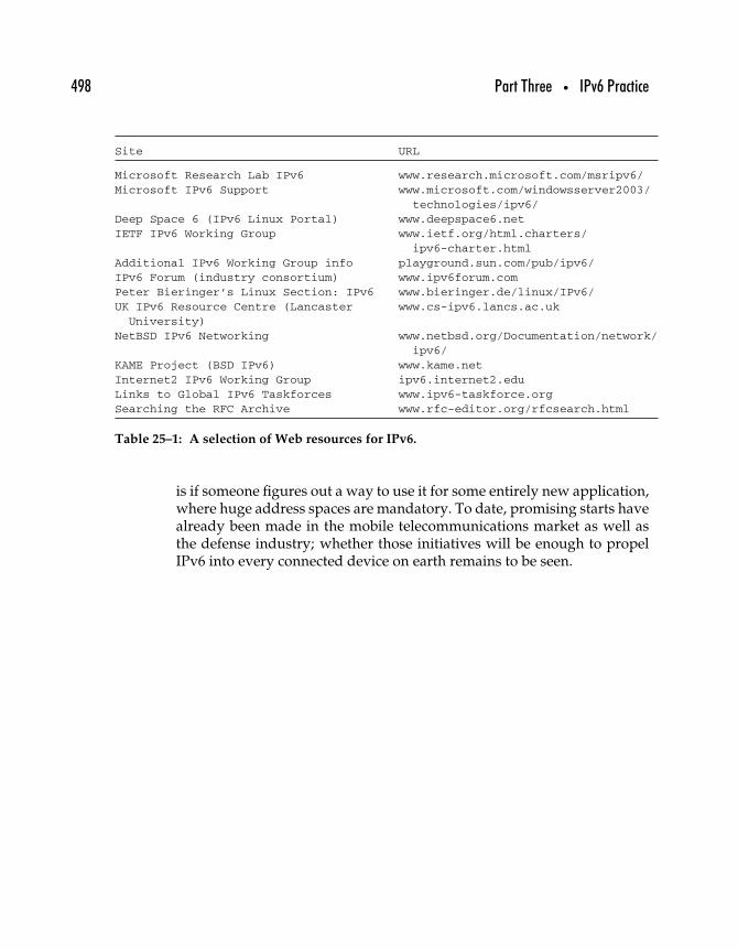
498 Part Three • IPv6 Practice
Site URL
Microsoft Research Lab IPv6 www.research.microsoft.com/msripv6/Microsoft IPv6 Support www.microsoft.com/windowsserver2003/
technologies/ipv6/Deep Space 6 (IPv6 Linux Portal) www.deepspace6.netIETF IPv6 Working Group www.ietf.org/html.charters/
ipv6-charter.htmlAdditional IPv6 Working Group info playground.sun.com/pub/ipv6/IPv6 Forum (industry consortium) www.ipv6forum.comPeter Bieringer’s Linux Section: IPv6 www.bieringer.de/linux/IPv6/UK IPv6 Resource Centre (Lancaster www.cs-ipv6.lancs.ac.uk
University)NetBSD IPv6 Networking www.netbsd.org/Documentation/network/
ipv6/KAME Project (BSD IPv6) www.kame.netInternet2 IPv6 Working Group ipv6.internet2.eduLinks to Global IPv6 Taskforces www.ipv6-taskforce.orgSearching the RFC Archive www.rfc-editor.org/rfcsearch.html
Table 25–1: A selection of Web resources for IPv6.
is if someone figures out a way to use it for some entirely new application,where huge address spaces are mandatory. To date, promising starts havealready been made in the mobile telecommunications market as well asthe defense industry; whether those initiatives will be enough to propelIPv6 into every connected device on earth remains to be seen.
IV
Appendix

This Page Intentionally Left Blank
IPv6 RFCs
The following are all IPv6-related RFCs that had been published by theIETF as of mid-2003. The list was generated by searches on the RFC archiveat www.rfc-editor.org. RFCs are listed in descending order, and each list-ing includes the RFC number, title, authors, date of publication, status (thatis, whether it is updated or obsoleted by some other RFC or if it updatesor obsoletes some other RFC), and type of document.
INFORMATIONAL RFCs provide information and are not to beinterpreted as specifying an Internet standard.
PROPOSED STANDARD RFCs specify a protocol that has been imple-mented and that is being considered for use as an Internet standard.
DRAFT STANDARD RFCs specify a protocol that has been implemented inat least two different forms and that has a body of experience and researchbacking it up. It often represents a revision of a PROPOSED STANDARD.
501
502 Part Four • Appendix
STANDARD RFCs (also denoted as STDs) specify a protocol that has beenaccepted as a standard for the Internet community.
BEST CURRENT PRACTICES documents are published as RFCs as well asBCPs and contain information about recommended procedures, processes,or techniques for accomplishing networking goals.
EXPERIMENTAL RFCs specify a protocol that is being investigated byresearchers. Experimental specifications should generally not be imple-mented or deployed in production networks and should be used withextreme caution in laboratory conditions.
RFCs published on April 1 are almost always “April Fool’s” jokes andshould be read for amusement only (however, there have been non-jokeRFCs published on April 1 as well as joke RFCs with a publication date ofApril, without the date).
RFC 3572
Internet Protocol Version 6 over MAPOS (Multiple Access Protocol OverSONET/SDH)
T. Ogura, M. Maruyama, T. YoshidaJuly 2003INFORMATIONAL
RFC 3542
Advanced Sockets Application Program Interface (API) for IPv6W. Stevens, M. Thomas, E. Nordmark, T. JinmeiMay 2003Obsoletes RFC 2292INFORMATIONAL
RFC 3531
A Flexible Method for Managing the Assignment of Bits of an IPv6Address Block
M. BlanchetApril 2003INFORMATIONAL
RFC 3513
Internet Protocol Version 6 (IPv6) Addressing ArchitectureR. Hinden, S. DeeringApril 2003Obsoletes RFC 2373PROPOSED STANDARD
Appendix • IPv6 RFCs 503
RFC 3493
Basic Socket Interface Extensions for IPv6R. Gilligan, S. Thomson, J. Bound, J. McCann, W. StevensMarch 2003Obsoletes RFC 2553INFORMATIONAL
RFC 3484
Default Address Selection for Internet Protocol Version 6 (IPv6)R. DravesFebruary 2003PROPOSED STANDARD
RFC 3364
Tradeoffs in Domain Name System (DNS) Support for Internet Protocolversion 6 (IPv6)
R. AusteinAugust 2002Updates RFC 2673, RFC 2874INFORMATIONAL
RFC 3363
Representing Internet Protocol version 6 (IPv6) Addresses in the DomainName System (DNS)
R. Bush, A. Durand, B. Fink, O. Gudmundsson, T. HainAugust 2002Updates RFC 2673, RFC 2874INFORMATIONAL
RFC 3316
Internet Protocol Version 6 (IPv6) for Some Second and Third GenerationCellular Hosts
J. Arkko, G. Kuijpers, H. Soliman, J. Loughney, J. WiljakkaApril 2003INFORMATIONAL
RFC 3314
Recommendations for IPv6 in Third Generation Partnership Project (3GPP)Standards
M. Wasserman, Ed.September 2002INFORMATIONAL
RFC 3307
Allocation Guidelines for IPv6 Multicast AddressesB. HabermanAugust 2002PROPOSED STANDARD
504 Part Four • Appendix
RFC 3306
Unicast-Prefix-based IPv6 Multicast AddressesB. Haberman, D. ThalerAugust 2002PROPOSED STANDARD
RFC 3266
Support for IPv6 in Session Description Protocol (SDP)S. Olson, G. Camarillo, A. B. RoachJune 2002Updates RFC 2327PROPOSED STANDARD
RFC 3226
DNSSEC and IPv6 A6 aware server/resolver message size requirementsO. GudmundssonDecember 2001Updates RFC 2535, RFC 2874PROPOSED STANDARD
RFC 3194
The H-Density Ratio for Address Assignment Efficiency: An Update on theH ratio
A. Durand, C. HuitemaNovember 2001Updates RFC 1715INFORMATIONAL
RFC 3178
IPv6 Multihoming Support at Site Exit RoutersJ. Hagino, H. SnyderOctober 2001INFORMATIONAL
RFC 3177
IAB/IESG Recommendations on IPv6 AddressIAB, IESGSeptember 2001INFORMATIONAL
RFC 3175
Aggregation of RSVP for IPv4 and IPv6 ReservationsF. Baker, C. Iturralde, F. Le Faucheur, B. DavieSeptember 2001PROPOSED STANDARD
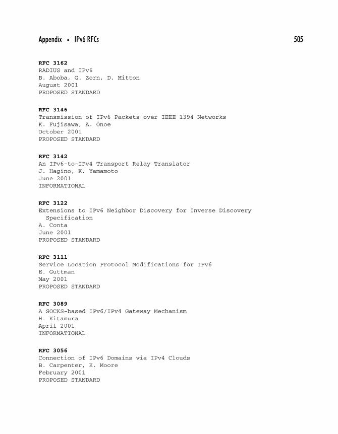
Appendix • IPv6 RFCs 505
RFC 3162
RADIUS and IPv6B. Aboba, G. Zorn, D. MittonAugust 2001PROPOSED STANDARD
RFC 3146
Transmission of IPv6 Packets over IEEE 1394 NetworksK. Fujisawa, A. OnoeOctober 2001PROPOSED STANDARD
RFC 3142
An IPv6-to-IPv4 Transport Relay TranslatorJ. Hagino, K. YamamotoJune 2001INFORMATIONAL
RFC 3122
Extensions to IPv6 Neighbor Discovery for Inverse DiscoverySpecification
A. ContaJune 2001PROPOSED STANDARD
RFC 3111
Service Location Protocol Modifications for IPv6E. GuttmanMay 2001PROPOSED STANDARD
RFC 3089
A SOCKS-based IPv6/IPv4 Gateway MechanismH. KitamuraApril 2001INFORMATIONAL
RFC 3056
Connection of IPv6 Domains via IPv4 CloudsB. Carpenter, K. MooreFebruary 2001PROPOSED STANDARD

506 Part Four • Appendix
RFC 3053
IPv6 Tunnel BrokerA. Durand, P. Fasano, I. Guardini, D. LentoJanuary 2001INFORMATIONAL
RFC 3041
Privacy Extensions for Stateless Address Autoconfigurationin IPv6
T. Narten, R. DravesJanuary 2001PROPOSED STANDARD
RFC 3019
IP Version 6 Management Information Base for The Multicast ListenerDiscovery Protocol
B. Haberman, R. WorzellaJanuary 2001PROPOSED STANDARD
RFC 2928
Initial IPv6 Sub-TLA ID AssignmentsR. Hinden, S. Deering, R. Fink, T. HainSeptember 2000INFORMATIONAL
RFC 2921
6BONE pTLA and pNLA Formats (pTLA)B. FinkSeptember 2000INFORMATIONAL
RFC 2894
Router Renumbering for IPv6M. CrawfordAugust 2000PROPOSED STANDARD
RFC 2893
Transition Mechanisms for IPv6 Hosts and RoutersR. Gilligan, E. NordmarkAugust 2000Obsoletes RFC 1933PROPOSED STANDARD
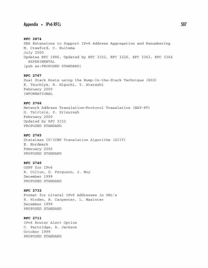
Appendix • IPv6 RFCs 507
RFC 2874
DNS Extensions to Support IPv6 Address Aggregation and RenumberingM. Crawford, C. HuitemaJuly 2000Updates RFC 1886, Updated by RFC 3152, RFC 3226, RFC 3363, RFC 3364EXPERIMENTAL
[pub as:PROPOSED STANDARD]
RFC 2767
Dual Stack Hosts using the Bump-In-the-Stack Technique (BIS)K. Tsuchiya, H. Higuchi, Y. AtarashiFebruary 2000INFORMATIONAL
RFC 2766
Network Address Translation—Protocol Translation (NAT-PT)G. Tsirtsis, P. SrisureshFebruary 2000Updated by RFC 3152PROPOSED STANDARD
RFC 2765
Stateless IP/ICMP Translation Algorithm (SIIT)E. NordmarkFebruary 2000PROPOSED STANDARD
RFC 2740
OSPF for IPv6R. Coltun, D. Ferguson, J. MoyDecember 1999PROPOSED STANDARD
RFC 2732
Format for Literal IPv6 Addresses in URL’sR. Hinden, B. Carpenter, L. MasinterDecember 1999PROPOSED STANDARD
RFC 2711
IPv6 Router Alert OptionC. Partridge, A. JacksonOctober 1999PROPOSED STANDARD

508 Part Four • Appendix
RFC 2710
Multicast Listener Discovery (MLD) for IPv6S. Deering, W. Fenner, B. HabermanOctober 1999PROPOSED STANDARD
RFC 2675
IPv6 JumbogramsD. Borman, S. Deering, R. HindenAugust 1999Obsoletes RFC 2147PROPOSED STANDARD
RFC 2590
Transmission of IPv6 Packets over Frame Relay Networks SpecificationA. Conta, A. Malis, M. MuellerMay 1999PROPOSED STANDARD
RFC 2553
Basic Socket Interface Extensions for IPv6R. Gilligan, S. Thomson, J. Bound, W. StevensMarch 1999Obsoletes RFC 2133, Obsoleted by RFC 3493, Updated by RFC 3152INFORMATIONAL
RFC 2546
6Bone Routing PracticeA. Durand, B. BuclinMarch 1999Obsoleted by RFC 2772INFORMATIONAL
RFC 2545
Use of BGP-4 Multiprotocol Extensions for IPv6 Inter-Domain RoutingP. Marques, F. DupontMarch 1999PROPOSED STANDARD
RFC 2529
Transmission of IPv6 over IPv4 Domains without Explicit TunnelsB. Carpenter, C. JungMarch 1999PROPOSED STANDARD
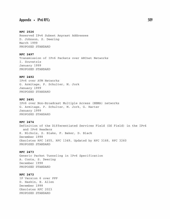
Appendix • IPv6 RFCs 509
RFC 2526
Reserved IPv6 Subnet Anycast AddressesD. Johnson, S. DeeringMarch 1999PROPOSED STANDARD
RFC 2497
Transmission of IPv6 Packets over ARCnet NetworksI. SouvatzisJanuary 1999PROPOSED STANDARD
RFC 2492
IPv6 over ATM NetworksG. Armitage, P. Schulter, M. JorkJanuary 1999PROPOSED STANDARD
RFC 2491
IPv6 over Non-Broadcast Multiple Access (NBMA) networksG. Armitage, P. Schulter, M. Jork, G. HarterJanuary 1999PROPOSED STANDARD
RFC 2474
Definition of the Differentiated Services Field (DS Field) in the IPv4and IPv6 Headers
K. Nichols, S. Blake, F. Baker, D. BlackDecember 1998Obsoletes RFC 1455, RFC 1349, Updated by RFC 3168, RFC 3260PROPOSED STANDARD
RFC 2473
Generic Packet Tunneling in IPv6 SpecificationA. Conta, S. DeeringDecember 1998PROPOSED STANDARD
RFC 2472
IP Version 6 over PPPD. Haskin, E. AllenDecember 1998Obsoletes RFC 2023PROPOSED STANDARD
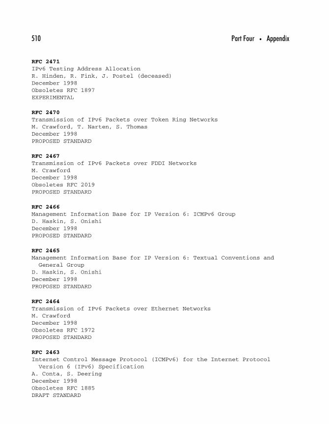
510 Part Four • Appendix
RFC 2471
IPv6 Testing Address AllocationR. Hinden, R. Fink, J. Postel (deceased)December 1998Obsoletes RFC 1897EXPERIMENTAL
RFC 2470
Transmission of IPv6 Packets over Token Ring NetworksM. Crawford, T. Narten, S. ThomasDecember 1998PROPOSED STANDARD
RFC 2467
Transmission of IPv6 Packets over FDDI NetworksM. CrawfordDecember 1998Obsoletes RFC 2019PROPOSED STANDARD
RFC 2466
Management Information Base for IP Version 6: ICMPv6 GroupD. Haskin, S. OnishiDecember 1998PROPOSED STANDARD
RFC 2465
Management Information Base for IP Version 6: Textual Conventions andGeneral Group
D. Haskin, S. OnishiDecember 1998PROPOSED STANDARD
RFC 2464
Transmission of IPv6 Packets over Ethernet NetworksM. CrawfordDecember 1998Obsoletes RFC 1972PROPOSED STANDARD
RFC 2463
Internet Control Message Protocol (ICMPv6) for the Internet ProtocolVersion 6 (IPv6) Specification
A. Conta, S. DeeringDecember 1998Obsoletes RFC 1885DRAFT STANDARD
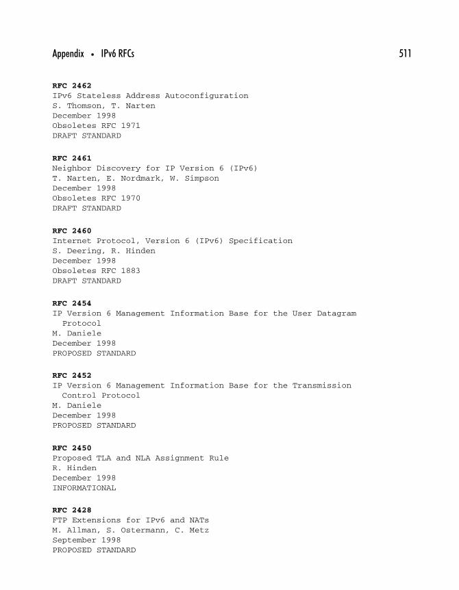
Appendix • IPv6 RFCs 511
RFC 2462
IPv6 Stateless Address AutoconfigurationS. Thomson, T. NartenDecember 1998Obsoletes RFC 1971DRAFT STANDARD
RFC 2461
Neighbor Discovery for IP Version 6 (IPv6)T. Narten, E. Nordmark, W. SimpsonDecember 1998Obsoletes RFC 1970DRAFT STANDARD
RFC 2460
Internet Protocol, Version 6 (IPv6) SpecificationS. Deering, R. HindenDecember 1998Obsoletes RFC 1883DRAFT STANDARD
RFC 2454
IP Version 6 Management Information Base for the User DatagramProtocol
M. DanieleDecember 1998PROPOSED STANDARD
RFC 2452
IP Version 6 Management Information Base for the TransmissionControl Protocol
M. DanieleDecember 1998PROPOSED STANDARD
RFC 2450
Proposed TLA and NLA Assignment RuleR. HindenDecember 1998INFORMATIONAL
RFC 2428
FTP Extensions for IPv6 and NATsM. Allman, S. Ostermann, C. MetzSeptember 1998PROPOSED STANDARD
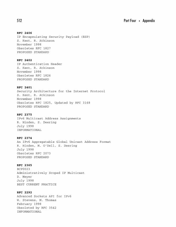
512 Part Four • Appendix
RFC 2406
IP Encapsulating Security Payload (ESP)S. Kent, R. AtkinsonNovember 1998Obsoletes RFC 1827PROPOSED STANDARD
RFC 2402
IP Authentication HeaderS. Kent, R. AtkinsonNovember 1998Obsoletes RFC 1826PROPOSED STANDARD
RFC 2401
Security Architecture for the Internet ProtocolS. Kent, R. AtkinsonNovember 1998Obsoletes RFC 1825, Updated by RFC 3168PROPOSED STANDARD
RFC 2375
IPv6 Multicast Address AssignmentsR. Hinden, S. DeeringJuly 1998INFORMATIONAL
RFC 2374
An IPv6 Aggregatable Global Unicast Address FormatR. Hinden, M. O’Dell, S. DeeringJuly 1998Obsoletes RFC 2073PROPOSED STANDARD
RFC 2365
BCP0023Administratively Scoped IP MulticastD. MeyerJuly 1998BEST CURRENT PRACTICE
RFC 2292
Advanced Sockets API for IPv6W. Stevens, M. ThomasFebruary 1998Obsoleted by RFC 3542INFORMATIONAL

Appendix • IPv6 RFCs 513
RFC 2185
Routing Aspects of IPv6 TransitionR. Callon, D. HaskinSeptember 1997INFORMATIONAL
RFC 2147
TCP and UDP over IPv6 JumbogramsD. BormanMay 1997Obsoleted by RFC 2675PROPOSED STANDARD
RFC 2133
Basic Socket Interface Extensions for IPv6R. Gilligan, S. Thomson, J. Bound, W. StevensApril 1997Obsoleted by RFC 2553INFORMATIONAL
RFC 2080
RIPng for IPv6G. Malkin, R. MinnearJanuary 1997PROPOSED STANDARD
RFC 2073
An IPv6 Provider-Based Unicast Address FormatY. Rekhter, P. Lothberg, R. Hinden, S. Deering, J. PostelJanuary 1997Obsoleted by RFC 2374PROPOSED STANDARD
RFC 2030
Simple Network Time Protocol (SNTP) Version 4 for IPv4, IPv6 and OSID. MillsOctober 1996Obsoletes RFC 1769INFORMATIONAL
RFC 2023
IP Version 6 Over PPPD. Haskin, E. AllenOctober 1996Obsoleted by RFC 2472PROPOSED STANDARD
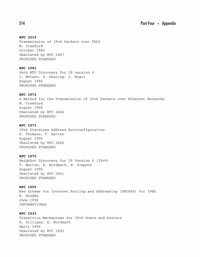
514 Part Four • Appendix
RFC 2019
Transmission of IPv6 Packets over FDDIM. CrawfordOctober 1996Obsoleted by RFC 2467PROPOSED STANDARD
RFC 1981
Path MTU Discovery for IP version 6J. McCann, S. Deering, J. MogulAugust 1996PROPOSED STANDARD
RFC 1972
A Method for the Transmission of IPv6 Packets over Ethernet NetworksM. CrawfordAugust 1996Obsoleted by RFC 2464PROPOSED STANDARD
RFC 1971
IPv6 Stateless Address AutoconfigurationS. Thomson, T. NartenAugust 1996Obsoleted by RFC 2462PROPOSED STANDARD
RFC 1970
Neighbor Discovery for IP Version 6 (IPv6)T. Narten, E. Nordmark, W. SimpsonAugust 1996Obsoleted by RFC 2461PROPOSED STANDARD
RFC 1955
New Scheme for Internet Routing and Addressing (ENCAPS) for IPNGR. HindenJune 1996INFORMATIONAL
RFC 1933
Transition Mechanisms for IPv6 Hosts and RoutersR. Gilligan, E. NordmarkApril 1996Obsoleted by RFC 2893PROPOSED STANDARD
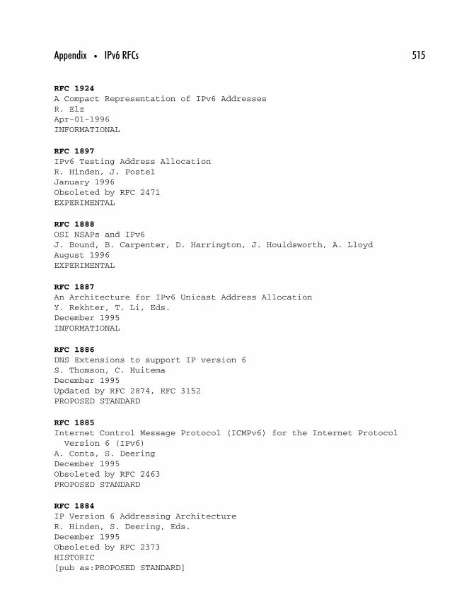
Appendix • IPv6 RFCs 515
RFC 1924
A Compact Representation of IPv6 AddressesR. ElzApr-01-1996INFORMATIONAL
RFC 1897
IPv6 Testing Address AllocationR. Hinden, J. PostelJanuary 1996Obsoleted by RFC 2471EXPERIMENTAL
RFC 1888
OSI NSAPs and IPv6J. Bound, B. Carpenter, D. Harrington, J. Houldsworth, A. LloydAugust 1996EXPERIMENTAL
RFC 1887
An Architecture for IPv6 Unicast Address AllocationY. Rekhter, T. Li, Eds.December 1995INFORMATIONAL
RFC 1886
DNS Extensions to support IP version 6S. Thomson, C. HuitemaDecember 1995Updated by RFC 2874, RFC 3152PROPOSED STANDARD
RFC 1885
Internet Control Message Protocol (ICMPv6) for the Internet ProtocolVersion 6 (IPv6)
A. Conta, S. DeeringDecember 1995Obsoleted by RFC 2463PROPOSED STANDARD
RFC 1884
IP Version 6 Addressing ArchitectureR. Hinden, S. Deering, Eds.December 1995Obsoleted by RFC 2373HISTORIC[pub as:PROPOSED STANDARD]
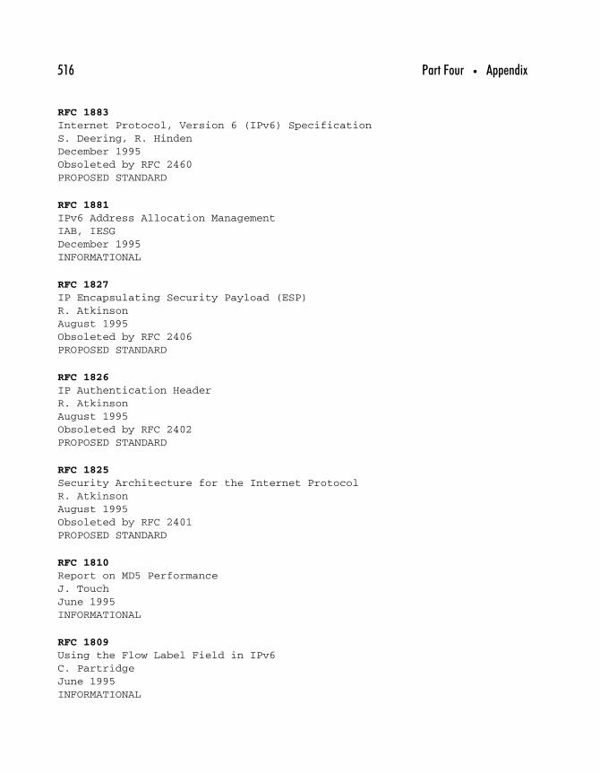
516 Part Four • Appendix
RFC 1883
Internet Protocol, Version 6 (IPv6) SpecificationS. Deering, R. HindenDecember 1995Obsoleted by RFC 2460PROPOSED STANDARD
RFC 1881
IPv6 Address Allocation ManagementIAB, IESGDecember 1995INFORMATIONAL
RFC 1827
IP Encapsulating Security Payload (ESP)R. AtkinsonAugust 1995Obsoleted by RFC 2406PROPOSED STANDARD
RFC 1826
IP Authentication HeaderR. AtkinsonAugust 1995Obsoleted by RFC 2402PROPOSED STANDARD
RFC 1825
Security Architecture for the Internet ProtocolR. AtkinsonAugust 1995Obsoleted by RFC 2401PROPOSED STANDARD
RFC 1810
Report on MD5 PerformanceJ. TouchJune 1995INFORMATIONAL
RFC 1809
Using the Flow Label Field in IPv6C. PartridgeJune 1995INFORMATIONAL

Appendix • IPv6 RFCs 517
RFC 1776
The Address is the MessageS. CrockerApr-01-1995INFORMATIONAL
RFC 1753
IPng Technical Requirements Of the Nimrod Routing and AddressingArchitecture
N. ChiappaDecember 1994INFORMATIONAL
RFC 1752
The Recommendation for the IP Next Generation ProtocolS. Bradner, A. MankinJanuary 1995PROPOSED STANDARD
RFC 1726
Technical Criteria for Choosing IP The Next Generation (IPng)C. Partridge, F. KastenholzDecember 1994INFORMATIONAL
RFC 1719
A Direction for IPngP. GrossDecember 1994INFORMATIONAL
RFC 1715
The H Ratio for Address Assignment EfficiencyC. HuitemaNovember 1994Updated by RFC 3194INFORMATIONAL
RFC 1710
Simple Internet Protocol Plus White PaperR. HindenOctober 1994INFORMATIONAL

518 Part Four • Appendix
RFC 1707
CATNIP: Common Architecture for the InternetM. McGovern, R. UllmannOctober 1994INFORMATIONAL
RFC 1705
Six Virtual Inches to the Left: The Problem with IPngR. Carlson, D. FicarellaOctober 1994INFORMATIONAL
RFC 1688
IPng Mobility ConsiderationsW. SimpsonAugust 1994INFORMATIONAL
RFC 1687
A Large Corporate User’s View of IPngE. FleischmanAugust 1994INFORMATIONAL
RFC 1686
IPng Requirements: A Cable Television Industry ViewpointM. VecchiAugust 1994INFORMATIONAL
RFC 1683
Multiprotocol Interoperability In IPngR. Clark, M. Ammar, K. CalvertAugust 1994INFORMATIONAL
RFC 1682
IPng BSD Host Implementation AnalysisJ. BoundAugust 1994INFORMATIONAL

Appendix • IPv6 RFCs 519
RFC 1680
IPng Support for ATM ServicesC. BrazdziunasAugust 1994INFORMATIONAL
RFC 1679
HPN Working Group Input to the IPng Requirements SolicitationD. Green, P. Irey, D. Marlow, K. O’DonoghueAugust 1994INFORMATIONAL
RFC 1678
IPng Requirements of Large Corporate NetworksE. Britton, J. TavsAugust 1994INFORMATIONAL
RFC 1677
Tactical Radio Frequency Communication Requirements for IPngB. AdamsonAugust 1994INFORMATIONAL
RFC 1676
INFN Requirements for an IPngA. Ghiselli, D. Salomoni, C. VistoliAugust 1994INFORMATIONAL
RFC 1675
Security Concerns for IPngS. BellovinAugust 1994INFORMATIONAL
RFC 1674
A Cellular Industry View of IPngM. TaylorAugust 1994INFORMATIONAL

520 Part Four • Appendix
RFC 1673
Electric Power Research Institute Comments on IPngR. SkeltonAugust 1994INFORMATIONAL
RFC 1672
Accounting Requirements for IPngN. BrownleeAugust 1994INFORMATIONAL
RFC 1671
IPng White Paper on Transition and Other ConsiderationsB. CarpenterAugust 1994INFORMATIONAL
RFC 1670
Input to IPng Engineering ConsiderationsD. HeagertyAugust 1994INFORMATIONAL
RFC 1669
Market Viability as a IPng CriteriaJ. CurranAugust 1994INFORMATIONAL
RFC 1668
Unified Routing Requirements for IPngD. Estrin, T. Li, Y. RekhterAugust 1994INFORMATIONAL
RFC 1667
Modeling and Simulation Requirements for IPngS. Symington, D. Wood, M. PullenAugust 1994INFORMATIONAL

Appendix • IPv6 RFCs 521
RFC 1622
Pip Header ProcessingP. FrancisMay 1994INFORMATIONAL
RFC 1621
Pip Near-term ArchitectureP. FrancisMay 1994INFORMATIONAL
RFC 1550
IP: Next Generation (IPng) White Paper SolicitationS. Bradner, A. MankinDecember 1993INFORMATIONAL
RFC 1475
TP/IX: The Next InternetR. UllmannJune 1993EXPERIMENTAL
RFC 1454
Comparison of Proposals for Next Version of IPT. DixonMay 1993INFORMATIONAL

This Page Intentionally Left Blank

00
Index
A
AAAA resource record, 304–305
advantage of, 309–310
A6 versus, 308
Access control, 94
Address Autoconfiguration, 225
Addresses (addressing)
allocation methods, 66–67, 272–273
cluster, 71
problems, proposals to fix, 62–63, 66
renumbering, 137–138
Simple Internet Protocol Plus, 71
Addresses, IPv4, 22, 24–29
compatible, 77, 156
encapsulated within IPv6, 156
mapped, 77, 78, 156
rationing, 38, 39–40
recycling, 38–39
replacing, 39
rethinking, 39
subnetting, 40–44, 48–49
Addresses, IPv6
aggregation, 124–126, 143–144
aggregation fields, 149–151
anycast, 138–139, 142, 195–208
broadcast function, 142–143
format, 148–156
global routing prefix and subnet ID,151–152
IPv4 addresses encapsulated within, 156
modified EUI-64 interface addressing,152–155
multicast, 142, 183–194
network and node, 143
node self-awareness, 156–157
obtaining and planning for, 343–344
representation, 144–145, 148–149
unicast, 142, 146–148
523

524 Index
Address family identifier (AFI), 245–246Address family information, 256Address Resolution, 225Address Resolution Protocol (ARP), 138, 227,
239Address space
geographic-based aggregation, 125–126IPv6 aggregation, 126provider-based aggregation, 124–125
Adelman, Len, 100Administrative domains (ADs), 238Advanced Encryption Standard (AES), 98ADVERTISE, 275Advertisements, router, 224, 231–233,
281–282Agent Discovery, 293Aggregation
addressing, 124–126, 143–144DNS, 306–308fields, 149–151
Algorithmsencryption and authentication, 97–104routing, 239–240
ALL_DHCP_Relay_Agents_and_Servers, 274ALL_DHCP_Servers, 274All Nodes Addresses, 187–188Allocation of addresses, 66–67, 272–273All Routers Addresses, 188AMD, 8Anycast, IPv4, 198Anycast, IPv6, 138–139, 142
address assignment, 199–200architectural issues, 197–200binding, 206configuration, 200future of, 206–208identifying unicast addresses, 204–206IPsec and, 199Neighbor Discovery and, 227overview of, 196pseudo, 196–197reserved addresses, 201–202responding to packets, 204
restrictions, 200–201role of, 195, 196–197routing, 203–204scope, 200specification, 200–201Subnetwork Router, 201
Anycast Address Resolving Protocol (AARP),206–207
Apache, 482–483, 488Apple Computer, Inc., 8, 28
LocalTalk, 154ARCnet, 154ARPA, IP4 and IP6, 305Ascom, 99A6
AAAA versus, 308domain name resolution, 307–308resource record, 306–307
Asymmetric encryption, 100ATM, 183Authentication
algorithms, 97–104data, 114, 117data origin, 95defined, 93Simple Internet Protocol Plus, 71
Authentication Header (AH), 89, 95, 105,114–119, 133, 162
Autoconfigurationcomparison of IPv4 and IPv6, 24description of IPv6, 136, 271–289renumbering, router and network, 272,
284–289Autoconfiguration, stateful, 24, 136, 271–272
DHCP messages, 274–278RFCs pertaining to, 273–274
Autoconfiguration, stateless, 14–15, 24, 136,272–273, 278
collision detection, 281design goals, 279–280link-local address, creating, 280–281privacy issues, 282–284router advertisements, 281–282

Index 525
Automatic allocation, 272Automatic tunneling, 80, 81, 329–331
Intra-Site Automatic Tunnel AddressingProtocol, 335–337
Autonomous system (AS), 238, 251
BBackbone, 239Behavior aggregates, 259, 260Bellman-Ford algorithm, 239Bidirectional tunneling, 297Binding update/acknowledgment/
request, 180, 297BIND 9, 316
building, with OpenSSL support, 449–455configuring, for use as an IPv4/IPv6
domain name server, 455–480BitchX, 316Blowfish, 99Boeing Computer Services, 28Boot Protocol (BOOTP), 46, 67, 136, 273Border Gateway Protocol (BGP), 240
basics of, 254–256entities involved, 253, 254gateway, 255multiprotocol extensions, 256–257speaker, 255
Border Gateway Protocol version 4 (BGP4),30, 240, 253–255, 380–381, 389–390,399–400
Brute-force attacks, 92, 99Bump-in-the-stack (BITS), 119–120Bump-in-the-wire (BITW), 120
CCare-of-address, 140CAST, 99“Catenet Model for Internetworking, The”
(Cerf), 26CATNIP, 69Cerf, Vint, 26Checksum, 211Christensen, Clayton, 6
Cisco Systems, 90, 340configuring 2611 router for IPv6, 365–376configuring 7200 router for IPv6, 376–382
Clark, David, 26CLASS, 302Classless Inter-Domain Routing (CIDR),
introduction of, 28, 30, 38, 44–46Client-server message exchanges, 276–278Cohen, Danny, 26Collision detection, 155, 281Confidentiality, defined, 93–94Configured tunneling, 80, 81Configuring IPv6
Cisco 2611 router for, 365–376Cisco 7200 router for, 376–382on FreeBSD, 352–359Hitachi GR2000 series routers for,
382–390NEC IX5010 series routers for, 390–401on Solaris 8, 359–364on Windows NT, 349–352
CONFIRM, 275Connectionless integrity, 95Connection-Less Network Protocol (CLNP),
69Connectivity issues, 63, 326–327Controlled link sharing, 262Cookie, 101Costs
comparison of IPv4 and IPv6, 25IPv6, 14
Courier Mail Server to configure emailserver, 481–491
Crocker, Dave, 70Cyphertext, 92Cyptography, 92
D
Data Encryption Standard (DES), 98–99Datagram identification, 129Datagram length, 129Data origin authentication, 95DECLINE, 275
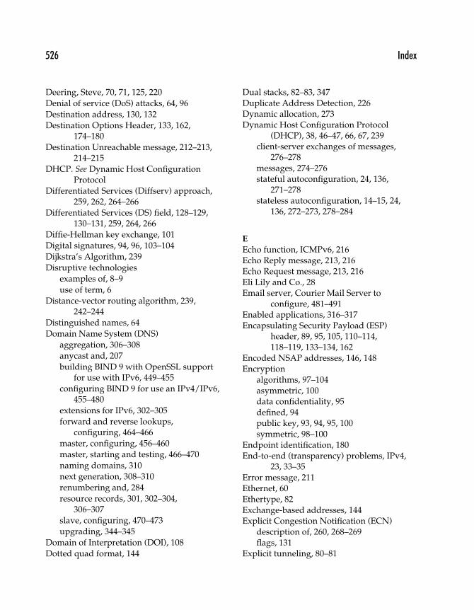
526 Index
Deering, Steve, 70, 71, 125, 220
Denial of service (DoS) attacks, 64, 96
Destination address, 130, 132
Destination Options Header, 133, 162,174–180
Destination Unreachable message, 212–213,214–215
DHCP. See Dynamic Host ConfigurationProtocol
Differentiated Services (Diffserv) approach,259, 262, 264–266
Differentiated Services (DS) field, 128–129,130–131, 259, 264, 266
Diffie-Hellman key exchange, 101
Digital signatures, 94, 96, 103–104
Dijkstra’s Algorithm, 239
Disruptive technologies
examples of, 8–9
use of term, 6
Distance-vector routing algorithm, 239,242–244
Distinguished names, 64
Domain Name System (DNS)
aggregation, 306–308
anycast and, 207
building BIND 9 with OpenSSL supportfor use with IPv6, 449–455
configuring BIND 9 for use an IPv4/IPv6,455–480
extensions for IPv6, 302–305
forward and reverse lookups,configuring, 464–466
master, configuring, 456–460
master, starting and testing, 466–470
naming domains, 310
next generation, 308–310
renumbering and, 284
resource records, 301, 302–304,306–307
slave, configuring, 470–473
upgrading, 344–345
Domain of Interpretation (DOI), 108
Dotted quad format, 144
Dual stacks, 82–83, 347Duplicate Address Detection, 226Dynamic allocation, 273Dynamic Host Configuration Protocol
(DHCP), 38, 46–47, 66, 67, 239client-server exchanges of messages,
276–278messages, 274–276stateful autoconfiguration, 24, 136,
271–278stateless autoconfiguration, 14–15, 24,
136, 272–273, 278–284
E
Echo function, ICMPv6, 216Echo Reply message, 213, 216Echo Request message, 213, 216Eli Lily and Co., 28Email server, Courier Mail Server to
configure, 481–491Enabled applications, 316–317Encapsulating Security Payload (ESP)
header, 89, 95, 105, 110–114,118–119, 133–134, 162
Encoded NSAP addresses, 146, 148Encryption
algorithms, 97–104asymmetric, 100data confidentiality, 95defined, 94public key, 93, 94, 95, 100symmetric, 98–100
Endpoint identification, 180End-to-end (transparency) problems, IPv4,
23, 33–35Error message, 211Ethernet, 60Ethertype, 82Exchange-based addresses, 144Explicit Congestion Notification (ECN)
description of, 260, 268–269flags, 131
Explicit tunneling, 80–81

Index 527
Extended unique identifier (EUI), 143modified EUI-64 interface addressing,
152–155, 202, 282, 283Extension headers
adding, to IPv6 headers, 160–162destination, 133, 162, 174–180fragment, 162, 170–174hop-by-hop, 132–133, 162, 174–180IPv6-in-IPv6 tunneling, 164–165optional Internet-layer data in, 165ordering, 162–164routing, 162, 165–170
Exterior Gateway Protocol (EGP), 239,240–241
F
Fault tolerance, 207–208File Transfer Protocol (FTP), 65Filtering firewalls
on FreeBSD, 418–426on Solaris 8, 403–418
Fixed-scope multicast addresses, 188–189Flag days, 285, 287–289Flags, 129
multicast, 184Flooding scopes, 253Flow label, 131, 260, 266–268Ford Motor Co., 28Foreign agent, 293FP (format prefix), 149, 150Fragmentation, 129, 135, 162, 170–174
IPv4, 170–171packet, 173–174path MTU, 217–220
Fragment Header, 133, 162, 170–174fields, 171–173
Frame Relay, 183Francis, Paul, 70, 71FreeBSD
autoconfiguration, 354–356configuring, for filesystem quota support,
488–489configuring IPv6 on, 352–359
filtering firewall on, 418–426kernel configuration, 354static configuration, 356–359
FreeS/WAN with IPv6 support, 317
GGateways, 235Gateway-to-Gateway Protocol (GGP), 240General Electric Co., 28Geographic-based aggregation, 125–126Global routing prefix, 151–152Global unicast address, 146, 147GOST, 99Group ID, 184, 185, 186
HHaberman, Brian, 206Header checksum, 130Header fields, IPv6, 130–132
version, 130Header format
IPv4, 127, 128–130IPv6, 126–130length, 128version, 128
HeadersSee also Extension headers; OptionheadersAuthentication Header (AH), 89, 95, 105,
114–117Encapsulating Security Payload (ESP), 89,
95, 105, 110–114RIP, 246Simple Internet Protocol Plus, 71
Hinden, Robert, 70, 71Hitachi GR2000 series routers, configuring
for IPv6, 382–390Home agent, 293Hop-by-hop options header, 132–133, 162,
174–180Hop limit field, 129, 131Host-to-host tunneling, 80Host-to-router tunneling, 80

528 Index
Huitema, Christian, 28, 69, 70, 220Huston, Geoff, 32
I
IBM, 28, 98ICMP (Internet Control Message Protocol),
role of, 210, 227ICMPv6 (Internet Control Message Protocol
IPv6), 184, 192Destination Unreachable message,
212–213, 214–215Echo Reply message, 213, 216Echo Request message, 213, 216fragmentation and path MTU,
217–220Internet control messages, 211–213message format, 210–211message header fields, 211new messages, 209–210Packet Too Big message, 213, 215Parameter Problem message, 213, 216Time Exceeded message, 213,
215–216IDEA (International Data Encryption
Algorithm), 99IEEE, 143Inbound Load balancing, 226Informational message, 211INFORMATION-REQUEST, 275Initialization vector, 113Innovator’s Dilemma, The (Christensen), 6Integrated Services (intserv) approach, 262,
263–264, 265Integrity
connectionless, 95defined, 93
Integrity Check Value (ICV), 114, 117Intel, 8, 282–283Inter-domain routing, 257Interface ID, 150Interior Gateway Protocol (IGP), 239International Organization for Standards
(ISO), 60
Internet
areas designated for change, 61–68
early assumptions about, 59–61
Internet Activities Board (IAB), 60
Internet Architecture Board (IAB), 60, 61
Internet Control Message Protocol. See ICMP
Internet Control Message Protocol IPv6. SeeICMPv6
Internet Engineering Note (IEN), No. 46, 26
Internet Engineering Steering Group (IESG),60, 61
Internet Group Management Protocol(IGMP), 184, 192, 210
Internet Key Exchange (IKE) protocol, 101,108
Internet Security Association and KeyManagement Protocol (ISAKMP),101–102, 108
Internetworking, ad hoc, 61
Internetwork Packet eXchange (IPX), 63, 82
Interoperability, 91–92
Intra-Site Automatic Tunnel AddressingProtocol (ISATAP), 335–337
IP Address Encapsulation (IPAE), 70
IP Encapsulation, 70
IPFilter, 316–317
IP4.ARPA, 305
IPng (IP Next Generation)
candidates, 68–72
RFCs covering, 72–73
IPsec (IP Security Protocol)
anycast and, 199
Authentication Header (AH), 89, 95, 105,114–119
basic operation, 104–106
comparison of IPv4 and IPv6, 24, 106
Encapsulating Security Payload (ESP), 89,95, 105, 110–114, 118–119
goals of, 94–95
implementing, on Sun Solaris, 426–440
implementing and deploying, 119–120
Integrity Check Value (ICV), 114, 117
network address translators and, 52

Index 529
security associations, 107–109
services provided, 91
tunnel and transport mode, 109–110
IP6.ARPA, 305
IPv4
address rationing, 38, 39–40
addresses, 22, 24–29
anycast, 198
end-to-end problems, 23, 33–35
fragmentation, 170–171
headers, 127, 128–130
mobility, 24, 139–140, 292–296, 298
Neighbor Discovery, 227–229
Open Shortest Path First, 253
options, 68
problems with, 22–23
routing, nondefault, 22–23, 29–33
IPv6
advantages over IPv4, 23
Forum Web site, 317
future for, 17–18, 493–497
-in-IPv6 tunneling, 164–165
network value, 11–12
possible growth of, 13–16
problems with, 496
Web sites for, 497, 498
IPv7, 69
Itoh, Jun-ichiro Itojun, 317
J
Jacobson, Van, 49
Java, 317
Jumbograms, 135
Jumbo Payload Option, 132, 133, 178
K
KAME, 317–318, 354
Karupiah, Ettikan Kandasamy, 207–208
Key exchange, 101
Key management, 100–102
KEY (security key), 304
L
Layer 2 Forwarding (L2F), 90Layer 2 Tunneling Protocol (L2TP), 90Learning lab, 338–339LFTP, 317Link layer address change, 226Link layer protocols, 314–316Link-local address, creating, 280–281Link-local network addresses, 34–35Link-local unicast address, 146, 147Link sharing, controlled, 262Link state algorithm, 239Link state database, 251Link state routing, 251Live networks, 494–496Load balancing, 207–208, 226–227localhost, configuring, 460–464Local state, 251LocalTalk, 154Logical IP subnet (LIS), 235–236Loopback unicast address, 147
M
Mail exchange (MX), 303–304Man-in-the-middle attacks (MITMs),
96–97Manual allocation, 273Maximum transmission unit (MTU), 134–135,
170–71, 215path, 217–220
MD2, MD4, MD5 (message digest functions),103, 117
Media Access Control (MAC), 143-48 interface identifier, 153–154
Merck and Co., Inc., 28Message authentication codes (MACs),
117Messages
body, 211DHCP, 274–278Internet control, 211–213Multicast Listener Discovery, 192–193
Metcalfe, Robert, 11, 12

530 Index
Microsoft Corp.configuring IPv6 on Windows NT,
349–352as an example of sustaining technology,
7–8global unique identifiers and, 283Point-to-Point Tunneling Protocol, 90–91Verisign’s issue of public key certificates,
93, 96MIT, 28Mobile node, 293Mobility
agent, 140, 293comparison of IPv4 and IPv6, 24, 139–140,
292–298home address, 180, 202RFCs pertaining to, 292
Modified EUI-64 interface addressing,152–155, 202, 282, 283
Moore’s Law, 11, 20Multicast, 142
address format, 184–185principles of, 183–184reserved and permanent addresses,
186–189, 190–191scope definitions, 185–186solicited-node, 188, 189, 191–192
Multicast Listener Discovery (MLD) protocol,184, 192–193, 210
Multihoming, 258Multiprotocol reachable NLRI, 257Multiprotocol unreachable NLRI, 257
N
NAME, 302NAPTR (naming authority pointer), 304National Institute of Standards and
Technology (NIST), 98, 103National Security Agency, 100NATs. See Network address translatorsNative IPv6, 326–327, 329, 332–333NEC IX5010 series routers, configuring for
IPv6, 390–401
Neighbor Advertisement message, 225Neighbor Discovery (ND), 138, 210
IPv6 compared with IPv4, 227–230messages, description of, 224–225network problems solved, 225–227router solicitation, 230–233
Neighbor Solicitation message, 224Neighbor Unreachability Detection, 226NetWare, 63, 82, 146Network(s)
addressing, 143mask, 31renumbering, 137–138routed, 236–238value, 11–12
Network address translators (NATs),23, 38
basic operation of, 51–52end-to-end problems and 33–34formation of, 49misconceptions, 52–53reasons for, 50RFCs pertaining to, 53–55
Network Associates, Inc., 99, 103Networked “things”, use of term, 10Network layer reachability information
(NLRI), 256–257Network Service Access Point (NSAP), 69
encoded addresses, 146, 148, 178Next headers, 114, 129, 131, 161Next-hop Determination, 226Next hop information, 256Nimrod network architecture, 166, 180NLA ID (next-level aggregation identifier),
150Node addressing, 143Node self-awareness, 156–157Nonbroadcast multiaccess (NBMA) network,
183Nondefault routing, 22–23, 29–33, 239Nonglobal interface identifier, 154Nordmark, Eric, 206Nortel’s Entrust products, 99

Index 531
Novell NetWare, 63, 82, 146NXT (next domain), 304
OOAKLEY, 102Ohta, Masataka, 207Open Shortest Path First (OSPF) algorithm,
239, 251–253OpenSSL support, building BIND 9 with,
449–455Option headers
current valid, 178–180destination, 133, 162, 174–180format, 174–175fragment, 133, 162, 170–174hop-by-hop, 132–133, 162, 174–180IPv4, 68, 130IPv6, 130, 132–134padding, 177routing, 162, 165–170Simple Internet Protocol Plus, 71specification and encoding, 175–177
Organizationally unique identifier (OUI), 143OSI (Open Systems Interconnection), 60, 63
PPackets
classification, 263fragmentation, 173–174responding to anycast, 204scheduling, 263size limits, 134–135
Packet Too Big message, 213, 215Padding, 113, 177Padding length, 113Parameter Discovery, 225Parameter Problem message, 213, 216Path MTU discovery (PMTUD), 132, 135, 180
fragmentation and, 218–219implementation issues, 220–221IPv6, 220
Payload data, 113Payload length, 115–116, 129, 131
Peers, 240–241Performance
comparison of IPv4 and IPv6, 24–25IPv6, 14
Per-hop behavior (PHB), 264Permanent multicast addresses, 189, 190–191Photuris, 101–102Ping function, 216P Internet Protocol (Pip), 70Point-to-Point Tunneling Protocol (PPTP),
90–91Prefix Discovery, 225Pretty Good Privacy (PGP), 99, 101Privacy
autoconfiguration and, 282–284Simple Internet Protocol Plus, 71
Private keys, 92Private network address space, 23, 49, 50Products, technologies versus, 15–16Protocol data unit (PDU), 217Protocol field, 129Protocol Indendent Multicast Sparse-Mode
(PIM-SM), 207Protocols, life expectancy, 20–21Protocol tunneling, 164Provider-based aggregation, 124–125, 144Proxy advertisements, 227Pseudo-anycast, 196–197Public key encryption, 93, 94, 95, 100Public key infrastructure (PKI) providers,
96–97
Q
Quake for IPv6, 317Quality of service
approaches to, 262basics of, 260–265Differentiated Services (Diffserv)
approach, 259, 262, 264–266Differentiated Services (DS) field, 259,
264, 266Explicit Congestion Notification, 260,
268–269
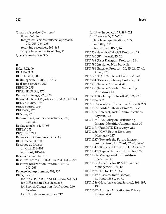
532 Index
Quality of service (Continued)flows, 266–268Integrated Services (intserv) approach,
262, 263–264, 265reserving resources, 262–263Simple Internet Protocol Plus, 71
Query formats, 304, 305
R
RC2/RC4, 99RDATA, 303RDLENGTH, 303Realm-specific IP (RSIP), 55–56Real-time services, 262REBIND, 275RECONFIGURE, 275Redirect message, 225, 226Regional Internet Registries (RIRs), 39, 40, 124RELAY-FORW, 275RELAY-REPL, 275RELEASE, 275RENEW, 275Renumbering, router and network, 272,
284–289Replay attacks, 64, 91, 95REPLY, 275REQUEST, 275Requests for Comments. See RFCsRES (reserved), 150Reserved addresses
anycast, 201–202multicast, 186–189
Reserved area, 116, 150Resource records (RRs), 301, 302–304, 306–307Resource ReSerVation Protocol (RSVP),
262–263Reverse lookup domain, 304, 305RFCs, lists of
for BOOTP, DHCP and DHCPv6, 273–274for Differentiated Services, 266for Explicit Congestion Notification, 260,
268–269for ICMPv6 message types, 212
for IPv6, in general, 73, 499–521
for IPv6 over X, 315–316
on link layer specifications, 155
on mobility, 292
on transition to IPv6, 76
RFC 33 (New HOST-HOST Protocol), 25
RFC 760 (IP Internet), 25, 26
RFC 768 (User Datagram Protocol), 314
RFC 790 (Assigned Numbers), 26
RFC 791 (Internet Protocol), 20, 25, 26, 27, 40,41, 63, 128
RFC 823 (DARPA Internet Gateway), 240
RFC 904 (Exterior Gateway Protocol), 240
RFC 917 (Internet Subnets), 41
RFC 950 (Internet Standard SubnettingProcedure), 41
RFC 951 (Bootstrap Protocol), 46, 136, 273
RFC 1034, 302
RFC 1058 (Routing Information Protocol), 239
RFC 1105 (Border Gateway Protocol), 254
RFC 1122 (Internet Hosts-CommunicationsLayers), 128
RFC 1174 (IAB Policy on DistributingInternet Identifier Assignments), 39
RFC 1191 (Path MTU Discovery), 218
RFC 1256 (ICMP Router DiscoveryMessages), 227
RFC 1287 (Towards the Future InternetArchitecture), 28, 59–61, 62, 63, 64–65
RFC 1347 (TCP and UDP with TUBA), 68–69
RFC 1349 (Type of Service in IP Suite), 128
RFC 1366 (Management of IP AddressSpace), 39, 40
RFC 1367 (Schedule for IP Address SpaceManagement), 39–40
RFC 1475 (TP/IXTP/IX), 69
RFC 1519 (Classless Inter-DomainRouting-CIDR), 44–45
RFC 1546 (Host Anycasting Service), 196–197,198
RFC 1597 (Address Allocation for PrivateInternets), 49

Index 533
RFC 1631 (IP Network Address Translators),49, 54
RFC 1633 (Integrated Services), 262
RFC 1688 (IPng Mobility), 292
RFC 1707 (CATNIP), 69
RFC 1710 (Simple Internet Protocol Plus), 70,72
RFC 1715 (H Ratio for Address AssignmentEfficiency), 28
RFC 1752 (IP Next Generation Protocol), 723
RFC 1771 (Border Gateway Protocol 4), 240,254–255
RFC 1772 (Border Gateway Protocolapplications), 255
RFC 1797 (Class A Subnet Experiment), 48–49
RFC 1809 (Flow Label Field in IPv6), 260
RFC 1818 (OSI NSAPs and IPv6), 178
RFC 1879 (Class A Subnet Experiment), 48, 49
RFC 1884 (IPv6 Addressing Architecture),124, 141, 195
RFC 1885 (Internet Control Message Protocolfor IPv6), 210
RFC 1886 (DNS Extensions), 304, 305
RFC 1917 (recycling of IP networks), 47
RFC 1924 (address representation), 145
RFC 1981 (Path MTU Discovery), 221
RFC 2002 (Mobility Support), 140
RFC 2080 (RIPng for IPv6), 248–250
RFC 2131 (Dynamic Host ConfigurationProtocol), 46, 136
RFC 2168, 304
RFC 2205 (Resource ReSerVation Protocol-RSVP), 262–263
RFC 2283 (Multiprotocol Extensions forBGP-4), 254, 256
RFC 2328 (OSFP Version 2), 239, 251–253, 253
RFC 2373 (Addressing Architecture), 138,146, 197
RFC 2374 (aggregation), 143–144, 149–151
RFC 2401 (Security Architecture for InternetProtocol), 89–93, 91, 107
RFC 2402 (IP Authentication Header),114–117, 118
RFC 2406 (IP Encapsulating SecurityPayload), 110–114, 117, 118
RFC 2453 (RIP version 2), 245
RFC 2460 (extension headers), 160, 161, 163,166, 260, 266–268, 285
RFC 2461 (Neighbor Discovery), 138, 224–233
RFC 2462 (Stateless AddressAutoconfiguration), 136, 278–279, 284
RFC 2463, 210, 211, 213
RFC 2473 (Packet Tunneling), 178–179
RFC 2474 (Differentiated Services Field),128–129, 259, 264
RFC 2481 (Explicit Congestion Notification),260, 268
RFC 2526 (Reserved IPv6 Subnet AnycastAddresses), 197, 201–202
RFC 2529 (Transmission of IPv6 over IPv4Domains without Explicit Tunnels),76, 81
RFC 2535, 304
RFC 2545 (BGP-4 Multiprotocol Extensions),253–254, 257
RFC 2598 (Expedited Forwarding PHB), 264
RFC 2661 (Layer Two Tunneling Protocol), 91
RFC 2663 (IP NATs), 54
RFC 2675 (Jumbograms), 135
RFC 2710 (Multicast Listener Discovery), 192,193, 204
RFC 2711 (Router Alert), 179
RFC 2740 (OSPF for IPv6), 253
RFC 2766 (NAT-Protocol Translation), 54, 55
RFC 2874 (DNS Extensions and Aggregationand Renumbering), 284, 306
RFC 2894 (Router Renumbering), 285,286–287
RFC 2915, 304
RFC 2960 (Stream Control TransmissionProtocol), 314
RFC 2988 (Integrated Services over Diffserv),265
RFC 2993 (Architectural Implications ofNATs), 54
RFC 3022 (Traditional NATs), 53–54

534 Index
RFC 3027 (Complications with NATs), 54
RFC 3041 (Privacy Extensions for StatelessAddress Autoconfiguration in IPv6),154–155, 283–284
RFC 3056 (Connection of IPv6 Domains viaIPv4 Clouds), 76, 83
RFC 3068 (Anycast Prefix for 6to4 RelayRouters), 202
RFC 3102 (Realm Specific IP), 55–56
RFC 3122 (Extensions to IPv6 NeighborDiscovery), 229
RFC 3152 (IP6.ARPA), 305
RFC 3168 (Explicit Congestion Notification),260, 268–269
RFC 3194 (Host-Density Ratio for AddressAssignment Efficiency: An Update onthe H Ratio), 28–29
RFC 3221 (Commentary on Inter-DomainRouting in the Internet), 32–33
RFC 3314 (IPv6 in Third GenerationPartnership Project), 494
RFC 3316 (IPv6 for Cellular Hosts), 494
RFC 3344 (IP Mobility Support for IPv4),292–293
RFC 3363 (IPv6 Addresses in DNS), 306, 308
RFC 3364 (Tradeoffs in DNS), 308–309
RFC 3424 (IAB Considerations for UNilateralSelf-Address Fixing-UNSAF), 34
RFC 3513 (address representation), 144–145,146, 147, 152, 155, 157, 187, 200–201
Rijndael data encryption algorithm, 98
RIPng, 248–250
RIP routing protocol, 239, 240, 242–248
Rivest, Ron, 100
Router Advertisement message, 224, 231–233,281–282
Router Alert Option, 132, 133, 179
Router Discovery, 225
Routers, configuring for IPv6
Cisco 2611, 365–376
Cisco 7200, 376–382
Hitachi GR2000 series, 382–390
NEC IX5010 series, 390–401
Router Solicitation message, 224, 230–231Router-to-host tunneling, 80Router-to-router tunneling, 79–80Routing
aggregation, 30–31algorithms, 239–240anycast, 203–204Border Gateway Protocol (BGP), 240,
253–257distance-vector algorithm, 239, 242–244Exterior Gateway Protocol, 239, 240–241fundamentals of, 235–242hardware-based forwarding, 342–343inter-domain, 257interior versus external, 238–239IPv4, 22–23, 29–33, 253IPv6, 241–242, 257–258networks, 236–238nondefault, 22–23, 29–33, 239Open Shortest Path First (OSPF)
algorithm, 239, 251–253optimization, 297–298option, 162, 165–170problems, proposals to fix, 62–63renumbering, 284–285, 286–287RIP, 242–248RIPng, 248–250scalability, 32–33software-based forwarding, 342–343Source Route Routing Head (Type 0), 166,
167–170tag, 246, 250
Routing Header, 133, 162, 165–170Routing Information Base (RIB), 30RSA, 99RSA algorithm, 100, 103
S
Scalability, 333–335Schneier, Bruce, 99Scope definitions, 185–186Secret key encryption, 98Secure Hash Algorithm (SHA), 103, 117

Index 535
Secure hashes, 94, 102–103, 117Security
See also Filtering firewalls; IPsec(IP Security Protocol)
encryption and authenticationalgorithms, 97–104
gateways, 104–105, 109goals, 93–97identifier, 154–155Internet Protocol issues, 90–93IPv6, 14, 24network address translators and, 52–53proposals addressing, 63–64
Security Association Database (SAD),108–109
Security Associations (SAs), 107–109Security Parameter Index (SPI), 107, 112–113,
116Security Policy Database (SPD), 108Segments Left field, 166Sequence number, 113, 116Session keys, 99Shamir, Adi, 100SIG (security signature), 304Simple Internet Protocol (SIP), 70Simple Internet Protocol Plus (SIPP), 70,
71–72Simple Key-management for Internet
Protocols (SKIP), 102Site-local network addresses, 34–35Site-local unicast address, 146, 147Site renumbering, 284, 285–2866over4, 81, 81–826to4, 83–84
automatic tunneling, 329–331network to native IPv6, 329, 332–333network to 6to4 network, 329, 331–332
Skipjack, 100SLA ID (site-level aggregation identifier), 150Solaris. See Sun SolarisSOLICIT, 275Solicited-node multicast address, 188, 189,
191–192
Source address, 130, 131Source Route Routing Head (Type 0), 166,
167–170Spoofing attacks, 96Stateful autoconfiguration, 24, 136, 271–272
DHCP messages, 274–278RFC pertaining to, 273–274
Stateless autoconfiguration, 14–15, 24, 136,272–273, 278
collision detection, 281design goals, 279–280link-local address, creating, 280–281privacy issues, 282–284router advertisements, 281–282
Static tunneling, 327–328Stream Control Transmission Protocol
(SCTP), 314Subnet ID, 151–152Subnetting issues, 257–258Subnetwork Router anycast address, 201Subnetworks (subnets), 40–44
Class A addresses, 48–49Sun Microsystem, 102Sun Solaris, implementing IPsec on, 426–440Sun Solaris 8
building TCP wrapper for IPv6 on,440–447
configuring IPv6 on, 359–364filtering firewall on, 403–418
Sustaining technologydefined, 7–8IPv6 as a, 16
Symmetric encryption, 98–100
T
TCP (Transmission Control Protocol), 260,314
TCP/IP, 60, 63TCP wrapper for IPv6 on Solaris 8, building,
440–447Technologies, products versus, 15–16Third Generation Partnership Project (3GPP),
493–494

536 Index
Time Exceeded message, 213, 215–216Time-to-live (TTL), 129, 302TLA ID (top-level aggregation identifier),
150Traceroute function, 215–216Traffic analysis attacks, 91Traffic control, 64Traffic flow confidentiality, 95Training, 337–338Transition
clients, deploying, 347dual stacks, 82–83, 347migration, 344–346phasing out IPv4, 347planning for, 339–344preparing for, 337–339RFCs covering, 766over4, 81, 81–826to4, 83–84steps, 323–327tunnels (tunneling), 77–82
Translation, 340–341Transparency (end-to-end) problems, IPv4,
23, 33–35Transport layer protocols, 314Transport mode, IPsec and, 109–110Trick or Treat Demon (TOTD), 316Tsuchiya, Paul, 70TTL. See Time-to-liveTUBA, 68–69Tunnels (tunneling), 77–82
automatic (6to4), 329–331bidirectional, 297encapsulation limit, 178–179explicit, 80–81Intra-Site Automatic Tunnel Addressing
Protocol, 335–337IPv6-in-IPv6, 164–165mode and IPsec, 109–110protocols, 90–91, 164
requirements, 77–79scalability, 333–3356to4 network to native IPv6, 329, 332–3336to4 network to 6to4 network, 329,
331–332static, 327–328types, 79–80without explicit, 81
Twofish, 99TYPE, 302Type of Service (ToS), 64, 67, 128–129, 259
UUllman, Robert, 69Unicast addresses, 142, 146–148
identifying, from anycast addresses,204–206
Unspecified addresses, 147User Datagram Protocol (UDP), 314
VVerisign, Inc., 93, 96Vermicelli Project, 316Viagenie, 317Virtual private networks (VPNs), 90, 109VLAN, 391–394
WWeb sites on IPv6, 497, 498Windows NT, configuring IPv6 on, 349–352WWW6to4, 316
XXerox, 28
ZZero compression, 145Zimmermann, Philip, 99