invitation to bid for - canton township
TRANSCRIPT

Charter Township of Canton
Invitation To Bid
for
PURCHASE OF ONE (1) HEAVY DUTY FIRE RESCUE VEHICLE
Contact: Deputy Director - Fire Chris Stoecklein
Phone: 734 394-5457 E-mail: [email protected]
Date Issued: 1/12/2017
Due Date & Time: 3:00 p.m., Thursday, January 26, 2017

The deadline established for the receipt of your sealed bid is 1/26/2017 at 3:00 p.m. The bid is to be submitted to the Clerk's Office, 1150 S. Canton Center Road, Canton, Michigan 48188. Address the bid to:
Canton - Clerk’s Office PURCHASE OF ONE (1) HEAVY DUTY FIRE RESCUE VEHICLE
DUE 1/26/2017 at 3:00 P.M. 1150 Canton Center S
Canton MI 48188 GENERAL REQUIREMENTS & INSTRUCTIONS
1. SUBMISSION OF OFFERS: All offers should be submitted in a sealed envelope or
package. The invitation title, opening date and time, company name, address and telephone number shall be clearly displayed on the outside of the sealed envelope or package. The delivery of responses to the Clerk’s Office prior to the specified date and time is solely and strictly the responsibility of the offeror. Any submittal received in the Clerk’s Office after the specified date and time will not be considered. Responses shall be submitted on the forms provided by Canton. Additional information may be attached to the submittal. Facsimile submissions are NOT acceptable. No offer may be modified after acceptance. No offer may be withdrawn after opening for a period of sixty days unless otherwise specified. Bid must include all costs. All offers must include the original and at least one (1) copy.
2. EXECUTION OF OFFER: Offer shall contain a manual signature in the space(s) provided
of a representative authorized to legally bind the offeror to the provisions therein.
3. EXECUTION OF ACCEPTANCE: Canton Township legally recognizes acceptance of formal offer when a written contract is signed by both parties. Offerer is not to assume that the Canton Board of Trustees resolution approving the bid or proposal is a binding contract.
4. OPENING & RECORDING: Opening shall be public in the Clerk’s Office immediately
following the advertised deadline date and time for receipt of submittals. 5. INTEGRITY: Canton Township does not discriminate on the basis of race, color, national
origin, sex, religion, age or disability in employment or the provision of services. 6. TABULATION: Bid results will be posted on the Township’s website at www.canton-
mi.org Please click on Doing Business, Bids & Proposals and then click on Bid Results.
7. BOARD AWARDS: As the best interest of Canton may require, Canton reserves the right to make award(s) by an individual item, group of items, all or none, or a combination thereof; on a geographical basis and/or on a countrywide basis with one or more supplier(s) or provider(s); to reject any and all offers or waive any irregularity or technicality in offers received. Offerors are cautioned to make no assumptions. Any or all awards made as a result of this invitation shall conform to applicable ordinances and policies of Canton Township. Bid awards will be posted on the Township’s website at www.canton-mi.org.

8. BRAND NAME OR EQUAL: If items requested by this invitation have been identified in the specifications by a brand name “OR EQUAL” description, such identification is intended to be descriptive and not restrictive and is to indicate the quality and characteristics of products that will be acceptable. Offers proposing “equal” products will be considered for award if such products are clearly identified in the offer and are determined by Canton to meet fully the salient characteristic requirements listed in the specifications.
9. PRICING: Unless otherwise specified prices offered shall remain firm for a period of at
least sixty (60) days; all pricing of goods shall include FOB Canton Township, all packing, handling, shipping charges and delivery to any point(s) within Canton to a secure area or inside delivery.
10. PAYMENT TERMS: Canton Township will remit full payment on all undisputed invoices
within thirty (30) days from receipt by the appropriate person(s) of the invoice or receipt of all products or services ordered.
11. INCURRED EXPENSE: This invitation does not commit Canton to make an award nor
shall Canton be responsible for any cost or expense which may be incurred by any respondent in preparing and submitting a reply, or any cost or expense incurred by any respondent prior to the execution of a purchase order or contract agreement.
12. QUESTIONS/ ADDENDA: Any questions concerning the conditions or specifications shall
be directed to the designated contact person. Addenda items will be posted on the township website, on the Purchasing Division page under Requests for Bids, Proposals and Qualifications. It is the bidder’s responsibility to check and verify that addenda have been issued. Failure to acknowledge addenda may result in the offer not being considered.
13. CLARIFICATION/CORRECTION OF ENTRY: Canton reserves the right to allow for
the clarification of questionable entries and the correction of OBVIOUS MISTAKES. 14. INSURANCE: The successful bidder is required to furnish evidence of the following
insurance requirements in accordance with Canton’s Risk Management Policy O:02. Work may not commence until the Certificates of Insurance have been received. The coverage requirements are as follows:
Workers’ Compensation Insurance: The Contractor shall procure and maintain during the life of this contract, Workers’ Compensation Insurance, including Employers’ Liability Coverage, in accordance with all applicable statutes of the State of Michigan. Commercial General Liability Insurance: The Contractor shall procure and maintain during the life of this contract, Commercial General Liability Insurance on an “Occurrence Basis” with limits of liability not less than $1,000,000 per occurrence and aggregate combined single limit, Personal Injury, Bodily Injury, and Property Damage. Coverage shall include the following extensions: (A) Contractual Liability; (B) Products and Completed Operations; (C) Independent Contractors Coverage; (D) Broad Form General Liability Extensions or equivalent. Motor Vehicle Liability: The Contractor, or its subcontractors, shall procure and maintain during the life of this contract Motor Vehicle Liability Insurance, including Michigan No-Fault

Coverage, with limits of liability not less than $1,000,000 per occurrence combined single limit, Bodily Injury, and Property Damage. Coverage shall include all owned vehicles, all non-owned vehicles, and all hired vehicles. Additional Insured: Commercial General Liability Insurance as described above, shall include an endorsement stating that the following shall be Additional Insured: The Charter Township of Canton, all elected and appointed officials, all employees and volunteers, all boards, commissions, and/or authorities and board members, including employees and volunteers thereof. Cancellation Notice: The Insurance coverage described above, shall include an endorsement stating the following: “It is understood and agreed that Thirty (30) days Advance Written Notice of Cancellation, Non-Renewal, Reduction, and/or Material Change shall be sent to: Brad Sharp, 1150 Canton Center S., Canton MI, 48188. Indemnification: To the fullest extent permitted by law, the (name of contractor) agrees to defend, pay on behalf of, indemnify, and hold harmless the Charter Township of Canton, its elected and appointed officials, employees and volunteers, and others working on behalf of the Charter Township of Canton against any and all claims, demands, suits, or loss, including all costs connected therewith, and for any damages which may be asserted, claimed, or recovered against or from the Charter Township of by reason of personal injury, including bodily injury or death and/or property damage, including loss of use thereof, which arises out of or is in any way connected or associated with this agreement. 15. PUBLIC ACT 517 OF 2012: In accordance with Public Act 517 of the Public Acts of 2012,
any Iran linked business is not eligible to submit a bid on a request for proposal with a public entity in Michigan. An “Iran linked business” includes the following: (1) A person engaging in investment activities in the energy sector of Iran, including a
person that provides oil or liquefied natural gas tanker or products used to construct or maintain pipelines used to transport oil or liquefied gas for the energy section of Iran; and
(2) A financial institution that extends credit to another person, if that person will use the credit to engage in investment activities in the energy sector of Iran.
For purposes of this prohibition, “person” includes an individual, corporation, company, limited liability company, business association, partnership, society, trust, or any other non-governmental entity, organization or group. It also includes a governmental entity or instrumentality of a governmental entity, or any successor, subunit, parent company or subsidiary of, or company under common ownership or control with and of the foregoing.

Township of Canton Fire Department
1 of 127
SPECIFICATIONS FOR A HEAVY DUTY RESCUE Sealed bids will be received by Canton Twp Fire Department for the furnishing of all necessary labor, equipment and material for the Fire Apparatus and other equipment as outlined in the following specifications.
INTENT OF SPECIFICATIONS It shall be the intent of these specifications to cover the furnishing and delivery of a complete fire apparatus. These detailed specifications cover the requirements as to the type of construction, finish, equipment and tests to which the fire apparatus shall conform. Minor details of construction and materials, which are not otherwise specified, are left to the discretion of the contractor.
Images and illustrative material in this specification are as accurate as known at the time of publication, but are subject to change without notice. Images and illustrative material is for reference only, and may include optional equipment and accessories and may not include all standard equipment.
INSTRUCTIONS TO BIDDERS The purchaser's standards for bidding automotive fire apparatus must be strictly adhered to, and all bid forms and questions must be complete and submitted with the bid. Omissions and variations shall result in immediate rejection of the bid.
Bids shall only be considered from companies that have an established reputation in the field of fire apparatus construction and have been in business for a minimum of 20 years. Furthermore, in order to insure fair, ethical, and legal competition, neither the original equipment manufacturer (O.E.M.) nor parent company of the O.E.M. shall have ever been fined or convicted of price fixing, bid rigging, or collusion in any domestic or international fire apparatus market (no exception).
If a bidder represents more than one fire apparatus company or brands of apparatus, they must only bid the top of the line that meets specification.
Each bidder shall furnish satisfactory evidence of their ability to construct the apparatus specified.
Any apparatus manufacturer or their parent company who has had a performance bond called in the last 10 years, shall not be eligible to bid. Any bids from these manufactures shall be immediately rejected (no exception).

Township of Canton Fire Department
2 of 127
Each bid shall be accompanied by a set of manufacturer's set of specifications consisting of a detailed description of the apparatus, construction methods, and equipment proposed to which the apparatus furnished under contract shall conform. These specifications shall indicate size, type, model and make of all components parts and equipment, providing proof of compliance with each and every item in the departments advertised specifications. A letter only, even though written on company letterhead, shall not be sufficient. An exception to this requirement shall not be acceptable.
In accordance with the current edition of NFPA 1901 standards, the proposal shall specify whether the fire department or apparatus dealership shall provide required loose equipment.
The purchaser will utilize this advertised specification to compare all submitted bid proposals. To facilitate comparison, all bid proposal specifications shall be submitted in the same sequence as the advertised specification. Any bidder who fails to submit a set of bid proposal specifications, or who photo copies and submits these specifications as their own construction details will be considered non responsive. This shall render such proposal ineligible for award.
The purchaser's specification shall, in all cases, govern the construction of the apparatus, unless a properly documented exception or deviation was approved. Any bid indicating that the manufacturer's proposal shall supersede the purchaser's specification will be considered a complete substitute and immediately rejected.
THE PURCHASER HAS THE RIGHT TO REJECT ANY BIDS WHICH DOES NOT MEET THESE SPECIFICATIONS AND IS THE SOLE DECIDER TO DEEM WHICH BID IS IN THE BEST INTEREST OF THE PURCHASER.
EXCEPTIONS These specifications are based upon design and performance criteria which have been developed by the fire department as a result of extensive research and careful analysis. Subsequently these specifications reflect the only type of fire apparatus that is acceptable at this time and all specifications herein contained are considered as minimum. Therefore exceptions to the specifications may not be accepted.
Bidders shall indicate in the "yes/no" column if their bid complies on each item (paragraph) specified.
If a product brand name is specified and is commercially available to all bidders, an exception to such items is not acceptable and such bid may be rejected.

Township of Canton Fire Department
3 of 127
Exceptions shall be allowed if they are equal to or superior to that specified and provided they are listed and fully explained on a separate page. All deviations, no matter how slight, shall be clearly explained on a separate sheet, in the bid sequence, citing the page and paragraph number(s) of the specifications, how the proposal deviation is different, how the deviation meets or exceeds the specifications and why it is necessary, and entitled "EXCEPTIONS TO SPECIFICATIONS". The buyer reserves the right to require a bidder to provide proof in each case that a substituted item is equal to that specified. The buyer shall be the sole judge in determination of acceptable substitutes.
Proposals that are found to have deviations without listing them or bids taking total exceptions to these advertised specifications will be rejected (no exception).
Bids not including all exceptions is a material breach and shall result in the bid being immediately rejected (no exception).
GENERAL DESIGN AND CONSTRUCTION The cab, chassis, pump module, and body are to be entirely designed, assembled and painted by the prime vehicle manufacturer, which minimizes third party involvement on engineering, design, service and warranty issues.
All bidders shall provide a list of the company, manufacturing location, and engineering source for each individual major component, including but not limited to the welded cab assembly, the pumphouse module assembly, the chassis assembly, body and electrical system. Apparatus using any subcontracted cab, chassis, pump module, electrical system or body will not be acceptable.
The apparatus shall be designed with due consideration to distribution of load between the front and rear axles. Weight balance and distribution shall be in accordance with the recommendations of the National Fire Protection Association.
The bidder shall make accurate statements as to the apparatus weight and dimensions.
QUALITY AND WORKMANSHIP All steel welding shall follow American welding Society D1.1-2004 recommendations for structural steel welding. All aluminum welding shall follow American welding Society and ANSI D1.2-2003 requirements for structural welding of aluminum. All sheet metal welding shall follow American Welding Society B2.1-2000 requirements for structural welding of sheet metal. Flux core arc welding to use alloy rods, type 7000, American welding Society standards A5.20-E70T1. Employees classified as welders are tested and certified to meet the American Welding Society codes upon hire and every three (3) years thereafter. The manufacturer shall be

Township of Canton Fire Department
4 of 127
required to have an American welding Society certified welding inspector in plant during working hours to monitor weld quality.
The manufacturer shall also be certified to operate a Quality Management System under the requirements of ISO 9001. These standards sponsored by the International organization for Standardization (ISO) specify the quality systems that shall be established by the manufacturer for design, manufacture, installation and service. A copy of the certificate of compliance shall be included with the bid.
To demonstrate the quality of the product and service, each bidder shall provide a list of at least twenty (20) fire departments/municipalities in the region that have bought a second time from the representing dealer. An exception to this requirement shall not be acceptable.
DELIVERY Apparatus, to insure proper break in of all components while still under warranty, shall be delivered under its own power - rail or truck freight shall not be acceptable. A qualified delivery representative shall deliver the apparatus and remain for a sufficient length of time to instruct personnel in proper operation, care and maintenance of the equipment delivered.
MANUALS AND SERVICE INFORMATION The manufacturer shall supply at time of delivery, complete operation and maintenance manuals covering the complete apparatus as delivered. A permanent plate shall be mounted in the drivers compartment which specifies the quantity and type of fluid required including engine oil, engine coolant, transmission, pump transmission lubrication, pump primer and drive axle.
SAFETY VIDEO Since video is much more effective than written documentation and can be replayed for new personnel and as a refresher for existing personnel, an apparatus safety video, in DVD format shall be provided at time of delivery. This video shall address key safety considerations for personnel to follow when they are driving, operating, and maintaining the apparatus. Safety procedures for the following shall be included on the video: vehicle pre trip inspection, chassis operation, pump operation and maintenance.
PERFORMANCE TESTS AND REQUIREMENTS A road test shall be conducted with the apparatus fully loaded and a continuous run of ten (10) miles or more shall be made under all driving conditions, during which time the apparatus shall show no loss of power or overheating. The transmission drive shaft or shafts, and rear axle shall run quietly and be free from abnormal vibration or noise throughout the operating range of the apparatus. Vehicle shall adhere to the following parameters:

Township of Canton Fire Department
5 of 127
A) The apparatus, when fully equipped and loaded, shall have not less than 25 percent nor more than 50 percent of the weight on the front axle, and not less than 50 percent nor more than 75 percent on the rear axle.
B) The apparatus shall be capable of accelerating to 35 mph from a standing start within 25 seconds on a level concrete highway without exceeding the maximum governed rpm of the engine.
C) The service brakes shall be capable of stopping a fully loaded vehicle in 35 feet at 20 mph on a level concrete highway. The air brake system shall conform to Federal Motor vehicle Safety Standards (FMVSS) 121.
D) The apparatus, fully loaded, shall be capable of obtaining a speed of 50 mph on a level concrete highway with the engine not exceeding the governed rpm (full load).
FAILURE TO MEET TEST In the event the apparatus fails to meet the test requirements of these specifications on the first trial, second trials may be made at the option of the bidder within 30 days of the date of the first trial. Such trials shall be final and conclusive and failure to comply with these requirements shall be cause for rejection. failure to comply with changes to conform to any clause of the specifications, within 30 days after notice is given to the bidder of such changes, shall also be cause for rejection of the apparatus. Permission to keep or store the apparatus in any building owned or occupied by the purchaser or its use by the purchaser during the above-specified period with the permission of the bidder shall not constitute acceptance.
SERVICE AND WARRANTY SUPPORT (DEALERSHIP) TO INSURE FULL SERVICE AFTER DELIVERY, THE SELLING BIDDER/DEALERSHIP MUST BE CAPABLE OF PROVIDING SERVICE WHEN REQUIRED.
The bidder/dealership shall show that the company is in position to render prompt service and to furnish replacement parts.
Each bidder/dealership must be able to display that they are actively in the fire apparatus service business by operating a factory authorized service center and parts repository capable of satisfying the warranty service requirements and parts requirements of the vehicle(s) being purchased.
The bidder/dealership must state the location of this authorized service center. This service center must have a staff of factory-trained mechanics, well versed in all aspects of service for all

Township of Canton Fire Department
6 of 127
major components of the apparatus. The service center must be within fifty (50) miles of the Fire Department.
SERVICE AND WARRANTY SUPPORT (MANUFACTURER) To provide an additional layer of service support, the successful manufacturer must also own a least two separate service facilities, one located in the northern portion of the US to service both Canada and the northern US states and one in the south to service the southern states.
The manufacturer shall stock 1 million parts equating to $5,000,000 of inventory dedicated to service and replacement parts to ensure quick response and minimize down time. Furthermore, the manufacturer shall house the inventory in a dedicated facility, with a dedicated shipping area that ensures service parts are given priority. The bidder shall provide detailed documentation of service and replacement part resources.
Parts identification shall be provided to both the dealer and the Fire Department through an on line web based application for the specific truck reflected in this specification. Access will be granted using the specific VIN number of the vehicle. The online web application will provide the ability to view complete bills of materials, digital photographs, parts drawings, assembly drawings, and access to all current operation, maintenance and service publications.
The manufacturer must also maintain a 24 hour/ 7 day a week, toll free emergency hot line.
The manufacturer shall employ a staff of adequate size (a minimum of 30 personnel) specifically dedicated to providing customer support and parts for the fielded fleet of vehicles it has produced.
The manufacturer shall employ a minimum of four certified EVT technicians on staff, not only providing technical expertise in the repair of fire apparatus, but also demonstrating the commitment to service after the sale.
COMMERCIAL GENERAL LIABILITY INSURANCE Coverage shall be written on a Commercial General Liability form. The policy shall be written on an occurrence form and shall include Contractual Liability coverage for bodily injury and property damage subject to the terms and conditions of the policy. The policy shall include Owner as an additional insured when required by written contract.
COMMERCIAL AUTOMOBILE LIABILITY INSURANCE The successful bidder shall, during the performance of the contract keep in force at least the following minimum limits of commercial automobile liability insurance:
Each Accident Combined Single Limit:$1,000,000

Township of Canton Fire Department
7 of 127
Coverage shall be written on a Commercial Automobile liability form.
UMBRELLA/EXCESS LIABILITY INSURANCE The successful bidder shall, during the performance of the contract and for three (3) years following acceptance of the product, keep in force at least the following minimum limits of umbrella liability insurance:
Aggregate:$25,000,000
Each Occurrence: $25,000,000
The umbrella policy shall be written on an occurrence basis and at a minimum provide excess to the Bidder's General Liability, Automobile Liability and Employer's Liability policies.
The required limits can be provided by one (1) or more policies provided all other insurance requirements are met.
Coverage shall be provided by a carrier(s) rated A- or better by A.M. Bests.
All policies shall provide a 30 day notice of cancellation to the named insured. The Certificate of Insurance shall provide the following cancellation clause: Should any of the above described polices be cancelled before the expiration date thereof, notice shall be delivered in accordance with the policy provisions. Bidder agrees to furnish owner with a current Certificate of Insurance with the coverages listed above along with its bid. The certificate shall show the purchaser as certificate holder.
SINGLE SOURCE MANUFACTURER Bids shall only be accepted from a single source apparatus manufacturer. The definition of single source is a manufacturer that designs and manufactures their products using an integrated approach, including the chassis, cab weldment, cab, pumphouse (including the sheet metal enclosure, valve controls, piping and operators panel) and body being designed, fabricated and assembled on the bidder's premises. The electrical system (hardwire or multiplex) shall be both designed and integrated by the same apparatus manufacturer. The warranties relative to these major components (excluding component warranties such as engine, transmission, axles, pump, etc.) must be from a single source manufacturer and not split between manufacturers (i.e. body, pumphouse, cab weldment and chassis). The bidder shall provide evidence that they comply with this requirement.
The bidder shall state the location of the factory where the apparatus is to be built.

Township of Canton Fire Department
8 of 127
NFPA 2016 STANDARDS This unit shall comply with the NFPA standards effective January 1, 2016, except for fire department specifications that differ from NFPA specifications. These exceptions shall be set forth in the Statement of Exceptions.
Certification of slip resistance of all stepping, standing and walking surfaces shall be supplied with delivery of the apparatus.
All horizontal surfaces designated as a standing or walking surface that are greater than 48.00" above the ground must be defined by a 1.00" wide line along its outside perimeter. Perimeter markings and designated access paths to destination points shall be identified on the customer approval print and are shown as approximate. Actual location(s) shall be determined based on materials used and actual conditions at final build. Access paths may pass through hose storage areas and opening or removal of covers or restraints may be required.Access paths may require the operation of devices and equipment such as the aerial device or ladder rack.
A plate that is highly visible to the driver while seated shall be provided. This plate shall show the overall height, length, and gross vehicle weight rating.
The manufacturer shall have programs in place for training, proficiency testing and performance for any staff involved with certifications.
An official of the company shall designate, in writing, who is qualified to witness and certify test results.
NFPA COMPLIANCY Apparatus proposed by the bidder shall meet the applicable requirements of the National Fire Protection Association (NFPA) as stated in current edition at time of contract execution. Fire department's specifications that differ from NFPA specifications shall be indicated in the proposal as "non-NFPA".
VEHICLE INSPECTION PROGRAM CERTIFICATION To assure the vehicle is built to current NFPA standards, the apparatus, in its entirety, shall be third-party, independent, audit-certified through Underwriters Laboratory (UL) that it is built and complies to all applicable standards in the current edition of NFPA 1901. The certification includes: all design, production, operational, and performance testing of not only the apparatus, but those components that are installed on the apparatus (no exception).
A placard shall be affixed in the driver's side area stating the third party agency, the date, the standard and the certificate number of the whole vehicle audit.

Township of Canton Fire Department
9 of 127
GENERATOR TEST If the unit has a generator, the generator shall be tested, approved, and certified by Underwriters Laboratories at the manufacturer's expense. The test results shall be provided to the Fire Department at the time of delivery.
BREATHING AIR TEST If the unit has breathing air, the apparatus manufacturer shall draw an air sample from the air system and certify that the air quality meets the requirements of NFPA 1989, Standard on Breathing Air Quality for Fire and Emergency Services Respiratory Protection.
DELIVERY OF APPARATUS Apparatus, to insure proper break in of all components while still under warranty, shall be delivered under it own power. Rail or truck freight shall not be acceptable. A qualified delivery driver with proper CDL licensing, medical card and complies with DOT requirements, representing the contractor shall deliver the apparatus to the dealer sales/service center. No Exception.
REQUIREMENTS OF THE APPARATUS MANUFACTURER The manufacturer of the apparatus must be fully owned and managed by a Parent Company, Corporation, Partnership, or that is a company 100% held in the United States of America.
Proposals from any manufacturer that is fully or partially owned and/or operated by a Foreign Company, Corporation, Partnership, or that is a company under any type of ownership, partnership, or any similar type of agreement shall be rejected immediately and their bid disqualified. (NO EXCEPTIONS).
CONTINGENCY FUND Each bidder shall add a Contingency Fund in the amount of $10,000.00. This fund shall be used for any changes made during the manufacturing of the unit. The bidder shall provide a contin-gency Fund Report after each change is made that affects the fund. Any remaining money in the contingency fund shall be credited back to the Fire Department.
INSPECTION TRIP(S) The bidder shall provide two (2) factory inspection trip(s) for three (3) customer representative(s). The inspection trip(s) shall be scheduled at times mutually agreed upon between the manufacturer's representative and the customer. Private air transportation is mandatory. All costs such as Private air travel, lodging and meals shall be the responsibility of the bidder.

Township of Canton Fire Department
10 of 127
PRECONSTRUCTION MEETING A preconstruction meeting will take place at the fire department. The meeting shall be scheduled at times mutually agreed upon between the manufacturer's representative and the customer.
WARRANTY AND SERVICE Bidder must state who the contact is for warranty, repairs and parts.
__________________________________________________
Name Phone
SERVICE AGENCY Bidder must state the name of the company that is licensed to do service and warranty on the vehicle, including pump, body and chassis.
__________________________________________________
Name Phone
REPAIR LICENSE NUMBER The bidder shall include the State of Michigan Vehicle Repair center license number.
AFTERMARKET SUPPORT WEBSITE A Customer Service website shall provide authorized dealers access to comprehensive information pertaining to the maintenance and service of their customer's apparatus. This tool shall provide the authorized dealer the ability to service and support their customers to the best of their ability with factory support at their fingertips.
This website shall also be accessible to the end user through the guest login. Limited access is available and vehicle specific parts information accessible by entering a specific VIN number. All end users should see their local authorized dealer for additional support and service.
The website shall provide the following to the designated individuals:
- Authorized dealer only - ability to access truck detail information on the major components of the vehicle, warranty information, available vehicle photographs, vehicle drawings, sales options, applicable vehicle software downloads, etc.
- Authorized dealer and customer - parts look-up capability, with the aid of digital photographs, part drawings, and assembly drawings.

Township of Canton Fire Department
11 of 127
- Authorized dealer only - ability to electronically submit warranty claims directly to the factory for reimbursement.
- Authorized dealer only - accessibility to multiple dealer reports that allow the dealership to maintain communication with the customer on the status of orders, claims, and phone contacts.
- Authorized dealer and customer - access to all currently published Operation and Maintenance and Service publications.
- Authorized dealer only - access to manufacturer Service Bulletins and Work Instructions containing information on current service topics and recommendations provided.
- Authorized dealer and customer - access to upcoming training classes offered by the manufacturer.
- Authorized dealer only - access to interactive electronic learning modules (Operators Guides) covering the operation of major vehicle components.
- Authorized dealer only - access to customer service articles, corporate news, quarterly newsletters, and key contacts.
ENGINEERING CAPABILITIES Due to the complexity of the requested vehicle, degreed and licensed engineering personnel shall be used in the design of the proposed vehicle.
All bidders shall list the number of degreed and licensed engineers including mechanical, electrical and professional engineers. Bidders shall include the total number of Associate, Bachelors and Masters Degrees. Bidders not supply engineering capabilities shall automatically be rejected. NO EXCEPTION
ENGINEERING METHODOLOGY Each bidder shall describe the engineering methodology that is used in the design process of custom fire apparatus
ENGINEERING RESPONSIBILITY In order to protect the Purchaser from divided design, engineering, manufacturing, warranty, and service responsibilities between chassis and body manufacturers, bids shall only be accepted from apparatus manufacturers who design, fabricate and manufacture the complete apparatus at their own facilities. The only exceptions to this shall be a commercial chassis, water pump, water

Township of Canton Fire Department
12 of 127
tank (if made of polypropylene). Private labeling of another manufacturer's body and/or chassis shall not meet the requirements of this section.
No Exception.
UNITS DELIVERED Each bid shall be accompanied by a list of at least twenty five (25) references of similarly constructed apparatus in the State of Michigan that have been in service for a minimum of five (5) years. Each reference must be of an apparatus manufactured of the same construction and style as these specifications. The list shall include the customer's name, address, phone number, email, and date placed in service.
Failure to supply this document with the proposal shall result in immediate rejection of the proposal. No Exceptions
LICENSED DEALER The dealer representing a fire apparatus manufacturer in the State of Michigan, shall be licensed to do business in the State of Michigan. The license must be issued to the bidder representing manufacturer as listed on the proposal submitted. Licenses submitted that are issued to a third party will not be accepted.
__________________________________________________________________
Dealer Name as provided on License Phone number
NEW VEHICLE ORIENTATION A qualified person from the manufacturer or sales agency shall be available at the discretion of the purchaser for orientation of the apparatus maintenance, chassis, pump and any other orientation required for equipment delivered. Trainer must have a minimum of 10 years in the repair, service and orientation of Fire Apparatus. Trainer must be recognized as a qualified instructor in pumps, chassis operation and maintenance. Trainer must be certified in engine, fire pumps and electrical repair for fire apparatus - NO EXCEPTIONS
Orientation for the new fire apparatus shall be provided by the bidder. The orientation shall consist of three (3) session(s) for the Canton Fire Department. Each session shall be up to a maximum of eight (8) hours (Depending on class size). Session content shall include classroom and/or hands on orientation with the new vehicle. The Fire Chief and the instructor shall agree on the class session(s) duration and required content. The orientation will take place at the Fire Department. If more orientation is required than specified in the specifications, the additional expense shall be covered by the Fire Department.

Township of Canton Fire Department
13 of 127
BID BOND All bidders shall provide a bid bond as security for the bid in the form of a 10% bid bond to accompany their bid. This bid bond shall be issued by a Surety Company who is listed on the U.S. Treasury Departments list of acceptable sureties as published in Department Circular 570. The bid bond shall be issued by an authorized representative of the Surety Company and shall be accompanied by a certified power of attorney dated on or before the date of bid. The bid bond shall include language, which assures that the bidder/principal shall give a bond or bonds as may be specified in the bidding or contract documents, with good and sufficient surety for the faithful performance of the contract, including the Basic One (1) Year Limited Warranty, and for the prompt payment of labor and material furnished in the prosecution of the contract.
Proposals received from bidders who do not manufacture the chassis shall provide a warranty that shall be issued jointly and severally by, and signed by, both the bidder and the chassis manufacturer.
If the successful bidder does not manufacture the chassis, the bidder shall supply a warranty bond, in addition to their performance bond, along with their signed contract. This warranty bond shall guarantee all terms and conditions of the Basic One (1) Year Limited Warranty and names both the bidder and chassis manufacturer as co-principals. This warranty bond shall be issued for the contract amount and shall remain in force for a term which is consistent with the term of the Basic One (1) Year Limited Warranty.
Notwithstanding any document or assertion to the contrary, any surety bond related to the sale of a vehicle shall apply only to the Basic One (1) Year Limited Warranty for such vehicle. Any surety bond related to the sale of a vehicle shall not apply to any other warranties that are included within this bid (OEM or otherwise) or to the warranties (if any) of any third party of any part, component, attachment or accessory that is incorporated into or attached to the vehicle. In the event of any contradiction or inconsistency between this provision and any other document or assertion, this provision shall prevail.
PERFORMANCE BOND Notwithstanding any document or assertion to the contrary, any surety bond related to the sale of a vehicle shall apply only to the Basic One (1) Year Limited Warranty for such vehicle. Any surety bond related to the sale of a vehicle shall not apply to any other warranties that are included within this bid (OEM or otherwise) or to the warranties (if any) of any third party of any part, component, attachment or accessory that is incorporated into or attached to the vehicle. In the event of any contradiction or inconsistency between this provision and any other document or assertion, this provision shall prevail. Please provide your manufacturer’s Performance Bond rating per thousand. ________________________/1000.

Township of Canton Fire Department
14 of 127
APPROVAL DRAWING A drawing of the proposed apparatus shall be provided for approval before construction begins. The sales representative shall also have a copy of the same drawing. The finalized and approved drawing shall become part of the contract documents. This drawing shall indicate the chassis make and model, location of the lights, siren, horns, compartments, major components, etc.
A "revised" approval drawing of the apparatus shall be prepared and submitted by the manufacturer to the purchaser showing any changes made to the approval drawing.
ELECTRICAL WIRING DIAGRAMS Two (2) electrical wiring diagrams, prepared for the model of chassis and body, shall be provided.
CHASSIS Chassis provided shall be a new, tilt-type custom fire apparatus. The chassis shall be manufactured in the apparatus body builder's facility eliminating any split responsibility. The chassis shall be designed and manufactured for heavy-duty service, with adequate strength and capacity for the intended load to be sustained and the type of service required.
WHEELBASE The wheelbase of the vehicle shall be no greater than 229.00".
GVW RATING The gross vehicle weight rating shall be a minimum of 49,800 lbs.
FRAME The chassis frame shall be built with two (2) steel channels bolted to five (5) cross members or more, depending on other options of the apparatus. The side rails shall be heat-treated steel measuring 10.25" x 3.50" x .375".
Each rail shall have a section modulus of 16.00 cubic inches, yield strength of 120,000 psi, and a resisting bending moment (rbm) of 1,921,069 inch-pounds.
FRAME REINFORCEMENT A full-length mainframe "C" liner shall be provided.
The liner shall be an internal "C" design, heat-treated steel measuring 9.38" x 3.13" x 0.25". Each reinforcement member shall have a section modulus of 3.90 cubic inches, yield strength of 120,000 psi and resisting bending moment (rbm) of 938,762 in-lb.

Township of Canton Fire Department
15 of 127
FRONT NON DRIVE AXLE The front axle shall be of the independent suspension design with a ground rating of 19,500 lb.
Upper and lower control arms shall be used on each side of the axle. Upper control arm castings shall be made of 100,000-psi yield strength 8630 steel and the lower control arm casting shall be made of 55,000-psi yield ductile iron.
The center cross members and side plates shall be constructed out of 80,000-psi yield strength steel.
Each control arm shall be mounted to the center section using elastomer bushings. These rubber bushings shall rotate on low friction plain bearings and be lubricated for life. Each bushing shall also have a flange end to absorb longitudinal impact loads, reducing noise and vibrations.
There shall be nine (9) grease fittings supplied, one (1) on each control arm pivot and one (1) on the steering gear extension.
The upper control arm shall be shorter than the lower arm so that wheel end geometry provides positive camber when deflected below rated load and negative camber above rated load.
Camber at load shall be zero degrees for optimum tire life.
The ball joint bearing shall be of low friction design and be maintenance free.
Toe links that are adjustable for alignment of the wheel to the center of the chassis shall be provided.
The wheel ends must have little to no bump steer when the chassis encounters a hole or obstacle.
The steering linkage shall provide proper steering angles for the inside and outside wheel, based on the vehicle wheelbase.
The axle shall have a third party certified turning angle of 45 degrees. Front discharge, front suction, or aluminum wheels shall not infringe on this cramp angle.
FRONT SUSPENSION An independent front suspension shall be provided with a minimum ground rating of 19,500 lb.
The independent suspension system shall be designed to provide maximum ride comfort. The design shall allow the vehicle to travel at highway speeds over improved road surfaces and at moderate speeds over rough terrain with minimal transfer of road shock and vibration to the vehicle's crew compartment.

Township of Canton Fire Department
16 of 127
Each wheel shall have a torsion bar type spring. In addition, each front wheel end shall also have energy absorbing jounce bumpers to prevent bottoming of the suspension.
The suspension design shall be such that there is at least 10.00" of total wheel travel and a minimum of 3.75" before suspension bottoms.
The torsion bar anchor lock system allows for simple lean adjustments, without the use of shims. One can adjust for a lean within 15 minutes per side. Anchor adjustment design is such that it allows for ride height adjustment on each side.
The independent suspension shall have been put through a durability test that simulated a minimum of 140,000 miles of inner city driving.
FRONT SHOCK ABSORBERS KONI heavy-duty telescoping shock absorbers shall be provided on the front suspension.
FRONT OIL SEALS Oil seals with viewing window shall be provided on the front axle.
FRONT TIRES Front tires shall be Goodyear® 315/80R22.50 radials, 20 ply G289 WHA tread, rated for 20,400 lb maximum axle load and 68 mph maximum speed.
The tires shall be mounted on Alcoa 22.50" x 9.00" polished aluminum disc wheels with a ten (10) stud, 11.25" bolt circle.
REAR AXLE The rear axle shall be a Meritor™, Model RS-26-185, with a capacity of 27,000 lb.
TOP SPEED OF VEHICLE A rear axle ratio shall be furnished to allow the vehicle to reach a top speed of 68 mph.
REAR SUSPENSION The rear suspension shall be Standens, semi-elliptical, 3.00" wide x 53.00" long, 12-leaf pack with a ground rating of 27,000 lb. The spring hangers shall be castings.
The two (2) top leaves shall wrap the forward spring hanger pin, and the rear of the spring shall be a slipper style end that shall ride in a rear slipper hanger. To reduce bending stress due to acceleration and braking, the front eye shall be a berlin eye that shall place the front spring pin in the horizontal plane within the main leaf.

Township of Canton Fire Department
17 of 127
A steel encased rubber bushing shall be used in the spring eye. The steel encased rubber bushing shall be maintenance free and require no lubrication.
REAR OIL SEALS Oil seals shall be provided on the rear axle(s).
REAR TIRES Rear tires shall be four (4) Goodyear® 12R22.50 radials, 16 ply all season G622 RSD tread, rated for 27,120 lb maximum axle load and 75 mph maximum speed.
The tires shall be mounted on Alcoa 22.50" x 8.25" polished aluminum disc wheels with a ten (10) stud 11.25" bolt circle.
TIRE BALANCE All tires shall be balanced with Counteract balancing beads. The beads shall be inserted into the tire and eliminate the need for wheel weights.
TIRE PRESSURE MANAGEMENT There shall be a VECSAFE LED tire alert pressure management system provided that shall monitor each tire's pressure. A chrome plated brass sensor shall be provided on the valve stem of each tire for a total of six (6) tires.
The sensor shall calibrate to the tire pressure when installed on the valve stem for pressures between 20 and 120 psi. The sensor shall activate an integral battery operated LED when the pressure of that tire drops 8 psi.
Removing the cap from the sensor shall indicate the functionality of the sensor and battery. If the sensor and battery are in working condition, the LED shall immediately start blinking.
LUG NUT COVERS Stainless steel lug nut covers shall be installed on all lug nuts.
EXTENDER, VALVE STEM A pair of 180 degree valve stem extenders shall be installed on the valve stems of the rear outside tires. The extender shall allow the tire pressure monitor cap to face the outside.
MUD FLAPS Mud flaps shall be installed behind the front and rear wheels of the apparatus.
WHEEL CHOCKS There shall be one (1) pair of Ziamatic AC-32, aluminum alloy, Quick-Choc wheel blocks provided.

Township of Canton Fire Department
18 of 127
WHEEL CHOCK BRACKETS There shall be one (1) pair of Ziamatic QCH-32-H horizontal mounting wheel chock brackets provided for the Ziamatic AC-32 wheel chocks. The brackets shall be mounted in front of the Driver's side rear tires.
ANTI-LOCK BRAKE SYSTEM The vehicle shall be equipped with a Meritor WABCO 4S4M, anti-lock braking system. The ABS shall provide a 4-channel anti-lock braking control on both the front and rear wheels. A digitally controlled system that utilizes microprocessor technology shall control the anti-lock braking system. Each wheel shall be monitored by the system. When any particular wheel begins to lockup, a signal shall be sent to the control unit. This control unit shall then reduce the braking of that wheel for a fraction of a second and then reapply the brake. This anti-lock brake system shall eliminate the lockup of any wheel thus helping to prevent the apparatus from skidding out of control.
BRAKES The service brake system shall be full air type.
The front brakes shall be Knorr/Bendix disc type with a 17.00" ventilated rotor for improved stopping distance.
The brake system shall be certified, third party inspected, for improved stopping distance.
The rear brakes shall be Meritor™, Disc Plus, Model EX225, disc operated with automatic slack adjusters and a 17.00" ventilated rotor for improved stopping distance.
BRAKE SYSTEM AIR COMPRESSOR The air compressor shall be a Cummins/WABCO with 18.7 cubic feet per minute output.
BRAKE SYSTEM The brake system shall include:
Bendix® brake treadle valve with vinyl covered foot surface
Heated automatic moisture ejector on air dryer
Total air system minimum capacity of 4,272 cubic inches
Two (2) air pressure gauges with a red warning light and an audible alarm, that activates when air pressure falls below 60 psi
Spring set parking brake system
Parking brake operated by a push-pull style control valve
A parking "brake on" indicator light on instrument panel

Township of Canton Fire Department
19 of 127
Park brake relay/inversion and anti-compounding valve, in conjunction with a double check valve system, with an automatic spring brake application at 40 psi
A pressure protection valve to prevent all air operated accessories from drawing air from the air system when the system pressure drops below 80 psi (550 kPa)
1/4 turn drain valves on each air tank
The air tank shall be primed and painted to meet a minimum 750 hour salt spray test.
To reduce the effects of corrosion, the air tank shall be mounted with stainless steel brackets (no exception).
BRAKE SYSTEM AIR DRYER The air dryer shall be a WABCO System Saver 1200 IWT, with internal wet tank, spin-on coalescing filter cartridge and 100 watt heater.
BRAKE LINES Color-coded nylon brake lines shall be provided. The lines shall be wrapped in a heat protective loom where necessary in the chassis.
AIR TANK, AIR HORNS AND TOOLS An additional air tank with 1454 cubic inch displacement shall be provided. The tank shall be used for chassis air horns and powering air tools.
An air tool outlet with a metering valve, located at the driver's side pump panel, shall be provided.
The air tank shall be primed and painted to meet a minimum 750 hour salt spray test. To reduce the effects of corrosion, the air tank shall be mounted with stainless steel brackets (no exception).
The output flow of the engine air compressor varies with engine RPM. Full compressor output is only achieved at governed engine speed. Engine speed may be limited by generators, pumps and other PTO driven options.
MANUAL MOISTURE EJECTOR(S) Manual moisture ejectors for a single axle pumper reservoir capacity shall be installed in the brake system.
The moisture ejector(s) shall be remote mounted on the driver side of vehicle, as close to the edge of vehicle as possible.
A loop shall be provided at the moisture ejector, to allow for ease of pulling the drain.

Township of Canton Fire Department
20 of 127
Each moisture ejector shall have a label directly under the ejector, stating air tank drain.
Nylon tubing, .38" diameter, shall be routed from the air tank to the moisture ejector. The nylon tubing shall be covered with protective split loom.
The moisture ejector(s) shall be provided on the as directed by the FD reservoir(s).
ENGINE The chassis shall be powered by an electronically controlled engine as described below:
Make: Cummins Model: L9 Power: 450 hp at 2100 rpm Torque: 1250 lb-ft at 1400 rpm Governed Speed:
2200 rpm
Emissions Level:
EPA 2017
Fuel: Diesel Cylinders: Six (6) Displacement: 543 cubic inches (8.9L) Starter: Delco 39MT™ Fuel Filters: Spin-on style primary filter with water separator and water-in-fuel sensor.
Secondary spin-on style filter.
The engine shall include On-board diagnostics (OBD), which provides self diagnostic and reporting. The system shall give the owner or repair technician access to state of health information for various vehicle sub systems. The system shall monitor vehicle systems, engine and after treatment. The system shall illuminate a malfunction indicator light on the dash console if a problem is detected.
HIGH IDLE A high idle switch shall be provided, inside the cab, on the instrument panel, that shall automatically maintain a preset engine rpm. A switch shall be installed, at the cab instrument panel, for activation/deactivation.
The high idle shall be operational only when the parking brake is on and the truck transmission is in neutral. A green indicator light shall be provided, adjacent to the switch. The light shall

Township of Canton Fire Department
21 of 127
illuminate when the above conditions are met. The light shall be labeled "OK to Engage High Idle."
ENGINE BRAKE A Jacobs® engine brake is to be installed with the controls located on the instrument panel within easy reach of the driver.
The driver shall be able to turn the engine brake system on/off and have a high, medium and low setting.
The engine brake shall activate when the system is on and the throttle is released.
The high setting of the brake application shall activate and work simultaneously with the variable geometry turbo (VGT) provided on the engine.
The engine brake shall be installed in such a manner that when the engine brake is slowing the vehicle the brake lights are activated.
The ABS system shall automatically disengage the auxiliary braking device, when required.
CLUTCH FAN A fan clutch shall be provided. The fan clutch shall be automatic when the pump transmission is in "Road" position, and constantly engaged when in "Pump" position.
ENGINE AIR INTAKE The engine air intake shall be located above the engine cooling package. It shall draw fresh air from the front of the apparatus through the radiator grille.
A stainless steel metal screen shall be installed at the inlet of the air intake system that shall meet NFPA 1901 requirements.
The air cleaner and stainless steel screen shall be easily accessible by tilting the cab.
EXHAUST SYSTEM The exhaust system shall be stainless steel from the engine's aftertreatment device, and shall be 4.00" in diameter. The exhaust system shall include a Single Module™ aftertreatment device to meet current EPA standards. An insulation wrap shall be provided on all exhaust pipes between the turbo and aftertreatment device to minimize the heat loss to the aftertreatment device. The exhaust shall terminate horizontally ahead of the right side rear wheels. A tailpipe diffuser shall be provided to reduce the temperature of the exhaust as it exits. Heat deflector shields shall be provided to isolate chassis and body components from the heat of the tailpipe diffuser.

Township of Canton Fire Department
22 of 127
EXHAUST MODIFICATION The exhaust pipe shall be brought out from under the body at a 90 degree angle from the truck. The tail pipe shall extend a minimum of 2.00" past the body, adaptable for the Plymovent system. The diameter of the diffuser shall be 6.00". There shall be a clearance of 4.00" completely around the pipe once past the side of the body. A stop shall be provided on the tail pipe that shall prevent the nozzle from sliding too far on.
RADIATOR The radiator and the complete cooling system shall meet or exceed NFPA and engine manufacturer cooling system standards.
For maximum corrosion resistance and cooling performance, the entire radiator core shall be constructed using long life aluminum alloy. The radiator core shall consist of aluminum fins, having a serpentine design, brazed to aluminum tubes. No solder joints or leaded material of any kind shall be acceptable in the core assembly.
The radiator core shall have a minimum front area of 1060 square inches.
Supply and return tanks shall be made of heavy duty glass-reinforced nylon that shall be crimped onto the core assembly using header tabs and a compression gasket to complete the radiator core assembly. There shall be a full steel frame around the inserts to enhance cooling system durability and reliability.
The radiator shall be compatible with commercial antifreeze solutions.
The radiator assembly shall be isolated from the chassis frame rails with rubber isolators to prevent the development of leaks caused by twisting or straining when the apparatus operates over uneven terrain.
The radiator shall include a de-aeration/expansion tank. For visual coolant level inspection, the radiator shall have a built-in sight glass. The radiator shall be equipped with a 15 psi pressure relief cap.
A drain port shall be located at the lowest point of the cooling system and/or the bottom of the radiator to permit complete flushing of the coolant from the system.
Shields or baffles shall be provided to prevent recirculation of hot air to the inlet side of the radiator.

Township of Canton Fire Department
23 of 127
COOLANT LINES Gates, or Goodyear, rubber hose shall be used for all engine coolant lines installed by the chassis manufacturer.
Hose clamps shall be stainless steel constant torque type to prevent coolant leakage. They shall react to temperature changes in the cooling system and expand or contract accordingly while maintaining a constant clamping pressure on the hose.
FUEL TANK A 75 gallon fuel tank shall be provided and mounted at rear of chassis. The tank shall be constructed of 12-gauge, hot rolled steel. It shall be equipped with swash partitions and a vent. To eliminate the effects of corrosion, the fuel tank shall be mounted with stainless steel straps. (no exception).
A .75" drain plug shall be provided in a low point of the tank for drainage.
A fill inlet shall be located on the left hand side of the body and be covered with a hinged, spring loaded, stainless steel door that is marked "Ultra Low Sulfur - Diesel Fuel Only."
A .50" diameter vent shall be provided running from top of tank to just below fuel fill inlet.
The tank shall meet all FHWA 393.67 requirements including a fill capacity of 95 percent of tank volume.
All fuel lines shall be provided as recommended by the engine manufacturer.
DIESEL EXHAUST FLUID TANK A 4.5 gallon diesel exhaust fluid (DEF) tank shall be provided and mounted in the driver's side body forward of the rear axle.
A 0.50" drain plug shall be provided in a low point of the tank for drainage.
A fill inlet shall be located on the driver's side of the body and be covered with a hinged, spring loaded, polished stainless steel door that is marked "Diesel Exhaust Fluid Only".
The tank shall meet the engine manufacturers requirement for 10 percent expansion space in the event of tank freezing.
The tank shall include an integrated heater unit that utilizes engine coolant to thaw the DEF in the event of freezing.

Township of Canton Fire Department
24 of 127
TRANSMISSION An Allison 5th generation, Model EVS 4000P, electronic, torque converting, automatic transmission shall be provided.
The transmission shall be equipped with prognostics to monitor oil life, filter life, and transmission health. A wrench icon on the shift selector's digital display shall indicate when service is due.
Two (2) PTO openings shall be located on left side and top of converter housing (positions 8 o'clock and 1 o'clock).
A transmission temperature gauge with red light and buzzer shall be installed on the cab instrument panel.
TRANSMISSION SHIFTER A six (6)-speed push button shift module shall be mounted to right of driver on console. Shift position indicator shall be indirectly lit for after dark operation.
The Allison shifter shall be a double-digit display model.
The transmission ratio shall be 1st - 3.51 to 1.00, 2nd - 1.91 to 1.00, 3rd - 1.43 to 1.00, 4th - 1.00 to 1.00, 5th - 0.75 to 1.00, 6th - 0.64 to 1.00, R- 4.80 to 1.00.
TRANSMISSION COOLER A Modine plate and fin transmission oil cooler shall be provided using engine coolant to control the transmission oil temperature.
DRIVELINE Drivelines shall be a heavy-duty metal tube and be equipped with Spicer® 1710 universal joints.
The shafts shall be dynamically balanced before installation.
A splined slip joint shall be provided in each driveshaft, slip joint shall be coated with Glidecoat® or equivalent.
STEERING Dual Sheppard, Model M110, steering gears, with integral heavy-duty power steering, shall be provided. For reduced system temperatures, the power steering shall incorporate an air to oil cooler and an Eaton, Model VN20, hydraulic pump with integral pressure and flow control. All power steering lines shall have wire braded lines with crimped fittings.

Township of Canton Fire Department
25 of 127
A tilt and telescopic steering column shall be provided to improve fit for a broader range of driver configurations.
STEERING WHEEL The steering wheel shall be 18.00" in diameter, have tilting and telescoping capabilities, and a 4-spoke design.
LOGO AND CUSTOMER DESIGNATION ON HORN BUTTON The steering wheel shall have an emblem containing the fire apparatus manufacturer's logo and customer name. The emblem shall have three (3) rows of text for the customer's department name. There shall be a maximum of eight (8) characters in the first row, 11 characters in the second row and 11 characters in the third row.
The first row of text shall be: Canton
The second row of text shall be: Fire
The third row of text shall be: Department
AUTOMATIC CHASSIS LUBRICATION A Vogel Automatic Lubrication System shall be provided. The lubrication shall be supplied while the vehicle ignition switch is active to allow a uniform application of grease to the locations listed. The electronic control unit that forms part of the system shall activate the pump after an adjustable interval time. The unit shall control and monitor pump operation and report any faults via an indicator light on the driver's dashboard of the cab.
The lubrication system reservoir, which requires a 15.00" wide x 14.50" high x 6.25" deep mounting area, shall be located in a servicable location on the apparatus.
- Independent suspension control Arm Pivot Points
- Rear Axle Slack Adjusters
- Rear Axle Brake Cam Screws
- Rear Suspension Spring Pins
- Rear Suspension Shackle Pins
- Walking Beam Pins Tandem axle, if applicable
WINCH A Warn, model 9.5cti multi-mount, 9,500 pound portable 12V electric winch shall be provided.

Township of Canton Fire Department
26 of 127
The winch shall mount to the vehicle receiver hitch and be held in place with a locking hardened pin. A heavy gauge wire and electrical plug shall be provided for quick connection to the vehicle electrical system.
The winch shall be provided with 100 feet of Warn nylon reinforced synthetic rope with a replaceable clevis hook.
A 40' remote control shall be provided.
A label shall be placed on or near the receiver that states the maximum winch load rating and the maximum rope load rating that the receiver can support.
BUMPER A one (1)-piece bumper manufactured from .25" formed steel with a .38" bend radius shall be provided. The bumper shall be a minimum of 10.00" high with a 1.50" top and bottom flange, and shall extend 26.00" from the face of the cab. The bumper shall be 95.28" wide with 45 degree corners and side plates. The bumper shall be metal finished and painted job color.
To provide adequate support strength, the bumper shall be mounted directly to the front of the C channel frame. The frame shall be a bolted modular extension frame constructed of 50,000 psi tensile steel.
GRAVEL PAN A gravel pan, constructed of bright aluminum treadplate, shall be furnished between the bumper and the cab face. The pan shall be properly supported from the underside to prevent flexing and vibration.
TOW HOOKS Two (2) chromed steel tow hooks shall be installed under the bumper and attached to the front frame members. The tow hooks shall be designed and positioned to allow up to a 6,000 lb straight horizontal pull in line with the centerline of the vehicle. The tow hooks shall not be used for lifting of the apparatus.
ACCESS PANEL A lift-out panel shall be provided in the center of the equipment tray for access to the area below.
Two (2) flush lift and turn latches shall secure the panel.
FULL WIDTH COVER OVER BUMPER A bright aluminum treadplate cover shall be provided over the entire top of the front bumper. This cover shall be provided over any trays or bumper mounted reels or hydraulic tools.

Township of Canton Fire Department
27 of 127
The cover shall be raised 8.50" above the gravel pan.
The cover shall be attached with a stainless steel hinge.
Two (2) D-ring latches will secure the cover in the closed position and two (2) gas springs will hold the cover in the open position. For ease of operation, the D-ring latches will be spaced 40.00" apart on the front face.
STRIP LIGHT UNDER BUMPER COVER There shall be one (1) Amdor Model AY-9220-31, 30.63" 12 volt DC LED strip light(s) provided on the inside of the front bumper cover.
The light(s) shall be activated when the battery switch is on and the bumper tray cover is open.
FRONT BUMPER LINE-X COATING Protective black Line-X® coating shall be provided on the outside exterior of the top front bumper flange. It shall not be sprayed on the underside of the flange.
The lining shall be properly installed by an authorized Line-X dealer.
CAB The cab shall be designed specifically for the fire service and manufactured by the chassis builder.
The cab shall be built by the apparatus manufacturer in a facility located on the manufacturer's premises (no exception).
For reasons of structural integrity and enhanced occupant protection, the cab shall be a heavy duty design, constructed to the following minimal standards.
The cab shall have 12 main vertical structural members located in the A-pillar (front cab corner posts), B-pillar (side center posts), C-pillar (rear corner posts), and rear wall areas. The A-pillar shall be constructed of solid A356-T5 aluminum castings. The B-pillar and C-pillar shall be constructed from 0.13" wall extrusions. The rear wall shall be constructed of two (2) 2.00" x 2.00" outer aluminum extrusions and two (2) 2.00" x 1.00" inner aluminum extrusions. All main vertical structural members shall run from the floor to 4.625" x 3.864" x 0.090" thick roof extrusions to provide a cage-like structure with the A-pillar and roof extrusions being welded into a 0.25" thick corner casting at each of the front corners of the roof assembly.
The front of the cab shall be constructed of a 0.13" firewall plate, covered with a 0.090" front skin (for a total thickness of 0.22"), and reinforced with a full width x 0.50" thick cross-cab support located just below the windshield and fully welded to the engine tunnel. The cross-cab

Township of Canton Fire Department
28 of 127
support shall run the full width of the cab and weld to each A-pillar, the 0.13" firewall plate, and the front skin.
The cab floors shall be constructed of 0.125" thick aluminum plate and reinforced at the firewall with an additional 0.25" thick cross-floor support providing a total thickness of 0.375" of structural material at the front floor area. The front floor area shall also be supported with two (2) triangular 0.30" wall extrusions that also provides the mounting point for the cab lift. This tubing shall run from the floor wireway of the cab to the engine tunnel side plates, creating the structure to support the forces created when lifting the cab.
The cab shall be 96.00" wide (outside door skin to outside door skin) to maintain maximum maneuverability (no exception).
The forward cab section shall have an overall height (from the cab roof to the ground) of approximately 99.00". The crew cab section shall have a 10.00" raised roof, with an overall cab height of approximately 109.00". The overall height listed shall be calculated based on a truck configuration with the lowest suspension weight rating, the smallest diameter tires for the suspension, no water weight, no loose equipment weight, and no personnel weight. Larger tires, wheels, and suspension shall increase the overall height listed.
The floor to ceiling height inside the crew cab shall be 64.50" in the center and outboard positions.
The crew cab floor shall measure 46.00" from the rear wall to the back side of the rear facing seat risers.
The medium block engine tunnel, at the rearward highest point (knee level), shall measure 61.50" to the rear wall. The big block engine tunnel shall measure 51.50" to the rear wall.
The crew cab shall be a totally enclosed design with the interior area completely open to improve visibility and verbal communication between the occupants.
The cab shall be a full tilt cab style.
A 3-point cab mount system with rubber isolators shall improve ride quality by isolating chassis vibrations from the cab.
CAB ROOF DRIP RAIL For enhanced protection from inclement weather, a drip rail shall be furnished on the sides of the cab. The drip rail shall be painted to match the cab roof, and bonded to the sides of the cab. The drip rail shall extend the full length of the cab roof.

Township of Canton Fire Department
29 of 127
INTERIOR CAB INSULATION The cab shall include 1.00" insulation in the ceiling, 1.50" insulation in the side walls, and 2.00" insulation in the rear wall to maximize acoustic absorption and thermal insulation.
FENDER LINERS Full circular inner fender liners in the wheel wells shall be provided.
PANORAMIC WINDSHIELD A one (1)-piece safety glass windshield shall be provided with over 2,775 square inches of clear viewing area. The windshield shall be full width and shall provide the occupants with a panoramic view. The windshield shall consist of three (3) layers: outer light, middle safety laminate, and inner light. The outer light layer shall provide superior chip resistance. The middle safety laminate layer shall prevent the windshield glass pieces from detaching in the event of breakage. The inner light shall provide yet another chip resistant layer. The cab windshield shall be bonded to the aluminum windshield frame using a urethane adhesive. A custom frit pattern shall be applied on the outside perimeter of the windshield for a finished automotive appearance.
WINDSHIELD WIPERS Three (3) electric windshield wipers with washer shall be provided that meet FMVSS and SAE requirements.
The washer reservoir shall be able to be filled without raising the cab.
ENGINE TUNNEL Engine hood side walls shall be constructed of 0.375" aluminum. The top shall be constructed of 0.125" aluminum and shall be tapered at the top to allow for more driver and passenger elbow room.
The engine hood shall be insulated for protection from heat and sound. The noise insulation keeps the dBA level within the limits stated in the current NFPA 1901 standards.
The engine tunnel shall be no higher than 17.00" off the crew cab floor (no exception).
INTERIOR CREW CAB REAR WALL ADJUSTABLE SEATING (PATENT PENDING) The interior rear wall of the crew cab shall have mounting holes every 2.75" to allow for adjustability of the forward facing crew cab seating along the rear wall. Seats shall be adjustable with use of simple hand tools allowing departments flexibility of their seating arrangement should their department needs change.

Township of Canton Fire Department
30 of 127
CAB REAR WALL EXTERIOR COVERING The exterior surface of the rear wall of the cab shall be overlaid with bright aluminum treadplate that covers the entire rear wall .
CAB LIFT A hydraulic cab lift system shall be provided consisting of an electric powered hydraulic pump, dual lift cylinders, and necessary hoses and valves.
Hydraulic pump shall have a manual override for backup in the event of electrical failure.
Lift controls shall be located on the right side pump panel or front area of the body in a convenient location.
The cab shall be capable of tilting 43 degrees to accommodate engine maintenance and removal.
The cab shall be locked down by a 2-point normally closed spring loaded hook type latch that fully engages after the cab has been lowered. The system shall be hydraulically actuated to release the normally closed locks when the cab lift control is in the raised position and cab lift system is under pressure. When the cab is completely lowered and system pressure has been relieved, the spring loaded latch mechanisms shall return to the normally closed and locked position.
For increased safety, a redundant mechanical stay arm shall be provided that must be manually put in place on the left side between the chassis and cab frame when the cab is in the raised position. This device shall be manually stowed to its original position before the cab can be lowered.
Cab Lift Interlock The cab lift system shall be interlocked to the parking brake. The cab tilt mechanism shall be active only when the parking brake is set and the ignition switch is in the on position. If the parking brake is released, the cab tilt mechanism shall be disabled.
GRILLE A bright finished aluminum mesh grille screen, inserted behind a bright finished grille surround, shall be provided on the front center of the cab.
SIDE OF CAB MOLDING Chrome molding shall be provided on both sides of cab.

Township of Canton Fire Department
31 of 127
MIRRORS A Retrac, Model 613422, dual vision, motorized, west coast style mirror with black finish shall be mounted on each side of the front cab door with chrome spring loaded retractable arms. The flat glass and convex glass shall be heated and adjustable with remote control within reach of the driver.
DOORS To enhance entry and egress to the cab, the forward cab door openings shall be a minimum of 37.50" wide x 63.37" high. The crew cab doors shall be located on the sides of the cab and shall be constructed in the same manner as the forward cab doors. The crew cab door openings shall be a minimum of 34.30" wide x 73.25" high.
The forward cab and crew cab doors shall be constructed of extruded aluminum with a nominal material thickness of 0.093". The exterior door skins shall be constructed from 0.090" aluminum.
A customized, vertical, pull-down type door handle shall be provided on the exterior of each cab door. The exterior handle shall be designed specifically for the fire service to prevent accidental activation, and shall provide 4.00" wide x 2.00" deep hand clearance for ease of use with heavy gloved hands.
Each door shall also be provided with an interior flush, open style paddle handle that shall be readily operable from fore and aft positions, and be designed to prevent accidental activation. The interior handles shall provide 4.00" wide x 1.25" deep hand clearance for ease of use with heavy gloved hands.
The cab doors shall be provided with both interior (rotary knob) and exterior (keyed) locks exceeding FMVSS standards. The keys shall be Model 1041. The locks shall be capable of activating when the doors are open or closed. The doors shall remain locked if locks are activated when the doors are opened, then closed.
A full length, heavy duty, stainless steel, piano-type hinge with a 0.38" pin and 11 gauge leaf shall be provided on all cab doors. There shall be double automotive-type rubber seals around the perimeter of the door framing and door edges to ensure a weather-tight fit.
A chrome grab handle shall be provided on the inside of each cab door for ease of entry.
The bottom cab step at each cab door location shall be located below the cab doors and shall be exposed to the exterior of the cab.

Township of Canton Fire Department
32 of 127
DOOR PANELS The inner cab door panels shall be constructed out of brushed stainless steel.
ELECTRIC OPERATED CAB DOOR WINDOWS All four (4) cab doors shall be equipped with electric operated windows with one (1) flush mounted automotive style switch on each door. The driver's door shall have four (4) switches, one (1) to control each door window.
Each switch shall allow intermittent or auto down operation for ease of use. Auto down operation shall be actuated by holding the window down switch for approximately 1 second.
CAB STEPS The forward cab and crew cab access steps shall be a full size two (2) step design to provide largest possible stepping surfaces for safe ingress and egress. The bottom steps shall be designed with a grip pattern punched into bright aluminum treadplate material to provide support, slip resistance, and drainage. The bottom steps shall be a bolt-in design to minimize repair costs should they need to be replaced. The forward cab steps shall be a minimum 25.00" wide, and the crew cab steps shall be 21.65" wide with a 10.00" minimum depth. The inside cab steps shall not exceed 16.50" in height. A slip-resistant handrail shall be provided adjacent to each cab door opening to assist during cab ingress and egress.
The vertical surfaces of the step well shall be aluminum treadplate.
STEP LIGHTS There shall be six (6) white LED step lights installed for cab and crew cab access steps.
One (1) light for the driver's access steps.
Two (2) lights for the driver's side crew cab access steps.
Two (2) lights for the passenger's side crew cab access steps.
One (1) light for the passenger's side access step.
In order to ensure exceptional illumination, each light shall provide a minimum of 25 foot-candles (fc) covering an entire 15" x 15" square placed ten (10) inches below the light and a minimum of 1.5 fc covering an entire 30" x 30" square at the same ten (10) inch distance below the light.
The lights shall be activated when the battery switch is on and the adjacent door is opened.
FENDER CROWNS Stainless steel fender crowns shall be installed at the cab wheel openings.

Township of Canton Fire Department
33 of 127
GRAB HANDLES (INTERIOR CREW CAB DOORS) A black rubber covered grab handle shall be mounted on the door post of the driver's and passenger's side crew cab door to assist in entering the cab. The grab handle shall be securely mounted to the hinge side of the door frame.
GRAB HANDLES/STRAP (INTERIOR CREW CAB) There shall be two (2) straps attached to the crew cab roof. Each strap shall be located as directed by the FD. These straps shall be furnished with a loop that is large enough to fit a gloved hand through.
INTERIOR CREW CAB DOOR HANDRAIL A handrail shall be provided on each interior crew cab door pan. The handrails shall be mounted at a 45 degree angle. These are in addition to the standard crew cab door handle.
MOUNTING PLATE ON ENGINE TUNNEL Equipment installation provisions shall be installed on the engine tunnel.
A 0.188" smooth aluminum plate shall be bolted to the top surface of the engine tunnel. The plate shall follow the contour of the engine tunnel and shall run the entire length of the engine tunnel. The plate shall be spaced off the engine tunnel .50" to allow for wire routing below the plate.
The mounting surface shall be painted to match the cab interior.
AIR BOTTLE HOLDER(S) There shall be two (2) Ziamatic, Model ULLH-EZO, SCBA holder(s) with a LLS, collision restraint holding strap, provided in the crew cab. The bracket(s) shall be located in the Driver and Passenger's side EMS cabinet mounted on 45-degree bracket.
BRACKET TO MOUNT SCBA HOLDER There shall be two (2) bracket(s) provided for mounting air bottle brackets. Each bracket shall be mounted on a 45 degree angle mounting plate located in the crew cab. Each mounting bracket shall be designed to hold one (1) Ziamatic SCBA holder. The bracket(s) shall be located mounted with the foot plate raised roughly 5" from the compartment floor in the passenger's side and Driver's EMS cabinets. The exact location in the compartment should be as directed by the FD.
The bracket(s) shall be located in the Driver and Passenger's side EMS cabinet as directed by the FD.

Township of Canton Fire Department
34 of 127
MOUNTING SYSTEM There shall be two (2) section(s) of Pac Trac equipment mounting systems located rear crew cab wall on the Passenger's side.
Pac Trac mounts shall be certified by Pac Trac to meet the latest NFPA requirements for mounting of equipment inside the cab.
CAB INTERIOR The cab interior shall be constructed of primarily metal (painted aluminum) to withstand the severe duty cycles of the fire service.
The officer side dash shall be a flat faced design to provide easy maintenance and shall be constructed out of painted aluminum.
The instrument cluster shall be surrounded with a high impact ABS plastic contoured to the same shape of the instrument cluster.
The engine tunnel shall be padded and covered, on the top and sides, with gray Turnout Tuff fabric.
Headliner shall be installed in both forward and rear cab sections. Headliner material shall be Turnout Tuff fabric. A sound barrier shall be part of its composition. Material shall be installed on aluminum sheet and securely fastened to interior cab ceiling.
Forward portion of cab headliner shall permit easy access for service of electrical wiring or other maintenance needs.
All wiring shall be placed in metal raceways. Routing through holes in tubing shall not be accepted due to chaffing that installation shall cause.
CAB INTERIOR UPHOLSTERY The cab interior upholstery shall be gray.
CAB INTERIOR PAINT The cab interior metal surfaces shall be painted black, vinyl texture paint.
CAB FLOOR The cab and crew cab flooring shall be constructed with bright aluminum treadplate.
CAB DEFROSTER To provide maximum defrost and heating performance, a 43,500 BTU heater-defroster unit with 350 CFM of air flow shall be provided inside the cab. The defroster unit shall be strategically

Township of Canton Fire Department
35 of 127
located under the center forward portion of the vacuum formed instrument panel. For easy access, a removable vacuum formed cover shall be installed over the defroster unit. The defroster shall include an integral aluminum frame air filter, high performance dual scroll blowers, and ducts designed to provide maximum defrosting capabilities for the 1-piece windshield. The defroster ventilation shall be built into the design of the cab dash instrument panel and shall be easily removable for maintenance. The defroster shall be capable of clearing 98 percent of the windshield and side glass when tested under conditions where the cab has been cold soaked at 0 degrees Fahrenheit for 10 hours, and a 2 ounce per square inch layer of frost/ice has been able to build up on the exterior windshield. The defroster system shall meet or exceed SAE J382 requirements.
CAB/CREW CAB HEATER Two (2) 44,180 BTU auxiliary heaters with 276 CFM (each unit) of air flow shall be provided inside the crew cab, one (1) in each outboard rear-facing seat riser. The heaters shall include high performance dual scroll blowers, one (1) for each unit. Outlets for the heaters shall be located below each rear facing seat riser and below the fronts of the driver and passenger seats, for efficient airflow. An extruded aluminum plenum shall be incorporated in the cab structure that shall transfer heat to the forward cab seating positions.
The heater/defroster and crew cab heaters shall be controlled by a single integral electronic control panel. The heater control panel shall allow the driver to control heat flow to the front and rear simultaneously. The control panel shall include variable adjustment for temperature and fan control, and be conveniently located on the dash in clear view of the driver. The control panel shall include highly visible, progressive LED indicators for both fan speed and temperature.
AIR CONDITIONING A high performance, customized air conditioning system shall be furnished inside the cab and crew cab.
The air conditioning system shall be capable of cooling the average cab temperature from 100 degrees Fahrenheit to 75 degrees Fahrenheit within 30 minutes at 50 percent relative humidity. The cooling performance test shall be run only after the cab has been heat soaked at 100 degrees Fahrenheit for a minimum of 4 hours.
A radiator mounted condenser with a 59,644 BTU output that meets and exceed the performance specification shall be installed. Mounting the condenser below the cab or body would reduce the performance of the system and shall not be acceptable.

Township of Canton Fire Department
36 of 127
One (1) evaporator unit shall be installed in the center roof with two (2) cores, one (1) for the cab and one (1) for the crew cab. The evaporator unit shall have an adequate BTU rating to meet the performance specifications.
Adjustable air outlets shall be strategically located on the evaporator cover per the following:
Four (4) shall be directed towards the driver's location
Four (4) shall be directed towards the officer's location
Seven (7) shall be directed towards the crew cab area
The air conditioner refrigerant shall be R-134A and shall be installed by a certified technician.
The air conditioner shall be controlled by a single electronic control panel. For ease of operation, the control panel shall include variable adjustment for temperature and fan control and be conveniently located on the dash in clear view of the driver.
SUN VISORS Two (2) smoked Lexan™ sun visors provided. The sun visors shall be located above the windshield with one (1) mounted on each side of the cab.
There shall be no retention bracket provided to help secure each sun visor in the stowed position.
GRAB HANDLES A black rubber covered grab handle shall be mounted on the door post of the driver and officer's side cab door to assist in entering the cab. The grab handles shall be securely mounted to the post area between the door and windshield.
ENGINE COMPARTMENT LIGHT An engine compartment light shall be installed under the engine hood, of which the switch is an integral part. Light shall have a .125" diameter weep hole in its lens to prevent moisture retention.
ACCESS TO ENGINE DIPSTICKS For access to the engine oil and transmission fluid dipsticks, there shall be a door on the engine tunnel, inside the crew cab. The door shall be on the rear wall of the engine tunnel, on the vertical surface.
The engine oil dipstick shall allow for checking only. The transmission dipstick shall allow for both checking and filling.

Township of Canton Fire Department
37 of 127
The door shall have a rubber seal for thermal and acoustic insulation. One (1) flush latch shall be provided on the access door.
MAP BOX A map box with five (5) shelves shall be located as directed by the FD. The map box shall be 12.75" wide x 12.38" deep x 18.00" high. The bottom two (2) shelves shall have a 4.50" clear opening, the center shelf shall have a 2.50" opening, and the top two (2) shelves shall have a 2.00" opening. The shelves shall slant down slightly towards the rear to help keep the records in place. The openings shall face the passenger side.
A 10.00" wide x 10.00" long x 3.50" high box shall be added to the driver side of the map box for the storage of two (2) side by side latex glove boxes.
The map box shall be constructed of .125" aluminum and shall be painted to match the cab interior.
SEATING CAPACITY The seating capacity in the cab shall be four (4).
DRIVER SEAT A seat shall be provided in the cab for the driver. The seat design shall be a cam action type, with air suspension. For increased convenience, the seat shall include a manual control to adjust the horizontal position (6.00" travel). The manual horizontal control shall be a towel-bar style located below the forward part of the seat cushion. To provide flexibility for multiple driver configurations, the seat shall have an adjustable reclining back. The seat back shall be a high back style with side bolster pads for maximum support. For optimal comfort, the seat shall be provided with 17.00" deep foam cushions designed with EVC (elastomeric vibration control).
The seat shall be furnished with a 3-point, shoulder type seat belt.
OFFICER SEAT A seat shall be provided in the cab for the passenger. The seat design shall be a cam action type, with air suspension. The seat back shall be a high back style with 9 degree fixed recline angle and side bolster pads for maximum support. For optimal comfort, the seat shall be provided with 17.00" deep foam cushions designed with EVC (elastomeric vibration control).
The seat shall be furnished with a 3-point, shoulder type seat belt.
REAR FACING DRIVER SIDE EMS COMPARTMENT A rear facing EMS compartment shall be provided in the crew cab at the driver side outboard position.

Township of Canton Fire Department
38 of 127
The compartment shall be 24.50" wide x 44.00" high x 26.75" deep. The lower rear wall shall be louvered to provide ventilation for the inside of the compartment.
The compartment shall provide access from outside the cab only with a double pan lap style door having a clear door opening of 17.00" wide x 36.00" high. The door shall include a non-locking D-ring latch and shall be located on the side of the cab over the wheelwell.
The compartment shall be constructed of smooth aluminum and painted to match the cab interior. The exterior door shall be painted to match the cab.
Compartment Light There shall be one (1) white Amdor, LED strip light installed on the right side of the compartment opening. The lights shall be controlled by an automatic door switch.
REAR FACING PASSENGER SIDE EMS COMPARTMENT A rear facing EMS compartment shall be provided in the crew cab at the passenger side outboard position.
The compartment shall be 24.50" wide x 44.00" high x 26.75" deep. The lower rear wall shall be louvered to provide ventilation for the inside of the compartment.
The compartment shall provide access from outside the cab only with a double pan lap style door having a clear door opening of 17.00" wide x 36.00" high. The door shall include a non-locking D-ring latch and shall be located on the side of the cab over the wheelwell.
The compartment shall be constructed of smooth aluminum and painted to match the cab interior. The exterior door shall be painted to match the cab.
Compartment Light There shall be one (1) white Amdor, LED strip light installed on the left side of the compartment opening. The lights shall be controlled by an automatic door switch.
FORWARD FACING DRIVER SIDE EMS COMPARTMENT A forward facing EMS compartment shall be provided in the crew cab located at the driver side outboard position.
The compartment shall be 22.00" wide x 60.00" high x 16.34" deep with one (1) Amdor roll up door, non-locking, with white finish. The clear door opening of the compartment shall be 16.75" wide x 50.00" high.
The compartment shall be constructed of smooth aluminum, and painted to match the cab interior.

Township of Canton Fire Department
39 of 127
Compartment Light There shall beone (1) white Amdor LED strip light installed on the right side of the compartment opening. The lights shall be controlled by an automatic door switch.
FORWARD FACING CENTER SEATS There shall be two (2) forward facing seats provided at the center position in the crew cab. For optimal comfort, the seats shall be provided with 15.00" deep foam cushions designed with EVC (elastomeric vibration control).
The seat back shall be an SCBA style with 90 degree back. The SCBA cavity shall be adjustable from front to rear in 1.00" increments to accommodate different sized SCBA cylinders. Moving the SCBA cavity shall be accomplished by unbolting, relocating, and re-bolting it in the desired location.
The seats shall be furnished with a 3-point, shoulder type seat belt.
SHELVING There shall be two (2) shelves provided in the EMS compartment. Each shelf shall be constructed of 0.090" aluminum with a .75" up-turned lip. Shelving shall be infinitely adjustable by means of a threaded tightener sliding in a track.
The location shall be in the full height forward facing EMS cabinet in the DS crew cab area.
SEAT UPHOLSTERY All seat upholstery shall be gray Turnout Tuff material.
AIR BOTTLE HOLDERS All SCBA type seats in the cab shall have a "Hands-Free" auto clamp style bracket in its backrest. For efficiency and convenience, the bracket shall include an automatic spring clamp that allows the occupant to store the SCBA bottle by simply pushing it into the seat back. For protection of all occupants in the cab, in the event of an accident, the inertial components within the clamp shall constrain the SCBA bottle in the seat and shall exceed the NFPA standard of 9G. Bracket designs with manual restraints (belts, straps, buckles) that could be inadvertently left unlocked and allow the SCBA to move freely within the cab during an accident, shall not be acceptable.
There shall be a quantity of two (2) SCBA brackets.

Township of Canton Fire Department
40 of 127
SEAT BELTS All seating positions shall have red seat belts. To provide quick, easy use for occupants wearing bunker gear, the female buckle and seat belt webbing length shall meet or exceed the current edition of NFPA 1901 and CAN/ULC - S515 standards.
The 3-point shoulder type seat belts shall include height adjustment. This adjustment shall optimize the belts effectiveness and comfort for the seated firefighter. The 3-point shoulder type seat belts shall be furnished with dual automatic retractors that shall provide ease of operation in the normal seating position.
The 3-point shoulder type belts shall also include the ReadyReach D-loop assembly to the shoulder belt system. The ReadyReach feature adds an extender arm to the D-loop location placing the D-loop in a closer, easier to reach location.
To ensure safe operation, the seats shall be equipped with seat belt sensors in the seat cushion and belt receptacle that shall activate an alarm indicating a seat is occupied but not buckled.
HELMET HOLDER There shall be a total of four (4) Zico, Model UHH-1, helmet holder bracket(s) provided in the cab. The brackets shall provide secure storage and quick access to each helmet. The location of the helmet holder bracket(s) shall be determined at the time of final inspection.
CAB DOME LIGHTS There shall be four (4) dual LED dome lights with black bezels provided. Two (2) lights shall be mounted above the inside shoulder of the driver and officer and two (2) lights shall be installed and located, one (1) on each side of the crew cab.
The color of the LED's shall be red and white.
The white LED's shall be controlled by the door switches and the lens switch.
The color LED's shall be controlled by the lens switch.
In order to ensure exceptional illumination, each white LED dome light shall provide a minimum of 10.1 foot-candles (fc) covering an entire 20.00" x 20.00" square seating position when mounted 40.00" above the seat.
ADDITIONAL OVERHEAD MAP LIGHT There shall be one (1) additional white round adjustable map light(s) installed in the cab and located over the Officer's seat.
Each light shall include a switch on the light housing.

Township of Canton Fire Department
41 of 127
The light switch(es) shall be connected directly to the battery power.
HAND HELD LIGHT There shall be two (2) Streamlight E-Spot, FireBox Vehicle Mount Systems, Model 45865, LED hand held flashlights with an orange thermoplastic body provided.
The location shall be in the crew cab area as directed by the FD.
The system shall include the hand light, a charger and the vehicle mount system.
CAB INSTRUMENTATION The cab instrument panel shall be a molded ABS panel and include gauges, an LCD display, telltale indicator lamps, control switches, alarms, and a diagnostic panel. The function of the instrument panel controls and switches shall be identified by a label adjacent to each item. Actuation of the headlight switch shall illuminate the labels in low light conditions. Telltale indicator lamps shall not be illuminated unless necessary. The cab instruments and controls shall be conveniently located within the forward cab section, forward of the driver. The gauge assembly and switch panels are designed to be removable for ease of service and low cost of ownership.
GAUGES The gauge panel shall include the following ten (10) black faced gauges with black bezels to monitor vehicle performance:
Voltmeter gauge (volts): o Low volts (11.8 VDC)
Amber caution indicator on the information center with intermittent alarm Amber caution light on gauge assembly
o High volts (15.5 VDC) Amber caution indicator on the information center with intermittent alarm Amber caution light on gauge assembly
o Very low volts (11.3 VDC) Red warning indicator on the information center with a steady alarm Amber caution light on gauge assembly
o Very high volts (16.0 VDC) Red warning indicator on the information center with a steady alarm Amber caution light on gauge assembly
Engine Tachometer (RPM)
Speedometer MPH (Major Scale), KM/H (Minor Scale)
Fuel level gauge (Empty - Full in fractions):

Township of Canton Fire Department
42 of 127
o Low fuel (1/8 full) Amber caution indicator on the information center with intermittent alarm Amber caution light on gauge assembly
o Very low fuel (1/32 full) Red caution indicator on the information center with steady alarm Amber caution light on gauge assembly
Engine Oil pressure Gauge (PSI): o Low oil pressure to activate engine warning lights and alarms
Red caution indicator on the information center with steady alarm Amber caution light on gauge assembly
Front Air Pressure Gauges (PSI): o Low air pressure to activate warning lights and alarm
Red warning indicator on the information center with a steady alarm Amber caution light on gauge assembly
Rear Air Pressure Gauges (PSI): o Low air pressure to activate warning lights and alarm
Red warning indicator on the information center with a steady alarm Amber caution light on gauge assembly
Transmission Oil Temperature Gauge (Fahrenheit): o High transmission oil temperature activates warning lights and alarm
Amber caution indicator on the information center with intermittent alarm Amber caution light on gauge assembly
Engine Coolant Temperature Gauge (Fahrenheit): o High engine temperature activates an engine warning light and alarms
Amber caution indicator on the information center with intermittent alarm Amber caution light on gauge assembly
Diesel Exhaust Fluid Level Gauge (Empty - Full in fractions): o Low fluid (1/8 full)
Amber indicator light in gauge dial
All gauges shall perform prove out at initial power-up to ensure proper performance.
INDICATOR LAMPS To promote safety, the following telltale indicator lamps shall be located on the instrument panel in clear view of the driver. The indicator lamps shall be "dead-front" design that is only visible when active. The colored indicator lights shall have descriptive text or symbols.
The following amber telltale lamps shall be present:

Township of Canton Fire Department
43 of 127
Low coolant
Trac cntl (traction control) (where applicable
Check engin
Check trans (check transmission
Aux brake overheat (Auxiliary brake overheat
Air rest (air restriction)
Caution (triangle symbol)
Water in fuel
DPF (engine diesel particulate filter regeneration)
Trailer ABS (where applicable)
Wait to start (where applicable)
HET (engine high exhaust temperature) (where applicable)
ABS (antilock brake system)
MIL (engine emissions system malfunction indicator lamp) (where applicable)
Side roll fault (where applicable)
Front air bag fault (where applicable)
The following red telltale lamps shall be present:
Warning (stop sign symbol)
Seat belt
Parking brake
Stop engine
Rack down
The following green telltale lamps shall be provided:
Left turn
Right turn
Battery on
The following blue telltale lamp shall be provided:
High beam
ALARMS Audible steady tone warning alarm: A steady audible tone alarm shall be provided whenever a warning message is present.

Township of Canton Fire Department
44 of 127
Audible pulsing tone caution alarm: A pulsing audible tone alarm (chime/chirp) shall be provided whenever a caution message is present without a warning message being present.
Alarm silence: Any active audible alarm shall be able to be silenced by holding the ignition switch at the top position for three (3) to five (5) seconds. For improved safety, silenced audible alarms shall intermittently chirp every 30 seconds until the alarm condition no longer exists. The intermittent chirp shall act as a reminder to the operator that a caution or warning condition still exists. Any new warning or caution condition shall enable the steady or pulsing tones respectively.
INDICATOR LAMP AND ALARM PROVE-OUT A system shall be provided which automatically tests telltale indicator lights and alarms located on the cab instrument panel. Telltale indicators and alarms shall perform prove-out at initial power-up to ensure proper performance.
CONTROL SWITCHES For ease of use, the following controls shall be provided immediately adjacent to the cab instrument panel within easy reach of the driver. All switches shall have backlit labels for low light applications.
Headlight/Parking light switch: A three (3)-position maintained rocker switch shall be provided. The first switch position shall deactivate all parking and headlights. The second switch position shall activate the parking lights. The third switch shall activate the headlights.
Panel back lighting intensity control switch: A three (3)-position momentary rocker switch shall be provided. Pressing the top half of the switch, "Panel Up" increases the panel back lighting intensity and pressing the bottom half of the switch, "Panel Down" decreases the panel back lighting intensity. Pressing the half or bottom half of the switch several times shall allow back lighting intensity to be gradually varied from minimum to maximum intensity level for ease of use.
Ignition switch: A three (3)-position maintained/momentary rocker switch shall be provided. The first switch position shall turn off and deactivate vehicle ignition. The second switch position shall activate vehicle ignition and shall perform prove-out on the telltale indicators and alarms for 3 to 5 seconds after the switch is turned on. A green indicator lamp is activated with vehicle ignition. The third momentary position shall temporarily silence all active cab alarms. An alarm "chirp" may continue as long as alarm condition exists. Switching ignition to off position shall terminate the alarm silence feature and reset function of cab alarm system.

Township of Canton Fire Department
45 of 127
Engine start switch: A two (2)-position momentary rocker switch shall be provided. The first switch position is the default switch position. The second switch position shall activate the vehicle's engine. The switch actuator is designed to prevent accidental activation.
Hazard switch shall be provided on the instrument panel or on the steering column.
Heater, defroster, and optional air conditioning control panel: A control panel with membrane switches shall be provided to control heater/defroster temperature and heater, defroster, and air conditioning fan speeds. A green LED status bar shall indicate the relative temperature and fan speed settings.
Turn signal arm: A self-canceling turn signal with high beam headlight and windshield wiper/washer controls shall be provided. The windshield wiper control shall have high, low, and intermittent modes.
Parking brake control: An air actuated push/pull park brake control valve shall be provided.
Chassis horn control: Activation of the chassis horn control shall be provided through the center of the steering wheel.
High idle engagement switch: A momentary rocker switch with integral indicator lamp shall be provided. The switch shall activate and deactivate the high idle function. The "OK To Engage High Idle" indicator lamp must be active for the high idle function to engage. A green indicator lamp integral to the high idle engagement switch shall indicate when the high idle function is engaged.
"OK To Engage High Idle" indicator lamp: A green indicator light shall be provided next to the high idle activation switch to indicate that the interlocks have been met to allow high idle engagement.
Emergency switching shall be controlled by a single Emergency Master switch which controls all emergency warning lights including lightbars, cab warning lights, body warning lights and high beam flash..
An additional "Emergency Master" button shall be provided on the lower left hand corner of the gauge panel to allow convenient control of the "Emergency Master" system from inside the driver's door when standing on the ground.
CUSTOM SWITCH PANELS The design of cab instrumentation shall allow for emergency lighting and other switches to be placed within easy reach of the operator thus improving safety. There shall be positions for up to

Township of Canton Fire Department
46 of 127
four (4) switch panels in the lower instrument console and up to six (6) switch panels in the overhead visor console. All switches have backlit labels for low light conditions.
DIAGNOSTIC PANEL A diagnostic panel shall be accessible while standing on the ground and located inside the driver's side door left of the steering column. The diagnostic panel shall allow diagnostic tools such as computers to connect to various vehicle systems for improved troubleshooting providing a lower cost of ownership. Diagnostic switches shall allow engine and ABS systems to provide blink codes should a problem exist.
The diagnostic panel shall include the following:
Engine diagnostic port
Transmission diagnostic port
ABS diagnostic port
Roll sensor diagnostic port
Command Zone USB diagnostic port
Engine diagnostic switch (blink codes flashed on check engine telltale indicator)
ABS diagnostic switch (blink codes flashed on ABS telltale indicator)
Diesel particulate filter regeneration switch (where applicable)
Diesel particulate filter regeneration inhibit switch (where applicable)
CAB LCD DISPLAY A digital four (4)-row by 20-character dot matrix display shall be integral to the gauge panel. The display shall be capable of showing simple graphical images as well as text. The display shall be split into three (3) sections. Each section shall have a dedicated function. The upper left section shall display the outside ambient temperature.
The upper right section shall display the following, along with other configuration specific information:
Odometer
Trip mileage
PTO hours
Fuel consumption
Engine hours
The bottom section shall display INFO, CAUTION, and WARNING messages. Text messages shall automatically activate to describe the cause of an audible caution or warning alarm. The

Township of Canton Fire Department
47 of 127
LCD shall be capable of displaying multiple text messages should more than one caution or warning condition exist.
AIR RESTRICTION INDICATOR A high air restriction warning indicator light LCD message with amber warning indicator and audible alarm shall be provided.
- Officer Speedometer, A Class I digital display speedometer shall be provided on the officer side overhead position.
"DO NOT MOVE APPARATUS" INDICATOR A flashing red indicator light, located in the driving compartment, shall be illuminated automatically per the current NFPA requirements. The light shall be labeled "Do Not Move Apparatus If Light Is On."
The same circuit that activates the Do Not Move Apparatus indicator shall activate a pulsing alarm when the parking brake is released.
DO NOT MOVE TRUCK MESSAGES Messages shall be displayed on the Command Zone™, color display located within sight of the driver whenever the Do Not Move Truck light is active. The messages shall designate the item or items not in the stowed for vehicle travel position (parking brake disengaged).
The following messages shall be displayed (where applicable):
Do Not Move Truck
DS Cab Door Open (Driver Side Cab Door Open)
PS Cab Door Open (Passenger's Side Cab Door Open)
DS Crew Cab Door Open (Driver Side Crew Cab Door Open)
PS Crew Cab Door Open (Passenger's Side Crew Cab Door Open)
DS Body Door Open (Driver Side Body Door Open)
PS Body Door Open (Passenger's Side Body Door Open)
Rear Body Door Open
DS Ladder Rack Down (Driver Side Ladder Rack Down)
PS Ladder Rack Down (Passenger Side Ladder Rack Down)
Deck Gun Not Stowed
Lt Tower Not Stowed (Light Tower Not Stowed)
Hatch Door Open
Fold Tank Not Stowed (Fold-A-Tank Not Stowed)

Township of Canton Fire Department
48 of 127
Aerial Not Stowed (Aerial Device Not Stowed)
Stabilizer Not Stowed
Steps Not Stowed
Handrail Not Stowed
Any other device that is opened, extended, or deployed that creates a hazard or is likely to cause major damage to the apparatus if the apparatus is moved shall be displayed as a caution message after the parking brake is disengaged.
SWITCH PANELS The built-in switch panels shall be located in the lower console or overhead console of the cab.
The switches shall be rocker-type and include an integral indicator light. For quick, visual indication the switch shall be illuminated whenever the switch is active. A 2-ply, scratch resistant laser engraved Gravoply label indicating the use of each switch shall be placed below the switches. The label shall allow light to pass through the letters for improved visibility in low light conditions. Switches and light source are integral to the switch panel assembly.
WIPER CONTROL Wiper control shall consist of a two (2)-speed windshield wiper control with intermittent feature and windshield washer controls.
SPARE CIRCUIT There shall be one (1) pair of wires, including a positive and a negative, installed on the apparatus.
The above wires shall have the following features:
The positive wire shall be connected directly to the battery power.
The negative wire shall be connected to ground.
Wires shall be protected to 2.5 amps at 12 volts DC.
Power and ground shall terminate Officer's dash area.
Termination shall be a Blue Sea Systems part number 1016 dual USB charger socket.
Wires shall be sized to 125% of the protection.
This circuit(s) may be load managed when the parking brake is applied.
SPARE CIRCUIT There shall be two (2) pair of wires, including a positive and a negative, installed on the apparatus.

Township of Canton Fire Department
49 of 127
The above wires shall have the following features:
The positive wire shall be connected directly to the battery power
The negative wire shall be connected to ground
Wires shall be protected to 20 amps at 12 volts DC
Power and ground shall terminate behind officer seat and on the officer's side of the engine tunnel
Termination shall be with a 10-place bus bar with screws and removable cover
Wires shall be sized to 125% of the protection
This circuit(s) may be load managed when the parking brake is set.
SPARE CIRCUIT There shall be one (1) pair of wires, including a positive and a negative, installed on the apparatus.
The above wires shall have the following features:
The positive wire shall be connected directly to the ignition switched power.
The negative wire shall be connected to ground.
Wires shall be protected to 20 amps at 12 volts DC.
Power and ground shall terminate behind the Officer's seat.
Termination shall be with a 10-place bus bar with screws and removable cover.
Wires shall be sized to 125% of the protection.
This circuit(s) may be load managed when the parking brake is set.
INFORMATION CENTER An information center employing a 7.00" diagonal touch screen color LCD display shall be encased in an ABS plastic housing.
The information center shall have the following specifications:
Operate in temperatures from -40 to 185 degrees Fahrenheit
An Optical Gel shall be placed between the LCD and protective lens
Five weather resistant user interface switches
Grey with black accents

Township of Canton Fire Department
50 of 127
Sunlight Readable
Linux operating system
Minimum of 1000nits rated display
Display can be changed to an available foreign language
A LCD display integral to the cab gauge panel shall be included as outlined in the cab instrumentation area.
Programmed to read US Customary
GENERAL SCREEN DESIGN Where possible, background colors shall be used to provide "At a Glance" vehicle information. If information provided on a screen is within acceptable limits, a green background shall be used.
If a caution or warning situation arises the following shall occur:
An amber background/text color shall indicate a caution condition
A red background/text color shall indicate a warning condition
The information center shall utilize an "Alert Center" to display text messages for audible alarm tones. The text messages shall be written to identify the item(s) causing the audible alarm to sound. If more than one (1) text message occurs, the messages shall cycle every second until the problem(s) have been resolved. The background color for the "Alert Center" shall change to indicate the severity of the "warning" message. If a warning and a caution condition occur simultaneously, the red background color shall be shown for all alert center messages.
A label for each button shall exist. The label shall indicate the function for each active button for each screen. Buttons that are not utilized on specific screens shall have a button label with no text or symbol.
HOME/TRANSIT SCREEN This screen shall display the following:
Vehicle Mitigation (if equipped)
Water Level (if equipped)
Foam Level (if equipped)
Seat Belt Monitoring Screen
Tire Pressure Monitoring (if equipped)
Digital Speedometer
Active Alarms

Township of Canton Fire Department
51 of 127
ON SCENE SCREEN This screen shall display the following and shall be auto activated with pump engaged (if equipped):
Battery Voltage
Fuel
Oil Pressure
Coolant Temperature
RPM
Water Level (if equipped)
Foam Level (if equipped)
Foam Concentration (if equipped)
Water Flow Rate (if equipped)
Water Used (if equipped)
Active Alarms
VIRTUAL BUTTONS There shall be four (4) virtual switch panel screens that match the overhead and lower lighting and HVAC switch panels.
PAGE SCREEN The page screen shall display the following and allow the user to progress into other screens for further functionality:
Diagnostics o Faults
Listed by order of occurrence Allows to sort by system
o Interlock Throttle Interlocks Pump Interlocks (if equipped) Aerial Interlocks (if equipped) PTO Interlocks (if equipped)
o Load Manager A list of items to be load managed shall be provided. The list shall
provide a description of the load. The lower the priority numbers the earlier the device shall be shed should
a low voltage condition occur.

Township of Canton Fire Department
52 of 127
The screen shall indicate if a load has been shed (disabled) or not shed. "At a glance" color features are utilized on this screen.
o Systems Command Zone
Module type and ID number
Module Version
Input or output number
Circuit number connected to that input or output
Status of the input or output
Power and Constant Current module diagnostic information Foam (if equipped) Pressure Controller (if equipped) Generator Frequency (if equipped)
o Live Data General Truck Data
Maintenance o Engine oil and filter o Transmission oil and filter o Pump oil (if equipped) o Foam (if equipped) o Aerial (if equipped)
Setup o Clock Setup o Date & Time
12 or 24 hour format Set time and date
o Backlight Daytime Night time Sensitivity
o Unit Selection o Home Screen o Virtual Button Setup o On Scene Screen Setup o Configure Video Mode
Set Video Contrast Set Video Color

Township of Canton Fire Department
53 of 127
Set Video Tint
Do Not Move o The screen shall indicate the approximate location and type of item that is open or
is not stowed for travel. The actual status of the following devices shall be indicate Driver Side Cab Door Passenger's Side Cab Door Driver Side Crew Cab Door Passenger's Side Crew Cab Door Driver Side Body Doors Passenger's Side Body Doors Rear Body Door(s) Ladder Rack (if applicable) Deck Gun (if applicable) Light Tower (if applicable) Hatch Door (if applicable) Stabilizers (if applicable) Steps (if applicable)
Notifications o View Active Alarms
Shows a list of all active alarms including date and time of the occurrence is shown with each alarm
Silence Alarms - All alarms are silenced
Timer Screen
HVAC (if equipped)
Tire Information (if equipped)
Button functions and button labels may change with each screen.
VEHICLE DATA RECORDER There shall be a vehicle data recorder (VDR) capable of reading and storing vehicle information provided.
The information stored on the VDR can be downloaded through a USB port mounted in a convenient location determined by cab model. A USB cable can be used to connect the VDR to a laptop to retrieve required information. The program to download the information from the VDR will be available to download on-line.

Township of Canton Fire Department
54 of 127
The vehicle data recorder shall be capable of recording the following data via hardwired and/or CAN inputs:
Vehicle Speed - MPH
Acceleration - MPH/sec
Deceleration - MPH/sec
Engine Speed - RPM
Engine Throttle Position - % of Full Throttle
ABS Event - On/Off
Seat Occupied Status - Yes/No by Position
Seat Belt Buckled Status - Yes/No by Position
Master Optical Warning Device Switch - On/Off
Time - 24 Hour Time
Date - Year/Month/Day
Seat Belt Monitoring System A seat belt monitoring system (SBMS) shall be provided on the color display and in the center overhead of the cab instrument panel. The SBMS shall be capable of monitoring up to 10 seating positions indicating the status of each seat position per the following:
Seat Occupied & Buckled = Green LED indicator illuminated
Seat Occupied & Unbuckled = Red LED indicator with audible alarm
No Occupant & Buckled = Red LED indicator with audible alarm
No Occupant & Unbuckled = No indicator and no alarm
The seat belt monitoring screen shall become active on the color display when:
The home screen is active: o and there is any occupant seated but not buckled or any belt buckled with an
occupant. o and there are no other Do Not Move Apparatus conditions present. As soon as all
Do Not Move Apparatus conditions are cleared, the SBMS shall be activated.
The SBMS shall include an audible alarm that shall warn that an unbuckled occupant condition exists and the parking brake is released, or the transmission is not in park.

Township of Canton Fire Department
55 of 127
INTERCOM SYSTEM A Setcom, Model IM-900, intercom system with single radio interface capability at the driver and officer positions shall be provided. There shall be two (2) under the helmet style radio transmit headsets provided.
The following components shall be supplied with this system:
One (1) IM-900 Intercom/radio mixer
One (1) CSB-900L Radio transmit headset, left cable dress
One (1) CSB-900R Radio transmit headset, right cable dress
All necessary station interconnect cables
RADIO / INTERCOM INTERFACE CABLE The apparatus manufacturer shall supply and install one (1) radio interface cable before delivery of the vehicle. The radio equipment to be used by the customer shall be:
Motorola High Power , Model Motorola XTL5000
TWO WAY RADIO INSTALLATION There shall be one (1) customer supplied two way radio(s) sent to the apparatus manufacturers preferred radio installer to be installed in the cab per the shipping document.
No antenna mount or whip shall be included in this option. Specific shipping requirements shall be followed.
RADIO ANTENNA MOUNT There shall be one (1) standard 1.125", 18 thread antenna-mounting base(s) installed on the right side on the cab roof with high efficiency, low loss, coaxial cable(s) routed to the instrument panel area. A weatherproof cap shall be installed on the mount.
VEHICLE CAMERA SYSTEM There shall be a color vehicle camera system provided with the following:
One (1) camera located at the rear of the apparatus, pointing rearward, displayed automatically with the vehicle in reverse
The camera images shall be displayed on the driver's Command Zone™, color display. Audio from the microphone on the active camera shall be emitted by an amplified speaker with volume control located behind the driver seat.

Township of Canton Fire Department
56 of 127
The following components shall be included:
One (1) SV-CW134639CAI, camera
One (1) amplified speaker (if applicable)
All necessary cables
RECESS REAR CAMERA A rear camera recess shall be provided in the center at the rear .
ELECTRICAL POWER CONTROL SYSTEM The primary power distribution shall be located forward of the officer's seating position and be easily accessible while standing on the ground for simplified maintenance and troubleshooting. Additional electrical distribution centers shall be provided throughout the vehicle to house the vehicle's electrical power, circuit protection, and control components. The electrical distribution centers shall be located strategically throughout the vehicle to minimize wire length. For ease of maintenance, all electrical distribution centers shall be easily accessible. All distribution centers containing fuses, circuit breakers and/or relays shall be easily accessible.
Distribution centers located throughout the vehicle shall contain battery powered studs for supplying customer installed equipment thus providing a lower cost of ownership.
Circuit protection devices, which conform to SAE standards, shall be utilized to protect electrical circuits. All circuit protection devices shall be rated per NFPA requirements to prevent wire and component damage when subjected to extreme current overload. General protection circuit breakers shall be Type-I automatic reset (continuously resetting). When required, automotive type fuses shall be utilized to protect electronic equipment. Control relays and solenoid shall have a direct current rating of 125 percent of the maximum current for which the circuit is protected per NFPA.
SOLID-STATE CONTROL SYSTEM A solid-state electronics based control system shall be utilized to achieve advanced operation and control of the vehicle components. A fully computerized vehicle network shall consist of electronic modules located near their point of use to reduce harness lengths and improve reliability. The control system shall comply with SAE J1939-11 recommended practices.
The control system shall operate as a master-slave system whereas the main control module instructs all other system components. The system shall contain patented Mission Critical software that maintains critical vehicle operations in the unlikely event of a main controller error. The system shall utilize a Real Time Operating System (RTOS) fully compliant with OSEK/VDX™ specifications providing a lower cost of ownership.

Township of Canton Fire Department
57 of 127
For increased reliability and simplified use the control system modules shall include the following attributes:
Green LED indicator light for module power
Red LED indicator light for network communication stability status
Control system self test at activation and continually throughout vehicle operation
No moving parts due to transistor logic
Software logic control for NFPA mandated safety interlocks and indicators
Integrated electrical system load management without additional components
Integrated electrical load sequencing system without additional components
Customized control software to the vehicle's configuration
Factory and field re programmable to accommodate changes to the vehicle's operating parameters
Complete operating and troubleshooting manuals
USB connection to the main control module for advanced troubleshooting
To assure long life and operation in a broad range of environmental conditions, the solid-state control system modules shall meet the following specifications:
Module circuit board shall meet SAE J771 specifications
Operating temperature from -40C to +70C
Storage temperature from -40C to +70C
Vibration to 50g
IP67 rated enclosure (Totally protected against dust and also protected against the effect of temporary immersion between 15 centimeters and one (1) meter)
Operating voltage from eight (8) volts to 16 volts DC
The main controller shall activate status indicators and audible alarms designed to provide warning of problems before they become critical.
CIRCUIT PROTECTION AND CONTROL DIAGRAM Copies of all job-specific, computer network input and output (I/O) connections shall be provided with each chassis. The sheets shall indicate the function of each module connection point, circuit protection information (where applicable), wire numbers, wire colors and load management information.

Township of Canton Fire Department
58 of 127
ON-BOARD ELECTRICAL SYSTEM DIAGNOSTICS Advanced on-board diagnostic messages shall be provided to support rapid troubleshooting of the electrical power and control system. The diagnostic messages shall be displayed on the information center located at the driver's position.
The on-board information center shall include the following diagnostic information:
Text description of active warning or caution alarms
Simplified warning indicators
Amber caution indication with intermittent alarm
Red warning indication with steady tone alarm
PROGNOSTICS A software based vehicle tool shall be provided to predict remaining life of the vehicles critical fluid and events (no exceptions).
The system shall send automatic indications to the Command Zone, color display and/or wireless enabled device to proactively alert of upcoming service intervals.
Prognostics shall include:
Engine oil and filter
Transmission oil and filter
Pump oil (if equipped)
Foam oil (if equipped)
Aerial oil and filter (if equipped)
ADVANCED DIAGNOSTICS An advanced, Windows-based, diagnostic software program shall be provided for this control system. The software shall provide troubleshooting tools to service technicians equipped with a Windows-based computer or wireless enabled device.
The service and maintenance software shall be easy to understand and use and have the ability to view system input/output (I/O) information.
TECH MODULE WITH WIFI An in cab module will provide Wifi wireless interface and data logging capability. The Wifi interface will comply with IEEE 802.11 b/g/n capabilities while communicating at 2.4 Gigahertz. The module will provide an external antenna connection allowing a line of site communication range of up to 300 feet with a roof mounted antenna.

Township of Canton Fire Department
59 of 127
The module will transmit a password protected web page to a wifi enabled device (i.e. most smart phones, tablets or laptops) allowing two levels of user interaction. The firefighter level will allow vehicle monitoring of the vehicle and firefighting systems on the apparatus. The technician level will allow diagnostic access to inputs and outputs installed on the Command Zone, control and information system.
The data logging capability will record faults from the engine, transmission, ABS and Command Zone, control and information systems as they occur. No other data will be recorded at the time the fault occurs. The data logger will provide up to 2 Gigabytes of data storage.
A USB connection will be provided on the Tech Module. It will provide a means to download data logger information and update software in the device.
INDICATOR LIGHT AND ALARM PROVE-OUT SYSTEM A system shall be provided which automatically tests basic indicator lights and alarms located on the cab instrument panel.
VOLTAGE MONITOR SYSTEM A voltage monitoring system shall be provided to indicate the status of the battery system connected to the vehicle's electrical load. The system shall provide visual and audible warning when the system voltage is below or above optimum levels.
The alarm shall activate if the system falls below 11.8 volts DC for more than two (2) minutes.
POWER AND GROUND STUDS Spare circuits shall be provided in the primary distribution center for two-way radio equipment.
The spare circuits shall consist of the following:
One (1) 12-volt DC, 30 amp battery direct spare
One (1) 12-volt DC ground and un-fused switched battery stud located in or adjacent to the power distribution center
ENHANCED SOFTWARE The solid-state control system shall include the following software enhancements:
All perimeter lights and scene lights (where applicable) shall be deactivated when the parking brake is released.

Township of Canton Fire Department
60 of 127
Cab and crew cab dome lights shall remain on for ten (10) seconds for improved visibility after the doors close. The dome lights shall dim after ten (10) seconds or immediately if the vehicle is put into gear.
Cab and crew cab perimeter lights shall remain on for ten (10) seconds for improved visibility after the doors close. The dome lights shall dim after ten (10) seconds or immediately if the vehicle is put into gear.
EMI/RFI PROTECTION To prevent erroneous signals from crosstalk contamination and interference, the electrical system shall meet, at a minimum, SAE J551/2, thus reducing undesired electromagnetic and radio frequency emissions. An advanced electrical system shall be used to ensure radiated and conducted electromagnetic interference (EMI) or radio frequency interference (RFI) emissions are suppressed at their source.
The apparatus shall have the ability to operate in the electromagnetic environment typically found in fire ground operations to ensure clean operations. The electrical system shall meet, without exceptions, electromagnetic susceptibility conforming to SAE J1113/25 Region 1, Class C EMR for 10Khz-1GHz to 100 Volts/Meter. The vehicle OEM, upon request, shall provide EMC testing reports from testing conducted on an entire apparatus and shall certify that the vehicle meets SAE J551/2 and SAE J1113/25 Region 1, Class C EMR for 10Khz-1GHz to 100 Volts/Meter requirements. Component and partial (incomplete) vehicle testing is not adequate as overall vehicle design can impact test results and thus is not acceptable by itself.
EMI/RFI susceptibility shall be controlled by applying appropriate circuit designs and shielding. The electrical system shall be designed for full compatibility with low-level control signals and high-powered two-way radio communication systems. Harness and cable routing shall be given careful attention to minimize the potential for conducting and radiated EMI/RFI susceptibility.
ELECTRICAL All 12-volt electrical equipment installed by the apparatus manufacturer shall conform to modern automotive practices. All wiring shall be high temperature crosslink type. Wiring shall be run, in loom or conduit, where exposed and have grommets where wire passes through sheet metal. Automatic reset circuit breakers shall be provided which conform to SAE Standards. Wiring shall be color, function and number coded. Function and number codes shall be continuously imprinted on all wiring harness conductors at 2.00" intervals. Exterior exposed wire connectors shall be positive locking, and environmentally sealed to withstand elements such as temperature extremes, moisture and automotive fluids.
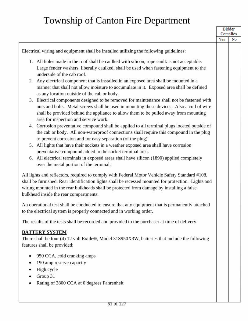
Township of Canton Fire Department
61 of 127
Electrical wiring and equipment shall be installed utilizing the following guidelines:
1. All holes made in the roof shall be caulked with silicon, rope caulk is not acceptable. Large fender washers, liberally caulked, shall be used when fastening equipment to the underside of the cab roof.
2. Any electrical component that is installed in an exposed area shall be mounted in a manner that shall not allow moisture to accumulate in it. Exposed area shall be defined as any location outside of the cab or body.
3. Electrical components designed to be removed for maintenance shall not be fastened with nuts and bolts. Metal screws shall be used in mounting these devices. Also a coil of wire shall be provided behind the appliance to allow them to be pulled away from mounting area for inspection and service work.
4. Corrosion preventative compound shall be applied to all terminal plugs located outside of the cab or body. All non-waterproof connections shall require this compound in the plug to prevent corrosion and for easy separation (of the plug).
5. All lights that have their sockets in a weather exposed area shall have corrosion preventative compound added to the socket terminal area.
6. All electrical terminals in exposed areas shall have silicon (1890) applied completely over the metal portion of the terminal.
All lights and reflectors, required to comply with Federal Motor Vehicle Safety Standard #108, shall be furnished. Rear identification lights shall be recessed mounted for protection. Lights and wiring mounted in the rear bulkheads shall be protected from damage by installing a false bulkhead inside the rear compartments.
An operational test shall be conducted to ensure that any equipment that is permanently attached to the electrical system is properly connected and in working order.
The results of the tests shall be recorded and provided to the purchaser at time of delivery.
BATTERY SYSTEM There shall be four (4) 12 volt Exide®, Model 31S950X3W, batteries that include the following features shall be provided:
950 CCA, cold cranking amps
190 amp reserve capacity
High cycle
Group 31
Rating of 3800 CCA at 0 degrees Fahrenheit

Township of Canton Fire Department
62 of 127
760 minutes of reserve capacity
Threaded stainless steel studs
Each battery case shall be a black polypropylene material with a vertically ribbed container for increased vibration resistance. The cover shall be manifold vented with a central venting location to allow a 45 degree tilt capacity.
The inside of each battery shall consist of a "maintenance free" grid construction with poly wrapped separators and a flooded epoxy bottom anchoring for maximum vibration resistance.
BATTERY SYSTEM There shall be a single starting system with an ignition switch and starter button provided and located on the cab instrument panel.
MASTER BATTERY SWITCH There shall be a master battery switch provided within the cab within easy reach of the driver to activate the battery system.
An indicator light shall be provided on the instrument panel to notify the driver of the status of the battery system.
BATTERY COMPARTMENTS Batteries shall be placed on non-corrosive mats and be stored in well-ventilated, painted stainless steel compartments located under the cab.
Heavy-duty battery cables shall be used to provide maximum power to the electrical system. Cables shall be color-coded.
Battery terminal connections shall be coated with anti-corrosion compound. Battery solenoid terminal connections shall be encapsulated with semi-permanent rubberized compound.
JUMPER STUDS One (1) set of battery jumper studs with plastic color-coded covers shall be included on the battery compartments.
BATTERY CHARGER There shall be a Kussmaul Pump Plus 1000, Model 091-56-12-B1, 18 amp single output battery charger/air compressor system with internal battery saver shall be provided. A display bar graph indicating the state of charge shall be included.

Township of Canton Fire Department
63 of 127
The battery saver circuit shall be capable of supplying up to three (3) amps for external loads such as hand light or auxiliary radio batteries.
The 120-volt air compressor shall be installed to maintain the air system pressure when the vehicle is not in use.
The battery charger shall be wired to the AC shoreline inlet through an AC receptacle adjacent to this battery charger.
Battery charger/compressor shall be located in the front left body compartment.
The battery charger indicator shall be located on the driver's seat riser.
AUTO EJECT FOR SHORELINE There shall be one (1) Kussmaul™, Model 091-55-20-120, 20 amp 120 volt AC shoreline inlet(s) provided to operate the dedicated 120 volt AC circuits on the apparatus.
The shoreline inlet(s) shall include red weatherproof flip up cover(s).
There shall be a release solenoid wired to the vehicle's starter to eject the AC connector when the engine is starting.
The shoreline(s) shall be connected to the battery charger.
There shall be a mating connector body supplied with the loose equipment.
There shall be a label installed near the inlet(s) that state the following:
Line Voltage
Current Ratting (amps)
Phase
Frequency
The shoreline receptacle shall be located on the driver side of cab, above wheel.
AUTO TRANSFER SWITCH To protect either the generator or external power source from back feed, an automatic relay system shall be installed to switch the on line device between the generator and the external power source when it is connected for use.
The transfer switch shall power all interior cab shoreline receptacles.

Township of Canton Fire Department
64 of 127
ELECTRIC POWER FOR WINCH Electric power provisions shall be furnished for the portable winch from the chassis battery system.
The receiver plug shall be located rear bumper and one near each rear wheel opening.
A total quantity of three (3) receptacles shall be provided.
ALTERNATOR A Leece-Neville, Model BLP4004H, alternator shall be provided. It shall have a rated output current of 350 amp as measured by SAE method J56. The alternator shall feature an integral, self diagnostic regulator and rectifier. The alternator shall be connected to the power and ground distribution system with heavy-duty cables sized to carry the full rated alternator output.
ELECTRONIC LOAD MANAGER An electronic load management (ELM) system shall be provided that monitors the vehicles 12-volt electrical system, automatically reducing the electrical load in the event of a low voltage condition, and automatically restoring the shed electrical loads when a low voltage condition expires. This ensures the integrity of the electrical system.
For improved reliability and ease of use, the load manager system shall be an integral part of the vehicle's solid state control system requiring no additional components to perform load management tasks. Load management systems which require additional components shall not be allowed.
The system shall include the following features:
System voltage monitoring.
A shed load shall remain inactive for a minimum of five minutes to prevent the load from cycling on and off.
Sixteen available electronic load shedding levels.
Priority levels can be set for individual outputs.
High Idle to activate before any electric loads are shed and deactivate with the service brake.
o If enabled: "Load Man Hi-Idle On" shall display on the information center. Hi-Idle shall not activate until 30 seconds after engine start up.
Individual switch "on" indicator to flash when the particular load has been shed.
The information center indicates system voltage.

Township of Canton Fire Department
65 of 127
The information center, where applicable, includes a "Load Manager" screen indicating the following:
Load managed items list, with priority levels and item condition.
Individual load managed item condition: o ON = not shed o SHED = shed
SEQUENCER A sequencer shall be provided that automatically activates and deactivates vehicle loads in a preset sequence thereby protecting the alternator from power surges. This sequencer operation shall allow a gradual increase or decrease in alternator output, rather than loading or dumping the entire 12 volt load to prolong the life of the alternator.
For improved reliability and ease of use, the load sequencing system shall be an integral part of the vehicle's solid state control system requiring no additional components to perform load sequencing tasks. Load sequencing systems which require additional components shall not be allowed.
Emergency light sequencing shall operate in conjunction with the emergency master light switch. When the emergency master switch is activated, the emergency lights shall be activated one by one at half-second intervals. Sequenced emergency light switch indicators shall flash while waiting for activation.
When the emergency master switch is deactivated, the sequencer shall deactivate the warning light loads in the reverse order.
Sequencing of the following items shall also occur, in conjunction with the ignition switch, at half-second intervals:
Cab Heater and Air Conditioning
Crew Cab Heater (if applicable)
Crew Cab Air Conditioning (if applicable)
Exhaust Fans (if applicable)
Third Evaporator (if applicable)
HEADLIGHTS There shall be a headlight kit containing four (4) Brightheadlight rectangular lights mounted in the front quad style, chrome housing on each side of the cab grille:

Township of Canton Fire Department
66 of 127
The outside light on each side shall contain a HID Xenon XP4656 high/low beam module
The inside light on each side shall contain a LED GL-4656A-H high beam module only
DIRECTIONAL LIGHTS
There shall be two (2) Whelen 600 series, LED combination directional/marker lights provided. The lights shall be located on the outside cab corners, next to the headlights.
The color of the lenses shall be the same color as the LED's.
INTERMEDIATE LIGHT There shall be two (2) Weldon, Model 9186-8580-29, amber LED turn signal marker lights furnished, one (1) each side, in the rear fender panel. The light shall double as a turn signal and marker light.
CAB CLEARANCE/MARKER/ID LIGHTS There shall be five (5) amber LED lights provided to indicate the presence and overall width of the vehicle in the following locations:
Three (3) amber LED identification lights shall be installed in the center of the cab above the windshield.
Two (2) amber LED clearance lights shall be installed, one (1) on each outboard side of the cab above the windshield.
FRONT CAB SIDE DIRECTIONAL/MARKER LIGHTS There shall be two (2) Truck-Lite®, Model 30080Y, amber LED lights installed front of the cab door, one (1) each side of the cab. This installation shall include a stainless steel cover.
The lights shall activate as marker lights with the headlight switch and directional lights with the corresponding directional circuit.
REAR CLEARANCE/MARKER/ID LIGHTING There shall be three (3) Truck-Lite®, Model 35200R, LED lights used as identification lights located at the rear of the apparatus per the following:
As close as practical to the vertical centerline
Centers spaced not less than 6.00" or more than 12.00" apart
Red in color
All at the same height

Township of Canton Fire Department
67 of 127
There shall be two (2) Truck-Lite, Model 35200R, LED lights installed at the rear of the apparatus used as clearance lights located at the rear of the apparatus per the following:
To indicate the overall width of the vehicle
One (1) each side of the vertical centerline
As near the top as practical
Red in color
To be visible from the rear
All at the same height
There shall be two (2) Truck-Lite, Model 35200R, LED lights installed on the side of the apparatus as marker lights as close to the rear as practical per the following:
To indicate the overall length of the vehicle
One (1) each side of the vertical centerline
As near the top as practical
Red in color
To be visible from the side
All at the same height
There shall be two (2) red reflectors located on the rear of the truck facing to the rear. One (1) each side, as far to the outside as practical, at a minimum of 15.00", but no more than 60.00", above the ground.
There shall be two (2) red reflectors located on the side of the truck facing to the side. One (1) each side, as far to the rear as practical, at a minimum of 15.00", but no more than 60.00", above the ground. Per FMVSS 108 and CMVSS 108 requirements.
REAR FMVSS LIGHTING There shall be two (2) Code 3®, Model 79STTRBZ, LED combination stop/tail, directional and back up lights provided at the rear of the apparatus, one (1) on each side. The lights shall be mounted with a chrome bezel.
Two (2) rows of red stop/tail LEDs
Two (2) rows of amber directional LEDs
One (1) row of white back up LEDs

Township of Canton Fire Department
68 of 127
LICENSE PLATE BRACKET There shall be one (1) license plate bracket mounted on the rear of the body.
A white LED light shall illuminate the license plate. A polished stainless steel light shield shall be provided over the light that shall direct illumination downward, preventing white light to the rear.
LIGHTING BEZEL There shall be two (2) Code 3, Model 65STK4, four (4) light aluminum housings shall be provided.
BACK-UP ALARM A PRECO, Model 1040, solid-state electronic audible back-up alarm that actuates when the truck is shifted into reverse shall be provided. The device shall sound at 60 pulses per minute and automatically adjust its volume to maintain a minimum ten (10) dBA above surrounding environmental noise levels.
CAB PERIMETER SCENE LIGHTS There shall be four (4) Amdor LumaBar H2O, Model AY-9500-020, 20.00" white LED strip lights provided, one (1) for each cab door.
These lights shall be activated automatically when the battery switch is on and the exit doors are opened or by the same means as the body perimeter scene lights.
BODY PERIMETER SCENE LIGHTS There shall be two (2) Amdor LumaBar H2O™, Model AY-9500-012, 12.00" 12 volt DC LED strip lights provided at the rear step area of the body, one (1) each side shining to the rear.
The perimeter scene lights shall be activated when the parking brake is applied.
ADDITIONAL PERIMETER LIGHTS There shall be six (6) lights Amdor® Luma Bar® H2O, Model AY-9500-020, 20.00" LED perimeter light sticks provided one (1) light under compartment D1, one (1) light under compartment P1, one (1) light under the compartment D3 and D4 door jamb and one (1) light under the compartment P3 and P4 door jamb.
The lights shall be activated by the same means as the body perimeter lights.

Township of Canton Fire Department
69 of 127
STEP LIGHTS Step lights shall be provided both at the rear of the body and in the recessed walkway on the roof of the body. All step lights shall be white LED lights.
There shall be one (1) step light provided on each side of the tailboard at the rear of the body.
There shall be one (1) chrome plated hooded step light provided every 4' in the recessed walkway.
Additional step lights shall be installed under the following conditions:
If a roof access ladder is installed on the rear of the apparatus, there shall be one (1) step light installed at the top of the each roof access ladder.
If an integral rear stairway is provided, there shall be one (1) step light provided for each step in the stairway.
In order to ensure exceptional illumination, each light shall provide a minimum of 25 foot-candles (fc) covering an entire 15.00" x 15.00" square placed 10.00" below the light and a minimum of 1.5 fc covering an entire 30.00" x 30.00" square at the same 10.00" distance below the light.
The step lights shall be activated when the parking brake is applied and deactivated when the parking brake is released.
All other steps on the apparatus shall be illuminated per the current edition of NFPA 1901.
12 VOLT LIGHTING There shall be two (2) Fire Research Spectra, Model SPA260-Q15*, 12 volt LED surface mounted scene light(s) with white bezel(s) provided one (1) high and forward on driver's side body and one (1) high and rearward on driver's side body.
The light(s) shall be controlled in the following way:
a switch at the driver's side switch panel
The light(s) may be load managed when the parking brake is applied.
12 VOLT LIGHTING There shall be two (2) Fire Research Spectra, Model SPA260-Q15*, 12 volt LED surface mounted scene light(s) with white bezel(s) provided one (1) high and forward on passenger's side body and one (1) high and rearward on passenger's side body.

Township of Canton Fire Department
70 of 127
The light(s) shall be controlled in the following way:
a switch at the driver's side switch panel
The light(s) may be load managed when the parking brake is applied.
12 VOLT LIGHTING There shall be one (1) Fire Research, Model SPA260-Q15*, 12 volt LED surface mounted scene light(s)with white bezel(s) provided rear body as high as possible.
The light(s) shall be controlled in the following way:
a switch at the driver's side switch panel
a switch in a stainless steel cup located at the rear no more than 62.00" from the ground
The light(s) may be load managed when the parking brake is applied.
12 VOLT LIGHTING There shall be one (1) Fire Research Evolution, Model FCA851-V20-*, 12 volt LED floodlight(s) provided on the front visor, centered.
The painted parts to be white.
The light(s) shall be controlled in the following way:
a switch at the driver's side switch panel
a switch at the pump operator's panel
These lights may be load managed when the parking brake is applied.
REAR WORK/SCENE LIGHTS NFPA 1901, 2016 edition, section 13.10.1.1.1 requires that the work area immediately behind the vehicle shall be illuminated to a level of at least 3 fc (30 lx) within a 10 ft x 10 ft (3 m x 3 m) square to the rear of the vehicle.
The rear work/scene lights are not on the apparatus as manufactured. The dealer shall provide and mount the rear work/scene lights.
WALKING SURFACE LIGHTS There shall be Two (2) Amdor Model LumaBar, white 12 volt DC LED strip light provided in the cargo area to illuminate the interior surface of the cargo area. Light(s) shall be located under the top flange of the cargo area.

Township of Canton Fire Department
71 of 127
The light shall be activated when the body step lights are on.
HEAVY DUTY RESCUE BODY CONSTRUCTION The body shall be built as a separate module prior to being mounted onto the substructure. The rescue body shall be constructed of 5052 aluminum.The structural support framing and the gussets used shall be of 2.00" (51 mm) square 0.125" (3 mm) wall 6061 aluminum alloy tubing. All exterior body corners shall be 3.00" (76 mm) radius aluminum, corrosion resistant alloy 6061 extrusions. Spacing of the 2.00" (51 mm) vertical supports shall not exceed 14.00" (356 mm) on center. The roof and corner extrusions shall be reinforced with interconnecting gusset supports at all stress points. The body shall be properly welded into a unitized construction. Proper reinforcing and supports shall be utilized throughout the entire construction process to ensure strength and rigidity.
The body shall be supported by 2.00" (51 mm) x 2.00" (51 mm) x 0.25" (6 mm) wall aluminum tubing. The cross sill tubes shall be spaced approximately 15.00" (381 mm) on center and interconnected to the body from front to rear.
A 1.00" (25 mm) x 3.00" (76 mm) aluminum bar shall be used as a stringer and shall be welded to the cross sills. The stringer shall be used to mount the body to the chassis frame rails.
ROOF CONSTRUCTION The roof shall be integral with the body construction. The roof shall be constructed of 0.125" (3 mm) bright aluminum treadplate and supported by 2.00" (51 mm) square 0.125" (3 mm) wall tubing welded in place approximately 12.00" (305 mm) on center. The roof shall be further reinforced with 2.00" (51 mm) square gussets welded approximately every 48.00" (1219 mm). The roof perimeters shall be constructed of a 3.00" (76 mm) radius extrusion with an integral drip molding. The roof extrusion shall also have an inset allowing the roof panel to be recessed into the extrusion giving further support and sealing effect at the outside edge.
The roof panel shall be welded to the roof extrusions and supports. All roof seams shall be continuously welded.
BODY AND COMPARTMENT SUPPORT The substructure for the body shall not be integral with the body but shall be a separate assembly.
The bottom of each lower compartment floor shall be supported by an under slung steel angle grid that shall be bolted to the chassis frame rails with grade 8 bolts in order to transfer major stress to the chassis frame and not through the body. The under slung support shall be constructed of 0.50" (13 mm) x 2.50" (64 mm) x 2.50" (64 mm) steel angle vertical supports.

Township of Canton Fire Department
72 of 127
Horizontal members shall be 0.38" (10 mm) x 2.00" (51 mm) x 3.00" (76 mm) and 0.38" (10 mm) x 2.50" (64 mm) x 3.50" (89 mm) steel angle.
The complete substructure shall be washed, primed and finish painted before being bolted to the chassis frame. A rubber coating shall be applied over the painted under slung support structure for an additional corrosion barrier.
A 3.00" (76 mm) x 0.75" (19 mm) rubber liner shall be placed on top of the chassis frame rails. The liner shall be used to prevent metal to metal contact where the body stringer rests on the chassis frame rails.
The compartment floors shall be bolted to the under slung substructure and the body shall be secured to the chassis frame by a minimum of four (4) tie-down assemblies. Each tie-down assembly shall consist of two (2) 2.00" (51 mm) x 6.25" (159 mm) x 0.75" (19 mm) steel plates and two (2) 14.00" (356 mm) long, 0.50" (13 mm) diameter steel rods. The tie-downs shall be easily accessible so that the body may be removed.
BODY LENGTH The length of the body shall be 257.00" (6,528 mm).
BODY WIDTH The width of the body shall be 96.00" (2,438 mm).
Compartment Depth
Standard Depth All standard depth side body compartments shall measure 28.00" (711 mm) deep from the outside of the body to the rear compartment wall. The usable depth inside each side body compartment shall be 26.00" (660 mm) deep.
Transverse All transverse side body compartments shall have a usable depth of 26.00" (660 mm) at the floor level. These compartments shall extend over the frame rails through to the other side of the body.
BODY HEIGHT The height of the body shall be 98.00" (2,489 mm) without any roof mounted options.
ROOF CONFIGURATION The roof of the body shall be configured with side hatch compartments, a recessed walkway, and a recessed area for mounting equipment. The recessed area shall be located at the front of the

Township of Canton Fire Department
73 of 127
body. The side hatch compartments and the recessed walkway shall be located rearward of the recessed area.
The side hatch compartments shall run the length of the body on both sides from the rear up to the recessed area. The side hatch compartments shall be provided in the following configuration:
There shall be two (2) hatch compartments of equal size on each side of the roof.
The recessed walkway shall be centered between the hatch compartments, running the length of the body up to the recessed area.
Recessed Area The recessed area shall be constructed of 0.125" (3 mm) aluminum treadplate and shall have two (2) 1.00" (25 mm) diameter drain holes. The drains shall be routed to drain below the body.
The recessed area shall be sized appropriately in order to allow proper mounting space and clearance for all roof mounted equipment where the designated mounting location is the recess on the roof of the body. The maximum allowable depth of the recessed area shall be equal to the depth of the recessed walkway. The recess shall be configured so that whenever possible, items mounted in the recess shall stow below the roof line of the body. If a piece of equipment is taller than the maximum depth of the recess, that item may protrude above the roof line.
Hatch Compartments All compartment doors shall be designed to hinge on the outboard side and shall be held open with gas cylinder struts.
The outside walls of the compartments shall be a double wall design to prevent equipment from denting the outside painted surface.
A 1.00" (25 mm) diameter drain shall be provided on the floor of each compartment. The drains shall be routed to drain below the body.
Size of Hatch Compartments The clear width of the side hatch compartments differs depending on the width of the body. The clear width of each side hatch compartment shall be as follows:
Clear Width of Side Hatch Compartments According to Width of Body Body Width Clear Width of Hatch Compartments 96.00" (2,438 mm) 26.50" (673 mm) 100.00" (2,540 mm) 28.50" (724 mm)

Township of Canton Fire Department
74 of 127
All hatch compartments on the roof of the body shall have the same clear depth inside the compartment unless listed otherwise. The inside depth can differ depending on the height of the body. The clear depth inside each hatch compartment shall be as follows:
Inside Depth of All Hatch Compartments According to Body Height Body Height Inside Depth of Hatch Compartments 90.00" (2,286 mm) 16.50" (419 mm) 98.00" (2,489 mm) 24.50" (622 mm) 100.00" (2,540 mm) 26.50" (673 mm) 103.25" (2,623 mm) 29.50" (749 mm) 106.25" (2,699 mm) 32.50" (826 mm) Body Height Not Listed Here Consult factory for depth of hatch compartments
Recessed Walkway The recessed walkway shall not be less than 30.00" (762 mm) wide. The depth of the walkway shall be equal to the depth of the hatch compartments. The walkway shall be constructed of aluminum treadplate and reinforced with 0.125" (3 mm) thick, 2.00" (51 mm) square aluminum tubing on 12.00" (305 mm) centers.
The treadplate in the walkway shall be formed up 90 degrees at least 2.00" (51 mm) on each side to form a double 0.125" (3 mm) vertical wall for a water tight seal.
There shall be two (2) 1.00" (25 mm) diameter drain holes provided in the walkway. The drains shall be routed to drain below the body.
ROLL-UP DOOR, SIDE COMPARTMENTS There shall be eight (8) compartment doors installed on the side compartments, double faced, aluminum construction, satin aluminum and manufactured by AMDOR™ brand roll-up doors.
Door(s) shall be constructed using 1.00" (25 mm) extruded double wall aluminum slats which shall feature a flat smooth interior surface to provide maximum protection against equipment hang-up. The slats shall be connected with a structural driven ball and socket hinge designed to provide maximum curtain diaphragm strength. Mounting and adjusting the curtain shall be done with a clip system that connects the curtain to the balancer drum allowing for easy tension adjustment without tools. The slats shall be mounted in reusable slat shoes with positive snap-lock securement.

Township of Canton Fire Department
75 of 127
Each slat shall incorporate weather tight recessed dual durometer seals. One (1) fin shall be designed to locate the seal within the extrusion. The second fin shall serve as a wiping seal which shall also allow for compression to prevent water ingression.
The doors shall be mounted in a one (1)-piece aluminum side frame with recessed side seals to minimize seal damage during equipment deployment. All seals including side frames, top gutters and bottom panel are to be manufactured utilizing non-marring materials.
Bottom panel flange of roll-up door shall be equipped with two (2) cut-outs to allow for easier access with gloved hands.
A stainless steel lift bar to be provided for opening the door and located at the bottom of each door with latches on the outer extrusion of the door frame. A ledge to be supplied over lift bar for additional area to aid in closing the door. The lift bar shall be located at the bottom of door with striker latches installed at the base of the side frames. Side frame mounted door strikers shall include support beneath the stainless steel lift bar to prevent door curtain bounce, improve bottom seal life expectancy and to avoid false door ajar signals.
All injection molded roll-up door wear components shall be constructed of Type 6 nylon.
Each roll-up door shall have a 3.00" (76 mm) diameter balancer/tensioner drum to assist in lifting the door. A garage door style shall not acceptable.
The header for the roll-up door assembly shall not exceed 4.00" (102 mm).
A heavy-duty magnetic switch shall be used for control of open compartment door warning lights.
EXTERIOR COMPARTMENTS The exterior compartment layout, dimensions and requirements shall be minimum specifications. The doors shall be able to withstand years of rugged service and wear. For this reason, the compartment door design, metal thickness and attachments shall be strictly adhered to. The compartment shall be constructed of .125" (3 mm)-corrosion resistant aluminum alloy, including all interior panels, floor and sides. The assemblies shall be held inside fixtures while being welded.
Compartment flooring shall be of the sweep out design with the floor higher than the compartment door frame. All compartments shall be supported on top, rear and bottom. The rear wall of each exterior compartment shall be welded to the cross sills. Drip protection shall be provided over all door openings with an integral roof extrusion or aluminum extrusion.

Township of Canton Fire Department
76 of 127
WHEEL WELLS The rear fenders shall be an integral part of the body sides and compartments. The inside of the fender shall be fitted with a full circular inner fender liner. All screws and bolts, which protrude into a compartment, shall have acorn nuts attached.
LEFT FORWARD COMPARTMENTS
First Compartment The first compartment shall be located directly behind the cab. The compartment dimensions shall be 62.50" (1588 mm) wide x 66.88" (1699 mm) high. The compartment shall be transverse, extending through to the other side of the body. The area over the frame rails shall be 62.50" (1588 mm) wide x 49.25" (1251 mm) high. The compartment door frame opening shall be 60.00" (1524 mm) wide x 64.00" (1626 mm) high. The compartment clear door opening shall be 57.50" (1461 mm) wide x 58.00" (1473 mm) high.
Second Compartment The second compartment shall be located behind the first compartment and directly ahead of the rear wheels. The compartment dimensions shall be 62.88" (1597 mm) wide x 66.88" (1699 mm) high. The compartment shall be transverse, extending through to the other side of the body. The area over the frame rails shall be 62.88" (1597 mm) wide x 49.25" (1251 mm) high. The compartment door frame opening shall be 60.00" (1524 mm) wide x 64.00" (1626 mm) high. The compartment clear door opening shall be 57.50" (1461 mm) wide x 58.00" (1473 mm) high.
Compartment Loading Each compartment shall be capable of holding 1,400 lb (636 kg). The area over the frame rails in each compartment shall be capable of holding an additional 1,000 lb (454 kg).
LEFT OVER WHEEL COMPARTMENT A compartment with a full height roll-up door shall be provided above the rear wheels. The compartment dimensions shall be 62.50" (1588 mm) wide x 39.13" (994 mm) high. The compartment shall be transverse, extending through to the other side of the body. The compartment door frame opening shall be 57.00" (1448 mm) wide x 36.25" (921 mm) high. The compartment clear door opening shall be 54.50" (1384 mm) wide x 31.25" (794 mm) high.
Compartment Loading The compartment shall be capable of holding 1,200 lb (545 kg). The area over the frame rails shall be capable of holding an additional 1,000 lb (454 kg).

Township of Canton Fire Department
77 of 127
LEFT REAR SIDE COMPARTMENT The left rear side compartment shall be located directly behind the rear wheels. The compartment dimensions shall be 62.50" (1588 mm) wide x 66.88" (1699 mm) high. The compartment door frame opening shall be 60.00" (1524 mm) wide x 64.00" (1626 mm) high. The compartment clear door opening shall be 57.50" (1461 mm) wide x 58.00" (1473 mm) high.
Compartment Loading The compartment shall be capable of holding 1,400 lb (635 kg).
RIGHT FORWARD COMPARTMENTS
First Compartment The first compartment shall be located directly behind the cab. The compartment dimensions shall be 62.50" (1588 mm) wide x 66.88" (1699 mm) high. The compartment shall be transverse, extending through to the other side of the body. The area over the frame rails shall be 62.50" (1588 mm) wide x 49.25" (1251 mm) high. The compartment door frame opening shall be 60.00" (1524 mm) wide x 64.00" (1626 mm) high. The compartment clear door opening shall be 57.50" (1461 mm) wide x 58.00" (1473 mm) high.
Second Compartment The second compartment shall be located behind the first compartment and directly ahead of the rear wheels. The compartment dimensions shall be 62.88" (1597 mm) wide x 66.88" (1699 mm) high. The compartment shall be transverse, extending through to the other side of the body. The area over the frame rails shall be 62.88" (1597 mm) wide x 49.25" (1251 mm) high. The compartment door frame opening shall be 60.00" (1524 mm) wide x 64.00" (1626 mm) high. The compartment clear door opening shall be 57.50" (1461 mm) wide x 58.00" (1473 mm) high.
Compartment Loading Each compartment shall be capable of holding 1,400 lb (636 kg). The area over the frame rails in each compartment shall be capable of holding an additional 1,000 lb (454 kg).
RIGHT OVER WHEEL COMPARTMENT A compartment with a full height roll-up door shall be provided above the rear wheels. The compartment dimensions shall be 62.50" (1588 mm) wide x 39.13" (994 mm) high. The compartment shall be transverse, extending through to the other side of the body. The compartment door frame opening shall be 57.00" (1448 mm) wide x 36.25" (921 mm) high. The compartment clear door opening shall be 54.50" (1384 mm) wide x 31.25" (794 mm) high.

Township of Canton Fire Department
78 of 127
Compartment Loading The compartment shall be capable of holding 1,200 lb (545 kg). The area over the frame rails shall be capable of holding an additional 1,000 lb (454 kg).
RIGHT REAR SIDE COMPARTMENT The right rear side compartment shall be located directly behind the rear wheels. The compartment dimensions shall be 62.50" (1588 mm) wide x 66.88" (1699 mm) high. The compartment door frame opening shall be 60.00" (1524 mm) wide x 64.00" (1626 mm) high. The compartment clear door opening shall be 57.50" (1461 mm) wide x 58.00" (1473 mm) high.
Compartment Loading The compartment shall be capable of holding 1,400 lb (635 kg).
REAR COMPARTMENT
Stairway Construction The rear compartment shall be divided into four (4) individual compartments constructed in a tiered design to provide a stairway to the recessed walkway on the roof of the body. Each individual compartment shall be provided with an aluminum treadplate lift-up door with a D ring latch. Each compartment door shall be provided with a gas cylinder strut on each side of the compartment door to hold the door in the open position.
There shall be one (1) 4.00" (102 mm) diameter compartment light provided on the inside surface of each compartment door. The light shall be actuated automatically when the door is raised to the open position.
Handrails shall be provided on each side of the stairway providing easier and safer maneuverability up and down the stairway.
Compartment Sizes The first step shall be a compartment located immediately above the rear bumper. The compartment dimensions shall be 40.00" wide (1016 mm) wide x 13.37" (340 mm) high x 26.00" (660 mm) deep. The compartment door frame opening shall be 40.00" (1016 mm) x 14.19" (360 mm) high. The compartment clear door opening shall be 38.50" (978 mm) wide x 12.44" (316 mm) high.
The remaining three (3) compartments shall comprise the remaining steps in the stairway with the recessed walkway serving as the stepping surface for the fourth and final step at the top of the stairway. The dimensions of each compartment shall be 40.00" (1016 mm) x 14.00" (356 mm) high. The clear door openings of all three (3) compartments shall be 38.50" (978 mm) wide x

Township of Canton Fire Department
79 of 127
13.25" (337 mm) high. There shall be three (3) depths created by the tiered design of the stairway. The second step compartment, located above the first step, shall be 65.63" (1667 mm) deep. The third step compartment, located above the second step, shall be 50.38" (1280 mm) deep. The fourth step compartment, located at the top of the stairway, shall be 35.38" (899 mm) deep.
Hatch Compartment Size In order to maximize the storage space of the roof configuration and to accommodate the 40.00" (1016 mm) width of the rear stairway, the hatch compartments adjacent to the rear stairs on each side of the body shall be reduced to 21.50" (546 mm) wide x 65.00" (1651 mm) long.
Compartment Loading The lower compartment shall be capable of holding 1,000 lb (454 kg). The area over the frame rails shall be capable of holding an additional 2,000 lb (907 kg).
MODIFICATION The first compartment step, located immediately above the rear bumper in the rear stairway shall be modified to fit a portable winch. Modifying the first step may affect the step height and/or compartment space available in the remaining step compartment(s) in the rest of the rear stairway.
HITCH RECEIVERS A total of three (3) hitch receivers shall be provided on the apparatus. The hitch receivers shall be constructed of heavy steel tubing and reinforced to the apparatus framework.
Rear Receiver A class IV hitch receiver shall be installed under the body at the rear of the apparatus.
The hitch receiver shall be properly reinforced to provide a maximum rating of 10,000 lb no-yield condition with a straight line pull (towing capacity) and a 1,000 lb tongue weight when used with a weight distributing hitch assembly. The hitch receiver shall be tested to provide a 2:1 straight line pull no-yield safety factor over the maximum load rating of the hitch receiver.
Trailer Wiring The trailer connection for the rear hitch receiver shall be a seven (7)-way flat blade recreational vehicle connector for trailer wiring compatible with electric brake systems, and a second connector with inverted ground meeting SAE J560 standards providing an auxiliary connection for warning devices.

Township of Canton Fire Department
80 of 127
Side Receivers There shall be one (1) hitch receiver installed under the body behind the rear wheels on each side of the body.
Each hitch receiver shall be properly reinforced to provide a maximum rating of 9,500 lb no-yield condition with a straight line pull. Each hitch receiver shall be tested to provide a 2:1 straight line pull no-yield safety factor over the maximum load rating of the hitch receiver.
FLOOR EXTENSION There shall be a floor extension from the transversed area over the frame to the compartment door. The extension shall have a 1.50" vertical lip and a return bend. The extension shall be support by angles off the side partitions of the compartment.
A total of four (4) shall be provided and located D4, P4, P3 and D3.
RACK FOR AIR BAGS Installed in compartment in the second step compartment at the rear body mounted flat shall be a rack that shall hold four (4) air bags in individual slots.
The rack shall be constructed of aluminum with all mating surfaces welded in place.
The dimensions of the air bags are Two (2) to be 44"long x 20" wide and two (2) to be 36" high x 20" wide .
STORAGE RACK FOR SPARE SCBA BOTTLES A storage rack shall be provided D3 compartment forward of the fill station to hold 12 spare SCBA bottles. The rack shall be built to hold the bottles three (3) wide x four (4) high.
The rack shall be constructed of 0.12" aluminum. The inside of the rack shall be left unpainted and the outside of the rack shall be painted the same color as the compartment it is installed in. Each storage slot shall angle to the rear of the rack in order to minimize the chances of the bottle falling out. A rubber bumper shall be provided on the rear wall of each slot to absorb the shock of the bottle being placed into position. Scuff tape material shall be applied to the inside of the each slot to reduce scratching on the bottle.
The inside dimension of each bottle slot shall be 7.50" x 7.50".
RECESS FOR REEL The compartment top and hatch compartment bottom shall be modified to allow three (3) reel(s) to be recessed. A removable aluminum treadplate shelf shall be installed on the reel bracket

Township of Canton Fire Department
81 of 127
providing additional storage above the reel that is accessible from the hatch compartment opening.
two (2) in D1, one (1) in P4.
REAR BUMPER A rear bumper shall be provided that is a an integral part of the rear body substructure.
The bumper shall be approximately 13.00" deep x 90.00" wide x 2.00" high.
The bumper shall have an aluminum treadplate deck with a 45 degree angled on each of the two (2) outside corners.
The body shall have a kickplate behind the bumper from the bottom of the body and up past the top of the bumper 3.38".
REAR WALL, BODY MATERIAL The rear wall shall be smooth and the same material as the body.
TOW EYES Two (2) rear painted tow eyes shall be located at the rear of the apparatus and shall be mounted directly to the chassis frame rails. The inner and outer edges of the tow eyes shall have a radius.
COMPARTMENT LIGHTING There shall be nine (9) compartments with Amdor, Model AY-9220, white 12 volt DC LED compartment light strips. The lights shall be mounted with mechanical fasteners.
There shall be two (2) strip lights installed vertically in each compartment opening per the latest NFPA requirements.
The lights shall be activated when the battery switch is on and the respective compartment door is opened.
ADDITIONAL COMPARTMENT LIGHTING There shall be one (1) Amdor, Model AY-9220-10, 10.22" long white 12 volt DC LED light stick(s) provided. These light shall be installed in the rearward DS hatch compartment. The lights shall be mounted with mechanical fasteners.
Opening the compartment door(s) shall automatically turn the compartment lighting on.

Township of Canton Fire Department
82 of 127
ADDITIONAL COMPARTMENT LIGHTING There shall be one (1) Amdor, Model AY-9220-31, 30.58" long white 12 volt DC LED light stick(s) provided. These light shall be installed in the PS rearward hatch compartment. The lights shall be mounted with mechanical fasteners.
Opening the compartment door(s) shall automatically turn the compartment lighting on.
These lights may be load managed when the parking brake is applied.
HATCH COMPARTMENT LIGHTING There shall be an Amdor LumaBar, Model AY-9220-0**, LED strip light mounted on the hinged side in the interior of each hatch compartment.
Each light shall be wired to an automatic door switch and to the "open door" indicator inside the cab.
STANDARD DEPTH SLIDE-OUT ADJUSTABLE HEIGHT TRAY There shall be one (1) slide-out tray provided.
Each tray shall have 2.00" high sides and a capacity rating of up to 250 lb in the extended position.
Each tray shall be as deep as possible for a standard depth compartment and as wide as possible for the specified mounting location.
Each tray shall be mounted on a pair of side mounted slides. The slide mechanisms shall have ball bearings for ease of operation and years of dependable service. The slides shall be mounted to shelf tracks to allow the tray to be adjustable up and down within the designated mounting location.
An automatic lock shall be provided for both the in and out tray positions. The lock trip mechanism shall be located at the front of the tray and shall be easily operated with a gloved hand.
The tray(s) shall be located one (1) in the P1 compartment forward of the divider and below the tilt down/slide-out tray.

Township of Canton Fire Department
83 of 127
STANDARD DEPTH SLIDE-OUT/TILT-DOWN TRAY There shall be two (2) slide-out trays provided.
The bottom of each tray shall constructed of 0.188" thick aluminum while special aluminum extrusions shall be utilized for the tray sides, ends, and tracks. The corners shall be welded to form a rigid unit.
The tray shall have 3.00" high sides, shall be full depth for a standard depth compartment and shall be as wide as possible for the specified mounting location.
A spring loaded lock shall be provided on each side at the front of the tray. Releasing the locks shall allow the tray to slide out approximately two-thirds (2/3) of its length from the stowed position and tip 30 degrees down from horizontal. The tray shall be equipped with ball bearing rollers for smooth operation.
Rubber padded stops shall be provided for the tray in both the stowed and extended positions.
The capacity rating of the tray shall be a minimum of 200 lb in the extended position.
The vertical position of the tray within the compartment shall be adjustable.
The tray(s) shall be located one (1) in the D1 compartment and one (1) in P1 forward of the divider.
HALF DEPTH SLIDE-OUT/TILT-DOWN TRAY There shall be four (4) slide-out trays provided for use in the transverse side body compartment(s).
Each tray shall be a slide-out/tilt down tray that is rated for up to 200 lb in the extended position. The bottom of each tray shall constructed of 0.188" thick aluminum while special aluminum extrusions shall be utilized for the tray sides, ends, and tracks. The corners shall be welded to form a rigid unit.
The tray shall have 3.00" high sides, shall be half depth of the transverse compartment and shall be as wide as possible for the specified mounting location.
A spring loaded lock shall be provided on each side at the front of the tray. Releasing the locks shall allow the tray to slide out approximately two-thirds (2/3) of its length from the stowed

Township of Canton Fire Department
84 of 127
position and tip 30 degrees down from horizontal. Each tray shall be equipped with ball bearing rollers for smooth operation.
Rubber padded stops shall be provided for the tray in both the stowed and extended positions.
The vertical position of each tray within the compartment shall be adjustable.
The tray(s) shall be located one (1) in the D2 compartment, two (2) in P3 each side of the divider and one (1) in P2.
STANDARD DEPTH SLIDE-OUT FLOOR MOUNTED TRAY There shall be six (6) floor mounted slide-out tray(s) with 2.00" sides provided one (1) in P1, one (1) in P3 below the floor extension, one (1) P4 below the floor extension, one (1) in D4 below the floor extension, D3 below the floor extension, two (2) in D1. Each tray shall be rated for up to 500 lb in the extended position. The tray(s) shall be constructed of 0.19" aluminum with welded corners. The finish shall be painted to match compartment interior.
Each tray shall be mounted on two (2) under mount, roller bearing type slides. Each slide shall be rated at 250 lb with a factor of safety of two (2).
To ensure years of dependable service the slides shall be coated with a finish that is tested to withstand a minimum of 1,000 hours of salt spray per ASTM B117.
To ensure years of easy operation, the slide shall require no more than a 50 lb force for push-in or pull-out movement when fully loaded after having been subjected to a 40 hour vibration (shaker) test under full load. The vibration drive file shall have been generated from accelerometer data collected from a heavy truck chassis driven over rough gravel roads in an unloaded condition. Proof of compliance shall be provided upon request.
Automatic locks shall be provided for both the "in" and "out" positions. The trip mechanism for the locks shall be located at the front of the tray for ease of use with a gloved hand.
ONE WAY UTILITY SLIDE-OUT FLOOR MOUNTED TRAY There shall be four (4) floor mounted utility slide-out tray(s) provided one (1) in the P2 compartment, two (2) in P3 (each side of the divider) and one (1) in D2 compartment. Each tray shall be rated for up to 500lb in the extended position. The tray(s) shall be constructed of .19" thick aluminum for the tray bottom and special aluminum extrusions for the tray sides, ends and tracks. The corners shall be welded. The finish shall be painted to match compartment interior.
The tray shall be 3.00" high x half the depth of the transverse compartment x as wide as possible for the compartment.

Township of Canton Fire Department
85 of 127
The tray shall be supported with a minimum of six (6) ball bearing rollers. The tray shall slide out two thirds (2/3) of its length in one direction.
Automatic locks shall be provided for both the "in" and "out" positions. The trip mechanism for the locks shall be located at the front of the tray for ease of use with a gloved hand.
TWO (2) WAY UTILITY SLIDE-OUT FLOOR MOUNTED TRAY There shall be two (2) floor mounted utility slide-out tray(s) provided one (1) in the D4, one (1) in P4 compartment. Each tray shall be rated for up to 500lb in the extended position. The tray(s) shall be constructed of .19" thick aluminum for the tray bottom and special aluminum extrusions for the tray sides, ends and tracks. The corners shall be welded. The finish shall be painted to match compartment interior.
The tray shall be 3.00" high x full depth of the transverse compartment x as wide as possible for the compartment.
The tray shall be supported with a minimum of six (6) ball bearing rollers. The tray shall slide out two thirds (2/3) of its length to either side of the apparatus.
Automatic locks shall be provided for both the "in" and "out" positions. The trip mechanism for the locks shall be located at the front of the tray for ease of use with a gloved hand.
STANDARD DEPTH SLIDE-OUT TOOLBOARD A slide-out aluminum toolboard shall be provided. The toolboard shall be constructed of 0.19" thick aluminum that is painted spatter gray to match compartment interior. The toolboard shall be provided with 0.20" diameter holes in a pegboard pattern with 1.00" centers between holes. A 1.00" x 1.00" aluminum tube frame shall be welded to the edge of the pegboard.
The toolboard shall be as deep as possible for a standard depth compartment, and as tall as possible for the specified mounting location.
The toolboard shall be mounted on an under mount, roller bearing type slide that is rated for 250 lb with a factor of safety of two (2).
To ensure years of dependable service the slide shall be coated with a finish that is tested to withstand a minimum of 1,000 hours of salt spray per ASTM B117.
To ensure years of easy operation, the slide shall require no more than a 50 lb force for push-in or pull-out movement when fully loaded after having been subjected to a 40 hour vibration (shaker) test under full load. The vibration drive file shall have been generated from

Township of Canton Fire Department
86 of 127
accelerometer data collected from a heavy truck chassis driven over rough gravel roads in an unloaded condition. Proof of compliance shall be provided upon request.
The slide shall be mounted to a shelf type track to allow side adjustment of the tool board.
A positive lock shall be provided to allow the toolboard to be locked in both the stowed and extended positions.
A total of One (1) standard depth slide-out toolboard(s) shall be provided. The toolboard(s) shall be located rearward of the compartment divider in the P1 compartment .
TOOLBOARD ADDED TO STANDARD DEPTH SLIDE-OUT TRAY An aluminum toolboard shall be provided and mounted in a standard depth slide-out tray (tray not included). The toolboard shall be constructed of 0.19" thick aluminum that is painted spatter gray to match compartment interior. The toolboard shall be provided with 0.20" diameter holes in a pegboard pattern with 1.00" centers between holes. A 1.00" x 1.00" aluminum tube frame shall be welded to the edge of the pegboard.
The toolboard shall span the full depth of the standard depth slide-out tray and shall be as tall as possible for the specified mounting location.
The toolboard shall be mounted on aluminum tracks to allow for side to side adjustment within the tray.
The total capacity rating of the toolboard shall vary depending on the tray it is mounted in (capacity rating for the toolboard shall match the capacity rating of the tray it is mounted in).
A total of Two (2) toolboard(s) shall be provided and mounted in the slide-out tray(s) located mounted on the slide-out trays located in D1 compartment.
TOOLBOARD ADDED TO TRANSVERSE SLIDE-OUT TRAY An aluminum toolboard shall be provided and mounted in a two (2)-way slide-out tray that spans the full depth of a transverse compartment (tray not included). The toolboard shall be constructed of 0.19" thick aluminum that is painted spatter gray to match compartment interior. The toolboard shall be provided with 0.20" diameter holes in a pegboard pattern with 1.00" centers between holes. A 1.00" x 1.00" aluminum tube frame shall be welded to the edge of the pegboard.
The toolboard shall span the full depth of the slide-out tray and shall be as tall as possible for the specified mounting location.

Township of Canton Fire Department
87 of 127
The toolboard shall be mounted on aluminum tracks to allow for side to side adjustment within the tray.
The total capacity rating of the toolboard shall vary depending on the tray it is mounted in (capacity rating for the toolboard shall match the capacity rating of the tray it is mounted in).
A total of One (1) toolboard(s) shall be provided and mounted in the slide-out tray(s) located one (1) in D4/P4 compartment .
BACKBOARD STORAGE A smooth aluminum welded in storage trough shall be located in the transverse compartment, in the D4/P4 compartment for storage of two (2) backboards that are to be determined.
The backboards shall be accessible from the driver's or passenger's side compartments.
A Velcro® strap shall be provided on each side to limit side to side movement of the backboard in the trough.
COMPARTMENT DUST FILTERS A total of eight (8) body compartment louvers shall have a removable dust filter installed to restrict road dirt from easily entering the compartment and shall be installed all exterior compartments.
OIL DRY HOPPER A portion of the roof hatch compartment shall be sectioned off to provide a storage bin for oil absorbent material. The top of the hopper shall be enclosed. A lift off access cover with pair of butterfly latches shall be provided to fill the hopper. This access shall be made as large as possible.
The hopper discharge tube shall be routed through the compartment below the hatch compartment with as little interference into this compartment as possible. The valve to control discharge shall be located 200 pounds in this compartment. The absorbent material shall be discharged through a PVC tube through the floor of this compartment allowing a bucket to be placed under the truck and filled..
This hopper shall have an approximate capacity for 200 lbs of absorbent material.
The hopper shall be located Passenger's side rearward hatch compartment.
STOKES BASKET MOUNTING Mounting shall be provided for a stokes basket in the transverse compartment in the transverse forward area in D4/P4 compartment rearward of the backboard transverse storage area. A sheet

Township of Canton Fire Department
88 of 127
metal style enclosure shall be fabricated and painted to match the compartment interior. The basket shall be secured at either end with a combination of footman loops and Velcro® web straps. The basket shall be accessible from either side of the compartment. The basket storage shall be bolted into place to allow for removal if desired.
The size of the stokes basket shall be to be determined.
A total quantity of one (1) shall be provided.
VERTICAL COMPARTMENT PARTITION Two (2) partitions shall be bolted in in P3 compartment and P1 compartment . Each partition shall be the to be determined vertical height of the compartment. Each partition shall be painted spatter gray to match compartment interior.
RUB RAIL Bottom edge of the side compartments shall be trimmed with a bright aluminum extruded rub rail.
Trim shall be 2.12" high with 1.38" flanges turned outward for rigidity.
The rub rails shall not be an integral part of the body construction, which allows replacement in the event of damage.
BODY FENDER CROWNS Stainless steel fender crowns shall be provided around the rear wheel openings.
A rubber welting shall be provided between the body and the crown to seal the seam and restrict moisture from entering.
A dielectric barrier shall be provided between the fender crown fasteners (screws) and the fender sheet metal to prevent corrosion.
AIR BOTTLE STORAGE (SINGLE) A quantity of two (2) air bottle compartments, 7.75" in diameter x 26.00" deep, shall be provided on the passenger side forward of the rear wheels and on the passenger side rearward of the rear wheels. A polished stainless steel door with a chrome plated flush lift & turn latch shall be provided to contain the air bottle. A dielectric barrier shall be provided between the door hinge, hinge fasteners and the body sheet metal.
Inside the compartment, black rubber matting shall be provided.

Township of Canton Fire Department
89 of 127
SWING DOWN STEP A swing down style rear access step shall be installed onto the rear tailboard. The step shall swing up and stow above the tailboard in the "up" position and swing down for use as a stepping surface in the "down" position.
A chrome plated lift handle shall be provided on the underside of the step to aid in raising and lowering the step.
The step shall be provided with gas assist cylinders to secure the step in the up and down positions.
The step shall be approximately 39.00" wide x 8.00" deep. The step shall be fabricated from polished aluminum treadplate with a Morton Cass insert to provide a non-skid stepping surface.
When the step is in the "down" position, a text message shall be displayed on the Vehicle Information Center multiplex display screen that reads "Rear Step Not Stowed".
When deployed, the step shall meet the NFPA requirement for minimum stepping height from the ground.
AIR HORN SYSTEM There shall be two (2) Grover air horns recessed in the front bumper. The horn system shall be piped to the air brake system wet tank utilizing 0.38" tubing. A pressure protection valve shall be installed in-line to prevent loss of air in the air brake system.
Air Horn Location The air horns shall be located on each side of the bumper, inside of the frame rails.
AIR HORN CONTROL Two (2) lanyard rope pull controls shall be provided, one (1) within reach of the driver and one (1) within reach of the officer.
ELECTRONIC SIREN A Code 3, model 3992, electronic siren shall be provided.
A second amplifier shall be included.
This siren shall include the following features:
Instant-On
Park Kill
Adjustable Backlighting

Township of Canton Fire Department
90 of 127
Automatic Short Circuit Protection
Scroll Mode
Hit-n-Go Mode
Automatic Siren Tones
AIR HORN Tone
Instant Public Address
Status LED
Radio Rebroadcast
Remote Siren Switching
Noice Cancelling Microphone
This siren to be active when the battery switch is on and that emergency master switch is on.
NFPA 1901, 2016 edition, Section 13.9.1.1 requires the siren manufacturer to certify the siren as meeting the requirements of SAE J1849, Emergency Vehicle Sirens.
Per the fire department specification, the siren and siren speaker come from separate manufacturers and a certification is therefore invalid. The apparatus shall be non compliant to NFPA 1901 standards at time of contract execution.
Siren head shall be located on a heavy duty swivel bracket mounted on the center console between the driver and officer seats, located as directed by the FD. The swivel bracket shall be capable of rotating a minimum of 180 degrees.
The electronic siren shall be controlled on the siren head only. No horn button or foot switches shall be required.
SPEAKER A Federal, Model BP200-EF, 200 watt speaker shall be provided. A chrome-plated "EF" flat grille shall be installed in front of the speaker.
The speaker shall be recessed in the left side of the front bumper, towards the outside.
AUXILIARY MECHANICAL SIREN A Federal Q2B® siren shall be furnished. A siren brake button shall be installed on the switch panel.
The control solenoid shall be powered up after the emergency master switch is activated.
The mechanical siren shall be recessed in the front bumper in the center. The siren shall be supported by the bumper framework.

Township of Canton Fire Department
91 of 127
The mechanical siren shall be actuated by a chrome push button located on the officer side of the engine tunnel and by the horn button in the steering wheel.
The driver shall have the option to control the siren or the chassis horn from the horn button by means of a selector switch located on the instrument panel.
MECHANICAL SIREN INTERLOCK The mechanical siren shall be interlocked to shutoff whenever parking brake is applied. The interlock shall disconnect the power only.
A second siren brake switch shall be installed on the passenger side. The switches shall have a red illuminated switch wired through the ignition switch.
CAB ROOF LIGHTBAR There shall be one (1) 82.00" Code 3 Defender™, Model DF82A, configuration number C93381 lightbar installed on the cab roof.
This lightbar shall include the following:
one (1) CQC6R red flashing LED module in the driver's side rear corner position
one (1) QA white steady burning alley light module in the driver's side end position
one (1) CQC6R red flashing LED module in the driver's side front corner position
one (1) QC6R red flashing LED module in the driver's side first front position
one (1) QC6W white flashing LED module in the driver's side second front position
one (1) QC6R red flashing LED module in the driver's side third front position
one (1) QC6R red flashing LED module in the driver's side fourth front position
one (1) QC6R red flashing LED module in the driver's side fifth front position
one (1) QC6R red flashing LED module in the driver's side sixth front position
one (1) QC6R red flashing LED module in the passenger's side sixth front position
one (1) QC6R red flashing LED module in the passenger's side fifth front position
one (1) QC6R red flashing LED module in the passenger's side fourth front position
one (1) QC6R red flashing LED module in the passenger's side third front position
one (1) QC6W white flashing LED module in the passenger's side second front position
one (1) QC6R red flashing LED module in the passenger's side first front position
one (1) CQC6R red flashing LED module in the passenger's side front corner position
one (1) QA white steady burning alley light module in the passenger's side end position
one (1) CQC6R red flashing LED module in the passenger's side rear corner position

Township of Canton Fire Department
92 of 127
There shall be three (2) switches in the cab on the switch panel to control this lightbar per the following:
one (1) switch for the flashing LED modules
one (1) switch for the driver's side alley light
one (1) switch for the passenger's side alley light
The white flashing LED modules shall be deactivated when the parking brake is applied.
FRONT ZONE LOWER LIGHTS There shall be four (4) Code 3®, Model 4612F*X, 4.00" high x 6.00" long flashing LED warning lights installed above the headlights in bezels matching the headlamps.
the driver's side front outside warning light to be red
the driver's side front inside warning light to be red
the passenger's side front outside warning light to be red
the passenger's side front inside warning light to be red
the warning light lens color(s) to be clear
There shall be a switch located in the cab on the switch panel to control the lights.
White LEDs shall be deactivated when the parking brake is applied.
The inside lights may be load managed when the parking brake is applied.
HEADLIGHT FLASHER The high beam headlights shall flash alternately between the left and right side.
There shall be a switch installed in the cab on the switch panel to control the high beam flash. This switch shall be live when the battery switch and the emergency master switches are on.
The flashing shall automatically cancel when the headlight (high or low beam) switch is activated or when the parking brake is set.
SIDE ZONE LOWER LIGHTING There shall be six (6) Code 3®, Model 4612XBZ-75 PRIZM, flashing LED lights with chrome trim provided.
The lights shall be located as follows:
Two (2) lights, located one (1) each side on the bumper extension. The side front lights to be red.

Township of Canton Fire Department
93 of 127
Two (2) lights, located rear of the crew cab doors, each side. The side middle lights to be red.
Two (2) lights, located over the body wheel well, each side. The side rear lights to be red.
The lens color(s) to be the same as the LEDs.
There shall be a switch in the cab on the switch panel to control the lights.
SIDE WARNING LIGHTS There shall be two (2) Code 3®, Model 7912XXBZ-75, 7.00" x 9.00" 12 volt DC LED flashing warning light(s) with chrome bezel(s), located on the side of the apparatus one (1) each side on the body.
The color of the LEDs shall be red.
The color of the lens shall be clear.
These lights shall be activated with the side warning switch.
The light(s) may be load managed when the parking brake is applied.
SIDE WARNING LIGHTS There shall be four (4) Code 3®, Model ULT6-X, 1.23" high x 4.73" long x .46" deep flashing LED warning light(s) lights provided.
The lights shall include red LEDs with a clear lens.
The lights shall be located Passenger's body side rub rails.
There shall be a switch in the cab on the switch panel to control the lights.
The lights may be load managed if colored and shall be disabled if white when the parking brake is applied.
SIDE WARNING LIGHTS There shall be four (4) Code 3®, Model ULT6-X, 1.23" high x 4.73" long x .46" deep flashing LED warning light(s) lights provided.
The lights shall include red LEDs with a clear lens.
The lights shall be located Driver's body side rub rails.
There shall be a switch in the cab on the switch panel to control the lights.

Township of Canton Fire Department
94 of 127
The lights may be load managed if colored and shall be disabled if white when the parking brake is applied.
SIDE WARNING LIGHTS There shall be two (2) Code 3®, Model 4612CXBZ-75, LED flashing warning light(s) with chrome bezel(s) located on the side of the apparatus each side above the EMS door.
The color of the lights shall be red.
The color of the lens shall be clear.
These lights shall be activated with the side warning switch.
These lights may be load managed if colored or disabled, if white, when the parking brake is set.
INTERIOR CAB DOOR WARNING LIGHTS There shall be four (4) Code 3, product number SD24*, 1.50" high x 3.70" long x 0.90" deep flashing LED warning lights with chrome trim and clear lenses provided on the inside door panels per the following:
one (1) light installed on the driver's side door panel
one (1) light installed on the passenger's side door panel
one (1) light installed on the passenger's side crew cab door panel
one (1) light installed on the driver's side crew cab door panel
The red and white LEDs with clear lens.
Each light shall be activated when the battery switch is on and the corresponding door is open.
REAR ZONE LOWER LIGHTING There shall be two (2) Code 3® Model 4612XBZ-75 4.00" x 6.00" LED flashing warning lights with bezels located at the rear of the apparatus.
The driver's side rear light to be red.
The passenger's side rear light to be red.
Each light shall include a lens that is clear.
There shall be a switch located in the cab on the switch panel to control the lights.

Township of Canton Fire Department
95 of 127
REAR/SIDE ZONE UPPPER WARNING LIGHTS There shall be four (4) Code 3®, Model 7912XXBZ-75, 7.00" x 9.00" 12 volt DC LED flashing warning lights with chrome bezels provided:
The side rear upper light(s) on the driver's side to be red.
The rear upper light(s) on the driver's side to be red.
The rear upper light(s) on the passenger's side to be red.
The side rear upper light(s) on the passenger's side to be red.
The lenses shall be clear.
There shall be one (1) switch located in the cab on the switch panel to control the lights.
TRAFFIC DIRECTING LIGHT There shall be one (1) Code 3 model NASL8SP, that includes two (2) 24.00" long x 2.00" high x 2.87" deep, LED traffic directing light modules installed at the rear of the apparatus.
A Code 3 control head shall be included with this installation.
The auxiliary warning mode shall be activated with the control head only.
This traffic directing light shall be surface mounted with a treadplate box at the rear of the apparatus as high as practical.
The traffic directing light control head shall be located within a heavy duty swivel bracket centered between the driver and passenger.
This swivel bracket shall enable the driver access as well as the passenger.
ELECTRICAL SYSTEM GENERAL DESIGN FOR ALTERNATING CURRENT The following guidelines shall apply to the 120/240 VAC system installation:
General Any fixed line voltage power source producing alternating current (ac) line voltage shall produce electric power at 60 cycles plus or minus 3 cycles.
Except where superseded by the requirements of NFPA 1901, all components, equipment and installation procedures shall conform to NFPA 70, National Electrical Code (herein referred to as the NEC).

Township of Canton Fire Department
96 of 127
Line voltage electrical system equipment and materials included on the apparatus shall be listed and installed in accordance with the manufacturer's instructions. All products shall be used only in the manner for which they have been listed.
Grounding Grounding shall be in accordance with Section 250-6 "Portable and Vehicle Mounted Generators" of the NEC. Ungrounded systems shall not be used. Only stranded or braided copper conductors shall be used for grounding and bonding.
An equipment grounding means shall be provided in accordance with Section 250-91 (Grounding Conductor Material) of the NEC.
The grounded current carrying conductor (neutral) shall be insulated from the equipment grounding conductors and from the equipment enclosures and other grounded parts. The neutral conductor shall be colored white or gray in accordance with Section 200-6 (Means of Identifying Grounding Conductors) of the NEC.
In addition to the bonding required for the low voltage return current, each body and driving or crew compartment enclosure shall be bonded to the vehicle frame by a copper conductor. This conductor shall have a minimum amperage rating of 115 percent of the nameplate current rating of the power source specification label as defined in Section 310-15 (amp capacities) of the NEC. A single conductor properly sized to meet the low voltage and line voltage requirements shall be permitted to be used.
All power source system mechanical and electrical components shall be sized to support the continuous duty nameplate rating of the power source.
Operation Instructions that provide the operator with the essential power source operating instructions, including the power-up and power-down sequence, shall be permanently attached to the apparatus at any point where such operations can take place.
Provisions shall be made for quickly and easily placing the power source into operation. The control shall be marked to indicate when it is correctly positioned for power source operation. Any control device used in the drive train shall be equipped with a means to prevent the unintentional movement of the control device from its set position.
A power source specification label shall be permanently attached to the apparatus near the operator's control station. The label shall provide the operator with the information detailed in Figure 19-4.10.

Township of Canton Fire Department
97 of 127
Direct drive (PTO) and portable generator installations shall comply with Article 445 (Generators) of the NEC.
Overcurrent protection The conductors used in the power supply assembly between the output terminals of the power source and the main over current protection device shall not exceed 144.00" (3658 mm) in length.
For fixed power supplies, all conductors in the power supply assembly shall be type THHW, THW, or use stranded conductors enclosed in nonmetallic liquid tight flexible conduit rated for a minimum of 194 degree Fahrenheit (90 degrees Celsius).
For portable power supplies, conductors located between the power source and the line side of the main overcurrent protection device shall be type SO or type SEO with suffix WA flexible cord rated for 600-volts at 194 degrees Fahrenheit (90 degrees Celsius).
Wiring Methods Fixed wiring systems shall be limited to the following:
Metallic or nonmetallic liquid tight flexible conduit rated at not less than 194 degrees Fahrenheit (90 degrees Celsius)
or
Type SO or Type SEO cord with a WA suffix, rated at 600 volts at not less than 194 degrees Fahrenheit (90 degrees Celsius)
Electrical cord or conduit shall not be attached to chassis suspension components, water or fuel lines, air or air brake lines, fire pump piping, hydraulic lines, exhaust system components, or low voltage wiring. In addition the wiring shall be run as follows.
Separated by a minimum of 12.00" (305 mm), or properly shielded, from exhaust piping
Separated from fuel lines by a minimum of 6.00" (152 mm) distance
Electrical cord or conduit shall be supported within 6.00" (152 mm) of any junction box and at a minimum of every 24.00" (610 mm) of continuous run. Supports shall be made of nonmetallic materials or corrosion protected metal. All supports shall be of a design that does not cut or abrade the conduit or cable and shall be mechanically fastened to the vehicle.
Wiring Identification All line voltage conductors located in the main panel board shall be individually and permanently identified. The identification shall reference the wiring schematic or indicate the

Township of Canton Fire Department
98 of 127
final termination point. When prewiring for future power sources or devices, the unterminated ends shall be labeled showing function and wire size.
Wet Locations All wet location receptacle outlets and inlet devices, including those on hardwired remote power distribution boxes, shall be of the grounding type provided with a wet location cover and installed in accordance with Section 210-7 "Receptacles and Cord Connections" of the NEC.
All receptacles located in a wet location shall be not less than 24.00" (610 mm) from the ground. Receptacles on off-road vehicles shall be a minimum of 30.00" (762 mm) from the ground.
The face of any wet location receptacle shall be installed in a plane from vertical to not more than 45 degrees off vertical. No receptacle shall be installed in a face up position.
Dry Locations All receptacles located in a dry location shall be of the grounding type. Receptacles shall be not less than 30.00" (762 mm) above the interior floor height.
All receptacles shall be marked with the type of line voltage (120-volts or 240-volts) and the current rating in amps. If the receptacles are direct current, or other than single phase, they shall be so marked.
Listing All receptacles and electrical inlet devices shall be listed to UL 498, Standard for Safety Attachment Plugs and Receptacles, or other appropriate performance standards. Receptacles used for direct current voltages shall be rated for the appropriate service.
Electrical System Testing The wiring and associated equipment shall be tested by the apparatus manufacturer or the installer of the line voltage system.
The wiring and permanently connected devices and equipment shall be subjected to a dielectric voltage withstand test of 900-volts for one (1) minute. The test shall be conducted between live parts and the neutral conductor, and between live parts and the vehicle frame with any switches in the circuit(s) closed. This test shall be conducted after all body work has been completed.
Electrical polarity verification shall be made of all permanently wired equipment and receptacles to determine that connections have been properly made.

Township of Canton Fire Department
99 of 127
Operational Test per Current NFPA 1901 Standard The apparatus manufacturer shall perform the following operation test and ensure that the power source and any devices that are attached to the line voltage electrical system are properly connected and in working order. The test shall be witnessed and the results certified by an independent third-party certification organization.
The prime mover shall be started from a cold start condition and the line voltage electrical system loaded to 100 percent of the nameplate rating.
The power source shall be operated at 100 percent of its nameplate voltage for a minimum of two (2) hours unless the system meets category certification as defined in the current NFPA 1901 standard.
Where the line voltage power is derived from the vehicle's low voltage system, the minimum continuous electrical load as defined in the current NFPA 1901 standard shall be applied to the low voltage electrical system during the operational test.
ONAN PROTEC 35KW SINGLE PHASE GENERATOR W/ XRT PTO The apparatus shall be equipped with a complete electrical power system. The wiring and generator installation shall conform to the present National Electrical Code Standards of the National Fire Protection Association. The installation shall be designed for continuous operation without overheating and undue stress on components.
The generator shall be a single phase, four (4)-wire, Onan 35kW driven by a transmission "power takeoff" attached to the side of the transmission.
Generator performance shall meet the American National Standards Institute (ANSI) C84.1-1982 voltage requirement as utilized from the receptacle.
Generator shall have a built in automatic voltage control.
Generator shall have a NEMA MG21 rating.
- Continuous Duty Rating: 35,000 watts
- Phase: Single
- Nominal Cycles: 60 hertz
- Nominal Amp Rating: 145 at 240-volts
- Engine Speed at Engagement: Idle

Township of Canton Fire Department
100 of 127
- Engine Speed Engaged: 1100/1400 rpm range
- Generator RPM: 1800 rpm
The output of the generator shall be controlled by an electronic governor. The truck engine shall be programmed so the generator's output is at 60 hertz.
The main chassis transmission PTO shall power the generator. A stainless steel splash guard shall be installed to reduce the amount of road spray on this frame-mounted generator.
The generator shall be operable in the stationary mode with a shift control located inside the cab with an indicator light to note engagement. For safety, the automatic high idle shall be activated through interlocks only after the chassis parking brake control is in the park position, the generator PTO transmission has made a complete shift and the truck transmission is in neutral.
An electric/hydraulic valve shall supply hydraulic fluid to the clutch engagement unit provided on the chassis PTO drive.
To properly monitor the generator performance and load demands during operation, the generator shall be equipped with a full instrument and control package. This panel shall be mounted adjacent to the load center. The following instruments shall be installed in the panel:
- One (1) Voltmeter
- Two (2) Ammeters
- One (1) Frequency Meter
- One (1) Hour Meter
- One (1) "Power On" Green Indicator Light
- One (1) PTO Engagement Indicator Light
- Two (2) Fuse Holders: With two (2) amp fuses for gauge protection
The meter and indicators shall be installed near eye level in the compartment. Instruments shall be flush mounted in an appropriate sized weatherproof electrical enclosure. All instruments used shall be accurate within +/- two (2) percent.
The system shall be installed by highly qualified electrical technicians to assure the required level of safety and protection to the fire apparatus operators. The wiring, electrical fixtures and components shall be to the highest industry quality standards available on the domestic market.

Township of Canton Fire Department
101 of 127
The equipment shall be the type designed for mobile installations subject to vibration, moisture and severe continuous usage.
All electrical wiring from the load center shall be fine stranded copper S.O. type with a 600 volt jacket. The wire shall be sized to the load and circuit breaker rating. The wire size shall be ten (10)-gauge on 30 amp circuits, 12-gauge on 20 amp circuits and 14-gauge on 15 amp circuits. The S.O. cable shall be run in corner areas and extruded aluminum pathways built into the body for easy access. Any S.O. cord not run in an enclosed raceway or cable tray shall have an additional abrasion resistant covering.
The main load center shall have circuit breakers rated to load demand.
Individual breakers shall be provided for all receptacles to isolate a tripped breaker from affecting any other on-line equipment.
An output shaft used to couple a XRT hydraulic tool system to the generator shall be provided.The output shaft shall be operational whenever the generator is in use.
GENERATOR LOCATION The generator shall be mounted under the body between the frame rails.
GENERATOR START A switch shall be located on the cab instrument panel and at the breaker panel area to engage the generator.
CIRCUIT BREAKER PANEL The circuit breaker panel shall be located low on the forward wall of compartment D4.
LIGHT TOWER There shall be one (1) Command Light Model CL602A-FS, light tower provided on the apparatus.
There shall be six (6) FRC Model J20, 20,000 lumens 240 volt AC LED light heads included on this tower.
This tower shall include the back light option.
This tower shall not include a strobe light.
This tower shall activate the Do Not Move Truck Indicator light in the cab if not in the stowed position when the parking brake is released.

Township of Canton Fire Department
102 of 127
LIGHT TOWER LOCATION The light tower shall be installed forward, on the rescue body roof.
LIGHT TOWER CONTROLLER There shall be a handheld wired controller included with the light tower.
LOCATION FOR THE LIGHT TOWER CONTROLLER The light tower controller shall be installed in the driver's side front body compartment.
ELECTRIC CORD REEL Furnished with the 120 volt AC electrical system shall be a Hannay, Series 1600, cord reel. The reel shall be provided with a 12 volt electric rewind switch that is guarded to prevent accidental operation and labeled for its intended use. The switch shall be protected with a fuse and installed at a height not to exceed 72.00" above the operators standing position.
The exterior finish of the reel(s) shall be painted #269 gray from the reel manufacturer.
A Nylatron guide to be provided to aid in the payout and loading of the reel. A ball stop shall be provided to prevent the cord from being wound on the reel.
A label shall be provided in a readily visible location adjacent to the reel. The label shall indicate current rating, current type, phase, voltage and total cable length.
A total of one (1) cord reel shall be provided one (1) rearward in the driver's side hatch comparment.
The cord reel should be configured with three (3) conductors.
CORD Provided for electric distribution shall be one (1) length installed on the reel of 200 feet of Carol Super Vu-Tron II yellow 12/3 electrical cord. A Hubbell L5-20, 20 amp, 120 volt, twist lock connector body shall be installed on the end of the cord.
PORTABLE JUNCTION BOX There shall be a total of one (1) electrical junction box(es), listed for use in wet locations and provided with light to indicate power on. Each box shall be designed to keep the exterior electrical components above 2.00" of standing water, protected from corrosion, and capable of being carried with a gloved hand.
There shall be a cable strain relief and a 1.00' pigtail with wire mesh grip, NEMA L5-20, 20 amp, 120 volt twist lock plug and boot provided for each box. Each box shall be powder coated yellow .

Township of Canton Fire Department
103 of 127
Each Akron, EJBX, box shall be provided with the following receptacles:
One (1) 120 vac, 15 amp straight blade duplex (household) receptacle
Three (3) 120 vac, 15 amp twist lock receptacles
JUNCTION BOX HOLDER There shall be an aluminum junction box holder installed adjacent to the cord reel. A total of one (1) shall be mounted at pick-up.
120 VOLT RECEPTACLE There shall be three (3), 20 amp 120 volt AC three (3) wire straight blade duplex receptacle(s) with waterproof flip up cover(s) installed One (1) in the P1 compartment (forward wall, mid height), one (1) in the P4 compartment (forward wall, mid height) and one (1) in the D1 compartment (rear wall, mounted high) . The NEMA configuration for the receptacles shall be 5-20R.
The receptacle(s) shall be powered from the shoreline inlet.
There shall be a label installed near the receptacle(s) that state the following:
Line Voltage
Current Ratting (amps)
Phase
Frequency
Power Source
CASCADE STORAGE VESSELS The breathing air cascade system shall meet NFPA requirements for a compressed air system that is used to provide air for human respiration, using self-contained breathing apparatus. It shall be capable of operating in a range of ambient temperatures between 0 degrees Fahrenheit and 125 degrees Fahrenheit (-18 degrees Celsius and 52 degrees Celsius), with a relative humidity up to and including 100 percent.
All flexible hose shall be installed without excessive bending and to prevent cuts, abrasions, and excessive temperatures. Also, the hose shall be installed to allow its replacement without requiring removal of major vehicle components or vehicle-mounted equipment.
The breathing air system shall be easy to maintain, with an arrangement of components that allows easy inspections, servicing, calibration, and adjustments without removing the components.

Township of Canton Fire Department
104 of 127
All major components in the breathing air system, including accessories, shall be clearly identified and labeled. Appropriate caution and warning labels shall be affixed where necessary to allow the equipment to be safely operated and maintained.
Two (2) complete manuals that document the operation and maintenance of the system shall be provided.
The complete breathing air system shall be tested for leaks and for proper functioning prior to its delivery.
The cascade system storage cylinders shall consist of the following major components:
Four (4) Storage Vessels
Four (4) Storage Vessel Shutoff Valves
Four (4) Storage Vessel Relief Devices
One (1) Storage Vessel Mounting Rack
Four (4) Inlet/outlet Connections
The cascade storage vessels, shall each be rated for 6000 psi (414 bar). These vessels shall be designed and constructed to conform to the requirements of the United Nations (UN) on the transportation of dangerous goods. Each vessel shall hold 510.50 cubic feet (14.45 cubic meters) of air at rated pressure, for a total system volume of 2,042 cubic feet (57.82 cubic meters). Each vessel shall be equipped with a UN shutoff valve and a built in, burst-disc pressure relief device.
The storage vessels shall be installed in compartment in the upper FORWARD hatch compartments, two (2) each side as far forward as possible.
BREATHING AIR SYSTEM GENERAL DESIGN The air system shall meet the requirements for a compressed air system used to provide air suitable for human respiration with self-contained breathing apparatus.
If a compressor or booster system is supplied it shall be capable of operating in a range of ambient temperature between 32 degree Fahrenheit and 100 degrees Fahrenheit (0 Celsius and 43 degrees Celsius).
If a cascade system is supplied it shall be capable of operating in a range of ambient temperatures between 0 degrees Fahrenheit and 125 degrees Fahrenheit (-18 degrees Celsius and 52 degrees Celsius).

Township of Canton Fire Department
105 of 127
The air system shall be capable of withstanding storage temperatures between 0 degrees Fahrenheit and 125 degrees Fahrenheit (-18 degrees Celsius and 52 degrees Celsius) without damage.
The air system in general shall be capable of being stored and operated in environments with relative humidity up to and including 100 percent.
All flexible hose shall be installed in such a manner as to prevent cuts, abrasions, exposure to damage, excessive temperatures, damage from loose equipment and excessive bending. The hose shall be installed in a manner that permits removal of hose without removal of major vehicle components or vehicle mounted equipment.
The air system design shall provide for maintainability by ensuring that the arrangement of the components shall allow easy inspections, servicing, calibration and adjustment without removing the components.
All major components in the air system, including accessories, shall be clearly identified and labeled. Appropriate caution and warning labels shall be affixed where necessary to allow the equipment to be safely operated and adjusted.
Two complete manuals shall be provided that document the operation and maintenance of the system.
If a compressor is supplied, the temperature of the compressed air shall not exceed 25 degrees Fahrenheit (14 degrees Celsius) above ambient temperatures when measured at the discharge nozzle of the compressor after cooler. Audible and visual alarms, automatic shutdown and prevention of automatic restart shall occur if any of the following conditions exist: low oil level or low oil pressure, high discharge air temperature, more than 24 ppm of moisture in the purification system outlet and if the carbon monoxide level exceeds 10 ppm.
The purification system shall be capable of producing the required air quality for a minimum of 50 hours with inlet at 80 degrees Fahrenheit (27 degrees Celsius) at saturation.
Low pressure breathing air supply from reels or in remote locations shall be provided with a low air pressure audible alarm warning device when the air volume is at or below 20 percent. This shall include upper and lower control stations on aerial devices.
The complete breathing air system shall be tested prior to delivery.
The fire department shall receive training with this breathing air system. A demonstration of the operation of the breathing air system shall be provided at the factory.

Township of Canton Fire Department
106 of 127
This demonstration shall include the following:
- Review of all safety items in the system
- Review of all component manuals
- A walk around review of all the components that make up the system
- A hands-on system demonstration of each functional item in the system, during which proper use of the system components shall be described
- A demonstration of how to properly shutdown and maintain the system
BREATHING AIR SYSTEM CONTROL PANEL A control panel for the breathing air system shall be provided. The control panel shall be 9.50" wide x 42.75" high x 23.00" deep and it shall be attached to the side of a SpaceSaver™ fill enclosure. It shall be made of aluminum that is 0.18" thick and has a painted, glare-resistant finish.
A painted aluminum box shall house and protect the components behind the control panel. The panel shall pivot on its mounting fasteners, to allow for maintenance of components behind the panel.
All gauges shall be at least 2.50" in diameter, and they shall be filled with glycerin. All valves shall be a slow-operating screw type that shall require minimal force, from three-fingered operation. A rope light shall be fastened to the full vertical height of the control panel, to provide uniform illumination to all controls on the panel.
All tubing that is behind the panel shall be stainless steel, with the exception of the supply hoses from the air storage and the hose that runs to the SCBA fill. These tubes and hoses shall have a 4:1 safety factor.
A refill fitting shall be supplied on the face of the air control panel, to allow the refilling of the system storage cylinders from an external source. With 6000 psi storage cylinders, a male CGA-677 fitting shall be provided, and with 4500 and 5000 psi storage cylinders, a male CGA-347 fitting shall be provided.
There shall be four (4) storage banks, each consisting of one (1) valve and one (1) gauge, provided on the control panel. If there are more cylinders than banks, two (2) cylinders shall be connected to the first storage bank (or banks) as needed.

Township of Canton Fire Department
107 of 127
The system shall be regulated with one (1) breathing air supplied gauge, one (1) 0-4500 psi regulator, and one (1) regulated pressure gauge. One (1) additional 0-400 psi low pressure, high flow rate regulated circuit with gauge.
A pressure relief valve preset, at no more than ten percent above the regulator output setting, shall be provided. A warning label that specifies the appropriate pressure regulator settings and the pressure relief setting shall be placed adjacent to the regulator.
An SCBA fill valve to control the air flowing into the SCBA cylinders shall be supplied on the air control panel. An SCBA fill gauge shall be supplied on the air control panel, to view the pressure in the SCBA cylinders during filling. This valve and gauge shall be used to manually vary the SCBA fill rates in accordance with the SCBA manufacturer's recommendations.
The panel shall be configured without a booster pump.
The panel shall be configured without a compressor connection.
FILL ENCLOSURE The fill enclosure shall be designed for mobile applications to fill SCBA or SCUBA cylinders. The enclosure shall totally enclose the cylinder during the fill process. The enclosure shall contain the cylinder and all fragments in the event of rupture during the fill process.
Construction shall be of 0.18" plate steel. The fill enclosure door shall be constructed of 0.25" stainless steel. The cylinder holders shall be lined with a material to protect each cylinder from abrasion.
The fill enclosure shall be designed to allow the filling of two (2) SCBA or SCUBA bottles either individually or simultaneously. Access to the enclosure for loading the cylinder shall be through a manually operated slide up door and tilt out bottle holder. The door shall be provided with a device to assist opening and provide smooth operation.
The loading position from the compartment floor to the center of the bottle valve shall be 14.60" in the lower holder and 23.50" in the upper holder. This shall place the lower loading position at waist height on average height vehicles.
The maximum length of either the SCBA or SCUBA bottle with the valve and fill adapter shall be 29.00" in the lower holder and 27.00" in the upper holder.
Automatic safety interlocks shall prevent cylinder filling until the door is completely closed. Two (2) fill hoses with SCBA or SCUBA adapters shall be provided within the enclosure.

Township of Canton Fire Department
108 of 127
If a cylinder should rupture, rapidly expanding air shall be vented through an opening in the bottom of the enclosure and out through the compartment floor. A break away rubber seal shall be provided to seal the compartment floor.
To ensure the integrity of the fill enclosure, bidders shall provide on request, an independent certification that a production unit has successfully withstood an SCBA cylinder explosion as per NFPA.
The fill enclosure shall be a SpaceSaver model 100A. The dimensions of the fill enclosure shall be approximately 42.56" high x 13.12" wide x 23.25" deep with a weight of approximately 400 lb.
A total of one (1) shall be provided D3 compartment rear of the twelve (12) bottle storage.
AIR REEL FOR TOOLS An air reel complete with hose and fittings shall be provided. The hose reel shall be rated for 300 psi working pressure and shall be capable of holding 150' of low pressure, 0.38" inside dimension hose.
The hose reel shall include the following features:
The side discs shall have rolled edges and concentric reinforcing ribs
The drum shall be roll formed with a full length weld
A bearing shall support the axle at each end of the reel to provide smooth rotation and eliminate weight on the swivel joint
The reel axle shall be the full length of the reel
The swivel joint inlet shall permit the reel to rotate freely while connected.
The reel shall be equipped with a 12-volt D.C. electric rewind motor operated by a push button switch which is guarded to prevent accidental operation. The switch shall be installed at a height not to exceed 72.00" above the operator's standing position. A properly rated circuit breaker shall be provided to protect the rewind motor against short circuits and overload. A 12-volt fuse shall protect the rewind control circuit.
The exterior finish of the reel(s) shall be painted #269 gray from the reel manufacturer.
A Nylatron guide to be provided to aid in the payout and loading of the reel. A ball stop shall be provided to prevent the end of the hose from being wound onto the reel.
The low pressure reel shall be equipped with 150' of Goodyear "Insta-Grip", heavy-duty, blue, #9273 hose. The hose shall be continuous with no unions. The hose end shall have a female

Township of Canton Fire Department
109 of 127
Hansen quick disconnect. To monitor the pressure in the supply line, a gauge and valve shall be provided at the air control panel.
A total of one (1) reel shall be provided in the hatch compartment above D1 compartment in the forward position.
A label shall be provided in a readily visible location adjacent to each reel. The label shall indicate utility air, the operating pressure, total hose length and hose size (inside dimension).
HYDRAULIC TOOL PUMP A XRT Power Systems hydraulic tool pump shall be installed on the Onan Protec generator. The pump shall be direct coupled to an output shaft on the Onan generator and shall be operational anytime the generator is running.
The pump shall have two (2) outlets, capable of operating up to two (2) tools simultaneously. The pump outlets shall be adjustable between 5,000 and 10,500 psi. Each outlet shall be set and controlled by a remote valve. The valves shall control the flow to each tool outlet or reel location. The valves shall be located in a location to be determined per Engineering recommendation.
A three (3) gallon fluid supply tank with sight gauge shall be provided. The tank shall be mounted above the pump providing a gravity fed oil supply to the system. The temperature gauge on the tank shall be in sight of the operator when mounted.
The tool operating pressure is Hurst 10,000 psi psi.
HYDRAULIC HOSE A 100' section of ultra-high pressure hose that has braided layers of high tensil steel wires shall be provided. The hose shall be a lightweight, rugged, flexible and kink resistant hose with bend restrictors at both ends. The minimum bend radius shall be 3.50" based on a hose working temperature between -40 degree Fahrenheit and +140 degree Fahrenheit. All layers shall be permanently bonded with a 41,000 psi minimum burst pressure. The hose shall provide a 4:1 operational safety factor.
The hose shall be one (1) continuous length, without unions, and shall be equipped with quick connection, type fittings at the tool end. The inside hose diameter shall be 0.25" with an outside diameter of 0.54".
A total of four (4) length(s) of hose shall be provided.
The colors of the hose(s) shall be:

Township of Canton Fire Department
110 of 127
Hose One (1): yellow/yellow
Hose Two (2): red/red
Hose Three (3): blue/blue
Hose Four (4): black/black
The brand, model and age of tool being used with the hose(s) shall be Hurst 10,000 PSI.
HYDRAULIC HOSE (CONNECTION) A 13'-20' section of ultra-high pressure hose shall be provided.
The hose shall be a lightweight, rugged, flexible and kink-resistant hose with braided layers of high tensile steel wires and bend restrictors at both ends. The minimum bend radius shall be 3.50", based on hose working temperature between -40 degree Fahrenheit and +140 degree Fahrenheit. All layers shall be permanently bonded with a 41,000 psi minimum burst pressure. The hose shall provide a 4:1 operational safety factor.
The inside diameter of the hose shall be 0.25" and the outside diameter of the hose shall be 0.54".
The hose shall be one (1) continuous length, without unions, and shall be equipped with quick connection type fittings at the power unit end.
A total of four (4) section(s) of hose shall be provided.
The color of the hose(s) shall be:
Hose 1 yellow/yellow
Hose 2 red/red
Hose 3 blue/blue
Hose 4 black/black
The hose(s) shall be located the reels in the bumper and the reels in the rescue body.
The brand, model and age of tool being used with the hose(s) shall be Hurst 10,000 psi.

Township of Canton Fire Department
111 of 127
HYDRAULIC HOSE FROM POWER SUPPLY TO VALVE A 20'-30' section of ultra-high pressure hose shall be provided.
The hose shall be a lightweight, rugged, flexible and kink-resistant hose with braided layers of high tensile steel wires and bend restrictors at both ends. The minimum bend radius shall be 3.50", based on hose working temperature between -40 degree Fahrenheit and +140 degree Fahrenheit. All layers shall be permanently bonded with a 41,000 psi minimum burst pressure.
There shall be a single black, 0.25" inside diameter pressure line with 10,500 psi operating pressure running from the pump to the valve. A single black, 0.25" inside diameter return line with 5,500 psi operating pressure shall be provided from the valve to the pump.
There shall be an additional 0.37" inside diameter, 2,250 psi orange hose running from the valve to the reservoir.
All hoses shall have a 4:1 safety factor.
A total of four (4) section(s) of hose shall be provided.
The brand, model and age of tool being used with this hose shall be Hurst 10,000 PSI.
HYDRAULIC REEL WITHOUT HOSE INSTALLED IN THE FRONT BUMPER EXTENSION A hydraulic hose reel shall be provided in the front bumper extension. The reel shall be operated by a 12 volt electric motor controlled by a rewind switch. The motor shall be protected by a circuit breaker and the rewind circuit shall be protected by a fuse. The switch shall be guarded to prevent accidental operation
The reel shall have capacity for a maximum of 100' of bonded or unbonded twinline hydraulic hose with an inside diameter of no more than 0.25" (hydraulic hose priced separately). There shall be no hose provided on the reel.
Surfaces where the hose comes in contact with the reel roller shall be constructed of stainless steel, chrome plated steel or plastic.
The brand, model and age of tool being used with this hose shall be Hurst 10K.
For each reel, A Nylatron guide to be provided to aid in the payout and loading of the reel. A ball stop will be provided for each reel that utilizes a captive roller assembly as the reel guide.

Township of Canton Fire Department
112 of 127
A label shall be provided in a readily visible location adjacent to the reel. The label shall indicate maximum flow pressure and total length of hose that can be installed on the reel.
The reel shall be protected from the weather by an aluminum treadplate enclosure. The cover shall be hinged and shall have a pneumatic arm on the inside to hold the cover in the open position. The bottom portion of the enclosure shall be removable.
Plastic conduit shall be provided to protect the hydraulic connection hose that supplies power to the hydraulic reel (connection hose priced separately). The conduit shall be routed from the back of the cab to near the front bumper.
A total quantity of two (2) reels shall be provided.
HYDRAULIC REEL WITH CAPACITY FOR 100' OF HOSE A hydraulic hose reel shall be provided. The reel shall be operated by a 12 volt electric motor controlled by a rewind switch. The motor shall be protected by a circuit breaker and the rewind circuit shall be protected by a fuse. The switch shall be installed at a height not to exceed 72.00" above the operator's standing position. The switch shall be guarded to prevent accidental operation.
The reel capacity shall be a minimum of 100' of 0.25" inside diameter dual hydraulic hose. Surfaces where the hose comes in contact with the reel roller shall be constructed of either stainless steel, chrome plated steel or plastic.
A Nylatron guide to be provided to aid in the payout and loading of the reel. A ball stop shall be provided to prevent the hose from being wound around the reel.
A label shall be provided in a readily visible location adjacent to the reel. The label shall indicate maximum flow pressure and total length of hose installed on the reel.
A total of two (2) reels shall be installed in the hatch compartment above D1 and P1.
The reel shall be designed for a Hurst 10K.
COUPLING KIT A Streamline Technology connection shall be provided to connect the hose to the hydraulic tools.
The connection shall allow a hydraulic twin line hose to be converted into a single connection.
A total of four (4) female connection fitting(s) shall be provided.

Township of Canton Fire Department
113 of 127
HYDRAULIC FLUID There shall be one (1) 2 gallon case of Hurst high pressure fluid provided.
A total of seven (7) case(s) shall be provided.
SECONDARY PTO DRIVEN HYDRAULIC TOOL PUMP A secondary XRT Power Systems hydraulic tool pump shall be installed on the truck transmission PTO.
The pump shall be direct coupled to a ten (10) or six (6) bolt PTO (depending on the transmission) and shall be operational anytime the hot shift PTO is engaged. The hydraulic tool pump shall be operable in the stationary mode with a PTO switch located inside the cab. There shall be an indicator light to note PTO engagement. The high idle shall be activated through interlocks only after the chassis parking brake control is in the park position and the transmission is in neutral.
(Engagement is at idle, before the engine is placed in high idle. The hydraulic pump requires high idle to achieve a pump speed of 1800 rpm with a truck engine speed normally in the 1225 rpm range.)
The pump shall have two (2) outlets capable of operating up to two (2) tools simultaneously. The pump outlets shall be adjustable between 5,000 and 10,500 psi. Each outlet shall be set and controlled by a remote valve. The valves shall control the flow to each tool outlet or reel location. The valves shall be located in a location as recommended by engineering.
The secondary system shall share a hydraulic reservoir with the primary XRT hydraulic tool system.
The tool operating pressure is Hurst 10,000 psi psi.
LOOSE EQUIPMENT The following equipment shall be furnished with the completed unit:
- One (1) bag of chrome, stainless steel, or cadmium plated screws, nuts, bolts and washers, as used in the construction of the unit
PAINT The exterior custom cab and body painting procedure shall consist of a seven (7) step finishing process as follows:
1. Manual Surface Preparation - All exposed metal surfaces on the custom cab and body shall be thoroughly cleaned and prepared for painting. Imperfections on the exterior

Township of Canton Fire Department
114 of 127
surfaces shall be removed and sanded to a smooth finish. Exterior seams shall be sealed before painting. Exterior surfaces that shall not be painted include; chrome plating, polished stainless steel, anodized aluminum and bright aluminum treadplate.
2. Chemical Cleaning and Pretreatment - All surfaces shall be chemically cleaned to remove dirt, oil, grease, and metal oxides to ensure the subsequent coatings bond well. The aluminum surfaces shall be properly cleaned and treated using a high pressure, high temperature 4 step Acid Etch process. The steel and stainless surfaces shall be properly cleaned and treated using a high temperature 3 step process specifically designed for steel or stainless. The chemical treatment converts the metal surface to a passive condition to help prevent corrosion. A final pure water rinse shall be applied to all metal surfaces.
3. Surfacer Primer - The Surfacer Primer shall be applied to a chemically treated metal surface to provide a strong corrosion protective basecoat. A minimum thickness of 2 mils of Surfacer Primer is applied to surfaces that require a Critical aesthetic finish. The Surfacer Primer is a two-component high solids urethane that has excellent sanding properties and an extra smooth finish when sanded.
4. Finish Sanding - The Surfacer Primer shall be sanded with a fine grit abrasive to achieve an ultra-smooth finish. This sanding process is critical to produce the smooth mirror like finish in the topcoat.
5. Sealer Primer - The Sealer Primer is applied prior to the Basecoat in all areas that have not been previously primed with the Surfacer Primer. The Sealer Primer is a two-component high solids urethane that goes on smooth and provides excellent gloss hold out when topcoated.
6. Basecoat Paint - Two coats of a high performance, two component high solids polyurethane basecoat shall be applied. The Basecoat shall be applied to a thickness that shall achieve the proper color match. The Basecoat shall be used in conjunction with a urethane clear coat to provide protection from the environment.
7. Clear Coat - Two (2) coats of Clear Coat shall be applied over the Basecoat color. The Clear Coat is a two-component high solids urethane that provides superior gloss and durability to the exterior surfaces. Lap style and roll-up doors shall be Clear Coated to match the body. Paint warranty for the roll-up doors shall be provided by the roll-up door manufacture.
Each batch of basecoat color shall be checked for a proper match before painting of the cab and the body. After the cab and body are painted, the color shall verified again to make sure that it matches the color standard. Electronic color measuring equipment shall be used to compare the color sample to the color standard entered into the computer. Color specifications shall be used to determine the color match. A Delta E reading shall be used to determine a good color match within each family color.

Township of Canton Fire Department
115 of 127
All removable items such as brackets, compartment doors, door hinges, and trim shall be removed and separately if required, to ensure paint behind all mounted items. Body assemblies that cannot be finish painted after assembly shall be finish painted before assembly.
The paint finish quality levels for critical areas of the apparatus (cab front and sides, body sides and doors, and boom lettering panels) are to meet or exceed Cadillac/General Motors GMW15777 global paint requirements. Orange peel levels are to meet or exceed the #6 A.C.T.standard in critical areas. These requirements must be met in order for the exterior paint finish to be considered acceptable. The manufacture's written paint standards shall be available upon request.
The cab and the body shall be painted #90 red.
PAINT - ENVIRONMENTAL IMPACT Contractor shall meet or exceed all current State regulations concerning paint operations. Pollution control shall include measures to protect the atmosphere, water and soil. Controls shall include the following conditions:
Topcoats and primers shall be chrome and lead free.
Metal treatment chemicals shall be chrome free. The wastewater generated in the metal treatment process shall be treated on-site to remove any other heavy metals.
Particulate emission collection from sanding operations shall have a 99.99% efficiency factor.
Particulate emissions from painting operations shall be collected by a dry filter or water wash process. If the dry filter is used, it shall have an efficiency rating of 98.00%. Water wash systems shall be 99.97% efficient
Water from water wash booths shall be reused. Solids shall be removed on a continual basis to keep the water clean.
Paint wastes are disposed of in an environmentally safe manner.
Empty metal paint containers shall be to recover the metal.
Solvents used in clean-up operations shall be recycled on-site or sent off-site for distillation and returned for reuse.
Additionally, the finished apparatus shall not be manufactured with or contain products that have ozone depleting substances. Contractor shall, upon demand, present evidence that the manufacturing facility meets the above conditions and that it is in compliance with his State EPA rules and regulations.

Township of Canton Fire Department
116 of 127
PAINT/SEAL CHASSIS FRAME ASSEMBLY The following components shall be treated with epoxy E-coat protection prior to finish paint:
Two (2) C-channel frame rails
Two (2) frame liners
The E-coat process shall meet the technical properties shown.
Before the frame rails are finish painted, all areas shall be sealed with a 3M 2084 metal sealant after the components are torqued to the frame rails:
- The joint between the main frame and the liner
- The joint between all crossmembers and the frame
- The joint between all spring hangers and the frame.
The chassis frame assembly shall be finish painted black before the installation of the cab and body, and before installation of the engine and transmission assembly, air brake lines, electrical wire harnesses, etc.
Components that are included with the chassis frame assembly that shall be finish painted are:
Frame rails
Frame liners
Cross members
Axles
Suspensions
Steering gear
Battery boxes
Bumper extension weldment
Frame extensions
Body mounting angles
Rear Body support substructure (front and rear)
Pump house substructure
Air tanks
Fuel tank
Castings

Township of Canton Fire Department
117 of 127
Individual piece parts used in chassis and body assembly
After the chassis frame assembly is finish painted, the following non-torqued joints shall be sealed with a SG-510A rust-proofing compound:
-All bolted on chassis components that could be vulnerable to rust, i.e. body mounting angles, air tanks, etc.
To summarize, all metal to metal contact components that are prone to rust, shall be protected.
COMPARTMENT INTERIOR PAINT The interior of compartmentation shall be painted with a gray spatter type paint.
REFLECTIVE STRIPES Three (3) reflective stripes shall be provided across the front of the vehicle and along the sides of the body. The reflective band shall consist of a 1.00" gold stripe at the top with a 1.00" gap then a 6.00" white stripe with a 1.00" gap and a 1.00" gold stripe on the bottom.
CHEVRON STRIPING ON THE FRONT BUMPER There shall be alternating chevron striping located on the front bumper.
The colors shall be red and yellow diamond grade.
The size of the striping shall be 6.00".
REAR CHEVRON STRIPING There shall be alternating chevron striping located on the rear-facing vertical surface of the apparatus. Covered surfaces shall include the exterior rear wall. Rear compartment doors, entry doors, or walkway areas shall not be covered.
The colors shall be red and yellow diamond grade.
Each stripe shall be 6.00" in width.
This shall meet the requirements of the current edition of NFPA 1901, which states that 50% of the rear surface shall be covered with chevron striping.
"Z" JOG IN REFLECTIVE STRIPE There shall be two (2) "Z"-shaped jog(s) provided in the reflective stripe design.
REFLECTIVE STRIPE INSIDE RUBRAILS A reflective stripe shall be provided inside the extruded aluminum rubrails. The reflective material shall be ruby red. There shall be a quantity of four (4) rubrails striped.

Township of Canton Fire Department
118 of 127
CAB DOOR REFLECTIVE STRIPE A 6.00" x 16.00" yellow diamond grade reflective stripe shall be provided across the interior of each cab door. The stripe shall be located approximately 1.00" up from the bottom, on the door panel.
This stripe shall meet the NFPA 1901 requirement.
LETTERING The lettering shall be totally encapsulated between two (2) layers of clear vinyl.
LETTERING Twenty-one (21) to forty (40) genuine gold leaf lettering, 3.00" high, with outline and shade shall be provided.
LETTERING Twenty-one (21) to forty (40) genuine gold leaf lettering, 9.00" high, with outline and shade shall be provided.
PAINTED PLATE(S) FOR LETTERING/NUMERALS There shall be one (1) painted aluminum plate(s) provided for department lettering. They shall be mounted rear of the truck on the right side and shall be large enough to fit four (4) 3" gold leaf letters in size.
DECAL INSTALLATION There shall be one (1) pair of decals furnished by the fire department and applied by the apparatus manufacturer.
CAB GRILLE DESIGN An American flag design shall be painted on the cab grille.
EMBLEM There shall be one (1) pair of emblems with the words "HONORING AMERICA'S BRAVEST 9-11-01" and a firefighter's helmet shall be mounted as directed by the FD.as directed by the FD The emblems shall be color imaged.

Township of Canton Fire Department
119 of 127
E-COATING OF STEEL COMPONENTS The following components shall be treated with an epoxy E-coat to provide resistance to corrosion and chemicals:
Cross members Torsion bar anchor weldments Battery boxes Bumper extension weldment Frame extensions Body mounting angles Rear body support weldment Under body support weldments (front and rear) The following components shall not be e-coated: Air tanks Fuel tank Castings Individual piece parts used in chassis and body assembly
The e-coated parts shall have a black top coat as well to provide an additional layer of protection and provide a consistent finish.
MANUAL, FIRE APPARATUS PARTS Two (2) custom parts manuals for the complete fire apparatus shall be provided in hard copy with the completed unit.
The manual shall contain the following:
- Job number
- Part numbers with full descriptions
- Table of contents
- Parts section sorted in functional groups reflecting a major system, component, or assembly

Township of Canton Fire Department
120 of 127
- Parts section sorted in Alphabetical order
- Instructions on how to locate a part
The manual shall be specifically written for the chassis and body model being purchased. It shall not be a generic manual for a multitude of different chassis and bodies.
SERVICE PARTS INTERNET SITE The service parts information included in this manual is also available on the factory website. The website offers additional functions and features not contained in this manual, such as digital photographs and line drawings of select items. The website also features electronic search tools to assist in locating parts quickly.
MANUALS, CHASSIS SERVICE Two (2) chassis service manuals containing parts and service information on major components shall be provided with the completed unit.
The manuals shall contain the following sections:
- Job number
- Table of contents
- Troubleshooting
- Front Axle/Suspension
- Brakes
- Engine
- Tires
- Wheels
- Cab
- Electrical, DC
- Air Systems
- Plumbing
- Appendix

Township of Canton Fire Department
121 of 127
The manual shall be specifically written for the chassis model being purchased. It shall not be a generic manual for a multitude of different chassis and bodies.
MANUALS, CHASSIS OPERATION Two (2) chassis operation manuals shall be provided.
ONE (1) YEAR MATERIAL AND WORKMANSHIP Each new piece of apparatus shall be provided with a minimum one (1) year basic apparatus material and workmanship limited warranty. The warranty shall cover such portions of the apparatus built by the manufacturer as being free from defects in material and workmanship that would arise under normal use and service.
A copy of the warranty certificate shall be submitted with the bid package (no exception).
ENGINE WARRANTY A Cummins five (5) year limited engine warranty shall be provided. A copy of the warranty certificate shall be submitted with the bid package.
STEERING GEAR WARRANTY A Sheppard three (3) year limited steering gear warranty shall be provided. A copy of the warranty certificate shall be submitted with the bid package.
FIFTY (50) YEAR STRUCTURAL INTEGRITY The chassis frame and crossmembers shall be provided with a fifty (50) year material and workmanship limited warranty. The warranty shall cover the chassis frame and crossmembers as being free from defects in material and workmanship that would arise under normal use and service.
A copy of the warranty certificate shall be submitted with the bid package (no exception).
FRONT AXLE THREE (3) YEAR MATERIAL AND WORKMANSHIP WARRANTY Independent front suspension shall be provided with a three (3) year material and workmanship limited warranty. The manufacturer's warranty shall provide that the independent front suspension and steering gears be free from any defect related to material and workmanship on the portion of the apparatus built by the manufacturer that would arise under normal use and service. A copy of the warranty certificate shall be submitted with the bid package (no exception).
REAR AXLE TWO (2) YEAR MATERIAL AND WORKMANSHIP WARRANTY A Meritor™ Axle two (2) year limited warranty shall be provided.

Township of Canton Fire Department
122 of 127
ABS BRAKE SYSTEM THREE (3) YEAR MATERIAL AND WORKMANSHIP WARRANTY A Meritor Wabco™ ABS brake system three (3) year limited warranty shall be provided.
TEN (10) YEAR STRUCTURAL INTEGRITY The new cab shall be provided with a ten (10) year material and workmanship limited warranty. The warranty shall cover such portions of the cab built by the manufacturer as being free from structural failures caused by defects in material and workmanship that would arise under normal use and service.
A copy of the warranty certificate shall be submitted with the bid package (no exception).
TEN (10) YEAR PRO-RATED PAINT AND CORROSION Each new piece of apparatus shall be provided with a ten (10) year pro-rated paint and corrosion limited warranty on the apparatus cab. The warranty shall cover painted exterior surfaces of the body to be free from blistering, peeling, corrosion, or any other adhesion defect caused by defective manufacturing methods or paint material selection that would arise under normal use and service.
A copy of the warranty certificate shall be submitted with the bid package (no exception).
FIVE (5) YEAR MATERIAL AND WORKMANSHIP The electronic modules and display(s) shall be provided with a five (5) year material and workmanship limited warranty. The warranty shall cover electronic modules to be free from failures caused by defects in material and workmanship.
A copy of the warranty certificate shall be submitted with the bid package (no exception).
CAMERA SYSTEM WARRANTY A fifty four (54) month warranty shall be provided for the camera system.
COMPARTMENT LIGHT WARRANTY The compartment lights shall not offer an extended warranty.
TRANSMISSION WARRANTY The transmission shall have a five (5) year/unlimited mileage warranty covering 100 percent parts and labor. The warranty is to be provided by Allison Transmission and not the apparatus builder.

Township of Canton Fire Department
123 of 127
TRANSMISSION COOLER WARRANTY The transmission cooler shall carry a five (5) year parts and labor warranty (exclusive to the transmission cooler). In addition, a collateral damage warranty shall also be in effect for the first three (3) years of the warranty coverage and shall not exceed $10,000 per occurrence. A copy of the warranty certificate shall be submitted with the bid package.
FIFTEEN (15) YEAR STRUCTURAL INTEGRITY Each new piece of apparatus shall be provided with a fifteen (15) year material and workmanship limited warranty on the apparatus body. The warranty shall cover such portions of the apparatus built by the manufacturer as being free from defects in material and workmanship that would arise under normal use and service.
A copy of the warranty certificate shall be submitted with the bid package (No Exception).
ROLL UP DOOR MATERIAL AND WORKMANSHIP WARRANTY An AMDOR roll-up door limited warranty shall be provided. The roll-up door shall be warranted against manufacturing defects for a period of ten (10) years. A five (5) year limited warranty shall be provided on painted roll up doors.
A copy of the warranty certificate shall be submitted with the bid package.
FIVE (5) YEAR GENERATOR WARRANTY There shall be a 5 year limited warranty provided for Onan hydraulic and Protec generators.
TEN (10) YEAR PRO-RATED PAINT AND CORROSION Each new piece of apparatus shall be provided with a ten (10) year pro-rated paint and corrosion limited warranty on the apparatus body. The warranty shall cover painted exterior surfaces of the body to be free from blistering, peeling, corrosion, or any other adhesion defect caused by defective manufacturing methods or paint material selection that would arise under normal use and service.
A copy of the warranty certificate shall be submitted with the bid package (no exception).
THREE (3) YEAR MATERIAL AND WORKMANSHIP The gold leaf lamination shall be provided with a three (3) year material and workmanship limited warranty. The warranty shall cover the gold leaf lamination as being free from defects in material and workmanship that would arise under normal use and service.
A copy of the warranty certificate shall be submitted with the bid package (no exception).

Township of Canton Fire Department
124 of 127
VEHICLE STABILITY CERTIFICATION The fire apparatus manufacturer shall provide a certification stating the apparatus complies with NFPA 1901, current edition, section 4.13, Vehicle Stability. The certification shall be provided at the time of bid.
ENGINE INSTALLATION CERTIFICATION The fire apparatus manufacturer shall provide a certification, along with a letter from the engine manufacturer stating they approve of the engine installation in the bidder's chassis. The certification shall be provided at the time of delivery.
POWER STEERING CERTIFICATION The fire apparatus manufacturer shall provide a certification stating the power steering system as installed meets the requirements of the component supplier. The certification shall be provided at the time of bid.
CAB INTEGRITY CERTIFICATION The fire apparatus manufacturer shall provide a cab crash test certification with this proposal. The certification shall state that a specimen representing the substantial structural configuration of the cab has been tested and certified by an independent third party test facility. Testing events shall be documented with photographs, real-time and high-speed video, vehicle accelerometers, cart accelerometers, and a laser speed trap. The fire apparatus manufacturer shall provide a state licensed professional engineer to witness and certify all testing events. Testing shall meet or exceed the requirements below:
- European Occupant Protection Standard ECE Regulation No.29.
- SAE J2422 Cab Roof Strength Evaluation - Quasi-Static Loading Heavy Trucks.
- SAE J2420 COE Frontal Strength Evaluation - Dynamic Loading Heavy Trucks.
- Roof Crush
The cab shall be subjected to a roof crush force of 22,500 lb. This value meets the ECE 29 criteria, and is equivalent to the front axle rating up to a maximum of ten (10) metric tons.
- Side Impact
The same cab shall be subjected to dynamic preload where a 13,275-lb moving barrier is slammed into the side of the cab at 5.50 mph, striking with an impact of 13,000 ft-lb of force. This test is part of the SAE J2422 test procedure and more closely represents the forces a cab shall see in a rollover incident.

Township of Canton Fire Department
125 of 127
- Frontal Impact
The same cab shall withstand a frontal impact of 32,600 ft-lb of force using a moving barrier in accordance with SAE J2420.
- Additional Frontal Impact
The same cab shall withstand a frontal impact of 65,200 ft-lb of force using a moving barrier. (Twice the force required by SAE J2420)
The same cab shall withstand all tests without any measurable intrusion into the survival space of the occupant area.
There shall be no exception to any portion of the cab integrity certification. Nonconformance shall lead to immediate rejection of bid.
CAB DOOR DURABILITY CERTIFICATION Robust cab doors help protect occupants. Cab doors shall survive a 200,000 cycle door slam test where the slamming force exceeds 20 G's of deceleration. The bidder shall certify that the sample doors similar to those provided on the apparatus have been tested and have met these criteria without structural damage, latch malfunction, or significant component wear.
WINDSHIELD WIPER DURABILITY CERTIFICATION Visibility during inclement weather is essential to safe apparatus performance. Windshield wipers shall survive a 3 million cycle durability test in accordance with section 6.2 of SAE J198 Windshield Wiper Systems - Trucks, Buses and Multipurpose Vehicles. The bidder shall certify that the wiper system design has been tested and that the wiper system has met these criteria.
ELECTRIC WINDOW DURABILITY CERTIFICATION Cab window roll-up systems can cause maintenance problems if not designed for long service life. The window regulator design shall complete 30,000 complete up-down cycles and still function normally when finished. The bidder shall certify that sample doors and windows similar to those provided on the apparatus have been tested and have met these criteria without malfunction or significant component wear.
SEAT BELT ANCHOR STRENGTH Seat belt attachment strength is regulated by Federal Motor Vehicle Safety Standards and should be validated through testing. Each seat belt anchor design shall withstand 3000 lb of pull on both the lap and shoulder belt in accordance with FMVSS 571.210 Seat Belt Assembly Anchorages. The bidder shall certify that each anchor design was pull tested to the required force and met the appropriate criteria.

Township of Canton Fire Department
126 of 127
SEAT MOUNTING STRENGTH Seat attachment strength is regulated by Federal Motor Vehicle Safety Standards and should be validated through testing. Each seat mounting design shall be tested to withstand 20 G's of force in accordance with FMVSS 571.207 Seating Systems. The bidder shall certify, at time of delivery, that each seat mount and cab structure design was pull tested to the required force and met the appropriate criteria.
CAB DEFROSTER CERTIFICATION Visibility during inclement weather is essential to safe apparatus performance. The defroster system shall clear the required windshield zones in accordance with SAE J381 Windshield Defrosting Systems Test Procedure And Performance Requirements - Trucks, Buses, And Multipurpose Vehicles. The bidder shall certify that the defrost system design has been tested in a cold chamber and passes the SAE J381 criteria.
CAB HEATER CERTIFICATION Good cab heat performance and regulation provides a more effective working environment for personnel, whether in-transit, or at a scene. The cab heaters shall warm the cab 77 degrees Fahrenheit from a cold-soak, within 30 minutes when tested using the coolant supply methods found in SAE J381. The bidder shall certify, at time of delivery, that a substantially similar cab has been tested and has met these criteria.
CAB AIR CONDITIONING PERFORMANCE CERTIFICATION Good cab air conditioning temperature and air flow performance keeps occupants comfortable, reduces humidity, and provides a climate for recuperation while at the scene. The cab air conditioning system shall cool the cab from a heat-soaked condition at 100 degrees Fahrenheit to an average of 78 degrees Fahrenheit in 30 minutes. The bidder shall certify that a substantially similar cab has been tested and has met these criteria.
AMP DRAW REPORT The bidder shall provide, at the time of bid and delivery, an itemized print out of the expected amp draw of the entire vehicle's electrical system.
The manufacturer of the apparatus shall provide the following:
Documentation of the electrical system performance tests.
A written load analysis, which shall include the following: o The nameplate rating of the alternator. o The alternator rating under the conditions specified per:
Applicable NFPA 1901 or 1906 (Current Edition). o The minimum continuous load of each component that is specified per:

Township of Canton Fire Department
127 of 127
Applicable NFPA 1901 or 1906 (Current Edition). o Additional loads that, when added to the minimum continuous load, determine the
total connected load. o Each individual intermittent load.
All of the above listed items shall be provided by the bidder per the applicable NFPA 1901 or 1906 (Current Edition).

1
CHARTER TOWNSHIP OF CANTON SPECIFICATIONS FOR PURCHASE OF HEAVY DUTY FIRE RESCUE VEHCILE
Purchase of: DESCRIPTION QTY UNIT UNIT PRICE EXTENDED PRICE Heavy Duty Fire 1 EACH $__________ $_______________ Fire Rescue Vehicle Make and Model of Vehicle ____________________ Year_____________ Date_______________ Company Name___________________________________________________ Address__________________________________________________________ City_______________________State_________Zip____________________ Phone_____________________________Fax__________________________ Authorized Representative Signature___________________________________ Printed Name of Authorized Representative______________________________ *PLEASE NOTE THAT THIS FORM MUST BE COMPLETED IN FULL. *ATTACH SUPPORTING DOCUMENTATION.

THE FOREGOING IS A TRUE STATEMENT OF FACTS:
I/we hereby certify under penalty of law that we are not an Iran linked business as defined in PA 517 of 2012.
Signature of Authorized Company Representative: _______________________________
Company _______________________________
Address: _______________________________
_______________________________
Date: _______________________________
Representative’s Name _______________________________
(Please Print)