invitation to bid for 20141023- 10131240_r - the
TRANSCRIPT

Accession No: 72975-73200
Invitation to Bid for 20141023- 10131240_R
MUDDY CREEK WWTP GRIT REPLACEMENT
PROJECT ID 10131240_R ,
- VOLUME THREE -
Project Schedule (unless amended):
Bid Documents Available: 10/23/2014
Deadline for Questions: 1:30 PM, Thursday, November 6, 2014
Bid Open: 1:30 PM, 11/13/2014
SET No.: __________
PROJECT MANUAL
VOL. III OF III
GRIT REPLACEMENT PROJECT
I.D. NO. 10131240
SANITARY SEWER NO. 6241
METROPOLITAN SEWER DISTRICT OF GREATER CINCINNATI
CINCINNATI, OHIO
AUGUST 2014
REVISED: OCTOBER 2014


TABLE OF CONTENTS (REV. OCTOBER, 2014)
DIVISION 01 – GENERAL REQUIREMENTS
SECTION PAGE
NUMBER DESCRIPTION NUMBER
01 11 00 SUMMARY OF PROJECT 01 11 00-1
01 12 16 CONSTRUCTION SEQUENCE 01 12 16-1
01 14 00 CONTROL OF WORK 01 14 00-1
01 20 00 MEASUREMENT AND PAYMENT 01 20 00-1
01 25 00 SUBSTITUTIONS 01 25 00-1
01 26 00 CONTRACT CONSIDERATIONS 01 26 00-1
01 31 19 PROJECT MEETINGS 01 31 19-1
01 31 21 SITE SAFETY PLAN 01 31 21-1
01 32 16 CONSTRUCTION PROGRESS SCHEDULE 01 32 16-1
01 33 00 SUBMITTALS 01 33 00-1
01 33 19 REFERENCE FORMS 01 33 19-1

Muddy Creek WWTP Grit Replacement
TABLE OF CONTENTS (REV. OCTOBER, 2014) Section Page Number Description Number
01 33 23 Installation and Erection Data ......................................... 01 33 23-1
01 35 00 Special Provisions ........................................................... 01 35 00-1
01 42 19 Applicable Codes ............................................................ 01 42 19-1
01 45 16 Contractor Quality Control ............................................. 01 45 16-1
01 45 29 Testing Laboratory Services ........................................... 01 45 29-1
01 50 00 Temporary Facilities ....................................................... 01 50 00-1
01 51 43 Temporary Bypass Pumping ........................................... 01 51 43-1
01 60 00 Delivery, Storage and Handling ...................................... 01 60 00-1
01 66 00 Material and Equipment .................................................. 01 66 00-1
01 71 23 Field Engineering ............................................................ 01 71 23-1
01 71 33 Restoration of Improvements .......................................... 01 71 33-1
01 73 29 Cutting and Patching ....................................................... 01 73 29-1
01 74 00 Cleaning .......................................................................... 01 74 00-1
01 75 00 Commissioning Requirements and Sequence ................. 01 75 00-1
01 75 01 Equipment Factory Acceptance Testing ......................... 01 75 01-1
01 75 02 Equipment Startup and Checkout ................................... 01 75 02-1
01 75 03 System Functional Testing .............................................. 01 75 03-1
01 75 04 Process Performance Testing .......................................... 01 75 04-1
01 75 05 Operational Testing ......................................................... 01 75 05-1
01 75 06 30 Day Commissioning Reliability Test ......................... 01 75 06-1
01 77 00 Contract Closeout............................................................ 01 77 00-1
01 77 19 Substantial Completion ................................................... 01 77 19-1
01 78 23 Equipment Operating and Maintenance Manual
Information ................................................................... 01 78 23-1
01 78 36 Manufacturer’s Product Warranties ................................ 01 78 36-1
01 78 39 Record Documents .......................................................... 01 78 39-1
01 78 43 Spare Parts and Maintenance Materials .......................... 01 78 43-1
01 79 00 Training ........................................................................... 01 79 00-1
DIVISION 02 – EXISTING CONDITIONS 02 30 00 Subsurface Conditions .................................................... 02 30 00-1
02 41 01 Demolition of Existing Facilities .................................... 02 41 01-1
02 42 00 Removal of Existing Equipment and Piping ................... 02 42 00-1
02 42 01 Removal of Existing Concrete ........................................ 02 42 01-1
Muddy Creek WWTP Grit Replacement
TABLE OF CONTENTS (REV. OCTOBER, 2014) Section Page Number Description Number
DIVISION 03 – CONCRETE 03 00 00 Concrete Work ................................................................ 03 00 00-1
03 01 30.71 Rehabilitation of Cast-In-Place Concrete .................. 03 01 30.71-1
03 15 00 Concrete Accessories ...................................................... 03 15 00-1
03 15 19 Concrete Anchoring Systems .......................................... 03 15 19-1
03 20 00 Concrete Reinforcement ................................................. 03 20 00-1
03 30 00 Cast-In-Place Concrete ................................................... 03 30 00-1
03 31 00 Concrete Formwork ........................................................ 03 31 00-1
DIVISION 04 – MASONRY 04 20 00 Unit Masonry .................................................................. 04 20 00-1
DIVISION 05 – METALS 05 31 00 Steel Roof Decking ......................................................... 05 31 00-1
05 50 00 Miscellaneous Metals...................................................... 05 50 00-1
05 52 13.10 Aluminum Handrails .................................................. 05 52 13.10-1
05 59 00 Aluminum Weir Plates .................................................... 05 59 00-1
DIVISION 06 – WOOD, PLASTICS, AND COMPOSITES 06 75 13 Fiberglass Reinforced Plastic (FRP) Fabrications .......... 06 75 13-1
DIVISION 07 – THERMAL AND MOISTURE PROTECTION 07 15 00 Dampproofing ................................................................. 07 15 00-1
07 19 00 Water Repellents ............................................................. 07 19 00-1
07 21 00 Thermal Insulation .......................................................... 07 21 00-1
07 55 20 Modified Bitumen ........................................................... 07 55 20-1
07 60 00 Flashing and Sheet Metal ................................................ 07 60 00-1
07 71 00 Roof Specialties .............................................................. 07 71 00-1
07 72 00 Roof Accessories ............................................................ 07 72 00-1
07 84 13 Penetration Firestopping ................................................. 07 84 13-1
07 84 46 Fire-Resistive Joint Systems ........................................... 07 84 46-1
07 90 00 Sealants ........................................................................... 07 90 00-1
Muddy Creek WWTP Grit Replacement
TABLE OF CONTENTS (REV. OCTOBER, 2014) Section Page Number Description Number
DIVISION 08 – DOORS AND WINDOWS 08 11 16 Aluminum Flush Doors and Frames ............................... 08 11 16-1
08 31 13 Floor Doors and Frames.................................................. 08 31 13-1
08 31 14 Access Panels .................................................................. 08 31 14-1
08 33 23 Overhead Coiling Doors ................................................. 08 33 23-1
08 51 13 Aluminum Windows ....................................................... 08 51 13-1
08 71 00 Door Hardware................................................................ 08 71 00-1
08 80 00 Glazing ............................................................................ 08 80 00-1
DIVISION 09 – FINISHES 09 91 00 Protective Coatings ......................................................... 09 91 00-1
09 91 00-1 Painting Schedule......................................................... 09 91 00-1-1
09 91 00-2 Painting Systems List ................................................... 09 91 00-2-1
09 91 00-3 Piping Colors ............................................................... 09 91 00-3-1
DIVISION 10 – SPECIALTIES 10 14 00 Signage ............................................................................ 10 14 00-1
10 44 16 Fire Extinguishers ........................................................... 10 44 16-1
DIVISION 22 – PLUMBING 22 00 00 Basic Mechanical Materials and Methods ...................... 22 00 00-1
22 05 29 Pipe Hangers and Supports ............................................. 22 05 29-1
22 05 53 Mechanical Identification ............................................... 22 05 53-1
22 07 00 Mechanical Insulation ..................................................... 22 07 00-1
22 08 00.12 Testing of Piping Systems ......................................... 22 08 00.12-1
22 11 00B Water Supply System .................................................... 22 11 00B-1
22 13 00 Sanitary Drainage System ............................................... 22 13 00-1
22 30 00 Plumbing Equipment ...................................................... 22 30 00-1
22 40 00 Plumbing Fixtures ........................................................... 22 40 00-1
DIVISION 23 – HEATING, VENTILATION AND AIR CONDITIONING 23 05 93 Testing, Adjusting, and Balancing .................................. 23 05 93-1
23 11 23 Natural Gas System.................... ……………………….23 11 23-1
23 23 00 Refrigerant Piping ........................................................... 23 23 00-1
Muddy Creek WWTP Grit Replacement
TABLE OF CONTENTS (REV. OCTOBER, 2014) Section Page Number Description Number
23 31 13 Ductwork......................................................................... 23 31 13-1
23 33 00 Ductwork Accessories .................................................... 23 33 00-1
23 33 56 Air Butterfly Valves ........................................................ 23 33 56-1
23 34 00 Fans ................................................................................. 23 34 00-1
23 37 00 Air Outlets and Inlets ...................................................... 23 37 00-1
23 75 23 Heating and Ventilating Unit .......................................... 23 75 23-1
23 81 26 Split Systems Air to Air Heat Pumps ............................. 23 81 26-1
DIVISION 26 – ELECTRICAL 26 05 00 Common Work Results for Electrical ............................. 26 05 00-1
26 05 19 Low Voltage Electrical Power Conductors and Cables .. 26 05 19-1
26 05 26 Grounding and Bonding .................................................. 26 05 26-1
26 05 29 Hangers and Supports for Electrical Systems ................. 26 05 29-1
26 05 33 Raceways and Boxes for Electrical Systems .................. 26 05 33-1
26 05 53 Identification for Electrical Systems ............................... 26 05 53-1
26 05 73 Overcurrent Protective Device Coordination
Study and Arc Flash Hazard Analysis ......................... 26 05 73-1
26 05 83 Electric Motors................................................................ 26 05 83-1
26 08 00 Commissioning of Electrical Systems ............................ 26 08 00-1
26 22 13 Dry-Type Transformers .................................................. 26 22 13-1
26 24 16 Panelboards ..................................................................... 26 24 16-1
26 24 19 Low Voltage Motor Control Centers .............................. 26 24 19-1
26 27 26 Wiring Devices ............................................................... 26 27 26-1
26 28 00 Low Voltage Circuit Protection Devices ........................ 26 28 00-1
26 29 00 Low Voltage Controllers................................................. 26 29 00-1
26 29 23 Variable Frequency Motor Controllers ........................... 26 29 23-1
26 50 00 Lighting ........................................................................... 26 50 00-1
DIVISION 27 – COMMUNICATIONS
27 21 00 Data Communications Network Equipment ................... 27 21 00-1
DIVISION 28 – ELECTRONIC SAFETY AND SECURITY
28 31 46 Smoke Detection Sensors ............................................... 28 31 46-1
Muddy Creek WWTP Grit Replacement
TABLE OF CONTENTS (REV. OCTOBER, 2014) Section Page Number Description Number
DIVISION 31 – EARTHWORK
31 11 00 Clearing and Grubbing .................................................... 31 11 00-1
31 23 00 Trenching and Backfill ................................................... 31 23 00-1
31 23 19 Dewatering ...................................................................... 31 23 19-1
31 25 00 Erosion and Sedimentation Control ................................ 31 25 00-1
DIVISION 33 – UTILITIES
33 05 11 Site Piping ....................................................................... 33 05 11-1
33 08 13 Piping Testing and Acceptance ....................................... 33 08 13-1
DIVISION 40 – PROCESS INTEGRATION 40 01 20.59 Piping and Equipment Cleaning and Testing............. 40 01 20.59-1
40 05 13.53 Ductile Iron Pipe………………………………... ..... 40 05 13.53-1
40 05 13.73 Plastic Pipe ................................................................. 40 05 13.73-1
40 05 23 Valves ............................................................................. 40 05 23-1
40 20 10 Slide Gates ...................................................................... 40 20 10-1
40 27 13 Steel, Alloy, and Copper Piping ..................................... 40 27 13-1
40 41 13 Process Piping Heat Tracing ........................................... 40 41 13-1
40 90 00 Process Controls – Scope of Work and
Loop Descriptions ......................................................... 40 90 00-1
40 91 00 Instrumentation Devices ................................................. 40 91 00-1
40 91 23.63 Influent Auto Sampler................................................ 40 91 23.63-1
40 92 43 Electric Actuators............................................................ 40 92 43-1
40 94 43 Programmable Logic Process Controllers ...................... 40 94 43-1
40 95 13 Control Panels ................................................................. 40 95 13-1
40 95 73 Instrument Signal and Power Wiring .............................. 40 95 73-1
DIVISION 43 – POLLUTION CONTROL EQUIPMENT (WASTEWATER) 43 21 13.25 Grit Pumps ............... ………………………………..43 21 13.25-1
43 21 39.16 Influent Sample Pump................................................ 43 21 39.16-1
DIVISION 46 – WATER AND WASTEWATER EQUIPMENT
46 23 54 Grit Removal Equipment ........................................ ……46 23 54-1

THIS PAGE INTENTIONALLY LEFT BLANK
BASIC MECHANICAL MATERIALS
AND METHODS 22 00 00-1 JULY 2013
SECTION 22 00 00
BASIC MECHANICAL MATERIALS AND METHODS
PART 1 - GENERAL
1.01 SCOPE
A. The work described in this Section and/or indicated on the Drawings shall include, except
where otherwise noted, the furnishing of all materials, equipment, appurtenances, accessories,
connections, labor, etc. required and/or necessary to completely install, clean, inspect, adjust,
test, balance and leave in safe and proper operating condition all mechanical systems. All
mechanical work shall be accomplished by workers skilled in the various trades involved.
B. Prior to the ordering or purchase of any equipment or materials or the layout or installation of
any work, visit and examine the site and shall examine and understand the work shown on the
Drawings and described in these Specifications. If any work involves existing equipment,
ductwork, piping, buildings, etc., first verify model numbers, electrical characteristics, sizes,
dimensions, etc. to be compatible with the work shown on the Drawings.
C. Throughout the course of the Project, schedule and coordinate work with the CITY and other
trades to optimize space utilization and avoid conflict or interference with the work of other
trades, structural elements, doors, windows, lights, conduit and other equipment or systems.
D. All electrical items shall be provided in accordance with applicable Sections of Division 26.
E. Produce complete finished operating systems and provide all incidental items required as part
of the work, regardless of whether such item is particularly specified or indicated.
1.02 QUALIFICATIONS
All materials shall be furnished by manufacturers fully experienced, reputable and qualified in the
manufacture of the particular material to be furnished. All material shall be designed, constructed
and installed in accordance with standard practices and methods and shall comply with these
Specifications as applicable.
1.03 SUBMITTALS
A. Submittals for all mechanical work shall conform to the requirements of Section 01 33 00 of
these Specifications.
B. Drawings and Specifications
1. The Drawings are diagrammatic and, unless specifically dimensioned, are intended to show
only the general arrangement of equipment and accessories, and the general routing of
piping, ductwork, etc. The Drawings do not specifically show every fitting, offset, contour,
etc. required to accomplish the intended work or to avoid every interference that may be
encountered. Arrange all work to fit within the allowed space without modifying any
building structure or property, and make readily accessible all equipment and accessories
requiring servicing or maintenance.
BASIC MECHANICAL MATERIALS
AND METHODS 22 00 00-2 JULY 2013
2. Should any changes be deemed necessary in items shown on the Drawings, shop drawings,
descriptions and the reason for the proposed changes shall be submitted to the CITY for
approval.
3. Exceptions and inconsistencies in Drawings and Specifications shall be brought to the
CITY's attention before Bids are submitted.
4. Titles of Sections and Articles in these Specifications are introduced merely for
convenience and are not to be construed as complete segregation of tabulation of the
various units of material and/or work.
C. Operating and Maintenance Instructions: Complete, neatly framed instructions for the care and
operation of all equipment shall be provided and installed where directed. Instruct the CITY's
personnel during the adjustment and testing period in the presence of the CITY's representative.
Demonstrate the complete operation of each and every piece of apparatus. In the case of
heating and air conditioning equipment, both the heating and cooling functions shall be fully
demonstrated at such times as are required. Instructional periods shall be for such lengths of
time as may be necessary to thoroughly familiarize operating personnel with the proper care,
operation and maintenance of the equipment.
D. Permits and Inspections
1. Obtain and pay for, as part of the mechanical work, all permits, fees, licenses, taxes,
assessments, etc. necessary for performing the work outlined in the Contract Documents.
2. All applicable certificates of inspection shall be delivered to the CITY at the completion of
the work.
1.04 TRANSPORATION AND DELIVERY
A. As part of the mechanical work, provide and pay for all transportation, delivery and storage
required for all equipment and materials.
B. The CONTRACTOR shall closely coordinate the ordering and delivery of all mechanical
equipment with other trades with other trades to assure that equipment will be delivered in time
to be installed without requiring special or temporary access or building modifications. Certain
equipment may have to be installed prior to the erection of the building walls or roofs.
1.05 STORAGE AND PROTECTION
A. Upon receipt of all equipment and materials, they shall be properly stored to protect them from
vandalism, theft, the elements and other harm or damage. Any equipment or materials received
in a damaged condition, or damaged after receipt, shall not be installed. Only new undamaged
equipment in first-class operating condition shall be installed.
B. Provide protection covers, skids, plugs or caps to protect equipment and materials stored or
otherwise exposed during construction.
1.06 QUALITY ASSURANCE
A. The manufacturer shall provide written certification to the CITY that all equipment furnished
complies with all applicable requirements of these Specifications.

BASIC MECHANICAL MATERIALS
AND METHODS 22 00 00-3 JULY 2013
B. Codes and Standards
1. All mechanical work shall be performed in accordance with all applicable codes,
ordinances, rules and regulations of local, state, federal or other authorities having
jurisdiction. As a minimum this shall include:
a. 2009 International Building Code
b. 2009 International Mechanical Code
c. 2009 International Energy Conservation Code
d. 2009 International Plumbing Code
e. 2009 International Fuel Gas Code
f. 2009 International Fire Code
g. National Fire Protection Association Codes
h. Unless otherwise specified on the Drawings, the latest edition of all codes, including
state and local amendments or ordinances, shall be followed. Where code or other
requirements exceed the provisions shown on the Contract Documents, notify the
CITY. Where provisions of the Contract Documents exceed code or other
requirements, the Work shall be performed in accordance with the Contract
Documents.
2. All equipment, products and materials used in mechanical work shall be Underwriter's
Laboratories listed or labeled as applicable.
3. Schedule all required tests and inspections with a minimum of 72 hours prior notice to the
CITY.
C. Allowable Tolerances: Equipment shall be readily adaptable for installation and operation in
the structures shown on the Drawings. No responsibility for alteration of a planned structure to
accommodate other types of equipment will be assumed by the CITY. Equipment which
requires alteration of the structures will be considered only if the CONTRACTOR assumes all
responsibility for making and coordinating all necessary alterations. All such alterations shall
be made at the CONTRACTOR's expense.
PART 2 - PRODUCTS
2.01 MATERIALS AND CONSTRUCTION
A. General
1. All equipment, materials, accessories, etc. used as part of the mechanical work shall be
new, of the best grade and quality and of current production, unless specified otherwise.
Equipment not specified in the Contract Documents shall be suitable for the intended use
and shall be subject to approval by the CITY.
2. All equipment, products and materials used in mechanical work shall be Underwriter's
Laboratories listed or labeled as applicable.
3. All equipment, products and materials shall be free of defects and shall be constructed to
operate in a safe manner without excessive noise, vibration, leakage or wear.
4. Electric motors shall be standard efficiency, drip-proof type unless otherwise specified.
BASIC MECHANICAL MATERIALS
AND METHODS 22 00 00-4 JULY 2013
B. Piping: See appropriate Sections of Divisions 22, 23, 33, and 40 for Specifications on various
piping systems. See Part 3 of this Section for general stipulations on installation of piping
systems.
C. Valves: See appropriate Sections of Divisions 23 and 40 for Specifications and Part 3 of this
Section for general stipulations on valve installation.
D. Unions: Provide and install unions between each item of equipment and the valve controlling
and/or the various piping connections to it.
1. Steel Pipe: Unions 2-1/2-inches and smaller shall have ground joints. Unions 3-inches and
larger shall have flanged unions.
2. Copper Pipe: Unions 2-1/2-inches and smaller shall have brass ground joints, copper to
copper. Unions 3-inches and larger shall have brass flanged unions, with brass bolts.
3. PVC Pipe: Unions 2-inches and smaller shall have threaded Buna O-rings. Unions
2-1/2-inches and larger shall be flanged.
E. Strainers
1. Strainers in water lines shall have cast iron bodies, with standard pattern, stainless steel or
monel baskets with standard perforations and shall be equal to Hellan Fluid Strainer, Type
D, unless otherwise specified in other Sections of Division 40.
2. All strainers shall be of the same size as the piping in which they are installed. Provide
dielectric union, if necessary, to isolate strainer from pipe material.
F. Equipment Bases: Each piece of equipment which is motor driven shall be furnished with an
approved base, which shall be in addition to the foundation. Each base shall be furnished
integral with the equipment or apparatus, or shall be furnished as a separate item, designed to
accommodate the equipment or apparatus. Submit shop drawings for all foundations and
supports for review.
G. Dielectric Isolation
1. Wherever copper, brass or bronze piping systems are connected to steel or iron piping
systems, this connection shall be made with dielectric isolators. The dielectric isolators
shall be so designed that non-ferrous piping materials shall be isolated by the use of Teflon
or nylon isolating materials made up in the form of screwed type unions or insulating
gaskets and bolt sleeves and washers for standard flanged connection. All dielectric
isolators shall be selected for the pressure of the system involved.
2. Dielectric isolators shall be Watts, Epco, Crane or Maloney.
PART 3 - EXECUTION
3.01 INSTALLATION
A. General
1. All equipment, materials, accessories, etc. used as part of the mechanical work shall be
installed according to the manufacturer's recommendations and in accordance with the best
BASIC MECHANICAL MATERIALS
AND METHODS 22 00 00-5 JULY 2013
practice and standards for the work.
2. All work shall be performed by competent personnel satisfactory to the CITY. All work
requiring particular skill shall be performed by persons that have had special training and
past experience in that line of work.
B. Equipment Support
1. Major equipment supports (concrete foundations, framed structural openings, etc.) shall be
furnished and installed under other Divisions of the Contract Documents as shown on the
Drawings. The mechanical work shall include the furnishing and installation of all
miscellaneous equipment supports, housekeeping pads, structural members, rods, clamps
and hangers required to provide adequate support of all mechanical equipment.
2. Unless otherwise shown on the Drawings, all mechanical equipment, piping and
accessories shall be installed level, square and plumb.
3. All equipment, piping, etc. supported by structural joists shall be supported by the top
chord only of such joists. Hangers shall not be attached to the bottom chord of any joists.
C. Pipe and Ductwork Penetrations
1. Sleeves shall be installed in all masonry or concrete walls, floors, roofs, etc. for pipe and
ductwork penetrations. Sleeves for pipe shall be standard weight steel pipe. Sleeves for
ductwork shall be 20 gauge galvanized steel. Sleeves shall be sized to provide a minimum
of 1/4-inch clearance between the sleeve and pipe or duct. For insulated pipes or ducts, the
clearance shall be between the sleeve and the insulation. Each penetration shall be
firestopped or otherwise protected by listed materials with a minimum fire rating equivalent
to the rating of the structural element where it occurs.
2. As far as possible, all pipe and ductwork penetrations shall be provided for at the time of
masonry or concrete construction. Where drilling is required, only core drills shall be used.
Star drills shall not be used.
3. All pipes penetrating walls or floors of any construction shall be installed with escutcheon
plates on both sides of the penetration securely fastened to the wall or floor. In finished
areas, escutcheon plates shall be chrome-plated. All escutcheons plates shall be sized to
completely conceal the penetration. Ductwork penetrating walls or floors of any material
shall be installed with closure plates on both sides of the penetration. Penetrations through
exterior walls shall be sealed weathertight.
4. All penetrations through fire rated structures shall be firestopped with materials listed for
such use and shall equal or exceed the rating of the structure being penetrated.
D. Flashing
1. All piping and ductwork penetrating roofs shall be flashed in an approved manner, shall be
watertight and shall conform to the requirements detailed in other Sections of these
Specifications.
2. Flashing for piping shall be sheet lead of not less than six pounds per square foot, shall
have a base not less than two square feet, and shall extend up over and into the open end of
the pipe. All flashing shall be properly caulked and sealed.

BASIC MECHANICAL MATERIALS
AND METHODS 22 00 00-6 JULY 2013
E. Welding
1. All welded pipe joints shall be made by the fusion welding process, employing a metallic
arc or gas welding process.
2. All welding operations shall conform to the latest recommendations of the American
Welding Society or to the applicable provisions of the ASME Code for Pressure Piping.
Pay for all electrical energy and/or gas used in welding.
F. Equipment Connections
1. Extend waste, water, gas and compressed air lines to the various items of equipment as
indicated or required, terminating the lines where and as directed. Make all final plumbing
connections. Provide shut-off valves and unions at each water, gas and air connection to
each item of equipment requiring same. Furnish all P-traps for waste connections to this
equipment.
2. During the roughing-in phase of the work, extend service lines to the various items of
equipment, terminating them at the proper points for connection to those items of
equipment as indicated on the detailed drawings of the equipment and/or as directed.
During the time the equipment is being installed or after it is in place, make all final
connections thereto.
3. The equipment manufacturer will provide all holes in the tops, racks, splash backs or
aprons required and will furnish all sinks, waste tailpieces, supply fittings, cocks, pedestals,
etc., required for all water and gas to be mounted on the equipment.
G. Cutting and Patching: Where cutting or patching becomes necessary to permit the installation
of any work or should it become necessary to repair any defects that may appear in patching,
the CONTRACTOR shall make the necessary repair at no cost to the CITY.
H. Large Apparatus and Equipment: All large apparatus and equipment which is specified or
shown to be furnished or installed under this Contract, and which may be too large to be moved
into its final position through the normal building openings planned, shall be placed in its
approximate final position before any obstructing structure is installed. All apparatus shall be
cribbed up from the floor and cared for as specified under "Storage and Protection" or as
directed by the CITY.
I. Cross Connection and Interconnections
1. No plumbing fixture, device or piping shall be installed which will provide a cross
connection or interconnection between a distributing supply for drinking or domestic
purposes and a polluted supply, such as drainage system or a soil or waste pipe which will
permit or make possible the backflow of sewage, polluted water or waste into the water
supply system.
2. Verify location of all existing utilities and make all connections to existing facilities as
required.
J. Thermal Expansion of Piping
1. Furnish and install all devices required to permit the expansion and contraction of all work
subject to expansion and contraction, particularly in steam, water supply and circulating
BASIC MECHANICAL MATERIALS
AND METHODS 22 00 00-7 JULY 2013
systems. In these systems employ expansion joints and guides where required or directed
by the Engineer. Swing joints, turns, expansion loops or long offsets shall be provided
wherever shown on the Drawings or wherever necessary to allow for the expansion of
piping within the building. Broken pipes or fittings broken due to rigid connections must
be removed and replaced at no cost to the CITY.
2. Anchor all lines having expansion joints so that expansion and contraction effect is equally
distributed. Verify exact locations of anchors and guides with the Engineer prior to making
installation. The lines having expansion joints shall be accurately guided on both sides of
each joint. These guides shall consist of saddles and "U" clamps where not otherwise
indicated and shall be properly arranged and supported. Submit complete details for
approval.
3. Installing expansion members, exercise care to preserve proper pitch on lines. Furnish and
install all special fittings, connectors, etc., as required.
3.02 SURFACE PREPARATION, SHOP, AND FIELD PAINTING
A. Unless otherwise specified herein or shown on the Drawings, general painting of mechanical
equipment shall be in accordance with Section 09 91 00 of these Specifications.
B. Touch-up painting of mechanical equipment shall be part of the mechanical work. All
equipment and materials that are painted or coated by the manufacturer shall be touched-up
prior to completion to conceal any and all scratches or other finish irregularities and to maintain
the integrity of the paint or coating. All painting and coating shall match the original and shall
conform to the requirements detailed in other Sections of these Specifications.
C. All roof-mounted equipment shall be painted with an exterior paint of a type and color as
approved by the CITY. The painting shall not impair the performance of the equipment in any
manner.
3.03 INSPECTION AND TESTING
A. Testing of Pipelines: Refer to Section 22 08 00 of these Specifications for general
requirements.
B. The mechanical work shall include all materials and labor required to properly test and balance
all mechanical systems as required by codes and as described herein.
C. Concealed, underground and insulated piping shall be tested in place before concealing,
burying or covering. Tests shall be conducted in the presence of the CITY or designated
representative. Equipment, materials and instruments required for tests shall be furnished
without incurring additions to the Contract. The Contractor shall schedule all required tests and
inspections with a minimum of 72 hours prior notice to the CITY.
D. Unless otherwise specified herein, all mechanical piping shall be tested as required by Code to
1-1/2 times the rated system pressure or 150 psig, whichever is greater. Care shall be taken to
isolate all equipment not suitable for this test pressure by installing pipe caps or blank flanges at
the equipment connections. All valves and fittings shall be tested under pressure.
E. Unless more stringent requirements are specified herein, the following procedures shall be used
for pressure testing building mechanical piping gravity-drained piping systems. Soil, waste and
BASIC MECHANICAL MATERIALS
AND METHODS 22 00 00-8 JULY 2013
vent piping shall be tested with water before installing fixtures. Water test shall be applied to
the system either in its entirety or in sections. If the test is applied to the entire system, all
openings in the piping shall be closed except to highest opening, and the system shall be filled
with water to the point of overflow. If the system is tested in sections, each opening except the
highest opening of the section under test shall be plugged and each section shall be filled with
water and tested with at least a 10-foot head of water. Each joint or pipe in the building except
the uppermost 10 feet of the system shall be submitted to a test with at least a 10 foot head of
water. The water shall be kept in the system, or in the portion under test, for at least one hour
before the inspection starts; no drop in the water level will be acceptable.
F. The services of an independent testing and balancing agency shall be used to balance the air
and water distribution systems.
3.04 CLEANING
A. At all times, the premises shall be kept reasonably clean and free of undue amounts of waste,
trash and debris by periodic cleaning and removal. After completion, all foreign material, trash
and other debris shall be removed from the site.
B. After all equipment has been installed, but prior to testing and balancing, all equipment, piping,
ductwork, etc. shall be thoroughly cleaned both inside and out.
C. All air moving equipment operated during construction shall have filters in place and changed
regularly so as to be clean.
D. After testing and balancing and just prior to CITY review and acceptance, all systems shall be
finally cleaned and shall be left ready for use. Air filters shall be new and piping strainers shall
be clean.
END OF SECTION 22 00 00

PIPE HANGERS AND SUPPORTS 22 05 29-1 JULY 2013
SECTION 22 05 29
PIPE HANGERS AND SUPPORTS
PART 1 - GENERAL
1.01 SCOPE
A. Design, furnish and install pipe hangers, supports and brackets necessary to install piping
furnished under these Contract Documents. Provide all foundations, shims, hangers, clamps,
supplemental steel, fasteners, anchor bolts and other hardware required for the complete
installation as shown on the Drawings and specified herein.
B. The Drawings do not show every pipe hanger or support location. The CONTRACTOR shall
provide all pipe hangers and supports required to securely support all piping in accordance with
the referenced standards.
C. In general, pipe supports shall refer to items which support pipe from below and hangers refer to
items which support pipe from above.
1.02 SUBMITTALS
A. Submit shop drawings and product data under provisions of Section 01 33 00.
B. Submit pipe hangers and support materials, locations, structural steel connections, supplemental
support steel, miscellaneous hardware and hot dip galvanizing procedure for materials not
factory galvanized.
C. Submit pipe hanger and support assembly drawings including location drawings identifying
member to which the hanger or support will be attached and a bill of materials for each
assembly.
1.03 QUALITY ASSURANCE
A. Work shall be installed by workers experienced in the selection, fabrication and installation of
pipe support systems.
B. Selection, fabrication and installation of pipe hangers and supports shall conform to the
requirements of ANSI/ASME B31.1, MSS SP-58, SP-69 and SP-89, except as supplemented or
modified by the requirements of these Specifications.
C. Weight balance calculations shall be made to determine the required supporting force at each
hanger location and the pipe weight load at each equipment connection.
D. Pipe support system shall utilize standard manufactured hangers and supports wherever possible.
E. Pipe support materials in contact with piping shall be compatible with the piping materials such
that neither shall have a deteriorating action on the other.
F. Supplemental steel shall be designed per AISC Steel Construction Manual and the International
Building Code.
G. All supporting equipment shall be designed with a minimum safety factor of 5 based on the
ultimate tensile strength of the material.
1.04 PROJECT CONDITIONS
Where pipe hangers and supports are to be installed in existing structures, the CONTRACTOR shall
PIPE HANGERS AND SUPPORTS 22 05 29-2 JULY 2013
be responsible for field verifying existing or as-built dimensions prior to fabrication of pipe hanger
and support systems.
1.05 SEQUENCING AND SCHEDULING
The CONTRACTOR shall coordinate scheduling of pipe hanger and support installation with the
piping system installation to prevent any damage to installed piping due lack of pipe supports.
PART 2 - PRODUCTS
2.01 ACCEPTABLE MANUFACTURERS
Pipe hangers and supports shall be manufactured by Anvil, B-Line Systems, Michigan Hanger
Company, Aickenstrut, or Jove.
2.02 GENERAL MATERIALS AND CONSTRUCTION
A. Contact between ferrous supports and non-ferrous piping materials shall not be permitted.
Supports and clamps shall be rubber coated or copper-plated as necessary to prevent this
condition.
B. All supports and hangers shall meet the following material requirements:
1. All exposed or submerged supports shall be Type 304 stainless steel. All fasteners shall be
Type 316 stainless steel. If the item described in the Figure numbers below cannot be
provided in stainless steel, the CONTRACTOR shall provide the closest equivalent product
in stainless steel.
2. All structural steel and stainless steel and hot rolled stainless steel rod shall conform to
ASTM A 36.
3. All pipe support columns shall conform to ASTM A 53, Grade B and shall be minimum
Schedule 40.
4. All embedded anchor bolt materials shall conform to ASTM A 193, Grade B8 or IFI-104,
Grade 304. Nuts shall be heavy hex nuts conforming to ASTM A 194, Grade 8 or IFI-104,
Grade 304. Minimum anchor bolt size and embedment shall be determined by the load that
the bolt is designed to support.
5. All rod and bolting materials shall conform to ASTM A 320, Grade B8. Nuts shall be heavy
hex nuts conforming to ASTM A 194, Grade 8 or 8T.
6. All carbon steel or malleable iron straps, hangers, clamps, U-bolts and other hardware in
contact with the pipe shall be shop primed except where specified or shown on the Drawings
to be galvanized.
7. Expansion type anchor bolts shall be of stainless steel construction and shall comply with
Federal Specifications FF-S-325.
8. Flat strap hangers shall not be permitted. Hangers relying on mastics or adhesives shall not
be used.
2.03 PIPE HANGERS FOR HORIZONTAL PIPING
A. Uninsulated Pipes: Steel, double bolt pipe clamp, equal to Anvil Figure 295(stainless).
B. Insulated Pipes: Steel, adjustable clevis pipe hanger, equal to Anvil Figure 260(stainless). Size
hanger to wrap around insulation; provide insulation protection shield between insulation and
PIPE HANGERS AND SUPPORTS 22 05 29-3 JULY 2013
hanger, equal to Anvil Figure 167(stainless).
C. Long runs of pipe subject to expansion shall be hung by means of adjustable swivel pipe roll
hangers equal to Anvil Figure 177(stainless).
D. Short runs of uninsulated pipe subject to expansion in sizes up to and including 3-1/2-inches as
well as all pipe of those sizes not subject to expansion shall be hung by means of adjustable
swivel, split pipe ring equal to Anvil Figure 104(stainless).
E. Insulated piping and tubing, short lengths of 4-inches and larger pipe subject to expansion, and
pipe 4-inches and larger not subject to expansion shall be hung by means of adjustable clevis
hangers equal to Anvil Figure 260(stainless). Corrosion resistant clevis hangers shall be
constructed of fiber reinforced plastic (FRP) and shall be equal to Jove FPH Series.
F. Uninsulated copper tubing shall be hung by means of copper-plated, split ring hangers with
copper-plated sockets equal to Anvil Figure CT-109.
2.04 PIPE SUPPORTS FOR HORIZONTAL PIPING
A. Pipe 2-inches and less in diameter and not subject to expansion may, when paralleling walls, be
supported by single hook clamp hangers equal to Anvil Figure 126(stainless).
B. Pipe supported from underneath and subject to expansion shall have adjustable pipe roll stand
supports equal to Anvil Figure 274(stainless). The pipe roll stand shall be supported by concrete
piers, structural steel or steel brackets as required.
C. Pipe supported from underneath and not subject to expansion shall have cast-in-place concrete
supports or adjustable pipe saddle supports on properly sized pipe stanchions and ample,
properly grouted floor flanges. Saddle supports shall be equal to Anvil Figure 264(stainless).
D. When supports are installed exterior to buildings, provide a 1/4-inch drain hole near the base.
2.05 PIPE RISER CLAMPS FOR VERTICAL PIPING
A. Steel riser clamps, equal to Anvil Figure 261(stainless).
B. Provide insulation protection shields for insulated piping.
2.06 MISCELLANEOUS HARDWARE
A. General: Miscellaneous hardware shall be stainless steel material in all process areas.
B C-Clamp with Locknut: Steel, equal to Anvil Figure 86(stainless).
C. Hanger Rods: Continuously threaded, steel, equal to Anvil Figure 146(stainless).
D. Welded Eye Hanger Rods: Steel, threaded at end, left or right hand thread as required, equal to
Anvil Figure 278 or 278L(stainless).
E. U-Bolts: Steel with four finished hex nuts, galvanized, special dimensions as required for
installation, equal to Anvil Figure 137(stainless) (137S for special dimensions).
F. Turnbuckle: Forged construction, equal to Anvil Figure 230(stainless).
G. Threaded Rod Coupling: Malleable iron, equal to Anvil Figure 136(stainless) (136R for
reducing).
H. Hangers suspended from structural steel shall be supported on U.F.S. beam clamp equal to Anvil
Figure 228L(stainless) or 292L(stainless) with links as required.
I. Hangers from concrete work shall be secured by universal, metal inserts equal to Anvil Figure
PIPE HANGERS AND SUPPORTS 22 05 29-4 JULY 2013
282(stainless), placed in the concrete at the time of pouring. Wooden plugs or other improvised
means shall not be used for any form of hanger fastening.
J. Protection Saddles: Protection saddles shall be equal to Anvil Figure 160(stainless) or
161(stainless).
K. Insulation Shields: Insulation shields shall be galvanized with a 180 degree contour equal to
Anvil Figure 167(stainless).
L. Shock absorbing devices for shock and sway suppression shall be equal to Anvil Figure
200(stainless).
2.07 SUPPLEMENTAL STEEL
A. Utilize standard steel or stainless steel shapes fabricated in accordance with ASTM A 36.
B. Prime and paint supplemental steel support brackets and assemblies after all fabrication
procedures (welding, drilling, cutting, etc.) are complete. No coating is required for stainless
steel components.
2.08 NON-METALLIC SUPPORTS
A. All glass fiber reinforced channel covered under this Section shall have a flame spread rating of
25 or less when tested per ASTM E 84.
B. Glass fiber reinforced channel framing shall have a minimum pull out resistance of 1,000 pounds
when a load is applied to the inside of the flanges over a 3/8-inch long section of the channel and
shall not deflect more than 1/4-inch when a uniform load of 1,000 pounds is applied to a 24-inch
beam. Framing shall have a surface veil over 100 percent of the surface which, along with a
properly designed filler system will protect against degradation from ultraviolet light and shall be
made from corrosion resistant grade polyester or vinylester resins. Framing shall be Aickenstrut
Type P or V.
C. Polyvinyl chloride channel framing shall be manufactured by the extrusion process and shall
have a minimum pull-out strength of 1,400 pounds when a load is applied to the inside of the
flanges over a 3/8-inch long section of the channel. Framing shall be manufactured from a UV
stabilized resin. Framing shall be Aickenstrut Type E.
D. Universal pipe clamps shall be made by the injection molding process using a polyurethane base
resin, shall have full and interlocking contact with the interior area of channel flanges to
maximize pull-out resistance, shall be adjustable to accommodate a minimum 3/4-inch variance
in OD sizes of piping or conduit, and shall contain no metal materials. Pipe clamps shall be
Aickenstrut "Aickenstrap".
E. All fasteners shall be manufactured from long glass fiber-reinforced polyurethane.
F. All threaded rods shall be made from vinylester resin.
2.09 INSULATION SHIELDS AND SADDLES - HORIZONTAL PIPING
A. Minimum insulation shield requirements unless otherwise noted:
1. Pipes 2-Inches and Smaller: 18 gauge x 12-inches long.
2. Pipes 2-1/2-Inches and Larger: 16 gauge x 12-inches long.
B. Shields shall be 180 degree type at all pipe hangers, except that on trapeze hangers, pipe rack and
on floor supported horizontal pipes shields shall be 360 degree type. Use foamglass inserts at all
shields, hangers, sleeves, etc.
PIPE HANGERS AND SUPPORTS 22 05 29-5 JULY 2013
PART 3 - EXECUTION
3.01 INSTALLATION
A. Pipe hangers and supports shall be installed in complete conformance with the manufacturer's
recommendations and the Contract Documents.
B. Pipe hangers and supports shall be capable of supporting the pipe in all conditions of operation.
Hangers and supports shall allow free expansion and contraction of the piping, and prevent
excessive stress resulting from transferred weight being induced into the pipe or connected
equipment.
C. Intermediate pipe supports shall be provided between building structural members so as not to
exceed maximum support spacing specified shall be galvanized structural steel angles (minimum
2-1/2 x 2-1/2 x 1/4-inch).
D. If vibration is encountered after the piping system is in operation, appropriate vibration control
equipment shall be installed at the direction of the ENGINEER.
E. All threaded connections installed loose, such as hanger rods and U-bolts, shall have a double
nut installation.
F. Provide pipe hangers or supports within 18-inches of each elbow and within 24-inches of each
equipment connection.
G. Pipes shall not be supported by non-loading bearing walls and partitions. Pipe hangers shall not
be connected to roof decking, bar joists or ceiling suspension systems unless approved by the
ENGINEER.
H. Unless otherwise shown, piping shall not be fastened to a support in such a manner than would
prevent axial movement due to thermal expansion and contraction.
I. Supports, guides, and anchors shall be so designed that excessive heat will not be transmitted to
the building steel. The temperature of supporting parts shall be based on a temperature gradient
of 100 degrees F per inch distance from the outside surface of the pipe.
J. No pipe shall be supported from floor grating.
K. The CONTRACTOR shall size supports and hangers using actual field dimensions.
3.02 INSTALLATION – HORIZONTAL PIPING
A. Spacing of hangers and supports for above ground horizontal piping shall be in accordance with
ANSI/ASME B31.1 and MSS SP-69.
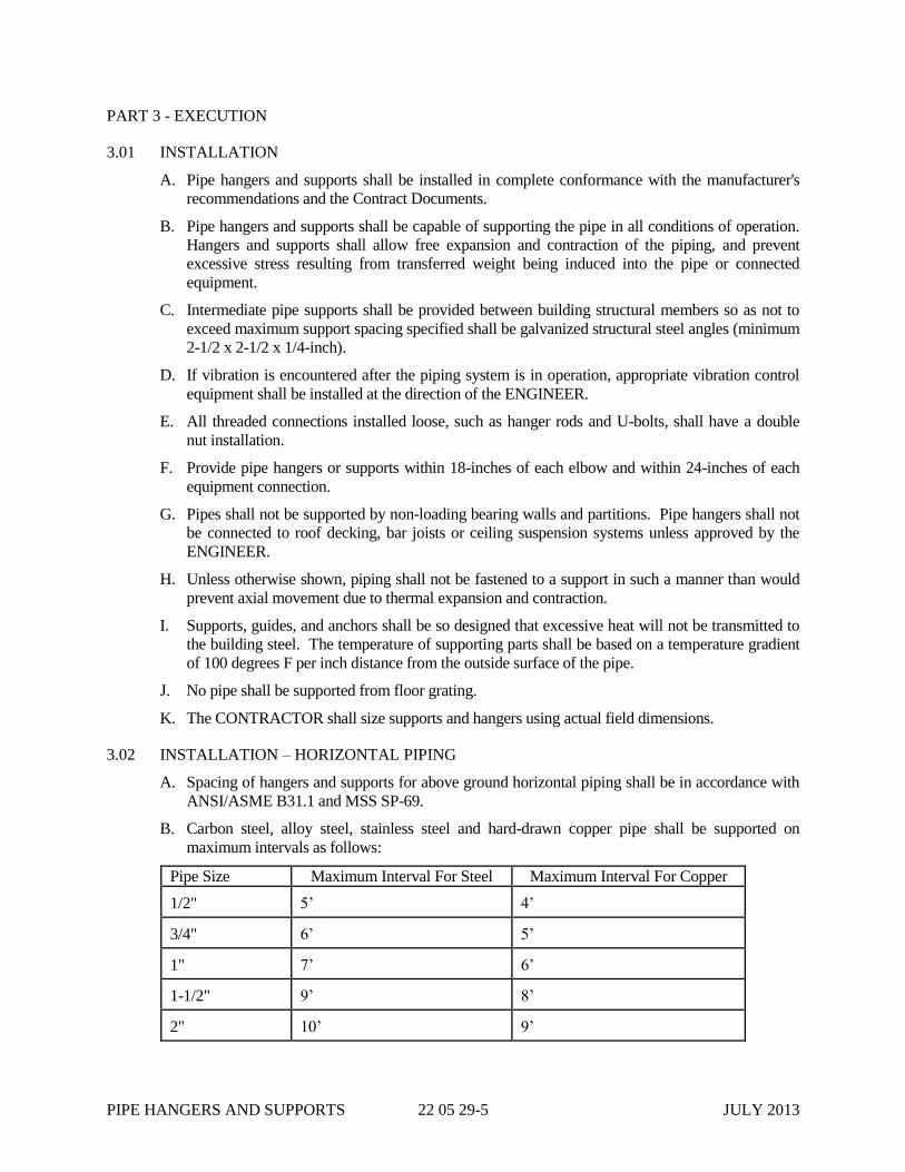
B. Carbon steel, alloy steel, stainless steel and hard-drawn copper pipe shall be supported on
maximum intervals as follows:
Pipe Size Maximum Interval For Steel Maximum Interval For Copper
1/2" 5’ 4’
3/4" 6’ 5’
1" 7’ 6’
1-1/2" 9’ 8’
2" 10’ 9’

PIPE HANGERS AND SUPPORTS 22 05 29-6 JULY 2013
Pipe Size Maximum Interval For Steel Maximum Interval For Copper
2-1/2" 11’ 10’
3" 12’ 11’
4" 13’ -
6" 17’ -
8" 19’ -
10" 22’ -
12" 23’ -
14" 25’ -
16" 27’ -
18" 28’ -
20" 30’ -
24" 32’ -
C. Uninsulated PVC and CPVC piping shall be supported on maximum intervals as follows at
design temperatures up to 80 degrees F:
Pipe Size Maximum Intervals
PVC Schedule 40 PVC Schedule 80 CPVC Schedule 80
1/2" - 3/4" 4’ 4’ 4’
1" 4’ 5’ 5’
1-1/4" - 1-1/2" 5’ 5’ 6’
2" 5’ 6’ 7’
2-1/2" 5’ 6’ 8’
3" 6’ 7’ 8’
4" 6’ 7’ 9’
6" 6’ 8’ 10’
D. Pipe hangers and supports shall be installed at intervals recommended for a specific application
by the piping system manufacturer.
E. Provide all necessary steel angles and other items required to maintain the minimum hanger or
support spacing.
F. Wherever possible, pipe attachments for uninsulated horizontal piping shall be pipe clamps.
G. Wherever possible, structural attachments shall be beam clamps.
H. Pipe Hangers
1. Pipe hangers, trapeze hangers, upper attachments and other supports shall be selected based

PIPE HANGERS AND SUPPORTS 22 05 29-7 JULY 2013
on pipe material, size and service conditions. Provide all hangers and rods, turnbuckles,
angles, channels and other structural supports to support the piping systems. The minimum
rod diameter for single pipe rigid rod hangers shall be as follows:
Pipe Size Minimum Hanger Rod Diameter For
Steel, Ductile and Cast Iron Soil Pipe
Minimum Hanger Rod
Diameter For Copper
And Plastic Pipe
2" and smaller 3/8" 3/8"
2-1/2" and 3" 1/2" 1/2"
4" and 5" 5/8" 1/2"
6" 3/4" 5/8"
8", 10" and 12" 7/8" 3/4"
14" 1" 7/8"
16" and 18" 1" -
20" and 24" 1-1/4" -
2. Hangers shall permit a minimum of 1-1/2-inch vertical adjustment after installation.
3. Where the piping system is subject to shock loads, such as seismic disturbances or thrusts
imposed by the actuation of safety valves, pipe hangers shall include shock absorbing
devices.
4. Hanger rods shall be subject to tensile loading only. At hanger locations where lateral or
axial movement is anticipated, suitable linkage shall be provided to permit swing. Where
lateral or axial movement cannot be tolerated, provide sway bracing for rods exceeding 10
feet.
5. Where horizontal piping movements are greater than 1/2-inch, or where the hanger rod
angularity from the vertical is greater than 4 degrees from the cold to hot position of the
pipe, the hanger pipe and structural attachments shall be offset in such a manner that the rod
is vertical in the hot position.
6. Hangers shall be designed so that they cannot become disengaged by movements of the
supported pipe.
7. Hangers shall be sized to fit around insulation.
I. Additional hangers and supports shall be provided as required so that there is no movement or
visible sagging between supports.
J. Where indicated on the Drawings or directed by the ENGINEER, exposed piping and tubing
carrying liquid shall be sloped as necessary to permit complete draining. Pipe deflection
between supports shall be considered when determining the slope required to permit complete
drainage.
K. Pipe Supports for Floor Supported Horizontal Piping: Pipe supports for horizontal piping
supported on concrete floors and on concrete bases shall be adjustable pipe saddle support with
U-bolt and screwed floor flange. Bolt floor flange to floor and bases utilizing all bolt holes. Use
foam glass inserts at all saddles, sleeves, etc.
PIPE HANGERS AND SUPPORTS 22 05 29-8 JULY 2013
L. Open ends of pipe columns used for support shall be completely covered with 1/4-inch thick
plate or angle leg welded in place.
3.03 INSTALLATION – VERTICAL PIPING
A. Supports for all pipes shall fit directly around the pipe, except that on insulated pipes, the support
shall be insulated and provided with vapor barrier.
B. Vertical pipes passing through floors shall be provided with a riser clamp at each floor. Riser
clamps shall have steel lugs, 1/3-inch thick x 2-inches high x 1-1/2-inches long, welded to the
clamp arms so that clamp does not come in contact with the pipe sleeve.
C. Vertical piping shall be supported as shown or required to prevent buckling or swaying utilizing
special brackets. Unless otherwise shown, vertical piping shall be supported at the bottom and at
each floor. Vertical copper tubing 1-inch and smaller in size shall be supported at five foot
intervals.
3.04 INSULATION SHIELDS AND SADDLES - HORIZONTAL PIPING
A. Galvanized pipe clamps, including bolts and nuts, shall be provided with the framing channels
and shall be used for securing pipes to channels. Pipe clamps on insulated pipes shall fit around
pipe, pipe insulation and pipe insulation protection shield. Clamps and fasteners shall be
stainless steel in all process areas.
B. Insulation on hot piping (carrying fluids above 70 degrees F) shall be protected at supports and
hangers with a 12-inch long galvanized steel protection saddle with welded center support.
Protection saddle shall be equal to Anvil Figure 160(stainless) or 161(stainless).
C. Insulation on cold piping (carrying fluids at 70 degrees F or below) shall be protected at supports
and hangers by galvanized steel insulation shields with a 180 degree contour. Insulation shields
shall be equal to Anvil Figure 167(stainless).
D. On insulation finished with an aluminum jacket, a 1/32-inch thick sheet of neoprene shall be
provided between the jacket and the shield.
3.05 SUPPLEMENTAL STEEL
A. All supplemental steel shall be stainless steel fabricated in accordance with the requirements of
the AISC Manual of Steel Construction and the International Building Code.
B. If used, no flame cutting of galvanized steel members will be permitted.
3.06 SURFACE PREPARATION AND SHOP PAINTING
Fabricated pipe supports and accessories, except where shown on the Drawings to be galvanized,
shall be cleaned and shop primed in accordance with the requirements of Section 09 91 00.
3.07 FIELD PAINTING
Field painting all pipe hangers, supports and accessories shall be in accordance with the requirements
of Section 09 91 00. Stainless and copper components shall be uncoated.
3.08 CLEANING
Prior to acceptance of the work of this Section, thoroughly clean all installed materials, equipment
and related areas in accordance with Section 01 74 00.
END OF SECTION 22 05 29
MECHANICAL IDENTIFICATION 22 05 53-1 JULY 2013
SECTION 22 05 53
MECHANICAL IDENTIFICATION
PART 1 - GENERAL
1.01 SCOPE
A. Work specified in this section is subject to the provisions of Section 22 00 00.
B. Furnish and install markers, tags and nameplates for heating, ventilating, air conditioning,
plumbing and fire protection equipment, piping, controls, and valves to fully identify these items
in reference to a master list.
C. Furnish a complete list of all equipment, piping, controls and valves with coordinated
designations and locations for each device.
1.02 REFERENCES
American National Standards Institute (ANSI) Standards: A13.1 Scheme for the Identification of
Piping Systems
1.03 SUBMITTALS
A. Submit product data in accordance with Section 01 33 00 of these Specifications.
B. Submit catalog cuts, product samples, installation instructions and any other information
required to determine compliance with the Contract Documents.
C. Submit complete list of equipment, piping, controls and valves with identification codes and
locations. Coordinate this list with the equipment identifications utilized in other sections of the
Specifications and by the various trades involved in the work.
1.04 QUALITY ASSURANCE
A. All materials of a similar type shall be the product of a single manufacturer.
B. Identification materials shall be manufactured by a company regularly producing this type of
product. Materials used shall be specifically manufactured for identification purposes.
1.05 SEQUENCING AND SCHEDULING
A. Coordinate installation of identification devices with the installation of the mechanical
equipment.
B. Installation of identification devices may be done at the equipment manufacturer's factory.
C. Install identification devices prior to final testing and balancing of the mechanical systems.
PART 2 - PRODUCTS
2.01 ACCEPTABLE MANUFACTURERS
Mechanical identification items shall be manufactured by W.H. Brady Company, Seton Name Plate
Corporation, or ComplianceSigns, Inc.
2.02 PIPE MARKERS
MECHANICAL IDENTIFICATION 22 05 53-2 JULY 2013
For pipe markers, refer to Section 09 91 00.
2.03 VALVE MARKERS
A. Provide 1-1/2-inch diameter polished brass markers, not less than 19 gauge thickness.
B. Letters shall be 1/4-inch high. Numbers shall be 1/2-inch high. Both letters and numbers shall
be stamped and black-filled.
C. Valve marker fasteners shall be either meter seals, four-ply 18 gauge smooth copper wire, brass
"S" hooks, or brass jack chain.
D. Markers shall bear indications corresponding to the notations on the framed wiring diagrams,
control diagrams and operating instructions.
2.04 EQUIPMENT NAMEPLATES
A. Provide 2-1/2 x 3/4-inch aluminum nameplates with black enamel background and either etched
or engraved lettering.
B. Provide corrosion-resistant fasteners.
C. Nameplates shall bear indications corresponding to the notations on the framed wiring diagrams,
control diagrams and operating instructions.
2.05 CONTROL NAMEPLATES
A. Provide laminated white plastic nameplates with black lettering.
B. Each switch position shall be clearly indicated.
C. Word nameplates to identify the respective product and function.
D. Provide corrosion-resistant fasteners.
PART 3 - EXECUTION
3.01 PIPE MARKERS
For pipe markers, refer to Section 09 91 00.
3.02 VALVE MARKERS
Fasten to valve body in a manner which will facilitate being easily read.
3.03 EQUIPMENT NAMEPLATES
Mount securely to the appropriate piece of equipment.
3.04 CONTROL NAMEPLATES
Mount securely to the appropriate control device such that switch position and control function are
easily read.
3.05 VALVE LIST FRAME
Secure on mechanical room wall; mount one valve list in frame.
END OF SECTION 22 05 53

MECHANICAL INSULATION 22 07 00-1 JULY 2013
SECTION 22 07 00
MECHANICAL INSULATION
PART 1 - GENERAL
1.01 SCOPE
A. Work specified in this section is subject to the provisions of Section 22 00 00.
B. Furnish and install thermal insulation for equipment, ductwork, piping and tanks as indicated
below.
1.02 REFERENCES
A. The latest edition of the testing standards indicated below shall be used as test procedures to
verify compliance of submitted products with performance standards specified herein.
Manufacturers of submitted products shall certify that materials furnished are tested in
accordance with these standards.
1. American Society for Testing and Materials (ASTM) Standards
ASTM E 84 Standard Test Method for Surface Burning Characteristics of Building
Materials
2. National Fire Protection Association (NFPA) Standards
NFPA 255 Method of Test of Surface Burning Characteristics of Building Materials
3. Underwriters Laboratories, (UL) Standards
UL 723 Test for Surface Burning Characteristics of Building Materials
1.03 QUALITY ASSURANCE
A. Insulation products shall have a Flame Spread Rating not exceeding 25 and Smoke Developed
Rating not exceeding 50.
B. Installation shall be performed by workers skilled in the fitting and installation of insulation
products.
1.04 SUBMITTALS
A. Submit product data in accordance with the provisions of Section 01 33 00.
B. Submit catalog cuts, performance data, sealing tape, mastic and all other information required to
demonstrate compliance with the Contract Documents.
C. Submit manufacturer's installation instructions.
PART 2 - PRODUCTS
2.01 ACCEPTABLE MANUFACTURERS
Insulation products shall be manufactured by CertainTeed, Knauf, Johns Manville, Owens-Corning,
IMCOA, Pittsburgh-Corning and Armstrong.
2.02 DUCTWORK INSULATION

MECHANICAL INSULATION 22 07 00-2 JULY 2013
A. Board type insulation shall be glass fiber board with factory applied foil-skrim-kraft vapor
barrier. Thermal conductivity shall not exceed 0.23 BTU./hr/Ft
2/F at 75 degrees F.
B. Ductwork carrying conditioned (heated or cooled) supply or return air located in mechanical
rooms or other service areas shall be insulated with 1-inch thick board type insulation.
C. Ductwork carrying outside air shall be insulated with 2-inch thick board type insulation.
D. Ductwork carrying exhaust air above suspended ceilings in return air plenums shall not be
insulated unless otherwise shown on the Drawings.
E. Ductwork carrying conditioned (heated or cooled) air located outdoors or otherwise exposed to
weather shall be insulated with 2-inch thick board type insulation and coated with waterproof
mastic.
2.03 PIPE INSULATION
A. Materials (Indoor Piping for Temperatures 150 F and Less):
1. Piping insulation shall be flexible elastomeric closed-cell type, slipped on the pipe prior to
connection whenever possible. Where the slip-on technique is not possible, the insulation
shall be pre-slit and snapped over the pipe with pre-applied adhesive. Butt joints shall be
sealed with insulation manufacturer's adhesive or heat fuse method. Where required, the
insulation shall be covered with insulation manufacturer's finish. Thermal conductivity shall
not exceed 0.27 BTU.in/hr/Ft
2/F at 75 degrees F.
2. Fittings shall be insulated using fabricated fitting covers of flexible elastomeric closed-cell
type insulation in accordance with the manufacturer's instructions. Join slit seams and
mitered joints with insulation manufacturer's adhesive or heat fuse method.
B. Materials (Outdoor Piping Exposed to Weather)
1. Premolded cellular glass thermal insulation shall be furnished in accordance with ASTM C
552 and C 585 fabricated for standard pipe sizes, fittings and valves.
2. Maximum thermal conductivity of 0.32 BTU.in/hr/Ft
2/F at 70 degrees F in accordance with
ASTM C 177 and C 518.
3. Maximum water vapor permeability of 0.00 perm-in when tested in accordance with ASTM
E 96.
4. Average density of 8.0 pounds per cubic foot.
5. Maximum Flame Spread Rating of 5 and Smoke-Developed Rating of 0 when tested in
accordance with NFPA 255.
6. Utilize installation adhesives and joint sealants as recommended by the insulation
manufacturer.
7. Furnish 30 gauge smooth Type 316 stainless steel jacketing over insulation retained by
stainless steel bands
8. Insulation products shall be equal to Pittsburgh Corning Foamglass.
C. Description: Piping insulation thickness shall be 1-inch for cold pipes up to 2-inches, 2-inch for
hot water pipes up to 2-inches 1-1/2-inches for pipes over 2-inches and up to 4-inches, and
2-inches for pipes over 4-inches in accordance with the ASHRAE/IES Standard 90.1.
PART 3 - EXECUTION
MECHANICAL INSULATION 22 07 00-3 JULY 2013
3.01 INSTALLATION
A. Insulation shall be installed in accordance with the manufacturer's recommendations.
B. Insulation butt joints shall be sealed with tape a minimum of 2-inches wide matching the
character of the insulation vapor barrier.
C. Insulation bonding must be by glue, self-adhesive lap or tape. Staples are not permitted.
Mechanical fasteners shall only be located on the underside of ductwork three feet or greater in
width. Seal all vapor barrier punctures.
D. Surface to be insulated and insulation shall be clean and dry during installation.
E. Insulation shall be continuous through wall or floor penetrations.
3.02 PIPE INSULATION
A. Pipe hangers shall be outside of the pipe insulation.
B. Install pipe insulation on exterior pipe below grade to a depth at least six inches below the frost
line or 30 inches below grade, whichever is greater.
C. Seal edges of pipe insulation with approved mastic to create a water and vapor proof seal.
D. Insulate all of the services listed below. Where domestic service is called out, it is defined as
piping concealed above ceilings and within walls or exposed in return air plenums and
mechanical rooms.
1. Tempered water piping.
2. Domestic potable water piping located in Mechanical Rooms, Toilet Room, storage rooms,
and Operator Room. Do not insulate potable water piping located in process areas.
3. Non-potable water piping subject to freezing and as indicated on drawings
4. Domestic hot water piping located in Mechanical Rooms, Toilet Room, storage rooms, and
Operator Room. Do not insulate hot potable water piping located in process areas.
5. AHU condensate piping.
6. Refrigeration piping.
E. Insulate all piping, valves and fittings that are heat traced in addition to those services specified
herein.
F. Paint or identify insulation on services in accordance with Section 22 05 53.
END OF SECTION 22 07 00

MECHANICAL INSULATION 22 07 00-4 JULY 2013
THIS PAGE INTENTIONALLY LEFT BLANK
TESTING OF PIPING SYSTEMS 22 08 00.12-1 JULY 2013
SECTION 22 08 00.12
TESTING OF PIPING SYSTEMS
PART 1 - GENERAL
1.01 DESCRIPTION
A. Scope: Test all piping for integrity, including include water tests, air tests, and smoke tests as
specified herein.
B. Related Sections: All Sections of Division 22 regarding Plumbing Piping Systems.
1.02 QUALITY ASSURANCE
A. Requirements of Regulatory Agencies:
1. Building Codes: Comply with the Uniform Plumbing Code, as supplemented by the authorities
having jurisdiction.
B. CITY shall witness all tests covered by this Section. CONTRACTOR shall provide 48 hours
advanced notice of tests.
1.03 SUBMITTALS
A. Submit a description of proposed testing methods, procedures, and apparatus to the CITY for
approval at least 48 hours in advance of testing.
B. Submit a test report for each test to the CITY certifying the test pressure, duration of the test, and test
performance of all installed piping.
PART 2 - PRODUCTS
NOT USED
PART 3 - EXECUTION
3.01 GENERAL
A. Test pressures for piping will be as scheduled in the piping Section(s). If not scheduled, they shall be
as specified below.
B. Conduct all tests in the presence of and in a manner approved by CITY and all state and local
authorities having jurisdiction. Repeat test for these authorities if requested by them.
C. Repair and retest all lines that do not pass the tests as specified herein.
D. All valves will be involved in the specified tests. CONTRACTOR shall plan and organize the test
procedures to test against at least one side of all valves (in closed position).
E. Inspect all valves, joints, and specialties for tightness and for proper operation while under test

TESTING OF PIPING SYSTEMS 22 08 00.12-2 JULY 2013
pressure.
3.02 LIQUID PRESSURE PIPING
A. Piping carrying water or sewage, and normally flowing full, will be pressure tested. The procedure
to be followed is:
1. For underground pipe, complete backfill and compaction at least to the pipe centerline and allow
concrete for thrust blocks to reach design strength before testing, unless otherwise approved by
Engineer.
2. For aboveground pipe, assure that adequate thrust restraint is in place before testing.
3. Fill section to be tested slowly with water and expel all air. Install corporation cocks, if
necessary, to remove all air.
4. Apply specified test pressure (or 100 psi if not specified) (at high point of piping) for two hours
and observe pressure gage. Check carefully for leaks while test pressure is being maintained.
5. If pressure drop is observed, accurately measure the amount of water which must be added to
regain the initial test pressure.
6. Repair all visible leaks.
7. Pipe passes the test if allowable leakage rate is not exceeded.
8. Allowable Leakage Rates (in gallons per hour per 1,000 feet per inch diameter):
a. Underground Ductile Iron: 0.075.
b. Exposed pipe and Copper, Steel, Plastic: None.
9. Should any discrepancies arise on pipe testing pressures between various specification
systems, most stringent requirements will govern.
3.03 DRAIN, AND VENT PIPING
A. Drain, and vent piping, which normally does not flow full, shall be tested by either the water test, at
the specified test pressure (or 10 ft. of head, if not specified), or by the air test, as detailed below:
B. Water Test
1. Fill the pipe with water to provide a positive differential head on the top of the pipe at the
highest point of the pipeline under test of the specified test pressure.
2. Apply specified test pressure for four hours and observe water level. Check carefully for leaks
while test pressure is being maintained.
3. If level drop is observed, accurately measure the amount of water which must be added to regain
the initial test pressure.
4. The amount of water added to maintain this head shall be the leakage.
5. Repair all visible leaks.
6. Pipe passes the test if allowable leakage rate is not exceeded.

TESTING OF PIPING SYSTEMS 22 08 00.12-3 JULY 2013
7. Allowable Leakage Rates (in gallons per hour per 1,000 feet per inch diameter):
a. Underground Sewer or Drain: 5.0.
b. Exposed Drain and Vent: None.
C. Air Test
1. Slowly fill the pipe with air to a pressure of 4 psig. Maintain pressure between 4 and 3.5 psig
for at least two minutes for temperature stabilization.
2. With a pressure of approximately 4 psig in pipe, disconnect air supply.
3. Allow pressure to decrease to 3.5 psig.
4. When the pressure reaches 3.5 psig, record the time required to decrease to 2.5 psig using a
stopwatch.
5. Pipe passes the test if the time required to decrease to 2.5 psig is at least 28.5 seconds per inch
diameter.
D. Should any discrepancies arise on pipe testing pressures between various specification systems,
most stringent requirements will govern.
3.04 AIR AND GAS PIPING
A. Piping which carries air or other gasses shall be tested by means of an air pressure test at the
specified test pressure (or 150 psi, if not specified):
1. If the process medium is air, the test medium shall be air, otherwise, then the test medium shall
be dehydrated, oil-free air with a dew point of –40°F.
2. Fill section to be tested slowly with air at specified test pressure for one hour and observe
pressure gage. Check carefully for leaks while test pressure is being maintained.
3. Pipe passes the test if no pressure drop occurs.
3.05 CLEANING AND DISPOSAL
A. Contractor shall provide suitable means for disposal of test and flushing water so that no damage
results to facilities or waterways. Means of disposal of test and flushing water shall be subject to the
approval of CITY, local governing authorities and regulatory agencies.
B. Cleaning
1. Thoroughly clean all piping and flush prior to placing in service in a manner approved by
Engineer.
2. Piping 24-inches in diameter and larger shall be inspected from inside and all debris, dirt and
foreign matter removed.
3. Disinfect all potable water piping in accordance with Section 22 11 00, Disinfection of
Plumbing.
4. After cleaning and flushing, purge all gas piping (except that carrying only air) with dry
nitrogen.

TESTING OF PIPING SYSTEMS 22 08 00.12-4 JULY 2013
END OF SECTION 22 08 00.12
WATER SUPPLY SYSTEM 22 11 00B-1 JULY 2013
SECTION 22 11 00B
WATER SUPPLY SYSTEM
PART 1 - GENERAL
1.01 SCOPE
A. Work specified in this section is subject to the provisions of Section 22 00 00.
B. Furnish, install, disinfect and test the water supply system as indicated on the Contract
Documents.
1.02 REFERENCES
A. This Specification references the latest edition of the publications listed below. Work shall be
performed and materials shall be furnished in accordance with these publications as referenced
herein:
1. International Plumbing Code
2. American National Standards Institute (ANSI)
A112.1.2 Air Gap Standards
B16.18 Cast Copper Alloy Solder-Joint Pressure Fittings
B16.22 Wrought Copper and Copper Alloy Solder Joint Pressure Fittings
B16.26 Cast Copper Alloy Fittings for Flared Copper Tubes
3. American Society of Sanitary Engineering (ASSE)
1003 Water Pressure Regulators and Reducing Valves for Domestic Water
Supply Systems
4. American Society for Testing and Material (ASTM)
B 88 Seamless Copper Water Tube
D 1785 Polyvinyl chloride (PVC) Plastic Pipe and Fittings, Schedules 40, 80 and
120
D 2466 Polyvinyl chloride (PVC) Plastic Pipe Fittings, Schedule 40
D 2467 Socket Type Polyvinyl chloride (PVC) Plastic Pipe Fittings, Schedule 80
D 2564 Solvent Cements for Polyvinyl chloride PVC Plastic Pipe and Fittings
5. American Water Works Association (AWWA)
C110 Gray-iron and Ductile-Iron Fittings, 3-inch through 48-inch for Water and
other Liquids
C111 Rubber-Gasket Joints for Ductile-Iron and Gray-Iron Pressure Pipe Fittings
C151 Ductile-Iron Pipe, Centrifugally Cast in Metal Molds or Sand-Lined Molds,
for Water or Other Liquids
C651 Standard for Disinfecting Water Mains
6. Plumbing and Drainage Institute (P&DI)
WH-201 Certification, Sizing, Placement of Water Hammer Arrestors.
1.03 SUBMITTALS
A. Submit product data in accordance with Section 01 33 00.

WATER SUPPLY SYSTEM 22 11 00B-2 JULY 2013
B. Submit product data on all products proposed for installation under this section, including but not
limited to the following:
1. Pipe and fittings.
2. Valves.
3. Pressure reducing valves.
4. Pressure control valves.
5. Thermostatic Mixing Valves.
6. Water hammer arresters.
C. Submit installation and maintenance instructions and spare parts lists in accordance with
Sections 01 78 23 and 01 78 43.
1.04 QUALITY ASSURANCE
A. Work shall be performed by workers skilled in the installation of domestic water systems.
B. Installation, disinfection and testing shall be supervised by a master plumber licensed in the State
of Ohio who shall be responsible for the installation of the entire system in accordance with the
International Plumbing Code.
PART 2 - PRODUCTS
2.01 PIPE FITTINGS (ABOVE GROUND)
A. Copper Tubing
1. ASTM B 88, Type L, hard drawn unless noted otherwise.
2. Fittings: Solder type, either cast bronze conforming to ANSI B16.18 or wrought copper or
bronze conforming to ANSI B16.22, except that unions shall conform to FS WW-U-516 and
be either brass or bronze and either threaded or soldered.
B. Copper Alloy Tubing
1. Tube: Heavy type conforming to ASTM B 543, Alloy 194.
2. Fittings: Solder type, either cast bronze conforming to ANSI B16.18 or wrought copper or
bronze conforming to ANSI B16.22, except that unions shall conform to FS WW-U-516 and
be either brass or bronze and either threaded or soldered.
C. PVC Piping
1. Schedule 80, ASTM D 1785.
2. Fittings: Solvent weld socket type, same schedule as piping, ASTM D 2466 or D 2467.
3. Solvent Cement: ASTM D 2564.
D. Ductile Iron Piping
1. Ductile iron pipe shall be manufactured in accordance with AWWA C151 and shall have a
minimum pressure rating of 250 psi.
2. Fittings shall be flanged and conform to AWWA C115/ANSI A21.15.
E. Stainless Steel Piping refer to specification 40 05 13.

WATER SUPPLY SYSTEM 22 11 00B-3 JULY 2013
2.03 JOINTS AND JOINTING MATERIALS
A. Flanges for ends of pipe and fittings shall be cast iron and conform to AWWA C110, except that
pipe flanges shall be screw-on type having threads confirming to ANSI B16.1 for 125 pound
Class. Bolts, nuts and gaskets shall conform to AWWA C111. Gaskets shall be plain rubber,
1/8-inch thick.
B. Fittings immediately inside exterior wall and fittings that unite dissimilar metals shall be
dielectric insulating type.
2.04 VALVES
A. Smaller than 3-inches shall be threaded or soldered, 3-inches and larger shall be flanged.
B. Gate Valves
1. Smaller than 3-inches shall be Class 125, Type III, rated for a hydraulic working pressure of
125 psi.
2. 3-inches and larger shall be Class 125, Type II, outside-screw-and yoke type; rated for a
hydraulic working pressure of 125 psi.
C. Check Valves
1. Smaller than 3-inches shall have bronze trim and either cast iron or steel body, and be rated
for a hydraulic working pressure of 125 psi.
2. 3-inches and larger shall be weight-loaded, have bronze trim and either cast iron or steel
body and be rated for a hydraulic working pressure of 125 psi.
a. Buried Lines: Mechanical joints.
b. In Valve Chambers, Valve Pits and Above Ground: Flanged joints.
D. Ball Valves
1. Smaller than 3-inches shall be bronze body with full port, rated for a hydraulic working
pressure of 150 psi.
2. 3-inches and larger shall be carbon steel or stainless steel body, stainless steel trim with full
port, rated for a hydraulic working pressure of 150 psi.
E. Globe Valves
1. Globe valves 2-inches and smaller shall be bronze body with rising stem, screwed bonnet,
integral bronze seat, renewable PTFE discs with screwed or solder joint ends. Valve shall be
rated for a non-shock cold working pressure of 300 psi.
2. Globe valves 2-1/2-inches and larger shall be iron body, Class 125, flanged ends with bolted
bonnet and non-rising stem. Valves shall be rated for a hydraulic working pressure of 150
psi.
F. Acceptable Manufacturers: Crane, Nibco, Stockham, Milwaukee, Watts, Apollo, Kitz.
2.05 PRESSURE REDUCING VALVES (1/2 to 2-INCH SIZE)
A. Provide bronze body, spring controlled, adjustable pressure reducing valve with threaded
connections.
B. Provide valves with high temperature diaphragm and renewable nickel alloy seat.
C. Provide with thermal expansion bypass.
WATER SUPPLY SYSTEM 22 11 00B-4 JULY 2013
D. Provide with separate bronze strainer with 20 mesh stainless steel basket. Attach to valve with
bronze nipple.
E. Rated for 300 psig maximum inlet water pressure with adjustable 25-75 psig outlet water
pressure.
F. Tested and certified under ASSE 1003 and the Standard Plumbing Code.
G. Acceptable Manufacturers: Watts 223SB, Wilkins, Mueller.
2.06 PRESSURE CONTROL VALVES (1-1/4-INCH to 6-INCH SIZE)
A. Provide fluid actuated automatic control valves where indicated to regulate downstream water
pressure.
B. Provide valves with cast iron valve body and cover. Exposed internal and external surfaces shall
be coated with an FDA approved fused epoxy finish coat.
C. Provide with flexible, non-wicking, FDA approved, reinforced synthetic elastomer diaphragm
integral with the valve assembly. Support the diaphragm with an actuation stem utilizing upper
and lower bearings.
D. Provide flow sealing in the closed position with a separate elastomer sealing ring and smooth
metal seat surface. Seat design shall be removable and shall not promote seal cutting or wear at
low flow rates.
E. Unless otherwise noted, valves shall be rated for a minimum of 150 psig inlet pressure with an
adjustable outlet pressure range of 30 to 90 psig. Nominal outlet pressure shall be adjusted to 50
psig.
F. Provide with inlet strainer per manufacturer's standard arrangement.
G. Provide valves with [threaded end connections for sizes 2-1/2 inch and smaller] [and] [flanged
end connections for sizes 3-inches and larger].
H. Acceptable Manufacturers: Watts Series 115, Clayton, GA Industries.
2.07 THERMOSTATIC MIXING VALVE
A. Thermostatic mixing valve shall conform to the requirements of ASSE Standard 1016 for hot
water temperature control.
B. Valve shall have a bronze or brass body and shall include integral check valves and an
adjustment cap with locking feature.
C. The valve shall be provided with union connections.
D. Valve shall be Watts Series MMV or equal by Simmons, PPP Inc. or Leonard.
E. For Safety equipment mixing valves refer to Section 22 40 00
2.08 WATER HAMMER ARRESTERS
A. Permanently packaged water hammer arrester with bellows, diaphragm or O-ring/disc sealing
mechanism.
B. Provide in accordance with PDI Standard WH-201.
C. Acceptable Manufacturers: Sioux Chief Hydra-Rester, Zurn, Josam.
2.09 AUTOMATIC SELF CLEANING NPW

WATER SUPPLY SYSTEM 22 11 00B-5 JULY 2013
A. Manufacturer
1. NPW Filter System for Grit Pump Seal Water (M-13-30-0001) in Grit Pump Room, Model
ORV-100-LE by Orival Inc. or equal.
2. NPW Filter System for Sludge Pump Seal Water (M-F-30-0001) in Parts Storage Building,
Model ORV-100-LE by Orival Inc. or equal.
3. NPW Filter System inside Dewatering Building (M-H2-30-0001) Model ORG-060-LE by
Orival Inc. or equal.
B. The filtration system shall contain an automatic, self-cleaning filter and a control system.
C. Filter shall have 1” threaded inlet and outlet connection for filtering up to 27 gpm and 6”
threaded inlet for flows greater than 300 gpm. The filter can be supplied with a 50 micron
stainless steel fine screen. The minimum fine screen open area shall be 42in2.
D. Threaded reducers can be installed to the inlet and outlet ports to reduce the line size down to the
required size.
E. Filter shall be completely self-cleaning, and the cleaning cycle shall be powered by line pressure
only. No external pneumatic or electric power is required, and continuous system flow shall be
maintained during the rinse cycle.
F. A rinse cycle shall be initiated by the control system based on differential pressure, by timer, or
by local manual action. A dirt collecting assembly shall sweep the entire screen area to remove
accumulated particles and send them to a waste drain through a 1” rinse valve.
G. The filtration control system shall consist of a microprocessor based controller in a water
resistant enclosure with an attached, wired, and preset Differential Pressure Switch (DPS) plus a
normally open 3-way solenoid valve. The Differential Pressure Switch will be factory preset to 7
psig increasing.
2.10 PIPING ACCESSORIES
A. Nipples: FS WW-N-351; be of same type material as piping on which installed.
B. Unions for Copper Tubing: Brass or bronze, have either threaded or solder joint ends and
conform to FS WW-U-516.
C. Unions for Steel Piping: FS WW-U-531.
D. Escutcheons: Polished chromium-plated pressed steel, split-hinged, locking type held in-place
by either an internal tension spring or a set-screw; encompass sleeve or opening.
E. Bolts and Nuts: Machined brass, stainless steel or galvanized carbon steel, and not smaller than
1/4-inch; bolts shall have hexagonal heads and nuts shall be hexagonal.
F. Solder for Solder-Jointed Tubing: 95 percent tin and five percent antimony. Flux shall be
non-corrosive type conforming to NSF 61.
G. Strainers
1. Strainers in water lines shall have standard pattern, stainless steel baskets with standard
perforations. Bodies shall be bronze for sizes 2-inch and smaller and cast iron for sizes 2-
1/2-inch and larger. Strainers shall be equal to Watts Series 77 unless otherwise specified in
other Sections of Division 15.
2. All strainers shall be of the same size as the piping in which they are installed. Provide
dielectric union, if necessary, to isolate strainer from pipe material.
WATER SUPPLY SYSTEM 22 11 00B-6 JULY 2013
2.11 TRAP PRIMER
A. Provide brass trap primer that automatically supplies water to P-traps upon 5 psi or less pressure
drop in water line.
B. Install trap primer, distribution unit(s) and water lines per manufacturer's recommendations.
C. Acceptable Manufacturers: Equal to Precision Plumbing Products.
PART 3 - EXECUTION
3.01 INSTALLATION
A. Install domestic water systems in accordance with AWWA standards and local codes applicable
to water system installation.
B. Trenching and backfill shall be in accordance with Section 31 23 00.
C. Cut pipe and tubing accurately to measurements established at worksite; work pipe into place
without springing and forcing. Install pipe with a fall towards either shut-off valve or lowest
fixture.
D. Remove fins and burrs from piping. Apply lubricant to male threads only; threads shall be full
cut, and not more than three threads on pipe shall remain exposed after tightening. Coat installed
and tested exposed ferrous threads with one coat of non-toxic primer and oil paint.
E. Cut ends of copper tubing square, and remove burrs. Clean ends of tubing and apply a rosin type
flux to outside surface of tubing ends and on recess inside of fittings. Insert tubing to full depth
of fitting; then solder-joints before soldering valves.
F. Install piping true to line and grade and support and guide in a manner which will ensure
indicated alignment. Installed piping shall clear obstructions, preserve headroom, keep openings
and passageways clear, and not be in same trenches as sewer lines. Water supply system
drawings are schematic; do not scale. Install unions on pipe ends immediately adjacent to
valves, equipment and tanks.
G. Valves shall be accessible for operation and servicing. Stems of installed valves shall not be
below horizontal position. Valves which will be in furred spaces shall be accessible.
H. Make-up soldered-to-threaded connections with male thread-to-solder adapters.
I. After pipes have been installed, either cap or plug ends of pipes. Neither bury, furr-in, nor
conceal piping before piping has been inspected and tested.
J. Provide access panels in finished walls for access to concealed valves, water hammer arrestors
and other devices requiring periodic maintenance.
K. Install insulation in accordance with Section 22 07 00.
L. Dielectric Isolation
1. Wherever copper, brass or bronze piping systems are connected to steel or iron piping
systems, this connection shall be made with dielectric isolators. The dielectric isolators shall
be so designed that non-ferrous piping materials shall be isolated by the use of Teflon or
nylon isolating materials made up in the form of screwed type unions or insulating gaskets
and bolt sleeves and washers for standard flanged connection. All dielectric isolators shall
be selected for the pressure of the system involved.
2. Dielectric isolators shall be Watts, Epco, Crane or Maloney.
WATER SUPPLY SYSTEM 22 11 00B-7 JULY 2013
3.02 TESTING
A. Test installed building water supply system in accordance with the International Plumbing Code
B. Test piping that will be buried and concealed prior to concealment.
3.03 DISINFECTING
A. Disinfect water systems in accordance with AWWA C651 and local codes applicable to water
system disinfecting.
B. Before disinfecting system, flush line in a manner which will remove all extraneous materials.
C. Disinfect each section of new line before seeking acceptance of water supply system.
D. Either directly apply chlorine or mix water and either calcium hypochlorite, chlorine gas, or
calcium chloride. Retain solution in pipe for not less than 24 hours, then measure residual
chlorine at ends of section and at other representative points; residual chlorine content is similar
to that obtained from source.
END OF SECTION 22 11 00B

WATER SUPPLY SYSTEM 22 11 00B-8 JULY 2013
THIS PAGE INTENTIONALLY LEFT BLANK
SANITARY DRAINAGE SYSTEM 22 13 00-1 JULY 2013
SECTION 22 13 00
SANITARY DRAINAGE SYSTEM
PART 1 - GENERAL
1.01 SCOPE
A. Work specified in this section is subject to the provisions of Section 22 00 00.
B. Furnish, install and test the sanitary sewer system as indicated on the Contract Documents. Do
not scale Drawings.
1.02 REFERENCES
A. This Specification references the latest edition of the publications listed below. Work shall be
performed and materials shall be furnished in accordance with these publications as referenced
herein:
1. International Plumbing Code
2. American National Standards Institute (ANSI)
B16.1 Cast Iron Pipe Flanges and Flanged Fittings Class 25,125, 250 and 800
B16.12 Cast Iron Threaded Drainage Fittings
B16.23 Cast Copper Alloy Solder Joint Drainage Fittings-DWV
3. American Society for Testing and Materials (ASTM)
A 48 Gray Iron Castings
A 74 Cast Iron Soil Pipe and Fittings
A 395 Ferritic Ductile Iron Pressure-Retaining Castings for Use at Elevated
Temperatures
A 888 Hubless Cast Iron Soil Pipe and Fittings
B 306 Copper Drainage Tube-DWV
C 564 Rubber Gaskets for Cast Iron Soil Pipe and Fittings
D 4101 Polypropylene Molding and Extrusion Materials
D 2665 Chlorinated Polyvinyl Chloride (CPVC) Plastic Pipe, Schedules 40 and 80
D 2665 Fittings: Solvent Weld Socket Type, Same Schedule as Piping
F 493 Solvent Cement
4. American Water Works Association (AWWA)
C110 Gray-Iron and Ductile-Iron Fittings, 3-inches through 48-inches, for Water
and other Liquids
C112 2-inch and 2-1/2-inch Cast Iron Pipe, Centrifugally Cast, for Water or other
Liquids
C302 Reinforced-Concrete Water Pipe - Noncylinder Type, Not Prestressed
5. Cast Iron Soil Pipe Institute (CISPI)
301 Hubless Cast Iron Soil Pipe and Fittings for Sanitary and Storm Drain,
Waste, and Vent Piping Applications
6. National Bureau of Standards (NBS)

SANITARY DRAINAGE SYSTEM 22 13 00-2 JULY 2013
Handbook H28
7. Underwriters Laboratories, Inc. (UL) Standards
UL 971 Listed Non-Metal Pipe
1.03 SUBMITTALS
A. Submit product data in accordance with Section 01 33 00.
B. Submit product data on all products proposed for installation under this section, including but not
limited to the following:
1. Pipe and fittings.
2. Drains.
3. Cleanouts.
C. Submit installation and maintenance instructions and spare parts lists.
1.04 QUALITY ASSURANCE
A. Work shall be performed by workers skilled in the installation of sanitary drainage systems.
B. Installation and testing shall be supervised by a master plumber licensed in the State of Ohio
who shall be responsible for the installation of the entire system in accordance with the
International Plumbing Code.
C. Installation tools and equipment shall not damage products.
1.05 JOBSITE CONDITIONS
Coordinate installation with other building systems in a manner which will preclude interferences.
PART 2 - PRODUCTS
2.01 UNDERGROUND CAST IRON SANITARY DRAINAGE PIPE AND FITTINGS
A. Provide cast iron pipe, furnished and coated in accordance with ASTM A 74, Class SV.
B. Joints shall be bell-and-spigot type, ASTM A 74, with rubber gaskets conforming to ASTM C
564.
2.02 ABOVEGROUND CAST IRON SANITARY DRAINAGE PIPE AND FITTINGS
A. Hub and Spigot: Pipe shall be hub type cast iron soil pipe, ASTM A 74. Fittings shall be
bell-and-spigot type per ASTM A 74 with rubber gaskets conforming to ASTM C 564.
B. Hubless: Pipe shall be hubless cast iron soil pipe in accordance with ASTM A 888 and CISPI
C301. Fittings shall conform to ASTM A 888 and CISPI Standard 301.
C. Copper DWV: Tubing shall be in accordance with ASTM B 306. Fittings shall be cast bronze
with solder ends conforming to ANSI B16.23.
D. Fittings shall be drainage-pattern type, compatible with pipe, except where adapters connect
different pipe materials.
2.03 POLYVINYL CHLORIDE (PVC) Drain Waste Vent (DWV) PIPE
A. PVC Pipe and Fittings, 2 to 8-inch diameter, concealed or buried:
SANITARY DRAINAGE SYSTEM 22 13 00-3 JULY 2013
1. Pipe in accordance with ASTM D 2665.
2. Fittings: Solvent weld socket type, DWV pattern, same schedule as piping, in accordance
with ASTM F 1866.
3. Solvent Cement: ASTM D 2564.
B. PVC Pipe and Fittings, 10 to 20-inch diameter, buried:
1. Schedule 40 pipe in accordance with ASTM 1785.
2. Fittings: Solvent weld socket type, DWV pattern, same schedule as piping, in accordance
with ASTM F 1866.
3. Solvent Cement: ASTM D 2564.
C. PVC Pipe and Fittings, 10 to 20-inch diameter, exposed:
1. Schedule 80 pipe in accordance with ASTM D 1785.
2. Fittings: Solvent weld socket type, DWV pattern, same schedule as piping, ASTM F 1866.
3. Solvent Cement: ASTM D 2564.
2.04 DRAINS
A. Floor Drain (FD-1)
1. Lacquered cast iron body, integral flange and double drainage weepholes with push-on joint
outlet connection.
2. Adjustable 6-inch diameter satin nickel bronze strainer with 1/2-inch thick grate with a free
area of at least 9.5 square inches.
3. Floor drains shall be Josam 30000-A, Smith, Wade, Zurn, or Ancon.
B. Floor Drain (FD-2)
1. Coated cast iron with side outlet hub connection, 13 x 11 IN rectangular top, removable
sediment bucket and extra heavy duty hinged grate.
2. Floor drain shall be Josam Series 38640, Smith, Wade, or Zurn.
C. Floor Drain (FD-3)
1. Provide with coated cast iron body, inside caulk connection, bottom outlet, round top and
heavy duty loose set tractor grate with removable internal dome strainer.
2. Hub drains shall be Josam 38850, Smith, Wade, Zurn, or Ancon.
D. Floor Drain (FD-4)
1. Coated cast iron body, integral flange and double drainage weepholes with push-on joint
outlet connection .
2. Adjustable 9-inch diameter tractor strainer with a free area of at least 21 square inches.
3. Floor drains shall be Josam 30000-E, Smith, Wade, Zurn, or Ancon.
E. Floor Drain (FD-5)
1. Coated cast iron with bottom outlet hub connection, 13 x 11 IN rectangular top, removable
sediment bucket and extra heavy duty hinged grate.
2. Floor drain shall be Josam Series 38620, Smith, Wade, or Zurn.
SANITARY DRAINAGE SYSTEM 22 13 00-4 JULY 2013
2.05 CLEANOUTS
A. Cleanout bodies shall be cast iron conforming to ASTM A 74.
B. Floor Cleanouts (FCO): Adjustable, with bronze tapped plug, scoriated nickel-bronze cover and,
if for membraned floors, a clamping device.
C. Wall Cleanouts (WCO): Bronze tapped plug, cover shall be polished stainless steel, in flanged
frame secured to plug with vandal-proof screw.
D. Exposed Cleanouts: Have tapered caulking ferrule and raised brass head cleanout plug.
E. Exterior Cleanouts (ECO): Have adjustable sleeve-type housing, countersunk threaded brass
plug and cast iron frame and cover.
F. Cleanout plugs shall not be larger than 4-inches. Cleanouts for cast iron soil pipe shall consists
of a longsweep 1/4 bend or one or two 1/8 bends extended to the place indicated; other cleanouts
shall be T-pattern, 90-degree branch drainage fittings having screw plugs.
G. Cleanouts shall be manufactured by Josam, Smith, Wade, Zurn, or Ancon.
H. Backwater valves shall be manufactured by Josam 67800, Ancon, or Zurn.
2.06 PIPING SPECIALTIES
A. Gaskets for Flanged Joints: Full-face, either neoprene, asbestos, or rubber; rubber gaskets:
AWWA C302.
B. Vent Caps for Service Weight Soil Pipe: ASTM A 74.
C. Gaskets, Glands and Bolts for Mechanical Joint Pipe and Fittings: AWWA C110, AWWA
C112 and FS WW-P-421C.
D. Unions for Ferrous Pipe 3-Inches in Diameter and Smaller: 150 pound steam-working-pressure
zinc-coated malleable iron ground-joint type.
E. Unions for Ferrous Pipe 3-1/2-Inches in Diameter and Larger: 125 pound
steam-working-pressure forges steel flange type, having cloth-inserted rubber gaskets 1/16-inch
thick.
F. Couplings for Joining Hubless Cast Iron Pipe and Fittings: Cast iron housing conforming to
ASTM A 48, Class 30A, have bitumastic coating, neoprene gasket conforming to ASTM C 564
and 18-8 stainless steel bolts and nuts.
G. Solder for Solder-Jointed Tubing: 95 percent tin and five percent antimony; flux shall be
non-corrosive.
H. Joint in Sanitary Lines Immediately Inside Exterior Wall and Joint Between Pipe of Dissimilar
Metal: Dielectric insulating joint, union or coupling.
I. Threaded joints shall have ANSI taper pipe threads conforming to NBS Handbook H.
J. Joint Compound: Either graphite, inert filer and oil or polytetra-fluoroethylene tape.
K. Joints in cast iron soil pipe and fittings having a double seal, compression-type molded neoprene
gasket shall have a modified hub to provide a positive seal.
2.07 FLASHING
Either soft-temper or cold-rolled copper weighting not less than 16 ounces per square foot or sheet
lead weighting not less than four pounds per square foot.

SANITARY DRAINAGE SYSTEM 22 13 00-5 JULY 2013
2.08 TRAPS
"P" type, unless otherwise indicated; ASTM A 74. Traps for steel pipe shall have either recess
drainage pattern or brass tube not less than 17 gauge. Traps for PVC piping shall conform to ASTM
D 2665 and shall be approved by NSF or IAPMO.
2.09 ESCUTCHEON
Polished chromium-plated pressed steel, split-hinged, locking type held in place by either an internal
tension spring or a set-screw and encompass sleeve or opening.
PART 3 - EXECUTION
3.01 INSTALLATION
A. Horizontal soil and waste pipe grades shall not be less than 1/4-inch per foot for 2-1/2-inch size
and smaller, and not be less than 1/8-inch per foot for 3-inch size and larger.
B. Changes of soil, waste, and drain pipe sizes shall be made with reducing fittings. Changes in
direction shall be with either 45 degree wyes; long or short-sweep 1/4, 1/6, 1/8, or 1/16 bends; or
elbows.
C. Install trap at each fixture and piece of equipment connecting to the sanitary sewer system. Place
trap as near fixture and equipment as possible; do not double-trap fixture.
D. Slip joints will be permitted only in trap seals or on inlet side of traps. Union connections shall
be made with either tucker or hub drainage fittings.
E. Install and connect products in accordance with product manufacturer's printed installation
instructions. Apply joint compound to threaded joints and tighten joints to a degree which will
prevent leaks.
F. Interior of pipe, pipe fittings, drains and cleanouts shall be clean before being installed and
foreign substances on interior surfaces shall have been removed.
G. Join sections of hubless pipe with cast iron assemblies. Tighten threaded assemblies to 60
inch-pounds torque on each joint with a torque wrench specifically designed for the purpose.
Retorque each screw not less than 24 hours after initial tightening.
H. Extend main vertical soil and waste stacks full size to roofline and above as vents, except where
otherwise specifically indicated. Install vent pipes in roof spaces as close as possible to roof
underside without forming traps in pipes; use fittings as required. If a circuit vent pipe from
fixture, or line of fixtures, will be connected to a vent line serving other fixtures, connect at least
6-inches above floor level rim of highest fixture served. Grade vent and branch-vent pipe in a
manner which will ensure that condensate will drain to vertical stack.
I. Surfaces and structures to, and on, which sewer products will be affixed, placed and erected shall
be capable of supporting those products.
J. Set pipe and fittings to line and grade before making-up joints
K. Angular deflection of joints shall not exceed the recommendations of the pipe and fitting
manufacturer. Should alignment require deflections to exceed those recommended, achieve
indicated deflection with either special bends or short lengths of pipe.
M. Secure products not to be buried to hangers, supports and anchors. Tighten bolts and nuts of
flanged joints to a degree which will prevent leaks.

SANITARY DRAINAGE SYSTEM 22 13 00-6 JULY 2013
N. Seal open ends of products at end of work period and in a manner which will prevent water and
foreign material from entering; remove seals when work resumes.
O. Install escutcheons where exposed piping, bare or insulated, passes through floors, walls and
ceilings. Fasten escutcheons to pipe or pipe covering.
P. Pipe sleeves for pipes passing under footings or through foundation walls shall be Schedule 40
ductile iron pipe extending one foot beyond either face of the footing or wall.
Q. Solvent-Welded PVC Joints: All solvent-welded PVC joints shall be installed in accordance
with ASTM 2855.
3.02 FLOOR DRAIN INSTALLATION
A. Coordinate floor drain locations and installation elevations with the Structural and Architectural
Drawings.
B. Install floor drains at the local low point in the floor slab.
C. Install floor drains with membrane clamping rings if the floor slab contains a membrane.
D. Protect the floor drain during the floor slab pour to prevent extraneous material from entering the
drain or waste piping. Cover during the remainder of the construction to prevent blockage with
construction debris.
3.03 CLEANOUT INSTALLATION
A. Install cleanout tee with screw plug on each building drain.
B. Install outside cleanouts at grade centered in an 18 x 18 x 4-inch thick concrete pad. Top of pad
shall be at grade elevation unless otherwise noted.
3.04 INSPECTION AND TESTING
A. Test installed sanitary drainage and building sewer systems with water and air in accordance
with [the International Plumbing Code.
B. If system exhibits leaks, repair leaks and retest system until system exhibits no leaks.
C. Test piping that will be buried and concealed prior to concealment.
3.05 CLEANING
A. Remove foreign material from product surfaces, but do not remove manufacturers' labels until
Project has been accepted by the Owner, then remove labels.
B. Repair pipe coating that may have been damaged during pipe installation.
END OF SECTION 22 13 00
PLUMBING EQUIPMENT 22 30 00-1 JULY 2013
SECTION 22 30 00
PLUMBING EQUIPMENT
PART 1 - GENERAL
1.01 SCOPE
A. Work specified in this section is subject to the provisions of Section 22 00 00.
B. Furnish and install plumbing equipment of the type specified below and scheduled on the
Drawings.
1.02 REFERENCES
A. The latest edition of the publications listed below is included as part of these Contract
Documents:
1. International Plumbing Code
2. ANSI/ASME Section 8D - Pressure Vessels
3. ANSI/NFPA 70 - National Electrical Code
4. ANSI/UL 1453 - Electric Booster and Commercial Storage Tank Water Heaters
5. Underwriters Laboratories, Inc. (UL) - UL Listing and Label
1.03 SUBMITTALS
A. Submit shop drawings and product data under provisions of Section 01 33 00.
B. Include dimension drawings of water heaters indicating components and connections to other
equipment and piping.
C. Include dimensions of tanks, tank lining methods, anchors, attachments, lifting points, tappings
and drains.
D. Submit manufacturer's installation instructions under provisions of Section 01 33 23.
E. Submit manufacturer's certificate that pressure vessels meet or exceed specified requirements.
F. Include operation, maintenance and inspection data, replacement part numbers and availability,
and service depot location and telephone number.
G. Submit pump curves, dimensional diagrams and wiring diagrams for pressure booster systems.
1.04 QUALITY ASSURANCE
A. Ensure products and installation of specified products are in conformance with recommendations
and requirements of the following organizations:
1. American Society of Mechanical Engineers (ASME)
2. National Board of Boiler and Pressure Vessel Inspectors (NBBPVI)
3. National Electrical Manufacturers' Association (NEMA)
4. Underwriters Laboratories (UL)
B. Ensure pumps operate at specified system fluid temperatures without vapor binding and
cavitation, are non-overloading in parallel or individual operation, operate within 25 percent of

PLUMBING EQUIPMENT 22 30 00-2 JULY 2013
midpoint of published maximum efficiency curve.
1.05 DELIVERY, STORAGE, AND HANDLING
A. Deliver products to site in undamaged condition by means consistent with the materials
provided.
B. Store and protect products from damage until installed on the job.
C. Provide temporary protection caps on all piping connection nozzles. Maintain caps in place until
installation of piping.
1.06 WARRANTY
A. Warranties shall include complete coverage of labor and material charges for repair of covered
equipment and shall be in accordance with Section 01 78 36 except as described herein.
B. Provide five year manufacturer's warranty for coverage of domestic water heaters and pumps.
PART 2 - PRODUCTS
2.01 GAS-FIRED TANKLESS WATER HEATERS
A. Factory assembled and wired, gas-fired tankless water heater, energy efficient per ASHRAE
standards, 150 psig working pressure, ASME rated temperature and pressure relief valve, with
copper coil fin and tube construction quick release waterways, and be factory assembled and
tested.
B. The heater shall be controlled by a solid state circuit board monitoring incoming and out going
temperatures with thermistors, sensing and controlling flow rate to setpoint temperature,
controlling both air and gas mixture inputs to maintain thermal combustion efficiency.
C. Safety devices shall include but not be limited to air fuel ratio sensor, a high limit temperature
switch, modulating and proportioning gas valves, and freeze protection sensor and an over heat
cutoff fuse.
D. Provide Temperature Pressure Safety Relief Valve on hot water supply
E. Provide Circuit setter on water supply.
F. Water heater shall be manufactured by AO Smith or approved equal; model 540H, at 5 GPM,
with maximum 10 PSI pressure loss, and minimum 75 degree F temperature rise.
PART 3 - EXECUTION
3.01 WATER HEATER INSTALLATION
A. Install water heaters in accordance with manufacturer's instructions and to UL requirements.
B. Coordinate with plumbing piping and related electrical work to achieve operating system.
3.03 DEMONSTRATION
A. Adjust water temperature setpoint to setting desired by the CITY.
B. Demonstrate proper operation of the water heaters to maintain the setpoint temperature,
including all safety devices, prior to acceptance.

PLUMBING EQUIPMENT 22 30 00-3 JULY 2013
C. The manufacturer's representative shall provide system start-up and instruction on operation and
maintenance.
END OF SECTION 22 30 00

PLUMBING EQUIPMENT 22 30 00-4 JULY 2013
THIS PAGE INTENTIONALLY LEFT BLANK

PLUMBING FIXTURES 22 40 00-1 JULY 2013
SECTION 22 40 00
PLUMBING FIXTURES
PART 1 - GENERAL
1.01 SCOPE
A. Work specified in this section is subject to the provisions of Section 22 00 00.
B. Furnish, install and test plumbing fixtures as indicated in the Contract Documents.
1.02 REFERENCES
A. This Specification references the latest edition of the publications listed below. Work shall be
performed and materials shall be furnished in accordance with these publications as referenced
herein:
1. International Plumbing Code
2. American National Standards Institute (ANSI)
A112.6.1M Supports for Off-the-Floor Plumbing Fixtures for Public Use
Z358.1 Emergency Eyewash and Shower Equipment
1.03 SUBMITTALS
A. Submit product data in accordance with the applicable requirements of Section 01 33 00.
B. Submittal data shall include catalog cuts for fixtures and all accessories. Product data shall
completely describe all features and materials of construction.
C. Submit service and maintenance manuals and spare parts lists for all fixtures.
1.04 QUALITY ASSURANCE
A. Inspect surfaces and structures to, and on, which plumbing fixtures will be affixed, placed, and
installed before starting the work of this section; surfaces shall be capable of supporting fixtures.
B. Surfaces which will be concealed by plumbing fixtures shall have been finished before fixtures
are installed.
C. Inspect fixtures before installing.
PART 2 - PRODUCTS
2.01 WATER CLOSETS
A. Floor Mount Flush Tank Water Closet (WC-1)
1. Provide floor mounted, floor outlet, vitreous china, low consumption water closet, standard
height.
2. Provide with close coupled tank, siphon jet closet combination with elongated bowl.
3. Provide with open front, elongated solid plastic seat with cover, Bemis, Beneke, Kohler or
Olsonite.
4. Provide with 3/8-inch chrome plated brass wall supply with wall flange and wheel handle
PLUMBING FIXTURES 22 40 00-2 JULY 2013
stop.
5. Water closets shall be American Standard 2462.016 or equal by Eljer or Kohler.
2.02 LAVATORIES
A. Wall-Hung Lavatory (LAV-1)
1. Provide wall mounted, 20 x 18-inch vitreous china lavatory, punched for 4-inch centerset
faucets, with faucet ledge and backsplash.
2. Provide with single lever centerset lavatory fitting on 4-inch centers with chrome plated
brass handle, aerator with 2.0 gpm flow restrictor, grid drain and 1-1/4-inch O.D. tailpiece.
Faucet shall be American Standard Reliant 2385.278 or equal by Eljer, Kohler, Delta, or
Moen.
3. Provide with 1-1/4 x 1-1/4-inch 17 gauge chrome plated cast brass adjustable P-trap with
cleanout, slip joint inlet and tubing outlet with wall flange.
4. Provide with 3/8-inch chrome plated brass wall supplies with wall flanges and wheel handle
stops.
5. Lavatory shall be American Standard Lucerne 0356 or equal by Eljer or Kohler.
2.03 SINKS
A. Countertop Single Compartment Sink (SK-1)
1. Provide 18 gauge, Type 304 stainless steel, 25 x 21 x 8-inch deep sink with one faucet
hole1, self-rimming type.
2. Provide with underside of sink fully undercoated.
3. Provide with single lever deck-mount faucet with 8-inch tubular swing spout, aerator with
2.5 gpm flow restrictor, 3/8-inch O.D. copper tube inlets, 1-hole installation. Faucet shall be
Elkay Model No. LKE-4160 or equal by Delta or Moen.
4. Provide duo strainer drain outlet fitting for 3-1/2-inch opening with one piece stainless
conical strainer basket with neoprene stopper and 1-1/2-inch tailpiece.
5. Provide with 1-1/2-inch 17 gauge chrome plated cast brass adjustable P-trap with cleanout,
slip joint inlet and tubing outlet with wall flange.
6. Provide with 3/8-inch chrome plated brass wall supplies with wall flanges and wheel handle
stops.
7. Sink shall be Elkay Lustertone LR-2521, or equal by Just.
2.04 EMERGENCY FIXTURES
A. Safety Shower/Eyewash (ESH-1)
1. Provide combination drench shower/eyewash units with impact-resistant plastic shower,
11-inch diameter stainless steel eyewash bowl, separate shower and eyewash stay-open
valves, 1-1/4 IPS supply inlet and drain, and floor flange. Construction to be of galvanized
steel pipe, and cast iron floor flange all coated with epoxy paint.
2. Provide with identification sign designed for wall mounting to read "EMERGENCY
SHOWER AND EYE WASH FOUNTAIN".
3. Shower/eyewash shall be Haws 8300CRP, or equal by Bradley or Speakman.
PLUMBING FIXTURES 22 40 00-3 JULY 2013
4. Provide with Thermostatic mixing valve specifically designed to provide tempered water for
safety shower/eyewash with a cold water bypass. Mixing valve shall be HAWS 9201E, or
approved equal.
B. Eyewash (EEW-1)
1. Provide sink-top mounted eyewash with stay-open ball valve and swing-away feature when
not in use. Refer to drawings for indication of sink mounting side.
2. Provide with identification sign for wall mounting to read "EMERGENCY EYEWASH
FOUNTAIN".
3. Eyewash shall be Haws 7612, or equal by Bradley or Speakman.
4. Provide with Thermostatic mixing valve specifically designed to provide tempered water for
safety shower/eyewash with a cold water bypass. Mixing valve shall be HAWS 9201EFE,
or approved equal.
2.05 HOSE BIBBS/WALL HYDRANTS
A. Hose Bibbs (HB1)
1. Provide brass hose bibbs with removable wheel handle, hose thread outlet of size indicated
on drawing with vacuum breaker.
2. Provide with polished chrome finish.
3. Inlet connection shall be copper tubing solder-type.
4. Hose bibbs shall be Woodford 24, or equal by Nibco or Chicago.
B. Non-Freeze Wall Hydrant (NFWH-1)
1. Provide non-freeze wall hydrant with vacuum breaker, 3/4-inch hose thread outlet in
accordance with ASSE Standard 1010.
2. Provide with one piece valve plunger and permanent type brass valve body.
3. Provide with hardened stainless steel stem and loose key.
4. Provide with polished brass casting.
5. Provide with 3/4-inch copper tube inlet.
6. Provide with wall clamp.
7. Wall hydrant shall be Woodford 65C, Ancon, or equal by Josam or Jonespec.
C. Post Hydrant (PH-1)
1. Provide bronze, non-freeze post hydrant with secured handle, 3/4-inch inlet and outlet
connections, vacuum breaker, and bronze casing.
2. Valve body shall be buried two feet deep.
3. Provide 12 x 12 x 12-inch deep (minimum) gravel around drain hole for post hydrant.
4. Acceptable Manufacturers: Ancon, Woodford, J.R. Smith or Zurn.
PART 3 - EXECUTION
3.01 INSTALLATION

PLUMBING FIXTURES 22 40 00-4 JULY 2013
A. Install plumbing fixtures in accordance with the manufacturer's installation instructions.
B. Install wall hung fixtures with heavy-duty carriers of the model and type recommended by the
manufacturer.
C. Caulk and seal around installed fixtures for a neat, finished appearance; coordinate with
architectural finishes and cabinetry related to the plumbing fixtures.
D. Install fixtures in accordance with all requirements of the International Plumbing Code.
E. Install handicap fixtures in accordance with all requirements of ANSI A117.1 and ADA
guidelines.
F. Insulate all exposed hot water and drain piping below lavatories and sinks, or configure hot
water and drain piping to protect against contact.
G. Install hose bibbs at 36 inches above floor or grating.
3.02 DEMONSTRATION
A. Test plumbing fixtures for proper operation and adjustments of valves, levels, etc.
B. Inspect plumbing connections to fixtures for leaks or damage. Repair as required.
END OF SECTION 22 40 00

TESTING, ADJUSTING AND
BALANCING 23 05 93 - 1 JULY 2013
SECTION 23 05 93
TESTING, ADJUSTING AND BALANCING
PART 1 - GENERAL
1.01 SCOPE
A. All work specified in this section is subject to the provisions of Section 22 00 00.
B. Total system balance shall be performed by an independent agency certified by the
Associated Air Balance Council (AABC) or the National Environmental Balancing Bureau
(NEBB). All work done by this agency shall be by qualified technicians under the direct
supervision of an AABC or NEBB certified test and balance engineer.
C. Total system balance shall be performed in accordance with the AABC National Standards,
2002, for Total System Balance and in accordance with the scope of work defined by the
Contract Documents.
D. Total system balance shall not begin until all systems are complete.
E. Upon the completion of the work, the test and balance agency shall submit four copies of the
complete Test and Balance Report to the CITY. Final test and balance report shall be
required two weeks following completion of test and balance.
F. One agency will be responsible for all phases of total system balance.
G. The testing and balance agency as part of its contract shall act as an authorized inspection
agency, and shall, during the test and balance, list systems that are installed incorrectly,
require correction or have not been installed in accordance with Drawings and
Specifications.
H. The test and balance agency shall permanently mark the settings of all valves, dampers and
other adjustment devices in a manner that will allow the settings to be restored. If a
balancing device is provided with a memory stop, it shall be set and locked.
I. CONTRACTOR shall coordinate testing and balancing of odor control system with make-up
air system, and with biofilter manufacturer’s requirements for installation check and start-up
assistance.
1.02 REFERENCES
A. Associated Air Balance Council (AABC) Standards: National Standards for Total System
Balance
B. National Environmental Balancing Bureau (NEBB) Standards: Procedural Standards for
Testing, Adjusting, Balancing of Environmental Systems
C. Sheet Metal and Air Conditioning Contractor's National Association (SMACNA) Standards:
HVAC Systems Testing, Adjusting and Balancing
1.03 SUBMITTALS

TESTING, ADJUSTING AND
BALANCING 23 05 93 - 2 JULY 2013
A. The name of the test and balance agency, plus the name and registration number of the
certified test and balance engineer, shall be submitted for approval within 30 days after the
award of the Contract.
B. The selected test and balance agency, plus the name and registration number of certified test
and balance engineer, shall be submitted to the CITY for approval within thirty days after the
award of the Contract.
1. Detailed procedures.
2. Agenda.
3. Report Forms.
4. AABC National Project Performance Guaranty.
5. Instrument List and Calibration Dates.
C. A reviewed copy of each of the above listing shall be returned to the test and balance agency
before total system balance is begun.
D. If a complete submittal in accordance with Article 1.03, Paragraph B is not received within
the specified time, the CITY reserves the right to select the test and balance agency.
PART 2 – PRODUCTS
NOT USED
PART3 - EXECUTION
3.01 REQUIRED DOCUMENTS
The CONTRACTOR shall provide the following, in a timely fashion, to the test and balance
agency: Contract Drawings and applicable Specifications; addenda; change orders; reviewed
shop drawings; reviewed equipment manufacturer's submittal data; and reviewed temperature
control drawings.
3.02 COOPERATION
A. The CONTRACTOR shall cooperate fully with the test and balance agency and provide:
1. Completely operable systems.
2. The right to adjust the systems.
3. Access to system components.
4. Immediate labor and tools to make corrections and repairs, when required, without undue
delay.
5. Balancing dampers as required by test and balance agency.
B. The CONTRACTOR shall start-up and maintain all heating, ventilating and air conditioning

TESTING, ADJUSTING AND
BALANCING 23 05 93 - 3 JULY 2013
systems and equipment into full operation and shall continue the operation of same during
each working day of testing and balancing. Start-up shall include, as a minimum, the
following:
1. All equipment operable in safe and normal conditions.
2. Temperature control systems installed complete.
3. Proper thermal overload protection in place for electrical equipment.
4. Air Systems
a. Filters clean and in place.
b. Duct systems clean of debris.
c. Correct fan rotation.
d. Fire and volume dampers in place and open.
e. Coil fins cleaned and combed.
f. Access doors closed and duct end caps in place.
g. All outlets installed and connected.
h. Duct systems leakage shall not exceed the rate specified.
5. Hydronic Systems
a. Flushed, filled and vented.
b. Correct pump rotation.
c. Proper strainer baskets clean and in place.
d. Temporary start-up strainer baskets removed.
e. Service and balance valves open.
C. If it is determined by the test and balance agency that drive changes are required, the
CONTRACTOR shall obtain and install all necessary components.
D. The Test and Balance Agency shall cooperate with the ENGINEER and the CONTRACTOR
to perform the work in such a manner as to meet the job schedule.
E. The test and balance agency shall leave all system components in proper working order, such
as:
1. Replace belt guards.
2. Close access doors.
3. Close doors to electrical switch boxes.
4. Restore thermostats to specified settings.
F. All recorded data shall represent a true, actually measured or observed condition.
G. Any abnormal conditions in the mechanical systems of conditions which prevent total system
balance, as observed by the test and balance agency, shall be reported as quickly as possible
to the ENGINEER.

TESTING, ADJUSTING AND
BALANCING 23 05 93 - 4 JULY 2013
END OF SECTION 23 05 93
NATURAL GAS SYSTEM 23 11 23-1 JULY 2013
SECTION 23 11 23
NATURAL GAS SYSTEM
PART 1 - GENERAL
1.01 SCOPE
A. Work specified in this section is subject to the provisions of Section 22 00 00.
B. Furnish and install natural gas distribution piping, pressure regulating valves, shutoff valves,
safety devices and other items required for a complete system.
1.02 REFERENCES
A. This Specification references the latest edition of the publications listed below. Work shall
be performed and materials shall be furnished in accordance with these publications as
referenced herein:
1. International Building Code
2. International Gas Code
3. National Fire Protection Association (NFPA) Standards
NFPA 54 National Fuel Gas Code
NFPA 70 National Electrical Code
4. American Society for Testing and Materials (ASTM) Standards
ASTM A 53 Pipe, Steel, Black and Hot-dipped, Zinc-coated, Welded and
Seamless
ASTM A 106 Seamless Carbon Steel Pipe for High Temperature Service
ASTM B 197 Cupola Malleable Iron
5. American National Standards Institute (ANSI)
Z21.15 Manually Operated Gas Valves
Z21.18 Gas Appliance Regulators
Z21.21 Automatic Valves for Gas Appliances
1.03 SUBMITTALS
A. Manufacturers' data, shop drawings and catalog cuts shall be submitted for all components
and materials in accordance with Section 01 33 00.
B. The CONTRACTOR shall obtain approval and permits from the authority having
jurisdiction for the proposed installation prior to submitting to the CITY.
1.04 QUALITY ASSURANCE
A. Manufacturers of equipment shall be firms capable of showing at least five years of
experience in the design and manufacture of natural gas equipment.

NATURAL GAS SYSTEM 23 11 23-2 JULY 2013
B. Installation of natural gas system components shall be performed by skilled workers
experienced in the installation of gas systems employed by and under direct supervision of a
licensed contractor.
1.05 COORDINATION
A. Installation scheduling of natural gas system components shall be coordinated with the
building construction schedule to cause no delays in the execution of other portions of the
construction contract.
B. Coordinate natural gas service requirements with the local gas company for proper meter
selection and installation.
PART 2 - PRODUCTS
2.01 PIPE AND FITTINGS
A. Pipe shall be Schedule 40 black steel, ASTM A 53 or A 106.
B. Outdoor aboveground piping shall be primed and painted with products suitable for the
installation environment. Coordinate finish color selection with the CITY.
C. Pipe Fittings
1. Malleable Iron, ASTM A 197, screwed end, 150 psig rated.
2. Steel butt-weld or socket-weld pipe fittings, Schedule 40.
2.02 VALVES AND ACCESSORIES
A. Valves and accessories shall be AGA certified and stamped certifying compliance with ANSI
Z21.15, ANSI Z21.18 or ANSI Z21.21 as applicable.
B. Shutoff valves 2-inches and smaller shall be cast iron body gas cock, threaded ends; Crane
No. 1228, Nibco or Stockham.
C. Shutoff valves greater than 2-inches shall be cast iron body gas cock, threaded ends; Crane
No. 324, Nibco or Stockham.
PART 3 - EXECUTION
3.01 PIPES AND FITTINGS
A. Install piping in accordance with NFPA 54 and the International Gas Code. Piping shall also
be supported in accordance with Section 22 05 29 where requirements exceed the Standard
Gas Code.
B. Test all piping in accordance with NFPA and the International Gas Code.
C. Gas piping shall be electrically continuous and bonded to a grounded electrode but shall not
itself be used as a grounding electrode.

NATURAL GAS SYSTEM 23 11 23-3 JULY 2013
3.02 DEMONSTRATION
A. The CONTRACTOR shall instruct CITY's personnel in proper operation and maintenance of
gas system components after final system testing is completed.
B. Provide written confirmation to the CITY that the gas system has been tested, inspected by
the authority having jurisdiction, and is in satisfactory working order.
END OF SECTION 23 11 23

NATURAL GAS SYSTEM 23 11 23-4 JULY 2013
THIS PAGE INTENTIONALLY LEFT BLANK

REFRIGERANT PIPING AND
PIPE SPECIALTIES 23 23 00-1 JULY 2013
SECTION 23 23 00
REFRIGERANT PIPING AND PIPE SPECIALTIES
PART 1 - GENERAL
1.01 SCOPE
A. All work specified in this section shall comply with the provisions of Section 22 00 00.
B. Furnish and install all refrigerant piping, fittings, valves and accessories for heating,
ventilating and air conditioning systems.
1.02 SUBMITTALS
A. Submit product data for refrigerant piping components in accordance with the provisions of
Section 01 33 00.
B. Submit piping layout drawings in sufficient detail to show all fittings, hanger and support
locations and accessories.
C. Submit written approval from the HVAC equipment manufacturer certifying that line sizes,
line lengths and piping accessories are acceptable and shall cause no equipment performance
problems.
1.03 QUALITY ASSURANCE
Installation of refrigerant piping shall be performed by skilled pipefitters with experience in
refrigerant piping installation.
1.04 DELIVERY, STORAGE AND HANDLING
A. Store piping in a clean, dry location and not subject to damage.
B. Store piping with evacuation charge intact and ends capped.
C. Handle piping carefully to prevent kinked bends or flattened areas. Pipe with this damage
shall not be installed on the Project.
PART 2 - PRODUCTS
2.01 PIPE AND PIPE FITTINGS
A. Refrigerant Piping
1. Piping: Copper tubing, ASTM B 88, Type L, Hard Drawn, Soldered. Copper tubing for
refrigeration service shall be ACR type shipped evacuated and with ends capped to
prevent contamination.
2. Fittings: Wrought copper, ANSI/ASME B16.26., soldered.
REFRIGERANT PIPING AND
PIPE SPECIALTIES 23 23 00-2 JULY 2013
3. Exterior of piping to have a protective coating of BLYGOLD or approved equal.
B. Condensate Drains
1. Piping: PVC pipe, ASTM D 1785 Schedule 40, solvent welded.
2. Fittings: PVC socket type, ASTM D 2466, solvent welded.
2.02 PIPE SPECIALTIES
A. Pipe Sleeves: Pipe sleeves shall be provided where pipes pass through any concrete or
masonry walls or partitions, through any concrete floors or roofs, and through any fire rated
enclosure. Annular spaces between wall (or insulation) and sleeve shall be packed with UL
labeled fire proofing material sufficient to maintain or exceed the fire rating of the structure
as manufactured by Dow or 3M. Provide escutcheons on both sides of sleeve to contain
packing.
B. Flexible Pipe Connections: Flexible connection for chiller refrigerant relief piping shall be
flexible metal hose constructed of 320 stainless steel wire braid. Hose shall be designed for
working pressure or not less than 125 psig and temperatures up to 250 degrees F and shall be
12-inches long with screwed end connections for chiller refrigerant relief piping.
C. Unions: Unions shall be the same material and working pressure as the fittings specified for
the piping system. Unions on piping 2-1/2-inches in size and larger shall have a bolted
flanged joint.
D. Dielectric Adaptors: Connection between copper and ferrous piping shall be made with an
insulating type dielectric adapter.
PART 3 - EXECUTION
3.01 INSTALLATION
A. Workmanship: Pipe shall be cut accurately to measurements established at the job site and
worked into place without springing or forcing. Pipes shall be installed to permit free
expansion and contraction without damage to joints, hangers or the building.
B. Changes in direction shall be made with fittings, except where branches are two or more
sizes less than the size of the main, the branch may be made using forged steel branch
connections such as weldolets, threadolets, latrolets, sweepolets and elbolets by Bonney
Forge, Capital Manufacturing, or WFI, Inc.
C. Pitch/Grade: All piping shall be installed with sufficient pitch to ensure drainage and
venting.
D. Solder Joint Connections: Copper tubing shall be cut square; ends shall be reamed and all
filings removed from interior of pipe. Joints shall be soldered with solder applied through
the feed holes and drawn through the full fitting length. Excess solder shall be wiped from
joint before solder hardens. Solder shall be a 95/5 tin antimony solder with a petroleum base
flux. Soldering to be in accordance with ANSI/AWS A5.8.
E. Threaded Connections: Screw-thread joints shall be made with cut tapered threads. Joints

REFRIGERANT PIPING AND
PIPE SPECIALTIES 23 23 00-3 JULY 2013
shall be made tight with Teflon tape unless otherwise specified. Not more than two threads
shall show after the joint is made tight. Pipes shall have burrs removed by reaming cut end.
F. Refrigerant lines to packaged HVAC equipment shall be sized by the equipment
manufacturer prior to submittal. Written acceptance by the equipment manufacturer of the
refrigerant line sizing shall be submitted.
G. Dielectric Isolation
1. Wherever copper, brass or bronze piping systems are connected to steel or iron piping
systems, this connection shall be made with dielectric isolators. The dielectric isolators
shall be so designed that non-ferrous piping materials shall be isolated by the use of
Teflon or nylon isolating materials made up in the form of screwed type unions or
insulating gaskets and bolt sleeves and washers for standard flanged connection. All
dielectric isolators shall be selected for the pressure of the system involved.
2. Dielectric isolators shall be Watts, Epco, Crane or Maloney.
H. Insulation shall be applied to refrigerant piping after piping tests are completed and accepted.
Suction piping shall be insulated. Liquid piping shall be insulated if clamped with suction
piping and the two lines shall be insulated as a unit. Hot gas piping shall not be insulated
except where it passes through a finished space, supply or return air plenum or duct, or
presents a personnel hazard through regular contact. Insulation shall be as described in
Section 22 07 00.
3.02 FLUSHING AND CLEANING
A. Refrigerant Piping: Flush all solid particles from the piping with compressed nitrogen or
freon if the piping has not been evacuated. Purge piping with nitrogen or other gas
acceptable by the pipe manufacturer to remove all moisture and contaminants.
B. The systems shall not be used, except for chemical cleaning, until the Construction Manager
has been assured that cleaning has been accomplished.
3.03 FIELD QUALITY CONTROL
A. All tests shall be made before piping is painted, covered, concealed or backfilled.
B. The testing requirements for the respective systems shall include all those of the applicable
governing codes, such as state, local and insurance, and those specified herein. All
code-required inspection certificates shall be furnished by the CONTRACTOR to the CITY.
C. The CONTRACTOR shall provide all pumps, gauges, valves and other equipment and
material necessary to properly conduct the tests. Before testing, remove or otherwise protect
from damage, control devices, air vents, fixtures, meters and other equipment that is not
designed to withstand test pressures.
D. Systems receiving pneumatic test shall be filled with nitrogen gas and charged to test
pressure. Hold test pressure for one hour minimum. Exterior surface of pipe shall show no
cracks or leaks and shall be completely drop dry.
E. Pneumatic Pressure Test Criteria

REFRIGERANT PIPING AND
PIPE SPECIALTIES 23 23 00-4 JULY 2013
1. Refrigerant Suction Piping: 200 percent of unit operating pressure.
2. Refrigerant Liquid Piping: 200 percent of unit operating pressure.
3. Refrigerant Gas Piping: 200 percent of unit operating pressure.
F. If inspection or test shows defects, such defective work or material shall be replaced. All
repairs to piping systems shall be made with new material. No caulking on screwed joints,
cracks or holes will be acceptable. Failed welds must be cut out and replaced. Where it
becomes necessary to replace pieces of pipe, such replacements shall be in the same length as
the defective piece. Tests shall be repeated after all defects have been made good.
END OF SECTION 23 23 00

DUCTWORK 23 31 13-1 JULY 2013
SECTION 23 31 13
DUCTWORK
PART 1 - GENERAL
1.01 SCOPE
A. Work specified in this section is subject to provisions of Section 22 00 00.
B. Provide materials, labor and accessories necessary to completely fabricate and install ductwork
shown on the Contract Documents.
1.02 REFERENCES
A. The latest edition of the publications listed below is included as part of these Contract
Documents:
1. International Mechanical Code
2. Sheet Metal and Air Conditioning Contractor's National Association (SMACNA)
Standards
a. HVAC Duct Construction Standards
b. HVAC Systems Duct Design
c. Rectangular Industrial Duct Construction Standards
d. Round Industrial Duct Construction Standards
3. American Society of Heating, Refrigerating and Air Conditioning Engineers (ASHRAE)
Standards
a. Fundamentals
b. Equipment
c. HVAC Systems and Applications
4. National Fire Protection Association (NFPA) Standards
NFPA 90A Installation of Air Conditioning and Ventilating Systems
NFPA 90B Warm Air Heating and Air Conditioning Systems
5. Underwriter's Laboratories (UL) Standards
UL 181 Factory Made Air Ducts and Connectors
6. American Society for Testing and Materials (ASTM) Standards
ASTM A 90 Weight of Coating on Zinc-Coated (Galvanized) Iron or Steel
Articles
ASTM A 525 General Requirements for Steel Sheet, Zinc-Coated (Galvanized) by
the Hot-Dip Process
ASTM A 527 Steel Sheet, Zinc-Coated (Galvanized) by the Hot-Dip Process, Lock
Forming Quality

DUCTWORK 23 31 13-2 JULY 2013
1.03 SUBMITTALS
A. Submit product data in accordance with the provisions of Section 01 33 00.
B. Submit product data on all products proposed for installation under this section, including but
not limited to the following:
1. Duct material product data.
2. Ductwork layouts (not less than 1/4-inch scale).
3. Duct joint installation methods.
1.04 QUALITY ASSURANCE
A. Work shall be performed in a neat, proficient manner by skilled workers experienced in the
fabrication and installation of ductwork systems of similar complexity.
B. The CONTRACTOR shall demonstrate experience on at least 10 projects requiring similar
fabrication and installation methods.
1.05 DELIVERY, STORAGE AND HANDLING
A. Material shall be delivered and stored on the Project site in a manner to protect from dirt,
moisture, and physical damage. The CONTRACTOR shall be responsible for providing the
on-site storage facilities.
B. Do not install materials damaged prior to installation. Replace damaged materials with new
materials.
1.06 SEQUENCING AND SCHEDULING
A. Coordinate installation schedule of ductwork with overall building construction schedule.
B. Coordinate installation locations of ductwork with the work of other trades to maximize the
accessibility and maintainability of all building systems.
PART 2 - PRODUCTS
2.01 DESCRIPTION
A. SMACNA Standards indicated shall mean standards published by the Sheet Metal and Air
Conditioning Contractor's National Association, Inc. Ductwork shall be constructed in
complete conformance with the latest edition of the SMACNA Manual. Duct classification
shall be as follows unless shown on the Drawings otherwise:
1. Ductwork from makeup air handling units;: Medium Pressure - 4-inches static pressure,
Class A Seals.
2. Ductwork for exhaust and intake air: Low Pressure - 1/2-inch static pressure, Class B
Seals.
DUCTWORK 23 31 13-3 JULY 2013
3. Industrial duct systems shall be Class 1.
B. Ductwork shall be constructed of G90 galvanized unless noted otherwise on the Drawings for
operating temperatures less than 400F. Ductwork shall be round or rectangular as indicated on
the Drawings. Sizes given shall be considered to be the minimum, and any conversion from the
given shape shall be made without increasing air velocity or friction losses. All duct
dimensions indicated are net clear inside dimensions.
C. Stainless steel ductwork shall be 304, ASTM A-240 with a No. 2B finish.
2.02 LOW PRESSURE DUCTWORK
Fabricate and support in accordance with SMACNA HVAC Duct Construction Standards and
ASHRAE handbooks, except as indicated. Provide duct material, gauges, reinforcing, and sealing
for operating pressures indicated.
2.03 MEDIUM PRESSURE DUCTWORK
Fabricate and support in accordance with SMACNA HVAC Duct Construction Standards and
ASHRAE Handbooks, except as indicated. Provide duct material, gauges, reinforcing, and sealing
for the operating pressures indicated.
PART 3 - EXECUTION
3.01 GENERAL
A. Transitions shall be made with a slope not exceeding 1 in 4 where space permits.
B. Transverse joints shall be sealed in accordance with SMACNA HVAC Construction Standards
"Duct Sealing Requirements" with UL listed mastics.
C. Round duct shall be connected to rectangular duct using spin-in fittings with scoop and damper
or scoop only with no damper as indicated on the Drawings.
3.02 SHEET METAL WORK
Unless otherwise specified or shown on the Drawings, construct and install all sheet metal work in
accordance with the latest version of SMACNA HVAC Duct Construction Standards, , the
SMACNA Rectangular Industrial Duct Construction Standards, or the SMACNA Round Industrial
Duct Construction Standards as applicable.
3.03 FIELD QUALITY CONTROL
A. All ductwork shall be leak tested in accordance with SMACNA Air Duct Leakage Test Manual
and shall be sealed to provide a system that is within the allowable leakage limits. The
ductwork test report shall be submitted to the CITY.
B. If the system is tested in sections, the leakage rates shall be added to define the performance of
the whole system. Leakage concentrated at one point may result in objectionable noise, even if
the system passes the leakage rate criteria. This noise source must be corrected to the
satisfaction of the CITY.

DUCTWORK 23 31 13-4 JULY 2013
C. Ductwork shall be insulated or acoustically lined where shown on the Drawings or specified in
Section 22 07 00.
D. Ductwork accessories shall be as specified in Section 23 33 00.
END OF SECTION 23 31 13
DUCTWORK ACCESSORIES 23 33 00-1 JULY 2013
SECTION 23 33 00
DUCTWORK ACCESSORIES
PART 1 - GENERAL
1.01 SCOPE
A. Work specified in this section is subject to the provisions of Section 22 00 00.
B. Furnish and install ductwork accessories as necessary to install ductwork shown on the
Contract Documents.
1.02 REFERENCES
A. This Specification references the latest edition of the publications listed below. Work shall
be performed and materials shall be furnished in accordance with these publications where
referenced herein:
1. International Mechanical Code
2. Sheet Metal and Air Conditioning Contractor's National Association (SMACNA)
Standards
a. HVAC Duct Construction Standards
b. HVAC Systems Duct Design
c. Rectangular Industrial Duct Construction Standards
d. Round Industrial Duct Construction Standards
3. American Society of Heating, Refrigerating and Air Conditioning Engineers (ASHRAE)
Standards
a. Equipment
b. HVAC Systems and Applications
d. Fundamentals
4. National Fire Protection Association (NFPA) Standards
NFPA 90A Installation of Air Conditioning and Ventilating Systems
NFPA 90B Warm Air Heating and Air Conditioning Systems
5. Underwriter's Laboratories (UL) Standards
UL 181 Factory Made Air Ducts and Connectors
1.03 SUBMITTALS
A. Submit product data in accordance with the provisions of Section 01 33 00.
B. Submit product data on all ductwork accessories proposed for installation under this section,
including, but not limited to the following:
1. Air turning vanes

DUCTWORK ACCESSORIES 23 33 00-2 JULY 2013
2. Volume control dampers
3. Backdraft dampers
4. Spin-in collar fittings
5. Flexible duct connectors
6. Duct access doors
C. Submittal data shall include catalog cuts, performance data, installation instructions and
other information required to completely describe the proposed equipment and allow
verification of conformance with the Specifications.
PART 2 - PRODUCTS
2.01 AIR TURNING DEVICES
A. Turning vanes shall be installed in all 90 degree square and rectangular elbows and at other
locations shown. The turning vanes shall be double thickness type, with vanes secured to the
runners and runners secured to the duct. Elbows in round ductwork and other radiused
elbows shall have an inside radius equal to the diameter of the duct.
B. Splitters shall be made of the same thickness galvanized steel as the duct, 24 gauge minimum
securely attached to a rod at the air leading edge and made of two thicknesses so the leading
edge presents a round nose to air flow. Length shall be equal to 1-1/2 times the width of the
smaller duct; 12-inch minimum.
2.02 VOLUME CONTROL DAMPERS
A. Single blade (up to 8-inches high), multi-blade (over 10-inches high), control damper.
B. Blades: Minimum 16 gauge galvanized steel, or extruded aluminum airfoil shape:
1. Pivot Rods: Steel, minimum 1/2-inch diameter or hex, 6-inches long. One rod extended
to permit operation of damper from outside duct.
2. Maximum length 42-inches; maximum width 8-inches.
3. At Points of Contact, Except for Manual Balancing Application: Interlocking or
overlapping edges, and compressible neoprene or extruded vinyl blade seals, designed
for temperature of minimum 40 degrees F at specified leakage rate. In addition, hot and
cold deck dampers, and dampers opening to the outside shall have compressible metal
side seals.
4. Except for Manual Balancing Application, Leakage When Closed: Guaranteed less than
10 cfm per square foot at both 1-inch and 4-inches WG static pressure.
5. Opposed blade type for balancing and modulating applications, parallel blade type for
2-position applications.
C. Frames: Galvanized steel bar minimum 2-inches wide x 12 gauge for dampers 10-inches
high or less, 3-1/2 x 7/8-inches, 16 gauge galvanized roll-formed channel with double
DUCTWORK ACCESSORIES 23 33 00-3 JULY 2013
thickness edges or 5 x 1 x 0.125-inch extruded aluminum channel for 11-inches high and
larger.
1. Corner bracing.
2. Full size of duct or opening in which installed.
D. Bearings: Bronze sleeve, steel ball type, or Cycoloy 800.
E. Manually operated dampers shall be provided with cadmium-plated steel quadrant with
device for locking damper in position.
F. Automated Dampers to have a 120VAC spring return direct coupled damper actuator
selection should be done in accordance with the damper manufacturer’s specification.
Provide auxiliary contact.
2.03 BACKDRAFT (RELIEF) DAMPERS
A. Heavy duty damper with anti-leakage features, counter-balanced, parallel blade operation.
B. Operating Linkage: Factory assembled, steel construction.
C. Counterbalance Weight: Adjustable and mounted on the entering side. Not required on
dampers located in ductwork on the discharge of fans.
D. Frame: 16 gauge galvanized 3-1/2-inch channel with 7/8-inch double thickness flanges and
corner bracing. Top and bottom stops and blade end seals shall be provided with galvanized
angles spot welded to frame and sealed with sealer. Face of angles shall have replaceable,
compressible polyurethane or neoprene seals.
E. Blades: Minimum 14 gauge extruded aluminum with extruded vinyl seals locked into blade
edges; maximum length 48-inches. Pivot rods shall be plated steel or molded synthetic
thermoplastic, ½-inch diameter or hex.
2.04 SPIN-IN COLLAR FITTINGS
Complete with air scoop and manual damper with locking device, for round duct connection to
supply duct. Spin-in collars shall be by the same manufacturer as the flexible duct and shall be
provided for each flexible duct take-off.
2.05 FLEXIBLE DUCT CONNECTIONS
A. Flexible duct connections shall be non-combustible, installed at all belt-driven equipment
and where shown. Material shall be glass fabric double coated with neoprene (30 ounces per
square yard minimum).
B. Provide duct supports on each side of flexible connections.
C. Acceptable Manufacturers: Ventfabrics, Duro-Dyne (Adamson Company), or Thermaflex.
2.06 DUCT ACCESS DOORS
A. Furnish in ductwork as indicated and wherever necessary for proper access to all

DUCTWORK ACCESSORIES 23 33 00-4 JULY 2013
instruments, controls, fire dampers, motorized dampers and equipment and for convenient
inspection, maintenance and replacement of same, size to be ample for usage. Openings
shall be reinforced on all sides with material or ductwork in which doors are installed.
B. Two-piece pan construction, consisting of outer side crimped over inner dished side. Not
less than two hinges and not less than two heavy cam latches. All contact surfaces of doors
covered with heavy dense felt securely fastened in place to make doors air tight.
C. Access doors to be insulated or soundproofed with same material as ducts or casings where
located.
D. Coordinate the location of access doors above inaccessible ceilings with the CITY.
PART 3 - EXECUTION
3.01 INSTALLATION
A. All ductwork accessories shall be installed in strict accordance with manufacturer's
recommendations.
B. Verify operation of dampers without binding of the linkage throughout entire operating
range.
C. Install flexible duct connectors with fabric in the midpoint of flexible range when in the
static condition. Verify that full extension or compression is not reached in the operating
mode.
D. Verify duct access door installation allows adequate accessibility to the duct device intended
for access.
END OF SECTION 23 33 00

AIR BUTTERFLY VALVES 23 33 56 - 1 JULY 2013
SECTION 23 33 56
AIR BUTTERFLY VALVES
PART 1 - GENERAL
1.01 SCOPE
A. Work specified in this section is subject to the provisions of Section 22 00 00.
B. Furnish and install air butterfly valves of the size, type, and characteristics described within
the Contract Documents.
1.02 REFERENCES
A. This Specification references the latest edition of the publications listed below. Work shall
be performed and materials shall be furnished in accordance with these publications as
referenced herein:
1. American Society for Testing and Materials (ASTM) Standards
ASTM C 581 Test for Chemical Resistance of Thermosetting Resins Used in
Glass Fiber Reinforced Structures
ASTM C 582 Specifications for Reinforced Plastic Laminates for Self
Supporting Structures for Use in a Chemical Environment
ASTM D 638 Test for Tensile Properties of Plastics
ASTM D 790 Test for Flexural Properties of Plastics
ASTM D 2563 Recommended Practice for Classifying Visual Defects in
Glass-Reinforced Plastic Laminate Parts
ASTM D 2583 Test for Indentation Hardness of Rigid Plastics by Means of a
Barcol Impressor
ASTM D 2584 Test for Ignition Loss of Cured Reinforced Resins
2. American National Standards Institute (ANSI) Standards
ANSI/ASME B16.5 Pipe Flanges and Flanged Fittings
1.03 SUBMITTALS
A. Submit product data in accordance with the provisions of Section 01 33 00.
B. Submit operating and maintenance data in accordance with Section 01 78 23.
1.04 WARRANTY
Refer to Section 01 78 36.
PART 2 - PRODUCTS
2.01 AIR BUTTERFLY VALVES (3, 4, 6, 8 and 10-INCHES)
A. Provide plastic air butterfly valves suitable for use in wet airstreams containing hydrogen
sulfide (H2S), sodium hypochlorite (NaOCl), and Sodium hydroxide (NaOH).
AIR BUTTERFLY VALVES 23 33 56 - 2 JULY 2013
B. Provide valves with single piece bodies with flange hole characteristics meeting ANSI Class
125/150 dimensions.
C. Valve Construction
1. Polypropylene lens butterfly disc and shaft bearings.
2. PVC body, end plug, and seal restrainer.
3. EPDM liner, moisture seal, and draft O-rings.
4. Type 416 stainless steel valve stem.
D. Valves shall be manufactured by Belco Manufacturing or Hayward Industrial Products.
2.02 MANUAL OPERATORS (3, 4, 6, 8 and 10-INCH VALVES)
A. Provide corrosion resistant operators by valve manufacturer.
B. Provide lever operators for 3 and 4-inch valves.
C. Provide gear operators for 6, 8 and 10-inch valves.
2.03 AIR BUTTERFLY VALVES (12 THROUGH 96-INCHES)
A. Provide FRP air butterfly valves suitable for use with wet airstreams containing hydrogen
sulfide (H2S), sodium hypochlorite (NaOCl), and sodium hydroxide (NaOH).
B. Provide valves with flange hole characteristics meeting ANSI Class 150/125 dimensions.
C. Valve Construction
1. O-ring seal gasket around periphery of blade shall provide a positive seal at 15-inches
water gauge air pressure.
2. Bearings shall be Teflon.
3. Packing shall be Teflon impregnated.
4. Shafts shall be totally encapsulated 316 stainless steel.
5. Valve construction shall be in accordance with ASTM C 582. The same laminating resin
shall be used throughout the housing and the blade.
6. Valve exterior resin coat shall be pigmented, opaque, non-air-inhibited surfacing resin
containing UV protectors. Color charts shall be submitted with shop drawings for
selection by the Owner.
7. The inner surfaces exposed to the chemical environment shall be a resin rich layer
minimum 0.010-inches thickness with a Nexus veil.
8. The structure of the valve shall be alternating layers of chopped strand mat and woven
roving.
9. Valve fiberglass resin shall be fire-retardant.
AIR BUTTERFLY VALVES 23 33 56 - 3 JULY 2013
D. Valves shall be Type B, Grade 4, manufactured by Ershigs.
2.04 MANUAL OPERATORS (12 THROUGH 96-INCH VALVES)
A. Provide corrosion resistant operators by valve manufacturer.
B. Manual operators shall be gear driven handwheel or chain wheel.
C. Valves installed over five feet AFF shall have chain wheel operators.
PART 3 - EXECUTION
3.01 INSTALLATION
A. Install valves in accordance with manufacturer's recommendations.
B. All valves and appurtenances shall be installed in the locations shown on the Drawings, true
to alignment and properly supported. Any damage to the above items shall be repaired to the
satisfaction of the CITY before they are installed.
C. Install valves between duct flanges with 316 stainless steel bolts, nuts and washers.
D. Support duct at both sides of each valve in a manner that allows removal of valve for
maintenance without temporary duct support.
END OF SECTION 23 33 56

AIR BUTTERFLY VALVES 23 33 56 - 4 JULY 2013
THIS PAGE INTENTIONALLY LEFT BLANK

FANS 23 34 00-1 JULY 2013
SECTION 23 34 00
FANS
PART 1 - GENERAL
1.01 SCOPE
A. Work specified in this section is subject to the provisions of Section 22 00 00.
B. Furnish and install unitary fans of the size, type, capacity and characteristics described
within the Contract Documents.
1.02 REFERENCES
A. This Specification references the latest edition of the publications listed below. Work shall
be performed and materials shall be furnished in accordance with these publications as
referenced herein.
1. International Mechanical Code
2. Underwriter's Laboratories (UL) Standards
UL 705 Power Ventilators
3. National Fire Protection Association (NFPA) Standards
NFPA 70 National Electrical Code
NFPA 90A Installation of Air Conditioning and Ventilating Systems
4. Air Movement and Control Association (AMCA) Standards
AMCA 99 Standards Handbook
AMCA 210 Laboratory Methods of Testing Fans for Rating Purposes
AMCA 300 Test Code for Sound Rating Air Moving Devices
5. American Society for Testing and Materials (ASTM) Standards
1.03 SUBMITTALS
A. Submit product data in accordance with the provisions of Section 01 33 00.
B. Submit product data on all products proposed for installation under this section, including
but not limited to the following:
1. Centrifugal roof exhausters (belt driven)
2. Centrifugal wall exhausters (direct driven)
3. Industrial centrifugal utility fans
4. Wall-mounted propeller fans
C. Submittal data shall include catalog cuts, performance curves and other information required
to evaluate conformance with these Specification requirements. Data submitted shall include
at least the following:
FANS 23 34 00-2 JULY 2013
1. Materials of construction.
2. Fan performance data and AMCA certification.
3. Fan motor, horsepower, starters, electrical data and/or disconnects where specified or
shown.
4. Roof curbs.
5. Fan accessories.
6. Installation and maintenance instructions.
7. Spare parts lists.
8. Disconnect switches where indicated.
D. Motors shall meet the requirements of Section 26 05 83.
E. Disconnects shall meet the requirements of Section 26 28 00.
F. Operating and maintenance data shall be furnished in accordance with Section 01 78
23.
1.04 QUALITY ASSURANCE
A. Provide factory built and tested fan equipment. Test fans in accordance with AMCA 210
and 300. Fans shall bear the AMCA Certified Performance Seal for both air and sound
performance.
B. Provide factory balanced fan wheel and shaft assemblies. Provide statically and dynamically
balanced fan assemblies. Imbalance shall not exceed limitations of the fan bearings for
maximum rated design life.
C. Belt drives shall be designed for not less than 150 percent of the connected driving capacity.
Motor sheave shall be adjustable to provide not less than 20 percent speed variation.
Sheaves shall be selected to drive the fan at a speed to produce the scheduled capacity when
set in the approximate midpoint of the sheave adjustment. Motors with V-belt drives shall be
provided with adjustable bases.
D. Units shall be rigidly constructed of materials suitable for the intended service and shall be
installed with accessories listed on the Contract Documents.
E. Fans shall bear the Underwriter's Laboratories label.
1.05 WARRANTY
Refer to Section 01 78 36.
PART 2 - PRODUCTS
2.01 CENTRIFUGAL ROOF EXHAUSTERS (BELT DRIVEN)
A. Provide centrifugal, belt-driven rooftop exhausters complete with roof curb and backdraft
FANS 23 34 00-3 JULY 2013
damper. The fan housing shall be one piece, seamless, heavy gauge aluminum, aluminum
mounted on a rigid support structure. The fan wheel shall be continuous welded, backward
inclined and non-overloading. Riveted construction not acceptable. The drive frame and
motor plates shall be constructed of galvanized steel mounted on vibration isolators. The
motor and drives shall be located out of the exhaust airstream. A rigid aluminum birdscreen
shall be mounted at the exhaust outlet. Fans shall be suitable for outdoor use. Fans shall
include adjustable motor pulleys and heavy duty ball bearings to provide a minimum L50 life
of 200,000 hours.
B. The roof curb shall be provided by the fan manufacturer to assure proper fit between fan curb
cap and roof curb. The curb shall be constructed of aluminum with continuously welded
seams, with rigid fiberglass insulation bonded to the interior. A wood nailer shall be
attached to the top of the curb for fan mounting. Construction of the curb shall account for
roof slope. The roofing flange shall be the 45 degree cant type.
C. Provide with permanently lubricated, open drip-proof motors designed for continuous
operation.
D. The roof curb shall be furnished with a gravity backdraft damper properly sized to attach to a
mounting flange in the curb base. The damper shall be aluminum with felt edge seals.
E. Upblast fans shall have a forced cooled motor compartment with breather tubes.
F. Provide a disconnect switch meeting the requirements of Section 26 28 00.
G. Acceptable Manufacturers: Penn, Greenheck, Cook, or Hartzell.
2.02 CENTRIFUGAL WALL EXHAUSTERS (DIRECT DRIVEN)
A. Provide packaged aluminum, direct-driven centrifugal wall exhausters of the capacities
scheduled.
B. Housing and motor cover shall be of aluminum construction. Unexposed wall plate and
recessed opening shall be of steel construction and finished with epoxy primer and acrylic
epoxy.
C. Provide with external drip ring to prevent contaminates from running down the building wall.
D. Impellers shall be backward-curved airfoil type of die formed aluminum construction.
E. Motors shall be isolated from the exhaust air stream and cooled with outside air. Motors
shall be of permanent split capacitor construction with pre-lubricated ball bearings and
thermal overload protection.
F. Provide fans with 1/2 x 1/2-inch mesh aluminum birdscreens.
G. Provide fans with disconnect switches.
H. Provide with aluminum, multiple blade counter balanced backdraft dampers for mounting
flush with the inside wall surface.
I. Corrosion resistant finishes.
J. Acceptable Manufacturers: Greenheck, Twin City or Penn.
FANS 23 34 00-4 JULY 2013
2.03 INDUSTRIAL CENTRIFUGAL UTILITY FAN
A. Provide industrial, centrifugal, backward-inclined flat blade, utility fans complete with steel
plate housing, flanged outlet, fan wheel, shaft, bearings, motor and motor variable frequency
drive.
B. The fan wheel shall be constructed of welded steel plate material suitable for the intended
service. Fan wheel configuration shall be of nonoverloading power characteristics. Fan
assembly shall be dynamically balanced at the factory. Riveted construction not acceptable.
C. The bearings shall be selected to provide a minimum average life of 75,000 hours at
maximum speeds.
D. Fan construction shall be AMCA Class II and shall bear the AMCA seal.
E. Fan and drive arrangement shall be AMCA as shown on the Drawings.
F. Variable Frequency Motor Controller to meet the requirements of Section 26 29 23.
G. Coat entire fan as indicated on drawings.
H. Provide with unit mounted disconnect switch meeting the requirements of Section 26 28 00.
I. Accessories as indicated on drawings:
1. Outlet flange
2. Lifting lugs.
3. Housing drain 1-1/2-inch female pipe thread w/ plug.
4. Inlet flange
5. Bolted access door for inspection and cleaning of wheel.
J. Acceptable Manufacturers: American Fan Company Type BI, Chicago Blower Type B,
Greenheck SWB, or Hartzell.
2.04 WALL-MOUNTED PROPELLER FANS
A. Provide belt driven sidewall propeller fans complete with fan blade, one piece steel fan panel
with spun venturi and driver support frame, motor and drive, bearings, gravity shutter, outlet
screens, motor side guards and mounting collars.
B. The propeller fan blade shall have six die formed gusseted blades welded to a spherically
formed hub. Provide keyway slots and set screws to secure fan wheel to the shaft.
C. The steel fan panel shall be of one piece construction with spun venturi, formed flanges and
welded corners. The fan panel shall have a drive support frame providing a rigid platform
for the motor and shaft. Provide a thermally fused powdered epoxy coating 4-5 mils thick.
D. Fan shaft shall be ground and polished steel with slotted keyways.
E. Bearings shall be the ball bearing pillow block type. Bearing shall be rated for an average
life of 100,000 hours.

FANS 23 34 00-5 JULY 2013
F. Provide matching factory fabricated motor side guards, outlet screens and mounting collars.
G. Shutters for exhaust fans shall be gravity type. Shutters shall be factory finished after
assembly with a coating as indicated on drawings. All material edges and surfaces shall be
thoroughly cleaned and deoxidized prior to application of an inhibitive primer.
H. Provide with unit mounted disconnect switch meeting the requirements of Division 26.
I. Acceptable Manufacturers: Penn Ventilator, Acme, Greenheck, or Cook.
2.05 FRP CENTRIFUGAL FANS
A. Provide packaged belt drive fans constructed of fiberglass reinforced polyester material.
B. Fan wheel shall be backward curvel type, of solid fiberglass construction.
C. All internal hardware and shaft shall be constructed of type 316 stainless steel. Internal
hardware shall be encapsulated.
D. All external hardware shall be resin-coated after assembly.
E. Belts shall be oil, heat and static resistant type. Shaft shall be turned, ground and polished.
Shaft shall be keyed at both ends.
F. Bearings shall be heavy duty, self-aligning, pillow block type.
G. Shaft seal shall be fiberglass and neoprene, and shall be installed with a neoprene shaft slinger.
H. Furnish with flanged inlet connection and rubber mount vibration isolators.
I. Base shall be epoxy coated steel.
J. Furnish fan with the following accessories:
1. PVC drain connection.
2. Weather guard outlet
3. Epoxy coated [drive guard and weather cover
4. Provide with disconnect switch
K. Acceptable Manufacturers: Hartzell Fan, Industrial Air, Greenheck or Viron.
PART 3 - EXECUTION
3.01 INSTALLATION
A. All units shall be installed in accordance with manufacturer's recommendations and as shown
on the Drawings. Provide adequate supports from wall or structure to prevent sagging,
vibration and damage.
B. Units shall be interlocked and controlled as shown on the Drawings.

FANS 23 34 00-6 JULY 2013
3.02 ROOF MOUNTED FANS
A. Install roof curb with roofing. Extend roof flashing up and over the roof curb sides. Mount
backdraft damper to curb, not to roof.
B. Mount fan level on roof curb after bonding a rubber gasket to roof curb top edge. Secure fan
to curb with lag bolts through fan curb cap into curb wood nailer. Use a minimum of two lag
bolts each fan side, with 12-inches maximum distance between bolts. Caulk between fan and
curb to provide a weathertight seal.
3.03 DEMONSTRATION
A. Verify proper rotation of fan wheel.
B. Verify proper operation of backdraft damper.
C. Adjust fan speed by adjusting or replacing sheaves to obtain proper air flow.
END OF SECTION 23 34 00

AIR OUTLETS AND INLETS 23 37 00-1 JULY 2013
SECTION 23 37 00
AIR OUTLETS AND INLETS
PART 1 - GENERAL
1.01 SCOPE
A. Work specified in this section is subject to the provisions of Section 22 00 00.
B. Furnish and install air outlets and inlets of the size, type, capacity, and characteristics
described within the Contract Documents.
1.02 REFERENCES
A. This Specification references the latest edition of the publications listed below. Work shall be
performed and materials shall be furnished in accordance with these publications as referenced
herein:
1. Sheet Metal and Air Conditioning Contractor's National Association (SMACNA)
Standards
HVAC Duct Construction Standards
2. American Society of Heating, Refrigerating and Air Conditioning Engineers (ASHRAE)
Standards
ASHRAE 70 Methods of Testing for Rating the Performance of Outlets and Inlets
3. Air Conditioning and Refrigeration Institute (ARI) Standards
ARI 650 Air Outlets and Inlets
4. National Fire Protection Association (NFPA) Standards
NFPA 90A Installation of Air Conditioning and Ventilating Systems
5. Air Movement and Control Associations (AMCA) Standards
AMCA 500 Test Method for Louvers, Dampers, and Shutters
6. Air Diffusion Council (ADC) Standards
ADC 1062: GRD Test Code for Grilles, Registers, and Diffusers
7. American Society for Testing and Materials (ASTM Standards)
ASTM E 90 Standard Method for Laboratory Measurement of Airborne
Sound Transmission Loss of Building Partitions
1.03 SUBMITTALS
A. Submit shop drawings and product data in accordance with the provisions of Section 01 33 00.
B. Submit product data on all air inlets and outlets including actuators proposed for installation
under this section.
C. Submit charts for color selection.
D. Submit sound attenuation data for acoustical products and sound power data for all outlets.
E. Submit airflow versus pressure drop performance data.
F. Submit louver schedule indicating type and sizes to suit field verified wall openings.

AIR OUTLETS AND INLETS 23 37 00-2 JULY 2013
PART 2 - PRODUCTS
2.01 STATIONARY LOUVERS - STANDARD
A. Drainable Blade Stationary Louvers
1. Frame shall be welded, box style with downspouts in jambs and mullions and extruded
from 6063T5 aluminum.
2. Frame depth shall be –as indicated on drawings and verified in field.
3. Frame minimum thickness shall be 0.081-inch.
4. Blade minimum thickness shall be 0.081-inch.
5. Blades shall have drain gutters.
6. Provide with 0.081-inch thick extended sill.
7. Provide with continuous appearing stationary blades.
8. Provide with Kynar 500 finish on all exposed surfaces, color selected by the CITY.
9. Provide with aluminum insect or bird screen, mounted on interior side of louver, as
indicated on the Louver Schedule on the Drawings.
10. Louver air flow performance shall be AMCA certified. See the Drawings for louver air
flow and size.
11. Acceptable Manufacturers: Equal to Ruskin Model ELF6375 or approved equal.
2.02 STATIONARY LOUVERS - FIBERGLASS
A. Louver shall be fiberglass construction and comply with ASTM D 4385-8A. Resin shall be
flame retardant vinyl ester based.
B. Frame shall be 0.125” thick, 4”x1.06” fiberglass channel.
C. Blades shall be 0.125” thick fiberglass on 45-degree angle at 5” center to center.
D. Screen shall be 0.5” mesh x 19 gauge PVC coated bird screen.
E. Louver shall bear AMCA seal. See the Louver Schedule on the Drawings for louver air flow
performance.
F. Louver colors as selected by the CITY during shop drawing review.
G. Acceptable Manufacturer: Equal to Swartwout Model SFG40.
2.03 COMBINATION LOUVERS
A. Drainable Blade Combination Louvers.
1. Frame shall be welded, box style with downspouts in jambs and mullions and extruded
from 6063T5 aluminum.
2. Frame depth shall be 6-inches.
3. Frame minimum thickness shall be 0.081-inch.
4. Stationary blade minimum thickness shall be 0.081-inch.
5. Adjustable blade minimum thickness shall be 0.081-inch.
6. Adjustable blade edge seal shall be vinyl.
AIR OUTLETS AND INLETS 23 37 00-3 JULY 2013
7. Adjustable blade pivot bearing shall be Nylon.
8. Stationary blades shall have drain gutters.
9. Provide with 0.081-inch thick extended sill.
10. Provide with continuous appearing stationary blades.
11. Provide with Kynar 500 finish on all exposed surfaces, color selected by the Engineer.
12. Provide with aluminum insect or bird screen, mounted on interior side of louver, as
indicated on the Louver Schedule on the Drawings.
13. Louver air flow performance shall be AMCA certified. See the Louver Schedule on the
Drawings for louver air flow performance.
14. Acceptable Manufacturers: Equal to Ruskin Model ELC6375.
2.04 GRAVITY HOODS
A. Intake vent shall be 0.08-inch thick aluminum. Base and throat shall have continuous welded
mitered corners. Aluminum hood shall be supported and reinforced by a structural frame. All
fasteners shall be aluminum.
B. Intake vents shall be provided with backdraft damper, insect screen and hinged hood.
C. Exhaust/relief vents shall be provided with gravity counter balanced backdraft damper, insect
screen and hinged hood.
D. The roof curb shall be provided by the vent manufacturer to assure proper fit between vent curb
cap and roof curb. The curb shall be 18-inches high, constructed of aluminum with continuously
welded seams, with rigid fiberglass insulation bonded to the interior. A wood nailer shall be
attached to the top of the curb for vent mounting. Construction of the curb shall account for roof
scope. The roofing flange shall be the 45 degree cant type. The roof curb shall have a mounting
flange located in the curb base to attach backdraft damper to.
E. Acceptable Manufacturers: Penn, Greenheck, or Acme.
2.05 GRILLES, REGISTERS AND DIFFUSERS
A. Units shall be of the type, size, construction, and factory finish as scheduled on the Drawings.
PART 3 - EXECUTION
3.01 LOUVERS
A. Louvers shall be installed according to the manufacturer's recommendations, and shall be
caulked and sealed at the frame and flanges to make the installation weathertight. Install louvers
plumb, level, in plane of wall, and in alignment with adjacent work.
B. Combination louver dampers shall be installed with required damper operators and linkage
mechanisms (furnished by louver/damper manufacturer) and shall be field adjusted for full
opening/closure stroke. Louvers shall be interlocked with exhaust fans as scheduled on the
Drawings
C. Install joint sealants in accordance with the requirements of Division 07.
D. Clean louver surfaces in accordance with manufacturer's instructions.
E. Repair minor damaged surfaces .

AIR OUTLETS AND INLETS 23 37 00-4 JULY 2013
3.02 GRAVITY ROOF VENTS
A. Install roof curb with roofing. Extend roof flashing up and over the roof curb sides. Mount
backdraft damper to curb, not to roof.
B. Mount vent level on roof curb after bonding a rubber gasket to roof curb top edge. Secure
vent to curb with lag bolts through vent curb cap with 12-inches maximum distance between
bolts. Caulk between vent and curb to provide a weathertight seal.
3.03 GRILLES, REGISTERS AND DIFFUSERS
A. All units located in ceiling tiles shall be centered or shall be on quarter points of 2 x 4 foot
tiles.
B. Where a line of sight allows the ductwork, wall, or ceiling structure to be seen behind any
units, such ductwork, wall, or ceiling structure shall be painted with non-flammable flat black
paint to minimize visibility.
C. All units not installed on T-bar ceiling grids shall be securely fastened to adjacent structures.
D. Coordinate frame type with type of ceiling/wall to ensure proper installation.
END OF SECTION 23 37 00
HEATING AND VENTILATING UNITS 23 75 23-1 OCTOBER 2014
SECTION 23 75 23
HEATING AND VENTILATING UNITS
PART 1 - GENERAL
1.01 SCOPE
A. Work specified in this section is subject to the provisions Section 22 00 00.
B. Furnish and install make-up air units of the size, type, capacity, and characteristics described
within the Contract Documents.
1.02 REFERENCES
A. The latest edition of the publications listed below is included as part of these Contract
Documents.
1. International Gas Code
2. International Mechanical Code
3. American Gas Association (AGA) Standards
AGA Certification
4. Underwriter's Laboratory (UL) Standards
UL 795 Commercial-Industrial Gas-Heating Equipment
5. National Fire Protection Association (NFPA) Standards
NFPA 54 National Fuel Gas Code
NFPA 70 National Electrical Code
NFPA 90A Installation of Air Conditioning and Ventilating Systems
6. American National Standards Institute (ANSI) Standards
ANSI Z83.4 Direct Gas-Fired Make-up Air Heaters
ANSI Z83.18 Recirculating Direct Gas-Fired Industrial Air Heaters
1.03 SUBMITTALS
A. Submit shop drawings and product data in accordance with Section 01 33 00.
B. Submit information including the following:
1. Motor.
2. Fan and air side performance.
3. Fuel input.
4. Heat output.
5. Unit dimensions, configuration and operating weights.

HEATING AND VENTILATING UNITS 23 75 23-2 OCTOBER 2014
6. Materials of construction.
7. Controls and sequence of operation.
8. Installation and operating procedures.
9. Provide complete electrical and control wiring diagrams specific to each unit being
provided.
C. Motors shall meet the requirements of Section 26 05 83.
D. Disconnects shall meet the requirements of Section 26 28 00.
E. Pilot lights, relays, switches and starters shall meet the requirements of Section 26 29 00.
F. Variable frequency drives shall meet the requirements of Section 26 29 23.
G. Operating and maintenance data shall be furnished in accordance with Section 01 78 23 of
these Specifications.
1.04 WARRANTY
Provide with parts warranty covering 18 months from shipment or 12 months after start-up
whichever comes first. Refer to Section 01 78 36 for additional requirements.
PART 2 - PRODUCTS
2.01 ACCEPTABLE MANUFACTURERS
Heating and ventilating units shall be manufactured by Absolute Aire, or Engineered Air.
2.02 UNIT DESCRIPTION
Units shall be shop fabricated and assembled. Unit shall be designed for outdoor or indoor
installation as indicated on drawings. Each unit shall have channel base for mounting on steel or
housekeeping pad; an insulated casing; outside air dampers and operators; and/or return air
dampers and operators; air filters; gas heating section; fan with vibration control panel; motor
starter; control transformer; access doors; and required miscellaneous components as indicated
on drawings.
2.03 UNIT CONSTRUCTION
A. Casing: The casing shall be constructed of a minimum 18 gauge aluminized steel and shall
be factory primed and enamel coated. The outside coating shall have an epoxy primer and
polyurethane coating and the inside shall have a primer coating. Units to be located outdoors
shall have pitched roof surfaces, and shall have weather resistant construction. Provide
access doors to all controls, filter section, heating section, fan section, and damper sections.
The unit shall be of double wall construction with minimum of 1 thick 1.5 PSF thermal fiber
insulation.
B. Fan: The blower shall be forward curved centrifugal and fan wheel shall be statically and
dynamically balanced. The fan shaft shall be constructed of stainless steel. The premium
HEATING AND VENTILATING UNITS 23 75 23-3 OCTOBER 2014
efficient motor shall be open drip-proof, with pre lubricated ball bearings and extended lube
lines. The fan drive shall be belt driven, designed for a 1.5 minimum service factor based on
motor horsepower or as indicated on drawings. Provide vibration isolators under the fan and
motor sized for the weight of the combined motor and frame.
C. Heating Section: Provide a direct fired burner with a maximum 25:1 turn down ratio and
stainless steel plates and aluminum burner. Provide FM and ANSI Z83.4 approved natural
gas controls with pilot and main gas regulator, and spark ignited pilot. Burners shall be
provided with an electronic flame safeguard controls and UV pilot flame sensing device.
The gas valve shall be able to modulate the gas flow in response to the discharge air sensor.
D. Dampers: Each unit shall have supply air, outside air dampers and return air dampers as
indicated on drawings. Dampers shall be parallel blade type with edge seals. Outside and
return air damper sets shall be capable of up to 100% recirculation
E. Inlet Hood: Each outdoor unit shall have a weatherproofed inlet hood with moisture
eliminators and a bird screen.
F. Filters: Provide filter section with 2 sets of 2-inch thick 30 percent efficient (ASHRAE 52)
standard sized filters .
G. Access panels shall have stainless steel hinges and be located across from the motor, fan,
filter, and burner. All panels shall have stainless steel or PVC coated steel latches
H. Convenience Receptacle and Light fixture shall be supplied on outdoor units.
I. Controls: Provide control panels mounted on unit or remote as indicated on drawings.
Panels located on units are to be less than 6 feet above finished floor. All panels shall have
an enclosure rating for area classification as stated on Electrical plans. Panels shall contain
the following safeties and control options:
1. Status lights.
2. Relays and contactors.
3. High limit switch.
4. Proof of airflow before pilot ignition.
5. High and low gas pressure switches.
6. Discharge air temperature sensor.
7. Flame monitoring system.
8. Magnetic full voltage fan motor starter.
9. Non fused disconnect switch.
10. Exhaust fan interlock relay (where indicated on drawings)
PART 3 - EXECUTION
3.01 PRODUCT HANDLING
HEATING AND VENTILATING UNITS 23 75 23-4 OCTOBER 2014
Each part of the unit shall be properly preserved and packed in accordance with the
manufacturer's standard practice. All components that may be subjected to damage during
shipment and handling shall be adequately braced and protected to prevent damage to the
equipment. Instructions for proper unpacking and handling shall be furnished. All parts shall be
prepared for shipment in a manner to ensure carrier acceptance and safe delivery to designated
location at the lowest applicable rate.
3.02 START-UP SERVICES
A. Provide the services of a qualified factory-trained, certified technician to supervise in start-
up of the equipment specified under this section.
B. The manufacturer's service representative shall provide technical direction for the following
work:
1. Inspection and final adjustments.
2. Operational and functional checks of Make-up Air Units.
3. Training of the CITY’s representative on the proper maintenance and operation of the
equipment.
C. The manufacturer's representative shall certify in writing that the equipment has been
installed, adjusted, and tested in accordance with the manufacturer’s instructions.
3.03 EXCEPTIONS
A. Vendor shall state in proposal that the equipment is in full compliance with this
Specification, or any exception to this Specification shall be clearly defined in the proposal.
B. Exceptions shall be noted by page and paragraph corresponding to the Specification.
Exceptions shall be indicated on the first page of the proposal.
END OF SECTION 23 75 23
SPLIT SYSTEMS AIR TO AIR
HEAT PUMPS 23 81 26-1 JULY 2013
SECTION 23 81 26
SPLIT SYSTEMS AIR TO AIR HEAT PUMPS
PART 1 - GENERAL
1.01 SCOPE
A. All work specified in this section shall comply with the provisions of Section 22 00 00.
B. Furnish all appropriate labor, tools, materials and equipment necessary to supply, receive, store
and install split system air-to-air heat pumps.
1.02 REFERENCES
A. International Mechanical Code
B. Air Moving and Conditioning Association, Inc. (AMCA) 210
C. National Fire Protection Association (NFPA) Standards: 90A Air Conditioning and Ventilating
Systems
D. Underwriter's Laboratories (UL): UL 1995 Standard and Label
1.03 QUALITY ASSURANCE
The equipment manufacturer shall furnish, without additional charge, a factory-trained
representative to provide check-out, test and start-up of equipment.
1.04 SUBMITTALS
A. Submit shop drawings in accordance with the requirements of Section 01 33 00 and Division
01.
B. Shop drawings shall include, but not necessarily limited to, the following:
1. Identification by equipment number.
2. Performance Data: Including evaporator and condenser air quantity, unit KW input,
evaporator fan brake HP, fan rpm, air velocity and pressure loss across evaporator coil.
3. Equipment operation weight.
4. Catalog data marked to indicate specified components used.
5. Unit specifications and Drawings describing construction methods, including materials,
metal gauges and component spacing and thicknesses.
6. Fan characteristic curve for each fan selection.
7. Operating sound level data of fan.
8. Arrangement of unit.
SPLIT SYSTEMS AIR TO AIR
HEAT PUMPS 23 81 26-2 JULY 2013
9. Complete dimensional data of each representative unit.
10. Arrangement, location and size of drains and electrical connections.
11. Complete cooling and heating performance for each unit.
12. Mounting details.
C. Operating and maintenance data shall be furnished in accordance with Section 01 78 23 of
these Specifications.
1.05 WARRANTY
Split system heat pump units shall include a one year warranty on all parts and labor and a five year
warranty on all compressors. Refer to Section 01 78 36 for additional warranty requirements.
PART 2 - PRODUCTS
2.01 ACCEPTABLE MANUFACTURERS
Split system air-to-air heat pumps shall be manufactured by Mitsubishi Electric or approved equal.
2.02 HEAT PUMP SYSTEM
Split system air-to-air heat pump units shall comply with the requirements listed in this section and
capacities, performance and arrangements as indicated on the Drawings.
2.03 INDOOR FAN – COIL UNIT
A. General: Indoor wall mounted unit shall provide cooling and heating and all accessories
required for proper, safe and reliable operation of cooling to outdoor temperatures of 14 deg F
and heating with outdoor temperature of negative 4 deg F.
B. Multi speed direct drive blower, evaporator coil charge with R 410 refrigerant.
C. 30 percent efficiency cleanable filter
D. Unit casing to have an Munsell No. 1 finish, and have hinged access doors.
E. Indoor coil shall have a protective coating of BLYGOLD PoluA1XT or approved equal.
2.04 OUTDOOR UNIT
A. General: Outdoor unit shall include invertor driven compressor, condensing coil charged with
refrigerant, prop fan, liquid and gas line valves and all accessories required for proper, safe and
reliable operation.
B. Outdoor unit shall be pad mounted as indicated on the Drawings.
C. The outdoor coil in the condensing unit shall receive a protective coating of BLYGOLD
PoluA1XT or approved equal.
D. Indoor unit shall be powered from outdoor unit.
SPLIT SYSTEMS AIR TO AIR
HEAT PUMPS 23 81 26-3 JULY 2013
2.05 UNIT CONTROLS
A. Temperature controller shall be Mitsubishi Electric PAR-21MAA wall mounted wired remote
controller with contact terminal interface as required or approved equal with:
on/off operation
cool / heat / auto / fan modes
set point temperature from 40F to 90F
fan speed settings
error indication
space temperature display
PART 3 – EXECUTION
3.01 INSTALLATION
A. Install and adjust each unit in accordance with the Drawings and the manufacturer's
instructions. The CONTRACTOR is responsible for charging the unit, and installation of
refrigerant piping between indoor and outdoor units.
B. Demonstrate operation of unit complete with all control functions and safety devices. Provide
written certification that such demonstration has been successfully completed to the CITY.
C. Anchor condensing units to service pads with full-size epoxy coated bolts.
D. Route fan coil unit condensate piping to drain in accordance with applicable codes.
E. Install clean air filters prior to final acceptance and occupancy by the CITY. Do not operate the
units at any time without proper air filters in place.
F. Verify proper operation of the heat pump system complete with all operating and safety
controls.
G. Train the CITY’s representative on the proper maintenance and operation of the equipment.
END OF SECTION 23 81 26

SPLIT SYSTEMS AIR TO AIR
HEAT PUMPS 23 81 26-4 JULY 2013
THIS PAGE INTENTIONALLY LEFT BLANK

COMMON WORK RESULTS
FOR ELECTRICAL 26 05 00-1 AUGUST 2014
SECTION 26 05 00
COMMON WORK RESULTS FOR ELECTRCAL
PART 1 - GENERAL
1.01 SUMMARY
Section includes basic electrical requirements specifically applicable to Division 26 Sections.
1.02 SCOPE
A. All work included in this Division and its Sections is coordinated with and complementary to
all the requirements and conditions set forth in other Divisions and Sections of the
Specifications, and associated drawings wherever applicable to the electrical work.
B. The intent and object of these Specifications and Drawings is to include a complete wiring
system to each and every device indicated or specified, including connecting all electrical
devices and/or equipment furnished by the CITY or other contractors.
1.03 REFERENCE
A. Institute of Electrical and Electronics Engineers (IEEE): ANSI/IEEE C2 – National
Electrical Safety Code
B. National Fire Protection Association (NFPA)
1. ANSI/NFPA 70 – National Electric Code
2. ANSI/NFPA 101 – Life Safety Code
C. Underwriters Laboratories (UL)
D. National Electrical Manufacturers Association (NEMA)
1. NEMA 250 – Enclosures for Electrical Equipment
2. NEMA FB-1 – Fittings and Supports for Conduit and Cable Assemblies
E. National Electrical Contractors Association (NECA): NECA Standard of Installation
F. Occupational Safety and Health Administration (OSHA): Title 29, Part 1910, Subpart S –
Electrical – Safety Standards for Electrical Systems
G. Insulated Cable Engineering Association: ANSI/ICEA T-27-581-2008 - Standard Test
Methods for Extruded Dielectric for Power, Control, Instrumentation and portable Cables for
Test
1.04 QUALITY ASSURANCE
A. All work shall be performed and materials provided in accordance with NFPA 70 - National
Electric Code (NEC), the National Electrical Safety Code (NESC), and other codes and
standards as applicable. Where required by the Authority Having Jurisdiction (AHJ),
equipment and materials shall be listed or labeled by Underwriters’ Laboratory (UL) or by a
nationally recognized testing laboratory acceptable to the AHJ. CONTRACTOR shall be
responsible for all costs associated with obtaining the required listing.
B. The CONTRACTOR shall not assume that any Drawing or Specification forming a part of
the Contract Documents authorizes the violation of any Code, regulation or standard. Where

COMMON WORK RESULTS
FOR ELECTRICAL 26 05 00-2 AUGUST 2014
conflicts arise, it shall be deemed that the CONTRACTOR has estimated the cost of all work
to be completed in accord with the prevailing Code.
C. The CONTRACTOR shall be licensed to perform electrical work in the jurisdiction in which
the Project is located.
D. The CONTRACTOR shall obtain all necessary permits for electrical work. Any required
fees and sales or use taxes applicable to this branch of work shall be paid by the
CONTRACTOR.
E. Upon completion of the work, the CONTRACTOR shall deliver to the CITY all required
certificates of inspection and approval.
1.05 DRAWINGS AND SPECIFICATIONS
A. The Drawings, which constitute a part of the Contract, are diagrammatic in nature and
indicate the general arrangement of circuits and outlets, location of switches, panel boards
and other work; but accuracy is not guaranteed, and field verification of all locations and
dimensions by CONTRACTOR is required.
B. The Drawings will not show all structural and installation details. It shall be the responsi-
bility of the CONTRACTOR to make a complete and satisfactory installation in accordance
with the best modern practice and methods.
C. CONTRACTOR shall be responsible for all dimensions required for laying-out and installing
the work. Any information involving accurate measurements of the building shall be taken
from the architectural and structural drawings, and field verified as required.
D. Outlets shall be located, as required, for proper installation of equipment and shall meet Code
requirements. Locations of equipment required to be wired shall be coordinated with
contractors of other trades. The CONTRACTOR shall consult the CITY and refer to all
details, sections, elevations and equipment plans and the plans of other trades for exact
location.
E. The CITY reserves the right to make reasonable changes in the location of outlets, apparatus
or equipment up to the time of roughing-in. Such changes as directed shall be made by the
CONTRACTOR without additional compensation.
1.06 CHANGE ORDER REQUESTS
Refer to Division 01 for procedures required for change order requests.
1.07 SUBMITTAL
A. All submittals shall be provided in accordance with the requirements of Section 01 33 00. A
copy of each Specification shall be provided with the submittal with addendum updates.
Each paragraph shall be check-marked to indicate Specification compliance or marked to
indicate requested deviations from Specification requirements. Check marks (√) shall denote
full compliance with a paragraph as a whole. If deviations from the Specifications are
indicated and, therefore requested by the CONTRACTOR, each deviation shall be underlined
and denoted by a number in the margin to the right of the identified paragraph. The
remaining portions of the paragraph not underlined will signify compliance on the part of the
CONTRACTOR with the Specifications. The submittal shall be accompanied by a detailed,
written justification for each deviation. Failure to include a copy of the marked-up
Specification Sections, along with justification(s) for any requested deviations to the
Specification requirements, with the submittal shall be sufficient cause for rejection of the

COMMON WORK RESULTS
FOR ELECTRICAL 26 05 00-3 AUGUST 2014
entire submittal with no further consideration.
B. CONTRACTOR’s Construction Schedule: The CONTRACTOR shall provide a construction
progress schedule, per the requirements of Section 01 32 16.
C. Shop Drawing Submittal Procedures: Coordinate preparation and processing of submittals
with performance of construction activities per the requirements of Section 01 33 00.
D. Shop Drawing Submittals
1. Include products specified in Division 26. Catalog cuts of equipment, devices, and
materials requested by the individual Specification Sections. Catalog information shall
include technical specifications and application information, including ratings, range,
weight, accuracy, etc. Catalog cuts shall be edited to show only the items, model
numbers, and information which apply.
2. Include raceway shop drawings per Section 26 05 33, 1.03 C.
3. Group submittal data of related systems, products and accessories into a single submittal,
per the requirements of Section 01 33 00.
E. Operation and Maintenance Data: For all equipment provided by the CONTRACTOR,
provide Operation and Maintenance Manuals per Section 01 78 23.
F. Project Meetings: Project meetings will be in accordance with Section 01 31 19.
1.08 RECORD DOCUMENTS
A. Scope: It is the intent of this Section that all wiring systems included in the Project be fully
documented. Record documents shall include all electrical devices and equipment furnished
by the CONTRACTOR, other contractors and the CITY. Such documentation shall consist
of "record drawings", per the requirements of Section 01 78 39.
B. Record Drawings
1. Record drawings shall consist of marked-up plans and shall contain the following
information:
a. Location of:
i. Large pull boxes and junction boxes (8-inches and larger)
ii. Equipment enclosures.
iii. Light switches and receptacles.
iv. Control stations.
v. Equipment shown on the plan sheets.
vi. Information as specified elsewhere in this Division.
2. CONTRACTOR shall also document the electrical work on Drawings obtained from
other sources.
a. Provide drawings of equipment furnished by this CONTRACTOR or other
contractors, which may be found on door panels or within instruction manuals
shipped with the equipment. CONTRACTOR shall mark up such drawings to reflect
any changes made as part of the electrical work.
b. Provide documentation of modifications that may have been made to electrical
equipment by manufacturer’s representatives or start-up personnel. It shall be the
responsibility of the CONTRACTOR to obtain a copy of such changes, and include
that information with the record documentation.

COMMON WORK RESULTS
FOR ELECTRICAL 26 05 00-4 AUGUST 2014
c. CONTRACTOR shall mark up submittal drawings of equipment furnished by this
CONTRACTOR or other contractors to reflect any changes made to the equipment as
part of the electrical work.
3. CONTRACTOR shall maintain a copy of the Record Drawings on-site, and keep them up
to date to reflect the work completed to date. Red-line copies shall be scanned at the end
of construction and provided to the CITY and ENGINEER for review.
4. Prior to final payment, the CONTRACTOR shall submit complete, clear, concise and
clean sets of marked-up prints, per the requirements of Section 01 78 39.
1.09 WARRANTIES
A. Provide guarantees, warranties and bonds as listed in the Instructions to Bidders, per Section
01 78 36.
B. CONTRACTOR shall leave the entire electrical system in good working order and shall, at
their expense, repair, rebuild, remodel and make good and acceptable all defective labor and
materials that may develop within 1-year after Substantial Completion of the Project, as
defined in Section 01 77 19.
C. It may be necessary to energize portions of the electrical system prior to final acceptance of
the complete work. It is the intent of these Specifications that the above guarantee period
shall be 1-year after Substantial Completion.
PART 2 - PRODUCTS
2.01 MATERIALS AND EQUIPMENT
A. All materials used for the electrical installation shall be new and unused, except as otherwise
indicated, and shall be uniform in type and manufacture for the entire electrical installation.
B. All materials shall be suitable for the conditions and duties imposed upon them in service and
shall be the latest standard catalog products of reputable manufacturers.
C. Substitutions: Refer to Section 00 21 13 Instructions to Bidders for information regarding
substitutions.
2.02 MANUFACTURERS
A. Manufacturers shall have minimum 5-years continuous experience in the manufacture of
products specified under this Section.
B. Where materials, equipment, apparatus or other products are specified by manufacturer,
brand name, type or catalog number, such designation is to establish standards of desired
quality and style and shall be the basis of the bid.
C. Where "Acceptable Manufacturers" are listed, the list is for general acceptance only. Actual
product used must conform to plans and Specifications and be of equivalent type, function,
appearance and quality as the specified manufacturer, brand name, type or catalog number, if
so specified. Products used shall be subject to Submittal requirements.
PART 3 - EXECUTION
3.01 EXAMINATION AND PREPARATION
COMMON WORK RESULTS
FOR ELECTRICAL 26 05 00-5 AUGUST 2014
A. Verify existing site conditions prior to beginning work.
B. Verify that mechanical work likely to damage wire and cable has been completed.
C. Verify that raceways are ready for cable installation. Completely and thoroughly swab
raceway before installing wire.
3.02 INSTALLATION
A. Installation/General:
1. The complete installation is to be accomplished by skilled electrical tradesmen, with
certified or suitably qualified individuals performing all special systems installation and
testing. All workmanship shall be of the highest quality, sub-standard work will be
rejected.
2. The CONTRACTOR shall check the Drawings and Specifications of all other Divisions
of work, such as Heating, Ventilating, Air Conditioning, Plumbing, Mechanical
Equipment, etc., for equipment and work which must be included in order to provide a
complete electrical installation.
3. Schedule the work and cooperate with all trades to avoid delays, interferences, and
unnecessary work. If any conflicts occur necessitating departures from the Drawings and
Specifications, details of departures and reasons therefore shall be submitted immediately
for the CITY’s consideration.
4. Do not stub up conduits prior to receipt of approved shop drawings showing conduit
entry locations.
5. Prior to final inspection, clean all dirt, mud and construction debris from all boxes,
cabinets, manholes and equipment enclosures.
6. Prior to energizing any equipment, the CONTRACTOR shall first make a thorough
inspection of it, and remove all packing, braces and shipping supports, and thoroughly
vacuum all dirt and debris. CONTRACTOR shall coordinate with the CITY and other
on-site contractors. CONTRACTOR shall not energize any equipment without notifying
the CITY.
7. Electrical Equipment to be installed and wired per Division 26 Specifications and
equipment installation instructions.
B. Wiring Installation/General
1. Install products in accordance with manufacturer’s instructions.
2. Use stranded conductors for control circuits.
3. Use conductor not smaller than 12 AWG for power and lighting circuits.
4. Use conductor not smaller than 14 AWG for 24 VDC and 120 VAC control circuits.
5. Use 10 AWG minimum conductors for 20 ampere, 120-volt branch circuits longer than
75-feet.
6. Use 10 AWG minimum conductors for 20 ampere, 277-volt branch circuits longer than
200-feet.
7. Pull all conductors into each raceway at same time.
8. Use suitable wire pulling lubricant.
COMMON WORK RESULTS
FOR ELECTRICAL 26 05 00-6 AUGUST 2014
9. Use suitable cable fittings and connectors.
10. Neatly train and lace wiring inside boxes, equipment and panel boards.
11. Clean conductor surfaces before installing lugs and connectors. All connectors for
copper conductors shall be manufactured from copper. No tin plated aluminum
connectors or lugs (even if rated for copper conductors) shall be acceptable.
12. Enclosures for switches, over-current devices and panelboards shall not be used as
junction boxes, splice boxes, auxiliary gutters or raceways for conductors feeding
through or tapping to other switches, over-current devices or panelboards unless specified
on Drawings.
13. No more than one conductor will be permitted to be connected to any single lug or
terminal, unless such lug or terminal is of a type specifically approved for the purpose.
C. Wiring Installation Overview
1. Install and terminate all cables and conductors indicated on Drawings.
2. Install and terminate wiring required for lighting system and convenience receptacles as
shown on Drawings.
3. Single-Conductor Cables: Install entirely in conduit.
4. Multiple-Conductor Cables: Install in trays per the Contract Drawings, insofar as
possible, within limitations specified herein; install in conduit between trays and
equipment, except where specified otherwise.
5. Instrumentation wiring (24VDC, 4-20mA, 0-10VDC, etc.), shall be installed in conduits
for their entire run.
D. Cable Pulling
1. Cable Lubricant: Use the cable manufacturer’s recommended lubricant.
2. Bending Radii: Not less than permitted by ICEA and cable manufacturer’s
specifications.
3. Conduit: Use of steel pulling cables is not permitted.
4. Type TC Cable (all ratings):
a. Pull by hand.
b. Basket-grip and rollers may be used for heavier AWG sizes on long pulls.
c. Cables may be pulled in groups or individually by hand. Care shall be taken to keep
cables in group pulls from twisting.
d. Installation using a mechanical puller:
i. Puller shall be equipped with gage to indicate pulling tension.
ii. For every pull involving the mechanical puller, CONTRACTOR shall furnish
ENGINEER with a signed report containing the following information:
1) Single-line of pull rigging.
2) Dimensions between rollers or sheaves.
3) Radius maintained at bends.
4) Footage of elevation changes.
5) Maximum pulling tension on gage.
6) Description of sheaves.

COMMON WORK RESULTS
FOR ELECTRICAL 26 05 00-7 AUGUST 2014
iii. Use rollers, sheaves, and similar devices during pulling to prevent damage to
cable.
1) Where tray changes direction, use sheave with large enough radius to satisfy
cable manufacturer’s maximum allowable cable side-wall pressure limits
and minimum binding radii requirements. Any permanent deformation of
the cable armor will be cause for cable replacement.
2) Pulling tensions on each cable shall not exceed cable manufacturer’s
specifications. Provide copy of maximum pulling tensions encountered to
ENGINEER after pulling cables.
iv. Short runs or ends of long runs may be pulled by hand using rollers as required.
v. After using any style of pulling grip, remove a minimum of 2-feet of pulling end
before installing termination.
E. Cables Installed in Conduit
1. CONTRACTOR may group Type TC cables used for power circuits in same conduit.
This shall be for short runs of three feet or less only, for conduit exit from MCC to
overhead cable tray. Otherwise each power circuits shall have individual conduit, unless
indicated otherwise on Drawings and as permitted per N.E.C.
2. CONTRACTOR may group Type TC cables used for control circuits in same conduit.
3. Instrument cables shall be grouped in conduit only with other instrument cables.
4. Conduits containing instrument cables shall be spaced minimum of 18 inches from non
instrument conduits or trays for parallel runs and run at right angles to the non-instrument
conduits or trays when conduits cross. Conduits crossing instrument signals shall be run
a minimum of 60” from power transformers and switchgear. Instrumentation Conduit to
be PVC Coated Galvanized Rigid Steel (PGRS) for installation in all areas.
5. Provide cable supports in vertical runs as required by NEC.
F. Cable Entry to Equipment
1. General:
a. Where top entry is required into motor control centers, switchgear, or similar
equipment in electrical rooms, cut holes in top of panels as required for conduit
and/or cable entry. Use care in cutting entry holes to prevent metal shavings, cutting
out, and other debris from falling into equipment.
b. Bottom/Side Entry:
i. Where bottom/side entry is required into equipment, CONTRACTOR shall cut
opening in bottom/side panel to match floor opening location.
ii. CONTRACTOR shall provide sleeves and floor openings as required.
c. After cables are installed in floor openings under equipment, fill remaining opening
with Fire Stop Systems “ELASTA-SEAL”.
2. Type TC Cables and Type XHHW Ground Conductor: Top entry into equipment
cabinets without conduit up to 3 feet maximum (electrical room only): Install on cabinet
top straight strain relief cord connector, threaded-type, O.Z. Gedney Co. Type SR, for
each cable.
3. Bottom entry into equipment cabinets without conduit up to 3 feet maximum:
a. Bundle cables together at entry and support from cabinet framing near floor entry.
COMMON WORK RESULTS
FOR ELECTRICAL 26 05 00-8 AUGUST 2014
b. If no suitable support framing is available, furnish and install 3/8" steel bar
approximately 6" above panel floor and tie cables thereto.
c. Use Thomas & Betts "Ty-Rap", or equal, specified elsewhere for binding and tying
cables.
d. Where cable entry is in conduit, no additional supports are required. Conduit
opening shall be horizontal and attached to cable tray with approved fittings.
e. Type XHHW cable tray ground shall be required for all cable tray runs. Taps into
this ground shall be protected from corrosion using a spray on enamel such as
glyptal. Other options must be approved by the CITY. In no case shall bare,
uncoated conductors be allowed to be left uncoated.
G. Splicing and Connections
1. Splicing: Splices permitted in lighting and convenience receptacle circuits. Use
insulated spring wire connectors with plastic caps for copper conductor splices and taps,
10 AWG and smaller.
2. All solenoids with integral wires to be spliced in a condulet mounted in close proximity.
Materials: Insulated crimp-sleeve connector, 3M Co. "Scotchlok S-11 and S31", or equal.
3. Other devices with integral wires to be terminated in a condulet or NEMA 4 terminal box
and connections to it are to be fully insulated and sealed with electrical tape.
4. Splicing not permitted in other circuits, unless specifically indicated or approved by
CITY and ENGINEER.
5. Make splices, taps, and terminations to carry full ampacity of conductors with no
perceptible temperature rise.
6. Install splices as continuous operation in accessible locations under clean, dry conditions.
a. Connections: General:
i. Connectors shall be UL listed for conductors and service conditions encountered.
All connectors shall be tin plated copper. All connectors #2AWG and larger
shall be two-hole, long barrel and shall be crimped multiple times as the lug
allows.
ii. Install connectors in accordance with manufacturer's instructions.
iii. Provide compression tools and properly sized dies needed to install compression
connectors. All compression tools shall be listed for the lugs being installed.
iv. Provide shield termination and grounding for terminations.
v. Provide necessary mounting hardware, covers, and connectors.
vi. Control connections:
1) Certain conductors may require re-identification of color. CONTRACTOR
shall make such re-identifications using Thomas & Betts Shrink-Kon thin
wall heat shrinkable tubing of the proper diameter and color. The tube shall
be a minimum of two inches in length and be heat shrunk. The re-
identifications shall be applied at both ends of circuit as well as in all
intermediate terminal boxes. Phasing tape is acceptable for larger
(>#10AWG) wires.
2) Cable jackets shall remain intact in close proximity to terminations and shall
not be stripped back to point of entry. Cable number defined on cable
schedules shall be applied to end of jacket using specified cable markers.
All cables with jackets shall be supported next to terminal strip. After

COMMON WORK RESULTS
FOR ELECTRICAL 26 05 00-9 AUGUST 2014
mounting the cables, all labels shall be legible and visible, and the cables
shall be traceable without disturbing the cable mounting or separating cable
bundles.
3) The cut end of the cable jackets shall be dressed out using Thomas & Betts
Shrink-Kon type CPO thin wall heat shrinkable tubing of the proper
diameter and in the color black. This heat shrunk tube shall cover the wire
breakout from the cable jacket.
4) All drain wires in instrument cables shall be insulated with Thomas & Betts
Shrink-Kon type CPO thin wall heat shrinkable tubing of the proper
diameter and in the color clear. This heat shrunk tube shall cover the wire
from breakout from the cable jacket to termination. Drain and cable shield
wires shall be terminated at the control panel end. The field end drain and
shield wires shall be neatly cutoff and taped or have heat shrink tubing
applied to provide insulation from ground.
b. Apparatus Lugs: 10 AWG and Smaller:
i. Type: Pre-insulated, ring-tongue compression terminals, Thomas & Betts “Sta-
Kon”, or equal.
ii. Use equipment with stud terminals, screw terminals without pressure plates, and
lighting panel board circuit breakers.
c. 460-Volt Motor Lead Terminations:
i. 10 AWG and Smaller: Use non-insulated, ring-tongue terminals, tin-plated
copper, compression-type, Burndy "Hylug Type YAV", or equal.
ii. 8 AWG through #4 AWG: Use non-insulated, 1-hole terminals, tin-plated
copper, color-coded, compression type, Burndy "Hylug Type YA-L", or equal;
apply four crimps per terminal.
iii. #2 AWG and Larger: Use non-insulated terminal, 2-hole NEMA spacing, tin-
plated copper, color-coded, compression type, Burndy "Hylug Type YA-2N", or
equal; apply four crimps per terminal.
d. Power Feeder Cables (480-Volt): Use non-insulated terminal, 2-hole NEMA
spacing, tin-plated copper, color-coded, compression type, Burndy "Hylug Type YA-
2N", or equal; apply four crimps per terminal.
e. Connecting Hardware: Use manufacturer’s standard design or silicon bronze nuts,
bolts, washers, and lock-washers; sizes as required.
f. Insulate bus connections with heat shrinking tubing, tape, and sheets.
g. Make bus connections removable and reusable in accordance with manufacturer’s
instructions.
H. Cable and Conductor Identifications
1. General:
a. Assign circuit name based on device or equipment at load end of circuit.
b. Where this would result in the same number being assigned to more than one circuit,
add number or letter to each otherwise identical circuit name to make it unique.
2. Cable Identifications: Identify Type CMP, TC, PLTC and all cables supplied by others at
each end of circuit using marking tag.
a. Type TC, PLTC, and CMP cables. Cable diameter - 0-.55”. Type Of Tag: Self-
laminating cable marker, Brady No. WML511-292.

COMMON WORK RESULTS
FOR ELECTRICAL 26 05 00-10 AUGUST 2014
b. Cable diameter - .30-.95”. Type Of Tag: Self-laminating cable marker, Brady No.
WML711-292.
c. Mark tag with cable number as indicated on Connection Diagrams utilizing one of
the following Brady portable printers. Hand marking of labels is not acceptable.
i. Bradymarker XC-PS or XC plus.
ii. Bradymarker I.D. PRO
d. Cable diameter - .95” and larger
i. Type of tag: Self-laminating cable marker, Brady No. WML2431-292-75.
ii. Marking shall be typewritten using permanent, water-proof ink or thermal
transfer.
e. Install so that cable number is visible without removing cable bundles or twisting
cable.
3. Conductor Identification:
a. Provide identifying sleeve on both ends of conductors of control circuits terminating
in control panels, and in terminal boxes.
b. Description: Sleeve shall be heat-shrink, polyolefin, white with black letters, thermal
printed type.
I. Insulation of Connections Including Stress Relief Applications
1. Motor Leads With Nominal 480 Volts - Insulation Of Connections: Wrap Scotch #70
HDT Self-Vulcanizing Rubber Electrical Tape – two half-lapped layers. Next apply a
minimum of two half-lapped layers of Scotch #33+ electrical tape. Taping shall protect
connection from puncture, weather and dirt. For larger installations, Scotch 130C may be
used to provide additional protection from any sharp edges. For installations subject to
high vibrations, install rubber pads around conductors to prevent erosion of the
insulation.
2. Equipment Terminations
a. For 600V applications no additional insulation is required.
b. CONTRACTOR will furnish and install stress-relief terminations and lugs on
medium-voltage shielded cables and connect cables to equipment. Stress Relief
Termination Kits will be RAYCHEM type HVT. Inside the equipment termination
compartment the copper tape will be protected by Raychem Uncoated Spooled
Tubing MWTM series without sealant. The shield braids will be butt spliced to 1/C
#8 to extend for grounding on the switch end only. The transformer end shall have
the shield terminations installed but shall be taped up and insulated from ground to
eliminate any circulating ground currents from damaging cable shield.
J. Phasing Conventions
1. If two sources of power can be connected together, they shall be wired to be “in phase”.
2. The connections to the marked equipment terminals shall follow the color convention.
3. CONTRACTOR supplied rotation devices shall be taped to follow this color convention.
4. Motor rotation shall be corrected if necessary by switching leads at the Power Panel
starter terminals.
5. All newly installed equipment shall be phased A-B-C left to right from the front of the
equipment, top to bottom and front to back with the equipment nameplate or operating
COMMON WORK RESULTS
FOR ELECTRICAL 26 05 00-11 AUGUST 2014
mechanism being the front. Any changes in this shall be approved in writing from the
ENGINEER.
K. Interface with Other Products
1. Identify wire and cable under provisions of Division 26.
2. Identify each conductor with its circuit number or other designation as required.
3.03 DEMOLITION
A. Coordinate and schedule all demolition work and outages of existing services prior to starting
work.
B. Existing services and facilities damaged or otherwise interrupted by the CONTRACTOR
through negligence or through use of faulty materials or workmanship shall be promptly
repaired, replaced, or otherwise restored by the CONTRACTOR without additional cost to
the CITY.
C. Interruptions of services necessary for connection to or modification of existing systems or
facilities shall occur only at pre-arranged times approved by the CITY. Interruptions shall
only occur after the provision of all necessary temporary work and the availability of
adequate labor and materials has been assured that the duration of the interruption will not
exceed the time agreed upon.
D. Existing materials shall remain the property of the CITY and shall be stored at a location and
in a manner as directed, or if classified by the CITY as unsuitable for further use, shall
become the property of the CONTRACTOR and shall be removed from the site.
E. All exposed conduits in structures or buildings to be removed, shall be cut and plugged flush
with structure or floor.
F. All wiring to be removed shall be disconnected at distribution panels or MCCs. All wiring
which serves equipment to be removed shall be removed.
G. Schedule: Demolish electrical equipment from structures as indicated or as required to
facilitate the installation of new equipment and work.
H. All wiring, conduit or equipment designated on the Demolition Plan shall be disposed of in a
safe manner in accordance with all applicable local, state and federal environmental agencies.
3.04 START-UP
A. All system start-ups are to be coordinated through the CITY.
B. Field testing and checking of installation to be performed by the manufacturer’s field
representative or by an independent testing firm provided by CONTRACTOR. This does not
relieve the CONTRACTOR of installing the equipment per the manufacturer’s instructions
and performing testing described in Section 26 08 00.
C. Provide adequate manpower during start-up to troubleshoot system. During such periods of
time said individual shall have no other responsibilities other than assisting the CITY.
D. CONTRACTOR shall comply with the requirements of Section 01 75 04 – Equipment
Startup and Section 01 75 05 – Functional Testing.
END OF SECTION 26 05 00

COMMON WORK RESULTS
FOR ELECTRICAL 26 05 00-12 AUGUST 2014
THIS PAGE INTENTIONALLY LEFT BLANK
LOW VOLTAGE ELECTRICAL POWER
CONDUCTORS AND CABLES 26 05 19-1 JULY 2013
SECTION 26 05 19
LOW-VOLTAGE ELECTRICAL POWER CONDUCTORS AND CABLES
PART 1 - GENERAL
1.01 SUMMARY
A. Section Includes:
1. Low-Voltage Cables
2. VFD Cables
3. Cable Connectors, Termination and Splice Kits, Lugs and Markers
B. Scope
1. Conductor sizes are based on copper.
2. Route wire and cable as required to meet Project conditions.
3. Where wire and cable routing is not shown, and destination only is indicated,
CONTRACTOR shall determine exact routing and lengths required.
1.02 REFERENCES
A. Institute of Electrical and Electronics Engineers (IEEE): ANSI/IEEE C2 – National
Electrical Safety Code
B. National Fire Protection Association (NFPA): ANSI/NFPA 70 – National Electric Code
C. Underwriters Laboratories (UL)
1. UL 44 – Thermoset-Insulated Wires and Cables
2. UL 83 – Thermoplastic-Insulated Wires and Cables
D. National Electrical Manufacturers Association (NEMA): NEMA WC7 – Cross-Linked
Thermosetting Insulated Wire and Cable for the Transmission and Distribution of Electric
Energy
E. ASTM International (ASTM)
1. ASTM B3 – Standard Specification for Soft or Annealed Copper Wire.
2. ASTM B8 – Standard Specification for Concentric-Lay-Stranded Copper Conductors,
Hard, Medium-Hard, or Soft.
3. ASTM B33 – Tinned Soft or Annealed Copper Wire for Electrical Purposes
F. National Electrical Contractors Association (NECA): Standard of Installation
1.03 SUBMITTALS

LOW VOLTAGE ELECTRICAL POWER
CONDUCTORS AND CABLES 26 05 19-2 JULY 2013
A. Submittals shall be in accordance with the requirements of Section 01 33 00 – Submittals and
Submittal Procedures.
B. Product Data: Provide manufacturer data sheets and catalog pages for all materials and
components.
C. Shop Drawings: Cable and conduit routing plans and cable schedule shall be provided by
CONTRACTOR for review by ENGINEER prior to installation per Section 26 05 33, 1.03 C.
D. Test and Evaluation Reports: Cable testing form for CITY approval. Cable testing form
shall detail tests to be performed with space to include detailed results for each test.
E. Manufacturers’ Instructions: Submit instructions for storage, preparation, and installation of
exothermic connectors and electrodes.
1.04 PROJECT CLOSEOUT SUBMITTALS
A. Section 01 77 00 – Project Closeout Procedures
B. Manufacturer Data: Submit original manufacturer manuals and data sheets for products
purchased.
C. Record Documentation: Provide accurate as-built record drawings in paper and electronic
format.
D. Certificate of Compliance: Provide approval of construction and installation by government
authority having jurisdiction.
1.05 QUALITY ASSURANCE
All Work shall be performed and materials provided in accordance with NFPA 70 - National
Electric Code (NEC), the National Electrical Safety Code (NESC), and other codes and standards
as applicable. Where required by the Authority Having Jurisdiction (AHJ), equipment and
materials shall be listed or labeled by Underwriters’ Laboratory (UL) or by a nationally
recognized testing laboratory acceptable to the AHJ. CONTRACTOR shall be responsible for all
costs associated with obtaining the required listing.
1.06 DELIVERY, STORAGE AND HANDLING
A. Wire and cables shall be handled and stored in accordance with manufacturer’s instructions.
One copy of these instructions shall be included with the equipment at time of shipment.
B. Accept materials on site in manufacturer’s packaging and inspect for damage.
C. Protect from weather. Provide adequate ventilation to prevent condensation.
D. Wire and cables shall be delivered in full reels and shall be protected against injury. UL
approved tags showing the manufacturer’s name and type of insulation, size, and length of
wire in each coil or reel shall be attached.
1.07 SITE CONDITIONS
A. General: CONTRACTOR shall make all necessary field measurements to verify that
equipment will fit in allocated space in full compliance with minimum required clearances

LOW VOLTAGE ELECTRICAL POWER
CONDUCTORS AND CABLES 26 05 19-3 JULY 2013
specified in National Electrical Code.
B. Construction Materials
1. Refer to Contract plans for NEMA rating requirements for equipment in each area.
2. Construction shall conform to the requirements of Section 26 05 00.
PART 2 - PRODUCTS
2.01 600-VOLT POWER CONDUCTORS IN CONDUIT
A. Use
1. Non VFD motors.
2. Miscellaneous feeders.
3. #14 AWG – 750kcmil AWG.
B. UL Listed, Type TC
1. General:
a. Copper conductor.
b. XLP Insulation.
c. Hypalon, CPE or Poylolefin Jacket.
2. Specific:
a. Conductor: Class B stranded annealed tinned copper.
b. Number of Conductors: 3
c. Insulation: XLP or EPR per UL 44 for type XHHW-2, VW-1 conductors.
d. Overall Jacket: Hypalon (CSPE), CPE or Polyolefin Jacket.
e. Standards: IEEE 1202 and UL 1277
f. Temperature: 90ºC.
g. Voltage: 600-volt.
h. Ground Conductor(s): Class B stranded annealed bare copper ground conductors(s)
on sizes larger than 10 AWG.
i. MCC Feeders: Three symmetrically placed stranded bare copper grounding
conductors.
j. Meets EPA 10 CFR, Part 261 for leachable lead content per TCLP method.
k. Conductor Identification:
i. 14 - 10 AWG: Colored per Method 1 Table K2 of ICEA S-66-524.
ii. 8 AWG and larger: Numbered per Method 4 or ICEA S-66-524.
C. Manufacturers
1. Okonite
2. Southwire
LOW VOLTAGE ELECTRICAL POWER
CONDUCTORS AND CABLES 26 05 19-4 JULY 2013
3. General Cable
4. Or Approved equal.
2.02 600-VOLT POWER AND CONTROL CONDUCTORS INSTALLED IN CONDUIT
A. Uses
1. Lighting/receptacles.
2. Grounding.
3. Control conductors – discrete wiring.
B. Description
1. General:
a. Copper conductor.
b. XLP Insulation.
2. Specific:
a. Conductor: Class B stranded annealed tinned copper.
b. Number of Conductors: 1
c. Insulation: XLP per UL 44 for type XHHW-2.
d. Temperature: 90ºC.
e. Voltage: 600-volt.
f. Size: 14 AWG through 4/0 AWG.
g. Conductor Identification: See Specification Article - Color Coding of Circuit
Conductors.
C. Manufacturers
1. General Cable
2. Okonite
3. Southwire
4. Or Approved equal.
2.03 600-VOLT POWER CONDUCTORS INSTALLED IN CONTROL PANELS
A. Uses: Control/Power wiring in control panels.
B. Description
1. General:
a. Copper conductor.
b. XLP Insulation.
2. Specific:
a. Conductor: Class K stranded annealed tinned copper.

LOW VOLTAGE ELECTRICAL POWER
CONDUCTORS AND CABLES 26 05 19-5 JULY 2013
b. Number of Conductors: 1
c. Insulation: XLP per UL 44.
d. Temperature: 90ºC.
e. Voltage: 600-volt.
f. Size: #14 through #10AWG.
g. Conductor Identification: See Specification Article - Color Coding of Circuit
Conductors Conductor Identification.
C. Manufacturers
1. General Cable
2. Okonite
3. Southwire
4. Or Approved equal.
2.04 CABLES FOR VFD APPLICATIONS INSTALLED IN CONDUIT
A. Uses: VFD motor feeders #14 AWG through #4/0 AWG.
B. Description:
1. General:
a. XLP insulation.
b. Two shields.
c. PVC jacket overall.
2. Specific:
a. Conductor: Class B stranded tinned copper.
b. Number of Conductors: 3
c. Insulation: XLP per UL 44 for type XHHW-2, VW-1 conductors.
d. Outer Shield: Aluminum Foil-Polyester Tape, TC – 100% coverage.
e. Drain Wire: Tinned copper.
f. Overall Jacket: Black, sunlight resistant PVC.
g. Standards: IEEE 1202, UL 1277.
h. Temperature: 90ºC.
i. Ground Conductor: Three Class B stranded bare copper grounding conductors.
j. Voltage: 600V (CSA & UL Type TC), 1000V (UL-flexible motor supply cable).
k. Meets EPA 10 CFR, Part 261 for leachable lead content per TCLP method.
l. Conductor Identification: Numbered per Method 4 of ICEA S-66-524
C. Manufacturer:
1. Belden 29000-Series.
2.05 WIRING CONNECTORS
LOW VOLTAGE ELECTRICAL POWER
CONDUCTORS AND CABLES 26 05 19-6 JULY 2013
A. Wire Sizes 10 AWG and Smaller:
1. Splices and Taps: 3M Scotchlok Type Y & R insulated spring connectors, or equivalent
NEC-approved component.
2. Terminals: Thomas & Betts Sta-Kon Series RA, RB and RC insulated terminals, or
equivalent NEC-approved component. Use locking fork type for connection to terminal
blocks and ring type for motor terminations.
B. Wire Sizes 8 AWG through 500 MCM:
1. Splices: Thomas & Betts or Burndy Hylug barrel-type 2-way compression connector, or
equivalent NEC-approved component.
2. Taps: Thomas & Betts or Burndy Hylug color-keyed C-type compression connector, or
equivalent NEC-approved component.
3. Pigtails: Thomas & Betts or Burndy Hylug color-keyed cable joint-type compression
connector, or equivalent NEC-approved component.
4. Lugs: Thomas & Betts or Burndy Hylug color-keyed long barrel-type lug compression
connector, or equivalent NEC-approved component. Use one hole-type for motor
terminations and wire sizes 8 AWG to 4 AWG. Use two hole-type for wire sizes 2 AWG
and larger.
2.06 CONNECTION INSULATION AND WRAP
A. Motor Lead Connection Insulation: Scotch 70 HDT self-vulcanizing rubber electrical tape, or
Approved equal. Heavy-duty, self-fusing, silicone electrical tape, 20-mil thickness.
B. Protection Wraps: Scotch Super 33+ vinyl electrical insulating tape with adhesive and elastic
backing, or Approved equal. Professional-grade, 7-mil thickness.
2.07 COLOR CODING OF CIRCUIT CONDUCTORS
A. Color coding shall be consistent throughout the site.
B. The following color code shall be followed for all 240/120, 208/120-volt system.
1. Phase A - Black.
2. Phase B - Red.
3. Phase C - Blue.
4. Single Phase System - Black for one hot leg, red for the other.
5. Neutral - White. Where there are two or more neutrals in one conduit, each shall be
individually identified with the associated circuit.
6. High Phase or Wild Leg - Orange.
7. Equipment Ground - Green.
C. The following color code shall be followed for all 480/277-volt systems.

LOW VOLTAGE ELECTRICAL POWER
CONDUCTORS AND CABLES 26 05 19-7 JULY 2013
1. Phase A - Brown.
2. Phase B - Orange.
3. Phase C - Yellow.
4. Neutral - Gray. Where there are two or more neutrals in one conduit, each shall be
individually identified with the associated circuit.
5. Equipment Ground - Green.
D. Switch legs shall be violet. Three-way switch runners shall be Pink.
E. All 120-VAC control wiring shall be Red for power and White for neutral.
F. Color wire by either using:
1. Wire manufactured of the desired color.
2. Continuously spiral wrap all exposed surfaces of wire and color tape, wrap to overlap ½-
width of tape.
3. Wire shall be color coded at all terminals, splices, and boxes.
PART 3 - EXECUTION
3.01 EXAMINATION
Refer to Section 26 05 00 for examination requirements of cable and wiring systems.
3.02 PREPARATION
Refer to Section 26 05 00 for preparation requirements of cable and wiring systems.
3.03 INSTALLATION
Refer to Section 26 05 00 for installation requirements of cable and wiring systems.
3.04 FIELD QUALITY CONTROL
Refer to Section 26 05 00 for field quality control and testing requirements of cable and wiring
systems.
END OF SECTION 26 05 19

LOW VOLTAGE ELECTRICAL POWER
CONDUCTORS AND CABLES 26 05 19-8 JULY 2013
THIS PAGE INTENTIONALLY LEFT BLANK
GROUNDING AND BONDING 26 05 26-1 JULY 2013
SECTION 26 05 26
GROUNDING AND BONDING
PART 1 - GENERAL
1.01 SUMMARY
A. Section Includes:
1. Rod Electrodes.
2. Grounding Conductors.
3. Mechanical Conductors.
4. Exothermic Connections.
5. Equipment Grounding Conductors.
6. Bonding Methods and Materials.
1.02 REFERENCES
A. Institute of Electrical and Electronics Engineers (IEEE)
1. IEEE 142 – Grounding of Industrial and Commercial Power Systems
2. ANSI/IEEE C2 – National Electrical Safety Code
B. National Fire Protection Association (NFPA): ANSI/NFPA 70 – National Electric Code
C. Underwriters Laboratories (UL): UL 467 – UL Standard for Safety for Grounding and
Bonding Equipment
D. National Electrical Manufacturers Association (NEMA): NEMA 250 – Enclosures for
Electrical Equipment
E. National Contractors Association (NECA): NECA Standard of Installation
1.03 SUBMITTALS
A. Submittals shall be in accordance with the requirements of Section 01 33 00 – Submittals and
Submittal Procedures.
B. Product Data: Provide manufacturer data sheets and catalog pages for all materials and
components.
C. Manufacturers’ Instructions: Submit instructions for storage, preparation, and installation of
exothermic connectors and electrodes.
D. Shop Drawings: Provide installation, dimension, and detail drawings for proposed grounding
system prior to installation of any ground components.
E. Test and Evaluation Reports: Indicate overall resistance to ground and resistance of each
GROUNDING AND BONDING 26 05 26-2 JULY 2013
electrode. Include testing procedures and values obtained.
1.04 PROJECT CLOSEOUT SUBMITTALS
A. Section 01 77 00 – Project Closeout Procedures
B. Manufacturer Operation and Maintenance Data: Submit original manufacturer manuals and
data sheets for products purchased.
C. Record Documentation: Provide accurate as-built record drawings in paper and electronic
format, per Section 01 78 39.
D. Certificate of Compliance: Provide approval of construction and installation by government
authority having jurisdiction.
1.05 QUALITY ASSURANCE
All work shall be performed and materials provided in accordance with NFPA 70 - National
Electric Code (NEC), the National Electrical Safety Code (NESC), and other codes and standards
as applicable. Where required by the Authority Having Jurisdiction (AHJ), equipment and
materials shall be listed or labeled by Underwriters’ Laboratory (UL) or by a nationally
recognized testing laboratory acceptable to the AHJ. CONTRACTOR shall be responsible for all
costs associated with obtaining the required listing.
1.06 DELIVERY, STORAGE AND HANDLING
A. Accept materials on site in manufacturer’s packaging and inspect for damage.
B. Store and protect in accordance with manufacturer’s instructions.
C. Protect from weather. Provide adequate ventilation to prevent condensation
1.07 SITE CONDITIONS
A. General: CONTRACTOR shall make all necessary field measurements to verify that
equipment will fit in allocated space in full compliance with minimum required clearances
specified in National Electrical Code.
B. Construction Materials
1. Refer to contract plans for NEMA rating requirements for equipment in each area.
2. Construction shall conform to the requirements of Section 26 05 00.
PART 2 - PRODUCTS
2.01 ROD ELECTRODE
A. Acceptable Manufacturers:
1. Thomas & Betts / Blackburn.
2. Erico.
GROUNDING AND BONDING 26 05 26-3 JULY 2013
3. Galvan Industries, Inc.
4. Or Approved equal.
B. Material: Copper-clad steel.
C. Diameter: 3/4-inch.
D. Length: 10-feet.
E. Connector: Connector required for test well connection only, otherwise exothermic welded
connection is required.
2.02 GROUNDING CONDUCTORS
A. Material: Bare: Annealed, concentric stranded bare copper.
B. Number of Conductors: 1
C. Foundation Electrodes: 4/0 AWG.
D. Grounding Electrode Conductor: Size to meet NFPA 70 requirements.
E. Bonding Conductor: Copper conductor
F. Size: Minimum #4 AWG.
2.03 CONNECTIONS
A. Manufacturers
1. Burndy.
2. O-Z/Gedney.
3. Thomas & Betts.
4. Anderson.
5. Or Approved equal.
B. Product Description: Compression Type Grounding Connectors and Lugs.
1. Compression, high conductivity pure wrought copper, non-ferrous, non-corrosive; heavy-
duty design.
2. Provide lugs for equipment to be grounded. Size in accordance with NEC.
3. All connectors must be of a heavy duty design and must be equivalent in current carrying
capacity to the maximum size copper conductors being joined while maintaining high
mechanical strength and electrical integrity.
4. Terminals and splices may accommodate only one conductor size. All other connectors
must be range taking.
5. All connectors must be designed to provide high integrity connections.

GROUNDING AND BONDING 26 05 26-4 JULY 2013
6. Connectors must be pre-filled with a corrosion inhibiting compound which is compatible
with the conductors being joined.
7. Long barrel – NEMA two hole spacing.
8. Connectors must be clearly and permanently marked with the information listed below:
a. Manufacturer symbol and/or logo.
b. Catalog number.
c. Conductors accommodated.
d. Installation die index number or die catalog number, as required.
e. Underwriters laboratories "Listing Mark".
C. Connections: Direct Burial or Embedded in Concrete
1. Cable To Cable: Compression.
2. Cable To Rebar Or Ground Rod Or Buried Ground Bus: Compression connector for this
intended purpose.
3. Cable tail to building column: Compression Lug.
4. All connectors must be listed by Underwriters Laboratories for direct burial in earth or
embedment in concrete. All connectors to be high conductivity copper. Non-ferrous,
non-corrosive.
2.04 GROUNDING TEST WELL COMPONENTS
A. Well Pipe: 8-inch diameter by 24-inch long concrete pipe with belled end.
B. Well Cover: Cast iron with legend "GROUND" embossed on cover.
2.05 GROUNDING TYPE INSULATED BUSHINGS
A. Where bonding and grounding of single or multiple conduits, or positive bonding or
grounding of metal conduit to the box, enclosure, or auxiliary gutter is required, the end of
the conduit shall be equipped with an insulated metallic grounding and bonding bushing.
B. Location: Where indicated on the plans, or where required by Code.
C. Manufacturers
1. Thomas & Betts, Series 3870.
2. O-Z/Gedney, Type BLG or HBLG.
PART 3 -EXECUTION
3.01 EXAMINATION AND PREPARATION
Verify that final backfill and compaction has been completed before driving rod electrodes.
3.02 INSTALLATION
GROUNDING AND BONDING 26 05 26-5 JULY 2013
A. General
1. Install products in accordance with manufacturer’s instructions.
2. All grounding conductors that are to be extended beyond the concrete surface shall have a
free pigtail of sufficient length to reach the point where they are to be connected without
splicing. Minimum extension shall be 5-feet or as shown on Drawings. Grounding
conductors that project from a concrete surface where they may be subject to mechanical
damage shall be terminated in a flush grounding plate. Grounding conductors that project
from a concrete surface shall be protected by using a 1” Schedule 40 PVC conduit
embedded in the concrete from 24” below grade (grid level) to above grade. Exposed
grounding conductors shall be supported on surfaces of the building and on equipment
with non-corrosive hardware, at not less than 4-foot intervals.
3. Provide bonding to meet regulatory requirements.
4. Install transient suppression plate where indicated.
5. Install 4/0 AWG bare copper wire in foundation footing where indicated.
6. Embedded ground cables and fittings shall be securely attached to concrete reinforcing
steel with tie wires to prevent displacement during concrete placement. Precautions shall
be taken to ensure that no damage is done to grounding conductors or connections during
backfilling, compacting, or concreting operations. The work shall be arranged in such a
manner that each part of the grounding system that is laid below finished grade shall be
completed and inspected before backfilling is done.
7. All available NEC-recognized grounding electrodes shall be bonded together to form a
grounding electrode system. Any separate made electrode present for other services
(telephone, cable TV, etc.), shall be bonded together with the grounding electrode system
for the electrical service.
B. Equipment Grounding
1. All non-current carrying parts of electrical equipment, such as motor frames, conduits,
cabinets, etc. shall be solidly grounded to the building ground system in accordance with
N.E.C. 250.
2. All exposed grounding connections between ground conductors and from ground conduc-
tors to equipment shall be made by compression connectors of an approved type. No
solder shall be used in any part of the ground circuit.
3. Ground tap connections to equipment shall be made at the points provided on the equip-
ment for grounding, in accordance with the equipment manufacturer's recommendations.
Connections from ground conductors to the ground buses of switch gear, switchboards,
motor control centers, and other cabinet-mounted equipment shall be made by means of
compression lug specified elsewhere.
4. Grounding connections shall be made in accordance with the Drawings and as specified
hereinbefore. Paint, scale, rust, corrosion or other foreign matter shall be removed from
the point of contact on metal surfaces before ground connections are made.
5. The electrical continuity of cable trays, wire-ways, pipes and enclosures shall be main-
tained by bonding. Bonding of electrical raceway and enclosures shall ensure electrical
GROUNDING AND BONDING 26 05 26-6 JULY 2013
continuity and the capacity to conduct safely any fault current that could be imposed.
Bonding shall comply fully with Article 250 of the NEC.
6. All electrical power apparatus shall be provided with a permanent and continuous ground
fault-current return path.
7. All sections of flexible conduit shall be jumpered with a bonding conductor in
accordance with N.E.C. Section 250-79, Table 250-94 with a minimum #8 AWG
stranded conductor.
3.03 FIELD QUALITY CONTROL
A. Additional Requirements
1. General:
a. Remove paint, rust, or other non-conduction material from contact surfaces before
making ground connections. Coat any exposed ground connections in Process Areas
with an enamel spray coating such as Glyptal to prevent corrosion.
b. Leave traps, junctions, and splices uncovered until reviewed by the CITY.
2. Raceway grounding: Ground conduit systems; use double locknuts at panels; use
bonding jumpers if conduits are installed in concentric knockouts, or if terminating in a
non-metallic box.
3. Equipment grounding:
a. Provide ground cable and/or equipment taps to motor control centers, control panels,
panel boards, power transformers, equipment cabinets, 2,300 and 4,000 volt motor
frames, and unit substations.
b. Any grounding conductor to which two or more equipment taps are connected shall
be No. 4/0 copper cable, or larger.
c. Where power cable contains an integral bare copper ground conductor, terminate
ground conductor to the associated equipment ground connection at both ends of the
cable.
d. Where power cable to equipment contains no bare copper ground conductor, furnish
and install a single-conductor ground wire to parallel the liquid tight flexible steel
conduit. Ground wire shall be snugly wrapped around flexible conduit and
terminated at grounding connectors (each end).
e. External grounding conductor shall be XHHW-2.
f. Conductor: Soft-annealed tinned copper, No. 10 AWG minimum.
g. Variable Speed Motors fed by type MC cables shall have a ground wire run between
the motor frame and the cable tray.
4. Structural Steel Grounding:
a. Connections: Copper Compression Lug two-hole, long barrel design.
b. Connections must be visible for inspection after installation complete.
c. Bond together metal siding not attached to grounded structure; bond to ground.
5. Buried Ground Loop: Provide excavation required for installation and backfill and
compact after installation is complete.

GROUNDING AND BONDING 26 05 26-7 JULY 2013
6. Depth:
a. Allow sufficient slack to prevent breakage during backfill or due to ground move-
ment.
b. Cover ground bus installed in slag or other corrosive fill with a minimum of 1-foot
radius of loam.
c. Leave traps, junctions and splices uncovered until reviewed by the CITY.
d. Backfill around bus completely, thoroughly tamping to provide good contact between
backfill materials and ground bus.
7. Ground Rods:
a. Locate ground rods at approximate locations shown, or as required to achieve
specific resistance.
b. Install in firm soil outside of excavated areas.
c. Drive top of rod to minimum depth of 2’-0” below grade or per N.E.C. requirements.
d. Use driving studs or other suitable means to prevent damage to threaded ends of
sectional rods.
e. Install additional rod electrodes as required to achieve specified resistance to ground.
B. Ground Tests
1. Test ground by Fall-of-Potential Test, using “Ground Megger” device, furnished by
CONTRACTOR.
a. Test Instrument
i. Sufficient resolution for ground system with resistive values below 1 ohm.
ii. Noise reduction capabilities.
b. Testing Method: Size, complexity and site may affect available test lead length.
c. Alternate test method to Fall-of-Potential.
i. Identify test method used: Slope or Four Potential
ii. Justify use of alternate method in report.
iii. If ground resistance is greater than 5-ohms, re-check all grounding connections
and install additional ground rods as required to achieve the specific resistance.
iv. Submit Test Report, under provisions of Division 26 08 00.
END OF SECTION 26 05 26

GROUNDING AND BONDING 26 05 26-8 JULY 2013
THIS PAGE INTENTIONALLY LEFT BLANK

HANGERS AND SUPPORTS FOR
ELECTRICAL SYSTEMS 26 05 29-1 JULY 2013
SECTION 26 05 29
HANGERS AND SUPPORTS FOR ELECTRICAL SYSTEMS
PART 1 - GENERAL
1.01 SUMMARY
A. Section Includes:
1. Conduit Supports.
2. Formed Steel Channels.
3. Sleeves.
4. Mechanical Seals for Sleeves.
5. Enclosure Stands.
1.02 REFERENCES
A. Institute of Electrical and Electronics Engineers (IEEE)
1. IEEE 142 – Grounding of Industrial and Commercial Power Systems
2. ANSI/IEEE C2 – National Electrical Safety Code
B. National Fire Protection Association (NFPA): ANSI/NFPA 70 – National Electric Code
C. ASTM International (ASTM)
1. ASTM A123 / A123M – Standard Specification for Zinc (Hot-Dip Galvanized) Coatings
on Iron and Steel Products.
2. ASTM A653 / A653M – Standard Specification for Steel Sheet, Zinc-Coated
(Galvanized) or Zinc-Iron Alloy-Coated (Galvannealed) by the Hot-Dip Process.
3. ASTM A924 / A924M – Standard Specification for General Requirements for Steel
Sheet, Metallic-Coated by the Hot-Dip Process.
D. National Electrical Manufacturers Association (NEMA): NEMA 250 – Enclosures for
Electrical Equipment
E. National Contractors Association (NECA): NECA Standard of Installation
1.03 SUBMITTALS
A. Section 01 33 00 – Submittals and Submittal Procedures.
B. Product Data: Provide manufacturer data sheets and catalog pages for all hanger and support
materials and components.
C. Design Data: Provide load carrying capacity of hangers and supports.
HANGERS AND SUPPORTS FOR
ELECTRICAL SYSTEMS 26 05 29-2 JULY 2013
D. Shop Drawings: Provide layout and detail drawings for proposed hanger systems.
1.04 PROJECT CLOSEOUT SUBMITTALS
A. Section 01 77 00 – Project Closeout Procedures
B. Record Documentation: Provide accurate as-built record drawings in paper and electronic
format, per Section 01 78 39.
C. Certificate of Compliance: Provide approval of construction and installation by government
authority having jurisdiction.
1.05 DELIVERY, STORAGE AND HANDLING
A. Accept materials on site in manufacturer’s packaging and inspect for damage.
B. Store and protect in accordance with manufacturer’s instructions.
C. Protect from weather. Provide adequate ventilation to prevent condensation.
1.06 SITE CONDITIONS
A. General: Contractor shall make all necessary field measurements to verify that equipment
will fit in allocated space in full compliance with minimum required clearances specified in
National Electrical Code.
B. Construction Materials
1. Refer to contract plans for NEMA rating requirements for equipment in each area.
2. Construction shall conform to the requirements of Section 26 05 00.
PART 2 - PRODUCTS
2.01 CONDUIT SUPPORTS
A. Framing channel shall be provided for groups of conduits.
B. Ceiling hangers shall be ½” adjustable threaded rod hangers, meeting ASTM A193.
C. Supports shall be Stainless Steel with stainless steel hardware.
D. Structural Support steel if required shall be aluminum.
2.02 FORMED STEEL CHANNEL
A. Manufacturer
1. Atkore - Unistrut.
2. Thomas & Betts.
2. Cooper B-line Systems.
4. Or Approved equal.

HANGERS AND SUPPORTS FOR
ELECTRICAL SYSTEMS 26 05 29-3 JULY 2013
B. Product Description: 1-5/8 inch by 1-5/8 inch 316 stainless steel, 12 gauge thick. With slots
1-1/2 inch on center or as indicated.
2.03 CONCRETE INSERTS
A. Manufacturer:
1. Hilti Corporation.
2. Rawl Systems.
B. Description: Stainless Steel inserts with two-part epoxy adhesive.
2.04 SLEEVES
A. Sleeves for Conduit Through Non-fire Rated Floors: 18 gage thick stainless steel.
B. Sleeves for Conduit Through Non-fire Rated, Walls, Footings, and Potentially Wet Floors:
Steel pipe or 18 gage thick stainless steel.
2.05 CABLE MANAGEMENT - HOLDERS
A. Manufacturer:
1. Hubbell – Kellems Wire Management Products
2. Or Approved equal.
B. Description: Stainless Steel heavy-duty single-weave braided cable support grip with
reinforced single eye, closed mesh.
2.06 ENCLOSURE STANDS
A. Enclosures, panels, and local control stations which are independently mounted (free
standing) shall be supported using 3” aluminum stands.
B. Construction: 3” aluminum channel welded to 6” square base. Aluminum shall be Type
6061-T6. Channel dimensions shall be 3” x 1.41”. Base dimensions shall be 6” x 6” x 3/8”
thick. Weld 2” gussets at base, on either side of channel.
C. Stand height shall be based on mounting requirements and shall provide full support to top of
enclosure. More than one stand is required if panel width is 16” or greater.
D. Mount stand base using 1/2" stainless steel anchors and fill in below with non-shrink grout.
Apply bituminuous coating to base where in contact with concrete.
PART 3 -EXECUTION
3.01 EXAMINATION AND PREPARATION
A. Verify that existing structures used for connections are structurally sound and will support
designated loads.
B. Verify openings are ready to receive sleeves.
HANGERS AND SUPPORTS FOR
ELECTRICAL SYSTEMS 26 05 29-4 JULY 2013
3.02 INSTALLATION
A. Hangers and Supports
1. Anchor and fasten electrical products to building elements and finishes as follows:
a. Concrete Structural Elements: Provide precast inserts, epoxy or adhesive anchors,
and preset inserts.
b. Solid Masonry Walls: Provide epoxy or adhesive anchors and preset inserts.
2. Inserts:
a. Install inserts for placement in concrete forms.
b. Provide hooked rod to concrete reinforcement section for inserts carrying pipe over 4
inches.
3. Install surface mounted cabinets and panelboards with minimum of four anchors. All
anchors to be stainless steel, epoxy type. No lead or plastic anchors are acceptable.
4. In wet and damp locations, install stainless steel channel supports to stand cabinets and
panelboards 1 inch off wall.
5. Support frames and anchors for mounting equipment to be furnished by the
CONTRACTOR and approved by the ENGINEER.
6. Raceway Surface Mounted: Support by one-hole, stainless clamps with clamp backs
which provide clearance between the raceways and the mounting surface.
7. Support coated conduit with stainless steel fasteners and supports.
8. Do not fasten supports to pipes, ducts, mechanical equipment, or conduit. Supports or
raceways shall not be mounted to or supported by handrails.
9. Do not drill structural steel members. Do not install supports that will weaken the
structure.
10. Install multiple conduit runs on common hangers.
11. Refer to NEC for maximum support spacing based on number and size of conduits.
12. Supports: Fabricate supports from formed aluminum channel or stainless steel members
as indicated. Rigidly weld members for shop connections. HDGAF required. Use HDG
hexagon head bolts for field connections to present neat appearance with adequate
strength and rigidity. Use spring lock washers under nuts.
B. Sleeves
1. Install rigid stainless steel sleeves where exposed raceways pass through ceilings, floors,
and walls (except exterior walls below grade).
2. Refer to Section 26 05 33 - Raceway and Boxes for wall seals.
3. Exterior watertight entries: Seal with adjustable interlocking rubber links.
4. Set sleeves in position in forms. Provide reinforcing around sleeves.
5. Size sleeves to accommodate their through penetrating items and allow a minimum of a 1
HANGERS AND SUPPORTS FOR
ELECTRICAL SYSTEMS 26 05 29-5 JULY 2013
inch void between the sleeve and the item of penetration.
6. Size sleeves large enough to allow for movement due to expansion and contraction.
Provide for continuous insulation wrapping.
7. Extend sleeves 3 inches above finished floors or ceilings, and 1 inch each side of finished
walls. Caulk sleeves.
8. Install stainless steel escutcheons at finished surfaces.
3.03 FIELD QUALITY CONTROL
A. Section 01 45 16 – Quality Requirements: Field inspecting and testing.
B. Section 01 14 00 – Execution – requirements for protecting finished work.
C. Protect adjacent surfaces and equipment from damage by material installation.
END OF SECTION 26 05 29

HANGERS AND SUPPORTS FOR
ELECTRICAL SYSTEMS 26 05 29-6 JULY 2013
THIS PAGE INTENTIONALLY LEFT BLANK
RACEWAYS AND BOXES FOR
ELECTRICAL SYSTEMS 26 05 33-1 AUGUST 2014
SECTION 26 05 33
RACEWAYS AND BOXES FOR ELECTRICAL SYSTEMS
PART 1 - GENERAL
1.01 SUMMARY
A. Section Includes:
1. Raceways – Conduit
2. Seals
3. Boxes
1.02 REFERENCES
A. Institute of Electrical and Electronics Engineers (IEEE): ANSI/IEEE C2 – National
Electrical Safety Code
B. National Fire Protection Association (NFPA) ANSI/NFPA 70 – National Electric Code
C. American National Standards Institute (ANSI)
1. ANSI/NEMA FB1 – Fittings, Cast Metal Boxes and Conduit Bodies for Conduit and
Cable Assemblies.
2. ANSI C80.1 – Rigid Steel Conduit, Zinc Coated.
3. ANSI 80.5 – Rigid Aluminum Conduit
D. ASTM International (ASTM)
1. ASTM A48, Rev. A – Gray Iron Castings
2. ASTM A193/A193M, Rev. C – Alloy Steel and Stainless Steel
3. ASTM F512 – Smooth Wall Polyvinylchloride Conduit and Fittings
E. National Electrical Manufacturers Association (NEMA)
1. NEMA 250 – Enclosures for Electrical Equipment
2. NEMA ICS 6 – Industrial Control and System Enclosures
F. National Contractors Association (NECA): NECA Standard of Installation
G. Underwriters Laboratories (UL)
1. UL 1 – Flexible Metal Electrical Conduit
2. UL 6 – Rigid Metal Electrical Conduit
3. UL 360 – Liquid Tight Flexible Electrical Conduit
RACEWAYS AND BOXES FOR
ELECTRICAL SYSTEMS 26 05 33-2 AUGUST 2014
1.03 SUBMITTALS
A. Section 01 33 00 – Submittals and Submittal Procedures.
B. Product Data: Provide manufacturer data sheets and catalog pages for all raceway, conduit,
and box materials and components.
C. Raceway System Shop Drawings: Provide layout and detail drawings for proposed raceway
systems for conduit and cable tray systems for review by ENGINEER prior to installation.
CONTRACTOR shall provide detailed wire and conduit schedules and conduit and cable tray
routing plan drawings in 11x17 format for ENGINEER review. Drawings shall be prepared
by CONTRACTOR using AutoCAD 2007 or greater. Conduit system drawings shall include
all conduit and wire systems, with the exception of those associated with lighting and
receptacles, which shall be field routed as required. Conduit and cable tray routing shall
avoid interferences, allow reasonable access to equipment for maintenance and operations
tasks, and shall comply with the requirements of this Specification. The conduit and cable
tray routing plans and wire and conduit schedules shall be submitted to ENGINEER for
review at least three weeks prior to installation. Submit detailed drawings showing the
following information:
1. Location of all conduits, cable trays, elevations above finished floor, type of conduit,
fittings, boxes and all other parts of the conduit system
2. Coordination of:
a. Conduit stub-ups and entrances for the actual equipment provided
b. Conduit, inserts and other items to be embedded in the concrete, or built into walls,
partitions, ceilings, or structural panels.
3. Terminal boxes and fabricated pull and junction box details:
a. Tabulation of locations and dimensions
b. Bill of Materials
c. Details of terminal boxes including subpanel layout, terminal block layout and
identification, and grounding provisions.
D. ENGINEER review of conduit and cable tray systems drawings is for general compliance
with the expectations of the contract documents and does not relieve the CONTRACTOR of
the responsibility to install complete wiring systems while avoiding interferences as required.
It is recognized that the raceway requirements indicated on the Contract Drawings are
diagrammatic in showing certain physical relationships which must be established within the
electrical work, and its interference with other work including utilities, and mechanical and
structural work and that such establishment is the exclusive responsibility of the
CONTRACTOR. CONTRACTOR shall provide offsets, transitions, boxes, fittings and
accessories which may be required but have not been shown because of the small scale of the
Drawings. All conduit and cable tray systems must be sized and installed per NEC
requirements.
1.04 PROJECT CLOSEOUT SUBMITTALS
A. Section 01 77 00 – Project Closeout Procedures
B. Record Documentation: Provide accurate as-built record drawings in paper and electronic
format.
RACEWAYS AND BOXES FOR
ELECTRICAL SYSTEMS 26 05 33-3 AUGUST 2014
C. Certificate of Compliance: Provide approval of construction and installation by government
authority having jurisdiction.
1.05 DELIVERY, STORAGE AND HANDLING
A. Accept materials on site in manufacturer’s packaging and inspect for damage.
B. Store and protect in accordance with manufacturer’s instructions.
C. Protect from weather. Provide adequate ventilation to prevent condensation.
D. Protect conduit from corrosion and entrance of debris by storing covered and above grade.
E. Protect PVC conduit from sunlight.
1.06 SITE CONDITIONS
A. General: CONTRACTOR shall make all necessary field measurements to verify that
equipment will fit in allocated space in full compliance with minimum required clearances
specified in National Electrical Code.
B. Construction Materials
1. Refer to contract plans for NEMA rating requirements for equipment in each area.
2. Construction shall conform to the requirements of Section 26 05 00.
PART 2 - PRODUCTS
2.01 RACEWAYS
A. General
1. Raceways shall be field routed as required. General locations for electrical and
instrumentation equipment are indicated on the electrical and instrumentation plans.
CONTRACTOR shall determine final location of all equipment, prior to routing of
conduit. The Electrical and Instrument Single-Line Diagrams include the major process
instrumentation and electrical wiring and conduit sizing.
2. Separate conduit systems (both above ground and underground) shall be provided for
power wiring above 600V, power and control wiring 600V and below, and for
instrumentation/communication wiring including 24VDC (4-20mADC signals,
intrinsically safe circuits, LAN, data highway circuits and communication circuits).
B. Conduit Raceway Sizes: Minimum conduit size shall be 3/4 inch for exposed and 1 inch for
embedded raceway. The size and type of conduit shall be as specified herein and as indicated
on the Drawings. Any conduit or raceway system for a trade size is not indicated on the
Drawings shall be sized by the CONTRACTOR in accordance with the NEC, and shall be
subject to the minimum sizes specified herein.
2.02 RACEWAY - CONDUIT
A. Conduit Requirements

RACEWAYS AND BOXES FOR
ELECTRICAL SYSTEMS 26 05 33-4 AUGUST 2014
1. All conduits shall be furnished in standard manufactured lengths.
2. Minimum Size: 3/4-inch unless otherwise specified.
3. Except as specifically noted on Drawings, conduit installation shall conform to this
section.
B. RIGID ALUMINUM CONDUIT
1. Uses and Limitations:
a. Standard conduit type for this Installation, except for instrumentation and VFD motor
feeders (which shall be installed in PVC coated galvanized rigid steel or as indicated
on the Drawings).
b. Exposed indoor and outdoor location, except power wiring to and from VFDs,
24VDC control(4-20mADC Signals) and any conduit embedded in or in contact with
concrete.
c. As permitted by NEC, Article 344.
d. As indicated on the Drawings or in Scope of Work.
e. Do not use underground or embedded in concrete.
f. All support material to be stainless steel including but not limited to strut, clamps,
supports hardware and inserts.
2. Acceptable Manufacturers:
a. Allied Tube & Conduit Corporation.
b. ALCOA
c. Or Approved equal.
3. Description:
a. Material: Copper-free Aluminum alloy No. 6063-T1.
b. Standards:
i. UL 64, “Standard For Electrical Rigid Metal Conduits - Aluminum…”
ii. ANSI C-80.5.
4. Couplings, Unions and Nipples: Threaded-type, aluminum alloy containing not more
than 0.40% copper.
5. Conduit Bodies:
a. Threaded-type, fabricated from copper-free aluminum alloy.
b. Equipment covers with solid gaskets and captive screw fasteners.
c. Acceptable Manufacturers:
i. Appleton, “Unilets-Form 85”.
ii. Killark, “O Series Electrolets”.
iii. Or approved equal.
C. PVC-COATED GALVANIZED RIGID STEEL CONDUIT (PGRS)
1. Uses and Limitations.
a. Instrumentation signal 24 VDC control and (4-20mA) conductors, all communication
cables, and VFD motor feeders or as indicated on the Drawings or in Scope of Work.

RACEWAYS AND BOXES FOR
ELECTRICAL SYSTEMS 26 05 33-5 AUGUST 2014
b. Any metal conduit embedded in or in direct contact with concrete.
c. Support materials, including clamps, hardware, strut, etc. shall be stainless steel.
2. Acceptable Manufacturers:
a. Thomas & Betts – OCAL.
b. Robroy Industries – Perma-Cote.
c. Or Approved equal.
3. Description: NEMA RN 1; Galvanized rigid steel conduit with external PVC coating, 40
mil thickness.
4. Manufacture: The hot dipped rigid steel galvanized conduit shall be coated with a primer
to provide a bond between the steel substrate and the coating. The PVC coating shall be
bonded to the primed outer surface of the conduit. The bond on the conduit and fittings
shall be stronger than the tensile strength of the PVC coating. A two part urethane
coating at a nominal 2 mil thickness shall be applied to the interior of all conduit and
fittings. The coating shall be sufficiently flexible to permit field bending of the conduit
without cracking or flaking of the interior coating. Conduit shall conform to UL 6 and
ANSI C80.1.
5. Fittings and Conduit Bodies: ANSI/NEMA FB 1; galvanized steel fittings with external
PVC coating and urethane interior coating to match conduit coatings. Conduit couplings,
fittings and connectors with a female conduit opening shall be provided with a PVC
sleeve extending a minimum of one conduit diameter or two inches, whichever is less,
beyond the threads to provide a seal of the PVC coating. The inside diameter of the
sleeve shall be the same diameter as the outside diameter of the conduit before coating.
The wall thickness of the sleeve shall be 40 mils.
D. FLEXIBLE LIQUID-TIGHT STEEL CONDUIT
1. Uses and Limitations:
a. Short lengths between motor terminal boxes or vibration producing devices and rigid
conduit.
b. Short lengths of conduit to motor-operated valves where valve movement occurs due
to thermal expansion of pipe.
c. Use in other location shown on Drawings.
d. Maximum Length: 36”
e. General use: Connecting conduit to motors or other equipment which may
experience movement.
f. Motors: Must allow for mechanical travel of slide bases.
g. Other limitations as defined by NEC, Article 350.
h. Minimum size: ½”
2. Acceptable Manufacturers:
a. Anaconda “Sealtite”, Type U.A.
b. Electri-Flex Company “Liquitite, L.A”
c. Or Approved equal.
3. Description:
RACEWAYS AND BOXES FOR
ELECTRICAL SYSTEMS 26 05 33-6 AUGUST 2014
a. Material: Mild steel, galvanized.
b. Construction: One continuous length of hot-dipped galvanized steel strip of uniform
weight and thickness and shaped in interlocking convolutions; fabrication shall result
in smooth interior surface.
c. Provide outer jacket of tough extruded polyvinyl. Jacket shall be positively locked to
steel core.
d. Continuous Integral Grounding Strip: Required in sizes 1¼-inch and smaller, not
required in larger sizes.
e. Color: Gray.
4. Liquid-Tight Fittings:
a. Acceptable Manufacturers:
i. O-Z/Gedney Company.
ii. Thomas & Betts, “Liquidtight”.
iii. Or Approved equal.
b. Material: Stainless steel or aluminum.
c. Compression-type with tapered hub and synthetic rubber gasket.
d. Ground ferrule for making positive ground contact with steel core.
e. Designed to prevent outer jacket from pulling away from steel core.
f. Liquid-tight, rain-tight and oil-tight suitable for wet locations and outdoor use.
5. Grounding Type Liquid-Tight Fittings:
a. Acceptable Manufacturers:
i. O-Z/Gedney Company, “Ground-Tite”.
ii. Thomas & Betts, “Liquidtight”.
iii. Or Approved equal.
b. Use grounding liquid-tight fittings with external ground wire in Classified areas or
where required by Code.
c. Gland nut with cast-in lug of stainless steel or aluminum with set screw.
d. Vinyl conduit sealing ring.
e. One-piece ferrule threaded to engage conduit spiral.
f. Body of fitting with vinyl knockout sealing ring and lock-nut.
6. Standards: UL 360 and UL 514.
E. NON-METALLIC CONDUIT
1. Uses and Limitations:
a. Conduit embedded in concrete for duct bank installations, except for elbows and
bends.
b. As indicated on drawings or in Scope of Work.
c. Embedded conduit used for equipment bonding grounding conductors.
2. Manufacturers:
a. Carlon Electrical Products.
b. CANTEX Inc.
RACEWAYS AND BOXES FOR
ELECTRICAL SYSTEMS 26 05 33-7 AUGUST 2014
c. Innerduct.
d. Or Approved equal.
3. Description: NEMA TC 2; Schedule 40 PVC
4. Fittings and Conduit Bodies: NEMA TC 3.
F. BUSHINGS
1. Bushings for conduits 1-inch and smaller shall be self-extinguishing thermoplastic type,
150°C temperature rating.
a. Acceptable Manufacturers:
i. Appleton, Series BBIXXH.
ii. Thomas & Betts, Series 510.
iii. O-Z/Gedney.
iv. Or Approved equal.
2. Bushings for conduits 1¼-inch and larger shall be malleable iron body with 150°C
insulating ring. Insulating material shall be locked in place and non-removable.
a. Acceptable Manufacturers:
i. Appleton, Series BUXXXI.
ii. Thomas & Betts, Series 1222.
iii. O-Z/Gedney.
iv. Or Approved equal.
2.03 HAZARDOUS LOCATION CONDUIT SEALS
A. Acceptable Manufacturers:
1. Appleton - ESUF or ESUM.
2. Hubbell-Killark - EY or EYS.
3. Cooper Crouse-Hinds - EYS or EZS.
4. Or Approved equal.
B. Product Description: Sealing fitting used where conduit passes through classified boundary.
Fittings are fillable with sealing compound, as recommended by the manufacturer. Conduit
seals shall be UL listed and comply with IP67.
C. Sealing Compound: Non-shrinking, pourable cement compound.
2.04 MECHANICAL SLEEVE SEALS
A. Manufacturers
1. Thunderline Link-Seal, Inc.
2. NMP Corporation.
3. Or Approved equal.

RACEWAYS AND BOXES FOR
ELECTRICAL SYSTEMS 26 05 33-8 AUGUST 2014
B. Product Description: Modular mechanical type, consisting of interlocking synthetic rubber
links shaped to continuously fill annular space between object and sleeve, connected with
bolts and pressure plates causing rubber sealing elements to expand when tightened,
providing watertight seal and electrical insulation.
C. Size: As instructed by manufacturer based on pipe size and opening size.
D. Sealing Element: EPDM rubber.
E. Pressure Plate: Glass-reinforced nylon plastic.
F. Bolts and Nuts: Type 316 stainless steel.
2.05 CAST IN PLACE WALL SEAL
A. Manufacturers:
1. O-Z/Gedney - Type WSK Thruwall and Floor Seals.
2. Or Approved equal.
B. Wall Sleeve: High strength PVC pipe, epoxy-coated steel pipe, or high strength polyethylene
pipe.
C. Bodies and Pressure Clamps: Hot dip galvanized malleable iron. Provide two bodies and
pressure clamps for each wall sleeve.
D. Sealing Grommet: Neoprene. Provide one for each body and pressure clamp assembly.
E. Pressure Rings: PVC coated steel. Provide two for each sealing grommet.
2.06 WATER-TIGHT CABLE CONNECTORS
A. Manufacturers:
1. Hubbell-Kellems IP66 Cord Connector
2. Or Approved equal.
B. Description: Machined or cast aluminum straight cord connector, water-tight to NEMA 4X /
IP66 standard - including metal clad sealing O-ring. Fitting shall include tapered
compression bushing, strain-relief, lubricated neoprene seal bushing, and threaded connector
body.
2.07 SEALING COMPOUNDS
A. Wire Bundle Moisture Sealant:
1. 3M EMB
2. Or Approved equal.
B. Conduit Fill Moisture Sealant:
1. 3M Scotchfil Electrical Insulation Putty
RACEWAYS AND BOXES FOR
ELECTRICAL SYSTEMS 26 05 33-9 AUGUST 2014
2. Rainbow Technology Duct Seal Putty
3. Or Approved equal.
2.08 FIRESTOPPING
A. Manufacturers:
1. 3M Fire Barrier.
2. Hilti Firestop Systems.
3. Or Approved equal.
B. Description: Firestopping material to fill spaces or voids in Electrical Room walls, including
conduit penetrations and voids as a result of construction.
C. Rating for walls and horizontal assemblies of 2-hours as determined per ASTM E 814 or UL
1479. Product shall have flame-spread index of less than 25, as determined by ASTM E 84.
2.09 BOXES
A. Outlet Boxes
1. Manufacturers:
a. Hubbell Wiring Devices.
b. Thomas & Betts Corp.
c. The Wiremold Co.
d. Or Approved equal.
2. Sheet Metal Outlet Boxes: ANSI/NEMA OS 1, aluminum, conform to FS W-J-800.
a. Luminaire and Equipment Supporting Boxes: Rated for weight of equipment
supported; include 1/2 inch male fixture studs where required.
b. Covers: Of the same material and to fit the box.
c. Concrete Ceiling Boxes: Concrete type.
d. Multiple gangboxes: One piece construction.
3. Cast Metal Outlet Boxes: NEMA FB 1, Type FD and conforming to FS W-C-586.
a. Material: Cast metal aluminum.
b. Aluminum used for cast metal fittings to be copper free.
c. Depth: At least 2-1/2 inches deep.
d. Furnish gasketed cover by box manufacturer. Cover of the same material designed to
fit the box.
e. Furnish threaded hubs.
f. Include cover screws.
4. Cast metal boxes to be close grain grey iron or copper free aluminum alloy, free from
blowholes, shrinkage cracks, cold-shuts, blisters, or other defects. Warped or defective
boxes will not be accepted.
5. Boxes and covers to have machined joints. Drilling and tapping to be accurate. Provide

RACEWAYS AND BOXES FOR
ELECTRICAL SYSTEMS 26 05 33-10 AUGUST 2014
clean cut, neoprene gaskets with boxes.
6. Cover Screws: Copper-silicon alloy for cast iron boxes, stainless steel for cast aluminum
boxes.
7. Wall Plates for Finished Areas: Provide standard cover.
8. Wall Plates for Unfinished Areas: Provide gasketed cover.
B. Pull and Junction Boxes
1. Manufacturers:
a. Hoffman.
b. Hubbell.
c. Or Approved equal
2. Junction boxes and pull boxes shall be cast metal or sheet steel as specified or indicated.
Covers shall be of the same material and shall fit the boxes.
3. Sheet Metal Boxes:
a. NEMA OS1, NEMA 4X rating minimum, aluminum or stainless steel with neoprene
gasket.
b. Sheet steel boxes 100 cu in or less in size shall be not less than 14 ga material; boxes
100 to 1,800 cu in shall be not less than 12-ga; and boxes larger than 1,800 cu in shall
be not less than 10-ga.
c. Unless otherwise approved by ENGINEER, boxes 3 x 3 x 1-1/2 ft and larger in any
dimension shall have a framework of structural steel members sized to provide a rigid
and substantial box. The structural steel members shall be welded, bolted, or riveted
together and to the sheet steel.
d. Covers shall be continuously hinged along one side and of the same gauge steel as
the boxes, or heavier if required to prevent bulging or warping.
e. Covers shall be attached with stainless steel clamps using copper silicon or stainless
steel screws. Covers heavier than 20 lbs. shall have two cast or pressed steel handles.
Surface-Mounted Cast Metal Box: NEMA 250, Type 4; flat-flanged,
surface-mounted junction box.
2.10 TERMINATION ENCLOSURES
A. Manufacturers:
1. Hoffman.
2. Hubbell.
3. Or Approved equal.
B. Disconnect Box: NEMA 4X stainless steel. Boxes shall have a continuous hinge with
stainless steel screw-down clamps and gasket. Box shall mounted on vented stainless steel
stand with hinged cover for access to riser. Motor cables and control cables shall be
separated by barriers within the pedestal, and will enter the disconnect box through separate
fittings. All hardware shall be stainless steel.
RACEWAYS AND BOXES FOR
ELECTRICAL SYSTEMS 26 05 33-11 AUGUST 2014
C. Junction Box Stands: Junction boxes shall be supported by stainless steel wireway box
stands with hinged cover for access to riser. Sizes are indicated on Drawings. Wireway
stands shall be vented. Vents shall be a minimum of 5” x 5” in size with 5 or more louvers.
Louvers shall include manufacturer supplied filter and mounting. One louver may be omitted
if a side conduit entry is required.
D. Junction Box Internal Construction: Boxes shall contain a painted white backpanel for
mounting of terminal strips. Terminals shall be DIN-rail mounted and conform to Section 26
29 00. Cable penetrations into the enclosure shall be sealed with Water-Tight Cable
Connectors detailed in this Section. Internal components shall be grounded.
PART 3 -EXECUTION
3.01 EXAMINATION AND PREPARATION
A. Verify that existing structures used for connections are structurally sound and will support
designated loads.
B. Verify installation will not interfere with egress or moving / actuating machinery.
3.02 INSTALLATION
A. Raceways
1. Raceway routing is shown in approximate locations unless dimensioned. Route as
required to complete wiring system.
2. Install raceways concealed in floors, walls, ceilings, or underground, unless otherwise
indicated or approved by ENGINEER.
3. Increase conduit size shown on the plan to meet ANSI/NFPA 70 conduit fill requirements
for the conductors installed.
4. Raceway Routing:
a. Install conduit to present a neat appearance. Route conduit parallel or perpendicular
to existing piping or building surfaces.
b. Route exposed raceway parallel and perpendicular to walls.
c. Route raceway installed above accessible ceilings parallel and perpendicular to walls.
d. Make changes in direction of exposed conduit runs with symmetrical bends or cast
metal conduit boxes.
e. Route conduit in and under slab from point-to-point or as shown on Drawings.
f. Maintain clearance for headroom.
g. Maintain clearance between raceway and piping for maintenance purposes.
h. Maintain 12 inch clearance between raceway and surfaces with temperatures
exceeding 104 degrees F (40 degrees C).
5. Raceway Support:
a. Support raceway using stainless steel straps, lay-in adjustable hangers, clevis
hangers, and split hangers.
b. Do not support raceway with wire or perforated pipe straps. Remove wire used for

RACEWAYS AND BOXES FOR
ELECTRICAL SYSTEMS 26 05 33-12 AUGUST 2014
temporary supports
c. Arrange raceway supports to prevent misalignment during wiring installation.
d. Support spacing shall be a maximum of seven feet on center. Support conduit within
three feet of a box, cabinet, or fitting.
e. Group conduit in parallel runs where practical. Use concentric bends for parallel
runs.
f. Group related raceway; support using conduit rack. Construct rack using steel
channel specified in Section 26 05 29; provide space on each for 25 percent
additional raceways.
g. Do not attach raceway conduit to ceiling support wires or other piping systems.
B. Conduit
1. Conduit Support:
a. Arrange supports to prevent misalignment during wiring installation.
b. Support conduit using stainless steel, lay-in adjustable hangers, clevis hangers and
split hangers.
c. Group related conduits; support using conduit rack. Construct rack using stainless
steel channel; provide space on each for 25% additional conduits.
d. Fasten conduit supports to building structure and surfaces using stainless steel
hardware.
e. Do not support conduit with wire or perforated pipe straps. Remove wire used for
temporary supports.
f. Do not attach conduit to ceiling support wires.
g. Maintain air gap between conduit and concrete surfaces.
2. Workmanship:
a. Cut conduit square using saw or pipe cutter; de-burr cut ends.
b. Bring conduit to shoulder of fittings; fasten securely.
c. Join nonmetallic conduit using cement, as recommended by manufacturer. Wipe
nonmetallic conduit dry and clean before joining. Apply full even coat of cement to
entire area inserted in fitting. Allow joint to cure for 20-minutes, minimum.
d. Use conduit hubs or sealing lock-nuts to fasten conduit to sheet metal boxes in damp
and wet locations and to cast boxes.
e. Install no more than equivalent of three 90-degree bends between boxes. Use conduit
bodies to make sharp changes in direction, as around beams. Use factory elbows or
hydraulic one-shot bender to fabricate bends for metal conduit larger than 2-inch size.
f. Avoid moisture traps; provide junction box with drain fitting at low points in conduit
system.
g. Provide suitable fittings to accommodate expansion and deflection where conduit
crosses expansion joints.
h. Provide suitable pull string in each empty conduit except sleeves and nipples.
i. Use suitable caps to protect installed conduit against entrance of dirt and moisture.
j. Provide sleeves and openings for exposed conduits and wireways, where they pass
through walls or floors.
k. Sleeves for individual conduits shall be mild steel tube, hot-dip galvanized inside and

RACEWAYS AND BOXES FOR
ELECTRICAL SYSTEMS 26 05 33-13 AUGUST 2014
out. Sleeves shall be equal in gauge to heavy wall steel conduit and extend a
minimum of 1-inch above finished floor surface.
l. Where vertical drops are made to equipment in open space, 1-inch rigid conduit shall
be minimum size used. Provide an outlet box at the underside of construction above
each drop. Boxes shall be threaded hub type. The vertical conduit shall be rigidly
supported at the top and bottom. A floor flange shall be used at the bottom of each
drop.
m. All raceways and apparatus shall be thoroughly blown out and cleaned of foreign
matter prior to pulling in wires.
3. Other Requirements:
a. Ground and bond conduit under provisions of Division 26 - Grounding & Bonding.
b. Identify conduit under provisions of Division 26 - Electrical Identification.
4. Liquid-Tight Flexible Conduit Installation:
a. Liquid-tight flexible conduit shall be installed in such a manner that liquids tend to
run off the surfaces and not drain toward the fittings.
b. All runs of flexible conduit to motors shall be as short as practicable, of the same size
as the conduit it extends and with enough slack to reduce the effects of vibration to a
minimum. A minimum of 18-inches and a maximum of 36-inches of flexible
conduits shall be installed for each motor.
c. Where the fittings are brought into an enclosure with a knock-out, a gasket assembly
consisting of an "O" ring and retainer shall be installed on the outside. Fittings shall
be insulated throat type.
5. Sizing Of Conduits:
a. CONTRACTOR shall determine conduit sizes, except use ¾-inch minimum.
b. In accordance with requirements of NEC, except where sizes are shown as larger on
Drawings.
6. Location:
a. Conduits shall be routed in field by CONTRACTOR.
b. Certain areas are designated as access, maintenance, hatchway, plant expansion and
similar areas; such areas shall be kept clear of field-routed conduit or other
equipment installed as part of this Project.
c. Locate conduits to avoid conflicts with large piping, HVAC ducts, flue gas ducts,
process equipment and support steel.
d. Coordinate location of conduits with work of others and with the CITY.
e. Do not install conduits in or along side cable tray.
7. Openings:
a. Floor openings for passage of conduits shall be provided by CONTRACTOR as
required.
i. Under motor control centers, unit substations and high voltage starter lineups.
ii. Under control panels and operator consoles.
b. CONTRACTOR shall provide for passage of electrical circuits through walls, floors
and grating platforms in all areas and where floor openings are not provided.
c. CONTRACTOR shall use corrosion prevention tape (3M or equal) on aluminum

RACEWAYS AND BOXES FOR
ELECTRICAL SYSTEMS 26 05 33-14 AUGUST 2014
conduit at wall and floor penetrations to prevent surface from contacting concrete.
Wrap conduit a minimum of 1” beyond end of concrete.
8. Sleeves:
a. Provide for passage of conduits through walls, floors or partitions. Where conduit or
raceway penetrates floors, ceilings, or walls, close off space between conduit or
raceway and adjacent surface with mechanical sleeve seals. Set sleeves in masonry
during construction; set sleeves through concrete before placement begins.
Coordinate with work of other Contractors and the CITY.
b. Material: Rigid steel conduit, pipe or flame retardant PVC conduit securely fastened
in position.
c. Floor Sleeves (referred to as “Grout Ring Floor Sleeves”):
i. The straight section shall be 12-gauge stainless steel outside diameter tube. The
grout ring shall be 3/4-inch wide and made of 12-guage stainless steel,
completely encircling the tube and welded in place perpendicular to the tube.
ii. For new installations, grout ring shall be centered in floor thickness. In existing
floors, the opening will be core drilled to a depth of 2-inches the diameter of the
grout ring. The remainder of the core drill to match the diameter of the tube.
iii. The sleeve shall be flush with the bottom of the floor and extend 4 inches above
the finished floor.
iv. The sleeve shall be sealed with grout.
v. These sleeves shall be used in all production/process areas.
d. Sleeves Through Exterior Building Walls: Install conduit in center or sleeve.
e. Seal around the sleeve with acrylic polymer sealant for a metallic building.
i. Acceptable Acrylic Polymer Sealant Manufacturers: DAP, Inc. or equal.
f. Seal interior and exterior joint of a masonry building with grout, if sleeve does not fit
tight in opening.
g. Openings required after footing, wall, floors or ceiling, as constructed, shall be core
drilled.
h. Openings required after footing, wall and floors shall be patched to match original
material in composition and appearance.
i. Openings required in existing concrete or masonry construction shall be core drilled.
j. Where openings are cut in grating platforms, provide additional structural bracing
required due to platform removal.
k. Notify the CITY prior to cutting openings in existing construction.
9. Joints: Make with approved couplings and unions to provide electrically continuous and
moisture-tight system.
10. Expansion Joints: Use expansion fittings and bonding jumpers wherever conduit spans
expansion joints in buildings or equipment.
11. Drainage: Avoid pockets in conduit runs as much as possible.
a. Provide the following at low spots in exposed conduit where pocket cannot be
avoided. Aluminum: Killark, KDB-1 or equal.
b. Galvanized or PVC Coated conduit.
i. Install in “T” in line with “T” pointing down.
RACEWAYS AND BOXES FOR
ELECTRICAL SYSTEMS 26 05 33-15 AUGUST 2014
ii. Install pipe plug in open end of “T” and drill 1/8” hole in pipe plug In general
areas or a drain rated for the hazardous location where required.
c. Weep holes in conduit runs are not permitted.
12. Bends:
a. Conduit Runs For Single-Conductor Wires: Not more than four 90-degree bends
between pulling points.
b. Conduit Runs for Other Cables: Not more than two 90-degree bends between pulling
points.
13. Field Cuts and Threads:
a. Cut ends of conduit square with hand or power saw and ream to remove burrs and
sharp edges. Do not use wheel cutter.
b. Threads cut on job shall have same effective length, thread dimensions and taper as
factory cut threads.
c. Carefully remove burrs, paint male threads using anti-seize compound per conduit
manufacturer’s requirements.
14. Conduit Ends:
a. Cap spare conduit.
b. Open conduit ends terminating in panels or enclosures where exposed to entrance of
foreign material: Plug space around cables with commercial duct-sealing compound.
c. Cap conduit ends during construction to prevent entrance of foreign material.
15. Cleaning: Clean and swab inside by mechanical means to remove foreign materials and
moisture before wires or cables are installed.
16. Conduit Connections:
a. Dry Locations At Panels & Boxes Indoors: T&B HTZ chase hub with insulated
throat.
b. At Panels and Boxes Outdoors, Obvious Wet Areas Or Ares Containing Process
Piping:
i. Rigid Conduit: Use fittings with ground hub, except where threaded hub is
provided.
ii. Acceptable Fittings Manufacturers: Myers “ScruTight” or equal.
iii. Flexible Conduit: Liquid-tight fittings specified in this section, and insulating
bushing.
iv. Insulating Bushings: Rugged thermosetting phenolic material. Acceptable
Manufacturers: O-Z/Gedney Company, Type A or Equal.
v. If box is not metal, bushing shall be grounded type. Acceptable Manufacturers:
O-Z/Gedney Company, Type BLG or equal.
C. PVC-Coated Rigid Steel Conduit Installation
1. General:
a. Teeth marks, gouges, etc., shall be coated with manufacturer’s touch-up compound.
b. Assemble conduit using manufacturer’s recommended tooling to bend, thread and
assemble.
RACEWAYS AND BOXES FOR
ELECTRICAL SYSTEMS 26 05 33-16 AUGUST 2014
c. Coat all exposed threads with manufacturer’s touch-up compound.
d. Raw field-cut threads shall be de-greased and coated with a zinc-rich paint.
e. Cover all screws after tightening with manufacturer’s touch-up compound.
f. Use manufacturer’s touch-up compound to seal sleeve to PVC-coating of attached
conduit.
g. Use stainless steel mounting hardware and fasteners.
2. Manufacturers:
a. Manufacturer of conduit shall certify installers prior to any conduit installation.
b. Acceptable manufacturers:
i. Robroy.
ii. Permacoat.
iii. Or equal.
D. Hazardous Location Installations
1. Conduit installation shall comply in all respects with the requirements of NEC for respec-
tive Class, Division and Group installation.
2. Connections:
a. Conduit shall be rigid type. Threaded joint shall be made of at least five threads,
fully engaged.
b. Boxes, fittings and joints shall be rated for the Hazardous Area.
c. Where flexible connections are necessary, such as connections to motors, light fix-
tures, etc., flexible connections shall be rated for the Hazardous Area.
3. Seals:
a. Seals shall be provided as required by NEC in each conduit entering a required
device, within 18-inches of device, in conduits entering an enclosure, and in conduit
runs leaving a hazardous area.
b. Seals shall be fitted with the proper compound approved for the purpose, as recom-
mended by the manufacturer.
c. Conduits in concrete slab shall be considered within the Hazardous Area and shall be
PGRS (PVC-Coated Galvanized Rigid Steel).
E. Installation – Boxes
1. Size boxes to conform with NEC requirements, install larger boxes where indicated or to
facilitate cable installation.
2. Install electrical boxes in locations as shown on Drawings, and as required for splices,
taps, wire pulling, equipment connections and compliance with regulatory requirements.
3. Unless otherwise indicated, outlet, junction, and pull boxes less than 1,800 cubic inches
shall be cast metal or malleable iron when installed:
a. Below grade floor elevation of structures, except fixture outlet boxes in ceilings.
i. Exposed less than 7 feet above the finished floor on floors above grade within a
structure.
ii. Exposed to the weather including those installed flush with the outside surface of

RACEWAYS AND BOXES FOR
ELECTRICAL SYSTEMS 26 05 33-17 AUGUST 2014
exterior walls. These boxes shall be NEMA 4.240.
4. Install cast outlet box in exterior locations exposed to the weather, below grade within a
structure and wet locations.
5. Install wall mounted boxes at elevations to accommodate mounting heights indicated or
specified in section for outlet device.
6. Electrical boxes, when shown on Drawings, are approximate locations unless
dimensioned. Adjust box location up to 10 feet prior to rough-in to accommodate
intended purpose.
7. Orient boxes to accommodate wiring devices. Covers and doors shall open facing up or
to the side.
8. Install drainage openings in the bottom and vent openings in the bottom or sides of
junction and pull boxes which receive conduit drainage.
9. Install surface junction and pull boxes with a 1/2 in clearance between the box and the
surface. Spacers shall be 1 x 1/2 x 1/8 in bar channels. Wood spacers shall not be
installed.
10. Align adjacent wall-mounted outlet boxes for switches, thermostats, and similar devices
with each other.
11. Install only one device in a single gang position.
12. Locate flush mounting box in masonry wall to require cutting of masonry unit corner
only. Coordinate masonry cutting to achieve neat opening.
13. Do not install flush mounting boxes back-to-back in walls; install minimum 6 inch
separation. Install minimum 24 inches separation in acoustic rated walls.
a. Orient boxes to accommodate wiring devices.
b. Locknuts, bushings, reducers and similar conduit fittings shall match the material of
the conduit.
c. Sheet metal boxes installed in masonry walls shall be square cornered tile type, or
standard boxes with square cornered tile type covers.
d. Secure flush mounting box to interior wall and partition studs. Accurately position to
allow for surface finish thickness.
e. Install adjustable steel channel fasteners for hung ceiling outlet box.
f. Do not fasten boxes to ceiling support wires or other piping systems.
g. Support boxes independently of conduit, except cast box that is connected to two
rigid metal conduits both supported within 12 inches of box.
h. Install gang box where more than one device is mounted together. Do not use
sectional box.
i. Install gang box with plaster ring for single device outlets.
j. Provide junction and pull boxes with covers where indicated or as required. The size
of junction and pull boxes shall be in accordance with the NEC, but larger boxes
shall be provided where shown. Larger sizes or additional boxes than those shown or
required may be installed to utilize standard sizes or to facilitate the installation.
k. Large Pull Boxes: Boxes larger than 100 cubic inches in volume or 12 inches in any
RACEWAYS AND BOXES FOR
ELECTRICAL SYSTEMS 26 05 33-18 AUGUST 2014
dimension.
i. Interior Dry Locations: Use hinged enclosure.
ii. Other Locations: Use surface-mounted cast metal box.
iii. Covers: To be attached with stainless steel screws. Furnish two cast or pressed
steel handles on covers heavier than 20 pounds.
l. Provide conduit hubs to terminate conduits at cast metal or malleable iron boxes
which do not have integral hubs, and at steel enclosures or boxes located below grade
floor elevation in structures.
m. Provide plates and covers on outlet boxes which do not have attached lighting
fixtures.
n. Aluminum boxes shall be protected from contact with concrete surfaces by the
application of a heavy alkali-resistant bituminous coating.
3.03 INTERFACE WITH OTHER PRODUCTS
A. Install conduit to preserve fire resistance rating of partitions and other elements. Coordinate
with the CITY.
B. Route conduit through roof openings for piping and ductwork or through suitable roof jack
with pitch pocket. Coordinate with the CITY.
3.04 FIELD QUALITY CONTROL
A. Section 01 45 16 – Quality Requirements: Field inspecting and testing.
B. Section 01 14 00 – Execution – requirements for protecting finished work.
C. Protect adjacent surfaces and equipment from damage by material installation.
END OF SECTION 26 05 33
IDENTIFICATION FOR
ELECTRICAL SYSTEMS 26 05 53-1 AUGUST 2014
SECTION 26 05 53
IDENTIFICATION FOR ELECTRICAL SYSTEMS
PART 1 - GENERAL
1.01 SUMMARY
A. Section Includes
1. Nameplates
2. Labels and Signs
3. Wire and Cable Markers
4. Conduit and Raceway Markers
1.02 REFERENCES
A. Institute of Electrical and Electronics Engineers (IEEE): ANSI/IEEE C2 – National
Electrical Safety Code
B. National Fire Protection Association (NFPA): ANSI/NFPA 70 – National Electric Code
C. Underwriters Laboratories (UL)
D. Occupational Safety and Health Administration (OSHA): OSHA 40 CFR 1910.145 –
Specification for Accident Prevention Signs and Tags
1.03 SUBMITTALS
A. Submittals shall be in accordance with the requirements of Section 01 33 00 – Submittals and
Submittal Procedures.
B. Product Data: Provide manufacturer catalog literature for each product required.
C. Shop Drawings: Provide a complete description and listing of proposed electrical
identification on Drawings, including list of wording, letter sizing, color coding, tag number,
symbols, location and function.
1.04 PROJECT CLOSEOUT SUBMITTALS
A. Section 01 77 00 – Project Closeout Procedures
B. Record Documentation: Provide accurate as-built record drawings in paper and electronic
format indicating actual locations of tagged devices, including tag numbers.
1.05 DELIVERY, STORAGE AND HANDLING
A. Accept materials on site in manufacturer’s packaging and inspect for damage.
B. Store and protect in accordance with manufacturer’s instructions.
IDENTIFICATION FOR
ELECTRICAL SYSTEMS 26 05 53-2 AUGUST 2014
C. Protect from weather. Provide adequate ventilation to prevent condensation.
1.06 SITE CONDITIONS
A. General: Contractor shall make all necessary field measurements to verify that equipment
will fit in allocated space in full compliance with minimum required clearances specified in
National Electrical Code.
B. Construction Materials
1. Refer to Contract plans for NEMA rating requirements for equipment in each area.
2. Construction shall conform to the requirements of Section 26 05 00.
PART 2 - PRODUCTS
2.01 NAMEPLATES
A. Product Description: Laminated two-layer plastic with engraved black letters on white
background.
B. Minimum nameplate thickness: 1/8 inch. Front edge: 1/32 inch.
C. Lettering Size
1. 3/16 inch minimum letters for identifying individual equipment and loads.
2. 1/4 inch letters for identifying grouped equipment and loads.
D. Nameplate Fabrication
1. Material: Laminated phenolic.
2. Inner layer: Black.
3. Outer layer: White.
4. Polished surface on both sides.
5. Engraved inscription: Black letters on white background.
6. Laminated thermoset plastic, 1/16-inch thick, engraved condensed block black lettering
on white background, square corners, and beveled front edges, or match existing.
7. Size: As required.
8. Letter Size: Minimum 3/16-inch.
9. Nameplates one inch or less in height shall have one mounting hole at each end.
Nameplates greater than one inch in height shall have mounting holes in the four corners.
10. Equipment nameplate engravings shall include the associated equipment description
without abbreviation and the equipment location number.
E. Legend Plates
IDENTIFICATION FOR
ELECTRICAL SYSTEMS 26 05 53-3 AUGUST 2014
1. Legend plates for pushbuttons, pilot lights, selector switches and other panel mounted
devices shall be large size with dimensions of approximately 2-7/16 inches wide by 2-
13/32 inches tall (Allen Bradley large automotive size), plastic, custom engraved with
black letters on white background.
2. Standard size legend plates shall be provided where devices are mounted on motor
control centers and spacing of the devices precludes the use of automotive size legend
plates.
3. Lettering size and line weight shall be the same for all legend plates on the same panel or
enclosure. Maximum size shall be 1/4-inch and minimum size shall be 1/8-inch.
2.02 LABELS AND SIGNS
A. Labels: Embossed adhesive tape, with 3/16 inch white letters on black background.
B. Safety Signs and Voltage Markers:
1. Provide high voltage signs for equipment operating over 600 volts. High voltage safety
signs for installation on equipment shall be either pressure sensitive acrylic or vinyl, shall
conform to 40 CFR 1910.145, and shall read, “DANGER - HIGH VOLTAGE - KEEP
OUT”.
a. Products and Manufacturers:
1) Brady - B-302-84084.
2) Or Approved equal.
2. Unless otherwise shown or specified, high voltage safety admittance signs shall be a
minimum of 10 inches high by 14 inches wide, of fiberglass reinforced plastic, and
conform to 40 CFR 1910.145. The signs shall resist fading from exposure to temperature
extremes, ultraviolet light, abrasive, and corrosive environments, and shall read,
“DANGER – ELECTRICAL EQUIPMENT – AUTHORIZED PERSONNEL ONLY”.
a. Provide for exterior of Electrical Room doors.
b. Mounting hardware shall be Type 316 stainless steel.
c. Products and Manufacturers:
1) Brady - B-120-71545.
2) Or Approved equal.
C. High voltage safety labels for cable tray shall be pressure sensitive vinyl conforming to 40
CFR 1910.145, 5 inches by 3.5 inches in size, and shall read, “DANGER - HIGH
VOLTAGE”.
1. Products and Manufacturers:
a. Brady - B-302-86139.
b. Or Approved equal.
D. Low voltage safety labels for cable tray shall be pressure sensitive vinyl conforming to 40
CFR 1910.145, 5 inches by 3.5 inches in size, and shall read, “DANGER - 480 VOLTS”.
1. Products and Manufacturers:
a. Brady - B-302-86060.
b. Or Approved equal.

IDENTIFICATION FOR
ELECTRICAL SYSTEMS 26 05 53-4 AUGUST 2014
E. Conduit Markers
1. Products and Manufacturers:
a. Brady - B-915 Snap-On series.
b. Seton - Snap-Around marker.
b. Or Approved equal.
2. Shall be pre-tensioned acrylic/vinyl construction coiled to completely encircle conduit for
conduit up through 5-inch diameter, or pre-molded to conform to the circumference of
conduit 6-inch and larger.
3. Strap-on style for 6-inch conduit shall be attached with stainless steel springs.
4. Conduit markers shall have black lettering on orange background and shall read, “FIBER
OPTIC”, “120 VOLTS”, “208 VOLTS”, “120/208 VOLTS”, “240 VOLTS”, “480
VOLTS”, or other voltage as required.
5. Custom Labels:
a. Shall have black lettering on yellow background.
b. Shall not contain abbreviations in legend.
F. Arc-flash Safety Signs: Provide as required per N.F.P.A. 70E. Refer to Section 26 05 73 for
requirements.
G. Wire Markers - Heat Shrinkable Wire and Cable Labeling System
1. White heat-shrinkable irradiated polyolefin shrink-on sleeves. Labels shall be thermal
printed. Labels shall be at least 2 inches wide.
2. Products and Manufacturers:
a. Brady - TLS 2200/TLS PC Link.
b. Or Approved equal.
2.03 UNDERGROUND WARNING TAPE
A. Manufacturers:
1. W.H. Brady Company – “Identoline”.
2. Seton.
3. Panduit Corp.
4. Thomas & Betts, Co. – “EZ-Code”.
5. Or Approved equal.
B. Description: 2 inch wide detectable tape with type B721 aluminum foil core laminated
between layers of 5 mil thick polyester plastic, colored red with suitable warning legend
describing buried electrical lines, similar to “CAUTION – BURIED ELECTRICAL LINE
BELOW.”
IDENTIFICATION FOR
ELECTRICAL SYSTEMS 26 05 53-5 AUGUST 2014
PART 3 -EXECUTION
3.01 EXAMINATION AND PREPARATION
Verify that existing surfaces are clean and ready for installation of equipment identification.
3.02 INSTALLATION
A. Installation shall be in accordance with the recommendations of the manufacturer and in
accordance with the contract documents.
B. Install nameplates and labels in accordance with manufacturer’s instructions to maintain the
NEMA rating of the equipment enclosure.
C. Install identifying devices after completion of painting.
D. Nameplate Installation
1. Install nameplate for each electrical distribution and control equipment enclosure with
stainless steel mechanical fasteners or adhesive.
2. Install nameplates for each control panel and major control components located outside
panel with corrosive-resistant mechanical fasteners, or adhesive.
3. Install nameplates for the following:
a. Each electrical distribution and control equipment enclosure.
b. Each starter, contactor, safety switch, local disconnect, and circuit breaker
enclosure.
c. Each pull box, junction box and termination box shall be labeled for box type
with voltage. Boxes containing fiber shall be labeled as Fiber Optic with box
type.
d. Each VFD enclosure and control panel.
e. All relays contained within MCC starters or control / electrical panels shall have
a nameplate matching the designation on the wiring diagram provided.
f. Local control stations noting the equipment, equipment number and contactor
location.
g. Motors and field loads. Nameplate shall include equipment number, MCC or
panel, and bucket or circuit number feeding the device.
h. All wall switches, receptacles, and electrical appurtenances. Nameplate shall
include panel number and circuit number.
4. Secure nameplate to equipment front using stainless steel screws, or rivets except on
explosion-proof equipment.
5. Secure nameplate from inside surface of door on panelboard that is recessed in finished
locations.
6. For explosion-proof equipment secure nameplate to equipment using suitable adhesive.
E. Label Installation
1. Install label parallel to equipment lines.
2. Install labels for permanent adhesion and seal with clear lacquer.
3. Install labels such as door signs after final painting has been completed and dried
IDENTIFICATION FOR
ELECTRICAL SYSTEMS 26 05 53-6 AUGUST 2014
completely.
4. Conduit Marker Installation:
a. Install conduit marker for each conduit longer than 6 feet.
b. Conduit Marker Spacing: 20 feet on center.
5. Install labels for all wiring:
a. Wire Marker Installation:
i. Install wire marker for each conductor at panelboard gutters, pull boxes, outlet
and junction boxes, terminal strips, and each load connection.
ii. Mark data cabling at each end. Install additional marking at accessible locations
along the cable run.
iii. Install labels at data outlets identifying patch panel and port designation as
indicated on Drawings.
iv. Install wire labels for all conductors, control wiring, and data cables in each
enclosure.
v. Power and Lighting Circuits: Branch circuit or feeder number indicated.
vi. Control Circuits: Control wire number indicated on schematic and
interconnection diagrams or shop drawings. Prefix the wire number with the full
circuit number.
3.03 FIELD QUALITY CONTROL
Section 01 45 16 – Quality Requirements: field inspecting and testing.
END OF SECTION 26 05 53

OVERCURRENT COORD STUDY
AND ARC-FLASH HAZARD ANALYSIS 26 05 73-1 JULY 2013
SECTION 26 05 73
OVERCURRENT PROTECTIVE DEVICE COORDINATION STUDY AND
ARC-FLASH HAZARD ANALYSIS
PART 1 - GENERAL
1.01 SUMMARY
A. Section Includes:
1. Short-Circuit and Protective Device Coordination Study
2. Arc-Flash Hazard Analysis
B. General
1. The CONTRACTOR shall utilize a Professional Engineer, Registered in the State of
Ohio, to prepare:
a. Electrical equipment short-circuit and protective device coordination study report for
the new equipment being installed.
b. Arc-Flash Hazard Analysis Study per NFPA 70E for the new equipment being
installed. The report shall include the results of the arc flash hazard analysis study for
energized electrical equipment in accordance with the methods outlined in IEEE
Standard 1584 and stated hereinafter.
C. Scope
1. The Short Circuit and Protective Device Coordination Report shall include analysis of all
electrical equipment, including the Utility Company equipment, that affect the installed
equipment’s short circuit ratings, protective device ratings and protective device settings.
2. The Work shall include the fabrication of signs with the arc flash hazard study results and
the installation of the signs on the equipment in accordance with NFPA 70E that includes the
personnel protective equipment (PPE) risk category, the energy available, and the clothing
recommendation.
1.02 REFERENCES
A. Institute of Electrical and Electronics Engineers (IEEE)
1. ANSI/IEEE C2 – National Electrical Safety Code
2. IEEE 141 – Recommended Practice for Electric Power Distribution and Coordination of
Industrial and Commercial Power Systems
3. IEEE 242 – Recommended Practice for Protection and Coordination of Industrial and
Commercial Power Systems
4. IEEE 399 – Recommended Practice for Industrial and Commercial Power System
Analysis
OVERCURRENT COORD STUDY
AND ARC-FLASH HAZARD ANALYSIS 26 05 73-2 JULY 2013
5. IEEE 241 – Recommended Practice for Electric Power Systems in Commercial Buildings
6. IEEE 1015 – Recommended Practice for Applying Low-Voltage Circuit Breakers Used
in Industrial and Commercial Power Systems
7. IEEE 1584 – Guide for Performing Arc-Flash Hazard Calculations
B. National Fire Protection Association (NFPA)
1. ANSI/NFPA 70 – National Electric Code
2. NFPA 70E – Standard for Electrical Safety in the Workplace
C. American National Standards Institute (ANSI)
1. ANSI C57.12.00 – Standard General Requirements for Liquid-Immersed Distribution,
Power, and Regulating Transformers
2. ANSI C37.13 – Standard for Low Voltage AC Power Circuit Breakers Used in
Enclosures
3. ANSI C37.010 – Standard Application Guide for AC High Voltage Circuit Breakers
Rated on a Symmetrical Current Basis
4. ANSI C 37.41 – Standard Design Tests for High Voltage Fuses, Distribution Enclosed
Single-Pole Air Switches, Fuse Disconnecting Switches and Accessories
5. ANSI C37.5 – Methods for Determining the RMS Value of a Sinusoidal Current Wave
and Normal-Frequency Recovery Voltage, and for Simplified Calculation of Fault
Currents
D. International Electrical Testing Association (NETA)
1. ANSI/NETA ATS 2009 – Acceptance Testing Specification for Electrical Power
Distribution Equipment and Systems
1.03 SUBMITTALS
A. Submittals shall be in accordance with the requirements of Section 01 33 00 – Submittals and
Submittal Procedures.
B. General:
1. The short-circuit and protective device coordination studies shall be submitted to the
CITY prior to receiving final approval of the distribution equipment shop drawings and
prior to release of equipment drawings for manufacturing. If formal completion of the
studies may cause delay in equipment manufacturing, approval from the CITY may be
obtained for preliminary submittal of sufficient study data to ensure that the selection of
device and characteristics will be satisfactory.
C. Record Documentation:
1. The results of the short-circuit, protective device coordination and arc flash hazard
analysis studies shall be summarized in a final report.
2. The report shall include the following sections:

OVERCURRENT COORD STUDY
AND ARC-FLASH HAZARD ANALYSIS 26 05 73-3 JULY 2013
a. One-line diagram showing protective device ampere ratings and associated
designations, cable size & lengths, transformer kVA & voltage ratings, motor &
generator kVA ratings, and switchgear/switchboard/panelboard designations.
b. Descriptions, purpose, basis and scope of the study.
c. Tabulations of the worst-case calculated short circuit duties as a percentage of the
applied device rating (automatic transfer switches, circuit breakers, fuses, etc.); the
short circuit duties shall be upward-adjusted for X/R ratios that are above the device
design ratings.
d. Protective device time versus current coordination curves with associated one line
diagram identifying the plotted devices, tabulations of ANSI protective relay
functions and adjustable circuit breaker trip unit settings.
e. Fault study input data, case descriptions, and current calculations including a
definition of terms and guide for interpretation of the computer printout.
f. Incident energy and flash protection boundary calculations.
g. Comments and recommendations for system improvements, where needed.
h. Executive Summary including source of information and assumptions made.
1.04 PROJECT CLOSEOUT SUBMITTALS
A. Section 01 77 00 – Project Closeout Procedures
1.05 QUALITY ASSURANCE
A. Qualifications:
1. The short-circuit, protective device coordination and arc flash hazard analysis studies
shall be conducted by a Registered Professional Electrical Engineer, Registered in the
State of Ohio, and skilled in performing and interpreting the power system studies.
PART 2 - PRODUCTS
2.01 STUDIES
A. CONTRACTOR to furnish short-circuit and protective device coordination studies. The
coordination study shall begin with the utility company's feeder protective device and include
all of the electrical protective devices down to and include the largest feeder circuit breaker
and motor starter in the 480 Volt motor control centers and power distribution panelboards.
The study shall also include variable frequency drives, harmonic filters, power factor
correction equipment, transformers and protective devices associated with variable frequency
drives, emergency and standby generators associated paralleling equipment and distribution
switchgear.
B. The CONTRACTOR shall furnish an Arc Flash Hazard Analysis Study per NFPA 70E -
Standard for Electrical Safety in the Workplace, reference Article 130.3 and Annex D.
C. The report shall be created using SKM software.
D. CONTRACTOR shall provide CITY with a copy of the project data files on DVD, upon
completion of the study.
OVERCURRENT COORD STUDY
AND ARC-FLASH HAZARD ANALYSIS 26 05 73-4 JULY 2013
2.02 DATA COLLECTION
A. CONTRACTOR shall collect all field data as required by the power system studies. The
Engineer performing the short-circuit, protective device coordination and arc flash hazard
analysis studies shall furnish the CONTRACTOR with a listing of required data immediately
after award of the contract. The CONTRACTOR shall expedite collection of the data to
eliminate unnecessary delays and assure completion of the studies as required for final
approval of the distribution equipment shop drawings and/or prior to the release of the
equipment for manufacturing.
B. Source combination may include present and future utility supplies, motors, and generators.
C. Load data utilized may include existing and proposed loads obtained from Contract
Documents provided by CITY or CONTRACTOR.
D. Include fault contribution of existing motors in the study, with motors < 50 hp grouped
together. The CONTRACTOR shall obtain required existing equipment data, if necessary, to
satisfy the study requirements.
2.03 SHORT-CIRCUIT AND PROTECTIVE DEVICE EVALUATION STUDY
A. Use actual conductor impedances if known. If unknown, use typical conductor impedances
based on IEEE Standards 141, latest edition.
B. Transformer design impedances and standard X/R ratios shall be used when test values are
not available.
C. Provide the following:
1. Calculation methods and assumptions.
2. Selected base per unit quantities.
3. One-line diagram of the system being evaluated with available fault at each bus, and
interrupting rating of devices noted.
4. Source impedance data, including electric utility system and motor fault contribution
characteristics.
5. Typical calculations.
6. Tabulations of calculated quantities.
7. Results, conclusions, and recommendations.
D. Calculate short-circuit momentary and interrupting duties for a three-phase bolted fault at
each:
1. Electric utility’s supply termination point.
2. Incoming switchgear.
3. Unit substation primary and secondary terminals.
4. Low voltage switchgear.
OVERCURRENT COORD STUDY
AND ARC-FLASH HAZARD ANALYSIS 26 05 73-5 JULY 2013
5. Motor control centers.
6. Standby generators and automatic transfer switches.
7. Branch circuit panelboards.
8. Other significant locations throughout the system.
E. For grounded systems, provide a bolted line-to-ground fault current study for areas as defined
for the three-phase bolted fault short-circuit study.
F. Protective Device Evaluation:
1. Evaluate equipment and protective devices and compare to short circuit ratings.
2. Adequacy of switchgear, motor control centers, and panelboard bus bracing to withstand
short-circuit stresses.
3. Adequacy of transformer windings to withstand short-circuit stresses.
4. Cable and busway sizes for ability to withstand short-circuit heating.
5. Notify CITY in writing, of existing, circuit protective devices improperly rated for the
calculated available fault current.
2.04 PROTECTIVE DEVICE COORDINATION STUDY
A. Proposed protective device coordination time-current curves shall be graphically displayed on
log-log scale paper.
B. Include on each curve sheet a complete title and one-line diagram with legend identifying the
specific portion of the system covered.
C. Terminate device characteristic curves at a point reflecting maximum symmetrical or
asymmetrical fault current to which device is exposed.
D. Identify device associated with each curve by manufacturer type, function, and, if applicable,
tap, time delay, and instantaneous settings recommended.
E. Plot the following characteristics on the curve sheets, where applicable:
1. Electric utility’s protective device.
2. Medium voltage equipment relays.
3. Medium and low voltage fuses including manufacturer’s minimum melt, total clearing,
tolerance, and damage bands.
4. Low voltage equipment circuit breaker trip devices, including manufacturer’s tolerance
bands.
5. Transformer full-load current, magnetizing inrush current, and ANSI transformer
withstand parameters.
6. Conductor damage curves.
7. Ground fault protective devices, as applicable.

OVERCURRENT COORD STUDY
AND ARC-FLASH HAZARD ANALYSIS 26 05 73-6 JULY 2013
8. Pertinent motor starting characteristics and motor damage points.
9. Pertinent generator short-circuit decrement curve and generator damage point.
10. Other system load protective devices for the largest branch circuit and the largest feeder
circuit breaker in each motor control center.
F. Provide adequate time margins between device characteristics such that selective operation is
provided, while providing proper protection.
2.05 ARC FLASH HAZARD ANALYSIS
A. The arc flash hazard analysis shall be performed according to the IEEE 1584 equations that
are presented in NFPA70E-2004, Annex D.
B. When appropriate, the short circuit calculations and the clearing times of the phase
overcurrent devices will be retrieved from the short-circuit and coordination study model.
Alternative methods shall be presented in the arc flash hazard analysis report.
C. The flash protection boundary and the incident energy shall be calculated at all significant
locations in the electrical distribution system (switchboards, switchgear, motor-control
centers, panelboards, busway and splitters) where work could be performed on energized
parts.
D. The Arc-Flash Hazard Analysis shall include all Medium Voltage (MV) and 480 volt
locations and significant locations in 240 volt and 208 volt systems fed from transformers
equal to or greater than 125 kVA.
E. Safe working distances shall be specified for calculated fault locations based upon the
calculated arc flash boundary considering an incident energy of 1.2 cal/cm2.
F. The Arc Flash Hazard analysis shall include calculations for maximum and minimum
contributions of fault current magnitude. The minimum calculation shall assume that the
utility contribution is at a minimum and shall assume a minimum motor load. Conversely, the
maximum calculation shall assume a maximum contribution from the utility and shall assume
motors to be operating under full-load conditions.
G. Arc flash computation shall include both line and load side of main breaker calculations,
where necessary.
H. Arc Flash calculations shall be based on actual overcurrent protective device clearing time.
Maximum clearing time will be capped at 2 seconds based on IEEE 1584-2002 section B.1.2.
2.06 REPORT SECTIONS
A. Input Data:
1. Utility three-phase and line-to-ground available contribution with associated X/R ratios.
2. Short-circuit reactance of rotating machines with associated X/R ratios.
3. Cable type, construction, size, # per phase, length, impedance and conduit type.
4. Bus duct type, size, length, and impedance.
OVERCURRENT COORD STUDY
AND ARC-FLASH HAZARD ANALYSIS 26 05 73-7 JULY 2013
5. Transformer primary & secondary voltages, winding configurations, kVA rating,
impedance, and X/R ratio.
6. Reactor inductance and continuous ampere rating.
7. Aerial line type, construction, conductor spacing, size, # per phase, and length.
B. Short-Circuit Data:
1. Source fault impedance and generator contributions.
2. X to R ratios.
3. Asymmetry factors.
4. Motor contributions.
5. Short circuit kVA.
6. Symmetrical and asymmetrical fault currents.
C. Recommended Protective Device Settings:
1. Phase and Ground Relays:
a. Current transformer ratio.
b. Current setting.
c. Time setting.
d. Instantaneous setting.
e. Specialty non-overcurrent device settings.
f. Recommendations on improved relaying systems, if applicable.
2. Circuit Breakers:
a. Adjustable pickups and time delays (long time, short time, ground).
b. Adjustable time-current characteristic.
c. Adjustable instantaneous pickup.
d. Recommendations on improved trip systems, if applicable.
D. Incident energy and flash protection boundary calculations.
1. Arcing fault magnitude.
2. Device clearing time.
3. Duration of arc.
4. Arc flash boundary.
5. Working distance.
6. Incident energy.
7. Hazard Risk Category.
8. Recommendations for arc flash energy reduction.

OVERCURRENT COORD STUDY
AND ARC-FLASH HAZARD ANALYSIS 26 05 73-8 JULY 2013
2.07 ARC FLASH WARNING LABELS
A. The CONTRACTOR shall provide a 4 in. x 6 in. thermal transfer type label of high adhesion
polyester for each work location analyzed.
B. The label shall have an orange header with the wording, “WARNING, ARC FLASH
HAZARD”, triangle graphic, and shall include the following information:
1. Location designation / Equipment ID.
2. Nominal voltage.
3. Flash protection boundary.
4. Hazard risk category.
5. Incident energy.
6. Working distance.
7. Required Flash Protection Equipment (PPE) for hazard category.
8. Engineering report number, revision number and issue date.
C. Labels shall be machine printed, with no field markings.
2.08 ZONE SELECTIVE INTERLOCKING CONFIGURATION
A. Establish settings and determine pickup levels and delay times which cascade downward,
starting with the closest trip device, such that the largest values are at the main circuit breaker
and the smallest values are at the branch circuit level.
B. Complete final coordination of zone selective interlocking system per manufacturer’s
requirements for proper operation.
C. Perform visual and continuity checks to verify control wiring has been installed correctly.
Perform primary injection testing at start-up, using a high-current, low-voltage AC power
supply. During primary injection testing, adjust protective device pickup settings to the
lowest possible level to limit current required for testing. All devices should open except for
devices on the circuit breaker being tested.
2.09 ARC FLASH REDUCTION MAINTENACE SYSTEM (ARMS) CONFIGURATION
A. Coordinate with Manufacturer to establish settings and determine pickup levels and delay
times for Arc flash Reduction Maintenance System.
PART 3 -EXECUTION
3.01 IMPLEMENTATION
A. FIELD ADJUSTMENT
1. Adjust relay and protective device settings according to the recommended settings table
provided by the coordination study. Field adjustments to be completed by the Testing

OVERCURRENT COORD STUDY
AND ARC-FLASH HAZARD ANALYSIS 26 05 73-9 JULY 2013
Firm, as specified in Section 26 08 00.
2. Make minor modifications to equipment as required to accomplish conformance with
short circuit and protective device coordination studies.
3. Notify CITY in writing of any required major equipment modifications.
4. Following completion of all studies, acceptance testing and startup by the Testing Firm,
as specified in Section 26 08 00.
B. ARC FLASH WARNING LABELS
1. Arc flash labels shall be provided in the following manner and all labels shall be based on
recommended overcurrent device settings.
a. For each 600, 480 and applicable 208 volt panelboards and disconnects, one arc flash
label shall be provided.
b. For each motor control center section, one arc flash label shall be provided and
located at the top of each section.
c. For each low voltage switchboard section, one arc flash label shall be provided.
d. For each switchgear section, one flash label shall be provided.
e. For medium voltage switches one arc flash label per section shall be provided.
2. Labels shall be field installed by the Testing Firm.
3. Arc flash warning labels shall follow N.E.C. Article 110.16.
3.02 CLOSEOUT ACTIVITIES
A. ARC FLASH TRAINING
1. The equipment vendor shall train personnel of the potential arc flash hazards associated
with working on energized equipment (minimum of 4 hours). Maintenance procedures in
accordance with the requirements of NFPA 70E, Standard For Electrical Safety
Requirements For Employee Workplaces, shall be provided in the equipment manuals.
END OF SECTION 26 05 73

OVERCURRENT COORD STUDY
AND ARC-FLASH HAZARD ANALYSIS 26 05 73-10 JULY 2013
THIS PAGE LEFT BLANK INTENTIONALLY
ELECTRIC MOTORS 26 05 83-1 AUGUST 2014
SECTION 26 05 83
ELECTRIC MOTORS
PART 1 - GENERAL
1.01 SUMMARY
A. Section Includes:
1. Low-Voltage General Duty Electric Motors, less than 600VAC.
2. Low-Voltage Inverter Duty Rated Motors, less than 600VAC.
1.02 REFERENCES
A. Institute of Electrical and Electronics Engineers (IEEE): ANSI/IEEE C2 – National
Electrical Safety Code
B. National Fire Protection Association (NFP: ANSI/NFPA 70 – National Electric Code
C. Underwriters Laboratories (UL) UL 467 – UL Standard for Safety for Grounding and
Bonding Equipment
D. National Electrical Manufacturers Association (NEMA): NEMA 250 – Enclosures for
Electrical Equipment
E. National Contractors Association (NECA): NECA Standard of Installation
1.03 SUBMITTALS
A. Submittals shall be in accordance with the requirements of Section 01 33 00 – Submittals and
Submittal Procedures.
B. Product Data: Provide manufacturer data sheets and catalog pages for all materials and
components. For inverter duty motors, provide Manufacturer’s certification that the motor is
compatible with the adjustable frequency drive to be used.
C. Shop Drawings: Provide installation, dimension, and detail drawings for each motor frame
size to be supplied.
D. Test and Evaluation Reports: Include testing procedures and values obtained. Motors shall
be tested per IEEE Standard 112 and shall be documented as part of factory testing.
E. Manufacturers’ Instructions: Submit instructions for storage, preparation, and installation of
exothermic connectors and electrodes.
1.04 PROJECT CLOSEOUT SUBMITTALS
A. Section 01 77 00 – Project Closeout Procedures
B. Manufacturer Operation and Maintenance Data: Submit original manufacturer manuals and
data sheets for products purchased.
ELECTRIC MOTORS 26 05 83-2 AUGUST 2014
C. Record Documentation: Provide accurate as-built record drawings in paper and electronic
format.
1.05 QUALITY ASSURANCE
All work shall be performed and materials provided in accordance with NFPA 70 - National
Electric Code (NEC), the National Electrical Safety Code (NESC), and other codes and standards
as applicable. Where required by the Authority Having Jurisdiction (AHJ), equipment and
materials shall be listed or labeled by Underwriters’ Laboratory (UL) or by a nationally
recognized testing laboratory acceptable to the AHJ. CONTRACTOR shall be responsible for all
costs associated with obtaining the required listing.
1.06 DELIVERY, STORAGE AND HANDLING
A. Accept materials on site in manufacturer’s packaging and inspect for damage.
B. Store and protect in accordance with manufacturer’s instructions.
C. Protect from weather. Provide adequate ventilation to prevent condensation
107 SITE CONDITIONS
A. General: CONTRACTOR shall make all necessary field measurements to verify that
equipment will fit in allocated space in full compliance with minimum required clearances
specified in National Electrical Code.
B. Construction Materials
1. Refer to contract plans for NEMA rating requirements for equipment in each area.
2. Construction shall conform to the requirements of Section 26 05 00.
1.08 WARRANTY
A. CONTRACTOR shall warrant all motors free from defects in materials and workmanship for
a minimum of five years from the date of CITY acceptance.
B. No pro-rating of warranty is acceptable.
PART 2 - PRODUCTS
2.01 MANUFACTURERS
A. General Electric.
B. Baldor.
C. Nidec / U.S. Motors.
D. Siemens USA.
E. Or Approved equal.

ELECTRIC MOTORS 26 05 83-3 AUGUST 2014
2.02 GENERAL MOTOR SPECIFICATIONS
A. General
1. Motors shall be NEMA Premium Efficiency and shall meet or exceed NEMA MG-1
efficiency ratings listed in NEMA Premium Table 12-11 and 12-12. Motors shall be
constructed in accordance with UL 1004 and UL 674 for hazardous locations where
required.
B. Mechanical
1. Enclosure to be TEFC (Totally Enclosed Fan Cooled) of cast iron construction, or
explosion-proof, as determined by the classification of the area and as defined in NEMA
MG 1. Lifting eye bolts shall be provided with the motor.
2. Wiring / conduit box and any other accessory connections boxes shall be oversized and of
cast iron, split construction. Wiring box shall be gasketed with petroleum-resistant
gaskets and contain a grounding lug terminal inside. Boxes shall be designed to rotate to
any one of four 90-degree positions. Furnish separate boxes for other devices such as
temperature sensors or space heaters.
3. Entire motor and wiring box shall be 2-part epoxy painted, 2 coats, with appropriate
primer. Coating shall pass ASTM B117 requirements for 96 hours.
4. All hardware to be corrosion resistant stainless steel or plated.
5. Motor enclosure to have Stainless Steel T-drain in bottom of motor.
6. Single-phase motors shall be 115/200/230V. Three-phase motors shall be 200/230/460V.
Motor speed shall match the requirements of the driven equipment.
7. Service Factor for motors shall be 1.15 (see below for Inverter-Duty motors).
8. Motor shall have copper rotors and stator windings with Class F insulation without
exceeding Class B temperature rise of 40°C ambient with NEMA Design B torque and
current requirements. NEMA Design shall be greater if required by the driven equipment
manufacturer.
9. Bearing system shall be anti-friction design and for direct connection unless specified
differently on Drawings. Direct coupled L-10 life for bearing shall be 130,000 hours.
Bearing lubrication system shall be grease design, re-greasable in service. Drain fitting
shall be provided for grease relief 180 degree opposite of inlet grease fitting. Inlet grease
fitting to be Alemite type with extensions to allow for re-lubrication without removing
coupling guards, etc. Grease to be polyurea type.
10. Bearings to be insulated/isolated type for variable frequency drive application above 100
HP (Horsepower) and include a shaft grounding brush. In motors 100 HP and below, a
shaft grounding brush or ring shall be utilized. Bearing design shall include cast iron
internal bearing caps.
11. Bearing Protection: Bearings to be protected by dynamic rotating seal (isolator) such as
Inpro design.
12. Vibration Requirements: Motor vibration shall be less than 0.04 IPS (Inches Per Second)
velocity in any direction. All motors to be tested and documented after final assembly.
ELECTRIC MOTORS 26 05 83-4 AUGUST 2014
Vibration to be tested on an isolated pad designed for such testing.
13. All motor physical designs shall be to a minimum of the latest edition of IEEE (Institute
of Electrical and Electronics Engineers) 841 for NEMA frame motors and NEMA
(National Electrical Manufacturers Association) MG-1.
14. Motors used in NEMA 3R, 4, 4X, and 7 areas shall have 120V single-phase space heaters
to prevent moisture condensation. Heater shall be sized to increase motor temperature by
approximately 10°C above ambient.
15. Motor nameplate to be embossed Stainless Steel with minimum 1/8” letter height. The
following information shall be required:
Voltage Current Phase
Service Factor Hz Ambient
Insulation Class Temperature Rise Class Weight
AFBMA for Bearings Vibration Spec Grease Type
MFG Type MFG Style Serial No.
Base Speed Speed Range @ Torque Efficiency
16. Motor construction shall be F2 configuration unless specified differently on Drawings.
All motors shall be designed for both F1 and F2 by pulling rotor and rotating stator
housing.
C. Explosion-Proof Motors
1. Premium-efficiency explosion-proof motors (EP or XP).
2. UL listed in accordance with UL 674 for Class I, Division 1, Group D for hazardous
atmospheres.
3. Class F insulation.
4. Meets UL surface temperature limit codes for Class I, Division 1, Group D areas.
5. Motor nameplate shall indicate UL frame temperature limit code.
6. UL-approved breather / drain device in motor drain hole.
D. Factory Tests
1. Factory tests shall be required as outlined in IEEE 841.
2. All motors will be run and data recorded. A preliminary report is to be included with
motor as well as provided to the CITY under separate cover.
2.03 INVERTER DUTY RATED MOTORS
A. General:
1. Motors used with adjustable frequency or variable frequency controllers shall be inverter
duty motors designed for inverter service. Inverter duty motors shall be designed for
speed ranges and load torque characteristics required by the driven equipment.
2. Inverter motors shall meet the requirements of NEMA MG1-31: Definite-Purpose
Inverter-Fed Polyphase Motors.
ELECTRIC MOTORS 26 05 83-5 AUGUST 2014
3. Inverter duty rated motors shall have 4:1 turndown with variable torque motor controllers
or constant torque motor controllers rating designed to operate from 25% of base speed to
base speed continuously with full load current and torque without exceeding the Class F
insulation with B temperature rise.
4. Motor insulation shall be designed to meet 2000-volt peak at a minimum of 0.1 micro-
second rise time which exceeds the NEMA MG 1, Part 31: 1600-volt peak requirement
for the 460 volt motors. Service Factor: 1.0.
5. Inverter duty motors shall have electrically insulated bearings or shall be equipped with a
shaft-grounding unit mounted on the fan housing with stub shaft extended from the motor
shaft. Larger motors, using the shaft-grounding unit, shall be equipped with two brushes,
totally enclosed, and sealed against environmental contamination.
6. NEMA over-temperature self-protection: Thermal-overload, self-reset bimetallic Klixon
switch for motors 5 horsepower and smaller. Motors greater than 5 horsepower require
controller alarm / trip: Self-powered, motor mounted auxiliary device with Form-C
output contacts wired to variable speed or adjustable frequency drive to shut down the
motor controller. Both the normally open contact and the normally closed contact shall be
available at the motor terminal box.
PART 3 -EXECUTION
3.01 EXAMINATION AND PREPARATION
A. Motor to be inspected for any signs of damage during shipment or handling. Hand rotate
shaft to verify free rotation.
B. Motor to be test run prior to installation. Vibration shall be less than 0.04 IPS.
3.02 INSTALLATION
A. Installation shall be in accordance with the recommendations of the manufacturer and in
accordance with the contract documents.
B. Motors shall be lubricated to manufacturer’s requirements prior to operation.
C. Check motor rotation and correct as needed. CONTRACTOR shall be responsible for
providing mechanic support if couplings need to be disconnected for rotation checks to
prevent damage to coupled equipment.
3.03 FIELD QUALITY CONTROL
A. Testing
1. CONTRACTOR shall verify that alignment meets the manufacturer’s recommendations
and that vibration is less than 0.04 IPS in all directions for both motor and driven load.
2. Motor insulation to be tested with 1,000 volt Megger type insulation tester. Insulation
must test minimum 100 Meg-Ohm.
3. If motor requires RTDs, the CONTRACTOR shall verify proper operation of motor RTD
protection system, prior to operation.

ELECTRIC MOTORS 26 05 83-6 AUGUST 2014
4. If motor is operated from a variable frequency drive, CONTRACTOR shall verify that
the common mode capacitors are disconnected if used on a high-resistance grounded
power system.
5. CONTRACTOR shall verify proper motor rotation with motor in uncoupled state.
6. CONTRACTOR shall lubricate bearings prior to startup, if required by manufacturer.
7. Refer to testing Section 26 08 00 for additional requirements.
3.04 SYSTEM START-UP
Commissioning of motor shall be part of system startup procedure.
END OF SECTION 26 05 83
COMMISSIONING OF ELECTRICAL
SYSTEMS 26 08 00-1 AUGUST 2014
SECTION 26 08 00
COMMISSIONING OF ELECTRICAL SYSTEMS
PART 1 - GENERAL
1.01 SUMMARY
A. Section Includes: Testing of electrical systems
B. Scope
1. Prior to energization of equipment or circuits, perform applicable tests and checks on all
electrical equipment, motors, and wiring to ensure compliance with all applicable codes
and standards and to demonstrate all systems function according to contract documents.
2. The CONTRACTOR shall retain an independent InterNational Electrical Testing
Association (NETA) member Testing Firm for specified on-site acceptance testing of the
project electrical power distribution system and utilization equipment covered by this
contract.
3. The CITY reserves the right to witness any tests performed by the Testing Firm.
CONTRACTOR shall provide the CITY 30-day advanced notice for all tests performed
by the Testing Firm.
4. The manufacturer of the electrical equipment supplied for the Project shall complete their
on-site factory inspection, testing, and setup prior to the Testing Firm’s Acceptance
Testing and subsequent Protective Device setting verification work. Power monitors
shall be setup by the factory representatives and power monitor readings and settings
verified by the Testing Firm. Manufacturer work is specified in the respective equipment
sections.
5. CONTRACTOR shall provide the labor, tools, material, including quality power sources
required by the Testing Firm equipment, and other services necessary to provide
specified tests and retesting.
6. Field tests performed are in addition to manufacturer testing performed prior to being
shipped from the manufacturer’s factory.
1.02 REFERENCES
A. Institute of Electrical and Electronics Engineers (IEEE)
1. ANSI/IEEE C2 – National Electrical Safety Code
2. IEEE Standard 43 – Recommended Practice for Testing Insulation Resistance of Rotating
Machinery.
3. IEEE Standard 142 – Recommended Practice for Grounding of Industrial and
Commercial Power Systems.
B. National Fire Protection Association (NFPA): ANSI/NFPA 70 – National Electric Code
C. Underwriters Laboratory (UL)
COMMISSIONING OF ELECTRICAL
SYSTEMS 26 08 00-2 AUGUST 2014
D. InterNational Electrical Testing Association (NETA): NETA ATS – Acceptance Testing
Specifications for Electrical Power Distribution Equipment and Systems
E. National Electrical Manufacturers Association (NEMA)
F. National Contractors Association (NECA)
G. ANSI International (ANSI)
H. American Society for Testing and Materials (ASTM)
I. Insulated Power Cable Engineer Association (IPCEA)
J. Occupational Safety and Health Administration (OSHA)
1.03 SUBMITTALS
A. Submittals shall be in accordance with the requirements of Section 01 33 00 – Submittals and
Submittal Procedures. Submittals include complete cable testing reports and thermography
reports.
B. Test and Evaluation Reports: Provide reports containing the following information:
1. Report summary
2. Description of tested equipment and a description of the tests.
3. List of testing equipment used and most recent calibration date.
4. Include testing procedures and values obtained.
5. Conclusions, recommendations, and appendix containing any applicable testing forms.
1.04 PROJECT CLOSEOUT SUBMITTALS
A. Section 01 77 00 – Project Closeout Procedures
B. Record Documentation: Provide accurate test and evaluation reports in paper and electronic
format.
1.05 QUALITY ASSURANCE
A. All work shall be performed and materials provided in accordance with NFPA 70 - National
Electric Code (NEC), the National Electrical Safety Code (NESC), and other codes and
standards as applicable. Where required by the Authority Having Jurisdiction (AHJ),
equipment and materials shall be listed or labeled by Underwriters’ Laboratory (UL) or by a
nationally recognized testing laboratory acceptable to the AHJ. CONTRACTOR shall be
responsible for all costs associated with obtaining the required listing.
B. The testing plan and procedures shall be developed by the Testing Firm and reviewed by the
ENGINEER. The Testing Firm shall have at least 10 years of field experience testing
electrical apparatus.
C. The Testing Firm project manager shall have at least 10 years of experience testing electrical
apparatus, and has obtained factory training. All other employees working on this project

COMMISSIONING OF ELECTRICAL
SYSTEMS 26 08 00-3 AUGUST 2014
shall have had specific factory, and/or field training in accordance with division-wide
standards.
D. To ensure compliance with quality control standards, the Testing Firm shall conduct periodic
audits of test procedures and test record forms to ensure compliance with industry standards.
E. All test records shall be recorded onto standardized test forms.
F. Should repairs be required, the Manufacturer shall make all necessary repairs from dedicated
locations that perform remanufacturing and reconditioning of electrical equipment. All
repairs shall be conducted under the direction of a quality control and reconditioning standard
pursuant to ISO9001 compliance. A quality certificate, computer database and final test
records shall document the progress of each piece of electrical equipment through the repair
or reconditioning process. All work shall be performed in accordance with industry
standards. Documentation of periodic audits, as specified above, shall also be maintained for
the dedicated remanufacturing and reconditioning facility.
G. The Testing Firm shall have a calibration program which maintains all applicable test
instrumentation within rated accuracy.
H. The accuracy of testing equipment shall be traceable to the National Bureau of Standards in
an unbroken chain.
I. Instruments shall be calibrated in accordance with the following frequency schedule:
1. Field instruments – six to twelve months minimum.
2. Laboratory instruments – twelve months minimum.
J. Dated calibration labels shall be visible on all test equipment.
K. Records must be kept up to date, which show date and results of all instruments calibrated or
tested.
L. An up-to-date instrument calibration instruction and procedure will be maintained for each
test instrument.
PART 2 - PRODUCTS
2.01 TESTING EQUIPMENT
CONTRACTOR shall provide all test equipment, as needed to perform the required tests.
PART 3 -EXECUTION
3.01 EXAMINATION AND PREPARATION
A. General
1. The CONTRACTOR shall torque down all accessible bolts; perform continuity checks
on all branch and control wiring; and perform rotational tests for all motors prior to and
in addition to tests performed by the Testing Firm, as specified herein. CONTRACTOR
shall remove metal shavings and thoroughly clean and vacuum equipment before testing
COMMISSIONING OF ELECTRICAL
SYSTEMS 26 08 00-4 AUGUST 2014
or energizing.
2. The CONTRACTOR shall supply a suitable and stable source of test power for testing at
each test site.
3. The CONTRACTOR shall notify the Testing Firm and the CITY and ENGINEER when
equipment becomes available for electrical tests. Work shall be coordinated to expedite
Project scheduling.
4. The CONTRACTOR will supply a complete set of as-built electrical plans, specifications
and any pertinent change orders to the Testing Firm and to the CITY prior to
commencement of testing.
5. The Testing Firm shall notify the CITY and ENGINEER prior to commencement of any
testing.
6. The Testing Firm shall be responsible for implementing all final settings and adjustments
on protective devices and electrical equipment as required.
7. Any system, material or workmanship which is found defective on the basis of electrical
tests shall be reported directly to the CITY and ENGINEER and shall be corrected by the
CONTRACTOR.
8. The CONTRACTOR shall maintain a written record of all tests and upon completion of
the Project, assemble and certify a final test report.
3.02 IMPLEMENTATION
A. General
1. The Testing Firm shall provide all material, equipment, labor and technical supervision to
perform electrical equipment tests and inspections. The Testing Firm shall administer all
acceptance and start-up testing, and is responsible for implementing the setpoint
parameters as required.
2. Refer to Specification 01 78 36 for manufacturer product warranties and guidelines.
3. The intent of these tests is to assure that all electrical equipment is operational within
industry standards and manufacturer’s tolerances and that equipment is installed and
functioning in the system in the manner intended by the CITY.
4. Upon completion of the tests and inspections noted in these Specifications, a label shall
be attached to all serviced devices. These labels will indicate date serviced and the
engineering service testing group responsible.
5. The tests and inspections shall determine suitability for initial continued reliable
operation.
B. Cable Testing
1. Insulation System – To ensure integrity of the cable insulation system after shipping, site
storage, and pulling through conduit an insulation resistance test will reveal insulation
deformities and moisture in the cable that otherwise might cause an untimely premature
cable failure possibly damaging equipment or personnel. Perform the following on all
customer power cables to and from main switchgear or switchboard. This would include
COMMISSIONING OF ELECTRICAL
SYSTEMS 26 08 00-5 AUGUST 2014
cables from utility transformer to the main switchgear or switchboard and cables from the
main switchgear to all secondary switchboards or distribution panels. Power feeds to
remote equipment as well as motor feed cables shall also be tested per this Section.
2. Visually inspect visible portion of cables for observable defects.
3. Insure all solid-state devices are disconnected from the system prior to meggering.
Typically but not all-inclusive would be Meters, trip units with voltage sensing, variable
speed drives and TVSS units.
4. Isolate cables by opening breakers. Meggering thru equipment like motors or
transformers will produce erroneous readings.
5. Perform insulation-resistance tests on each line and load cable, phase-to-phase, phase-to-
ground, phase-to-neutral and neutral-to-ground in each conduit. Megger at 1,000 Vdc for
600 volt cable and 500 Vdc for 300 volt cable for one minute. For 5kV cables megger at
5kV dc for one minute.
6. Insulation resistance shall be above 100 meg-ohms.
7. Ensure cable termination connections are tight after testing.
C. Low Voltage Air Switches
1. Mechanical, Electrical and Visual Inspection
a. Inspect for physical and mechanical condition.
b. Check for proper anchorage and required area clearances.
c. Perform mechanical operation tests.
d. Check blade alignment.
e. Check each fuse holder for adequate mechanical support of each fuse.
f. Inspect all bus or cable connections for tightness torque in accordance with the
manufacturer's recommendations.
g. Test all electrical and mechanical interlock systems for proper operation and
sequencing.
h. Vacuum and clean entire switch. (If cleaning solution is used, use only type
recommended by the manufacturer.)
i. Check proper phase barrier materials and installation.
j. Lubricate in accordance with the manufacturer's instructions. (Use only
manufacturer's recommended lubricant.)
k. Exercise all active components.
l. Inspect all indicating devices for proper operation.
2. Electrical Tests
a. Perform insulation resistance tests on each pole, phase-to- phase and phase-to-ground
for one minute each.
b. Perform contact resistance test across each switch blade and fuse holder.
D. Follow up testing
1. Included in above cost as part of original Project.
COMMISSIONING OF ELECTRICAL
SYSTEMS 26 08 00-6 AUGUST 2014
2. Three months after equipment start-up, perform thermal scans of all breaker to cable,
breaker, bus connections, cable to panel chassis. Tests are to be done with system
normally loaded for 2 hours, not with partial or an unloaded condition.
3. Thermal scan temperatures shall be evaluated as follows (based on comparable size or
adjacent phases and loaded breakers, bus connections, and terminations).
a. 1-3 degrees C rise, Investigate as to the cause of temp rise.
b. 4 – 15 degree C rise, Repair as soon as possible.
c. 16 or higher degree C rise, Repair immediately.
4. Ensure that all bus and breaker to cable connections are tight.
5. Note corrective actions taken, deficiencies, recommendations and any general comments.
Thermal scans of areas of concern shall be presented in the report in full color.
6. Finish recording data on test forms, completely filling in the blanks.
7. Turn in 3 copies of report to CITY and ENGINEER for approval.
3.03 FIELD QUALITY CONTROL
A. Additional Requirements
B. Safety and Precautions
1. Safety practices shall include, but are not limited to, the following requirements:
a. Occupational Safety and Health Act of 1970 – OSHA 29CFR 1910.269
b. National Fire Protection Association – NFPA 70E
c. Applicable state and local safety operating procedures.
2. All tests shall be performed with apparatus de-energized except where otherwise
specified.
3. The Testing Firm’s lead test engineer for the Project shall be a designated safety
representative and shall be present on the Project and supervise testing operations and
safety requirements.
4. Power circuits shall have conductors shorted to ground by a hotline grounded device
approved for the purpose in accordance with the appropriate test procedures.
5. Work shall not proceed until the safety representative has determined that it is safe to do
so.
6. The Testing Firm shall have available sufficient protective barriers and warning signs,
where necessary, to conduct specified tests safely.
7. The CITY’s safety procedures shall be reviewed and understood and followed by the
Testing Firm personnel.
3.04 SYSTEM START-UP
A. Commissioning
1. CONTRACTOR will coordinate all startup activities with the CITY. Upon completion
COMMISSIONING OF ELECTRICAL
SYSTEMS 26 08 00-7 AUGUST 2014
of the electrical work, CONTRACTOR shall place the entire installation in operation, test
for proper function, and show systems and equipment to be free of defects. Motors and
driven equipment shall not be run until properly lubricated. Pumps shall not be run until
water or process fluid supply is connected and turned on. Test and record motor
maximum load amperage and terminal voltage when uncoupled and coupled for each
motor. Refer to Section 01 75 01 – Equipment Startup and Verification Sequence,
Section 01 75 03 – Equipment Commissioning, and Section 01 75 04 – Equipment
Startup.
2. Prior to energizing systems:
a. Remove and account for all test equipment, jumper wires, and tools used during
testing.
b. Remove and account for safety grounds and tools.
c. Replace all barriers and covers, close all doors, and secure all latches.
d. Remove safety locks and tags.
e. Ensure all adjustable meters, relays and trip devices are properly set in accordance
with the coordination study.
f. Apply testing label to equipment
3.05 CLOSEOUT ACTIVITIES
A. Demonstration
1. Note corrective actions taken, deficiencies, recommendations and any general comments.
2. Finish recording data on test forms, completely filling in the blanks.
3. Turn in 3 electronic copies of report to CITY and ENGINEER for approval.
END OF SECTION 26 08 00

COMMISSIONING OF ELECTRICAL
SYSTEMS 26 08 00-8 AUGUST 2014
THIS PAGE INTENTIONALLY LEFT BLANK

DRY TYPE TRANSFORMERS 26 22 13-1 JULY 2013
SECTION 26 22 13
DRY-TYPE TRANSFORMERS
PART 1 - GENERAL
1.01 SUMMARY
A. Section Includes: Dry-Type Transformers, 600V maximum.
B. Scope: Individually mounted dry-type transformers, 600V maximum, for general power and
lighting applications.
1.02 REFERENCES
A. Institute of Electrical and Electronics Engineers (IEEE)
1. ANSI/IEEE C2 – National Electrical Safety Code
2. ANSI/IEEE C57.12.01 – General Requirements for Dry-Type Distribution and Power
Transformers
3. ANSI/IEEE C89.2 – Dry Type Transformers for General Applications
B. National Fire Protection Association (NFPA): ANSI/NFPA 70 – National Electric Code
C. Underwriters Laboratories (UL)
1. UL 467 – UL Standard for Safety for Grounding and Bonding Equipment
2. UL 506 – Specialty Transformers
D. National Electrical Manufacturers Association (NEMA):
1. NEMA ST 20 – Dry-Type Transformers for General Applications
E. National Electrical Contractors Association (NECA)
1. NECA Standard of Installation
1.03 SUBMITTALS
A. Submittals shall be in accordance with the requirements of Section 01 33 00 – Submittals and
Submittal Procedures.
B. Product Data: Provide manufacturer data sheets and catalog pages for all materials and
components. Information to include outline and support point dimensions of transformer unit
and accessories, weight, kVA rating, primary and secondary voltage, % impedance, coil tap
configurations, insulation class, sound level, rated temperature rise, installation instructions,
wiring diagram, efficiency, inrush current, and UL rating label drawing.
C. Test and Evaluation Reports: Provide manufacturer test reports including the following
production tests: applied potential, induced potential, no load losses, voltage ratio, polarity,
and continuity. Manufacturer shall perform the following additional tests on units identical to

DRY TYPE TRANSFORMERS 26 22 13-2 JULY 2013
the design type being supplied to this specification, and shall provide test data sheets to prove
performance of these tests: sound levels, temperature rise tests, full-load losses, regulation,
and impedance. Include testing procedures and values obtained.
D. Manufacturers’ Instructions: Submit instructions for storage, preparation, and installation of
dry-type transformers.
1.04 PROJECT CLOSEOUT SUBMITTALS
A. Section 01 77 00 – Project Closeout Procedures
B. Manufacturer Operation and Maintenance Data: Submit original manufacturer manuals and
data sheets for products purchased.
C. Record Documentation: Provide accurate as-built record drawings in paper and electronic
format.
D. Certificate of Compliance: Provide approval of construction and installation by government
authority having jurisdiction.
1.05 QUALITY ASSURANCE
A. The manufacturer of the transformer as indicated by the label on the transformer shall be the
manufacturer of the major components within the transformer.
B. The manufacturer listed within this Specification has been selected for use on this Project.
All others need to be pre-approved by the CITY and ENGINEER before submitting.
C. All Transformers shall be UL listed and UL labeled.
1.06 DELIVERY, STORAGE, AND HANDLING
A. Accept materials on site in manufacturer’s packaging and inspect for damage.
B. Store and protect in accordance with manufacturer’s instructions and in accordance with
Section 01 60 00.
C. Protect from weather. Provide adequate ventilation to prevent condensation.
1.07 SITE CONDITIONS
A. General: CONTRACTOR shall make all necessary field measurements to verify that
equipment will fit in allocated space in full compliance with minimum required clearances
specified in National Electrical Code.
B. Construction Materials
1. Refer to Contract plans for NEMA rating requirements for equipment in each area.
2. Construction shall conform to the requirements of Section 26 05 00.
1.08 WARRANTY
Manufacturer shall warrant specified equipment free from defects in materials and workmanship
DRY TYPE TRANSFORMERS 26 22 13-3 JULY 2013
for a minimum of one year from the date of CITY acceptance.
PART 2 - PRODUCTS
2.01 MANUFACTURER
A. EATON / Cutler-Hammer
B. General Electric
C. Schneider Electric / Square D
D. Or Approved equal
2.02 GENERAL REQUIREMENTS
A. Core: Transformer core shall be constructed of high grade, grain-oriented, non-aging silicon
steel with high magnetic permeability, low hysteresis, and low eddy current losses. Magnetic
flux densities shall be kept well below core saturation point. Laminations shall be miter-cut.
Transformer core shall be clamped using insulated bolts through the core laminations to
provide consistent pressure throughout the core length. Completed core and coil shall be
bolted to enclosure base and isolated from base with rubber vibration-absorbing mounts.
Transformer core shall be visibly grounded to enclosure with a copper strap.
B. Windings: Transformers shall have electrically isolated primary and secondary windings.
Primary and secondary winding configurations shall be as specified. Provisions shall be
made to permit separate grounding of the neutral conductor and the enclosure.
C. Enclosure: NEMA 2, drip-proof or NEMA ST 20, Type 1 or NEMA 3R with supplied rain
shields based on NEMA rating of location, shall be constructed of heavy gauge steel with
lifting provisions. Finish shall consist of degreasing, phosphate cleaning, and an electro-
deposited ANSI 61 enamel paint. Enclosure shall meet UL 506 requirements for the
following characteristics:
1. Ventilation Openings
2. Corrosion Resistance
3. Cable Bending Space
4. Surface Temperature Rise
5. Winding Compartment Temperature Rise
6. Terminations
D. Coils: Transformer coils shall be copper. Transformer coils 15kVA and above shall be
impregnated with varnish. Transformer coils 10kVA and below shall be encapsulated.
E. Taps: Transformers shall have the following primary voltage no-load tap arrangements
unless noted otherwise in plans: 15kVA-300kVA – six (6) 2-1/2 percent taps. 2 above and 4
below nominal voltage.
2.03 PERFORMANCE
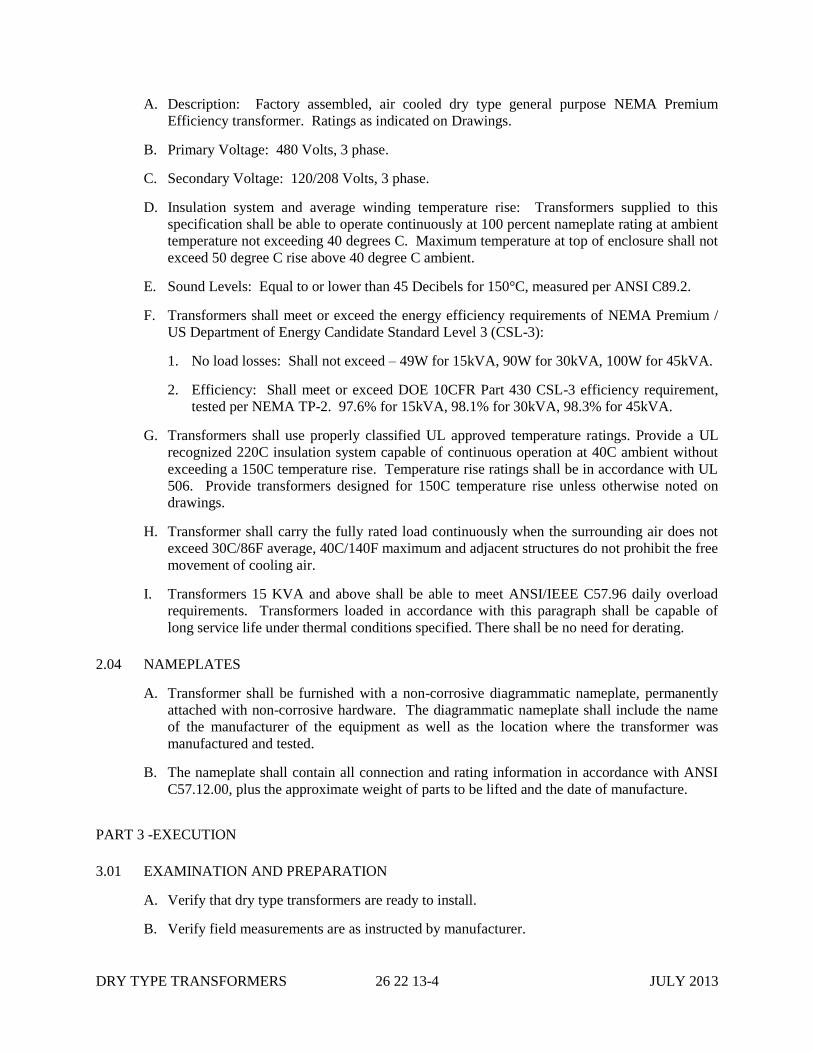
DRY TYPE TRANSFORMERS 26 22 13-4 JULY 2013
A. Description: Factory assembled, air cooled dry type general purpose NEMA Premium
Efficiency transformer. Ratings as indicated on Drawings.
B. Primary Voltage: 480 Volts, 3 phase.
C. Secondary Voltage: 120/208 Volts, 3 phase.
D. Insulation system and average winding temperature rise: Transformers supplied to this
specification shall be able to operate continuously at 100 percent nameplate rating at ambient
temperature not exceeding 40 degrees C. Maximum temperature at top of enclosure shall not
exceed 50 degree C rise above 40 degree C ambient.
E. Sound Levels: Equal to or lower than 45 Decibels for 150°C, measured per ANSI C89.2.
F. Transformers shall meet or exceed the energy efficiency requirements of NEMA Premium /
US Department of Energy Candidate Standard Level 3 (CSL-3):
1. No load losses: Shall not exceed – 49W for 15kVA, 90W for 30kVA, 100W for 45kVA.
2. Efficiency: Shall meet or exceed DOE 10CFR Part 430 CSL-3 efficiency requirement,
tested per NEMA TP-2. 97.6% for 15kVA, 98.1% for 30kVA, 98.3% for 45kVA.
G. Transformers shall use properly classified UL approved temperature ratings. Provide a UL
recognized 220C insulation system capable of continuous operation at 40C ambient without
exceeding a 150C temperature rise. Temperature rise ratings shall be in accordance with UL
506. Provide transformers designed for 150C temperature rise unless otherwise noted on
drawings.
H. Transformer shall carry the fully rated load continuously when the surrounding air does not
exceed 30C/86F average, 40C/140F maximum and adjacent structures do not prohibit the free
movement of cooling air.
I. Transformers 15 KVA and above shall be able to meet ANSI/IEEE C57.96 daily overload
requirements. Transformers loaded in accordance with this paragraph shall be capable of
long service life under thermal conditions specified. There shall be no need for derating.
2.04 NAMEPLATES
A. Transformer shall be furnished with a non-corrosive diagrammatic nameplate, permanently
attached with non-corrosive hardware. The diagrammatic nameplate shall include the name
of the manufacturer of the equipment as well as the location where the transformer was
manufactured and tested.
B. The nameplate shall contain all connection and rating information in accordance with ANSI
C57.12.00, plus the approximate weight of parts to be lifted and the date of manufacture.
PART 3 -EXECUTION
3.01 EXAMINATION AND PREPARATION
A. Verify that dry type transformers are ready to install.
B. Verify field measurements are as instructed by manufacturer.
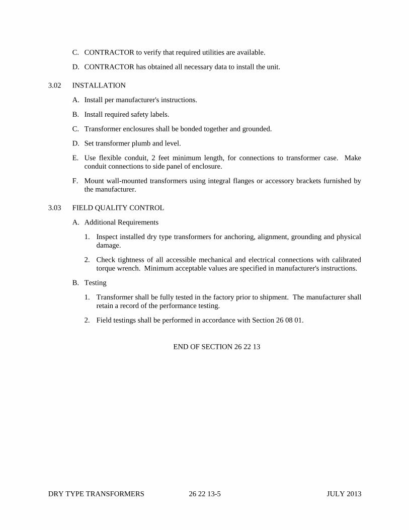
DRY TYPE TRANSFORMERS 26 22 13-5 JULY 2013
C. CONTRACTOR to verify that required utilities are available.
D. CONTRACTOR has obtained all necessary data to install the unit.
3.02 INSTALLATION
A. Install per manufacturer's instructions.
B. Install required safety labels.
C. Transformer enclosures shall be bonded together and grounded.
D. Set transformer plumb and level.
E. Use flexible conduit, 2 feet minimum length, for connections to transformer case. Make
conduit connections to side panel of enclosure.
F. Mount wall-mounted transformers using integral flanges or accessory brackets furnished by
the manufacturer.
3.03 FIELD QUALITY CONTROL
A. Additional Requirements
1. Inspect installed dry type transformers for anchoring, alignment, grounding and physical
damage.
2. Check tightness of all accessible mechanical and electrical connections with calibrated
torque wrench. Minimum acceptable values are specified in manufacturer's instructions.
B. Testing
1. Transformer shall be fully tested in the factory prior to shipment. The manufacturer shall
retain a record of the performance testing.
2. Field testings shall be performed in accordance with Section 26 08 01.
END OF SECTION 26 22 13

DRY TYPE TRANSFORMERS 26 22 13-6 JULY 2013
THIS PAGE INTENTIONALLY LEFT BLANK
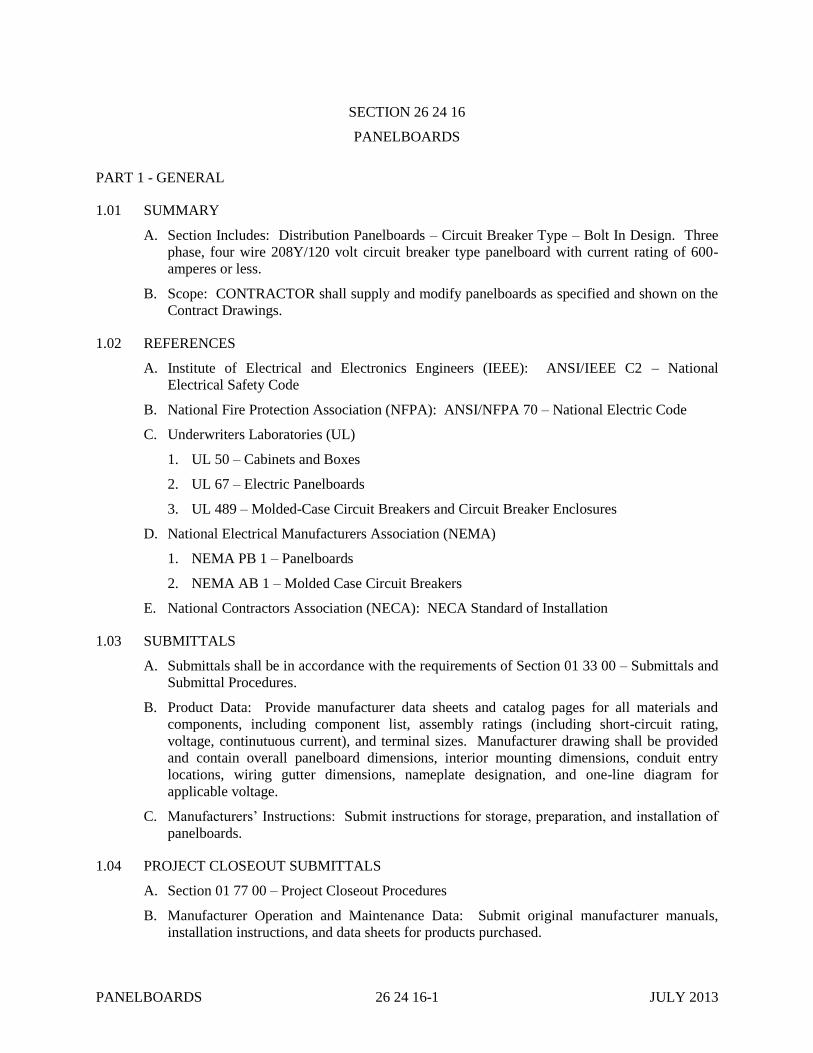
PANELBOARDS 26 24 16-1 JULY 2013
SECTION 26 24 16
PANELBOARDS
PART 1 - GENERAL
1.01 SUMMARY
A. Section Includes: Distribution Panelboards – Circuit Breaker Type – Bolt In Design. Three
phase, four wire 208Y/120 volt circuit breaker type panelboard with current rating of 600-
amperes or less.
B. Scope: CONTRACTOR shall supply and modify panelboards as specified and shown on the
Contract Drawings.
1.02 REFERENCES
A. Institute of Electrical and Electronics Engineers (IEEE): ANSI/IEEE C2 – National
Electrical Safety Code
B. National Fire Protection Association (NFPA): ANSI/NFPA 70 – National Electric Code
C. Underwriters Laboratories (UL)
1. UL 50 – Cabinets and Boxes
2. UL 67 – Electric Panelboards
3. UL 489 – Molded-Case Circuit Breakers and Circuit Breaker Enclosures
D. National Electrical Manufacturers Association (NEMA)
1. NEMA PB 1 – Panelboards
2. NEMA AB 1 – Molded Case Circuit Breakers
E. National Contractors Association (NECA): NECA Standard of Installation
1.03 SUBMITTALS
A. Submittals shall be in accordance with the requirements of Section 01 33 00 – Submittals and
Submittal Procedures.
B. Product Data: Provide manufacturer data sheets and catalog pages for all materials and
components, including component list, assembly ratings (including short-circuit rating,
voltage, continutuous current), and terminal sizes. Manufacturer drawing shall be provided
and contain overall panelboard dimensions, interior mounting dimensions, conduit entry
locations, wiring gutter dimensions, nameplate designation, and one-line diagram for
applicable voltage.
C. Manufacturers’ Instructions: Submit instructions for storage, preparation, and installation of
panelboards.
1.04 PROJECT CLOSEOUT SUBMITTALS
A. Section 01 77 00 – Project Closeout Procedures
B. Manufacturer Operation and Maintenance Data: Submit original manufacturer manuals,
installation instructions, and data sheets for products purchased.
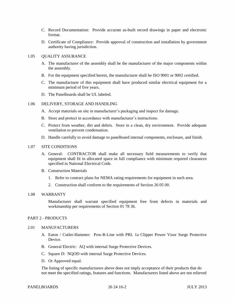
PANELBOARDS 26 24 16-2 JULY 2013
C. Record Documentation: Provide accurate as-built record drawings in paper and electronic
format.
D. Certificate of Compliance: Provide approval of construction and installation by government
authority having jurisdiction.
1.05 QUALITY ASSURANCE
A. The manufacturer of the assembly shall be the manufacturer of the major components within
the assembly.
B. For the equipment specified herein, the manufacturer shall be ISO 9001 or 9002 certified.
C. The manufacturer of this equipment shall have produced similar electrical equipment for a
minimum period of five years.
D. The Panelboards shall be UL labeled.
1.06 DELIVERY, STORAGE AND HANDLING
A. Accept materials on site in manufacturer’s packaging and inspect for damage.
B. Store and protect in accordance with manufacturer’s instructions.
C. Protect from weather, dirt and debris. Store in a clean, dry environment. Provide adequate
ventilation to prevent condensation.
D. Handle carefully to avoid damage to panelboard internal components, enclosure, and finish.
1.07 SITE CONDITIONS
A. General: CONTRACTOR shall make all necessary field measurements to verify that
equipment shall fit in allocated space in full compliance with minimum required clearances
specified in National Electrical Code.
B. Construction Materials
1. Refer to contract plans for NEMA rating requirements for equipment in each area.
2. Construction shall conform to the requirements of Section 26 05 00.
1.08 WARRANTY
Manufacturer shall warrant specified equipment free from defects in materials and
workmanship per requirements of Section 01 78 36.
PART 2 - PRODUCTS
2.01 MANUFACTURERS
A. Eaton / Cutler-Hammer: Pow-R-Line with PRL 1a Clipper Power Visor Surge Protective
Device.
B. General Electric: AQ with internal Surge Protective Devices.
C. Square D: NQOD with internal Surge Protective Devices.
D. Or Approved equal.
The listing of specific manufacturers above does not imply acceptance of their products that do
not meet the specified ratings, features and functions. Manufacturers listed above are not relieved
PANELBOARDS 26 24 16-3 JULY 2013
from meeting these Specifications in their entirety.
2.02 RATINGS
A. Panelboards rated 480 VAC shall have short-circuit ratings as shown on the Drawings or as
herein scheduled, but not less than 14,000 amperes RMS symmetrical.
B. Panelboards rated 240VAC or less shall have short-circuit ratings as shown on the Drawings
or as herein scheduled, but not less than 10,000 amperes RMS symmetrical.
C. Panelboards shall be labeled with a UL short-circuit rating. When series ratings are applied
with integral or remote upstream devices, a label or manual shall be provided. It shall state
the conditions of the UL series ratings including:
1. Size and type of upstream device.
2. Branch devices that can be used.
3. UL series short-circuit rating.
2.03 CONSTRUCTION
A. Interiors shall be completely factory assembled. They shall be designed such that switching
and protective devices can be replaced without disturbing adjacent units and without
removing the main bus connectors.
B Trims for branch circuit panelboards shall be supplied with a hinged door over all circuit
breaker handles. Doors in panelboard trims shall not uncover any live parts. Doors shall
have a semi flush cylinder lock and catch assembly. Door-in-door trim shall be provided.
Both hinged trim and trim door shall utilize three point latching. No tools shall be required to
install or remove trim. Trim shall be equipped with a door-actuated trim locking tab. Equip
locking tab with provision for a screw such that removal of trim requires a tool, at the
CITY’S option. Installation shall be tamper resistant with no exposed hardware on the
panelboard trim.
C. Distribution panelboard trims shall cover all live parts. Switching device handles shall be
accessible.
D. Surface trims shall be same height and width as box. Flush trims shall overlap the box by 3/4
of an inch on all sides.
E. A directory card with a clear plastic cover shall be supplied and mounted on the inside of
each door.
F. All locks shall be keyed alike.
G. Enclosures shall be at least 20 inches wide made from hot-dipped galvanized steel with
hinged door painted medium gray ANSI 61 enamel. Enclosure shall be rated for the area
installed and meet rigidity requirements per UL 50 standards.
2.04 BUS
A. Main bus bars shall be tin plated copper sized in accordance with UL standards to limit
temperature rise on any current carrying part to a maximum of 65 degrees C above an
ambient of 40 degrees C maximum. Bus bars shall be insulated between phases for the entire
length of the bus.
B. A solidly bonded tin plated copper equipment ground bar shall be provided.
PANELBOARDS 26 24 16-4 JULY 2013
C. Full-size (100%-rated) insulated neutral bars shall be included for panelboards shown with
neutral. Bus bar taps for panels with single-pole branches shall be arranged for sequence
phasing of the branch circuit devices. Neutral busing shall have a suitable lug for each
outgoing feeder requiring a neutral connection. 200%- rated neutrals shall be supplied for
panels designated on Drawings with oversized neutral conductors. Provisions for bonding the
neutral bus to the panel ground bus shall be provided.
2.05 CIRCUIT BREAKERS
A. The minimum short-circuit rating for branch circuit panelboards shall be as specified herein
or as indicated on the Drawings. Panelboards shall be fully rated.
B. Circuit breaker shall be molded-case type, bolt-on type, heavy-duty, quick-make, quick-
break, single- and multi-pole circuit breakers of the types specified herein, shall be provided
for each circuit with toggle handles that indicate when unit has tripped.
C. Circuit breakers shall be thermal-magnetic type with common type handle for all multiple
pole circuit breakers. Circuit breakers shall be minimum 100-ampere frame and through 100-
ampere trip sizes shall take up the same pole spacing. Circuit breakers shall be UL listed as
type SWD for lighting circuits.
1. Circuit breaker handle locks shall be provided for all circuits that supply exit signs,
emergency lights, energy management, and control system (EMCS) panels and fire alarm
panels.
D. Circuit breakers shall have a minimum interrupting rating of 10,000 amperes symmetrical at
240 volts, and 14,000 amperes symmetrical at 480 volts, unless otherwise noted on the
Drawings.
E. All unused spaces provided, unless otherwise specified, shall be fully equipped for future
devices, including all appropriate connectors and mounting hardware.
2.06 MAIN AND FEEDER PROTECTIVE DEVICES
A. Molded case circuit breakers shall have integral thermal and instantaneous magnetic trip in
each pole.
B. Provide metal oxide varistor (MOV) surge protective device (SPD) integral within the
Panelboard that indicates the status and condition of the SPD, tested per NEMA LS-1, rated
IEEE C3 Combined Wave of 20kV and 10kA with 200kAIC internal fusing and listed /
labeled per UL 1449.
PART 3 -EXECUTION
3.01 EXAMINATION AND PREPARATION
A. Verify field measurements are as instructed by manufacturer.
B. CONTRACTOR to verify that required utilities are available.
C. CONTRACTOR has obtained all necessary data to install the unit.
3.02 INSTALLATION
A. Install circuit breakers in accordance with manufacturer's written instructions, NEMA PB 1.1
and NEC standards, and the Contract Drawings.
PANELBOARDS 26 24 16-5 JULY 2013
B. Install required safety labels.
C. CONTRACTOR is responsible for providing a printed, accurate panel directory for each
panel installed.
3.03 FIELD QUALITY CONTROL
A. Additional Requirements
1. Inspect complete installation for physical damage, proper alignment, anchorage, and
grounding.
2. Check tightness of bolted connections and circuit breaker connections using calibrated
torque wrench or torque screwdriver per manufacturer's written specifications.
END OF SECTION 26 24 16

PANELBOARDS 26 24 16-6 JULY 2013
THIS PAGE INTENTIONALLY LEFT BLANK
LOW-VOLTAGE MOTOR
CONTROL CENTERS 26 24 19-1 AUGUST 2014
SECTION 26 24 19
LOW-VOLTAGE MOTOR CONTROL CENTERS
PART 1 - GENERAL
1.01 SUMMARY
A. Section Includes: Factory assembled Low-Voltage Motor Control Centers (MCC), 600 volt
and less.
B. Scope
1. CONTRACTOR shall furnish and install the quantity and type of 480 Volt Motor Control
Center (MCC) assemblies identified in the Contract Drawings. Also included are
necessary training, spare parts and installation/start-up assistance.
2. The MCC shall be furnished by a single manufacturer and shall be supplied with
accessories; enclosure type, finish and color described, and shall be designed for storage
and service conditions, including ambient, overload and unusual operating conditions, as
specified.
3. Design, construction and testing shall be in strict accord with latest revision of industry
standards and shall include as a minimum the applicable requirements of those listed
below. The CONTRACTOR shall be responsible for determining differences in the
listed standards and this specification and shall bring them to the attention of the CITY.
Where standards or specifications contain different minimum requirements, the more
stringent shall be used.
1.02 REFERENCES
A. Institute of Electrical and Electronics Engineers (IEEE): ANSI/IEEE C2 – National
Electrical Safety Code
B. National Fire Protection Association (NFPA)
1. ANSI/NFPA 70 – National Electric Code
2. ANSI/NFPA 101 – Life Safety Code
C. Underwriters Laboratories (UL): UL 845 – UL Standard for Motor Control Centers
D. National Electrical Manufacturers Association (NEMA)
1. NEMA 250 – Enclosures for Electrical Equipment
2. NEMA ICS 1 – General Standards for Industrial Controls and Systems
3. NEMA ICS 2 – Industrial Control and Systems Controllers and Assemblies
E. National Electrical Contractors Association (NECA): NECA Standard of Installation
F. Occupational Safety and Health Administration (OSHA): Title 29, Part 1910, Subpart S –
Electrical – Safety Standards for Electrical Systems
LOW-VOLTAGE MOTOR
CONTROL CENTERS 26 24 19-2 AUGUST 2014
1.03 SUBMITTALS
A. Submit for CITY review, prior to purchasing and fabrication, in accordance with the
requirements of Section 01 33 00:
1. All drawings shall be prepared in accordance with current industry standards and good
industrial practice. All information shall be in the English language, clearly readable,
with IEEE, NEMA and ANSI symbols, device numbers and other requirements.
Dimensions shall be English units (e.g., inches).
2. Submittal of typical drawings for similar MCC lineups is not acceptable. Uniquely
numbered and titled drawings shall be submitted.
3. Drawing or drawings showing single line, front elevation, dimensions, aisle space,
equipment weights, nameplate engravings, shipping splits, anchor bolt plan with
dimensions and device summary.
4. Incoming line section and MCC section base plans clearly defining space available for
power and control leads.
5. Elementary (schematic) diagrams including power and control of each unit. Elementary
diagrams shall include numbered terminal points, device designations, and all
interconnections to other units within the motor control center and to all associated
remote equipment, devices, and field instruments. Interfaces to systems and equipment
provided as work of other sections of this specification shall be fully coordinated by the
CONTRACTOR and shall be indicated on the elementary wiring diagrams.
6. Wiring (Interconnection) diagrams including power and control of each unit.
7. Include single-line diagram representation of each MCC.
8. Include conduit entrance locations and requirements.
9. Include interrupting, withstand and continuous current rating of bus bars, feeder tap units,
starter units, and main incoming units.
10. Time current curves for all protective devices.
11. The drawings are to have CITY’s equipment identification added.
12. Ethernet I/P architectural layout where used.
13. Provide manufacturer data sheets and catalog pages for all materials and components.
B. Test and Evaluation Reports: Include testing procedures and values obtained.
C. “As Shipped” Drawings
1. CONTRACTOR shall supply a complete set of “As Shipped” drawings.
a. The drawings shall consist of those previously submitted for review.
b. The drawings shall be supplied in a time frame not to exceed equipment shipment.
c. Elementary (schematic) diagrams of the Motor Control Center buckets. Diagrams
shall match those shipped with MCCs, and a copy shall be located within each unit.
D. CAD Drawing Format: CONTRACTOR shall supply CITY all drawings in AutoCAD

LOW-VOLTAGE MOTOR
CONTROL CENTERS 26 24 19-3 AUGUST 2014
2005/2007 format on a CD. All Drawings, provided on paper or CD, shall be accompanied
with copies plotted (not scanned) to PDF. This will apply to preliminary through as-built
drawing releases.
E. Instruction Manuals
1. Contained in as many heavy duty locking type Post Binders with index pages as required.
2. Contains the following minimum materials: Provide in printed and electronic format.
a. Service & Maintenance Manuals for NEMA Starters/Contactors.
b. Manuals for thermal magnetic circuit breakers and motor circuit protectors.
c. MCC Installation Manual.
d. MCC Application & General Instruction Manual.
3. Quantity as indicated in specification section 01 33 00.
F. Spare Parts List: Furnish a list of recommended spare parts complete with pricing required
for normal operation and maintenance of the equipment.
1.04 PROJECT CLOSEOUT SUBMITTALS
A. Section 01 77 00 – Project Closeout Procedures
B. Manufacturer Operation and Maintenance Data: Submit original manufacturer manuals and
data sheets for products purchased per Section 01 79 23.
C. Record Documentation: Provide accurate as-built record drawings in paper and electronic
format per Section 01 78 39.
D. Certificate of Compliance: Provide approval of construction and installation by government
authority having jurisdiction.
1.05 QUALITY ASSURANCE
A. All Work shall be performed and materials provided in accordance with NFPA 70 - National
Electric Code (NEC), the National Electrical Safety Code (NESC), and other codes and
standards as applicable. Where required by the Authority Having Jurisdiction (AHJ),
equipment and materials shall be listed or labeled by Underwriters’ Laboratory (UL) or by a
nationally recognized testing laboratory acceptable to the AHJ. CONTRACTOR shall be
responsible for all costs associated with obtaining the required listing.
B. The manufacturer shall have specialized in the design, manufacture and assembly of MCCs
for a minimum of ten years.
C. The manufacturer is to be ISO 9001 certified for the design and manufacture of MCCs of this
type.
D. Construction of all MCCs shall meet the requirements set forth by UL Publication UL845,
NEMA Publication ICS-2-322 and the National Electrical Code.
E. All manufactured standard units shall bear the UL label, and CSA certification where
required.
F. Tests called for in this Specification shall be made in strict accord with applicable standards.

LOW-VOLTAGE MOTOR
CONTROL CENTERS 26 24 19-4 AUGUST 2014
Certified test reports covering shop testing shall be provided by the CONTRACTOR to the
CITY and provided in the Instruction Manuals.
G. The Motor Control Centers shall be tested for satisfactory alignment, mechanical operation
and dielectric strength.
H. Service Personnel
1. The Manufacturer shall directly employ a nationwide service organization, consisting of
factory trained field service personnel dedicated to the start-up, maintenance, and repair
of Motor Control Centers. The organization shall consist of regional and local offices.
2. The Manufacturer shall provide a fully automated national dispatch center to coordinate
field service personnel schedules. One toll-free number shall reach a qualified support
person 24 hours/day, 7 days/week, and 365 days/year. If emergency service is required,
response time shall be 3 hours or less.
I. Replacement Parts Stocking
1. Parts shall be available through an extensive network to ensure around-the-clock parts
availability throughout the country.
2. Recommended spare parts shall be fully stocked by local field service personnel with
back-up available from national parts center and the manufacturing location. The national
parts center Customer Support Parts Coordinators shall be on-call 24 hours/day, 7
days/week, and 365 days/year for immediate parts availability. Parts from the national
parts center shall be shipped within 4 hours on the next available flight out and delivered
to the customer's site within 24 hours.
1.06 FACTORY ACCEPTANCE TEST (FAT)
A. The manufacturer shall organize and perform a Factory Acceptance Test per Section 01 75 02
– Equipment Factory Acceptance Testing.
B. Testing
1. The MCC shall be completely assembled, wired, adjusted and tested at the factory. After
assembly, the complete MCC shall be tested to ensure the accuracy of the wiring and the
functioning of all equipment.
2. A certified test report of all standard production tests shall be shipped with each
assembly.
3. Factory test as outlined above shall be witnessed by the CITY’S representative at the
discretion of the CITY.
4. The manufacturer shall notify the CITY two (2) weeks prior to the date the tests are to be
performed. CITY or CITY’s Representative shall have the right to witness the testing of
the assembly at the factory at no additional expense.
C. Details
1. Download all parameters and configurations for across the line starters (ALS), and soft
starters (SS).
LOW-VOLTAGE MOTOR
CONTROL CENTERS 26 24 19-5 AUGUST 2014
2. Full voltage test with a load (motor) for all Soft Starters.
3. Full voltage test with a meter for all ALSs.
4. Estimate five (5) days for all of the MCCs for this Project. Manufacturer to provide one
person for factory assistance during the FAT duration.
1.07 DELIVERY, STORAGE, AND HANDLING
A. The CONTRACTOR shall notify the CITY in writing of his intent to ship not less than five
days before each shipment. At that time, the following information shall be supplied.
1. The method of shipment and carrier.
2. The estimated date of arrival at job site.
3. The number of packages, the overall dimensions, and shipping weight or each package.
4. The contents and Bill of Lading for each package.
B. The shipping container shall provide the following data with unpacking:
1. CITY's Name, Purchase Order Number and Equipment Number.
2. Manufacturer Name.
3. Identification consistent with the Bill of Lading.
C. Provide with the Equipment Shipment, in an obvious place, instructions for lifting, moving
and storage.
D. Equipment shall be suitably packaged for protection against damage, dust, and moisture
during transit and for short time outdoor storage.
E. The MCC shipping split shall be securely bolted to a skid capable of being moved by tow
motor.
F. CONTRACTOR shall accept materials on-site and inspect for damage.
G. CONTRACTOR shall store and protect equipment in accordance with manufacturer’s
instructions and in accordance with Section 01 60 00. Provide adequate ventilation to prevent
condensation.
1.08 SITE CONDITIONS
A. General: CONTRACTOR shall make all necessary field measurements to verify that
equipment will fit in allocated space in full compliance with minimum required clearances
specified in National Electrical Code.
B. Construction Materials
1. Refer to contract plans for NEMA rating requirements for equipment in each area.
2. Construction shall conform to the requirements of Section 26 05 00.

LOW-VOLTAGE MOTOR
CONTROL CENTERS 26 24 19-6 AUGUST 2014
1.09 WARRANTY
CONTRACTOR shall warrant specified equipment per the requirements of Section 01 78 36.
PART 2 - PRODUCTS
2.01 MANUFACTURERS
A. Allen-Bradley
B. Eaton / Cutler-Hammer
C. General Electric
D. Square-D
2.02 ENVIRONMENTAL CONDITIONS
A. Operating Ambient Temperature: Control room: 32°F to 104°F(0°C to 40°C)
B. Relative Humidity: 5-95%, non-condensing
C. Altitude: <3,300 ft above Mean Sea Level
D. Ventilation: Clean filtered air.
2.03 ELECTRICAL SUPPLY
A. General
1. 480/277 Volt 3 phase WYE connected.
2. Solidly Grounded Neutral.
3. Voltage Variation: +10%, -10%.
4. Frequency: 60HZ.
2.04 GENERAL STRUCTURAL REQUIREMENTS
A. Each MCC shall consist of vertical sections bolted together to form a rigid, self-supporting,
free-standing assembly, and shall be designed to permit future additions or rearrangement of
control units. Each vertical section shall be divided into compartments, which shall contain a
motor control unit connected to a common vertical power bus.
B. Individual vertical sections shall be fabricated from minimum 12-gauge steel top and bottom
frames. These steel frames shall be connected by vertical members consisting of steel box-
sills at each corner and minimum 13-gauge vertical channels.
C. Removable lifting angles shall be provided on top of each MCC shipping split.
D. Channel sills suitable for supporting the complete assembly shall be provided under the full
length of the MCC. These sills shall be an integral part of the structure, and shall be suitable
for attaching to a foundation.
LOW-VOLTAGE MOTOR
CONTROL CENTERS 26 24 19-7 AUGUST 2014
E. The MCC enclosure shall be designed to provide maximum protection against the specified
operating environment.
1. Enclosure type shall be NEMA Type 12 or as otherwise specified on the Drawings.
2. Gasketing shall be closed cell neoprene material.
F. Vertical sections shall have a nominal height of 90-inches.
1. The nominal standard width of each section shall be 20-inches.
2. Large reduced voltage starters may be mounted in vertical sections of greater width.
3. The nominal standard depth of each section shall be 20-inches, unless indicated otherwise
on drawings..
4. MCCs will be installed on a 3.5” high housekeeping pad. Manufacturer shall account for
this fact when designing breaker operator handles to meet the 6’-7” height limitation
required by the NEC.
G. The dimensions of all sections shall be as indicated. Actual dimensions may vary slightly to
conform with manufacturer’s standard dimensions. However, CONTRACTOR will be
responsible to ensure that any variations in dimensions, will still meet all of the working
space clearance requirements of the NEC.
H. Each section shall be dead-front and dead-back construction (unless Drawings or
Specifications specifically call for back-to-back sections).
1. Vertical barriers with insulating inserts shall completely isolate the horizontal and
vertical bus compartments from the motor starter area.
2. Rear access shall not be necessary for inspection, maintenance and power and ground bus
splices of MCCs.
3. On front-only MCCs, rear covers shall be provided.
4. Provide MCCs for front-only or for back-to-back construction as indicated.
5. Each vertical section shall have side sheets extending the full height and depth of the
section to minimize the chance of fault propagation.
I. The top and bottom of each vertical section shall be provided with an adequate conduit (or
cable) entrance area.
J. Each vertical section shall be provided with a top and bottom horizontal wireway extending
the entire length of the MCC.
1. The top and bottom horizontal wireways shall be isolated from all bus bars with a
grounded steel barrier.
2. The wireway opening between sections shall have rounded corners and the edges shall be
rolled back.
3. Horizontal wireways of back-to-back sections shall allow complete access from the front
section through to the back section.

LOW-VOLTAGE MOTOR
CONTROL CENTERS 26 24 19-8 AUGUST 2014
4. Horizontal wireways shall have removable covers.
K. End vertical sections shall have gasketed cover plates, which can be easily removed to allow
addition of future vertical sections, extensions of horizontal wiring troughs and horizontal and
ground bus.
L. Each standard vertical section shall have a vertical wireway extending the full height of the
structure.
1. This wireway shall be completely independent from plug-in buckets, isolated from the
horizontal and vertical bus and from adjacent vertical sections.
2. It shall have its own separate hinged door, and shall have no obstructions in the wire way.
3. Tie bars shall be provided in each vertical trough for cable/wire tie-down.
4. The vertical wire troughs shall intersect the top and bottom horizontal wire troughs for
easy cable routing.
5. A permanent wireway wall shall separate the units from the vertical wireway, and remain
intact even when the units are removed.
6. Minimum cross sectional area for the vertical wireway shall be 28 square inches.
M. Formed doors with concealed hinges shall be provided on the structure for: mains lugs, plug-
in buckets, unused unit mounting spaces, special units and all wireways. Doors shall be held
closed by means of 1/4 turn (or other approved means) captive fasteners and be removable.
N. The framework and the panels shall be chemically cleaned; hot phosphate treated, rinsed, and
given an eletrostatically applied baked coat of Epoxy powder paint - semi-gloss luster ANSI
No. 49 Grey. All structural bolts, nuts and washers shall be suitably treated to prevent
corrosion. All back plates of power cells, low voltage compartments and wireways shall be
painted high visibility gloss white.
O. Shipping splits shall not exceed 60”.
P. Removable top plate for cutting cable/conduit access.
2.05 BUS BARS
A. The main horizontal bus shall be rated as indicated on the single-line diagrams included with
the contract drawings and shall be tin plated copper and extend the entire length of the MCC.
1. Splicing horizontal buses shall be accomplished using a splice kit of the same ampere
rating as the horizontal power bus. Double stud bus clamp assemblies comprised of flat
washers and pre-assembled nuts with conical washers shall be used. These assemblies
shall provide a minimum of two bolted connections to each side of the splice. The splice
connections shall be front or top accessible for servicing with a torque wrench. The
location of all splices shall be indicated by a label located on the inside of the vertical
wireway door.
B. The vertical bus current rating provided in each section shall be determined by Manufacturer
and shall be 300A minimum or as indicated on the single-line diagrams included with the
contract drawings and shall be tin plated copper consisting of a single bus per phase of a
uniform cross section from top to bottom.
LOW-VOLTAGE MOTOR
CONTROL CENTERS 26 24 19-9 AUGUST 2014
1. For center mounted horizontal bus, the total ampere rating may be obtained with half of
the ampere rating of the bus extending above and the other half below the horizontal bus.
2. Vertical bus supports shall be formed of high dielectric strength, low moisture absorbing,
and high impact material with ample creep distance between bus bars. The vertical bus
shall be mounted in recessed channels of the bus support molding to protect against
accumulation of dust and tracking between phases. As a minimum, manual shutters shall
be available for isolation of unused stab openings so that personnel are not exposed to
live vertical bus bars and the bus is isolated from arcing faults.
3. The vertical bus shall be firmly bolted to the horizontal bus for a permanent contact.
B. Horizontal and vertical power buses shall be braced to withstand the mechanical stress caused
by fault currents.
1. Bus bracing shall be as indicated elsewhere in this Specification.
2. All ratings shall be UL listed.
C. Horizontal and vertical power bus ratings and material shall be as indicated elsewhere in this
specification.
1. Continuous current ratings shall be in accordance with temperature rise specifications set
forth by UL, ANSI and NEMA standards.
2. Maximum temperature rise of 50º Cover a 40ºC ambient.
D. A horizontal ground bus shall be provided in each section of the MCC.
1. Horizontal ground bus shall be ¼” x 1” tin plated copper run continuously throughout the
MCC.
2. Splicing the horizontal ground bus shall be accomplished using a splice kit of the same
ampere rating as the horizontal ground bus. See horizontal power bus splicing for
additional requirements.
3. Horizontal ground bus shall be located at the bottom of the MCC. Manufacturer shall
provide long barrel compression lugs (NEMA 2-hole spacing holes) on each end of the
ground bus for connection of 4/0 AWG copper conductor.
E. A vertical ground bus shall be provided in each section of the MCC.
1. Vertical ground bus shall be tin plated copper and run parallel to the power distribution
bus in each vertical section.
2. The vertical ground bus shall be connected to the horizontal ground bus to form a
complete internal grounding system.
3. The vertical ground bus in combination with the unit ground stab shall establish unit
insert grounding before the plug-in power stabs engage the power bus. As the unit is
withdrawn, grounding shall be maintained until after the plug-in power stabs are
disengaged.

LOW-VOLTAGE MOTOR
CONTROL CENTERS 26 24 19-10 AUGUST 2014
2.06 MAIN INCOMING LINE COMPARTMENT
A. Incoming Power Supply:
1. Line Voltage / Frequency: 480 Volts, 3 wire / 60 Hertz.
2. Main Bus Bracing: 65kA RMS Symmetrical minimum.
3. MCC Connection Type: Main Circuit Breaker
4. Incoming Line Compartment Location: As indicated on the MCC elevation drawings,
provided with the Contract Documents
B. The incoming power feeder enters the MCC from the top or bottom, as indicated on the MCC
elevation drawings, provided with the Contract Documents.
C. The incoming line compartment shall be of a height recommended by the manufacturer to
terminate the specified feeder cables without a TOP HAT, but in no case less than two space
factors plus the wireway.
D. The incoming line compartment shall be front accessible and isolated from the horizontal and
vertical wireways. The connection between the horizontal power bus and the mains lugs shall
be by bus. No cable connections allowed. The bus connection shall be rated no smaller than
the horizontal power bus.
E. Each mains lug pad shall have NEMA 2-hole spacing holes. One main lug pad per phase
shall be provided. Manufacturer shall provide long barrel, tin-plated copper, compression
lugs per phase (NEMA 2-hole spacing holes for ½” bolts at 1-3/4” spacing) on each mains
lug pad. No aluminum is acceptable. Lug size as indicated on the drawings.
F. Main Circuit Breaker disconnect shall be sized with frame and trip ratings as shown on the
single-line drawings. The interrupting capacity rating shall meet or exceed the available fault
current as determined by the Overcurrent Protective Device Coordination Study, Section 26
05 73. Provide a circuit breaker with thermal magnetic trip unit for 400A and smaller frames
(unless otherwise noted on drawings); provide electronic trip unit for 600A and larger frames.
Provide one normally open and one normally closed circuit breaker auxiliary contract which
follows the position of the circuit breaker main contacts for indication of “On” or
“Off/Tripped”. Main Circuit Breakers shall be frame mounted and shall be located at the top
or bottom of the section, as indicated on the single-line and MCC elevation drawings.
G. Incoming line section shall have a removable clear Lexan cover over all energized
components when unit door is opened for inspection. Lexan cover to be easily removable for
connections and IR scanning.
H. Main incoming line section shall contain two (2) current transformers with size as indicated
on the single line drawings. Class shall be C200 minimum. Current transformer secondaries
shall be wired to a short circuiting type terminal board GE type EB-27 or equal located in the
incoming line section.
I. MCC shall include a Transient Voltage Surge Suppressor (TVSS) to protect from transient
surges and electrical line noises. The surge protection devices shall be located within the
MCC and be as close as possible to the main incoming power. Suppressed voltage rating
shall be 1,500V peak at 480V system voltage. Surge current capacity shall be 160,000A per
phase. Assembly shall be UL rated and include status and shall include status lights for unit

LOW-VOLTAGE MOTOR
CONTROL CENTERS 26 24 19-11 AUGUST 2014
on and functional, and loss of phase or device fault.
2.07 UNIT INFORMATION
A. Mounting
1. Plug-in units shall consist of a unit assembly, unit support pan and unit door assembly.
2. Each plug-in unit shall be supported and guided by a removable unit support pan, so
different unit arrangements are easily accomplished. The rearrangement of a unit support
pan from one location to another shall be accomplished without the use of special tools.
3. After insertion, each plug-in unit shall be held in placed by two (2) or more multi-turn
latches, located at the front of the unit. At least one (1) latch shall be located at the top of
the insert and one (1) at the bottom, for front accessibility and installation convenience. A
service position shall be provided with the unit supported in the structure but disengaged
from the bus. Padlocking shall be possible in this position.
4. Each unit shall be provided with removable pin type hinges that allow the door to swing
open at least 110°. Doors shall be removable from any location in the center without
disturbing any other doors. The unit doors shall be fastened to the stationary structure so
that it can be closed to cover the unit space when the insert has been removed. The unit
doors shall be held closed with a minimum of a single ¼-turn pawl type latch (or other
approved means) designed to contain forces during fault conditions.
B. Power Stabs
1. The unit plug-in power stab assemblies shall be tin plated copper for a low resistance
connection and designed to tighten during heavy current surges.
2. All full voltage starter units through NEMA size 5 and feeder tap units less than 225
amperes shall be of the drawout type. Drawout provisions shall include a positive guide
rail system and stab shrouds to absolutely ensure alignment of stabs with the vertical bus.
Drawout units shall have a tin-plated stab assembly for connection to the vertical bus. No
wiring to these stabs shall extend into the bus compartment.
C. Handle
1. An industrial, heavy duty, flange mounted handle mechanism shall be supplied for the
control of each disconnect switch. This mechanism shall be engaged with the disconnect
device at all times as an integral part of the unit regardless of unit door position.
2. The operator handle shall pivot in the vertical plane. The on-off condition of the
disconnecting means shall be indicated by the handle position, red and green colored
indicators (which include the words ON and OFF), and the international symbols I and O
along with a pictorial indication of the handle position.
3. Handle shall also allow padlocking of the disconnect in the "ON" and "OFF" positions
with up to three (3) padlocks. All operating handles shall be of a non-conductive
material.
4. The operator handle of all units shall be interlocked with the unit door so that the
disconnect means cannot be switched to the ON position unless the door is closed. A
means shall be provided for purposely defeating this interlock during maintenance or
LOW-VOLTAGE MOTOR
CONTROL CENTERS 26 24 19-12 AUGUST 2014
testing. This interlock shall also prevent opening the unit door unless the disconnecting
means is in the OFF position. An externally operated defeater requiring the use of a tool
shall provide access to the unit without interrupting service.
5. The operator handle shall be interlocked with the unit so that the unit cannot be inserted
or withdrawn with the operator handle in the ON position.
D. NEMA / EEMAC Wiring Class
1. NEMA/EEMAC Class I - Standard wiring diagrams for individual units shall consist of
drawings that identify electrical devices, connections, and terminal number designations.
Individual unit diagrams are supplied for each unit.
2. All power wiring shall have crimp type lugs for connections both internal to the unit and
for the external connection to the motor. No exceptions.
3. Soft Start
a. Separate terminal blocks are provided for control and power wiring.
b. Termination for motor lead wiring shall be crimp type lugs supplied by
CONTRACTOR. If power terminal blocks are the only option, then make sure to list
as an exception. Power terminal blocks are rated for a minimum of 90 deg C.
4. Non Soft Start
a. NEMA/EEMAC Type B: Pull-apart terminal blocks shall be supplied for user
control terminations for all field wiring and for all spare contacts for future wiring by
CITY.
b. NEMA Size 1 & 2: Power terminal blocks are rated for a minimum of 90 deg C if
required.
c. NEMA Size 3 through 5: Load power termination shall be 2-hole crimp lugs by
CONTRACTOR. If power terminal blocks are the only option, then make sure to list
as an exception. Power terminal blocks are rated for a minimum of 90 deg C.
d. Circuit Breaker Feeders:
i. 0-400A frame: Power termination on load side of circuit breakers shall be 1-hole
crimp lugs by CONTRACTOR.
ii. > 400A frame: Power termination on load side of circuit breakers shall be 2-hole
crimp lugs by CONTRACTOR
2.08 MOTOR CIRCUIT PROTECTORS (MCP)
A. Shall be suitable for use in NEMA combination starters and soft start controllers.
B. Provide a minimum of (8) eight positive cam stops for the instantaneous setting.
C. Shipped with the instantaneous setting on the lowest value.
D. The motor full load current shall be used to determine the magnetic trip setting of the MCP.
E. A push to trip mechanism on the MCP provides a manual means for tripping.
F. The combination (starter plus MCP) short circuit withstand rating shall not be less than the
MCC Bus identified elsewhere this specification. MCP shall not utilize current limiting
fuses.

LOW-VOLTAGE MOTOR
CONTROL CENTERS 26 24 19-13 AUGUST 2014
G. CITY’s motors are almost exclusively premium efficiency IEEE841 design where new
motors are utilized. CITY’s distribution system may provide up to 5% higher than nominal
voltage at motor terminals. It is desired to avoid having to swap out similar frame MCPs in
the field due to nuisance tripping to obtain additional adjustability in excess of 1,300% of
FLC. Even worse is the situation where the nuisance tripping bumps into the next frame size
and the bucket design is affected. Manufacturer shall size the MCP taking into account
CITY’s motor choice to provide sufficient adjustability. CONTRACTOR shall be
responsible for obtaining and field verification of all existing motor data. Correction of any
field issues with inrush currents shall be at the MCC manufacturer’s expense.
2.09 THERMAL MAGNETIC CIRCUIT BREAKERS
A. Shall be suitable for use in power feeders.
B. Rated Design-Frame & Trip (Percent): 80% unless otherwise indicated.
C. Interrupting Capacity (Sym Amperes): Equal to or greater than Main Bus listed elsewhere
this specification without the use of current limiting fuses.
D. Line and Load Terminal Wire Type: Copper.
E. 0-400A Molded Case Circuit Breaker Application Table:
Range of Application Range Fixed Fixed
Trips of Trips Thermal Magnetic
15-150A 15-150A YES YES
200-400A 200-400A YES NO
F. Greater than 400A Molded Case Circuit Breaker (unless otherwise noted)
1. Electronic RMS Trip Units (Standard).
2. Front Adjustable Trip Units.
3. Diagnostics not required.
4. System monitoring not required.
5. LSIG Capability.
6. 100% Rating.
G. MCC Feeder Breakers with Arc Flash Reduction:
1. Manufacturers:
a. Eaton – Digitrip RMS 310+.
b. Or Approved equal.
2. Description: Electronic RMS Trip Unit with the following additional features – provide
local and remote selectable Maintenance Mode trip settings with dedicated analog
instantaneous sensing circuit to deliver faster breaker clearing times than instantaneous
for Arcflash Reduction Maintenance Switching (ARMS). Trip unit shall offer a contact
output for remote verification of trip setting, in addition to local indication at the breaker

LOW-VOLTAGE MOTOR
CONTROL CENTERS 26 24 19-14 AUGUST 2014
of trip setting.
2.10 FUSED DISCONNECT SWITCHES
A. The fused disconnects shall have blade type contacts and shall be supplied with fuse clips.
Fuse holders shall be for specified fuses only and shall reject insertion of other type fuses.
1. NEMA/EEMAC Starter Sizes 1 through 5 - UL Listed Class RK1.
2. Fusible Disconnect 30 through 600A - UL Listed Class RK1.
3. Fusible Disconnect 800 through 1,200A - UL Listed Class L.
B. 400-Amp fusible disconnect switch must be a minimum of 3½ space factors to allow proper
bending radius for a 3/C 500 kcmil cable which may be terminated on the switch.
C. Fusible disconnect switches above 400A shall utilize a bolted pressure contact switch with
visible blade disconnect mechanism.
D. Fused disconnect switches shall be so designed as to withstand the peak let-through current of
the selected fuse element without damage to the current carrying parts.
E. All fused disconnect switch conducting materials to be tin plated.
F. Units with side by side fused disconnects to be supplied only where indicated.
2.11 NEMA RATED CONTROLLERS
A. Disconnecting
1. Fusible disconnect switches shall be supplied in combination starter units where shown
on drawings and sized as shown in table below.
NEMA
Fusible
Disconnect
Starter
Size
Size
(Amps)
1 30
2 60
3 100
4 200
5 400
2. Motor Circuit Protectors shall be supplied in combination starter units where shown on
drawings.
B. Combination Starters.
1. Magnetic starters and contactors shall be built and sized in accordance with NEMA
standards for industrial control. They shall be UL Listed and CSA Certified. NEMA size
1 shall be the minimum size employed in any magnetic starter or contactor unit.
Contactors to have molded coils, replaceable contacts, and metal mounting plate.
2. The dielectric for the switching devices shall be air.
LOW-VOLTAGE MOTOR
CONTROL CENTERS 26 24 19-15 AUGUST 2014
3. Magnetic starters are UL certified to comply with IEC 947-4-1 Type “2” coordination
requirements when used with specified fuses/circuit breakers and overload relays.
4. Unit control power shall be provided by a control circuit transformer. It shall be mounted
within the unit with a VA of at least twice the total sealed VA of the starter including any
other loads as shown on drawings. The secondary side of the control circuit transformer
shall be 120V AC and have one leg fused and the other leg grounded. Primary protection
shall be by primary UL Class CC fuses.
5. Control wiring shall be #14 AWG, tin plated copper, 90° C, VW-1 Rated. Power wiring
shall be minimum #10 AWG, tinned or bare copper, 90° C, VW-1 Rated. Control
conductor color coding shall be manufacturer's standard with the exception that all status
and alarm signal circuits that will be powered from external sources, including the
process control systems, shall be yellow to indicate the presence of a foreign control
voltage.
6. Each contactor/relay is to be supplied with a surge suppressor on the coil.
7. Starter control wiring arrangement to be per wiring diagrams included with the contract
drawings. Motor starters will be controlled via traditional hardwired I/O from an external
PLC panel or via other hardwired controls, as indicated on the contract drawings.
8. Reversing and multi-speed controllers shall have both mechanical and electrical
interlocks between the two contactors.
9. Terminal Blocks shall be mounted within the unit insert located in front for easy
accessibility. Pull-apart terminal blocks shall consist of a male and female part held
together with captive screws on plug-in units for easy removal of the unit from the
structure. The terminals of both portions shall be recessed to isolate them from
accidental contact when withdrawn, Terminal marking shall be provided identifying all
terminations.
a. Control terminal blocks shall be pull-apart consisting of a minimum of 18 terminals
rated at 25A.
b. Power terminal blocks shall not be provided.
c. Terminal block rails shall not be mounted in the vertical wireways.
10. Each starter door is to be provided with an external low profile overload relay reset
button. The overload relay is defined elsewhere this Specification.
11. Contactor coils to be a maximum of 120VAC. Machine Tool Type Control relays shall
be used for NEMA #4 & #5 starters to reduce VA required for field and remote devices.
No exceptions. 480 VAC coil circuits shall be fused.
C. Overload Relays
1. The solid state overload relays shall provide protection for T-frame and U-frame motors
and shall meet NEMA Class 20 tripping characteristic unless otherwise indicated.
2. The overload relays shall have a tripping time as indicated by their Class under locked
rotor condition and shall be designed to trip within 3-seconds for phase loss conditions.
3. Ambient insensitive - Solid state electronics detect only the current actually going to the
motor and its effect in heating motor windings. The overload is unaffected by changes in

LOW-VOLTAGE MOTOR
CONTROL CENTERS 26 24 19-16 AUGUST 2014
ambient temperature and shall be heaterless construction.
4. Overload trip indication shall be provided.
5. Self-powered - Generates its own low voltage control power through the same current
sensors used to monitor motor current. Control wiring to be similar traditional NEMA
starter. Loops of coiled wire to achieve proper ratio shall not be required.
6. Isolated hard contacts: 1 N.C. & 1 N.O.
7. Manual reset mode.
8. Overload relays shall be adjustable and contain a wide range of full load currents in the
adjustment range.
9. Short Circuit self-protection - In a short circuit, current sensors reach “saturation” and
limit generated voltage well below safe limits of the electronic circuitry so as not to
damage the electronic components in the overload device.
10. Unless noted otherwise, overloads shall be sized from Manufacturer’s overload selection
guide on the basis of TEFC motors with 1.0 service factor, based on listed motor
horsepower and full-load current provided by the CONTRACTOR. All new motors are
premium efficiency and have a 1.15 service factor. The 15% is retained as a thermal
margin for differences in the ambient between the MCC and motor location.
2.12 DOOR MOUNTED CONTROLS
A. NEMA Rated Controllers and Contactors – All devices to be 30.5mm NEMA Type 4/13
watertight/oiltight.
1. With controls as indicated on wiring schematics in the contract drawings, including:
Selector Switches, pushbuttons, LED type Push-To-Test (PTT) lights, and legend plates.
B. Soft Starters (NO SOFT STARTERS INCLUDED WITH THIS PROJECT) - All devices to
be 30.5mm NEMA Type 4/13 watertight/oiltight. Identical to NEMA Rated Controllers
above.
C. Reversing Starters: With controls as indicated on wiring schematics in the contract drawings,
including: Selector Switches, pushbuttons, LED type Push-To-Test (PTT) lights, and legend
plates.
D. Interconnecting wiring between door mounted devices and internal devices to route via the
terminal block with the exception of HIM wiring.
2.13 MOTOR TESTING PORTS:
On-Line Motor Monitor External Data Port. For new motor control centers, motor starters for
critical equipment, as defined by MSDGC (above 7.5HP or as shown on the single-line
diagrams); shall be furnished with on-line motor data monitoring devices as specified herein and
as indicated on Drawings. On-line motor monitor data port shall include an on-line motor
monitoring interface module, CTs, PTs (as required), wiring and panel mount connector plug
furnished by Baker Instrument Company division of SKF. The motor monitor interface shall be
the Baker/SKF Dynamic Motor Link EP1000 for use with the Baker Instrument Explorer Series
on-line motor testing equipment, without exception. The EP1000 motor monitoring equipment
LOW-VOLTAGE MOTOR
CONTROL CENTERS 26 24 19-17 AUGUST 2014
shall include the EP Box pre-wired for voltage inputs, current input and mixed signal output port
connected to the EP1000 panel data port with the manufactured supplied MCC cable. The on-line
motor monitoring equipment shall be fully installed and wired in accordance with the
manufacturers published instructions and recommendations.
2.14 POWER METERING / ARC FLASH REDUCTION CONTROL STATION
A. Each motor control center shall be provided with a power metering system. The power
metering system shall consist of a digital microprocessor-based line metering system, current
transformers (located in the incoming line section) and fused potential transformers. Power
metering display module shall be furnished flush mounted in a 12” height bucket with a 30
amp circuit breaker for disconnecting the potential transformer primaries. The power meter
unit shall be removable. The main Current Transformers shall be run through a short
circuiting type terminal block type EB-27 located external to the removable unit. The power
meter shall be GE Digital Energy type Multilin PQM-II with Power Analysis / Harmonic
Analysis option (A) and an Ethernet interface (GE Multinet-FE serial to Ethernet converter)
installed, with no exceptions to match CITYs existing equipment, for future connection to the
CITY’s SCADA Ethernet switch. Power monitor and Ethernet interface shall be connected
per Manufacturer instructions using Serial cable interface – Belden 9841 or Equal. Power
meters are to be factory programmed with standard or basic metering parameters. Also
included in the bucket shall be the remote ARMs system selector switch and indicating light
(see below).
B. Each MCC shall be equipped with an Arc Flash Reduction Switch and Indicating Light. The
switch shall be a two position, maintained contact type. Light to be blue LED type to match
low voltage substation power circuit breaker requirements. Devices are to be wired to a
terminal block for connection to remote switch. See the Contract Drawings for the bucket
layout. Selector switch and indicating light shall be 30.5mm type. Lights shall be BLUE
24VDC LED design with push-to-test feature and clear plastic hinged cover. Both switch and
indicating light shall be wired to a terminal board located in this bucket. Relays, terminals,
DC power supply, lights, and selector switches required for maintenance mode operation
shall be provided. Relays and power supply shall be mounted in the breaker bucket with the
feeder breaker trip unit.
2.15 IDENTIFICATION
A. Each vertical section shall have a stamped metallic identification nameplate indicating serial
number, bus rating and vertical section reference numbering. The nameplate shall be
externally mounted near the center of the vertical wireway door of each section.
B. Units shall have an identification label, indicating either a catalog number or serial number
description, and shall be located inside of the unit compartment.
C. Each MCC and each door of every unit in the control center shall have an engraved iden-
tification nameplate.
D. Nameplates shall be equal to a laminated phenolic with white outer layers and a black center
layer and beveled edges. Lettering shall be engraved to produce black letters on a white
background. All nameplates shall be stainless steel screw fastened.
E. The MCC main nameplate shall be located at the incoming line compartment. The nameplate
shall be the Manufacturer's standard size but no less than 2-inch high by 8-inch long with 1-
LOW-VOLTAGE MOTOR
CONTROL CENTERS 26 24 19-18 AUGUST 2014
inch high characters.
F. The unit door nameplate shall be 2-inch high by 6-inch long. The engraving will identify the
following with 1/8” letters: motor location number, equipment name, and MCC number
(including MCC number, vertical and compartment numbers).
G. For nameplate schedule for all equipment descriptions and location numbers, reference the
MCC loads lists in the contract drawings.
2.16 BLANK SPACE
Provide a minimum of 20% blank space for each motor control center supplied. Provide a
minimum of two 12-inch and two 6-inch blank doors for unused space. The blank space shall be
arranged, as a minimum, in 3-space factor continuous segments.
2.17 SPARE PARTS
A. The Manufacturer shall furnish a list of recommended spare parts required for normal
operation and maintenance of the equipment. The CITY will review this list with the
Manufacturer and determine which spare parts are desired.
B. Include startup spares and ship with the equipment.
C. Manufacturer shall provide information on any spare parts programs (on-site, off-site) that are
offered in lieu of simply ordering all required spares.
D. Complete spare buckets for feeders, combination starters, and soft starts shall be included as
indicated on drawings.
E. Refer to Section 01 78 43 for additional spare parts requirements.
PART 3 -EXECUTION
3.01 EXAMINATION AND PREPARATION
Verify existing site conditions prior to beginning Work.
3.02 INSTALLATION
A. Installation of motor control centers shall be in accordance with the recommendations of the
manufacturer and in accordance with the Contract Documents.
B. CONTRACTOR shall adjust the circuit breakers to the lowest setting which will not cause a
false trip.
C. CONTRACTOR shall adjust the overload protection for each motor in accordance with the
manufacturer’s instructions, based on the actual full load amperes of the connected motor.
D. CONTRACTOR shall be responsible for programming all devices. Copies all programs to be
electronically provided to the CITY’s representative.
3.03 FIELD QUALITY CONTROL
LOW-VOLTAGE MOTOR
CONTROL CENTERS 26 24 19-19 AUGUST 2014
A. Additional Requirements
1. An experienced, competent, and authorized representative of the manufacturer shall visit
the site of the Work and inspect, check, adjust if necessary, and approve the equipment
installation. The representative shall be present when the equipment is placed in
operation, and shall revisit the job site as often as necessary until all trouble is corrected
and the equipment installation and operation are satisfactory in the opinion of CITY.
2. The manufacturer's representative shall furnish a written report certifying that the
equipment has been properly installed; is free from any undue stress imposed by
connecting conduit or anchor bolts; and has been operated under full load conditions and
that it operated satisfactorily.
3. All costs for these services shall be included in the Contract Price for the number of days
and round trips to the site as required.
B. Field Testing
1. The MCC shall be completely assembled, wired, and adjusted on site. After assembly,
the complete assembly shall be field tested to ensure the accuracy of the wiring and the
functioning of all equipment. The main bus system shall be given a dielectric test
between live parts and ground and between opposite polarities per manufacturers
recommendations. Protect solid state devices from test voltages.
2. The wiring and control circuits shall be given a dielectric test between live parts and
ground, in accordance with manufacturers’ recommendations.
3. Test as outlined above shall be witnessed by the CITY’S representative at the discretion
of the CITY.
4. The manufacturer shall notify the CITY two (2) weeks prior to the date the tests are to be
performed. CITY or CITY’s Representative shall have the right to witness the testing of
the MCC assembly.
5. Complete field testing of equipment functionality and condition is required.
6. Refer to testing Specification Section 26 08 00 for additional testing requirements.
3.04 SYSTEM STARTUP
A. CONTRACTOR shall provide the following services for the system startup of the Motor
Control Centers:
1. Develop plan for checkout and startup activities.
2. Coordinate with plant personal to understand the process each MCC is applied on.
3. Coordinate with plant operations and maintenance personal to startup each MCC.
4. Refer to Section 01 75 01 – Equipment Startup and Verification Sequence for additional
startup requirements.
3.05 CLOSEOUT ACTIVITIES
A. Training for CITY’s personnel.

LOW-VOLTAGE MOTOR
CONTROL CENTERS 26 24 19-20 AUGUST 2014
1. Training Duration: Three (3) 4 hour sessions for up to 6 people.
2. Training Type: Certified Training: A portion of the plant electrical maintenance to be
trained and certified to execute any equipment warranty requirements. The
CONTRACTOR shall provide the services of a factory-trained instructor for the purpose
of training the CITY's personnel in the proper operation and maintenance of the Motor
Control Centers. Training shall address the theory of operation, MCC communications
systems, testing, troubleshooting and maintenance of the Motor Control Centers, in
accordance with Section 01 79 00. Each session shall cover the same material. Training
shall be certified on Form 44 00 00-B specified in Section 01 33 19.
3. Location: CITY’s plant site.
3.06 ATTACHMENTS
Refer to contract drawings for additional details for the motor control centers.
END OF SECTION 26 24 19

WIRING DEVICES 26 27 26-1 JULY 2013
SECTION 26 27 26
WIRING DEVICES
PART 1 - GENERAL
1.01 SUMMARY
A. Section Includes
1. Wall Switches.
2. Receptacles.
3. Telephone Outlets / Data Outlets.
4. Wall Plates.
1.02 REFERENCES
A. National Fire Protection Association (NFPA): ANSI/NFPA 70 – National Electric Code
B. Underwriters Laboratories (UL) – all devices shall be UL Listed for the current and voltage
specified.
C. National Electrical Manufacturers Association (NEMA)
1. NEMA 250 – Enclosures for Electrical Equipment
2. NEMA WD 1 – Enclosures for Electrical Equipment
3. NEMA WD 6 – General Standards for Industrial Controls and Systems
1.03 SUBMITTALS
A. Submittals shall be in accordance with the requirements of Section 01 33 00 – Submittals and
Submittal Procedures.
B. Product Data: Provide manufacturer data sheets and catalog pages for all materials and
components, including component list, assembly ratings (including voltage and continutuous
current), dimensions and terminal sizes.
C. Manufacturers’ Instructions: Submit instructions for storage, preparation, and installation of
panelboards.
1.04 PROJECT CLOSEOUT SUBMITTALS
A. Section 01 77 00 – Project Closeout Procedures
B. Manufacturer Operation and Maintenance Data: Submit original manufacturer manuals,
installation instructions, and data sheets for products purchased.
C. Record Documentation: Provide accurate as-built record drawings in paper and electronic
format.
WIRING DEVICES 26 27 26-2 JULY 2013
D. Certificate of Compliance: Provide approval of construction and installation by government
authority having jurisdiction.
1.05 DELIVERY, STORAGE AND HANDLING
A. Accept materials on site in manufacturer’s packaging and inspect for damage.
B. Store and protect in accordance with manufacturer’s instructions.
C. Protect from weather, dirt and debris. Store in a clean, dry environment. Provide adequate
ventilation to prevent condensation.
1.06 SITE CONDITIONS
A. General: CONTRACTOR shall make all necessary field measurements to verify that
equipment shall fit in allocated space in full compliance with minimum required clearances
specified in National Electrical Code.
B. Construction Materials
1. Refer to Contract plans for NEMA rating requirements for equipment in each area.
2. Construction shall conform to the requirements of Section 26 05 00.
1.07 WARRANTY
Manufacturer shall warrant specified equipment free from defects in materials and workmanship
per requirements of Section 01 78 36.
PART 2 - PRODUCTS
2.01 WALL SWITCHES
A. Manufacturers:
1. Hubbell.
2. Cooper Crouse-Hinds.
3. Legrand - Pass & Seymour.
4. or Approved equal.
B. Product Description: Heavy-duty, AC only general use single-pole, double-throw snap
switch, NEMA WD 1, UL 20. Ivory plastic body with toggle handle.
C. Ratings: 120VAC, 20 Amps.
D. NEMA 7 Hazardous Areas: Class I, Division 1 (NEMA 7) two position snap switch. Switch
shall be factory assembled and sealed in an explosion-proof housing and UL Listed for
function indicated. Cooper Crouse-Hinds EDS series switch, or Approved equal.
2.02 RECEPTACLES
A. Manufacturers:
WIRING DEVICES 26 27 26-3 JULY 2013
1. Hubbell – 5362 series.
2. Legrand - Pass & Seymour – 2095W series.
3. Cooper Crouse-Hinds.
4. Or Approved equal.
B. Product Description: Heavy-duty, general use duplex GFCI receptacle which accepts 5-15P
or 5-20P straight blade plugs and includes provisions for testing and resetting, and indicating
light when device is tripped. NEMA WD 1, UL 498, and UL 943 Class A.
C. Ratings: 120VAC, 20 Amps.
2.03 TELEPHONE OUTLETS / DATA OUTLETS
A. Manufacturers:
1. Leviton.
2. Hubbell Premise Wiring, HXJ Series jacks.
3. Legrand – Pass & Seymour.
4. Or Approved equal.
B. Product Description: RJ-45 jack for terminating 100-ohm, balanced, 4-pair UTP, TIA/EIA-
568-B.1. Complies with Category 5e and UL 1863. Data grade RJ-45 jack with beryllium
copper with min. 50 micro-inch gold plating contacts. Modular design consisting of 2-port,
single gang box. Jacks shall be color coded to indicate data or voice communications and
shall accept a machine-printed termination position label.
2.04 WALL PLATES
A. Manufacturers:
1. O-Z/Gedney – Type FS-I-GFCA.
2. Hubbell.
3. Cooper Crouse-Hinds.
4. Legrand – Pass & Seymour.
5. TayMac Corporation (weather covers).
6. Or Approved equal.
B. Indoor Installations: Provide stainless steel or aluminum plate with gasketed spring-loaded
lift cover, rated for NEMA area designation.
C. Outdoor Installations: Provide clear In-Use type weatherproof lift cover for receptacles,
depth to be compatible with space from inside to outside panel doors to allow outside panel
doors to fully close.
PART 3 -EXECUTION
3.01 EXAMINATION AND PREPARATION
Verify that location of control stations is accessible to operators without obstruction.
3.02 INSTALLATION

WIRING DEVICES 26 27 26-4 JULY 2013
A. Disconnect switches shall be mounted at a height of 48 inches above finished floor to bottom
of enclosure. Install switches so they are rigidly supported and readily accessible. Provide
stainless steel mounting channel or phenolic spacers to give nominal 1/2-inch separation from
concrete walls in wet or damp locations.
B. After all wiring terminations have been completed, terminals and terminal blocks shall be
sprayed with a silicone resin similar to Dow Corning R-4-3117 conformal coating.
C. For disconnect switches serving motors with space heaters, provide lamecoid nameplate
engraved "WARNING - Motor space heater energized with switch open".
END OF SECTION 26 28 00
LOW VOLTAGE CIRCUIT
PROTECTION DEVICES 26 28 00-1 JULY 2013
SECTION 26 28 00
LOW VOLTAGE CIRCUIT PROTECTION DEVICES
PART 1 - GENERAL
1.01 SUMMARY
A. Section Includes
1. Disconnect switches
2. Terminal blocks
1.02 REFERENCES
A. Institute of Electrical and Electronics Engineers (IEEE): ANSI/IEEE C2 – National
Electrical Safety Code
B. National Fire Protection Association (NFPA): ANSI/NFPA 70 – National Electric Code
C. Underwriters Laboratories (UL): UL 94 – Tests for Flammability of Plastic Materials for
Parts in Devices and Appliances
D. National Electrical Manufacturers Association (NEMA)
1. NEMA 250 – Enclosures for Electrical Equipment
2. NEMA ICS-1 – General Standards for Industrial Controls and Systems
3. NEMA ICS-2 – Industrial Control Devices, Controllers, and Assemblies
4. NEMA KS-1 – Enclosed Switches
E. National CONTRACTORs Association (NECA): NECA Standard of Installation
1.03 SUBMITTALS
A. Submittals shall be in accordance with the requirements of Section 01 33 00 – Submittals and
Submittal Procedures.
B. Product Data: Provide manufacturer data sheets and catalog pages for all materials and
components, including component list, assembly ratings (including short-circuit rating,
voltage, continutuous current), and terminal sizes. Manufacturer drawing shall be provided
and contain overall panelboard dimensions, interior mounting dimensions, conduit entry
locations, wiring gutter dimensions, nameplate designation, and one-line diagram for
applicable voltage.
C. Manufacturers’ Instructions: Submit instructions for storage, preparation, and installation of
panelboards.
1.04 PROJECT CLOSEOUT SUBMITTALS
A. Section 01 77 00 – Project Closeout Procedures
LOW VOLTAGE CIRCUIT
PROTECTION DEVICES 26 28 00-2 JULY 2013
B. Manufacturer Operation and Maintenance Data: Submit original manufacturer manuals,
installation instructions, and data sheets for products purchased.
C. Record Documentation: Provide accurate as-built record drawings in paper and electronic
format.
D. Certificate of Compliance: Provide approval of construction and installation by government
authority having jurisdiction.
1.05 DELIVERY, STORAGE AND HANDLING
A. Accept materials on site in manufacturer’s packaging and inspect for damage.
B. Store and protect in accordance with manufacturer’s instructions.
C. Protect from weather, dirt and debris. Store in a clean, dry environment. Provide adequate
ventilation to prevent condensation.
1.06 SITE CONDITIONS
A. General: CONTRACTOR shall make all necessary field measurements to verify that
equipment shall fit in allocated space in full compliance with minimum required clearances
specified in National Electrical Code.
B. Construction Materials
1. Refer to Contract plans for NEMA rating requirements for equipment in each area.
2. Construction shall conform to the requirements of Section 26 05 00.
1.07 WARRANTY
Manufacturer shall warrant specified equipment free from defects in materials and workmanship
per requirements of Section 01 78 36.
PART 2 - PRODUCTS
2.01 DISCONNECT SWITCHES
A. Manufacturers:
1. Square D.
2. Eaton.
3. General Electric.
4. or Approved equal.
B. Disconnect switches for local lock-out or safety shall be 600 VAC, unless otherwise
specified, heavy-duty safety-type with an operating handle capable of being padlocked in the
“off” position. The switch shall have a positive, quick-make / quick-break mechanism.
Fusible switches shall be provided with Class R fuses rated as indicated on drawings. Line
terminals shall be shielded.

LOW VOLTAGE CIRCUIT
PROTECTION DEVICES 26 28 00-3 JULY 2013
C. Enclosures shall have seal ratings in accordance with area NEMA rating, and NEMA 4X
enclosures shall be of stainless steel construction. Enclosure doors shall have a defeatable
door interlock to prevent the door from opening when operating handle is in the “on”
position.
D. Switches shall be rated for corresponding motor horsepower and shall comply with NEMA
KS-1.
E. Disconnect switches shall be furnished with an auxiliary contact for indicating switch
position to PLC. Auxiliary contact – 1 N.O./1 N.C..
2.02 DISCONNECT SWITCHES – ACTUATORS
A. Manufacturers:
1. Allen-Bradley.
2. Eaton.
3. Or Approved equal.
B. Description: Enclosed rotary disconnect switch for local lock-out of valve or gate actuators.
Switch shall be padlockable in the OFF position, allowing up to three locks. Rating – 600V,
3-phase, NEMA 4X minimum stainless steel enclosure. Provide auxiliary contacts – 1 N.O./1
N.C.. Rotary disconnect shall be UL listed.
2.03 NAMEPLATES
A. Nameplates for all control stations, relays, motor contactors, MCCs, and disconnect switches
shall be provided in accordance with the requirements of Section 26 05 00.
B. Nameplates shall be machine engraved laminated white phenolic or lamacoid nameplates
with black lettering.
C. Nameplate engraving shall include the associated equipment description without abbreviation
and the equipment location number as defined by the CITY.
D. If changes to nameplate wording are changed prior to commencement of engraving, the
CONTRACTOR shall make requested changes without additional cost or time.
E. Engraving lettering shall be a minimum of 1/8” height.
F. Nameplates shall be attached with adhesive if mounting to a smooth, flat surface, or by
mounting clamp if being attached to conduit.
G. If instruments are mounted inside a panel, the tag numbers of instruments enclosed shall be
machine embossed on metallic adhesive labels and applied to interior of panel.
H. Nameplates shall be attached to panel surfaces, not to instruments.
PART 3 -EXECUTION
3.01 EXAMINATION AND PREPARATION
LOW VOLTAGE CIRCUIT
PROTECTION DEVICES 26 28 00-4 JULY 2013
Verify that location of control stations is accessible to operators without obstruction.
3.02 INSTALLATION
A. Disconnect switches shall be mounted at a height of 48 inches above finished floor to bottom
of enclosure. Install switches so they are rigidly supported and readily accessible. Provide
stainless steel mounting channel or phenolic spacers to give nominal 1/2-inch separation from
concrete walls in wet or damp locations.
B. After all wiring terminations have been completed, terminals and terminal blocks shall be
sprayed with a silicone resin similar to Dow Corning R-4-3117 conformal coating.
C. For disconnect switches serving motors with space heaters, provide lamecoid nameplate
engraved "WARNING - Motor space heater energized with switch open".
END OF SECTION 26 28 00

LOW VOLTAGE CONTROLLERS 26 29 00-1 AUGUST 2014
SECTION 26 29 00
LOW VOLTAGE CONTROLLERS
PART 1 - GENERAL
1.01 SUMMARY
A. Section Includes
1. Miscellaneous electrical control devices
2. Relays and contactors
3. Starters
1.02 REFERENCES
A. Institute of Electrical and Electronics Engineers (IEEE) ANSI/IEEE C2 – National Electrical
Safety Code
B. National Fire Protection Association (NFPA): ANSI/NFPA 70 – National Electric Code
C. Underwriters Laboratories (UL):
1. UL 94 – Tests for Flammability of Plastic Materials for Parts in Devices and Appliances
2. UL-508A – Industrial Control Panels
D. National Electrical Manufacturers Association (NEMA)
1. NEMA 250 – Enclosures for Electrical Equipment
2. NEMA AB-1 – Molded Case Circuit Breakers
3. NEMA ICS-1 – General Standards for Industrial Controls and Systems
4. NEMA ICS-2 – Industrial Control Devices, Controllers, and Assemblies
5. NEMA KS-1 – Enclosed Switches
E. National CONTRACTORs Association (NECA): NECA Standard of Installation
1.03 SUBMITTALS
A. Submittals shall be in accordance with the requirements of Section 01 33 00 – Submittals and
Submittal Procedures.
B. Product Data: Provide manufacturer data sheets and catalog pages for all materials and
components, including component list, assembly ratings (including short-circuit rating,
voltage, continutuous current), and terminal sizes. Manufacturer drawing shall be provided
and contain overall panelboard dimensions, interior mounting dimensions, conduit entry
locations, wiring gutter dimensions, nameplate designation, and one-line diagram for
applicable voltage.
LOW VOLTAGE CONTROLLERS 26 29 00-2 AUGUST 2014
C. Manufacturers’ Instructions: Submit instructions for storage, preparation, and installation of
panelboards.
1.04 PROJECT CLOSEOUT SUBMITTALS
A. Section 01 77 00 – Project Closeout Procedures
B. Manufacturer Operation and Maintenance Data: Submit original manufacturer manuals,
installation instructions, and data sheets for products purchased.
C. Record Documentation: Provide accurate as-built record drawings in paper and electronic
format.
D. Certificate of Compliance: Provide approval of construction and installation by government
authority having jurisdiction.
1.05 DELIVERY, STORAGE AND HANDLING
A. Accept materials on site in manufacturer’s packaging and inspect for damage.
B. Store and protect in accordance with manufacturer’s instructions.
C. Protect from weather, dirt and debris. Store in a clean, dry environment. Provide adequate
ventilation to prevent condensation.
1.06 SITE CONDITIONS
A. General: CONTRACTOR shall make all necessary field measurements to verify that
equipment shall fit in allocated space in full compliance with minimum required clearances
specified in National Electrical Code.
B. Construction Materials
1. Refer to contract plans for NEMA rating requirements for equipment in each area.
2. Construction shall conform to the requirements of Section 26 05 00.
1.07 WARRANTY
Manufacturer shall warrant specified equipment free from defects in materials and workmanship
per requirements of Section 01 78 36.
PART 2 - PRODUCTS
2.01 GENERAL
A. All electrical and control panels shall be constructed to UL 508A standardards and shall be
UL Listed and bear the UL label.
2.02 CONTROL DEVICES
A. Manufacturer:

LOW VOLTAGE CONTROLLERS 26 29 00-3 AUGUST 2014
1. Allen-Bradley - 800 Series.
2. Square D - Harmony Type K.
3. IDEC - TWTD Series.
4. Cutler-Hammer - 10250T Series.
5. Or Approved equal.
B. General: Pushbuttons, selector switches, and pilot lights:
1. Type: 30.5mm, heavy duty, watertight and oiltight NEMA rated devices. NEMA rating
to match enclosure type.
2. Terminals: Screw type for wire connections.
3. Legend Plates: Custom lettered, jumbo size, designations as shown on Drawings.
4. Contacts: 10A thermal continuous rating at 120VAC. Class A150 or higher.
Arrangement or Form as indicated on Drawings.
5. Approvals: UL listed, CSA certified.
C. Selector Switches:
1. Selector switches shall have maintained position contacts unless otherwise noted on
Drawings. Rotary operator.
2. Switches shall have contact blocks and have positions to match functions identified on
Drawings.
D. Push Buttons: Flush head, momentary contact type. Operator colors shall be, unless
otherwise noted:
1. Red - Stop.
2. Green - Start.
3. Yellow - Reset.
4. Black - all other functions.
E. Indicating Lights: Push-to-test, transformer type (120 VAC x 6 VAC), with LED lamps and
appropriate faceted plastic color cap. Lamp life of minimum 10,000 hours. Indication colors
shall be, unless otherwise noted:
1. Green - Running, Open.
2. Red - Stopped, Closed.
3. Amber - Failure, Transition.
4. White - Equipment Ready, Normal Condition.
F. Control Stations:
1. Independent or local control station enclosures shall be stainless steel or Rosite glass
polyester with NEMA rating to match location. Enclosures shall be UL 508 Listed.
2. Control stations shall be specifically designed for 30.5mm devices and shall have number
of openings and conduit hubs required for devices as defined on Drawings.

LOW VOLTAGE CONTROLLERS 26 29 00-4 AUGUST 2014
3. Control station covers shall have captive cover screws with oil-resistant gasket.
2.03 CONTROL RELAYS
A. Load-Switching Relays:
1. Manufacturers:
a. Allen-Bradley – Model 700-HK
b. Potter & Brumfield – Model KUP.
c. IDEC – Model RH.
d. Or Approved equal.
2. Load-switching control relays shall be Allen-Bradley 700-HK Series slim line relay with
700-HK-DPDT socket base for 2-pole applications and Allen-Bradley 700-HA Series
tube base relay with 700-HN101 base for 3-pole applications, or approved equal.
3. Suppression on the relay coils should be used in all applications where the device
controlling the relay(s) does not implement “zero-crossing” switching.
B. Logic Level Switching Control Relays:
1. Manufacturers:
a. Allen-Bradley – Model 700-HK
b. Potter & Brumfield – Model KUP.
c. IDEC – Model RH.
d. Or Approved equal.
2. Control relays used for switching solid-state logic and signal circuits shall be of the plug-
in type. Contacts shall, as a minimum, be two Form C, DPDT with a 5 amp rating.
Relay coil voltage shall be as indicated on the Drawings and used in part selection.
3. Suppression on the relay coils should be used in all applications where the device
controlling the relay(s) does not implement “zero-crossing” switching.
C. Time Delay Relays:
1. Manufacturers:
a. Allen-Bradley - Model 700-HT.
b. Potter & Brumfield - Model CG.
c. IDEC - Model RTE.
d. Or Approved equal.
2. Description: NEMA ICS 5, solid state time delay relay, field adjustable, totally enclosed,
plug-in type mounted on heavy duty octal sockets with barrier protected screw terminals.
3. Functions: On-delay, off-delay, and interval timing.
4. Timing Range: 1-100 seconds..
5. Contacts: NEMA ICS 2, Form C, DPDT, pin-style terminals.
6. Contact Ratings: NEMA ICS 2, 10A. continuous rating at 120 VAC.
LOW VOLTAGE CONTROLLERS 26 29 00-5 AUGUST 2014
7. Coil Voltage: 120 volts, 60 Hz., AC.
8. Include tube base.
D. Alternating Relays:
1. Manufacturers:
a. Allen-Bradley Model 700-HTA.
b. Dwyer Instruments Series DPC.
c. Macromatic ARP Series.
d. Or Approved equal.
2. Description: Switching relay to alternate between two loads.
3. Control Voltage: 120 VAC, 60 Hz.
4. Contacts: 10A SPDT, or as indicated on Drawings.
5. Housing: Industrial plug-in, 8-pin octal socket mounting, impact resistant dust cover.
6. Indicators: (2) LEDs indicating Load A or Load B active.
7. Life Expectancy: 10,000,000 operations – mechanical. 100,000 operations – electrical at
full load.
E. Seal Leak Relays:
1. Manufacturers:
a. Dwyer Instruments - Series SLD.
b. ATC Diversified Electronics - Model SPM.
c. Macromatic - SFP Series.
d. Or Approved equal.
2. Description: Single channel relay for monitoring shaft seal leaks of submersible pump
motors with adjustable sensitivity range.
3. Control Voltage: 120 VAC, 60 Hz.
4. Contacts: 10A DPDT, or as indicated on Drawings.
5. Housing: Industrial plug-in, 11-pin octal socket mounting, impact resistant dust cover.
6. Indicators: (1) LED indicating leak detected.
7. Sensitivity Adjustment: 4.7k Ω to 100k Ω adjustable.
8. Life Expectancy: 10,000,000 operations – mechanical. 50,000 operations – electrical at
full load.
F. E-Stop Safety Relays
1. Manufacturers:
a. Allen-Bradley - Guardmaster MSR100, or Approved equal.
2. Single-Function Safety Relay for any coordination of E-Stop circuits.
LOW VOLTAGE CONTROLLERS 26 29 00-6 AUGUST 2014
2.04 NEMA RATED CONTROLLERS
A. Disconnecting: Motor Circuit Protectors shall be supplied in combination starter units where
shown on Drawings.
B. Combination Starters
1. Manufacturers:
a. Allen-Bradley.
b. Cutler-Hammer.
c. Square D.
d. General Electric.
e. Or Approved equal.
2. Magnetic starters and contactors shall be built and sized in accordance with NEMA
standards for industrial control. They shall be UL Listed and CSA Certified. NEMA size
1 shall be the minimum size employed in any magnetic starter or contactor unit.
Contactors to have molded coils, replaceable contacts, and metal mounting plate.
3. Enclosures shall be 316 stainless steel meeting NEMA 4X requirements. Mounting
height shall be 48” from concrete walkway surface to centerline of enclosure.
4. The dielectric for the switching devices shall be air.
5. Magnetic starters are UL certified.
6. Unit control power shall be provided by a control circuit transformer. It shall be mounted
within the unit with a VA of at least twice the total sealed VA of the starter including any
other loads as shown on Drawings. The secondary side of the control circuit transformer
shall be 120V AC and have one leg fused and the other leg grounded. Primary protection
shall be by primary UL Class CC fuses.
7. Control wiring shall be a minimum of #14 AWG, tin plated copper, 90° C, VW-1 Rated.
Power wiring shall be minimum #10 AWG, tinned or bare copper, 90° C, VW-1 Rated.
Control conductor color coding shall be manufacturer's standard with the exception that
all status and alarm signal circuits that will be powered from external sources, including
the process control systems, shall be yellow to indicate the presence of a foreign control
voltage.
8. Each contactor/relay is to be supplied with a surge suppressor on the coil (120V).
9. Starter control wiring arrangement to be per wiring diagrams included with the Contract
Drawings. Motor starters will be controlled via traditional hardwired I/O from an
external PLC panel or via other hardwired controls, as indicated on the Contract
Drawings.
10. Reversing and multi-speed controllers shall have both mechanical and electrical
interlocks between the two contactors.
11. Terminal Blocks shall be mounted within the unit insert located in front for easy
accessibility. Pull-apart terminal blocks shall consist of a male and female part held
together with captive screws on plug-in units for easy removal of the unit from the
structure. The terminals of both portions shall be recessed to isolate them from
LOW VOLTAGE CONTROLLERS 26 29 00-7 AUGUST 2014
accidental contact when withdrawn, terminal marking shall be provided identifying all
terminations.
a. Control terminal blocks shall be pull-apart consisting of a minimum of 18 terminals
rated at 25A.
b. Power terminal blocks shall not be provided.
c. Terminal block rails shall not be mounted in the vertical wireways.
12. Each starter door is to be provided with an external low profile overload relay reset
button. The overload relay is defined elsewhere this Specification.
13. Contactor coils to be a maximum of 120VAC. Machine Tool Type Control relays shall
be used for NEMA #4 and #5 starters to reduce VA required for field and remote devices.
No exceptions. 480 VAC coil circuits shall be fused.
C. Overload Relays
1. Manufacturers: to compliment starter.
a. Allen-Bradley.
b. Cutler-Hammer.
c. Square D.
d. General Electric.
e. Or Approved equal.
2. The solid state overload relays shall provide protection for T-frame and U-frame motors
and shall meet NEMA Class 20 tripping characteristic unless otherwise indicated.
3. The overload relays shall have a tripping time as indicated by their Class under locked
rotor condition and shall be designed to trip within 3-seconds for phase loss conditions.
4. Ambient insensitive - Solid state electronics detect only the current actually going to the
motor and its effect in heating motor windings. The overload is unaffected by changes in
ambient temperature and shall be heaterless construction.
5. Overload trip indication shall be provided.
6. Self-powered - Generates its own low voltage control power through the same current
sensors used to monitor motor current. Control wiring to be similar to a traditional
NEMA starter. Loops of coiled wire to achieve proper ratio shall not be required.
7. Isolated hard contacts: 1 N.C. and 1 N.O. When enclosed in a field-mounted panel,
provide an externally accessible reset push button.
8. Manual reset mode.
9. Overload relays shall contain a wide range of full load currents in the adjustment range.
10. Short Circuit self-protection - In a short circuit, current sensors reach “saturation” and
limit generated voltage well below safe limits of the electronic circuitry so as not to
damage the electronic components in the overload device.
11. Unless noted otherwise, overloads shall be sized from Manufacturer’s overload selection
guide on the basis of TEFC motors with 1.0 service factor, based on listed motor
horsepower and full-load current provided by the CONTRACTOR. All motors are
LOW VOLTAGE CONTROLLERS 26 29 00-8 AUGUST 2014
premium efficiency and have a 1.15 service factor. The 15% is retained as a thermal
margin for differences in the ambient between the starter and motor location.
2.05 TERMINAL BLOCKS
A. Manufacturers: Allen-Bradley (design basis), or Approved equal.
B. Terminal blocks shall be 600 VAC rated, captive screw with pressure plate type. Terminal
blocks shall be DIN rail compatible and include mounting hardware, end anchors, barriers,
markers, insertion bridges, etc. Allen-Bradley model numbers:
Circuit Breaker (120VAC) 1489-A Series
Terminal Block (120VAC and 24VDC) 1492-J Series (J4 min.)
Grounding Terminal Block (120VAC) 1492-JG Series
Fused Terminal Block (24VDC) 1492-H5
Fused Terminal Block (120VAC) 1492-H4
2.06 SURGE PROTECTION DEVICE
A. Manufacturer:
1. Square D – Model SDSA3650.
2. Eaton – Model SP1.
3. Or Approved equal.
B. General: Surge Protection Device must meet UL 1449 3rd
Edition requirements for a Type 1
SPD.
C. Maximum Continuous Operating Voltage (MCOV) shall not be less than 115% of the
nominal system operation voltage.
D. Response time shall be no greater than 1 nanosecond for any of the individual protection
modes.
E. The unit shall be UL1283 Listed.
F. The surge current shall be equally distributed to all MOV components to ensure equal
stressing and maximum performance. The surge suppression platform must provide equal
impedance paths to each matched MOV.
G. Each unit shall include a high-performance EMI/RFI noise rejection filter. Noise attenuation
for electric line noise shall be 50 dB or greater at 100 kHz.
H. Each unit shall be equipped with 200 kA IC internal fuses for short-circuit current protection.
The unit shall provide continuous monitoring of the fusing system.
I. Thermal detection shall be provided to monitor for overheating in all modes due to thermal
runaway.
J. Indicator lights shall be provided for each phase and shall indicate whether the circuit is fully
operational or a loss of protection has occurred.
K. The unit shall have a minimum total surge current capacity (8x20 microsecond waveform) of
40 kA per phase.

LOW VOLTAGE CONTROLLERS 26 29 00-9 AUGUST 2014
2.07 PANEL HEATERS
A. Manufacturer:
1. Hoffman/Pentair - DAH-series.
2. Or Approved equal.
B. Product Description: Electric heater with operator adjustable thermostat range from 0°F to
100°F. Heater shall have aluminum housing, ball bearing fan, terminal strip with clamp
connectors, UL 508A Listed. Number and wattage of heaters shall be calculated and
determined based on the interior size of the completed panel. Power - 120VAC.
2.08 ADDITIONAL CONTROLS
A. Optical Float Switch:
1. Manufacturers:
a. Cox Research – Opti-Float.
2. Product Description: Fiber optic-based level floats for explosion-proof areas. Float
activation shall be based on a beam of light from a transmitter in the control panel. The
float shall have no electrical components or metallic wires in the wet well.
3. Float switch shall have a stainless steel beam eclipser contained within a polypropylene
housing. Floats shall operate in liquid temperatures of 0-55°C. Fiber optic cable shall be
integral to the float, factory installed, and shall have sufficient length to be supported
before entering control panel and include 18-24” of slack for termination inside control
panel. Furnish stainless steel cable weights. Model number: OPTI-F1-XX-WT1.
4. Transceivers shall be 12VDC din-rail mounted unit. Provide one transceiver for every
two (2) floats. Refer to Drawings for total number of floats / transceivers required.
Model number: OPTI-TR2. Tranceiver shall include a 120VAC to 12VDC power
supply, Class 2 din-rail mounted. Model number: OPTI-PS1. All electrical components
shall be UL Listed.
PART 3 -EXECUTION
3.01 EXAMINATION AND PREPARATION
Verify that location of control stations is accessible to operators without obstruction.
3.02 INSTALLATION
A. Control stations and disconnect switches shall be mounted at a height of 36 inches above
finished floor to bottom of enclosure. Install control stations so they are rigidly supported
and located so as not to impair access to equipment for maintenance.
B. Install starters so they are rigidly supported and readily accessible. Provide stainless steel
mounting channel or phenolic spacers to give nominal 1/2-inch separation from concrete
walls in wet or damp locations.
C. After all wiring terminations have been completed, terminals and terminal blocks shall be

LOW VOLTAGE CONTROLLERS 26 29 00-10 AUGUST 2014
sprayed with a silicone resin similar to Dow Corning R-4-3117 conformal coating.
D. Level floats shall be hung at appropriate depths using rigid hooks and stainless steel braided
strain relief / support grip. All hooks and mounting material shall be stainless steel. Each
float shall be mounted from an individual hook. Floats shall be marked with permanent
labels inside the wet well. Fiber cables shall not be stretched, kinked, or placed in a bind.
TABLE 1
ELECTRICAL/CONTROL PANEL SCHEDULE
Equipment
Designation
Location Enclosure
Type
NEMA
Area Rating
- Panel
Provided
by
M-B-51-0003/04 Pre-Aeration Sump Pumps #1&2 Panel NEMA 4X Contractor
M-B-51-0006 Grit Pump No. 1 LCS NEMA 4X Contractor
M-B-51-0007 Grit Pump No. 2 LCS NEMA 4X Contractor
M-B-51-0008 Grit Pump No. 3 LCS NEMA 4X Contractor
M-B-23-0029 Grit Pump No.1/2 Discharge Valve LCS NEMA 4X Eq. Mfr.
M-B-23-0019 Grit Tank 1 Influent Slide Gate LCS NEMA 4X Eq. Mfr.
M-B-23-0020 Grit Tank 2 Influent Slide Gate LCS NEMA 4X Eq. Mfr.
M-B-23-0030 Grit Pump No. 2/3 Discharge Valve LCS NEMA 4X Eq. Mfr.
M-B-23-0031 Grit Pump Discharge Valve to Vortex Separator 1 LCS NEMA 4X Eq. Mfr.
M-B-23-0032 Grit Pump Discharge Valve to Vortex Separator 2 LCS NEMA 4X Eq. Mfr.
M-B-03-0009 Grit Dewatering Conveyor 1 LCS NEMA 4X Eq. Mfr.
M-B-03-0010 Grit Dewatering Conveyor 2 LCS NEMA 4X Eq. Mfr.
M-B-51-0009 Influent Sample Pump LCS NEMA 4X Contractor
END OF SECTION 26 29 00
VARIABLE FREQUENCY
MOTOR CONTROLLERS 26 29 23-1 AUGUST 2014
SECTION 26 29 23
VARIABLE FREQUENCY MOTOR CONTROLLERS
PART 1 - GENERAL
1.01 SUMMARY
A. Section Includes: Panel-mounted variable frequency drive motor controllers (VFDs).
B. Scope
1. CONTRACTOR shall furnish and install the quantity and type of Variable Frequency
Drive (VFD) assemblies identified in the Contract Drawings. Also included are
necessary training, spare parts and installation/start-up assistance.
2. The VFD shall be furnished by a single manufacturer and shall be supplied with
accessories; enclosure type, finish and color described, and shall be designed for storage
and service conditions, including ambient, overload and unusual operating conditions, as
specified.
3. Design, construction and testing shall be in strict accord with latest revision of industry
standards and shall include as a minimum the applicable requirements of those listed
below. The CONTRACTOR shall be responsible for determining differences in the
listed standards and this Specification and shall bring them to the attention of the CITY.
Where standards or specifications contain different minimum requirements, the more
stringent shall be used.
1.02 REFERENCES
A. Institute of Electrical and Electronics Engineers (IEEE): ANSI/IEEE C2 – National
Electrical Safety Code
B. National Fire Protection Association (NFPA)
1. ANSI/NFPA 70 – National Electric Code
2. ANSI/NFPA 101 – Life Safety Code
C. Underwriters Laboratories (UL): UL 508 / 508A – UL Standard for Industrial Control
Equipment and Control Panels
D. National Electrical Manufacturers Association (NEMA)
1. NEMA 250 – Enclosures for Electrical Equipment
2. NEMA ICS 1 – General Standards for Industrial Controls and Systems
3. NEMA ICS 2 – Industrial Control and Systems Controllers and Assemblies
E. National Electrical Contractors Association (NECA): NECA Standard of Installation
1.03 SUBMITTALS
VARIABLE FREQUENCY
MOTOR CONTROLLERS 26 29 23-2 AUGUST 2014
A. The following information shall be provided for CITY review, prior to purchasing and
fabrication, in accordance with the requirements of Section 01 33 00:
1. Elevation drawings of enclosure including dimensional information, panel layout, and
conduit entrances.
2. Major component list with unit descriptions, including amperage ratings, enclosure
ratings, fault ratings, nameplate information, etc. as required for approval.
3. Wiring diagrams, including power and control diagrams.
4. Provide manufacturer data sheets and catalog pages for all materials and components,
including panel components such as contactors, circuit breakers and fuses, control power
transformers, pilot devices, and relays.
5. All drawings shall be prepared in accordance with current industry standards and good
industrial practice. All information shall be in the English language, clearly readable,
with IEEE, NEMA and ANSI symbols, device numbers and other requirements.
Dimensions shall be English units (e.g., inches).
6. The drawings are to have CITY’s equipment identification added.
7. Ethernet I/P architectural layout where required.
1.04 PROJECT CLOSEOUT SUBMITTALS
A. Section 01 77 00 – Project Closeout Procedures
B. Manufacturer Operation and Maintenance Data: Submit original manufacturer manuals and
data sheets for products purchased per Section 01 78 23.
C. Record Documentation: Provide accurate as-built record drawings in paper and electronic
format per Section 01 78 39.
D. Certificate of Compliance: Provide approval of construction and installation by government
authority having jurisdiction.
E. Test and Evaluation Reports: Include testing procedures and values obtained.
F. “As Shipped” Drawings
1. CONTRACTOR hall supply a complete set of “As Shipped” drawings.
a. The Drawings shall consist of those previously submitted for review.
b. The Drawings shall be supplied in a time frame not to exceed equipment shipment.
c. Elementary (schematic) diagrams of the VFDs. Diagrams shall match those shipped
with the VFDs, and a copy shall be located within each unit
G. CAD Drawing Format: CONTRACTOR shall supply CITY all drawings in AutoCAD 2007
format on a CD. All Dawings, provided on paper or CD, shall be accompanied with copies
plotted (not scanned) to PDF. This will apply to preliminary through as-built drawing
releases.
H. Instruction Manuals
1. Provide instruction / installation manuals for VFD and Operator Interface.
VARIABLE FREQUENCY
MOTOR CONTROLLERS 26 29 23-3 AUGUST 2014
2. Contained in as many heavy duty locking type Post Binders with index pages as required.
3. Contains the following minimum materials: Provide in printed and electronic format.
a. Service, set-up and maintenance manuals on drive controllers.
b. Manuals on drive diagnostics.
c. Manuals for individual cards on the drive controllers.
d. Service & Maintenance Manuals.
4. Quantity as indicated in Secification Section 01 33 00.
I. Spare Parts List: Furnish a list of recommended spare parts complete with pricing required
for normal operation and maintenance of the equipment.
1.05 QUALITY ASSURANCE
A. All Work shall be performed and materials provided in accordance with NFPA 70 - National
Electric Code (NEC), the National Electrical Safety Code (NESC), and other codes and
standards as applicable. Where required by the Authority Having Jurisdiction (AHJ),
equipment and materials shall be listed or labeled by Underwriters’ Laboratory (UL) or by a
nationally recognized testing laboratory acceptable to the AHJ. CONTRACTOR shall be
responsible for all costs associated with obtaining the required listing.
B. The MANUFACTURER shall have specialized in the design, manufacture and assembly of
VFDs for a minimum of ten years.
C. The MANUFACTURER is to be ISO 9001 certified for the design and manufacture of VFDs
of this type.
D. All manufactured standard units shall bear the UL label, and CSA certification where
required.
E. Tests called for in this specification shall be made in strict accord with applicable standards.
Certified test reports covering shop testing shall be provided by the CONTRACTOR to the
CITY and provided in the Instruction Manuals.
F. Service Personnel
1. The Manufacturer shall directly employ a nationwide service organization, consisting of
factory trained field service personnel dedicated to the start-up, maintenance, and repair
of AC Drives. The organization shall consist of regional and local offices.
2. The Manufacturer shall provide a fully automated national dispatch center to coordinate
field service personnel schedules. One toll-free number shall reach a qualified support
person 24 hours/day, 7 days/week, and 365 days/year. If emergency service is required,
response time shall be 3 hours or less.
G. Replacement Parts Stocking
1. Parts shall be available through an extensive network to ensure around-the-clock parts
availability throughout the country.
2. Recommended spare parts shall be fully stocked by local field service personnel with
back-up available from national parts center and the manufacturing location. The
national parts center Customer Support Parts Coordinators shall be on-call 24 hours/day,
VARIABLE FREQUENCY
MOTOR CONTROLLERS 26 29 23-4 AUGUST 2014
7 days/week, and 365 days/year for immediate parts availability. Parts from the national
parts center shall be shipped within 4 hours on the next available flight out and delivered
to the customer's site within 24 hours.
1.06 FACTORY ACCEPTANCE TEST (FAT)
A. The manufacturer shall organize and perform a Factory Acceptance Test per Section 01 75 01
– Equipment Factory Acceptance Testing.
B. Testing
1. The VFD panels shall be completely assembled, wired, adjusted and tested at the factory.
After assembly, the complete VFD system shall be tested to ensure the accuracy of the
wiring and the functioning of all equipment.
2. A certified test report of all standard production tests shall be shipped with each
assembly.
3. Factory test as outlined above shall be witnessed by the CITY’S representative at the
discretion of the CITY.
4. The manufacturer shall notify the CITY two (2) weeks prior to the date the tests are to be
performed. CITY or CITY’s Representative shall have the right to witness the testing of
the assembly at the factory at no additional expense.
C. Details
1. Download all parameters and configurations for variable frequency drives (VFDs).
2. Full voltage test with a load (motor) for all VFDs.
1.07 DELIVERY, STORAGE, AND HANDLING
A. The CONTRACTOR shall notify the CITY in writing of his intent to ship not less than five
days before each shipment. At that time, the following information shall be supplied.
1. The method of shipment and carrier.
2. The estimated date of arrival at job site.
3. The number of packages, the overall dimensions, and shipping weight or each package.
4. The contents and Bill of Lading for each package.
B. The shipping container shall provide the following data with unpacking:
1. CITY's Name, Purchase Order Number and Equipment Number.
2. MANUFACTURER Name.
3. Identification consistent with the Bill of Lading.
C. Provide with the Equipment Shipment, in an obvious place, instructions for lifting, moving
and storage.
D. Equipment shall be suitably packaged for protection against damage, dust, and moisture

VARIABLE FREQUENCY
MOTOR CONTROLLERS 26 29 23-5 AUGUST 2014
during transit and for short time outdoor storage.
E. CONTRACTOR shall accept materials on-site and inspect for damage.
F. CONTRACTOR shall store and protect equipment in accordance with manufacturer’s
instructions and in accordance with Section 01 60 00. Provide adequate ventilation to prevent
condensation.
1.08 SITE CONDITIONS
A. General: CONTRACTOR shall make all necessary field measurements to verify that
equipment will fit in allocated space in full compliance with minimum required clearances
specified in National Electrical Code.
B. Construction Materials
1. Refer to contract plans for NEMA rating requirements for equipment in each area.
2. Construction shall conform to the requirements of Section 26 05 00.
1.09 WARRANTY
CONTRACTOR shall warrant specified equipment per the requirements of Section 01 78 36.
PART 2 - PRODUCTS
2.01 VARIABLE FREQUENCY DRIVES (VFD)
A. Variable frequency AC motor drive shall be specifically designed for use in stand-alone
enclosures or panels. The same drive model shall be provided for similar horsepower motors
except for constant and variable torque differences, or as specifically indicated otherwise on
the contract drawings. VFDs 100 horsepower and greater shall be 18 pulse drives, unless
specifically indicated otherwise on contract drawings.
B. Each unit shall contain a microprocessor controlled, PWM adjustable frequency drive with a
motor circuit protector or fusible disconnect switch (see drawings) and door mounted Human
Interface Module (HIM).
1. A HIM shall be provided for each drive unit to perform the following basic functions:
a. Backlit LCD display with graphics capability.
b. Allow local or remote operation of drive starting and stopping and selection of
forward or reverse direction.
c. HIM to be capable of being removed and temporarily cable connected for local
operation within distance of cable.
d. Local digital speed setting.
e. Programming parameters.
f. Display Panel for drive status, error messages, and parameter values.
g. Upload / download capability for drive program.
2. Drive Options:
a. NEMA Type 1.

VARIABLE FREQUENCY
MOTOR CONTROLLERS 26 29 23-6 AUGUST 2014
b. Control circuit transformer with primary & secondary protection.
c. Constant Torque rating
d. English language.
e. HIM programmer/control with digital pot.
f. 120V AC Control – Interface Module.
g. Auxiliary contacts: drive fault and drive run.
h. Isolated analog input and output (4-20mA).
i. Line reactor.
j. Communications interface card – Ethernet/IP
k. Minimum drive HP: ¾
3. Hardware
a. Diode or fully gated bridge on the input.
b. DC bus inductor on all ratings or provide line reactor.
c. MOV protection with jumpers.
d. Common Mode Capacitors with jumpers.
e. Gold-plated plug-in connections on printed circuit boards.
f. Internal Common Mode Cores on drive output.
g. Microprocessor based inverter logic isolated from power circuits.
h. IGBT inverter section.
i. Customer interface common for all HP ratings.
j. Optimized for 4kHz carrier frequency.
k. Status and Power LEDs.
l. Status LEDs for communication status.
4. Control Logic
a. Operate drive with motor disconnected.
b. Controlled shutdown, when properly Protected (fuse or Motor circuit protector), with
no component failure in the event of a phase to phase or to ground short circuit.
c. Thermal manage to provide full protection of the power devices by reducing PWM
frequency, and output speed.
d. Adjustable PWM carrier frequency within a range of 2-10kHz.
e. Selectable vector control or V/Hz.
f. Overload:
i. Rated current continuously.
ii. 110% overload capability for up to 1 minute.
iii. 150% overload capability for up to 30 seconds.
g. Multiple programmable stop modes.
h. Multiple acceleration and deceleration rates.
i. Programmable speed setpoints with input terminals identified.
j. Protection for loss of an input or output phase.
k. Output frequency: 0-400Hz
l. The drive will provide UL listed Class 10 motor overload protection.
VARIABLE FREQUENCY
MOTOR CONTROLLERS 26 29 23-7 AUGUST 2014
5. Data Communication Interface
a. Single point interface board for data communication through Ethernet/IP link.
b. Interface shall permit discrete transfer of operating and speed control commands to
the VFD.
c. Interface shall permit discrete transfer of VFD operating status to PLC.
d. All VFD programmable setup parameters shall be read/write accessible through the
Ethernet/IP communication interface.
e. Interface board shall have a configurable communication rate.
f. Discrete conditions and status indication for hard-wire control interface shall be
configured to be available for control and monitoring across the Ethernet/IP interface.
C. VFD Manufacturer: Allen-Bradley Powerflex (as supplied by CBT Company, Inc.).
1. Supplier shall be CBT Company; 737 6th Street, Cincinnati, Ohio 45203. Contractor
shall use CBT Company for the base bid. Alternative suppliers would be considered by
the CITY, but they must be listed as a bid substitution with a deduct amount provided for
the bid. The CITY will evaluate the alternate vendor and lower cost provided.
2.02 ENCLOSURES
A. Variable frequency drives shall be mounted in enclosures having a NEMA rating matching
the area being installed, as defined on contract drawings. Cabinets shall be fabricated using
12-gauge (minimum) sheet stainless steel or aluminum. Cabinets shall be provided with an
interior frame or otherwise formed so as to provide a rigid structure.
B. Enclosures shall be front accessible. Enclosures shall be designed for wall mounting or free-
standing applications and shall not require clearance from the back of the panel for
ventilation or other purposes.
C. Enclosure layouts shall be designed for entry and exit of cables, as required.
D. Design for panel controls shall be per Section 26 29 00.
2.03 DISCONNECT
A. Enclosures shall include a door-interlocked disconnect switch or molded case circuit breaker
type motor circuit protector, with an exterior-accessible lockable operator. If a disconnect
switch is provided, fast-acting drive branch circuit fusing shall be installed to protect against
internal faults or external load faults.
B. An auxiliary contact shall be furnished with the disconnect switch or motor circuit protector
for use as a disconnecting means for any external control voltage source within the enclosure,
and to indicate power status to Plant SCADA system.
2.04 TERMINAL BLOCKS
A. Terminal blocks shall be 600VAC rated, captive screw with pressure plate type. Terminal
blocks shall be DIN rail compatible and include mounting hardware, end anchors, barriers,
markers, insertion bridges, etc.
B. Manufacturers: Allen-Bradley or Approved equal.

VARIABLE FREQUENCY
MOTOR CONTROLLERS 26 29 23-8 AUGUST 2014
C. Components and Allen-Bradley model numbers:
1. Circuit Breaker (120VAC) 1489-A Series
2. Terminal Block (120VAC and 24VDC) 1492-J Series (J4 min.)
3. Grounding Terminal Block (120VAC) 1492-JG Series
4. Fused Terminal Block (24VDC) 1492-H5
5. Fused Terminal Block (120VAC) 1492-H4
2.05 DOOR MOUNTED CONTROLS
A. Variable Frequency Drives - All devices to be 30.5mm NEMA Type 4/13 watertight/oiltight.
1. On/Off/Remote switch. In “ON” position, the VFD will run as long as there are no faults
and the stop pushbuttons are not pressed. The speed will be determined based on the
speed selected with the HIM. In “Remote” position, the VFD will be started and stopped
based on remote signals from the CITY SCADA system. Include engraved legend plate
“ON/OFF/REMOTE”.
2. HIM mounted in drive door. This device must be capable of: storing drive control
parameters, being removed while drive is operating and writing drive parameters to
another drive.
3. Auto/Manual switch on HIM to allow switching from CITY’s remote control to local
HIM control. Control refers to speed and discrete logic.
4. Red LED transformer type PTT light with engraved legend plate “STOPPED”.
5. Green LED transformer type PTT light with engraved legend plate “RUNNING”.
7. Amber LED transformer type PTT light with engraved legend plate “ALARM”.
8. Additional controls specific to the Manufacturer’s equipment may be added.
B. Interconnecting wiring between door mounted devices and internal devices to route via the
terminal block with the exception of HIM wiring.
2.06 MOTOR TESTING PORTS:
On-Line Motor Monitor External Data Port: New VFDs above 7.5 HP shall be furnished with an
on-line motor data monitoring device as specified herein and as indicated on drawings. On-line
motor monitor data port shall include an on-line motor monitoring interface module, CTs, PTs (as
required), wiring and panel mount connector plug furnished by Baker Instrument Company
division of SKF. The motor monitor interface shall be the Baker/SKF Dynamic Motor Link
EP1000 for use with the Baker Instrument Explorer Series on-line motor testing equipment,
without exception. The EP1000 motor monitoring equipment shall include the EP Box pre-wired
for voltage inputs, current input and mixed signal output port connected to the EP1000 panel data
port with the manufactured supplied cable. The on-line motor monitoring equipment shall be
fully installed and wired in accordance with the manufacturers published instructions and
recommendations.

VARIABLE FREQUENCY
MOTOR CONTROLLERS 26 29 23-9 AUGUST 2014
2.07 COMMUNICATION – ETHERNET INDUSTRIAL PROTOCOL (ETHERNET/IP)
A. Provide EtherNet/IP communication module connected to VFD.
B. Standard: EtherNet IEEE 802.3, TCP/IP protocol suite, and CIP (Common Industrial
Protocol), the real-time I/O and information protocol.
C. Supports both time-critical (implicit) and non time critical (explicit) message transfer services
of CIP. Exchange of time-critical messages is based on producer/consumer model where a
transmitting device produces data on a network and many receiving devices can consume this
data simultaneously.
D. Refer to Specification 27 21 00 for 600V-rated Ethernet cable.
E. Provide an EtherNet/IP switch in the VFD enclosure.
1. Full duplex capability on all ports.
2. VLAN.
3. 25% SPARE switch inputs.
4. Manufacturer: Hirschmann SPIDER Industrial Ethernet rail switch, 10/100BASE-TX-
ports as required, with Hirschmann RPS-30 24VDC DIN-rail power supply unit.
5. Quantity: (1) switch and (1) power supply per VFD panel.
PART 3 -EXECUTION
3.01 EXAMINATION AND PREPARATION
Verify existing site conditions prior to beginning Work.
3.02 INSTALLATION
A. Installation of variable frequency drives shall be in accordance with the recommendations of
the manufacturer and in accordance with the contract documents.
B. CONTRACTOR shall be responsible for programming all devices. Copies of all programs to
be electronically provided to the CITY’s representative.
3.03 FIELD QUALITY CONTROL
A. Additional Requirements
1. An experienced, competent, and authorized representative of the manufacturer shall visit
the site of the Work and inspect, check, adjust if necessary, and approve the equipment
installation. The representative shall be present when the equipment is placed in
operation, and shall revisit the job site as often as necessary until all trouble is corrected
and the equipment installation and operation are satisfactory in the opinion of CITY.
2. The manufacturer's representative shall furnish a written report certifying that the

VARIABLE FREQUENCY
MOTOR CONTROLLERS 26 29 23-10 AUGUST 2014
equipment has been properly installed; is free from any undue stress imposed by
connecting conduit or anchor bolts; and has been operated under full load conditions and
that it operated satisfactorily.
3. All costs for these services shall be included in the Contract Price for the number of days
and round trips to the site as required.
B. Field Testing
1. The VFD enclosure shall be completely installed, wired, and adjusted on site. After
installation, the complete system shall be field tested to ensure the accuracy of the wiring
and the functioning of all equipment.
2. The wiring and control circuits shall be given a dielectric test between live parts and
ground, in accordance with manufacturers recommendations.
3. Test as outlined above shall be witnessed by the CITY’S representative at the discretion
of the CITY.
4. The manufacturer shall notify the CITY two (2) weeks prior to the date the tests are to be
performed. CITY or CITY’s Representative shall have the right to witness the testing of
the VFD assembly.
5. Complete field testing of equipment functionality and condition is required.
6. Refer to testing specification Section 26 08 00 for additional testing requirements.
3.04 SYSTEM STARTUP
A. CONTRACTOR shall provide the following services for the system startup of the
Variable Frequency Drives (VFD)
1. Develop plan for checkout and startup activities.
2. Coordinate with plant personal to understand the process each drive is applied on.
3. Coordinate with plant operations and maintenance personal to startup each drive.
4. Startup activities shall include but not be limited to: pre-power check, megger motor
resistances, phase-to-phase and phase-to-ground check, verify system grounding,
connections, and drive tuning for system operation.
5. Startup measurements and drive parameters shall be recorded and provided to CITY.
6. Refer to Section 01 75 02 – Equipment Startup and Checkout for additional system
startup requirements.
3.05 CLOSEOUT ACTIVITIES
A. Training for CITY’s personnel: Training Duration
1. Three (3) 2 hour sessions for up to 6 people.
B. Training Type: Certified Training: A portion of the plant electrical maintenance to be trained
and certified to execute any equipment warranty requirements. The CONTRACTOR shall
provide the services of a factory-trained instructor for the purpose of training the CITY's
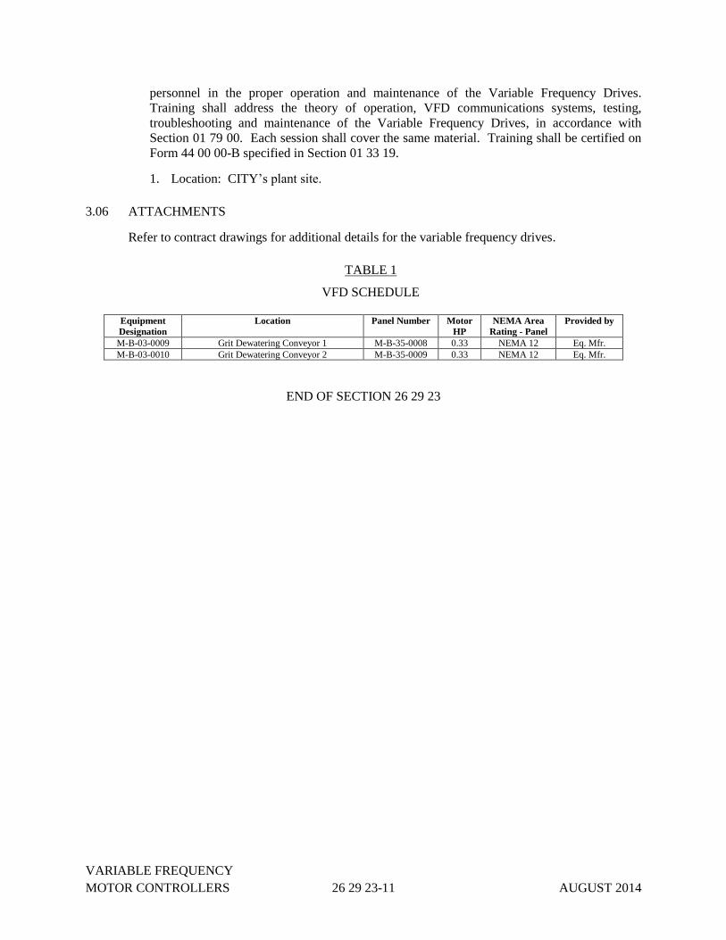
VARIABLE FREQUENCY
MOTOR CONTROLLERS 26 29 23-11 AUGUST 2014
personnel in the proper operation and maintenance of the Variable Frequency Drives.
Training shall address the theory of operation, VFD communications systems, testing,
troubleshooting and maintenance of the Variable Frequency Drives, in accordance with
Section 01 79 00. Each session shall cover the same material. Training shall be certified on
Form 44 00 00-B specified in Section 01 33 19.
1. Location: CITY’s plant site.
3.06 ATTACHMENTS
Refer to contract drawings for additional details for the variable frequency drives.
TABLE 1
VFD SCHEDULE
Equipment
Designation
Location Panel Number Motor
HP
NEMA Area
Rating - Panel
Provided by
M-B-03-0009 Grit Dewatering Conveyor 1 M-B-35-0008 0.33 NEMA 12 Eq. Mfr.
M-B-03-0010 Grit Dewatering Conveyor 2 M-B-35-0009 0.33 NEMA 12 Eq. Mfr.
END OF SECTION 26 29 23

VARIABLE FREQUENCY
MOTOR CONTROLLERS 26 29 23-12 AUGUST 2014
THIS PAGE INTENTIONALLY LEFT BLANK
LIGHTING 26 50 00-1 JULY 2013
SECTION 26 50 00
LIGHTING
PART 1 - GENERAL
1.01 SUMMARY
A. Section Includes:
1. Interior Luminaries – Fluorescent
2. Luminaries - LED
3. Emergency Lighting Units
4. Exit Signs
5. Classified Location Lighting – NEMA 7
6. Luminaries – Metal Halide
7. Go / No-Go Lights
8. Incandescent Fixtures
9. Poles
10. Motion Sensors
1.02 REFERENCES
A. Institute of Electrical and Electronics Engineers (IEEE)
1. ANSI/IEEE C2 – National Electrical Safety Code
B. National Fire Protection Association (NFPA)
1. ANSI/NFPA 70 – National Electric Code
2. NFPA 101 – Life Safety Code
C. ANSI International (ANSI)
1. ANSI C82.11 – High Frequency Fluorescent Lamp Ballasts
2. ANSI C82.1 – Lamp Ballast-Line Frequency Fluorescent Lamp Ballast
3. ANSI C78 – Electric Lamps
D. Underwriters Laboratories (UL)
1. ANSI/UL 935 – Fluorescent Lamp Ballasts
E. National Electrical Manufacturers Association (NEMA)
LIGHTING 26 50 00-2 JULY 2013
1. NEMA 250 – Enclosures for Electrical Equipment
F. National Contractors Association (NECA)
1. NECA Standard of Installation
1.03 SUBMITTALS
A. Submittals shall be in accordance with the requirements of Section 01 33 00 – Submittals and
Submittal Procedures.
B. Product Data: Provide manufacturer data sheets, catalog pages, dimensions, ratings,
photometric data and performance data for all fixtures supplied. Information shall be
organized by fixture type.
C. Shop Drawings: Provide installation drawings for review with ENGINEER prior to
installation. Indicate dimensions and components for each lighting fixture that is not a
standard product of the manufacturer.
D. Manufacturers’ Instructions: Submit instructions for storage, preparation, and installation of
lighting fixtures.
1.04 PROJECT CLOSEOUT SUBMITTALS
A. Section 01 77 00 – Project Closeout Procedures
B. Manufacturer Operation and Maintenance Data: Submit original manufacturer manuals and
data sheets for products purchased. Include replacement parts list.
C. Record Documentation: Provide accurate as-built record drawings in paper and electronic
format of actual locations of each lighting fixture.
1.05 QUALITY ASSURANCE
All Work shall be performed and materials provided in accordance with NFPA 70 - National
Electric Code (NEC), the National Electrical Safety Code (NESC), and other codes and standards
as applicable. Where required by the Authority Having Jurisdiction (AHJ), equipment and
materials shall be listed or labeled by Underwriters’ Laboratory (UL) or by a nationally
recognized testing laboratory acceptable to the AHJ. CONTRACTOR shall be responsible for all
costs associated with obtaining the required listing.
1.06 DELIVERY, STORAGE, AND HANDLING
A. Accept materials on site in manufacturer’s packaging and inspect for damage.
B. Store and protect in accordance with manufacturer’s instructions.
C. Protect from weather. Provide adequate ventilation to prevent condensation.
1.07 SITE CONDITIONS
A. General
1. Verify locations of lighting fixtures prior to rough-in.
LIGHTING 26 50 00-3 JULY 2013
2. Lighting fixtures are shown on plan drawings in approximate locations unless
dimensioned. Adjust location and mounting to eliminate conflicts with other equipment
and structures at no additional cost to CITY. Install at locations and heights required for
uniform illumination.
1.08 WARRANTY
CONTRACTOR shall warrant specified equipment per the requirements of Section 01 78 36.
PART 2 - PRODUCTS
2.01 INTERIOR LUMINAIRES – FLUORESCENT [D, T8]
A. Description: Two-lamp high-efficiency electronic fluorescent fixture with instant start
NEMA Premium Efficiency electronic ballast, high PF, Energy efficient, CBM certified.
B. Manufacturers:
1. Holophane – HES series (gasketed).
2. Lithonia – DMW-series (gasketed) / AF-series (open).
3. Columbia Lighting – KL-series (open).
C. Housing - Electrical Rooms [T8]: Metal with white baked enamel finish. Turret style, heavy
duty industrial, 20% up light.
D. Housing - Process areas [D]: Fiberglass body, enclosed and gasketed housing, acrylic lens.
D. Lamps: Two 32W T8 fluorescent tubes, 48” length ea.
E. Input Voltage: 120VAC, 60HZ, MVOLT.
F. Mounting: Pendant mount from ceiling.
G. Accessories: Wire guards for all open style fixtures.
2.02 LUMINAIRES – LED [L1, L2, L3, L4]
A. Description: Industrial wet location rated [L1, L3] or Hazardous location rated [L2], LED
fixture, dedicated thermal management, fused.
B. Manufacturers:
1. Holophane – Petrolux LED series (PLED2) or Petrolux LED series (HPLED).
2. Or Approved equal.
C. Housing: Cast aluminum housing with Type 5 low angle borosilicate glass reflector –
gasketed. Ratings - NEMA 4X, IP66, UL 1598 Listed.
D. Lamps: LED module with 5,000K CCT+/-250 color temperature. Lumens shall be 12,000
[L1] or 18,000 [L3] as identified on Schedule.
E. Input Voltage: 120VAC, 60Hz, Auto-sensing. Include 6kV/3kA surge protection. Fault
LIGHTING 26 50 00-4 JULY 2013
tolerant design – continues to operate after single LED failure.
F. Mounting: Pendant, ceiling, stanchion mount – as identified on Schedule.
G. Accessories: High-Bay units shall include safety chain kit. Outdoor units shall include
photoelectric cell control.
H. Description: Industrial high mast area lighting [L4], LED fixture, with thermal management.
I. Manufacturers:
1. American Electric Lighting (AEL) – Autobahn Series ATB2.
2. Or Approved equal.
J. Housing: Cast aluminum housing with enhances corrosion resistant finish option. Rated for
outdoor use, IP66.
K. Lamps: LED modules with 5,000K CCT+/-250 color temperature. Lumens shall be 24,500
minimum as identified on Schedule. Distribution shall be Roadway Type IV.
L. Input Voltage: 120VAC, 60Hz, MVOLT. Include IEEE/ANSI C62.41 Category C
(10kV/5kA) or greater surge protection built into housing. Fault tolerant design – continues
to operate after single LED failure.
M. Mounting: Pole. Housing shall be compatible to mount to existing 40’-0” high mast poles at
the Muddy Creek Treatment Plant. Furnish all mounting adapters and hardware required for
mounting to existing poles.
N. Accessories: Outdoor units shall include complete photoelectric cell control, including
photocell and photocontrol receptacle.
2.03 EMERGENCY LIGHTING UNITS [E]
A. Description: Self-contained incandescent emergency lighting unit.
B. Manufacturers:
1. Lithonia – INDX series.
2. Holophane – DeSoto M60 series.
3. Thomas & Betts – E12NN series.
C. Housing: Polyester / thermoplastic, NEMA 4 rated for industrial areas.
D. Lamps: 50W/54W , 12V, 2-head halogen.
E. Input Voltage: 120VAC, 60 Hz.
F. Mounting: Wall mount.
G. Battery: Lead calcium.
H. Battery Charger: Current limiting regulated charger.
I. Rated Emergency Power: 90-minute minimum.

LIGHTING 26 50 00-5 JULY 2013
J. Accessories: Self-Diagnostics.
2.04 EXIT SIGNS [X]
A. Description: Combination exit sign with 2-head emergency lighting unit, LED sign lights.
B. Manufacturers: Thomas & Betts – SVX Combo series.
C. Housing: Gray / black thermoplastic body.
D. Face: Clear polycarbonate face with red letters.
E. Directional Arrows: Universal type for field adjustment.
F. Lamps: Sign – High-efficiency LEDs. Emergency heads – (2) 12-Watt MR-16 halogen
lamps.
G. Input Voltage: 120VAC, 60 Hz.
H. Mounting: Wall mount above doorway.
I. Battery: Nickel cadmium.
J. Battery Charger: Continuous charger with periodic pulse charge at battery full capacity,
brownout, over-current, short-circuit protection.
K. Rated Emergency Power: 90-minutes.
2.05 CLASSIFIED LOCATION LIGHTING – NEMA 7 [A4]
A. Description: Wallpack metal halide for hazardous areas, NFPA Class I, Div. 2 rated fixture,
non-cutoff, fused.
B. Manufacturers: Holophane - Wallpack IV Hazardous series or Approved equal.
C. Housing: Cast aluminum reflector housing with borosilicate glass reflector.
D. Lamps: 100W metal halide.
E. Input Voltage: 120VAC, 60Hz, MVOLT.
F. Mounting: Wall mount.
G. Accessories: NEMA decal. Outdoor units shall include photoelectric cell control.
2.06 LUMINARIES – METAL HALIDE [A6]
A. Description: Wallpack metal halide, non-cutoff, fused, standard optics.
B. Manufacturers:
1. Holophane - Wallpack IV series.
2. Lithonia – TWH series.
3. Or Approved equal.
LIGHTING 26 50 00-6 JULY 2013
C. Housing: Cast aluminum reflector housing with borosilicate glass reflector.
D. Lamps: 100W metal halide.
E. Input Voltage: 120VAC, 60Hz, MVOLT.
F. Mounting: Wall mount.
G. Accessories: Outdoor units shall have photoelectric cell control – integral.
2.07 LUMINARIES – GO / NO-GO LIGHTS [G]
A. Description: Tower alarm lights, stackable, 70mm steady LED module.
B. Manufacturers: Allen-Bradley 855T series.
C. Housing: Polycarbonate construction, black base and cap. NEMA 4X rating.
D. Lamps: LED. Colors as indicated on wiring diagrams or fixture schedule.
E. Input Voltage: 120VAC, 60Hz.
F. Mounting: Wall-mount bracket.
G. Accessories: Sound module when specifically noted.
2.08 LUMINARIES – INCANDESCENT FIXTURES [I]
A. Description: Wet location fixture for use with standard incandescent light bulbs.
B. Manufacturers: Cooper Crouse-Hinds – VaporGard VX, or Approved equal.
C. Housing: Aluminum body, glass globe, 1-1/4” hub, housing for A-21 lamp.
D. Lamps: 14W LED bulb. Mfr: Sylvania, Philips.
E. Input Voltage: 120VAC.
F. Mounting: Stanchion mount.
2.09 LUMINARIES – POLES
A. Description: Square straight aluminum pole, 4” square, height as required for fixture height
listed in Schedule. Pole construction per local EPA NON-AASHTO rating. Assembly shall
include hand hole, pole base, nut covers. Satin brush finish. Stainless steel hardware.
B. Manufacturers: Holophane, Lithonia, or Approved equal.
2.10 MOTION SENSORS
A. Description: Fixture mount or ceiling mount self-contained occupancy sensor providing 360
degree lens, low bay (8’ – 25’) coverarge. Sensor shall use passive infrared detection
technology with microprocessor control and operate at line voltage (120V). Sensor model
shall provide square foot coverage adequate for each space identified. Fixture shall have
selectable manual timer settings between 30 seconds and 30 minutes. Color – off-white.

LIGHTING 26 50 00-7 JULY 2013
B. Manufacturers: Levition – OSFHU series or ODC series, or Approved equal.
PART 3 -EXECUTION
3.01 EXAMINATION AND PREPARATION
A. Verify existing conditions before starting Work.
B. Examine substrate and supporting grids for luminaires.
C. Examine each luminaire to determine suitability for lamps specified.
3.02 INSTALLATION
A. Install in accordance with manufacturers instructions.
B. Install suspended luminaires using pendants supported from swivel hangers or chain hangers.
Provide pendant length required to suspend luminaire at indicated height. Furnish and install
any support steel required for suspension of luminaires.
C. Install surface mounted luminaires plumb and adjust to align with building lines and with
each other. Secure to prohibit movement.
D. Install wall-mounted luminaires at height as indicated on Drawings or as scheduled.
E. Install accessories furnished with each luminaire.
F. Connect luminaires to branch circuit outlets using flexible conduit per Specification 26 05 33,
or as indicated.
G. Make wiring connections to branch circuit using building wire with insulation suitable for
temperature conditions within luminaire.
H. Install specified lamps in each luminaire.
I. Ground and bond interior luminaires and metal accessories to branch circuit equipment
grounding conductor.
J. Exterior luminaries shall not use handrail as part of the support structure – they must be
independently and rigidly supported.
K. Pole lights located in NFPA Classified areas shall have conduit seal fittings located inside
pole – install pole over top of conduit with seal fitting and anchor.
L. Motion sensors shall be mounted to have an unobstructed sensor view of the entire space and
shall be located near the entrance to the space. Sensors shall be rigidly mounted to fixture or
ceiling. Provide all hardware and boxes required for mounting.
3.03 FIELD QUALITY CONTROL
A. Additional Requirements
B. Testing: Operate each luminaire after installation and connection. Inspect for proper

LIGHTING 26 50 00-8 JULY 2013
connection and operation.
3.04 SYSTEM STARTUP
Commissioning: Relamp luminaires which have failed lamps at Substantial Completion.
END OF SECTION 26 50 00
DATA COMMUNICATIONS
NETWORK EQUIPMENT 27 21 00-1 AUGUST 2014
SECTION 27 21 00
DATA COMMUNICATIONS NETWORK EQUIPMENT
PART 1 - GENERAL
1.01 SUMMARY
A. Section Includes:
1. Fiber Patch Panels
2. Ethernet Switches
3. Communications Cabling
1.02 REFERENCES
A. National Fire Protection Association (NFPA)
1. NFPA 262 – Standard Method of Test for Flame Travel and Smoke of Wires and Cables
for Use in Air-Handling Spaces
B. Underwriters Laboratories (UL)
1. UL 2043 – Fire Test for Heat and Visible Smoke Release for Discrete Products and their
Accessories Installed in Air-Handling Spaces.National Electrical Manufacturers
Association (NEMA)
1.03 SUBMITTALS
A. Submittals shall be in accordance with the requirements of Section 01 33 00 – Submittals and
Submittal Procedures.
B. Product Data: Provide manufacturer data sheets, catalog pages, dimensions, ratings,
photometric data and performance data for all fixtures supplied. Information shall be
organized by fixture type.
C. Shop Drawings: Provide installation drawings for review with ENGINEER prior to
installation. Indicate dimensions and components for each lighting fixture that is not a
standard product of the manufacturer.
D. Test Reports: Indicate procedures and results for specified field testing and inspection.
E. Fiber Optic Cables: The following additional information is to be included in the submittal:
1. Cut sheets and catalog literature for proposed fiber optic cable, and fiber optic cable
accessories (pigtails, connectors, etc.)
2. Manufacturer specifications and data that clearly shows that the fiber optic cable meets
all requirements specified herein.
3. Sample of the proposed cable.
DATA COMMUNICATIONS
NETWORK EQUIPMENT 27 21 00-2 AUGUST 2014
4. Physical dimension drawings of all fiber optic accessories.
5. Proposed fiber identification sequence and labeling.
6. Provide a Recommended Spare Parts List (RSPL).
7. Provide a list of recommended special tools for fiber installation testing or maintenance.
8. Cable pulling plan that specifies the sequence of work tasks, materials, and equipment.
9. Provide an optical link analysis for each fiber optic link. Calculate point-to-point
(transmit/receive) optical power loss of each fiber link using proposed installed cable
lengths. Include all losses through connectors and patch panels. Submit calculated values
including sketches graphically showing the proposed cable route.
10. Provide a point-to-point interconnection cable diagram clearly depicting and identifying
actual cable routing through all new and existing raceway. Include cables, connectors,
patch panels, and media converters.
F. Network Cabling Schedule: Contractor to submit network cable schedule. Actual cable length
required to be verified in the field by the Contractor.
G. Manufacturers’ Instructions: Submit instructions for storage, preparation, and installation of
lighting fixtures.
1.04 PROJECT CLOSEOUT SUBMITTALS
A. Section 01 77 00 – Project Closeout Procedures
B. Manufacturer Operation and Maintenance Data: Submit original manufacturer manuals and
data sheets for products purchased. Include replacement parts list.
C. Record Documentation: Provide accurate as-built record drawings in paper and electronic
format of actual locations of each lighting fixture.
1.05 QUALITY ASSURANCE
A. All Work shall be performed and materials provided in accordance with NFPA 70 - National
Electric Code (NEC), the National Electrical Safety Code (NESC), and other codes and
standards as applicable. Where required by the Authority Having Jurisdiction (AHJ),
equipment and materials shall be listed or labeled by Underwriters’ Laboratory (UL) or by a
nationally recognized testing laboratory acceptable to the AHJ. CONTRACTOR shall be
responsible for all costs associated with obtaining the required listing.
B. Installer: Company specializing in installing products specified in this section with minimum
three years experience, and with service facilities within 50 miles of project. Installing
company to employ Fiber Optic Association (FOA) certified or MSD approved equal
installers.
C. Testing Agency: Company member of International Electrical Testing Association and
specializing in testing products specified in this section with minimum three years
experience.
D. All connections to the CITY's existing network shall be fully coordinated between the CITY
and the CONTRACTOR. Prior to connecting to the existing network, the CONTRACTOR
DATA COMMUNICATIONS
NETWORK EQUIPMENT 27 21 00-3 AUGUST 2014
shall provide a written request to the CITY for a CITY representative to be available when
existing systems are disconnected and at the time of any new connections.
1.06 DELIVERY, STORAGE, AND HANDLING
A. Accept materials on site in manufacturer’s packaging and inspect for damage.
B. Store and protect in accordance with manufacturer’s instructions.
C. Protect from weather. Provide adequate ventilation to prevent condensation.
1.07 WARRANTY
CONTRACTOR shall warrant specified equipment per the requirements of Section 01 78 36.
1.08 QUALIFICATIONS
A. Manufacturer: Company specializing in manufacturing products specified in this section with
minimum three years experience.
B. Installer: Company specializing in installing products specified in this section with minimum
three years experience, and with service facilities within 50 miles of project. Installing
company to employ Fiber Optic Association (FOA) certified or MSD approved equal
installers.
C. Testing Agency: Company member of International Electrical Testing Association and
specializing in testing products specified in this section with minimum three years
experience.
PART 2 - PRODUCTS
2.01 FIBER PATCH PANELS
A. Description: Enclosed fiber optic break-out panel with fiber management and media
converters as required. Refer to Contract Drawings for panel count, design layout, and Bill of
Materials.
B. Panel Construction: Panel shall meet the requirements of Section 40 95 13.
2.02 ETHERNET SWITCHES
A. Description: Industrial rail-mounted switch for Ethernet applications, including VFDs,
vendor-furnished PLCs, and programming ports.
B. Manufacturers:
1. Hirschmann SPIDER TX.
2. Or Approved Hirschmann equal.
C. Detail: Switch shall support the quantity of 10/100BaseTX ports to meet the functionality
indicated in this specification and as shown on the Drawings. Switches shall have a
minimum of four 10/100Base-T, RJ-45 ports. A minimum of 20% spare ports shall be
DATA COMMUNICATIONS
NETWORK EQUIPMENT 27 21 00-4 AUGUST 2014
provided for the installed system.
D. Environmental: Suitable for installation in industrial environments. Operating Temperature
Range: 0 to 40C.
E. Mounting: DIN-rail mounted suitable for panel installation.
2.03 MEDIA CONVERTERS
A. Description: Fiber optic media converters for all systems requiring conversion from copper
media to fiber optic media.
B. Manufacturers:
1. Hirschmann SPIDER 1TX/1FX EEC with conformal coating for fiber to Ethernet.
2. Phoenix Contact PSI-MOS ControlNet to fiber converter.
C. Description: Ethernet converter shall be industrial-grade DIN-rail mounted 100Base-FX-
Multimode to 100Base-TX media converter. ControlNet converter shall be industrial-grade,
DIN-rail mounted, 5 Mbps coax to 850 nm multi-mode fiber.
D. Power Supply: Furnish 24V DC DIN-rail mounted power supply – Hirschmann RPS 30.
Quantity as required for media converters being furnished.
E. Spares: Furnish one spare media converter for each type provided. Spares shall be furnished
in original packaging to CITY.
2.04 COMMUNICATION CABLING
A. Network Fiber Optic Cable:
1. Heavy duty, loose buffer/dry construction cable with each fiber individually buffered to
900 um buffer diameter and individually strengthened with Aramid yarn strength
members. Cable to be U.L. listed as type OFCP or OFNP and suitable for indoor use and
duct or tray installation.
2. Cable Specifications
a. Fiber Size: 50 micron/125 micron (core/cladding)
b. Fiber Count: 24, 12, or 6 fibers
c. Maximum Short Term Tensile Load: 600 pounds
d. Maximum Long Term Tensile Load: 180 pounds
e. Crush Resistance: 2200 Newton/cm.
f. Operating Temperature: 0 to +70 degrees C.
g. Outside Diameter: 0.40 inches for non-armor 0.92 inches for armor (maximum).
h. Proof Test: 100 kpsi.
3. Manufacturers:
a. Belden Corporation – Multi-mode OM3 50/125 μm
b. Model for Armor: 12 fibers – B9C231
c. Model for Armor: 24 fibers – B9C232
d. Model for Non-Armor: 6 fibers – B9C202
e. Model for Non-Armor: 12 fibers – B9C204
f. Model for Non-Armor: 24 fibers – B9C205
DATA COMMUNICATIONS
NETWORK EQUIPMENT 27 21 00-5 AUGUST 2014
B. Fiber Optic Patch Cables:
1. Fiber optic jumper cables shall be furnished and installed for equipment interfacing and
between termination cabinets. The jumpers shall be 50/125 microns as required,
multimode for operation at 1300 nm. They shall be tight-buffered and be protected by
Kevlar-type strength material. The manufacturer of these
C. Terminal Connectors:
1. Provide fiber optic connectors; type ST or STII for connection to ST Patch Panel
Couplers, twist-lock design, with ceramic or zirconia ferrule and strain relief boot.
2. Connector Specifications:
a. Insertion Loss (typical): Less than 0.2 dB.
b. Repeatability: Less than 0.2 dB.
c. Operating Temperature: -40 to +80 degrees C.
d. Body Material: Nickel-plated brass
D. Coaxial “ControlNet” Cable:
1. Manufacturers:
a. Belden Model 3092A.
b. Substitutions: Approved equal.
2. Product Description: Quad-Shield RG-6 cable for use with Allen-Bradley ControlNet
networks.
a. Coaxial 18 AWG, solid bare copper-covered steel
b. Polyethylene insulation, color-coded black
c. 24 AWG stranded tinned copper drain wire
d. 4-layer aluminum foil shield/braid
e. PVC jacket
E. Ethernet Unshielded Twisted Pair (UTP) Cable:
1. Manufacturers:
a. Belden Model 1872A – Cat 6 Enhanced Bonded-Pair
b. Substitutions: Approved equal.
2. Product Description: Ethernet cables and connectors shall be provided for as specified, as
required for a complete and working system, and/or as shown on the drawings. Cable for
Ethernet wiring shall be UTP Cat 6 cable.
a. Jacket color coding for cables shall be as follows:
1) Standard Cat-6 SCADA Networks - Blue
2) Standard Cat-6 PLC Networks - White
3) Standard Cat-6 all other networks - Orange or Yellow
4) Crossover cables - Red
b. Cable Requirements:
1) 23 AWG
2) 4 pair solid conductor
3) 100 Ohm impedance
4) 1-350 MHz frequency range
5) Max attenuation 40 dB/350 MHz
6) Min NEXT 37dB/350MHz

DATA COMMUNICATIONS
NETWORK EQUIPMENT 27 21 00-6 AUGUST 2014
7) Min PS-NEXT 35dB/350MHz
8) Min return loss 17.0 dB/350 MHz
c. Plenum rated cable shall have FEP insulation jacketing and FEP insulation for
conductors. Non plenum rated cable shall have PVC insulation jacketing and
polyethylene insulation for conductors.
3. Ethernet Patch Cables. Pre-wired and terminated patch cables with RJ-45 connectors and
lever protecting boot shall be furnished for all connections to computers, network
equipment, and controller equipment except where physical conditions (i.e. length over
12 ft. or conduit size) require unterminated wire to be installed. Patch cables shall be Cat-
5e for networks speeds up to 100 Mbps, and Cat-6 for networks speeds greater than 100
Mbps and shall meet the requirements of Cat-5e and Cat-6 cable specified in this section.
Straight through cables shall be wired using the T568-B standard for both connectors as
shown in section 3-1.01. Crossover cables shall be wired using the T568-A standard for
one connector and the T568-B standard for the opposite end.
F. Ethernet Shielded Twisted Pair Cable:
1. Manufacturers:
a. Belden Model 7958A – Cat 5E Data Tuff
b. Substitutions: Approved equal.
2. Product Description: Ethernet cables rated at 600V for use within motor control centers
(MCC) and variable frequency drive (VFD) panels.
a. Jacket color coding for cables shall be as follows:
1) Standard Cat-5E SCADA Networks - Blue
2) Standard Cat-5E PLC Networks - White
3) Standard Cat-5E all other networks - Orange or Yellow
4) Crossover cables - Red
b. Cable Requirements:
1) 24 AWG
2) 4 pair solid conductor
3) 100 Ohm impedance
4) 1-200 MHz frequency range
5) Max attenuation 32.4 dB/200 MHz
6) Min PS-NEXT 27.8dB/200MHz
7) Min PS-ELFEXT 14.7dB/200MHz
8) Min return loss 15.0 dB/200 MHz
c. Outer Shield: Aluminum foil polyester tape with 24AWG tinned copper drain wire.
G. Network Outlet Jacks:
1. Manufacturers:
a. Leviton
b. Substitutions: Approved equal.
c. Hubbell Premise Wiring, IFP Series Faceplates and HXJ Series jacks
d. Phoenix Contact
e. Substitutions: Approved equal.
2. Product Description: Conform to TIA/EIA 568 requirements for cable connectors for
specific cable types. Work station communication outlets shall be of a modular design
consisting of a 1-port or 2-port, single gang, high impact thermoplastic faceplate and data
DATA COMMUNICATIONS
NETWORK EQUIPMENT 27 21 00-7 AUGUST 2014
grade RJ45 jacks as shown on the drawings. RJ45 jack contacts shall be beryllium copper
with minimum 50 microinch gold plating. Faceplates shall be provided with screw covers
and machine printed labels. RJ45 jacks shall be color coded to indicate data or voice
communications and shall accept a machine-printed termination position label.
PART 3 -EXECUTION
3.01 EXAMINATION AND PREPARATION
A. Verify existing conditions before starting Work.
B. Examine substrate and supporting grids for luminaires.
C. Examine each luminaire to determine suitability for lamps specified.
3.02 INSTALLATION
A. Install pathways as indicated on Drawings.
B. Install wire and cable in accordance with all local and national codes.
C. Cables to be pulled in one continuous length. Splicing will not be allowed.
D. Install termination cabinets plumb, and attach securely to building wall at each corner.
E. Install pull string in each empty communication conduit over 10 feet in length or containing
bends.
F. Install engraved plastic nameplates in accordance with Section 27 05 53.
G. Ground and bond pathways, cable shields, and equipment in accordance with Section 27 05
26.
H. Install fiber optic cable and connectors in accordance with the manufacturer’s
recommendations. A precision cleaver shall be used and cleaved ends shall be verified for
cleave angle and cleanliness using a microscope.
I. Install terminal connectors for each individual fiber within the cable and terminate at the
patch panel.
J. Install cables in the indicated raceway systems. Inspect raceways prior to pulling cables. Rod
and swab out conduits and ducts prior to installing cables.
K. Pull cables prior to attachment of connectors.
L. Pull cables using an indirect attachment method such as a "Kellems Grip" which distributes
the pulling forces over the outer portion of the cable. Pulls directly on the fiber core will not
be allowed.
M. Do not exceed maximum pulling strength limits of the cable during installation. Monitor
cable pull tensions at all times during the installation of the cable using a remote sensing
puller, strain gauge or running line tensiometer. If electronic tension monitoring equipment is
used, it shall be calibrated or checked for calibration on a daily basis or prior to any cable
pull.

DATA COMMUNICATIONS
NETWORK EQUIPMENT 27 21 00-8 AUGUST 2014
N. To reduce cable friction and minimize pulling forces during installation, use a polymer-based,
water soluble lubricant when pulling cable.
O. Do not exceed the minimum bend radius of the cable. Tight loops, kinks, knots or tight bends
will not be allowed during installation.
P. For conduit installation, the minimum bending radius (under installation tensile load) shall be
6 inches. Use sweeping elbows at all transitions from horizontal to vertical conduit runs. Use
Mogul type conduit bodies for 45 and 90 degree turns.3.03
Q. Pull the cable in one continuous run. Do not make splices in cable. Provide adequate run
lengths on cable reels to make termination-to-termination runs without splices.
R. Provide junction boxes and pull boxes as required by the cable manufacturer.
3.03 FIELD QUALITY CONTROL
A. Section 01 77 00 - Execution and Closeout Requirements: Field inspecting, testing, adjusting,
and balancing.
B. Inspect and test optical fiber cables in accordance with NETA ATS, except Section 4.
Perform inspections and tests listed in NETA ATS, Section 7.25.
C. Inspect and test copper cables and terminations in accordance with TIA/EIA 568.
3.04 SYSTEM STARTUP
A. Test fiber optic cables before and after field installation. Tests to be performed by an
independent testing firm approved by the CITY and shall be witnessed by the ENGINEER.
The cost of testing shall be included with the lump sum bid of Part 1 (Ref. No. G1).
1. Upon receipt of the fiber optic cable reels, test each fiber separately with an Optical Time
Domain Reflectometer (OTDR) to verify fiber length, attenuation and continuity.
2. After the cable has been installed, visually inspect each fiber termination for out-of-round
conditions and surface defects such as cracks and micro-chips using a 200x inspection
microscope.
3. After connectors have been attached at both ends, test each fiber with an optical power
meter and calibrated light source or OTDR. Tests shall be bi-directional.
B. Furnish certification documents for each test and record the following data. Include printouts
from the OTDR with the certification documents.
1. Installer's company name and address.
2. Installer's name.
3. Testing Company’s name and address.
4. Tester’s name.
5. Date of certification.
6. Attenuation of each fiber link.
DATA COMMUNICATIONS
NETWORK EQUIPMENT 27 21 00-9 AUGUST 2014
7. Length of each fiber optic link measured.
8. Equipment used to certify the fiber optic link.
9. Name of person(s) recording the test data.
C. Power meters shall have calibrations traceable to National Institute of Standards and
Technology (NIST) standards.
D. The maximum total loss including connectors and cable attenuation for each fiber optic link
shall not exceed 5 dB.
END OF SECTION 27 21 00

DATA COMMUNICATIONS
NETWORK EQUIPMENT 27 21 00-10 AUGUST 2014
THIS PAGE INTENTIONALLY LEFT BLANK

SMOKE DETECTION SENSORS 28 31 46-1 OCTOBER 2014
SECTION 28 31 46
SMOKE DETECTION SENSORS
PART 1 - GENERAL
1.01 SUMMARY
Alarm initiating devices for smoke detection.
1.02 REFERENCES
A. National Fire Protection Association (NFPA)
1. NFPA 72 National Fire Alarm Code.
B. Underwriters Laboratories Inc. (UL)
1. UL 217 Smoke Detectors, Single and Multiple Stations
1.03 SUBMITTALS
A. Submittals shall be in accordance with the requirements of Section 01 33 00 – Submittals and
Submittal Procedures.
B. Product Data: Provide manufacturer data sheets and catalog pages for all materials and
components, including component list, assembly ratings (including short-circuit rating,
voltage, continuous current), dimensions, and terminal sizes.
C. Manufacturers’ Instructions: Submit instructions for storage, preparation, and installation of
panelboards.
1.04 PROJECT CLOSEOUT SUBMITTALS
A. Section 01 77 00 – Project Closeout Procedures
B. Manufacturer Operation and Maintenance Data: Submit original manufacturer manuals,
installation instructions, and data sheets for products purchased.
C. Record Documentation: Provide accurate as-built record drawings in paper and electronic
format.
1.05 DELIVERY, STORAGE, AND HANDLING
A. Accept materials on site in manufacturer’s packaging and inspect for damage.
B. Store and protect in accordance with manufacturer’s instructions.
C. Protect from weather, dirt and debris. Store in a clean, dry environment. Provide adequate
ventilation to prevent condensation.
1.06 SITE CONDITIONS

SMOKE DETECTION SENSORS 28 31 46-2 OCTOBER 2014
General: CONTRACTOR shall make all necessary field measurements to verify that equipment
shall fit in allocated space in full compliance with minimum required clearances specified in
National Electrical Code.
1.07 WARRANTY
Manufacturer shall warrant specified equipment per the requirements of Section 01 78 36.
PART 2 - PRODUCTS
2.01 GENERAL
A. Product Description: Smoke detector, conventional, hardwired, 120V AC, self-restoring,
ceiling-mounted on standard single gang electrical box, with plug in electrical connections.
B. Sensor: Ionization or photoelectric.
C. Power Source: 120V AC, 60 Hz
D. Audio Alarm: Minimum 85dB at 10 feet.
E. Temperature Range: 40F to 100F.
F. Signal Output: Relay with minimum one Form C contact, 1A @ 120V AC.
G. Battery Backup: None
2.02 MANUFACTURERS
A. Edwards Signaling & Security Systems
B. Kidde
C. Or approved equal.
PART 3 -EXECUTION
3.01 INSTALLATION
A. One smoke detector shall be installed in each new Electrical Room (total of 1).
B. Smoke detector shall be ceiling mounted in the center of the space.
C. Device shall be mounted firmly in place, with fasteners and supports adequate to support the
required load.
D. Furnish and install wire and conduit to provide 120VAC power for each smoke detector, from
the nearest lighting panel.
E. Furnish and install wire and conduit to connect the smoke detector with each local PLC
panel, as one discrete input. Use (3) - #14AWG for each detector in ¾” conduit.
F. Smoke detectors shall be wired and installed per manufacturer’s requirements, and in
accordance with NFPA 72.

SMOKE DETECTION SENSORS 28 31 46-3 OCTOBER 2014
G. Device shall be wired to a single, continuous (non-switched) power source, which is not
protected by a ground fault interrupter.
3.02 TESTING
A. Smoke detector and PLC input alarm shall be tested in accordance with NFPA 72, Chapter 7.
B. Before energizing device, check for correct connections and test for short circuits, ground
faults, continuity, and insulation.
C. Ground all circuits and verify response of trouble signals.
D. Check installation and operation of smoke detector using the walk test.
END OF SECTION 28 31 46

SMOKE DETECTION SENSORS 28 31 46-4 OCTOBER 2014
THIS PAGE LEFT BLANK INTENTIONALLY
CLEARING AND GRUBBING 31 11 00-1 JULY 2013
SECTION 31 11 00
CLEARING AND GRUBBING
PART 1 - GENERAL
1.01 SCOPE
A. Clearing and grubbing includes, but is not limited to, removing from the Project site, trees,
stumps, roots, brush, structures, abandoned utilities, trash, debris and all other materials found on
or near the surface of the ground in the construction area and understood by generally accepted
engineering practice not to be suitable for construction of the type contemplated. Precautionary
measures that prevent damage to existing features to remain are part of the work.
B. Clearing and grubbing operations shall be coordinated with temporary and permanent erosion and
sedimentation control procedures.
1.02 QUALITY ASSURANCE
A. The CONTRACTOR shall comply with applicable codes, ordinances, rules, regulations and laws
of local, municipal, state or federal authorities having jurisdiction over the Project. All required
permits of a temporary nature shall be obtained for construction operations by the
CONTRACTOR.
B. Open burning, if allowed, shall first be permitted by the local authority having jurisdiction. The
CONTRACTOR shall notify the local fire department and abide by fire department restrictions.
PART 2 – PRODUCTS
2.01 EQUIPMENT
The CONTRACTOR shall furnish equipment of the type normally used in clearing and grubbing
operations including, but not limited to, tractors, trucks, and loaders.
PART 3 – EXECUTION
3.01 SCHEDULING OF CLEARING
A. The CONTRACTOR shall clear at each construction site only that length of the right of way,
permanent or construction easement which would be the equivalent of one month's pipe laying.
This length shall be determined from the CONTRACTOR's Progress Schedule.
B. The CITY may permit clearing for additional lengths of the pipe line provided that temporary
erosion and sedimentation controls are in place and a satisfactory stand of temporary grass is
established. Should a satisfactory stand of grass not be possible, no additional clearing shall be
permitted beyond that specified above.
C. A satisfactory stand of grass shall have no bare spots larger than one square yard. Bare spots shall
be scattered and the bare area shall not comprise more than one percent of any given area.
CLEARING AND GRUBBING 31 11 00-2 JULY 2013
3.02 CLEARING AND GRUBBING
A. Clear the construction easement or road right of way only if necessary.
B. Grubbing shall consist of completely removing roots, stumps, trash and other debris from all
graded areas so that topsoil is free of roots and debris. Topsoil is to be left sufficiently clean so
that further picking and raking will not be required.
C. All stumps, roots, foundations and planking embedded in the ground shall be removed and
disposed of. Piling and butts of utility poles shall be removed to a minimum depth of two feet
below the limits of excavation for structures, trenches and roadways or two feet below finish
grade, whichever is lower.
D. Landscaping features shall include, but are not necessarily limited to, fences, cultivated trees,
cultivated shrubbery, property corners, man made improvements, subdivision and other signs
within the right of way and easement. The CONTRACTOR shall take extreme care in moving
landscape features and promptly re establishing these features.
E. Surface rocks and boulders shall be grubbed from the soil and removed from the site if not
suitable as rip rap.
F. Where the tree limbs interfere with utility wires, or where the trees to be felled are in close
proximity to utility wires, the tree shall be taken down in sections to eliminate the possibility of
damage to the utility.
G. Any work pertaining to utility poles shall comply with the requirements of the appropriate utility.
H. All fences adjoining any excavation or embankment that, in the CONTRACTOR's opinion, may
be damaged or buried, shall be carefully removed, stored and replaced. Any fencing that, in the
CITY's opinion, is significantly damaged shall be replaced with new fence material.
I. The CONTRACTOR shall exercise special precautions for the protection and preservation of
trees, cultivated shrubs, sod, fences, etc. situated within the limits of the construction area but not
directly within excavation and/or fill limits. The CONTRACTOR shall be held liable for any
damage the CONTRACTOR's operations have inflicted on such property.
J. The CONTRACTOR shall be responsible for all damages to existing improvements resulting from
CONTRACTOR's operations.
3.03 DISPOSAL OF DEBRIS
A. The debris resulting from the clearing and grubbing operation shall be hauled to a disposal site
secured by the CONTRACTOR and shall be disposed of in accordance with all requirements of
federal, state, county and municipal regulations. No debris of any kind shall be deposited in any
stream or body of water, or in any street or alley. No debris shall be deposited upon any private
property except with written consent of the property owner. In no case shall any material or debris
be left on the Project, shoved onto abutting private properties or buried on the Project.
B. When approved in writing by the CITY and when authorized by the proper authorities, the
CONTRACTOR may dispose of such debris by burning on the Project site provided all
requirements set forth by the governing authorities are met. The authorization to burn shall not
relieve the CONTRACTOR in any way from damages which may result from CONTRACTOR's
operations. On easements through private property, the CONTRACTOR shall not burn on the site
CLEARING AND GRUBBING 31 11 00-3 JULY 2013
unless written permission is also secured from the property owner, in addition to authorization
from the proper authorities.
END OF SECTION 31 11 00

CLEARING AND GRUBBING 31 11 00-4 JULY 2013
THIS PAGE INTENTIONALLY LEFT BLANK

TRENCHING AND BACKFILLING 31 23 00-1 JULY 2013
SECTION 31 23 00
TRENCHING AND BACKFILLING
PART 1 - GENERAL
1.01 SCOPE
This section covers clearing, grubbing, and preparation of the site; removal and disposal of all
debris; excavation and trenching; tunneled (trenchless construction) crossings; the handling,
storage, transportation, and disposal of all excavated material; all necessary sheeting, shoring, and
protection work; preparation of subgrades; pumping and dewatering as necessary; protection of
adjacent property; backfilling; pipe embedment; surfacing and grading; and other appurtenant
work.
1.02 GENERAL
A. With reference to the terms and conditions of the construction standards for excavations set
forth in OSHA "Safety and Health Regulations for Construction", Chapter XVII of Title 29,
CFR, Part 1926, CONTRACTOR shall employ a competent person and, when necessary
based on the regulations, a registered Professional Engineer, to act upon all pertinent matters
of the work of this section.
B. All backfill operations shall be in accordance with the City of Cincinnati Supplement to the
State of Ohio (ODOT) Construction and Material Specifications, as shown on MSD Standard
Drawing Acc. No. 49032, except as otherwise noted herein. All requirements of these items
shall be strictly adhered to by the CONTRACTOR and enforced by the CITY.
1.03. SUBMITTALS
A. Drawings, specifications, and data covering the proposed materials shall be submitted in
accordance with the Submittals section.
B. At least 30 days before starting construction on the sheeting and shoring, the sheeting and
shoring design engineer shall complete and submit to ENGINEER the Protection System
Design Certificate (Figure 2-02202) and the CONTRACTOR shall use the sheeting and
shoring design. A separate certificate shall be submitted for each unique design. The
certificate shall be signed and sealed by the registered professional engineer that designed the
protection system. The professional engineer shall be licensed or registered in the state where
the protection system is located.
1. Filter Fabric Data. Complete descriptive and engineering data for the fabric shall be
submitted in accordance with the Submittals section. Data submitted shall include:
a. A 12 inch square [300 mm] sample of fabric.
b. Manufacturer's descriptive product data.
c. Installation instructions.
PART 2 - PRODUCTS
2.01 MATERIALS
TRENCHING AND BACKFILLING 31 23 00-2 JULY 2013
A. Compacted bank run gravel backfill, meeting the requirements of Section 703.20 of the City
supplement and MSD Standard Drawing 49032, above the “initial backfill” shall be required
for all conduits and trenches under sidewalks, driveway and parking lot pavements.
B. Costs for backfilling, meeting the above requirements, shall be included in the price bid for
all types of conduit specified on the contract plans.
C. Allowable bedding and initial backfill for pipe shall be Class I or Class II as defined below
and applied as per MSD Standard Drawing Accession Number 49032 requirements.
D. Class I – Angular ¼ inch to 1inch graded stone, including a number of fill materials such as
coral, slag, cinders, crushed stone, crushed shells, and shells. Where any ungraded (one size
aggregated) crushed stone, coral or slag is used, limit size to 3/4 inch maximum. Use this
material where the depth of cover of the conduit is between fourteen (14) feet and thirty-five
(35) feet.
E. Class II – Coarse sands and gravels with maximum particle size of 1 inch, including various
graded sands and gravels containing small percentages of fines, generally being granular and
non-cohesive, either wet or dry. Soil Types GW, GP, SW, and SP are included in this class
as further defined in ASTM-D-2487. Use of this material is applicable to conduits when the
depth of cover is fourteen (14) feet or less.
2.02 MATERIALS TESTING
A. Preliminary Review of Materials
1. As required by CITY, all tests for preliminary review of materials shall be made by an
acceptable independent testing laboratory at the expense of CONTRACTOR. Two initial
gradation tests shall be made for each type of embedment, fill, backfill, or other material,
and one additional gradation test shall be made for each additional five-hundred
(500) tons of each material delivered to the site. In addition, one set of initial Atterberg
Limits test shall be made for each fill materials containing more than twenty (20) percent
by weight passing the No. 200 sieve. One additional Atterberg Limits test shall be made
or each additional five-hundred (500) tons of each material delivered to the site.
2. All material testing shall be made by an independent testing laboratory, approved by the
CITY, at the expense of CONTRACTOR under the lump sum bid.
3. Field Testing Expense. All moisture-density (Proctor) tests and relative density tests on
the materials, and all in-place field density tests, shall be made by an independent testing
laboratory, approved by the CITY, and performed on a Time and Materials Basis (Force
Account) against the allowance established for such in Section 01 20 00, Measurement
and Payment. CONTRACTOR shall provide access to the materials and work area and
shall assist the laboratory as needed in obtaining representative samples.
4. Required Tests. For planning purposes, the following guidelines shall be used for
frequency of field tests. Additional tests shall be performed as necessary for job
conditions and number of failed tests. Retesting resulting from failed test shall be at no
cost to the CITY. Test results shall be submitted as indicated in the Submittals section.
a. Two moisture density (Proctor) tests in accordance with ASTM D698 (or, when
required, ASTM D1557), or two relative density tests in accordance with
ASTM D4253 and D4254 for each type of general fill, designated fill, backfill, or
other material proposed.
b. In-place field density and moisture tests at intervals of 1000 feet [300 m] maximum
along the trench.
TRENCHING AND BACKFILLING 31 23 00-3 JULY 2013
c. One in-place field density and moisture test for every 200 cubic yards [153 m3] of
backfill.
d. One in-place density and moisture test whenever there is a suspicion of a change in
the quality of moisture control or effectiveness of compaction.
e. At least one test for every full shift of compaction operations on mass earthwork.
f. Additional gradation, Proctor, and relative density tests whenever the source or
quality of material changes.
PART 3 - EXECUTION
3.01 CLEARING AND GRUBBING
A. All clearing shall be performed as necessary for access, stringing of pipeline materials, and
construction of the pipeline and appurtenant structures.
B. Clearing and grubbing shall be performed in accordance with Section 31 11 00.
C. Two (2) days prior to clearing and grubbing, the construction limits shall be marked and the
CONTRACTORshall walk the project with CITY’S personnel to locate trees to be saved and
trees to be removed.
3.02 EXCAVATION
A. Excavations shall provide adequate working space and clearances for the work to be
performed therein and for installation and removal of concrete forms. In no case shall
excavation faces be undercut for extended footings.
B. Subgrade surfaces shall be clean and free of loose material of any kind when concrete is
placed thereon.
C. Except where exterior surfaces are specified to be damp-proofed, monolithic concrete
manholes and other concrete structures or parts thereof, which do not have footings that
extend beyond the outside face of exterior walls, may be placed directly against excavation
faces without the use of outer forms, provided that such faces are stable.
D. Classification of Excavated Materials: No classification of excavated materials will be made
for payment purposes. Excavation and trenching work shall include the removal and
subsequent handling of all materials excavated or otherwise removed in performance of the
work, regardless of the type, character, composition, or condition thereof.
E. Blasting
1. Blasting or other use of explosives for excavation will not be permitted.
2. All rock which cannot be handled, crushed, processed, and compacted as earth shall be
kept separate from other excavated materials and shall not be mixed with backfill or
embankment materials except as specified or directed.
F. Dewatering
1. Dewatering equipment shall be provided to remove and dispose of all surface water and
groundwater entering excavations, trenches, or other parts of the work. Each excavation
shall be kept dry during subgrade preparation and continually thereafter until the structure
to be built, or the pipe to be installed therein, is completed to the extent that no damage
from hydrostatic pressure, flotation, or other cause will result.
2. All excavations for concrete structures or trenches which extend down to or below

TRENCHING AND BACKFILLING 31 23 00-4 JULY 2013
groundwater shall be dewatered by lowering and keeping the groundwater beneath such
excavations. Any Contract specified dewatering depth shall be maintained below the
prevailing bottom of excavation at all times.
3. Surface water shall be diverted or otherwise prevented from entering excavations or
trenches to the greatest extent possible without causing damage to adjacent property.
4. CONTRACTOR shall be responsible for the condition of any pipe or conduit which he
may use for drainage purposes, and all such pipe or conduit shall be left clean and free of
sediment.
5. CONTRACTOR shall obtain from the appropriate agencies and authorities, the
dewatering and stormwater discharge permits required to remove and dispose of
groundwater, surface water, and any other water used in CONTRACTOR's operations.
The permits shall be obtained prior to start of construction.
G. Sheeting and Shoring
1. Except where banks are cut back on a stable slope or other effective trench support is
provided, excavations for structures and trenches shall be supported with steel sheet
piling and shoring as necessary to prevent caving or sliding.
2. Sheet piling or other excavation support systems shall be installed as necessary to limit
the extent of excavations for deeper structures and to protect adjacent structures and
facilities from damage due to excavation and subsequent construction. CONTRACTOR
shall assume complete responsibility for, and shall install adequate protection systems for
prevention of damage to existing facilities.
3. Sheeting, shoring and excavation support systems shall be designed by a Professional
Engineer registered in the state of Ohio.
4. Trench sheeting may be removed if the pipe strength is sufficient to carry trench loads
based on trench width to the back of sheeting. Trench sheeting shall not be pulled after
backfilling. Where trench sheeting is left in place, it shall not be braced against the pipe,
but shall be supported in a manner which will preclude concentrated loads or horizontal
thrusts on the pipe. Cross braces installed above the pipe to support sheeting may be
removed after pipe embedment has been completed. Trench sheeting shall be removed
unless otherwise permitted by CITY. Trench sheeting will not be removed, if in the
opinion of CITY, removal of the sheeting will cause damage to the facility it is
protecting. If left in place, the sheeting shall be cut off 12 inches below finished grade.
The design of the support system shall be such as to permit complete removal while
maintaining safety and stability at all times.
H. Stabilization
1. Sub-grades for concrete structures and trench bottoms shall be firm, dense, and
thoroughly compacted and consolidated; shall be free from mud and muck; and shall be
sufficiently stable to remain firm and intact under the feet of the workers.
2. Sub-grades for concrete structures or trench bottoms which are otherwise solid, but which
become mucky on top due to construction operations, shall be reinforced with crushed
rock or gravel as specified for granular fills. The stabilizing material shall be placed in a
manner that no voids remain in the granular fill. All excess granular fill with unfilled
void space shall be removed. The finished elevation of stabilized sub-grades shall allow
for installation of pipes, manholes, etc. to the elevations indicated on the drawings.
3.03 TRENCH EXCAVATION
TRENCHING AND BACKFILLING 31 23 00-5 JULY 2013
A. No more trench shall be opened in advance of pipe laying than is necessary to expedite the
work. One (1) block or four-hundred (400) feet, whichever is the shorter, shall be the
maximum length of open trench on any line under construction.
B. Except where no dig methods are indicated on the drawings, is specified, or is permitted by
CITY, all trench excavation shall be open cut from the surface and conform to MSD Standard
Drawing 49032.
C. Alignment, Grade, and Minimum Cover
1. The alignment and grade or elevation of each pipeline shall be fixed and determined from
offset stakes. Vertical and horizontal alignment of pipes, and the maximum joint
deflection used in connection therewith, shall be in conformity with requirements of the
section covering installation of pipe.
2. Where pipe grades or elevations are not definitely fixed by the contract drawings,
trenches shall be excavated to a depth sufficient to provide a minimum depth of backfill
cover over the top of the pipe of 60 inches over pipes below paved and graded streets
and, of 48 inches over pipes in other locations. Greater pipe cover depths may be
necessary on vertical curves or to provide adequate clearance beneath existing pipes,
conduits, drains, drainage structures, or other obstructions encountered at normal pipe
grades. Measurement of pipe cover depth shall be made vertically from the outside top of
pipe to finished ground or pavement surface elevation, except where future surface
elevations are indicated on the drawings.
D. Fill Section: where the sewer trench is in a fill section and the top of the pipe extends above
the vertical limits of where the fill begins (portions of the trench backfill are in the
constructed embankement) the CONTRACTOR shall refer to ODOT section 603
requirements, and City Supplement requirements thereto, for placement of the embankement
fill prior to beginning the trench excavation.
E. Mechanical Excavation
1. The use of mechanical equipment will not be permitted in locations where its operation
would cause damage to trees, buildings, culverts, or other existing property, utilities, or
structures above or below ground. In all such locations, hand excavating methods shall
be used.
2. Mechanical equipment used for trench excavation shall be of a type, design, and
construction, and shall be so operated, that the rough trench excavation bottom elevation
can be controlled, and that trench alignment is such that pipe, when accurately laid to
specified alignment, will be centered in the trench with adequate sidewall clearance.
Undercutting the trench sidewall to obtain sidewall clearance will not be permitted.
3. In locations where maximum trench widths are required for designated rigid conduits,
mechanical equipment shall be operated so that uniform trench widths and vertical
sidewalls are obtained at least from an elevation twelve (12) inches above the top of the
installed pipe to the bottom of the trench.
F. Cutting Concrete Surface Construction
1. Cuts in concrete pavement and concrete base pavements shall be no larger than necessary
to provide adequate working space for proper installation of pipe and appurtenances.
Cutting shall be started with a concrete saw in a manner which will provide a clean
groove at least one and one-half (1-1/2) inches deep along each side of the trench and
along the perimeter of cuts for structures.
TRENCHING AND BACKFILLING 31 23 00-6 JULY 2013
2. Concrete pavement and concrete base pavement over trenches excavated for pipelines
shall be removed so that a shoulder not less than 6 inches in width at any point is left
between the cut edge of the pavement and the top edge of the trench. Trench width at the
bottom shall not be greater than at the top and no undercutting will be permitted.
Pavement cuts shall be made to and between straight or accurately marked curved lines
which, unless otherwise required, shall be parallel to the center line of the trench.
3. Pavement removal for connections to existing lines or structures shall not exceed the
extent necessary for the installation.
4. Where the trench parallels the length of concrete walks, and the trench location is all or
partially under the walk, the entire walk shall be removed and replaced. Where the
trench crosses drives, walks, curbs, or other surface construction, the surface construction
shall be removed and subsequently replaced between existing joints or between saw cuts
as specified for pavement.
G. Excavation Below Pipe Sub-grade
1. Except where otherwise required, pipe trenches shall be excavated below the underside of
the pipe, as indicated on Figure 1-02202, to provide for the installation of granular
embedment.
2. Bell holes shall provide adequate clearance for tools and methods used for installing pipe.
No part of any bell or coupling shall be in contact with the trench bottom, trench walls, or
granular embedment when the pipe is jointed.
H. Artificial Foundations in Trenches: Whenever unsuitable or unstable soil conditions are
encountered, trenches shall be excavated below grade and the trench bottom shall be brought
to grade with suitable material.
3.04 TRENCH EMBEDMENTS
A. Trench embedment materials both below and above the bottom of the pipe, classes of
embedment to be used, and placement and compaction of embedment materials shall contain
NO cinders, clay lumps, or other material which may cause pipe corrosion.
B. Groundwater Barrier
1. Continuity of embedment material shall be interrupted by low permeability groundwater
barriers to impede passage of water through the embedment. Groundwater barriers for
sewer lines that contain manholes with cast-in-place bases shall be compacted soil around
each manhole, extending through any granular material beneath the manhole, and
meeting ASTM D2487 soil classification GC, SC, CL, or ML-CL and shall be compacted
to ninety-five (95) percent of maximum density at near the optimum moisture content
(ASTM D698). Material may be finely divided, suitable job excavated material, free
from stones, organic matter, and debris.
2. Groundwater barriers for sewer lines that contain manholes with precast (developed)
bases and for all other pipelines shall be soil plugs of three (3) feet in width, extending
the full depth and width of granular material, and spaced not more than four hundred
(400) feet apart. The soil plugs shall be constructed from soil meeting ASTM D2487
classification GC, SC, CL, or ML, and compacted to ninety-five (95) percent of
maximum density at near the optimum moisture content (ASTM D698).
3.05 BACKFILL INSTALLATION REQUIREMENTS
A. Compacted Backfill: Where CLSM is not required, compacted granular backfill for the full

TRENCHING AND BACKFILLING 31 23 00-7 JULY 2013
depth of sewer trench shall conform to requirements of MSD Standard Drawing Accession
Number 49032, in the locations indicated below:
1. Where beneath pavements, surfacings, driveways, curbs, gutters, walks, or other surface
construction or structures.
2. Where in street, road, or highway shoulders.
B. The top portion of backfill beneath established lawn areas shall be finished per section 01 71
33 “Restoration of Improvements”.
C. For backfilling in other areas than indicated in 1 above can consist of local site material with
the following qualifications:
1. No rocks, frozen lumps, or foreign mater and partical in excess of three (3) inches shall
be included.
2. Material does not consist of highly plastic silts, clays, organic silts or peat.
3. No rubbish, muck or unsuitable materials are included, and any stones or shale of up to
one-half cubic (0.5) foot in volume in the backfill are separated for each other and the
pipe by at least six (6) inches of earth or approved site or select backfill.
D. Jetted Backfill
1. In lieu of compacting the bank run gravel backfill in four (4) inch lifts, the bank run
gravel backfill may be compacted by thoroughly jetting with water, in areas outside of
the right of way, provided satisfactory drainage and removal of the free water is provided.
2. The Bank Run Gravel backfill shall be consolidated by thoroughly jetting with water.
For jetting, a hose not smaller than one and one-half (1-1/2) inch diameter and a nozzle
not smaller than one (1) inch diameter and not shorter than two-thirds (2/3) the depth of
the trench carrying a water pressure of forty (40) pounds per square inch (psi) shall be
inserted in a uniform pattern, at five feet maximum spacing, to obtain maximum
consolidation. After the final jetting of the trench, the backfill shall be left to settle and to
permit drainage of impounded water. Typical jetting procedures shall include a water
removal system at intervals not to exceed five huindred (500) lineal feet of trench. Water
removal shall not begin until the water surfaces above the backfill. After jetting is
complete, the area around the jetting hole shall be filled and compacted by the use of the
bucket on the equipment used for excavating. Settled trench surfaces shall then be
brought to grade by filling with Bank Run Gravel backfill and compacted to a density
equal to that of the adjacent ground.
3. Water shall be removed by installing an opening in the manhole or installing a vertical
eight-inch perforated pipe with filter paper adjacent to the manhole. If the vertical pipe
method is used, the vertical pipe shall be filled with #57 (see ODOT specifications) stone
after all water is removed by pumping. All manhole openings shall be plugged and
sealed after jetting and water removal operations are completed.
E. Groundwater barriers specified under pipe embedment shall extend to the top of the graded
gravel backfill.
F. Ordinary Backfill. Compaction of trench backfill above pipe embedment in locations other
than those specified will not be required except to the extent necessary to prevent future
settlement. Contractor shall be responsible for backfill settlement as specified.
G. Ordinary earth backfill material to be placed above embedments shall be free of brush, roots
more than 2 inches [50 mm] in diameter, debris, cinders, and any corrosive material, but may
TRENCHING AND BACKFILLING 31 23 00-8 JULY 2013
contain rubble and detritus from rock excavation, stones, and boulders in certain portions of
the trench depth.
H. Backfill material above embedments shall be placed by methods which will not impose
excessive concentrated or unbalanced loads, shock, or impact on installed pipe, and which
will not result in displacement of the pipe.
I. Compact masses of stiff clay or other consolidated material more than 1 cubic foot [0.03 m3]
in volume shall not be permitted to fall more than 5 feet [1.5 m] into the trench, unless
cushioned by at least 2 feet [600 mm] of loose backfill above pipe embedment.
J. No trench backfill material containing rocks or rock excavation detritus shall be placed in the
upper 18 inches [450 mm] of the trench, nor shall any stone larger than 8 inches [200 mm] in
its greatest dimension be placed within 3 feet [900 mm] of the top of pipe. Large stones may
be placed in the remainder of the trench backfill only if well separated and so arranged that
no interference with backfill settlement will result.
K. Water-Settled Earth Backfill. Settlement or consolidation of trench backfill using water
jetting or ponding shall not be performed.
3.06 DRAINAGE MAINTENANCE
Trenches across roadways, driveways, walks, or other trafficways adjacent to drainage ditches or
watercourses shall not be backfilled prior to completion of backfilling the trench on the upstream
side of the trafficway, to prevent impounding water after the pipe has been laid. Bridges and
other temporary structures required to maintain traffic across such unfilled trenches shall be
constructed and maintained by CONTRACTOR. Backfilling shall be done so that water will not
accumulate in unfilled or partially filled trenches. All material deposited in roadway ditches or
other watercourses crossed by the line of trench shall be removed immediately after backfilling is
completed, and the original section, grades, and contours of ditches or watercourses shall be
restored. Surface drainage shall not be obstructed longer than necessary.
3.07 FINAL GRADING
A. After other outside work has been finished, and backfilling and embankments completed and
settled, all areas which are to be graded shall be brought to existing grade and slope at the
indicated elevations, slopes, and contours.
B. Use of graders or other power equipment will be permitted for final grading and dressing of
slopes, provided the result is uniform and equivalent to manual methods. All surfaces shall
be graded to secure effective drainage.
C. Final grades and surfaces shall be smooth, even, and free from clods and stones, weeds,
brush, and other debris.
D. Seeding and other restoration activities shall comply with section 01 71 33 “Restoration of
Improvements”.
3.08 DISPOSAL OF EXCESS EXCAVATED MATERIALS
A. Disposal of excess material from other trench excavation sites shall be as follows. Except as
otherwise permitted, all excess excavated materials shall be disposed of away from the site.
B. Broken concrete and other debris resulting from pavement or sidewalk removal, excavated
rock in excess of the amount permitted to be installed in trench backfill, debris encountered in
excavation work, and other similar waste materials shall be disposed of away from the site.

TRENCHING AND BACKFILLING 31 23 00-9 JULY 2013
3.09 SETTLEMENT
A. CONTRACTOR shall be responsible for all settlement of trench backfill which may occur
within the correction period stipulated in the General Conditions.
B. CONTRACTOR shall make, or cause to be made, all repairs or replacements made necessary
by settlement within thirty (30) days after notice from CITY.
END OF SECTION 31 23 00

TRENCHING AND BACKFILLING 31 23 00-10 JULY 2013
THIS PAGE INTENTIONALLY LEFT BLANK

DEWATERING 31 23 19-1 JULY 2013
SECTION 31 23 19
DEWATERING
PART 1 – GENERAL
1.01 SCOPE
A. This Section shall apply to all excavations. CONTRACTOR shall submit to CITY a dewatering
plan detailing every aspect of the dewatering portion of the work including but not limited to
pumps, pump installation, well construction, power plan, sediment control facilities, emergency
plans for equipment, power or natural causes, decommissioning and restoration.
B. Construct all permanent work in areas free from water. Design, construct and maintain all wells,
pumps, vacuum systems, sumps, dikes, levees, cofferdams and diversion and drainage channels as
necessary to maintain the areas free from water and to protect the areas to be occupied by
permanent work from water damage. Remove temporary works after they have served their
purpose.
C. The CONTRACTOR shall be responsible for the stability of all temporary and permanent slopes,
grades, foundations, materials and structures during the course of the Contract. Repair and
replace all slopes, grades, foundations, materials and structures damaged by water, both surface
and subsurface, to the lines, grades and conditions existing prior to the damage, at no additional
cost to the CITY.
D. The CONTRACTOR shall be responsible for completing and filing the Well Log and Drilling
Report form with the Ohio Department of Natural Resources, Division of Water for any well, well
point, pit or other device used for the purpose of removing ground water from an aquifer in
accordance with the Ohio Revised Code.
E. The CONTRACTOR shall notify CITY immediately if the dewater systems for all sources have
the capacity to remove more than 100,000 gallons per day of ground water. CITY must register
with the Ohio Department of Natural Resources, Division of Water, within 3 months after
completion of dewatering facility.
PART 2 – PRODUCTS
2.01 ACCEPTABLE MANUFACTURERS
Filter bags shall be manufactured by US Fabrics Inc. or Carthage Mills or Equal.
2.02 MATERIAL REQUIREMENTS
Filter bags used for treating water discharged from dewatering operations shall be made from non-
woven needle punched geotextile material sewn with high strength, double stitched “J” type
seams. The opening size shall be of 80 US Std Sieve.
2.03 OPERATIONAL REQUIREMENTS
A suitable means of accessing the bag with machinery required for disposal purposes must be
DEWATERING 31 23 19-2 JULY 2013
provided. Filter bags shall be replaced when they become half full. Spare bags shall be kept
available for replacement of those that have failed or filled.
Bags shall be located in a well vegetated (grassy) area, and discharge on to stable erosion resistant
areas. On locations, where this is not possible, a geotextile flow path shall be provided. Filter bags
shall not be placed on slopes greater than 5%.
The pump discharge hose shall be inserted into the bags in the manner specified by the
manufacturer and securely clamped.
The pumping rate shall be no greater than 750 gpm or half the maximum specified by the
manufacturer whichever less is.
Filter bags shall be inspected daily. If any problem is detected, pumping shall cease immediately
and not resume until the problem is corrected.
PART 3 – EXECUTION
3.01 CARE OF WATER
A. Except where the excavated materials are designated as materials for permanent work, material
from required excavation may be used for dikes, levees, cofferdams and other temporary backfill.
B. Furnish, install, maintain and operate necessary pumping and other equipment for dewatering the
various parts of the work and for maintaining the foundation and other parts free from water as
required for constructing each part of the work.
C. Install all drainage ditches, sumps and pumps to control excessive seepage on excavated slopes, to
drain isolated zones with perched water tables and to drain impervious surfaces at final excavation
elevation.
D. Dewater by means which will insure dry excavations, preserve final lines and grades, do not
disturb or displace adjacent soil.
E. All pumping and drainage shall be done with no damage to property or structures and without
interference with the rights of the public, owners of private property, pedestrians, vehicular traffic
or the work of other contractors, and in accordance with all pertinent laws, ordinances and
regulations.
F. Do not overload or obstruct existing drainage facilities.
G. After they have served their purpose, remove all temporary protective work at a satisfactory time
and in a satisfactory manner. All diversion channels and other temporary excavations in areas
where the compacted fill or other structures will be constructed shall be cleaned out, backfilled
and processed under the same Specifications as those governing the compacted fill. Fill or grout
all temporary dewatering wells unless otherwise directed by the CITY.
3.02 DEWATERING
A. By the use of well points, pumps, tile drains or other approved methods, the CONTRACTOR
shall prevent the accumulation of water in excavated areas. Should water accumulate, it shall be
promptly removed.
DEWATERING 31 23 19-3 JULY 2013
B. Excavations shall be continuously dewatered to maintain a ground water level no higher than three
to four feet below the lowest point in the excavation. Dewatering systems shall be designed to
allow for localized variations in the depth of excavations required to reach a suitable foundation.
Dewatering shall be accomplished well enough in advance of excavation to ensure that
groundwater is already lowered prior to completing the final excavation to finish subgrade.
C. All destabilized subgrade conditions caused by inadequate or untimely dewatering operations shall
be undercut and backfilled with suitable backfill material at no additional cost to the CITY.
D. Piezometric observation wells are required to monitor the ground water level to insure proper
dewatering prior to excavation below the static water table. The number of wells required will
vary depending on the size and depth of structures.
E. Any well, well point, pit, or other device installed for the purpose of lowering the ground water
level to facilitate construction of this project shall be properly abandoned in accordance with the
provisions of Ohio EPA.
F. All dewatering flows are to be directed through filter bags before discharge to stabilized sites such
as rivers, streams or storm sewers; not onto exposed soils, stream banks, or any other site where
the flow could cause erosion.
END OF SECTION 31 23 19

DEWATERING 31 23 19-4 JULY 2013
THIS PAGE INTENTIONALLY LEFT BLANK
EROSION AND SEDIMENTATION
CONTROL 31 25 00-1 JULY 2013
SECTION 31 25 00
EROSION AND SEDIMENTATION CONTROL
PART 1 – GENERAL
1.01 SCOPE
The work specified in this Section consists of providing and maintaining temporary and permanent
erosion and sedimentation controls as shown on the Drawings. This Section also specifies the
subsequent removal of temporary erosion and sedimentation controls.
1.02 SUBMITTALS
A. Submit product data in accordance with the requirements of Section 01 33 00 of these
Specifications.
B. Prior to any construction activity, the CONTRACTOR shall submit, for the CITY's approval, a
schedule for the accomplishment of temporary and permanent erosion and sedimentation control
work. No work shall be started until the erosion and sedimentation control schedule and methods
of operation have been approved by the CITY.
1.03 SEDIMENTATION AND EROSION CONTROL PLAN
A. The CONTRACTOR will be responsible for submitting a Sedimentation and Erosion Control
Plan to the CITY prior to the initiation of any construction work. The plan shall be submitted
within two weeks following the Notice of Award of the Contract. Once approved, the plan shall
be used by the CONTRACTOR throughout the Project. Deviations from the approved plan shall
be submitted to the CITY three weeks prior to the change for the CITY’s consideration.
B. Work shall be scheduled to expose areas subject to erosion for the shortest possible time, and
natural vegetation shall be preserved to the greatest extent practical. Temporary storage and
construction buildings shall be located, and construction traffic routed, to minimize erosion.
Temporary fast-growing vegetation or other suitable ground cover shall be provided as necessary
to control runoff.
C. The CONTRACTOR shall be responsible to check the Mitigative Measures installed on a weekly
basis and correct any deficiencies found or identified by the CITY throughout the entire Project.
D. The plan shall be used to address the environmental concerns shown on the Contract Drawings
and the Mitigative Measures of these Specifications. It shall also include sound creek crossing
techniques, location of access/haul roads, location of staging and stockpile sites, type and location
of erosion control devices, as well as to specify a person responsible for overseeing the
implementation of the Sedimentation and Erosion Control Plan.
E. The following shall be used as a guide to develop the Erosion Control Plan:
1. Staging/Stockpile Sites- Identify location of potential site.
2. Erosion Control Devices - Identify type of erosion control device (silt fence, stream bates,
rock check dams, etc.); show location of devices (stream crossings, sloping areas, etc.); timing
and method of permanent stabilization and re-vegetation.
EROSION AND SEDIMENTATION
CONTROL 31 25 00-2 JULY 2013
1.04 QUALITY ASSURANCE
A. The temporary and permanent erosion and sedimentation control measures shown on the
Drawings are minimum requirements. Any additional erosion and sedimentation control measures
required by the CONTRACTOR's means, methods, techniques and sequence of operation will be
installed by the CONTRACTOR at no additional cost to the CITY.
B. Perform all work under this Section in accordance with all pertinent rules and regulations
including, but not necessarily limited to, those stated in these Specifications. Where provisions of
pertinent rules and regulations conflict with these Specifications, the more stringent provisions
shall govern.
PART 2 – PRODUCTS
2.01 SILT FENCE
Silt fence shall be polymer type netting with a built-in cord running throughout the top edge of the fabric.
Posts shall be either steel or pressure treated fir, southern pine or hemlock and shall be spaced not more
than six feet on center. Silt fence shall be provided with netting to provide reinforcing when necessary.
Silt fence shall have an Equivalent Opening Size (EOS) of 40 to 100. Silt fence fabric shall have a
maximum permeability of 40 gallons per minute per square foot. Silt fence fabric must be on the OHIO
DOT Qualified Product List.
2.02 HAY BALES
Hay bales shall be clean, seed free cereal hay type.
2.03 INLET PROTECTION FOR CATCH BASINS IN UNPAVED AREAS
Inlet protection for catch basins in unpaved areas shall consist of filter fabric fence with a securely nailed
2” x 4” wood frame. Use filter fabric conforming to 712.09 Type C as referenced by ODOT Standards.
2.04 INLET PROTECTION FOR CATCH BASINS IN PAVED AREAS
Inlet protection for catch basins in paved areas shall consist of wire mesh galvanized 11 gage or plastic
mesh with geotextile fabric and surrounded by AASHTO # 57 stone gravel installed as shown in
drawings.
PART 3 – EXECUTION
Provide all materials and promptly take all actions necessary to achieve effective erosion and
sedimentation control in accordance with ODOT requirements, local enforcing agency guidelines and
these Specifications.
All Temporary Erosion Control measures and devices shall be installed as indicated on the approved
plans and working Drawings, shall be maintained until no longer needed, and shall then be removed.
Deteriorated hay bales and dislodged filter stone shall be replaced with new materials. Detention ponds,
if constructed, shall be maintained in a condition ensuring that unfiltered water will not leave the pond.

EROSION AND SEDIMENTATION
CONTROL 31 25 00-3 JULY 2013
Temporary erosion and sedimentation control devices shall be installed and maintained from the initial
land disturbance activity until the satisfactory completion and establishment of permanent erosion control
measures. At that time, temporary devices shall be removed.
END OF SECTION 31 25 00

EROSION AND SEDIMENTATION
CONTROL 31 25 00-4 JULY 2013
THIS PAGE INTENTIONALLY LEFT BLANK
SITE PIPING 33 05 11-1 JULY 2013
SECTION 33 05 11
SITE PIPING
PART 1 – GENERAL
1.01 SCOPE
A. Provide all labor, materials, equipment, and incidentals necessary to construct and disinfect (if
required) all piping and appurtenances located outside the buildings and structures and test as
shown on the Drawings and as specified herein.
B. Site piping covered under this section shall begin at the outside face of structures and buildings,
except where there is no joint at the outside face, then site piping shall begin not more than two
feet beyond the face of the structure or building.
C. Site piping shall include piping in utility vaults and manholes.
D. Site piping shall include all aerial piping.
1.02 SUBMITTALS
A. Complete shop drawings and product data on all piping and accessories shall be submitted to the
Engineer in accordance with the requirements of Section 01 33 00 of these Specifications.
B. Shop drawings shall indicate piping layout in plan and/or elevations and shall include a complete
schedule of all pipe, fittings, specials, hangers and supports. Special castings shall be clearly
detailed showing all pertinent dimensions. Special coatings shall be clearly identified.
C. The CONTRACTOR shall furnish the CITY with lists of all pieces of pipe and fittings in each
shipment received. These lists shall give the serial or mark number, weight, class, size and
description of each item received.
D. The CONTRACTOR shall submit written evidence to the CITY that the products furnished
under this section will conform with the material and mechanical requirements specified herein.
Certified copies of independent laboratory test results or mill test results from the pipe supplier
may be considered evidence of compliance provided such tests are performed in accordance with
the appropriate testing standards by experienced, competent personnel. In case of doubt as to the
accuracy or adequacy of mill tests, the CITY may require that the CONTRACTOR furnish test
reports from an independent testing laboratory on samples of pipe materials.
1.03 QUALITY ASSURANCE
If ordered by the CITY, each pipe manufacturer shall furnish the services of a competent factory
representative to supervise and/or inspect the installation of pipe. This service will be furnished for a
minimum of five days during initial pipe installation.
PART 2 – PRODUCTS
2.01 DUCTILE IRON PIPE (DIP)
Ductile iron pipe, fittings, and accessories shall be as specified in Section 40 05 13.53 of these
Specifications.
A. Ductile Iron Pipe
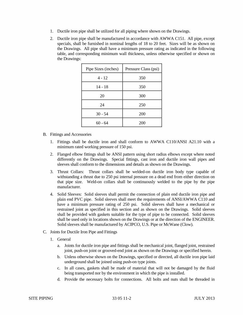
SITE PIPING 33 05 11-2 JULY 2013
1. Ductile iron pipe shall be utilized for all piping where shown on the Drawings.
2. Ductile iron pipe shall be manufactured in accordance with AWWA C151. All pipe, except
specials, shall be furnished in nominal lengths of 18 to 20 feet. Sizes will be as shown on
the Drawings. All pipe shall have a minimum pressure rating as indicated in the following
table, and corresponding minimum wall thickness, unless otherwise specified or shown on
the Drawings:
Pipe Sizes (inches) Pressure Class (psi)
4 - 12 350
14 - 18 350
20 300
24 250
30 - 54 200
60 - 64 200
B. Fittings and Accessories
1. Fittings shall be ductile iron and shall conform to AWWA C110/ANSI A21.10 with a
minimum rated working pressure of 150 psi.
2. Flanged elbow fittings shall be ANSI pattern using short radius elbows except where noted
differently on the Drawings. Special fittings, cast iron and ductile iron wall pipes and
sleeves shall conform to the dimensions and details as shown on the Drawings.
3. Thrust Collars: Thrust collars shall be welded-on ductile iron body type capable of
withstanding a thrust due to 250 psi internal pressure on a dead end from either direction on
that pipe size. Weld-on collars shall be continuously welded to the pipe by the pipe
manufacturer.
4. Solid Sleeves: Solid sleeves shall permit the connection of plain end ductile iron pipe and
plain end PVC pipe. Solid sleeves shall meet the requirements of ANSI/AWWA C110 and
have a minimum pressure rating of 250 psi. Solid sleeves shall have a mechanical or
restrained joint as specified in this section and as shown on the Drawings. Solid sleeves
shall be provided with gaskets suitable for the type of pipe to be connected. Solid sleeves
shall be used only in locations shown on the Drawings or at the direction of the ENGINEER.
Solid sleeves shall be manufactured by ACIPCO, U.S. Pipe or McWane (Clow).
C. Joints for Ductile Iron Pipe and Fittings
1. General
a. Joints for ductile iron pipe and fittings shall be mechanical joint, flanged joint, restrained
joint, push-on joint or grooved-end joint as shown on the Drawings or specified herein.
b. Unless otherwise shown on the Drawings, specified or directed, all ductile iron pipe laid
underground shall be joined using push-on type joints.
c. In all cases, gaskets shall be made of material that will not be damaged by the fluid
being transported nor by the environment in which the pipe is installed.
d. Provide the necessary bolts for connections. All bolts and nuts shall be threaded in
SITE PIPING 33 05 11-3 JULY 2013
accordance with ANSI B1.1, Coarse Thread Series, Class 2A external and 2B internal
fit. All bolts and nuts shall be made in the U.S.A.
2. Mechanical Joints
a. Joints shall conform to AWWA C111/ANSI A21.11.
b. Bolts and nuts shall be Tee Head Bolts and nuts of high strength low-alloy steel in
accordance with ASTM A 242 to the dimensions shown in AWWA C111/ANSI
A21.11.
c. Gaskets shall be in accordance with AWWA C111/ANSI A21.11 and shall be
constructed of plain rubber.
d. Mechanical joint glands shall be ductile iron.
3. Push-On Joints: Push-on joints and gaskets shall conform to AWWA C111/ANSI A21.11.
Details of the joint design shall be in accordance with the manufacturer's standard practice
such as ACIPCO “Fastite”, McWane (Clow) “Bell-Tite”, or U.S. Pipe “Tyton” joints.
4. Restrained Joints
a. Restrained joints shall be ACIPCO FLEX-RING or “LOK-RING”, McWane (Clow)
“SUPER-LOCK” or U.S. “TR-FLEX” or “LOK-TYTE”.
b. Restraining gaskets shall be ACIPCO “Fast-Grip” or U.S. Pipe “Field-Lok Gasket”.
c. Bolts and nuts shall be in accordance with the manufacturer's recommendations.
d. Gaskets shall be in accordance with the manufacturer's recommendations.
D. Linings: All ductile iron pipe and fittings shall be ceramic epoxy lined except for NPW ductile
iron piping. All ductile iron NPW pipe and fittings shall be double cement lined.
E. Wall Sleeves
1. Where piping passes through concrete structures, furnish and install wall sleeves unless wall
pipes or other provisions are specifically shown on the Drawings. Wall sleeves shall be
accurately located and securely fastened into position before concrete is poured.
2. Wall Sleeves
a. For pipe sizes smaller than 3-inches, wall sleeves shall be steel oversize sleeves
furnished with a full circle, integral, or continuously welded waterstop collar. The
sleeve seal shall be the mechanically expanded, synthetic rubber type. Provide all
associated bolts, seals and seal fittings, pressure clamps, or plates necessary to achieve a
watertight installation. Sleeves shall extend the full thickness of the concrete. Sleeves
and seal shall be Link Seal.
b. For larger pipe sizes, wall sleeves shall be statically cast ductile iron mechanical joint
wall sleeves. Unless specified or shown otherwise for a specific situation, wall sleeves
shall be mechanical joint bell-plain end type with waterstop/thrust collar. The collar
shall be capable of withstanding a thrust force caused by a 250 psi dead end load from
either direction on that size pipe. Sleeves shall be constructed with studs and
mechanical joint retainer gland on the air side of the concrete structure. Where the
concrete structure is exposed to dirt on one side and is wet on the other side, construct
with studs and glands on the dirt side. Wall sleeves shall be equal to ACIPCO A-10771.
F. Flange Adapters: Flange adapters shall permit the connection of unthreaded, ungrooved,
open-ended, ductile iron pipe to ANSI/ASME B16.1, Class 125 flanges. Flange adapters shall
meet the test requirements of ANSI/ASME B16.1 for Class 125 flanges. The adapter shall be a
ductile iron casting incorporating a flange with extended throat, set screws and gasket. The
gasket shall provide a compression seal between the adapter, the pipe and the adjacent flange.

SITE PIPING 33 05 11-4 JULY 2013
Flange adapters are to be used only in locations specifically shown on the Drawings or at the
direction of the ENGINEER, and in accordance with the manufacturer's recommendations.
Flange adapters shall be manufactured by McWane, Uni-Flange (Series 400) or EBAA Iron.
2.02 POLYVINYL CHLORIDE (PVC) GRAVITY SEWER OR DRAIN PIPE
A. Polyvinyl chloride gravity sewer or drain pipe shall be as specified as below
B. Acceptability of PVC pipe for gravity pipelines is indicated in the following table:
Standard
Minimum Thickness
Type PVC (as
specified in ASTM
D 1784)
Wall
Acceptable
Manufacturers
< 6
8 to
15
18
21
24
30 to 48
ASTM D 3034
SDR 35
12454B
Solid Open
Certainteed
J-M Pipe
Yes Yes No No No No
C. All pipe shall have a minimum pipe stiffness of 46 psi at five percent deflection as determined by
ASTM D 2412.
D. PVC gravity sewer or drain pipe shall be supplied in lengths not longer than 13 feet.
E. Fittings
1. Fittings 15-inches in diameter and less shall be manufactured in accordance with ASTM D
3034. PVC compound shall be 12454B or 12454C as specified in ASTM D 1784.
a. For sizes 8-inches and less in diameter, fittings shall be molded in one-piece with no
solvent welded joints. Minimum socket depths shall be as specified in ASTM D 3034,
Table 2.
b. For sizes 10-inches and larger in diameter, fittings shall be fabricated from pipe
conforming to ASTM D 3034 using solvent welding. No field fabrication of fittings
will be allowed. All such fabrication shall be performed at the factory and the fittings
shall be delivered ready for use.
2. Fittings 18-inches in diameter and larger shall be fabricated from pipe conforming to ASTM
F 679 using solvent welding. No field fabrication of fittings will be allowed. All such
fabrication shall be performed at the factory and the fittings shall be delivered ready for use.
F. Joints: Joints for pipe and fittings shall be of the integral bell and spigot type with a confined
elastomeric gasket having the capability of absorbing expansion and contraction without leakage,
when tested in accordance with ASTM D 3212. Gaskets shall meet the requirements of ASTM
F 477. The joint system shall be subject to the approval of the Engineer and shall be identical for
pipe and fittings.
G. Manhole Connections
1. Solid Wall and Closed Profile Wall Pipe: The sewer shall be connected to manholes
utilizing a standard pipe section.
2. Open Profile Wall Pipe: The sewer shall be connected to manholes with an adapter piece.
The adapter piece shall have an open profile pipe bell and a solid wall pipe spigot for
penetrating the manhole wall.
H. Acceptance: Acceptance will be on the basis of the CITY's inspection and the manufacturer's
SITE PIPING 33 05 11-5 JULY 2013
written certification that the pipe and fittings were manufactured and tested in accordance with
the applicable standards.
2.03 GLASS REINFORCED PLASTIC (GRP) GRAVITY SEWER OR DRAIN PIPE
A. Resin: The manufacturer shall use only polyester or vinyl ester resin systems designed for
the service intended.
B. Filler: Silica sand shall conform to the requirements of ASTM C 33, except that the
requirements for gradation shall not apply.
C. Additives: Resin additives, such as curing agents, pigments, dyes, fillers and thixotropic
agents, when used, shall not be detrimental to the pipe.
D. Fiber-Glass Reinforcement: Fiberglass filaments and chop rovings shall be commercial grade
glass fibers with a finish compatible with the resin used. For sewer applications ECR-glass
shall be used.
E. Pipe: The filament wound fiberglass pipe must be manufactured using a continuous
advancing mandrel process utilizing continuous glass fiber reinforcements in the
circumferential direction. Both continuous glass fiber rovings and chopped roving will be
incorporated for high hoop strength and axial reinforcement. A sand fortifier shall be used to
provide increased stiffness with placement near the neutral axis in the core. Pipe shall be
manufactured in accordance with either ASTM D3517 or ASTM D3754. Pipe shall be
supplied in nominal lengths of 10 to 40 feet. Actual lay length shall be nominal ±2 inch.
Special short lengths may be used where surface geography or installation conditions require
shorter lengths. The average wall thickness of the pipe shall not be less than the nominal wall
thickness published in the manufacturer’s literature, and the minimum wall thickness at any
point shall not be less than 87.5% of the nominal wall thickness. All points around each end
of a pipe unit shall fall within 1/4 inch or 0.5% of the nominal diameter of the pipe,
whichever is greater, to a plane perpendicular to the longitudinal axis of the pipe.
F. Fittings: Elbows, reducers, tees, wyes, laterals and other fittings shall be of the same
structural design as adjoining pipe. Fittings shall be manufactured with mitered sections of
pipe and joined by fiber-glass overlay.
G. Layup Joint: Joint shall be made from glass fiber reinforcements impregnated with polyester
resin.
H. Acceptable Manufacturer: Manufacturer shall be U.S. Composite Pipe South, or equal.
2.04 FIBERGLASS REINFORCED PLASTIC PIPE
Refer to Section 40 05 14.
PART 3 – EXECUTION
3.01 EXISTING UNDERGROUND UTILITIES AND OBSTRUCTIONS
A. The Drawings indicate utilities or obstructions that are known to exist according to the best
information available to the CITY. The CONTRACTOR shall call Ohio Utility Protection
Service and all utilities, agencies or departments that own and/or operate utilities in the vicinity
of the construction work site at least 72 hours (three business days) prior to construction to verify
the location of the existing utilities.
B. Existing Utility Location: The following steps shall be exercised to avoid interruption of

SITE PIPING 33 05 11-6 JULY 2013
existing utility service.
1. Provide the required notice to the utility owners and allow them to locate their facilities.
Field utility locations are valid for only 10 days after original notice. The CONTRACTOR
shall ensure, at the time of any excavation, that a valid utility location exists at the point of
excavation.
2. Expose the facility, for a distance of at least 200 feet in advance of pipeline construction, to
verify its true location and grade. Repair, or have repaired, any damage to utilities resulting
from locating or exposing their true location.
3. Avoid utility damage and interruption by protection with means or methods recommended
by the utility owner.
4. Maintain a log identifying when phone calls were made, who was called, area for which
utility relocation was requested and work order number issued, if any. The CONTRACTOR
shall provide the CITY an updated copy of the log bi-weekly, or more frequently if required.
C. Conflict with Existing Utilities
1. Horizontal Conflict: Horizontal conflict shall be defined as when the actual horizontal
separation between a utility, main, or service and the proposed piping does not permit safe
installation of the piping by the use of sheeting, shoring, tieing-back, supporting, or
temporarily suspending service of the parallel or crossing facility. The CONTRACTOR
may change the proposed alignment of the piping to avoid horizontal conflicts if the new
alignment remains within the available right-of-way or easement, complies with regulatory
agency requirements and after a written request to and subsequent approval by the
ENGINEER. Where such relocation of the piping is denied by the ENGINEER, the
CONTRACTOR shall arrange to have the utility, main, or service relocated.
2. Vertical Conflict: Vertical conflict shall be defined as when the actual vertical separation
between a utility, main, or service and the proposed piping does not permit the crossing
without immediate or potential future damage to the utility, main, service, or the piping. The
CONTRACTOR may change the proposed grade of the piping to avoid vertical conflicts if
the changed grade maintains adequate cover and complies with regulatory agencies
requirements after written request to and subsequent approval by the ENGINEER. Where
such relocation of the piping is denied by the ENGINEER, the CONTRACTOR shall
arrange to have the utility, main, or service relocated.
D. Electronic Locator: Have available at all times an electronic pipe locator and a magnetic locator,
in good working order, to aid in locating existing pipe lines or other obstructions.
E. Water and Sewer Separation
1. Potable water mains should maintain a minimum 10 foot edge-to-edge separation from
sewer lines, whether gravity or pressure. If the main cannot be installed providing the 10
foot separation, the separation may be reduced, provided the bottom of the water main is a
minimum of 18-inches above the top of the sewer. Should neither of these two separation
criteria be possible, the potable water main shall be installed below the sewer with a
minimum vertical separation of 18-inches and the water main shall be encased in concrete
with a minimum depth of 6-inches.
2. Where water mains cross the sewer, the pipe joint adjacent to the pipe crossing the sewer
shall be cut to provide maximum separation of the pipe joints from the sewer.
3. No water main shall pass through, or come in contact with, any part of a sanitary sewer
manhole.
SITE PIPING 33 05 11-7 JULY 2013
3.02 LOCATION AND GRADE
A. The Drawings show the alignment of the piping and the location of other appurtenances.
B. Construction Staking
1. The location of principal components of the work is shown on the Drawings. The
CONTRACTOR shall be responsible for performing all survey work required for
construction, including the establishment of base lines and any detailed surveys and bench
marks adjacent to the work. Base lines shall be defined as the line to which the location of
the work is referenced, i.e. edge of pavement, road centerline, property line, right-of-way or
survey line.
2. The level of detail of survey required shall be that which the correct location of the site
piping can be established for construction.
3.03 LAYING AND PIPE ASSEMBLY
A. Installation
1. Proper implements, tools and facilities shall be provided for the safe performance of the
work. All pipe, fittings, valves and hydrants shall be lowered carefully into the trench by
means of slings, ropes or other suitable tools or equipment in such a manner as to prevent
damage to piping materials and protective coatings and linings. Under no circumstances
shall piping materials be dropped or dumped into the trench.
2. All pipe, fittings, valves, and other appurtenances shall be examined carefully for damage
and other defects immediately before installation. Defective materials shall be marked and
held for inspection by the CITY, who may prescribe corrective repairs or reject the
materials.
3. All lumps, blisters and excess coating shall be removed from the socket and plain ends of
each pipe, and the outside of the plain end and the inside of the bell shall be wiped clean and
dry and free from dirt, sand, grit or any foreign materials before the pipe is laid. No pipe
containing dirt shall be laid.
4. Foreign material shall be prevented from entering the pipe while it is being placed in the
trench. No debris, tools, clothing or other materials shall be placed in the pipe at any time.
5. As each length of pipe is placed in the trench, the joint shall be assembled and the pipe
brought to correct line and grade. The pipe shall be secured in place with approved backfill
material.
6. Applying pressure to the top of the pipe, such as with a backhoe bucket, to lower the pipe to
the proper elevation or grade, shall not be permitted.
7. Provide mylar detection tape and tracer wire for all non-metallic pipe. Detection tape shall
be buried 4 to 10-inches deep. Should detection tape need to be installed deeper, the
CONTRACTOR shall provide 3-inch wide tape. In no case shall detection tape be buried
greater than 20-inches from the finish grade surface. Tracer wire shall be a 19 gauge, tin
coated, copper conductor with green, polyethylene insulation (Item Number RT1803W).
Core material shall be comprised of high-tenacity, woven polyester with water blocking
yarns encapsulated in a 30 mil, HDPE jacket providing corrosion resistance, flexibility,
impact strength and 1800 lbs. tensile strength. Tracer wire shall not conduct an electrical
current when struck by lightning and shall be designed for direct bury and directional
boring applications. Tracer wire shall be Trace-Safe Water Blocking Tracer wire,
manufactured by NEPTCO and produced in the United States of America, or equal.
SITE PIPING 33 05 11-8 JULY 2013
B. Alignment and Gradient
1. Lay pipe straight in alignment and gradient or follow true curves as nearly as practicable.
Do not deflect any joint more than the maximum deflection recommended by the
manufacturer.
2. Maintain a transit, level and accessories on the job to lay out angles and ensure that
deflection allowances are not exceeded.
3. The CONTRACTOR shall check the invert elevation for gravity sewer or drain pipe at each
manhole at least three times daily, start, mid-day and end of day. Elevations shall be
checked more frequently if more than 100 feet of pipe is installed in a day or if the pipe is
being constructed at minimum slope.
4. The CONTRACTOR shall check the horizontal alignment of the pipeline at the same
schedule as for invert elevations.
C. Expediting of Work: Excavate, lay the pipe, and backfill as closely together as possible. Do not
leave unjointed pipe in the trench overnight. Backfill and compact the trench as soon as possible
after laying and jointing is completed. Cover the exposed end of the installed pipe each day at
the close of work and at all other times when work is not in progress. If necessary to backfill
over the end of an uncompleted pipe or accessory, close the end with a suitable plug, either
push-on, mechanical joint, restrained joint or as approved by the ENGINEER.
D. Joint Assembly
1. Push-on, mechanical, flange and restrained type joints shall be assembled in accordance with
the manufacturer's recommendations.
2. Each restrained joint shall be inspected by the CONTRACTOR to ensure that it has been
“homed” 100 percent.
3. The CONTRACTOR shall internally inspect each pipe joint to insure proper assembly for
pipe 24-inches in diameter and larger after the pipe has been brought to final alignment.
4. Field welding of steel pipe joints shall conform to the requirements of AWWA C206. All
welding shall be performed by persons meeting the qualification requirements of
ANSI/AWS D1.1.
E. Cutting Pipe: Cut ductile iron pipe using an abrasive wheel saw. Cut PVC pipe using a suitable
saw; remove all burrs and smooth the end before jointing. The CONTRACTOR shall cut the
pipe and bevel the end, as necessary, to provide the correct length of pipe necessary for installing
the fittings, valves, accessories and closure pieces in the correct location. Only push-on or
mechanical joint pipe shall be cut.
F. Lining Repair: Repair linings and recoat spigot ends of cut pipe with a product equal to Protecto
101 or Madewell 1104 coal tar epoxy in accordance with the manufacturer's recommendations
and as specified below:
1. Remove all burrs and areas of loose lining materials by sanding or scraping to bare metal.
2. Remove oil and lubricants used during field cutting.
3. Lining shall be stripped back a minimum of 1-inch from the spigot end into well adhered
lined areas.
4. Roughen 1 to 2-inches of good lining with a rough grade (40 grit) emery paper, rasp or small
chisel, to allow an overlap between new and existing lining.
5. Apply lining repair material in the number of coats required to match the thickness
SITE PIPING 33 05 11-9 JULY 2013
requirements as specified in Part 2 of this section and in accordance with the manufacturer's
recommendations.
3.04 CONNECTIONS TO EXISTING PIPING
A. Make connections to existing pipe lines as shown on the Drawings.
B. Location: Before laying pipe, locate the points of connection to existing piping and uncover as
necessary to confirm the nature of the connection to be made.
C. Interruption of Services: Make connections to existing piping only when system operations
permit. Operate existing valves only with the specific authorization and direct supervision of the
CITY.
D. Connections Using Solid Sleeves: Where solid sleeves are shown on the Drawings, the
CONTRACTOR shall furnish materials and labor necessary to make the connection using a
solid sleeve to the existing pipe line.
E. Connections Using Flange Filler: Flange filler shall be used only where shown on the Drawings
or approved by the ENGINEER to make up minor differences in pipe length less than 3-inches.
Joint bolt length shall be increased by the thickness of the flange filler.
F. Connections Using Mechanical Pipe Couplings: Where pipe couplings are shown on the
Drawings, the CONTRACTOR shall furnish materials and labor necessary to make the
connection using a pipe coupling to the existing pipe line, including all necessary cutting,
plugging and backfill.
G. Connections to Pressure Mains
1. Connections to ductile iron pipe pressure mains shall be by the direct tap method or service
clamp, as detailed on the Drawings in full accordance with AWWA requirements.
2. Connections to polyvinyl chloride pipe shall be made using a full body service clamp.
3. Pressure ratings for connections shall be the same as the pressure rating for the pipe.
3.05 THRUST RESTRAINT
A. Provide restraint at all points where hydraulic thrust may develop.
B. Retainer Glands: Provide retainer glands where shown or called for on the Drawings and all
associated fittings, valves and related piping. Retainer glands shall be installed in accordance
with the manufacturer's recommendations, particularly, the required torque of the set screws.
The CONTRACTOR shall furnish a torque wrench to verify the torque on all set screws which
do not have inherent torque indicators.
C. Harnessing
1. Provide harness rods only where specifically shown on the Drawings or directed by the
ENGINEER.
2. Where possible, harness rods shall be installed through the mechanical joint bolt holes.
Where it is not possible, provide 90 degree bend eye bolts.
D. Concrete Blocking
1. Where shown on the Drawings, provide concrete blocking for all bends, tees, valves, and
other points where thrust may develop, except where other exclusive means of thrust
restraint are specifically shown on the Drawings.
SITE PIPING 33 05 11-10 JULY 2013
2. Concrete shall be as specified in Section 03 30 00 of these Specifications.
3. Form and pour concrete blocking at fittings as shown on the Drawings and as directed by the
ENGINEER. Pour blocking against undisturbed earth. Increase dimensions when required
by over excavation.
3.06 INSPECTION AND TESTING
All pressure and leakage testing shall be performed in accordance with the requirements of Section
33 08 13 of these Specifications.
3.07 INSULATION AND HEAT TRACING
Provide insulation and heat tracing in accordance with Section 40 41 13 of these Specifications.
3.08 DISINFECTION
All potable water lines shall be disinfected in accordance with Section 22 11 00B of these
Specifications.
END OF SECTION 33 05 11
PIPING TESTING AND ACCEPTANCE 33 08 13-1 JULY 2013
SECTION 33 08 13
PIPING TESTING AND ACCEPTANCE
PART 1 - GENERAL
1.01 SCOPE
A. Furnish all labor, materials, tools, equipment and related items required to perform tests of
gravity pipelines and perform integrity and leakage tests of pressure and vacuum piping.
Cost for all testing shall be included in the lump sum bid and is not part of the testing
allowance.
B. The testing requirements covered under this section shall apply to all piping systems covered
under Section 33 05 11 of these Specifications.
1.02 SUBMITTALS
Submittals shall conform to the requirements of Section 01 33 00 of these Specifications and shall
include a description of the testing procedures to be employed and the report form to be
furnished.
PART 2 - PRODUCTS
2.01 TEST MEDIUMS
The CITY will provide the necessary water required for testing the work. The CONTRACTOR
shall furnish all other test mediums. The CONTRACTOR shall furnish all equipment, necessary
piping and required labor to transport water from its source to the test location for use in testing.
2.02 TEST EQUIPMENT
The CONTRACTOR shall furnish all labor and equipment, including required pumps with
regulated bypass meters and gauges, for conducting of the piping tests.
PART 3 - EXECUTION
3.01 GENERAL
A. The entire length of all pressurized piping and gravity lines shall be field tested for tightness
by a test as described in this section.
B. The timing and sequence of testing shall be scheduled by the CONTRACTOR, subject to the
approval of the CITY. The CONTRACTOR shall provide the CITY with a minimum of 24
hours notice prior to the start of any test. All tests must be observed by the CITY.
C. The CONTRACTOR shall repair any leaks discovered during the initial filling of the piping
and during the testing sequence. All known and visible leaks shall be repaired, whether or
not the leakage rate is within allowable limits.
3.02 MAJOR PIPING
A. All piping not listed under Article 3.03 or 3.04 shall be tested in accordance with Article
3.02. This shall include gravity and pressure pipelines. Storm drains shall be exempted from
testing required by this section.

PIPING TESTING AND ACCEPTANCE 33 08 13-2 JULY 2013
B. Clean and test lines before requesting final acceptance. Where any obstruction is met, clean
the lines by means of rods, swabs, or other instruments. When requested by the CITY, flush
out lines and manholes before final inspection.
C. Gravity Pipelines
1. Pipe lines shall be straight and show a uniform grade between manholes. Correct any
discrepancies discovered during inspection.
2. Pipe joints for pipelines 30-inches in diameter and larger shall be air tested individually.
The joint tester assembly shall be placed over the joint and shall pressurize the joint area
to 4 psi. The pressure shall not drop more than 2 psi in 10 seconds. The joint tester
assembly shall be equal to that as supplied by Cherne Industries, Inc.
3. Infiltration Tests: Use only when groundwater is two feet above the top of the pipe.
a. Install suitable weirs in manholes selected by the CITY to determine the leakage of
ground water into the sewer. Measure leakage only when all visible leaks have been
repaired and the ground water is two feet above the top of the pipe. If leakage in any
section of the pipeline exceeds 100 gpd/inch/diameter/mile, locate and repair leaks.
Repair methods must be approved by the CITY. After repairs are completed, re-test
for leakage.
b. Furnish, install and remove the necessary weirs, plugs and bulkheads required to
perform the leakage tests. Where continuous monitoring of low level is required, the
CONTRACTOR shall provide and operate monitoring equipment.
4. Exfiltration Tests: Choose one of the following when groundwater is not two feet above
the top of the pipe.
a. Hydrostatic Test
i. Test pipe between manholes or structures with a minimum of 10 feet hydrostatic
pressure, measured at the center of the pipe at the upstream manhole or structure.
ii. The ends of the pipe in the test section shall be closed with suitable watertight
bulkheads. Inserted into the top of each bulkhead shall be a 2-inch pipe nipple
with an elbow. At the upper end of the test section, a 12-inch riser pipe shall be
connected to the 2-inch nipple. The test section of pipe shall be filled through the
pipe connection in the lower bulkhead which shall be fitted with a valve, until all
air is exhausted and until water overflows the riser pipe at the upper end. Water
may be introduced into the pipe 24 hours prior to the test period to allow
complete saturation. House service lines, if installed, shall also be fitted with
suitable bulkheads having provisions for the release of air while the test section is
being filled with water.
iii. During the test period, which shall extend over a period of 2 hours, water shall be
introduced into the riser pipe from measured containers at such intervals as are
necessary to maintain the water level at the top of the riser pipe. The total
volume of water added during the test period shall not exceed that specified for
infiltration.
b. Low-Pressure Air Test
i. Prior to air testing, the section of pipeline between manholes or structures shall
be thoroughly cleaned and wetted. Immediately after cleaning or while the pipe
is water soaked, the sewer shall be tested with low-pressure air. At the
CONTRACTOR's option, pipelines may be tested in lengths between manholes
or in short sections (25 feet or less) using Air-Lock balls pulled through the line

PIPING TESTING AND ACCEPTANCE 33 08 13-3 JULY 2013
from manhole to manhole. Air shall be slowly supplied to the plugged sewer
section until internal air pressure reaches approximately 4.0 psi. After this
pressure is reached and the pressure allowed to stabilize (approximately two to
five minutes), the pressure may be reduced to 3.5 psi before starting the test. If a
1.0 psi drop does not occur within the test time, then the line has passed the test.
If the pressure drops more than 1.0 psi during the test time, the line is presumed
to have failed the test, and the CONTRACTOR will be required to locate the
failure, make necessary repairs and retest the line. Minimum test time for
various pipe sizes, in accordance with ASTM C 828 is as follows:
Nominal Pipe Size, inches T (time) Min/100 Feet
8 1.2
10 1.5
12 1.8
14 2.0
15 and 16 2.1
18 2.4
21 3.0
24 3.6
27 4.2
30 4.8
36 6.0
39 6.6
42 7.3
48 8.6
ii. Required test equipment, including Air-Lock balls, braces, air hose, air source,
timer, rotometer as applicable, cut-off valves, pressure reducing valve, 0-15 psi
pressure gauge, 0-5 psi pressure gauge with gradations in 0.1 psi and accuracy of
+ two percent, shall be provided by the CONTRACTOR.
iii. The CONTRACTOR shall keep records of all tests made. Copy of such records
will be given to the CITY. Such records shall show date, line number and
stations, operator and such other pertinent information as required by the CITY.
iv. The CONTRACTOR is cautioned to observe proper safety precautions in
performance of the air testing. It is imperative that plugs be properly secured and
that care be exercised in their removal. Every precaution shall be taken to avoid
the possibility of over-pressurizing the line.
5. HDPE, FRP, GRP and PVC Deflection Test: Test HDPE, FRP and PVC gravity
pipelines for excessive deflection as specified in the City of Cincinnati Supplement to the
State of Ohio, Department of Transportation, Construction and Material Specifications.
Maximum limit for vertical deflection shall be 5% of the pipe inside diameter.

PIPING TESTING AND ACCEPTANCE 33 08 13-4 JULY 2013
Deflection tests shall be conducted thirty (30) days after placing backfill.
CONTRACTOR shall repair or replace sewers failing the deflection tests at no cost to
CITY.
D. Pressure Pipelines
1. All sections of pipeline subject to internal pressure shall be pressure tested in accordance
with AWWA C600. A section of line will be considered ready for testing after
completion of all thrust restraint and backfilling.
2. Each segment of pipeline between line valves shall be tested individually.
3. Test Preparation
a. For pipelines less than 24-inches in diameter, flush pipeline section thoroughly at
flow velocities greater than 2.5 feet per second, adequate to remove debris from pipe
and valve seats. For pipelines 24-inches in diameter and larger, the main shall be
carefully swept clean and mopped, if directed by the Engineer. Partially operate
valves and hydrants to clean out seats. Provide correctly sized temporary outlets in
number adequate to achieve flushing velocities.
b. Provide temporary blocking, bulkheads, flanges and plugs as necessary, to assure all
new pipe, valves and appurtenances will be pressure tested.
c. Before applying test pressure, air shall be completely expelled from the pipeline and
all appurtenances. Unless permanent air vents are in place, insert temporary
corporation stops at highpoints to expel air as line is filled with water.
d. Fill pipeline slowly with water. Provide a suitable pump with an accurate water
meter to pump the line to the specified pressure. Differential pressure at valves and
hydrants shall equal the maximum possible, but shall not exceed manufacturer's
pressure rating. Where necessary, provide temporary back pressure to meet the
differential pressure restrictions.
e. Valves and hydrants shall not be operated in either the opening or closing direction at
differential pressures above their rated pressure.
4. The test pressure shall be measured at the lowest point in the test segment and shall be
maintained for a minimum of two hours. Test piping in accordance with the minimum
test pressures shown in 40 01 20.59.
5. The test pressure shall not vary by more than 5 psi for the test duration. Should the
pressure drop more than 5 psi at any time during the test period, the pressure shall be
restored to the specified test pressure. Provide an accurate pressure gage with graduation
not less than 5 psi.
6. Leakage: Leakage shall be defined as the quantity of water that must be pumped into the
test section equal to the sum of the water, to maintain pressure within 5 psi of the
specified test pressure for the test duration plus water required to return line to test
pressure at the end of the test. Leakage shall be the total cumulative amount measured on
a water meter.
7. Test Results: No test section shall be accepted if the leakage exceeds the limits
determined under Section 5 of AWWA C600. The leakage test shall be repeated until the
test section is accepted. All visible leaks shall be repaired regardless of leakage test
results.
8. Completion: After a pipeline section has been accepted, relieve test pressure. Record
type, size and location of all outlets on record drawings.

PIPING TESTING AND ACCEPTANCE 33 08 13-5 JULY 2013
9. Should any discrepancies arise on pipe testing pressures between various specification
sections, most stringent requirements will govern.
3.03 MAJOR AIR PIPING
A. All air piping, 4-inches and larger, subject to internal pressure not listed under Article 3.03 of
this section shall be tested in accordance with this Article.
B. Each segment of pipeline between line valves shall be tested individually.
C. Test Preparation
1. For pipelines less than 24-inches, the pipeline shall be cleaned using a pig or swab to
remove all dirt and debris. For pipelines 24-inches in diameter and larger, the pipeline
shall be carefully swept. Partially operate valves to clean out seats.
2. Provide temporary blocking, bulkheads, flanges, and plugs as necessary to assure all new
pipe, valves, and appurtenances will be pressure tested. Provide an air tap as required for
filling the pipeline.
3. Test equipment to be provided by the CONTRACTOR shall include Air-Lock balls,
braces, air hoses, air source, timer, cut-off valves, 30 psi pressure gauge with minimum
graduations of 02. psi and an accuracy of 2 percent.
4. Fill the pipeline slowly with air until the test pressure has been reached. Allow the
pressure to stabilize for 15 minutes.
D. Test the pipeline at a test pressure of 25 psi for one hour. If a measurable pressure drop is
observed by the end of the test period, the pipeline has failed the test. All leaks shall be
located and repaired and the system retested until no measurable pressure drop is observed.
E. Completion: After a pipeline has been accepted, relieve the test pressure. Submit a copy of
the test results to the CITY for review and approval.
3.04 VIDEO TAPING OF INSTALLED SEWERS
A. CONTRACTOR to furnish videotaping of installed sewers, meeting the requirements of Item
603.059 of the City Supplement to the State of Ohio (ODOT) Construction and Material
Specifications and according to the following current requirements:
1. Current Pipeline Assessment Certification Program PACP certification of all CCTV
operators will be required for all CCTV work.
2. Database shall be an unmodified NASSCO-PACP Certified Access Database.
3. CCTV Software shall be NASSCO-PACP certified.
B. Initial Survey Television Inspection
1. The CONTRACTOR shall televise the sewer and shall inspect the upstream and
downstream manholes of each sewer segment televised and document all observations.
2. Sewer sections and manholes shall be inspected by means of remote CCTV. If a
blockage cannot be removed and hampers the videotaping of the sewer in one direction,
then the CONTRACTOR shall attempt to complete the section by televising from the
other manhole to complete the section. This reversal must immediately follow the initial
direction on the same survey and report. The CONTRACTOR must immediately report
the obstruction to the CITY.
3. The recorded video must show the entire circumference of the sewer. Any flow control

PIPING TESTING AND ACCEPTANCE 33 08 13-6 JULY 2013
to remove standing water and debris shall be incidental to this item. The
CONTRACTOR must also consider weather conditions to obtain the best video image of
the sewer. This may require the CONTRACTOR to delay any video work until after
major rain events to allow the system to return to lower dry weather flow.
4. Perform all CCTV inspections in accordance with NASSCO’s PACP. CCTV inspections
will be conducted entirely in digital format. The entire inspection survey shall be
recorded in MPEG-1 format written to DVD and submitted with digital links to the
survey. All cleaning and television inspection reports shall be with-in +/- 2 feet of the
measured linear footage between manholes along the existing sewer centerline from the
center of the manhole.
5. The documentation of the work shall consist of PACP CCTV Reports, Unmodified PACP
database, logs, electronic reports, etc. noting important features encountered during the
inspection. The speed of travel shall be slow enough to inspect each pipe joint, tee
connection, structural deterioration, infiltration and inflow sources, and deposits, but
should not, at any time, be faster than thirty (30) feet per minute. The camera must be
centered in the pipe to provide accurate distance measurements to provide exact locations
of important features in the sewer and these footage measurements shall be displayed and
documented on the video. The completed DVD will become the property of the CITY.
6. Every section of sewer (manhole to manhole) shall be identified by audio and
alphanumeric on the video display and shall include Project name, municipality, street
name, CAGIS manhole numbers (CONTRACTOR shall request the eight digit manhole
numbers assigned by CITY for all proposed and existing manholes included in video),
inspector’s name, sewer diameter and length, and date of inspection. Important features
shall be identified by audio and on PACP log to include all manholes, active and inactive
service connections, structural defects, maintenance problems, grease, roots, infiltration,
obvious inflow sources, etc. All video must be continuously metered from manhole to
manhole. In addition to televising the sewer, all manholes shall be panned with the video
camera and visually inspected.
3.05 REPAIRS
If the leakage exceeds the specified allowable limits, the point or points of leakage shall be
sought out and remedied by the CONTRACTOR at no additional cost to the CITY. Repair
methods must be approved by the CITY.
3.06 FLUSHING AND CLEANING
The systems shall not be used, except for chemical cleaning, until the CITY has been assured that
cleaning has been accomplished.
3.07 FINAL ACCEPTANCE
A. No pipeline installation shall be accepted until all known and visible leaks have been
repaired, whether or not the leakage is within the maximum allowable limits.
B. The CONTRACTOR will certify that all required tests have been successfully completed
before the work is accepted.
END OF SECTION 33 08 13
PIPING AND EQUIPMENT CLEANING AND TESTING 40 01 20.59-1 AUGUST 2014
SECTION 40 01 20.59
PIPING AND EQUIPMENT CLEANING AND TESTING
PART 1 - GENERAL
1.01 SCOPE
A. This Section specifies the general procedures to be followed in cleaning and testing piping.
B. CONTRACTOR shall furnish all labor, tools, and equipment required for this work.
C. The CITY's Representative shall be notified in advance of equipment/system cleaning and
testing.
D. Cleaning method, test medium and test pressure are defined for each service on the attached
Cleaning and Testing Index. See Part 3 of this Specification for complete description of
cleaning methods and test procedures.
1.02 REFERENCES
A. The latest edition of the publications listed below is included as part of these Contract
Documents:
1. American National Standards Institute (ANSI) and American Water Works Association
(AWWA)
2. Standard Mechanical Code
1.03 SUBMITTALS
A. The proposed testing procedures, including test medium and pressure, line segments and
equipment included in the test, methods of isolating test from rest of system, and pressure
monitoring techniques, shall be approved by the CITY's Representative prior to
commencement of the test.
B. A detailed report of pressure tests on piping and equipment shall be forwarded in duplicate to
the CITY. This report shall show date of test, lines tested, test medium, length of time test
pressure was held, pressure drop or rise, and extent of venting or repressurizing.
C. The CONTRACTOR may submit a test procedure or cleaning specification in lieu of this
Specification to the CITY for approval. Any deviations from this Specification must be
approved in writing by the CITY before any such deviation is instituted.
PART 2 - PRODUCTS
2.01 GENERAL
A. Detergents, solvents, and other cleaning materials shall be compatible with the materials of
fabrication of the systems in which they are used. They shall not adversely affect the
materials or mechanisms in the systems and they shall be acceptable to equipment
manufacturers. Detergents, solvents, and other cleaning agents shall also be compatible with
the process streams to be handled by the systems in which they are used.
B. Materials in blinds, gaskets, bolts, etc. used in isolating segments of systems shall be
compatible with the systems being cleaned and/or tested.
PIPING AND EQUIPMENT CLEANING AND TESTING 40 01 20.59-2 AUGUST 2014
PART 3 - EXECUTION
3.01 CLEANING
A. General
1. The CONTRACTOR shall provide and install necessary temporary connections, strainers
and other equipment to thoroughly clean the piping systems before start-up. The
CONTRACTOR shall dispose of cleaning agents and remove temporary connections and
strainers after cleaning is complete.
2. Piping shall be cleaned just prior to installation and/or plant start up whenever possible.
Cleaned piping material shall be protected against contamination by sealing open ends
with clean plastic sheet or metal foil.
3. Cleaning procedures will be approved by the CITY, or his designated Representative, and
completed to his satisfaction.
4. Cleaning shall be otherwise completed according to the schedule in Table 1 "Cleaning
and Testing Index".
B. Cleaning Methods
1. Cleaning Method "A"
a. Prior to erection:
i. Hammer, brush, etc., to loosen sand, dirt, scale, or other contaminants when
necessary.
ii. Blow with air, or hose with clean water, and visually inspect for contaminants.
iii. On pipes stored before erection, dry and seal the ends to prevent contamination
during storage.
b. After erection thoroughly flush the system with clean water or steam to remove all
foreign material and blow free of water with dry oil-free air.
2. Cleaning Method "B"
a. Carefully handle fabrication and installation to avoid all unnecessary contamination
of these lines.
b. Thoroughly flush with clean water after installation.
c. Purge with dry, oil-free air until lines are completely dry before placing in service.
3.02 TESTING
A. General
1. Test pressure shall be as defined in the attached Testing and Cleaning Index. Final test
pressure for each test shall be maintained for a sufficient length of time to facilitate a
complete inspection of all joints and connections, but no less than that specified by the
applicable testing procedure. When it is necessary, for practicality, to include a vessel or
other equipment, the test pressure shall not exceed the allowable cold limit of the
equipment.
2. Detected leaks shall be repaired. Piping systems shall be retested if revisions or repairs
are made in piping or pressure equipment.
3. Since the risk of failure, with the attendant possibility of injury, is appreciably greater
during testing, all safety measures required by codes or ordinances applicable to the

PIPING AND EQUIPMENT CLEANING AND TESTING 40 01 20.59-3 AUGUST 2014
situation shall be taken.
4. Equipment or piping to be pressure tested shall not be insulated, covered, painted or
concealed prior to test. Compression joint underground piping may be backfilled prior to
pressure test except that joints shall remain exposed until after the test. Tie rods, clamps,
and all other restraints, shall be in place and fastened.
5. These tests shall not be used to establish pressure ratings.
6. Protect all piping and equipment against over-pressure collapse from vacuum and
hydraulic shock during the filling, testing, and draining procedures. Seats of iron valves
shall not be subjected to a pressure in excess of the maximum cold working pressure of
the valve. Pressure tests against other closed valves shall not exceed the manufacturer's
cold pressure limit. Note that where significant differences in elevation exist, there is a
risk of over-pressure in the lower portions of the system in order to attain test pressure in
the upper portion of the system.
7. Apply test pressure only after the system and test medium are at approximately the same
temperature, preferably not less than 60F. Note that some applicable codes require
testing above a specified minimum temperature. Water temperature shall not exceed
125F.
8. Test, including the inspection of all joints, shall be made to the satisfaction of the CITY's
Representative. Following the completion and approval of the test, restore all
components of the system to normal operating condition. This includes removing the
temporary provisions installed for the test.
9. Testing shall be otherwise completed according to schedule in Table 1 "Cleaning and
Testing Index".
B. Preparatory Work
1. Remove from the system all pumps, turbines, traps, shock arresters, expansion joints,
instruments, control valves, safety valves, rupture discs, filters, orifice plates, etc., which
might be damaged by the test, or are designated by the CITY's Representative. Also
remove all items such as orifice plates which might trap air in a system to be
hydrostatically tested. Disconnect all instrument supplies.
2. Open but do not backseat all valves including bypass valves. Lines containing check
valves shall have the source of test pressure on the upstream side.
3. Clean system prior to testing.
4. Systems may be separated into sub-systems for testing if such action will expedite or
simplify the testing.
C. Testing Methods
1. Test Procedure T1 (Hydrostatic Test)
a. Only filtered water shall be used as test media.
b. No hydrostatic testing shall be done when the ambient temperature is 40F or lower
unless special cold weather provisions are approved by the CITY.
c. Provide vents and drains as required.
d. All lines shall be thoroughly cleaned before testing. See Article 3.01 for cleaning
procedures.
e. Items which are not to be subjected to the hydrostatic test shall be either removed or

PIPING AND EQUIPMENT CLEANING AND TESTING 40 01 20.59-4 AUGUST 2014
blanked off. Short sections of piping removed to permit the installation of blinds or
blanks shall be tested separately.
f. The test pump hook-up for hydrostatic test shall permit applying the pressure
gradually under close control. A valve shall be provided for isolating the piping from
the pressure source during the test period. The system should be filled with water
through a low connection point, care being taken that air is completely vented so that
there are no air pockets remaining. The pressure shall be applied gradually and held
at the specified value for the time required to visually check each weld, connection,
joint, flange, etc., but not less than a minimum of one hour. Test readings may be
taken at the lowest point of the line or system of lines with static head added to the
minimum hydrostatic test pressure. Care shall be taken to insure that at no point a
dangerous over-pressure is experienced.
g. The hydrostatic test shall be considered satisfactory if no visible leakage, cracks or
other signs of distress are discovered on the piping or at any joints. There is no
requirement for minimum pressure drop during the test period; however, the cause of
any pressure loss other than that due to temperature change or similar reasons shall
be justified to the satisfaction of the CITY's Representative.
h. Minor leaks in screwed or flanged joints may be repaired without retesting subject to
the approval of the CITY's Representative.
i. Any welded joint found leaking shall be repaired in accordance with the original
welding procedure and completely retested.
j. After completion of hydrostatic testing, the system shall be completely drained at all
low points in such a way as to accomplish thorough flushing of the system. Test
blinds, temporary supports, test equipment, etc., shall be removed, and any valves,
orifice plates, short sections of piping, miscellaneous in-line equipment or
instruments that were removed prior to testing shall be re-installed and the line left
ready for service. New gaskets shall be used when re-installing flanged items.
k. Care shall be taken to insure the complete removal of all water from the line or
system after testing. If there is any danger of contamination or freezing, blowing out
the fluid with air is necessary.
2. Test Procedure T2 (Leak Test for Drains and Vents - Piping and Equipment)
a. Fill the system with water and visually inspect for leaks.
b. No pressure shall be applied by pump, by supply line, or other external source. The
test crew shall be responsible for filling the system at a rate low enough to prevent
pressurizing due to restricted outflow of air.
c. The test will be considered completed when the CITY, or his designated
Representative, is satisfied that all joints are reasonably tight.
3.03 INSPECTION
A. The CITY’s Representative reserves the right to make any inspections. The CONTRACTOR
shall give the CITY’s Representative free access to his work, and whenever requested, shall
furnish him with full information as to progress of the work and its various parts at place of
fabrication or on the job site. Such inspection shall not relieve the CONTRACTOR from full
responsibility for the quality and correctness of his work.
B. If the Specification, CITY’s Representative’s instructions, ordinances, law, or any other
public authority require any special tests or approval, the CONTRACTOR shall give the
CITY’s Representative timely notice of his readiness for inspection. If the inspection is by an
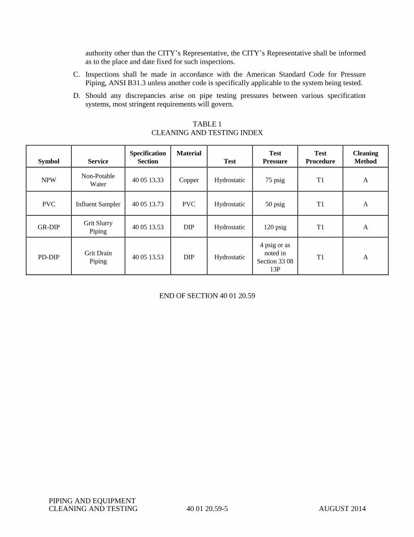
PIPING AND EQUIPMENT CLEANING AND TESTING 40 01 20.59-5 AUGUST 2014
authority other than the CITY’s Representative, the CITY’s Representative shall be informed
as to the place and date fixed for such inspections.
C. Inspections shall be made in accordance with the American Standard Code for Pressure
Piping, ANSI B31.3 unless another code is specifically applicable to the system being tested.
D. Should any discrepancies arise on pipe testing pressures between various specification
systems, most stringent requirements will govern.
TABLE 1
CLEANING AND TESTING INDEX
Symbol
Service
Specification
Section
Material
Test
Test
Pressure
Test
Procedure
Cleaning
Method
NPW Non-Potable
Water 40 05 13.33 Copper Hydrostatic 75 psig T1 A
PVC Influent Sampler 40 05 13.73 PVC Hydrostatic 50 psig T1 A
GR-DIP Grit Slurry
Piping 40 05 13.53 DIP Hydrostatic 120 psig T1 A
PD-DIP Grit Drain
Piping 40 05 13.53 DIP Hydrostatic
4 psig or as
noted in
Section 33 08
13P
T1 A
END OF SECTION 40 01 20.59

PIPING AND EQUIPMENT CLEANING AND TESTING 40 01 20.59-6 AUGUST 2014
THIS PAGE INTENTIONALLY LEFT BLANK

DUCTILE IRON PIPE 40 05 13.53-1 JULY 2013
SECTION 40 05 13.53
DUCTILE IRON PIPE
PART 1 - GENERAL
1.01 SCOPE
A. Provide all labor, materials, equipment and incidentals necessary to construct all ductile iron pipe
and appurtenances located inside and under buildings and structures, and test as shown on the
Drawings and as specified herein.
B. Ductile iron pipe and appurtenances covered under this section shall include all interior pipe and
accessories to the outside face of structures and buildings, except where there is no joint at the
outside face. Where there is no joint at the exterior face, this section shall include all ductile iron
pipe and accessories within two feet of the exterior face of the structure or building.
C. This section includes piping and fittings in utility vaults and manholes.
D. This section includes buried pressure pipe and fittings.
1.02 SUBMITTALS
A. Complete shop drawings and product data on all piping and fittings shall be submitted to the
CITY in accordance with the requirements of Section 01 33 00 of these Specifications.
B. Shop drawings shall indicate piping layout in plan and/or elevations and shall include a complete
schedule of all pipe, fittings, specials, hangers and supports. Special castings shall be detailed
showing all pertinent dimensions. Special coatings shall be clearly identified.
C. The CONTRACTOR shall furnish the CITY with lists of all pieces of pipe and fittings in each
shipment received. These lists shall give the serial or mark number, weight, class, size and
description of each item received.
D. The CONTRACTOR shall submit written evidence to the CITY that the products furnished under
this section will conform with the material and mechanical requirements specified herein.
Certified copies of independent laboratory test results or mill test results from the pipe supplier
may be considered evidence of compliance provided such tests are performed in accordance with
the appropriate testing standards by experienced, competent personnel. In case of doubt as to the
accuracy or adequacy of mill tests, the CITY may require that the CONTRACTOR furnish test
reports from an independent testing laboratory on samples of pipe materials.
PART 2 - PRODUCTS
2.01 DUCTILE IRON PIPE (DIP)
A. Ductile iron pipe shall be utilized for all piping where shown on the Drawings.
B. Ductile iron pipe shall be manufactured in accordance with AWWA C151. All pipe, except
specials, shall be furnished in nominal lengths of 18 to 20 feet. Sizes will be as shown on the
Drawings. All pipe shall have a minimum pressure rating as indicated in the following table, and

DUCTILE IRON PIPE 40 05 13.53-2 JULY 2013
corresponding minimum wall thickness, unless otherwise specified or shown on the Drawings:
Pipe Sizes (inches) Pressure Class (psi)
4 –24 350
C. Flanged pipe minimum wall thickness shall be equal to Special Thickness Class 53. Flanges shall
be furnished by the pipe manufacturer.
D. Flexible Joint (Ball Joint) Pipe: Flexible, restrained joint pipe shall be minimum Thickness Class.
Appropriate transition pieces shall be utilized on each end of run of flexible joint pipe.
E. All ductile iron pipes and fittings shall be coated with ceramic epoxy lining, unless otherwise
noted.
2.02 FITTINGS AND ACCESSORIES
A. Fittings shall be ductile iron and shall conform to AWWA C110/ANSI A21.10 with a minimum
rated working pressure of 250 psi.
B. Flanged elbow fittings shall be ANSI pattern using short radius elbows except where noted
differently on the Drawings. Special fittings, ductile iron wall pipes and sleeves shall conform to
the dimensions and details as shown on the Drawings.
C. All grooved end fittings shall conform to the laying length requirements of AWWA C110/ANSI
A21.10 end preparation requirements of AWWA C606, and wall thickness requirements of
AWWA C110/ANSI A21.10.
D. Welded-on Outlets: Welded-on outlets shall be ductile iron body type and shall be faced and
tapped for AWWA C110/ANSI A21.10 flange or mechanical joint connection. All welding,
fabrication and outlet hole drilling shall be performed by the manufacturer. Outlets shall be free
of burrs. Sizes shall be as indicated on the Drawings. The outlets shall be welded on minimum
Special Thickness Class 51 ductile iron pipe greater than 12-inches and Special Thickness Class
52 for smaller pipe.
E. Thrust Collars: Thrust collars shall be welded on ductile iron body type capable of withstanding a
thrust due to 250 psi internal pressure on a dead end from either direction on that pipe size. The
welded on collars shall be continuously welded to the pipe by the pipe manufacturer.
F. Solid sleeves shall permit the connection of plain end ductile iron pipe. Solid sleeves shall meet
the requirements of ANSI/AWWA C110 for pattern and have a minimum pressure rating of 250
psi. Solid sleeves shall have mechanical or restrained joints as specified in this section and as
shown on the Drawings. Solid sleeves shall be used only in locations shown on the Drawings or
at the direction of the CITY.
G. Tapping Saddles: Tapping saddles shall be ductile iron body type with O ring gasket and alloy
steel straps. Connection shall be flanged or mechanical joint as detailed on the Drawings.
Tapping saddles shall be equal to ACIPCO A 10920 for mechanical joint and ACIPCO A 30920
for flanged joints.
H. Restrained Flange Adapter (RFA): The RFA shall permit the connection of unthreaded,
ungrooved, open ended ductile iron pipe to ANSI/ASME B16.1, Class 125 flanges. The RFA

DUCTILE IRON PIPE 40 05 13.53-3 JULY 2013
shall meet the test requirements of ANSI/ASME B16.1 for Class 125 flanges. The RFA shall be a
ductile iron casting incorporating gripping wedges and gasket. The gasket shall provide a
compression seal between the RFA, the pipe and the adjacent flange. RFAs are to be used only in
locations specifically shown on the Drawings and shall be installed in accordance with the
manufacturer's recommendations. The RFA shall be EBAA Iron Megaflange-Flange Adapter
Series 2100, or Star Pipe Products StarFlange Series 3200.
I. Service Clamps: Service clamps shall be ductile iron, double strap clamps equal to Mueller.
2.03 JOINTS
A. General
1. Unless shown or specified otherwise, joints for buried service shall be push on or restrained
joint type for pipe and standard mechanical, push on or restrained joints for fittings. Joints for
exposed service shall be flanged for pipe and fittings, unless shown otherwise.
2. Provide the necessary bolts for connections. All bolts and nuts shall be threaded in
accordance with ANSI B1.1, Coarse Thread Series, Class 2A external and 2B internal fit. All
bolts and nuts shall be made in the U.S.A.
3. In all cases, gaskets shall be made of material that will not be damaged by the fluid being
transported nor by the environment in which the pipe is installed.
B. Push On and Mechanical Joints
1. Joints shall conform to AWWA C111/ANSI A21.11.
2. Bolts and nuts shall be Tee Head bolts and nuts of high strength low alloy steel in accordance
with ASTM A 242 to the dimension shown in AWWA C111/ANSI A21.11.
3. Gaskets shall be in accordance with AWWA C111/ANSI A21.11 and shall be constructed of
plain rubber unless otherwise shown on the Drawings. Gaskets shall be Viton for air service.
4. Mechanical joint glands shall be ductile iron.
C. Flanged Joints
1. Flanged joints shall conform to AWWA C115/ANSI A21.15. Flanges shall be ductile iron
and shall be furnished by the pipe manufacturer.
2. Flanged joints shall be bolted with through stud or tap bolts of required size as directed. Bolt
length and diameter shall conform to ANSI/AWWA C115 for Class 125 flanges shown in
ANSI/ASME B16.1.
a. Bolts for exposed service shall be zinc plated, cold pressed, steel machine bolts
conforming to ASTM A 307, Grade B. Nuts for exposed service shall be zinc plated,
heavy hex conforming to ASTM A 563. Zinc plating shall conform to ASTM B 633,
Type II.
b. Bolts for submerged service shall be stainless steel machine bolts conforming to ASTM A
193, Grade B8. Nuts shall be heavy hex, stainless steel conforming to ASTM A 194,
Grade 8.
3. Gaskets shall be made of 1/8 inch thick, Neoprene. Gaskets may be ring type or full face type.
DUCTILE IRON PIPE 40 05 13.53-4 JULY 2013
4. For 16-inch and larger flanged joints use gaskets equal to American “Toruseal” or US Pipe
“Flange Tyte”.
5. Flanged ductile iron pipe shall have flanges cast solidly or threaded to the pipe barrel. Pipe
threads shall be of such length that with flanges screwed home, the end of the pipe shall
project beyond the face line of the flange. Flange and pipe shall then be machined to give a
flush finish to the pipe and the flange and surface shall be normal to the axis of the pipe.
Ductile iron flanges shall be of such design that the flange neck completely covers the
threaded portion of the pipe to protect same against corrosion. All pipe with threaded type
flanges shall be assembled, faced, and drilled at the point of manufacture, unless otherwise
approved by the ENGINEER.
6. Flange filler shall conform to AWWA C110/ANSI A21.10. Joint bolt length shall be
increased by the thickness of the flange filler.
7. Where tap or stud bolts are required, flanges shall be drilled and tapped accordingly.
D. Restrained Joints
1. Restrained joints: Restrained joints shall be manufactured restrained joint or restraining
gasket joint as specified below.
a. Manufactured restrained joints shall be American FLEX RING or LOK RING, U.S. Pipe
TR FLEX or HP LOK, Griffin SNAP-LOK or Clow SUPER LOCK.
b. Restraining gasket joints shall be assembled with American Fast-Grip gaskets or US Pipe
FIELD LOK gasket.
c. Retainer glands on a mechanical joint may be used as a restrained joint only where
retainer glands are specifically shown on the Drawings or where specifically specified.
d. Where retainer glands are allowed, in lieu of retainer glands specified elsewhere, the joint
may be assembled with US Pipe MJ FIELD LOK gasket.
e. No field welding for manufactured restrained joint pipe assembly will be permitted.
Where field cutting of restrained joint pipe is required, the joint may be assembled with
American Field Flex-Rings or US Pipe TR FLEX GRIPPER Rings.
2.04 WALL SLEEVES
A. Where piping passes through concrete structures, furnish and install wall sleeves unless wall pipes
or other provisions are specifically shown on the Drawings.
B. Wall Sleeves
1. For pipe sizes smaller than 3-inches, wall sleeves shall be steel oversize sleeves furnished
with a full circle, integral or continuously welded waterstop collar. The sleeve seal shall be
the mechanically expanded, synthetic rubber type. Provide all associated bolts, seals and seal
fittings, pressure clamps or plates necessary to achieve a watertight installation. Sleeves shall
extend the full thickness of the concrete. Sleeves and seal shall be Link Seal.
2. For larger pipe sizes, wall sleeves shall be statically cast ductile iron mechanical joint wall
sleeves, unless shown otherwise. Unless specified or shown otherwise for a specific situation,
wall sleeves shall be mechanical joint bell-plain end type with waterstop/thrust collar. The
collar shall be capable of withstanding a thrust force caused by a 250 psi dead end load from
either direction on that size pipe. Sleeves shall be constructed with studs and mechanical joint
DUCTILE IRON PIPE 40 05 13.53-5 JULY 2013
retainer gland on the air side of the concrete structure. Where the concrete structure is
exposed to dirt on one side and is wet on the other side, construct with studs and glands on the
dirt side.
2.05 COATINGS
The exterior of pipe and fittings for buried service shall be factory coated with an asphaltic coating
conforming to AWWA C151/ANSI 21.51 for ductile iron pipe, AWWA C115/ANSI 21.15 for flanged
pipe and AWWA C110/ANSI 21.10 for fittings. Pipe and fittings which shall be exposed or
submerged shall be factory coated with a general purpose rust inhibitive primer compatible with the
type of paint which will be field applied in accordance with the requirements of Section 09 91 00 of
these Specifications.
2.06 LININGS
A. All Pipe and fittings shall be ceramic epoxy lined in accordance with AWWA C104/ ANSI A21.4,
standard thickness, unless specified otherwise. No lining shall be provided for ductile iron pipe
and fittings used for air service.
B. Linings shall cover all exposed surfaces of pipe and fittings subject to contact with sewer liquid or
gas. The lining of the pipe barrel shall extend from spigot end through the socket to the edge of
the gasket sealing area or recess for pipe using push on gaskets, and to the edge of the gasket seat
for mechanical joints. The lining shall also cover the exterior of the spigot end from the end of the
pipe to beyond the gasket sealing area. The lining in fittings shall cover the interior surfaces
including the socket areas as defined above. All linings shall be hermetically sealed at the ends.
C. Ceramic Epoxy Lining
1. Lining Material: The lining material shall be Protecto 401 Ceramic Epoxy, an amine cured
novalac epoxy containing at least 20 percent by volume of ceramic quartz pigment. The
material shall meet the following minimum requirements:
a. A permeability rating of 0.00 when tested according to Method A of ASTM E-96-66,
Procedure A with a test duration of 30 days.
b. The following test shall be run on coupons from factory lined ductile iron pipe:
i. ASTM B-117 Salt Spray (scribed panel) – Results to equal 0.0 undercutting after two
years.
ii. ASTM G-95 Cathodic Disbondment 1.5 volts @ 77 F. Results to equal no more
than 0.5 mm undercutting after 30 days.
iii. Immersion Testing rated using ASTM D-714-87.
1) 20% Sulfuric Acid – No effect after two years.
2) 140 F 25% Sodium Hydroxide – No effect after two years.
3) 160 F Distilled Water – No effect after two years.
4) 120 F Tap Water (scribed panel) – 0.0 undercutting after two years with no
effect.
c. An abrasion resistance of no more than 3 mils (.075 mm) loss after one million cycles
using European Standard EN 598: 1994 Section 7.8 Abrasion Resistance.
2. Surface Preparation: Surface preparation shall consist of the ductile iron surface to a near-
gray blast finish. This degree of cleanliness is comparable to a SSPC-SP10 for steel with the
DUCTILE IRON PIPE 40 05 13.53-6 JULY 2013
exception that ductile iron attains a gray color when blast cleaned. The blast cleaning
operation shall remove 95% of all surface contaminants, including tightly adhered annealing
scale. The anchor tooth pattern, resulting from the blasting operation, shall have a minimum
height of 3.0 mils.
3. Applicators: The lining shall be applied using a centrifugal lance applicator by applicators
certified by the lining manufacturer. The workers shall be experienced and competent in the
surface preparation, application and inspection of the lining to be applied.
4. Lining: After the surface preparation and within 8 hours of surface preparation, the interior of
the pipe shall receive 40 mils nominal dry film thickness of Protecto 401. Minimum
thickness shall be 30 mils. No lining shall take place when the substrate or ambient
temperature is below 40 degrees Fahrenheit. The surface shall be dry and dust free. If flange
pipe or fittings are lined, the lining shall not be used on the face of the flange.
5. Bell Sockets and Spigot Ends: The gasket area and spigot end up to 6 inches back from the
end of the spigot end shall be coated with 6 mils nominal, 10 mils maximum, using Protecto
Joint Compound. The Joint Compound shall be applied by brush to ensure coverage. Care
should be taken that the Joint Compound is smooth without excess buildup in the gasket seat
or on the spigot ends. Coating of the gasket seat and spigot ends shall be performed after the
application of the lining.
6. Number of Coats: The number of coats of lining material applied shall be as recommended
by the lining manufacturer. However, in no case shall this material be applied above the dry
thickness per coat recommended by the lining manufacturer in printed literature. The
maximum or minimum time between coats shall be that time recommended by the lining
material manufacturer. To prevent delamination between coats, no material shall be used for
lining which is not indefinitely recoatable with itself without roughening of the surface.
7. Touch-Up and Repair: Protecto Joint Compound shall be used for touch-up or repair in
accordance with manufacturer’s recommendations.
8. Lining Holiday Test: At the manufacturer’s facility, the lining shall be tested over 100% of
the pipe barrel surface with a high-voltage spark tester as recommended by ASTM
Designation G-62 Method B. If holidays are found in the lining by the above test at the
manufacturing plant, the holiday shall be repaired per the lining manufacturer’s
recommendation. The holiday detector shall be a commercially available detector available
from holiday detection equipment manufacturers such as SPY, TINKER AND RASOR, and
ZORELCO.
9. All pipe linings shall be checked for thickness using a magnetic film thickness gauge.
Thickness testing shall be performed in accordance with SSPC-PA-2.
10. Each pipe joint and fitting shall be marked with the date of application of the lining system
and with the numerical sequence of application of that date.
11. Certification: The pipe or fitting manufacturer shall supply a certificate attesting to the fact
that the applicator met the requirements of this Specification, and that the material used was
as specified.
12. Handling: Protecto 401 lined pipe and fittings shall be handled only from the outside of the
pipe and fittings. No forks, chains, straps, hooks, etc. shall be placed inside the pipe and
fittings for lifting, positioning, or laying.
DUCTILE IRON PIPE 40 05 13.53-7 JULY 2013
2.07 RETAINER GLANDS
Retainer glands for ductile iron pipe shall be Megalug Series 1100, as manufactured by EBAA Iron,
Uni-Flange Series 1400, as manufactured by Ford Meter Box Company, or Star Pipe Products
StarGrip Series 3000.
PART 3 - EXECUTION
3.01 CUTTING
A. When new or existing pipe is required to be cut, the pipe shall be cut in such a manner as to leave
a smooth end normal to the axis of the pipe.
B. All cutting of ductile iron pipe shall be performed with a cutting saw. All burrs shall be removed
from the inside and outside edges of all cut pipe. All damaged linings and coatings shall be
repaired.
C. Lining Repair: Repair epoxy linings and recoat spigot ends of cut pipe with Protecto 101 or
Madewell 1104 coal tar epoxy in accordance with the manufacturer's recommendations and as
specified below:
1. Remove all burrs and areas of loose lining materials by sanding or scraping to bare metal.
2. Remove oil and lubricants used during field cutting.
3. Lining shall be stripped back a minimum of 1 inch from the spigot end into well adhered lined
areas.
4. Roughen 1 to 2 inches of good lining with a rough grade (40 grit) emery paper, rasp or small
chisel, to allow an overlap between new and existing lining.
5. Apply lining repair material in the number of coats required to match the thickness
requirements as specified in Part 2 of this section and in accordance with the manufacturer's
recommendations.
3.02 JOINT ASSEMBLY
A. General: Ductile iron pipe shall be assembled in accordance with ANSI/AWWA C600.
B. Push On Joints: The inside of the bell and the outside of the pipe from the plain end to the guide
stripe shall be wiped clean immediately before assembling the pipe joint. Then the rubber gasket
shall be inserted into a groove or shaped recess in the bell. Both the bell and spigot ends to be
joined shall be wiped again to ensure they are thoroughly clean. A liberal coating of special
lubricant furnished by the pipe manufacturer shall be applied to the outside of the pipe. The plain
end shall be centered in the bell and the spigot pushed home.
C. Mechanical Joints
1. The surfaces with which the rubber gasket comes in contact shall be brushed thoroughly with
a wire brush just prior to assembly to remove all loose rust or foreign material which may be
present and to provide clean surfaces which shall be brushed with a liberal amount of soapy
water or other approved lubricant just prior to slipping the gasket over the spigot end and into
the bell. Lubricant shall be brushed over the gasket prior to installation to remove loose dirt
DUCTILE IRON PIPE 40 05 13.53-8 JULY 2013
and lubricate the gasket as it is forced into its retaining space.
2. Joint bolts shall be tightened by the use of wrenches and to a tension recommended by the
pipe manufacturer. When tightening bolts, the gland shall be brought up toward the pipe bell.
If effective sealing is not attained at the maximum torque indicated above, the joint shall be
disassembled and reassembled after thorough cleaning. Overstressing of bolts to compensate
for poor installation shall not be permitted.
3. After installation, bolts and nuts in buried piping shall be given two heavy coats of a
bituminous paint. Bolts and nuts for exposed or submerged service shall be coated in
accordance with the requirements of Section 09 91 00 of these Specifications.
D. Flanged Joints
1. All flanges shall be true and perpendicular to the axis of the pipe. Flanges shall be cleaned of
all burrs, deformations, or other imperfections before joining. Flanged joints shall be installed
so as to ensure uniform gasket compression. All bolting shall be pulled up to the specified
torque by crossover sequence. Where screwed flanges are used, the finished pipe edge shall
not extend beyond the face of the flange, and the flange neck shall completely cover the
threaded portion of the pipe.
2. Connections to equipment shall be made in such a way that no torque is placed on the
equipment flanges. Connecting flanges must be in proper position and alignment and no
external force may be used to bring them together properly.
3. After installation, bolts and nuts for exposed or submerged service shall be coated in
accordance with the requirements of Section 09 91 00 of these Specifications.
4. Flanged filler shall be used only where shown on the Drawings or approved by the
ENGINEER to make up minor differences in pipe length, less than 3 inches. Joint bolts shall
be increased in length by the thickness of the flange filler.
3.03 DRILLING AND TAPPING
A. Wherever required ductile iron pipe and fittings shall be drilled and tapped to receive any other
piping. All holes shall be drilled accurately at right angles to the axis of any pipe or fitting.
Where plugs are drilled, holes shall be at right angles to the face of the plug.
B. Unless shown otherwise, small diameter pipes, less than 2 inches, shall be connected to ductile
iron pipe using one of the following methods:
1. Direct tap.
2. Direct tap with service clamp.
3. Direct tap boss.
4. Tapped plug or flange on tapping saddle.
C. In no case shall the effective number of threads be less than 4
3.04 CONSTRUCTING BENEATH AND BEYOND STRUCTURES
A. Construct beyond buildings and structures in accordance with Section 31 23 00 of these
DUCTILE IRON PIPE 40 05 13.53-9 JULY 2013
Specifications.
B. All ductile iron pipe installed under buildings or basins shall be encased and backfilled in
accordance with Section 31 23 00 of these Specifications.
C. All ductile iron pipes entering buildings or basins shall be adequately supported between the
structure and undisturbed earth to prevent damage resulting from settlement of backfill around the
structure.
3.05 CONSTRUCTING WITHIN STRUCTURES
A. Proper and suitable tools and appliances for safe and convenient handling and laying of pipe and
fittings shall be used. Care shall be taken to prevent the pipe coating from being damaged,
particularly cement linings on the inside of the pipes and fittings. Any damage shall be remedied
as directed by the ENGINEER.
B. All pipe and fittings shall be carefully examined by the CONTRACTOR for defects just before
installing and no pipe or fitting shall be installed if it is defective. If any defective pipe or fitting
is discovered after having been installed, it shall be removed and replaced in a satisfactory manner
with a sound pipe or fitting by the CONTRACTOR at CONTRACTOR's own expense.
C. All pipes and fittings shall be thoroughly cleaned before they are installed and shall be kept clean
until they are used in the completed work. Open ends of pipe shall be kept plugged with a
bulkhead during construction.
D. All elbows, tees, brackets, crosses, and reducers in pressure piping systems shall be adequately
restrained against thrust.
E. Wall pipe and wall sleeves shall be accurately located and securely fastened in place before
concrete is poured. All wall pipe and sleeves shall have wall collars properly located to be in the
center of the wall where the respective pipes are to be installed. Pipe passing through the sleeve
shall extend no more than three feet beyond the structure without a piping joint.
F. Wall pipe and wall sleeves shall be constructed when the wall or slab is constructed. Blocking out
or breaking of the wall for later installation shall not be permitted.
G. Cutting or weakening of structural members to facilitate pipe installation shall not be permitted.
All piping shall be installed in place without springing or forcing.
H. Exposed ductile iron piping shall be supported as shown on the Drawings and specified in Section
22 05 29 of these Specifications.
3.06 FIELD PAINTING
Field painting of exposed and submerged pipe shall be in accordance with the requirements of
Section 09 91 00 of these Specifications.
3.07 INSPECTION AND TESTING
All testing shall be in accordance with the requirements of Section 40 01 20.59 of these Specifications.
END OF SECTION 40 05 13.53

DUCTILE IRON PIPE 40 05 13.53-10 JULY 2013
THIS PAGE INTENTIONALLY LEFT BLANK
PLASTIC PIPE 40 05 13.73-1 JULY 2013
SECTION 40 05 13.73
PLASTIC PIPE
PART 1 - GENERAL
1.01 SCOPE
Provide all labor, materials, equipment and incidentals necessary to construct all polyvinyl
chloride pipe and appurtenances located inside buildings and structures, and test as shown on the
Drawings and as specified herein.
1.02 SUBMITTALS
A. Complete shop drawings and product data on all piping and fittings shall be submitted to the
CITY in accordance with the requirements of Section 01 33 00 of these Specifications.
B. Shop drawings shall indicate piping layout in plan and/or elevations and shall include a
complete schedule of all pipe, fittings, specials, hangers and supports.
C. The CONTRACTOR shall furnish the CITY with lists of all pieces of pipe and fittings in
each shipment received. These lists shall give the serial or mark number, schedule or class,
size and description of each item received.
D. The CONTRACTOR shall submit written evidence to the CITY that the products furnished
under this Section will conform with the material and mechanical requirements specified
herein. Certified copies of independent laboratory test results or mill test results from the
pipe supplier may be considered evidence of compliance provided such tests are performed in
accordance with the appropriate testing standards by experienced, competent personnel. In
case of doubt as to the accuracy or adequacy of mill tests, the CITY may require that the
CONTRACTOR furnish test reports from an independent testing laboratory on samples of
pipe materials.
PART 2 - PRODUCTS
2.01 POLYVINYL CHLORIDE (PVC) PRESSURE PIPE
A. Schedule Pipe
1. Unless specified or shown on the Drawings otherwise, use schedule polyvinyl chloride
pipe for all interior polyvinyl chloride pipe.
2. Piping: PVC
a. Schedule 80 in accordance with ASTM D 1785.
b. Fittings: Solvent weld socket type, same schedule as piping, ASTM D 2466 or D
2467.
c. Solvent Cement: ASTM D 2564.
2.02 WALL SLEEVES AND WALL PIPES
A. Wall Sleeves: For pipe sizes 3-inches and smaller, wall sleeves shall be steel oversize sleeves
furnished with a full circle, integral, or continuously welded waterstop collar. The sleeve seal
shall be the mechanically expanded, synthetic rubber type. Provide all associated bolts, seals
and seal fittings, pressure clamps, or plates necessary to achieve a watertight installation.
PLASTIC PIPE 40 05 13.73-2 JULY 2013
Sleeves shall extend the full thickness of the concrete. Sleeves and seal shall be Link Seal.
Bolts shall be stainless steel.
For larger pipe sizes, wall sleeves shall be ductile iron mechanical joint wall sleeves. Unless
specified or shown otherwise for a specific situation, wall sleeves shall be mechanical joint
bell-plain end type with waterstop/thrust collar. The waterstop collar shall be capable of
withstanding a thrust force caused by a 250 psi dead end load from either direction on that size
pipe. Sleeves shall be constructed with studs and mechanical joint [retainer] gland on the air side
of the concrete structure. Provide retainer gland where shown on the Drawings. Where the
concrete structure is exposed to dirt on one side and is wet on the other side, construct with studs
and glands on the dirt side. Wall sleeves shall be equal to ACIPCO A-10771.
2.03 RESTRAINED FLANGE ADAPTERS
A. The RFA shall permit the connection of unthreaded, ungrooved, open-ended polyvinyl
chloride pipe to ANSI/ASME B16.1, Class 125 flanges. The RFA shall meet the test
requirements of ANSI/ASME B16.1 for Class 125 flanges. The RFA shall be a ductile iron
casting incorporating a flange with a serrated edge, clamping bolts, and gasket. The gasket
shall provide a compression seal between the RFA, the pipe and the adjacent flange. RFAs
are to be used only in accordance with the manufacturer's recommendations. The RFA shall
be Uni-Flange, EBAA Iron, or Star Pipe Products.
B. Bolts and Nuts
1. All bolts and nuts shall be made in the U.S.A. Bolts and nuts shall be threaded in
accordance with ANSI/ASME B1.1, Coarse Thread Series, Class 2A external and Class
2B internal fit.
2. Bolts for submerged and exposed service shall be stainless steel machine bolts
conforming to ASTM A 193, Grade B8. All nuts shall be heavy hex, stainless steel
conforming to ASTM A 194, Grade 8.
2.04 RETAINER GLANDS
Retainer glands shall be ductile iron and shall be equal to EBAA Iron 1100 PV or Uni-Flange
Model 1300.
PART 3 - EXECUTION
3.01 CUTTING
A. When new or existing pipe is required to be cut, the pipe shall be cut in such a manner as to
leave a smooth end normal to the axis of the pipe.
B. All cutting of polyvinyl chloride pipe shall be performed with a cutting saw. All burrs shall
be removed from the inside and outside edges of all cut pipe. All damaged linings and
coatings shall be repaired.
3.02 JOINT ASSEMBLY
A. Push-On Joints: The inside of the bell and the outside of the pipe from the plain end to the
guide stripe shall be wiped clean immediately before assembling the pipe joint. Then the
rubber gasket shall be inserted into a groove or shaped recess in the bell. Both the bell and
spigot ends to be joined shall be wiped again to ensure they are thoroughly clean. A liberal
coating of special lubricant furnished by the pipe manufacturer shall be applied to the outside
PLASTIC PIPE 40 05 13.73-3 JULY 2013
of the pipe. The plain end shall be centered in the bell and the spigot pushed home.
B. Mechanical Joints:
1. The surfaces with which the rubber gasket comes in contact shall be brushed thoroughly
with a wire brush just prior to assembly to remove all dirt or foreign material which may
be present and to provide clean surfaces which shall be brushed with a liberal amount of
soapy water or other approved lubricant just prior to slipping the gasket over the spigot
end and into the bell. Lubricant shall be brushed over the gasket prior to installation to
remove loose dirt and lubricate the gasket as it is forced into its retaining space.
2. Joint bolts shall be tightened by the use of wrenches and to a tension recommended by
the pipe manufacturer. When tightening bolts, the gland shall be brought up toward the
pipe bell. If effective sealing is not attained at the maximum torque indicated above, the
joint shall be disassembled and reassembled after thorough cleaning. Overstressing of
bolts to compensate for poor installation shall not be permitted.
C. Flanged Joints
1. All restrained flange adapters shall be installed true and perpendicular to the axis of the
pipe. Flanged joints shall be installed so as to ensure uniform gasket compression. All
bolting shall be pulled up to the specified torque by crossover sequence. The finished
pipe edge shall not extend beyond the face of the flange.
2. Connections to equipment shall be made in such a way that no torque is placed on the
equipment flanges. Connecting flanges must be in proper position and alignment and no
external force may be used to bring them together properly.
D. Solvent-Welded Joints: All solvent-welded joints shall be in accordance with ASTM 2855.
3.03 CONSTRUCTING WITHIN STRUCTURES
A. Proper and suitable tools and appliances for safe and convenient handling and laying of pipe
and fittings shall be used. Any damage shall be remedied as directed by the CITY.
B. All pipe and fittings shall be carefully examined by the CONTRACTOR for defects just
before installing and no pipe or fitting shall be installed if it is defective. If any defective
pipe or fitting is discovered after having been installed, it shall be removed and replaced in a
satisfactory manner with a sound pipe or fitting by the CONTRACTOR at CONTRACTOR's
own expense.
C. All pipes and fittings shall be thoroughly cleaned before they are installed and shall be kept
clean until they are used in the completed work. Open ends of pipe shall be kept plugged
with a bulkhead during construction.
D. All elbows, tees, brackets, crosses, and reducers in pressure piping systems shall be
adequately restrained against thrust.
E. Wall pipe and wall sleeves shall be accurately located and securely fastened in place before
concrete is poured. All wall pipe and sleeves shall have wall collars properly located to be in
the center of the wall where the respective pipes are to be installed. Pipe passing through the
sleeve shall extend no more than three feet beyond the structure with a piping joint.
F. Wall pipe and wall sleeves shall be constructed when the wall or slab is constructed.
Blocking out or breaking of the wall for later installation shall not be permitted.
G. Cutting or weakening of structural members to facilitate pipe installation shall not be
permitted. All piping shall be installed in place without springing or forcing.

PLASTIC PIPE 40 05 13.73-4 JULY 2013
H. Exposed polyvinyl chloride piping shall be supported as specified in Section 22 05 29 of
these Specifications.
3.04 INSPECTION AND TESTING
All testing shall be in accordance with the requirements of Section 40 01 20.59 of these
Specifications.
END OF SECTION 40 05 13.73

VALVES 40 05 23-1 AUGUST 2014
SECTION 40 05 23
VALVES
PART 1 - GENERAL
1.01 SCOPE
A. Furnish all labor, materials, equipment and incidentals required to complete and make ready
for operation, all valves and appurtenances as shown on the Drawings and as specified herein.
B. This Section does not include valves for combustible or flammable liquids or gases.
C. The equipment shall include, but is not limited to, the following:
1. Gate Valves
2. Plug Valves
3. Bronze Ball Valves
4. Stainless Steel Ball Valves
5. Check Valves
6. PVC Ball Valves
7. PVC Ball Check Valves
8. Pressure Regulators
9. Solenoid Valves
10. Seal Water Control Panels
11. Valve Boxes
1.02 SUBMITTALS
A. Submit to the CITY, within 30 days after execution of the Contract, a list of materials to be
furnished, the names of the suppliers, and the date of delivery of materials to the site.
B. Complete shop drawings of all valves and appurtenances shall be submitted to the CITY for
approval in accordance with Section 01 33 00 of these Specifications. Clearly indicate make,
model, location, type, size and pressure rating.
C. Operating and maintenance data for all valves shall be furnished in accordance with Section
01 78 23 of these Specifications.
1.03 STORAGE AND PROTECTION
Valves and all associated accessories shall be stored and protected in accordance with the
requirements of Section 01 60 00 of these Specifications.
1.04 QUALITY ASSURANCE
The manufacturer shall provide written certification to the CITY that all equipment furnished
complies with all applicable requirements of these Specifications.
PART 2 - PRODUCTS

VALVES 40 05 23-2 AUGUST 2014
2.01 GENERAL
A. Provide valves of same manufacturer throughout where possible.
B. Provide valves with manufacturer's name and pressure rating clearly marked on the outside of
the valve body.
C. All exposed bolts, nuts, and washers shall be stainless steel.
D. Length Tolerance. Unless otherwise specified, the actual length of valves shall be within
± 1/16 inch of the specified or theoretical length.
2.02 SHOP PAINTING
A. All exterior ferrous metal surfaces of exposed or submerged valves and appurtenances shall
receive a coating of rust-inhibitive primer compatible with the finish paint specified in
Section 09 91 00 of these Specifications.
B. The exterior of all buried valves shall have a factory applied, two coat coal tar epoxy coating
system. The coal tar epoxy shall be Tnemec Tneme-Tar 46-413, Indurall Ruffstuff 2100 Coal
Tar Epoxy or KopCoat Bitumastic No. 300-M. Each coating shall have a dry film thickness
of 8-10 mils.
C. All interior ferrous metal surfaces of valves, except for finished or bearing surfaces, and
appurtenances shall be provided with two coats, interior epoxy coating conforming to the
requirements of AWWA C550 and NSF 61. The coating shall be equal to Tnemec Series 20
Pota Pox, Valspar Series 78 Hi-Build Epoxy, or KopCoat Hi-Gard Epoxy. The coating
system shall have a dry film thickness of 4 - 6 mils.
2.03 GATE VALVES (GV)
A. Valves 3-Inches in Diameter and Smaller: Gate valves shall be bronze, heavy duty, rising
stem, wedge type with screwed or union bonnet. Valve ends shall be threaded or solder type
as appropriate. Valves shall have a minimum 200 psi working pressure for water and 125 psi
working pressure for steam. Valves shall be made in the U.S.A. Gate valves shall be equal
to Crane No. 428 (threaded) or Crane No. 1334 (solder end).
B. Valves 4-Inches Through 12-Inches in Diameter: Gate valves 4 through 12-inches shall be
resilient wedge type conforming to the requirements of AWWA C509 rated for 200 psi
working pressure.
1. Valves shall be provided with two O-ring stem seals with one O-ring located above and
one O-ring below the stem collar. The area between the O-rings shall be filled with
lubricant to provide lubrication to the thrust collar bearing surfaces each time the valve is
operated. At least one anti-friction washer shall be utilized to further minimize operating
torque. All seals between valve parts, such as body and bonnet, bonnet and bonnet cover,
shall be flat gaskets or O-rings.
2. The valve gate shall be made of cast iron having a vulcanized, synthetic rubber coating,
or a seat ring attached to the disc with retaining screws. Sliding of the rubber on the
seating surfaces to compress the rubber will not be allowed. The design shall be such
that compression-set of the rubber shall not affect the ability of the valve to seal when
pressure is applied to either side of the gate. The sealing mechanism shall provide zero
leakage at the water working pressure when installed with the line flow in either
direction.
3. All internal ferrous surfaces shall be coated with epoxy to a minimum thickness of 4 mils.
VALVES 40 05 23-3 AUGUST 2014
The epoxy shall be non-toxic, impart no taste to the water and shall conform to AWWA
C550, latest revision.
4. Gate valves 4 through 12-inches shall be manufactured by American RxD, American
Flow Control, or Mueller
C. Valves 16-Inches in Diameter and Larger: Valves shall be double-disc type conforming to
the requirements of AWWA C500. Valves shall be designed for horizontal installation with
tracks and rollers, bypass valves, and bevel gear type actuator. Valves shall be rated for 150
psi working pressure.
D. Valve ends shall be mechanical joint type except where flanged or restrained joint ends are
shown. Flanged joints shall meet the requirements of ANSI B16.1, Class 125.
E. Operators
1. Manually operated valves, including geared valves, shall be non-rising stem type having
O-ring seals.
2. Valves for buried service shall have a nut type operator and shall be equipped with a
valve box and extension stem as specified in this Section unless access to the operator is
provided by a manhole.
3. Valves for non-buried service shall be equipped with a handwheel operator. Valves six
feet or more above the operating floor shall be equipped with a chainwheel operator and
chain for operation from floor level.
4. Valves shall be provided with motorized operators where shown on the Drawings and as
specified in this Section.
2.04 PLUG VALVES (PV)
A. Valves shall be of the non-lubricated, eccentric type with resilient faced plugs and shall be
furnished with end connections as shown on the Drawings. Design of the valve shall provide
that contact between the seat and the plug shall only occur in the final degrees of plug
movement. Valves shall be suitable for throttling service and service where valve operation
is infrequent.
B. Valves shall provide drip-tight shut-off up to the full pressure rating with pressure in either
direction. Pressure ratings shall be established by hydrostatic tests conducted in accordance
with ANSI B16.1. Valves shall be rated at a minimum of 150 psi.
C. Valves shall have a port area equal to at least 80 percent of the full pipe area.
D. Bodies shall be cast-iron, conforming to ASTM A 126, Class B (carbon steel for 2-inch
valves). Mechanical joint valves shall have bell ends conforming to applicable requirements
of AWWA C111/ANSI A21.11. Flanged joints shall meet the requirements of ANSI B16.1,
Class 125. Flanged valves with flange-to-MJ adapters shall not be acceptable in lieu of MJ
valves. Grooved ends shall be per AWWA C-606. Screwed ends shall be to the NPT
standard. All external nuts and bolts shall be stainless steel. The valve body shall have two
coats of asphalt varnish applied to the valve interior.
E. Bodies in 4” and larger valves shall be furnished with a 1/8” welded overlay seat of not less
than 90 percent pure nickel. Seat area shall be raised, with raised surface completely covered
with weld to insure that the plug face contacts only nickel. Screwed-in seats shall not be
acceptable.
F. The plug shall be of ASTM A 126, Class B cast iron. The plug shall have a cylindrical
VALVES 40 05 23-4 AUGUST 2014
seating surface eccentrically offset from the center of the plug shaft. The interference
between the plug face and body seat, with the plug in the closed position, shall be externally
adjustable in the field with the valve in the line under pressure. Plug shall be Chloroprene
(CR). Valves utilizing ball shaped plugs or round shaped ports are not acceptable.
G. Valves shall have sleeve type metal bearings and shall be of sintered, oil impregnated
permanently lubricated type 316 ASTM A743, Grade CF8M in ½ - 36" sizes. In valves
larger than 36", the upper and lower plug journals shall be fitted with ASTM A-240 type 316
stainless sleeves with bearings of ASTM B30, Alloy C95400 aluminum bronze. Non-
metallic bearings shall not be acceptable. Top and bottom journal areas shall be supplied
with standard Alemite grease fittings. The bearings must be grooved to provide equal
distribution of grease throughout the entire circumference. The bottom grease fitting shall
not be located directly under the valve for improved access.
H. Shaft seals shall be of the multiple V-ring type and shall be externally adjustable and
repackable without removing the actuator or bonnet from the valve under pressure. When
supplied with gear actuators, an actuator mounting bracket shall be provided to allow for a
physical separation between the valve and actuator and for visual inspection and clearance to
adjust the packing. All valves shall have a cast iron packing gland follower required to
facilitate packing adjustment. Pre-spaced packing shims are not an acceptable alternative and
valves utilizing O-ring seals or non-adjustable packing shall not be acceptable.
I. Pressure ratings shall be 175 psi on sizes ½ - 12" and 150 psi for 14 - 72". Every valve shall
be given a hydrostatic and seat test with test results being certified.
J. Actuators
1. Manual valves shall have lever or gear actuators and tee wrenches, extension stems,
floorstands, etc., as indicated on the plans. All valves 6" and larger shall be equipped
with gear actuators. All gearing shall be enclosed in a cast iron housing and be suitable
for running in a lubricant with seals provided on all shafts to prevent entry of dirt and
water into the actuator. The actuator shaft and the quadrant shall be supported on
permanently lubricated bronze bearings. Actuators shall clearly indicate valve position
and an adjustable stop shall be provided to set closing torque and to provide adjustment
to compensate for change in pressure differential or flow direction change. All exposed
nuts, bolts and washers shall be stainless steel.
2. Motorized actuators shall be provided where shown on the Drawings and as specified in
Section 40 92 43. G-Series cylinder actuators shall be equipped with an operating nut to
allow manual valve operation in case of supply failure.
3. Valves and operators for submerged or buried service shall have seals on all shafts and
gaskets on valve operator covers to prevent the entry of water. Operator mounting
brackets for buried or submerged service shall be totally enclosed and shall have gasket
seals. All exposed nuts, bolts, springs, and washers shall be stainless steel.
K. Operators
1. Valves for non-buried service, six feet or more above the operating floor shall be
furnished with a chainwheel operator and chain for operation from floor level. All other
valves shall be equipped with a handwheel operator unless noted otherwise.
2. Valves shall be equipped with pedestal type operators where shown on the Drawings.
L. Limit Switches
1. Where shown on the P&IDs, provide open/close limit switches indicating the open/close
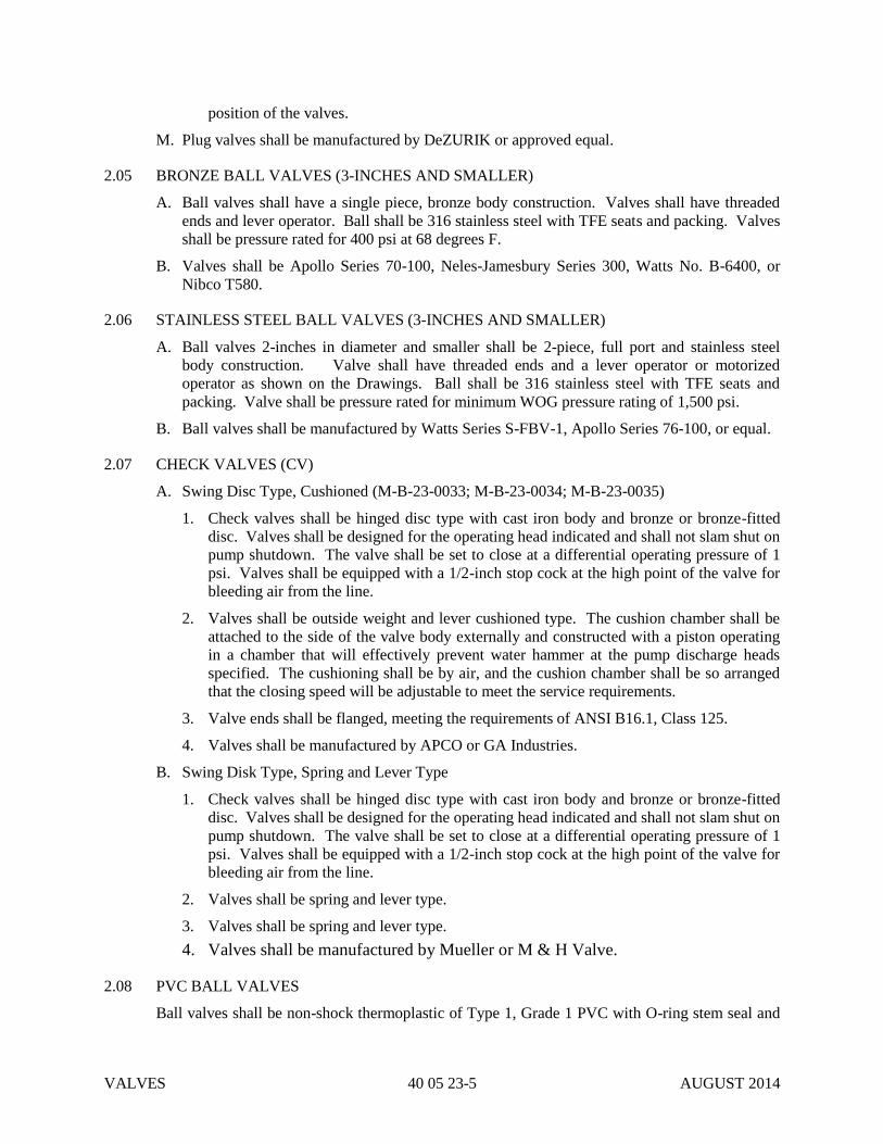
VALVES 40 05 23-5 AUGUST 2014
position of the valves.
M. Plug valves shall be manufactured by DeZURIK or approved equal.
2.05 BRONZE BALL VALVES (3-INCHES AND SMALLER)
A. Ball valves shall have a single piece, bronze body construction. Valves shall have threaded
ends and lever operator. Ball shall be 316 stainless steel with TFE seats and packing. Valves
shall be pressure rated for 400 psi at 68 degrees F.
B. Valves shall be Apollo Series 70-100, Neles-Jamesbury Series 300, Watts No. B-6400, or
Nibco T580.
2.06 STAINLESS STEEL BALL VALVES (3-INCHES AND SMALLER)
A. Ball valves 2-inches in diameter and smaller shall be 2-piece, full port and stainless steel
body construction. Valve shall have threaded ends and a lever operator or motorized
operator as shown on the Drawings. Ball shall be 316 stainless steel with TFE seats and
packing. Valve shall be pressure rated for minimum WOG pressure rating of 1,500 psi.
B. Ball valves shall be manufactured by Watts Series S-FBV-1, Apollo Series 76-100, or equal.
2.07 CHECK VALVES (CV)
A. Swing Disc Type, Cushioned (M-B-23-0033; M-B-23-0034; M-B-23-0035)
1. Check valves shall be hinged disc type with cast iron body and bronze or bronze-fitted
disc. Valves shall be designed for the operating head indicated and shall not slam shut on
pump shutdown. The valve shall be set to close at a differential operating pressure of 1
psi. Valves shall be equipped with a 1/2-inch stop cock at the high point of the valve for
bleeding air from the line.
2. Valves shall be outside weight and lever cushioned type. The cushion chamber shall be
attached to the side of the valve body externally and constructed with a piston operating
in a chamber that will effectively prevent water hammer at the pump discharge heads
specified. The cushioning shall be by air, and the cushion chamber shall be so arranged
that the closing speed will be adjustable to meet the service requirements.
3. Valve ends shall be flanged, meeting the requirements of ANSI B16.1, Class 125.
4. Valves shall be manufactured by APCO or GA Industries.
B. Swing Disk Type, Spring and Lever Type
1. Check valves shall be hinged disc type with cast iron body and bronze or bronze-fitted
disc. Valves shall be designed for the operating head indicated and shall not slam shut on
pump shutdown. The valve shall be set to close at a differential operating pressure of 1
psi. Valves shall be equipped with a 1/2-inch stop cock at the high point of the valve for
bleeding air from the line.
2. Valves shall be spring and lever type.
3. Valves shall be spring and lever type.
4. Valves shall be manufactured by Mueller or M & H Valve.
2.08 PVC BALL VALVES
Ball valves shall be non-shock thermoplastic of Type 1, Grade 1 PVC with O-ring stem seal and

VALVES 40 05 23-6 AUGUST 2014
Teflon ball seat. O-ring seals shall be Viton. Valves shall withstand 150 psi pressure. Valves
shall have union connections at each end. Valves shall be Hayward "Safe Block", or Chemtrol
TU Series, or Spears (True Union 2000 Industrial).
2.09 PVC BALL CHECK VALVES
Ball check valves shall be non-shock thermoplastic type of Type 1, Grade 1 PVC with O-ring ball
seal. O-ring seals shall be Viton. The valve shall have a true union connection for easy removal.
The valve shall operate in the vertical or horizontal position. Valve shall be Hayward "True
Check" or Chemtrol BC Series, or Spears (True Union 2000 Industrial).
2.10 PRESSURE REGULATORS
A. Regulators shall be of a cast bronze body, stainless steel seat ring with 1/2 to 2-inch NPT
threaded connections.
B. Provide regulator with separate "Y" type strainer with 20 mesh stainless steel screen and
removable plug. Attach strainer at the inlet end of regulator with bronze nipple.
C. Unless otherwise noted, pressure regulator shall be factory set at [45] psi and have an
adjustable range of 25 to 84 psi using an external adjusting screw. Valve shall be rated for
150 psig minimum inlet water pressure.
D. Valves shall be manufactured by Watts No. 25AUB or Mueller H-9300 Series.
2.11 ‘Y’ TYPE STRAINER
A. ‘Y’ Type Strainer shall be of flanged type and 20 mesh stainless steel screen and removable
plug.
B. Manufacturer: Eaton Model 85Y or approved equal.
2.12 SOLENOID VALVES
A. Solenoid valves shall have packless construction without packing box or sliding seal.
B. Solenoid coils for AC service shall be 115 volts, 60 hertz, encapsulated, Class F, for
continuous duty at rated voltage ± 10 percent and 40°C ambient, in a NEMA Type 4
enclosure, with a conduit knockout.
C. Solenoid coils for DC service shall be 125 volts, Class H, for continuous duty at rated voltage
± 10 percent and 40°C ambient, in a NEMA Type 4 enclosure, with a conduit knockout.
D. Valves shall be normally closed unless otherwise specified or indicated on the Drawings.
Normally open solenoid valves shall close when energized and normally closed solenoid
valves shall open when energized.
As indicated
on drawings
Type
Body/Bonnet
Trim
Seals
Disc
Stem
Bonnet Gasket
Spring
End Connection
Temp. Limitations
Valve Operator
2-Way, pilot operated
Brass or bronze
Buna-N or Teflon
Buna-N or Teflon
Manufacturer’s standard
Manufacturer’s standard
Manufacturer’s standard
Threaded
32 to 104°F
Integral

VALVES 40 05 23-7 AUGUST 2014
Manufacturers ASCO “8210 Series”
2.13 MOTORIZED ACTUATORS
Motorized actuators shall be as specified in Section 40 92 43 of these Specifications.
2.14 SEAL WATER CONTROL PANELS
A. Seal water control panels shall monitor and control water pressure and seal water flow.
Panels shall be for provided for single mechanical seals as specified below and shown on the
Drawings.
B. Single Mechanical Seals.
1. Unit shall include 1 inlet and 1 outlet port. Ports shall be 3/8” compression fitting ports.
The inlet ports shall consist of a seal water supply port and the outlet port shall be the
mechanical seal supply port.
2. The unit shall have a pressure reducing valve, flow rotameter, manual flow control valve,
low flow sensor/switch, purge outlet and mounting bracket. The unit shall be capable of
measuring and controlling seal water flows between 2 and 50 GPH. Unit shall have a
pressure rating of 160 psig.
3. All metal components shall be Type 316 stainless steel. Unit body shall be
polyoxymethylene(POM) or PVC.
4. The low flow sensor shall operate on a 10-55 DC volts with a switching frequency of 100
Hz.
5. The unit shall be a SP50 as manufactured by Chesterton or equal product offered by John
Crane.
2.15 VALVE BOXES (VB)
A. All valves shall be equipped with valve boxes. The valve boxes shall be cast iron two-piece
screw type with drop covers. Valve boxes shall have a 5.25-inch inside diameter. Valve box
covers shall weigh a minimum of 13 pounds. The valve boxes shall be adjustable to 6-inches up
or down from the nominal required cover over the pipe. Valve boxes shall be of sufficient length
that bottom flange of the lower belled portion of the box is below the valve operating nut.
Ductile or cast iron extensions shall be provided as necessary. Covers shall have "WATER
VALVE", "SEWER", "AIR", or "WATER" cast into them. Valve boxes shall be manufactured
in the United States.
B. Valve boxes shall be manufactured by Tyler or Opelika.
PART 3 - EXECUTION
3.01 INSTALLATION
All valves and appurtenances shall be installed in the locations shown on the Drawings, true to
alignment and properly supported. Any damage to the above items shall be repaired to the
satisfaction of the CITY before they are installed.
3.02 FIELD PAINTING
All exposed, non-buried or submerged valves and appurtenances specified herein except for

VALVES 40 05 23-8 AUGUST 2014
stainless steel shall be painted as part of the work in Section 09 91 00 of these Specifications.
3.03 INSPECTION AND TESTING
Following installation, operating tests will be performed to demonstrate to the CITY that all
equipment and accessories will function in a satisfactory manner. The CONTRACTOR shall
make, at CONTRACTOR's own expense, all necessary changes, modifications and/or
adjustments required to ensure satisfactory operation.
3.04 CLEANING
Prior to acceptance of the work of this Section, thoroughly clean all installed materials,
equipment and related areas in accordance with Section 01 74 00 of these Specifications.
END OF SECTION 40 05 23

SLIDE GATES 40 20 10-1 AUGUST 2014
SECTION 40 20 10
SLIDE GATES
PART 1 – GENERAL
1.01 SCOPE
The work covered by this section includes furnishing all labor, equipment and materials required
to install Stainless Steel Channel Gates and operators as shown on the Drawings and/or specified
herein.
1.02 GENERAL
A. Equipment provided under this Section shall be fabricated, and assembled in full conformity
with Drawings, Specifications, engineering data, instructions, and recommendations of the
equipment manufacturer, unless exceptions are noted by ENGINEER.
B. Gates and actuators shall be furnished with all necessary parts and accessories indicated on
the Drawings, specified, or otherwise required for a complete, properly operating installation
and shall be the latest standard products of a manufacturer regularly engaged in the
production of sluice gates.
1. The Basic Mechanical Materials and Methods Section shall apply to all equipment
furnished under this Section. If requirements in this Specification differ from those in the
Basic Mechanical Materials and Methods Section, the requirements specified herein shall
take precedence.
2. Permanent Number Plates: Gates that have been assigned a number on the Drawings or
in the Gate Schedule shall be provided with a permanent number plate. The location of
number plates and the method of fastening shall be acceptable to CITY. Numerals shall
be at least 1 inch high and shall be black baked enamel on anodized aluminum plate.
1.03 SUBMITTALS
A. Submit shop drawings and engineering data in accordance with the requirements of Section
01 33 00 of these Specifications.
B. Operation and maintenance manuals shall be furnished in accordance with the requirements
of Section 01 78 23 of these Specifications.
C. Shop drawings shall be prepared and assembled by the listed gate manufacturers. Shop
drawings prepared and assembled by manufacturer's sales representatives, distributors,
dealers, fabrication shops or other than the listed gate manufacturers will not be accepted.
1.04 STORAGE AND PROTECTION
Gates and plates shall be stored and protected in accordance with the requirements of Section 01
60 00 of these Specifications.
1.05 QUALITY ASSURANCE
A. The manufacturer shall provide written certification to the CITY that all equipment furnished
complies with all applicable requirements of these Specifications.
B. The gate manufacturer shall provide unit responsibility for all items specified in this section.
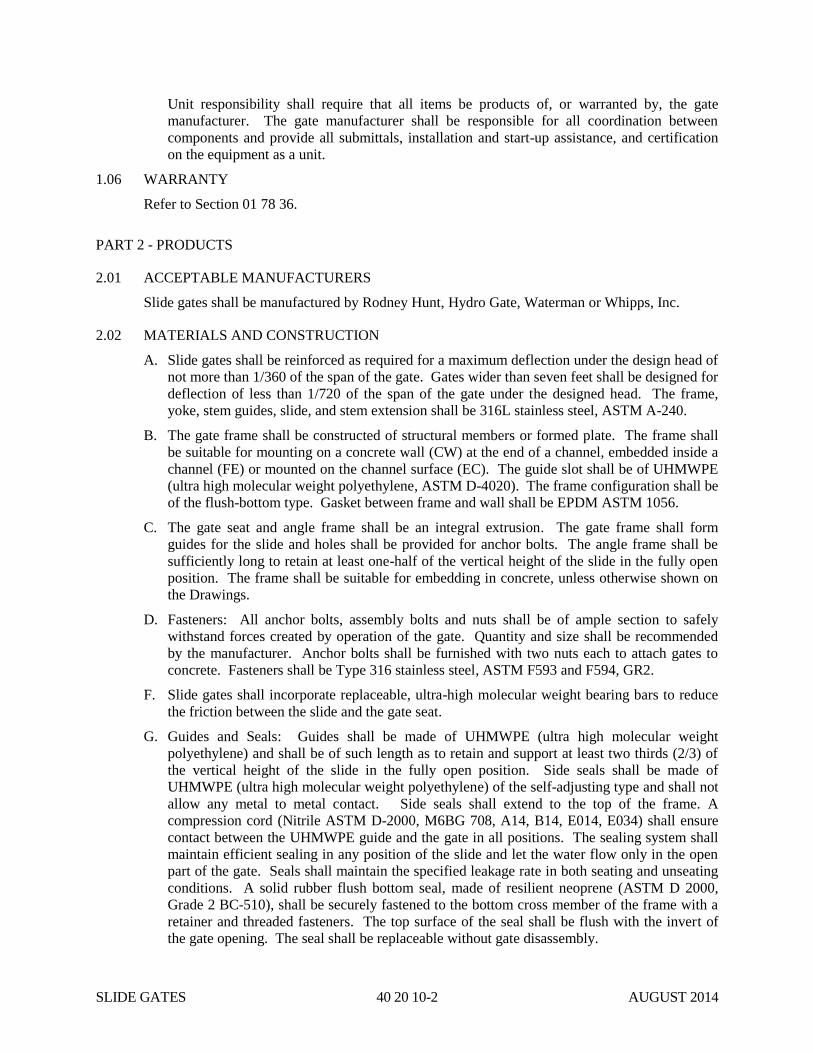
SLIDE GATES 40 20 10-2 AUGUST 2014
Unit responsibility shall require that all items be products of, or warranted by, the gate
manufacturer. The gate manufacturer shall be responsible for all coordination between
components and provide all submittals, installation and start-up assistance, and certification
on the equipment as a unit.
1.06 WARRANTY
Refer to Section 01 78 36.
PART 2 - PRODUCTS
2.01 ACCEPTABLE MANUFACTURERS
Slide gates shall be manufactured by Rodney Hunt, Hydro Gate, Waterman or Whipps, Inc.
2.02 MATERIALS AND CONSTRUCTION
A. Slide gates shall be reinforced as required for a maximum deflection under the design head of
not more than 1/360 of the span of the gate. Gates wider than seven feet shall be designed for
deflection of less than 1/720 of the span of the gate under the designed head. The frame,
yoke, stem guides, slide, and stem extension shall be 316L stainless steel, ASTM A-240.
B. The gate frame shall be constructed of structural members or formed plate. The frame shall
be suitable for mounting on a concrete wall (CW) at the end of a channel, embedded inside a
channel (FE) or mounted on the channel surface (EC). The guide slot shall be of UHMWPE
(ultra high molecular weight polyethylene, ASTM D-4020). The frame configuration shall be
of the flush-bottom type. Gasket between frame and wall shall be EPDM ASTM 1056.
C. The gate seat and angle frame shall be an integral extrusion. The gate frame shall form
guides for the slide and holes shall be provided for anchor bolts. The angle frame shall be
sufficiently long to retain at least one-half of the vertical height of the slide in the fully open
position. The frame shall be suitable for embedding in concrete, unless otherwise shown on
the Drawings.
D. Fasteners: All anchor bolts, assembly bolts and nuts shall be of ample section to safely
withstand forces created by operation of the gate. Quantity and size shall be recommended
by the manufacturer. Anchor bolts shall be furnished with two nuts each to attach gates to
concrete. Fasteners shall be Type 316 stainless steel, ASTM F593 and F594, GR2.
F. Slide gates shall incorporate replaceable, ultra-high molecular weight bearing bars to reduce
the friction between the slide and the gate seat.
G. Guides and Seals: Guides shall be made of UHMWPE (ultra high molecular weight
polyethylene) and shall be of such length as to retain and support at least two thirds (2/3) of
the vertical height of the slide in the fully open position. Side seals shall be made of
UHMWPE (ultra high molecular weight polyethylene) of the self-adjusting type and shall not
allow any metal to metal contact. Side seals shall extend to the top of the frame. A
compression cord (Nitrile ASTM D-2000, M6BG 708, A14, B14, E014, E034) shall ensure
contact between the UHMWPE guide and the gate in all positions. The sealing system shall
maintain efficient sealing in any position of the slide and let the water flow only in the open
part of the gate. Seals shall maintain the specified leakage rate in both seating and unseating
conditions. A solid rubber flush bottom seal, made of resilient neoprene (ASTM D 2000,
Grade 2 BC-510), shall be securely fastened to the bottom cross member of the frame with a
retainer and threaded fasteners. The top surface of the seal shall be flush with the invert of
the gate opening. The seal shall be replaceable without gate disassembly.

SLIDE GATES 40 20 10-3 AUGUST 2014
H. Operators and Stems
1. Operating stems shall be of a size to safely withstand, without buckling or distortion, the
stresses induced by normal operating forces. The stems shall be designed to transmit, in
compression, at least twice the rated output of the floor stand or bench stand with a 40
pound effort on the crank or handwheel.
2. The threaded portion of the stem shall have machined cut threads of the Acme type.
3. Stems of more than one section shall be joined by bronze couplings, threaded and keyed
or bored and pinned to the stems. All threaded and keyed couplings of the same size
shall be interchangeable. The couplings shall be of greater strength than the stem.
4. Manually operated rising stem gates shall be provided with an adjustable, bronze stop
collar on the stem above the floor stand lift nut.
5. All stems shall be fabricated from 316 stainless steel, ASTM A-276, and shall not be less
than 1-1/2-inches in diameter.
6. Provide a clear, plastic stem (polycarbonate ASTM D-3935) cover with mylar position
indicator strip.
7. Gates having width equal to or greater than two times their height shall be provided with
two lifting mechanisms connected by a tandem shaft.
8. Rising stem gates shall be provided with a clear polycarbonate stem cover. The stem
cover shall have a cap and condensation vents as well as a clear mylar position indicating
tape. The tape shall be field applied to the stem cover after the gate has been installed
and positioned.
I. Manual Operators
1. Manual operation shall be by handwheel, minimally 24-inches in diameter or
crank-operated floor stands or bench stands as shown on the Drawings. Handwheel
operated type shall be without gear reduction; crank-operated type shall have either a
single or double gear reduction, depending upon the lifting capacity required. Each type
shall be provided with a threaded, cast bronze lift nut to engage the operating stem. Each
manual operator shall be designed to operate the gate under the maximum specified
seating and unseating heads by using a maximum effort of 40 lbs. (178 N) on the crank or
handwheel and shall be able to withstand, without damage, an effort of 80 lbs. (356 N).
2. Tapered roller bearings or ball thrust bearings shall be provided above and below a flange
on the operating nut to support both opening and closing thrusts.
3. Floor stands shall operate the gates with not greater than 40 pound pull on the crank or
handwheel. Gears, where required, shall be steel or cast iron with machine cut teeth
designed for smooth operation. The pinion shafts on crank-operated floor stands, either
single or double, shall be supported on tapered roller bearings or needle bearings. All
components shall be totally enclosed in a cast iron case and cover. Positive mechanical
seals, to retain lubricant and exclude moisture and dirt, shall be provided on the operating
nut and the pinion shafts where they extend from the cast iron case or gear box.
Lubricating fittings shall be provided for the lubrication of all gears and bearings.
4. The removable crank shall be cast iron with a revolving brass or iron grip. Floor stands
shall include a cast iron pedestal design to position the input shaft approximately
36-inches above the operating floor.
J. Motorized Operators

SLIDE GATES 40 20 10-4 AUGUST 2014
Electric actuators shall be as specified in Section 40 92 43.
2.03 SHOP PAINTING
A. All iron and steel surfaces, except machined surfaces, shall be shop cleaned by blasting in
accordance with the coating manufacturer's recommendations and finish painted with an
epoxy or epoxy/polyurethane coating system. Non-submerged components shall be painted
with two coats of epoxy paint having a total dry film thickness of at least 10 mils and one
topcoat of polyurethane having a dry film thickness of at least 2 mils. All components
subject to submergence shall be painted with three coats of epoxy paint having a total
combined dry film thickness of at least 15 mils [375 μm]. Finish color shall be medium gray,
except for handwheels, levers, and other operating devices, which shall be safety red. Field
painting of gates, actuators, and appurtenances, other than touchup painting, will not be
required. A sufficient quantity of additional coating materials shall be furnished by the gate
manufacturer to permit field touchup of damaged coatings.
2.04 PERFORMANCE
A. Gates shall be substantially watertight under the design head conditions. Leakage shall not
exceed 0.05 U.S. gallon per minute per foot (0.60 l/min per meter) of seal periphery under the
design seating head and unseating head.
B. The slide gates shall be designed to withstand the maximum design head (maximum design
head shall be taken as the height of the slide unless otherwise shown in the schedule).
C. The gate's sealing system should have been tested through a cycle test in an abrasive
environment and should show that the leakage requirements are still obtained after 25,000
cycles with a minimum deterioration.
PART 3 - EXECUTION
3.01 INSTALLATION
A. Slide gates and stop plates shall be installed as shown on the Drawings, specified herein, and
in accordance with the manufacturer's recommendations.
B. Slide gate and stop plate frames and plates shall be checked, prior to installation, for
projections or warpage that would promote excessive leakage. Defective gates and plates
shall be removed and replaced.
C. Slide gate and stop plate frames shall be installed true to the lines and elevations shown and
accurately aligned. Frames shall be internally braced and adequately supported during
concrete placement and/or installation.
3.02 INSPECTION AND TESTING
Following installation, operating tests will be performed to demonstrate to the Engineer that all
slide gates, weir gates and stop plates will perform in a satisfactory manner. The Contractor shall
make, at Contractor's expense, all necessary modifications, changes and/or adjustments required
to ensure satisfactory operation.
3.03 CLEANING
Prior to acceptance of the work of this section, thoroughly clean all installed materials and related
areas in accordance with the requirements of Section 01 74 00 of these Specifications.
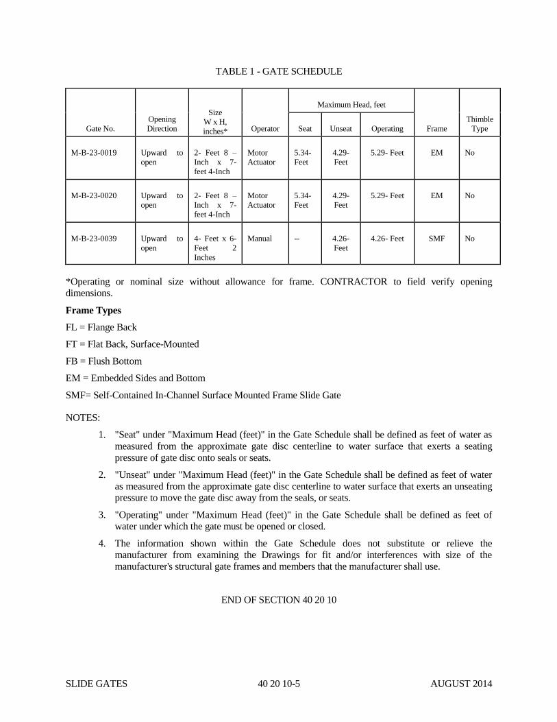
SLIDE GATES 40 20 10-5 AUGUST 2014
TABLE 1 - GATE SCHEDULE
Gate No.
Opening
Direction
Size
W x H,
inches* Operator
Maximum Head, feet
Frame
Thimble
Type Seat Unseat Operating
M-B-23-0019 Upward to
open
2- Feet 8 –
Inch x 7-
feet 4-Inch
Motor
Actuator
5.34-
Feet
4.29-
Feet
5.29- Feet EM No
M-B-23-0020 Upward to
open
2- Feet 8 –
Inch x 7-
feet 4-Inch
Motor
Actuator
5.34-
Feet
4.29-
Feet
5.29- Feet EM No
M-B-23-0039 Upward to
open
4- Feet x 6-
Feet 2
Inches
Manual -- 4.26-
Feet
4.26- Feet SMF No
*Operating or nominal size without allowance for frame. CONTRACTOR to field verify opening
dimensions.
Frame Types
FL = Flange Back
FT = Flat Back, Surface-Mounted
FB = Flush Bottom
EM = Embedded Sides and Bottom
SMF= Self-Contained In-Channel Surface Mounted Frame Slide Gate
NOTES:
1. "Seat" under "Maximum Head (feet)" in the Gate Schedule shall be defined as feet of water as
measured from the approximate gate disc centerline to water surface that exerts a seating
pressure of gate disc onto seals or seats.
2. "Unseat" under "Maximum Head (feet)" in the Gate Schedule shall be defined as feet of water
as measured from the approximate gate disc centerline to water surface that exerts an unseating
pressure to move the gate disc away from the seals, or seats.
3. "Operating" under "Maximum Head (feet)" in the Gate Schedule shall be defined as feet of
water under which the gate must be opened or closed.
4. The information shown within the Gate Schedule does not substitute or relieve the
manufacturer from examining the Drawings for fit and/or interferences with size of the
manufacturer's structural gate frames and members that the manufacturer shall use.
END OF SECTION 40 20 10

SLIDE GATES 40 20 10-6 AUGUST 2014
THIS PAGE INTENTIONALLY LEFT BLANK
STEEL, ALLOY, AND COPPER PIPING 40 27 13-1 JULY 2013
SECTION 40 27 13
STEEL, ALLOY, AND COPPER PIPING
PART 1 - GENERAL
1.01 SCOPE
A. The work covered by this section includes furnishing all labor, equipment and materials required
to furnish, install and test steel pipe, alloy pipe, stainless steel pipe and copper tubing, including
all fittings, sleeves, unions and accessories, as specified herein and/or shown on the Drawings.
B. The CONTRACTOR's attention is called to the fact that all steel and alloy piping or copper tubing
is not necessarily shown completely on the Drawings, which are more or less schematic.
However, the CONTRACTOR shall furnish and install all pipe and fittings and do all piping work
indicated or required for the proper operation of all equipment and services requiring such piping.
1.02 GENERAL DESIGN REQUIREMENTS
A. All such work shall be done by competent workers in a thorough workmanlike manner according
to best practice and in compliance with all codes and applicable regulations, with proper
provisions for uncoupling, draining, expansion and contraction.
B. Process piping furnished as an integral part of an item of equipment shall conform to the
requirements of the latest edition of ANSI B16.3, Code for Petroleum Refining Piping or ANSI
B16.4, Code for Refrigeration Piping, as applicable.
1.03 SUBMITTALS
Complete shop drawings and engineering data on fabricated piping shall be submitted to the CITY in
accordance with the requirements of Section 01 33 00 of these Specifications.
1.04 STORAGE AND PROTECTION
A. Piping and accessories shall be stored and protected in accordance with the requirements of
Section 01 60 00 of these Specifications.
B. All piping and tubing and accessories shall be stored above ground fully supported so as not to
bend or deflect excessively under their own weight. Piping shall be stored with slope so as to be
free draining.
1.05 QUALITY ASSURANCE
Prior to its incorporation into the work, the CONTRACTOR shall submit to the CITY written
evidence that the pipe furnished under this section is in conformance with the material and mechanical
requirements specified herein. Certified copies of independent laboratory test results or mill test
results from the pipe supplier may be considered evidence of compliance provided such tests are
performed in accordance with the appropriate ASTM or AWWA testing standards by experienced,
competent personnel. In case of doubt as to the accuracy or adequacy of mill tests, the CITY may
require that the CONTRACTOR furnish test reports from an independent testing laboratory on
samples of pipe materials.
STEEL, ALLOY, AND COPPER PIPING 40 27 13-2 JULY 2013
PART 2 – PRODUCTS
2.01 MATERIALS AND CONSTRUCTION
A. General
1. Unless otherwise shown or specified on the Drawings, all piping 2-1/2-inches and smaller
shall be copper tubing, except that Schedule 40 red brass threaded nipples with 125 pound
forged bronze threaded fittings per ANSI B16.15 are acceptable for short branches to pressure
gauges and drains. Unless otherwise shown or specified, pipe 3-inches and larger shall be
galvanized alloy pipe or cast iron or ductile iron pipe. Carbon steel pipe shall be used only
where approved by the ENGINEER or where specifically indicated on the Drawings.
2. No broken, cracked, deformed, imperfectly coated or otherwise damaged or defective pipe or
fittings shall be used. All such materials shall be removed from the site.
B. Stainless Steel Pipe
1. Stainless steel pipe in sizes 10-inches and smaller shall be seamless stainless steel pipe
conforming to the requirements of ASTM A 312, Type 304.
2. Unless otherwise specified or shown, stainless steel pipe 1-1/2-inches and smaller shall be
screwed, Schedule 40S. Steel pipe in sizes 2 through 10-inches shall be welded, Schedule
10S.
3. Screwed fittings and unions 1-1/2-inches and smaller shall be 3,000 pound forged stainless
steel conforming to ASTM A 182, Grade F304 and ANSI B16.11.
4. Welded fittings shall be of the butt-welded type of wrought stainless steel conforming to
ASTM A 403, Grade WP304 and ANSI B16.9. Reducing branch connections shall be made
using threadolets or weldolets.
5. Flanges shall be 150 pound, forged stainless steel conforming to ASTM A 182, Grade 304
and ANSI B16.5. Bolts shall be heavy hex conforming to ASTM A 193, Grade B8. Nuts
shall be heavy hex conforming to ASTM A 194, Grade 8. Gaskets shall be red rubber,
1/16-inch thick, conforming to ANSI B16.21. Gaskets for piping operating at temperatures in
excess of 150 degrees F shall be compressed asbestos or soft corrugated metal.
C. Copper Pipe
1. Exposed copper tubing for water or gas shall be seamless harddrawn copper tube conforming
to the requirements of ASTM B 88, Type L. Buried copper tubing shall be seamless,
annealed copper tube conforming to the requirements of ASTM B 88, Type K. Annealed
copper tube may be furnished in straight lengths or coils. All fittings shall be soldered, except
at valves which may be flared, compression types or threaded type supplied with solder socket
by threaded adaptors. Fittings shall conform to ANSI B16.18 or ANSI/ASME B16.22.
Where required for connection to equipment, valves, and accessories, ANSI B16.24, Class
150, cast bronze, brazed joint.
2. Copper tubing for instrument air service in sizes 5/8-inch O.D. and smaller shall be coated,
seamless, bright annealed copper tube conforming to ASTM B 68, Type DHP. Wall
thickness of copper tube shall be as follows:
STEEL, ALLOY, AND COPPER PIPING 40 27 13-3 JULY 2013
Tube O.D. Wall Thickness
1/4" 0.030"
3/8" 0.032"
1/2" 0.035"
5/8" 0.040"
3. Instrument air tubing shall be factory coated with a layer of black PVC meeting the
requirements of ASTM D 1047, IPCEA S-61-402, and applicable UL standards. Minimum
coating thickness shall be 0.032-inch. Unless otherwise shown, minimum size of instrument
air tubing shall be 3/8-inch O.D.
4. Fittings for copper tube shall be wrought copper conforming to ASTM B 75 and ANSI
B16.22 for silver brazed joints. Fittings for annealed copper tube in instrument air service
shall be of the flareless, compression type, Hoke "Gyrolok", Crawford "Swagelok" or Parker
"Trible-Lok", conforming to ASTM B 16 or B 124.
D. Stainless Steel Tubing
1. Stainless steel tubing for sample and process leads shall be seamless, bright annealed stainless
steel tube conforming to ASTM A 269, Type 316 with minimum 3/8-inch O.D. and
0.035-inch wall thickness.
2. Fittings for stainless steel tubing shall be of the flareless, compression type of 316 stainless
steel.
3. Where process leads or sample tubing are specified to be heat traced, furnish pre-insulated
factory traced and jacketed tubing with 4 watts per foot, parallel, self-regulating, electric
tracing, glass fiber, insulation and black, 105 degree PVC jacket overall. Tubing shall
conform to Article 2.06, Paragraph A above. Product shall be factory mutual approved for
Class I, Division 2 locations and shall operate on 120 volt, 60 Hz, single phase power. All
necessary termination and splicing accessories shall be furnished by the tubing manufacturer.
E. Unions: Unions shall be of the ground joint type. Unions in carbon steel and alloy steel piping
shall be 300 pound galvanized malleable iron conforming to ASTM A 197 and ANSI B16.3 with
bronze to iron seats. Unions in stainless steel piping shall be 3,000 pound forged stainless steel
conforming to ASTM A 182, Grade F304 and ANSI B 16.11. Unions in copper piping shall be
cast red bronze with bronze to bronze seats.
F. Pipe Dope
1. All threaded connections shall be made up using Teflon pipe dope applied to the male threads
only.
2. Virgin Teflon thread tape shall be Hercules Packing Company "Herculon", 3-M Company
"Scotch No. 48" or Crane Packing Company "Teflon Thread Tape".
3. Teflon thread paste may be used in place of tape on very large or very small joints.
G. Expansion Couplings
1. Expansion couplings for steel and alloy pipe shall conform to the requirements of Section 22
STEEL, ALLOY, AND COPPER PIPING 40 27 13-4 JULY 2013
05 16 of these Specifications.
2. Expansion couplings shall be furnished where shown on the Drawings, required, or directed
by the ENGINEER.
H. Linings
1. Where shown or specified, piping shall be furnished with a coal tar enamel lining or coal tar
epoxy lining as described herein.
2. Coal tar enamel linings shall consist of a primer and a hot-applied lining of coal tar enamel.
Pipe to be coated shall be given a solvent cleaning followed by a commercial blast cleaning in
accordance with SSPC SP-6. Primer shall be applied immediately after blasting. Thickness
of coal tar enamel lining shall be 3/32-inch. Except for specials and welded field joints all
pipe shall be lined in the shop by mechanical means. Coal tar enamel lining shall conform to
the requirements of AWWA C203.
3. Coal tar epoxy linings shall consist of a two-component inhibitive epoxy primer and a
two-component high build, polyamide cured coal tar epoxy lining. Pipe to be coated shall be
given a solvent cleaning followed by a near white blast cleaning in accordance with SSPC
SP-10. Primer shall be applied immediately after blasting to a minimum dry film thickness of
1.5 mils. Coal tar epoxy finish shall be applied in two coats having a minimum dry film
thickness of 10 mils per coat. Finished lining shall have a dry film thickness of 20-25 mils.
Except for specials and welded field joints, all pipe shall be lined in the shop by mechanized
means. Coal tar epoxy linings shall conform to the requirements of AWWA C210.
4. The manufacturers of the lined pipe and field lining materials shall furnish the CITY written
certifications that the pipe lining systems conform to all applicable requirements of AWWA
C203 or AWWA C210, as appropriate.
I. Coatings
1. Where shown or specified, buried piping shall be furnished with a coal tar enamel coating or
cold-applied, plastic tape wrap coating as described herein.
2. Coal tar enamel coatings shall consist of a primer, a hot-applied coating of coal tar enamel, a
bonded wrap of coal tar saturated asbestos felt, and a protective wrapping of 75 pound Kraft
paper. Pipe to be coated shall be given a solvent cleaning followed by a commercial blast
cleaning in accordance with SSPC SP-6. Primer shall be applied immediately after blasting.
Except for specials, fittings and field joints, all pipe shall be coated in the shop by mechanical
means. Coal tar enamel coatings shall conform to the requirements of AWWA C203.
3. Cold-applied, plastic tape wrap coatings shall consist of a primer, a cold-applied wrap of
laminated polyethylene tape, and a protective wrapping of 90 pound Kraft paper or 50-50-50
pound laminated Kraft paper. Pipe to be coated shall be given a solvent cleaning followed by
a commercial blast cleaning in accordance with SSPC SP-6. Primer shall be applied
immediately after blasting. Laminated tape wrap shall have an overall thickness of not less
than 1/2-inch. Except for specials, fittings and field joints, all pipe shall be coated in the shop
by mechanical means. Cold-applied plastic tape wrap coatings shall comply with the
requirements of AWWA C209 and C214. Plastic tape coatings and materials shall be as
manufactured by the Tapecoat Company, Republic Steel Corporation or Polyken Division of
Kendall Company, subject, however, to the requirements of these Specifications.

STEEL, ALLOY, AND COPPER PIPING 40 27 13-5 JULY 2013
4. The manufacturers of the coated pipe and field coating materials shall provide the CITY with
written certifications that the pipe coating systems conform to all applicable requirements of
AWWA C203, C209, C210 or C214, as appropriate.
PART 3 – EXECUTION
3.01 INSTALLATION
A. General
1. All exposed piping shall be firmly anchored and supported by pipe supports or anchors as
shown or required. Pipe supports shall be furnished as shown on the Drawings or in
accordance with the requirements of Section 22 05 29 of these Specifications. All pipe shall
be carefully placed to the proper lines and grades as shown on the Drawings.
2. Full lengths of pipe shall be used wherever possible. Short lengths of pipe with couplings
will not be permitted. Pipe shall be cut to exact measurement and shall be installed without
forcing or springing.
3. Lines which slope shall have the right-of-way over lines whose elevations can be changed.
Offsets, transitions, and changes in direction in pipes shall be made as required to maintain
proper head room, slope, etc.
4. Piping shall be installed in such manner and at such times as will require a minimum of
cutting and repairing of building structures. In case any such cutting or repairing is necessary,
it shall be done only with the permission of the ENGINEER. Cutting and repairing shall be
performed by craftsmen of the trade which originally executed the work, and repairs shall
match the original condition.
5. Except for annealed tubing, all changes in direction in piping systems shall be made with
suitable fittings. Annealed tubing shall be bent using suitable bending tools.
6. When storing and installing pipe, care shall be taken to prevent damage to the pipe coatings.
Steel pipe with an exterior bituminous or plastic coating or wrapping shall be handled using
rubber or canvas slings. All damaged coatings shall be repaired to the satisfaction of the
Engineer.
7. A liberal number of unions and/or flanged joints shall be used to permit the ready removal of
any section. Unions shall be installed in all piping connections to equipment, to regulating
valves, and wherever necessary to facilitate the dismantling of piping and removal of valves
and other items requiring maintenance. Flanges on equipment may be considered as unions.
8. Installed piping shall not interfere with the operation of or accessibility to doors and/or
windows, shall not encroach on aisles, passageways and equipment, and shall not interfere
with the servicing or maintenance of any equipment.
9. The interior of all piping shall be free from obstructions and protrusions. All burrs shall be
removed from the inside and outside edges of all cut pipe by reaming. Cutting shall be done
in such a manner so as to leave a smooth end at right angles to pipe threads. Tool marks and
unnecessary pipe threads shall be avoided. Cuttings and other foreign material shall be
removed from the inside of the pipe prior to installation.

STEEL, ALLOY, AND COPPER PIPING 40 27 13-6 JULY 2013
10. Unless otherwise shown on the Drawings, piping and tubing laid underground shall have a
minimum cover over the top of the pipe as follows:
a. Located in Roadway: 48-inches
b. Located in Other Paved Areas: 36-inches
c. Water, Gas and Drain Piping, 4-inch I.D. and Larger: 30-inches
d. Water, Gas and Drain Piping, 3-1/2-inch I.D. and Smaller: 24-inches
e. Located Under Building: 6-inches
11. Suitable galvanized steel pipe sleeves of adequate inside diameter shall be provided where
piping or tubing passes through walls and floors of buildings and structures. Inside diameter
of sleeve shall be approximately 1/2-inch larger than outside diameter of pipe or insulation. A
welded steel plate waterstop with a minimum dimension 4-inches larger than outside diameter
of sleeve shall be furnished for use in underground walls. Sleeves shall be built into the
concrete or masonry wall or floor. Under no circumstances will blocking out or breaking of
walls be permitted for later insertion. After installation of piping, the space between the pipe
and the sleeve shall be caulked air and watertight. Caulking shall be oakum and lead in
concrete and masonry construction and rope asbestos in wood or plaster construction.
12. After installation, the interior of all piping shall be cleaned as necessary to remove flux, slag,
scale, rust, dirt, oil, and other foreign material. As piping is installed, open ends shall be
covered or plugged as necessary to prevent the entrance of foreign matter and to maintain the
required cleanliness.
13. Piping laid underground shall be fully supported along its entire length by a compacted layer
of select earth backfill or sand in accordance with the requirements of Section 31 20 00 of
these Specifications. Select earth backfill (or sand, in the case of coated or wrapped steel
pipe) shall also be placed and compacted around the piping to provide a cover of not less than
12-inches over the top of the pipe.
14. Piping and tubing shall be supported as shown on the Drawings and/or specified in Section 22
05 29 of these Specifications.
15. Changes in pipe size shall be made using reducing fittings, not bushings. If centerline
elevation is not specified, use eccentric reducers in horizontal piping. On liquid lines,
eccentricity shall be down with top of pipe level. On vapor and gas lines, eccentricity shall be
up with bottom level.
16. Indicated locations and sizes of equipment connections are approximate; exact locations and
sizes of piping, valves, etc., shall conform to approved shop drawings. Connection sizes shall
not be smaller than scheduled size or equipment outlet size, whichever is larger.
B. Installation of Steel and Alloy Piping
1. Pipe threads shall be concentric with the outside of the pipe and shall conform to ANSI B2.1.
When threading stainless steel pipe, dies shall have 20 to 30 degree hook. Finished joints
shall have no more than three threads exposed. Before assembly, pipe ends and threads shall
be inspected and any defective pieces replaced. All joints shall be properly aligned before
connection to prevent thread damage. Pipe dope shall be used on the male threads of all
threaded connections. Teflon thread tape shall be applied two threads back from the end of
the pipe of fitting to prevent shredding. Excess pipe dope shall be trimmed or cleaned off to
provide adherence for paints or coatings. After joining, exposed threads in underground
STEEL, ALLOY, AND COPPER PIPING 40 27 13-7 JULY 2013
piping shall be given a heavy coat of bituminous paint or other suitable protective compound
prior to backfilling.
2. All flanges shall be faced and drilled and shall be true and perpendicular to the axis of the
pipe. Flanges shall be cleaned of all burrs, deformations or other imperfections before
joining. Flanged joints shall be installed so as to ensure uniform gasket compression. All
bolting shall be pulled up to the specified torque by crossover sequence. Where screwed
flanges are used, the pipe edge shall not extend beyond the face of the flange, and the flange
neck shall completely cover the threaded portion of the pipe. Where slip-on flanges are used,
the distance from the end of the pipe to the gasket face of the flange shall not exceed "t" plus
1/4-inch, where "t" is the pipe wall thickness. Unless otherwise required, bolt holes shall
straddle the vertical and horizontal axes of the pipe. Connections to equipment shall be made
in such a way that no strain is placed on the equipment flanges.
3. For flanged connections between steel or alloy piping and cast or ductile iron piping or
valves, steel flanges shall be flat faced and furnished with full-face gaskets, insulating
bushings, and, when buried, stainless steel bolts.
4. Where steel or alloy pipe is connected to copper tubing, insulating bushings or couplings shall
be used to prevent galvanic corrosion.
C. Installation of Copper Tubing
1. Annealed copper tubing shall be cut square, and ends reamed using suitable tools. Bending
tools shall be used in making bends. Minimum bend radii shall be 1-inch for 1/4-inch O.D.
tubing and 1-1/2-inches for 3/8-inch O.D. and larger. Compression fittings shall be installed
in conformance with the manufacturer's instructions. Plastic coatings shall be cut back only
far enough to permit installation of fittings. When a section of tubing is cut from a coil, the
end of the unused portion shall be crimped closed.
2. Hard drawn copper tubing and fittings shall be assembled using silver brazing alloy and flux
as recommended by the manufacturers. Tubing shall be properly cut square, ends reamed,
and both fitting and tubing polished with steel wool before fluxing. Joints shall be properly
heated, care being taken not to overheat. After the brazing alloy has been run in, the joint
shall be wiped clean. Brazing wire shall be fluxed before using. Unless otherwise specified,
copper tubing shall be installed in conformance with the manufacturer's instructions.
3. Dielectric Protection: Copper tubing or fittings shall not be permitted to come in contact with
steel piping, reinforcing steel, or other steel at any location. Electrical checks shall be made to
ensure no contact is made between copper tubing and steel elements. Wherever electrical
contact is demonstrated by such tests, CONTRACTOR shall provide dielectric protection.
3.02 SURFACE PREPARATION AND SHOP PAINTING
All ferrous piping not specified to be galvanized or otherwise coated shall be cleaned and shop primed
or coated in accordance with the requirements of Section 09 91 00 of these Specifications.
3.03 FIELD PAINTING
Following installation and testing, all exposed piping shall be field primed and painted in accordance
with the requirements of Section 09 91 00 of these Specifications.

STEEL, ALLOY, AND COPPER PIPING 40 27 13-8 JULY 2013
3.04 INSPECTION AND TESTING
A. After all piping has been placed and backfilled between the joints, each run of newly laid pipe, or
any valved section thereof, shall be tested by the CONTRACTOR in the presence of the CITY,
and tests shall be continued until all leaks have been made tight to the satisfaction of the CITY.
B. All piping carrying liquids under pressure shall be subjected to a hydrostatic gauge pressure of
150 percent of the maximum expected operating pressure or 150 psig, whichever is greater, based
on the elevation of the lowest point of the section under test, corrected to the elevation of the
pressure gauge. All piping carrying low pressure air shall be subjected to a hydrostatic gauge
pressure of at least 150 percent of the maximum expected operating pressure or 15 psig,
whichever is greater.
C. All testing shall be in accordance with the procedures outlined in Section 04 01 20.59 of these
Specifications.
D. The CONTRACTOR shall take all precautions necessary to protect any equipment that might be
damaged by the pressures used in the tests. Delicate equipment shall be valved off, removed or
otherwise protected.
E. All piping shall be securely anchored and restrained against movement prior to application of test
procedures. Prior to the pressure test, pipe laid in trenches shall be partially backfilled adequately
to secure the pipe during the test. All joints, fittings and valves will be left open where possible.
All exposed pipe, fittings, valves and joints shall be carefully examined during the pressure test.
F. Before applying the specified test pressure during a test using water as the pressurizing medium,
all air shall be expelled from the pipe. If hydrants, blowoffs, or air release valves are not available
at the high places, the CONTRACTOR shall make the necessary taps at points of highest
elevation before the test is made and insert plugs after the test has been completed.
G. Subject welded joints to hammer tests while under pressure.
H. Any leakage developing during the test shall be corrected at the CONTRACTOR's expense by
tightening, replacing packing or gaskets, or replacing defective portions of the piping system. No
caulking will be permitted. If the defective portion cannot be located, the CONTRACTOR, at
CONTRACTOR's expense, shall remove and reconstruct as much of the original work as
necessary to obtain a piping system tested without leakage.
I. After all tests on any section have been completed to the satisfaction of the CITY, the
CONTRACTOR shall carefully clean, blow out, and drain the line of all water to prevent freezing
of the same. The CONTRACTOR shall also demonstrate to the satisfaction of the CITY that any
and all lines are free from obstructions and foreign material.
J. The CONTRACTOR shall bear the complete cost of the tests, including set up, labor, temporary
piping, blocking, gauges, bulkheads, water, air, soap solutions, and other materials required to
conduct the tests.
END OF SECTION 40 27 13

HEAT TRACING OF PIPING 40 41 13-1 AUGUST 2014
SECTION 40 41 13
PROCESS PIPING HEAT TRACING
PART 1 - GENERAL
1.01 SUMMARY
A. Scope: Provide all labor, materials, equipment and incidentals required to furnish, install, test
and place in satisfactory operation a Heat Trace System to prevent the freezing of process
piping as specified herein, the requirements of Section 26 05 00, Common Work Results for
Electrical and shown on the drawings.
B. Related Sections: CONTRACTOR shall coordinate the requirements of the Work in this
Section along with the requirements of the Sections listed below which includes, but is not
necessarily limited to, Work that is directly related to this Section.
1. Section 01 66 00, Material and Equipment.
2. Section 01 75 01, Equipment Startup and Verification Sequence.
3. Section 01 78 23, Equipment Operating and Maintenance Manual.
4. Section 01 79 00, Training.
5. Section 09 91 00, Protective Coatings.
6. Division 26, Applicable Sections on Electrical.
7. Division 40, Applicable Sections on Instrumentation and Controls.
1.02 QUALITY ASSURANCE
A. Reference Standards: Comply with applicable provisions and recommendations of the
following codes and standards (using the latest editions), except as otherwise shown or
specified.
National Fire Protection Association.
Uniform Building Code and local administrative authorities.
Uniform Fire Code.
Uniform Mechanical Code.
Model Energy Code.
U.S. Department of Labor, Occupational Safety and Health Administration, Safety and
Health Standards (29 CRF 1910) (OSHA).
National Electric Manufacturer’s Association (NEMA) Industrial Control and Systems - 1,
General Requirements.
Factory Mutual Research Corp. (FM)
HEAT TRACING OF PIPING 40 41 13-2 AUGUST 2014
Institute of Electrical and Electronics Engineers (IEEE), Standard 515.
U.S. National Electric Code (NEC)
Underwriter’s Laboratories, Inc. (UL), Standard 746B
American National Standards Institute (ANSI)
Federal Specification HH-1-558B, Insulation Blocks, Boards, Blankets, Felts, Sleeving, Pipe
Fitting Covering.
ASTM C 547, Mineral Fiber Preformed Insulation.
ASTM E 84, Surface Burning Characteristics of Building Materials.
Canadian Standards Association (CSA).
B. Manufacturer shall have at least five years of experience of producing substantially similar
equipment, and shall be able to show evidence of at least five installations in satisfactory
operation for at least five years.
C. Insulation Design Criteria
1. Insulation systems including covering, mastics, adhesives, sealers and facings shall have
the following fire hazard classifications:
a. Flame spread: 25 maximum.
b. Fuel contributed: 50 maximum.
c. Smoke developed: 50 maximum.
2. Source Quality Control: Perform the following tests and inspections at the factory:
a. Flame spread.
b. Fuel contributed.
c. Smoke developed.
D. Manufacturer’s Certificate: Certify that system has been tested at the factory and meets or
exceeds code and specification requirements.
E. Field Measurements: Take field measurements as needed prior to installation to ensure
proper fitting of Work.
1.03 SUBMITTALS
A. All submittals shall be provided in accordance with the requirements of Section 01 33 00.
B. Shop Drawings: Submit for approval the following:
1. Complete layout and installation drawings for the heat tracing system showing mounting
details, dimensions, fitting locations, materials of construction, including Manufacturer's
literature, catalog cuts and specifications for the equipment and accessories, showing
performance data, electrical wiring and point-to-point connection drawings.
2. Panel layout and dimensional drawings, wiring diagrams, power requirements for each
location / panel, limits of supply, and Bill of Materials.
HEAT TRACING OF PIPING 40 41 13-3 AUGUST 2014
3. Insulation: Submit Manufacturer’s catalog information for approval including the
following:
a. Thermal properties
b. Physical Properties
c. Fire Hazard Ratings
d. Facing information
e. Fabrication information for pipe fittings and valve insulation and coatings.
C. Field Test Results: Provide final documentation submittal that system has been tested in the
field after installed, and operation has been verified correct.
D. Operation and Maintenance Manuals:
1. Submit complete installation, operation and maintenance manuals including test reports,
maintenance data and schedules, description of operation and spare parts information.
2. Furnish Operation and Maintenance Manuals in conformance with the requirements of
Section 01 78 23.
1.04 PRODUCT DELIVERY, STORAGE AND HANDLING
A. Deliver materials to the site to ensure uninterrupted progress of the Work. Conform with
requirements of Section 01 60 00.
B. All boxes, crates and packages shall be inspected by CONTRACTOR upon delivery to the
site. CONTRACTOR shall notify CITY if any loss or damage exists to equipment or
components. Replace loss and repair damage to new condition, in accordance with
Manufacturer's instructions.
C. Store materials to permit easy access for inspection and identification. Keep all material off
the ground, using pallets, platforms, or other supports. Protect steel members and packaged
materials from corrosion and deterioration.
D. Protect insulation materials at all times from moisture.
PART 2 - PRODUCTS
2.01 PRODUCT AND MANUFACTURER
A. Provide one of the following:
1. Chromalox: Model SRL.
2. Tyco Thermal Controls: Raychem BTV.
3. Thermon: Model BSX.
4. Or approved equal.
2.02 SERVICE AND PERFORMANCE REQUIREMENTS
A. General
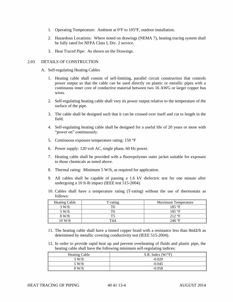
HEAT TRACING OF PIPING 40 41 13-4 AUGUST 2014
1. Operating Temperature: Ambient at 0°F to 105°F, outdoor installation.
2. Hazardous Locations: Where noted on drawings (NEMA 7), heating tracing system shall
be fully rated for NFPA Class I, Div. 2 service.
3. Heat Traced Pipe: As shown on the Drawings.
2.03 DETAILS OF CONSTRUCTION
A. Self-regulating Heating Cables
1. Heating cable shall consist of self-limiting, parallel circuit construction that controls
power output so that the cable can be used directly on plastic or metallic pipes with a
continuous inner core of conductive material between two 16 AWG or larger copper bus
wires.
2. Self-regulating heating cable shall vary its power output relative to the temperature of the
surface of the pipe.
3. The cable shall be designed such that it can be crossed over itself and cut to length in the
field.
4. Self-regulating heating cable shall be designed for a useful life of 20 years or more with
“power on” continuously.
5. Continuous exposure temperature rating: 150 °F
6. Power supply: 120 volt AC, single phase, 60 Hz power.
7. Heating cable shall be provided with a fluoropolymer outer jacket suitable for exposure
to those chemicals as noted above.
8. Thermal rating: Minimum 5 W/ft, as required for application.
9. All cables shall be capable of passing a 1.6 kV dielectric test for one minute after
undergoing a 10 ft-lb impact (IEEE test 515-2004).
10. Cables shall have a temperature rating (T-rating) without the use of thermostats as
follows:
Heating Cable T-rating Maximum Temperature
3 W/ft T6 185 °F
5 W/ft T6 185 °F
8 W/ft T5 212 °F
10 W/ft T4A 248 °F
11. The heating cable shall have a tinned copper braid with a resistance less than 8mΩ/ft as
determined by metallic covering conductivity test (IEEE 515-2004).
12. In order to provide rapid heat up and prevent overheating of fluids and plastic pipe, the
heating cable shall have the following minimum self-regulating indices:
Heating Cable S.R. Index (W/°F)
3 W/ft -0.020
5 W/ft -0.045
8 W/ft -0.058

HEAT TRACING OF PIPING 40 41 13-5 AUGUST 2014
10 W/ft -0.071
13. The self-regulating index is the rate of change of power output in watts per ° Fahrenheit
as measured between temperatures of 50 °F and 100 °F and confirmed by the type test
and published data sheets.
14. In order to facilitate longer circuit lengths and smaller breaker sizing the heating cable
shall have the following maximum inrush current at 50 °F.
Heating Cable Maximum Inrush at
time = 1sec (mA/ft)
Maximum Inrush at
time = 10 sec (mA/ft)
Maximum Inrush at
time = 300 sec (mA/ft)
3 W/ft, 120 V 58 54 41
5 W/ft, 120 V 155 128 66
8 W/ft, 120 V 210 180 83
10 W/ft, 120 V 432 319 123
15. In order to ensure that self-regulating heating cable does not increase power output when
accidentally exposed to high temperatures resulting in thermal runaway and self-ignition,
the cable shall produce less than 10 percent of rated power when energized and heated to
300 °F for 30 minutes. After this test, if the cable is allowed to cool to 50 °F and is
reenergized, it must not have an increasing power output leading to thermal runaway.
16. In order to confirm useful life, the self-regulating heating cable shall maintain between 75
and 110 percent of its original power output after having been cycled 500 times between
50 °F and 150 °F, allowing no more than 12 minutes of dwell time at each temperature.
17. The heating cable shall have the following third party approvals:
a. UL Listed for: Ordinary Areas
b. FM approved for:
i. Ordinary Areas
ii. Class I, Division 2 groups B, C, D
iii. Class II, Division 2 groups F, G
iv. Class III, Division 2
B. Locations
1. A ground fault protection device set at 30 mA, with a nominal 100 ms response time shall
be used to protect each circuit.
2. The temperature identification number (T-rating) of the cable shall comply with FM
requirements as applicable.
3. Connection methods used with the cable shall be suitable for use in all site locations.
C. Termination for Self-Regulating Cables
1. All connection components used to terminate self-regulating heating cables, including
power connectors, splices, tees and connectors, shall be approved for the respective area
classification and approved as a system with the particular heating cable in use.
2. Under no circumstances shall terminations which are manufactured by a vendor other
than the cable manufacturer be used.
HEAT TRACING OF PIPING 40 41 13-6 AUGUST 2014
3. Components shall be rated NEMA 4X, unless located within a NEMA 7 area.
D. Power Supply: Each circuit of heating cable shall be powered and controlled by an integrated
power supply/thermostat unit. The unit shall be provided in a molded NEMA 4X watertight
enclosure. Each circuit shall be provided with a signal light wired to the terminating end that
indicates when the tracer tape is energized.
E. Power Supply/Thermostat Box: The power supply/thermostat box shall provide power
connections and control of the heat trace system. The thermostat shall sense the pipeline
temperature. The unit has the following characteristics:
1. Power Supply: 120 VAC, single phase, 60 Hz.
2. Switch Rating: 22 Amps at 120 VAC.
3. Control Temperature Range: -40 °F to 160 °F.
4. Scale Division: 10 °F.
5. Sensor Material: Stainless Steel.
6. Maximum Exposure Temperature: 450 °F.
7. Operating Temperature Setting: 60 °F.
8. Enclosure Rating / Material: NEMA 4X, stainless steel.
9. Assemblies and panels shall be UL listed.
10. PLC control / status: Provide general alarm solid-state relay for contact output to plant
SCADA system – open on alarm. General alarm shall consist of the following alarms:
a. Low / High Temperature.
b. Low / High Current.
c. Low / High Voltage.
d. Ground Fault Alarm.
F. Pipe Insulation:
1. Fiberglass Insulation:
a. Type: Heavy density sectional pipe insulation with vapor barrier and self-sealing lap.
b. Density: Four pounds per cubic foot.
c. R-Value Minimum 4.0 hr.-ft2-°F/BTU.
d. Fittings: Molded fiberglass.
e. Jointing Materials: Manufacturer’s recommended adhesives and tape.
f. Valve Insulation: Miter cut nesting size covering segments of same thickness as
pipeline, for insulation of valves. Valve stems of insulated valves shall be of
sufficient length to allow normal operation of the valve with the insulation installed.
g. Product and Manufacturer: Provide one of the following:
i. Owens Corning Fiberglass Corporation, Fiberglas 25ASJ/SSL.
ii. Certain-Teed Products Corporation.
iii. Or Approved equal.
2. Weatherproof Insulation Jacket:
HEAT TRACING OF PIPING 40 41 13-7 AUGUST 2014
a. Type: Smooth embossed aluminum metal jacket.
b. Thickness: 0.016-inches.
c. Moisture Barrier: Polycraft.
d. Fastening: Pre-formed "Z"-lock seam with 2-inch butt strap with sealant.
e. Bands: 1/2-inch aluminum bands with wing seals.
f. Fittings:
i. Type: Pre-fabricated aluminum fittings.
ii. Thickness: 0.016-inches.
g. Product and Manufacturer: Provide one of the following:
i. Certain-Teed Products Corporation.
ii. Childers Products Company, Lock-On and Slip-On.
iii. Or Approved equal.
2.04 SPARE PARTS AND MAINTENANCE
A. Furnish and deliver the following spare parts carefully boxed or packaged and plainly marked
for reordering:
1. One (1) coil of heat trace cable (100 feet).
2. One (1) thermostat.
3. Two (2) junction box connector kits.
4. Two (2) cold lead connection kits.
5. Two (2) end seal kits.
B. Spare parts shall be packed in sturdy containers with clear indelible identification markings
and shall be stored in a dry, warm location until transferred to the CITY.
PART 3 - EXECUTION
3.01 PREPARATION
A. CONTRACTOR to ensure all piping sections to be insulated have been completed before
applying any heat tracing and insulation materials.
B. Follow Manufacturer’s instructions for all materials needed to prepare the piping for heat
trace runs and pipe insulation.
3.02 INSTALLATION
A. CONTRACTOR shall install all components of the Heat Trace System in accordance with the
approved Shop Drawings and the Manufacturers’ instructions and recommendations.
CONTRACTOR shall coordinate with the pipe insulation contractor during the work.
B. Tracing should be placed along the bottom run of the pipe. Wrap heat trace cable around
valves, instruments, etc. located in the piping system, as per manufacturer’s instructions.
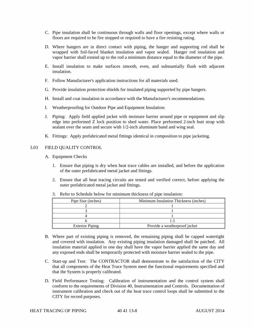
HEAT TRACING OF PIPING 40 41 13-8 AUGUST 2014
C. Pipe insulation shall be continuous through walls and floor openings, except where walls or
floors are required to be fire stopped or required to have a fire resisting rating.
D. Where hangers are in direct contact with piping, the hanger and supporting rod shall be
wrapped with foil-faced blanket insulation and vapor sealed. Hanger rod insulation and
vapor barrier shall extend up to the rod a minimum distance equal to the diameter of the pipe.
E. Install insulation to make surfaces smooth, even, and substantially flush with adjacent
insulation.
F. Follow Manufacturer's application instructions for all materials used.
G. Provide insulation protection shields for insulated piping supported by pipe hangers.
H. Install and coat insulation in accordance with the Manufacturer's recommendations.
I. Weatherproofing for Outdoor Pipe and Equipment Insulation:
J. Piping: Apply field applied jacket with moisture barrier around pipe or equipment and slip
edge into preformed Z lock position to shed water. Place preformed 2-inch butt strap with
sealant over the seam and secure with 1/2-inch aluminum band and wing seal.
K. Fittings: Apply prefabricated metal fittings identical in composition to pipe jacketing.
3.03 FIELD QUALITY CONTROL
A. Equipment Checks
1. Ensure that piping is dry when heat trace cables are installed, and before the application
of the outer prefabricated metal jacket and fittings.
2. Ensure that all heat tracing circuits are tested and verified correct, before applying the
outer prefabricated metal jacket and fittings.
3. Refer to Schedule below for minimum thickness of pipe insulation:
Pipe Size (inches) Minimum Insulation Thickness (inches)
2 1
3 1
4 1
6 1.5
Exterior Piping Provide a weatherproof jacket
B. Where part of existing piping is removed, the remaining piping shall be capped watertight
and covered with insulation. Any existing piping insulation damaged shall be patched. All
insulation material applied in one day shall have the vapor barrier applied the same day and
any exposed ends shall be temporarily protected with moisture barrier sealed to the pipe.
C. Start-up and Test: The CONTRACTOR shall demonstrate to the satisfaction of the CITY
that all components of the Heat Trace System meet the functional requirements specified and
that the System is properly calibrated.
D. Field Performance Testing: Calibration of instrumentation and the control system shall
conform to the requirements of Division 40, Instrumentation and Controls. Documentation of
instrument calibration and check out of the heat trace control loops shall be submitted to the
CITY for record purposes.
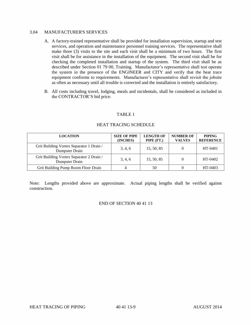
HEAT TRACING OF PIPING 40 41 13-9 AUGUST 2014
3.04 MANUFACTURER'S SERVICES
A. A factory-trained representative shall be provided for installation supervision, startup and test
services, and operation and maintenance personnel training services. The representative shall
make three (3) visits to the site and each visit shall be a minimum of two hours. The first
visit shall be for assistance in the installation of the equipment. The second visit shall be for
checking the completed installation and startup of the system. The third visit shall be as
described under Section 01 79 00, Training. Manufacturer’s representative shall test operate
the system in the presence of the ENGINEER and CITY and verify that the heat trace
equipment conforms to requirements. Manufacturer’s representative shall revisit the jobsite
as often as necessary until all trouble is corrected and the installation is entirely satisfactory.
B. All costs including travel, lodging, meals and incidentals, shall be considered as included in
the CONTRACTOR’S bid price.
TABLE 1
HEAT TRACING SCHEDULE
LOCATION SIZE OF PIPE
(INCHES)
LENGTH OF
PIPE (FT.)
NUMBER OF
VALVES
PIPING
REFERENCE
Grit Building Vortex Separator 1 Drain /
Dumpster Drain 3, 4, 6 15, 50, 85 0 HT-0401
Grit Building Vortex Separator 2 Drain /
Dumpster Drain 3, 4, 6 15, 50, 85 0 HT-0402
Grit Building Pump Room Floor Drain 4 50 0 HT-0403
Note: Lengths provided above are approximate. Actual piping lengths shall be verified against
construction.
END OF SECTION 40 41 13

HEAT TRACING OF PIPING 40 41 13-10 AUGUST 2014
THIS PAGE LEFT BLANK INTENTIONALLY

PROCESS CONTROLS – SCOPE OF
WORK AND LOOP DESCRIPTIONS 40 90 00-1 AUGUST 2014
SECTION 40 90 00
PROCESS CONTROLS – SCOPE OF WORK AND LOOP DESCRIPTIONS
PART 1 – GENERAL
1.01 GENERAL REQUIREMENTS
A. This Section includes a description of all materials, labor, and installation for all facets of the
control system and its associated devices. The intent is to give a general description of the
requirements for a complete construction of the instrumentation and controls for this Project
as specified or indicated on the Drawings.
B. If this Specification conflicts with any of the referenced documents or with good engineering
practice, the CONTRACTOR shall refer the conflict immediately to the CITY or the CITY’s
representative for resolution.
1.02 CODES, STANDARDS, AND PERMITS
A. All work shall be performed and materials shall be furnished in accordance with the
following standards where applicable:
1. National Electrical Code (NEC).
2. National Electrical Safety Code (NESC).
3. National Fire Protection Association (NFPA).
4. Federal, State, and Local Codes.
5. Instrument Society of America (ISA)
6. American Society for Testing and Materials (ASTM).
7. American Wire Gauge (AW6).
8. Federal Specification (Fed Spec).
9. American National Standards Institute (ANSI).
10. Institute of Electrical and Electronics Engineers (IEEE).
11. Insulated Cable Engineers Association (ICEA).
12. Insulated Power Cable Engineer’s Association (IPCEA).
13. Illuminating Engineering Society (IES).
14. National Electrical Manufacturers Association (NEMA).
15. Underwriters’ Laboratories, Inc. (UL).
16. Factory Mutual (FM).
17. Tubing – American Society for Testing of Materials (ASTM).
1.03 INSPECTIONS
A. Comply with requirements of local inspection authority.
B. Schedule inspections with the local inspection authority so that no new work is concealed
PROCESS CONTROLS – SCOPE OF
WORK AND LOOP DESCRIPTIONS 40 90 00-2 AUGUST 2014
prior to required inspections.
C. If required by the local authority having jurisdiction, upon completion of installation, a
nationally recognized third-party testing laboratory shall inspect the enclosure and provide
written certification verification that each unit assembly meets all local requirements.
Inspection shall be acceptable to local authority having jurisdiction. All costs associated with
the inspection shall be the responsibility of the CONTRACTOR. Any modifications required
to be performed by third party inspection shall be included on the as-built record documents
and submitted to the CITY.
1.04 INTENT OF DRAWINGS
A. Drawings indicate approximate desired position of equipment, panels, and instrumentation
devices. Minor deviations in panel locations to suit field conditions are acceptable. Major
changes in the location of panels must be approved. Locations of panels must be coordinated
with piping, mechanical, and all other contractors to avoid interference.
B. It is the responsibility of the selected CONTRACTOR to coordinate the mounting locations
for all panels.
C. Mounting locations for in-line instrumentation devices will be coordinated with the piping,
mechanical or HVAC contractor.
D. Mounting of remote transmitters, or any devices, which are not directly installed in process
lines, shall be installed in order to allow ease of access and maintenance.
E. Actual conduit routings are to be field determined. The plan drawings are intended to show
“home-runs” from a specific control panel only.
1.05 SUBMITTALS
A. The CONTRACTOR shall submit, for approval, all CONTRACTOR furnished
instrumentation, panels, and valves before purchase.
B. Upon Completion of Job, submit the following:
1. Supply "as-built" drawings: Marked-up red line drawings.
2. Give the CITY’s representative all manufacturers’ literature upon completion of job.
1.06 DESCRIPTION
A. Work Included
1. Provide and install instruments and provide instrument supports.
2. Provide process-sensing piping / tubing, fittings and supports from process isolation
valve to instrument.
3. Provide instrument cabling / wiring, raceways, cable trays, fittings and supports between
control room, control panels, junction boxes and field instruments.
4. The CONTRACTOR shall furnish all materials required for the proper installation of all
sensors, final control elements, and process control system equipment.
5. The CONTRACTOR shall perform testing and provide adequate documentation, making
adjustments as necessary, to ensure proper performance of the sensors and final control
elements provided as part of process and mechanical systems.
PROCESS CONTROLS – SCOPE OF
WORK AND LOOP DESCRIPTIONS 40 90 00-3 AUGUST 2014
6. Set Control Panels or Field Junction Boxes.
7. Provide supervision and labor that has been qualified by training and experience, to
perform the specific activities.
8. Issue instrumentation for installation by other contractors as required.
9. Initiate a documented request for all work which is not included in the current authorized
contract and design documents.
10. CONTRACTOR is responsible for the work shown on the P&ID and instrument
drawings. CONTRACTOR shall become familiar with reference drawings and those
drawings assigned to other CONTRACTORS.
11. Receive and inspect instruments and control panels. Notify the CITY immediately of any
signs of damage or if discrepancies exist between the packing slip and the items being
received.
12. Maintain field records indicating date for receipt of instruments and control panels on
site.
13. Store all instruments, control panels, and junction boxes in a clean and dry area that
provides shelter from the rain and mechanical abuse. Provide heating / cooling to
maintain an ambient temperature between 32 degrees and 72 degrees F.
14. Note: All computer consoles, cabinets and peripheral equipment must be stored, handled,
moved and installed in an upright position only.
15. Ensure that all miscellaneous items such as special cabling, mounting brackets, etc., are
stored with the associated instruments or control panels.
16. Protect all instrument flange faces, diaphragm seal surfaces, capillary tubing and threaded
connections from mechanical abuse.
17. Ensure that plugs and caps are not removed from instrument openings / connections
during storage.
18. The CONTRACTOR shall insure that each instrument is provided with a permanently
attached tag. The tags shall be 2” diameter round phenolic plastic, black on both sides
with 5/16” engraved white lettering centered on tag. The tag shall be attached to the
instrument using stainless steel wire rope. Ferrules are to be stainless steel. In the event
that the instrument manufacturer does not provide instrument tags meeting these
requirements, the CONTRACTOR shall provide these tags.
19. The CONTRACTOR shall protect the internal components of any control panel when
drilling, installing conduit openings, and similar construction activities. This is typically
done by enclosing the components in plastic wrap. Any metal shavings and other loose
debris shall be promptly removed after modifications to the control panel. After final
terminations, vacuum the control panel.
20. Specification 40 95 13 (Control Panels) shall be the primary guiding document to be used
when fabricating a new control panel, or modifying an existing one. This Specification,
in conjunction with the control panel layout design, bill of materials and nameplate
schedules are required for a quality fabrication.
21. Specification 40 94 43 (Programmable Logic Process Controllers) describes the control
system requirements and contains the I/O list.
PROCESS CONTROLS – SCOPE OF
WORK AND LOOP DESCRIPTIONS 40 90 00-4 AUGUST 2014
B. Related Work Not Included In This Section
1. Installation of in-line instruments and control valves. (But the wiring and pneumatic
terminations of such are included.)
2. Fabrication of Custom Control Panels.
3. Instrumentation and controls furnished with vendor skid units.
1.07 SYSTEM DESCRIPTION
A. Process instrumentation requirements are shown and described on the flow sheets, instrument
list and coordination schedule, instrument wiring drawings, wiring / pneumatic and
communication conduit plans, conduit schedules and installation details.
B. In general, the facility consists of Allen Bradley PLC Control Logix or Compact Logix
control systems with various remote I/O panels, and associated field and panel-mounted
instrumentation.
C. For PLC peer-peer communications, as well as SCADA communications to the PLC control
systems, Ethernet is the standard. Fiber shall be run for distances greater than one hundred
meters.
D. For PLC communications with Remote I/O control panels, Control Net shall be the standard.
1.08 PROJECT / SITE CONDITIONS
A. CITY-Installed Equipment
1. CONTRACTOR shall acknowledge the right of the CITY, or other of his contractors, to
place or install any equipment during the progress of the work as required.
2. CONTRACTOR shall agree that such placing and installation of equipment shall not, in
any way, signify the completion of the work or any portion of it, nor shall it signify the
CITY's acceptance of the work or any portion of it.
1.09 SEQUENCING / SCHEDULING
It is the responsibility of the CONTRACTOR to sequence and schedule all work. The
CONTRACTOR will coordinate with all other disciplines and trades to schedule all work. Any
re-work caused by inadequate coordination with other trades will be the responsibility of the
CONTRACTOR.
1.10 COORDINATION
A. Inspections and Reports: Inspect the work of other contractors which precedes your work
and upon which your work depends. Report to the CITY any deviations from the contract
documents. Failure to make an inspection and report shall constitute an acceptance of the
other contractors' work.
B. Delays: Notify the CITY of any existing or foreseeable causes for delay in the work.
1.11 DRAWING CONFLICTS
Lay out your work first, before you start, and report all drawing conflicts to the CITY. The CITY
will not assume responsibility for cost incurred by the CONTRACTOR because of lack of
preparation.
PROCESS CONTROLS – SCOPE OF
WORK AND LOOP DESCRIPTIONS 40 90 00-5 AUGUST 2014
PART 2 – INSTRUMENTATION REQUIREMENTS
2.01 HEAD CELL INFLUENT GATE ACTUATORS (Quantity = 2) GENERAL CONTRACTOR
TO PROVIDE
A. The automatic gate actuators shall be as specified in Specification 40 92 43.
B. Option “OC” is required. Eight (8) interposing relays are part of the actuator’s control.
C. 4-20 mA position feedback is required.
2.02 GRIT PUMP SUCTION HEADER VALVE ACTUATORS (Quantity = 2) GENERAL
CONTRACTOR TO PROVIDE
A. The automatic gate actuators shall be as specified in Specification 40 92 43.
B. Option “OC” is required. Eight (8) interposing relays are part of the actuator’s control.
C. 4-20 mA position feedback is required.
2.03 GRIT PUMP SUCTION VALVE ACTUATORS (Quantity = 3) GENERAL CONTRACTOR
TO PROVIDE
A. The automatic gate actuators shall be as specified in Specification 40 92 43.
B. Option “OC” is required. Eight (8) interposing relays are part of the actuator’s control.
C. 4-20 mA position feedback is required.
2.04 GRIT PUMP DISCHARGE VALVE ACTUATORS (Quantity = 3) GENERAL CONTRACTOR
TO PROVIDE
A. The automatic gate actuators shall be as specified in Specification 40 92 43.
B. Option “OC” is required. Eight (8) interposing relays are part of the actuator’s control.
C. 4-20 mA position feedback is required.
2.05 GRIT PUMP DISCHARGE HEADER VALVE ACTUATORS (Quantity = 4) GENERAL
CONTRACTOR TO PROVIDE
A. The automatic gate actuators shall be as specified in Specification 40 92 43.
B. Option “OC” is required. Eight (8) interposing relays are part of the actuator’s control.
C. 4-20 mA position feedback is required.
PART 3 – LOOP DESCRIPTIONS FOR BUNDLE PROJECT
3.01 SCOPE
A. In general, simple analog and discrete control, logic and indication requirements are depicted
on the Process and Instrumentation Diagrams (P&IDs) supplied as part of this package.
Where additional information is necessary, it is included in the descriptions that follow.
B. The items described in Paragraph 3.02, are general loop requirements for typical plant unit
operations. It is intended that these general requirements shall be followed where applicable.
C. The items described in Paragraph 3.03, are loop descriptions for typical plant unit operations.

PROCESS CONTROLS – SCOPE OF
WORK AND LOOP DESCRIPTIONS 40 90 00-6 AUGUST 2014
It is intended that these descriptions, in conjunction with the P&IDs, provide sufficient
system configuration information for the majority of simple control systems. Where
additional descriptions are necessary or where control logic deviates from the general and
typical descriptions, it is described in the Paragraph.
D. Software Alarms
1. All analog inputs to the plant control system shall have low and high software alarms.
Where low and/or high software alarms are not specified elsewhere in this Specification,
they shall initially be turned off or set for 0% (low alarm) and 100% (high alarm) of the
signal range. This will help eliminate nuisance alarms during checkout and start-up.
2. All software alarms shall be reviewed with the plant superintendent, or his designee,
during programming or panel checkout and again during field checkout or start-up. The
System Manufacturer shall change all software alarm setpoint values as instructed by the
plant superintendent. For critical alarms, the System Manufacturer shall configure the
associated graphic symbol to flash or change color when in an alarm condition.
3.02 LOOP DESCRIPTIONS – GENERAL REQUIREMENTS
A. Equipment protection interlocks and safety interlocks (motor temperature and moisture
switches, emergency stops, low-low level shutdowns, etc.), shall be hardwired and shall not
reside in the plant control system. Hardwired equipment protection interlocks and safety
interlocks shall be functional at all times, regardless of operating mode (HAND, AUTO,
LOCAL, REMOTE, etc.) Equipment protection circuits shall be fail-safe, the circuit shall
open to stop equipment.
B. All motor control logic in the plant control system shall include COMMAND DISAGREE
logic. The plant control system shall generate a COMMAND DISAGREE alarm to alert the
operator that a fault has occurred for any of the following conditions:
1. When a motor is called to run by the control system and no run feedback is received by
the plant control system within a preset, adjustable period of time. This shall only be
applied to those motors which have run feedback to the plant control system.
2. When a motor is running based on a manual command generated through the plant
control system, or based on an automated sequence in the plant control system, and run
feedback is lost by the plant control system for a preset, adjustable period of time. This
shall only be applied to those motors which have run feedback to the plant control
system.
3. When a motor is called to run based on a manual command generated through the plant
control system, or based on an automated sequence in the plant control system, and the
feedback from a LOCAL/OFF/REMOTE or similar field-mounted switch indicates that
the unit is not in the REMOTE mode. This shall only be applied to those motors which
have UNIT IN REMOTE feedback to the plant control system.
C. All control valve logic in the plant control system shall include COMMAND DISAGREE
logic. The plant control system shall generate a COMMAND DISAGREE alarm to alert the
operator that a fault has occurred for any of the following conditions:
1. When a motorized actuator is called to open, based on a SCADA command generated
through the plant control system, and the feedback from a ZSO has not been detected for
a predetermined and adjustable amount of time, this constitutes a FAIL-TO-OPEN
command disagree alarm (FAILOP).
2. When a motorized actuator is called to close, based on a SCADA command generated
PROCESS CONTROLS – SCOPE OF
WORK AND LOOP DESCRIPTIONS 40 90 00-7 AUGUST 2014
through the plant control system, and the feedback from a ZSC has not been detected for
a predetermined and adjustable amount of time, this constitutes a FAIL-TO-CLOSE
command disagree alarm (FAILCL).
3. When a motorized actuator is called to stop, based on a SCADA command generated
through the plant control system, and the position (gate percent opened or closed) is not
constant after a predetermined and adjustable amount of time, this constitutes a FAIL-
TO-STOP command disagree alarm (FAILST).
D. All analog inputs shall be monitored by the plant control system to identify out of range
signals (less than 4 mA DC or more than 20 mA DC). When the control system detects an
out of range signal which continues for more than five minutes, an alarm shall be generated
by the plant control system. The alarm shall identify the particular analog signal which is out
of range.
3.03 LOOP DESCRIPTIONS – TYPICAL TAGGING CONVENTIONS
A. Typical Motor Status Monitoring – Constant Speed Motors
1. Motor run (typically designated XI and annotated RUN) and overload (typically
designated XA and annotated OVERLOAD) status will be indicated in the plant control
system.
2. Where conditions other than motor overload are sensed in the MCC (e.g., motor
temperature or moisture switch activated), the fault condition is combined with motor
overload and the resulting fault (typically designated ZA and annotated FAULT) status
will be indicated in the control system.
3. Total unit run time (typically designated KQI and annotated RUNTIME) will be provided
for the motor in the plant control system.
B. Typical Motor Status Monitoring – Variable Speed Motors
1. Motor run (typically designated XI and annotated RUN) and combination VFD fault and
motor overload (typically designated ZA and annotated FAULT) status will be indicated
in the plant control system.
2. Where conditions other than VFD fault and motor overload are sensed in the MCC (e.g.,
motor temperature or moisture switch activated), the fault condition is combined with
motor overload and VFD fault and the resulting fault (typically designated ZA and
annotated FAULT) status will be indicated in the control system.
3. Total unit run time (typically designated KQI and annotated RUNTIME) will be provided
for the motor in the plant control system.
4. Variable speed drives generally have a LOCAL-OFF-REMOTE switch mounted on the
drive cabinet for starting or stopping the drive a LOCAL-REMOTE switch for speed
control. Unless otherwise stated in the project specific loop descriptions, a REMOTE
contact from each switch shall be wired in series to provide an indication in the control
system. Where UNIT IN REMOTE feedback (typically designated YN and annotated
UNIT IN REMOTE) is required for a control loop, it will be shown on the P&IDs.
C. Typical Motor Control Loop – Local/MCC HAND-OFF-AUTO Switch
1. When the HAND-OFF-AUTO switch is in the HAND mode, the equipment will run
continuously regardless of the automatic control logic. In the HAND mode, personnel
protective and equipment protective interlocks shall be enabled to shut down the
equipment. In the HAND mode, the equipment will run even in the event of PLC or
PROCESS CONTROLS – SCOPE OF
WORK AND LOOP DESCRIPTIONS 40 90 00-8 AUGUST 2014
control system failure. The operator assumes control responsibility in HAND mode.
2. When the HAND-OFF-AUTO switch is in the OFF mode, the equipment will not run
under any circumstances.
3. When the HAND-OFF-AUTO switch is in the AUTO mode, the equipment will run in
response to a single automatic contact from PLC or hardwired logic functions.
4. Where UNIT IN AUTO feedback (typically designated XI and annotated UNIT IN
AUTO) is required, it will be shown on the P&IDs.
D. Typical Motor Control Loop – Local/MCC LOCAL-OFF-REMOTE Switch
1. When the LOCAL-OFF-REMOTE switch is in the LOCAL mode, the equipment will run
continuously regardless of the remote control logic. In the LOCAL mode, personnel
protective and equipment protective interlocks shall be enabled to shut down the
equipment. In the LOCAL mode, the equipment will run even in the event of PLC or
control system failure. The operator assumes control responsibility in LOCAL mode.
2. When the LOCAL-OFF-REMOTE switch is in the OFF mode, the equipment will not run
under any circumstances.
3. When the LOCAL-OFF-REMOTE switch is in the REMOTE mode, the equipment will
run in response to a single remote contact from PLC or hardwired logic functions.
4. Where UNIT IN REMOTE feedback (typically designated YN and annotated UNIT IN
REMOTE) is required for a control loop, it will be shown on the P&IDs.
E. Typical Motor Control Loop – Local START-STOP Switch
1. The START-STOP switch is typically set up for three-wire momentary control logic.
2. In the event of loss of power, the motor must be manually restarted.
3. Hardwired START-STOP switches shall operate equipment even in the event of PLC or
control system failure.
F. Typical Valve Control Loop – Local OPEN-STOP-CLOSE Switch
1. The OPEN-STOP-CLOSE switch is completely hardwired in the motor control circuit.
2. The LOCAL-OFF-REMOTE switch needs to be in LOCAL in order for there to be
manual control from the OPEN-STOP-CLOSE switch.
3. Hardwired OPEN-STOP-CLOSE switches shall operate equipment even in the event of
PLC or control system failure.
G. Typical Software Control Switches
1. Where an automatic control strategy is implemented in software and it is necessary to
disable the automatic operation, a software MANUAL-OFF-AUTO switch (typically
designated HS and annotated MANUAL-OFF-AUTO) may be provided on the P&IDs.
In the AUTO mode, the automatic control logic operates the control system output. In
the OFF mode, the control system output remains open. In the MANUAL mode, the
output contact remains closed or is controlled by a software START-STOP switch.
2. Where no automatic control strategy is implemented in software, but it is necessary to
disable the automatic operation elsewhere, a software ENABLE-OFF switch (typically
designated HS and annotated ENABLE OFF) may be provided on the P&IDs. In the
OFF mode, the output contact from the control system remains open. In the ENABLE
mode, the output contact remains closed.
PROCESS CONTROLS – SCOPE OF
WORK AND LOOP DESCRIPTIONS 40 90 00-9 AUGUST 2014
3. Where a software START-STOP switch (typically designated HS and annotated START-
STOP) is shown on the P&IDs, the control system shall provide one normally open
contact which closes for an adjustable time period to start the equipment and one
normally closed contact which opens for an adjustable time period to stop the equipment.
Where an automatic control sequence interfaces with a hardwired START-STOP
momentary logic circuit, the control system shall provide one normally open contact
which closes for an adjustable time period to start the equipment and one normally closed
contact which opens for an adjustable time period to stop the equipment.
4. When a software RUN-STOP switch (typically designated HS and annotated RUN-
STOP) is shown on the P&IDs, the control system shall provide one normally open
contact which closes for as long as the control system logic calls for the equipment to
run.
5. Where a software OPEN-CLOSE switch (typically designated HS and annotated OPEN-
CLOSE) is shown on the P&IDs, the control system shall provide one normally open
contact which closes when the control system logic calls for the valve to open and
another normally open contact that closes when the control system logic calls for the
valve to close. The outputs remain closed until the valve has reached its new position, as
confirmed by the valve limit switches.
a. When the valve is fully closed, the valve closed indicator in the plant control system,
ZIC, shall be on. When the valve is fully closed, the valve open indicator in the plant
control system, ZIO, shall be off.
b. When the valve is fully opened, the valve open indicator in the plant control system,
ZIO, shall be on. When the valve is fully opened, the valve closed indicator in the
plant control system, ZIC shall be off.
c. When the valve is neither fully opened (ZIO) nor fully closed (ZIC), the valve “In
Transition” indicator graphic in the plant control system shall be on.
H. Typical Analog Loop – Indication and Alarm
1. Analog values (designated LI, PI, etc.), will be indicated in the plant control system.
Readouts for pressure, temperature, flow and analytical loops shall be in engineering
units based on the field transmitter range. Readouts for special analog loops, analog
signals from equipment not supplied, will be listed in the Initial Software Settings list
attached to this Section or described in the Project specific loop descriptions.
2. Required software alarm functions (designated LAL, TAH, AAL, etc.), derived from
analog variables are shown on the P&IDs. Initial setpoints for software switches will be
listed in the Initial Software Settings list attached to this Section (if applicable) or
described in the Project specific loop descriptions.
I. Typical Analog Loop – Control and Alarm
1. All software PID (proportional, integral, derivative) controllers (designated LIC, PIC,
FIC, AIC, PDIC) must show setpoint, process variable, and manipulated variable and
allow access to tuning parameters from the operator interface software package. Any
software controller shall have the capability of being placed in MANUAL mode and have
the capability of manually adjusting the output in MANUAL mode from the operator
interface software package. Indicator readouts for software PID controllers shall conform
to the requirements given in the Typical Analog Loop – Indication and Alarm description
above.
2. Required software alarm functions (designated LALL, TAH, AAL, etc.), derived from
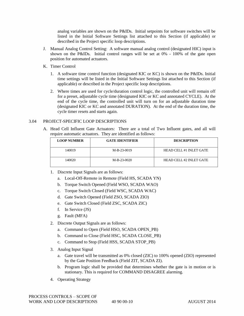
PROCESS CONTROLS – SCOPE OF
WORK AND LOOP DESCRIPTIONS 40 90 00-10 AUGUST 2014
analog variables are shown on the P&IDs. Initial setpoints for software switches will be
listed in the Initial Software Settings list attached to this Section (if applicable) or
described in the Project specific loop descriptions.
J. Manual Analog Control Setting: A software manual analog control (designated HIC) input is
shown on the P&IDs. Initial control ranges will be set at 0% - 100% of the gate open
position for automated actuators.
K. Timer Control
1. A software time control function (designated KIC or KC) is shown on the P&IDs. Initial
time settings will be listed in the Initial Software Settings list attached to this Section (if
applicable) or described in the Project specific loop descriptions.
2. Where times are used for cycle/duration control logic, the controlled unit will remain off
for a preset, adjustable cycle time (designated KIC or KC and annotated CYCLE). At the
end of the cycle time, the controlled unit will turn on for an adjustable duration time
(designated KIC or KC and annotated DURATION). At the end of the duration time, the
cycle timer resets and starts again.
3.04 PROJECT-SPECIFIC LOOP DESCRIPTIONS
A. Head Cell Influent Gate Actuators: There are a total of Two Influent gates, and all will
require automatic actuators. They are identified as follows:
LOOP NUMBER GATE IDENTIFIER DESCRIPTION
140019 M-B-23-0019 HEAD CELL #1 INLET GATE
140020 M-B-23-0020 HEAD CELL #2 INLET GATE
1. Discrete Input Signals are as follows:
a. Local-Off-Remote in Remote (Field HS, SCADA YN)
b. Torque Switch Opened (Field WSO, SCADA WAO)
c. Torque Switch Closed (Field WSC, SCADA WAC)
d. Gate Switch Opened (Field ZSO, SCADA ZIO)
e. Gate Switch Closed (Field ZSC, SCADA ZIC)
f. In Service (JS)
g. Fault (MFA)
2. Discrete Output Signals are as follows:
a. Command to Open (Field HSO, SCADA OPEN_PB)
b. Command to Close (Field HSC, SCADA CLOSE_PB)
c. Command to Stop (Field HSS, SCADA STOP_PB)
3. Analog Input Signal
a. Gate travel will be transmitted as 0% closed (ZIC) to 100% opened (ZIO) represented
by the Gate Position Feedback (Field ZIT, SCADA ZI).
b. Program logic shall be provided that determines whether the gate is in motion or is
stationary. This is required for COMMAND DISAGREE alarming.
4. Operating Strategy

PROCESS CONTROLS – SCOPE OF
WORK AND LOOP DESCRIPTIONS 40 90 00-11 AUGUST 2014
a. In REMOTE, the gate can be opened or closed from SCADA. SCADA controls will
have a command to OPEN, and a command to CLOSE. The position feedback (ZI)
will give the operator position indication from SCADA.
b. In LOCAL, the SCADA is disabled. The local OPEN and CLOSE switches can
manipulate the gate via the operator in LOCAL mode. In LOCAL, the operator will
place the OPEN-STOP-CLOSE selector to STOP to complete the gate movement.
LOCAL, OPEN, STOP and CLOSE are all hardwired in the motor control circuit.
c. Status Indications – SCADA will display the open (ZIO) and closed (ZIC) of each
gate travel position switch. SCADA will display the actuator “In Service” status (JS).
SCADA will display the REMOTE (YN) selector position.
d. Alarm Indications – SCADA will display command disagree alarms Fail-To-Open
(FAILOP), Fail-To-Close (FAILCL) and Fail-To-Stop (FAILST).
e. SCADA will display actuator fault alarm (MFA). This alarm occurs when the gate
actuator is In Service (JS), and the monitor relay on the actuator is tripped.
f. SCADA will display torque alarm in open (WAO) and torque alarm in closed (WAC)
signals.
B. Grit Pump Selection PLUG Valve Actuators: There are a total of Twelve Path Selection Plug
Valves, and all will require automatic actuators. They are identified as follows:
LOOP NUMBER GATE IDENTIFIER DESCRIPTION
140021 M-B-23-0021 HEAD CELL #1 OUTLET PLUG VALVE
140022 M-B-23-0022 HEAD CELL #2 OUTLET PLUG VALVE
14023 M-B-23-0023 GRIT SUCTION #1 PLUG VALVE
14024 M-B-23-0024 GRIT SUCTION #2 PLUG VALVE
14025 M-B-23-0025 GRIT SUCTION #3 PLUG VALVE
14026 M-B-23-0026 GRIT DISCHARGE #1 PLUG VALVE
14027 M-B-23-0027 GRIT DISCHARGE #2 PLUG VALVE
14028 M-B-23-0028 GRIT DISCHARGE #3 PLUG VALVE
14029 M-B-23-0029 GRIT DISCHARGE #4 PLUG VALVE
14030 M-B-23-00230 GRIT DISCHARGE #5 PLUG VALVE
14031 M-B-23-0031 GRIT DISCHARGE #6 PLUG VALVE
14032 M-B-23-0032 GRIT DISCHARGE #7 PLUG VALVE
1. Discrete Input Signals are as follows:
a. Local-Off-Remote in Remote (Field HS, SCADA YN)
b. Torque Switch Opened (Field WSO, SCADA WAO)
c. Torque Switch Closed (Field WSC, SCADA WAC)
PROCESS CONTROLS – SCOPE OF
WORK AND LOOP DESCRIPTIONS 40 90 00-12 AUGUST 2014
d. Valve Switch Opened (Field ZSO, SCADA ZIO)
e. Valve Switch Closed (Field ZSC, SCADA ZIC)
f. In Service (JS)
g. Fault (MFA)
2. Discrete Output Signals are as follows:
a. Command to Open (Field HSO, SCADA OPEN_PB)
b. Command to Close (Field HSC, SCADA CLOSE_PB)
c. Command to Stop (Field HSS, SCADA STOP_PB)
3. Analog Input Signal
a. Valve travel will be transmitted as 0% closed (ZIC) to 100% opened (ZIO)
represented by the Valve Position Feedback (Field ZIT, SCADA ZI).
b. Program logic shall be provided that determines whether the gate is in motion or is
stationary. This is required for COMMAND DISAGREE alarming.
4. Operating Strategy
a. In REMOTE, the valve can be opened or closed from SCADA. SCADA controls will
have a command to OPEN, and a command to CLOSE. The position feedback (ZI)
will give the operator position indication from SCADA.
b. In LOCAL, the SCADA is disabled. The local OPEN and CLOSE switches can
manipulate the gate via the operator in LOCAL mode. In LOCAL, the operator will
place the OPEN-STOP-CLOSE selector to STOP to complete the valve movement.
LOCAL, OPEN, STOP and CLOSE are all hardwired in the motor control circuit.
c. Status Indications – SCADA will display the open (ZIO) and closed (ZIC) of each
valve travel position switch. SCADA will display the actuator “In Service” status
(JS). SCADA will display the REMOTE (YN) selector position.
d. Alarm Indications – SCADA will display command disagree alarms Fail-To-Open
(FAILOP), Fail-To-Close (FAILCL) and Fail-To-Stop (FAILST).
e. SCADA will display actuator fault alarm (MFA). This alarm occurs when the gate
actuator is In Service (JS), and the monitor relay on the actuator is tripped.
f. SCADA will display torque alarm in open (WAO) and torque alarm in closed (WAC)
signals.
3.05 CONTROL SYSTEM MODIFICATIONS FOR BUNDLE PROJECT
A. Control System Communications
1. Control Net Fine Screens Building to Grit Building - General: Refer to Drawing I-603.
CONTRACTOR to provide and install conduit, Control Net cable and cable fittings and
Fiber Spur Patch Down Panels and connectors.
a. Control Net originates in panel M-20-F01. The Control Net taps are existing for
Node 01 through Node 06. Verify the terminating resistor is installed in panel M-20-

PROCESS CONTROLS – SCOPE OF
WORK AND LOOP DESCRIPTIONS 40 90 00-13 AUGUST 2014
F02.
b. Install Fiber Spur Patch Down Panel Assembled IAW Drawing E-502-04, near panel
M-20-F02. Route C-Net Coax from near Node 06 to Fiber Spur Patch Down Panel
and connect.
c. Install Fiber Spur Patch Down Panel Assembled IAW Drawing E-502-04, near panel
M4-14-R01. Route C-Net Coax from Node 07 to Fiber Spur Patch Down Panel and
connect.
d. Route conduit and fiber from Media Converter to Fiber Spur Patch Down Panel near
M4-14-R01.
e. Connect cable to Node 07 of panel M-20-F03 via the Control Net tap.
f. Connect cable to Node 08 of panel M4-14-R01. Remove Terminating Resistor from
Node 06 and install C-Net cable to Node 06. Install terminating resistor at Node 08.
END OF SECTION 40 90 00

PROCESS CONTROLS – SCOPE OF
WORK AND LOOP DESCRIPTIONS 40 90 00-14 AUGUST 2014
THIS PAGE INTENTIONALLY LEFT BLANK
INSTRUMENTATION DEVICES 40 91 00-1 OCTOBER 2014
SECTION 40 91 00
INSTRUMENTATION DEVICES
PART 1 - GENERAL
1.01 SCOPE
A. Primary Elements
B. Transmitters
C. Receivers
D. Analytical instruments
1.02 SYSTEM DESCRIPTION
A. System consists of all field and panel mounted instrumentation devices as noted, complete
with all necessary signal converters, isolators, amplifiers, power supplies, and other
appurtenances necessary for interfacing with other components.
B. Except as noted, scale all indicators in engineering units.
1.03 SUBMITTALS
A. Submit product data.
B. Operating and maintenance data shall be furnished in accordance with Section 01 78 23 of
these specifications.
1.04 WARRANTY
Refer to Section 01 78 36.
PART 2 - PRODUCTS
2.01 DISSOLVED OXYGEN / pH ANALYZER / TRANSMITTER
A. Type: Continuous-reading microprocessor based electronics unit incorporating diagnostic
capabilities. Display shall be two rows of sixteen alphanumeric digits. Mounting shall be
corrosion resistant stainless steel, fiberglass or thermoplastic.
B. Range: 0-5 mg/l dissolved oxygen.
0-14 Ph
C. Output: 3 Isolated 4 to 20 mADC proportional to measurement range. Provide three
independently configurable alarm outputs for high limit, low limit, and fault output, rated 3
amps, 120 VAC.
D. Enclosure: NEMA 4X, stainless steel, Polycarbonate, and aluminum . For outdoor
applications, provide thermostatically controlled space heater as required to maintain
operating temperatures.
E. Power Supply: 120 VAC.
F. Calibration: Unit shall have one-touch, automatic calibration.

INSTRUMENTATION DEVICES 40 91 00-2 OCTOBER 2014
G. Schedule
Tag Mounting Area Classification
AIT140044 SURFACE Non Classified
H. Acceptable Manufacturers: Equal to Hach sc200.
2.02 DISSOLVED OXYGEN SENSOR – UNION MOUNT
A. Type: Continuous-reading dissolved oxygen probe with microprocessor based electronics
unit incorporating diagnostic capabilities. Unit shall be supplied with automatic temperature.
B. Sensor: The sensor shall use the Clark principle for measurement of dissolved oxygen.
Sensor shall be contained in a sealed enclosure and shall be non-repairable requiring no
special tools for replacement and shall be installed in an 11-inch diameter ball float if floating
is required in the table below. Mounting shall be union mount of corrosion resistant stainless
steel, fiberglass or thermoplastic.
C. Range: 0-5 mg/l dissolved oxygen.
D. Output: Digital to Controller
E. Enclosure: NEMA 4x, stainless steel, fiberglass, aluminum or thermoplastic. For outdoor
applications, provide thermostatically controlled space heater as required to maintain
operating temperatures.
F. Power Supply: N/A.
G. Calibration: From Controller
H. Area Classification: Sensor shall be supplied with intrinsically safe barriers, in accordance
with the manufacturer’s recommendations, for mounting in hazardous areas if required in the
table below.
I. Schedule
Tag Mounting Area Classification
AE-140044B SURFACE Non Classified
J. Acceptable Manufacturers: Equal to Hach LDO MODEL2 and 9257000 Union Mount.
2.03 pH SENSOR – UNION MOUNT
A. Type: Continuous-reading pH probe with microprocessor based electronics unit incorporating
diagnostic capabilities. Unit shall be supplied with automatic temperature. Mounting shall
be union mount of corrosion resistant stainless steel, fiberglass or thermoplastic.
B. Range: 0-14 Ph.
C. Output: Digital to Controller
D. Enclosure: NEMA 4X, stainless steel, Polycarbonate, and aluminum. For outdoor
applications, provide thermostatically controlled space heater as required to maintain
operating temperatures.
E. Power Supply: N/A
F. Calibration: From Controller
G. Schedule
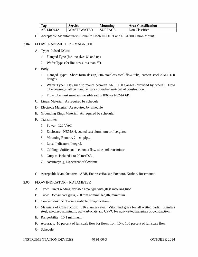
INSTRUMENTATION DEVICES 40 91 00-3 OCTOBER 2014
Tag Service Mounting Area Classification
AE-140044A WASTEWATER SURFACE Non Classified
H. Acceptable Manufacturers: Equal to Hach DPD1P1 and 6131300 Union Mount.
2.04 FLOW TRANSMITTER – MAGNETIC
A. Type: Pulsed DC coil
1. Flanged Type (for line sizes 8” and up).
2. Wafer Type (for line sizes less than 8”).
B. Body
1. Flanged Type: Short form design, 304 stainless steel flow tube, carbon steel ANSI 150
flanges.
2. Wafer Type: Designed to mount between ANSI 150 flanges (provided by others). Flow
tube housing shall be manufacturer’s standard material of construction.
3. Flow tube must meet submersible rating IP68 or NEMA 6P.
C. Linear Material: As required by schedule.
D. Electrode Material: As required by schedule.
E. Grounding Rings Material: As required by schedule.
F. Transmitter
1. Power: 120 VAC.
2. Enclosure: NEMA 4, coated cast aluminum or fiberglass.
3. Mounting Remote, 2-inch pipe.
4. Local Indicator: Integral.
5. Cabling: Sufficient to connect flow tube and transmitter.
6. Output: Isolated 4 to 20 mADC.
7. Accuracy: + 1.0 percent of flow rate.
G. Acceptable Manufacturers: ABB, Endress+Hauser, Foxboro, Krohne, Rosemount.
2.05 FLOW INDICATOR – ROTAMETER
A. Type: Direct reading, variable area type with glass metering tube.
B. Tube: Borosilicate glass, 250 mm nominal length, minimum.
C. Connections: NPT – size suitable for application.
D. Materials of Construction: 316 stainless steel, Viton and glass for all wetted parts. Stainless
steel, anodized aluminum, polycarbonate and CPVC for non-wetted materials of construction.
E. Rangeability: 10:1 minimum.
F. Accuracy: 10 percent of full scale flow for flows from 10 to 100 percent of full scale flow.
G. Schedule

INSTRUMENTATION DEVICES 40 91 00-4 OCTOBER 2014
Tag Calibrated
Range
Mounting
Configuration
Needle Valve Size
FI-070001 0-60 GPM VERTICAL N/A 1” NPT
FI-070002 0-60 GPM VERTICAL N/A 1” NPT
H. Acceptable Manufacturers: ABB, Brooks, King.
2.06 LEVEL TRANSMITTER – RADAR – OPEN AIR LIQUIDS
A. Type: Loop powered liquid level transmitter based upon open air radar technology.
B. Sensor: Horn Antenna plastic 80mm
C. Transmitter
1. Output: Isolated 4 to 20 mADC.
2. Power: Two-wire, 24 VDC.
3. Mounting: See Schedule
4. Cabling: N/A.
5. Enclosure: Plastic, NEMA 4X.
6. Local Indication: Two-line, 8 character LCD with 4-button keypad.
D. Acceptable Manufacturers: Equal to Vega Vegapuls 61
2.07 PRESSURE REGULATOR 3” AND LARGER
A. Type: Direct operated water pressure reducing valve. Self contained, requires no control
lines.
B. Material Cast Iron.
C. Pressure Rating: 200 psi.
D. Diaphram and disc: Elastomer.
E. Spring Range: 30 – 80 psi.
F. Max Temperature: 150ºF
Tag Pressure Setting Line size Fluid
PRV-400009 50 psig 4” Water
PRV-070001 50 psig 3” NPW
G. Acceptable Manufacturers: Equal to Watts Series 2300.
2.08 GAS DETECTOR – COMBUSTIBLE
A. Type: Dual wavelength, with reflector panel, to measure percent LEL of petroleum or methane
vapors as indicated below.
B. Sending Power: 24 VDC.
C. Receiver Power: 24 VDC.
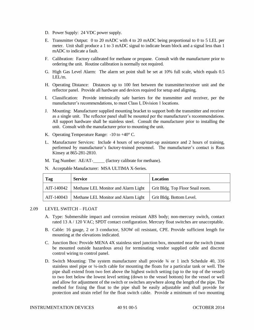
INSTRUMENTATION DEVICES 40 91 00-5 OCTOBER 2014
D. Power Supply: 24 VDC power supply.
E. Transmitter Output: 0 to 20 mADC with 4 to 20 mADC being proportional to 0 to 5 LEL per
meter. Unit shall produce a 1 to 3 mADC signal to indicate beam block and a signal less than 1
mADC to indicate a fault.
F. Calibration: Factory calibrated for methane or propane. Consult with the manufacturer prior to
ordering the unit. Routine calibration is normally not required.
G. High Gas Level Alarm: The alarm set point shall be set at 10% full scale, which equals 0.5
LEL/m.
H. Operating Distance: Distances up to 100 feet between the transmitter/receiver unit and the
reflector panel. Provide all hardware and devices required for setup and aligning.
I. Classification: Provide intrinsically safe barriers for the transmitter and receiver, per the
manufacturer’s recommendations, to meet Class I, Division 1 locations.
J. Mounting: Manufacturer supplied mounting bracket to support both the transmitter and receiver
as a single unit. The reflector panel shall be mounted per the manufacturer’s recommendations.
All support hardware shall be stainless steel. Consult the manufacturer prior to installing the
unit. Consult with the manufacturer prior to mounting the unit.
K. Operating Temperature Range: -10 to +40° C.
L. Manufacturer Services: Include 4 hours of set-up/start-up assistance and 2 hours of training,
performed by manufacturer’s factory-trained personnel. The manufacturer’s contact is Russ
Kinsey at 865-281-2810.
M. Tag Number: AE/AT- (factory calibrate for methane).
N. Acceptable Manufacturer: MSA ULTIMA X-Series.
Tag Service Location
AIT-140042 Methane LEL Monitor and Alarm Light Grit Bldg. Top Floor Snail room.
AIT-140043 Methane LEL Monitor and Alarm Light Grit Bldg. Bottom Level.
2.09 LEVEL SWITCH – FLOAT
A. Type: Submersible impact and corrosion resistant ABS body; non-mercury switch, contact
rated 13 A / 120 VAC; SPDT contact configuration. Mercury float switches are unacceptable.
B. Cable: 16 gauge, 2 or 3 conductor, SJOW oil resistant, CPE. Provide sufficient length for
mounting at the elevations indicated.
C. Junction Box: Provide MENA 4X stainless steel junction box, mounted near the switch (must
be mounted outside hazardous area) for terminating vendor supplied cable and discrete
control wiring to control panel.
D. Switch Mounting: The system manufacturer shall provide ¾ or 1 inch Schedule 40, 316
stainless steel pipe or ¼-inch cable for mounting the floats for a particular tank or well. The
pipe shall extend from two feet above the highest switch setting (up to the top of the vessel)
to two feet below the lowest level setting (down to the vessel bottom) for the vessel or well
and allow for adjustment of the switch or switches anywhere along the length of the pipe. The
method for fixing the float to the pipe shall be easily adjustable and shall provide for
protection and strain relief for the float switch cable. Provide a minimum of two mounting

INSTRUMENTATION DEVICES 40 91 00-6 OCTOBER 2014
brackets for fixing the pipe to the vessel wall while maintaining appropriate standoff distance.
The system manufacturer shall ensure mounting is in accordance with the manufacturer’s
recommendations.
E. Intrinsic Safety Barriers: Provide manufacturer’s recommended intrinsic safety barriers for
hazardous areas where scheduled below.
F. Acceptable Manufacturers: ITT Flygt ENM-10 or equal.
2.10 TEMPERATURE TRANSMITTER
A. Type: Transmitter complete with platinum RTD.
B. Accuracy: + 0.20 percent of calibrated span.
C. Output: Isolated, 4 to 20 mA DC, linear with temperature into loop loads of 0 to 500 ohms.
D. Power Supply: 24 VDC (two wire).
E. Enclosure: Plastic for Interior use.
F. Schedule
Tag Calibrated
Range
Indicator Scale
Units
“U” Length Location / Area
Classification
TT-140038B 40 to 90 ºF N/A N/A UNCLASS
G. Acceptable Manufacturers: KeleST-T91K or equal, Minco, Burns, Emerson.
PART 3 - EXECUTION
3.01 INSTALLATION
A. Locate field instruments so they are accessible for maintenance and orient so that indicators
are readily visible. Unless otherwise indicated, mount instruments 36 to 60-inches above
work surface. Provide 2-inch diameter, 304 stainless steel, Schedule 10 pipe welded to a 10-
inch square by ¼-inch thick stainless steel base plate for support unless wall or other
mounting arrangement is indicated. Space instruments at least ½-inch off concrete walls by
stainless steel channels or phenolic spacers.
B. Provide stainless steel or aluminum sun screens or shades for all electronic instruments
located outdoors.
C. Provide stainless steel identification tags attached with stainless steel wire or screws for all
field instruments.
3.02 TESTS AND CALIBRATION
A. Perform continuity tests on instrumentation conductors.
B. Calibrate each instrument to its published accuracy. Submit calibration sheets including the
instrument tag number or name, the date, name of individual performing calibration,
procedures and equipment used, and results obtained.
END OF SECTION 40 91 00
INFLUENT AUTO SAMPLER 40 91 23.63-1 JULY 2013
SECTION 40 91 23.63
INFLUENT AUTO SAMPLER
PART 1 - GENERAL
1.01 SCOPE
A. The work covered by this section consists of furnishing all labor, equipment and materials
required to install, test and place into satisfactory operation the wastewater sampler as shown
on the Drawings and described herein.
B. The sampler shall be complete with refrigerator and all accessories necessary for installation.
1.02 SUBMITTALS
A. Complete shop drawings and engineering data shall be submitted to the CITY in accordance
with the requirements of Section 01 33 00 of these Specifications.
B. Submit complete operation and maintenance manuals for the sampler and accessories in
accordance with the requirements of Section 01 78 23 of these Specifications.
1.03 STORAGE AND PROTECTION
Sampler and accessories shall be stored and protected in accordance with the manufacturer's
recommendations.
1.04 QUALITY ASSURANCE
The manufacturer shall furnish a written certification to the CITY that all equipment furnished
complies with all applicable requirements of these Specifications.
1.05 WARRANTY
Refer to Section 01 78 36.
PART 2 - PRODUCTS
2.01 ACCEPTABLE MANUFACTURER
The wastewater sampler shall be equal to Hach Sigma 1600 Sampler.
2.02 WASTEWATER SAMPLER
A. The refrigerated composite wastewater sampler shall be engineered for outstanding corrosion
resistance and shall be suitable for use over a wide range of sampling applications. The
refrigerated composite sampler shall be capable of collecting repeated sample increments and
depositing them into a single container. The collected sample shall be stored in a
refrigerated enclosure capable of maintaining a sample temperature of 39 degrees F (4
degrees C) in ambient temperature of 120 degrees F (49 degrees C).
INFLUENT AUTO SAMPLER 40 91 23.63-2 JULY 2013
B. The refrigerator shall include sensing devices for ambient air temperature, evaporator plate
temperature, and interior air temperature. The unit shall be self-defrosting and shall use a
forced air condensing coil with filtered frontal ventilation to allow zero clearance
installation. A compressor with a minimum rating of 1/6 HP shall be used.
C. The copper refrigeration lines shall be protected with polyester tubing and phenolic paint.
The condenser coil shall be coated with polyurethane for added corrosion resistance. The
refrigerator evaporator plate shall be aluminum with a food grade epoxy coating to resist
corrosion. The exterior and base of the refrigerator shall be constructed of reinforced
fiberglass plastic with a UV resistant gel coat. The interior of the refrigerator shall be food
grade ABS plastic for easy cleaning and to inhibit bacterial growth. The refrigerator shall
include 1-1/2-inches of rigid foamed-in-place insulation to aid in sample preservation. The
refrigerator shall have a hinged, reinforced fiberglass plastic controller enclosure which is
capable of being locked. The temperature control knob shall be located under this enclosure.
The refrigerator door shall also have hasps capable of accepting a padlock to prevent
unauthorized tampering with the sample compartment contents. A magnetic gasket shall be
used to seal the refrigerator door. The refrigerator power supply and solid state thermostat
shall be contained in a sealed, NEMA 4 equivalent, aluminum enclosure inside the
refrigerator base. All other exposed metal components shall be either anodized or irradiated
aluminum, stainless steel, or galvanized steel.
D. The refrigerator shall be provided with an adjustable, weight activated mechanism to
automatically terminate sampling at a predetermined level; no contact with the sample liquid
shall be acceptable in determining the shut-off level. An exterior indicator light shall be
provided to indicate when the container is full.
2.03 SAMPLING PROGRAM
A. The sampling cycle shall be established using a 2 and 4-digit thumbwheel switch, with the
optional use of the sampler delay mode. Sampling Modes, Start, Reset, Test and Sampling
Complete indicators are also available on the control panel.
B. The sampler shall have two modes of operation: composite time and composite flow. In the
time mode, the interval between samples shall be adjustable between 1 and 9,999 minutes in
one minute intervals. The sampler shall also have an independent time delay to the first sample,
adjustable from 1 to 9,999 minutes in 1 minute intervals. In the flow mode, the sampler shall be
capable of collecting samples proportional to a remote 4-20 mA analog signal. The flow
increment between samples shall be adjustable in one unit increments from 1 to 9,999 signals
from the external flow measuring device.
C. Sample volume shall be electronically controlled by counting actual pump revolutions to ensure
repeatable sample size. Direct calibration of sample volume shall also be provided to allow for
precise volumetric determination or to allow for the use of extra long suction lines or special
modes such as suction line precondition. The total number of individual samples to be
delivered to the composite sample container shall be selectable over a range of 1 to 9,999. A
control shall be provided to allow for the manual collection of a sample, along with controls to
allow for the manual operation of the sampler's pump.
2.04 SAMPLE COLLECTION
The samples shall be collected using a dipper arm assembly that takes samples directly from the

INFLUENT AUTO SAMPLER 40 91 23.63-3 JULY 2013
flow through chamber. The sampler collects samples on a timed-cycle basis or in proportion to
flowrate when used in conjunction with a flow meter. The flow through chamber receives a
continuous flow of wastewater supplied by a pump or gravity flow. Gravity flows the wastewater
out of the sampler chamber through a 3 in. diameter outlet. To prevent suspended solids from
settling, the flow rate through the sampler chamber can be 5–30 gallons per minute. The rotating
cam operated dipper arm cycle takes a repetitive 25 mL sample from the chamber’s wastewater
flow.
2.05 CONTROLS AND ENCLOSURE
All of the sampler's electronic circuitry and mechanical components shall be contained within a
totally sealed controller. The controller enclosure shall be submersible, watertight, dust-tight, and
corrosion resistant. A clear plastic cover for the controller shall be available as an additional
option. All of the sampler's logic circuitry shall be contained in a single, easily replaceable circuit
board assembly.
2.06 ACCESSORIES
The sampler shall be provided with one 3 gallon polyethylene sample containers with lids and
polypropylene screw caps. To aid in cleaning, the sample containers shall have a wide mouth and
contain no inaccessible corners.
2.07 ELECTRICAL
The unit shall be capable of operation on 120 volt AC, 60 Hz, 4.8 amp power. The controller shall
contain an internal lithium battery to provide the sampler with a continuous memory. This battery
shall have a minimum typical life of five years, and shall maintain the sampler's program settings
when the sampler is turned off and in the event of an external power interruption.
PART 3 - EXECUTION
3.01 INSTALLATION
Installation shall be in strict accordance with the manufacturer's instructions and recommendations
in the location shown on the Drawings.
END OF SECTION 40 91 23.63

INFLUENT AUTO SAMPLER 40 91 23.63-4 JULY 2013
THIS PAGE LEFT BLANK INTENTIONALLY
ELECTRIC ACTUATORS 40 92 43-1 AUGUST 2014
SECTION 40 92 43
ELECTRIC ACTUATORS
PART 1 - GENERAL
1.01 DESCRIPTION
A. Scope
1. This section includes materials and installation of electric motor actuators for valves and gates
that were not expressly described in other sections.
2. This Specification covers electric actuators for valves and gates which shall include related
operator appurtenances as shown on the Drawings.
3. Powered actuators shall be sized, furnished, installed, tested and commissioned by the
Supplier, as specified in this section.
B. Coordination
1. Review installation procedures under this and other Sections and coordinate the installation of
items that must be installed with, or before the electric actuators Work.
2. Notify the City and other contractors in advance of the installation of the electric actuators to
provide them with sufficient time for operational coordination and the installation of items
included in their contracts that must be installed with, or before, the electric actuators Work.
C. Related Sections:
1. Division 40, Applicable Sections on Instrumentation and Controls.
2. Division 26, Electrical.
1.02 REFERENCES
A. Standards referenced in this Section are listed below:
1. ASTM A519, Seamless Carbon and Alloy Steel Mechanical Tubing
2. ASTM B584, Copper Alloy Sand Castings for General Applications
3. National Electrical Code, (NEC).
4. National Electrical Manufacturers' Association, (NEMA).
5. NEMA ICS-2, Industrial Control Devices, Controllers and Assemblies.
6. Underwriters Laboratory (UL).
1.03 QUALITY ASSURANCE
A. Manufacturer’s Qualifications: Electric Actuators shall be the product of one manufacturer.
ELECTRIC ACTUATORS 40 92 43-2 AUGUST 2014
B. Component Supply and Compatibility
1. Obtain all equipment included in this Section regardless of the component manufacturer from
a single electric actuator manufacturer.
2. The electric actuator manufacturer to review and approve or to prepare all Shop Drawings and
other submittals for all components furnished under this Section.
3. All components shall be specifically designed for the specified service and shall be integrated
into the overall assembly by the electric actuator manufacturer.
1.04 SUBMITTALS
A. General: Contract Submittals shall be in accordance with the requirements of Section 01 33 00 –
Submittals. Additional and specific information to be included in the submittal are described
herein.
B. Product literature to consist of the most recent printed product instructions, product information
and product specifications for all equipment supplied. Identify product used when more than one
product is described on a page.
C. Submit manufacturer’s catalog data showing motor actuator parts and materials of construction,
referenced by AISI, ASTM, SAE, or CDA specification and grade. Identify coatings.
D. Show the maximum torque required to open and close each actuator. Show maximum torque
shall include sating or unseating torque, bearing torque, dynamic torque, and hydrostatic torque.
Assume that the differential pressure across the valve is equal to the valve pressure rating.
E. Shop Drawings: Submit the following:
1. Fabrication, assembly and installation diagrams including dimensions and weights.
2. Setting drawings, templates, and directions for the installation of anchor bolts and other
anchorages.
3. Wiring diagrams specific for electric actuators being furnished. General wiring diagrams are
not acceptable.
4. Complete nameplate data for electric actuators.
5. Deviations from the Contract Documents.
F. Shop Test Results: Supplier shall submit Test procedures and test documentation forms for
review and acceptance by the CITY at least two (2) weeks before the proposed Test date.
G. Field Test Results: Submit a written report giving the results of the field tests required.
H. Operation and Maintenance Manuals: Furnish Operation and Maintenance Manuals in
conformance with the requirements of Section 01 78 23, Equipment Operating, and Maintenance
Manual Information. Submit complete Installation, Operation and Maintenance Manuals
including, test reports, maintenance data and schedules, description of operation and spare parts
information.
1.05 DELIVERY, STORAGE, AND HANDLING
ELECTRIC ACTUATORS 40 92 43-3 AUGUST 2014
A. Refer to Section 01 60 00 for delivery and handling requirements.
B. Storage and Protection
1. Store materials to permit easy access for inspection and identification. Keep all material off
the ground, using pallets, platforms, or other supports. Protect steel members and packaged
materials from corrosion and deterioration.
2. Store all mechanical equipment in covered storage off the ground and prevent condensation.
C. Acceptance at Site: All boxes, crates, and packages shall be inspected by CONTRACTOR upon
delivery to the Site. CONTRACTOR shall notify CITY, in writing, if any loss or damage exists to
equipment or components. Replace loss and repair damage to new condition in accordance with
manufacturer's instructions.
1.06 WARRANTY
A. CONTRACTOR shall warrant specified equipment free from defects in material and
workmanship for a minimum of one (1) year from the date of substantial completion. Refer to
Specification 01 78 36 for warranty requirements.
B. The warranty shall cover all parts and labor for onsite preventive maintenance and onsite demand
maintenance, providing replacement components and/or parts, and replenishment of onsite spare
parts. The following spare parts are required:
1. Fuses (quantity 3 of each type)
2. Bulbs (quantity 3 of each type)
3. Others as recommended by Vendor
C. Furnished spare parts shall be stored onsite for usage during the warranty period. At the
completion of the warranty period deliver the spares to the CITY.
PART 2 - PRODUCTS
2.01 MANUFACTURERS
A. Manufacturers: Provide equipment of the following:
1. AUMA SA series.
2. Limitorque MX series multiturn or QX series quarterturn.
2.02 OPEN/STOP/CLOSE AND MODULATING ACTUATORS
A. Large Motorized Actuators
1. Open/Stop/Close and Modulating Actuators:
a. Application Criteria:
i. Ambient Temperature Rating: -22 to + 140F.
ii. Ambient Humidity: 100 percent.
ELECTRIC ACTUATORS 40 92 43-4 AUGUST 2014
iii. Power Supply: 460 volts, 3 phase, 60 Hz.
iv. Control Voltages: Furnish internal control transformer with 120 VAC, single phase,
60 Hz, for PLC contact outputs and secondary transformer at 24V for internal
controls as required. Control transformers shall include short circuit and overload
protection.
v. Torques: Electric motor operator shall be capable of providing not less than 1-1/2
times the required operator torque for opening and closing of its associated device.
b. Duty Cycle, unless otherwise specified:
i. Minimum 60 starts per hour rating for open/close actuators
ii. Minimum 1,200 starts per hour or continuous rated for modulating actuators.
c. All externally-exposed nuts, bolts and other fasteners shall be Type 316 stainless steel.
Fasteners shall be installed with appropriate anti-seize compound to allow subsequent
disassembly.
d. General:
i. Conform to AWWA C540, Power-Actuating Devices for Valves and Slide Gates,
and as specified herein.
ii. The CONTRACTOR shall be responsible for coordinating torque requirements with
motorized actuator manufacturer.
e. Electric Motor: General:
i. For open/close/stop actuators, provide reversible type motors suitable for OPEN-
CLOSE-STOP service of high torque characteristics. For modulating actuators,
provide reversible type motors suitable for modulating service of high torque
characteristics.
ii. Motor shall be high torque, with sufficient power to operate the gate through one
complete cycle, open-close-open or close-open-close under the maximum unbalanced
head when voltage to terminals is within 10% of specified voltage.
iii. Motor shall have copper windings.
iv. The motor starting torque shall be equal to 2-1/2 times the running torque.
f. Motor Construction:
i. Enclosure: Shall be in conformance with Division 26. Unless otherwise specified,
motor and all electrical enclosures shall be rated NEMA 4X. Operators located in
hazardous areas shall be provided with NEMA 7 enclosures. All external fasteners
shall be non-corrosive stainless steel.
ii. TENV motor with Class F insulation for unclassified areas and explosion proof type
for Class I, Division 1, areas as indicated in the schedule.
iii. Service Factor: 1.15
iv. Power Supply: 460 volt, 3 phase, 60 Hz, unless otherwise specified.
v. Efficiency: High-efficiency conforming to NEMA MG 1.
vi. Bearings: Anti-friction with a minimum B-10 life of 100,000 hours, lifetime pre-
lubricated and sealed.
vii. Horsepower: As required
viii. Overcurrent protection: provide winding thermostats.
ix. Built-in thermostat and condensation heater, if indicated on the Drawings.
g. Actuator Gearing:
ELECTRIC ACTUATORS 40 92 43-5 AUGUST 2014
i. Housing: Die-cast aluminum.
ii. Close coupled to electric motor, 90 degree gear operator, double reduction.
iii. Input Shaft Gearing: Spur, bevel, helical gear and pinion or single stage worm gear
drive assembly.
iv. Output Shaft Gearing: Self-locking worm gears with minimum gear backlash.
v. All gearing shall be hardened alloy steel or a combination of hardened alloy steel and
alloy bronze, accurately cut by hobbing machine.
vi. Lubrication: Grease or oil bath. Motor shall have the capability of removal without
the need of draining oil from the actuator gearbox.
vii. Bearings: Ball or roller with a minimum B-10 life of 100,000 hours, lifetime pre-
lubricated and sealed.
viii. Input Shaft: Hardened alloy steel.
ix. Provide mechanical stops adjustable to ± 5 degrees at each end of travel.
x. Provide mechanical position indicator.
xi. For rising stem actuators it shall be possible to remove the stem from the top without
removing the actuator from the valve, disconnecting any electrical wiring, or
disassembling any of the gearing. All gearing shall be designed to withstand a 100
percent overload.
h. Dry Contacts (Limit Switches): Dry contacts selectable and configurable as normally
open or normally closed, rated at least 5A at 250VAC or 30VDC shall be provided. The
contacts shall indicate any position of the associated device and any of the following
functions:
i. Device Open and Close status.
ii. Off Selected.
iii. Local Selected.
iv. Remote Selected.
v. Lost Main Power Phase.
vi. Internal Failure Detected / Actuator Fault.
vii. Thermostat Tripped.
viii. High Torque on Open / Close.
ix. Loss of power
i. In the event of a (main) power (supply) loss or failure, the four position contacts must be
self-latching to maintain interlock capabilities.
j. The internal circuits associated with the remote control and monitoring functions are to be
designed to withstand simulated lightning impulses of up to at least 1.1 KV.
k. Open and close limit switches shall be geared to the drive mechanism and in step at all
times, whether the unit is operated electrically or manually and whether or not the
actuator is powered by the 3-phase power supply. Friction devices or setscrew
arrangements shall not be used to maintain the setting.
l. Provide driven mechanism totally enclosed to prevent entrance of foreign matter or loss
of lubricant.
m. Opened and closed limit switches for all gates, unless otherwise shown or specified shall
be set to 100% and 0% of travel.
n. Actuators shall be provided with 4-20mA analog position output.
ELECTRIC ACTUATORS 40 92 43-6 AUGUST 2014
2. Torque Switches:
a. Provide adjustable torque switches with each associated gate or valve.
b. The torque switches shall operate during the complete gate or valve cycle without the use
of auxiliary relays, linkages, latches or other devices.
c. Factory set torque switches to satisfy the calculated value corresponding to the maximum
operating conditions. Furnish detailed instructions by manufacturer for final setting after
installation.
d. It shall be possible to select the torque switches to control the open and close limit
positions in either direction of gate or valve travel.
e. Torque and turns limitation to be adjustable as follows:
i. Position Setting Range: Multiturn 1 to 500 or 10 to 5,000 turns, with resolution to
7.5° of actuator output. 1/4 turn – 90 degrees + or – 5 degrees at each end.
ii. Torque Setting: 40% to 100% rated torque.
iii. Torque sensing must be affected directly electronically. Extrapolating torque from
mechanically measured motor speed is not acceptable due to response time. Torque
measurement shall be independent of variations in frequency, voltage, or
temperature.
iv. “Latching” to be provided for the torque sensing system to inhibit torque off during
unseating or during starting in mid-travel against high inertia loads.
v. The electric circuit diagram of the actuator should not vary, remaining identical
regardless of whether the gate is to open or close on torque or position limit.
vi. Provide integral keypad, manufacturer’s wireless handheld keypad, or setting tool
required for non-intrusive calibration and interrogation of the actuator.
f. Hand wheel and Chain wheel Operation:
i. Furnish the actuator with a hand wheel for manual operation, so connected that
operation by the motor will not cause the hand wheel to rotate.
ii. Provide integral declutching mechanisms to disengage motor and motor gearing
mechanically.
iii. Should power be returned to the motor while the hand wheel is in use, design of the
unit shall prevent transmission of the motor torque to the hand wheel.
iv. The hand wheel shall require an effort of no more than 80 pounds on the rim for
seating or unseating load, or 60 pounds on running load.
v. The hand wheel shall have an arrow and the word OPEN or CLOSE indicating
required rotation. The hand wheel shall operate in the clockwise direction to close.
vi. Operators more than 6 feet-0 inches above the operating floor level shall be equipped
with chain operators.
g. Controls: Provide the following in a separate compartment integral with the actuator.
i. Starter: Reversing magnetic starter for open/close actuators and reversing solid-state
starter for modulating actuators.
ii. Control Power Transformer: Provide a transformer to transform the rated 3-phase, 60
Hz power to 120 volts, single phase. The transformer shall be rated for no more than
80% of the load and complete with a grounded and fused secondary and dual primary
fuses.
iii. Control Power Transformer: Provide a 120V transformer to power the solid-state
electronics for the modulating actuators.

ELECTRIC ACTUATORS 40 92 43-7 AUGUST 2014
h. Provide the following control devices integral to the actuator:
i. Provide Local-Off-Remote selector switch. The local position provides operation
from open-close-stop pushbuttons (or switches) on the actuator. The Off position
disables all operation. The remote position enables control from a remote source.
ii. Open-Close-Stop pushbuttons (or switches) with hold-to-run or momentary contact
selection.
iii. Open-Close indicating lights, Fault indicating light, motor running in Open or Closed
direction, and 0 to 100 percent position indication on a liquid crystal display or via
mechanical indication. Open shall be green. Closed shall be red. Intermediate valve
position shall be indicated by both the red and green lights being illuminated at the
same time.
i. Provide thermal overload and single phasing protection of the motor.
j. Actuator circuit boards shall be rated for high temperature service, minimum 55C.
k. External signal interface interposing terminals shall be of sufficient size to accommodate
#12 AWG solid conductors. Interposing terminals shall be clearly designated to indicate
signal type and termination details.
l. Actuator shall have an internal watertight and dustproof O-ring seal between the internal
electrical elements of the actuator and the terminal compartment to protect from ingress
of dust when the terminal cover is removed for wiring.
m. Motorized actuators shall be of the non-intrusive design housed in a double sealed
watertight enclosure rated to IEC Publication 529, IP68 (6 meters, 48 hours).
n. Testing: Test each actuator in the shop in conformance with AWWA C540.
o. Diagnostics/Configurations Features: Actuators shall include provisions to view and
modify actuators configuration parameters as well as receive diagnostic information for
faults.
B. Small, Medium Duty, Motorized Actuators, Open/Close or Modulating
1. Actuator shall be a reversible electric motor driven gear reducer with integral controls for
motorized operation of small diameter, non-rising stem, quarter-turn operated PVC ball valves
and small butterfly valves. The actuator shall be provided and sized by the valve manufacturer
to meet the maximum torque and control requirements of the valve.
2. The actuator shall operate the valve from full open to full closed as shown in Table 2 of this
section.
3. The actuator shall operate on the power supply as shown in Table 2 of this section.
4. The actuators and controls shall be rated for weatherproof service as shown in Table 2.
5. The actuator shall have the following options:
a. Two limit switches
b. Manual override
c. Adjustable 5 second - 14 minute cycle length control
d. Mechanical brake
e. Local/Remote Selector switch to allow for remote operation.
f. Where Modulating control is needed and indicated in Table 2, provide capability to receive
a 4-20 mA signal.
ELECTRIC ACTUATORS 40 92 43-8 AUGUST 2014
6. The actuators shall be Flowserve-Worcester 75 or equal.
2.03 SURFACE PREPARATION AND PAINTING
A. Clean, prime coat, and finish coat ferrous metal surfaces of equipment in the shop in to conform
with aggressive process environments in wastewater treatment plants. Actuator shall be painted
with a high-solids epoxy primer and finish painted with a polymer powder coat.
B. Coat machined, polished and non-ferrous surfaces bearing surfaces and similar unpainted surfaces
with corrosion prevention compound, which shall be maintained during storage, and until
equipment begins operation.
2.04 SOURCE QUALITY CONTROL
A. Shop Tests
1. Test each electric actuator fully assembled in the vertical position for proper seating.
2. Fully open and close gate disc in its guide system to ensure that it operates freely.
3. Operate and test floor stands, bench stands, and motor operators to ensure proper assembly
and operation.
B. Start up and Field Tests: Refer to section 3.2A
2.05 LOCAL CONTROL STATIONS
A. When integrated actuator controls are not accessible from grade (greater than 60” Above Finished
Floor) due to installation requirements, a remote-mounted Local Control Station shall be provided
with the actuator.
B. Local Control Stations shall have the following functions:
1. Local-Off-Remote selector switch
2. Open-Stop-Close selector switch
3. OPENED green indicating light
4. FAULT amber indicating light
5. CLOSED red indicating light
C. Local Control Stations can be a manufacturer standard remote unit with umbilical cable or a
stainless steel NEMA 4X enclosure. If manufacturer design remote unit, furnish cabling required
to connect actuator to remote control unit. If enclosure, devices shall be per Section 26 29 00. All
Local Control Stations shall be no larger than 10” wide by 6” deep.
D. Dewatering Conveyor Slide Gate Control Panel shall contain control stations for four (4) actuators
enclosed in a single NEMA 4X panel having dimension limits of 16” wide x 20” high. Device
requirements per 26 29 00. Dewatering Conveyor Slide Gate Control Panel is shown on Contract
wiring diagrams.
E. Regardless of local control configurations, actuator must still provide dry fault contacts for
SCADA interface, in addition to requirements for control stations noted above.
ELECTRIC ACTUATORS 40 92 43-9 AUGUST 2014
PART 3 - EXECUTION
3.01 INSTALLATION
A. All wires and cables shall be tagged with legible permanent tags that shall be per the designations
provided in the Specifications and Drawings.
B. All components mounted inside and outside of the actuator shall be tagged per the designations
(including terminal blocks, termination units, and power supplies) provided in the documents and
instructions provided herein. Tagging shall be firmly affixed permanent non-corrosive labels.
C. Powered actuators shall be located so that they are readily accessible for operation and
maintenance. Powered actuators shall not be mounted where shock or vibration will impair their
operation. Support systems shall not be attached to handrails, process piping, or mechanical
equipment
D. Powered actuators shall have their manual operating accessory, where possible, located between
36 to 48 inches above the floor or a work platform or pedestal. Each powered operator shall be
provided with a 16-gage stainless steel identification tag. Identification tags shall bear the
complete equipment number of the actuator, as specified. Characters shall be ¼ inch, die-
stamped. Identification tags shall be securely attached to the actuator in a readily visible location
using stainless steel screws or wire.
3.02 START-UP AND FIELD TESTS
A. Start-up and Field Testing
1. Field test and calibrate equipment to demonstrate to the CITY's representative that all
equipment will satisfactorily perform the functions and criteria specified in Part 2.
2. Provide all test apparatus required at no extra cost to CITY.
3. Follow testing procedures recommended by the manufacturer and approved by the CITY.
4. Perform field tests, to be witnessed by the CITY, to verify operation under field conditions.
The objective of these tests shall be to demonstrate that the overall system, including actuators
and controls, meets the requirements of the Contract Documents.
5. Each actuator shall be field-tested and individual test certificates shall be furnished. Each test
certificate shall record gear ratios for both manual and automatic drive, closing direction and
wiring diagram code number.
6. Field testing shall record the following parameters:
a. Current at maximum torque setting
b. Torque at maximum torque setting
c. Actuator Output speed or Operating time
7. Supplier shall provide installation oversight for the connectivity between the powered actuator
and the control system. Supplier shall perform the required power and signal interface
checkout to confirm signal interface connectivity to the control system.
8. Once all installation activities have been completed, Supplier shall certify in writing that the
installation is satisfactory and the equipment and system will perform as required.
ELECTRIC ACTUATORS 40 92 43-10 AUGUST 2014
9. Supplier shall perform on-site testing in compliance with Section 01 75 07 – Operational
Testing.
B. Instruction of Operations and Maintenance Personnel:
1. Comply with Section 01 79 00, Training.
2. Instruction Course: After equipment is fully operational, and before CITY will assume
responsibility for the operation of electric actuators. Electric Actuator manufacturer’s
operating specialists shall instruct the CITY's operating personnel in the care, maintenance,
and proper operation of the equipment. Two training sessions shall be required. One shall
consist of two (2) hours devoted to operations training and one shall consist of two (2) hours
devoted to maintenance training.
3. All training sessions may be videotaped by CITY.
C. Manufacturer's Installation Report: Prepare manufacturer's installation reports and submit within
30 days after completion of field-testing and operation instruction. The reports shall be prepared
in accordance with the requirements of Section 01 78 23, Equipment Operating, and Maintenance
Manual Information, and shall include the following:
1. Field tests, including and not limited to operational test reports.
2. Description of installation deficiencies not resolved to the CITY's satisfaction.
3. Description of problems or potential problems.
4. Names of CITY personnel who attended the operations and maintenance training sessions.
5. Record copy of materials used for the training sessions including an outline summary of the
course.
3.03 MANUFACTURER’S SERVICES
A. Required Manufacturer’s Services: Retain qualified factory-trained representatives of the electric
actuators manufacturer for a minimum period of 24 hours (total) to perform the following services.
The manufacturer’s representatives shall check and approve their respective portions of the
installation, supervise initial operation and testing in the presence of the CITY and instruct the
CITY's personnel in operation and maintenance of the equipment.
1. Equipment Installation:
a. Oversee installation of the equipment and accessories specified herein. Several field trips
may be required.
b. Inspect the completed installation and note deficiencies.
2. Start-up and Field Testing:
a. Be present and assist CONTRACTOR during start-up, adjusting, and field-testing of
completed installation, as outlined in 3.2.A.
b. Furnish test forms and procedures for field-testing.
c. The manufacturer’s representative shall revisit the jobsite as often as necessary until all
trouble is corrected and the installation is entirely satisfactory to the CITY.
3. Instruction of Operation and Maintenance Personnel: Provide Operation and Maintenance
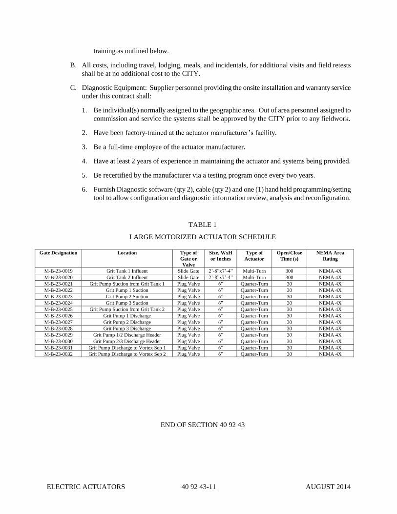
ELECTRIC ACTUATORS 40 92 43-11 AUGUST 2014
training as outlined below.
B. All costs, including travel, lodging, meals, and incidentals, for additional visits and field retests
shall be at no additional cost to the CITY.
C. Diagnostic Equipment: Supplier personnel providing the onsite installation and warranty service
under this contract shall:
1. Be individual(s) normally assigned to the geographic area. Out of area personnel assigned to
commission and service the systems shall be approved by the CITY prior to any fieldwork.
2. Have been factory-trained at the actuator manufacturer’s facility.
3. Be a full-time employee of the actuator manufacturer.
4. Have at least 2 years of experience in maintaining the actuator and systems being provided.
5. Be recertified by the manufacturer via a testing program once every two years.
6. Furnish Diagnostic software (qty 2), cable (qty 2) and one (1) hand held programming/setting
tool to allow configuration and diagnostic information review, analysis and reconfiguration.
TABLE 1
LARGE MOTORIZED ACTUATOR SCHEDULE
Gate Designation Location Type of
Gate or
Valve
Size, WxH
or Inches
Type of
Actuator
Open/Close
Time (s)
NEMA Area
Rating
M-B-23-0019 Grit Tank 1 Influent Slide Gate 2’-8”x7’-4” Multi-Turn 300 NEMA 4X
M-B-23-0020 Grit Tank 2 Influent Slide Gate 2’-8”x7’-4” Multi-Turn 300 NEMA 4X
M-B-23-0021 Grit Pump Suction from Grit Tank 1 Plug Valve 6” Quarter-Turn 30 NEMA 4X
M-B-23-0022 Grit Pump 1 Suction Plug Valve 6” Quarter-Turn 30 NEMA 4X
M-B-23-0023 Grit Pump 2 Suction Plug Valve 6” Quarter-Turn 30 NEMA 4X
M-B-23-0024 Grit Pump 3 Suction Plug Valve 6” Quarter-Turn 30 NEMA 4X
M-B-23-0025 Grit Pump Suction from Grit Tank 2 Plug Valve 6” Quarter-Turn 30 NEMA 4X
M-B-23-0026 Grit Pump 1 Discharge Plug Valve 6” Quarter-Turn 30 NEMA 4X
M-B-23-0027 Grit Pump 2 Discharge Plug Valve 6” Quarter-Turn 30 NEMA 4X
M-B-23-0028 Grit Pump 3 Discharge Plug Valve 6” Quarter-Turn 30 NEMA 4X
M-B-23-0029 Grit Pump 1/2 Discharge Header Plug Valve 6” Quarter-Turn 30 NEMA 4X
M-B-23-0030 Grit Pump 2/3 Discharge Header Plug Valve 6” Quarter-Turn 30 NEMA 4X
M-B-23-0031 Grit Pump Discharge to Vortex Sep 1 Plug Valve 6” Quarter-Turn 30 NEMA 4X
M-B-23-0032 Grit Pump Discharge to Vortex Sep 2 Plug Valve 6” Quarter-Turn 30 NEMA 4X
END OF SECTION 40 92 43

ELECTRIC ACTUATORS 40 92 43-12 AUGUST 2014
THIS PAGE INTENTIONALLY LEFT BLANK

PROGRAMMABLE LOGIC
PROCESS CONTROLLERS 40 94 43-1 OCTOBER 2014
SECTION 40 94 43
PROGRAMMABLE LOGIC PROCESS CONTROLLERS
PART 1 - GENERAL
1.01 SUMMARY
A. Section includes programmable controllers and accessories.
B. Section includes scope of services for System Programmer SUBCONTRACTOR to
ENGINEER.
C. Related Sections
1. Section 26 05 26 - Grounding and Bonding for Electrical Systems.
2. Section 26 05 53 - Identification for Electrical Systems.
3. Section 40 90 00 – Scope of Work, Loop Descriptions
4. Section 40 95 13 – Control Panels
1.02 REFERENCES
A. National Electrical Manufacturers Association:
1. NEMA IA 2.2 - Programmable Controllers-Equipment Requirements and Tests.
2. NEMA IA 2.3 - Programmable Controllers - Programming Languages.
3. NEMA ICS 3 - Industrial Control and Systems: Factory Built Assemblies.
4. NEMA ICS 6 - Industrial Control and Systems: Enclosures.
1.03 SYSTEM DESCRIPTION
A. Configuration: Networked programmable controllers for controlling the Muddy Creek
Wastewater Treatment Plant processes.
B. Drawings: Supplementing this Section, the Drawings indicate the number and sizes of PLCs,
and locations of PLCs. All hardware, including power supplies, special cables, and other
appurtenant equipment, shall be provided to meet the functional requirements described
herein and indicated on the Drawings. The CONTRACTOR will provide electrical
schematics showing all interconnection of PLC equipment and field devices.
C. I/O List: An input/output (I/O) field device signal listing is included as an Appendix attached
to this Section.
1.04 SUBMITTALS
A. Section 01 33 00 - Submittal Procedures: Submittal procedures.
B. Shop Drawings: Indicate electrical characteristics and connection requirements, including
layout of completed assemblies with bill of materials, interconnecting cabling and complete
field wiring, dimensions, weights, external power requirements, and power wiring
schematics.
C. Product Data: Submit catalog data for each component specified showing electrical
characteristics and connection requirements.

PROGRAMMABLE LOGIC
PROCESS CONTROLLERS 40 94 43-2 OCTOBER 2014
D. Test Reports: Indicate procedures and results for specified factory and field testing and
inspection.
E. Manufacturer's Field Reports: Indicate activities on site, adverse findings, and
recommendations.
1.05 CLOSEOUT SUBMITTALS
A. Section 01 77 00 - Execution and Closeout Requirements: Closeout procedures.
B. Project Record Documents: Record actual locations of controller cabinets and input and
output devices connected to system. Include interconnection wiring and cabling information,
and terminal block layouts in controller cabinets. Include copy of manufacturer's certified as-
built drawings and red-line scanned copies of field-verified Contract Drawings.
C. Operation and Maintenance Data: Submit bound copies of operating and programming
instructions, and include card replacement, adjustments, and preventive maintenance
procedures and materials.
1.06 QUALIFICATIONS
A. Manufacturer: Allen-Bradley ControlLogix and CompactLogix families of Programmable
Logic Controllers.
B. Supplier: CBT Company; 737 6th Street, Cincinnati, Ohio 45203.
C. Contractor shall use CBT Company for the base bid. Alternative suppliers would be
considered by the CITY, but they must be listed as a bid substitution with a deduct amount
provided for the bid. The CITY will evaluate the alternate vendor and lower cost provided.
1.07 ENVIRONMENTAL REQUIREMENTS
A. Section 01 60 00 - Product Requirements.
B. Conform to specified service conditions during and after installation of programmable
controllers. Maintain area free of dirt and dust during and after installation of products.
1.08 MAINTENANCE SERVICE
A. Section 01 77 00 - Execution and Closeout Requirements: Maintenance service.
B. Furnish service and maintenance of programmable controllers for one year from Date of
Substantial Completion.
1.09 MAINTENANCE MATERIALS
A. Section 01 77 00 - Execution and Closeout Requirements: Spare parts and maintenance
products.
B. Retain all documentation pertaining to the receipt of devices or instrumentation. Provide this
documentation and transfer ownership to the CITY.
1.10 MISCELLANEOUS
Delivery, Storage and Shipping: Delivery, storage and shipping shall be as required in Section 01
60 00 – Delivery, Storage, and Handling.
PROGRAMMABLE LOGIC
PROCESS CONTROLLERS 40 94 43-3 OCTOBER 2014
PART 2 - PRODUCTS
2.01 MATERIALS AND QUALITY
A. Material shall be new, free from defects, and of the quality specified. Each type of
instrument, instrument accessory, and device shall be by the same manufacturer throughout
the work.
B. Interchangeability: All programmable logic controller systems shall be products of the same
manufacturer and of the same series or product line. Processors, local and remote
input/output hardware, communications Module Types, and specialty Module Types such as
coprocessors and ASCII Module Types shall be interchangeable among all I/O panels and
systems. PLC Module Types and hardware by other manufacturers will be acceptable only if
the PLC manufacturer does not offer suitable Module Types and hardware for the same
functions and as approved by ENGINEER.
C. Acceptable Manufacturers: The PLCs shall be Allen-Bradley ControlLogix or
CompactLogix as detailed below, no exceptions, to match the CITY’s existing equipment. If
a newer version of a component is available at the time of construction, the newer version
shall be offered as an option to the CITY. CONTRACTOR must ensure full compatibility of
newer component with the overall system design. The CITY will make the final decision on
which version is preferred. Each PLC I/O rack shall have redundant power supplies. All
PLC CPU racks shall be redundant.
D. Appurtenances: The PLC processor and I/O hardware shall be provided as complete systems,
as shown on the system architecture drawings. The PLCs shall include all necessary
hardware for a complete working system. All special rack or panel mounted power supplies,
special interconnecting and programming cables, special grounding hardware, or isolation
devices shall be furnished as required for proper operation of the equipment. Signal
converters, signal boosters, amplifiers, special power supplies, special cable, special
grounding, intrinsically safe relays and current repeaters, surge suppression devices, and
isolation devices shall be furnished and installed as required for proper operation of the
equipment.
E. PLC Arrangement: The PLCs shall be distributed and arranged as indicated on the system
architecture diagram and panel arrangement drawings.
F. System Enclosures: Programmable logic controllers and input/output hardware shall be
housed in shop-assembled panels as indicated on the drawings and as described in Section 26
24 16.
G. Configuration Software: CONTRACTOR shall provide all required software to configure
and program all PLC systems provided under this Contract licensed to and shipped to the
CITY no later than three weeks from the approval of the FIRST STAGE SUBMITTAL.
2.02 PROGRAMMABLE CONTROLLER
A. Manufacturers
1. Allen-Bradley ControlLogix Family.
2. Allen-Bradley CompactLogix Family.
3. Substitutions: Not Permitted.
B. Processors
1. Allen-Bradley ControlLogix: 1756-L71
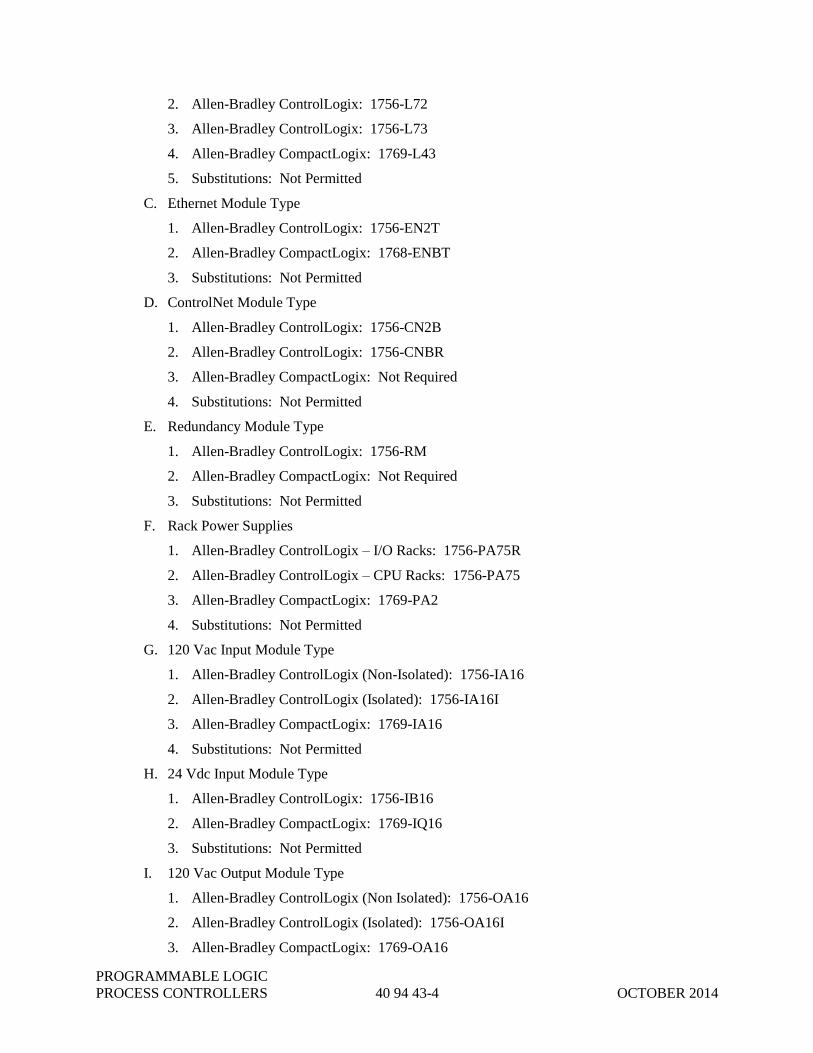
PROGRAMMABLE LOGIC
PROCESS CONTROLLERS 40 94 43-4 OCTOBER 2014
2. Allen-Bradley ControlLogix: 1756-L72
3. Allen-Bradley ControlLogix: 1756-L73
4. Allen-Bradley CompactLogix: 1769-L43
5. Substitutions: Not Permitted
C. Ethernet Module Type
1. Allen-Bradley ControlLogix: 1756-EN2T
2. Allen-Bradley CompactLogix: 1768-ENBT
3. Substitutions: Not Permitted
D. ControlNet Module Type
1. Allen-Bradley ControlLogix: 1756-CN2B
2. Allen-Bradley ControlLogix: 1756-CNBR
3. Allen-Bradley CompactLogix: Not Required
4. Substitutions: Not Permitted
E. Redundancy Module Type
1. Allen-Bradley ControlLogix: 1756-RM
2. Allen-Bradley CompactLogix: Not Required
3. Substitutions: Not Permitted
F. Rack Power Supplies
1. Allen-Bradley ControlLogix – I/O Racks: 1756-PA75R
2. Allen-Bradley ControlLogix – CPU Racks: 1756-PA75
3. Allen-Bradley CompactLogix: 1769-PA2
4. Substitutions: Not Permitted
G. 120 Vac Input Module Type
1. Allen-Bradley ControlLogix (Non-Isolated): 1756-IA16
2. Allen-Bradley ControlLogix (Isolated): 1756-IA16I
3. Allen-Bradley CompactLogix: 1769-IA16
4. Substitutions: Not Permitted
H. 24 Vdc Input Module Type
1. Allen-Bradley ControlLogix: 1756-IB16
2. Allen-Bradley CompactLogix: 1769-IQ16
3. Substitutions: Not Permitted
I. 120 Vac Output Module Type
1. Allen-Bradley ControlLogix (Non Isolated): 1756-OA16
2. Allen-Bradley ControlLogix (Isolated): 1756-OA16I
3. Allen-Bradley CompactLogix: 1769-OA16
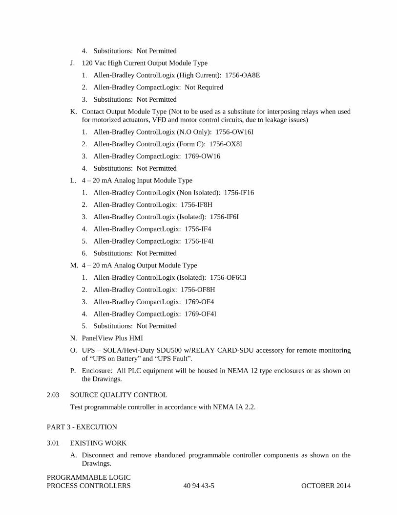
PROGRAMMABLE LOGIC
PROCESS CONTROLLERS 40 94 43-5 OCTOBER 2014
4. Substitutions: Not Permitted
J. 120 Vac High Current Output Module Type
1. Allen-Bradley ControlLogix (High Current): 1756-OA8E
2. Allen-Bradley CompactLogix: Not Required
3. Substitutions: Not Permitted
K. Contact Output Module Type (Not to be used as a substitute for interposing relays when used
for motorized actuators, VFD and motor control circuits, due to leakage issues)
1. Allen-Bradley ControlLogix (N.O Only): 1756-OW16I
2. Allen-Bradley ControlLogix (Form C): 1756-OX8I
3. Allen-Bradley CompactLogix: 1769-OW16
4. Substitutions: Not Permitted
L. 4 – 20 mA Analog Input Module Type
1. Allen-Bradley ControlLogix (Non Isolated): 1756-IF16
2. Allen-Bradley ControlLogix: 1756-IF8H
3. Allen-Bradley ControlLogix (Isolated): 1756-IF6I
4. Allen-Bradley CompactLogix: 1756-IF4
5. Allen-Bradley CompactLogix: 1756-IF4I
6. Substitutions: Not Permitted
M. 4 – 20 mA Analog Output Module Type
1. Allen-Bradley ControlLogix (Isolated): 1756-OF6CI
2. Allen-Bradley ControlLogix: 1756-OF8H
3. Allen-Bradley CompactLogix: 1769-OF4
4. Allen-Bradley CompactLogix: 1769-OF4I
5. Substitutions: Not Permitted
N. PanelView Plus HMI
O. UPS – SOLA/Hevi-Duty SDU500 w/RELAY CARD-SDU accessory for remote monitoring
of “UPS on Battery” and “UPS Fault”.
P. Enclosure: All PLC equipment will be housed in NEMA 12 type enclosures or as shown on
the Drawings.
2.03 SOURCE QUALITY CONTROL
Test programmable controller in accordance with NEMA IA 2.2.
PART 3 - EXECUTION
3.01 EXISTING WORK
A. Disconnect and remove abandoned programmable controller components as shown on the
Drawings.

PROGRAMMABLE LOGIC
PROCESS CONTROLLERS 40 94 43-6 OCTOBER 2014
B. Extend existing programmable controller installations using materials and methods
compatible with existing installations as shown on the Drawings.
C. Clean and repair existing programmable controllers to remain or to be reinstalled.
3.02 INSTALLATION
A. Connect input and output devices.
B. Install engraved plastic nameplates in accordance with the Drawings.
C. Equipment shall be located so that it is readily accessible for operation and maintenance.
D. Ground and bond programmable controllers and their enclosures in accordance with Section
26 05 26.
3.03 FIELD QUALITY CONTROL
Perform operational testing on control systems to verify proper operation and field wiring
connections.
3.04 MANUFACTURER'S FIELD SERVICES
Prepare and start up programmable controller.
3.05 DEMONSTRATION AND TRAINING
Furnish 16 hours of instruction each for two people to be conducted by manufacturer's
representative at the representative’s training facility.
3.06 INPUT/OUTPUT SCHEDULE
Device Tag (Service): An I/O Listing is provided as an Appendix to this section.
3.07 PLC HARDWARE SCHEDULE
A. Muddy Creek Bundle Project Upgrades – Grit Facilities Remote I/O Panel: Refer to Drawing
I-613-04 for Bill of Materials of Remote I/O Panel, Racks 1&2.
B. Muddy Creek Bundle Project Upgrades – Grit Facilities Remote I/O Panel Modifications:
Refer to Specification 40 90 00, Paragraph 3.05 for hardware and modification requirements
for existing PLC panel.
3.08 SCOPE OF SERVICES
A. Work provided under this Division includes final system design implementation, furnishing
all components, system installation services, required support services, and complete
documentation for the additions to the Plant Control System (PCS) to be completed under this
Project. This work is limited to the SCADA system configuration for the new equipment
installations that are included in this Project and shown on the Drawings. All other SCADA
system configuration related to this work shall include all materials, labor, and tools required
to fabricate, deliver, unload, handle, erect, adjust, field calibrate, and test a complete and
operable, and fully integrated addition to the PCS, as indicated on the Drawings and
Specifications. Install all panels and designated instrumentation devices and provide all
mechanical and pneumatic interconnections between the various components and their local
sources of supply.
B. The intent of these Specifications is to provide a complete and operational and fully

PROGRAMMABLE LOGIC
PROCESS CONTROLLERS 40 94 43-7 OCTOBER 2014
integrated addition to the PCS. Additional items of equipment, materials, or labor not
specifically called for by these Specifications, which may reasonably be considered to make
the system complete and operational, shall be supplied as part of this work.
C. Responsibility for provision of this system shall be split as follows:
1. CONTRACTOR - The CONTRACTOR and/or his designated subcontractor shall be
responsible for the procurement of the required field instrumentation, the required Digital
hardware to include PLCs, Remote I/O, and the panels to house and provide operational
support for said digital hardware.
Furthermore, the CONTRACTOR and/or his designated subcontractor shall be
responsible for the proper connection of all digital controls equipment as designated in
the electrical drawings and the P&IDs and submitting all PLC and I/O schematics to
provide a fully functional system.
Purchase and supply of all hardware and software specified by the system programmer,
as limited and directed by this Specification, necessary for the proper construction and
operation of the Controls, shall be done by the CONTRACTOR.
Purchase, supply mounting, calibration, and commissioning and testing of all field
resident instrumentation, starters, drives, and control stations shall be the responsibility of
the CONTRACTOR and/or his designated subcontractor, or selected equipment vendor.
The CONTRACTOR and/or his designated subcontractor shall be responsible for testing
of all systems connected by them and demonstrating at an acceptance test that the devices
and the communication between devices is functioning properly.
All vendor-supplied PLCs shall be programmed by the equipment vendor, per MSDGC
SCADA standards. The grit dewatering system PLC will be provided and programmed
by the equipment vendor.
2. ENGINEER - ENGINEER shall provide a City-approved subcontractor (System
Programmer) to be responsible for programming and or configuring the Programmable
Logic Controllers (PLCs) and the Human Machine Interface (HMI), to provide a fully
integrated addition to the Plant Control System (PCS).
The ENGINEER and their System Programmer shall hold a preliminary design workshop
with the CONTRACTOR and/or their designated subcontractor, and the CITY, for the
purpose of definition of Project standards for programming, documentation, and panel
fabrication. CITY plant standards shall serve as the basis of the Project standards. The
System Programmer will define his software needs with regard to the existing HMI software
for the PCS and its applicability to the new additions to the PCS.
The ENGINEER shall exercise oversight of the System Programmer.
3. The System Programmer – The System Programmer shall be a subcontractor to the
ENGINEER and shall be responsible for configuration of the Plant Control System (PCS)
hardware and software into a fully operational addition to the PCS. The vendor-supplied
PLC will be programmed by the equipment vendor, per the MSDGC SCADA standards.
The system programming and detailed Specification of digital hardware, and software
configuration, as directed by these Specifications and Drawings, shall be accomplished
by the System Programmer.
Paragraph 4 describes the scope of the System Programmer, who is a subcontractor to the
ENGINEER.

PROGRAMMABLE LOGIC
PROCESS CONTROLLERS 40 94 43-8 OCTOBER 2014
4. System Programmer Task Description
a. Prepare an Application Software development task Progress Plan.
b. Prepare for and attend Application Software Development/Review meetings. This
includes a maximum of 4 meetings (2 during development and 2 during
implementation and commissioning).
c. Receive and set-up application software development system(s) provided by the
CITY to include PLC system, HMI system, and related peripheral devices specified
under this Project only.
d. Review control strategies provided by the ENGINEER, I/O lists, and resolve/finalize
missing data base points and related parameters. Develop a database listing for the
PLC and HMI systems. Submit control strategies to the CITY and ENGINEER for
review.
e. Develop HMI software for process graphics utilizing process graphic conventions as
defined in the most current CITY SCADA standards; develop an initial set of process
graphics display and control screens for the iFIX HMI system in accordance with the
most current CITY SCADA standards; submit a PDF file of the process graphics to
CITY for review at the 75% level. Finalize graphics based on CITY’s comments.
Perform functional testing of the process graphics screens. Install process graphics
on “target” HMI systems.
f. Develop PLC programming for process control, including verification of PLC I/O
system partitioning; develop software configuration for control logic and alarms; and
pre-test, document, and install process control logic configuration.
g. Conduct a Hardware Factory Acceptance Test (FAT) at the Electrical
CONTRACTOR’s facility following successful completion of the Electrical
CONTRACTOR’s factory acceptance tests. The application specific FAT will
include the graphic screens, the HMI database, the PLC logic, and a simulation of the
communication links. I/O will be tested with simulated inputs from the interface
terminal blocks in the PLC enclosures to the HMI subsystems. Develop and submit
copies of completed test forms and a punch list of open items.
h. Perform checkout and start-up for the application software programming for the
PLC-based Process Instrumentation and Control System. The Electrical
CONTRACTOR will be responsible for the calibration and setup of all field devices,
including but not limited to: switches, transmitters, valve actuators, drives, and all
other field equipment. Programmer will not begin the application software checkout
until CONTRACTOR has fully completed the setup, calibration, and checkout of all
I/O for the Project and has provided signed checkout sheets to the CITY. Equipment
vendors must be scheduled by the CONTRACTOR for support during the application
programming system checkout.
i. Prepare for and provide application software orientation and training for CITY staff,
including formal classroom presentation and hands-on exposure for the PLC and
HMI application software. Up to four, two-hour training sessions will be provided at
Muddy Creek WWTP at times selected by CITY. Up to 8 sets of training materials
will be provided by Programmer.
j. Provide final documentation for application software. Up to two hard copy sets of
the final application software documentation and an electronic copy will be provided
by the Programmer.
k. Prepare and submit a final punch list for outstanding items related to application
software and system integration tasks and resolve all reasonable items within

PROGRAMMABLE LOGIC
PROCESS CONTROLLERS 40 94 43-9 OCTOBER 2014
Programmer’s control on final punch list.
END OF SECTION 40 94 43
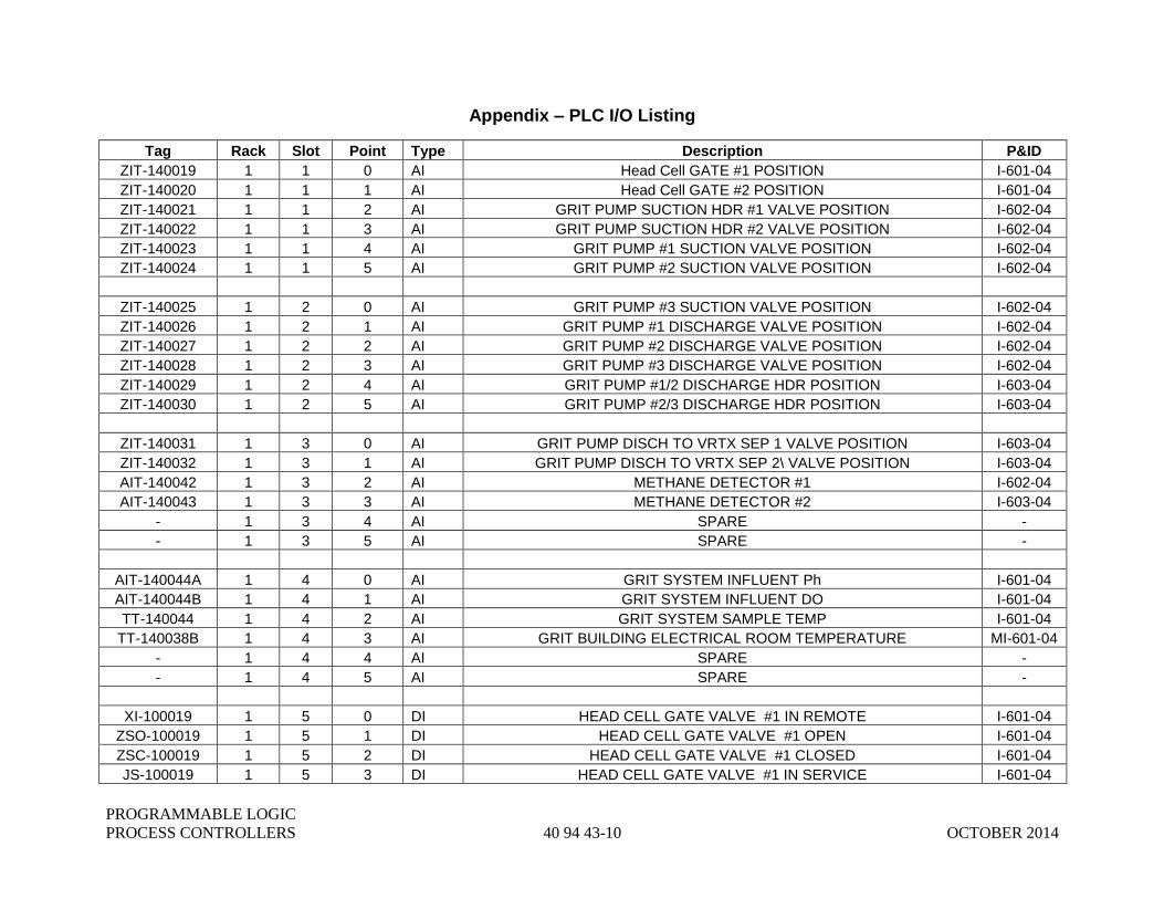
PROGRAMMABLE LOGIC
PROCESS CONTROLLERS 40 94 43-10 OCTOBER 2014
Appendix – PLC I/O Listing
Tag Rack Slot Point Type Description P&ID
ZIT-140019 1 1 0 AI Head Cell GATE #1 POSITION I-601-04
ZIT-140020 1 1 1 AI Head Cell GATE #2 POSITION I-601-04
ZIT-140021 1 1 2 AI GRIT PUMP SUCTION HDR #1 VALVE POSITION I-602-04
ZIT-140022 1 1 3 AI GRIT PUMP SUCTION HDR #2 VALVE POSITION I-602-04
ZIT-140023 1 1 4 AI GRIT PUMP #1 SUCTION VALVE POSITION I-602-04
ZIT-140024 1 1 5 AI GRIT PUMP #2 SUCTION VALVE POSITION I-602-04
ZIT-140025 1 2 0 AI GRIT PUMP #3 SUCTION VALVE POSITION I-602-04
ZIT-140026 1 2 1 AI GRIT PUMP #1 DISCHARGE VALVE POSITION I-602-04
ZIT-140027 1 2 2 AI GRIT PUMP #2 DISCHARGE VALVE POSITION I-602-04
ZIT-140028 1 2 3 AI GRIT PUMP #3 DISCHARGE VALVE POSITION I-602-04
ZIT-140029 1 2 4 AI GRIT PUMP #1/2 DISCHARGE HDR POSITION I-603-04
ZIT-140030 1 2 5 AI GRIT PUMP #2/3 DISCHARGE HDR POSITION I-603-04
ZIT-140031 1 3 0 AI GRIT PUMP DISCH TO VRTX SEP 1 VALVE POSITION I-603-04
ZIT-140032 1 3 1 AI GRIT PUMP DISCH TO VRTX SEP 2\ VALVE POSITION I-603-04
AIT-140042 1 3 2 AI METHANE DETECTOR #1 I-602-04
AIT-140043 1 3 3 AI METHANE DETECTOR #2 I-603-04
- 1 3 4 AI SPARE -
- 1 3 5 AI SPARE -
AIT-140044A 1 4 0 AI GRIT SYSTEM INFLUENT Ph I-601-04
AIT-140044B 1 4 1 AI GRIT SYSTEM INFLUENT DO I-601-04
TT-140044 1 4 2 AI GRIT SYSTEM SAMPLE TEMP I-601-04
TT-140038B 1 4 3 AI GRIT BUILDING ELECTRICAL ROOM TEMPERATURE MI-601-04
- 1 4 4 AI SPARE -
- 1 4 5 AI SPARE -
XI-100019 1 5 0 DI HEAD CELL GATE VALVE #1 IN REMOTE I-601-04
ZSO-100019 1 5 1 DI HEAD CELL GATE VALVE #1 OPEN I-601-04
ZSC-100019 1 5 2 DI HEAD CELL GATE VALVE #1 CLOSED I-601-04
JS-100019 1 5 3 DI HEAD CELL GATE VALVE #1 IN SERVICE I-601-04

PROGRAMMABLE LOGIC
PROCESS CONTROLLERS 40 94 43-11 OCTOBER 2014
Tag Rack Slot Point Type Description P&ID
ZA-100019 1 5 4 DI HEAD CELL GATE VALVE #1 ACTUATOR FAULT I-601-04
WA-100019 1 5 5 DI HEAD CELL GATE VALVE #1 TORQUE ALARM I-601-04
- 1 5 6 DI SPARE I-601-04
- 1 5 7 DI SPARE I-601-04
XI-100020 1 5 8 DI HEAD CELL GATE VALVE #2 IN REMOTE I-601-04
ZSO-100020 1 5 9 DI HEAD CELL GATE VALVE #2 OPEN I-601-04
ZSC-100020 1 5 10 DI HEAD CELL GATE VALVE #2 CLOSED I-601-04
JS-100020 1 5 11 DI HEAD CELL GATE VALVE #2 IN SERVICE I-601-04
ZA-10020 1 5 12 DI HEAD CELL GATE VALVE #2 FAULT -
WA-10020 1 5 13 DI HEAD CELL GATE VALVE #2 TORQUE ALARM -
- 1 5 14 DI SPARE -
- 1 5 15 DI SPARE -
XI-140021 1 6 0 DI GRIT PUMP SUCTIN HDR VALVE #1 IN REMOTE I-602-04
ZSO-140021 1 6 1 DI GRIT PUMP SUCTIN HDR VALVE #1 OPEN I-604-04
ZSC-140021 1 6 2 DI GRIT PUMP SUCTIN HDR VALVE #1 CLOSED -
JS-140021 1 6 3 DI GRIT PUMP SUCTIN HDR VALVE #1 IN SERVICE -
ZA-140021 1 6 4 DI GRIT PUMP SUCTIN HDR VALVE #1 FAULT -
WA-140021 1 6 5 DI GRIT PUMP SUCTIN HDR VALVE #1 TORQUE ALARM I-602-04
- 1 6 6 DI SPARE I-602-04
- 1 6 7 DI SPARE I-602-04
XI-140022 1 6 8 DI GRIT PUMP SUCTIN HDR VALVE #2 IN REMOTE I-602-04
ZSO-140022 1 6 9 DI GRIT PUMP SUCTIN HDR VALVE #2 OPEN I-602-04
ZSC-140022 1 6 10 DI GRIT PUMP SUCTIN HDR VALVE #2 CLOSED I-602-04
JS-140022 1 6 11 DI GRIT PUMP SUCTIN HDR VALVE #2 IN SERVICE I-602-04
ZA-140022 1 6 12 DI GRIT PUMP SUCTIN HDR VALVE #2 FAULT I-602-04
WA-140022 1 6 13 DI GRIT PUMP SUCTIN HDR VALVE #2 TORQUE ALARM I-602-04
- 1 6 14 DI SPARE I-602-04
- 1 6 15 DI SPARE I-602-04
XI-140023 1 7 0 DI GRIT PUMP SUCTION VALVE #1 IN REMOTE I-602-04
ZSO-140023 1 7 1 DI GRIT PUMP SUCTION VALVE #1 OPEN I-602-04
ZSC-140023 1 7 2 DI GRIT PUMP SUCTION VALVE #1 IN CLOSED I-602-04
JS-140023 1 7 3 DI GRIT PUMP SUCTION VALVE #1 IN SERVICE I-602-04
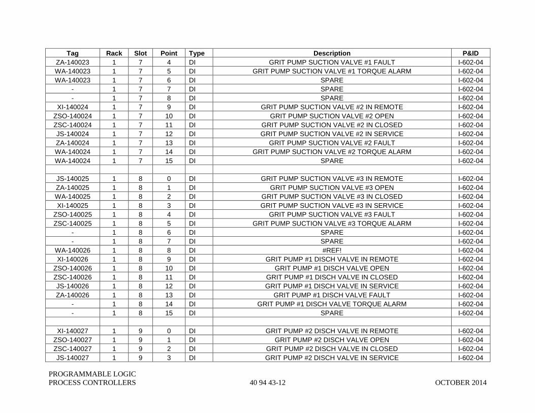
PROGRAMMABLE LOGIC
PROCESS CONTROLLERS 40 94 43-12 OCTOBER 2014
Tag Rack Slot Point Type Description P&ID
ZA-140023 1 7 4 DI GRIT PUMP SUCTION VALVE #1 FAULT I-602-04
WA-140023 1 7 5 DI GRIT PUMP SUCTION VALVE #1 TORQUE ALARM I-602-04
WA-140023 1 7 6 DI SPARE I-602-04
- 1 7 7 DI SPARE I-602-04
- 1 7 8 DI SPARE I-602-04
XI-140024 1 7 9 DI GRIT PUMP SUCTION VALVE #2 IN REMOTE I-602-04
ZSO-140024 1 7 10 DI GRIT PUMP SUCTION VALVE #2 OPEN I-602-04
ZSC-140024 1 7 11 DI GRIT PUMP SUCTION VALVE #2 IN CLOSED I-602-04
JS-140024 1 7 12 DI GRIT PUMP SUCTION VALVE #2 IN SERVICE I-602-04
ZA-140024 1 7 13 DI GRIT PUMP SUCTION VALVE #2 FAULT I-602-04
WA-140024 1 7 14 DI GRIT PUMP SUCTION VALVE #2 TORQUE ALARM I-602-04
WA-140024 1 7 15 DI SPARE I-602-04
JS-140025 1 8 0 DI GRIT PUMP SUCTION VALVE #3 IN REMOTE I-602-04
ZA-140025 1 8 1 DI GRIT PUMP SUCTION VALVE #3 OPEN I-602-04
WA-140025 1 8 2 DI GRIT PUMP SUCTION VALVE #3 IN CLOSED I-602-04
XI-140025 1 8 3 DI GRIT PUMP SUCTION VALVE #3 IN SERVICE I-602-04
ZSO-140025 1 8 4 DI GRIT PUMP SUCTION VALVE #3 FAULT I-602-04
ZSC-140025 1 8 5 DI GRIT PUMP SUCTION VALVE #3 TORQUE ALARM I-602-04
- 1 8 6 DI SPARE I-602-04
- 1 8 7 DI SPARE I-602-04
WA-140026 1 8 8 DI #REF! I-602-04
XI-140026 1 8 9 DI GRIT PUMP #1 DISCH VALVE IN REMOTE I-602-04
ZSO-140026 1 8 10 DI GRIT PUMP #1 DISCH VALVE OPEN I-602-04
ZSC-140026 1 8 11 DI GRIT PUMP #1 DISCH VALVE IN CLOSED I-602-04
JS-140026 1 8 12 DI GRIT PUMP #1 DISCH VALVE IN SERVICE I-602-04
ZA-140026 1 8 13 DI GRIT PUMP #1 DISCH VALVE FAULT I-602-04
- 1 8 14 DI GRIT PUMP #1 DISCH VALVE TORQUE ALARM I-602-04
- 1 8 15 DI SPARE I-602-04
XI-140027 1 9 0 DI GRIT PUMP #2 DISCH VALVE IN REMOTE I-602-04
ZSO-140027 1 9 1 DI GRIT PUMP #2 DISCH VALVE OPEN I-602-04
ZSC-140027 1 9 2 DI GRIT PUMP #2 DISCH VALVE IN CLOSED I-602-04
JS-140027 1 9 3 DI GRIT PUMP #2 DISCH VALVE IN SERVICE I-602-04
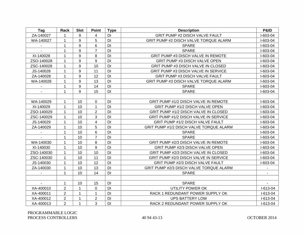
PROGRAMMABLE LOGIC
PROCESS CONTROLLERS 40 94 43-13 OCTOBER 2014
Tag Rack Slot Point Type Description P&ID
ZA-140027 1 9 4 DI GRIT PUMP #2 DISCH VALVE FAULT I-603-04
WA-140027 1 9 5 DI GRIT PUMP #2 DISCH VALVE TORQUE ALARM I-603-04
- 1 9 6 DI SPARE I-603-04
- 1 9 7 DI SPARE I-603-04
XI-140028 1 9 8 DI GRIT PUMP #3 DISCH VALVE IN REMOTE I-603-04
ZSO-140028 1 9 9 DI GRIT PUMP #3 DISCH VALVE OPEN I-603-04
ZSC-140028 1 9 10 DI GRIT PUMP #3 DISCH VALVE IN CLOSED I-603-04
JS-140028 1 9 11 DI GRIT PUMP #3 DISCH VALVE IN SERVICE I-603-04
ZA-140028 1 9 12 DI GRIT PUMP #3 DISCH VALVE FAULT I-603-04
WA-140028 1 9 13 DI GRIT PUMP #3 DISCH VALVE TORQUE ALARM I-603-04
- 1 9 14 DI SPARE I-603-04
- 1 9 15 DI SPARE I-603-04
WA-140029 1 10 0 DI GRIT PUMP #1/2 DISCH VALVE IN REMOTE I-603-04
XI-140029 1 10 1 DI GRIT PUMP #1/2 DISCH VALVE OPEN I-603-04
ZSO-140029 1 10 2 DI GRIT PUMP #1/2 DISCH VALVE IN CLOSED I-603-04
ZSC-140029 1 10 3 DI GRIT PUMP #1/2 DISCH VALVE IN SERVICE I-603-04
JS-140029 1 10 4 DI GRIT PUMP #1/2 DISCH VALVE FAULT I-603-04
ZA-140029 1 10 5 DI GRIT PUMP #1/2 DISCH VALVE TORQUE ALARM I-603-04
- 1 10 6 DI SPARE I-603-04
- 1 10 7 DI SPARE I-603-04
WA-140030 1 10 8 DI GRIT PUMP #2/3 DISCH VALVE IN REMOTE I-603-04
XI-140030 1 10 9 DI GRIT PUMP #2/3 DISCH VALVE OPEN I-603-04
ZSO-140030 1 10 10 DI GRIT PUMP #2/3 DISCH VALVE IN CLOSED I-603-04
ZSC-140030 1 10 11 DI GRIT PUMP #2/3 DISCH VALVE IN SERVICE I-603-04
JS-140030 1 10 12 DI GRIT PUMP #2/3 DISCH VALVE FAULT I-603-04
ZA-140030 1 10 13 DI GRIT PUMP #2/3 DISCH VALVE TORQUE ALARM -
- 1 10 14 DI SPARE -
- 1 10 15 DI SPARE -
XA-400010 2 1 0 DI UTILITY POWER OK I-613-04
XA-400011 2 1 1 DI RACK 1 REDUNDANT POWER SUPPLY OK I-613-04
XA-400012 2 1 2 DI UPS BATTERY LOW I-613-04
XA-400013 2 1 3 DI RACK 2 REDUNDANT POWER SUPPLY OK I-613-04

PROGRAMMABLE LOGIC
PROCESS CONTROLLERS 40 94 43-14 OCTOBER 2014
Tag Rack Slot Point Type Description P&ID
XA-400014 2 1 4 DI UPS POWER OK I-613-04
XA-4000115 2 1 5 DI 24VDC POWER OK I-613-04
TAH-300001 2 1 6 DI PANEL HIGH TEMPERATURE ALARM I-613-04
- 2 1 7 DI SPARE -
- 2 1 8 DI SPARE -
- 2 1 9 DI SPARE -
- 2 1 10 DI SPARE -
- 2 1 11 DI SPARE -
- 2 1 12 DI SPARE -
- 2 1 13 DI SPARE -
- 2 1 14 DI SPARE -
- 2 1 15 DI SPARE -
JI-140003 2 2 0 DI SUMP PUMP #1 IN SERVICE I-603-04
XI-140003 2 2 1 DI SUMP PUMP #1 IN AUTO (REMOTE) I-603-04
YN-140003 2 2 2 DI SUMP PUMP #1 RUNNING I-603-04
XA-140003 2 2 3 DI SUMP PUMP #1 OVERLOAD ALARM I-603-04
FAL-140003 2 2 4 DI SUMP PUMP #1 SEAL WATER FLOW ALARM I-603-04
- 2 2 5 DI SPARE -
IS-140037 2 2 6 DI GRIT PUMP ROOM EXHAUST FAN RUNNING MI-601-04
LAH-140005 2 2 7 DI SUMP HIGH LEVEL ALARM I-603-04
JI-140004 2 2 8 DI SUMP PUMP #2 IN SERVICE I-603-04
XI-140004 2 2 9 DI SUMP PUMP #2 IN AUTO (REMOTE) I-603-04
YN-140004 2 2 10 DI SUMP PUMP #2 RUNNING I-603-04
XA-140004 2 2 11 DI SUMP PUMP #2 OVERLOAD ALARM I-603-04
FAL-140004 2 2 12 DI SUMP PUMP #2 SEAL WATER FLOW ALARM I-603-04
- 2 2 13 DI SPARE -
- 2 2 14 DI SPARE -
- 2 2 15 DI SPARE -
XI-140031 2 3 0 DI GRIT PUMP DISCH VLV TO VRTX SEP 1 IN REMOTE -
ZSO-140031 2 3 1 DI GRIT PUMP DISCH VLV TO VRTX SEP 1 OPEN -
ZSC-140031 2 3 2 DI GRIT PUMP DISCH VLV TO VRTX SEP 1 CLOSES -
JS-140031 2 3 3 DI GRIT PUMP DISCH VLV TO VRTX SEP 1 IN SERVICE -

PROGRAMMABLE LOGIC
PROCESS CONTROLLERS 40 94 43-15 OCTOBER 2014
Tag Rack Slot Point Type Description P&ID
ZA-140031 2 3 4 DI GRIT PUMP DISCH VLV TO VRTX SEP 1 FAULT -
WA-140031 2 3 5 DI GRIT PUMP DISCH VLV TO VRTX SEP 1 TORQUE ALARM I-601-04
- 2 3 6 DI SPARE -
- 2 3 7 DI SPARE -
XI-140032 2 3 8 DI GRIT PUMP DISCH VLV TO VRTX SEP 2 IN REMOTE -
ZSO-140032 2 3 9 DI GRIT PUMP DISCH VLV TO VRTX SEP 2 OPEN -
ZSC-140032 2 3 10 DI GRIT PUMP DISCH VLV TO VRTX SEP 2 CLOSES -
JS-140032 2 3 11 DI GRIT PUMP DISCH VLV TO VRTX SEP 2 IN SERVICE -
ZA-140032 2 3 12 DI GRIT PUMP DISCH VLV TO VRTX SEP 2 FAULT -
WA-140032 2 3 13 DI GRIT PUMP DISCH VLV TO VRTX SEP 2 TORQUE ALARM -
YN-140044 2 3 14 DI SPARE -
- 2 3 15 DI SAMPLE PUMP RUN STATUS -
- 2 4 0 DO HEAD CELL GATE VALVE #1 OPEN COMMAND -
HS-140019A 2 4 1 DO HEAD CELL GATE VALVE #1 CLOSE COMMAND I-601-04
HS-140019B 2 4 2 DO HEAD CELL GATE VALVE #1 STOP COMMAND I-601-04
HS-140019C 2 4 3 DO HEAD CELL GATE VALVE #2 OPEN COMMAND -
HS-140020C 2 4 4 DO HEAD CELL GATE VALVE #2 CLOSE COMMAND I-601-04
HS-140020C 2 4 5 DO HEAD CELL GATE VALVE #2 STOP COMMAND I-601-04
HS-140020C 2 4 6 DO #REF! I-601-04
- 2 4 7 DO SPARE PRIMARY
- 2 4 8 DO SPARE PRIMARY
- 2 4 9 DO SPARE PRIMARY
- 2 4 10 DO SPARE PRIMARY
- 2 4 11 DO SPARE PRIMARY
- 2 4 12 DO SPARE PRIMARY
HS-140021A 2 4 13 DO GRIT PUMP SUCTION HDR VALVE #1 OPEN COMMAND -
HS-140021B 2 4 14 DO GRIT PUMP SUCTION HDR VALVE #1 CLOSE COMMAND I-602-04
HS-140021C 2 4 15 DO GRIT PUMP SUCTION HDR VALVE #1 STOP COMMAND I-602-04
HS-100022A 2 5 0 DO SPARE I-602-04
HS-100022B 2 5 1 DO GRIT PUMP SUCTION HDR VALVE OPEN COMMAND I-602-04
HS-100022C 2 5 2 DO GRIT PUMP SUCTION HDR VALVE CLOSE COMMAND I-602-04
HS-100022C 2 5 3 DO GRIT PUMP SUCTION HDR VALVE STOP COMMAND I-602-04
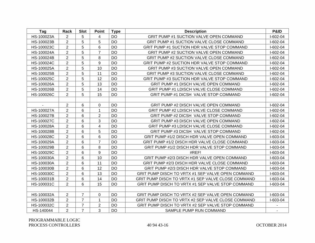
PROGRAMMABLE LOGIC
PROCESS CONTROLLERS 40 94 43-16 OCTOBER 2014
Tag Rack Slot Point Type Description P&ID
HS-100023A 2 5 4 DO GRIT PUMP #1 SUCTION VALVE OPEN COMMAND I-602-04
HS-100023B 2 5 5 DO GRIT PUMP #1 SUCTION VALVE CLOSE COMMAND I-602-04
HS-100023C 2 5 6 DO GRIT PUMP #1 SUCTION HDR VALVE STOP COMMAND I-602-04
HS-100024A 2 5 7 DO GRIT PUMP #2 SUCTION VALVE OPEN COMMAND I-602-04
HS-100024B 2 5 8 DO GRIT PUMP #2 SUCTION VALVE CLOSE COMMAND I-602-04
HS-100024C 2 5 9 DO GRIT PUMP #2 SUCTION HDR VALVE STOP COMMAND I-602-04
HS-100025A 2 5 10 DO GRIT PUMP #3 SUCTION VALVE OPEN COMMAND I-602-04
HS-100025B 2 5 11 DO GRIT PUMP #3 SUCTION VALVE CLOSE COMMAND I-602-04
HS-100025C 2 5 12 DO GRIT PUMP #3 SUCTION HDR VALVE STOP COMMAND I-602-04
HS-100026A 2 5 13 DO GRIT PUMP #1 DISCH VALVE OPEN COMMAND I-602-04
HS-100026B 2 5 14 DO GRIT PUMP #1 LDISCH VALVE CLOSE COMMAND I-602-04
HS-100026C 2 5 15 DO GRIT PUMP #1 DICSH VALVE STOP COMMAND I-602-04
- 2 6 0 DO GRIT PUMP #2 DISCH VALVE OPEN COMMAND I-602-04
HS-100027A 2 6 1 DO GRIT PUMP #2 LDISCH VALVE CLOSE COMMAND I-602-04
HS-100027B 2 6 2 DO GRIT PUMP #2 DICSH VALVE STOP COMMAND I-602-04
HS-100027C 2 6 3 DO GRIT PUMP #3 DISCH VALVE OPEN COMMAND I-602-04
HS-100028A 2 6 4 DO GRIT PUMP #3 LDISCH VALVE CLOSE COMMAND I-602-04
HS-100028B 2 6 5 DO GRIT PUMP #3 DICSH VALVE STOP COMMAND I-602-04
HS-100028C 2 6 6 DO GRIT PUMP #1/2 DISCH HDR VALVE OPEN COMMAND I-603-04
HS-100029A 2 6 7 DO GRIT PUMP #1/2 DISCH HDR VALVE CLOSE COMMAND I-603-04
HS-100029B 2 6 8 DO GRIT PUMP #1/2 DISCH HDR VALVE STOP COMMAND I-603-04
HS-100029C 2 6 9 DO #REF! I-603-04
HS-100030A 2 6 10 DO GRIT PUMP #2/3 DISCH HDR VALVE OPEN COMMAND I-603-04
HS-100030A 2 6 11 DO GRIT PUMP #2/3 DISCH HDR VALVE CLOSE COMMAND I-603-04
HS-100030B 2 6 12 DO GRIT PUMP #2/3 DISCH HDR VALVE STOP COMMAND I-603-04
HS-100030C 2 6 13 DO GRIT PUMP DISCH TO VRTX #1 SEP VALVE OPEN COMMAND I-603-04
HS-100031B 2 6 14 DO GRIT PUMP DISCH TO VRTX #1 SEP VALVE CLOSE COMMAND I-603-04
HS-100031C 2 6 15 DO GRIT PUMP DISCH TO VRTX #1 SEP VALVE STOP COMMAND I-603-04
HS-100032A 2 7 0 DO GRIT PUMP DISCH TO VRTX #2 SEP VALVE OPEN COMMAND I-603-04
HS-100032B 2 7 1 DO GRIT PUMP DISCH TO VRTX #2 SEP VALVE CLOSE COMMAND I-603-04
HS-100032C 2 7 2 DO GRIT PUMP DISCH TO VRTX #2 SEP VALVE STOP COMMAND -
HS-140044 2 7 3 DO SAMPLE PUMP RUN COMMAND -
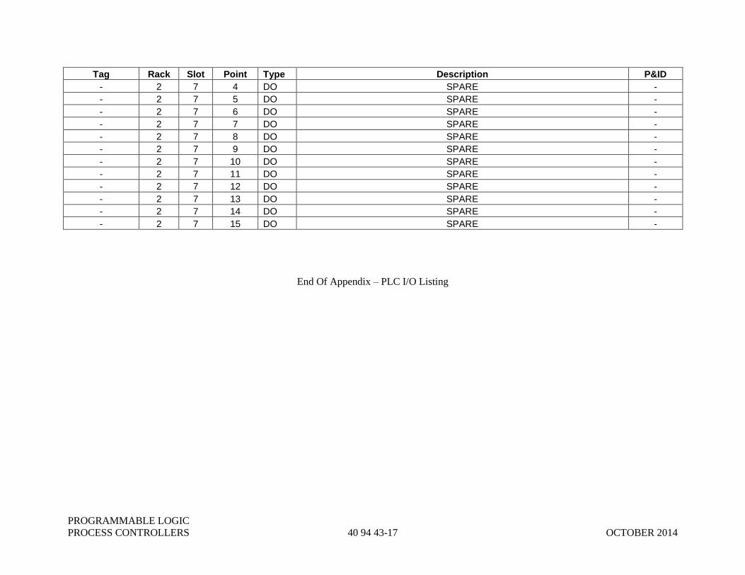
PROGRAMMABLE LOGIC
PROCESS CONTROLLERS 40 94 43-17 OCTOBER 2014
Tag Rack Slot Point Type Description P&ID
- 2 7 4 DO SPARE -
- 2 7 5 DO SPARE -
- 2 7 6 DO SPARE -
- 2 7 7 DO SPARE -
- 2 7 8 DO SPARE -
- 2 7 9 DO SPARE -
- 2 7 10 DO SPARE -
- 2 7 11 DO SPARE -
- 2 7 12 DO SPARE -
- 2 7 13 DO SPARE -
- 2 7 14 DO SPARE -
- 2 7 15 DO SPARE -
End Of Appendix – PLC I/O Listing

PROGRAMMABLE LOGIC
PROCESS CONTROLLERS 40 94 43-18 OCTOBER 2014
THIS PAGE INTENTIONALLY LEFT BLANK
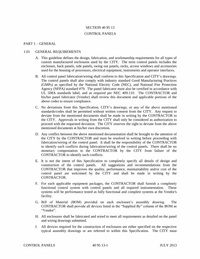
CONTROL PANELS 40 95 13-1 JULY 2013
SECTION 40 95 13
CONTROL PANELS
PART 1 – GENERAL
1.01 GENERAL REQUIREMENTS
A. This guideline defines the design, fabrication, and workmanship requirements for all types of
custom manufactured enclosures used by the CITY. The term control panels includes the
enclosure, back panels, side panels, swing out panels, racks, access windows and accessories
used for the housing of processors, electrical equipment, instruments and operator interfaces.
B. All control panel fabrication/wiring shall conform to this Specification and CITY’s drawings.
The control panels shall also comply with industry standard Good Manufacturing Practices
(GMPs) as specified by the National Electric Code (NEC), and National Fire Protection
Agency (NFPA) standard #79. The panel fabricator must also be certified in accordance with
UL 508A standards label, and as required per NEC 409.110. The CONTRACTOR and
his/her panel fabricator (Vendor) shall review this document and applicable portions of the
above codes to ensure compliance.
C. No deviations from this Specification, CITY’s drawings, or any of the above mentioned
standards/codes shall be permitted without written consent from the CITY. Any request to
deviate from the mentioned documents shall be made in writing by the CONTRACTOR to
the CITY. Approvals in writing from the CITY shall only be considered as authorization to
proceed with the requested deviation. The CITY reserves the right to deviate from the above
mentioned documents at his/her own discretion.
D. Any conflict between the above mentioned documentation shall be brought to the attention of
the CITY by the CONTRACTOR and must be resolved in writing before proceeding with
fabrication/wiring of the control panel. It shall be the responsibility of the CONTRACTOR
to identify such conflicts during fabrication/wiring of the control panels. There shall be no
monetary compensation to the CONTRACTOR by the CITY from failure of the
CONTRACTOR to identify such conflicts.
E. It is not the intent of this Specification to completely specify all details of design and
construction of the control panels. All suggestions and recommendations from the
CONTRACTOR that improves the quality, performance, maintainability and/or cost of the
control panel are welcomed by the CITY and shall be made in writing by the
CONTRACTOR.
F. For each applicable equipment packages, the CONTRACTOR shall furnish a completely
functional control system with control panels and all required instrumentation. These
systems will be performance tested as fully functional and complete systems at the Vendor's
facility.
G. Bill of Material (BOM) provided on each enclosure’s assembly drawing. The
CONTRACTOR shall provide all devices listed in the “Supplied By” column of the BOM as
“Vendor”.
H. All enclosures shall be fabricated and wired to meet all requirements as detailed on the panel
and wiring drawings submitted.
I. All devices required for the construction of enclosures are either specified on the respective
typical assembly drawings or are referred to within this Specification. The CITY must
CONTROL PANELS 40 95 13-2 JULY 2013
approve any changes to these components.
J. In order to provide a fully functional system, the CONTRACTOR shall furnish any material
or equipment required for fabrication that is not specifically mentioned in this Specification.
The selection of all accessories, materials, and methods of fabrication not mentioned in this
Specification and/or the CITY’s drawings, but which are necessary to complete the
fabrication of the control panel, shall be the responsibility of the CONTRACTOR and shall
be carried out in accordance as stated by the NEC, and the NFPA.
K. All custom-fabricated enclosures in outdoor areas shall be constructed to meet NEMA 4X
requirements unless otherwise specified. Sloped “watershed” enclosures are required for
clean areas.
L. All panels shall be either free standing, equipment mounted or wall mounted type enclosures.
Freestanding enclosures are required to have sanitary legs at least 12” from finished floor to
bottom of enclosure. All wall mounted type enclosures shall have a means to anchor the
enclosure to a wall and/or process equipment/skid.
M. The enclosures shall be completely wired, tested and contain all components, (including
components supplied by the CITY) prior to shipment. The panels shall be ready for
installation and subsequent start up upon arrival at the CITY’s site.
N. The CONTRACTOR shall provide supervision and labor that has been qualified by training
and experience, to perform the specific activities.
O. The CONTRACTOR shall issue panel components or associated instrumentation for
installation by other contractors as required.
P. The CONTRACTOR shall initiate a documented request for all work, which is not included
in the current authorized contract and design documents.
Q. The CONTRACTOR shall receive and inspect control system equipment, instruments,
control panels, junction boxes and miscellaneous components. Notify the CITY, or the
CITY’s Representative, immediately of any signs of damage or if discrepancies exist between
the packing slip and the items being received.
R. The CONTRACTOR shall maintain field records indicating date for receipt of control system
equipment, instruments, control panels and junction boxes on site.
S. The CONTRACTOR shall provide documentation of all control panel components including
model numbers, serial numbers and spare parts listings.
T. The CONTRACTOR will store all control system equipment, instruments, control panels,
junction boxes and instruments in a clean and dry area that provides shelter from the rain and
mechanical abuse. Provide heating/cooling to maintain an ambient temperature between 32
degrees and 72 degrees F.
U. The CONTRACTOR will ensure that all miscellaneous items such as special cabling,
mounting brackets, etc., are stored with the associated control system equipment, instruments
or control panels.
V. The CONTRACTOR will protect all instrument flange faces, diaphragm seal surfaces,
capillary tubing and threaded connections, relating to the control panel, from mechanical
abuse and ensure that plugs and caps are not removed from device openings or connections
during storage.
W. No equipment will be shipped to the CITY’s facility without a Factory Acceptance Test and
written authorization by the CITY or the CITY’s representative.
CONTROL PANELS 40 95 13-3 JULY 2013
X. Equipment covered by this section shall be listed by UL, or by a nationally recognized third
party testing laboratory. All unit assemblies (skid mounted packages, panel assemblies, or
enclosures of assemblies of components where at least one component is required to be
singularly UL listed) shall be either UL listed or listed by another testing organization
acceptable to the governing authority (authority having jurisdiction). All costs associated
with obtaining the certification of listing shall be the responsibility of the CONTRACTOR.
If no third-party testing laboratory provides the required listing, an independent test shall be
performed at CONTRACTOR’s expense. Before the test is conducted, CONTRACTOR shall
submit a copy of the testing procedure to be used for approval by the governing authority.
1.02 CONTROL SYSTEM DETAIL
A. Exact control panel components and configurations will vary per equipment package.
Typical custom control systems contain:
1. An equipment mounted Remote I/O cabinet containing Allen Bradley I/O modules,
terminal blocks and miscellaneous instrumentation. All instrumentation is wired to and
controlled from this enclosure. More than one cabinet may be required based on device
locations.
2. Floor or wall mounted HMI (SCADA) enclosures.
3. A free standing or wall mounted cabinet housing the Allen Bradley PLC or processor.
1.03 RELATED WORK NOT INCLUDED IN THIS SECTION
A. Installation of instruments and components outside the package boundaries.
B. Instrumentation and controls furnished with HVAC systems.
C. Work indicated as "existing" or "NIC" on the Drawings.
1.04 APPROVAL DRAWINGS/DOCUMENTS
A. Submittals shall be in accordance with the requirements of Section 01 33 00 of these
specifications. The following Drawings and documents shall be submitted to the CITY for
review and approval:
1. Enclosure layout, including overall dimensions for enclosure, back panel, side panel,
swing out panel and/or rack.
2. Panel layouts, including orientation and dimensional requirements for component
mounting.
3. Front panel layouts, including orientation and dimensional requirements of all
components to be mounted on the panel.
4. Wiring schematics, including power distribution details, control circuits and/or point to
point details.
5. Computer communication details.
6. Itemized list of components for front panel mounting including manufacturer and model
number.
7. Itemized list of components for back, side and/or swing out panel mounting including
manufacturer and model number.
8. Instrument nameplate schedules.
CONTROL PANELS 40 95 13-4 JULY 2013
9. The panel fabricator shall be located within a 150 mile radius of Cincinnati.
10. Instrument loop drawings shall be submitted with control panel shop drawings.
11. All items shall be properly identified on drawings, which shall include labeling of all
wires, connectors, contact and relay coil terminals, devices, splices, splice boxes, and
terminal strips.
B. Substitutions of itemized components as listed on the BOM can only be made with approval
from the CITY. Substitutions will only be accepted if procurement of preferred components
adversely affects the delivery schedule.
C. Any drawing/documentation to be developed by the CONTRACTOR shall be submitted to
the CITY or the CITY’s representative for approval. The CITY reserves the right to request
any additional information and/or clarification deemed necessary for the fabrication/wiring of
the control panel at no additional cost to the CITY. No fabrication/wiring is to proceed
without the approval of the appropriate drawings/documentation.
D. The CITY shall be given an allowance of four weeks from date of receipt of
drawings/documentation for review.
E. Drawings shall be developed on AutoCAD (latest release) unless otherwise specified or
permitted by the CITY. Files of the drawings will also be delivered to the CITY on CD-
ROM, or other approved storage media. Electronic copies of the typical drawings will be
made available prior to development, if required.
F. In addition, the CONTRACTOR shall provide copies of all additional drawings or sketches
generated to facilitate construction or fabrication.
G. All documentation received by the CONTRACTOR from component suppliers is considered
property of the CITY and shall be turned over to the CITY at the time of shipment of the
enclosures.
H. Operating and maintenance data shall be furnished in accordance with Section 01 78 23 of
these specifications.
1.05 SCHEDULE
A. Delay in shipment of control panel by vendors, insufficient manpower or any delay caused by
unforeseen circumstances will not be considered by the CITY as reasons for a delay in
schedule.
B. The CONTRACTOR’S bid shall comply with the listed Bill of Materials. Any deviations
must be identified at time of bid.
1.06 INSPECTION/TESTING
A. The CITY reserves the right to inspect all control panels prior to shipment. The
CONTRACTOR shall notify the CITY at least ten days prior to the readiness of the control
panel for inspection. The CONTRACTOR’S control panel fabricator is expected to have
completed their own inspection to satisfy themselves that the fabrication is completed and
correct to the best of their knowledge prior to the inspection by the CITY. Any rejections
and/or comments based on the inspection will be corrected/resolved by the CONTRACTOR
prior to shipment of the control panel at no cost to the CITY. The approval of the inspection
of the control panel by the CITY in no way releases the CONTRACTOR from guarantees as
to materials, apparatus, workmanship and performance of the entire control panel.
B. The CITY reserves the right to conduct specific Factory Acceptance Testing (FAT) prior to
CONTROL PANELS 40 95 13-5 JULY 2013
the shipment of the panels from the Vendor’s facility. The CITY will provide input to the
CONTRACTOR developed FAT documentation to ensure verification of the enclosure
functionality.
C. The CONTRACTOR agrees to support the FAT by providing the panels, a place to conduct
the testing and adequate utilities required to operate and test the panels as a complete system.
D. The CONTRACTOR shall correctly complete the required equipment qualification
documents furnished by the CITY prior to final Factory Acceptance Testing (FAT).
E. The CITY reserves the right to be present at any FAT and to inspect the work at any time
during fabrication.
F. Prior to the inspection of the control panel by the CITY, the CONTRACTOR shall
completely inspect and test the control panel fabricators work for the following, but not
limited to:
1. All nameplates and tags are in the correct arrangement, good appearance, correct
inscriptions and spelling and proper attachment.
2. All equipment/instruments are checked mechanically for proper arrangement, installation,
assembly and compliance with the Specification and Drawings.
3. All electrical circuits are checked for continuity, operability and compliance with the
Specification and Drawings.
4. All pneumatic tubing/piping is checked for continuity, operability and compliance with
the Specification and Drawings.
G. Prior to the FAT, the CONTRACTOR should perform a power on test to ensure proper
wiring.
H. The CONTRACTOR is liable for back charges to correct any items found not in compliance
with the Specification and/or Drawings after the initial inspection of the control panel by the
CITY.
I. The CITY reserves the right to waive the control panel inspection prior to shipment of panel
by the control panel fabricator. Such action by the CITY in no way releases the
CONTRACTOR from guarantees as to materials, apparatus, workmanship and performance
of the entire control panel, and still holds the CONTRACTOR liable for back charges to
correct any items found not in compliance with the Specification and/or Drawings.
1.07 SHIPPING
A. Preparation
1. All external pneumatic connections are to be capped (tubing fittings) or plugged (pipe
fittings).
2. Cushion all glass and fragile surfaces, at points of contact with the crate. Use crepe
cellulose or other suitable nonabrasive material.
3. Secure and restrain from movement all loose components and accessories.
4. Utilize interior protectors and braces as necessary.
5. Use plastic or waterproof paper to cover panels to prevent water damage during transit
and required "on-site" storage.
6. The CONTRACTOR is to provide two days notice to the CITY or the CITY’s
CONTROL PANELS 40 95 13-6 JULY 2013
representative before shipping.
B. Crating
1. If additional protection, e.g., wooden crate, is required depending upon type of transport,
the CONTRACTOR is to make this determination and provide such protection.
2. The CONTRACTOR is to provide crate and packing materials to meet all applicable
regulations and codes.
3. The CONTRACTOR shall ship the panels to the destination listed in the purchase order.
4. Prior to accepting shipment, the CITY reserves the right to inspect all panels for damage
during shipment. If any damage is evident, the shipment shall not be accepted. The
CONTRACTOR shall be responsible for settling any claims with the carrier.
5. The CONTRACTOR shall provide shipping weight to the CITY before enclosures are
shipped.
1.08 WARRANTY
Refer to Section 01 78 36.
PART 2 - PRODUCTS
1.01 2.01 ENCLOSURE RATINGS
A. Control panels enclosure ratings shall match the environment that they are installed.
B. NEMA 12: For Indoor areas in non-classified areas.
C. NEMA 4 or 4X: Stainless Steel or Fiberglass for Outdoor areas.
D. NEMA 7: Explosive Gas/Vapors
E. NEMA 9: Explosive Fibers/Flyings
F. Panel Wall Thickness: 14 or 16 Gauge
2.02 SUB-PANELS
A. Material of Construction: Cold or Hot Rolled Carbon Steel Painted White.
B. Material Thickness: 12 or 14 Gauge
2.03 PUSH BUTTON STATIONS AND OPERATOR DEVICES
A. Push button station enclosure and operators shall adhere to NEMA ratings per Section 2.01
above and requirements of Section 26 29 00.
B. Use Allen Bradley 800H or 800T 30.5 mm push buttons, selectors, pilot lights, etc.
C. Use 800H-W series for nameplates.
2.04 PLC HARDWARE REQUIREMENTS
A. Refer to Specification 40 94 43 for detailed requirements of a programmable controller
system.
B. Allen Bradley Control Logix is the client standard.
CONTROL PANELS 40 95 13-7 JULY 2013
C. Use Allen Bradley Compact Logix in lieu of Control Logix only with approval from the
client.
D. The use of redundant PLC power supplies are required to protect the PLC processor.
E. The use of Flex I/O (Bulletin 1794) is generally not permitted.
F. Provide 20% installed spare I/O capacity in PLC and Remote I/O panels. This includes I/O
modules AND terminations.
2.05 WIRING
A. See Specification 40 95 73 for specific wiring details.
B. All wire type and size shall be in accordance with the NEC. The Vendor is responsible for
properly selecting the size of wire to be used in accordance with all applicable codes.
Preferred wire types for typical applications are listed in Specification 40 95 73.
C. The color of the wire used shall be in accordance with the Wire Color Code Table in
Specification 40 95 73 unless prior permission is obtained from the CITY.
D. Use only pre-printed wire markers. The use of hand written markers is not permitted. Heat
shrink type wire markers are preferred, however, adhesive type markers are acceptable with
approval from the CITY. All wires and cables are to be properly labeled per the schematic
drawings.
2.06 TERMINAL BLOCKS
A. Reference the respective panel schematic wiring drawing, and the Panel Drawing Bill of
Material List for preferred types and models.
B. All terminal blocks shall be rated IP20 or IP30.
2.07 CIRCUIT PROTECTION
A. Fuse or Circuit Breaker sizing shall be in accordance with the applicable article of the NEC.
B. Reference the respective panel schematic wiring drawing and the panel drawing Bill of
Material (B.O.M.) list for preferred types and models of circuit protection devices.
C. The use of current-limiting fuses (example Bussman LPJ) for each incoming 120 VAC feed
is required so that the control panel’s SCCR (short circuit current rating) may be maximized.
D. Use a finger-safe fuse holder for each incoming 120VAC fuse (example Bussman
JTN60030).
E. Circuit breakers are primarily used on branch 120 VAC circuits. UL 489 listed breakers are
preferred.
F. Fused terminal blocks for branch circuits shall be provided with fuse-blown indications.
PART 3 - EXECUTION
3.01 PANEL CONSTRUCTION
A. Construction
1. All edges of the enclosure shall be ground and polished to standard radius bends.
2. Welding materials and procedures shall be as required to assure structural integrity.
CONTROL PANELS 40 95 13-8 JULY 2013
Grind all welds smooth and flush with the surrounding metal. Seams shall be
continuously welded and ground smooth.
3. Stiffeners shall be provided as required on the interior of the surfaces to maintain the
enclosure’s flatness. Generally, no evidence of fastening means shall appear on the face
of the finished enclosure. Exceptions to this shall require prior CITY approval.
4. Interior mounting studs for the sub-panel shall be provided. These studs shall be
constructed of material compatible with the panel enclosure, and shall have sufficient
strength and location to support the sub-panel and all the devices mounted thereon.
These studs shall be permanently affixed to the sides or back of the enclosure, and have
no evidence of fastening means appear on the face of the finished enclosure.
5. Panel shall be constructed and assembled to meet the requirements of UL 508A.
B. Sub-Panels
1. Each sub-panel shall have sufficient mounting holes in number and size to correspond
with the sub-panel mounting studs on the interior of the enclosure.
2. Each sub-panel will be shipped mounted within the enclosure complete with all devices
specified in the BOM.
C. Doors
1. All edges of the panel doors shall be ground and polished to standard radius bends.
2. Stiffeners shall be provided as required on the rear surfaces to maintain the Panel Door
flatness. No evidence of fastening means shall appear on the face of the finished
enclosure.
3. All panel doors shall be attached to the enclosure by means of a continuous hinge (or
hinges). No evidence of fastening means shall appear on the face of the finished
enclosure.
4. All panel doors shall have sufficient latching mechanism(s) placed appropriately such
that the panel doors will properly seal to meet the NEMA 4X enclosure rating for
Outdoor enclosures.
5. No distortion of the panel doors is permitted as a result of machining cutouts or mounting
instruments and devices.
6. When specified by the assembly drawings, the devices mounted in the door or sides of
the enclosure shall be sealed to maintain a positive purge air pressure within the panel.
D. Surface Preparation
1. A smooth brushed finish is acceptable.
2. Remove weld spatter and sharp weld edges.
3. Clean with a solvent to remove grease and oil deposits.
3.02 DEVICE MOUNTING
A. All equipment/instruments shall be mounted as per manufacturer’s instruction with no
obstructions preventing easy access for maintenance or removal of equipment/instrument
without the need for removal of the entire panel.
B. All equipment/instruments shall be properly spaced for proper ventilation and wiring as per
manufacturer’s instruction.
CONTROL PANELS 40 95 13-9 JULY 2013
C. All heat generating equipment/instruments shall be mounted near to the bottom of the control
panel as possible. If deemed necessary muffin fans shall be installed for circulation of air
within the enclosure.
D. Power conditioners shall be provided for all microprocessor controllers and computer
hardware.
E. Internal receptacles shall be mounted in control panels that house processors, which require
configuration/programming with a laptop plug-in terminal. Receptacles shall be individually
fused, with the fuse rated for the proper ampacity protection as recommended by the laptop
manufacturer.
F. Free standing control panels shall contain an individual fluorescent lamp mounted at the top
of the control panel. Light shall be individually fused and be equipped with an on/off toggle
switch, and a door limit switch.
G. All devices and electrical equipment not DIN rail mounted shall be rigidly mounted to the
sub-panel by using drilled and tapped mounting holes. Use the appropriate mounting
hardware.
H. When assembling Allen Bradley PLC or Remote I/O panels, adhere to the minimum spacing
requirements of Allen Bradley PLC components, chassis and power supplies as required.
I. Locate all devices per the respective panel layout drawing. Changes in the layout require
prior CITY approval.
J. Where required, devices may be mounted to the door utilizing the appropriate mounting
hardware while maintaining the existing NEMA integrity rating. External receptacles and
programming ports are required for enclosures containing processors.
3.03 ELECTRICAL REQUIREMENTS
A. The Control panel shall be provided with a dedicated disconnecting means for each individual
incoming supply circuit. The disconnecting means shall be manually operable and plainly
indicate whether it is in the closed (on) or open (off) position.
B. The disconnecting means shall be mounted within the control panel enclosure, at the top of
the enclosure (must be within human reach) with no other equipment mounted above it.
Proper space shall be allocated for wire bending as required per the NEC.
C. All components in a control panel shall be UL listed, in accordance with achieving UL508A
certification.
D. Finger-safe devices shall be employed for all devices. When this is not possible, appropriate
guarding shall be used. This ensures that there will not be a shock hazard.
E. Control Panel Wiring
1. All wiring shall be in accordance with the applicable articles of the NEC. Reference
Section 409573 for specific wiring details. Conductors shall be properly sized for the
correct amperage per the NEC and NFPA #79 codes/standards.
2. Conductors shall have a minimum of 600V, THHN/THWN or MTW insulation.
3. Where possible, run wiring between devices and terminal blocks in wire ducts with
covers. When this is not practical, wire runs shall be neatly arranged, supported, bundled
with nylon tie-wraps, and secured to the sub-panel. Ensure that there is enough slack to
act as a strain relief.
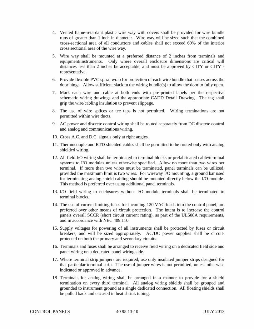
CONTROL PANELS 40 95 13-10 JULY 2013
4. Vented flame-retardant plastic wire way with covers shall be provided for wire bundle
runs of greater than 1 inch in diameter. Wire way will be sized such that the combined
cross-sectional area of all conductors and cables shall not exceed 60% of the interior
cross sectional area of the wire way.
5. Wire way shall be mounted at a preferred distance of 2 inches from terminals and
equipment/instruments. Only where overall enclosure dimensions are critical will
distances less than 2 inches be acceptable, and must be approved by CITY or CITY’s
representative.
6. Provide flexible PVC spiral wrap for protection of each wire bundle that passes across the
door hinge. Allow sufficient slack in the wiring bundle(s) to allow the door to fully open.
7. Mark each wire and cable at both ends with pre-printed labels per the respective
schematic wiring drawings and the appropriate CADD Detail Drawing. The tag shall
grip the wire/cabling insulation to prevent slippage.
8. The use of wire splices or tee taps is not permitted. Wiring terminations are not
permitted within wire ducts.
9. AC power and discrete control wiring shall be routed separately from DC discrete control
and analog and communications wiring.
10. Cross A.C. and D.C. signals only at right angles.
11. Thermocouple and RTD shielded cables shall be permitted to be routed only with analog
shielded wiring.
12. All field I/O wiring shall be terminated to terminal blocks or prefabricated cable/terminal
systems to I/O modules unless otherwise specified. Allow no more than two wires per
terminal. If more than two wires must be terminated, panel terminals can be utilized,
provided the maximum limit is two wires. For wireway I/O mounting, a ground bar used
for terminating analog shield cabling should be mounted directly below the I/O module.
This method is preferred over using additional panel terminals.
13. I/O field wiring to enclosures without I/O module terminals shall be terminated to
terminal blocks.
14. The use of current limiting fuses for incoming 120 VAC feeds into the control panel, are
preferred over other means of circuit protection. The intent is to increase the control
panels overall SCCR (short circuit current rating), as part of the UL508A requirements,
and in accordance with NEC 409.110.
15. Supply voltages for powering of all instruments shall be protected by fuses or circuit
breakers, and will be sized appropriately. AC/DC power supplies shall be circuit-
protected on both the primary and secondary circuits.
16. Terminals and fuses shall be arranged to receive field wiring on a dedicated field side and
panel wiring on a dedicated panel wiring side.
17. Where terminal strip jumpers are required, use only insulated jumper strips designed for
that particular terminal strip. The use of jumper wires is not permitted, unless otherwise
indicated or approved in advance.
18. Terminals for analog wiring shall be arranged in a manner to provide for a shield
termination on every third terminal. All analog wiring shields shall be grouped and
grounded to instrument ground at a single dedicated connection. All floating shields shall
be pulled back and encased in heat shrink tubing.

CONTROL PANELS 40 95 13-11 JULY 2013
F. Terminal Block Installation
1. Terminals shall be provided for all field control wiring connections. Control wiring
terminals shall be grouped separately from power distribution terminals. Terminals shall
be strip DIN rail mounted to the back panel and shall contain approximately 20% spare.
Separate terminal strips shall be dedicated for AC and DC wiring and shall be
individually and clearly labeled.
2. Terminals shall be screw type and rated for a minimum of 15 amps, or as indicated
otherwise on drawings. Each terminal shall be clearly labeled to correspond with
markings on the electrical drawings, by use of terminal marking strips.
3. Locate all terminal blocks per the respective panel layout drawing. Changes in the layout
require prior CITY approval.
4. All terminal strips and individual terminals shall be labeled per the respective schematic
wiring drawings and the appropriate CADD Detail Drawing.
5. Ground circuits shall use grounded terminal blocks unless prior approval is obtained from
the CITY. Ground terminals are color-coded with green, yellow, or both colors.
6. The manufacturer’s restrictions on wire size for multiple wire terminations on one
terminal block shall be followed. However, no more than two wires shall be terminated
on one side of one terminal block.
7. Fuse blocks shall be provided with DIN rail mounting and contain an integral fuse pull
mechanism. Control panel shall contain 20% spare fuses. No inline wire fuses shall be
allowed. Each individual fuse block shall be clearly labeled to correspond with markings
on the electrical drawings.
8. Terminals and fuse block shall be mounted with unobstructed access to them. There shall
be no internal or external wiring crossing over the terminals or fuse blocks.
G. Grounding
1. Grounding shall be in accordance with Article 250 of the NEC with the exception that the
use of metallic armored cabling and/or rigid metal conduit, as a grounding path, is not
acceptable. A separate conductor shall be provided.
2. The secondary side of all control power transformers or power supplies shall be grounded
to the equipment/instrument ground.
3. Provide grounding bars for the appropriately sized wire as required.
4. Each enclosure shall have an individual equipment ground which shall be referenced to
earth ground. The equipment ground shall be clearly labeled. The connection to earth
ground shall be via a grounding conductor. Reliance on metal conduit or armored
cabling connections is not permitted.
5. The control panel shall contain a common equipment and instrument ground busbar
(copper). The ground busbar will be clearly labeled and bonded to the enclosure.
6. All analog signal wiring shields shall be grouped and terminated to the instrument ground
as well as all instruments/devices.
7. Each sub-panel shall be grounded to the equipment ground. Connection of ground to
sub-panels and side panels shall not be permitted through the panel bolts. A separate
appropriately sized grounding conductor is required.
8. The enclosure door shall always be grounded to the equipment/instrument ground. This
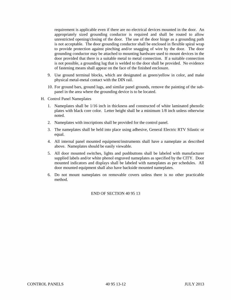
CONTROL PANELS 40 95 13-12 JULY 2013
requirement is applicable even if there are no electrical devices mounted in the door. An
appropriately sized grounding conductor is required and shall be routed to allow
unrestricted opening/closing of the door. The use of the door hinge as a grounding path
is not acceptable. The door grounding conductor shall be enclosed in flexible spiral wrap
to provide protection against pinching and/or snagging of wire by the door. The door
grounding conductor may be attached to mounting hardware used to mount devices in the
door provided that there is a suitable metal to metal connection. If a suitable connection
is not possible, a grounding lug that is welded to the door shall be provided. No evidence
of fastening means shall appear on the face of the finished enclosure.
9. Use ground terminal blocks, which are designated as green/yellow in color, and make
physical metal-metal contact with the DIN rail.
10. For ground bars, ground lugs, and similar panel grounds, remove the painting of the sub-
panel in the area where the grounding device is to be located.
H. Control Panel Nameplates
1. Nameplates shall be 1/16 inch in thickness and constructed of white laminated phenolic
plates with black core color. Letter height shall be a minimum 1/8 inch unless otherwise
noted.
2. Nameplates with inscriptions shall be provided for the control panel.
3. The nameplates shall be held into place using adhesive, General Electric RTV Silastic or
equal.
4. All internal panel mounted equipment/instruments shall have a nameplate as described
above. Nameplates should be easily viewable.
5. All door mounted switches, lights and pushbuttons shall be labeled with manufacturer
supplied labels and/or white phenol engraved nameplates as specified by the CITY. Door
mounted indicators and displays shall be labeled with nameplates as per schedules. All
door mounted equipment shall also have backside mounted nameplates.
6. Do not mount nameplates on removable covers unless there is no other practicable
method.
END OF SECTION 40 95 13

INSTRUMENT SIGNAL AND
POWER WIRING 40 95 73-1 JULY 2013
SECTION 40 95 73
INSTRUMENT SIGNAL AND POWER WIRING
PART 1 – GENERAL
1.01 GENERAL REQUIREMENTS
A. All requirements of Specification 40 90 00 form a part of this Section.
B. Perform the following work as part of Electrical Construction Specifications, indicated as
required in Division 26 Specifications.
1.02 CODES AND STANDARDS
A. Work shall comply with:
1. National Electrical Code (NEC).
2. National Electrical Safety Code (NESC).
3. National Fire Protection Association (NFPA).
4. Federal, State, and Local Codes.
5. Instrument Society of America (ISA)
B. Provide new materials and equipment that meet the requirements of:
1. American National Standards Institute (ANSI).
2. Institute of Electrical and Electronics Engineers (IEEE).
3. Insulated Power Cable Engineers Association (IPCEA).
4. National Electrical Manufacturers Association (NEMA).
5. Underwriters’ Laboratories, Inc. (UL).
6. Factory Mutual (FM).
1.03 INSPECTIONS
A. Comply with requirements of local inspection authority.
B. Schedule inspections with the local inspection authority so that no new work is concealed
prior to required inspections.
1.04 SUBMITTALS
A. Upon Completion of Job, submit the following:
1. Supply "as-built" drawings: Marked-up red lines.
2. Give CITY's representative all manufacturers' literature upon completion of job.
1.05 DRAWING CONFLICTS
Lay out your work first, before you start, and report all Drawing conflicts to the CITY. The
CITY will not assume responsibility for cost incurred by the CONTRACTOR because of lack of
preparation.

INSTRUMENT SIGNAL AND
POWER WIRING 40 95 73-2 JULY 2013
1.06 DESCRIPTION
A. Work Included
1. CITY furnished instruments are listed in the Instrument List and coordination Schedule.
Field instruments are furnished with mounting brackets and air supply regulator if
applicable.
2. The CONTRACTOR is responsible for the installation of all control panels, junction
boxes, and any other control enclosures required for the complete installation of this
system.
3. Wiring and terminations of all instrument devices associated with this Project is the
responsibility of the CONTRACTOR.
4. Provide cabling and/or wiring necessary to wire the following CITY or CONTRACTOR
furnished items:
a. Instruments
b. Control Panels
c. Remote I/O Panels
d. Field Termination Boxes
5. Provide raceway, fittings and supports.
6. Provide cable tray accessories and supports, as required.
7. Provide power wiring to field instrument requiring 120 VAC power.
PART 2 - PRODUCTS
2.01 GENERAL
Refer to Division 26, Electrical Basic Materials and Methods of the Electrical Specifications for
all products.
2.02 CABLE REQUIREMENTS (MINIMUM)
A. Conductors shall be properly sized for the correct amperage per the NEC and NFPA #79
codes/standards. Conductors shall be stranded soft-annealed copper. Single conductors shall
be XHHW insulation.
1. 120VAC Conductors shall be color coded in the following manner:
a. BLACK - AC line, load, and hardwired control circuits in line voltage.
b. WHITE - AC Neutral
c. GREEN - Ground
d. YELLOW - Any AC conductor within a control panel from an external power source
that remains live after the control panel disconnect is opened.
e. RED - All 120 VAC Control and I/O Wiring
2. 24VDC Conductors shall be color coded in the following manner:
a. DARK BLUE - DC Control Circuits (positive)
b. DARK BLUE with White Stripe - DC Control Circuits (negative or common)
c. LIGHT BLUE - Intrinsically safe circuits
d. YELLOW - Any DC conductor within a control panel from an external power source

INSTRUMENT SIGNAL AND
POWER WIRING 40 95 73-3 JULY 2013
that remains live after the control panel disconnect is opened.
3. Twisted shielded pair conductors for analog wiring:
a. BLACK Positive (+24V)
b. CLEAR Negative (COM)
c. SHIELD Shield (SHLD)
B. Cable types are specified as follows. Other types may be used only with approval.
CABLE TYPE USAGE CABLE
DESCRIPTION/SIZE
Belden 8719 Analog I/O 1 Twisted Pair #18 AWG,
Shield
XHHW AC/DC Discrete I/O – Field Wiring #14 AWG minimum
XHHW AC/DC Discrete I/O – Panel Wiring #16 AWG minimum
XHHW AC/DC Control Power – Field Wiring #12 AWG minimum
XHHW AC/DC Control Power – Panel Wiring #14 AWG minimum
Belden 9366 Temperature 1 Triad
Belden 3092A ControlNet Quad-Shielded RG6 Coaxial
Belden 11872A Ethernet Category 6
Belden B9C231 Optical Fiber Cable Armor – 12 Fibers
Belden B9C232 Optical Fiber Cable Armor – 24 Fibers
Belden B9C202 Optical Fiber Cable Non-Armor – 6 Fibers
Belden B9C204 Optical Fiber Cable Non-Armor – 12 Fibers
Belden B9C205 Optical Fiber Cable Non-Armor – 24 Fibers
PART 3 - EXECUTION
3.01 GENERAL
A. Provide supervision and labor that has been qualified by training and experience to perform
the activities.
B. Ensure the physical mounting of an instrument is complete, prior to terminating conduit and
wiring at the instrument.
C. Reference Specification Division 26 Electrical Specifications for installation methods not
listed.
3.02 GENERAL WIRING PRACTICES
A. Separate systems consisting of conduit and wire shall be provided for the following types of
applications:
1. Analog signals (4-20 mA DC), Thermocouple Wire and Resistance Temperature Devices
(RTDs)
2. 24 VDC Discrete signals; 24 VDC Power
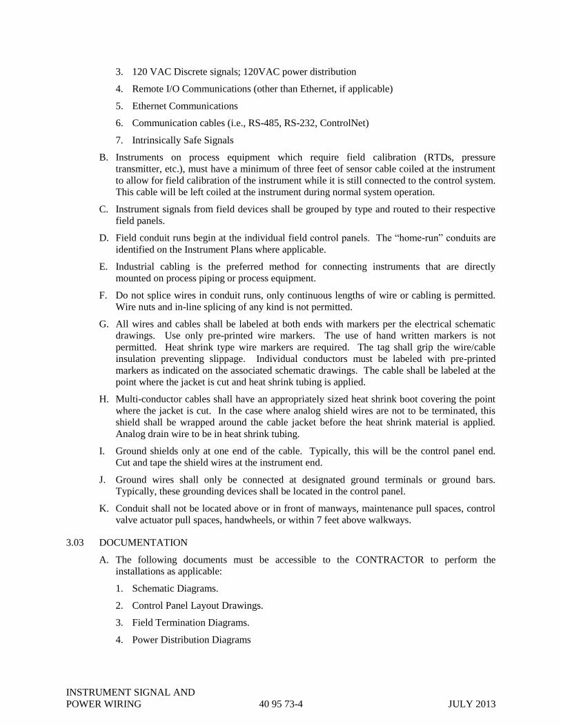
INSTRUMENT SIGNAL AND
POWER WIRING 40 95 73-4 JULY 2013
3. 120 VAC Discrete signals; 120VAC power distribution
4. Remote I/O Communications (other than Ethernet, if applicable)
5. Ethernet Communications
6. Communication cables (i.e., RS-485, RS-232, ControlNet)
7. Intrinsically Safe Signals
B. Instruments on process equipment which require field calibration (RTDs, pressure
transmitter, etc.), must have a minimum of three feet of sensor cable coiled at the instrument
to allow for field calibration of the instrument while it is still connected to the control system.
This cable will be left coiled at the instrument during normal system operation.
C. Instrument signals from field devices shall be grouped by type and routed to their respective
field panels.
D. Field conduit runs begin at the individual field control panels. The “home-run” conduits are
identified on the Instrument Plans where applicable.
E. Industrial cabling is the preferred method for connecting instruments that are directly
mounted on process piping or process equipment.
F. Do not splice wires in conduit runs, only continuous lengths of wire or cabling is permitted.
Wire nuts and in-line splicing of any kind is not permitted.
G. All wires and cables shall be labeled at both ends with markers per the electrical schematic
drawings. Use only pre-printed wire markers. The use of hand written markers is not
permitted. Heat shrink type wire markers are required. The tag shall grip the wire/cable
insulation preventing slippage. Individual conductors must be labeled with pre-printed
markers as indicated on the associated schematic drawings. The cable shall be labeled at the
point where the jacket is cut and heat shrink tubing is applied.
H. Multi-conductor cables shall have an appropriately sized heat shrink boot covering the point
where the jacket is cut. In the case where analog shield wires are not to be terminated, this
shield shall be wrapped around the cable jacket before the heat shrink material is applied.
Analog drain wire to be in heat shrink tubing.
I. Ground shields only at one end of the cable. Typically, this will be the control panel end.
Cut and tape the shield wires at the instrument end.
J. Ground wires shall only be connected at designated ground terminals or ground bars.
Typically, these grounding devices shall be located in the control panel.
K. Conduit shall not be located above or in front of manways, maintenance pull spaces, control
valve actuator pull spaces, handwheels, or within 7 feet above walkways.
3.03 DOCUMENTATION
A. The following documents must be accessible to the CONTRACTOR to perform the
installations as applicable:
1. Schematic Diagrams.
2. Control Panel Layout Drawings.
3. Field Termination Diagrams.
4. Power Distribution Diagrams
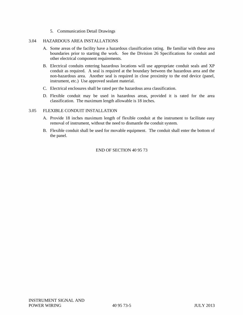
INSTRUMENT SIGNAL AND
POWER WIRING 40 95 73-5 JULY 2013
5. Communication Detail Drawings
3.04 HAZARDOUS AREA INSTALLATIONS
A. Some areas of the facility have a hazardous classification rating. Be familiar with these area
boundaries prior to starting the work. See the Division 26 Specifications for conduit and
other electrical component requirements.
B. Electrical conduits entering hazardous locations will use appropriate conduit seals and XP
conduit as required. A seal is required at the boundary between the hazardous area and the
non-hazardous area. Another seal is required in close proximity to the end device (panel,
instrument, etc.) Use approved sealant material.
C. Electrical enclosures shall be rated per the hazardous area classification.
D. Flexible conduit may be used in hazardous areas, provided it is rated for the area
classification. The maximum length allowable is 18 inches.
3.05 FLEXIBLE CONDUIT INSTALLATION
A. Provide 18 inches maximum length of flexible conduit at the instrument to facilitate easy
removal of instrument, without the need to dismantle the conduit system.
B. Flexible conduit shall be used for movable equipment. The conduit shall enter the bottom of
the panel.
END OF SECTION 40 95 73

INSTRUMENT SIGNAL AND
POWER WIRING 40 95 73-6 JULY 2013
THIS PAGE INTENTIONALLY LEFT BLANK

GRIT PUMPS 43 21 13.25-1 AUGUST 2014
SECTION 43 21 13.25
GRIT PUMPS
PART 1 - GENERAL
1.01 SCOPE (M-B-51-0006, M-B-51-0007 AND M-B-51-0008)
CONTRACTOR shall provide all labor, materials, equipment and incidentals required to provide
recessed impeller centrifugal pumps complete and operational with motors, control equipment and
accessories as shown and specified. Anchor bolts are included in this Section.
1.02. RELATED SECTIONS
A. Section 01 78 23, Operation and Maintenance Data.
B. Section 01 79 00, Instructions of Operations and Maintenance Personnel.
C. Division 3, Concrete
D. Section 26 05 83, Electric Motors.
E. Division 40, Sections on Instrumentation and Controls.
F. Division 26, Electrical.
1.03 QUALITY ASSURANCE
A. Manufacturer shall have a minimum of five years experience in the production of recessed
impeller centrifugal pumps and shall show evidence of satisfactory service in at least five
installations.
B. Reference Standards: Comply with applicable provisions and recommendations of the following,
except as otherwise shown or specified.
1. Standards of the Hydraulic Institute.
2. National Electric Code.
3. Standards of National Electrical Manufacturers Association.
4. Institute of Electrical and Electronic Engineers.
5. American National Standards Institute.
6. Standards of American Water Works Association.
C. Shop Tests
1. Pump casings shall be hydrostatically tested to twice the discharge head or 1-1/2 times the
shutoff head, whichever is greater.
2. Certified Factory Test
a. Pump assembly shall be operated from zero to maximum capacity as shown on the approved
GRIT PUMPS 43 21 13.25-2 AUGUST 2014
curve.
b. Results of the test shall be shown in a plot of test curves showing head, flow, horsepower,
efficiency, and current.
c. Readings shall be taken at a minimum of five evenly spaced capacity points including shut-
off, design point and minimum head for which pump is designed to operate.
3. Peak-to-peak vibration amplitude for shop testing shall not exceed 3.0 mils in all directions and
at all frequencies when measured at each pump and driver bearing housing.
4. Each test shall be witnessed by a Registered Professional Engineer, who may be an employee of
the manufacturer. He shall sign and seal all copies of curves and shall certify that hydrostatic
tests were performed.
5. Tests shall be conducted in conformance with applicable methods described in Hydraulic
Institute Standards.
6. Pumps shall not be shipped until the ENGINEER has approved the test reports.
1.04 SUBMITTAL
A. Shop Drawings: Submit for approval the following:
1. Manufacturer's literature, illustrations, specifications, paint certification and engineering data
including: dimensions, materials, size, weight, performance data and curves showing overall
pump efficiencies, required net positive suction head, allowable suction lift, flow rate, head,
brake horsepower, motor horsepower, speed and shut-off head.
2. Shop Drawings Showing: Fabrication, assembly, installation and wiring diagrams.
3. Four copies of certified pump tests.
4. Motor tests and data as described in Part 2, below.
B. Operation and Maintenance Manuals
1. Submit complete installation, operation and maintenance manuals including copies of all
approved Shop Drawings, test reports, maintenance data and schedules, description of operation
and spare parts information.
2. Furnish Operation and Maintenance Manuals in conformance with the requirements of Section
01 78 23, Operation and Maintenance Data.
1.05 STORAGE AND PROTECTION
Pumps shall be stored and protected in accordance with the requirements of Section 01 60 00 of these
Specifications.
1.06 QUALITY ASSURANCE
A. The manufacturer shall assume unit responsibility for all items specified in this section. Unit
responsibility shall require that all items be products of, or warranted by, the manufacturer. The
manufacturer shall be responsible for all coordination between components and provide all
submittals, installation and start-up assistance and certifications on the equipment as a unit.
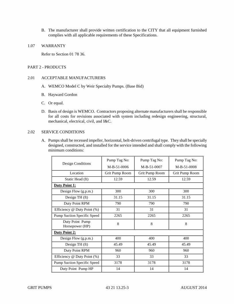
GRIT PUMPS 43 21 13.25-3 AUGUST 2014
B. The manufacturer shall provide written certification to the CITY that all equipment furnished
complies with all applicable requirements of these Specifications.
1.07 WARRANTY
Refer to Section 01 78 36.
PART 2 - PRODUCTS
2.01 ACCEPTABLE MANUFACTURERS
A. WEMCO Model C by Weir Specialty Pumps. (Base Bid)
B. Hayward Gordon
C. Or equal.
D. Basis of design is WEMCO. Contractors proposing alternate manufacturers shall be responsible
for all costs for revisions associated with system including redesign engineering, structural,
mechanical, electrical, civil, and I&C.
2.02 SERVICE CONDITIONS
A. Pumps shall be recessed impeller, horizontal, belt-driven centrifugal type. They shall be specially
designed, constructed, and installed for the service intended and shall comply with the following
minimum conditions:
Design Conditions Pump Tag No:
M-B-51-0006
Pump Tag No:
M-B-51-0007
Pump Tag No:
M-B-51-0008
Location Grit Pump Room Grit Pump Room Grit Pump Room
Static Head (ft) 12.59 12.59 12.59
Duty Point 1:
Design Flow (g.p.m.) 300 300 300
Design TH (ft) 31.15 31.15 31.15
Duty Point RPM 790 790 790
Efficiency @ Duty Point (%) 31 31 31
Pump Suction Specific Speed 2265 2265 2265
Duty Point Pump
Horsepower (HP) 8 8 8
Duty Point 2:
Design Flow (g.p.m.) 400 400 400
Design TH (ft) 45.49 45.49 45.49
Duty Point RPM 960 960 960
Efficiency @ Duty Point (%) 33 33 33
Pump Suction Specific Speed 3178 3178 3178
Duty Point Pump HP 14 14 14
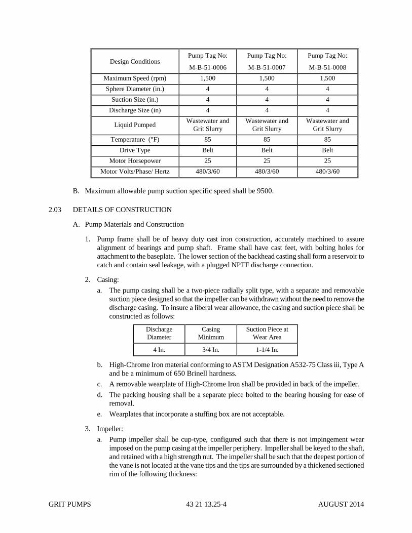
GRIT PUMPS 43 21 13.25-4 AUGUST 2014
Design Conditions Pump Tag No:
M-B-51-0006
Pump Tag No:
M-B-51-0007
Pump Tag No:
M-B-51-0008
Maximum Speed (rpm) 1,500 1,500 1,500
Sphere Diameter (in.) 4 4 4
Suction Size (in.) 4 4 4
Discharge Size (in) 4 4 4
Liquid Pumped Wastewater and
Grit Slurry
Wastewater and
Grit Slurry
Wastewater and
Grit Slurry
Temperature (°F) 85 85 85
Drive Type Belt Belt Belt
Motor Horsepower 25 25 25
Motor Volts/Phase/ Hertz 480/3/60 480/3/60 480/3/60
B. Maximum allowable pump suction specific speed shall be 9500.
2.03 DETAILS OF CONSTRUCTION
A. Pump Materials and Construction
1. Pump frame shall be of heavy duty cast iron construction, accurately machined to assure
alignment of bearings and pump shaft. Frame shall have cast feet, with bolting holes for
attachment to the baseplate. The lower section of the backhead casting shall form a reservoir to
catch and contain seal leakage, with a plugged NPTF discharge connection.
2. Casing:
a. The pump casing shall be a two-piece radially split type, with a separate and removable
suction piece designed so that the impeller can be withdrawn without the need to remove the
discharge casing. To insure a liberal wear allowance, the casing and suction piece shall be
constructed as follows:
Discharge
Diameter
Casing
Minimum
Suction Piece at
Wear Area
4 In. 3/4 In. 1-1/4 In.
b. High-Chrome Iron material conforming to ASTM Designation A532-75 Class iii, Type A
and be a minimum of 650 Brinell hardness.
c. A removable wearplate of High-Chrome Iron shall be provided in back of the impeller.
d. The packing housing shall be a separate piece bolted to the bearing housing for ease of
removal.
e. Wearplates that incorporate a stuffing box are not acceptable.
3. Impeller:
a. Pump impeller shall be cup-type, configured such that there is not impingement wear
imposed on the pump casing at the impeller periphery. Impeller shall be keyed to the shaft,
and retained with a high strength nut. The impeller shall be such that the deepest portion of
the vane is not located at the vane tips and the tips are surrounded by a thickened sectioned
rim of the following thickness:
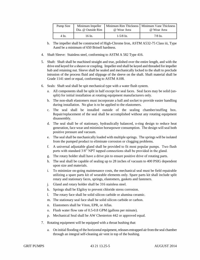
GRIT PUMPS 43 21 13.25-5 AUGUST 2014
Pump Size Minimum Impeller
Dia. @ Outside Rim
Minimum Rim Thickness
@ Wear Area
Minimum Vane Thickness
@ Wear Area
4 In. 16 In. 1-5/8 In. 7/8 In.
b. The impeller shall be constructed of High-Chrome Iron, ASTM A532-75 Class iii, Type
Aand be a minimum of 650 Brinell hardness.
4. Shaft Sleeve: Stainless steel, conforming to ASTM A 582 Type 416.
5. Shaft: Shaft shall be machined straight and true, polished over the entire length, and with the
drive end keyed for a sheave or coupling. Impeller end shall be keyed and threaded for impeller
hub and retaining nut. Sleeve shall be sealed and mechanically locked to the shaft to preclude
intrusion of the process fluid and slippage of the sleeve on the shaft. Shaft material shall be
Grade 1141 steel or equal, conforming to ASTM A108.
6. Seals: Shaft seal shall be spit mechanical type with a water flush system.
a. All components shall be split in half except for seal faces. Seal faces may be solid (un-
split) for initial installation at rotating equipment manufacturers only.
b. The non-shaft elastomers must incorporate a ball and socket to provide easier handling
during installation. No glue is to be applied to the elastomers.
c. The seal shall be installed outside of the sealing chamber/stuffing box.
Repair/replacement of the seal shall be accomplished without any rotating equipment
disassembly.
d. The seal shall be of stationary, hydraulically balanced, o-ring design to reduce heat
generation, face wear and minimize horsepower consumption. The design will seal both
positive pressure and vacuum.
e. The seal shall be mechanically loaded with multiple springs. The springs will be isolated
from the pumped product to eliminate corrosion or clogging problems.
f. A universal adjustable gland shall be provided to fit most popular pumps. Two flush
ports with standard 3/8” NPT tapped connections shall be provided in the gland.
g. The rotary holder shall have a drive pin to ensure positive drive of rotating parts.
h. The seal shall be capable of sealing up to 28 inches of vacuum to 400 PSIG dependent
upon size and materials.
i. To minimize on-going maintenance costs, the mechanical seal must be field repairable
utilizing a spare parts kit of wearable elements only. Spare parts kit shall include split
rotary and stationary faces, springs, elastomers, gaskets and fasteners.
j. Gland and rotary holder shall be 316 stainless steel.
k. Springs shall be Elgiloy to prevent chloride stress corrosion.
l. The rotary face shall be solid silicon carbide or alumina ceramic.
m. The stationary seal face shall be solid silicon carbide or carbon.
n. Elastomers shall be Viton, EPR, or Aflas.
o. Flush water flow rate of 0.5-0.8 GPM (gallons per minute).
p. Mechanical Seal shall be AW Chesterton 442 or approved equal.
7. Rotating equipment will be equipped with a throat bushing that:
a. On initial flooding of the horizontal equipment, releases entrapped air from the seal chamber
through an integral self-cleaning air vent in top of the bushing.

GRIT PUMPS 43 21 13.25-6 AUGUST 2014
b. Creates fluid exchange and improved circulation in the seal chamber that reduces frictional
heat accumulation around the mechanical seal.
c. Positions particulate matter/contaminants for removal by conveying them from the bore to
the shaft by means of an integral machined spiral.
d. Removes particulate matter/contaminants from the seal chamber to the impeller for
expulsion.
e. Reduces or eliminates flush water requirements depending on pumped fluid.
f. Bushing shall be 316 stainless steel, 416 stainless steel, bronze, glass filled PTFE, carbon
graphite filled PTFE or titanium, as recommended by the manufacturer.
f. Throat bushing will be a Spiral Tractm
Version D, Type A as provided by AW Chesterton
USA or EnviroSeal Ltd of Nova Scotia, Canada.
8. Bearings: Anti-friction, grease or oil lubricated with a minimum B-10 life of 100,000 hours.
9. Baseplate: Structural steel or cast iron provided with means for collecting and draining oil and
water.
10. Furnish with 125 pound ANSI connection flanges and handhole.
11. Coupling:
a. Shall have a minimum 1.5 service factor based on the drive rated horsepower and protected
with an OSHA approved guard.
b. Belts and sheaves shall be furnished and installed to drive the pump at the speed necessary
to meet the rated design conditions.
c. Belt guard must be able to be removed by one person and be hinged for viewing of the
belts.
12. Anchor bolts and inserts shall be furnished under this Section and shall be sized and installed in
accordance with the manufacturer's recommendations. The anchor bolts shall be Type 316
stainless steel.
13. Brass or stainless steel nameplates giving the manufacturer's model and serial number, rated
capacity, head, speed and all other pertinent data shall be attached to the pump.
B. Motors
1. Motors shall conform to the requirements of Section 26 05 83, Electric Motors.
2. TEFC, solid shaft, ball bearing type.
3. Motors shall be in accordance with all current applicable standards of NEMA, IEEE, AFBMA,
NEC, and ANSI.
4. Motors shall be normal starting torque, normal slip, squirrel cage induction type.
5. Motors shall be capable of carrying full load current continuously without injurious temperature
rise in an ambient temperature of 50C.
6. Motors shall be provided with a service factor of 1.15.
GRIT PUMPS 43 21 13.25-7 AUGUST 2014
7. Motors shall be of sufficient size so that there will be no overload on the motor above rated
nameplate horsepower under any condition of operation from shut-off to zero head, unless
otherwise specifically permitted in this Section.
8. Motor thrust bearings shall be adequate to carry continuous thrust loads under all conditions of
pump operation from zero head to shut-off.
9. Locked rotor currents shall be as specified in NEMA standards.
10. Lubrication may be grease or oil type.
C. Power Transmission
1. Pump shall be driven by the motor through a sheave and belt configuration, utilizing
adjustable ratio sheaves. Belt and sheave system shall have a 1.5 safety factor based on the
motor nameplate horsepower.
2. Drive components shall be enclosed in an OSHA-compliant protective steel guard. Guard
shall have removable components allowing access to the belts and sheaves for maintenance.
3. The pump manufacturer shall provide a common pump and motor base, constructed of
minimum 3/8-inch thick fabricated steel, suitably reinforced to support the full weight of the
pump, motor, belt drive, and guards.
a. The pump manufacturer shall furnish and install a separate, adjustable motor base with
hand wheel adjustment so that the motor can be easily moved for V-belt tensioning and
adjustment, TB Woods type MC 3B, modified with a welded steel gusset, or equal.
b. The pump manufacturer shall supply and install belts and sheaves to drive the pump at
the speed necessary to meet the rated conditions.
i. The drive shall be of the stationary control variable speed TB Woods type “SVS” or
equal, which allows a speed change by means of an adjustment to the motor sheave
when the drive is not in operation.
c. An approved fiberglass or thermoplastic belt guard shall be provided to safely enclose the
belt drive. If metal guards are furnished, they shall be of all Type 316 stainless steel
construction with suitable lifting eyes and handles to aid in removal.
D. Instrumentation and Controls
1. Local Control Stations are specified and detailed in Specification Section 40 90 00.
2. Programming of the PLC for operation of the Grit Pumps is the responsibility of the Grit
Removal Equipment manufacturer. The operation of the Grit Pumps and associated
equipment shall be as detailed in Specification Section 40 90 00.
3. The Grit Pump manufacturer must coordinate with the Grit Removal Equipment manufacturer
and the Systems Integrator during programming development, pre-commissioning testing and
startup to deliver an approved working system.
2.04 TOOLS, SPARE PARTS AND MAINTENANCE MATERIALS
A. Each pump shall be furnished with the following:
1. One shaft sleeve
GRIT PUMPS 43 21 13.25-8 AUGUST 2014
2. One Suction Piece
3. One Set of V-Belts
4. One impeller nut or bolt.
5. Mechanical Seal Spare Parts Kit.
6. Special tools required for maintenance or operation.
B. Spare parts shall be packed in sturdy containers with clear indelible identification markings and
shall be stored in a dry, warm location until transferred to the CITY at the conclusion of the
Project.
C. From shaft end, Pumps M-B-51-0006 and M-B-51-0007 are clockwise and M-B-51-0008 is
counter clockwise rotation. CONTRACTOR shall provide spare parts for each pump such that it is
suited for the respective pump’s rotation.
2.05 SURFACE PREPARATION AND PAINTING
A. Motors, drives and appurtenances shall receive shop primer and shop coating conforming to
requirements of Section 09 91 00, Painting. If any damage to the paint system occurs, the
equipment shall be repainted as directed by the CITY.
B. Surface preparation and painting shall conform to the requirements of Section 09 91 00, Painting.
C. All gears, bearing surfaces, machined surfaces and other surfaces which are to remain unpainted
shall receive a heavy application of grease or other rust-resistant coating. This coating shall be
maintained during storage and until the equipment is placed into operation.
D. Contractor shall certify, in writing, that the shop primer and shop coating system is compatible
with the finish coating system in accordance with Section 09 91 00, Painting.
PART 3 - EXECUTION
3.01 INSTALLATION
A. Installation shall be in complete accordance with manufacturer's instructions and
recommendations.
B. Installing Pump Bases
1. All pumping units shall be installed on concrete bases and secured with anchor bolts in
accordance with the manufacturer's recommendations and as shown.
2. The concrete bases shall be poured up to 1-inch below the metal bases or soleplates.
3. Concrete work and grout are in Division 03, Concrete.
4. The base with the equipment mounted thereon, or the soleplate, shall then be accurately
shimmed to grade and the spaces between filled with an approved nonshrink grout.
5. After the grout has reached its initial set, exposed edges shall be cut back 1/2-inch and the edges
neatly finished with 1 to 2 cement mortar.
GRIT PUMPS 43 21 13.25-9 AUGUST 2014
6. Where channel baseplates are used, the void inside the channel shall be filled with nonshrink
mortar and the open ends plastered with 1 to 2 cement mortar.
C. Neatly placed 1-inch hard copper pipe shall be provided on each pump to convey leakage to
nearest drainage inlet.
D. Installation shall include furnishing and applying an initial supply of grease and oil, recommended
by the manufacturer.
E. Support piping independent of pump.
F. Check and align pump, motor and shafting.
3.02 START-UP AND TEST
A. Verify that structures, pipes and equipment are compatible.
B. Make adjustments required to place system in proper operating condition.
C. Furnish the services of a factory representative for one, 8 hour day during the installation phase of
the equipment. The factory representative shall have full knowledge and experience in the
installation of the type of equipment being installed.
D. Furnish the services of a factory representative for one, 8 hour day who has complete knowledge
of proper operation start-up procedure and maintenance requirements to inspect the final
installation and supervise a test run of the equipment.
E. Furnish the services of a factory representative who has complete knowledge of the operational
and maintenance requirements of the system. The factory representative shall instruct the CITY's
personnel in the proper operation of the equipment in accordance with Section 01 79 00.
F. Substituting a service representative from the local representative organization is not acceptable
unless approved by the CITY, based on documented training on the subject equipment. Decision
of the CITY is final.
G. The schedule of all services provided shall be in accordance with a schedule approved by the
CITY.
H. A manufacturer's representative shall check and approve the installation before operation.
Manufacturer’s representative shall test operate the system in the presence of the CITY and verify
that the pumps conform to requirements, and instruct plant personnel on care and maintenance of
the equipment. He shall revisit the jobsite as often as necessary until all trouble is corrected and
the installation is entirely satisfactory.
I. Peak-to-peak vibration amplitude for field testing shall not exceed 3.0 mils in all directions and at
all frequencies when measured at each pump and driver bearing housing.
3.03 MANUFACTURER’S SERVICES
A. A factory trained representative shall be provided for installation supervision, start-up and test
services, and operation and maintenance personnel training services.
B. The representative shall make four visits to the site

GRIT PUMPS 43 21 13.25-10 AUGUST 2014
1. The first visit shall be for assistance in the installation of equipment at Grit Pumps M-B-51-
0006, M-B-51-0007 and M-B-51-0008.
2. The second visit shall be for checking the completed installation and start-up of the system at
Grit Pumps M-B-51-0006, M-B-51-0007 and M-B-51-0008.
3. The third and fourth visits shall be as described under Section 01 79 00, Instruction of
Operations and Maintenance Personnel.
C. All costs, including travel, lodging, meals and incidentals shall be considered as included in the
CONTRACTORS’s lump sum bid price.
3.04 CLEANING
Prior to the acceptance of the work of this section, thoroughly clean all installed materials, equipment
and related areas in accordance with the requirements of Section 01 74 00 of these Specifications.
END OF SECTION 43 21 13.25

INFLUENT SAMPLE PUMP 43 21 39.16-1 JULY 2013
SECTION 43 21 39.16
INFLUENT SAMPLE PUMP
PART 1 - GENERAL
1.01 SCOPE
A. Provide pump(s) as described herein. Install equipment in accordance with the
manufacturer's instructions and these Specifications.
B. The pump(s) shall be totally submersible and electric driven.
1.02 SUBMITTALS
A. Submit shop drawings and engineering data in accordance with the requirements of Section
01 33 00 of these Specifications. Indicate the following:
1. Manufacturer's name, pump size and model number and description bulletin of the pump
furnished.
2. Outline dimension of the pump.
3. Pump characteristic curves showing head, capacity, horsepower, minimum head, rated
and shut-off conditions.
4. Motor manufacturer's name, motor horsepower, rpm, frame size and motor descriptive
information. Include motor features and data sheet.
B. Operation and maintenance manuals shall be furnished in accordance with the requirements
of Section 01 78 23 of these Specifications. Include address and telephone numbers
pertinent to nearest service locations and for ordering parts.
1.03 STORAGE AND PROTECTION
Pump(s) shall be stored and protected in accordance with the requirements of Section 01 60 00 of
these Specifications.
1.04 QUALITY ASSURANCE
Provide a manufacturer's written certification to the CITY that furnished equipment complies
with all applicable requirements of these Specifications.
1.05 WARRANTY
Refer to Section 01 78 36.
PART 2 - PRODUCTS
2.01 ACCEPTABLE MANUFACTURERS

INFLUENT SAMPLE PUMP 43 21 39.16-2 JULY 2013
Provide pump(s) equal to EBARA Model 50 DVU or Approved Equal.
2.02 OPERATING REQUIREMENTS
A. Pump(s) shall operate in domestic wastewater having a pH range of 6.5 to 8.5.
B. Capacity: 5-30 gpm
C. RPM:1,800
D. TDH, feet: 15
2.03 MATERIALS AND CONSTRUCTION
A. Furnish cast iron motor and terminal housing.
B. Provide stainless steel motor shaft sealed by a double mechanical seal in a separate oil filled
chamber.
C. Provide built-in, automatic, thermal protection that prevents failure caused by clogging,
overloading, dry running and voltage drop.
D. Provide cast iron impeller and casing with large passageway to prevent clogging. The
impeller shall have a minimum Brinell hardness of 200.
E. Provide rubber-lined suction cover and stainless steel fasteners.
F. Provide float switch assembled to pump for on-off operation.
2.04 MOTOR
A. Data
1. RPM: 1,800.
2. Horsepower: 1.
3. Power: 3 Phase, 208/230/460V, 60 Hz.
4. Duty: Continuous.
B. Furnish motor in an air filled housing with permanently lubricated sealed bearings.
2.05 CONTROLS
A. Pump is for continuous run, sample pump use and manual on-off from the Influent Pump
Station control panel (INF-LCP).
B. Float switch described in 2.03 F serves to stop the pump should water level drop and permits
the pump to run with adequate water level.
2.06 CABLE
A. Provide cable suitable for submersible pump applications with cable code or legend
embossed on the cable.
INFLUENT SAMPLE PUMP 43 21 39.16-3 JULY 2013
B. Size cable to conform to NEC specifications for pump and service intended.
C. Provide pump with 33 feet of cable.
D. Furnish cable installed to pump such that cable stress is relieved and
watertight/moisture-tight seal is obtained.
2.07 SHOP PAINTING
All materials specified under this section shall be shop primed as part of the work under this
section. Surface preparation and paint shall be as specified in Section 09 91 00 of these
Specifications.
PART 3 - EXECUTION
3.01 INSTALLATION
Install pump to piping and in the location shown on the Drawings.
3.02 PAINTING
All shop primed surfaces shall be cleaned and painted as specified in Section 09 91 00 of these
Specifications.
END OF SECTION 43 21 39.16

INFLUENT SAMPLE PUMP 43 21 39.16-4 JULY 2013
THIS PAGE INTENTIONALLY LEFT BLANK

GRIT REMOVAL EQUIPMENT 46 23 54-1 JULY 2013
SECTION 46 23 54
GRIT REMOVAL EQUIPMENT
PART 1 - GENERAL
1.01 SCOPE
A. The work required under this Section consists of furnishing and installing all equipment and
materials required to provide the plant grit removal equipment, as shown on the Drawings
and/or as herein specified.
B. The plant grit removal equipment shall be a complete grit removal, washing and dewatering
system consisting of, but not limited to, the following major system components and\or
assemblies:
1. Two 12-foot diameter Grit Concentrator units (Headcell) with inlet chute, supports and
connections (M-B-03-0005, M-B-03-0006).
2. Two grit washing\classification units (Grit Vortex Separators, M-B-03-0007 and M-B-
03-0008).
3. Two grit snail grit dewatering\escalator units (M-B-03-0009 and M-B-03-0010).
4. Three grit slurry pumps – centrifugal with recessed impeller (M-B-51-0006, M-B-51-
0007, and M-B-51-0008). Refer to Spec Section 43 21 13.25-1.
5. One system control panel (M-B-49-0004) and two grit dewatering conveyor electrical
panels (M-B-35-0008 and M-B-35-0009)
6. Two Headcell influent sluice gates (M-B-23-0019 and M-B-23-0020) and one main
influent channel sluice gate (M-B-23-0039). Refer to Spec Section 40 20 10.
7. Two 1-inch flow meters and associated valves on the NPW fluidizing lines for the grit
concentrator units.
8. One rotameter, three pressure gages and two electrically operated solenoid valves for
each vortex separator/ grit dewatering conveyor units.
9. One grit dewatering/conveyor supply water rotameter for each dewatering/conveyor unit.
10. Two grit dewatering/conveyor, flexible reinforced rubber discharge chutes.
C. The CONTRACTOR shall provide and install all components, bolts, gaskets, fasteners, anchor
bolts, and electrical equipment required for a complete operating system as herein specified
and\or shown on the Drawings.
D. The basis of design for the grit removal equipment described herein is Hydro International, Inc.
The CONTRACTOR will be allowed to submit an alternate system as provided for in Section 00
41 03A, Material and Equipment Offerings. The CONTRACTOR proposing alternate system
shall be responsible for all costs for the alternate system including but not limit to, redesign
engineering and construction, including all costs to the Part 2, 3, and 4 CONTRACTORS.
1.02 RELATED SECTION
A. Slide Gate - 40 20 10
B. Grit Slurry Pump – 43 21 13.25-1

GRIT REMOVAL EQUIPMENT 46 23 54-2 JULY 2013
C. Control Panel, Controls and Instrumentation – 40 95 13
D. Painting – 09 91 00
1.03 DESIGN REQUIREMENTS
A. Each Settleable Solids Concentrator (Headcell) shall be designed and be capable of meeting
the below criteria when receiving flows from screened domestic wastewater. Each Settleable
Solids Concentrator shall have a hydraulic capacity of 17.5 mgd.
Plant Influent
Flow (mgd)
Number of
Units
Flow per One
Headcell (mgd) 95% Grit Removal of
the Below Size Particle
(micron) @2.65 s.g.
Headloss
(inches)
35 2 17.5 150 12”
15 2 7.5 80 3”
15 1 15 125 9”
B. The Grit Concentrator unit shall be placed in a concrete tank and receive the incoming
screened flow. The Grit Concentrator shall provide sufficient surface area to remove the
specified grit particles from the specified peak flow and concentrate the grit in a sump at the
bottom of the unit. The de-gritted effluent from the Grit Concentrator shall be weir
discharged as shown on the drawings.
C. The Grit Concentrator shall be all-hydraulic, self-activating and shall not require internal
moving parts.
D. The Grit Pump shall convey the concentrated grit slurry from the underflow of the Grit
Concentrator to the Grit Washing unit.
E. The Grit Washing unit shall receive the underflow from the Grit Concentrator. The unit shall
be mounted above and discharge the concentrated and washed grit slurry to the Grit
Dewatering Escalator. The de-gritted overflow shall be discharged upstream of the Grit
Concentrator.
F. The Grit Dewatering Escalator shall receive the underflow from the Grit Washing unit and
allow the washed grit to settle in its integral clarifier. A slow moving belt shall carry the grit
to the point of discharge allowing it to dewater during transport. The washed and dewatered
grit shall be discharged to a dewatered grit receptacle with a drain supplied by OTHERS.
G. The de-gritted overflow shall be discharged upstream of the primary grit removal equipment.
H. The Grit Removal system and all appurtenances shall be supplied by a single supplier.
I. The system to be furnished hereunder shall be made by a manufacturer regularly engaged in
such work and who has furnished similar installations and had them in successful and
continuous operation for a minimum period of ten years.
J. Data on performance testing, service history and operation of existing installations using the
submitted equipment shall be made available to the CITY, upon request, for use in
determining that the Grit Removal System offered meets the intent of the Contract,
performance requirements and criteria stated in these Specifications.

GRIT REMOVAL EQUIPMENT 46 23 54-3 JULY 2013
K. The Grit Concentrator technology shall be designed utilizing Computational Fluid Dynamics
(CFD) and field data to verify its flow regime, headloss and grit removal characteristics.
Upon request, data on the computation methods used and generic simulation results shall be
made available to the CITY.
L. Grit screw classifiers, grasshoppers, reciprocating rakes and similar type of units shall not be
accepted.
M. Units using Apex valves shall not be accepted.
N. Equipment using paddles or air to supplement or induce a vortex shall not be accepted.
O. All parts of the equipment shall be amply proportioned for all stresses which may occur
during operation and for any additional stresses which may occur during fabrication, erection
and starting.
P. All welding shall comply to the most current standards of the American Welding Society
(AWS).
Q. Stainless steel 304 material and finishes shall comply with the following:
1. Plate and sheet ASTM A 167; ASTM A 240
2. Bar ASTM A 276; ASTM A 479
3. Tube ASTM A 312
4. Exterior finishes shall be acid washed to a uniform finish.
1.04 SUBMITTALS
A. Submit shop drawings in accordance with the requirements of Section 01 33 00 of these
Specifications. Include dimensional drawings of panels, panel layouts and BOM, full
component data, and detailed wiring diagrams.
B. Operation and maintenance manuals shall be furnished in accordance with the requirements
of Section 01 78 23 of these Specifications.
1.05 STORAGE AND PROTECTION
A. Equipment shall be delivered, stored and protected in accordance with the manufacturer's
instructions and the requirements of Section 01 60 00 of these Specifications.
B. The CONTRACTOR shall obtain and provide with the shop drawings and with the shipping
bill of materials, instructions for storage of all equipment supplied including equipment
exercising instructions, humidity and temperature control instructions which shall be
followed by the CONTRACTOR.
1.06 QUALITY ASSURANCE
The manufacturer shall provide the CITY with written certification that all equipment furnished
complies with all applicable requirements of these Specifications.
1.07 WARRANTY
Refer to Section 01 78 36.
PART 2 - PRODUCTS

GRIT REMOVAL EQUIPMENT 46 23 54-4 JULY 2013
2.01 ACCEPTABLE MANUFACTURERS
The base bid price shall be based on equipment offered and manufactured by Hydro International.
The grit concentrator equipment shall be Eutek Headcell System as manufactured by Hydro
International or pre-approved equal. The remaining grit equipment shall be Eutek System as
manufactured by Hydro International or pre-approved equal. The CONTRACTOR shall provide
a base bid price for the work based on the base bid manufacturer and may include
additive/deductive prices for proposed alternates in Section 00 41 03A. Alternate suppliers shall
be required to meet the requirements of the contract documents and shall provide either a
certification with their price to the CONTRACTOR at the time of bid stating that they fully
comply with the contract documents, or a detailed list of exceptions to be submitted with the bid
in addition to the items required by paragraph 1.02. In addition, the additive/deductive price shall
include all modifications required to accommodate the alternate design. Award will be based on
the base bid. If CONTRACTOR proposes an alternate, he will need to comply with the
requirements of Section 01 25 00 and list all deviations from this specification. Selection of an
Alternate manufacturer will be based on a review, following bidding, of the exceptions to the
specifications and proposed cost change, including the cost of modifying the design and building,
piping, electrical, instrumentation and controls, and any other ancillary items required to
accommodate the alternate design. CONTRACTOR must assume all schedule risk from use of an
alternate manufacturer. Revised design must be stamped by an Engineer registered in the state of
Ohio and submitted for review. The CONTRACTOR shall include all additional costs in the
alternate price.
2.02 GRIT CONCENTRATORS M-B-03-0005, M-B-03-0006 (HEADCELL)
A. Two grit concentrator units M-B-03-0005 and M-B-03-0006 shall be furnished. The grit
concentrator units shall meet the below design criteria:
1. Number of Units: 2
2. Size: 12’ diameter
3. Number of Trays per Unit: 6
4. Surface Area/Unit: 678 ft2
5. Peak Loading Rate: 18.4 gpm/ft2
6. Performance: 95% removal of all grit
(specific gravity 2.65) ≥ 80 microns at Average Flow
7. Performance: 95% removal of all grit
(specific gravity 2.65) ≥ 150 microns at Peak Flow
8. Average Flow/Unit: 7.5 mgd with no more than 3" headloss
9. Peak Flow/Unit: 17.5 mgd with 12" headloss
10. Influent Duct Opening: 2’8” width x 7’4” height
11. Discharge: Weir
12. Underflow Connection: 6"
13. NPW Connection: 1" NPT
14. Materials of Construction: 304SS Support structure/duct/underflow; LDPE trays
B. The concentrators shall each consist of a stack of six, 12-foot diameter nested trays having a
GRIT REMOVAL EQUIPMENT 46 23 54-5 JULY 2013
minimum combined total of 1,356 square feet of settling surface. The concentrator shall have
a peak loading rate at 18.4 gpm\ft2. No exceptions shall be allowed.
C. The concentrator shall be designed to be a flow-driven all-hydraulic system that consists of
self cleaning, corrosion resistant, non-metallic trays supported in a frame. The concentrator
shall not have or require any moving parts to settle or enhance grit separation and settling.
D. Concentrator trays shall have a nominal diameter of 144 inches. Flow passages shall be self
cleaning and free of any sharp projections, burrs, flashing, sharp projections and fittings. The
tray design shall prevent accumulation of solids and stringy or fibrous materials. Trays shall
be constructed of LDPE having a minimum thickness of 1\4 inch.
E. The concentrator shall be furnished with a 304 stainless steel support frame. The stainless
steel materials used to fabricate the frame shall have a minimum thickness of 14 gauge. All
weldments shall be ground smooth to the touch. Fasteners and\or hardware used in
construction of the frame shall be 304 stainless steel. The frame shall be provided with pre-
drilled baseplates for enabling the CONTRACTOR to secure the frame support members to
the concrete floor\base slab. The trays shall be mechanically secured and fixed to the support
frame in such manner that changes in flow shall not enable the trays to move or rack from
their installed locations. The design of the frame and installation of the trays shall permit the
CONTRACTOR to form a circular grit collection sump beneath the installed frame\tray
assembly per manufacture instructions and dimensions. The manufacturer shall provide
anchor bolt requirements and placement drawings\data to the CONTRACTOR. The
CONTRACTOR shall utilize the manufacturer’s anchor bolts requirements for anchorage and
utilize 304 stainless steel anchor bolts to secure the frame\tray system.
F. The concentrator shall receive flow from a concrete influent channel. Flow from the channel
into the concentrator shall be via a manufacturer provided inlet. The influent duct of the
concentrator unit shall be fabricated from 14 gage SS. The inlet entry shall be flanged to
permit anchorage by CONTRACTOR provided anchor bolts to the concrete influent channel.
The design of the concentrator inlet shall proportionally split the flow to the individual trays.
The inlet shall be mechanically connected to each inlet tray to provide a positive, rigid
connection. The inlet shall be rigid and self supporting between the concrete channel and the
frame. The inlet assembly shall not require any intermediate supports and shall be totally
supported by its connection to the concrete influent channel and the concentrator frame.
G. All pipe flanges shall conform to ANSI B16.1 bolt patterns.
2.03 GRIT VORTEX SEPARATOR UNITS - M-B-03-0007 AND M-B-03-0008
A. Two Grit Vortex Separator units M-B-03-0007 and M-B-03-0008 shall be furnished. The
units shall be a dynamic type separator and be designed to operate continuously with pumped
underflows from the Headcell Concentrators.
B. The grit vortex separator unit shall meet the following criteria:
1. Number of Units: 2
2. Size:32" diameter
3. Performance: 95% removal of all grit
(specific gravity 2.65) ≥ 75 microns in the flow range
4. Influent Solids Concentration: ≤ 1.0%
5. Design Flow/Unit: 300 gpm with 15’ of headloss

GRIT REMOVAL EQUIPMENT 46 23 54-6 JULY 2013
6. Minimum Flow/Unit: 280 gpm with 13’ of headloss
7. Maximum Flow/Unit: 400 gpm with 26.6’ of headloss
8. Influent Connection: 6” flanged pipe
9. Effluent Connection: 8” flanged pipe
10. Underflow Connection: 3” NPT pipe
11. NPW Connection: 1.5” NPT
12. Material of Construction: 304 SS
13. Operation: Continuous / Intermittent minimum 10-15 minutes
C. Each unit shall have a maximum headloss of 15 feet at 300 gpm. Each unit shall achieve a
95% removal efficiency of 75 micron at 300 gpm and larger grit having a specific gravity of
2.6 at flows ranging from 280 gpm to 400 gpm.
D. The grit vortex separator unit shall be 32 inches in diameter and have dished and flanged
heads manufactured from 304 stainless steel having a minimum thickness of 1\4 inch. These
vessel walls shall be 3/16 inch thick. The removable top access shall have a minimum
diameter of 18 inches. Any internal elements shall be removable from inside the units.
E. The units shall be mounted above the Grit Dewatering Conveyor onto a free standing
supporting frame with three legs manufactured from 304 stainless steel materials. The frame
design and mounting of the grit vortex separator assemblies shall be arranged and located
such that maintenance has a minimum 18 inches clearance between the bottom of the grit
underflow pipes and the Dewatering Conveyor clarifier surface. The frame supports shall be
provided with pre-drilled baseplates for CONTRACTOR provided anchor bolts. Each vortex
separator unit shall be mounted directly on the clarifier of the grit dewatering conveyor unit
via support bars spanning the grit dewatering conveyor. The manufacturer shall provide the
CONTRACTOR with required anchor bolt sizes and anchor bolt location
templates\dimensions.
F. Each grit vortex separator unit shall have one 6-inch flanged inlet and one 8-inch flanged
outlet connection. Flanges shall be rotatable and conform to ANSI B16.1 bolt patterns for
125 pound drillings.
G. The system shall be designed to withstand a maximum 14.7 psig pressure at the influent of
the unit. The actual maximum pressure at inlet shall be no more than 14.7 psig. Grit
underflow from the grit vortex separator units shall be transported by gravity to the Grit
Dewatering Conveyor. The grit washing\classification units shall each be provided with a
hydraulic valve that assures delivery of a continuous flow of washed grit slurry to the
dewatering unit. The hydraulic valve shall have no mechanical or moving parts.
1. Each grit vortex separator unit shall include a Hydraulic Valve (HV) to deliver a
continuous flow at wash slurry to Grit Dewatering Conveyor located directly below. The
HV shall have no mechanical or moving parts.
2. The grit vortex separator unit shall have a single 1 ½ inch NPT pipe slab for connection
to plant NPW.
H. Each unit shall be provided with the following connections: One 1-1\2 inch grit underflow
connection; one 3-inch threaded drain connection; and one 1-1\2 inch threaded fluidizing
water connection for the hydraulic valve backwash. All threaded connection shall be NPT.
I. The grit washing\classification units shall be provided with the following equipment to

GRIT REMOVAL EQUIPMENT 46 23 54-7 JULY 2013
regulate and automate the water supply. Additional non-electrical gages and monitoring
devices are specified in Article 1.01 of this Specification. Unless size is stipulated, sizes shall
be by the manufacturer:
1. One (1) 1.5” bronze ball valve for main water supply shut off.
2. One (1) 1.5” bronze globe valve to regulate water flow to the HV.
3. One (1) 1.5” NEMA 4X brass solenoid valve to automate system water to the HV.
4. One (1) 1.5” NEMA 4X brass solenoid valve to automate system backwash water.
5. One (1) 0-100 psig pressure gauge to monitor the supply water delivery pressure.
6. One (1) 0-30 psig pressure gauge (Pd) to monitor the pressure in the grit slurry discharge
(underflow) line.
7. One (1) 0-30 psig pressure gauge (Pi) to measure the inlet pressure to the Grit Washing
unit.
8. Three (3) 1/4” bronze ball valves to isolate the pressure gauges.
9. One (1) 0-35 gpm SS flow meter.
J. The grit washing\classification unit shall be pre-piped to the limits shown on the Drawings.
K. Each Grit vortex separator unit shall be all-hydraulic with no moving parts within the unit.
The grit underflow from the Grit Washing units shall be transported by gravity to the Grit
Dewatering Conveyor unit. Fluidizing Water shall be continuously supplied to the Grit
Washing units.
2.04 GRIT DEWATERING CONVEYOR (M-B-03-0009 AND M-B-03-0010)
A. Two Grit Dewatering Conveyor Units – M-B-03-0009 and M-B-03-0010 shall be furnished.
The grit dewatering conveyor unit shall meet the following criteria:
1. Number of Units: 2
2. Maximum Grit Load: 2.0 cy/hr
3. Performance: 95% removal of all grit (specific gravity 2.65) ≥ 75 microns
with less than 15% volatile solids and greater than 60% total solids
4. Belt Width: 12"
5. Clarifier size: 60" square
6. Min. Free Water Surface area: 17.3 ft2
7. Motor: 0.33 hp, TENV
8. Overflow Connection: 6" flanged pipe
9. Drain Connection: 3" flanged pipe
10.NPW Connection: 1" NPT
11. Body Material: 304 SS
12. Belt Material: Neoprene Rubber, re-enforced with Polyester and Aluminum
B. The grit dewatering conveyor unit shall have the dewatering capacity of 2.0 cubic yards per
hour. The unit shall be provided with an integral clarifier having a minimum of 17.3 sq. ft. of
free water surface area and walls having a minimum slope of 45 degrees from the horizontal.
GRIT REMOVAL EQUIPMENT 46 23 54-8 JULY 2013
The clarifier shall be provided with fitted with an overflow weir having a minimum length of
60 inches. Grit clarifier unit shall have 6-inch freeboard. A 6-inch flanged overflow pipe
shall be provided.
C. Unless otherwise specified, the grit dewatering conveyor unit shall be manufactured from 10
gage SS.
D. Each Grit Dewatering Conveyor unit shall is designed to capture and dewater concentrated,
washed grit slurry from the Grit Washing unit.
E. Each Grit Dewatering Conveyor unit clarifier shall be designed based on a settling rate not to
exceed 3.2 gpm/ft2.
F. The tail roll mechanism shall be self-cleaning. As the belt rotates with the tailroll at the
bottom of the unit the belt cleats shall lift from the belt to provide a gap of at least a 1-inch.
The Grit Dewatering Conveyor unit belt shall be provided with 2” openings to allow transfer
of fine solids internal to the belt to the underside of each cleat. The tailroll shall be fitted
with a scraper, which shall also function as an internal belt scraper.
G. Each Grit Dewatering Conveyor shall be provided with an integral square clarifier which
shall provide at least 3 inches of freeboard.
H. The housing for Each Grit Dewatering Conveyor belt shall be fitted under the clarifier. The
housing for the Grit Dewatering Conveyor belt shall be stainless steel with urethane bonded
to the internal surfaces. The belt housing shall be inclined at 30 degrees.
I. Each belt housing shall be provided with clean out plates and one (1) flanged drain. 3-inch
flange shall be supplied on the grit dewatering conveyor drain connection.
J. Each Grit Dewatering Escalator unit shall be supplied with a belt made of 1/8 inch x 1/32
inch two-ply polyester reinforced continuous conductor belting. The belt cleats shall be 3-
3/8” X 4-9/16” of molded 60 Durometer neoprene and aluminum reinforced and shall be
vulcanized on the belt. The cleats shall attach to the belt with minimum 5/32 inch thick
neoprene hinges.
K. Each Grit Dewatering Escalator units shall be provided with a 9-3/4 inch diameter lagged
headroll. The headroll shall be adjustable to allow take-up of slack in the Grit Dewatering
Escalator belt. Adjustment of the headroll shall not affect the headroll retainer plate, scraper,
or drive unit.
L. Each Grit Dewatering Escalator unit shall be provided with a headroll scraper having 1/4 inch
thick high density polyethylene (HDPE) contact surfaces with a 1/4 inch thick HDPE retainer
plate. Both retainer plate and scraper shall be loaded to keep belt cleats closed tightly around
the headroll during operation.
M. Each Grit Dewatering Escalator unit is provided with a tailroll designed to mount internally
to the unit belt housing with external sealed bearings.
N. Each Grit Dewatering Escalator unit support structure shall be as shown on the general
arrangement drawing and anchored to a stable base.
O. Each Grit Dewatering Escalator unit shall be supplied with a factory installed rinse bar
system. The system shall include:
1. Two spray bars located above the belt and below the clarifier liquid level to enhance grit
washing.
2. One spray bar located at the bottom of the clarifier as a tailroll area rinse.

GRIT REMOVAL EQUIPMENT 46 23 54-9 JULY 2013
P. Each Grit Dewatering Escalator shall be provided with a drive unit consisting of the motor
and the helical gear reducer, mounted as a single integrated unit. All Bearings shall be anti-
friction, ball, or roller type bearings.
Q. Each motor shall be 3 phase, 460 VAC, 60 Hz, NEMA Design B, TENV enclosure.
R. Each helical gear reducer shall have hardened alloy steel gears accurately cut to shape.
S. A mechanical torque-limiting clutch shall be mounted on the headroll gear assembly to
prevent an accidental overload of the drive unit and belt.
T. Each drive speed shall be adjusted by a variable speed drive housed in the control enclosure.
The belt speed shall be adjustable from 1-5 ft/min.
U. Each Grit Dewatering Escalator unit shall be supplied with the following valves:
1. One (1) 3” eccentric cast iron plug valve located on the unit drain.
2. One (1) 1” NEMA 4X brass solenoid valve to automate the water to the rinse bar system.
3. Two (2), 1” bronze ball valve to manually shut off flow to the rinse bar system and tail
roll shutoff.
4. One (1) 1” bronze globe valve to manually regulate flow to the tailroll spray bar.
5. One (1) ¾” bronze ball valves to manually shut off the top rinse bars.
6. One (1) 1-10 gpm acrylic flow meter.
2.05 GRIT SYSTEM UTILITY REQUIREMENTS
A. The below continuous water usage requirements and pressures shall be considered the
maximum demands.
1. Each Grit Concentrator Unit (Headcell): 20 gpm continuous at minimum 50 psig
(fluidizing)
2. Each Grit Vortex Separator Unit (Slurry Cup): 30 gpm continuous at 50 psig ±5 psi.
3. Each Grit Dewatering Conveyor Unit (Grit Snail): 10 gpm continuous at 50 psig ±5 psi.
B. The below intermittent water usage requirements and pressures in addition to the continuous
demand shall be considered the maximum intermittent demands. The total intermittent water
usage shall be: Grit Vortex Separator unit (Slurry Cup) 47 gpm at 50 psig, ±5 psi, for 1-2
minutes every 2-4 hours.
C. The system shall require 480 VAC, three phase electrical service connections to operate.
2.06 CONTROL PANEL AND CONTROLS AND INSTRUMENTATION
A. The control panel shall be provided by the manufacturer for CONTRACTOR installation and
connections. The panel shall be freestanding, floor mounted, 304 stainless steel NEMA 4X
construction. Electrical VFD panels can be wall mounted. The panel shall contain all variable
frequency drives (escalator), logic, controllers and components to start\stop all equipment and
completely control the grit system. Control panel enclosure and components shall meet the
requirements of Section 40 95 13 of these Specifications. Comply with Division 26
specifications for wiring, motors, VFDs, control devices, etc. Comply with Section 40 94 43
for PLCs. All panels shall comply with UL 508A. Grit concentrator units require no controls.
B. VFD Panel shall adhere to the following specifications:

GRIT REMOVAL EQUIPMENT 46 23 54-10 JULY 2013
1. Enclosure Rating: NEMA 4X
2. Material:3 04SS
3. Voltage: 480 Volt
4. Phase: 3 Phase
5. Frequency: 60 Hz
6. Load: 15 Amp
C. Electrical panels containing VFDs shall be separate from PLC control panel. Each electrical
panel shall have a door-mounted lockable breaker/switch for isolation. Electrical panels shall
have a door-mounted Human Interface Module (HIM) for the VFD, allowing access to
control functions without having to open the panel.
D. The Control panel shall contain all switches, indicator lights, and other components necessary
to operate the following equipment:
1. One (1) Grit Washing unit
2. One (1) Grit Dewatering Escalator
E. Control panel will be supplied to provide a PLC Control System which will process all input
and output functions and logic for both panels, and provide outputs to three (3) Grit Pump
starters located in the MCC.
F. Electrical control panel shall be supplied with a Transformer with 480 volt primary winding
and 120 volt secondary winding with fused secondary.
G. The control panel shall be supplied with applicable Allen Bradley Control Logix PLC which
will control all grit vortex separators and grit dewatering conveyor functions.
H. The PLC shall be provided with Ethernet Communications Module for remote SCADA
monitoring.
I. Each panel door layout shall include the following items:
1. Front panel mounted combination main disconnect switch and circuit breaker (Electrical
panel)
2. Back lit, push-to-test Power On indicating light (Electrical panel)
3. System three position HOA switch
4. System Emergency Stop push button; Assemble in individual enclosures for field
placement at each unit.
5. System Alarm Reset push button
6. Grit Separation three position HOA switch
7. Grit Separation supply water three position HOA switch.
8. Grit Separation backwash water valve three position HOA switch
9. Grit Separation auxiliary backwash pushbutton
10. Grit Separation RUNNING indicating light
11. Grit Separation SUPPLY OPEN light
12. Grit Separation BACKWASH OPEN light

GRIT REMOVAL EQUIPMENT 46 23 54-11 JULY 2013
13. Grit Separation BLOWDOWN light
14. Grit Separation WET/DRY/REMOTE three position switch
15. SYSTEM BLOWDOWN three position HOA switch
16. Grit Dewatering Escalator running light
17. Grit Dewatering Escalator three position HOA switch
18. Grit Dewatering Escalator fail indicating light
19. Grit Dewatering Escalator manual STOP push button
20. Grit Dewatering Escalator manual START push button
21. Grit Dewatering Escalator manual speed potentiometer
22. Grit Dewatering Escalator rinse water valve three position HOA switch
23. Grit Dewatering Escalator rinse water valve OPEN indicating light
24. Grit Dewatering Escalator FAIL RESET push button
25. Grit Dewatering Escalator LOCAL/REMOTE switch for escalator speed control
2.07 OPERATIONAL SEQUENCE
A. An external water supply shall be provided by the CONTRACTOR for manufacturer
controlled distribution to the grit vortex separator unit and the grit dewatering conveyor unit.
The manufacturer shall provide all components required for monitoring, distribution and
control of the water supply to the grit system.
B. The system shall be controlled to provide automatic or manual operation, manual starting and
stopping and system shut down when a fault is detected. Clarified plant water shall be
supplied and distributed between the Grit Concentrator fluidizing line, the Grit Washing unit
and the Grit Dewatering Escalator unit. Screened raw wastewater shall be gravity fed /
pumped into the Grit Concentrator continuously.
C. Grit Washing Unit
1. Grit slurry from the Grit Concentrator shall be pumped to the Grit Washing continuously
/ intermittently for 10-15 minutes.
2. During operation, a small volume of washed grit slurry shall continuously underflow
from the Grit Washing unit. Control of the grit slurry underflow rate is via the hydraulic
valve mounted on the bottom of the unit. A portion of the system water is continuously
introduced to the hydraulic valve.
3. Periodically, (typically twice per hour during heavy grit loads and typically once per hour
during light grit loads), a backwash sequence is initiated, by cycling solenoid valves,
which flushes the grit underflow gap inside the unit. Frequency and duration of
backwash cycles is adjustable.
4. Periodically, (typically once every 4 backwashes), a blowdown sequence is initiated to
flush accumulations of debris inside the unit. Blowdown is accomplished by stopping the
influent to the Grit Washing unit, cycling solenoid valves, and resuming operation.
Frequency and duration of blowdown cycles is adjustable.
D. Grit Dewatering Escalator Unit
1. The Grit Dewatering Escalator belt shall run whenever grit slurry is being transported to

GRIT REMOVAL EQUIPMENT 46 23 54-12 JULY 2013
the unit.
2. While the dewatering unit is running, water shall be directed to the tailroll self cleaning
mechanism and grit rinse system.
3. The belt speed shall be adjustable via a manual speed control potentiometer on the
control panel or by remote signal (4 20ma) from the plant SCADA system.
4. A motion sensor shall be installed on the side of the Grit Dewatering Escalator takeup
frame and shall detect movement of the headroll scraper arm. Lack of motion of the
headroll scraper arm shall indicate lack of belt movement, drive unit failure and/or
scraper arm overload. Lack of belt movement or scraper arm overload shall interrupt
signal from the motion sensor to the timer. If the motion sensor fails to reset the timer,
the Grit Dewatering Escalator shall stop and the failure light illuminate.
5. After a System Shut Down the Grit Dewatering Escalator shall continue to operate for a
pre-determined amount of time to allow for the removal and dewatering of all grit
accumulated in the clarifier. The off delay timer shall be adjustable from 0-60 minutes
with a typically delay off time of 15 minutes.
6. Grit Pumps: Selected pump will start with selected dewatering unit. PLC shall provide
I/O for all three grit pumps of the following: Discrete Inputs- In Remote, Run
Confirmation, In Service, Seal Water Flow, and Fault. Discrete Outputs- Pump Start.
2.08 SPARE PARTS
A. The manufacturer shall furnish the following spare parts for the system, packed for long term
storage in labeled containers. These parts shall be in addition to parts needed for testing:
1. One complete replacement escalator belt assembly.
2. One each type and pressure rated, pressure gauge.
PART 3 - EXECUTION
3.01 INSTALLATION
Installation shall be in accordance with the manufacturer's instructions and recommendations and
details as shown on the Drawings. Installation shall include furnishing any required oil and
grease in accordance with the manufacturer's recommendations. Anchor bolts shall be stainless
steel and shall be set by the CONTRACTOR in accordance with reviewed shop drawings.
3.02 INSPECTION AND TESTING
Following installation, the CONTRACTOR shall have the manufacturer demonstrate with
performance testing, to the CITY's satisfaction, that the completed system meets all the
requirements of this Specification, including, but not limited to, the specified removal efficiencies
at the designated flow rates. Should an independent testing lab be required to resolve any issues
concerning the function and\or ability of the system to perform as per requirements in this
Specification, costs for the latter shall be borne by the CONTRACTOR at no additional cost to
the CITY. The CONTRACTOR shall make, at CONTRACTOR's own expense, all necessary
changes, modifications, and/or adjustments required to assure satisfactory operation.
3.03 MANUFACTURER’S SERVICE
A. Furnish the services of a factory trained technician for 2, eight hour days during the
GRIT REMOVAL EQUIPMENT 46 23 54-13 JULY 2013
installation phase of the equipment. The factory representative shall have full knowledge and
experience in the installation of the type of equipment being installed.
B. Furnish the services of a factory trained technician, having complete knowledge of proper
operation start up procedure and maintenance requirements for 2, eight hour days, to inspect
the final installation and supervise a test run of the equipment.
C. Furnish the services of a factory representative, having complete knowledge of the
operational and maintenance requirements of the system for a minimum of four, four-hour
days for training the CITY’s personnel in operation and maintenance of the equipment, in
accordance with Section 01 79 00. This time shall be coordinated and scheduled with the
Plant Superintendant in writing and shall not be considered part of any previous time spent on
site.
3.04 FIELD PAINTING
All shop primed surfaces shall be cleaned and painted as specified in Section 09 91 00 of these
Specifications.
3.05 CLEANING
Prior to the acceptance of the work of this Section, thoroughly clean all installed materials,
equipment and related areas in accordance with Section 01 74 00 of these Specifications.
END OF SECTION 46 23 54

GRIT REMOVAL EQUIPMENT 46 23 54-14 JULY 2013
THIS PAGE INTENTIONALLY LEFT BLANK