investigation of stainless steel corrosion in ultrahigh-purity water and steam systems by surface...
TRANSCRIPT
Investigation of Stainless Steel Corrosionin Ultrahigh-Purity Water and Steam Systems
by Surface Analytical TechniquesXia Dong, Ronald G. Iacocca, Bethany L. Bustard, and Craig A. J. Kemp
(Submitted August 13, 2008; in revised form March 6, 2009)
Stainless steel pipes with different degrees of rouging and a Teflon�-coated rupture disc with severecorrosion were thoroughly investigated by combining multiple surface analytical techniques. The surfaceroughness and iron oxide layer thickness increase with increasing rouge severity, and the chromium oxidelayer coexists with the iron oxide layer in samples with various degrees of rouging. Unlike the rougingobserved for stainless steel pipes, the fast degradation of the rupture disc was caused by a crevicecorrosion environment created by perforations in the protective Teflon coating. This failure analysisclearly shows the highly corrosive nature of ultrapure water used in the manufacture of pharmaceuticalproducts, and demonstrates some of the unexpected corrosion mechanisms that can be encountered inthese environments.
Keywords corrosion, pharmaceutical, rouge, stainless steel,surface analysis
1. Introduction
Stainless steel is often chosen as the material of construc-tion for processing equipment used in the chemical andpharmaceutical industries because of its inherent corrosionresistance and the ease of use. Under some environments,stainless steel is not inert and degradation of stainless steelmay occur through different mechanisms. In ultraclean waterand steam systems, specifically, those required for theproduction of pharmaceutical products, the degradation ofstainless steel often leads to the generation of particles—ahighly undesirable phenomenon.
The process, known as rouging, begins with the formationof a thin yellow surface film, that if allowed to grow, willproceed (in color progression) to black, at which time, if theoxide layer is thick enough, the scale will spall and generateparticles downstream.
Information in the pharmaceutical industry has focused onthe general description of rouge (Ref 1). Various scenarios havebeen put forth to describe the formation of rouge and tocharacterize it. Additional work has been published to describethe various stages/types/of rouge (Ref 2). Tverburg hasdescribed three classes of rouge. Class 1 appears as anorange/magenta film comprising particles that are electrostat-ically attached to the surface. The particles are removed by
ultrasonic cleaning. The following reactions have beenproposed:
2Fe0 þ 4H2O! 2FeO(OH)þ 3H2 " ðEq 1Þ
producing an orange discoloration, or
2FeO(OH)þ 2H2O! Fe2O3 þ 3H2 " ðEq 2Þ
or
2Fe0 þ 3H2O! Fe2O3 þ 3H2 " ðEq 3Þ
producing a magenta discoloration.Class 2 rouge typically occurs in the presence of chlorides.
The scale that forms must be removed by mechanical orchemical means. The result is a red discoloration and thefollowing mechanisms have been proposed:
Cr2O3 þ 10Cl� þ 2H2O! 2CrCl3 þ 4HClO
2Fe0 þ 3ClO� ! Fe2O3 þ 3Cl�ðEq 4Þ
Note that with Class 2 rouge, both chromium and iron are ac-tive species in the degradation reaction.
For Class 3 rouging, the species that forms is not Fe2O3
(hematite) but rather Fe3O4 (magnetite). Because of this, thescale is blue-black in color and cannot be removed by simplecleaning. The mechanism follows the expected reactions formagnetite:
Fe0 þ H2O! FeOþ H2 ðgÞ2FeOþ H2O! Fe2O3 þ H2 ðgÞFeOþ Fe2O3 ! Fe3O4
ðEq 5Þ
Because nearly all of the above reactions include the oxidationof iron, the primary mechanism used to control the formationof rouge in clean water systems is to introduce chemical agentsthat reduce iron at the interior surface of the pipe, therebypreventing the formation of any iron oxide (Ref 1). According
Xia Dong, Ronald G. Iacocca, Bethany L. Bustard, and CraigA.J. Kemp, Eli Lilly and Company, DC 3811, Indianapolis, IN 46285.Contact e-mail: [email protected].
JMEPEG (2010) 19:135–141 �ASM InternationalDOI: 10.1007/s11665-009-9430-x 1059-9495/$19.00
Journal of Materials Engineering and Performance Volume 19(1) February 2010—135
to Banes, passivation imparts several benefits through (Ref 3):(1) enhanced corrosion resistance, (2) a contaminant-free envi-ronment, (3) longevity of the system, and (4) system purity.This increased corrosion resistance, in theory, is derived bythe formation of chromium oxide, which is more adherentthan iron oxide. It should form a passive layer between theinterior of the stainless steel pipe and the water/steam beingtransported. Regardless of the theory behind passivation, prac-tically speaking, rouge can quickly form even after such treat-ments, particularly in the presence of superheated steam. Morein-depth analyses are required to understand the formation ofthis discoloration.
For stainless steel, rouging is a commonly observed long-term phenomenon, but it can also be degraded at a speed muchfaster than expected under certain environments in pharmaceu-tical manufacturing. Insidious corrosion, or corrosion thatoccurs in localized environments rather than generalizedcorrosion, can be extremely destructive because of the difficultyin detecting the corrosion event. Pitting and crevice corrosionare examples of this scenario. An example will be provided onthe corrosion of Teflon-coated rupture discs used in stainlesssteel tanks to prevent the generation of excessive pressure incontainment vessels. The Teflon coating was applied to impartcorrosion resistance over that of unprotected 316L stainlesssteel; however, inadvertently, a more aggressive corrosionenvironment was created.
In this article, optical imaging, SEM (secondary electronmicroscopy)/EDS (energy dispersive x-ray spectroscopy), AES(Auger electron spectroscopy), and TOF-SIMS (time of flight-secondary ion mass spectrometry) were used to investigate bothrouge formation, when stainless steel is exposed to water orsteam, and the discoloration of rupture discs used in stainlesssteel tanks. The relationship between the iron oxide layerthickness, the surface roughness, and the extent of rougedevelopment was studied by SEM and AES.
In the case of the stainless steel rupture disc, the applicationof a Teflon coating caused the degradation to occur at specificlocations on the device. Using the same tools mentioned above,data are given on both the loss of integrity of the Teflon and ason the degradation of the stainless steel substrate.
2. Experimental
Three stainless steel pipes, with different degrees of rouging,were cut into small pieces for optical imaging and AESanalysis. Every effort was made to minimize the possibility ofsurface contamination during the sample preparation process.The discolored rupture disc, which was made from 316Lstainless steel with a Teflon membrane coating, was removedfrom a 1000 gallon 316 stainless steel tank used as a watercontainer for a cleaning in place (CIP) system.
The SEM and ESEM images and EDS spectra were obtainedusing a Philips XL30 ESEM with a PGT IMIX EDS system.Images were captured at varying magnifications using theEverhardt-Thornley secondary electron detector for the stain-less steel pipes and using a gaseous secondary electron detectorfor the rupture disc.
All TOF-SIMS spectra and images were collected using aPhysical Electronics (Chanhassen, MN) TRIFT-III instrument,equipped with a 15 kV Ga+-focused liquid metal ion gun.The primary ion beam (DC) current was approximately
700 pA. The high mass resolution spectra were collected usinga bunched primary ion beam while an unbunched beam wasused to provide high spatial resolution images. Chargecompensation was achieved with an auxiliary low-energyelectron flood gun that was engaged between primary ionpulses.
The depth profiles of the stainless steel pipes with variousextents of rouge were collected with a Physical Electronics 690Scanning Auger Microscope, using a 10 kV, 10 nA electronbeam. The sputtering rates were determined based on a SiOx
standard. The etch-depth defining oxide/substrate interface wasidentified by locating the point at which the oxygen signaldecreased to its half-maximum value.
Three stainless steel pipes with various histories were firstexamined using an optical microscope. Pipe 1 was mechani-cally polished and had never been exposed to water or steam.This pipe was used as a control sample. Pipe 2 was alsomechanically polished and had been exposed to 80 �C water fora short time period, although the exact time is unknown. Pipe 3had been retired after a long period of service in the watersystem. The exact sample history was not known. The nominalroughnesses of pipes (Ra) are about 10, 14, and 94 microinchfor Pipes 1, 2, and 3, respectively.
3. Results and Discussion
3.1 Rouge Investigation
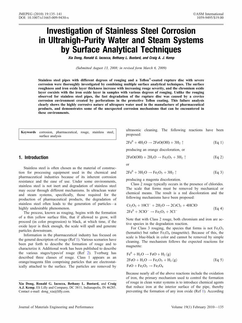
To understand the extent of rouging, SEM micrographs ofthe three pipe samples were obtained, as shown in Fig. 1. Pipe1 received no exposure to high-temperature water or steam,Pipe 2 is in the preliminary stages of rouging, exhibiting ayellow-colored oxide scale, and Pipe 3 is at a more advancedstage of rouge, exhibiting a red-colored oxide scale. In SEMmicrographs, the control sample surface (Fig. 1a) exhibits theoriginal mechanical polishing features that would be expectedin a mechanically polished material. The micrograph of Pipe 2(Fig. 1b) shows the same polishing features, though to a moresevere extent. This increased severity is not caused by exposureto a corrosive environment but rather is an artifact ofmechanical polishing. Because these features are readilyvisible, this material is in the early stages of oxidation. ThePipe 3 surface contains ‘‘island’’ features, as shown in Fig. 1c,and appears rougher than the other two pipes, indicating moresevere degradation occurring on this sample.
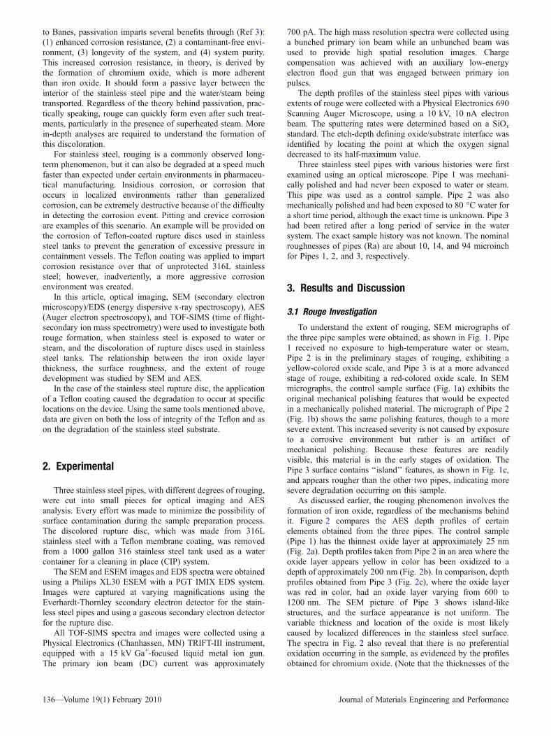
As discussed earlier, the rouging phenomenon involves theformation of iron oxide, regardless of the mechanisms behindit. Figure 2 compares the AES depth profiles of certainelements obtained from the three pipes. The control sample(Pipe 1) has the thinnest oxide layer at approximately 25 nm(Fig. 2a). Depth profiles taken from Pipe 2 in an area where theoxide layer appears yellow in color has been oxidized to adepth of approximately 200 nm (Fig. 2b). In comparison, depthprofiles obtained from Pipe 3 (Fig. 2c), where the oxide layerwas red in color, had an oxide layer varying from 600 to1200 nm. The SEM picture of Pipe 3 shows island-likestructures, and the surface appearance is not uniform. Thevariable thickness and location of the oxide is most likelycaused by localized differences in the stainless steel surface.The spectra in Fig. 2 also reveal that there is no preferentialoxidation occurring in the sample, as evidenced by the profilesobtained for chromium oxide. (Note that the thicknesses of the
136—Volume 19(1) February 2010 Journal of Materials Engineering and Performance
oxide layer were calculated based on the sputtering rateobtained from a silicon oxide standard; therefore, the absolutemeasurement may not be accurate. However, the relativecomparison between different samples is still valid.)
It has been suggested in previous research in the rougingprocess that chromium oxide may preferentially form at themetal/water (or steam) interface because of its thermodynamicstability and tenacity as compared to various oxides of iron;however, chromium oxide depletion is not observed in thecurrent work. Such observations may have been detected onsamples that have undergone a passivation treatment, whereiron is intentionally removed from the interface, allowingchromium oxide to form preferentially.
3.2 Failure Analysis of Rupture Disc
Although rouge is considered to be a uniform corrosion/oxidation phenomenon, the following example will illustratehow the corrosion mechanism can become an insidiousphenomenon occurring in a very localized fashion.
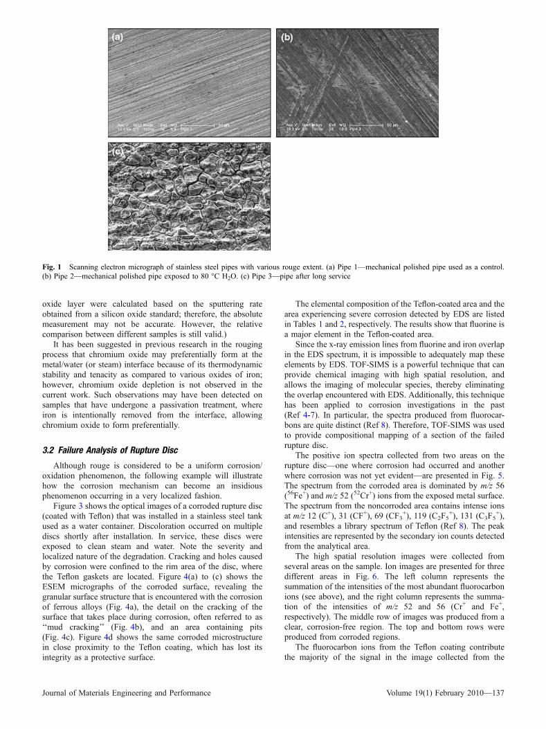
Figure 3 shows the optical images of a corroded rupture disc(coated with Teflon) that was installed in a stainless steel tankused as a water container. Discoloration occurred on multiplediscs shortly after installation. In service, these discs wereexposed to clean steam and water. Note the severity andlocalized nature of the degradation. Cracking and holes causedby corrosion were confined to the rim area of the disc, wherethe Teflon gaskets are located. Figure 4(a) to (c) shows theESEM micrographs of the corroded surface, revealing thegranular surface structure that is encountered with the corrosionof ferrous alloys (Fig. 4a), the detail on the cracking of thesurface that takes place during corrosion, often referred to as‘‘mud cracking’’ (Fig. 4b), and an area containing pits(Fig. 4c). Figure 4d shows the same corroded microstructurein close proximity to the Teflon coating, which has lost itsintegrity as a protective surface.
The elemental composition of the Teflon-coated area and thearea experiencing severe corrosion detected by EDS are listedin Tables 1 and 2, respectively. The results show that fluorine isa major element in the Teflon-coated area.
Since the x-ray emission lines from fluorine and iron overlapin the EDS spectrum, it is impossible to adequately map theseelements by EDS. TOF-SIMS is a powerful technique that canprovide chemical imaging with high spatial resolution, andallows the imaging of molecular species, thereby eliminatingthe overlap encountered with EDS. Additionally, this techniquehas been applied to corrosion investigations in the past(Ref 4-7). In particular, the spectra produced from fluorocar-bons are quite distinct (Ref 8). Therefore, TOF-SIMS was usedto provide compositional mapping of a section of the failedrupture disc.
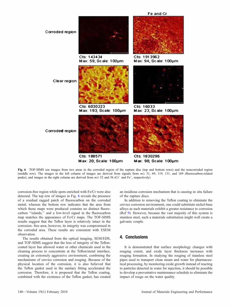
The positive ion spectra collected from two areas on therupture disc—one where corrosion had occurred and anotherwhere corrosion was not yet evident—are presented in Fig. 5.The spectrum from the corroded area is dominated by m/z 56(56Fe+) and m/z 52 (52Cr+) ions from the exposed metal surface.The spectrum from the noncorroded area contains intense ionsat m/z 12 (C+), 31 (CF+), 69 (CF3
+), 119 (C2F5+), 131 (C3F5
+),and resembles a library spectrum of Teflon (Ref 8). The peakintensities are represented by the secondary ion counts detectedfrom the analytical area.
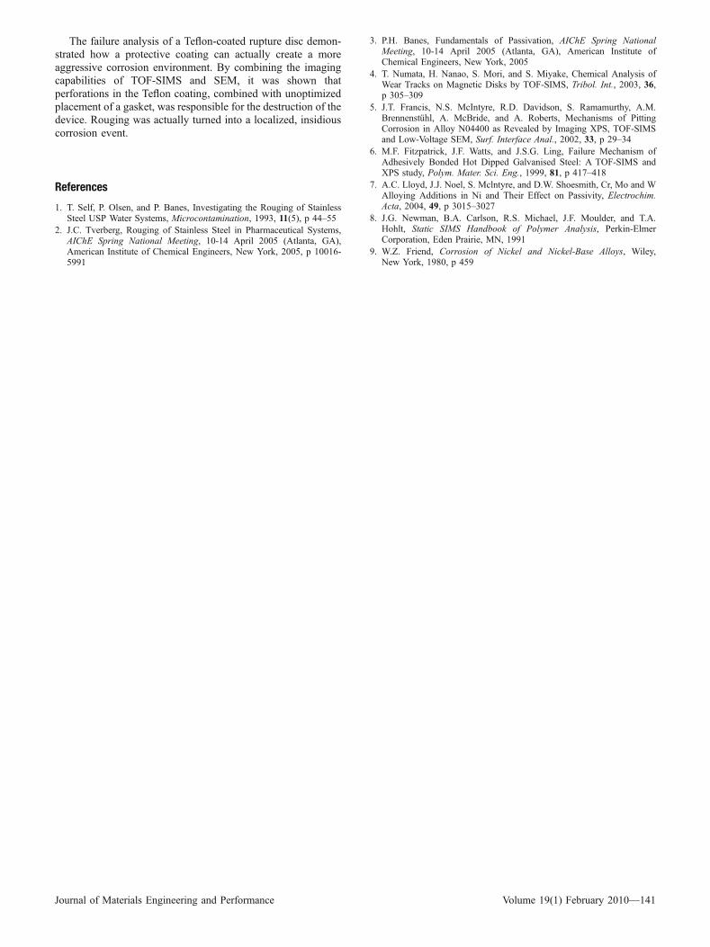
The high spatial resolution images were collected fromseveral areas on the sample. Ion images are presented for threedifferent areas in Fig. 6. The left column represents thesummation of the intensities of the most abundant fluorocarbonions (see above), and the right column represents the summa-tion of the intensities of m/z 52 and 56 (Cr+ and Fe+,respectively). The middle row of images was produced from aclear, corrosion-free region. The top and bottom rows wereproduced from corroded regions.
The fluorocarbon ions from the Teflon coating contributethe majority of the signal in the image collected from the
Fig. 1 Scanning electron micrograph of stainless steel pipes with various rouge extent. (a) Pipe 1—mechanical polished pipe used as a control.(b) Pipe 2—mechanical polished pipe exposed to 80 �C H2O. (c) Pipe 3—pipe after long service
Journal of Materials Engineering and Performance Volume 19(1) February 2010—137
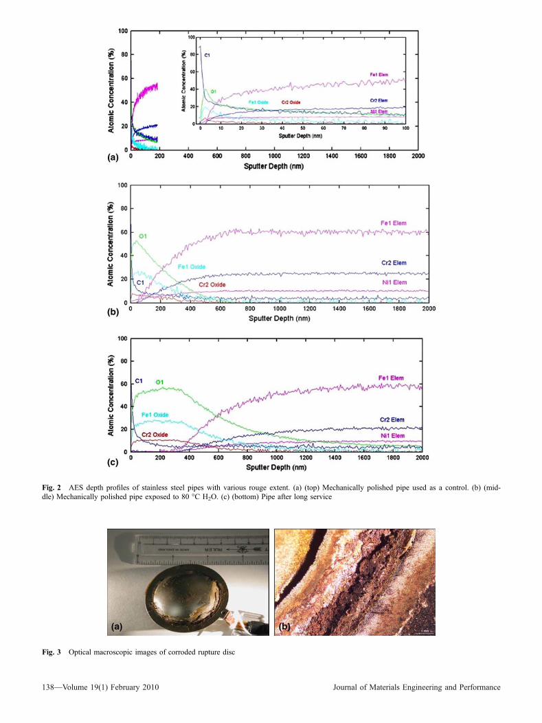
Fig. 2 AES depth profiles of stainless steel pipes with various rouge extent. (a) (top) Mechanically polished pipe used as a control. (b) (mid-dle) Mechanically polished pipe exposed to 80 �C H2O. (c) (bottom) Pipe after long service
Fig. 3 Optical macroscopic images of corroded rupture disc
138—Volume 19(1) February 2010 Journal of Materials Engineering and Performance
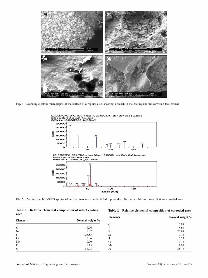
Fig. 4 Scanning electron micrographs of the surface of a rupture disc, showing a breach in the coating and the corrosion that ensued
Table 1 Relative elemental composition of intact coatingarea
Elements Normal weight %
C 17.96Ni 0.02F 23.83Cr 0.06Mn 0.00Fe 0.15O 57.98
Table 2 Relative elemental composition of corroded area
Elements Normal weight %
C 0.99Ni 5.85F 20.99Si 0.15S 0.25Cr 7.38Mn 1.05Fe 35.78
Fig. 5 Positive ion TOF-SIMS spectra taken from two areas on the failed rupture disc. Top: no visible corrosion. Bottom: corroded area
Journal of Materials Engineering and Performance Volume 19(1) February 2010—139
corrosion-free region while spots enriched with Fe/Cr were alsodetected. The top row of images in Fig. 6 reveals the presenceof a residual ragged patch of fluorocarbon on the corrodedmetal; whereas the bottom row indicates that the area fromwhich those maps were produced contains no distinct fluoro-carbon ‘‘islands,’’ and a low-level signal in the fluorocarbonmap matches the appearance of Fe/Cr maps. The TOF-SIMSresults suggest that the Teflon layer is relatively intact in thecorrosion- free area; however, its integrity was compromised inthe corroded area. These results are consistent with ESEMobservation.
The results obtained from the optical imaging, SEM/EDS,and TOF-SIMS suggest that the loss of integrity of the Teflon-coated layer has allowed water or other chemicals used in thecleaning process to concentrate at the Teflon/metal interface,creating an extremely aggressive environment, combining themechanisms of crevice corrosion and rouging. Because of thephysical location of the corrosion, it is also believed thatthe Teflon gasket used in the sanitary fitting accelerated thecorrosion. Therefore, it is proposed that the Teflon coating,combined with the existence of the Teflon gasket, has created
an insidious corrosion mechanism that is causing in situ failureof the rupture discs.
In addition to removing the Teflon coating to eliminate thecrevice corrosion environment, one could substitute nickel-basealloys as such materials exhibit a greater resistance to corrosion(Ref 9). However, because the vast majority of this system isstainless steel, such a materials substitution might well create agalvanic couple.
4. Conclusions
It is demonstrated that surface morphology changes withrouging extent, and oxide layer thickness increases withrouging formation. In studying the rouging of stainless steelpipes used to transport clean steam and water for pharmaceu-tical processing, by monitoring oxide growth instead of reactingto particles detected in water for injection, it should be possibleto develop a preventative maintenance schedule to eliminate theimpact of rouge on the water quality.
Fig. 6 TOF-SIMS ion images from two areas in the corroded region of the rupture disc (top and bottom rows) and the noncorroded region(middle row). The images in the left column of images are derived from signals from m/z 31, 69, 119, 131, and 169 (fluorocarbon-relatedpeaks), and images in the right column are derived from m/z 52 and 56 (Cr+ and Fe+, respectively)
140—Volume 19(1) February 2010 Journal of Materials Engineering and Performance
The failure analysis of a Teflon-coated rupture disc demon-strated how a protective coating can actually create a moreaggressive corrosion environment. By combining the imagingcapabilities of TOF-SIMS and SEM, it was shown thatperforations in the Teflon coating, combined with unoptimizedplacement of a gasket, was responsible for the destruction of thedevice. Rouging was actually turned into a localized, insidiouscorrosion event.
References
1. T. Self, P. Olsen, and P. Banes, Investigating the Rouging of StainlessSteel USP Water Systems, Microcontamination, 1993, 11(5), p 44–55
2. J.C. Tverberg, Rouging of Stainless Steel in Pharmaceutical Systems,AIChE Spring National Meeting, 10-14 April 2005 (Atlanta, GA),American Institute of Chemical Engineers, New York, 2005, p 10016-5991
3. P.H. Banes, Fundamentals of Passivation, AIChE Spring NationalMeeting, 10-14 April 2005 (Atlanta, GA), American Institute ofChemical Engineers, New York, 2005
4. T. Numata, H. Nanao, S. Mori, and S. Miyake, Chemical Analysis ofWear Tracks on Magnetic Disks by TOF-SIMS, Tribol. Int., 2003, 36,p 305–309
5. J.T. Francis, N.S. McIntyre, R.D. Davidson, S. Ramamurthy, A.M.Brennenstuhl, A. McBride, and A. Roberts, Mechanisms of PittingCorrosion in Alloy N04400 as Revealed by Imaging XPS, TOF-SIMSand Low-Voltage SEM, Surf. Interface Anal., 2002, 33, p 29–34
6. M.F. Fitzpatrick, J.F. Watts, and J.S.G. Ling, Failure Mechanism ofAdhesively Bonded Hot Dipped Galvanised Steel: A TOF-SIMS andXPS study, Polym. Mater. Sci. Eng., 1999, 81, p 417–418
7. A.C. Lloyd, J.J. Noel, S. Mclntyre, and D.W. Shoesmith, Cr, Mo and WAlloying Additions in Ni and Their Effect on Passivity, Electrochim.Acta, 2004, 49, p 3015–3027
8. J.G. Newman, B.A. Carlson, R.S. Michael, J.F. Moulder, and T.A.Hohlt, Static SIMS Handbook of Polymer Analysis, Perkin-ElmerCorporation, Eden Prairie, MN, 1991
9. W.Z. Friend, Corrosion of Nickel and Nickel-Base Alloys, Wiley,New York, 1980, p 459
Journal of Materials Engineering and Performance Volume 19(1) February 2010—141