introduction - digitalocean
TRANSCRIPT


INDEX
http://www.goblin-helicopter.com
Please read this user manual carefully, it contains instructions for the correct assembly of the model. Please refer to the web site www.goblin-helicopter.com for updates and other important information.
VERY IMPORTANT
It is extremely important that you take a moment to register your helicopter with us. This is the only way to ensure that you are properly informed about changes to your kit, such as upgrades, retrofits and other important developments. SAB Heli Division cannot be held responsible for any issues with your model and will not provide support unless you register your model.
The Serial number is also engraved in the Aluminum part.
Thank you for your purchase, we hope you enjoy your new Goblin helicopter!
SAB Heli Division
You will find your serial number on the RED plate of the transmission module and on the product card included with your kit. Please take a moment to register your kit online via our web site at:
17 – INSTALLATION BATTERY/FBL/RX18 – INSTALLATION CANOPY19 – IN FLIGHT20 – MAINTENANCE21 – TRANSMISSION MODULE22 – CHECK LIST23 – SPARE PARTS
9 – ASSEMBLING OF THE MODULES10 – TENSIONER ASSEMBLY11 – LOWER SIDE FRAME INSTALLATION12 – LANDING GEAR INSTALLATION13 – ENGINE UNIT ASSEMBLY14 – TAIL GROUP ASSEMBLY15 – TAIL BOOM ASSEMBLY16 – TANK ASSEMBLY
1 – INTRODUCTION2 – IMPORTANT NOTES3 – NOTE FOR ASSEMBLY4 – CARBON ROD ASSEMBLY5 – TRANSMISSION GROUP ASSEMBLY6 – SWASHPLATE SERVOS ASSEMBLY7 – FRAME GROUP ASSEMBLY8 – HEAD ASSEMBLY
Page 1
INTRODUCTION

1558mm
1445mm
331
mm
187
mm
GOBLIN RAW NITRO TECHNICAL SPECIFICATIONS
Minimum tail blades size: 105mm Maximum tail blades size: 115mm
• Cyclic Servos: Standard size 40mm.
• Tail Servo: Standard size 40mm.
• Throttle Servo: Mini size 35 mm or Standard size 40mm.
• Main Rotor Ratio: 7.7- 8.3 :1 (27T included: 8:1).
• Tail Rotor Ratio : 5.1 - 4.9:1 ( 22T included: 5.1:1 ).
• Tank Capacity: 650ml.
• RX Battery Size: 2S-1800 / 2500 mAh.
• RTF Approx. Weight: 4000 g (RTF no fuel).
• Main blade length: 650mm to 720mm ( 690mm included ).
• Tail blade length: 105 to 115 mm ( 105mm included ).
• Main rotor diameter: 1558 mm (with 690 mm blades).
• Tail rotor diameter: 284 mm (with 105 mm tail blades).
• Engine: .90 to .105 Nitro Heli Engine.
Page 2
INTRODUCTION

IMPORTANT NOTES *This radio controlled helicopter is not a toy.*This radio controlled helicopter can be very dangerous. *This radio controlled helicopter is a technically complex device which has to be built and handled very carefully.*This radio controlled helicopter must be built following these instructions. This manual provides the necessary information to correctly assemble the model. It is necessary to carefully follow all the instructions.*Inexperienced pilots must be monitored by expert pilots.*All operators must wear safety glasses and take appropriate safety precautions.*A radio controlled helicopter must only be used in open spaces without obstacles, and far enough from people to minimize the possibility of accidents or of injury to property or persons.*A radio controlled helicopter can behave in an unexpected manner, causing loss of control of the model, making it very dangerous.*Lack of care with assembly or maintenance can result in an unreliable and dangerous model.
*Neither SAB Heli Division nor its agents have any control over the assembly, maintenance and use of this product. Therefore, no responsibility can be traced back to the manufacturer. You hereby agree to release SAB Heli Division from any responsibility or liability arising from the use of this product. SAFETY GUIDELINES *Fly only in areas dedicated to the use of model helicopters.*Follow all control procedures for the radio frequency system.*It is necessary that you know your radio system well. Check all functions of the transmitter before every flight.*The blades of the model rotate at a very high speed; be aware of the danger they pose and the damage they may cause.*Never fly in the vicinity of other people. DAMAGE LIMITS SAB HELI DIVISION SHALL NOT BE LIABLE FOR SPECIAL, INDIRECT OR CONSEQUENTIAL DAMAGES, LOSS OF PROFITS OR PRODUCTION OR COMMERCIAL LOSS IN ANY WAY CONNECTED WITH THE PRODUCT, WHETHER SUCH CLAIM IS BASED IN CONTRACT, WARRANTY, NEGLIGENCE, OR STRICT LIABILITY. Further, in no event shall the liability of SAB Heli Division exceed the individual price of the Product on which liability is asserted. As SAB Heli Division has no control over use, setup, final assembly, modification or misuse, no liability shall be assumed nor accepted for any resulting damage or injury. By the act of use, setup or assembly the user accepts all resulting liability. If you as the Purchaser or user are not prepared to accept the liability associated with the use of this Product, you are advised to return this Product immediately in new and unused condition to the place of purchase. LIMITED WARRANTY SAB Heli Division reserves the right to change or modify this warranty without notice and disclaims all other warranties, express or implied.
(a) This warranty is limited to the original Purchaser (“Purchaser”) and is not transferable. REPLACEMENT AS PROVIDED UNDER THIS WARRANTY IS THE EXCLUSIVE REMEDY OF THE PURCHASER This warranty covers only those Products purchased from an authorized SAB Heli Division dealer. Third party transactions are not covered by this warranty. Proof of purchase is required for warranty claims.
(b) Limitations- SAB HELI DIVISION MAKES NO WARRANTY OR REPRESENTATION, EXPRESS OR IMPLIED, ABOUT NONIFRINGEMENT, MERCHANTABILITY OR FITNESS FOR A PARTICULAR PURPOSE OF THE PRODUCT. THE PURCHASER ACKNOWLEDGES THAT THEY ALONE HAVE DETERMINED THAT THE PRODUCT WILL SUITABLY MEET THE REQUIREMENTS OF THE PURCHASER’S INTENDED USE.
(c) Purchaser Remedy- SAB Heli Division’s sole obligation hereunder shall be that SAB Heli Division will, at its option, replace any Product determined by SAB Heli Division to be defective In the event of a defect, this is the Purchaser’s exclusive remedy. Replacement decisions are at the sole discretion of SAB Heli Division. This warranty does not cover cosmetic damage or damage due to acts of God, accident, misuse, abuse, negligence, commercial use, or modification of or to any part of the Product. This warranty does not cover damage due to improper installation, operation, maintenance or attempted repair by anyone.
Page 3
IMPORTANT NOTES

Manual
Extra Card
CANOPY BOX 4
BOX 1
BOX 3
BOX 2
BLADE HOLDERFAN CASETANK
*Generic pliers.*Hexagonal driver, size 1.5, 2, 2.5, 3mm.*4/5mm T-Wrench.*5.5mm Socket wrench (for M3 nuts).*8mm Hex fork wrench (for M5 nuts).
*Medium threadlocker (SAB p/n HA116-S).*Strong retaining compound (SAB p/n HA115-S).*Spray lubricant (eg. Try-Flow Oil).*Synthetic grease (eg. Microlube 261).*Cyanoacrylate adhesive.
*Pitch Gauge (for set-up).*Soldering equipment (for Engine wiring).
*Engine: .90 to .105 Nitro Heli Engine.*Muffer suited for the engine being used.
*Batteries: 2S/1800-2500mAh.
*Governor unit.*1 flybarless 3 axis control unit*Radio power system.
*1 throttle servo ( Mini Size ).*3 cyclic servos ( Standard Size ).*1 tail rotor servo ( Standard Size ).
*6 channel radio control system on 2.4 GHz*Fuel.
The assembly process is described in the following chapters.Each chapter provides you with the box, bag and/or foamnumbers you will need for that chapter. The informationis printed in a black box in the upper corner of the page.
INSIDE THE MAIN BOX THERE ARE:
Green screw and Green bearing in the illustration means you
need to use:Use retaining compound
( SAB HA115-S )
Use Proper LubricantUse CA Glue
Indicates that for this assembly phase you need materials that are:BOX xxx, BAG xxx.
Important
ADDITIONAL COMPONENTS REQUIRED TOOLS, LUBRICANTS, ADHESIVES
Blue screw and blue bearing in the illustration means you
need to use:Thread Locker Medium
Strength ( SAB HA116-S)
BOX xx, BAGxx
NOTES FOR ASSEMBLY Please refer to this manual for assembly instructions for this model. Follow the order of assembly indicated. The instructions are divided into chapters, which are structured in a way that each step is based on the work done in the previous step. Changing the order of assembly may result in additional or unnecessary steps.Use thread lockers and retaining compounds as indicated. In general, each bolt or screw that engages with a metal part requires thread lock. It is necessary to pay attention to the symbols listed below:
Page 4
NOTE FOR ASSEMBLY

Approx 717mm
13mm 13mm NOTE:
Threaded Rod M2.5x40mm(HC242-S)
Threaded Rod M2.5x40mm(HC242-S)
Carbon Rod 2.5x 4x691mm(HC619-S)
Aluminum Bushing Aluminum Bushing
Box 4, Bag for page 5
Brass Tube 5x 4.1x40mm(H0769-S)NOTE: Glue the tube on the carbon rod after setting up the tail servo, in order to define the correct gluing position.
Page 5
CARBON ROD ASSEMBLY

Rear Servo Mount(H1207-S)
Socket Head Cap Screw M2.5x8mm(HC020-S)
TRANSMISSION GROUP ASSEMBLED AND VERIFIED
The unit is ready to useCheck page 39 for more information.
Front Tail Pulley Z27(H1336-S)
Metric Hex Nylon Nut M4(HC212-S)
Main Pulley Z52(H1335-S)
Finishing Washer M2.5(H0255-S)
Bushing(H1275-S)
Socket Head Cap Screw M4x22mm(HC104-S)
Rear Servo Mount Support(H1206-S)
Socket Head Cap Screw M3x8mm(HC050-S)
Box 1, Bag for page 6
Socket Head Cap Screw M2.5x8mm(HC020-S)
Front Servo Mount(H1217-S)
Free Wheel Clutchgrease HA075
Shim 12x 16x0.1mm(HC538-S)
Page 6
TRANSMISSION GROUP ASSEMBLY

18mm
90°
Servo Tool
Standard Servo
Servo Arm(HA050-S)
Socket screw M3x6mm(HC044-S)Uniball M2
(H0064-S)
SERVO ASSEMBLY
The linkage ball must be positioned 18 mm out on the servo arm. The recommended servo arm to use is: SAB p/n [HA050/HA051].
Ensure the alignment of the servo arms (and sub trim is set) before installation of the servos in the model.Proceed with installation following the instructions below. You can use the G10 servo tool to align the front servo arms with the theoretical horizontal line. (Figure 3)
Socket Head Cap Screw M2.5x8mm(HC020-S)
Servo Spacer(H0075-S)
Front Servo Rear Servo
Socket screw M2x6mm(HC004-S)
Socket Head Cap Screw M2.5x8mm(HC020-S)
Servo Spacer(H0075-S)
Socket Head Cap Screw M2.5x8mm(HC020-S)
Box 1, Bag for page 7
Page 7
SWASHPLATE SERVOS ASSEMBLY

Install here the 2 special NUT Block ( you can find in single bag )
LEFT UPPER MAIN FRAME ASSEMBLY
UP Main Frame Left(H1359-L)
Botton Head Cap Screw M3x6mm(HC094-S)
Engine Spacer(H0678-S)
Flat Head Cap Screw M2.5x5(HC128-S)
Nut Block(H1386-S)
Nut Block(H1386-S)
Engine Spacer(H0678-S)
Flat Head Cap Screw M2.5x5(HC128-S)
UP Main Frame Right(H1359-R)
RIGHT UPPER MAIN FRAME ASSEMBLYBotton Head Cap Screw M3x6mm(HC094-S)
Box 3, Bag for page 8 CARBON FRAME
The manufacturing process of the carbon parts often leaves micro-burrs and sharp edges. We recommend de-burring the edges to minimize the risks of electrical wire cuts, etc.Very important in red line zone.
Page 8
FRAME GROUP ASSEMBLY
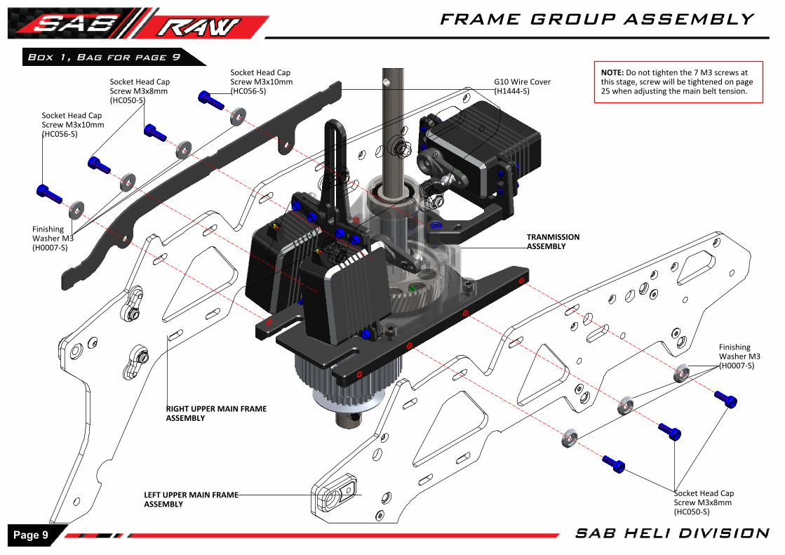
Socket Head Cap Screw M3x8mm(HC050-S)
Finishing Washer M3(H0007-S)
Finishing Washer M3(H0007-S)
Socket Head Cap Screw M3x8mm(HC050-S)
Box 1, Bag for page 9
TRANMISSIONASSEMBLY
RIGHT UPPER MAIN FRAMEASSEMBLY
LEFT UPPER MAIN FRAMEASSEMBLY
Socket Head Cap Screw M3x10mm(HC056-S)
Socket Head Cap Screw M3x10mm(HC056-S)
G10 Wire Cover(H1444-S)
NOTE: Do not tighten the 7 M3 screws at this stage, screw will be tightened on page 25 when adjusting the main belt tension.
Page 9
FRAME GROUP ASSEMBLY
GG JJ
Internal External
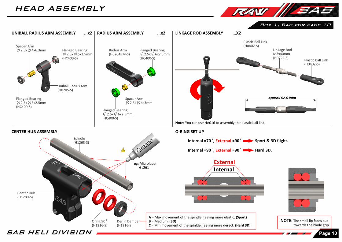
Approx 62-63mm
LINKAGE ROD ASSEMBLY ...X2
Plastic Ball Link(H0402-S)
Linkage Rod M3x40mm(H0722-S)
Plastic Ball Link(H0402-S)
CENTER HUB ASSEMBLY
eg: Microlube GL261
Spindle(H1263-S)
Center Hub(H1280-S)
Derlin Damper(H1216-S)
RADIUS ARM ASSEMBLY ...x2
Radius Arm(H0204BM-S)
Spacer Arm2.5x 4x3mm
Spacer Arm2.5x 4x6.3mm
Uniball Radius Arm(H0205-S)
UNIBALL RADIUS ARM ASSEMBLY ...x2
Flanged Bearing2.5x 6x2.5mm
(HC400-S)
Flanged Bearing2.5x 6x2.5mm
(HC400-S)
Flanged Bearing2.5x 6x2.5mm
(HC400-S)
Flanged Bearing2.5x 6x2.5mm
(HC400-S)
Internal =70 , External =90 Sport & 3D flight.
Internal =90 , External =90 Hard 3D.
O-RING SET UP
NOTE: The small lip faces out towards the blade grip.
Box 1, Bag for page 10
Note: You can use HA016 to assembly the plastic ball link.
Oring 90(H1216-S)
A = Max movement of the spindle, feeling more elastic. (Sport)B = Medium. (3D)C = Min movement of the spinlde, feeling more derect. (Hard 3D)
Page 10
HEAD ASSEMBLY

Small ID
Larger ID
Socket Head CapScrew M2.5x18mm(HC032-S)
Uniball M3(H0065-S)
NOTE:
Washer 10x 16x0.2mm[HC232-S]
The HPS head should be assembled with one, 1mm shim (HC230) on each side. The blade grips must move freely, but they should not move just under their own weight. After approximately 10/20 flights, please check preload, you can add one or two 0.2mm shim (HC232) if preload has changed.
eg: Microlube GL261
Box 1, Bag for page 11
LINKAGE RODASSEMBLED
RADIUS ARMASSEMBLY
Already assembled with green Loctite
UNIBALL RADIUS ARM ASSEMBLY
CENTER HUBASSEMBLY
Blade Grip (H1411-S)
Washer11x 13.8x0.5
(HC594-S)
Thrust Bearing8x 14x4mm
(HC437-S)
Button Head CapScrew M6x10mm(HC122-S)
Washer6x 12 x1mm
(HC193-S)
Blade Grip Arm(H1202-S)
Socket Head CapSpecial M4x8mm(HC582-S)
Socket Head Cap Screw M2.5x15mm(HC028-S)
Washer2.5x 4x0.3mm
(HC172-S)
Bearing8x 14x4mm
(HC417-S)Already assembled with green Loctite
NOTE:Washer 8x 14x0.2mm [HC228-S]After approximately 10/20 flights, please check preload, you can add one 0.2mm shim on each side if preload has changed ( Extra bag box 2).However, we suggest to replace the o-rings after about 100 flights.
Page 11
HEAD ASSEMBLY

Socket Head Shoulder Screw M4x 21.5mm(HC545-S)
Socket Head CapScrew M3x12mm(HC062-S)
Metric Hex Nylon Nut M4(HC212-S)
eg: Microlube GL261
Reference Pin(H1048-S)
Uniball M3(H0065-S)
Uniball M3(H0065-S)
SWASHPLATE ASSEMBLY
Swashplate SET(H1204-S)
Box 1, Bag for page 12
UPPER FRAME & TRANSMISSIONGROUP ASSEMBLY
Socket Head CapScrew M3x12mm(HC062-S)
Page 12
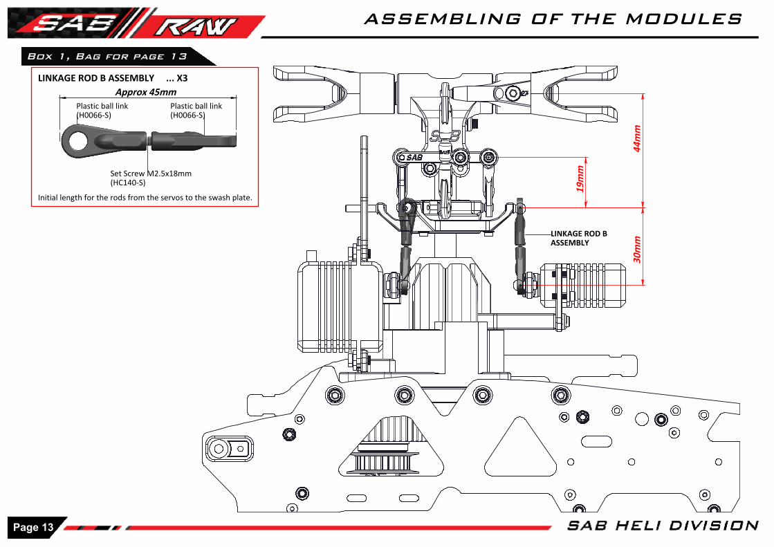
ASSEMBLING OF THE MODULES
44m
m
19m
m
30m
m
Approx 45mm
Initial length for the rods from the servos to the swash plate.
LINKAGE ROD B ASSEMBLY ... X3
Set Screw M2.5x18mm(HC140-S)
Plastic ball link (H0066-S)
Plastic ball link (H0066-S)
LINKAGE ROD B ASSEMBLY
Box 1, Bag for page 13
Page 13
ASSEMBLING OF THE MODULES
6m
m
4m
m
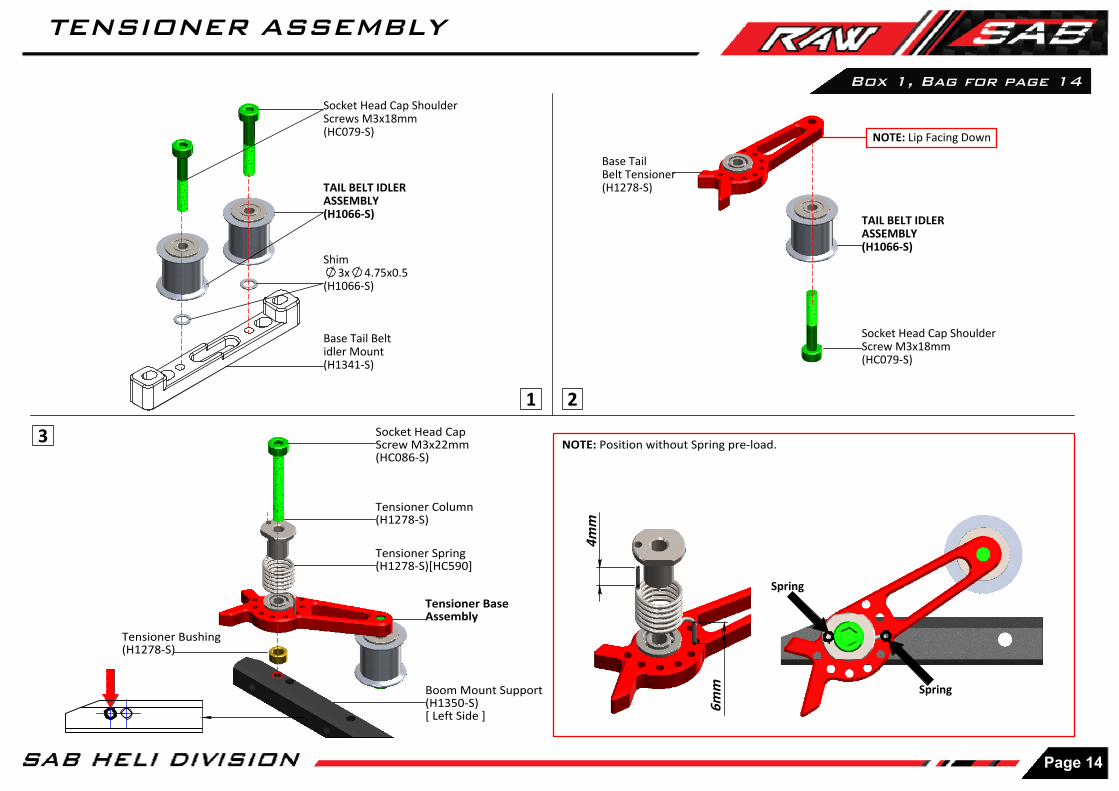
Box 1, Bag for page 14
1 2
3
Socket Head Cap ShoulderScrews M3x18mm(HC079-S)
TAIL BELT IDLER ASSEMBLY(H1066-S)
Shim 3x 4.75x0.5
(H1066-S)
Base Tail Belt idler Mount(H1341-S)
Socket Head Cap Shoulder Screw M3x18mm(HC079-S)
TAIL BELT IDLER ASSEMBLY(H1066-S)
Base Tail Belt Tensioner(H1278-S)
Tensioner Bushing(H1278-S)
Tensioner Base Assembly
Tensioner Spring(H1278-S)[HC590]
Tensioner Column(H1278-S)
Socket Head Cap Screw M3x22mm(HC086-S)
NOTE: Position without Spring pre-load.
Boom Mount Support(H1350-S)[ Left Side ]
NOTE: Lip Facing Down
Spring
Spring
Page 14
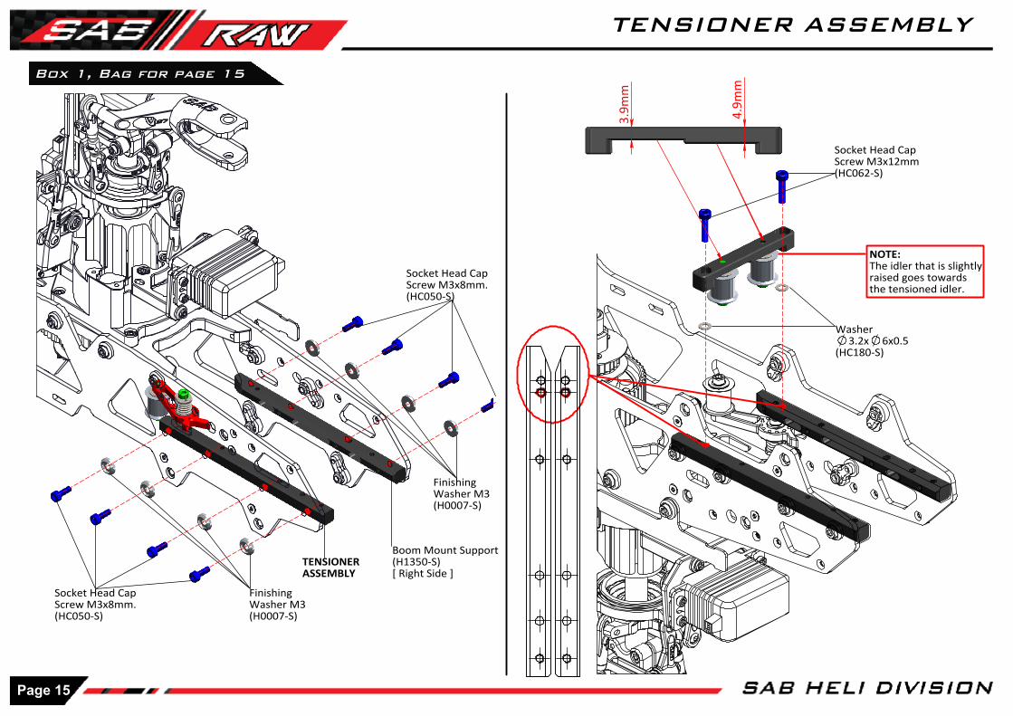
TENSIONER ASSEMBLY
3.9
mm
4.9
mm
Box 1, Bag for page 15
Socket Head Cap Screw M3x8mm.(HC050-S)
Socket Head Cap Screw M3x8mm.(HC050-S)
Finishing Washer M3(H0007-S)
Finishing Washer M3(H0007-S)
Socket Head Cap Screw M3x12mm(HC062-S)
NOTE:The idler that is slightlyraised goes towardsthe tensioned idler.
TENSIONERASSEMBLY
Boom Mount Support(H1350-S)[ Right Side ]
Washer3.2x 6x0.5
(HC180-S)
Page 15
TENSIONER ASSEMBLY

Box 3, Bag for page 16
Spacer(H1340-S)
Double Side Tape(HA081-S)
Spacer(H1340-S)
Lower Main Frame (H1344-S)
Double Side Tape(HA081-S)
Nut Block(H1386-S)
Flat Head CapScrew M2.5x5(HC128-S)
Nut Block(H1386-S)
Flat Head CapScrew M2.5x5(HC128-S)
RIGHT SIDE STICKER
LOWER SIDE FRAME ASSEMBLY
LOWER RIGHT MAIN FRAME ASSEMBLY LOWER LEFT MAIN FRAME ASSEMBLY
Lower Main Frame (H1344-S)
LEFT SIDE STICKER
Page 16
LOWER SIDE FRAME INSTALLATION
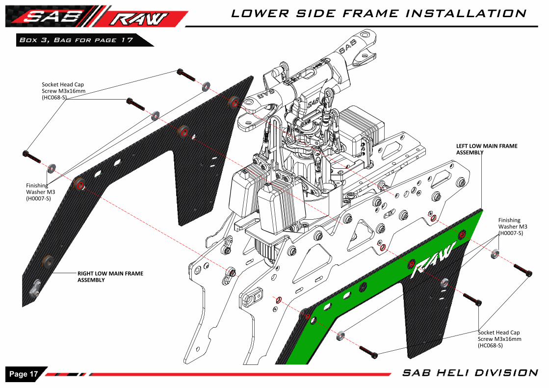
Finishing Washer M3(H0007-S)
Socket Head Cap Screw M3x16mm(HC068-S)
Box 3, Bag for page 17
LEFT LOW MAIN FRAMEASSEMBLY
RIGHT LOW MAIN FRAMEASSEMBLY
Socket Head Cap Screw M3x16mm(HC068-S)
Finishing Washer M3(H0007-S)
Page 17
LOWER SIDE FRAME INSTALLATION
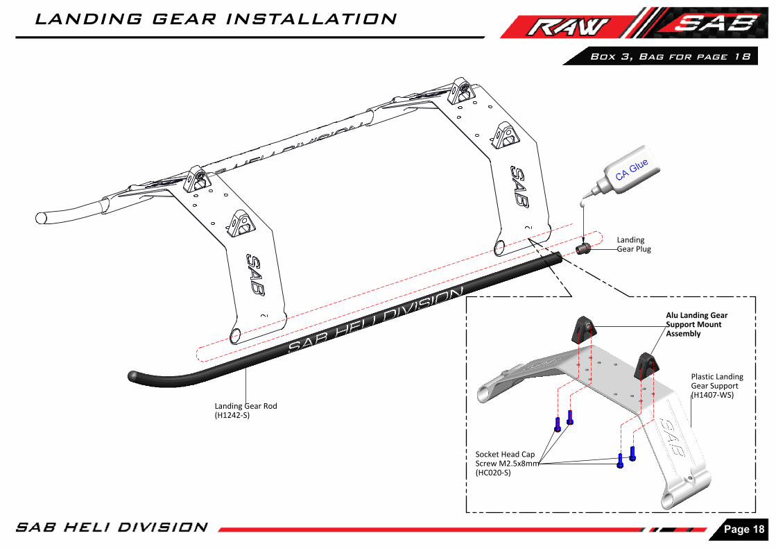
Plastic Landing Gear Support(H1407-WS)
Landing Gear Rod(H1242-S)
Landing Gear Plug
Box 3, Bag for page 18
Alu Landing Gear Support MountAssembly
Socket Head Cap Screw M2.5x8mm(HC020-S)
Page 18
LANDING GEAR INSTALLATION

Approx 25mm
Set Screw M4x4mm(HC152-S)
Socket Head CapScrew M3x12mm(HC062-S)
Finishing Washer M3(H0007-S)
Box 3, Bag for page 19
Socket Head CapScrews M3x14mm(HC064-S)
Socket Head CapScrews M3x12(HC062-S)
Finishing Washer M3(H0007-S)
NOTE: Tighten the set screws at the endof the landing gear assembly step. You can then check how flat the model is sitting.
CF Low Side Frame Front(H1358-S)
LANDING GEARASSEMBLY
Flat Head CapScrew M2.5x8mm(HC125-S)
Flat Head CapScrew M2.5x8mm(HC125-S)
NOTE:An M3 screw can be used temporarily tofind the correct alignment of H1348.
Canopy Spacer(H1348-S)
Page 19
LANDING GEAR INSTALLATION

II
CLUTCH UNIT ASSEMBLY ENGINE MOUNT ASSEMBLY
Clutch Bell ( Black )(H0674BL-S)[ Bell + Clutch Line ]
IMPORTANT NOTE Don't use any retaining compound in red area between H0668 and H0672.
Pulley Assembly (Black)(H0675BL-27-S)[ Pulley + Bearing ]
Button Head CapScrew M4x8mm(HC098-S)
Clutch (H0670-S)
Clutch Support(H0672-S)
Fan(H0671BM-S)
Flat Head CapScrew M3x8mm(HC134-S)
SECTION
Note:Counterbore external side.
More options are available
Shaft OS Engine(H0668-B-S)
Note: Use the shaft depending on your Engine.
Shaft YS Engine(H0668-A-S)
Socket Head CapScrew M3x8mm(HC050-S)
Engine Support SX(H0665-S)
Engine Support Spacer(H0682-S)
Socket Head CapScrew M3x8mm(HC050-S)
Flat Head CapScrew M3x8mm(HC134-S)
Engine Support DX(H0665-S)
Flat Head CapScrew M3x8mm(HC134-S)
Box 3, Bag for page 20
Page 20
ENGINE UNIT ASSEMBLY

ENGINE ASSEMBLY
NOTE:
Using Crank Clamp ( accessory not included in the kit ) you can easily tighten the assembly onto the engine shaft. With a 6mm hex driver, you can tighten the clutch unit.
IMPORTANT:
First Tighten the clutch unit with a hex tool against the engine bearing. Only after this step, tighten the 2 M3x10 screws.
NOTE:
Do not add loctite on the engine shaft
Socket Head CapScrews M3x10mm(HC056-S)
EngineWasher 10x 15x0.75mm( Supplied with The Engine )
Socket Head Cap Screws M3x10mm(HC056-S)
CLUTCH UNITASSEMBLY
Crank ClampEngineWasherClutch Unit
HEX 6mm
Socket Head CapScrew M4x15mm(HC103-S)
Engine Belt HTD3 309mm 13mm(HC617-S)
ENGINE
ENGINE MOUNTING
MAIN RATIO
It is possible to have 5 ratios using the following Pulleys:
H0675BL-28-S 52/28 7.7H0675BL-27-S 52/27 8.0H0675BL-26-S 52/26 8.3
The KIT includes ratio : 52T-27T -> 8.0
ENGINE MOUNT ASSEMBLY
Box 3, Bag for page 21
Page 21
ENGINE UNIT ASSEMBLY

CUT
The second is to use two magnets on the fan. Please use the following methods for installation:
Install 2 magnets on the fan with epoxy glue (please ensure to clean the parts with degreaser before glueing together)
[ Fig. 1 ] ). To install the sensor, you can use the two pre-cut M2.5 holes.
Not all sensors are the same, so you can adapt the position with the carbon support (H0729).
With Align and Spartan sensors, you can use the part of the support that already has holes in it.
With any other sensor, you can use the part without holes and adapt as required.
INSTALLATION OF THE RPM SENSOR
On the RAW nitro it is possible to use two different methods to install an RPM sensor. The first is a backplate sensor as demonstrated in the picture on the right.
P.S: Not all YS engines can support this method. Please seek further guidance from your engine manufacturer.
Magnet
Sensor
Socket Head Cap Screw M2.5x6mm(HC018-S)
H0729-S RPM Sensor Support
Socket Head CapScrew M2.5x6mm(HC018-S)
RPM Sensor Support
Sensor
ENGINE ASSEMBLY
Box 3, Bag for page 22
Page 22
ENGINE UNIT ASSEMBLY
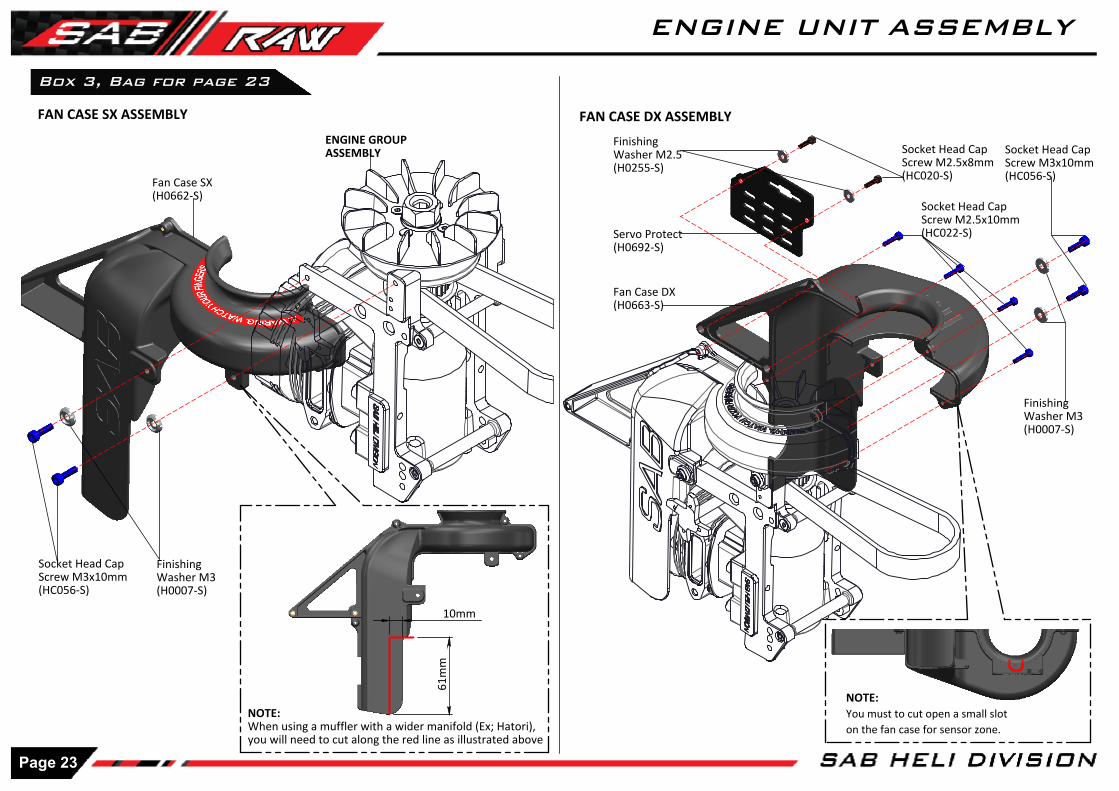
Socket Head Cap Screw M3x10mm(HC056-S)
10mm
61m
m
FAN CASE SX ASSEMBLY FAN CASE DX ASSEMBLY
Fan Case SX(H0662-S)
Socket Head Cap Screw M3x10mm(HC056-S)
Finishing Washer M3(H0007-S)
ENGINE GROUPASSEMBLY
Socket Head Cap Screw M2.5x10mm(HC022-S)
Finishing Washer M3(H0007-S)
Fan Case DX(H0663-S)
NOTE:When using a muffler with a wider manifold (Ex; Hatori), you will need to cut along the red line as illustrated above
NOTE:You must to cut open a small slot on the fan case for sensor zone.
Socket Head Cap Screw M2.5x8mm(HC020-S)
Finishing Washer M2.5(H0255-S)
Servo Protect(H0692-S)
Box 3, Bag for page 23
Page 23
ENGINE UNIT ASSEMBLY

Aprrox 90mm
Aprrox 82mm Aprrox 78mm
Approx 10-12mm
Socket Head Cap Screw M2.5x8mm(HC020-S)
Finishing Washer M2.5(H0255-S)
Uniball M2(H0538-S)
LINKAGE ASSEMBLY
Plastic Ball Link M2(H0403-S)
Plastic Ball Link M2(H0403-S)
Thread Rod M2x64mm(HC243-S)
LINKAGE ASSEMBLY
When installing the throttle servo, It is important to have the correct distance for the ball.
INSTALLATION OF THE THROTTLE SERVO
Servo Block(H0251-S)
Socket Head CapScrew M2.5x12mm(HC026-S)
35mm Servo Gas Support(H1442-S)
[H0538]
[HA050]
[HC044]
Install the throttle servo support as shown.In Figure 1 you can see a typical installation with OS engine.In Figure 2 you can see a typical installation with YS engine.
Box 3, Bag for page 24
35mm Servo Spacer(H1442-S)
Page 24
ENGINE UNIT ASSEMBLY
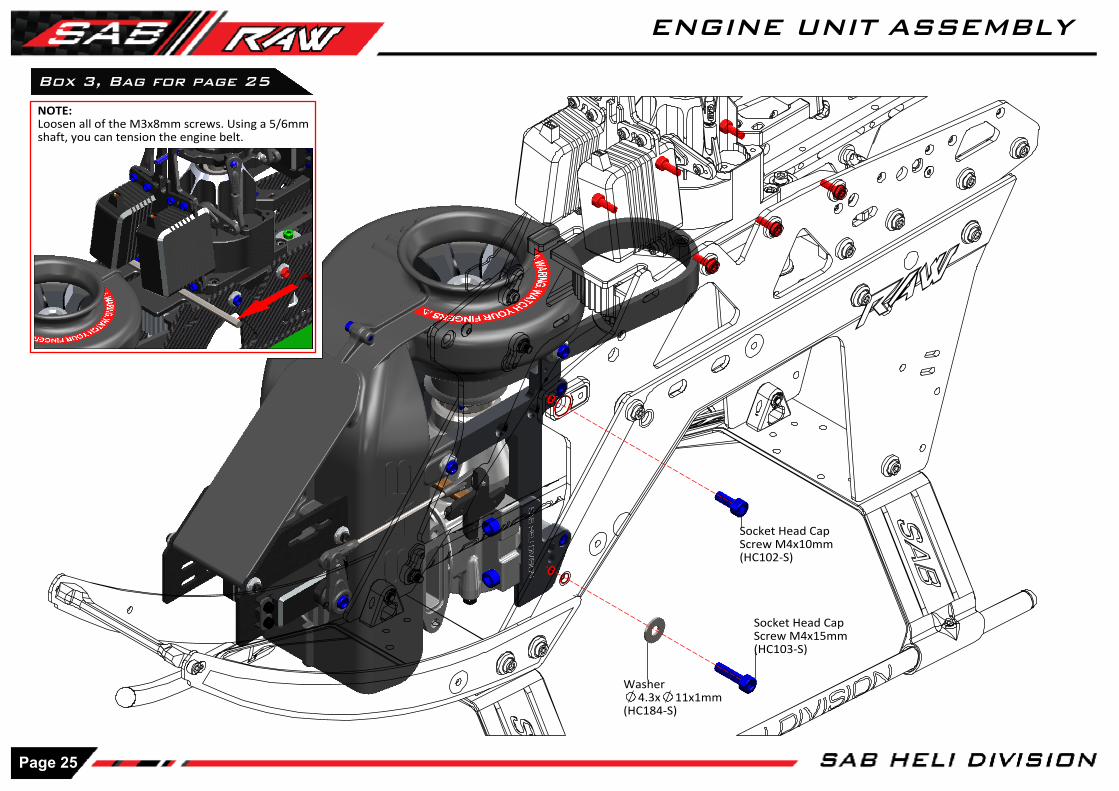
Socket Head Cap Screw M4x15mm(HC103-S)
Box 3, Bag for page 25
Socket Head Cap Screw M4x10mm(HC102-S)
NOTE:Loosen all of the M3x8mm screws. Using a 5/6mm shaft, you can tension the engine belt.
Washer4.3x 11x1mm
(HC184-S)
Page 25
ENGINE UNIT ASSEMBLY

Note: Smaller ID
Note: Larger ID
Note: S >> Left Side
Note: S >> Right Side
Spindle Shaft(H0220-S)
Oring 90 Shore(HC594-S)
Spacer4x 6.9x0.5mm
(HC594-S)
Uniball M2.5x 5H6(H0064-S)
Socket Head CapScrew M2x6mm(HC004-S)
Spacer7x 9x0.5
(HC594-S)
Thrust Bearing4x 9x4mm
(HC434-S)
Socket Head Cap Screw M3x6mm(HC044-S)
Tail Blade Grip(H1233-S)Assembled with bearing
TAIL PITCH SLIDERASSEMBLY(H1249-S)
Tail Pitch Slider Link(H0261-S)
Spacer2x 3x3mm
(H0261-S)
Socket Head CapScrew M2x6mm(HC004-S)
NOTE:It is a normal for the tail to feel a bit tight after initial assembly as the tail spindle preload is usually high when the helicopter is brand new. The preload will loosen up after 2-5 flights allowing the system to become smooth.
eg: Microlube GL261
Tail Shaft(H1313-S)
eg: Microlube GL261
Box 2, Bag for page 26
Shim 4.1x 5.5x0.1mm(HC594-S)
TAIL PITCH SLIDER ASSEMBLY
Bearing4x 9x2.5mm
(HC403-S)Assembled
Page 26
TAIL GROUP ASSEMBLY
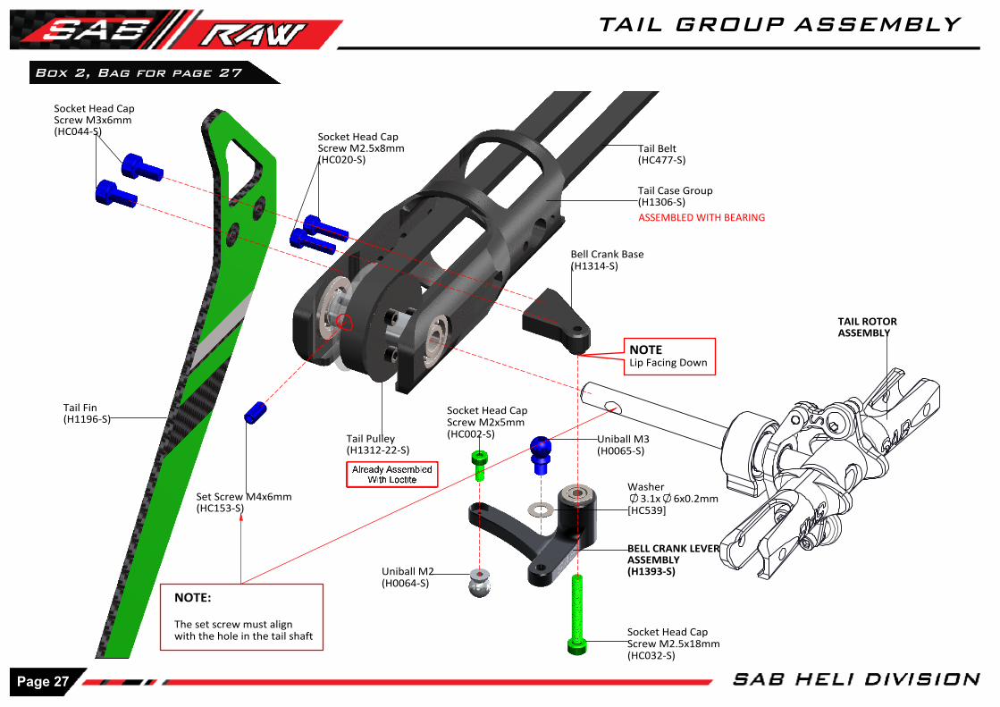
ASSEMBLED WITH BEARING
Socket Head Cap Screw M3x6mm(HC044-S)
Set Screw M4x6mm(HC153-S)
NOTE:
The set screw must align with the hole in the tail shaft
Tail Pulley(H1312-22-S)
Tail Case Group(H1306-S)
BELL CRANK LEVERASSEMBLY(H1393-S)
Socket Head Cap Screw M2.5x18mm(HC032-S)
Uniball M2(H0064-S)
Socket Head Cap Screw M2x5mm(HC002-S) Uniball M3
(H0065-S)
TAIL ROTORASSEMBLY
Socket Head Cap Screw M2.5x8mm(HC020-S)
Bell Crank Base(H1314-S)
Box 2, Bag for page 27
NOTELip Facing Down
Tail Fin(H1196-S)
Tail Belt(HC477-S)
Washer3.1x 6x0.2mm
[HC539]
Page 27
TAIL GROUP ASSEMBLY

18m
m
Approx 400mm
[H1310]Box 4, Bag for page 28
Buttom Head Cap Screw M3x4mm(HC038-S)
TAIL GROUP ASSEMBLY
Buttom Head Cap Screw M3x4mm(HC038-S)
Socket Head Cap Screw M2.5x12mm(HC026-S)
Carbon Rod Support(H1310-S)
TUBE Tail Boom(H1339-S)
Socket Head Screw M2x6mm(HC004-S)
TAIL SERVO ASSEMBLY
The distance between the axis and the ball must be around 18mm
Standard Servo
Socket Head Screw M3x6mm(HC044-S)
Uniball M2(H0064-S)
Servo Arm(HA050-S)
Socket Head Cap Screw M2.5x8mm(HC020-S)
Servo Spacer(H0075-S)
Servo Mount(H1353-S)
TAIL SERVO ASSEMBLY
Socket Head Cap Screw M3x12mm(HC062-S)
NOTE:Please use a Tie Rod to insert the belt into the tube.
Page 28
TAIL BOOM ASSEMBLY
Box 2, Bag for page 29
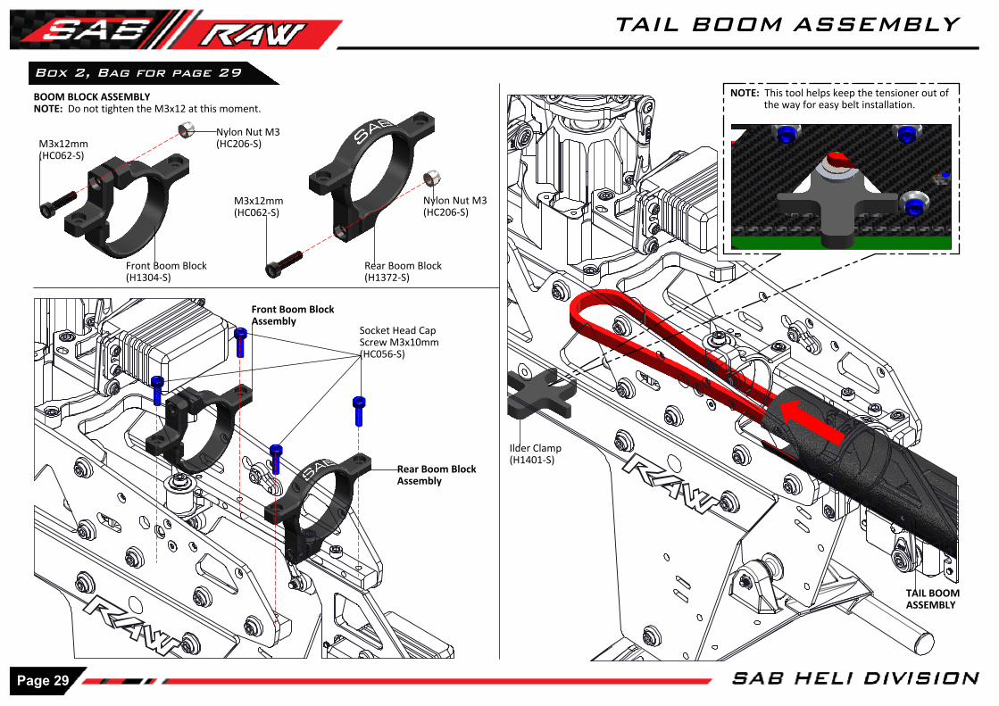
Rear Boom Block(H1372-S)
Socket Head CapScrew M3x10mm(HC056-S)
Nylon Nut M3(HC206-S)
TAIL BOOM ASSEMBLY
Ilder Clamp(H1401-S)
NOTE: This tool helps keep the tensioner out ofthe way for easy belt installation.
BOOM BLOCK ASSEMBLYNOTE: Do not tighten the M3x12 at this moment.
M3x12mm(HC062-S)
Front Boom Block(H1304-S)
M3x12mm(HC062-S)
Nylon Nut M3(HC206-S)
Front Boom BlockAssembly
Rear Boom BlockAssembly
Page 29
TAIL BOOM ASSEMBLY
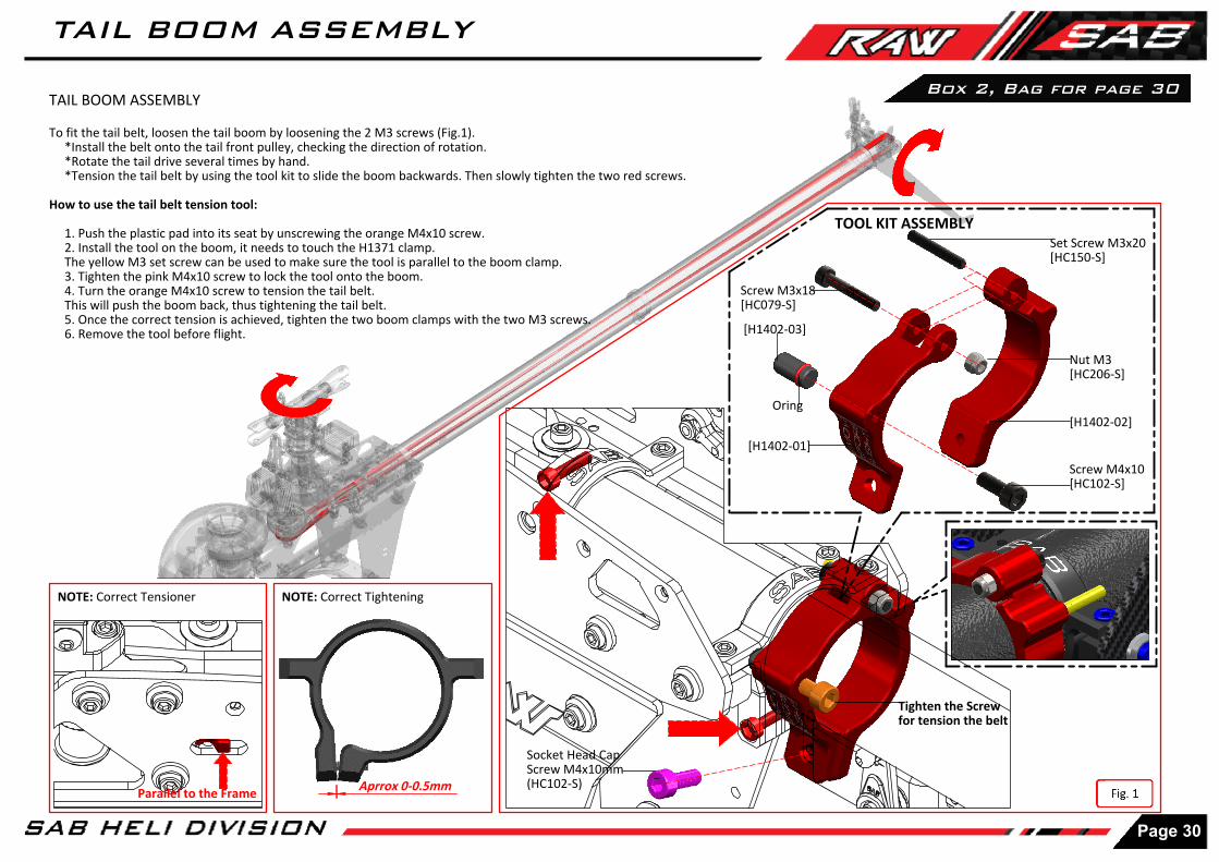
Aprrox 0-0.5mm
Socket Head Cap Screw M4x10mm(HC102-S)
TAIL BOOM ASSEMBLY
To fit the tail belt, loosen the tail boom by loosening the 2 M3 screws (Fig.1). *Install the belt onto the tail front pulley, checking the direction of rotation. *Rotate the tail drive several times by hand. *Tension the tail belt by using the tool kit to slide the boom backwards. Then slowly tighten the two red screws.
How to use the tail belt tension tool:
1. Push the plastic pad into its seat by unscrewing the orange M4x10 screw. 2. Install the tool on the boom, it needs to touch the H1371 clamp. The yellow M3 set screw can be used to make sure the tool is parallel to the boom clamp. 3. Tighten the pink M4x10 screw to lock the tool onto the boom. 4. Turn the orange M4x10 screw to tension the tail belt. This will push the boom back, thus tightening the tail belt. 5. Once the correct tension is achieved, tighten the two boom clamps with the two M3 screws. 6. Remove the tool before flight.
NOTE: Be sure that the servo wire does not get in contact with the belt.
NOTE: Correct Tightening
[H1402-01]
[H1402-02]
[H1402-03]
Oring
Set Screw M3x20[HC150-S]
Nut M3[HC206-S]
Screw M3x18[HC079-S]
Screw M4x10[HC102-S]
Tighten the Screw for tension the belt
TOOL KIT ASSEMBLY
Box 2, Bag for page 30
NOTE: Correct Tensioner
Parallel to the Frame
Page 30
TAIL BOOM ASSEMBLY
Use These Slots
Box 2, Bag for page 31
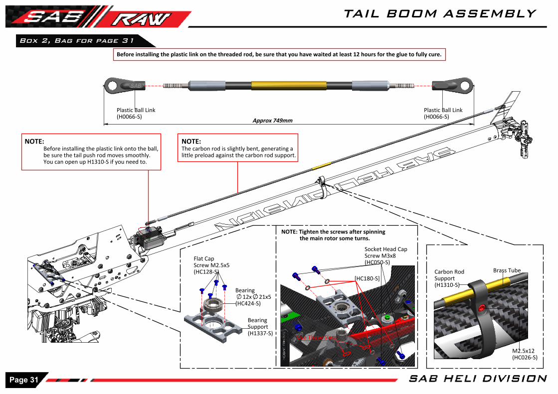
Carbon Rod Support(H1310-S)
Before installing the plastic link on the threaded rod, be sure that you have waited at least 12 hours for the glue to fully cure.
Plastic Ball Link(H0066-S)
Plastic Ball Link(H0066-S)
NOTE:Before installing the plastic link onto the ball, be sure the tail push rod moves smoothly. You can open up H1310-S if you need to.
NOTE:The carbon rod is slightly bent, generating a little preload against the carbon rod support.
Approx 749mm
M2.5x12(HC026-S)
Brass Tube
Bearing Support(H1337-S)
Bearing 12x 21x5
(HC424-S)
Flat Cap Screw M2.5x5(HC128-S)
Socket Head Cap Screw M3x8(HC050-S)
NOTE: Tighten the screws after spinning the main rotor some turns.
[HC180-S]
Page 31
TAIL BOOM ASSEMBLY
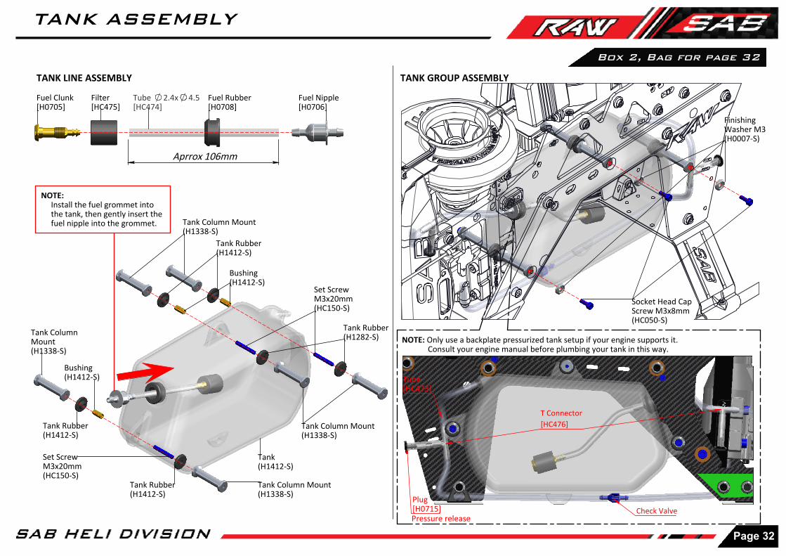
Aprrox 106mm
Tube[HC473]
Plug[H0715]
T Connector[HC476]
Check Valve
Box 2, Bag for page 32
TANK LINE ASSEMBLY
Tank Column Mount(H1338-S)
Fuel Clunk[H0705]
Filter[HC475]
Tube 2.4x 4.5[HC474]
Fuel Rubber[H0708]
Fuel Nipple[H0706]
NOTE: Install the fuel grommet into the tank, then gently insert the fuel nipple into the grommet.
Tank Rubber(H1282-S)
Set Screw M3x20mm(HC150-S)
Tank(H1412-S)
Tank Rubber(H1412-S)
Set Screw M3x20mm(HC150-S)
Tank Column Mount(H1338-S)
Tank Rubber(H1412-S)
Tank Column Mount(H1338-S)
Finishing Washer M3(H0007-S)
Socket Head Cap Screw M3x8mm(HC050-S)
TANK GROUP ASSEMBLY
NOTE: Only use a backplate pressurized tank setup if your engine supports it. Consult your engine manual before plumbing your tank in this way.
Tank Column Mount(H1338-S)
Pressure release
Tank Rubber(H1412-S)
Bushing(H1412-S)
Bushing(H1412-S)
Page 32
TANK ASSEMBLY
Box 2, Bag for page 33
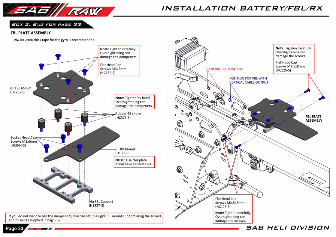
NOTE: 2mm thick tape for the gyro is recommended.
Note: Tighten carefully.Overnightening candamage the dampeners.
Flat Head CapScrews M3x5mm(HC132-S)
CF FBL Mount(H1237-S)
Alu FBL Support(H1237-S)
FBL PLATE ASSEMBLY
Flat Head Cap Screws M2.5x8mm(HC125-S)
Flat Head CapScrews M2.5x8mm(HC125-S)
FBL PLATEASSEMBLY
CF RX Mount(H1399-S)
Socket Head CapScrews M3x6mm(HC044-S)
NOTE: Use this plate if you have separate RX.
Note: Tighten by hand.Overnightening candamage the dampeners.
Rubber 65 shore(HC573-S)
Note: Tighten carefully. Overnightening can damage the screws.
If you do not want to use the dampeners, you can setup a rigid FBL mount support using the screws and bushings supplied in bag 33-2
Note: Tighten carefully. Overnightening can damage the screws.
GENERAL FBL POSITION
POSITION FOR FBL WITH VERTICAL CABLE OUTPUT
Page 33
INSTALLATION BATTERY/FBL/RX

Zip Tie
Zip Tie
NOTE:You will need to cut about 60mmoff the front of the wire support.
Box 2, Bag for page 34
Button Cap ScrewSpecial M2.5x6mm(HC019-S)
Wire Support(H1107-S)
Finishing Washer M3(H0007-S)
Socket Head Cap Screws M3x10(HC056-S)NOTE:You can wait to tighten thisscrew after running all of yourwires on the wire support.
Page 34
INSTALLATION BATTERY/FBL/RX

CONNECTOR
Box 2, Bag for page 35
Washer M3Assembly(H1444-S)
In bag 35, you can find a “3D Printed” antenna support.Use it as desired with your RX system.
Antenna Support[H1134]
Double Side-Tape(HA035-S)
Wire Support(H1444-S)
NOTE:You can wait to tighten this screw after running all of your wires on the wire support.
Wire Support(H1444-S)
Velcro Tape(HA045-S) BATTERY 2S
SERVO WIRES
Page 35
INSTALLATION BATTERY/FBL/RX

CANOPY
*Put canopy and move as (Figure.1) and installation screw (Figure.2)
Canopy Nitro Raw(H1424-S)
Box 2, Bag for page 36
Socket Head Cap Screw M3x14mm.(HC064-S)
Socket Head Cap Screw M3x12mm(HC062-S)
Finishing Washer M3(H0007-S)
Finishing Washer M3(H0007-S)
Finishing Washer M3(H0007-S)
Socket Head Cap Screw M3x12mm(HC062-S)
Black Battery Hatch(H1347-S)
DoubleSide Tape(H1347-S)
Soft Mousse(H1347-S)
Self Head CapScrew M3x10mm(HC136-S)
NOTE:The tab at the bottom of the plastic bottom base will goabove the landing gear. It is normal to feel a little resistancewhen trying to snap the hatch into the closed position.
Rubber Washer2x 10x1mm
[HC612]
Double side Tape[HA081]
Page 36
INSTALLATION CANOPY
Plastic Stop Oring
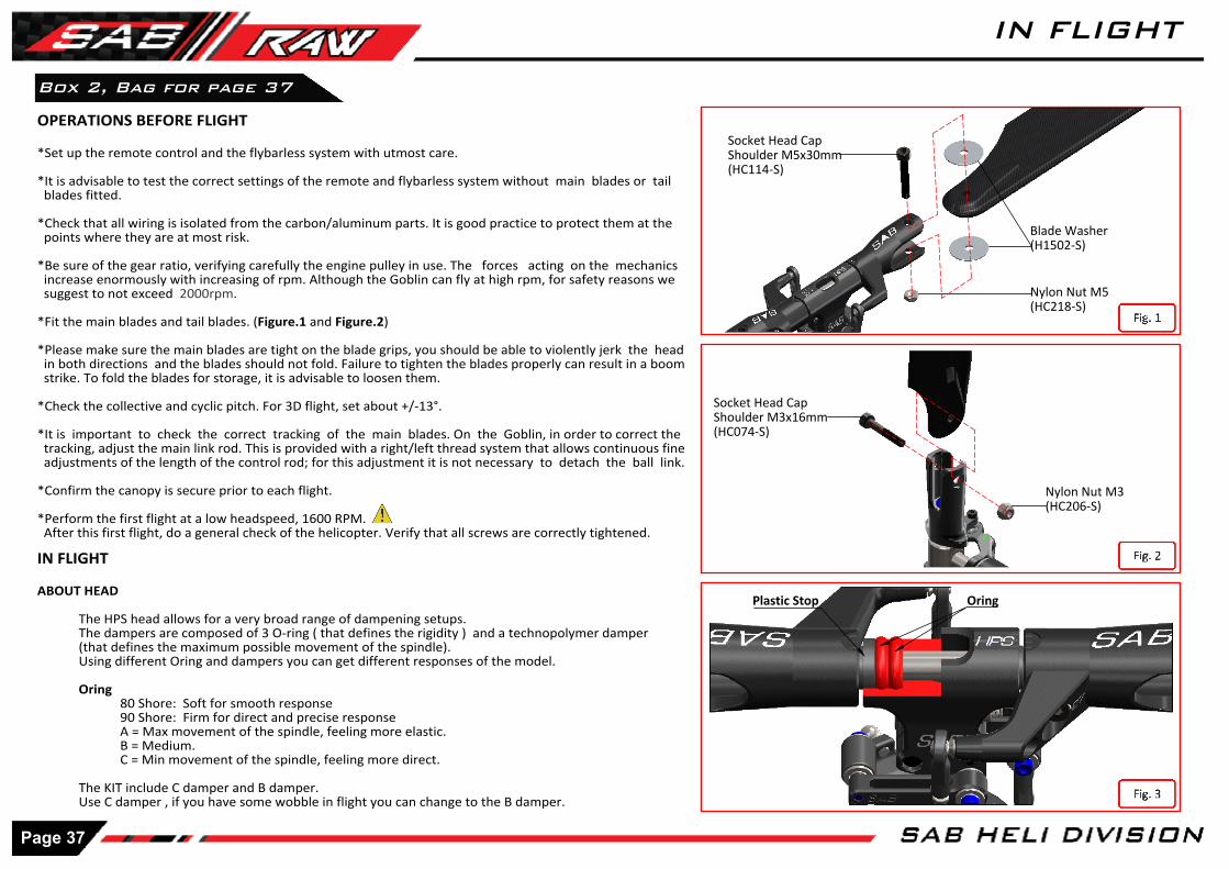
IN FLIGHT
ABOUT HEAD
The HPS head allows for a very broad range of dampening setups.The dampers are composed of 3 O-ring ( that defines the rigidity ) and a technopolymer damper (that defines the maximum possible movement of the spindle).Using different Oring and dampers you can get different responses of the model.
Oring80 Shore: Soft for smooth response90 Shore: Firm for direct and precise responseA = Max movement of the spindle, feeling more elastic.B = Medium.C = Min movement of the spindle, feeling more direct.
The KIT include C damper and B damper.Use C damper , if you have some wobble in flight you can change to the B damper.
OPERATIONS BEFORE FLIGHT
*Set up the remote control and the flybarless system with utmost care.
*It is advisable to test the correct settings of the remote and flybarless system without main blades or tail blades fitted.
*Check that all wiring is isolated from the carbon/aluminum parts. It is good practice to protect them at the points where they are at most risk.
*Be sure of the gear ratio, verifying carefully the engine pulley in use. The forces acting on the mechanics increase enormously with increasing of rpm. Although the Goblin can fly at high rpm, for safety reasons we suggest to not exceed 2000rpm.
*Fit the main blades and tail blades. (Figure.1 and Figure.2)
*Please make sure the main blades are tight on the blade grips, you should be able to violently jerk the head in both directions and the blades should not fold. Failure to tighten the blades properly can result in a boom strike. To fold the blades for storage, it is advisable to loosen them.
*Check the collective and cyclic pitch. For 3D flight, set about +/-13°.
*It is important to check the correct tracking of the main blades. On the Goblin, in order to correct the tracking, adjust the main link rod. This is provided with a right/left thread system that allows continuous fine adjustments of the length of the control rod; for this adjustment it is not necessary to detach the ball link.
*Confirm the canopy is secure prior to each flight.
*Perform the first flight at a low headspeed, 1600 RPM. After this first flight, do a general check of the helicopter. Verify that all screws are correctly tightened.
Socket Head CapShoulder M5x30mm(HC114-S)
Nylon Nut M5(HC218-S)
Nylon Nut M3(HC206-S)
Socket Head CapShoulder M3x16mm(HC074-S)
Box 2, Bag for page 37
Blade Washer(H1502-S)
Page 37
IN FLIGHT
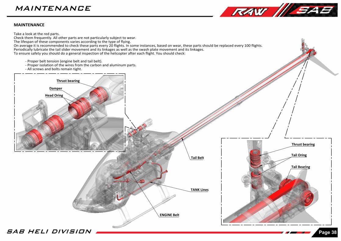
ENGINE Belt
Tail Belt
TANK Lines
Thrust bearing
Damper
Head Oring
Thrust bearing
Tail Bearing
MAINTENANCE
Take a look at the red parts.Check them frequently. All other parts are not particularly subject to wear.The lifespan of these components varies according to the type of flying. On average it is recommended to check these parts every 20 flights. In some instances, based on wear, these parts should be replaced every 100 flights.Periodically lubricate the tail slider movement and its linkages as well as the swash plate movement and its linkages.To ensure safety you should do a general inspection of the helicopter after each flight. You should check:
- Proper belt tension (engine belt and tail belt).- Proper isolation of the wires from the carbon and aluminum parts.- All screws and bolts remain tight.
Tail Oring
Page 38
MAINTENANCE

Ball Bearing 10x 22x6mm
(HC587-S)
Ball Bearing 2Rs 12x 24x6mm
(HC587-S)
1
2
MAIN SHAFT REPLACEMENTFor replacing the main shaft:
*Remove the serial number plate*Remove the M4 screw*Remove and replace the main shaft*Screw in the M4 screw, with high force and using green loctite
Main Top Structure(H1331-S)
Main Shaft(H1330-S)
K Gear Z14 0.75(H1333-S)
K Gear Z58 0.75(H1208-S)
Main Structure(H1332-S)
Use SAB HA076 Grease inside the module.
NOTE:
Before removing the M4 screw, use heat to break down the loctite.(example use a gas torch).
[HC128]
HC230
M4x30(HC587-S)
Pin 3x6
Bushing(H1334-S)
Ball Bearing 2Rs 10x 24x7mm
(HC587-S)
Ball Bearing 6x 13x5mm
(HC587-S)
Bushing(HC587-S)
Shim(HC587-S)
HC232
NOTE:
Before to open the transmission module, use heat to neutralize the loctite. (example use a gas torch)
TRANMISSION MODULEThe transmission module is supplied assembled and verified, ready to be used.Explode and Spare Parts
Page 39
TRANSMISSION MODULE
Page 40
CHECK LIST
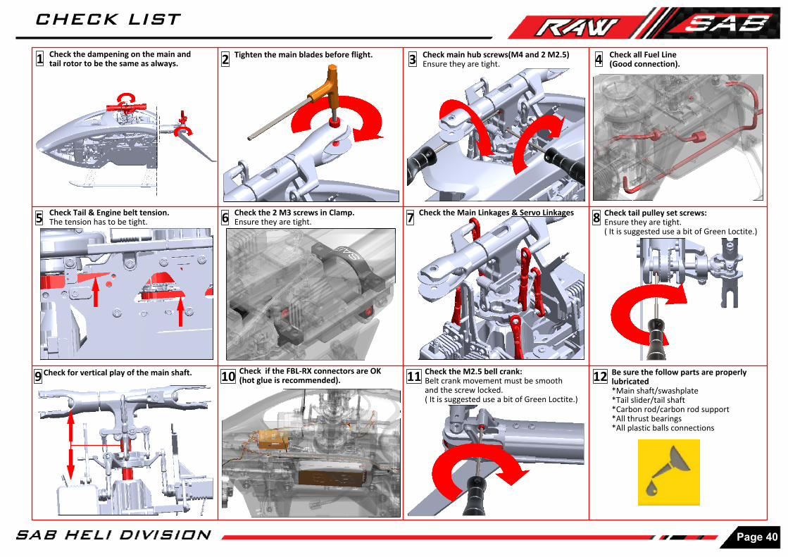
9
Check Tail & Engine belt tension. The tension has to be tight.
10 Check if the FBL-RX connectors are OK(hot glue is recommended). 11 Check the M2.5 bell crank:
Belt crank movement must be smooth and the screw locked.( It is suggested use a bit of Green Loctite.)
Be sure the follow parts are properly lubricated*Main shaft/swashplate*Tail slider/tail shaft*Carbon rod/carbon rod support*All thrust bearings*All plastic balls connections
12
Check tail pulley set screws: Ensure they are tight.( It is suggested use a bit of Green Loctite.)
8
Check all Fuel Line(Good connection).4
7 Check the Main Linkages & Servo Linkages
Check for vertical play of the main shaft.
65 Check the 2 M3 screws in Clamp. Ensure they are tight.
1 2 3 Check main hub screws(M4 and 2 M2.5) Ensure they are tight.
Tighten the main blades before flight.Check the dampening on the main and tail rotor to be the same as always.

- 10 x Plastic Ball Link.
Plastic Ball Link[H0066-S]
- 5 x Uniballs M3x4 5H3.5.
Uniball M3x4 5H3[H0065-S]
- 5 x Uniballs M2.- 5 x Uniball Spacers.- 5 x Head Cap Screws M2x8.- 5 x Head Cap Screws M2x6.
Uniball M2 5H6[H0064-S]
- 10 x Finishing Washers M3.
Finishing Washer M3[H0007-S]
- 10 x Servo Spacers.
Servo Spacer[H0075-S]
- 2 x Plastic Tail Linkage.- 2 x Grip Link Bushing.- 2 x Head Cap Screws M2x6.
Plastic Tail Linkage [H0261-S]
- 10 x Finishing Washer M2.5.
Finishing Washer M2.5 [H0255-S]
- 1 x Tail Spindle.- 2 x Head Cap Screws M3x6.
Spacer[H0219-S]
Tail Spindle[H0220-S]
Radius Arm HPS[H0204BM-S]
- 8 x Flanged Bearing 2.5x 6x2.5.- 2 x Washer 2.5x4x0.3mm.- 2 x Head Cap Screw M2.5x15.- 2 x Head Cap Screw M2.5x18. - 2 x Radius Plastic Arm.
Radius Plastic Arm[H0205-S]
Plastic Ball Link[H0403-S]
- 5 x Plastic Ball Link.
Uniball[H0538-S]
- 5 x UniBall.
Plastic Fan Case SET[H0662-S]
- 1 x Plastic Fan Case Left.- 1 x Plastic Fan Case Right.- 4 x Finishing Washer M3.- 4 x Head Cap Screws M3x10mm.- 5 x Head Cap Screws M2.5x10mm.
Engine Mount[H0665-S]
- 1 x Engine Mount Left.- 1 x Engine Mount Right. - 1 x Engine Shaft YS.
Engine Shaft YS[H0668-A-S]
Engine Shaft OS[H0668-B-S]
- 1 x Engine Shaft OS.
Spacer[H0062-S]
- 4 x Spacer 7x 9x0,5mm.
- 2 x Radius Arm.- 2 x Spacer Arm 2.5x4x6.3.- 2 x Spacer Arm 2.5x4x3mm.- 2 x Uniball Radius Arm. - 2 x Spacer 4x 6,9x0,5mm.
Servo Block [H0392-S]
- 8 x Servo Block.- 8 x Servo Spacer.- 16 x Head Screws M2.5x10.
Steel Clutch[H0670-S]
- 1 x Steel Clutch.- 2 x Button Cap Screw M4x8.
- 1 x Aluminum Engine Fan.- 4 x Flat Head Cap M3x8mm.
Aluminum Engine Fan[H0671BM-S]
- 1 x Aluminum Clutch Support.
Aluminum Clutch Support[H0672-S]
- 1 x Clutch Bell.- 1 x Clutch Line.
Aluminum Clutch Bell[H0674BL-S]
- 1 x Z26 to Z28 Nitro Pulley.- 1 x Nitro Pulley Flange.- 3 x Radial Bearing 12x 18x4mm.
Aluminum Engine Pulley 26T to 28T[H0675BL-26-28-S]
- 2 x Engine Support Spacer.- 2 x Socket Screw M3x8mm.- 2 x Flat Screw M3x8mm.
Engine Support Spacer[H0682-S]
- 4 x Engine Frame Spacer.- 4 x Button Screw M3x6mm.
Engine Frame Spacer[H0678BM-S]
Page 41
SPARE PARTS
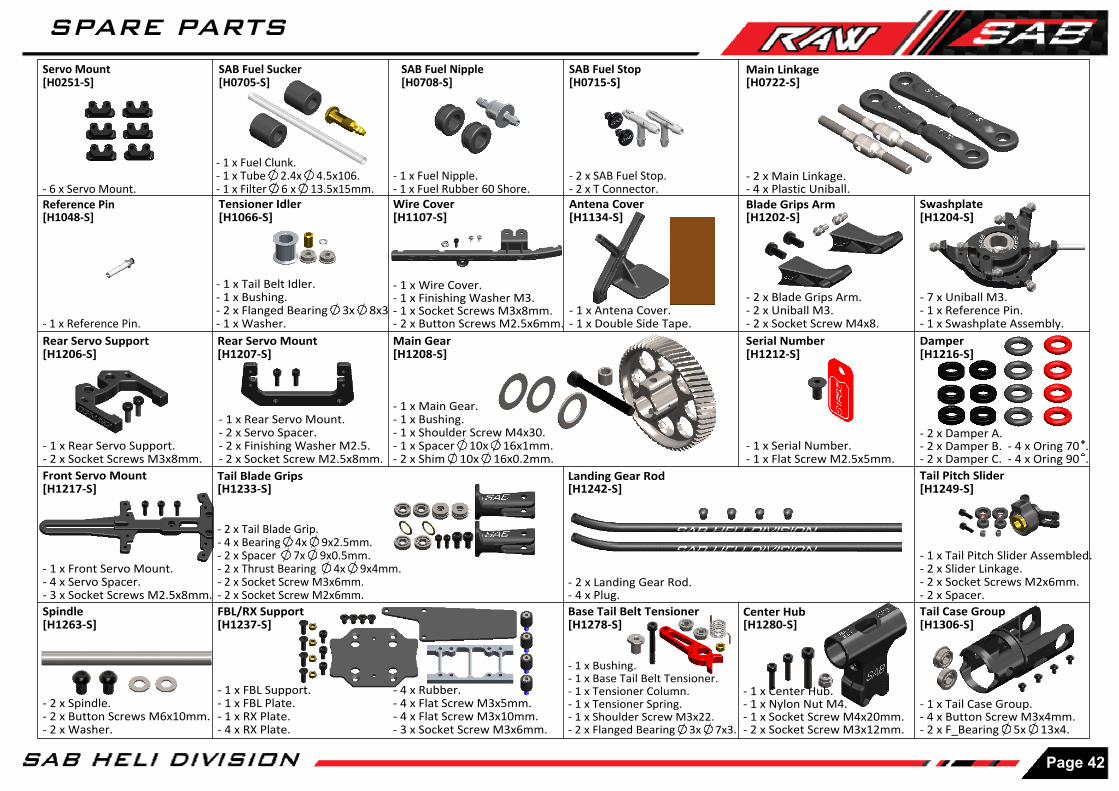
Tensioner Idler[H1066-S]
- 1 x Tail Belt Idler.- 1 x Bushing.- 2 x Flanged Bearing 3x 8x3- 1 x Washer.
- 2 x SAB Fuel Stop.- 2 x T Connector.
SAB Fuel Stop [H0715-S]
- 1 x Fuel Nipple.- 1 x Fuel Rubber 60 Shore.
SAB Fuel Nipple[H0708-S]
- 1 x Fuel Clunk.- 1 x Tube 2.4x 4.5x106.- 1 x Filter 6 x 13.5x15mm.
SAB Fuel Sucker[H0705-S]
Reference Pin[H1048-S]
- 1 x Reference Pin.
- 1 x Wire Cover.- 1 x Finishing Washer M3.- 1 x Socket Screws M3x8mm.- 2 x Button Screws M2.5x6mm.
Wire Cover[H1107-S]
Rear Servo Support[H1206-S]
- 7 x Uniball M3.- 1 x Reference Pin.- 1 x Swashplate Assembly.
Swashplate[H1204-S]
Rear Servo Mount[H1207-S]
- 1 x Rear Servo Mount.- 2 x Servo Spacer.- 2 x Finishing Washer M2.5.- 2 x Socket Screw M2.5x8mm.
Damper[H1216-S]
- 4 x Oring 70 .- 4 x Oring 90 .
- 2 x Damper A.- 2 x Damper B.- 2 x Damper C.
- 1 x Main Gear.- 1 x Bushing.- 1 x Shoulder Screw M4x30.- 1 x Spacer 10x 16x1mm.- 2 x Shim 10x 16x0.2mm.
Main Gear[H1208-S]
Servo Mount[H0251-S]
- 6 x Servo Mount.Antena Cover[H1134-S]
- 1 x Antena Cover.- 1 x Double Side Tape.
Blade Grips Arm[H1202-S]
- 2 x Blade Grips Arm.- 2 x Uniball M3.- 2 x Socket Screw M4x8.Serial Number[H1212-S]
- 1 x Serial Number.- 1 x Flat Screw M2.5x5mm.
Front Servo Mount[H1217-S]
- 1 x Rear Servo Support.- 2 x Socket Screws M3x8mm.
- 1 x Front Servo Mount.- 4 x Servo Spacer.- 3 x Socket Screws M2.5x8mm.
Tail Blade Grips[H1233-S]
- 2 x Tail Blade Grip.- 4 x Bearing 4x 9x2.5mm.- 2 x Spacer 7x 9x0.5mm.- 2 x Thrust Bearing 4x 9x4mm.- 2 x Socket Screw M3x6mm.- 2 x Socket Screw M2x6mm.
- 1 x Tail Pitch Slider Assembled.- 2 x Slider Linkage.- 2 x Socket Screws M2x6mm.- 2 x Spacer.
Tail Pitch Slider[H1249-S]
Spindle[H1263-S]
- 2 x Spindle.- 2 x Button Screws M6x10mm.- 2 x Washer.
Landing Gear Rod[H1242-S]
- 2 x Landing Gear Rod.- 4 x Plug.
- 4 x Rubber.- 4 x Flat Screw M3x5mm.- 4 x Flat Screw M3x10mm.- 3 x Socket Screw M3x6mm.
- 1 x FBL Support.- 1 x FBL Plate.- 1 x RX Plate.- 4 x RX Plate.
FBL/RX Support[H1237-S]
Center Hub[H1280-S]
- 1 x Center Hub.- 1 x Nylon Nut M4.- 1 x Socket Screw M4x20mm.- 2 x Socket Screw M3x12mm.
- 1 x Bushing.- 1 x Base Tail Belt Tensioner.- 1 x Tensioner Column.- 1 x Tensioner Spring.- 1 x Shoulder Screw M3x22.- 2 x Flanged Bearing 3x 7x3.
Base Tail Belt Tensioner[H1278-S]
- 1 x Tail Case Group.- 4 x Button Screw M3x4mm.- 2 x F_Bearing 5x 13x4.
Tail Case Group[H1306-S]
Main Linkage[H0722-S]
- 2 x Main Linkage.- 4 x Plastic Uniball.
Page 42
SPARE PARTS

Tail Pulley 22T[H1312-22-S]
- 1 x Tail Pulley 23T.- 1 x Set Screw M3x6mm.
Carbon Rod Support[H1310-S]
- 1 x Carbon Rod Support.- 1 x Socket Screw M2.5x12.
Tail Shaft[H1313-S]
- 1 x Tail Shaft.- 1 x Tail Hub.- 2 x Oring.
Main Shaft[H1330-S]
Pinion[H1333-S]
- 1 x Pinion.- 2 x Shim 6x 9 x 0.2mm.
- 1 x SAB Fuel Tank.- 4 x Fuel Rubber.- 2 x Bushing.
SAB Fuel Tank[H1412-S]
- 1 x Main Structure.- 2 x Pin 3x6.- 1 x Bearing 10x 22x6mm.- 1 x Bearing 2RS 12x 24x6.
Top Case[H1331-S]
- 1 x Main Shaft.- 1 x Shoulder Screw M4x30.- 1 x Bushing.- 2 x Shim 10x 16x0.2mm.
Main Structure[H1332-S]
- 1 x Main Case.- 5 x Socket Screws M3x12mm.- 1 x Bearing 2Rs 10x 24x7mm.- 1 x Bearing 6x 13x5mm.
Gear Bushing[H1334-S]
- 1 x Gear Bushing.- 2 x Shim 10x 16x0.2mm.- 1 x Washer 10x 16x1mm.
Main Pulley[H1335-S]
- 1 x Main Pulley SET.- 1 x Bushing.- 1 x Shim 12x 16x0.1mm.
Front Tail Pulley[H1336-S]
- 1 x Front Tail Pulley SET.- 3 x Shim 12x 16x0.1mm.
Bearing Support[H1337-S]
Tank Column[H1338-S]
Carbon Tail Boom[H1339-S]
- 1 x Tail Belt Ilder Mount.- 2 x Socket Screw M3x12mm.- 2 x Shim 3x 6x0.5mm.
Tail Belt Ilder Mount[H1341-S]
- 1 x Carbon Tail Boom.
- 1 x Bearing Support.- 1 xBearing 12x 21x5mm .- 4 x Socket Screw M3x8mm.- 4 x Flat Screw M2.5x5mm.
- 2 x Tank Column.- 1 x Set Screw M3x20.
Bell Crank Base[H1314-S]
- 1 x Bell Crank Base.- 1 x Socket Screw M2.5x8mm.
LOWER Main Frame[H1344-S]
- 1 x LOWER Main Frame.- 1 x Green Sticker.
Frame Spacer[H1340-S]
- 8 x Frame Spacer.- 2 x Soft Mousse.- 2 x Double Side Tape.
- 1 x Black Battery Hatch.- 2 x Tapping Screws M3x10mm.
Black Battery Hatch[H1347-S]
- 1 x Boom Mount Support.- 4 x Finishing Washer M3.- 4 x Socket Screws M3x10.
Boom Mount Support[H1350-S]
Canopy Spacer[H1348-S]
- 1 x Canopy Spacer.- 2 x Flat Screws M2.5x8mm.- 2 x Nylon Nut M3.
- 2 x Set Sticker.- 2 x CF Low Side Frame Front.
CF Low Side Frame Front[H1358-S]
- 1 x Tail Servo Mount.- 2 x Socket Screw M3x12mm.
Tail Servo Mount[H1353-S]
Page 43
SPARE PARTS
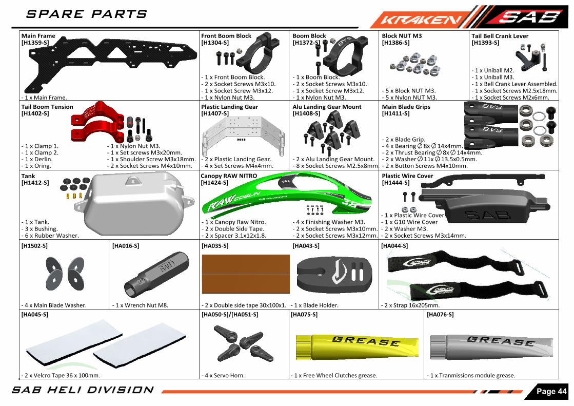
Canopy RAW NITRO[H1424-S]
- 1 x Canopy Raw Nitro.- 2 x Double Side Tape.- 2 x Spacer 3.1x12x1.8.
- 1 x Boom Block.- 2 x Socket Screws M3x10.- 1 x Socket Screw M3x12.- 1 x Nylon Nut M3.
Boom Block[H1372-S]
Block NUT M3[H1386-S]
- 5 x Block NUT M3.- 5 x Nylon NUT M3.
Main Frame[H1359-S]
- 1 x Main Frame.Main Blade Grips[H1411-S]
- 2 x Blade Grip.- 4 x Bearing 8x 14x4mm.- 2 x Thrust Bearing 8x 14x4mm.- 2 x Washer 11x 13.5x0.5mm.- 2 x Button Screws M4x10mm.
Tail Bell Crank Lever [H1393-S]
- 1 x Uniball M2.- 1 x Uniball M3.- 1 x Bell Crank Lever Assembled.- 1 x Socket Screws M2.5x18mm.- 1 x Socket Screws M2x6mm.
- 1 x Blade Holder.
[HA043-S]
- 1 x Tranmissions module grease.
[HA076-S][HA075-S]
- 1 x Free Wheel Clutches grease.- 4 x Servo Horn.
[HA050-S]/[HA051-S]- 2 x Double side tape 30x100x1. - 2 x Strap 16x205mm.
[HA044-S][HA035-S]
Tail Boom Tension[H1402-S]
- 1 x Nylon Nut M3.- 1 x Set screws M3x20mm.- 1 x Shoulder Screw M3x18mm.- 2 x Socket Screws M4x10mm.
[HA016-S]
[HA045-S]- 1 x Wrench Nut M8.
- 2 x Velcro Tape 36 x 100mm.
Front Boom Block[H1304-S]
- 1 x Front Boom Block.- 2 x Socket Screws M3x10.- 1 x Socket Screw M3x12.- 1 x Nylon Nut M3.
- 1 x Clamp 1.- 1 x Clamp 2.- 1 x Derlin.- 1 x Oring.
- 2 x Plastic Landing Gear.- 4 x Set Screws M4x4mm.
Plastic Landing Gear[H1407-S]
- 2 x Alu Landing Gear Mount.- 8 x Socket Screws M2.5x8mm.
Alu Landing Gear Mount[H1408-S]
Tank[H1412-S]
- 1 x Tank.- 3 x Bushing.- 6 x Rubber Washer.
- 4 x Finishing Washer M3.- 2 x Socket Screws M3x10mm. - 2 x Socket Screws M3x12mm.
Plastic Wire Cover[H1444-S]
- 1 x Plastic Wire Cover. - 1 x G10 Wire Cover- 2 x Washer M3. - 2 x Socket Screws M3x14mm.
[H1502-S]
- 4 x Main Blade Washer.
Page 44
SPARE PARTS

[HC004-S]
- 8 x Socket Head Cap Screws M2x6mm.
[HC008-S] [HC018-S] [HC019-S] [HC020-S] [HC022-S]
- 8 x Socket Head Cap Screws M2x8mm.
- 8 x Socket Head Cap Screws M2.5x8mm.
- 8 x Button Head Cap Screws M2.5x6mm.
- 8 x Socket Head Cap Screws M2.5x8mm.
[HC038-S]
[HC026-S]
- 8 x Socket Head Cap Screws M3x14mm.
- 5 x Washer 10x 16x0.2mm.
- 5 x Washer 10x 16x1mm.- 8 x Nylon Nut M4.- 8 x Nylon Nut M3.
- 5 x Washer 6x 12x1mm.
- 5 x Washer 3.2x 6x0.5mm.- 8 x Set Screws M4x6.- 8 x Set Screws M4x4.
- 8 x Flat Head Cap Screws M3x5mm.
[HC206-S] [HC212-S] [HC230-S] [HC232-S] [HC242-S]
- 3 x Thread Rod M2.5x40mm.
[HC140-S]
- 8 x Set Screws M2.5x18.[HC152-S] [HC153-S] [HC176-S] [HC180-S] [HC193-S]
- 5 x Washer 3x 4x0.5mm.
[HC122-S] [HC125-S] [HC128-S] [HC132-S]
- 8 x Button Head Cap Screws M6x10mm.
- 8 x Flat Head Cap Screws M2.5x8mm.
- 8 x Flat Head Cap Screws M2.5x5mm.
[HC086-S]
- 8 x Socket Head Cap Screws M3x22mm.
[HC094-S] [HC098-S] [HC102-S] [HC103-S] [HC111-S]
- 8 x Button Head Cap Screws M3x6mm.
- 8 x Button Head Cap Screws M4x8mm.
- 8 x Socket Head Cap Screws M4x10mm.
- 8 x Socket Head Cap Screws M4x15mm.
- 8 x Socket Shoulder Screws M4x24.
- 8 x Socket Head Cap Screws M3x12mm.
- 8 x Socket Head Cap Screws M3x10mm.
- 8 x Socket Head Cap Screws M3x8mm.
[HC068-S][HC062-S][HC056-S][HC050-S]
- 8 x Socket Head Cap Screws M3x6mm.
[HC044-S]
- 8 x Socket Head Cap Screws M2.5x10.
- 8 x Socket Head Cap Screws M2.5x12.
[HC032-S]
- 8 x Socket Head Cap Screws M2.5x18.
- 8 x Button Head Cap Screws M3x4mm.
[HC074-S]
- 2 x Socket Shoulder Screws M3x16.- 2 x Nylon Nut M3.
[HC104-S]
- 8 x Socket Head Cap Screws M4x22mm.
[HC144-S]
- 8 x Set Screws M3x6.
[HC150-S]
- 8 x Set Screws M2.5x20.
[HC197-S]
- 8 x Nylon Nut M2.[HC243-S]
- 2 x Thread Rod M2x64mm. - 1 x Tail Belt 2004mm.
[HC477-S] [HC330-S]
- 4 x Oring Damper.
[HC064-S]
- 8 x Socket Head Cap Screws M3x16mm.
[HC079-S]
- 2 x Socket Shoulder Screws M3x18.- 2 x Nylon Nut M3.
[HC134-S]
- 8 x Flat Head Cap Screws M3x8mm.
[HC135-S] [HC136-S]
- 8 x Flat Head Cap Screws M3x10mm.
- 8 x Tapping Head Cap Screws M3x10mm.
Page 45
SPARE PARTS
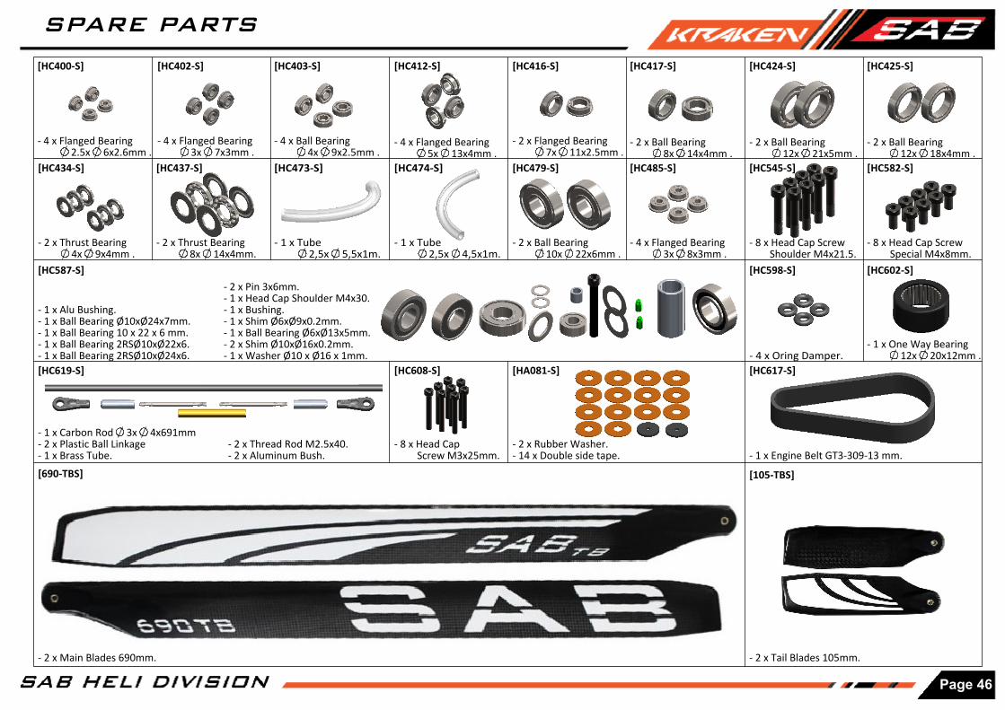
[HC402-S] [HC416-S]
[HC437-S][HC434-S]
[HC425-S][HC424-S][HC417-S]
[HC582-S]
- 2 x Tail Blades 105mm.
[105-TBS][690-TBS]
[HC545-S]
- 1 x Engine Belt GT3-309-13 mm.
- 1 x Carbon Rod 3x 4x691mm- 2 x Plastic Ball Linkage- 1 x Brass Tube.
- 2 x Main Blades 690mm.
- 4 x Flanged Bearing 3x 7x3mm .
- 2 x Flanged Bearing 7x 11x2.5mm .
- 2 x Ball Bearing 8x 14x4mm .
- 2 x Ball Bearing 12x 21x5mm .
- 2 x Ball Bearing 12x 18x4mm .
- 2 x Thrust Bearing 4x 9x4mm .
- 2 x Thrust Bearing 8x 14x4mm.
[HC403-S]
- 4 x Ball Bearing 4x 9x2.5mm .
- 4 x Flanged Bearing 5x 13x4mm .
[HC412-S]
[HC474-S]
- 1 x Tube 2,5x 4,5x1m.
- 1 x Tube 2,5x 5,5x1m.
[HC473-S]
- 2 x Ball Bearing 10x 22x6mm .
[HC479-S] [HC485-S]
- 4 x Flanged Bearing 3x 8x3mm .
- 8 x Head Cap Screw Special M4x8mm.
[HC587-S]
- 1 x Alu Bushing.- 1 x Ball Bearing Ø10xØ24x7mm.- 1 x Ball Bearing 10 x 22 x 6 mm.- 1 x Ball Bearing 2RSØ10xØ22x6.- 1 x Ball Bearing 2RSØ10xØ24x6.
- 2 x Pin 3x6mm.- 1 x Head Cap Shoulder M4x30.- 1 x Bushing.- 1 x Shim Ø6xØ9x0.2mm.- 1 x Ball Bearing Ø6xØ13x5mm.- 2 x Shim Ø10xØ16x0.2mm.- 1 x Washer Ø10 x Ø16 x 1mm.
- 8 x Head Cap Screw Shoulder M4x21.5.
[HC619-S]
- 2 x Thread Rod M2.5x40.- 2 x Aluminum Bush.
[HC608-S]
- 8 x Head Cap Screw M3x25mm.
[HC617-S]
- 4 x Flanged Bearing 2.5x 6x2.6mm .
[HC400-S]
[HC598-S]
- 4 x Oring Damper.
[HC602-S]
- 1 x One Way Bearing 12x 20x12mm .
[HA081-S]
- 2 x Rubber Washer.- 14 x Double side tape.
Page 46
SPARE PARTS