integrating water elements into architectural ... - cloudfront.net
TRANSCRIPT

AS197358
Integrating Water Elements into Architectural Renderings Using Particle Flow Steven Schain Post Production Supervisor / M & E Content Manager 4D Technologies
Learning Objectives
1. Create a liquid simulation to simulate fountains and other water features. 2. Configure the fluid simulation setup for water features. 3. Assign a Motion Field space warp to affect the flow of the water. 4. Apply materials and render the fluid using the Arnold® renderer.
Description
Many architectural designs incorporate a water feature as a prominent visual component of the structure. This class explains how to implement 3ds Max Fluids for the creation of these features. This class takes you through the process of creating animated water fountains and tranquil waterfalls that can be found in a variety of landscapes. You will learn how to simulate water flow using Max Fluids and the Motion Field spacewarp. You will also learn how to apply a custom material to render realistic water. This class will step through the process of building a fluid flow from beginning to end using the capabilities built into the Max Liquid fluid dynamics system.
About the Speaker
Steven Schain is the post-production supervisor for all CADLearning products from 4D Technologies, as well as the content development manager of CADLearning's Media & Entertainment products for Autodesk, Inc. software, including 3ds Max and Maya. In 1998, Autodesk recognized Steven as one of only 16 Autodesk Training specialists worldwide. He has since contributed to Autodesk's certified courseware for 9 releases of 3ds Max, was a co-developer of Autodesk's ACI Program and 3ds Max’s fundamental standards, and is currently an Autodesk Certified Instructor. As a premier Autodesk trainer, he has continued teaching end users, companies, and many others, including The Walt Disney Company, Guess, and the United States Army. As a 7-year veteran of Autodesk University, Steven has taught classes ranging from creating particle fountains in 3ds Max, to classes on 3D printing and entrepreneurship. [email protected]

i
Contents Introduction .................................................................................................................................................. 1
Setting up the Scene ..................................................................................................................................... 1
Creating a Fluid Simulation ........................................................................................................................... 2
Add a Liquid Object ....................................................................................................................................... 3
Fluid Setup .................................................................................................................................................... 5
Editing Liquid Attributes ............................................................................................................................... 5
Adding an Emitter ..................................................................................................................................... 6
Adding Colliders and a Kill Plane ............................................................................................................... 6
Editing Solver Parameters ............................................................................................................................. 7
Adjusting Simulation Parameters ............................................................................................................. 7
Configuring Liquid Parameters ............................................................................................................... 10
Editing Emitter Object Parameters ......................................................................................................... 11
Modifying Collision Object Parameters .................................................................................................. 14
Caching .................................................................................................................................................... 15
Modifying viewport display settings ....................................................................................................... 16
Configuring render settings .................................................................................................................... 18
Solving the Simulation ................................................................................................................................ 20
Applying Materials ...................................................................................................................................... 20
Creating and Assigning a Water Material ............................................................................................... 20
Creating a Simple Water Material .......................................................................................................... 20
Assigning the Material ............................................................................................................................ 21
Rendering the Fountain .............................................................................................................................. 22
Creating a preview ...................................................................................................................................... 22
Rendering with Arnold ................................................................................................................................ 23
Render a Low-Resolution Animation .......................................................................................................... 24

1
Introduction
As an architect or designer, Autodesk’s design software allows you to create buildable fountain designs for anything from simple water pools to highly complex, articulated, multi-water jet fountains. Often, it is helpful to see a design animated to see how the water features will look once they are assembled and functioning. While you can create a static model of the water streams that shoot from the jets, to visualize the actual fountain, the water jets can be animated using several methods. Max Fluids is the most ideal method. It can be used for creating a dynamic simulation of water jets and other water features. 3ds Max is the ideal environment for creating animated versions of fountain designs. Whether the model is built within 3ds Max or is imported from another program, such as Autodesk Revit, you can create the animation for the water using the fluid system built into 3ds Max. With Fluids, you can add physically based simulations, as well as realistic water materials. This can be used to create a complex animated fountain system. Controlling the simulation of the water is what makes Fluids in 3ds Max a better solution than simply using a standard particle system. While a particle system can portray the motion of water spraying from a jet and colliding with another surface, presenting a realistic animation involves being able to simulate the complex dynamics of water within a scene. Fluid has the needed capabilities for simulating liquid and its interaction with objects, which makes it possible to create fountains with multiple flows. Once the fluid simulation is complete, you can output both a preview animation and a fully rendered sequence. In many cases, an animated sequence is rendered to a video file that can be played back at full speed. The level of quality of the final rendering is based on your requirements. If you’re running a test to see if the animation looks the way you want it to, you can save a preview rendering of the viewport. When it comes time to creating a final, high-quality rendering, the Arnold rendering engine can create a realistic rendered animation. This class will discuss and outline the steps you would take to create the water features in an architectural fountain and then render the animation to a fully rendered sequence using 3ds Max.
Setting up the Scene
The scene being used in this lesson is an architectural fountain that contains a waterfall in the pool area, a spherical stone located in the middle of the fountain. When determining what needs to happen in this scene, the water in the waterfall will continuously fall from the back of the fountain and bounce off the spherical stone in the center. The water should not just completely bounce away; some of the water should run down the spherical stone. To accomplish this, you will use the Fluid the simulation tools available in 3ds Max.

2
THE FOUNTAIN AS SEEN IN THE FOUR VIEWPORT LAYOUT
Creating a Fluid Simulation
The fluid system built into 3ds Max is a highly capable fluid dynamics simulation system. With Max Fluids, you can create fluid animations ranging from simple water drops; to highly complex fluid simulations with multiple fluid types, and even foam. Unlike particle systems that allow you to create the effect of simulated liquid, Fluids in 3ds Max provides a true physical simulation. A fluid simulation is created using the Liquid object, which is based on the Bifrost fluid simulation system. Bifrost allows you to create different kinds of fluid simulations. For example, you can create ocean waves with crashing sea foam, or chocolate syrup pouring over some pancakes. This is all done through the Fluids simulation system using the Liquid object. Once a liquid object is added to the scene, you can open the simulation view to begin creating a liquid simulation.

3
THE SIMULATION VIEW DIALOG
To start here, use: Fluid_Fountain_01.max
Add a Liquid Object Once the scene is set up with materials, lighting, cameras, etc., it’s time to create the fluid simulation. The first step is to add a Liquid object into the scene. Then, you open the Simulation view to begin creating the particle flow.
1. In the Command panel, click the Create tab. 2. In the Create Geometry drop-down, choose Fluids. 3. Expand the Object Type rollout and select Liquid.

4
4. In the Fountain Cam viewport, click and drag on the upper left side to create a small Liquid object. In this case, the size does not make any difference.
5. Now in the Command panel, switch over to the Modify panel.

5
6. With the Liquid001 object selected, in the Setup rollout, click Simulation View to open the Simulation View dialog box.
THE SIMULATION VIEW DIALOG BOX WITH THE LIQUID OBJECT ADDED TO THE SCENE.
Fluid Setup When creating fluid simulations, an important option that you should look at first is the Solver Parameters > Master Voxel Size. This determines the resolution of the space when the liquid is simulated. A smaller number increases the resolution, while a larger number decreases it. When working with Fluids in 3ds Max, you can quickly create a large number of particles if your Master Voxel size is too small. This is critical, because the more particles are created that it has to calculate, the more memory is required. Getting the right Voxel size is important. A Voxel size that’s too large will create an inaccurate simulation, and one that’s too small will create a simulation that utilizes more memory and takes longer to calculate than is necessary. While there is no magic number for this, you can start out with a larger value and incrementally decrease it until you get the result you’re looking for. Before you begin making changes to the Solver parameters, you must first set up the liquid attributes and add emitters, colliders, a kill plane, and in this case, a guide system and motion field.
Editing Liquid Attributes Once a liquid object is created, you need to begin by editing the liquid attributes for the simulation. The first thing you’ll need to add is an emitter. While you can use the liquid icon as either a sphere, box, or plane emitter, you can also select a custom object. This allows you to emit fluid from any object in the scene. In this scene, there is a box placed where water would be coming up into the waterfall for the fountain. This will be used as the emitter for the water in the scene.

6
Adding an Emitter 7. In the Simulation View dialog, Liquid Attributes tab, Emitters rollout, change the Icon
Type to Custom from the drop-down.
ICON TYPE SHOWN AS CUSTOM.
8. In the Add Custom Emitter Objects group, click Add. 9. In the Add Emitters dialog box, hold the CTRL key and select Fluid Emitter and
Fountain Liquid Container, and then click Add to add these to the list of emitters.
Adding Colliders and a Kill Plane Once you’ve added the emitter, you need to add the objects in the scene that the fluid will collide with. In this case, it will collide with the sphere, the waterfall, and the fountain pool. Once the colliders are added, adding a kill plane will make sure that any fluid particle that touches the kill plane is automatically deleted. This ensures that the fluid particles do not live forever in the scene, which makes it more efficient and it uses less memory.
10. In the Colliders/Kill Planes rollout, Add Colliders group, click the Pick button. In the camera viewport, select the Wall_Collider object, the Granite Sphere object, and the Fountain Wall object.
11. In the Add Kill Planes group, click the Add button. 12. In the Add Kill Planes dialog, click Kill Plane, and then click Add.
13. Click Pick again to stop picking objects.

7
The last item for the moment is to add a motion field. The motion field can be used to apply different forces to particles, fluids, and the vertices of polygon objects. In this case, the motion field will be used to add just a little bit of velocity to the water coming out of the waterfall. While there are alternative ways to accomplish the same task, this is a simple and flexible method, as it allows you to limit the area of influence, causing the liquid to be affected by the motion field within a given envelope. 14. In the Motion Field rollout, Add Motion Fields group, click the Add button. 15. In the Add Motion Fields dialog, click Motion Field, and then click Add.
Editing Solver Parameters Once you’re finished adding the various objects to the Liquid Attributes tab, it’s time to move on to editing the Solver parameters. The Solver parameters define various aspects of the simulation of fluid within the scene for this liquid. Some of those aspects include options like the Master Voxel size, simulation fidelity, what type of liquid is being simulated, and the parameters for the emitter and collision objects.
Adjusting Simulation Parameters There are two rollouts in the simulation parameters configuration: General Parameters, and Simulation Parameters. The General Parameters allow you to specify the frame range for the simulation, along with the system scale and the properties for the Solver that are being used. The second rollout, Simulation Parameters, contains options for transport steps, time steps, and Voxel scaling that affect the fidelity of the simulation. Time steps, for example, can greatly increase the quality of the simulation by sampling more times per frame during simulation calculation.

8
THE SIMULATION PARAMETERS PANEL.
To start from here, use: Fluid_Fountain_03.max One of the most critical values that needs to be adjusted for any fluid simulation is the Master Voxel size. This value determines the overall subdivision of the space within 3ds Max. The Master Voxel Size can also be visualized by looking at the fluid icon in the viewport when the Show Voxel Grid option is checked. This option displays a small box that represents the size of each voxel within the scene. Decreasing the Master Voxel Size will increase the resolution of the simulation. While this will make the simulation more accurate, it also increases the amount of memory required and the length of time it will take to calculate the simulation. Increasing the Master Voxel Size has the opposite effect. It decreases the overall resolution of the simulation and decreases the fidelity of the simulation at the same time. However, this will decrease the memory requirements and increase the speed of calculation.

9
SOLVER PROPERTIES SHOWING THE MASTER VOXEL SIZE, ALONG WITH THE VOXEL GRID ON THE RIGHT.
1. In the General Parameters rollout, Solver Properties group, change the Master Voxel
Size to 1.0.
MASTER VOXEL SIZE SET TO 1.0—NOTICE THE CHANGE IN THE SIZE OF THE VOXEL GRID.
The Time Steps control how often the simulation is sampled as it’s processed. Increasing the maximum time steps and adjusting the adaptivity can increase the fidelity of the simulation. This results in collision detection and fluid simulation being more accurate.
2. In the Time Steps rollout, set the Adaptivity to 0.5. This value goes from 0 to 1—the higher the value, the closer to the Max time steps for overall calculation. A lower value will tend more towards the minimum time steps. 0.5 is a good starting place.
3. Set the Min Time Steps to a value of 2. 4. Then set the Max Time Steps to a value of 15.
THE TIME STEPS CONFIGURED FOR THE SIMULATION.

10
Configuring Liquid Parameters One of the most important aspects of fluid simulation are the liquid parameters. These parameters determine what type of liquid you are simulating. The liquid parameters panel contains several options you can use to configure liquids ranging from water to honey, or even very thick, gooey caramel. While you can change individual parameters one at a time, there are several presets available. These presets include water, motor oil, putty, beer, and honey. Which one you use, is based on your needs.
THERE ARE MANY PRESETS AVAILABLE FOR A VARIETY OF LIQUIDS.
5. From the presets drop-down, scroll down and select Water. 6. To the right of the preset, click Load selected preset to load the parameters for the
water.
11
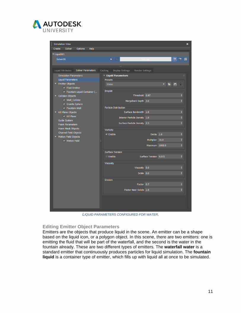
LIQUID PARAMETERS CONFIGURED FOR WATER.
Editing Emitter Object Parameters Emitters are the objects that produce liquid in the scene. An emitter can be a shape based on the liquid icon, or a polygon object. In this scene, there are two emitters: one is emitting the fluid that will be part of the waterfall, and the second is the water in the fountain already. These are two different types of emitters. The waterfall water is a standard emitter that continuously produces particles for liquid simulation. The fountain liquid is a container type of emitter, which fills up with liquid all at once to be simulated.

12
THE EMITTER OBJECT PARAMETERS.
Here, you will configure the general parameters for the emitter objects, then use the override option for the container emitter parameters. 7. In the Emitter Parameters rollout, set the Stickiness Strength to 0.5. This will cause
the fluid to be less sticky when it meets surfaces it’s colliding against.
THE EMITTER PARAMETERS ROLLOUT

13
8. In the Emitter Conversion Parameters rollout, set the Mode to Shell. Because this emitter is a flat plane, using the Shell mode will be more efficient.
9. Then, set the Thickness value to 1.0. This will thicken the plane so that it is one Voxel thick when calculating fluids emitted from it.
Now that the basic emitter parameters have been configured, you need to create an override for the liquid that’s already in the fountain. This will be a solid container, as opposed to a shell emitter.
10. In the parameters list on the left side of the simulation view, expand Emitter Objects, if it is not already expanded, and then click the Fountain Liquid Container object.
11. Open the Emitter Parameters rollout and check Override Global Controls.
12. With the Global Controls overridden, set the Emitter Type to Container. 13. Verify that the Stickiness value is set to 1.0.
14. In the Emitter Conversion Parameters, check Override Global Controls. 15. In the Conversion group, set the Mode to Solid (Robust). 16. Make sure the Thickness is set to 0 and leave all the other parameters at their defaults.

14
THE OVERRIDDEN SETTINGS
Modifying Collision Object Parameters With several collision objects in the scene, you need to make sure that the conversion process parameters are set correctly. These parameters determine how the simulation Solver deals with the different types of geometry. With simple geometry like the sphere, you can use the Solid option. When you have more advanced geometry, especially geometry with cutouts and holes, using the Solid (Robust) is a more accurate solution. If your geometry is a simple shell that is not solid, you can use the Shell option. This is good for objects like planes that are a single polygon thick.
THE SIMULATION VIEW WITH COLLISION OBJECTS CHOSEN.

15
17. In the Collider Conversion Parameters, set the Mode to Solid.
18. Set the Thickness value to 0.5.
To start from here, use: Fluid_Fountain_04.max
Caching As fluid systems generate more particles, the computer needs to spend more time calculating how those particles are going to move and interact. This can cause fluid systems to be evaluated more and more slowly as your frames progress in the viewport. By default, liquid simulations are saved to a disk cache on your hard drive, or where you specify. Configuring the cache settings allows you to specify where those files are saved. The Caching tab of the simulation view contains the settings you can use to override the defaults. The default cache location will be located within the project folder in a folder called “SimCache”. You can use the default folder location to make it easier when working on a simulation. Of course, you can always specify a new location if the drive you’re working on does not have a lot of extra space. Keep in mind that the cache files can take up gigabytes of storage space for a large, complex simulation. So, having a drive with plenty of available space is important.

16
THE SIMCACHE FOLDER SHOWN IN WINDOWS EXPLORER.
Modifying viewport display settings The Display Settings tab of the Simulation View dialog box contains two rollouts: one for the liquid settings and one for the foam settings. Depending on how you want to visualize the simulation within the 3ds Max viewport, you can change the display type for each.
THE DISPLAY TYPE DROP-DOWN SHOWING THE LIQUID SETTINGS DISPLAY OPTIONS.
There are seven different Display Type options. The Bifrost mesh options offer both a dynamic mesh and a cached mesh. If you choose any of the mesh options, a Mesh Settings panel will appear, which allows you to define the quality of the mesh.

17
THE BIFROST DYNAMIC MESH OPTIONS SHOWN IN THE LIQUID SETTINGS.
This simulation will use the Display Type of Point. This display option creates three-dimensional points within the viewport that are colored based on the selected color channel. There are a number of color channels available.
THE COLOR CHANNEL DROP-DOWN OPEN SHOWING SEVERAL CHANNEL OPTIONS.
19. In the Particle Settings group, make sure the Color Channel is set to Vorticity. 20. Change the Size value to 0.5. Leave all other values at their defaults.
When you begin simulating the liquid, the color channel will use the vorticity value of the fluid to vary the colors in the viewport display of the simulation. In this case, colors with a minimum amount of vorticity will get the darker blue color, and higher vorticity values will get the lighter blue color. This allows you to easily visualize a specific channel right inside the viewport.

18
Configuring render settings Once the fluid simulation is configured, you’ll want to set the rendering parameters for the fluid simulation. Each Solver can have its own render settings. So, if you have more than one Solver, let’s say one high-resolution and one low-resolution, you can have different render settings for each.
THE RENDER SETTINGS TAB IN THE SIMULATION VIEW DIALOG.
Since this animation is going to be rendered using the Arnold renderer, you can make use of Arnold’s ability to directly render the liquid. Since there is only one Solver, you do not need to choose the Solver to render for this step. 21. In the Liquid Settings rollout, from the Render As drop-down, select Arnold Surface.

19
22. In the Surface Controls rollout, set the Hole Kill Threshold to 0.2. This will help eliminate holes in the mesh that may be created by the simulation. A higher value will fill in larger holes; a value of 0 will render the mesh as calculated by the simulation.
23. Leave all other options at their defaults. Once the simulation is complete, you can always come back and make changes to the settings.
THE ARNOLD SURFACE LIQUID SETTINGS.
Before moving on, let’s discuss the use of channels within a simulation. A channel such as age, churn, or density can be used when applying maps to a simulated liquid. These channels can be used to affect color, as well as other elements of the material applied to the surface.
CHANNELS SHOWING THE VORTICITY CHANNEL BEING ADDED.

20
Solving the Simulation
Once all the simulation settings have been configured, you’re ready to solve the simulation and generate the liquid. This is done through the Solver. When solving a simulation, there are options for solving for the liquid and solving for foam, along with generating the mesh element. In this case, you will just solve for the liquid.
24. In the Liquid1 > Solver01 entry, enable the Solve Liquid Component. 25. Click Start Solve to begin solving the fluid simulation. Once the fluid simulation starts, it can take a long time to calculate. Calculation times will range, depending on the speed of your computer and the parameters within the Solver.
THE FOUNTAIN SHOWING THE BLUE PARTICLES OF THE FLUID SYSTEM.
Applying Materials
For this fountain, you are looking to create realistic water from a physical material. While water material can be created using a variety of methods, starting with a physical material preset makes it much easier.
Creating and Assigning a Water Material
To start from here, use: Fluid_Fountain_04.max
Creating a Simple Water Material
1. Open the Slate Material Editor. 2. From the Material/Map Browser, in the General materials rollout, choose the Physical
material.

21
3. Click and drag the physical material out into the work area, then double-click the material
to open the parameters. 4. At the top, rename the material to “Blue_Water”. 5. A quick way to set the initial parameters for the water are to use a preset. From the
Presets drop-down, choose Glass (Solid Geometry). 6. Expand the Material mode and set the drop-down to Advanced.
7. Set the Roughness value to 0.05. 8. In the Reflections group, set the Index of Refraction (IOR) to 1.33. This is the index of
refraction of water at 20°C.
9. In the Transparency group, click the color swatch for the transparency color. 10. In the Color Selector: Transparency Color dialog, set the Red value to 0.6, the Green
to 0.8, and the Blue to 0.95.
Assigning the Material 11. Make sure the liquid001 object is selected.

22
12. With the Blue_Water material as the current active material, in the Slate Material Editor
toolbar, click Assign Material to Selection. Once the material is assigned to the fluid, you’re ready to render the animation.
Rendering the Fountain Now that the fluid simulation has been completed, you’re ready to render the animation. First, to save time, create a viewport preview of the fountain so you can see the simulation as it will look in real time. This is a much faster way to preview your animation than any other kind of test rendering. Once the fluid simulation has been set up to meet your needs, you can move on to a higher-quality render using Arnold to provide a photoreal view of the fountain.
Creating a preview 1. Right-click in the camera viewport to make it the active viewport. 2. In the Tools menu, Preview - Grab Viewport option, select Create Preview Animation
to open the Make Preview dialog box.
3. In the Make Preview dialog, Preview Range, keep the Active Time Segment selected.

23
4. In the Visual Style group, set the Per-View Preset to Standard, and Preference to Default Shading.
5. In the Output section, click the Choose Codec… button. 6. From the Video Compression dialog that pops up, use the Microsoft Video 1 codec
and click OK. You can choose a different codec if desired, depending on what is installed on your particular computer.
7. Make sure the Render Viewport is set to Fountain_Cam. 8. Click the Create button. 3ds Max will take a little while, and you’ll see the time slider
progressing through the frames while the preview is created. Once the preview is complete, 3ds Max will open a media player associated with the AVI file. Playing the animation back in real-time allows you to see what the particle animation will look like and how the particle flow is being evaluated over time.
Rendering with Arnold Once you like the way the simulation has performed, you can proceed with rendering the scene with Arnold.

24
Render a Low-Resolution Animation Now that the fluid simulation is configured, the material is applied, and the preview has been accepted, it is time to prepare a first pass, low-resolution test render of the final animation. This test render will give you a good idea of what the fountain animation will look like. Arnold is already the current renderer, so there is no need to select it. 1. From the Main menu, click Render Setup to open the Render Setup dialog. 2. On the Common tab, in the Time Output section, click the Active Time Segment
option.
3. The output size is already configured for HDTV. Set the Width to 480, which will automatically set the Height to 270—a small animation, but a good preview size.

25
4. Set the file location in the Render Output section by clicking on the Files… button. 5. This opens directly into the render output directory of the current project folder. 6. Navigate to the renderoutput folder of the 3ds Max Project folder. 7. In the File name type in, enter, “Fountain_.png”, and then click Save.
8. In the PNG Configuration dialog, set the colors to RGB 24 bit, and since there will be no need to render with an alpha channel, uncheck the Alpha channel option and click OK.
That now sets the file name and path for the files that will be saved to the hard drive once rendering begins.
9. Switch over to the Arnold Renderer tab. 10. In the Sampling and Ray Depth rollout, General group, set the Camera (AA) value to
2, the Diffuse ray depth to 1, and the Specular ray depth to 1. This will help speed up rendering compared to the current settings.

26
The current render setting in the file reflects a lower sampling quality. This lower sampling will reduce the time it takes to render the scene at the cost of noise and detail. 11. Make sure the Fountain_Cam viewport is the current render view, and then click the
render button. For the first several frames, you won’t see very much happening because the waterfall liquid starts emitting at frame zero, and you won’t see too much for a least a few frames. When the animation is finished rendering, you can play back the image sequence using the RAM player, or you can bring the sequence into your favorite video editing or compositing program.

27
A RENDERING OF THE LIQUID SIMULATION USING ARNOLD.

28
The Blast Magazine
www.cadlearning.com
@3DProfessor
facebook.com/CADLearning
linkedin.com/in/sschain/
For More Information: