scadapack - cloudfront.net
TRANSCRIPT

6602 HART Module
SCADAPack
Version:
Date:
3.9.1
July 2021
Document Number: 250517

2
Table of Contents
..........................................................................................................................51 Legal Information
..........................................................................................................................62 Technical Support
..........................................................................................................................73 Safety Information
..........................................................................................................................104 About the Book
..........................................................................................................................135 About the 6602 HART Module
..........................................................................................................................166 Cybersecurity
..........................................................................................................................187 HART Architecture
..................................................................................................................................187.1 Using HART Data from the 6602 HART module in Logic
..................................................................................................................................197.2 Using the 6602 HART module in an AMS
..................................................................................................................................207.3 Using the 6602 HART module for HART Device Maintenance
..........................................................................................................................218 Hardware Overview
..................................................................................................................................248.1 Analog Inputs
................................................................................................................248.1.1 Range and Scaling
..................................................................................................................................268.2 Analog Outputs: 8 AI, 4 AO Model Only
................................................................................................................278.2.1 Range and Scaling
................................................................................................................288.2.2 Load Resistance Requirements
..................................................................................................................................288.3 Isolation and Protection Summary
..........................................................................................................................329 Installation
..................................................................................................................................329.1 Instructions for North America
..................................................................................................................................349.2 Instructions for ATEX and IECEx
..................................................................................................................................369.3 Mounting the 6602 HART Module
..................................................................................................................................409.4 Power Supply Requirements
..................................................................................................................................429.5 Connecting I/O Modules
................................................................................................................429.5.1 Precautions
................................................................................................................449.5.2 Cabling Guidance
................................................................................................................459.5.3 Attaching Intermodule Cables
..........................................................................................................................4810 Addressing
..................................................................................................................................4810.1 Addressing Rules

3
..................................................................................................................................4810.2 Setting the I/O Module Address
..........................................................................................................................5111 Field Wiring
..................................................................................................................................5111.1 Wiring Screw-Termination Connectors
..................................................................................................................................5311.2 Analog Input Wiring
................................................................................................................5411.2.1 Analog Input Wiring Example
..................................................................................................................................5711.3 Analog Output Wiring: 8 AI, 4 AO Model Only
................................................................................................................5811.3.1 Analog Output Wiring Example: 8 AI, 4 AO Model Only
..........................................................................................................................6012 Configuration
..........................................................................................................................6213 Diagnostics
..........................................................................................................................6314 Troubleshooting
..................................................................................................................................6314.1 Analog Inputs
..................................................................................................................................6314.2 Analog Outputs: 8 AI, 4 AO Model Only
..........................................................................................................................6415 Maintenance
..................................................................................................................................6415.1 Calibration
..................................................................................................................................6415.2 Updating Module Firmware
..................................................................................................................................6615.3 Updating Bootloader Firmware
..........................................................................................................................6916 Specifications
..................................................................................................................................6916.1 General
..................................................................................................................................7016.2 Communications
..................................................................................................................................7116.3 Analog Inputs
..................................................................................................................................7216.4 Analog Outputs: 8 AI, 4 AO Model Only
..........................................................................................................................7417 Standards and Certifications

3.9.1
6602 HART Module
4

3.9.1
6602 HART Module Legal Information
5
1 Legal Information
The information provided in this documentation contains general descriptions and/or technicalcharacteristics of the performance of the products contained herein. This documentation is notintended as a substitute for and is not to be used for determining suitability or reliability of theseproducts for specific user applications. It is the duty of any such user or integrator to perform theappropriate and complete risk analysis, evaluation and testing of the products with respect to therelevant specific application or use thereof. Neither Schneider Electric nor any of its affiliates orsubsidiaries shall be responsible or liable for misuse of the information contained herein. If youhave any suggestions for improvements or amendments or have found errors in this publication,please notify us.
No part of this document may be reproduced in any form or by any means, electronic ormechanical, including photocopying, without express written permission of Schneider Electric.
All pertinent state, regional, and local safety regulations must be observed when installing andusing this product. For reasons of safety and to help ensure compliance with documentedsystem data, only the manufacturer should perform repairs to components.
Trademarks
Schneider Electric, ClearSCADA, EcoStruxure, Modbus, RemoteConnect, SCADAPack,Telepace, and Trio are trademarks and the property of Schneider Electric SE, its subsidiariesand affiliated companies. All other trademarks are the property of their respective owners.
Address
Schneider Electric Systems USA
Process Automation SCADA & Telemetry38 Neponset Avenue, Foxboro, Massachusetts 02035 USADirect Worldwide: +1 (613) 591-1943Email: [email protected] Free within North America: +1 (888) 267-2232www.se.com
© 2016 - 2021 Schneider Electric Systems USA Inc.All rights reserved.

3.9.1
6602 HART ModuleTechnical Support
6
2 Technical Support
Questions and requests related to any part of this documentation can be directed to one of thefollowing support centers.
Technical support: Americas, Europe, Middle East, Asia
Available Monday to Friday 8:00 am – 6:30 pm Eastern Time
Check ourFAQs
Explore our extensive knowledge database and FAQ videos tofind answers quickly:
https://se.com/faq
Email us Save time by emailing us your inquiry and an expert will contactyou:
Send us an email anytime.
Call us Need someone to provide some technical support?
· Toll free within North America: 1-888-226-6876
· Direct Worldwide: +1-613-591-1943
Technical support: Australia/New Zealand (Pacific)
Available Monday to Friday 8:00 am - 5:00 pm Australian Eastern Standard Time
Check ourFAQs
Explore our extensive knowledge database and FAQ videos tofind answers quickly:
https://se.com/faq
Email us Save time by emailing us your inquiry and an expert will contactyou:
Send us an email anytime.
Call us Need someone to provide some technical support?
· Inside Australia: 13 73 28 (13 SEAU)
· Inside New Zealand: 0800 652 999

3.9.1
6602 HART Module Safety Information
7
3 Safety Information
Important information
Read these instructions carefully, and look at the equipment to become familiar withthe device before trying to install, operate, or maintain it. The following specialmessages may appear throughout this documentation or on the equipment to warn ofpotential hazards or to call attention to information that clarifies or simplifies aprocedure.
The addition of this symbol to a Danger or Warning safety label indicatesthat an electrical hazard exists, which will result in personal injury if theinstructions are not followed.
This is the safety alert symbol. It is used to alert you to potential personalinjury hazards. Obey all safety messages that follow this symbol to avoidpossible injury or death.
Please note
Electrical equipment should be installed, operated, serviced, and maintained only by qualifiedpersonnel. No responsibility is assumed by Schneider Electric for any consequences arising outof the use of this material.
A qualified person is one who has skills and knowledge related to the construction, installation,and operation of electrical equipment and has received safety training to recognize and avoid thehazards involved.

3.9.1
6602 HART ModuleSafety Information
8
Before you begin
Do not use this product on machinery lacking effective point-of-operation guarding. Lack ofeffective point-of-operation guarding on a machine can result in serious injury to the operator ofthat machine.
WARNING
EQUIPMENT OPERATION HAZARD
· Verify that all installation and set up procedures have been completed.
· Before operational tests are performed, remove all blocks or other temporary holding meansused for shipment from all component devices.
· Remove tools, meters, and debris from equipment.
Failure to follow these instructions can result in death or serious injury.
Follow all start-up tests recommended in the equipment documentation. Store all equipmentdocumentation for future reference.
Test all software in both simulated and real environments.
Verify that the completed system is free from all short circuits and grounds, except thosegrounds installed according to local regulations (according to the National Electrical Code in theU.S.A, for instance). If high-potential voltage testing is necessary, follow recommendations inequipment documentation to help prevent accidental equipment damage.
Operation and adjustments
The following precautions prevail:
· Regardless of the care exercised in the design and manufacture of equipment or in theselection and ratings of components, there are hazards that can be encountered if suchequipment is improperly operated.
· It is sometimes possible to misadjust the equipment and thus produce unsatisfactory orunsafe operation. Always use the manufacturer’s instructions as a guide for functionaladjustments. Personnel who have access to these adjustments should be familiar with theequipment manufacturer’s instructions and the machinery used with the electrical equipment.
· Only those operational adjustments actually required by the operator should be accessible tothe operator. Access to other controls should be restricted to prevent unauthorized changes inoperating characteristics.

3.9.1
6602 HART Module Safety Information
9
Acceptable use
WARNING
UNACCEPTABLE USE
Do not use SCADAPacks or I/O modules as an integral part of a safety system. Thesedevices are not safety products.
Failure to follow these instructions can result in death or serious injury.
CAUTION
EQUIPMENT OPERATION HAZARD
When devices are used for applications with technical safety requirements, the relevantinstructions must be followed.
Use only Schneider Electric software or approved software with Schneider Electric hardwareproducts.
Failure to follow these instructions can result in minor or moderate injury.
For details on installation of the 6602 HART module in hazardous locations, see:
· Instructions for North America
· Instructions for ATEX and IECEx
32
34

3.9.1
6602 HART ModuleAbout the Book
10
4 About the Book
Audience
WARNING
UNINTENDED EQUIPMENT OPERATION
The application of this product requires expertise in the design and programming of controlsystems. Only persons with such expertise are allowed to program, install, alter, and applythis product.
Follow all local and national safety codes and standards.
Failure to follow these instructions can result in death or serious injury.
This manual is written for people who need to install, troubleshoot or maintain the 6602 HighwayAddressable Remote Transducer (HART) module hardware. These individuals are typically:
· Systems Engineers
· Commissioning Engineers
· Maintenance Technicians
Document scope
This manual describes:
· The physical design of the 6602 HART module, including detailed hardware specifications
· Installation, wiring and addressing for the 6602 HART module
· Diagnostics capabilities on the 6602 HART module
· Maintenance recommendations for the 6602 HART module
This manual assumes that you are connecting your 6602 HART module to a SCADAPack x70RTU and using the SCADAPack RemoteConnect configuration software.
Validity note
This document is valid for:
· SCADAPack x70 firmware version 9.6.1 and earlier
· SCADAPack RemoteConnect configuration software version 3.9.1 and earlier
Related documents
Use this manual with the other manuals included in your SCADAPack x70 documentation set.The table below describes the manuals available in the documentation set.

3.9.1
6602 HART Module About the Book
11
Folder Manual Content
Getting Started Getting Started · The SCADAPack x70 family of productsavailable in this release
· The basic steps to get your SCADAPackx70 device operational
· Where to get more information aboutconfiguring, monitoring and managingyour SCADAPack x70 device
SCADAPackSoftwareInstallation
SCADAPack SoftwareInstallation
· Hardware and software requirements
· Installation procedures
· Accessing help
· Troubleshooting guidance
HardwareManuals
The hardware manual foryour SCADAPack x70device
· Installation, wiring and addressinginformation
· Diagnostics capabilities
· Maintenance recommendations
· Hardware specifications
ConfigurationManuals
SCADAPackRemoteConnectConfiguration Software
· Setting up and managing projects for yourSCADAPack x70 device
PC CommunicationSettings -SCADAPackCommDTM
· Setting up communications betweenSCADAPack RemoteConnect and yourSCADAPack x70 device
SCADAPack x70Configuration
· Configuring SCADAPack x70 deviceoperation
Porting Guide forSCADAPack E toSCADAPackRemoteConnect
· Moving from SCADAPack E toSCADAPack RemoteConnect
· Locating SCADAPack E Configuratorfeatures in SCADAPack RemoteConnect
· Locating SCADAPack Workbenchfeatures in SCADAPack RemoteConnect
· Compatibility chart
Porting Guide for Telepaceto SCADAPackRemoteConnect
· Moving from Telepace to SCADAPackRemoteConnect
· Tutorial for creating a project
· Compatibility chart

3.9.1
6602 HART ModuleAbout the Book
12
TechnicalReferenceManuals
SCADAPackCommunication InterfacesTechnical Reference
· USB, serial and IP communications
· Mobile communications
· Dialup modem communications
SCADAPack OperationsTechnical Reference
· The SCADAPack x70 device file system
· Command line operations
· Diagnostics operations
· Telnet server operations
· FTP server operations
SCADAPack SCADAProtocols TechnicalReference
· DNP3 protocol support
· Modbus protocol support
· IEC 60870-5-104 protocol support
LogicProgrammingManuals
SCADAPack LogicProgramming Overview
· The differences between EcoStruxureControl Expert (Unity Pro) and theSCADAPack x70 Logic Editorenvironment
· Key programming concepts
· Basic procedures needed to use theSCADAPack x70 Logic Editor
SCADAPack FunctionBlocks TechnicalReference
· The custom SCADAPack x70 functionblocks that are available for developingIEC 61131-3 applications
Using EFB Toolkit withSCADAPack x70
· Using the Schneider Electric EFB Toolkitwith SCADAPack x70 devices andSCADAPack RemoteConnectconfiguration software
SecurityAdministratorManuals
SCADAPack SecurityAdministrator
· Configuring security on your SCADAPackx70 device
SCADAPack SecurityTechnical Reference
· Security standards
· Security overview
· DNP3 Secure Authentication
· Diagnostics
· Attack vectors and requirements

3.9.1
6602 HART Module About the 6602 HART Module
13
5 About the 6602 HART Module
The 6602 Highway Addressable Remote Transducer (HART) module combines an analog I/Ointerface and a HART interface to help you connect HART sensors and actuators to yourSCADAPack.
6602 HART modules use 4...20 mA analog signals to perform continuous process controlfunctions in the same way as other SCADAPack x70 device analog inputs and analog outputs.
The 6602 HART modules also support the HART protocol, which superimposes a digital signalon top of the analog signal. The HART digital signal communicates additional instrumentinformation which may include instrument status, additional process variables, configuration dataor diagnostics. The HART digital information is acquired at a slower, non-deterministic rate.
The 6602 HART module comes in 2 models:
The 8 AI, 4 AO model connects up to 8 HART sensors and up to 4 actuators to yourSCADAPack.
· 8 analog inputs
· 4 analog outputs
The 8 AI model connects up to 8 HART sensors to your SCADAPack. There are no analogoutputs.
You can also connect your 6602 HART module to non-HART instruments by configuring theinputs or outputs for 4...20 mA or 0...20 mA current. See the SCADAPack x70 Configurationmanual for details.
The 6602 HART modules can be used with SCADAPack x70 RTUs.
The images below show the 2 models of the 6602 HART module, with analog outputs andwithout. The non-AO model has no connector or LEDs at the top of the module. Throughout therest of the manual, the images shown will be of the 6602 HART module with analog outputs.

3.9.1
6602 HART ModuleAbout the 6602 HART Module
14
Model 8 AI, 4 AO Model 8 AI

3.9.1
6602 HART Module About the 6602 HART Module
15
Connections
I/O modules include a short intermodule cable for connecting to a SCADAPack or to another I/Omodule. For information about the maximum number of I/O modules supported, see thehardware manual for your SCADAPack. For details on connecting I/O modules, see AttachingIntermodule Cables .
Screw-termination connectors are provided for connecting the inputs and outputs to the devicesyou want to monitor or control. For details on wiring input and output connectors, see FieldWiring .
Configuration
You can configure inputs and outputs in the following ways:
· Locally or remotely using the SCADAPack RemoteConnect configuration software on aMicrosoft Windows-based computer.
45
51

3.9.1
6602 HART ModuleCybersecurity
16
6 Cybersecurity
Cybersecurity is a branch of network administration that addresses attacks on or by computersystems and through computer networks that can result in accidental or intentional disruptions.The objective of cybersecurity is to help provide increased levels of protection for information andphysical assets from theft, corruption, misuse, or accidents while maintaining access forintended users.
No single cybersecurity approach is adequate. Schneider Electric recommends a defense-in-depth approach. This approach layers the network with security features, appliances, andprocesses. The basic components of this approach are:
· Risk assessment: A systematic security analysis of the environment and related systems.
· A security plan built on the results of the risk assessment
· A multi-phase training campaign
· Network separation and segmentation: Physical separation of the control network from othernetworks, and the division of the control network itself into segments and security zones.
· System Access Control: Controlling access to the system with firewalls, authentication,authorization, and other software means, and traditional physical security measures such asvideo surveillance, fences, locked doors and gates, and locked equipment cabinets.
· Device hardening: The process of configuring a device against communication-based threats.Device hardening measures include disabling unused network ports, password management,access control, and the disabling of all unnecessary protocols and services.
· Network monitoring and maintenance: An effective defense-in-depth campaign requirescontinual monitoring and system maintenance to meet the challenge of new threats as theydevelop.
· See Security Considerations in the Security Technical Reference manual
Contact us
For more information, refer to the Schneider Electric Cybersecurity Support Portal athttp://www.se.com/b2b/en/support/cybersecurity/overview.jsp.
Additional Resources
Industrial Control Systems Cyber Emergency Response Team (ICS-CERT)https://ics-cert.us-cert.gov
ICS-CERT Recommended Practiceshttps://ics-cert.us-cert.gov/Recommended-Practices
Center for Internet Security (CIS) Top 20 Critical Security Controlshttps://www.cisecurity.org/cybersecurity-best-practices
FBI Cyber Crimehttps://www.fbi.gov/investigate/cyber

3.9.1
6602 HART Module Cybersecurity
17
Guide to Industrial Control Systems (ICS) Securityhttps://www.nist.gov/publications/guide-industrial-control-systems-ics-security
WaterISAC Water Security Networkhttps://www.waterisac.org
3.9.1
6602 HART ModuleHART Architecture
18
7 HART Architecture
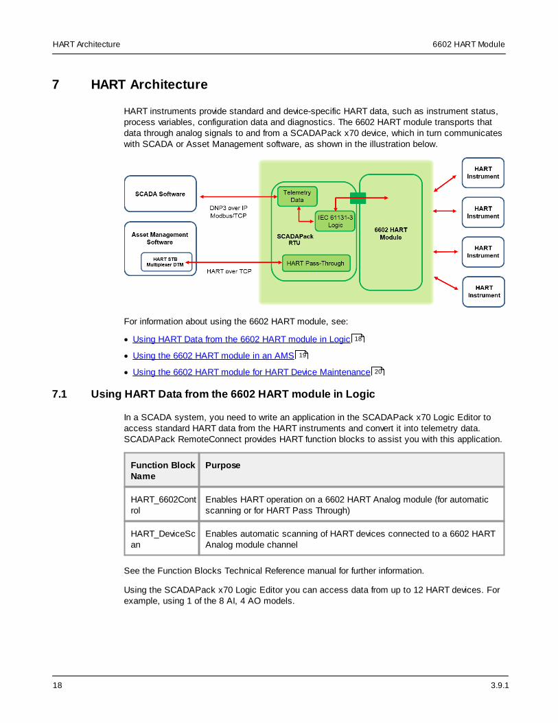
HART instruments provide standard and device-specific HART data, such as instrument status,process variables, configuration data and diagnostics. The 6602 HART module transports thatdata through analog signals to and from a SCADAPack x70 device, which in turn communicateswith SCADA or Asset Management software, as shown in the illustration below.
For information about using the 6602 HART module, see:
· Using HART Data from the 6602 HART module in Logic
· Using the 6602 HART module in an AMS
· Using the 6602 HART module for HART Device Maintenance
7.1 Using HART Data from the 6602 HART module in Logic
In a SCADA system, you need to write an application in the SCADAPack x70 Logic Editor toaccess standard HART data from the HART instruments and convert it into telemetry data.SCADAPack RemoteConnect provides HART function blocks to assist you with this application.
Function BlockName
Purpose
HART_6602Control
Enables HART operation on a 6602 HART Analog module (for automaticscanning or for HART Pass Through)
HART_DeviceScan
Enables automatic scanning of HART devices connected to a 6602 HARTAnalog module channel
See the Function Blocks Technical Reference manual for further information.
Using the SCADAPack x70 Logic Editor you can access data from up to 12 HART devices. Forexample, using 1 of the 8 AI, 4 AO models.
18
19
20

3.9.1
6602 HART Module HART Architecture
19
7.2 Using the 6602 HART module in an AMS
SCADAPack 570, SCADAPack 574, and SCADAPack 575 models support the SchneiderElectric HART Multiplexer DTM that can be used in SCADAPack RemoteConnect withSchneider Electric and third-party Device Type Managers (DTMs) to communicate with HARTdevices through the 6602 HART module. SCADAPack 470 and SCADAPack 474 models do notpresently support this.
Accessing help for the HART Communication DTM
For the help manual, see the HART - STB Multiplexer - Applications Guide.
The manual opens in a new window.
On the HART STB Multiplexer page:
1. Click in any configurable field in the user interface or tab to a button or drop-down list, thenpress F1
2. Press the Help button
Installing a HART Communication DTM
To install a HART communication DTM for use with the 6602 module on a separate computer (forexample, on the same server as an Asset Management System), you can use the SCADAPackRemoteConnect installation DVD (or other media) and install only the needed component.
1. Start the SCADAPack RemoteConnect installer on the separate computer.
2. Select Browse Media.
3. Navigate to DTMs > HartDTM.
4. Run the setup installer for the HART DTM by running Schneider Electric Hart STBMultiplexer DTM Library.exe.
Using an Asset Management System
When you use the 6602 HART module with an Asset Management System (AMS), you need toenable the HART Pass Through functionality in SCADAPack RemoteConnect to receivestandard and device-specific data from the HART instruments. You also need to enable HARToperation by using a SCADAPack x70 Logic Editor HART_6602Control function block for each6602 HART analog module. In the Function Blocks Technical Reference manual, seeHART_6602Control. The HART over TCP protocol that is used for HART Pass Through is not asecure protocol. See the SCADAPack x70 Configuration manual for further details onCybersecurity and the HART protocol.
Using the AMS, you can access up to 12 HART devices on a SCADAPack x70. For example,using 1 of the 8 AI, 4 AO 6602 HART modules.
3.9.1
6602 HART ModuleHART Architecture
20
7.3 Using the 6602 HART module for HART Device Maintenance
SCADAPack 570, SCADAPack 574, and SCADAPack 575 models support the SchneiderElectric HART Multiplexer DTM that can be used in SCADAPack RemoteConnect withSchneider Electric and third-party Device Type Managers (DTMs) to communicate with HARTdevices through the 6602 HART module. SCADAPack 470 and SCADAPack 474 models do notpresently support this.
SCADAPack RemoteConnect is an FDT 2.1-, FDT 2.0-, and FDT 1.2-compatible frameapplication. Alternatively, you can use other FDT- and DTM-compliant frame applications. Wherean alternate FDT frame application is used on a computer where SCADAPack RemoteConnectis not installed, you can use the SCADAPack RemoteConnect installation DVD (or other media)and install only the needed component. Start the SCADAPack RemoteConnect installer on theseparate computer, select Browse Media, navigate to DTMs > HartDTM and run the setupinstaller for the HART DTM by running Schneider Electric Hart STB Multiplexer DTMLibrary.exe.
When you use the 6602 HART module for HART device maintenance, you need to enable theHART Pass Through functionality in SCADAPack RemoteConnect. You also need to enableHART operation by using a SCADAPack x70 Logic Editor HART_6602Control function block foreach 6602 HART analog module. In the Function Blocks Technical Reference manual, seeHART_6602Control. The HART over TCP protocol that is used for HART Pass Through is not asecure protocol. See the SCADAPack x70 Configuration manual for details.
The Schneider Electric HART Multiplexer DTM supports HART Pass Through communication formaintenance purposes on up to 32 HART channels on a single SCADAPack x70 device. SeeUsing the 6602 HART module in an AMS .19

3.9.1
6602 HART Module Hardware Overview
21
8 Hardware Overview
The 8 AI, 4 AO 6602 HART module increases the SCADAPack I/O capacity by providing:
· 8 analog inputs
· 4 analog outputs
The 8 AI 6602 HART module provides 8 analog inputs only.
The figure below shows the inputs and outputs on the 8 AI, 4 AO model.
For ease of wiring and maintenance, external connections are terminated on removableconnectors. If you need to remove the 6602 HART module cover for any reason, first carefullyconsider the following information.

3.9.1
6602 HART ModuleHardware Overview
22
WARNING
UNINTENDED EQUIPMENT OPERATION
Evaluate the operational state of the equipment being monitored or controlled by theSCADAPack or the I/O module before applying or removing power.
Failure to follow these instructions can result in death or serious injury.
WARNING
ELECTRICAL HAZARD
Remove power from the I/O module before removing the I/O module cover.
Failure to follow these instructions can result in death or serious injury.
NOTICE
STATIC ELECTRICITY DAMAGE
The electronics inside the I/O module can be damaged by static electricity. If you need toremove the I/O module cover, wear an anti-static wrist strap that is connected to ground.Failing to follow this step can cause intermittent or total loss of I/O module operation and willvoid the warranty.
Failure to follow these instructions can result in equipment damage.
For complete hardware specifications, see Specifications .
Input/OutputType
Label PolaritySensitive
Description
Analoginputs
HART AI
1+ and 1-to
8+ and 8-
Yes · Uni-polar, differential
· Software-configurable for:
4...20 mA (HART capable)
0...20 mA (HART disabled)
· Support HART protocol point-to-pointmode
· Electrical isolation is provided betweenchannels and from each channel toSCADAPack RTU circuitry
Analogoutputs: 8 AI, 4AO modelonly
HART AO1
1+ and 1-to
Yes · Uni-polar
· Software-configurable for:
4...20 mA (HART capable)
69
24
26

3.9.1
6602 HART Module Hardware Overview
23
Input/OutputType
Label PolaritySensitive
Description
4+ and 4- 0...20 mA (HART disabled)
· Support HART protocol point-to-pointmode
· Electrical isolation is provided from eachchannel to SCADAPack RTU circuitry
1Applies to the 8 AI, 4 AO model only.
3.9.1
6602 HART ModuleHardware Overview
24
8.1 Analog Inputs
Analog inputs are used to monitor devices such as pressure, level, flow and temperaturetransmitters, instrumentation such as pH and conductivity sensors, and other high-level analogsignal sources.
Each analog input can be individually configured for 4...20 mA (HART capable) or 0...20 mA(HART disabled) operation, using the SCADAPack RemoteConnect configuration software.
Configuration
Use the SCADAPack RemoteConnect configuration software to define the characteristics ofeach analog input, including:
· DNP3 parameters
· Modbus parameters
· Alert notifications
· Range and Scaling
· Value deviation
For more information about configuring analog inputs, see the Configuring Analog and Digital I/OChannels topic in the SCADAPack x70 Configuration manual.
Wiring
Analog inputs support solid or stranded wires from 2.5...0.2 mm2 (12...28 AWG).
For more information, see Wiring Screw-Termination Connectors .
Specifications
For analog input specifications, see Specifications .
8.1.1 Range and Scaling
The 6602 HART module analog inputs use isolated, differential, unipolar analog-to-digitalconverters (ADC) that measure input currents from 0...20 mA including over range capability. Formore information, see Analog Inputs under Specifications.
To assign SCADAPack database objects to the analog input channels, use the SCADAPackRemoteConnect configuration software to select the signal range for each analog input channel.Each analog input channel can be configured for one of the following signal ranges:
· 4...20 mA (HART capable)
· 0...20 mA (HART disabled)
The signal range selected is used in conjunction with the Raw Minimum and Raw Maximumconfiguration for each analog object to present an integer value for the analog input. See tablebelow.
24
51
69
71

3.9.1
6602 HART Module Hardware Overview
25
Engineering Minimum and Engineering Maximum configurations are also available for eachanalog object to scale from the analog object’s integer value to its Engineering Floating Pointobject value. Analog objects simultaneously provide both integer and engineering values. TheSCADAPack configuration can independently choose either value type for logic, protocolreporting, and other applications.
An Under Range Limit and Over Range Limit can also be configured on each analog object.These are configured in Engineering Floating Point units. Depending on the configuration valueschosen, Under Range Limit and Over Range Limit can be configured to report an out of rangephysical analog input signal, or an unexpected process signal.
Under range status on an analog object is indicated through an object quality flag. The underrange quality flag is set when the engineering value of an object is lower than the under rangelimit configured in SCADAPack RemoteConnect. Over range status on an analog object isindicated through an object quality flag. The over range quality flag is set when the engineeringvalue of an object is higher than the Over Range Limit configured in SCADAPackRemoteConnect.
The under range and over range flags are visible in the SCADAPack RemoteConnect objectbrowser, via protocols such as DNP3, in logic variable quality fields, and in other applications.
The default attributes for analog objects for SCADAPack x70 device analog input channels are:
· Raw Minimum = 0, Raw Maximum = 10000
· Engineering Minimum = 0, Engineering Maximum = 100
· Under Range Limit = -1
· Over Range Limit = disabled
In their default configuration, analog input channel over range detection is disabled.
Analog input channels configured for 0..20 mA do not indicate under range conditions.
Current signals
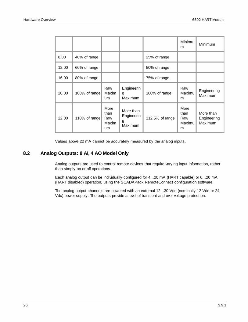
The following table shows the relationship between analog input channel current range, analogsignal, and the analog object’s reported integer and engineering values.
Input 0...20 mA Range (HART disabled) 4...20 mA Range (HART capable)
Current (mA)
AnalogSignal(% of Range)
ObjectIntegerValue
ObjectEngineering Value
Analog Signal(% of Range)
ObjectIntegerValue
ObjectEngineeringValue
0.00 0%RawMinimum
Engineering Minimum
-25% of range
LessthanRawMinimum
Less thanEngineeringMinimum
4.00 20% of range 0% Raw Engineering
3.9.1
6602 HART ModuleHardware Overview
26
Minimum
Minimum
8.00 40% of range 25% of range
12.00 60% of range 50% of range
16.00 80% of range 75% of range
20.00 100% of rangeRawMaximum
EngineeringMaximum
100% of rangeRawMaximum
EngineeringMaximum
22.00 110% of range
MorethanRawMaximum
More thanEngineeringMaximum
112.5% of range
MorethanRawMaximum
More thanEngineeringMaximum
Values above 22 mA cannot be accurately measured by the analog inputs.
8.2 Analog Outputs: 8 AI, 4 AO Model Only
Analog outputs are used to control remote devices that require varying input information, ratherthan simply on or off operations.
Each analog output can be individually configured for 4...20 mA (HART capable) or 0...20 mA(HART disabled) operation, using the SCADAPack RemoteConnect configuration software.
The analog output channels are powered with an external 12...30 Vdc (nominally 12 Vdc or 24Vdc) power supply. The outputs provide a level of transient and over-voltage protection.

3.9.1
6602 HART Module Hardware Overview
27
WARNING
DATA LOSS, APPLICATION LOSS
When the logic application running in the SCADAPack x70 devices stops unexpectedly, theSCADAPack x70 firmware turns OFF all physical digital outputs and sets all physical analogoutputs to a value of zero. This can occur in the following situations:
· Logic application unexpectedly HALTs
· Logic application is put into a STOP state by the user
· Logic application restarts from a user initiated SCADAPack RemoteConnect command
· SCADAPack x70 device is restarted
· Logic application is removed
Evaluate the operational state of the equipment being monitored or controlled by theSCADAPack x70 device and the logic application before resuming operation.
Failure to follow these instructions can result in death or serious injury.
Configuration
Use the SCADAPack RemoteConnect configuration software to define the characteristics ofeach analog output, including:
· DNP3 parameters
· Modbus parameters
· Alert notifications
· Range and Scaling
· Value deviation
For more information about configuring analog outputs, see the Configuring Analog and DigitalI/O Channels topic in the SCADAPack x70 Configuration manual.
Wiring
Analog outputs support solid or stranded wires from 2.5...0.2 mm2 (12...28 AWG).
For more information, see Wiring Screw-Termination Connectors .
Specifications
For analog output specifications, see Specifications .
8.2.1 Range and Scaling
The analog output module has a 16 bit, unipolar, digital-to-analog converter (DAC).
27
51
69
3.9.1
6602 HART ModuleHardware Overview
28
In the SCADAPack RemoteConnect configuration software, you can configure each of the analogoutput module channels for one of the following ranges:
· 4...20 mA (HART capable)
· 0...20 mA (HART disabled)
Configuration for objects attached to the analog output module channels uses the RawMinimum to Raw Maximum and Engineering Minimum to Engineering Maximumparameters for integer and engineering scaling, respectively.
These scaling ranges are applied automatically to the selected analog output signal range(4...20 mA or 0...20 mA).
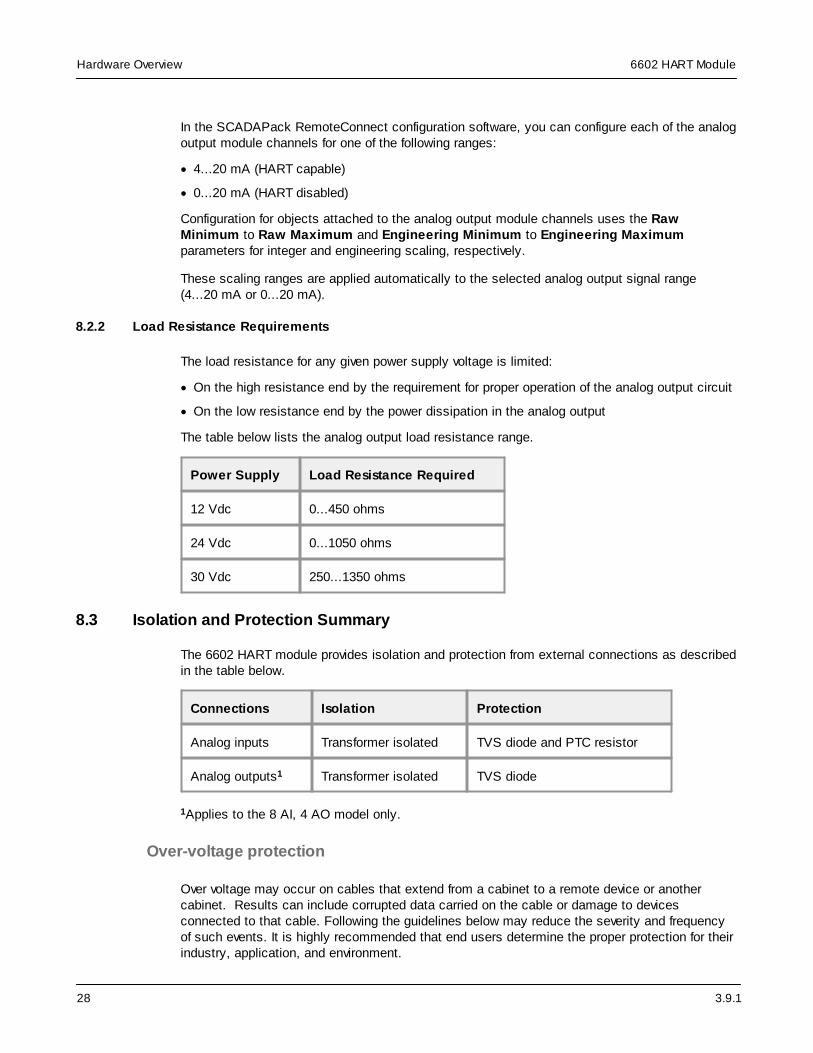
8.2.2 Load Resistance Requirements
The load resistance for any given power supply voltage is limited:
· On the high resistance end by the requirement for proper operation of the analog output circuit
· On the low resistance end by the power dissipation in the analog output
The table below lists the analog output load resistance range.
Power Supply Load Resistance Required
12 Vdc 0...450 ohms
24 Vdc 0...1050 ohms
30 Vdc 250...1350 ohms
8.3 Isolation and Protection Summary
The 6602 HART module provides isolation and protection from external connections as describedin the table below.
Connections Isolation Protection
Analog inputs Transformer isolated TVS diode and PTC resistor
Analog outputs1 Transformer isolated TVS diode
1Applies to the 8 AI, 4 AO model only.
Over-voltage protection
Over voltage may occur on cables that extend from a cabinet to a remote device or anothercabinet. Results can include corrupted data carried on the cable or damage to devicesconnected to that cable. Following the guidelines below may reduce the severity and frequencyof such events. It is highly recommended that end users determine the proper protection for theirindustry, application, and environment.
3.9.1
6602 HART Module Hardware Overview
29
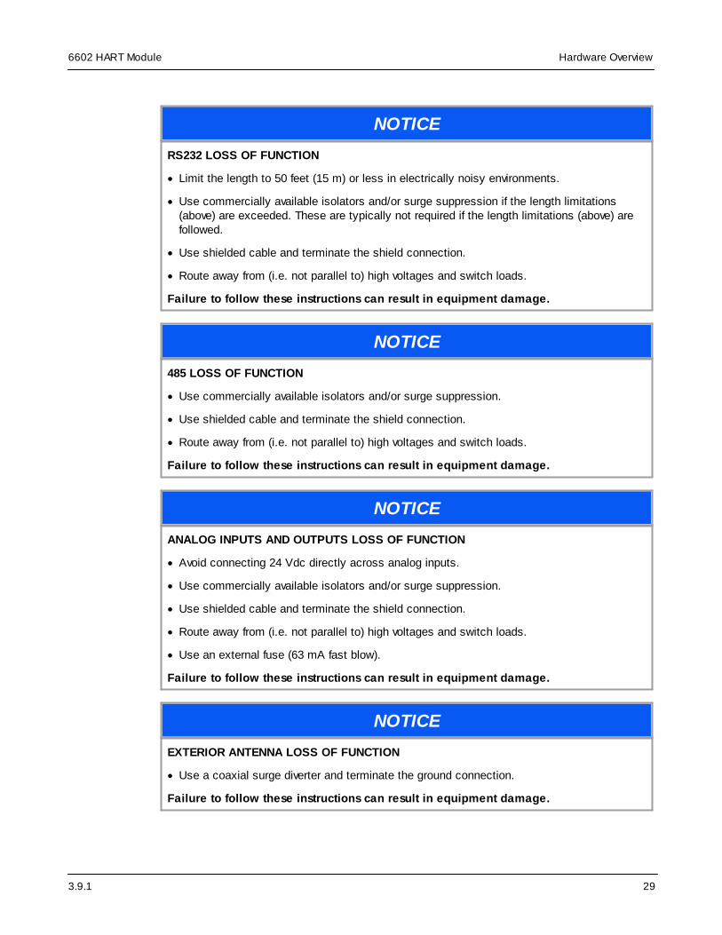
NOTICE
RS232 LOSS OF FUNCTION
· Limit the length to 50 feet (15 m) or less in electrically noisy environments.
· Use commercially available isolators and/or surge suppression if the length limitations(above) are exceeded. These are typically not required if the length limitations (above) arefollowed.
· Use shielded cable and terminate the shield connection.
· Route away from (i.e. not parallel to) high voltages and switch loads.
Failure to follow these instructions can result in equipment damage.
NOTICE
485 LOSS OF FUNCTION
· Use commercially available isolators and/or surge suppression.
· Use shielded cable and terminate the shield connection.
· Route away from (i.e. not parallel to) high voltages and switch loads.
Failure to follow these instructions can result in equipment damage.
NOTICE
ANALOG INPUTS AND OUTPUTS LOSS OF FUNCTION
· Avoid connecting 24 Vdc directly across analog inputs.
· Use commercially available isolators and/or surge suppression.
· Use shielded cable and terminate the shield connection.
· Route away from (i.e. not parallel to) high voltages and switch loads.
· Use an external fuse (63 mA fast blow).
Failure to follow these instructions can result in equipment damage.
NOTICE
EXTERIOR ANTENNA LOSS OF FUNCTION
· Use a coaxial surge diverter and terminate the ground connection.
Failure to follow these instructions can result in equipment damage.
3.9.1
6602 HART ModuleHardware Overview
30
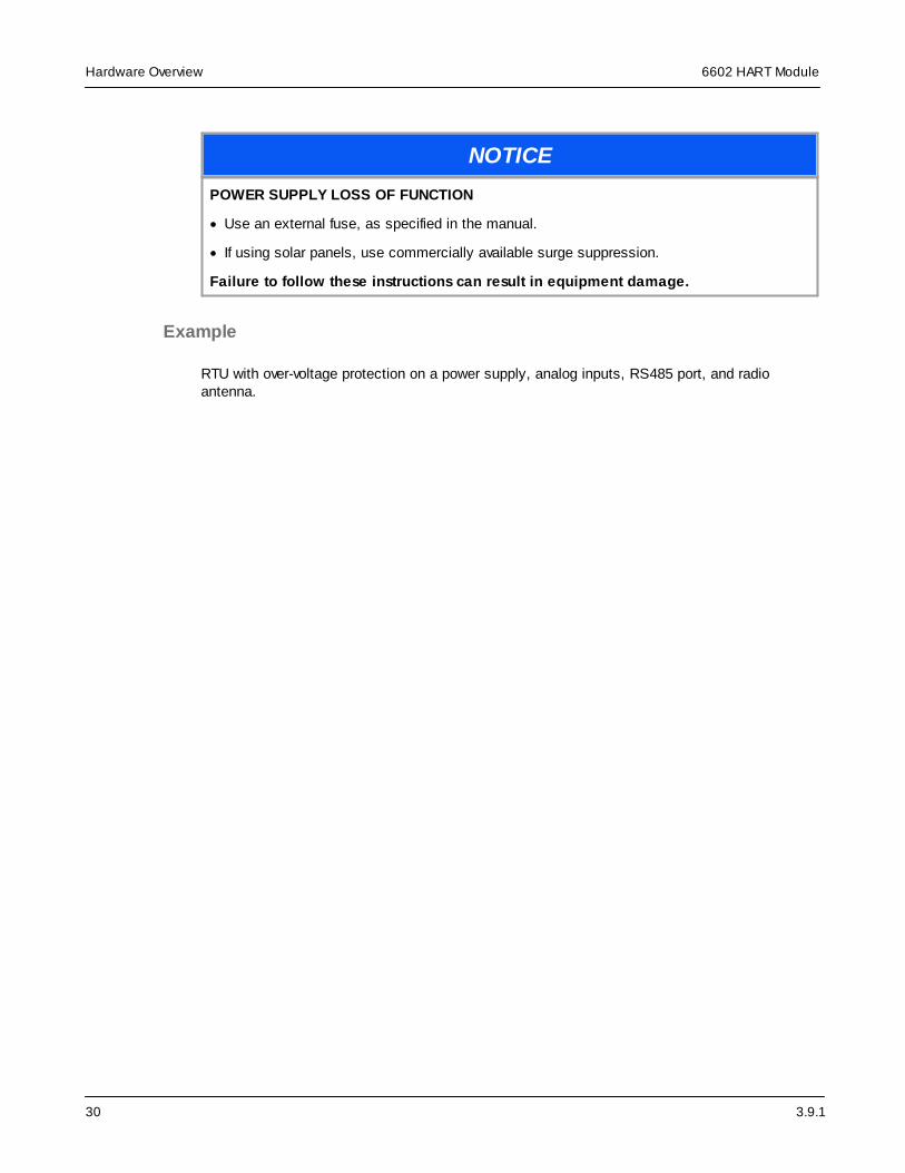
NOTICE
POWER SUPPLY LOSS OF FUNCTION
· Use an external fuse, as specified in the manual.
· If using solar panels, use commercially available surge suppression.
Failure to follow these instructions can result in equipment damage.
Example
RTU with over-voltage protection on a power supply, analog inputs, RS485 port, and radioantenna.

3.9.1
6602 HART Module Hardware Overview
31
For additional information, refer to the Schneider Electric document Grounding, Earthingand Lightning Protection, Chapter 7 “Grounding and Electromagnetic Compatibility of PLCSystems “ (Doc# 33002439).

3.9.1
6602 HART ModuleInstallation
32
9 Installation
The I/O module is factory-configured and under normal conditions does not require removal orinsertion of any peripherals or components. The I/O configurations are stored in a combination ofbattery-backed RAM and flash memory on the SCADAPack.
NOTICE
UNINTENDED EQUIPMENT OPERATION
Installing the I/O module in an environment where the electromagnetic compatibility (EMC)rating exceeds the certified EMC rating for the module can lead to unpredictable operation andunexpected results.
Before mounting the I/O module, check the Standards and Certifications topic to verify whichEMC standards are supported.
Failure to follow these instructions can result in equipment damage.
The following sections describe specific aspects of installing the I/O module.
· Instructions for North America
· Instructions for ATEX and IECEx
· Mounting the 6602 HART Module
· Power Supply Requirements
· Connecting I/O Modules
9.1 Instructions for North America
The information in this section applies to installation of the 6602 HART module in North America.
Applies to SCADAPack products, models TBUP570 and TBUP575 and connected expansionmodules
These products are available for use in Class I, Division 2, Groups A, B, C & D and Class I Zone2 Hazardous locations. Such locations are defined in Article 500 and 505 of the US National FireProtection Association (NFPA) publication NFPA 70, otherwise known as the National ElectricalCode, and in Section 18 of the Canadian Standards Association C22.1 (Canadian ElectricalCode) and in IEC/EN 60079-10
These products have been recognized for use in these hazardous locations and in non-hazardous locations only.
Certification is in accordance with Standards ANSI/ISA-12.12.01-2015 and CAN/CSA C22.2 NO.213-15, Non-incendive Electrical Equipment for Use in Class I and II, Division 2 and Class III,Divisions 1 and 2 Hazardous (Classified) Locations, subject to the following conditions:
1. This device is an open-type device that is to be installed in an enclosure with a toolremovable cover or door, suitable for the environment.
32
34
36
40
42

3.9.1
6602 HART Module Installation
33
2. Confirm that the location is free from explosively hazardous gases before wiring, connectingor disconnecting the product, using any USB connection or replacing any fuses.
WARNING
EXPLOSION HAZARD
Do not connect or disconnect equipment while circuits are live, unless the area is free ofignitable concentrations.
Failure to follow these instructions can result in death or serious injury.
AVERTISSEMENT
RISQUE D'EXPLOSION
Ne pas connecter ou déconnecter les équipements quand les circuits sont branchés, saufsi l’aire de travail ne contient pas de produits inflammables.
Si ces directives ne sont pas respectées, cela entrainera la mort ou des blessuresgraves.
Refer to Articles 500 through 502 of the National Electrical Code (NFPA 70) and Appendix Jof CSA C22.1 for further information on hazardous locations and approved Division 2 wiringmethods.
Refer to Articles 505 of the National Electrical Code (NFPA 70) and Section 18 of CSA C22.1for further information on hazardous locations and approved Zone 2 wiring methods.
3.9.1
6602 HART ModuleInstallation
34
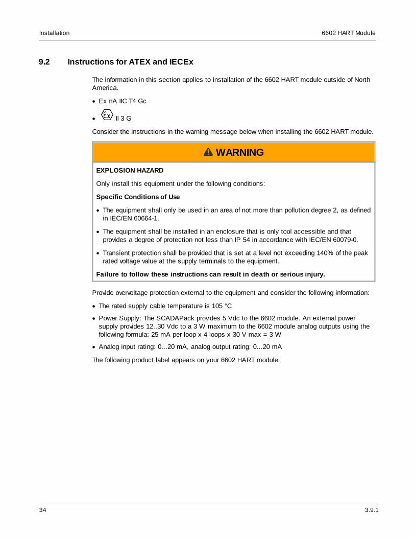
9.2 Instructions for ATEX and IECEx
The information in this section applies to installation of the 6602 HART module outside of NorthAmerica.
· Ex nA IIC T4 Gc
· II 3 G
Consider the instructions in the warning message below when installing the 6602 HART module.
WARNING
EXPLOSION HAZARD
Only install this equipment under the following conditions:
Specific Conditions of Use
· The equipment shall only be used in an area of not more than pollution degree 2, as definedin IEC/EN 60664-1.
· The equipment shall be installed in an enclosure that is only tool accessible and thatprovides a degree of protection not less than IP 54 in accordance with IEC/EN 60079-0.
· Transient protection shall be provided that is set at a level not exceeding 140% of the peakrated voltage value at the supply terminals to the equipment.
Failure to follow these instructions can result in death or serious injury.
Provide overvoltage protection external to the equipment and consider the following information:
· The rated supply cable temperature is 105 °C
· Power Supply: The SCADAPack provides 5 Vdc to the 6602 module. An external powersupply provides 12..30 Vdc to a 3 W maximum to the 6602 module analog outputs using thefollowing formula: 25 mA per loop x 4 loops x 30 V max = 3 W
· Analog input rating: 0...20 mA, analog output rating: 0...20 mA
The following product label appears on your 6602 HART module:

3.9.1
6602 HART Module Installation
35
Model 8 AI, 4 AO
Model 8 AI
3.9.1
6602 HART ModuleInstallation
36
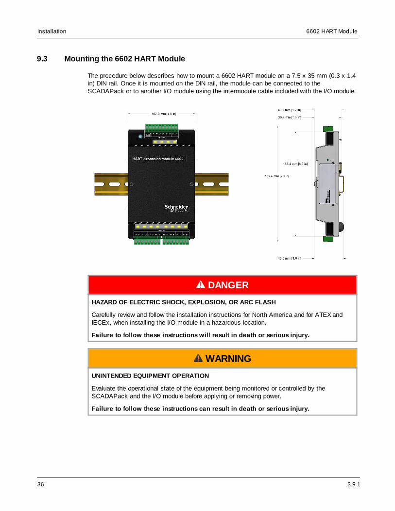
9.3 Mounting the 6602 HART Module
The procedure below describes how to mount a 6602 HART module on a 7.5 x 35 mm (0.3 x 1.4in) DIN rail. Once it is mounted on the DIN rail, the module can be connected to theSCADAPack or to another I/O module using the intermodule cable included with the I/O module.
DANGER
HAZARD OF ELECTRIC SHOCK, EXPLOSION, OR ARC FLASH
Carefully review and follow the installation instructions for North America and for ATEX andIECEx, when installing the I/O module in a hazardous location.
Failure to follow these instructions will result in death or serious injury.
WARNING
UNINTENDED EQUIPMENT OPERATION
Evaluate the operational state of the equipment being monitored or controlled by theSCADAPack and the I/O module before applying or removing power.
Failure to follow these instructions can result in death or serious injury.
3.9.1
6602 HART Module Installation
37
WARNING
ELECTRICAL HAZARD
Remove power from the I/O module before mounting it on a DIN rail.
Do not remove the I/O module cover when mounting the module. The I/O module is designedso that it can be mounted on a DIN rail with the cover in place.
Failure to follow these instructions can result in death or serious injury.
NOTICE
UNINTENDED EQUIPMENT OPERATION
The mounting position can affect the maximum operating temperature for the I/O module andthe current rating for the digital outputs.
Before mounting the I/O module, check the Specifications topic to confirm the maximumoperating temperature and digital output current rating for your mounting position.
Failure to follow these instructions can result in equipment damage.
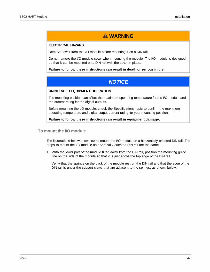
To mount the I/O module
The illustrations below show how to mount the I/O module on a horizontally oriented DIN rail. Thesteps to mount the I/O module on a vertically oriented DIN rail are the same.
1. With the lower part of the module tilted away from the DIN rail, position the mounting guideline on the side of the module so that it is just above the top edge of the DIN rail.
Verify that the springs on the back of the module rest on the DIN rail and that the edge of theDIN rail is under the support claws that are adjacent to the springs, as shown below.

3.9.1
6602 HART ModuleInstallation
38
2. Push firmly on the module while tilting it toward the DIN rail until the DIN rail is positionedunder both the upper and lower claws on the back of the module.
3. Verify that the mounting guide line is aligned with the edge of the DIN rail, then release thepressure on the springs so that the DIN rail is held firmly in place between the upper andlower claws.
The figure below shows a DIN rail correctly positioned in the upper and lower claws on theback of the I/O module.
3.9.1
6602 HART Module Installation
39
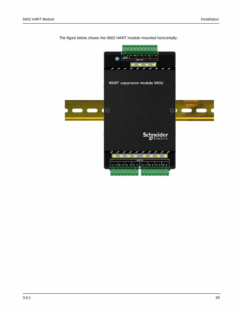
The figure below shows the 6602 HART module mounted horizontally.

3.9.1
6602 HART ModuleInstallation
40
9.4 Power Supply Requirements
Power for a 2-wire instrument loop is typically 24 Vdc and needs to be sufficient to provide thenecessary voltage for the field device.
Power supply ripple and noise
The table below shows the specifications for the power supply for a HART loop. The ripple andnoise specifications help to prevent direct interference with the HART signals. The impedancelimit helps to provide a low impedance path for HART signals. This helps to prevent inadvertentcoupling and crosstalk between multiple HART loops powered from a common supply. Includethe resistance of output fuses, if any, when measuring this value
Maximum ripple 47...125 Hz (0.2 Vpp)
Maximum noise 500 Hz to 10 kHz (1.2 mV rms)
Maximum series impedance 500 Hz to 10 kHz (10 ohms)
The 6602 HART module is powered by the SCADAPack through the I/O bus cable that connectsthe units. For maximum system configurations, see Specifications .
In the 8 AI, 4 AO model, the four analog outputs require an external 12...30 Vdc power supply.
The 6602 module requires 1.3 W. This is a maximum and represents the input power to theSCADAPack.
WARNING
UNINTENDED EQUIPMENT OPERATION
The input power supply must be a DC supply.
Failure to follow these instructions can result in death or serious injury.
WARNING
UNINTENDED EQUIPMENT OPERATION
Safety Extra Low Voltage (SELV) or Protective Extra Low Voltage (PELV) power supplies arerequired on the power input and I/O points. Power supplies with 100...240 Vac inputs thatcomply with safety standard IEC/EN 60950 generally have SELV outputs. Check with themanufacturer or the agency certification listing to confirm that they have SELV outputs.
Failure to follow these instructions can result in death or serious injury.
Use the power supply recommended by Schneider Electric, providing 100...240 Vac in and 24Vdc, 2.5 A out (see the SCADAPack Part Ordering List manual).
69

3.9.1
6602 HART Module Installation
41
System grounding
Ground the system by connecting the system power supply common to the chassis or panelground. On the I/O module, the power supply common (the “-“ connector for the 12...30 Vdcsupply) is connected to the chassis internally within the CPU card. As a result, it is not isolated.
None of the I/O module pins, including any of the commons, are connected to chassis ground.As a result, they are isolated.
Whenever feasible, it is recommended that additional power supplies be grounded at a commonpoint with the panel SCADAPack power supply.

3.9.1
6602 HART ModuleInstallation
42
9.5 Connecting I/O Modules
The topics in this section describe how to attach I/O modules to a SCADAPack, or to anotherI/O module.
I/O modules are mounted on a 7.5 x 35 mm (0.3 x 1.4 in) DIN rail and then connected to aSCADAPack using intermodule cables. The intermodule cable is a ribbon cable that distributespower (5 Vdc) and communications signals from the SCADAPack to the I/O modules. Thesepower and communication signals are referred to as the I/O bus.
The figure below shows a SCADAPack x70 device with an I/O module connected to it. You canconnect multiple I/O modules to a single SCADAPack up to the maximum number of modulessupported by the device. See the SCADAPack hardware manual for details.
The illustration below shows a connected intermodule cable. The maximum number of modulesmay also be limited by the total length of the cable. See Cabling Guidance for further detailson intermodule cables. While the size and shape of your devices may differ and the color of theconnectors may be different, the location of the intermodule cable is the same on each devicetype.
Before attaching intermodule cables , read the Precautions and the Cabling Guidance .
9.5.1 Precautions
Before connecting I/O modules:
· Confirm that the power supply is rated for the total number of modules in the system. SomeI/O modules, such as those with analog outputs, require an additional DC power supply tooperate. See Specifications for details.
· Confirm that the intermodule cables you are are less than the maximum total cable length.See Maximum Intermodule Cable Length .
· Review the recommendations below to help avoid static electricity damage.
44
45 42 44
69
45

3.9.1
6602 HART Module Installation
43
NOTICE
STATIC ELECTRICITY DAMAGE
Static electricity damage can cause intermittent or total loss of equipment operation. Tohelp avoid static electricity damage:
· Wear an anti-static wrist strap that is connected to ground if you need to remove thedevice cover.
· Use the shortest length intermodule cable that is practical. This helps to minimize voltagedrops and interference from electrical noise.
· Keep the intermodule cable away from electrical noise sources such as inductive loadswitching and variable frequency drives.
· If you are using a shielded cable, connect the shielding wire on the intermodule cable to aconvenient chassis ground point. There is a small hole in the I/O module for grounding theshielding wire.
· Do not install intermodule cables in the same cable tray or in parallel with field wiring.Intermodule cables can cross field wiring at 90° if necessary.
Failure to follow these instructions can result in equipment damage.
3.9.1
6602 HART ModuleInstallation
44
9.5.2 Cabling Guidance
This topic summarizes the rules for connecting I/O modules to SCADAPack x70 devices. Theserules apply to the following SCADAPack I/O modules:
· 6601 input output module
· 6602 HART module
· 6607 input output module
· 5304 analog output module
· 5405 digital input module
· 5410 high speed counter input module
· 5414 digital input module
· 5415 relay output module
· 5505 RTD input module
· 5506 analog input module
· 5606 input output module
· 5607 input output module
Using only 5000 series I/O modules
If you are using only 5000 series I/O modules with a SCADAPack x70 device, connect the 5000series module directly to the SCADAPack using a 20-pin to 16-pin adapter cable (soldseparately, see the SCADAPack Part Ordering List manual).
Using 5000 and 6000 series I/O modules
If you are using a combination of 5000 series I/O modules and 6000 series I/O modules with aSCADAPack x70 device, connect a 6000 series module to the SCADAPack first, followed byany other 6000 series modules. Then connect the 5000 series modules to the last 6000 seriesmodule.
SCADAPack x70 devices and 6000 series modules provide a 20-pin I/O bus connector while5000 series modules provide a 16-pin connector. Use the 20-pin to 16-pin adapter cable (soldseparately, see the SCADAPack Part Ordering List manual) to transition from a 20-pinconnector to a 16-pin connector.
General guidance
· Use the shortest length intermodule cable that is practical. This helps to minimize voltagedrops and interference from electrical noise.
· Keep the intermodule cable away from electrical noise sources such as inductive loadswitching and variable frequency drives.
· If you are using a shielded cable, connect the shielding wire on the intermodule cable to aconvenient chassis ground point. There is a small hole in the I/O module for grounding theshielding wire.

3.9.1
6602 HART Module Installation
45
· Install intermodule cables in separate cable trays from field wiring, and not in parallel with fieldwiring. Intermodule cables can cross field wiring at 90° if necessary.
Intermodule cables
When determining the location of your I/O modules, review the following information aboutshielded intermodule cables and maximum intermodule cable length.
Shielded intermodule cables
Shielded intermodule cables have a foil and braid shielding. Intermodule cables longer than 30cm (12 in) are shielded for physical protection and for isolation from electrical noise. Theshielding is connected to a terminal lug at one end of the cable.
When using a shield for an intermodule cable, fasten the shield only to the module that isclosest to the SCADAPack. Connect the shield to the enclosure using the self-tapping screwprovided.
You can use up to 3 shielded intermodule cables. The total length of all cables can not exceed1.82 m (75 in).
Maximum intermodule cable length
I/O modules ship with a short intermodule cable that is used to connect I/O modules to aSCADAPack or to another I/O module.
The maximum total intermodule cable length in a single system is 1.82 m (75 in). This lengthrestriction does not include the short intermodule cable supplied with the I/O module. SchneiderElectric offers several cable lengths that can be combined to reach the 1.82 m (75 in) limit.
Keep the following in mind:
· No more than 1.5 m (60 in) of total expansion cable length can follow a controller or powersupply before an additional power supply needs to be added
· 1.14 m (45 in) and 1.82 m (75 in) expansion cables need to be followed by a power supply
· The highest power consumption modules need to be to closest to the controller or powersupply with 6000 series modules first, followed by 5000 series modules due to connectorlimitations
· The maximum number of power supply modules, not including the controller, is 2
· A 30 cm (12 in) or a 76 cm (30 in) cable is typically used to connect modules on separate DINrails
To purchase additional intermodule cables, contact your Schneider Electric representative.
9.5.3 Attaching Intermodule Cables
This topic describes how to attach an intermodule cable between a SCADAPack and an I/Omodule. Follow the same steps to connect two I/O modules.

3.9.1
6602 HART ModuleInstallation
46
WARNING
UNINTENDED EQUIPMENT OPERATION
Evaluate the operational state of the equipment being monitored or controlled by theSCADAPack or the I/O module before applying or removing power.
Failure to follow these instructions can result in death or serious injury.
WARNING
ELECTRICAL HAZARD
The I/O bus does not support live-swapping.
Remove power from the SCADAPack and the I/O module before removing the cover.
Failure to follow these instructions can result in death or serious injury.
NOTICE
STATIC ELECTRICITY DAMAGE
Static electricity damage can cause intermittent or total loss of equipment operation.
Always wear an anti-static wrist strap that is connected to ground when you remove the devicecover.
Failure to follow these instructions can result in equipment damage.
5410 High Speed Counter Input Module Considerations
NOTICE
UNEXPECTED COUNTER READINGS
Do not disconnect a 5410 high speed counter input module while the module and RTU arepowered.
Do not remove power from a 5410 high speed counter input module while the RTU is poweredand communicating with the module.
Failure to follow these instructions can result in unexpected counter readings.
Power off the RTU before connecting or disconnecting the inter-module cable to the 5410 highspeed counter input module.
Power off the RTU and 5410 high speed counter input module at the same time. Use a commonpower supply input for the RTU and I/O modules.

3.9.1
6602 HART Module Installation
47
To attach intermodule cables
1. Power down each SCADAPack and I/O module that you are connecting.
2. Remove the cover from the device if required to access the intermodule cable.
3. Press one end of the intermodule cable firmly into the I/O bus connector on theSCADAPack.
SCADAPack x70 devices and 6000 series modules provide a 20-pin I/O bus connector while5000 series modules provide a 16-pin connector. Use the 20-pin to 16-pin adapter cable (soldseparately, see the SCADAPack Part Ordering List manual) to transition from a 20-pinconnector to a 16-pin connector.
The connectors on intermodule cables are keyed so they can only be inserted in onedirection. If the connector does not push easily into the I/O bus connector, reverse it and tryagain.
4. Press the other end of the intermodule cable firmly into the I/O bus connector on the I/Omodule.
The illustration below shows a connected intermodule cable. While the size and shape ofyour devices may differ and the color of the connectors may be different, the location of theintermodule cable is the same on each device type.
5. Replace the cover on the I/O module and on the SCADAPack if it was removed, taking careto check that the ribbon cable connecting the I/O module is not pinched.
6. Apply power to the SCADAPack.
You are now ready to configure the I/O module.

3.9.1
6602 HART ModuleAddressing
48
10 Addressing
This section describes the addressing rules for an I/O module and the procedure for setting theI/O module address.
WARNING
UNINTENDED EQUIPMENT OPERATION
Review the power requirements for the I/O modules before combining modules.
Failure to follow these instructions can result in death or serious injury.
I/O modules can be combined in any manner up to the maximum number supported by theSCADAPack. For details about the maximum supported system configuration, see theSCADAPack hardware manual for guidance.
Each I/O module connected to the SCADAPack is assigned a unique I/O module address.
For more information see:
· Addressing Rules
· Setting the I/O Module Address
10.1 Addressing Rules
I/O modules are shipped from the factory at address 0.
· If you are connecting only 1 6602 HART module to a SCADAPack 470, SCADAPack 570, orSCADAPack 574, you can leave the address at 0
· If you are connecting 1 6602 HART module to a SCADAPack 474, you will need to change theaddress. The SCADAPack 474 includes an internal 6607 input output module at address 0.
· If you are connecting more than 1 external 6000 series module to your SCADAPack x70device, each module requires a unique address
10.2 Setting the I/O Module Address
I/O modules are shipped from the factory at address 0.
· To avoid conflict with the addresses of other I/O modules, change the address of any otherexternal 6000 series I/O modules
WARNING
UNINTENDED EQUIPMENT OPERATION
Evaluate the operational state of the equipment being monitored or controlled by theSCADAPack and the I/O module before applying or removing power.
Failure to follow these instructions can result in death or serious injury.
48
48

3.9.1
6602 HART Module Addressing
49
WARNING
UNINTENDED EQUIPMENT OPERATION
Remove power from the I/O module before initially setting the I/O module address and beforechanging the I/O module address.
Failure to follow these instructions can result in death or serious injury.
WARNING
UNINTENDED EQUIPMENT OPERATION
Be very careful that you do not set the I/O module address to an address that is assigned toanother I/O module connected to the same SCADAPack.
If 2 I/O modules have the same address, you will lose communications with both modules.
Failure to follow these instructions can result in death or serious injury.
To set or change an I/O module address
1. Remove power from the I/O module.
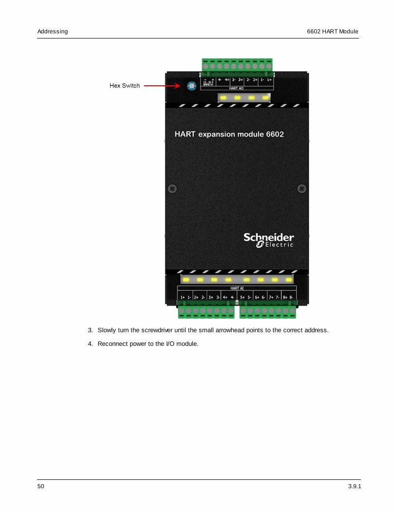
2. Insert a 2.4 mm (3/32 in) slotted screwdriver into the inner circle of the rotary hex switch.
3.9.1
6602 HART ModuleAddressing
50
3. Slowly turn the screwdriver until the small arrowhead points to the correct address.
4. Reconnect power to the I/O module.

3.9.1
6602 HART Module Field Wiring
51
11 Field Wiring
In general, the installation practice for wired HART devices is the same as for conventional 4...20mA instrumentation.
Guidelines for wiring the 6602 HART module
· Use shielded twisted pair cabling with the specified conductor size (see Cablingconsiderations ) and a UL rating of 105 °C
· Ground the shield at one point only, close to the SCADAPack power supply
· Use the specified power supply
· Ground the negative side of the power supply
Cabling considerations
Use individually shielded twisted pair cable, either in single pair or multi-pair varieties.Unshielded cables may be used for short distances, provided ambient noise and cross-talk willnot adversely impact communication.
The minimum conductor size is 0.205 mm2 (24 AWG) for cable runs less than 1,500 meters
(5000 ft) and 0.518 mm2 (20 AWG) for longer distances.
Additional information on wire length and capacitance is available at https://fieldcommgroup.org/.
Grounding
Ground the signal loop, if at all, at one point only. Connect the cable shielding to ground, againat one point only. The single ground point will usually be at or near the SCADAPack powersupply.
For more information see:
· Wiring Screw-Termination Connectors
· Analog Input Wiring
· Analog Output Wiring: 8 AI, 4 AO Model Only
11.1 Wiring Screw-Termination Connectors
Screw-termination style connectors are provided to terminate wiring from:
· Power supplies
· RS485 devices
· Input/output (I/O) modules
These 5 mm (0.197 in) pitch connectors support solid or stranded wires from 2.5...0.2 mm2
(12...30 AWG).
51
40
51
53
57

3.9.1
6602 HART ModuleField Wiring
52
WARNING
UNINTENDED EQUIPMENT OPERATION
Evaluate the operational state of the equipment being monitored or controlled by theSCADAPack or the I/O module before wiring screw-termination connectors.
Failure to follow these instructions can result in death or serious injury.
WARNING
ELECTRICAL HAZARD
Remove power from all modules and devices before servicing.
Failure to follow these instructions can result in death or serious injury.
To wire a connector
1. Use a slotted screwdriver to loosen the termination screw.
2. Insert the stripped wire into the connector so that the bared wire is located under the screw.
Verify that the bared wire is placed fully within the connector, as illustrated below.
3. Apply 0.5 N•m (4.5 lb-in) torque to tighten the screw so the wire is held firmly in place.

3.9.1
6602 HART Module Field Wiring
53
11.2 Analog Input Wiring
This section describes the wiring for the analog inputs.
For more information see:
· Analog Input Wiring Example 54

3.9.1
6602 HART ModuleField Wiring
54
11.2.1 Analog Input Wiring Example
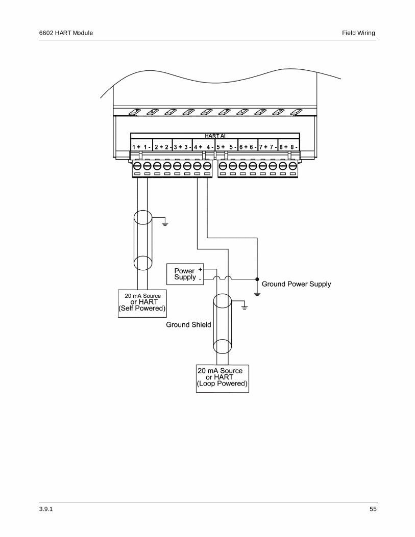
The analog inputs support loop-powered and self-powered transmitters.
WARNING
ELECTRICAL HAZARD
Remove power from all devices before connecting or disconnecting inputs or outputs to anyterminal or installing or removing any hardware.
Failure to follow these instructions can result in death or serious injury.
NOTICE
LIGHTNING SURGE THROUGH ANALOG INPUTS
If a transducer or transmitter connected to an analog channel is placed outside of the buildingor structure where the SCADAPack or I/O module that provides the analog inputs is installed,there is an increased possibility of extremely severe power surges caused by lightning. Inthese cases, additional surge protection must be supplied by the user.
Failure to follow these instructions can result in equipment damage.
NOTICE
UNINTENDED EQUIPMENT OPERATION
Do not exceed the maximum input range specified for each analog input. For details, see theSpecifications topic.
Failure to follow these instructions can result in equipment damage.
Loop-powered transmitters
Loop-powered transmitters are two-terminal devices that are connected between a power supplyand the analog input. The loop current from the power supply passes through the transmitter andreturns to the power supply through a resistor in the 20 mA input circuit.
Self-powered transmitters
Self-powered transmitters have two terminals:
· Power In connects to a power supply
· Signal Out connects to the analog input channel
Use self-powered transmitters that have a current output.
In the wiring example below, a self-powered transmitter is grounded and connected to AI 1. Aloop-powered transmitter is connected to AI 4.
3.9.1
6602 HART Module Field Wiring
55

3.9.1
6602 HART ModuleField Wiring
56
As illustrated below, the 6602 HART module does not need to be the last device in the currentloop.

3.9.1
6602 HART Module Field Wiring
57
11.3 Analog Output Wiring: 8 AI, 4 AO Model Only
This section describes the wiring for the analog outputs on the 8 AI, 4 AO model.
For further information see:
· Analog Output Wiring Example: 8 AI, 4 AO Model Only 58

3.9.1
6602 HART ModuleField Wiring
58
11.3.1 Analog Output Wiring Example: 8 AI, 4 AO Model Only
There are two configuration options for the external 24 Vdc power supply that is required whenthe optional analog output module is installed:
· The analog output module and the SCADAPack can each have their own 24 Vdc powersupply. In this configuration, the analog outputs are isolated from the SCADAPack RTU inputpower.
· The analog output module can share an external 24 Vdc power supply with the SCADAPack.In this configuration, the analog outputs are not isolated from the SCADAPack RTU inputpower.
WARNING
ELECTRICAL HAZARD
Remove power from all devices before connecting or disconnecting inputs or outputs to anyterminal or installing or removing any hardware.
Failure to follow these instructions can result in death or serious injury.
NOTICE
UNINTENDED EQUIPMENT OPERATION
Install a 0.125 A fast-acting fuse on the input voltage side of the analog output power supplyconnection.
Failure to follow these instructions can result in equipment damage.
The figure below shows loads connected to the positive terminals on analog outputs 4 and 3.

3.9.1
6602 HART Module Field Wiring
59
The analog output circuitry is configured internally to receive power from an external powersupply on pins 9 and 10 of the removable terminal block. The analog outputs are not isolatedfrom each other, but are isolated from the SCADAPack RTU circuitry.

3.9.1
6602 HART ModuleConfiguration
60
12 Configuration
The 6602 HART module inputs and outputs can be configured locally or remotely using theSCADAPack RemoteConnect configuration software on a Microsoft Windows-based computer.
· To send HART data to a SCADA system or make use of HART data in logic, use theSCADAPack x70 Logic Editor to write an application to access standard HART data from theHART instruments and convert it into telemetry data. In the Function Blocks TechnicalReference manual, see HART Function Blocks.
· To send HART data to an Asset Management System (AMS), or to maintain HART devicesusing an FDT- and DTM-compatible frame application such as SCADAPack RemoteConnect,enable the HART Pass Through functionality in SCADAPack RemoteConnect. This issupported for SCADAPack 570, SCADAPack 574, and SCADAPack 575 models.SCADAPack 470 and SCADAPack 474 models do not presently support this functionality. Inthe SCADAPack x70 Configuration manual, see HART Pass Through and in the FunctionBlocks Technical Reference manual, see HART_6602Control: Enable HART module. Thisallows the AMS or maintenance application to receive standard and device-specific data fromthe HART instruments. See Using the 6602 HART module in an AMS .
SCADAPack RemoteConnect configuration software
The configuration software provides a graphical user interface that allows you to:
· Configure parameters for the SCADAPack and any attached I/O modules and then load thoseparameters into the SCADAPack
· Interact online with the SCADAPack to view status information, diagnostics information andcurrent parameter values for the SCADAPack and any attached I/O modules
· Use the built-in SCADAPack x70 Logic Editor to develop IEC 61131-3 applications that extendand enhance the functionality provided by the SCADAPack and any attached I/O modules
The configuration software is comprised of a frame application that is FDT 2.1, FDT 2.0, and FDT1.2 compliant and Device Type Managers (DTMs).
For information about See
Working with projects andDTMs
SCADAPack RemoteConnect Configuration Software manual
Configuringcommunications with theSCADAPack
PC Communication Settings -SCADAPack CommDTM manual
Configuring deviceparameters and interactingonline with the device
SCADAPack x70 Configuration manual
Using the SCADAPack x70Logic Editor
Logic Programming Overview manual
19

3.9.1
6602 HART Module Configuration
61
Accessing help for theHART Communication DTM
For the help manual, see the HART - STB Multiplexer -Applications Guide.
The manual opens in a new window.

3.9.1
6602 HART ModuleDiagnostics
62
13 Diagnostics
The 6602 HART module provides an LED for each input and output. LEDs indicate that there iscommunication between a HART field instrument and the relevant input or output on the 6602HART module.
The table below describes the LEDs on the 6602 HART module.
Name Color Description
Analog input Yellow Lit when HART communications are active
Analog output (8 AI, 4 AO modelonly)
Yellow Lit when HART communications are active
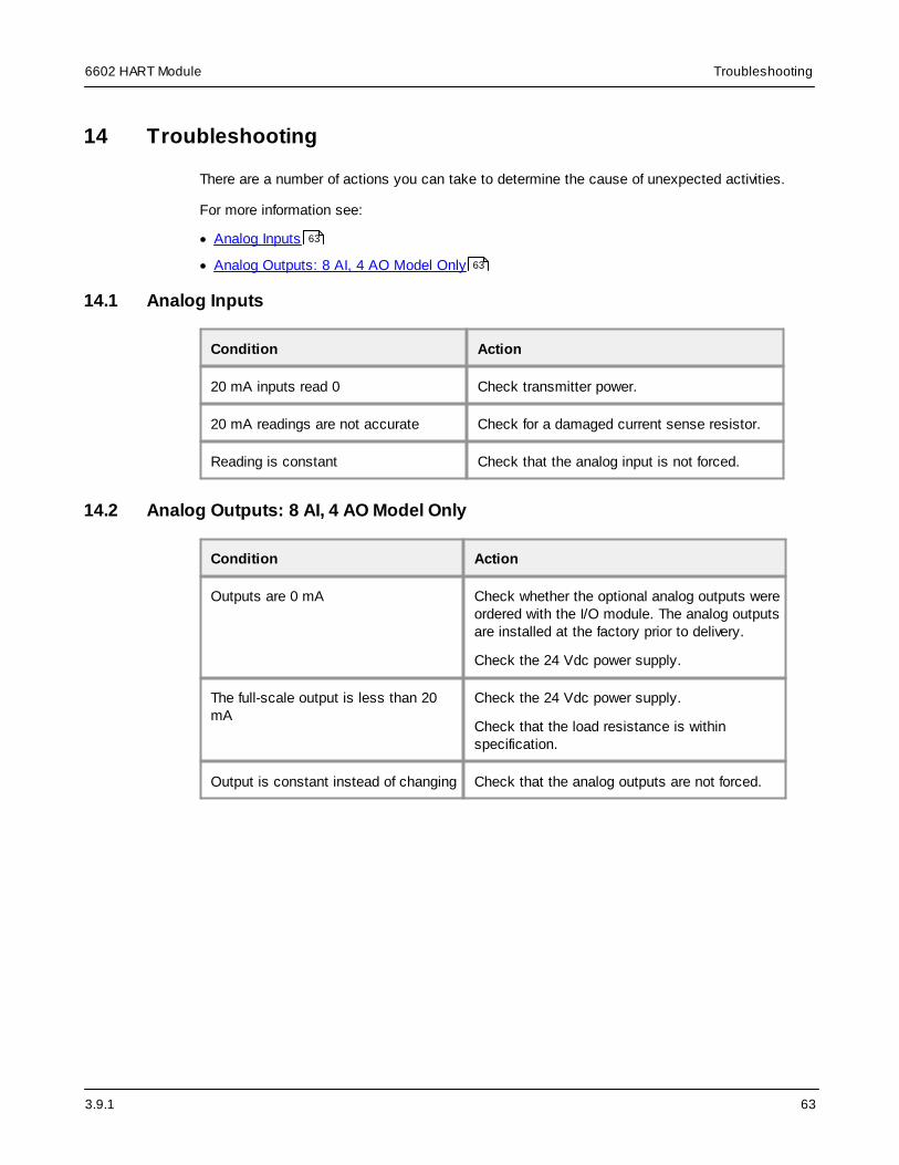
3.9.1
6602 HART Module Troubleshooting
63
14 Troubleshooting
There are a number of actions you can take to determine the cause of unexpected activities.
For more information see:
· Analog Inputs
· Analog Outputs: 8 AI, 4 AO Model Only
14.1 Analog Inputs
Condition Action
20 mA inputs read 0 Check transmitter power.
20 mA readings are not accurate Check for a damaged current sense resistor.
Reading is constant Check that the analog input is not forced.
14.2 Analog Outputs: 8 AI, 4 AO Model Only
Condition Action
Outputs are 0 mA Check whether the optional analog outputs wereordered with the I/O module. The analog outputsare installed at the factory prior to delivery.
Check the 24 Vdc power supply.
The full-scale output is less than 20mA
Check the 24 Vdc power supply.
Check that the load resistance is withinspecification.
Output is constant instead of changing Check that the analog outputs are not forced.
63
63
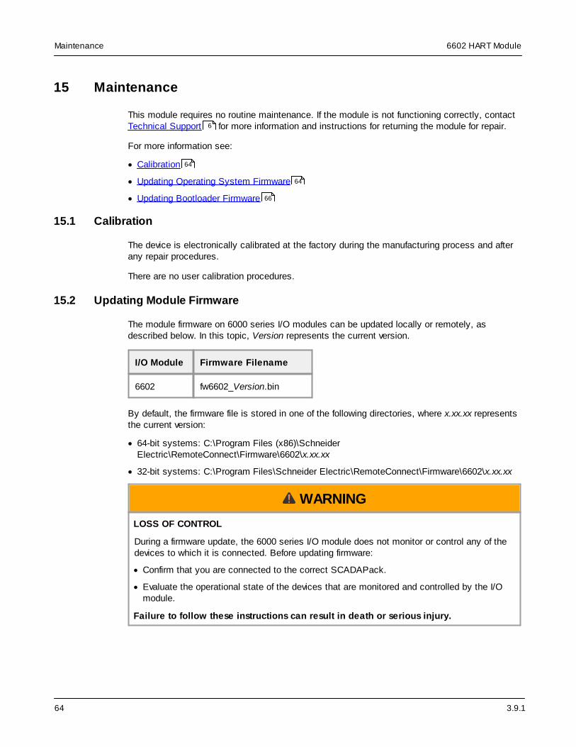
3.9.1
6602 HART ModuleMaintenance
64
15 Maintenance
This module requires no routine maintenance. If the module is not functioning correctly, contactTechnical Support for more information and instructions for returning the module for repair.
For more information see:
· Calibration
· Updating Operating System Firmware
· Updating Bootloader Firmware
15.1 Calibration
The device is electronically calibrated at the factory during the manufacturing process and afterany repair procedures.
There are no user calibration procedures.
15.2 Updating Module Firmware
The module firmware on 6000 series I/O modules can be updated locally or remotely, asdescribed below. In this topic, Version represents the current version.
I/O Module Firmware Filename
6602 fw6602_Version.bin
By default, the firmware file is stored in one of the following directories, where x.xx.xx representsthe current version:
· 64-bit systems: C:\Program Files (x86)\SchneiderElectric\RemoteConnect\Firmware\6602\x.xx.xx
· 32-bit systems: C:\Program Files\Schneider Electric\RemoteConnect\Firmware\6602\x.xx.xx
WARNING
LOSS OF CONTROL
During a firmware update, the 6000 series I/O module does not monitor or control any of thedevices to which it is connected. Before updating firmware:
· Confirm that you are connected to the correct SCADAPack.
· Evaluate the operational state of the devices that are monitored and controlled by the I/Omodule.
Failure to follow these instructions can result in death or serious injury.
6
64
64
66

3.9.1
6602 HART Module Maintenance
65
WARNING
UNINTENDED EQUIPMENT OPERATION
Do not remove power from the SCADAPack during the firmware update.
Do not disconnect the 6000 series I/O module from the SCADAPack during the firmwareupdate.
Do not use the RESTART DEVICE command during the firmware update.
If power is interrupted for any reason during the firmware update, contact Technical Support.
Failure to follow these instructions can result in death or serious injury.
NOTICE
INCOMPATIBLE FIRMWARE VERSIONS
Before installing a firmware update, check the Release Notes for the firmware update todetermine the most suitable I/O module firmware version for the SCADAPack firmware versionand the functionality you are using.
Failure to follow these instructions can result in equipment damage.
Note: Outputs on the I/O module turn off during the firmware update and remain off until theupdate is complete. Updates can take up to several minutes.
To update the firmware on a 6602 I/O module
1. Use SCADAPack RemoteConnect to transfer the fw6602_Version.bin file to theSCADAPack file system:
a. Connect SCADAPack RemoteConnect to the SCADAPack x70 device and go Online.
b. Under My Network, right-click on SCADAPack x70 Controller Settings -DeviceDTM and select Additional Functions > Write File to Device.
c. In the Write File to Device dialog, click Browse to navigate to the location of the file onyour computer.
d. Click Open.
e. In the Write File to Device dialog, click OK.
2. Start the I/O firmware upgrade:
a. Under My Network, right-click on SCADAPack x70 Controller Settings -DeviceDTM and select Additional Functions > Execute Command.
b. Enter the command, where Version is the current version:
restart iofirm fw6602_Version.bin module_address
Where the module_address is the address of your I/O module. The I/O module address is

3.9.1
6602 HART ModuleMaintenance
66
a number from 0 to 3.
Example: restart iofirm fw6602_Version.bin 0
WARNING
UNINTENDED EQUIPMENT OPERATION
If the firmware update was unsuccessful, the I/O module will remain in a state where it doesnot monitor or control any of the devices to which it is connected.
Carefully review the message indicating whether the firmware update was successful orunsuccessful. Unsuccessful firmware updates are also reported through the SCADAPackx70 device’s System Status Code. See RemoteConnect Online Diagnostics mode. For alist of the possible status code values, see the System Status Codes topic.
Failure to follow these instructions can result in death or serious injury.
3. After the firmware update is complete, open a command line or Telnet session and use theVER command to display device version information.
You can use the VER command to verify that the firmware update is complete. The updatetakes approximately 5 minutes, so if you use the VER command before the 5 minutes haselapsed, you may not see the updated device version information. If after 5 minutes you donot see the updated device version information, you can try to update the firmware again. Ifthe update continues to be unsuccessful, contact Technical Support.
15.3 Updating Bootloader Firmware
The bootloader firmware on 6000 series I/O modules can be updated locally or remotely, asdescribed below. Version represents the current version.
I/O Module Bootloader Filename
6602 bl6602_Version.bin
By default, the bootloader file is stored in one of the following directories, where x.xx.xxrepresents the current version:
· 64-bit systems: C:\Program Files (x86)\SchneiderElectric\RemoteConnect\Firmware\6602\x.xx.xx
· 32-bit systems: C:\Program Files\Schneider Electric\RemoteConnect\Firmware\6602\x.xx.xx

3.9.1
6602 HART Module Maintenance
67
WARNING
LOSS OF CONTROL
During a bootloader update, the 6000 series I/O module does not monitor or control any of thedevices to which it is connected. Before updating the bootloader on the I/O module:
· Confirm that you are connected to the correct SCADAPack
· Evaluate the operational state of the devices that are monitored and controlled by the I/Omodule.
Failure to follow these instructions can result in death or serious injury.
WARNING
UNINTENDED EQUIPMENT OPERATION
Do not remove power from the SCADAPack during the bootloader update.
Do not disconnect the 6000 series I/O module from the SCADAPack during the bootloaderupdate.
If power is interrupted for any reason during the bootloader update, contact TechnicalSupport.
Failure to follow these instructions can result in death or serious injury.
NOTICE
INCOMPATIBLE FIRMWARE VERSIONS
Before installing a bootloader update, check the Release Notes for the bootloader update todetermine the most suitable I/O module bootloader version for the SCADAPack firmwareversion and the functionality you are using.
Failure to follow these instructions can result in equipment damage.
To update the bootloader on a 6602 I/O module
1. Use SCADAPack RemoteConnect to transfer the .bin file to the SCADAPack file system:
a. Connect SCADAPack RemoteConnect to the SCADAPack x70 device and go Online.
b. Under My Network, right-click on SCADAPack x70 Controller Settings -DeviceDTM and select Additional Functions > Write File to Device.
c. In the Write File to Device dialog, click Browse to navigate to the location of the file onyour computer.
d. Click Open.
e. In the Write File to Device dialog, click OK.

3.9.1
6602 HART ModuleMaintenance
68
2. Start the bootloader firmware upgrade:
a. Under My Network, right-click on SCADAPack x70 Controller Settings -DeviceDTM and select Additional Functions > Execute Command.
b. Enter the command, where Version is the current version:
restart iofirm bl6602_Version.bin module_address
where module_address is the I/O module address. The I/O module address is a numberfrom 0 to 3.
Example: restart iofirm bl6602_Version.bin 0
WARNING
UNINTENDED EQUIPMENT OPERATION
If the bootloader update was unsuccessful, the I/O module will remain in a state where itdoes not monitor or control any of the devices to which it is connected.
Carefully review the message indicating whether the firmware update was successful orunsuccessful. Unsuccessful firmware updates are also reported through the SCADAPackx70 device’s System Status Code. See RemoteConnect Online Diagnostics mode. For alist of the possible status code values, see the System Status Codes topic.
Failure to follow these instructions can result in death or serious injury.

3.9.1
6602 HART Module Specifications
69
16 Specifications
Disclaimer: Schneider Electric reserves the right to change product specifications withoutnotice. If you have questions about any of the specifications, contact Technical Support .
For more information see:
· General
· Communications
· Analog Inputs
· Analog Outputs: 8 AI, 4 AO Model Only
16.1 General
Item Specification
Environment -40…70 °C (-40…158 °F) operating temperature
-40…85 °C (-40…185 °F) storage temperature
5...95% relative humidity, non-condensing
Pollution Degree 2
Overvoltage Category II
Equipment Class I
Elevation 0...2000 m (0...6562 ft)
Terminations 2.5...0.2 mm2 (12...28 AWG), solid or stranded
Packaging Corrosion-resistant zinc-plated steel with black enamel paint
Dimensions 102.0 mm (4.0 in) wide
182.4 mm (7.2 in) high
46.5 mm (1.8 in) deep
HART devices Maximum configuration:
· 1 6602 HART module
· 12 HART channels (standard data) accessible usingSCADAPack x70 logic function blocks with 1 6602 HARTmodule (8 AI, 4 AO model). Fewer HART channels areavailable when using the 8 AI model.
· SCADAPack 570, SCADAPack 574, and SCADAPack 575models: 1 active HART Pass Through connection using theSchneider Electric HART STB Multiplexer DTM to any of the
6
69
70
71
72

3.9.1
6602 HART ModuleSpecifications
70
12 HART channels. For SCADAPack 470 and SCADAPack474 models: HART Pass Through not presently supported.
HART devices can be connected using either:
· 1 6602 HART module, 8 AI model (1 x 8 analog inputs = 8) or1 6602 HART module 8 AI, 4 AO model
HART protocol HART protocol versions 5, 6, and 7 when using HART PassThrough mode
ARCOM protocol ARCOM HART multiplexer protocol
TCP port number 5001 (default) when enabled
Power requirements From the SCADAPack:
· 6602 HART module model 8 AI: 1.0 W
· 6602 HART module model 8 AI, 4 AO: 1.3 W
Mechanical shock IEC 61131-2
½ sine, 15 ms, 15 g
Vibration IEC 61131-2
5...8.4 Hz: Amplitude controlled, 7.0 mm (0.28 in) peak-to-peak
8.4...150 Hz: Acceleration controlled, 1.0 g peak
16.2 Communications
Item Specification
I/O bus SCADAPack 470, SCADAPack 570, and SCADAPack 574
· Maximum number of 6601 input output modules with optionalanalog outputs is 4
· Maximum number of 6602 HART modules with optionalanalog outputs is 1
· Maximum number of 6607 input output modules in thesystem is 4
SCADAPack 474
· Maximum number of 6601 input output modules with optionalanalog outputs is 4
· Maximum number of 6602 HART modules with optionalanalog outputs is 1
· Maximum number of 6607 input output modules in thesystem is 3

3.9.1
6602 HART Module Specifications
71
SCADAPack 575
· Maximum number of 6601 input output modules with optionalanalog outputs is 3
· Maximum number of 6602 HART modules with optionalanalog outputs is 1
· Maximum number of 6607 input output modules in thesystem is 4
16.3 Analog Inputs
Item Specification
Quantity 8
Type Uni-polar, differential, current
HART 1 HART device per analog input
Typically less than 10 second scan rate
Ranges Input Type:
4...20 mA (HART capable)
0...20 mA (HART disabled)
Over-range: Measures up to 22 mA
Under-range: 4...20 mA measures to 0 mA
Input resistance 280 ohms
Accuracy ±0.1% of full scale at 25 °C (77 °F)
±0.2% over-temperature range
Resolution Fast, no filtering
· 14 effective bits
· 1 µA resolution
Filtered 50/60 Hz
· 16 effective bits
· 0.4 µA resolution
Transient protection PTC and TVS protected
Sampling rate Fast, no filtering

3.9.1
6602 HART ModuleSpecifications
72
100 ms to 99% of full scale
Response to 99% of change 70 ms
Response to 90% of change 40 ms
Scan rate: 100 ms
Filtered 50/60 Hz
Scan rate: 660 ms
Common mode rejection > 80 dB
Normal mode rejection Filtered 50/60 Hz
> 80 dB
Isolation 100 Vdc isolation from channel to SCADAPack RTU circuitryand chassis
250 Vac isolation from channel SCADAPack RTU circuitry andchassis
16.4 Analog Outputs: 8 AI, 4 AO Model Only
Item Specification
Quantity 4
Type Uni-polar
HART 1 HART device per analog output
Typically 5 second scan rate (maximum 7 across all enabledchannels)
Range 4...20 mA (HART capable)
0...20 mA (HART disabled)
Voltage output may be accomplished with external precisionresistor
Accuracy ±0.15% at 25 °C (77 °F)
±0.35% of full scale over-temperature range
Resolution 16 bit digital-to-analog conversion (DAC)
0.4 µA
Transient protection TVS protected

3.9.1
6602 HART Module Specifications
73
Response time 40 ms for 0% to 90% signal change
Load range 12 Vdc: 0…450 ohms
24 Vdc: 0…1050 ohms
30 Vdc: 250…1350 ohms
Power supply (external) 12…30 Vdc (±10%)
Cable length < 30 m (98.4 ft)
Requires SELV/PELV power supply
20 mA plus up to 20 mA per output
100 mA total
3 W at 30 Vdc
Isolation Transformer
250 Vac isolation from channel SCADAPack RTU circuitry andchassis
3.9.1
6602 HART ModuleStandards and Certifications
74
17 Standards and Certifications
Introduction
SCADAPack x70 devices are designed to comply with the relevant standards and rules forelectrical equipment in an industrial automation environment.
Industrial Standards
Requirements specific to the SCADAPack functional characteristics, immunity, robustness, andsafety:
· IEC/EN 61131-2
· UL 61010
CE Marking Compliance
· For the latest information regarding product compliance with European Directives for CEmarking, refer to the EU Declaration of Conformity issued for your product at www.se.com
· For the latest information regarding product compliance with RoHS, WEEE directives andREACH regulation, visit the Schneider Electric Check a Product portal atwww.reach.schneider-electric.com
Installation in Classified Ex Area
· Certification is in accordance with Standards ANSI/ISA-12.12.01-2015 and CAN/CSA C22.2NO. 213-15, Non-incendive Electrical Equipment for Use in Class I and II, Division 2 and ClassIII, Divisions 1 and 2 Hazardous (Classified) Locations
· ATEX (European directive 2014/34/EU) in defined atmosphere Zone 2 according to EN 60079-0and EN 60079-15
· IECEx in defined atmosphere Zone 2 according to IEC 60079-0 and IEC 60079-15
Specific Countries
For Australia and New Zealand: ACMA requirements for RCM marking
For United States: FCC Part 15 Subpart B Class A


6607 Input Output Module
SCADAPack
Version:
Date:
3.9.1
July 2021
Document Number: 250518

2
Table of Contents
..........................................................................................................................61 Legal Information
..........................................................................................................................72 Technical Support
..........................................................................................................................83 Safety Information
..........................................................................................................................114 About the Book
..........................................................................................................................145 About the 6607 Input Output Module
..........................................................................................................................166 Cybersecurity
..........................................................................................................................187 Hardware Overview
..................................................................................................................................207.1 Digital Inputs
..................................................................................................................................217.2 Counter Inputs
..................................................................................................................................227.3 Digital Outputs
..................................................................................................................................237.4 Analog Inputs
................................................................................................................247.4.1 Range and Scaling
..................................................................................................................................267.5 Analog Outputs
................................................................................................................287.5.1 Range and Scaling
................................................................................................................287.5.2 Load Resistance Requirements
..................................................................................................................................287.6 Isolation and Protection Summary
..........................................................................................................................328 Installation
..................................................................................................................................328.1 ATEX Requirements
..................................................................................................................................338.2 Mounting the I/O Module
..................................................................................................................................378.3 Power Supply Requirements
................................................................................................................388.3.1 Analog Output Power Supply Wiring
..................................................................................................................................398.4 Connecting I/O Modules
................................................................................................................408.4.1 Precautions
................................................................................................................418.4.2 Cabling Guidance
................................................................................................................438.4.3 Attaching Intermodule Cables
..........................................................................................................................469 Addressing
..................................................................................................................................469.1 Addressing Rules
..................................................................................................................................469.2 Setting the I/O Module Address

3
..........................................................................................................................4910 Field Wiring
..................................................................................................................................5010.1 Wiring Screw-Termination Connectors
..................................................................................................................................5110.2 Digital and Counter Input Wiring
................................................................................................................5210.2.1 Digital and Counter Input Wiring Example
..................................................................................................................................5410.3 Digital Output Wiring
................................................................................................................5510.3.1 Digital Output Wiring Example
..................................................................................................................................5710.4 Analog Input Wiring
................................................................................................................5810.4.1 Analog Input Wiring Example
................................................................................................................5910.4.2 Supporting a Mix of Current and Voltage Inputs
................................................................................................................6110.4.3 Helping to Prevent Interruption of the Current Loop
..................................................................................................................................6310.5 Analog Output Wiring
................................................................................................................6410.5.1 Analog Output Wiring Example
................................................................................................................6610.5.2 Supporting Current and Voltage Outputs
..........................................................................................................................6811 Configuration
..........................................................................................................................6912 Diagnostics
..................................................................................................................................6912.1 LEDs
..................................................................................................................................6912.2 Digital Inputs
..................................................................................................................................6912.3 Digital Outputs
..................................................................................................................................7012.4 Analog Inputs
..................................................................................................................................7012.5 Analog Outputs
..........................................................................................................................7113 Maintenance
..................................................................................................................................7113.1 Calibration
..................................................................................................................................7113.2 Updating Module Firmware
..................................................................................................................................7313.3 Updating Bootloader Firmware
..........................................................................................................................7614 Specifications
..................................................................................................................................7614.1 General
..................................................................................................................................7714.2 Power Supply
..................................................................................................................................7714.3 Communications
..................................................................................................................................7814.4 Digital Inputs
..................................................................................................................................7914.5 Counter Inputs
..................................................................................................................................7914.6 Digital Outputs
..................................................................................................................................8014.7 Analog Inputs

4
..................................................................................................................................8114.8 Analog Outputs
..........................................................................................................................8315 Standards and Certifications

3.9.1
6607 Input Output Module
5

3.9.1
6607 Input Output ModuleLegal Information
6
1 Legal Information
The information provided in this documentation contains general descriptions and/or technicalcharacteristics of the performance of the products contained herein. This documentation is notintended as a substitute for and is not to be used for determining suitability or reliability of theseproducts for specific user applications. It is the duty of any such user or integrator to perform theappropriate and complete risk analysis, evaluation and testing of the products with respect to therelevant specific application or use thereof. Neither Schneider Electric nor any of its affiliates orsubsidiaries shall be responsible or liable for misuse of the information contained herein. If youhave any suggestions for improvements or amendments or have found errors in this publication,please notify us.
No part of this document may be reproduced in any form or by any means, electronic ormechanical, including photocopying, without express written permission of Schneider Electric.
All pertinent state, regional, and local safety regulations must be observed when installing andusing this product. For reasons of safety and to help ensure compliance with documentedsystem data, only the manufacturer should perform repairs to components.
Trademarks
Schneider Electric, ClearSCADA, EcoStruxure, Modbus, RemoteConnect, SCADAPack,Telepace, and Trio are trademarks and the property of Schneider Electric SE, its subsidiariesand affiliated companies. All other trademarks are the property of their respective owners.
Address
Schneider Electric Systems USA
Process Automation SCADA & Telemetry38 Neponset Avenue, Foxboro, Massachusetts 02035 USADirect Worldwide: +1 (613) 591-1943Email: [email protected] Free within North America: +1 (888) 267-2232www.se.com
© 2016 - 2021 Schneider Electric Systems USA Inc.All rights reserved.

3.9.1
6607 Input Output Module Technical Support
7
2 Technical Support
Questions and requests related to any part of this documentation can be directed to one of thefollowing support centers.
Technical support: Americas, Europe, Middle East, Asia
Available Monday to Friday 8:00 am – 6:30 pm Eastern Time
Check ourFAQs
Explore our extensive knowledge database and FAQ videos tofind answers quickly:
https://se.com/faq
Email us Save time by emailing us your inquiry and an expert will contactyou:
Send us an email anytime.
Call us Need someone to provide some technical support?
· Toll free within North America: 1-888-226-6876
· Direct Worldwide: +1-613-591-1943
Technical support: Australia/New Zealand (Pacific)
Available Monday to Friday 8:00 am - 5:00 pm Australian Eastern Standard Time
Check ourFAQs
Explore our extensive knowledge database and FAQ videos tofind answers quickly:
https://se.com/faq
Email us Save time by emailing us your inquiry and an expert will contactyou:
Send us an email anytime.
Call us Need someone to provide some technical support?
· Inside Australia: 13 73 28 (13 SEAU)
· Inside New Zealand: 0800 652 999

3.9.1
6607 Input Output ModuleSafety Information
8
3 Safety Information
Important information
Read these instructions carefully, and look at the equipment to become familiar withthe device before trying to install, operate, or maintain it. The following specialmessages may appear throughout this documentation or on the equipment to warn ofpotential hazards or to call attention to information that clarifies or simplifies aprocedure.
The addition of this symbol to a Danger or Warning safety label indicatesthat an electrical hazard exists, which will result in personal injury if theinstructions are not followed.
This is the safety alert symbol. It is used to alert you to potential personalinjury hazards. Obey all safety messages that follow this symbol to avoidpossible injury or death.
Please note
Electrical equipment should be installed, operated, serviced, and maintained only by qualifiedpersonnel. No responsibility is assumed by Schneider Electric for any consequences arising outof the use of this material.
A qualified person is one who has skills and knowledge related to the construction, installation,and operation of electrical equipment and has received safety training to recognize and avoid thehazards involved.

3.9.1
6607 Input Output Module Safety Information
9
Before you begin
Do not use this product on machinery lacking effective point-of-operation guarding. Lack ofeffective point-of-operation guarding on a machine can result in serious injury to the operator ofthat machine.
WARNING
EQUIPMENT OPERATION HAZARD
· Verify that all installation and set up procedures have been completed.
· Before operational tests are performed, remove all blocks or other temporary holding meansused for shipment from all component devices.
· Remove tools, meters, and debris from equipment.
Failure to follow these instructions can result in death or serious injury.
Follow all start-up tests recommended in the equipment documentation. Store all equipmentdocumentation for future reference.
Test all software in both simulated and real environments.
Verify that the completed system is free from all short circuits and grounds, except thosegrounds installed according to local regulations (according to the National Electrical Code in theU.S.A, for instance). If high-potential voltage testing is necessary, follow recommendations inequipment documentation to help prevent accidental equipment damage.
Operation and adjustments
The following precautions prevail:
· Regardless of the care exercised in the design and manufacture of equipment or in theselection and ratings of components, there are hazards that can be encountered if suchequipment is improperly operated.
· It is sometimes possible to misadjust the equipment and thus produce unsatisfactory orunsafe operation. Always use the manufacturer’s instructions as a guide for functionaladjustments. Personnel who have access to these adjustments should be familiar with theequipment manufacturer’s instructions and the machinery used with the electrical equipment.
· Only those operational adjustments actually required by the operator should be accessible tothe operator. Access to other controls should be restricted to prevent unauthorized changes inoperating characteristics.

3.9.1
6607 Input Output ModuleSafety Information
10
Acceptable use
WARNING
UNACCEPTABLE USE
Do not use SCADAPacks or I/O modules as an integral part of a safety system. Thesedevices are not safety products.
Failure to follow these instructions can result in death or serious injury.
CAUTION
EQUIPMENT OPERATION HAZARD
When devices are used for applications with technical safety requirements, the relevantinstructions must be followed.
Use only Schneider Electric software or approved software with Schneider Electric hardwareproducts.
Failure to follow these instructions can result in minor or moderate injury.

3.9.1
6607 Input Output Module About the Book
11
4 About the Book
Audience
WARNING
UNINTENDED EQUIPMENT OPERATION
The application of this product requires expertise in the design and programming of controlsystems. Only persons with such expertise are allowed to program, install, alter, and applythis product.
Follow all local and national safety codes and standards.
Failure to follow these instructions can result in death or serious injury.
This manual is written for people who need to install, troubleshoot or maintain the 6607 inputoutput module hardware. These individuals are typically:
· Systems Engineers
· Commissioning Engineers
· Maintenance Technicians
Document scope
This manual describes:
· The physical design of the 6607 input output module, including detailed hardwarespecifications
· Installation, wiring and addressing for the 6607 input output module
· Diagnostics capabilities on the 6607 input output module
· Maintenance recommendations for the 6607 input output module
Validity note
This document is valid for:
· SCADAPack x70 firmware version 9.6.1 and earlier
· SCADAPack RemoteConnect configuration software version 3.9.1 and earlier
Related documents
Use this manual with the other manuals included in your SCADAPack x70 documentation set.The table below describes the manuals available in the documentation set.
Folder Manual Content

3.9.1
6607 Input Output ModuleAbout the Book
12
Getting Started Getting Started · The SCADAPack x70 family of productsavailable in this release
· The basic steps to get your SCADAPackx70 device operational
· Where to get more information aboutconfiguring, monitoring and managingyour SCADAPack x70 device
SCADAPackSoftwareInstallation
SCADAPack SoftwareInstallation
· Hardware and software requirements
· Installation procedures
· Accessing help
· Troubleshooting guidance
HardwareManuals
The hardware manual foryour SCADAPack x70device
· Installation, wiring and addressinginformation
· Diagnostics capabilities
· Maintenance recommendations
· Hardware specifications
ConfigurationManuals
SCADAPackRemoteConnectConfiguration Software
· Setting up and managing projects for yourSCADAPack x70 device
PC CommunicationSettings -SCADAPackCommDTM
· Setting up communications betweenSCADAPack RemoteConnect and yourSCADAPack x70 device
SCADAPack x70Configuration
· Configuring SCADAPack x70 deviceoperation
Porting Guide forSCADAPack E toSCADAPackRemoteConnect
· Moving from SCADAPack E toSCADAPack RemoteConnect
· Locating SCADAPack E Configuratorfeatures in SCADAPack RemoteConnect
· Locating SCADAPack Workbenchfeatures in SCADAPack RemoteConnect
· Compatibility chart
Porting Guide for Telepaceto SCADAPackRemoteConnect
· Moving from Telepace to SCADAPackRemoteConnect
· Tutorial for creating a project
· Compatibility chart
Technical SCADAPack · USB, serial and IP communications

3.9.1
6607 Input Output Module About the Book
13
ReferenceManuals
Communication InterfacesTechnical Reference
· Mobile communications
· Dialup modem communications
SCADAPack OperationsTechnical Reference
· The SCADAPack x70 device file system
· Command line operations
· Diagnostics operations
· Telnet server operations
· FTP server operations
SCADAPack SCADAProtocols TechnicalReference
· DNP3 protocol support
· Modbus protocol support
· IEC 60870-5-104 protocol support
LogicProgrammingManuals
SCADAPack LogicProgramming Overview
· The differences between EcoStruxureControl Expert (Unity Pro) and theSCADAPack x70 Logic Editorenvironment
· Key programming concepts
· Basic procedures needed to use theSCADAPack x70 Logic Editor
SCADAPack FunctionBlocks TechnicalReference
· The custom SCADAPack x70 functionblocks that are available for developingIEC 61131-3 applications
Using EFB Toolkit withSCADAPack x70
· Using the Schneider Electric EFB Toolkitwith SCADAPack x70 devices andSCADAPack RemoteConnectconfiguration software
SecurityAdministratorManuals
SCADAPack SecurityAdministrator
· Configuring security on your SCADAPackx70 device
SCADAPack SecurityTechnical Reference
· Security standards
· Security overview
· DNP3 Secure Authentication
· Diagnostics
· Attack vectors and requirements

3.9.1
6607 Input Output ModuleAbout the 6607 Input Output Module
14
5 About the 6607 Input Output Module
The I/O module increases the SCADAPack I/O capacity by providing:
· 16 digital inputs, 8 of which have an associated counter
· 10 digital outputs
· 8 analog inputs
· 2 analog outputs
The 6607 input output module can be used with SCADAPack x70 RTUs.
This document describes how to use the 6607 input output module.
Connections
The I/O module includes a short intermodule cable for connecting to a SCADAPack or to anotherI/O module. For information about the maximum number of 6607 input output modulessupported, see the hardware manual for your SCADAPack. For details on connecting I/Omodules, see Intermodule Cabling .
Screw-termination connectors are provided for connecting the inputs and outputs to the devicesyou want to monitor or control. For details on wiring input and output connectors, see FieldWiring .
43
49

3.9.1
6607 Input Output Module About the 6607 Input Output Module
15
Configuration
You can configure the I/O module inputs and outputs in the following ways:
· Locally or remotely using the SCADAPack RemoteConnect configuration software on adesktop or laptop computer connected to the SCADAPack through the USB Device port orthrough any of the available serial or Ethernet ports.
· Remotely as part of an end-to-end SCADA system using the EcoStruxure Geo SCADA Expert(ClearSCADA) software.
Before you begin configuring the inputs and outputs on the I/O module, determine whether theGeo SCADA Expert software will be used for any configuration tasks. This documentationassumes you are using the SCADAPack RemoteConnect configuration software to configure theI/O module. For information about using the Geo SCADA Expert software, see the Geo SCADAExpert documentation.

3.9.1
6607 Input Output ModuleCybersecurity
16
6 Cybersecurity
Cybersecurity is a branch of network administration that addresses attacks on or by computersystems and through computer networks that can result in accidental or intentional disruptions.The objective of cybersecurity is to help provide increased levels of protection for information andphysical assets from theft, corruption, misuse, or accidents while maintaining access forintended users.
No single cybersecurity approach is adequate. Schneider Electric recommends a defense-in-depth approach. This approach layers the network with security features, appliances, andprocesses. The basic components of this approach are:
· Risk assessment: A systematic security analysis of the environment and related systems.
· A security plan built on the results of the risk assessment
· A multi-phase training campaign
· Network separation and segmentation: Physical separation of the control network from othernetworks, and the division of the control network itself into segments and security zones.
· System Access Control: Controlling access to the system with firewalls, authentication,authorization, and other software means, and traditional physical security measures such asvideo surveillance, fences, locked doors and gates, and locked equipment cabinets.
· Device hardening: The process of configuring a device against communication-based threats.Device hardening measures include disabling unused network ports, password management,access control, and the disabling of all unnecessary protocols and services.
· Network monitoring and maintenance: An effective defense-in-depth campaign requirescontinual monitoring and system maintenance to meet the challenge of new threats as theydevelop.
· See Security Considerations in the Security Technical Reference manual
Contact us
For more information, refer to the Schneider Electric Cybersecurity Support Portal athttp://www.se.com/b2b/en/support/cybersecurity/overview.jsp.
Additional Resources
Industrial Control Systems Cyber Emergency Response Team (ICS-CERT)https://ics-cert.us-cert.gov
ICS-CERT Recommended Practiceshttps://ics-cert.us-cert.gov/Recommended-Practices
Center for Internet Security (CIS) Top 20 Critical Security Controlshttps://www.cisecurity.org/cybersecurity-best-practices
FBI Cyber Crimehttps://www.fbi.gov/investigate/cyber

3.9.1
6607 Input Output Module Cybersecurity
17
Guide to Industrial Control Systems (ICS) Securityhttps://www.nist.gov/publications/guide-industrial-control-systems-ics-security
WaterISAC Water Security Networkhttps://www.waterisac.org

3.9.1
6607 Input Output ModuleHardware Overview
18
7 Hardware Overview
The I/O module increases the SCADAPack I/O capacity by providing:
· 16 digital inputs, 8 of which have an associated counter
· 10 digital outputs
· 8 analog inputs
· 2 analog outputs
The figure below shows the inputs and outputs on the I/O module.
For ease of wiring and maintenance, external connections are terminated on removableconnectors. If you need to remove the I/O module cover for any reason, first carefully considerthe following information.

3.9.1
6607 Input Output Module Hardware Overview
19
WARNING
UNINTENDED EQUIPMENT OPERATION
Evaluate the operational state of the equipment being monitored or controlled by theSCADAPack or the I/O module before removing power.
Failure to follow these instructions can result in death or serious injury.
WARNING
ELECTRICAL HAZARD
Remove power from the I/O module before removing the I/O module cover.
Failure to follow these instructions can result in death or serious injury.
NOTICE
STATIC ELECTRICITY DAMAGE
The electronics inside the I/O module can be damaged by static electricity. If you need toremove the I/O module cover, wear an anti-static wrist strap that is connected to ground.Failing to follow this step can cause intermittent or total loss of I/O module operation and willvoid the warranty.
Failure to follow these instructions can result in equipment damage.
For complete hardware specifications, see Specifications .
Input/OutputType
Label PolaritySensitive
Description
Digital inputs
Counterinputs
DI 1 to 16
DI 1 to 8
Yes · Digital inputs, the first eight (DI 1-8) of whichhave associated counters
· Organized into two groups of eight inputs: DI1-8 and DI 9-16
· Each group shares a common return
· The two groups are optically isolated from oneanother and from the SCADAPack RTU inputpower
Digitaloutputs
DO 1 to 10 No · Dry contact Form A Normally Openmechanical relay outputs
· Organized into two groups of 5 inputs: DO 1-5and DO 6-10
76
20
21
22

3.9.1
6607 Input Output ModuleHardware Overview
20
Input/OutputType
Label PolaritySensitive
Description
· Voltage-free NO contacts that share acommon return
· Electrical isolation is provided between eachdigital output group and the SCADAPack RTUinput power
Analog inputs AI 1 to 8 Yes · Configurable using SCADAPackRemoteConnect configuration software
Analogoutputs
AO 1 to 2 Yes · Electrical isolation is provided from eachchannel to SCADAPack RTU input power, butnot between channels
7.1 Digital Inputs
There are 16 digital inputs provided.
The digital inputs:
· Provide Sequence of Event (SOE) timestamping to support SOE applications
· Support state debouncing
Digital inputs are used to monitor the state of devices such as valves, motors and level switches.
Wetting voltage for the volt-free contacts is usually provided by the DC power used with theSCADAPack.
The LED for each digital input is lit when the input is active.
Digital inputs are available for nominal 12...24 Vdc operation. A current-limiting resistor on eachinput determines the voltage range.
Configuration
Use the SCADAPack RemoteConnect configuration software to define the characteristics ofeach digital input, including:
· DNP3 parameters
· Modbus parameters
· Event attributes
· Alert notifications
· Physical I/O performance
For more information about configuring digital inputs, see the Configuring Analog and Digital I/OChannels topic in the SCADAPack x70 Configuration manual.
23
26
3.9.1
6607 Input Output Module Hardware Overview
21
Wiring
Digital inputs support solid or stranded wires from 2.5...0.2 mm2 (12...30 AWG).
For more information, see Wiring Screw-Termination Connectors .
Specifications
For digital input specifications, see Specifications .
7.2 Counter Inputs
In the 6607 input output module, digital inputs 1 to 8 have an associated counter. The counterinputs are represented as 32-bit counters.
The corresponding digital input invert settings are applied prior to counting transitions of theinput.
· If configured as non-inverting (default configuration), counter input objects count OFF to ONtransitions.
· If configured as inverted, ON to OFF transitions are counted on the corresponding counterchannel.
The LED for each counter input is lit when the input is active.
Configuration
Use the SCADAPack RemoteConnect configuration software to define the characteristics ofeach counter input, including:
· DNP3 parameters
· Modbus parameters
· Event attributes
· Alert notifications
For more information about configuring counter inputs, see the Configuring Counter I/O Channelstopic in the SCADAPack x70 Configuration manual.
Wiring
Counter inputs support solid or stranded wires from 2.5...0.2 mm2 (12...30 AWG).
For more information, see Wiring Screw-Termination Connectors .
Specifications
For counter input specifications, see Specifications .
50
78
50
79

3.9.1
6607 Input Output ModuleHardware Overview
22
7.3 Digital Outputs
The I/O module expands the function of the SCADAPack with 10 dry contact (mechanical) relayoutputs.
Digital outputs are used to control panel lamps, relays, motor starters, solenoid valves and otherdevices. The relay outputs are well suited to applications that cannot tolerate any off-stateleakage current, that require high load currents, or that involve non-standard voltages or currentranges.
For Form A digital outputs that have a single Normally Open (NO) contact, loads can beconnected to either the high or the low side of the power source.
The LED for each digital output is lit when the NO contact is closed, or activated, and the circuitis continuous.
WARNING
DATA LOSS, APPLICATION LOSS
When the logic application running in the SCADAPack x70 devices stops unexpectedly, theSCADAPack x70 firmware turns OFF all physical digital outputs and sets all physical analogoutputs to a value of zero. This can occur in the following situations:
· Logic application unexpectedly HALTs
· Logic application is put into a STOP state by the user
· Logic application restarts from a user initiated SCADAPack RemoteConnect command
· SCADAPack x70 device is restarted
· Logic application is removed
Evaluate the operational state of the equipment being monitored or controlled by theSCADAPack x70 device and the logic application before resuming operation.
Failure to follow these instructions can result in death or serious injury.
Configuration
Use the SCADAPack RemoteConnect configuration software to define the characteristics ofeach digital output, including:
· DNP3 parameters
· Modbus parameters
· Event attributes
· Alert notifications
For more information about configuring digital outputs, see the Configuring Analog and Digital I/OChannels topic in the SCADAPack x70 Configuration manual.

3.9.1
6607 Input Output Module Hardware Overview
23
Wiring
Digital outputs support solid or stranded wires from 2.5...0.2 mm2 (12...30 AWG).
For more information, see Wiring Screw-Termination Connectors .
Specifications
For digital output specifications, see Specifications .
7.4 Analog Inputs
Analog inputs are used to monitor devices such as pressure, level, flow and temperaturetransmitters, instrumentation such as pH and conductivity sensors, and other high-level analogsignal sources.
The analog inputs are factory-calibrated for 0...20 mA and 4...20 mA current operation and for0...5 Vdc and 1...5 Vdc operation. The input type can be changed using SCADAPackRemoteConnect configuration software. The input range is selected using the SCADAPackRemoteConnect configuration software. The SCADAPack and the I/O module use a 24-bit delta-sigma analog-to-digital converter (ADC).
· In current mode, a 250 ohm current sense resistor is used across each single-ended analoginput channel. The measurement range in current mode is 0...20 mA or 4...20 mA, selectablethrough the SCADAPack RemoteConnect configuration software. The 250 ohm resistorproduces a voltage drop (input reading) of 5 Vdc for 20 mA of current flow. Loop current willonly flow in analog inputs that have been configured for 20 mA.
· In voltage mode, the analog inputs are high-impedance and single-ended with a measurementrange of 0...5 Vdc or 1...5 Vdc, selectable through the SCADAPack RemoteConnectconfiguration software.
The SCADAPack supports using a mix of current mode and voltage mode analog inputs ifrequired. For details, see Supporting a Mix of Current and Voltage Inputs .
Configuration
Use the SCADAPack RemoteConnect configuration software to define the characteristics ofeach analog input, including:
· DNP3 parameters
· Modbus parameters
· Alert notifications
· Range and Scaling
· Value deviation
For more information about configuring analog inputs, see the Configuring Analog and Digital I/OChannels topic in the SCADAPack x70 Configuration manual.
50
79
59
24

3.9.1
6607 Input Output ModuleHardware Overview
24
Wiring
Analog inputs support solid or stranded wires from 2.5...0.2 mm2 (12...30 AWG).
For more information, see Wiring Screw-Termination Connectors .
Specifications
For analog input specifications, see Specifications .
7.4.1 Range and Scaling
The 6607 input output module analog inputs use single-ended, common ground, unipolar analog-to-digital converters (ADC) that measure input currents from 0...20 mA or input voltages from0...5 Vdc including under range and over range capability. For more information, see AnalogInputs under Specifications.
To assign SCADAPack database objects to the analog input channels, use the SCADAPackRemoteConnect configuration software to select the signal range for each analog input channel.Each analog input channel can be configured for one of the following signal ranges:
· 0...20 mA
· 4...20 mA
· 0...5 Vdc
· 1...5 Vdc
The signal range selected is used in conjunction with the Raw Minimum and Raw Maximumconfiguration for each analog object to present an integer value for the analog input. See tablesbelow.
Engineering Minimum and Engineering Maximum configurations are also available for eachanalog object to scale from the analog object’s integer value to its Engineering Floating Pointobject value. Analog objects simultaneously provide both integer and engineering values. TheSCADAPack configuration can independently choose either value type for logic, protocolreporting, and other applications.
An Under Range Limit and Over Range Limit can also be configured on each analog object.These are configured in Engineering Floating Point units. Depending on the configuration valueschosen, Under Range Limit and Over Range Limit can be configured to report an out of rangephysical analog input signal, or an unexpected process signal.
Under range status on an analog object is indicated through an object quality flag. The underrange quality flag is set when the engineering value of an object is lower than the under rangelimit configured in SCADAPack RemoteConnect. Over range status on an analog object isindicated through an object quality flag. The over range quality flag is set when the engineeringvalue of an object is higher than the Over Range Limit configured in SCADAPackRemoteConnect.
The under range and over range flags are visible in the SCADAPack RemoteConnect objectbrowser, via protocols such as DNP3, in logic variable quality fields, and in other applications.
50
80
80

3.9.1
6607 Input Output Module Hardware Overview
25
The default attributes for analog objects for SCADAPack x70 device analog input channels are:
· Raw Minimum = 0, Raw Maximum = 10000
· Engineering Minimum = 0, Engineering Maximum = 100
· Under Range Limit = -1
· Over Range Limit = disabled
In their default configuration, analog input channel over range detection is disabled.
Analog input channels configured for 0..20 mA or 0..5 Vdc do not indicate under rangeconditions.
Current signals
The following table shows the relationship between analog input channel current range, analogsignal, and the analog object’s reported integer and engineering values.
Input 0...20 mA Range 4...20 mA Range
Current (mA)
AnalogSignal(% of Range)
ObjectIntegerValue
ObjectEngineering Value
Analog Signal(% of Range)
ObjectIntegerValue
ObjectEngineeringValue
0.00 0%RawMinimum
Engineering Minimum
-25% of range
LessthanRawMinimum
Less thanEngineeringMinimum
4.00 20% of range 0%RawMinimum
EngineeringMinimum
8.00 40% of range 25% of range
12.00 60% of range 50% of range
16.00 80% of range 75% of range
20.00 100% of rangeRawMaximum
EngineeringMaximum
100% of rangeRawMaximum
EngineeringMaximum
22.00 110% of range
MorethanRawMaximum
More thanEngineeringMaximum
112.5% of range
MorethanRawMaximum
More thanEngineeringMaximum

3.9.1
6607 Input Output ModuleHardware Overview
26
Values above 22 mA cannot be accurately measured by the analog inputs.
Voltage signals
The following table shows the relationship between analog input channel voltage range, analogsignal and the analog object’s reported integer and engineering values.
Input 0...5 Vdc Range 1...5 Vdc Range
Voltage(Vdc)
AnalogSignal(% of Range)
ObjectIntegerValue
ObjectEngineering Value
Analog Signal(% of Range)
ObjectIntegerValue
ObjectEngineering Value
0.00 0%RawMinimum
EngineeringMinimum
-25% of range
LessthanRawMinimum
Less thanEngineeringMinimum
1.00 20% of range 0%RawMinimum
EngineeringMinimum
2.00 40% of range 25% of range
3.00 60% of range 50% of range
4.00 80% of range 75% of range
5.00 100% of rangeRawMaximum
EngineeringMaximum
100% of rangeRawMaximum
EngineeringMaximum
5.50 110% of range
MorethanRawMaximum
More thanEngineeringMaximum
112.5% of range
MorethanRawMaximum
More thanEngineeringMaximum
Values above 5.50 V cannot be accurately measured by the analog inputs.
7.5 Analog Outputs
Analog outputs are used to control remote devices that require varying input information, ratherthan simply on or off operations.
The analog output channels are powered with an external 12...30 Vdc (nominally 12 Vdc or 24

3.9.1
6607 Input Output Module Hardware Overview
27
Vdc) power supply. They can be configured for 4...20 mA current or 0...20 mA current. Theoutputs provide a level of transient and over-voltage protection. Analog output resolution is 12bits. The outputs share a common return with each other and with the analog inputs.
WARNING
DATA LOSS, APPLICATION LOSS
When the logic application running in the SCADAPack x70 devices stops unexpectedly, theSCADAPack x70 firmware turns OFF all physical digital outputs and sets all physical analogoutputs to a value of zero. This can occur in the following situations:
· Logic application unexpectedly HALTs
· Logic application is put into a STOP state by the user
· Logic application restarts from a user initiated SCADAPack RemoteConnect command
· SCADAPack x70 device is restarted
· Logic application is removed
Evaluate the operational state of the equipment being monitored or controlled by theSCADAPack x70 device and the logic application before resuming operation.
Failure to follow these instructions can result in death or serious injury.
Configuration
Use the SCADAPack RemoteConnect configuration software to define the characteristics ofeach analog output, including:
· DNP3 parameters
· Modbus parameters
· Alert notifications
· Range and Scaling
· Value deviation
For more information about configuring analog outputs, see the Configuring Analog and DigitalI/O Channels topic in the SCADAPack x70 Configuration manual.
Wiring
Analog outputs support solid or stranded wires from 2.5...0.2 mm2 (12...30 AWG).
For more information, see Wiring Screw-Termination Connectors .
Specifications
For analog output specifications, see Specifications .
28
50
81

3.9.1
6607 Input Output ModuleHardware Overview
28
7.5.1 Range and Scaling
The analog output module has a 12-bit, unipolar, digital-to-analog converter (DAC).
In the SCADAPack RemoteConnect configuration software, you can select one of the followingAO Output Type ranges. The analog output channels use the same range:
· 0...20 mA
· 4...20 mA
The resolution is 5.9 µA per DAC count.
Configuration for objects attached to the analog output module channels uses the RawMinimum to Raw Maximum and Engineering Minimum to Engineering Maximumparameters for integer and engineering scaling, respectively.
These scaling ranges are applied automatically to the selected analog output signal range(0...20 mA or 4...20 mA).
7.5.2 Load Resistance Requirements
The load resistance for any given power supply voltage is limited:
· On the high resistance end by the requirement for proper operation of the analog output circuit
· On the low resistance end by the power dissipation in the analog output
The table below lists the analog output load resistance range. The operating range is within thearea defined as resistance limits.
Power Supply Load Resistance Required
12 Vdc 0...400 ohms
24 Vdc 0...1000 ohms
30 Vdc 250...1300 ohms
7.6 Isolation and Protection Summary
The 6607 input output module provides isolation and protection from external connections asdescribed in the table below.
Connections Isolation Protection
Digital inputs Optical Current-limiting resistor andreverse polarity diode
Digital outputs Relay None
Analog inputs Digital isolators TVS diode and PTC
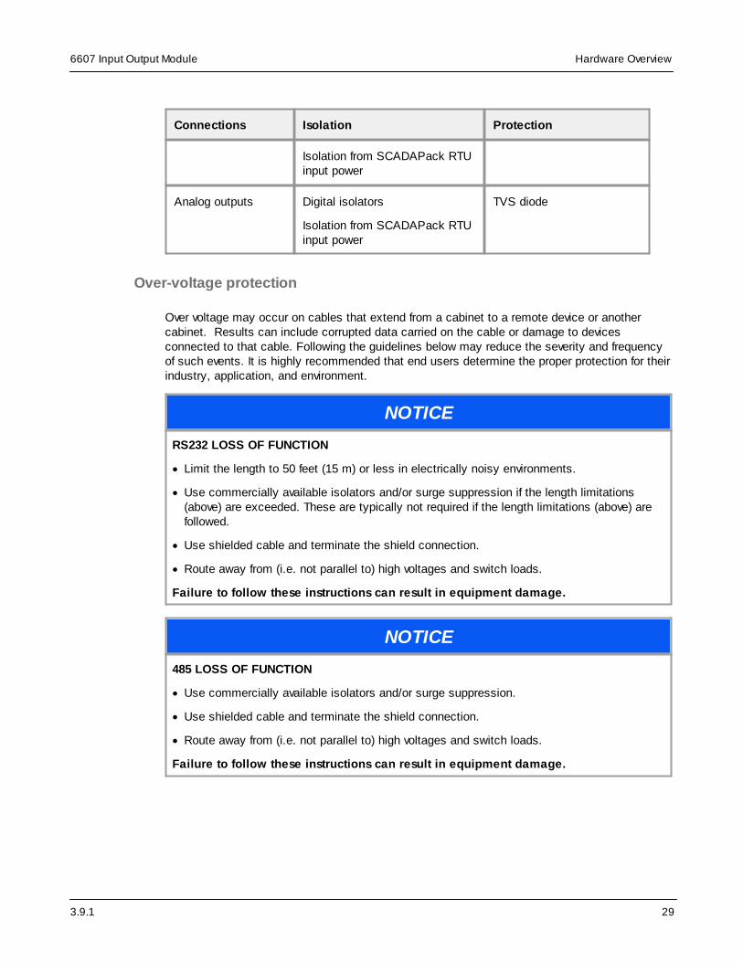
3.9.1
6607 Input Output Module Hardware Overview
29
Connections Isolation Protection
Isolation from SCADAPack RTUinput power
Analog outputs Digital isolators
Isolation from SCADAPack RTUinput power
TVS diode
Over-voltage protection
Over voltage may occur on cables that extend from a cabinet to a remote device or anothercabinet. Results can include corrupted data carried on the cable or damage to devicesconnected to that cable. Following the guidelines below may reduce the severity and frequencyof such events. It is highly recommended that end users determine the proper protection for theirindustry, application, and environment.
NOTICE
RS232 LOSS OF FUNCTION
· Limit the length to 50 feet (15 m) or less in electrically noisy environments.
· Use commercially available isolators and/or surge suppression if the length limitations(above) are exceeded. These are typically not required if the length limitations (above) arefollowed.
· Use shielded cable and terminate the shield connection.
· Route away from (i.e. not parallel to) high voltages and switch loads.
Failure to follow these instructions can result in equipment damage.
NOTICE
485 LOSS OF FUNCTION
· Use commercially available isolators and/or surge suppression.
· Use shielded cable and terminate the shield connection.
· Route away from (i.e. not parallel to) high voltages and switch loads.
Failure to follow these instructions can result in equipment damage.

3.9.1
6607 Input Output ModuleHardware Overview
30
NOTICE
ANALOG INPUTS AND OUTPUTS LOSS OF FUNCTION
· Avoid connecting 24 Vdc directly across analog inputs.
· Use commercially available isolators and/or surge suppression.
· Use shielded cable and terminate the shield connection.
· Route away from (i.e. not parallel to) high voltages and switch loads.
· Use an external fuse (63 mA fast blow).
Failure to follow these instructions can result in equipment damage.
NOTICE
EXTERIOR ANTENNA LOSS OF FUNCTION
· Use a coaxial surge diverter and terminate the ground connection.
Failure to follow these instructions can result in equipment damage.
NOTICE
POWER SUPPLY LOSS OF FUNCTION
· Use an external fuse, as specified in the manual.
· If using solar panels, use commercially available surge suppression.
Failure to follow these instructions can result in equipment damage.
Example
RTU with over-voltage protection on a power supply, analog inputs, RS485 port, and radioantenna.

3.9.1
6607 Input Output Module Hardware Overview
31
For additional information, refer to the Schneider Electric document Grounding, Earthingand Lightning Protection, Chapter 7 “Grounding and Electromagnetic Compatibility of PLCSystems “ (Doc# 33002439).

3.9.1
6607 Input Output ModuleInstallation
32
8 Installation
The I/O module is factory-configured and under normal conditions does not require removal orinsertion of any peripherals or components. The I/O configurations are stored in a combination ofbattery-backed RAM and flash memory on the SCADAPack.
NOTICE
UNINTENDED EQUIPMENT OPERATION
Installing the I/O module in an environment where the electromagnetic compatibility (EMC)rating exceeds the certified EMC rating for the module can lead to unpredictable operation andunexpected results.
Before mounting the I/O module, check the Standards and Certifications topic to verify whichEMC standards are supported.
Failure to follow these instructions can result in equipment damage.
The following sections describe specific aspects of installing the I/O module.
· ATEX Requirements
· Mounting the 6607 input output module
· Power Supply Requirements
· Connecting I/O modules
8.1 ATEX Requirements
The information in this topic applies when the unit is being used for ATEX applications.
Specific conditions of use
Before installing the equipment, carefully review the instructions in the warning message below.
32
33
37
39

3.9.1
6607 Input Output Module Installation
33
WARNING
EXPLOSION HAZARD
Only install this equipment when the following conditions are met:
Specific Conditions of Use
· The equipment shall only be used in an area of not more than pollution degree 2, as definedin IEC/EN 60664-1.
· The equipment shall be installed in an enclosure that is only tool accessible and thatprovides a degree of protection not less than IP 54 in accordance with IEC/EN 60079-0.
· Transient protection shall be provided that is set at a level not exceeding 140 % of the peakrated voltage value at the supply terminals to the equipment.
Failure to follow these instructions can result in death or serious injury.
Connection terminal blocks
· Screw connection terminal blocks:
o For 5 mm (0.197 in) pitch connectors support solid or stranded wires from 2.5...0.2 mm2
(12...30 AWG)
o For 3.5 mm (0.138 in) pitch connectors support solid or stranded wires from 1.5...0.2 mm2
(14...28 AWG)
· Torque for screw connection terminal block connectors: 0.5 N•m (4.5 Lb-in). For Serial 5 port,apply 0.2 N•m (1.7 lb-in) torque.
· Minimum supply cable temperature rating: 105 °C (221 °F)
8.2 Mounting the I/O Module
The I/O module is mounted on a 7.5 x 35 mm (0.3 x 1.4 in) DIN rail then connected to theSCADAPack or to another I/O module.
The figure below shows the I/O module dimensions when mounted.

3.9.1
6607 Input Output ModuleInstallation
34
DANGER
HAZARD OF ELECTRIC SHOCK, EXPLOSION, OR ARC FLASH
Carefully review and follow all instructions in the Important Notices for Hazardous Locationstopic for information when installing the I/O module in a hazardous location.
Failure to follow these instructions will result in death or serious injury.
See Important Notices for Hazardous Locations .
WARNING
UNINTENDED EQUIPMENT OPERATION
Evaluate the operational state of the equipment being monitored or controlled by theSCADAPack and the I/O module before removing power.
Failure to follow these instructions can result in death or serious injury.
8

3.9.1
6607 Input Output Module Installation
35
WARNING
ELECTRICAL HAZARD
Remove power from the I/O module before mounting it on a DIN rail.
Do not remove the I/O module cover when mounting the module. The I/O module is designedso that it can be mounted on a DIN rail with the cover in place.
Failure to follow these instructions can result in death or serious injury.
NOTICE
UNINTENDED EQUIPMENT OPERATION
The mounting position can affect the maximum operating temperature for the I/O module andthe current rating for the digital outputs.
Before mounting the I/O module, check the Specifications topic to confirm the maximumoperating temperature and digital output current rating for your mounting position.
Failure to follow these instructions can result in equipment damage.
To mount the I/O module
The illustrations below show how to mount the I/O module on a horizontally oriented DIN rail. Thesteps to mount the I/O module on a vertically oriented DIN rail are the same.
1. With the lower part of the module tilted away from the DIN rail, position the mounting guideline on the side of the module so that it is just above the top edge of the DIN rail.
Verify that the springs on the back of the module rest on the DIN rail and that the edge of theDIN rail is under the support claws that are adjacent to the springs, as shown below.

3.9.1
6607 Input Output ModuleInstallation
36
2. Push firmly on the module while tilting it toward the DIN rail until the DIN rail is positionedunder both the upper and lower claws on the back of the module.
3. Verify that the mounting guide line is aligned with the edge of the DIN rail, then release thepressure on the springs so that the DIN rail is held firmly in place between the upper andlower claws.
The figure below shows a DIN rail correctly positioned in the upper and lower claws on theback of the I/O module.
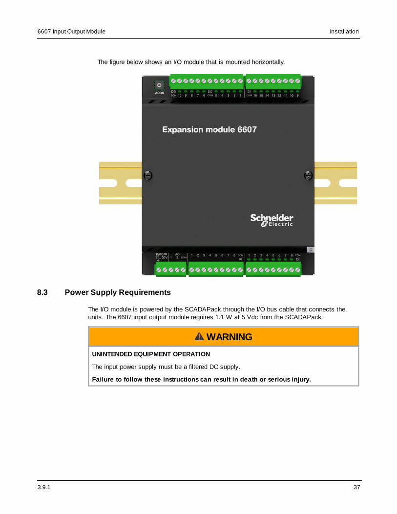
3.9.1
6607 Input Output Module Installation
37
The figure below shows an I/O module that is mounted horizontally.
8.3 Power Supply Requirements
The I/O module is powered by the SCADAPack through the I/O bus cable that connects theunits. The 6607 input output module requires 1.1 W at 5 Vdc from the SCADAPack.
WARNING
UNINTENDED EQUIPMENT OPERATION
The input power supply must be a filtered DC supply.
Failure to follow these instructions can result in death or serious injury.

3.9.1
6607 Input Output ModuleInstallation
38
WARNING
UNINTENDED EQUIPMENT OPERATION
Safety Extra Low Voltage (SELV) or Protective Extra Low Voltage (PELV) power supplies arerequired on the power input and I/O points. Power supplies with 100...240 Vac inputs thatcomply with safety standard IEC/EN 60950 generally have SELV outputs. Check with themanufacturer or the agency certification listing to confirm that they have SELV outputs.
Failure to follow these instructions can result in death or serious injury.
The following Schneider Electric power supply can be used:
· Schneider Electric Phaseo regulated power supply providing 100...240 Vac in and 24 Vdc, 2.5A out.
8.3.1 Analog Output Power Supply Wiring
There are two installation options for the external 24 Vdc power supply that are required whenthe analog outputs are used:
· The analog outputs and the SCADAPack can each have their own 24 Vdc power supply. Inthis configuration, the analog outputs are isolated from the system logic.
· The analog outputs can share an external 24 Vdc power supply with the SCADAPack. In thisconfiguration, the analog outputs are not isolated from the system logic.
NOTICE
UNINTENDED EQUIPMENT OPERATION
Install an external 0.063 A fast-acting fuse on the input voltage side of the analog output powersupply connection.
Failure to follow these instructions can result in equipment damage.
The following figure illustrates the power supply configurations for isolated and non-isolatedanalog outputs.

3.9.1
6607 Input Output Module Installation
39
For details about wiring the power supply connectors, see Wiring Screw-TerminationConnectors .
8.4 Connecting I/O Modules
The topics in this section describe how to attach I/O modules to a SCADAPack, or to anotherI/O module.
I/O modules are mounted on a 7.5 x 35 mm (0.3 x 1.4 in) DIN rail and then connected to aSCADAPack using intermodule cables. The intermodule cable is a ribbon cable that distributespower (5 Vdc) and communications signals from the SCADAPack to the I/O modules. Thesepower and communication signals are referred to as the I/O bus.
The figure below shows a SCADAPack x70 device with an I/O module connected to it. You canconnect multiple I/O modules to a single SCADAPack up to the maximum number of modules
50
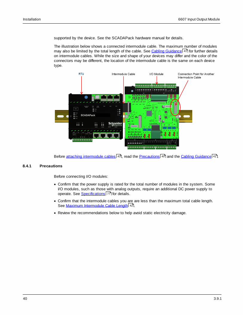
3.9.1
6607 Input Output ModuleInstallation
40
supported by the device. See the SCADAPack hardware manual for details.
The illustration below shows a connected intermodule cable. The maximum number of modulesmay also be limited by the total length of the cable. See Cabling Guidance for further detailson intermodule cables. While the size and shape of your devices may differ and the color of theconnectors may be different, the location of the intermodule cable is the same on each devicetype.
Before attaching intermodule cables , read the Precautions and the Cabling Guidance .
8.4.1 Precautions
Before connecting I/O modules:
· Confirm that the power supply is rated for the total number of modules in the system. SomeI/O modules, such as those with analog outputs, require an additional DC power supply tooperate. See Specifications for details.
· Confirm that the intermodule cables you are are less than the maximum total cable length.See Maximum Intermodule Cable Length .
· Review the recommendations below to help avoid static electricity damage.
41
43 40 41
77
42

3.9.1
6607 Input Output Module Installation
41
NOTICE
STATIC ELECTRICITY DAMAGE
Static electricity damage can cause intermittent or total loss of equipment operation. Tohelp avoid static electricity damage:
· Wear an anti-static wrist strap that is connected to ground if you need to remove thedevice cover.
· Use the shortest length intermodule cable that is practical. This helps to minimize voltagedrops and interference from electrical noise.
· Keep the intermodule cable away from electrical noise sources such as inductive loadswitching and variable frequency drives.
· If you are using a shielded cable, connect the shielding wire on the intermodule cable to aconvenient chassis ground point. There is a small hole in the I/O module for grounding theshielding wire.
· Do not install intermodule cables in the same cable tray or in parallel with field wiring.Intermodule cables can cross field wiring at 90° if necessary.
Failure to follow these instructions can result in equipment damage.
8.4.2 Cabling Guidance
This topic summarizes the rules for connecting I/O modules to SCADAPack x70 devices. Theserules apply to the following SCADAPack I/O modules:
· 6601 input output module
· 6602 HART module
· 6607 input output module
· 5304 analog output module
· 5405 digital input module
· 5410 high speed counter input module
· 5414 digital input module
· 5415 relay output module
· 5505 RTD input module
· 5506 analog input module
· 5606 input output module
· 5607 input output module
Using only 5000 series I/O modules
If you are using only 5000 series I/O modules with a SCADAPack x70 device, connect the 5000series module directly to the SCADAPack using a 20-pin to 16-pin adapter cable (soldseparately, see the SCADAPack Part Ordering List manual).

3.9.1
6607 Input Output ModuleInstallation
42
Using 5000 and 6000 series I/O modules
If you are using a combination of 5000 series I/O modules and 6000 series I/O modules with aSCADAPack x70 device, connect a 6000 series module to the SCADAPack first, followed byany other 6000 series modules. Then connect the 5000 series modules to the last 6000 seriesmodule.
SCADAPack x70 devices and 6000 series modules provide a 20-pin I/O bus connector while5000 series modules provide a 16-pin connector. Use the 20-pin to 16-pin adapter cable (soldseparately, see the SCADAPack Part Ordering List manual) to transition from a 20-pinconnector to a 16-pin connector.
General guidance
· Use the shortest length intermodule cable that is practical. This helps to minimize voltagedrops and interference from electrical noise.
· Keep the intermodule cable away from electrical noise sources such as inductive loadswitching and variable frequency drives.
· If you are using a shielded cable, connect the shielding wire on the intermodule cable to aconvenient chassis ground point. There is a small hole in the I/O module for grounding theshielding wire.
· Install intermodule cables in separate cable trays from field wiring, and not in parallel with fieldwiring. Intermodule cables can cross field wiring at 90° if necessary.
Intermodule cables
When determining the location of your I/O modules, review the following information aboutshielded intermodule cables and maximum intermodule cable length.
Shielded intermodule cables
Shielded intermodule cables have a foil and braid shielding. Intermodule cables longer than 30cm (12 in) are shielded for physical protection and for isolation from electrical noise. Theshielding is connected to a terminal lug at one end of the cable.
When using a shield for an intermodule cable, fasten the shield only to the module that isclosest to the SCADAPack. Connect the shield to the enclosure using the self-tapping screwprovided.
You can use up to 3 shielded intermodule cables. The total length of all cables can not exceed1.82 m (75 in).
Maximum intermodule cable length
I/O modules ship with a short intermodule cable that is used to connect I/O modules to aSCADAPack or to another I/O module.
The maximum total intermodule cable length in a single system is 1.82 m (75 in). This lengthrestriction does not include the short intermodule cable supplied with the I/O module. Schneider

3.9.1
6607 Input Output Module Installation
43
Electric offers several cable lengths that can be combined to reach the 1.82 m (75 in) limit.
Keep the following in mind:
· No more than 1.5 m (60 in) of total expansion cable length can follow a controller or powersupply before an additional power supply needs to be added
· 1.14 m (45 in) and 1.82 m (75 in) expansion cables need to be followed by a power supply
· The highest power consumption modules need to be to closest to the controller or powersupply with 6000 series modules first, followed by 5000 series modules due to connectorlimitations
· The maximum number of power supply modules, not including the controller, is 2
· A 30 cm (12 in) or a 76 cm (30 in) cable is typically used to connect modules on separate DINrails
To purchase additional intermodule cables, contact your Schneider Electric representative.
8.4.3 Attaching Intermodule Cables
This topic describes how to attach an intermodule cable between a SCADAPack and an I/Omodule. Follow the same steps to connect two I/O modules.
WARNING
UNINTENDED EQUIPMENT OPERATION
Evaluate the operational state of the equipment being monitored or controlled by theSCADAPack or the I/O module before applying or removing power.
Failure to follow these instructions can result in death or serious injury.
WARNING
ELECTRICAL HAZARD
The I/O bus does not support live-swapping.
Remove power from the SCADAPack and the I/O module before removing the cover.
Failure to follow these instructions can result in death or serious injury.
NOTICE
STATIC ELECTRICITY DAMAGE
Static electricity damage can cause intermittent or total loss of equipment operation.
Always wear an anti-static wrist strap that is connected to ground when you remove the devicecover.
Failure to follow these instructions can result in equipment damage.

3.9.1
6607 Input Output ModuleInstallation
44
5410 High Speed Counter Input Module Considerations
NOTICE
UNEXPECTED COUNTER READINGS
Do not disconnect a 5410 high speed counter input module while the module and RTU arepowered.
Do not remove power from a 5410 high speed counter input module while the RTU is poweredand communicating with the module.
Failure to follow these instructions can result in unexpected counter readings.
Power off the RTU before connecting or disconnecting the inter-module cable to the 5410 highspeed counter input module.
Power off the RTU and 5410 high speed counter input module at the same time. Use a commonpower supply input for the RTU and I/O modules.
To attach intermodule cables
1. Power down each SCADAPack and I/O module that you are connecting.
2. Remove the cover from the device if required to access the intermodule cable.
3. Press one end of the intermodule cable firmly into the I/O bus connector on theSCADAPack.
SCADAPack x70 devices and 6000 series modules provide a 20-pin I/O bus connector while5000 series modules provide a 16-pin connector. Use the 20-pin to 16-pin adapter cable (soldseparately, see the SCADAPack Part Ordering List manual) to transition from a 20-pinconnector to a 16-pin connector.
The connectors on intermodule cables are keyed so they can only be inserted in onedirection. If the connector does not push easily into the I/O bus connector, reverse it and tryagain.
4. Press the other end of the intermodule cable firmly into the I/O bus connector on the I/Omodule.
The illustration below shows a connected intermodule cable. While the size and shape ofyour devices may differ and the color of the connectors may be different, the location of theintermodule cable is the same on each device type.

3.9.1
6607 Input Output Module Installation
45
5. Replace the cover on the I/O module and on the SCADAPack if it was removed, taking careto check that the ribbon cable connecting the I/O module is not pinched.
6. Apply power to the SCADAPack.
You are now ready to configure the I/O module.

3.9.1
6607 Input Output ModuleAddressing
46
9 Addressing
This section describes the addressing rules for an I/O module and the procedure for setting theI/O module address.
WARNING
UNINTENDED EQUIPMENT OPERATION
Review the power requirements for the I/O modules before combining modules.
Failure to follow these instructions can result in death or serious injury.
I/O modules can be combined in any manner up to the maximum number supported by theSCADAPack. For details about the maximum supported system configuration, see theSCADAPack hardware manual for guidance.
Each I/O module connected to the SCADAPack is assigned a unique I/O module address.
For more information see
· Addressing Rules
· Setting the I/O Module Address
9.1 Addressing Rules
I/O modules are shipped from the factory at address 1.
· If you are connecting only 1 external 6607 input output module to a SCADAPack 470,SCADAPack 570, or SCADAPack 574, you can leave the address at 1.
· If you are connecting 1 or more external 6607 input output modules to a SCADAPack 474 orSCADAPack 575, you will need to change the address. The SCADAPack 474 includes aninternal 6607 input output module at address 0 and the SCADAPack 575 includes an internal6601 input output module at address 0.
· If you are connecting more than 1 external 6000 series I/O module to your SCADAPack x70,each module requires a unique address.
9.2 Setting the I/O Module Address
By default, the I/O module physical address is set to 0. To avoid conflict with the addresses ofother I/O modules connected to the same SCADAPack, the address can be set anywhere in therange 0 to F. This is a selected value in hexadecimal (0 to 9, A to F). The equivalent softwareconfiguration of the module address is set in decimal (0 to 15).
46
46

3.9.1
6607 Input Output Module Addressing
47
WARNING
UNINTENDED EQUIPMENT OPERATION
Evaluate the operational state of the equipment being monitored or controlled by theSCADAPack and the I/O module before applying or removing power.
Failure to follow these instructions can result in death or serious injury.
WARNING
UNINTENDED EQUIPMENT OPERATION
Remove power from the I/O module before initially setting the I/O module address and beforechanging the I/O module address.
Failure to follow these instructions can result in death or serious injury.
WARNING
UNINTENDED EQUIPMENT OPERATION
Be very careful that you do not set the I/O module address to an address that is assigned toanother I/O module connected to the same SCADAPack.
If 2 I/O modules have the same address, you will lose communications with both modules.
Failure to follow these instructions can result in death or serious injury.
To set or change an I/O module address
1. Insert a 2.4 mm (3/32 in) slotted screwdriver into the inner circle of the rotary hex switch.

3.9.1
6607 Input Output ModuleAddressing
48
2. Slowly turn the screwdriver until the small arrowhead points to the correct address.
3.9.1
6607 Input Output Module Field Wiring
49
10 Field Wiring
The I/O modules use screw termination style connectors for termination of field wiring. These
connectors accommodate solid or stranded wires from 2.5...0.2 mm2 (12...30 AWG). Theconnectors are removable allowing replacement of the module without disturbing the field wiring.Leave enough slack in the field wiring for the connector to be removed.
For ease of wiring and maintenance, external connections are terminated on removableconnectors. If you need to remove the I/O module cover for any reason, first carefully considerthe following information.
WARNING
UNINTENDED EQUIPMENT OPERATION
Evaluate the operational state of the equipment being monitored or controlled by theSCADAPack or the I/O module before removing power.
Failure to follow these instructions can result in death or serious injury.
WARNING
ELECTRICAL HAZARD
Remove power from the I/O module before removing the I/O module cover.
Failure to follow these instructions can result in death or serious injury.
NOTICE
STATIC ELECTRICITY DAMAGE
The electronics inside the I/O module can be damaged by static electricity. If you need toremove the I/O module cover, wear an anti-static wrist strap that is connected to ground.Failing to follow this step can cause intermittent or total loss of I/O module operation and willvoid the warranty.
Failure to follow these instructions can result in equipment damage.
For more information see
· Wiring Screw-Termination Connectors
· Digital and Counter Input Wiring
· Digital Output Wiring
· Analog Input Wiring
· Analog Output Wiring
50
51
54
57
63

3.9.1
6607 Input Output ModuleField Wiring
50
10.1 Wiring Screw-Termination Connectors
Screw-termination style connectors are provided to terminate wiring from:
· Power supplies
· RS485 devices
· Input/output (I/O) modules
These 5 mm (0.197 in) pitch connectors support solid or stranded wires from 2.5...0.2 mm2
(12...30 AWG).
WARNING
UNINTENDED EQUIPMENT OPERATION
Evaluate the operational state of the equipment being monitored or controlled by theSCADAPack or the I/O module before wiring screw-termination connectors.
Failure to follow these instructions can result in death or serious injury.
WARNING
ELECTRICAL HAZARD
Remove power from all modules and devices before servicing.
Failure to follow these instructions can result in death or serious injury.
To wire a connector
1. Use a slotted screwdriver to loosen the termination screw.
2. Insert the stripped wire into the connector so that the bared wire is located under the screw.
Verify that the bared wire is placed fully within the connector, as illustrated below.

3.9.1
6607 Input Output Module Field Wiring
51
3. Apply 0.5 N•m (4.5 lb-in) torque to tighten the screw so the wire is held firmly in place.
10.2 Digital and Counter Input Wiring
This section describes the wiring for the digital and counter inputs.
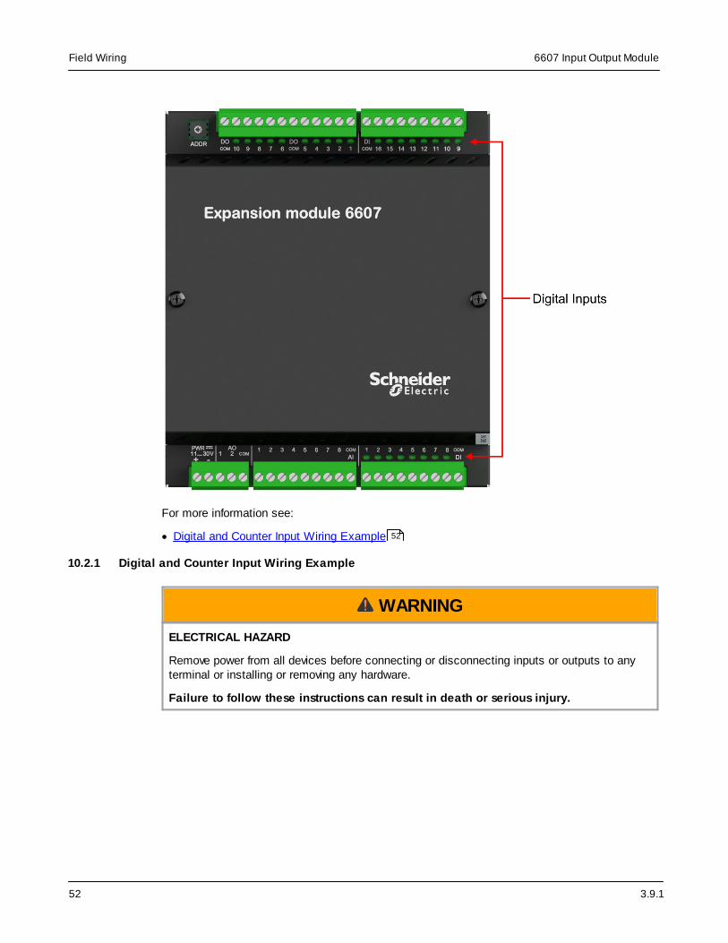
3.9.1
6607 Input Output ModuleField Wiring
52
For more information see:
· Digital and Counter Input Wiring Example
10.2.1 Digital and Counter Input Wiring Example
WARNING
ELECTRICAL HAZARD
Remove power from all devices before connecting or disconnecting inputs or outputs to anyterminal or installing or removing any hardware.
Failure to follow these instructions can result in death or serious injury.
52

3.9.1
6607 Input Output Module Field Wiring
53
NOTICE
UNINTENDED EQUIPMENT OPERATION
When wiring digital and counter inputs:
· Confirm that the connection to the digital or counter input does not exceed the ratings for theinput. See the Specifications topic for details.
· Confirm that the polarity of the connection is correct with the two positive terminals wiredtogether and the two negative terminals wired together.
Failure to follow these instructions can result in equipment damage.
NOTICE
SIGNAL INTERFERENCE DUE TO NOISE
When the unit is operating in an electrically noisy environment use shielded wires onconnections to digital and counter inputs.
Failure to follow these instructions can result in equipment damage.
The figure below shows a shielded connection to DI 1 and an unshielded connection to DI 5.Both connections are wired to the common for digital inputs 1-8 and to a power supply orbattery.

3.9.1
6607 Input Output ModuleField Wiring
54
10.3 Digital Output Wiring
This section describes the wiring for the digital outputs.

3.9.1
6607 Input Output Module Field Wiring
55
For more information see:
· Digital Output Wiring Example
10.3.1 Digital Output Wiring Example
WARNING
ELECTRICAL HAZARD
Remove power from all devices before connecting or disconnecting inputs or outputs to anyterminal or installing or removing any hardware.
Failure to follow these instructions can result in death or serious injury.
55
3.9.1
6607 Input Output ModuleField Wiring
56
NOTICE
RELAY CONTACT DAMAGE
Incandescent lamps and other loads may have inrush currents that will exceed the ratedmaximum current of the relay contacts. This inrush current may damage the relay contacts.Use interposing relays in these situations.
When controlling inductive loads, the relay contacts on digital outputs must be protected. Theenergy stored in the coil can generate significant electrical noise when the relay contacts areopened.
· To suppress the noise in DC circuits, place a diode across the coil
Failure to follow these instructions can result in equipment damage.
NOTICE
UNINTENDED EQUIPMENT OPERATION
External lightning protection is required if the device being controlled is outside the physicalarea (cubicle or building) in which the SCADAPack is located.
Failure to follow these instructions can result in equipment damage.
Form A digital output wiring
The figure below shows loads on outputs 3 and 4 connected to the negative side of the powersupply and switched from the positive side.
Loads can be connected to the positive side of the power supply and be switched from thenegative side of the power supply as outputs 6 and 7 are shown.
When using inductive loads, place a diode across the load to suppress noise and extend the lifeof the relay contacts, as shown in outputs 3 and 7.

3.9.1
6607 Input Output Module Field Wiring
57
10.4 Analog Input Wiring
This section describes the wiring for the analog inputs.
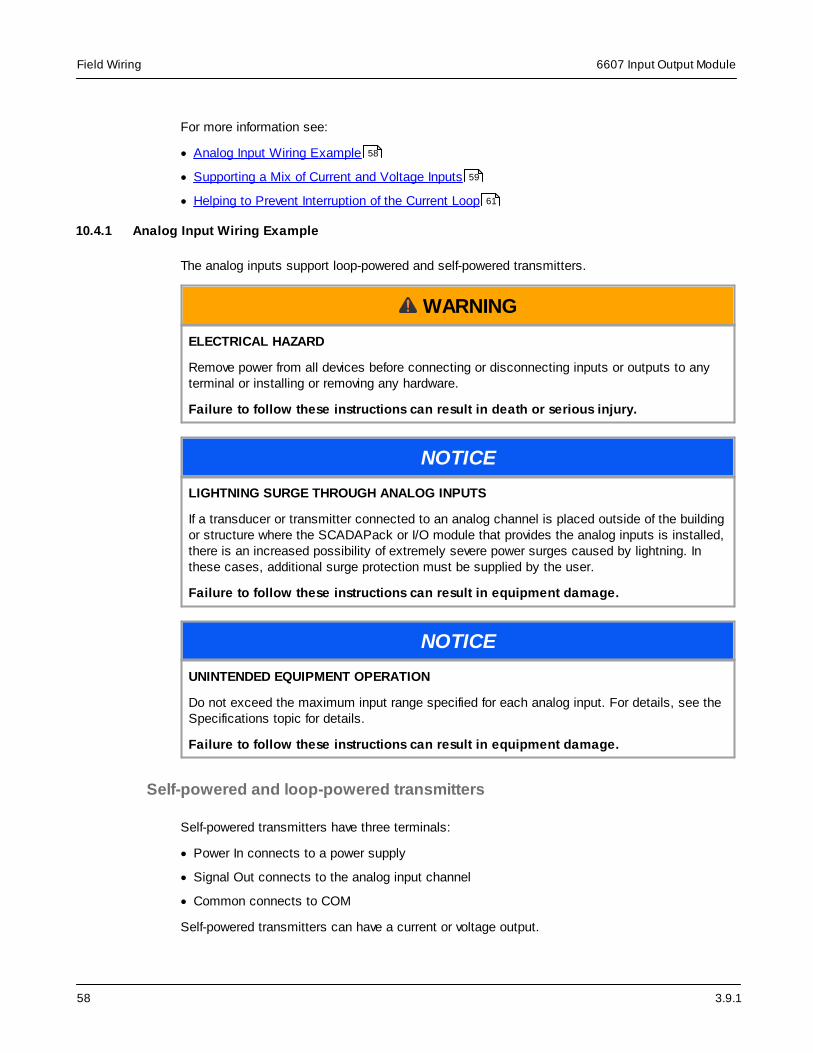
3.9.1
6607 Input Output ModuleField Wiring
58
For more information see:
· Analog Input Wiring Example
· Supporting a Mix of Current and Voltage Inputs
· Helping to Prevent Interruption of the Current Loop
10.4.1 Analog Input Wiring Example
The analog inputs support loop-powered and self-powered transmitters.
WARNING
ELECTRICAL HAZARD
Remove power from all devices before connecting or disconnecting inputs or outputs to anyterminal or installing or removing any hardware.
Failure to follow these instructions can result in death or serious injury.
NOTICE
LIGHTNING SURGE THROUGH ANALOG INPUTS
If a transducer or transmitter connected to an analog channel is placed outside of the buildingor structure where the SCADAPack or I/O module that provides the analog inputs is installed,there is an increased possibility of extremely severe power surges caused by lightning. Inthese cases, additional surge protection must be supplied by the user.
Failure to follow these instructions can result in equipment damage.
NOTICE
UNINTENDED EQUIPMENT OPERATION
Do not exceed the maximum input range specified for each analog input. For details, see theSpecifications topic for details.
Failure to follow these instructions can result in equipment damage.
Self-powered and loop-powered transmitters
Self-powered transmitters have three terminals:
· Power In connects to a power supply
· Signal Out connects to the analog input channel
· Common connects to COM
Self-powered transmitters can have a current or voltage output.
58
59
61
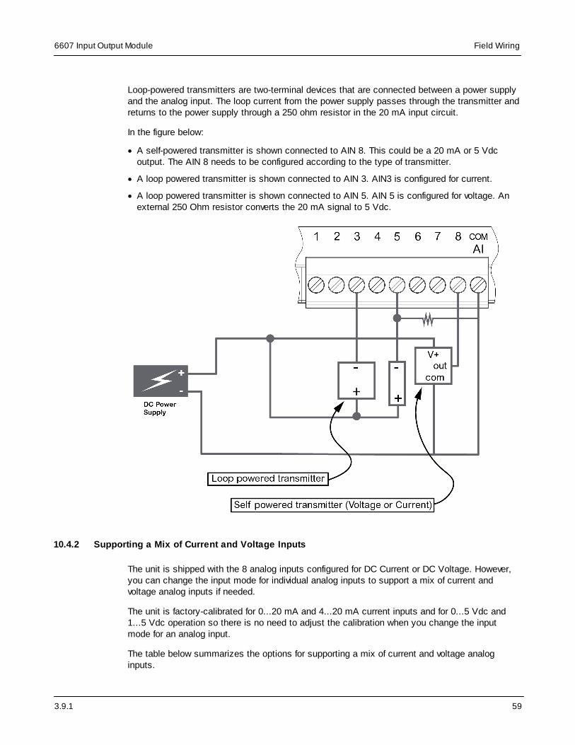
3.9.1
6607 Input Output Module Field Wiring
59
Loop-powered transmitters are two-terminal devices that are connected between a power supplyand the analog input. The loop current from the power supply passes through the transmitter andreturns to the power supply through a 250 ohm resistor in the 20 mA input circuit.
In the figure below:
· A self-powered transmitter is shown connected to AIN 8. This could be a 20 mA or 5 Vdcoutput. The AIN 8 needs to be configured according to the type of transmitter.
· A loop powered transmitter is shown connected to AIN 3. AIN3 is configured for current.
· A loop powered transmitter is shown connected to AIN 5. AIN 5 is configured for voltage. Anexternal 250 Ohm resistor converts the 20 mA signal to 5 Vdc.
10.4.2 Supporting a Mix of Current and Voltage Inputs
The unit is shipped with the 8 analog inputs configured for DC Current or DC Voltage. However,you can change the input mode for individual analog inputs to support a mix of current andvoltage analog inputs if needed.
The unit is factory-calibrated for 0...20 mA and 4...20 mA current inputs and for 0...5 Vdc and1...5 Vdc operation so there is no need to adjust the calibration when you change the inputmode for an analog input.
The table below summarizes the options for supporting a mix of current and voltage analoginputs.

3.9.1
6607 Input Output ModuleField Wiring
60
Analog Input Configuredfor...
Measuring Considerations
Voltage Current Requires addition of external 250 Ohmresistor.
Allows the SCADAPack 470 to be removedwhile not interrupting the 20 mA current flowand transmitter operation.
Current Current Removing the SCADAPack 470 or poweringoff will interrupt the current flow.
Voltage Voltage None
Converting current input to voltage input
On analog input 1, an external resistor is used to convert current input to voltage input before itreaches the physical input.
The external resistor converts the current to voltage. The 6607 input output module input isconfigured for voltage. This wiring approach allows you to configure the current loop so it is notinterrupted if the unit requires servicing. For details, see Helping to Prevent Interruption of theCurrent Loop . 61

3.9.1
6607 Input Output Module Field Wiring
61
10.4.3 Helping to Prevent Interruption of the Current Loop
WARNING
ELECTRICAL HAZARD
Remove power from all devices before connecting or disconnecting inputs or outputs to anyterminal or installing or removing any hardware.
Failure to follow these instructions can result in death or serious injury.
NOTICE
UNINTENDED EQUIPMENT OPERATION
Do not exceed the maximum voltage specified for each analog input.
Failure to follow these instructions can result in equipment damage.

3.9.1
6607 Input Output ModuleField Wiring
62
NOTICE
UNINTENDED EQUIPMENT OPERATION
The SCADAPack or I/O module must be the only loop current measurement device in the loopwhen using the analog inputs in the 20 mA measurement mode. If power to the module isremoved, the module reverts to voltage mode and results in an open current loop. Applicationsthat cannot tolerate this possibility need to use external current sense resistors with themodule input range set to voltage.
Failure to follow these instructions can result in equipment damage.
Add 250 ohm external resistors to the current loop at the terminal strip to help preventinterruption of the current loop if the SCADAPack or I/O module is being serviced. The physicalwiring of the 250 ohm external resistors at the terminal strip is illustrated below.
As illustrated below, the SCADAPack or I/O module providing the analog inputs needs to be thelast device in the current loop.

3.9.1
6607 Input Output Module Field Wiring
63
10.5 Analog Output Wiring
This section describes the wiring for the analog outputs.

3.9.1
6607 Input Output ModuleField Wiring
64
For more information see:
· Analog Output Wiring Example
· Supporting Current and Voltage Outputs
10.5.1 Analog Output Wiring Example
The figure below shows loads connected to the two analog outputs.
WARNING
ELECTRICAL HAZARD
Remove power from all devices before connecting or disconnecting inputs or outputs to anyterminal or installing or removing any hardware.
Failure to follow these instructions can result in death or serious injury.
64
66

3.9.1
6607 Input Output Module Field Wiring
65
NOTICE
UNINTENDED EQUIPMENT OPERATION
Install a 0.063A fast-acting fuse on the input voltage side of the analog output power supplyconnection.
Failure to follow these instructions can result in equipment damage.
The analog output circuitry is configured internally to receive power from an external powersupply on pins 1 and 2 of the removable terminal block. Pin 5 (Com 1-2) and pin 2 (power input–) are connected internally. As illustrated in the following figure, the two analog outputs are notisolated from each other, but are isolated from the SCADAPack RTU circuitry.

3.9.1
6607 Input Output ModuleField Wiring
66
10.5.2 Supporting Current and Voltage Outputs
The analog outputs can be configured for 4...20 mA current or 0...20 mA current.
If a voltage output is required (1...5 Vdc, for example), run the 4...20 mA or 0...20 mA signal tothe device that requires a voltage input and place a 250 ohm resistor across the input terminalsof that device.
The table below lists resistance values and output range settings for common voltage ranges.The resistance value listed is the parallel resistance of the device and the load resistor.
Resistance Output Range Voltage Range
250 ohm 0...20 mA 0...5 Vdc

3.9.1
6607 Input Output Module Field Wiring
67
Resistance Output Range Voltage Range
4...20 mA 1...5 Vdc
500 ohm 0...20 mA 0...10 Vdc
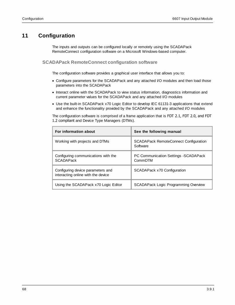
3.9.1
6607 Input Output ModuleConfiguration
68
11 Configuration
The inputs and outputs can be configured locally or remotely using the SCADAPackRemoteConnect configuration software on a Microsoft Windows-based computer.
SCADAPack RemoteConnect configuration software
The configuration software provides a graphical user interface that allows you to:
· Configure parameters for the SCADAPack and any attached I/O modules and then load thoseparameters into the SCADAPack
· Interact online with the SCADAPack to view status information, diagnostics information andcurrent parameter values for the SCADAPack and any attached I/O modules
· Use the built-in SCADAPack x70 Logic Editor to develop IEC 61131-3 applications that extendand enhance the functionality provided by the SCADAPack and any attached I/O modules
The configuration software is comprised of a frame application that is FDT 2.1, FDT 2.0, and FDT1.2 compliant and Device Type Managers (DTMs).
For information about See the following manual
Working with projects and DTMs SCADAPack RemoteConnect ConfigurationSoftware
Configuring communications with theSCADAPack
PC Communication Settings -SCADAPackCommDTM
Configuring device parameters andinteracting online with the device
SCADAPack x70 Configuration
Using the SCADAPack x70 Logic Editor SCADAPack Logic Programming Overview

3.9.1
6607 Input Output Module Diagnostics
69
12 Diagnostics
Input and output modules provide LEDs that indicate the status of inputs and outputs. There arealso a number of actions you can take to determine the cause of unexpected activities.
For more information see
· LEDs
· Digital Inputs
· Digital Outputs
· Analog Inputs
· Analog Outputs
12.1 LEDs
The I/O module provides an LED for each digital input and output. When the LED is on, the inputor output is energized, meaning it has an active connection. Digital input LEDs blink whenpulses are applied if the digital input is configured to be a counter.
12.2 Digital Inputs
Condition Action
Input LED does not come on wheninput signal is applied.
Check that the input signal at the terminationblock is at least 50% of the digital input range.
If this is a DC input, check the polarity of thesignal.
Input is on when no signal is applied.The LED is off.
Check that the digital inputs are not forced on.
Input is off when a signal is applied.The LED is on.
Check that the digital inputs are not forced off.
12.3 Digital Outputs
Condition Action
Output LED does not come on whenoutput is turned on.
Check the Power LED on the SCADAPack.
Output LED comes on but the outputdoes not close.
Check if the relay is stuck. If so, return themodule for repair.
Output LED comes on and output isclosed, but the field device is not
Check the field wiring.
Check the external device.
69
69
69
70
70

3.9.1
6607 Input Output ModuleDiagnostics
70
activated.
Output LED and relay are on whenexpected to be off.
Check that the output is not forced on.
Output LED and relay are off whenexpected to be on.
Check that the output is not forced off.
12.4 Analog Inputs
Condition Action
20 mA inputs read 0. Check transmitter power.
Reading is at or near 0 for every inputsignal.
Check whether the input transient suppressorsare damaged.
20 mA readings are not accurate. Check for a damaged 250 ohm current senseresistor.
Reading is constant. Check that the analog input is not forced.
Reading seems out of calibration forsmall inputs but improves as inputincreases.
Check the input range setting.
In Current Loop Mode, there can be anopen circuit in the Current Loop.
Refer to the section Helping to PreventInterruption of the Current Loop .
Other devices are not functional afterinstallation of the I/O module.
In Current Loop mode, make the I/O modulethe last device in the loop, or use a signalisolator as discussed in the section Helping toPrevent Interruption of the Current Loop .
12.5 Analog Outputs
Condition Action
Outputs are 0 mA Check the 24 Vdc power supply.
The full-scale output is less than 20mA
Check the 24 Vdc power supply.
Check that the load resistance is withinspecification.
Output is constant instead of changing Check that the analog outputs are not forced.
61
61
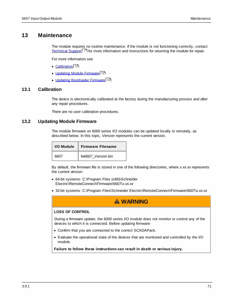
3.9.1
6607 Input Output Module Maintenance
71
13 Maintenance
The module requires no routine maintenance. If the module is not functioning correctly, contactTechnical Support for more information and instructions for returning the module for repair.
For more information see
· Calibration
· Updating Module Firmware
· Updating Bootloader Firmware
13.1 Calibration
The device is electronically calibrated at the factory during the manufacturing process and afterany repair procedures.
There are no user calibration procedures.
13.2 Updating Module Firmware
The module firmware on 6000 series I/O modules can be updated locally or remotely, asdescribed below. In this topic, Version represents the current version.
I/O Module Firmware Filename
6607 fw6607_Version.bin
By default, the firmware file is stored in one of the following directories, where x.xx.xx representsthe current version:
· 64-bit systems: C:\Program Files (x86)\SchneiderElectric\RemoteConnect\Firmware\6607\x.xx.xx
· 32-bit systems: C:\Program Files\Schneider Electric\RemoteConnect\Firmware\6607\x.xx.xx
WARNING
LOSS OF CONTROL
During a firmware update, the 6000 series I/O module does not monitor or control any of thedevices to which it is connected. Before updating firmware:
· Confirm that you are connected to the correct SCADAPack.
· Evaluate the operational state of the devices that are monitored and controlled by the I/Omodule.
Failure to follow these instructions can result in death or serious injury.
7
71
71
73

3.9.1
6607 Input Output ModuleMaintenance
72
WARNING
UNINTENDED EQUIPMENT OPERATION
Do not remove power from the SCADAPack during the firmware update.
Do not disconnect the 6000 series I/O module from the SCADAPack during the firmwareupdate.
If power is interrupted for any reason during the firmware update, contact Technical Support.
Failure to follow these instructions can result in death or serious injury.
NOTICE
INCOMPATIBLE FIRMWARE VERSIONS
Before installing a firmware update, check the Release Notes for the firmware update todetermine the most suitable I/O module firmware version for the SCADAPack firmware versionand the functionality you are using.
Failure to follow these instructions can result in equipment damage.
Note: Outputs on the I/O module turn off during the firmware update and remain off until theupdate is complete. Updates can take up to several minutes.
To update the firmware on a 6607 I/O module
1. Use SCADAPack RemoteConnect to transfer the .bin file to the SCADAPack file system:
a. Connect SCADAPack RemoteConnect to the SCADAPack x70 device and go Online.
b. Under My Network, right-click on SCADAPack x70 Controller Settings -DeviceDTM and select Additional Functions > Write File to Device.
c. In the Write File to Device dialog, click Browse to navigate to the location of the file onyour computer.
d. Click Open.
e. In the Write File to Device dialog, click OK.
2. Start the I/O firmware upgrade:
a. Under My Network, right-click on SCADAPack x70 Controller Settings -DeviceDTM and select Additional Functions > Execute Command.
b. Enter the command:
restart iofirm fw6607_Version.bin module_address
Where the module_address is the address of your I/O module. The I/O module address isa number from 0 to 15. The 6607 module located inside a SCADAPack 474 is alwaysaddress 0.

3.9.1
6607 Input Output Module Maintenance
73
Example: restart iofirm fw6607_Version.bin 0
WARNING
UNINTENDED EQUIPMENT OPERATION
If the firmware update was unsuccessful, the I/O module will remain in a state where it doesnot monitor or control any of the devices to which it is connected.
Carefully review the message indicating whether the firmware update was successful orunsuccessful. Unsuccessful firmware updates are also reported through the SCADAPackx70 device’s System Status Code. See RemoteConnect Online Diagnostics mode. For alist of the possible status code values, see the System Status Codes topic.
Failure to follow these instructions can result in death or serious injury.
3. After the firmware update is complete, open a command line or Telnet session and use theVER command to display device version information.
13.3 Updating Bootloader Firmware
The bootloader firmware on 6000 series I/O modules can be updated locally or remotely, asdescribed below. Version represents the current version.
I/O Module Bootloader Filename
6607 bl6607_Version.bin
By default, the bootloader file is stored in one of the following directories, where x.xx.xxrepresents the current version:
· 64-bit systems: C:\Program Files (x86)\SchneiderElectric\RemoteConnect\Firmware\6607\x.xx.xx
· 32-bit systems: C:\Program Files\Schneider Electric\RemoteConnect\Firmware\6607\x.xx.xx
WARNING
LOSS OF CONTROL
During a bootloader update, the 6000 series I/O module does not monitor or control any of thedevices to which it is connected. Before updating the bootloader on the I/O module:
· Confirm that you are connected to the correct SCADAPack
· Evaluate the operational state of the devices that are monitored and controlled by the I/Omodule.
Failure to follow these instructions can result in death or serious injury.

3.9.1
6607 Input Output ModuleMaintenance
74
WARNING
UNINTENDED EQUIPMENT OPERATION
Do not remove power from the SCADAPack during the bootloader update.
Do not disconnect the 6000 series I/O module from the SCADAPack during the bootloaderupdate.
If power is interrupted for any reason during the bootloader update, contact TechnicalSupport.
Failure to follow these instructions can result in death or serious injury.
NOTICE
INCOMPATIBLE FIRMWARE VERSIONS
Before installing a bootloader update, check the Release Notes for the bootloader update todetermine the most suitable I/O module bootloader version for the SCADAPack firmwareversion and the functionality you are using.
Failure to follow these instructions can result in equipment damage.
To update the bootloader on a 6607 I/O module
1. Use SCADAPack RemoteConnect to transfer the .bin file to the SCADAPack file system:
a. Connect SCADAPack RemoteConnect to the SCADAPack x70 device and go Online.
b. Under My Network, right-click on SCADAPack x70 Controller Settings -DeviceDTM and select Additional Functions > Write File to Device.
c. In the Write File to Device dialog, click Browse to navigate to the location of the file onyour computer.
d. Click Open.
e. In the Write File to Device dialog, click OK.
2. Start the I/O firmware upgrade:
a. Under My Network, right-click on SCADAPack x70 Controller Settings -DeviceDTM and select Additional Functions > Execute Command.
b. Enter the command:
restart iofirm bl6607_Version.bin module_address
where module_address is the I/O module address. The I/O module address is a numberfrom 0 to 15. The 6607 module located inside a SCADAPack 474 is always address 0.
Example: restart iofirm bl6607_Version.bin 0

3.9.1
6607 Input Output Module Maintenance
75
WARNING
UNINTENDED EQUIPMENT OPERATION
If the bootloader update was unsuccessful, the I/O module will remain in a state where itdoes not monitor or control any of the devices to which it is connected.
Carefully review the message indicating whether the firmware update was successful orunsuccessful. Unsuccessful firmware updates are also reported through the SCADAPackx70 device’s System Status Code. See RemoteConnect Online Diagnostics mode. For alist of the possible status code values, see the System Status Codes topic.
Failure to follow these instructions can result in death or serious injury.
3. After the firmware update is complete, open a command line or Telnet session and use theVER command to display device version information.

3.9.1
6607 Input Output ModuleSpecifications
76
14 Specifications
Disclaimer: Schneider Electric reserves the right to change product specifications withoutnotice. If you have questions about any of the specifications, contact Technical Support .
For more information see
· General
· Power Supply
· Communications
· Digital Inputs
· Counter Inputs
· Digital Outputs
· Analog Inputs
· Analog Outputs
14.1 General
Item Specification
Environment -40…70 °C (-40…158 °F) operating temperature when the unit ismounted horizontally on a vertical surface
-40…65 °C (-40…149 °F) operating temperature when the unit ismounted in any other position
-40…85 °C (-40…185 °F) storage temperature
5...95% relative humidity, non-condensing
Pollution Degree 2, Installation Category I, Indoor use
Elevation 3,000 m (9,842 ft)
Over-voltage category II
Equipment class III - SELV
Terminations 2.5...0.2 mm2 (12...30 AWG), solid or stranded
Packaging Corrosion-resistant zinc-plated steel with black enamel paint
Dimensions 142 mm (5.6 in) wide
166 mm (6.5 in) high
46 mm (1.8 in) deep
Mechanical Shock IEC 61131-2
7
76
77
77
78
79
79
80
81

3.9.1
6607 Input Output Module Specifications
77
½ sine, 15 ms, 15 g
Vibration IEC 61131-2
5...8.4 Hz: Amplitude controlled, 7.0 mm (0.28 in) peak-to-peak
8.4...150 Hz: Acceleration controlled, 1.0 g peak
14.2 Power Supply
Item Specification
Input voltage Rated (UL) 14...29 Vdc
Voltage limits: 12...30 Vdc
Power requirements 10 mA plus up to 20 mA per output
Analog output power requirements at 24 Vdc at the 6607, bothoutputs at 20 mA. Add 1.2 W. (1.5 W at 30 Vdc.)
14.3 Communications
Item Specification
I/O bus SCADAPack 470, SCADAPack 570, and SCADAPack 574
· Maximum number of 6601 input output modules with optionalanalog outputs is 4
· Maximum number of 6602 HART modules with optional analogoutputs is 1
· Maximum number of 6607 input output modules in the systemis 4
SCADAPack 474
· Maximum number of 6601 input output modules with optionalanalog outputs is 4
· Maximum number of 6602 HART modules with optional analogoutputs is 1
· Maximum number of 6607 input output modules in the systemis 3
SCADAPack 575
· Maximum number of 6601 input output modules with optionalanalog outputs is 3
· Maximum number of 6602 HART modules with optional analogoutputs is 1

3.9.1
6607 Input Output ModuleSpecifications
78
· Maximum number of 6607 input output modules in the systemis 4
14.4 Digital Inputs
Item Specification
Quantity 16
Typical operating voltage 12 Vdc
24 Vdc
Turn-on voltage Minimum: 9 Vdc
Turn-off voltage Maximum: 4 Vdc
Connectors 2 removable, 9-pin
Indicators 16 LEDs
Over-voltage tolerance 36 Vdc
150% sustained over-voltage without foreseeable damage
Input current 1.2 mA typical at 12 Vdc
2.4 mA typical at 24 Vdc
Reporting 10 ms timestamped Sequence of Event (SOE)
Status Chatter filter detection when digital state changes faster than 5Hz
Isolation Isolation is in 2 groups of 8
Isolation from logic supply and chassis: 250 Vac/350 Vdc
Item Specification
Quantity 4
Typical operating voltage 12 Vdc
24 Vdc
Turn-on voltage Minimum: 9 Vdc

3.9.1
6607 Input Output Module Specifications
79
Turn-off voltage Maximum: 4 Vdc
Over-voltage tolerance 36 Vdc sustained over-voltage without foreseeable damage
Input current 0.35…0.45 mA at 12 Vdc
0.75…0.85 mA at 24 Vdc
Reporting · 10 ms timestamped Sequence of Events (SOE)
· Input state inversion
Status Chatter filter detection when digital state changes faster than 5Hz
Isolation Ground return connected to chassis ground
Cable length Maximum: 3 m (9.84 ft)
14.5 Counter Inputs
Item Specification
Quantity 8
Electrical characteristics Shared with digital input channels
Reporting 32-bit counters
Deviation
Timestamped events
Unsolicited reporting
DI1, DI2, DI3, and DI4supported counting
Range: 0 to 1.5 kHz
Rising edge counting
Falling edge counting (using digital input state inversion)
DI5, DI6, DI7, and DI8supported counting
Range: 0 to 150 Hz
Rising edge counting
Falling edge counting (using digital input state inversion)
14.6 Digital Outputs
Item Specification

3.9.1
6607 Input Output ModuleSpecifications
80
Quantity 10
Connector Removable, 12-pin
Type Form A Contacts (normally open)
5 contacts share one common
Indicators Logic-powered LEDs
Inductive loads Place a diode across the coil to suppress the noise in DCcircuits and extend the life of the relay contacts
See the Digital Output Wiring Example topic in theSCADAPack 474 Hardware manual for further information.
Isolation Isolation is in 2 groups of 5
250 vac / 350 Vdc maximum to SCADAPack RTU circuitry andchassis
Dry Contact Relay Version
Contact rating 2 A, 30 Vdc
10 A maximum per common
14.7 Analog Inputs
Item Specification
Quantity 8
Type Uni-polar, voltage, or current
Connector Removable, 9-pin
Resolution (100 mssampling)
24 bit conversion
0.25 mV resolution on 5 Vdc range
1 µA resolution on 20 mA range
Resolution (500 mssampling)
24 bit conversion
0.05 mV resolution on 5 Vdc range
0.2 µA resolution on 20 mA range
Accuracy ±0.1% of full scale at 25 °C (77 °F)
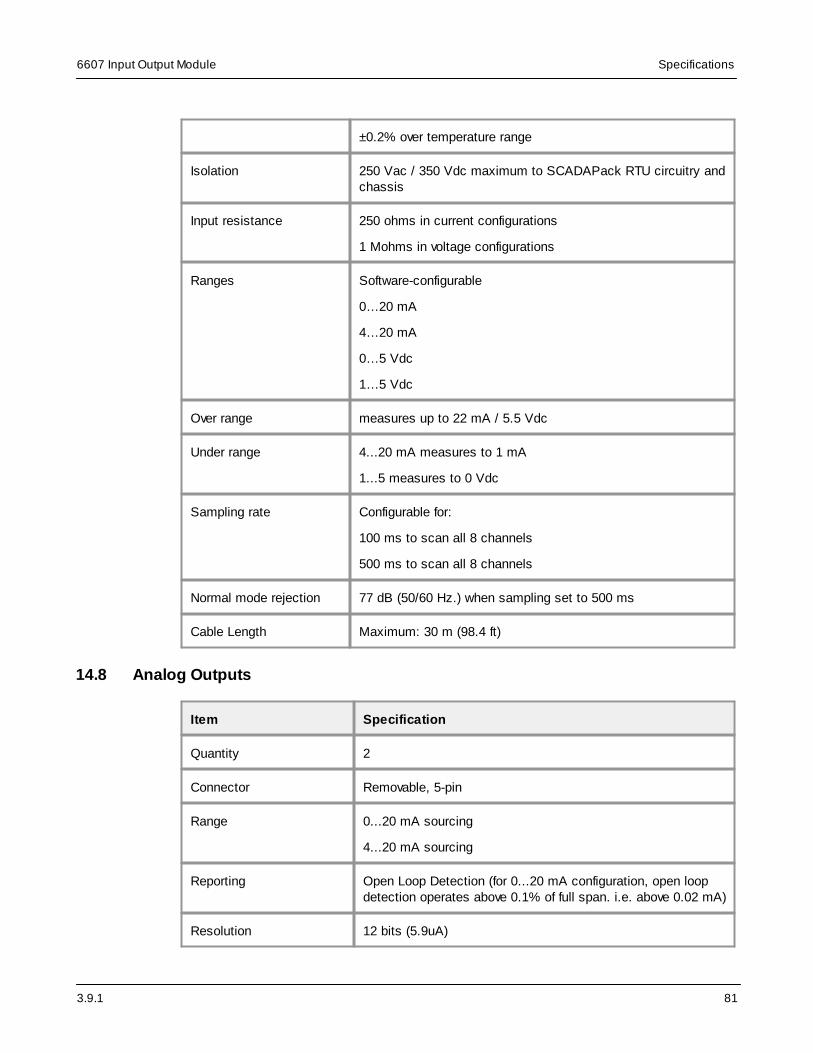
3.9.1
6607 Input Output Module Specifications
81
±0.2% over temperature range
Isolation 250 Vac / 350 Vdc maximum to SCADAPack RTU circuitry andchassis
Input resistance 250 ohms in current configurations
1 Mohms in voltage configurations
Ranges Software-configurable
0…20 mA
4…20 mA
0…5 Vdc
1…5 Vdc
Over range measures up to 22 mA / 5.5 Vdc
Under range 4...20 mA measures to 1 mA
1...5 measures to 0 Vdc
Sampling rate Configurable for:
100 ms to scan all 8 channels
500 ms to scan all 8 channels
Normal mode rejection 77 dB (50/60 Hz.) when sampling set to 500 ms
Cable Length Maximum: 30 m (98.4 ft)
14.8 Analog Outputs
Item Specification
Quantity 2
Connector Removable, 5-pin
Range 0...20 mA sourcing
4...20 mA sourcing
Reporting Open Loop Detection (for 0...20 mA configuration, open loopdetection operates above 0.1% of full span. i.e. above 0.02 mA)
Resolution 12 bits (5.9uA)
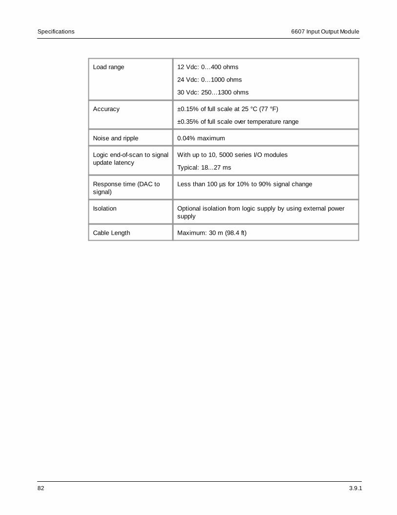
3.9.1
6607 Input Output ModuleSpecifications
82
Load range 12 Vdc: 0…400 ohms
24 Vdc: 0…1000 ohms
30 Vdc: 250…1300 ohms
Accuracy ±0.15% of full scale at 25 °C (77 °F)
±0.35% of full scale over temperature range
Noise and ripple 0.04% maximum
Logic end-of-scan to signalupdate latency
With up to 10, 5000 series I/O modules
Typical: 18...27 ms
Response time (DAC tosignal)
Less than 100 µs for 10% to 90% signal change
Isolation Optional isolation from logic supply by using external powersupply
Cable Length Maximum: 30 m (98.4 ft)

3.9.1
6607 Input Output Module Standards and Certifications
83
15 Standards and Certifications
Introduction
SCADAPacks are designed to comply with the relevant standards and rules for electricalequipment in an industrial automation environment.
Industrial Standards
Requirements specific to the SCADAPack functional characteristics, immunity, robustness, andsafety:
· IEC/EN 61131-2
· CSA 22.2 No. 61010-1-12 and CSA 22.2 No. 61010-2-201
· UL 61010-1 and UL 61010-2-201
CE Marking Compliance
· For the latest information regarding product compliance with European Directives for CEmarking, refer to the EU Declaration of Conformity issued for your product at www.se.com
· For the latest information regarding product compliance with RoHS, WEEE directives andREACH regulation, visit the Schneider Electric Check a Product portal atwww.reach.schneider-electric.com
Installation in Classified Ex Area
· Hazardous locations Class I, Division 2, groups A, B, C, and D, T4 and Class I, Zone 2, T4,
UL 12.12.01
· ATEX (EU Directive 2014/34/EU) in defined atmosphere Zone 2 according to EN IEC 60079-0,EN IEC 60079-7 and EN IEC 60079-15

3.9.1
6607 Input Output ModuleStandards and Certifications
84
WARNING
EXPLOSION HAZARD
THESE DEVICES ARE OPEN-TYPE DEVICES THAT ARE TO BE INSTALLED IN ANENCLOSURE WITH TOOL REMOVABLE COVER OR DOOR, SUITABLE FOR THEENVIRONMENT.
Failure to follow these instructions can result in death or serious injury.
WARNING
EXPLOSION HAZARD
DO NOT DISCONNECT WHILE THE CIRCUIT IS LIVE OR UNLESS THE AREA IS FREE OFIGNITABLE CONCENTRATIONS.
AVERTISSEMENT – RISQUE D’EXPLOSION. NE PAS DÉBRANCHER PENDANT QUE LECIRCUIT EST SOUS TENSION OU À MOINS QUE L’EMPLACEMENT NE SOIT EXEMPT DECONCENTRATIONS INFLAMMABLES.
Failure to follow these instructions can result in death or serious injury.
Specific Countries
For Australia and New Zealand: ACMA requirements for RCM marking
Specific Countries
For United States: FCC Part 15 Subpart B Class A
