integrated genset control c6200 + c6250 - elr
TRANSCRIPT

Integrated Genset Control
C6200 + C6250
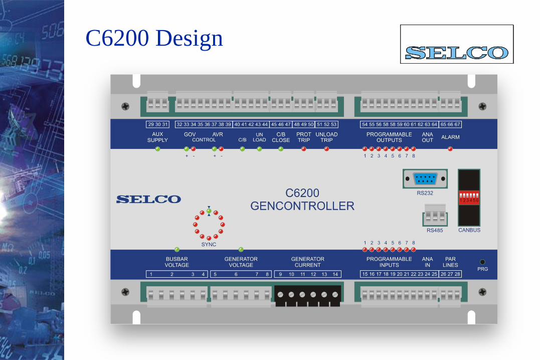
C6200 Design
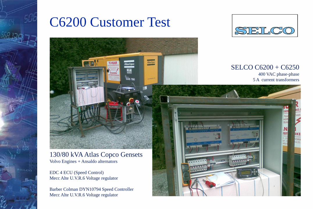
C6200 Customer Test
130/80 kVA Atlas Copco GensetsVolvo Engines + Ansaldo alternators
EDC 4 ECU (Speed Control)
Mecc Alte U.V.R.6 Voltage regulator
Barber Colman DYN10794 Speed Controller
Mecc Alte U.V.R.6 Voltage regulator
SELCO C6200 + C6250400 VAC phase-phase
5 A current transformers
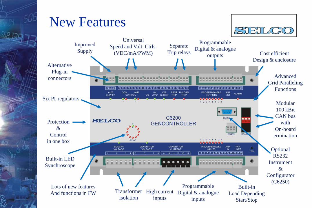
Transformer
isolation
Programmable
Digital & analogue
inputs
Protection
&
Control
in one box
Built-in LED
Synchroscope
Programmable
Digital & analogue
outputs
Separate
Trip relays
Universal
Speed and Volt. Ctrls.
(VDC/mA/PWM)
Modular
100 kBit
CAN bus
with
On-board
ermination
Optional
RS232
Instrument
&
Configurator
(C6250)
Improved
Supply Cost efficient
Design & enclosureAlternative
Plug-in
connectors
Lots of new features
And functions in FW
New Features
Built-in
Load Depending
Start/Stop
Advanced
Grid Paralleling
Functions
Six PI-regulators
High current
inputs
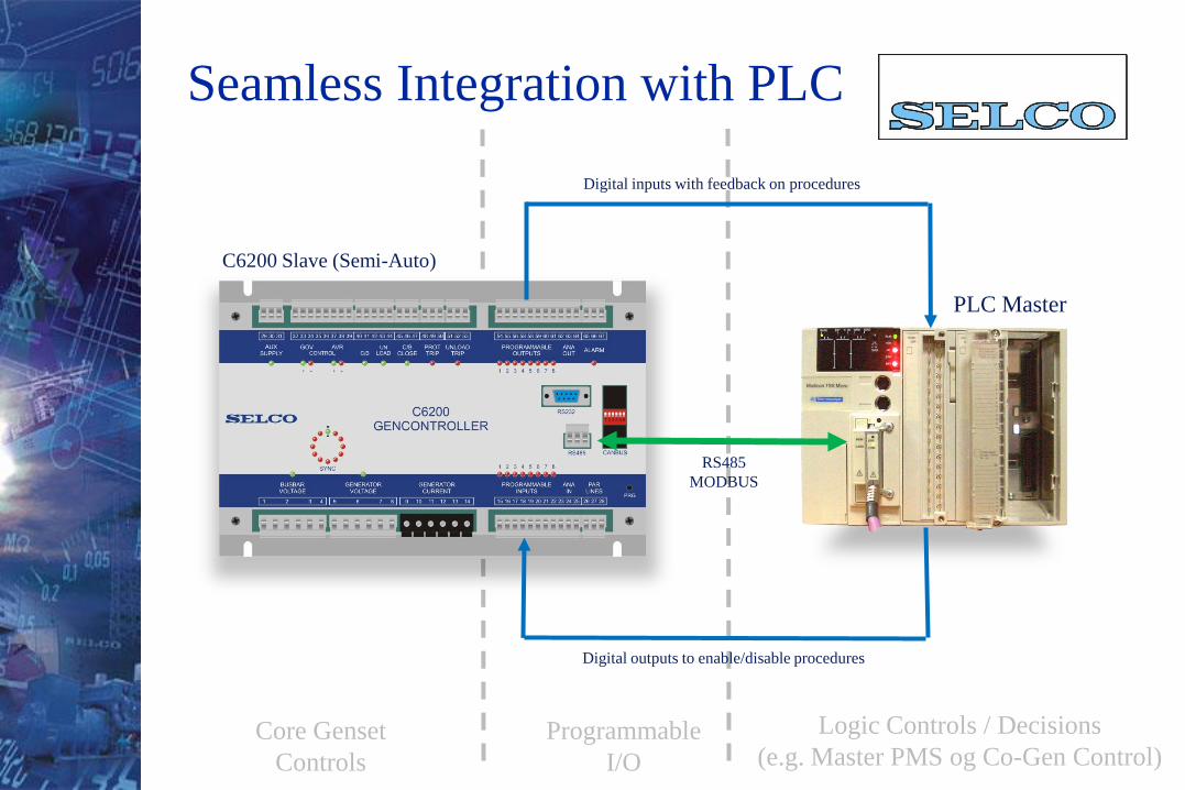
Seamless Integration with PLC
C6200 Slave (Semi-Auto)
PLC Master
Core Genset
Controls
Logic Controls / Decisions
(e.g. Master PMS og Co-Gen Control)
RS485
MODBUS
Digital outputs to enable/disable procedures
Digital inputs with feedback on procedures
Programmable
I/O
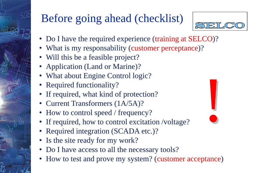
• Do I have the required experience (training at SELCO)?
• What is my responsability (customer perceptance)?
• Will this be a feasible project?
• Application (Land or Marine)?
• What about Engine Control logic?
• Required functionality?
• If required, what kind of protection?
• Current Transformers (1A/5A)?
• How to control speed / frequency?
• If required, how to control excitation /voltage?
• Required integration (SCADA etc.)?
• Is the site ready for my work?
• Do I have access to all the necessary tools?
• How to test and prove my system? (customer acceptance)
Before going ahead (checklist)
!!
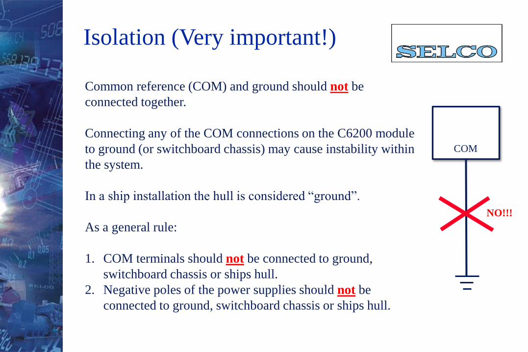
Common reference (COM) and ground should not be
connected together.
Connecting any of the COM connections on the C6200 module
to ground (or switchboard chassis) may cause instability within
the system.
In a ship installation the hull is considered “ground”.
As a general rule:
1. COM terminals should not be connected to ground,
switchboard chassis or ships hull.
2. Negative poles of the power supplies should not be
connected to ground, switchboard chassis or ships hull.
Isolation (Very important!)
COM
NO!!!
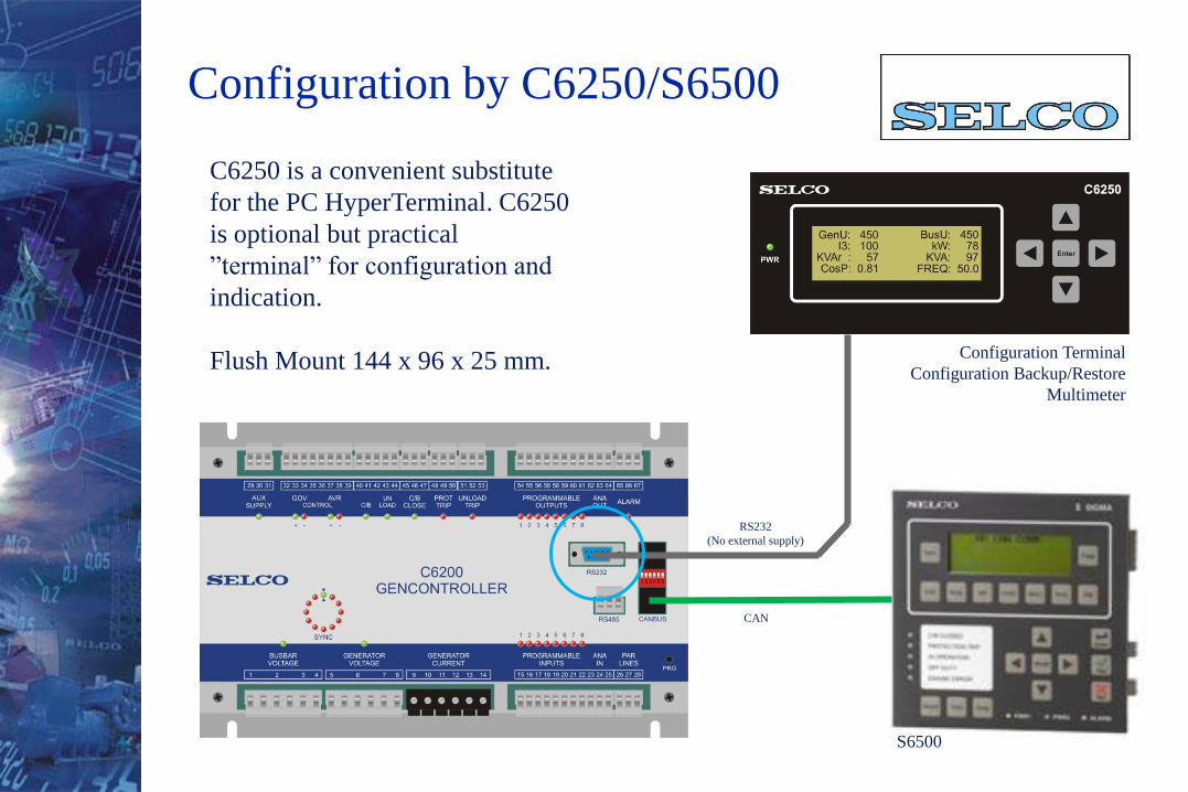
Configuration by C6250/S6500
RS232
(No external supply)
Configuration Terminal
Configuration Backup/Restore
Multimeter
C6250 is a convenient substitute
for the PC HyperTerminal. C6250
is optional but practical
”terminal” for configuration and
indication.
Flush Mount 144 x 96 x 25 mm.
CAN
S6500

+ -
24 VDC-30% / +20%
The front AUX SUPPLY
LED illuminates with a
steady green light to indicate
that the supply voltage is
OK and within the limits of
safe operation
Supply reference (-) has
connection to the modules
COM terminals (same
potential). Auxillary supply
is NOT isolated
Auxillary Supply
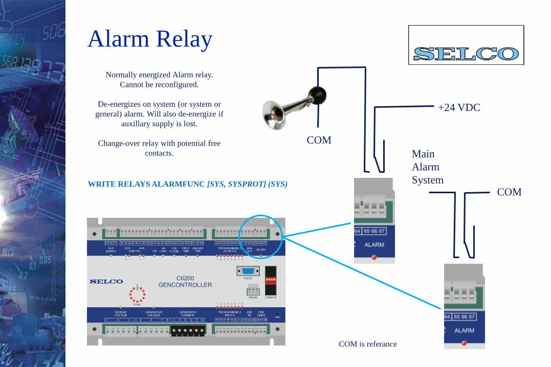
+24 VDC
COM
Normally energized Alarm relay.
Cannot be reconfigured.
De-energizes on system (or system or
general) alarm. Will also de-energize if
auxillary supply is lost.
Change-over relay with potential free
contacts. Main
Alarm
SystemCOM
WRITE RELAYS ALARMFUNC [SYS, SYSPROT] (SYS)
Alarm Relay
COM is referance
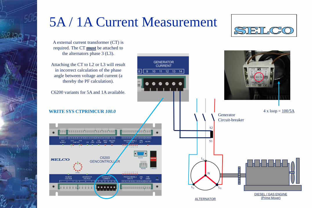
A external current transformer (CT) is
required. The CT must be attached to
the alternators phase 3 (L3).
Attaching the CT to L2 or L3 will result
in incorrect calculation of the phase
angle between voltage and current (a
thereby the PF calculation).
C6200 variants for 5A and 1A available.
ALTERNATOR
L3
L2
L1
DIESEL / GAS ENGINE
(Prime Mover)
N
S2
S1
WRITE SYS CTPRIMCUR 100.0Generator
Circuit-breaker
4 x loop = 100/5A
5A / 1A Current Measurement
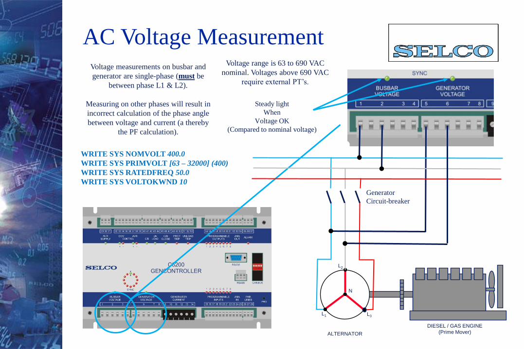
Voltage measurements on busbar and
generator are single-phase (must be
between phase L1 & L2).
Measuring on other phases will result in
incorrect calculation of the phase angle
between voltage and current (a thereby
the PF calculation).
ALTERNATOR
L3
L2
L1
DIESEL / GAS ENGINE
(Prime Mover)
N
Generator
Circuit-breaker
WRITE SYS NOMVOLT 400.0
WRITE SYS PRIMVOLT [63 – 32000] (400)
WRITE SYS RATEDFREQ 50.0
WRITE SYS VOLTOKWND 10
Steady light
When
Voltage OK
(Compared to nominal voltage)
AC Voltage MeasurementVoltage range is 63 to 690 VAC
nominal. Voltages above 690 VAC
require external PT’s.
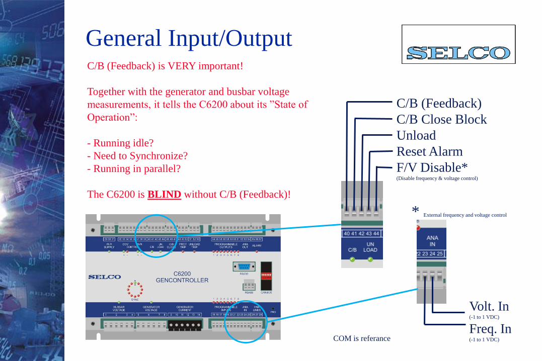
General Input/Output
C/B (Feedback)
C/B Close Block
Unload
Reset Alarm
F/V Disable*(Disable frequency & voltage control)
C/B (Feedback) is VERY important!
Together with the generator and busbar voltage
measurements, it tells the C6200 about its ”State of
Operation”:
- Running idle?
- Need to Synchronize?
- Running in parallel?
The C6200 is BLIND without C/B (Feedback)!
Volt. In(-1 to 1 VDC)
Freq. In(-1 to 1 VDC)
* External frequency and voltage control
COM is referance
CosGENMAXCUR
PRIMVOLTGENCAP
33
cos3
3PRIMVOLT
GENCAPGENMAXCUR
AV
VAGENMAXCUR 65
00.13
4003
000.45
AV
WGENMAXCUR 54.234
8.03
4003
000.130
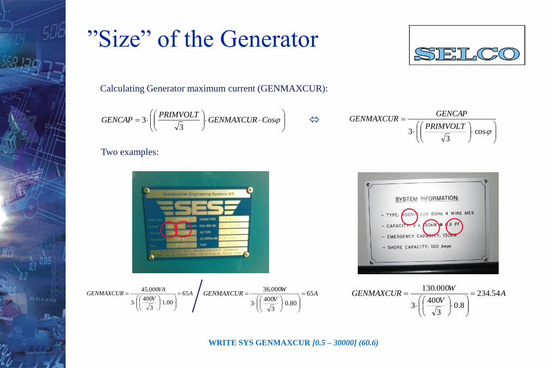
Calculating Generator maximum current (GENMAXCUR):
Two examples:
WRITE SYS GENMAXCUR [0.5 – 30000] (60.6)
AV
WGENMAXCUR 65
80.03
4003
000.36
”Size” of the Generator
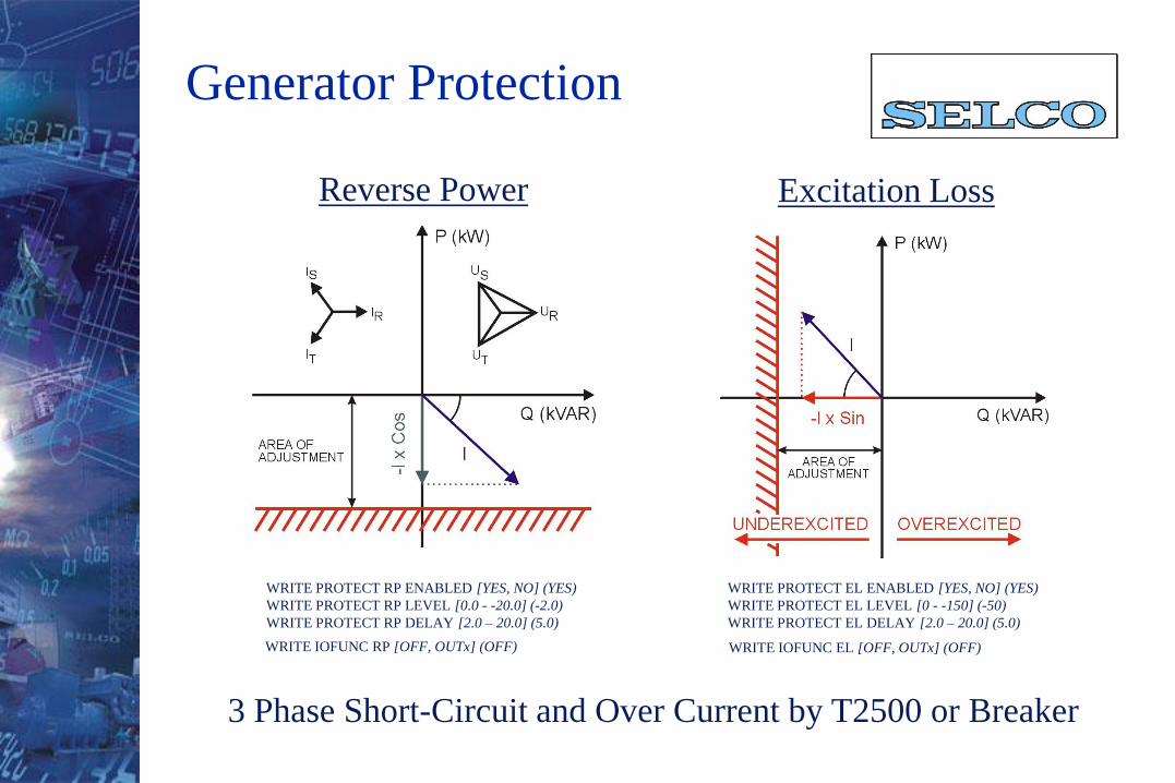
Generator Protection
Reverse Power Excitation Loss
WRITE PROTECT RP ENABLED [YES, NO] (YES)
WRITE PROTECT RP LEVEL [0.0 - -20.0] (-2.0)
WRITE PROTECT RP DELAY [2.0 – 20.0] (5.0)
WRITE PROTECT EL ENABLED [YES, NO] (YES)
WRITE PROTECT EL LEVEL [0 - -150] (-50)
WRITE PROTECT EL DELAY [2.0 – 20.0] (5.0)
WRITE IOFUNC RP [OFF, OUTx] (OFF) WRITE IOFUNC EL [OFF, OUTx] (OFF)
3 Phase Short-Circuit and Over Current by T2500 or Breaker
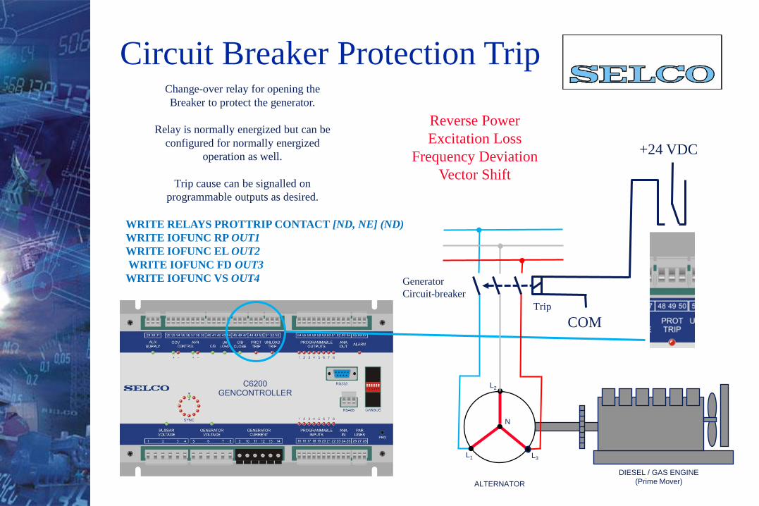
Change-over relay for opening the
Breaker to protect the generator.
Relay is normally energized but can be
configured for normally energized
operation as well.
Trip cause can be signalled on
programmable outputs as desired.
ALTERNATOR
L3
L2
L1
DIESEL / GAS ENGINE
(Prime Mover)
N
Generator
Circuit-breaker
COM
+24 VDC
Trip
WRITE RELAYS PROTTRIP CONTACT [ND, NE] (ND)
WRITE IOFUNC RP OUT1
WRITE IOFUNC EL OUT2
WRITE IOFUNC FD OUT3
WRITE IOFUNC VS OUT4
Circuit Breaker Protection Trip
Reverse Power
Excitation Loss
Frequency Deviation
Vector Shift
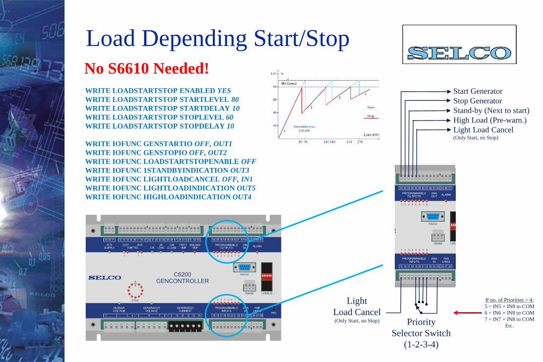
Load Depending Start/Stop
WRITE LOADSTARTSTOP ENABLED YES
WRITE LOADSTARTSTOP STARTLEVEL 80
WRITE LOADSTARTSTOP STARTDELAY 10
WRITE LOADSTARTSTOP STOPLEVEL 60
WRITE LOADSTARTSTOP STOPDELAY 10
WRITE IOFUNC GENSTARTIO OFF, OUT1
WRITE IOFUNC GENSTOPIO OFF, OUT2
WRITE IOFUNC LOADSTARTSTOPENABLE OFF
WRITE IOFUNC 1STANDBYINDICATION OUT3
WRITE IOFUNC LIGHTLOADCANCEL OFF, IN1
WRITE IOFUNC LIGHTLOADINDICATION OUT5
WRITE IOFUNC HIGHLOADINDICATION OUT4
Start Generator
Stop Generator
Stand-by (Next to start)
High Load (Pre-warn.)
Light Load Cancel(Only Start, no Stop)
Priority
Selector Switch
(1-2-3-4)
If no. of Priorities > 4:
5 = IN5 + IN8 to COM
6 = IN6 + IN8 to COM
7 = IN7 + IN8 to COM
Etc.
Light
Load Cancel(Only Start, no Stop)
No S6610 Needed!

ALTERNATOR
V1
V2
V3 Fuel PumpActuator
DIESEL / GAS ENGINE
(Prime Mover)
PICK-UP
Flywheel
FUEL CONTROL
SPEED FEEDBACK SIGNAL (PULSE TRAIN)
ELECTRONIC
SPEED
CONTROLLER
WRITE SYS SPEEDCTRL ENABLED YES
WRITE SYS SPEEDCTRL ANAOUT SIGNAL VOLT
WRITE SYS SPEEDCTRL ANAOUT VOLTMIN 10.000
WRITE SYS SPEEDCTRL ANAOUT VOLTMAX 0.000
Controlling RPM/f by VDC
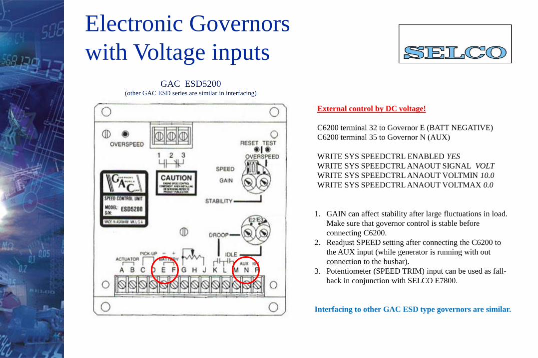
Electronic Governors
with Voltage inputsGAC ESD5200
(other GAC ESD series are similar in interfacing)
External control by DC voltage!
C6200 terminal 32 to Governor E (BATT NEGATIVE)
C6200 terminal 35 to Governor N (AUX)
WRITE SYS SPEEDCTRL ENABLED YES
WRITE SYS SPEEDCTRL ANAOUT SIGNAL VOLT
WRITE SYS SPEEDCTRL ANAOUT VOLTMIN 10.0
WRITE SYS SPEEDCTRL ANAOUT VOLTMAX 0.0
1. GAIN can affect stability after large fluctuations in load.
Make sure that governor control is stable before
connecting C6200.
2. Readjust SPEED setting after connecting the C6200 to
the AUX input (while generator is running with out
connection to the busbar).
3. Potentiometer (SPEED TRIM) input can be used as fall-
back in conjunction with SELCO E7800.
Interfacing to other GAC ESD type governors are similar.
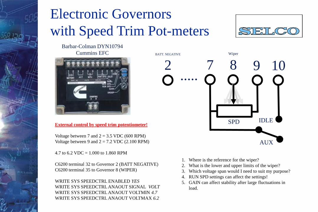
Electronic Governors
with Speed Trim Pot-metersBarbar-Colman DYN10794
Cummins EFC
External control by speed trim potentiometer!
Voltage between 7 and 2 = 3.5 VDC (600 RPM)
Voltage between 9 and 2 = 7.2 VDC (2.100 RPM)
4.7 to 6.2 VDC = 1.000 to 1.860 RPM
C6200 terminal 32 to Governor 2 (BATT NEGATIVE)
C6200 terminal 35 to Governor 8 (WIPER)
WRITE SYS SPEEDCTRL ENABLED YES
WRITE SYS SPEEDCTRL ANAOUT SIGNAL VOLT
WRITE SYS SPEEDCTRL ANAOUT VOLTMIN 4.7
WRITE SYS SPEEDCTRL ANAOUT VOLTMAX 6.2
7Wiper
8 9 10BATT. NEGATIVE
2
SPD
AUX
IDLE
1. Where is the reference for the wiper?
2. What is the lower and upper limits of the wiper?
3. Which voltage span would I need to suit my purpose?
4. RUN SPD settings can affect the settings!
5. GAIN can affect stability after large fluctuations in
load.
.....
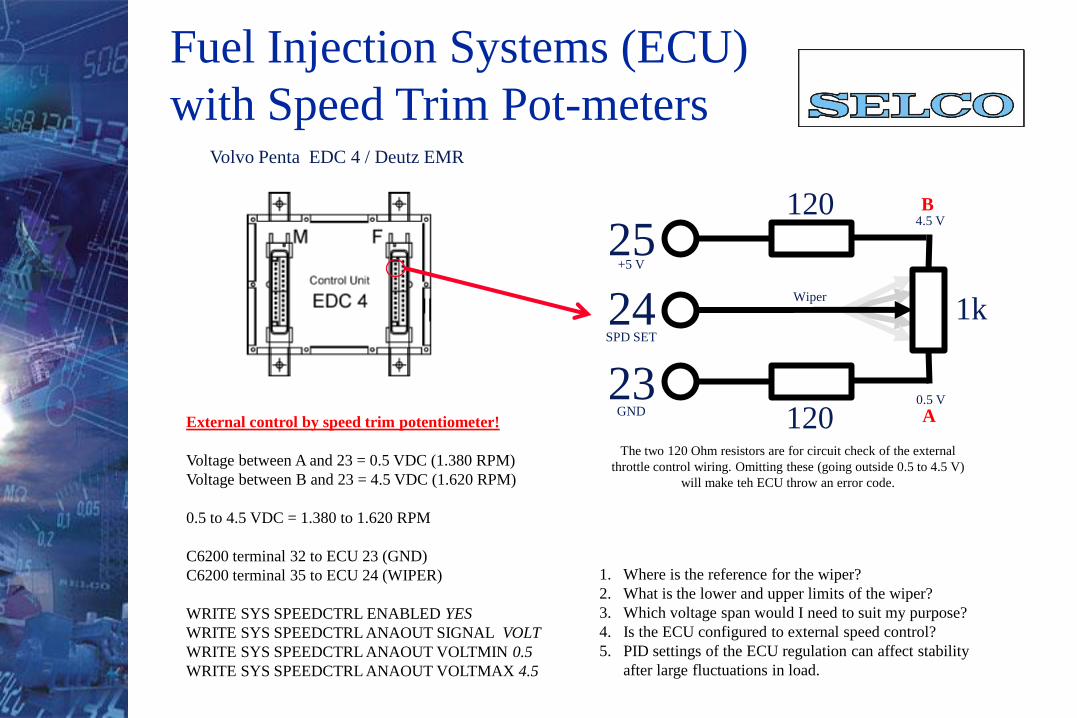
Fuel Injection Systems (ECU)
with Speed Trim Pot-metersVolvo Penta EDC 4 / Deutz EMR
External control by speed trim potentiometer!
Voltage between A and 23 = 0.5 VDC (1.380 RPM)
Voltage between B and 23 = 4.5 VDC (1.620 RPM)
0.5 to 4.5 VDC = 1.380 to 1.620 RPM
C6200 terminal 32 to ECU 23 (GND)
C6200 terminal 35 to ECU 24 (WIPER)
WRITE SYS SPEEDCTRL ENABLED YES
WRITE SYS SPEEDCTRL ANAOUT SIGNAL VOLT
WRITE SYS SPEEDCTRL ANAOUT VOLTMIN 0.5
WRITE SYS SPEEDCTRL ANAOUT VOLTMAX 4.5
1. Where is the reference for the wiper?
2. What is the lower and upper limits of the wiper?
3. Which voltage span would I need to suit my purpose?
4. Is the ECU configured to external speed control?
5. PID settings of the ECU regulation can affect stability
after large fluctuations in load.
120
23
Wiper
1k24
25
120
+5 V
GND
SPD SET
4.5 V
0.5 V
B
A
The two 120 Ohm resistors are for circuit check of the external
throttle control wiring. Omitting these (going outside 0.5 to 4.5 V)
will make teh ECU throw an error code.
ALTERNATOR
V1
V2
V3 Fuel PumpActuator
DIESEL / GAS ENGINE
(Prime Mover)
PICK-UP
Flywheel
FUEL CONTROL
SPEED FEEDBACK SIGNAL (PULSE TRAIN)
ELECTRONIC
SPEED
CONTROLLER
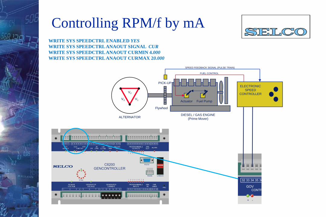
WRITE SYS SPEEDCTRL ENABLED YES
WRITE SYS SPEEDCTRL ANAOUT SIGNAL CUR
WRITE SYS SPEEDCTRL ANAOUT CURMIN 4.000
WRITE SYS SPEEDCTRL ANAOUT CURMAX 20.000
Controlling RPM/f by mA
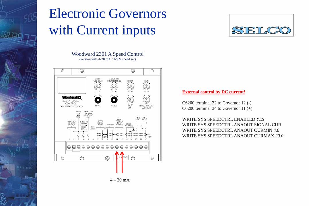
Electronic Governors
with Current inputs
Woodward 2301 A Speed Control(version with 4-20 mA / 1-5 V speed set)
External control by DC current!
C6200 terminal 32 to Governor 12 (-)
C6200 terminal 34 to Governor 11 (+)
WRITE SYS SPEEDCTRL ENABLED YES
WRITE SYS SPEEDCTRL ANAOUT SIGNAL CUR
WRITE SYS SPEEDCTRL ANAOUT CURMIN 4.0
WRITE SYS SPEEDCTRL ANAOUT CURMAX 20.0
4 – 20 mA
WRITE SYS SPEEDCTRL ENABLED YES
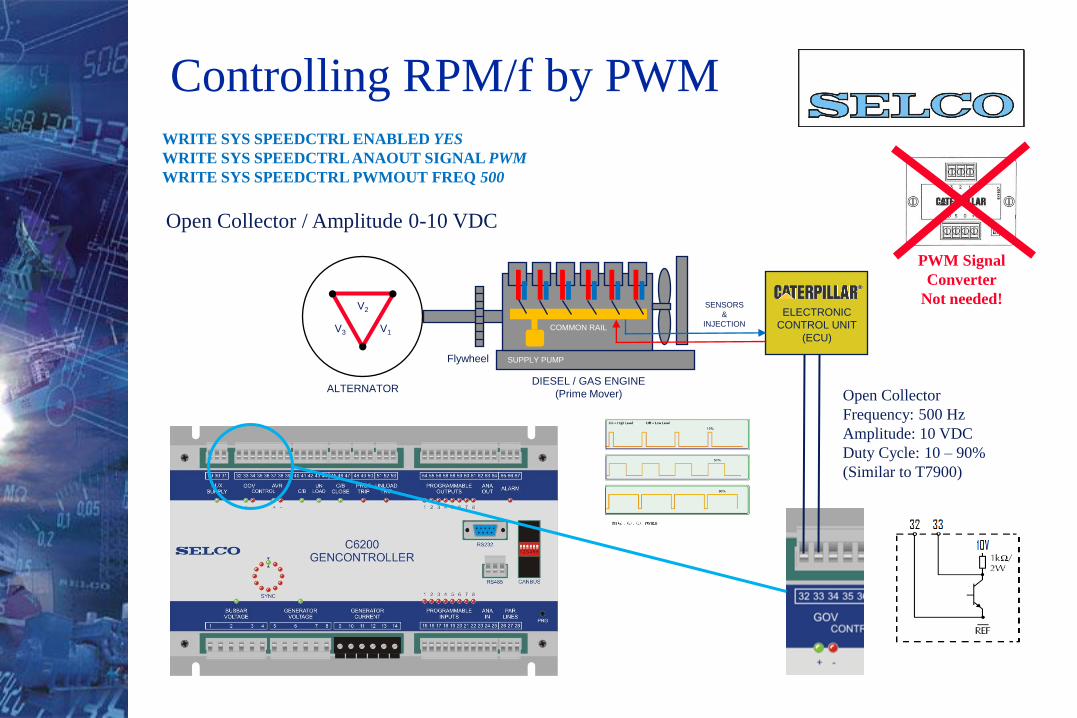
WRITE SYS SPEEDCTRL ANAOUT SIGNAL PWM
WRITE SYS SPEEDCTRL PWMOUT FREQ 500
ALTERNATOR
V1
V2
V3
DIESEL / GAS ENGINE
(Prime Mover)
ELECTRONIC
CONTROL UNIT
(ECU)
Flywheel
COMMON RAIL
SUPPLY PUMP
SENSORS
&
INJECTION
Open Collector / Amplitude 0-10 VDC
Controlling RPM/f by PWM
Open Collector
Frequency: 500 Hz
Amplitude: 10 VDC
Duty Cycle: 10 – 90%
(Similar to T7900)
PWM Signal
Converter
Not needed!

Governor Systems
with 500 Hz PWM input
External control by PWM signal of ADEM!
C6200 terminal 32 to BATTERY –
C6200 terminal 33 to ADEM 10 (RATED SPEED)
WRITE SYS SPEEDCTRL ENABLED YES
WRITE SYS SPEEDCTRL ANAOUT SIGNAL PWM
WRITE SYS SPEEDCTRL PWMOUT FREQ 500
External control by PWM signal of PEEC!
C6200 terminal 32 to PEEC 19 (BATTERY -)
C6200 terminal 33 to PEEC 9 (PRIMARY THROTTLE)
WRITE SYS SPEEDCTRL ENABLED YES
WRITE SYS SPEEDCTRL ANAOUT SIGNAL PWM
WRITE SYS SPEEDCTRL PWMOUT FREQ 500
Caterpillar ADEM Caterpillar PEEC
PWMPWM
REFREF
-+
BATTERY
PWM Signal
Converter
Not needed!
PWM Signal
Converter
Not needed!
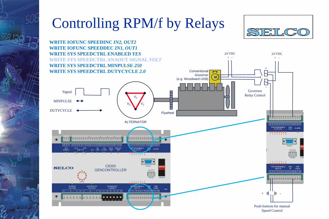
WRITE IOFUNC SPEEDINC IN2, OUT2
WRITE IOFUNC SPEEDDEC IN1, OUT1
WRITE SYS SPEEDCTRL ENABLED YES
WRITE SYS SPEEDCTRL ANAOUT SIGNAL VOLT
WRITE SYS SPEEDCTRL MINPULSE 250
WRITE SYS SPEEDCTRL DUTYCYCLE 2.0M
ALTERNATOR
V1
V2
V3
Conventional
Govornor
(e.g. Woodward UG8)
Flywheel
24 VDC
+ -24 VDC
+ -
Push-buttons for manual
Speed Control
+ -
+
-Governor
Relay Control
Controlling RPM/f by Relays
MINPULSE
DUTYCYCLE
Signal
ALTERNATOR
V1
V2
V3
DIESEL / GAS ENGINE
(Prime Mover)
Flywheel
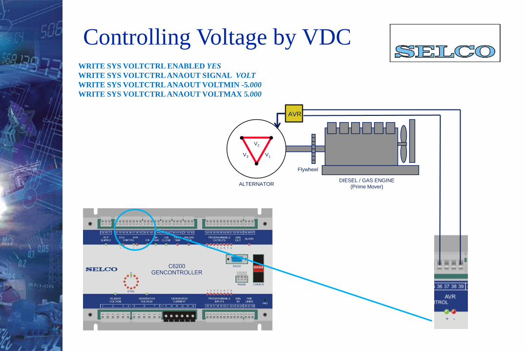
WRITE SYS VOLTCTRL ENABLED YES
WRITE SYS VOLTCTRL ANAOUT SIGNAL VOLT
WRITE SYS VOLTCTRL ANAOUT VOLTMIN -5.000
WRITE SYS VOLTCTRL ANAOUT VOLTMAX 5.000
Controlling Voltage by VDC
AVR
Controlling Voltage by VDC
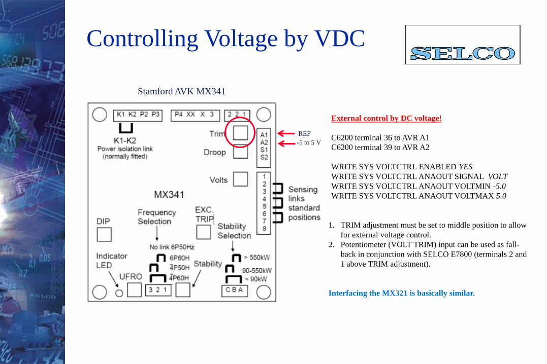
-5 to 5 V
REF
External control by DC voltage!
C6200 terminal 36 to AVR A1
C6200 terminal 39 to AVR A2
WRITE SYS VOLTCTRL ENABLED YES
WRITE SYS VOLTCTRL ANAOUT SIGNAL VOLT
WRITE SYS VOLTCTRL ANAOUT VOLTMIN -5.0
WRITE SYS VOLTCTRL ANAOUT VOLTMAX 5.0
1. TRIM adjustment must be set to middle position to allow
for external voltage control.
2. Potentiometer (VOLT TRIM) input can be used as fall-
back in conjunction with SELCO E7800 (terminals 2 and
1 above TRIM adjustment).
Interfacing the MX321 is basically similar.
Stamford AVK MX341
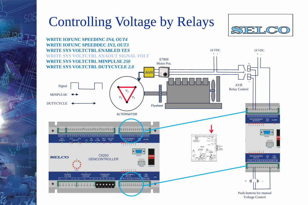
WRITE IOFUNC SPEEDINC IN4, OUT4
WRITE IOFUNC SPEEDDEC IN3, OUT3
WRITE SYS VOLTCTRL ENABLED YES
WRITE SYS VOLTCTRL ANAOUT SIGNAL VOLT
WRITE SYS VOLTCTRL MINPULSE 250
WRITE SYS VOLTCTRL DUTYCYCLE 2.0
ALTERNATOR
V1
V2
V3
Flywheel
24 VDC
+ -24 VDC
+ -
Push-buttons for manual
Voltage Control
+ -
+
-AVR
Relay Control
Controlling Voltage by Relays
MINPULSE
DUTYCYCLE
Signal
AVR
E7800
Motor Pot.
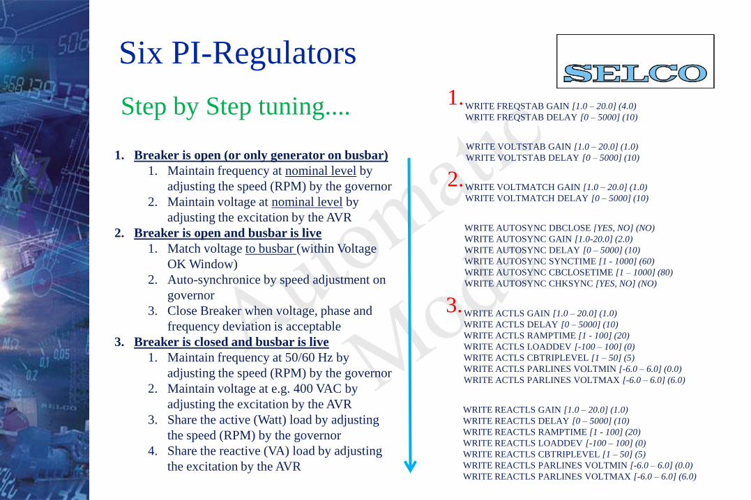
Six PI-Regulators
WRITE FREQSTAB GAIN [1.0 – 20.0] (4.0)
WRITE FREQSTAB DELAY [0 – 5000] (10)
WRITE AUTOSYNC DBCLOSE [YES, NO] (NO)
WRITE AUTOSYNC GAIN [1.0-20.0] (2.0)
WRITE AUTOSYNC DELAY [0 – 5000] (10)
WRITE AUTOSYNC SYNCTIME [1 - 1000] (60)
WRITE AUTOSYNC CBCLOSETIME [1 – 1000] (80)
WRITE AUTOSYNC CHKSYNC [YES, NO] (NO)
WRITE VOLTMATCH GAIN [1.0 – 20.0] (1.0)
WRITE VOLTMATCH DELAY [0 – 5000] (10)
WRITE ACTLS GAIN [1.0 – 20.0] (1.0)
WRITE ACTLS DELAY [0 – 5000] (10)
WRITE ACTLS RAMPTIME [1 - 100] (20)
WRITE ACTLS LOADDEV [-100 – 100] (0)
WRITE ACTLS CBTRIPLEVEL [1 – 50] (5)
WRITE ACTLS PARLINES VOLTMIN [-6.0 – 6.0] (0.0)
WRITE ACTLS PARLINES VOLTMAX [-6.0 – 6.0] (6.0)
WRITE REACTLS GAIN [1.0 – 20.0] (1.0)
WRITE REACTLS DELAY [0 – 5000] (10)
WRITE REACTLS RAMPTIME [1 - 100] (20)
WRITE REACTLS LOADDEV [-100 – 100] (0)
WRITE REACTLS CBTRIPLEVEL [1 – 50] (5)
WRITE REACTLS PARLINES VOLTMIN [-6.0 – 6.0] (0.0)
WRITE REACTLS PARLINES VOLTMAX [-6.0 – 6.0] (6.0)
WRITE VOLTSTAB GAIN [1.0 – 20.0] (1.0)
WRITE VOLTSTAB DELAY [0 – 5000] (10)
1.
2.
3.
1. Breaker is open (or only generator on busbar)
1. Maintain frequency at nominal level by
adjusting the speed (RPM) by the governor
2. Maintain voltage at nominal level by
adjusting the excitation by the AVR
2. Breaker is open and busbar is live
1. Match voltage to busbar (within Voltage
OK Window)
2. Auto-synchronice by speed adjustment on
governor
3. Close Breaker when voltage, phase and
frequency deviation is acceptable
3. Breaker is closed and busbar is live
1. Maintain frequency at 50/60 Hz by
adjusting the speed (RPM) by the governor
2. Maintain voltage at e.g. 400 VAC by
adjusting the excitation by the AVR
3. Share the active (Watt) load by adjusting
the speed (RPM) by the governor
4. Share the reactive (VA) load by adjusting
the excitation by the AVR
Step by Step tuning....
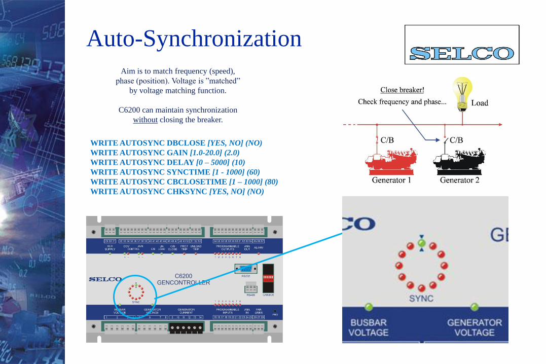
Auto-Synchronization
WRITE AUTOSYNC DBCLOSE [YES, NO] (NO)
WRITE AUTOSYNC GAIN [1.0-20.0] (2.0)
WRITE AUTOSYNC DELAY [0 – 5000] (10)
WRITE AUTOSYNC SYNCTIME [1 - 1000] (60)
WRITE AUTOSYNC CBCLOSETIME [1 – 1000] (80)
WRITE AUTOSYNC CHKSYNC [YES, NO] (NO)
Aim is to match frequency (speed),
phase (position). Voltage is ”matched”
by voltage matching function.
C6200 can maintain synchronization
without closing the breaker.

Change-over relay for closing the
generator circuit breaker.
Relay is normally de-energized.
Dead bus closure is optional.
ALTERNATOR
L3
L2
L1
DIESEL / GAS ENGINE
(Prime Mover)
N
Generator
Circuit-breaker
COM
+24 VDC
Close
Circuit Breaker Closeure

Load balance (active and/or reactive) is
communicated using a DC-voltage
between -6 and 6 VDC. Voltage span can
be configured to match e.g. T4800 or
T4400 (0-1 / 0-3 VDC).
COM is referance.
Load Sharing / Parallel Lines
WRITE ACTLS PARLINES VOLTMIN [-6.0 – 6.0] (0.0)
WRITE ACTLS PARLINES VOLTMAX [-6.0 – 6.0] (6.0)
WRITE REACTLS PARLINES VOLTMIN [-6.0 – 6.0] (0.0)
WRITE REACTLS PARLINES VOLTMAX [-6.0 – 6.0] (6.0)
Watt
COM
VA
C6200
#1
C6200
#2
C6200
#3
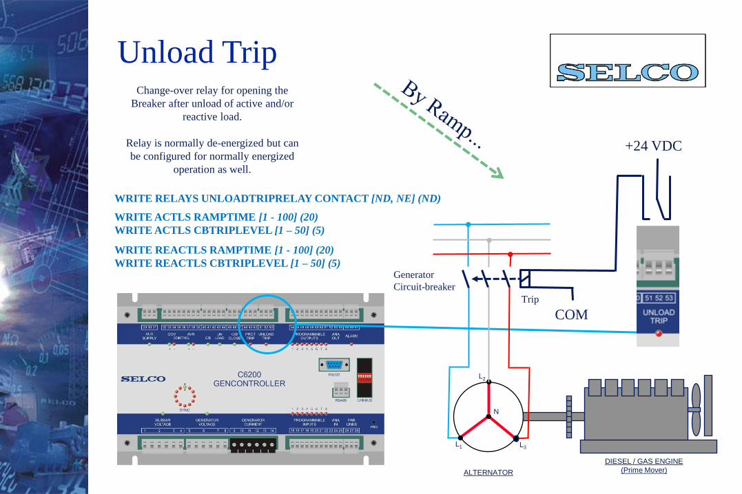
Change-over relay for opening the
Breaker after unload of active and/or
reactive load.
Relay is normally de-energized but can
be configured for normally energized
operation as well.
ALTERNATOR
L3
L2
L1
DIESEL / GAS ENGINE
(Prime Mover)
N
Generator
Circuit-breaker
COM
+24 VDC
Trip
Unload Trip
WRITE RELAYS UNLOADTRIPRELAY CONTACT [ND, NE] (ND)
WRITE ACTLS RAMPTIME [1 - 100] (20)
WRITE ACTLS CBTRIPLEVEL [1 – 50] (5)
WRITE REACTLS RAMPTIME [1 - 100] (20)
WRITE REACTLS CBTRIPLEVEL [1 – 50] (5)
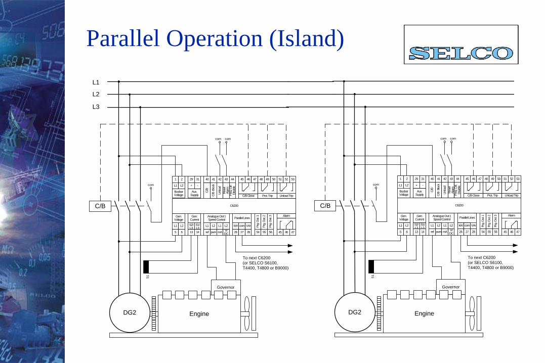
Parallel Operation (Island)
S1
L1
L2
L3
C/B
Busbar Voltage
C/B
C/B Close
C6200
1 2
L1 L2
29 31
+ -
Aux. Supply
40 41 42 43 44
C/B
Blo
ck
Unlo
ad
Rese
t A
larm
Fre
q. C
trl.
Disable
45 46 47 48 49 50 51 52 53
Prot. Trip Unload Trip
5 6
L1 L2
Gen. Voltage
13 14
S2/ L3
S1/L3
Gen. Current
ref pwm
L1 L2
Analogue Out 1 Speed Control
mAV/DC
L1 L2
26 27
kW com
Parallel Lines
28
VAr
Alarm
45 46 47
Prg
. Out.
1
Prg
. Out.
2
Prg
. Out.
3
54 55 56
com
com
To next C6200
(or SELCO S6100,
T4400, T4800 or B9000)
com
Governor
EngineDG2
S1
C/B
Busbar Voltage
C/B
C/B Close
C6200
1 2
L1 L2
29 31
+ -
Aux. Supply
40 41 42 43 44
C/B
Blo
ck
Unlo
ad
Rese
t A
larm
Fre
q. C
trl.
Disable
45 46 47 48 49 50 51 52 53
Prot. Trip Unload Trip
5 6
L1 L2
Gen. Voltage
13 14
S2/ L3
S1/L3
Gen. Current
ref pwm
L1 L2
Analogue Out 1 Speed Control
mAV/DC
L1 L2
26 27
kW com
Parallel Lines
28
VAr
Alarm
45 46 47
Prg
. Out.
1
Prg
. Out.
2
Prg
. Out.
3
54 55 56
com
com
To next C6200
(or SELCO S6100,
T4400, T4800 or B9000)
com
Governor
EngineDG2
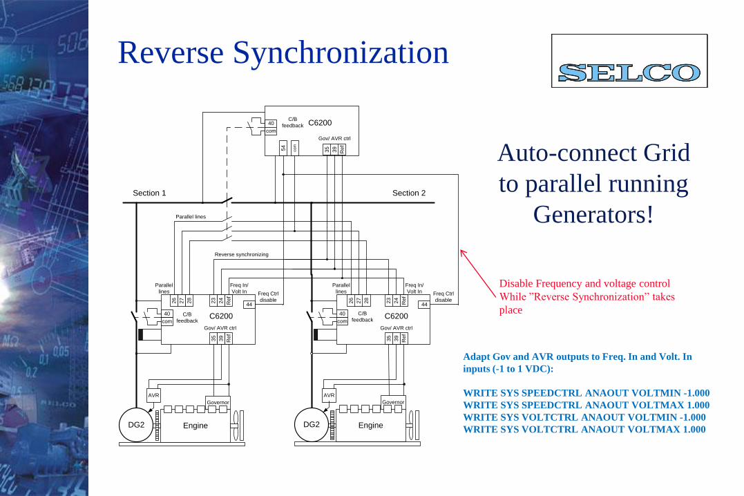
Reverse Synchronization
23
24
35
39
Re
fR
ef
35
39
Re
f
23
24
35
39
Re
fR
ef
Freq In/
Volt In
Freq In/
Volt In
Gov/ AVR ctrl
Gov/ AVR ctrl Gov/ AVR ctrl
Section 1
44
Freq Ctrl
disable44
Freq Ctrl
disable26
27
28
Parallel
lines
26
27
28
Parallel
lines
Parallel lines
Reverse synchronizing
AVR
54
co
m
C6200
C6200 C6200
Governor
EngineDG2
Governor
EngineDG2
AVR
Section 2
40
com
C/B
feedback
40
com
C/B
feedback
40
com
C/B
feedback
Adapt Gov and AVR outputs to Freq. In and Volt. In
inputs (-1 to 1 VDC):
WRITE SYS SPEEDCTRL ANAOUT VOLTMIN -1.000
WRITE SYS SPEEDCTRL ANAOUT VOLTMAX 1.000
WRITE SYS VOLTCTRL ANAOUT VOLTMIN -1.000
WRITE SYS VOLTCTRL ANAOUT VOLTMAX 1.000
Disable Frequency and voltage control
While ”Reverse Synchronization” takes
place
Auto-connect Grid
to parallel running
Generators!
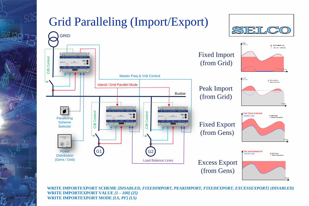
Grid Paralleling (Import/Export)
Fixed Import
(from Grid)
Peak Import
(from Grid)
Fixed Export
(from Gens)
Excess Export
(from Gens)
WRITE IMPORTEXPORT SCHEME [DISABLED, FIXEDIMPORT, PEAKIMPORT, FIXEDEXPORT, EXCESSEXPORT] (DISABLED)
WRITE IMPORTEXPORT VALUE [1 – 100] (25)
WRITE IMPORTEXPORT MODE [LS, PF] (LS)
G1 G2
Master Freq & Volt Control
Island / Grid Parallel Mode
Load Balance Lines
C/B
Con
tro
l
C/B
Con
tro
l
C/B
Con
tro
l
GRID
Busbar
12 3
4
Power
Distribution
(Gens / Grid)
Paralleling
Scheme
Selector
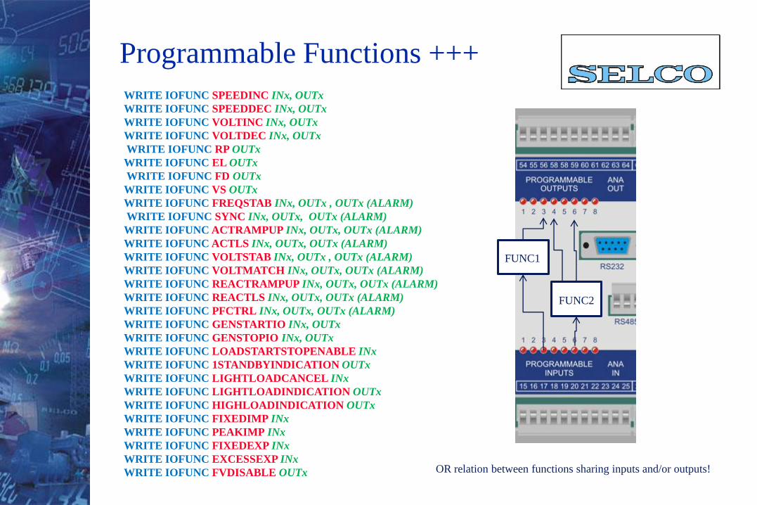
Programmable Functions +++
WRITE IOFUNC SPEEDINC INx, OUTx
WRITE IOFUNC SPEEDDEC INx, OUTx
WRITE IOFUNC VOLTINC INx, OUTx
WRITE IOFUNC VOLTDEC INx, OUTx
WRITE IOFUNC RP OUTx
WRITE IOFUNC EL OUTx
WRITE IOFUNC FD OUTx
WRITE IOFUNC VS OUTx
WRITE IOFUNC FREQSTAB INx, OUTx , OUTx (ALARM)
WRITE IOFUNC SYNC INx, OUTx, OUTx (ALARM)
WRITE IOFUNC ACTRAMPUP INx, OUTx, OUTx (ALARM)
WRITE IOFUNC ACTLS INx, OUTx, OUTx (ALARM)
WRITE IOFUNC VOLTSTAB INx, OUTx , OUTx (ALARM)
WRITE IOFUNC VOLTMATCH INx, OUTx, OUTx (ALARM)
WRITE IOFUNC REACTRAMPUP INx, OUTx, OUTx (ALARM)
WRITE IOFUNC REACTLS INx, OUTx, OUTx (ALARM)
WRITE IOFUNC PFCTRL INx, OUTx, OUTx (ALARM)
WRITE IOFUNC GENSTARTIO INx, OUTx
WRITE IOFUNC GENSTOPIO INx, OUTx
WRITE IOFUNC LOADSTARTSTOPENABLE INx
WRITE IOFUNC 1STANDBYINDICATION OUTx
WRITE IOFUNC LIGHTLOADCANCEL INx
WRITE IOFUNC LIGHTLOADINDICATION OUTx
WRITE IOFUNC HIGHLOADINDICATION OUTx
WRITE IOFUNC FIXEDIMP INx
WRITE IOFUNC PEAKIMP INx
WRITE IOFUNC FIXEDEXP INx
WRITE IOFUNC EXCESSEXP INx
WRITE IOFUNC FVDISABLE OUTx
FUNC1
FUNC2
OR relation between functions sharing inputs and/or outputs!