integrated deethanizer/ethylene fractionation column
TRANSCRIPT
Note: Within nine months from the publication of the mention of the grant of the European patent, any person may givenotice to the European Patent Office of opposition to the European patent granted. Notice of opposition shall be filed ina written reasoned statement. It shall not be deemed to have been filed until the opposition fee has been paid. (Art.99(1) European Patent Convention).
Printed by Jouve, 75001 PARIS (FR)
Europäisches Patentamt
European Patent Office
Office européen des brevets
(19)
EP
1 03
5 09
4B
1*EP001035094B1*(11) EP 1 035 094 B1
(12) EUROPEAN PATENT SPECIFICATION
(45) Date of publication and mentionof the grant of the patent:12.05.2004 Bulletin 2004/20
(21) Application number: 00104104.5
(22) Date of filing: 28.02.2000
(51) Int Cl.7: C07C 7/04, B01D 3/14
(54) Integrated deethanizer/ethylene fractionation column
Integrierte Entethanisator/ Ethylenfraktionierungskolonne
Colonne intégrée de dééthanisation et de fractionnement d’éthylène
(84) Designated Contracting States:AT BE CH CY DE DK ES FI FR GB GR IE IT LI LUMC NL PT SE
(30) Priority: 10.03.1999 US 266214
(43) Date of publication of application:13.09.2000 Bulletin 2000/37
(73) Proprietor: Kellogg Brown & Root, Inc.Houston, Texas 77002-7990 (US)
(72) Inventor: Stork, KarlSanta Barbara, CA 93103-1750 (US)
(74) Representative:Weiss, Wolfgang, Dipl.-Chem. Dr. et alWeickmann & WeickmannPatentanwältePostfach 86 08 2081635 München (DE)
(56) References cited:WO-A-97/15795 US-A- 5 709 780
EP 1 035 094 B1
5
10
15
20
25
30
35
40
45
50
55
2
Description
FIELD OF THE INVENTION
[0001] The present invention relates to an apparatus and method for the deethanization and ethylene fractionationin an olefin plant processing propane and heavier feedstocks, and particularly to the use of an integrated column whichcombines both the deethanizer and ethylene fractionator into a single column.
BACKGROUND OF THE INVENTION
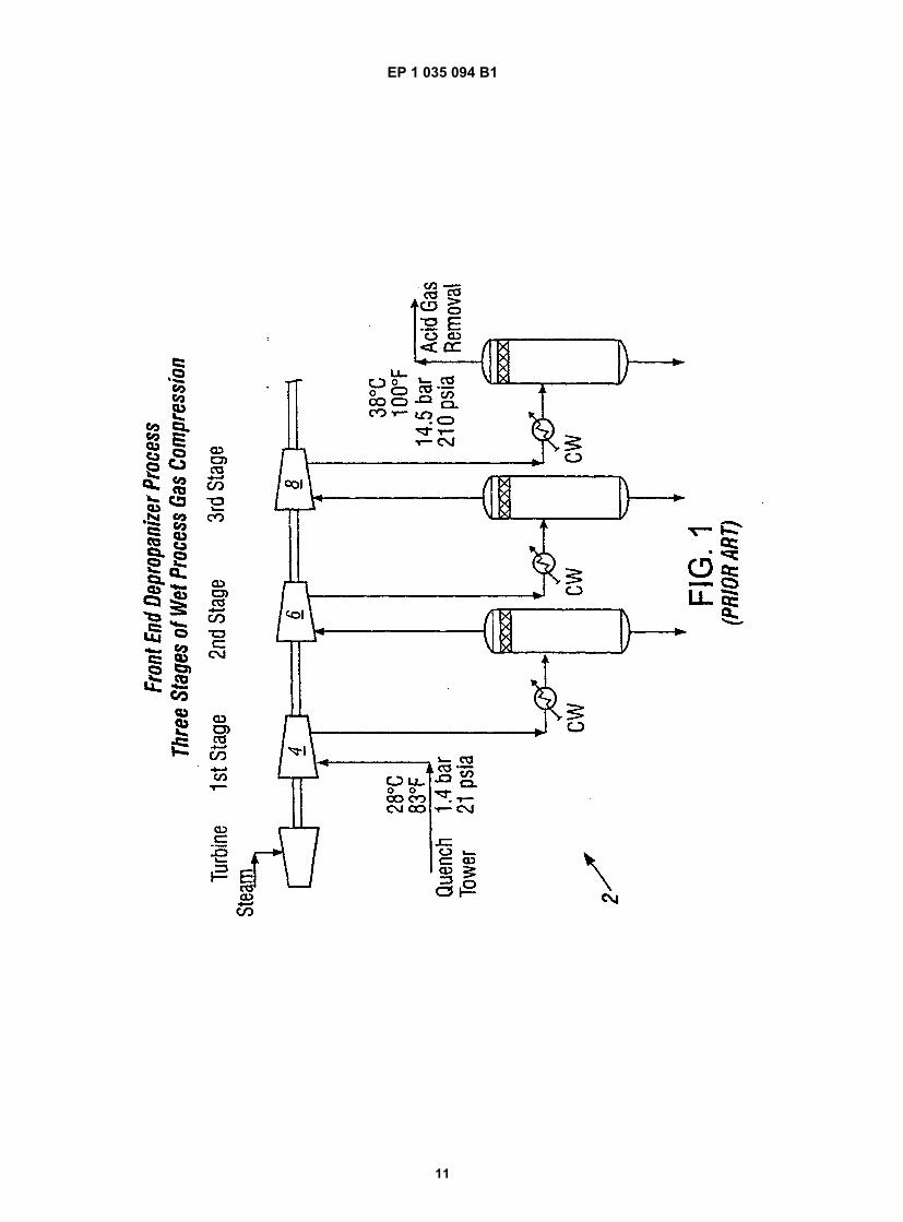
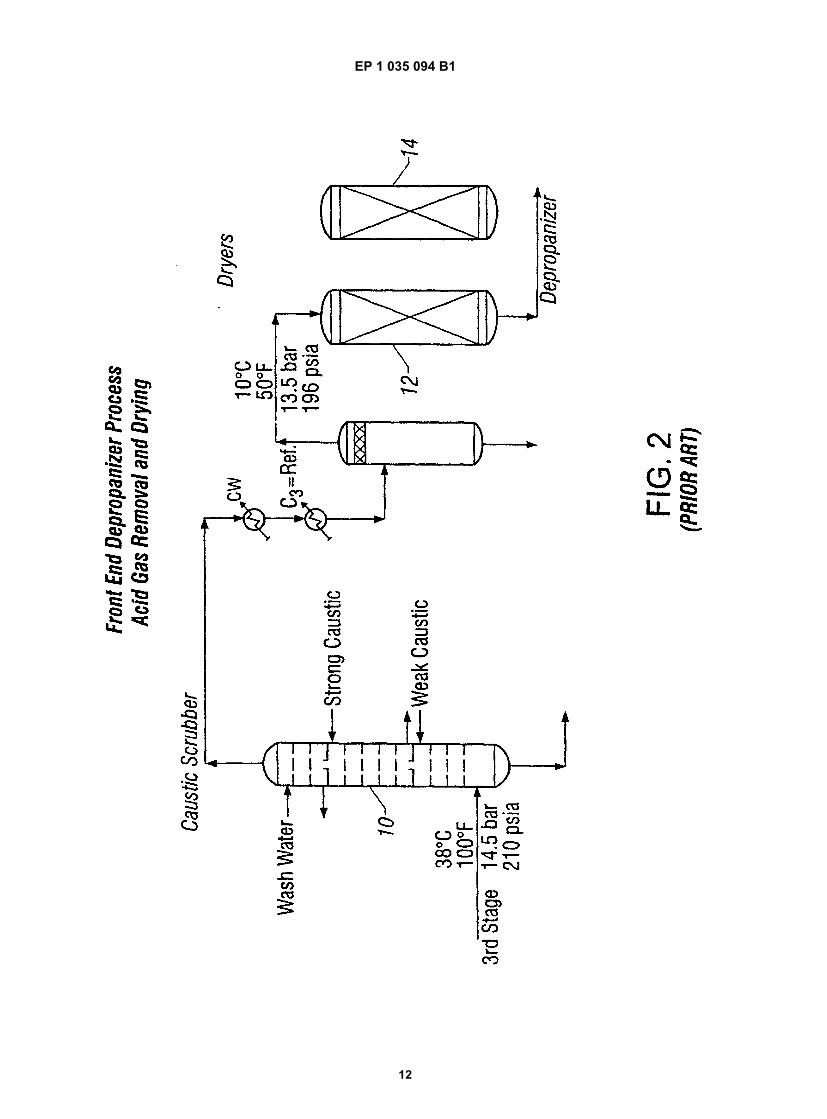
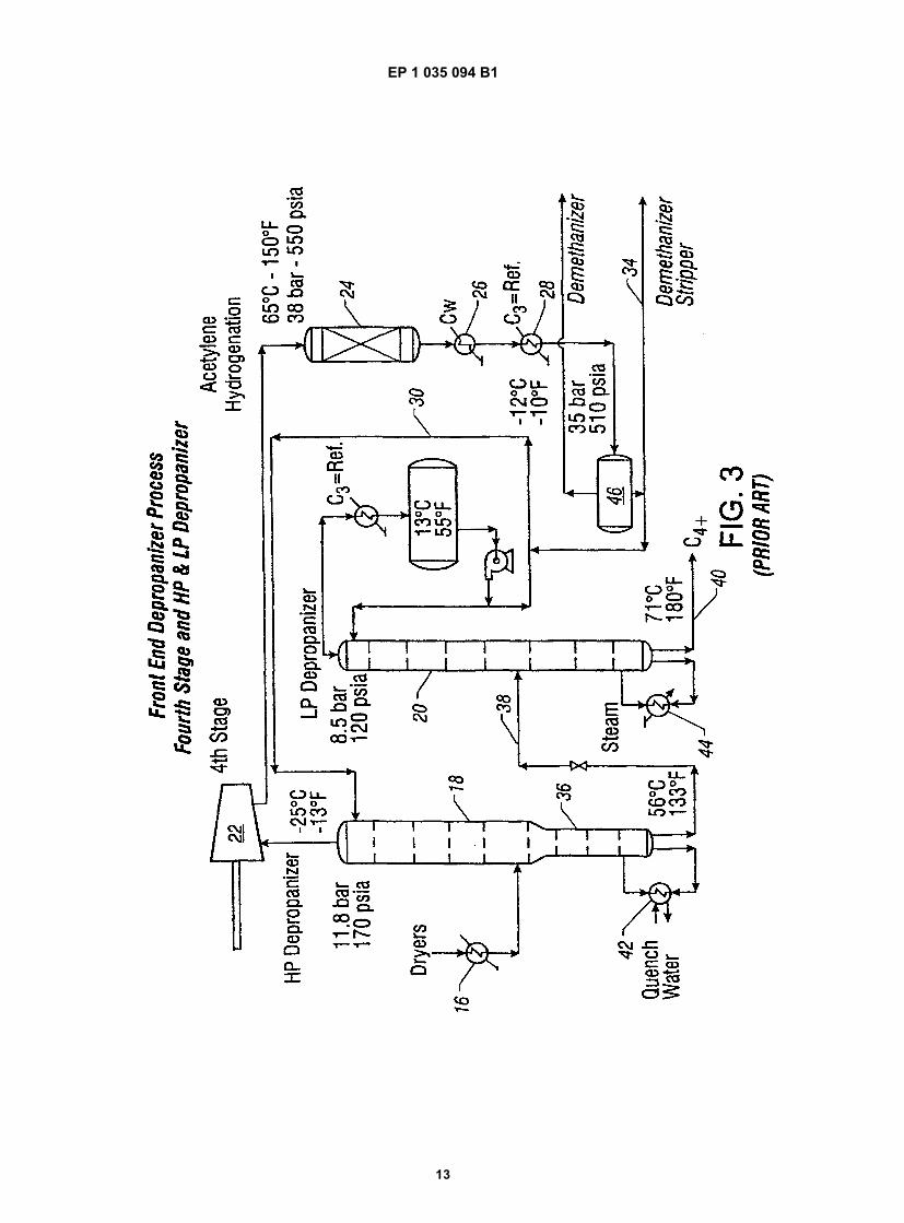
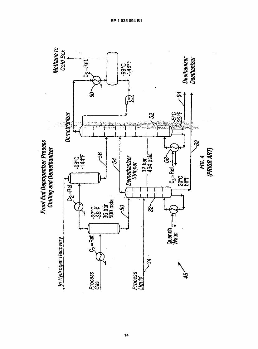
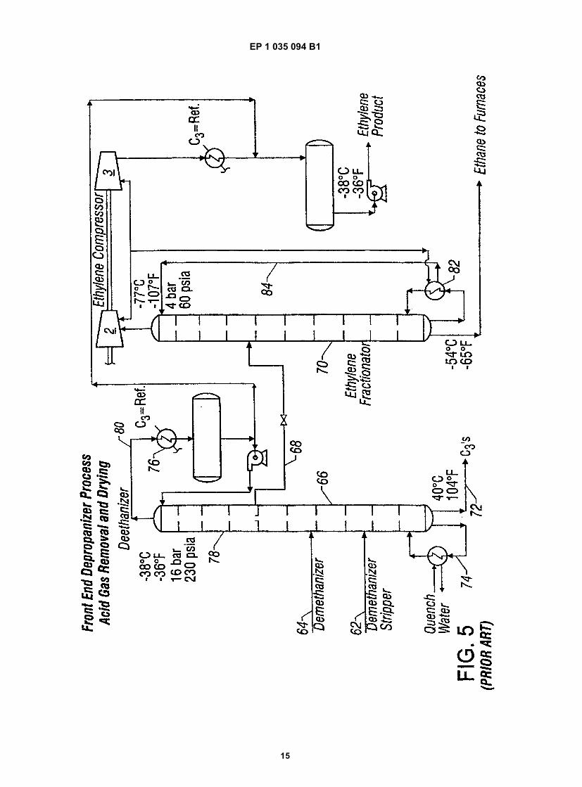
[0002] A typical process for the separation and recovery of olefins from pyrolysis furnaces operated with feedstocksheavier than ethane, is known as the front end depropanizer and front end acetylene hydrogenation scheme. A briefreview of the typical front end depropanizer process is in order.[0003] Starting with the separation section 2 after the water quench, as shown on the simplified process flow diagramof Fig. 1, there are three stages 4,6,8 of conventional compression to raise the pressure of the process gas from justabove atmospheric to a pressure of about 15 bars (210 psia). Condensed liquids, i.e. hydrocarbons and water, areseparated.[0004] The gas is then treated in a conventional two or three stage caustic wash tower 10 as shown in Fig. 2 for theremoval of carbon dioxide and hydrogen sulfide. The gas is cooled and mildly chilled before entering the dryers 12,14. Water is removed completely.[0005] The gas is then further chilled in propylene refrigerant exchanger 16 seen in Fig. 3, and enters the highpressure depropanizer 18 which does not really operate at high pressure but is only called that because there is alsoa low pressure depropanizer 20. The high pressure depropanizer 18 typically operates at a pressure of 12 bars (170psia), and the low pressure depropanizer 20 at a pressure of 8.5 bars (120 psia).[0006] The overhead of the high pressure depropanizer 18 is usually compressed in compressor 22 to a pressureof 38 bars (550 psia) and is then sent to the acetylene hydrogenation system 24 which typically consists of two or threeadiabatic reactors in series with inter-cooler for the removal of the heat of reaction. The reactor effluent is cooled incooling water exchanger 26 and partially condensed in propylene refrigerant exchanger 28. A portion of the condensateis used as reflux via line 30 for the high pressure depropanizer 18. The rest is sent to the demethanizer stripper 32(see Fig. 4) via line 34.[0007] In the stripping section 36 of the high pressure depropanizer 18 only ethane and lighter components areremoved, resulting in a fairly low bottoms temperature of 56°C (133°F). The bottoms product is sent via line 38 to thelow pressure depropanizer 20 where it is separated into C3's and C4+. The C3 is used as reflux in the high pressuredepropanizer 18 via line 30, while the C4+ is sent to the debutanizer (not shown) via line 40. Due to the low operatingpressure, the bottoms temperatures in the depropanizers 18,20 are quite low, namely 56°C (133°F) and 71°C (160°F).Therefore, there is no fouling in either tower 18,20 or their respective reboilers 42,44.[0008] The acetylene hydrogenation unit 24 is highly efficient and selective. The acetylene removal easily results inacetylene concentrations of less than 1 ppm in the final ethylene product while the ethylene gain amounts to 50% ormore of the acetylene. Due to the high hydrogen content of the feed gas, no carbonaceous material is deposited onthe catalyst. The catalyst needs no regeneration and thus the reactors 24 need no spares. Green oil formation isminiscule.[0009] In the acetylene hydrogenation reactor 24 about 80% of the methyl-acetylene and 20% of the propadiene areconverted to propylene. If the olefins plant produces polymer grade propylene the remaining C3H4 can be easily frac-tionated into the propane product; the high conversion of methyl-acetylene and propadiene in the acetylene hydrogen-ation reactors obviates the need for an additional separate C3H4 hydrogenation system.[0010] The operational stability of the acetylene hydrogenation reactor 24 is enhanced by its location in the grossoverhead loop of the depropanizer 18 and in the minimum flow recycle circuit of the fourth stage of compression 22.These factors reduce the acetylene concentration in the inlet to the reactor 24 and stabilize the flow rate irrespectiveof the furnace throughput.[0011] The vapor and liquid from the reflux accumulator 46 of the high pressure depropanizer 18 flow to the chillingand demethanization section 48 (see Fig. 4). The liquid plus the condensate formed at -37°C (-35°F) is sent via re-spective lines 34 and 50 to the demethanizer stripper 32. The overhead vapor from the demethanizer stripper 32 plusthe liquids formed at lower temperatures are sent to the main demethanizer 52 via. respective lines 54 and 56. Thetower 52 is reboiled by reboiler 58 with condensing propylene refrigerant, and reflux is condensed in heat exchanger60 with low temperature ethylene refrigerant.[0012] The respective bottoms products 62,64 of the two demethanizers 32,52, after some heat exchange which isnot shown, enter the prior art deethanizer 66. The tower 66 recovers approximately 40 percent of the ethylene containedin the two feeds as high purity product. Sixty percent of the ethylene and all the ethane leave the tower 66 as a side
EP 1 035 094 B1
5
10
15
20
25
30
35
40
45
50
55
3
stream 68 and proceed to the low pressure ethylene fractionator 70. The deethanizer 66 is reboiled by reboiler 74 withquench water and reflux is condensed in exchanger 76 with -40° propylene refrigerant. The bottoms product 72 of thedeethanizer 66 is a stream containing propylene, propane and the remaining C3H4. It flows to a conventional propylenefractionator (not shown). Because of the ethylene fractionation in its top section 78, the deethanizer 66 has fifty moretrays than a conventional deethanizer (without the side draw) which produces a mixed ethylene and ethane overheadproduct in line 80.[0013] The ethylene fractionator 70 is a relatively low pressure tower typically operating at 4 bars (60 psia) withapproximately 100 trays. It uses an open heat pump. Ethylene refrigerant is condensed in the reboiler 82 and is thenused as reflux via line 84. Effectively, the reboiler 82 also serves as the reflux condenser. There are no reflux pumpsand there is no reflux drum.[0014] Other references of interest are U.S. Patents 5,709,780 and 5,755,933, both to Ognisty et al.
SUMMARY OF THE INVENTION
[0015] The present invention combines the deethanizer and ethylene fractionator of the prior art into a single frac-tionation column, reduces the pressure of the deethanizer to that of the ethylene fractionator and locates the deethanizerand the stripping section of the ethylene fractionator in the bottom portion of a single distillation column divided by avertical wall. Locating the deethanizer and the stripping sections of the ethylene fractionator in the bottom section ofa single distillation column divided by a vertical wall has the capital cost savings of replacing two large columns witha slightly larger column; eliminates the deethanizer reflux condenser, drum and pumps; and employs a much smallerdeethanizer reboiler.[0016] In one aspect, the present invention provides an integrated deethanizer and ethylene fractionation columnfor separating a feed stream comprising ethylene, ethane and C3+ into an ethylene stream, an ethane stream and aC3+ stream. The integrated column is made of a single shell housing a refluxed upper portion and a lower portion. Eachof the integrated column portions comprise multiple vapor-liquid contacting elements. A generally vertical wall partitionsthe lower portion into a deethanizer section and an ethylene stripper section. A feed line supplies at least one feedstream to at least one feed stage of the deethanizer section of the lower portion of the column, between a plurality ofabsorption stages above the feed stage and a plurality of stripping stages below the feed stage, for producing anoverhead vapor stream from the deethanizer section consisting essentially of ethylene and ethane and a bottomsstream consisting essentially of C3 and heavier components. A distribution pan with vapor chimney(s) at the lower endof the upper portion of the column facilitates passage of vapors from the deethanizer and ethylene stripper sectionsinto the upper column portion, and collects liquid for passage from the upper portion of the column into the upper stageof the deethanizer section and into the ethylene stripping section.[0017] The integrated column can have a deethanizer section comprising from 20 to 60 trays. The upper and lowerportions of the integrated column preferably have the same cross-sectional diameter. The integrated column can alsoinclude a reboiler for the deethanizer section heated with high pressure depropanizer gross overhead or some othersuitable heating medium. The integrated column can also include a reboiler for the ethylene stripper section, heatedby ethylene condensed at a relatively higher pressure than the integrated column. The integrated column preferablyincludes a line for refluxing the upper portion of the column with the ethylene condensed in the ethylene stripper sectionreboiler. The integrated column can include a compressor for compressing overhead vapor from the upper portion ofthe column to the pressure of the ethylene stripper section reboiler. The integrated column preferably comprises re-spective liquid lines from the distribution pan to the tops of the dethanizer section and the ethylene stripper section.The line from the distribution pan to the top of the deethanizer section can include a valve for controlling the amountof liquid supplied to the deethanizer section. The integrated column preferably has an operating pressure of from 2 to20 bars (30 to 290 psia).[0018] In another aspect, the invention provides a process for separating a feed stream comprising ethylene, ethaneand C3+ into an ethylene stream, an ethane stream and a C3+ stream. The method includes supplying the feed streamto the at least one feed stage of the deethanizer section of the lower portion of the integrated column described above;passing overhead vapor from the deethanizer and ethylene stripper sections through the chimney(s) of the distributionpan to the upper portion of the column; refluxing the upper portion of the column with ethylene and recovering essentiallypure ethylene overhead from the upper portion of the column; passing liquid from the distribution pan into an upperstage of the deethanizer section and into an upper stage of the ethylene stripper section; reboiling the deethanizersection and recovering a C3+ bottoms product stream therefrom essentially free of ethane and ethylene; and reboilingthe ethylene stripper section and recovering an ethane bottoms product stream therefrom essentially free of ethyleneand C3+.[0019] The deethanizer section preferably comprises from 20 to 60 trays, and the upper and lower portions of theintegrated column have the same cross-sectional diameter. The process preferably includes feeding first and secondfeed streams from a demethanizer and a demethanizer stripper to different intermediate feed stages in the deethanizer
EP 1 035 094 B1
5
10
15
20
25
30
35
40
45
50
55
4
section. The process can include controlling the amount of liquid feed to the upper stage of the deethanizer sectionfrom the distribution pan. The integrated column can be operated at a pressure from 2 to 20 bars (30 to 290 psia). Thedeethanizer section is preferably reboiled with high pressure depropanizer gross overhead. The process can furtherinclude compressing the overhead ethylene and condensing a portion of the compressed ethylene to supply heat forthe reboiling of the ethylene stripper section. The condensed ethylene from the reboiling can be used for the refluxingof the upper portion of the integrated column.
BRIEF DESCRIPTION OF THE DRAWINGS
[0020]
Fig. 1 (prior art) is a simplified process flow diagram showing the three stages of wet process gas compression ina front end depropanizer process.Fig. 2 (prior art) is a simplified flow diagram of acid gas removal and drying in a front end depropanizer process.Fig. 3 (prior art) is a simplified process flow diagram of fourth stage compression and high pressure/low pressuredepropanizers in a front end depropanizer process.Fig. 4 (prior art) is a simplified process flow diagram of a demethanizer stripper and demethanizer in a front enddepropanizer process.Fig. 5 (prior art) is a simplified flow diagram of the deethanizer and ethylene fractionator in a front end depropanizerprocess.Fig. 6 is a simplified process flow diagram of ethylene recovery in a front end depropanizer process according toone embodiment of the present invention.
DETAILED DESCRIPTION OF THE INVENTION
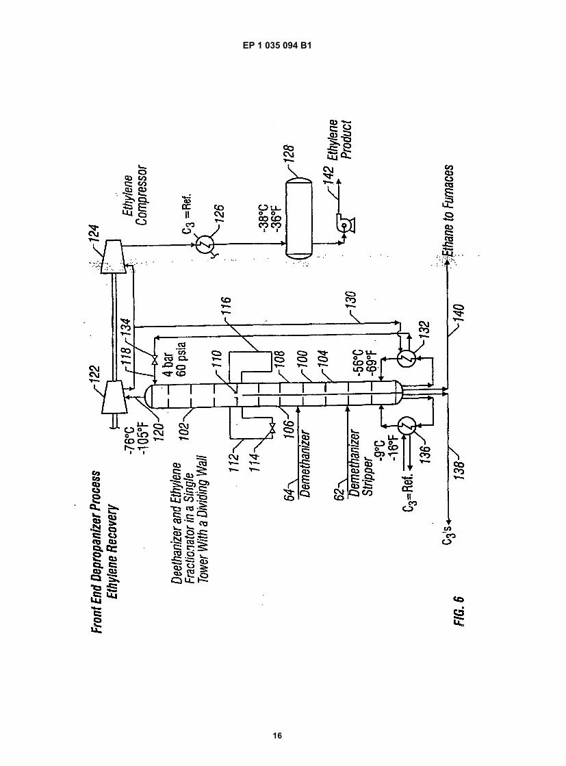
[0021] With reference to Fig. 6, a single tower 100 achieves the sharp separation of high purity ethylene as anoverhead product, a mixed C3+ product with an extremely low ethane content as a bottoms product on the left side106, and an ethane product on the right side 108 of the lower portion 104 of the column 100 for recycle to the pyrolysisfurnaces (not shown). The column 100 is preferably operated at a pressure of from 2 to 20 bars (30 to 290 psia), morepreferably at a pressure of from 2 to 6 bars (30 to 90 psia), and especially at about 4 bars (60 psia).[0022] The column 100 includes an upper portion 102 and the lower portion 104. The upper portion 102 serves asthe absorption section of the ethylene fractionator. The lower section 104 of the column is partitioned by a verticalpartition which divides the lower portion 104 into left and right sides 106,108, respectively. The left side 106 serves asthe deethanizer, whereas the right side 108 serves as the stripping section of the ethylene fractionator.[0023] The demethanizer stripper bottoms 62 and demethanizer bottoms 64 are fed to trays or stages in the leftsection 106 which have about the same composition. Vapors from the left section 106 pass overhead with vapors fromthe right section 108 through a distribution pan 110 which allows vapor to pass upwardly therethrough, but restrainsliquid from passing from the upper column portion 102 into the lower column portion 104. The vapor from the left section106 can be in fluid communication with the vapor from the right section 108 at the top tray or stage of each section106,108.[0024] A line 112 introduces liquid from the distribution pan 110 to the top stage of the left section 106. The line 112can include a control valve 114 for controlling the rate of liquid reflux to the left section 106. A line 116 is used tointroduce liquid from the distribution pan 110 to the top of right section 108. Typically the amount of reflux in line 112is controlled via valve 114, while the line 116 is a liquid overflow from the distribution pan 110. The amount of liquid inline 112 is usually a fraction of the liquid in line 116.[0025] The upper portion 102 of the column 100 is refluxed with ethylene via line 118. Essentially pure ethylenevapor is recovered overhead in line 120. The overhead ethylene vapor is compressed in compressors 122 and 124,cooled with propylene refrigerant in exchanger 126 and collected in accumulator 128. A portion of the compressedethylene is supplied via line 130 to reboiler 132 which supplies heat to a lower end of the right section 108. The reboiler132 can be external or internally located in the bottom of the right section 108. Ethylene vapor condensed in the reboiler132 is let down across valve 134 into line 118 for reflux of the upper column portion 102 as described above.[0026] The left section 106 is heated by reboiler 136 which cools propylene refrigerant to supply the necessary heat.A C3+ product stream is obtained from the bottom of the left section 106 in line 138. An ethane product is obtainedfrom the bottom of the right section 108 in line 140 and can be recycled to the pyrolysis furnace (not shown). Theethylene product is recovered via line 142.
EP 1 035 094 B1
5
10
15
20
25
30
35
40
45
50
55
5
EXAMPLE 1
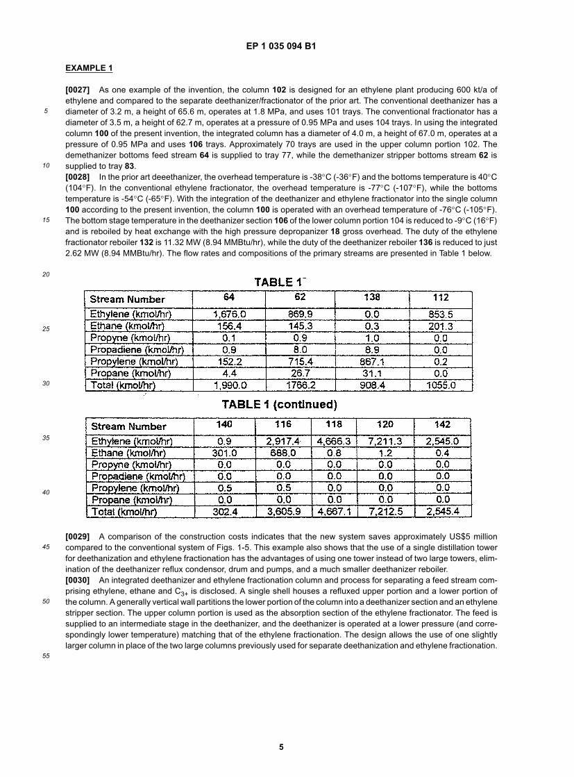
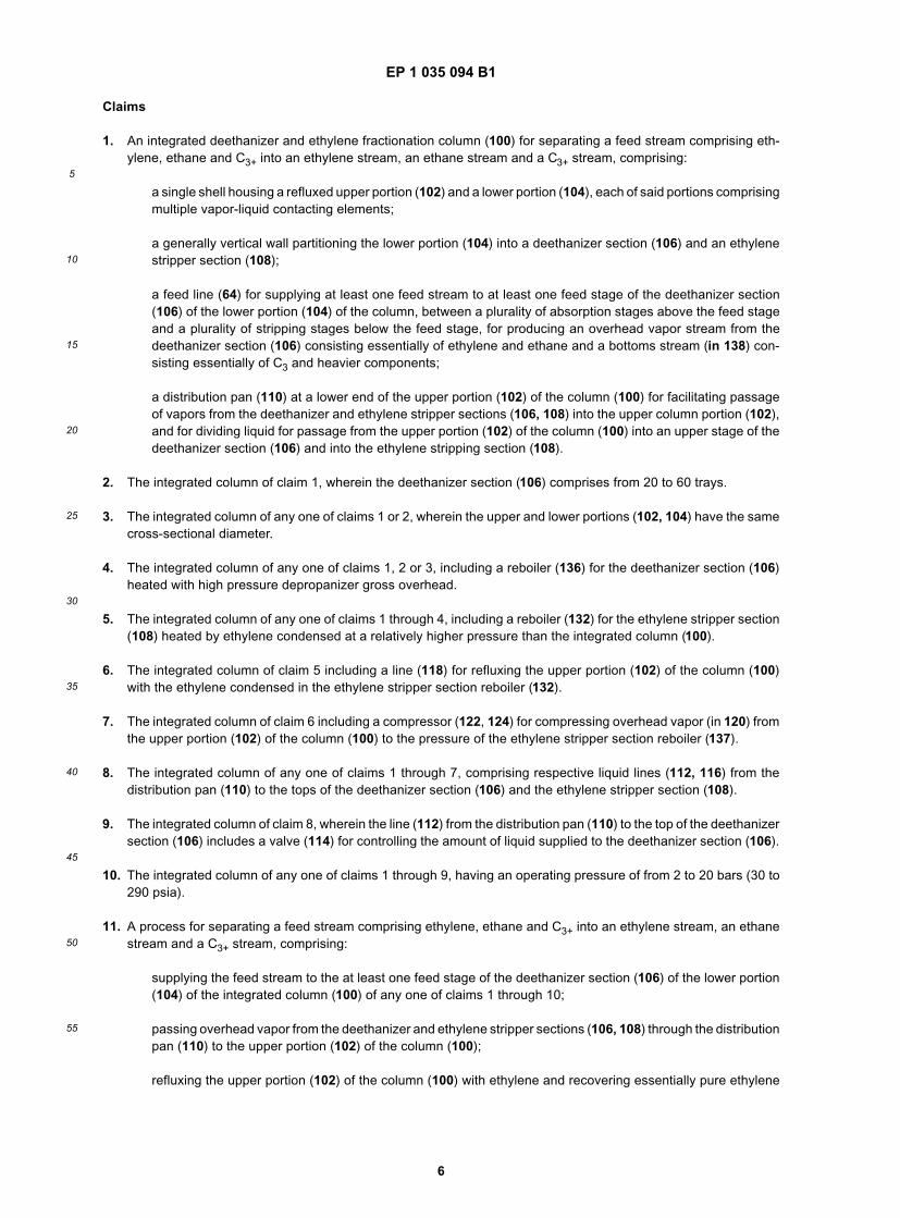
[0027] As one example of the invention, the column 102 is designed for an ethylene plant producing 600 kt/a ofethylene and compared to the separate deethanizer/fractionator of the prior art. The conventional deethanizer has adiameter of 3.2 m, a height of 65.6 m, operates at 1.8 MPa, and uses 101 trays. The conventional fractionator has adiameter of 3.5 m, a height of 62.7 m, operates at a pressure of 0.95 MPa and uses 104 trays. In using the integratedcolumn 100 of the present invention, the integrated column has a diameter of 4.0 m, a height of 67.0 m, operates at apressure of 0.95 MPa and uses 106 trays. Approximately 70 trays are used in the upper column portion 102. Thedemethanizer bottoms feed stream 64 is supplied to tray 77, while the demethanizer stripper bottoms stream 62 issupplied to tray 83.[0028] In the prior art deeethanizer, the overhead temperature is -38°C (-36°F) and the bottoms temperature is 40°C(104°F). In the conventional ethylene fractionator, the overhead temperature is -77°C (-107°F), while the bottomstemperature is -54°C (-65°F). With the integration of the deethanizer and ethylene fractionator into the single column100 according to the present invention, the column 100 is operated with an overhead temperature of -76°C (-105°F).The bottom stage temperature in the deethanizer section 106 of the lower column portion 104 is reduced to -9°C (16°F)and is reboiled by heat exchange with the high pressure depropanizer 18 gross overhead. The duty of the ethylenefractionator reboiler 132 is 11.32 MW (8.94 MMBtu/hr), while the duty of the deethanizer reboiler 136 is reduced to just2.62 MW (8.94 MMBtu/hr). The flow rates and compositions of the primary streams are presented in Table 1 below.
[0029] A comparison of the construction costs indicates that the new system saves approximately US$5 millioncompared to the conventional system of Figs. 1-5. This example also shows that the use of a single distillation towerfor deethanization and ethylene fractionation has the advantages of using one tower instead of two large towers, elim-ination of the deethanizer reflux condensor, drum and pumps, and a much smaller deethanizer reboiler.[0030] An integrated deethanizer and ethylene fractionation column and process for separating a feed stream com-prising ethylene, ethane and C3+ is disclosed. A single shell houses a refluxed upper portion and a lower portion ofthe column. A generally vertical wall partitions the lower portion of the column into a deethanizer section and an ethylenestripper section. The upper column portion is used as the absorption section of the ethylene fractionator. The feed issupplied to an intermediate stage in the deethanizer, and the deethanizer is operated at a lower pressure (and corre-spondingly lower temperature) matching that of the ethylene fractionation. The design allows the use of one slightlylarger column in place of the two large columns previously used for separate deethanization and ethylene fractionation.
EP 1 035 094 B1
5
10
15
20
25
30
35
40
45
50
55
6
Claims
1. An integrated deethanizer and ethylene fractionation column (100) for separating a feed stream comprising eth-ylene, ethane and C3+ into an ethylene stream, an ethane stream and a C3+ stream, comprising:
a single shell housing a refluxed upper portion (102) and a lower portion (104), each of said portions comprisingmultiple vapor-liquid contacting elements;
a generally vertical wall partitioning the lower portion (104) into a deethanizer section (106) and an ethylenestripper section (108);
a feed line (64) for supplying at least one feed stream to at least one feed stage of the deethanizer section(106) of the lower portion (104) of the column, between a plurality of absorption stages above the feed stageand a plurality of stripping stages below the feed stage, for producing an overhead vapor stream from thedeethanizer section (106) consisting essentially of ethylene and ethane and a bottoms stream (in 138) con-sisting essentially of C3 and heavier components;
a distribution pan (110) at a lower end of the upper portion (102) of the column (100) for facilitating passageof vapors from the deethanizer and ethylene stripper sections (106, 108) into the upper column portion (102),and for dividing liquid for passage from the upper portion (102) of the column (100) into an upper stage of thedeethanizer section (106) and into the ethylene stripping section (108).
2. The integrated column of claim 1, wherein the deethanizer section (106) comprises from 20 to 60 trays.
3. The integrated column of any one of claims 1 or 2, wherein the upper and lower portions (102, 104) have the samecross-sectional diameter.
4. The integrated column of any one of claims 1, 2 or 3, including a reboiler (136) for the deethanizer section (106)heated with high pressure depropanizer gross overhead.
5. The integrated column of any one of claims 1 through 4, including a reboiler (132) for the ethylene stripper section(108) heated by ethylene condensed at a relatively higher pressure than the integrated column (100).
6. The integrated column of claim 5 including a line (118) for refluxing the upper portion (102) of the column (100)with the ethylene condensed in the ethylene stripper section reboiler (132).
7. The integrated column of claim 6 including a compressor (122, 124) for compressing overhead vapor (in 120) fromthe upper portion (102) of the column (100) to the pressure of the ethylene stripper section reboiler (137).
8. The integrated column of any one of claims 1 through 7, comprising respective liquid lines (112, 116) from thedistribution pan (110) to the tops of the deethanizer section (106) and the ethylene stripper section (108).
9. The integrated column of claim 8, wherein the line (112) from the distribution pan (110) to the top of the deethanizersection (106) includes a valve (114) for controlling the amount of liquid supplied to the deethanizer section (106).
10. The integrated column of any one of claims 1 through 9, having an operating pressure of from 2 to 20 bars (30 to290 psia).
11. A process for separating a feed stream comprising ethylene, ethane and C3+ into an ethylene stream, an ethanestream and a C3+ stream, comprising:
supplying the feed stream to the at least one feed stage of the deethanizer section (106) of the lower portion(104) of the integrated column (100) of any one of claims 1 through 10;
passing overhead vapor from the deethanizer and ethylene stripper sections (106, 108) through the distributionpan (110) to the upper portion (102) of the column (100);
refluxing the upper portion (102) of the column (100) with ethylene and recovering essentially pure ethylene
EP 1 035 094 B1
5
10
15
20
25
30
35
40
45
50
55
7
overhead from the upper portion (102) of the column (100);
passing liquid from the distributor pan (110) into an upper stage of the deethanizer section (106) and into anupper stage of the ethylene stripper section (108);
reboiling the deethanizer section (106) and recovering a C3+ bottoms product stream (in 138) therefrom es-sentially free of ethane and ethylene;
reboiling the ethylene stripper section (108) and recovering an ethane bottoms product stream (in 140) there-form essentially free of ethylene and C3+.
12. The process of claim 11, wherein first and second feed streams from a demethanizer and a demethanizer stripperare fed to different intermediate feed stages in the deethanizer section (106).
13. The process of any one of claims 11 or 12, including controlling the amount of liquid feed to the upper stage of thedeethanizer section (106) from the distribution pan (110).
14. The process of any one of claims 11, 12, or 13, wherein the integrated column (100) is operated at a pressurefrom 2 to 20 bars (30 to 290 psia).
15. The process of any one of claims 11 through 14, wherein the deethanizer section (106) is reboiled with high pressuredepropanizer gross overhead.
16. The process of any one of claims 11 through 15, further comprising compressing the overhead ethylene (in 120)and condensing a portion of the compressed ethylene to supply heat for the reboiling of the ethylene strippersection (108).
17. The process of claim 16, wherein the condensed ethylene from the reboiling is used for the refluxing (in 118) ofthe upper portion (102) of the integrated column (100).
Patentansprüche
1. Integrierter Entethanisator und Ethylenfraktionierungskolonne (100) zum Auftrennen eines Einspeisungsstroms,der Ethylen, Ethan und C3+ enthält, in einen Ethylenstrom, einen Ethanstrom und einen C3+-Strom, umfassend:
einen Einzelmantel, der den refluxierten oberen Teil (102) und einen unteren Teil (104) umgibt, wobei jederder Teile mehrere Dampf-Flüssigkeit-Kontaktelemente umfasst;
eine im allgemeinen vertikale Wand, die den unteren Teil (104) in einen Entethanisatorabschnitt (106) undeinen Ethylenstripperabschnitt (108) einteilt;
eine Einspeisungsleitung (64) zum Zuführen mindestens eines Einspeisungsstroms in mindestens eine Ein-speisungsstufe des Entethanisatorabschnitts (106) des unteren Teils (104) der Kolonne, zwischen einer Viel-zahl von Absorptionsstufen über der Einspeisungsstufe und einer Vielzahl von Strippstufen unter der Einspei-sungsstufe, zum Erzeugen eines Überkopfdampfstromes aus dem Entethanisatorabschnitt (106), bestehendim wesentlichen aus Ethylen und Ethan, und eines Bodenstromes (in 138), bestehend im wesentlichen ausC3 und schwereren Komponenten;
Eine Verteilerwanne (110) an einem unteren Ende des oberen Teils (102) der Kolonne (100) zum Erleichterndes Durchgangs von Dämpfen aus den Entethanisator- und Ethylenstripperabschnitten (106, 108) in den obe-ren Kolonnenteil (102) und zum Abtrennen von Flüssigkeit zum Durchgang von dem oberen Teil (102) derKolonne (100) in eine obere Stufe des Entethanisatorabschnitts (106) und in den Ethylenstripperabschnitt(108).
2. Integrierte Kolonne nach Anspruch 1, worin der Entethanisatorabschnitt (106) von 20 bis 60 Böden umfasst.
3. Integrierte Kolonne nach einem der Ansprüche 1 oder 2, worin die oberen und unteren Teile (102, 104) den gleichen
EP 1 035 094 B1
5
10
15
20
25
30
35
40
45
50
55
8
Querschnittsdurchmesser aufweisen.
4. Integrierte Kolonne nach einem der Ansprüche 1, 2 oder 3, einschließlich eines Nachverdampfers (136) für denEntethanisatorabschnitt (106), der erhitzt wird mit Hochdruckentpropanisatorrohüberkopfprodukt.
5. Integrierte Kolonne nach einem der Ansprüche 1 bis 4, einschließlich eines Nachverdampfers (132) für den Ethy-lenstripperabschnitt (108), der erhitzt wird mit Ethylen, das bei einem relativ höheren Druck kondensiert ist als dieintegrierte Kolonne (100).
6. Integrierte Kolonne nach Anspruch 5, umfassend eine Leitung (118) zum Refluxieren des oberen Teils (102) derKolonne (100) mit dem Ethylen, das in dem Ethylenstripperabschnittnachverdampfer (132) kondensiert wird.
7. Integrierte Kolonne nach Anspruch 6, einschließlich eines Kompressors (122, 124) zum Komprimieren von Über-kopfdampf (in 120) aus dem oberen Teil (102) der Kolonne (100) auf den Druck des Ethylenstripperabschnittnach-verdampfers (137).
8. Integrierte Kolonne nach einem der Ansprüche 1 bis 7, umfassend entsprechende Flüssigkeitsleitungen (112, 116)aus der Verteilerwanne (110) zu den Oberseiten des Entethanisatorabschnitts (106) und des Ethylenstripperab-schnitts (108).
9. Integrierte Kolonne nach Anspruch 8, worin die Leitung (112) von der Verteilerwanne (110) zu der Oberseite desEntethanisatorabschnitts (106) ein Ventil (114) zur Steuerung der Flüssigkeitsmenge, die dem Entethanisatorab-schnitt (106) zugeführt wird, umfasst.
10. Integrierte Kolonne nach einem der Ansprüche 1 bis 9 mit einem Betriebsdruck von 2 bis 20 bar (30 bis 290 psia).
11. Verfahren zum Auftrennen eines Einspeisungsstroms, umfassend Ethylen, Ethan und C3+ in einen Ethylenstrom,einen Ethanstrom und einen C3+-Strom, umfassendZuführen des Einspeisungsstroms zu mindestens einer Einspeisungsstufe des Entethanisatorabschnitts (106) desunteren Teils (104) der integrierten Kolonne (100) nach einem der Ansprüche 1 bis 10;Durchleiten von Überkopfdampf aus den Entethanisator- und Ethylenstripperabschnitten (106, 108) über die Ver-teilerwane (110) zu dem oberen Teil (102) der Kolonne (100);Refluxieren des oberen Teils (102) der Kolonne (100) mit Ethylen und Gewinnen von im Wesentlichen reinemÜberkopfethylen aus dem oberen Teil (102) der Kolonne (100);Durchleiten von Flüssigkeit aus der Verteilerwanne (110) in eine obere Stufe des Entethanisatorabschnitts (106)und in eine obere Stufe des Ethylenstripperabschnitts (108);Nachverdampfen des Entethanisatorabschnitts (106) und Gewinnen eines C3+-Bodenproduktstromes (in 138) dar-aus, der im wesentlichen frei von Ethan und Ethylen ist;Nachverdampfen des Ethylenstripperabschnitts (108) und Gewinnen eines Ethanbodenproduktstromes (in 140)daraus, der im wesentlichen frei von Ethylen und C3+ ist.
12. Verfahren nach Anspruch 11, worin erste und zweite Einspeisungsströme aus einem Entmethanisator und einemEntmethanisatorstripper verschiedenen Zwischeneinspeisungsstufen in dem Entethanisatorabschnitt (106) zuge-führt werden.
13. Verfahren nach einem der Ansprüche 11 oder 12, einschließlich Steuern der Flüssigkeitsmenge, die einer oberenStufe des Entethanisatorabschnitts (106) aus der Verteilerwanne (110) zugeführt wird.
14. Verfahren nach einem der Ansprüche 11, 12 oder 13, worin die integrierte Kolonne (100) bei einem Druck von 2bis 20 bar (30 bis 290 psia) betrieben wird.
15. Verfahren nach einem der Ansprüche 11 bis 14, worin der Entethanisatorabschnitt (106) mit Hochdruckentpro-panisiererrohüberkopfprodukt nachverdampft wird.
16. Verfahren nach einem der Ansprüche 11 bis 15, weiterhin umfassend das Komprimieren des Überkopfethylens(in 120) und Kondensieren eines Teils des komprimierten Ethylens, um Hitze zum Nachverdampfen dem Ethylen-stripperabschnitt (108) zuzuführen.
EP 1 035 094 B1
5
10
15
20
25
30
35
40
45
50
55
9
17. Verfahren nach Anspruch 16, worin das kondensierte Ethylen aus dem Nachverdampfer zum Refluxieren (in 118)des oberen Teils (102) der integrierten Kolonne (100) verwendet wird.
Revendications
1. Colonne intégrée (100) de dééthanisation et de fractionnement d'éthylène servant à séparer un courant d'alimen-tation, comprenant de l'éthylène, de l'éthane et du C3+, en un courant d'éthylène, un courant d'éthane et un courantde C3+, comprenant :
une enveloppe unique contenant une partie supérieure (102) à reflux et une partie inférieure (104), chacunedesdites parties comportant de multiples éléments mettant en contact des vapeurs et liquides ;une cloison globalement verticale divisant la partie inférieure (104) en une zone de dééthanisation (106) etune zone de rectification (108) d'éthylène ;une conduite d'alimentation (64) pour fournir au moins un courant d'alimentation à au moins un étage d'ali-mentation de la zone de dééthanisation (106) de la partie inférieure (104) de la colonne, entre plusieurs étagesd'absorption au-dessus de l'étage d'alimentation et plusieurs étages de rectification sous l'étage d'alimenta-tion, pour produire depuis la zone de dééthanisation (106) un courant de vapeurs de tête essentiellementconstitué d'éthylène et d'éthane et un courant de bas de colonne (en 138) essentiellement composé de C3+etde fractions plus lourdes ;un plateau de distribution (110) à une extrémité inférieure de la partie supérieure (102) de la colonne (100)pour faciliter le passage de vapeurs depuis les zones de dééthanisation et de rectification d'éthylène (106,108) vers la partie supérieure (102) de la colonne, et pour diviser le liquide avant son passage de la partiesupérieure (102) de la colonne (100) à un étage supérieur de la zone de dééthanisation (106) et à la zone derectification (108) d'éthylène.
2. Colonne intégrée selon la revendication 1, dans laquelle la zone de dééthanisation (106) comporte de 20 à 60plateaux.
3. Colonne intégrée selon l'une quelconque des revendications 1 et 2, dans laquelle les parties supérieure et infé-rieure (102, 104) ont le même diamètre en section transversale.
4. Colonne intégrée selon l'une quelconque des revendications 1 à 3, comprenant un rebouilleur (136) pour la zonede dééthanisation (106) chauffée avec le distillat de tête brut d'un dépropaniseur à haute pression.
5. Colonne intégrée selon l'une quelconque des revendications 1 à 4, comprenant un rebouilleur (132) pour la zonede rectification (108) d'éthylène, chauffée par de l'éthylène condensé à une pression relativement supérieure àcelle de la colonne intégrée (100).
6. Colonne intégrée selon la revendication 5, comprenant une conduite (118) pour un reflux dans la partie supérieure(102) de la colonne (100) avec l'éthylène condensé dans le rebouilleur (132) de la zone de rectification d'éthylène.
7. Colonne intégrée selon la revendication 6, comprenant un compresseur (122, 124) pour comprimer les vapeursde tête (en 120) venant de la partie supérieure (102) de la colonne (100) à la pression du rebouilleur (137) de lazone de rectification d'éthylène.
8. Colonne intégrée selon l'une quelconque des revendications 1 à 7, comprenant des conduites respectives (112,116) de liquides entre le plateau de distribution (110) et les sommets de la zone de dééthanisation (106) et de lazone de rectification (108) d'éthylène.
9. Colonne intégrée selon la revendication 8, dans laquelle la conduite (112) entre le plateau de distribution (110) etle haut de la zone de dééthanisation (106) comporte une vanne (114) pour réguler la quantité de liquide fourni àla zone de dééthanisation (106).
10. Colonne intégrée selon l'une quelconque des revendications 1 à 9, ayant une pression de fonctionnement de 2 à20 bars (30 à 290 psia).
11. Procédé pour séparer un courant d'alimentation comprenant de l'éthylène, de l'éthane et du C3+ en un courant
EP 1 035 094 B1
5
10
15
20
25
30
35
40
45
50
55
10
d'éthylène, un courant d'éthane et un courant de C3+, comprenant les étapes consistant à :
envoyer le courant d'alimentation dans ledit au moins un étage d'alimentation de la zone de dééthanisation(106) de la partie inférieure (104) de la colonne intégrée (100) selon l'une quelconque des revendications 1à 10 ;faire passer les vapeurs de tête sortant des zones de dééthanisation et de rectification d'éthylène (106, 108)par le plateau de distribution (110) vers la partie supérieure (102) de la colonne (100) ;réaliser un reflux avec de l'éthylène dans la partie supérieure (102) de la colonne (100) et récupérer de l'éthy-lène de tête sensiblement pur à la sortie de la partie supérieure (102) de la colonne (100) ;faire passer un liquide depuis le plateau de distribution (110) vers un étage supérieur de la zone de déétha-nisation (106) et vers un étage supérieur de la zone de rectification d'éthylène (108) ;réaliser un rebouillage dans la zone de dééthanisation (106) et récupérer à la sortie de celle-ci un courant deproduit de bas de colonne composé de C3+ (en 138) sensiblement dépourvu d'éthane et d'éthylène ;réaliser un rebouillage dans la zone de rectification (108) d'éthylène et récupérer à la sortie de celle-ci uncourant de produit de fond constitué d'éthane (en 140) sensiblement exempt d'éthylène et de C3+.
12. Procédé selon la revendication 11, dans lequel les premier et deuxième courants d'alimentation issus d'un démé-thaniseur et d'un rectificateur de déméthanisation sont envoyés dans différents étages d'alimentation intermédiai-res de la zone de dééthanisation (106).
13. Procédé selon l'une quelconque des revendications 11 et 12, comprenant l'étape consistant à réguler la quantitéde liquide fourni à l'étage supérieur de la zone de dééthanisation (106) à partir du plateau de distribution (110).
14. Procédé selon l'une quelconque des revendications 11 à 13, dans lequel la colonne intégrée (100) fonctionne àune pression de 2 à 20 bars (30 à 290 psia).
15. Procédé selon l'une quelconque des revendications 11 à 14, dans lequel la zone de dééthanisation (106) estsoumise à un rebouillage avec le distillat de tête brut d'un dépropaniseur à haute pression.
16. Procédé selon l'une quelconque des revendications 11 à 15, comprenant en outre l'étape consistant à comprimerle distillat de tête constitué d'éthylène (en 120) et à condenser une partie de l'éthylène comprimé pour fournir dela chaleur pour le rebouillage de la zone de rectification d'éthylène (108).
17. Procédé selon la revendication 16, dans lequel l'éthylène condensé résultant du rebouillage est utilisé pour laréalisation du reflux (en 118) dans la partie supérieure (102) de la colonne intégrée (100).
EP 1 035 094 B1
11
EP 1 035 094 B1
12
EP 1 035 094 B1
13
EP 1 035 094 B1
14
EP 1 035 094 B1
15
EP 1 035 094 B1
16