instruction handbook b maxx 3000 - baumüller
TRANSCRIPT
Instruction handbook
Read the Instruction handbook before starting any work!
Language EnglishTranslation
Document No. 5.11018.16Part No. 441839Status 07-Jul-2021
E 5.11018.16
b maXX 3000
BM3200 / BM3300Compact Servo Unit
Copyright This Instruction handbook may be copied by the owner in any quantity, but only for internaluse. This Instruction handbook may not be copied or reproduced, in whole or in part, for anyother purposes.The use and disclosure of information contained in this Instruction handbook are not permit-ted.Designations and company marks contained in this Instruction handbook could be trade-marks, the use of which by third parties for their own purposes could violate the rights of therights holder.
Preliminary informationWarning Insofar as this document is identified as being preliminary information, the followingapplies:this version is regarded as providing advance technical information to users of the describeddevices and their functions at an early enough time in order to adapt to any possible changesor expanded functionality. This information must be regarded as being preliminary, as it has not yet passed throughBaumüller's internal review process. In particular, this information is still subject to changes,thus no legal liability can be derived from this preliminary information. Baumüller assumes noliability for damages that might arise from this possibly faulty or incomplete version. If you detect or suspect any content errors and/or major form errors in this preliminary infor-mation, we request that you notify the Baumüller support specialist responsible for you.Please provide us, via this employee, with your insights and comments so that we can takethem into account and include them when transitioning from the preliminary information tothe final information (as reviewed by Baumüller). The conditions stipulated in the following section under "Obligatory" are invalid in case of pre-liminary information.
Obligatory This Instruction handbook are a part of the equipment/machine. This Instruction handbookmust be available to the operator at all times and must be in legible condition. If the equip-ment/machine is sold or moved another location, this Instruction handbook must be passedon by the owner together with the equipment/machine.After any sale of the equipment/machine, this original and all copies must be handed over tothe buyer. After disposal or any other end use, this original and all copies must be destroyed.
When the present Instruction handbook is handed over, corresponding sets of Instructionhandbooks of a previous version are automatically invalidated. Please note that the specifications/data/information are current values according to theprinting date. These statements are not legally binding with regard to measurements,computation or calculations.Baumüller Nürnberg GmbH reserves the right, in developing its products further, to changethe technical specifications and handling of it products concerned without prior notice.
No liability can be accepted concerning the correctness of this Instruction handbook unlessotherwise specified in the General Conditions of Sale and Delivery.
Baumüller Nürnberg GmbH
Ostendstr. 80 - 9090482 NurembergGermany
Tel. +49 9 11 54 32 - 0 Fax: +49 9 11 54 32 - 1 30
Email : [email protected]: www.baumueller.com

Table of contents
1 General . . . . . . . . . . . . . . . . . . . . . . . . . . . . . . . . . . . . . . . . . . . . . . . . . . . . . . . . . . . . . . . . . . 7
1.1 Information on this Instruction handbook. . . . . . . . . . . . . . . . . . . . . . . . . . . . . . . . . . . . 71.2 Key to symbols . . . . . . . . . . . . . . . . . . . . . . . . . . . . . . . . . . . . . . . . . . . . . . . . . . . . . . . 71.3 Limitation of liability . . . . . . . . . . . . . . . . . . . . . . . . . . . . . . . . . . . . . . . . . . . . . . . . . . . . 81.4 Copyright protection. . . . . . . . . . . . . . . . . . . . . . . . . . . . . . . . . . . . . . . . . . . . . . . . . . . . 91.5 Applicable documents . . . . . . . . . . . . . . . . . . . . . . . . . . . . . . . . . . . . . . . . . . . . . . . . . . 91.6 Spare parts . . . . . . . . . . . . . . . . . . . . . . . . . . . . . . . . . . . . . . . . . . . . . . . . . . . . . . . . . 101.7 Disposal . . . . . . . . . . . . . . . . . . . . . . . . . . . . . . . . . . . . . . . . . . . . . . . . . . . . . . . . . . . . 101.8 Guarantee provisions. . . . . . . . . . . . . . . . . . . . . . . . . . . . . . . . . . . . . . . . . . . . . . . . . . 101.9 Customer service. . . . . . . . . . . . . . . . . . . . . . . . . . . . . . . . . . . . . . . . . . . . . . . . . . . . . 101.10 Terms used . . . . . . . . . . . . . . . . . . . . . . . . . . . . . . . . . . . . . . . . . . . . . . . . . . . . . . . . . 10
2 Safety . . . . . . . . . . . . . . . . . . . . . . . . . . . . . . . . . . . . . . . . . . . . . . . . . . . . . . . . . . . . . . . . . . 11
2.1 Contents of the Instruction handbook . . . . . . . . . . . . . . . . . . . . . . . . . . . . . . . . . . . . . 112.2 Changes and modifications to the device . . . . . . . . . . . . . . . . . . . . . . . . . . . . . . . . . . 112.3 Appropriate use . . . . . . . . . . . . . . . . . . . . . . . . . . . . . . . . . . . . . . . . . . . . . . . . . . . . . . 122.4 Risk assessment according EU Directive . . . . . . . . . . . . . . . . . . . . . . . . . . . . . . . . . . 132.5 Responsibility of the operating company . . . . . . . . . . . . . . . . . . . . . . . . . . . . . . . . . . . 152.6 Protective devices . . . . . . . . . . . . . . . . . . . . . . . . . . . . . . . . . . . . . . . . . . . . . . . . . . . . 152.7 Training of the personnel . . . . . . . . . . . . . . . . . . . . . . . . . . . . . . . . . . . . . . . . . . . . . . . 162.8 Personal protective equipment . . . . . . . . . . . . . . . . . . . . . . . . . . . . . . . . . . . . . . . . . . 172.9 Special hazards . . . . . . . . . . . . . . . . . . . . . . . . . . . . . . . . . . . . . . . . . . . . . . . . . . . . . . 182.10 Fire fighting . . . . . . . . . . . . . . . . . . . . . . . . . . . . . . . . . . . . . . . . . . . . . . . . . . . . . . . . . 192.11 Safety equipment. . . . . . . . . . . . . . . . . . . . . . . . . . . . . . . . . . . . . . . . . . . . . . . . . . . . . 202.12 Behavior in hazardous situations or at accidents . . . . . . . . . . . . . . . . . . . . . . . . . . . . 202.13 Signs and labels . . . . . . . . . . . . . . . . . . . . . . . . . . . . . . . . . . . . . . . . . . . . . . . . . . . . . 21
3 Technical Data . . . . . . . . . . . . . . . . . . . . . . . . . . . . . . . . . . . . . . . . . . . . . . . . . . . . . . . . . . . 25
3.1 Dimensions . . . . . . . . . . . . . . . . . . . . . . . . . . . . . . . . . . . . . . . . . . . . . . . . . . . . . . . . . 253.2 Weight . . . . . . . . . . . . . . . . . . . . . . . . . . . . . . . . . . . . . . . . . . . . . . . . . . . . . . . . . . . . . 263.3 Operating conditions . . . . . . . . . . . . . . . . . . . . . . . . . . . . . . . . . . . . . . . . . . . . . . . . . . 273.3.1 System types. . . . . . . . . . . . . . . . . . . . . . . . . . . . . . . . . . . . . . . . . . . . . . . . . . . . . . . 273.3.2 Requirements to the energy supply: power supply . . . . . . . . . . . . . . . . . . . . . . . . . . 283.3.3 Requirements to the control voltage / 24 V-supply . . . . . . . . . . . . . . . . . . . . . . . . . . 293.3.4 Requirements to the motor . . . . . . . . . . . . . . . . . . . . . . . . . . . . . . . . . . . . . . . . . . . . 293.3.5 Required environmental conditions . . . . . . . . . . . . . . . . . . . . . . . . . . . . . . . . . . . . . . 303.3.6 Correction factors at modified operational conditions . . . . . . . . . . . . . . . . . . . . . . . . 313.3.6.1 Installation altitude . . . . . . . . . . . . . . . . . . . . . . . . . . . . . . . . . . . . . . . . . . . . . . . . . . 313.3.6.2 Environmental temperature . . . . . . . . . . . . . . . . . . . . . . . . . . . . . . . . . . . . . . . . . . . 323.3.6.3 Supply voltage . . . . . . . . . . . . . . . . . . . . . . . . . . . . . . . . . . . . . . . . . . . . . . . . . . . . . 323.3.6.4 DC-link voltage . . . . . . . . . . . . . . . . . . . . . . . . . . . . . . . . . . . . . . . . . . . . . . . . . . . . 343.3.7 Cooling . . . . . . . . . . . . . . . . . . . . . . . . . . . . . . . . . . . . . . . . . . . . . . . . . . . . . . . . . . . 353.4 Electrical data . . . . . . . . . . . . . . . . . . . . . . . . . . . . . . . . . . . . . . . . . . . . . . . . . . . . . . . 363.4.1 Electrical data BM3X01-XT/BM3X11-XT. . . . . . . . . . . . . . . . . . . . . . . . . . . . . . . . . . 363.4.2 Electrical data BM3X02-XT, BM3X03-XT, BM3X04-XT, 400 V. . . . . . . . . . . . . . . . . 383.4.3 Electrical data BM3X12-XT, BM3X13-XT, 400 V . . . . . . . . . . . . . . . . . . . . . . . . . . . 403.4.4 Electrical data BM3XXX-XE, 230 V. . . . . . . . . . . . . . . . . . . . . . . . . . . . . . . . . . . . . . 423.4.5 Frequency-output-dependent current derating . . . . . . . . . . . . . . . . . . . . . . . . . . . . . 453.4.6 Load cycle according to EN61800-6 . . . . . . . . . . . . . . . . . . . . . . . . . . . . . . . . . . . . . 46
Instruction handbook b maXX BM3200, BM3300
Document no. 5.11018.15
3of 212
4of 212
Table of contents
4 Design and Function . . . . . . . . . . . . . . . . . . . . . . . . . . . . . . . . . . . . . . . . . . . . . . . . . . . . . . 49
4.1 Design . . . . . . . . . . . . . . . . . . . . . . . . . . . . . . . . . . . . . . . . . . . . . . . . . . . . . . . . . . . . . 504.2 Identification of the device . . . . . . . . . . . . . . . . . . . . . . . . . . . . . . . . . . . . . . . . . . . . . . 524.2.1 Part number BM3200, BM3300 . . . . . . . . . . . . . . . . . . . . . . . . . . . . . . . . . . . . . . . . . 524.2.2 Type plate . . . . . . . . . . . . . . . . . . . . . . . . . . . . . . . . . . . . . . . . . . . . . . . . . . . . . . . . . 534.2.3 Type code . . . . . . . . . . . . . . . . . . . . . . . . . . . . . . . . . . . . . . . . . . . . . . . . . . . . . . . . . 544.3 UL notes . . . . . . . . . . . . . . . . . . . . . . . . . . . . . . . . . . . . . . . . . . . . . . . . . . . . . . . . . . . . 564.4 Display and operating elements BM3200, BM3300 . . . . . . . . . . . . . . . . . . . . . . . . . . . 584.4.1 Function of the 7-segment display. . . . . . . . . . . . . . . . . . . . . . . . . . . . . . . . . . . . . . . 624.4.2 Function of the LEDs H11 to H14 . . . . . . . . . . . . . . . . . . . . . . . . . . . . . . . . . . . . . . . 634.4.3 Function of the LEDs H31/H32 and H41/H42 . . . . . . . . . . . . . . . . . . . . . . . . . . . . . . 644.4.4 Settings address switches . . . . . . . . . . . . . . . . . . . . . . . . . . . . . . . . . . . . . . . . . . . . . 66
5 Transport and Packaging . . . . . . . . . . . . . . . . . . . . . . . . . . . . . . . . . . . . . . . . . . . . . . . . . . 71
5.1 Safety notes for transport . . . . . . . . . . . . . . . . . . . . . . . . . . . . . . . . . . . . . . . . . . . . . . . 715.2 What to observe when transporting . . . . . . . . . . . . . . . . . . . . . . . . . . . . . . . . . . . . . . . 715.3 Transport inspection. . . . . . . . . . . . . . . . . . . . . . . . . . . . . . . . . . . . . . . . . . . . . . . . . . . 725.4 Unpacking . . . . . . . . . . . . . . . . . . . . . . . . . . . . . . . . . . . . . . . . . . . . . . . . . . . . . . . . . . 725.5 Disposal of the packaging . . . . . . . . . . . . . . . . . . . . . . . . . . . . . . . . . . . . . . . . . . . . . . 72
6 Mounting . . . . . . . . . . . . . . . . . . . . . . . . . . . . . . . . . . . . . . . . . . . . . . . . . . . . . . . . . . . . . . . . 73
6.1 Safety notes . . . . . . . . . . . . . . . . . . . . . . . . . . . . . . . . . . . . . . . . . . . . . . . . . . . . . . . . . 736.2 Preparing for mounting. . . . . . . . . . . . . . . . . . . . . . . . . . . . . . . . . . . . . . . . . . . . . . . . . 766.3 Drilling templates . . . . . . . . . . . . . . . . . . . . . . . . . . . . . . . . . . . . . . . . . . . . . . . . . . . . . 776.4 Mounting instruction BM3200, BM3300 . . . . . . . . . . . . . . . . . . . . . . . . . . . . . . . . . . . . 79
7 Installation . . . . . . . . . . . . . . . . . . . . . . . . . . . . . . . . . . . . . . . . . . . . . . . . . . . . . . . . . . . . . . 81
7.1 Safety notes . . . . . . . . . . . . . . . . . . . . . . . . . . . . . . . . . . . . . . . . . . . . . . . . . . . . . . . . . 817.2 Voltage test . . . . . . . . . . . . . . . . . . . . . . . . . . . . . . . . . . . . . . . . . . . . . . . . . . . . . . . . . 837.3 Demands on the electrical power supply . . . . . . . . . . . . . . . . . . . . . . . . . . . . . . . . . . . 847.4 Requirements for the connection cables . . . . . . . . . . . . . . . . . . . . . . . . . . . . . . . . . . . 847.5 Protection of the device and accordingly of the cable . . . . . . . . . . . . . . . . . . . . . . . . . 847.6 PE connection and RCD compatibility . . . . . . . . . . . . . . . . . . . . . . . . . . . . . . . . . . . . . 857.7 Installation requirements with regard to EMC stability . . . . . . . . . . . . . . . . . . . . . . . . . 857.8 Shielding plan. . . . . . . . . . . . . . . . . . . . . . . . . . . . . . . . . . . . . . . . . . . . . . . . . . . . . . . . 867.8.1 Shielding connection mounting plate . . . . . . . . . . . . . . . . . . . . . . . . . . . . . . . . . . . . . 877.8.2 Shielding connection with shield sheet . . . . . . . . . . . . . . . . . . . . . . . . . . . . . . . . . . . 877.8.2.1 Mounting shield sheet . . . . . . . . . . . . . . . . . . . . . . . . . . . . . . . . . . . . . . . . . . . . . . . 877.8.2.2 Connecting the shield. . . . . . . . . . . . . . . . . . . . . . . . . . . . . . . . . . . . . . . . . . . . . . . . 887.9 Requirements for the motor temperature sensors . . . . . . . . . . . . . . . . . . . . . . . . . . . . 917.10 Installation procedure BM3200, BM3300 . . . . . . . . . . . . . . . . . . . . . . . . . . . . . . . . . . . 927.11 Connecting diagrams . . . . . . . . . . . . . . . . . . . . . . . . . . . . . . . . . . . . . . . . . . . . . . . . . . 937.11.1 BM3XXX-XT as a compact servo unit (3-phase) . . . . . . . . . . . . . . . . . . . . . . . . . . . . 947.11.2 BM3XXX as an axis unit . . . . . . . . . . . . . . . . . . . . . . . . . . . . . . . . . . . . . . . . . . . . . . 977.11.3 BM3XXX-XT as a compact servo unit (single-phase) . . . . . . . . . . . . . . . . . . . . . . . 1027.11.4 BM3XXX-XE as compact servo unit (1-phase, 230 V). . . . . . . . . . . . . . . . . . . . . . . 1057.11.5 Application: Power supply connection (3-phase) with energy compensation . . . . . 1087.11.6 Application: DC link connection of further BM3XXX or of additional capacities. . . . 110
Instruction handbook b maXX BM3200, BM3300
Document no. 5.11018.15 Baumüller Nürnberg GmbH
Table of contents
7.12 Connections. . . . . . . . . . . . . . . . . . . . . . . . . . . . . . . . . . . . . . . . . . . . . . . . . . . . . . . . 1137.12.1 BM3200, BM3300 front side . . . . . . . . . . . . . . . . . . . . . . . . . . . . . . . . . . . . . . . . . . 1137.12.1.1 X1 - Service interface . . . . . . . . . . . . . . . . . . . . . . . . . . . . . . . . . . . . . . . . . . . . . . 1147.12.1.2 X2 - Digital inputs/outputs . . . . . . . . . . . . . . . . . . . . . . . . . . . . . . . . . . . . . . . . . . . 1157.12.1.3 X3 / X4 - fieldbus connection . . . . . . . . . . . . . . . . . . . . . . . . . . . . . . . . . . . . . . . . . 1167.12.1.4 X6 - analog inputs/outputs . . . . . . . . . . . . . . . . . . . . . . . . . . . . . . . . . . . . . . . . . . . 1207.12.1.5 X6 / X7 - encoder connection . . . . . . . . . . . . . . . . . . . . . . . . . . . . . . . . . . . . . . . . 1217.12.2 Connections BM3200, BM3300 on top . . . . . . . . . . . . . . . . . . . . . . . . . . . . . . . . . . 1277.12.2.1 X200 - 24V voltage supply. . . . . . . . . . . . . . . . . . . . . . . . . . . . . . . . . . . . . . . . . . . 1317.12.2.2 X202, X203, X205 - power supply, DC link, ballast resistor connection . . . . . . . . 1327.12.2.3 X300 - signal bus . . . . . . . . . . . . . . . . . . . . . . . . . . . . . . . . . . . . . . . . . . . . . . . . . . 1347.12.3 Connections BM3200, BM3300 at the bottom. . . . . . . . . . . . . . . . . . . . . . . . . . . . . 1367.12.3.1 X101 - motor temperature . . . . . . . . . . . . . . . . . . . . . . . . . . . . . . . . . . . . . . . . . . . 1377.12.3.2 X102 - safe torque off - option . . . . . . . . . . . . . . . . . . . . . . . . . . . . . . . . . . . . . . . . 1377.12.3.3 X107 - motor connection . . . . . . . . . . . . . . . . . . . . . . . . . . . . . . . . . . . . . . . . . . . . 1387.12.4 PE connections BM3200, BM3300 rear panel . . . . . . . . . . . . . . . . . . . . . . . . . . . . 139
8 Operation . . . . . . . . . . . . . . . . . . . . . . . . . . . . . . . . . . . . . . . . . . . . . . . . . . . . . . . . . . . . . . 141
8.1 Safety notes. . . . . . . . . . . . . . . . . . . . . . . . . . . . . . . . . . . . . . . . . . . . . . . . . . . . . . . . 1418.2 Operating concept . . . . . . . . . . . . . . . . . . . . . . . . . . . . . . . . . . . . . . . . . . . . . . . . . . . 1428.2.1 Enable signals . . . . . . . . . . . . . . . . . . . . . . . . . . . . . . . . . . . . . . . . . . . . . . . . . . . . . 1428.2.2 Monitoring . . . . . . . . . . . . . . . . . . . . . . . . . . . . . . . . . . . . . . . . . . . . . . . . . . . . . . . . 1428.2.3 Service interface . . . . . . . . . . . . . . . . . . . . . . . . . . . . . . . . . . . . . . . . . . . . . . . . . . . 1438.3 DC-link load / switch-on frequency of power supply . . . . . . . . . . . . . . . . . . . . . . . . . 1438.4 Optional safety function STO of BM3300 . . . . . . . . . . . . . . . . . . . . . . . . . . . . . . . . . 1448.4.1 Safety notes according STO function (Safe Torque Off). . . . . . . . . . . . . . . . . . . . . 1448.4.2 Safety levels and safety notes. . . . . . . . . . . . . . . . . . . . . . . . . . . . . . . . . . . . . . . . . 1458.4.3 Function. . . . . . . . . . . . . . . . . . . . . . . . . . . . . . . . . . . . . . . . . . . . . . . . . . . . . . . . . . 1468.4.4 Timing . . . . . . . . . . . . . . . . . . . . . . . . . . . . . . . . . . . . . . . . . . . . . . . . . . . . . . . . . . . 1478.4.5 Supply with separate power supplies . . . . . . . . . . . . . . . . . . . . . . . . . . . . . . . . . . . 1478.4.6 Examples for input wiring . . . . . . . . . . . . . . . . . . . . . . . . . . . . . . . . . . . . . . . . . . . . 1488.5 Fieldbus communication . . . . . . . . . . . . . . . . . . . . . . . . . . . . . . . . . . . . . . . . . . . . . . 1518.5.1 EtherCAT®. . . . . . . . . . . . . . . . . . . . . . . . . . . . . . . . . . . . . . . . . . . . . . . . . . . . . . . . 1518.5.2 VARAN. . . . . . . . . . . . . . . . . . . . . . . . . . . . . . . . . . . . . . . . . . . . . . . . . . . . . . . . . . . 1538.5.3 CANopen®. . . . . . . . . . . . . . . . . . . . . . . . . . . . . . . . . . . . . . . . . . . . . . . . . . . . . . . . 1558.5.4 POWERLINK®. . . . . . . . . . . . . . . . . . . . . . . . . . . . . . . . . . . . . . . . . . . . . . . . . . . . . 157
9 Maintenance . . . . . . . . . . . . . . . . . . . . . . . . . . . . . . . . . . . . . . . . . . . . . . . . . . . . . . . . . . . . 159
9.1 Safety notes. . . . . . . . . . . . . . . . . . . . . . . . . . . . . . . . . . . . . . . . . . . . . . . . . . . . . . . . 1599.2 Environmental conditions. . . . . . . . . . . . . . . . . . . . . . . . . . . . . . . . . . . . . . . . . . . . . . 1599.3 Inspection intervals - maintenance notes . . . . . . . . . . . . . . . . . . . . . . . . . . . . . . . . . 1609.3.1 Periodic maintenance . . . . . . . . . . . . . . . . . . . . . . . . . . . . . . . . . . . . . . . . . . . . . . . 1619.4 Repairs . . . . . . . . . . . . . . . . . . . . . . . . . . . . . . . . . . . . . . . . . . . . . . . . . . . . . . . . . . . 164
10 Troubleshooting and Fault Correction. . . . . . . . . . . . . . . . . . . . . . . . . . . . . . . . . . . . . . . 165
10.1 Behavior in case of malfunctions . . . . . . . . . . . . . . . . . . . . . . . . . . . . . . . . . . . . . . . . 16510.2 Monitoring functions. . . . . . . . . . . . . . . . . . . . . . . . . . . . . . . . . . . . . . . . . . . . . . . . . . 16610.2.1 Monitoring functions . . . . . . . . . . . . . . . . . . . . . . . . . . . . . . . . . . . . . . . . . . . . . . . . 16710.3 Error detection . . . . . . . . . . . . . . . . . . . . . . . . . . . . . . . . . . . . . . . . . . . . . . . . . . . . . . 16910.4 Troubleshooting/error acknowledge . . . . . . . . . . . . . . . . . . . . . . . . . . . . . . . . . . . . . 169
Instruction handbook b maXX BM3200, BM3300
Document no. 5.11018.15
5of 212
6of 212
Table of contents
11 Accessories and Spare Parts . . . . . . . . . . . . . . . . . . . . . . . . . . . . . . . . . . . . . . . . . . . . . . 171
11.1 Cables . . . . . . . . . . . . . . . . . . . . . . . . . . . . . . . . . . . . . . . . . . . . . . . . . . . . . . . . . . . . 17111.1.1 Cable power supply-device . . . . . . . . . . . . . . . . . . . . . . . . . . . . . . . . . . . . . . . . . . . 17111.1.2 Cable device-motor . . . . . . . . . . . . . . . . . . . . . . . . . . . . . . . . . . . . . . . . . . . . . . . . . 17111.1.3 Hybrid cable device-encoder-motor . . . . . . . . . . . . . . . . . . . . . . . . . . . . . . . . . . . . . 17211.1.4 Cable DC-link. . . . . . . . . . . . . . . . . . . . . . . . . . . . . . . . . . . . . . . . . . . . . . . . . . . . . . 17411.1.5 Cable control power supply / signals . . . . . . . . . . . . . . . . . . . . . . . . . . . . . . . . . . . . 17411.1.6 Cable signal bus . . . . . . . . . . . . . . . . . . . . . . . . . . . . . . . . . . . . . . . . . . . . . . . . . . . 17511.1.7 Cables - EtherCAT®, VARAN, POWERLINK® . . . . . . . . . . . . . . . . . . . . . . . . . . . . 17511.1.8 Accessories - CANopen®. . . . . . . . . . . . . . . . . . . . . . . . . . . . . . . . . . . . . . . . . . . . . 17611.1.9 Cable service interface . . . . . . . . . . . . . . . . . . . . . . . . . . . . . . . . . . . . . . . . . . . . . . 17611.1.10 Encoder cables . . . . . . . . . . . . . . . . . . . . . . . . . . . . . . . . . . . . . . . . . . . . . . . . . . . . 17711.1.10.1 Connecting cable for Resolver . . . . . . . . . . . . . . . . . . . . . . . . . . . . . . . . . . . . . . . . 17911.1.10.2 Connecting cable for encoder with HIPERFACE® . . . . . . . . . . . . . . . . . . . . . . . . . 18011.1.10.3 Connecting cable for encoder with EnDat® or SSI. . . . . . . . . . . . . . . . . . . . . . . . . 18111.1.10.4 Connecting cable for encoder with EnDat® 2.2 . . . . . . . . . . . . . . . . . . . . . . . . . . . 18211.1.10.5 Connecting cable for sine/square-wave incremental encoder . . . . . . . . . . . . . . . . 18411.2 Fuses . . . . . . . . . . . . . . . . . . . . . . . . . . . . . . . . . . . . . . . . . . . . . . . . . . . . . . . . . . . . . 18511.2.1 Cable protection. . . . . . . . . . . . . . . . . . . . . . . . . . . . . . . . . . . . . . . . . . . . . . . . . . . . 18511.2.2 Device protection . . . . . . . . . . . . . . . . . . . . . . . . . . . . . . . . . . . . . . . . . . . . . . . . . . . 18511.2.3 Cable protection and device protection . . . . . . . . . . . . . . . . . . . . . . . . . . . . . . . . . . 18611.3 Line filter. . . . . . . . . . . . . . . . . . . . . . . . . . . . . . . . . . . . . . . . . . . . . . . . . . . . . . . . . . . 18711.3.1 Required environmental conditions line filter . . . . . . . . . . . . . . . . . . . . . . . . . . . . . . 18711.3.2 Line filter for 3-phase devices BM3XXX-XTXX . . . . . . . . . . . . . . . . . . . . . . . . . . . . 18711.3.3 Line filter for 1-phase devices BM3XXX-XEXX . . . . . . . . . . . . . . . . . . . . . . . . . . . . 18911.4 Spare parts. . . . . . . . . . . . . . . . . . . . . . . . . . . . . . . . . . . . . . . . . . . . . . . . . . . . . . . . . 19011.4.1 Connectors BM3200, BM3300. . . . . . . . . . . . . . . . . . . . . . . . . . . . . . . . . . . . . . . . . 19011.4.2 Accessories kit shielding BM3200, BM3300 . . . . . . . . . . . . . . . . . . . . . . . . . . . . . . 191
12 Shutdown, Storage. . . . . . . . . . . . . . . . . . . . . . . . . . . . . . . . . . . . . . . . . . . . . . . . . . . . . . . 193
12.1 Safety instructions . . . . . . . . . . . . . . . . . . . . . . . . . . . . . . . . . . . . . . . . . . . . . . . . . . . 19312.2 Requirements to the executing personnel . . . . . . . . . . . . . . . . . . . . . . . . . . . . . . . . . 19412.3 Shutdown . . . . . . . . . . . . . . . . . . . . . . . . . . . . . . . . . . . . . . . . . . . . . . . . . . . . . . . . . . 19412.4 Demounting . . . . . . . . . . . . . . . . . . . . . . . . . . . . . . . . . . . . . . . . . . . . . . . . . . . . . . . . 19412.5 Storage conditions . . . . . . . . . . . . . . . . . . . . . . . . . . . . . . . . . . . . . . . . . . . . . . . . . . . 19512.6 Recommissioning . . . . . . . . . . . . . . . . . . . . . . . . . . . . . . . . . . . . . . . . . . . . . . . . . . . . 196
13 Disposal. . . . . . . . . . . . . . . . . . . . . . . . . . . . . . . . . . . . . . . . . . . . . . . . . . . . . . . . . . . . . . . . 197
13.1 Safety regulations. . . . . . . . . . . . . . . . . . . . . . . . . . . . . . . . . . . . . . . . . . . . . . . . . . . . 19713.2 Disposal facilities/authorities . . . . . . . . . . . . . . . . . . . . . . . . . . . . . . . . . . . . . . . . . . . 199
Appendix A - Abbreviations. . . . . . . . . . . . . . . . . . . . . . . . . . . . . . . . . . . . . . . . . . . . . . . . . . . . 201
Appendix B - Information according EU Eco-Design Directive 2019/1781 . . . . . . . . . . . . . . 203
Appendix C - Declaration of Conformity . . . . . . . . . . . . . . . . . . . . . . . . . . . . . . . . . . . . . . . . . 205
Table of figures . . . . . . . . . . . . . . . . . . . . . . . . . . . . . . . . . . . . . . . . . . . . . . . . . . . . . . . . . . . . . 209
Overview of Revisions . . . . . . . . . . . . . . . . . . . . . . . . . . . . . . . . . . . . . . . . . . . . . . . . . . . . . . . 211
Instruction handbook b maXX BM3200, BM3300
Document no. 5.11018.15 Baumüller Nürnberg GmbH
1GENERAL
1.1 Information on this Instruction handbook
This Instruction handbook provides important information on handling the device. A pre-requisite for safe work is compliance with all specified safety notes and procedural in-structions.
Additionally, the valid accident prevention regulations and general safety regulations ap-plicable to the scope of application the device must be complied with.
Read this Instruction handbook, particularly the safety notes chapter, completely beforebeginning any work on the device. This Instruction handbook is part of the product andmust be kept accessible to personnel at all times in the immediate vicinity of the device.
1.2 Key to symbols
Warning notes
Warning notes are identified by symbols in this Instruction handbook. The notes are in-troduced by signal words that express the extent of the danger.
It is imperative that these notes be complied with and are conscientiously regarded in or-der to prevent accidents, personal injury and material damage.
DANGER!
....points out a directly dangerous situation, that will lead to severe injuries or death,if not avoided.
WARNING!
....points out a potentially dangerous situation, that could lead to severe injuries ordeath, if not avoided.
7of 212
Instruction handbook b maXX BM3200, BM3300
Document no. 5.11018.15
Limitation of liability1.3
Recommen-dations
1.3 Limitation of liability
All specifications and notes in this Instruction handbook were compiled taking into ac-count the applicable standards and regulations, the state of the art and our knowledgeand experience of many years.
The manufacturer assumes no liability for damages due to:
m noncompliance with the Instruction handbook
m usage for other than the intended purpose
m usage by untrained personnel
The actual scope of delivery can vary in case of optional equipment, laying claim to addi-tional order options, or on account of the latest technical changes to the explanations andrepresentations described herein.
The user bears the responsibility for performing service and commissioning in accor-dance with the safety regulations of the applicable standards and all other relevant gov-ernmental or local regulations referring to the dimensioning and protection of conductors,grounding, disconnectors, overcurrent protection, etc.
The person who carried out the mounting or installation is liable for any damage, whichincurred when assembling or connecting the device.
CAUTION!
....points out a potentially dangerous situation, that can lead to minor or slight injuries,if not avoided.
NOTICE!
....points out a potentially dangerous situation, that can lead to material damage, ifnot avoided.
NOTE!
....highlights useful hints and recommendations, as well as information for the effi-cient and trouble-free use.
Instruction handbook b maXX BM3200, BM3300
Document no. 5.11018.15 Baumüller Nürnberg GmbH
8of 212
General 1
1.4 Copyright protectionThe Instruction handbook must be treated confidentially. It is to be used exclusively bypersonnel who work with the device. The consignment of the Instruction handbook to thirdpersons without the written permission of the manufacturer is prohibited.
1.5 Applicable documents
Components of other manufacturers are integrated into the device. For these purchasedparts, hazard assessments have been performed by the respective manufacturers. Thecompliance of the design construction with the applicable European and national regula-tions has been declared for the components by the respective manufacturers.
NOTE!
The specific contents, text, drawings, images and other representations are copy-righted and subject to industrial property rights. Any prohibited usage is punishableby law.
CANopen® is a registered trademark of CAN in Automation e. V.
EnDat® is a registered trademark of Dr. Johannes Heidenhain GmbH,83301 Traunreut, Germany
EtherCAT® is a registered trademark of Beckhoff Automation GmbH, 33415 Verl, Germany
HIPERFACE®
HIPERFACE DSL®is a registered trademark of SICK STEGMANN GmbH, 78166 Donaueschingen, Germany
PROFINET is a registered trademark of PROFIBUS International
speedtec® is a registered trademark of INTERCONTEC Produkt GmbH 94559 Niederwinkling, Germany
NOTE!
Please note, that BAUMÜLLER is not responsible to examine whether any (industrialproperty) rights of third parties are infringed by the application-specific use of theBAUMÜLLER products/components or the execution.
Instruction handbook b maXX BM3200, BM3300
Document no. 5.11018.15
9of 212
Spare parts1.6
1.6 Spare parts
Procure spare parts through an authorized dealer or directly from the manufacturer.
Refer to ZAccessories and Spare Parts– as from page 171.
1.7 Disposal
Insofar as no take-back or disposal agreement has been made, please disassemble unitscorrectly and properly recycle the constituent parts.
Refer to ZDisposal– on page 197.
1.8 Guarantee provisions
The guarantee provisions are stated in a separate document of the sales documents.
The devices described herein may only be operated in accordance with the stipulatedmethods, procedures and conditions. Anything else not presented here, including the op-eration of devices in mounted positions, is not permitted and must be cleared with theplant on a case-by-case basis. If the devices are operated in any other manner than asdescribed within this Instruction handbook, then all guarantee and warranty rights are ren-dered null and void.
1.9 Customer service
Our customer service is available to provide you with technical information.
Info on the responsible contact persons is available at all times via telephone, fax, mail orthe Internet.
1.10 Terms used
The term „device“ or the item designation BM3XXX are also used in this documentationfor this Baumüller product „BM3200, BM3300“. A list of the abbreviations used can befound in ZAppendix A - Abbreviations– from page 201.
WARNING!
False or flawed spare parts can lead to damage, malfunction or complete fail-ure, thus endangering safety.
Therefore:
m Only use original spare parts of the manufacturer.
Instruction handbook b maXX BM3200, BM3300
Document no. 5.11018.15 Baumüller Nürnberg GmbH
10of 212
2SAFETY
This section provides an overview of all of the important safety aspects for optimum pro-tection of personnel as well as for the safe and problem-free operation.
2.1 Contents of the Instruction handbook
Each person who is tasked with performing work on or with the device must have readand understood the Instruction handbook before working with the device. This also ap-plies if the person involved with this kind of device or a similar one, or has been trainedby the manufacturer.
2.2 Changes and modifications to the device
In order to prevent hazards and to ensure optimum performance, no changes, additionsor modifications may be undertaken on the device that have not been explicitly approvedby the manufacturer.
11of 212
Instruction handbook b maXX BM3200, BM3300
Document no. 5.11018.15
Appropriate use2.3
2.3 Appropriate use
The device is conceived and constructed exclusively for usage compliant with its intendedpurpose described in this Instruction handbook.
The devices of the model series BM3200, BM3300 contains of a power converter in com-bination with a servo controller. Devices are available in graduated design size and per-formance classes. The device BM3200, BM3300 is used exclusively as a converter forcontrolling a motor.
A device is considered as being used compliant with its intended purpose if all notes andinformation of this Instruction handbook are adhered to.
WARNING!
Danger arising from usage for an unintended purpose!
Any usage that goes beyond the intended purpose and/or any non-compliant use ofthe device can lead to dangerous situations.
Therefore:
m Only use the device compliant with its intended purpose.
m Observe all specifications of this Instruction handbook.
m Ensure that only qualified personnel work with/on this device.
m When configuring, ensure that the device is always operated within its specifica-tions.
m Mount the device on a wall, which is sustainable.
m The device must always be operated within a control cabinet.
m Ensure that the power supply complies with the stipulated specifications.
m The device may only be operated in a technically flawless condition.
m Only operate the device in combination with components approved by BaumüllerNürnberg GmbH.
m Only operate the devices in secondary surrounding (e.g. an industrial environ-ment). The device has been developed in such a manner that it fulfills the require-ments of the category C3 according to IEC 61800-3:2012. The device is notintended to be connected to the public power supply. To operate the device in pri-mary surrounding of the category C2/C1 (residential, business and commercial ar-eas, directly on a public low-voltage power supply without an intermediatetransformer), special measures to reduce the transient emissions (line-internal andradiated) must be provided for and certifiable by the system builder. Otherwise,EMC interference could occur without such additional measures. Whether a devicedescribed here can itself qualify for category C2/C1 with additional measures can-not be guaranteed.
Instruction handbook b maXX BM3200, BM3300
Document no. 5.11018.15 Baumüller Nürnberg GmbH
12of 212
Safety 2
2.4 Risk assessment according EU DirectiveEarth current Check the quality of the earth connection: - before connecting the device to the power supply for the first time and - within the recommended service intervals
Requirements:
m Cross section of the grounding cable according EN 61800-5-1
m Note the required torque of connection!
m Grounded mounting plate made of metal
m Mains filter, device and shielding of the motor cable are on the same HF potential
Stored electric charge
Do not touch electrically live parts before the discharge time of 15 min runs up, checkzero-potential before touching.
Electromagnetic fields
The device causes electromagnetic fields when operating.
Any person with individual device for cardiac assistance (pacemaker, defibrillator) muststay in sufficient distance to the operating device.
Burn injuries Please note that the surface of the device can heat up considerably.
m Wear safety gloves!
Radiated emission The high-frequency electromagnetic fields within the operation environment must not ex-ceed the field strength of the second environment according EN 61800-3.
Internal or external ignition source
Internal or external ignition sources are not allowed within the environment of the devices!
m Use ABC powder for extinguishing a fire!
Gas Toxic fumes can be released in case of failure.
No flammable fume or dust and no flammable/explosive gases are permitted within theenvironment of the devices!
In order to avoid damage to persons because of explosions:
m ventilate the area and
m immediate evacuation.
Transportation and mounting
Falling down of the device can cause damage to persons.
Note the weight of the device when selecting the mounting screws!
Select the fastening torques of the mounting screws according the specification of thescrew manufacturer!
m Wear safety helmets/shoes!
Instruction handbook b maXX BM3200, BM3300
Document no. 5.11018.15
13of 212
Risk assessment according EU Directive2.4
Mounting Unprotected hands can be injured at the sharp edges of the device.
m Wear safety gloves!
Unprotected eyes can be injured by thrown up metal particles caused by drilling or makingcut-outs.
m Wear safety glasses!
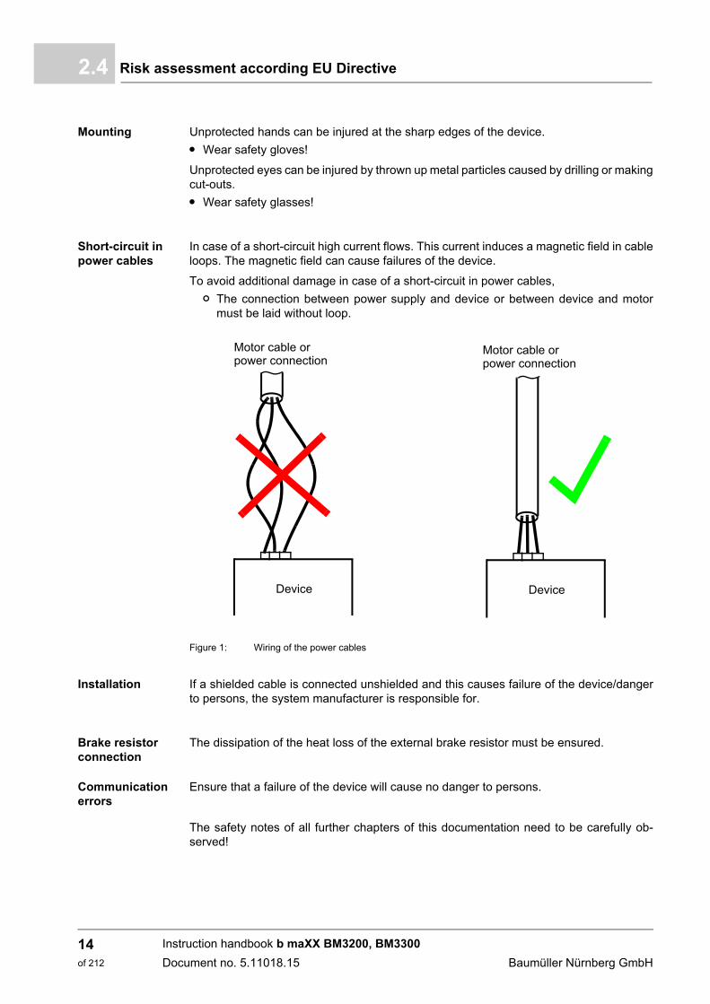
Short-circuit in power cables
In case of a short-circuit high current flows. This current induces a magnetic field in cableloops. The magnetic field can cause failures of the device.
To avoid additional damage in case of a short-circuit in power cables,
n The connection between power supply and device or between device and motormust be laid without loop.
Figure 1: Wiring of the power cables
Installation If a shielded cable is connected unshielded and this causes failure of the device/dangerto persons, the system manufacturer is responsible for.
Brake resistor connection
The dissipation of the heat loss of the external brake resistor must be ensured.
Communication errors
Ensure that a failure of the device will cause no danger to persons.
The safety notes of all further chapters of this documentation need to be carefully ob-served!
Device
Motor cable or
Device
power connectionMotor cable orpower connection
Instruction handbook b maXX BM3200, BM3300
Document no. 5.11018.15 Baumüller Nürnberg GmbH
14of 212

Safety 2
2.5 Responsibility of the operating companyThe device will be used in commercial areas. Thus, the proprietor of the device is subjectto the legal work safety regulations.
Along with the notes on work safety in this Instruction handbook, the safety, accident pre-vention and environmental protection regulations valid for the area of application of thisdevice must be complied with. Whereby:
m The operating company must inform himself about the applicable work health and safe-ty regulations and ascertain, in a hazard assessment, any additional hazards that couldarise from the special working conditions in the use area of the device. These mustthen be implemented in the form of operating instruction for operation of the device.
m This Instruction handbook must be kept accessible to personnel working with the de-vice at all times in the immediate vicinity of the device.
m The specifications of the Instruction handbook must be adhered to completely andwithout exception.
m The device may only be operated in a technically faultless and operationally safe con-dition.
2.6 Protective devices
All devices BM3200, BM3300 must be installed in an appropriate control cabinet to meetthe IP code required in EN 61800-5-1, chapter 4.2.3.3 (BM3200, BM3300: IP 30: only up-per horizontal surfaces; IP 20: all other surfaces).
IP code
Compact servo unitBM320X, BM330X, BM321X, BM331X
IP 20
DANGER!
Risk of fatal injury from electrical current!
There is an immediate risk of fatal injury if live electrical parts are contacted.
Therefore:
m The devices BM3200, BM3300 must be in operated inside of a control cabinet thatprovides protection against direct contact of the devices and at least meets the re-quirements of EN 61800-5-1, Chapter 4.2.3.3.
m Fault protection according EN 60204-1:2018, section 6.3 is fulfilled by measuresof preventing touch voltages.
Instruction handbook b maXX BM3200, BM3300
Document no. 5.11018.15
15of 212
Training of the personnel2.7
2.7 Training of the personnel
In this Instruction handbook, the following qualifications are stipulated for various areasof activity:
m Operating personnel
n The drive system may only be operated by persons who have been specially trained,familiarized and authorized.
n Troubleshooting, maintenance, cleaning, maintenance and replacement may onlybe performed by trained or familiarized personnel. These persons must be familiarwith the Instruction handbook and act accordingly.
n Initial operation and training may only be performed by qualified personnel.
m Qualified personnel
n Electrical engineers authorized by Baumüller Nürnberg GmbH, and qualified electri-cians of the customer or a third party who have learned to install and maintainBaumüller drive systems and are authorized to ground and identify electrical powercircuits and devices in accordance with the safety engineering standards of the com-pany.
n Qualified personnel have had occupational training or instruction in accordance withthe respective locally applicable safety engineering standards for the upkeep anduse of appropriate safety equipment.
WARNING!
Risk of injury due to insufficient qualifications!
Improper handling can lead to significant personal injury and material damage.
Therefore:
m Certain activities can only be performed by the persons stated in the respectivechapters of this Instruction handbook.
Instruction handbook b maXX BM3200, BM3300
Document no. 5.11018.15 Baumüller Nürnberg GmbH
16of 212

Safety 2
2.8 Personal protective equipmentThe wearing of personal protective equipment is required when working in order to mini-mize health and safety risks.
m The protective equipment necessary for each respective type of work shall always beworn during work.
m The personal safety signs present in each working area must be observed.
Wear for special work.
Protective work clothing
should be snug-fitting work clothes, with low tearing resistance, narrow sleeves andwith no extending parts. When having longer hair use a safety hair net.
No rings or chains should be worn.
Hard hat
to protect against parts falling down and against parts, which are flying around.
Safety shoes
to protect against heavy objects falling down.
Safety gloves
to protect hands against friction, abrasion, puncturing or more severe injuries, as wellas against the contact with hot objects.
Safety goggles
to protect the eyes against objects, which are flying around and against splashes.
Instruction handbook b maXX BM3200, BM3300
Document no. 5.11018.15
17of 212
Special hazards2.9
2.9 Special hazards
In the following section, the remaining marginal risks will be stated that have been iden-tified as a result of the hazard analysis.
Observe the safety notes listed here and the warning notes in the further chapters of thismanual to reduce health risks and dangerous situations.
Electrical current
Danger from residual energy
DANGER!
Risk of fatal injury from electrical current!
There is an immediate risk of fatal injury if live electrical parts are contacted. Damageto the insulation or individual components can be life-threatening.
Therefore:
m Switch off the electrical power immediately in case of damage to the power supplyinsulation.
m Only allow work on the electrical system to be performed by qualified personnel.
m Switch off the current when any kind of work is being performed on the electricalsystem and ensure safety before switching on again.
DANGER!
Risk of fatal injury from electrical current!
Stored electric charge.
Discharge time of the rack system = discharge time of the device with the longest DClink discharge time in the rack system.
Refer to ZElectrical data– from page 36.
Therefore:
m Do not touch electrically live parts before taking into account the discharge time ofthe capacitors.
m Pay attention to the corresponding notes on the device.
m If several devices are connected e.g. with a rectifier unit, the DC link discharge cantake a much longer time. In this case, the necessary waiting period must itself bedetermined or a measurement made to ensure the device is de-energized. Thisdischarge time must be posted, together with an IEC 60417-5036 (2002-10) warn-ing symbol, on a clearly visible location of the control cabinet.
Instruction handbook b maXX BM3200, BM3300
Document no. 5.11018.15 Baumüller Nürnberg GmbH
18of 212
Safety 2
Moving compo-nents2.10 Fire fighting
WARNING!
Risk of injury from moving components!
Rotating components and/or components moving linearly can result in severe injury.
Therefore:
m Do not touch moving components during operation.
m Do not open any covering during operation.
m The amount of residual mechanical energy depends on the application. Poweredcomponents still turn/move for a certain length of time even after the power supplyhas been switched off. Ensure that adequate safety measures are taken.
DANGER!
Risk of fatal injury from electrical current!
There is a risk of electric shock if an electrically-conductive, fire-extinguishing agentis used.
Therefore:
m Use the following fire-extinguishing agent:
ABC powder / CO2
Instruction handbook b maXX BM3200, BM3300
Document no. 5.11018.15
19of 212
Safety equipment2.11
2.11 Safety equipment
2.12 Behavior in hazardous situations or at accidents
Preventive measures
m Always be prepared for accidents or fire!
m Keep first-aid equipment (e.g. first-aid kits, blankets, etc.) and fire extinguishers readilyaccessible.
m Familiarize personnel with accident signalling systems, first aid equipment and life sav-ing equipment.
And if something does happen: respond properly
m Stop operation of the device immediately with an EMERGENCY Stop.
m Initiate first aid measures.
m Evacuate persons from the danger zone.
m Notify the responsible persons of the site.
m Alarm medical personnel and/or the fire department.
m Keep access routes clear for rescue vehicles.
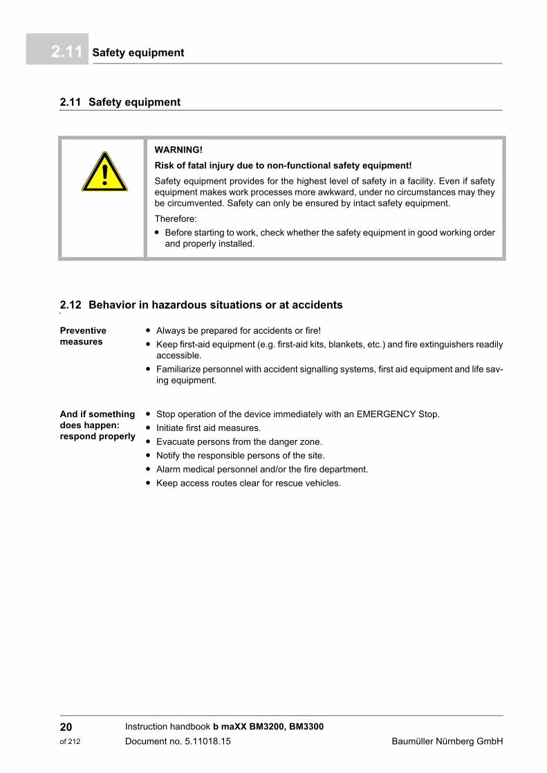
WARNING!
Risk of fatal injury due to non-functional safety equipment!
Safety equipment provides for the highest level of safety in a facility. Even if safetyequipment makes work processes more awkward, under no circumstances may theybe circumvented. Safety can only be ensured by intact safety equipment.
Therefore:
m Before starting to work, check whether the safety equipment in good working orderand properly installed.
Instruction handbook b maXX BM3200, BM3300
Document no. 5.11018.15 Baumüller Nürnberg GmbH
20of 212

Safety 2
2.13 Signs and labelsThe following symbols and information signs are located in the working area. They referto the adjacencies, where they were affixed.
WARNING!
Risk of injury due to illegible symbols!
Over the course of time, stickers and symbols on the device can become dirty or oth-erwise unrecognizable.
Therefore:
m Maintain all safety, warning and operating labels on the device in easily readablecondition.
Electrical voltage
Only qualified personnel may work in work areas that identified with this.
Unauthorized persons may not touch working materials marked correspondingly.
DANGER!
Risk of fatal injury from electrical current!
Stored electric charge.
Discharge time of the rack system = discharge time of the device with the longest DClink discharge time in the rack system.
Refer to ZElectrical data– from page 36.
Therefore:
m Do not touch before taking into account the discharge time of the capacitors andelectrically live parts.
m Heed corresponding notes on the equipment.
m If several devices are connected e.g. with a rectifier unit, the DC link discharge cantake a much longer time. In this case, the necessary waiting period must itself bedetermined or a measurement made to ensure the device is de-energized. Thisdischarge time must be posted, together with an IEC 60417-5036 (2002-10) warn-ing symbol, on a clearly visible location of the control cabinet.
Instruction handbook b maXX BM3200, BM3300
Document no. 5.11018.15
21of 212
Signs and labels2.13
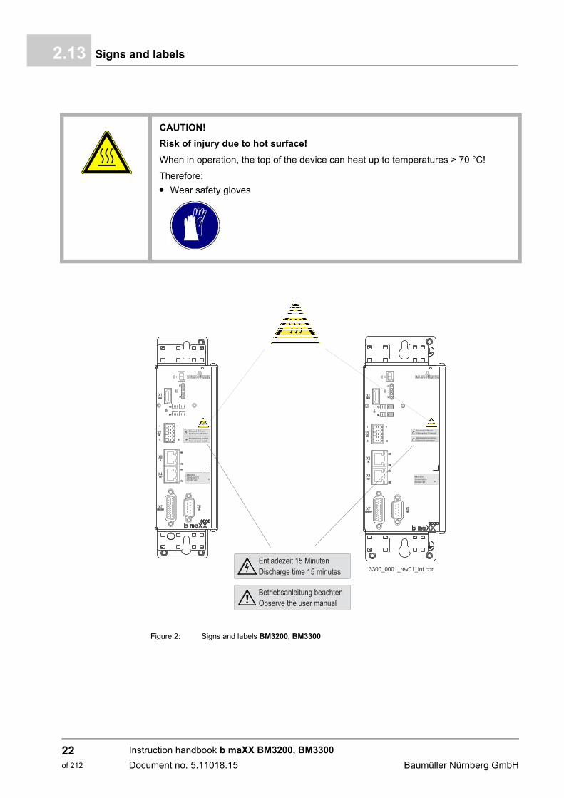
Figure 2: Signs and labels BM3200, BM3300
CAUTION!
Risk of injury due to hot surface!
When in operation, the top of the device can heat up to temperatures > 70 °C!
Therefore:
m Wear safety gloves
Instruction handbook b maXX BM3200, BM3300
Document no. 5.11018.15 Baumüller Nürnberg GmbH
22of 212
Safety 2
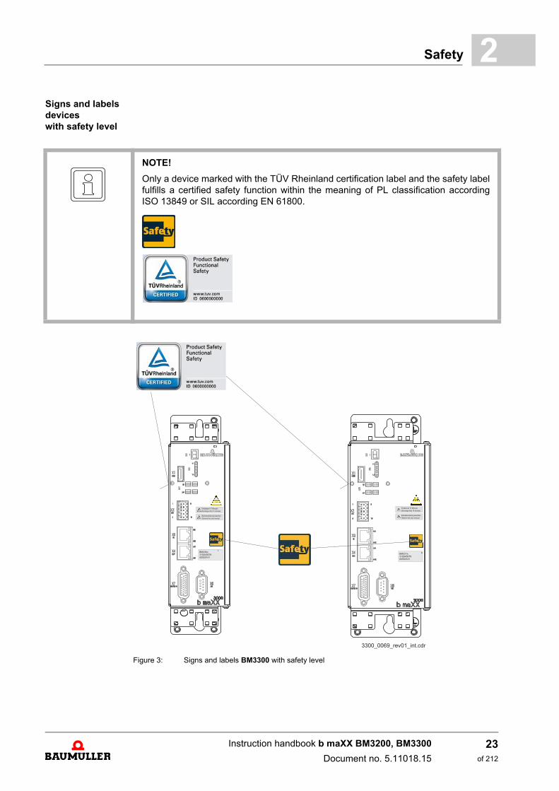
Signs and labels devices with safety levelFigure 3: Signs and labels BM3300 with safety level
NOTE!
Only a device marked with the TÜV Rheinland certification label and the safety labelfulfills a certified safety function within the meaning of PL classification accordingISO 13849 or SIL according EN 61800.
Instruction handbook b maXX BM3200, BM3300
Document no. 5.11018.15
23of 212

Signs and labels2.13
Instruction handbook b maXX BM3200, BM3300
Document no. 5.11018.15 Baumüller Nürnberg GmbH
24of 212
3TECHNICAL DATA
3.1 Dimensions
With the help of the following figures, the space requirements in the control cabinet aredetermined. In order to execute the necessary drilling/section please refer to ZDrillingtemplates– from page 77.
NOTE!
All dimensions in mm.
25of 212
Instruction handbook b maXX BM3200, BM3300
Document no. 5.11018.15
Weight3.2
3.2 Weight
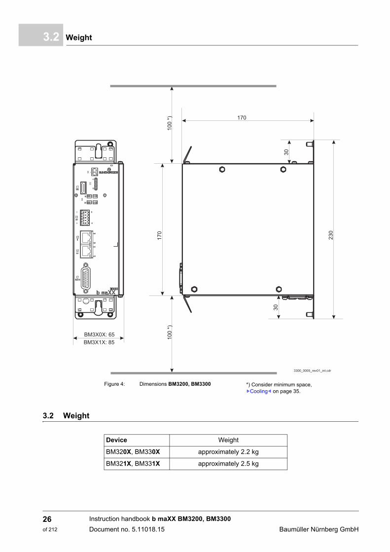
Figure 4: Dimensions BM3200, BM3300 *) Consider minimum space, ZCooling– on page 35.
Device Weight
BM320X, BM330X approximately 2.2 kg
BM321X, BM331X approximately 2.5 kg
Instruction handbook b maXX BM3200, BM3300
Document no. 5.11018.15 Baumüller Nürnberg GmbH
26of 212
Technical Data 3
3.3 Operating conditions3.3.1 System types
There is a differential structure of current supply networks and it is distinguished betweenthree basic types, referring to their grounding, which is accordant to DIN VDE0100 part300 and accordingly to IEC 60364:
m In a TN-system one point is directly grounded (main ground). The cabinet of the elec-trical installation is connected via protective conductors and accordingly PE-conduc-tors with this point.
m In a TT-system a point is directly grounded (main ground). The cabinet of the electricinstallation is connected to ground connections, which, however, are separated fromthe main ground.
m In an IT-system there is no direct connection between active conductors (L1, L2, L3,N) and grounded parts (PE). The cabinets of the electrical installation are grounded.The separation is reached, by the use of an isolating transformer or with the use of anindependent current source (generator, battery).
If there is an adequate low-impedance grounding within the TN- or the TT-network, thena line-side fuse is activated. A high-impedance grounding does not activate the fuse, sothat the ground currents (error current) can be potentially dangerous. For this reason, cir-cuit breakers are used for the error current monitoring.
At a short-circuit to ground, no ground current can flow and the line-side fuses cannot beactivated, by which the operation can be kept up. Only a second short-circuit to ground atanother phase would cause an current error, which can trigger a fuse. In order to detectthe first short-circuit to ground an insulation monitor and for the second short-circuit toground, a current error monitoring, are necessary.
Supported system types
NOTICE!
The operation of the BM3200, BM3300 devices is possible with TT- and TN-net-works.
The common network types in the USA are differentiate clearly from the Europeannetworks. Besides the Solidly Grounded Wye, which is similar to the TN-S-system,there is also a Corner Grounded Delta (this differs to the description in the IEC). TheBM3200, BM3300 may not be operated here.
An operation with DC-link connection and use of a active mains rectifier is forbidden.
Instruction handbook b maXX BM3200, BM3300
Document no. 5.11018.15
27of 212
Operating conditions3.3
3.3.2 Requirements to the energy supply: power supply
1) If the voltage falls below UACmin for t > 0,1 s the error „Power unit not ready-to-operate“ is generated.2) The rated voltage is 3 x 400 V
At lower supply voltages the output power of the device reduces, refer to correction factor at modified envi-ronmental conditions, ZSupply voltage– on page 32.
3) The control voltage must accord to PELV (EN 61800-5-1, chapter 3.21) and accordingly SELV (EN 61800-5-1, chapter 3.35).At a control voltage < 24 V the ventilator power is reduced. Therefore, it can be necessary, that the outputcurrents also be reduced.
4) Rate of change of system frequency max. 1 Hz/s (EN 61000-2-4, class 3)
BM3200, BM3300
Power supply(also refer to ZSystem types– from page 27)
TN-/TT-system
Inductance (sum of supply inductance and the power choke inductance)
Min. uk = 0 %, max. uk = 4 %
Rated supply voltage/frequency 1) 2) (UAC) 1 x 230 V, 50/60 Hz1 x 400 V, 50/60 Hz
3 x 400 V, 50/60 Hz
Absolute supply voltage minimum1) 2) (UACmin)Absolute supply voltage maximum1) 2) (UACmax)
110 V / 50/60 Hz528 V / 50/60 Hz
Absolute frequency minimum 4)
Absolute frequency maximum 4)47 Hz63 Hz
Overvoltage categoryEN 61800-5-1, chapt. 4.3.6
III
Harmonic components (power supply voltage)EN 61800-3, chapter 5.2.1, class 3
THDU b 12 %
Power Supply voltage asymmetryEN 61000-2-4, tab. 1, class 3
Max. 3 %
Commutation notchEN 61800-3, chapter 5.2.1, class 3
Setback depth < 40 %, area < 250 % x degree
Voltage dropEN 61800-3:2004 and A1:2012
10 % to 80 % 1)
Voltage variations/deviationsEN 61200-2-4, Class 3
+/-10 %+10 % to -15 % at a time of
b 1 min
Control voltage 3) (UDC)complying with EN 61131-2:1994, table 7
+ 24 V -15 % / +20 %
Max. short-circuit strength power supplyonly necessary to comply with UL508C
5000 A
Prospective short-circuit current according EN 61800-5-1 5 kA
Instruction handbook b maXX BM3200, BM3300
Document no. 5.11018.15 Baumüller Nürnberg GmbH
28of 212
Technical Data 3
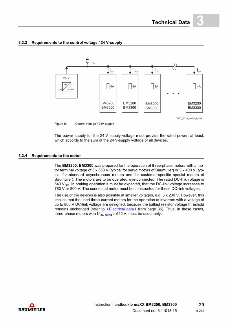
3.3.3 Requirements to the control voltage / 24 V-supplyFigure 5: Control voltage / 24V-supply
The power supply for the 24 V supply voltage must provide the rated power, at least,which accords to the sum of the 24 V-supply voltage of all devices.
3.3.4 Requirements to the motor
The BM3200, BM3300 was prepared for the operation of three-phase motors with a mo-tor terminal voltage of 3 x 350 V (typical for servo motors of Baumüller) or 3 x 400 V (typ-ical for standard asynchronous motors and for customer-specific special motors ofBaumüller). The motors are to be operated wye-connected. The rated DC-link voltage is540 VDC. In braking operation it must be expected, that the DC-link voltage increases to780 V or 800 V. The connected motor must be constructed for these DC-link voltages.
The use of the devices is also possible at smaller voltages, e.g. 3 x 230 V. However, thisimplies that the used three-current motors for the operation at inverters with a voltage ofup to 800 V DC-link voltage are designed, because the ballast resistor voltage thresholdremains unchanged (refer to ZElectrical data– from page 36). Thus, in these cases,three-phase motors with UDC rated 540 V, must be used, only.
BM3200BM3300
BM3200BM3300
BM3200BM3300
BM3200BM3300
Instruction handbook b maXX BM3200, BM3300
Document no. 5.11018.15
29of 212
Operating conditions3.3
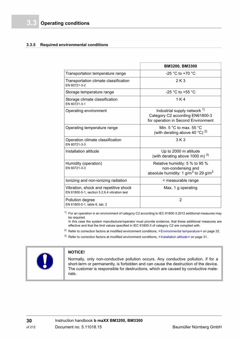
3.3.5 Required environmental conditions
1) For an operation in an environment of category C2 according to IEC 61800-3:2012 additional measures maybe required. In this case the system manufacturer/operator must provide evidence, that these additional measures areeffective and that the limit values specified in IEC 61800-3 of category C2 are complied with.
2) Refer to correction factors at modified environment conditions, ZEnvironmental temperature– on page 32.3) Refer to correction factors at modified environment conditions, ZInstallation altitude– on page 31.
BM3200, BM3300
Transportation temperature range -25 °C to +70 °C
Transportation climate classification EN 60721-3-2
2 K 3
Storage temperature range -25 °C to +55 °C
Storage climate classificationEN 60721-3-1
1 K 4
Operating environment Industrial supply network 1)
Category C2 according EN61800-3 for operation in Second Environment
Operating temperature range Min. 5 °C to max. 55 °C (with derating above 40 °C) 2)
Operation climate classificationEN 60721-3-3
3 K 3
Installation altitude Up to 2000 m altitude(with derating above 1000 m) 3)
Humidity (operation)EN 60721-3-3
Relative humidity: 5 % to 95 % non-condensing and
absolute humidity: 1 g/m3 to 29 g/m3
Ionizing and non-ionizing radiation < measurable range
Vibration, shock and repetitive shock EN 61800-5-1, section 5.2.6.4 vibration test
Max. 1 g operating
Pollution degreeEN 61800-5-1, table 6, tab. 2
2
NOTICE!
Normally, only non-conductive pollution occurs. Any conductive pollution, if for ashort-term or permanently, is forbidden and can cause the destruction of the device.The customer is responsible for destructions, which are caused by conductive mate-rials.
Instruction handbook b maXX BM3200, BM3300
Document no. 5.11018.15 Baumüller Nürnberg GmbH
30of 212
Technical Data 3
3.3.6 Correction factors at modified operational conditionsIf the devices BM3200, BM3300 are used at operational conditions, which cause differentcorrection factors, then all correction factors for the permitted output power and accord-ingly the output current, must be taken into account by multiplication at the same time.
The following correction factors are to be considered if nothing other is specified at the„Technical data“ of the device:
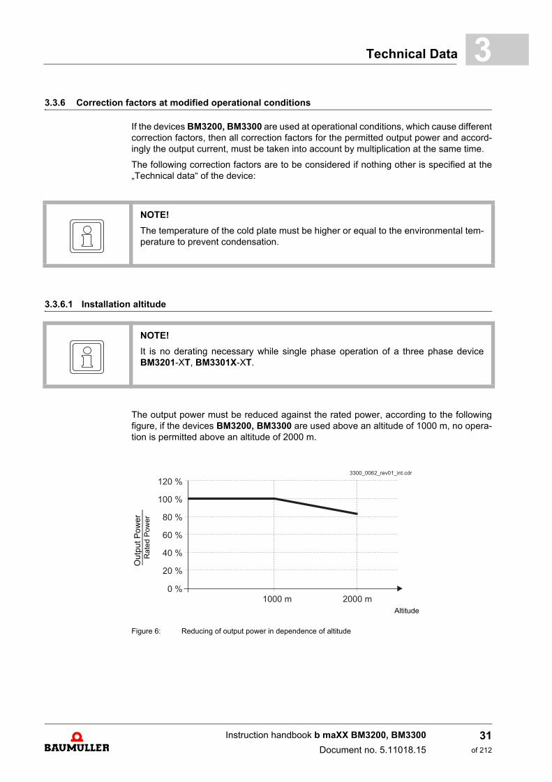
3.3.6.1 Installation altitude
The output power must be reduced against the rated power, according to the followingfigure, if the devices BM3200, BM3300 are used above an altitude of 1000 m, no opera-tion is permitted above an altitude of 2000 m.
Figure 6: Reducing of output power in dependence of altitude
NOTE!
The temperature of the cold plate must be higher or equal to the environmental tem-perature to prevent condensation.
NOTE!
It is no derating necessary while single phase operation of a three phase deviceBM3201-XT, BM3301X-XT.
Out
put P
ow
er
Rat
ed P
ower
Altitude
Instruction handbook b maXX BM3200, BM3300
Document no. 5.11018.15
31of 212
Operating conditions3.3
3.3.6.2 Environmental temperature
The devices BM3200, BM3300 are provided for an environmental temperature of Trated = 40 °C. At usage in environments with a temperature between 40 °C and 55 °Cthe permitted output current (IO) is to be calculated according to the following formula:
The coolant temperature corresponds to the environmental temperature.
3.3.6.3 Supply voltage
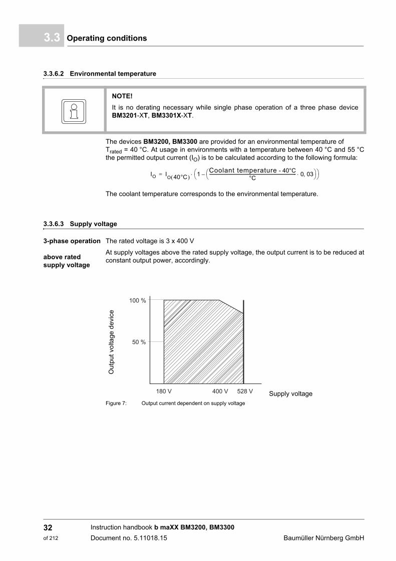
3-phase operation
above rated supply voltage
The rated voltage is 3 x 400 V
At supply voltages above the rated supply voltage, the output current is to be reduced atconstant output power, accordingly.
Figure 7: Output current dependent on supply voltage
NOTE!
It is no derating necessary while single phase operation of a three phase deviceBM3201-XT, BM3301X-XT.
IO IO 40°C 1
Coolant temperature - 40°C°C
--------------------------------------------------------------------------------------- 0 03 –
=
Ou
tpu
t vo
ltage
dev
ice
Supply voltage180 V 400 V 528 V
100 %
50 %
Instruction handbook b maXX BM3200, BM3300
Document no. 5.11018.15 Baumüller Nürnberg GmbH
32of 212
Technical Data 3
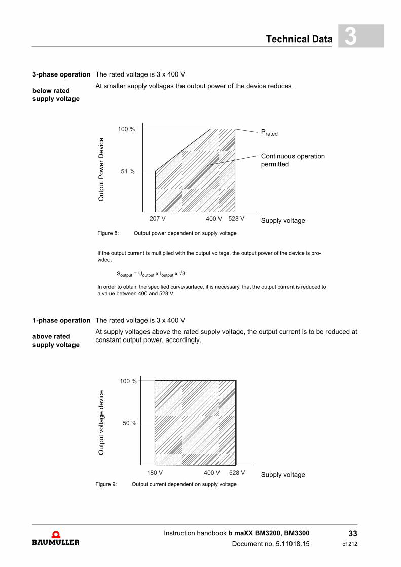
3-phase operationbelow rated supply voltage
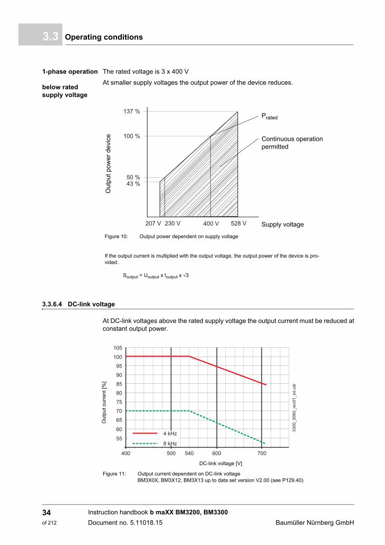
The rated voltage is 3 x 400 V
At smaller supply voltages the output power of the device reduces.
1-phase operation
above rated supply voltage
The rated voltage is 3 x 400 V
At supply voltages above the rated supply voltage, the output current is to be reduced atconstant output power, accordingly.
Figure 9: Output current dependent on supply voltage
Out
put
Pow
er D
evic
e
Prated
Continuous operation permitted
Supply voltage
Figure 8: Output power dependent on supply voltage
If the output current is multiplied with the output voltage, the output power of the device is pro-vided.
Soutput = Uoutput x Ioutput x 3
In order to obtain the specified curve/surface, it is necessary, that the output current is reduced to a value between 400 and 528 V.
207 V 400 V 528 V
100 %
51 %
Out
put
volta
ge
devi
ce
Supply voltage
Instruction handbook b maXX BM3200, BM3300
Document no. 5.11018.15
33of 212
Operating conditions3.3
1-phase operation
below rated supply voltage
The rated voltage is 3 x 400 V
At smaller supply voltages the output power of the device reduces.
3.3.6.4 DC-link voltage
At DC-link voltages above the rated supply voltage the output current must be reduced atconstant output power.
Figure 11: Output current dependent on DC-link voltageBM3X0X, BM3X12, BM3X13 up to data set version V2.00 (see P129.40)
Out
put p
ower
dev
ice
Prated
Continuous operation permitted
Supply voltage
Figure 10: Output power dependent on supply voltage
If the output current is multiplied with the output voltage, the output power of the device is pro-vided.
Soutput = Uoutput x Ioutput x 3
Ou
tput
cu
rren
t [%
]
DC-link voltage [V]
Instruction handbook b maXX BM3200, BM3300
Document no. 5.11018.15 Baumüller Nürnberg GmbH
34of 212

Technical Data 3
Figure 12: Output current dependent on DC-link voltageBM3X13 data set version V2.01 and higher (see P129.40)
3.3.7 Cooling
BM3200/BM3300
1) Air temperature in the entire suction area of the device.2) The cooling air requirement must at least accord to a free blowing process of a device. A free blowing process
means, that the air in- and output can take place unimpeded. At installation of the device into a control cab-inet, it may be necessary, to insert additional fans, to cover the necessary cooling air requirement. If the nec-essary cooling air requirement of the power heat sink is not provided, the output power of the device must bereduced.
Out
put c
urre
nt [%
]
DC-link voltage [V]
Cooling air temperature 1) Min. 0 °C to max. 55 °CRated temperature = 40 °C
Cooling air requirement 2) Refer to ZElectrical data– from page 36
Instruction handbook b maXX BM3200, BM3300
Document no. 5.11018.15
35of 212

Electrical data3.4
3.4 Electrical data
3.4.1 Electrical data BM3X01-XT/BM3X11-XT
With internal ballast resistor BM3X01-XTXX-XXXXX-B-XXXXX-
Footnotes refer to ZPage 44–.
BM3X01 3-phase/3 x 400 V
BM3X01 1-phase/1 x 400 V
Input rated power output 1) 4.2 kVA 3.9 kVA
Input rated current (Ieff) 1) 2) 3) 6 A 5.6 A
Distortion factor of the input current (THDI)1) 118 % 130 %
Input peak current (Ieff) 1) 2) 3) 10.4 A 5.6 A
DC-link voltage power supply-dependent/rating 540 VDC
DC-link capacitance (internal) 235 µF
DC-link capacitance (external) Refer to DC link connection of additional capacities from ZPage 110–
DC-link discharge time (internal DC-link capacitance) ca. 450 s
Capacitance DC-link toPE 22 nF
Output voltage (UAC) 1) 4) 0 ... 400 V
Output frequency at 4 kHz 5) 6) 0 ... 450 Hz
Output rated current (IAC) 1)4)7)8)9) at 2 kHz 5) 5 A 2 A
Output rated current (IAC) 1)4)7)8)9) at 4 kHz 5) 5 A 2 A
Output rated current (IAC) 1)4)7)8)9) at 8 kHz 5) 3.5 A 2 A
Output rated current (IAC) 1)4)7)8)9) at 16 kHz 5) 2.5 A 2 A
Output peak current (IAC) 1)4)7)8)9) at 2 kHz 5) 10 A 2 A
Output peak current (IAC) 1)4)7)8)9) at 4 kHz 5) 10 A 2 A
Output peak current (IAC) 1)4)7)8)9) at 8 kHz 5) 7 A 2 A
Output peak current (IAC) 1)4)7)8)9) at 16 kHz 5) 5 A 2 A
Max. peak current time 60 s
Ballast resistor start-up voltage 785 V
Ballast resistor peak power 1200 W for max. 150 ms
Average ballast resistor power 100 W
Switch on ready-to-operate after 4 s
Max. upload time 0.5 s
Power loss referring to power connection 70 W 50 W
Power loss referring to control voltage Max. 30 W
Cooling air requirement 11 m3/h
Instruction handbook b maXX BM3200, BM3300
Document no. 5.11018.15 Baumüller Nürnberg GmbH
36of 212
Technical Data 3
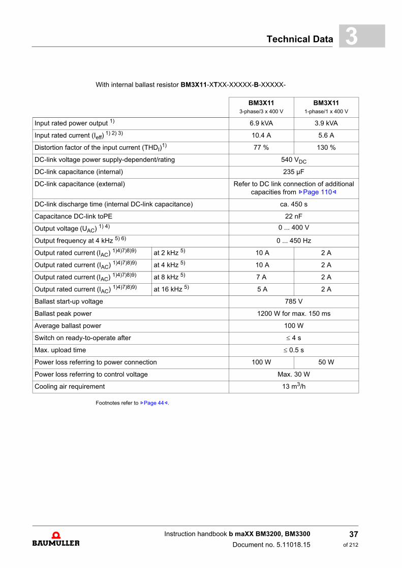
With internal ballast resistor BM3X11-XTXX-XXXXX-B-XXXXX-
Footnotes refer to ZPage 44–.
BM3X11 3-phase/3 x 400 V
BM3X11 1-phase/1 x 400 V
Input rated power output 1) 6.9 kVA 3.9 kVA
Input rated current (Ieff) 1) 2) 3) 10.4 A 5.6 A
Distortion factor of the input current (THDI)1) 77 % 130 %
DC-link voltage power supply-dependent/rating 540 VDC
DC-link capacitance (internal) 235 µF
DC-link capacitance (external) Refer to DC link connection of additional capacities from ZPage 110–
DC-link discharge time (internal DC-link capacitance) ca. 450 s
Capacitance DC-link toPE 22 nF
Output voltage (UAC) 1) 4) 0 ... 400 V
Output frequency at 4 kHz 5) 6) 0 ... 450 Hz
Output rated current (IAC) 1)4)7)8)9) at 2 kHz 5) 10 A 2 A
Output rated current (IAC) 1)4)7)8)9) at 4 kHz 5) 10 A 2 A
Output rated current (IAC) 1)4)7)8)9) at 8 kHz 5) 7 A 2 A
Output rated current (IAC) 1)4)7)8)9) at 16 kHz 5) 5 A 2 A
Ballast start-up voltage 785 V
Ballast peak power 1200 W for max. 150 ms
Average ballast power 100 W
Switch on ready-to-operate after 4 s
Max. upload time 0.5 s
Power loss referring to power connection 100 W 50 W
Power loss referring to control voltage Max. 30 W
Cooling air requirement 13 m3/h
Instruction handbook b maXX BM3200, BM3300
Document no. 5.11018.15
37of 212

Electrical data3.4
3.4.2 Electrical data BM3X02-XT, BM3X03-XT, BM3X04-XT, 400 V
a) with internal ballast resistor BM3X02-XTXX-XXXXX-B-XXXXX- b) without internal ballast resistor BM3X02-XTXX-XXXXX-E-XXXXX-
Footnotes refer to ZPage 44–.
BM3X02 3-phase/3 x 400 V
BM3X033-phase/3 x 400 V
BM3X043-phase/3 x 400 V
Input rated power output 1) 1.3 kVA 2.3 kVA 4.2 kVA
Input rated current (Ieff) 1) 2) 3) 1.8 A 3.3 A 6 A
Distortion factor of the input current (THDI)1) 118 %
Input peak current (Ieff) 1) 2) 3) 6.3 A 11.4 A 15.6 A
DC-link voltage power supply-dependent/rating 540 VDC
DC-link capacitance (internal) 235 µF
DC-link capacitance (external)(only devices BM3X0X-XTXX-XXXXX-B)
Refer to DC link connection of additional capacities from ZPage 110–
DC-link discharge time (internal DC-link capacitance) ca. 450 s
Capacitance DC-link toPE 22 nF
Output voltage (UAC) 1) 4) 0 ... 400 V
Output frequency at 4 kHz 5) 6) 0 ... 450 Hz
Output rated current (IAC) 1)4)7)8)9) at 2 kHz 5) 1.5 A 2.7 A 5 A
Output rated current (IAC) 1)4)7)8)9) at 4 kHz 5) 1.5 A 2.7 A 5 A
Output rated current (IAC) 1)4)7)8)9) at 8 kHz 5) 1.1 A 1.9 A 3.5 A
Output rated current (IAC) 1)4)7)8)9) at 16 kHz 5) 0.8 A 1.3 A 2.5 A
Output peak current (IAC) 1)4)7)8)9) at 2 kHz 5) 6 A 11 A 15 A
Output peak current (IAC) 1)4)7)8)9) at 4 kHz 5) 6 A 11 A 15 A
Output peak current (IAC) 1)4)7)8)9) at 8 kHz 5) 4.2 A 7.7 A 10.5 A
Output peak current (IAC) 1)4)7)8)9) at 16 kHz 5) 3 A 5.4 A 7.4 A
Max. peak current time 60 s 30 s
Ballast start-up voltage 785 V
Ballast peak power, internal ballast resistor a) 1200 W for max. 150 ms
Average ballast power, internal ballast resistor a) 100 W
Permitted ballast current (Î), external ballast resistor b) Max. 7.0 A
Ballast resistor, external ballast resistor b) 111 61
Switch on ready-to-operate after 4 s
Max. upload time 0.5 s
Power loss referring to power connection 70 W
Power loss referring to control voltage Max. 30 W
Cooling air requirement 11 m3/h
Instruction handbook b maXX BM3200, BM3300
Document no. 5.11018.15 Baumüller Nürnberg GmbH
38of 212

Technical Data 3
Footnotes refer to ZPage 44–.
BM3X02 1-phase/1 x 400 V
BM3X031-phase/1 x 400 V
BM3X041-phase/1 x 400 V
Input rated power output 1) 1.2 kVA 1.4 kVA
Input rated current (Ieff) 1) 2) 3) 4.2 A 5.6 A
Distortion factor of the input current (THDI)1) 130 %
Input peak current (Ieff) 1) 2) 3) 5.6 A
DC-link voltage power supply-dependent/rating 540 VDC
DC-link capacitance (internal), external not permitted 235 µF
DC-link discharge time (internal DC-link capacitance) ca. 450 s
Capacitance DC-link toPE 22 nF
Output voltage (UAC) 1) 4) 0 ... 400 V
Output frequency at 4 kHz 5) 6) 0 ... 450 Hz
Output rated current (IAC) 1)4)7)8)9) at 2 kHz 5) 2 A
Output rated current (IAC) 1)4)7)8)9) at 4 kHz 5) 2 A
Output rated current (IAC) 1)4)7)8)9) at 8 kHz 5) 2 A
Output rated current (IAC) 1)4)7)8)9) at 16 kHz 5) 2 A
Output peak current (IAC) 1)4)7)8)9) at 2 kHz 5) 2 A
Output peak current (IAC) 1)4)7)8)9) at 4 kHz 5) 2 A
Output peak current (IAC) 1)4)7)8)9) at 8 kHz 5) 2 A
Output peak current (IAC) 1)4)7)8)9) at 16 kHz 5) 2 A
Ballast start-up voltage 785 V
Ballast peak power, internal ballast resistor a) 1200 W for max. 150 ms
Average ballast power, internal ballast resistor a) 100 W
Permitted ballast current (Î), external ballast resistor b) Max. 7.0 A
Ballast resistor, external ballast resistor b) 111
Switch on ready-to-operate after 4 s
Max. upload time 0,5 s
Power loss referring to power connection 50 W
Power loss referring to control voltage Max. 30 W
Cooling air requirement 11 m3/h
Instruction handbook b maXX BM3200, BM3300
Document no. 5.11018.15
39of 212
Electrical data3.4
3.4.3 Electrical data BM3X12-XT, BM3X13-XT, 400 V
a) with internal ballast resistor BM3X02-XTXX-XXXXX-B-XXXXX- b) without internal ballast resistor BM3X02-XTXX-XXXXX-E-XXXXX-
BM3X123-phase/3 x 400 V
BM3X133-phase/3 x 400 V
Input rated power output 1) 5.4 kVA 6.9 kVA
Input rated current (Ieff) 1) 2) 3) 7.8 A 10.4 A
Distortion factor of the input current (THDI)1) 118 % 77 %
Input peak current (Ieff) 1) 2) 3) 20.8 A 20.8 A
DC-link voltage power supply-dependent/rating 540 VDC
DC-link capacitance (internal) 235 µF
DC-link capacitance (external)(only devices BM3X0X-XTXX-XXXXX-B)
Refer to DC link connection of additional capacities from ZPage 110–
DC-link discharge time (internal DC-link capacitance) ca. 450 s
Capacitance DC-link toPE 22 nF
Output voltage (UAC) 1) 4) 0 ... 400 V
Output frequency at 4 kHz 5) 6) 0 ... 450 Hz
Output rated current (IAC) 1)4)7)8)9) at 2 kHz 5) 6.5 A 10 A
Output rated current (IAC) 1)4)7)8)9) at 4 kHz 5) 6.5 A 10 A
Output rated current (IAC) 1)4)7)8)9) at 8 kHz 5) 4.8 A 7 A / 7.5 A 11)
Output rated current (IAC) 1)4)7)8)9) at 16 kHz 5) 3.4 A 5 A
Output peak current (IAC) 1)4)7)8)9) at 2 kHz 5) 20 A
Output peak current (IAC) 1)4)7)8)9) at 4 kHz 5) 20 A
Output peak current (IAC) 1)4)7)8)9) at 8 kHz 5) 14 A
Output peak current (IAC) 1)4)7)8)9) at 16 kHz 5) 10 A
Max. peak current time 10 s
Ballast start-up voltage 785 V
Ballast peak power, internal ballast resistor a) 1200 W for max. 150 ms
Average ballast power, internal ballast resistor a) 100 W
Permitted ballast current (Î), external ballast resistor b) Max. 12.8 A
Ballast resistor, external ballast resistor b) 61
Switch on ready-to-operate after 4 s
Max. upload time 0.5 s
Power loss referring to power connection 70 W
Power loss referring to control voltage Max. 30 W
Cooling air requirement 11 m3/h
Instruction handbook b maXX BM3200, BM3300
Document no. 5.11018.15 Baumüller Nürnberg GmbH
40of 212

Technical Data 3
BM3X121-phase/1 x 400 V
BM3X131-phase/1 x 400 V
Input rated power output 1) 1.4 kVA
Input rated current (Ieff) 1) 2) 3) 5.6 A
Distortion factor of the input current (THDI)1) 130 %
Input peak current (Ieff) 1) 2) 3) 5.6 A
DC-link voltage power supply-dependent/rating 540 VDC
DC-link capacitance (internal), external not permitted 235 µF
DC-link discharge time (internal DC-link capacitance) Ca. 450 s
Capacitance DC-link toPE 22 nF
Output voltage (UAC) 1) 4) 0 ... 400 V
Output frequency at 4 kHz 5) 6) 0 ... 450 Hz
Output rated current (IAC) 1)4)7)8)9) at 2 kHz 5) 2 A
Output rated current (IAC) 1)4)7)8)9) at 4 kHz 5) 2 A
Output rated current (IAC) 1)4)7)8)9) at 8 kHz 5) 2 A
Output rated current (IAC) 1)4)7)8)9) at 16 kHz 5) 2 A
Output peak current (IAC) 1)4)7)8)9) at 2 kHz 5) 2 A
Output peak current (IAC) 1)4)7)8)9) at 4 kHz 5) 2 A
Output peak current (IAC) 1)4)7)8)9) at 8 kHz 5) 2 A
Output peak current (IAC) 1)4)7)8)9) at 16 kHz 5) 2 A
Ballast start-up voltage 785 V
Ballast peak power, internal ballast resistor a) 1200 W for max. 150 ms
Average ballast power, internal ballast resistor a) 100 W
Permitted ballast current (Î), external ballast resistor b) Max. 12.8 A
Ballast resistor, external ballast resistor b) 61
Switch on ready-to-operate after 4 s
Max. upload time 0.5 s
Power loss referring to power connection 70 W
Power loss referring to control voltage Max. 30 W
Cooling air requirement 11 m3/h
Instruction handbook b maXX BM3200, BM3300
Document no. 5.11018.15
41of 212
Electrical data3.4
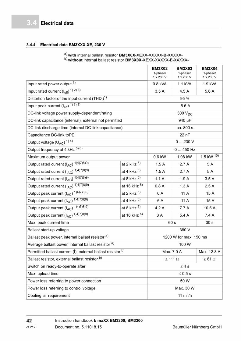
3.4.4 Electrical data BM3XXX-XE, 230 V
a) with internal ballast resistor BM3X0X-XEXX-XXXXX-B-XXXXX- b) without internal ballast resistor BM3X0X-XEXX-XXXXX-E-XXXXX-
BM3X021-phase/1 x 230 V
BM3X031-phase/1 x 230 V
BM3X041-phase/1 x 230 V
Input rated power output 1) 0.8 kVA 1.1 kVA 1.9 kVA
Input rated current (Ieff) 1) 2) 3) 3.5 A 4.5 A 5.6 A
Distortion factor of the input current (THDI)1) 95 %
Input peak current (Ieff) 1) 2) 3) 5.6 A
DC-link voltage power supply-dependent/rating 300 VDC
DC-link capacitance (internal), external not permitted 940 µF
DC-link discharge time (internal DC-link capacitance) ca. 800 s
Capacitance DC-link toPE 22 nF
Output voltage (UAC) 1) 4) 0 ... 230 V
Output frequency at 4 kHz 5) 6) 0 ... 450 Hz
Maximum output power 0.6 kW 1.08 kW 1.5 kW 10)
Output rated current (IAC) 1)4)7)8)9) at 2 kHz 5) 1.5 A 2.7 A 5 A
Output rated current (IAC) 1)4)7)8)9) at 4 kHz 5) 1.5 A 2.7 A 5 A
Output rated current (IAC) 1)4)7)8)9) at 8 kHz 5) 1.1 A 1.9 A 3.5 A
Output rated current (IAC) 1)4)7)8)9) at 16 kHz 5) 0.8 A 1.3 A 2.5 A
Output peak current (IAC) 1)4)7)8)9) at 2 kHz 5) 6 A 11 A 15 A
Output peak current (IAC) 1)4)7)8)9) at 4 kHz 5) 6 A 11 A 15 A
Output peak current (IAC) 1)4)7)8)9) at 8 kHz 5) 4.2 A 7.7 A 10.5 A
Output peak current (IAC) 1)4)7)8)9) at 16 kHz 5) 3 A 5.4 A 7.4 A
Max. peak current time 60 s 30 s
Ballast start-up voltage 380 V
Ballast peak power, internal ballast resistor a) 1200 W for max. 150 ms
Average ballast power, internal ballast resistor a) 100 W
Permitted ballast current (Î), external ballast resistor b) Max. 7.0 A Max. 12.8 A
Ballast resistor, external ballast resistor b) 111 61
Switch on ready-to-operate after 4 s
Max. upload time 0.5 s
Power loss referring to power connection 50 W
Power loss referring to control voltage Max. 30 W
Cooling air requirement 11 m3/h
Instruction handbook b maXX BM3200, BM3300
Document no. 5.11018.15 Baumüller Nürnberg GmbH
42of 212
Technical Data 3
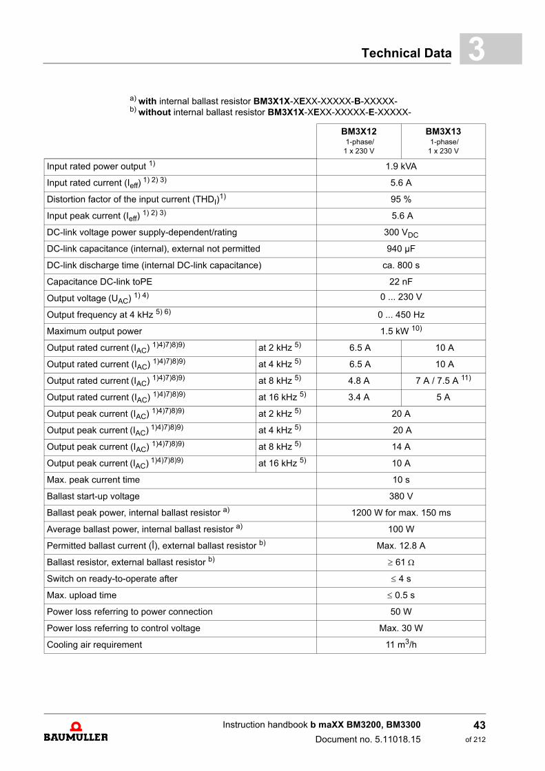
a) with internal ballast resistor BM3X1X-XEXX-XXXXX-B-XXXXX- b) without internal ballast resistor BM3X1X-XEXX-XXXXX-E-XXXXX-BM3X12 1-phase/1 x 230 V
BM3X13 1-phase/1 x 230 V
Input rated power output 1) 1.9 kVA
Input rated current (Ieff) 1) 2) 3) 5.6 A
Distortion factor of the input current (THDI)1) 95 %
Input peak current (Ieff) 1) 2) 3) 5.6 A
DC-link voltage power supply-dependent/rating 300 VDC
DC-link capacitance (internal), external not permitted 940 µF
DC-link discharge time (internal DC-link capacitance) ca. 800 s
Capacitance DC-link toPE 22 nF
Output voltage (UAC) 1) 4) 0 ... 230 V
Output frequency at 4 kHz 5) 6) 0 ... 450 Hz
Maximum output power 1.5 kW 10)
Output rated current (IAC) 1)4)7)8)9) at 2 kHz 5) 6.5 A 10 A
Output rated current (IAC) 1)4)7)8)9) at 4 kHz 5) 6.5 A 10 A
Output rated current (IAC) 1)4)7)8)9) at 8 kHz 5) 4.8 A 7 A / 7.5 A 11)
Output rated current (IAC) 1)4)7)8)9) at 16 kHz 5) 3.4 A 5 A
Output peak current (IAC) 1)4)7)8)9) at 2 kHz 5) 20 A
Output peak current (IAC) 1)4)7)8)9) at 4 kHz 5) 20 A
Output peak current (IAC) 1)4)7)8)9) at 8 kHz 5) 14 A
Output peak current (IAC) 1)4)7)8)9) at 16 kHz 5) 10 A
Max. peak current time 10 s
Ballast start-up voltage 380 V
Ballast peak power, internal ballast resistor a) 1200 W for max. 150 ms
Average ballast power, internal ballast resistor a) 100 W
Permitted ballast current (Î), external ballast resistor b) Max. 12.8 A
Ballast resistor, external ballast resistor b) 61
Switch on ready-to-operate after 4 s
Max. upload time 0.5 s
Power loss referring to power connection 50 W
Power loss referring to control voltage Max. 30 W
Cooling air requirement 11 m3/h
Instruction handbook b maXX BM3200, BM3300
Document no. 5.11018.15
43of 212
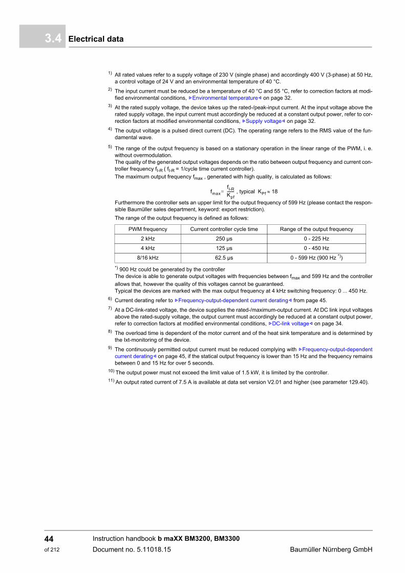
Electrical data3.4
1) All rated values refer to a supply voltage of 230 V (single phase) and accordingly 400 V (3-phase) at 50 Hz,a control voltage of 24 V and an environmental temperature of 40 °C.
2) The input current must be reduced be a temperature of 40 °C and 55 °C, refer to correction factors at modi-fied environmental conditions, ZEnvironmental temperature– on page 32.
3) At the rated supply voltage, the device takes up the rated-/peak-input current. At the input voltage above therated supply voltage, the input current must accordingly be reduced at a constant output power, refer to cor-rection factors at modified environmental conditions, ZSupply voltage– on page 32.
4) The output voltage is a pulsed direct current (DC). The operating range refers to the RMS value of the fun-damental wave.
5) The range of the output frequency is based on a stationary operation in the linear range of the PWM, i. e.without overmodulation.The quality of the generated output voltages depends on the ratio between output frequency and current con-troller frequency fI-R ( fI-R = 1/cycle time current controller).
The maximum output frequency fmax , generated with high quality, is calculated as follows:
Furthermore the controller sets an upper limit for the output frequency of 599 Hz (please contact the respon-sible Baumüller sales department, keyword: export restriction).
The range of the output frequency is defined as follows:
*) 900 Hz could be generated by the controllerThe device is able to generate output voltages with frequencies between fmax and 599 Hz and the controller
allows that, however the quality of this voltages cannot be guaranteed.Typical the devices are marked with the max output frequency at 4 kHz switching frequency: 0 ... 450 Hz.
6) Current derating refer to ZFrequency-output-dependent current derating– from page 45.7) At a DC-link-rated voltage, the device supplies the rated-/maximum-output current. At DC link input voltages
above the rated-supply voltage, the output current must accordingly be reduced at a constant output power,refer to correction factors at modified environmental conditions, ZDC-link voltage– on page 34.
8) The overload time is dependent of the motor current and of the heat sink temperature and is determined bythe Ixt-monitoring of the device.
9) The continuously permitted output current must be reduced complying with ZFrequency-output-dependentcurrent derating– on page 45, if the statical output frequency is lower than 15 Hz and the frequency remainsbetween 0 and 15 Hz for over 5 seconds.
10) The output power must not exceed the limit value of 1.5 kW, it is limited by the controller.11) An output rated current of 7.5 A is available at data set version V2.01 and higher (see parameter 129.40).
PWM frequency Current controller cycle time Range of the output frequency
2 kHz 250 µs 0 - 225 Hz
4 kHz 125 µs 0 - 450 Hz
8/16 kHz 62.5 µs 0 - 599 Hz (900 Hz *))
fmax
fI-RKpf-------- , typical KPf 18=
Instruction handbook b maXX BM3200, BM3300
Document no. 5.11018.15 Baumüller Nürnberg GmbH
44of 212
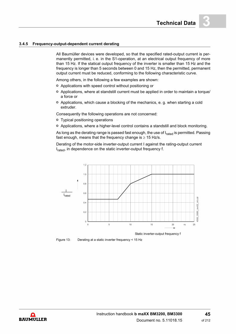
Technical Data 3
3.4.5 Frequency-output-dependent current deratingAll Baumüller devices were developed, so that the specified rated-output current is per-manently permitted, i. e. in the S1-operation, at an electrical output frequency of morethan 15 Hz. If the statical output frequency of the inverter is smaller than 15 Hz and thefrequency is longer than 5 seconds between 0 and 15 Hz, then the permitted, permanentoutput current must be reduced, conforming to the following characteristic curve.
Among others, in the following a few examples are shown:
n Applications with speed control without positioning or
n Applications, where at standstill current must be applied in order to maintain a torque/a force or
n Applications, which cause a blocking of the mechanics, e. g. when starting a cold extruder.
Consequently the following operations are not concerned:
n Typical positioning operations
n Applications, where a higher-level control contains a standstill and block monitoring.
As long as the derating range is passed fast enough, the use of Irated is permitted. Passingfast enough, means that the frequency change is 15 Hz/s.
Derating of the motor-side inverter-output current I against the rating-output current Irated, in dependence on the static inverter-output frequency f.
Static inverter-output frequency f
Figure 13: Derating at a static inverter frequency < 15 Hz
I Irated
Instruction handbook b maXX BM3200, BM3300
Document no. 5.11018.15
45of 212
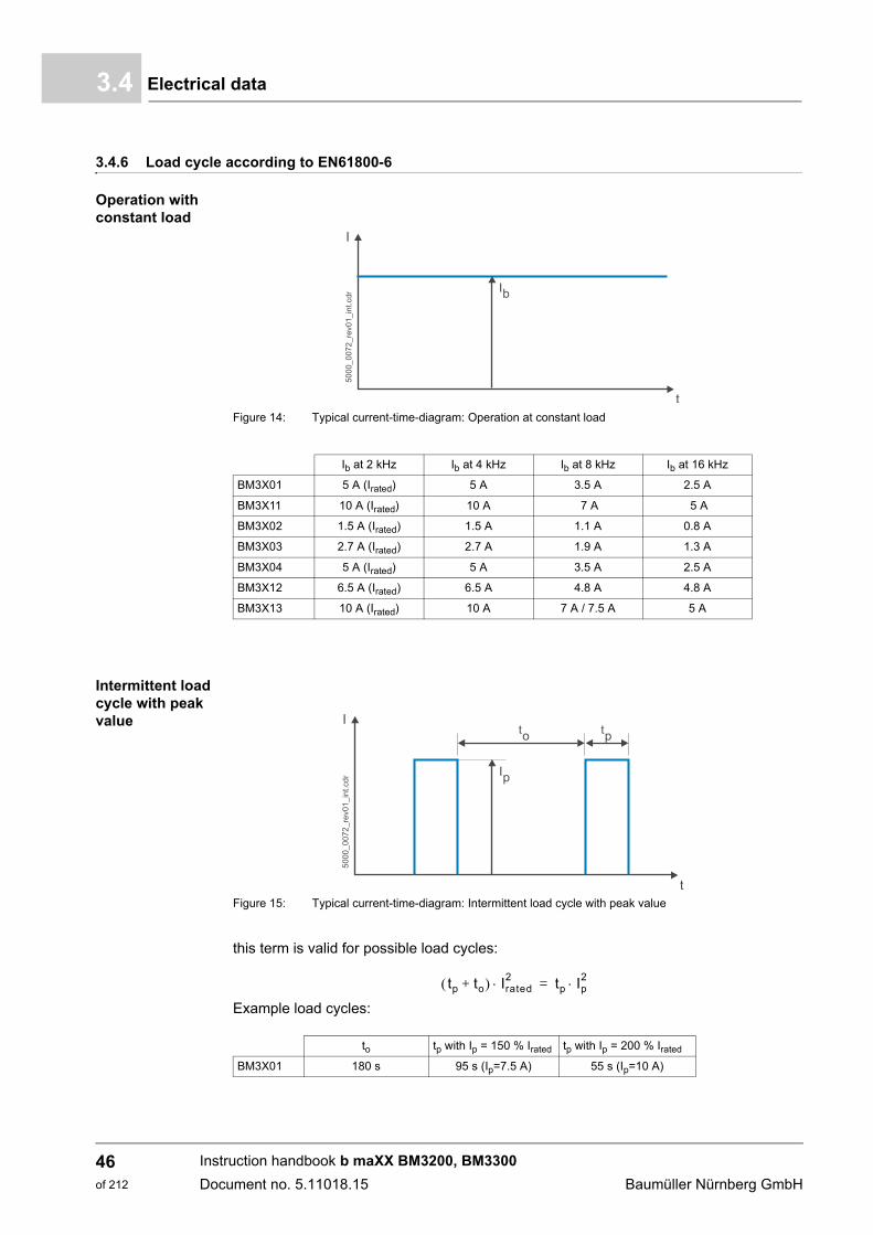
Electrical data3.4
3.4.6 Load cycle according to EN61800-6
Operation with constant load
Figure 14: Typical current-time-diagram: Operation at constant load
Intermittent load cycle with peak value
Figure 15: Typical current-time-diagram: Intermittent load cycle with peak value
this term is valid for possible load cycles:
Example load cycles:
Ib at 2 kHz Ib at 4 kHz Ib at 8 kHz Ib at 16 kHz
BM3X01 5 A (Irated) 5 A 3.5 A 2.5 A
BM3X11 10 A (Irated) 10 A 7 A 5 A
BM3X02 1.5 A (Irated) 1.5 A 1.1 A 0.8 A
BM3X03 2.7 A (Irated) 2.7 A 1.9 A 1.3 A
BM3X04 5 A (Irated) 5 A 3.5 A 2.5 A
BM3X12 6.5 A (Irated) 6.5 A 4.8 A 4.8 A
BM3X13 10 A (Irated) 10 A 7 A / 7.5 A 5 A
to tp with Ip = 150 % Irated tp with Ip = 200 % Irated
BM3X01 180 s 95 s (Ip=7.5 A) 55 s (Ip=10 A)
tp to+ Irated2 tp Ip
2=
Instruction handbook b maXX BM3200, BM3300
Document no. 5.11018.15 Baumüller Nürnberg GmbH
46of 212
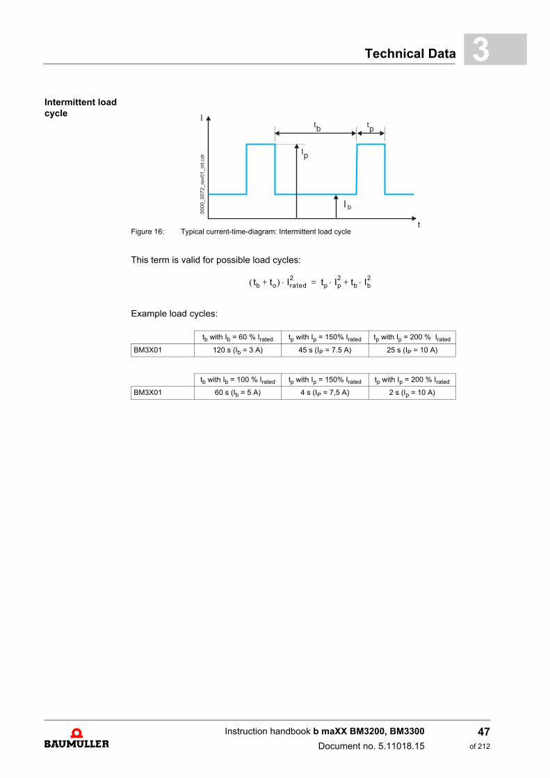
Technical Data 3
Intermittent load cycleFigure 16: Typical current-time-diagram: Intermittent load cycle
This term is valid for possible load cycles:
Example load cycles:
tb with Ib = 60 % Irated tp with Ip = 150% Irated tp with Ip = 200 % Irated
BM3X01 120 s (Ib = 3 A) 45 s (IP = 7.5 A) 25 s (IP = 10 A)
tb with Ib = 100 % Irated tp with Ip = 150% Irated tp with Ip = 200 % Irated
BM3X01 60 s (Ib = 5 A) 4 s (IP = 7,5 A) 2 s (Ip = 10 A)
tb to+ Irated2 tp Ip
2 tb Ib2+=
Instruction handbook b maXX BM3200, BM3300
Document no. 5.11018.15
47of 212
Electrical data3.4
Instruction handbook b maXX BM3200, BM3300
Document no. 5.11018.15 Baumüller Nürnberg GmbH
48of 212
4DESIGN AND FUNCTION
In this chapter the basic design of the device BM3200, BM3300 is described and the typecode on the devices is described.
NOTE!
The devices of the BM3200, BM3300-series are intended for the use in the „Secondenvironment“ (industrial environment) compliant with EN 61800-3. EMC-interferenc-es can appear, if it is connected to the public supply.
Also see ZAppropriate use– from page 12.
NOTE!
Components of Baumüller Nürnberg GmbH are intended to be installed into commer-cially available control cabinets
There are a number of reasons, why the components should be operated in commer-cially available control cabinets. Especially the following points are assured by install-ing these components into the control cabinet:
m The protection against contact, requested by the user can be implemented.
m The stated thermal environment conditions (temperature, relative air humidity,cleanliness of the coolants,...), in the technical data of the components and devic-es is assured.
m The stated mechanical environment conditions (technical data of the componentsand devices (vibration, shocks,....) is assured.
m The stated notes in the technical data for the EMC-compatible configuration and inorder to obtain an EMC-compatible design (shielding concepts, installation princi-ples, leadthroughs,...) can be implemented.
49of 212
Instruction handbook b maXX BM3200, BM3300
Document no. 5.11018.15
Design4.1
4.1 Design
The BM3200, BM3300 device series are servo converters of Baumüller Nürnberg GmbH.The devices consist of a power unit and a controller unit, which are integrated in a com-mon housing. The rated current of the devices reaches from 5 A to 10 A. The devices dif-fer in size, power and equipment (hard- and software). Variants see ZType code– frompage 54.
The devices BM3200, BM3300 are part of the Baumüller device series b maXX and canbe interconnected with other Baumüller devices.
The device series b maXX mainly consists of 2 systems:
Module system consisting of a supply unit and of one or several axis units.
m Supply unit
This is a mains rectifier-/active mains rectifier unit for the supply of axis units via the DC-link.
The AC voltage at the three-phase system is converted from the input sided mains recti-fier unit into DC voltage. The DC-link capacitors smooth this DC-link voltage. Additionallythe active mains rectifier unit can regenerate excess braking energy as sinusoidal currentinto the power supply.
m Axis unit (with controller)
This is a motor power inverter, which is supplied from the DC-link via a mains rectifier- ora active mains rectifier unit.
The output sided inverter generates a three-phase current system with a variable fre-quency and voltage for the supply of the connected motor.
The controller part controls the inverter of the power unit. The controller is operated eitherby an operating software or by a superordinated control.
NOTE!
A device of the series BM3200, BM3300 can be operated as an axis unit.
NOTICE!
A proper operation of the BM3200, BM3300 as an axis unit, can be guaranteed atBaumüller mains rectifier units. An operation on active mains rectifiers is forbid-den.
The mains rectifier unit must be supplied by a TT- or TN-network.
Instruction handbook b maXX BM3200, BM3300
Document no. 5.11018.15 Baumüller Nürnberg GmbH
50of 212
Design and Function 4
Compact servo unitSupply-/axis unit and controller in one housing, these devices can be operated individu-ally also.
The input sided inverter converts the AC current into DC current, which was taken fromthe power supply. The DC-link capacitors smooth this DC-link voltage. The output sidedinverter generates a three-phase system with variable frequency and voltage for the sup-ply of the connected motor.
The controller parts controls the inverter of the power unit. The controller is operated ei-ther by operating software or by a master control.
NOTE!
A device of the series BM3200, BM3300 is a compact servo unit.
Instruction handbook b maXX BM3200, BM3300
Document no. 5.11018.15
51of 212
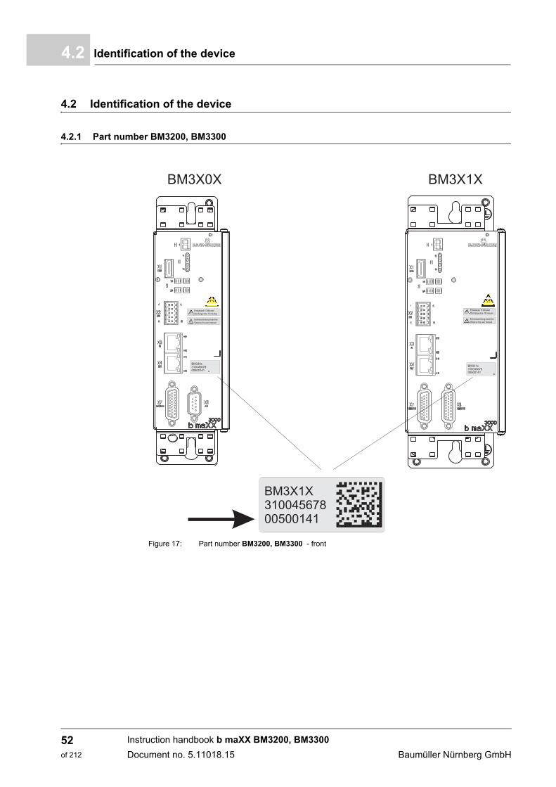
Identification of the device4.2
4.2 Identification of the device
4.2.1 Part number BM3200, BM3300
Figure 17: Part number BM3200, BM3300 - front
Instruction handbook b maXX BM3200, BM3300
Document no. 5.11018.15 Baumüller Nürnberg GmbH
52of 212
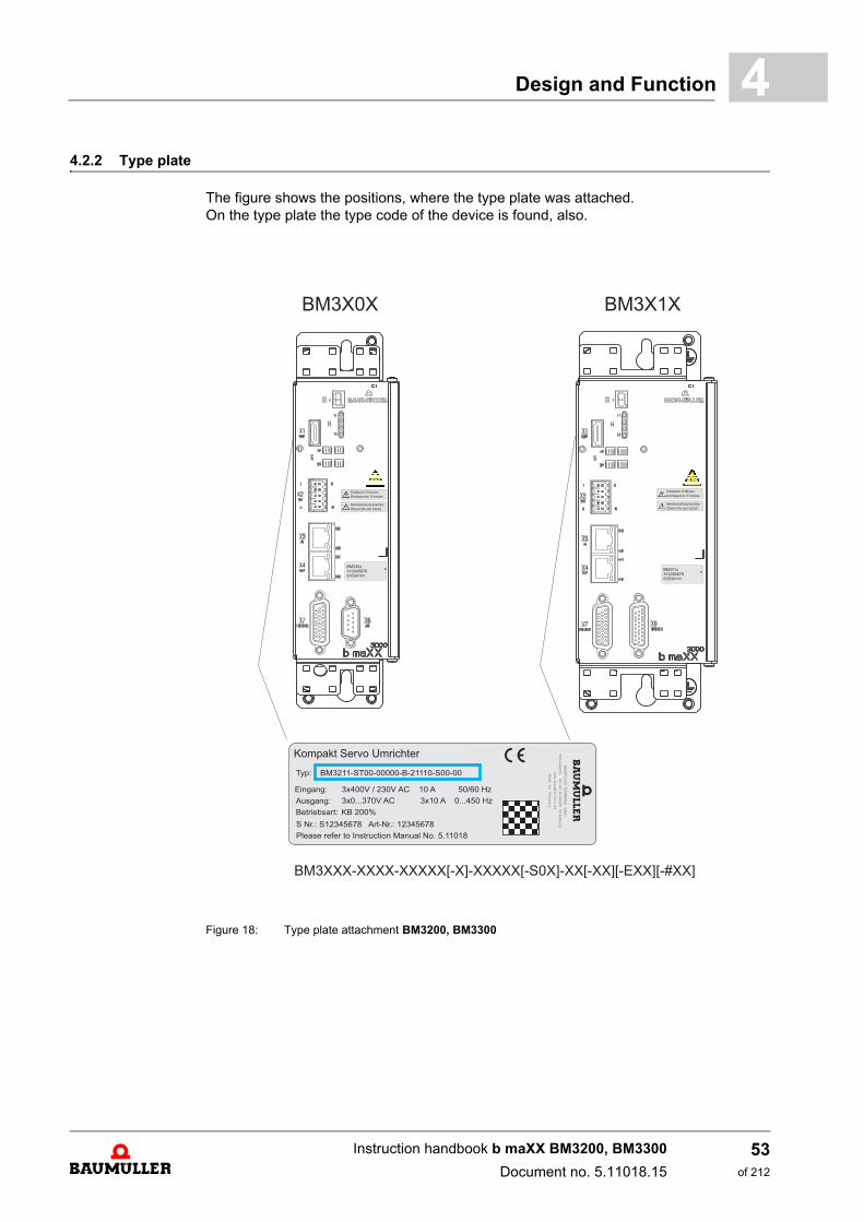
Design and Function 4
4.2.2 Type plateThe figure shows the positions, where the type plate was attached.On the type plate the type code of the device is found, also.
Figure 18: Type plate attachment BM3200, BM3300
Instruction handbook b maXX BM3200, BM3300
Document no. 5.11018.15
53of 212

Identification of the device4.2
4.2.3 Type code
The type code has the format:
BM3XXX-XXXX-XXXXX[-X]-XXXXX[-S0X]-XX[-XX][-EXX][-#XX].
The type code is explained in the following table.
BM3XXX-XXXX-XXXXX[-X]-XXXXX[-S0X]-XX[-XX][-EXX][-#XX] Device generation
BM3XXX-XXXX-XXXXX[-X]-XXXXX[-S0X]-XX[-XX][-EXX][-#XX] Device design
2: Compact servo unit3: Compact servo unit safety
BM3XXX-XXXX-XXXXX[-X]-XXXXX[-S0X]-XX[-XX][-EXX][-#XX] Housing size
0 to 1: see ZDimensions– from page 25.
BM3XXX-XXXX-XXXXX[-X]-XXXXX[-S0X]-XX[-XX][-EXX][-#XX] Current grading (output rated current)
see ZElectrical data– from page 36
BM3XXX-XXXX-XXXXX[-X]-XXXXX[-S0X]-XX[-XX][-EXX][-#XX] Type of cooling
S: Air-cooled with air supply and air exhaust in the control cabinet
BM3XXX-XXXX-XXXXX[-X]-XXXXX[-S0X]-XX[-XX][-EXX][-#XX] Type of power supply
T: Grounded TN or TT power supply networkE: single phase power supply onlyG: Grounded delta systems, IT systems,
grounded TN or TT systems
BM3XXX-XXXX-XXXXX[-X]-XXXXX[-S0X]-XX[-XX][-EXX][-#XX] Type of electronic safety relay(only BM3300)
0: No safety relay2: Double safety relay
BM3XXX-XXXX-XXXXX[-X]-XXXXX[-S0X]-XX[-XX][-EXX][-#XX] Design
0: Standard
BM3XXX-XXXX-XXXXX[-X]-XXXXX[-S0X]-XX[-XX][-EXX][-#XX] Hardware design basic unit
0XX: Compact servo unit with ballast transistor, UDC link = 540 V
BM3XXX-XXXX-XXXXX[-X]-XXXXX[-S0X]-XX[-XX][-EXX][-#XX] Special design basic unit00: Standard
BM3XXX-XXXX-XXXXX[-X]-XXXXX[-S0X]-XX[-XX][-EXX][-#XX] Ballast resistor optionalB: Ballast resistor integratedE, -: Without internal ballast resistor,
connection for external ballast resistor
Instruction handbook b maXX BM3200, BM3300
Document no. 5.11018.15 Baumüller Nürnberg GmbH
54of 212

Design and Function 4
BM3XXX-XXXX-XXXXX[-X]-XXXXX[-S0X]-XX[-XX][-EXX][-#XX] Fieldbus interface1: EtherCAT® CoE2: VARAN3: CANopen®
4: POWERLINK®
5: ProfiNET RT/IRT7: EtherCAT® SoE
BM3XXX-XXXX-XXXXX[-X]-XXXXX[-S0X]-XX[-XX][-EXX][-#XX] Encoder interface1: HIPERFACE®, EnDat® 2.1, SSI, square and sine
incremental encoder, resolver2: EnDat® 2.23: HIPERFACE DSL®
4: HIPERFACE®, EnDat® 2.1/2.2, square and sineincremental encoder, resolver
5: 2 encoders: Encoder 1 and encoder 2, see 1 6: 2 encoders: Encoder 1 (see. 1), encoder 2 (see 2)7: 2 encoders: Encoder 1 (see 1), encoder 2 (see 3)8: 2 encoders: Encoder 1 (see 2), encoder 2 (see 1)9: 2 encoders: Encoder 1 and encoder 2, see 2A: 2 encoders: Encoder 1 (see 2), encoder 2 (see 3)B: 2 encoders: Encoder 1 (see 3), encoder 2 (see 1)C: 2 encoders: Encoder 1 (see 3), encoder 2 (see 2)D: 2 encoders: Encoder 1 and encoder 2, see 3
BM3XXX-XXXX-XXXXX[-X]-XXXXX[-S0X]-XX[-XX][-EXX][-#XX] Digital inputs/outputs1: 2 digital inputs/ 2 digital outputs
BM3XXX-XXXX-XXXXX[-X]-XXXXX[-S0X]-XX[-XX][-EXX][-#XX] Analog inputs/outputs0: No analog inputs/outputs1: 1 analog input/ 2 analog outputs
signal bus for max.12 devices2: 2 analog inputs/2 analog outputs
extended signal bus for max. 30 devices
BM3XXX-XXXX-XXXXX[-X]-XXXXX[-S0X]-XX[-XX][-EXX][-#XX] Option inputs/outputs0: no
BM3XXX-XXXX-XXXXX[-X]-XXXXX[-S0X]-XX[-XX][-EXX][-#XX] Kind of STO function optional (only BM3300)S00: Safety function STO
Note: Not conform to Safety Standards.Permitted for process protection only.
S01: Safety function STO accordingSafety claim PLe / SIL3(for replacement only)
S02: Safety function STO accordingSafety claim PLe / SIL3with short-circuit detection
BM3XXX-XXXX-XXXXX[-X]-XXXXX[-S0X]-XX[-XX][-EXX][-#XX] Incompatible controller software version
BM3XXX-XXXX-XXXXX[-X]-XXXXX[-S0X]-XX[-XX][-EXX][-#XX] Option compatible controller software version
BM3XXX-XXXX-XXXXX[-X]-XXXXX[-S0X]-XX[-XX][-EXX][-#XX] Software function option
BM3XXX-XXXX-XXXXX[-X]-XXXXX[-S0X]-XX[-XX][-EXX][-#XX] Safety level option (only BM3300)#00: Used for safety level STO
Instruction handbook b maXX BM3200, BM3300
Document no. 5.11018.15
55of 212
UL notes4.3
4.3 UL notes
The notes below must be observed in case you consider UL 508 C.
ZRequirements to the energy supply: power supply– on page 28
ZRequired environmental conditions– on page 30
ZRequirements for the motor temperature sensors– on page 91
ZConnections– from page 113
Connections from ZPage 113– to ZPage 139–
n For use with grounded wye sources only or equivalent.
n Note the maximum surrounding air temperature.n Use in a pollution degree 2 environment only.
n Motor over-temperature sensing is required. Drive intended to be used with motors that have thermal sensor mounted in or on the motors.Connection see ZConnecting diagrams– from page 93
n Position of wiring terminals to indicate the proper connec-tions for the power supply, load, control circuit, and similar devices refer to ZPage 113–.
n Note tightening torque values marked for field terminals.
Instruction handbook b maXX BM3200, BM3300
Document no. 5.11018.15 Baumüller Nürnberg GmbH
56of 212
Design and Function 4
ZFuses– from page 185n Devices are suitable for use on a circuit capable of deliver-ing not more than 15000 rms symmetrical amperes,480Y/277 VAC maximumm when protected by J Class Fuses rated min. 480 VAC, max. 15 A or
m when protected by a circuit breaker rated min. 480/277 V, max. 20 A.
n Integral solid state short circuit protection does not provide branch circuit protection. Branch circuit protection must be provided in accordance with the Manufacturer Instructions, National Electrical Code and any additional local codes.
Instruction handbook b maXX BM3200, BM3300
Document no. 5.11018.15
57of 212
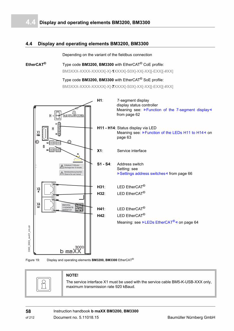
Display and operating elements BM3200, BM33004.4
4.4 Display and operating elements BM3200, BM3300
Depending on the variant of the fieldbus connection
EtherCAT® Type code BM3200, BM3300 with EtherCAT® CoE profile:
BM3XXX-XXXX-XXXXX[-X]-1XXXX[-S0X]-XX[-XX][-EXX][-#XX]
Type code BM3200, BM3300 with EtherCAT® SoE profile:
BM3XXX-XXXX-XXXXX[-X]-7XXXX[-S0X]-XX[-XX][-EXX][-#XX]
Figure 19: Display and operating elements BM3200, BM3300 EtherCAT®
H1: 7-segment displaydisplay status controllerMeaning see: ZFunction of the 7-segment display–from page 62
H11 - H14: Status display via LED Meaning see: ZFunction of the LEDs H11 to H14– onpage 63
X1: Service interface
S1 - S4: Address switchSetting: see ZSettings address switches– from page 66
H31: LED EtherCAT®
H32: LED EtherCAT®
H41: LED EtherCAT®
H42: LED EtherCAT®
Meaning: see ZLEDs EtherCAT®– on page 64
NOTE!
The service interface X1 must be used with the service cable BM5-K-USB-XXX only,maximum transmission rate 920 kBaud.
Instruction handbook b maXX BM3200, BM3300
Document no. 5.11018.15 Baumüller Nürnberg GmbH
58of 212
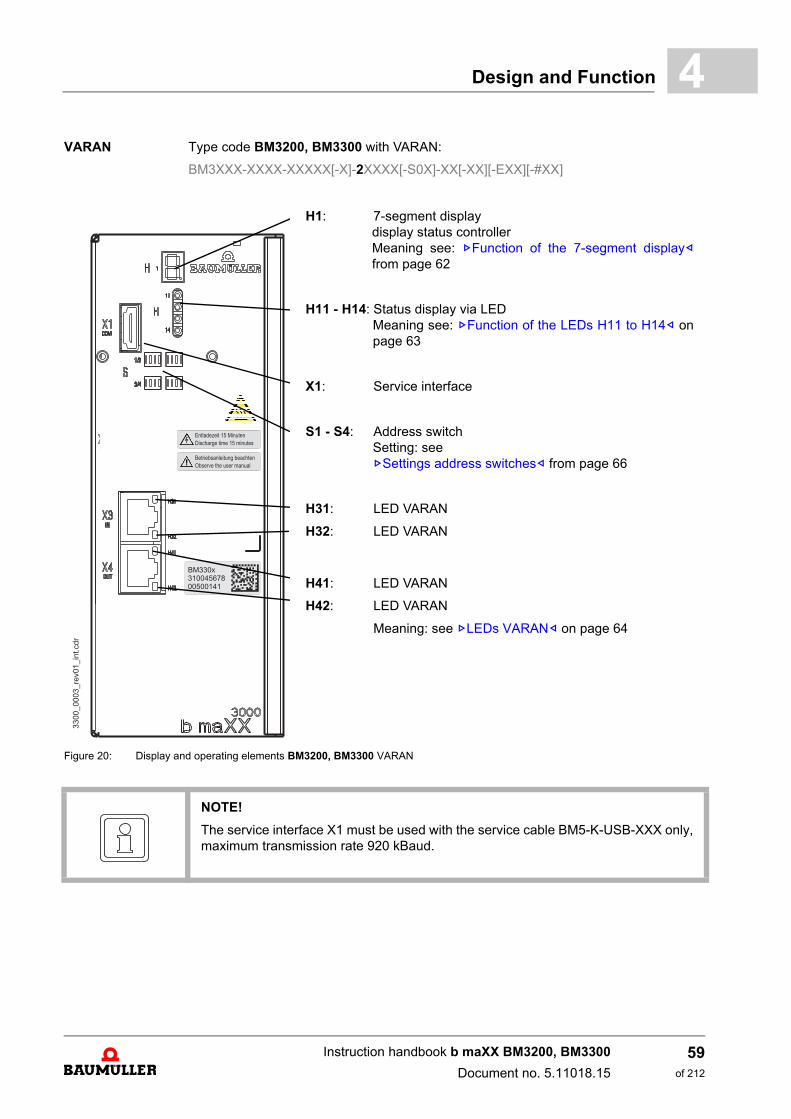
Design and Function 4
VARAN Type code BM3200, BM3300 with VARAN:BM3XXX-XXXX-XXXXX[-X]-2XXXX[-S0X]-XX[-XX][-EXX][-#XX]
Figure 20: Display and operating elements BM3200, BM3300 VARAN
H1: 7-segment displaydisplay status controllerMeaning see: ZFunction of the 7-segment display–from page 62
H11 - H14: Status display via LED Meaning see: ZFunction of the LEDs H11 to H14– onpage 63
X1: Service interface
S1 - S4: Address switchSetting: see ZSettings address switches– from page 66
H31: LED VARAN
H32: LED VARAN
H41: LED VARAN
H42: LED VARAN
Meaning: see ZLEDs VARAN– on page 64
NOTE!
The service interface X1 must be used with the service cable BM5-K-USB-XXX only,maximum transmission rate 920 kBaud.
Instruction handbook b maXX BM3200, BM3300
Document no. 5.11018.15
59of 212
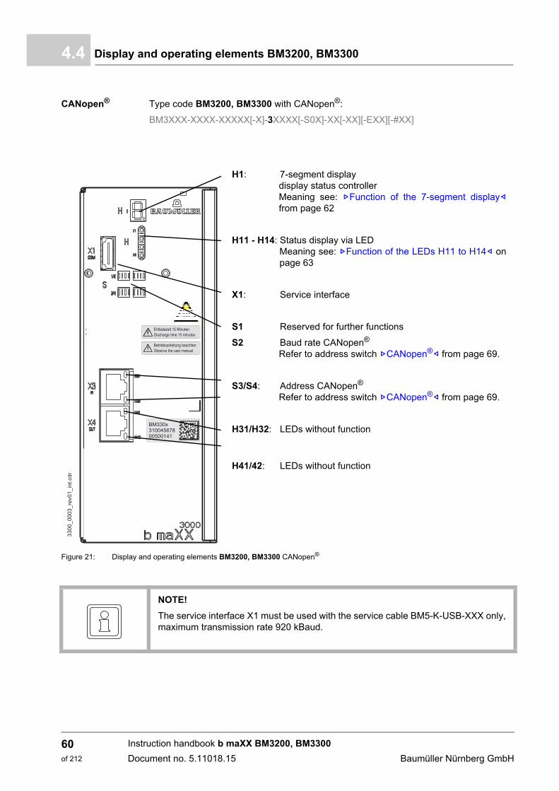
Display and operating elements BM3200, BM33004.4
CANopen® Type code BM3200, BM3300 with CANopen®:
BM3XXX-XXXX-XXXXX[-X]-3XXXX[-S0X]-XX[-XX][-EXX][-#XX]
Figure 21: Display and operating elements BM3200, BM3300 CANopen®
H1: 7-segment displaydisplay status controllerMeaning see: ZFunction of the 7-segment display–from page 62
H11 - H14: Status display via LED Meaning see: ZFunction of the LEDs H11 to H14– onpage 63
X1: Service interface
S1 Reserved for further functions
S2 Baud rate CANopen®
Refer to address switch ZCANopen®– from page 69.
S3/S4: Address CANopen®
Refer to address switch ZCANopen®– from page 69.
H31/H32: LEDs without function
H41/42: LEDs without function
NOTE!
The service interface X1 must be used with the service cable BM5-K-USB-XXX only,maximum transmission rate 920 kBaud.
Instruction handbook b maXX BM3200, BM3300
Document no. 5.11018.15 Baumüller Nürnberg GmbH
60of 212
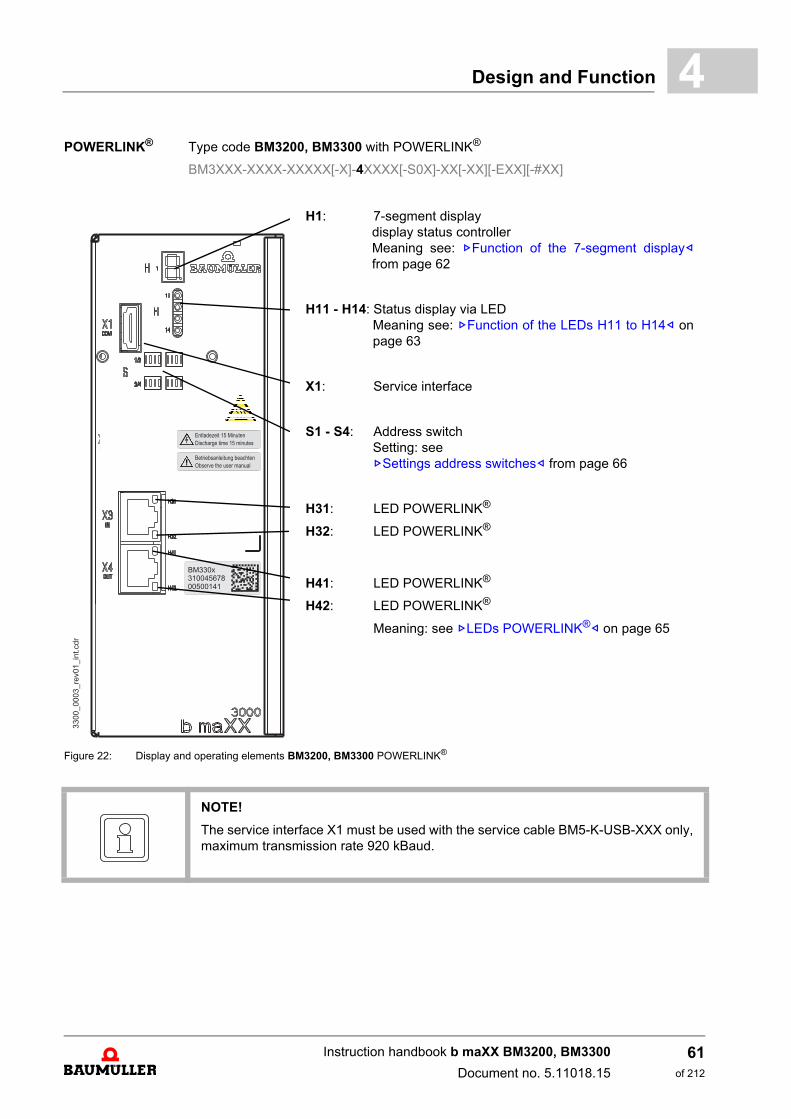
Design and Function 4
POWERLINK® Type code BM3200, BM3300 with POWERLINK®BM3XXX-XXXX-XXXXX[-X]-4XXXX[-S0X]-XX[-XX][-EXX][-#XX]
Figure 22: Display and operating elements BM3200, BM3300 POWERLINK®
H1: 7-segment displaydisplay status controllerMeaning see: ZFunction of the 7-segment display–from page 62
H11 - H14: Status display via LED Meaning see: ZFunction of the LEDs H11 to H14– onpage 63
X1: Service interface
S1 - S4: Address switchSetting: see ZSettings address switches– from page 66
H31: LED POWERLINK®
H32: LED POWERLINK®
H41: LED POWERLINK®
H42: LED POWERLINK®
Meaning: see ZLEDs POWERLINK®– on page 65
NOTE!
The service interface X1 must be used with the service cable BM5-K-USB-XXX only,maximum transmission rate 920 kBaud.
Instruction handbook b maXX BM3200, BM3300
Document no. 5.11018.15
61of 212
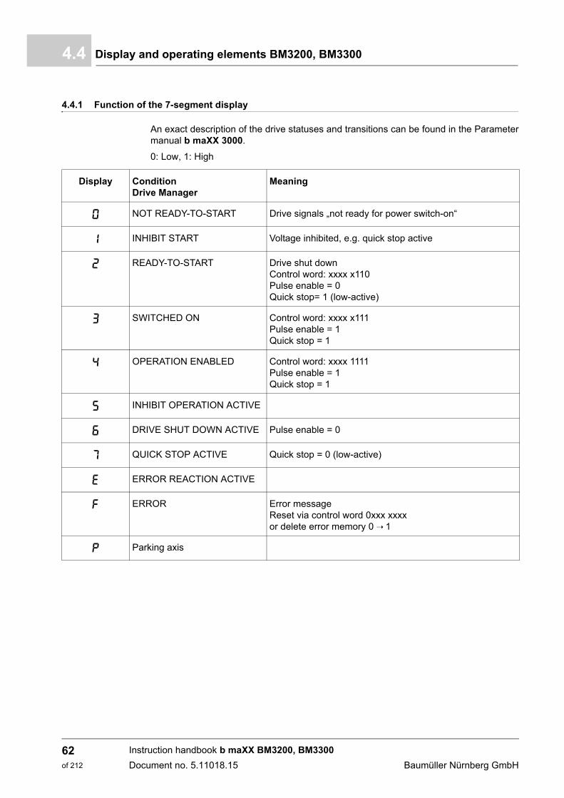
Display and operating elements BM3200, BM33004.4
4.4.1 Function of the 7-segment display
An exact description of the drive statuses and transitions can be found in the Parametermanual b maXX 3000.
0: Low, 1: High
Display Condition Drive Manager
Meaning
0 NOT READY-TO-START Drive signals „not ready for power switch-on“
1 INHIBIT START Voltage inhibited, e.g. quick stop active
2 READY-TO-START Drive shut downControl word: xxxx x110Pulse enable = 0Quick stop= 1 (low-active)
3 SWITCHED ON Control word: xxxx x111Pulse enable = 1Quick stop = 1
4 OPERATION ENABLED Control word: xxxx 1111Pulse enable = 1Quick stop = 1
5 INHIBIT OPERATION ACTIVE
6 DRIVE SHUT DOWN ACTIVE Pulse enable = 0
7 QUICK STOP ACTIVE Quick stop = 0 (low-active)
E ERROR REACTION ACTIVE
F ERROR Error messageReset via control word 0xxx xxxxor delete error memory 0 ➝ 1
P Parking axis
Instruction handbook b maXX BM3200, BM3300
Document no. 5.11018.15 Baumüller Nürnberg GmbH
62of 212
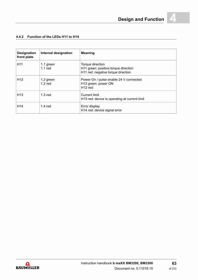
Design and Function 4
4.4.2 Function of the LEDs H11 to H14Designation front plate
Internal designation Meaning
H11 1.1 green1.1 red
Torque directionH11 green: positive torque directionH11 red: negative torque direction
H12 1.2 green1.2 red
Power-On / pulse enable 24 V connectedH12 green: power ONH12 red:
H13 1.3 red Current limitH13 red: device is operating at current limit
H14 1.4 red Error displayH14 red: device signal error
Instruction handbook b maXX BM3200, BM3300
Document no. 5.11018.15
63of 212
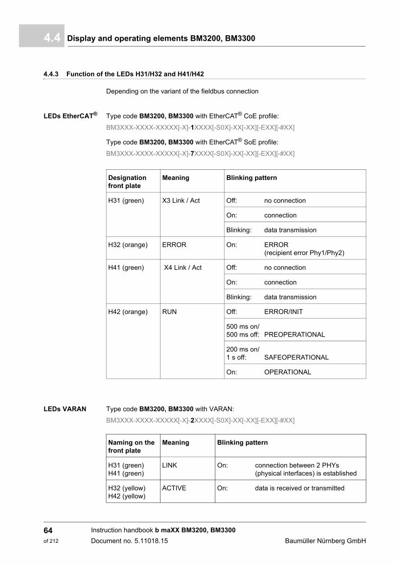
Display and operating elements BM3200, BM33004.4
4.4.3 Function of the LEDs H31/H32 and H41/H42
Depending on the variant of the fieldbus connection
LEDs EtherCAT® Type code BM3200, BM3300 with EtherCAT® CoE profile:
BM3XXX-XXXX-XXXXX[-X]-1XXXX[-S0X]-XX[-XX][-EXX][-#XX]
Type code BM3200, BM3300 with EtherCAT® SoE profile:
BM3XXX-XXXX-XXXXX[-X]-7XXXX[-S0X]-XX[-XX][-EXX][-#XX]
LEDs VARAN Type code BM3200, BM3300 with VARAN:
BM3XXX-XXXX-XXXXX[-X]-2XXXX[-S0X]-XX[-XX][-EXX][-#XX]
Designation front plate
Meaning Blinking pattern
H31 (green) X3 Link / Act Off: no connection
On: connection
Blinking: data transmission
H32 (orange) ERROR On: ERROR (recipient error Phy1/Phy2)
H41 (green) X4 Link / Act Off: no connection
On: connection
Blinking: data transmission
H42 (orange) RUN Off: ERROR/INIT
500 ms on/ 500 ms off: PREOPERATIONAL
200 ms on/1 s off: SAFEOPERATIONAL
On: OPERATIONAL
Naming on the front plate
Meaning Blinking pattern
H31 (green)H41 (green)
LINK On: connection between 2 PHYs (physical interfaces) is established
H32 (yellow)H42 (yellow)
ACTIVE On: data is received or transmitted
Instruction handbook b maXX BM3200, BM3300
Document no. 5.11018.15 Baumüller Nürnberg GmbH
64of 212
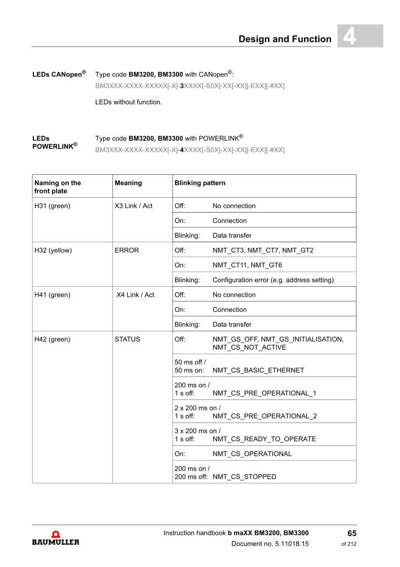
Design and Function 4
LEDs CANopen® Type code BM3200, BM3300 with CANopen®:BM3XXX-XXXX-XXXXX[-X]-3XXXX[-S0X]-XX[-XX][-EXX][-#XX]
LEDs without function.
LEDs POWERLINK®
Type code BM3200, BM3300 with POWERLINK®
BM3XXX-XXXX-XXXXX[-X]-4XXXX[-S0X]-XX[-XX][-EXX][-#XX]
Naming on the front plate
Meaning Blinking pattern
H31 (green) X3 Link / Act Off: No connection
On: Connection
Blinking: Data transfer
H32 (yellow) ERROR Off: NMT_CT3, NMT_CT7, NMT_GT2
On: NMT_CT11, NMT_GT6
Blinking: Configuration error (e.g. address setting)
H41 (green) X4 Link / Act Off: No connection
On: Connection
Blinking: Data transfer
H42 (green) STATUS Off: NMT_GS_OFF, NMT_GS_INITIALISATION,NMT_CS_NOT_ACTIVE
50 ms off /50 ms on: NMT_CS_BASIC_ETHERNET
200 ms on /1 s off: NMT_CS_PRE_OPERATIONAL_1
2 x 200 ms on /1 s off: NMT_CS_PRE_OPERATIONAL_2
3 x 200 ms on /1 s off: NMT_CS_READY_TO_OPERATE
On: NMT_CS_OPERATIONAL
200 ms on /200 ms off: NMT_CS_STOPPED
Instruction handbook b maXX BM3200, BM3300
Document no. 5.11018.15
65of 212
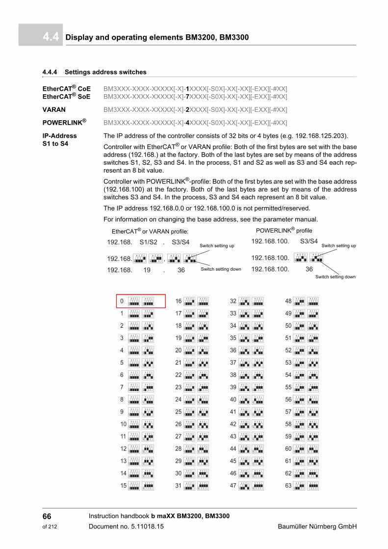
Display and operating elements BM3200, BM33004.4
4.4.4 Settings address switches
EtherCAT® CoEEtherCAT® SoE
BM3XXX-XXXX-XXXXX[-X]-1XXXX[-S0X]-XX[-XX][-EXX][-#XX]BM3XXX-XXXX-XXXXX[-X]-7XXXX[-S0X]-XX[-XX][-EXX][-#XX]
VARAN BM3XXX-XXXX-XXXXX[-X]-2XXXX[-S0X]-XX[-XX][-EXX][-#XX]
POWERLINK® BM3XXX-XXXX-XXXXX[-X]-4XXXX[-S0X]-XX[-XX][-EXX][-#XX]
IP-Address S1 to S4
The IP address of the controller consists of 32 bits or 4 bytes (e.g. 192.168.125.203).
Controller with EtherCAT® or VARAN profile: Both of the first bytes are set with the baseaddress (192.168.) at the factory. Both of the last bytes are set by means of the addressswitches S1, S2, S3 and S4. In the process, S1 and S2 as well as S3 and S4 each rep-resent an 8 bit value.
Controller with POWERLINK®-profile: Both of the first bytes are set with the base address(192.168.100) at the factory. Both of the last bytes are set by means of the addressswitches S3 and S4. In the process, S3 and S4 each represent an 8 bit value.
The IP address 192.168.0.0 or 192.168.100.0 is not permitted/reserved.
For information on changing the base address, see the parameter manual.
EtherCAT® or VARAN profile: POWERLINK® profile
Switch setting up
Switch setting down
Switch setting up
Switch setting down
Instruction handbook b maXX BM3200, BM3300
Document no. 5.11018.15 Baumüller Nürnberg GmbH
66of 212

Design and Function 4
Instruction handbook b maXX BM3200, BM3300
Document no. 5.11018.15
67of 212
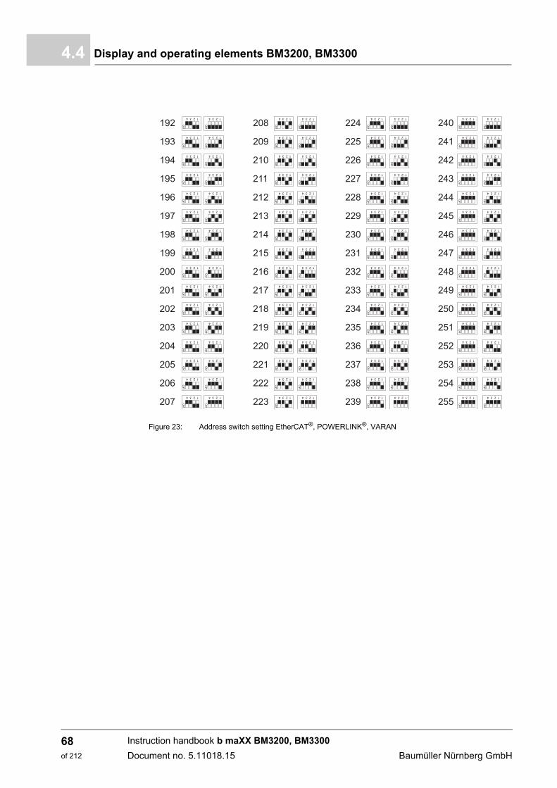
Display and operating elements BM3200, BM33004.4
Figure 23: Address switch setting EtherCAT®, POWERLINK®, VARAN
Instruction handbook b maXX BM3200, BM3300
Document no. 5.11018.15 Baumüller Nürnberg GmbH
68of 212

Design and Function 4
CANopen® BM3XXX-XXXX-XXXXX[-X]-3XXXX[-S0X]-XX[-XX][-EXX][-#XX]Baud rate S2
NOTE!
Switch up
= 0001
20 kBit/s 125 kBit/s, default setting
250 kBit/s 500 kBit/s
1 MBit/s
switch
Instruction handbook b maXX BM3200, BM3300
Document no. 5.11018.15
69of 212

Display and operating elements BM3200, BM33004.4
Address S3/S4
Figure 24: Address setting CANopen®
Instruction handbook b maXX BM3200, BM3300
Document no. 5.11018.15 Baumüller Nürnberg GmbH
70of 212
5TRANSPORT AND PACKAGING
5.1 Safety notes for transport
5.2 What to observe when transporting
For initial transport of a device, it is packed at the manufacturer's plant. If the device mustbe transported, ensure that the following conditions are met throughout the entire trans-port:
m Climate class 2 K 3 as per EN 60721-3-2
m Temperature range - 25 °C up to + 70 °C
m Vibration, shock, continuous shock class 2 M 1 as per EN 60721-3-2
NOTICE!
Damage due to unauthorized transport!
Transport handled by untrained personnel can lead to a substantial amount of mate-rial damage.
m The unloading of the packages upon delivery as well as the in-house transportshould only be done by trained personnel.
m Contact Baumüller Nürnberg GmbH sales office if necessary.
WARNING!
Danger of physical impact!
Secure devices against falling down.
Therefore:
m Take suitable measures, such as supports, hoists, straps, etc., to ensure that de-vice cannot fall down.
m Use appropriate means of transport.
71of 212
Instruction handbook b maXX BM3200, BM3300
Document no. 5.11018.15
Transport inspection5.3
5.3 Transport inspection
Upon receiving the delivered goods, immediately examine them for completeness andtransport damage.
If there is visible transport damage on the outside, proceed as follows:
m Do not accept the delivery or conditionally accept it with reservations.
m Note the extent of the damage on the transport documents or on the delivery note ofthe shipping agent.
m Immediately file a complaint with the freight carrier. Have the complaint confirmed inwriting and immediately contact the responsible representative of Baumüller NürnbergGmbH.
5.4 Unpacking
After having received the packaged device:
h Avoid forceful transport agitation and hard jolts, e.g. when putting an item down.
If no transport damage is visible:
h Open the packaging of the device.
h Verify the delivery scope based on the delivery note.
File a claim with the responsible Baumüller representative if the delivery is incomplete.
5.5 Disposal of the packaging
The packaging consists of cardboard, plastic, metal parts, corrugated cardboard and/orwood.
h When disposing of the packaging, comply with the national regulations valid at the usearea.
NOTE!
The device may not be operated if there is visible transport damage!
NOTE!
Claim each individual deficiency as soon as it has been detected. Damage claims canonly be validly asserted within the claim registration period.
Instruction handbook b maXX BM3200, BM3300
Document no. 5.11018.15 Baumüller Nürnberg GmbH
72of 212

6MOUNTING
The device is intended for mounting it into a control cabinet.
Mounting comprises the following steps:
1 Mounting preparation (for drilling holes, see ZDrilling templates– from page 77)
2 Mounting the device (for attachment, see ZMounting instruction BM3200, BM3300– on page 79)
6.1 Safety notes
NOTE!
Mounting shall only be performed by employees of the manufacturer or by other qual-ified personnel.
Qualified personnel are persons who – on account of their occupational training, ex-perience, instruction and knowledge of relevant standards and stipulations, accidentprevention regulations and operating conditions – are authorized by the persons, re-sponsible for the safety of the facilities to perform the respective activities that arenecessary, while at the same time recognizing and preventing any potential risks.The qualifications necessary for working with the device are, for example:
m Occupational training or instruction in accordance with the standards of safety en-gineering for the care and use of appropriate safety equipment.
73of 212
Instruction handbook b maXX BM3200, BM3300
Document no. 5.11018.15
Safety notes6.1
WARNING!
Danger as a result of faulty mounting!
The mounting requires qualified personnel with adequate experience. Faulty mount-ing can lead to life-threatening situations or substantial material damage.
Therefore:
m Only allow mounting to be performed by employees of the manufacturer or by oth-er qualified personnel.
WARNING!
Danger of physical impact!
Secure devices against falling down.
NOTICE!
Danger due to electrostatic discharge.
The connecting terminals of the device are partially at risk due from ESD.
Therefore:
Please heed the respective notes.
Instruction handbook b maXX BM3200, BM3300
Document no. 5.11018.15 Baumüller Nürnberg GmbH
74of 212
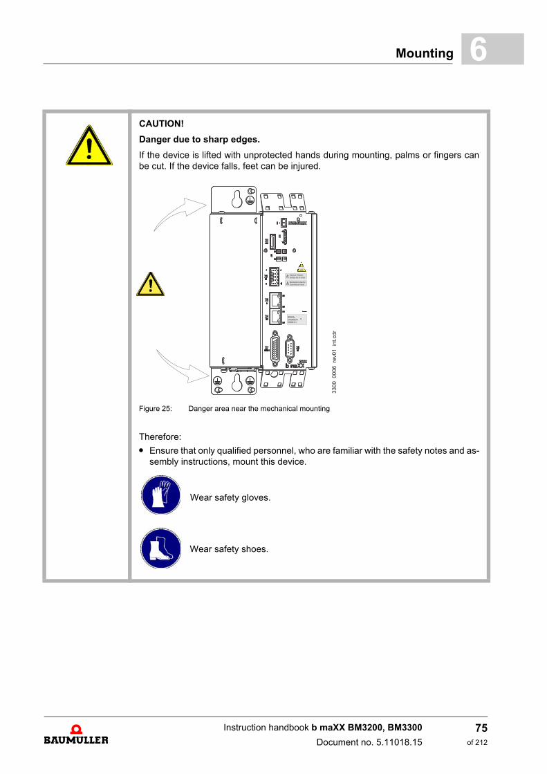
Mounting 6
CAUTION!
Danger due to sharp edges.
If the device is lifted with unprotected hands during mounting, palms or fingers canbe cut. If the device falls, feet can be injured.
Figure 25: Danger area near the mechanical mounting
Therefore:
m Ensure that only qualified personnel, who are familiar with the safety notes and as-sembly instructions, mount this device.
Wear safety gloves.
Wear safety shoes.
Instruction handbook b maXX BM3200, BM3300
Document no. 5.11018.15
75of 212
Preparing for mounting6.2
6.2 Preparing for mounting
Based on the project planning and the drilling templates (see ZDrilling templates– frompage 77), the positions of the attachment drill holes can be determined.
NOTICE!
Property damage due to conductive contamination.
Therefore:
m When performing installation work of any kind, it must be ensured that no foreignmaterial (e.g. drill shavings, copper strands, etc.) gets into the device as a result.
m If possible, the drilling of the holes should be done before mounting the device andthe configuring of the cables should take place outside of the control cabinet. If thisis not possible, the device must be appropriately covered.Remove this covering again prior to starting operation without fail!
CAUTION!
Eye injury due to flung particles.
Metal particles are flung when making the drill holes and the cutout sections.
Therefore:
Wear safety goggles!
Instruction handbook b maXX BM3200, BM3300
Document no. 5.11018.15 Baumüller Nürnberg GmbH
76of 212
Mounting 6
6.3 Drilling templatesHow to determine the required space in the control cabinet, see ZDimensions– frompage 25.
Use the drilling templates to make the necessary drill holes.
Tolerance specifications
NOTE!
Consider the minimum clearances for cooling when making the drill holes.
Further notes see ZDimensions– from page 25 and ZCooling– from page 35.
NOTE!
m Assembly permitted in the displayed position only (vertical with air cooling from thebottom to the top).
m A lining up of several devices next to each other is possible. Comply with the specified clearance of 100 mm above and below the device, so that the air circu-lation for heat dissipation is guaranteed.
NOTE!
All dimensions in mm.
Drill hole dimensioning ±0.2 mm
Relative tolerance of discretionary divisions ±0.1 mm
Instruction handbook b maXX BM3200, BM3300
Document no. 5.11018.15
77of 212
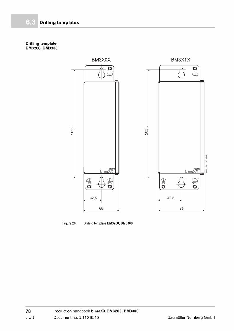
Drilling templates6.3
Drilling template BM3200, BM3300
Figure 26: Drilling template BM3200, BM3300
Instruction handbook b maXX BM3200, BM3300
Document no. 5.11018.15 Baumüller Nürnberg GmbH
78of 212
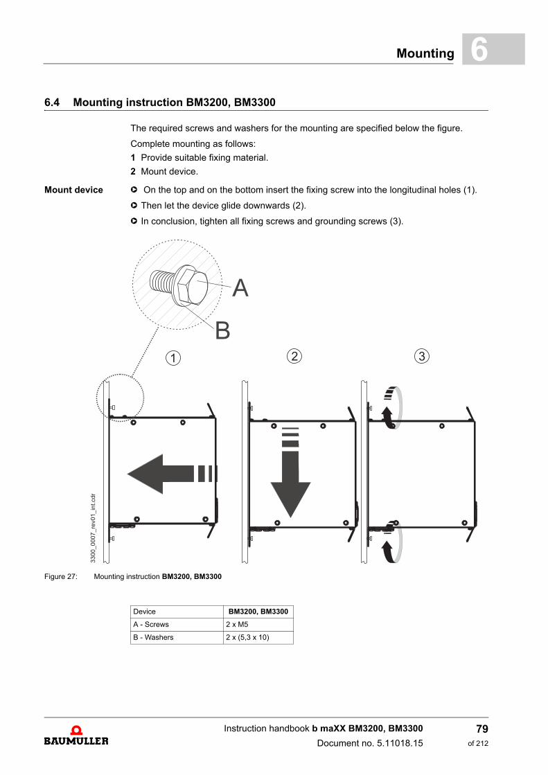
Mounting 6
6.4 Mounting instruction BM3200, BM3300The required screws and washers for the mounting are specified below the figure.
Complete mounting as follows:
1 Provide suitable fixing material.
2 Mount device.
Mount device h On the top and on the bottom insert the fixing screw into the longitudinal holes (1).
h Then let the device glide downwards (2).
h In conclusion, tighten all fixing screws and grounding screws (3).
Figure 27: Mounting instruction BM3200, BM3300
Device BM3200, BM3300
A - Screws 2 x M5
B - Washers 2 x (5,3 x 10)
Instruction handbook b maXX BM3200, BM3300
Document no. 5.11018.15
79of 212

Mounting instruction BM3200, BM33006.4
Instruction handbook b maXX BM3200, BM3300
Document no. 5.11018.15 Baumüller Nürnberg GmbH
80of 212
7INSTALLATION
This chapter describes the electrical installation of the device. The mechanical mountingis described in ZMounting– from page 73.
Assure, that the technical preconditions are fulfilled, before installation:
Prior to installation, ensure that the technical prerequisites have been fulfilled:
1 Check the demands on the electrical power supply.
2 Check the requirements for the electrical cables and the provision of corresponding ca-bles.
3 Check the properties of the connections and the specified configuration of the respec-tive cables.
7.1 Safety notes
NOTE!
Installation shall only be performed by employees of the manufacturer or by otherqualified personnel.
Qualified personnel are persons who – on account of their occupational training, ex-perience, instruction and knowledge of relevant standards and stipulations, accidentprevention regulations and operating conditions – are authorized by the persons re-sponsible for the safety of the facilities to perform the respective activities that arenecessary, while at the same time recognizing and preventing any potential risks.The qualifications necessary for working with the device are, for example:
m Occupational training or instruction, and the authorization to commission, groundand mark electrical power circuits and devices in accordance with the standards ofthe safety engineering.
m Occupational training or instruction, in accordance with the standards of work safe-ty, for the care and use of appropriate safety equipment.
81of 212
Instruction handbook b maXX BM3200, BM3300
Document no. 5.11018.15
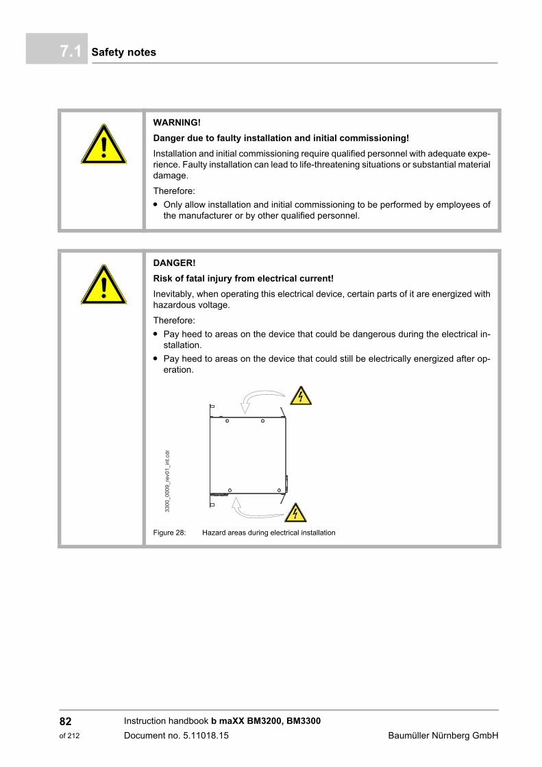
Safety notes7.1
WARNING!
Danger due to faulty installation and initial commissioning!
Installation and initial commissioning require qualified personnel with adequate expe-rience. Faulty installation can lead to life-threatening situations or substantial materialdamage.
Therefore:
m Only allow installation and initial commissioning to be performed by employees ofthe manufacturer or by other qualified personnel.
DANGER!
Risk of fatal injury from electrical current!
Inevitably, when operating this electrical device, certain parts of it are energized withhazardous voltage.
Therefore:
m Pay heed to areas on the device that could be dangerous during the electrical in-stallation.
m Pay heed to areas on the device that could still be electrically energized after op-eration.
Figure 28: Hazard areas during electrical installation
33
00
_0
00
9.c
dr
_re
v0
1_
int
Instruction handbook b maXX BM3200, BM3300
Document no. 5.11018.15 Baumüller Nürnberg GmbH
82of 212
Installation 7
Danger from residual energy7.2 Voltage test
DANGER!
Risk of fatal injury from electrical current!
Stored electric charge.
Discharge time of the complete system = discharge time of the device with the lon-gest DC link discharge time in the complete system.
Refer to Z Electrical Data –.
Therefore:
m Do not touch electrically live parts before taking into account the discharge time ofthe capacitors.
m Heed corresponding notes on the equipment.
m If additional capacitors are connected to the DC link, the DC link discharge cantake a much longer time. In this case, the necessary waiting period must itself bedetermined or a measurement made as to whether the equipment is de-energized.This discharge time must be posted, together with an IEC 60417-5036 (2002-10)warning symbol, on a clearly visible location of the control cabinet.
DANGER!
Risk of fatal injury from electrical current!
During the routine test of these devices, a voltage test is performed by BaumüllerNürnberg GmbH in accordance with EN 61800-5-1, section 5.2.3.2. Thus it is unnec-essary for the customer to do this.
Therefore:
m Subsequent tests of the devices using high voltages may only be performed byBaumüller Nürnberg GmbH.
m Disconnect the converter from the system during high-voltage testing!
Instruction handbook b maXX BM3200, BM3300
Document no. 5.11018.15
83of 212
Demands on the electrical power supply7.3
7.3 Demands on the electrical power supply
For all important data, see ZRequirements to the energy supply: power supply– frompage 28.
Minor deviations from requirements in the power supply can lead to malfunctioning of thedevice. If the power supply deviates too much from the requirements, the device can bedestroyed.
The devices may only be operated in secondary surroundings (e.g. an industrial environ-ment).
The destruction of the device can cause personal injury.
7.4 Requirements for the connection cables
h Take into account IEC/EN 60204-1, Chapter 13 when selecting the cable.
h The protective ground cross-section of the cable must be compliant with IEC/EN 60204-1, section 5.2, tab. 1.
h A fixed connection for the protective ground conductor is mandatorily specified for op-eration of the device.
h Use copper cable approved for a minimum of 60 °C (drives < 3 x 100 A) or 75 °C(drives 3 x 100 A), if UL 508C is in consideration.
For further details (e.g. maximum permissible length), see ZCables– from page 171.
7.5 Protection of the device and accordingly of the cable
In order to protect this device and accordingly the cables against overload and possibledamages / destruction due to the power supply, cable protection fuses and device pro-tection fuses must be installed. Data of the required fuses see ZFuses– from page 185.
DANGER!
Risk of fatal injury from electrical current!
If the requirements for the power supply are not complied, the device can be dam-aged or destroyed, thereby greatly endangering individuals.
Therefore:
m Prior to installation, ensure that the prerequisites for power supply have been ful-filled.
Instruction handbook b maXX BM3200, BM3300
Document no. 5.11018.15 Baumüller Nürnberg GmbH
84of 212
Installation 7
7.6 PE connection and RCD compatibilityDepending on the functional principle, leakage current >3.5 mAAC or >10 mADC can flowthrough the protective conductor. Consequently, a PE connection in accordance with EN61800-5-1 is specified.
7.7 Installation requirements with regard to EMC stability
DANGER!
Risk of fatal injury from electrical current!
This product can cause direct and/or alternating current in the protective ground con-ductor.
The leakage current, due to the functional principle of the device, can lead to prema-ture triggering of the fault current protective device or generally prevent triggering ofit.
Therefore:
m Wherever a differential current device (RCD) is used for protection in case of director indirect contact, only an RCD of the type B is permissible to provide current tothis product.
m Otherwise a different protective measure must be utilized, such as separation fromthe surroundings by means of double or enhanced isolation, or separation from thepower supply network by means of an isolating transformer, for example.
NOTE!
The emission of radio frequency interference (RFI) is to a great extent dependent onthe wiring, spatial expansiveness and the arrangement of the components in the sys-tem. Ensuring electromagnetic compatibility compliance in accordance with legal re-quirements is therefore only possible on the completely assembled system and isthus the responsibility of the system manufacturer or proprietor (re Art. 6, Par. 9 ofthe EMVG; European EMC law).
NOTE!
The important information on EMC-compliant installation can be found in this Instruc-tion handbook. Additional notes on building a CE-compliant system, that are impera-tive to take heed of, can be found in the Baumüller Instruction handbook „Filters formains applications“, 5.09010. This manual can be obtained from BaumüllerNürnberg GmbH.
Instruction handbook b maXX BM3200, BM3300
Document no. 5.11018.15
85of 212
Shielding plan7.8
In order to achieve an EMC-compatible and interference-free operation within the frame-work of legislation, the following aspects must be considered.Please do not hesitate to contact our sales department or the application department ofBaumüller Nürnberg GmbH, if there are any questions.
m Only use Baumüller motor cables and Baumüller components.
m Use suitable line filters recommended by Baumüller Nürnberg GmbH.
m Mount all components on a single mounting plate with a continuously good electrically-conductive surface (e.g. galvanized steel plate).
m Keep the ground connection device/ground plate as short as possible (< 30 cm), usingfine-stranded cables with a large cross section (refer to ZPE connections BM3200, BM3300 rear panel– on page 139).
m Ensure the correct sequence at installation:Power supply - fuse - filter - BM3200, BM3300 - (motor filter) - motor.
m Ensure that the motor cable is continuous, without interruption.Do not interrupt motor cables with terminals, contactors or fuses, for example.
m If possible route the cables on the surface of the grounded mounting plate (i. e. the least effective antenna height).
m When routing in parallel, minimum clearance of 20 cm should be observed betweensignal and control cables vis-à-vis the power cables.
m Cables of different EMC categories (e.g. signal cables - line cables and/or motor ca-bles) should be crossed at a 90 ° angle.
m Contact the major cable shield when laying cables through walls, which separate dif-ferent EMC areas.
m Contact all the cable’s shields on both sides surface-to-surface and also well-conduc-tive with ground.
7.8 Shielding plan
The shielding of the motor cable as well as of the motor temperature cable must be con-nected electrically with the mounting plate or with shield sheet (see ZAccessories kitshielding BM3200, BM3300– on page 191).
HINWEIS!
A ferrite core (part No. 308293) must be used with a DC link connection longer than3 m to ensure a reliable EMC interference immunity of the BM3200, BM3300. TheDC link cables connected with 1C1 and 1D1 must be led through the ferrite core with3 turns per cable. The ferrite core should be as close as possible to the connectionX205 of the BM3200, BM3300.
NOTE!
Baumüller Nürnberg GmbH recommends the shielding connection with shield sheet.
Instruction handbook b maXX BM3200, BM3300
Document no. 5.11018.15 Baumüller Nürnberg GmbH
86of 212
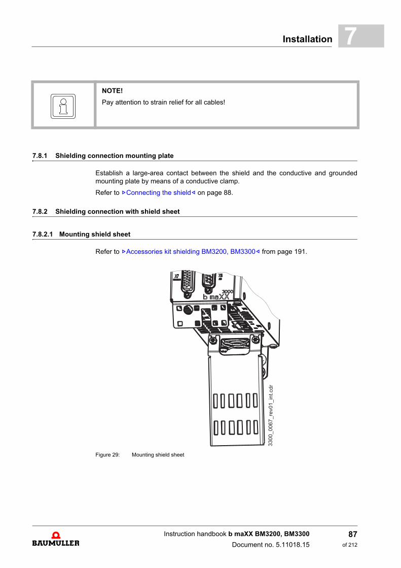
Installation 7
7.8.1 Shielding connection mounting plate
Establish a large-area contact between the shield and the conductive and groundedmounting plate by means of a conductive clamp.
Refer to ZConnecting the shield– on page 88.
7.8.2 Shielding connection with shield sheet
7.8.2.1 Mounting shield sheet
Refer to ZAccessories kit shielding BM3200, BM3300– from page 191.
Figure 29: Mounting shield sheet
NOTE!
Pay attention to strain relief for all cables!
Instruction handbook b maXX BM3200, BM3300
Document no. 5.11018.15
87of 212
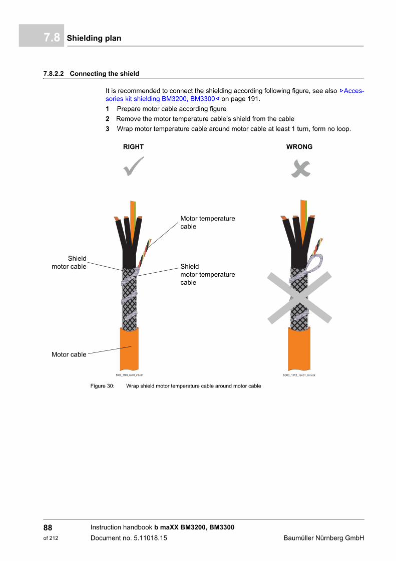
Shielding plan7.8
7.8.2.2 Connecting the shield
It is recommended to connect the shielding according following figure, see also ZAcces-sories kit shielding BM3200, BM3300– on page 191.
1 Prepare motor cable according figure
2 Remove the motor temperature cable’s shield from the cable
3 Wrap motor temperature cable around motor cable at least 1 turn, form no loop.
RIGHT WRONG
Shieldmotor cable
Motor cable
Motor temperaturecable
Shieldmotor temperaturecable
Figure 30: Wrap shield motor temperature cable around motor cable
������������������������������������������������������������
������������������������������������������������������������
������������������������������������������������������������
������������������������������������������������������������
Instruction handbook b maXX BM3200, BM3300
Document no. 5.11018.15 Baumüller Nürnberg GmbH
88of 212
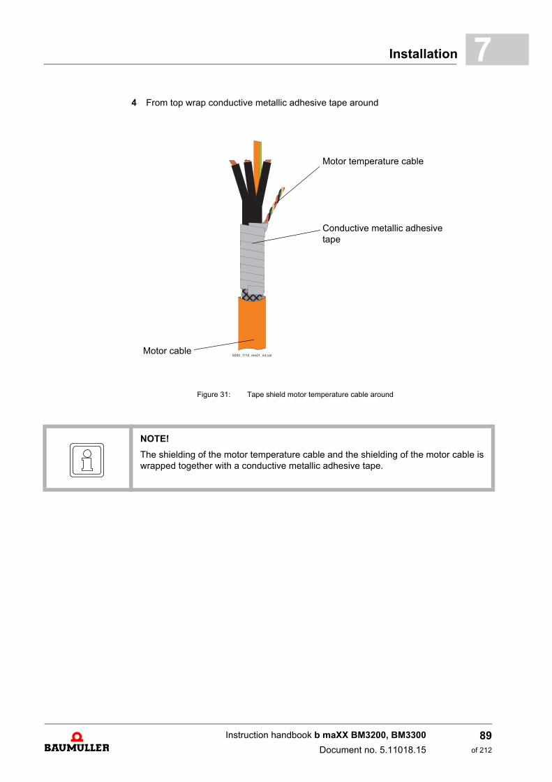
Installation 7
4 From top wrap conductive metallic adhesive tape aroundMotor cable
Motor temperature cable
Conductive metallic adhesive tape
Figure 31: Tape shield motor temperature cable around
������������������������������������������������������������
������������������������������������������������������������
NOTE!
The shielding of the motor temperature cable and the shielding of the motor cable iswrapped together with a conductive metallic adhesive tape.
Instruction handbook b maXX BM3200, BM3300
Document no. 5.11018.15
89of 212
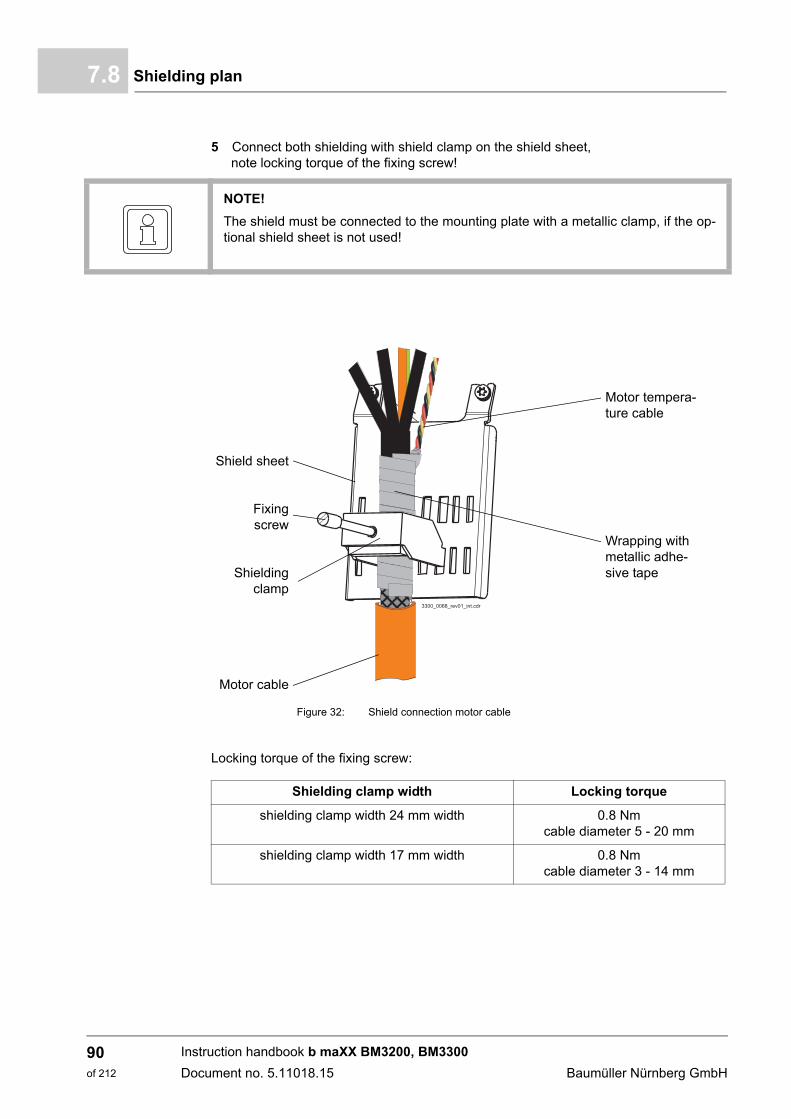
Shielding plan7.8
5 Connect both shielding with shield clamp on the shield sheet,note locking torque of the fixing screw!
Locking torque of the fixing screw:
NOTE!
The shield must be connected to the mounting plate with a metallic clamp, if the op-tional shield sheet is not used!
Shield sheet
Fixingscrew
Shieldingclamp
Motor cable
Figure 32: Shield connection motor cable
Motor tempera-ture cable
Wrapping with metallic adhe-sive tape
Shielding clamp width Locking torque
shielding clamp width 24 mm width 0.8 Nmcable diameter 5 - 20 mm
shielding clamp width 17 mm width 0.8 Nmcable diameter 3 - 14 mm
������������������������
������������������������
Instruction handbook b maXX BM3200, BM3300
Document no. 5.11018.15 Baumüller Nürnberg GmbH
90of 212
Installation 7
7.9 Requirements for the motor temperature sensorsTo protect the motor against impermissible overheating, a motor temperature sensor canbe connected to the BM3200, BM3300 device via the encoder cable or directly. The de-vice switches off of the motor when a settable threshold temperature has been exceeded.
1) Motor protection thermistor (PTC) as per DIN 44080-082
NOTICE!
The motor must be protected against overtemperature according EN 61800-5-1. The device‘s integrated monitoring function „Overtemperature Motor“ fulfills this re-quirement.The user is responsible for realization of the motor overtemperature monitoring ac-cording EN 61800-5-1 in case the used motor is not equipped with a motor tempera-ture sensor or the sensor is not connected.
NOTE!
The thermal memory of the motor and the speed-dependent electronic motor over-load protection is not available if no motor temperature sensor is used.
NOTE!
The motor temperature sensor must be connected either on the BM3200, BM3300directly or via the encoder cable, the other input must not be connected.
Type Additional requirements Isolation
KTY84/PT1000 - SELV/PELV
MSKL 1) (PTC) R = 1 k at TProtection, Imax < 2 mA SELV/PELV
NOTE!
The motor temperature sensor should be installed in such a manner that „safe elec-trical separation“ is ensured. The motor temperature sensors integrated intoBaumüller motors meet these requirements. If third-party motors are connected, theproprietor must ensure that the temperature sensors used in the motor of a third-partymanufacturer motor comply with the „safe electrical separation“ function.
Instruction handbook b maXX BM3200, BM3300
Document no. 5.11018.15
91of 212
Installation procedure BM3200, BM33007.10
7.10 Installation procedure BM3200, BM3300
h All cables must be installed EMC-compatible.
h Connect cable (see ZConnecting diagrams– from page 93).(Observe the allowable torque!)
The installation consists of the following steps:
1 Connect motor to the terminals 1U2, 1V2, 1W2, PE.Consider the appropriate phase connection (rotational direction)Consider the allowable torques!Connection data see ZX107 - motor connection– on page 138.
2 Connect fuses (F1), also see ZFuses– from page 185.
3 Connect main contactor (K1, option).
4 Connect line filter (Z1)
5 Connect device via the power supply input terminals BM32XX-XT, BM33XX-XTThree-phase: 1U1, 1V1 and 1W1at reduced power also single-phase possible: 1U1 and 1W1BM32XX-XE, BM33XX-XESingle-phase: L and NConnection data see ZX202, X203, X205 - power supply, DC link, ballast resistorconnection– on page 132.
6 Connect the protection conductor to the PE connection (a permanent PE connectionis compulsory), also see ZPE connections BM3200, BM3300 rear panel– on page 139.
7 Connect 24 V-supply via terminals X200 -1, X200 -2Connection data see ZX200 - 24V voltage supply– on page 131.
8 Connect signal bus X300 (see ZX300 - signal bus– from page 134)
9 Connect encoder(encoder types and pin assignment see ZX6 / X7 - encoder connection– from page121)
DANGER!
Risk of fatal injury from electrical current!
Parts under voltage are dangerous to life.
Therefore:
m Assure, that the device and the parts (e. g. power cables), which are mounted aswell as the mounting range are de-energized during mounting.
NOTE!
The plugging and pulling of the energized encoder cable is not permitted and cancause a destruction.Therefore, the 24V-supply voltage must be switched off before and the connectormust be interlocked.
Instruction handbook b maXX BM3200, BM3300
Document no. 5.11018.15 Baumüller Nürnberg GmbH
92of 212
Installation 7
10 Connection temperature sensor of motor (consider polarity!)m Use of encoder cable
m Use of connector ZX101 - motor temperature– on page 137
11 Connect signal generator for pulse enable:via terminals X2 -5 (IF1), X2 -1 (M24V), see ZX2 - Digital inputs/outputs– on page 115.
12 Only when using devices without internal ballast resistor BM3XXX-XXXX-XXXXX-E-XXXXX and dependent on the application connect a ballast resistor (RB) to the termi-nals 1C1 and Ba-, also see ZElectrical data– from page 36.
7.11 Connecting diagrams
The connecting diagram for the power supply, the motor, the pulse enable a. s. o. areshown from ZPage 94– onwards.
The connection data and the pin assignments are found from ZPage 113– onwards.
NOTE!
The motor temperature sensor must be connected either on the BM3200, BM3300X101 directly or via the encoder cable. It is forbidden to use both connections simul-taneously.
NOTE!
The ballast resistor connection is not short-circuit proof.
When using devices BM3200, BM3300 without internal ballast resistor an externalballast resistor must be connected in case of braking operation.
NOTE!
In order to ensure an adequate current carrying capacity of the connections, complyto the torques!
NOTE!
The identifiers 1C1 and 1D1 were taken over from DIN EN 60445. 1C1 is the connec-tion to the positive DC link cable/rail, and in the past was identified by Baumüller insome devices as ZK+. 1D1 is the connection to the negative DC link cable/rail, andin the past was identified by Baumüller in some devices as ZK-.
Instruction handbook b maXX BM3200, BM3300
Document no. 5.11018.15
93of 212
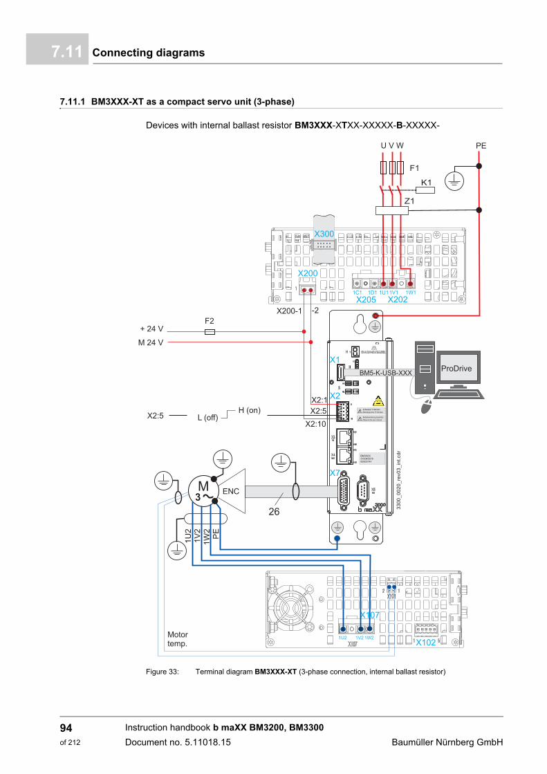
Connecting diagrams7.11
7.11.1 BM3XXX-XT as a compact servo unit (3-phase)
Devices with internal ballast resistor BM3XXX-XTXX-XXXXX-B-XXXXX-
Figure 33: Terminal diagram BM3XXX-XT (3-phase connection, internal ballast resistor)
Instruction handbook b maXX BM3200, BM3300
Document no. 5.11018.15 Baumüller Nürnberg GmbH
94of 212
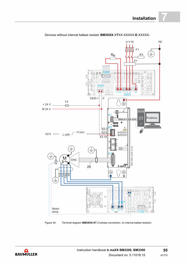
Installation 7
Devices without internal ballast resistor BM3XXX-XTXX-XXXXX-E-XXXXX-Figure 34: Terminal diagram BM3XXX-XT (3-phase connection, no internal ballast resistor)
Instruction handbook b maXX BM3200, BM3300
Document no. 5.11018.15
95of 212
Connecting diagrams7.11
X1 Service interface, see ZX1 - Service interface– on page 114.
X2 Digital in- and outputs, e.g. pulse enable, see ZX2 - Digital inputs/outputs– on page 115.
X2:5 Input pulse enable, Low: not enabled, High: enabled (operation possible).
X3, X4 Connections for fieldbus EtherCAT®, VARAN, CANopen®, POWERLINK®, according to the version also see ZX3 / X4 - fieldbus connection– on page 116.
X6 Analog in- and outputs, see ZX6 - analog inputs/outputs– on page 120.
X7 Encoder analysis, see ZX6 / X7 - encoder connection– from page 121.
X101 Connection motor temperature,see ZX101 - motor temperature– on page 137.
X102 Connection STO,see ZX102 - safe torque off - option– on page 137.
X107 Motor, also see ZRequirements to the motor– on page 29 and ZX107 - motor connection– on page 138.
X200 Connections for the 24 V-voltage supply (SELV/PELV), see ZRequirements to the control voltage / 24 V-supply– on page 29 and ZX200 - 24V voltage supply– on page 131.
X202 Power supply, see ZRequirements to the energy supply: power supply– from page 28 andZX202, X203, X205 - power supply, DC link, ballast resistor connection– on page 132.
X203 Power supply and ballast resistor connection, see ZRequirements to the energy supply: power supply– from page 28 andZX202, X203, X205 - power supply, DC link, ballast resistor connection– on page 132.
X300 Signal bus, connection to further units, see ZX300 - signal bus– on page 134.
PE PE-connection,see ZPE connection and RCD compatibility– from page 85 andZPE connections BM3200, BM3300 rear panel– on page 139.
F1 Fuses (cable + device), see ZProtection of the device and accordingly of the cable– from page 84.
F2 Fuse for the 24 V-voltage supply
K1 Power circuit contactor (optional)
Z1 Line filter, see ZLine filter– on page 187.
Instruction handbook b maXX BM3200, BM3300
Document no. 5.11018.15 Baumüller Nürnberg GmbH
96of 212
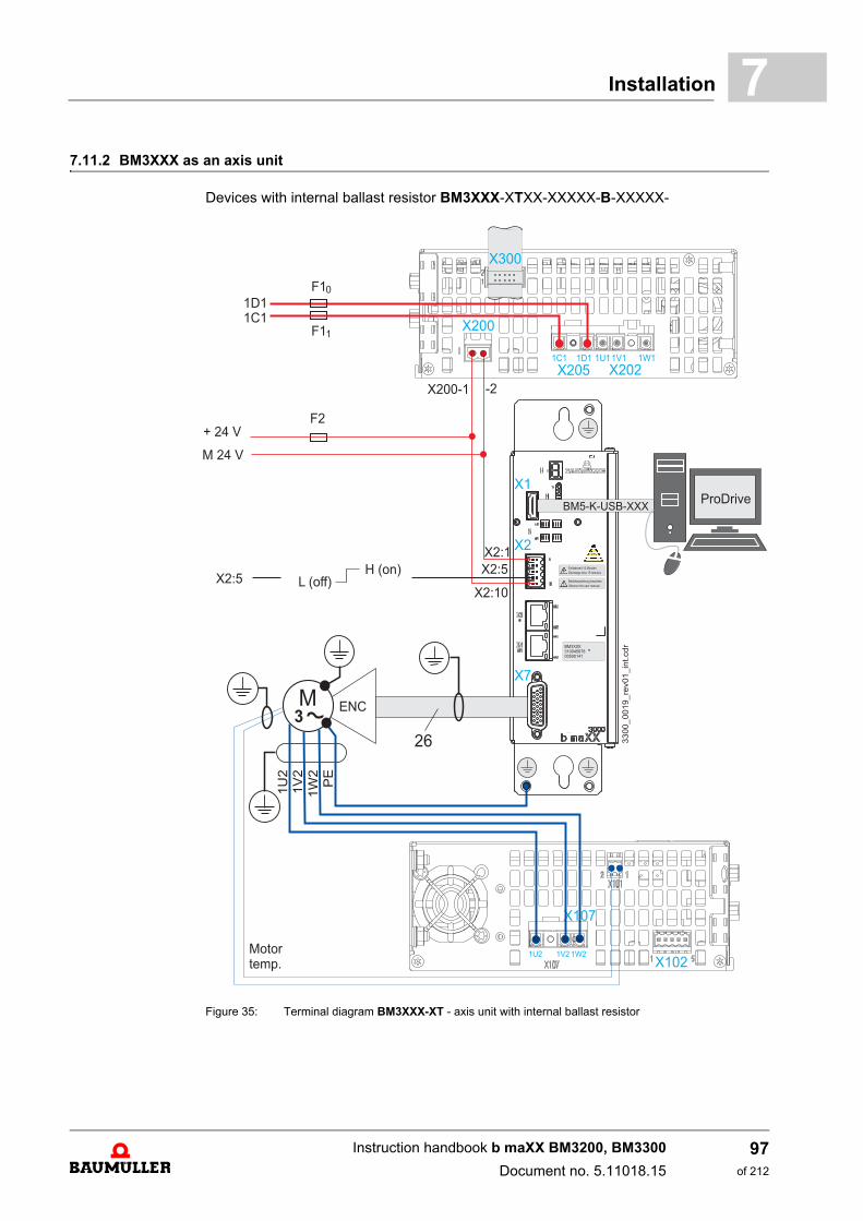
Installation 7
7.11.2 BM3XXX as an axis unitDevices with internal ballast resistor BM3XXX-XTXX-XXXXX-B-XXXXX-
Figure 35: Terminal diagram BM3XXX-XT - axis unit with internal ballast resistor
Instruction handbook b maXX BM3200, BM3300
Document no. 5.11018.15
97of 212

Connecting diagrams7.11
Devices without internal ballast resistor BM3XXX-XTXX-XXXXX-E-XXXXX-
Figure 36: Terminal diagram BM3XXX - axis unit, without internal ballast resistor
Instruction handbook b maXX BM3200, BM3300
Document no. 5.11018.15 Baumüller Nürnberg GmbH
98of 212
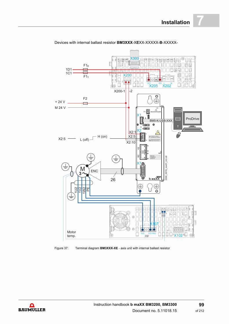
Installation 7
Devices with internal ballast resistor BM3XXX-XEXX-XXXXX-B-XXXXX-Figure 37: Terminal diagram BM3XXX-XE - axis unit with internal ballast resistor
Instruction handbook b maXX BM3200, BM3300
Document no. 5.11018.15
99of 212
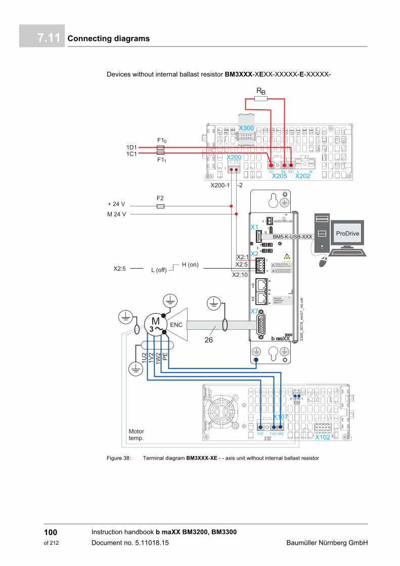
Connecting diagrams7.11
Devices without internal ballast resistor BM3XXX-XEXX-XXXXX-E-XXXXX-
Figure 38: Terminal diagram BM3XXX-XE - - axis unit without internal ballast resistor
Instruction handbook b maXX BM3200, BM3300
Document no. 5.11018.15 Baumüller Nürnberg GmbH
100of 212
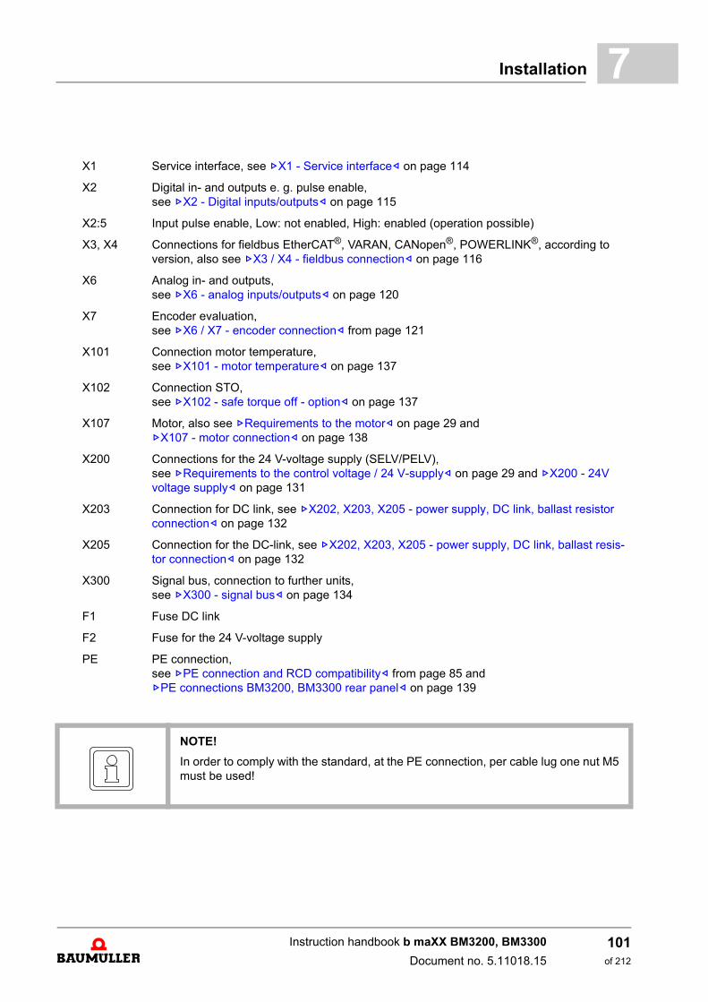
Installation 7
X1 Service interface, see ZX1 - Service interface– on page 114
X2 Digital in- and outputs e. g. pulse enable, see ZX2 - Digital inputs/outputs– on page 115
X2:5 Input pulse enable, Low: not enabled, High: enabled (operation possible)
X3, X4 Connections for fieldbus EtherCAT®, VARAN, CANopen®, POWERLINK®, according to version, also see ZX3 / X4 - fieldbus connection– on page 116
X6 Analog in- and outputs, see ZX6 - analog inputs/outputs– on page 120
X7 Encoder evaluation, see ZX6 / X7 - encoder connection– from page 121
X101 Connection motor temperature, see ZX101 - motor temperature– on page 137
X102 Connection STO, see ZX102 - safe torque off - option– on page 137
X107 Motor, also see ZRequirements to the motor– on page 29 and ZX107 - motor connection– on page 138
X200 Connections for the 24 V-voltage supply (SELV/PELV), see ZRequirements to the control voltage / 24 V-supply– on page 29 and ZX200 - 24V voltage supply– on page 131
X203 Connection for DC link, see ZX202, X203, X205 - power supply, DC link, ballast resistor connection– on page 132
X205 Connection for the DC-link, see ZX202, X203, X205 - power supply, DC link, ballast resis-tor connection– on page 132
X300 Signal bus, connection to further units, see ZX300 - signal bus– on page 134
F1 Fuse DC link
F2 Fuse for the 24 V-voltage supply
PE PE connection,see ZPE connection and RCD compatibility– from page 85 andZPE connections BM3200, BM3300 rear panel– on page 139
NOTE!
In order to comply with the standard, at the PE connection, per cable lug one nut M5must be used!
Instruction handbook b maXX BM3200, BM3300
Document no. 5.11018.15
101of 212
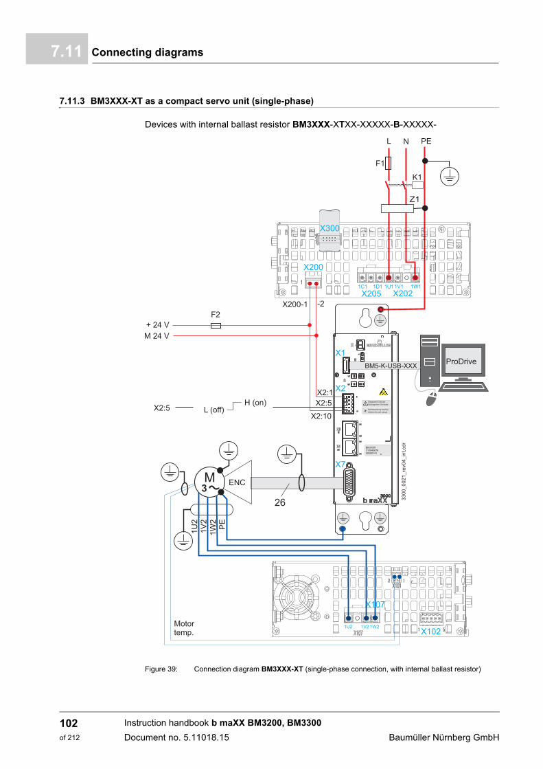
Connecting diagrams7.11
7.11.3 BM3XXX-XT as a compact servo unit (single-phase)
Devices with internal ballast resistor BM3XXX-XTXX-XXXXX-B-XXXXX-
Figure 39: Connection diagram BM3XXX-XT (single-phase connection, with internal ballast resistor)
Instruction handbook b maXX BM3200, BM3300
Document no. 5.11018.15 Baumüller Nürnberg GmbH
102of 212
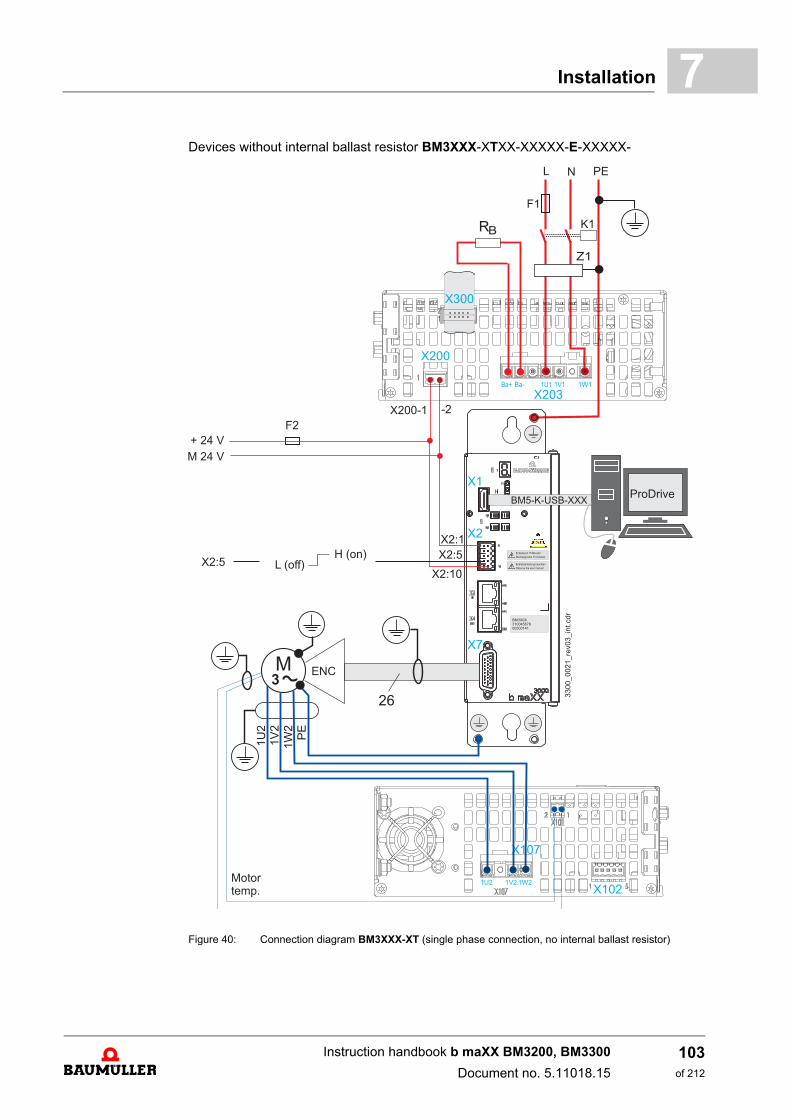
Installation 7
Devices without internal ballast resistor BM3XXX-XTXX-XXXXX-E-XXXXX-Figure 40: Connection diagram BM3XXX-XT (single phase connection, no internal ballast resistor)
Instruction handbook b maXX BM3200, BM3300
Document no. 5.11018.15
103of 212

Connecting diagrams7.11
X1 Service interface, see ZX1 - Service interface– on page 114
X2 Digital in- and outputs, e.g. pulse enable, see ZX2 - Digital inputs/outputs– on page 115.
X2:5 Input pulse enable, Low: not enabled, High: enabled (operation possible)
X3, X4 Connections for fieldbus EtherCAT®, VARAN, CANopen®, POWERLINK®, according to the version, also see ZX3 / X4 - fieldbus connection– on page 116
X6 Analog in- and outputs,see ZX6 - analog inputs/outputs– on page 120.
X7 Encoder evaluation,see ZX6 / X7 - encoder connection– from page 121.
X101 Connection motor temperature,see ZX101 - motor temperature– on page 137.
X102 Connection STO,see ZX102 - safe torque off - option– on page 137.
X107 Motor, also see ZRequirements to the motor– on page 29 and ZX107 - motor connection– on page 138.
X200 Connections for 24 V-voltage supply (SELV/PELV), see ZRequirements to the control voltage / 24 V-supply– on page 29 and ZX200 - 24V voltage supply– on page 131.
X202 Power supply connection, see ZRequirements to the energy supply: power supply– from page 28 andZX202, X203, X205 - power supply, DC link, ballast resistor connection– on page 132.
X203 Power supply and ballast resistor connection, see ZRequirements to the energy supply: power supply– from page 28 andZX202, X203, X205 - power supply, DC link, ballast resistor connection– on page 132.
X300 Signal bus, connection to further units, see ZX300 - signal bus– on page 134.
PE PE-connection,see ZPE connection and RCD compatibility– from page 85 andZPE connections BM3200, BM3300 rear panel– on page 139.
F1 Fuses (cable + device),see ZProtection of the device and accordingly of the cable– from page 84.
F2 Fuse for the 24 V-voltage supply
K1 Power circuit contactor (optional)
Z1 Line filter, see ZLine filter– on page 187.
Instruction handbook b maXX BM3200, BM3300
Document no. 5.11018.15 Baumüller Nürnberg GmbH
104of 212
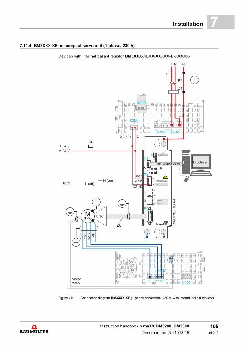
Installation 7
7.11.4 BM3XXX-XE as compact servo unit (1-phase, 230 V)Devices with internal ballast resistor BM3XXX-XEXX-XXXXX-B-XXXXX-
Figure 41: Connection diagram BM3XXX-XE (1-phase connection, 230 V, with internal ballast resistor)
Instruction handbook b maXX BM3200, BM3300
Document no. 5.11018.15
105of 212
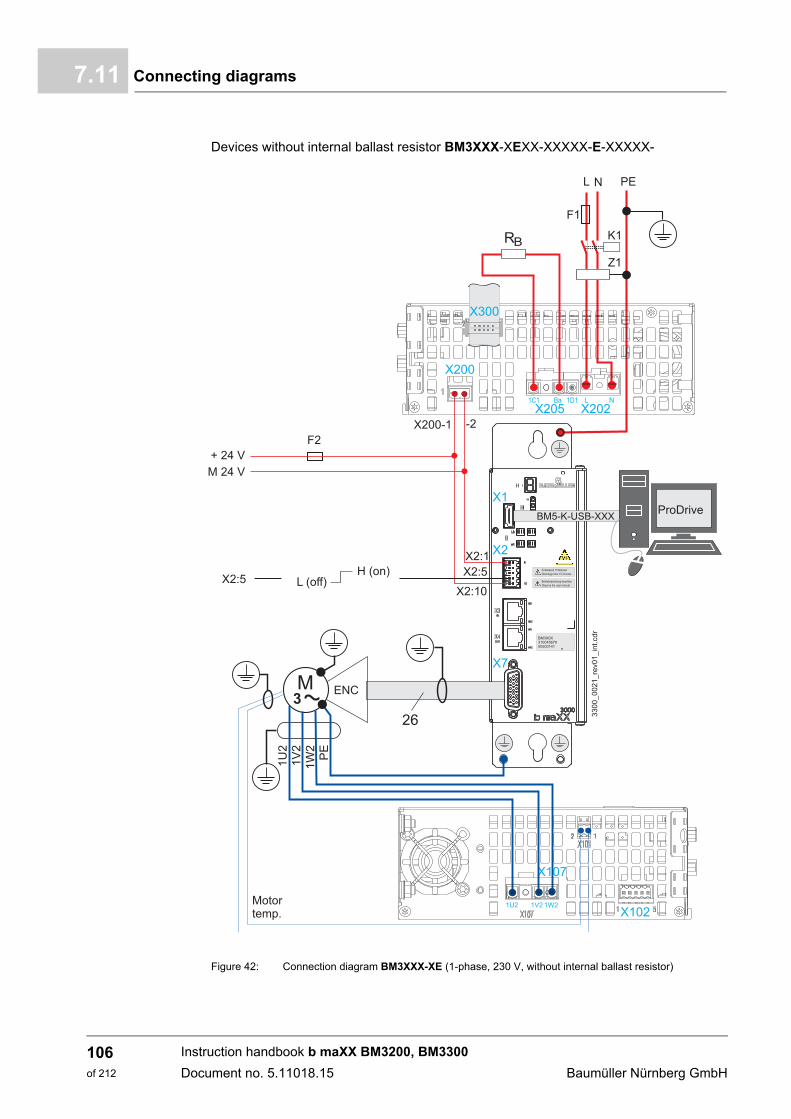
Connecting diagrams7.11
Devices without internal ballast resistor BM3XXX-XEXX-XXXXX-E-XXXXX-
Figure 42: Connection diagram BM3XXX-XE (1-phase, 230 V, without internal ballast resistor)
Instruction handbook b maXX BM3200, BM3300
Document no. 5.11018.15 Baumüller Nürnberg GmbH
106of 212
Installation 7
X1 Service interface, see ZX1 - Service interface– on page 114.
X2 Digital in- and outputs, e.g. pulse enable, see ZX2 - Digital inputs/outputs– on page 115.
X2:5 Input pulse enable, Low: not enabled, High: enabled (operation possible)
X3, X4 Connections for fieldbus EtherCAT®, VARAN, CANopen®, POWERLINK®, according to the version, also see ZX3 / X4 - fieldbus connection– on page 116.
X6 Analog in- and outputs,see ZX6 - analog inputs/outputs– on page 120.
X7 Encoder evaluation, see ZX6 / X7 - encoder connection– from page 121.
X101 Connection motor temperature, see ZX101 - motor temperature– on page 137.
X102 Connection STO, see ZX102 - safe torque off - option– on page 137.
X107 Motor, also see ZRequirements to the motor– on page 29 and ZX107 - motor connection– on page 138.
X200 Connections for 24 V-voltage supply (SELV/PELV), see ZRequirements to the control voltage / 24 V-supply– on page 29 and ZX200 - 24V voltage supply– on page 131.
X202 Power supply connection, see ZRequirements to the energy supply: power supply– from page 28 andZX202, X203, X205 - power supply, DC link, ballast resistor connection– on page 132.
X205 DC link and ballast resistor connection,see ZX202, X203, X205 - power supply, DC link, ballast resistor connection– on page 132.
X300 Signal bus, connection to further units, see ZX300 - signal bus– on page 134.
PE PE-connection,see ZPE connection and RCD compatibility– from page 85 andZPE connections BM3200, BM3300 rear panel– on page 139.
F1 Fuses (cable + device), see ZProtection of the device and accordingly of the cable– from page 84.
F2 Fuse for the 24 V-voltage supply
K1 Main contactor (optional)
Z1 Line filter, see ZLine filter– on page 187.
Instruction handbook b maXX BM3200, BM3300
Document no. 5.11018.15
107of 212

Connecting diagrams7.11
7.11.5 Application: Power supply connection (3-phase) with energy compensation
for devices with internal ballast resistor BM3XXX-XTXX-XXXXX-B-XXXXX-
Figure 43: Application: Power supply connection with energy compensation
Instruction handbook b maXX BM3200, BM3300
Document no. 5.11018.15 Baumüller Nürnberg GmbH
108of 212
Installation 7
Installation notesAdditional notes for installation
n All devices must be parametrized „supply via power supply“
n A destruction of a single device can result in secondary damage of the two other devices
n A combined operation on 2 phases and 3 phases is not allowed,it is not allowed to enable a single device in case of one or several fuses have beentripped (danger is overload).
n This application is only valid for the following devicesBM3201, BM3202, BM3203, BM3204, BM3211, BM3212, BM3213,BM3301, BM3302, BM3303, BM3304, BM3311, BM3312, BM3313
n No further devices or components (e.g. external DC link capacitors) are allowed to beconnected to the DC link
F1, F2, F2 Fuses (cable protection+ device protection), separate fuse for every device
F10-F15 Option: a destruction of the next devices can be avoided
F4 Fuse for the 24 V-voltage supply
Filter Separate line filter for every device, (a shared filter can be possible, but its function is not guaranteed)
L1a, L2a, L3a, Line choke, uK = 2 - 4 %, separate choke for every device, the use of the same type of chokes is required
NOTE!
No chokes are required if the power demand of all devices together is at no time higher than 5 kW.
NOTICE!
Only the following devices can be combined
BM3203, BM3204, BM3212, BM3213, BM3303, BM3304, BM3312 and BM3313
or
BM3201, BM3202, BM3211, BM3301, BM3302 and BM3311.
Other interconnections are forbidden!
Instruction handbook b maXX BM3200, BM3300
Document no. 5.11018.15
109of 212
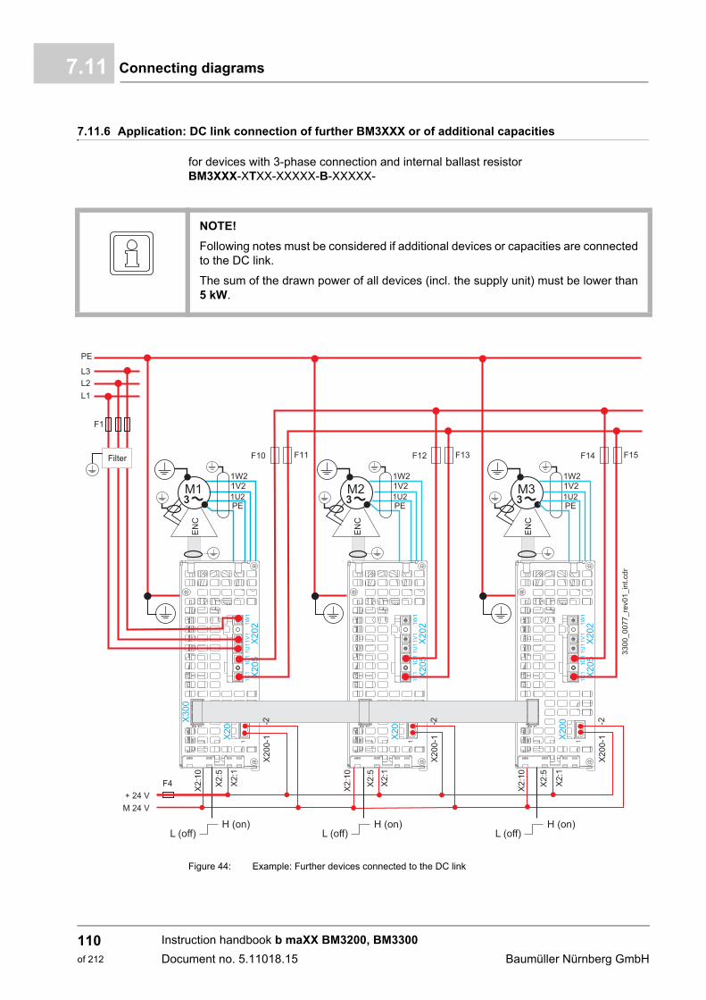
Connecting diagrams7.11
7.11.6 Application: DC link connection of further BM3XXX or of additional capacities
for devices with 3-phase connection and internal ballast resistorBM3XXX-XTXX-XXXXX-B-XXXXX-
Figure 44: Example: Further devices connected to the DC link
NOTE!
Following notes must be considered if additional devices or capacities are connectedto the DC link.
The sum of the drawn power of all devices (incl. the supply unit) must be lower than5 kW.
Instruction handbook b maXX BM3200, BM3300
Document no. 5.11018.15 Baumüller Nürnberg GmbH
110of 212

Installation 7
Installation notesFigure 45: Max. external capacitance that can be connected dependent on the power supply voltage
F1 Fuses (cable protection+ device protection)
F10-F15 Option: a destruction of the next device can be avoided
F4 Fuse for the 24 V-voltage supply
Filter The supplying device must be connected to a filter
CAUTION!
The maximum number of devices or the maximum DC link capacitance that can beconnected depend on the power supply voltage, see ZFigure 45– on page 111.
The required waiting time between two charging procedures depends on the externalconnected DC link capacitance, see ZFigure 46– on page 112
200 250 300 350 400 450 500 5500
1
2
3
4
5
6
7
8
9
10
200 250 300 350 400 450 500 550
Power supply voltage (AC, phase to phase voltage)
[V]
235
470
705
940
1175
1410
1645
1880
2015
2350
Total additional capacitance connected to the DC link [µF]
Example:
connected to the DC link
1
2
3
4
5
6
7
8
9
10
No. of additional devices
Instruction handbook b maXX BM3200, BM3300
Document no. 5.11018.15
111of 212
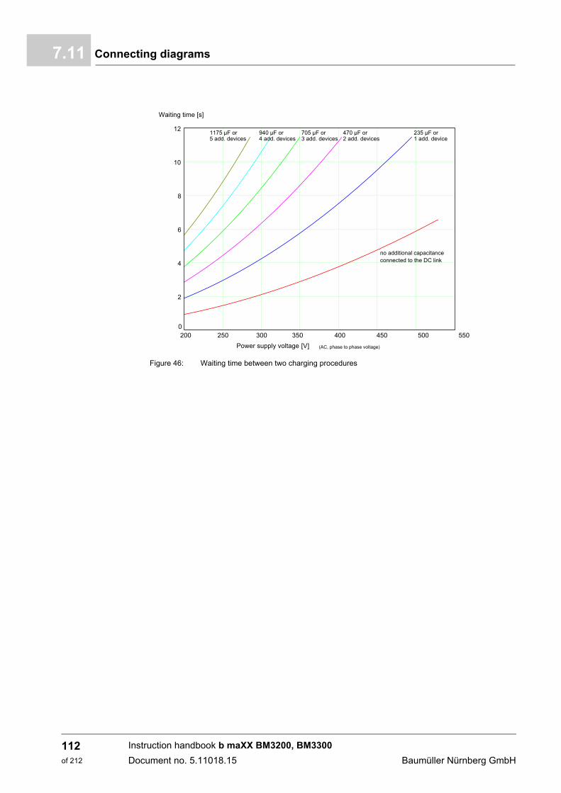
Connecting diagrams7.11
Figure 46: Waiting time between two charging procedures
200 250 300 350 400 450 500 5500
2
4
6
8
10
12
200 250 300 350 400 450 500 550
Power supply voltage (AC, phase to phase voltage)
[V]
0
Waiting time [s]
no additional capacitanceconnected to the DC link
235 µF or 1 add. device
470 µF or 2 add. devices
705 µF or 3 add. devices
940 µF or 4 add. devices
1175 µF or 5 add. devices
Instruction handbook b maXX BM3200, BM3300
Document no. 5.11018.15 Baumüller Nürnberg GmbH
112of 212
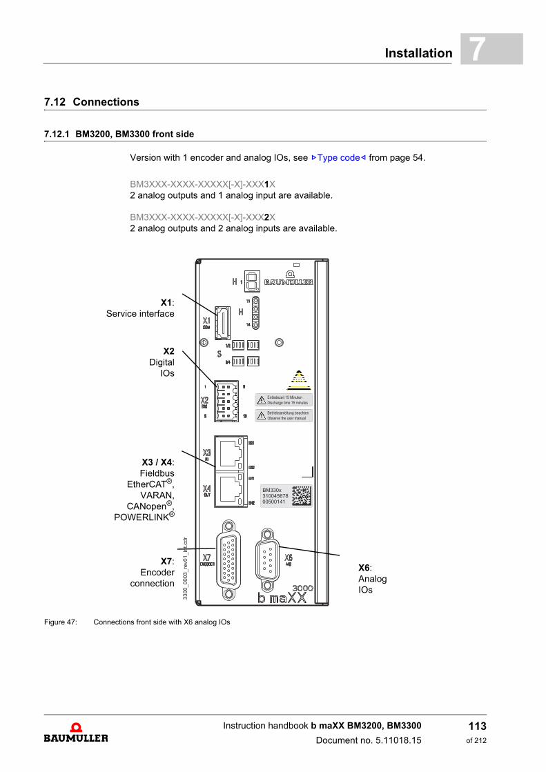
Installation 7
7.12 Connections7.12.1 BM3200, BM3300 front side
Version with 1 encoder and analog IOs, see ZType code– from page 54.
BM3XXX-XXXX-XXXXX[-X]-XXX1X2 analog outputs and 1 analog input are available.
BM3XXX-XXXX-XXXXX[-X]-XXX2X2 analog outputs and 2 analog inputs are available.
Figure 47: Connections front side with X6 analog IOs
X1:Service interface
X2Digital
IOs
X3 / X4:Fieldbus
EtherCAT®,VARAN,
CANopen®,POWERLINK®
X7:Encoder
connection
X6:AnalogIOs
Instruction handbook b maXX BM3200, BM3300
Document no. 5.11018.15
113of 212
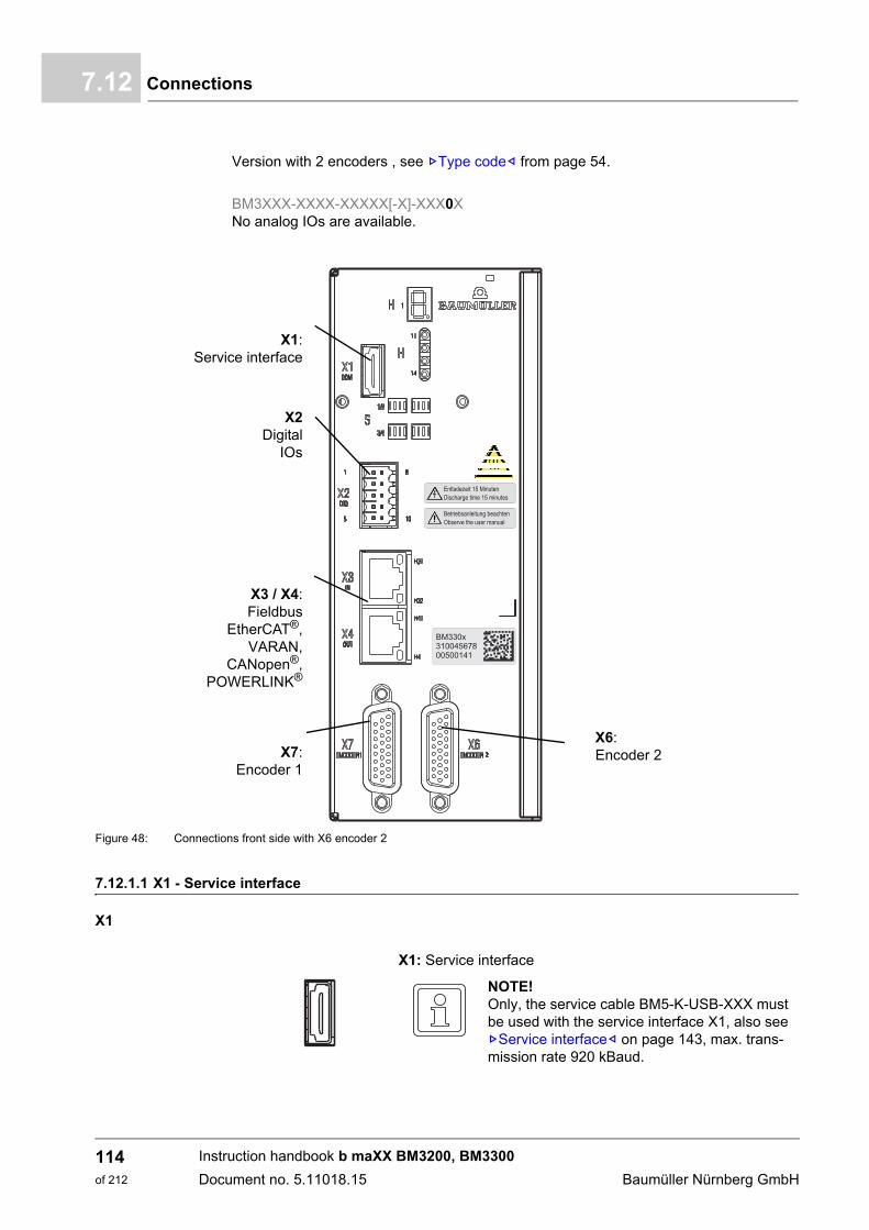
Connections7.12
Version with 2 encoders , see ZType code– from page 54.
BM3XXX-XXXX-XXXXX[-X]-XXX0XNo analog IOs are available.
Figure 48: Connections front side with X6 encoder 2
7.12.1.1 X1 - Service interface
X1
X1:Service interface
X2Digital
IOs
X3 / X4:Fieldbus
EtherCAT®,VARAN,
CANopen®,POWERLINK®
X7:Encoder 1
X6:Encoder 2
X1: Service interface
NOTE!Only, the service cable BM5-K-USB-XXX must be used with the service interface X1, also see ZService interface– on page 143, max. trans-mission rate 920 kBaud.
Instruction handbook b maXX BM3200, BM3300
Document no. 5.11018.15 Baumüller Nürnberg GmbH
114of 212
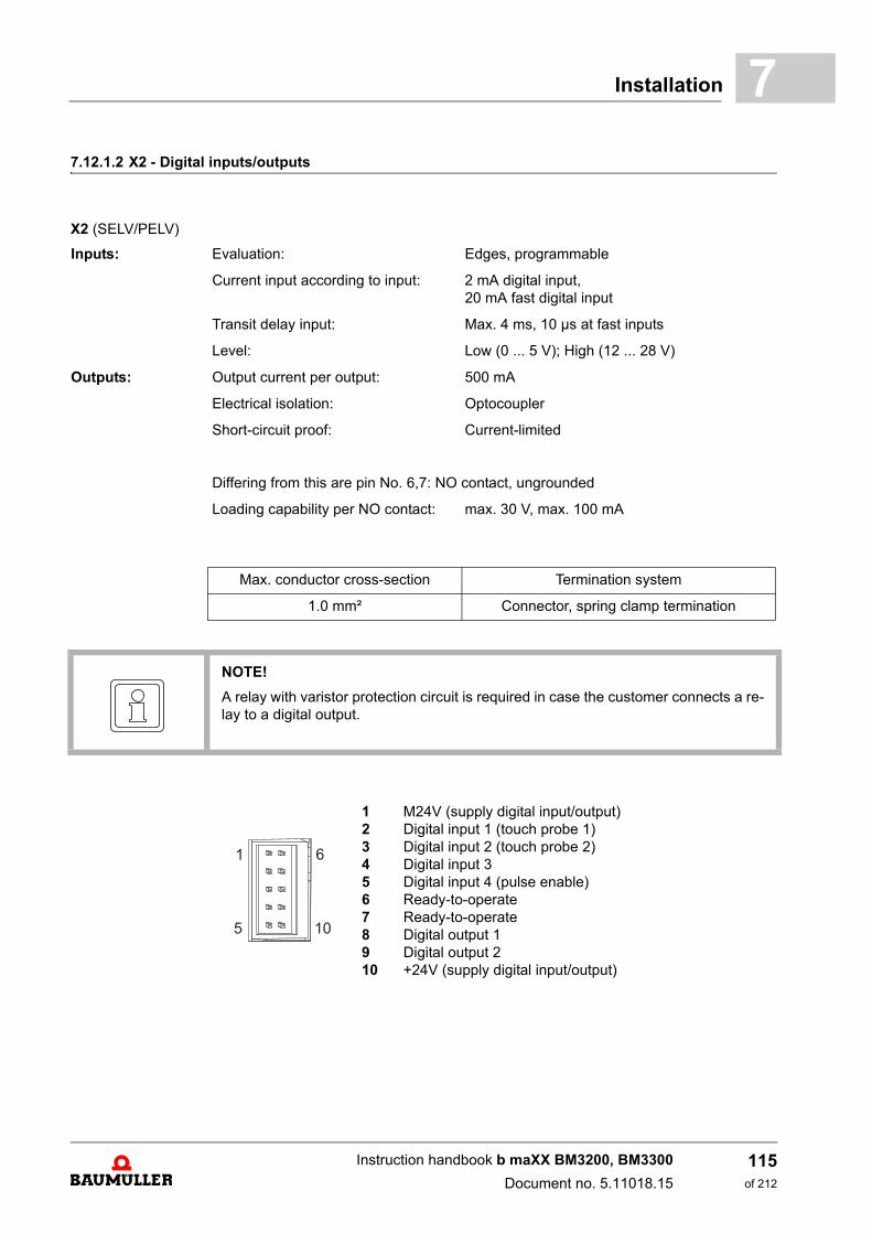
Installation 7
7.12.1.2 X2 - Digital inputs/outputsX2 (SELV/PELV)
Inputs: Evaluation: Edges, programmable
Current input according to input: 2 mA digital input,20 mA fast digital input
Transit delay input: Max. 4 ms, 10 µs at fast inputs
Level: Low (0 ... 5 V); High (12 ... 28 V)
Outputs: Output current per output: 500 mA
Electrical isolation: Optocoupler
Short-circuit proof: Current-limited
Differing from this are pin No. 6,7: NO contact, ungrounded
Loading capability per NO contact: max. 30 V, max. 100 mA
Max. conductor cross-section Termination system
1.0 mm² Connector, spring clamp termination
NOTE!
A relay with varistor protection circuit is required in case the customer connects a re-lay to a digital output.
1 M24V (supply digital input/output)2 Digital input 1 (touch probe 1)3 Digital input 2 (touch probe 2)4 Digital input 35 Digital input 4 (pulse enable)6 Ready-to-operate7 Ready-to-operate8 Digital output 19 Digital output 210 +24V (supply digital input/output)
1
5
6
10
Instruction handbook b maXX BM3200, BM3300
Document no. 5.11018.15
115of 212
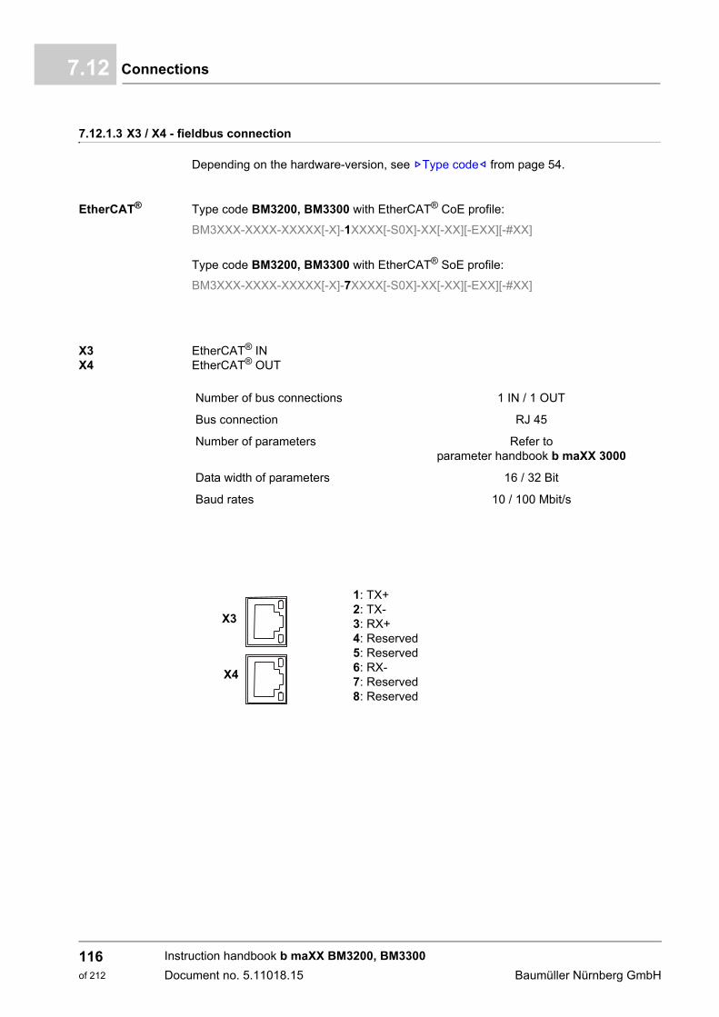
Connections7.12
7.12.1.3 X3 / X4 - fieldbus connection
Depending on the hardware-version, see ZType code– from page 54.
EtherCAT® Type code BM3200, BM3300 with EtherCAT® CoE profile:
BM3XXX-XXXX-XXXXX[-X]-1XXXX[-S0X]-XX[-XX][-EXX][-#XX]
Type code BM3200, BM3300 with EtherCAT® SoE profile:
BM3XXX-XXXX-XXXXX[-X]-7XXXX[-S0X]-XX[-XX][-EXX][-#XX]
X3X4
EtherCAT® INEtherCAT® OUT
Number of bus connections 1 IN / 1 OUT
Bus connection RJ 45
Number of parameters Refer toparameter handbook b maXX 3000
Data width of parameters 16 / 32 Bit
Baud rates 10 / 100 Mbit/s
1: TX+2: TX-3: RX+4: Reserved5: Reserved6: RX-7: Reserved8: Reserved
X3
X4
Instruction handbook b maXX BM3200, BM3300
Document no. 5.11018.15 Baumüller Nürnberg GmbH
116of 212
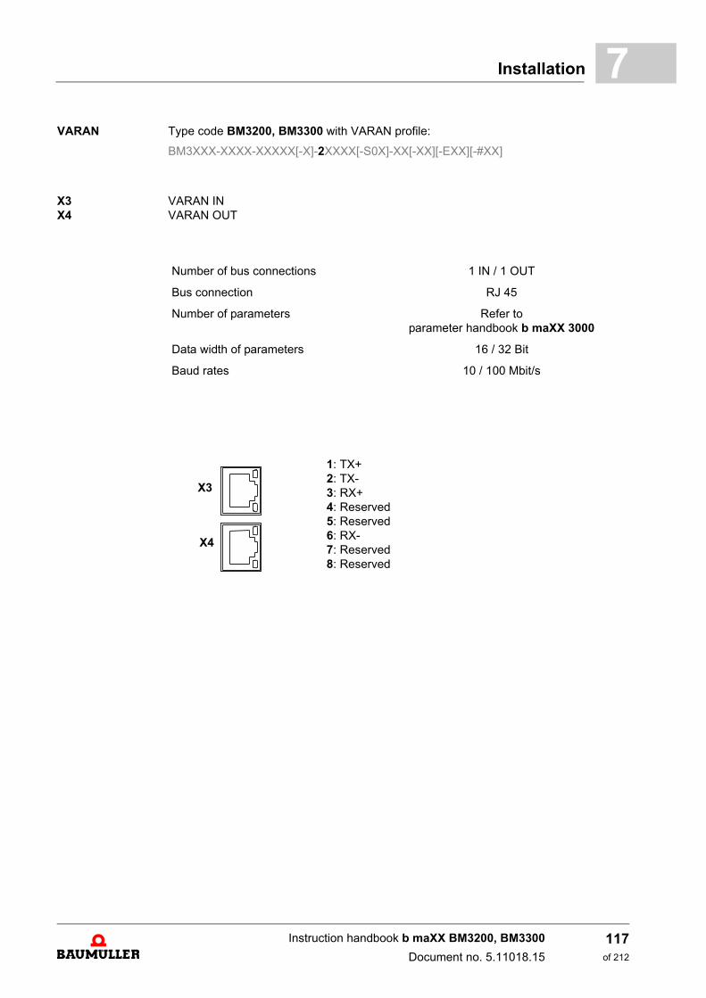
Installation 7
VARAN Type code BM3200, BM3300 with VARAN profile:BM3XXX-XXXX-XXXXX[-X]-2XXXX[-S0X]-XX[-XX][-EXX][-#XX]
X3X4
VARAN INVARAN OUT
Number of bus connections 1 IN / 1 OUT
Bus connection RJ 45
Number of parameters Refer toparameter handbook b maXX 3000
Data width of parameters 16 / 32 Bit
Baud rates 10 / 100 Mbit/s
1: TX+2: TX-3: RX+4: Reserved5: Reserved6: RX-7: Reserved8: Reserved
X3
X4
Instruction handbook b maXX BM3200, BM3300
Document no. 5.11018.15
117of 212

Connections7.12
CANopen® Type code BM3200, BM3300 with CANopen®:
BM3XXX-XXXX-XXXXX[-X]-3XXXX[-S0X]-XX[-XX][-EXX][-#XX]
X3X4
CANopen® INCANopen® OUT
Memory 4 kByte DP-RAM, 256 kByte RAM, 1 MByte Flash-EPROM
Number of bus connections 2, no slot rules
Bus connection 2 connectors RJ45, 8-pin
Baud rates 20/125/250/500/1000 kBit/s
Address range 7 Bit; address 1 to address 127
Address setting DIP-switch
Short-circuit proof RJ45-connection Yes
Isolation Optocoupler, DC/DC-converter
1: CAN_H2: CAN_L3: GND4: Reserved5: Reserved6: Reserved7: GND8: Reserved
X3
X4
Instruction handbook b maXX BM3200, BM3300
Document no. 5.11018.15 Baumüller Nürnberg GmbH
118of 212
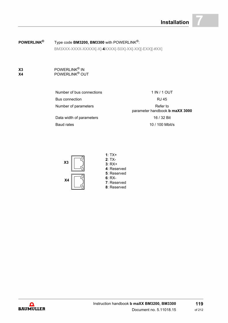
Installation 7
POWERLINK® Type code BM3200, BM3300 with POWERLINK®:BM3XXX-XXXX-XXXXX[-X]-4XXXX[-S0X]-XX[-XX][-EXX][-#XX]
X3X4
POWERLINK® INPOWERLINK® OUT
Number of bus connections 1 IN / 1 OUT
Bus connection RJ 45
Number of parameters Refer toparameter handbook b maXX 3000
Data width of parameters 16 / 32 Bit
Baud rates 10 / 100 Mbit/s
1: TX+2: TX-3: RX+4: Reserved5: Reserved6: RX-7: Reserved8: Reserved
X3
X4
Instruction handbook b maXX BM3200, BM3300
Document no. 5.11018.15
119of 212
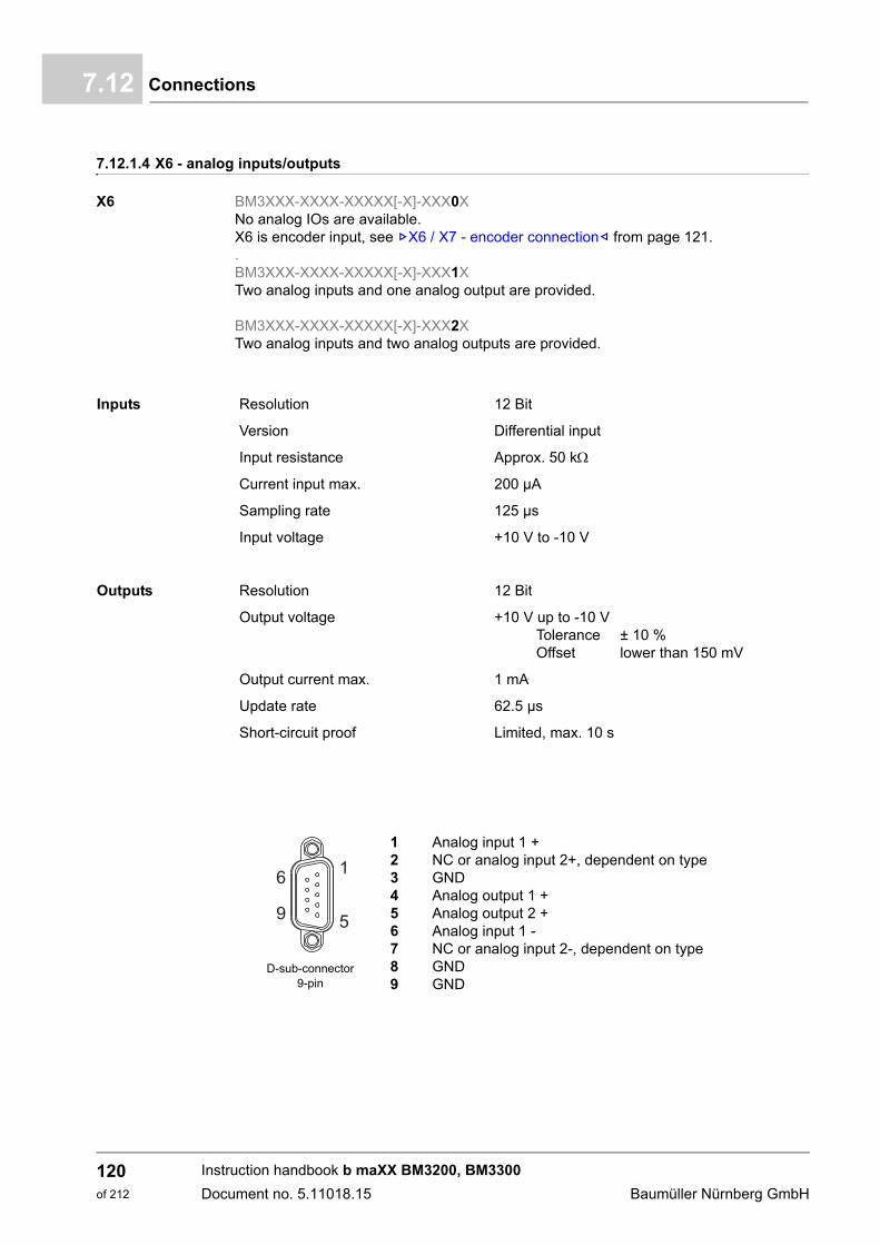
Connections7.12
7.12.1.4 X6 - analog inputs/outputs
X6 BM3XXX-XXXX-XXXXX[-X]-XXX0XNo analog IOs are available.X6 is encoder input, see ZX6 / X7 - encoder connection– from page 121..BM3XXX-XXXX-XXXXX[-X]-XXX1XTwo analog inputs and one analog output are provided.
BM3XXX-XXXX-XXXXX[-X]-XXX2XTwo analog inputs and two analog outputs are provided.
Inputs Resolution 12 Bit
Version Differential input
Input resistance Approx. 50 k
Current input max. 200 µA
Sampling rate 125 µs
Input voltage +10 V to -10 V
Outputs Resolution 12 Bit
Output voltage +10 V up to -10 VTolerance ± 10 %Offset lower than 150 mV
Output current max. 1 mA
Update rate 62.5 µs
Short-circuit proof Limited, max. 10 s
D-sub-connector 9-pin
1 Analog input 1 +2 NC or analog input 2+, dependent on type3 GND4 Analog output 1 +5 Analog output 2 +6 Analog input 1 -7 NC or analog input 2-, dependent on type8 GND9 GND
Instruction handbook b maXX BM3200, BM3300
Document no. 5.11018.15 Baumüller Nürnberg GmbH
120of 212
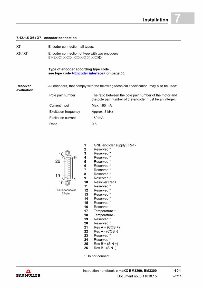
Installation 7
7.12.1.5 X6 / X7 - encoder connectionX7 Encoder connection, all types.
X6 / X7 Encoder connection of type with two encodersBM3XXX-XXXX-XXXXX[-X]-XXX0X
Type of encoder according type code ,see type code ZEncoder interface– on page 55.
Resolver evaluation
All encoders, that comply with the following technical specification, may also be used:
Pole pair number The ratio between the pole pair number of the motor and the pole pair number of the encoder must be an integer.
Current input Max. 160 mA
Excitation frequency Approx. 8 kHz
Excitation current 160 mA
Ratio 0.5
D-sub-connector 26-pin
1 GND encoder supply / Ref -2 Reserved *3 Reserved *4 Reserved *5 Reserved *6 Reserved *7 Reserved *8 Reserved *9 Reserved *10 Resolver Ref +11 Reserved *12 Reserved *13 Reserved *14 Reserved *15 Reserved *16 Reserved *17 Temperature +18 Temperature -19 Reserved *20 Reserved *21 Res A + (COS +)22 Res A - (COS -)23 Reserved *24 Reserved *25 Res B + (SIN +)26 Res B - (SIN -)
* Do not connect
Instruction handbook b maXX BM3200, BM3300
Document no. 5.11018.15
121of 212
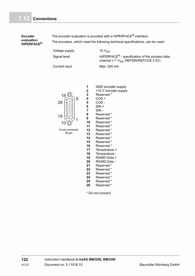
Connections7.12
Encoder evaluation HIPERFACE®
The encoder evaluation is provided with a HIPERFACE®-interface.
The encoders, which meet the following technical specifications, can be used:
Voltage supply 10 VDC
Signal level HIPERFACE® - specification of the process data channel (~1 VSS; REFSIN/REFCOS 2.5V)
Current input Max. 250 mA
D-sub-connector 26-pin
1 GND encoder supply 2 +10 V encoder supply3 Reserved *4 COS +5 COS -6 SIN +7 SIN -8 Reserved *9 Reserved *10 Reserved *11 Reserved *12 Reserved *13 Reserved *14 Reserved *15 Reserved *16 Reserved *17 Temperature +18 Temperature -19 RS485 Data +20 RS485 Data -21 Reserved *22 Reserved *23 Reserved *24 Reserved *25 Reserved *26 Reserved *
* Do not connect
Instruction handbook b maXX BM3200, BM3300
Document no. 5.11018.15 Baumüller Nürnberg GmbH
122of 212

Installation 7
Encoder evaluation with EnDat® 2.1 or SSIThe encoders, which meet the following technical specifications, can be used:
Voltage supply 5 VDC controlled
Signal level ~1 VSS
Current input Max. 250 mA
D-sub-connector 26-pin
1 GND encoder supply2 +5 V encoder supply3 Clock+4 A + (COS +)5 A - (COS -)6 B + (SIN +)7 B - (SIN -)8 Reserved *9 Reserved *10 Reserved *11 Sense GND12 Sense Vcc13 Clock-14 Reserved *15 Reserved *16 Reserved *17 Temperature +18 Temperature -19 Data +20 Data -21 Reserved *22 Reserved *23 Reserved *24 Reserved *25 Reserved *26 Reserved *
* Do not connect
Instruction handbook b maXX BM3200, BM3300
Document no. 5.11018.15
123of 212
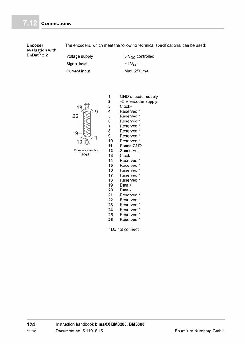
Connections7.12
Encoder evaluation with EnDat® 2.2
The encoders, which meet the following technical specifications, can be used:
Voltage supply 5 VDC controlled
Signal level ~1 VSS
Current input Max. 250 mA
D-sub-connector 26-pin
1 GND encoder supply 2 +5 V encoder supply3 Clock+4 Reserved *5 Reserved *6 Reserved *7 Reserved *8 Reserved *9 Reserved *10 Reserved *11 Sense GND12 Sense Vcc13 Clock-14 Reserved *15 Reserved *16 Reserved *17 Reserved *18 Reserved *19 Data +20 Data -21 Reserved *22 Reserved *23 Reserved *24 Reserved *25 Reserved *26 Reserved *
* Do not connect
Instruction handbook b maXX BM3200, BM3300
Document no. 5.11018.15 Baumüller Nürnberg GmbH
124of 212
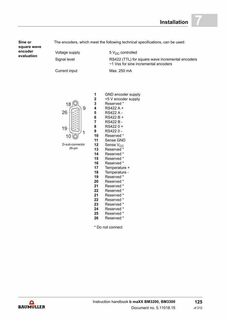
Installation 7
Sine or square waveencoder evaluationThe encoders, which meet the following technical specifications, can be used:
Voltage supply 5 VDC controlled
Signal level RS422 (TTL) for square wave incremental encoders~1 Vss for sine incremental encoders
Current input Max. 250 mA
D-sub-connector 26-pin
1 GND encoder supply2 +5 V encoder supply3 Reserved *4 RS422 A +5 RS422 A -6 RS422 B +7 RS422 B -8 RS422 0 +9 RS422 0 -10 Reserved *11 Sense GND12 Sense VCC13 Reserved *14 Reserved *15 Reserved *16 Reserved *17 Temperature +18 Temperature -19 Reserved *20 Reserved *21 Reserved *22 Reserved *21 Reserved *22 Reserved *23 Reserved *24 Reserved *25 Reserved *26 Reserved *
* Do not connect
Instruction handbook b maXX BM3200, BM3300
Document no. 5.11018.15
125of 212

Connections7.12
Encoder evaluation withHIPERFACE DSL®
The encoders, which meet the following technical specifications, can be used:
Signal level HIPERFACE DSL®
Current input Max. 250 mA
D-sub-connector 26-pin
1 GND encoder supply2 10 V encoder supply3 Reserved *4 Reserved *5 Reserved *6 Reserved *7 Reserved *8 Reserved *9 Reserved *10 Reserved *11 Reserved *12 Reserved *13 Reserved *14 Reserved *15 Reserved *16 Reserved *17 Reserved *18 Reserved *19 DSL-20 DSL+21 Reserved *22 Reserved *21 Reserved *22 Reserved *23 Reserved *24 Reserved *25 Reserved *26 Reserved *
* Do not connect
NOTE!
The use of the standard accessory connector included in the accessory kit HIPERFACE DSL® (part No. 460219) is required.
Instruction handbook b maXX BM3200, BM3300
Document no. 5.11018.15 Baumüller Nürnberg GmbH
126of 212
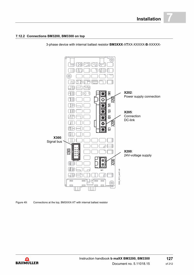
Installation 7
7.12.2 Connections BM3200, BM3300 on top3-phase device with internal ballast resistor BM3XXX-XTXX-XXXXX-B-XXXXX-
Figure 49: Connections at the top, BM3XXX-XT with internal ballast resistor
X300:Signal bus
X202:Power supply connection
X205:ConnectionDC-link
X200:24V-voltage supply
Instruction handbook b maXX BM3200, BM3300
Document no. 5.11018.15
127of 212
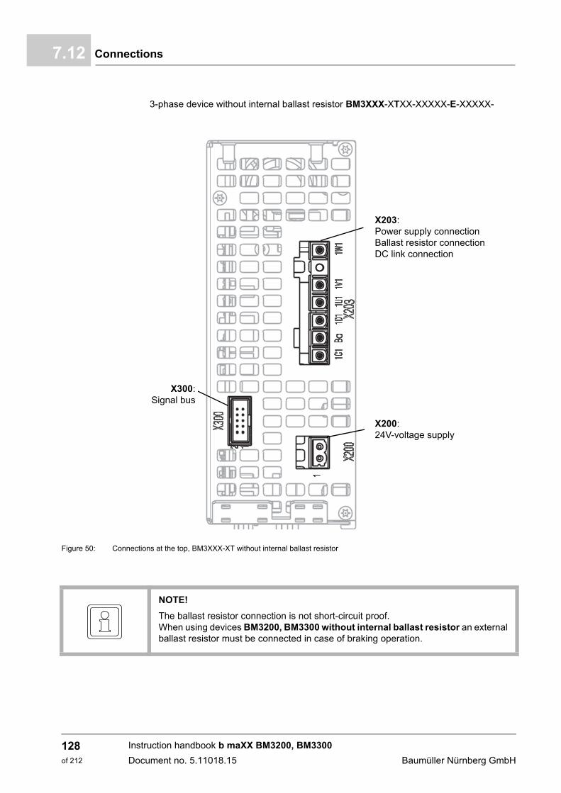
Connections7.12
3-phase device without internal ballast resistor BM3XXX-XTXX-XXXXX-E-XXXXX-
Figure 50: Connections at the top, BM3XXX-XT without internal ballast resistor
X300:Signal bus
X203:Power supply connectionBallast resistor connectionDC link connection
X200:24V-voltage supply
NOTE!
The ballast resistor connection is not short-circuit proof.When using devices BM3200, BM3300 without internal ballast resistor an externalballast resistor must be connected in case of braking operation.
Instruction handbook b maXX BM3200, BM3300
Document no. 5.11018.15 Baumüller Nürnberg GmbH
128of 212
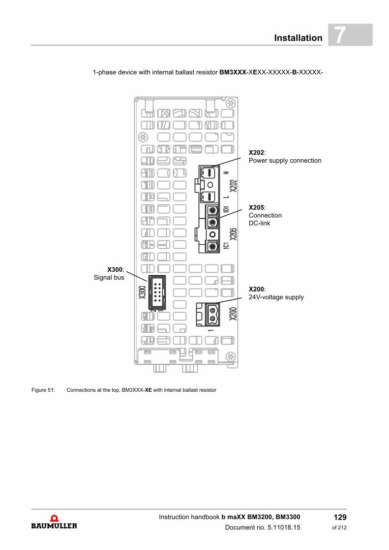
Installation 7
1-phase device with internal ballast resistor BM3XXX-XEXX-XXXXX-B-XXXXX-Figure 51: Connections at the top, BM3XXX-XE with internal ballast resistor
X300:Signal bus
X202:Power supply connection
X205:ConnectionDC-link
X200:24V-voltage supply
Instruction handbook b maXX BM3200, BM3300
Document no. 5.11018.15
129of 212
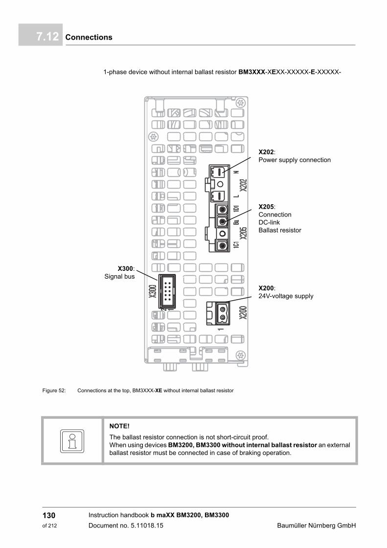
Connections7.12
1-phase device without internal ballast resistor BM3XXX-XEXX-XXXXX-E-XXXXX-
Figure 52: Connections at the top, BM3XXX-XE without internal ballast resistor
X300:Signal bus
X202:Power supply connection
X205:ConnectionDC-linkBallast resistor
X200:24V-voltage supply
NOTE!
The ballast resistor connection is not short-circuit proof.When using devices BM3200, BM3300 without internal ballast resistor an externalballast resistor must be connected in case of braking operation.
Instruction handbook b maXX BM3200, BM3300
Document no. 5.11018.15 Baumüller Nürnberg GmbH
130of 212
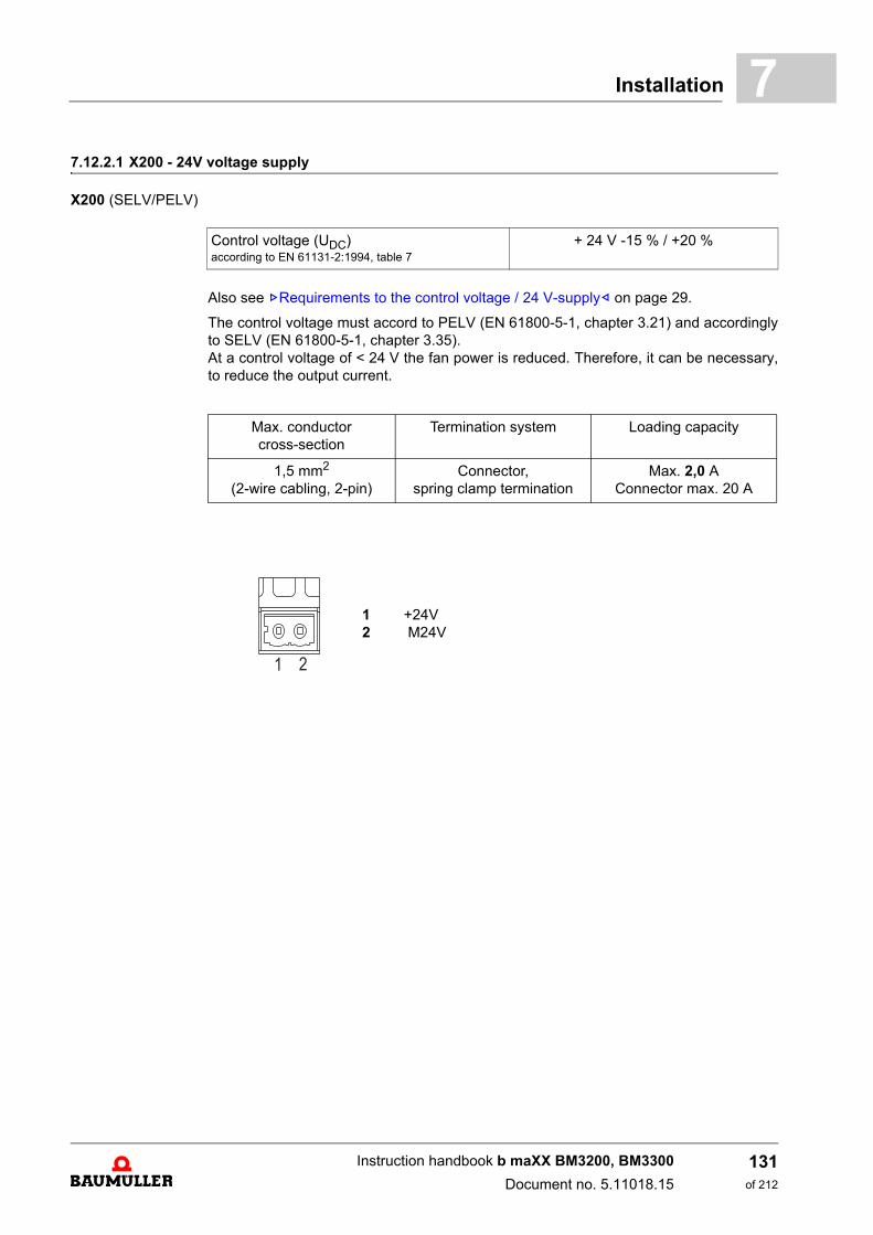
Installation 7
7.12.2.1 X200 - 24V voltage supplyX200 (SELV/PELV)
Also see ZRequirements to the control voltage / 24 V-supply– on page 29.
The control voltage must accord to PELV (EN 61800-5-1, chapter 3.21) and accordinglyto SELV (EN 61800-5-1, chapter 3.35).At a control voltage of < 24 V the fan power is reduced. Therefore, it can be necessary,to reduce the output current.
Control voltage (UDC)according to EN 61131-2:1994, table 7
+ 24 V -15 % / +20 %
Max. conductor cross-section
Termination system Loading capacity
1,5 mm2
(2-wire cabling, 2-pin) Connector,
spring clamp terminationMax. 2,0 A
Connector max. 20 A
1 +24V 2 M24V
Instruction handbook b maXX BM3200, BM3300
Document no. 5.11018.15
131of 212
Connections7.12
7.12.2.2 X202, X203, X205 - power supply, DC link, ballast resistor connection
NOTE!
A device of the series BM3200, BM3300 can be operated as a compact servo unitand accordingly as an axis unit.
NOTE!
A proper execution of BM3200, BM3300 as an axis unit can only be ensured atBaumüller supply units (mains rectifiers).
The DC-link terminal is not protected against overload, polarity reversal or groundfault.
A connection of one or several DC-link terminals of the BM3200, BM3300 to an activemains rectifier unit is forbidden.
NOTE!
The ballast resistor connection is not short-circuit proof.When using devices BM3200, BM3300 without internal ballast resistor an externalballast resistor must be connected in case of braking operation.
Instruction handbook b maXX BM3200, BM3300
Document no. 5.11018.15 Baumüller Nürnberg GmbH
132of 212
Installation 7
X202 BM3XXX-XTXX-XXXXX-B-XXXXX-, device with internal ballast resistorPower supply1U1, 1V1, 1W1
X202 BM3XXX-XE, device with/without internal ballast resistor
Power supplyL, N
X203 BM3XXX-XTXX-XXXXX-E-XXXXX-, device without internal ballast resistor
Power supply1U1, 1V1, 1W1
DC link connection1C1, 1D1
Ballast resistor connection1C1, Ba-
X205 BM3XXX-XTXX-XXXXX-B-XXXXX-, device with internal ballast resistorBM3XXX-XEXX-XXXXX-B-XXXXX-, device with internal ballast resistor
DC link connection1C1, 1D1
X205 BM3XXX-XEXX-XXXXX-E-XXXXX-, device without internal ballast resistor
DC link connection1C1, 1D1
Ballast resistor connection1C1, Ba-
PE Refer to ZPE connections BM3200, BM3300 rear panel– from page 139.
Connection system Loading capacity
Connector,screw terminal
Connector max. 20 A
Minimum Maximum
Conductor cross-sectionsolid conductorfinely strandedwith ferrule (with/without protective cover)
0.08 mm² / AWG280.08 mm² / AWG28
0.2 mm²
4 mm² / AWG124 mm² / AWG12
2.5 mm²
Tightening torque 0.4 Nm 0.5 Nm
Screwdriver blade 0.6 x 3.5 mm
Remove insulation 7 mm / 0.9 in
Instruction handbook b maXX BM3200, BM3300
Document no. 5.11018.15
133of 212
Connections7.12
7.12.2.3 X300 - signal bus
If a system of b maXX devices is installed with signal bus connection, then all devices areconnected with one another via the signal bus. The bus including the supply unit can bescanned by each participant and individual signals can be set. Via this bus the supply unitcan indicate errors to the axes, so that the individual axes can react. Each axis can gen-erate messages to the other axes, for example failures, ballast resistors on or warningsignal bus.
NOTE!
Dependent on the type of the used device
BM3XXX-XXXX-XXXXX[-X]-XXX1Xup to 12 devices can be connected
or
BM3XXX-XXXX-XXXXX[-X]-XXX2Xup to 30 devices can be connected.
Instruction handbook b maXX BM3200, BM3300
Document no. 5.11018.15 Baumüller Nürnberg GmbH
134of 212
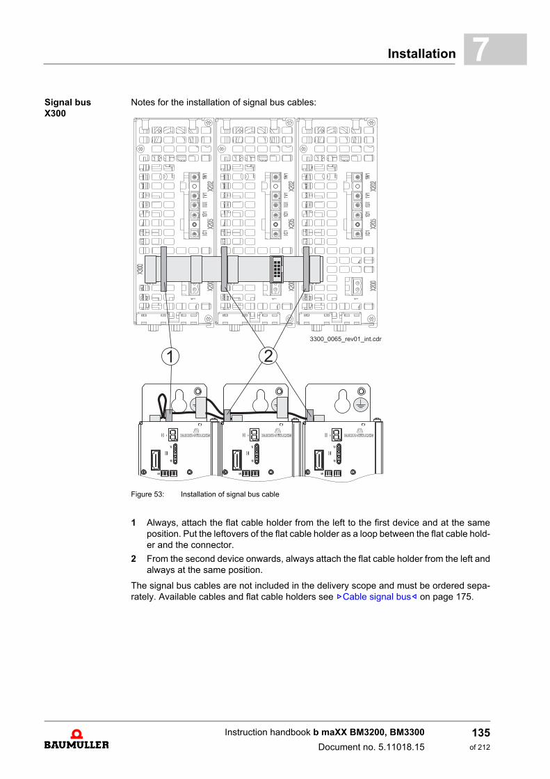
Installation 7
Signal busX300Notes for the installation of signal bus cables:
Figure 53: Installation of signal bus cable
1 Always, attach the flat cable holder from the left to the first device and at the sameposition. Put the leftovers of the flat cable holder as a loop between the flat cable hold-er and the connector.
2 From the second device onwards, always attach the flat cable holder from the left andalways at the same position.
The signal bus cables are not included in the delivery scope and must be ordered sepa-rately. Available cables and flat cable holders see ZCable signal bus– on page 175.
Instruction handbook b maXX BM3200, BM3300
Document no. 5.11018.15
135of 212
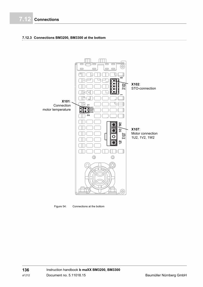
Connections7.12
7.12.3 Connections BM3200, BM3300 at the bottom
Figure 54: Connections at the bottom
X101:Connection
motor temperature
X102:STO-connection
X107:Motor connection1U2, 1V2, 1W2
Instruction handbook b maXX BM3200, BM3300
Document no. 5.11018.15 Baumüller Nürnberg GmbH
136of 212

Installation 7
7.12.3.1 X101 - motor temperatureX101 (SELV/PELV)
7.12.3.2 X102 - safe torque off - option
X102 (SELV/PELV)
Termination system
Connector, spring clamp termination
Minimum Maximum
Connector cross-sectionsolid conductorfinely strandedwith ferrule (with/without protective cover)
0.2 mm² / AWG280.2 mm² / AWG28
0.2 mm²
1.5 mm² / AWG161.5 mm² / AWG16
1.5 mm² / 1 mm²
1 Motor temperature +2 Motor temperature -
2
1
Max. connector cross-section Termination system
1.0 mm² Connector, spring clamp termination
STO1: X102-1/2STO2: X102-4/5
Digital input according EN61131-2 type 2 with following change:
LowVoltage: -0.3 ... 5 VIL at 5 V: max. 23 mAeff
HighVoltage: 20 ... 30 VIL at 20 V: max. 31 mAeffIL at 30 V: min. 35 mAeff
Max. reaction time Max. 30 ms
Instruction handbook b maXX BM3200, BM3300
Document no. 5.11018.15
137of 212

Connections7.12
7.12.3.3 X107 - motor connection
X1071U2, 1V2, 1W2
PE Refer to ZPE connections BM3200, BM3300 rear panel– from page 139.
5 STO 2 GND4 STO 2 24V3 NC2 STO 1 GND1 STO 1 24 V
1
5
NOTE!
The used power supply must comply with the defined voltage drop accordingEN60204-1.
Connection system Loading capacity
Connector, screw terminal
Is limited by the device, also see ZElectrical data– from page 36
connector max. 20 A.
Minimum Maximum
Max. cross-sectionsolid conductorfinely strandedwith ferrule (with/without protective cover)
0.08 mm² / AWG280.08 mm² / AWG28
0.2 mm²
4 mm² / AWG124 mm² / AWG12
2.5 mm²
Locking torque 0.4 Nm 0.5 Nm
Screwdriver blade 0.6 x 3.5 mm
Skinning length 7 mm / 0,9 in
Instruction handbook b maXX BM3200, BM3300
Document no. 5.11018.15 Baumüller Nürnberg GmbH
138of 212
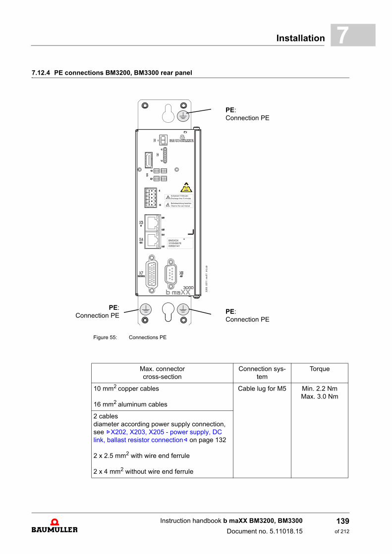
Installation 7
7.12.4 PE connections BM3200, BM3300 rear panelFigure 55: Connections PE
PE:Connection PE
PE:Connection PE
PE:Connection PE
Max. connector cross-section
Connection sys-tem
Torque
10 mm2 copper cables
16 mm2 aluminum cables
Cable lug for M5 Min. 2.2 NmMax. 3.0 Nm
2 cablesdiameter according power supply connection,see ZX202, X203, X205 - power supply, DC link, ballast resistor connection– on page 132
2 x 2.5 mm2 with wire end ferrule
2 x 4 mm2 without wire end ferrule
Instruction handbook b maXX BM3200, BM3300
Document no. 5.11018.15
139of 212
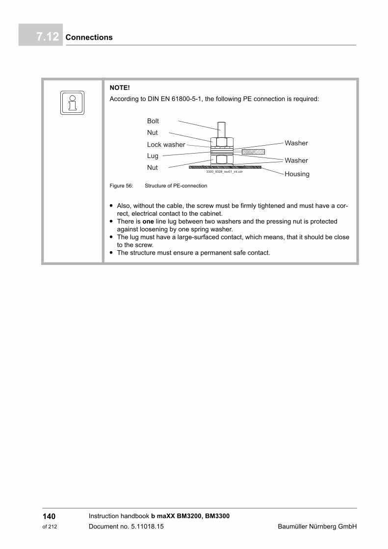
Connections7.12
NOTE!
According to DIN EN 61800-5-1, the following PE connection is required:
Figure 56: Structure of PE-connection
m Also, without the cable, the screw must be firmly tightened and must have a cor-rect, electrical contact to the cabinet.
m There is one line lug between two washers and the pressing nut is protected against loosening by one spring washer.
m The lug must have a large-surfaced contact, which means, that it should be close to the screw.
m The structure must ensure a permanent safe contact.
Instruction handbook b maXX BM3200, BM3300
Document no. 5.11018.15 Baumüller Nürnberg GmbH
140of 212
8OPERATION
8.1 Safety notes
WARNING!
Risk of injury due to improper operation!
Improper operation can lead to severe personal injury or material damage.
Therefore:
m Perform all operational steps according to the details of this Instruction handbook.
m Before beginning work, ensure that all coverings and protective devices are in-stalled and are functioning properly.
m The control cabinet in which the device is installed should be protected againstcontact with energized parts.Keep all doors of the control cabinet closed during operation.
NOTICE!
Environmental conditions that do not meet the requirements.
Environmental conditions that are non-compliant can lead to property damage.
Therefore:
m Ensure that the environmental conditions are kept compliant during operation (seeZRequired environmental conditions– on page 30).
WARNING!
Risk of injury due to inadequate qualifications!
Inevitably, when operating this electrical device, certain parts of this device are ener-gized with hazardous voltage. Improper handling can lead to significant personal in-jury and material damage.
Therefore:
m Only qualified personnel may work on this device!
141of 212
Instruction handbook b maXX BM3200, BM3300
Document no. 5.11018.15

Operating concept8.2
8.2 Operating concept
After the device was put into operation, it is parameterized (adapted to the application). Ifthe parameterization is completed the device can be operated either with the pulse en-able signal or with pulse enable signal and quick stop signal.
8.2.1 Enable signals
These signals must have a signal level of 24 VDC and must be connected to the terminals(ZX2 - Digital inputs/outputs– on page 115), also see ZConnecting diagrams– from page93.
Pulse enable During operation the signal „Pulse enable“ always must be activated, so that the devicecan supply power. A running motor coasts down, if the signal is set to 0 V.
Quick stop (optional)
Only switch off the „quick stop“ signal if the system / the device must be stopped as quick-ly as possible, the drive reaction can be adjusted (see the parameter manual).
During operation, the „quick stop“ signal must be continuously provided in order for thedevice to provide output.
Which digital input is used a quick stop input can be parameterized (see parameter man-ual b maXX 3000, 5.12001).
8.2.2 Monitoring
The controller part monitors the device during operation. If the controller part detects acondition, which deviates from normal operation, the device generates a warning/an errormessage.
Warning If the controller part detects an operational condition, which exceeds a warning limit, anaccording warning is either shown by the display or by the control. The device shows themost important warning (current limit reached) via the LED H13 (see ZDisplay and oper-ating elements BM3200, BM3300– from page 58).
Error message If the controller part detects, that the device is not operating correctly, this is shown viathe 7-segment-display, see ZPage 62– and the LEDs H11 to H14, see ZPage 63–.
For further information see ZTroubleshooting and Fault Correction– from page 165.
Instruction handbook b maXX BM3200, BM3300
Document no. 5.11018.15 Baumüller Nürnberg GmbH
142of 212

Operation 8
8.2.3 Service interfaceThe service interface transfers controller parameters from a PC/laptop to the controllervia the parameterization software ProDrive.
h connect a free USB-port of the PC/laptop with the controller.
The driver for this connection was installed on the PC/laptop with ProDrive. The settingsof the connection (baud rate, etc.) are made in ProDrive. Refer to ProDrive Online help.
8.3 DC-link load / switch-on frequency of power supply
Switch-on frequency accords to the time between two switch-on procedures. This periodcannot be selected freely, as each switch-on procedure is connected with a thermal loadof the precharge resistors.
These precharge resistors limit the starting current, when switching on the power supplyvoltage.
NOTE!
Only, the service cable BM5-K-USB-XXX must be used for the X1-service interface.Also see ZCable service interface– on page 176. The maximum transmission rate is920 kBaud.
NOTE!
If the service cable is not used, keep it in its ESD-packaging.
NOTE!
Between two switch-on procedures, there must be at least 3 minutes. If the time,which is required to cool down is under this time, thermal overload and destruction ofthe precharge resistors can occur.
Instruction handbook b maXX BM3200, BM3300
Document no. 5.11018.15
143of 212
Optional safety function STO of BM33008.4
8.4 Optional safety function STO of BM3300
8.4.1 Safety notes according STO function (Safe Torque Off)
WARNING!
m When STO is activated, the drive is not disconnected from power supply.
m The safety function Safe Torque Off (STO) is not sufficient as the only safetyfunction for drives which are affected by a permanent moment, for example, incase of suspended loads.
m The function STO may only be operated in combination with emergency stopdevices according to DIN EN ISO 13850 or safety sensors according to EN 61496.
WARNING!
In the unlikely event of a total failure of an internal driver (IGBT) or a control element,a temporary excitation of the drive can occur (also if STO is active). The angularmovement covered depends on the rotor position and the number of pole pairs of themotor. The maximum is 180°/number of pole pairs.
DANGER!
Danger due to moving engine parts!
The supply of the inputs by a connected safety component (emergency stop device,safety light curtain) leads to the immediate supply of the driver stage. A converterfailure may lead to an unexpected start-up. Ensure by the use of the external safetycomponents that an unexpected start-up is prevented during commissioning.
Therefore:
m Maintain an adequate distance from moving machine parts/line parts or from themoving machine/line.
Instruction handbook b maXX BM3200, BM3300
Document no. 5.11018.15 Baumüller Nürnberg GmbH
144of 212
Operation 8
8.4.2 Safety levels and safety notesType code BM3300 with safety function STO (Safe Torque Off):
BM33XX-XXXX-XXXXX[-X]-XXXXX[-S00]-XX[-XX][-EXX][-#XX]
Safety version optional
S00: Safety function STOThere is no conformity to the safety standards.Permitted for process protection only.
S01: Safety function STOSafety claim PLe / SIL3 (for replacement only)
S02: Safety function STOSafety claim PLe / SIL3with short-circuit detection (standard type)
according EN ISO 13849-1 and EN 62061
The Baumüller compact servo unit BM33XX-XXXX-XXXXX[-X]-XXXXX-S01/S02-XX[-XX][-EXX][-#XX] provides the safety function STO (Safe Torque Off).
m The drive is without torque in STO function.
m The activation of the power amplifier is reliable disabled.
m The STO function fulfills the stop category 0 according EN 60204-1.
If no load is active on the motor shaft, the drive will coast to a standstill. For this reasonno active danger is caused by the drive in case of an enabled STO function. A restart ofthe drive is not possible without a reset of the STO function.
NOTE!
Devices with the approval mark of TÜV Rheinland and the Safety label provide a cer-tified safety function, only, refer to ZPage 23–.
Instruction handbook b maXX BM3200, BM3300
Document no. 5.11018.15
145of 212
Optional safety function STO of BM33008.4
The STO function of the devices BM33XX-XXXX-XXXXX[-X]-XXXXX-S01/S02 complies with the following safety levels and standards:
m Characteristic data according IEC 61508-1 to 7 and IEC 62061(data for use of the device as a subsystem in safety functions)
n Safety Integrity Level SIL CL 3
n PFH: 3.6 x 10⁻¹⁰ 1/h, corresponds to 0.4 % of SIL 3
n PFDav: 3.2 x 10⁻⁵ corresponds to 3.2 % of SIL 3
n Proof Test interval 20 a
Remark: At a PFH value, which is < 1 % of the allowed SIL-threshold, the perfor-mance of special Proof Tests within the mission time of the product is re-garded as not necessary.
m Characteristic data according EN ISO 13849-1
n Performance Level PL e
n Category: Cat 4
n MTTFd: high (751 a)
n Diagnostic Coverage: high (99 %)
For further information call our application department.
8.4.3 Function
In case of a failure or on request (by activating an emergency stop device, interrupting asafety light curtain), the STO function ensures that the power supply of the converter inthe power stage is shut down safely and the pulse inhibitor is activated. Thus, the motorcan no longer generate a rotating field. The mains supply is not disconnected from themotor when the shut down function is activated.
The safety relay function is based on the fail-safe principle. The safety function STO „safetorque off“ is active, as long as there is no voltage at the input terminals (X102). There-fore, the functioning of the safety function is ensured at voltage failure, also. In order todeactivate „safe torque off“, a voltage of 24 V must be applied to the terminals (X102).
The error „Shut down because of safety function“, error No. 1013 is generated if the BM3300 is in state „Operation enabled“ and the voltage on the input of the STO functionis switched off.
The warning „Safety function“, warning No. 1046 is generated if the BM3300 is in anotherstate except „Operation enabled“ and the voltage on the input of the STO function isswitched off. The warning is reset as soon as the voltage is available again.
Instruction handbook b maXX BM3200, BM3300
Document no. 5.11018.15 Baumüller Nürnberg GmbH
146of 212

Operation 8
8.4.4 TimingFigure 57: Timing STO function
Td: < 40 ms
Td2: max. 30 ms
n The controller is enabled after 40 ms, when both voltages are activated
n The controller is disabled after max. 30 ms, when one voltage deactivated
8.4.5 Supply with separate power supplies
Figure 58: Supply with separate power supplies
24V STOA
24V STOB
STO "S01"
STO "S02"
Td
Td
Td2
Td2
Td
Td
TdTd2
STO
STO STO
STO
STO STO
STO
STOSTO
STO
GND
GND+24 V
+24 V
Instruction handbook b maXX BM3200, BM3300
Document no. 5.11018.15
147of 212
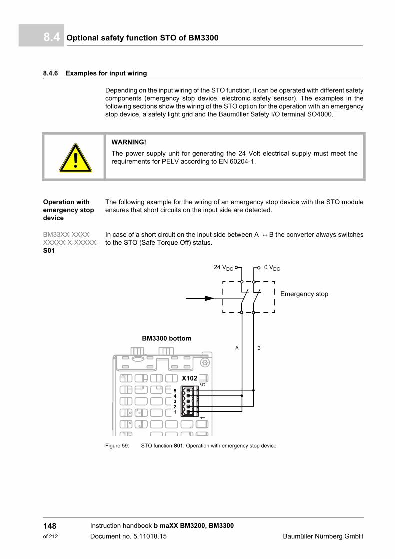
Optional safety function STO of BM33008.4
8.4.6 Examples for input wiring
Depending on the input wiring of the STO function, it can be operated with different safetycomponents (emergency stop device, electronic safety sensor). The examples in thefollowing sections show the wiring of the STO option for the operation with an emergencystop device, a safety light grid and the Baumüller Safety I/O terminal SO4000.
Operation with emergency stop device
The following example for the wiring of an emergency stop device with the STO moduleensures that short circuits on the input side are detected.
BM33XX-XXXX-XXXXX-X-XXXXX-S01
In case of a short circuit on the input side between A B the converter always switchesto the STO (Safe Torque Off) status.
Figure 59: STO function S01: Operation with emergency stop device
WARNING!
The power supply unit for generating the 24 Volt electrical supply must meet therequirements for PELV according to EN 60204-1.
BM3300 bottom
X102
54321
0 V DC24 V DC
Emergency stop
A B
0 VDC24 VDC
Instruction handbook b maXX BM3200, BM3300
Document no. 5.11018.15 Baumüller Nürnberg GmbH
148of 212
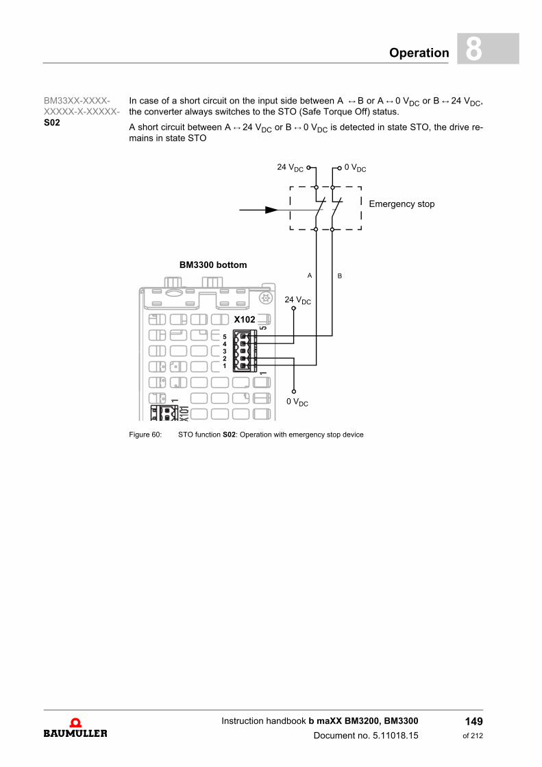
Operation 8
BM33XX-XXXX-XXXXX-X-XXXXX-S02In case of a short circuit on the input side between A B or A 0 VDC or B 24 VDC,the converter always switches to the STO (Safe Torque Off) status.
A short circuit between A 24 VDC or B 0 VDC is detected in state STO, the drive re-mains in state STO
Figure 60: STO function S02: Operation with emergency stop device
BM3300 bottom
X102
54321
Emergency stop
24 VDC
0 VDC
24 VDC 0 VDC
A B
Instruction handbook b maXX BM3200, BM3300
Document no. 5.11018.15
149of 212
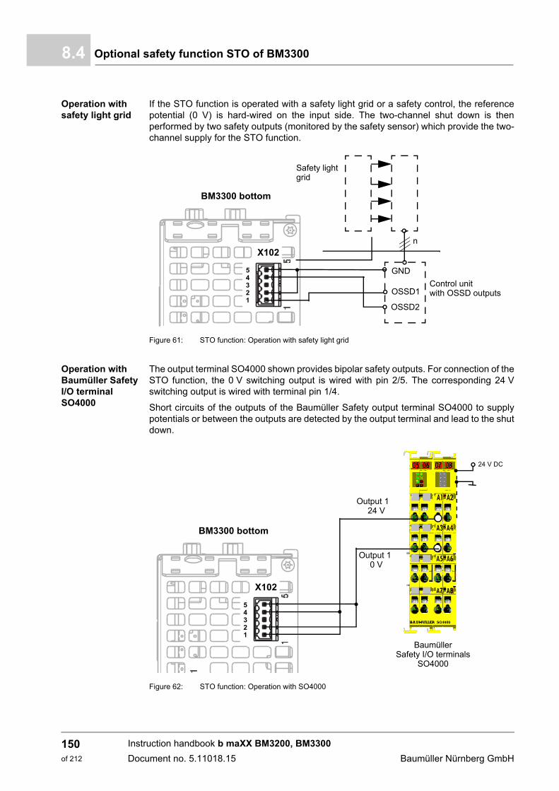
Optional safety function STO of BM33008.4
Operation with safety light grid
If the STO function is operated with a safety light grid or a safety control, the referencepotential (0 V) is hard-wired on the input side. The two-channel shut down is thenperformed by two safety outputs (monitored by the safety sensor) which provide the two-channel supply for the STO function.
Figure 61: STO function: Operation with safety light grid
Operation with Baumüller Safety I/O terminal SO4000
The output terminal SO4000 shown provides bipolar safety outputs. For connection of theSTO function, the 0 V switching output is wired with pin 2/5. The corresponding 24 Vswitching output is wired with terminal pin 1/4.
Short circuits of the outputs of the Baumüller Safety output terminal SO4000 to supplypotentials or between the outputs are detected by the output terminal and lead to the shutdown.
Figure 62: STO function: Operation with SO4000
BM3300 bottom
X102
54321
n
Safety lightgrid
GND
OSSD2
OSSD1Control unitwith OSSD outputs
BM3300 bottom
X102
54321
24 V DC
BaumüllerSafety I/O terminals
SO4000
Output 124 V
Output 10 V
Instruction handbook b maXX BM3200, BM3300
Document no. 5.11018.15 Baumüller Nürnberg GmbH
150of 212
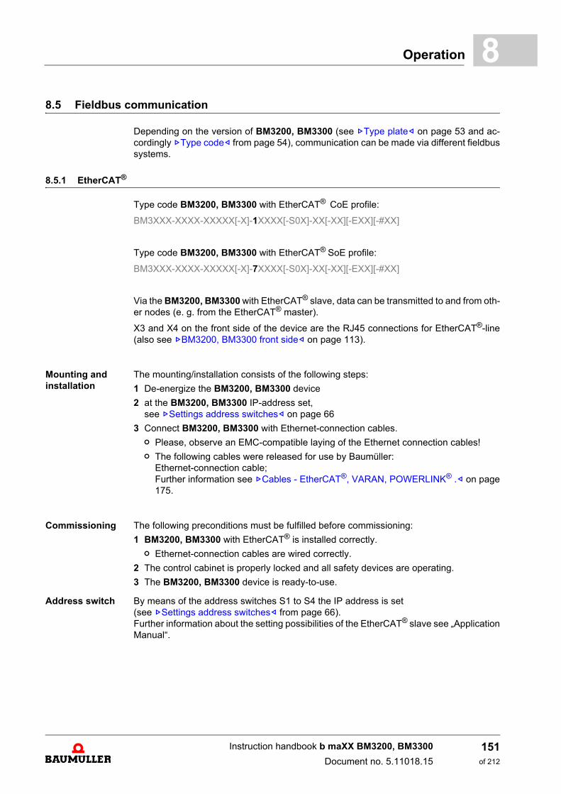
Operation 8
8.5 Fieldbus communicationDepending on the version of BM3200, BM3300 (see ZType plate– on page 53 and ac-cordingly ZType code– from page 54), communication can be made via different fieldbussystems.
8.5.1 EtherCAT®.
Type code BM3200, BM3300 with EtherCAT® CoE profile:
BM3XXX-XXXX-XXXXX[-X]-1XXXX[-S0X]-XX[-XX][-EXX][-#XX]
Type code BM3200, BM3300 with EtherCAT® SoE profile:
BM3XXX-XXXX-XXXXX[-X]-7XXXX[-S0X]-XX[-XX][-EXX][-#XX]
Via the BM3200, BM3300 with EtherCAT® slave, data can be transmitted to and from oth-er nodes (e. g. from the EtherCAT® master).
X3 and X4 on the front side of the device are the RJ45 connections for EtherCAT®-line(also see ZBM3200, BM3300 front side– on page 113).
Mounting and installation
The mounting/installation consists of the following steps:
1 De-energize the BM3200, BM3300 device
2 at the BM3200, BM3300 IP-address set,see ZSettings address switches– on page 66
3 Connect BM3200, BM3300 with Ethernet-connection cables.
n Please, observe an EMC-compatible laying of the Ethernet connection cables!
n The following cables were released for use by Baumüller:Ethernet-connection cable; Further information see ZCables - EtherCAT®, VARAN, POWERLINK® .– on page175.
Commissioning. The following preconditions must be fulfilled before commissioning:
1 BM3200, BM3300 with EtherCAT® is installed correctly.
n Ethernet-connection cables are wired correctly.
2 The control cabinet is properly locked and all safety devices are operating.
3 The BM3200, BM3300 device is ready-to-use.
Address switch By means of the address switches S1 to S4 the IP address is set (see ZSettings address switches– from page 66). Further information about the setting possibilities of the EtherCAT® slave see „ApplicationManual“.
Instruction handbook b maXX BM3200, BM3300
Document no. 5.11018.15
151of 212

Fieldbus communication8.5
Parameters The parameter settings determine the behavior of the EtherCAT® slave in operation. Pa-rameters are set with the software ProDrive.
1 Start ProDrive
2 Click on „Project Tree“.
3 Communication settings with ProDrive
n Project Tree: Configuration/Fieldbus Slave (refer also Parameter manual b maXX 3000, 5.12001)
m Set Synchronization to „On“
m SYNC time = EtherCAT® cycle time = 125 µs to 8 ms
This setting is not necessary if using the CoE profile (CoE: CANopen® over Eth-erCAT®) and the EtherCAT® master has set the parameter 1C32.02 „Cycle Time“to a valid value or „Distributed Clock“ is set to Sync0.
When using the SoE profile (Servodrive profile over EtherCAT®) the fieldbus cy-cle time can be set via S parameter S-0-0002 or directly via controller parameterfieldbus cycle time. In case „Distributed Clock“ is activated the set fieldbus cycletime must be identical with the Sync0 Unit cycle. The Sync0 Unit cycle is set viathe EtherCAT® master. No synchronous operation is possible if this condition isnot fulfilled. The slave inhibits the change from PreOperational to SafeOperational and generates an error message.
Instruction handbook b maXX BM3200, BM3300
Document no. 5.11018.15 Baumüller Nürnberg GmbH
152of 212

Operation 8
8.5.2 VARAN.Type code BM3200, BM3300 with VARAN:
BM3XXX-XXXX-XXXXX[-X]-2XXXX[-S0X]-XX[-XX][-EXX][-#XX]
A BM3200, BM3300 with fieldbus option VARAN can communicate with a VARAN mas-ter.
X3 and X4 on the front side of the device are the RJ45 connections for VARAN (also seeZBM3200, BM3300 front side– on page 113).
Mounting and in-stallation
The mounting/installation consists of the following steps:
1 De-energize the BM3200, BM3300 device
2 Set the BM3200, BM3300 IP-address,see ZSettings address switches– on page 66
3 Connect BM3200, BM3300 with VARAN bus cables (Ethernet-LAN cable at least CAT 5).
n X3: VARAN-In, X4: VARAN-Out. On the first BM3200, BM3300 node of a VARAN line X3 is connected with the VA-RAN master. X4 is connected with X3 of the next BM3200, BM3300 slave in the line,and so on. The last node of a VARAN line has no connection of X4 or is connectedwith a PC (tunneling of Ethernet frames via VARAN to the controller, e. g. to com-municate with ProDrive).Each slave within the VARAN line can be addressed and parametrized via selectionof its IP address.
Abbildung 63: VARAN fieldbus connection
NOTE!
A point-to-point connection between PC (ProDrive) and BM3200, BM3300 VARANslave X4 for commissioning is possible even without a VARAN master.
Instruction handbook b maXX BM3200, BM3300
Document no. 5.11018.15
153of 212
Fieldbus communication8.5
n Please, observe an EMC-compatible laying of the Ethernet connection cables!
n The following cables were released for use by Baumüller:Ethernet connection cable; Further information see ZCables - EtherCAT®, VARAN, POWERLINK® .– on page175.
Commissioning. The following preconditions must be fulfilled before commissioning:
1 BM3200, BM3300 with VARAN is installed correctly.
n Ethernet connection cables are wired correctly.
2 The control cabinet is properly locked and all safety devices are operating.
3 The BM3200, BM3300 device is ready-to-use.
4 Create a Lasal-Class2 project using the driver classes for BM3200, BM3300 drives forcyclic and service data communication.
5 Start the VARAN control
Address switch By means of the address switches S1 to S4 the IP-address is set (Refer to settings ZSetting the IP address with address switches– from page 67).
Parameters The parameter settings determine the behavior of the VARAN-Slave in operation. Param-eters are set with the software ProDrive.
1 Start ProDrive
2 Click on „Project Tree“.
3 Communication settings with ProDrive
n Project Tree: Configuration/Fieldbus Slave (refer also Parameter manual BM3200, BM3300)
m set Synchronization to „On“
m set Fieldbus cycle time according VARAN cycle time (1 ms, 2 ms, 4 ms or 8 ms)
Instruction handbook b maXX BM3200, BM3300
Document no. 5.11018.15 Baumüller Nürnberg GmbH
154of 212
Operation 8
8.5.3 CANopen®.Type code BM3200, BM3300 with CANopen®:
BM3XXX-XXXX-XXXXX[-X]-3XXXX[-S0X]-XX[-XX][-EXX][-#XX]
The data can be transmitted to all the other CAN-users (e g from CANopen® master) viathe BM3200, BM3300.
X3 and X4 are the RJ45 connections for CAN bus cables (also see ZBM3200, BM3300front side– on page 113), which are on the front side of the device.
Mounting and installation
The mounting / installation consists of the following steps:
1 De-energize BM3200, BM3300 device
2 Set address and baud rate (transfer rate) at the BM3200, BM3300,see ZCANopen®– on page 69.
3 Connect BM3200, BM3300 with CANopen®-bus cables (and, if necessary, a terminat-ed connector).
n Comply to EMC-oriented laying of CANopen® connection cables!
n Baumüller released the following cables for use:CANopen® connection cable; further information see ZAccessories - CANopen®.– on page 176.
Commissioning The following preconditions must be fulfilled before commissioning can be made:
1 BM3200, BM3300 with CANopen® is correctly installed.
n CANopen®-connection cables are correctly wired.
2 The control cabinet has been locked correctly and the safety devices have been putinto operation.
3 The BM3200, BM3300 device is ready-to-use.
Address switch By means of the address switch S1 to S4 the settings, like e.g. the baud rate (transferrate) and the address setting (slave No. /ID) are made (see ZCANopen®– on page 69). Further information about parameter setting of the CANopen® slave, see „ApplicationManual“.
Process of commissioning
The test-commissioning is divided into the following sections:
1 Configuration of the CANopen® slave
2 Testing of the CANopen® slave
NOTE!
If the BM3200, BM3300 device is the last bus node in the line, X4 must be terminatedwith a terminating connector (see ZAccessories - CANopen®.– on page 176).
Instruction handbook b maXX BM3200, BM3300
Document no. 5.11018.15
155of 212

Fieldbus communication8.5
Configuring the CANopen® slave
The CANopen® is configured at the running device with ProDrive and a NMT-Master.
1 Switch on BM3200, BM3300 with CANopen®
2 Start ProDrive
3 Ensure, that the CANopen® slave communicates with the NMT-Master (the slave re-ports to the master with the boot-up telegram), i. e. CAN-telegrams can be send/re-ceived.
Make the following settings:
4 ProDrive: Activate communication source (see Parameter Manual: Drive manager)
5 NMT-Master: Create PDO-Mapping (see Programming Manual CANopen®“)
6 NMT-Master: with the NMT-command :=1 into the state „OPERATIONAL change“,then the cyclic communication starts.
Testing of the CANopen®-Slave
The CANopen® slave is tested, by using the total CANopen® network.
ProDrive does not indicate errors, the CANopen® slave was commissioned.
Operation Avoid a reset of the BM3200, BM3300 in the cyclical operation of the CANopen® slave.
WARNING!
Risk of injury due to moving parts!
Rotating and/or linearly moving parts can causesevere injuries.
If a reset of the BM3200, BM3300 device is released in the running cyclical operationor if the communication source is switched off, this can cause unwanted conditionsin the active application.
Therefore:
m Ensure, that the NMT master does not execute a reset, as long as the BM3200,BM3300 device is in the cyclical operation
m Ensure, that the CANopen® communication source only is able to communicatewith the BM3200, BM3300 device.
NOTE!
After a reset the booting data set is loaded in the controller. In addition the mappingis set on the CANopen®, which was saved in the controller part before the reset wasexecuted.
Instruction handbook b maXX BM3200, BM3300
Document no. 5.11018.15 Baumüller Nürnberg GmbH
156of 212
Operation 8
8.5.4 POWERLINK®.Type code BM3200, BM3300 with POWERLINK®:
BM3XXX-XXXX-XXXXX[-X]-4XXXX[-S0X]-XX[-XX][-EXX][-#XX]
BM3200, BM3300 devices can communicate with a POWERLINK® Managing Node viathe fieldbus connection POWERLINK®.
X3 and X4 on the front side of the device are the RJ45 connections for POWERLINK®
(also see ZBM3200, BM3300 front side– on page 113).
Mounting and in-stallation
The mounting/installation consists of the following steps:
1 De-energize the BM3200, BM3300 device
2 Set the BM3200, BM3300 IP-address,see ZSettings address switches– on page 66.
3 Connect BM3200, BM3300 with Ethernet-connection cables.
n Please, observe an EMC-compatible laying of the Ethernet connection cables!
n The following cables were released for use by Baumüller:Ethernet-connection cable; Further information see ZCables - EtherCAT®, VARAN, POWERLINK® .– on page175.
Commissioning The following preconditions must be fulfilled before commissioning:
1 BM3200, BM3300 with POWERLINK® is installed correctly.
n Ethernet-connection cables are wired correctly.
2 The control cabinet is properly locked and all safety devices are operating.
3 The BM3200, BM3300 device is ready-to-use.
Address switch By means of the address switches S3 and S4 the last byte of the IP-address is set (Refer to settings ZSettings address switches– on page 66). IP address 192.168.100.0 is not allowed.Further information about the setting possibilities of the POWERLINK® Controlled Nodesee „Application Manual“.
Parameters The parameter settings determine the behavior of the POWERLINK® Controlled Node inoperation. Parameters are set with the software ProDrive.
1 Start ProDrive
2 Click on „Project Tree“.
3 Communication settings with ProDrive
n Project Tree: Configuration/Fieldbus Slave (refer also Parameter manual BM3200, BM3300)
m Set Synchronization to „On“
m SYNC time = Fieldbus cycle time = POWERLINK® cycle time = 500 µs to 8 ms
This setting is not necessary if using the POWERLINK® profile and the POWER-LINK® Managing Node sets a valid value in object 0x1006 „Communication cycleperiod“.
Instruction handbook b maXX BM3200, BM3300
Document no. 5.11018.15
157of 212

Fieldbus communication8.5
Instruction handbook b maXX BM3200, BM3300
Document no. 5.11018.15 Baumüller Nürnberg GmbH
158of 212

9MAINTENANCE
9.1 Safety notes
Basic information
9.2 Environmental conditions
If the stipulated environmental conditions are adhered to, then the device is maintenance-free. For the prescribed environmental conditions, see ZRequired environmental condi-tions– on page 30.
WARNING!
Risk of injury due to improperly performed maintenance work!
Improper maintenance can lead to severe personal injury and material damage.
Therefore:
m Before beginning work, make sure that there is adequate working clearance.
m Make sure that the mounting area is kept clean and orderly. Parts and tools thatare loosely stacked or are lying around can cause accidents.
159of 212
Instruction handbook b maXX BM3200, BM3300
Document no. 5.11018.15
Inspection intervals - maintenance notes9.3
9.3 Inspection intervals - maintenance notes
Preventive maintenance is prescribed to keep the device in an optimum operating condi-tion and ensure a long service life. It is recommended to have inspections performed reg-ularly by qualified personnel.
Daily inspection:
Basic check points as to whether discrepancies have occurred during operation:
m Does the motor work as requested?
m Is the operating environment normal?
m Is the cooling system working normal?
m Is there an unusual vibration or noise during operation?
m Does the motor overheat during operation?
Regularly scheduledinspection:
Before inspection, switch off the input voltage and wait until the device's capacitors havedischarged.
DANGER!
Risk of fatal injury from electrical current!
Therefore:
m Switch off voltage before performing work!
m Only qualified personnel may mount, install and maintain the devices.
m Please remove all metallic objects worn, such as watches or rings, for example,before beginning to work on the device.
m Insulated tools are permitted, only.
Instruction handbook b maXX BM3200, BM3300
Document no. 5.11018.15 Baumüller Nürnberg GmbH
160of 212

Maintenance 9
9.3.1 Periodic maintenance
m environmental condition
m Voltage
DANGER!
Risk of fatal injury from electrical current!
Stored electric charge.
Discharge time of the modular system = discharge time of the device with the longestDC link discharge time in the modular system.
Refer to Z Electrical Data –.
Therefore:
m Do not touch before taking into account the discharge time of the capacitors andelectrically live parts.
m Heed corresponding notes on the equipment.
m If additional capacitors are connected to the intermediate circuit, the intermediatecircuit discharge can take a much longer time. In this case, the necessary waitingperiod must itself be determined or a measurement made as to whether the equip-ment is de-energized. This discharge time must be posted, together with an IEC60417-5036 (2002-10) warning symbol, on a clearly visible location of the controlcabinet.
Check points Methods and criteria Inspection intervals
Daily Semi-annu-ally
Annu-ally
Check environmental temperature, humidity and vibrations.Check, whether dust, oil or water drops are visible.
Visual inspection and measurement of the environmen-tal conditions, comparison with standard values.
O
Check, whether there are hazardous objects in the vicinity.
Visual inspection O
Check points Methods and criteria Inspection intervals
Daily Semi-annu-ally
Annu-ally
Check the voltage of the power supply network and the control circuits
Measurement and comparison with standard values. O
Instruction handbook b maXX BM3200, BM3300
Document no. 5.11018.15
161of 212
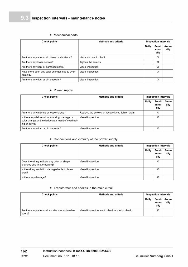
Inspection intervals - maintenance notes9.3
m Mechanical parts
m Power supply
m Connections and circuitry of the power supply
m Transformer and chokes in the main circuit
Check points Methods and criteria Inspection intervals
Daily Semi-annu-ally
Annu-ally
Are there any abnormal noises or vibrations? Visual and audio check O
Are there any loose screws? Tighten the screws. O
Are there any bent or damaged parts? Visual inspection O
Have there been any color changes due to over-heating?
Visual inspection O
Are there any dust or dirt deposits? Visual inspection O
Check points Methods and criteria Inspection intervals
Daily Semi-annu-ally
Annu-ally
Are there any missing or loose screws? Replace the screws or, respectively, tighten them. O
Is there any deformation, cracking, damage or color change on the device as a result of overheat-ing or aging?
Visual inspection O
Are there any dust or dirt deposits? Visual inspection O
Check points Methods and criteria Inspection intervals
Daily Semi-annu-ally
Annu-ally
Does the wiring indicate any color or shape changes due to overheating?
Visual inspection O
Is the wiring insulation damaged or is it discol-ored?
Visual inspection O
Is there any damage? Visual inspection O
Check points Methods and criteria Inspection intervals
Daily Semi-annu-ally
Annu-ally
Are there any abnormal vibrations or noticeable odors?
Visual inspection, audio check and odor check O
Instruction handbook b maXX BM3200, BM3300
Document no. 5.11018.15 Baumüller Nürnberg GmbH
162of 212
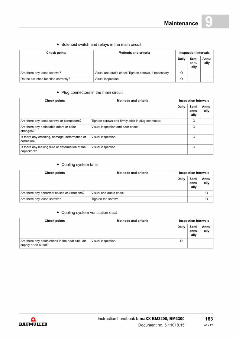
Maintenance 9
m Solenoid switch and relays in the main circuitm Plug connectors in the main circuit
m Cooling system fans
m Cooling system ventilation duct
Check points Methods and criteria Inspection intervals
Daily Semi-annu-ally
Annu-ally
Are there any loose screws? Visual and audio check Tighten screws, if necessary. O
Do the switches function correctly? Visual inspection O
Check points Methods and criteria Inspection intervals
Daily Semi-annu-ally
Annu-ally
Are there any loose screws or connectors? Tighten screws and firmly stick in plug connector. O
Are there any noticeable odors or color changes?
Visual inspection and odor check O
Is there any cracking, damage, deformation or corrosion?
Visual inspection O
Is there any leaking fluid or deformation of the capacitors?
Visual inspection O
Check points Methods and criteria Inspection intervals
Daily Semi-annu-ally
Annu-ally
Are there any abnormal noises or vibrations? Visual and audio check O
Are there any loose screws? Tighten the screws. O
Check points Methods and criteria Inspection intervals
Daily Semi-annu-ally
Annu-ally
Are there any obstructions in the heat sink, air supply or air outlet?
Visual inspection O
Instruction handbook b maXX BM3200, BM3300
Document no. 5.11018.15
163of 212
Repairs9.4
9.4 Repairs
In case of device damage, please inform your sales office or:
Baumüller Nürnberg GmbH
Ostendstr. 80 - 90 90482 Nuremberg Germany
Tel. +49 9 11 54 32 - 0Fax: +49 9 11 54 32 - 1 30
Mail: [email protected]: www.baumueller.com
Instruction handbook b maXX BM3200, BM3300
Document no. 5.11018.15 Baumüller Nürnberg GmbH
164of 212
10TROUBLESHOOTING AND
FAULT CORRECTION
10.1 Behavior in case of malfunctions
Basic information
DANGER!
Risk of fatal injury from electrical current!
Inevitably, when operating this electrical device, certain parts of it are energized withhazardous voltage.
Therefore:
m Pay heed to areas on the device that could be dangerous.
WARNING!
Risk of injury due to improper fault correction!
Therefore:
m Only qualified personnel may work on this device!
m Personnel that work with the b maXX device must be trained in the safety regula-tions and the handling of the device, and be familiar with the correct operation ofit. In particular, reacting to error indications and conditions requires that the oper-ator must have special knowledge.
165of 212
Instruction handbook b maXX BM3200, BM3300
Document no. 5.11018.15
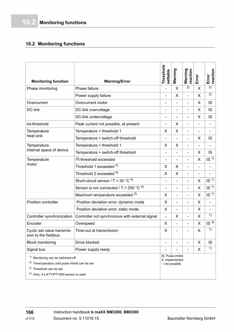
Monitoring functions10.2
10.2 Monitoring functions
Monitoring function Warning/Error Th
res
ho
ld
set
tab
le
Wa
rnin
g
Wa
rnin
gre
ac
tio
n
Err
or
Err
or
rea
cti
on
Phase monitoring Phase failure - X 2) X 2)
Power supply failure - X - X 2)
Overcurrent Overcurrent motor - - - X IS
DC-link DC-link overvoltage - - - X IS
DC-link undervoltage - - - X IS
Ixt-threshold Peak current not possible, at present - X - - -
Temperatureheat sink
Temperature > threshold 1 X X - - -
Temperature > switch-off threshold - - - X IS
Temperature Internal space of device
Temperature > threshold 1 X X - - -
Temperature > switch-off threshold - - - X IS
Temperature motor
I2t-threshold exceeded - - - X IS 1)
Threshold 1 exceeded 4) X X - - -
Threshold 2 exceeded 4) X X - - -
Short-circuit sensor / T < 30 °C 4) - - - X IS 1)
Sensor is not connected / T > 250 °C 4) - - - X IS 1)
Maximum temperature exceeded 2) X - - X IS 1)
Position controller Position deviation error, dynamic mode X - - X -
Position deviation error, static mode X - - X -
Controller synchronization Controller not synchronous with external signal - X - X 1)
Encoder Overspeed X - - X IS 3)
Cyclic set value transmis-sion to the fieldbus
Time-out at transmission X - - X 1)
Block monitoring Drive blocked - - - X IS
Signal bus Power supply ready - - - X 1)
1) Monitoring can be switched-off2) Time/operation until pulse inhibit can be set3) Threshold can be set 4) Only, if a KTY/PT1000-sensor is used
IS: Pulse inhibitX: implemented-: not possible
Instruction handbook b maXX BM3200, BM3300
Document no. 5.11018.15 Baumüller Nürnberg GmbH
166of 212
Troubleshooting and Fault Correction 10
10.2.1 Monitoring functionsOvercurrent This monitoring function checks, if the motor- or the power supply current is 1.3 timesgreater than the output peak current. It serves as a protection against an output-sidedshort-circuit.
DC-link This monitoring function checks the voltage in the DC-link. If the voltage falls under afixed, internal value (about 210 V), then „DC link undervoltage“ is signaled from the con-troller and a warning is displayed. If the voltage exceeds a fixed, internal value (about825 V) then “DC link overvoltage“ is signaled from the controller and an immediate pulseinhibit takes place.
Ixt-threshold This monitoring function checks the heat sink temperature and the current load, whetherit can supply the peak current or the max. rated current, at the moment. If peak current isnot possible, the message “Ixt-threshold 1 exceeded“ is displayed.
Temperature internal space of device
This monitoring function checks the temperature in the internal space of the device.
m If the temperature is greater than the warning threshold, the controller displays a warn-ing.
m If the temperature is greater than the permitted temperature of the device‘s internalspace, an error is generated, the error reaction can be set.
Temperature heat sink
This monitoring function checks the temperature of the heat sink.
m If the temperature is greater than the warning threshold, the controller displays a warn-ing.
m If the temperature is greater than the maximum permitted heat sink temperature of thedevice‘s internal space, an error is generated, the error reaction can be set.
Temperature motor
This monitoring function checks the temperature of the motor. if the I²t-overload of thecontroller is displayed.
Only forKTY84 and PT1000sensor
If the set temperature threshold 1 is exceeded, then the warning „Temperature threshold1 exceeded“ is generated by the controller.
If the set temperature threshold 2 is exceeded, then the warning „Temperature threshold2 exceeded“ is generated by the controller.
If the temperature falls below the minimum measurable value, or if a short circuit occursat the sensor, then the error message „Temperature sensor short circuit“ is generated.
If the temperature exceeds the maximum measurable temperature, or if the sensor is notconnected, then the error message „Temperature sensor not connected“ is generated bythe controller.
For all sensors
If the threshold set (type-specific) in the temperature switch or in the sensor is exceeded,then the error message „Over temperature“ is generated by the controller and the pulsesare inhibited immediately.
Position controller
This monitoring function checks the position deviation limit statical/dynamical.
The error message „position deviation statical“ or „position deviation dynamical“ is set, ifthe present position deviation statical/dynamical is greater than the set position deviationlimit. After the monitoring time (deviation time) has past an additional error message isdisplayed and an immediate pulse inhibit takes place. The reaction time is settable.
Instruction handbook b maXX BM3200, BM3300
Document no. 5.11018.15
167of 212
Monitoring functions10.2
Block monitoring This monitoring function checks the motor speed and the motor current. If both of the following conditions are met for the period „block monitoring time“, then theerror/the warning „drive blocked“ is signaled to the controller and an immediate pulse in-hibit takes place.
m Motor speed = 0
m The motor current output from the device is the same as the set motor limit current (cur-rent limit).
Signal bus All power units at the axis devices are connected with a „signal bus“. Each user can re-quest for and set the bus signals including the supply unit.
Signal bus - supply ready-for-use
Indicates, when the supply unit is in the status „ready-for-use“. This signal is generatedafter the recognition and identification of the power supply. At a power rectifier „ready-for-use“ is active after about 4 s after switching on the 24 V-supply voltage.
At power supply errors and power supply failure the ready-for-use signal is reset. Theaxes must react upon this and must change into the error state.
Signal bus - ballast resistor on
The DC-link voltage is monitored independently by each axis. The mode parameter(140.1) bit 0 sets, if the signal for the control of the ballast resistor shall be activated atthis warning. If the voltage of the ballast resistor drops below the ballast resistor threshold(P130.29 protected) - 20 V (hysteresis) the axis resets the signal at the bus and deletesthe warning.
The ballast resistor threshold is calculated from max. UDC-link with:
Ballast resistor = max. UDC-link - 30 V
Instruction handbook b maXX BM3200, BM3300
Document no. 5.11018.15 Baumüller Nürnberg GmbH
168of 212
Troubleshooting and Fault Correction 10
10.3 Error detectionAn error state is signaled by the lighting-up of the red LED H14 on the front side of thecabinet; also see ZDisplay and operating elements BM3200, BM3300– on page 58 on-ward.
Further information according the subjects error messages and error numbers, see „pa-rameter manual b maXX 3000“.
10.4 Troubleshooting/error acknowledge
The basis of troubleshooting are the error messages, which also are called error lists.
If the red error-LED H14 is flashing, then one error occurred, at least.
The error messages are reset by executing an error acknowledge. An individual error ac-knowledge is not possible. The acknowledge causes a reset of the error, if the reset ispossible because of the error situation.
There are three methods to acknowledge errors:
m On the control word via write access.
m Via a digital input
m Via the pulse enable input:Precondition is, that the drive can be controlled via the hardware inputs only (thismeans that the motor control cannot be set via another communication source). Fur-thermore, the option „error acknowledge via pulse enable“ must be activated. The firstrising edge of the pulse enable acknowledges the errors. However, the drive has notstarted, yet. A second rising edge is necessary for enabling.
Further information referring to the subject error acknowledge is found in „Parametermanual b maXX 3000“.
NOTE!
At warnings or errors without error reaction the LED H14 „error“ flashes. Only errormessages with error reactions are signaled by a constant lighting-up.
NOTE!
The device is delivered with predefined error reactions. The error reaction of the de-vice can be set in the marked error messages in „Dependent on setting“ in the column„Reaction“. Errors, where an immediate pulse inhibit is executed cannot be changed,due to safety reasons.
Instruction handbook b maXX BM3200, BM3300
Document no. 5.11018.15
169of 212

Troubleshooting/error acknowledge10.4
Instruction handbook b maXX BM3200, BM3300
Document no. 5.11018.15 Baumüller Nürnberg GmbH
170of 212

11ACCESSORIES AND SPARE PARTS
In this appendix the accessory-/spare parts for the devices of the series BM3200,BM3300 are listed. Do not hesitate to contact our product management for inquiries andsuggestions referring to spare parts.
11.1 Cables
11.1.1 Cable power supply-device
1) The length of the cable between line filter and power supply, in order to comply with the EMC-Guideline, is irrelevant.2) The laying procedure is not specified. The DC link connections must be laid DC compliant.
11.1.2 Cable device-motor
1) Only with a Baumüller cable with this maximum length and with a Baumüller line filter it can be expected that the limit values of the EMC-product standard EN_61800-3 can be complied with. If n-parallel-laid motor cables are used, then the maximum length is to be reducedby the factor 1/n.
2) With Baumüller cables with this maximum length and the use of Baumüller line filters, it can be expected that the limit values of theEMC-regulation is complied with.
Device Cross-section Maximum Length 1) Connection to the device 2)
BM320XBM330XBM321XBM331X
4 x 1 bis 2.5 mm2
(AWG 18 - 14)As required Flexible cable
with/without wire end ferrule(screw contact)
Device Cross-section Maximum Length 1) Connection at Device 2)
BM320XBM330XBM321XBM331X
4 x 1 to 4 mm2
(AWG 28 - 12)Max. 50 m Flexible cable
with/without wire end ferrule(screw contact)
171of 212
Instruction handbook b maXX BM3200, BM3300
Document no. 5.11018.15
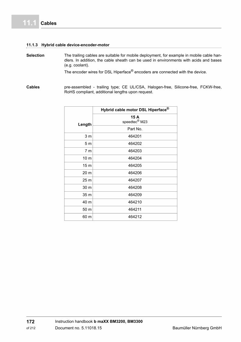
Cables11.1
11.1.3 Hybrid cable device-encoder-motor
Selection The trailing cables are suitable for mobile deployment, for example in mobile cable han-dlers. In addition, the cable sheath can be used in environments with acids and bases(e.g. coolant).
The encoder wires for DSL Hiperface® encoders are connected with the device.
Cables pre-assembled - trailing type; CE UL/CSA, Halogen-free, Silicone-free, FCKW-free,RoHS compliant, additional lengths upon request.
Length
Hybrid cable motor DSL Hiperface®
15 Aspeedtec® M23
Part No.
3 m 464201
5 m 464202
7 m 464203
10 m 464204
15 m 464205
20 m 464206
25 m 464207
30 m 464208
35 m 464209
40 m 464210
50 m 464211
60 m 464212
Instruction handbook b maXX BM3200, BM3300
Document no. 5.11018.15 Baumüller Nürnberg GmbH
172of 212

Accessories and Spare Parts 11
m Motor cable with DSL Hiperface® 15 AFigure 64: Motor cable with DSL Hiperface® 15 A
Cable: 4G1.5+(2x0,75)+(2x22AWG)Shielding: copper wires, tinned
Motor side: Circular metal connector speedtec® M23 8-pinConnect outside shielding and inside shielding with the connector housing.
Device side: Metal D-sub connector 45°, 26-pin with electronics, part No. 460219.Connect inside shielding with the connector housing.
Connect cable shield with thehousing of the connector.
Cable length(according order)
Heat shrink tubing
400 mmData cable shielded
Connect the cable shieldingvia the strain relief clampof the connector housing.
Pin 1
1
3
A
D4
DSL- blue
DSL+ white
Pin 19 DSL-Pin 20 DSL+
B+B-
VW
GN/GE
U
Circular connector Type of stranding Unconnected wires Cross section of wire
1 U 1,5 mm² / black / U
3 V 1,5 mm² / black / V
4 W 1,5 mm² / black / W
GN/GE 1,5 mm² / green-yellow
A B+ 0,75 mm² / black
B B- 0,75 mm² / black
C DSL+ 22 AWG / white
D DSL- 22 AWG / blue
Housing - Outside shielding
Housing - Inside shielding
Instruction handbook b maXX BM3200, BM3300
Document no. 5.11018.15
173of 212
Cables11.1
11.1.4 Cable DC-link
11.1.5 Cable control power supply / signals
1) The laying procedure is not specified.2) The length of the cable in order to comply with the EMC-regulation is irrelevant.
Device Cross-section Connection at Device
BM3X0XBM3X1X
2 x 1 to 2.5 mm2
(AWG 18 - 14)Flexible cable with/without wire end ferrule
(screw contact)
HINWEIS!
A ferrite core (part No. 308293) must be used with a DC link connection longer than3 m to ensure a reliable EMC interference immunity of the BM3200, BM3300. TheDC link cables connected with 1C1 and 1D1 must be led through the ferrite core with3 turns per cable. The ferrite core should be close to the connection X205 of theBM3200, BM3300.
Cross-section 1) 1.5 mm2
Maximum length (without digital IO) 2) As desired
Maximum length digital IO 30 m
Connection at device Without/with wire end ferrules(plug-in terminal
Instruction handbook b maXX BM3200, BM3300
Document no. 5.11018.15 Baumüller Nürnberg GmbH
174of 212
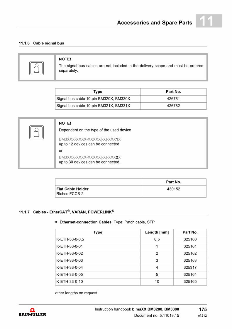
Accessories and Spare Parts 11
11.1.6 Cable signal bus11.1.7 Cables - EtherCAT®, VARAN, POWERLINK® .
m Ethernet-connection Cables, Type: Patch cable, STP
other lengths on request
NOTE!
The signal bus cables are not included in the delivery scope and must be orderedseparately.
Type Part No.
Signal bus cable 10-pin BM320X, BM330X 426781
Signal bus cable 10-pin BM321X, BM331X 426782
NOTE!
Dependent on the type of the used device
BM3XXX-XXXX-XXXXX[-X]-XXX1Xup to 12 devices can be connected
or
BM3XXX-XXXX-XXXXX[-X]-XXX2Xup to 30 devices can be connected.
Part No.
Flat Cable HolderRichco FCCS-2
430152
Type Length [mm] Part No.
K-ETH-33-0-0,5 0.5 325160
K-ETH-33-0-01 1 325161
K-ETH-33-0-02 2 325162
K-ETH-33-0-03 3 325163
K-ETH-33-0-04 4 325317
K-ETH-33-0-05 5 325164
K-ETH-33-0-10 10 325165
Instruction handbook b maXX BM3200, BM3300
Document no. 5.11018.15
175of 212
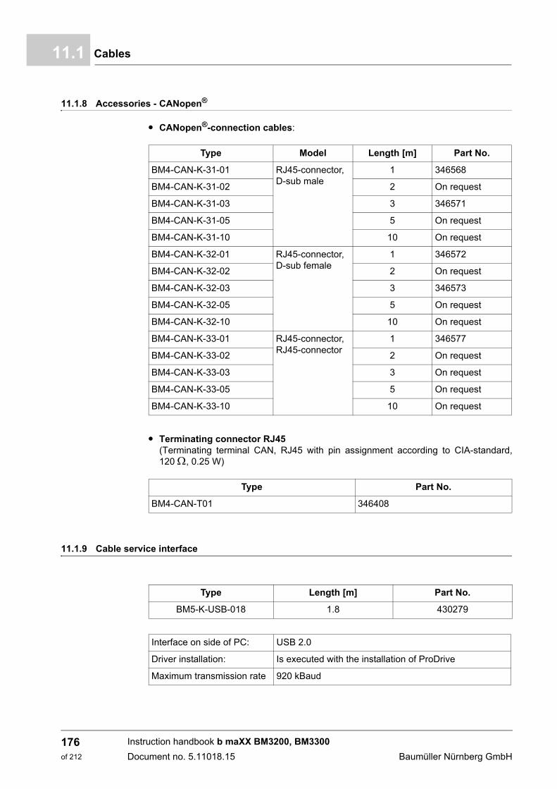
Cables11.1
11.1.8 Accessories - CANopen®.
m CANopen®-connection cables:
m Terminating connector RJ45 (Terminating terminal CAN, RJ45 with pin assignment according to CIA-standard,120 , 0.25 W)
11.1.9 Cable service interface
Type Model Length [m] Part No.
BM4-CAN-K-31-01 RJ45-connector, D-sub male
1 346568
BM4-CAN-K-31-02 2 On request
BM4-CAN-K-31-03 3 346571
BM4-CAN-K-31-05 5 On request
BM4-CAN-K-31-10 10 On request
BM4-CAN-K-32-01 RJ45-connector, D-sub female
1 346572
BM4-CAN-K-32-02 2 On request
BM4-CAN-K-32-03 3 346573
BM4-CAN-K-32-05 5 On request
BM4-CAN-K-32-10 10 On request
BM4-CAN-K-33-01 RJ45-connector, RJ45-connector
1 346577
BM4-CAN-K-33-02 2 On request
BM4-CAN-K-33-03 3 On request
BM4-CAN-K-33-05 5 On request
BM4-CAN-K-33-10 10 On request
Type Part No.
BM4-CAN-T01 346408
Type Length [m] Part No.
BM5-K-USB-018 1.8 430279
Interface on side of PC: USB 2.0
Driver installation: Is executed with the installation of ProDrive
Maximum transmission rate 920 kBaud
Instruction handbook b maXX BM3200, BM3300
Document no. 5.11018.15 Baumüller Nürnberg GmbH
176of 212
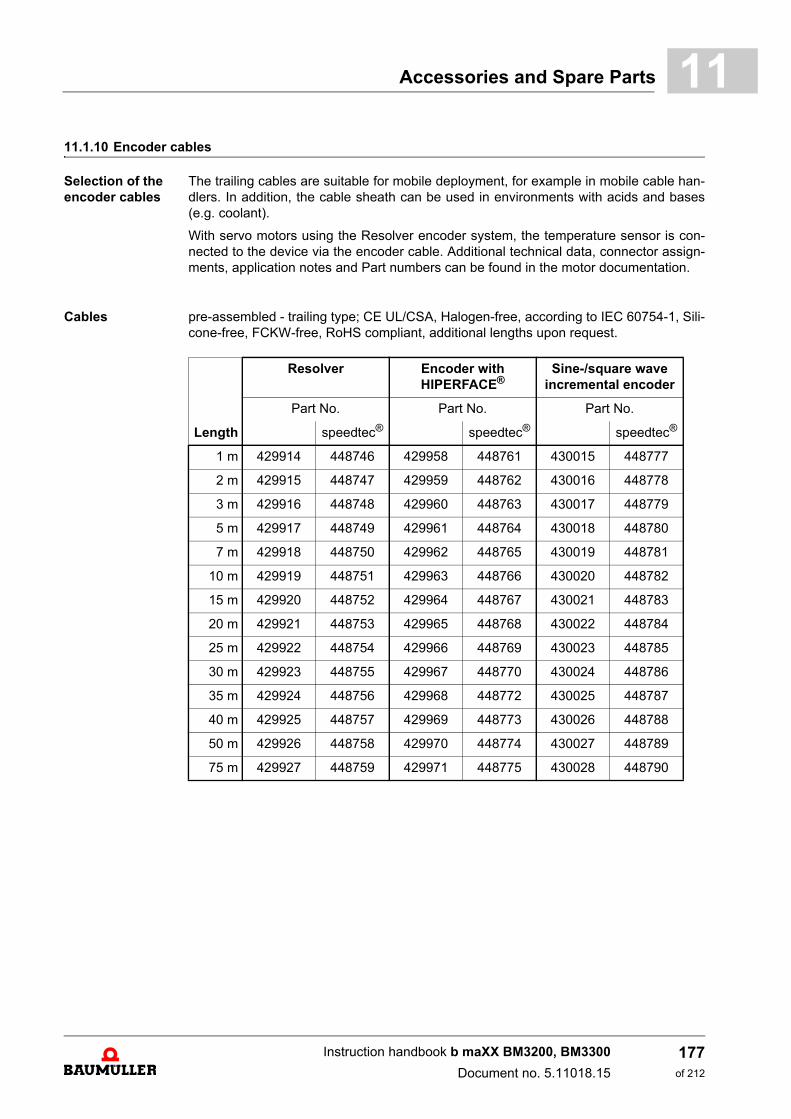
Accessories and Spare Parts 11
11.1.10 Encoder cablesSelection of the encoder cables
The trailing cables are suitable for mobile deployment, for example in mobile cable han-dlers. In addition, the cable sheath can be used in environments with acids and bases(e.g. coolant).
With servo motors using the Resolver encoder system, the temperature sensor is con-nected to the device via the encoder cable. Additional technical data, connector assign-ments, application notes and Part numbers can be found in the motor documentation.
Cables pre-assembled - trailing type; CE UL/CSA, Halogen-free, according to IEC 60754-1, Sili-cone-free, FCKW-free, RoHS compliant, additional lengths upon request.
Length
Resolver Encoder with HIPERFACE®
Sine-/square wave incremental encoder
Part No. Part No. Part No.
speedtec® speedtec® speedtec®
1 m 429914 448746 429958 448761 430015 448777
2 m 429915 448747 429959 448762 430016 448778
3 m 429916 448748 429960 448763 430017 448779
5 m 429917 448749 429961 448764 430018 448780
7 m 429918 448750 429962 448765 430019 448781
10 m 429919 448751 429963 448766 430020 448782
15 m 429920 448752 429964 448767 430021 448783
20 m 429921 448753 429965 448768 430022 448784
25 m 429922 448754 429966 448769 430023 448785
30 m 429923 448755 429967 448770 430024 448786
35 m 429924 448756 429968 448772 430025 448787
40 m 429925 448757 429969 448773 430026 448788
50 m 429926 448758 429970 448774 430027 448789
75 m 429927 448759 429971 448775 430028 448790
Instruction handbook b maXX BM3200, BM3300
Document no. 5.11018.15
177of 212
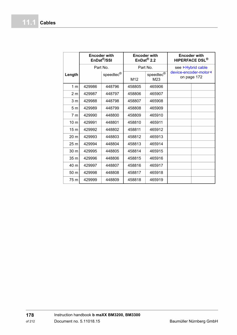
Cables11.1
Length
Encoder with EnDat®/SSI
Encoder with EnDat® 2.2
Encoder with HIPERFACE DSL®
Part No. Part No. see ZHybrid cable device-encoder-motor–
on page 172speedtec®
M12speedtec®
M23
1 m 429986 448796 458805 465906
2 m 429987 448797 458806 465907
3 m 429988 448798 458807 465908
5 m 429989 448799 458808 465909
7 m 429990 448800 458809 465910
10 m 429991 448801 458810 465911
15 m 429992 448802 458811 465912
20 m 429993 448803 458812 465913
25 m 429994 448804 458813 465914
30 m 429995 448805 458814 465915
35 m 429996 448806 458815 465916
40 m 429997 448807 458816 465917
50 m 429998 448808 458817 465918
75 m 429999 448809 458818 465919
Instruction handbook b maXX BM3200, BM3300
Document no. 5.11018.15 Baumüller Nürnberg GmbH
178of 212
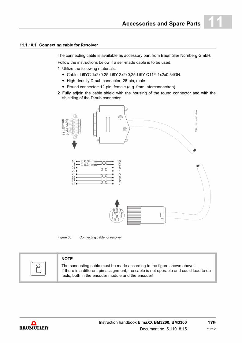
Accessories and Spare Parts 11
11.1.10.1 Connecting cable for ResolverThe connecting cable is available as accessory part from Baumüller Nürnberg GmbH.
Follow the instructions below if a self-made cable is to be used:
1 Utilize the following materials:
m Cable: Li9YC 1x2x0.25-Li9Y 2x2x0,25-Li9Y C11Y 1x2x0.34GN.
m High-density D-sub connector: 26-pin, male
m Round connector: 12-pin, female (e.g. from Interconnectron)
2 Fully adjoin the cable shield with the housing of the round connector and with theshielding of the D-sub connector.
Figure 65: Connecting cable for resolver
NOTE
The connecting cable must be made according to the figure shown above! If there is a different pin assignment, the cable is not operable and could lead to de-fects, both in the encoder module and the encoder!
Instruction handbook b maXX BM3200, BM3300
Document no. 5.11018.15
179of 212

Cables11.1
11.1.10.2 Connecting cable for encoder with HIPERFACE® .
The connecting cable is available as accessory part from Baumüller Nürnberg GmbH.
Follow the instructions below if a self-made cable is to be used:
1 Utilize the following materials:
m Cable: Li9YC3x2x0.25-Li9Y3x2x0,25-Li9Y C11Y 1x2x0.34GN. Two cable pairs arenot needed and also not connected.
m High-density D-sub connector: 26-pin, male
m Round connector: 12-pin, female (e.g. from Interconnectron)
2 Fully adjoin the cable shield with the housing of the round connector and with theshielding of the D-sub connector.
Figure 66: Connecting cable for encoder with HIPERFACE®
5000_1102_re
v01_in
t.cdr
21456
19201718
7
1210
815
2734
6
Æ 0.34 mmÆ 0.34 mm
NOTE
The connecting cable must be made according to the figure shown above! If there is a different pin assignment, the cable is not operable and could lead to de-fects, both in the encoder module and the encoder!
Instruction handbook b maXX BM3200, BM3300
Document no. 5.11018.15 Baumüller Nürnberg GmbH
180of 212

Accessories and Spare Parts 11
11.1.10.3 Connecting cable for encoder with EnDat® or SSIThe connecting cable is available as accessory part from Baumüller Nürnberg GmbH.
Follow the instructions below if a self-made cable is to be used:
1 Utilize the following materials:
m Cable: Li9YC3x2x0.25-Li9Y3x2x0,25-Li9Y C11Y 1x2x0.34GN. Two cable pairs arenot needed and also not connected.
m High-density D-sub connector: 26-pin, male
m Round connector: 17-pin, female (e.g. from Interconnectron)
2 Fully adjoin the cable shield with the housing of the round connector and with theshielding of the D-sub connector.
Figure 67: Connecting cable for encoder with EnDat® or SSI
NOTE
The connecting cable must be made according to the figure shown above! If there is a different pin assignment, the cable is not functionally operable and couldlead to defects, both in the encoder module and the encoder!
Instruction handbook b maXX BM3200, BM3300
Document no. 5.11018.15
181of 212
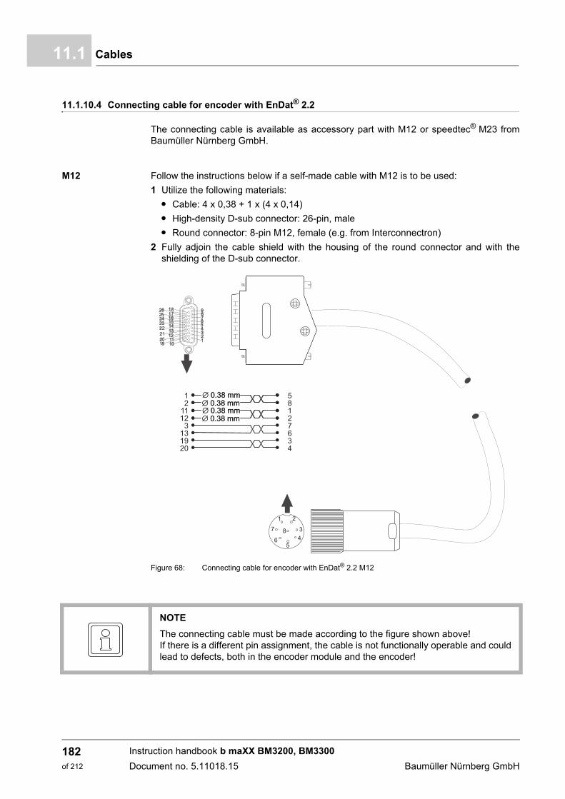
Cables11.1
11.1.10.4 Connecting cable for encoder with EnDat® 2.2
The connecting cable is available as accessory part with M12 or speedtec® M23 fromBaumüller Nürnberg GmbH.
M12 Follow the instructions below if a self-made cable with M12 is to be used:
1 Utilize the following materials:
m Cable: 4 x 0,38 + 1 x (4 x 0,14)
m High-density D-sub connector: 26-pin, male
m Round connector: 8-pin M12, female (e.g. from Interconnectron)
2 Fully adjoin the cable shield with the housing of the round connector and with theshielding of the D-sub connector.
Figure 68: Connecting cable for encoder with EnDat® 2.2 M12
NOTE
The connecting cable must be made according to the figure shown above! If there is a different pin assignment, the cable is not functionally operable and couldlead to defects, both in the encoder module and the encoder!
Instruction handbook b maXX BM3200, BM3300
Document no. 5.11018.15 Baumüller Nürnberg GmbH
182of 212
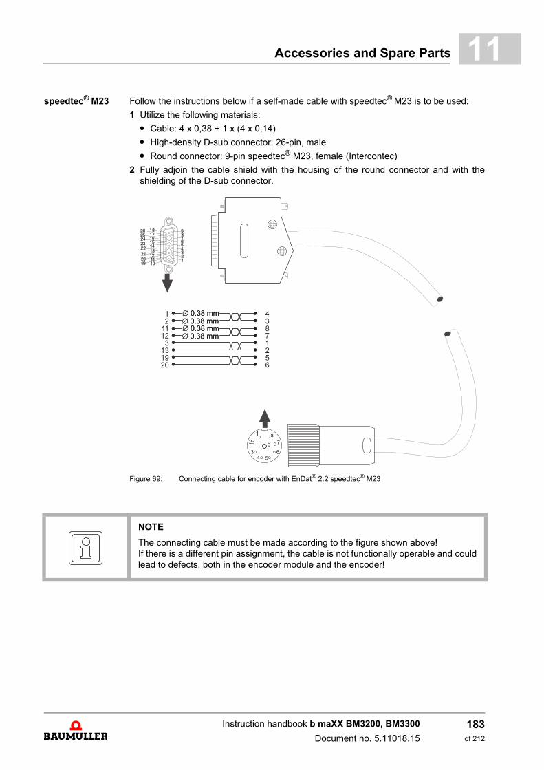
Accessories and Spare Parts 11
speedtec® M23 Follow the instructions below if a self-made cable with speedtec® M23 is to be used:1 Utilize the following materials:
m Cable: 4 x 0,38 + 1 x (4 x 0,14)
m High-density D-sub connector: 26-pin, male
m Round connector: 9-pin speedtec® M23, female (Intercontec)
2 Fully adjoin the cable shield with the housing of the round connector and with theshielding of the D-sub connector.
Figure 69: Connecting cable for encoder with EnDat® 2.2 speedtec® M23
NOTE
The connecting cable must be made according to the figure shown above! If there is a different pin assignment, the cable is not functionally operable and couldlead to defects, both in the encoder module and the encoder!
Instruction handbook b maXX BM3200, BM3300
Document no. 5.11018.15
183of 212
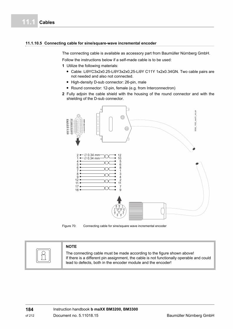
Cables11.1
11.1.10.5 Connecting cable for sine/square-wave incremental encoder
The connecting cable is available as accessory part from Baumüller Nürnberg GmbH.
Follow the instructions below if a self-made cable is to be used:
1 Utilize the following materials:
m Cable: Li9YC3x2x0.25-Li9Y3x2x0,25-Li9Y C11Y 1x2x0.34GN. Two cable pairs arenot needed and also not connected.
m High-density D-sub connector: 26-pin, male
m Round connector: 12-pin, female (e.g. from Interconnectron)
2 Fully adjoin the cable shield with the housing of the round connector and with theshielding of the D-sub connector.
Figure 70: Connecting cable for sine/square wave incremental encoder
50
00
_11
03
_re
v0
1_
int.
cd
r
21456
89
12111718
7
1210
568
342
1179
1
Æ 0.34 mmÆ 0.34 mm
NOTE
The connecting cable must be made according to the figure shown above! If there is a different pin assignment, the cable is not functionally operable and couldlead to defects, both in the encoder module and the encoder!
Instruction handbook b maXX BM3200, BM3300
Document no. 5.11018.15 Baumüller Nürnberg GmbH
184of 212
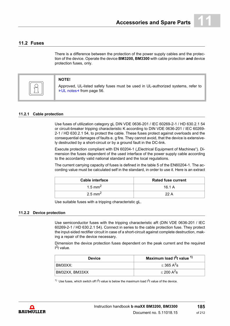
Accessories and Spare Parts 11
11.2 FusesThere is a difference between the protection of the power supply cables and the protec-tion of the device. Operate the device BM3200, BM3300 with cable protection and deviceprotection fuses, only.
11.2.1 Cable protection
Use fuses of utilization category gL DIN VDE 0636-201 / IEC 60269-2-1 / HD 630.2.1 54or circuit-breaker tripping characteristic K according to DIN VDE 0636-201 / IEC 60269-2-1 / HD 630.2.1 54, to protect the cable. These fuses protect against overloads and theconsequential damages of faults e. g fire. They cannot avoid, that the device is extensive-ly destructed by a short-circuit or by a ground fault in the DC-link.
Execute protection compliant with EN 60204-1 („Electrical Equipment of Machines“). Di-mension the fuses dependent of the used interface of the power supply cable accordingto the accordantly valid national standard and the local regulations.
The current carrying capacity of fuses is defined in the table 5 of the EN60204-1. The ac-cording value must be calculated self in the standard, in order to use it. Here is an extract
Use suitable fuses with a tripping characteristic gL.
11.2.2 Device protection
Use semiconductor fuses with the tripping characteristic aR (DIN VDE 0636-201 / IEC60269-2-1 / HD 630.2.1 54). Connect in series to the cable protection fuse. They protectthe input-sided rectifier circuit in case of a short-circuit against complete destruction, mak-ing a repair of the device necessary.
Dimension the device protection fuses dependent on the peak current and the requiredI2t value.
1) Use fuses, which switch off I2t value is below the maximum load I2t value of the device.
NOTE!
Approved, UL-listed safety fuses must be used in UL-authorized systems, refer toZUL notes– from page 56.
Cable interface Rated fuse current
1.5 mm2 16.1 A
2.5 mm2 22 A
Device Maximum load I2t value 1)
BM30XX: 365 A2s
BM32XX, BM33XX 200 A2s
Instruction handbook b maXX BM3200, BM3300
Document no. 5.11018.15
185of 212

Fuses11.2
11.2.3 Cable protection and device protection
There are two possibilities to protect the cable and the device:
m Cable protection fuses and semiconductor fuses, which are connected in series
m Use all-range fuses with a tripping characteristic gR or gS (DIN VDE 0636-201 / IEC60269-2-1 / HD 630.2.1 54).
The suitable cable and device protection fuses must be dimensioned dependent on theinterface of the used power supply cable, the peak current and of the required I2toff inZDevice protection– on page 185.
In contrast to the fuses, the devices and cables can be protected with listed „Circuit break-ers“ complying to UL (DIVQ).
Permitted are circuit breakers without a tripping delay, only. Circuit breakers with only athermal tripping characteristic are not tested and therefore not permitted. It must be con-sidered that the installation is protected against fire but not against destruction.
Dimension the circuit breaker dependent on the interface of the used power supply cableas well as from the rated and the peak current of the devices.
Producer Device protection Device protection and cable protection
SIBA 60 033 05 16A (10 x 38 mm) aR 20 477 34 16A (NH000) gRL gS20 209 34 16A (NH00) gRL gS50 124 34 16A (14 x 51 mm) gRL gS
Bussmann FWP-20A14F 20A 700V 14x51mm aR 170M1560D 20A 690V NH000 gR
DFJ-15 (21 x 57 mm) Class J
Mersen (former Ferraz)
NH000GS69V32PV Ref:X322043C (NH000) 32A 690V gS
FR10GR69V20 Ref: E1014580(10 x 38 mm) 20A 690V gR
FR22GC69V25 Ref: B220916(22 x 58 mm) 25A 690V gRC
HSJ15 (21 x 57 mm) Class J
Siemens 3NC1415: 15A/690V, (14 x 51 mm) aR3NC1016: 16A/600V, (10 x 38 mm) aR
3NE1813-0: 16A/690V, NH000 gS 3NE8015-1: 25A/690V, NH00 gR
Instruction handbook b maXX BM3200, BM3300
Document no. 5.11018.15 Baumüller Nürnberg GmbH
186of 212

Accessories and Spare Parts 11
11.3 Line filterLine filters are combinations of capacitors, reactors, resistors and voltage limiters, whichshall reduce the electromagnetic influence of environment. Further information see linefilter, 5.09010.
11.3.1 Required environmental conditions line filter
11.3.2 Line filter for 3-phase devices BM3XXX-XTXX
m Block diagram of line filter (simplified)
Figure 71: Block diagram line filter
m Selection of the correct line filter for 3-phase devices
In dependency of the application install a line filter from the following table:
Transport temperature range -25 °C up to +85 °C
Storage temperature range - 25 °C up to +85 °C
Operating environment industry power supply
Operating temperature range -25 °C up to +85 °C
Irated AC 1) Type Part No. Use with devices
5 A BFN 3-1-0007-001 314277 BM320X-XTXX, BM330X-XTXX
10 A BFN 3-1-0016-001 314278 BM321X-XTXX, BM331X-XTXX
Instruction handbook b maXX BM3200, BM3300
Document no. 5.11018.15
187of 212
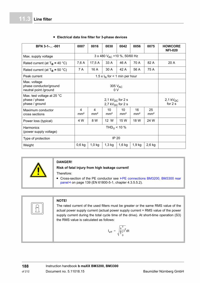
Line filter11.3
m Electrical data line filter for 3-phase devices
BFN 3-1-... -001 0007 0016 0030 0042 0056 0075 HOWCORE NFI-020
Max. supply voltage 3 x 480 VAC +10 %, 50/60 Hz
Rated current (at TB = 40 °C) 7,6 A 17,5 A 33 A 46 A 70 A 82 A 20 A
Rated current (at TB = 50 °C) 7 A 16 A 30 A 42 A 56 A 75 A
Peak current 1.5 x IN for < 1 min per hour
Max. voltagephase conductor/groundneutral point /ground
305 VAC0 V
Max. test voltage at 25 °C phase / phase phase / ground
2,1 kVDC for 2 s2,7 kVDC for 2 s
2,1 kVDC for 2 s
Maximum conductor cross sections
4 mm²
4 mm²
10 mm²
10 mm²
16 mm²
25 mm²
Power loss (typical) 4 W 8 W 12 W 15 W 18 W 24 W
Harmonics(power supply voltage)
THDU < 10 %
Type of protection IP 20
Weight 0,6 kg 1,0 kg 1,3 kg 1,6 kg 1,9 kg 2,6 kg
DANGER!
Risk of fatal injury from high leakage current!
Therefore:
m Cross-section of the PE conductor see ZPE connections BM3200, BM3300 rearpanel– on page 139 (EN 61800-5-1, chapter 4.3.5.5.2).
NOTE!
The rated current of the used filters must be greater or the same RMS value of the
actual power supply current (actual power supply current = RMS value of the power
supply current during the total cycle time of the drive). At short-time operation (S3)
the RMS value is calculated as follows:
Ieff1T--- i2
0
T
dt=
Instruction handbook b maXX BM3200, BM3300
Document no. 5.11018.15 Baumüller Nürnberg GmbH
188of 212
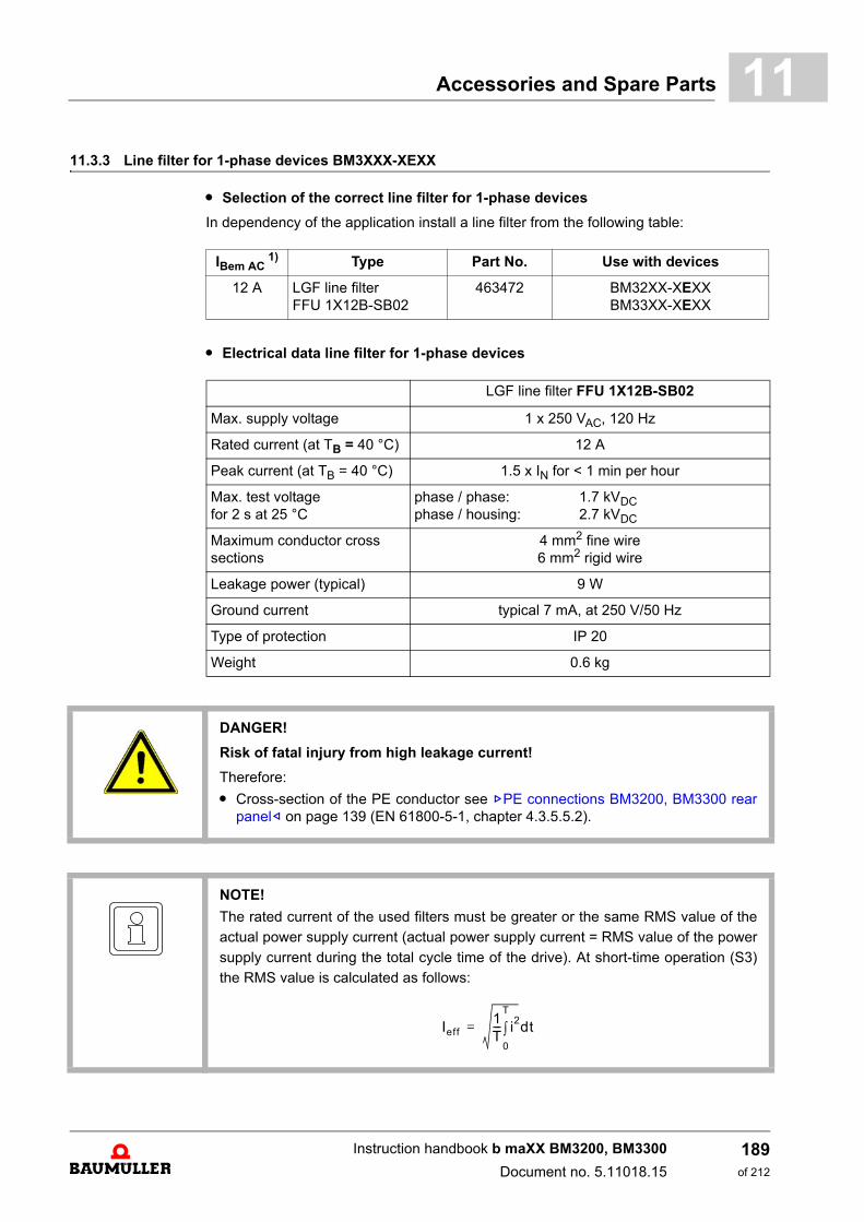
Accessories and Spare Parts 11
11.3.3 Line filter for 1-phase devices BM3XXX-XEXXm Selection of the correct line filter for 1-phase devices
In dependency of the application install a line filter from the following table:
m Electrical data line filter for 1-phase devices
IBem AC 1) Type Part No. Use with devices
12 A LGF line filterFFU 1X12B-SB02
463472 BM32XX-XEXXBM33XX-XEXX
LGF line filter FFU 1X12B-SB02
Max. supply voltage 1 x 250 VAC, 120 Hz
Rated current (at TB = 40 °C) 12 A
Peak current (at TB = 40 °C) 1.5 x IN for < 1 min per hour
Max. test voltagefor 2 s at 25 °C
phase / phase: 1.7 kVDCphase / housing: 2.7 kVDC
Maximum conductor cross sections
4 mm2 fine wire6 mm2 rigid wire
Leakage power (typical) 9 W
Ground current typical 7 mA, at 250 V/50 Hz
Type of protection IP 20
Weight 0.6 kg
DANGER!
Risk of fatal injury from high leakage current!
Therefore:
m Cross-section of the PE conductor see ZPE connections BM3200, BM3300 rearpanel– on page 139 (EN 61800-5-1, chapter 4.3.5.5.2).
NOTE!
The rated current of the used filters must be greater or the same RMS value of the
actual power supply current (actual power supply current = RMS value of the power
supply current during the total cycle time of the drive). At short-time operation (S3)
the RMS value is calculated as follows:
Ieff1T--- i2
0
T
dt=
Instruction handbook b maXX BM3200, BM3300
Document no. 5.11018.15
189of 212
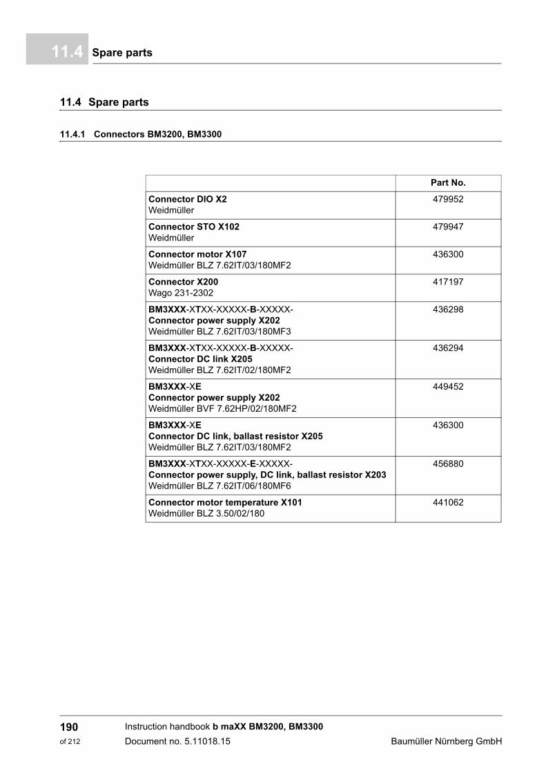
Spare parts11.4
11.4 Spare parts
11.4.1 Connectors BM3200, BM3300
Part No.
Connector DIO X2Weidmüller
479952
Connector STO X102Weidmüller
479947
Connector motor X107Weidmüller BLZ 7.62IT/03/180MF2
436300
Connector X200Wago 231-2302
417197
BM3XXX-XTXX-XXXXX-B-XXXXX-Connector power supply X202Weidmüller BLZ 7.62IT/03/180MF3
436298
BM3XXX-XTXX-XXXXX-B-XXXXX-Connector DC link X205Weidmüller BLZ 7.62IT/02/180MF2
436294
BM3XXX-XEConnector power supply X202Weidmüller BVF 7.62HP/02/180MF2
449452
BM3XXX-XEConnector DC link, ballast resistor X205Weidmüller BLZ 7.62IT/03/180MF2
436300
BM3XXX-XTXX-XXXXX-E-XXXXX-Connector power supply, DC link, ballast resistor X203Weidmüller BLZ 7.62IT/06/180MF6
456880
Connector motor temperature X101Weidmüller BLZ 3.50/02/180
441062
Instruction handbook b maXX BM3200, BM3300
Document no. 5.11018.15 Baumüller Nürnberg GmbH
190of 212
Accessories and Spare Parts 11
11.4.2 Accessories kit shielding BM3200, BM3300NOTE!
Optional, not included in delivery!
Part No.
BM3200, BM3300 Cable shield grounding clamp 24 mm width 437738
Cable shield grounding clamp 17 mm width 437736
Instruction handbook b maXX BM3200, BM3300
Document no. 5.11018.15
191of 212

Spare parts11.4
Instruction handbook b maXX BM3200, BM3300
Document no. 5.11018.15 Baumüller Nürnberg GmbH
192of 212
12SHUTDOWN, STORAGE
In this chapter we describe, how you decommission and store the device.
12.1 Safety instructions
h Refer to ZSafety– from page 11 and the information in ZTransport and Packaging–from page 71.
The shutdown of the device may only be carried out by for this qualified personnel.
DANGER!
Risk of fatal injury from electrical current!
Stored electric charge.
Discharge time of the system = discharge time of the device with the longest DC linkdischarge time.
Therefore:
m Do not touch electrically live parts before taking into account the discharge time ofthe capacitors.
m Assure, that all electric connections are current-free and are safe against switch-on.
m Before working, check at the electrical connections with suitable measuring devic-es, that the connections are off-circuit.
m Remove the connections not until the safe isolation from supply has been checked.
m If additional capacitors are connected to the DC link, the DC link discharge cantake a much longer time. In this case, the necessary waiting period must itself bedetermined or a measurement made as to whether the equipment is de-energized.This discharge time must be posted, together with an IEC 60417-5036 (2002-10)warning symbol, on a clearly visible location of the control cabinet.
193of 212
Instruction handbook b maXX BM3200, BM3300
Document no. 5.11018.15
Requirements to the executing personnel12.2
12.2 Requirements to the executing personnel
The personnel, who is appointed to setting out of operation, must have the requiredknowledge and instructions, which is necessary for an execution according to the rules.Select the personnel in such a way, that the safety instructions, which are mounted to thedevice and its parts as well as to the connections, are understood and applied to.
12.3 Shutdown
Execute the setting out of operation as follows:
1 put the device off-circuit and assure the device against unintentional restart.
2 check the isolation from supply of all connections (earliest 10 minutes after switchingoff).
3 demount the connections and protect the connections according to the safety instruc-tions.
4 document the shut down setting.
12.4 Demounting
The demounting assumes a completed, documented setting out of operation.
1 secure the device against falling off/out.
2 loosen all mechanical connections.
3 lift the device out of the control cabinet.
4 store the device in a suitable packing.
5 at transportation pay attention to, that the device is not damaged by wrong storage orsevere shocks, also see ZWhat to observe when transporting– on page 71.
NOTICE!
Note sharp edges.
In case, while installing, you lift a device with unprotected hands, fingers/palm can becut. If the device falls off, your feet can be cut up.
Therefore:
m Ensure that only qualified personnel, who are familiar with the safety notes and as-sembly instructions, demount this device.
Wear safety gloves.
mWear safety shoes.
Instruction handbook b maXX BM3200, BM3300
Document no. 5.11018.15 Baumüller Nürnberg GmbH
194of 212
Shutdown, Storage 12
In case you want to dispose the device, additional data is available in chapter ZDisposal–from page 197.12.5 Storage conditions
The device is maintenance-free. If you keep to the environmental conditions during theentire period of storage, you can assume, that the device will not be damaged. In casethe environmental conditions during storage are not kept, you should assume that the de-vice is damaged after storage.
CAUTION!
Property damage because of incorrect storage conditions
Incorrect storage can damage/destroy the device.
Therefore:
Assure, that the environmental conditions are kept during the entire period of storage:
m Climatic category 1K4
m Temperature range -25 °C to +55 °C
CAUTION!
Recommissioning without forming of the capacitors.
From six months storage period on, the capacitors are destroyed during commission-ing, if they are not formed beforehand
m Reform the DC link capacitors:
n by supplying the device ready-to-operate for at least one hour with supply volt-age
n but do not transmit a pulse enable during this time.
m Consider, that it is imperative, to connect the accordingly prescribed line commu-tating reactor for this forming procedure. Devices, where no line commutating re-actor is necessary can directly be supplied with power supply voltage.
Instruction handbook b maXX BM3200, BM3300
Document no. 5.11018.15
195of 212
Recommissioning12.6
12.6 Recommissioning
Execute commissioning as with a new device, see ZMounting– from page 73, ZInstallation– from page 81.
.
CAUTION!
Recommissioning without forming of the capacitors.
From six months storage period on, the capacitors are destroyed during commission-ing, if they are not formed beforehand
m Reform the DC link capacitors:
n by supplying the device ready-to-operate for at least one hour with supply voltage
n but do not transmit a pulse enable during this time.
m Consider, that it is imperative, to connect the accordingly prescribed line commu-tating reactor for this forming procedure. Devices, where no line commutating re-actor is necessary can directly be supplied with power supply voltage.
Instruction handbook b maXX BM3200, BM3300
Document no. 5.11018.15 Baumüller Nürnberg GmbH
196of 212
13DISPOSAL
13.1 Safety regulations
NOTE!
Baumüller products are not subject to the scope of the EU’s Waste Electrical andElectronic Equipment Directive (WEEE, 2012/19/EU). Hence, Baumüller is not obli-gated to bear costs for return and disposal of waste electronic equipment.
DANGER!
Risk of fatal injury from electrical current!
Stored electric charge.
Discharge time of the modular system = discharge time of the device with the longestDC link discharge time in the modular system.
Refer to ZElectrical data– from page 36.
Therefore:
m Do not touch before taking into account the discharge time of the capacitors andelectrically live parts.
m Heed corresponding notes on the equipment.
m If several devices are connected e.g. with a mains rectifier unit, the DC link dis-charge can take a much longer time. In this case, the necessary waiting periodmust itself be determined or a measurement made to ensure the device is de-en-ergized. This discharge time must be posted, together with an IEC 60417-5036(2002-10) warning symbol, on a clearly visible location of the control cabinet.
197of 212
Instruction handbook b maXX BM3200, BM3300
Document no. 5.11018.15

Safety regulations13.1
CAUTION!
Danger due to sharp edges.
If the device is lifted with unprotected hands during deinstallation, palms or fingerscan be cut. If the device falls, feet could be injured.
Therefore:
m Ensure that only qualified personnel, who are familiar with the safety notes and as-sembly instructions, mount this device.
Wear safety gloves.
Wear safety shoes.
WARNING!
Danger of physical impact!
Secure device against falling down.
Therefore:
m Take suitable measures, such as supports, hoists and assisting personnel, to en-sure that device cannot fall down.
m Use appropriate means of transport.
NOTICE!
Avoid polluting the environment as a result of improper disposal.
Therefore:
m Only dispose in compliance with the health and safety regulations.
m Take heed of any special local regulations. If you are unable to directly ensure safedisposal yourself, commission a suitable disposal contractor.
m In the event of a fire, hazardous substances could possibly be generated or re-leased.
m Do not expose electronic components to high temperatures.
m Beryllium oxide is used as inner insulation, for example for various power semicon-ductors. The beryllium dust that is generated upon opening is injurious to thehealth.Do not open electronic components.
m Dispose of capacitors, semiconductor modules and electronic scrap as specialwaste.
Instruction handbook b maXX BM3200, BM3300
Document no. 5.11018.15 Baumüller Nürnberg GmbH
198of 212
Disposal 13
13.2 Disposal facilities/authorities
Ensure that the disposal is handled in compliance with the disposal policies of your com-pany, as well as with all national regulations of the responsible disposal facilities and au-thorities. In case of doubt, consult the bureau of commerce or environmental protectionauthority responsible for your company.
WARNING!
Danger as a result of faulty demounting!
The demounting and disposal requires qualified personnel with adequate experience.
Therefore:
m Only allow demounting and disposal to be performed by qualified personnel.
Instruction handbook b maXX BM3200, BM3300
Document no. 5.11018.15
199of 212

Disposal facilities/authorities13.2
Instruction handbook b maXX BM3200, BM3300
Document no. 5.11018.15 Baumüller Nürnberg GmbH
200of 212

APPENDIX A - ABBREVIATIONS
AC Alternating current
BB Ready-to-operate
CE Compliant with the directives of theEuropean Union
DC Direct current
DIN Deutsches Institut für Normunge.V (German National StandardsInstitute).
EMC Electromagnetic compatibility
EMVG European EMC law
EN European standard
ESD Electrostatic discharge
ext External
GND Ground
Î Peak current
IAC RMS-value of alternating current
IDC RMS-value of direct current
IEC International ElectrotechnicalCommission
IP Ingress protection; protection rat-ing
IS Pulse inhibit
Chap. Chapter
KG Cooling air requirement of deviceinterior
KLK Cooling air requirement of passivecooling unit
MSKL Motor protection thermistor
n = 0 Rotational speed = 0
nist Rotational speed actual value
nmax Maximum rotational speed
nmin Minimum rotational speed
MSL Height above mean sea level
nsoll Rotational speed set value
NTC Negative temperature coefficientthermistor
PE Protected groundground conductor connection
PELV Protective extra-low voltage, withsafe isolation, grounded
PLL Phase Locked Loop
ppm Parts per million
PTC Positive temperature coefficientthermistor
RB Ballast Resistor
RCD Residual current protective device/ ground fault circuit breaker
SELV Safety extra-low voltage, with safeisolation
SH Quick stop
STO Safe Torque Off
Tab. Table
U Voltage
Û Peak voltage
UAC RMS-value, AC voltage
UDC RMS-value, DC voltage
UL Underwriters Laboratories
UDC link DC link voltage
VDE Verband der Elektrotechnik, Elek-tronik und Informationstechnik(German electrical engineering,electronics and IT association)
ZK DC link
201of 212
Instruction handbook b maXX BM3200, BM3300
Document no. 5.11018.15

A
Instruction handbook b maXX BM3200, BM3300
Document no. 5.11018.15 Baumüller Nürnberg GmbH
202of 212
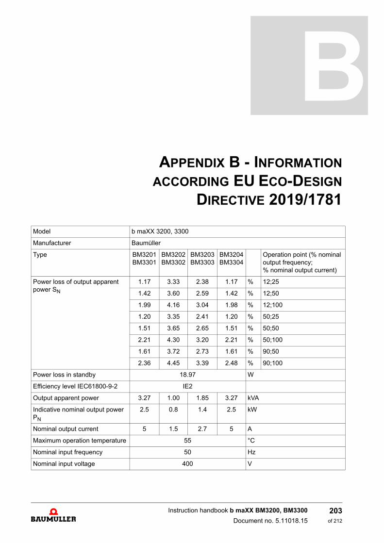
APPENDIX B - INFORMATION
ACCORDING EU ECO-DESIGN
DIRECTIVE 2019/1781
Model b maXX 3200, 3300
Manufacturer Baumüller
Type BM3201BM3301
BM3202BM3302
BM3203BM3303
BM3204BM3304
Operation point (% nominal output frequency; % nominal output current)
Power loss of output apparent power SN
1.17 3.33 2.38 1.17 % 12;25
1.42 3.60 2.59 1.42 % 12;50
1.99 4.16 3.04 1.98 % 12;100
1.20 3.35 2.41 1.20 % 50;25
1.51 3.65 2.65 1.51 % 50;50
2.21 4.30 3.20 2.21 % 50;100
1.61 3.72 2.73 1.61 % 90;50
2.36 4.45 3.39 2.48 % 90;100
Power loss in standby 18.97 W
Efficiency level IEC61800-9-2 IE2
Output apparent power 3.27 1.00 1.85 3.27 kVA
Indicative nominal output power PN
2.5 0.8 1.4 2.5 kW
Nominal output current 5 1.5 2.7 5 A
Maximum operation temperature 55 °C
Nominal input frequency 50 Hz
Nominal input voltage 400 V
203of 212
Instruction handbook b maXX BM3200, BM3300
Document no. 5.11018.15
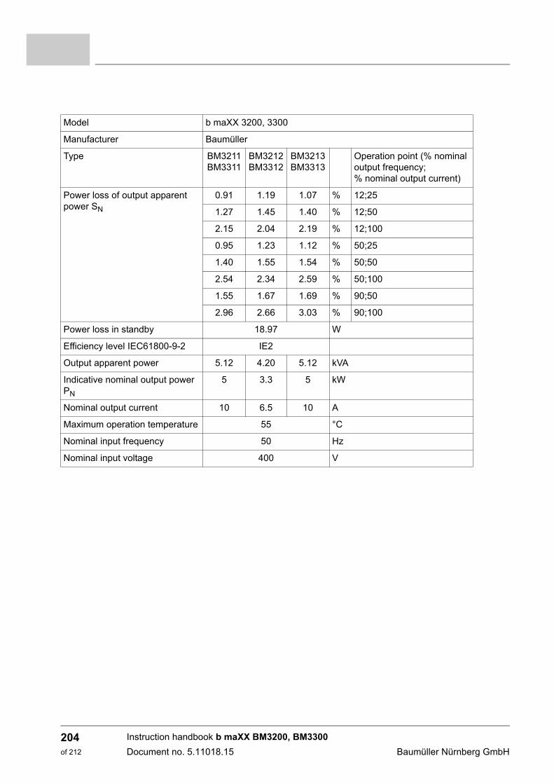
Model b maXX 3200, 3300
Manufacturer Baumüller
Type BM3211BM3311
BM3212BM3312
BM3213BM3313
Operation point (% nominal output frequency; % nominal output current)
Power loss of output apparent power SN
0.91 1.19 1.07 % 12;25
1.27 1.45 1.40 % 12;50
2.15 2.04 2.19 % 12;100
0.95 1.23 1.12 % 50;25
1.40 1.55 1.54 % 50;50
2.54 2.34 2.59 % 50;100
1.55 1.67 1.69 % 90;50
2.96 2.66 3.03 % 90;100
Power loss in standby 18.97 W
Efficiency level IEC61800-9-2 IE2
Output apparent power 5.12 4.20 5.12 kVA
Indicative nominal output power PN
5 3.3 5 kW
Nominal output current 10 6.5 10 A
Maximum operation temperature 55 °C
Nominal input frequency 50 Hz
Nominal input voltage 400 V
Instruction handbook b maXX BM3200, BM3300
Document no. 5.11018.15 Baumüller Nürnberg GmbH
204of 212

APPENDIX C - DECLARATION OF
CONFORMITY
+
205of 212
Instruction handbook b maXX BM3200, BM3300
Document no. 5.11018.15
EU - Declaration of Conformity Doc.-No: 5.12061.04Date: 08-Sep-2020
according to EMC Directive 2014/30/EU and Low Voltage Directive 2014/35/EU
The Manufacturer: Baumüller Nürnberg GmbH
Ostendstraße 80-90
90482 Nuremberg, Deutschland
declares that the product:
Name: Compact Servo Unit b maXX 3000
Type: BM3201, BM3202, BM3203, BM3204, BM3211, BM3212, BM3213
manufactured since: 01-Nov-2012
was developed, designed and manufactured in accordance with the EMC Directive 2014/30/EU and the Low Voltage Di-rective 2014/35/EU.
Applied harmonized standards:
Attention must be paid to the safety instructions in the manual.
Nuremberg / 8-Sep-2020Location / Date
The content of the Declaration of Conformity is subject to change. The current version can be obtained on request.
Standard Title
DIN EN 62061:2016 Safety of Machinery - Functional safety of safety-related electrical, electronic and programmable electronic control systems
DIN EN 61800-5-1:2017-11 Variable-speed electrical power drives- Part 5-1: Safety requirements - Electrical, thermal and energy
DIN EN 61800-5-2:2017-11 Variable-speed electrical power drivesPart 5-2 Safety requirements - Functional
DIN EN 61800-3:2019-04 Variable-speed electrical power drivesPart 3: EMC-requirements and specific test methods
Instruction handbook b maXX BM3200, BM3300
Document no. 5.11018.15 Baumüller Nürnberg GmbH
206of 212

Declaration of Conformity B
EC - Declaration of Conformity Doc.-No: 5.12060.03Date: 14-Jun-2016
according to Machinery Directive 2006/42/ECThe Manufacturer: Baumüller Nürnberg GmbH
Ostendstraße 80-9090482 Nürnberg, Germany
declares, that the products:
Designation: Compact Servo Unit b maXX 3000 with safety relay
Type: BM3301-ST20, BM3302-ST20, BM3302-ST20, BM3304-ST20, BM3311-ST20, BM3312-ST20, BM3313-ST20
manufactured since: 22-Oct-2013
are developed, designed and manufactured in accordance with the Machinery Directive 2006/42/EC. These products com-ply with the requirements of the EMC Directive 2014/30/EU and the Low Voltage Directive 2014/35/EU.
Applied harmonized standards:
Authorized person to compile the technical files: Name: Engelbert Meier, Baumüller Nürnberg GmbH, Section AESAddress: Ostendstraße 80-90, 90482 Nürnberg, Germany
Notified body executed the EC type-examination procedures according to Machinery Directive 2006/42/EC:Name: TÜV Rheinland Industrie Service GmbH Address: Am Grauen Stein, 51105 Köln / GermanyIdentification number: 0035Registration numbers: 01/205/5354.00/13
Attention should be paid to the safety instructions in the manual.This product is to be used in machinery and must not put into operation until the machinery, into with it is incorporated, has been declaredto be in conformity with the Machinery Directive 2006/42/EC.
Nuremberg / 14-Jun-2016Location / Date
Subject to change of this declaration of EC conformity without notice. Actual valid edition on request.
Norm Title
EN 62061:2016-05 Safety of machinery - Functional safety of safety-related electrical, electronic and programmable electronic control systems
EN ISO 13849-1:2008AC: 2009
Safety of machinery - Safety-related parts of control systems, Part 1: General principles for design
EN 61800-5-1:2008-04
Adjustable speed electrical power drive systems. Part 5-1: Safety requirements. Electrical, thermal and energy
EN 61800-5-2:2007 Adjustable speed electrical power drive systems. Part 5-2: Safety requirements. Functional
EN 60204-1:2006A1:2009
Electrical equipment of machines Part 1:General requirements
EN 61800-3:2012-09 Adjustable speed electrical power drive systems. Part 3: EMC requirements and specific test methods
IEC 61508, Teil 1-7:2010
Functional safety of safety-related electrical, electronic and programmable electronic control systems
Instruction handbook b maXX BM3200, BM3300
Document no. 5.11018.15
207of 212

Instruction handbook b maXX BM3200, BM3300
Document no. 5.11018.15 Baumüller Nürnberg GmbH
208of 212
Table of figures
Table of figures
Wiring of the power cables......................................................................................................... 14Signs and labels BM3200, BM3300 ........................................................................................... 22Signs and labels BM3300 with safety level.............................................................................. 23Dimensions BM3200, BM3300................................................................................................... 26Control voltage / 24V-supply ...................................................................................................... 29Reducing of output power in dependence of altitude ................................................................. 31Output current dependent on supply voltage ............................................................................. 32Output power dependent on supply voltage............................................................................... 33Output current dependent on supply voltage ............................................................................. 33Output power dependent on supply voltage............................................................................... 34Output current dependent on DC-link voltageBM3X0X, BM3X12, BM3X13 up to data set version V2.00 (see P129.40) ................................ 34Output current dependent on DC-link voltageBM3X13 data set version V2.01 and higher (see P129.40) ....................................................... 35Derating at a static inverter frequency < 15 Hz.......................................................................... 45Typical current-time-diagram: Operation at constant load ......................................................... 46Typical current-time-diagram: Intermittent load cycle with peak value....................................... 46Typical current-time-diagram: Intermittent load cycle ................................................................ 47Part number BM3200, BM3300 - front ...................................................................................... 52Type plate attachment BM3200, BM3300.................................................................................. 53Display and operating elements BM3200, BM3300 EtherCAT® ................................................ 58Display and operating elements BM3200, BM3300 VARAN...................................................... 59Display and operating elements BM3200, BM3300 CANopen® ................................................ 60Display and operating elements BM3200, BM3300 POWERLINK® .......................................... 61Address switch setting EtherCAT®, POWERLINK®, VARAN ................................................... 68Address setting CANopen® .................................................................................................................................. 70Danger area near the mechanical mounting .............................................................................. 75Drilling template BM3200, BM3300............................................................................................ 78Mounting instruction BM3200, BM3300 ..................................................................................... 79Hazard areas during electrical installation ................................................................................. 82Mounting shield sheet ................................................................................................................ 87Wrap shield motor temperature cable around motor cable ........................................................ 88Tape shield motor temperature cable around ............................................................................ 89Shield connection motor cable ................................................................................................... 90Terminal diagram BM3XXX-XT (3-phase connection, internal ballast resistor) ......................... 94Terminal diagram BM3XXX-XT (3-phase connection, no internal ballast resistor) .................... 95Terminal diagram BM3XXX-XT - axis unit with internal ballast resistor ..................................... 97Terminal diagram BM3XXX - axis unit, without internal ballast resistor..................................... 98Terminal diagram BM3XXX-XE - axis unit with internal ballast resistor..................................... 99Terminal diagram BM3XXX-XE - - axis unit without internal ballast resistor............................ 100Connection diagram BM3XXX-XT (single-phase connection, with internal ballast resistor) .... 102Connection diagram BM3XXX-XT (single phase connection, no internal ballast resistor)....... 103Connection diagram BM3XXX-XE (1-phase connection, 230 V, with internal ballast resistor) 105Connection diagram BM3XXX-XE (1-phase, 230 V, without internal ballast resistor) ............. 106Application: Power supply connection with energy compensation........................................... 108Example: Further devices connected to the DC link ................................................................ 110Max. external capacitance that can be connected dependent on the power supply voltage ... 111Waiting time between two charging procedures ...................................................................... 112Connections front side with X6 analog IOs .............................................................................. 113Connections front side with X6 encoder 2................................................................................ 114
Instruction handbook b maXX BM3200, BM3300
Document no. 5.11018.15209
of 212

210of 212
Table of figures
Connections at the top, BM3XXX-XT with internal ballast resistor ........................................... 127Connections at the top, BM3XXX-XT without internal ballast resistor ...................................... 128Connections at the top, BM3XXX-XE with internal ballast resistor........................................... 129Connections at the top, BM3XXX-XE without internal ballast resistor...................................... 130Installation of signal bus cable.................................................................................................. 135Connections at the bottom........................................................................................................ 136Connections PE........................................................................................................................ 139Structure of PE-connection....................................................................................................... 140Timing STO function ................................................................................................................. 147Supply with separate power supplies ....................................................................................... 147STO function S01: Operation with emergency stop device ...................................................... 148STO function S02: Operation with emergency stop device ...................................................... 149STO function: Operation with safety light grid .......................................................................... 150STO function: Operation with SO4000 ..................................................................................... 150VARAN fieldbus connection ..................................................................................................... 153Motor cable with DSL Hiperface® 15 A..................................................................................... 173Connecting cable for resolver ................................................................................................... 179Connecting cable for encoder with HIPERFACE® .................................................................................... 180Connecting cable for encoder with EnDat® or SSI ................................................................... 181Connecting cable for encoder with EnDat® 2.2 M12 ................................................................ 182Connecting cable for encoder with EnDat® 2.2 speedtec® M23............................................... 183Connecting cable for sine/square wave incremental encoder .................................................. 184Block diagram line filter............................................................................................................. 187
Instruction handbook b maXX BM3200, BM3300
Document no. 5.11018.15 Baumüller Nürnberg GmbH
Overview of Revisions
Overview of Revisions
Version Status Changes
5.11018.02 26-Oct-2012. Creation
5.11018.03 22-Apr-2013 Timing safety relay changed,UL notes/UL fuses added,Note „From six months storage period on, the capacitors are destroyed during commissioning, if they are not formed beforehand“ addedElectrical data of „Safe Torque Off“ connection changed
5.11018.04 10-Jan-2014 Declaration of Conformity according Machinery DirectiveSafety Certificate
5.11018.05 11-Nov-2014 Error correction, additions STO, POWERLINK®
5.11018.06 11-Jul-2015 New implemented VARAN, additional power ratings
5.11018.07 24-Sep-2015 New BM3200, 3300 without internal ballast resistor
5.11018.08 04-Jul-.2016 Additional power ratings, devices for 230 V power supply
5.11018.09 09-Aug-.2016 Timing STO module correctedTechnical data updated
5.11018.10 24-Apr-2017 Line filter for single-phase devices
5.11018.11 16-Nov-2017 Technical data updated
5.11018.11 01-Mar-2018 Technical data updatedSafety function with short-circuit detectionNew device BM3002 added
5.11018.12 05-Nov-2018 Type with second encoder addedSafety function S02 addedBM3X13 V2.01 and higher: Output rated current 8 kHz changed to 7.5 A
5.11018.13 10-Dec-2018 BM3002 removed
5.11018.14 22-May-2019 Risk assessment added
5.11018.15 28-Nov-2019 Update
5.11018.16 07-Jul-2021 Update
Instruction handbook b maXX BM3200, BM3300
Document no. 5.11018.15
211of 212

Notes:
Instruction handbook b maXX BM3200, BM3300
Document no. 5.11018.15 Baumüller Nürnberg GmbH
212of 212


Baumüller Nürnberg GmbH Ostendstraße 80-90 90482 Nürnberg T: +49(0)911-5432-0 F: +49(0)911-5432-130 www.baumueller.com
All information given in this handbook is customer information, subject to change without notice. We reserve the right to further develop and actualize our products continuously using our permanent revision service. Please notice, that specifications/data/information are current values according to the printing date.These statements are not legally binding according to the measurement, computation and calculations. Before you make any information given in this manual to the basis of your own calculations and/or applications, please make sure that you have the latest edition of the information in hand.No liability can be accepted concerning the correctness of the information.