installation - practical moto
TRANSCRIPT
Y A11333
Front
R
LH
RH
L
EM0ZZ–04
A07419
12 Pointed Head Bolt
Front
7 2 4 6
53 1 8 5318
7246
P21151
Painted Mark
Front
P00868
Painted Mark
90°90°
90°90°
EM–52–ENGINE MECHANICAL (5VZ–FE) CYLINDER HEAD
1228Author�: Date�:
2003 TOYOTA TACOMA (RM1002U)
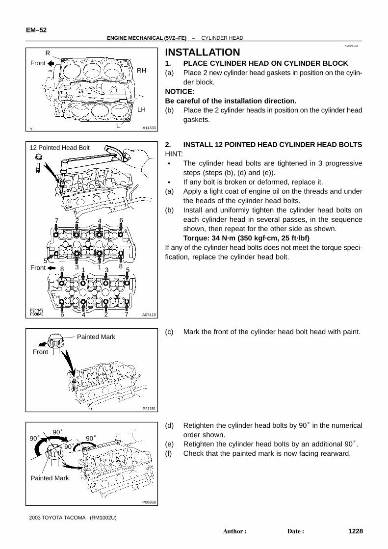
INSTALLATION1. PLACE CYLINDER HEAD ON CYLINDER BLOCK(a) Place 2 new cylinder head gaskets in position on the cylin-
der block.NOTICE:Be careful of the installation direction.(b) Place the 2 cylinder heads in position on the cylinder head
gaskets.
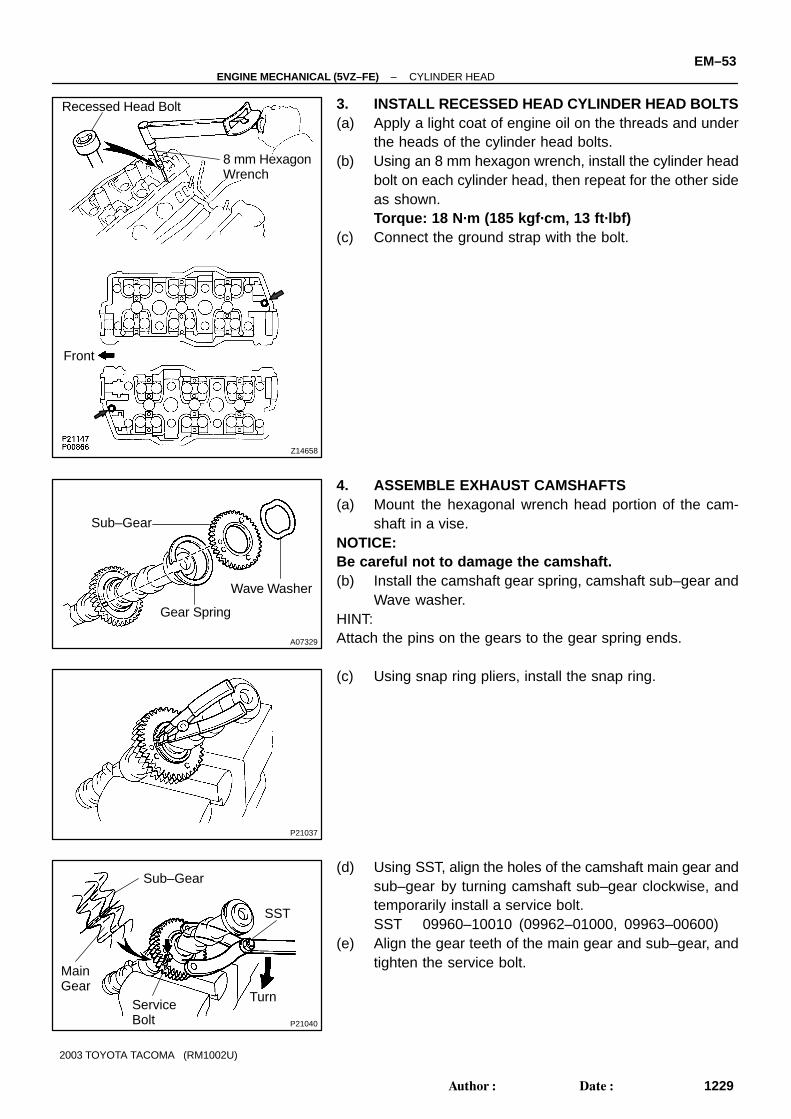
2. INSTALL 12 POINTED HEAD CYLINDER HEAD BOLTSHINT:� The cylinder head bolts are tightened in 3 progressive
steps (steps (b), (d) and (e)).� If any bolt is broken or deformed, replace it.
(a) Apply a light coat of engine oil on the threads and underthe heads of the cylinder head bolts.
(b) Install and uniformly tighten the cylinder head bolts oneach cylinder head in several passes, in the sequenceshown, then repeat for the other side as shown.Torque: 34 N·m (350 kgf·cm, 25 ft·lbf)
If any of the cylinder head bolts does not meet the torque speci-fication, replace the cylinder head bolt.
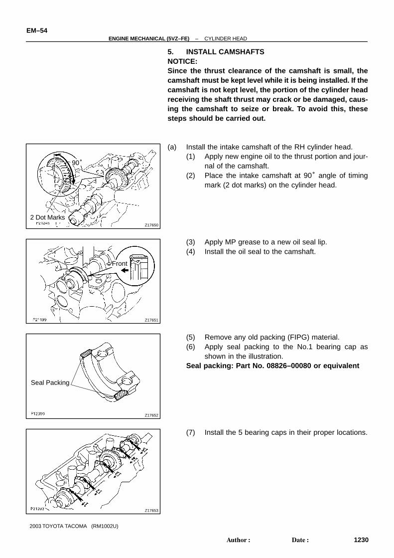
(c) Mark the front of the cylinder head bolt head with paint.
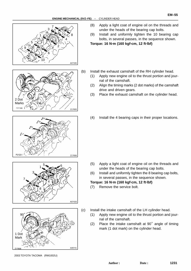
(d) Retighten the cylinder head bolts by 90° in the numericalorder shown.
(e) Retighten the cylinder head bolts by an additional 90°.(f) Check that the painted mark is now facing rearward.
Z14658
8 mm HexagonWrench
Front
Recessed Head Bolt
A07329
Gear Spring
Wave Washer
Sub–Gear
P21037
P21040
SST
Turn
Sub–Gear
MainGear
ServiceBolt
–ENGINE MECHANICAL (5VZ–FE) CYLINDER HEADEM–53
1229Author�: Date�:
2003 TOYOTA TACOMA (RM1002U)
3. INSTALL RECESSED HEAD CYLINDER HEAD BOLTS(a) Apply a light coat of engine oil on the threads and under
the heads of the cylinder head bolts.(b) Using an 8 mm hexagon wrench, install the cylinder head
bolt on each cylinder head, then repeat for the other sideas shown.Torque: 18 N·m (185 kgf·cm, 13 ft·lbf)
(c) Connect the ground strap with the bolt.
4. ASSEMBLE EXHAUST CAMSHAFTS(a) Mount the hexagonal wrench head portion of the cam-
shaft in a vise.NOTICE:Be careful not to damage the camshaft.(b) Install the camshaft gear spring, camshaft sub–gear and
Wave washer.HINT:Attach the pins on the gears to the gear spring ends.
(c) Using snap ring pliers, install the snap ring.
(d) Using SST, align the holes of the camshaft main gear andsub–gear by turning camshaft sub–gear clockwise, andtemporarily install a service bolt.SST 09960–10010 (09962–01000, 09963–00600)
(e) Align the gear teeth of the main gear and sub–gear, andtighten the service bolt.
Z17650
90°
2 Dot Marks
Z17651
Front
Z17652
Seal Packing
Z17653
EM–54–ENGINE MECHANICAL (5VZ–FE) CYLINDER HEAD
1230Author�: Date�:
2003 TOYOTA TACOMA (RM1002U)
5. INSTALL CAMSHAFTSNOTICE:Since the thrust clearance of the camshaft is small, thecamshaft must be kept level while it is being installed. If thecamshaft is not kept level, the portion of the cylinder headreceiving the shaft thrust may crack or be damaged, caus-ing the camshaft to seize or break. To avoid this, thesesteps should be carried out.
(a) Install the intake camshaft of the RH cylinder head.(1) Apply new engine oil to the thrust portion and jour-
nal of the camshaft.(2) Place the intake camshaft at 90° angle of timing
mark (2 dot marks) on the cylinder head.
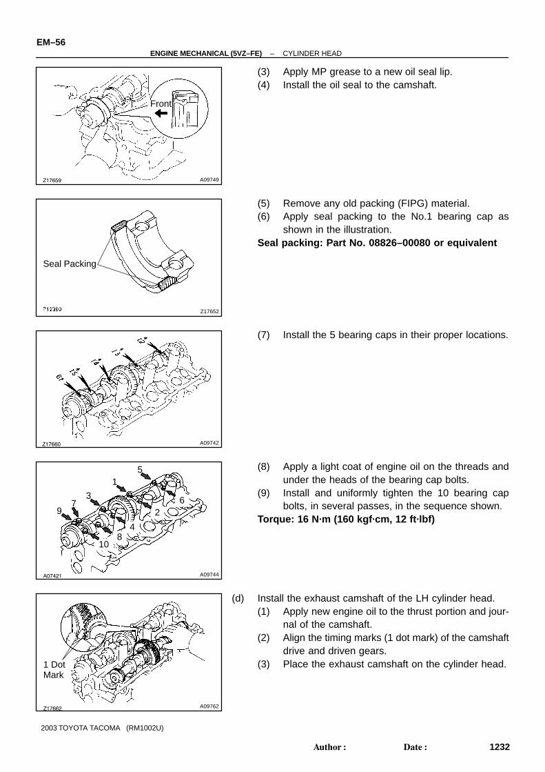
(3) Apply MP grease to a new oil seal lip.(4) Install the oil seal to the camshaft.
(5) Remove any old packing (FIPG) material.(6) Apply seal packing to the No.1 bearing cap as
shown in the illustration.Seal packing: Part No. 08826–00080 or equivalent
(7) Install the 5 bearing caps in their proper locations.
A07335
2
1
3
45
6
7
8
10
9
Z17655
2 Dot Marks
Z17656
A07420
2
1
3
4
5 6
7
8
Z17658 A09741
90°
1 Dot Mark
–ENGINE MECHANICAL (5VZ–FE) CYLINDER HEADEM–55
1231Author�: Date�:
2003 TOYOTA TACOMA (RM1002U)
(8) Apply a light coat of engine oil on the threads andunder the heads of the bearing cap bolts.
(9) Install and uniformly tighten the 10 bearing capbolts, in several passes, in the sequence shown.
Torque: 16 N·m (160 kgf·cm, 12 ft·lbf)
(b) Install the exhaust camshaft of the RH cylinder head.(1) Apply new engine oil to the thrust portion and jour-
nal of the camshaft.(2) Align the timing marks (2 dot marks) of the camshaft
drive and driven gears.(3) Place the exhaust camshaft on the cylinder head.
(4) Install the 4 bearing caps in their proper locations.
(5) Apply a light coat of engine oil on the threads andunder the heads of the bearing cap bolts.
(6) Install and uniformly tighten the 8 bearing cap bolts,in several passes, in the sequence shown.
Torque: 16 N·m (160 kgf·cm, 12 ft·lbf)(7) Remove the service bolt.
(c) Install the intake camshaft of the LH cylinder head.(1) Apply new engine oil to the thrust portion and jour-
nal of the camshaft.(2) Place the intake camshaft at 90° angle of timing
mark (1 dot mark) on the cylinder head.
Z17659 A09749
Front
Z17652
Seal Packing
Z17660 A09742
A07421 A09744
72
4
6
5
3
1
8
9
10
Z17662 A09762
1 Dot Mark
EM–56–ENGINE MECHANICAL (5VZ–FE) CYLINDER HEAD
1232Author�: Date�:
2003 TOYOTA TACOMA (RM1002U)
(3) Apply MP grease to a new oil seal lip.(4) Install the oil seal to the camshaft.
(5) Remove any old packing (FIPG) material.(6) Apply seal packing to the No.1 bearing cap as
shown in the illustration.Seal packing: Part No. 08826–00080 or equivalent
(7) Install the 5 bearing caps in their proper locations.
(8) Apply a light coat of engine oil on the threads andunder the heads of the bearing cap bolts.
(9) Install and uniformly tighten the 10 bearing capbolts, in several passes, in the sequence shown.
Torque: 16 N·m (160 kgf·cm, 12 ft·lbf)
(d) Install the exhaust camshaft of the LH cylinder head.(1) Apply new engine oil to the thrust portion and jour-
nal of the camshaft.(2) Align the timing marks (1 dot mark) of the camshaft
drive and driven gears.(3) Place the exhaust camshaft on the cylinder head.
Z17663 A09746
A07423 A09747
7 2
4
6
5
3
1
8
P13274
Seal Packing
P21206
: Semi–Circular Plug
Front
–ENGINE MECHANICAL (5VZ–FE) CYLINDER HEADEM–57
1233Author�: Date�:
2003 TOYOTA TACOMA (RM1002U)
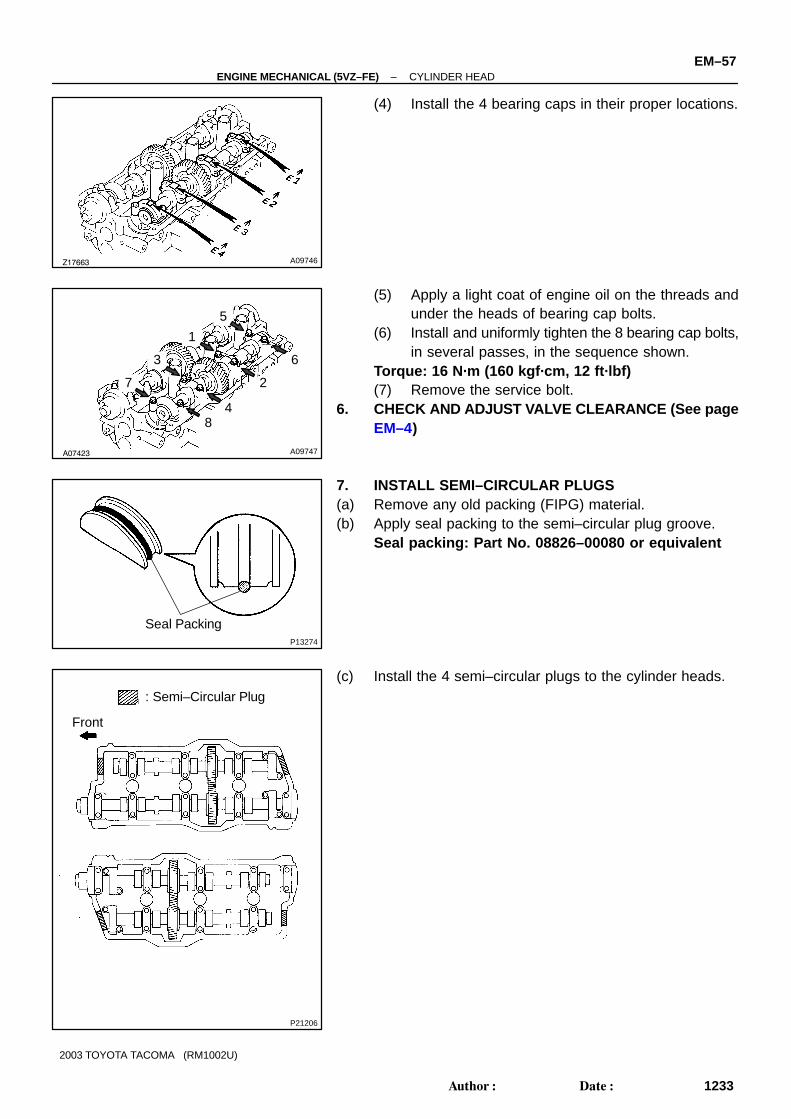
(4) Install the 4 bearing caps in their proper locations.
(5) Apply a light coat of engine oil on the threads andunder the heads of bearing cap bolts.
(6) Install and uniformly tighten the 8 bearing cap bolts,in several passes, in the sequence shown.
Torque: 16 N·m (160 kgf·cm, 12 ft·lbf)(7) Remove the service bolt.
6. CHECK AND ADJUST VALVE CLEARANCE (See pageEM–4)
7. INSTALL SEMI–CIRCULAR PLUGS(a) Remove any old packing (FIPG) material.(b) Apply seal packing to the semi–circular plug groove.
Seal packing: Part No. 08826–00080 or equivalent
(c) Install the 4 semi–circular plugs to the cylinder heads.
P00827
: Seal Packing
Front
A11028
2WD, 4WD
A11030
EM–58–ENGINE MECHANICAL (5VZ–FE) CYLINDER HEAD
1234Author�: Date�:
2003 TOYOTA TACOMA (RM1002U)
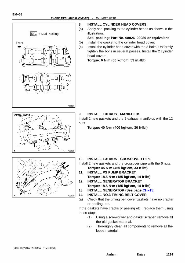
8. INSTALL CYLINDER HEAD COVERS(a) Apply seal packing to the cylinder heads as shown in the
illustration.Seal packing: Part No. 08826–00080 or equivalent
(b) Install the gasket to the cylinder head cover.(c) Install the cylinder head cover with the 8 bolts. Uniformly
tighten the bolts in several passes. Install the 2 cylinderhead covers.Torque: 6 N·m (60 kgf·cm, 53 in.·lbf)
9. INSTALL EXHAUST MANIFOLDSInstall 2 new gaskets and the 2 exhaust manifolds with the 12nuts.
Torque: 40 N·m (400 kgf·cm, 30 ft·lbf)
10. INSTALL EXHAUST CROSSOVER PIPEInstall 2 new gaskets and the crossover pipe with the 6 nuts.
Torque: 45 N·m (450 kgf·cm, 33 ft·lbf)11. INSTALL PS PUMP BRACKET
Torque: 18.5 N·m (185 kgf·cm, 14 ft·lbf)12. INSTALL GENERATOR BRACKET
Torque: 18.5 N·m (185 kgf·cm, 14 ft·lbf)13. INSTALL GENERATOR (See page CH–15)14. INSTALL NO.3 TIMING BELT COVER(a) Check that the timing belt cover gaskets have no cracks
or peeling, etc.If the gaskets have cracks or peeling etc., replace them usingthese steps:
(1) Using a screwdriver and gasket scraper, remove allthe old gasket material.
(2) Thoroughly clean all components to remove all theloose material.
P21198
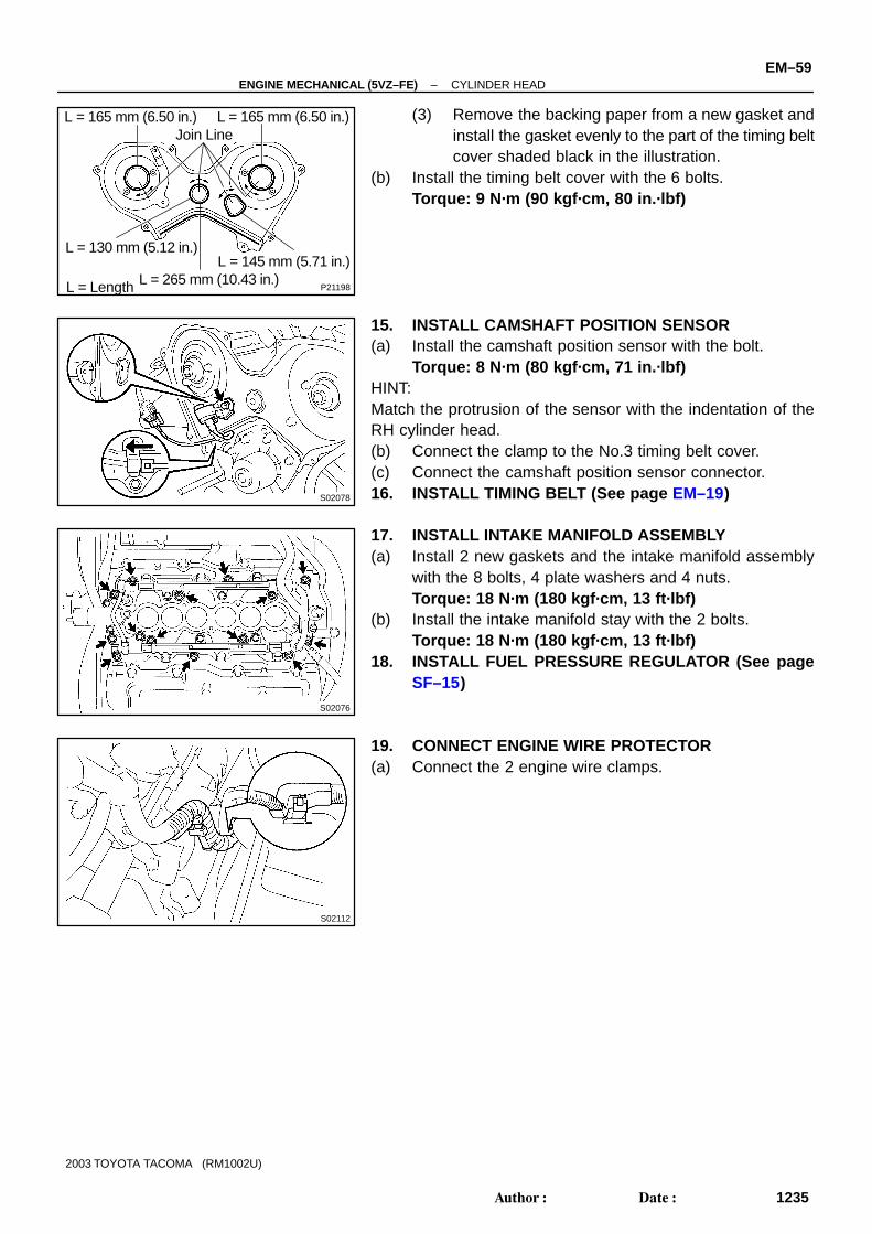
L = 165 mm (6.50 in.)Join Line
L = 130 mm (5.12 in.)
L = 265 mm (10.43 in.)L = Length
L = 145 mm (5.71 in.)
L = 165 mm (6.50 in.)
S02078
S02076
S02112
–ENGINE MECHANICAL (5VZ–FE) CYLINDER HEADEM–59
1235Author�: Date�:
2003 TOYOTA TACOMA (RM1002U)
(3) Remove the backing paper from a new gasket andinstall the gasket evenly to the part of the timing beltcover shaded black in the illustration.
(b) Install the timing belt cover with the 6 bolts.Torque: 9 N·m (90 kgf·cm, 80 in.·lbf)
15. INSTALL CAMSHAFT POSITION SENSOR(a) Install the camshaft position sensor with the bolt.
Torque: 8 N·m (80 kgf·cm, 71 in.·lbf)HINT:Match the protrusion of the sensor with the indentation of theRH cylinder head.(b) Connect the clamp to the No.3 timing belt cover.(c) Connect the camshaft position sensor connector.16. INSTALL TIMING BELT (See page EM–19)
17. INSTALL INTAKE MANIFOLD ASSEMBLY(a) Install 2 new gaskets and the intake manifold assembly
with the 8 bolts, 4 plate washers and 4 nuts.Torque: 18 N·m (180 kgf·cm, 13 ft·lbf)
(b) Install the intake manifold stay with the 2 bolts.Torque: 18 N·m (180 kgf·cm, 13 ft·lbf)
18. INSTALL FUEL PRESSURE REGULATOR (See pageSF–15)
19. CONNECT ENGINE WIRE PROTECTOR(a) Connect the 2 engine wire clamps.
A07327
(d)
(d)
(e)(f)
(d)
(d)
S02073
A07326
(e)
(d)
S02071
EM–60–ENGINE MECHANICAL (5VZ–FE) CYLINDER HEAD
1236Author�: Date�:
2003 TOYOTA TACOMA (RM1002U)
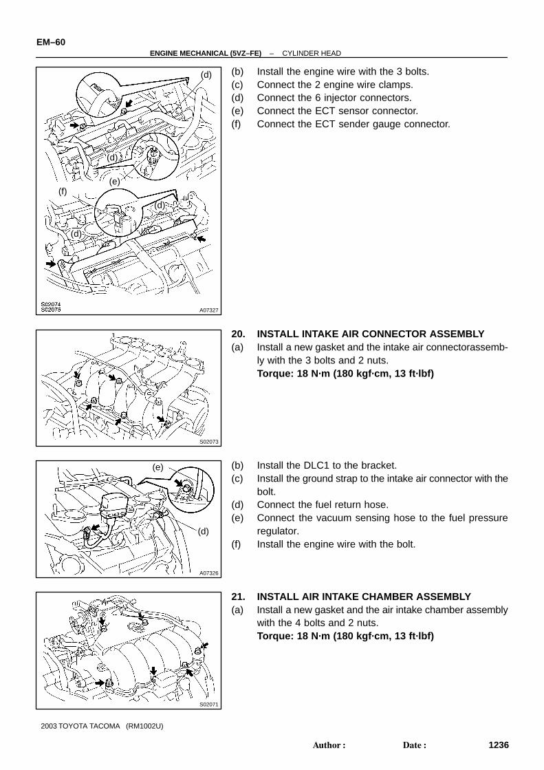
(b) Install the engine wire with the 3 bolts.(c) Connect the 2 engine wire clamps.(d) Connect the 6 injector connectors.(e) Connect the ECT sensor connector.(f) Connect the ECT sender gauge connector.
20. INSTALL INTAKE AIR CONNECTOR ASSEMBLY(a) Install a new gasket and the intake air connectorassemb-
ly with the 3 bolts and 2 nuts.Torque: 18 N·m (180 kgf·cm, 13 ft·lbf)
(b) Install the DLC1 to the bracket.(c) Install the ground strap to the intake air connector with the
bolt.(d) Connect the fuel return hose.(e) Connect the vacuum sensing hose to the fuel pressure
regulator.(f) Install the engine wire with the bolt.
21. INSTALL AIR INTAKE CHAMBER ASSEMBLY(a) Install a new gasket and the air intake chamber assembly
with the 4 bolts and 2 nuts.Torque: 18 N·m (180 kgf·cm, 13 ft·lbf)
A07325
(d)
(e)
(f)
(d)
(b)
(c)
–ENGINE MECHANICAL (5VZ–FE) CYLINDER HEADEM–61
1237Author�: Date�:
2003 TOYOTA TACOMA (RM1002U)
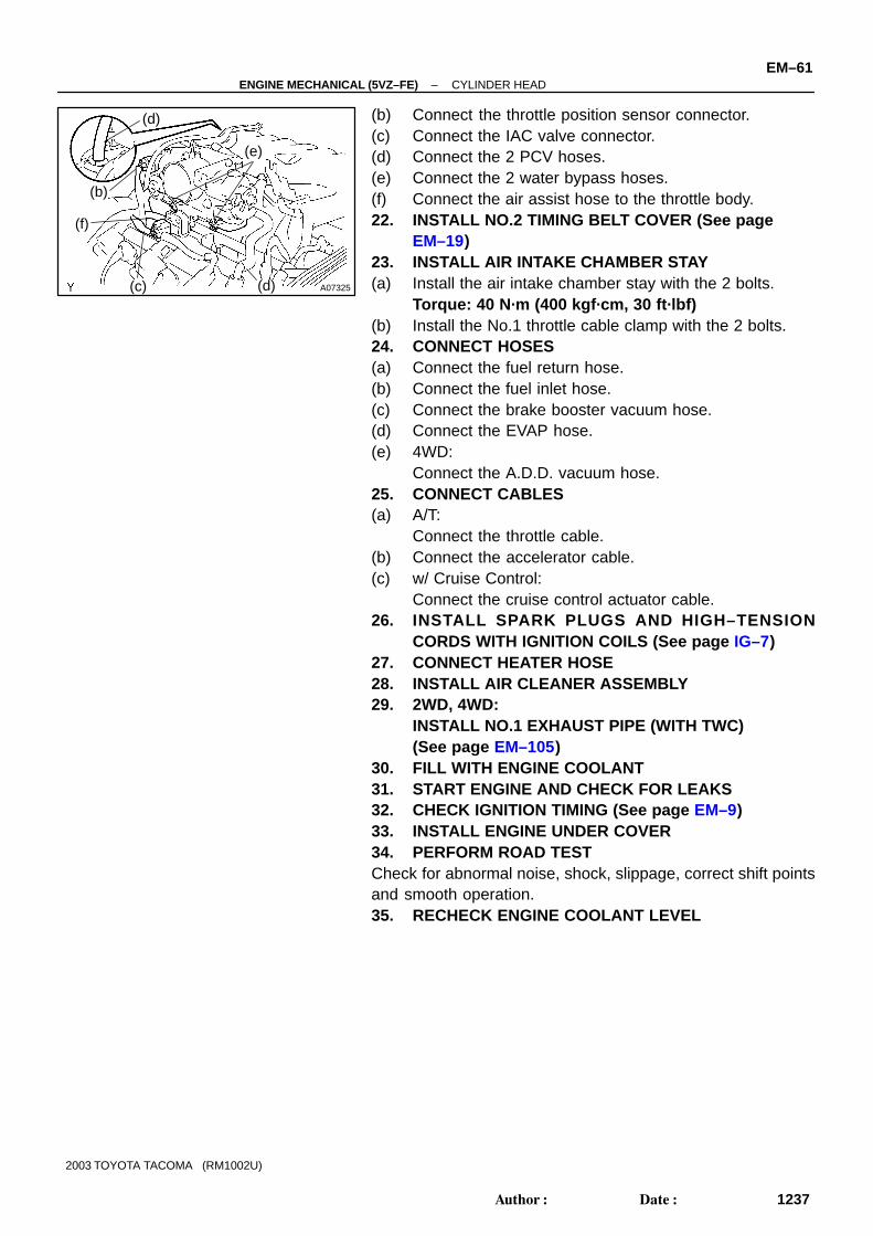
(b) Connect the throttle position sensor connector.(c) Connect the IAC valve connector.(d) Connect the 2 PCV hoses.(e) Connect the 2 water bypass hoses.(f) Connect the air assist hose to the throttle body.22. INSTALL NO.2 TIMING BELT COVER (See page
EM–19)23. INSTALL AIR INTAKE CHAMBER STAY(a) Install the air intake chamber stay with the 2 bolts.
Torque: 40 N·m (400 kgf·cm, 30 ft·lbf)(b) Install the No.1 throttle cable clamp with the 2 bolts.24. CONNECT HOSES(a) Connect the fuel return hose.(b) Connect the fuel inlet hose.(c) Connect the brake booster vacuum hose.(d) Connect the EVAP hose.(e) 4WD:
Connect the A.D.D. vacuum hose.25. CONNECT CABLES(a) A/T:
Connect the throttle cable.(b) Connect the accelerator cable.(c) w/ Cruise Control:
Connect the cruise control actuator cable.26. INSTALL SPARK PLUGS AND HIGH–TENSION
CORDS WITH IGNITION COILS (See page IG–7)27. CONNECT HEATER HOSE28. INSTALL AIR CLEANER ASSEMBLY29. 2WD, 4WD:
INSTALL NO.1 EXHAUST PIPE (WITH TWC) (See page EM–105)
30. FILL WITH ENGINE COOLANT31. START ENGINE AND CHECK FOR LEAKS32. CHECK IGNITION TIMING (See page EM–9)33. INSTALL ENGINE UNDER COVER34. PERFORM ROAD TESTCheck for abnormal noise, shock, slippage, correct shift pointsand smooth operation.35. RECHECK ENGINE COOLANT LEVEL