installation manual - asset-trade
TRANSCRIPT

Applicable Model
Before starting operation, maintenance, or programming, carefully read themanuals supplied by Mori Seiki, the NC unit manufacturer, and equipmentmanufacturers so that you fully understand the information they contain.Keep the manuals carefully so that they will not be lost.
IM-CENZS1500-D1EN
Applicable NC Unit
INSTALLATION MANUAL
The manuals for maintenance are comprised of the followingmanuals including this manual: MAINTENANCE MANUAL, MAINTENANCE INFORMATION,INSTALLATION MANUAL and DRAWINGS.
NZ-S1500
MSC-700MSC-701
• The contents of this manual are subject to change without notice due to improvements to the machine or in order to improve the manual. Consequently, please bear in mind that there may be slight discrepancies between the contents of the manual and the actual machine. Changes to the instruction manual are made in revised editions which are distinguished from each other by updating the instruction manual number.
• Should you discover any discrepancies between the contents of the manual and the actual machine, or if any part of the manual is unclear, please contact Mori Seiki and clarify these points before using the machine. Mori Seiki will not be liable for any damages occurring as a direct or indirect consequence of using the machine without clarifying these points.
• All rights reserved: reproduction of this instruction manual in any form, in whole or in part, is not permitted without the written consent of Mori Seiki.
The product shipped to you (the machine and accessory equipment) has been manufactured in accordance with the laws and standards that prevail in the relevant country or region. Consequently it cannot be exported, sold, or relocated, to a destination in a country with different laws or standards.
The export of this product is subject to an authorization from the government of the exporting country.
Check with the government agency for authorization.
990730
SIGNAL WORD DEFINITION
A variety of symbols are used to indicate different types of warning information and advice.
Learn the meanings of these symbols and carefully read the explanation to ensure safe operation while using this manual.
<Symbols related with warning>
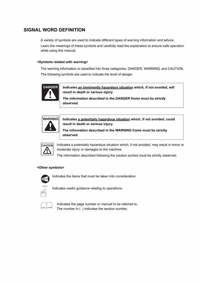
The warning information is classified into three categories, DANGER, WARNING, and CAUTION.
The following symbols are used to indicate the level of danger.
Indicates a potentially hazardous situation which, if not avoided, may result in minor or moderate injury or damages to the machine.
The information described following the caution symbol must be strictly observed.
<Other symbols>
Indicates the items that must be taken into consideration.
Indicates useful guidance relating to operations.
Indicates the page number or manual to be referred to.The number in ( ) indicates the section number.
DANGER Indicates an imminently hazardous situation which, if not avoided, will result in death or serious injury.
The information described in the DANGER frame must be strictly observed.
WARNING Indicates a potentially hazardous situation which, if not avoided, could result in death or serious injury.
The information described in the WARNING frame must be strictly observed.
CAUTION
NOTE

FOREWORD
This manual describes items to be understood and prepared before the machine is installed. Therefore, users are urged to read this manual before the machine is installed.
When the machine is delivered, MORI SEIKI's servicemen install the machine at the specified place. The information in this manual should be referred to when the machine is moved by the user to make sure the necessary procedures and items to be checked are executed.
CONTENTS
1. ENVIRONMENTAL REQUIREMENTS . . . . . . . . . . . . . . . . . . . . . . . . . . . . . . . . . . . . . P-1
2. RECOMMENDED INSTALLATION CONDITIONS. . . . . . . . . . . . . . . . . . . . . . . . . . . . . P-2
3. PREPARATION FOR INSTALLATION . . . . . . . . . . . . . . . . . . . . . . . . . . . . . . . . . . . . . . P-4
3.1 Power Requirements . . . . . . . . . . . . . . . . . . . . . . . . . . . . . . . . . . . . . . . . . . . . . . P-5
3.2 Power Cable. . . . . . . . . . . . . . . . . . . . . . . . . . . . . . . . . . . . . . . . . . . . . . . . . . . . . P-6
3.3 Grounding Cable . . . . . . . . . . . . . . . . . . . . . . . . . . . . . . . . . . . . . . . . . . . . . . . . . P-7
3.4 Main Breaker for the Shop Power Distribution Board . . . . . . . . . . . . . . . . . . . . . P-8
3.5 Compressed Air Supply . . . . . . . . . . . . . . . . . . . . . . . . . . . . . . . . . . . . . . . . . . . . P-9
3.6 Hoses for Supplying Compressed Air . . . . . . . . . . . . . . . . . . . . . . . . . . . . . . . . . P-9
4. AFTER RECEIVING THE MACHINE . . . . . . . . . . . . . . . . . . . . . . . . . . . . . . . . . . . . . . P-10
5. CARRYING THE MACHINE. . . . . . . . . . . . . . . . . . . . . . . . . . . . . . . . . . . . . . . . . . . . . P-11
5.1 Preparation. . . . . . . . . . . . . . . . . . . . . . . . . . . . . . . . . . . . . . . . . . . . . . . . . . . . . P-11
5.2 Carrying the Machine by Hoisting . . . . . . . . . . . . . . . . . . . . . . . . . . . . . . . . . . . P-12
6. CONNECTING THE POWER CABLE . . . . . . . . . . . . . . . . . . . . . . . . . . . . . . . . . . . . . P-14
7. CONNECTION OF COMPRESSED AIR SUPPLY HOSE . . . . . . . . . . . . . . . . . . . . . . P-16
8. REMOVING TRANSIT CLAMPS . . . . . . . . . . . . . . . . . . . . . . . . . . . . . . . . . . . . . . . . . P-16
9. MOUNTING ACCESSORIES. . . . . . . . . . . . . . . . . . . . . . . . . . . . . . . . . . . . . . . . . . . . P-16
10. LEVEL ADJUSTMENT . . . . . . . . . . . . . . . . . . . . . . . . . . . . . . . . . . . . . . . . . . . . . . . . . P-17
APPENDIX 1 INSTALLATION DATA. . . . . . . . . . . . . . . . . . . . . . . . . . . . . . . . . APPENDIX-1
1.1 Hoisting the Machine . . . . . . . . . . . . . . . . . . . . . . . . . . . . . . . . . . . . . . APPENDIX-1
1.1.1 NZ-S1500/500, NZ-S1500/1000 . . . . . . . . . . . . . . . . . . . . . . APPENDIX-1
1.2 Positions of Transit Clamps . . . . . . . . . . . . . . . . . . . . . . . . . . . . . . . . . APPENDIX-2
1.2.1 NZ-S1500/500 . . . . . . . . . . . . . . . . . . . . . . . . . . . . . . . . . . . . APPENDIX-2
1.2.2 NZ-S1500/1000 . . . . . . . . . . . . . . . . . . . . . . . . . . . . . . . . . . . APPENDIX-3
1.2.3 Headstock 2 specifications (gang type turret specification). . . . . . . . . . . . . . . . . . . . . . . . APPENDIX-4
APPENDIX 2 POWER CAPACITY TABLE . . . . . . . . . . . . . . . . . . . . . . . . . . . . APPENDIX-6
2.1 Standard Specifications . . . . . . . . . . . . . . . . . . . . . . . . . . . . . . . . . . . . APPENDIX-6
2.2 High Output (Rank 1)/High Torque (Rank 1) Specifications . . . . . . . . . APPENDIX-8
2.3 High Output (Rank 2)/High Torque (Rank 2) Specifications . . . . . . . . . APPENDIX-9
2.4 High Output (Rank 3)/High Torque (Rank 3) Specifications . . . . . . . . APPENDIX-10
APPENDIX 3 POWER CABLE SIZE AND SCREW TIGHTENING TORQUE . . . . . . . . . . . . . . . . . . . . . . . . . . . . . . APPENDIX-11
3.1 Power Cable Size (Specified According to Breaker Capacity) . . . . . . APPENDIX-11
3.2 Tightening Torque. . . . . . . . . . . . . . . . . . . . . . . . . . . . . . . . . . . . . . . . APPENDIX-13
APPENDIX 4 MACHINE NOISE DATA . . . . . . . . . . . . . . . . . . . . . . . . . . . . . . APPENDIX-14
P-1
1. ENVIRONMENTAL REQUIREMENTS
Consider the following requirements when selecting a site to install the machine.
<Ambient temperature, humidity, and altitude>
Install the machine at a site where the ambient temperature remains within the range 10 to 35°C, the humidity does not exceed 75% RH (with no condensation), and the altitude is lower than 1000 m. Failure to comply with these conditions could cause trouble in the electrical systems of the NC unit and peripheral devices and lead to machine failure.
Install the machine at a site where neither it nor the NC unit is subject to direct sunlight. Direct sunlight will raise the temperature and cause thermal displacement, adversely affecting machining accuracy.
<Vibration>
The machine must not be installed at a site subject to excessive vibration (greater than
4.9 m/s2). Excessive vibration could lead to machine failure and will adversely affect machining accuracy.
<Dust>
(1) Choose an installation site that is as free as possible from dirt, dust, and mist. If dirt and dust adhere to the cooling fan fitted inside the machine its cooling capability will be impaired and this could lead to machine failure.
(2) Install the machine at a site where it will not be reached by chips, water, and oil scattered from other machines. These could cause machine failure.
<Installation ground>
Make sure the floor is strong enough to support the machine. The floor must not be sloped or irregular in any way. Twisting or other distortion of the machine will adversely affect machining accuracy.
<Maintenance area>
When installing the machine, refer to the installation drawing and other instructions and provide sufficient maintenance area to allow the chip conveyor (if featured) and coolant tank to be removed, and the electrical cabinet door to be opened and closed, without difficulty. If you do not provide sufficient maintenance area it will not be possible to carry out maintenance work properly and the life of the machine will be shortened.
Refer to the INSTALLATION DRAWING in the DRAWINGS published separately.
CAUTION
NOTE
CAUTION
CAUTION
NOTE
CAUTION
P-2
2. RECOMMENDED INSTALLATION CONDITIONS
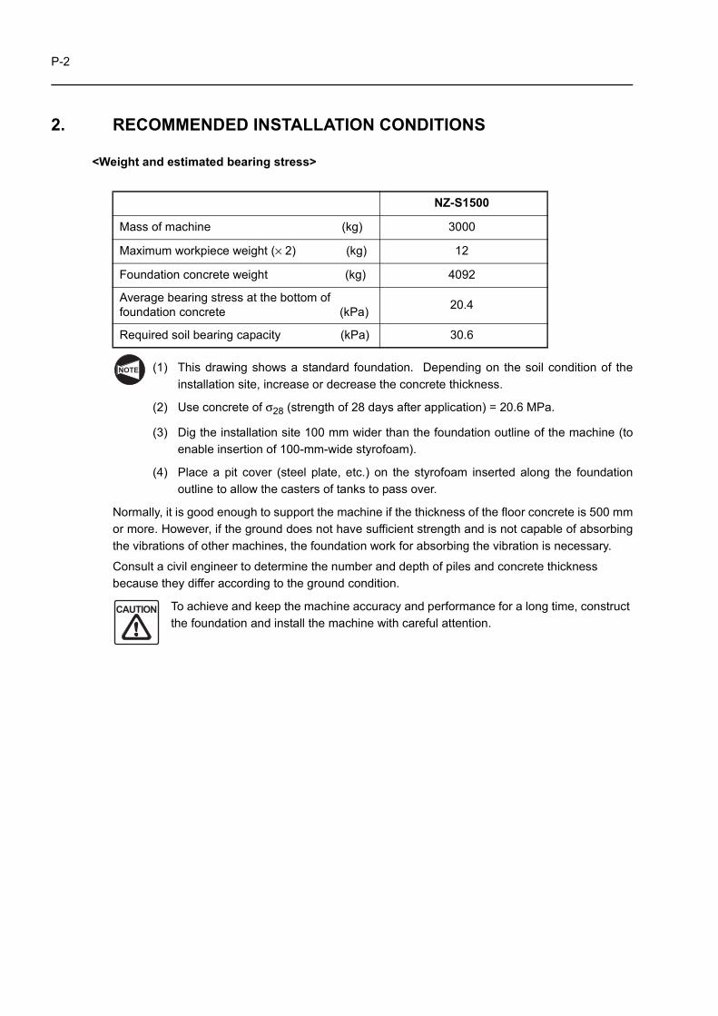
<Weight and estimated bearing stress>
(1) This drawing shows a standard foundation. Depending on the soil condition of theinstallation site, increase or decrease the concrete thickness.
(2) Use concrete of σ28 (strength of 28 days after application) = 20.6 MPa.
(3) Dig the installation site 100 mm wider than the foundation outline of the machine (toenable insertion of 100-mm-wide styrofoam).
(4) Place a pit cover (steel plate, etc.) on the styrofoam inserted along the foundationoutline to allow the casters of tanks to pass over.
Normally, it is good enough to support the machine if the thickness of the floor concrete is 500 mmor more. However, if the ground does not have sufficient strength and is not capable of absorbingthe vibrations of other machines, the foundation work for absorbing the vibration is necessary.
Consult a civil engineer to determine the number and depth of piles and concrete thicknessbecause they differ according to the ground condition.
To achieve and keep the machine accuracy and performance for a long time, construct the foundation and install the machine with careful attention.
NZ-S1500
Mass of machine (kg) 3000
Maximum workpiece weight (× 2) (kg) 12
Foundation concrete weight (kg) 4092
Average bearing stress at the bottom of foundation concrete (kPa) 20.4
Required soil bearing capacity (kPa) 30.6
NOTE
CAUTION
P-3
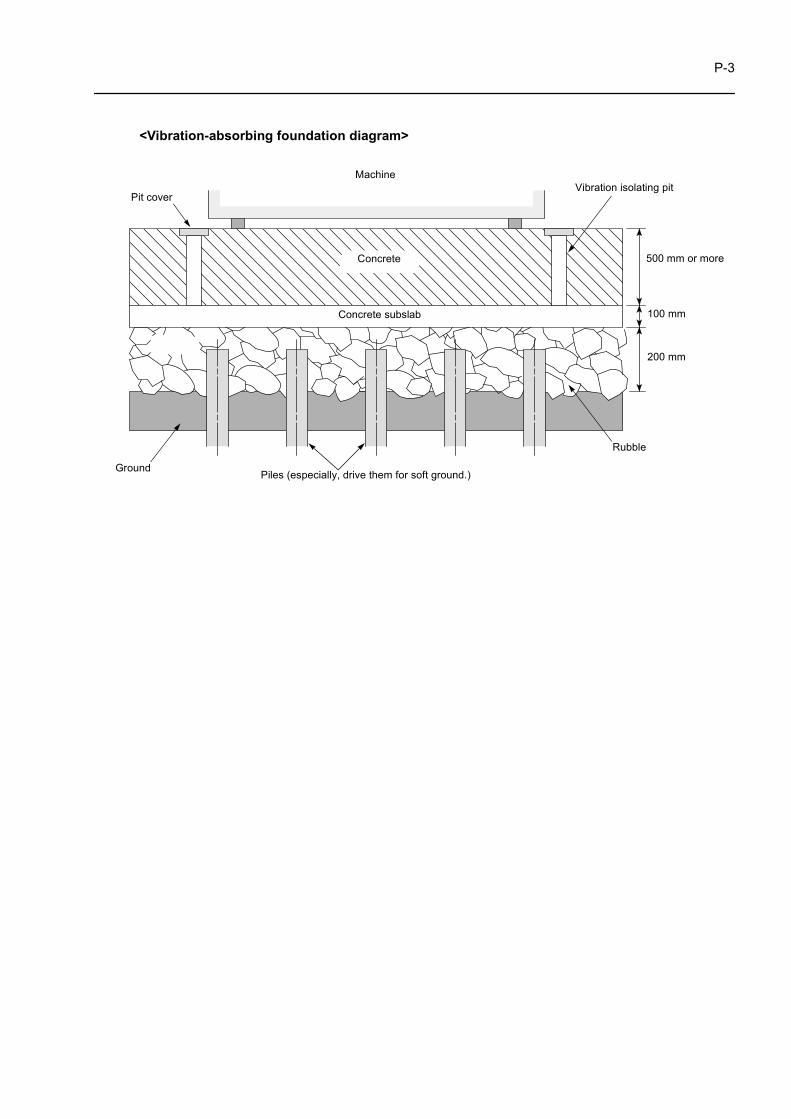
<Vibration-absorbing foundation diagram>
Concrete
Machine
Pit coverVibration isolating pit
Rubble
Piles (especially, drive them for soft ground.)Ground
Concrete subslab 100 mm
200 mm
500 mm or more
P-4
3. PREPARATION FOR INSTALLATION
Mori Seiki service technicians will visit the customer to install the machine at the customer's plant.
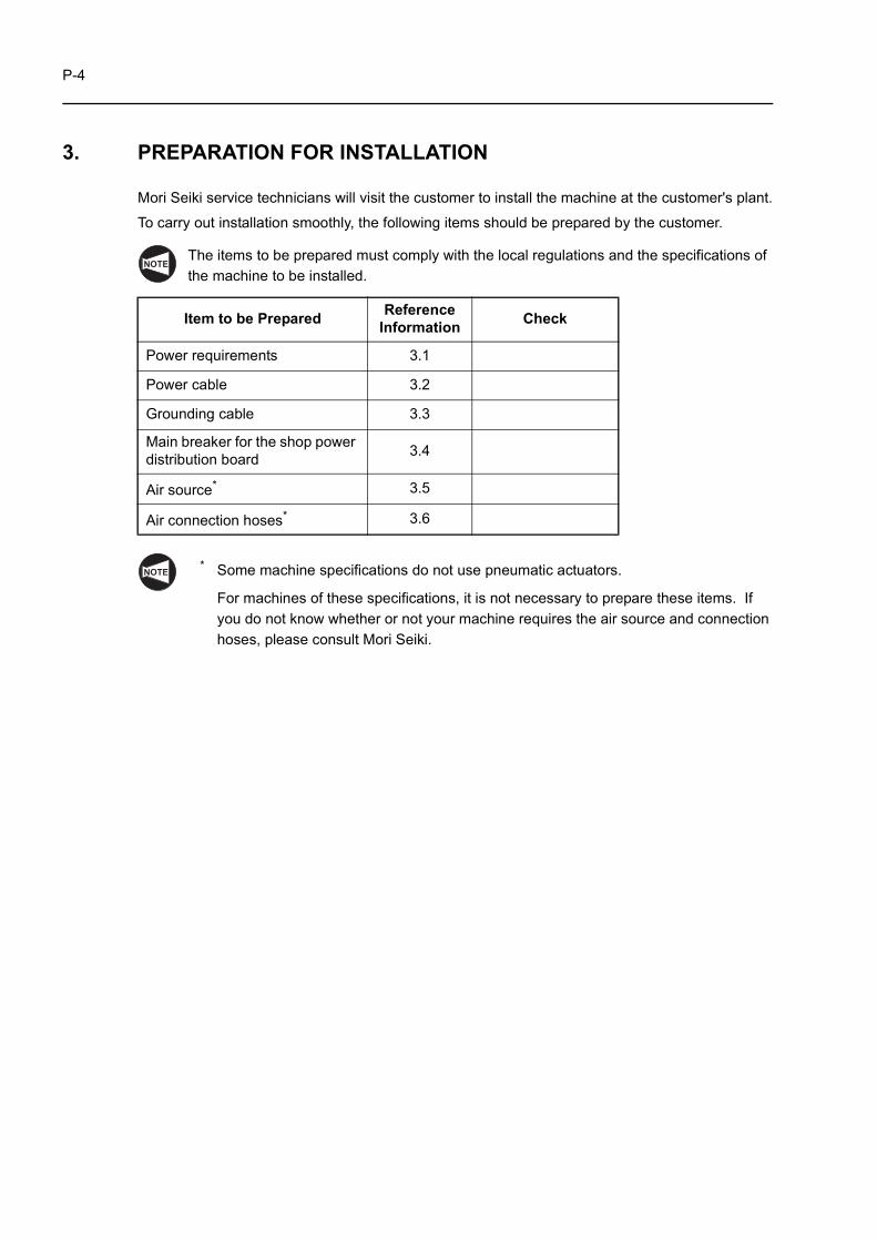
To carry out installation smoothly, the following items should be prepared by the customer.
The items to be prepared must comply with the local regulations and the specifications of the machine to be installed.
* Some machine specifications do not use pneumatic actuators.
For machines of these specifications, it is not necessary to prepare these items. If you do not know whether or not your machine requires the air source and connection hoses, please consult Mori Seiki.
Item to be Prepared Reference Information Check
Power requirements 3.1
Power cable 3.2
Grounding cable 3.3
Main breaker for the shop power distribution board 3.4
Air source* 3.5
Air connection hoses* 3.6
NOTE
NOTE
P-5
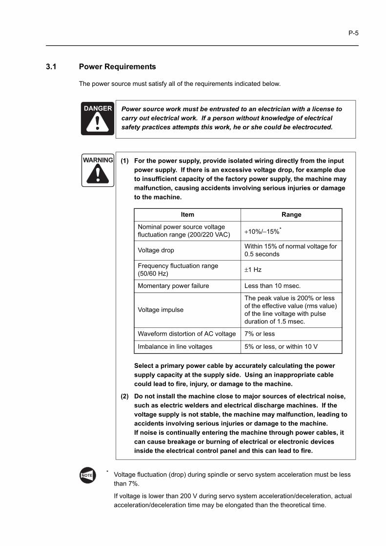
3.1 Power Requirements
The power source must satisfy all of the requirements indicated below.
* Voltage fluctuation (drop) during spindle or servo system acceleration must be less than 7%.
If voltage is lower than 200 V during servo system acceleration/deceleration, actual acceleration/deceleration time may be elongated than the theoretical time.
DANGER Power source work must be entrusted to an electrician with a license to carry out electrical work. If a person without knowledge of electrical safety practices attempts this work, he or she could be electrocuted.
WARNING (1) For the power supply, provide isolated wiring directly from the input power supply. If there is an excessive voltage drop, for example due to insufficient capacity of the factory power supply, the machine may malfunction, causing accidents involving serious injuries or damage to the machine.
Select a primary power cable by accurately calculating the power supply capacity at the supply side. Using an inappropriate cable could lead to fire, injury, or damage to the machine.
(2) Do not install the machine close to major sources of electrical noise, such as electric welders and electrical discharge machines. If the voltage supply is not stable, the machine may malfunction, leading to accidents involving serious injuries or damage to the machine.If noise is continually entering the machine through power cables, it can cause breakage or burning of electrical or electronic devices inside the electrical control panel and this can lead to fire.
Item Range
Nominal power source voltage fluctuation range (200/220 VAC) +10%/−15%*
Voltage drop Within 15% of normal voltage for 0.5 seconds
Frequency fluctuation range (50/60 Hz) ±1 Hz
Momentary power failure Less than 10 msec.
Voltage impulse
The peak value is 200% or less of the effective value (rms value) of the line voltage with pulse duration of 1.5 msec.
Waveform distortion of AC voltage 7% or less
Imbalance in line voltages 5% or less, or within 10 V
NOTE
P-6
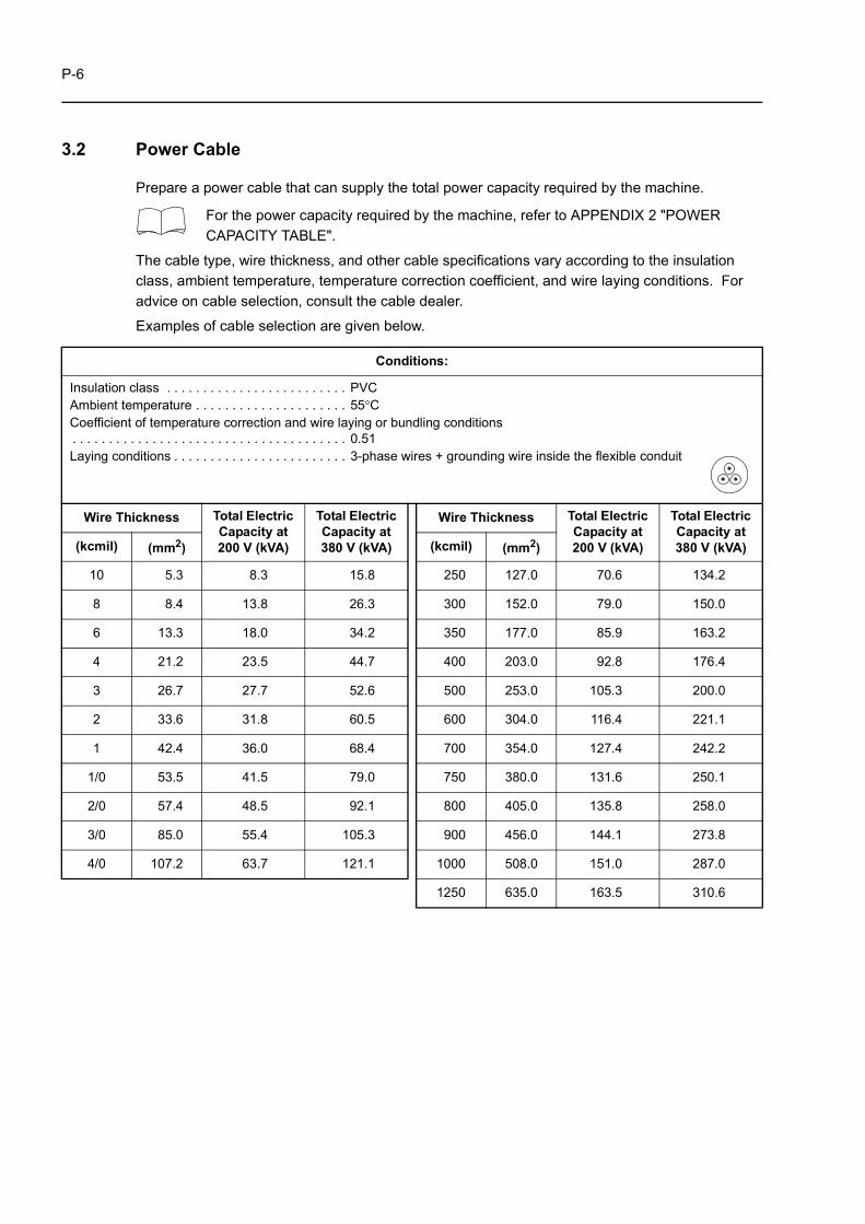
3.2 Power Cable
Prepare a power cable that can supply the total power capacity required by the machine.
For the power capacity required by the machine, refer to APPENDIX 2 "POWER CAPACITY TABLE".
The cable type, wire thickness, and other cable specifications vary according to the insulation class, ambient temperature, temperature correction coefficient, and wire laying conditions. For advice on cable selection, consult the cable dealer.
Examples of cable selection are given below.
Conditions:
Insulation class . . . . . . . . . . . . . . . . . . . . . . . . . PVCAmbient temperature . . . . . . . . . . . . . . . . . . . . . 55°CCoefficient of temperature correction and wire laying or bundling conditions. . . . . . . . . . . . . . . . . . . . . . . . . . . . . . . . . . . . . . 0.51Laying conditions . . . . . . . . . . . . . . . . . . . . . . . . 3-phase wires + grounding wire inside the flexible conduit
Wire Thickness Total Electric Capacity at 200 V (kVA)
Total Electric Capacity at 380 V (kVA)
Wire Thickness Total Electric Capacity at 200 V (kVA)
Total Electric Capacity at 380 V (kVA)(kcmil) (mm2) (kcmil) (mm2)
10 5.3 8.3 15.8 250 127.0 70.6 134.2
8 8.4 13.8 26.3 300 152.0 79.0 150.0
6 13.3 18.0 34.2 350 177.0 85.9 163.2
4 21.2 23.5 44.7 400 203.0 92.8 176.4
3 26.7 27.7 52.6 500 253.0 105.3 200.0
2 33.6 31.8 60.5 600 304.0 116.4 221.1
1 42.4 36.0 68.4 700 354.0 127.4 242.2
1/0 53.5 41.5 79.0 750 380.0 131.6 250.1
2/0 57.4 48.5 92.1 800 405.0 135.8 258.0
3/0 85.0 55.4 105.3 900 456.0 144.1 273.8
4/0 107.2 63.7 121.1 1000 508.0 151.0 287.0
1250 635.0 163.5 310.6
P-7
3.3 Grounding Cable
For the grounding cable, consult the cable manufacturer to select the one which is sufficient to take earth for the machine to be installed.
When selecting the grounding cable, observe the applicable local regulations where the machine is installed.
Meaning of "Leak Current"
Indoor electrical wiring and equipment are "insulated" in order to prevent current leakage.
However, when the insulation becomes old or damaged, or when the wires/equipment are exposed to water, current leaks out and a "leak current" is generated.
Since leak currents can cause accidents that endanger human life, such as electric shock and fire, due care is required. Particular care is necessary when using electrical equipment in locations where there is exposure to water (where coolant is used, for example).
Meaning of "Electric Shock"
When a person touches wiring or electrical equipment from which current is leaking, electricity flows through that person's body to the ground. This is an "electric shock."
If the current is weak, the result is nothing more than a "shock" in the commonly understood sense, but if it is strong, the life of the affected person may be endangered.
Be sure to ground electrical equipment properly by connecting a grounding cable.
Note also that water on the body of the person subject to the shock will allow the electricity to be conducted more easily, and for this reason you must take particular care not to touch electrical equipment with wet hands.
DANGER (1) Be sure to carry out the grounding work. If the grounding work is not done, there will be a danger of electrocution.
(2) The grounding wire should be as short as possible and should have the same thickness as the power wires. Perform class D grounding work with the grounding resistance of 100 Ω or less. If the grounding is ineffective, there will be a danger of electrocution.
(3) Check for earth faults and short circuits after completing the grounding work.
WARNING Do not connect any other grounding wire to the ground. If a machine such as an electric welder or electric discharge machine is grounded to the steel reinforcing rods in the reinforced concrete structure of the plant, do not connect the grounding wire of the machine to the reinforcing rods too. Unless the grounding wire is connected to an independent ground, the machine could malfunction due to noise from other machines, leading to accidents involving serious injuries or damage to the machine.
P-8
3.4 Main Breaker for the Shop Power Distribution Board
Use a breaker for an AC inverter as the main breaker on the shop power distribution board.If another type of breaker is used, it may be actuated by the high-frequency leak current specific to AC inverters.
High-frequency leak current will not adversely affect operators.
Meaning of "Breaker"
This is a device that automatically shuts off the current within 0.1 seconds in the event of an abnormal current flow such as a leak current.
By installing a breaker in the distribution panel, it is possible to prevent accidents due to current leakage from electrical equipment and devices.
Since machine tools use many AC inverters, you must select a breaker of a type that will not be erroneously actuated by the high-frequency leak current from the inverters.
Select the correct circuit breaker and power distribution board capacities by consulting the electric part manufacturer based on the current consumption calculated by the following formula.
* Allowance for selection
For the power capacity required by the machine, refer to APPENDIX 2 "POWER CAPACITY TABLE".
NOTE
Current (A) =Total Electric Capacity (kVA) × 1000
3 × 200 (V)× 1.25*
P-9
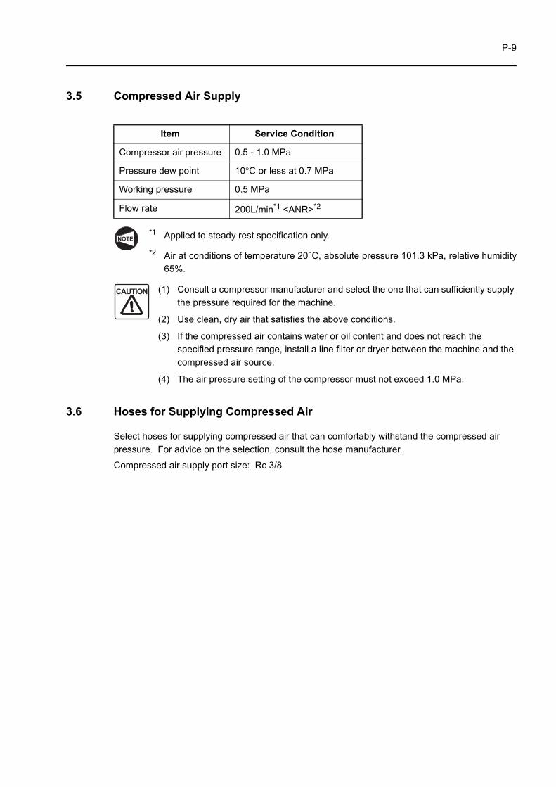
3.5 Compressed Air Supply
*1 Applied to steady rest specification only.
*2 Air at conditions of temperature 20°C, absolute pressure 101.3 kPa, relative humidity65%.
(1) Consult a compressor manufacturer and select the one that can sufficiently supply the pressure required for the machine.
(2) Use clean, dry air that satisfies the above conditions.
(3) If the compressed air contains water or oil content and does not reach the specified pressure range, install a line filter or dryer between the machine and the compressed air source.
(4) The air pressure setting of the compressor must not exceed 1.0 MPa.
3.6 Hoses for Supplying Compressed Air
Select hoses for supplying compressed air that can comfortably withstand the compressed air pressure. For advice on the selection, consult the hose manufacturer.
Compressed air supply port size: Rc 3/8
Item Service Condition
Compressor air pressure 0.5 - 1.0 MPa
Pressure dew point 10°C or less at 0.7 MPa
Working pressure 0.5 MPa
Flow rate 200L/min*1 <ANR>*2
NOTE
CAUTION
P-10
4. AFTER RECEIVING THE MACHINE
When transporting the machine or if the machine is not installed immediately after its delivery, store it in a place where the ambient temperature remains within the range −20 to 60°C and the humidity does not exceed 75% RH (with no condensation). Failure to comply with these conditions could cause troubles in the electrical systems of the NC unit and peripheral devices and lead to machine faults.
When the machine is delivered, pay attention to the following points.
If the machine is delivered in a package, check the external frame of the package. If the machine is delivered without a package, check the external appearance of the machine.
If the package frame is damaged, contact Mori Seiki before unpacking the machine. If the machine appearance shows damage, contact Mori Seiki, leaving the damage as it is.
If the machine is not moved to the installation site immediately after its delivery, keep it in a location not exposed to the elements and not subject to dust, dirt, or mist.
Leaving the machine in such places will cause rusting or corrosion.
CAUTION
NOTE
CAUTION
P-11
5. CARRYING THE MACHINE
When the machine is delivered to your shop, Mori Seiki's service technicians will install the machine at the designated place. Refer to the information below if you move the machine after initial installation, for example due to a floor layout change.
If it becomes necessary to carry the machine due to relocation of the plant or selling of the machine, contact Mori Seiki.
5.1 Preparation
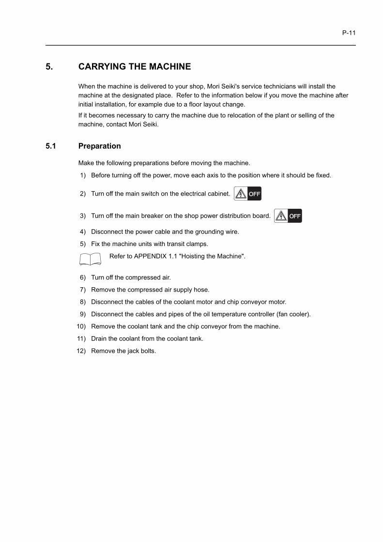
Make the following preparations before moving the machine.
1) Before turning off the power, move each axis to the position where it should be fixed.
2) Turn off the main switch on the electrical cabinet.
3) Turn off the main breaker on the shop power distribution board.
4) Disconnect the power cable and the grounding wire.
5) Fix the machine units with transit clamps.
Refer to APPENDIX 1.1 "Hoisting the Machine".
6) Turn off the compressed air.
7) Remove the compressed air supply hose.
8) Disconnect the cables of the coolant motor and chip conveyor motor.
9) Disconnect the cables and pipes of the oil temperature controller (fan cooler).
10) Remove the coolant tank and the chip conveyor from the machine.
11) Drain the coolant from the coolant tank.
12) Remove the jack bolts.
P-12
5.2 Carrying the Machine by Hoisting
Observe the following cautions when carrying the machine by hoisting.
WARNING (1) Only a qualified technician should perform machine hoisting work. Operation of the crane or forklift by a person unfamiliar with safe operation practices could lead to accidents involving serious injuries or damage to the machine.
(2) Use only wires, shackles and jigs of the dimensions specified in the manual. They must be strong enough to support the mass of the machine. Check the mass of the machine by referring to the specifications in this manual. If the machine is hoisted using equipment that cannot bear its mass it will fall, causing serious injuries or damage to the machine.
(3) When hoisting the machine, always pay attention to the location of the center of gravity for the machine and make sure that the machine is well balanced in both the crosswise and lengthwise directions by hoisting it a little above the floor. If you continue to hoist the machine although it is not properly balanced, it will fall, causing serious injuries or damage to the machine.
(4) If two or more people work together to lift the machine, they must work carefully while exchanging signals. If someone operates the machine or the crane inadvertently when other people are working inside or close to the machine, it could cause serious injuries.
(5) Before hoisting the machine, check that no tools, rags, etc., have been left inside it. When the machine is lifted, these articles could fall out and injure plant personnel or damage the machine.
(6) Before hoisting the machine, check that all of its parts are clamped. Lifting the machine while any of the parts is not clamped adequately could damage the machine.
(7) If a crane is used to hoist the machine, do not carry the machine while it is lifted to an excessive height. Lifting the machine excessively high when carrying it will create more potential hazards than when carrying it at a lower height.
(8) When moving the machine with a forklift, do not lift it high above the ground. If it is moved in this condition, it may become unbalanced and fall, or the forklift may topple over, causing serious injuries or damage to the machine.
(9) Use a crane or forklift that can comfortably bear the mass of the machine. If a crane or forklift without sufficient capacity to lift the machine is used, the machine will fall, causing serious injuries or damage to the machine.
P-13
(1) When moving the machine with rollers, set the number of rollers, and the material that they are made of, so as to ensure that they can support the mass of the machine. Also use skid and leading boards that can support the mass of the machine. If they cannot support the mass of the machine the rollers, skid, or leading board may be distorted, making it impossible to move the machine.
(2) After the machine has been installed, it must be leveled. Adjust the machine's crown and distortion values according to the Accuracy Test Results Chart delivered with the machine. If this adjustment is not carried out properly, machining accuracy will be adversely affected.
NOTE
P-14
6. CONNECTING THE POWER CABLE
This section explains the connection of power cable from the shop power distribution board to the transformer and then to the machine.
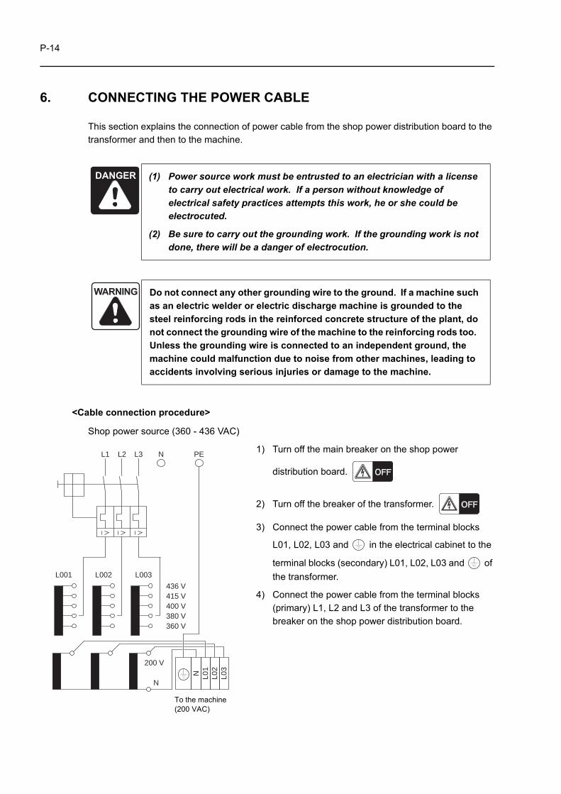
<Cable connection procedure>
Shop power source (360 - 436 VAC)
1) Turn off the main breaker on the shop power
distribution board.
2) Turn off the breaker of the transformer.
3) Connect the power cable from the terminal blocks
L01, L02, L03 and in the electrical cabinet to the
terminal blocks (secondary) L01, L02, L03 and of the transformer.
4) Connect the power cable from the terminal blocks (primary) L1, L2 and L3 of the transformer to the breaker on the shop power distribution board.
DANGER (1) Power source work must be entrusted to an electrician with a license to carry out electrical work. If a person without knowledge of electrical safety practices attempts this work, he or she could be electrocuted.
(2) Be sure to carry out the grounding work. If the grounding work is not done, there will be a danger of electrocution.
WARNING Do not connect any other grounding wire to the ground. If a machine such as an electric welder or electric discharge machine is grounded to the steel reinforcing rods in the reinforced concrete structure of the plant, do not connect the grounding wire of the machine to the reinforcing rods too. Unless the grounding wire is connected to an independent ground, the machine could malfunction due to noise from other machines, leading to accidents involving serious injuries or damage to the machine.
L1 L2 L3 N PE
L001 L002 L003
436 V415 V400 V380 V360 V
200 V
N
N L01
L02
L03
To the machine (200 VAC)
P-15
(1) Terminal blocks L1, L2, and L3 are for 400 VAC system (360 - 436 VAC) and those L01, L02, and L03 are for 200 VAC system. Never connect the cable to wrong terminal blocks, otherwise the machine will be damaged.
(2) If the cable is run through the punched hole in the transformer circuit breaker box, take proper cable protection means conforming to IP54.
For the transformer of 24.5 kVA or 34.64 kVA, connect the power cable from L1, L2, and L3 to the primary side of the breaker. The transformers with larger capacity have terminal blocks, therefore, connection should be made to the terminal blocks.
5) Connect the ground cable to the terminal block PE in the transformer for grounding the machine.
6) Check the grounding resistance of the grounding wire.
7) Turn on the main breaker on the shop power distribution board.
8) Turn on the breaker of the transformer.
9) Check the input voltage.
10) Check the phase order with a phase rotation indicator.
If a phase rotation indicator is not available, check the phase order by checking the direction of rotation of the hydraulic pump motor.
WARNING Check the overall phase order of the input voltages L1, L2, L3 (R, S, T) using a phase rotation indicator. If the phase order is incorrect, the machine will malfunction, causing serious injury or damage to the machine.
CAUTION
NOTE
NOTE
P-16
7. CONNECTION OF COMPRESSED AIR SUPPLY HOSE
Follow the procedure below to connect the compressed air supply hose.
1) Turn off the power.
2) Connect the compressed air supply hose from the air source to the air supply port (Rc 3/8) in the air panel of the machine.
3) Start the compressor to supply the compressed air to the machine.
4) Make sure that there is no air leak at hose joints and pneumatic actuators.
5) Adjust the compressed air pressure to the specified value with the regulator in the air panel.
For the correct air pressure, refer to MACHINE SPECIFICATIONS in the MAINTENANCE INFORMATION published separately.
8. REMOVING TRANSIT CLAMPS
After carrying the machine to the required place, remove all transit clamps before turning on the power.
(1) The transit clamps that cannot be removed before turning on the power should be removed immediately after turning on the power, in the handle mode with the chuck in the unclamped state. Attempting axis feed while the transit clamps are in place will damage the machine.
(2) If a rust-preventive coating is applied to the slideway surfaces, it must be removed completely. Attempting axis feed while rust-preventive coating remains on the slideways could cause machine failure.
Keep the removed transit clamps so that they will not be lost.
9. MOUNTING ACCESSORIES
If accessories such as the chip conveyor or the coolant tank are provided with the machine, mount them as a part of the machine installation process.
(1) When installing the machine, mount the coolant tank and the chip conveyor by pushing them into an appropriate position. Otherwise, coolant may be splashed around the machine causing the operator or persons around the machine to topple down and get injured.
(2) Check that all necessary covers are mounted.
CAUTION
CAUTION
P-17
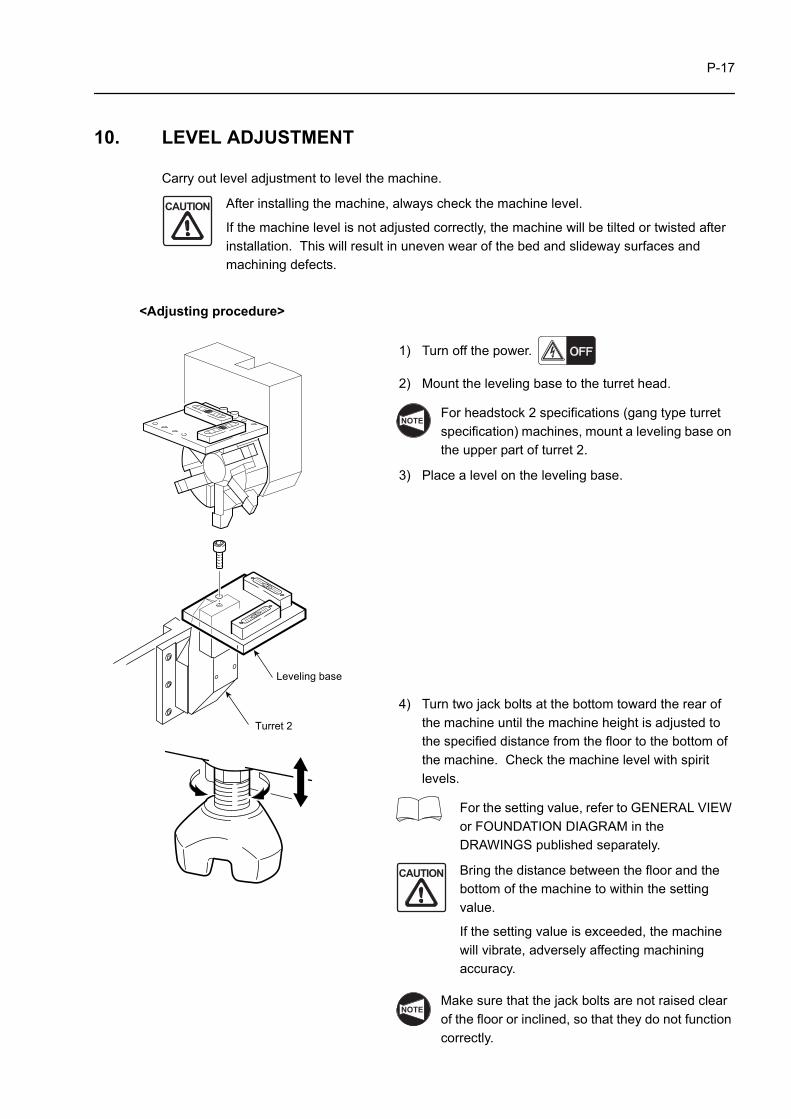
10. LEVEL ADJUSTMENT
Carry out level adjustment to level the machine.
After installing the machine, always check the machine level.
If the machine level is not adjusted correctly, the machine will be tilted or twisted after installation. This will result in uneven wear of the bed and slideway surfaces and machining defects.
<Adjusting procedure>
1) Turn off the power.
2) Mount the leveling base to the turret head.
For headstock 2 specifications (gang type turret specification) machines, mount a leveling base on the upper part of turret 2.
3) Place a level on the leveling base.
4) Turn two jack bolts at the bottom toward the rear of the machine until the machine height is adjusted to the specified distance from the floor to the bottom of the machine. Check the machine level with spirit levels.
For the setting value, refer to GENERAL VIEW or FOUNDATION DIAGRAM in the DRAWINGS published separately.
Bring the distance between the floor and the bottom of the machine to within the setting value.
If the setting value is exceeded, the machine will vibrate, adversely affecting machining accuracy.
Make sure that the jack bolts are not raised clear of the floor or inclined, so that they do not function correctly.
CAUTION
Leveling base
Turret 2
NOTE
CAUTION
NOTE
P-18
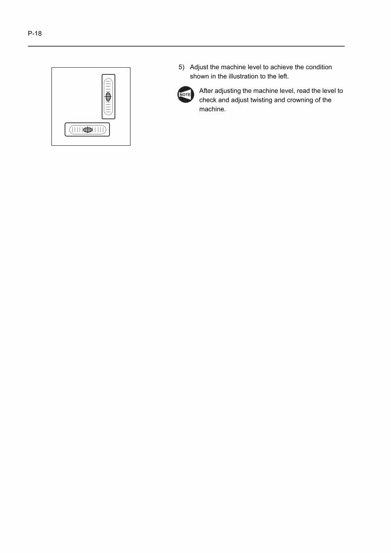
5) Adjust the machine level to achieve the condition shown in the illustration to the left.
After adjusting the machine level, read the level to check and adjust twisting and crowning of the machine.
NOTE
APPENDIX-1
APPENDIX 1 INSTALLATION DATA
Prepare for installation of the machine by referring to the data presented here.
1.1 Hoisting the Machine
Instructions on hoisting the machine in order to move it are given below.
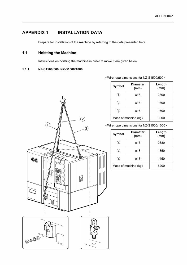
1.1.1 NZ-S1500/500, NZ-S1500/1000
<Wire rope dimensions for NZ-S1500/500>
<Wire rope dimensions for NZ-S1500/1000>
Symbol Diameter (mm)
Length (mm)
φ16 2800
φ16 1600
φ16 1600
Mass of machine (kg) 3000
Symbol Diameter (mm)
Length (mm)
φ18 2680
φ18 1350
φ18 1450
Mass of machine (kg) 5200
1
2
3
1
2
3
APPENDIX-2
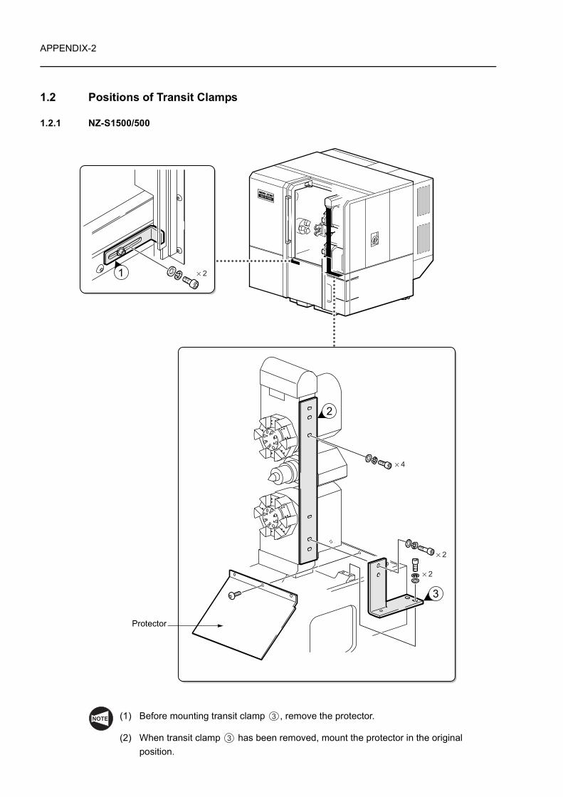
1.2 Positions of Transit Clamps
1.2.1 NZ-S1500/500
(1) Before mounting transit clamp , remove the protector.
(2) When transit clamp has been removed, mount the protector in the original position.
× 4
× 2
× 2
× 2
Protector
NOTE 3
3
APPENDIX-3
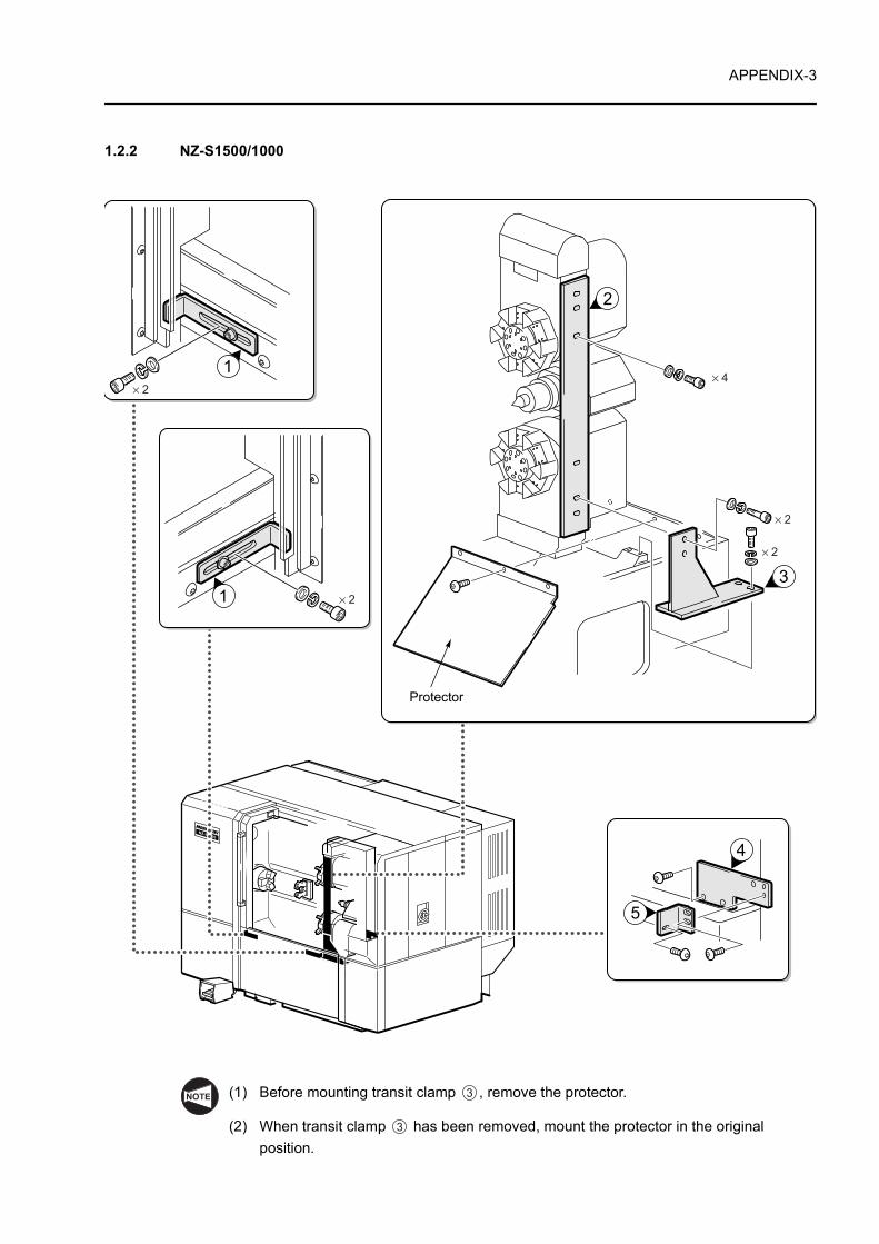
1.2.2 NZ-S1500/1000
(1) Before mounting transit clamp , remove the protector.
(2) When transit clamp has been removed, mount the protector in the original position.
× 2
× 4
× 2
× 2
× 2
Protector
NOTE 3
3
APPENDIX-4
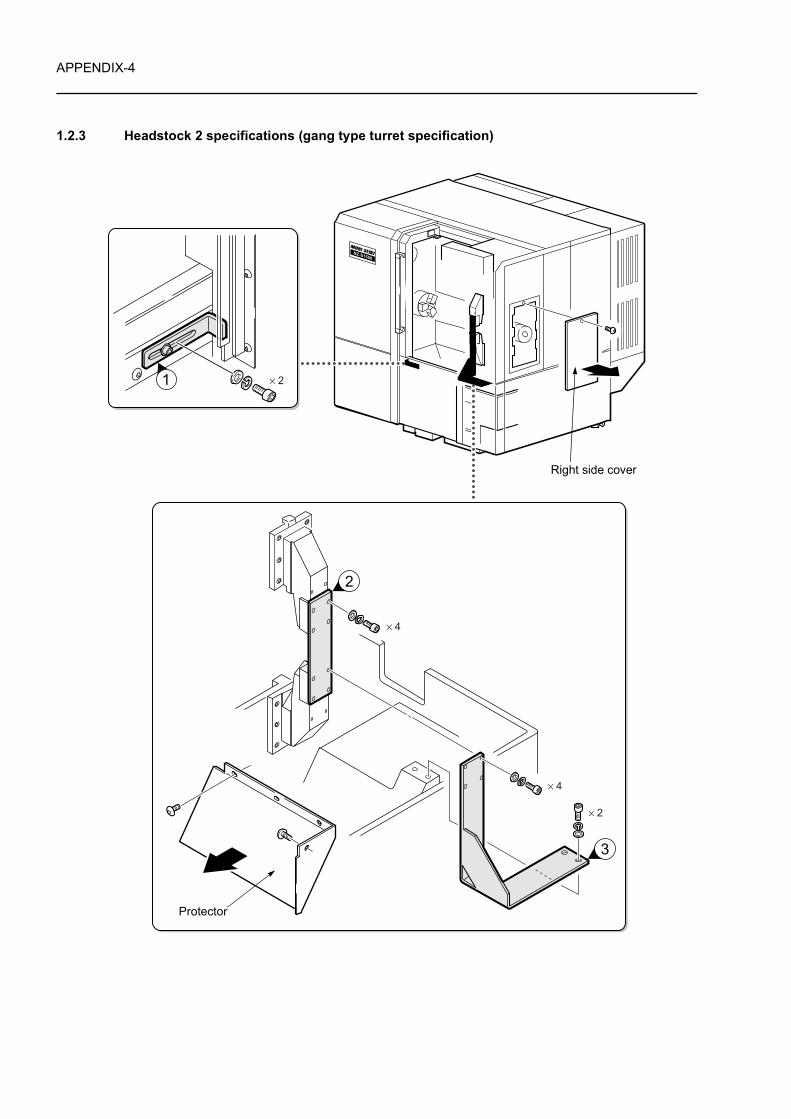
1.2.3 Headstock 2 specifications (gang type turret specification)
× 4
× 2
× 2
× 4
Protector
Right side cover
APPENDIX-5
<Transit clamp mounting procedure>
1) Remove the protector and the right side cover.
2) Insert your hand through the right side face and finger tighten the bolts of transit clamp at the positions shown in the figure.
3) Feed turret 2 to the position where transit clamp can be mounted on it.
4) Feed turret 1 to the position where transit clamp can be mounted on it.
5) From the front of the machine, insert transit clamp between turret 1 and turret 2.
6) Tighten the four bolts of transit clamp , the four bolts of transit clamps and (to be
tightened together) and the two finger tightened bolts of transit clamp .
7) Mount the right side cover.
<Transit clamp removal procedure>
1) Remove the right side cover.
2) Insert your hand through the right side face and remove the bolts of transit clamp .
3) From the front of the machine, remove the bolts of transit clamps and on the turret side.
4) Mount the protector and the right side cover.
3
3
2
2
2 2 3
3
3
2 3
APPENDIX-6
APPENDIX 2 POWER CAPACITY TABLE
Breaker and power distribution board capacities are determined using the current calculated by the following formula.
* Allowance for selection
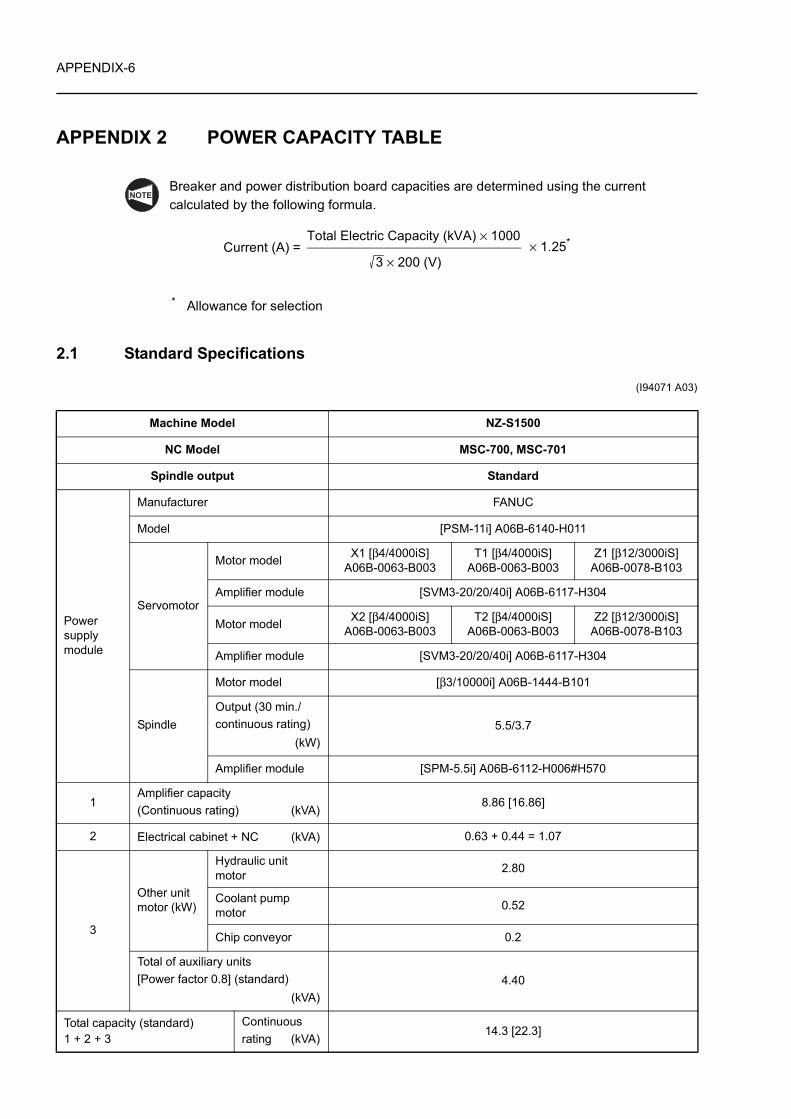
2.1 Standard Specifications
(I94071 A03)
Machine Model NZ-S1500
NC Model MSC-700, MSC-701
Spindle output Standard
Power supply module
Manufacturer FANUC
Model [PSM-11i] A06B-6140-H011
Servomotor
Motor model X1 [β4/4000iS]A06B-0063-B003
T1 [β4/4000iS]A06B-0063-B003
Z1 [β12/3000iS]A06B-0078-B103
Amplifier module [SVM3-20/20/40i] A06B-6117-H304
Motor model X2 [β4/4000iS]A06B-0063-B003
T2 [β4/4000iS]A06B-0063-B003
Z2 [β12/3000iS]A06B-0078-B103
Amplifier module [SVM3-20/20/40i] A06B-6117-H304
Spindle
Motor model [β3/10000i] A06B-1444-B101
Output (30 min./continuous rating)
(kW)5.5/3.7
Amplifier module [SPM-5.5i] A06B-6112-H006#H570
1Amplifier capacity (Continuous rating) (kVA)
8.86 [16.86]
2 Electrical cabinet + NC (kVA) 0.63 + 0.44 = 1.07
3
Other unit motor (kW)
Hydraulic unit motor 2.80
Coolant pump motor 0.52
Chip conveyor 0.2
Total of auxiliary units [Power factor 0.8] (standard)
(kVA)4.40
Total capacity (standard)1 + 2 + 3
Continuous rating (kVA)
14.3 [22.3]
NOTE
Current (A) =Total Electric Capacity (kVA) × 1000
3 × 200 (V)× 1.25*

APPENDIX-7
Values in [ ] are those for loader specification.
220 V 50 Hz transformer (kVA) 5
Machine Model NZ-S1500
NC Model MSC-700, MSC-701
Spindle output Standard
NOTE
APPENDIX-8
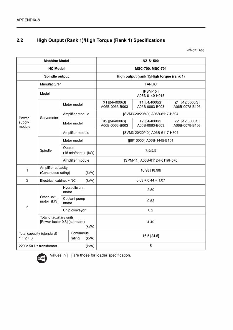
2.2 High Output (Rank 1)/High Torque (Rank 1) Specifications
(I94071 A03)
Values in [ ] are those for loader specification.
Machine Model NZ-S1500
NC Model MSC-700, MSC-701
Spindle output High output (rank 1)/High torque (rank 1)
Power supply module
Manufacturer FANUC
Model [PSM-15i]A06B-6140-H015
Servomotor
Motor model X1 [β4/4000iS]A06B-0063-B003
T1 [β4/4000iS]A06B-0063-B003
Z1 [β12/3000iS]A06B-0078-B103
Amplifier module [SVM3-20/20/40i] A06B-6117-H304
Motor model X2 [β4/4000iS]A06B-0063-B003
T2 [β4/4000iS]A06B-0063-B003
Z2 [β12/3000iS]A06B-0078-B103
Amplifier module [SVM3-20/20/40i] A06B-6117-H304
Spindle
Motor model [β6/10000i] A06B-1445-B101
Output (15 min/cont.) (kW)
7.5/5.5
Amplifier module [SPM-11i] A06B-6112-H011#H570
1Amplifier capacity (Continuous rating) (kVA)
10.98 [18.98]
2 Electrical cabinet + NC (kVA) 0.63 + 0.44 = 1.07
3
Other unit motor (kW)
Hydraulic unit motor 2.80
Coolant pump motor 0.52
Chip conveyor 0.2
Total of auxiliary units[Power factor 0.8] (standard)
(kVA)4.40
Total capacity (standard)1 + 2 + 3
Continuous rating (kVA)
16.5 [24.5]
220 V 50 Hz transformer (kVA) 5
NOTE
APPENDIX-9
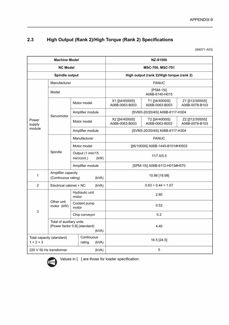
2.3 High Output (Rank 2)/High Torque (Rank 2) Specifications
(I94071 A03)
Values in [ ] are those for loader specification.
Machine Model NZ-S1500
NC Model MSC-700, MSC-701
Spindle output High output (rank 2)/High torque (rank 2)
Power supply module
Manufacturer FANUC
Model [PSM-15i]A06B-6140-H015
Servomotor
Motor model X1 [β4/4000iS]A06B-0063-B003
T1 [β4/4000iS]A06B-0063-B003
Z1 [β12/3000iS]A06B-0078-B103
Amplifier module [SVM3-20/20/40i] A06B-6117-H304
Motor model X2 [β4/4000iS]A06B-0063-B003
T2 [β4/4000iS]A06B-0063-B003
Z2 [β12/3000iS]A06B-0078-B103
Amplifier module [SVM3-20/20/40i] A06B-6117-H304
Spindle
Manufacturer FANUC
Motor model [β6/10000i] A06B-1445-B101#H0502
Output (1 min/15 min/cont.) (kW)
11/7.5/5.5
Amplifier module [SPM-15i] A06B-6112-H015#H570
1Amplifier capacity (Continuous rating) (kVA)
10.98 [18.98]
2 Electrical cabinet + NC (kVA) 0.63 + 0.44 = 1.07
3
Other unit motor (kW)
Hydraulic unit motor 2.80
Coolant pump motor 0.52
Chip conveyor 0.2
Total of auxiliary units[Power factor 0.8] (standard)
(kVA)4.40
Total capacity (standard)1 + 2 + 3
Continuous rating (kVA)
16.5 [24.5]
220 V 50 Hz transformer (kVA) 5
NOTE
APPENDIX-10
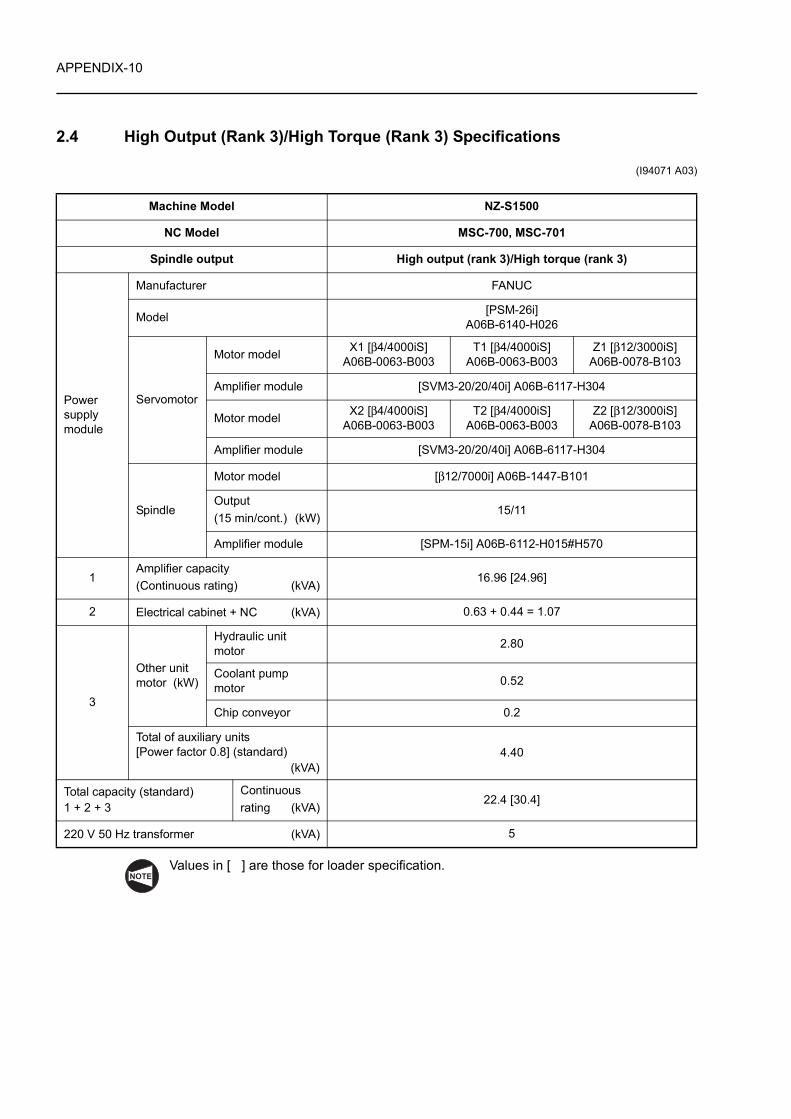
2.4 High Output (Rank 3)/High Torque (Rank 3) Specifications
(I94071 A03)
Values in [ ] are those for loader specification.
Machine Model NZ-S1500
NC Model MSC-700, MSC-701
Spindle output High output (rank 3)/High torque (rank 3)
Power supply module
Manufacturer FANUC
Model [PSM-26i]A06B-6140-H026
Servomotor
Motor model X1 [β4/4000iS]A06B-0063-B003
T1 [β4/4000iS]A06B-0063-B003
Z1 [β12/3000iS]A06B-0078-B103
Amplifier module [SVM3-20/20/40i] A06B-6117-H304
Motor model X2 [β4/4000iS]A06B-0063-B003
T2 [β4/4000iS]A06B-0063-B003
Z2 [β12/3000iS]A06B-0078-B103
Amplifier module [SVM3-20/20/40i] A06B-6117-H304
Spindle
Motor model [β12/7000i] A06B-1447-B101
Output (15 min/cont.) (kW)
15/11
Amplifier module [SPM-15i] A06B-6112-H015#H570
1Amplifier capacity (Continuous rating) (kVA)
16.96 [24.96]
2 Electrical cabinet + NC (kVA) 0.63 + 0.44 = 1.07
3
Other unit motor (kW)
Hydraulic unit motor 2.80
Coolant pump motor 0.52
Chip conveyor 0.2
Total of auxiliary units[Power factor 0.8] (standard)
(kVA)4.40
Total capacity (standard)1 + 2 + 3
Continuous rating (kVA)
22.4 [30.4]
220 V 50 Hz transformer (kVA) 5
NOTE
APPENDIX-11
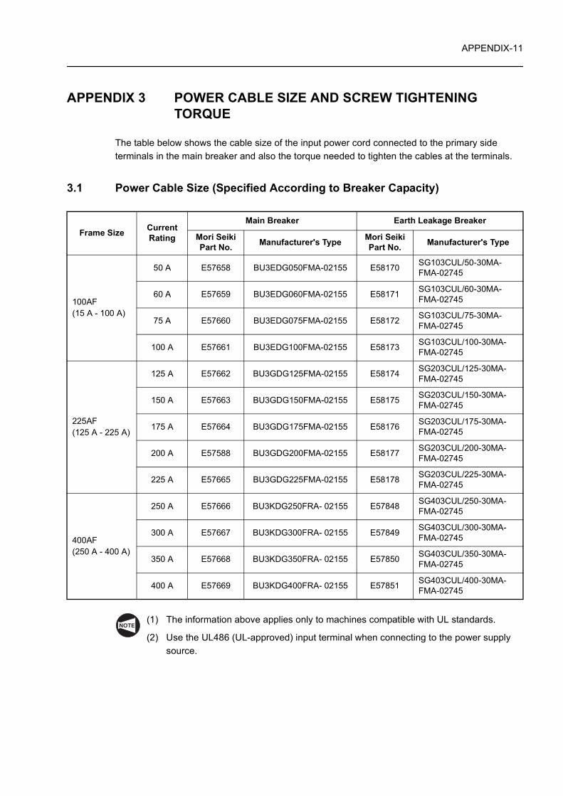
APPENDIX 3 POWER CABLE SIZE AND SCREW TIGHTENING TORQUE
The table below shows the cable size of the input power cord connected to the primary side terminals in the main breaker and also the torque needed to tighten the cables at the terminals.
3.1 Power Cable Size (Specified According to Breaker Capacity)
(1) The information above applies only to machines compatible with UL standards.
(2) Use the UL486 (UL-approved) input terminal when connecting to the power supply source.
Frame Size Current Rating
Main Breaker Earth Leakage Breaker
Mori Seiki Part No. Manufacturer's Type Mori Seiki
Part No. Manufacturer's Type
100AF(15 A - 100 A)
50 A E57658 BU3EDG050FMA-02155 E58170 SG103CUL/50-30MA-FMA-02745
60 A E57659 BU3EDG060FMA-02155 E58171 SG103CUL/60-30MA-FMA-02745
75 A E57660 BU3EDG075FMA-02155 E58172 SG103CUL/75-30MA-FMA-02745
100 A E57661 BU3EDG100FMA-02155 E58173 SG103CUL/100-30MA-FMA-02745
225AF(125 A - 225 A)
125 A E57662 BU3GDG125FMA-02155 E58174 SG203CUL/125-30MA-FMA-02745
150 A E57663 BU3GDG150FMA-02155 E58175 SG203CUL/150-30MA-FMA-02745
175 A E57664 BU3GDG175FMA-02155 E58176 SG203CUL/175-30MA-FMA-02745
200 A E57588 BU3GDG200FMA-02155 E58177 SG203CUL/200-30MA-FMA-02745
225 A E57665 BU3GDG225FMA-02155 E58178 SG203CUL/225-30MA-FMA-02745
400AF(250 A - 400 A)
250 A E57666 BU3KDG250FRA- 02155 E57848 SG403CUL/250-30MA-FMA-02745
300 A E57667 BU3KDG300FRA- 02155 E57849 SG403CUL/300-30MA-FMA-02745
350 A E57668 BU3KDG350FRA- 02155 E57850 SG403CUL/350-30MA-FMA-02745
400 A E57669 BU3KDG400FRA- 02155 E57851 SG403CUL/400-30MA-FMA-02745
NOTE
APPENDIX-12
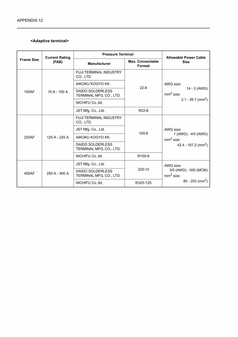
<Adaptive terminal>
Frame Size Current Rating (FAB)
Pressure TerminalAllowable Power Cable
SizeManufacturer Max. Connectable Format
100AF 15 A - 100 A
FUJI TERMINAL INDUSTRY CO., LTD.
22-8AWG size:
14 - 3 (AWG)mm2 size:
2.1 - 26.7 (mm2)
AIKOKU KOGYO KK.
DAIDO SOLDERLESS TERMINAL MFG. CO., LTD.
NICHIFU Co.,ltd.
JST Mfg. Co., Ltd. R22-8
225AF 125 A - 225 A
FUJI TERMINAL INDUSTRY CO., LTD.
100-8AWG size:
1 (AWG) - 4/0 (AWG)mm2 size:
42.4 - 107.2 (mm2)
JST Mfg. Co., Ltd.
AIKOKU KOGYO KK.
DAIDO SOLDERLESS TERMINAL MFG. CO., LTD.
NICHIFU Co.,ltd. R100-8
400AF 250 A - 400 A
JST Mfg. Co., Ltd.325-12
AWG size:3/0 (AWG) - 500 (MCM)
mm2 size:85 - 253 (mm2)
DAIDO SOLDERLESS TERMINAL MFG. CO., LTD.
NICHIFU Co.,ltd. R325-12S
APPENDIX-13
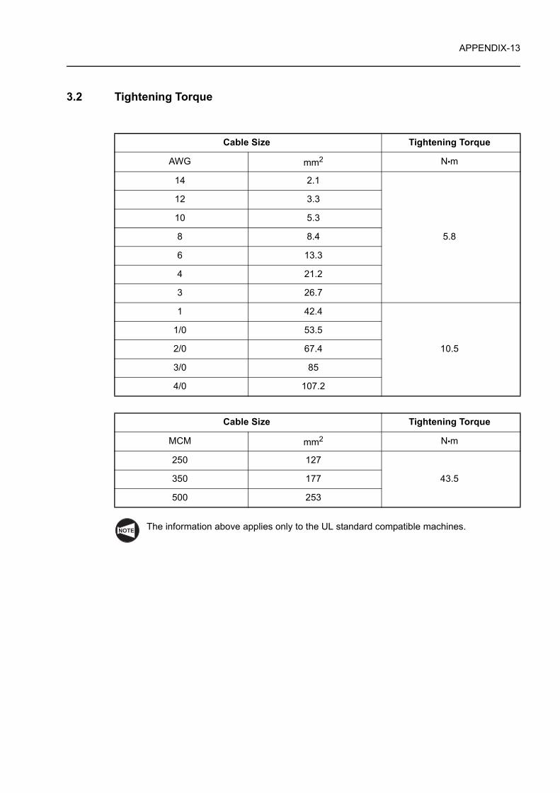
3.2 Tightening Torque
The information above applies only to the UL standard compatible machines.
Cable Size Tightening Torque
AWG mm2 N•m
14 2.1
5.8
12 3.3
10 5.3
8 8.4
6 13.3
4 21.2
3 26.7
1 42.4
10.5
1/0 53.5
2/0 67.4
3/0 85
4/0 107.2
Cable Size Tightening Torque
MCM mm2 N•m
250 127
43.5 350 177
500 253
NOTE
APPENDIX-14
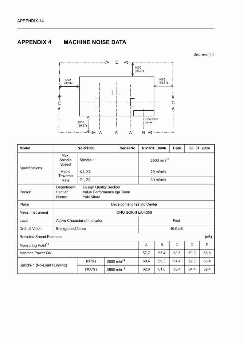
APPENDIX 4 MACHINE NOISE DATA
Unit: mm (in.)
Model NZ-S1500 Serial No. NS151EL0006 Date 08. 01. 2006
Specifications
Max. Spindle Speed
Spindle 1 3500 min−1
Rapid Traverse
Rate
X1, X2 20 m/min
Z1, Z2 30 m/min
PersonDepartment: Design Quality SectionSection: Value Performance Iga TeamName: Yuki Kitora
Place Development Testing Center
Meas. Instrument ONO SOKKI LA-4350
Level Active Character of Indicator Fast
Default Value Background Noise 49.9 dB
Radiated Sound Pressure (dB)
Measuring Point*1 A B C D E
Machine Power ON 57.7 57.4 58.6 59.3 55.8
Spindle 1 (No-Load Running)(80%) 2800 min−1 60.4 59.3 61.4 59.3 58.4
(100%) 3500 min−1 62.6 61.0 63.4 64.4 59.4
1000(39.37)
Operation panel
1000(39.37)
1000(39.37)
1000(39.37)
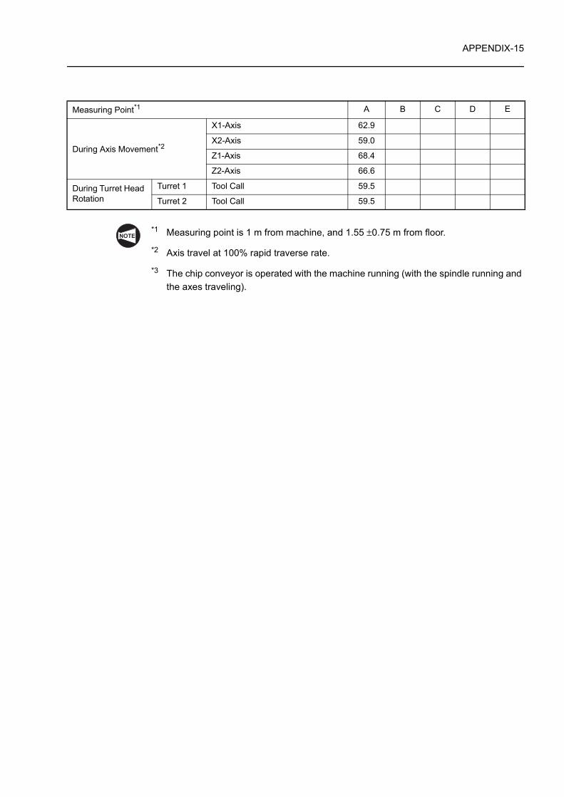
APPENDIX-15
*1 Measuring point is 1 m from machine, and 1.55 ±0.75 m from floor.
*2 Axis travel at 100% rapid traverse rate.
*3 The chip conveyor is operated with the machine running (with the spindle running and the axes traveling).
Measuring Point*1 A B C D E
During Axis Movement*2
X1-Axis 62.9
X2-Axis 59.0
Z1-Axis 68.4
Z2-Axis 66.6
During Turret Head Rotation
Turret 1 Tool Call 59.5
Turret 2 Tool Call 59.5
NOTE
INDEX
Page
AAFTER RECEIVING THE MACHINE . . . . . . . . . . . . . . . . . . . . . . . . . . . . . . . . . . . . . . . . . . P-10
CCARRYING THE MACHINE . . . . . . . . . . . . . . . . . . . . . . . . . . . . . . . . . . . . . . . . . . . . . . . . . P-11Carrying the Machine by Hoisting . . . . . . . . . . . . . . . . . . . . . . . . . . . . . . . . . . . . . . . . . . . . . P-12Compressed Air Supply . . . . . . . . . . . . . . . . . . . . . . . . . . . . . . . . . . . . . . . . . . . . . . . . . . . . . P-9CONNECTING THE POWER CABLE . . . . . . . . . . . . . . . . . . . . . . . . . . . . . . . . . . . . . . . . . P-14CONNECTION OF COMPRESSED AIR SUPPLY HOSE . . . . . . . . . . . . . . . . . . . . . . . . . . P-16
EENVIRONMENTAL REQUIREMENTS . . . . . . . . . . . . . . . . . . . . . . . . . . . . . . . . . . . . . . . . . . P-1
GGrounding Cable . . . . . . . . . . . . . . . . . . . . . . . . . . . . . . . . . . . . . . . . . . . . . . . . . . . . . . . . . . P-7
HHeadstock 2 specifications (gang type turret specification) . . . . . . . . . . . . . . . . . . APPENDIX-4High Output (Rank 1)/High Torque (Rank 1) Specifications . . . . . . . . . . . . . . . . . . APPENDIX-8High Output (Rank 2)/High Torque (Rank 2) Specifications . . . . . . . . . . . . . . . . . . APPENDIX-9High Output (Rank 3)/High Torque (Rank 3) Specifications . . . . . . . . . . . . . . . . . APPENDIX-10Hoisting the Machine . . . . . . . . . . . . . . . . . . . . . . . . . . . . . . . . . . . . . . . . . . . . . . . APPENDIX-1Hoses for Supplying Compressed Air . . . . . . . . . . . . . . . . . . . . . . . . . . . . . . . . . . . . . . . . . . . P-9
IINSTALLATION DATA . . . . . . . . . . . . . . . . . . . . . . . . . . . . . . . . . . . . . . . . . . . . . . APPENDIX-1
LLEVEL ADJUSTMENT . . . . . . . . . . . . . . . . . . . . . . . . . . . . . . . . . . . . . . . . . . . . . . . . . . . . . P-17
MMACHINE NOISE DATA . . . . . . . . . . . . . . . . . . . . . . . . . . . . . . . . . . . . . . . . . . . APPENDIX-14Main Breaker for the Shop Power Distribution Board . . . . . . . . . . . . . . . . . . . . . . . . . . . . . . . P-8MOUNTING ACCESSORIES . . . . . . . . . . . . . . . . . . . . . . . . . . . . . . . . . . . . . . . . . . . . . . . . P-16
-i-
INDEX
Page
NNZ-S1500/1000 . . . . . . . . . . . . . . . . . . . . . . . . . . . . . . . . . . . . . . . . . . . . . . . . . . . APPENDIX-3NZ-S1500/500 . . . . . . . . . . . . . . . . . . . . . . . . . . . . . . . . . . . . . . . . . . . . . . . . . . . . APPENDIX-2NZ-S1500/500, NZ-S1500/1000 . . . . . . . . . . . . . . . . . . . . . . . . . . . . . . . . . . . . . . . APPENDIX-1
PPositions of Transit Clamps . . . . . . . . . . . . . . . . . . . . . . . . . . . . . . . . . . . . . . . . . . APPENDIX-2Power Cable . . . . . . . . . . . . . . . . . . . . . . . . . . . . . . . . . . . . . . . . . . . . . . . . . . . . . . . . . . . . . . P-6Power Cable Size (Specified According to Breaker Capacity) . . . . . . . . . . . . . . . APPENDIX-11POWER CABLE SIZE AND SCREW TIGHTENING TORQUE . . . . . . . . . . . . . . APPENDIX-11POWER CAPACITY TABLE . . . . . . . . . . . . . . . . . . . . . . . . . . . . . . . . . . . . . . . . . . APPENDIX-6Power Requirements . . . . . . . . . . . . . . . . . . . . . . . . . . . . . . . . . . . . . . . . . . . . . . . . . . . . . . . P-5Preparation . . . . . . . . . . . . . . . . . . . . . . . . . . . . . . . . . . . . . . . . . . . . . . . . . . . . . . . . . . . . . . P-11PREPARATION FOR INSTALLATION . . . . . . . . . . . . . . . . . . . . . . . . . . . . . . . . . . . . . . . . . . P-4
RRECOMMENDED INSTALLATION CONDITIONS . . . . . . . . . . . . . . . . . . . . . . . . . . . . . . . . . P-2REMOVING TRANSIT CLAMPS . . . . . . . . . . . . . . . . . . . . . . . . . . . . . . . . . . . . . . . . . . . . . P-16
SStandard Specifications . . . . . . . . . . . . . . . . . . . . . . . . . . . . . . . . . . . . . . . . . . . . . APPENDIX-6
TTightening Torque . . . . . . . . . . . . . . . . . . . . . . . . . . . . . . . . . . . . . . . . . . . . . . . . . APPENDIX-13
-ii-
Date:
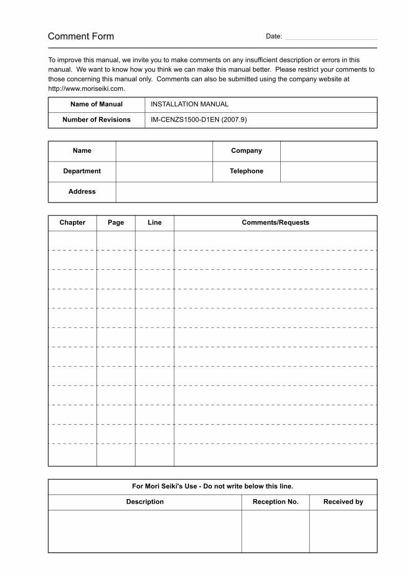
To improve this manual, we invite you to make comments on any insufficient description or errors in this manual. We want to know how you think we can make this manual better. Please restrict your comments to those concerning this manual only. Comments can also be submitted using the company website at http://www.moriseiki.com.
Name of Manual INSTALLATION MANUAL
Number of Revisions IM-CENZS1500-D1EN (2007.9)
Name Company
Department Telephone
Address
Chapter Page Line Comments/Requests
For Mori Seiki's Use - Do not write below this line.
Description Reception No. Received by
Comment Form
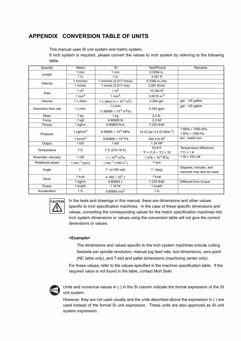
APPENDIX CONVERSION TABLE OF UNITS
This manual uses SI unit system and metric system.If inch system is required, please convert the values to inch system by referring to the followingtable.
In the texts and drawings in this manual, there are dimensions and other values specific to inch specification machines. In the case of these specific dimensions and values, converting the corresponding values for the metric specification machines into inch system dimensions or values using the conversion table will not give the correct dimensions or values.
<Example>
The dimensions and values specific to the inch system machines include cutting feedrate per spindle revolution, manual jog feed rate, tool dimensions, zero point (NC lathe only), and T-slot and pallet dimensions (machining center only).
For these values, refer to the values specified in the machine specification table. If the required value is not found in the table, contact Mori Seiki.
Units and numerical values in ( ) in the SI column indicate the formal expression of the SIunit system.
However, they are not used usually and the units described above the expression in ( ) areused instead of the formal SI unit expression. These units are also approved as SI unitsystem expression.
Quantity Metric SI Yard/Pound Remarks
Length1 mm 1 mm 0.0394 in.1 m 1 m 3.281 ft
Velocity1 mm/min 1 mm/min (0.017 mm/s) 0.0394 in./min1 m/min 1 m/min (0.017 m/s) 3.281 ft/min
Area1 m2 1 m2 10.764 ft2
1 mm2 1 mm2 0.0016 in.2
Volume 1 L (liter) 1 L (liter) (1 × 10⁻³ m3) 0.264 gal. gal.: US gallon
Volumetric flow rate 1 L/min1 L/min
(1.66666 × 10⁻⁵ m3/s)0.264 gpm
gal.: US gallon
Mass 1 kg 1 kg 2.2 lb.Force 1 kgf 9.80665 N 2.2 lbfTorque 1 kgf•m 9.80665 N•m 7.233 ft•lbf
Pressure1 kgf/cm2 9.80665 × 10⁻² MPa 14.22 psi (14.22 lbf/in.2)
1 MPa = 1000 kPa1 kPa = 1000 Pa
1 ton/m2 9.80665 × 10³ Pa 204.4 lb./ft2 ton: metric ton
Output 1 kW 1 kW 1.34 HP
Temperature 1°C 1°C (274.16 K)33.8°F
°F = (1.8 × °C) + 32Temperature difference: 1°C = 1 K
Kinematic viscosity 1 cSt 1 × 10⁻⁶ m2/s 1.076 × 10⁻⁵ ft2/s 1 St = 100 cSt
Rotational speed 1 min-1 (rpm) 1 min-1 (1/60 s-1) 1 rpm
Angle 1° 1° (π/180 rad) 1° (deg)Degrees, minutes, and seconds may also be used.
Work1 kcal 4.186 × 10³ J 1 kcal
1 kgf•m 9.80665 J 7.233 ft•lbf Different from torquePower 1 kcal/h 1.16 W 1 kcal/h
Acceleration 1 G 9.80665 m/s2 1 G
CAUTION
NOTE
Printed in Japan
http://www.moriseiki.com
MORI SEIKI CO., LTD.Nagoya Head Office
2-35-16 Meieki, Nakamura-ku, Nagoya City, Aichi 450-0002, JapanPhone: (052) 587-1811 Fax.: (052) 587-1818
Nara Campus362 Idono-cho, Yamato-Koriyama City, Nara 639-1183, JapanPhone: (0743) 53-1121106 Kita Koriyama-cho, Yamato-Koriyama City, Nara 639-1160, JapanPhone: (0743) 53-1125
Iga Campus201 Midai, Iga City, Mie 519-1414, JapanPhone: (0595) 45-4151
Chiba Campus488-19 Suzumi-cho, Funabashi City, Chiba 274-0052, JapanPhone: (047) 410-8800
MORI SEIKI U.S.A., INC.Head Office
5655 Meadowbrook Drive, Rolling Meadows, Illinois 60008Phone: (1)-847-593-5400 Fax.: (1)-847-593-5433
Administrative Department2100 Golf Road Suite 300, Rolling Meadows, Illinois 60008Phone: (1)-847-290-8535 Fax.: (1)-847-290-5500
Technical CentersChicago, Dallas, Los Angeles, Detroit, Cincinnati, Boston, New Jersey
Representative OfficeCharlotte, San Francisco
MORI SEIKI MEXICO, S.A. DE C.V.Head Office & Technical Center
Montecito 38 Piso 12-38 Col. Napoles 03810 México D.F.Phone: (52)-55-9000-3276 Fax.: (52)- 55-9000-3279
MORI SEIKI BRASIL LTDA.Head Office & Technical Center
Rua República do Iraque, 1432 2 and, Campo Belo 04611-002 São Paulo - SP, BrasilPhone: (55)-11-5543-1762 Fax.: (55)-11-5543-1948
MORI SEIKI GmbHHead Office
Antoniusstrasse 14, 73249 Wernau, GermanyPhone: (49)-7153-934-0 Fax.: (49)-7153-934-220
Technical CentersStuttgart, Istanbul, Prague, München, Hamburg, Düsseldorf
MORI SEIKI (UK) LTD.Head Office
202 Bedford Avenue, Slough SL1 4RY, EnglandPhone: (44)-1753 526518 Fax.: (44)-1753 524695
Technical CentersLondon, Birmingham
Representative OfficeLeicester
MORI SEIKI FRANCE S.A.S.Head Office & Technical Center
Parc du Moulin, 1 Rue du Noyer BP 19326 Roissy en France 95705 Roissy CDG Cedex, FrancePhone: (33)-1-39-94-68-00 Fax.: (33)-1-39-94-68-59
Technical CentersToulouse, MS SYFRAMO S.A.S.
MORI SEIKI ITALIANA S.R.L.Head Office & Technical Center
Via Riccardo Lombardi N. 10, 20153 Milano, ItalyPhone: (39)-02-4894921 Fax.: (39)-02-48914448
MORI SEIKI ESPAÑA S.A.Head Office & Technical Center
Calle de la Electrónica, Bloque B, Nave 9 Poligono Industrial "La Ferreria" 08110 Montcada I Reixac (Barcelona), SpainPhone: (34)-935-75-36-46 Fax.: (34)-935-75-08-47
MORI SEIKI SINGAPORE PTE LTDHead Office & Technical Center
3 Toh Guan Road East, Singapore 608835Phone: (65)-6560-5011 Fax.: (65)-6567-6234
Technical CenterMALAYSIA BRANCH
MORI SEIKI (THAILAND) CO., LTD.Head Office & Technical Center
119/2 Moo 8, Bangnathani Building 1st Floor A1, Bangna-Trad KM.3 Road Kwaeng Bangna, Khet Bangna, Bangkok 10260, ThailandPhone: (66)-2-361-3700-5 Fax.: (66)-2-361-3706
MORI SEIKI (TAIWAN) CO., LTD.Head Office & Technical Center
No. 8, Kong 8th Road, Linkou No. 2 Industrial District, Linkou Hsiang, Taipei Hsien, Taiwan, R.O.C.Phone: (886)-2-2603-1701 Fax.: (886)-2-2603-1706
MORI SEIKI HONG KONG LIMITEDHead Office & Technical Center
Unit 02, 8/F., Vicwood Plaza, 199 Des Voeux Road, Central, Hong KongPhone: (852)-2757-8910 Fax.: (852)-2757-7839
MORI SEIKI (SHANGHAI) CO., LTD.Head Office
Room 4301, 4307, Maxdo Center, No.8 Xing Yi Rd., HongQiao Development Zone, Shanghai 200336, ChinaPhone: (86)-21-5208-0270 Fax.: (86)-21-5208-0273
Technical CenterShanghai, Beijing, Tianjin, Dalian, Shenzhen, Chongqing, Guangzhou
MORI SEIKI KOREA CO., LTD.Head Office & Technical Center
A-101, 2 SK TWIN TECH TOWER, 345-9 Kasan-dong, Kumcheon-Ku, Seoul, KoreaPhone: (82)-2-862-0925 Fax.: (82)-2-862-0928
PT. MORI SEIKI INDONESIAHead Office & Technical Center
Komplek Gading Bukit Indah Blok M/01 J1. Bukit Gading Raya, Kalapa Gading, Jakarta Utara, 14240 IndonesiaPhone: (62)-21-453-1199 Fax.: (62)-21-4585-7414
MORI SEIKI CO., LTD. India BranchHead Office & Technical Center
India Branch: 404 A World Trade Centre, Babar Rd. Connaught Place,New Delhi - 110001, India
Phone: (91)-11-4152-8520 Fax.: (91)-11-4152-8530
MORI SEIKI AUSTRALIA PTY LTDHead Office
6/6 Garden Road Clayton VIC 3168, AustraliaPhone: (61)-3-8545-0900 Fax.: (61)-3-9561-4999
Technical CentersMelbourne, Sydney
The export of this product is subject to an authorization from the government of the exporting country.Check with the government agency for authorization.
061110