installation instructions - gfa - elektromaten
TRANSCRIPT
Installation instructions
LB 700
Model: 20070000
-en- Status: 51171468_h_08.2018
0 0 0 0 0 0 0 0 0 0 0 5 1 1 7 1 4 6 8 XXXXX
2
GfA ELEKTROMATEN GmbH & Co. KG Wiesenstraße 81 • 40549 Düsseldorf www.gfa-elektromaten.de
3
Contents
1 General safety instructions ............................................................................................ 4
1 Specifications ............................................................................................................... 5
2 Recommended installation ............................................................................................ 6
3 Installing the housing .................................................................................................... 6
4 Check the power supply connection .............................................................................. 7
5 Wiring the dock leveller to the control ............................................................................ 8
6 Rapid adjustment .......................................................................................................... 9
7 PCB overview ............................................................................................................. 11
1 Terminal diagram ........................................................................................................ 12
2 Control programming .................................................................................................. 13
3 Programmingtable....................................................................................................... 14
4 Description of dock-leveller functions .......................................................................... 19
Dock leveller with hinged lip ................................................................................................... 19
Dock leveller with telescopic lip (2 valves) ............................................................................. 20
5 Description of functions of additional components ....................................................... 22
Wheel-block sensor (X5) ........................................................................................................ 22
Vehicle detector, external (X6) ............................................................................................... 22
Mechanism for release/locking of dock leveller/door (X7) ...................................................... 22
Position sensor for dock leveller (X8)..................................................................................... 22
Traffic lights / Lighting (X9) .................................................................................................... 22
Vehicle shelter (X10).............................................................................................................. 23
6 Control-device connection diagram for T801 (optional) ................................................ 24
7 Control-unit status display ........................................................................................... 25
8 Declaration of incorporation / Declaration of conformity ............................................... 27
Symbols
Warning! Possible injury or danger of death!
Warning! High voltage! Danger of death!
Note! Important information!
4
1 General safety instructions
Intended use
The controller is intended for the actuation of dock levellers with a hinged wedge lip or an
extendible lip.
Operating safety is ensured only when the controller is used as intended. No liability is
accepted for any use other than that described in these instructions.
Modifications are allowed only with the consent of the manufacturer. Unauthorised changes
render the manufacturer’s declaration void.
Information on safety
The system must be installed and commissioned by trained, qualified personnel only.
Only qualified electricians may work on the electrical systems. They must be able to assess
the work they are assigned, recognise potential sources of danger, and implement suitable
safety measures.
Installation work must be performed only when all power supplies are disconnected.
Observe the applicable safety and accident prevention regulations and standards.
Covers and protective equipment
Operate only with the system’s own covers and protective equipment.
Make sure that gaskets are properly seated and screw unions adequately tightened.
Replacement parts
Use only original replacement parts.
5
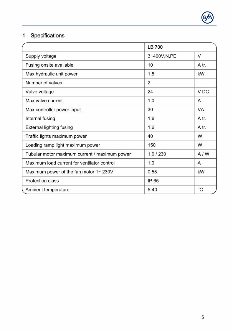
1 Specifications
LB 700
Supply voltage 3~400V,N,PE V
Fusing onsite available 10 A tr.
Max hydraulic unit power 1,5 kW
Number of valves 2
Valve voltage 24 V DC
Max valve current 1,0 A
Max controller power input 30 VA
Internal fusing 1,6 A tr.
External lighting fusing 1,6 A tr.
Traffic lights maximum power 40 W
Loading ramp light maximum power 150 W
Tubular motor maximum current / maximum power 1,0 / 230 A / W
Maximum load current for ventilator control 1,0 A
Maximum power of the fan motor 1~ 230V 0,55 kW
Protection class IP 65
Ambient temperature 5-40 °C
6
2 Recommended installation
Your dock leveller can be put into operation quickly and safely when you follow the
recommended procedure below:
• Install the housing
• Check the power supply connection
• Wire the dock leveller to the controller
• Rapid adjustment
The dock leveller can now be operated.
• Install additional components
• Program additional components and functions
3 Installing the housing
The dock leveller controller must be fitted vertically to a plane foundation free of vibrations.
The installation site must be seen clearly from the dock leveller room.
7
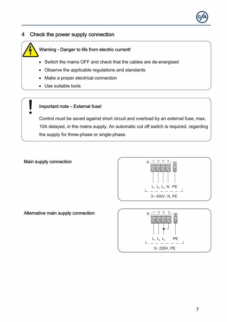
4 Check the power supply connection
Warning - Danger to life from electric current!
Switch the mains OFF and check that the cables are de-energised
Observe the applicable regulations and standards
Make a proper electrical connection
Use suitable tools
Important note – External fuse!
Control must be saved against short circuit and overload by an external fuse, max.
10A delayed, in the mains supply. An automatic cut off switch is required, regarding
the supply for three-phase or single-phase.
Main supply connection
Alternative main supply connection 1.1
1.2
1.3
1.4
L2L1 L3 PE
X
1.1
1.2
1.3
1.4
L2L1 L3 N PE
3~ 400V, N, PE
X
8
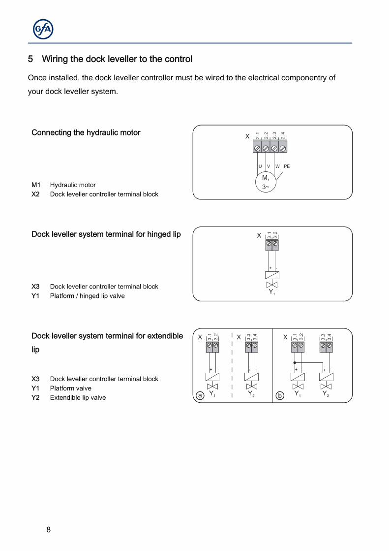
5 Wiring the dock leveller to the control
Once installed, the dock leveller controller must be wired to the electrical componentry of
your dock leveller system.
Connecting the hydraulic motor
M3~
1
2.1
2.2
2.3
2.4
VU W PE
X
M1 Hydraulic motor X2 Dock leveller controller terminal block
Dock leveller system terminal for hinged lip 3.2
3.1
+ -
Y1
X
X3 Dock leveller controller terminal block Y1 Platform / hinged lip valve
Dock leveller system terminal for extendible
lip
3.1
+ -
Y1
3.4
3.3
+ -
Y2
X X
ⓐ
3.1
+ -
Y1
3.4
3.3
+ -
Y2
X
ⓑ
X3 Dock leveller controller terminal block Y1 Platform valve Y2 Extendible lip valve
9
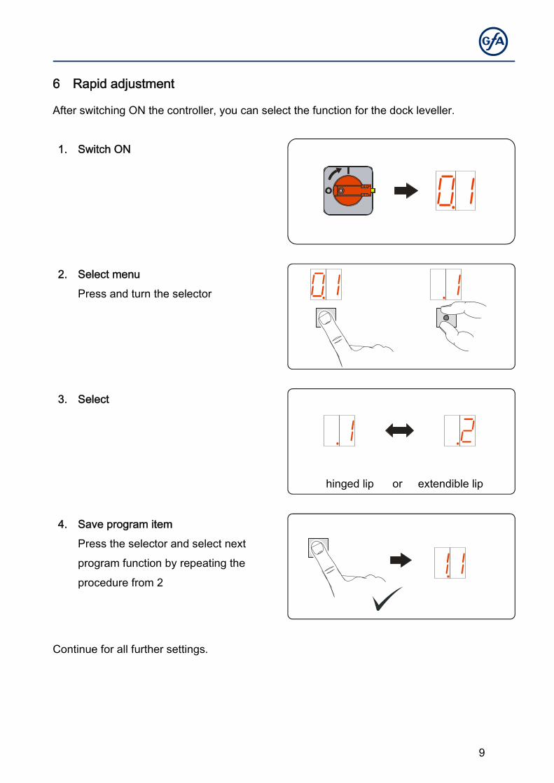
6 Rapid adjustment
After switching ON the controller, you can select the function for the dock leveller.
1. Switch ON
2. Select menu
Press and turn the selector
3. Select
hinged lip or extendible lip
4. Save program item
Press the selector and select next
program function by repeating the
procedure from 2
Continue for all further settings.
10
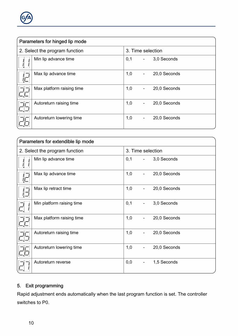
Parameters for hinged lip mode
2. Select the program function 3. Time selection Min lip advance time 0,1 - 3,0 Seconds
Max lip advance time 1,0 - 20,0 Seconds
Max platform raising time 1,0 - 20,0 Seconds
Autoreturn raising time 1,0 - 20,0 Seconds
Autoreturn lowering time 1,0 - 20,0 Seconds
Parameters for extendible lip mode
2. Select the program function 3. Time selection Min lip advance time 0,1 - 3,0 Seconds
Max lip advance time 1,0 - 20,0 Seconds
Max lip retract time 1,0 - 20,0 Seconds
Min platform raising time 0,1 - 3,0 Seconds
Max platform raising time 1,0 - 20,0 Seconds
Autoreturn raising time 1,0 - 20,0 Seconds
Autoreturn lowering time 1,0 - 20,0 Seconds
Autoreturn reverse 0,0 - 1,5 Seconds
5. Exit programming
Rapid adjustment ends automatically when the last program function is set. The controller
switches to P0.
11
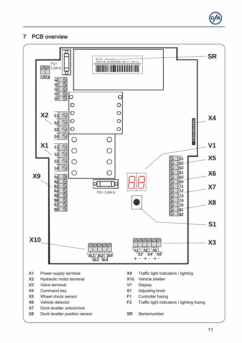
7 PCB overview
2.1
1.1
2.2
1.2
2.3
1.3
2.4
1.4
9.1
5.15.25.36.16.26.37.17.27.37.4
8.18.2
9.29.39.49.59.69.79.8
1.61.5
X2
X1
X9
X10
F2= 1,6A tr.
F1=1,6A tr.
X3
X5
X6
X7
X8
S1
V1
X4
SR
10.110.2
10.310.4
10.53.1
3.23.3
3.4 3.63.5
7.5
+ - + - + -
Ser.Nr. : xxxxxxxxArtikel Nr. 20-30004984 HW x.x SW x.x
X1 Power supply terminal X9 Traffic light indicators / lighting X2 Hydraulic motor terminal X10 Vehicle shelter X3 Valve terminal V1 Display X4 Command key S1 Adjusting knob X5 Wheel chock sensor F1 Controller fusing X6 Vehicle detector F2 Traffic light indicators / lighting fusing X7 Dock leveller unlock/lock X8 Dock leveller position sensor SR Seriennumber
12
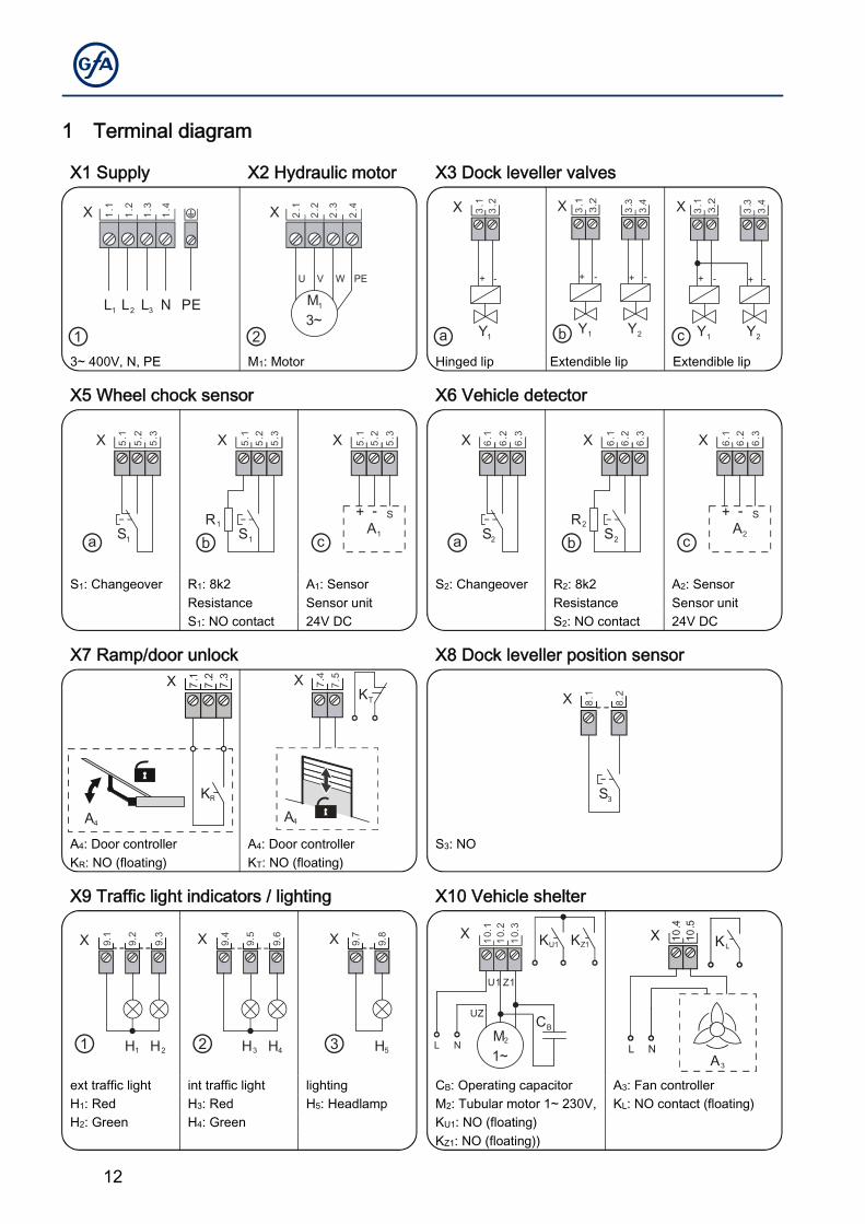
1 Terminal diagram
X1 Supply X2 Hydraulic motor X3 Dock leveller valves
1.1
1.2
1.3
1.4
L2L1 L3 N PE
X
①
2.1
2.2
2.3
2.4
VU W PE
X
M3~
1
②
3.2
3.1
+ -
Y1ⓐ
3.1
+ -
Y1
3.4
3.3
+ -
Y2
X
ⓑ
3.1
+ -
Y1
3.4
3.3
+ -
Y2
X
ⓒ3~ 400V, N, PE M1: Motor Hinged lip Extendible lip Extendible lip
X5 Wheel chock sensor X6 Vehicle detector
5.1
5.2
5.3
S1ⓐ
X
S1
R1
5.1
5.2
5.3
ⓑ
X
A1
5.1
5.2
5.3
+ - S
ⓒ
X 6.1
6.2
6.3
S2ⓐ
X
S2
R2
6.1
6.2
6.3
ⓑ
X
A2
6.1
6.2
6.3
+ - S
ⓒ
X
S1: Changeover R1: 8k2 A1: Sensor S2: Changeover R2: 8k2 A2: Sensor Resistance Sensor unit Resistance Sensor unit S1: NO contact 24V DC S2: NO contact 24V DC
X7 Ramp/door unlock X8 Dock leveller position sensor
7.1
7.2
7.3X
KR
A4
7.5
A4
XKT 8.
1
8.2X
S3
A4: Door controller A4: Door controller S3: NO KR: NO (floating) KT: NO (floating)
X9 Traffic light indicators / lighting X10 Vehicle shelter
9.1
9.2
9.3
H1 H2①
X 9.4
9.5
9.6
H4H3②
X 9.7
9.8
H5③
X 10.1
10.2
10.3
M1~
2
UZ
NL
U1 Z1
CB
KZ1KU1X X 10
.410
.5
A3
KL
NL
ext traffic light int traffic light lighting CB: Operating capacitor A3: Fan controller H1: Red H3: Red H5: Headlamp M2: Tubular motor 1~ 230V, KL: NO contact (floating) H2: Green H4: Green KU1: NO (floating) KZ1: NO (floating))
13
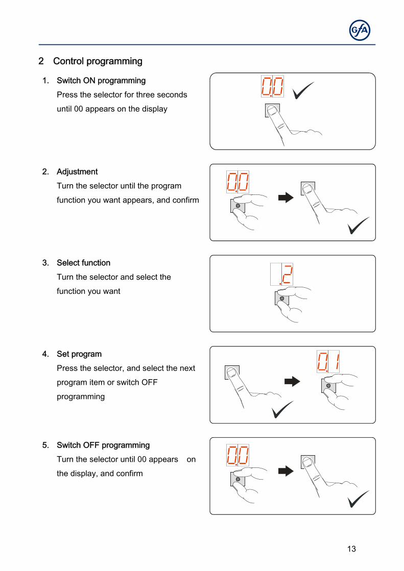
2 Control programming
1. Switch ON programming
Press the selector for three seconds
until 00 appears on the display
2. Adjustment
Turn the selector until the program
function you want appears, and confirm
3. Select function
Turn the selector and select the
function you want
4. Set program
Press the selector, and select the next
program item or switch OFF
programming
5. Switch OFF programming
Turn the selector until 00 appears on
the display, and confirm
14
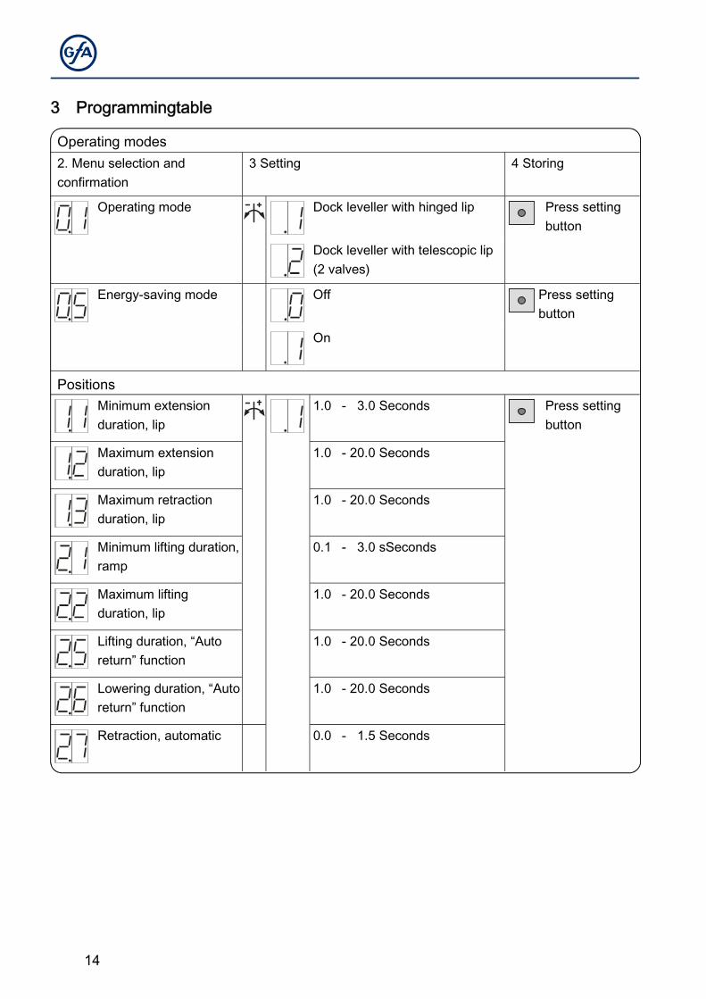
3 Programmingtable
Operating modes 2. Menu selection and confirmation
3 Setting 4 Storing
Operating mode Dock leveller with hinged lip Press setting button
Dock leveller with telescopic lip (2 valves)
Energy-saving mode Off Press setting button
On
Positions Minimum extension
duration, lip 1.0 - 3.0 Seconds Press setting
button
Maximum extension duration, lip
1.0 - 20.0 Seconds
Maximum retraction duration, lip
1.0 - 20.0 Seconds
Minimum lifting duration, ramp
0.1 - 3.0 sSeconds
Maximum lifting duration, lip
1.0 - 20.0 Seconds
Lifting duration, “Auto return” function
1.0 - 20.0 Seconds
Lowering duration, “Auto return” function
1.0 - 20.0 Seconds
Retraction, automatic 0.0 - 1.5 Seconds
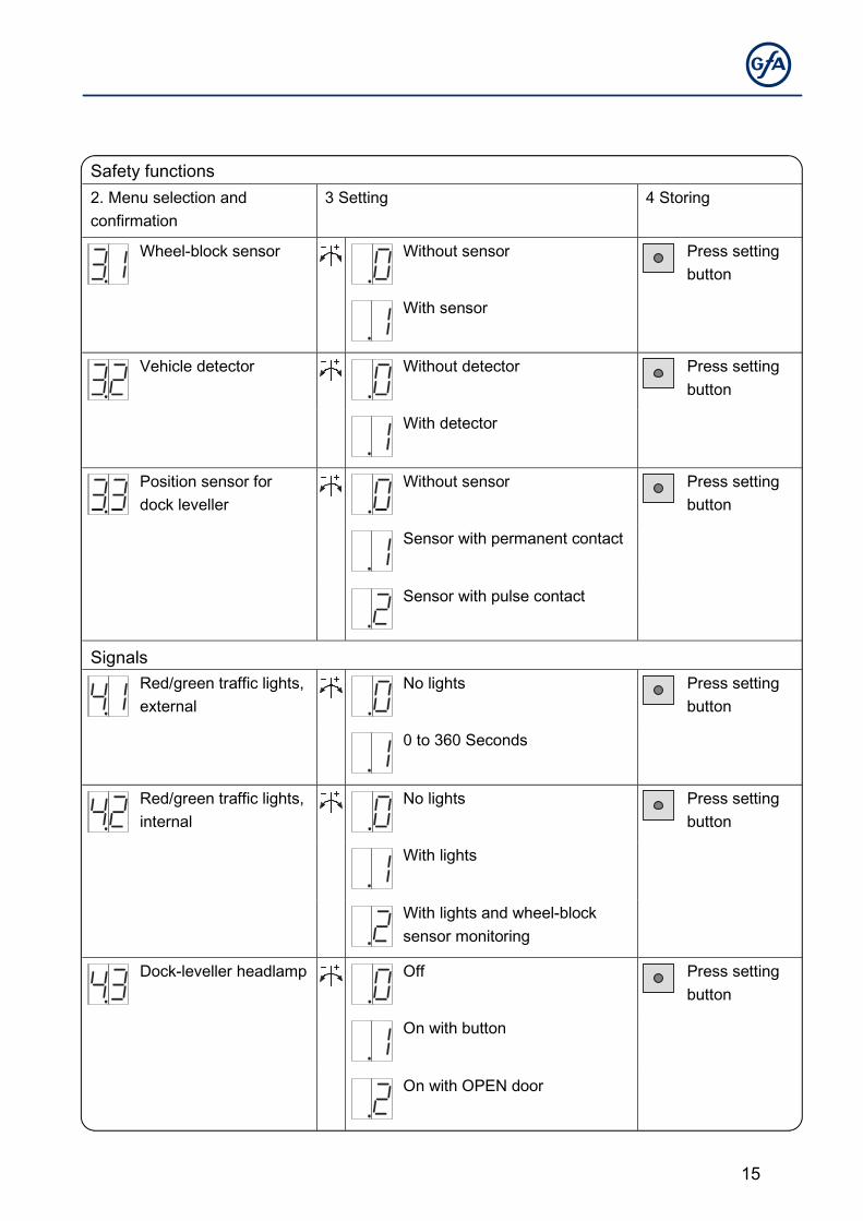
15
Safety functions 2. Menu selection and confirmation
3 Setting 4 Storing
Wheel-block sensor Without sensor Press setting button
With sensor
Vehicle detector Without detector Press setting button
With detector
Position sensor for dock leveller
Without sensor Press setting button
Sensor with permanent contact
Sensor with pulse contact
Signals Red/green traffic lights,
external No lights Press setting
button
0 to 360 Seconds
Red/green traffic lights, internal
No lights Press setting button
With lights
With lights and wheel-block sensor monitoring
Dock-leveller headlamp Off Press setting button
On with button
On with OPEN door
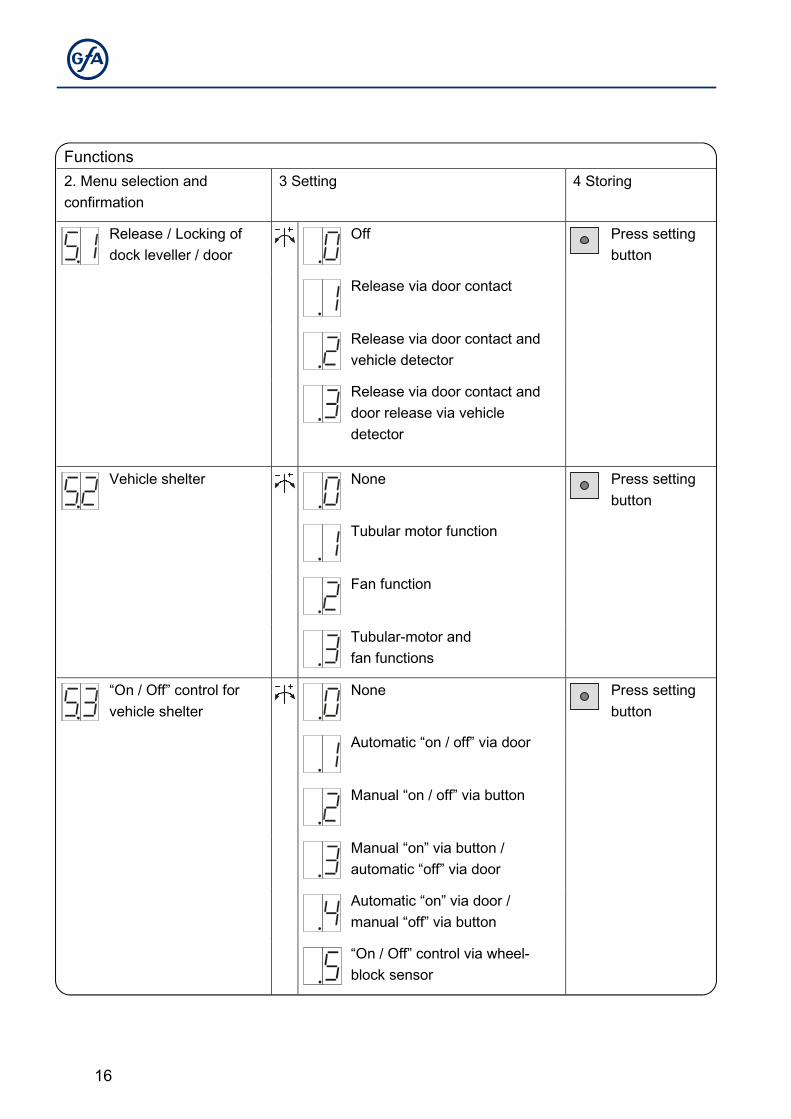
16
Functions 2. Menu selection and confirmation
3 Setting 4 Storing
Release / Locking of dock leveller / door
Off Press setting button
Release via door contact
Release via door contact and vehicle detector
Release via door contact and door release via vehicle detector
Vehicle shelter
None Press setting button
Tubular motor function
Fan function
Tubular-motor and fan functions
“On / Off” control for vehicle shelter
None Press setting button
Automatic “on / off” via door
Manual “on / off” via button
Manual “on” via button / automatic “off” via door
Automatic “on” via door / manual “off” via button
“On / Off” control via wheel-block sensor
17
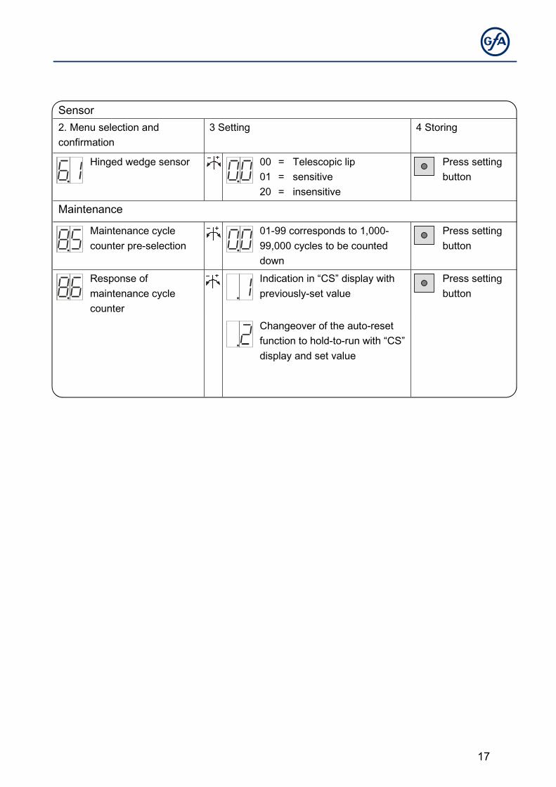
Sensor 2. Menu selection and confirmation
3 Setting 4 Storing
Hinged wedge sensor 00 = Telescopic lip 01 = sensitive 20 = insensitive
Press setting button
Maintenance
Maintenance cycle counter pre-selection
01-99 corresponds to 1,000-99,000 cycles to be counted down
Press setting button
Response of maintenance cycle counter
Indication in “CS” display with previously-set value
Press setting button
Changeover of the auto-reset function to hold-to-run with “CS” display and set value
18
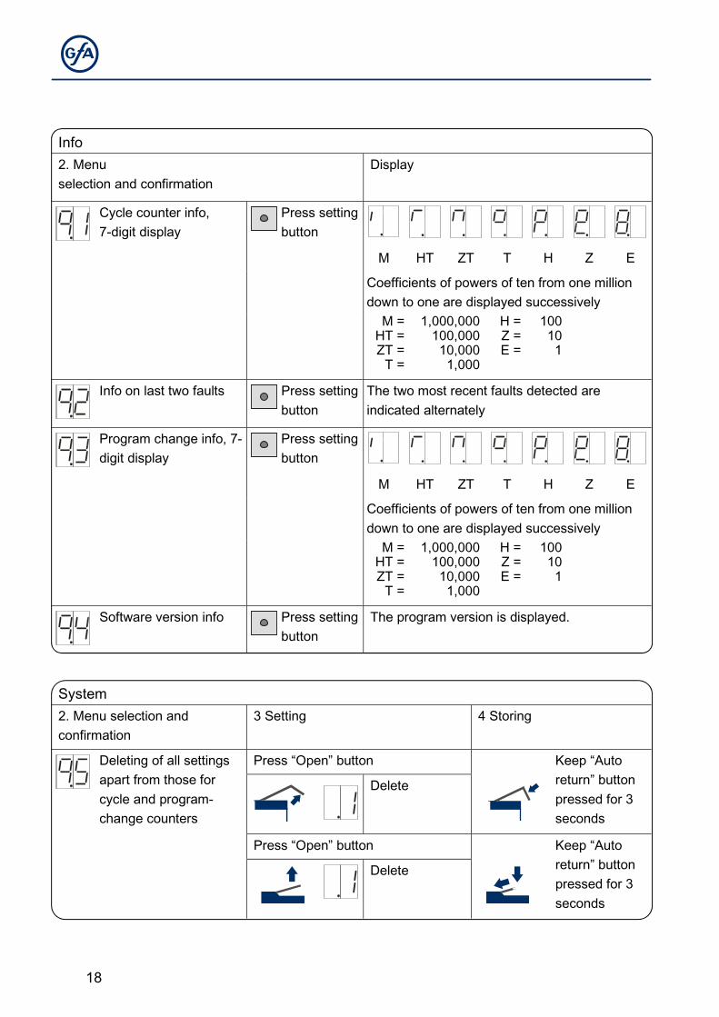
Info 2. Menu selection and confirmation
Display
Cycle counter info, 7-digit display
Press setting button
M HT ZT T H Z E
Coefficients of powers of ten from one million down to one are displayed successively
M =HT =ZT =
T =
1,000,000100,00010,0001,000
H = Z = E =
100 10 1
Info on last two faults Press setting button
The two most recent faults detected are indicated alternately
Program change info, 7-digit display
Press setting button
M HT ZT T H Z E
Coefficients of powers of ten from one million down to one are displayed successively
M =HT =ZT =
T =
1,000,000100,00010,0001,000
H = Z = E =
100 10 1
Software version info Press setting button
The program version is displayed.
System 2. Menu selection and confirmation
3 Setting 4 Storing
Deleting of all settings apart from those for cycle and program-change counters
Press “Open” button Keep “Auto return” button pressed for 3 seconds
Delete
Press “Open” button Keep “Auto return” button pressed for 3 seconds
Delete
19
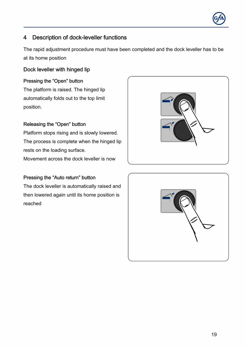
4 Description of dock-leveller functions
The rapid adjustment procedure must have been completed and the dock leveller has to be
at its home position
Dock leveller with hinged lip
Pressing the “Open” button
The platform is raised. The hinged lip
automatically folds out to the top limit
position.
Releasing the “Open” button
Platform stops rising and is slowly lowered.
The process is complete when the hinged lip
rests on the loading surface.
Movement across the dock leveller is now
Pressing the “Auto return” button
The dock leveller is automatically raised and
then lowered again until its home position is
reached
20
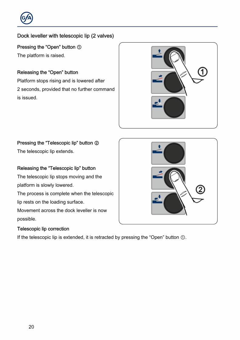
Dock leveller with telescopic lip (2 valves)
Pressing the “Open” button ①
The platform is raised.
Releasing the “Open” button
Platform stops rising and is lowered after
2 seconds, provided that no further command
is issued.
Pressing the “Telescopic lip” button ②
The telescopic lip extends.
Releasing the “Telescopic lip” button
The telescopic lip stops moving and the
platform is slowly lowered.
The process is complete when the telescopic
lip rests on the loading surface.
Movement across the dock leveller is now
possible.
Telescopic lip correction
If the telescopic lip is extended, it is retracted by pressing the “Open” button ①.
21
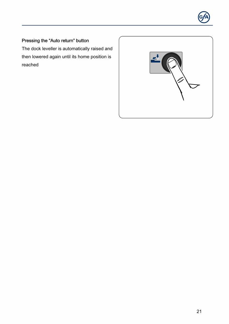
Pressing the “Auto return” button
The dock leveller is automatically raised and
then lowered again until its home position is
reached
22
5 Description of functions of additional components
Wheel-block sensor (X5)
If the wheel block is placed against a tyre of the vehicle, the dock leveller can be operated.
The external traffic lights change from green to red. Activation with menu 3.1
Vehicle detector, external (X6)
If the vehicle is detected by the detector, the external traffic lights change from green to red.
Activation with menu 3.2
Mechanism for release/locking of dock leveller/door (X7)
The “door - dock leveller” or “dock leveller - door” sequence is controlled via the lock contact.
It is possible to incorporate a vehicle detector for the release function. The door release
contact is switched with the dock leveller at its standby position. Activation with menu 5.1
Position sensor for dock leveller (X8)
The detection of the dock leveller at its standby position is achieved via an external additional
contact. Activation with menu 3.3
Traffic lights / Lighting (X9)
The dock-leveller control system has outputs for a headlamp as well as internal and/or
external red/green traffic lights.
External red/green traffic lights
The green lamp indicates to the driver the operational readiness status of the dock leveller for
docking. Once the lorry has docked, the traffic lights change to red. Here, a wheel-block
sensor or vehicle detector needs to be used. If no sensor is connected, the traffic light
changes to red as soon as the home position is left. The changeover from red to green is
controlled via a time period setting. The time period starts as soon as the dock leveller has
again reached its home position. If a wheel-block sensor is active and engaged, there will be
alternate flashing of the red and green traffic lights after the changeover period has elapsed.
23
Only when the wheel-block sensor is not engaged, will there be a changeover to a steady
green signal at the traffic lights. Activation with menu 4.1
Internal red/green traffic lights
The green lamp indicates that movement across the dock leveller is possible. For all other
statuses, the red lamp will be lit. With the traffic lights, a non-engaged wheel-block sensor
can be indicated during loading. If the wheel-block sensor is not engaged for longer than 3
seconds, the traffic light changes to red. If such a “fault” occurs, the “Open” button has to be
pressed to change the traffic lights to green. Activation with menu 4.2
Headlamp
If the dock leveller is operated or the door reaches the OPEN limit position, the headlamp
illuminates the leveller area. Activation with menu 4.3
The outputs for the internal/external red/green traffic lights and the headlamp are protected
from short-circuiting via a shared 1.6-A fuse.
Vehicle shelter (X10)
There are 3 isolated contacts available for connecting the vehicle shelter. For a tubular
motor, two of the contacts are interlocked. With the third contact, a fan can be activated.
Activation and selection with menu 5.2
The vehicle shelter can be automatically activated and deactivated via a button or a wheel-
block sensor. Activation and selection with menu 5.3.
24
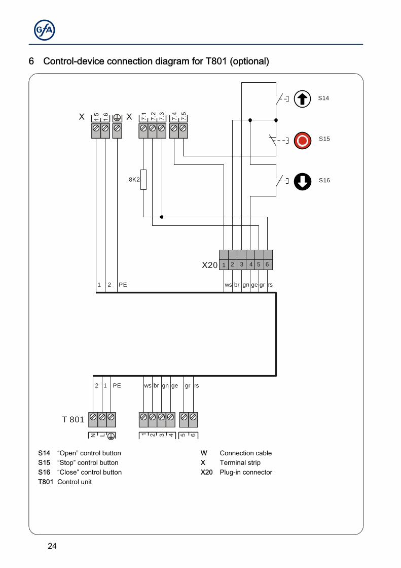
6 Control-device connection diagram for T801 (optional)
S14 “Open” control button W Connection cable S15 “Stop” control button X Terminal strip S16 “Close” control button X20 Plug-in connector T801 Control unit
7.1
17.
23
7.3
4
X 7.4
7.5
1.5
N
1.6
L
X
X20
S14
S15
S168K2
2 5 6
gegnbrws rsgrPE12
1 2 3 4 5 6
ws br gn ge gr rsPE1 2
T 801
25
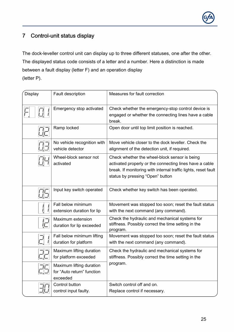
7 Control-unit status display
The dock-leveller control unit can display up to three different statuses, one after the other.
The displayed status code consists of a letter and a number. Here a distinction is made
between a fault display (letter F) and an operation display
(letter P).
Display Fault description Measures for fault correction
Emergency stop activated Check whether the emergency-stop control device is engaged or whether the connecting lines have a cable break.
Ramp locked Open door until top limit position is reached.
No vehicle recognition with vehicle detector
Move vehicle closer to the dock leveller. Check the alignment of the detection unit, if required.
Wheel-block sensor not activated
Check whether the wheel-block sensor is being activated properly or the connecting lines have a cable break. If monitoring with internal traffic lights, reset fault status by pressing “Open” button
Input key switch operated Check whether key switch has been operated.
Fall below minimum extension duration for lip
Movement was stopped too soon; reset the fault status with the next command (any command).
Maximum extension duration for lip exceeded
Check the hydraulic and mechanical systems for stiffness. Possibly correct the time setting in the program.
Fall below minimum lifting duration for platform
Movement was stopped too soon; reset the fault status with the next command (any command).
Maximum lifting duration for platform exceeded
Check the hydraulic and mechanical systems for stiffness. Possibly correct the time setting in the program. Maximum lifting duration
for “Auto return” function exceeded
Control button control input faulty.
Switch control off and on. Replace control if necessary.
26
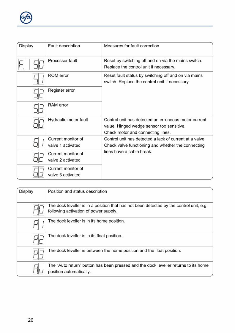
Display Fault description Measures for fault correction
Processor fault Reset by switching off and on via the mains switch. Replace the control unit if necessary.
ROM error Reset fault status by switching off and on via mains switch. Replace the control unit if necessary.
Register error
RAM error
Hydraulic motor fault Control unit has detected an erroneous motor current value. Hinged wedge sensor too sensitive. Check motor and connecting lines.
Current monitor of valve 1 activated
Control unit has detected a lack of current at a valve. Check valve functioning and whether the connecting lines have a cable break. Current monitor of
valve 2 activated
Current monitor of valve 3 activated
Display Position and status description
The dock leveller is in a position that has not been detected by the control unit, e.g. following activation of power supply.
The dock leveller is in its home position.
The dock leveller is in its float position.
The dock leveller is between the home position and the float position.
The “Auto return” button has been pressed and the dock leveller returns to its home position automatically.
27
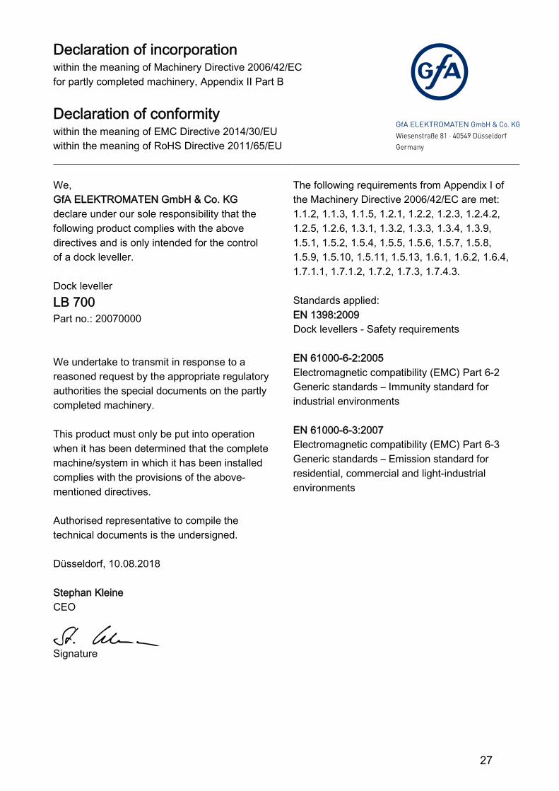
8 D eclar ati on of incor por ation / D eclar ati on of confor mity
Declaration of incorporation within the meaning of Machinery Directive 2006/42/EC for partly completed machinery, Appendix II Part B
Declaration of conformity within the meaning of EMC Directive 2014/30/EU within the meaning of RoHS Directive 2011/65/EU
We, GfA ELEKTROMATEN GmbH & Co. KG declare under our sole responsibility that the following product complies with the above directives and is only intended for the control of a dock leveller. Dock leveller LB 700 Part no.: 20070000 We undertake to transmit in response to a reasoned request by the appropriate regulatory authorities the special documents on the partly completed machinery. This product must only be put into operation when it has been determined that the complete machine/system in which it has been installed complies with the provisions of the above-mentioned directives. Authorised representative to compile the technical documents is the undersigned. Düsseldorf, 10.08.2018 Stephan Kleine CEO
Signature
The following requirements from Appendix I of the Machinery Directive 2006/42/EC are met: 1.1.2, 1.1.3, 1.1.5, 1.2.1, 1.2.2, 1.2.3, 1.2.4.2, 1.2.5, 1.2.6, 1.3.1, 1.3.2, 1.3.3, 1.3.4, 1.3.9, 1.5.1, 1.5.2, 1.5.4, 1.5.5, 1.5.6, 1.5.7, 1.5.8, 1.5.9, 1.5.10, 1.5.11, 1.5.13, 1.6.1, 1.6.2, 1.6.4, 1.7.1.1, 1.7.1.2, 1.7.2, 1.7.3, 1.7.4.3. Standards applied: EN 1398:2009 Dock levellers - Safety requirements EN 61000-6-2:2005 Electromagnetic compatibility (EMC) Part 6-2 Generic standards – Immunity standard for industrial environments EN 61000-6-3:2007 Electromagnetic compatibility (EMC) Part 6-3 Generic standards – Emission standard for residential, commercial and light-industrial environments

28