installation instructions - behler-young
TRANSCRIPT
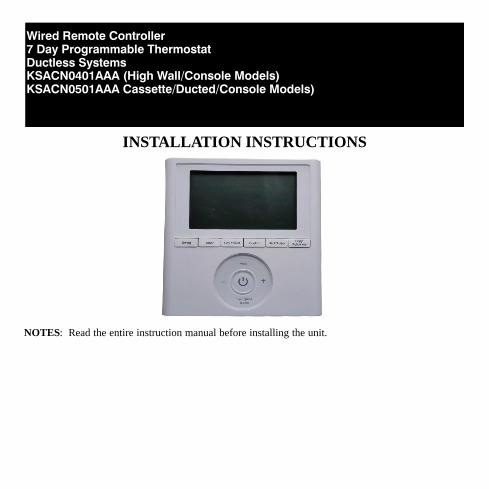
Wired Remote Controller7 Day Programmable ThermostatDuctless SystemsKSACN0401AAA (High Wall/Console Models) KSACN0501AAA Cassette/Ducted/Console Models)
INSTALLATION INSTRUCTIONS
NOTES: Read the entire instruction manual before installing the unit.
2
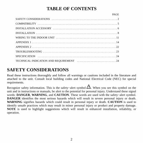
TABLE OF CONTENTSPAGE
SAFETY CONSIDERATIONS 2. . . . . . . . . . . . . . . . . . . . . . . . . . . . . . . . . . . . . . . . . . . . . . .
COMPATIBILITY 5. . . . . . . . . . . . . . . . . . . . . . . . . . . . . . . . . . . . . . . . . . . . . . . . . . . . . . . . .
INSTALLATION ACCESSORY 6. . . . . . . . . . . . . . . . . . . . . . . . . . . . . . . . . . . . . . . . . . . . . .
INSTALLATION 8. . . . . . . . . . . . . . . . . . . . . . . . . . . . . . . . . . . . . . . . . . . . . . . . . . . . . . . . . .
WIRING TO THE INDOOR UNIT 11. . . . . . . . . . . . . . . . . . . . . . . . . . . . . . . . . . . . . . . . . . .
APPENDIX 1 14. . . . . . . . . . . . . . . . . . . . . . . . . . . . . . . . . . . . . . . . . . . . . . . . . . . . . . . . . . . .
APPENDIX 2 22. . . . . . . . . . . . . . . . . . . . . . . . . . . . . . . . . . . . . . . . . . . . . . . . . . . . . . . . . . . .
TROUBLESHOOTING 23. . . . . . . . . . . . . . . . . . . . . . . . . . . . . . . . . . . . . . . . . . . . . . . . . . . .
SPECIFICATION 24. . . . . . . . . . . . . . . . . . . . . . . . . . . . . . . . . . . . . . . . . . . . . . . . . . . . . . . .
TECHNICAL INDICATION AND REQUIREMENT 24. . . . . . . . . . . . . . . . . . . . . . . . . . . .
SAFETY CONSIDERATIONSRead these instructions thoroughly and follow all warnings or cautions included in the literature andattached to the unit. Consult local building codes and National Electrical Code (NEC) for specialrequirements.
Recognize safety information. This is the safety−alert symbol ! ! . When you see this symbol on theunit and in instructions or manuals, be alert to the potential for personal injury. Understand these signalwords: DANGER, WARNING, and CAUTION. These words are used with the safety−alert symbol.DANGER identifies the most serious hazards which will result in severe personal injury or death.WARNING signifies hazards which could result in personal injury or death. CAUTION is used toidentify unsafe practices which may result in minor personal injury or product and property damage.NOTE is used to highlight suggestions which will result in enhanced installation, reliability, oroperation.
3
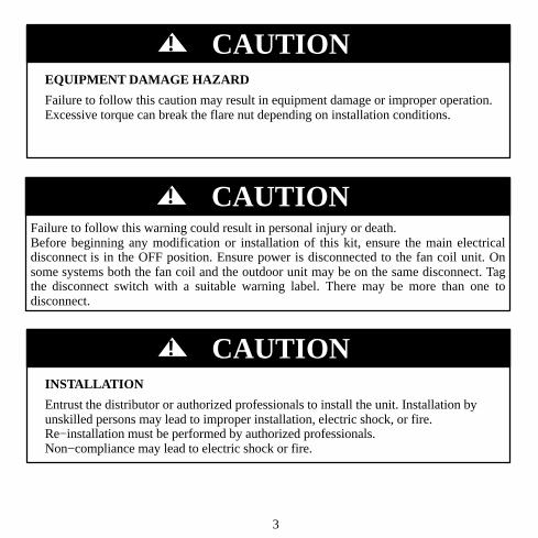
EQUIPMENT DAMAGE HAZARD
Failure to follow this caution may result in equipment damage or improper operation.Excessive torque can break the flare nut depending on installation conditions.
CAUTION!
EQUIPMENT DAMAGE HAZARD
Failure to follow this warning could result in personal injury or death.Before beginning any modification or installation of this kit, ensure the main electricaldisconnect is in the OFF position. Ensure power is disconnected to the fan coil unit. Onsome systems both the fan coil and the outdoor unit may be on the same disconnect. Tagthe disconnect switch with a suitable warning label. There may be more than one todisconnect.
CAUTION!
INSTALLATION
Entrust the distributor or authorized professionals to install the unit. Installation byunskilled persons may lead to improper installation, electric shock, or fire.Re−installation must be performed by authorized professionals.Non−compliance may lead to electric shock or fire.
CAUTION!
4
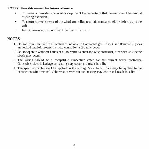
NOTES: Save this manual for future reference.
� This manual provides a detailed description of the precautions that the user should be mindfulof during operation.
� To ensure correct service of the wired controller, read this manual carefully before using theunit.
� Keep this manual, after reading it, for future reference.
NOTES: 1. Do not install the unit in a location vulnerable to flammable gas leaks. Once flammable gases
are leaked and left around the wire controller, a fire may occur.2. Do not operate with wet hands or allow water to enter the wire controller, otherwise an electric
shock may occur.3. The wiring should be a compatible connection cable for the current wired controller.
Otherwise, electric leakage or heating may occur and result in a fire. 4. The specified cables shall be applied in the wiring. No external force may be applied to the
connection wire terminal. Otherwise, a wire cut and heating may occur and result in a fire.
5
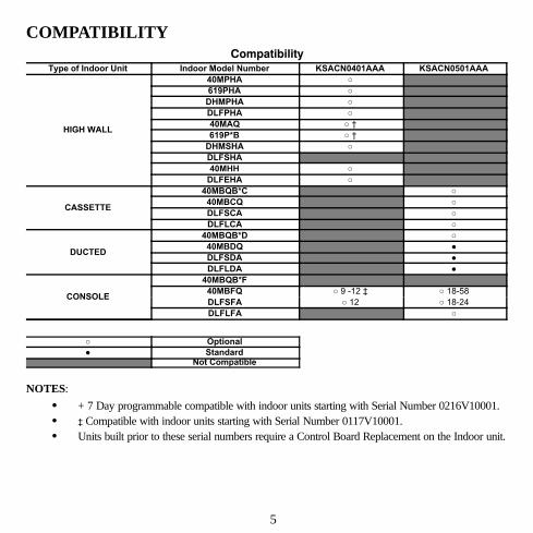
COMPATIBILITYCompatibility
Type of Indoor Unit Indoor Model Number KSACN0401AAA KSACN0501AAA
HIGH WALL
40MPHA ○
619PHA ○
DHMPHA ○
DLFPHA ○
40MAQ ○ †
619P*B ○ †
DHMSHA ○
DLFSHA
40MHH ○
DLFEHA ○
CASSETTE
40MBQB*C ○
40MBCQ ○
DLFSCA ○
DLFLCA ○
DUCTED
40MBQB*D ○
40MBDQ ●
DLFSDA ●
DLFLDA ●
CONSOLE
40MBQB*F
40MBFQ ○ 9 -12 ‡ ○ 18-58
DLFSFA ○ 12 ○ 18-24
DLFLFA ○
○ Optional
● StandardNot Compatible
NOTES:
� + 7 Day programmable compatible with indoor units starting with Serial Number 0216V10001. � ‡ Compatible with indoor units starting with Serial Number 0117V10001.� Units built prior to these serial numbers require a Control Board Replacement on the Indoor unit.
6
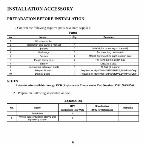
INSTALLATION ACCESSORY
PREPARATION BEFORE INSTALLATION
1. Confirm the following required parts have been supplied.
Parts
No. Name Qty. Remarks
1 Wired controller 1
2 Installation and owner's manual 1
3 Screws 3 M4X20 (for mounting on the wall)
4 Wall plugs 3 For mounting on the wall
5 Screws 2 M4X25 (for mounting on the switch box)
6 Plastic screw bars 2 For fixing on the switch box
7 Battery 1 CR2032 3 VDC
8 Connection Extension Cable 1 19 feet (6 meters)
9 Adapter Board 1 Required for High Wall 40MAQ/619P*B/DHMPHA Only
10 Display Board 1 Required for High Wall 40MAQ/619P*B/DHMPHA Only
NOTES: Extension wire available through RCD (Replacement Components). Part Number: 17401204000769.
2. Prepare the following assemblies on site.
Assemblies
No. NameQTY.
(Embedded into Wall)
Specification
(Only for Reference)Remarks
1 Switch box 1
2Wiring tube (insulating sleeve and
tightening screw)1
7
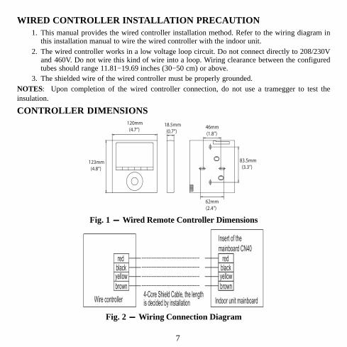
WIRED CONTROLLER INSTALLATION PRECAUTION1. This manual provides the wired controller installation method. Refer to the wiring diagram in
this installation manual to wire the wired controller with the indoor unit.2. The wired controller works in a low voltage loop circuit. Do not connect directly to 208/230V
and 460V. Do not wire this kind of wire into a loop. Wiring clearance between the configuredtubes should range 11.81−19.69 inches (30−50 cm) or above.
3. The shielded wire of the wired controller must be properly grounded.NOTES: Upon completion of the wired controller connection, do not use a tramegger to test theinsulation.
CONTROLLER DIMENSIONS
123mm (4.8”)
120mm (4.7”)
18.5mm (0.7”)
83.5mm (3.3”)
46mm (1.8”)
62mm (2.4”)
Fig. 1 - Wired Remote Controller Dimensions
redblackyellow
brown
redblackyellow
brown
Insert of the
mainboard CN40
Wire controller Indoor unit mainboard 4-Core Shield Cable, the length is decided by installation
--------------------------------------------------------------------------------------------------------------------------------------------
Fig. 2 - Wiring Connection Diagram
8
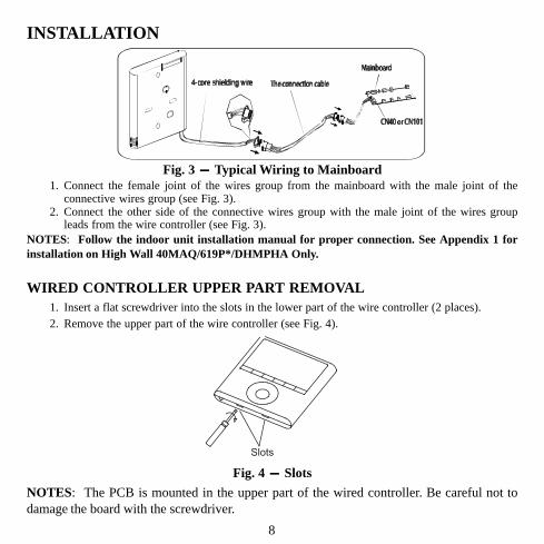
INSTALLATION
Fig. 3 - Typical Wiring to Mainboard1. Connect the female joint of the wires group from the mainboard with the male joint of the
connective wires group (see Fig. 3).2. Connect the other side of the connective wires group with the male joint of the wires group
leads from the wire controller (see Fig. 3).NOTES: Follow the indoor unit installation manual for proper connection. See Appendix 1 forinstallation on High Wall 40MAQ/619P*/DHMPHA Only.
WIRED CONTROLLER UPPER PART REMOVAL1. Insert a flat screwdriver into the slots in the lower part of the wire controller (2 places).2. Remove the upper part of the wire controller (see Fig. 4).
Slots
Fig. 4 - Slots
NOTES: The PCB is mounted in the upper part of the wired controller. Be careful not todamage the board with the screwdriver.
9
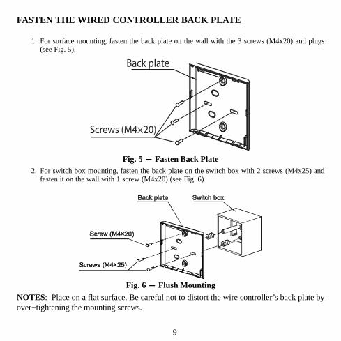
FASTEN THE WIRED CONTROLLER BACK PLATE
1. For surface mounting, fasten the back plate on the wall with the 3 screws (M4x20) and plugs(see Fig. 5).
Back plate
Screws (M4×20)
Fig. 5 - Fasten Back Plate2. For switch box mounting, fasten the back plate on the switch box with 2 screws (M4x25) and
fasten it on the wall with 1 screw (M4x20) (see Fig. 6).
Fig. 6 - Flush Mounting
NOTES: Place on a flat surface. Be careful not to distort the wire controller’s back plate byover−tightening the mounting screws.
10
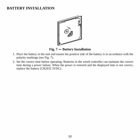
BATTERY INSTALLATION
Fig. 7 - Battery Installation1. Place the battery in the unit and ensure the positive side of the battery is in accordance with the
polarity markings (see Fig. 7).2. Set the correct time before operating. Batteries in the wired controller can maintain the correct
time during a power failure. When the power is restored and the displayed time is not correct,replace the battery (CR2032 3VDC).
11
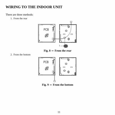
WIRING TO THE INDOOR UNIT
There are three methods:1. From the rear
PCB
1
Fig. 8 - From the rear2. From the bottom
PCB
Fig. 9 - From the bottom
12
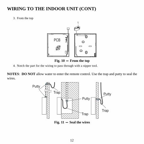
WIRING TO THE INDOOR UNIT (CONT)
3. From the top
PCB
1
Fig. 10 - From the top4. Notch the part for the wiring to pass through with a nipper tool.
NOTES: DO NOT allow water to enter the remote control. Use the trap and putty to seal thewires.
Putty
Putty
PuttyTrap
Trap Trap
Fig. 11 - Seal the wires
13
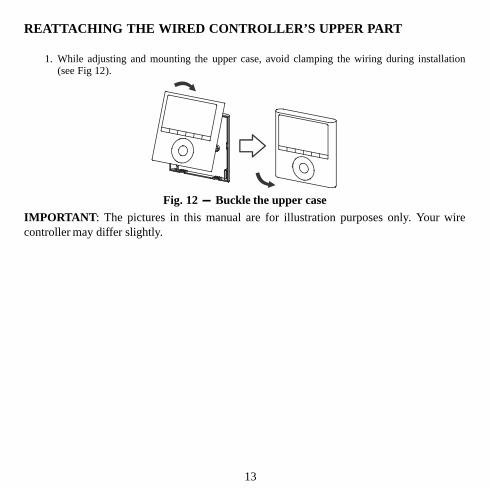
REATTACHING THE WIRED CONTROLLER’S UPPER PART
1. While adjusting and mounting the upper case, avoid clamping the wiring during installation(see Fig 12).
Fig. 12 - Buckle the upper caseIMPORTANT: The pictures in this manual are for illustration purposes only. Your wirecontroller may differ slightly.
14
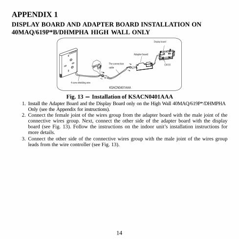
APPENDIX 1DISPLAY BOARD AND ADAPTER BOARD INSTALLATION ON40MAQ/619P*B/DHMPHA HIGH WALL ONLY
KSACN0401AAA
Adapter board
Display board
4-core shielding wire
The connectioncable
CN101
Fig. 13 - Installation of KSACN0401AAA1. Install the Adapter Board and the Display Board only on the High Wall 40MAQ/619P*/DHMPHA
Only (see the Appendix for instructions).2. Connect the female joint of the wires group from the adapter board with the male joint of the
connective wires group. Next, connect the other side of the adapter board with the displayboard (see Fig. 13). Follow the instructions on the indoor unit’s installation instructions formore details.
3. Connect the other side of the connective wires group with the male joint of the wires groupleads from the wire controller (see Fig. 13).
15
DISPLAY BOARD AND ADAPTER BOARD INSTALLATION ON40MAQ/619P*B/DHMPHA HIGH WALL ONLY (CONT)
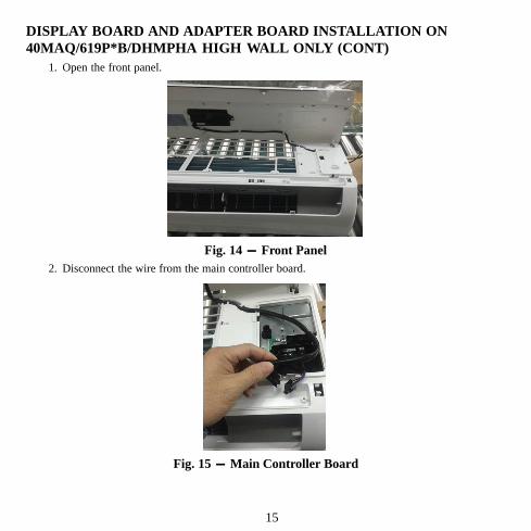
1. Open the front panel.
Fig. 14 - Front Panel2. Disconnect the wire from the main controller board.
Fig. 15 - Main Controller Board
16
DISPLAY BOARD AND ADAPTER BOARD INSTALLATION (CONT)
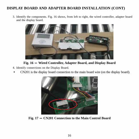
3. Identify the components. Fig. 16 shows, from left to right, the wired controller, adapter boardand the display board.
Fig. 16 - Wired Controller, Adapter Board, and Display Board4. Identify connections on the Display Board.
� CN201 is the display board connection to the main board wire (on the display board).
Fig. 17 - CN201 Connection to the Main Control Board
17
DISPLAY BOARD AND ADAPTER BOARD INSTALLATION (CONT)
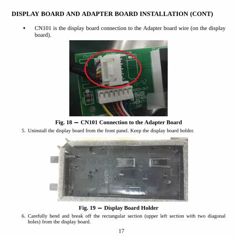
� CN101 is the display board connection to the Adapter board wire (on the displayboard).
Fig. 18 - CN101 Connection to the Adapter Board5. Uninstall the display board from the front panel. Keep the display board holder.
Fig. 19 - Display Board Holder6. Carefully bend and break off the rectangular section (upper left section with two diagonal
holes) from the display board.
18
DISPLAY BOARD AND ADAPTER BOARD INSTALLATION (CONT)
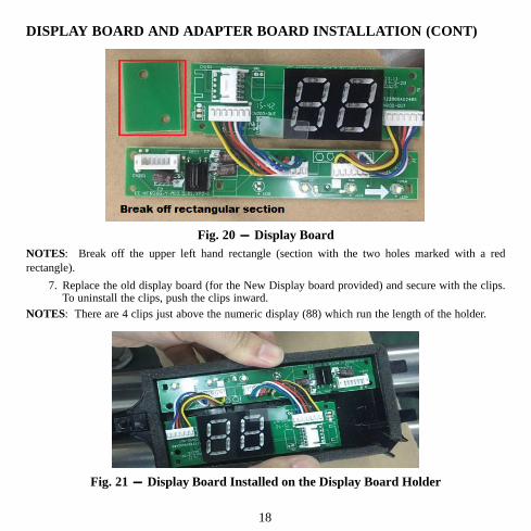
Fig. 20 - Display BoardNOTES: Break off the upper left hand rectangle (section with the two holes marked with a redrectangle).
7. Replace the old display board (for the New Display board provided) and secure with the clips.To uninstall the clips, push the clips inward.
NOTES: There are 4 clips just above the numeric display (88) which run the length of the holder.
Fig. 21 - Display Board Installed on the Display Board Holder
19
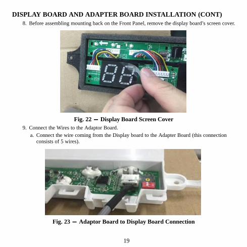
DISPLAY BOARD AND ADAPTER BOARD INSTALLATION (CONT)8. Before assembling mounting back on the Front Panel, remove the display board’s screen cover.
Fig. 22 - Display Board Screen Cover9. Connect the Wires to the Adaptor Board.
a. Connect the wire coming from the Display board to the Adapter Board (this connectionconsists of 5 wires).
Fig. 23 - Adaptor Board to Display Board Connection
20
DISPLAY BOARD AND ADAPTER BOARD INSTALLATION (CONT)
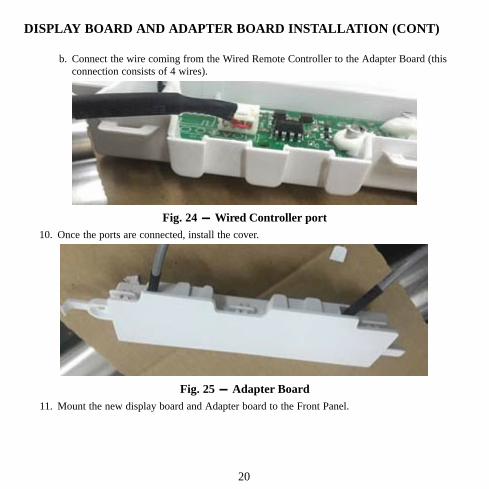
b. Connect the wire coming from the Wired Remote Controller to the Adapter Board (thisconnection consists of 4 wires).
Fig. 24 - Wired Controller port10. Once the ports are connected, install the cover.
Fig. 25 - Adapter Board11. Mount the new display board and Adapter board to the Front Panel.
21
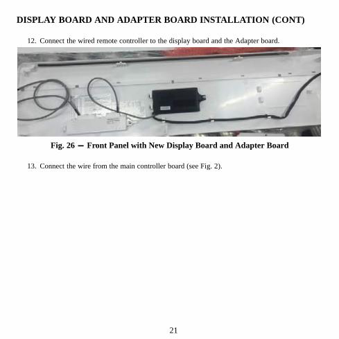
DISPLAY BOARD AND ADAPTER BOARD INSTALLATION (CONT)
12. Connect the wired remote controller to the display board and the Adapter board.
Fig. 26 - Front Panel with New Display Board and Adapter Board
13. Connect the wire from the main controller board (see Fig. 2).

22
APPENDIX 2INSTALLATION of KSACN0401AAA for CONSOLE INDOOR MODELS SIZES 9−12
Fig. 27 - Main Control Board
Fig. 28 - Net Module1. Cut off the J1 jumper cable located on the Main Control Board (see Fig. 5).2. Locate the net module connected to CN20 on the Main Control Board.3. Connect the wired control with the net module.
23
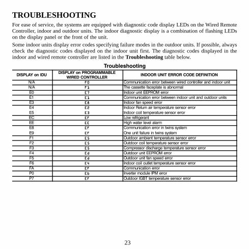
TROUBLESHOOTINGFor ease of service, the systems are equipped with diagnostic code display LEDs on the Wired RemoteController, indoor and outdoor units. The indoor diagnostic display is a combination of flashing LEDson the display panel or the front of the unit.
Some indoor units display error codes specifying failure modes in the outdoor units. If possible, alwayscheck the diagnostic codes displayed on the indoor unit first. The diagnostic codes displayed in theindoor and wired remote controller are listed in the Troubleshooting table below.
Troubleshooting
DISPLAY on IDUDISPLAY on PROGRAMMABLE
WIRED CONTROLLERINDOOR UNIT ERROR CODE DEFINITION
N/A F0 Communication error between wired controller and indoor unit
N/A F1 The cassette faceplate is abnormal
E0 E7 Indoor unit EEPROM error
E1 E1 Communication error between indoor unit and outdoor units
E3 E8 Indoor fan speed error
E4 E2 Indoor Return air temperature sensor error
E5 E3 Indoor coil temperature sensor error
EC EF Low refrigerant
EE EE High water level alarm
E8 EF Communication error in twins system
E9 EF One unit failure in twins system
F1 E5 Outdoor ambient temperature sensor error
F2 E5 Outdoor coil temperature sensor error
F3 E5 Compressor discharge temperature sensor error
F4 Ed Outdoor unit EEPROM error
F5 Ed Outdoor unit fan speed error
F6 E4 Indoor coil outlet temperature sensor error
FA EF Communication error
P0 Eb Inverter module IPM error
P7 EF Outdoor IGBT temperature sensor error
24
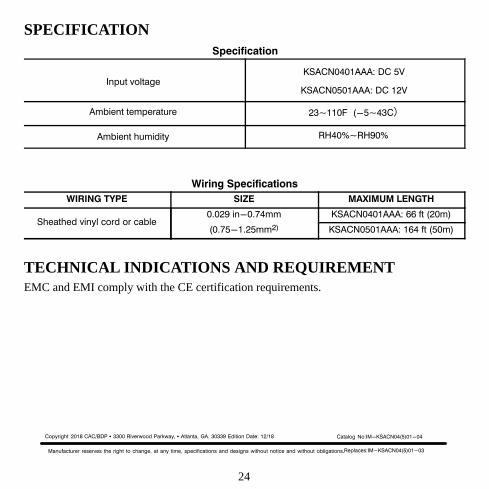
SPECIFICATIONSpecification
Input voltageKSACN0401AAA: DC 5V
KSACN0501AAA: DC 12V
Ambient temperature 23~110F (-5~43C)
Ambient humidity RH40%~RH90%
Wiring Specifications
WIRING TYPE SIZE MAXIMUM LENGTH
Sheathed vinyl cord or cable0.029 in-0.74mm
(0.75-1.25mm2)
KSACN0401AAA: 66 ft (20m)
KSACN0501AAA: 164 ft (50m)
TECHNICAL INDICATIONS AND REQUIREMENTEMC and EMI comply with the CE certification requirements.
Copyright 2018 CAC/BDP � 3300 Riverwood Parkway, � Atlanta, GA. 30339 Edition Date: 12/18
Manufacturer reserves the right to change, at any time, specifications and designs without notice and without obligations.Replaces:IM-KSACN04(5)01-03
Catalog No:IM-KSACN04(5)01-04