installation and operation instructions manual - bock water
TRANSCRIPT
WARNINGImproper installation, adjustment, alteration,
service or maintenance can cause serious injury or property damage. Refer to this manual. For assistance or additional information, consult a qualified installer or service agency.
WARNINGInstall in accordance with all local codes. In the
absence of local codes, refer to NFPA 54 or CSA B149.1.
CAUTIONThe recommended temperature for normal
residential use is 120°F. The dial on the aquastat does not always reflect the out-coming water temperature and it could occasionally exceed 120°F. Variation in out-coming temperature could be based on factors including but not limited to usage patterns and type of installation.
WARNINGHotter water increases the risk of scald injury. Before adjusting the water temperature setting, read this instruction manual. Temperatures at which injury occurs vary with the person’s age and the length of exposure. The slower reaction time of children, elderly or physically or mentally challenged persons increases the scalding hazard to them. It is recommended that lower water temperatures be used where these exposure hazards exist. Households with small children or invalids may require a temperature setting less than 120°F to prevent accidental contact with hot water. To produce less than 120°F, use point-of-use temperature limiting devices.
If higher water temperature is needed in part of the water system, automatic temperature limiting devices must be used on all lines to water taps.
WARNINGWater heater blankets may restrict air flow to
the water heater and cause fire, asphyxiation, personal injury or death.
THIS MANUAL HAS BEEN PREPARED TO ACQUAINT YOU WITH THE INSTALLATION,
OPERATION, AND MAINTENANCE OF YOUR WATER HEATER AND TO PROVIDE IMPORTANT
SAFETY INFORMATION.
Read all instructions thoroughly before attempting installation or operation of your water heater. Keep these instructions for future reference.Local plumbing and electrical codes must be followed in the installation of this water heater. In the absence of a local code use the UNIFORM PLUMBING CODE and the NFPA Code. Local codes may supersede instructions in this installation manual.These instructions are a guide for the correct installation of the water heater. The manufacturer will not be liable for damages caused by failure to comply with the installation and operating instruc-tions outlined on the following pages.DO NOT use this appliance if any part has been under water. Immediately call a qualified service technician to inspect the appliance and to replace any part of the control system and any gas control which has been under water.
FAILURE TO FOLLOW THESE INSTRUCTIONS OR ALL APPLICABLE BUILDING CODES
AND REGULATIONS VOIDS THE WARRANTY ON THIS WATER HEATER.
Warranty, Registration Card and Parts List are included.Owner: Please remember to return the Registration Card!
To the Consumer: Please read these and all component
instructions and keep for future reference.
To the Installer: Please attach these instructions
next to the water heater.
Rev4 12/201823402 EN
Installation and Operation Instructions Manual
Models: OT300, OT400, OT500
High Efficiency Commercial Gas Water Heater
– Do not store or use gasoline or other flammable vapors and liquids in the vicinity of this or any other appliance.– WHAT TO DO IF YOU SMELL GAS
• Do not try to light any appliance.• Do not touch any electrical switch; do not use any phone in your building.
• Immediately call your gas supplier from a neigh- bor’s phone. Follow the gas supplier’s instructions.• If you cannot reach your gas supplier, call the fire department.
– Installation and service must be performed by a qualified installer, service agency or the gas supplier.
WARNING: If the information in these instructions is not followed exactly, a fire or explosion may result causing property damage, personal injury or death.
IMPORTANT SAFETY INSTRUCTIONS
The proper installation, use and servicing of this water heater is very important to your safety and the safety of others.
This is the safety alert symbol. Statements following this symbol contain important safety information. Obey all safety messages that follow this symbol to avoid possible injury or death. Important safety information will be preceded by the safety alert symbol and the words DANGER, WARNING, CAUTION, OR NOTICE.
DANGER indicates an imminently hazardous situation which, if not avoided, will result in serious injury or death.
WARNING indicates a potentially hazardous situation which, if not avoided, could result in serious injury or death.
CAUTION indicates a hazardous situation which, if not avoided, could result in minor or moderate injury.
NOTICE calls attention to observe a specified procedure.
SAVE THESE INSTRUCTIONS
DANGER Water heaters utilizing Liquefied Petroleum gas (LP) are different from natural gas models. A natural gas heater will not function safely on LP gas and vice versa. To avoid possible equipment damage, personal injury or fire: DO NOT connect this water heater to a fuel type not in accordance with the rating label. These units are only certified for a single fuel type.
DANGER Failure to properly install the vent and combustion air intake system as outlined in this manual can result in unsafe operation of the water heater. To avoid the risk of fire, explosion, or asphyxiation from carbon monoxide, never operate this water heater unless it is properly vented and has adequate air supply for combustion and dilution of flue gas. Be sure to inspect the system for proper installation at initial start-up; and at least annually thereafter. See the Maintenance section for more information.
Page 2
TABLE OF CONTENTS
Section I: Specifications . . . . . . . . . . . . . . . . . . . . . . . . . . . . . . . . . . . . . . . . . . . . .4
Section II: General Information . . . . . . . . . . . . . . . . . . . . . . . . . . . . . . . . . . . . . . . .5
Section III: Pre-Installation . . . . . . . . . . . . . . . . . . . . . . . . . . . . . . . . . . . . . . . . . . . .9
Section IV: Installation . . . . . . . . . . . . . . . . . . . . . . . . . . . . . . . . . . . . . . . . . . . . . .12
Section V: Operation . . . . . . . . . . . . . . . . . . . . . . . . . . . . . . . . . . . . . . . . . . . . . . .37
Section VI: Maintenance . . . . . . . . . . . . . . . . . . . . . . . . . . . . . . . . . . . . . . . . . . . .41
Section VII: Troubleshooting . . . . . . . . . . . . . . . . . . . . . . . . . . . . . . . . . . . . . . . . .45
Section VIII: Parts List . . . . . . . . . . . . . . . . . . . . . . . . . . . . . . . . . . . . . . . . . . . . . . .50
Section IX: Warranty . . . . . . . . . . . . . . . . . . . . . . . . . . . . . . . . . . . . . . . . . . . . . . .54
Page 3
Model
Rat
ed S
tora
ge
Cap
acit
y, G
AL
(L)
Rat
ed M
axim
um
Inp
ut,
Btu
/hr
(kW
)
Ther
mal
Effi
cien
cy
(%)
@ M
ax. I
npu
t
Rec
over
y @
100°F
rise
, GA
L/H
R (
L/H
R)
A C E G HO
T (
NPT
)
Air
In
take
(P
VC
)
Rat
ed M
inim
um
Inp
ut,
Btu
/hr
(kW
)
Ther
mal
Effi
cien
cy
(%)
@ M
in. I
npu
t
1st
Hr.
Del
iver
y @
100°
F ri
se, G
AL
(L)
B D F CO
LD (
NPT
)
Gas
(N
PT)
Exh
aust
V
ent
(PV
C)
Table 1: Dimensions
Page 4
SECTION I: SPECIFICATIONS
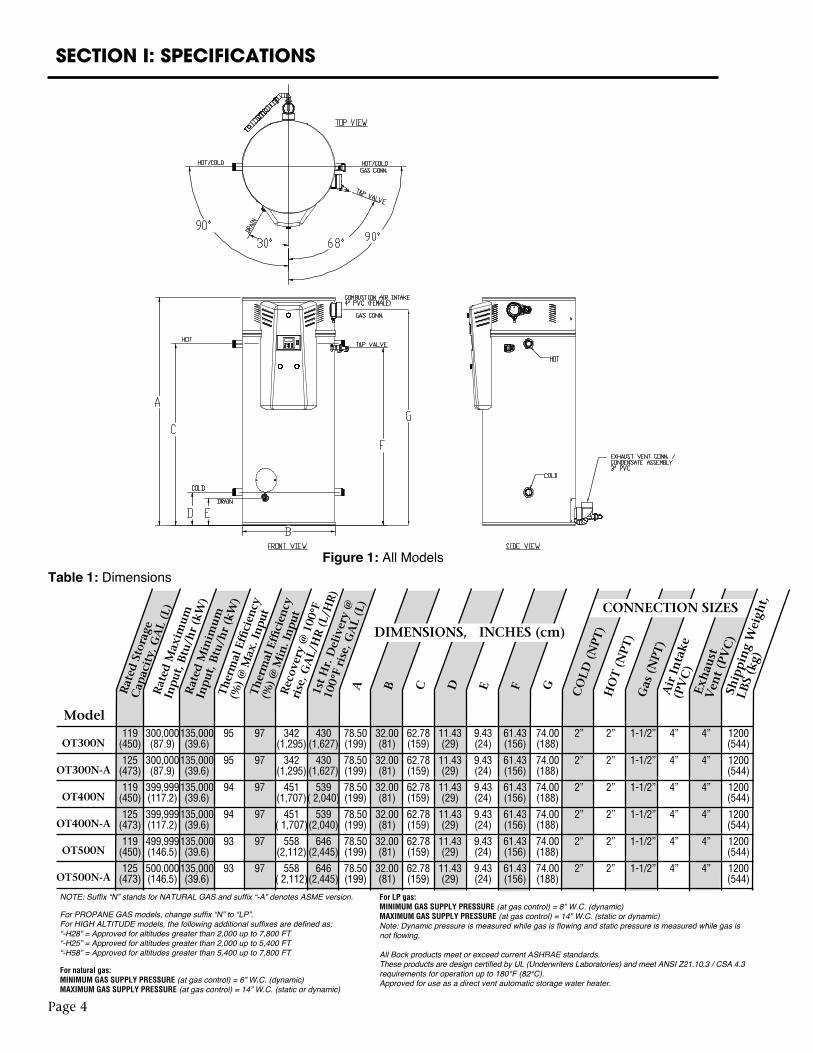
Figure 1: All Models
DIMENSIONS, INCHES (cm)
NOTE: Suffix “N” stands for NATURAL GAS and suffix “-A” denotes ASME version.
For PROPANE GAS models, change suffix “N” to “LP”.For HIGH ALTITUDE models, the following additional suffixes are defined as:“-H28” = Approved for altitudes greater than 2,000 up to 7,800 FT“-H25” = Approved for altitudes greater than 2,000 up to 5,400 FT“-H58” = Approved for altitudes greater than 5,400 up to 7,800 FT
For natural gas: MINIMUM GAS SUPPLY PRESSURE (at gas control) = 6” W.C. (dynamic)MAXIMUM GAS SUPPLY PRESSURE (at gas control) = 14” W.C. (static or dynamic)
119 300,000 135,000 95 97 342 430 78.50 32.00 62.78 11.43 9.43 61.43 74.00 2” 2” 1-1/2” 4” 4” 1200 (450) (87.9) (39.6) (1,295) (1,627) (199) (81) (159) (29) (24) (156) (188) (544)
125 300,000 135,000 95 97 342 430 78.50 32.00 62.78 11.43 9.43 61.43 74.00 2” 2” 1-1/2” 4” 4” 1200 (473) (87.9) (39.6) (1,295) (1,627) (199) (81) (159) (29) (24) (156) (188) (544)
119 399,999 135,000 94 97 451 539 78.50 32.00 62.78 11.43 9.43 61.43 74.00 2” 2” 1-1/2” 4” 4” 1200 (450) (117.2) (39.6) (1,707) ( 2,040) (199) (81) (159) (29) (24) (156) (188) (544)
125 399,999 135,000 94 97 451 539 78.50 32.00 62.78 11.43 9.43 61.43 74.00 2” 2” 1-1/2” 4” 4” 1200 (473) (117.2) (39.6) ( 1,707) (2,040) (199) (81) (159) (29) (24) (156) (188) (544)
119 499,999 135,000 93 97 558 646 78.50 32.00 62.78 11.43 9.43 61.43 74.00 2” 2” 1-1/2” 4” 4” 1200 (450) (146.5) (39.6) (2,112) (2,445) (199) (81) (159) (29) (24) (156) (188) (544)
125 500,000 135,000 93 97 558 646 78.50 32.00 62.78 11.43 9.43 61.43 74.00 2” 2” 1-1/2” 4” 4” 1200 (473) (146.5) (39.6) ( 2,112) (2,445) (199) (81) (159) (29) (24) (156) (188) (544)
OT300N
OT300N-A
OT400N
OT400N-A
OT500N
OT500N-A
CONNECTION SIZES
Ship
pin
g W
eigh
t,
LBS
(kg)
For LP gas:MINIMUM GAS SUPPLY PRESSURE (at gas control) = 8” W.C. (dynamic)MAXIMUM GAS SUPPLY PRESSURE (at gas control) = 14” W.C. (static or dynamic)Note: Dynamic pressure is measured while gas is flowing and static pressure is measured while gas is not flowing.
All Bock products meet or exceed current ASHRAE standards.These products are design certified by UL (Underwriters Laboratories) and meet ANSI Z21.10.3 / CSA 4.3 requirements for operation up to 180°F (82°C).Approved for use as a direct vent automatic storage water heater.
Page 5
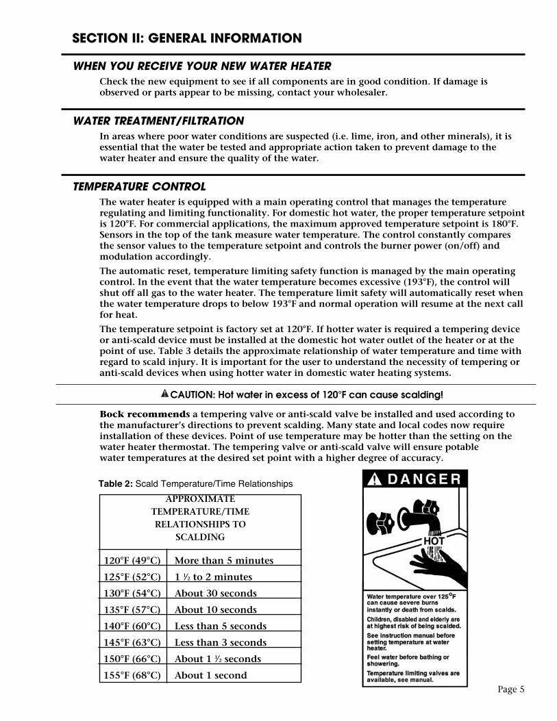
APPROXIMATETEMPERATURE/TIMERELATIONSHIPS TO
SCALDING
120°F (49°C) More than 5 minutes
125°F (52°C) 1 1⁄2 to 2 minutes
130°F (54°C) About 30 seconds
135°F (57°C) About 10 seconds
140°F (60°C) Less than 5 seconds
145°F (63°C) Less than 3 seconds
150°F (66°C) About 1 1⁄2 seconds
155°F (68°C) About 1 second
Table 2: Scald Temperature/Time Relationships
SECTION II: GENERAL INFORMATION
WHEN YOU RECEIVE YOUR NEW WATER HEATERCheck the new equipment to see if all components are in good condition. If damage is observed or parts appear to be missing, contact your wholesaler.
WATER TREATMENT/FILTRATIONIn areas where poor water conditions are suspected (i.e. lime, iron, and other minerals), it is essential that the water be tested and appropriate action taken to prevent damage to the water heater and ensure the quality of the water.
TEMPERATURE CONTROLThe water heater is equipped with a main operating control that manages the temperature regulating and limiting functionality. For domestic hot water, the proper temperature setpoint is 120°F. For commercial applications, the maximum approved temperature setpoint is 180°F. Sensors in the top of the tank measure water temperature. The control constantly compares the sensor values to the temperature setpoint and controls the burner power (on/off) and modulation accordingly.
The automatic reset, temperature limiting safety function is managed by the main operating control. In the event that the water temperature becomes excessive (193°F), the control will shut off all gas to the water heater. The temperature limit safety will automatically reset when the water temperature drops to below 193°F and normal operation will resume at the next call for heat.
The temperature setpoint is factory set at 120°F. If hotter water is required a tempering device or anti-scald device must be installed at the domestic hot water outlet of the heater or at the point of use. Table 3 details the approximate relationship of water temperature and time with regard to scald injury. It is important for the user to understand the necessity of tempering or anti-scald devices when using hotter water in domestic water heating systems.
CAUTION: Hot water in excess of 120°F can cause scalding!
Bock recommends a tempering valve or anti-scald valve be installed and used according to the manufacturer’s directions to prevent scalding. Many state and local codes now require installation of these devices. Point of use temperature may be hotter than the setting on the water heater thermostat. The tempering valve or anti-scald valve will ensure potable water temperatures at the desired set point with a higher degree of accuracy.
SECTION II: GENERAL INFORMATION
ANODE RODSThe water heater is supplied with a factory installed powered anode system to prevent corrosion of internal tank components. Specifically, the type of anode system that is used is an impressed-cur-rent anode system. This system uses a power supply that regulates the protective current output based on actual conditions inside the tank. The two anode rods in the tank are not consumed over time and, therefore, do not need to be removed and inspected. Refer to the Maintenance section of this manual for periodic inspection instructions for the powered anode system.
NOTICE TO THE OWNER: The water heater must be connected to the power supply for the powered anode system to operate. DO NOT DISCONNECT THE WATER HEATER FROM THE POWER SUPPLY FOR AN EXTENDED PERIOD OF TIME. WITHOUT POWER, THE ANODE SYSTEM WILL NOT BE CAPABLE OF PROVIDING CORROSION PROTECTION. When the power switch to the right of the display is OFF and there is a connection to the power supply, the powered anode system will still function. If the water heater must be disconnected from the power supply for an extended period, the tank must be drained. Refill the tank prior to reconnect-ing the water heater to the power supply.
CAUTION
Hydrogen gas is produced in a hot water system served by the heater that has not been used for a long period of time (2 weeks or more). Hydrogen gas is extremely flammable. To reduce the risk of injury under these conditions, it is recommended that a hot water faucet be opened for several minutes before using any electrical appliance connected to the hot water system. When hydrogen is present, there will probably be an unusual sound such as air escaping through the pipe as the water begins to flow. There should be no smoking or open flame near the faucet at the time it is open.
TEMPERATURE AND PRESSURE RELIEF VALVE (T&P)
CAUTION
To reduce the risk of excessive pressures and temperatures in this water heater, install temperature and pressure protective equipment required by local codes and no less than a combination temperature and pressure relief valve certified by a nationally recognized testing laboratory that maintains periodic inspection of production of listed equipment or materials, as meeting the requirements for Relief Valves and Automatic Gas Shutoff Devices for Hot Water Supply Systems, ANSI Z21.22. This valve must be marked with a maximum set pressure not to exceed the marked maximum working pressure of the water heater. Install the valve in an opening provided and marked for this purpose in the water heater, and orient it or provide tubing so that any discharge from the valve exits only within 6 inches above, or at any distance below, the structural floor, and does not contact any live electrical part. The discharge opening must not be blocked or reduced in size under any circumstances.
CAUTION
Scalding injury and/or water damage can occur from either the manual lifting of the lever or the normal operation of the T&P valve if it is not piped to a proper drain. If the valve fails to flow water or reseat, call your plumber.
The T&P valve is factory installed. A discharge drain tube must be installed (responsibility of the installer) and shall terminate plain, not threaded, 6 inches above the floor drain. The drain tube material must be approved for temperatures of 120o F or greater and a pressure of 150 PSI or greater.
Page 6
SECTION II: GENERAL INFORMATION
BACKFLOW PREVENTER (CLOSED SYSTEM)Some local municipal codes and ordinances require the use of these devices on potable (domestic) water lines. Where backflow preventers, check valves, or pressure regulating valves are required, it will be necessary to install a thermal expansion tank (designed for use with potable water) in order to prevent pressure build up in the water heater and associated piping, which could cause the T&P valve to discharge. Follow the expansion tank manufacturer’s recommendations when selecting a tank for your hot water system. The expansion tank pressure shall equal the water heater system pressure prior to initial warm up.
Note: Working pressure of the water heater is 150 PSI. Do not exceed 150 PSI.
CONDENSATIONCondensation of flue gases will occur in the exhaust vent and portions of the heat exchanger during burner operation. Condensate is considered acidic based on its typical pH range of 3.5 to 3.8 on a scale of 0 to 14 (a pH of 7 is neutral). Some installations may require the use of a condensate neutralizer kit to reduce the acidity of the condensate prior to it entering the building’s drainage system. When possible, locate a floor drain in close proximity to the water heater to minimize the length of the drain line. The water heater is supplied with a condensate elbow assembly that must be installed to the water heater before the exhaust vent is connected. Horizontal sections of the exhaust vent shall slope upward away from the water heater a minimum of 1/8” per foot. This will allow the condensate in the vent to run back to the condensate drain on the water heater. In some instances, condensate may form in the intake piping during periods following burner operation. Horizontal sections of air intake piping shall slope downward away from the water heater a minimum of 1/8” per foot. When applicable, if downward sloping is not possible or vertical sections are used for air intake piping, a condensate drainage tube can be installed on the intake piping (near the intake pipe connection on the water heater). See Section IV: Installation / Vent and Combustion Air Intake / Condensate Elbow Assembly and Section IV: Installation / Vent & Combustion Air Intake / Optional Condensate Line for installation details.
HIGH ALTITUDEThe water heaters covered in this manual are safety certified for altitudes up to 7,800 feet. For high altitude applications (i.e. installations at altitudes greater than 2,000 feet), models that are designated with a suffix “-H28”, “-H25”, or “-H58” must be used. Natural gas models for high altitude will contain the suffix “-H28” and are certified for use at altitudes greater than 2,000 FT up to 7,800 FT. LP gas models containing the suffix “-H25” are certified for use at altitudes greater than 2,000 FT up to 5,400 FT. LP models that contain the suffix “-H58” are certified for use at altitudes greater than 5,400 FT up to 7,800 FT.
Following installation at high altitudes, verify that O2 readings and CO levels in the exhaust vent are within the specified ranges given in Section VI: Maintenance, “Check the Combustion System”.
Due to the natural reduction in input rate at higher altitudes, the actual hot water output of the heater is gradually reduced as altitude is increased. Expect a 2.8% input rate reduction per 1,000 feet altitude. However, all high altitude models are factory adjusted to maintain the rated sea-level minimum input at minimum fan speed.
Page 7
Page 8
SECTION II: GENERAL INFORMATION
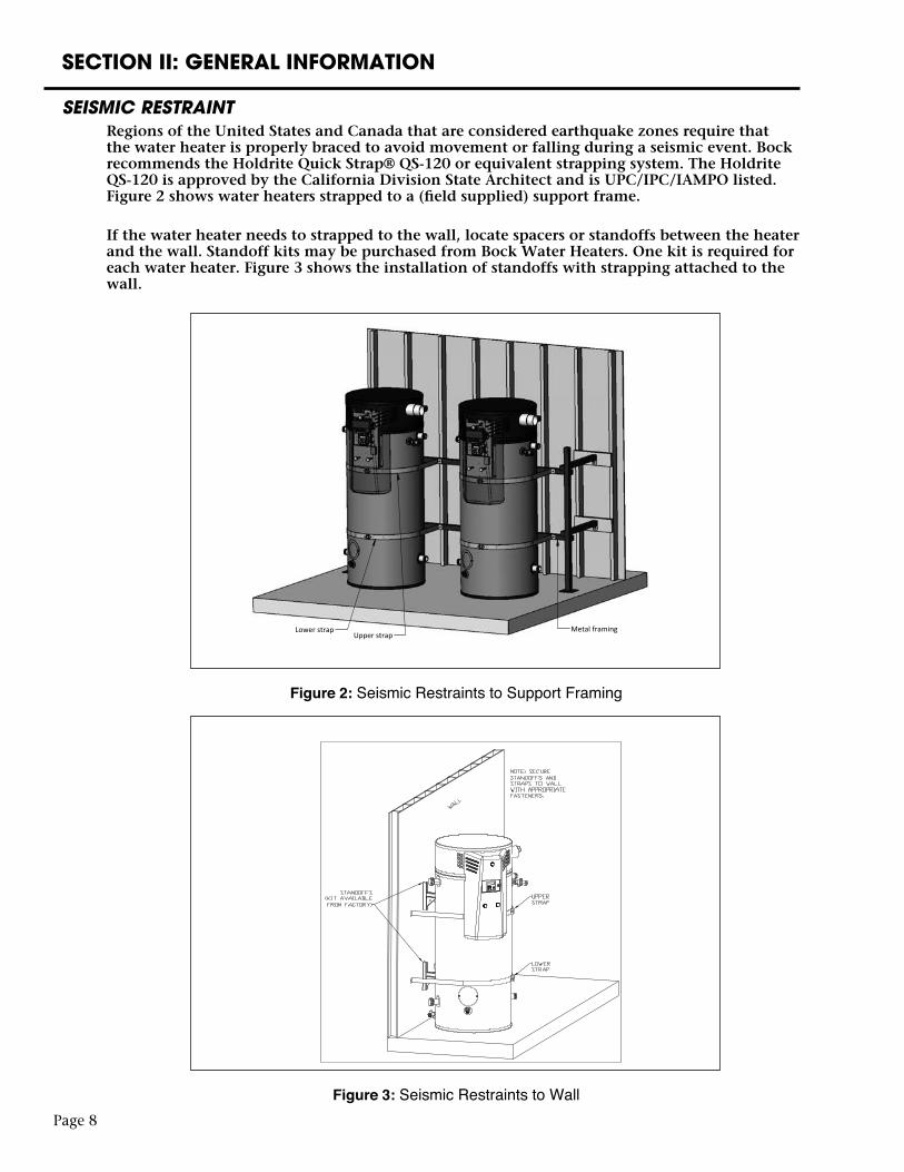
SEISMIC RESTRAINTRegions of the United States and Canada that are considered earthquake zones require that the water heater is properly braced to avoid movement or falling during a seismic event. Bock recommends the Holdrite Quick Strap® QS-120 or equivalent strapping system. The Holdrite QS-120 is approved by the California Division State Architect and is UPC/IPC/IAMPO listed. Figure 2 shows water heaters strapped to a (field supplied) support frame.
If the water heater needs to strapped to the wall, locate spacers or standoffs between the heater and the wall. Standoff kits may be purchased from Bock Water Heaters. One kit is required for each water heater. Figure 3 shows the installation of standoffs with strapping attached to the wall.
Metal framingUpper strap
Lower strap
Figure 2: Seismic Restraints to Support Framing
Figure 3: Seismic Restraints to Wall
Page 9
SECTION III: PRE-INSTALLATION
LOCATION CAUTION
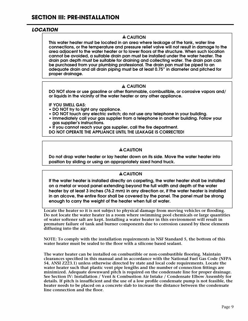
This water heater must be located in an area where leakage of the tank, water line connections, or the temperature and pressure relief valve will not result in damage to the area adjacent to the water heater or to lower floors of the structure. When such location cannot be avoided, a suitable drain pan must be installed under the water heater. The drain pan depth must be suitable for draining and collecting water. The drain pan can be purchased from your plumbing professional. The drain pan must be piped to an adequate drain and all drain piping must be at least 0.75” in diameter and pitched for proper drainage.
CAUTION DO NOT store or use gasoline or other flammable, combustible, or corrosive vapors and/
or liquids in the vicinity of the water heater or any other appliance.
IF YOU SMELL GAS: • DO NOT try to light any appliance. • DO NOT touch any electric switch; do not use any telephone in your building. • Immediately call your gas supplier from a telephone in another building. Follow your
gas supplier’s instructions. • If you cannot reach your gas supplier, call the fire department. DO NOT OPERATE THE APPLIANCE UNTIL THE LEAKAGE IS CORRECTED!
CAUTION Do not drop water heater or lay heater down on its side. Move the water heater into
position by sliding or using an appropriately sized hand truck.
CAUTION If the water heater is installed directly on carpeting, the water heater shall be installed
on a metal or wood panel extending beyond the full width and depth of the water heater by at least 3 inches (76.2 mm) in any direction or, if the water heater is installed in an alcove, the entire floor shall be covered by the panel. The panel must be strong enough to carry the weight of the heater when full of water.
Locate the heater so it is not subject to physical damage from moving vehicles or flooding. Do not locate the water heater in a room where swimming pool chemicals or large quantities of water softener salt are kept. Installing a water heater in this environment will result in premature failure of tank and burner components due to corrosion caused by these elements diffusing into the air. NOTE: To comply with the installation requirements in NSF Standard 5, the bottom of this water heater must be sealed to the floor with a silicone based sealant.
The water heater can be installed on combustible or non-combustible flooring. Maintain clearances specified in this manual and in accordance with the National Fuel Gas Code (NFPA 54, ANSI Z223.1) unless otherwise directed by state and local code requirements. Locate the water heater such that plastic vent pipe lengths and the number of connection fittings are minimized. Adequate downward pitch is required on the condensate line for proper drainage. See Section IV: Installation / Vent & Combustion Air Intake / Condensate Elbow Assembly for details. If pitch is insufficient and the use of a low profile condensate pump is not feasible, the heater needs to be placed on a concrete slab to increase the distance between the condensate line connection and the floor.
SECTION III: PRE-INSTALLATION
GAS SUPPLY LINEPrior to installation, contact your local gas utility to confirm that sufficient gas service is available for the water heater. The gas meter must have adequate capacity to supply the rated maximum gas input of the water heater in addition to other gas fired equipment connected to the meter.
Minimum Gas Supply PressureThe gas supply must be capable of maintaining a minimum pressure at the inlet of the gas control during water heater operation at maximum input. The pressure will be lowest at the gas control during water heater operation (i.e. gas is flowing) at maximum input. For natural gas models, during operation at maximum input, the supply pressure at the gas control must be at least 6” W.C. For LP gas models, during operation at maximum input, the supply pressure at the gas control must be at least 8” W.C.
Refer to Table 3 for gas supply line sizing. The table shows maximum input in thousands of BTU’s per hour for various pipe sizes and lengths. The table assumes gas supply pressures of 14” W.C. or less and a pressure drop of 0.3” W.C.
At minimum, use 1-1/4” gas supply pipe for models OT300 and OT400. For model OT500, use a minimum of 1-1/2” pipe. Maximum Gas Supply PressureThe gas supply pressure shall never be greater than 14” W.C. Pressures greater than 14” W.C. may damage the gas control which could cause a fire or explosion. Refer to Section IV: Installation / Gas Connections for further installation instructions.
Page 10
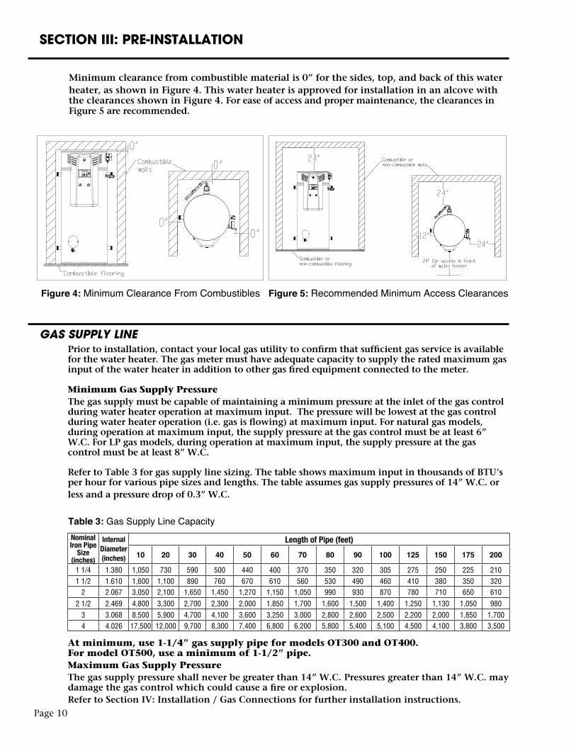
Figure 4: Minimum Clearance From Combustibles Figure 5: Recommended Minimum Access Clearances
Nominal Iron Pipe
Size (inches)
Internal Diameter (inches)
Length of Pipe (feet)
10 20 30 40 50 60 70 80 90 100 125 150 175 200
1 1/4 1.380 1,050 730 590 500 440 400 370 350 320 305 275 250 225 2101 1/2 1.610 1,600 1,100 890 760 670 610 560 530 490 460 410 380 350 320
2 2.067 3,050 2,100 1,650 1,450 1,270 1,150 1,050 990 930 870 780 710 650 6102 1/2 2.469 4,800 3,300 2,700 2,300 2,000 1,850 1,700 1,600 1,500 1,400 1,250 1,130 1,050 980
3 3.068 8,500 5,900 4,700 4,100 3,600 3,250 3,000 2,800 2,600 2,500 2,200 2,000 1,850 1,7004 4.026 17,500 12,000 9,700 8,300 7,400 6,800 6,200 5,800 5,400 5,100 4,500 4,100 3,800 3,500
Table 3: Gas Supply Line Capacity
Minimum clearance from combustible material is 0” for the sides, top, and back of this waterheater, as shown in Figure 4. This water heater is approved for installation in an alcove with the clearances shown in Figure 4. For ease of access and proper maintenance, the clearances in Figure 5 are recommended.
Page 11
SECTION III: PRE-INSTALLATION
COMBUSTION AND VENTILATION AIRThe water heater can be installed to utilize combustion air from either inside or outside the building. Refer to “Section IV: Installation” for detailed venting specifications. If indoor air is used for combustion air it is imperative that the room has an adequate air supply. Inadequate air supplies may lead to unsafe levels of carbon monoxide (CO) and excessive levels of soot. See NFPA 54 or the discussions of “Unconfined Space” and “Confined Space” below. In addition, poor ventilation will also result in hot spots around the heater. Temperatures over 90°F near the water heater generally indicate a lack of ventilation.
UNCONFINED SPACEUnconfined space is defined by NFPA 54 as a space with a volume greater than 50 cubic feet (during typical use) per 1000 BTUH of the total combined input of all fuel burning appliances in the space. Rooms leading directly to the installation space through doors that cannot be closed can be considered part of the space. Exception: Buildings with full vapor barriers, tight doors and windows or air infiltration rates of less than 0.35 air changes per hour will be considered a confined space and require additional air supplies.
CONFINED SPACEConfined space is defined by NFPA 54 as a space with a volume less than 50 cubic feet (during typical use) per 1000 BTUH of the total combined input of all fuel burning appliances in the space. Buildings or rooms of unusually tight construction are also considered a confined space. See “Unconfined Space: Exception”.When installing fuel burning appliances in a confined space, air must be supplied to that space from either inside or outside of the building as conditions allow.A. Inside Air Supply: A confined space shall be provided with two permanent openings; one within 12 inches of the top and one within 12 inches of the bottom of the enclosure. These openings shall lead directly to room(s) of sufficient volume so that the combined volume of all the space meets the criteria for unconfined space. Each opening shall have a minimum free area of 1 square inch per 1000 Btu/hr of the combined total input of all fuel burning appliances in the space. Each opening shall have an area of not less than 100 square inches or a minimum dimension of not less than 3 inches.B. Outside Air Supply: Confined spaces shall be provided with two permanent openings; one within 12 inches of the top and one within 12 inches of the bottom of the enclosure. These openings shall communicate directly, or by ducts, with the outdoors or spaces that communicate with the outdoors.1.) Leading directly to the outside or through vertical ducts: Each opening shall have a minimum free area of one square inch per 4000 Btu/hr of total input rating of all equipment in the enclosure.2.) Leading to outside through horizontal ducts: Each opening shall have a minimum free area of one square inch per 2000 Btu/hr of total input rating of all equipment in the enclosure. Note: All ducts shall have the same cross sectional area as the free area of each opening to which they connect. The minimum dimensions of all ducts shall not be less than three inches. Powered combustion air supplies are also commercially available and may be used.
LOUVERS & GRILLESIn calculating the free area of an opening, consideration must be given to the blocking effects of louvers or grilles protecting the opening. Any screens used must be no finer than 1⁄4 inch mesh. If the free area of a louver or grille is known, this should be used in calculating the size of opening required. If free area is unknown, it may be assumed that wood louvers will have 20 to 25% free area and metal louvers and grilles will have 60 to 75% free area. Louvers and grilles should be fixed in the open position or interlocked with the equipment so that they open automatically during equipment operation.
SECTION IV: INSTALLATION
VENT & COMBUSTION AIR INTAKE
DANGER Failure to properly install the vent and combustion air intake system as outlined in this
manual can result in unsafe operation of the water heater. To avoid the risk of fire, explosion, or asphyxiation from carbon monoxide, never operate this water heater unless it is properly vented and has adequate air supply for combustion. Be sure to inspect the system for proper installation at initial start-up; and at least annually thereafter. See the Maintenance section for more information.
NOTICE Failure to comply with orientation and minimum spacing requirements between exhaust vent and air intake terminals may lead to cross-contamination of combustion air. Cross-contamination may lead to nuisance lockouts from ignition or flame failures and will increase maintenance on parts such as the flame rod. Attention must be given to the unique conditions at every jobsite to avoid the possibility of exhaust gas entering the air intake.
The water heater venting and combustion air intake can be installed as a power direct vent system (combustion air from outside the building) or power vent system (combustion air from inside the building). Vertical or horizontal (side-wall) configurations may be used.
Note: If air from inside the building will be used for combustion air, the require-ments in Section III, “Unconfined Space” must be met.
A power direct vent system may terminate in a 2-pipe configuration or with a concentric vent kit. The concentric vent kit must be purchased separately. The IPEX System 636® 4” concentric kit is approved by Bock Water Heaters. The connection size on the concentric vent cannot be smaller than the vent and intake pipe diameter. The vent and intake equivalent lengths must comply with minimum and maximum lengths specified in Tables 4 and 5.
The water heater is supplied with a pre-assembled PVC condensate assembly that must be installed to the exhaust pipe prior to connection of the exhaust venting. See instructions in Section IV: Installation / Vent & Combustion Air Intake / Condensate Elbow Assembly.
A 4” PVC 90 deg. standard bend elbow is supplied and must be used as the combustion air intake termination fitting for either a direct vent or power vent system. For a power vent system, connect the elbow directly to the 4” connector supplied with the water heater. For a direct vent system, use the elbow as the outside termination fitting. The supplied 90 deg. elbow contains a protective screen to block foreign debris or small animals from entering the pipe. If a screen is preferred at the exhaust termination, it must have a low resistance to airflow. Refer to the type of screen used in the supplied elbow. A screen that significantly restricts airflow will reduce the performance of the water heater and could cause nuisance control lockouts.
Prior to connecting intake piping to the water heater, look down the end of the air intake assembly (see Item 6, page 47) to make sure damper is oriented such that the pins on opposing sides of the swinging gate are level. If not, adjust orientation of the air intake assembly by loosening the flexible coupling from the blower and turning the intake assembly until the pins are level.
All vent length measurements specified in this manual are in addition to the pre-assembled piping and supplied assemblies and fittings. Equivalent pipe lengths shall not be greater than the maximum lengths (or less than minimums) given in Tables 4 and 5. See the notes under Tables 4 and 5 for additional information pertaining to direct vent or power vent system lengths.
Note: DO NOT connect the water heater to an existing vent or chimney. It must be vented separately from all other appliances.
Page 12
SECTION IV: INSTALLATION
The following materials are approved for use as the vent and combustion air intake piping:
• PVC (DWV, ASTM-D2665 or CSA B181.2)• PVC (Schedule 40, ASTM-D1785 or CSA B137.3)• PVC (SDR Series, ASTM-D2241 or CSA B137.3)• CPVC (Schedule 40, ASTM-F441 or CSA B137.3)• CPVC (SDR Series, ASTM-F442)• ABS (Schedule 40, DWV, ASTM-D2661 or CSA B181.1) • AL29-4C Stainless Steel
In Canada, check local codes to ensure that SDR series is approved for use. SDR is not approved for all installations in Canada.
NOTICE Installations in Canada must conform to the requirements of CSA B149 code. Plastic
vent systems must be assembled with pipe, fittings, cements, and primers listed to ULC S636. Components of this listed system shall not be interchanged with other vent systems or unlisted pipe/fittings. In Canada, the primer and cement must be of the same manufacturer as the vent system; do not mix primers and cements from one manufacturer with a vent system from a different manufacturer. The supplied plastic pipe/fittings are certified as part of the water heater.
Page 13
The following materials are approved for use for the fittings in the vent and combustion air intake systems:
• PVC (Schedule 40 DWV, ASTM D2665)• CPVC (Schedule 40, ASTM F438)• ABS (Schedule 40 DWV, ASTM D2661) • AL29-4C Stainless Steel
The use of cellular core PVC (ASTM F891), cellular core CPVC, or Radel® (polyphenylsul-fone) in non-metallic vent pipe and systems is prohibited. Covering non-metallic vent pipe and fittings with thermal insulation is prohibited.
SECTION IV: INSTALLATION
Page 14
Minimum and Maximum System Lengths
The water heater should be located such that plastic vent pipe lengths and the number of connection fittings are minimized. Minimum and maximum equivalent pipe lengths for the vent and combustion air intake systems are given in Tables 4 and 5. Either 4 in. or 6 in. plastic piping may be used. The water heater is provided with a 4” female PVC connection for the air intake and a 3” female PVC connection (on the condensate assembly) for the exhaust vent. For ease of installation and potential future inspection, a 4” flexible coupling is supplied for connection to the 4” PVC fitting on the air intake. The flexible coupling should be used as the first connection on the intake for both 4” and 6” vent systems. Slide the large end of the flexible coupling over the female PVC fitting.
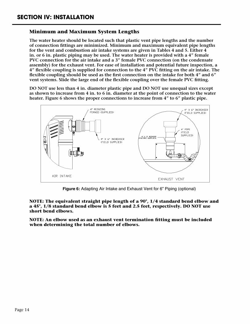
DO NOT use less than 4 in. diameter plastic pipe and DO NOT use unequal sizes except as shown to increase from 4 in. to 6 in. diameter at the point of connection to the water heater. Figure 6 shows the proper connections to increase from 4” to 6” plastic pipe.
NOTE: The equivalent straight pipe length of a 90°, 1/4 standard bend elbow and a 45°, 1/8 standard bend elbow is 5 feet and 2.5 feet, respectively. DO NOT use short bend elbows.
NOTE: An elbow used as an exhaust vent termination fitting must be included when determining the total number of elbows.
Figure 6: Adapting Air Intake and Exhaust Vent for 6” Piping (optional)
Page 15
SECTION IV: INSTALLATION
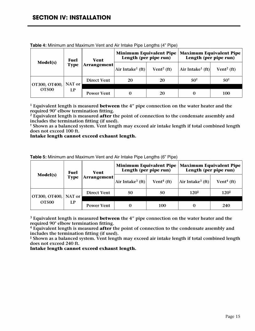
Table 4: Minimum and Maximum Vent and Air Intake Pipe Lengths (4” Pipe)
1 Equivalent length is measured between the 4” pipe connection on the water heater and the required 90° elbow termination fitting.2 Equivalent length is measured after the point of connection to the condensate assembly and includes the termination fitting (if used).† Shown as a balanced system. Vent length may exceed air intake length if total combined length does not exceed 100 ft.Intake length cannot exceed exhaust length.
Table 5: Minimum and Maximum Vent and Air Intake Pipe Lengths (6” Pipe)
3 Equivalent length is measured between the 4” pipe connection on the water heater and the required 90° elbow termination fitting.4 Equivalent length is measured after the point of connection to the condensate assembly and includes the termination fitting (if used).‡ Shown as a balanced system. Vent length may exceed air intake length if total combined length does not exceed 240 ft.Intake length cannot exceed exhaust length.
Model(s) Fuel Type
Vent Arrangement
Minimum Equivalent Pipe Length (per pipe run)
Maximum Equivalent Pipe Length (per pipe run)
Air Intake1 (ft) Vent2 (ft) Air Intake1 (ft) Vent2 (ft)
OT300, OT400, OT500
NAT orLP
Direct Vent 20 20 50† 50†
Power Vent 0 20 0 100
Model(s) Fuel Type
Vent Arrangement
Minimum Equivalent Pipe Length (per pipe run)
Maximum Equivalent Pipe Length (per pipe run)
Air Intake3 (ft) Vent4 (ft) Air Intake3 (ft) Vent4 (ft)
OT300, OT400,OT500
NAT orLP
Direct Vent 50 50 120‡ 120‡
Power Vent 0 100 0 240
Page 16
SECTION IV: INSTALLATION
The vent and combustion air intake systems must be sufficiently supported alongvertical and horizontal sections. At minimum, it is recommended that a support is placed along the vent or air intake piping every 4 feet. For horizontal systems, the first support shall be located immediately adjacent to the first 90-deg. elbow following the vertical section connected to the water heater. The support method should act to isolate the vent and combustion air intake piping from floor joists or other structural members to reduce transmis-sion of noise and vibration.
NOTE: Do not support, pin, or secure the vent and combustion air intake pipe in a way that restricts the normal thermal expansion and contraction of the venting material.
For replacement installations, thoroughly inspect the existing vent and combustion air intake systems prior to installing the new water heater. The following steps shall be taken to properly inspect the existing vent system:
• Verify that the materials as specified in this manual have been used.
• Verify the maximum and minimum vent and combustion air intake equivalent lengths and terminal clearances meet the specifications in this manual.
• Inspect the vent and combustion air intake systems for cracking. Pay close attention to joints between elbows and straight pipe.
• Inspect the system for misalignment of components. This may lead to sagging and unwanted stresses in the joints.
If any corrections are required they must be computed before installing the replacement water heater.
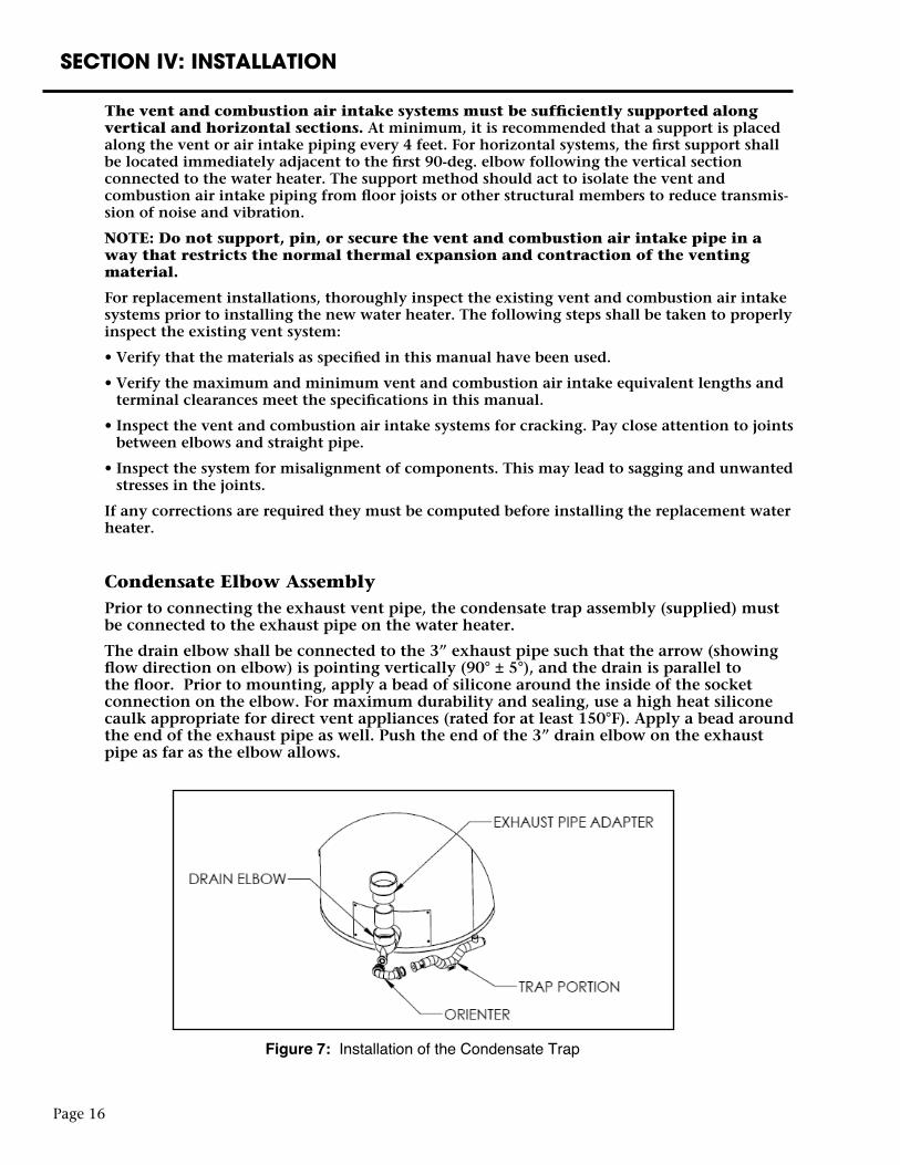
Condensate Elbow AssemblyPrior to connecting the exhaust vent pipe, the condensate trap assembly (supplied) must be connected to the exhaust pipe on the water heater.
The drain elbow shall be connected to the 3” exhaust pipe such that the arrow (showing flow direction on elbow) is pointing vertically (90° ± 5°), and the drain is parallel to the floor. Prior to mounting, apply a bead of silicone around the inside of the socket connection on the elbow. For maximum durability and sealing, use a high heat silicone caulk appropriate for direct vent appliances (rated for at least 150°F). Apply a bead around the end of the exhaust pipe as well. Push the end of the 3” drain elbow on the exhaust pipe as far as the elbow allows.
Figure 7: Installation of the Condensate Trap
Page 17
SECTION IV: INSTALLATION
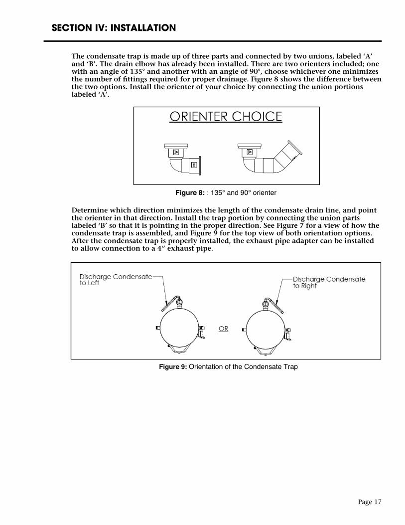
The condensate trap is made up of three parts and connected by two unions, labeled ‘A’ and ‘B’. The drain elbow has already been installed. There are two orienters included; one with an angle of 135° and another with an angle of 90°, choose whichever one minimizes the number of fittings required for proper drainage. Figure 8 shows the difference between the two options. Install the orienter of your choice by connecting the union portions labeled ‘A’.
Determine which direction minimizes the length of the condensate drain line, and point the orienter in that direction. Install the trap portion by connecting the union parts labeled ‘B’ so that it is pointing in the proper direction. See Figure 7 for a view of how the condensate trap is assembled, and Figure 9 for the top view of both orientation options. After the condensate trap is properly installed, the exhaust pipe adapter can be installed to allow connection to a 4” exhaust pipe.
Figure 8: : 135° and 90° orienter
Figure 9: Orientation of the Condensate Trap
Page 18
SECTION IV: INSTALLATION
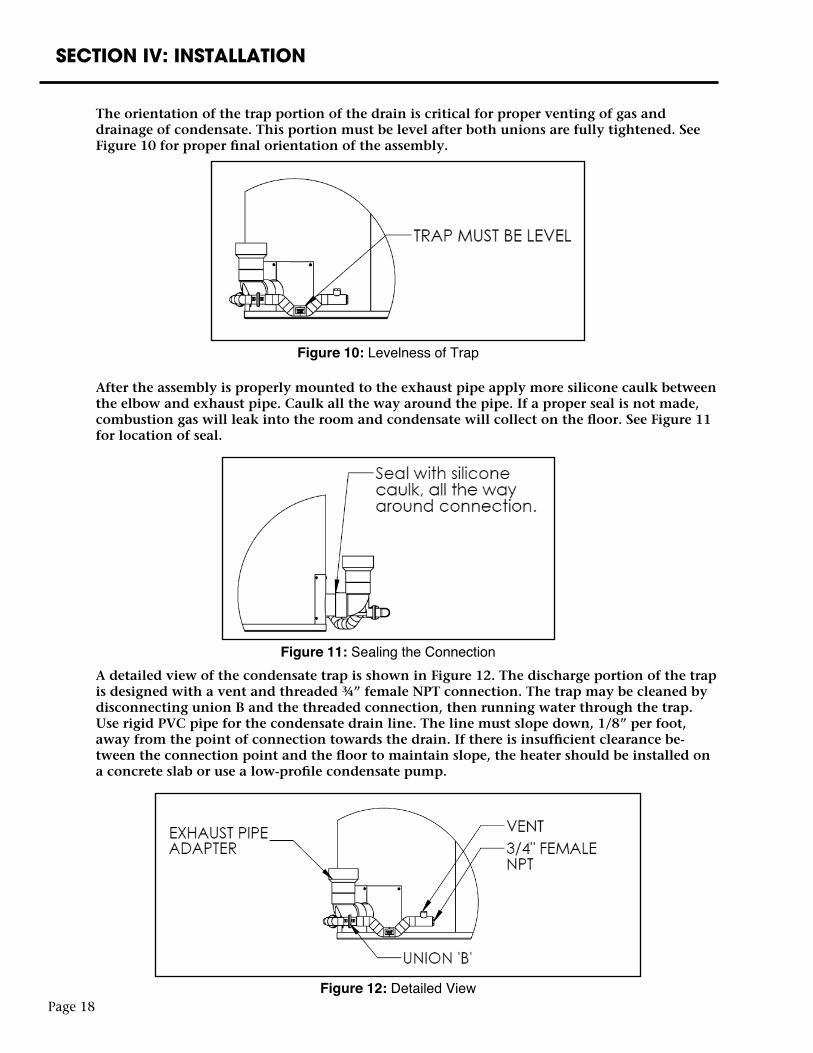
The orientation of the trap portion of the drain is critical for proper venting of gas and drainage of condensate. This portion must be level after both unions are fully tightened. See Figure 10 for proper final orientation of the assembly.
After the assembly is properly mounted to the exhaust pipe apply more silicone caulk between the elbow and exhaust pipe. Caulk all the way around the pipe. If a proper seal is not made, combustion gas will leak into the room and condensate will collect on the floor. See Figure 11 for location of seal.
Figure 10: Levelness of Trap
Figure 11: Sealing the ConnectionA detailed view of the condensate trap is shown in Figure 12. The discharge portion of the trap is designed with a vent and threaded ¾” female NPT connection. The trap may be cleaned by disconnecting union B and the threaded connection, then running water through the trap. Use rigid PVC pipe for the condensate drain line. The line must slope down, 1/8” per foot, away from the point of connection towards the drain. If there is insufficient clearance be-tween the connection point and the floor to maintain slope, the heater should be installed on a concrete slab or use a low-profile condensate pump.
Figure 12: Detailed View
SECTION IV: INSTALLATION
Page 19
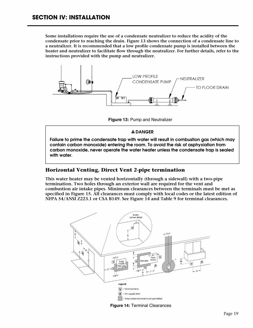
Figure 14: Terminal Clearances
DANGER
Failure to prime the condensate trap with water will result in combustion gas (which may contain carbon monoxide) entering the room. To avoid the risk of asphyxiation from carbon monoxide, never operate the water heater unless the condensate trap is sealed with water.
Horizontal Venting, Direct Vent 2-pipe termination
This water heater may be vented horizontally (through a sidewall) with a two-pipe termination. Two holes through an exterior wall are required for the vent and combustion air intake pipes. Minimum clearances between the terminals must be met as specified in Figure 15. All clearances must comply with local codes or the latest edition of NFPA 54/ANSI Z223.1 or CSA B149. See Figure 14 and Table 9 for terminal clearances.
Some installations require the use of a condensate neutralizer to reduce the acidity of the condensate prior to reaching the drain. Figure 13 shows the connection of a condensate line to a neutralizer. It is recommended that a low profile condensate pump is installed between the heater and neutralizer to facilitate flow through the neutralizer. For further details, refer to the instructions provided with the pump and neutralizer.
Figure 13: Pump and Neutralizer
Page 20
1 In accordance with the current CSA B149.1 Natural Gas and Propane Installation Code.2 In accordance with the current ANSI Z223.1 / NFPA 54 National Fuel Gas Code.
† A vent shall not terminate directly above a sidewalk or paved driveway that is located between two single family dwellings and serves both dwellings.
Permitted only if veranda, porch, deck, or balcony is fully open on a minimum of two sides beneath the floor.
* Clearance in accordance with local installation codes and the requirements of the gas supplier.
In addition to the clearances specified, the following items shall be accounted for during installation:• Do not terminate near soffit vents or crawl space or other area where condensate or vapor could create a
nuisance hazard or cause property damage.• Do not locate the exhaust vent terminal where condensate or vapor could cause damage or could be
detrimental to the operation of regulators, relief valves, or other equipment.• Do not locate the exhaust vent terminal over public area or walkways where condensate or vapor can
cause nuisance or hazard.• Do not locate the vent terminal in proximity to plants/shrubs.• The vent and air intake shall terminate a minimum of 12” (30.5 cm) above expected snowfall level to
prevent blockage.• It is best practice to locate the intake and exhaust terminations on a common plane.
SECTION IV: INSTALLATION
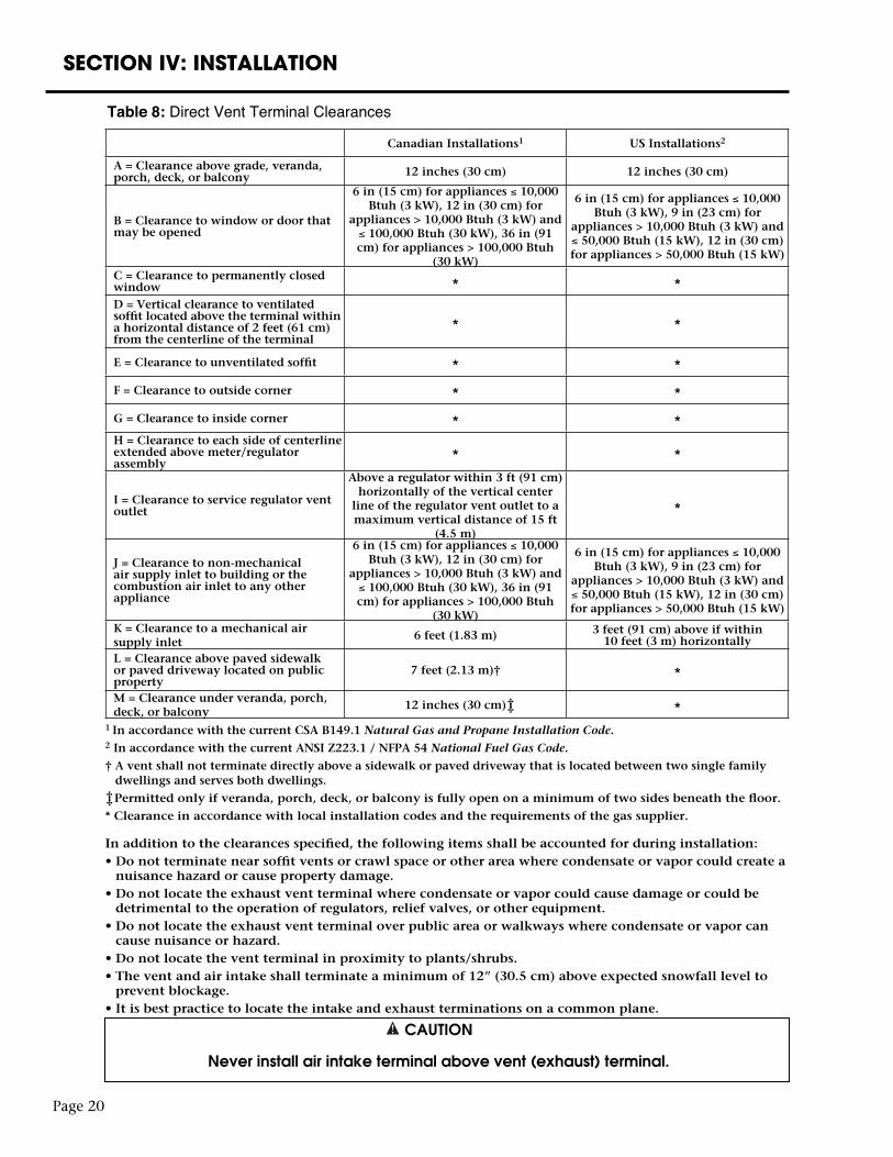
Table 8: Direct Vent Terminal Clearances
Canadian Installations1 US Installations2
A = Clearance above grade, veranda, porch, deck, or balcony 12 inches (30 cm) 12 inches (30 cm)
B = Clearance to window or door that may be opened
6 in (15 cm) for appliances ≤ 10,000 Btuh (3 kW), 12 in (30 cm) for
appliances > 10,000 Btuh (3 kW) and ≤ 100,000 Btuh (30 kW), 36 in (91 cm) for appliances > 100,000 Btuh
(30 kW)
6 in (15 cm) for appliances ≤ 10,000 Btuh (3 kW), 9 in (23 cm) for
appliances > 10,000 Btuh (3 kW) and ≤ 50,000 Btuh (15 kW), 12 in (30 cm) for appliances > 50,000 Btuh (15 kW)
C = Clearance to permanently closed window * *D = Vertical clearance to ventilated soffit located above the terminal within a horizontal distance of 2 feet (61 cm) from the centerline of the terminal
* *
E = Clearance to unventilated soffit * *
F = Clearance to outside corner * *
G = Clearance to inside corner * *H = Clearance to each side of centerline extended above meter/regulator assembly
* *
I = Clearance to service regulator vent outlet
Above a regulator within 3 ft (91 cm) horizontally of the vertical center
line of the regulator vent outlet to a maximum vertical distance of 15 ft
(4.5 m)
*
J = Clearance to non-mechanical air supply inlet to building or the combustion air inlet to any other appliance
6 in (15 cm) for appliances ≤ 10,000 Btuh (3 kW), 12 in (30 cm) for
appliances > 10,000 Btuh (3 kW) and ≤ 100,000 Btuh (30 kW), 36 in (91 cm) for appliances > 100,000 Btuh
(30 kW)
6 in (15 cm) for appliances ≤ 10,000 Btuh (3 kW), 9 in (23 cm) for
appliances > 10,000 Btuh (3 kW) and ≤ 50,000 Btuh (15 kW), 12 in (30 cm) for appliances > 50,000 Btuh (15 kW)
K = Clearance to a mechanical air supply inlet
6 feet (1.83 m) 3 feet (91 cm) above if within 10 feet (3 m) horizontally
L = Clearance above paved sidewalk or paved driveway located on public property
7 feet (2.13 m)† *
M = Clearance under veranda, porch, deck, or balcony
12 inches (30 cm) *
††
CAUTION
Never install air intake terminal above vent (exhaust) terminal.
††
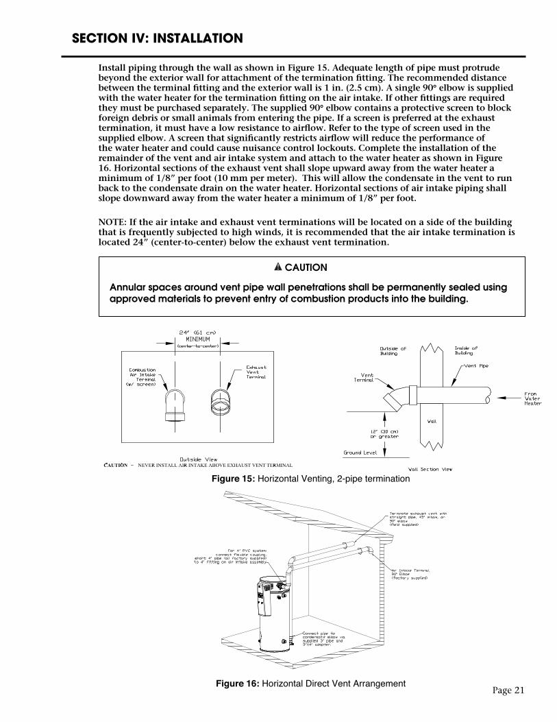
Install piping through the wall as shown in Figure 15. Adequate length of pipe must protrude beyond the exterior wall for attachment of the termination fitting. The recommended distance between the terminal fitting and the exterior wall is 1 in. (2.5 cm). A single 90° elbow is supplied with the water heater for the termination fitting on the air intake. If other fittings are required they must be purchased separately. The supplied 90° elbow contains a protective screen to block foreign debris or small animals from entering the pipe. If a screen is preferred at the exhaust termination, it must have a low resistance to airflow. Refer to the type of screen used in the supplied elbow. A screen that significantly restricts airflow will reduce the performance of the water heater and could cause nuisance control lockouts. Complete the installation of the remainder of the vent and air intake system and attach to the water heater as shown in Figure 16. Horizontal sections of the exhaust vent shall slope upward away from the water heater a minimum of 1/8” per foot (10 mm per meter). This will allow the condensate in the vent to run back to the condensate drain on the water heater. Horizontal sections of air intake piping shall slope downward away from the water heater a minimum of 1/8” per foot.
NOTE: If the air intake and exhaust vent terminations will be located on a side of the building that is frequently subjected to high winds, it is recommended that the air intake termination is located 24” (center-to-center) below the exhaust vent termination.
CAUTION
Annular spaces around vent pipe wall penetrations shall be permanently sealed using approved materials to prevent entry of combustion products into the building.
Page 21
SECTION IV: INSTALLATION
Figure 15: Horizontal Venting, 2-pipe termination
Figure 16: Horizontal Direct Vent Arrangement
SECTION IV: INSTALLATION
Page 22
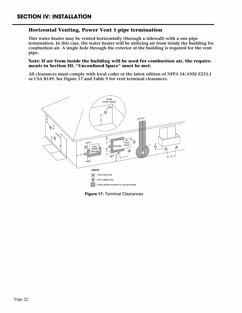
Horizontal Venting, Power Vent 1-pipe termination
This water heater may be vented horizontally (through a sidewall) with a one-pipe termination. In this case, the water heater will be utilizing air from inside the building for combustion air. A single hole through the exterior of the building is required for the vent pipe.
Note: If air from inside the building will be used for combustion air, the require-ments in Section III, “Unconfined Space” must be met.
All clearances must comply with local codes or the latest edition of NFPA 54/ANSI Z223.1 or CSA B149. See Figure 17 and Table 9 for vent terminal clearances.
Figure 17: Terminal Clearances
Page 23
SECTION IV: INSTALLATION
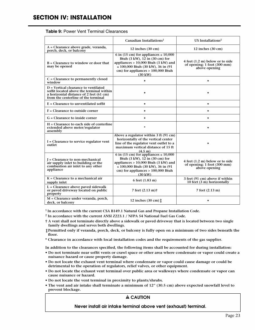
Table 9: Power Vent Terminal Clearances
1 In accordance with the current CSA B149.1 Natural Gas and Propane Installation Code.2 In accordance with the current ANSI Z223.1 / NFPA 54 National Fuel Gas Code.† A vent shall not terminate directly above a sidewalk or paved driveway that is located between two single
family dwellings and serves both dwellings. Permitted only if veranda, porch, deck, or balcony is fully open on a minimum of two sides beneath the
floor.* Clearance in accordance with local installation codes and the requirements of the gas supplier.
In addition to the clearances specified, the following items shall be accounted for during installation:• Do not terminate near soffit vents or crawl space or other area where condensate or vapor could create a
nuisance hazard or cause property damage.• Do not locate the exhaust vent terminal where condensate or vapor could cause damage or could be
detrimental to the operation of regulators, relief valves, or other equipment.• Do not locate the exhaust vent terminal over public area or walkways where condensate or vapor can
cause nuisance or hazard.• Do not locate the vent terminal in proximity to plants/shrubs.• The vent and air intake shall terminate a minimum of 12” (30.5 cm) above expected snowfall level to
prevent blockage.
††
Canadian Installations1 US Installations2
A = Clearance above grade, veranda, porch, deck, or balcony 12 inches (30 cm) 12 inches (30 cm)
B = Clearance to window or door that may be opened
6 in (15 cm) for appliances ≤ 10,000 Btuh (3 kW), 12 in (30 cm) for
appliances > 10,000 Btuh (3 kW) and ≤ 100,000 Btuh (30 kW), 36 in (91 cm) for appliances > 100,000 Btuh
(30 kW)
4 feet (1.2 m) below or to side of opening; 1 foot (300 mm)
above opening
C = Clearance to permanently closed window * *D = Vertical clearance to ventilated soffit located above the terminal within a horizontal distance of 2 feet (61 cm) from the centerline of the terminal
* *
E = Clearance to unventilated soffit * *F = Clearance to outside corner * *G = Clearance to inside corner * *H = Clearance to each side of centerline extended above meter/regulator assembly
* *
I = Clearance to service regulator vent outlet
Above a regulator within 3 ft (91 cm) horizontally of the vertical center
line of the regulator vent outlet to a maximum vertical distance of 15 ft
(4.5 m)
*
J = Clearance to non-mechanical air supply inlet to building or the combustion air inlet to any other appliance
6 in (15 cm) for appliances ≤ 10,000 Btuh (3 kW), 12 in (30 cm) for
appliances > 10,000 Btuh (3 kW) and ≤ 100,000 Btuh (30 kW), 36 in (91 cm) for appliances > 100,000 Btuh
(30 kW)
4 feet (1.2 m) below or to side of opening; 1 foot (300 mm)
above opening
K = Clearance to a mechanical air supply inlet
6 feet (1.83 m) 3 feet (91 cm) above if within 10 feet (3 m) horizontally
L = Clearance above paved sidewalk or paved driveway located on public property
7 feet (2.13 m)† 7 feet (2.13 m)
M = Clearance under veranda, porch, deck, or balcony
12 inches (30 cm) *††
CAUTION
Never install air intake terminal above vent (exhaust) terminal.
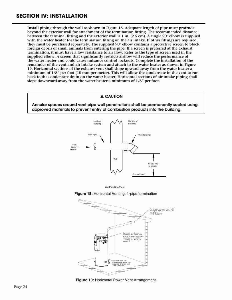
Install piping through the wall as shown in Figure 18. Adequate length of pipe must protrude beyond the exterior wall for attachment of the termination fitting. The recommended distance between the terminal fitting and the exterior wall is 1 in. (2.5 cm). A single 90° elbow is supplied with the water heater for the termination fitting on the air intake. If other fittings are required they must be purchased separately. The supplied 90° elbow contains a protective screen to block foreign debris or small animals from entering the pipe. If a screen is preferred at the exhaust termination, it must have a low resistance to air flow. Refer to the type of screen used in the supplied elbow. A screen that significantly restricts airflow will reduce the performance of the water heater and could cause nuisance control lockouts. Complete the installation of the remainder of the vent and air intake system and attach to the water heater as shown in Figure 19. Horizontal sections of the exhaust vent shall slope upward away from the water heater a minimum of 1/8” per foot (10 mm per meter). This will allow the condensate in the vent to run back to the condensate drain on the water heater. Horizontal sections of air intake piping shall slope downward away from the water heater a minimum of 1/8” per foot.
CAUTION
Annular spaces around vent pipe wall penetrations shall be permanently sealed using approved materials to prevent entry of combustion products into the building.
Page 24
SECTION IV: INSTALLATION
Figure 18: Horizontal Venting, 1-pipe termination
Figure 19: Horizontal Power Vent Arrangement
Vent Terminal
From Water
Heater
Wall
Outside of Building
Inside of Building
Vent Pipe
12" (30 cm) or greater
Ground Level
Wall Section View
Figure 6: Horizontal Venting, 1-pipe termination
Page 25
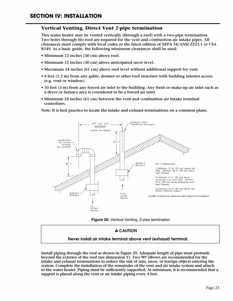
Vertical Venting, Direct Vent 2-pipe terminationThis water heater may be vented vertically (through a roof) with a two-pipe termination. Two holes through the roof are required for the vent and combustion air intake pipes. All clearances must comply with local codes or the latest edition of NFPA 54/ANSI Z223.1 or CSA B149. As a basic guide, the following minimum clearances shall be used:
• Minimum 12 inches (30 cm) above roof.
• Minimum 12 inches (30 cm) above anticipated snow level.
• Maximum 24 inches (61 cm) above roof level without additional support for vent.
• 4 feet (1.2 m) from any gable, dormer or other roof structure with building interior access (e.g. vent or window).
• 10 feet (3 m) from any forced air inlet to the building. Any fresh or make-up air inlet such as a dryer or furnace area is considered to be a forced air inlet.
• Minimum 24 inches (61 cm) between the vent and combustion air intake terminal centerlines.
Note: It is best practice to locate the intake and exhaust terminations on a common plane.
CAUTION
Never install air intake terminal above vent (exhaust) terminal.
Install piping through the roof as shown in Figure 20. Adequate length of pipe must protrude beyond the exterior of the roof (see dimension Y). Two 90° elbows are recommended for the intake and exhaust terminations to reduce the risk of rain, snow, or foreign objects entering the system. Complete the installation of the remainder of the vent and air intake system and attach to the water heater. Piping must be sufficiently supported. At minimum, it is recommended that a support is placed along the vent or air intake piping every 4 feet.
SECTION IV: INSTALLATION
Figure 20: Vertical Venting, 2-pipe termination
Page 26
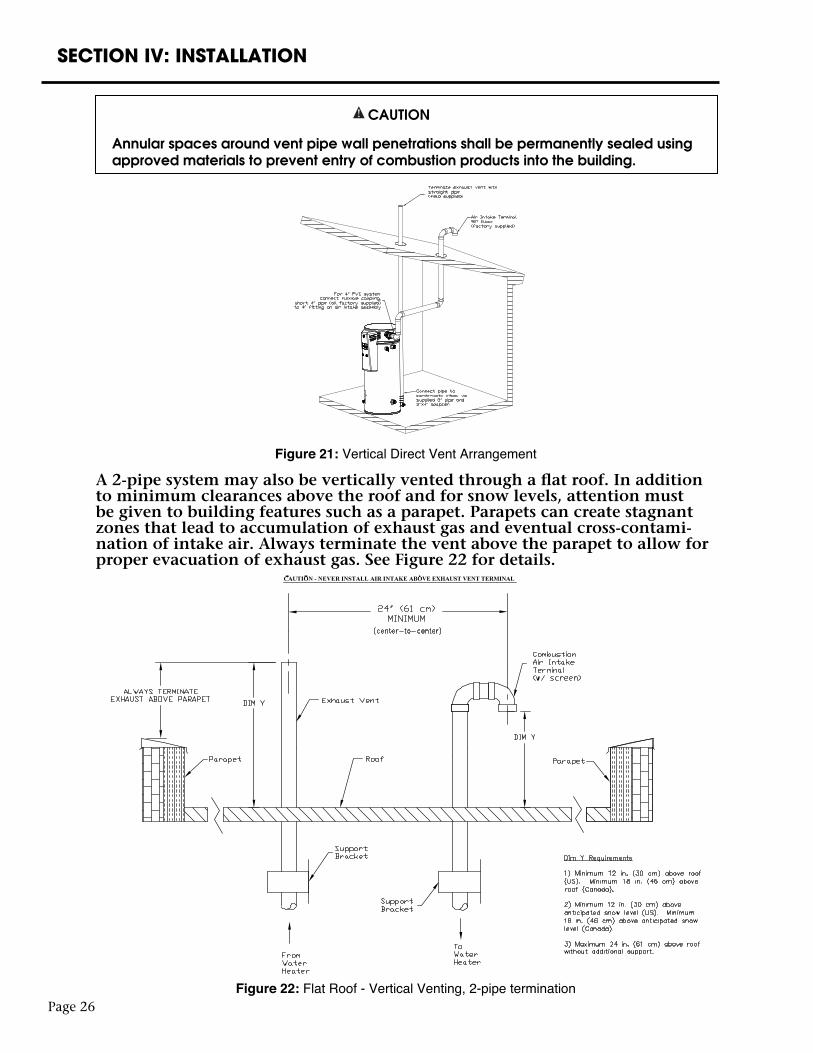
CAUTION
Annular spaces around vent pipe wall penetrations shall be permanently sealed using approved materials to prevent entry of combustion products into the building.
A 2-pipe system may also be vertically vented through a flat roof. In addition to minimum clearances above the roof and for snow levels, attention must be given to building features such as a parapet. Parapets can create stagnant zones that lead to accumulation of exhaust gas and eventual cross-contami-nation of intake air. Always terminate the vent above the parapet to allow for proper evacuation of exhaust gas. See Figure 22 for details.
SECTION IV: INSTALLATION
Figure 21: Vertical Direct Vent Arrangement
Figure 22: Flat Roof - Vertical Venting, 2-pipe termination
Page 27
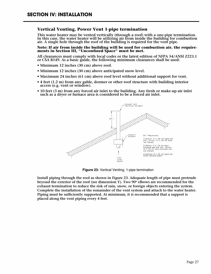
Install piping through the roof as shown in Figure 23. Adequate length of pipe must protrude beyond the exterior of the roof (see dimension Y). Two 90° elbows are recommended for the exhaust termination to reduce the risk of rain, snow, or foreign objects entering the system. Complete the installation of the remainder of the vent system and attach to the water heater. Piping must be sufficiently supported. At minimum, it is recommended that a support is placed along the vent piping every 4 feet.
SECTION IV: INSTALLATION
Figure 23: Vertical Venting, 1-pipe termination
Vertical Venting, Power Vent 1-pipe terminationThis water heater may be vented vertically (through a roof) with a one-pipe termination. In this case, the water heater will be utilizing air from inside the building for combustion air. A single hole through the roof of the building is required for the vent pipe.
Note: If air from inside the building will be used for combustion air, the require-ments in Section III, “Unconfined Space” must be met. All clearances must comply with local codes or the latest edition of NFPA 54/ANSI Z223.1 or CSA B149. As a basic guide, the following minimum clearances shall be used:
• Minimum 12 inches (30 cm) above roof.
• Minimum 12 inches (30 cm) above anticipated snow level.
• Maximum 24 inches (61 cm) above roof level without additional support for vent.
• 4 feet (1.2 m) from any gable, dormer or other roof structure with building interior access (e.g. vent or window).
• 10 feet (3 m) from any forced air inlet to the building. Any fresh or make-up air inlet such as a dryer or furnace area is considered to be a forced air inlet.
SECTION IV: INSTALLATION
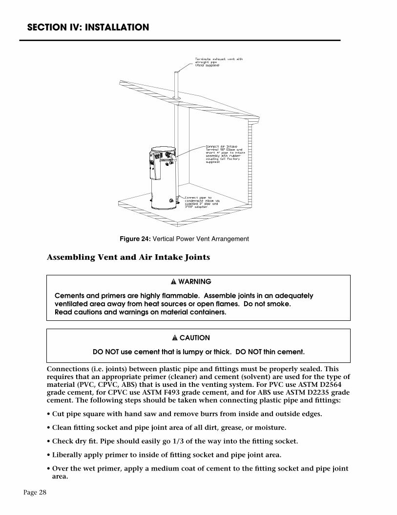
Assembling Vent and Air Intake Joints
WARNING
Cements and primers are highly flammable. Assemble joints in an adequately ventilated area away from heat sources or open flames. Do not smoke. Read cautions and warnings on material containers.
CAUTION
DO NOT use cement that is lumpy or thick. DO NOT thin cement.
Connections (i.e. joints) between plastic pipe and fittings must be properly sealed. This requires that an appropriate primer (cleaner) and cement (solvent) are used for the type of material (PVC, CPVC, ABS) that is used in the venting system. For PVC use ASTM D2564 grade cement, for CPVC use ASTM F493 grade cement, and for ABS use ASTM D2235 grade cement. The following steps should be taken when connecting plastic pipe and fittings:
• Cut pipe square with hand saw and remove burrs from inside and outside edges.
• Clean fitting socket and pipe joint area of all dirt, grease, or moisture.
• Check dry fit. Pipe should easily go 1/3 of the way into the fitting socket.
• Liberally apply primer to inside of fitting socket and pipe joint area.
• Over the wet primer, apply a medium coat of cement to the fitting socket and pipe joint area.
Page 28
Figure 24: Vertical Power Vent Arrangement
Page 29
SECTION IV: INSTALLATION
• Insert pipe into fitting with a slight twisting motion. Ensure that the pipe is bottomed into the fitting.
• Hold pipe and fitting for 30 seconds to prevent push off.
• Wipe off excess cement. Cure time may be at least 2 hours for Ø4” pipe at 60°F. Longer cure time is required for larger diameter pipe and/or lower temperatures.
Note: The vent and combustion air intake pipe/fittings must overlap a minimumof 1/2 inch (1.3 cm) at each joint. DO NOT drill or punch holes in the plastic pipeor fittings.
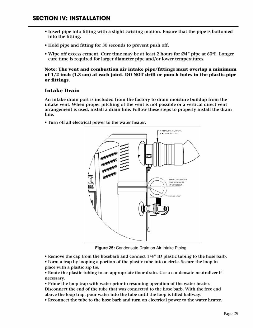
Intake Drain
An intake drain port is included from the factory to drain moisture buildup from the intake vent. When proper pitching of the vent is not possible or a vertical direct vent arrangement is used, install a drain line. Follow these steps to properly install the drain line:
• Turn off all electrical power to the water heater.
• Remove the cap from the hosebarb and connect 1/4” ID plastic tubing to the hose barb.• Form a trap by looping a portion of the plastic tube into a circle. Secure the loop inplace with a plastic zip tie.• Route the plastic tubing to an appropriate floor drain. Use a condensate neutralizer ifnecessary.• Prime the loop trap with water prior to resuming operation of the water heater.Disconnect the end of the tube that was connected to the hose barb. With the free endabove the loop trap, pour water into the tube until the loop is filled halfway.• Reconnect the tube to the hose barb and turn on electrical power to the water heater.
Figure 25: Condensate Drain on Air Intake Piping
SECTION IV: INSTALLATION
WATER CONNECTIONS
CAUTION
This water heater incorporates fittings that contain a nonmetallic lining. DO NOT apply heat to these fittings when making sweat connections to the heater. Sweat tubing to an adapter before securing adapter to any fittings on water heaters.
ALL PIPING SHOULD CONFORM TO LOCAL CODES AND ORDINANCES. It is highly recommended that unions and shut-off valves are installed at the potable water connections to allow for isolation and/or movement during service. All piping should be adequately insulated with an approved material to minimize heat loss.
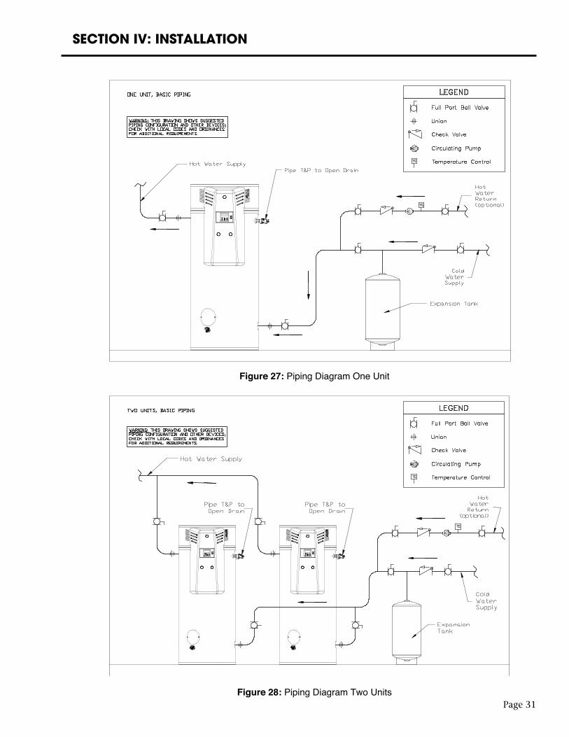
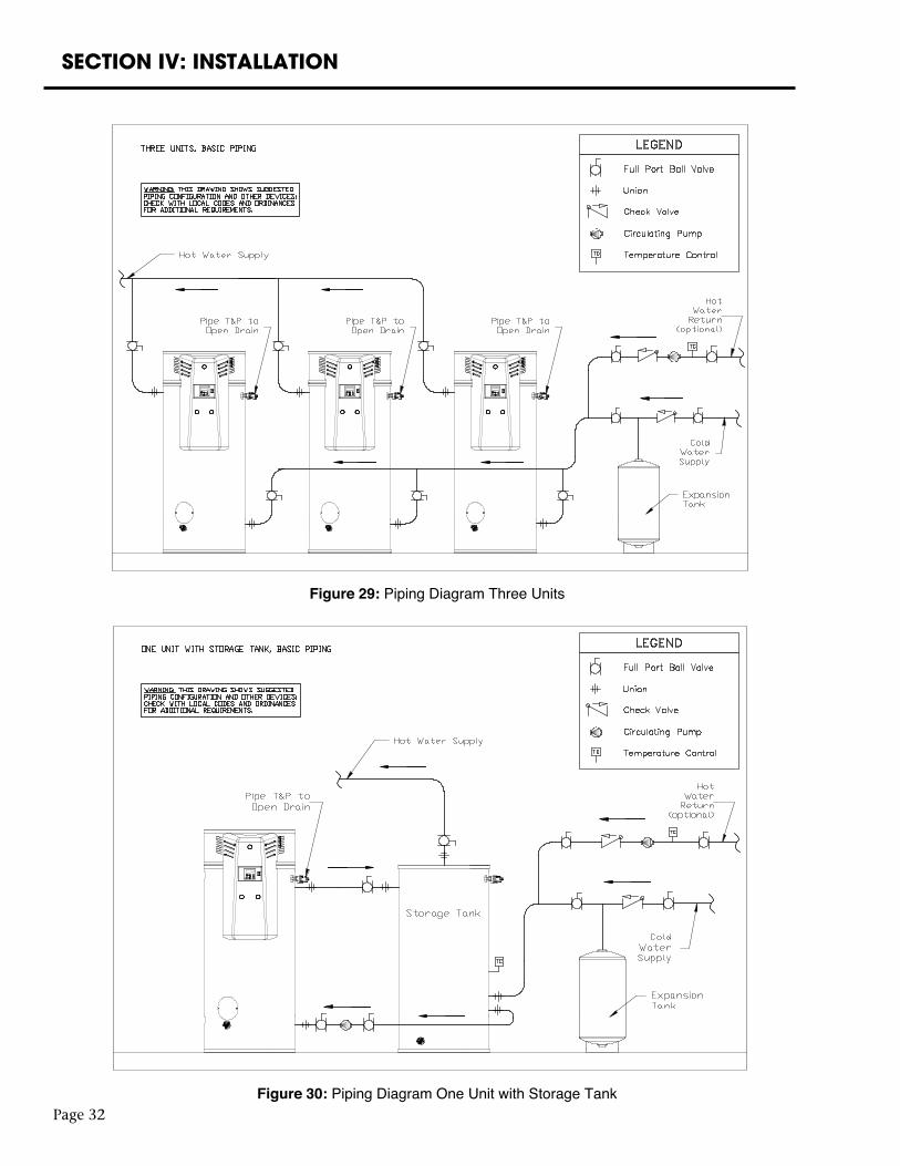
Piping diagrams are provided in Figures 27 - 30 for a variety of configurations.
POTABLE WATER CONNECTIONS
IMPORTANT: THE WATER HEATER MUST BE FILLED WITH WATER BEFORE CONNECTING ELECTRIC POWER.
1) Close the main water supply valve before continuing with the installation. After the main water supply is shut-off, relieve the water line pressure by opening a faucet. Once the pressure has been relieved, close the faucet. The “Cold” and “Hot” potable water connections are labeled on the water heater. Install a union and shut-off valve at both potable water connections. A tempering valve or anti-scald valve should be installed at the potable water outlet and used according to the manufacturer’s specifications to prevent scalding.
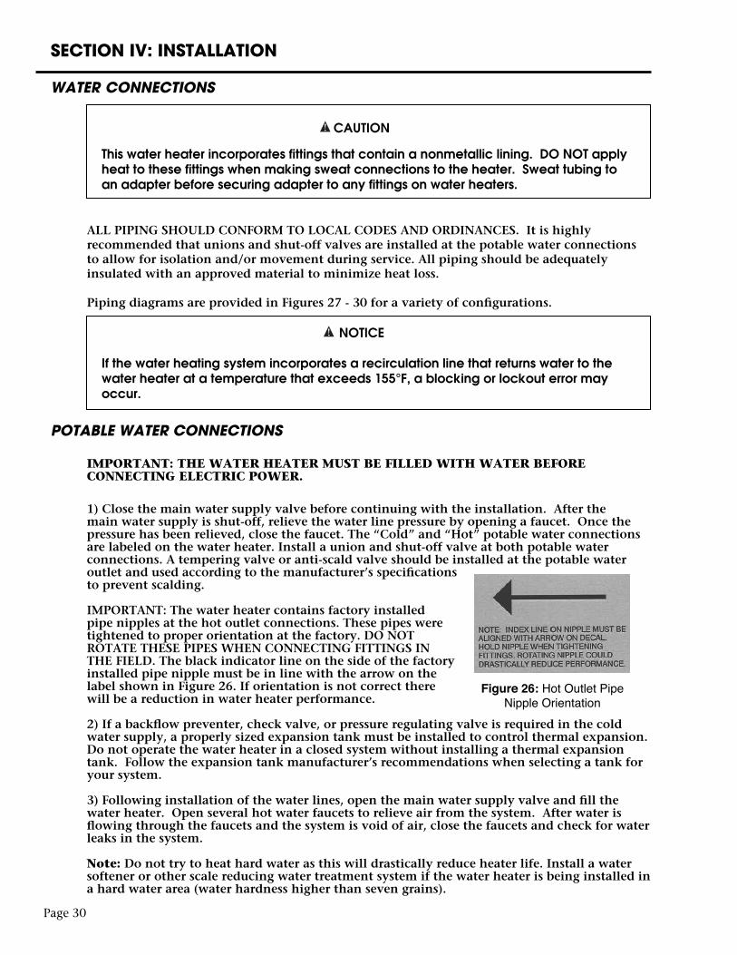
IMPORTANT: The water heater contains factory installed pipe nipples at the hot outlet connections. These pipes were tightened to proper orientation at the factory. DO NOT ROTATE THESE PIPES WHEN CONNECTING FITTINGS IN THE FIELD. The black indicator line on the side of the factory installed pipe nipple must be in line with the arrow on the label shown in Figure 26. If orientation is not correct there will be a reduction in water heater performance.
2) If a backflow preventer, check valve, or pressure regulating valve is required in the cold water supply, a properly sized expansion tank must be installed to control thermal expansion. Do not operate the water heater in a closed system without installing a thermal expansion tank. Follow the expansion tank manufacturer’s recommendations when selecting a tank for your system.
3) Following installation of the water lines, open the main water supply valve and fill the water heater. Open several hot water faucets to relieve air from the system. After water is flowing through the faucets and the system is void of air, close the faucets and check for water leaks in the system.
Note: Do not try to heat hard water as this will drastically reduce heater life. Install a water softener or other scale reducing water treatment system if the water heater is being installed in a hard water area (water hardness higher than seven grains).
Page 30
NOTICE
If the water heating system incorporates a recirculation line that returns water to the water heater at a temperature that exceeds 155°F, a blocking or lockout error may occur.
Figure 26: Hot Outlet Pipe Nipple Orientation
SECTION IV: INSTALLATION
Page 31
Figure 27: Piping Diagram One Unit
Figure 28: Piping Diagram Two Units
SECTION IV: INSTALLATION
Page 32
Figure 29: Piping Diagram Three Units
Figure 30: Piping Diagram One Unit with Storage Tank
SECTION IV: INSTALLATION
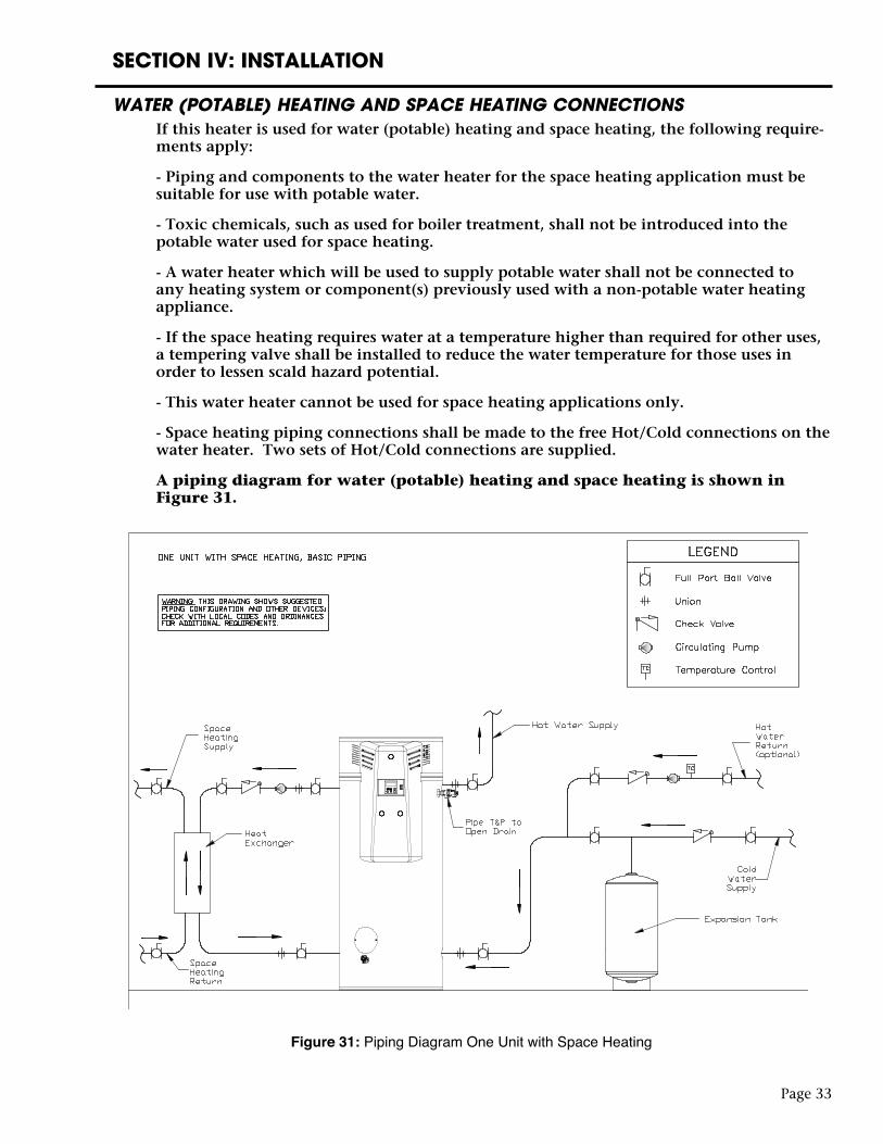
WATER (POTABLE) HEATING AND SPACE HEATING CONNECTIONSIf this heater is used for water (potable) heating and space heating, the following require-ments apply:
- Piping and components to the water heater for the space heating application must be suitable for use with potable water.
- Toxic chemicals, such as used for boiler treatment, shall not be introduced into the potable water used for space heating.
- A water heater which will be used to supply potable water shall not be connected to any heating system or component(s) previously used with a non-potable water heating appliance.
- If the space heating requires water at a temperature higher than required for other uses, a tempering valve shall be installed to reduce the water temperature for those uses in order to lessen scald hazard potential.
- This water heater cannot be used for space heating applications only.
- Space heating piping connections shall be made to the free Hot/Cold connections on the water heater. Two sets of Hot/Cold connections are supplied.
A piping diagram for water (potable) heating and space heating is shown in Figure 31.
Page 33
Figure 31: Piping Diagram One Unit with Space Heating
Page 34
SECTION IV: INSTALLATION
GAS CONNECTIONS
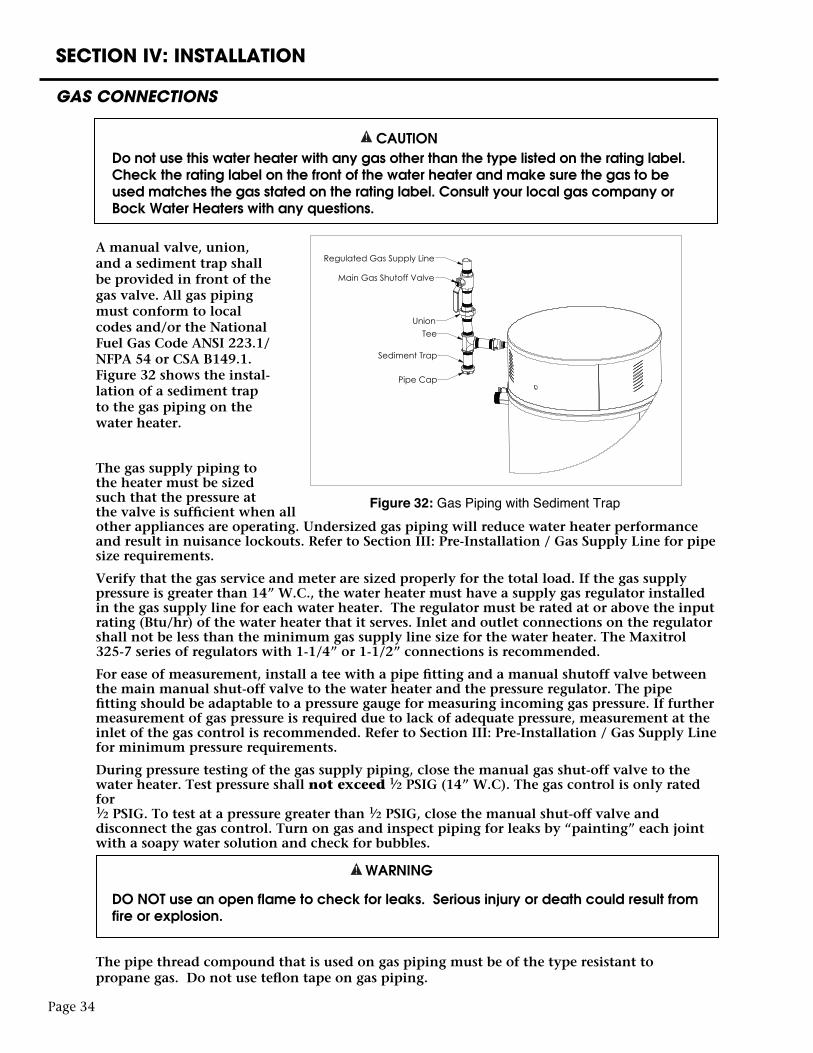
CAUTION Do not use this water heater with any gas other than the type listed on the rating label.
Check the rating label on the front of the water heater and make sure the gas to be used matches the gas stated on the rating label. Consult your local gas company or Bock Water Heaters with any questions.
A manual valve, union, and a sediment trap shall be provided in front of the gas valve. All gas piping must conform to local codes and/or the National Fuel Gas Code ANSI 223.1/NFPA 54 or CSA B149.1. Figure 32 shows the instal-lation of a sediment trap to the gas piping on the water heater.
The gas supply piping to the heater must be sized such that the pressure at the valve is sufficient when all other appliances are operating. Undersized gas piping will reduce water heater performance and result in nuisance lockouts. Refer to Section III: Pre-Installation / Gas Supply Line for pipe size requirements.
Verify that the gas service and meter are sized properly for the total load. If the gas supply pressure is greater than 14” W.C., the water heater must have a supply gas regulator installed in the gas supply line for each water heater. The regulator must be rated at or above the input rating (Btu/hr) of the water heater that it serves. Inlet and outlet connections on the regulator shall not be less than the minimum gas supply line size for the water heater. The Maxitrol 325-7 series of regulators with 1-1/4” or 1-1/2” connections is recommended.
For ease of measurement, install a tee with a pipe fitting and a manual shutoff valve between the main manual shut-off valve to the water heater and the pressure regulator. The pipe fitting should be adaptable to a pressure gauge for measuring incoming gas pressure. If further measurement of gas pressure is required due to lack of adequate pressure, measurement at the inlet of the gas control is recommended. Refer to Section III: Pre-Installation / Gas Supply Line for minimum pressure requirements.
During pressure testing of the gas supply piping, close the manual gas shut-off valve to the water heater. Test pressure shall not exceed 1⁄2 PSIG (14” W.C). The gas control is only rated for 1⁄2 PSIG. To test at a pressure greater than 1⁄2 PSIG, close the manual shut-off valve and disconnect the gas control. Turn on gas and inspect piping for leaks by “painting” each joint with a soapy water solution and check for bubbles.
WARNING
DO NOT use an open flame to check for leaks. Serious injury or death could result from fire or explosion.
The pipe thread compound that is used on gas piping must be of the type resistant to propane gas. Do not use teflon tape on gas piping.
Figure 32: Gas Piping with Sediment Trap
SECTION IV: INSTALLATION
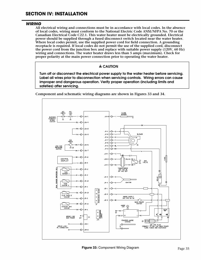
WIRING All electrical wiring and connections must be in accordance with local codes. In the absence of local codes, wiring must conform to the National Electric Code ANSI/NFPA No. 70 or the Canadian Electrical Code C22.1. This water heater must be electrically grounded. Electrical power should be supplied through a fused disconnect switch located near the water heater. Where local codes permit, use the supplied power cord for field connection. A grounding receptacle is required. If local codes do not permit the use of the supplied cord, disconnect the power cord from the junction box and replace with suitable power supply (120V, 60 Hz) wiring and connections. The water heater draws less than 5 amps (maximum). Check for proper polarity at the main power connection prior to operating the water heater.
CAUTION
Turn off or disconnect the electrical power supply to the water heater before servicing. Label all wires prior to disconnection when servicing controls. Wiring errors can cause improper and dangerous operation. Verify proper operation (including limits and safeties) after servicing.
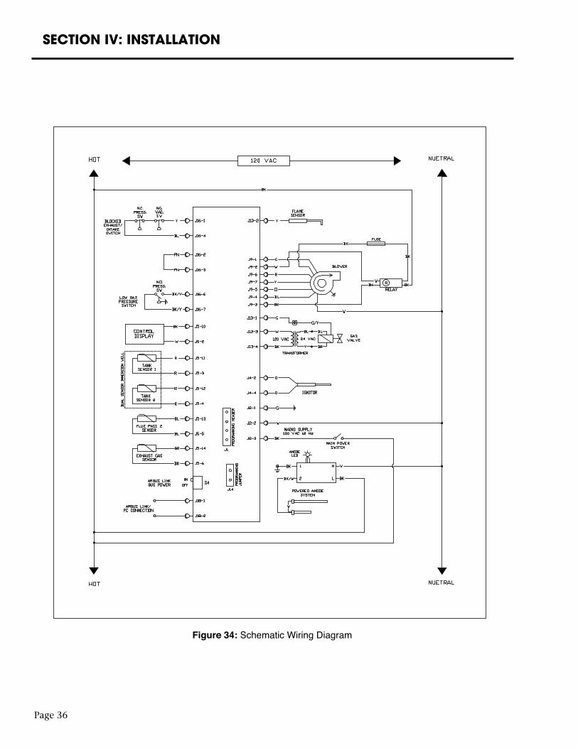
Component and schematic wiring diagrams are shown in Figures 33 and 34.
Page 35Figure 33: Component Wiring Diagram
Page 36
SECTION IV: INSTALLATION
Figure 34: Schematic Wiring Diagram
Page 37
SECTION V: OPERATION
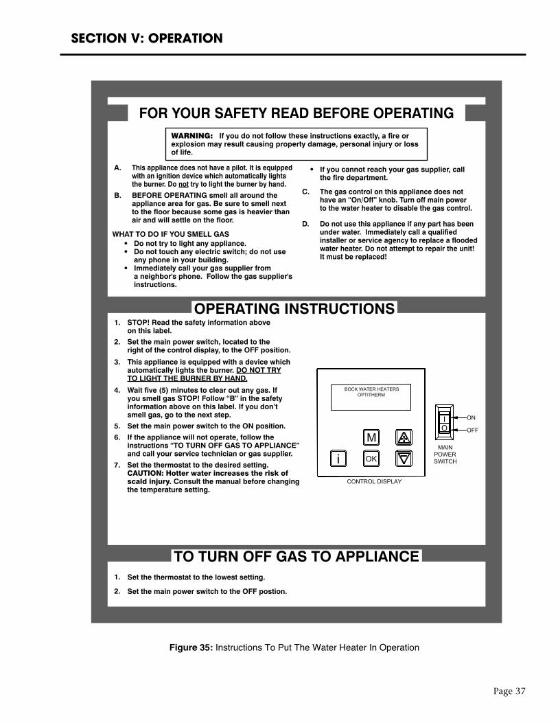
Set the thermostat to the desired setting.CAUTION: Hotter water increases the risk ofscald injury. Consult the manual before changingthe temperature setting.
This appliance does not have a pilot. It is equippedwith an ignition device which automatically lightsthe burner. Do not try to light the burner by hand.
A.
STOP! Read the safety information aboveon this label.
1.
Set the main power switch, located to theright of the control display, to the OFF position.
2.
Set the main power switch to the ON position. 5.
If the appliance will not operate, follow theinstructions “TO TURN OFF GAS TO APPLIANCE”and call your service technician or gas supplier.
6.
Wait five (5) minutes to clear out any gas. Ifyou smell gas STOP! Follow “B” in the safetyinformation above on this label. If you don’tsmell gas, go to the next step.
4.
This appliance is equipped with a device whichautomatically lights the burner. DO NOT TRYTO LIGHT THE BURNER BY HAND.
3.
BEFORE OPERATING smell all around theappliance area for gas. Be sure to smell nextto the floor because some gas is heavier thanair and will settle on the floor.
B. C.
D.WHAT TO DO IF YOU SMELL GAS
Do not try to light any appliance.Do not touch any electric switch; do not useany phone in your building.Immediately call your gas supplier froma neighbor's phone. Follow the gas supplier'sinstructions.
The gas control on this appliance does nothave an “On/Off” knob. Turn off main powerto the water heater to disable the gas control.
Do not use this appliance if any part has beenunder water. Immediately call a qualifiedinstaller or service agency to replace a floodedwater heater. Do not attempt to repair the unit!It must be replaced!
WARNING: If you do not follow these instructions exactly, a fire orexplosion may result causing property damage, personal injury or lossof life.
If you cannot reach your gas supplier, callthe fire department.
FOR YOUR SAFETY READ BEFORE OPERATING
OPERATING INSTRUCTIONS
TO TURN OFF GAS TO APPLIANCE1.
7.
Set the thermostat to the lowest setting.
2. Set the main power switch to the OFF postion.
Figure 35: Instructions To Put The Water Heater In Operation
SECTION V: OPERATION
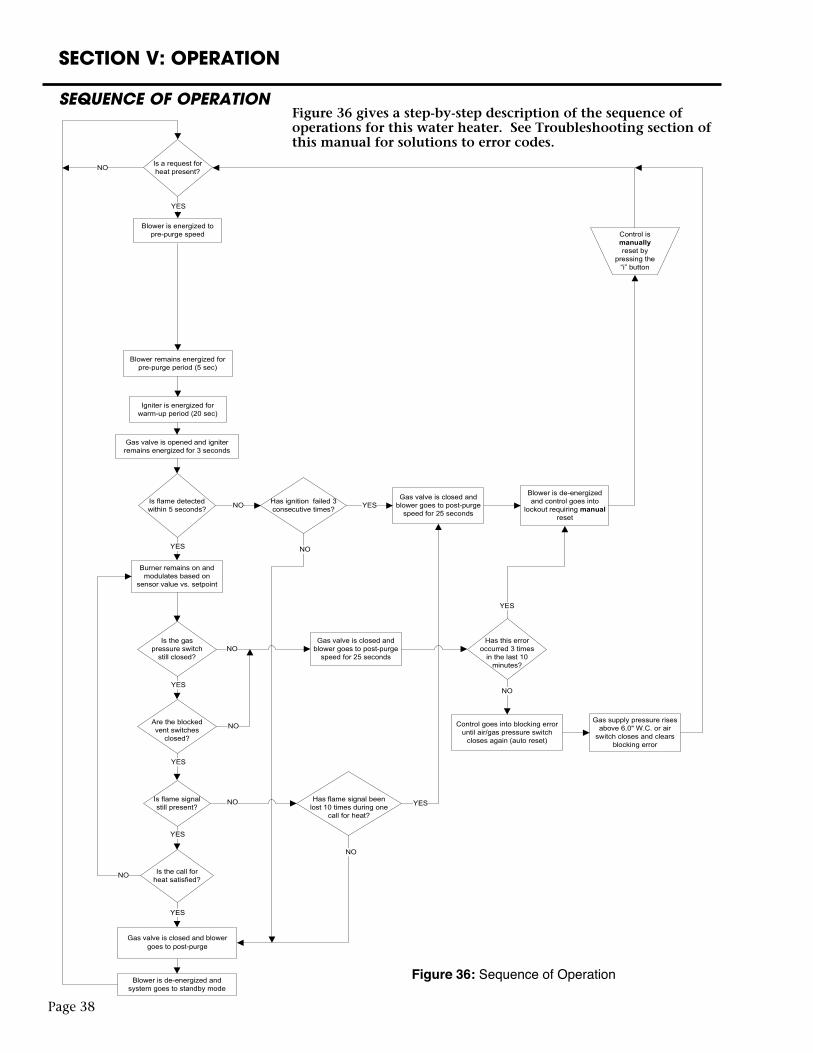
SEQUENCE OF OPERATION
Gas valve is closed and blowergoes to post-purge
Figure 36: Sequence of Operation
Figure 36 gives a step-by-step description of the sequence of operations for this water heater. See Troubleshooting section of this manual for solutions to error codes.
Page 38
Page 39
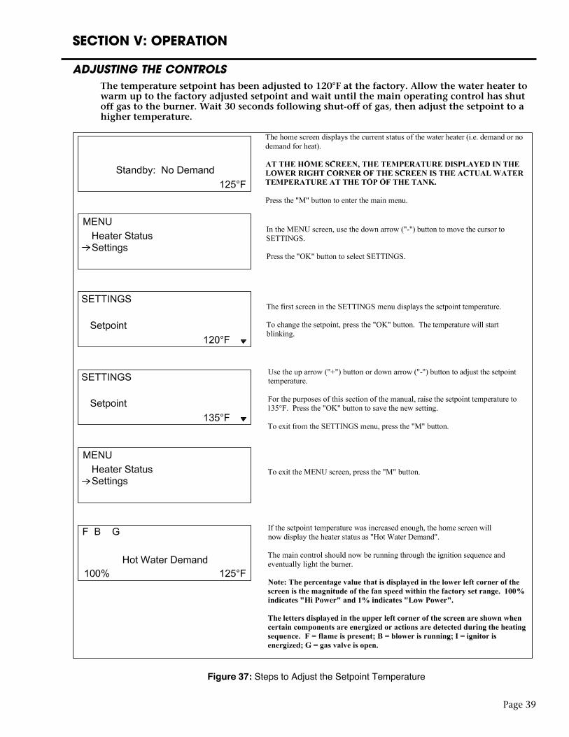
SECTION V: OPERATION
ADJUSTING THE CONTROLSThe temperature setpoint has been adjusted to 120°F at the factory. Allow the water heater to warm up to the factory adjusted setpoint and wait until the main operating control has shut off gas to the burner. Wait 30 seconds following shut-off of gas, then adjust the setpoint to a higher temperature.
Figure 37: Steps to Adjust the Setpoint Temperature
SECTION V: OPERATION
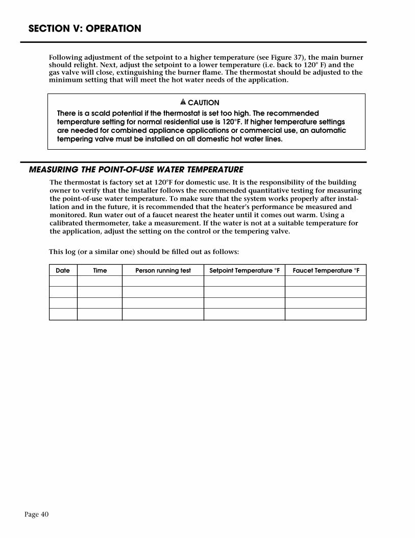
Following adjustment of the setpoint to a higher temperature (see Figure 37), the main burner should relight. Next, adjust the setpoint to a lower temperature (i.e. back to 120° F) and the gas valve will close, extinguishing the burner flame. The thermostat should be adjusted to the minimum setting that will meet the hot water needs of the application.
CAUTION There is a scald potential if the thermostat is set too high. The recommended
temperature setting for normal residential use is 120°F. If higher temperature settings are needed for combined appliance applications or commercial use, an automatic tempering valve must be installed on all domestic hot water lines.
MEASURING THE POINT-OF-USE WATER TEMPERATUREThe thermostat is factory set at 120°F for domestic use. It is the responsibility of the building owner to verify that the installer follows the recommended quantitative testing for measuring the point-of-use water temperature. To make sure that the system works properly after instal-lation and in the future, it is recommended that the heater’s performance be measured and monitored. Run water out of a faucet nearest the heater until it comes out warm. Using a calibrated thermometer, take a measurement. If the water is not at a suitable temperature for the application, adjust the setting on the control or the tempering valve.
This log (or a similar one) should be filled out as follows:
Page 40
Date Time Person running test Setpoint Temperature °F Faucet Temperature °F
Page 41
SECTION VI: MAINTENANCE
NOTICE TO THE OWNER: If you are having a mechanical problem with your water heater, contact your service company or installer.
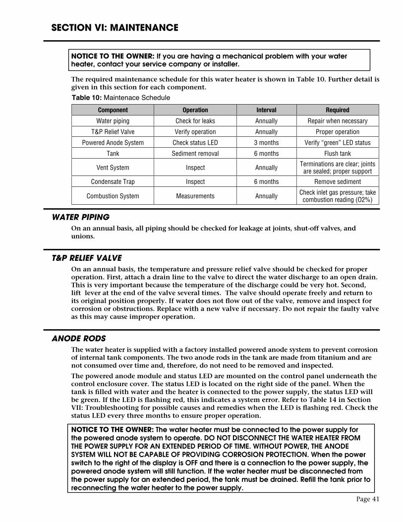
The required maintenance schedule for this water heater is shown in Table 10. Further detail is given in this section for each component.
WATER PIPINGOn an annual basis, all piping should be checked for leakage at joints, shut-off valves, and unions.
T&P RELIEF VALVEOn an annual basis, the temperature and pressure relief valve should be checked for proper operation. First, attach a drain line to the valve to direct the water discharge to an open drain. This is very important because the temperature of the discharge could be very hot. Second, lift lever at the end of the valve several times. The valve should operate freely and return to its original position properly. If water does not flow out of the valve, remove and inspect for corrosion or obstructions. Replace with a new valve if necessary. Do not repair the faulty valve as this may cause improper operation.
ANODE RODSThe water heater is supplied with a factory installed powered anode system to prevent corrosion of internal tank components. The two anode rods in the tank are made from titanium and are not consumed over time and, therefore, do not need to be removed and inspected.
The powered anode module and status LED are mounted on the control panel underneath the control enclosure cover. The status LED is located on the right side of the panel. When the tank is filled with water and the heater is connected to the power supply, the status LED will be green. If the LED is flashing red, this indicates a system error. Refer to Table 14 in Section VII: Troubleshooting for possible causes and remedies when the LED is flashing red. Check the status LED every three months to ensure proper operation. NOTICE TO THE OWNER: The water heater must be connected to the power supply for the powered anode system to operate. DO NOT DISCONNECT THE WATER HEATER FROM THE POWER SUPPLY FOR AN EXTENDED PERIOD OF TIME. WITHOUT POWER, THE ANODE SYSTEM WILL NOT BE CAPABLE OF PROVIDING CORROSION PROTECTION. When the power switch to the right of the display is OFF and there is a connection to the power supply, the powered anode system will still function. If the water heater must be disconnected from the power supply for an extended period, the tank must be drained. Refill the tank prior to reconnecting the water heater to the power supply.
Table 10: Maintenace ScheduleComponent Operation Interval Required
Water piping Check for leaks Annually Repair when necessary
T&P Relief Valve Verify operation Annually Proper operation
Powered Anode System Check status LED 3 months Verify “green” LED status
Tank Sediment removal 6 months Flush tank
Vent System Inspect Annually Terminations are clear; joints are sealed; proper support
Condensate Trap Inspect 6 months Remove sediment
Combustion System Measurements Annually Check inlet gas pressure; take combustion reading (O2%)
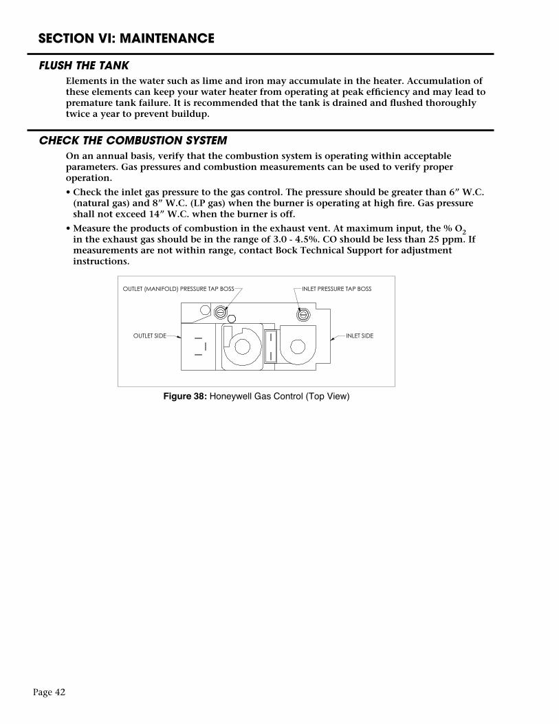
Page 42
SECTION VI: MAINTENANCE
FLUSH THE TANKElements in the water such as lime and iron may accumulate in the heater. Accumulation of these elements can keep your water heater from operating at peak efficiency and may lead to premature tank failure. It is recommended that the tank is drained and flushed thoroughly twice a year to prevent buildup.
CHECK THE COMBUSTION SYSTEMOn an annual basis, verify that the combustion system is operating within acceptable parameters. Gas pressures and combustion measurements can be used to verify proper operation.
• Check the inlet gas pressure to the gas control. The pressure should be greater than 6” W.C. (natural gas) and 8” W.C. (LP gas) when the burner is operating at high fire. Gas pressure shall not exceed 14” W.C. when the burner is off.
• Measure the products of combustion in the exhaust vent. At maximum input, the % O2 in the exhaust gas should be in the range of 3.0 - 4.5%. CO should be less than 25 ppm. If measurements are not within range, contact Bock Technical Support for adjustment instructions.
Figure 38: Honeywell Gas Control (Top View)
SECTION VI: MAINTENANCE
INSPECT THE VENTING SYSTEM AND BURNERThe vent and combustion air intake system should be checked at least once a year for damage and blockage. Make sure all joints are secure and that the system is properly supported. Inspect the outdoor terminals to make sure they are free of obstructions.
Inspect the condensate elbow assembly for blockage every six months. Remove the 3/4” plug at the end of the trap and pull out any accumulation of sediment. Refer to Figure 6 in Section IV: Installation / Condensate Elbow Assembly for location of the 3/4” plug. Be careful to not rotate any portion of the condensate elbow assembly when removing or tightening the plug. Changing the orientation of the condensate drainage point with the exhaust pipe on the water heater may adversely effect water heater operation.
CAUTION
For your safety, removal of the blower assembly and the burner must be performed by a qualified service technician. All parts must be replaced to their original position prior to operating the water heater.
The water heater utilizes a forced draft combustion system to draw combustion air to the burner and remove exhaust gas from the vent. The combustion air intake is under a negative pressure which may cause unwanted objects to be pulled into the intake vent pipe. Over time, these objects may collect in the burner and affect burner ignitions and water heater performance. While not required as a periodic maintenance item, inspecting the burner for blockage should be done once all other potential causes for ignition failures have been checked (i.e. the ignitor, flame rod, gas supply pressure, etc.). In order to inspect the burner, a portion of the overall assembly must be removed for access. Before proceeding, make sure the power switch is OFF and close the main shut-off valve on the gas supply.
• First, remove the ignitor and flame rod and set aside.
• Second, disconnect the wiring harnesses and the air intake piping from the blower.
• Third, remove the blower, along with other connected components, by removing four screws at the gas control plus four nuts and washers at the burner mounting flange.
Refer to Figure 39 for a visual location of components.
Page 43
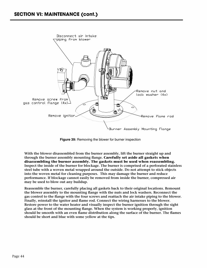
SECTION VI: MAINTENANCE (cont.)
With the blower disassembled from the burner assembly, lift the burner straight up and through the burner assembly mounting flange. Carefully set aside all gaskets when disassembling the burner assembly. The gaskets must be used when reassembling. Inspect the inside of the burner for blockage. The burner is comprised of a perforated stainless steel tube with a woven metal wrapped around the outside. Do not attempt to stick objects into the woven metal for cleaning purposes. This may damage the burner and reduce performance. If blockage cannot easily be removed from inside the burner, compressed air may be used to blow out any buildup.
Reassemble the burner, carefully placing all gaskets back to their original locations. Remount the blower assembly to the mounting flange with the nuts and lock washers. Reconnect the gas control to the flange with the four screws and reattach the air intake piping to the blower. Finally, reinstall the ignitor and flame rod. Connect the wiring harnesses to the blower. Restore power to the water heater and visually inspect the burner ignition through the sight glass at the front of the mounting flange. When the system is working properly, ignition should be smooth with an even flame distribution along the surface of the burner. The flames should be short and blue with some yellow at the tips.
Page 44
Figure 39: Removing the blower for burner inspection
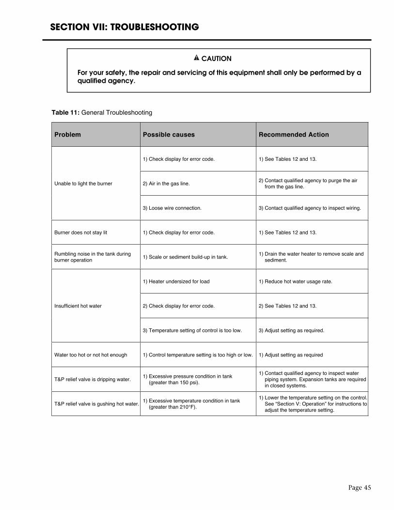
Page 45
SECTION VII: TROUBLESHOOTING
CAUTION
For your safety, the repair and servicing of this equipment shall only be performed by a qualified agency.
Table 11: General Troubleshooting
Problem Possible causes Recommended Action
Unable to light the burner
1) Check display for error code. 1) See Tables 12 and 13.
2) Air in the gas line. 2) Contact qualified agency to purge the air from the gas line.
3) Loose wire connection. 3) Contact qualified agency to inspect wiring.
Burner does not stay lit 1) Check display for error code. 1) See Tables 12 and 13.
Rumbling noise in the tank during burner operation 1) Scale or sediment build-up in tank. 1) Drain the water heater to remove scale and
sediment.
Insufficient hot water
1) Heater undersized for load 1) Reduce hot water usage rate.
2) Check display for error code. 2) See Tables 12 and 13.
3) Temperature setting of control is too low. 3) Adjust setting as required.
Water too hot or not hot enough 1) Control temperature setting is too high or low. 1) Adjust setting as required
T&P relief valve is dripping water. 1) Excessive pressure condition in tank (greater than 150 psi).
1) Contact qualified agency to inspect water piping system. Expansion tanks are required in closed systems.
T&P relief valve is gushing hot water. 1) Excessive temperature condition in tank (greater than 210°F).
1) Lower the temperature setting on the control. See “Section V: Operation” for instructions to adjust the temperature setting.
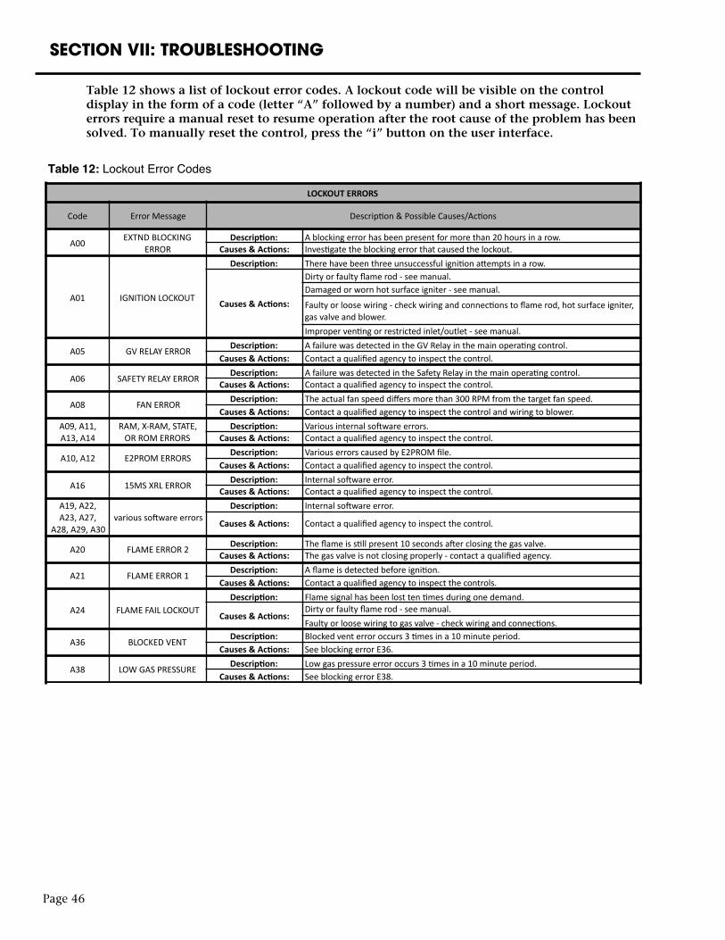
Page 46
SECTION VII: TROUBLESHOOTING
Table 12: Lockout Error Codes
LOCKOUTERRORS
Code ErrorMessage Descrip0on&PossibleCauses/Ac0ons
A00 EXTNDBLOCKINGERROR
Descrip2on: Ablockingerrorhasbeenpresentformorethan20hoursinarow.Causes&Ac2ons: Inves0gatetheblockingerrorthatcausedthelockout.
A01 IGNITIONLOCKOUT
Descrip2on: Therehavebeenthreeunsuccessfuligni0onaOemptsinarow.
Causes&Ac2ons:
Dirtyorfaultyflamerod-seemanual.Damagedorwornhotsurfaceigniter-seemanual.
Faultyorloosewiring-checkwiringandconnec0onstoflamerod,hotsurfaceigniter,gasvalveandblower.Improperven0ngorrestrictedinlet/outlet-seemanual.
A05 GVRELAYERROR Descrip2on: AfailurewasdetectedintheGVRelayinthemainopera0ngcontrol.Causes&Ac2ons: Contactaqualifiedagencytoinspectthecontrol.
A06 SAFETYRELAYERROR Descrip2on: AfailurewasdetectedintheSafetyRelayinthemainopera0ngcontrol.Causes&Ac2ons: Contactaqualifiedagencytoinspectthecontrol.
A08 FANERROR Descrip2on: Theactualfanspeeddiffersmorethan300RPMfromthetargetfanspeed.Causes&Ac2ons: Contactaqualifiedagencytoinspectthecontrolandwiringtoblower.
A09,A11,A13,A14
RAM,X-RAM,STATE,ORROMERRORS
Descrip2on: Variousinternalsoawareerrors.Causes&Ac2ons: Contactaqualifiedagencytoinspectthecontrol.
A10,A12 E2PROMERRORS Descrip2on: VariouserrorscausedbyE2PROMfile.Causes&Ac2ons: Contactaqualifiedagencytoinspectthecontrol.
A16 15MSXRLERROR Descrip2on: Internalsoawareerror.Causes&Ac2ons: Contactaqualifiedagencytoinspectthecontrol.
A19,A22,A23,A27,
A28,A29,A30varioussoawareerrors
Descrip2on: Internalsoawareerror.
Causes&Ac2ons: Contactaqualifiedagencytoinspectthecontrol.
A20 FLAMEERROR2 Descrip2on: Theflameiss0llpresent10secondsaaerclosingthegasvalve.Causes&Ac2ons: Thegasvalveisnotclosingproperly-contactaqualifiedagency.
A21 FLAMEERROR1 Descrip2on: Aflameisdetectedbeforeigni0on.Causes&Ac2ons: Contactaqualifiedagencytoinspectthecontrols.
A24 FLAMEFAILLOCKOUTDescrip2on: Flamesignalhasbeenlostten0mesduringonedemand.
Causes&Ac2ons:Dirtyorfaultyflamerod-seemanual.Faultyorloosewiringtogasvalve-checkwiringandconnec0ons.
A36 BLOCKEDVENT Descrip2on: Blockedventerroroccurs30mesina10minuteperiod.Causes&Ac2ons: SeeblockingerrorE36.
A38 LOWGASPRESSURE Descrip2on: Lowgaspressureerroroccurs30mesina10minuteperiod.Causes&Ac2ons: SeeblockingerrorE38.
1
Table 12 shows a list of lockout error codes. A lockout code will be visible on the control display in the form of a code (letter “A” followed by a number) and a short message. Lockout errors require a manual reset to resume operation after the root cause of the problem has been solved. To manually reset the control, press the “i” button on the user interface.
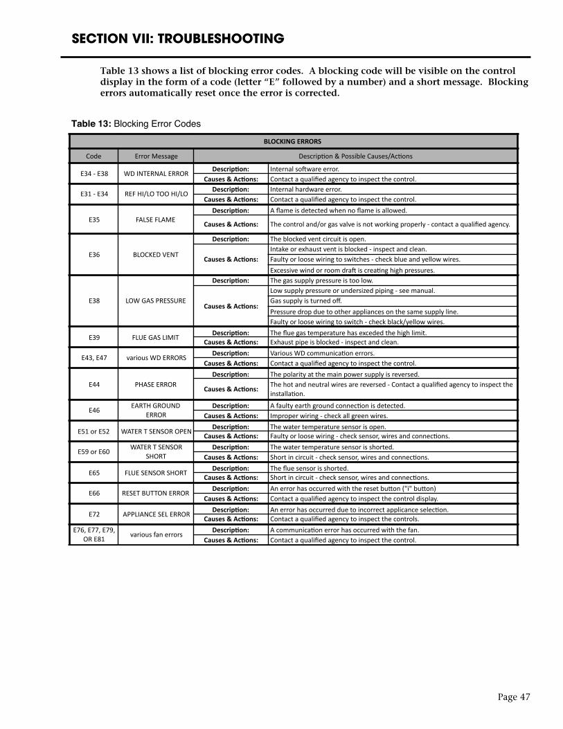
Page 47
SECTION VII: TROUBLESHOOTING
Table 13 shows a list of blocking error codes. A blocking code will be visible on the control display in the form of a code (letter “E” followed by a number) and a short message. Blocking errors automatically reset once the error is corrected.
Table 13: Blocking Error Codes
BLOCKINGERRORS
Code ErrorMessage Descrip0on&PossibleCauses/Ac0ons
E34-E38 WDINTERNALERROR Descrip4on: InternalsoEwareerror.Causes&Ac4ons: Contactaqualifiedagencytoinspectthecontrol.
E31-E34 REFHI/LOTOOHI/LO Descrip4on: Internalhardwareerror.Causes&Ac4ons: Contactaqualifiedagencytoinspectthecontrol.
E35 FALSEFLAMEDescrip4on: Aflameisdetectedwhennoflameisallowed.
Causes&Ac4ons: Thecontroland/orgasvalveisnotworkingproperly-contactaqualifiedagency.
E36 BLOCKEDVENT
Descrip4on: Theblockedventcircuitisopen.
Causes&Ac4ons:Intakeorexhaustventisblocked-inspectandclean.Faultyorloosewiringtoswitches-checkblueandyellowwires.ExcessivewindorroomdraEiscrea0nghighpressures.
E38 LOWGASPRESSURE
Descrip4on: Thegassupplypressureistoolow.
Causes&Ac4ons:
Lowsupplypressureorundersizedpiping-seemanual.Gassupplyisturnedoff.Pressuredropduetootherappliancesonthesamesupplyline.Faultyorloosewiringtoswitch-checkblack/yellowwires.
E39 FLUEGASLIMIT Descrip4on: Thefluegastemperaturehasexcededthehighlimit.Causes&Ac4ons: Exhaustpipeisblocked-inspectandclean.
E43,E47 variousWDERRORS Descrip4on: VariousWDcommunica0onerrors.Causes&Ac4ons: Contactaqualifiedagencytoinspectthecontrol.
E44 PHASEERRORDescrip4on: Thepolarityatthemainpowersupplyisreversed.
Causes&Ac4ons: Thehotandneutralwiresarereversed-Contactaqualifiedagencytoinspecttheinstalla0on.
E46 EARTHGROUNDERROR
Descrip4on: Afaultyearthgroundconnec0onisdetected.Causes&Ac4ons: Improperwiring-checkallgreenwires.
E51orE52 WATERTSENSOROPEN Descrip4on: Thewatertemperaturesensorisopen.Causes&Ac4ons: Faultyorloosewiring-checksensor,wiresandconnec0ons.
E59orE60 WATERTSENSORSHORT
Descrip4on: Thewatertemperaturesensorisshorted.Causes&Ac4ons: Shortincircuit-checksensor,wiresandconnec0ons.
E65 FLUESENSORSHORT Descrip4on: Thefluesensorisshorted.Causes&Ac4ons: Shortincircuit-checksensor,wiresandconnec0ons.
E66 RESETBUTTONERROR Descrip4on: Anerrorhasoccurredwiththeresetbudon("i"budon)Causes&Ac4ons: Contactaqualifiedagencytoinspectthecontroldisplay.
E72 APPLIANCESELERROR Descrip4on: Anerrorhasoccurredduetoincorrectapplicanceselec0on.Causes&Ac4ons: Contactaqualifiedagencytoinspectthecontrols.
E76,E77,E79,ORE81 variousfanerrors Descrip4on: Acommunica0onerrorhasoccurredwiththefan.
Causes&Ac4ons: Contactaqualifiedagencytoinspectthecontrol.
1
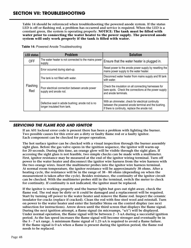
Table 14 should be referenced when troubleshooting the powered anode system. If the status LED is off or flashing red, a problem has occurred and service is required. When the LED is a constant green, the system is operating properly. NOTICE: The tank must be filled with water prior to connecting the water heater to the power supply. The powered anode system will only work properly if the tank is filled with water.
SERVICING THE FLAME ROD AND IGNITORIf an A01 lockout error code is present there has been a problem with lighting the burner. Two possible causes for this error are a dirty or faulty flame rod or a faulty ignitor. Each component can be checked for proper operation.
The hot surface ignitor can be checked with a visual inspection through the burner assembly sight glass. Before the gas valve opens in the ignition sequence, the ignitor will warm-up for 20 seconds. During this time, an orange glow will be visible through the sight glass. If accessing the sight glass is not feasible, two simple checks can be made with a multimeter. First, ignitor resistance may be measured at the end of the ignitor wiring terminal. Turn off power to the water heater and disconnect the ignitor wire harness from the wire harness with the two orange wires. Insert the multimeter probes into the ignitor wire harness terminal. At normal room temperature, the ignitor resistance will be approximately 38 ohms. After a heating cycle, the resistance will be in the range of 38 - 80 ohms (depending on when the measurement is taken after the cycle). Besides resistance, the continuity of the ignitor circuit can be checked. With the multimeter probes still in the terminal, switch the meter to check for continuity. If continuity is not indicated, the ignitor must be replaced.
If the ignitor is working properly and the burner lights but goes out right away, check the flame rod. The rod may be dirty or it could be damaged and a replacement will be required. Start by turning off power to the water heater and remove the flame rod. Inspect the ceramic insulator for cracks (replace if cracked). Clean the rod with fine steel wool and reinstall. Turn on power to the water heater and enter the Installer Menu on the control display (see next subsection for instructions). Arrow down until the third screen that displays the flame signal. During the next ignition attempt, a flame signal (in microamps, “uA”) will be displayed. Under normal operation, the flame signal will be between 2 - 5 uA during a successful ignition period. As the fan speed increases the flame signal will become stronger and eventually be in the 5 - 7 uA range. A minimum flame signal of 1.25 uA is required to avoid a flame failure. If the flame signal is 0 uA when a flame is present during the ignition period, the flame rod needs to be replaced.
Page 48
SECTION VII: TROUBLESHOOTING
Table 14: Powered Anode Troubleshooting
Table 14 should be referenced when troubleshooting the powered anode system. If the status LED is off or flashing red, a problem has occurred and service is required. When the LED is a constant green, the system is operating properly. NOTICE: The tank must be filled with water prior to connecting the water heater to the power supply. The powered anode system will only work properly if the tank is filled with water.
SERVICING THE FLAME ROD AND IGNITORIf an A01 lockout error code is present there has been a problem with lighting the burner. Two possible causes for this error are a dirty or faulty flame rod or a faulty ignitor. Each component can be checked for proper operation.
The hot surface ignitor can be checked with a visual inspection through the burner assembly sight glass. Before the gas valve opens in the ignition sequence, the ignitor will warm-up for 20 seconds. During this time, an orange glow will be visible through the sight glass. If accessing the sight glass is not feasible, two simple checks can be made with a multimeter. First, ignitor resistance may be measured at the end of the ignitor wiring terminal. Turn off power to the water heater and disconnect the ignitor wire harness from the wire harness with the two orange wires. Insert the multimeter probes into the ignitor wire harness terminal. At normal room temperature, the ignitor resistance will be approximately 38 ohms. After a heating cycle, the resistance will be in the range of 38 - 80 ohms (depending on when the measurement is taken after the cycle). Besides resistance, the continuity of the ignitor circuit can be checked. With the multimeter probes still in the terminal, switch the meter to check for continuity. If continuity is not indicated, the ignitor must be replaced.
If the ignitor is working properly and the burner lights but goes out right away, check the flame rod. The rod may be dirty or it could be damaged and a replacement will be required. Start by turning off power to the water heater and remove the flame rod. Inspect the ceramic insulator for cracks (replace if cracked). Clean the rod with fine steel wool and reinstall. Turn on power to the water heater and enter the Installer Menu on the control display (see next subsection for instructions). Arrow down until the third screen that displays the flame signal. During the next ignition attempt, a flame signal (in microamps, “uA”) will be displayed. Under normal operation, the flame signal will be between 2 - 5 uA during a successful ignition period. As the fan speed increases the flame signal will become stronger and eventually be in the 5 - 7 uA range. A minimum flame signal of 1.25 uA is required to avoid a flame failure. If the flame signal is 0 uA when a flame is present during the ignition period, the flame rod needs to be replaced.
Page 50
SECTION VII: TROUBLESHOOTING
Table 14: Powered Anode Troubleshooting
LED status Problem Solution
OFF The water heater is not connected to the mains power supply. Ensure that the water heater is plugged in.
FlashingRed
Error occurred during start-up. Reset power to the anode power supply by resetting the mains power supply to the water heater.
The tank is not filled with water. Disconnect water heater from mains supply and fill tank with water.
Poor electrical connection between anode power supply and anode rod.
Check the insulation on all connecting harnesses for bare spots. Check the connections at the power supply and anode terminals.
Defective seal in adode bushing; anode rod is no longer insulated from tank.
With an ohmmeter, check for electrical continuity between the powered anode terminal and the bushing. If there is continuity, replace the anode rod.
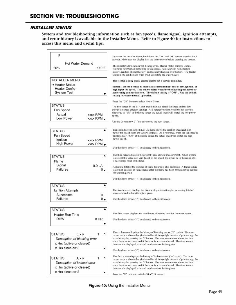
SECTION VII: TROUBLESHOOTING
INSTALLER MENUSSystem and troubleshooting information such as fan speeds, flame signal, ignition attempts, and error history is available in the Installer Menu. Refer to Figure 40 for instructions to access this menu and useful tips.
Page 49
Figure 40: Using the Installer Menu
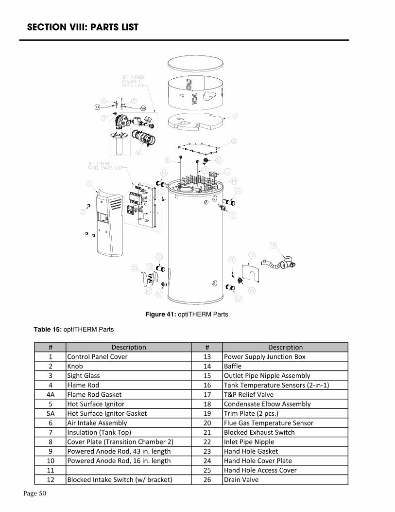
Page 50
SECTION VIII: PARTS LIST
Figure 41: optiTHERM Parts
Table 15: optiTHERM PartsTable 16: optiTHERM Parts
# #1 132 143 154 16 Tank Temperature Sensors (2-in-1)
4A 17 T&P Relief Valve5 18
5A 196 20 Flue Gas Temperature Sensor7 218 229 23
10 2411 2512 26
Outlet Pipe Nipple Assembly
Control Panel CoverKnob
Hand Hole Gasket
Description Description
Inlet Pipe NippleBlocked Exhaust Switch
Blocked Intake Switch (w/ bracket)Air Proving Switch (w/ bracket)Powered Anode Rod, 16 in. lengthPowered Anode Rod, 43 in. lengthCover Plate (Transition Chamber 2)
Trim Plate (2 pcs.)
Drain ValveHand Hole Access CoverHand Hole Cover Plate
Hot Surface Ignitor Gasket
Flame Rod GasketCondensate Elbow Assembly
Power Supply Junction BoxBaffle
Insulation (Tank Top)Air Intake Assembly
Hot Surface Ignitor
Flame RodSight Glass
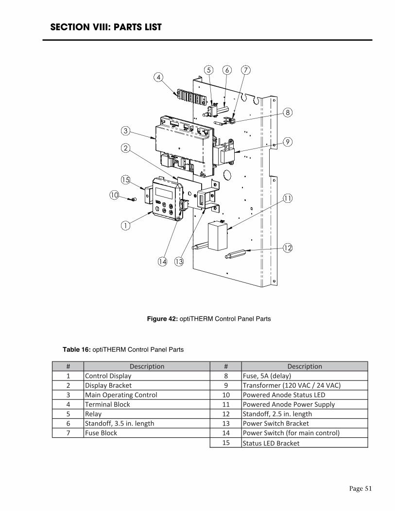
Page 51
SECTION VIII: PARTS LIST
1
10
15
2
3
45 6 7
8
9
11
12
1314
Figure 42: optiTHERM Control Panel Parts
Table 16: optiTHERM Control Panel Parts
Page 51
SECTION VIII: PARTS LIST
1
10
15
2
3
45 6 7
8
9
11
12
1314
Figure 42: optiTHERM Control Panel Parts
Table 16: optiTHERM Control Panel Parts
15 Status LED Bracket
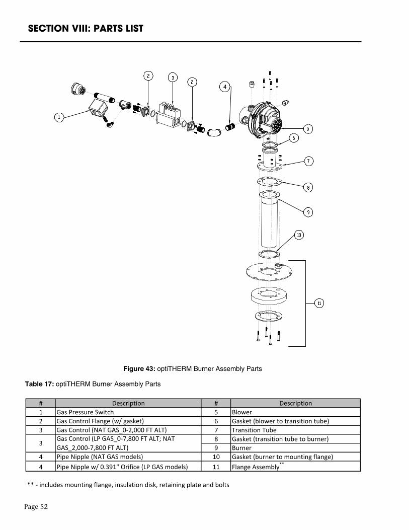
Page 52
SECTION VIII: PARTS LIST
Figure 43: optiTHERM Burner Assembly Parts
Table 17: optiTHERM Burner Assembly PartsTable 18: optiTHERM Burner Assembly Parts
# #1 52 6 Gasket (blower to transition tube)3 7 Transition Tube
8 Gasket (transition tube to burner)9 Burner
4 10 Gasket (burner to mounting flange)4 11 Flange Assembly**
** - includes mounting flange, insulation disk, retaining plate and bolts
Description Description
Pipe Nipple w/ 0.391" Orifice (LP GAS models)
Blower
3Gas Control (LP GAS_0-7,800 FT ALT; NAT GAS_2,000-7,800 FT ALT)
Gas Control (NAT GAS_0-2,000 FT ALT)
Pipe Nipple (NAT GAS models)
Gas Pressure SwitchGas Control Flange (w/ gasket)
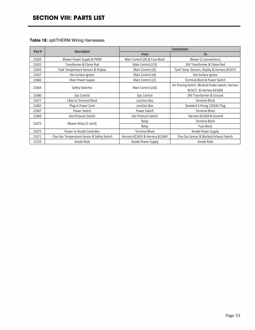
Page 53
SECTION VIII: PARTS LIST
Table 18: optiTHERM Wiring Harnesses
SECTION IX: WARRANTY
LIMITED WARRANTY FOR GAS-FIRED WATER HEATER
Bock Water Heaters, Inc.110 S. Dickinson Street
Madison, WI 53703
Phone: 608-257-2225
WHAT DOES THIS LIMITED WARRANTY COVER?This limited warranty applies only to the original consumer purchaser.
General Defects and Malfunctions: This warranty covers defections and malfunctions in your new water heater for a period of one year from the original installation date. We will repair or replace, at our option, any defective or malfunctioning component of the water heater. This limited warranty will terminate if you sell or otherwise transfer the water heater, or the water heater is installed at a location different from its original installation location.
Tank and Heat Exchanger: We also warrant that the tank and heat exchanger will not leak due to defective materials or workmanship for five years from the date of original installation or from date of manufacture in the event the Limited Warranty Registration Card was not completed and returned to manufacturer. If the tank and heat exchanger is leaking and we have verified that the leak is due to a defect in materials and workmanship, we will replace the tank with a tank that is the nearest Bock model available at the time of replacement. If a replacement tank is provided, it will remain warranted under this section as if it were the original tank. For example, if we send you a replacement tank under this limited warranty two years after the original installation date, then the replacement tank will remain warranted for the remaining three years after the original installation date.
HOW DO YOU GET SERVICE UNDER THE LIMITED WARRANTY?In order for the warranty period to begin on the date of installation, you must return the warranty registration card attached below within 30 days of purchasing the water heater. You may also register your water heater online at www.bockwaterheaters.com. You must have a copy of the original sales receipt at the time you request service. Failure to return the warranty registration card and provide a copy of the sales receipt will result in the warranty period beginning from the date of manufacture.
To get service under this limited warranty you should contact either the dealer or installer. If dealer or installer is unknown you can contact us via e-mail at [email protected] or call us Monday through Friday between the hours of 8 o’clock a.m. to 5 o’clock p.m. Central Time at the following number: 1-608-257-2225.
You can also write us at the following address:
Bock Water Heaters, Inc.
Warranty Support Group
110 S. Dickinson Street
Madison, WI 53703
We will respond not later than ten days after we have received your request for service.
Page 54
Page 55
Bock Water Heaters, Inc. • 110 South Dickinson Street • Madison, WI 53703 Telephone 608-257-2225 • Fax 608-257-5304
www.bockwaterheaters.com
SECTION IX: WARRANTY
WHAT DOES THIS LIMITED WARRANTY NOT COVER?This limited warranty does not cover water heaters that are or were:
• Incorrectly installed, especially where the installation violates state or local plumbing, housing or building codes.
• Operated at inappropriate settings, excessive pressures or temperatures.• Exposed to adverse local conditions and specifically sediment or lime precipitation in the
tank or corrosive elements in the atmosphere or unacceptable water quality. • Installed outside the United States or Canada.• Accidentally damaged.
Also, we will not cover the following charges, costs and losses:
• Any freight or delivery charges.• Any removal or installation charges.• Charges to return the water heater or part to the manufacturer.• Water damage, loss or damage to property, inconvenience or loss of use.
WHAT WILL VOID THE LIMITED WARRANTY?If you do any of the following, you will void this limited warranty:
• Fail to retain an original copy of your sales receipt. • Fail to retain the actual rating plate from the water heater.• Alter or remove the serial number.• Transfer or sell the water heater.• Remove the water heater from its original location and install it somewhere else.• Fail to follow the care and maintenance instructions provided with the water heater. • Alter, disable or in any way cause the Impressed Current Cathodic Protection system to be
inoperable.• Fail to maintain in continuous good working condition the Impressed Current Cathodic
Protection system.
HOW DOES STATE LAW RELATE TO THIS LIMITED WARRANTY?This is a limited warranty. WE MAKE NO OTHER EXPRESS WARRANTIES WITH RESPECT TO THIS WATER HEATER. We will not assume, nor authorize any person to assume for us any other liability in connection with the sale or operation of this water heater. ANY IMPLIED WARRANTIES, INCLUDING MECHANTABILITY OR FITNESS FOR A PARTICULAR APPLICATION, IMPOSED ON THIS SALE UNDER THE LAWS OF THE STATE OF SALE ARE LIMITED TO ONE YEAR. This warranty gives you specific legal rights, and you may also have other rights which vary from state to state. Some states do not allow limitations on how long an implied warranty lasts, so the above limitation may not apply to you.
WE WILL NOT BE RESPONSIBLE FOR WATER DAMAGE, LOSS OF USE OF THE UNIT, INCONVENIENCE, LOSS OR DAMAGE TO PERSONAL PROPERTY, WHETHER DIRECT OR INDIRECT, AND WHETHER ARISING IN CONTACT OR TORT. Some states do not allow the exclusion of incidental or consequential damages, so the above exclusion may not apply to you.


