installation and administration guide - sap help portal
TRANSCRIPT
Installation andAdministration Guide
SAP Engineering Control Center Interface to ECADFor: Mentor PADS
Product version: 1.0.4.0Publishing date: 29.10.2019 | Build number: 1.0.4.0.9
XPLM Solution GmbH
Altmarkt-Galerie
Dresden Altmarkt 25
01067 Dresden
Office: +49 351 82658-0
Fax: +49 351 82658-88
Web: www.xplm.com
Legal informationCopyrights and trademarks
This document contains information protected by copyright. All rights, including those of the translation, arereserved. No part of this documentation may be reproduced in any form (print, photocopy, microfilm or in anyother form) or processed, copied or distributed using electronic systems without the written permission ofXPLM Solution GmbH. The information contained in this documentation does not represent a legal obligationfor XPLM Solution GmbH. The described software is delivered under a license agreement that regulates itsuse. All trademarks are the property of their respective owners.
Disclaimer
XPLM Solution GmbH is not liable for errors in this documentation. This documentation may contain linksto web sites of other companies or organizations that XPLM Solution GmbH does not own or control.XPLM Solution GmbH neither checks the accessibility of these websites nor makes any representations.The information in this document is based on a standard installation. The actual appearance of a specificinstallation may vary depending on the local environment and configuration realized for the individualcustomer requirements.
Support
If you encounter problems with the integration, please check the knowledge base at https://support.sap.com,or create a ticket.
Privacy policy
Compliance with applicable privacy laws is very important to XPLM Solution GmbH. In the light of the EUGeneral Data Protection Regulation (GDPR), XPLM Solution GmbH informs about the handling of personaldata when using the integration.
The integration itself does not "store" personal data in a general sense, but merely exchanges informationbetween ECAD and PLM in attributes. Whatever is defined in these attributes is left to the definition of thecustomer. For example, if the integration is configured accordingly, user data like first and last name aretransferred from PLM to ECAD in order to be used in the drawing frame and generated outputs.
External log files are saved by the integration on the user’s computer to record actions and progress ofintegration functions. Depending on the selected log level, these log files also contain information fromWindows environment variables, for example the Windows user name.
■ Attribute information exchanged between ECAD and PLM is represented in the file metadata.xml. Thisfile is saved in the configured project directory or, depending on the ECAD tool used, directly in the projectfiles.
■ Log files are saved by default in the directory %TEMP%\integrate. This directory can be deleted, but newlog files are created when the integration is used again.
XPLM Solution GmbH also refers to the privacy policies of the ECAD vendors and SAP's Security Guide forDocument Management (DMS) for information about how personal information is handled in their systems.
Installation and Administration Guide www.xplm.com ii
Table of ContentsGlossary.......................................................................................................... 5
1 Introduction........................................................................................ 71.1 About this document........................................................................................... 71.2 Abbreviations........................................................................................................71.3 Architecture...........................................................................................................8
2 Installation.......................................................................................... 92.1 System requirements........................................................................................... 92.2 Required licenses.................................................................................................92.3 Importing and activating BC Set...................................................................... 102.4 Installing the integration....................................................................................112.5 Understanding the directory structure............................................................ 122.6 Understanding integration variables................................................................13
3 Post-installation............................................................................... 153.1 Mentor PADS.......................................................................................................153.1.1 Setting up integration menu (PADS Logic).......................................................... 15
3.1.2 Setting up integration menu (PADS Layout)........................................................ 16
4 Initial setup.......................................................................................174.1 Mentor PADS.......................................................................................................174.1.1 Setting up library.................................................................................................. 17
4.1.2 Creating schematic template................................................................................18
4.1.3 Creating PCB template........................................................................................ 18
4.2 SAP Engineering Control Center......................................................................184.2.1 Updating DType settings...................................................................................... 18
4.2.2 Setting up DTypes................................................................................................19
4.2.3 Setting up material............................................................................................... 19
4.2.4 Setting up status net............................................................................................ 20
4.2.5 Setting up templates............................................................................................ 21
4.2.6 Setting up classification........................................................................................22
4.2.7 Distributing integration with Subversion............................................................... 23
5 Configuration....................................................................................255.1 Datamodel............................................................................................................25
Installation and Administration Guide www.xplm.com iii
5.2 Configuration files..............................................................................................265.2.1 Datamodel configuration files...............................................................................26
5.2.2 Other configuration files....................................................................................... 28
5.3 General configuration options.......................................................................... 295.3.1 Handling of variant-specific output files............................................................... 29
5.3.2 Encrypting passwords.......................................................................................... 29
5.3.3 Configuring new attributes and mapping............................................................. 30
5.3.4 Configuring attribute field lengths........................................................................ 31
5.3.5 Configuring names of output files........................................................................ 32
5.3.6 Hiding output file options......................................................................................32
5.3.7 Configuring additional output files........................................................................33
5.3.8 Configuring start dialog in Synchronize Parts......................................................34
5.3.9 Configuring BOM representation..........................................................................34
5.3.10 Including or excluding BOM items....................................................................... 35
5.4 Mentor PADS.......................................................................................................355.4.1 Configuring PDF output........................................................................................35
5.4.2 Configuring Gerber data.......................................................................................36
5.5 SAP Engineering Control Center......................................................................365.5.1 Configuring templates...........................................................................................36
5.5.2 Configuring alternative BOM positions.................................................................37
6 Update............................................................................................... 396.1 Updating the integration....................................................................................39
7 Uninstallation................................................................................... 407.1 Uninstalling the integration...............................................................................40
8 Troubleshooting............................................................................... 418.1 Solving integration issues.................................................................................41
9 References........................................................................................439.1 Modifier options..................................................................................................43
Installation and Administration Guide www.xplm.com iv
GlossaryAssembly data
Defines an output file with the assembly data of the PCB. Saved by default as original to Assemblydocument.
Assembly document
Defines a datamodel object in ECTR that saves the assembly information of the PCB.
Assembly material
Defines an SAP material master with the BOM items of the assembly variant.
Assembly PDF
Defines an output file with the variant-specific assembly drawing as a PDF file. Saved by default asoriginal to Assembly document.
Attribute
Defines an object property in the design and datamodel.
BOM
Bill Of Material – Defines the list of components/materials.
BOM item
Defines a position in the BOM with unique ID, quantity and other attributes.
Component
Defines a component in the PADS library.
Datamodel
Defines objects and the relationship between these objects for a certain design in ECTR. The datamodelobjects are visible in ECTR and managed by the integration.
ECAD
Electronic Computer Aided Design – Defines the software-supported development in electricalengineering and electronic design.
Fabrication data
Defines an output file with the fabrication data (Gerber- and drill files, etc.) of the PCB. Saved by defaultas original to PCB document.
Fabrication PDF
Defines an output file with the fabrication drawing (drill plot) for the PCB as a PDF file. Saved by defaultas original to PCB document.
IDF data
Defines an output file with the proprietary design and fabrication data of the PCB. The IDF format is usedto enable data exchange between ECAD and MCAD. Saved by default as original to PCB document.
Innovation container
Defines an output file with the native design files. Saved by default as original to Innovation document.
Innovation document
Defines a datamodel object in ECTR that saves the design.
Innovation PDF
Defines an output file with the basic schematic as a PDF file. Saved by default as original to Innovationdocument.
Installation and Administration Guide www.xplm.com 5 / 43
Material
Defines an SAP material master that is either produced or purchased.
ODB++ data
Defines an output file with the proprietary design and fabrication data of the PCB. Saved by default asoriginal to PCB document.
PCB
Printed Circuit Board – Defines a bare board for the electrical connection of electronic components.
PCB document
Defines a datamodel object in ECTR that saves the fabrication information of the PCB.
PCB material
Defines an SAP material master with the bare board as the first BOM item.
Project
Defines a design file in PADS containing schematics and PCB layouts, including related files.
Schematic
Defines a diagram with electrical or electronic circuits and connections.
Schematic PDF
Defines an output file with the variant-specific schematic as a PDF file. Saved by default as original toAssembly document.
Installation and Administration Guide www.xplm.com 6 / 43
1 Introduction1.1 About this document
1 Introduction
1.1 About this documentThis document describes the installation and configuration of the integration platform SAPEngineering Control Center Interface to ECAD.
The document provides a basic understanding of the system architecture and directory structure,shows the installation and initial setup process, and provides detailed information on how toconfigure SAP Engineering Control Center Interface to ECAD to meet customer requirements.
This document is intended for system administrators who install and configure SAP EngineeringControl Center Interface to ECAD.
1.2 AbbreviationsBecome familiar with the abbreviations listed here. You will find them throughout the document.
Name Abbreviation <product> <productID> Notes
SAP EngineeringControl CenterInterface toECAD
Integration
SAP EngineeringControl Center
ECTR This abbreviationis also used todescribe actionsfor storing andreading data inSAP.
Mentor PADS(with PADSLogic and PADSLayout)
PADS PADS XPA
Note: Within this document, the placeholders <productID> and <product> are used invariables, paths and directories. The values can appear in lower and upper case.
Installation and Administration Guide www.xplm.com 7 / 43
1 Introduction1.3 Architecture
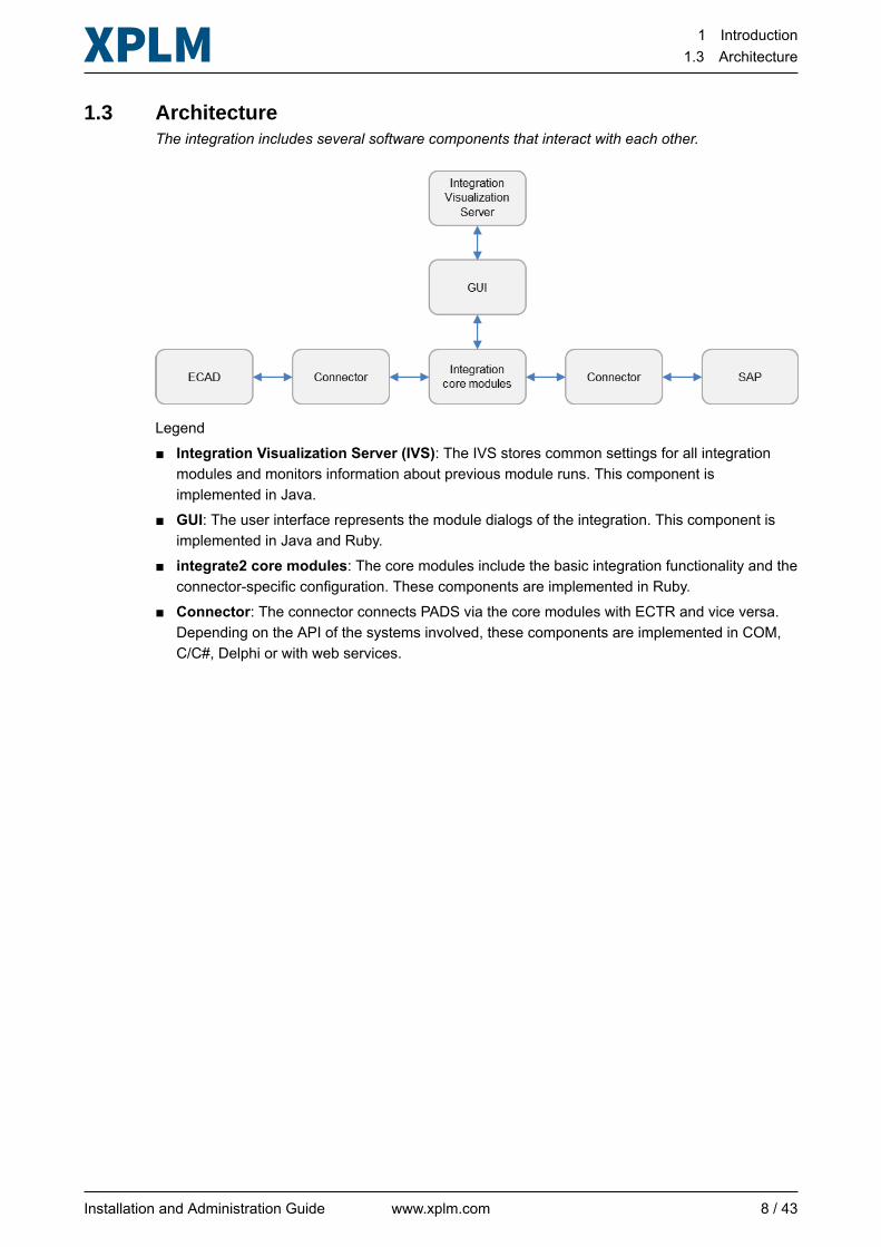
1.3 ArchitectureThe integration includes several software components that interact with each other.
Legend■ Integration Visualization Server (IVS): The IVS stores common settings for all integration
modules and monitors information about previous module runs. This component isimplemented in Java.
■ GUI: The user interface represents the module dialogs of the integration. This component isimplemented in Java and Ruby.
■ integrate2 core modules: The core modules include the basic integration functionality and theconnector-specific configuration. These components are implemented in Ruby.
■ Connector: The connector connects PADS via the core modules with ECTR and vice versa.Depending on the API of the systems involved, these components are implemented in COM,C/C#, Delphi or with web services.
Installation and Administration Guide www.xplm.com 8 / 43
2 Installation2.1 System requirements
2 Installation
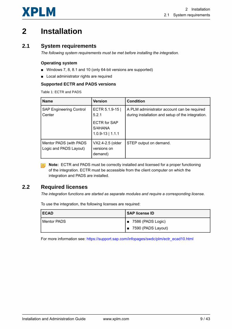
2.1 System requirementsThe following system requirements must be met before installing the integration.
Operating system
■ Windows 7, 8, 8.1 and 10 (only 64-bit versions are supported)■ Local administrator rights are required
Supported ECTR and PADS versions
Table 1: ECTR and PADS
Name Version Condition
SAP Engineering ControlCenter
ECTR 5.1.9-15 |5.2.1
ECTR for SAPS/4HANA1.0.9-13 | 1.1.1
A PLM administrator account can be requiredduring installation and setup of the integration.
Mentor PADS (with PADSLogic and PADS Layout)
VX2.4-2.5 (olderversions ondemand)
STEP output on demand.
Note: ECTR and PADS must be correctly installed and licensed for a proper functioningof the integration. ECTR must be accessible from the client computer on which theintegration and PADS are installed.
2.2 Required licensesThe integration functions are started as separate modules and require a corresponding license.
To use the integration, the following licenses are required:
ECAD SAP license ID
Mentor PADS ■ 7586 (PADS Logic)■ 7590 (PADS Layout)
For more information see: https://support.sap.com/infopages/swdc/plm/ectr_ecad10.html
Installation and Administration Guide www.xplm.com 9 / 43
2 Installation2.3 Importing and activating BC Set
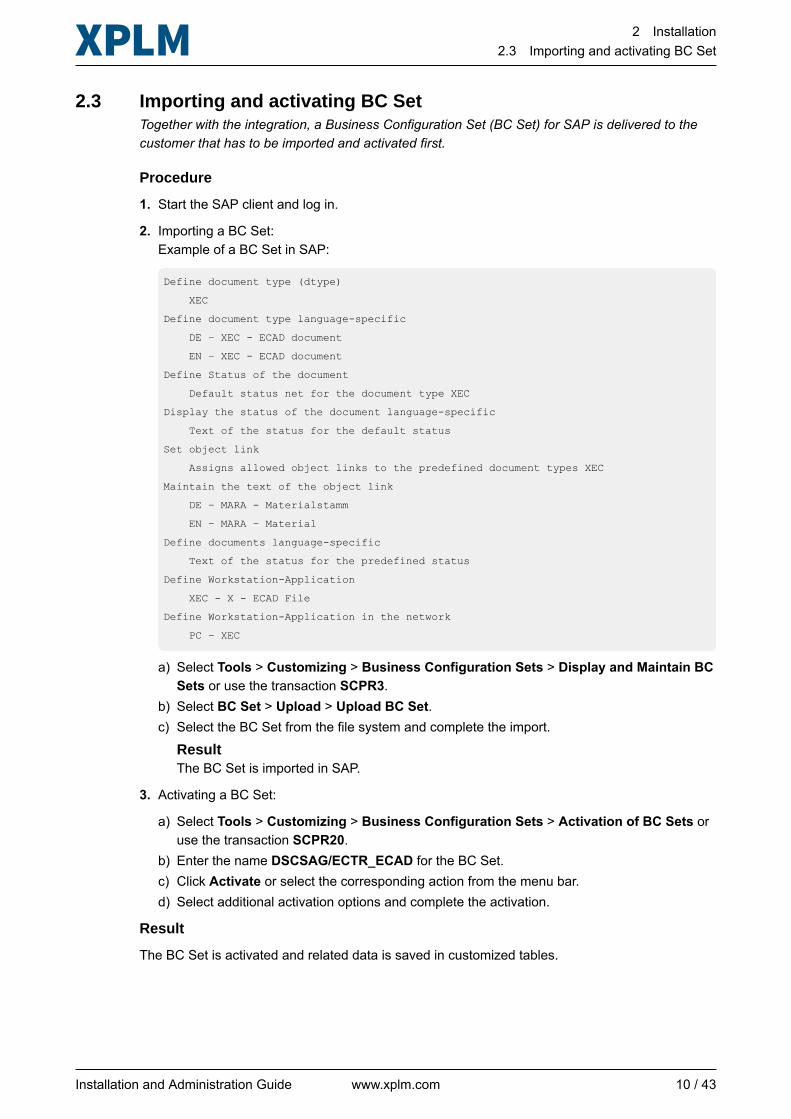
2.3 Importing and activating BC SetTogether with the integration, a Business Configuration Set (BC Set) for SAP is delivered to thecustomer that has to be imported and activated first.
Procedure
1. Start the SAP client and log in.
2. Importing a BC Set:Example of a BC Set in SAP:
Define document type (dtype)
XEC
Define document type language-specific
DE – XEC - ECAD document
EN – XEC - ECAD document
Define Status of the document
Default status net for the document type XEC
Display the status of the document language-specific
Text of the status for the default status
Set object link
Assigns allowed object links to the predefined document types XEC
Maintain the text of the object link
DE – MARA - Materialstamm
EN – MARA – Material
Define documents language-specific
Text of the status for the predefined status
Define Workstation-Application
XEC - X - ECAD File
Define Workstation-Application in the network
PC – XEC
a) Select Tools > Customizing > Business Configuration Sets > Display and Maintain BCSets or use the transaction SCPR3.
b) Select BC Set > Upload > Upload BC Set.c) Select the BC Set from the file system and complete the import.
ResultThe BC Set is imported in SAP.
3. Activating a BC Set:
a) Select Tools > Customizing > Business Configuration Sets > Activation of BC Sets oruse the transaction SCPR20.
b) Enter the name DSCSAG/ECTR_ECAD for the BC Set.c) Click Activate or select the corresponding action from the menu bar.d) Select additional activation options and complete the activation.
Result
The BC Set is activated and related data is saved in customized tables.
Installation and Administration Guide www.xplm.com 10 / 43
2 Installation2.4 Installing the integration
2.4 Installing the integrationThe integration is installed with an installer. The installation media are available in the SAPdownload portal.
Before you start
■ Make sure that PADS is installed correctly.■ To make sure that the integration can create and change objects in ECTR, log on to ECTR with
the account used for the integration and complete the following actions:□ Create documents and materials. Also record mandatory fields with their required values
when creating the objects, you will need this information later when configuring theintegration.
□ Change attribute values for the created objects.□ Reserve objects (check out) and and clear the reservation (check in).□ Change the object status. Also record corresponding status names/codes, you will need
this information later when configuring the integration.□ Delete the created objects.
■ Download the installation media from the download portal.■ Import and activate the BC Set first.
Procedure
1. Close PADS if it's running.
2. Start the installer with administration rights.
3. Select the integration to install and follow the steps of the wizard:■ Integration to Mentor PADS (PADS Schematic + PADS Layout)
4. Click Install to start the installation.
5. When the installation is complete, click Finish to close the installer.
Result
The integration is installed.
Next steps
Complete the required post-installation steps. See Post-installation on page 15.
See alsoSystem requirements on page 9
Installation and Administration Guide www.xplm.com 11 / 43
2 Installation2.5 Understanding the directory structure
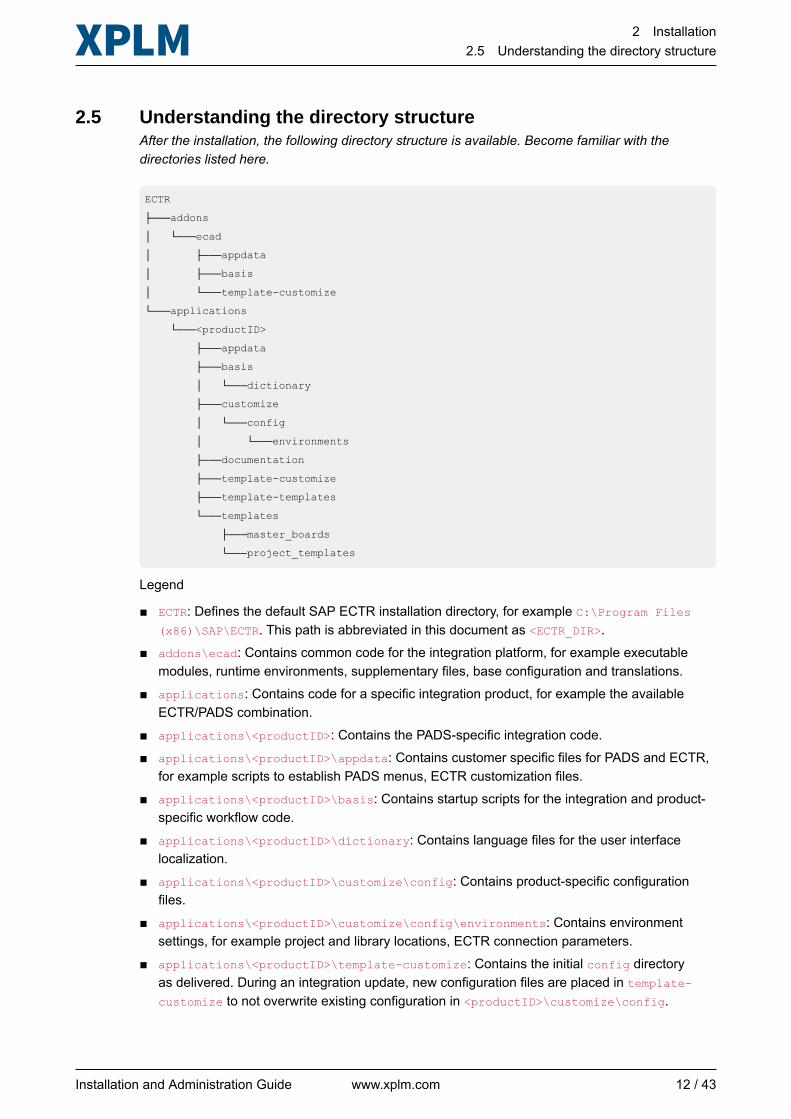
2.5 Understanding the directory structureAfter the installation, the following directory structure is available. Become familiar with thedirectories listed here.
ECTR
├───addons
│ └───ecad
│ ├───appdata
│ ├───basis
│ └───template-customize
└───applications
└───<productID>
├───appdata
├───basis
│ └───dictionary
├───customize
│ └───config
│ └───environments
├───documentation
├───template-customize
├───template-templates
└───templates
├───master_boards
└───project_templates
Legend
■ ECTR: Defines the default SAP ECTR installation directory, for example C:\Program Files(x86)\SAP\ECTR. This path is abbreviated in this document as <ECTR_DIR>.
■ addons\ecad: Contains common code for the integration platform, for example executablemodules, runtime environments, supplementary files, base configuration and translations.
■ applications: Contains code for a specific integration product, for example the availableECTR/PADS combination.
■ applications\<productID>: Contains the PADS-specific integration code.■ applications\<productID>\appdata: Contains customer specific files for PADS and ECTR,
for example scripts to establish PADS menus, ECTR customization files.■ applications\<productID>\basis: Contains startup scripts for the integration and product-
specific workflow code.■ applications\<productID>\dictionary: Contains language files for the user interface
localization.■ applications\<productID>\customize\config: Contains product-specific configuration
files.■ applications\<productID>\customize\config\environments: Contains environment
settings, for example project and library locations, ECTR connection parameters.■ applications\<productID>\template-customize: Contains the initial config directory
as delivered. During an integration update, new configuration files are placed in template-customize to not overwrite existing configuration in <productID>\customize\config.
Installation and Administration Guide www.xplm.com 12 / 43
2 Installation2.6 Understanding integration variables
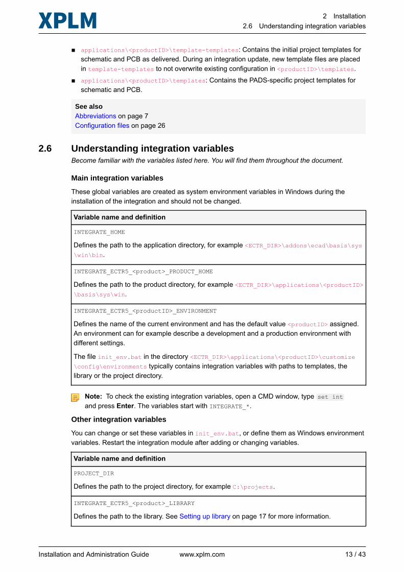
■ applications\<productID>\template-templates: Contains the initial project templates forschematic and PCB as delivered. During an integration update, new template files are placedin template-templates to not overwrite existing configuration in <productID>\templates.
■ applications\<productID>\templates: Contains the PADS-specific project templates forschematic and PCB.
See alsoAbbreviations on page 7Configuration files on page 26
2.6 Understanding integration variablesBecome familiar with the variables listed here. You will find them throughout the document.
Main integration variables
These global variables are created as system environment variables in Windows during theinstallation of the integration and should not be changed.
Variable name and definition
INTEGRATE_HOME
Defines the path to the application directory, for example <ECTR_DIR>\addons\ecad\basis\sys\win\bin.
INTEGRATE_ECTR5_<product>_PRODUCT_HOME
Defines the path to the product directory, for example <ECTR_DIR>\applications\<productID>\basis\sys\win.
INTEGRATE_ECTR5_<productID>_ENVIRONMENT
Defines the name of the current environment and has the default value <productID> assigned.An environment can for example describe a development and a production environment withdifferent settings.
The file init_env.bat in the directory <ECTR_DIR>\applications\<productID>\customize\config\environments typically contains integration variables with paths to templates, thelibrary or the project directory.
Note: To check the existing integration variables, open a CMD window, type set intand press Enter. The variables start with INTEGRATE_*.
Other integration variables
You can change or set these variables in init_env.bat, or define them as Windows environmentvariables. Restart the integration module after adding or changing variables.
Variable name and definition
PROJECT_DIR
Defines the path to the project directory, for example C:\projects.
INTEGRATE_ECTR5_<product>_LIBRARY
Defines the path to the library. See Setting up library on page 17 for more information.
Installation and Administration Guide www.xplm.com 13 / 43
2 Installation2.6 Understanding integration variables
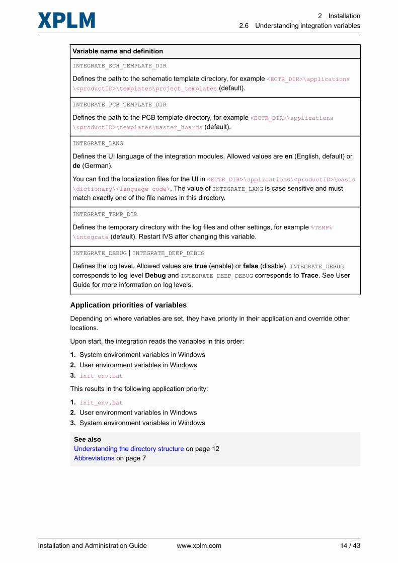
Variable name and definition
INTEGRATE_SCH_TEMPLATE_DIR
Defines the path to the schematic template directory, for example <ECTR_DIR>\applications\<productID>\templates\project_templates (default).
INTEGRATE_PCB_TEMPLATE_DIR
Defines the path to the PCB template directory, for example <ECTR_DIR>\applications\<productID>\templates\master_boards (default).
INTEGRATE_LANG
Defines the UI language of the integration modules. Allowed values are en (English, default) orde (German).
You can find the localization files for the UI in <ECTR_DIR>\applications\<productID>\basis\dictionary\<language code>. The value of INTEGRATE_LANG is case sensitive and mustmatch exactly one of the file names in this directory.
INTEGRATE_TEMP_DIR
Defines the temporary directory with the log files and other settings, for example %TEMP%\integrate (default). Restart IVS after changing this variable.
INTEGRATE_DEBUG | INTEGRATE_DEEP_DEBUG
Defines the log level. Allowed values are true (enable) or false (disable). INTEGRATE_DEBUGcorresponds to log level Debug and INTEGRATE_DEEP_DEBUG corresponds to Trace. See UserGuide for more information on log levels.
Application priorities of variables
Depending on where variables are set, they have priority in their application and override otherlocations.
Upon start, the integration reads the variables in this order:
1. System environment variables in Windows2. User environment variables in Windows3. init_env.bat
This results in the following application priority:
1. init_env.bat
2. User environment variables in Windows3. System environment variables in Windows
See alsoUnderstanding the directory structure on page 12Abbreviations on page 7
Installation and Administration Guide www.xplm.com 14 / 43
3 Post-installation3.1 Mentor PADS
3 Post-installationAfter the main installation, you must complete certain manual steps to make the integration workcorrectly with PADS and ECTR. It is important that you go through the information in this chaptercarefully.
3.1 Mentor PADS
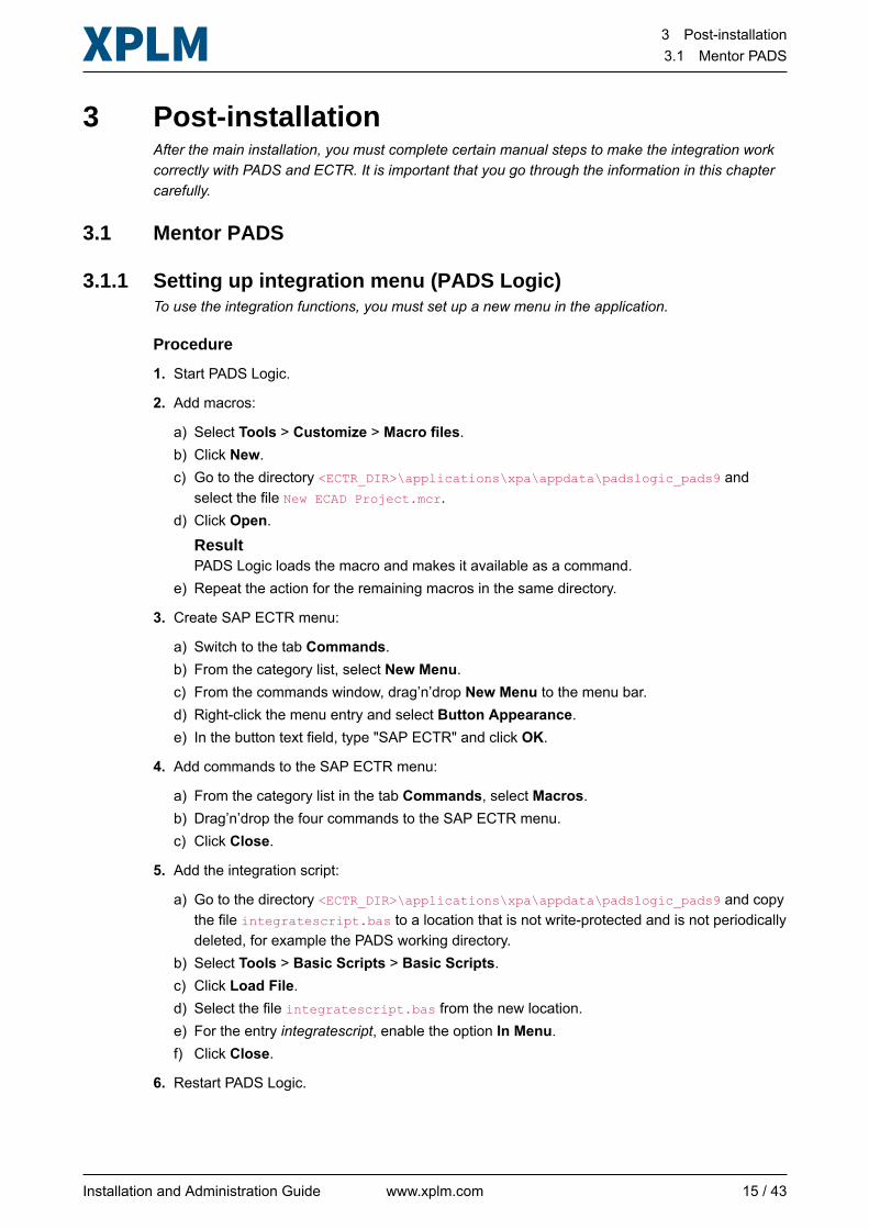
3.1.1 Setting up integration menu (PADS Logic)To use the integration functions, you must set up a new menu in the application.
Procedure
1. Start PADS Logic.
2. Add macros:
a) Select Tools > Customize > Macro files.b) Click New.c) Go to the directory <ECTR_DIR>\applications\xpa\appdata\padslogic_pads9 and
select the file New ECAD Project.mcr.d) Click Open.
ResultPADS Logic loads the macro and makes it available as a command.
e) Repeat the action for the remaining macros in the same directory.
3. Create SAP ECTR menu:
a) Switch to the tab Commands.b) From the category list, select New Menu.c) From the commands window, drag’n’drop New Menu to the menu bar.d) Right-click the menu entry and select Button Appearance.e) In the button text field, type "SAP ECTR" and click OK.
4. Add commands to the SAP ECTR menu:
a) From the category list in the tab Commands, select Macros.b) Drag’n’drop the four commands to the SAP ECTR menu.c) Click Close.
5. Add the integration script:
a) Go to the directory <ECTR_DIR>\applications\xpa\appdata\padslogic_pads9 and copythe file integratescript.bas to a location that is not write-protected and is not periodicallydeleted, for example the PADS working directory.
b) Select Tools > Basic Scripts > Basic Scripts.c) Click Load File.d) Select the file integratescript.bas from the new location.e) For the entry integratescript, enable the option In Menu.f) Click Close.
6. Restart PADS Logic.
Installation and Administration Guide www.xplm.com 15 / 43
3 Post-installation3.1 Mentor PADS
Result
The menu is set up and accessible from the menu bar.
3.1.2 Setting up integration menu (PADS Layout)To use the integration functions in PADS Layout, repeat the instructions from PADS Logic.
Installation and Administration Guide www.xplm.com 16 / 43
4 Initial setup4.1 Mentor PADS
4 Initial setup
4.1 Mentor PADS
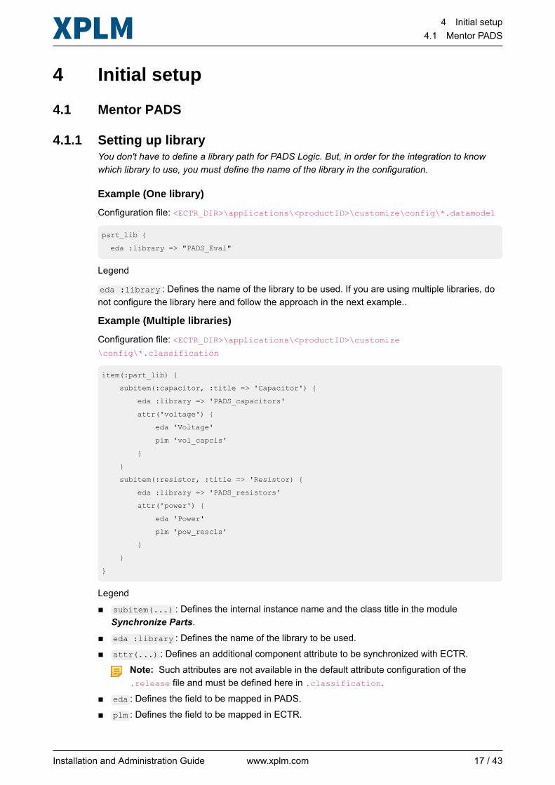
4.1.1 Setting up libraryYou don't have to define a library path for PADS Logic. But, in order for the integration to knowwhich library to use, you must define the name of the library in the configuration.
Example (One library)
Configuration file: <ECTR_DIR>\applications\<productID>\customize\config\*.datamodel
part_lib {
eda :library => "PADS_Eval"
Legend
eda :library : Defines the name of the library to be used. If you are using multiple libraries, donot configure the library here and follow the approach in the next example..
Example (Multiple libraries)
Configuration file: <ECTR_DIR>\applications\<productID>\customize\config\*.classification
item(:part_lib) {
subitem(:capacitor, :title => 'Capacitor') {
eda :library => 'PADS_capacitors'
attr('voltage') {
eda 'Voltage'
plm 'vol_capcls'
}
}
subitem(:resistor, :title => 'Resistor) {
eda :library => 'PADS_resistors'
attr('power') {
eda 'Power'
plm 'pow_rescls'
}
}
}
Legend■ subitem(...) : Defines the internal instance name and the class title in the module
Synchronize Parts.■ eda :library : Defines the name of the library to be used.■ attr(...) : Defines an additional component attribute to be synchronized with ECTR.
Note: Such attributes are not available in the default attribute configuration of the.release file and must be defined here in .classification.
■ eda : Defines the field to be mapped in PADS.■ plm : Defines the field to be mapped in ECTR.
Installation and Administration Guide www.xplm.com 17 / 43
4 Initial setup4.2 SAP Engineering Control Center
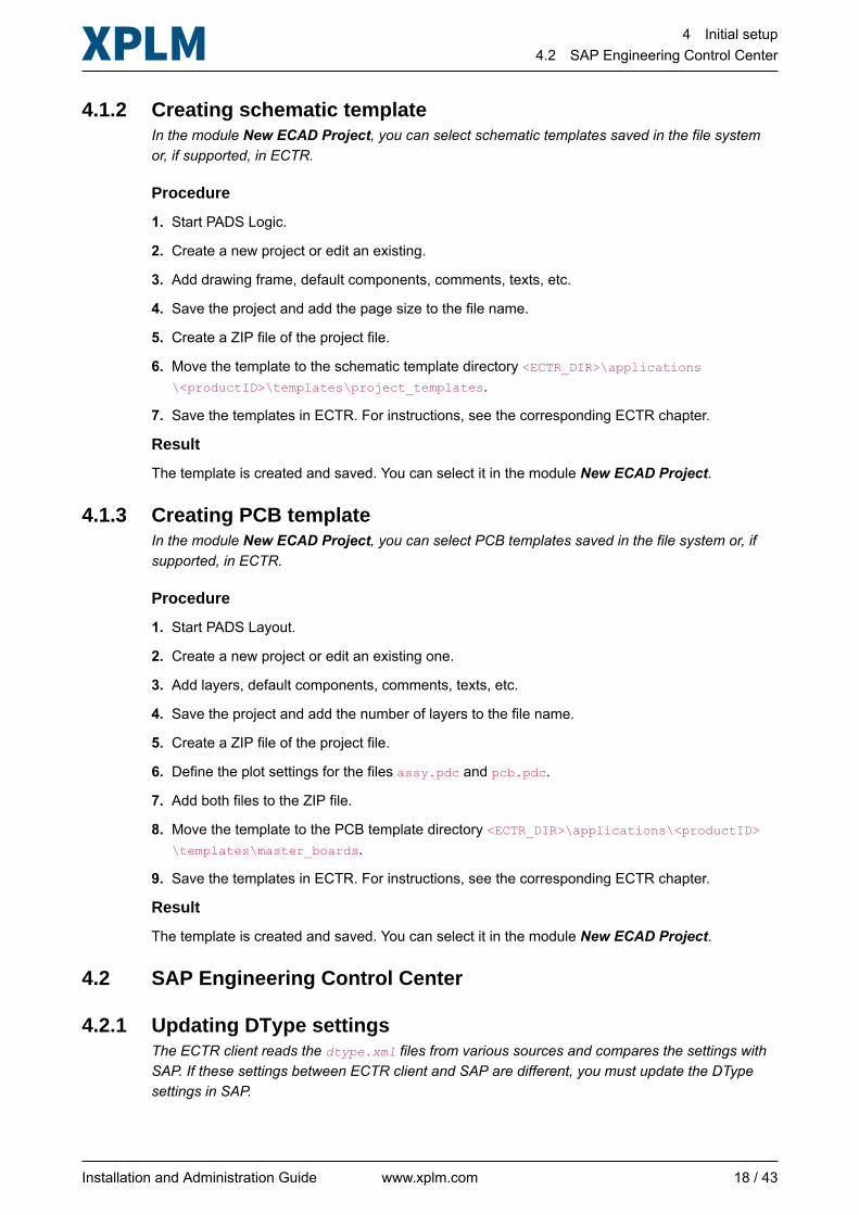
4.1.2 Creating schematic templateIn the module New ECAD Project, you can select schematic templates saved in the file systemor, if supported, in ECTR.
Procedure
1. Start PADS Logic.
2. Create a new project or edit an existing.
3. Add drawing frame, default components, comments, texts, etc.
4. Save the project and add the page size to the file name.
5. Create a ZIP file of the project file.
6. Move the template to the schematic template directory <ECTR_DIR>\applications\<productID>\templates\project_templates.
7. Save the templates in ECTR. For instructions, see the corresponding ECTR chapter.
Result
The template is created and saved. You can select it in the module New ECAD Project.
4.1.3 Creating PCB templateIn the module New ECAD Project, you can select PCB templates saved in the file system or, ifsupported, in ECTR.
Procedure
1. Start PADS Layout.
2. Create a new project or edit an existing one.
3. Add layers, default components, comments, texts, etc.
4. Save the project and add the number of layers to the file name.
5. Create a ZIP file of the project file.
6. Define the plot settings for the files assy.pdc and pcb.pdc.
7. Add both files to the ZIP file.
8. Move the template to the PCB template directory <ECTR_DIR>\applications\<productID>\templates\master_boards.
9. Save the templates in ECTR. For instructions, see the corresponding ECTR chapter.
Result
The template is created and saved. You can select it in the module New ECAD Project.
4.2 SAP Engineering Control Center
4.2.1 Updating DType settingsThe ECTR client reads the dtype.xml files from various sources and compares the settings withSAP. If these settings between ECTR client and SAP are different, you must update the DTypesettings in SAP.
Installation and Administration Guide www.xplm.com 18 / 43
4 Initial setup4.2 SAP Engineering Control Center
Before you start
Install the integration first.
Procedure
1. In ECTR, select Administrator > System Setup > Upload Settings to SAP System.
2. Click Yes to confirm the upload.
Result
DType settings in SAP are updated from the ECTR client.
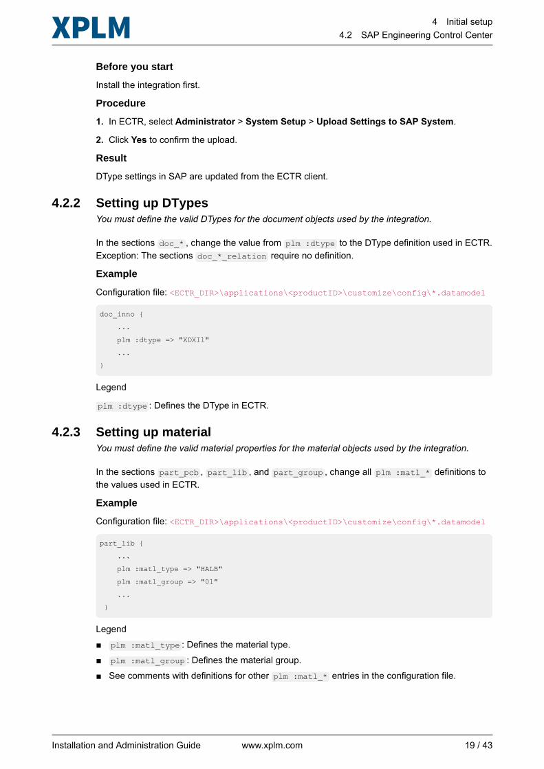
4.2.2 Setting up DTypesYou must define the valid DTypes for the document objects used by the integration.
In the sections doc_* , change the value from plm :dtype to the DType definition used in ECTR.Exception: The sections doc_*_relation require no definition.
Example
Configuration file: <ECTR_DIR>\applications\<productID>\customize\config\*.datamodel
doc_inno {
...
plm :dtype => "XDXI1"
...
}
Legend
plm :dtype : Defines the DType in ECTR.
4.2.3 Setting up materialYou must define the valid material properties for the material objects used by the integration.
In the sections part_pcb , part_lib , and part_group , change all plm :matl_* definitions tothe values used in ECTR.
Example
Configuration file: <ECTR_DIR>\applications\<productID>\customize\config\*.datamodel
part_lib {
...
plm :matl_type => "HALB"
plm :matl_group => "01"
...
}
Legend■ plm :matl_type : Defines the material type.■ plm :matl_group : Defines the material group.■ See comments with definitions for other plm :matl_* entries in the configuration file.
Installation and Administration Guide www.xplm.com 19 / 43
4 Initial setup4.2 SAP Engineering Control Center
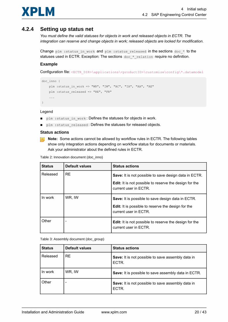
4.2.4 Setting up status netYou must define the valid statuses for objects in work and released objects in ECTR. Theintegration can reserve and change objects in work; released objects are locked for modification.
Change plm :status_in_work and plm :status_released in the sections doc_* to thestatuses used in ECTR. Exception: The sections doc_*_relation require no definition.
Example
Configuration file: <ECTR_DIR>\applications\<productID>\customize\config\*.datamodel
doc_inno {
plm :status_in_work => "WR", "IW", "AC", "IA", "AA", "AE"
plm :status_released => "RE", "FR"
...
}
Legend■ plm :status_in_work : Defines the statuses for objects in work.■ plm :status_released : Defines the statuses for released objects.
Status actions
Note: Some actions cannot be allowed by workflow rules in ECTR. The following tablesshow only integration actions depending on workflow status for documents or materials.Ask your administrator about the defined rules in ECTR.
Table 2: Innovation document (doc_inno)
Status Default values Status actions
Released RE Save: It is not possible to save design data in ECTR.
Edit: It is not possible to reserve the design for thecurrent user in ECTR.
In work WR, IW Save: It is possible to save design data in ECTR.
Edit: It is possible to reserve the design for thecurrent user in ECTR.
Other - Edit: It is not possible to reserve the design for thecurrent user in ECTR.
Table 3: Assembly document (doc_group)
Status Default values Status actions
Released RE Save: It is not possible to save assembly data inECTR.
In work WR, IW Save: It is possible to save assembly data in ECTR.
Other - Save: It is not possible to save assembly data inECTR.
Installation and Administration Guide www.xplm.com 20 / 43
4 Initial setup4.2 SAP Engineering Control Center
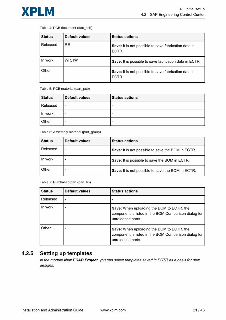
Table 4: PCB document (doc_pcb)
Status Default values Status actions
Released RE Save: It is not possible to save fabrication data inECTR.
In work WR, IW Save: It is possible to save fabrication data in ECTR.
Other - Save: It is not possible to save fabrication data inECTR.
Table 5: PCB material (part_pcb)
Status Default values Status actions
Released - -
In work - -
Other - -
Table 6: Assembly material (part_group)
Status Default values Status actions
Released - Save: It is not possible to save the BOM in ECTR.
In work - Save: It is possible to save the BOM in ECTR.
Other - Save: It is not possible to save the BOM in ECTR.
Table 7: Purchased part (part_lib)
Status Default values Status actions
Released - -
In work - Save: When uploading the BOM to ECTR, thecomponent is listed in the BOM Comparison dialog forunreleased parts.
Other - Save: When uploading the BOM to ECTR, thecomponent is listed in the BOM Comparison dialog forunreleased parts.
4.2.5 Setting up templatesIn the module New ECAD Project, you can select templates saved in ECTR as a basis for newdesigns.
Installation and Administration Guide www.xplm.com 21 / 43
4 Initial setup4.2 SAP Engineering Control Center
Before you start
In PADS, create a schematic template and a PCB template and save each in a separate ZIP file.See the corresponding PADS chapter under Initial setup on page 17 for best practices.
Procedure
1. Create a new document in ECTR.
2. In the list DType Group, select the ECAD application.
3. In the list DType, select the entry Schematic Template or Layout Template.
4. Click Browse and select the corresponding template ZIP file.
5. In the field Description, enter a descriptive name like Schematic template or Layout template.
6. Click OK.
Result
When you click the button Load on the tab PLM Template, the integration searches for the DTypedefinitions Schematic Template and Layout Template and shows the results in the selection lists.
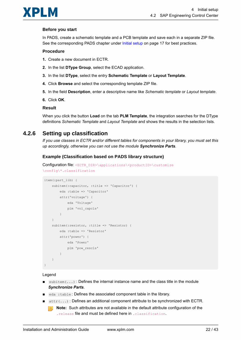
4.2.6 Setting up classificationIf you use classes in ECTR and/or different tables for components in your library, you must set thisup accordingly, otherwise you can not use the module Synchronize Parts.
Example (Classification based on PADS library structure)
Configuration file: <ECTR_DIR>\applications\<productID>\customize\config\*.classification
item(:part_lib) {
subitem(:capacitor, :title => 'Capacitor') {
eda :table => 'Capacitor'
attr('voltage') {
eda 'Voltage'
plm 'vol_capcls'
}
}
subitem(:resistor, :title => 'Resistor) {
eda :table => 'Resistor'
attr('power') {
eda 'Power'
plm 'pow_rescls'
}
}
}
Legend■ subitem(...) : Defines the internal instance name and the class title in the module
Synchronize Parts.■ eda :table : Defines the associated component table in the library.■ attr(...) : Defines an additional component attribute to be synchronized with ECTR.
Note: Such attributes are not available in the default attribute configuration of the.release file and must be defined here in .classification.
Installation and Administration Guide www.xplm.com 22 / 43
4 Initial setup4.2 SAP Engineering Control Center
■ eda : Defines the field to be mapped in PADS.■ plm : Defines the field to be mapped in ECTR.
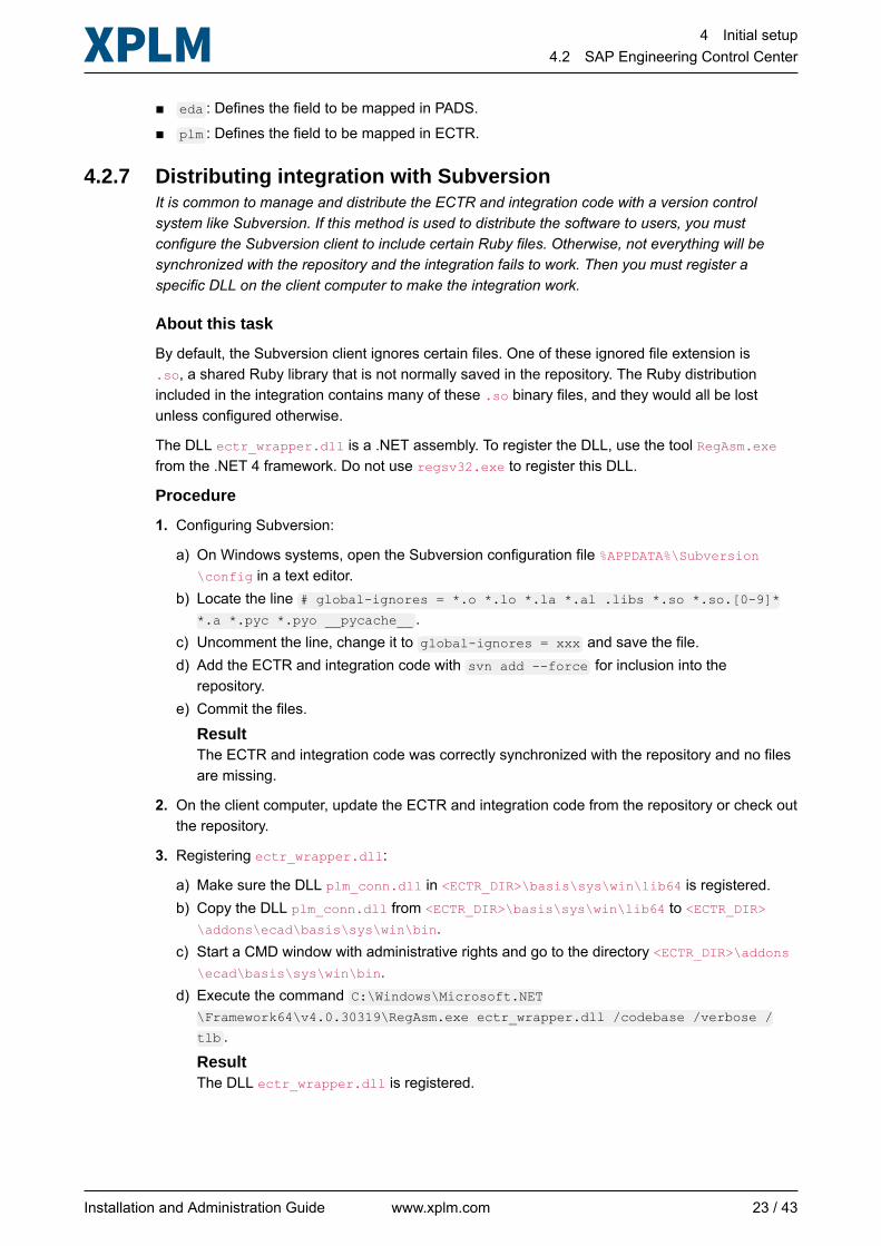
4.2.7 Distributing integration with SubversionIt is common to manage and distribute the ECTR and integration code with a version controlsystem like Subversion. If this method is used to distribute the software to users, you mustconfigure the Subversion client to include certain Ruby files. Otherwise, not everything will besynchronized with the repository and the integration fails to work. Then you must register aspecific DLL on the client computer to make the integration work.
About this task
By default, the Subversion client ignores certain files. One of these ignored file extension is.so, a shared Ruby library that is not normally saved in the repository. The Ruby distributionincluded in the integration contains many of these .so binary files, and they would all be lostunless configured otherwise.
The DLL ectr_wrapper.dll is a .NET assembly. To register the DLL, use the tool RegAsm.exefrom the .NET 4 framework. Do not use regsv32.exe to register this DLL.
Procedure
1. Configuring Subversion:
a) On Windows systems, open the Subversion configuration file %APPDATA%\Subversion\config in a text editor.
b) Locate the line # global-ignores = *.o *.lo *.la *.al .libs *.so *.so.[0-9]**.a *.pyc *.pyo __pycache__ .
c) Uncomment the line, change it to global-ignores = xxx and save the file.d) Add the ECTR and integration code with svn add --force for inclusion into the
repository.e) Commit the files.
ResultThe ECTR and integration code was correctly synchronized with the repository and no filesare missing.
2. On the client computer, update the ECTR and integration code from the repository or check outthe repository.
3. Registering ectr_wrapper.dll:
a) Make sure the DLL plm_conn.dll in <ECTR_DIR>\basis\sys\win\lib64 is registered.b) Copy the DLL plm_conn.dll from <ECTR_DIR>\basis\sys\win\lib64 to <ECTR_DIR>
\addons\ecad\basis\sys\win\bin.c) Start a CMD window with administrative rights and go to the directory <ECTR_DIR>\addons
\ecad\basis\sys\win\bin.d) Execute the command C:\Windows\Microsoft.NET
\Framework64\v4.0.30319\RegAsm.exe ectr_wrapper.dll /codebase /verbose /
tlb .
ResultThe DLL ectr_wrapper.dll is registered.
Installation and Administration Guide www.xplm.com 23 / 43
4 Initial setup4.2 SAP Engineering Control Center
Result
Integration code that is manually distributed via Subversion works on the client computers beingused.
Installation and Administration Guide www.xplm.com 24 / 43
5 Configuration5.1 Datamodel
5 Configuration
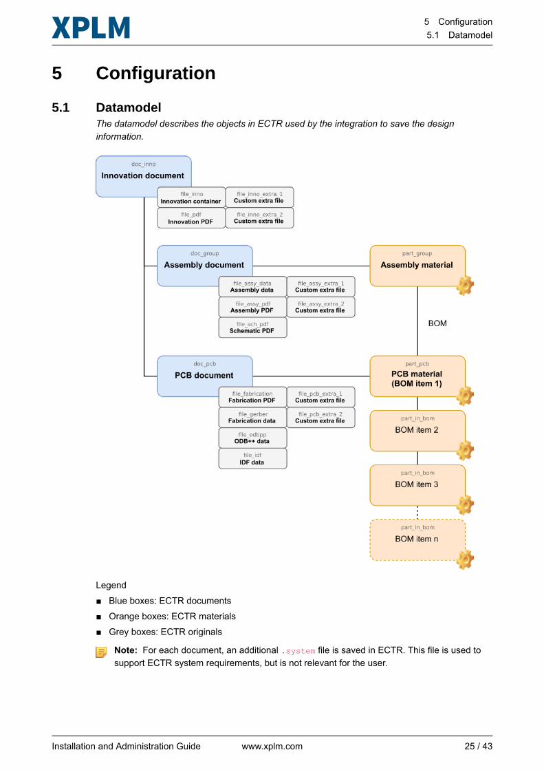
5.1 DatamodelThe datamodel describes the objects in ECTR used by the integration to save the designinformation.
Legend■ Blue boxes: ECTR documents■ Orange boxes: ECTR materials■ Grey boxes: ECTR originals
Note: For each document, an additional .system file is saved in ECTR. This file is used tosupport ECTR system requirements, but is not relevant for the user.
Installation and Administration Guide www.xplm.com 25 / 43
5 Configuration5.2 Configuration files
5.2 Configuration files
5.2.1 Datamodel configuration filesThe datamodel configuration is located in the product-specific configuration directory <ECTR_DIR>\applications\<productID>\customize\config and controls the data exchange betweenPADS and ECTR.
Scope of datamodel configuration
In the datamodel configuration you typically maintain:
■ General object and attribute definitions in PADS and ECTR■ Attribute mapping rules between PADS and ECTR■ Definitions of workflow status actions in ECTR■ Creation of output files■ Configuration of BOM processing and synchronization of components and materials
Datamodel configuration files
The datamodel configuration is defined in the following main files:
Configuration file Description
*.classification Contains product-specific mapping rules for the partssynchronization in the module Synchronize Parts. Entries inthis file redefine or extend the *.release file.
Note: Only change this file if you use classes in ECTRand/or different component tables in your library.
*.datamodel Contains the product-specific configuration of the datamodelobjects and attributes with extended properties. Entries in thisfile redefine or extend the *.release file.
Note: Always maintain changes to datamodel objectsin this file.
*.release Contains the basic configuration of the datamodel objects andattributes with their default properties. The *.release file isread first by the integration and then complemented by the twoother files *.datamodel and *.classification.
Note: Only change this file if it is explicitly required inthis document.
Available configuration sections
In the *.datamodel file, you can change or extend the default settings of the datamodel objects.The following table shows the available configuration sections and their application.
Configuration section Description
bom_source Defines settings and properties of the BOM attributes whenexporting the BOM from PADS.
Installation and Administration Guide www.xplm.com 26 / 43
5 Configuration5.2 Configuration files
Configuration section Description
bom_target Defines settings and properties of the BOM attributes whenuploading the BOM to ECTR, for example the initial positionnumber, incrementation, sorting, etc.
doc_group Defines settings and properties of the datamodel objectAssembly document.
doc_group_part_group_relation This relationship object has no definition.
doc_inno Defines settings and properties of the datamodel objectInnovation document.
doc_inno_doc_group_relation This relationship object has no definition.
doc_inno_doc_pcb_relation This relationship object has no definition.
doc_pcb Defines settings and properties of the datamodel object PCBdocument.
doc_pcb_part_pcb_relation This relationship object has no definition.
doc_template_pcb Defines settings and properties of the datamodel object thatmanages the PCB template.
doc_template_sch Defines settings and properties of the datamodel object thatmanages the schematic template.
file_assy_data Defines settings and properties of the output file Assemblydata.
file_assy_extra_1 Defines settings and properties of a custom output file that issaved by default to Assembly document.
file_assy_extra_2 Defines settings and properties of a custom output file that issaved by default to Assembly document.
file_assy_pdf Defines settings and properties of the output file AssemblyPDF.
file_fabrication Defines settings and properties of the output file FabricationPDF.
file_gerber Defines settings and properties of the output file Fabricationdata.
file_idf_data Defines settings and properties of the output file IDF data.
file_inno Defines settings and properties of the output file Innovationcontainer.
file_inno_extra_1 Defines settings and properties of a custom output file that issaved by default to Innovation document.
file_inno_extra_2 Defines settings and properties of a custom output file that issaved by default to Innovation document.
file_odbpp Defines settings and properties of the output file ODB++ data.
Installation and Administration Guide www.xplm.com 27 / 43
5 Configuration5.2 Configuration files
Configuration section Description
file_pcb_extra_1 Defines settings and properties of a custom output file that issaved by default to PCB document.
file_pcb_extra_2 Defines settings and properties of a custom output file that issaved by default to PCB document.
file_pdf Defines settings and properties of the output file InnovationPDF.
file_sch_pdf Defines settings and properties of the output file SchematicPDF.
file_template_pcb Defines settings and properties of the PCB template file.
file_template_sch Defines settings and properties of the schematic template file.
part_group Defines settings and properties of the datamodel objectAssembly material.
part_in_bom Defines settings and properties of the component andmaterial attributes in the BOM Comparison dialog.
part_lib Defines settings and properties of the component andmaterial attributes in the module Synchronize Parts.
part_pcb Defines settings and properties of the datamodel object PCBmaterial.
See alsoUnderstanding integration variables on page 13
5.2.2 Other configuration filesIn addition to the datamodel configuration files, there are the language files that control thelocalized texts of UI elements in the module dialogs, and the IVS preferences file.
Language files
Configuration file: <ECTR_DIR>\applications\<productID>\basis\dictionary\<languagecode>\ectr.txt
By default, the integration comes localized in German and English. The following files define thelanguage you can set in the module dialogs:■ de\ectr.txt (German)■ en\ectr.txt (English)
Examples of common changes to UI texts:
■ Changing names of options in the module Save and section Design, for example Keepreserved, Upload design, or PDF.
■ Changing section titles in the module Save, for example Design, or Assemblies.■ Changing tab names in the BOM Comparison dialog, for example Refdes View, Quantity
View, or Unassigned Parts.
Installation and Administration Guide www.xplm.com 28 / 43
5 Configuration5.3 General configuration options
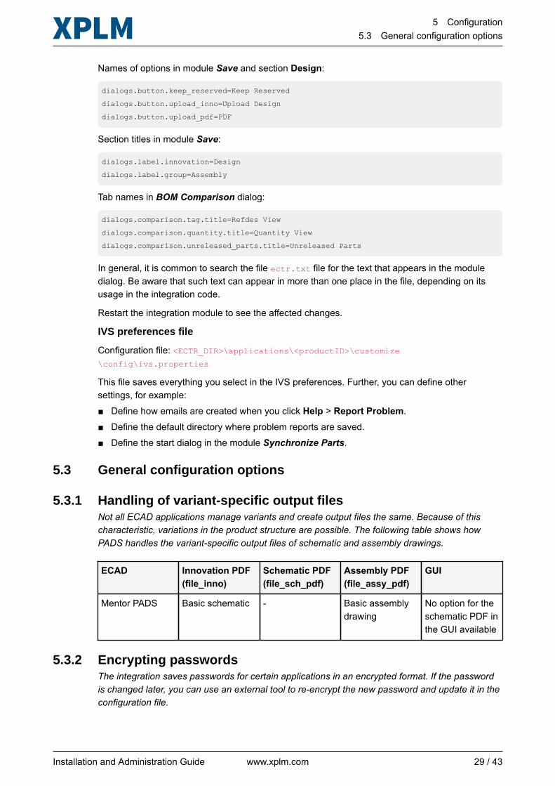
Names of options in module Save and section Design:
dialogs.button.keep_reserved=Keep Reserved
dialogs.button.upload_inno=Upload Design
dialogs.button.upload_pdf=PDF
Section titles in module Save:
dialogs.label.innovation=Design
dialogs.label.group=Assembly
Tab names in BOM Comparison dialog:
dialogs.comparison.tag.title=Refdes View
dialogs.comparison.quantity.title=Quantity View
dialogs.comparison.unreleased_parts.title=Unreleased Parts
In general, it is common to search the file ectr.txt file for the text that appears in the moduledialog. Be aware that such text can appear in more than one place in the file, depending on itsusage in the integration code.
Restart the integration module to see the affected changes.
IVS preferences file
Configuration file: <ECTR_DIR>\applications\<productID>\customize\config\ivs.properties
This file saves everything you select in the IVS preferences. Further, you can define othersettings, for example:■ Define how emails are created when you click Help > Report Problem.■ Define the default directory where problem reports are saved.■ Define the start dialog in the module Synchronize Parts.
5.3 General configuration options
5.3.1 Handling of variant-specific output filesNot all ECAD applications manage variants and create output files the same. Because of thischaracteristic, variations in the product structure are possible. The following table shows howPADS handles the variant-specific output files of schematic and assembly drawings.
ECAD Innovation PDF(file_inno)
Schematic PDF(file_sch_pdf)
Assembly PDF(file_assy_pdf)
GUI
Mentor PADS Basic schematic - Basic assemblydrawing
No option for theschematic PDF inthe GUI available
5.3.2 Encrypting passwordsThe integration saves passwords for certain applications in an encrypted format. If the passwordis changed later, you can use an external tool to re-encrypt the new password and update it in theconfiguration file.
Installation and Administration Guide www.xplm.com 29 / 43
5 Configuration5.3 General configuration options
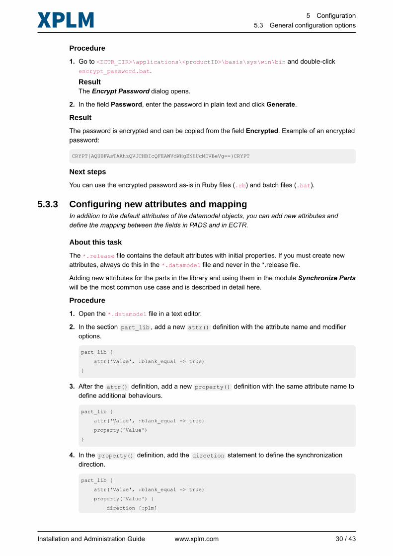
Procedure
1. Go to <ECTR_DIR>\applications\<productID>\basis\sys\win\bin and double-clickencrypt_password.bat.
ResultThe Encrypt Password dialog opens.
2. In the field Password, enter the password in plain text and click Generate.
Result
The password is encrypted and can be copied from the field Encrypted. Example of an encryptedpassword:
CRYPT{AQUBFAsTAAhzQVJCHBIcQFEAWVdWHgENHUcMDVBeVg==}CRYPT
Next steps
You can use the encrypted password as-is in Ruby files (.rb) and batch files (.bat).
5.3.3 Configuring new attributes and mappingIn addition to the default attributes of the datamodel objects, you can add new attributes anddefine the mapping between the fields in PADS and in ECTR.
About this task
The *.release file contains the default attributes with initial properties. If you must create newattributes, always do this in the *.datamodel file and never in the *.release file.
Adding new attributes for the parts in the library and using them in the module Synchronize Partswill be the most common use case and is described in detail here.
Procedure
1. Open the *.datamodel file in a text editor.
2. In the section part_lib , add a new attr() definition with the attribute name and modifieroptions.
part_lib {
attr('Value', :blank_equal => true)
}
3. After the attr() definition, add a new property() definition with the same attribute name todefine additional behaviours.
part_lib {
attr('Value', :blank_equal => true)
property('Value')
}
4. In the property() definition, add the direction statement to define the synchronizationdirection.
part_lib {
attr('Value', :blank_equal => true)
property('Value') {
direction [:plm]
Installation and Administration Guide www.xplm.com 30 / 43
5 Configuration5.3 General configuration options
}
}
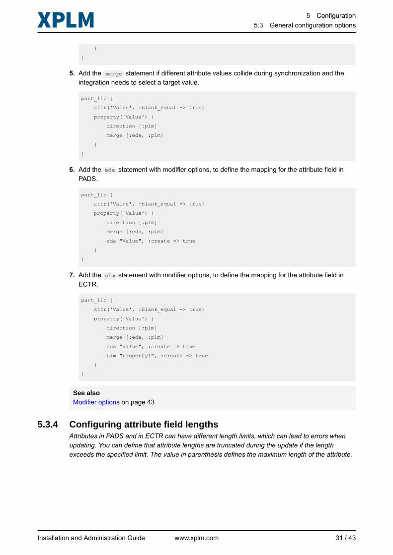
5. Add the merge statement if different attribute values collide during synchronization and theintegration needs to select a target value.
part_lib {
attr('Value', :blank_equal => true)
property('Value') {
direction [:plm]
merge [:eda, :plm]
}
}
6. Add the eda statement with modifier options, to define the mapping for the attribute field inPADS.
part_lib {
attr('Value', :blank_equal => true)
property('Value') {
direction [:plm]
merge [:eda, :plm]
eda "Value", :create => true
}
}
7. Add the plm statement with modifier options, to define the mapping for the attribute field inECTR.
part_lib {
attr('Value', :blank_equal => true)
property('Value') {
direction [:plm]
merge [:eda, :plm]
eda "value", :create => true
plm "property1", :create => true
}
}
See alsoModifier options on page 43
5.3.4 Configuring attribute field lengthsAttributes in PADS and in ECTR can have different length limits, which can lead to errors whenupdating. You can define that attribute lengths are truncated during the update if the lengthexceeds the specified limit. The value in parenthesis defines the maximum length of the attribute.
Installation and Administration Guide www.xplm.com 31 / 43
5 Configuration5.3 General configuration options
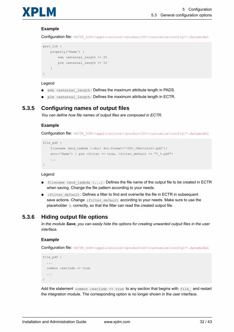
Example
Configuration file: <ECTR_DIR>\applications\<productID>\customize\config\*.datamodel
part_lib {
property('Name') {
eda :external_length => 20
plm :external_length => 10
}
}
Legend■ eda :external_length : Defines the maximum attribute length in PADS.■ plm :external_length : Defines the maximum attribute length in ECTR.
5.3.5 Configuring names of output filesYou can define how file names of output files are composed in ECTR.
Example
Configuration file: <ECTR_DIR>\applications\<productID>\customize\config\*.datamodel
file_pdf {
filename imod_lambda {|doc| doc.format('<ID>_<Revision>.pdf')}
attr('Name') { plm :filter => true, :filter_default => "%_%.pdf"}
...
}
Legend
■ filename imod_lambda {...} : Defines the file name of the output file to be created in ECTRwhen saving. Change the file pattern according to your needs.
■ :filter_default : Defines a filter to find and overwrite the file in ECTR in subsequentsave actions. Change :filter_default according to your needs. Make sure to use theplaceholder % correctly, so that the filter can read the created output file.
5.3.6 Hiding output file optionsIn the module Save, you can easily hide the options for creating unwanted output files in the userinterface.
Example
Configuration file: <ECTR_DIR>\applications\<productID>\customize\config\*.datamodel
file_pdf {
...
common :exclude => true
...
}
Add the statement common :exclude => true to any section that begins with file_ and restartthe integration module. The corresponding option is no longer shown in the user interface.
Installation and Administration Guide www.xplm.com 32 / 43
5 Configuration5.3 General configuration options
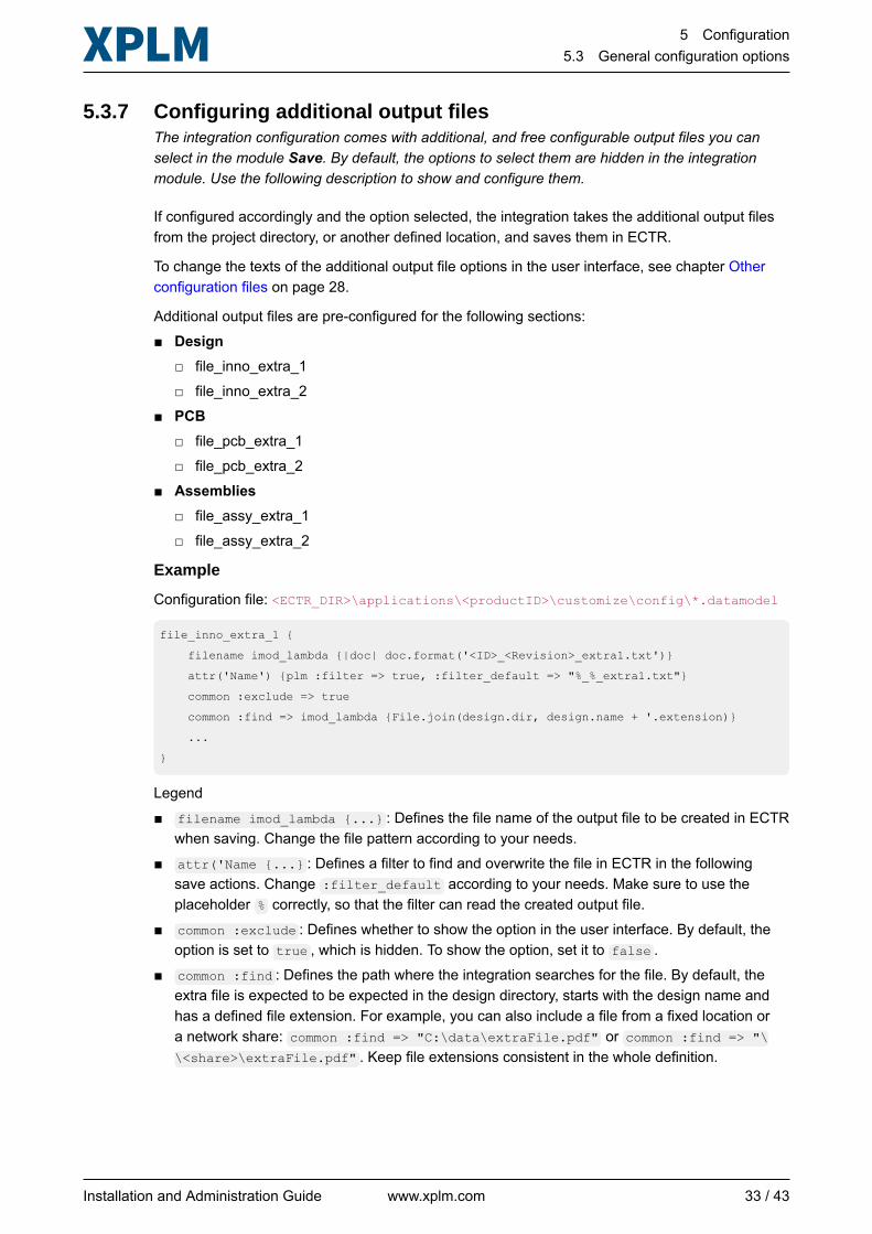
5.3.7 Configuring additional output filesThe integration configuration comes with additional, and free configurable output files you canselect in the module Save. By default, the options to select them are hidden in the integrationmodule. Use the following description to show and configure them.
If configured accordingly and the option selected, the integration takes the additional output filesfrom the project directory, or another defined location, and saves them in ECTR.
To change the texts of the additional output file options in the user interface, see chapter Otherconfiguration files on page 28.
Additional output files are pre-configured for the following sections:■ Design
□ file_inno_extra_1□ file_inno_extra_2
■ PCB□ file_pcb_extra_1□ file_pcb_extra_2
■ Assemblies□ file_assy_extra_1□ file_assy_extra_2
Example
Configuration file: <ECTR_DIR>\applications\<productID>\customize\config\*.datamodel
file_inno_extra_1 {
filename imod_lambda {|doc| doc.format('<ID>_<Revision>_extra1.txt')}
attr('Name') {plm :filter => true, :filter_default => "%_%_extra1.txt"}
common :exclude => true
common :find => imod_lambda {File.join(design.dir, design.name + '.extension)}
...
}
Legend■ filename imod_lambda {...} : Defines the file name of the output file to be created in ECTR
when saving. Change the file pattern according to your needs.■ attr('Name {...} : Defines a filter to find and overwrite the file in ECTR in the following
save actions. Change :filter_default according to your needs. Make sure to use theplaceholder % correctly, so that the filter can read the created output file.
■ common :exclude : Defines whether to show the option in the user interface. By default, theoption is set to true , which is hidden. To show the option, set it to false .
■ common :find : Defines the path where the integration searches for the file. By default, theextra file is expected to be expected in the design directory, starts with the design name andhas a defined file extension. For example, you can also include a file from a fixed location ora network share: common :find => "C:\data\extraFile.pdf" or common :find => "\\<share>\extraFile.pdf" . Keep file extensions consistent in the whole definition.
Installation and Administration Guide www.xplm.com 33 / 43
5 Configuration5.3 General configuration options
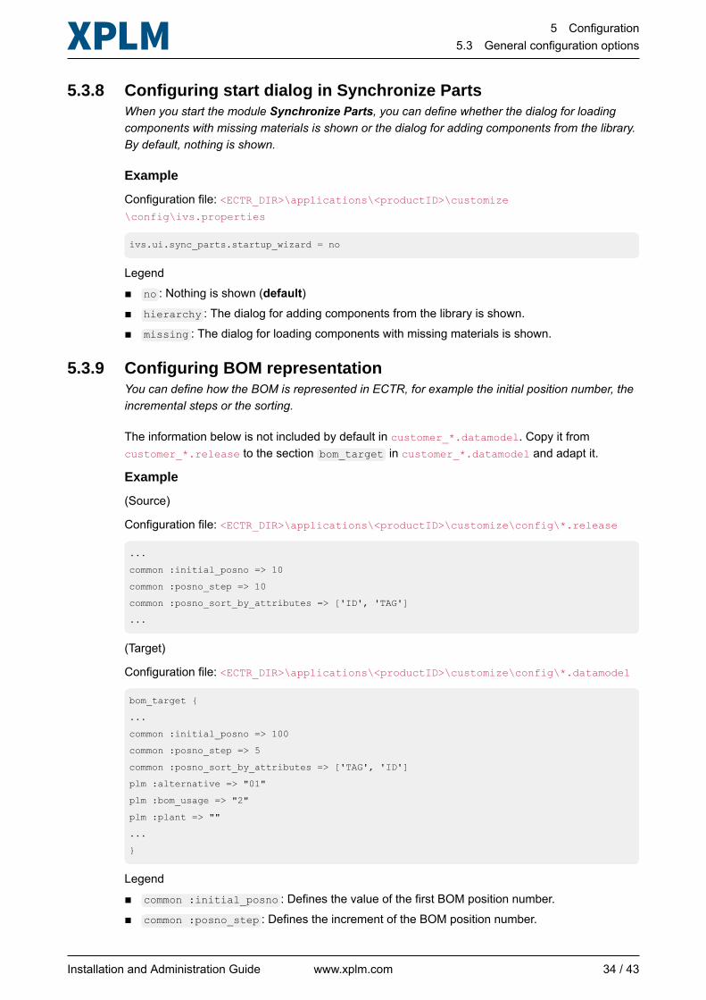
5.3.8 Configuring start dialog in Synchronize PartsWhen you start the module Synchronize Parts, you can define whether the dialog for loadingcomponents with missing materials is shown or the dialog for adding components from the library.By default, nothing is shown.
Example
Configuration file: <ECTR_DIR>\applications\<productID>\customize\config\ivs.properties
ivs.ui.sync_parts.startup_wizard = no
Legend■ no : Nothing is shown (default)■ hierarchy : The dialog for adding components from the library is shown.■ missing : The dialog for loading components with missing materials is shown.
5.3.9 Configuring BOM representationYou can define how the BOM is represented in ECTR, for example the initial position number, theincremental steps or the sorting.
The information below is not included by default in customer_*.datamodel. Copy it fromcustomer_*.release to the section bom_target in customer_*.datamodel and adapt it.
Example
(Source)
Configuration file: <ECTR_DIR>\applications\<productID>\customize\config\*.release
...
common :initial_posno => 10
common :posno_step => 10
common :posno_sort_by_attributes => ['ID', 'TAG']
...
(Target)
Configuration file: <ECTR_DIR>\applications\<productID>\customize\config\*.datamodel
bom_target {
...
common :initial_posno => 100
common :posno_step => 5
common :posno_sort_by_attributes => ['TAG', 'ID']
plm :alternative => "01"
plm :bom_usage => "2"
plm :plant => ""
...
}
Legend■ common :initial_posno : Defines the value of the first BOM position number.■ common :posno_step : Defines the increment of the BOM position number.
Installation and Administration Guide www.xplm.com 34 / 43
5 Configuration5.4 Mentor PADS
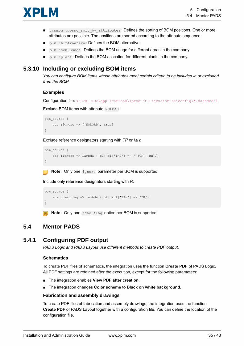
■ common :posno_sort_by_attributes : Defines the sorting of BOM positions. One or moreattributes are possible. The positions are sorted according to the attribute sequence.
■ plm :alternative : Defines the BOM alternative.■ plm :bom_usage : Defines the BOM usage for different areas in the company.■ plm :plant : Defines the BOM allocation for different plants in the company.
5.3.10 Including or excluding BOM itemsYou can configure BOM items whose attributes meet certain criteria to be included in or excludedfrom the BOM.
Examples
Configuration file: <ECTR_DIR>\applications\<productID>\customize\config\*.datamodel
Exclude BOM items with attribute NOLOAD :
bom_source {
eda :ignore => ['NOLOAD', true]
}
Exclude reference designators starting with TP or MH:
bom_source {
eda :ignore => lambda {|bl| bl['TAG'] =~ /^(TP)|(MH)/}
}
Note: Only one ignore parameter per BOM is supported.
Include only reference designators starting with R:
bom_source {
eda :cae_flag => lambda {|bl| sbl['TAG'] =~ /^R/}
}
Note: Only one :cae_flag option per BOM is supported.
5.4 Mentor PADS
5.4.1 Configuring PDF outputPADS Logic and PADS Layout use different methods to create PDF output.
Schematics
To create PDF files of schematics, the integration uses the function Create PDF of PADS Logic.All PDF settings are retained after the execution, except for the following parameters:
■ The integration enables View PDF after creation.■ The integration changes Color scheme to Black on white background.
Fabrication and assembly drawings
To create PDF files of fabrication and assembly drawings, the integration uses the functionCreate PDF of PADS Layout together with a configuration file. You can define the location of theconfiguration file.
Installation and Administration Guide www.xplm.com 35 / 43
5 Configuration5.5 SAP Engineering Control Center
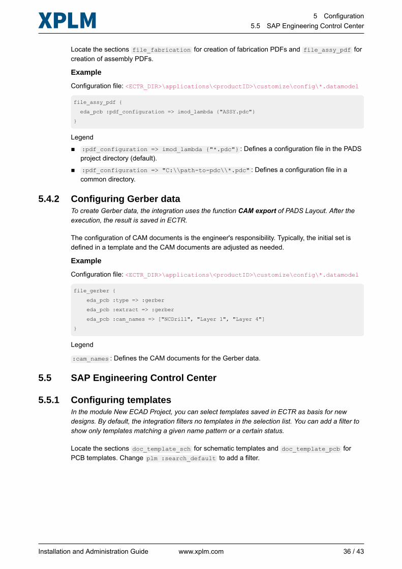
Locate the sections file_fabrication for creation of fabrication PDFs and file_assy_pdf forcreation of assembly PDFs.
Example
Configuration file: <ECTR_DIR>\applications\<productID>\customize\config\*.datamodel
file_assy_pdf {
eda_pcb :pdf_configuration => imod_lambda {"ASSY.pdc"}
}
Legend■ :pdf_configuration => imod_lambda {"*.pdc"} : Defines a configuration file in the PADS
project directory (default).■ :pdf_configuration => "C:\\path-to-pdc\\*.pdc" : Defines a configuration file in a
common directory.
5.4.2 Configuring Gerber dataTo create Gerber data, the integration uses the function CAM export of PADS Layout. After theexecution, the result is saved in ECTR.
The configuration of CAM documents is the engineer's responsibility. Typically, the initial set isdefined in a template and the CAM documents are adjusted as needed.
Example
Configuration file: <ECTR_DIR>\applications\<productID>\customize\config\*.datamodel
file_gerber {
eda_pcb :type => :gerber
eda_pcb :extract => :gerber
eda_pcb :cam_names => ["NCDrill", "Layer 1", "Layer 4"]
}
Legend
:cam_names : Defines the CAM documents for the Gerber data.
5.5 SAP Engineering Control Center
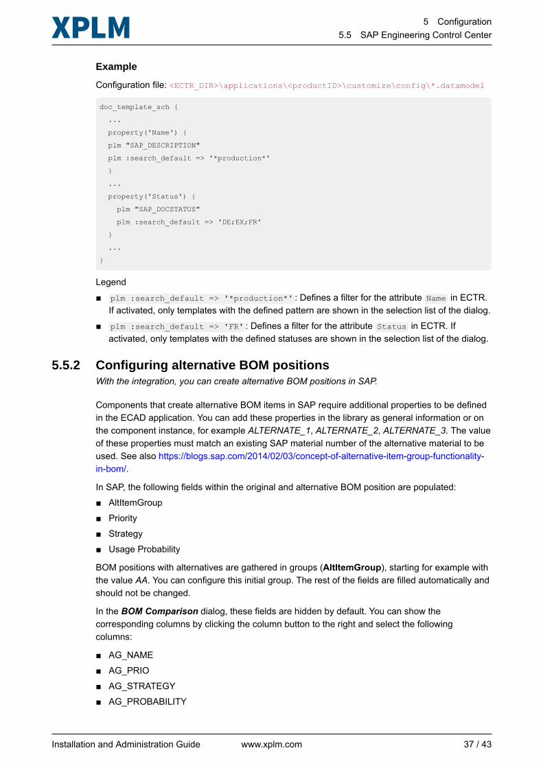
5.5.1 Configuring templatesIn the module New ECAD Project, you can select templates saved in ECTR as basis for newdesigns. By default, the integration filters no templates in the selection list. You can add a filter toshow only templates matching a given name pattern or a certain status.
Locate the sections doc_template_sch for schematic templates and doc_template_pcb forPCB templates. Change plm :search_default to add a filter.
Installation and Administration Guide www.xplm.com 36 / 43
5 Configuration5.5 SAP Engineering Control Center
Example
Configuration file: <ECTR_DIR>\applications\<productID>\customize\config\*.datamodel
doc_template_sch {
...
property('Name') {
plm "SAP_DESCRIPTION"
plm :search_default => '*production*'
}
...
property('Status') {
plm "SAP_DOCSTATUS"
plm :search_default => 'DE;EX;FR'
}
...
}
Legend■ plm :search_default => '*production*' : Defines a filter for the attribute Name in ECTR.
If activated, only templates with the defined pattern are shown in the selection list of the dialog.■ plm :search_default => 'FR' : Defines a filter for the attribute Status in ECTR. If
activated, only templates with the defined statuses are shown in the selection list of the dialog.
5.5.2 Configuring alternative BOM positionsWith the integration, you can create alternative BOM positions in SAP.
Components that create alternative BOM items in SAP require additional properties to be definedin the ECAD application. You can add these properties in the library as general information or onthe component instance, for example ALTERNATE_1, ALTERNATE_2, ALTERNATE_3. The valueof these properties must match an existing SAP material number of the alternative material to beused. See also https://blogs.sap.com/2014/02/03/concept-of-alternative-item-group-functionality-in-bom/.
In SAP, the following fields within the original and alternative BOM position are populated:■ AltItemGroup■ Priority■ Strategy■ Usage Probability
BOM positions with alternatives are gathered in groups (AltItemGroup), starting for example withthe value AA. You can configure this initial group. The rest of the fields are filled automatically andshould not be changed.
In the BOM Comparison dialog, these fields are hidden by default. You can show thecorresponding columns by clicking the column button to the right and select the followingcolumns:
■ AG_NAME■ AG_PRIO■ AG_STRATEGY■ AG_PROBABILITY
Installation and Administration Guide www.xplm.com 37 / 43
5 Configuration5.5 SAP Engineering Control Center
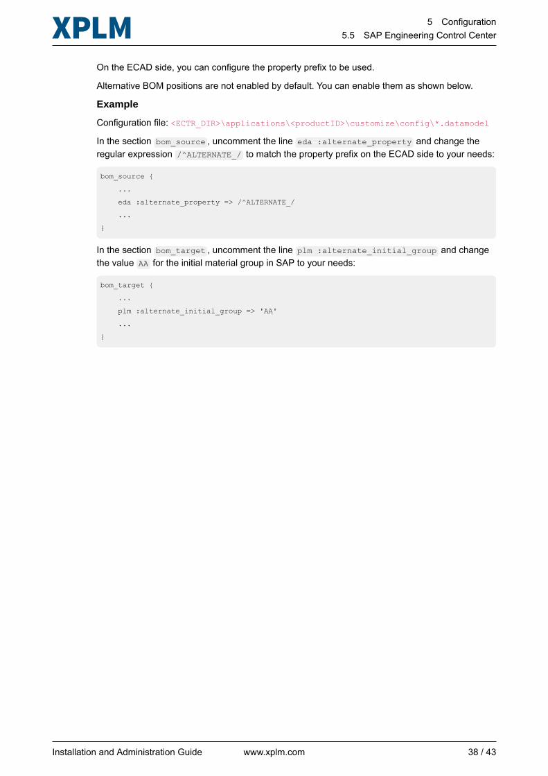
On the ECAD side, you can configure the property prefix to be used.
Alternative BOM positions are not enabled by default. You can enable them as shown below.
Example
Configuration file: <ECTR_DIR>\applications\<productID>\customize\config\*.datamodel
In the section bom_source , uncomment the line eda :alternate_property and change theregular expression /^ALTERNATE_/ to match the property prefix on the ECAD side to your needs:
bom_source {
...
eda :alternate_property => /^ALTERNATE_/
...
}
In the section bom_target , uncomment the line plm :alternate_initial_group and changethe value AA for the initial material group in SAP to your needs:
bom_target {
...
plm :alternate_initial_group => 'AA'
...
}
Installation and Administration Guide www.xplm.com 38 / 43
6 Update6.1 Updating the integration
6 Update
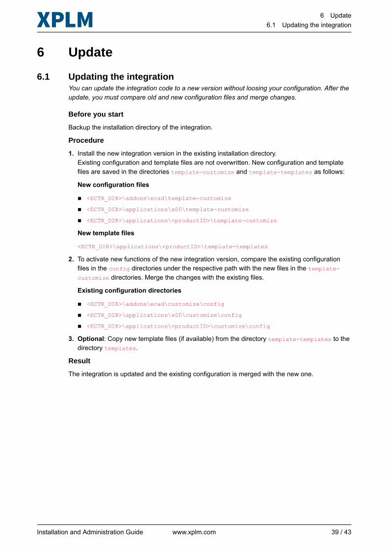
6.1 Updating the integrationYou can update the integration code to a new version without loosing your configuration. After theupdate, you must compare old and new configuration files and merge changes.
Before you start
Backup the installation directory of the integration.
Procedure
1. Install the new integration version in the existing installation directory.Existing configuration and template files are not overwritten. New configuration and templatefiles are saved in the directories template-customize and template-templates as follows:
New configuration files
■ <ECTR_DIR>\addons\ecad\template-customize
■ <ECTR_DIR>\applications\x00\template-customize
■ <ECTR_DIR>\applications\<productID>\template-customize
New template files
<ECTR_DIR>\applications\<productID>\template-templates
2. To activate new functions of the new integration version, compare the existing configurationfiles in the config directories under the respective path with the new files in the template-customize directories. Merge the changes with the existing files.
Existing configuration directories
■ <ECTR_DIR>\addons\ecad\customize\config
■ <ECTR_DIR>\applications\x00\customize\config
■ <ECTR_DIR>\applications\<productID>\customize\config
3. Optional: Copy new template files (if available) from the directory template-templates to thedirectory templates.
Result
The integration is updated and the existing configuration is merged with the new one.
Installation and Administration Guide www.xplm.com 39 / 43
7 Uninstallation7.1 Uninstalling the integration
7 Uninstallation
7.1 Uninstalling the integrationAn uninstall program is provided during the installation of the integration.
Procedure
1. Select Control Panel > All Control Panel Items > Programs and Features.
2. Select SAP Engineering Control Center Interface to ECAD and click Uninstall/Change.
Result
The integration is uninstalled.
Installation and Administration Guide www.xplm.com 40 / 43
8 Troubleshooting8.1 Solving integration issues
8 Troubleshooting
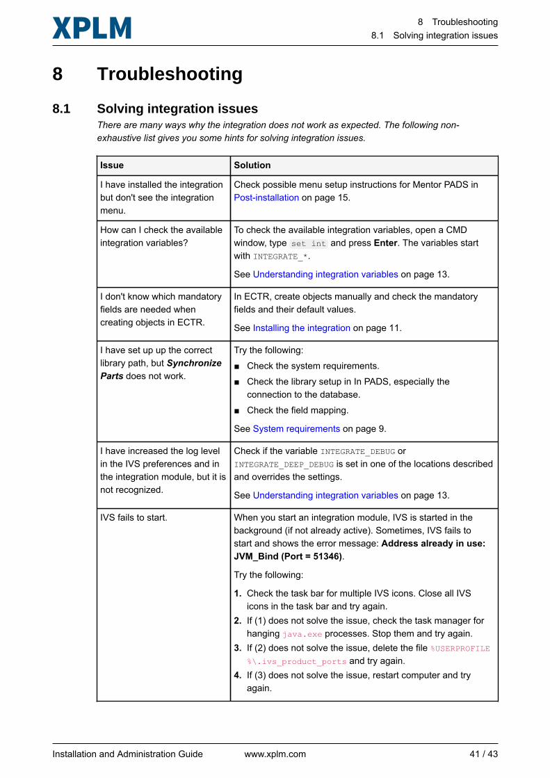
8.1 Solving integration issuesThere are many ways why the integration does not work as expected. The following non-exhaustive list gives you some hints for solving integration issues.
Issue Solution
I have installed the integrationbut don't see the integrationmenu.
Check possible menu setup instructions for Mentor PADS inPost-installation on page 15.
How can I check the availableintegration variables?
To check the available integration variables, open a CMDwindow, type set int and press Enter. The variables startwith INTEGRATE_*.
See Understanding integration variables on page 13.
I don't know which mandatoryfields are needed whencreating objects in ECTR.
In ECTR, create objects manually and check the mandatoryfields and their default values.
See Installing the integration on page 11.
I have set up up the correctlibrary path, but SynchronizeParts does not work.
Try the following:■ Check the system requirements.■ Check the library setup in In PADS, especially the
connection to the database.■ Check the field mapping.
See System requirements on page 9.
I have increased the log levelin the IVS preferences and inthe integration module, but it isnot recognized.
Check if the variable INTEGRATE_DEBUG orINTEGRATE_DEEP_DEBUG is set in one of the locations describedand overrides the settings.
See Understanding integration variables on page 13.
IVS fails to start. When you start an integration module, IVS is started in thebackground (if not already active). Sometimes, IVS fails tostart and shows the error message: Address already in use:JVM_Bind (Port = 51346).
Try the following:
1. Check the task bar for multiple IVS icons. Close all IVSicons in the task bar and try again.
2. If (1) does not solve the issue, check the task manager forhanging java.exe processes. Stop them and try again.
3. If (2) does not solve the issue, delete the file %USERPROFILE%\.ivs_product_ports and try again.
4. If (3) does not solve the issue, restart computer and tryagain.
Installation and Administration Guide www.xplm.com 41 / 43
8 Troubleshooting8.1 Solving integration issues
Issue Solution
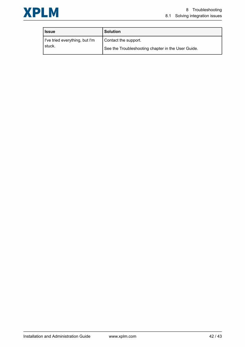
I've tried everything, but I'mstuck.
Contact the support.
See the Troubleshooting chapter in the User Guide.
Installation and Administration Guide www.xplm.com 42 / 43
9 References9.1 Modifier options
9 References
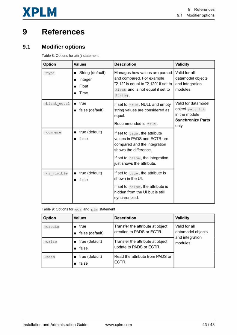
9.1 Modifier optionsTable 8: Options for attr() statement
Option Values Description Validity
:type ■ String (default)■ Integer■ Float■ Time
Manages how values are parsedand compared. For example"2.12" is equal to "2.120" if set toFloat and is not equal if set toString .
Valid for alldatamodel objectsand integrationmodules.
:blank_equal ■ true■ false (default)
If set to true , NULL and emptystring values are considered asequal.
Recommended is true .
:compare ■ true (default)■ false
If set to true , the attributevalues in PADS and ECTR arecompared and the integrationshows the difference.
If set to false , the integrationjust shows the attribute.
:ui_visible ■ true (default)■ false
If set to true , the attribute isshown in the UI.
If set to false , the attribute ishidden from the UI but is stillsynchronized.
Valid for datamodelobject part_libin the moduleSynchronize Partsonly.
Table 9: Options for eda and plm statement
Option Values Description Validity
:create ■ true■ false (default)
Transfer the attribute at objectcreation to PADS or ECTR.
:write ■ true (default)■ false
Transfer the attribute at objectupdate to PADS or ECTR.
:read ■ true (default)■ false
Read the attribute from PADS orECTR.
Valid for alldatamodel objectsand integrationmodules.
Installation and Administration Guide www.xplm.com 43 / 43