industrial & commercial transportation
TRANSCRIPT

Terminals and Connectors
INDUSTRIAL & COMMERCIAL TRANSPORTATION /// TERMINALS AND CONNECTORS
INDUSTRIAL & COMMERCIAL TRANSPORTATION


Contents
General Information About TE Connectivity .................................................................. 2
TE.com ................................................................................................. 3
Introduction to Connectors ......................................................4-5
Connector Series Overview.................................................... 6-10
AMP ProductsAMPSEAL Connectors ............................................................11-20
AMPSEAL 16 Connectors ......................................................21-34
Circular DIN Connectors .......................................................35-44
HDSCS Connectors.................................................................45-62
LEAVYSEAL Connectors ...................................................... 63-78
Superseal 1.0 Connectors .....................................................79-84
DEUTSCH ProductsAEC Series ................................................................................ 85-90
DRB Series ..................................................................................91-98
DRC Series ...............................................................................99-108
DT Family ................................................................................109-132
HD10 Series ............................................................................133-144
HD30 & HDP20 Series ....................................................... 145-160
STRIKE Series ......................................................................... 161-168
Common Contacts .............................................................. 169-180
Tooling .......................................................................................181-190
Specialty ProductsBussing Options ....................................................................191-194
Controller Area Networks ................................................195-207
Diodes & Resistors ............................................................ 205-208
Printed Circuit Board Connectors ...............................209-222
Single Terminal .................................................................... 223-228
Additional Resources Modification List .................................................................230-238
Other TE Industrial & Commercial TransportationProducts ............................................................................... 239-240
Requirements & Standards ....................................................... 241
Glossary ................................................................................. 242-247
Index .......................................................................................248-252

INDUSTRIAL & COMMERCIAL TRANSPORTATION /// TERMINALS AND CONNECTORS
TE Connectivity Industrial & Commercial Transportation
We go to extremes to make sure EVERY CONNECTION COUNTS.
TE Connectivity’s (TE) products are in nearly every
high-tech product imaginable. From consumer
electronics, health care, energy supply, and
communication networks, to the transportation and
aviation industries, TE’s extensive portfolio of over
500,000 products keep the world connected. TE’s
intelligent and robust solutions and technologies
carry over to the industrial and heavy duty vehicle
markets. TE offers products that work just as hard
as the vehicles in which they are installed.
Years ago, tractors, construction equipment,
trucks, and boats had simple electrical systems that might have included electrical starting and a
basic lighting package. Today, ECUs, joysticks, fuel-efficient engines, LED lights, and CAN systems are
standard equipment. The need to protect sensitive electrical systems from vibration, moisture, dust,
dirt, salt and airborne particles has never been greater. TE Industrial & Commercial Transportation is a
leader in supporting today’s increasingly complex and sophisticated equipment and applications.
TE’s comprehensive line of Industrial & Commercial Transportation products include an unparalleled
portfolio of rugged electrical connector products and sensor technologies. TE’s environmentally sealed
connectors are designed to withstand the harshest environmental conditions and to keep vehicles
moving forward. TE’s portfolio of heavy duty sensors help vehicles operate safer, cleaner, and smarter.
From heavy duty trucks to construction equipment, mining vehicles to fire trucks, as well as boats,
motorcycles, and tractors, leading manufacturers count on TE Industrial & Commercial Transportation.

PAGE 3
TE Connectivity Industrial & Commercial Transportation
Online Resources
The TE Connectivity Industrial & Commercial Transportation’s website is an innovative and interactive source for
application information, product updates, and technical solutions.
PRODUCT LITERATURE AND VIDEOS TE Industrial & Commercial Transportation offers a variety of product specific catalogs, brochures, and videos to better serve you. For more information on literature for TE Industrial & Commercial Transportation, please contact your representative or go to http://www.te.com/usa-en/industries/truck-bus-off-road-vehicles/ ictliterature.html
To view videos about TE Industrial & Commercial Transportation, please go to http://www.te.com/usa-en/industries/truck-bus-off-road-vehicles/ ict-video-index.html
TE INDUSTRIAL & COMMERCIAL TRANSPORTATION PRODUCTS For more information on TE Industrial & Commercial Transportation products, please go to http://www.te.com/usa-en/industries/truck-bus-off-road-vehicles/products.html
PRODUCT INFORMATION CENTER (PIC) You can rely on TE Connectivity’s PIC team to provide support for answers to your general information or technical questions in an efficient and effective manner. Connect with our PIC staff, http://www.te.com/usa-en/customer-support/email.html

INDUSTRIAL & COMMERCIAL TRANSPORTATION /// TERMINALS AND CONNECTORS
Introduction to Connectors
In heavy industries, electrical systems must stand up to rigorous conditions and all weather environments. Failure in an electrical system can be expensive to diagnose and down equipment can stop entire operations. As equipment becomes increasingly sophisticated and reliant on electronic packaging and diagnostics, design engineers know the importance of choosing environmentally sealed electrical connectors capable of holding up to extreme conditions. Many manufacturers count on TE Connectivity Industrial & Commercial Transportation’s electrical connectors to maintain their electrical connections.
Benefits of industrial connectors There are many different connectors for harsh environments and connector selection for each specific appli-cation is important. Once the questions of wire gauge and pin count have been addressed, the environmental challenges specific to each application must be identified, including if the electrical system will be exposed to heat, impact or vibration. Other elements that need to be addressed include if the connectors will be suscep-tible to moisture or chemicals and field serviceability. Developed with simplicity of design and ease of use in mind, TE connectors offer a variety of innovative solutions to suit nearly any application and stand up to envi-ronmental challenges.
Whether for a new application or a retrofit, connectors provide simplified design and wiring, and easy field repairs. TE Industrial & Commercial Transportation’s connector applications include ECUs, joysticks, industrial and marine engines, control boxes, lights and CAN systems, just to mention a few. TE Industrial & Commercial Transportation’s connector series offer several features designed to combat environmental challenges.
Connector features help protect electrical connections Connector bodies must be able to stand up to environmental conditions. Rugged all-metal bodies and corrosion resistant thermoplastic shells are manufactured from high quality materials selected for their ability to withstand years of environmental exposure. Metal connectors are built to withstand the force and shock of hard impacts that connectors face in rough environments. High-grade thermoplastic connectors are lightweight and are engineered to be flame resistant and extremely chemical resistant. Different connector body materials are available to meet diverse application requirements.

PAGE 5
Introduction to Connectors
Proper contact alignment is another important aspect of environmentally sealed electrical connectors. Sec-ondary locks snap into or onto the mating face of a connector to help confirm the contacts slide together properly when the connectors are mated. Many of TE Industrial & Commercial Transportation’s connectors feature secondary locks that are commonly referred to as wedgelocks, terminal position assurance (TPA), or primary latch reinforcement (PLR). Wedgelocks, TPAs, and PLRs provide additional stability to both the contact barrel and the mated connectors.
A firm, secure locking mechanism that can withstand vibration and shock is critical to maintain a steadfast connector engagement in rugged applications. TE Industrial & Commercial Transportation’s connectors are held together by push-latches, threaded coupling rings, or tightened together by jackscrews. The locking mecha-nisms are easy to engage and disengage and give an audible or tactile signal when they are securely fastened. Once fastened, the locking mechanisms prevent disengagement due to vibration or impact. Since even a small degradation in electrical connections can be critical to industrial vehicles, manufacturers are turning to TE Industrial & Commercial Transportation’s environmentally sealed electrical connectors to keep their equipment running. Connectors are increasingly needed as industrial equipment becomes more complex and reliant on electronic control units, CAN systems, and on-board communications systems. With a wide vari-ety of industrial electrical connectors, manufacturers can find a connector for nearly any application. No matter the environment, TE’s industrial connectors provide the innovative solutions demanded by harsh conditions. TE’s dedication to quality and innovation has created a unique system of easy-to-use connectors to simplify processes from start to finish.
INDUSTRIAL & COMMERCIAL TRANSPORTATION /// TERMINALS AND CONNECTORS
Connector Series Overview
Connector Series Overview
TE Connectivity connectors offer different shapes, latching mechanisms, mounting styles, and materials
to meet diverse application requirements and offer accessories to further expand the series’ flexibility.
Below is an overview of each connector series that highlights the cavity count, wire gauge, material, and
locking mechanism style. For complete series information, please see the series section of the catalog.
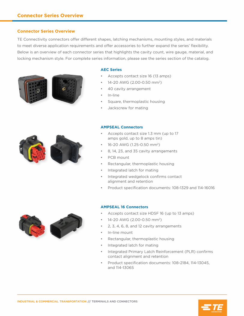
AEC Series
• Accepts contact size 16 (13 amps)
• 14-20 AWG (2.00-0.50 mm2)
• 40 cavity arrangement
• In-line
• Square, thermoplastic housing
• Jackscrew for mating
AMPSEAL Connectors
• Accepts contact size 1.3 mm (up to 17 amps gold, up to 8 amps tin)
• 16-20 AWG (1.25-0.50 mm2)
• 8, 14, 23, and 35 cavity arrangements
• PCB mount
• Rectangular, thermoplastic housing
• Integrated latch for mating
• Integrated wedgelock confirms contact alignment and retention
• Product specification documents: 108-1329 and 114-16016
AMPSEAL 16 Connectors
• Accepts contact size HDSF 16 (up to 13 amps)
• 14-20 AWG (2.00-0.50 mm2)
• 2, 3, 4, 6, 8, and 12 cavity arrangements
• In-line mount
• Rectangular, thermoplastic housing
• Integrated latch for mating
• Integrated Primary Latch Reinforcement (PLR) confirms contact alignment and retention
• Product specification documents: 108-2184, 114-13045, and 114-13065
PAGE 7
Connector Series Overview
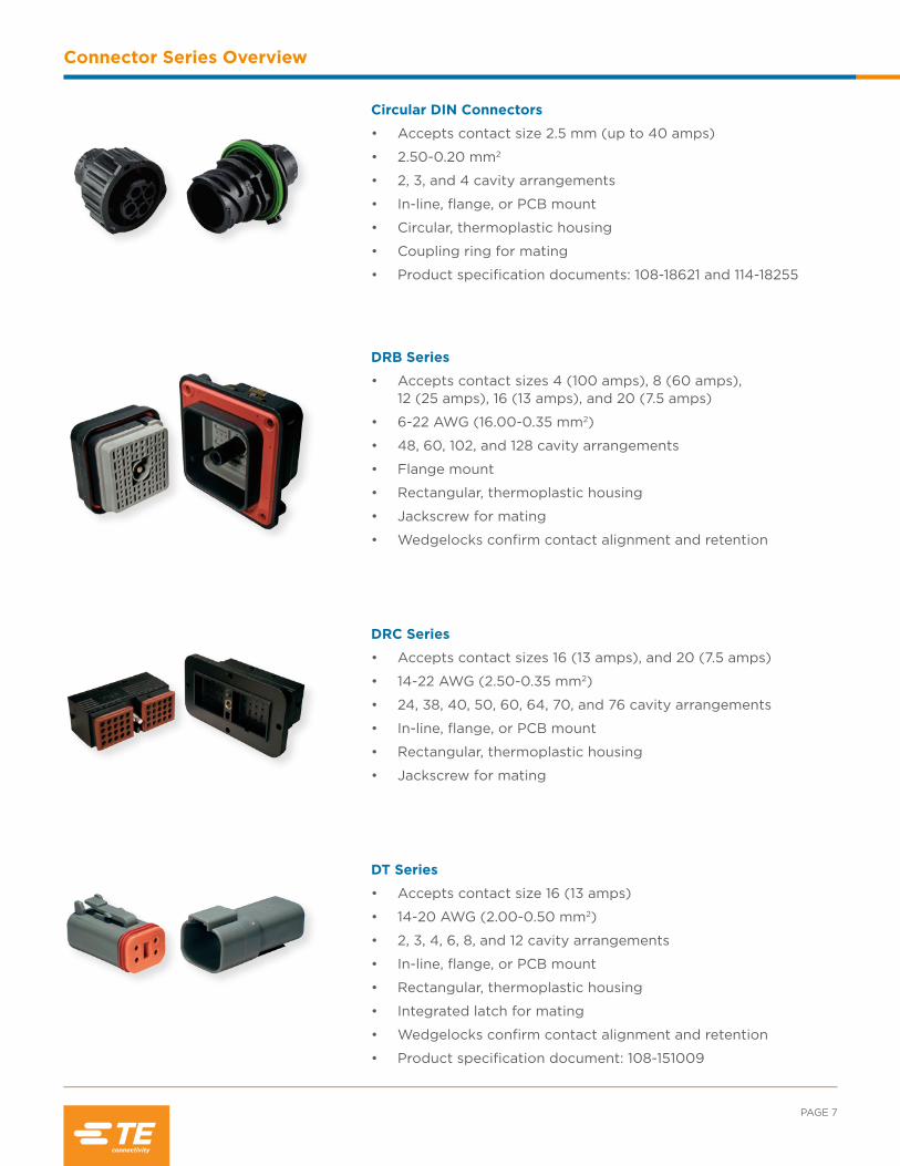
DRB Series
• Accepts contact sizes 4 (100 amps), 8 (60 amps), 12 (25 amps), 16 (13 amps), and 20 (7.5 amps)
• 6-22 AWG (16.00-0.35 mm2)
• 48, 60, 102, and 128 cavity arrangements
• Flange mount
• Rectangular, thermoplastic housing
• Jackscrew for mating
• Wedgelocks confirm contact alignment and retention
DRC Series
• Accepts contact sizes 16 (13 amps), and 20 (7.5 amps)
• 14-22 AWG (2.50-0.35 mm2)
• 24, 38, 40, 50, 60, 64, 70, and 76 cavity arrangements
• In-line, flange, or PCB mount
• Rectangular, thermoplastic housing
• Jackscrew for mating
DT Series
• Accepts contact size 16 (13 amps)
• 14-20 AWG (2.00-0.50 mm2)
• 2, 3, 4, 6, 8, and 12 cavity arrangements
• In-line, flange, or PCB mount
• Rectangular, thermoplastic housing
• Integrated latch for mating
• Wedgelocks confirm contact alignment and retention
• Product specification document: 108-151009
Circular DIN Connectors
• Accepts contact size 2.5 mm (up to 40 amps)
• 2.50-0.20 mm2
• 2, 3, and 4 cavity arrangements
• In-line, flange, or PCB mount
• Circular, thermoplastic housing
• Coupling ring for mating
• Product specification documents: 108-18621 and 114-18255
INDUSTRIAL & COMMERCIAL TRANSPORTATION /// TERMINALS AND CONNECTORS
Connector Series Overview
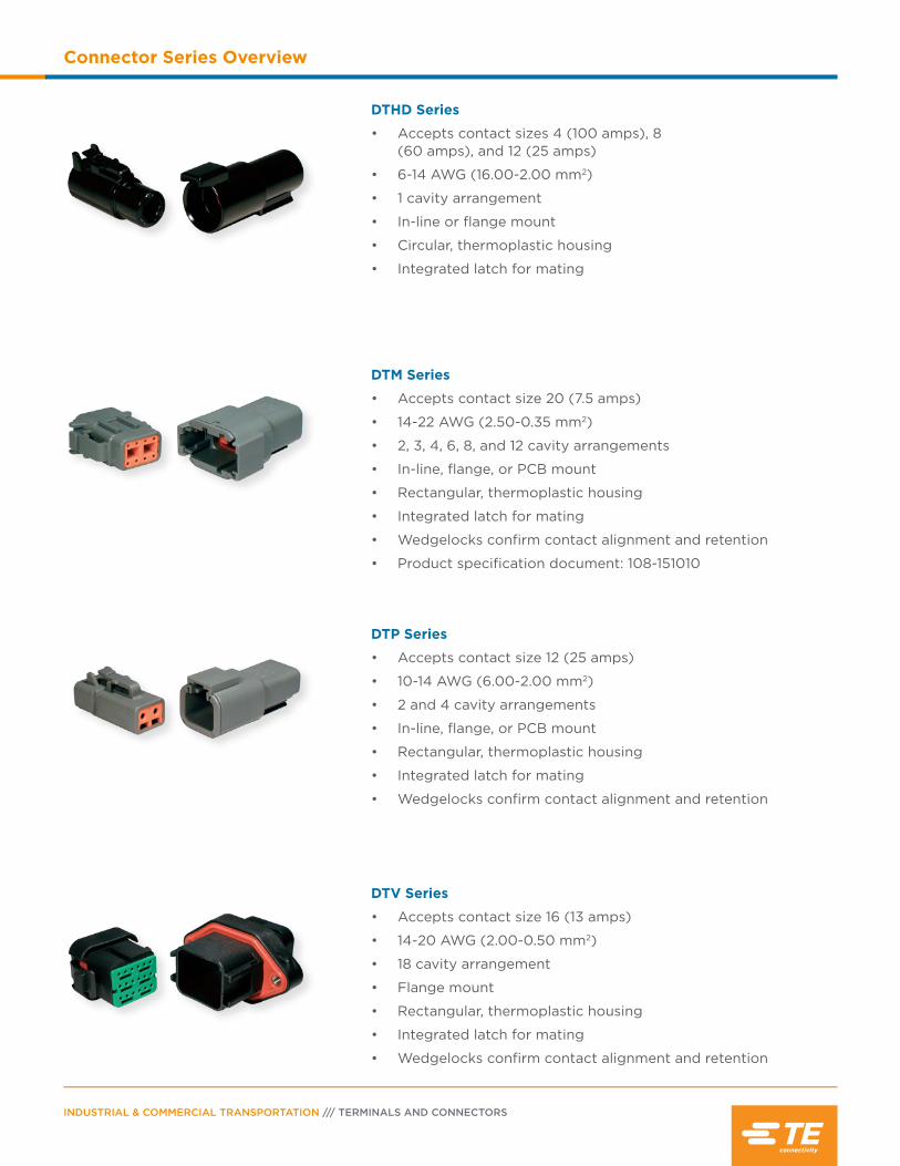
DTM Series
• Accepts contact size 20 (7.5 amps)
• 14-22 AWG (2.50-0.35 mm2)
• 2, 3, 4, 6, 8, and 12 cavity arrangements
• In-line, flange, or PCB mount
• Rectangular, thermoplastic housing
• Integrated latch for mating
• Wedgelocks confirm contact alignment and retention
• Product specification document: 108-151010
DTP Series
• Accepts contact size 12 (25 amps)
• 10-14 AWG (6.00-2.00 mm2)
• 2 and 4 cavity arrangements
• In-line, flange, or PCB mount
• Rectangular, thermoplastic housing
• Integrated latch for mating
• Wedgelocks confirm contact alignment and retention
DTV Series
• Accepts contact size 16 (13 amps)
• 14-20 AWG (2.00-0.50 mm2)
• 18 cavity arrangement
• Flange mount
• Rectangular, thermoplastic housing
• Integrated latch for mating
• Wedgelocks confirm contact alignment and retention
DTHD Series
• Accepts contact sizes 4 (100 amps), 8 (60 amps), and 12 (25 amps)
• 6-14 AWG (16.00-2.00 mm2)
• 1 cavity arrangement
• In-line or flange mount
• Circular, thermoplastic housing
• Integrated latch for mating
PAGE 9
Connector Series Overview
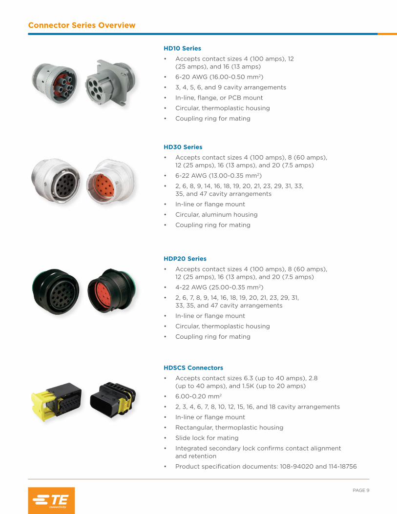
HD10 Series
• Accepts contact sizes 4 (100 amps), 12 (25 amps), and 16 (13 amps)
• 6-20 AWG (16.00-0.50 mm2)
• 3, 4, 5, 6, and 9 cavity arrangements
• In-line, flange, or PCB mount
• Circular, thermoplastic housing
• Coupling ring for mating
HDP20 Series
• Accepts contact sizes 4 (100 amps), 8 (60 amps), 12 (25 amps), 16 (13 amps), and 20 (7.5 amps)
• 4-22 AWG (25.00-0.35 mm2)
• 2, 6, 7, 8, 9, 14, 16, 18, 19, 20, 21, 23, 29, 31, 33, 35, and 47 cavity arrangements
• In-line or flange mount
• Circular, thermoplastic housing
• Coupling ring for mating
HD30 Series
• Accepts contact sizes 4 (100 amps), 8 (60 amps), 12 (25 amps), 16 (13 amps), and 20 (7.5 amps)
• 6-22 AWG (13.00-0.35 mm2)
• 2, 6, 8, 9, 14, 16, 18, 19, 20, 21, 23, 29, 31, 33, 35, and 47 cavity arrangements
• In-line or flange mount
• Circular, aluminum housing
• Coupling ring for mating
HDSCS Connectors
• Accepts contact sizes 6.3 (up to 40 amps), 2.8 (up to 40 amps), and 1.5K (up to 20 amps)
• 6.00-0.20 mm2
• 2, 3, 4, 6, 7, 8, 10, 12, 15, 16, and 18 cavity arrangements
• In-line or flange mount
• Rectangular, thermoplastic housing
• Slide lock for mating
• Integrated secondary lock confirms contact alignment and retention
• Product specification documents: 108-94020 and 114-18756
INDUSTRIAL & COMMERCIAL TRANSPORTATION /// TERMINALS AND CONNECTORS
Connector Series Overview
STRIKE Series
• Accepts contact sizes 16 (13 amps) and 20 (7.5 amps)
• 14-22 AWG (2.50-0.35 mm2)
• 32 and 64 cavity arrangements
• In-line, flange, or PCB mount
• Square, thermoplastic housing
• Lever for mating
• TPA confirms contact alignment and retention
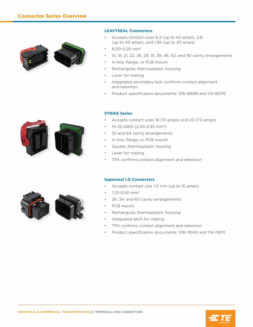
LEAVYSEAL Connectors
• Accepts contact sizes 6.3 (up to 40 amps), 2.8 (up to 40 amps), and 1.5K (up to 20 amps)
• 6.00-0.20 mm2
• 15, 18, 21, 22, 26, 29, 31, 39, 46, 62, and 92 cavity arrangements
• In-line, flange, or PCB mount
• Rectangular, thermoplastic housing
• Lever for mating
• Integrated secondary lock confirms contact alignment and retention
• Product specification documents: 108-18696 and 114-18376
Superseal 1.0 Connectors
• Accepts contact size 1.0 mm (up to 15 amps)
• 1.25-0.50 mm2
• 26, 34, and 60 cavity arrangements
• PCB mount
• Rectangular, thermoplastic housing
• Integrated latch for mating
• TPA confirms contact alignment and retention
• Product specification documents: 108-78140 and 114-78011

Contents
AMPSEAL Connector Overview ...........................12
Product Documentation ..........................................12
Performance Specifications ...................................12
Material Specifications .............................................13
Dimensions ...................................................................13
Configurations .............................................................13
Ordering Information ............................................... 14
Accessories ...................................................................15
Contacts .................................................................. 15-16
Tooling ............................................................................17
How To Instructions ............................................18-19
INDUSTRIAL & COMMERCIAL TRANSPORTATION /// TERMINALS AND CONNECTORS
AMPSEAL Connectors
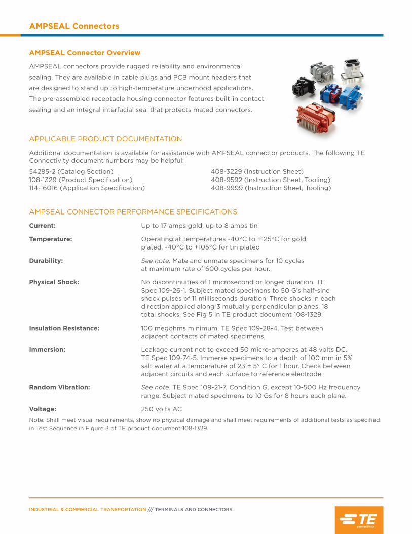
AMPSEAL Connector Overview
AMPSEAL connectors provide rugged reliability and environmental
sealing. They are available in cable plugs and PCB mount headers that
are designed to stand up to high-temperature underhood applications.
The pre-assembled receptacle housing connector features built-in contact
sealing and an integral interfacial seal that protects mated connectors.
APPLICABLE PRODUCT DOCUMENTATION
Additional documentation is available for assistance with AMPSEAL connector products. The following TE Connectivity document numbers may be helpful:
54285-2 (Catalog Section) 108-1329 (Product Specification) 114-16016 (Application Specification)
408-3229 (Instruction Sheet) 408-9592 (Instruction Sheet, Tooling)408-9999 (Instruction Sheet, Tooling)
AMPSEAL CONNECTOR PERFORMANCE SPECIFICATIONS
Current: Up to 17 amps gold, up to 8 amps tin
Temperature: Operating at temperatures -40°C to +125°C for gold plated, -40°C to +105°C for tin plated
Durability: See note. Mate and unmate specimens for 10 cycles at maximum rate of 600 cycles per hour.
Physical Shock: No discontinuities of 1 microsecond or longer duration. TE Spec 109-26-1. Subject mated specimens to 50 G’s half-sine shock pulses of 11 milliseconds duration. Three shocks in each direction applied along 3 mutually perpendicular planes, 18 total shocks. See Fig 5 in TE product document 108-1329.
Insulation Resistance: 100 megohms minimum. TE Spec 109-28-4. Test between adjacent contacts of mated specimens.
Immersion: Leakage current not to exceed 50 micro-amperes at 48 volts DC. TE Spec 109-74-5. Immerse specimens to a depth of 100 mm in 5% salt water at a temperature of 23 ± 5° C for 1 hour. Check between adjacent circuits and each surface to reference electrode.
Random Vibration: See note. TE Spec 109-21-7, Condition G, except 10-500 Hz frequency range. Subject mated specimens to 10 Gs for 8 hours each plane.
Voltage: 250 volts AC
Note: Shall meet visual requirements, show no physical damage and shall meet requirements of additional tests as specified in Test Sequence in Figure 3 of TE product document 108-1329.
AC
BE E
D GF F
PAGE 13
AMPSEAL Connectors
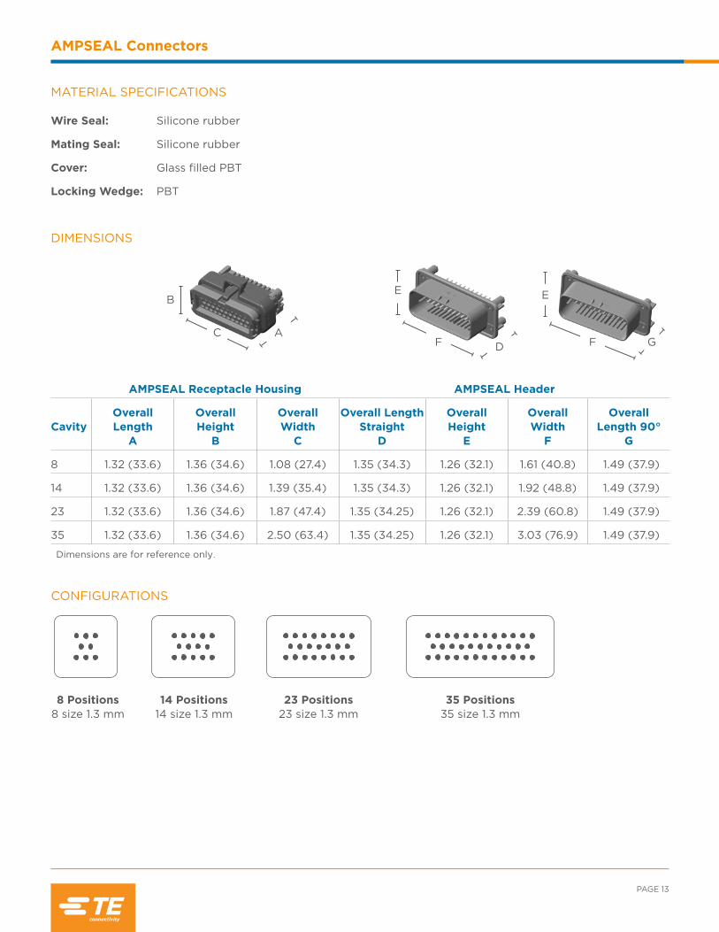
DIMENSIONS
AMPSEAL Receptacle Housing AMPSEAL Header
CavityOverall Length
A
Overall Height
B
Overall Width
C
Overall Length Straight
D
Overall Height
E
Overall Width
F
Overall Length 90°
G
8 1.32 (33.6) 1.36 (34.6) 1.08 (27.4) 1.35 (34.3) 1.26 (32.1) 1.61 (40.8) 1.49 (37.9)
14 1.32 (33.6) 1.36 (34.6) 1.39 (35.4) 1.35 (34.3) 1.26 (32.1) 1.92 (48.8) 1.49 (37.9)
23 1.32 (33.6) 1.36 (34.6) 1.87 (47.4) 1.35 (34.25) 1.26 (32.1) 2.39 (60.8) 1.49 (37.9)
35 1.32 (33.6) 1.36 (34.6) 2.50 (63.4) 1.35 (34.25) 1.26 (32.1) 3.03 (76.9) 1.49 (37.9)
Dimensions are for reference only.
CONFIGURATIONS
8 Positions8 size 1.3 mm
14 Positions 14 size 1.3 mm
23 Positions 23 size 1.3 mm
35 Positions 35 size 1.3 mm
Wire Seal: Silicone rubber
Mating Seal: Silicone rubber
Cover: Glass filled PBT
Locking Wedge: PBT
MATERIAL SPECIFICATIONS
INDUSTRIAL & COMMERCIAL TRANSPORTATION /// TERMINALS AND CONNECTORS
AMPSEAL Connectors
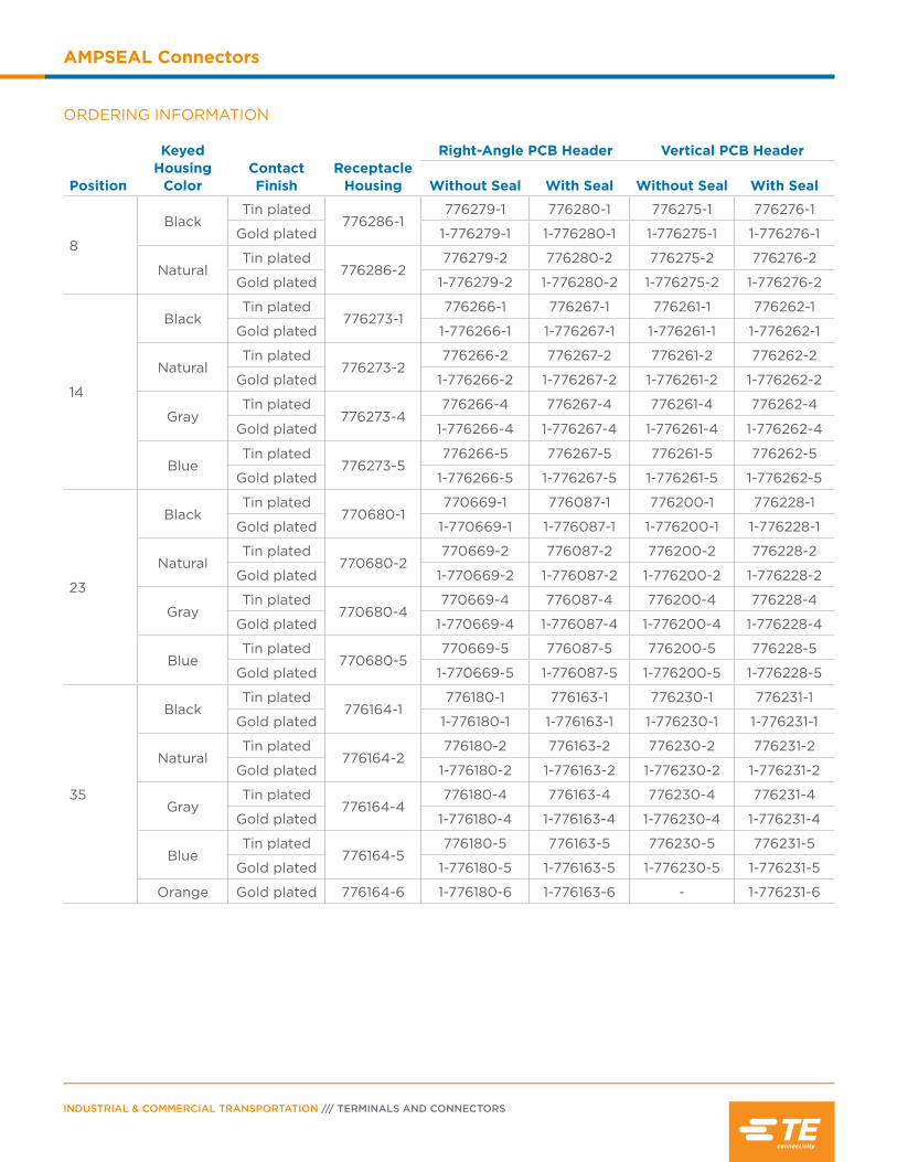
ORDERING INFORMATION
Position
Keyed Housing
ColorContact Finish
Receptacle Housing
Right-Angle PCB Header Vertical PCB Header
Without Seal With Seal Without Seal With Seal
8
BlackTin plated
776286-1776279-1 776280-1 776275-1 776276-1
Gold plated 1-776279-1 1-776280-1 1-776275-1 1-776276-1
NaturalTin plated
776286-2776279-2 776280-2 776275-2 776276-2
Gold plated 1-776279-2 1-776280-2 1-776275-2 1-776276-2
14
BlackTin plated
776273-1776266-1 776267-1 776261-1 776262-1
Gold plated 1-776266-1 1-776267-1 1-776261-1 1-776262-1
NaturalTin plated
776273-2776266-2 776267-2 776261-2 776262-2
Gold plated 1-776266-2 1-776267-2 1-776261-2 1-776262-2
GrayTin plated
776273-4776266-4 776267-4 776261-4 776262-4
Gold plated 1-776266-4 1-776267-4 1-776261-4 1-776262-4
BlueTin plated
776273-5776266-5 776267-5 776261-5 776262-5
Gold plated 1-776266-5 1-776267-5 1-776261-5 1-776262-5
23
BlackTin plated
770680-1770669-1 776087-1 776200-1 776228-1
Gold plated 1-770669-1 1-776087-1 1-776200-1 1-776228-1
NaturalTin plated
770680-2770669-2 776087-2 776200-2 776228-2
Gold plated 1-770669-2 1-776087-2 1-776200-2 1-776228-2
GrayTin plated
770680-4770669-4 776087-4 776200-4 776228-4
Gold plated 1-770669-4 1-776087-4 1-776200-4 1-776228-4
BlueTin plated
770680-5770669-5 776087-5 776200-5 776228-5
Gold plated 1-770669-5 1-776087-5 1-776200-5 1-776228-5
35
BlackTin plated
776164-1776180-1 776163-1 776230-1 776231-1
Gold plated 1-776180-1 1-776163-1 1-776230-1 1-776231-1
NaturalTin plated
776164-2776180-2 776163-2 776230-2 776231-2
Gold plated 1-776180-2 1-776163-2 1-776230-2 1-776231-2
GrayTin plated
776164-4776180-4 776163-4 776230-4 776231-4
Gold plated 1-776180-4 1-776163-4 1-776230-4 1-776231-4
BlueTin plated
776164-5776180-5 776163-5 776230-5 776231-5
Gold plated 1-776180-5 1-776163-5 1-776230-5 1-776231-5
Orange Gold plated 776164-6 1-776180-6 1-776163-6 - 1-776231-6
PAGE 15
AMPSEAL Connectors
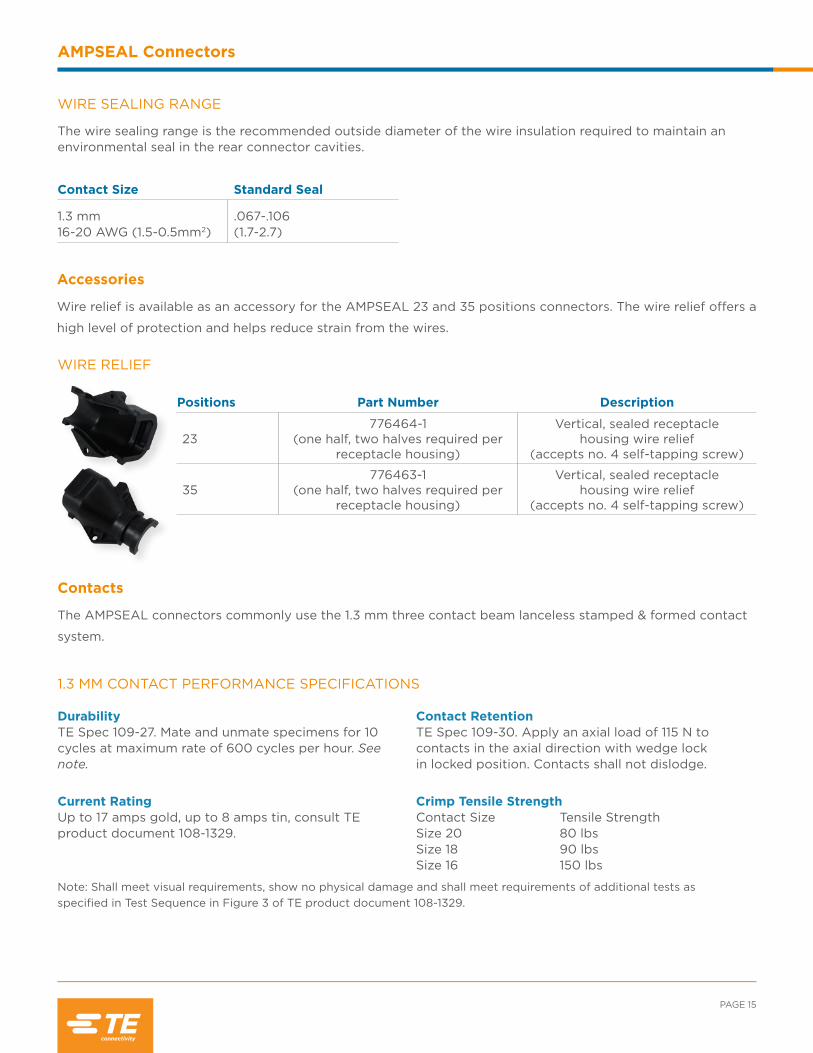
Positions Part Number Description
23776464-1
(one half, two halves required per receptacle housing)
Vertical, sealed receptacle housing wire relief
(accepts no. 4 self-tapping screw)
35776463-1
(one half, two halves required per receptacle housing)
Vertical, sealed receptacle housing wire relief
(accepts no. 4 self-tapping screw)
WIRE RELIEF
Accessories
Wire relief is available as an accessory for the AMPSEAL 23 and 35 positions connectors. The wire relief offers a
high level of protection and helps reduce strain from the wires.
Contacts
1.3 MM CONTACT PERFORMANCE SPECIFICATIONS
DurabilityTE Spec 109-27. Mate and unmate specimens for 10 cycles at maximum rate of 600 cycles per hour. See note.
Current RatingUp to 17 amps gold, up to 8 amps tin, consult TE product document 108-1329.
Contact Retention TE Spec 109-30. Apply an axial load of 115 N to contacts in the axial direction with wedge lock in locked position. Contacts shall not dislodge.
Crimp Tensile Strength Contact Size Tensile StrengthSize 20 80 lbsSize 18 90 lbsSize 16 150 lbs
Note: Shall meet visual requirements, show no physical damage and shall meet requirements of additional tests as specified in Test Sequence in Figure 3 of TE product document 108-1329.
WIRE SEALING RANGE
Contact Size Standard Seal
1.3 mm 16-20 AWG (1.5-0.5mm2)
.067-.106 (1.7-2.7)
The wire sealing range is the recommended outside diameter of the wire insulation required to maintain an environmental seal in the rear connector cavities.
The AMPSEAL connectors commonly use the 1.3 mm three contact beam lanceless stamped & formed contact
system.

INDUSTRIAL & COMMERCIAL TRANSPORTATION /// TERMINALS AND CONNECTORS
AMPSEAL Connectors
Size
Receptacle Part Numbers
Wire Size AWG (mm2)
Insulation Diameter
(mm) FinishStrip FormPackage Quantity Loose Piece
Package Quantity
1.3 mm
770520-1 5000 770854-1 100016-20
(1.5-0.5).067-.106(1.7-2.7)
Pre-tin plated
770520-3 5000 770854-3 1000 Selective gold plated
1.3 MM STAMPED & FORMED CONTACTS FOR AMPSEAL
SEALING PLUGS
Open cavities provide pathways for contaminates to enter the connectors. To maintain seal integrity, any unused cavity that has been pierced must be filled with the appropriate size sealing plug.
Color Part Number Contact SizeWire Gauge
Range Material
White 770678-1 1.3 mm 16-20 AWG Nylon
PAGE 17
AMPSEAL Connectors
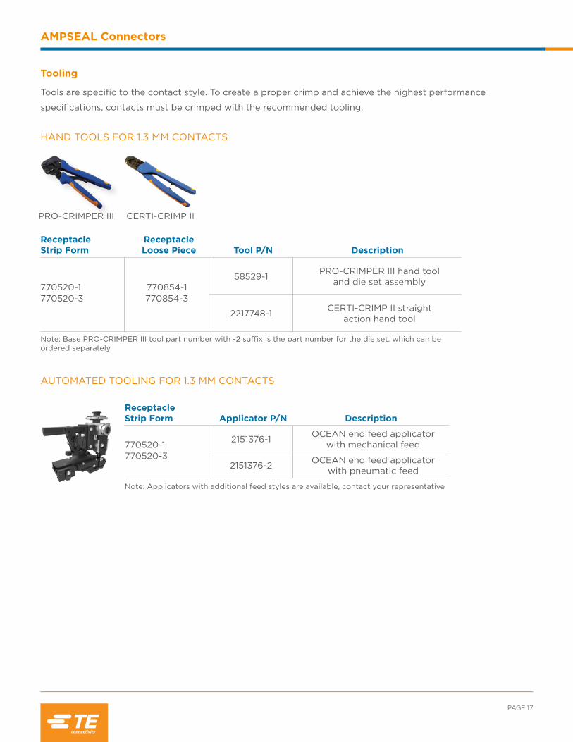
HAND TOOLS FOR 1.3 MM CONTACTS
Receptacle Strip Form
Receptacle Loose Piece Tool P/N Description
770520-1 770520-3
770854-1 770854-3
58529-1 PRO-CRIMPER III hand tool and die set assembly
2217748-1 CERTI-CRIMP II straight action hand tool
Note: Base PRO-CRIMPER III tool part number with -2 suffix is the part number for the die set, which can be ordered separately
PRO-CRIMPER III CERTI-CRIMP II
AUTOMATED TOOLING FOR 1.3 MM CONTACTS
Receptacle Strip Form Applicator P/N Description
770520-1 770520-3
2151376-1 OCEAN end feed applicator with mechanical feed
2151376-2 OCEAN end feed applicator with pneumatic feed
Note: Applicators with additional feed styles are available, contact your representative
Tooling
Tools are specific to the contact style. To create a proper crimp and achieve the highest performance
specifications, contacts must be crimped with the recommended tooling.
INDUSTRIAL & COMMERCIAL TRANSPORTATION /// TERMINALS AND CONNECTORS
AMPSEAL Connectors
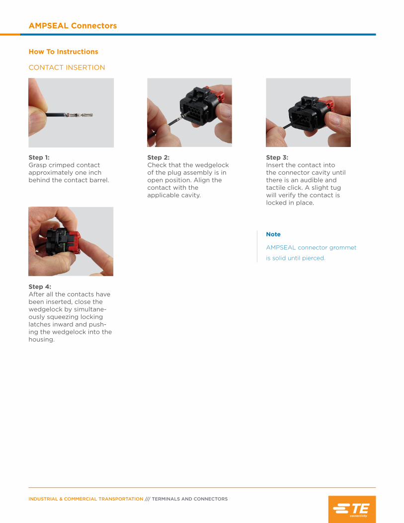
CONTACT INSERTION
How To Instructions
Step 1:Grasp crimped contact approximately one inch behind the contact barrel.
Step 2: Check that the wedgelock of the plug assembly is in open position. Align the contact with the applicable cavity.
Step 3:Insert the contact into the connector cavity until there is an audible and tactile click. A slight tug will verify the contact is locked in place.
Step 4:After all the contacts have been inserted, close the wedgelock by simultane-ously squeezing locking latches inward and push-ing the wedgelock into the housing.
Note
AMPSEAL connector grommet
is solid until pierced.
PAGE 19
AMPSEAL Connectors
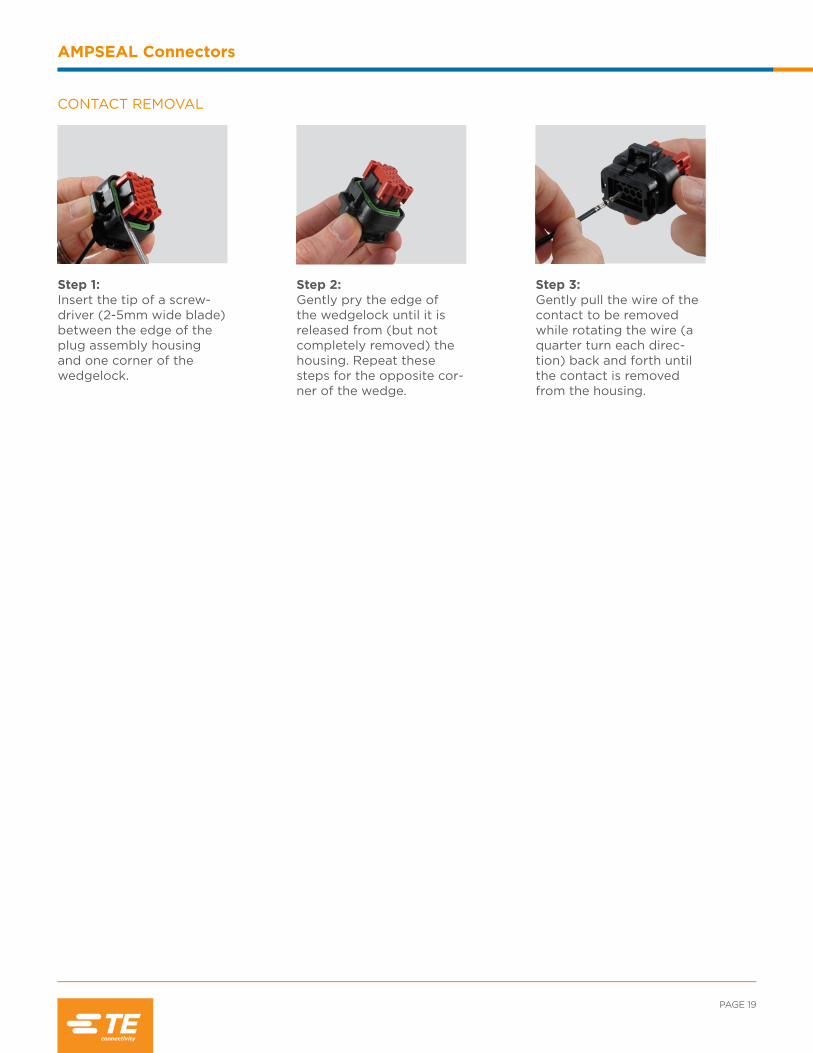
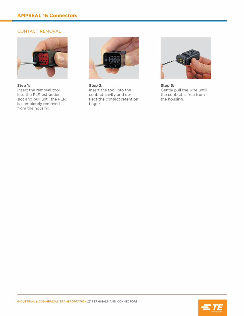
CONTACT REMOVAL
Step 1:Insert the tip of a screw-driver (2-5mm wide blade) between the edge of the plug assembly housing and one corner of the wedgelock.
Step 2:Gently pry the edge of the wedgelock until it is released from (but not completely removed) the housing. Repeat these steps for the opposite cor-ner of the wedge.
Step 3:Gently pull the wire of the contact to be removed while rotating the wire (a quarter turn each direc-tion) back and forth until the contact is removed from the housing.

NOTES:
INDUSTRIAL & COMMERCIAL TRANSPORTATION /// TERMINALS AND CONNECTORS
AMPSEAL Connectors

Contents
AMPSEAL 16 Connector Overview .....................22
Product Documentation .........................................22
Performance Specifications ..................................22
Material Specifications ............................................23
Dimensions ..................................................................23
Configurations ............................................................23
Ordering Information .............................................. 24
Accessories ...........................................................25-26
AMPSEAL 16 Hybrid Lever ............................. 27-28
Contacts ............................................................... 29-30
Tooling .....................................................................31-32
How To Instructions ..........................................33-34

INDUSTRIAL & COMMERCIAL TRANSPORTATION /// TERMINALS AND CONNECTORS
AMPSEAL 16 Connectors
AMPSEAL 16 Connector Overview
The AMPSEAL 16 connector system is targeted for off-road, heavy duty
industrial, recreational and agricultural applications. This wire-to-wire and
wire-to-device connector line was designed to meet the rigorous demands
of an industry that requires the highest standards in performance.
AMPSEAL 16 receptacle and pin housings offer a one-piece approach
and come fully assembled.
APPLICABLE PRODUCT DOCUMENTATION
Additional documentation is available for assistance with AMPSEAL 16 products. The following TE Connectivity document numbers may be helpful:
1654281-2 (Catalog Section) 108-2184 (Product Specification)114-13065 (Application Specification)
114-13045 (Application Specification, Contacts) 408-8623 (Instruction Sheet)501-708 (Qualification Test Report)
AMPSEAL 16 CONNECTOR PERFORMANCE SPECIFICATIONS
Current: Up to 13 amps
Temperature: Operating at temperatures -40°C to +125°C
Durability: See note. 50 cycles.
Insulation Resistance: 20 megohms minimum. SAE J2030 6.3. Insulation resistance at 1000 volts DC adjacent terminals measured after 60 seconds or until stabilization occurs.
Immersion: IP67 rating
Random Vibration: No discontinuities. See note. EIA-364-28 Subject mated specimens to 21 G’s rms between 25 to 2000 Hz. Twenty hours in each of three mutually perpendicular planes.
Voltage: 250 volts DC
Note: Shall meet visual requirements, show no physical damage, and meet requirements of additional tests as specified in Product Qualification and Requalification Test Sequence in Figure 3 of TE product document 108-2184.

PAGE 23
AMPSEAL 16 Connectors
CONFIGURATIONS
DIMENSIONS
AMPSEAL 16 Receptacle Housing AMPSEAL 16 Cap
Cavity Overall Length A
Overall Height B
Overall Width C
Overall Length D
Overall Height E
Overall Width F
2 1.45 (36.75) .93 (23.5) .80 (20.33) 1.87 (47.55) .75 (18.93) .77 (19.60)
3 1.45 (36.80) .93 (23.5) .98 (24.83) 1.87 (47.55) .75 (19.15) .95 (24.10)
4 1.44 (36.70) 1.06 (26.8) 1.00 (25.33) 1.87 (47.55) .88 (22.45) .97 (24.60)
6 1.44 (36.60) 1.22 (31.0) 1.00 (25.33) 1.87 (47.55) 1.05 (26.65) .97 (24.60)
8 1.45 (36.80) 1.24 (31.5) 1.15 (29.33) 1.87 (47.55) 1.05 (26.65) 1.13 (28.60)
12 1.45 (36.80) 1.24 (31.5) 1.51 (38.33) 1.87 (47.55) 1.05 (26.65) 1.48 (37.60)
Dimensions are for reference only.
AC
B E
DF
8 Positions 8 size 16
12 Positions 12 size 16
2 Positions 2 size 16
3 Positions 3 size 16
4 Positions 4 size 16
6 Positions 6 size 16
Wire Seal: Silicone rubber
Plug Peripheral Seal:
Silicone rubber
Housing 15% Glass filled thermoplastic
CPA: 15% Glass filled thermoplastic
PLR: 15% Glass filled thermoplastic
MATERIAL SPECIFICATIONS

INDUSTRIAL & COMMERCIAL TRANSPORTATION /// TERMINALS AND CONNECTORS
AMPSEAL 16 Connectors
ORDERING INFORMATION
PositionPLR
Color Keying
Receptacle Housing
Standard Dia. SealCap
Standard Dia. Seal
Receptacle Housing
Reduced Dia. SealCap
Reduced Dia. Seal
2
Red Key A 776427-1 776428-1 776522-1 776534-1
Gray Key B 776427-2 776428-2 776522-2 776534-2
Yellow Key C 776427-3 776428-3 776522-3 776534-3
Green Key D 776427-4 776428-4 776522-4 776534-4
3
Red Key A 776429-1 776430-1 776523-1 776535-1
Gray Key B 776429-2 776430-2 776523-2 776535-2
Yellow Key C 776429-3 776430-3 776523-3 776535-3
Green Key D 776429-4 776430-4 776523-4 776535-4
4
Red Key A 776487-1 776488-1 776524-1 776536-1
Gray Key B 776487-2 776488-2 776524-2 776536-2
Yellow Key C 776487-3 776488-3 776524-3 776536-3
Green Key D 776487-4 776488-4 776524-4 776536-4
6
Red Key A 776433-1 776434-1 776531-1 776537-1
Gray Key B 776433-2 776434-2 776531-2 776537-2
Yellow Key C 776433-3 776434-3 776531-3 776537-3
8
Red Key A 776494-1 776495-1 776532-1 776538-1
Gray Key B 776494-2 776495-2 776532-2 776538-2
Yellow Key C 776494-3 776495-3 776532-3 776538-3
Green Key D 776494-4 776495-4 776532-4 776538-4
12
Red Key A 776437-1 776438-1 776533-1 776539-1
Gray Key B 776437-2 776438-2 776533-2 776539-2
Yellow Key C 776437-3 776438-3 776533-3 776539-3
Green Key D 776437-4 776438-4 776533-4 776539-4
PLR(Primary Latch Reinforcement)
CPA (Connector Position
Assurance)
CapReceptacle housing and cap PLR colors are mechanically keyed to mate only with identical colors.
Part Number Suffix:-1 = A key (red PLR)-2 = B key (gray PLR)-3 = C key (yellow PLR)-4 = D key (green PLR)
Receptacle Housing

PAGE 25
AMPSEAL 16 Connectors
AccessoriesBackshells and mounting clips are accessory items available for use with AMPSEAL 16 connectors. These
accessories cover design requirements by assisting with mounting, providing additional protection, and offering
increased aesthetics.
WIRE SEALING RANGE The wire sealing range is the recommended outside diameter of the wire insulation required to maintain an environmental seal in the rear connector cavities.
Contact Size Standard SealReduced
Diameter Seal
HDSF 16 14-20 AWG (2.0-0.5mm2)
.086-.144 (2.18-3.67)
.051-.100 (1.30-2.54)
Number of Positions Conduit Size
Part Numbers
Standard Straight
Standard 90°
Low Profile 90° Rec. Housing
Low Profile 90° Pin Housing
2NC08/NW7.5 2035047-1† 2035048-1† 2035366-1 2098436-1
NC12/NW10 - 2035048-5† 2035366-3 2098436-3
3NC08/NW7.5 2035047-2† 2035048-2† 2035366-2 2098436-2
NC12/NW10 - 2035048-6† 2035366-4 2098436-4
4
NC08/NW7.5 2035047-3† 2035048-3† 2035366-7 2098436-7
NC12/NW10 2035047-5† 2035048-7† 2035366-9 2098436-9
NC16/NW13 - - 1-2035366-1 1-2098436-1
6
NC08/NW7.5 2035047-4† - 2035366-8 2098436-8
NC12/NW10 2035047-6† - 1-2035366-0 1-2098436-0
NC16/NW13 - - 1-2035366-2 1-2098436-2
8NC12/NW10 2035047-7† - - -
NC16/NW13 2035047-9† 2035047-9† - -
12
NC12/NW10 2035047-8† - - -
NC16/NW13 1-2035047-0† - - -
NC20/NW17 1-2035047-1† - - -† = Backshell available only with latch window. Can be used for cap assembly if desired.
BACKSHELLS

INDUSTRIAL & COMMERCIAL TRANSPORTATION /// TERMINALS AND CONNECTORS
AMPSEAL 16 Connectors
BACKSHELLS - NEXT GENERATION
Number of Positions Conduit Size
Plug Part Numbers Cap Part Numbers
Straight Backshell Part Number
90° Adapter Part Number
Straight Backshell Part Number
90° Adapter Part Number
2
Smooth 2292797-1 2292849-1 2292860-1 2292849-1
NC12/NW10 2292797-2 2292849-2 2292860-2 2292849-2
NC08/NW7.5 2292797-3 2292849-3 2292860-3 2292849-3
3
Smooth 2292798-1 2292849-1 2292861-1 2292849-1
NC12/NW10 2292798-2 2292849-2 2292861-2 2292849-2
NC08/NW7.5 2292798-3 2292849-3 2292861-3 2292849-3
4
Smooth 2292799-1 2292850-1 2292862-1 2292850-1
NC16/NW13 2292799-2 2292850-2 2292862-2 2292850-2
NC12/NW10 2292799-3 2292850-3 2292862-3 2292850-3
6
Smooth 2292800-1 2292850-1 2292863-1 2292850-1
NC16/NW13 2292800-2 2292850-2 2292863-2 2292850-2
NC12/NW10 2292800-3 2292850-3 2292863-3 2292850-3
8
Smooth 2292801-1 2292851-1 2292864-1 2292851-1
NC20/NW17 2292801-2 2292851-2 2292864-2 2292851-2
NC16/NW13 2292801-3 2292851-3 2292864-3 2292851-3
12
Smooth 2292802-1 2292851-1 2292865-1 2292851-1
NC16/NW13 2292802-2 2292851-2 2292865-2 2292851-2
NC12/NW10 2292802-3 2292851-3 2292865-3 2292851-3
Note: Expected availability December 2015, contact your representative
Part Number Description
1924487-1 Mounting clip without anti-rotational feature
1924487-2 Mounting clip with anti-rotational feature
MOUNTING CLIPS
PAGE 27
AMPSEAL 16 Connectors
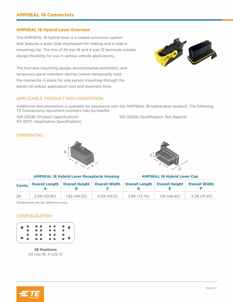
AMPSEAL 16 Hybrid Lever Overview
The AMPSEAL 16 hybrid lever is a sealed connector system
that features a lever slide mechanism for mating and a slide in
mounting clip. The mix of 24 size 16 and 4 size 12 terminals creates
design flexibility for use in various vehicle applications.
The tool-less mounting design, environmental protection, and
temporary panel retention latches (which temporarily hold
the connector in place for one person mounting through the
panel) all reduce application cost and assembly time.
APPLICABLE PRODUCT DOCUMENTATION
Additional documentation is available for assistance with the AMPSEAL 16 hybrid lever product. The following TE Connectivity document numbers may be helpful:
108-32036 (Product Specification)114-32117 (Application Specification)
501-32026 (Qualification Test Report)
DIMENSIONS
AMPSEAL 16 Hybrid Lever Receptacle Housing AMPSEAL 16 Hybrid Lever Cap
Cavity Overall Length A
Overall Height B
Overall Width C
Overall Length D
Overall Height E
Overall Width F
28 2.08 (52.95) 1.82 (46.25) 4.59 (116.5) 2.86 (72.75) 1.91 (48.45) 4.38 (111.25)
Dimensions are for reference only.
AC
BE
DF
CONFIGURATION
28 Positions 24 size 16, 4 size 12

INDUSTRIAL & COMMERCIAL TRANSPORTATION /// TERMINALS AND CONNECTORS
AMPSEAL 16 Connectors
ORDERING INFORMATION
Position Keying Plug Housing Cap Housing
28Key A 2138839-1 2138846-1
Key B 2138839-2 2138846-2
AccessoriesWire covers and mounting clips are accessory items available for use with AMPSEAL 16 hybrid lever connectors.
These accessories cover design requirements by assisting with mounting and providing wire strain relief.
Part Number Description
2138853-1 Wire cover for 28 position AMPSEAL 16 hybrid lever
Part Number Description
2138852-1 Mounting clip, 5 mm panel
2138852-2 Mounting clip, 4 mm panel
2138852-3 Mounting clip, 3 mm panel
WIRE COVER
MOUNTING CLIPS

PAGE 29
AMPSEAL 16 Connectors
Contacts
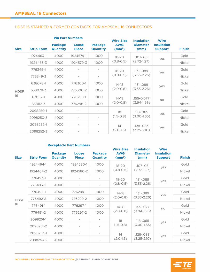
AMPSEAL 16 and AMPSEAL 16 hybrid lever connectors commonly use the HDSF size 16 contact system.
The contacts are round, stamped & formed contacts with dual beam sockets.
HDSF 16 CONTACT PERFORMANCE SPECIFICATIONS
DurabilitySAE J2030 6.11. 50 cycles. See note.
Current RatingUp to 13 amps, consult TE product document 108-2184.
Contact RetentionIEC 512-8, Test 51a. Apply axial load of 111 N to contacts at a maximum rate of 10 N per second (or 50mm per minute) and hold for 10 seconds. Contacts shall not dislodge.
Crimp Tensile Strength USCAR 21 @ 50mm/minWire Gauge Tensile Strength18 AWG 90 N Min16 AWG 120 N Min14 AWG 180 N Min
Note: Shall meet visual requirements, show no physical damage, and meet requirements of additional tests as specified in the Product Qualification and Requalification Test Sequence in Figure 3 of TE product document 108-2184. USCAR is a trademark.
Contact Size
Test Current Amps
Voltage Drop (millivolts max)
18 8 100
16 10 100
14 13 100
Voltage Drop
INDUSTRIAL & COMMERCIAL TRANSPORTATION /// TERMINALS AND CONNECTORS
AMPSEAL 16 Connectors
Size
Pin Part NumbersWire Size
AWG (mm2)
Insulation Diameter
(mm)
Wire Insulation Support FinishStrip Form
Package Quantity
Loose Piece
Package Quantity
HDSF 16
1924463-1 4000 1924579-1 1000 18-20 (0.8-0.5)
.107-.05 (2.72-1.27)
yesGold
1924463-3 4000 1924579-3 1000 Nickel
776349-1 4000 - - 18-20 (0.8-0.5)
.131-.089 (3.33-2.26)
yesGold
776349-3 4000 - - Nickel
638078-1 4000 776300-1 1000 14-18 (2.0-0.8)
.131-.089 (3.33-2.26)
yesGold
638078-3 4000 776300-2 1000 Nickel
638112-1 4000 776298-1 1000 14-18 (2.0-0.8)
.155-0.077 (3.94-1.96)
noGold
638112-3 4000 776298-2 1000 Nickel
2098250-1 4000 - - 18(1.5-0.8)
.118-.065(3.00-1.65)
yesGold
2098250-3 4000 - - Nickel
2098252-1 4000 - - 14 (2.0-1.5)
.128-.083(3.25-2.10)
yesGold
2098252-3 4000 - - Nickel
HDSF 16 STAMPED & FORMED CONTACTS FOR AMPSEAL 16 CONNECTORS
Size
Receptacle Part NumbersWire Size
AWG (mm2)
Insulation Diameter
(mm)
Wire Insulation Support FinishStrip Form
Package Quantity
Loose Piece
Package Quantity
HDSF 16
1924464-1 4000 1924580-1 1000 18-20 (0.8-0.5)
.107-.05 (2.72-1.27)
yesGold
1924464-2 4000 1924580-2 1000 Nickel
776493-1 4000 - - 18-20 (0.8-0.5)
.131-.089 (3.33-2.26)
yesGold
776493-2 4000 - - Nickel
776492-1 4000 776299-1 1000 14-18 (2.0-0.8)
.131-.089 (3.33-2.26)
yesGold
776492-2 4000 776299-2 1000 Nickel
776491-1 4000 776297-1 1000 14-18 (2.0-0.8)
.155-.077 (3.94-1.96)
noGold
776491-2 4000 776297-2 1000 Nickel
2098251-1 4000 - - 18(1.5-0.8)
.118-.065(3.00-1.65)
yesGold
2098251-2 4000 - - Nickel
2098253-1 4000 - - 14
(2.0-1.5).128-.083
(3.25-2.10)yes
Gold
2098253-2 4000 - - Nickel

PAGE 31
AMPSEAL 16 Connectors
SEALING PLUGS
Open cavities provide pathways for contaminates to enter the connectors. To maintain seal integrity, any un-used cavity must be filled with the appropriate size sealing plug.
Color Part Number Contact SizeWire Gauge
Range Description
Yellow 776363-1 Size 16 16-20 AWG PBT, used with AMPSEAL 16 (standard diameter cavities)
White 776364-1 Size 20 16-20 AWG PBT, used with AMPSEAL 16 (reduced diameter cavities)
Tooling
HAND TOOLS FOR HDSF 16 CONTACTS
Pin Strip Form Pin Loose PieceSocket
Strip FormSocket
Loose Piece Tool P/N Description
1924463-11924463-3
1924579-11924579-3
1924464-11924464-2
1924580-11924580-2 2119118-1
PRO-CRIMPER III hand tool and die
set assembly
638078-1638078-3776349-1776349-3
776300-1776300-2
776492-1776492-2776493-1 776493-2
776299-1 776299-2
91337-1PRO-CRIMPER III hand tool and die
set assembly
638112-1638112-3
776298-1776298-2
776491-1 776491-2
776297-1776297-2 2217753-1
CERTI-CRIMP II straight action
hand tool
Note: Base PRO-CRIMPER III tool part number with -2 suffix is the part number for the die set, which can be ordered separately
PRO-CRIMPER III CERTI-CRIMP II
Tools are specific to the contact style. To create a proper crimp and achieve the highest performance
specifications, contacts must be crimped with the recommended tooling.
INDUSTRIAL & COMMERCIAL TRANSPORTATION /// TERMINALS AND CONNECTORS
AMPSEAL 16 Connectors
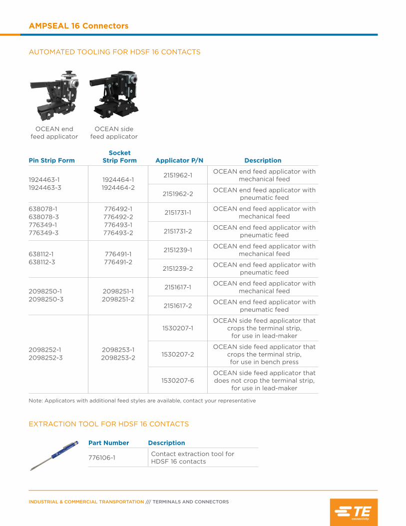
AUTOMATED TOOLING FOR HDSF 16 CONTACTS
Pin Strip FormSocket
Strip Form Applicator P/N Description
1924463-11924463-3
1924464-11924464-2
2151962-1 OCEAN end feed applicator with mechanical feed
2151962-2 OCEAN end feed applicator with pneumatic feed
638078-1638078-3776349-1776349-3
776492-1776492-2776493-1 776493-2
2151731-1 OCEAN end feed applicator with mechanical feed
2151731-2 OCEAN end feed applicator with pneumatic feed
638112-1638112-3
776491-1 776491-2
2151239-1 OCEAN end feed applicator with mechanical feed
2151239-2 OCEAN end feed applicator with pneumatic feed
2098250-12098250-3
2098251-12098251-2
2151617-1 OCEAN end feed applicator with mechanical feed
2151617-2 OCEAN end feed applicator with pneumatic feed
2098252-12098252-3
2098253-12098253-2
1530207-1OCEAN side feed applicator that
crops the terminal strip, for use in lead-maker
1530207-2OCEAN side feed applicator that
crops the terminal strip, for use in bench press
1530207-6OCEAN side feed applicator that does not crop the terminal strip,
for use in lead-maker
Note: Applicators with additional feed styles are available, contact your representative
EXTRACTION TOOL FOR HDSF 16 CONTACTS
Part Number Description
776106-1 Contact extraction tool for HDSF 16 contacts
OCEAN end feed applicator
OCEAN side feed applicator
PAGE 33
AMPSEAL 16 Connectors
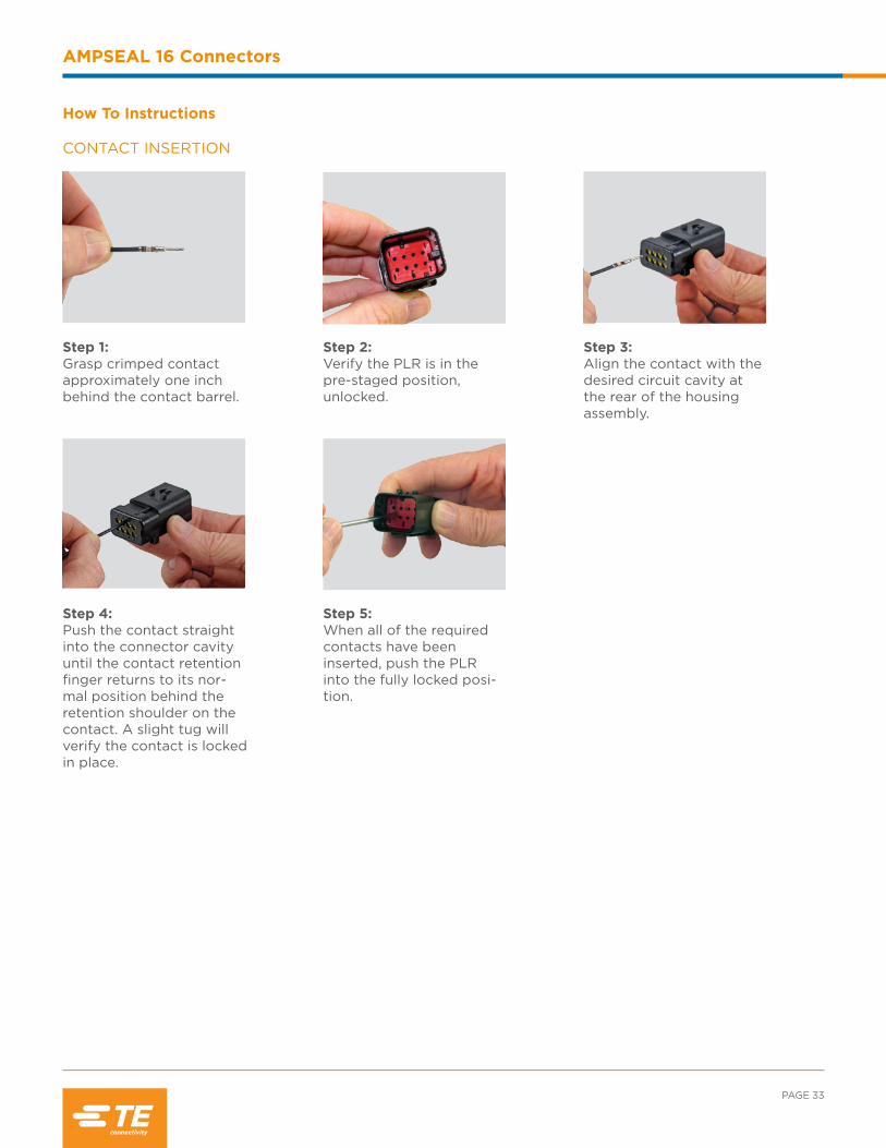
CONTACT INSERTION
How To Instructions
Step 1:Grasp crimped contact approximately one inch behind the contact barrel.
Step 2:Verify the PLR is in the pre-staged position, unlocked.
Step 3:Align the contact with the desired circuit cavity at the rear of the housing assembly.
Step 4:Push the contact straight into the connector cavity until the contact retention finger returns to its nor-mal position behind the retention shoulder on the contact. A slight tug will verify the contact is locked in place.
Step 5:When all of the required contacts have been inserted, push the PLR into the fully locked posi-tion.
INDUSTRIAL & COMMERCIAL TRANSPORTATION /// TERMINALS AND CONNECTORS
AMPSEAL 16 Connectors
CONTACT REMOVAL
Step 1:Insert the removal tool into the PLR extraction slot and pull until the PLR is completely removed from the housing.
Step 2:Insert the tool into the contact cavity and de-flect the contact retention finger.
Step 3:Gently pull the wire until the contact is free from the housing.

Contents
Circular DIN Connector Overview ..................... 36
Product Documentation ........................................ 36
Performance Specifications ................................. 36
Material Specifications ........................................... 36
Dimensions ..................................................................37
Configurations ............................................................37
Ordering Information .............................................. 38
Accessories ...........................................................38-39
Contacts .................................................................39-41
Tooling ................................................................... 42-44

INDUSTRIAL & COMMERCIAL TRANSPORTATION /// TERMINALS AND CONNECTORS
Circular DIN Connectors
Circular DIN Connector Overview
The Circular DIN connectors are designed to meet the requirements of the
DIN 72585/ISO 15170 standards. They feature a coupling ring for mating.
Circular DIN connectors are suitable for in-line, flange mount, or PCB
applications.
APPLICABLE PRODUCT DOCUMENTATION
Additional documentation is available for assistance with Circular DIN products. The following TE document numbers may be helpful:
1654286-3 (Catalog Section) 108-18621 (Product Specification) 114-18255 (Application Specification)
CIRCULAR DIN CONNECTOR PERFORMANCE SPECIFICATIONS
Current: Up to 40 amps
Temperature: Operating at temperatures -40°C to +120°C for plastic parts, short term up to +140°C defined in the standard ISO 15170
Durability: 20 cycles, max. testing requirement in the standard ISO 15170, former DIN 72585
Insulation Resistance: No flash over or breakdown between every two contacts or between every contact and outer contour of the housing permitted at 1000 volts AC and 50 or 60 Hz for 60 seconds.
Immersion: No ingress of water is allowed, acc. to DIN 40050-9 IPX7, IPX9K
Vibration: According to standard ISO 15170, former DIN 72585
Dielectric Withstanding Voltage: No flash over or breakdown between every two contacts or between every contact and outer contour of the housing permitted at 1000 volts AC and 50 or 60 Hz for 60 seconds.
Flange Seal: Silicone rubber
Housing: Glass filled PBT and PA
MATERIAL SPECIFICATIONS

AØB
ØD
C
PAGE 37
Circular DIN Connectors
DIMENSIONS
Circular DIN Socket Housing Circular DIN Pin Housing
Cavity Overall Length A
Overall Height ØB
Overall Length C
Overall Height ØD
2 1.22 (31.0) 1.29 (32.8) 1.73 (44.0) 1.34 (34.0)
3 1.22 (31.0) 1.29 (32.8) 1.73 (44.0) 1.34 (34.0)
4 1.22 (31.0) 1.29 (32.8) 1.73 (44.0) 1.34 (34.0)
Dimensions are for reference only.
CONFIGURATIONS
3 Positions 3 size 2.5 mm
2 Positions 2 size 2.5 mm
4 Positions 4 size 2.5 mm
INDUSTRIAL & COMMERCIAL TRANSPORTATION /// TERMINALS AND CONNECTORS
Circular DIN Connectors
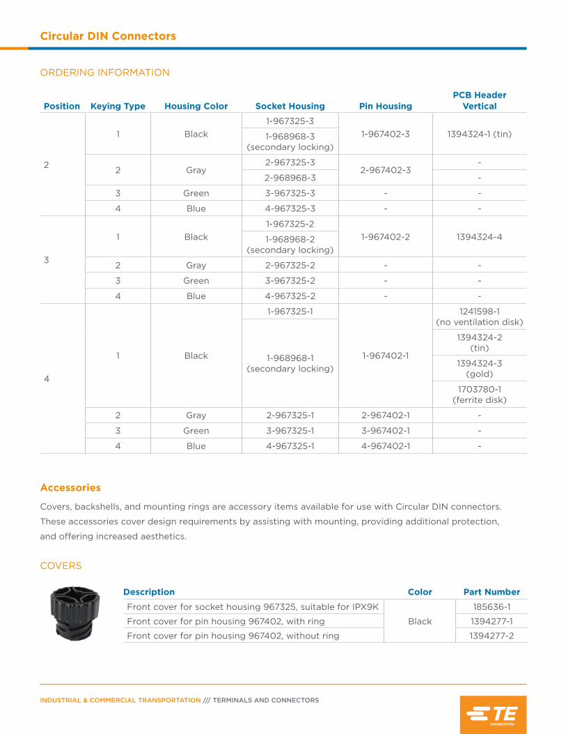
ORDERING INFORMATION
Position Keying Type Housing Color Socket Housing Pin HousingPCB Header
Vertical
2
1 Black1-967325-3
1-967402-3 1394324-1 (tin)1-968968-3 (secondary locking)
2 Gray2-967325-3
2-967402-3-
2-968968-3 -
3 Green 3-967325-3 - -
4 Blue 4-967325-3 - -
3
1 Black1-967325-2
1-967402-2 1394324-41-968968-2 (secondary locking)
2 Gray 2-967325-2 - -
3 Green 3-967325-2 - -
4 Blue 4-967325-2 - -
4
1 Black
1-967325-1
1-967402-1
1241598-1 (no ventilation disk)
1-968968-1 (secondary locking)
1394324-2 (tin)
1394324-3 (gold)
1703780-1 (ferrite disk)
2 Gray 2-967325-1 2-967402-1 -
3 Green 3-967325-1 3-967402-1 -
4 Blue 4-967325-1 4-967402-1 -
COVERS
Description Color Part Number
Front cover for socket housing 967325, suitable for IPX9K
Black
185636-1
Front cover for pin housing 967402, with ring 1394277-1
Front cover for pin housing 967402, without ring 1394277-2
Accessories
Covers, backshells, and mounting rings are accessory items available for use with Circular DIN connectors.
These accessories cover design requirements by assisting with mounting, providing additional protection,
and offering increased aesthetics.
PAGE 39
Circular DIN Connectors
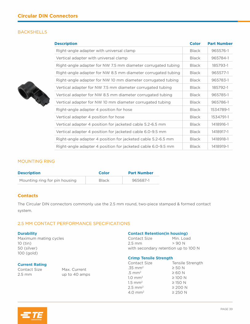
BACKSHELLS
Description Color Part Number
Right-angle adapter with universal clamp Black 965576-1
Vertical adapter with universal clamp Black 965784-1
Right-angle adapter for NW 7.5 mm diameter corrugated tubing Black 185793-1
Right-angle adapter for NW 8.5 mm diameter corrugated tubing Black 965577-1
Right-angle adapter for NW 10 mm diameter corrugated tubing Black 965783-1
Vertical adapter for NW 7.5 mm diameter corrugated tubing Black 185792-1
Vertical adapter for NW 8.5 mm diameter corrugated tubing Black 965785-1
Vertical adapter for NW 10 mm diameter corrugated tubing Black 965786-1
Right-angle adapter 4 position for hose Black 1534789-1
Vertical adapter 4 position for hose Black 1534791-1
Vertical adapter 4 position for jacketed cable 5.2-6.5 mm Black 1418916-1
Vertical adapter 4 position for jacketed cable 6.0-9.5 mm Black 1418917-1
Right-angle adapter 4 position for jacketed cable 5.2-6.5 mm Black 1418918-1
Right-angle adapter 4 position for jacketed cable 6.0-9.5 mm Black 1418919-1
2.5 MM CONTACT PERFORMANCE SPECIFICATIONS
DurabilityMaximum mating cycles10 (tin)50 (silver)100 (gold)
Current Rating Contact Size Max. Current2.5 mm up to 40 amps
Contact Retention(in housing)Contact Size Min. Load2.5 mm > 90 N with secondary retention up to 100 N
Crimp Tensile Strength Contact Size Tensile Strength.35 mm2 ≥ 50 N.5 mm2 ≥ 60 N1.0 mm2 ≥ 100 N1.5 mm2 ≥ 150 N2.5 mm2 ≥ 200 N4.0 mm2 ≥ 250 N
Description Color Part Number
Mounting ring for pin housing Black 965687-1
MOUNTING RING
Contacts
The Circular DIN connectors commonly use the 2.5 mm round, two-piece stamped & formed contact
system.
INDUSTRIAL & COMMERCIAL TRANSPORTATION /// TERMINALS AND CONNECTORS
Circular DIN Connectors
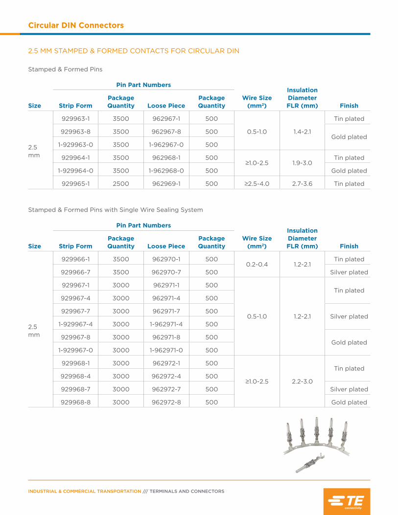
2.5 MM STAMPED & FORMED CONTACTS FOR CIRCULAR DIN
Stamped & Formed Pins
Size
Pin Part Numbers
Wire Size (mm2)
Insulation Diameter FLR (mm) FinishStrip Form
Package Quantity Loose Piece
Package Quantity
2.5 mm
929963-1 3500 962967-1 500
0.5-1.0 1.4-2.1
Tin plated
929963-8 3500 962967-8 500Gold plated
1-929963-0 3500 1-962967-0 500
929964-1 3500 962968-1 500≥1.0-2.5 1.9-3.0
Tin plated
1-929964-0 3500 1-962968-0 500 Gold plated
929965-1 2500 962969-1 500 ≥2.5-4.0 2.7-3.6 Tin plated
Stamped & Formed Pins with Single Wire Sealing System
Size
Pin Part Numbers
Wire Size (mm2)
Insulation Diameter FLR (mm) FinishStrip Form
Package Quantity Loose Piece
Package Quantity
2.5 mm
929966-1 3500 962970-1 5000.2-0.4 1.2-2.1
Tin plated
929966-7 3500 962970-7 500 Silver plated
929967-1 3000 962971-1 500
0.5-1.0 1.2-2.1
Tin plated929967-4 3000 962971-4 500
929967-7 3000 962971-7 500Silver plated
1-929967-4 3000 1-962971-4 500
929967-8 3000 962971-8 500Gold plated
1-929967-0 3000 1-962971-0 500
929968-1 3000 962972-1 500
≥1.0-2.5 2.2-3.0
Tin plated929968-4 3000 962972-4 500
929968-7 3000 962972-7 500 Silver plated
929968-8 3000 962972-8 500 Gold plated
PAGE 41
Circular DIN Connectors
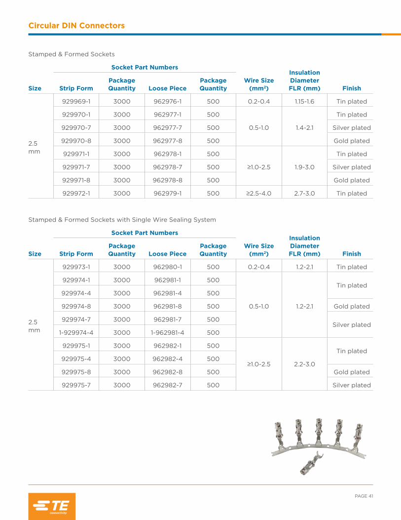
Stamped & Formed Sockets
Size
Socket Part Numbers
Wire Size (mm2)
Insulation Diameter FLR (mm) FinishStrip Form
Package Quantity Loose Piece
Package Quantity
2.5 mm
929969-1 3000 962976-1 500 0.2-0.4 1.15-1.6 Tin plated
929970-1 3000 962977-1 500
0.5-1.0 1.4-2.1
Tin plated
929970-7 3000 962977-7 500 Silver plated
929970-8 3000 962977-8 500 Gold plated
929971-1 3000 962978-1 500
≥1.0-2.5 1.9-3.0
Tin plated
929971-7 3000 962978-7 500 Silver plated
929971-8 3000 962978-8 500 Gold plated
929972-1 3000 962979-1 500 ≥2.5-4.0 2.7-3.0 Tin plated
Stamped & Formed Sockets with Single Wire Sealing System
Size
Socket Part Numbers
Wire Size (mm2)
Insulation Diameter FLR (mm) FinishStrip Form
Package Quantity Loose Piece
Package Quantity
2.5 mm
929973-1 3000 962980-1 500 0.2-0.4 1.2-2.1 Tin plated
929974-1 3000 962981-1 500
0.5-1.0 1.2-2.1
Tin plated929974-4 3000 962981-4 500
929974-8 3000 962981-8 500 Gold plated
929974-7 3000 962981-7 500Silver plated
1-929974-4 3000 1-962981-4 500
929975-1 3000 962982-1 500
≥1.0-2.5 2.2-3.0
Tin plated929975-4 3000 962982-4 500
929975-8 3000 962982-8 500 Gold plated
929975-7 3000 962982-7 500 Silver plated
INDUSTRIAL & COMMERCIAL TRANSPORTATION /// TERMINALS AND CONNECTORS
Circular DIN Connectors
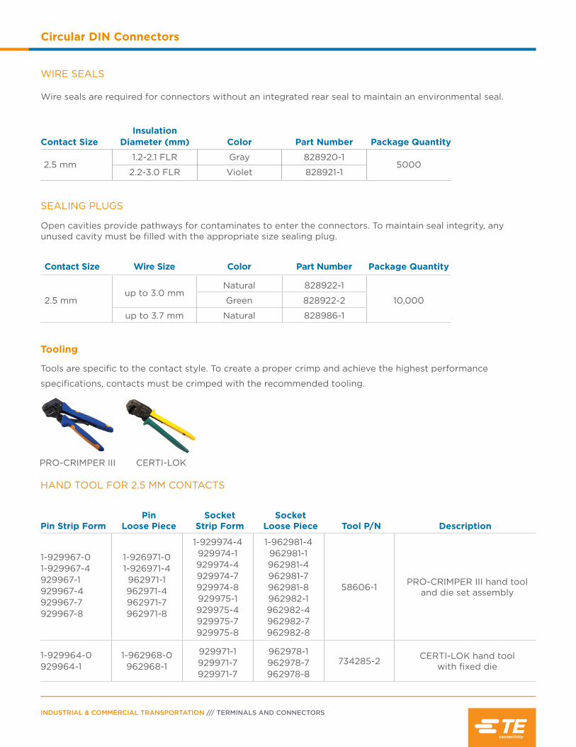
WIRE SEALS
Wire seals are required for connectors without an integrated rear seal to maintain an environmental seal.
Contact SizeInsulation
Diameter (mm) Color Part Number Package Quantity
2.5 mm1.2-2.1 FLR Gray 828920-1
50002.2-3.0 FLR Violet 828921-1
SEALING PLUGS
Open cavities provide pathways for contaminates to enter the connectors. To maintain seal integrity, any unused cavity must be filled with the appropriate size sealing plug.
Contact Size Wire Size Color Part Number Package Quantity
2.5 mmup to 3.0 mm
Natural 828922-1
10,000Green 828922-2
up to 3.7 mm Natural 828986-1
HAND TOOL FOR 2.5 MM CONTACTS
Pin Strip FormPin
Loose PieceSocket
Strip FormSocket
Loose Piece Tool P/N Description
1-929967-01-929967-4929967-1929967-4929967-7 929967-8
1-926971-0 1-926971-4962971-1962971-4962971-7 962971-8
1-929974-4 929974-1 929974-4 929974-7 929974-8 929975-1 929975-4 929975-7 929975-8
1-962981-4 962981-1 962981-4 962981-7 962981-8 962982-1 962982-4 962982-7 962982-8
58606-1 PRO-CRIMPER III hand tool and die set assembly
1-929964-0929964-1
1-962968-0962968-1
929971-1 929971-7 929971-7
962978-1 962978-7 962978-8
734285-2 CERTI-LOK hand tool with fixed die
PRO-CRIMPER III CERTI-LOK
Tooling
Tools are specific to the contact style. To create a proper crimp and achieve the highest performance
specifications, contacts must be crimped with the recommended tooling.
PAGE 43
Circular DIN Connectors
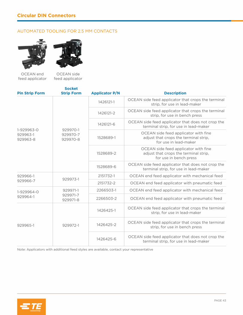
AUTOMATED TOOLING FOR 2.5 MM CONTACTS
Pin Strip FormSocket
Strip Form Applicator P/N Description
1-929963-0 929963-1929963-8
929970-1929970-7 929970-8
1426121-1 OCEAN side feed applicator that crops the terminal strip, for use in lead-maker
1426121-2 OCEAN side feed applicator that crops the terminal strip, for use in bench press
1426121-6 OCEAN side feed applicator that does not crop the terminal strip, for use in lead-maker
1528689-1OCEAN side feed applicator with fine adjust that crops the terminal strip,
for use in lead-maker
1528689-2OCEAN side feed applicator with fine adjust that crops the terminal strip,
for use in bench press
1528689-6 OCEAN side feed applicator that does not crop the terminal strip, for use in lead-maker
929966-1929966-7 929973-1
2151732-1 OCEAN end feed applicator with mechanical feed
2151732-2 OCEAN end feed applicator with pneumatic feed
1-929964-0929964-1
929971-1929971-7929971-8
2266503-1 OCEAN end feed applicator with mechanical feed
2266503-2 OCEAN end feed applicator with pneumatic feed
929965-1 929972-1
1426425-1 OCEAN side feed applicator that crops the terminal strip, for use in lead-maker
1426425-2 OCEAN side feed applicator that crops the terminal strip, for use in bench press
1426425-6 OCEAN side feed applicator that does not crop the terminal strip, for use in lead-maker
Note: Applicators with additional feed styles are available, contact your representative
OCEAN end feed applicator
OCEAN side feed applicator
INDUSTRIAL & COMMERCIAL TRANSPORTATION /// TERMINALS AND CONNECTORS
Circular DIN Connectors
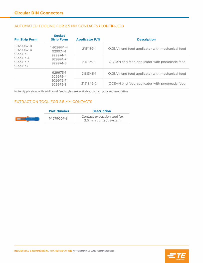
AUTOMATED TOOLING FOR 2.5 MM CONTACTS (CONTINUED)
Pin Strip FormSocket
Strip Form Applicator P/N Description
1-929967-01-929967-4929967-1929967-4929967-7929967-8
1-929974-4 929974-1 929974-4 929974-7 929974-8
2151139-1 OCEAN end feed applicator with mechanical feed
2151139-1 OCEAN end feed applicator with pneumatic feed
-
929975-1 929975-4 929975-7 929975-8
2151345-1 OCEAN end feed applicator with mechanical feed
2151345-2 OCEAN end feed applicator with pneumatic feed
Note: Applicators with additional feed styles are available, contact your representative
EXTRACTION TOOL FOR 2.5 MM CONTACTS
Part Number Description
1-1579007-8 Contact extraction tool for 2.5 mm contact system

Contents
HDSCS Connector Overview ............................... 46
Product Documentation ........................................ 46
Performance Specifications ................................. 46
Material Specifications ............................................47
Dimensions ..................................................................47
Configurations ........................................................... 48
Ordering Information ....................................... 49-50
Accessories ............................................................51-52
Contacts ................................................................53-55
Tooling ....................................................................57-60
How To Instructions .......................................... 60-61
INDUSTRIAL & COMMERCIAL TRANSPORTATION /// TERMINALS AND CONNECTORS
HDSCS Connectors
HDSCS Connector Overview
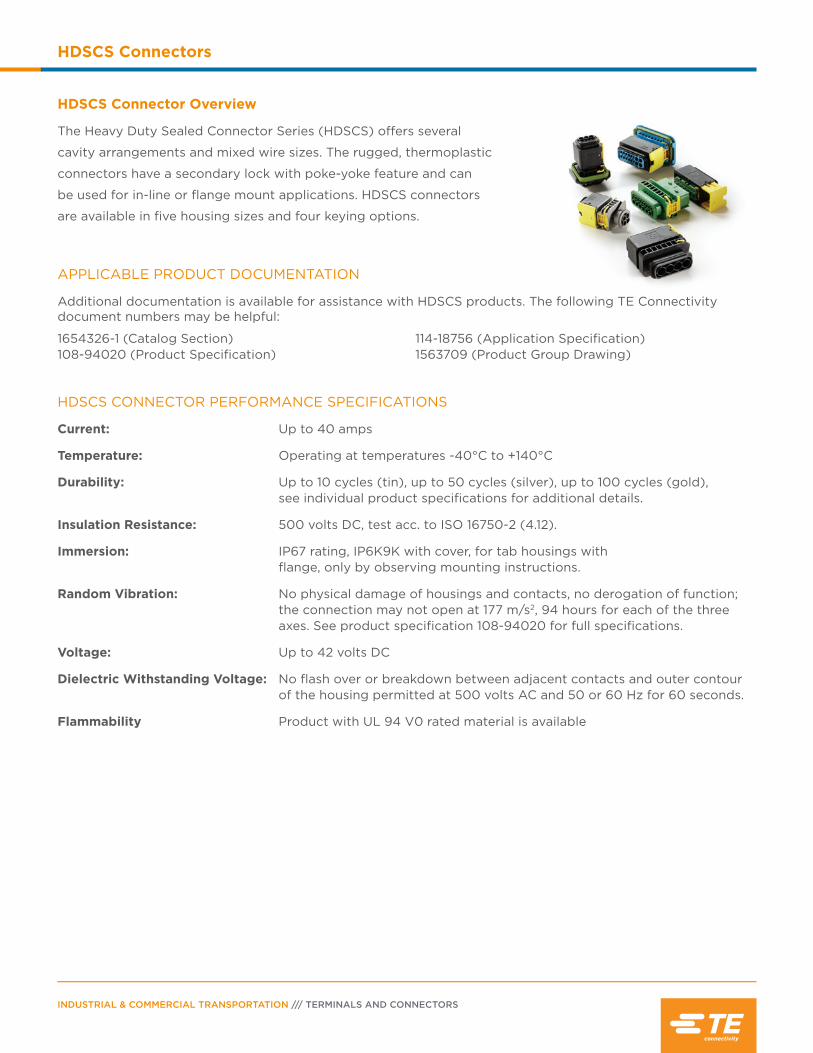
The Heavy Duty Sealed Connector Series (HDSCS) offers several
cavity arrangements and mixed wire sizes. The rugged, thermoplastic
connectors have a secondary lock with poke-yoke feature and can
be used for in-line or flange mount applications. HDSCS connectors
are available in five housing sizes and four keying options.
APPLICABLE PRODUCT DOCUMENTATION
Additional documentation is available for assistance with HDSCS products. The following TE Connectivity document numbers may be helpful:
1654326-1 (Catalog Section) 108-94020 (Product Specification)
114-18756 (Application Specification) 1563709 (Product Group Drawing)
HDSCS CONNECTOR PERFORMANCE SPECIFICATIONS
Current: Up to 40 amps
Temperature: Operating at temperatures -40°C to +140°C
Durability: Up to 10 cycles (tin), up to 50 cycles (silver), up to 100 cycles (gold), see individual product specifications for additional details.
Insulation Resistance: 500 volts DC, test acc. to ISO 16750-2 (4.12).
Immersion: IP67 rating, IP6K9K with cover, for tab housings with flange, only by observing mounting instructions.
Random Vibration: No physical damage of housings and contacts, no derogation of function; the connection may not open at 177 m/s2, 94 hours for each of the three axes. See product specification 108-94020 for full specifications.
Voltage: Up to 42 volts DC
Dielectric Withstanding Voltage: No flash over or breakdown between adjacent contacts and outer contour of the housing permitted at 500 volts AC and 50 or 60 Hz for 60 seconds.
Flammability Product with UL 94 V0 rated material is available

A
CB
E
D
F
PAGE 47
HDSCS Connectors
DIMENSIONS
HDSCS Receptacle Housing HDSCS Tab Housing
Group Overall Length A
Overall Height B
Overall Width C
Overall Length D
Overall Height E
Overall Width F
A 1.23 (31.3) 0.73 (18.5) 1.02 (26.0) 1.64 (47.1) 0.75 (19.0) 1.09 (27.6)
B 1.23 (31.3) 1.01 (25.7) 1.19 (30.2) 1.64 (47.1) 1.06 (27.0) 1.09 (27.6)
C 1.23 (31.3) 1.01 (25.7) 1.23 (31.2) 1.64 (47.1) 1.06 (27.0) 1.28 (32.6)
D 1.23 (31.3) 1.01 (25.7) 1.54 (39.2) 1.64 (47.1) 1.06 (27.0) 1.60 (40.6)
E 1.23 (31.3) 1.01 (25.7) 2.02 (51.2) 1.64 (47.1) 1.06 (27.0) 2.07 (52.6)
Dimensions are for reference only.
Flange Seal: Silicone rubber
Seal for Secondary Locking:
Silicone rubber
Housing: Glass filled PBT
Secondary Locking:
Glass filled PBT
Slide Lock: Glass filled PBT
MATERIAL SPECIFICATIONS
INDUSTRIAL & COMMERCIAL TRANSPORTATION /// TERMINALS AND CONNECTORS
HDSCS Connectors
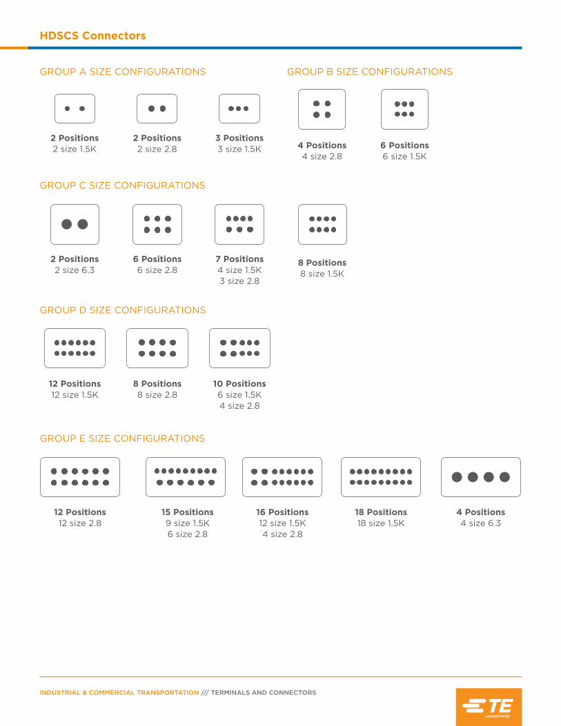
6 Positions 6 size 2.8
2 Positions 2 size 6.3
7 Positions 4 size 1.5K 3 size 2.8
8 Positions 8 size 1.5K
12 Positions 12 size 1.5K
8 Positions 8 size 2.8
10 Positions 6 size 1.5K 4 size 2.8
12 Positions 12 size 2.8
15 Positions 9 size 1.5K 6 size 2.8
16 Positions 12 size 1.5K4 size 2.8
18 Positions 18 size 1.5K
4 Positions 4 size 6.3
GROUP C SIZE CONFIGURATIONS
GROUP D SIZE CONFIGURATIONS
GROUP E SIZE CONFIGURATIONS
3 Positions 3 size 1.5K
2 Positions 2 size 2.8
2 Positions 2 size 1.5K
GROUP A SIZE CONFIGURATIONS
6 Positions 6 size 1.5K
4 Positions 4 size 2.8
GROUP B SIZE CONFIGURATIONS
PAGE 49
HDSCS Connectors
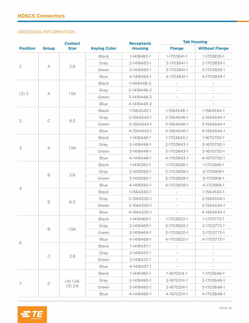
ORDERING INFORMATION
Position GroupContact
Size Keying ColorReceptacle
Housing
Tab Housing
Flange Without Flange
2 A 2.8
Black 1-1418483-1 1-1703841-1 1-1703839-1
Gray 2-1418483-1 2-1703841-1 2-1703839-1
Green 3-1418483-1 3-1703841-1 3-1703839-1
Blue 4-1418483-1 4-1703841-1 4-1703839-1
(3) 2 A 1.5K
Black 1-1418448-2 - -
Gray 2-1418448-2 - -
Green 3-1418448-2 - -
Blue 4-1418448-2 - -
2 C 6.3
Black 1-1564542-1 1-1564546-1 1-1564544-1
Gray 2-1564542-1 2-1564546-1 2-1564544-1
Green 3-1564542-1 3-1564546-1 3-1564544-1
Blue 4-1564542-1 4-1564546-1 4-1564544-1
3 A 1.5K
Black 1-1418448-1 1-1703843-1 1-1670730-1
Gray 2-1418448-1 2-1703843-1 2-1670730-1
Green 3-1418448-1 3-1703843-1 3-1670730-1
Blue 4-1418448-1 4-1703843-1 4-1670730-1
4
B 2.8
Black 1-1418390-1 1-1703808-1 1-1703818-1
Gray 2-1418390-1 2-1703808-1 2-1703818-1
Green 3-1418390-1 3-1703808-1 3-1703818-1
Blue 4-1418390-1 4-1703808-1 4-1703818-1
E 6.3
Black 1-1564330-1 - 1-1564534-1
Gray 2-1564330-1 - 2-1564534-1
Green 3-1564330-1 - 3-1564534-1
Blue 4-1564330-1 - 4-1564534-1
6
B 1.5K
Black 1-1418469-1 1-1703820-1 1-1703773-1
Gray 2-1418469-1 2-1703820-1 2-1703773-1
Green 3-1418469-1 3-1703820-1 3-1703773-1
Blue 4-1418469-1 4-1703820-1 4-1703773-1
C 2.8
Black 1-1418437-1 - -
Gray 2-1418437-1 - -
Green 3-1418437-1 - -
Blue 4-1418437-1 - -
7 C (4) 1.5K(3) 2.8
Black 1-1418480-1 1-1670214-1 1-1703648-1
Gray 2-1418480-1 2-1670214-1 2-1703648-1
Green 3-1418480-1 3-1670214-1 3-1703648-1
Blue 4-1418480-1 4-1670214-1 4-1703648-1

INDUSTRIAL & COMMERCIAL TRANSPORTATION /// TERMINALS AND CONNECTORS
HDSCS Connectors
ORDERING INFORMATION (CONTINUED)
Position GroupContact
Size Keying ColorReceptacle
Housing
Tab Housing
Flange Without Flange
8
C 1.5K
Black 1-1418479-1 1-1564416-1 1-1564512-1
Gray 2-1418479-1 2-1564416-1 2-1564512-1
Green 3-1418479-1 3-1564416-1 3-1564512-1
Blue 4-1418479-1 4-1564416-1 4-1564512-1
D 2.8
Black 1-1670894-1 - 1-1564522-1
Gray 2-1670894-1 - 2-1564522-1
Green 3-1670894-1 - 3-1564522-1
Blue 4-1670894-1 - 4-1564522-1
10 D (6) 1.5K (4) 2.8
Black 1-1564514-1 1-1564518-1 1-1564516-1
Gray 2-1564514-1 2-1564518-1 2-1564516-1
Green 3-1564514-1 3-1564518-1 3-1564516-1
Blue 4-1564514-1 4-1564518-1 4-1564516-1
12
D 1.5K
Black 1-1703639-1 1-1564520-1 1-1564414-1
Gray 2-1703639-1 2-1564520-1 2-1564414-1
Green 3-1703639-1 3-1564520-1 3-1564414-1
Blue 4-1703639-1 4-1564520-1 4-1564414-1
E 2.8
Black 1-1670901-1 - -
Gray 2-1670901-1 - -
Green 3-1670901-1 - -
Blue 4-1670901-1 - -
15 E (9) 1.5K(6) 2.8
Black 1-1563878-1 1-1564532-1 1-1564530-1
Gray 2-1563878-1 2-1564532-1 2-1564530-1
Green 3-1563878-1 3-1564532-1 3-1564530-1
Blue 4-1563878-1 4-1564532-1 4-1564530-1
16 E (12) 1.5K(4) 2.8
Black 1-1564337-1 1-1564407-1 1-1564528-1
Gray 2-1564337-1 2-1564407-1 2-1564528-1
Green 3-1564337-1 3-1564407-1 3-1564528-1
Blue 4-1564337-1 4-1564407-1 4-1564528-1
18 E 1.5K
Black 1-1563759-1 1-1564526-1 1-1564412-1
Gray 2-1563759-1 2-1564526-1 2-1564412-1
Green 3-1563759-1 3-1564526-1 3-1564412-1
Blue 4-1563759-1 4-1564526-1 4-1564412-1
PAGE 51
HDSCS Connectors
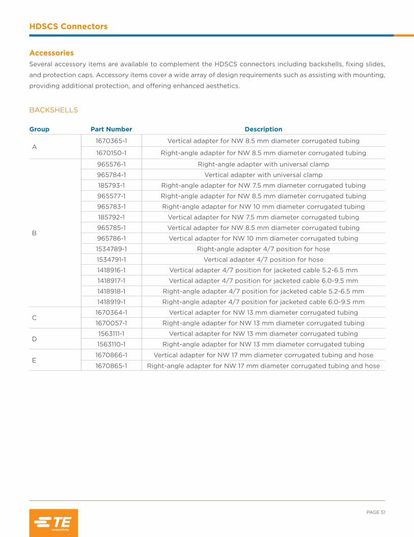
AccessoriesSeveral accessory items are available to complement the HDSCS connectors including backshells, fixing slides,
and protection caps. Accessory items cover a wide array of design requirements such as assisting with mounting,
providing additional protection, and offering enhanced aesthetics.
Group Part Number Description
A1670365-1 Vertical adapter for NW 8.5 mm diameter corrugated tubing
1670150-1 Right-angle adapter for NW 8.5 mm diameter corrugated tubing
B
965576-1 Right-angle adapter with universal clamp
965784-1 Vertical adapter with universal clamp
185793-1 Right-angle adapter for NW 7.5 mm diameter corrugated tubing
965577-1 Right-angle adapter for NW 8.5 mm diameter corrugated tubing
965783-1 Right-angle adapter for NW 10 mm diameter corrugated tubing
185792-1 Vertical adapter for NW 7.5 mm diameter corrugated tubing
965785-1 Vertical adapter for NW 8.5 mm diameter corrugated tubing
965786-1 Vertical adapter for NW 10 mm diameter corrugated tubing
1534789-1 Right-angle adapter 4/7 position for hose
1534791-1 Vertical adapter 4/7 position for hose
1418916-1 Vertical adapter 4/7 position for jacketed cable 5.2-6.5 mm
1418917-1 Vertical adapter 4/7 position for jacketed cable 6.0-9.5 mm
1418918-1 Right-angle adapter 4/7 position for jacketed cable 5.2-6.5 mm
1418919-1 Right-angle adapter 4/7 position for jacketed cable 6.0-9.5 mm
C1670364-1 Vertical adapter for NW 13 mm diameter corrugated tubing
1670057-1 Right-angle adapter for NW 13 mm diameter corrugated tubing
D1563111-1 Vertical adapter for NW 13 mm diameter corrugated tubing
1563110-1 Right-angle adapter for NW 13 mm diameter corrugated tubing
E1670866-1 Vertical adapter for NW 17 mm diameter corrugated tubing and hose
1670865-1 Right-angle adapter for NW 17 mm diameter corrugated tubing and hose
BACKSHELLS

INDUSTRIAL & COMMERCIAL TRANSPORTATION /// TERMINALS AND CONNECTORS
HDSCS Connectors
Group Part Number Color Panel Thickness
A
1703838-6 Gray 3.5 mm
1703838-1 Yellow 3.0 mm
1703838-2 Red 2.5 mm
B
1703810-6 Gray 3.5 mm
1703810-1 Yellow 3.0 mm
1703810-2 Red 2.5 mm
C
1670720-6 Gray 3.5 mm
1670720-1 Yellow 3.0 mm
1670720-2 Red 2.5 mm
D
1564562-1 Yellow 3.0 mm
1564562-2 Red 2.5 mm
1564562-5 Gray 1.5 mm
1564562-4 Natural 1.0 mm
E
1564411-6 Gray 3.5 mm
1564411-1 Yellow 3.0 mm
1564411-2 Red 2.5 mm
1564411-5 Gray 1.5 mm
Group Part Number Housing
A2112299-1 Receptacle
2112289-1 Tab
B2112300-1 Receptacle
2112291-1 Tab
C2112301-1 Receptacle
2112293-1 Tab
D2112302-1 Receptacle
2112295-1 Tab
E2112303-1 Receptacle
2112297-1 Tab
FIXING SLIDES Fixing slides are used to help secure HDSCS connectors while mounting them. The locking slides can accommodate panel thicknesses from 1.0-3.5 mm.
PROTECTION CAPS The HDSCS protection caps provide an environmental seal and are used to protect the connector interface when the two halves are not mated.

PAGE 53
HDSCS Connectors
AMP MCP CONTACT PERFORMANCE SPECIFICATIONS
Durability10 cycles (tin)50 cycles (silver)100 cycles (gold)
Current RatingContact Size Max. Current1.5K up to 20 amps2.8 up to 40 amps6.3/4.8K up to 40 amps
Contact RetentionContact Size Min. Load1.5K 40/60 N2.8 80 N6.3/4.8K 80 N
Crimp Tensile Strength Contact Size Tensile Strength1.5K.22 mm2 ≥ 32 N.35 mm2 ≥ 50 N.50 mm2 ≥ 60 N.75 mm2 ≥ 85 N1.0 mm2 ≥ 108 N1.25 mm2 ≥ 135 N (16 AWG)1.5 mm2 ≥ 135 N
2.8 .22 mm2 ≥ 28 N.35 mm2 ≥ 50 N.50 mm2 ≥ 60 N .75 mm2 ≥ 85 N1.0 mm2 ≥ 108 N1.5 mm2 ≥ 150 N2.5 mm2 ≥ 200 N 6.3./4.8K .35 mm2 ≥ 50 N.50 mm2 ≥ 60 N.75 mm2 ≥ 85 N1.0 mm2 ≥ 108 N1.5 mm2 ≥ 150 N 2.5 mm2 ≥ 200 N4.0 mm2 ≥ 310 N6.0 mm2 ≥ 450 N
Contacts
The HDSCS connectors commonly use the AMP MCP stamped & formed contact system.
INDUSTRIAL & COMMERCIAL TRANSPORTATION /// TERMINALS AND CONNECTORS
HDSCS Connectors
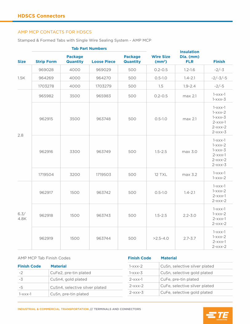
Stamped & Formed Tabs with Single Wire Sealing System - AMP MCP
Size
Tab Part Numbers
Wire Size (mm2)
Insulation Dia. (mm)
FLR FinishStrip FormPackage Quantity Loose Piece
Package Quantity
1.5K
969028 4000 969029 500 0.2-0.5 1.2-1.6 -2/-3
964269 4000 964270 500 0.5-1.0 1.4-2.1 -2/-3/-5
1703278 4000 1703279 500 1.5 1.9-2.4 -2/-5
2.8
965982 3500 965983 500 0.2-0.5 max 2.1 1-xxx-1 1-xxx-3
962915 3500 963748 500 0.5-1.0 max 2.1
1-xxx-1 1-xxx-21-xxx-3 2-xxx-1 2-xxx-22-xxx-3
962916 3300 963749 500 1.5-2.5 max 3.0
1-xxx-1 1-xxx-21-xxx-3 2-xxx-1 2-xxx-22-xxx-3
1719504 3200 1719503 500 12 TXL max 3.2 1-xxx-1 1-xxx-2
6.3/ 4.8K
962917 1500 963742 500 0.5-1.0 1.4-2.1
1-xxx-1 1-xxx-22-xxx-1 2-xxx-2
962918 1500 963743 500 1.5-2.5 2.2-3.0
1-xxx-1 1-xxx-22-xxx-12-xxx-2
962919 1500 963744 500 >2.5-4.0 2.7-3.7
1-xxx-1 1-xxx-22-xxx-1 2-xxx-2
AMP MCP Tab Finish Codes
Finish Code Material
-2 CuFe2, pre-tin plated
-3 CuSn4, gold plated
-5 CuSn4, selective silver plated
1-xxx-1 CuSn, pre-tin plated
Finish Code Material
1-xxx-2 CuSn, selective silver plated
1-xxx-3 CuSn, selective gold plated
2-xxx-1 CuFe, pre-tin plated
2-xxx-2 CuFe, selective silver plated
2-xxx-3 CuFe, selective gold plated
AMP MCP CONTACTS FOR HDSCS
PAGE 55
HDSCS Connectors
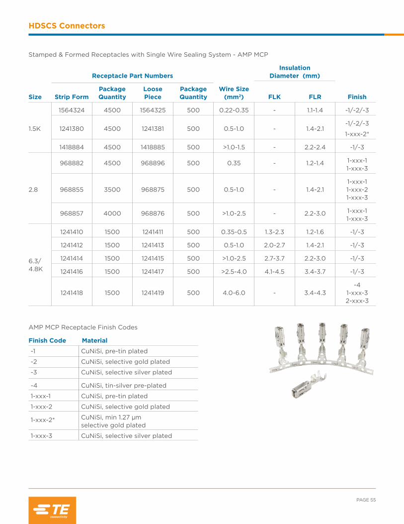
Stamped & Formed Receptacles with Single Wire Sealing System - AMP MCP
Size
Receptacle Part Numbers
Wire Size (mm2)
Insulation Diameter (mm)
FinishFLK FLRStrip FormPackage Quantity
Loose Piece
Package Quantity
1.5K
1564324 4500 1564325 500 0.22-0.35 - 1.1-1.4 -1/-2/-3
1241380 4500 1241381 500 0.5-1.0 - 1.4-2.1-1/-2/-3
1-xxx-2*
1418884 4500 1418885 500 >1.0-1.5 - 2.2-2.4 -1/-3
2.8
968882 4500 968896 500 0.35 - 1.2-1.4 1-xxx-1 1-xxx-3
968855 3500 968875 500 0.5-1.0 - 1.4-2.11-xxx-1 1-xxx-21-xxx-3
968857 4000 968876 500 >1.0-2.5 - 2.2-3.0 1-xxx-1 1-xxx-3
6.3/ 4.8K
1241410 1500 1241411 500 0.35-0.5 1.3-2.3 1.2-1.6 -1/-3
1241412 1500 1241413 500 0.5-1.0 2.0-2.7 1.4-2.1 -1/-3
1241414 1500 1241415 500 >1.0-2.5 2.7-3.7 2.2-3.0 -1/-3
1241416 1500 1241417 500 >2.5-4.0 4.1-4.5 3.4-3.7 -1/-3
1241418 1500 1241419 500 4.0-6.0 - 3.4-4.3-4
1-xxx-32-xxx-3
AMP MCP Receptacle Finish Codes
Finish Code Material
-1 CuNiSi, pre-tin plated
-2 CuNiSi, selective gold plated
-3 CuNiSi, selective silver plated
-4 CuNiSi, tin-silver pre-plated
1-xxx-1 CuNiSi, pre-tin plated
1-xxx-2 CuNiSi, selective gold plated
1-xxx-2* CuNiSi, min 1.27 µm selective gold plated
1-xxx-3 CuNiSi, selective silver plated

INDUSTRIAL & COMMERCIAL TRANSPORTATION /// TERMINALS AND CONNECTORS
HDSCS Connectors
WIRE SEALS
Wire seals are required for connectors without an integrated rear seal to maintain an environmental seal.
Contact SizeInsulation
Diameter (mm) Color Part Number Package Quantity
1.5K
0.9-1.2 Green 1718705-1
10,000
1.2-1.6Red 964971-1
Blue 1394133-1
1.4-1.9 Gray 963530-1
1.9-2.1 Yellow 964972-1
1.9-2.4 Orange 2112323-1
2.81.2-2.1 Blue
828904-1 1000
828904-210,000
2.2-3.0 White 828905-1
6.3/4.8K
1.4-2.0 Yellow 2177018-1
10,000
2.0-2.7 White 1394511-1
2.7-2.9 Red brown 1823111-1
3.4-3.7 Blue 1394512-1
4.0-4.5 Green 1719043-1
SEALING PLUGS
Open cavities provide pathways for contaminates to enter the connectors. To maintain seal integrity, any unused cavity must be filled with the appropriate size sealing plug.
Contact Size Wire Size Color Part Number Package Quantity
1.5K 3.6 mmWhite 963531-1
10,000
Natural 1394132-1
2.8 5.6 mmNatural 828922-1
Green 828922-2
6.3/4.8K 8.5 mm Transparent 967652-1

PAGE 57
HDSCS Connectors
HAND TOOL FOR AMP MCP CONTACTS
ContactSize
Tab Strip Form
Tab Loose Piece
Receptacle Strip Form
Receptacle Loose Piece Tool P/N Description
1.5K
1703278 964269969028
1703279 964270969029
- -539663-2 (die)
539663-2 (frame)ERGOCRIMP
hand tool and die assembly- - 1418884 1418885 5-1579001-3 (die)
539635-1 (frame)
- - 1564324 1564325 4-1579016-0 (die)539635-1 (frame)
2.8
962915 962916
963748963749 - -
539758-2 (die)539635-1 (frame)
ERGOCRIMP hand tool
and die assembly965982 965983 539737-2 (die)
539635-1 (frame)
- - 968882 968896 539725-2 (die)539635-1 (frame)
6.3/ 4.8K
962917962918962919
963742963743 963744
- -539757-2 (die)
539635-1 (frame)
ERGOCRIMP hand tool
and die assembly
- - 1241410 1241412
1241411 1241413
539955-2 (die)539635-1 (frame)
- - 1241416 1241414
1241415 1241417
539956-2 (die)539635-1 (frame)
- - 1241418 1241419 3-1579021-7 (die)539635-1 (frame)
Tooling
Tools are specific to the contact style. To create a proper crimp and achieve the highest performance
specifications, contacts must be crimped with the recommended tooling.
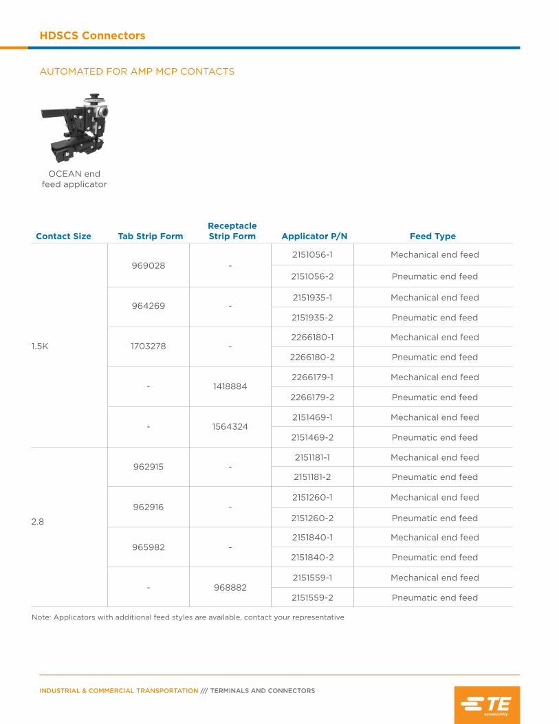
INDUSTRIAL & COMMERCIAL TRANSPORTATION /// TERMINALS AND CONNECTORS
HDSCS Connectors
AUTOMATED FOR AMP MCP CONTACTS
Contact Size Tab Strip FormReceptacle Strip Form Applicator P/N Feed Type
1.5K
969028 -2151056-1 Mechanical end feed
2151056-2 Pneumatic end feed
964269 -2151935-1 Mechanical end feed
2151935-2 Pneumatic end feed
1703278 -2266180-1 Mechanical end feed
2266180-2 Pneumatic end feed
- 14188842266179-1 Mechanical end feed
2266179-2 Pneumatic end feed
- 15643242151469-1 Mechanical end feed
2151469-2 Pneumatic end feed
2.8
962915 -2151181-1 Mechanical end feed
2151181-2 Pneumatic end feed
962916 -2151260-1 Mechanical end feed
2151260-2 Pneumatic end feed
OCEAN end feed applicator
2.8
965982 -2151840-1 Mechanical end feed
2151840-2 Pneumatic end feed
- 9688822151559-1 Mechanical end feed
2151559-2 Pneumatic end feed
Note: Applicators with additional feed styles are available, contact your representative
2.8
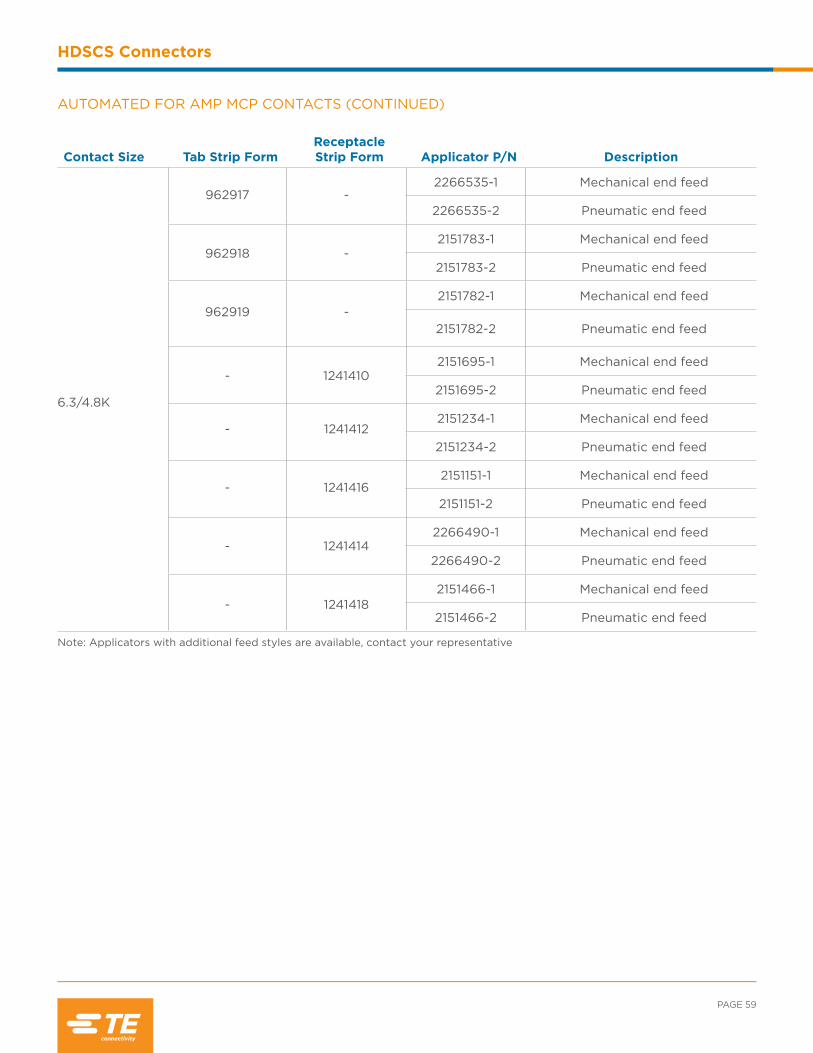
PAGE 59
HDSCS Connectors
AUTOMATED FOR AMP MCP CONTACTS (CONTINUED)
Contact Size Tab Strip FormReceptacle Strip Form Applicator P/N Description
6.3/4.8K
962917 -2266535-1 Mechanical end feed
2266535-2 Pneumatic end feed
962918 -2151783-1 Mechanical end feed
2151783-2 Pneumatic end feed
962919 -2151782-1 Mechanical end feed
2151782-2 Pneumatic end feed
- 12414102151695-1 Mechanical end feed
2151695-2 Pneumatic end feed
- 12414122151234-1 Mechanical end feed
2151234-2 Pneumatic end feed
- 12414162151151-1 Mechanical end feed
2151151-2 Pneumatic end feed
- 12414142266490-1 Mechanical end feed
2266490-2 Pneumatic end feed
- 12414182151466-1 Mechanical end feed
2151466-2 Pneumatic end feed
Note: Applicators with additional feed styles are available, contact your representative
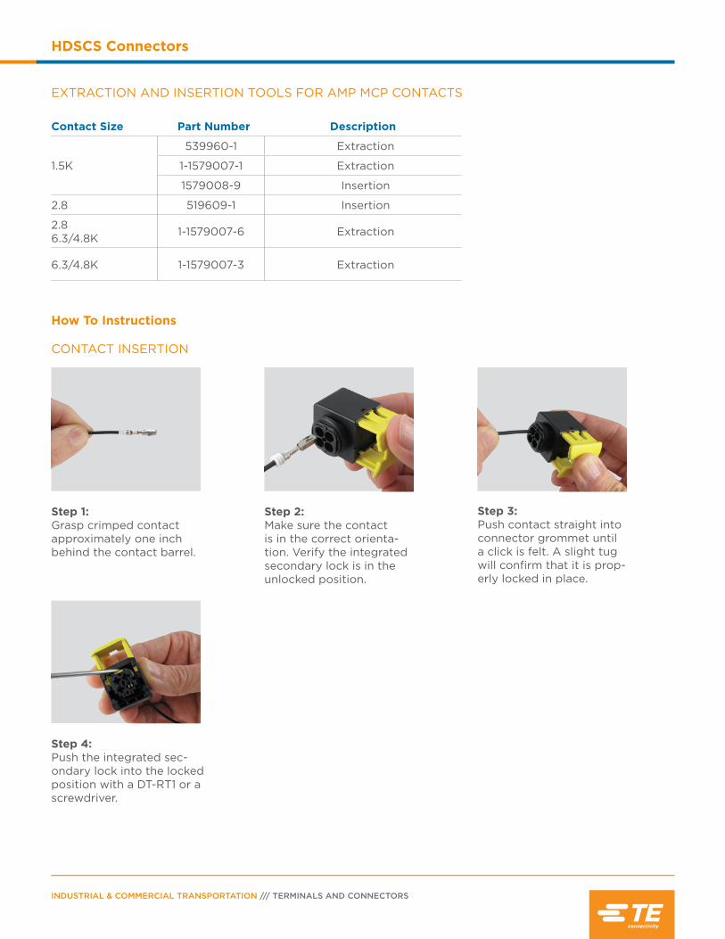
INDUSTRIAL & COMMERCIAL TRANSPORTATION /// TERMINALS AND CONNECTORS
HDSCS Connectors
CONTACT INSERTION
How To Instructions
Step 1:Grasp crimped contact approximately one inch behind the contact barrel.
Step 2:Make sure the contact is in the correct orienta-tion. Verify the integrated secondary lock is in the unlocked position.
Step 3:Push contact straight into connector grommet until a click is felt. A slight tug will confirm that it is prop-erly locked in place.
Step 4:Push the integrated sec-ondary lock into the locked position with a DT-RT1 or a screwdriver.
EXTRACTION AND INSERTION TOOLS FOR AMP MCP CONTACTS
Contact Size Part Number Description
1.5K
539960-1 Extraction
1-1579007-1 Extraction
1579008-9 Insertion
2.8 519609-1 Insertion
2.86.3/4.8K 1-1579007-6 Extraction
6.3/4.8K 1-1579007-3 Extraction
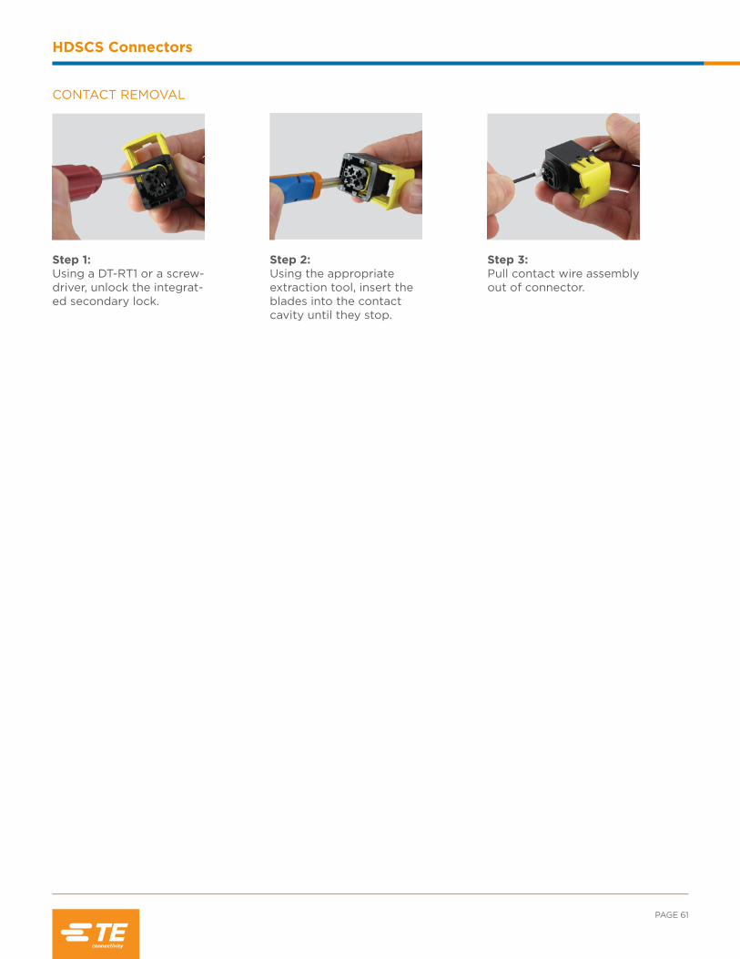
PAGE 61
HDSCS Connectors
Step 1:Using a DT-RT1 or a screw-driver, unlock the integrat-ed secondary lock.
CONTACT REMOVAL
Step 2:Using the appropriate extraction tool, insert the blades into the contact cavity until they stop.
Step 3:Pull contact wire assembly out of connector.

INDUSTRIAL & COMMERCIAL TRANSPORTATION /// TERMINALS AND CONNECTORS
HDSCS Connectors
NOTES:
Contents
LEAVYSEAL Connector Overview................... 64
Product Documentation ........................................ 64
Performance Specifications ................................. 64
Material Specifications ........................................... 64
Dimensions ................................................................. 65
Configurations .................................................... 65-66
Ordering Information ........................................67-68
Accessories ............................................................69-71
Contacts ................................................................. 71-73
Tooling .................................................................... 75-77
How To Instructions .................................................78
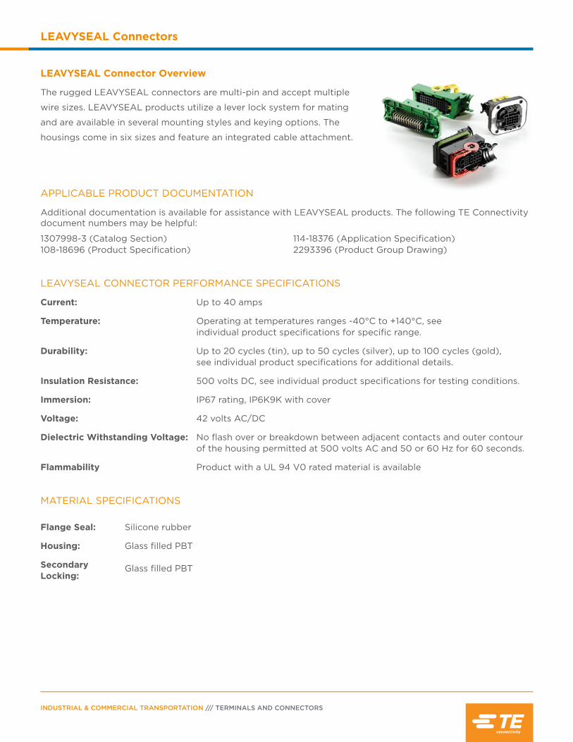
INDUSTRIAL & COMMERCIAL TRANSPORTATION /// TERMINALS AND CONNECTORS
LEAVYSEAL Connectors
LEAVYSEAL Connector Overview
The rugged LEAVYSEAL connectors are multi-pin and accept multiple
wire sizes. LEAVYSEAL products utilize a lever lock system for mating
and are available in several mounting styles and keying options. The
housings come in six sizes and feature an integrated cable attachment.
APPLICABLE PRODUCT DOCUMENTATION
Additional documentation is available for assistance with LEAVYSEAL products. The following TE Connectivity document numbers may be helpful:
1307998-3 (Catalog Section) 108-18696 (Product Specification)
114-18376 (Application Specification)2293396 (Product Group Drawing)
LEAVYSEAL CONNECTOR PERFORMANCE SPECIFICATIONS
Current: Up to 40 amps
Temperature: Operating at temperatures ranges -40°C to +140°C, see individual product specifications for specific range.
Durability: Up to 20 cycles (tin), up to 50 cycles (silver), up to 100 cycles (gold), see individual product specifications for additional details.
Insulation Resistance: 500 volts DC, see individual product specifications for testing conditions.
Immersion: IP67 rating, IP6K9K with cover
Voltage: 42 volts AC/DC
Dielectric Withstanding Voltage: No flash over or breakdown between adjacent contacts and outer contour of the housing permitted at 500 volts AC and 50 or 60 Hz for 60 seconds.
Flammability Product with a UL 94 V0 rated material is available
Flange Seal: Silicone rubber
Housing: Glass filled PBT
Secondary Locking:
Glass filled PBT
MATERIAL SPECIFICATIONS

A
CB
E
D
F
PAGE 65
LEAVYSEAL Connectors
DIMENSIONS
LEAVYSEAL Receptacle Housing LEAVYSEAL Tab Housing
Group Overall Length A
Overall Height B
Overall Width C
Overall Length D
Overall Height E
Overall Width F
1 1.46 (37.0) 1.57 (40.0) 2.33 (57.9) 1.48 (37.6) 1.93 (49.0) 1.91 (48.4)
2 1.49 (37.9) 1.72 (43.7) 2.73 (69.4) 1.81 (46.1) 2.03 (51.5) 2.62 (66.6)
3 1.73 (44.0) 1.64 (41.7) 3.64 (92.5) 2.19 (55.5) 2.47 (62.7) 3.62 (92.0)
4 1.43 (36.4) 1.71 (43.5) 4.09 (104.0) - - -
5 1.73 (44.0) 1.81 (46.0) 4.04 (102.5) 1.80 (45.8) 2.78 (70.7) 4.46 (113.3)
6 1.83 (46.6) 1.79 (45.5) 5.26 (133.5) - - -
Dimensions are for reference only.
18 Positions 12 size 1.5K 6 size 2.8
29 Positions 26 size 1.5K 2 size 2.81 size 6.3
26 Positions 12 size 1.5K 12 size 2.82 size 6.3
46 Positions 46 size 1.5K
22 Positions 16 size 1.5K 6 size 2.8
15 Positions 15 size 2.8
21 Positions 21 size 2.8
GROUP 1 CONFIGURATIONS GROUP 2 CONFIGURATIONS
GROUP 3 CONFIGURATIONS GROUP 4 CONFIGURATIONS
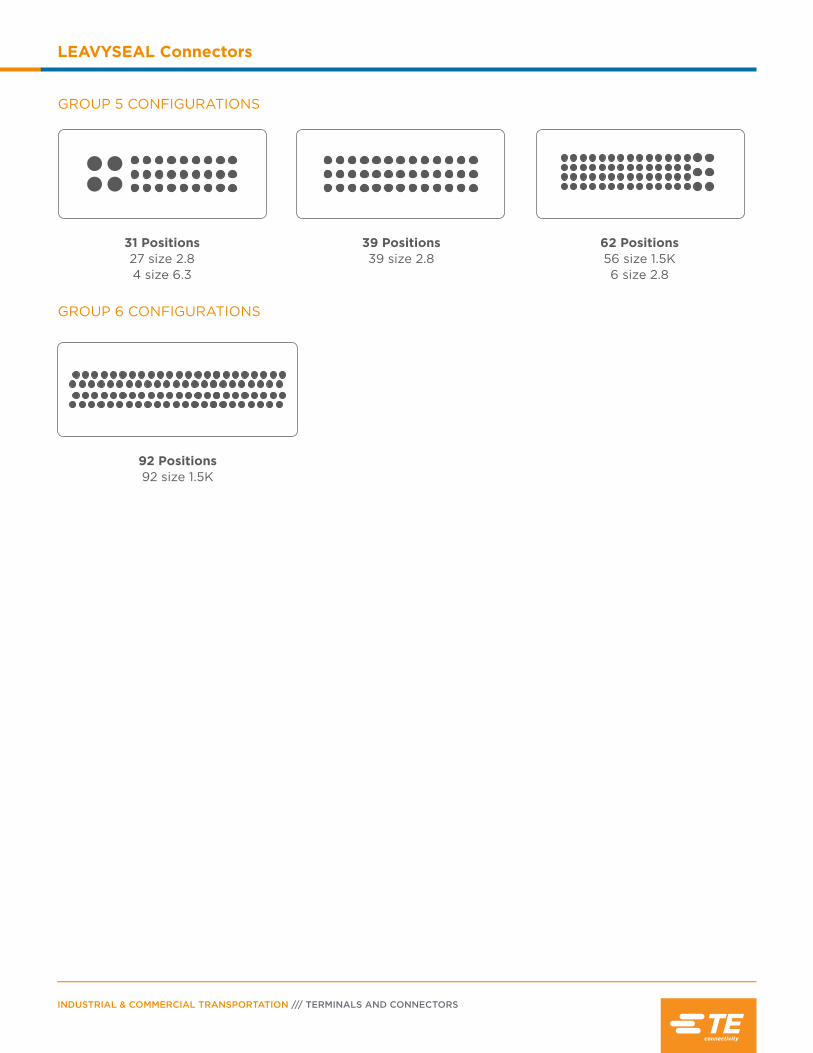
INDUSTRIAL & COMMERCIAL TRANSPORTATION /// TERMINALS AND CONNECTORS
LEAVYSEAL Connectors
31 Positions 27 size 2.8 4 size 6.3
39 Positions 39 size 2.8
62 Positions 56 size 1.5K6 size 2.8
GROUP 5 CONFIGURATIONS
92 Positions 92 size 1.5K
GROUP 6 CONFIGURATIONS

PAGE 67
LEAVYSEAL Connectors
ORDERING INFORMATION
Contact Size
Receptacle Housing
Tab Housing
Position Group Keying Housing Color In-line/Flange PCB
15 1 2.8
A Black 1-1534126-1 1703799-1 -
B Natural 2-1534126-1 - -
C Blue 3-1534126-1 - -
21 2 2.8
A Black 1-1534127-1 1-2112162-1(flange)
1534238-1 (straight)
B Natural 2-1534127-1 2-2112162-1 -
C Blue 3-1534127-1 3-2112162-1 -
D Violet 4-1534127-1 4-2112162-1 -
31 5 (27) 2.8 (4) 6.3
A Bordeaux 1-1564297-6 - -
39 5 2.8E Emerald Green 5-1718321-3 5-1718323-1
5-1418363-1 (straight)
5-1418363-3 (90°)
F Fawn Brown 6-1718321-3 6-1718323-1 -
46 4 1.5K A Black 1-2112231-1 - -
62 5(56) 1.5K(6) 2.8
A Black 1-1418883-1 1-1718324-1
1-1418362-1 (straight)
1-1418362-3 (90°)
B Gray 2-1418883-1 2-1718324-1
2-1418362-1 (straight)
2-1418362-3 (90°)
C Blue 3-1418883-1 3-1718324-1 -
D Green 4-1418883-1 - -
92 6 1.5K
ABlack
1-703998-1 (NW 26 wire
exit)- 1-1452228-9
(straight)3-1703998-1 (NW 29 wire
exit)
B Black4-1703998-1 (NW 29 wire
exit)- -
C Black5-1703998-1 (NW 29 wire
exit)- -

INDUSTRIAL & COMMERCIAL TRANSPORTATION /// TERMINALS AND CONNECTORS
LEAVYSEAL Connectors
ORDERING INFORMATION - V0 RATED MATERIAL
Contact Size
Receptacle Housing
Tab Housing
Position Group Keying Housing Color In-line/Flange PCB
18 1 (12) 1.5K (6) 2.8
A Black 1823440-2 1-1823448-2 -
21 2 2.8 A Black 1-2208688-1 1-2112162-1* (flange)
1534238-1*(straight)
22 1 (16) 1.5K (6) 2.8
A Black 1-1823440-3 1-1823449-1 -
B Gray 2-1823440-3 2-1823449-1 -
C Blue 3-1823440-3 - -
D Green 4-1823440-3 - -
26 3(12) 1.5K (12) 2.8(2) 6.3
A Black 1-2112035-11-2112041-1
-1-2112041-2
29 2(26) 1.5K (2) 2.8(1) 6.3
A Black 1-1823402-1 - -
B Gray 2-1823402-1 - -
C Blue 3-1823402-1 - -
31 5 (27) 2.8 (4) 6.3
A Bordeaux 1-2208685-6 - -
39 5 2.8E Emerald Green 5-2208684-3 5-1718323-1*
5-1418363-1*(straight)
5-1418362-3*(90°)
F Fawn Brown 6-2208684-3 6-1718323-1* -
62 5(56) 1.5K(6) 2.8
A Black 1-1823498-1 - -
B Gray 2-1823498-1 - -
C Blue 3-1823498-1 - -
D Green 4-1823498-1 - -
*Non-V0 rated material
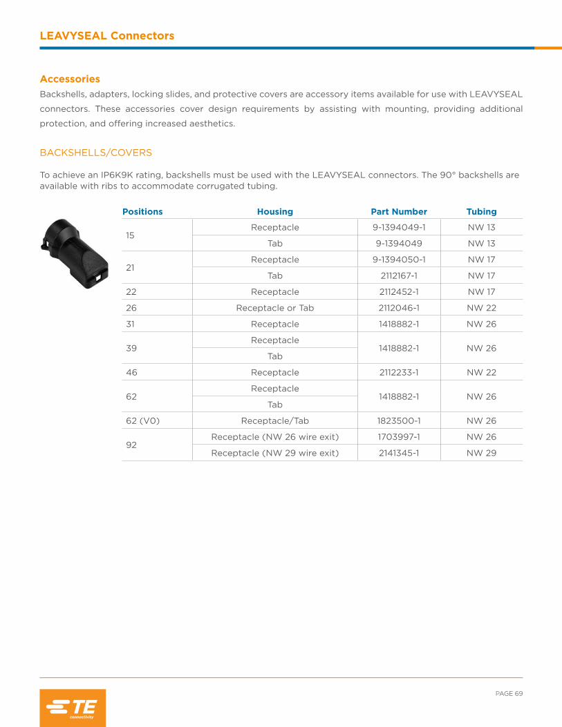
PAGE 69
LEAVYSEAL Connectors
Positions Housing Part Number Tubing
15Receptacle 9-1394049-1 NW 13
Tab 9-1394049 NW 13
21Receptacle 9-1394050-1 NW 17
Tab 2112167-1 NW 17
22 Receptacle 2112452-1 NW 17
26 Receptacle or Tab 2112046-1 NW 22
31 Receptacle 1418882-1 NW 26
39Receptacle
1418882-1 NW 26Tab
46 Receptacle 2112233-1 NW 22
62Receptacle
1418882-1 NW 26Tab
62 (V0) Receptacle/Tab 1823500-1 NW 26
92Receptacle (NW 26 wire exit) 1703997-1 NW 26
Receptacle (NW 29 wire exit) 2141345-1 NW 29
AccessoriesBackshells, adapters, locking slides, and protective covers are accessory items available for use with LEAVYSEAL
connectors. These accessories cover design requirements by assisting with mounting, providing additional
protection, and offering increased aesthetics.
BACKSHELLS/COVERS To achieve an IP6K9K rating, backshells must be used with the LEAVYSEAL connectors. The 90° backshells are available with ribs to accommodate corrugated tubing.
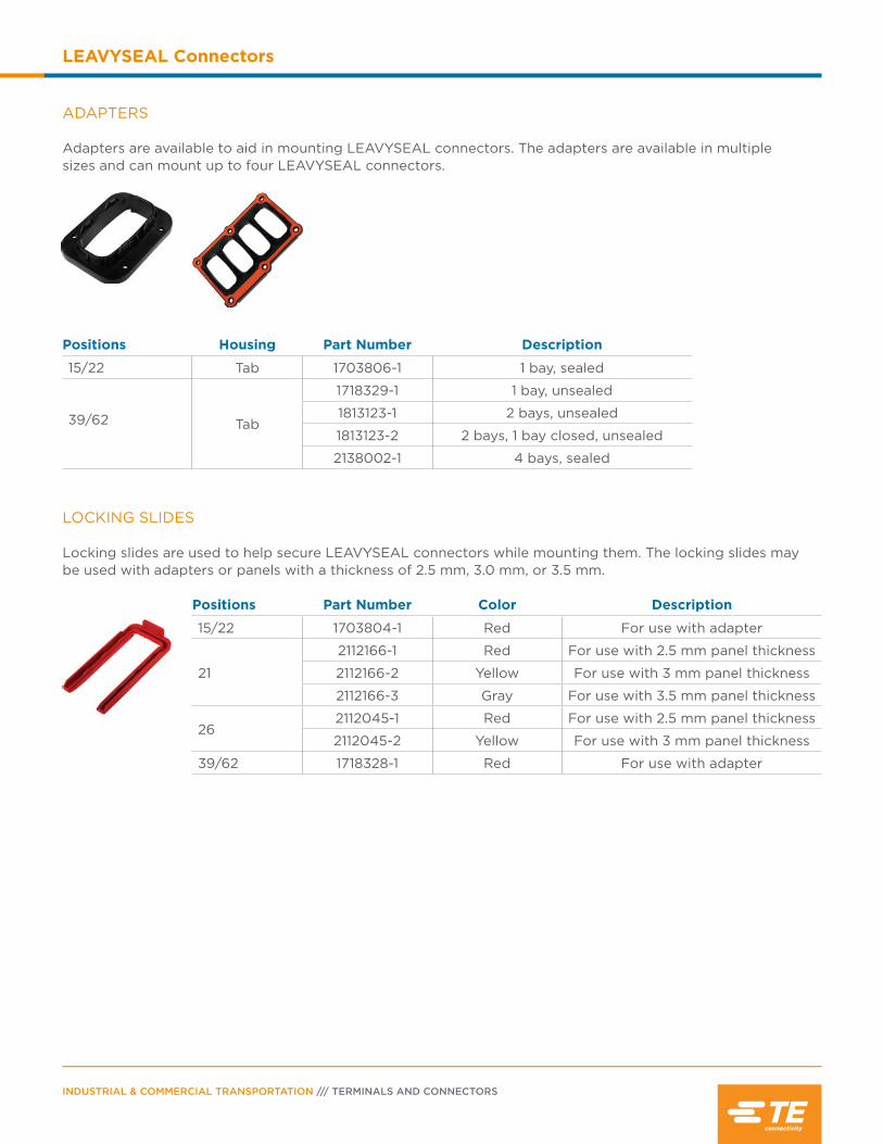
INDUSTRIAL & COMMERCIAL TRANSPORTATION /// TERMINALS AND CONNECTORS
LEAVYSEAL Connectors
Positions Housing Part Number Description
15/22 Tab 1703806-1 1 bay, sealed
39/62 Tab
1718329-1 1 bay, unsealed
1813123-1 2 bays, unsealed
1813123-2 2 bays, 1 bay closed, unsealed
2138002-1 4 bays, sealed
ADAPTERS Adapters are available to aid in mounting LEAVYSEAL connectors. The adapters are available in multiple sizes and can mount up to four LEAVYSEAL connectors.
Positions Part Number Color Description
15/22 1703804-1 Red For use with adapter
21
2112166-1 Red For use with 2.5 mm panel thickness
2112166-2 Yellow For use with 3 mm panel thickness
2112166-3 Gray For use with 3.5 mm panel thickness
262112045-1 Red For use with 2.5 mm panel thickness
2112045-2 Yellow For use with 3 mm panel thickness
39/62 1718328-1 Red For use with adapter
LOCKING SLIDES Locking slides are used to help secure LEAVYSEAL connectors while mounting them. The locking slides may be used with adapters or panels with a thickness of 2.5 mm, 3.0 mm, or 3.5 mm.
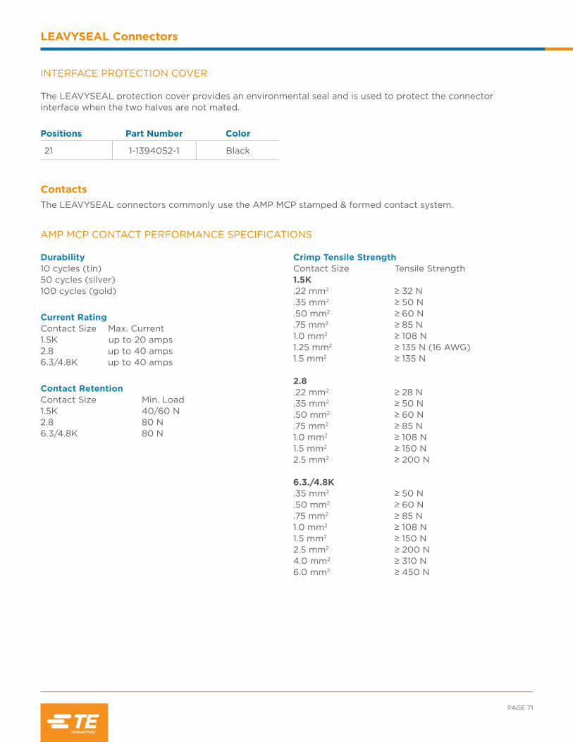
PAGE 71
LEAVYSEAL Connectors
Positions Part Number Color
21 1-1394052-1 Black
Contacts
The LEAVYSEAL connectors commonly use the AMP MCP stamped & formed contact system.
INTERFACE PROTECTION COVER The LEAVYSEAL protection cover provides an environmental seal and is used to protect the connector interface when the two halves are not mated.
AMP MCP CONTACT PERFORMANCE SPECIFICATIONS
Durability10 cycles (tin)50 cycles (silver)100 cycles (gold)
Current RatingContact Size Max. Current1.5K up to 20 amps2.8 up to 40 amps6.3/4.8K up to 40 amps
Contact RetentionContact Size Min. Load1.5K 40/60 N2.8 80 N6.3/4.8K 80 N
Crimp Tensile Strength Contact Size Tensile Strength1.5K.22 mm2 ≥ 32 N.35 mm2 ≥ 50 N.50 mm2 ≥ 60 N.75 mm2 ≥ 85 N1.0 mm2 ≥ 108 N1.25 mm2 ≥ 135 N (16 AWG)1.5 mm2 ≥ 135 N
2.8 .22 mm2 ≥ 28 N.35 mm2 ≥ 50 N.50 mm2 ≥ 60 N .75 mm2 ≥ 85 N1.0 mm2 ≥ 108 N1.5 mm2 ≥ 150 N2.5 mm2 ≥ 200 N 6.3./4.8K .35 mm2 ≥ 50 N.50 mm2 ≥ 60 N.75 mm2 ≥ 85 N1.0 mm2 ≥ 108 N1.5 mm2 ≥ 150 N 2.5 mm2 ≥ 200 N4.0 mm2 ≥ 310 N6.0 mm2 ≥ 450 N

INDUSTRIAL & COMMERCIAL TRANSPORTATION /// TERMINALS AND CONNECTORS
LEAVYSEAL Connectors
AMP MCP CONTACTS FOR LEAVYSEAL
Stamped & Formed Tabs with Single Wire Sealing System - AMP MCP
Size
Tab Part Numbers
Wire Size (mm2)
Insulation Dia. (mm)
FLR FinishStrip FormPackage Quantity Loose Piece
Package Quantity
1.5K
969028 4000 969029 500 0.2-0.5 1.2-1.6 -2/-3
964269 4000 964270 500 0.5-1.0 1.4-2.1 -2/-3/-5
1703278 4000 1703279 500 1.5 1.9-2.4 -2/-5
2.8
965982 3500 965983 500 0.2-0.5 max 2.1 1-xxx-1 1-xxx-3
962915 3500 963748 500 0.5-1.0 max 2.1
1-xxx-1 1-xxx-21-xxx-3 2-xxx-1 2-xxx-22-xxx-3
962916 3300 963749 500 1.5-2.5 max 3.0
1-xxx-1 1-xxx-21-xxx-3 2-xxx-1 2-xxx-22-xxx-3
1719504 3200 1719503 500 12 TXL max 3.2 1-xxx-1 1-xxx-2
6.3/ 4.8K
962917 1500 963742 500 0.5-1.0 1.4-2.1
1-xxx-1 1-xxx-22-xxx-12-xxx-2
962918 1500 963743 500 1.5-2.5 2.2-3.0
1-xxx-1 1-xxx-22-xxx-12-xxx-2
962919 1500 963744 500 >2.5-4.0 2.7-3.7
1-xxx-1 1-xxx-22-xxx-12-xxx-2
AMP MCP Tab Finish Codes
Finish Code Material
-2 CuFe2, pre-tin plated
-3 CuSn4, gold plated
-5 CuSn4, selective silver plated
1-xxx-1 CuSn, pre-tin plated
Finish Code Material
1-xxx-2 CuSn, selective silver plated
1-xxx-3 CuSn, selective gold plated
2-xxx-1 CuFe, pre-tin plated
2-xxx-2 CuFe, selective silver plated
2-xxx-3 CuFe, selective gold plated

PAGE 73
LEAVYSEAL Connectors
Stamped & Formed Receptacles with Single Wire Sealing System - AMP MCP
Size
Receptacle Part Numbers
Wire Size (mm2)
Insulation Diameter (mm)
FinishFLK FLRStrip FormPackage Quantity
Loose Piece
Package Quantity
1.5K
1564324 4500 1564325 500 0.22-0.35 - 1.1-1.4 -1/-2/-3
1241380 4500 1241381 500 0.5-1.0 - 1.4-2.1-1/-2/-3
1-xxx-2*
1418884 4500 1418885 500 >1.0-1.5 - 2.2-2.4 -1/-3
2.8
968882 4500 968896 500 0.35 - 1.2-1.4 1-xxx-1 1-xxx-3
968855 3500 968875 500 0.5-1.0 - 1.4-2.11-xxx-1 1-xxx-21-xxx-3
968857 4000 968876 500 >1.0-2.5 - 2.2-3.0 1-xxx-1 1-xxx-3
6.3/ 4.8K
1241410 1500 1241411 500 0.35-0.5 1.3-2.3 1.2-1.6 -1/-3
1241412 1500 1241413 500 0.5-1.0 2.0-2.7 1.4-2.1 -1/-3
1241414 1500 1241415 500 >1.0-2.5 2.7-3.7 2.2-3.0 -1/-3
1241416 1500 1241417 500 >2.5-4.0 4.1-4.5 3.4-3.7 -1/-3
1241418 1500 1241419 500 4.0-6.0 - 3.4-4.3-4
1-xxx-32-xxx-3
AMP MCP Receptacle Finish Codes
Finish Code Material
-1 CuNiSi, pre-tin plated
-2 CuNiSi, selective gold plated
-3 CuNiSi, selective silver plated
-4 CuNiSi, tin-silver pre-plated
1-xxx-1 CuNiSi, pre-tin plated
1-xxx-2 CuNiSi, selective gold plated
1-xxx-2* CuNiSi, min 1.27 µm selective gold plated
1-xxx-3 CuNiSi, selective silver plated
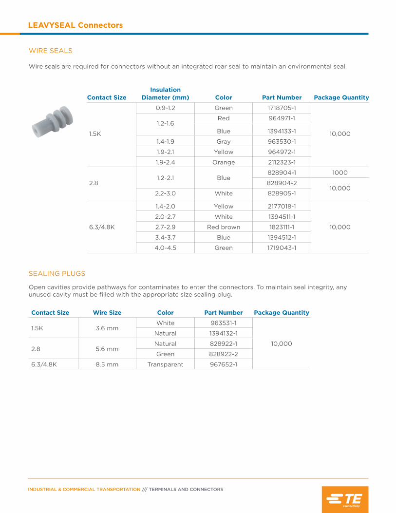
INDUSTRIAL & COMMERCIAL TRANSPORTATION /// TERMINALS AND CONNECTORS
LEAVYSEAL Connectors
WIRE SEALS
Wire seals are required for connectors without an integrated rear seal to maintain an environmental seal.
Contact SizeInsulation
Diameter (mm) Color Part Number Package Quantity
1.5K
0.9-1.2 Green 1718705-1
10,000
1.2-1.6Red 964971-1
Blue 1394133-1
1.4-1.9 Gray 963530-1
1.9-2.1 Yellow 964972-1
1.9-2.4 Orange 2112323-1
2.81.2-2.1 Blue
828904-1 1000
828904-210,000
2.2-3.0 White 828905-1
6.3/4.8K
1.4-2.0 Yellow 2177018-1
10,000
2.0-2.7 White 1394511-1
2.7-2.9 Red brown 1823111-1
3.4-3.7 Blue 1394512-1
4.0-4.5 Green 1719043-1
SEALING PLUGS
Open cavities provide pathways for contaminates to enter the connectors. To maintain seal integrity, any unused cavity must be filled with the appropriate size sealing plug.
Contact Size Wire Size Color Part Number Package Quantity
1.5K 3.6 mmWhite 963531-1
10,000
Natural 1394132-1
2.8 5.6 mmNatural 828922-1
Green 828922-2
6.3/4.8K 8.5 mm Transparent 967652-1
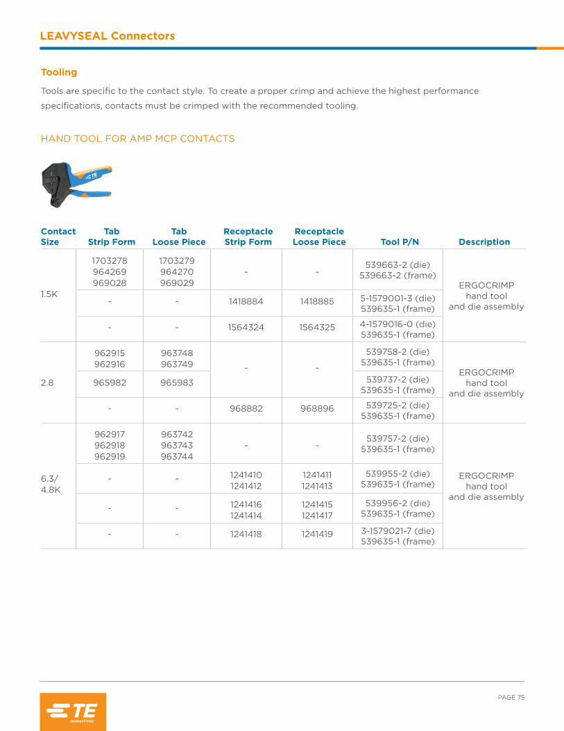
PAGE 75
LEAVYSEAL Connectors
HAND TOOL FOR AMP MCP CONTACTS
ContactSize
Tab Strip Form
Tab Loose Piece
Receptacle Strip Form
Receptacle Loose Piece Tool P/N Description
1.5K
1703278 964269969028
1703279 964270969029
- -539663-2 (die)
539663-2 (frame)ERGOCRIMP
hand tool and die assembly- - 1418884 1418885 5-1579001-3 (die)
539635-1 (frame)
- - 1564324 1564325 4-1579016-0 (die)539635-1 (frame)
2.8
962915 962916
963748963749 - -
539758-2 (die)539635-1 (frame)
ERGOCRIMP hand tool
and die assembly965982 965983 539737-2 (die)
539635-1 (frame)
- - 968882 968896 539725-2 (die)539635-1 (frame)
6.3/ 4.8K
962917962918962919
963742963743 963744
- -539757-2 (die)
539635-1 (frame)
ERGOCRIMP hand tool
and die assembly
- - 1241410 1241412
1241411 1241413
539955-2 (die)539635-1 (frame)
- - 1241416 1241414
1241415 1241417
539956-2 (die)539635-1 (frame)
- - 1241418 1241419 3-1579021-7 (die)539635-1 (frame)
Tooling
Tools are specific to the contact style. To create a proper crimp and achieve the highest performance
specifications, contacts must be crimped with the recommended tooling.
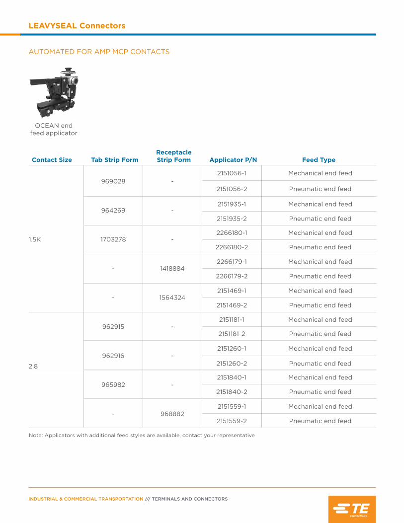
INDUSTRIAL & COMMERCIAL TRANSPORTATION /// TERMINALS AND CONNECTORS
LEAVYSEAL Connectors
AUTOMATED FOR AMP MCP CONTACTS
OCEAN end feed applicator
Contact Size Tab Strip FormReceptacle Strip Form Applicator P/N Feed Type
1.5K
969028 -2151056-1 Mechanical end feed
2151056-2 Pneumatic end feed
964269 -2151935-1 Mechanical end feed
2151935-2 Pneumatic end feed
1703278 -2266180-1 Mechanical end feed
2266180-2 Pneumatic end feed
- 14188842266179-1 Mechanical end feed
2266179-2 Pneumatic end feed
- 15643242151469-1 Mechanical end feed
2151469-2 Pneumatic end feed
2.8
962915 -2151181-1 Mechanical end feed
2151181-2 Pneumatic end feed
962916 -2151260-1 Mechanical end feed
2151260-2 Pneumatic end feed
2.8
965982 -2151840-1 Mechanical end feed
2151840-2 Pneumatic end feed
- 9688822151559-1 Mechanical end feed
2151559-2 Pneumatic end feed
Note: Applicators with additional feed styles are available, contact your representative
2.8

PAGE 77
LEAVYSEAL Connectors
AUTOMATED FOR AMP MCP CONTACTS (CONTINUED)
Contact Size Tab Strip FormReceptacle Strip Form Applicator P/N Description
6.3/4.8K
962917 -2266535-1 Mechanical end feed
2266535-2 Pneumatic end feed
962918 -2151783-1 Mechanical end feed
2151783-2 Pneumatic end feed
962919 -2151782-1 Mechanical end feed
2151782-2 Pneumatic end feed
- 12414102151695-1 Mechanical end feed
2151695-2 Pneumatic end feed
- 12414122151234-1 Mechanical end feed
2151234-2 Pneumatic end feed
- 12414162151151-1 Mechanical end feed
2151151-2 Pneumatic end feed
- 12414142266490-1 Mechanical end feed
2266490-2 Pneumatic end feed
- 12414182151466-1 Mechanical end feed
2151466-2 Pneumatic end feed
Note: Applicators with additional feed styles are available, contact your representative
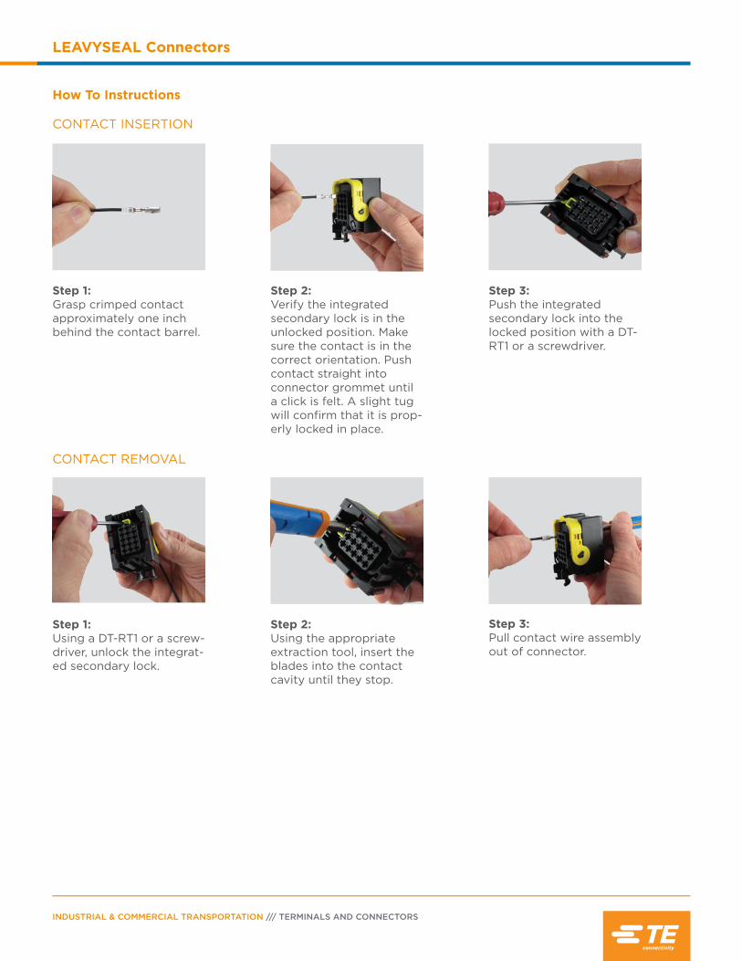
INDUSTRIAL & COMMERCIAL TRANSPORTATION /// TERMINALS AND CONNECTORS
LEAVYSEAL Connectors
CONTACT INSERTION
How To Instructions
Step 1:Grasp crimped contact approximately one inch behind the contact barrel.
Step 2:Verify the integrated secondary lock is in the unlocked position. Make sure the contact is in the correct orientation. Push contact straight into connector grommet until a click is felt. A slight tug will confirm that it is prop-erly locked in place.
Step 3:Pull contact wire assembly out of connector.
Step 3:Push the integrated secondary lock into the locked position with a DT-RT1 or a screwdriver.
Step 1:Using a DT-RT1 or a screw-driver, unlock the integrat-ed secondary lock.
CONTACT REMOVAL
Step 2:Using the appropriate extraction tool, insert the blades into the contact cavity until they stop.

Contents
Superseal 1.0 Connector Overview ...................80
Product Documentation ........................................80
Performance Specifications .................................80
Material Specifications ...........................................80
Dimensions ...................................................................81
Configurations .............................................................81
Ordering Information ...............................................82
Contacts ...................................................................... 83
Tooling .......................................................................... 84
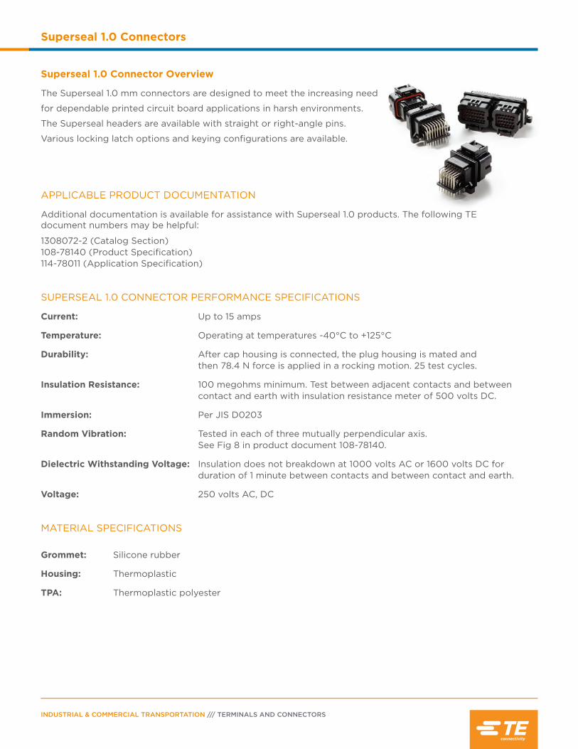
INDUSTRIAL & COMMERCIAL TRANSPORTATION /// TERMINALS AND CONNECTORS
Superseal 1.0 Connectors
Superseal 1.0 Connector Overview
The Superseal 1.0 mm connectors are designed to meet the increasing need
for dependable printed circuit board applications in harsh environments.
The Superseal headers are available with straight or right-angle pins.
Various locking latch options and keying configurations are available.
APPLICABLE PRODUCT DOCUMENTATION
Additional documentation is available for assistance with Superseal 1.0 products. The following TE document numbers may be helpful:
1308072-2 (Catalog Section) 108-78140 (Product Specification) 114-78011 (Application Specification)
SUPERSEAL 1.0 CONNECTOR PERFORMANCE SPECIFICATIONS
Current: Up to 15 amps
Temperature: Operating at temperatures -40°C to +125°C
Durability: After cap housing is connected, the plug housing is mated and then 78.4 N force is applied in a rocking motion. 25 test cycles.
Insulation Resistance: 100 megohms minimum. Test between adjacent contacts and between contact and earth with insulation resistance meter of 500 volts DC.
Immersion: Per JIS D0203
Random Vibration: Tested in each of three mutually perpendicular axis. See Fig 8 in product document 108-78140.
Dielectric Withstanding Voltage: Insulation does not breakdown at 1000 volts AC or 1600 volts DC for duration of 1 minute between contacts and between contact and earth.
Voltage: 250 volts AC, DC
MATERIAL SPECIFICATIONS
Grommet: Silicone rubber
Housing: Thermoplastic
TPA: Thermoplastic polyester
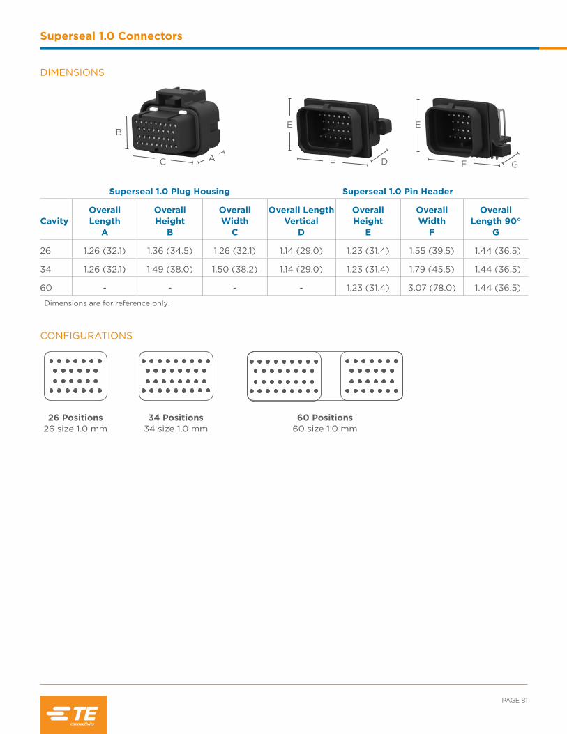
D
E
GF
E
F
PAGE 81
Superseal 1.0 Connectors
DIMENSIONS
Superseal 1.0 Plug Housing Superseal 1.0 Pin Header
CavityOverall Length
A
Overall Height
B
Overall Width
C
Overall Length Vertical
D
Overall Height
E
Overall Width
F
Overall Length 90°
G
26 1.26 (32.1) 1.36 (34.5) 1.26 (32.1) 1.14 (29.0) 1.23 (31.4) 1.55 (39.5) 1.44 (36.5)
34 1.26 (32.1) 1.49 (38.0) 1.50 (38.2) 1.14 (29.0) 1.23 (31.4) 1.79 (45.5) 1.44 (36.5)
60 - - - - 1.23 (31.4) 3.07 (78.0) 1.44 (36.5)
Dimensions are for reference only.
CONFIGURATIONS
34 Positions 34 size 1.0 mm
26 Positions 26 size 1.0 mm
60 Positions 60 size 1.0 mm
AC
B
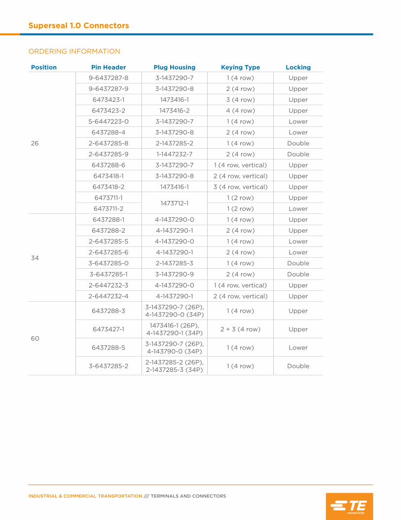
INDUSTRIAL & COMMERCIAL TRANSPORTATION /// TERMINALS AND CONNECTORS
Superseal 1.0 Connectors
ORDERING INFORMATION
Position Pin Header Plug Housing Keying Type Locking
26
9-6437287-8 3-1437290-7 1 (4 row) Upper
9-6437287-9 3-1437290-8 2 (4 row) Upper
6473423-1 1473416-1 3 (4 row) Upper
6473423-2 1473416-2 4 (4 row) Upper
5-6447223-0 3-1437290-7 1 (4 row) Lower
6437288-4 3-1437290-8 2 (4 row) Lower
2-6437285-8 2-1437285-2 1 (4 row) Double
2-6437285-9 1-1447232-7 2 (4 row) Double
6437288-6 3-1437290-7 1 (4 row, vertical) Upper
6473418-1 3-1437290-8 2 (4 row, vertical) Upper
6473418-2 1473416-1 3 (4 row, vertical) Upper
6473711-11473712-1
1 (2 row) Upper
6473711-2 1 (2 row) Lower
34
6437288-1 4-1437290-0 1 (4 row) Upper
6437288-2 4-1437290-1 2 (4 row) Upper
2-6437285-5 4-1437290-0 1 (4 row) Lower
2-6437285-6 4-1437290-1 2 (4 row) Lower
3-6437285-0 2-1437285-3 1 (4 row) Double
3-6437285-1 3-1437290-9 2 (4 row) Double
2-6447232-3 4-1437290-0 1 (4 row, vertical) Upper
2-6447232-4 4-1437290-1 2 (4 row, vertical) Upper
60
6437288-3 3-1437290-7 (26P), 4-1437290-0 (34P) 1 (4 row) Upper
6473427-1 1473416-1 (26P), 4-1437290-1 (34P) 2 + 3 (4 row) Upper
6437288-5 3-1437290-7 (26P),4-143790-0 (34P) 1 (4 row) Lower
3-6437285-2 2-1437285-2 (26P), 2-1437285-3 (34P) 1 (4 row) Double

PAGE 83
Superseal 1.0 Connectors
Stamped & Formed Receptacles - 1.0 mm
SizeReceptacle Strip Form
Wire Size (mm2)
Insulation Diameter
(mm) Finish
1.0 mm
3-1447221-4 0.5 1.6-2.2 Copper alloyGold over nickel (contact part), Tin over Nickel (crimp area)
3-1447221-3
.75-.85 1.6-2.4
1.25 1.9-2.2
SEALING PLUGS
Open cavities provide pathways for contaminates to enter the connectors. To maintain seal integrity, any unused cavity must be filled with the appropriate size sealing plug.
Contact Size Color Part Number
1.0 mm White 4-1437284-3
1.0 MM CONTACT PERFORMANCE SPECIFICATIONS
Durability25 cycles, per “Kojiri” (rocking motion) durability test
Current RatingUp to 15 amps, consult TE product specification 108-78140
Contact Retention (between contact and housing) 1.0mm ≥ 58.8N
Crimp Tensile Strength Contact Size Tensile Strength.5mm2 ≥ 88.2N.85 mm2 ≥ 127.4N1.25 mm2 ≥ 176.4N
1.0 MM STAMPED & FORMED CONTACTS FOR SUPERSEAL 1.0
Contacts
The Superseal 1.0 mm connectors commonly use the AMP Superseal double spring, stamped & formed contact
system.

INDUSTRIAL & COMMERCIAL TRANSPORTATION /// TERMINALS AND CONNECTORS
Superseal 1.0 Connectors
HAND TOOLS FOR 1.0 MM CONTACTS
Receptacle P/N Tool P/N Description
3-1447221-33-1447221-4
1454509-1 CERTI-CRIMP straight actionhand tool with fixed dies
AUTOMATED TOOLING FOR 1.0 MM CONTACTS
Receptacle P/N Applicator P/N Description
3-1447221-33-1447221-4
2151705-1 OCEAN end feed applicator with mechanical feed
2151705-2 OCEAN end feed applicator with pneumatic feed
Note: Applicators with additional feed styles are available, contact your representative
Tooling
Tools are specific to the contact style. To create a proper crimp and achieve the highest performance
specifications, contacts must be crimped with the recommended tooling.

Contents
AEC Series Overview .............................................. 86
Performance Specifications ................................. 86
Material Specifications ........................................... 86
Dimensions ..................................................................87
Configurations ............................................................87
Ordering Information .............................................. 88
Accessories ................................................................. 89
How To Instructions ......................................... 89-90

INDUSTRIAL & COMMERCIAL TRANSPORTATION /// TERMINALS AND CONNECTORS
AEC Series
AEC Series Overview
DEUTSCH AEC series connectors are environmentally sealed,
heavy duty electrical connectors that accept size 16 contacts. The
AEC series connectors are constructed of rugged thermoplastic
and offer several keying options.
Grommet: Silicone rubber
Jackscrew: Stainless steel
Plug Threaded Inserts:
Stainless steel
Receptacle Threaded Inserts:
Stainless steel/brass
Shell: Glass filled PEI
MATERIAL SPECIFICATIONS
DEUTSCH CONNECTOR PERFORMANCE SPECIFICATIONS
Temperature: Operating at temperatures -55°C to +125°C
Durability: No electrical or mechanical defects after 100 cycles of engagement and disengagement.
Vibration: No unlocking or unmating and exhibits no mechanical or physical damage after sinusoidal vibration levels of 20 G’s at 10 to 2000 Hz in each of the three mutually perpendicular planes. No electrical discontinuities longer than 1 microsecond.
Fluid Resistance: Connectors show no damage when exposed to most fluids used in industrial applications.
Insulation Resistance: 1000 megohms minimum at 25°C.
Immersion: IP68 rating
Moisture Resistance: Properly wired and mated connections will withstand immersion under three feet of water without loss of electronic qualities or leakage.
Dielectric Withstanding Voltage: Current leakage less than 2 milliamps at 1500 volts AC.
Thermal Cycle: No cracking, chipping or leaking after 20 test cycles from -55°C to +125°C.
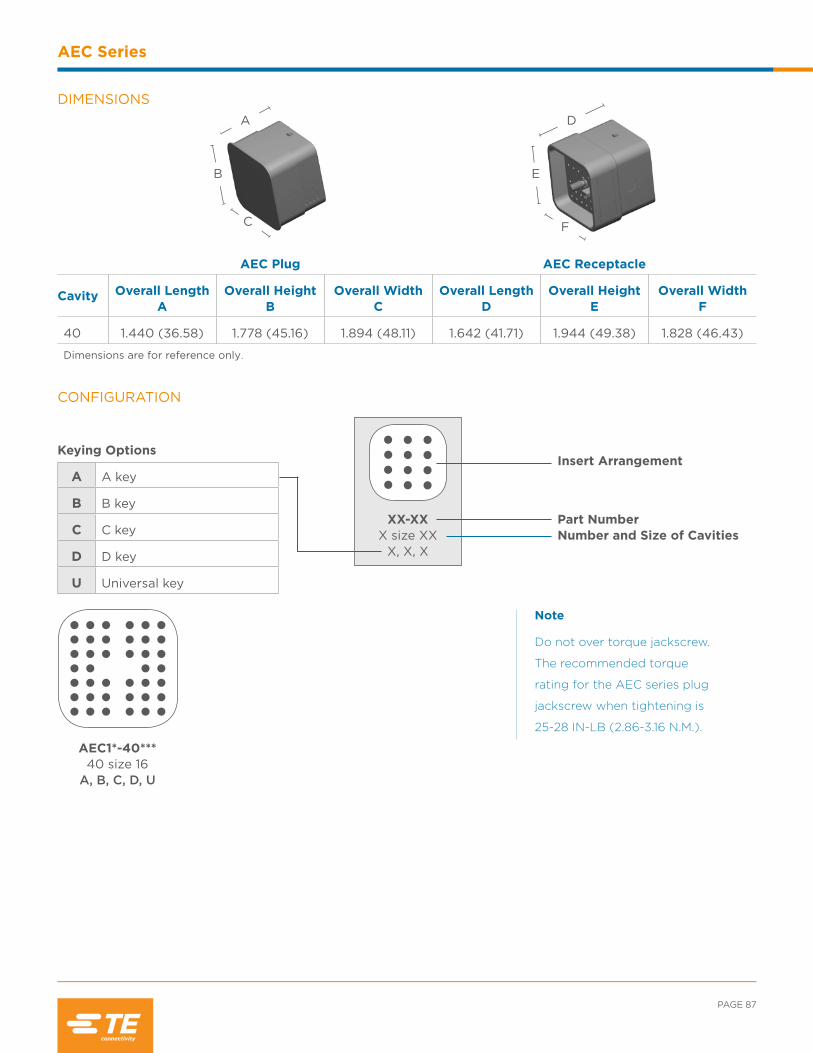
PAGE 87
AEC Series
DIMENSIONS
AEC Plug AEC Receptacle
Cavity Overall Length A
Overall Height B
Overall Width C
Overall Length D
Overall Height E
Overall Width F
40 1.440 (36.58) 1.778 (45.16) 1.894 (48.11) 1.642 (41.71) 1.944 (49.38) 1.828 (46.43)
Dimensions are for reference only.
D
E
F
A
B
C
CONFIGURATION
Keying Options
A A key
B B key
C C key
D D key
U Universal key
AEC1*-40*** 40 size 16
A, B, C, D, U
XX-XXX size XX
X, X, X
Insert Arrangement
Number and Size of CavitiesPart Number
Note
Do not over torque jackscrew.
The recommended torque
rating for the AEC series plug
jackscrew when tightening is
25-28 IN-LB (2.86-3.16 N.M.).
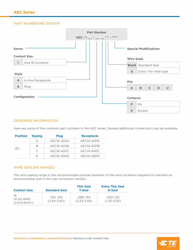
INDUSTRIAL & COMMERCIAL TRANSPORTATION /// TERMINALS AND CONNECTORS
AEC Series
PART NUMBERING SYSTEM
Part Number
AEC - 1 __ - __ __ * * - ****
Series Contact Size
1 Size 16 Contacts
Style
4 In-line Receptacle
6 Plug
Configuration
Special Modifications
Wire Seals
Blank Standard Seal
E Extra Thin Wall Seal
Key
A B C D U
Contacts
P Pin
S Socket
ORDERING INFORMATION Here are some of the common part numbers in the AEC series. Several additional connectors may be available.
Position Keying Plug Receptacle
40
A AEC16-40SA AEC14-40PA
B AEC16-40SB AEC14-40PB
C AEC16-40SC AEC14-40PC
D AEC16-40SD AEC14-40PD
WIRE SEALING RANGES The wire sealing range is the recommended outside diameter of the wire insulation required to maintain an environmental seal in the rear connector cavities.
Contact Size Standard SealThin Seal
T-SealExtra Thin Seal
E-Seal
1614-20 AWG (2.0-0.5mm2)
.100-.134(2.54-3.40)
.088-.134(2.23-3.40)
.053-.120(1.35-3.05)

PAGE 89
AEC Series
Dust Cap Description Part Number
Dust cap, 40 way receptacle, environmentally sealed 0504-002-4001
Dust cap, 40 way receptacle, non-environmentally sealed
0515-009-4005
Dust cap, 40 way plug, non-environmentally sealed 0515-010-4005
Boot Description Part Number
Boot, 40 way plug or receptacle, black, step-down AEC40-BT-STPDWN
*Distorting the boots can lessen their longevity
Accessories
Dust caps and boots are available for use with AEC series connectors. The dust caps are designed to help
provide protection to the connector interface when the connector halves are not mated. The boots are
aesthetically appealing and provide increased protection from dirt, paint overspray, and pressure washing.
How To Instructions
CONTACT INSERTION
Step 1:Grasp crimped contact approximately one inch behind the contact barrel.
Step 2:Hold connector with rear grommet facing you.
Step 3:Push contact straight into connector grommet until a click is felt. A slight tug will confirm that it is prop-erly locked in place.
LA
D
D D istrib
utio
n
Exclusive to

INDUSTRIAL & COMMERCIAL TRANSPORTATION /// TERMINALS AND CONNECTORS
AEC Series
CONTACT REMOVAL
Step 1:With rear insert toward you, snap appropriate size removal tool over the wire of contact to be removed. .
Step 2:Slide tool along the wire into the insert cavity until it engages contact and resistance is felt.
Step 3:Pull contact wire assembly out of connector.

Contents
DRB Series Overview ...............................................92
Performance Specifications ..................................92
Material Specifications ............................................92
Dimensions ................................................................. 93
Configurations ........................................................... 93
Ordering Information .............................................. 94
Required Components .................................... 95-96
Accessories ..................................................................97
How To Instructions ..........................................97-98

INDUSTRIAL & COMMERCIAL TRANSPORTATION /// TERMINALS AND CONNECTORS
DRB Series
DRB Series Overview
DEUTSCH DRB series connectors are heavy duty connectors suitable for
bulkhead applications. They are designed to accommodate multiple
wire gauges and feature high pin counts, including 48, 60, 102, and 128
cavities. To increase the design flexibility, the DRB series offers several
mounting flange options and wire arrangements. The DRB series is suited
for on- and off-highway applications, marine, industrial, and agriculture
markets in harsh environments.
Flange Body: Glass filled PA
Flange Clip: Spring steel
Grommet: Silicone rubber
Jackscrew: Stainless steel
Shell: Glass filled PA
Wedgelocks: Glass filled PBT
MATERIAL SPECIFICATIONS
DEUTSCH CONNECTOR PERFORMANCE SPECIFICATIONS
Temperature: Operating at temperatures -55°C to +125°C
Durability: No electrical or mechanical defects after 100 cycles of engagement and disengagement.
Vibration: No unlocking or unmating and exhibits no mechanical or physical damage after sinusoidal vibration levels of 20 G’s at 10 to 2000 Hz in each of the three mutually perpendicular planes. No electrical discontinuities longer than 1 microsecond.
Fluid Resistance: Connectors show no damage when exposed to most fluids used in industrial applications.
Insulation Resistance: 1000 megohms minimum at 25°C.
Immersion: IP68 rating
Moisture Resistance: Properly wired and mated connections will withstand immersion under three feet of water without loss of electronic qualities or leakage.
Dielectric Withstanding Voltage: Current leakage less than 2 milliamps at 1500 volts AC.
Thermal Cycle: No cracking, chipping or leaking after 20 test cycles from -55°C to +125°C.
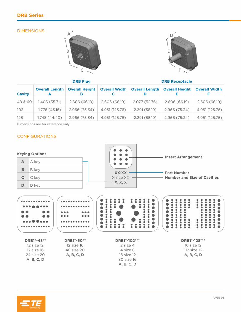
PAGE 93
DRB Series
DIMENSIONS
DRB Plug DRB Receptacle
CavityOverall Length
AOverall Height
BOverall Width
COverall Length
DOverall Height
EOverall Width
F
48 & 60 1.406 (35.71) 2.606 (66.19) 2.606 (66.19) 2.077 (52.76) 2.606 (66.19) 2.606 (66.19)
102 1.778 (45.16) 2.966 (75.34) 4.951 (125.76) 2.291 (58.19) 2.966 (75.34) 4.951 (125.76)
128 1.748 (44.40) 2.966 (75.34) 4.951 (125.76) 2.291 (58.19) 2.966 (75.34) 4.951 (125.76)
Dimensions are for reference only.
D
F
E
A
B
C
CONFIGURATIONS
Keying Options
A A key
B B key
C C key
D D key
XX-XXX size XX
X, X, X
Insert Arrangement
Number and Size of CavitiesPart Number
DRB1*-48** 12 size 12 12 size 16 24 size 20 A, B, C, D
DRB1*-60** 12 size 16
48 size 20 A, B, C, D
DRB1*-102*** 2 size 4 4 size 8
16 size 12 80 size 16 A, B, C, D
DRB1*-128*** 16 size 12 112 size 16 A, B, C, D
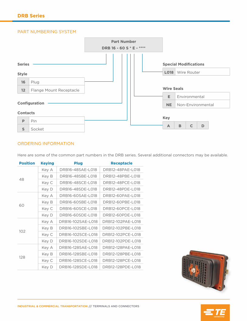
INDUSTRIAL & COMMERCIAL TRANSPORTATION /// TERMINALS AND CONNECTORS
DRB Series
PART NUMBERING SYSTEM
Part Number
DRB 16 - 60 S * E - ****
Series Style
16 Plug
12 Flange Mount Receptacle
Configuration Contacts
P Pin
S Socket
Special Modifications
L018 Wire Router
Wire Seals
E Environmental
NE Non-Environmental
Key
A B C D
ORDERING INFORMATION
Here are some of the common part numbers in the DRB series. Several additional connectors may be available.
Position Keying Plug Receptacle
48
Key A DRB16-48SAE-L018 DRB12-48PAE-L018
Key B DRB16-48SBE-L018 DRB12-48PBE-L018
Key C DRB16-48SCE-L018 DRB12-48PCE-L018
Key D DRB16-48SDE-L018 DRB12-48PDE-L018
60
Key A DRB16-60SAE-L018 DRB12-60PAE-L018
Key B DRB16-60SBE-L018 DRB12-60PBE-L018
Key C DRB16-60SCE-L018 DRB12-60PCE-L018
Key D DRB16-60SDE-L018 DRB12-60PDE-L018
102
Key A DRB16-102SAE-L018 DRB12-102PAE-L018
Key B DRB16-102SBE-L018 DRB12-102PBE-L018
Key C DRB16-102SCE-L018 DRB12-102PCE-L018
Key D DRB16-102SDE-L018 DRB12-102PDE-L018
128
Key A DRB16-128SAE-L018 DRB12-128PAE-L018
Key B DRB16-128SBE-L018 DRB12-128PBE-L018
Key C DRB16-128SCE-L018 DRB12-128PCE-L018
Key D DRB16-128SDE-L018 DRB12-128PDE-L018

PAGE 95
DRB Series
WIRE SEALING RANGE The wire sealing range is the recommended outside diameter of the wire insulation required to maintain an environmental seal in the rear connector cavities.
Contact Size Standard SealExtra Thin Seal
E-Seal
2016-22 AWG (1.0-0.35mm2)
.040-.095(1.02-2.41)
.040-.095(1.02-2.41)
1614-20 AWG (2.0-0.5mm2)
.100-.134(2.54-3.40)
.053-.120(1.35-3.05)
1210-14 AWG (5.0-2.0mm2)
.134-.170(3.40-4.32)
.097-.158(2.46-4.01)
88-10 AWG (8.0-5.0mm2)
.190-.240(4.83-6.10)
.135-.220(3.43-5.59)
46 AWG (13.0mm2)
.280-.292(7.11-7.42)
.261-.292(6.63-7.42)
A complete DRB assembly requires a wedgelock for each plug and receptacle and a mounting flange. There are
several flange options to accommodate design requirements. The wedgelocks are required to confirm proper
contact placement.
Plug PlugWedgelock(s) Flange Receptacle
Wedgelock(s) Receptacle
Required Components
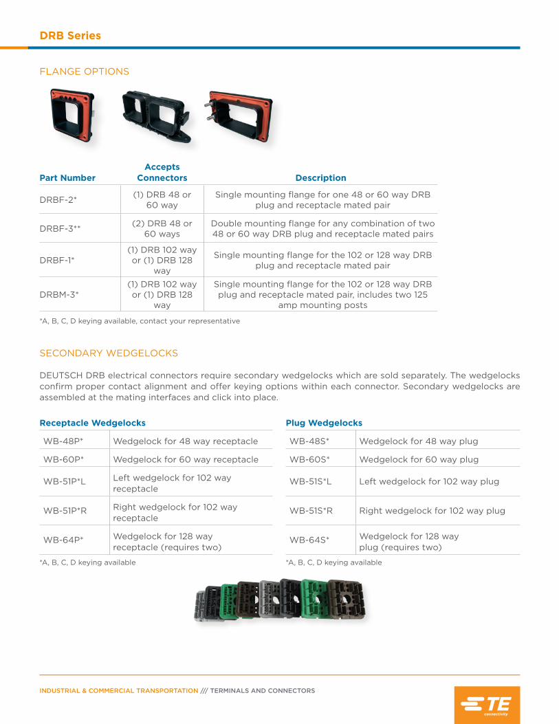
INDUSTRIAL & COMMERCIAL TRANSPORTATION /// TERMINALS AND CONNECTORS
DRB Series
FLANGE OPTIONS
Part NumberAccepts
Connectors Description
DRBF-2* (1) DRB 48 or 60 way
Single mounting flange for one 48 or 60 way DRB plug and receptacle mated pair
DRBF-3** (2) DRB 48 or 60 ways
Double mounting flange for any combination of two 48 or 60 way DRB plug and receptacle mated pairs
DRBF-1*(1) DRB 102 way or (1) DRB 128
way
Single mounting flange for the 102 or 128 way DRB plug and receptacle mated pair
DRBM-3*(1) DRB 102 wayor (1) DRB 128
way
Single mounting flange for the 102 or 128 way DRB plug and receptacle mated pair, includes two 125
amp mounting posts
*A, B, C, D keying available, contact your representative
SECONDARY WEDGELOCKS
DEUTSCH DRB electrical connectors require secondary wedgelocks which are sold separately. The wedgelocks confirm proper contact alignment and offer keying options within each connector. Secondary wedgelocks are assembled at the mating interfaces and click into place.
Receptacle Wedgelocks
WB-48P* Wedgelock for 48 way receptacle
WB-60P* Wedgelock for 60 way receptacle
WB-51P*L Left wedgelock for 102 way receptacle
WB-51P*R Right wedgelock for 102 way receptacle
WB-64P* Wedgelock for 128 way receptacle (requires two)
*A, B, C, D keying available
Plug Wedgelocks
WB-48S* Wedgelock for 48 way plug
WB-60S* Wedgelock for 60 way plug
WB-51S*L Left wedgelock for 102 way plug
WB-51S*R Right wedgelock for 102 way plug
WB-64S* Wedgelock for 128 way plug (requires two)
*A, B, C, D keying available

PAGE 97
DRB Series
Part Number Description
DRB48-60-BT 48 way plug or receptacle boot, black
DRB48-60-BT 60 way plug or receptacle boot, black
DRB102-BT 102/128 way plug or receptacle boot, black
DRB102-BT-90DEG
102/128 way plug or receptacle boot, 90° bend, black
*Distorting the boots can lessen their longevity
Accessories
BOOTS
Boots provide a professional looking finishing touch for DEUTSCH DRB series connectors. Made of durable plastisol, these slip-on boots are not only aesthetically appealing, but also provide increased protection from dirt, paint overspray, and pressure washing. The plastisol boots are rated from -20°F to +212°F (-28°C to +100°C) and offer a slip-on design making installation quick and easy.
How To Instructions
CONTACT INSERTION
Step 1:Hold connector with rear grommet/wire rout-er cap facing you.
Step 2:Push contact straight into contact cavity until a click is heard/felt. A slight tug will confirm the contact is inserted correctly.
Step 3:Once all contacts are in place, insert wedge-lock by lining up the keyway. The wedgelock will press into place.
LA
D
D D istrib
utio
n
Exclusive to

INDUSTRIAL & COMMERCIAL TRANSPORTATION /// TERMINALS AND CONNECTORS
DRB Series
ASSEMBLY
Improper assembly can cause the jackscrew to be stripped during assembly. To prevent damage, the jackscrew will strip out be-fore the threads in the connector are damaged. If the jackscrew becomes stripped, please replace the jackscrew and the push nut.
Step 1:Wedgelocks should be pressed firmly in place, with only a slight gap showing between the wedgelock and connector.
Step 2:If the wedgelock will not go all the way in, check to make sure all of the con-tacts are properly seated.
Step 3:Contacts should be fully inserted into the con-nector, with the locking fingers in place under the shoulder of the con-tact. If a contact is not fully inserted, the reten-tion finger will prevent the wedgelock from pressing into place.
Step 4:When mating the plug with the receptacle, confirm that the plug is not being pulled into the receptacle at an angle by the jackscrew.
Note
Do not over torque jackscrew.
The recommended torque
rating for the DRB series plug
jackscrew when tightening is
30-35 IN-LB (3.38-3.95 N.M.).
CONTACT REMOVAL
Step 1:Remove wedgelock using a screwdriver. Pull wed-gelock straight out.
Step 2:To remove contacts, gently pull wire backwards, while at the same time releas-ing the locking finger by moving it away from the contact with a screwdriver.

Contents
DRC Series Overview ............................................ 100
Performance Specifications ............................... 100
Material Specifications ......................................... 100
Dimensions .................................................................101
Configurations ..........................................................102
Ordering Information .................................... 103-104
Accessories ....................................................... 106-107
How To Instructions ...............................................108

INDUSTRIAL & COMMERCIAL TRANSPORTATION /// TERMINALS AND CONNECTORS
DRC Series
DRC Series Overview
The environmentally sealed DEUTSCH DRC series is a rectangular
connector series that offers insert arrangements of 24, 40, 50, 60, 64, 70,
and 76 cavities and accepts size 12, 16, and 20 contacts. Several mounting
options are available including in-line, flange mount, and PCB mount.
Grommet: Silicone rubber
Insert Retainer: Unfilled PEI
Jackscrew: Stainless steel
Receptacle Threaded Inserts:
Stainless steel/Brass
Shell: Glass filled PA, Glass filled PPS
MATERIAL SPECIFICATIONS
DEUTSCH CONNECTOR PERFORMANCE SPECIFICATIONS
Temperature: Operating at temperatures -55°C to +125°C
Durability: No electrical or mechanical defects after 100 cycles of engagement and disengagement.
Vibration: No unlocking or unmating and exhibits no mechanical or physical damage after sinusoidal vibration levels of 20 G’s at 10 to 2000 Hz in each of the three mutually perpendicular planes. No electrical discontinuities longer than 1 microsecond.
Fluid Resistance: Connectors show no damage when exposed to most fluids used in industrial applications.
Insulation Resistance: 1000 megohms minimum at 25°C.
Immersion: IP68 rating
Moisture Resistance: Properly wired and mated connections will withstand immersion under three feet of water without loss of electronic qualities or leakage.
Dielectric Withstanding Voltage: Current leakage less than 2 milliamps at 1500 volts AC.
Thermal Cycle: No cracking, chipping or leaking after 20 test cycles from -55°C to +125°C.
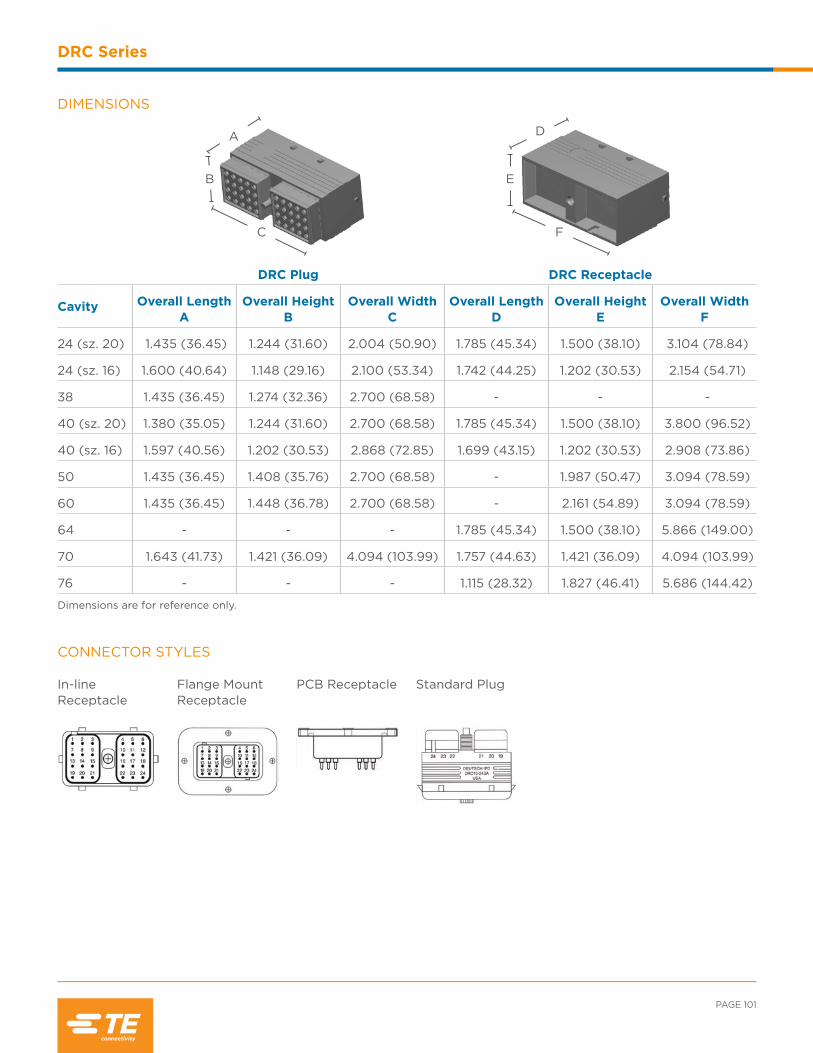
PAGE 101
DRC Series
CONNECTOR STYLES
In-line Receptacle
Flange Mount Receptacle
PCB Receptacle Standard Plug
DIMENSIONS
DRC Plug DRC Receptacle
Cavity Overall Length A
Overall Height B
Overall Width C
Overall Length D
Overall Height E
Overall Width F
24 (sz. 20) 1.435 (36.45) 1.244 (31.60) 2.004 (50.90) 1.785 (45.34) 1.500 (38.10) 3.104 (78.84)
24 (sz. 16) 1.600 (40.64) 1.148 (29.16) 2.100 (53.34) 1.742 (44.25) 1.202 (30.53) 2.154 (54.71)
38 1.435 (36.45) 1.274 (32.36) 2.700 (68.58) - - -
40 (sz. 20) 1.380 (35.05) 1.244 (31.60) 2.700 (68.58) 1.785 (45.34) 1.500 (38.10) 3.800 (96.52)
40 (sz. 16) 1.597 (40.56) 1.202 (30.53) 2.868 (72.85) 1.699 (43.15) 1.202 (30.53) 2.908 (73.86)
50 1.435 (36.45) 1.408 (35.76) 2.700 (68.58) - 1.987 (50.47) 3.094 (78.59)
60 1.435 (36.45) 1.448 (36.78) 2.700 (68.58) - 2.161 (54.89) 3.094 (78.59)
64 - - - 1.785 (45.34) 1.500 (38.10) 5.866 (149.00)
70 1.643 (41.73) 1.421 (36.09) 4.094 (103.99) 1.757 (44.63) 1.421 (36.09) 4.094 (103.99)
76 - - - 1.115 (28.32) 1.827 (46.41) 5.686 (144.42)
Dimensions are for reference only.
C
A
B
F
D
E
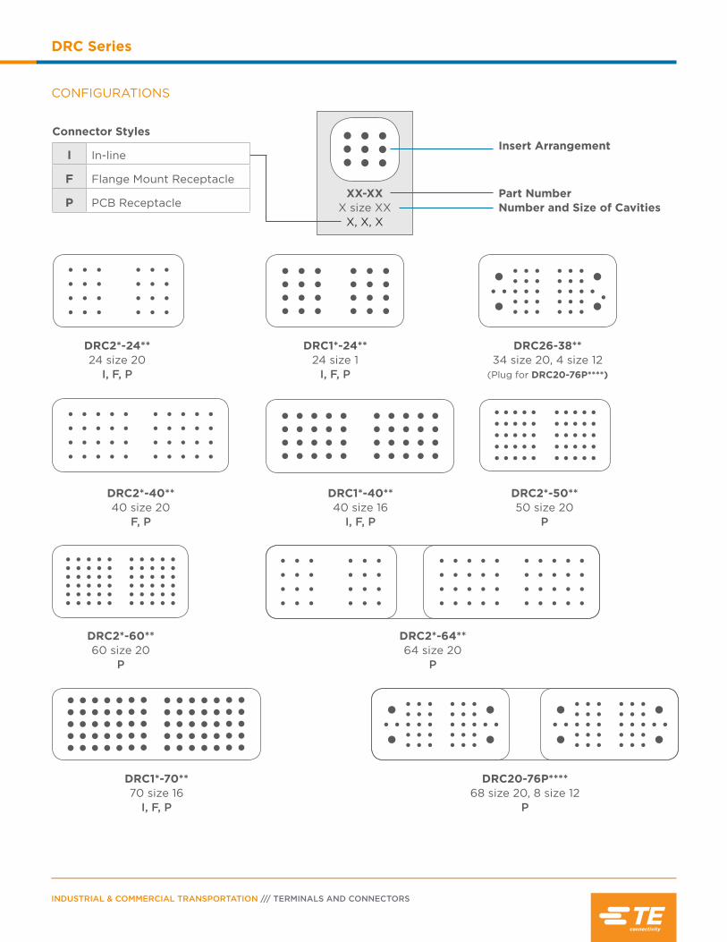
INDUSTRIAL & COMMERCIAL TRANSPORTATION /// TERMINALS AND CONNECTORS
DRC Series
CONFIGURATIONS
Connector Styles
I In-line
F Flange Mount Receptacle
P PCB ReceptacleXX-XX
X size XXX, X, X
Insert Arrangement
Number and Size of CavitiesPart Number
DRC1*-40** 40 size 16
I, F, P
DRC2*-50** 50 size 20
P
DRC2*-60** 60 size 20
P
DRC1*-70** 70 size 16
I, F, P
DRC2*-40** 40 size 20
F, P
DRC1*-24** 24 size 1
I, F, P
DRC26-38** 34 size 20, 4 size 12
(Plug for DRC20-76P****)
DRC2*-24** 24 size 20
I, F, P
DRC2*-64** 64 size 20
P
DRC20-76P**** 68 size 20, 8 size 12
P
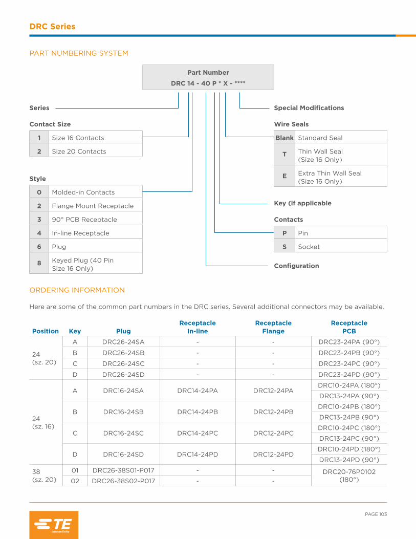
PAGE 103
DRC Series
PART NUMBERING SYSTEM
Part Number
DRC 14 - 40 P * X - ****
Series Contact Size
1 Size 16 Contacts
2 Size 20 Contacts
Style
0 Molded-in Contacts
2 Flange Mount Receptacle
3 90° PCB Receptacle
4 In-line Receptacle
6 Plug
8 Keyed Plug (40 Pin Size 16 Only)
Special Modifications Wire Seals
Blank Standard Seal
T Thin Wall Seal (Size 16 Only)
E Extra Thin Wall Seal (Size 16 Only)
Key (if applicable Contacts
P Pin
S Socket
Configuration
ORDERING INFORMATION Here are some of the common part numbers in the DRC series. Several additional connectors may be available.
Position Key PlugReceptacle
In-lineReceptacle
FlangeReceptacle
PCB
24(sz. 20)
A DRC26-24SA - - DRC23-24PA (90°)
B DRC26-24SB - - DRC23-24PB (90°)
C DRC26-24SC - - DRC23-24PC (90°)
D DRC26-24SD - - DRC23-24PD (90°)
24 (sz. 16)
A DRC16-24SA DRC14-24PA DRC12-24PADRC10-24PA (180°)
DRC13-24PA (90°)
B DRC16-24SB DRC14-24PB DRC12-24PBDRC10-24PB (180°)
DRC13-24PB (90°)
C DRC16-24SC DRC14-24PC DRC12-24PCDRC10-24PC (180°)
DRC13-24PC (90°)
D DRC16-24SD DRC14-24PD DRC12-24PDDRC10-24PD (180°)
DRC13-24PD (90°)
38(sz. 20)
01 DRC26-38S01-P017 - - DRC20-76P0102 (180°)02 DRC26-38S02-P017 - -
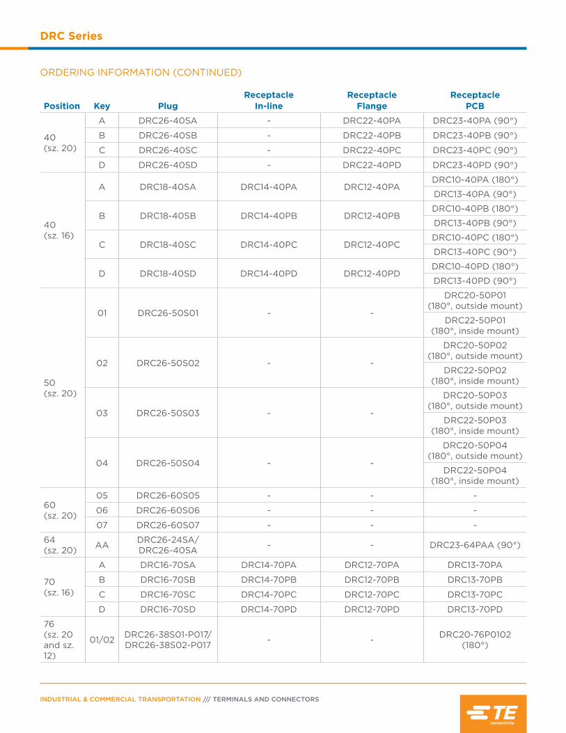
INDUSTRIAL & COMMERCIAL TRANSPORTATION /// TERMINALS AND CONNECTORS
DRC Series
ORDERING INFORMATION (CONTINUED)
Position Key PlugReceptacle
In-lineReceptacle
FlangeReceptacle
PCB
40(sz. 20)
A DRC26-40SA - DRC22-40PA DRC23-40PA (90°)
B DRC26-40SB - DRC22-40PB DRC23-40PB (90°)
C DRC26-40SC - DRC22-40PC DRC23-40PC (90°)
D DRC26-40SD - DRC22-40PD DRC23-40PD (90°)
40(sz. 16)
A DRC18-40SA DRC14-40PA DRC12-40PADRC10-40PA (180°)
DRC13-40PA (90°)
B DRC18-40SB DRC14-40PB DRC12-40PBDRC10-40PB (180°)
DRC13-40PB (90°)
C DRC18-40SC DRC14-40PC DRC12-40PCDRC10-40PC (180°)
DRC13-40PC (90°)
D DRC18-40SD DRC14-40PD DRC12-40PDDRC10-40PD (180°)
DRC13-40PD (90°)
50 (sz. 20)
01 DRC26-50S01 - -
DRC20-50P01 (180°, outside mount)
DRC22-50P01 (180°, inside mount)
02 DRC26-50S02 - -
DRC20-50P02 (180°, outside mount)
DRC22-50P02 (180°, inside mount)
03 DRC26-50S03 - -
DRC20-50P03 (180°, outside mount)
DRC22-50P03 (180°, inside mount)
04 DRC26-50S04 - -
DRC20-50P04 (180°, outside mount)
DRC22-50P04 (180°, inside mount)
60(sz. 20)
05 DRC26-60S05 - - -
06 DRC26-60S06 - - -
07 DRC26-60S07 - - -
64(sz. 20) AA DRC26-24SA/
DRC26-40SA - - DRC23-64PAA (90°)
70(sz. 16)
A DRC16-70SA DRC14-70PA DRC12-70PA DRC13-70PA
B DRC16-70SB DRC14-70PB DRC12-70PB DRC13-70PB
C DRC16-70SC DRC14-70PC DRC12-70PC DRC13-70PC
D DRC16-70SD DRC14-70PD DRC12-70PD DRC13-70PD
76(sz. 20 and sz. 12)
01/02 DRC26-38S01-P017/ DRC26-38S02-P017 - - DRC20-76P0102
(180°)
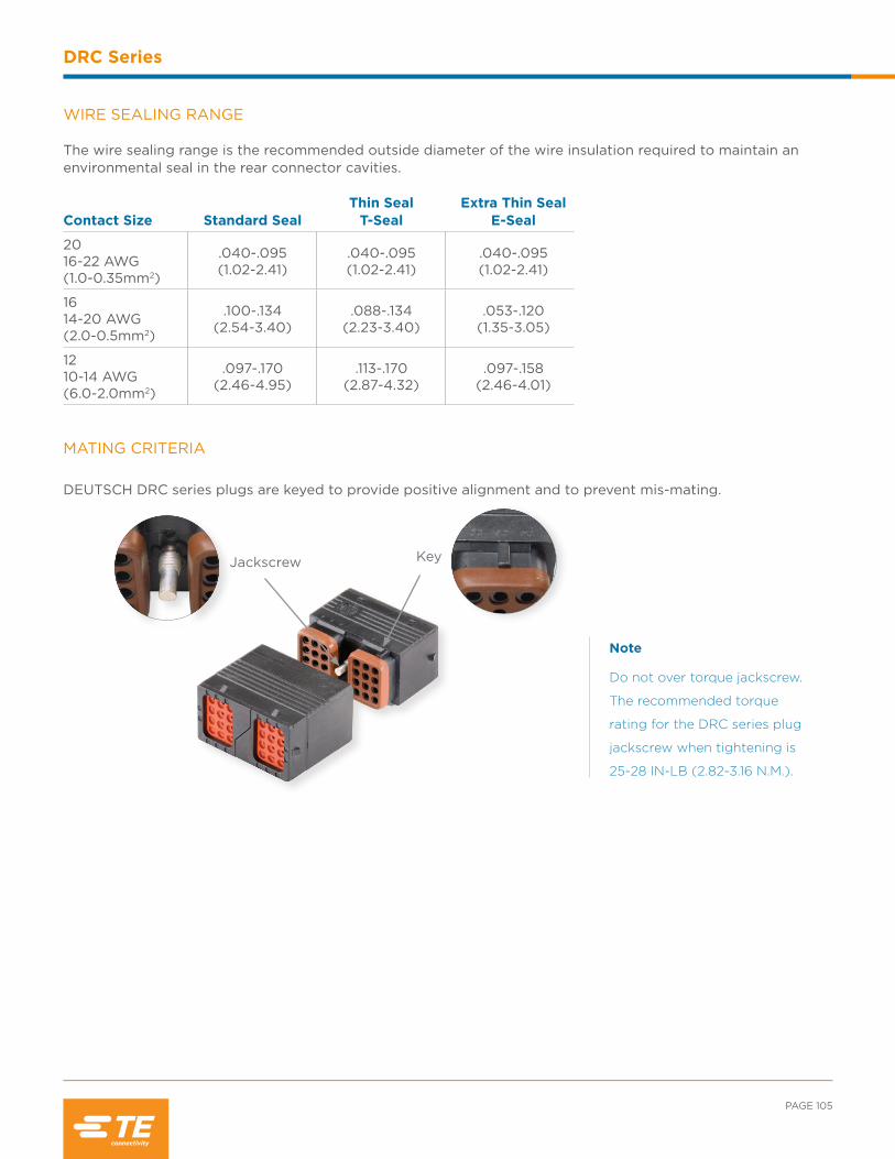
PAGE 105
DRC Series
MATING CRITERIA
DEUTSCH DRC series plugs are keyed to provide positive alignment and to prevent mis-mating.
Jackscrew Key
Note
Do not over torque jackscrew.
The recommended torque
rating for the DRC series plug
jackscrew when tightening is
25-28 IN-LB (2.82-3.16 N.M.).
WIRE SEALING RANGE The wire sealing range is the recommended outside diameter of the wire insulation required to maintain an environmental seal in the rear connector cavities.
Contact Size Standard SealThin Seal
T-SealExtra Thin Seal
E-Seal
2016-22 AWG (1.0-0.35mm2)
.040-.095(1.02-2.41)
.040-.095(1.02-2.41)
.040-.095(1.02-2.41)
1614-20 AWG (2.0-0.5mm2)
.100-.134(2.54-3.40)
.088-.134(2.23-3.40)
.053-.120(1.35-3.05)
1210-14 AWG (6.0-2.0mm2)
.097-.170(2.46-4.95)
.113-.170(2.87-4.32)
.097-.158(2.46-4.01)
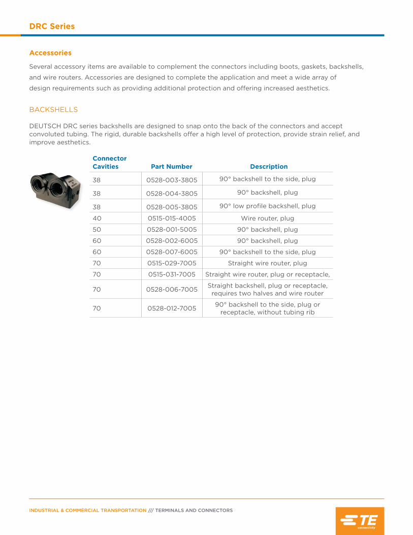
INDUSTRIAL & COMMERCIAL TRANSPORTATION /// TERMINALS AND CONNECTORS
DRC Series
BACKSHELLS DEUTSCH DRC series backshells are designed to snap onto the back of the connectors and accept convoluted tubing. The rigid, durable backshells offer a high level of protection, provide strain relief, and improve aesthetics.
Connector Cavities Part Number Description
38 0528-003-3805 90° backshell to the side, plug
38 0528-004-3805 90° backshell, plug
38 0528-005-3805 90° low profile backshell, plug
40 0515-015-4005 Wire router, plug
50 0528-001-5005 90° backshell, plug
60 0528-002-6005 90° backshell, plug
60 0528-007-6005 90° backshell to the side, plug
70 0515-029-7005 Straight wire router, plug
70 0515-031-7005 Straight wire router, plug or receptacle,
70 0528-006-7005 Straight backshell, plug or receptacle, requires two halves and wire router
70 0528-012-7005 90° backshell to the side, plug or receptacle, without tubing rib
Accessories
Several accessory items are available to complement the connectors including boots, gaskets, backshells,
and wire routers. Accessories are designed to complete the application and meet a wide array of
design requirements such as providing additional protection and offering increased aesthetics.
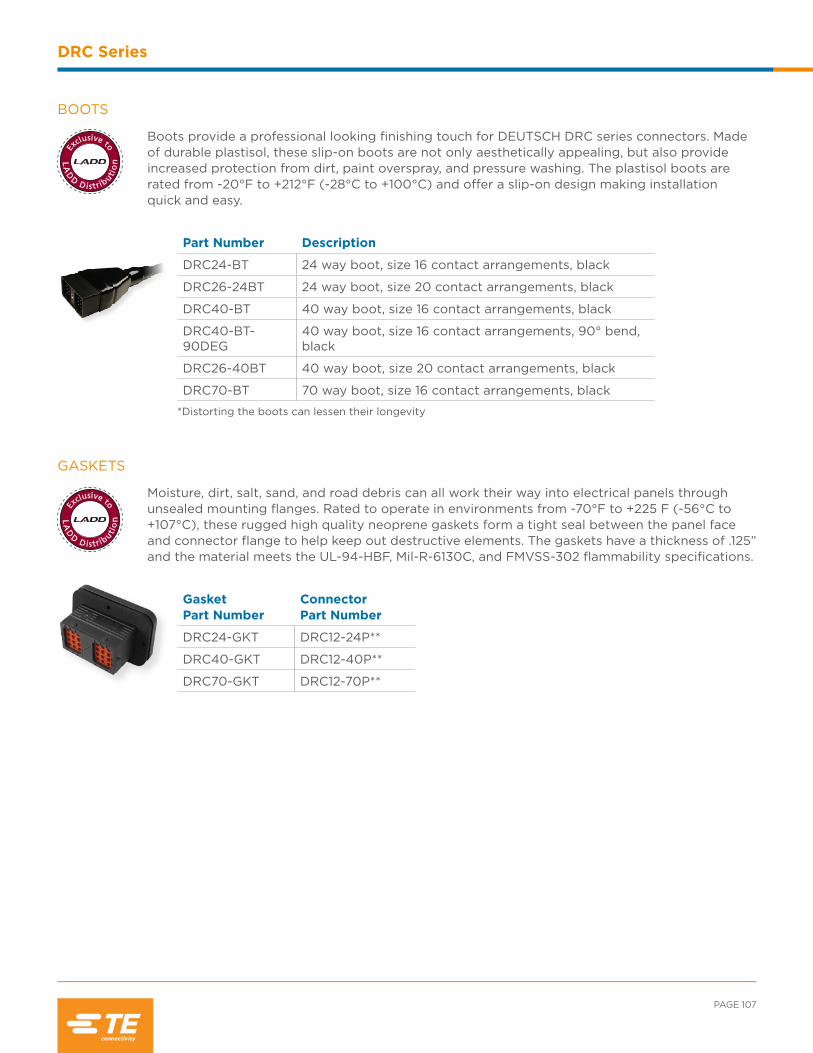
LA
D
D D istrib
utio
n
Exclusive to
LA
D
D D istrib
utio
n
Exclusive to
PAGE 107
DRC Series
GASKETS
Moisture, dirt, salt, sand, and road debris can all work their way into electrical panels through unsealed mounting flanges. Rated to operate in environments from -70°F to +225 F (-56°C to +107°C), these rugged high quality neoprene gaskets form a tight seal between the panel face and connector flange to help keep out destructive elements. The gaskets have a thickness of .125” and the material meets the UL-94-HBF, Mil-R-6130C, and FMVSS-302 flammability specifications.
Gasket Part Number
Connector Part Number
DRC24-GKT DRC12-24P**
DRC40-GKT DRC12-40P**
DRC70-GKT DRC12-70P**
BOOTS
Boots provide a professional looking finishing touch for DEUTSCH DRC series connectors. Madeof durable plastisol, these slip-on boots are not only aesthetically appealing, but also provide increased protection from dirt, paint overspray, and pressure washing. The plastisol boots are rated from -20°F to +212°F (-28°C to +100°C) and offer a slip-on design making installation quick and easy.
Part Number Description
DRC24-BT 24 way boot, size 16 contact arrangements, black
DRC26-24BT 24 way boot, size 20 contact arrangements, black
DRC40-BT 40 way boot, size 16 contact arrangements, black
DRC40-BT-90DEG
40 way boot, size 16 contact arrangements, 90° bend, black
DRC26-40BT 40 way boot, size 20 contact arrangements, black
DRC70-BT 70 way boot, size 16 contact arrangements, black
*Distorting the boots can lessen their longevity
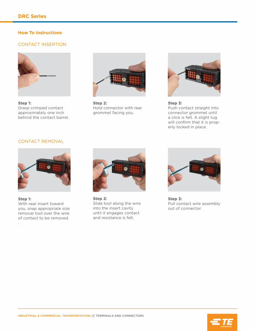
INDUSTRIAL & COMMERCIAL TRANSPORTATION /// TERMINALS AND CONNECTORS
DRC Series
CONTACT REMOVAL
Step 1:With rear insert toward you, snap appropriate size removal tool over the wire of contact to be removed. .
Step 2:Slide tool along the wire into the insert cavity until it engages contact and resistance is felt.
Step 3:Pull contact wire assembly out of connector.
How To Instructions
CONTACT INSERTION
Step 1:Grasp crimped contact approximately one inch behind the contact barrel.
Step 2:Hold connector with rear grommet facing you.
Step 3:Push contact straight into connector grommet until a click is felt. A slight tug will confirm that it is prop-erly locked in place.

Contents
DT Family Overview ................................................110
Product Documentation ......................................... 111
Performance Specifications .................................. 111
Material Specifications ............................................ 111
Dimensions .......................................................... 112-113
Configurations ...........................................................114
Ordering Information ....................................... 115-116
Required Components .................................... 117-118
Special Modifications ......................................118-120
Accessories ......................................................... 121-127
DT Family Printed Circuit Board........................ 128
DTMH Series & High TemperatureModification ......................................................129-130
DTV Series .................................................................. 131
How To Instructions ............................................... 132

INDUSTRIAL & COMMERCIAL TRANSPORTATION /// TERMINALS AND CONNECTORS
DT Family
DT Family Overview
DEUTSCH DT, DTM, and DTP series environmentally sealed connectors
are designed for cable to cable and cable to board applications. The DT
connectors are used in harsh environment applications where even a
small degradation in connection may be critical. Thermoplastic housings
offer a wide operating temperature range and silicone rear wire and
interface seals allow the connectors to withstand conditions of extreme
temperature and moisture.
The DEUTSCH DT series general purpose connectors will provide
reliability and performance on the engine or transmission, under the
hood, on the chassis, or in the cab.
DT SERIES OVERVIEWDEUTSCH DT series connectors offer field proven reliability and rugged quality. The DT design strengths include optional flange mounting, multi-pin arrangements, and design flexibility. The DT series offers the designer the ability to use multiple size 16 contacts, each with 13 amp continuous capacity, within a single shell.
DTP SERIES OVERVIEWDEUTSCH DTP series connectors provide solutions for your power application requirements. Building on both the DT and DTM design strengths, the DTP connector line was developed to fill the need for higher amperage, multi-pin connectors.
The DTP series offers the designer the ability to use multiple size 12 contacts, each with 25 amp continuous capacity, within a single shell. The DTP connectors are currently available in two and four pin configurations.
DTM SERIES OVERVIEWDEUTSCH DTM series connectors offer solutions to your smaller wire gauge applications. Building on the DT design strengths, the DTM connector line was developed to fill the need for lower amperage, multi-pin connectors. The DTM series offers the designer the ability to use multiple size 20 contacts, each with 7.5 amp continuous capacity, within a single shell.
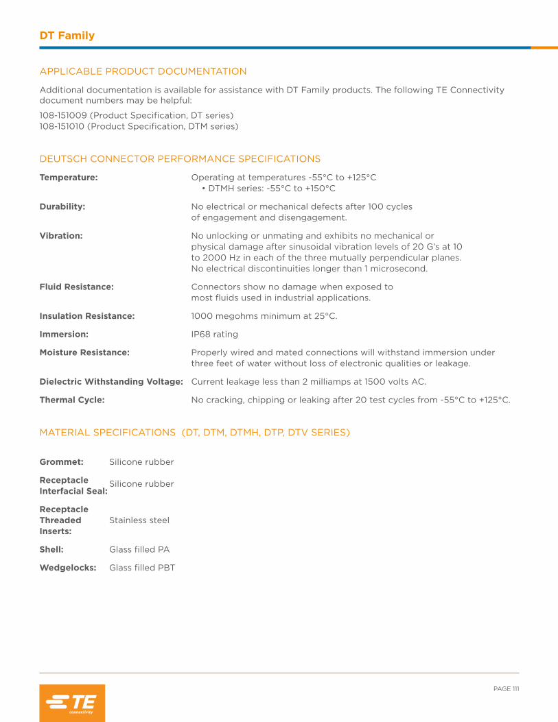
PAGE 111
DT Family
APPLICABLE PRODUCT DOCUMENTATION
Additional documentation is available for assistance with DT Family products. The following TE Connectivity document numbers may be helpful:
108-151009 (Product Specification, DT series) 108-151010 (Product Specification, DTM series)
MATERIAL SPECIFICATIONS (DT, DTM, DTMH, DTP, DTV SERIES)
Grommet: Silicone rubber
Receptacle Interfacial Seal:
Silicone rubber
Receptacle Threaded Inserts:
Stainless steel
Shell: Glass filled PA
Wedgelocks: Glass filled PBT
DEUTSCH CONNECTOR PERFORMANCE SPECIFICATIONS
Temperature: Operating at temperatures -55°C to +125°C • DTMH series: -55°C to +150°C
Durability: No electrical or mechanical defects after 100 cycles of engagement and disengagement.
Vibration: No unlocking or unmating and exhibits no mechanical or physical damage after sinusoidal vibration levels of 20 G’s at 10 to 2000 Hz in each of the three mutually perpendicular planes. No electrical discontinuities longer than 1 microsecond.
Fluid Resistance: Connectors show no damage when exposed to most fluids used in industrial applications.
Insulation Resistance: 1000 megohms minimum at 25°C.
Immersion: IP68 rating
Moisture Resistance: Properly wired and mated connections will withstand immersion under three feet of water without loss of electronic qualities or leakage.
Dielectric Withstanding Voltage: Current leakage less than 2 milliamps at 1500 volts AC.
Thermal Cycle: No cracking, chipping or leaking after 20 test cycles from -55°C to +125°C.
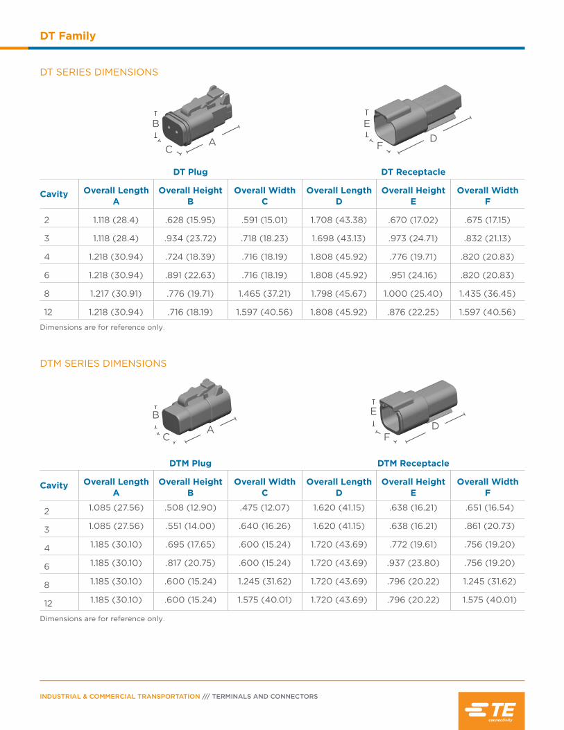
INDUSTRIAL & COMMERCIAL TRANSPORTATION /// TERMINALS AND CONNECTORS
DT Family
DTM SERIES DIMENSIONS
DTM Plug DTM Receptacle
Cavity Overall Length A
Overall Height B
Overall Width C
Overall Length D
Overall Height E
Overall Width F
2 1.085 (27.56) .508 (12.90) .475 (12.07) 1.620 (41.15) .638 (16.21) .651 (16.54)
3 1.085 (27.56) .551 (14.00) .640 (16.26) 1.620 (41.15) .638 (16.21) .861 (20.73)
4 1.185 (30.10) .695 (17.65) .600 (15.24) 1.720 (43.69) .772 (19.61) .756 (19.20)
6 1.185 (30.10) .817 (20.75) .600 (15.24) 1.720 (43.69) .937 (23.80) .756 (19.20)
8 1.185 (30.10) .600 (15.24) 1.245 (31.62) 1.720 (43.69) .796 (20.22) 1.245 (31.62)
12 1.185 (30.10) .600 (15.24) 1.575 (40.01) 1.720 (43.69) .796 (20.22) 1.575 (40.01)
Dimensions are for reference only.
F
EDA
C
B
DT SERIES DIMENSIONS
DT Plug DT Receptacle
Cavity Overall Length A
Overall Height B
Overall Width C
Overall Length D
Overall Height E
Overall Width F
2 1.118 (28.4) .628 (15.95) .591 (15.01) 1.708 (43.38) .670 (17.02) .675 (17.15)
3 1.118 (28.4) .934 (23.72) .718 (18.23) 1.698 (43.13) .973 (24.71) .832 (21.13)
4 1.218 (30.94) .724 (18.39) .716 (18.19) 1.808 (45.92) .776 (19.71) .820 (20.83)
6 1.218 (30.94) .891 (22.63) .716 (18.19) 1.808 (45.92) .951 (24.16) .820 (20.83)
8 1.217 (30.91) .776 (19.71) 1.465 (37.21) 1.798 (45.67) 1.000 (25.40) 1.435 (36.45)
12 1.218 (30.94) .716 (18.19) 1.597 (40.56) 1.808 (45.92) .876 (22.25) 1.597 (40.56)
Dimensions are for reference only.
FD
E
AC
B
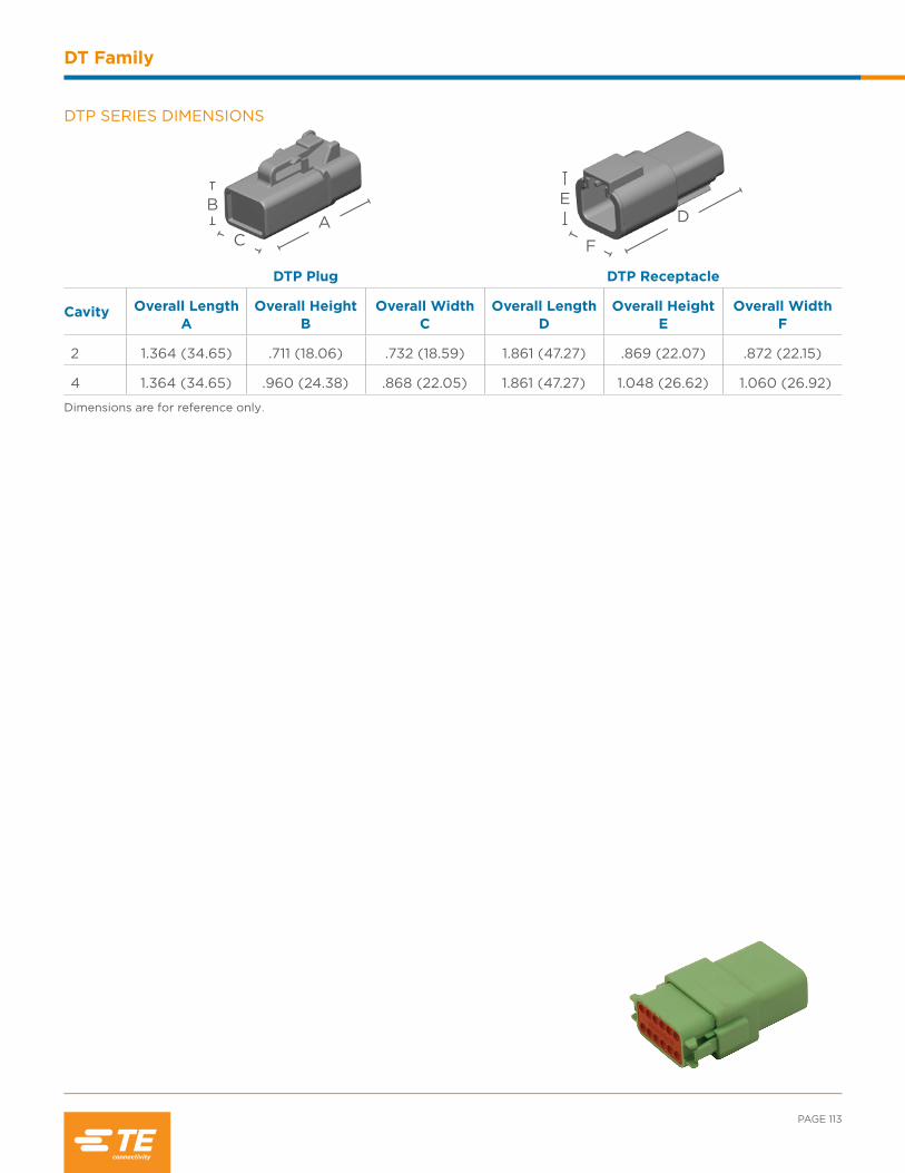
PAGE 113
DT Family
DTP SERIES DIMENSIONS
DTP Plug DTP Receptacle
Cavity Overall Length A
Overall Height B
Overall Width C
Overall Length D
Overall Height E
Overall Width F
2 1.364 (34.65) .711 (18.06) .732 (18.59) 1.861 (47.27) .869 (22.07) .872 (22.15)
4 1.364 (34.65) .960 (24.38) .868 (22.05) 1.861 (47.27) 1.048 (26.62) 1.060 (26.92)
Dimensions are for reference only.
F
DE
AC
B
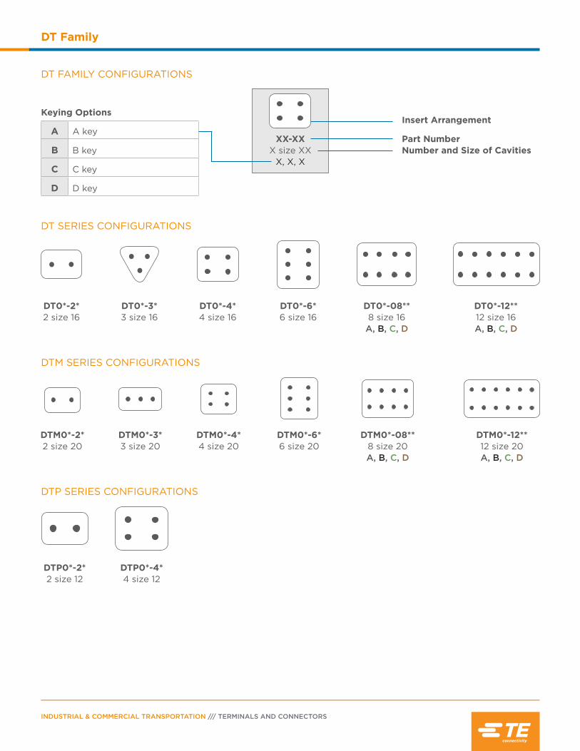
INDUSTRIAL & COMMERCIAL TRANSPORTATION /// TERMINALS AND CONNECTORS
DT Family
DT0*-3* 3 size 16
DT0*-08** 8 size 16
A, B, C, D
DT0*-12** 12 size 16 A, B, C, D
DT0*-4* 4 size 16
DT0*-2* 2 size 16
DT FAMILY CONFIGURATIONS
DT0*-6* 6 size 16
DT SERIES CONFIGURATIONS
DTM SERIES CONFIGURATIONS
Keying Options
A A key
B B key
C C key
D D key
XX-XXX size XX
X, X, X
Insert Arrangement
Number and Size of CavitiesPart Number
DTM0*-08** 8 size 20 A, B, C, D
DTM0*-12** 12 size 20 A, B, C, D
DTM0*-2* 2 size 20
DTM0*-3* 3 size 20
DTM0*-4* 4 size 20
DTM0*-6* 6 size 20
DTP SERIES CONFIGURATIONS
DTP0*-2* 2 size 12
DTP0*-4* 4 size 12
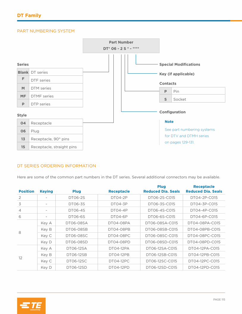
PAGE 115
DT Family
PART NUMBERING SYSTEM
Part Number
DT* 06 - 2 S * - ****
Series
Blank DT series
F DTF series
M DTM series
MF DTMF series
P DTP series
Style
04 Receptacle
06 Plug
13 Receptacle, 90° pins
15 Receptacle, straight pins
Special Modifications Key (if applicable) Contacts
P Pin
S Socket
Configuration
DT SERIES ORDERING INFORMATION
Here are some of the common part numbers in the DT series. Several additional connectors may be available.
Position Keying Plug ReceptaclePlug
Reduced Dia. SealsReceptacle
Reduced Dia. Seals
2 - DT06-2S DT04-2P DT06-2S-C015 DT04-2P-C015
3 - DT06-3S DT04-3P DT06-3S-C015 DT04-3P-C015
4 - DT06-4S DT04-4P DT06-4S-C015 DT04-4P-C015
6 - DT06-6S DT04-6P DT06-6S-C015 DT04-6P-C015
8
Key A DT06-08SA DT04-08PA DT06-08SA-C015 DT04-08PA-C015
Key B DT06-08SB DT04-08PB DT06-08SB-C015 DT04-08PB-C015
Key C DT06-08SC DT04-08PC DT06-08SC-C015 DT04-08PC-C015
Key D DT06-08SD DT04-08PD DT06-08SD-C015 DT04-08PD-C015
12
Key A DT06-12SA DT04-12PA DT06-12SA-C015 DT04-12PA-C015
Key B DT06-12SB DT04-12PB DT06-12SB-C015 DT04-12PB-C015
Key C DT06-12SC DT04-12PC DT06-12SC-C015 DT04-12PC-C015
Key D DT06-12SD DT04-12PD DT06-12SD-C015 DT04-12PD-C015
Note
See part numbering systems
for DTV and DTMH series
on pages 129-131.
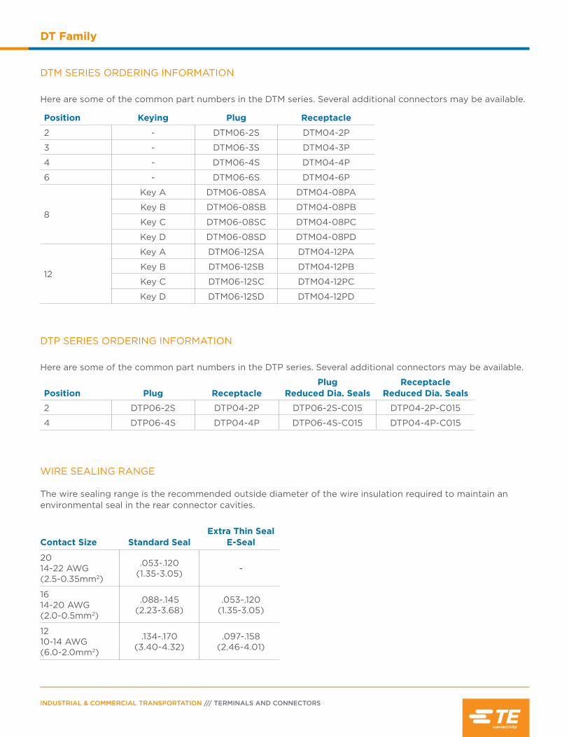
INDUSTRIAL & COMMERCIAL TRANSPORTATION /// TERMINALS AND CONNECTORS
DT Family
WIRE SEALING RANGE The wire sealing range is the recommended outside diameter of the wire insulation required to maintain an environmental seal in the rear connector cavities.
Contact Size Standard SealExtra Thin Seal
E-Seal
2014-22 AWG (2.5-0.35mm2)
.053-.120(1.35-3.05) -
1614-20 AWG (2.0-0.5mm2)
.088-.145 (2.23-3.68)
.053-.120(1.35-3.05)
1210-14 AWG (6.0-2.0mm2)
.134-.170(3.40-4.32)
.097-.158(2.46-4.01)
DTM SERIES ORDERING INFORMATION
Here are some of the common part numbers in the DTM series. Several additional connectors may be available.
Position Keying Plug Receptacle
2 - DTM06-2S DTM04-2P
3 - DTM06-3S DTM04-3P
4 - DTM06-4S DTM04-4P
6 - DTM06-6S DTM04-6P
8
Key A DTM06-08SA DTM04-08PA
Key B DTM06-08SB DTM04-08PB
Key C DTM06-08SC DTM04-08PC
Key D DTM06-08SD DTM04-08PD
12
Key A DTM06-12SA DTM04-12PA
Key B DTM06-12SB DTM04-12PB
Key C DTM06-12SC DTM04-12PC
Key D DTM06-12SD DTM04-12PD
DTP SERIES ORDERING INFORMATION
Here are some of the common part numbers in the DTP series. Several additional connectors may be available.
Position Plug ReceptaclePlug
Reduced Dia. SealsReceptacle
Reduced Dia. Seals
2 DTP06-2S DTP04-2P DTP06-2S-C015 DTP04-2P-C015
4 DTP06-4S DTP04-4P DTP06-4S-C015 DTP04-4P-C015
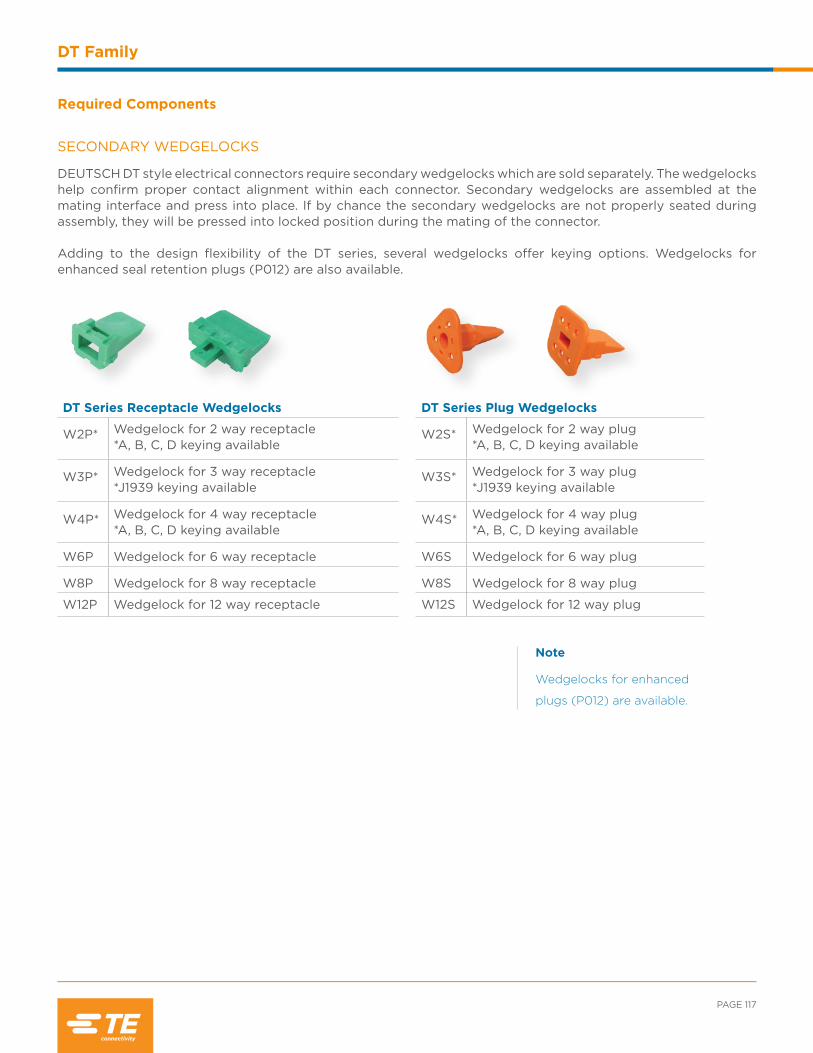
PAGE 117
DT Family
Note
Wedgelocks for enhanced
plugs (P012) are available.
Required Components
SECONDARY WEDGELOCKS
DEUTSCH DT style electrical connectors require secondary wedgelocks which are sold separately. The wedgelocks help confirm proper contact alignment within each connector. Secondary wedgelocks are assembled at the mating interface and press into place. If by chance the secondary wedgelocks are not properly seated during assembly, they will be pressed into locked position during the mating of the connector.
Adding to the design flexibility of the DT series, several wedgelocks offer keying options. Wedgelocks for enhanced seal retention plugs (P012) are also available.
DT Series Plug Wedgelocks
W2S* Wedgelock for 2 way plug*A, B, C, D keying available
W3S* Wedgelock for 3 way plug*J1939 keying available
W4S* Wedgelock for 4 way plug*A, B, C, D keying available
W6S Wedgelock for 6 way plug
W8S Wedgelock for 8 way plug
W12S Wedgelock for 12 way plug
DT Series Receptacle Wedgelocks
W2P* Wedgelock for 2 way receptacle *A, B, C, D keying available
W3P* Wedgelock for 3 way receptacle *J1939 keying available
W4P* Wedgelock for 4 way receptacle *A, B, C, D keying available
W6P Wedgelock for 6 way receptacle
W8P Wedgelock for 8 way receptacle
W12P Wedgelock for 12 way receptacle

INDUSTRIAL & COMMERCIAL TRANSPORTATION /// TERMINALS AND CONNECTORS
DT Family
Special Modifications
The DT series connectors offer several modifications to enhance the design flexibility and meet application
specific needs. Options include enhanced seal retention, flanges, and connector body color just to mention a few.
By combining the DT series connectors with the available modifications and accessories, the design possibilities
are immense.
B016 MODIFICATION The B016 receptacle modification helps prevent mis-mating. The B016 is available for the DT 12 way connectors, DT13/15, and DTF13/15 PCB series connectors. In addition to the four keying positions (A, B, C, or D) and color coding, the B016 enhancement gives the user both visual and tactile proof of correct mating, thus helping eliminate mis-mating opportunities during assembly. Please note the P012 plug is the required mate for the B016 receptacle to make the enhancement effective.
DTP Series Plug Wedgelocks
WP-2S Wedgelock for 2 way plug
WP-4S Wedgelock for 4 way plug
DTP Series Receptacle Wedgelocks
WP-2P Wedgelock for 2 way receptacle
WP-4P Wedgelock for 4 way receptacle
DTM Series Plug Wedgelocks
WM-2S* Wedgelock for 2 way plug*A, B, C, D keying available
WM-3S Wedgelock for 3 way plug
WM-4S Wedgelock for 4 way plug
WM-6S Wedgelock for 6 way plug
WM-8S Wedgelock for 8 way plug
WM-12S Wedgelock for 12 way plug
DTM Series Receptacle Wedgelocks
WM-2P* Wedgelock for 2 way receptacle *A, B, C, D keying available
WM-3P Wedgelock for 3 way receptacle
WM-4P Wedgelock for 4 way receptacle
WM-6P Wedgelock for 6 way receptacle
WM-8P Wedgelock for 8 way receptacle
WM-12P Wedgelock for 12 way receptacle

PAGE 119
DT Family
E003 MODIFICATION The E003 modification offers a protective end cap attached to the rear of the connector. There are holes in the cap to allow the contacts to be inserted.
C015 MODIFICATION The C015 modification offers a reduced diameter insert cavity allowing for a proper seal with smaller wire insulation. The C015 modification is also referred to as an “E” seal.
P012 MODIFICATION The DT P012 plugs provide enhanced front seal retention resulting in an ultra tight environmental seal. The enhanced seal retention keeps the seal in place during mating and unmating. The P012 modification requires an enhanced P012 wedgelock. The DEUTSCH P012 modification is available in 2, 3, 4, 6, 8, and 12 cavity arrangements. P012 plugs have a black connector body except for the 8 and 12 cavity arrangements, where the color is based on the key.
DETECTOR The Detector connector has an integrated LED used for diagnostics. The transparent housing features reduced diameter seals and may be ordered with or without an end cap. Color coded wedgelocks for operating voltages, 12VDC and 24VDC are available.
Description Part Number
Plug, 2 way, LED, transparent Ultem material, reduced diameter seals, end cap
DT06-2S-SDT-CE27
Plug, 2 way, LED, transparent Ultem material, reduced diameter seals
DT06-2S-SDT-CE28
Wedgelock, LED, 12V, yellow W2S-SDT-12V
Wedgelock, LED, 24V, red W2S-SDT-24V

INDUSTRIAL & COMMERCIAL TRANSPORTATION /// TERMINALS AND CONNECTORS
DT Family
Note
Additional modifications
are available, please contact
your representative.
E004 MODIFICATION The E004 modification changes the connector body color to black.
E005 MODIFICATION The E005 modification offers a protective end cap attached to the rear of the connector and has a black connector body.
E007 & E008 MODIFICATION To meet the application requirements where wires need added protection, the DT (E008) and DTM (E007) series may be supplied with shrink boot adapters. These adapters accept shrink tubing.
FLANGE MODIFICATIONS Designed to simplify wire routing and assembly, DT series receptacles are available in many mounting configurations and styles. Welded flange • Welded flange - BL04, BL08, CL03, L012, LE14 • Welded flange, end cap - LE07, LE11 • Welded flange, shrink boot adapter - LE08, LE12 Sealed flange • Sealed flange, end cap - CL09, LE01, LE05, LE06, LE09, LE10, LE17, LE21 • Sealed flange, shrink boot adapter - BL10, CL07

LA
D
D D istrib
utio
n
Exclusive to
LA
D
D D istrib
utio
n
Exclusive to
PAGE 121
DT Family
Accessories
Several accessory items are available to complement the connectors including boots, backshells, gaskets, dust
caps, and mounting clips. Accessory items cover a wide array of design requirements such as assisting with
mounting, providing additional protection, and offering enhanced aesthetics.
Thermoplastic Dust Cap Part Number Connector Part Number
1011-344-0205 DT06-2S
1011-345-0305 DT06-3S
1011-346-0405 DT06-4S
1011-347-0605 DT06-6S
1011-348-0805 DT06-08S*
1011-349-1205 DT06-12S*, DT16-15S*, DT16-18S*
GASKETS
Moisture, dirt, salt, sand, and road debris can all work their way into electrical panels through unsealed mounting flanges. Rated to operate in environments from -70°F to +225°F (-56°C to +107°C), these rugged high quality neoprene gaskets form a tight seal between the panel face and connector flange to help keep out destructive elements. The gaskets have a thickness of .125” and the material meets the UL-94-HBF, Mil-R-6130C, and FMVSS-302 flammability specifications.
DUST CAPS
The DT series dust caps are made of either thermoplastic or durable plastisol and are designed to provide protection for the connector interface when the two halves are not mated. The plastisol caps, available for plugs and receptacles, are suitable for providing temporary protection from dirt, dust, and paint overspray. The thermoplastic caps provide an environmental seal for an unmated plug.
Gasket Part Number Connector Part Number
DT3P-L012-GKT DT04-3P-L012
DT4P-L012-GKT DT04-4P-L012
DTP4P-L012-GKT DTP04-4P-L012
DT8P-L012-GKT DT04-08P*-L012
DT12-L012-GKT DT04-12P*-L012DTM04-12P*-L012
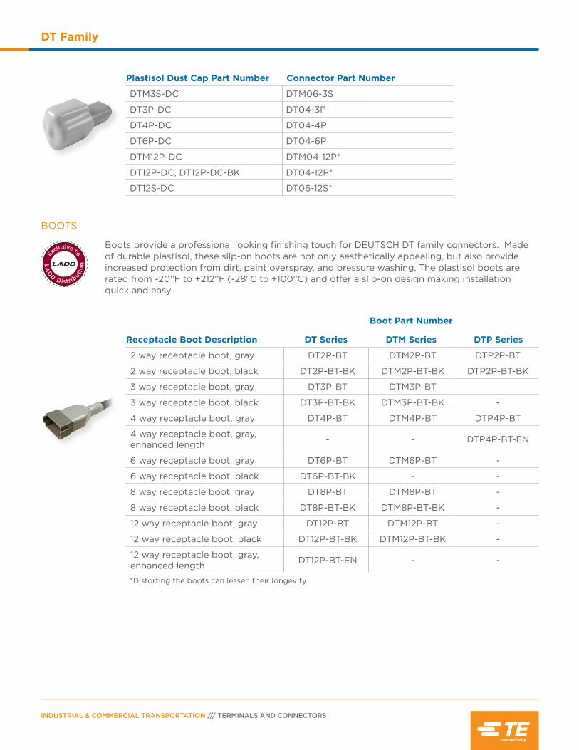
LA
D
D D istrib
utio
n
Exclusive to
INDUSTRIAL & COMMERCIAL TRANSPORTATION /// TERMINALS AND CONNECTORS
DT Family
Plastisol Dust Cap Part Number Connector Part Number
DTM3S-DC DTM06-3S
DT3P-DC DT04-3P
DT4P-DC DT04-4P
DT6P-DC DT04-6P
DTM12P-DC DTM04-12P*
DT12P-DC, DT12P-DC-BK DT04-12P*
DT12S-DC DT06-12S*
Receptacle Boot Description
Boot Part Number
DT Series DTM Series DTP Series
2 way receptacle boot, gray DT2P-BT DTM2P-BT DTP2P-BT
2 way receptacle boot, black DT2P-BT-BK DTM2P-BT-BK DTP2P-BT-BK
3 way receptacle boot, gray DT3P-BT DTM3P-BT -
3 way receptacle boot, black DT3P-BT-BK DTM3P-BT-BK -
4 way receptacle boot, gray DT4P-BT DTM4P-BT DTP4P-BT
4 way receptacle boot, gray, enhanced length - - DTP4P-BT-EN
6 way receptacle boot, gray DT6P-BT DTM6P-BT -
6 way receptacle boot, black DT6P-BT-BK - -
8 way receptacle boot, gray DT8P-BT DTM8P-BT -
8 way receptacle boot, black DT8P-BT-BK DTM8P-BT-BK -
12 way receptacle boot, gray DT12P-BT DTM12P-BT -
12 way receptacle boot, black DT12P-BT-BK DTM12P-BT-BK -
12 way receptacle boot, gray, enhanced length DT12P-BT-EN - -
*Distorting the boots can lessen their longevity
BOOTS
Boots provide a professional looking finishing touch for DEUTSCH DT family connectors. Made of durable plastisol, these slip-on boots are not only aesthetically appealing, but also provide increased protection from dirt, paint overspray, and pressure washing. The plastisol boots are rated from -20°F to +212°F (-28°C to +100°C) and offer a slip-on design making installation quick and easy.
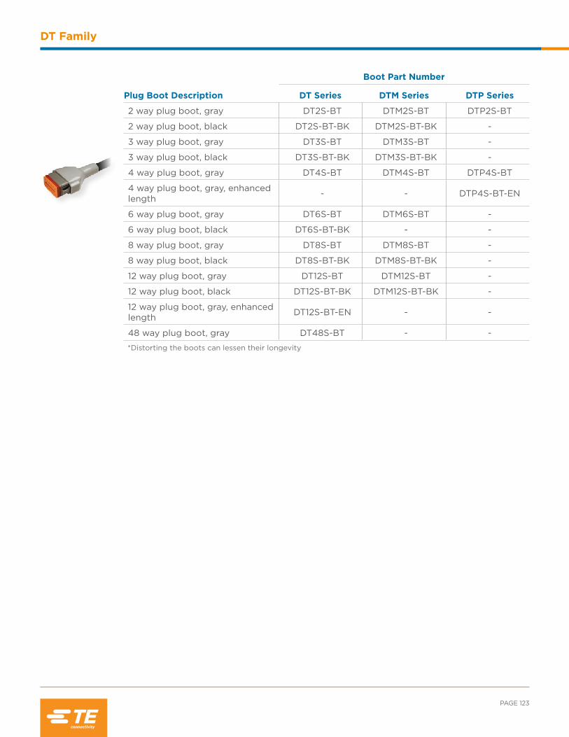
PAGE 123
DT Family
Plug Boot Description
Boot Part Number
DT Series DTM Series DTP Series
2 way plug boot, gray DT2S-BT DTM2S-BT DTP2S-BT
2 way plug boot, black DT2S-BT-BK DTM2S-BT-BK -
3 way plug boot, gray DT3S-BT DTM3S-BT -
3 way plug boot, black DT3S-BT-BK DTM3S-BT-BK -
4 way plug boot, gray DT4S-BT DTM4S-BT DTP4S-BT
4 way plug boot, gray, enhanced length - - DTP4S-BT-EN
6 way plug boot, gray DT6S-BT DTM6S-BT -
6 way plug boot, black DT6S-BT-BK - -
8 way plug boot, gray DT8S-BT DTM8S-BT -
8 way plug boot, black DT8S-BT-BK DTM8S-BT-BK -
12 way plug boot, gray DT12S-BT DTM12S-BT -
12 way plug boot, black DT12S-BT-BK DTM12S-BT-BK -
12 way plug boot, gray, enhanced length DT12S-BT-EN - -
48 way plug boot, gray DT48S-BT - -
*Distorting the boots can lessen their longevity

INDUSTRIAL & COMMERCIAL TRANSPORTATION /// TERMINALS AND CONNECTORS
DT Family
DT Series Receptacle Backshells
Connector StyleStrain Relief Tubing size (mm) Part Number
DT04-2P 180° 6, 7.5, 8.5, and 10 1011-229-0205
180° X 6, 7.5, 8.5, and 10 1011-257-0205
90° 6, 7.5, 8.5, and 10 1011-230-0205
90° X 6, 7.5, 8.5, and 10 1011-258-0205
DT04-3P 180° 6, 7.5, 8.5, and 10 1011-233-0305
180° X 6, 7.5, 8.5, and 10 1011-261-0305
90° 6, 7.5, 8.5, and 10 1011-234-0305
90° X 6, 7.5, 8.5, and 10 1011-262-0305
DT04-4P 180° 6, 7.5, 8.5, and 10 1011-237-0405
180° X 6, 7.5, 8.5, and 10 1011-265-0405
90° 6, 7.5, 8.5, and 10 1011-238-0405
90° X 6, 7.5, 8.5, and 10 1011-266-0405
DT04-6P 180° 8.5, 10, and 13 1011-241-0605
180° X 8.5, 10, and 13 1011-269-0605
90° 8.5, 10, and 13 1011-242-0605
90° X 8.5, 10, and 13 1011-270-0605
DT04-08P* 180° 8.5, 10, and 13 1011-245-0805
90° 8.5, 10, and 13 1011-246-0805
DT04-12P* 180° 10, 13, and 17 1011-249-1205
90° 10, 13, and 17 1011-250-1205
BACKSHELLS
The DEUTSCH DT and DTM series backshells are designed to snap onto and mate with all standard (basic plug and receptacles without modifications that affect the rear of the connector) DT and DTM series connectors. The rigid, durable backshells offer a high level of protection and allow convoluted tubing to nest within the rear of the backshell. Straight (180°) and right angle (90°) versions and backshells with strain relief for jacketed cable are also available.
Since the backshells are designed to work with the standard DT and DTM connectors, tests should be conducted for fit and function of a backshell being used on any part with a modification.
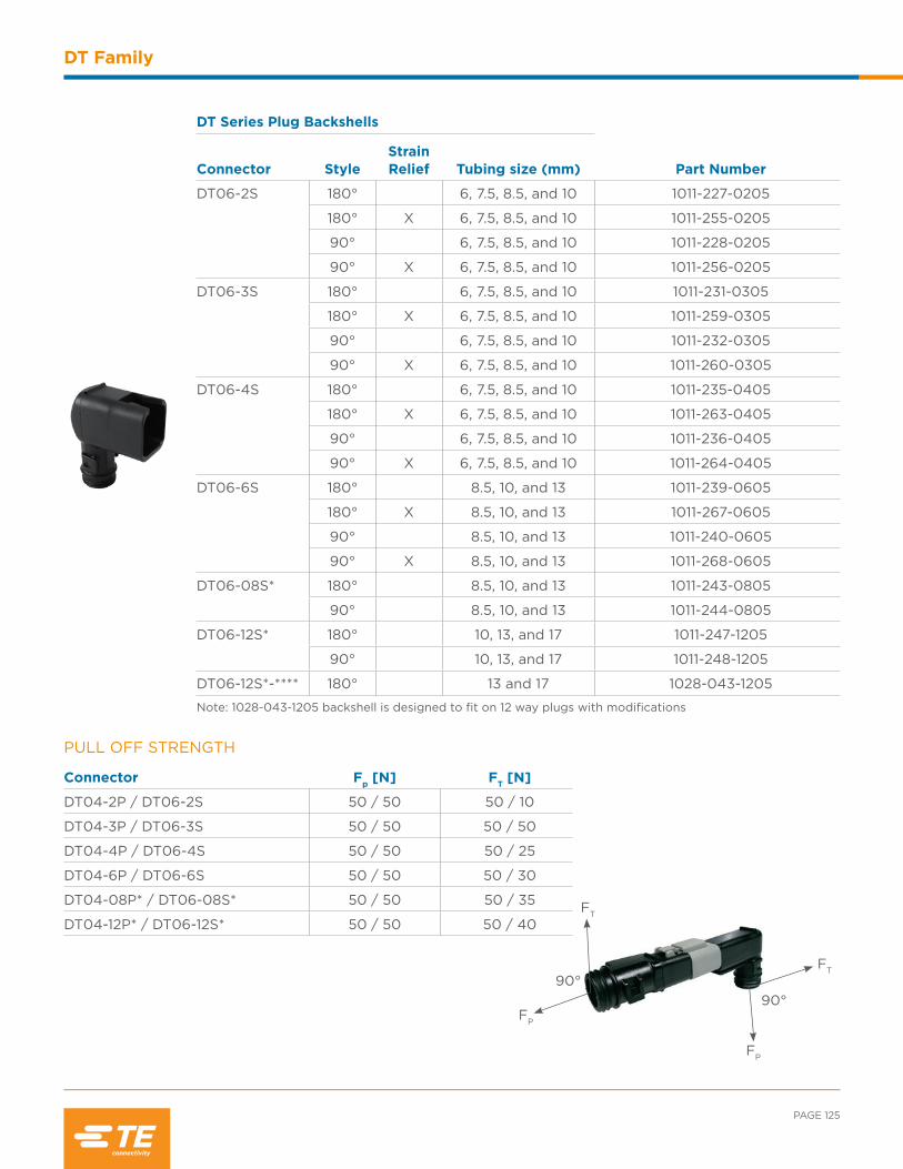
PAGE 125
DT Family
90°90°
FT
FP
FP
FT
PULL OFF STRENGTH
Connector Fp [N] FT [N]
DT04-2P / DT06-2S 50 / 50 50 / 10
DT04-3P / DT06-3S 50 / 50 50 / 50
DT04-4P / DT06-4S 50 / 50 50 / 25
DT04-6P / DT06-6S 50 / 50 50 / 30
DT04-08P* / DT06-08S* 50 / 50 50 / 35
DT04-12P* / DT06-12S* 50 / 50 50 / 40
DT Series Plug Backshells
Connector StyleStrain Relief Tubing size (mm) Part Number
DT06-2S 180° 6, 7.5, 8.5, and 10 1011-227-0205
180° X 6, 7.5, 8.5, and 10 1011-255-0205
90° 6, 7.5, 8.5, and 10 1011-228-0205
90° X 6, 7.5, 8.5, and 10 1011-256-0205
DT06-3S 180° 6, 7.5, 8.5, and 10 1011-231-0305
180° X 6, 7.5, 8.5, and 10 1011-259-0305
90° 6, 7.5, 8.5, and 10 1011-232-0305
90° X 6, 7.5, 8.5, and 10 1011-260-0305
DT06-4S 180° 6, 7.5, 8.5, and 10 1011-235-0405
180° X 6, 7.5, 8.5, and 10 1011-263-0405
90° 6, 7.5, 8.5, and 10 1011-236-0405
90° X 6, 7.5, 8.5, and 10 1011-264-0405
DT06-6S 180° 8.5, 10, and 13 1011-239-0605
180° X 8.5, 10, and 13 1011-267-0605
90° 8.5, 10, and 13 1011-240-0605
90° X 8.5, 10, and 13 1011-268-0605
DT06-08S* 180° 8.5, 10, and 13 1011-243-0805
90° 8.5, 10, and 13 1011-244-0805
DT06-12S* 180° 10, 13, and 17 1011-247-1205
90° 10, 13, and 17 1011-248-1205
DT06-12S*-**** 180° 13 and 17 1028-043-1205
Note: 1028-043-1205 backshell is designed to fit on 12 way plugs with modifications
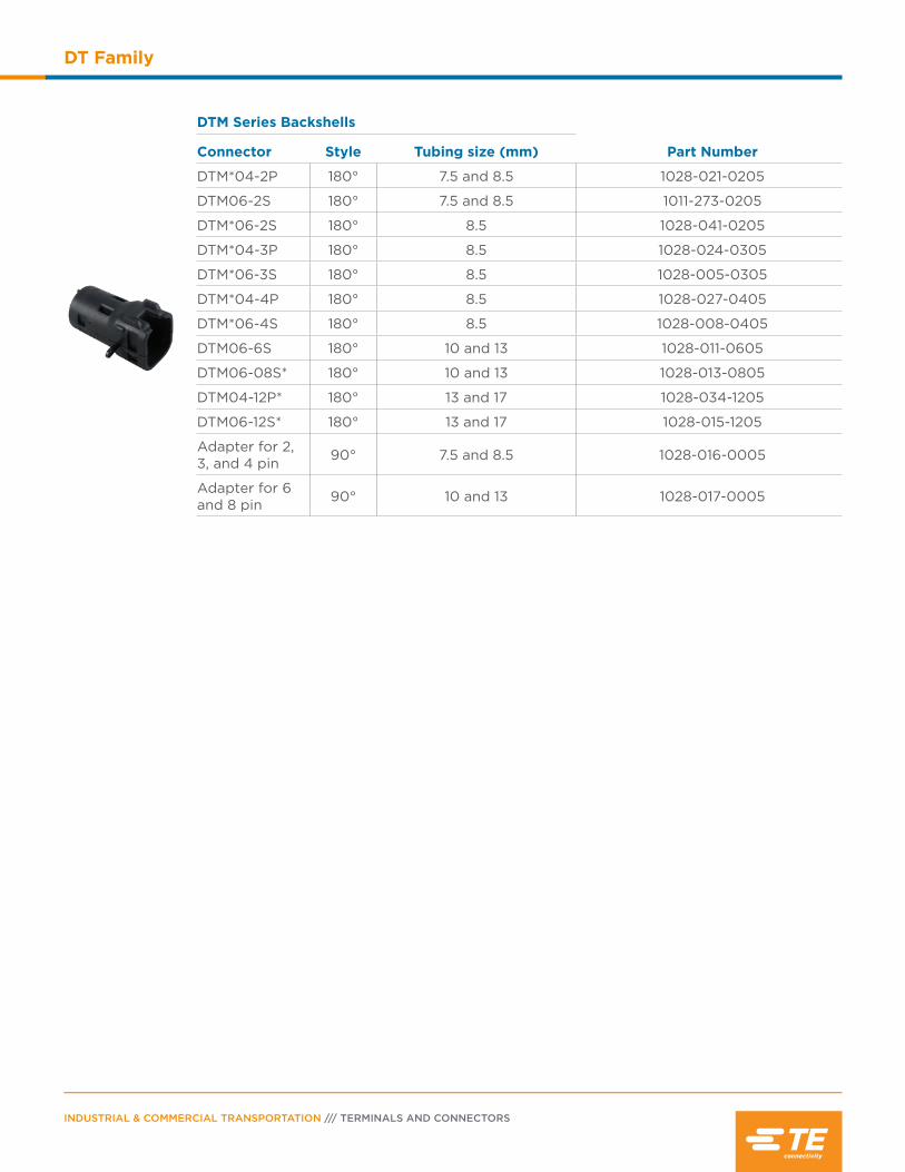
INDUSTRIAL & COMMERCIAL TRANSPORTATION /// TERMINALS AND CONNECTORS
DT Family
DTM Series Backshells
Connector Style Tubing size (mm) Part Number
DTM*04-2P 180° 7.5 and 8.5 1028-021-0205
DTM06-2S 180° 7.5 and 8.5 1011-273-0205
DTM*06-2S 180° 8.5 1028-041-0205
DTM*04-3P 180° 8.5 1028-024-0305
DTM*06-3S 180° 8.5 1028-005-0305
DTM*04-4P 180° 8.5 1028-027-0405
DTM*06-4S 180° 8.5 1028-008-0405
DTM06-6S 180° 10 and 13 1028-011-0605
DTM06-08S* 180° 10 and 13 1028-013-0805
DTM04-12P* 180° 13 and 17 1028-034-1205
DTM06-12S* 180° 13 and 17 1028-015-1205
Adapter for 2, 3, and 4 pin 90° 7.5 and 8.5 1028-016-0005
Adapter for 6 and 8 pin 90° 10 and 13 1028-017-0005

PAGE 127
DT Family
Part NumberCavity
ArrangementMountingDirection Color/Material
Hole O.D.inches (mm)
1027-003-1200 DT 2, 3, 4, 6, 12DTM, DTP (all) Straight Stainless steel .433 (11.0)
1027-005-1200 DT 2, 3, 4, 6, 12DTM, DTP (all) Straight Stainless steel .512 (13.0)
1027-004-1200 DT 2, 3, 4, 6, 12DTM, DTP (all) Straight Steel w/
zinc plating .512 (13.0)
1027-008-1200 DT 2, 3, 4, 6, 12DTM, DTP (all) Side Steel w/
zinc plating .433 (11.0)
1027-013-1200/ 1027-017-1200
DT 2, 3, 4, 6, 12DTM, DTP (all) Side Steel w/
zinc plating .323 (8.2)
1027-001-0800 DT 8 cavity only Straight Stainless steel .433 (11.0)
1027-006-0800 DT 8 cavity only Straight Stainless steel .512 (13.0)
1027-002-0800 DT 8 cavity only Straight Steel w/ zinc plating .512 (13.0)
1027-014-0800 DT 8 cavity only Straight Steel w/ zinc plating .323 (8.2)
1011-026-0205 DT 2, 3, 4, 6, 12DTM, DTP (all) Straight Gray
plastic .200 (5.08)
1011-030-0205 DT 2, 3, 4, 6, 12DTM, DTP (all) Straight Black
plastic ---
1011-310-0205**Connector removeable with 50N of force
DT 2, 3, 4, 6, 12DTM, DTP (all) Straight Black
plastic ---
1011-027-0805 DT 8 cavity only Straight Grayplastic .200 (5.08)
MOUNTING CLIPS
Mounting clips are installed on the receptacle to mount DT series connectors. To meet design needs, the clips are available for several configurations and in plastic, stainless steel, or steel with zinc plating.

INDUSTRIAL & COMMERCIAL TRANSPORTATION /// TERMINALS AND CONNECTORS
DT Family
DT Family Printed Circuit Board Connectors
The DT Family offers printed circuit board (PCB) connectors that are heavy duty environmentally sealed
connectors designed for wire-to-circuit board connections. Available in a variety of styles for the DT,
DTM, and DTP connector series, DEUTSCH PCB connectors cover a range of pin counts from 2 to 48
and wire gauges from 10 to 22. Many of the connectors are available in straight or 90° pin options.
PCB PART NUMBERING SYSTEM
DT FAMILY PCB CONFIGURATIONS
Part Number
DT* 13 - 6 P * - ****
Series
Blank DT series
F DTF series
M DTM series
MF DTMF series
P DTP series
Style
13 Receptacle, 90° pins
15 Receptacle, straight pins
Special Modifications Key (if applicable)
A B C D
Contacts
P Pin
Configuration
Connector Description
Pin/Flange Style
90° Flange Straight Flange 90° FlangelessStraight
Flangeless
2 way receptacle, DT series DT13-2P DT15-2P DTF13-2P -
3 way receptacle, DT series - - DTF13-3P -
4 way receptacle, DT series DT13-4P DT15-4P DTF13-4P -
4 way receptacle, DTP series DTP13-4P DTP15-4P - -
6 way receptacle, DT series DT13-6P DT15-6P DTF13-6P -
8 way receptacle, DT series DT13-08P* DT15-08P* - -
12 way receptacle, DT series DT13-12P* DT15-12P* DTF13-12P* DTF15-12P*
12 way receptacle, DTM series DTM13-12P* DTM15-12P* - -
48 way receptacle, DTM series - - - DTMF15-48P
* = Keying (A, B, C, or D)
Note
For additional information,
please see the PCB section.
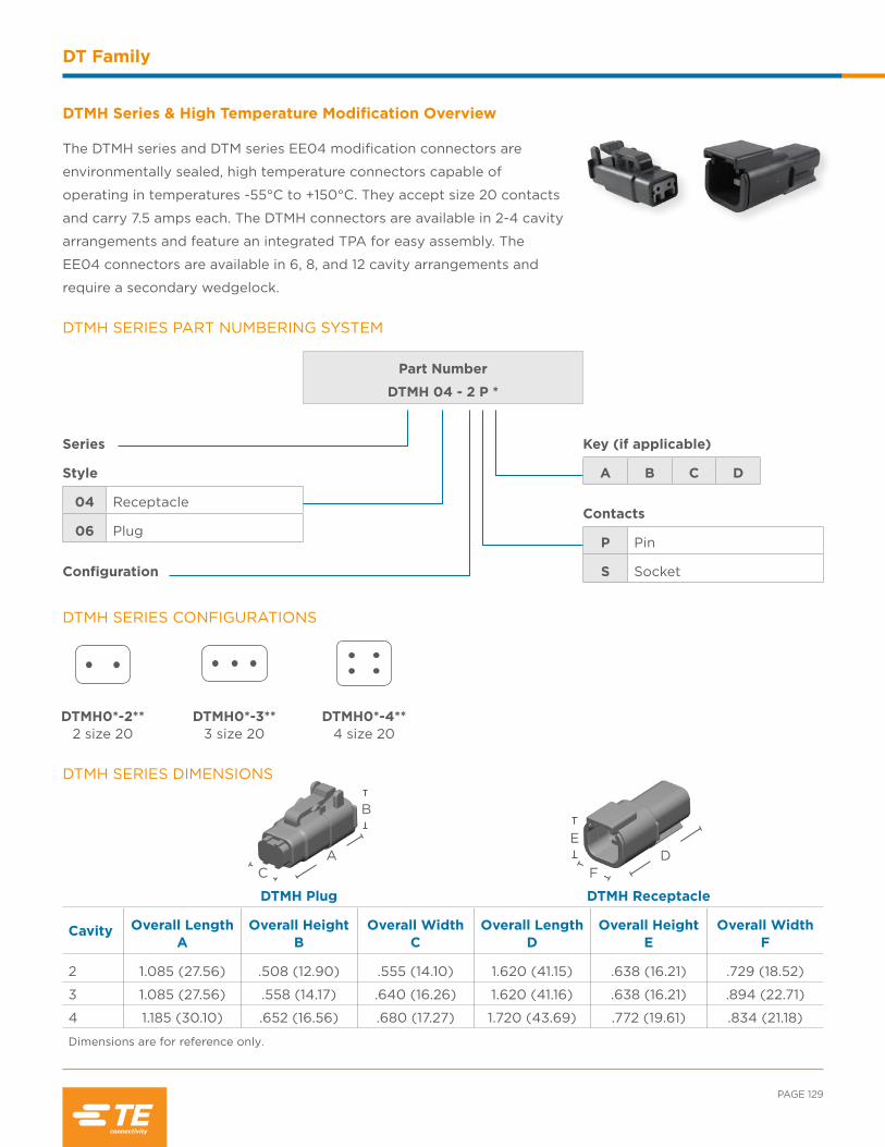
PAGE 129
DT Family
DTMH Series & High Temperature Modification Overview
The DTMH series and DTM series EE04 modification connectors are
environmentally sealed, high temperature connectors capable of
operating in temperatures -55°C to +150°C. They accept size 20 contacts
and carry 7.5 amps each. The DTMH connectors are available in 2-4 cavity
arrangements and feature an integrated TPA for easy assembly. The
EE04 connectors are available in 6, 8, and 12 cavity arrangements and
require a secondary wedgelock.
DTMH SERIES PART NUMBERING SYSTEM
Part Number
DTMH 04 - 2 P *
Series
Style
04 Receptacle
06 Plug
Configuration
Key (if applicable)
A B C D
Contacts
P Pin
S Socket
DTMH SERIES DIMENSIONS
DTMH Plug DTMH Receptacle
Cavity Overall Length A
Overall Height B
Overall Width C
Overall Length D
Overall Height E
Overall Width F
2 1.085 (27.56) .508 (12.90) .555 (14.10) 1.620 (41.15) .638 (16.21) .729 (18.52)
3 1.085 (27.56) .558 (14.17) .640 (16.26) 1.620 (41.16) .638 (16.21) .894 (22.71)
4 1.185 (30.10) .652 (16.56) .680 (17.27) 1.720 (43.69) .772 (19.61) .834 (21.18)
Dimensions are for reference only.
AC
B
F
ED
DTMH SERIES CONFIGURATIONS
DTMH0*-2** 2 size 20
DTMH0*-3** 3 size 20
DTMH0*-4** 4 size 20

INDUSTRIAL & COMMERCIAL TRANSPORTATION /// TERMINALS AND CONNECTORS
DT Family
DTM SERIES (EE04 MOD) PART NUMBERING SYSTEM
DTM SERIES CONFIGURATIONS
Part Number
DTM 06 - 6 S * - EE04
Series
Style
04 Receptacle
06 Plug
Configuration
6 8 12
High Temperature Black Modification Key (if applicable)
A B C D
Contacts
P Pin
S Socket
DTM SERIES DIMENSIONS
DTM Plug DTM Receptacle
Cavity Overall Length A
Overall Height B
Overall Width C
Overall Length D
Overall Height E
Overall Width F
6 1.185 (30.10) .817 (20.75) .600 (15.24) 1.720 (43.69) .937 (23.80) .756 (19.20)
8 1.185 (30.10) .600 (15.24) 1.245 (31.62) 1.720 (43.69) .792 (20.12) 1.245 (31.62)
12 1.185 (30.10) .600 (15.24) 1.575 (40.01) 1.720 (43.69) .796 (20.22) 1.575 (40.01)
Dimensions are for reference only.
DTM0*-08**-EE04 8 size 20
A, B, C, D
DTM0*-12**-EE04 12 size 20
A, B, C, D
DTM0*-6*-EE04 6 size 20
F
E
DAC
B
Note
DTM EE04 connectors require
a secondary wedgelock
that is sold separately.

PAGE 131
DT Family
DTV Series Overview
The DEUTSCH DTV series connectors offer the same time tested
reliability and performance as the DT series, with the added flexibility
of an 18 cavity flanged design.
DTV SERIES PART NUMBERING SYSTEM
Part Number
DTV 06 - 18 S *
Series
Style
02 Receptacle
06 Plug
Configuration
Key (if applicable)
A B C D
Contacts
P Pin
S Socket
E
F D
B
C A
DTV SERIES DIMENSIONS
DTV Plug DTV Receptacle
Cavity Overall Length A
Overall Height B
Overall Width C
Overall Length D
Overall Height E
Overall Width F
18 1.405 (35.69) 1.059 (26.90) 1.450 (36.83) 2.495 (63.37) 1.786 (45.36) 3.194 (81.12)
Dimensions are for reference only.
DTV Series Plug Wedgelock
WV-18S Wedgelock for 18 way plug
DTV Series Receptacle Wedgelock
WV-18P Wedgelock for 18 way receptacle
SECONDARY WEDGELOCKS
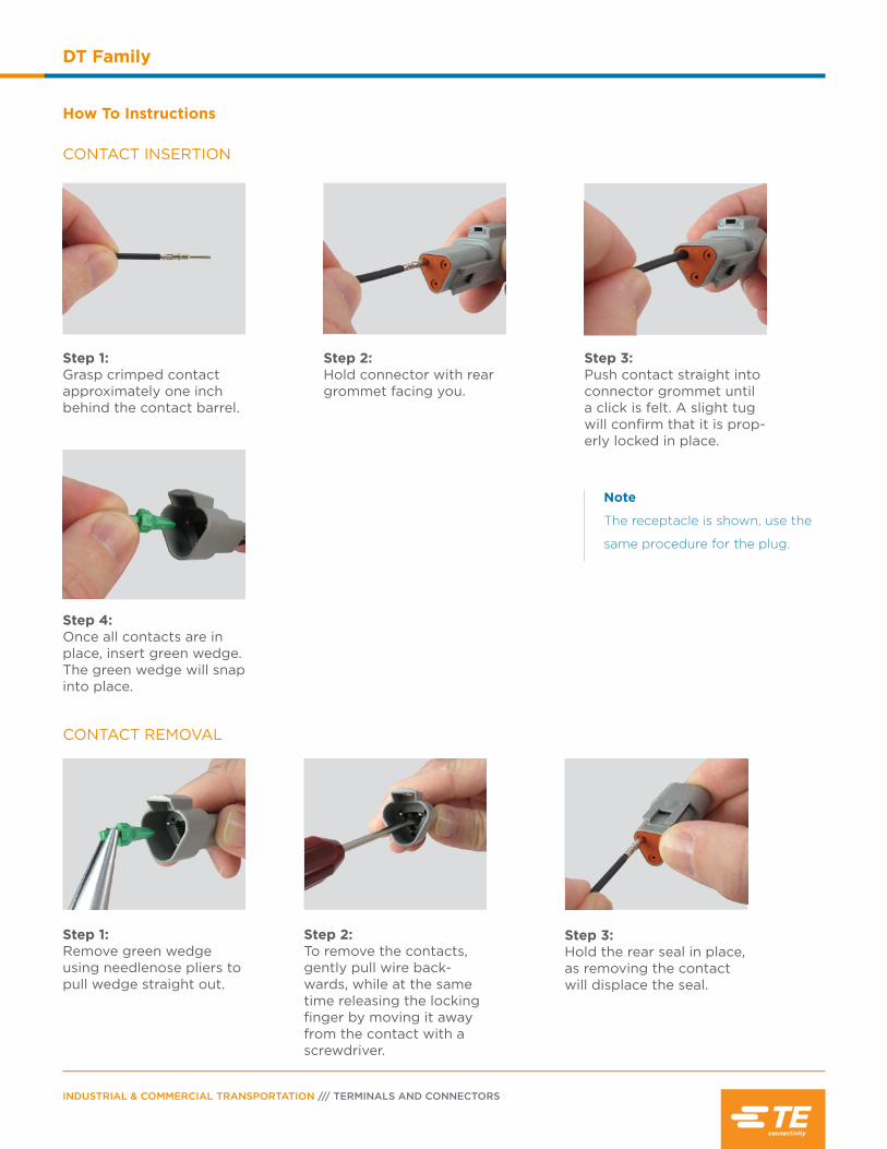
INDUSTRIAL & COMMERCIAL TRANSPORTATION /// TERMINALS AND CONNECTORS
DT Family
How To Instructions
CONTACT INSERTION
CONTACT REMOVAL
Note
The receptacle is shown, use the
same procedure for the plug.
Step 1:Grasp crimped contact approximately one inch behind the contact barrel.
Step 2:Hold connector with rear grommet facing you.
Step 3:Push contact straight into connector grommet until a click is felt. A slight tug will confirm that it is prop-erly locked in place.
Step 4:Once all contacts are in place, insert green wedge. The green wedge will snap into place.
Step 1:Remove green wedge using needlenose pliers to pull wedge straight out.
Step 2:To remove the contacts, gently pull wire back-wards, while at the same time releasing the locking finger by moving it away from the contact with a screwdriver.
Step 3:Hold the rear seal in place, as removing the contact will displace the seal.

Contents
HD10 Series Overview ..........................................134
Performance Specifications ................................134
Material Specifications ..........................................134
Dimensions ................................................................ 135
Configurations .......................................................... 136
Ordering Information ............................................. 137
Special Modifications ............................................. 138
Accessories ........................................................139-142
How To Instructions ...............................................143

INDUSTRIAL & COMMERCIAL TRANSPORTATION /// TERMINALS AND CONNECTORS
HD10 Series
HD10 Series Overview
The HD10 series is an environmentally sealed, thermoplastic, and
cylindrical connector series. With arrangements from 3 to 9 cavities,
HD10 connectors accept size 4, 12, or 16 contacts and are available
either in-line or flanged. HD10 connectors are heavily used for diagnostic
applications and are available with or without a coupling ring.
Grommet: Silicone rubber
Insert Retainer: Thermoplastic
Receptacle Interfacial Seal: Silicone rubber
Shell: Thermoplastic
MATERIAL SPECIFICATIONS
DEUTSCH CONNECTOR PERFORMANCE SPECIFICATIONS
Temperature: Operating at temperatures -55°C to +125°C
Durability: No electrical or mechanical defects after 100 cycles of engagement and disengagement.
Vibration: No unlocking or unmating and exhibits no mechanical or physical damage after sinusoidal vibration levels of 20 G’s at 10 to 2000 Hz in each of the three mutually perpendicular planes. No electrical discontinuities longer than 1 microsecond.
Fluid Resistance: Connectors show no damage when exposed to most fluids used in industrial applications.
Insulation Resistance: 1000 megohms minimum at 25°C.
Immersion: IP68 rating
Moisture Resistance: Properly wired and mated connections will withstand immersion under three feet of water without loss of electronic qualities or leakage.
Dielectric Withstanding Voltage: Current leakage less than 2 milliamps at 1500 volts AC.
Thermal Cycle: No cracking, chipping or leaking after 20 test cycles from -55°C to +125°C.
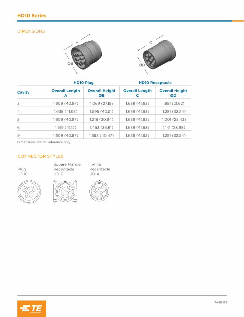
PAGE 135
HD10 Series
DIMENSIONS
HD10 Plug HD10 Receptacle
Cavity Overall Length A
Overall Height ØB
Overall Length C
Overall Height ØD
3 1.609 (40.87) 1.069 (27.15) 1.639 (41.63) .851 (21.62)
4 1.639 (41.63) 1.595 (40.51) 1.639 (41.63) 1.281 (32.54)
5 1.609 (40.87) 1.218 (30.94) 1.639 (41.63) 1.001 (25.43)
6 1.619 (41.12) 1.453 (36.91) 1.639 (41.63) 1.141 (28.98)
9 1.609 (40.87) 1.593 (40.47) 1.639 (41.63) 1.281 (32.54)
Dimensions are for reference only.
ØD
CA
ØB
CONNECTOR STYLES
Plug HD16
Square Flange Receptacle HD10
In-line Receptacle HD14
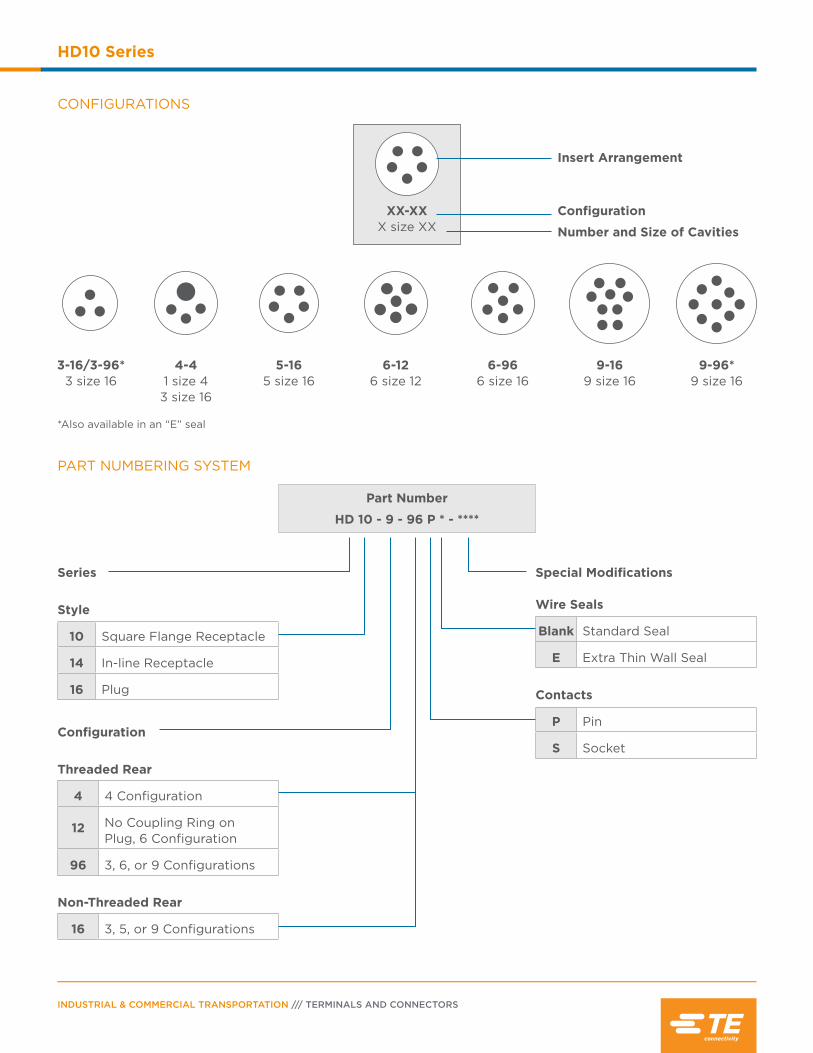
INDUSTRIAL & COMMERCIAL TRANSPORTATION /// TERMINALS AND CONNECTORS
HD10 Series
PART NUMBERING SYSTEM
Part Number
HD 10 - 9 - 96 P * - ****
Series
Style
10 Square Flange Receptacle
14 In-line Receptacle
16 Plug
Configuration
Threaded Rear
4 4 Configuration
12 No Coupling Ring on Plug, 6 Configuration
96 3, 6, or 9 Configurations
Non-Threaded Rear
16 3, 5, or 9 Configurations
Special Modifications Wire Seals
Blank Standard Seal
E Extra Thin Wall Seal
Contacts
P Pin
S Socket
XX-XXX size XX
CONFIGURATIONS
Insert Arrangement
Number and Size of Cavities
Configuration
4-41 size 43 size 16
5-165 size 16
6-126 size 12
6-966 size 16
3-16/3-96*3 size 16
*Also available in an “E” seal
9-169 size 16
9-96*9 size 16
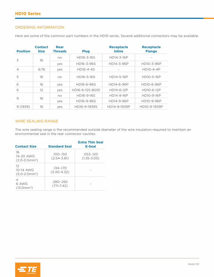
PAGE 137
HD10 Series
WIRE SEALING RANGE The wire sealing range is the recommended outside diameter of the wire insulation required to maintain an environmental seal in the rear connector cavities.
ORDERING INFORMATION Here are some of the common part numbers in the HD10 series. Several additional connectors may be available.
PositionContact
SizeRear
Threads PlugReceptacle
InlineReceptacle
Flange
3 16no HD16-3-16S HD14-3-16P -
yes HD16-3-96S HD14-3-96P HD10-3-96P
4 4/16 yes HD16-4-4S - HD10-4-4P
5 16 no HD16-5-16S HD14-5-16P HD10-5-16P
6 16 yes HD16-6-96S HD14-6-96P HD10-6-96P
6 12 yes HD16-6-12S-B010 HD14-6-12P HD10-6-12P
9 16no HD16-9-16S HD14-9-16P HD10-9-16P
yes HD16-9-96S HD14-9-96P HD10-9-96P
9 (1939) 16 yes HD16-9-1939S HD14-9-1939P HD10-9-1939P
Contact Size Standard SealExtra Thin Seal
E-Seal
1614-20 AWG (2.0-0.5mm2)
.100-.150(2.54-3.81)
.053-.120(1.35-3.05)
1210-14 AWG (5.0-2.0mm2)
.134-.170(3.40-4.32) -
46 AWG (13.0mm2)
.280-.292(7.11-7.42) -

INDUSTRIAL & COMMERCIAL TRANSPORTATION /// TERMINALS AND CONNECTORS
HD10 Series
Special Modifications
HD10 series connectors offer several modifications to enhance the design flexibility and meet application
specific needs. Options include the addition of a coupling ring and connector body color, just to mention a few.
By combining the HD10 series connectors with the available modifications and accessories, the design
possibilities are increased.
B010 MODIFICATION The B010 modification provides the addition of a coupling ring used for mating. The B010 modification is only available on the HD16-6-12S-B010 connector.
E004 MODIFICATION The E004 modification changes the HD10 series connector from the standard gray to a black connector body.
J1939 MODIFICATIONS (BP03, P080) The P080 modification changes the HD10 series connector body color from the standard gray to green and meets the J1939 Type II requirements. The BP03 modification is similar to the P080 modification, but features a panel mount.
N005 MODIFICATION The N005 modification is an HD10 series receptacle with molded-in, straight PCB pins.

PAGE 139
HD10 Series
BACKSHELLS
DEUTSCH HD10 series backshells are designed to screw onto all threaded HD10 connectors. Rated for temperatures from -40°C to +134°C, the rigid, durable backshells offer a high level of protection, provide strain relief, and improve aesthetics.
Connector Part Number CableDiameter
BackshellPart Number
Compression NutPart Number
HD1*-3-96* .187-.300 M902-2131 M902-2041
.300-.430 M902-2132 M902-2042
HD1*-6-96*/HD1*-6-12* .187-.300 M902-2161 M902-2041
.300-.430 M902-2162 M902-2042
.430-.570 M902-2163 M902-2053
.570-.710 M902-2164 M902-2054
HD1*-9-96*/HD1*-9-1939** .187-.300 M902-2191 M902-2041
.300-.430 M902-2192 M902-2042
.430-.570 M902-2193 M902-2053
.570-.710 M902-2194 M902-2054
Backshell Technical Specifications:Material - PC/PET Polyester Blend, UV-Stabilized, Flame Retardant, Black Flammability - UL94-VO rated material, Weatherability - UL746C
Accessories
Several accessory items are available to complement HD10 series connectors including boots, backshells, gaskets,
and protective caps. Accessory items cover a wide array of design requirements such as assisting with mounting,
providing additional protection, and offering enhanced aesthetics.
LA
D
D D istrib
utio
n
Exclusive to

helpful hint
INDUSTRIAL & COMMERCIAL TRANSPORTATION /// TERMINALS AND CONNECTORS
HD10 Series
Part Number Description
HD10-3BT 3 cavity boot, gray
HD10-5BT 5 cavity boot, gray
HD10-5BT-BK 5 cavity boot, black
HD10-6BT 6 cavity boot, gray
HD10-6BT-BK 6 cavity boot, black
HD10-9BT 9 cavity boot, gray
HD10-9BT-BK 9 cavity boot, black
*Distorting the boots can lessen their longevity
BOOTS
Boots provide a professional looking finishing touch for DEUTSCH HD10 series connectors. Made of durable plastisol, these slip-on boots are not only aesthetically appealing, but also provide increased protection from dirt, paint overspray, and pressure washing. The plastisol boots are rated from -20°F to +212°F (-28°C to + 100°C) and offer a slip-on design making installation quick and easy.
Part Number Description
HD18-003 3 cavity strain relief
HD18-006 6 cavity strain relief
HD18-009 4 or 9 cavity strain relief
STRAIN RELIEF DEUTSCH HD10 series strain reliefs are designed to screw onto threaded 3, 4, 6, and 9 cavity HD10 connectors. The rigid, durable strain reliefs offer a high level of protection, provide tie wrap holders to reduce strain from the wires, and improve aesthetics.
Attaching the connector to a structure eliminates straining the electrical system in service.
LA
D
D D istrib
utio
n
Exclusive to
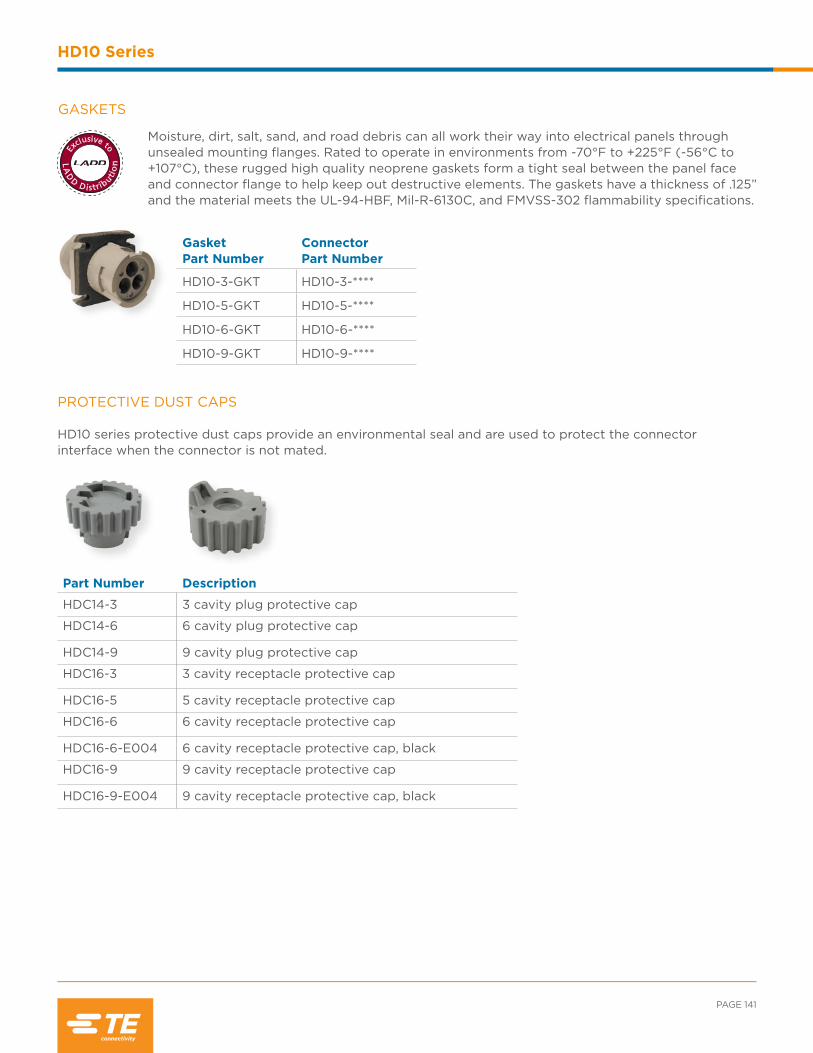
PAGE 141
HD10 Series
GASKETS
Moisture, dirt, salt, sand, and road debris can all work their way into electrical panels through unsealed mounting flanges. Rated to operate in environments from -70°F to +225°F (-56°C to +107°C), these rugged high quality neoprene gaskets form a tight seal between the panel face and connector flange to help keep out destructive elements. The gaskets have a thickness of .125” and the material meets the UL-94-HBF, Mil-R-6130C, and FMVSS-302 flammability specifications.
Gasket Part Number
Connector Part Number
HD10-3-GKT HD10-3-****
HD10-5-GKT HD10-5-****
HD10-6-GKT HD10-6-****
HD10-9-GKT HD10-9-****
PROTECTIVE DUST CAPS HD10 series protective dust caps provide an environmental seal and are used to protect the connector interface when the connector is not mated.
Part Number Description
HDC14-3 3 cavity plug protective cap
HDC14-6 6 cavity plug protective cap
HDC14-9 9 cavity plug protective cap
HDC16-3 3 cavity receptacle protective cap
HDC16-5 5 cavity receptacle protective cap
HDC16-6 6 cavity receptacle protective cap
HDC16-6-E004 6 cavity receptacle protective cap, black
HDC16-9 9 cavity receptacle protective cap
HDC16-9-E004 9 cavity receptacle protective cap, black
LA
D
D D istrib
utio
n
Exclusive to
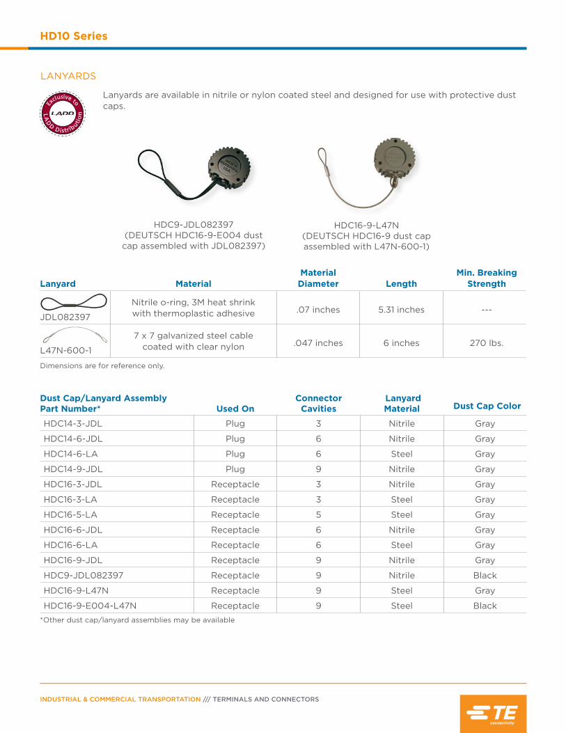
INDUSTRIAL & COMMERCIAL TRANSPORTATION /// TERMINALS AND CONNECTORS
HD10 Series
LANYARDS
Lanyards are available in nitrile or nylon coated steel and designed for use with protective dust caps.
HDC16-9-L47N(DEUTSCH HDC16-9 dust capassembled with L47N-600-1)
HDC9-JDL082397 (DEUTSCH HDC16-9-E004 dust
cap assembled with JDL082397)
Dust Cap/Lanyard Assembly Part Number* Used On
Connector Cavities
Lanyard Material Dust Cap Color
HDC14-3-JDL Plug 3 Nitrile Gray
HDC14-6-JDL Plug 6 Nitrile Gray
HDC14-6-LA Plug 6 Steel Gray
HDC14-9-JDL Plug 9 Nitrile Gray
HDC16-3-JDL Receptacle 3 Nitrile Gray
HDC16-3-LA Receptacle 3 Steel Gray
HDC16-5-LA Receptacle 5 Steel Gray
HDC16-6-JDL Receptacle 6 Nitrile Gray
HDC16-6-LA Receptacle 6 Steel Gray
HDC16-9-JDL Receptacle 9 Nitrile Gray
HDC9-JDL082397 Receptacle 9 Nitrile Black
HDC16-9-L47N Receptacle 9 Steel Gray
HDC16-9-E004-L47N Receptacle 9 Steel Black
*Other dust cap/lanyard assemblies may be available
Lanyard MaterialMaterial Diameter Length
Min. Breaking Strength
JDL082397
Nitrile o-ring, 3M heat shrink with thermoplastic adhesive .07 inches 5.31 inches ---
L47N-600-1
7 x 7 galvanized steel cable coated with clear nylon .047 inches 6 inches 270 lbs.
Dimensions are for reference only.
LA
D
D D istrib
utio
n
Exclusive to
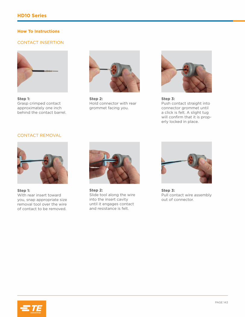
PAGE 143
HD10 Series
How To Instructions
CONTACT INSERTION
CONTACT REMOVAL
Step 1:Grasp crimped contact approximately one inch behind the contact barrel.
Step 2:Hold connector with rear grommet facing you.
Step 3:Push contact straight into connector grommet until a click is felt. A slight tug will confirm that it is prop-erly locked in place.
Step 1:With rear insert toward you, snap appropriate size removal tool over the wire of contact to be removed.
Step 2:Slide tool along the wire into the insert cavity until it engages contact and resistance is felt.
Step 3:Pull contact wire assembly out of connector.

INDUSTRIAL & COMMERCIAL TRANSPORTATION /// TERMINALS AND CONNECTORS
HD10 Series
NOTES:
Contents
HD30 & HDP20 Series Overview ......................145
Performance Specifications ................................146
Material Specifications .......................................... 147
Dimensions ................................................................ 147
Configurations ................................................. 148-149
Ordering Information ......................................150-151
Special Modifications .....................................153-154
Accessories ........................................................154-158
Mounting ............................................................158-159
How To Instructions ...................................... 159-160
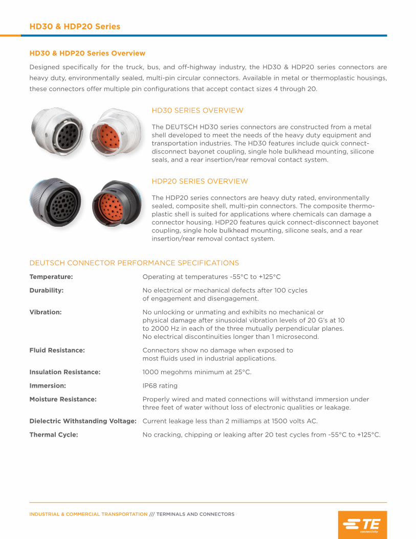
INDUSTRIAL & COMMERCIAL TRANSPORTATION /// TERMINALS AND CONNECTORS
HD30 & HDP20 Series
HD30 & HDP20 Series Overview
Designed specifically for the truck, bus, and off-highway industry, the HD30 & HDP20 series connectors are
heavy duty, environmentally sealed, multi-pin circular connectors. Available in metal or thermoplastic housings,
these connectors offer multiple pin configurations that accept contact sizes 4 through 20.
HD30 SERIES OVERVIEW The DEUTSCH HD30 series connectors are constructed from a metal shell developed to meet the needs of the heavy duty equipment and transportation industries. The HD30 features include quick connect-disconnect bayonet coupling, single hole bulkhead mounting, silicone seals, and a rear insertion/rear removal contact system.
HDP20 SERIES OVERVIEW The HDP20 series connectors are heavy duty rated, environmentally sealed, composite shell, multi-pin connectors. The composite thermo-plastic shell is suited for applications where chemicals can damage a connector housing. HDP20 features quick connect-disconnect bayonet coupling, single hole bulkhead mounting, silicone seals, and a rear insertion/rear removal contact system.
DEUTSCH CONNECTOR PERFORMANCE SPECIFICATIONS
Temperature: Operating at temperatures -55°C to +125°C
Durability: No electrical or mechanical defects after 100 cycles of engagement and disengagement.
Vibration: No unlocking or unmating and exhibits no mechanical or physical damage after sinusoidal vibration levels of 20 G’s at 10 to 2000 Hz in each of the three mutually perpendicular planes. No electrical discontinuities longer than 1 microsecond.
Fluid Resistance: Connectors show no damage when exposed to most fluids used in industrial applications.
Insulation Resistance: 1000 megohms minimum at 25°C.
Immersion: IP68 rating
Moisture Resistance: Properly wired and mated connections will withstand immersion under three feet of water without loss of electronic qualities or leakage.
Dielectric Withstanding Voltage: Current leakage less than 2 milliamps at 1500 volts AC.
Thermal Cycle: No cracking, chipping or leaking after 20 test cycles from -55°C to +125°C.
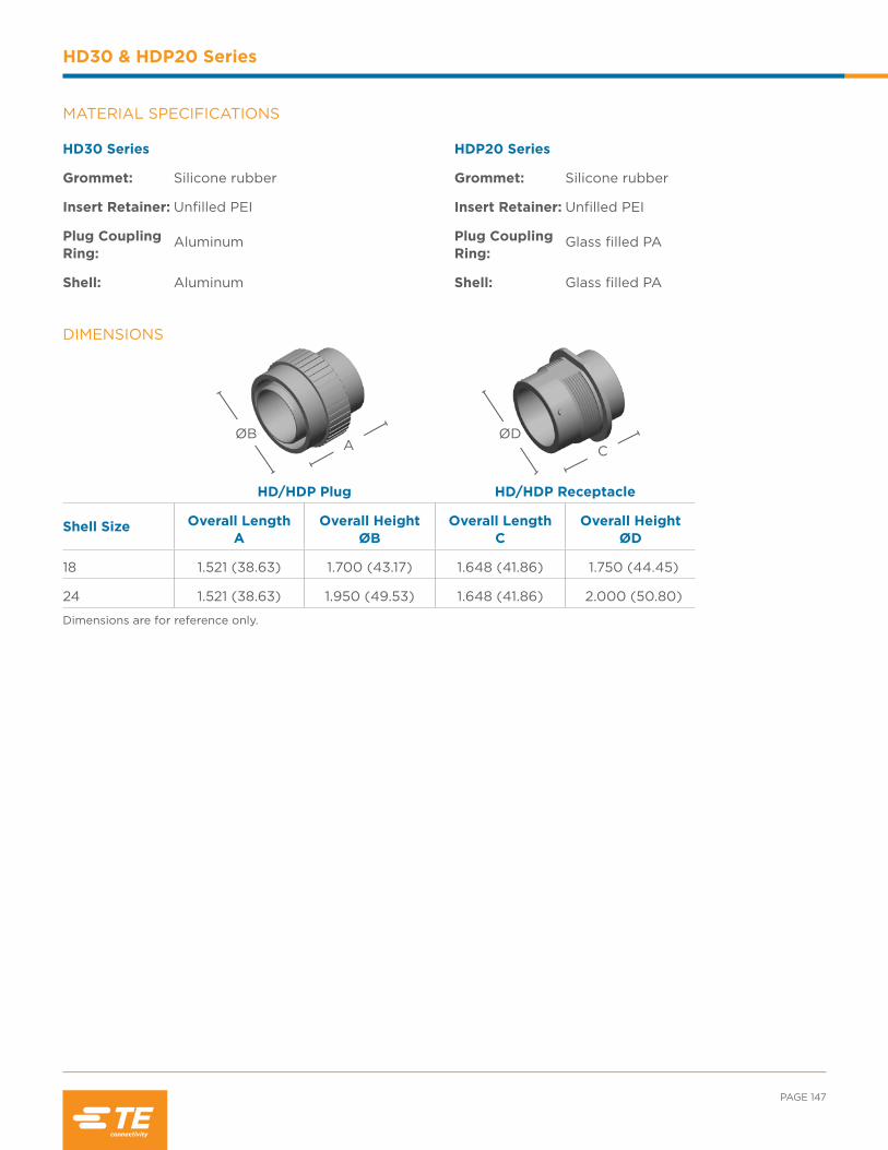
PAGE 147
HD30 & HDP20 Series
HDP20 Series
Grommet: Silicone rubber
Insert Retainer: Unfilled PEI
Plug Coupling Ring:
Glass filled PA
Shell: Glass filled PA
HD30 Series
Grommet: Silicone rubber
Insert Retainer: Unfilled PEI
Plug Coupling Ring:
Aluminum
Shell: Aluminum
MATERIAL SPECIFICATIONS
DIMENSIONS
HD/HDP Plug HD/HDP Receptacle
Shell Size Overall Length A
Overall Height ØB
Overall Length C
Overall Height ØD
18 1.521 (38.63) 1.700 (43.17) 1.648 (41.86) 1.750 (44.45)
24 1.521 (38.63) 1.950 (49.53) 1.648 (41.86) 2.000 (50.80)
Dimensions are for reference only.
CØD
AØB
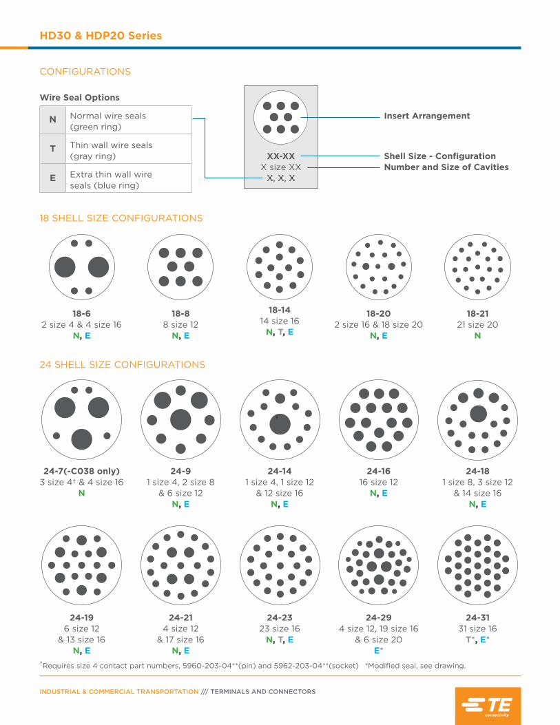
INDUSTRIAL & COMMERCIAL TRANSPORTATION /// TERMINALS AND CONNECTORS
HD30 & HDP20 Series
CONFIGURATIONS
18 SHELL SIZE CONFIGURATIONS
24 SHELL SIZE CONFIGURATIONS
Wire Seal Options
N Normal wire seals (green ring)
T Thin wall wire seals (gray ring)
E Extra thin wall wire seals (blue ring)
XX-XXX size XX
X, X, X
Insert Arrangement
Number and Size of CavitiesShell Size - Configuration
*Modified seal, see drawing.†Requires size 4 contact part numbers, 5960-203-04**(pin) and 5962-203-04**(socket)
18-88 size 12
N, E
18-1414 size 16
N, T, E
18-202 size 16 & 18 size 20
N, E
18-62 size 4 & 4 size 16
N, E
18-2121 size 20
N
24-7(-C038 only)3 size 4† & 4 size 16
N
1
24-14 1 size 4, 1 size 12
& 12 size 16 N, E
24-1616 size 12
N, E
24-9 1 size 4, 2 size 8
& 6 size 12 N, E
24-18 1 size 8, 3 size 12
& 14 size 16 N, E
24-214 size 12
& 17 size 16N, E
24-196 size 12
& 13 size 16N, E
24-2323 size 16
N, T, E
24-294 size 12, 19 size 16
& 6 size 20E*
24-3131 size 16
T*, E*
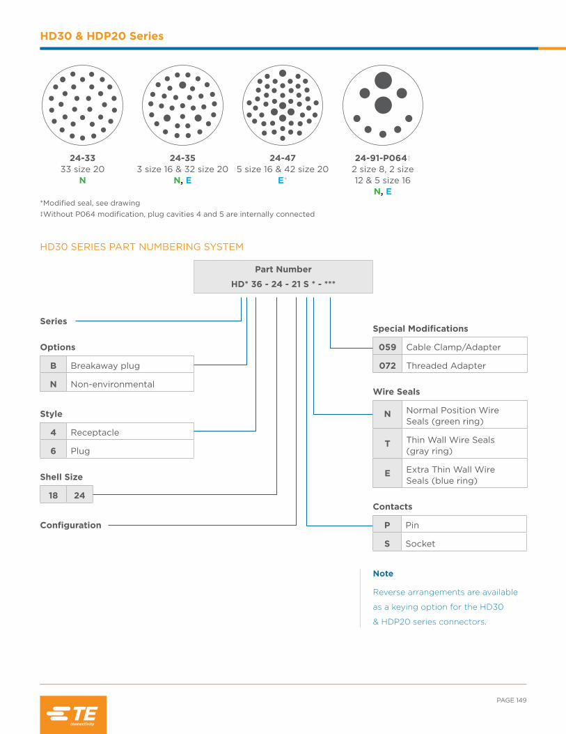
*Modified seal, see drawing ‡Without P064 modification, plug cavities 4 and 5 are internally connected
24-91-P064‡2 size 8, 2 size 12 & 5 size 16
N, E
24-475 size 16 & 42 size 20
E*
24-353 size 16 & 32 size 20
N, E
24-3333 size 20
N
PAGE 149
HD30 & HDP20 Series
HD30 SERIES PART NUMBERING SYSTEM
Part Number
HD* 36 - 24 - 21 S * - ***
Series
Options
B Breakaway plug
N Non-environmental
Style
4 Receptacle
6 Plug
Shell Size
18 24
Configuration
Special Modifications
059 Cable Clamp/Adapter
072 Threaded Adapter
Wire Seals
N Normal Position Wire Seals (green ring)
T Thin Wall Wire Seals (gray ring)
E Extra Thin Wall Wire Seals (blue ring)
Contacts
P Pin
S Socket
Note
Reverse arrangements are available
as a keying option for the HD30
& HDP20 series connectors.

helpful hint
INDUSTRIAL & COMMERCIAL TRANSPORTATION /// TERMINALS AND CONNECTORS
HD30 & HDP20 Series
HDP20 SERIES PART NUMBERING SYSTEM
Part Number
HDP 26 - 24 - 21 S * - ****
Series
Style
4 Receptacle
6 Plug
Shell Size
18 24
Configuration
Contacts
P Pin
S Socket
Special Modifications
L015 Threaded Adapter
L017 Ring Adapter
L024 Wide Threaded Adapter
Wire Seals
N Normal Position Wire Seals (green ring)
T Thin Wall Wire Seals (gray ring)
E Extra Thin Wall Wire Seals (blue ring)
Making the socket contact side the “hot side” can reduce the danger of electric shock.
ORDERING INFORMATION Here are some of the common part numbers in the HD30 &HDP20 series. Several additional connectors may be available.
Shell Sz-Position Series
Plug Standard Dia. Seal
Receptacle Standard Dia. Seal
Plug Reduced Dia. Seal
Receptacle Reduced Dia. Seal
18-6HDP20 HDP26-18-6SN HDP24-18-6PN HDP26-18-6SE HDP24-18-6PE
HD30 HD36-18-6SN HD34-18-6PN HD36-18-6SE HD34-18-6PE
18-8HDP20 HDP26-18-8SN HDP24-18-8PN HDP26-18-8SE HDP24-18-8PE
HD30 HD36-18-8SN HD34-18-8PN HD36-18-8SE HD34-18-8PE
18-14HDP20 HDP26-18-14SN HDP24-18-14PN HDP26-18-14SE HDP24-18-14PE
HD30 HD36-18-14SN HD34-18-14PN HD36-18-14SE HD34-18-14PE
18-20HDP20 HDP26-18-20SN HDP24-18-20PN HDP26-18-20SE HDP24-18-20PE
HD30 HD36-18-20SN HD34-18-20PN HD36-18-20SE HD34-18-20PE
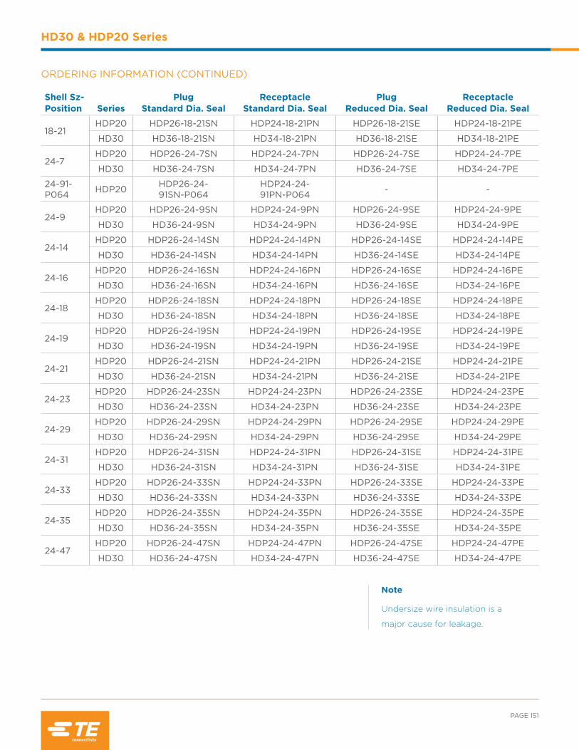
PAGE 151
HD30 & HDP20 Series
ORDERING INFORMATION (CONTINUED)
Shell Sz-Position Series
Plug Standard Dia. Seal
Receptacle Standard Dia. Seal
Plug Reduced Dia. Seal
Receptacle Reduced Dia. Seal
18-21HDP20 HDP26-18-21SN HDP24-18-21PN HDP26-18-21SE HDP24-18-21PE
HD30 HD36-18-21SN HD34-18-21PN HD36-18-21SE HD34-18-21PE
24-7HDP20 HDP26-24-7SN HDP24-24-7PN HDP26-24-7SE HDP24-24-7PE
HD30 HD36-24-7SN HD34-24-7PN HD36-24-7SE HD34-24-7PE
24-91-P064 HDP20 HDP26-24-
91SN-P064HDP24-24-91PN-P064 - -
24-9HDP20 HDP26-24-9SN HDP24-24-9PN HDP26-24-9SE HDP24-24-9PE
HD30 HD36-24-9SN HD34-24-9PN HD36-24-9SE HD34-24-9PE
24-14HDP20 HDP26-24-14SN HDP24-24-14PN HDP26-24-14SE HDP24-24-14PE
HD30 HD36-24-14SN HD34-24-14PN HD36-24-14SE HD34-24-14PE
24-16HDP20 HDP26-24-16SN HDP24-24-16PN HDP26-24-16SE HDP24-24-16PE
HD30 HD36-24-16SN HD34-24-16PN HD36-24-16SE HD34-24-16PE
24-18HDP20 HDP26-24-18SN HDP24-24-18PN HDP26-24-18SE HDP24-24-18PE
HD30 HD36-24-18SN HD34-24-18PN HD36-24-18SE HD34-24-18PE
24-19HDP20 HDP26-24-19SN HDP24-24-19PN HDP26-24-19SE HDP24-24-19PE
HD30 HD36-24-19SN HD34-24-19PN HD36-24-19SE HD34-24-19PE
24-21HDP20 HDP26-24-21SN HDP24-24-21PN HDP26-24-21SE HDP24-24-21PE
HD30 HD36-24-21SN HD34-24-21PN HD36-24-21SE HD34-24-21PE
24-23HDP20 HDP26-24-23SN HDP24-24-23PN HDP26-24-23SE HDP24-24-23PE
HD30 HD36-24-23SN HD34-24-23PN HD36-24-23SE HD34-24-23PE
24-29HDP20 HDP26-24-29SN HDP24-24-29PN HDP26-24-29SE HDP24-24-29PE
HD30 HD36-24-29SN HD34-24-29PN HD36-24-29SE HD34-24-29PE
24-31HDP20 HDP26-24-31SN HDP24-24-31PN HDP26-24-31SE HDP24-24-31PE
HD30 HD36-24-31SN HD34-24-31PN HD36-24-31SE HD34-24-31PE
24-33HDP20 HDP26-24-33SN HDP24-24-33PN HDP26-24-33SE HDP24-24-33PE
HD30 HD36-24-33SN HD34-24-33PN HD36-24-33SE HD34-24-33PE
24-35HDP20 HDP26-24-35SN HDP24-24-35PN HDP26-24-35SE HDP24-24-35PE
HD30 HD36-24-35SN HD34-24-35PN HD36-24-35SE HD34-24-35PE
24-47HDP20 HDP26-24-47SN HDP24-24-47PN HDP26-24-47SE HDP24-24-47PE
HD30 HD36-24-47SN HD34-24-47PN HD36-24-47SE HD34-24-47PE
Note
Undersize wire insulation is a
major cause for leakage.

Color Coded Ring
Color code is visible from the rear of the receptacle or plug.
Green: Normal SealGray: Thin Wall SealBlue: Extra Thin Wall Seal
INDUSTRIAL & COMMERCIAL TRANSPORTATION /// TERMINALS AND CONNECTORS
HD30 & HDP20 Series
WIRE SEALING RANGE The wire sealing range is the recommended outside diameter of the wire insulation required to maintain an environmental seal in the rear connector cavities.
Contact SizeN-Seal
Green RingT-Seal
Gray RingT-Seal
Modified*E-Seal
Blue RingE-Seal
Modified*
2014-22 AWG (2.5-0.35mm2)
.040-.095(1.02-2.41)
.040-.095(1.02-2.41) - .040-.095
(1.02-2.41).040-.083(1.01-2.10)
1614-20 AWG (2.0-0.5mm2)
.100-.134(2.54-3.40)
.088-.134(2.23-3.40)
.088-.106(2.24-2.69)
.053-.120(1.35-3.05)
.053-.103(1.35-2.62)
1210-14 AWG (6.0-2.0mm2)
.134-.170(3.40-4.32)
.113-.170(2.87-4.32) - .097-.158
(2.46-4.01).097-.158
(2.46-4.01)
88-10 AWG (10.0-5.0mm2)
.190-.240(4.83-6.10)
.170-.240(4.32-6.10) - .135-.220
(3.43-5.59) -
46 AWG (16.0-13.0mm2)
.280-.292(7.11-7.42)
.261-.292(6.63-7.42) - .261-.292
(6.63-7.42) -
44 AWG (25.0-21.0mm2)
.311-.420(7.90-10.67) - - - -
*DEUTSCH cavity arrangements 24-29, 24-47, and 24-31 are only available with the modified seals. Arrangement 24-31 Modified E Seal = .053-.106. Please see drawings 0425-016-0000 and 0425-021-0000 for full specifications.
Ø
helpful hint
Proper wire outside diameters help provide water tight seals.
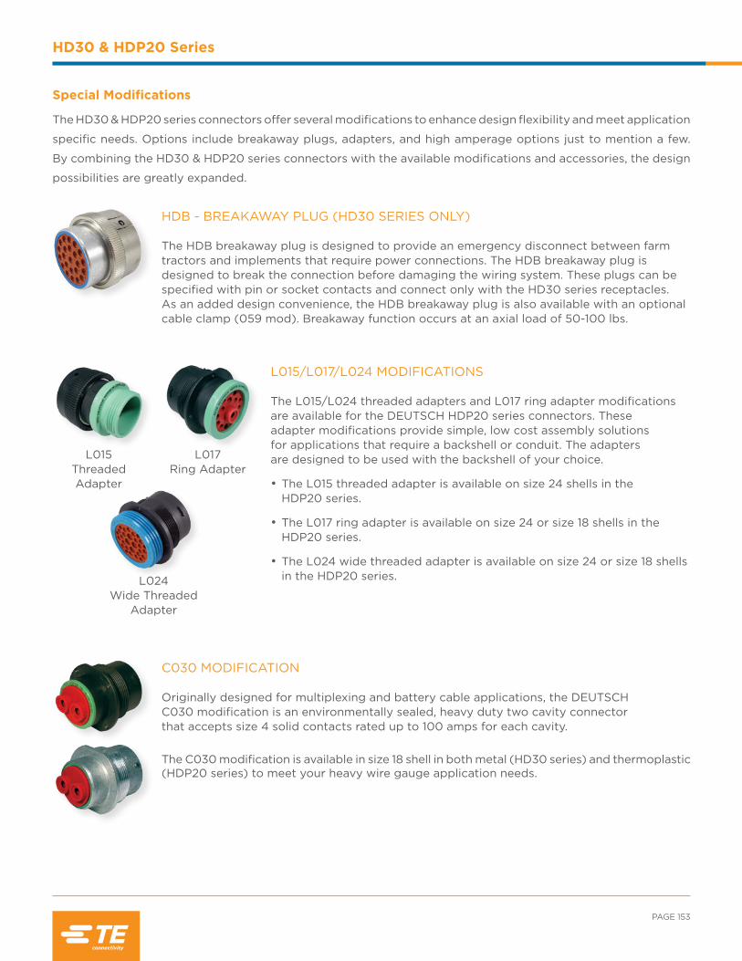
PAGE 153
HD30 & HDP20 Series
HDB - BREAKAWAY PLUG (HD30 SERIES ONLY) The HDB breakaway plug is designed to provide an emergency disconnect between farm tractors and implements that require power connections. The HDB breakaway plug is designed to break the connection before damaging the wiring system. These plugs can be specified with pin or socket contacts and connect only with the HD30 series receptacles. As an added design convenience, the HDB breakaway plug is also available with an optional cable clamp (059 mod). Breakaway function occurs at an axial load of 50-100 lbs.
Special Modifications
The HD30 & HDP20 series connectors offer several modifications to enhance design flexibility and meet application
specific needs. Options include breakaway plugs, adapters, and high amperage options just to mention a few.
By combining the HD30 & HDP20 series connectors with the available modifications and accessories, the design
possibilities are greatly expanded.
L015/L017/L024 MODIFICATIONS The L015/L024 threaded adapters and L017 ring adapter modifications are available for the DEUTSCH HDP20 series connectors. These adapter modifications provide simple, low cost assembly solutions for applications that require a backshell or conduit. The adapters are designed to be used with the backshell of your choice.
• The L015 threaded adapter is available on size 24 shells in the HDP20 series.
• The L017 ring adapter is available on size 24 or size 18 shells in the HDP20 series.
• The L024 wide threaded adapter is available on size 24 or size 18 shells in the HDP20 series.
L015Threaded Adapter
L024Wide Threaded
Adapter
L017Ring Adapter
C030 MODIFICATION Originally designed for multiplexing and battery cable applications, the DEUTSCH C030 modification is an environmentally sealed, heavy duty two cavity connector that accepts size 4 solid contacts rated up to 100 amps for each cavity.
The C030 modification is available in size 18 shell in both metal (HD30 series) and thermoplastic (HDP20 series) to meet your heavy wire gauge application needs.

INDUSTRIAL & COMMERCIAL TRANSPORTATION /// TERMINALS AND CONNECTORS
HD30 & HDP20 Series
BOOTS
Boots provide a professional looking finishing touch for the DEUTSCH HD30 & HDP20 family of connectors. Made of durable plastisol, these slip-on boots are not only aesthetically appealing, but also provide increased protection from dirt, paint overspray, and pressure washing. The plastisol boots are rated from -20°F to +212°F (-28°C to +100°C) and offer a slip-on design making installation quick and easy.
Accessories
Several accessory items can be used to complement the connectors. The HD30 & HDP20 family accessories
include items such as boots, backshells, gaskets, and protective caps. Accessories are designed to complete the
application and meet a wide array of design requirements such as solutions for mounting, providing additional
protection, and offering increased aesthetics.
CABLE CLAMP/BACKSHELL MODIFICATIONS DEUTSCH cable clamps provide positive support to the wire bundle while reducing strain on the connector. The backshell is available with or without drain holes.
Part Number Suffix Description
-072 Adapter only
-059 Adapter and cable clamp assembly with drain holes
-L006 Adapter and cable clamp assembly without drain holes
Part Number Description
HD30-18BT 18 shell size boot, gray
HD30-18BT-BK 18 shell size boot, black
HD30-18BT-90-BK 18 shell size boot, 90° bend, black
LC-90BT-HT 18 shell size boot, 90° bend, high temperature material, yellow
HD30-24BT 24 shell size boot, gray
HD30-24BT-BK 24 shell size boot, black
HD30-24BT-90-BK 24 shell size boot, 90° bend, black
MT-90BT-HT-24 24 shell size boot, 90° bend, high temperature material, yellow
*Distorting the boots can lessen their longevity
C041/CL20 MODIFICATIONS The C041 and CL20 modifications are available for the DEUTSCH HDP20 series 14 pin connector. The C041 modification features a data link key and reduced diameter seals on the receptacle. The CL20 modification includes a ring adapter, reduced diameter seals, and a data link key on the plug.
LA
D
D D istrib
utio
n
Exclusive to

PAGE 155
HD30 & HDP20 Series
HDP20 Series Dust Caps
Shell Size Part Number Description
18 HDC26-18 Plug cap for receptacle protection, environmentally sealed24 HDC26-24
Shell Size Orientation HD30 Series Backshell Part Number
18Straight
WHDS-18-1
24 WHDS-24-1
1890°
WHDS-18-2
24 WHDS-24-2
HD30 Series Dust Caps
Shell Size Part Number Description
18 HDC36-18Plug cap for receptacle protection
24 HDC36-24
18 HDC34-18Receptacle cap for plug protection
24 HDC34-24
*To order HD30(HD3*-**) protective caps without the mounting chain, add -1E to the end of the part number
PROTECTIVE DUST CAPS Protective caps are available for both plug and receptacle halves of the connectors. The metal caps, for use with the HD30 series, come with a mounting chain and are used to protect the connector while not mated. The thermoplastic caps, for use with the HDP20 series, are available with or without a lanyard.
STRAIN RELIEF The DEUTSCH HD30 & HDP20 series connectors offer several backshell options to meet your design needs. Backshell options include straight or 90° and plastic or metal. The metal backshells work best with the HD30 series. It is attached to the rear of the connector using an adjustable screw and is secured to the wire bundle with the use of a tie wrap. The plastic backshells work best with the HDP20 series and attach to the rear of the connector with either a clamshell snap closure or by screwing them on to a threaded adapter. The rigid, durable backshells offer a high level of protection, provide strain relief, and improve aesthetics.
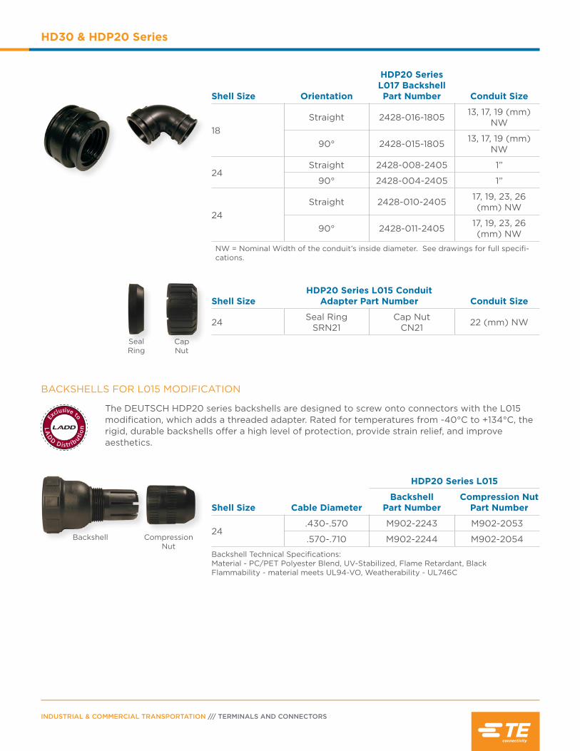
INDUSTRIAL & COMMERCIAL TRANSPORTATION /// TERMINALS AND CONNECTORS
HD30 & HDP20 Series
BACKSHELLS FOR L015 MODIFICATION
The DEUTSCH HDP20 series backshells are designed to screw onto connectors with the L015 modification, which adds a threaded adapter. Rated for temperatures from -40°C to +134°C, the rigid, durable backshells offer a high level of protection, provide strain relief, and improve aesthetics.
Shell Size Orientation
HDP20 Series L017 Backshell Part Number Conduit Size
18Straight 2428-016-1805 13, 17, 19 (mm)
NW
90° 2428-015-1805 13, 17, 19 (mm) NW
24Straight 2428-008-2405 1”
90° 2428-004-2405 1”
24Straight 2428-010-2405 17, 19, 23, 26
(mm) NW
90° 2428-011-2405 17, 19, 23, 26 (mm) NW
NW = Nominal Width of the conduit’s inside diameter. See drawings for full specifi-cations.
Shell SizeHDP20 Series L015 Conduit
Adapter Part Number Conduit Size
24 Seal Ring SRN21
Cap Nut CN21 22 (mm) NW
HDP20 Series L015
Shell Size Cable DiameterBackshell
Part NumberCompression Nut
Part Number
24.430-.570 M902-2243 M902-2053
.570-.710 M902-2244 M902-2054
Backshell Technical Specifications:Material - PC/PET Polyester Blend, UV-Stabilized, Flame Retardant, BlackFlammability - material meets UL94-VO, Weatherability - UL746C
SealRing
CapNut
Backshell CompressionNut
LA
D
D D istrib
utio
n
Exclusive to
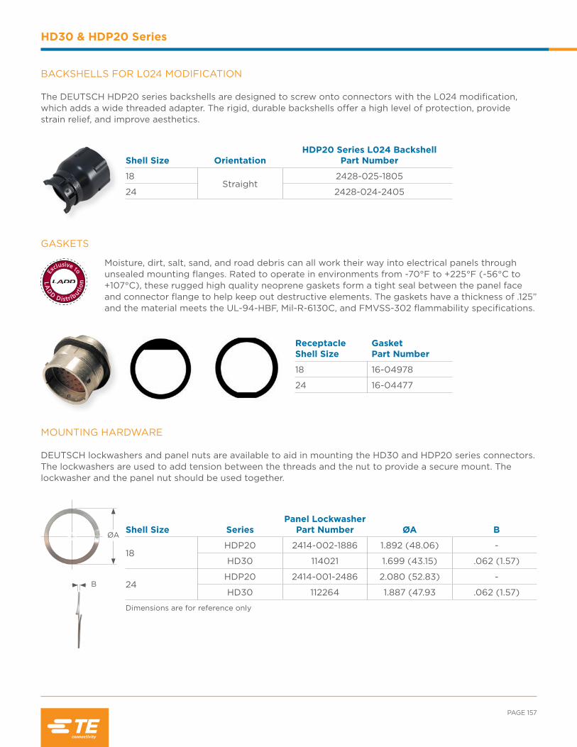
PAGE 157
HD30 & HDP20 Series
GASKETS
Moisture, dirt, salt, sand, and road debris can all work their way into electrical panels through unsealed mounting flanges. Rated to operate in environments from -70°F to +225°F (-56°C to +107°C), these rugged high quality neoprene gaskets form a tight seal between the panel face and connector flange to help keep out destructive elements. The gaskets have a thickness of .125” and the material meets the UL-94-HBF, Mil-R-6130C, and FMVSS-302 flammability specifications.
Shell Size OrientationHDP20 Series L024 Backshell
Part Number
18Straight
2428-025-1805
24 2428-024-2405
Receptacle Shell Size
Gasket Part Number
18 16-04978
24 16-04477
BACKSHELLS FOR L024 MODIFICATION The DEUTSCH HDP20 series backshells are designed to screw onto connectors with the L024 modification, which adds a wide threaded adapter. The rigid, durable backshells offer a high level of protection, provide strain relief, and improve aesthetics.
MOUNTING HARDWARE DEUTSCH lockwashers and panel nuts are available to aid in mounting the HD30 and HDP20 series connectors. The lockwashers are used to add tension between the threads and the nut to provide a secure mount. The lockwasher and the panel nut should be used together.
B
ØA Shell Size Series
Panel Lockwasher Part Number ØA B
18HDP20 2414-002-1886 1.892 (48.06) -
HD30 114021 1.699 (43.15) .062 (1.57)
24HDP20 2414-001-2486 2.080 (52.83) -
HD30 112264 1.887 (47.93 .062 (1.57)
Dimensions are for reference only
LA
D
D D istrib
utio
n
Exclusive to
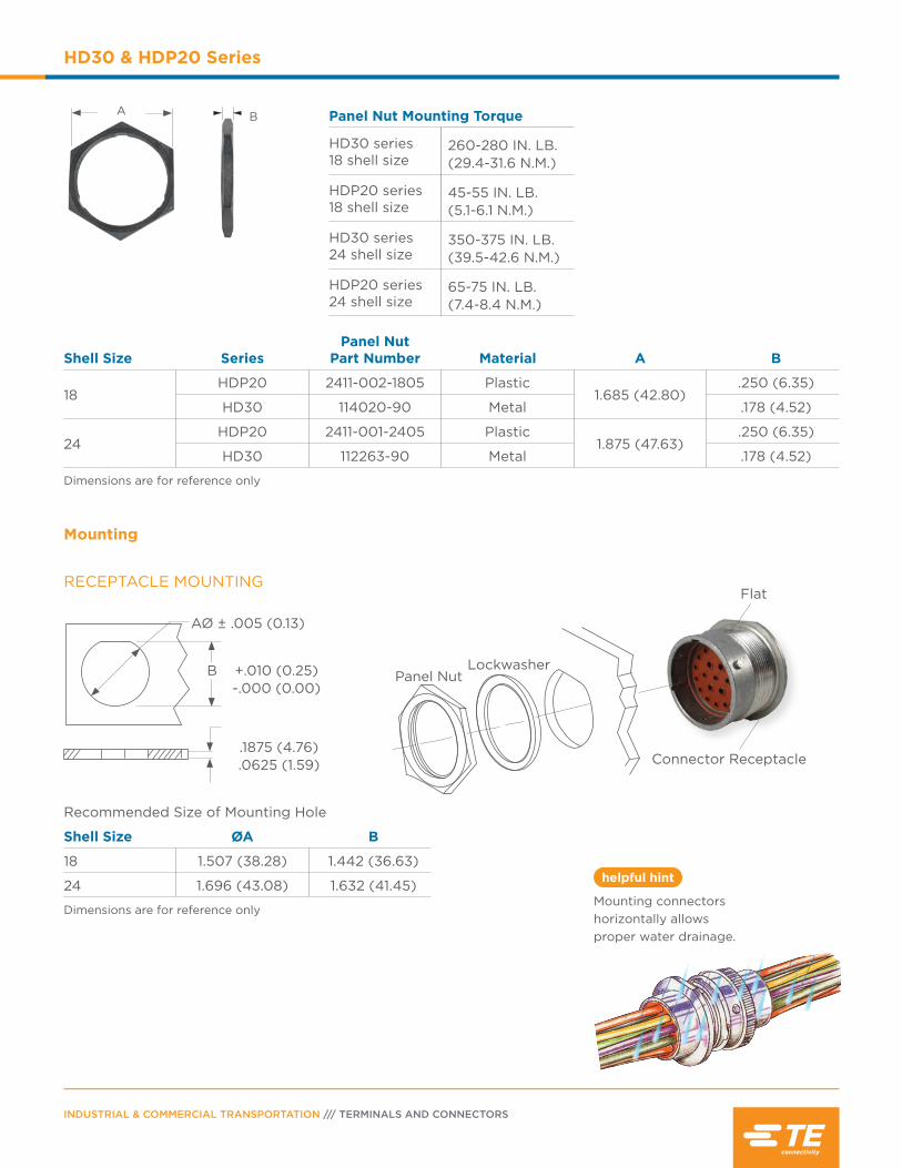
INDUSTRIAL & COMMERCIAL TRANSPORTATION /// TERMINALS AND CONNECTORS
HD30 & HDP20 Series
Shell Size SeriesPanel Nut
Part Number Material A B
18HDP20 2411-002-1805 Plastic
1.685 (42.80).250 (6.35)
HD30 114020-90 Metal .178 (4.52)
24HDP20 2411-001-2405 Plastic
1.875 (47.63).250 (6.35)
HD30 112263-90 Metal .178 (4.52)
Dimensions are for reference only
A B Panel Nut Mounting Torque
HD30 series 18 shell size
260-280 IN. LB.(29.4-31.6 N.M.)
HDP20 series 18 shell size
45-55 IN. LB.(5.1-6.1 N.M.)
HD30 series 24 shell size
350-375 IN. LB.(39.5-42.6 N.M.)
HDP20 series 24 shell size
65-75 IN. LB.(7.4-8.4 N.M.)
RECEPTACLE MOUNTING
Recommended Size of Mounting Hole
Shell Size ØA B
18 1.507 (38.28) 1.442 (36.63)
24 1.696 (43.08) 1.632 (41.45)
Dimensions are for reference only
Mounting
AØ ± .005 (0.13)
+.010 (0.25)-.000 (0.00)
.1875 (4.76).0625 (1.59)
Panel NutLockwasher
Connector Receptacle
Flat
helpful hint
Mounting connectors horizontally allows proper water drainage.
B
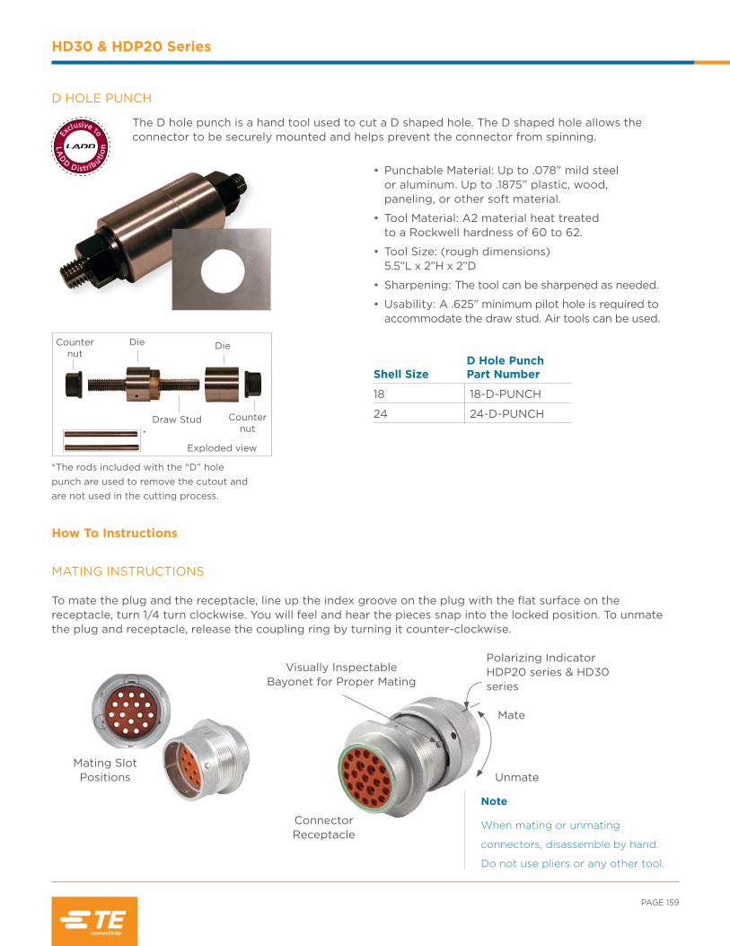
PAGE 159
HD30 & HDP20 Series
Note
When mating or unmating
connectors, disassemble by hand.
Do not use pliers or any other tool.
Shell SizeD Hole Punch Part Number
18 18-D-PUNCH
24 24-D-PUNCH
How To Instructions
*The rods included with the “D” hole punch are used to remove the cutout and are not used in the cutting process.
Exploded view
Die Die
Draw Stud Counternut
Counternut
*
D HOLE PUNCH
The D hole punch is a hand tool used to cut a D shaped hole. The D shaped hole allows the connector to be securely mounted and helps prevent the connector from spinning.
• Punchable Material: Up to .078” mild steel or aluminum. Up to .1875” plastic, wood, paneling, or other soft material.
• Tool Material: A2 material heat treated to a Rockwell hardness of 60 to 62.
• Tool Size: (rough dimensions) 5.5”L x 2”H x 2”D
• Sharpening: The tool can be sharpened as needed.
• Usability: A .625” minimum pilot hole is required to accommodate the draw stud. Air tools can be used.
MATING INSTRUCTIONS To mate the plug and the receptacle, line up the index groove on the plug with the flat surface on the receptacle, turn 1/4 turn clockwise. You will feel and hear the pieces snap into the locked position. To unmate the plug and receptacle, release the coupling ring by turning it counter-clockwise.
Unmate
Mate
Polarizing IndicatorHDP20 series & HD30 series
Visually InspectableBayonet for Proper Mating
ConnectorReceptacle
Mating Slot Positions
LA
D
D D istrib
utio
n
Exclusive to

INDUSTRIAL & COMMERCIAL TRANSPORTATION /// TERMINALS AND CONNECTORS
HD30 & HDP20 Series
Note
Do not twist or insert
tool at an angle.
Step 1:Grasp contact approxi-mately one inch behind the contact crimp barrel.
CONTACT INSERTION
Step 2:Hold connector with the rear grommet facing you.
Step 3:Push contact straight into connector grom-met until a positive stop is felt. A slight tug will confirm that it is prop-erly locked in place.
Step 1:With rear insert toward you, snap appropriate size removal tool over the wire of contact to be removed.
Step 2:Slide tool along the wire into the insert cavity until it engages contact and resistance is felt.
Step 3:Pull contact wire assembly out of connector.
CONTACT REMOVAL

Contents
STRIKE Series Overview .................................... 162
Performance Specifications ............................... 162
Material Specifications ......................................... 162
Dimensions ............................................................... 163
Configurations ......................................................... 163
Ordering Information ............................................ 164
Accessories ............................................................... 165
How To Instructions ..................................... 166-167

INDUSTRIAL & COMMERCIAL TRANSPORTATION /// TERMINALS AND CONNECTORS
STRIKE Series
STRIKE Series Overview
The STRIKE connector series features a lever lock system and is
designed for heavy duty equipment applications. The environmentally
sealed series offers two different size rugged housings that accept
contacts from size 20 to 16 with arrangements of 32 and 64 cavities.
DEUTSCH CONNECTOR PERFORMANCE SPECIFICATIONS
Temperature: Operating at temperatures -55°C to +125°C
Durability: No electrical or mechanical defects after 100 cycles of engagement and disengagement.
Vibration: No unlocking or unmating and exhibits no mechanical or physical damage after sinusoidal vibration levels of 20 G’s at 10 to 2000 Hz in each of the three mutually perpendicular planes. No electrical discontinuities longer than 1 microsecond.
Fluid Resistance: Connectors show no damage when exposed to most fluids used in industrial applications.
Insulation Resistance: 1000 megohms minimum at 25°C.
Immersion: IP68 rating
Moisture Resistance: Properly wired and mated connections will withstand immersion under three feet of water without loss of electronic qualities or leakage.
Dielectric Withstanding Voltage: Current leakage less than 2 milliamps at 1500 volts AC.
Thermal Cycle: No cracking, chipping or leaking after 20 test cycles from -55°C to +125°C.
MATERIAL SPECIFICATIONS
Flange Seal: Silicone rubber
Plug Grommet: Silicone rubber
Receptacle Threaded Inserts:
Brass
Shell: Glass filled PBT
TPA: Glass filled PBT

PAGE 163
STRIKE Series
DIMENSIONS
STRIKE Plug STRIKE Receptacle
Cavity Overall Length A
Overall Height B
Overall Width C
Overall Length D
Overall Height E
Overall Width F
MD 3.189 (81.00) 1.909 (84.50) 1.531 (38.90) 3.228 (82.00) 2.205 (56.00) 1.575 (40.00)
FL 3.358 (85.28) 1.913 (48.60) 2.780 (70.60) 3.228 (82.00) 2.205 (56.00) 2.953 (75.00)
Dimensions are for reference only.
AC
B E
DF
CONFIGURATIONS
Connector Styles
I In-line
F Flange Mount Receptacle
P PCB ReceptacleXX*-XX
X size XXX, X, X
Insert Arrangement
Number and Size of CavitiesShell Size/Key - Configuration
MD*-32A 4 Size 16
28 Size 20 I, F, P
FL*-64A 8 Size 16
56 Size 20 I, F
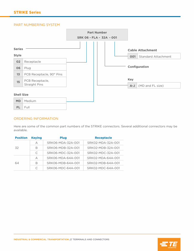
INDUSTRIAL & COMMERCIAL TRANSPORTATION /// TERMINALS AND CONNECTORS
STRIKE Series
PART NUMBERING SYSTEM
Part Number
SRK 06 - FLA - 32A - 001
Series
Style
02 Receptacle
06 Plug
13 PCB Receptacle, 90° Pins
15 PCB Receptacle, Straight Pins
Shell Size
MD Medium
FL Full
Cable Attachment
001 Standard Attachment
Configuration
Key
A-J (MD and FL size)
ORDERING INFORMATION Here are some of the common part numbers of the STRIKE connectors. Several additional connectors may be available.
Position Keying Plug Receptacle
32
A SRK06-MDA-32A-001 SRK02-MDA-32A-001
B SRK06-MDB-32A-001 SRK02-MDB-32A-001
C SRK06-MDC-32A-001 SRK02-MDC-32A-001
64
A SRK06-MDA-64A-001 SRK02-MDA-64A-001
B SRK06-MDB-64A-001 SRK02-MDB-64A-001
C SRK06-MDC-64A-001 SRK02-MDC-64A-001
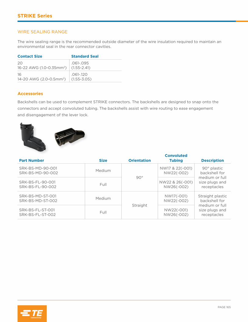
PAGE 165
STRIKE Series
Accessories
Backshells can be used to complement STRIKE connectors. The backshells are designed to snap onto the
connectors and accept convoluted tubing. The backshells assist with wire routing to ease engagement
and disengagement of the lever lock.
Part Number Size OrientationConvoluted
Tubing Description
SRK-BS-MD-90-001SRK-BS-MD-90-002 Medium
90°
NW17 & 22(-001)NW22(-002)
90° plastic backshell for
medium or full size plugs and
receptaclesSRK-BS-FL-90-001 SRK-BS-FL-90-002 Full NW22 & 26(-001)
NW26(-002)
SRK-BS-MD-ST-001SRK-BS-MD-ST-002 Medium
Straight
NW17(-001)NW22(-002)
Straight plastic backshell for
medium or full size plugs and
receptaclesSRK-BS-FL-ST-001SRK-BS-FL-ST-002 Full NW22(-001)
NW26(-002)
Contact Size Standard Seal
2016-22 AWG (1.0-0.35mm2)
.061-.095(1.55-2.41)
1614-20 AWG (2.0-0.5mm2)
.061-.120(1.55-3.05)
WIRE SEALING RANGE The wire sealing range is the recommended outside diameter of the wire insulation required to maintain an environmental seal in the rear connector cavities.

INDUSTRIAL & COMMERCIAL TRANSPORTATION /// TERMINALS AND CONNECTORS
STRIKE Series
CONTACT INSERTION
Step 1:Confirm TPA locking is open.
Step 2:Hold connector with rear seal retainer facing you.
Step 3:Push contact straight into the grommet until a positive stop is felt. A slight tug will confirm that it is properly locked in place.
Step 4:Push to close the TPA. TPA will not close unless all contacts are fully seated in connector.
How To Instructions
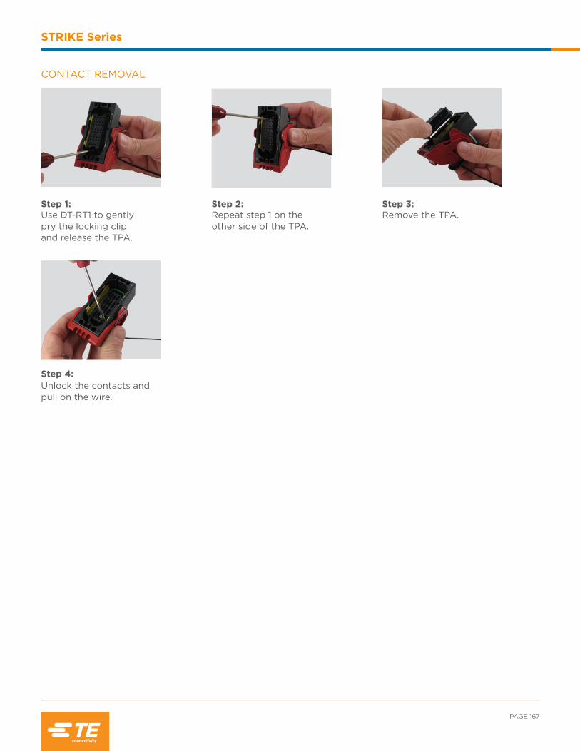
PAGE 167
STRIKE Series
CONTACT REMOVAL
Step 1:Use DT-RT1 to gently pry the locking clip and release the TPA.
Step 2:Repeat step 1 on the other side of the TPA.
Step 3:Remove the TPA.
Step 4:Unlock the contacts and pull on the wire.

INDUSTRIAL & COMMERCIAL TRANSPORTATION /// TERMINALS AND CONNECTORS
STRIKE Series
NOTES:

Contents
Common Contacts Overview .............................170
Performance Specifications ................................. 171
Wire Sealing Ranges ...............................................101
Solid Contact Part Numbers ............................... 172
Stamped & Formed Contacts Part Numbers............................................................ 173
PCB Pins ..................................................................... 174
Crimping ..................................................................... 175
Crimp Inspection ..................................................... 176
Accessories ........................................................ 177-178
How To Instructions .......................................179-180
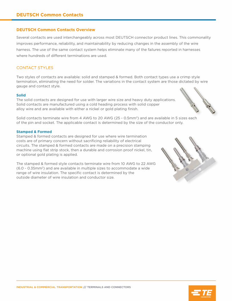
INDUSTRIAL & COMMERCIAL TRANSPORTATION /// TERMINALS AND CONNECTORS
DEUTSCH Common Contacts
DEUTSCH Common Contacts Overview
Several contacts are used interchangeably across most DEUTSCH connector product lines. This commonality
improves performance, reliability, and maintainability by reducing changes in the assembly of the wire
harness. The use of the same contact system helps eliminate many of the failures reported in harnesses
where hundreds of different terminations are used.
CONTACT STYLES
Two styles of contacts are available: solid and stamped & formed. Both contact types use a crimp style termination, eliminating the need for solder. The variations in the contact system are those dictated by wire gauge and contact style.
SolidThe solid contacts are designed for use with larger wire size and heavy duty applications. Solid contacts are manufactured using a cold heading process with solid copper alloy wire and are available with either a nickel or gold plating finish.
Solid contacts terminate wire from 4 AWG to 20 AWG (25 - 0.5mm2) and are available in 5 sizes each of the pin and socket. The applicable contact is determined by the size of the conductor only.
Stamped & FormedStamped & formed contacts are designed for use where wire termination costs are of primary concern without sacrificing reliability of electrical circuits. The stamped & formed contacts are made on a precision stamping machine using flat strip stock, then a durable and corrosion proof nickel, tin, or optional gold plating is applied.
The stamped & formed style contacts terminate wire from 10 AWG to 22 AWG (6.0 - 0.35mm2) and are available in multiple sizes to accommodate a wide range of wire insulation. The specific contact is determined by the outside diameter of wire insulation and conductor size.
PAGE 171
DEUTSCH Common Contacts
helpful hint
A crimp tensile test easily and rapidly identifies a proper crimp.
DEUTSCH CONTACT PERFORMANCE SPECIFICATIONS
DurabilityNo electrical or mechanical defects after 100 cycles of engagement and disengagement.
Current Rating (Contact current rating at 125° C continuous)Contact Size Max. CurrentSize 20 7.5 ampsSize 16 13 ampsSize 12 25 ampsSize 8 60 ampsSize 4 100 amps
Contact Retention (Solid and Stamped & Formed)Contacts withstand a minimum load of:20 lbs (89 N) for size 2025 lbs (111 N) for size 1630 lbs (133 N) for size 1235 lbs (156 N) for size 835 lbs (156 N) for size 4
Crimp Tensile Strength (Solid)Contact Size Tensile StrengthSize 20 20 lbsSize 16 25 lbsSize 12 70 lbsSize 8 90 lbsSize 4 300 lbs
Crimp Tensile Strength (Stamped & Formed) Contact Size Tensile StrengthSize 20 20 lbsSize 16 25 lbsSize 12 70 lbs
Contact Millivolt DropContact
SizeTest Current
AmpsMillivolt
Drop* (Solid)Millivolt
Drop* (S&F)
20 7.5 60 100
16 13 60 100
12 25 60 100
8 60 60 -
4 100 60 -
*Less drop through wire

INDUSTRIAL & COMMERCIAL TRANSPORTATION /// TERMINALS AND CONNECTORS
DEUTSCH Common Contacts
Solid Contact Plating Codes
Part Number Suffix Plating Material
31 Gold
90 Nickel (size 4 pin only)
141 Nickel
Note
See information drawing
0425-015-0000.
Size
Solid Contact Part NumbersWire Size
AWG (mm2)
Recommended Strip Length Inches (mm)
Min. Contact
Retention
Ref Crimp Tensile Lbs. (N)
Max Rated Amps at 125° C
ContinuousPin Socket
20 0460-202-20** 0462-201-20** 20(0.50)
.156-.218(3.96-5.54)
20(89)
20(89)
7.5
20 0460-010-20** 0462-005-20** 16-18(1.0-0.75)
.156-.218(3.96-5.54)
20(89)
20(89)
7.5
16 0460-202-16** 0462-201-16** 16-20(1.5-0.50)
.250-.312(6.35-7.92)
25(111)
35-20(156-89)
13
16 0460-215-16** 0462-209-16** 14(2.0)
.250-.312(6.35-7.92)
25(111)
70(311)
13
12 0460-204-12** 0462-203-12** 12-14(3.0-2.0)
.222-.284(5.64-7.21)
30(134)
75-70(334-311)
25
8 0460-204-08** 0462-203-08** 8-10(10.0-5.0)
.430-.492(10.92-12.50)
35(156)
125-90(556-400)
60
4 0460-204-04** 0462-203-04** 6(16.0-13.0)
.430-.492(10.92-12.50)
35(156)
300(1334)
100
4 (C038)
5960-203-04141 5962-203-04141 4(25.0-21.0)
.430-.492(10.92-12.50)
35(156)
300(1334)
100
** = Plating codes
SOLID CONTACT PART NUMBERS
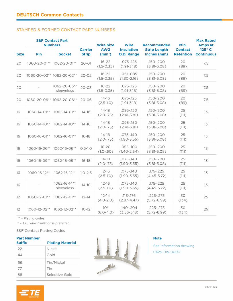
PAGE 173
DEUTSCH Common Contacts
Size
S&F Contact Part Numbers
Carrier Strip
Wire Size AWG (mm2)
Wire Insulation
O.D. Range
Recommended Strip Length Inches (mm)
Min. Contact
Retention
Max Rated Amps at 125° C
ContinuousPin Socket
20 1060-20-01** 1062-20-01** 20-01 16-22(1.5-0.35)
.075-.125(1.91-3.18)
.150-.200(3.81-5.08)
20(89)
7.5
20 1060-20-02** 1062-20-02** 20-02 16-22(1.5-0.35)
.051-.085(1.30-2.16)
.150-.200(3.81-5.08)
20(89)
7.5
20 - 1062-20-03**sleeveless
20-03 16-22(1.5-0.35)
.075-.125(1.91-3.18)
.150-.200(3.81-5.08)
20(89)
7.5
20 1060-20-06** 1062-20-06** 20-06 14-16(2.5-1.0)
.075-.125(1.91-3.18)
.150-.200(3.81-5.08)
20(89)
7.5
16 1060-14-01** 1062-14-01** 14-16 14-18(2.0-.75)
.095-.150(2.41-3.81)
.150-.200(3.81-5.08)
25(111)
13
16 1060-14-10** 1062-14-10** 14-16 14-18(2.0-.75)
.095-.150(2.41-3.81)
.150-.200(3.81-5.08)
25(111)
13
16 1060-16-01** 1062-16-01** 16-18 14-18(2.0-.75)
.075-.140(1.90-3.55)
.150-.200(3.81-5.08)
25(111)
13
16 1060-16-06** 1062-16-06** 0.5-1.0 16-20(1.0-.50)
.055-.100(1.40-2.54)
.150-.200(3.81-5.08)
25(111)
13
16 1060-16-09** 1062-16-09** 16-18 14-18(2.0-.75)
.075-.140(1.90-3.55)
.150-.200(3.81-5.08)
25(111)
13
16 1060-16-12** 1062-16-12** 1.0-2.5 12-16(2.5-1.0)
.075-.140(1.90-3.55)
.175-.225(4.45-5.72)
25(111)
13
16 - 1062-16-14**sleeveless
14-16 12-16(2.5-1.0)
.075-.140(1.90-3.55)
.175-.225(4.45-5.72)
25(111)
13
12 1060-12-01** 1062-12-01** 12-14 12-14(4.0-2.0)
.113-.176(2.87-4.47)
.225-.275(5.72-6.99)
30(134)
25
12 1060-12-02** 1062-12-02** 10-12 10†(6.0-4.0)
.140-.204(3.56-5.18)
.225-.275(5.72-6.99)
30(134)
25
** = Plating codes
† = TXL wire insulation is preferred
STAMPED & FORMED CONTACT PART NUMBERS
S&F Contact Plating Codes
Part Number Suffix Plating Material
22 Nickel
44 Gold
66 Tin/Nickel
77 Tin
88 Selective Gold
Note
See information drawing
0425-015-0000.

INDUSTRIAL & COMMERCIAL TRANSPORTATION /// TERMINALS AND CONNECTORS
DEUTSCH Common Contacts
Note
See information drawing 0425-
202-0000 for full specifications.
HD10 Series HDP20 Series HD30 Series
End of Connector
AD
B C
PCB PINS
Straight reduced diameter extended pins are available for installation in the DEUTSCH family of connectors. The use of removable contacts provides design flexibility and a low cost alternative to meet application needs.These solid copper alloy pins may be specified in various platings and assembled in HD30, HDP20, HD10, DRC, or DT receptacles.
MaterialCopper alloy
Plating Codes31: Gold90: Tin141: Nickel
PCB MountingConsult factory for PCB mounting details and pin positions.
Contact Size Part Number A B C
200460-208-2031 1.305 (33.15) .248 (6.30) .025 (.64)
0460-208-2090 1.305 (33.15) .248 (6.30) .025 (.64)
16
0460-208-16141 1.300 (33.02) .248 (6.30) .025 (.64)
0460-208-1631 1.300 (33.02) .248 (6.30) .025 (.64)
0460-229-16141 .545 (13.84) .248 (6.30) .025 (.64)
0460-241-16141 1.305 (33.15) .160 (4.06) .040 (1.02)
0460-244-16141 .976 (24.79) .400 (10.16) .041 (1.04)
0460-244-1631 .976 (24.79) .400 (10.16) .041 (1.04)
12
0460-208-12141 1.305 (33.15) .248 (6.30) .025 (.64)
0460-245-1231 1.024 (26.01) .500 (12.70) .041 (1.04)
0460-245-1290 1.024 (26.01) .500 (12.70) .041 (1.04)
Dimensions are for reference only.
Series D*
HD30/HDP20 .939 (23.85)
HD10 .925 (23.50)
DT .777 (19.74)
DT04-2P .677 (17.20)
DT04-3P .677 (17.20)
DRC 1.063 (27.00)*D is equal to the distance from the contact shoulder to the end of the connector.
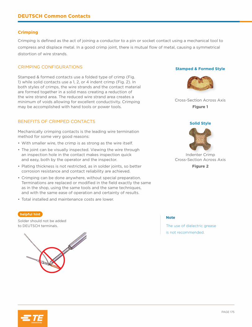
PAGE 175
helpful hint
DEUTSCH Common Contacts
CRIMPING CONFIGURATIONS
Stamped & formed contacts use a folded type of crimp (Fig. 1) while solid contacts use a 1, 2, or 4 indent crimp (Fig. 2). In both styles of crimps, the wire strands and the contact material are formed together in a solid mass creating a reduction of the wire strand area. The reduced wire strand area creates a minimum of voids allowing for excellent conductivity. Crimping may be accomplished with hand tools or power tools.
Crimping
Crimping is defined as the act of joining a conductor to a pin or socket contact using a mechanical tool to
compress and displace metal. In a good crimp joint, there is mutual flow of metal, causing a symmetrical
distortion of wire strands.
Stamped & Formed Style
Cross-Section Across Axis
Figure 1
Solid Style
Indenter Crimp Cross-Section Across Axis
Figure 2
Note
The use of dielectric grease
is not recommended.
BENEFITS OF CRIMPED CONTACTS
Mechanically crimping contacts is the leading wire termination method for some very good reasons:
• With smaller wire, the crimp is as strong as the wire itself.
• The joint can be visually inspected. Viewing the wire through an inspection hole in the contact makes inspection quick and easy, both by the operator and the inspector.
• Plating thickness is not restricted, as in solder joints, so better corrosion resistance and contact reliability are achieved.
• Crimping can be done anywhere, without special preparation. Terminations are replaced or modified in the field exactly the same as in the shop, using the same tools and the same techniques, and with the same ease of operation and certainty of results.
• Total installed and maintenance costs are lower.
Solder should not be added to DEUTSCH terminals.
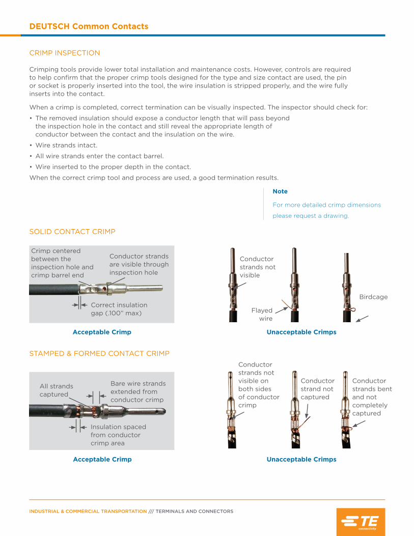
INDUSTRIAL & COMMERCIAL TRANSPORTATION /// TERMINALS AND CONNECTORS
DEUTSCH Common Contacts
CRIMP INSPECTION
Crimping tools provide lower total installation and maintenance costs. However, controls are required to help confirm that the proper crimp tools designed for the type and size contact are used, the pin or socket is properly inserted into the tool, the wire insulation is stripped properly, and the wire fully inserts into the contact.
When a crimp is completed, correct termination can be visually inspected. The inspector should check for:
• The removed insulation should expose a conductor length that will pass beyond the inspection hole in the contact and still reveal the appropriate length of conductor between the contact and the insulation on the wire.
• Wire strands intact.
• All wire strands enter the contact barrel.
• Wire inserted to the proper depth in the contact.
When the correct crimp tool and process are used, a good termination results.
SOLID CONTACT CRIMP
STAMPED & FORMED CONTACT CRIMP
Note
For more detailed crimp dimensions
please request a drawing.
Conductor strands not visible
Birdcage
Flayed wire
All strandscaptured
Bare wire strands extended from conductor crimp
Insulation spaced from conductor crimp area
Crimp centered between the inspection hole and crimp barrel end
Conductor strands are visible through inspection hole
Correct insulation gap (.100” max)
Conductor strands not visible on both sides of conductor crimp
Conductor strands bent and not completely captured
Conductor strand not captured
Acceptable Crimp
Acceptable Crimp
Unacceptable Crimps
Unacceptable Crimps

PAGE 177
DEUTSCH Common Contacts
Part Number Contact Size Color
0413-216-2005 20 Red
0413-215-1605 16 White
0413-214-1205 12 Yellow
Accessories
Additional accessories are available to aid in the design flexibility and sealing requirements of applications.
Accessory items such as sealing plugs and keying pins help to maintain an environmental seal and prevent
mis-mating.
KEYING PINS
Keying pins are solid plastic rods used to help prevent mis-mating of like connectors in close proximity. Applicable DEUTSCH product lines include HD10, HD30, HDP20, DT, and DTM series.
Keying pins are inserted into the retention fingers of an empty socket cavity. Once installed, the keying pin blocks a mating contact pin from being inserted. The contact pin will be blocked before the coupling device mates the connectors, helping to prevent the mis-mating of like connectors. Proper usage requires that the corresponding mating pin be omitted and a sealing plug inserted in the rear cavity of the mating connector. Individual applications will vary, and testing should be done to determine the best pattern arrangement to help prevent improper connector mating.
Note
Multiple keying pins may
be required to help prevent
unintentional forced mating.
Note
TXL wire insulation with 10 AWG
is not recommended because it
may not provide an environmental
seal against the insert seal.
CONTACT CRIMP SLEEVE REDUCER
A crimp sleeve reducer is available to allow DEUTSCH size 4 solid contacts to accept 8-10 AWG wire. Whenpopulating a connector using a contact with a reducer sleeve, be sure the insert seal penetrates the rear grommet. The use of the crimp sleeve reducer requires no extra crimp tools and provides an easy transition and increased flexibility.
Insert Seal0410-241-0406
Crimp Sleeve 0421-203-04141
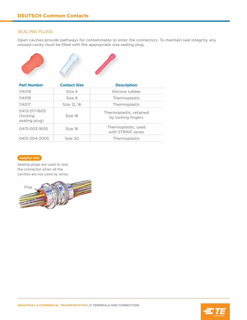
helpful hint
INDUSTRIAL & COMMERCIAL TRANSPORTATION /// TERMINALS AND CONNECTORS
DEUTSCH Common Contacts
SEALING PLUGS
Open cavities provide pathways for contaminates to enter the connectors. To maintain seal integrity, any unused cavity must be filled with the appropriate size sealing plug.
Part Number Contact Size Description
114019 Size 4 Silicone rubber
114018 Size 8 Thermoplastic
114017 Size 12, 16 Thermoplastic
0413-217-1605(locking sealing plug)
Size 16Thermoplastic, retained
by locking fingers
0413-003-1605 Size 16 Thermoplastic, used with STRIKE series
0413-204-2005 Size 20 Thermoplastic
Plug
Sealing plugs are used to seal the connector when all the cavities are not used by wires.
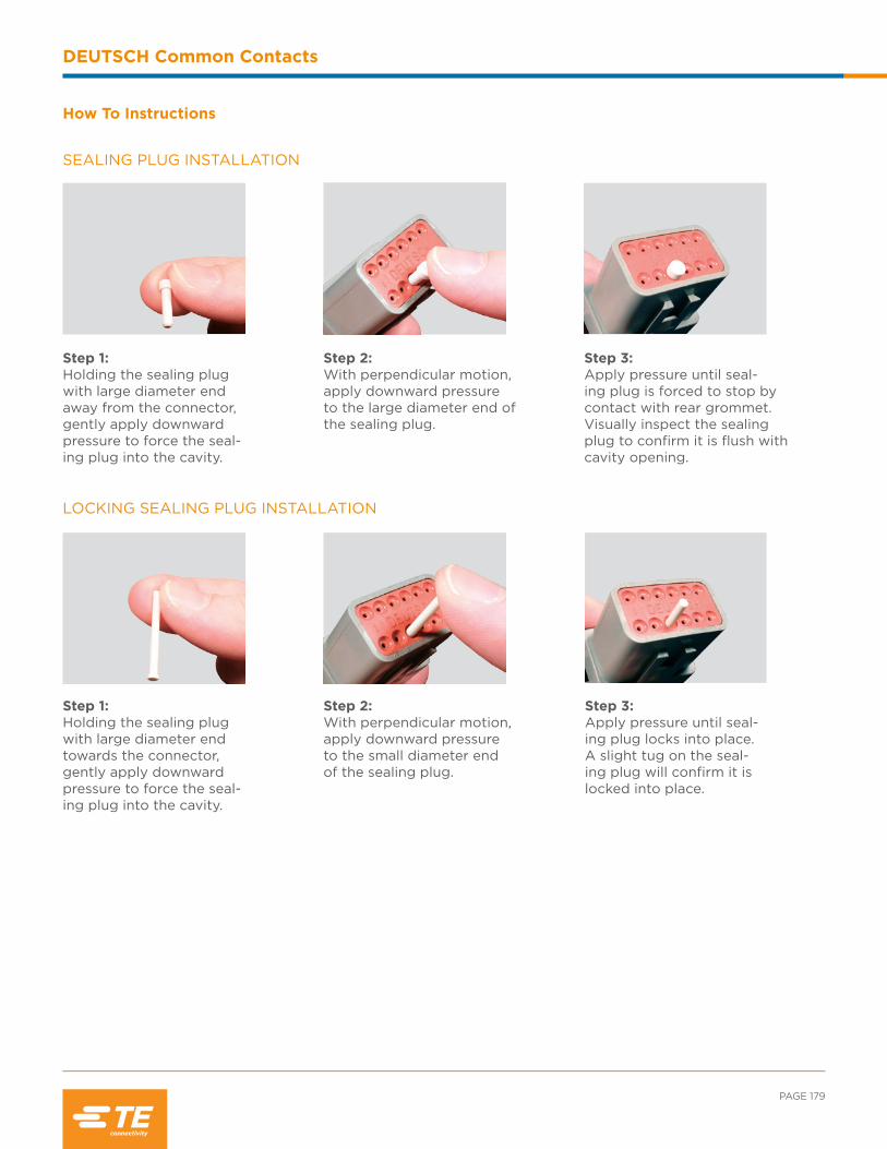
PAGE 179
DEUTSCH Common Contacts
Step 3:Apply pressure until seal-ing plug is forced to stop by contact with rear grommet. Visually inspect the sealing plug to confirm it is flush with cavity opening.
Step 1:Holding the sealing plug with large diameter end away from the connector, gently apply downward pressure to force the seal-ing plug into the cavity.
Step 2:With perpendicular motion, apply downward pressure to the large diameter end of the sealing plug.
Step 1:Holding the sealing plug with large diameter end towards the connector, gently apply downward pressure to force the seal-ing plug into the cavity.
Step 2:With perpendicular motion, apply downward pressure to the small diameter end of the sealing plug.
Step 3:Apply pressure until seal-ing plug locks into place. A slight tug on the seal-ing plug will confirm it is locked into place.
How To Instructions
SEALING PLUG INSTALLATION
LOCKING SEALING PLUG INSTALLATION
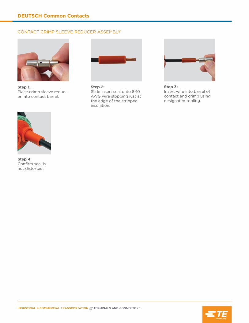
INDUSTRIAL & COMMERCIAL TRANSPORTATION /// TERMINALS AND CONNECTORS
DEUTSCH Common Contacts
Step 1:Place crimp sleeve reduc-er into contact barrel.
Step 2:Slide insert seal onto 8-10 AWG wire stopping just at the edge of the stripped insulation.
Step 4:Confirm seal is not distorted.
Step 3:Insert wire into barrel of contact and crimp using designated tooling.
CONTACT CRIMP SLEEVE REDUCER ASSEMBLY

Contents
Tooling Overview .................................................... 182
Automated Tooling .........................................182-184
Hand Tools .........................................................185-186
Removal Tools .......................................................... 187
How To Instructions ...................................... 188-190

INDUSTRIAL & COMMERCIAL TRANSPORTATION /// TERMINALS AND CONNECTORS
DEUTSCH Tooling
Crimp Tool Overview
The two types of DEUTSCH contacts are solid and stamped & formed. Both styles of contacts
are designed for crimp style terminations - no solder is required or recommended. A crimp style
termination displaces the wire strands creating a superior bond between the wire and the contact.
Several tools are available for hand and production wire crimping, wire insertion and removal, and
wedgelock/terminal position assurance removal. The tools are specific to the solid contacts or the
stamped & formed contacts. To create a proper crimp and achieve the highest performance
specifications, contacts must be crimped with the recommended tooling.
Automated Tooling Overview
For higher production volumes, a pneumatic power crimp tool is available for the DEUTSCH solid
contacts, and applicator dies for stamped & formed contacts. The HDP-400, a pneumatic solid crimp
tool, is a fast, bench-top tool that crimps most DEUTSCH contacts. The HDP-400 has a foot control,
and easy-to-change dies and locators for each contact size. TE’s stamped & formed OCEAN applicator
dies are heavy duty mini-dies that work in many industry standard presses. The OCEAN applicator
dies offer simple adjustments and the flexibility to accept different sized contacts and wire gauge.
AUTOMATED TOOLING FOR SOLID CONTACTS
Tool Part Number Contact Size Contact Part Number
HDP-400
4 0460-204-04900462-203-04141
8 0460-204-081410462-203-08141
12 0460-204-12**0462-203-12**
16
0460-202-16**0462-201-16**
0460-215-16**0462-209-16**
20 0460-202-20**0462-201-20**
For the appropriate die and locator, see drawing 0425-205-0000

PAGE 183
DEUTSCH Tooling
Part Number Go-No-Go Gauges
GA20N HDP-400 Size 20
450GA-16N HDP-400 Size 16
450GA-12N HDP-400 Size 12
GA8-SPEC HDP-400 Size 8
450GA-4-SPEC HDP-400 Size 4
AUTOMATED TOOLING FOR STAMPED & FORMED CONTACTS
Pin P/N Socket P/NInsulation Range
O.D. (mm)Applictor P/N
Conversion Kit P/N
Size
12
-Gro
up 1
1060-12-0144 1060-12-0166
1062-12-01441062-12-0166
.151-.176(3.83-4.47)
2266124-17-2266124-8
.130-.154(3.30-3.91)
2266125-17-2266125-8
.113-.135(2.87-3.43)
2266126-17-2266127-8
Size
12
-Gro
up 2
1060-12-0222 1060-12-0244
1062-12-02221062-12-0244
.185-.204 (4.70-5.18)
2266127-1 7-2266127-8
.155-.190 (3.94-4.83)
2266128-1 7-2266128-8
.140-.160 (3.56-4.06)
2266129-1 7-226129-8
Size
16
-G
roup
1
1060-14-01221060-14-01441060-14-0177
1060-14-1077 1060-14-1088
1062-14-0122 1062-14-0144 1062-14-0177
1062-14-1077 1062-14-1088
.120-.150 (3.05-3.81)
2266100-1 7-2266100-8
.105-.125 (2.67-3.18)
2266101-1 7-2266101-8
1060-16-0122 1060-16-0144 1060-16-0177
1060-16-07221060-16-07441060-16-0777
1060-16-0977 1060-16-0988
1062-16-0122 1062-16-0144 1062-16-0177
1062-16-07221062-16-07441062-16-0777
1062-16-0977 1062-16-0988
.105-.125 (2.67-3.18)
2266101-1 7-2266101-8
.085-.111 (2.16-2.82)
2266102-1 7-2266102-8
.075-.105 (1.91-2.67)
2266103-1 7-2266103-8
.063-.094 (1.60-2.39)
2266104-1 7-2266104-8
The -1 suffix on the applicator p/n represents a mechanical feed, for other feed options contact your representative. The conversion kit is to convert applicators within the same group. For more information, please reference TE catalog 1-1773730-8 or contact your representative.
HDP-400 TOOLING ACCESSORIESThe Go-No-Go gauge is used to determine if the HDP-400 tool is calibrated within the recommended specifications to produce a proper crimp.

INDUSTRIAL & COMMERCIAL TRANSPORTATION /// TERMINALS AND CONNECTORS
DEUTSCH Tooling
Pin P/N Socket P/NInsulation Range
O.D. (mm)Applictor P/N
Conversion Kit P/N
Size
16
-G
roup
2
1060-16-06221060-16-06441060-16-06771060-16-0688
1062-16-06221062-16-06441062-16-06771062-16-0688
.063-.094 (1.60-2.39)
2266110-1 7-2266110-8
.050-.075 (1.27-1.91)
2266111-1 7-2266111-8
Size
16
-G
roup
3 1060-16-1222 1060-16-12441060-16-1277
- - -
1062-16-1222 1062-16-1244 1062-16-1277
1062-16-1422 1062-16-1444 1062-16-1477
.120-.140 (3.05-3.56)
2266112-1 7-2266112-8
.105-.125 (2.67-3.18)
2266113-1 7-2266113-8
.090-.110 (2.29-2.79)
2266114-1 7-2266114-8
.075-.095 (1.91-2.41)
2266115-1 7-2266115-8
Size
20
-G
roup
1
1060-20-0122 1060-20-0144 1060-20-0177
---
1062-20-0122 1062-20-0144 1062-20-0177
1062-20-0322 1062-20-0344 1062-20-0377
.105-.125 (2.67-3.18)
2266116-1 7-2266116-8
.085-.111 (2.16-2.82)
2266117-1 7-2266117-8
.075-.105 (1.91-2.67)
2266118-1 7-2266118-8
1060-20-0222 1060-20-0244 1060-20-0277
1062-20-0222 1062-20-0244 1062-20-0277
.063-.085 (1.62-2.16)
2266119-1 7-2266119-8
.050-.075 (1.27-1.91)
2266120-1 7-2266120-8
The -1 suffix on the applicator p/n represents a mechanical feed, for other feed options contact your representative. The conversion kit is to convert applicators within the same group. For more information, please reference TE catalog 1-1773730-8 or contact your representative.
AUTOMATED TOOLING FOR STAMPED & FORMED CONTACTS (CONTINUED)

PAGE 185
DEUTSCH Tooling
Hand Tool Overview
For field service, prototype, and low-volume production, there are several easy-to-use hand crimp tools for both
solid barrel and stamped & formed contacts. All hand crimp tools provide a tight, complete crimp with minimal
effort. The HDT-48-00, the most commonly used tool for solid contacts, crimps a wide range of contact sizes.
It provides a symmetrical four indent crimp, is compact and easy-to-use for field service, yet sturdy and reliable
enough for low volume production. Hand crimp tools for DEUTSCH stamped & formed contacts are wire gauge
specific and simultaneously crimp the insulation and conductor, saving time and effort during field service.
HDT-1561HDT-48-00HDT-04-08 HDT-50-00
LA
DD D istrib
utio
n
Exclusive to
Contact SizeContact Part
Number Tool Part Number Crimp Type
4 0460-204-04900462-203-04141 HDT-04-08 Two indent crimp
8 0460-204-081410462-203-08141 HDT-04-08 Two indent crimp
12 0460-204-12**0462-203-12**
HDT-48-00 Four indent crimp
HDT-1561 Two indent crimp
HDT-50-00 One indent crimp
16
0460-202-16**0462-201-16**0460-215-16**0462-209-16**
HDT-48-00 Four indent crimp
HDT-1561 Two indent crimp
HDT-50-00 One indent crimp
20 0460-202-20**0462-201-20**
HDT-48-00 Four indent crimp
HDT-1561 Two indent crimp
HDT-50-00 One indent crimp
HAND TOOLS FOR SOLID CONTACTS

INDUSTRIAL & COMMERCIAL TRANSPORTATION /// TERMINALS AND CONNECTORS
DEUTSCH Tooling
helpful hintPart Number Crimp Tool Replacement Part
0426-209-0000 Adjustment screw and locking nut
M2700-395-10 Locking nut
Part Number Description
G454 HDT-48-00 Go-No-Go Gauge
Go-no-go gauges are used to inspect crimp tooling. The G454 gauge is used with the HDT-48-00 hand tool.
HAND TOOLS FOR DEUTSCH STAMPED & FORMED CONTACTS
DTT-12-01 DTT-16-00DTT-16-01
DTT-20-00DTT-20-02
DTT-12-00
Contact SizeContact Part
Number Tool Part Number
12
1060-12-01**1062-12-01** DTT-12-00
1060-12-02**1062-12-02** DTT-12-01
16
1060-16-01** 1062-16-01** 1060-16-06**1062-16-06**
DTT-16-00(14-16 AWG)
DTT-16-01(18 AWG)
20
1060-20-01**1062-20-01** DTT-20-00
1060-20-02**1062-20-02** DTT-20-02
HDT-48-00 TOOLING ACCESSORIESReplacement parts, such as adjustment screws, locking nuts, and inspection tools are available for the HDT-48-00 hand tool.
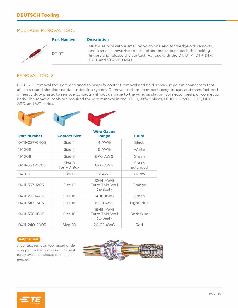
PAGE 187
helpful hint
DEUTSCH Tooling
MULTI-USE REMOVAL TOOL
Part Number Description
DT-RT1
Multi-use tool with a small hook on one end for wedgelock removal, and a small screwdriver on the other end to push back the lockingfingers and release the contact. For use with the DT, DTM, DTP, DTV,DRB, and STRIKE series.
Part Number Contact SizeWire Gauge
Range Color
0411-027-0405 Size 4 4 AWG Black
114009 Size 4 6 AWG White
114008 Size 8 8-10 AWG Green
0411-353-0805 Size 8for HD Box 8-10 AWG Green
Extended
114010 Size 12 12 AWG Yellow
0411-337-1205 Size 1212-14 AWG
Extra Thin Wall(E-Seal)
Orange
0411-291-1405 Size 16 14-16 AWG Green
0411-310-1605 Size 16 16-20 AWG Light Blue
0411-336-1605 Size 1616-18 AWG
Extra Thin Wall(E-Seal)
Dark Blue
0411-240-2005 Size 20 20-22 AWG Red
REMOVAL TOOLS DEUTSCH removal tools are designed to simplify contact removal and field service repair in connectors that utilize a round shoulder contact retention system. Removal tools are compact, easy-to-use, and manufactured of heavy duty plastic to remove contacts without damage to the wire, insulation, connector seals, or connector body. The removal tools are required for wire removal in the DTHD, Jiffy Splices, HD10, HDP20, HD30, DRC, AEC, and WT series.
A contact removal tool taped or tie wrapped to the harness will make it easily available, should repairs be needed.

helpful hint
INDUSTRIAL & COMMERCIAL TRANSPORTATION /// TERMINALS AND CONNECTORS
DEUTSCH Tooling
WIRE STRIPPING
CRIMPING WITH THE HDT-48-00 HAND TOOL
How To Instructions
Step 3:Measure the exposed strands to be sure the crimp length is correct.
Step 1:1. Choose the correct AWG for the contact being used.
2. Measure from the end of the wire the recom-mended strip length according to the contact size.
3. Place the wire into a stripping tool at the rec-ommended strip length. Strip the wire according to stripping tool instruc-tions.
Step 2:1. After stripping, a small piece of the insulation should come off.
2. Check for any broken strands or for a dent in the wire. If either exist, the wire is damaged and should be cut and stripped again.
Leaving the stripped portion of the insulation on the wire until crimping will avoid flayed wire strands.
Incorrect
Step 3:1. Insert wire into contact. Contact must be cen-tered between indentors. Close handles until crimp cycle is completed. 2. Release handles and remove crimped contact.
Step 1:1. Strip insulation from wire.
2. Raise selector knob and rotate until arrow is aligned with wire size to be crimped. 3. Loosen locknut, turn adjusting screw in until it stops.
Step 2:Insert contact with barrel up. Turn adjusting screw counter clockwise un-til contact is flush with indentor cover. Tighten locknut.
Note
Tool must be adjusted for
each type/size of contact.
Correct
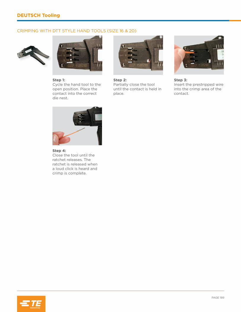
PAGE 189
DEUTSCH Tooling
CRIMPING WITH DTT STYLE HAND TOOLS (SIZE 16 & 20)
Step 4:Close the tool until the ratchet releases. The ratchet is released when a loud click is heard and crimp is complete.
Step 1:Cycle the hand tool to the open position. Place the contact into the correct die nest.
Step 3:Insert the prestripped wire into the crimp area of the contact.
Step 2:Partially close the tool until the contact is held in place.
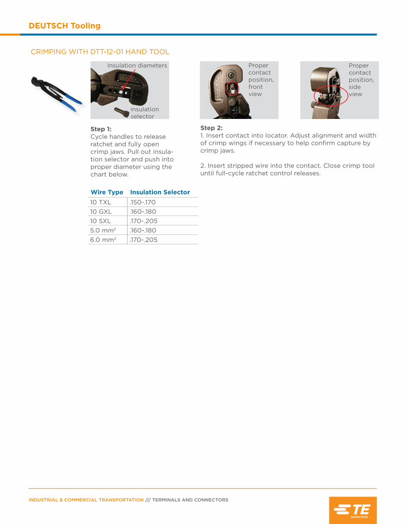
INDUSTRIAL & COMMERCIAL TRANSPORTATION /// TERMINALS AND CONNECTORS
DEUTSCH Tooling
CRIMPING WITH DTT-12-01 HAND TOOL
Step 1:Cycle handles to release ratchet and fully open crimp jaws. Pull out insula-tion selector and push into proper diameter using the chart below.
Step 2:1. Insert contact into locator. Adjust alignment and width of crimp wings if necessary to help confirm capture by crimp jaws.
2. Insert stripped wire into the contact. Close crimp tool until full-cycle ratchet control releases.
Wire Type Insulation Selector10 TXL .150-.17010 GXL .160-.18010 SXL .170-.2055.0 mm2 .160-.1806.0 mm2 .170-.205
Insulation diameters
Insulationselector
Propercontactposition,front view
Propercontactposition,side view

Contents
Bussed Feedback Overview ............................... 192
Bussed Examples .................................................... 192
Dimensions ................................................................ 193
Ordering Information .............................................194

INDUSTRIAL & COMMERCIAL TRANSPORTATION /// TERMINALS AND CONNECTORS
Bussing Options
Bussed Overview
DEUTSCH industrial bussed feedback receptacles are environmentally sealed connectors designed for use
in heavy duty applications where multiple circuits require a common electrical pathway. Available in the
DT Series, DEUTSCH bussed connectors feature integrated bussbars with standard DEUTSCH contacts.
A bussbar, or buss, is a thin conductive strip connecting two or more contacts within the body of a connector.
Bussbars allow power or data to be fed into a connector through one or more terminals and drawn out as
needed through the other contacts on the same buss. Connectors can carry one or more bussbars, creating
multiple independent electrical circuits within the same connector body and distributing power or data to
many components. A single bussed connector can replace several standard connectors or splices, saving space,
wiring, and weight.
DT SERIES BUSSED FEEDBACK RECEPTACLES
DT bussed feedback receptacles are a compact economical bussingoption housed in rugged, field-proven DT receptacle bodies. The bussed DTs mate with standard DT plugs and meet all the performance specifications for the DT series. The connectors are available in multiple buss configurations using standard size 16 contacts, with plating options in nickel or gold.
BUSSED EXAMPLES
In the examples, there are three size 16 pins each rated for 13 amps mounted to the buss. A total of 13 amps can be pulled into one pin and going out the 13 amps are split between the remaining two pins. No more than 13 amps can go through any single pin.
13 amps
10 amps
3 amps
13 amps
6.5 amps
6.5 amps
Note
The maximum current rating is the
total amount of current for the entire
buss. Current can be distributed
in many combinations, but cannot
exceed 13 amps per contact.

PAGE 193
Bussing Options
DT SERIES BUSSED FEEDBACK RECEPTACLE PART NUMBERING SYSTEM
Part Number
DT 04 - 4 P * - ****
Series
Style
04 In-line Receptacle
Configuration
Special Modifications
Key (if applicable)
Contacts
P Pin
DIMENSIONS
DT Receptacle
Cavity Overall Length A
Overall Height B
Overall Width C
2 1.818 (46.18) .670 (17.15) .675 (17.15)
4 1.868 (47.45) .797 (20.24) .820 (20.83)
6 1.858 (47.19) .972 (24.69) .820 (20.83)
8 1.848 (46.94) 1.000 (25.40) 1.435 (36.45)
12 2.043 (51.89) .876 (22.25) 1.597 (40.56)
Dimensions are for reference only.
AC
B
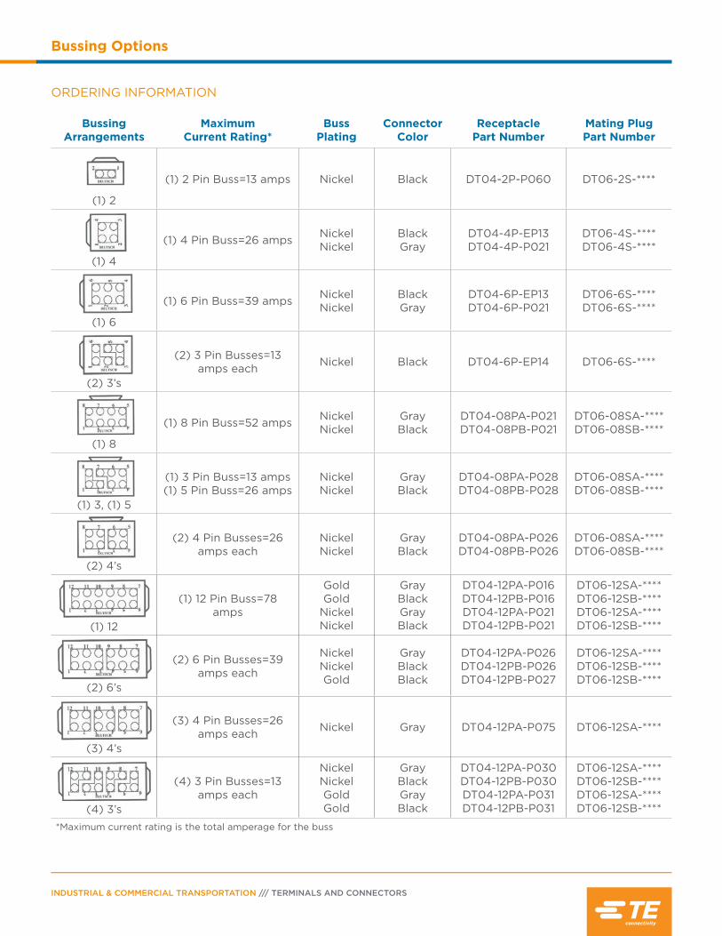
INDUSTRIAL & COMMERCIAL TRANSPORTATION /// TERMINALS AND CONNECTORS
Bussing Options
ORDERING INFORMATION
Bussing Arrangements
MaximumCurrent Rating*
Buss Plating
ConnectorColor
ReceptaclePart Number
Mating PlugPart Number
(1) 2
(1) 2 Pin Buss=13 amps Nickel Black DT04-2P-P060 DT06-2S-****
(1) 4
(1) 4 Pin Buss=26 amps NickelNickel
BlackGray
DT04-4P-EP13DT04-4P-P021
DT06-4S-****DT06-4S-****
(1) 6
(1) 6 Pin Buss=39 amps NickelNickel
BlackGray
DT04-6P-EP13DT04-6P-P021
DT06-6S-****DT06-6S-****
(2) 3’s
(2) 3 Pin Busses=13 amps each Nickel Black DT04-6P-EP14 DT06-6S-****
(1) 8
(1) 8 Pin Buss=52 amps NickelNickel
GrayBlack
DT04-08PA-P021DT04-08PB-P021
DT06-08SA-****DT06-08SB-****
(1) 3, (1) 5
(1) 3 Pin Buss=13 amps(1) 5 Pin Buss=26 amps
NickelNickel
GrayBlack
DT04-08PA-P028DT04-08PB-P028
DT06-08SA-****DT06-08SB-****
(2) 4’s
(2) 4 Pin Busses=26 amps each
NickelNickel
GrayBlack
DT04-08PA-P026DT04-08PB-P026
DT06-08SA-****DT06-08SB-****
(1) 12
(1) 12 Pin Buss=78 amps
GoldGold
NickelNickel
GrayBlackGrayBlack
DT04-12PA-P016DT04-12PB-P016DT04-12PA-P021DT04-12PB-P021
DT06-12SA-****DT06-12SB-****DT06-12SA-****DT06-12SB-****
(2) 6’s
(2) 6 Pin Busses=39 amps each
NickelNickelGold
GrayBlackBlack
DT04-12PA-P026DT04-12PB-P026DT04-12PB-P027
DT06-12SA-****DT06-12SB-****DT06-12SB-****
(3) 4’s
(3) 4 Pin Busses=26 amps each Nickel Gray DT04-12PA-P075 DT06-12SA-****
(4) 3’s
(4) 3 Pin Busses=13 amps each
NickelNickelGoldGold
GrayBlackGrayBlack
DT04-12PA-P030DT04-12PB-P030DT04-12PA-P031DT04-12PB-P031
DT06-12SA-****DT06-12SB-****DT06-12SA-****DT06-12SB-****
*Maximum current rating is the total amperage for the buss

Contents
Controller Area Networks (CAN) Overview ....................................................................196
ISO Box .......................................................................196
J1939/11 9-pin Diagnostic .............................198-199
J1939/13 Connector Options ....................200-201
J1939/15 Connector Options ................... 202-203

INDUSTRIAL & COMMERCIAL TRANSPORTATION /// TERMINALS AND CONNECTORS
Controller Area Networks
CAN Overview
Controller Area Networks, or CAN, are multiplex data systems. Multiplexing allows multiple data signals to
travel on the same wires, integrating separate electronic systems and applications to a single point control and
monitoring system. Using signals sent over a serial network, CAN systems provide instantaneous monitoring
of diagnostic and control systems allowing early detection of potential problems. Early detection of problems
leads to lower repair costs and reduced downtime. CAN systems allow an operator to use a single command
station to control diagnostic systems and receive such varied information as brake and transmission
temperature, tire pressure, fuel efficiency, and emissions levels. Anything that can be measured and controlled
electronically can be monitored and directed by a CAN system.
Part Number Description
HDBOX-24-91PN ISO Box assembly
HDBOX-24-91PE ISO Box assembly, reduced wire seal
HD36-24-91SN-059 Plug, cable clamp assembly
HD36-24-91SE-059 Plug, cable clamp assembly, reduced wire seal
HDB36-24-91SN-059 Plug, breakaway coupling, cable clamp assembly
HDB36-24-91SE-059 Plug, breakaway coupling, cable clamp assembly, reduced wire seal
DT06-4S-EP06* Plug, black, end cap
DT06-2S-EP06* Plug, black, end cap
W4S-P012 Wedgelock, green
W2S-P012 Wedgelock, green
0460-204-08141 Pin, solid, size 8
0460-204-12141 Pin, solid, size 12
0460-202-1631 Pin, solid, size 16, gold
0462-203-08141 Socket, solid, size 8
0462-203-12141 Socket, solid, size 12
0462-201-1631 Socket, solid, size 16, gold
*DT series receptacles are molded in the HDBox
ISO/CD 11783-2 ISO BOX AND ASSOCIATED CONNECTORS
Originally designed for agricultural applications, the DEUTSCH ISO Box creates a communication pathway between an on-board CAN system and the electronic components on an attached implement. The HDBox, which holds two DT13 connectors and an HD30 series receptacle, mounts on the vehicle and mates with an HD30 plug connector that features a breakaway coupling ring. DEUTSCH breakaway couplings are designed to help prevent damage to the vehicle or the attached implement by fragmenting and separating from the vehicle in the event of a drive-away disconnect.
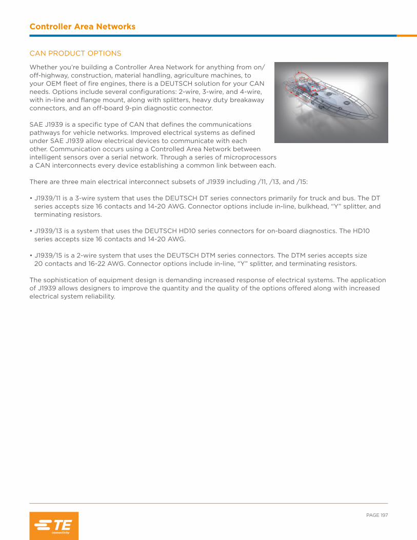
PAGE 197
Controller Area Networks
CAN PRODUCT OPTIONS
Whether you’re building a Controller Area Network for anything from on/ off-highway, construction, material handling, agriculture machines, to your OEM fleet of fire engines, there is a DEUTSCH solution for your CAN needs. Options include several configurations: 2-wire, 3-wire, and 4-wire, with in-line and flange mount, along with splitters, heavy duty breakaway connectors, and an off-board 9-pin diagnostic connector.
SAE J1939 is a specific type of CAN that defines the communications pathways for vehicle networks. Improved electrical systems as defined under SAE J1939 allow electrical devices to communicate with each other. Communication occurs using a Controlled Area Network between intelligent sensors over a serial network. Through a series of microprocessors a CAN interconnects every device establishing a common link between each.
There are three main electrical interconnect subsets of J1939 including /11, /13, and /15: • J1939/11 is a 3-wire system that uses the DEUTSCH DT series connectors primarily for truck and bus. The DT series accepts size 16 contacts and 14-20 AWG. Connector options include in-line, bulkhead, “Y” splitter, and terminating resistors. • J1939/13 is a system that uses the DEUTSCH HD10 series connectors for on-board diagnostics. The HD10 series accepts size 16 contacts and 14-20 AWG. • J1939/15 is a 2-wire system that uses the DEUTSCH DTM series connectors. The DTM series accepts size 20 contacts and 16-22 AWG. Connector options include in-line, “Y” splitter, and terminating resistors.
The sophistication of equipment design is demanding increased response of electrical systems. The application of J1939 allows designers to improve the quantity and the quality of the options offered along with increased electrical system reliability.
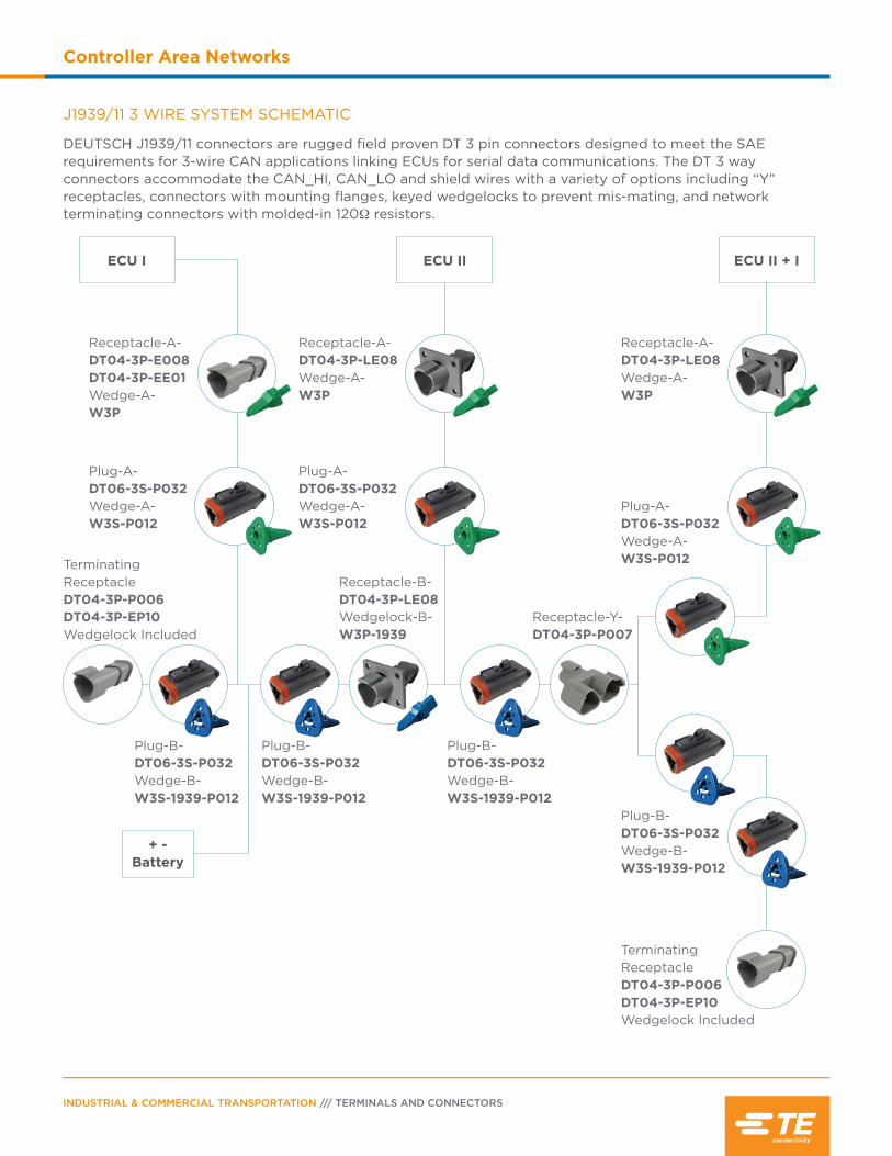
INDUSTRIAL & COMMERCIAL TRANSPORTATION /// TERMINALS AND CONNECTORS
Controller Area Networks
J1939/11 3 WIRE SYSTEM SCHEMATIC
DEUTSCH J1939/11 connectors are rugged field proven DT 3 pin connectors designed to meet the SAE requirements for 3-wire CAN applications linking ECUs for serial data communications. The DT 3 way connectors accommodate the CAN_HI, CAN_LO and shield wires with a variety of options including “Y” receptacles, connectors with mounting flanges, keyed wedgelocks to prevent mis-mating, and network terminating connectors with molded-in 120Ω resistors.
ECU II + IECU I
+ - Battery
ECU II
Receptacle-A-DT04-3P-E008DT04-3P-EE01Wedge-A-W3P
Receptacle-A-DT04-3P-LE08Wedge-A-W3P
Receptacle-A-DT04-3P-LE08Wedge-A-W3P
Plug-A-DT06-3S-P032Wedge-A-W3S-P012
Plug-A-DT06-3S-P032Wedge-A-W3S-P012
Plug-A-DT06-3S-P032Wedge-A-W3S-P012
Plug-B-DT06-3S-P032Wedge-B-W3S-1939-P012
Plug-B-DT06-3S-P032Wedge-B-W3S-1939-P012
Plug-B-DT06-3S-P032Wedge-B-W3S-1939-P012
Plug-B-DT06-3S-P032Wedge-B-W3S-1939-P012
Terminating ReceptacleDT04-3P-P006DT04-3P-EP10Wedgelock Included
Terminating ReceptacleDT04-3P-P006DT04-3P-EP10Wedgelock Included
Receptacle-B-DT04-3P-LE08Wedgelock-B-W3P-1939
Receptacle-Y-DT04-3P-P007

PAGE 199
Controller Area Networks
Part Number Description
DT04-3P-P007 Receptacle, “y” connector
DT04-3P-E008 Receptacle, gray, shrink boot adapter
DT04-3P-P006 Receptacle, gray, 120Ω resistor
DT04-3P-EE01 Receptacle, black, shrink boot adapter
DT04-3P-EP10 Receptacle, black, 120Ω resistor
DT06-3S-E008 Plug, gray, shrink boot adapter
DT06-3S-P006 Plug, gray, 120Ω resistor
DT06-3S-EP11 Plug, black, shrink boot adapter
DT06-3S-PP01 Plug, black, 120Ω resistor
DT06-3S-PE01 Plug, black, 120Ω resistor, latch guard
DT06-3S-P032 Plug, black, single piece shrink boot adapter
W3P-1939 Wedgelock, blue
W3S Wedgelock, orange
W3S-P012 Wedgelock, green
W3S-1939 Wedgelock, blue
W3S-1939-P012 Wedgelock, blue
0460-202-1631 Pin, solid, size 16, gold
1060-16-0144 Pin, stamped & formed, size 16, gold
0460-247-1631 Pin, solid, size 16, gold, extended
0462-201-1631 Socket, solid, size 16, gold
1062-16-0144 Socket, stamped & formed, size 16, gold
0462-221-1631 Socket, solid, size 16, gold, extended
J1939/11 DEUTSCH CONNECTOR OPTIONS
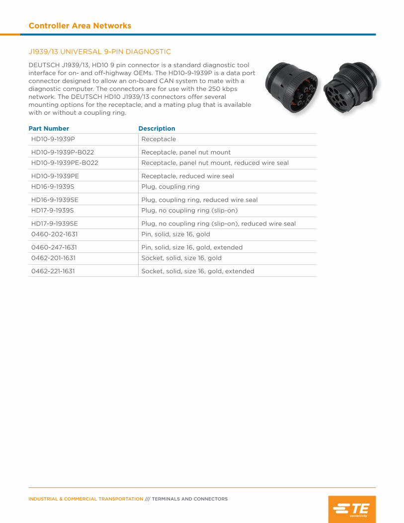
INDUSTRIAL & COMMERCIAL TRANSPORTATION /// TERMINALS AND CONNECTORS
Controller Area Networks
Part Number Description
HD10-9-1939P Receptacle
HD10-9-1939P-B022 Receptacle, panel nut mount
HD10-9-1939PE-B022 Receptacle, panel nut mount, reduced wire seal
HD10-9-1939PE Receptacle, reduced wire seal
HD16-9-1939S Plug, coupling ring
HD16-9-1939SE Plug, coupling ring, reduced wire seal
HD17-9-1939S Plug, no coupling ring (slip-on)
HD17-9-1939SE Plug, no coupling ring (slip-on), reduced wire seal
0460-202-1631 Pin, solid, size 16, gold
0460-247-1631 Pin, solid, size 16, gold, extended
0462-201-1631 Socket, solid, size 16, gold
0462-221-1631 Socket, solid, size 16, gold, extended
J1939/13 UNIVERSAL 9-PIN DIAGNOSTIC
DEUTSCH J1939/13, HD10 9 pin connector is a standard diagnostic tool interface for on- and off-highway OEMs. The HD10-9-1939P is a data port connector designed to allow an on-board CAN system to mate with a diagnostic computer. The connectors are for use with the 250 kbpsnetwork. The DEUTSCH HD10 J1939/13 connectors offer several mounting options for the receptacle, and a mating plug that is available with or without a coupling ring.
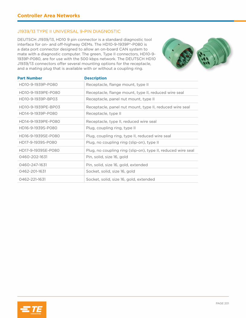
PAGE 201
Controller Area Networks
Part Number Description
HD10-9-1939P-P080 Receptacle, flange mount, type II
HD10-9-1939PE-P080 Receptacle, flange mount, type II, reduced wire seal
HD10-9-1939P-BP03 Receptacle, panel nut mount, type II
HD10-9-1939PE-BP03 Receptacle, panel nut mount, type II, reduced wire seal
HD14-9-1939P-P080 Receptacle, type II
HD14-9-1939PE-P080 Receptacle, type II, reduced wire seal
HD16-9-1939S-P080 Plug, coupling ring, type II
HD16-9-1939SE-P080 Plug, coupling ring, type II, reduced wire seal
HD17-9-1939S-P080 Plug, no coupling ring (slip-on), type II
HD17-9-1939SE-P080 Plug, no coupling ring (slip-on), type II, reduced wire seal
0460-202-1631 Pin, solid, size 16, gold
0460-247-1631 Pin, solid, size 16, gold, extended
0462-201-1631 Socket, solid, size 16, gold
0462-221-1631 Socket, solid, size 16, gold, extended
J1939/13 TYPE II UNIVERSAL 9-PIN DIAGNOSTIC
DEUTSCH J1939/13, HD10 9 pin connector is a standard diagnostic tool interface for on- and off-highway OEMs. The HD10-9-1939P*-P080 is a data port connector designed to allow an on-board CAN system to mate with a diagnostic computer. The green, Type II connectors, HD10-9-1939P-P080, are for use with the 500 kbps network. The DEUTSCH HD10 J1939/13 connectors offer several mounting options for the receptacle, and a mating plug that is available with or without a coupling ring.

INDUSTRIAL & COMMERCIAL TRANSPORTATION /// TERMINALS AND CONNECTORS
Controller Area Networks
J1939/15 2 WIRE SYSTEM SCHEMATIC
SAE J1939/15 defines the requirements for reduced physical layer 2-wire CAN systems consisting of an unshielded twisted pair of wires. DEUTSCH DTM 2 way connectors are offered in several modifications to meet the requirements of this standard. DTM connectors for serial data communications include “Y” receptacles, connectors with end caps and shrink boot adapters, and receptacles with molded-in 120Ω resistors for network terminations.
ECU N + IECU
+ - Battery
ECU N
Receptacle-A-DTM04-2P-****Wedge-A-WM-2P
Receptacle-A-DTM04-2P-****Wedge-A-WM-2P
Receptacle-A-DTM04-2P-****Wedge-A-WM-2P
Plug-A-DTM06-2S-****Wedge-A-WM-2S
Plug-A-DTM06-2S-****Wedge-A-WM-2S
Plug-A-DTM06-2S-****Wedge-A-WM-2S
Plug-B-DTM06-2S-****Wedge-B-WM-2SB
Plug-B-DTM06-2S-****Wedge-B-WM-2SB
Plug-B-DTM06-2S-****Wedge-B-WM-2SB
Plug-B-DTM06-2S-****Wedge-B-WM-2SB
Terminating ReceptacleDTM04-2P-EP10Wedgelock Included
Terminating ReceptacleDTM04-2P-EP10Wedgelock Included
Receptacle-B-DTM04-2P-****Wedgelock-B-WM-2PB
Receptacle-Y-DTM04-2P-P007
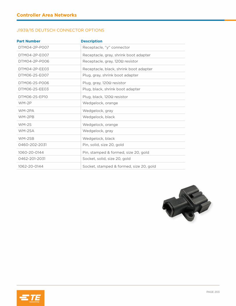
PAGE 203
Controller Area Networks
Part Number Description
DTM04-2P-P007 Receptacle, “y” connector
DTM04-2P-E007 Receptacle, gray, shrink boot adapter
DTM04-2P-P006 Receptacle, gray, 120Ω resistor
DTM04-2P-EE03 Receptacle, black, shrink boot adapter
DTM06-2S-E007 Plug, gray, shrink boot adapter
DTM06-2S-P006 Plug, gray, 120Ω resistor
DTM06-2S-EE03 Plug, black, shrink boot adapter
DTM06-2S-EP10 Plug, black, 120Ω resistor
WM-2P Wedgelock, orange
WM-2PA Wedgelock, gray
WM-2PB Wedgelock, black
WM-2S Wedgelock, orange
WM-2SA Wedgelock, gray
WM-2SB Wedgelock, black
0460-202-2031 Pin, solid, size 20, gold
1060-20-0144 Pin, stamped & formed, size 20, gold
0462-201-2031 Socket, solid, size 20, gold
1062-20-0144 Socket, stamped & formed, size 20, gold
J1939/15 DEUTSCH CONNECTOR OPTIONS

INDUSTRIAL & COMMERCIAL TRANSPORTATION /// TERMINALS AND CONNECTORS
Controller Area Networks
NOTES:

Contents
Diodes & Resistors Overview.............................206
Configurations .........................................................206
Diodes & Resistor Characteristics .......... 207-208
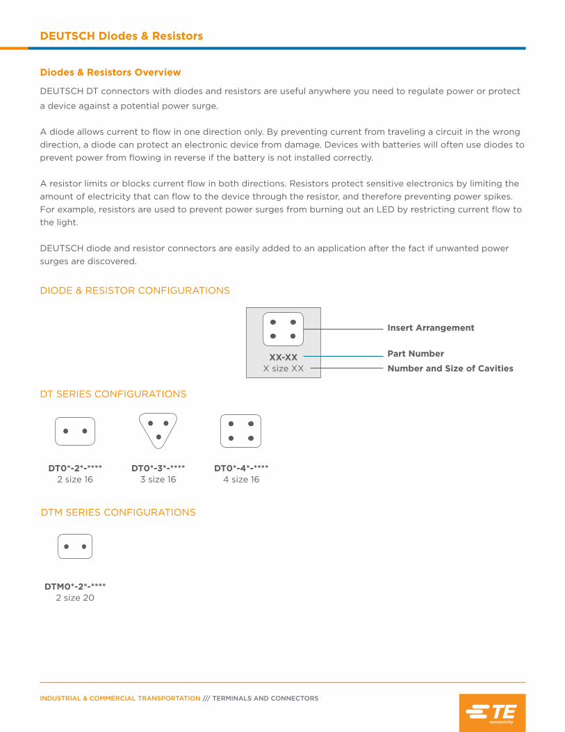
INDUSTRIAL & COMMERCIAL TRANSPORTATION /// TERMINALS AND CONNECTORS
DEUTSCH Diodes & Resistors
Diodes & Resistors Overview
DEUTSCH DT connectors with diodes and resistors are useful anywhere you need to regulate power or protect
a device against a potential power surge.
A diode allows current to flow in one direction only. By preventing current from traveling a circuit in the wrong direction, a diode can protect an electronic device from damage. Devices with batteries will often use diodes to prevent power from flowing in reverse if the battery is not installed correctly.
A resistor limits or blocks current flow in both directions. Resistors protect sensitive electronics by limiting the amount of electricity that can flow to the device through the resistor, and therefore preventing power spikes. For example, resistors are used to prevent power surges from burning out an LED by restricting current flow to the light.
DEUTSCH diode and resistor connectors are easily added to an application after the fact if unwanted power surges are discovered.
DT0*-3*-**** 3 size 16
DT0*-4*-**** 4 size 16
DT0*-2*-**** 2 size 16
DT SERIES CONFIGURATIONS
DIODE & RESISTOR CONFIGURATIONS
XX-XXX size XX
Insert Arrangement
Number and Size of Cavities
Part Number
DTM SERIES CONFIGURATIONS
DTM0*-2*-**** 2 size 20
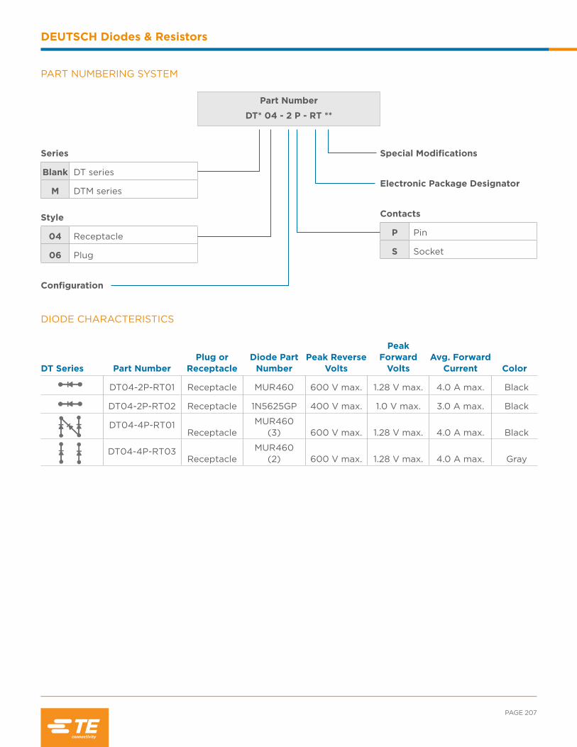
PAGE 207
DEUTSCH Diodes & Resistors
PART NUMBERING SYSTEM
Part Number
DT* 04 - 2 P - RT **
Series
Blank DT series
M DTM series
Style
04 Receptacle
06 Plug
Configuration
Special Modifications
Electronic Package Designator
Contacts
P Pin
S Socket
DIODE CHARACTERISTICS
DT Series Part NumberPlug or
ReceptacleDiode Part
NumberPeak Reverse
Volts
Peak Forward
VoltsAvg. Forward
Current Color
DT04-2P-RT01 Receptacle MUR460 600 V max. 1.28 V max. 4.0 A max. Black
DT04-2P-RT02 Receptacle 1N5625GP 400 V max. 1.0 V max. 3.0 A max. Black
DT04-4P-RT01Receptacle
MUR460 (3) 600 V max. 1.28 V max. 4.0 A max. Black
DT04-4P-RT03Receptacle
MUR460 (2) 600 V max. 1.28 V max. 4.0 A max. Gray
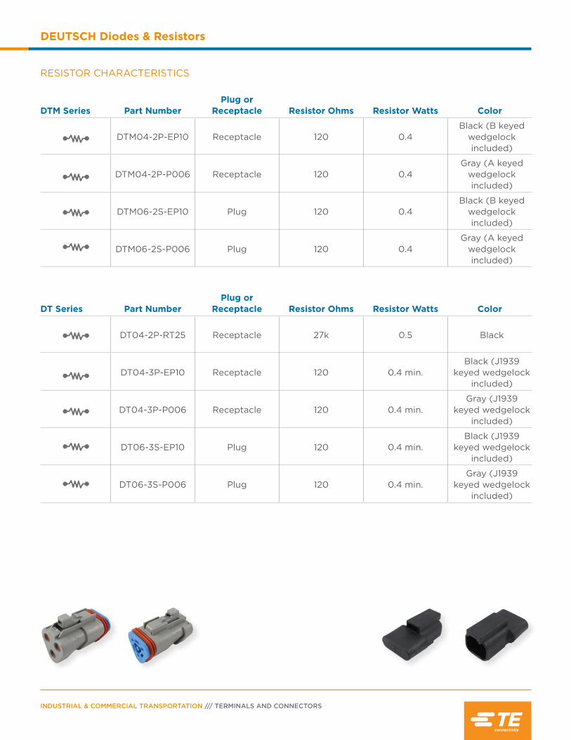
INDUSTRIAL & COMMERCIAL TRANSPORTATION /// TERMINALS AND CONNECTORS
DEUTSCH Diodes & Resistors
DTM Series Part NumberPlug or
Receptacle Resistor Ohms Resistor Watts Color
DTM04-2P-EP10 Receptacle 120 0.4Black (B keyed
wedgelock included)
DTM04-2P-P006 Receptacle 120 0.4Gray (A keyed
wedgelock included)
DTM06-2S-EP10 Plug 120 0.4Black (B keyed
wedgelock included)
DTM06-2S-P006 Plug 120 0.4Gray (A keyed
wedgelock included)
DT Series Part NumberPlug or
Receptacle Resistor Ohms Resistor Watts Color
DT04-2P-RT25 Receptacle 27k 0.5 Black
DT04-3P-EP10 Receptacle 120 0.4 min.Black (J1939
keyed wedgelock included)
DT04-3P-P006 Receptacle 120 0.4 min.Gray (J1939
keyed wedgelock included)
DT06-3S-EP10 Plug 120 0.4 min.Black (J1939
keyed wedgelock included)
DT06-3S-P006 Plug 120 0.4 min.Gray (J1939
keyed wedgelock included)
RESISTOR CHARACTERISTICS

Contents
Printed Circuit Board Overview .........................210
PCB Connector Options .......................................210
AMPSEAL Connectors ........................................... 211
Circular DIN Connectors ........................................ 211
DRC Series ......................................................... 212-213
DT Family ...........................................................214-216
HD10 Series ...............................................................216
LEAVYSEAL ............................................................... 217
STRIKE Series ........................................................... 217
Superseal 1.0 Connectors ..................................... 218
PCB Enclosures and Headers .....................218-221
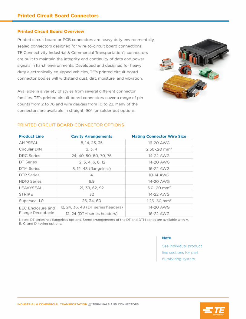
INDUSTRIAL & COMMERCIAL TRANSPORTATION /// TERMINALS AND CONNECTORS
Printed Circuit Board Connectors
Printed Circuit Board Overview
Printed circuit board or PCB connectors are heavy duty environmentally
sealed connectors designed for wire-to-circuit board connections.
TE Connectivity Industrial & Commercial Transportation’s connectors
are built to maintain the integrity and continuity of data and power
signals in harsh environments. Developed and designed for heavy
duty electronically equipped vehicles, TE’s printed circuit board
connector bodies will withstand dust, dirt, moisture, and vibration.
Available in a variety of styles from several different connector
families, TE’s printed circuit board connectors cover a range of pin
counts from 2 to 76 and wire gauges from 10 to 22. Many of the
connectors are available in straight, 90°, or solder pot options.
Note
See individual product
line sections for part
numbering system.
PRINTED CIRCUIT BOARD CONNECTOR OPTIONS
Product Line Cavity Arrangements Mating Connector Wire Size
AMPSEAL 8, 14, 23, 35 16-20 AWG
Circular DIN 2, 3, 4 2.50-.20 mm2
DRC Series 24, 40, 50, 60, 70, 76 14-22 AWG
DT Series 2, 3, 4, 6, 8, 12 14-20 AWG
DTM Series 8, 12, 48 (flangeless) 16-22 AWG
DTP Series 4 10-14 AWG
HD10 Series 6,9 14-20 AWG
LEAVYSEAL 21, 39, 62, 92 6.0-.20 mm2
STRIKE 32 14-22 AWG
Superseal 1.0 26, 34, 60 1.25-.50 mm2
EEC Enclosure and Flange Receptacle
12, 24, 36, 48 (DT series headers) 14-20 AWG
12, 24 (DTM series headers) 16-22 AWGNotes: DT series has flangeless options. Some arrangements of the DT and DTM series are available with A, B, C, and D keying options.
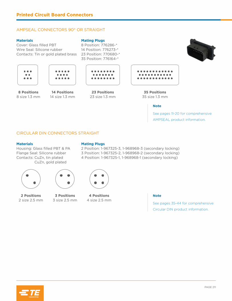
PAGE 211
Printed Circuit Board Connectors
Note
See pages 11-20 for comprehensive
AMPSEAL product information.
Note
See pages 35-44 for comprehensive
Circular DIN product information.
AMPSEAL CONNECTORS 90 ° OR STRAIGHT
Materials Cover: Glass filled PBT Wire Seal: Silicone rubberContacts: Tin or gold plated brass
Mating Plugs 8 Position: 776286-* 14 Position: 776273-*23 Position: 770680-*35 Position: 776164-*
8 Positions8 size 1.3 mm
14 Positions 14 size 1.3 mm
23 Positions 23 size 1.3 mm
35 Positions 35 size 1.3 mm
CIRCULAR DIN CONNECTORS STRAIGHT
Materials Housing: Glass filled PBT & PA Flange Seal: Silicone rubberContacts: CuZn, tin plated CuZn, gold plated
Mating Plugs 2 Position: 1-967325-3, 1-968968-3 (secondary locking)3 Position: 1-967325-2, 1-968968-2 (secondary locking)4 Position: 1-967325-1, 1-968968-1 (secondary locking)
3 Positions 3 size 2.5 mm
2 Positions 2 size 2.5 mm
4 Positions 4 size 2.5 mm
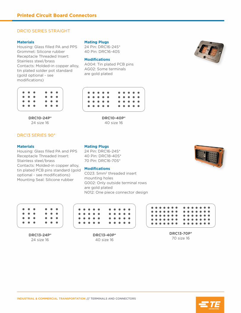
INDUSTRIAL & COMMERCIAL TRANSPORTATION /// TERMINALS AND CONNECTORS
Printed Circuit Board Connectors
DRC10 SERIES STRAIGHT
Materials Housing: Glass filled PA and PPSGrommet: Silicone rubberReceptacle Threaded Insert: Stainless steel/brassContacts: Molded-in copper alloy, tin plated solder pot standard (gold optional - see modifications)
Mating Plugs 24 Pin: DRC16-24S*40 Pin: DRC16-40S
Modifications A004: Tin plated PCB pins AG02: Some terminals are gold plated
DRC10-40P* 40 size 16
DRC10-24P* 24 size 16
DRC13 SERIES 90°
Materials Housing: Glass filled PA and PPSReceptacle Threaded Insert: Stainless steel/brassContacts: Molded-in copper alloy, tin plated PCB pins standard (gold optional - see modifications)Mounting Seal: Silicone rubber
Mating Plugs 24 Pin: DRC16-24S*40 Pin: DRC18-40S*70 Pin: DRC16-70S*
Modifications C023: 5mm2 threaded insert mounting holes G002: Only outside terminal rows are gold plated N012: One piece connector design
DRC13-40P* 40 size 16
DRC13-70P* 70 size 16
DRC13-24P* 24 size 16

PAGE 213
Printed Circuit Board Connectors
DRC20/22 SERIES STRAIGHT
Materials Housing: Glass filled PA and PPSGrommet: Silicone rubberReceptacle Threaded Insert: Stainless steel/brassContacts: Molded-in copper alloy, gold plated mating side, tin plated PCB side (size 12 contacts are tin plated on mating and PCB sides)Mounting Seal: Silicone rubber
Mating Plugs 50 Pin: DRC26-50S**60 Pin: DRC26-60S**76 Pin: (2) DRC26-38S**
DRC20
DRC22
DRC2*-50P* 50 size 20
DRC20-60P* 60 size 20
DRC20-76P**** 68 size 20, 8 size 12
DRC23 SERIES 90°
Materials Housing: Glass filled PA and PPSGrommet: Silicone rubberReceptacle Threaded Insert: Stainless steel/brassContacts: Molded-in copper alloy, gold plated PCB pins standard (tin optional)Mounting Seal: Silicone rubber
Mating Plugs 24 Pin: DRC26-24S*40 Pin: DRC26-40S*64 Pin: DRC26-24S*, DRC26-40S*
Modifications N010: Custom mount N012: One piece connector design
DRC2*-40** 40 size 20
DRC2*-24** 24 size 20
DRC2*-64** 64 size 20
Note
See pages 99-108 for comprehensive
DRC series product information.
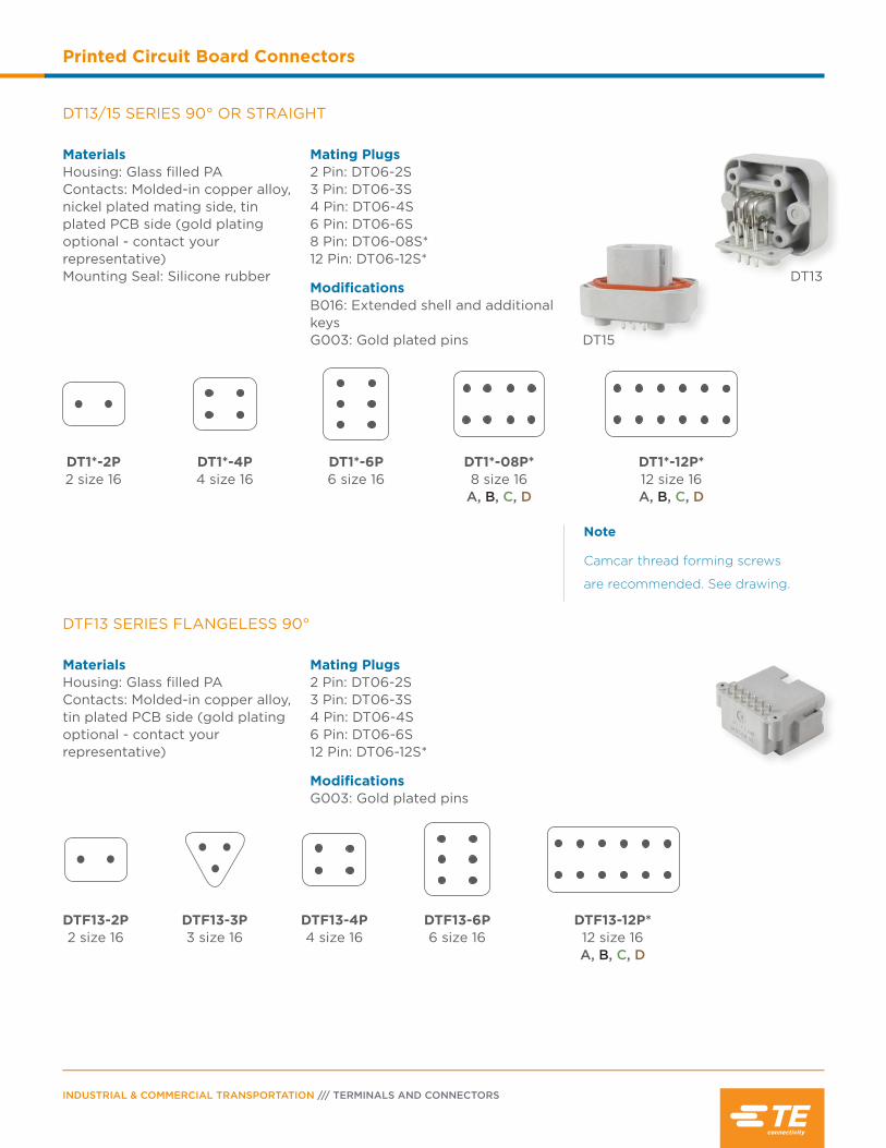
INDUSTRIAL & COMMERCIAL TRANSPORTATION /// TERMINALS AND CONNECTORS
Printed Circuit Board Connectors
DTF13 SERIES FLANGELESS 90°
Materials Housing: Glass filled PAContacts: Molded-in copper alloy, tin plated PCB side (gold plating optional - contact your representative)
Mating Plugs 2 Pin: DT06-2S3 Pin: DT06-3S4 Pin: DT06-4S6 Pin: DT06-6S12 Pin: DT06-12S*
Modifications G003: Gold plated pins
DTF13-3P 3 size 16
DTF13-12P* 12 size 16 A, B, C, D
DTF13-4P 4 size 16
DTF13-2P 2 size 16
DTF13-6P 6 size 16
DT13/15 SERIES 90° OR STRAIGHT
Materials Housing: Glass filled PAContacts: Molded-in copper alloy, nickel plated mating side, tin plated PCB side (gold plating optional - contact your representative)Mounting Seal: Silicone rubber
Mating Plugs 2 Pin: DT06-2S3 Pin: DT06-3S4 Pin: DT06-4S6 Pin: DT06-6S8 Pin: DT06-08S*12 Pin: DT06-12S*
Modifications B016: Extended shell and additional keys G003: Gold plated pins
DT13
DT15
Note
Camcar thread forming screws
are recommended. See drawing.
DT1*-08P* 8 size 16
A, B, C, D
DT1*-12P* 12 size 16 A, B, C, D
DT1*-4P 4 size 16
DT1*-2P 2 size 16
DT1*-6P 6 size 16

PAGE 215
Printed Circuit Board Connectors
DTF15 SERIES FLANGELESS STRAIGHT
Materials Housing: Glass filled PAContacts: Molded-in copper alloy, tin plated PCB side (gold plating optional - contact your representative)
Mating Plugs 12 Pin: DT06-12S*
Modifications G003: Gold plated pins
DTF15-12P* 12 size 16 A, B, C, D
DTM13/15 SERIES 90° OR STRAIGHT
Materials Housing: Glass filled PAContacts: Molded-in copper alloy, tin plated PCB side (gold plating optional - contact your representative)Mounting Seal: Silicone rubber
Mating Plugs 12 Pin: DTM06-12S*
DTM1*-12P* 12 size 20 A, B, C, D
DTM13
DTM15
helpful hint
By fixing the connectors to the board prior to soldering, pressure can be greatly reduced at the solder joint.
Note
See pages 109-132 for comprehensive
DT Family product information.

INDUSTRIAL & COMMERCIAL TRANSPORTATION /// TERMINALS AND CONNECTORS
Printed Circuit Board Connectors
HD10 SERIES STRAIGHT
Materials Housing: Glass filled PAContacts: Molded-in copper alloy, nickel platedMounting Seal: Standard o-rings may be used
Mating Plugs 6 Pin: HD16-6-96S9 Pin: HD16-9-96S
Modifications N005: Straight reduced diameter pins supplied as standard
HD10-6-96P-N0056 size 16
HD10-9-96P-N0059 size 16
DTMF15 SERIES STRAIGHT
Materials Housing: Glass filled PAContacts: Molded-in copper alloy, tin plated (gold plating optional - contact your representative)
Mating Plugs 12 Pin: (4) DTM06-12S*
Modifications B026: Alternate keying position
DTMF15-48P (4) 12 size 20
DTP10/13/15 SERIES 90° OR STRAIGHT
Materials Housing: Glass filled PAContacts: Molded-in copper alloy, tin platedMounting Seal: Silicone rubber
Mating Plugs 4 Pin: (4) DTP06-4S
DTP13
DTP10DTP1*-4P 4 size 12

PAGE 217
Printed Circuit Board Connectors
STRIKE13/15 SERIES 90° OR STRAIGHT
Materials Housing: Glass filled PBTContacts: Molded-in copper alloy, tin plated (gold plating optional- contact your representative)
Mating Plugs 32 Pin: SRK06-MD*-32A-001
Modifications G003: Gold plated pins
SRK1*-MD*-32A-001-**** 4 Size 16
28 Size 20
LEAVYSEAL CONNECTORS 90° OR STRAIGHT
Materials Housing: Glass filled PBTContacts: CuSn, silver plated
Mating Plugs 21 Pin: 1-1534127-1, 1-2208688-1 (V0 rated material)39 Pin: 5-1718321-3, 5-2208684-3 (V0 rated material)62 Pin: 1-1418883-1 (A key), 2-1418883-1 (B key)92 Pin: 1-703998-1 (NW 26 wire exit), 3-1703998-1 (NW 29 wire exit)
21 Positions 21 size 2.8
39 Positions 39 size 2.8
62 Positions 56 size 1.56 size 2.8
92 Positions 92 size 1.5
Note
See pages 63-78 for comprehensive
LEAVYSEAL product information.
Note
See pages 161-168 for comprehensive
STRIKE series product information.
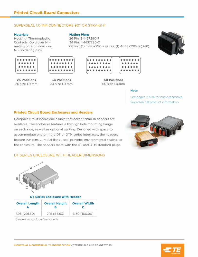
INDUSTRIAL & COMMERCIAL TRANSPORTATION /// TERMINALS AND CONNECTORS
Printed Circuit Board Connectors
Printed Circuit Board Enclosures and Headers
Compact circuit board enclosures that accept snap-in headers are
available. The enclosure features a through hole mounting flange
on each side, as well as optional venting. Designed with space to
accommodate one or more DT or DTM series interfaces, the headers
feature 90° pins. A radial flange seal provides environmental sealing to
the enclosure. The headers mate with the DT and DTM standard plugs.
DT SERIES ENCLOSURE WITH HEADER DIMENSIONS
DT Series Enclosure with Header
Overall Length A
Overall Height B
Overall Width C
7.93 (201.30) 2.15 (54.63) 6.30 (160.00)
Dimensions are for reference only
B
A
C
SUPERSEAL 1.0 MM CONNECTORS 90° OR STRAIGHT
Materials Housing: ThermoplasticContacts: Gold over Ni - mating pins, tin-lead over Ni - soldering pins
Mating Plugs 26 Pin: 3-1437290-734 Pin: 4-1437290-060 Pin: (1) 3-1437290-7 (26P), (1) 4-1437290-0 (34P)
34 Positions 34 size 1.0 mm
26 Positions 26 size 1.0 mm
60 Positions 60 size 1.0 mm
Note
See pages 79-84 for comprehensive
Superseal 1.0 product information.
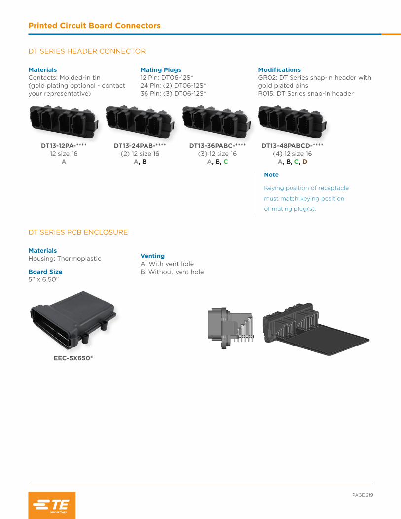
PAGE 219
Printed Circuit Board Connectors
DT SERIES HEADER CONNECTOR
Materials Contacts: Molded-in tin (gold plating optional - contact your representative)
Mating Plugs 12 Pin: DT06-12S*24 Pin: (2) DT06-12S*36 Pin: (3) DT06-12S*
Modifications GR02: DT Series snap-in header with gold plated pins R015: DT Series snap-in header
DT13-48PABCD-****(4) 12 size 16
A, B, C, D
DT13-12PA-****12 size 16
A
DT13-24PAB-****(2) 12 size 16
A, B
DT13-36PABC-****(3) 12 size 16
A, B, C
Note
Keying position of receptacle
must match keying position
of mating plug(s).
EEC-5X650*
DT SERIES PCB ENCLOSURE
Materials Housing: Thermoplastic
Board Size 5” x 6.50”
VentingA: With vent holeB: Without vent hole
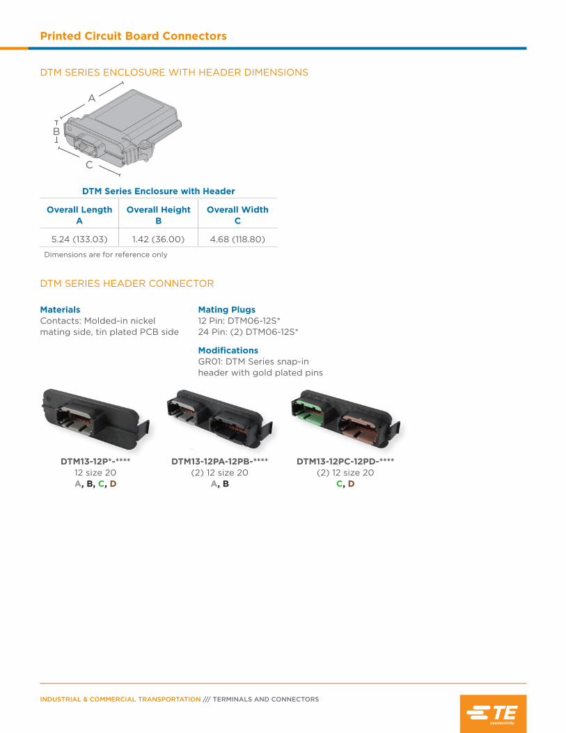
INDUSTRIAL & COMMERCIAL TRANSPORTATION /// TERMINALS AND CONNECTORS
Printed Circuit Board Connectors
DTM SERIES HEADER CONNECTOR
Materials Contacts: Molded-in nickel mating side, tin plated PCB side
Mating Plugs 12 Pin: DTM06-12S*24 Pin: (2) DTM06-12S*
Modifications GR01: DTM Series snap-in header with gold plated pins
DTM13-12P*-****12 size 20A, B, C, D
DTM13-12PA-12PB-****(2) 12 size 20
A, B
DTM13-12PC-12PD-****(2) 12 size 20
C, D
DTM SERIES ENCLOSURE WITH HEADER DIMENSIONS
DTM Series Enclosure with Header
Overall Length A
Overall Height B
Overall Width C
5.24 (133.03) 1.42 (36.00) 4.68 (118.80)
Dimensions are for reference only
A
B
C
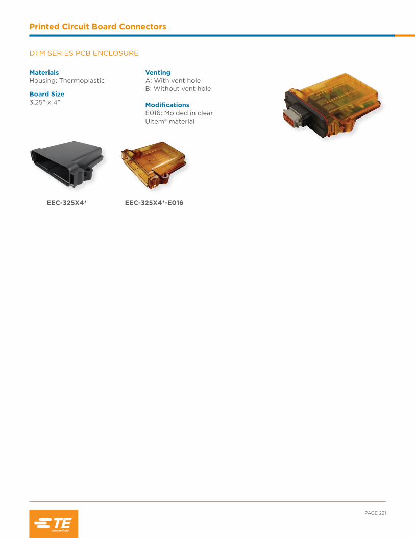
PAGE 221
Printed Circuit Board Connectors
DTM SERIES PCB ENCLOSURE
Materials Housing: Thermoplastic
Board Size 3.25” x 4”
VentingA: With vent holeB: Without vent hole ModificationsE016: Molded in clear Ultem® material
EEC-325X4* EEC-325X4*-E016

INDUSTRIAL & COMMERCIAL TRANSPORTATION /// TERMINALS AND CONNECTORS
Printed Circuit Board Connectors
NOTES:

Contents
DTHD Series Overview .........................................224
DTHD Series Material Specifications ..............224
DTHD Series Dimensions .....................................224
DTHD Series Ordering Information ................. 225
DTHD Special Modifications .............................. 225
DTHD Series Accessories ....................................226
Jiffy Splice Overview ............................................ 227
Jiffy Splice Dimensions ........................................ 227
Jiffy Splice How To Instructions .............. 227-228

INDUSTRIAL & COMMERCIAL TRANSPORTATION /// TERMINALS AND CONNECTORS
Single Terminal Solutions
Single Terminal Overview
Two different solutions are available for applications that require heavy duty single terminal connections.
DEUTSCH DTHD series connectors and Jiffy Splices provide environmentally sealed field-serviceable
connections for the full range of wire gauges covered by DEUTSCH contacts. DTHD connectors are heavy
duty power terminations for in-line and mounted applications. Jiffy Splices are lightweight in-line splices for
quick connections. Both options provide easy installation and service with standard tools and contacts.
DTHD SERIES OVERVIEW
DTHD connectors are single terminal connectors for heavy duty applications. Easy to install, environmentally sealed and compact in size, they are a simple, field serviceable alternative to a splice. DTHD connectors are available in three sizes, carry 25 to 100 amps, and can be mounted or used in-line.
DIMENSIONS
DTHD Plug DTHD Receptacle
Contact Size
Overall Length A
Overall Height B
Overall Width C
Overall Length D
Overall Height E
Overall Width F
12 1.498 (38.05) .771 (19.58) .570 (14.48) 2.068 (52.53) .850 (21.59) .710 (18.08)
8 1.498 (38.05) .861 (21.87) .660 (16.76) 2.068 (52.53) .940 (23.88) .800 (20.32)
4 1.498 (38.05) 1.076 (27.33) .875 (22.23) 2.068 (52.53) 1.170 (29.72) 1.045 (26.54)
Dimensions are for reference only.
AC
B
D
F
E
Grommet: Silicone rubber
Shell: Unfilled PEI
MATERIAL SPECIFICATIONS

PAGE 225
Single Terminal Solutions
DTHD SERIES PART NUMBERING SYSTEM
Part Number
DTHD 06 - 1 - 4 S - ****
Series
Style
04 Receptacle
06 Plug
Single Terminal
Special Modifications
Contacts
P Pin
S Socket
Contact Size
4 8 12
ORDERING INFORMATION
Here are some of the common part numbers in the DTHD series. Several additional connectors may be available.
Position Contact Size Plug Receptacle
1
12 DTHD06-1-12S DTHD04-1-12P
8 DTHD06-1-8S DTHD04-1-8P
4 DTHD06-1-4S DTHD04-1-4P
Special Modifications
DTHD series connectors offer modifications to enhance the design flexibility and meet application specific
needs. Options include end caps and flanges.
L009 L013
E003 MODIFICATION The E003 is an end cap modification. The end cap is a protective cap that is sonically welded to the rear of the connector.
L013 & L009 MODIFICATION The L013 and L009 are sealed flange modifications. The L013 offers outside mounting and the L009 offers inside mounting.
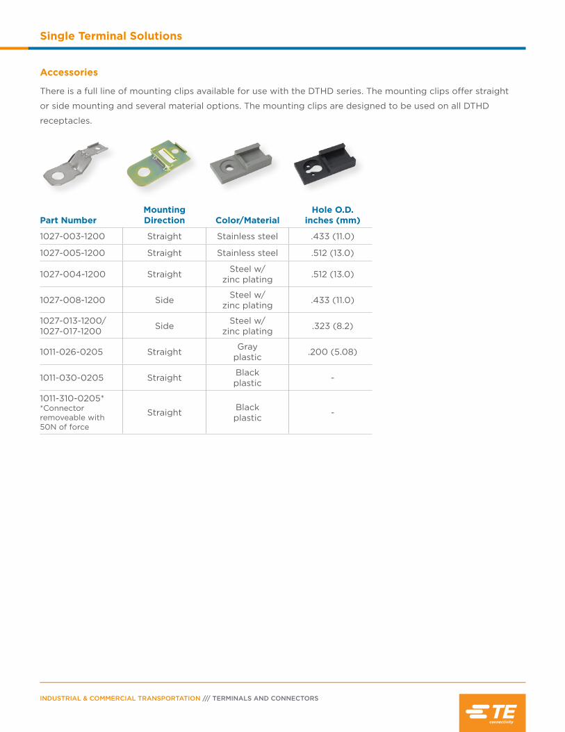
INDUSTRIAL & COMMERCIAL TRANSPORTATION /// TERMINALS AND CONNECTORS
Single Terminal Solutions
Accessories
There is a full line of mounting clips available for use with the DTHD series. The mounting clips offer straight
or side mounting and several material options. The mounting clips are designed to be used on all DTHD
receptacles.
Part NumberMountingDirection Color/Material
Hole O.D.inches (mm)
1027-003-1200 Straight Stainless steel .433 (11.0)
1027-005-1200 Straight Stainless steel .512 (13.0)
1027-004-1200 Straight Steel w/zinc plating .512 (13.0)
1027-008-1200 Side Steel w/zinc plating .433 (11.0)
1027-013-1200/ 1027-017-1200 Side Steel w/
zinc plating .323 (8.2)
1011-026-0205 Straight Grayplastic .200 (5.08)
1011-030-0205 Straight Blackplastic -
1011-310-0205**Connector removeable with 50N of force
Straight Blackplastic -
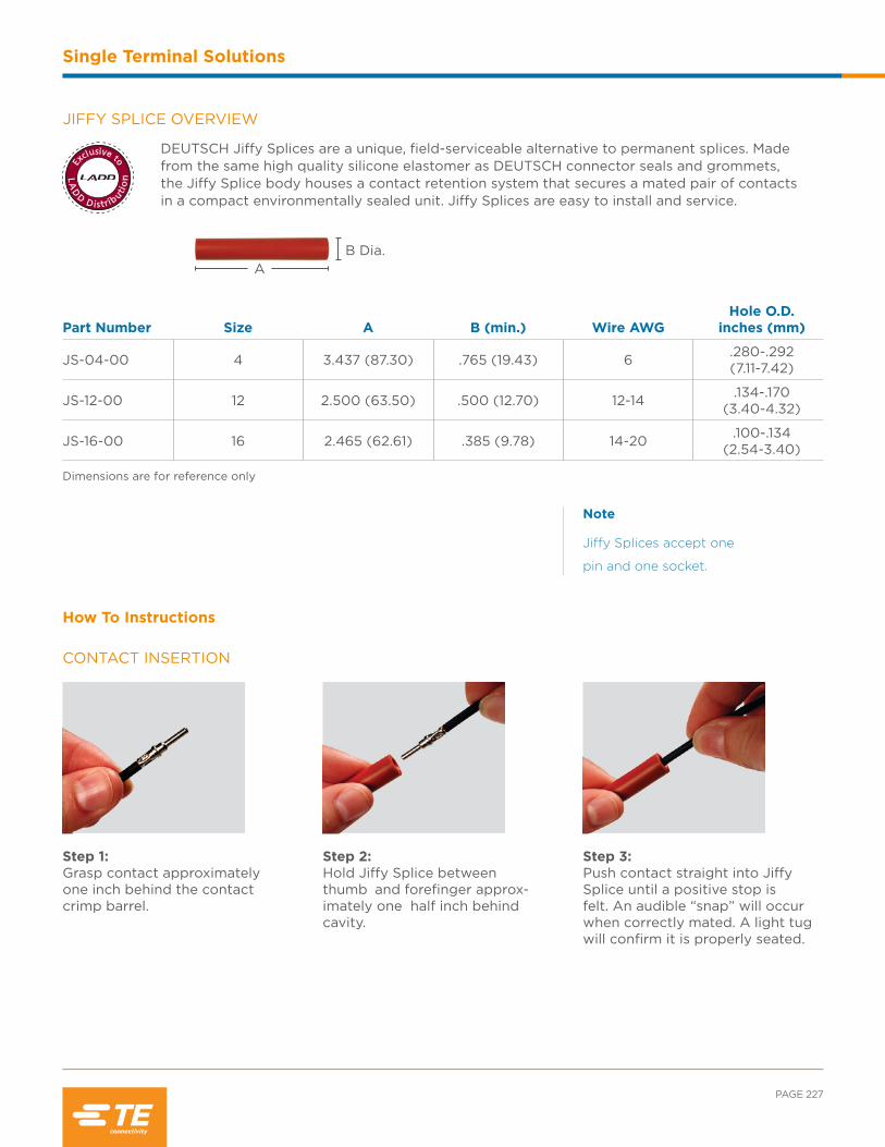
PAGE 227
Single Terminal Solutions
B Dia.A
JIFFY SPLICE OVERVIEW
DEUTSCH Jiffy Splices are a unique, field-serviceable alternative to permanent splices. Made from the same high quality silicone elastomer as DEUTSCH connector seals and grommets, the Jiffy Splice body houses a contact retention system that secures a mated pair of contacts in a compact environmentally sealed unit. Jiffy Splices are easy to install and service.
Part Number Size A B (min.) Wire AWGHole O.D.
inches (mm)
JS-04-00 4 3.437 (87.30) .765 (19.43) 6 .280-.292(7.11-7.42)
JS-12-00 12 2.500 (63.50) .500 (12.70) 12-14 .134-.170(3.40-4.32)
JS-16-00 16 2.465 (62.61) .385 (9.78) 14-20 .100-.134(2.54-3.40)
Dimensions are for reference only
Note
Jiffy Splices accept one
pin and one socket.
Step 1:Grasp contact approximately one inch behind the contact crimp barrel.
Step 2:Hold Jiffy Splice between thumb and forefinger approx-imately one half inch behind cavity.
Step 3:Push contact straight into Jiffy Splice until a positive stop is felt. An audible “snap” will occur when correctly mated. A light tug will confirm it is properly seated.
How To Instructions
CONTACT INSERTION
LA
D
D D istrib
utio
n
Exclusive to

INDUSTRIAL & COMMERCIAL TRANSPORTATION /// TERMINALS AND CONNECTORS
Single Terminal Solutions
Step 1:Snap appropriate size removal tool over the wire.
Step 2:Hold Jiffy Splice between thumb and forefinger approx-imately one half inch behind cavity. Slide tool into cavity until resistance is felt and retaining fingers are engaged. Do not twist or insert tool at an angle.
Step 3:Grip Jiffy Splice between thumb and forefinger and slowly pull contact wire as-sembly with removal tool out of cavity.
CONTACT REMOVAL

Contents
DEUTSCH Modification List ..................... 230-238
Other TE Industrial & Commercial Transportation Products ............................ 239-240
Requirements & Standards .................................. 241
Glossary ............................................................242-247
Index ...................................................................248-251
INDUSTRIAL & COMMERCIAL TRANSPORTATION /// TERMINALS AND CONNECTORS
Additional Resources
Modification List
The modification list is only applicable to the DEUTSCH product line and series listed. Modifications listed are
for reference only and may not be available for every arrangement.
Mod # Series Description
A
A004 DRC Receptacle with molded-in PCB pins, 24 and 40 way
A006 DRC Receptacle with molded-in PCB pins, 40 way, #40 pin removed
B
B009 HD10 Receptacle with raised key removed from front of flange, no rear threads
B010 HD10 Plug with coupling ring added
B016 DT, DT13/15 Receptacle has extended shell and enhanced keys, plug has enhanced seal retention (P012), 12 way
B019 HD30 Custom snap ring mount
B022 HD10 Receptacle with D-hole panel mount, rear threads, J1939, black
B025 HD10 Receptacle with D-hole panel mount, no rear threads, black
B026 DTMF PCB receptacle with alternate keying, requires plugs with WM-12S-B026 wedgelocks
B028 DT15 5 P.S.I rating
BE
BE02 DT Receptacle with extended shell and enhanced keys (B016), end cap
BE03 DT Receptacle with extended shell and enhanced keys (B016), end cap, black
BE04 DT Receptacle with extended shell and enhanced keys (B016), end cap, reduced diameter seals (E seal), black
BE05 DTReceptacle with extended shell and enhanced keys (B016), end cap, sealed flange, reduced diameter seals (E seal), threaded stainless steel flange inserts
BL
BL04 DT Receptacle with extended shell and enhanced keys (B016), welded flange
BL08 DT Receptacle with extended shell and enhanced keys (B016), welded flange, black

PAGE 231
Additional Resources
Mod # Series Description
BL10 DTReceptacle with extended shell and enhanced keys (B016), sealed flange, reduced diameter seals (E seal), shrink boot adapter, threaded stainless steel flange inserts
BL11 DTReceptacle with extended shell and enhanced keys (B016), sealed flange, reduced diameter seals (E seal), end cap, threaded stainless steel flange inserts
BP
BP03 HD10 Receptacle with D-hole panel mount, J1939 Type II, green
C
C003 HDN Standard cavity marking identification
C008 DT Cavity blocked (C)
C012 HD30 Cavities blocked (J, P)
C015 DT, DTP Reduced diameter seals (E seal)
C016 HD10 Cavities blocked (H, J) - HD10 Series 9 way
C017 DT, DTM, DTP Solid rear grommet
C018 HD30 Cavities blocked (11, 18, 19), N/E seal options
C019 HD30 Cavities blocked (1, 2, 8, 9), N/E seal options
C020 HD30 Cavities blocked (A, D), N/E seal options
C021 HD30 Cavities blocked (A, B, C, D)
C022 HD30 Cavities blocked (A, D, J, M), with reduced diameter seals (E seal)
C024 HD10 Cavities blocked (B, C, D)
C026 DRC Cavities blocked, 50 way
C030 HD30, HDP20 Four size 16 cavities blocked (1, 2, 5, 6)
C038 HD30, HDP20 Three size 4, four size 16, requires special size 4 AWG contacts
C041 HDP20 Receptacle with diagnostic keying
CE
CE01 DT Reduced diameter seals (E seal), end cap
CE02 DT, DTP Reduced diameter seals (E seal), black
CE03 DT Reduced diameter seals (E seal), end cap, black
CE04 DT Reduced diameter seals (E seal), shrink boot adapter

INDUSTRIAL & COMMERCIAL TRANSPORTATION /// TERMINALS AND CONNECTORS
Additional Resources
Mod # Series Description
CE05 DT Plug with reduced diameter seals (E seal), enhanced seal retention (P012), end cap
CE06 DT Plug with reduced diameter seals (E seal), enhanced seal retention (P012)
CE07 DT Receptacle with extended shell and enhanced keys (B016), reduced diameter seals (E seal), end cap
CE08 DT Receptacle with extended shell and enhanced keys (B016), reduced diameter seals (E seal)
CE09 DT Reduced diameter seals (E seal), shrink boot adapter, black
CE10 DT Plug with reduced diameter seals (E seal), enhanced seal retention (P012), black
CE11 DT Plug with reduced diameter seals (E seal), enhanced seal retention (P012), end cap, black
CE12 DT Plug with reduced diameter seals (E seal), enhanced seal retention (P012), shrink boot adapter, black
CE13 DT Plug with reduced diameter seals (E seal), enhanced seal retention (P012), shrink boot adapter
CE14 DT Plug with reduced diameter seals (E seal), enhanced seal retention (P012), latch guard end cap, black
CE27 DT Plug with reduced diameter seals (E seal), enhanced seal retention (P012), for use with integrated LED wedgelock, end cap, transparent Ultem
CE28 DT Plug with reduced diameter seals (E seal), enhanced seal retention (P012), for use with integrated LED wedgelock, transparent Ultem
CL
CL01 HD30 Cavities blocked (J, Q, R, S, X), adapter for cable clamp (072)
CL03 DT Reduced diameter seals (E seal), welded flange
CL07 DT Reduced diameter seals (E seal), sealed flange, shrink boot adapter
CL08 DT Reduced diameter seals (E seal), welded flange, end cap, disabled latch
CL09 DT Reduced diameter seals (E seal), sealed flange, end cap, black
CL15 DT Reduced diameter seals (E seal), welded flange, black
CL20 HDP20 Plug with diagnostic keying
CG
CG01 DRC 5mm threaded insert with silver plating, molded-in contacts, outside rows gold
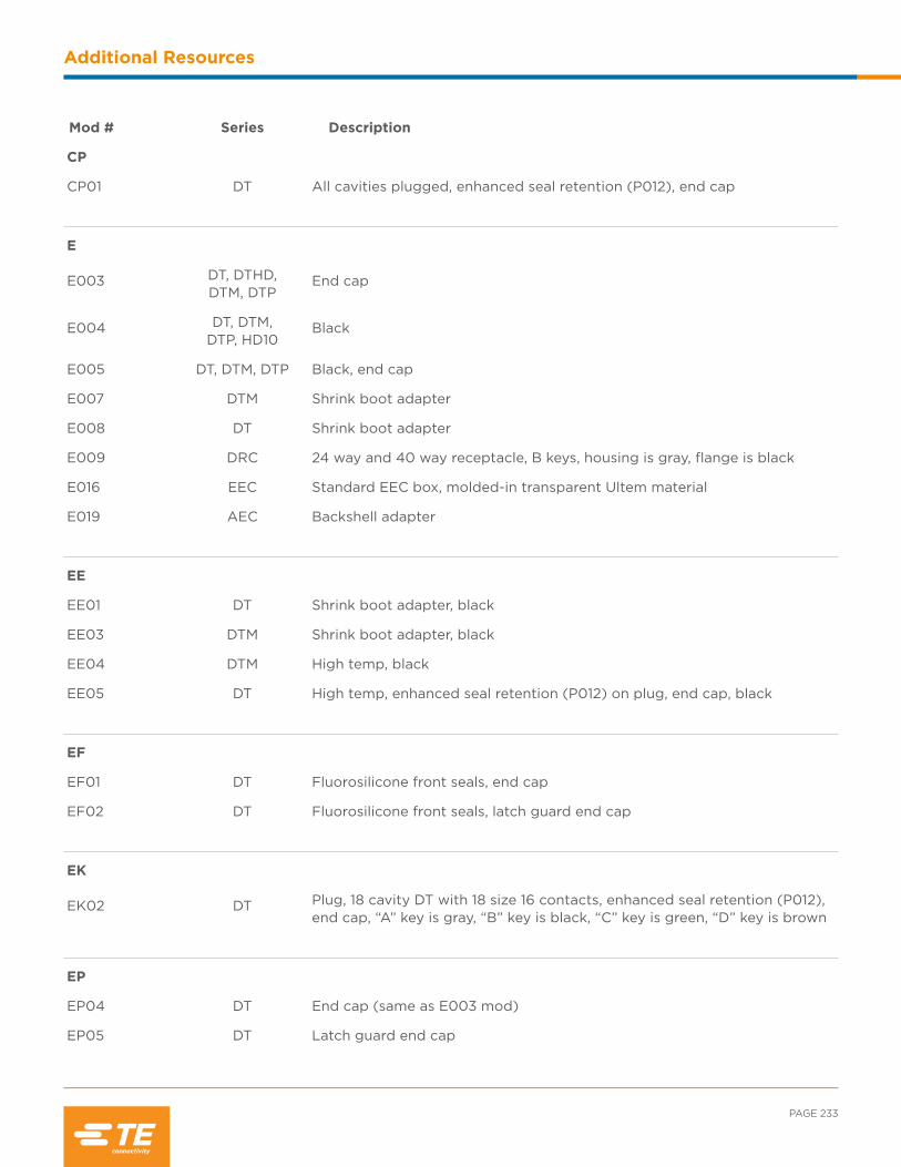
PAGE 233
Additional Resources
Mod # Series Description
CP
CP01 DT All cavities plugged, enhanced seal retention (P012), end cap
E
E003 DT, DTHD, DTM, DTP
End cap
E004 DT, DTM, DTP, HD10
Black
E005 DT, DTM, DTP Black, end cap
E007 DTM Shrink boot adapter
E008 DT Shrink boot adapter
E009 DRC 24 way and 40 way receptacle, B keys, housing is gray, flange is black
E016 EEC Standard EEC box, molded-in transparent Ultem material
E019 AEC Backshell adapter
EE
EE01 DT Shrink boot adapter, black
EE03 DTM Shrink boot adapter, black
EE04 DTM High temp, black
EE05 DT High temp, enhanced seal retention (P012) on plug, end cap, black
EF
EF01 DT Fluorosilicone front seals, end cap
EF02 DT Fluorosilicone front seals, latch guard end cap
EK
EK02 DT Plug, 18 cavity DT with 18 size 16 contacts, enhanced seal retention (P012), end cap, “A” key is gray, “B” key is black, “C” key is green, “D” key is brown
EP
EP04 DT End cap (same as E003 mod)
EP05 DT Latch guard end cap
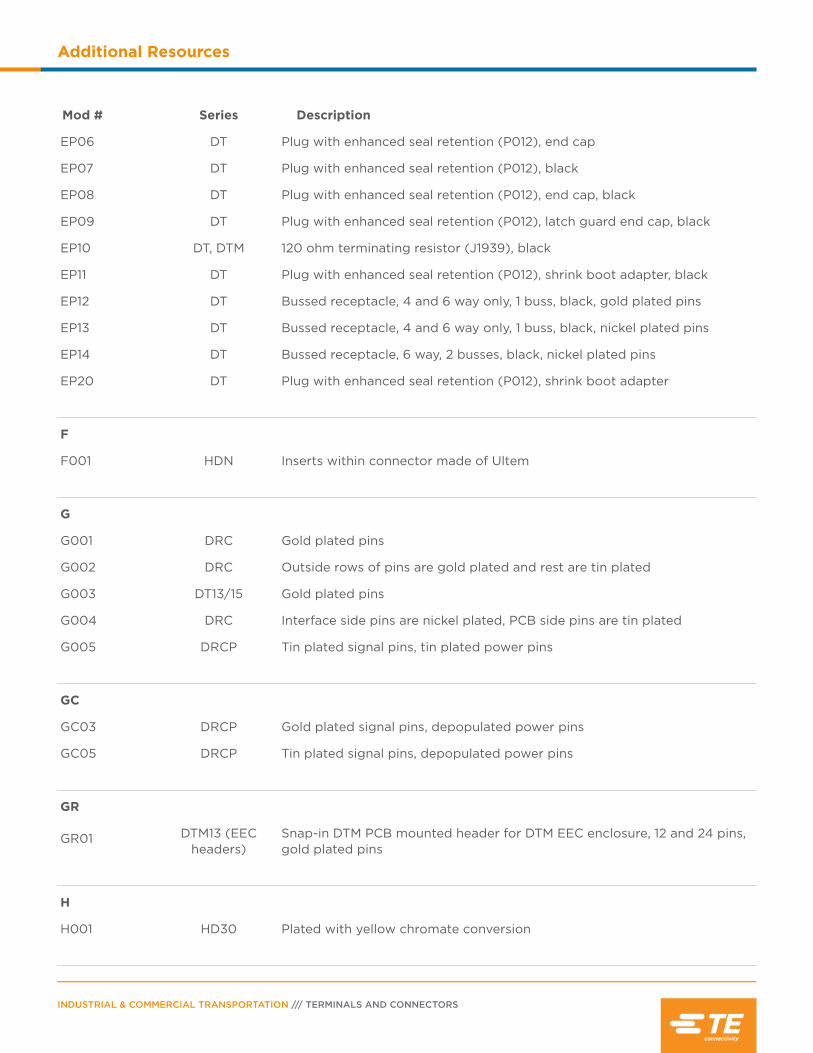
INDUSTRIAL & COMMERCIAL TRANSPORTATION /// TERMINALS AND CONNECTORS
Additional Resources
Mod # Series Description
EP06 DT Plug with enhanced seal retention (P012), end cap
EP07 DT Plug with enhanced seal retention (P012), black
EP08 DT Plug with enhanced seal retention (P012), end cap, black
EP09 DT Plug with enhanced seal retention (P012), latch guard end cap, black
EP10 DT, DTM 120 ohm terminating resistor (J1939), black
EP11 DT Plug with enhanced seal retention (P012), shrink boot adapter, black
EP12 DT Bussed receptacle, 4 and 6 way only, 1 buss, black, gold plated pins
EP13 DT Bussed receptacle, 4 and 6 way only, 1 buss, black, nickel plated pins
EP14 DT Bussed receptacle, 6 way, 2 busses, black, nickel plated pins
EP20 DT Plug with enhanced seal retention (P012), shrink boot adapter
F
F001 HDN Inserts within connector made of Ultem
G
G001 DRC Gold plated pins
G002 DRC Outside rows of pins are gold plated and rest are tin plated
G003 DT13/15 Gold plated pins
G004 DRC Interface side pins are nickel plated, PCB side pins are tin plated
G005 DRCP Tin plated signal pins, tin plated power pins
GC
GC03 DRCP Gold plated signal pins, depopulated power pins
GC05 DRCP Tin plated signal pins, depopulated power pins
GR
GR01 DTM13 (EEC headers)
Snap-in DTM PCB mounted header for DTM EEC enclosure, 12 and 24 pins, gold plated pins
H
H001 HD30 Plated with yellow chromate conversion

PAGE 235
Additional Resources
Mod # Series Description
HL
HL01 HD30 Dust cap plated with yellow chromate conversion, sash chain with eyelet for #10 screw
HL02 HD30 Adapter for cable clamp (-072) plated with yellow chromate conversion
J
J001 HD30 Reverse cavity marking identification on grommet
J059 HD30 Reverse cavity marking identification on grommet, cable clamp (-059)
K
K001 AEC Molded-in shell marking, remove blue stripe, end cap
K003 DT16 Plug, 15 cavity DT with two size 12 contacts and 13 size 16 contacts, enhanced seal retention (P012), end cap, black
K004 DT16 Plug, 18 cavity DT with 18 size 16 contacts, enhanced seal retention (P012), end cap, black
KP
KP01 DT16 Plug, six cavity DT with six size 16 contacts, enhanced seal retention (P012), end cap, green
L
L001 HD30 Same as -059 (cable clamp)
L003 HD30 Cable clamp adapter (-072)
L005 HD30 Cable clamp adapter (-072) without drain holes
L006 HD30 -059 modification using adapter without drain holes
L009 DTHD Sealed flange, inside mount
L011 DRC Wire router
L012 DT, DTP, DTM Welded flange
L013 DTHD Sealed flange, outside mount
L015 HDP20 Threaded adapter for backshell strain relief
L017 HDP20 Ring adapter for backshell strain relief
L018 DRB Wire router
L020 HD30, HD50 Removes #10 eyelet from the dust cap chain
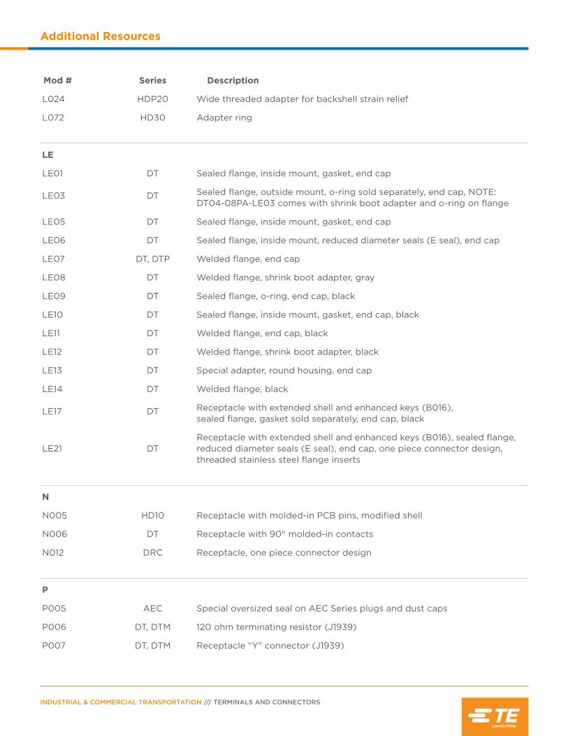
INDUSTRIAL & COMMERCIAL TRANSPORTATION /// TERMINALS AND CONNECTORS
Additional Resources
Mod # Series Description
L024 HDP20 Wide threaded adapter for backshell strain relief
L072 HD30 Adapter ring
LE
LE01 DT Sealed flange, inside mount, gasket, end cap
LE03 DT Sealed flange, outside mount, o-ring sold separately, end cap, NOTE: DT04-08PA-LE03 comes with shrink boot adapter and o-ring on flange
LE05 DT Sealed flange, inside mount, gasket, end cap
LE06 DT Sealed flange, inside mount, reduced diameter seals (E seal), end cap
LE07 DT, DTP Welded flange, end cap
LE08 DT Welded flange, shrink boot adapter, gray
LE09 DT Sealed flange, o-ring, end cap, black
LE10 DT Sealed flange, inside mount, gasket, end cap, black
LE11 DT Welded flange, end cap, black
LE12 DT Welded flange, shrink boot adapter, black
LE13 DT Special adapter, round housing, end cap
LE14 DT Welded flange, black
LE17 DT Receptacle with extended shell and enhanced keys (B016), sealed flange, gasket sold separately, end cap, black
LE21 DTReceptacle with extended shell and enhanced keys (B016), sealed flange, reduced diameter seals (E seal), end cap, one piece connector design, threaded stainless steel flange inserts
N
N005 HD10 Receptacle with molded-in PCB pins, modified shell
N006 DT Receptacle with 90° molded-in contacts
N012 DRC Receptacle, one piece connector design
P
P005 AEC Special oversized seal on AEC Series plugs and dust caps
P006 DT, DTM 120 ohm terminating resistor (J1939)
P007 DT, DTM Receptacle “Y” connector (J1939)
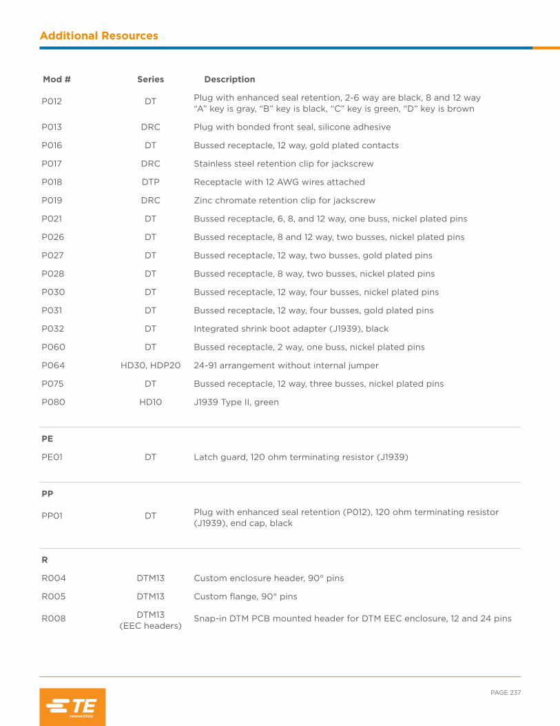
PAGE 237
Additional Resources
Mod # Series Description
P012 DT Plug with enhanced seal retention, 2-6 way are black, 8 and 12 way “A” key is gray, “B” key is black, “C” key is green, “D” key is brown
P013 DRC Plug with bonded front seal, silicone adhesive
P016 DT Bussed receptacle, 12 way, gold plated contacts
P017 DRC Stainless steel retention clip for jackscrew
P018 DTP Receptacle with 12 AWG wires attached
P019 DRC Zinc chromate retention clip for jackscrew
P021 DT Bussed receptacle, 6, 8, and 12 way, one buss, nickel plated pins
P026 DT Bussed receptacle, 8 and 12 way, two busses, nickel plated pins
P027 DT Bussed receptacle, 12 way, two busses, gold plated pins
P028 DT Bussed receptacle, 8 way, two busses, nickel plated pins
P030 DT Bussed receptacle, 12 way, four busses, nickel plated pins
P031 DT Bussed receptacle, 12 way, four busses, gold plated pins
P032 DT Integrated shrink boot adapter (J1939), black
P060 DT Bussed receptacle, 2 way, one buss, nickel plated pins
P064 HD30, HDP20 24-91 arrangement without internal jumper
P075 DT Bussed receptacle, 12 way, three busses, nickel plated pins
P080 HD10 J1939 Type II, green
PE
PE01 DT Latch guard, 120 ohm terminating resistor (J1939)
PP
PP01 DT Plug with enhanced seal retention (P012), 120 ohm terminating resistor (J1939), end cap, black
R
R004 DTM13 Custom enclosure header, 90° pins
R005 DTM13 Custom flange, 90° pins
R008 DTM13 (EEC headers)
Snap-in DTM PCB mounted header for DTM EEC enclosure, 12 and 24 pins

INDUSTRIAL & COMMERCIAL TRANSPORTATION /// TERMINALS AND CONNECTORS
Additional Resources
Mod # Series Description
R015 DT13 (EEC headers)
Snap-in DT PCB mounted header for DT EEC enclosure, 12, 24, 36, and 48 pins
RT
RT01 DT Receptacle with MUR 460 diode
RT02 DT Receptacle with 1N5625GP diode
RT03 DT Receptacle with MUR 460 diode, 4 way available
RT06 DT Receptacle with Phillips T.V.S diode 1.5KE130CA, green
RT25 DT Receptacle with 27k ohm resistor, black
#’s
059 HD30 Addition of threaded adapter and cable clamp assembly
072 HD30 Addition of threaded adapter
1E HD30 Removes rivet and chain from protective dust cap

PAGE 239
Additional Resources
We go to extremes to make every connection countTE Industrial & Commercial Transportation has a product series for every harsh environment. Our time-tested, high vibration resistant products and technologies provide the right solution for your applications and requirements. In addition to our terminals and connectors, our product portfolio extends to offer sensors, cylinder head wiring, hybrid & electric mobility solutions, relays, and lighting.
SENSORS TE’s broad portfolio of sensor technologies is designed for a wide range of applications. TE’s sensors perform under the extreme temperature, vibration, shock, durability and performance profiles required by heavy duty on- and off-highway vehicles. Sensors for engine management, aftertreatment systems, transmissions, vehicle control and management, and cabin and occupant safety are available.
CYLINDER HEAD WIRING TE offers a full-range of cable products and pass-through connectors for cylinder head wiring that deliver highly integrated systems in harsh environment applications. TE’s cylinder head wiring solutions are suitable for heavy duty diesel motors, common rail engines, pump nozzle engines, harness sytem undervalve cover for injector, and sensor to cylinder head exit connections.
HYBRID & ELECTRIC MOBILITY SOLUTIONS TE has combined experience in the transportation and high-voltage industries to create safe, reliable, efficient solutions for hybrid and electric vehicles. Our solutions include AK 4.3.3, LV215-1 compliant connections and headers for electric vehicles. Also, by utilizing an integrated internal HVIL that optimizes package size and plug and header selections, multiple wire harness assembly routing options are created.
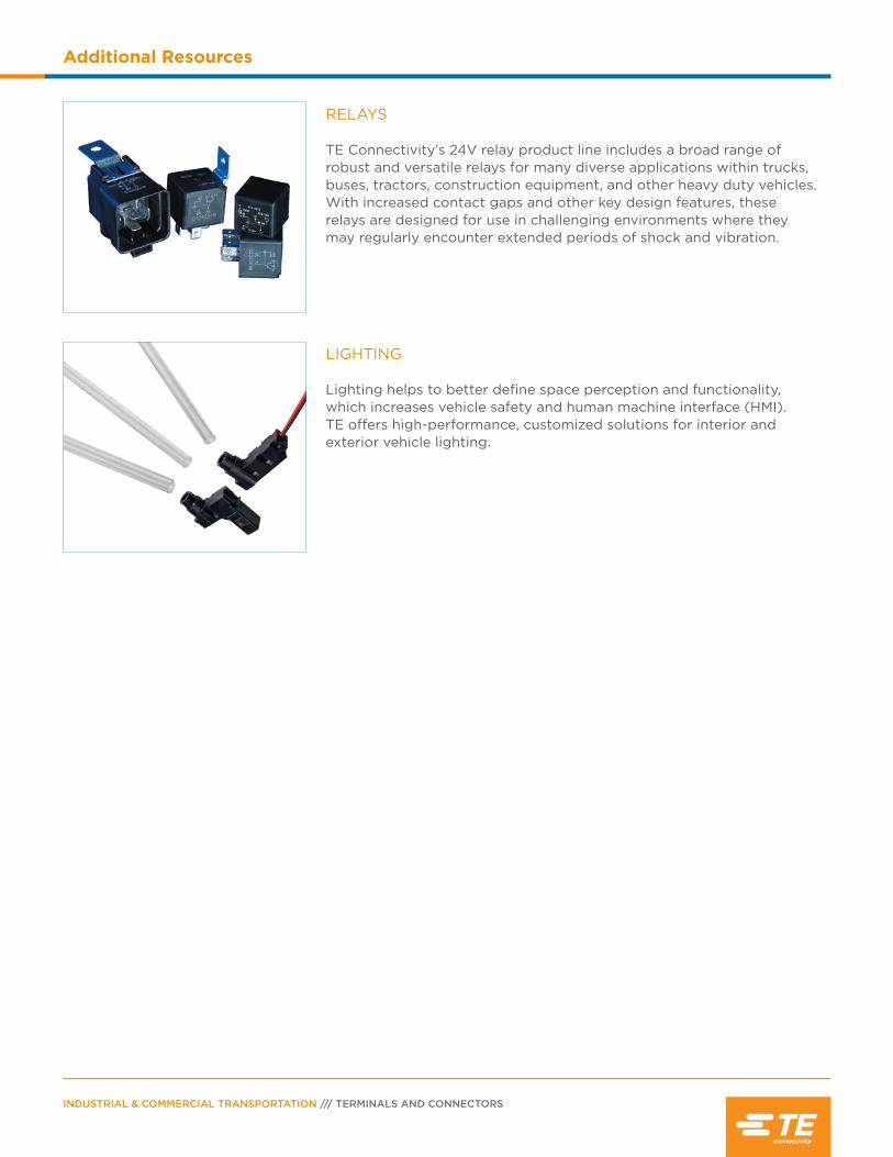
INDUSTRIAL & COMMERCIAL TRANSPORTATION /// TERMINALS AND CONNECTORS
Additional Resources
RELAYS TE Connectivity’s 24V relay product line includes a broad range of robust and versatile relays for many diverse applications within trucks, buses, tractors, construction equipment, and other heavy duty vehicles. With increased contact gaps and other key design features, these relays are designed for use in challenging environments where they may regularly encounter extended periods of shock and vibration.
LIGHTING Lighting helps to better define space perception and functionality, which increases vehicle safety and human machine interface (HMI). TE offers high-performance, customized solutions for interior and exterior vehicle lighting.
PAGE 241
Additional Resources
Requirements & Standards
IMDSThe International Material Data System (IMDS) is a collective, computer-based material data system developed as a collaborative effort by large automo-tive OEMs to manage environmentally relevant as-pects of parts used in vehicles. It has been adopted as the global standard for reporting material content in the automotive industry. TE Connectivity recogniz-es IMDS and will work with customers that use the system.
IP RatingThe IP Rating system is a way of classifying the de-gree of protection provided against the intrusion of solid objects, dust, and water in electrical enclosures. The 6 in IP 67 means that the connectors have to be completely sealed from fine dust. The 7 in IP 67 means that the connector needs to be protected from the effects of a one meter submersion. AMPSEAL, AMPSEAL 16, HDSCS, and LEAVYSEAL connectors are IP 67 rated. DEUTSCH connectors are rated IP 68. The 8 in IP 68 means that the con-nector needs to be protected from the effects of immersion in water under pressure for long periods.
IP6K9KIP6K9K is similar to the standard IP Ratings, but is commonly referred to as a pressure washing specification. The letter K is used after the numbers to denote special testing. The 6K means the connec-tors need to be completely sealed from fine dust. The 9K means the connector needs to be protect-ed from the penetrating effects of water used for high pressure/steam jet cleaning purposes. Several DEUTSCH connectors in the DT, DTM, DRC, and DRB series have been through independent lab testing and pass IP6K9K, as well as AMPSEAL connectors. HDSCS and LEAVYSEAL connectors used with the appropriate accessories meet the IP6K9K standard.
J1939/11, J1939/13, and J1939/15See CAN section.
J2030J2030 is an SAE standard for connectors between two cables or between a cable and an electrical component. The standard primarily focuses on the connectors used to mate to the electrical component. J2030 also provides environmental test and acceptance criteria for connectors used in DC electrical systems of 50 V or less in heavy duty applications typically used in off-highway equipment. Severe applications may require more rigid test levels, or field-testing on the intended application. AMPSEAL 16 connectors meet the SAE J2030 standard.
RoHSThe Restriction of Hazardous Substances (RoHS) in electrical and electronic equipment is a Eu-ropean directive. The directive restricts the use of lead, mercury, cadmium, hexavalent chromi-um, polybrominated biphenyls, and polybro-minated diphenyl ether in new electrical and electronic components. To verify individual product compliance, please visit http://www.te.com/commerce/alt/product-compliance.do.
UL RecognizedA UL Recognized Component is one that is to be installed within a larger assembly by a manufacturer, and this larger assembly is then expected to be tested by UL to become UL LISTED. AMPSEAL, AMPSEAL 16, and many DEUTSCH connectors are UL Recognized Components. DEUTSCH connectors that are UL Recognized Components include the AEC, DRC, DT, DTM, DTP, HD10, and HDP20 series. Not every variation and/or modification within a DEUTSCH series may be UL Recognized Components. AMPSEAL connectors are UL 94 V0 rated. LEAVYSEAL and HDSCS products constructed with a UL 94 V0 rated material are available. For additional information, visit www.ul.com.
INDUSTRIAL & COMMERCIAL TRANSPORTATION /// TERMINALS AND CONNECTORS
Glossary
AWG (American Wire Gauge): Standardized system of wire diameter measurement. Commonly referred to as wire gauge. (Reference: National Bureau of Standards, Copper Wire Table [Handbook 100] AVS.)
Adapter: Device attached to a connector to allow connection to a second device that it would not otherwise be able to attach.
Ambient Temperature: The temperature of a medium (gas or liquid) surrounding an object.
Ampere (amp): The unit of current. One ampere is the current flowing through one ohm of resistance at one volt potential.
ARC Resistance: Time required for an electrical current to render the surface of a material conduc- tive due to carbonization by the arc flame. Or, the time required for an arc to establish a conductive path in a material.
Applicator: Tooling used in automatic machines to crimp stamped & formed contacts.
Backshell: A secondary attachment for the rear of a connector to provide strain relief, environmental protection, and/or improved aesthetics.
Barrel: (1) Conductor Barrel: the section of the terminal, splice, or contact that accommodates the stripped wire. (2) Insulation Barrel: the section of the terminal, splice, or contact that accommodates the unstripped wire.
Barrel Chamfer: Beveled entry at mating end of the socket contact. Reduces contact mating force for easier connector mating.
Blocked Cavities: Unused holes or contact posi- tions in a connector which have been filled with sealing plugs or made inaccessible by modification to the rear grommet.
Breakaway: Connector with a slotted coupling ring. Coupling ring is intended to fragment and allow connectors to separate without damage to the implement in the event of an unintended pull-away.
Boot: Attachment for the back of a connector. Boots are typically flexible, made from plastic or plastisol, and may provide wire strain relief, envi-ronmental protection, and/or improved aesthetics.
Bulkhead: Dividing wall or partition. Bulkhead connectors are designed to be mounted to a dividing wall through a cutout.
Buss (also bussbar, bus or busbar): A thin conductive strip connecting multiple contacts within the body of a connector. Used to distribute electrical current to the branches of a circuit.
Cable Clamp: An attachment to provide support and strain relief to the wire bundle where it exits the connector.
Cavity: Hole in the connector grommet and housing, into which the contact must fit.
Cold Heading: Process by which contacts are formed from individual pieces of metal using dies and punches.
Compression Nut: Secondary backshell assembly. Threads onto rear of backshell to compact the wire bundle and provide additional support.
Conductivity: The capability of a material to carry an electrical current.
Conductor: Any material capable of carrying an electrical charge easily. The most common mate-rials for wire and cable applications are aluminum and copper (bare or coated).
Connector Position Assurance (CPA): A locking mechanism on the connector that prevents the mated connectors from accidental unmating.
PAGE 243
Glossary
Contact: Conductive device crimped or soldered onto the end of conductor wire to allow the transfer of electricity or data to a second conductor. Contacts are most frequently used in multiples in connectors. Also commonly referred to as terminals, pins and/or sockets.
Contact, Crimp: Wire termination engineered to be permanently applied to conductor wire end with pres-sure. Does not use solder or heat.
Contact, Insertable/Removable: Wire termination that can be mechanically joined to or removed from the connector body.
Contact, Pin: Wire termination with solid mating end. Provides connection by insertion into a female or socket contact. Also referred to as male contact.
Contact, Receptacle: Wire termination with hollow mating end into which the pin or male terminal is in-serted. Also referred to as a female contact. Contact, Socket: Wire termination with hollow mating end into which the pin or male terminal is inserted. Also referred to as a female contact.
Contact, Solder: Wire termination joined to the wire conductor with a metal joining compound. Contacts intended for solder will typically have a cup, hol-low-cylinder eyelet or hook to accept a conductor and retain the applied solder.
Contact Area: The area where two conductors, a wire termination and a conductor, or two wire terminations touch, permitting the flow of electricity.
Contact Arrangement: The number, spacing, and or-ganization of cavities in a connector.
Contact Rating: The maximum recommended amper-age to be passed through a wire terminal.
Contact Resistance: The measurement of opposition to electrical flow through a pair of mated wire termi-nations. Resistance may be measured in ohms or in millivolt drop at a specified current over the mated terminals.
Contact Retention: The axial load in either direction that a terminal can withstand without being dislodged from its correct position in the connector.
Contact Shoulder: A small flange or collar on a termi-nal that limits the contact’s travel into or removal from the connector.
Contact Size: Overall size of barrel determined by size of wire it will accept.
Controller Area Network (CAN): Multiplex data sys-tems. Multiplexing allows multiple data signals to trav-el on the same wires, integrating separate electronic systems and applications to a single point control and monitoring system. SAE J1939/11, J1939/13, and J1939/15 are specific types of controller area net-works.
Corrosion Resistance: The ability of a substance to withstand corrosion.
Coupling Ring: Attached cylindrical ring used to lock mated connectors together.
Crimping: To mechanically secure a terminal or splice to a conductor by use of pressure.
Crimping Die: The part of a crimping tool that phys-ically compresses the contact barrel and shapes the crimp.
Crimp Tool: Implement that permanently attaches a contact to a wire using pressure.
Current (I): The rate of transfer of electricity usually expressed in amperes.
Current Rating: The maximum continuous electrical flow of a current recommended for a given wire situa-tion. Expressed in amperes.
Dielectric Strength: The voltage which an insulating material can withstand before breakdown occurs, usually expressed as a voltage gradient (such as volts/mil).

INDUSTRIAL & COMMERCIAL TRANSPORTATION /// TERMINALS AND CONNECTORS
Glossary
Dielectric Test: A test in which a voltage higher than the rated voltage is applied for a specific time to de-termine the adequacy of the insulation under normal conditions.
Dielectric Withstanding Voltage: The amount of leak-age current that flows through the insulation.
Diode: Electronic component that allows electrical flow in one direction only.
Direct Current: An electrical current that flows in one direction only.
Dust Cover: Cap used to protect and conceal the in-terface of an unmated connector.
“E” Seal: Reduced diameter insert cavity in the rear grommet. Creates a proper seal with smaller than standard wire or insulation. Also referred to as extra thin or European seal. “E” seals are smaller than “N” and “T” seals.
End Cap: A protective cover integral to, or sonically welded onto the rear of a connector.
Engaging and Separating Force: Measured pull re-quired to mate or unmate contacts or connectors.
Enhanced Key: Additional indexing or polarization to help prevent mis-mating.
Enhanced Seal Retention: Modification to the plug, front seal, and wedgelock to help prevent the seal from separating from the connector during unmating.
Environmentally Sealed: Maintains functionality when exposed to environmental elements.
Extraction Tool: An implement for removing contacts from a connector.
Flange: A flat, perpendicular extension of the con-nector body. Flanges are used for mounting and are typically found on receptacles.
Flange Seal: Elastomeric silicone seal used between flange and mounting surface to prevent leakage around the mounting cutout.
Front Seal: Elastomeric silicone seal or o-ring on the mating face of a connector. The front seal is also re-ferred to as an interfacial seal and is usually found on the plug.
Grommet: Rubber or elastomeric seal. On connectors the grommet is on the rear or cable end of the con-nector and has the cavities through which the contact is inserted into the connector body.
Ground: A conducting connection between an elec-trical circuit and the earth or other large conducting body to serve as an earth thus making a complete electrical circuit.
Header: Flanged connector designed for wire to print-ed circuit board applications.
Heat Seal: In cabling, a method of sealing a tape wrap jacket by means of thermal fusion.
Heat Shrink: Type of tubing that shrinks to form a tight bond when heated.
Indenter: The part of a crimp tool or die that com-presses the contact barrel onto the conductor.
In-line: Connectors that are not intended for use in mounted or PCB applications.
Insertion Tool: A device used to guide contacts into proper position within a connector.
Inspection Hole: An opening in a barrel contact to allow visual inspection of the conductor to verify that it has been inserted to the right depth.
Insulation Resistance: The measure of resistance of-fered by insulation material to the flow of current.
Insulation: A material having high resistance to the flow of electric current.
PAGE 245
Glossary
Insulation Crimp: (1) The physical deformation of the insulation sleeve covering a terminal or splice and the adjacent conductor insulation to hold the sleeve in place; (2) Shape combination of insulation sleeve to terminal or splice and conductor insulation after crimping.
Insulation Resistance: That property of an insulating material which resists electrical current flow through the insulating material when a potential difference is applied.
Insulation Support: The portion of the contact barrel enclosing but not crimped to the conductor insulation.
Interface: The surfaces of a mating pair of connectors that face each other when connected.
Interfacial Seal: A seal at the mating edge of the con-nector to prevent ingress of moisture or contaminants when a connector is properly mated.
Internal Seal: Waterproof form, typically made of silicone elastomer, that is inside the body of the con-nector. Provides moisture and fluid resistance when connectors are properly mated.
IP Rating: A way of classifying the degree of protec-tion provided against the intrusion of solid objects, dust, and water in electrical enclosures.
Jacket: An outer nonmetallic protective covering ap-plied over an insulated wire or cable.
Key: Unique pattern of corresponding notches and projections on a set of mating connectors. The projec-tions are intended to match the notches and prevent mis-mating.
Keying Pin: Solid plastic rod designed to be inserted into an empty socket cavity to help prevent mis-mat-ing.
Locator: A device in a crimp tool to help provide proper contact position during crimping.
Lockwasher: Thin metal ring used between the panel nut and mounting surface to create spring force to confirm a tight fitting mount.
Millimeters Squared or mm2: Unit of measure for Eu-ropean Wire Size Standards (ref. DIN 72551-6 and ISO 6722-3).
Moisture Resistance: Amount of water (in any form) that a properly wired and mated connection will with-stand without loss of electronic qualities or leakage.
Mounting Bracket: A rectangular metal device used to attach or mount connectors in an application.
Mounting Clip: A plastic or metal piece that attaches to a non-flanged connector to allow surface mounting.
“N” Seal: Normal wire seal diameter.
Neoprene: Thermosetting material, chemically known as polychloroprene, with excellent flame retarding and abrasion resisting qualities.
Nest: The part of a crimping die that supports the barrel during crimping.
Newton (N): A unit of force which is based on the metric system. It is the force that produces an acceler-ation of 1 meter per second per second when exerted on a mass of 1 kilogram.
O-ring: Circular seal found around the inside diameter of a receptacle: typically made from elastomeric or silicone material. Provides an environmental seal.
Oxidation: The process of uniting a compound with oxygen, usually resulting in an unwanted surface deg-radation of the material or compound.
Panel Nut: A hexagonal threaded plastic or metal ring. Along with a lockwasher, a panel nut is used for mounting.
Partial Strip: A quantity less than a standard full reel of stamped & formed contacts.
PCB (Printed Circuit Board) Mount: Connectors de-signed for wire to printed circuit board applications.

INDUSTRIAL & COMMERCIAL TRANSPORTATION /// TERMINALS AND CONNECTORS
Glossary
Peak Voltage: The maximum instantaneous voltage.
Pin Housing (Cap): One half of a mated pair of con-nectors. AMPSEAL 16 pin housings mate with a recep-tacle contact housing (plug) and house pin contacts.
Plating: Thin overlay coating of metal on contacts or components. Can be used to improve conductivity, provide for easy soldering, and prevent corrosion.
Plug: One half of a mated pair of connectors. Plugs typically have the locking mechanism for the mat-ed pair, usually house the sockets, and mate with a receptacle.
Pre-Tinned: Solder applied to the contact and/or con-ductor prior to soldering.
Primary Latch Reinforcement (PLR): Locking mech-anism that snaps into place on the mating face of a connector after the connector is populated. A PLR holds contacts in correct alignment for mating and prevents them from being removed.
Pull-Out Force: Measured energy required to separate a conductor from a contact, or a contact from a termi-nation assembly.
Ratchet Control: A crimping device that helps provide a full crimping cycle by allowing motion in only one direction until contact is fully crimped.
Receptacle: One half of a mated pair of connectors. Receptacles mate with a plug and usually house pins.
Receptacle Housing (Plug): One half of a mated pair of connectors. AMPSEAL and AMPSEAL 16 plugs typ-ically have the locking mechanism for the mated pair, house the receptacle contacts, and mate with a pin housing (cap) or header.
Reduced Diameter Seal: Smaller than standard holes in the connector grommet.
Removal Tool: Device to disengage contacts from connector body.
Retaining Bolt: Screw used to draw and hold mating connectors together.
Retaining Sleeve: Lining sheath that fits into recepta-cle body to maintain internal seal and provide keying.
Reverse Arrangement: Non-standard cavity/contact assignment (eg. Plug connectors that require pin con-tacts, and receptacles that require socket contacts).
Ring Adapter (HDP20): Cylindrical rim or collar at-tached to the rear of a connector to allow the attach-ment of backshells or strain relief.
Sealed Flange: A flange that is molded or tooled as an integral part of the connector body to help prevent leakage at the mounting site.
Sealing Plug: A non-conductive dummy pin inserted to fill an open cavity in a connector. Sealing plugs are required to maintain the integrity of the environmen-tal seal.
Seamless Terminal or Splice: Terminal or splice conductor barrel made from a single piece of metal, finished without lines or grooves that would typically appear where metal is joined to metal.
Secondary Lock: Device inserted into or onto the connector interface to position and hold contacts in correct alignment. Secondary locks are called wedge-locks or terminal position assurance.
Self-Extinguishing: The characteristic of a material whose flame is extinguished after the igniting flame is removed.
Selective Plating: Application of a thin coating of a finish metal to specific parts of a contact, but not to others. If selective plating is used, plating is typically applied to the mating surface to provide better con-ductivity and reduce wear and corrosion.
Shells: Outside case into which the insert and con-tacts are assembled. Shells of mating connectors usu-ally also provide proper alignment and protection of projecting contacts. Also known as housing or body.
PAGE 247
Glossary
Shield: A metallic layer, commonly aluminum or cop-per, of tape, braid or spiral wrapped wire construction. Its primary purpose is to prevent electrostatic or elec-tromagnetic interference between adjacent wires and external sources.
Shielded Cable: A cable in which the insulated con-ductor or conductors is/are enclosed in a conducting envelope or envelopes. Constructed so that essen-tially every point on the surface of the insulation is at ground potential or at some predetermined potential with respect to ground.
Shrink Boot Adapter: Thermoplastic rear adapter de-signed to provide a lip for heat shrink to form around to attach it securely to a connector.
Signal: An electric current used to convey information either digital, analog, audio or video.
Sleeving: A braided, knitted or woven tube.
Splice: A connection of two or more conductors or cables to provide good mechanical strength as well as good conductivity.
Socket Contact Sleeve: A cylindrical, protective en-casement for the contact fingers or a contact spring. The socket contact sleeve holds the inner mechanism of the contact in place and provides a smooth exterior surface.
Solderless Connection: Joint between two metals created by pressure without the use of metallic alloy compounds or heat.
Solid Contact: Closed barrel terminal manufactured using a cold heading process.
Stamped & Formed Contact: Open barrel terminal manufactured using a precision stamping process.
Strain Relief: Hard plastic or metal device that attach-es to the rear of a connector to provide wire support.
Strand: A single filament of uninsulated wire.
Strip: To remove insulation from a conductor.
Swedge: A cold-forging process to press-fit or force two metal forms into one.
“T” Seal: Reduced diameter insert cavity in the rear grommet. Also referred to as thin seal, a “T” seal allows for the use of smaller wire or thinner insula-tion diameter. A “T” seal is larger than an “E” seal and smaller than an “N” seal.
Temperature Coefficient of Resistivity: The change in resistance per degree of change in temperature.
Terminal: A device designed to attach to the end of a conductor wire to allow it to connect to another con-ductor wire and allow electrical current to pass be-tween them. Also commonly referred to as a contact.
UL Recognized Component: One that is to be installed within a larger assembly by a manufacturer, and this larger assembly is then expected to be tested by UL to become UL Listed.
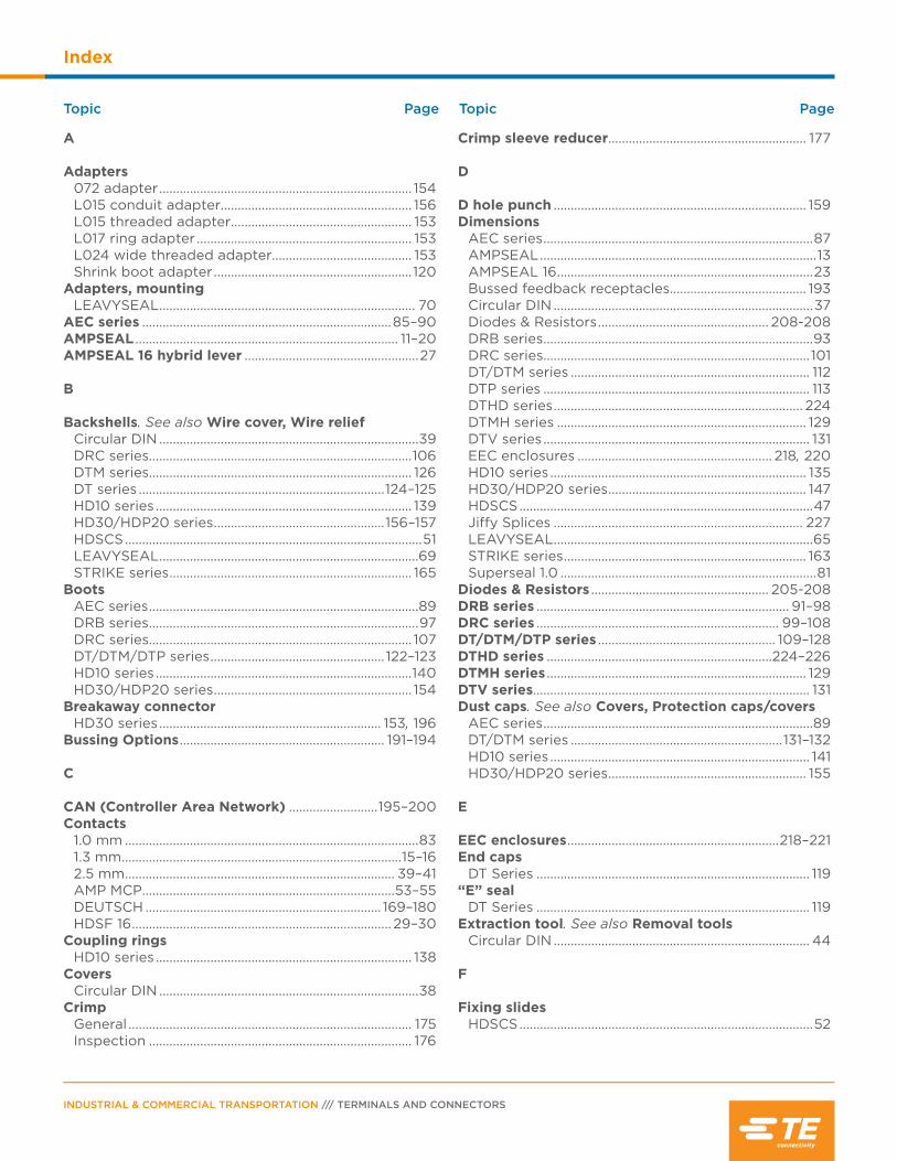
Topic Page Topic Page
INDUSTRIAL & COMMERCIAL TRANSPORTATION /// TERMINALS AND CONNECTORS
Index
A
Adapters072 adapter .......................................................................... 154L015 conduit adapter........................................................ 156L015 threaded adapter ..................................................... 153L017 ring adapter ............................................................... 153L024 wide threaded adapter......................................... 153Shrink boot adapter .......................................................... 120
Adapters, mountingLEAVYSEAL ........................................................................... 70
AEC series .........................................................................85–90AMPSEAL ............................................................................. 11–20 AMPSEAL 16 hybrid lever ...................................................27
B
Backshells. See also Wire cover, Wire reliefCircular DIN ............................................................................39DRC series.............................................................................106DTM series............................................................................. 126DT series ........................................................................124–125HD10 series ........................................................................... 139HD30/HDP20 series ..................................................156–157HDSCS .......................................................................................51LEAVYSEAL ............................................................................69STRIKE series ....................................................................... 165
BootsAEC series ...............................................................................89DRB series ...............................................................................97DRC series............................................................................. 107DT/DTM/DTP series ................................................... 122–123HD10 series ...........................................................................140HD30/HDP20 series .......................................................... 154
Breakaway connectorHD30 series ................................................................. 153, 196
Bussing Options ............................................................ 191–194
C
CAN (Controller Area Network) ..........................195–200Contacts
1.0 mm ......................................................................................831.3 mm ..................................................................................15–162.5 mm ............................................................................... 39–41AMP MCP..........................................................................53–55DEUTSCH ..................................................................... 169–180HDSF 16 ............................................................................ 29–30
Coupling ringsHD10 series ........................................................................... 138
CoversCircular DIN ............................................................................38
CrimpGeneral ................................................................................... 175Inspection ............................................................................. 176
Crimp sleeve reducer .......................................................... 177
D
D hole punch .......................................................................... 159Dimensions
AEC series ...............................................................................87AMPSEAL .................................................................................13AMPSEAL 16 ...........................................................................23Bussed feedback receptacles........................................ 193Circular DIN ............................................................................37Diodes & Resistors .................................................. 208-208DRB series ...............................................................................93DRC series.............................................................................. 101DT/DTM series ...................................................................... 112DTP series .............................................................................. 113DTHD series ......................................................................... 224DTMH series ......................................................................... 129DTV series .............................................................................. 131EEC enclosures ......................................................... 218, 220HD10 series ........................................................................... 135HD30/HDP20 series .......................................................... 147HDSCS ......................................................................................47Jiffy Splices ......................................................................... 227LEAVYSEAL ............................................................................65STRIKE series ....................................................................... 163Superseal 1.0 ...........................................................................81
Diodes & Resistors .................................................... 205-208 DRB series .......................................................................... 91–98DRC series ....................................................................... 99–108DT/DTM/DTP series .................................................... 109–128DTHD series ..................................................................224–226DTMH series ............................................................................ 129DTV series................................................................................. 131Dust caps. See also Covers, Protection caps/covers
AEC series ...............................................................................89DT/DTM series ..............................................................131–132HD10 series ............................................................................ 141HD30/HDP20 series .......................................................... 155
E
EEC enclosures ..............................................................218–221End caps
DT Series ................................................................................ 119“E” seal
DT Series ................................................................................ 119Extraction tool. See also Removal tools
Circular DIN ........................................................................... 44
F
Fixing slidesHDSCS ......................................................................................52
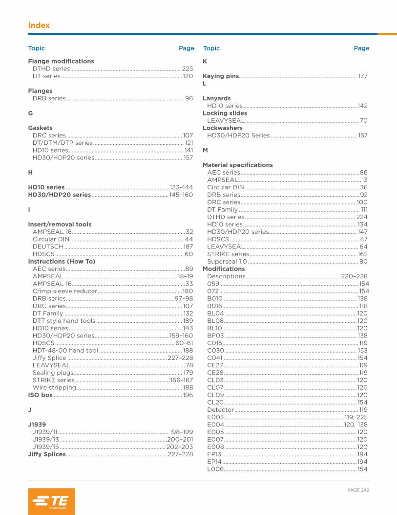
PAGE 249
Index
Topic Page Topic Page
Flange modificationsDTHD series ......................................................................... 225DT series ................................................................................ 120
FlangesDRB series .............................................................................. 96
G
GasketsDRC series............................................................................. 107DT/DTM/DTP series ............................................................ 121HD10 series ............................................................................ 141HD30/HDP20 series .......................................................... 157
H
HD10 series .................................................................... 133–144 HD30/HDP20 series ................................................... 145–160
I
Insert/removal toolsAMPSEAL 16 ...........................................................................32Circular DIN ........................................................................... 44DEUTSCH .............................................................................. 187HDSCS ..................................................................................... 60
Instructions (How To)AEC series ...............................................................................89AMPSEAL ...........................................................................18–19AMPSEAL 16 ...........................................................................33Crimp sleeve reducer ........................................................180DRB series ........................................................................97–98DRC series............................................................................. 107DT Family .............................................................................. 132DTT style hand tools ......................................................... 189HD10 series ........................................................................... 143HD30/HDP20 series ................................................. 159–160HDSCS ...............................................................................60–61HDT-48-00 hand tool ....................................................... 188Jiffy Splice ..................................................................227–228LEAVYSEAL ............................................................................78Sealing plugs........................................................................ 179STRIKE series ...............................................................166–167Wire stripping ...................................................................... 188
ISO box ..................................................................................... 196
J
J1939J1939/11 ......................................................................... 198–199J1939/13 .......................................................................200–201J1939/15 ......................................................................202–203
Jiffy Splices ...................................................................227–228
K
Keying pins.............................................................................. 177L
LanyardsHD10 series ........................................................................... 142
Locking slidesLEAVYSEAL ........................................................................... 70
LockwashersHD30/HDP20 Series ......................................................... 157
M
Material specificationsAEC series ...............................................................................86AMPSEAL .................................................................................13Circular DIN ............................................................................36DRB series ...............................................................................92DRC series............................................................................ 100DT Family ................................................................................ 111DTHD series ......................................................................... 224HD10 series ........................................................................... 134HD30/HDP20 series .......................................................... 147HDSCS ......................................................................................47LEAVYSEAL ........................................................................... 64STRIKE series ....................................................................... 162Superseal 1.0 ......................................................................... 80
ModificationsDescriptions .............................................................. 230–238059 ........................................................................................... 154072 ............................................................................................ 154B010 ........................................................................................ 138B016 .......................................................................................... 118BL04 ....................................................................................... 120BL08 ........................................................................................ 120BL10 ......................................................................................... 120BP03 ....................................................................................... 138C015 .......................................................................................... 119C030 ....................................................................................... 153C041 ........................................................................................ 154CE27 ......................................................................................... 119CE28 ......................................................................................... 119CL03 ........................................................................................ 120CL07 ........................................................................................ 120CL09 ....................................................................................... 120CL20 ........................................................................................ 154Detector .................................................................................. 119E003................................................................................119, 225E004 .............................................................................. 120, 138E005 ....................................................................................... 120E007 ........................................................................................ 120E008 ....................................................................................... 120EP13 .........................................................................................194EP14 .........................................................................................194L006........................................................................................ 154
Topic Page Topic Page
INDUSTRIAL & COMMERCIAL TRANSPORTATION /// TERMINALS AND CONNECTORS
Index
L009....................................................................................... 225L012 ......................................................................................... 120L013 ........................................................................................ 225L015 ......................................................................................... 153L017 ......................................................................................... 153L024 ........................................................................................ 153LE01 ......................................................................................... 120LE05 ........................................................................................ 120LE06 ........................................................................................ 120LE07 ........................................................................................ 120LE08 ........................................................................................ 120LE09 ........................................................................................ 120LE10 ......................................................................................... 120LE11...........................................................................................120LE12 ......................................................................................... 120LE14 ......................................................................................... 120LE17 ......................................................................................... 120LE21 ......................................................................................... 120N005 ....................................................................................... 138P012 .......................................................................................... 119P016 .........................................................................................194P021 .........................................................................................194P026 ........................................................................................194P027 ........................................................................................194P028 ........................................................................................194P030........................................................................................194P031 .........................................................................................194P060 .......................................................................................194P064........................................................................................ 149P075 ........................................................................................194P080 ....................................................................................... 138
Mounting clips. See also Fixing slides, Locking slidesAMPSEAL 16 ...........................................................................26DT/DTM/DTP series ........................................................... 127DTHD series ......................................................................... 226
Mounting ringCircular DIN ............................................................................39
P
Panel nutHD30/HDP20 series .......................................................... 158
PCB pins ................................................................................... 174PCB (Printed Circuit Board) ................................. 209–222Performance specifications
1.0 mm contacts ....................................................................831.3 mm contacts .....................................................................152.5 mm contacts ...................................................................39AEC series ...............................................................................86AMP MCP contacts ........................................................53, 71AMPSEAL .................................................................................12AMPSEAL 16 ...........................................................................22Circular DIN ............................................................................36DEUTSCH contacts............................................................. 171DRB series ...............................................................................92
DRC series............................................................................ 100DT Family ................................................................................ 111HD10 series ........................................................................... 134HD30/HDP20 series ..........................................................146HDSCS ..................................................................................... 46HDSF 16 ....................................................................................29LEAVYSEAL ........................................................................... 64STRIKE series ....................................................................... 162Superseal 1.0 ......................................................................... 80
Primary latch reinforcement (PLR) .................................24Protection caps/covers
HDSCS ......................................................................................52LEAVYSEAL .............................................................................71
S
Sealing plugsAMPSEAL .................................................................................16AMPSEAL 16 ............................................................................31Circular DIN ............................................................................42DEUTSCH .............................................................................. 178HDSCS ...............................................................................56, 74Superseal 1.0 ..........................................................................83
Shrink boot adapterDT/DTM series ..................................................................... 120
Standards ................................................................................. 241Strain relief
DT series ................................................................................ 124HD10 series ...........................................................................140HD30/HDP20 series ..................................................155–156
Superseal 1.0 .................................................................... 79–84
T
ToolingAutomated crimp tools
AMPSEAL ..............................................................................17AMPSEAL 16 ........................................................................32Circular DIN .................................................................43–44DEUTSCH .................................................................. 182–184HDSCS ............................................................. 58–59, 76–77Superseal 1.0 ...................................................................... 84
DEUTSCH ...................................................................... 181–190Hand crimp tools
AMPSEAL ..............................................................................17AMPSEAL 16 .........................................................................31Circular DIN .........................................................................42DEUTSCH ...................................................................185–186HDSCS ............................................................................57, 75Superseal 1.0 ...................................................................... 84
Removal toolsAMPSEAL 16 ........................................................................32Circular DIN ........................................................................ 44DEUTSCH ........................................................................... 187HDSCS .................................................................................. 60
PAGE 251
Index
Topic Page Topic Page
Tooling accessories .................................................... 183, 186
W
WedgelocksDRB series .............................................................................. 96DT/DTM/DTP series ............................................................ 117DTV series .............................................................................. 131
Wire coverAMPSEAL 16 ...........................................................................28
Wire reliefAMPSEAL .................................................................................15
Wire routerDRC series.............................................................................106
Wire sealing rangesAEC series ...............................................................................88AMPSEAL .................................................................................15AMPSEAL 16 ...........................................................................25DRB series ...............................................................................95DRC series.............................................................................105DT Family ............................................................................... 116HD10 series ........................................................................... 137HD30/HDP20 series .......................................................... 152STRIKE series ....................................................................... 165
Wire sealsCircular DIN ............................................................................42HDSCS ......................................................................................56LEAVYSEAL ............................................................................74

INDUSTRIAL & COMMERCIAL TRANSPORTATION /// TERMINALS AND CONNECTORS
NOTES:


TE Connectivity
4849 Hempstead Station Drive Kettering, OH 45429 USA
Tel: +1-888-441-9982
Fax: +1-937-312-9731
www.te.com
INDUSTRIAL & COMMERCIAL TRANSPORTATION /// TERMINALS AND CONNECTORS
te.comTE Connectivity, TE connectivity (logo), LADD, EVERY CONNECTION COUNTS, AMP, AMP MCP, AMPSEAL, AMPSEAL 16, CERTI-CRIMP, CERTI-LOK, DETECTOR, DEUTSCH, ERGOCRIMP, LEAVYSEAL, PRO-CRIMPER, and STRIKE, are trademarks.
USCAR is a trademark.
All other logos, products and/or company names referred to herein might be trademarks of their respective owners.
The information given herein, including drawings, illustrations and schematics which are intended for illustration purposes only, is believed to be reliable. However, TE Connectivity makes no warranties as to its accuracy or completeness and disclaims any liability in connection with its use. TE Connectivity‘s obligations shall only be as set forth in TE Connectivity‘s Standard Terms and Conditions of Sale for this product and in no case will TE Connectivity be liable for any incidental, indirect or consequential damages arising out of the sale, resale, use or misuse of the product. Users of TE Connectivity products should make their own evaluation to determine the suitability of each such product for the specific application.
© 2015 TE Connectivity Ltd. family of companies All Rights Reserved.
TS-ICT-T&CCAT 08/15 Original
LET’S CONNECT
We make it easy to connect with our experts and are ready to provide all the support you need. For additional information or product assistance, please contact your field representative or our customer service department. Additional information is also available on the website http://www.te.com/usa-en/industries/ truck-bus-off-road-vehicles.html.
TECHNICAL SUPPORT
te.com/support-center
Asia: +86 400-820-6015
Europe, Middle East, & Africa: +49 6251-133-0
North America: +1-888-441-9982