imposed sinusoidal source and load currents for an indirect matrix converter
TRANSCRIPT

© 2012 IEEE
IEEE Transactions on Industrial Electronics Vol. 58, No. 11, pp. 4986-4987, September 2012.
Imposed Sinusoidal Source and Load Currents for an Indirect Matrix Converter
M. RiveraJ. RodriguezJ. R. EspinozaT. FriedliJ. W. KolarA. WilsonC. A. Rojas
This material is posted here with permission of the IEEE. Such permission of the IEEE does not in any way imply IEEE endorsement of any of ETH Zurich‘s products or services. Internal or personal use of this material is permitted. However, permission to reprint/republish this material for advertising or promotional purposes or for creating new collective works for resale or redistribution must be obtained from the IEEE by writing to [email protected]. By choosing to view this document, you agree to all provisions of the copyright laws protecting it.
IEEE TRANSACTIONS ON INDUSTRIAL ELECTRONICS, VOL. 59, NO. 9, SEPTEMBER 2012 3427
Imposed Sinusoidal Source and Load Currents for anIndirect Matrix Converter
Marco Rivera, Member, IEEE, Jose Rodriguez, Fellow, IEEE, José R. Espinoza, Member, IEEE,Thomas Friedli, Member, IEEE, Johann W. Kolar, Fellow, IEEE, Alan Wilson, Member, IEEE, and
Christian A. Rojas, Student Member, IEEE
Abstract—A new strategy for indirect matrix converters whichallows an optimal control of source and load currents is pre-sented in this paper. This method uses the commutation stateof the converter in the subsequent sampling time according toan optimization algorithm given by a simple cost functional andthe discrete system model. The control goals are regulation ofoutput current according to an arbitrary reference and also a goodtracking of the source current to its reference which is imposedto have a sinusoidal waveform with low distortion. Experimentalresults support the theoretical development.
Index Terms—AC–AC power conversion, current control, ma-trix converter, predictive control.
NOMENCLATURE
is Source current [isA isB isC ]T .vs Source voltage [vsA vsB vsC ]T .ii Input current [iA iB iC ]T .vi Input voltage [vA vB vC ]T .io Load current [ia ib ic]T .vo Load voltage [va vb vc]T .i∗s Source current reference [i∗sA i∗sB i∗sC ]T .i∗o Output current reference [i∗a i∗b i∗c]
T .Cf Filter capacitor.Lf Filter inductor.Rf Filter resistor.RL Load resistance.LL Load inductance.
I. INTRODUCTION
THE indirect matrix converter (IMC) [1] has been thesubject to investigation for some time. One of the favor-
able features of an IMC is the absence of a dc-link capaci-
Manuscript received October 9, 2010; revised July 4, 2011; acceptedOctober 3, 2011. Date of publication October 14, 2011; date of currentversion April 13, 2012. This work was supported by the Centro Científico-Tecnológico de Valparaíso (CCTVal) No. FB0821, FONDECYT Project, underGrant 1100404 and by the Universidad Técnica Federico Santa María.
M. Rivera, J. Rodriguez, A. Wilson, and C. A. Rojas are with theElectronics Engineering Department, Universidad Técnica Federico SantaMaría (UTFSM), 2390123 Valparaíso, Chile (e-mail: [email protected];[email protected]; [email protected]; [email protected]).
J. R. Espinoza is with the Department of Electrical Engineering, Universidadde Concepción, 407-0386 Concepción, Chile (e-mail: [email protected]).
T. Friedli and J. W. Kolar are with the Power Electronic Systems Laboratory,Swiss Federal Institute of Technology (ETH) Zurich, 8092 Zurich, Switzerland(e-mail: [email protected]; [email protected]).
Color versions of one or more of the figures in this paper are available onlineat http://ieeexplore.ieee.org.
Digital Object Identifier 10.1109/TIE.2011.2172171
tor, which allows for the construction of compact converterscapable of operating at adverse atmospheric conditions suchas extreme temperatures and pressures. These features havebeen explored extensively and are the main reasons why thematrix converters family has been investigated for decades [2].IMC features an easy to implement and more secure com-mutation technique, the dc-link zero current commutation [3].Moreover, the conventional IMC has bidirectional power flowcapabilities and can be designed to have small sized reactiveelements in its input filter. These characteristics make the IMCa suitable technology for high-efficiency converters for specificapplications such as military, aerospace, wind turbine generatorsystem, external elevators for building construction and skinpass mill, as reported in [4]–[6], where these advantages makeup for the additional cost of an IMC compared to conventionalconverters. IMC uses complex pulse width modulation (PWM)and space vector modulation (SVM) schemes to achieve thegoal of unity power factor and sinusoidal output current [2],[7]–[13]. Thanks to technological advances, fast and powerfulmicroprocessors are used for the control and modulation ofpower converters. To deal with the high processing powerneeded for these microprocessors, some research has shown thepositive potential of model predictive control (MPC) techniquesin many power electronics applications [14], [15]. This is anonlinear control method that takes advantage of the discreteinherent nature of the commutated power converter. Whilethere are a few challenges to the predictive control method,it has been demonstrated as an appealing alternative to powerconverter control because its concepts are very intuitive andeasy to understand, and it can be applied to a wide varietyof systems. In addition, it may involve multiple systems, deadtime compensation, and nonlinear constraints, making it an easycontroller to implement, particularly since it is open to modi-fications and extensions for specific applications, as reviewedin [16]–[21]. This control scheme has some advantages overtraditional linear controllers and PWM modulators, such asfast dynamic responses and an easy inclusion of constraintson the system [22]. Predictive current control (PCC) can bedescribed as a particular case of MPC which takes into accountthe inherent discrete nature of the switching states of the powerconverter and the digital implementation [20], [21], [23]–[25].Most of PCC methods applied in matrix converters take intoconsideration the output current regulation and the instanta-neous reactive power minimization on the input side, obtaininginput currents in phase with their respective phase voltages.However, this cannot ensure that they present a sinusoidal
0278-0046/$26.00 © 2011 IEEE

3428 IEEE TRANSACTIONS ON INDUSTRIAL ELECTRONICS, VOL. 59, NO. 9, SEPTEMBER 2012
Fig. 1. General topology of the 3 × 3 indirect matrix converter.
waveform, particularly when harmonic distortion is present inthe source voltage. To overcome this issue and enhance thequality of the source current, in the following pages, this paperillustrates how the PCC can be applied to an IMC and how bothsource and load currents waveforms can be directly controlled.
II. INDIRECT MATRIX CONVERTER MODEL
The IMC topology is shown in Fig. 1. DC-link voltage vdc
is obtained as a function of the rectifier switches and the inputvoltages vi as follows:
vdc = [Sr1 − Sr4 Sr3 − Sr6 Sr5 − Sr2]vi (1)
and input currents ii are defined as a function of the rectifierswitches and the dc-link current idc as
ii =
⎡⎣Sr1 − Sr4
Sr3 − Sr6
Sr5 − Sr2
⎤⎦ idc. (2)
DC-link current idc is determined as a function of the inverterswitches and the output currents io as
idc = [Si1 Si3 Si5]io (3)
and finally, output voltages are synthesized as a function of theinverter switches and the dc-link voltage vdc as
vo =
⎡⎣Si1 − Si4
Si3 − Si6
Si5 − Si2
⎤⎦ vdc. (4)
These equations correspond to the nine and eight validswitching states for the rectifier and the inverter stage, re-spectively, as reported in [3], following the restrictions of noshort circuits in the input and no open lines in the output. Apositive dc-link voltage at any time is also mandatory for aconventional IMC, so the nine rectifier states reduce to onlythree valid states in every sampling time Ts. In addition, therectifier includes an LfCf filter on the input side which isneeded to prevent over voltages and to provide filtering of thehigh-frequency components of the input currents produced by
the commutations and the inductive nature of the load. The filterconsists of a second-order system described by
disdt
=1
Lf(vs − vi) −
Rf
Lfis (5)
dvi
dt=
1Cf
(is − ii). (6)
The load model is obtained similarly. Assuming an inductive-resistive load as shown in Fig. 1, the following equation de-scribes the behavior of the load:
diodt
=1
LLvo − RL
LLio. (7)
Additionally, the impedance model of the input filter isdefined as
Zc =1
jwsCf(8)
Zl =Rf + jwsLf (9)
where ws = 2πfs, with fs the source frequency. The loadimpedance is represented as
Zo = RL + jwoLL (10)
where wo = 2πfo, with fo the load frequency. Finally, the filtermodel in terms of impedance is given as
vs =vi + isZl
is = ii + vi/Zc. (11)
III. PROBLEM ON THE INPUT SIDE
SVM and PWM techniques generate a desired output voltagewith unity power factor [2], [7]–[13], but there is a displacementangle between the source line current is and input current ii dueto the filter parameters and consequently a displacement anglebetween the source voltage and current, requiring additionalcontrollers to handle this angle [26]. From (8) and (9) and (11),this displacement angle is given as
δ = arctan (wsCf (Vs − RfIs)) /(Is
(1 − w2
sLfCf
))(12)
where Vs and Is are the source voltage and current fundamentalamplitudes, respectively. In [26], it has been proposed that
RIVERA et al.: IMPOSED SINUSOIDAL SOURCE AND LOAD CURRENTS FOR AN INDIRECT MATRIX CONVERTER 3429
two power factor compensation methods can be used, eachone considering direct SVM to compensate the displacementangle δ between source voltage and current with the goalto obtain a unity power factor from a voltage transfer ratiogreater than or equal to 0.35, but the compensated displacementangle decreases while the voltage transfer ratio increases, andadditionally, the source current does not present a sinusoidalwaveform. In [27], the authors proposed a modified direct SVMmethod to control matrix converters with transfer ratio less than0.5, allowing to compensate a maximum displacement angle ofπ/6 (30◦), but the source currents are not considered in thiswork presenting a distorted waveform as well. Predictive tech-niques that have been proposed in the last years have focusedon the minimization of the instantaneous reactive power on theinput side, but there are no reports of additional works based ona source current control [3], [20], [21], [24], [28].
In summary, as well this is not a real issue in a predictivecontroller, one of the main drawbacks of SVM techniques is thecompensation of nonunitary displacement power factor (DPF)in the supply side of the system (between is and vs), dueto the LfCf input filter and the dynamic amplitude of io.As mentioned, recently, solutions based on SVM have beenproposed to solve this drawback, but it requires a more complexalgorithm, and it has a limit in the compensable DPF, whichdepends on the modulation index. Today, most of the worksdeveloped on matrix converters with predictive control havefocused on the control of the output side while maintainingminimum instantaneous reactive power on the input side, butthere are no reports of a source current control with imposedwaveform like the model proposed in this paper. In comparisonto classical methods, by using a predictive algorithm, the con-troller and modulator merge in only one block, making it easierto implement than SVM and PWM methods. The proposed pre-dictive strategy presented in this paper suggests that a control ofthe source current with imposed waveform should be performedrather than an instantaneous reactive power minimization. Thepredictive algorithm evaluates at every sampling time Ts allof the 24 possible states and chooses the one that returns theminimal value for the cost functional g to be applied in the nextsampling instant. The minimization of g guarantees two goals:the output currents follow their references with accuracy, andthe converter draws sinusoidal input currents with unity inputDPF according to their references.
IV. PREDICTIVE CURRENT CONTROL FOR THE IMC WITH
IMPOSED SINUSOIDAL SOURCE CURRENTS
To minimize the computational cost, the αβ linear transformis applied to all three-phase current and voltage vectors, definedas
[uα
uβ
]=
[2/3 −1/3 −1/30
√3/3 −
√3/3
] ⎡⎣ua
ub
uc
⎤⎦ (13)
where the vector [ua ub uc]T is the three-phase current orvoltage vector, and [uα uβ ]T is the αβ vector.
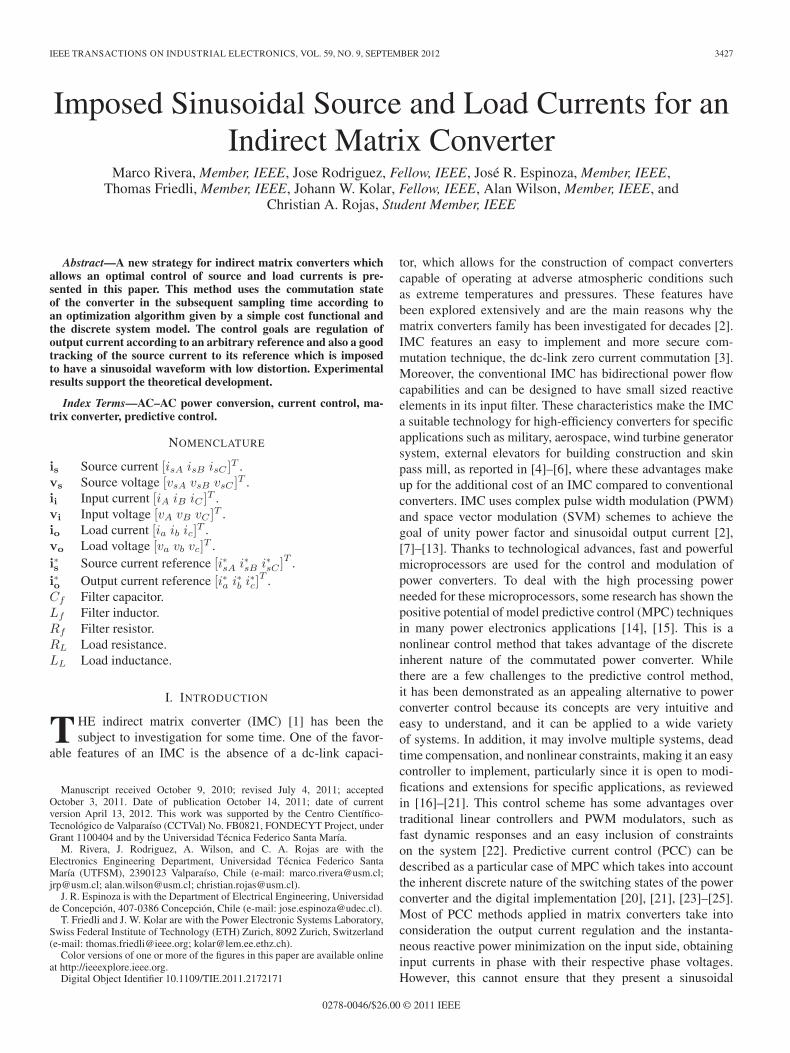
Fig. 2. Predictive source and output current control scheme with sourcecurrent reference.
In [3], a predictive control strategy for an IMC has beenpresented, where the approach pursues the selection of theswitching state of the converter that leads the output currentscloset their respective references at the end of the samplingperiod, while minimizing the instantaneous reactive poweron the input side. As mentioned before, this strategy cannotensure sinusoidal waveform of the source current, particularlywhen harmonic distortion is present in the source voltage.The proposed MPC scheme is represented in Fig. 2, where incomparison to the before mentioned strategy, the term whichminimizes the reactive power on the input side is replaced bya direct control of the source current waveforms to force themto follow a sinusoidal reference independent of the distortionpresent on the input side. The method applies the best switchingstate of the converter based on a cost function minimization ofthe load and source current errors with an arbitrary weightingfactor, but this choice cannot ensure a perfect tracking or zeroerror. This method attempts to impose source currents withsinusoidal waves with an acceptable performance in the IMC,using the optimum commutation state in each sample time. Dueto the power balance principle (input/output coupling effects) inmatrix converters and under harmonic distortion in the mains,it is impossible to ensure constant active power in both sidesand they will necessarily affect the converter waveforms. Thiseffect will be present in matrix converters (direct or indirect),regardless of the control method being considered. In the pro-posed control method, the minimization of the source currenterror means that the quantities of the load current are damaged.However, if an adequate tradeoff between source and loadcurrent is selected, the distortion of both currents is reduced.
A. Prediction Model
Since the predictive controller is formulated in discrete time,it is necessary to derive a discrete time model for the load-converter system. The input side can be represented by a state
3430 IEEE TRANSACTIONS ON INDUSTRIAL ELECTRONICS, VOL. 59, NO. 9, SEPTEMBER 2012
space model [20], with the state variables is and vi obtainedfrom (5) and (6) as follows:[
v̇i
i̇s
]= A
[vi
is
]+ B
[vs
ii
](14)
where
A =[
0 1/Cf
−1/Lf −Rf/Lf
]
B =[
0 −1/Cf
1/Lf 0
]. (15)
The discrete time state space model is determined as[vi(k + 1)is(k + 1)
]= Φ
[vi(k)is(k)
]+ Γ
[vs(k)ii(k)
](16)
with
Φ = eATs , Γ = A−1(Φ − I2×2)B. (17)
The output current prediction can be obtained using a for-ward Euler approximation in (7) as
io(k + 1) = d1vo(k) + d2io(k) (18)
where, d1 = Ts/LL and d2 = 1 − RLTs/LL are constants de-pendent on load parameters and the sampling time Ts[20]. Notethat the current is(k + 1) and io(k + 1) depend upon Si(k)through (2) and (3).
B. Cost Function Definition
The error between the predicted load currents and its refer-ences can be expressed as follows:
�io(k + 1) = |i∗oα − ioα| +∣∣i∗oβ − ioβ
∣∣ (19)
where ioα and ioβ denote the load current in αβ coordinates fork + 1 sample time, and i∗oα and i∗oβ their respective references.Furthermore, the error between the reference and predictedvalue of the source current can be expressed as
�is(k + 1) = |i∗sα − isα| +∣∣i∗sβ − isβ
∣∣ (20)
where, i∗sα and i∗sβ correspond to the source current references(see Appendix for additional information) and isα and isβ arethe source current predictions in sample k + 1. Expressions of(19) and (20) are merged in a single cost function as indicatedin (21) which is evaluated for every switching state, applyingto the converter the switching state that minimizes this qualityfunction, as has been explained before. Finally, (19) and (20)are combined into a single so-called quality function as follows:
g = �io(k + 1) + γi�is(k + 1) (21)
where γi is a weighting factor. Noting that g = 0 (for anarbitrary value of γi) gives perfect tracking of the load andsource currents, then by minimizing g, the optimum value for
TABLE IEXPERIMENTAL SETUP PARAMETERS
commutation state is guaranteed. In practice, by the appropriateselection of the weighting factor γi, a given total harmonicdistortion (THD) of the input and output currents is obtained.The principal method for selection of the weighting factors andanalysis of the performance system effects is presented in [29],where first it is established in a value equal to zero to prioritizethe control of the output current, and later it is increased slowlyaiming to obtain minimal THD of source and load currents.
V. RESULTS
A laboratory IMC prototype designed and built by Univer-sidad Tecnica Federico Santa Maria, thanks to the support ofthe Power Electronics Systems Laboratory of ETH Zurich,was used for experimental evaluation. The converter featuresinsulated gate bipolar transistors (IGBTs) of type IXRH40N120for the bidirectional switch of the rectifier side and standardIGBTs with antiparallel diodes IRG4PC30UD for the inverterstage. Experimental results are presented in this section, byconsidering the parameters indicated in Table I. As demon-strated in [3] and [15], the high calculation power of today’sexisting digital signal processors (DSPs) makes this methodvery attractive to control power converters. The control schemepresented in [3] was implemented in a 160 MIPS fixed pointADSP21991 DSP board and a sampling time of Ts = 20 μs.In our experimental results, it has been considered the samesampling time, and the control scheme was implemented in adSPACE 1103. Similar to the setup used in [3], the processorboard is connected to additional boards that include a FPGAfor the commutation sequence generation and the signal con-ditioning for the measurement of voltages and currents. InSection V-A, experimental results of the method proposed in [3]have been presented to compare them with experimental resultsof the proposed method which are presented in Section V-B.However, in this case, it is considered the utilization of a three-phase variac as the ac source available in our laboratory, whichbehaves like a weak ac supply for the system, due to theinductance associated with the autotransformer connection.
A. Method I: Predictive Current Control With InstantaneousReactive Power Minimization
It is known that most industrial application requires unitypower factor in the grid side. For this reason, as reported in
RIVERA et al.: IMPOSED SINUSOIDAL SOURCE AND LOAD CURRENTS FOR AN INDIRECT MATRIX CONVERTER 3431
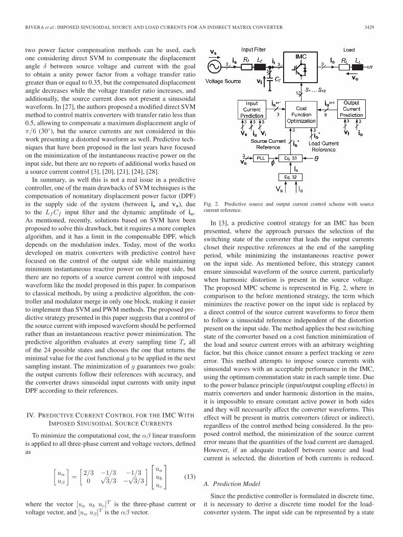
Fig. 3. Experimental results of current control with instantaneous reactivepower minimization (q∗s = 0); source voltage vsA [V] and current isA [A];output current ia [A] and its reference i∗a [A].
[3], through the instantaneous reactive power minimization, thesystem is forced to work with a unity DPF on the input side.The cost function considered in this case is
g = �i2o + λq�q2s (22)
which allows the control of the load current and the mini-mization of the instantaneous reactive power on the input side.In (22), λq is a weighting factor, and �qs denotes the errorbetween the reference and predicted value of the instantaneousreactive power in k + 1 sampling time, expressed as follows:
�qs = q∗s − (vsαisβ − vsβisα) (23)
with vsα, vsβ , isα, and isβ the source voltages and currents inαβ coordinates, respectively. The instantaneous reactive powerreference is established as q∗s = 0 to have a unity DPF on theinput side. Fig. 3 (above) shows the measured source currentand voltage of phase A and Fig. 3 (below) shows the referenceand measured output current of phase a. As expected, thesource current fulfils the condition of unity DPF showing analmost sinusoidal waveform in phase with its respective volt-age, and, as a consequence, the instantaneous reactive power isminimized.
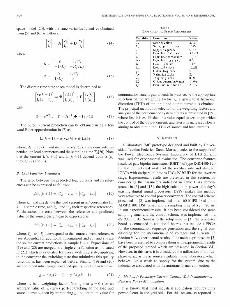
This is achieved by considering the value of the weightingfactor equal to λq = 0.003 which has been empirically adjustedas explained in [29], where first it is established in a valueequal to zero to prioritize the control of the output current, andlater it is increased slowly aiming to obtain unity DPF in theinput currents while maintaining a good behavior on the outputside. In Fig. 3, it is possible to observe a very good trackingof the load current ia with respect to its reference i∗a. As itcan be observed in Fig. 3, the source current shows a ripplecorresponding to the resonance frequency of the input filterand the harmonic distortion of the ac supply such as it can beobserved in the spectrum of Fig. 4. This phenomenon is dueto the utilization of a three-phase variac as the ac supply. Asummary of the source current THD is given in Table II.
Fig. 4. Experimental results of current control including instantaneous reac-tive power minimization. (a) Spectrum of source voltage [pu]. (b) Spectrum ofsource current [pu]. (c) Spectrum of output current [pu].
TABLE IIEXPERIMENTAL THD RESULTS OFisA
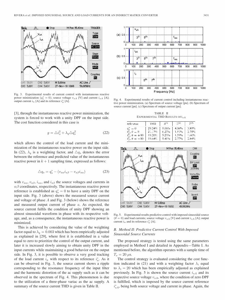
Fig. 5. Experimental results predictive control with imposed sinusoidal source(θ = 0) and load currents; source voltage vsA [V] and current isA [A]; outputcurrent ia and its reference i∗a [A].
B. Method II: Predictive Current Control With ImposedSinusoidal Source Currents
The proposed strategy is tested using the same parametersemployed in Method I and detailed in Appendix—Table I. Asmentioned before, the algorithm operates with a sample time ofTs = 20 μs.
The control strategy is evaluated considering the cost func-tion indicated in (21) and with a weighting factor λi equalto λi = 20 which has been empirically adjusted as explainedpreviously. In Fig. 5 is shown the source current isA and itsrespective source voltage vsA, where the condition of zero DPFis fulfilled, which is imposed by the source current referencei∗sA, being both source voltage and current in phase. Again, the
3432 IEEE TRANSACTIONS ON INDUSTRIAL ELECTRONICS, VOL. 59, NO. 9, SEPTEMBER 2012
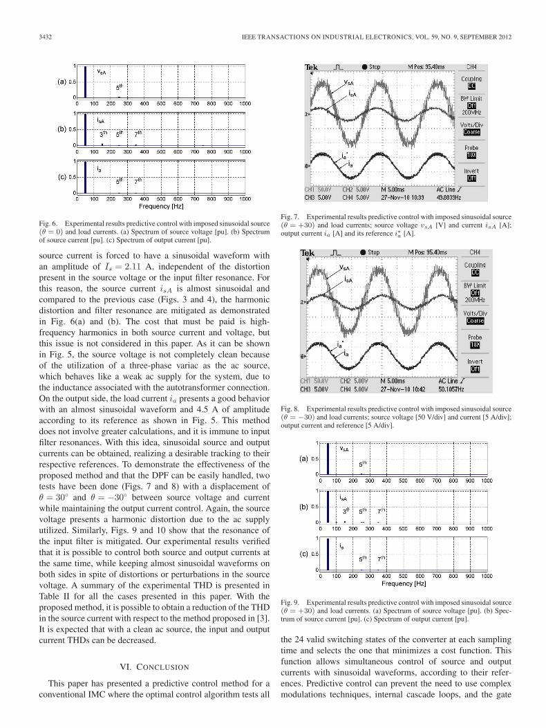
Fig. 6. Experimental results predictive control with imposed sinusoidal source(θ = 0) and load currents. (a) Spectrum of source voltage [pu]. (b) Spectrumof source current [pu]. (c) Spectrum of output current [pu].
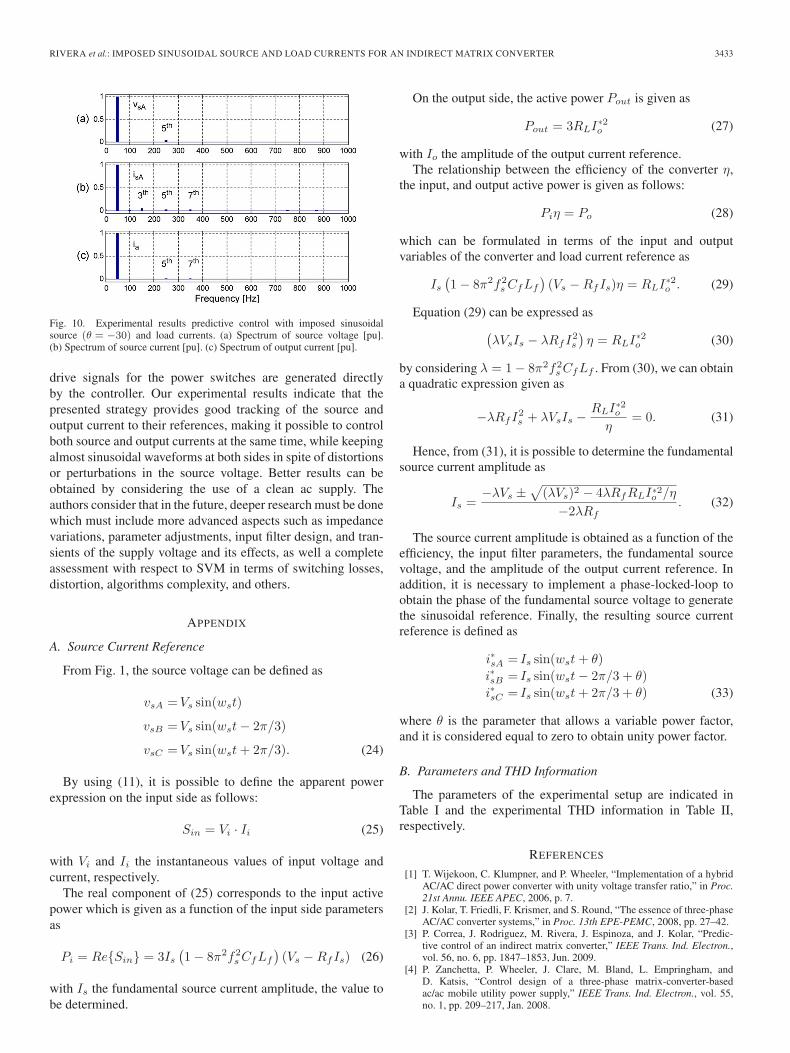
source current is forced to have a sinusoidal waveform withan amplitude of Is = 2.11 A, independent of the distortionpresent in the source voltage or the input filter resonance. Forthis reason, the source current isA is almost sinusoidal andcompared to the previous case (Figs. 3 and 4), the harmonicdistortion and filter resonance are mitigated as demonstratedin Fig. 6(a) and (b). The cost that must be paid is high-frequency harmonics in both source current and voltage, butthis issue is not considered in this paper. As it can be shownin Fig. 5, the source voltage is not completely clean becauseof the utilization of a three-phase variac as the ac source,which behaves like a weak ac supply for the system, due tothe inductance associated with the autotransformer connection.On the output side, the load current ia presents a good behaviorwith an almost sinusoidal waveform and 4.5 A of amplitudeaccording to its reference as shown in Fig. 5. This methoddoes not involve greater calculations, and it is immune to inputfilter resonances. With this idea, sinusoidal source and outputcurrents can be obtained, realizing a desirable tracking to theirrespective references. To demonstrate the effectiveness of theproposed method and that the DPF can be easily handled, twotests have been done (Figs. 7 and 8) with a displacement ofθ = 30◦ and θ = −30◦ between source voltage and currentwhile maintaining the output current control. Again, the sourcevoltage presents a harmonic distortion due to the ac supplyutilized. Similarly, Figs. 9 and 10 show that the resonance ofthe input filter is mitigated. Our experimental results verifiedthat it is possible to control both source and output currents atthe same time, while keeping almost sinusoidal waveforms onboth sides in spite of distortions or perturbations in the sourcevoltage. A summary of the experimental THD is presented inTable II for all the cases presented in this paper. With theproposed method, it is possible to obtain a reduction of the THDin the source current with respect to the method proposed in [3].It is expected that with a clean ac source, the input and outputcurrent THDs can be decreased.
VI. CONCLUSION
This paper has presented a predictive control method for aconventional IMC where the optimal control algorithm tests all
Fig. 7. Experimental results predictive control with imposed sinusoidal source(θ = +30) and load currents; source voltage vsA [V] and current isA [A];output current ia [A] and its reference i∗a [A].
Fig. 8. Experimental results predictive control with imposed sinusoidal source(θ = −30) and load currents; source voltage [50 V/div] and current [5 A/div];output current and reference [5 A/div].
Fig. 9. Experimental results predictive control with imposed sinusoidal source(θ = +30) and load currents. (a) Spectrum of source voltage [pu]. (b) Spec-trum of source current [pu]. (c) Spectrum of output current [pu].
the 24 valid switching states of the converter at each samplingtime and selects the one that minimizes a cost function. Thisfunction allows simultaneous control of source and outputcurrents with sinusoidal waveforms, according to their refer-ences. Predictive control can prevent the need to use complexmodulations techniques, internal cascade loops, and the gate
RIVERA et al.: IMPOSED SINUSOIDAL SOURCE AND LOAD CURRENTS FOR AN INDIRECT MATRIX CONVERTER 3433
Fig. 10. Experimental results predictive control with imposed sinusoidalsource (θ = −30) and load currents. (a) Spectrum of source voltage [pu].(b) Spectrum of source current [pu]. (c) Spectrum of output current [pu].
drive signals for the power switches are generated directlyby the controller. Our experimental results indicate that thepresented strategy provides good tracking of the source andoutput current to their references, making it possible to controlboth source and output currents at the same time, while keepingalmost sinusoidal waveforms at both sides in spite of distortionsor perturbations in the source voltage. Better results can beobtained by considering the use of a clean ac supply. Theauthors consider that in the future, deeper research must be donewhich must include more advanced aspects such as impedancevariations, parameter adjustments, input filter design, and tran-sients of the supply voltage and its effects, as well a completeassessment with respect to SVM in terms of switching losses,distortion, algorithms complexity, and others.
APPENDIX
A. Source Current Reference
From Fig. 1, the source voltage can be defined as
vsA = Vs sin(wst)
vsB = Vs sin(wst − 2π/3)
vsC = Vs sin(wst + 2π/3). (24)
By using (11), it is possible to define the apparent powerexpression on the input side as follows:
Sin = Vi · Ii (25)
with Vi and Ii the instantaneous values of input voltage andcurrent, respectively.
The real component of (25) corresponds to the input activepower which is given as a function of the input side parametersas
Pi = Re{Sin} = 3Is
(1 − 8π2f2
s CfLf
)(Vs − RfIs) (26)
with Is the fundamental source current amplitude, the value tobe determined.
On the output side, the active power Pout is given as
Pout = 3RLI∗2o (27)
with Io the amplitude of the output current reference.The relationship between the efficiency of the converter η,
the input, and output active power is given as follows:
Piη = Po (28)
which can be formulated in terms of the input and outputvariables of the converter and load current reference as
Is
(1 − 8π2f2
s CfLf
)(Vs − RfIs)η = RLI∗2o . (29)
Equation (29) can be expressed as(λVsIs − λRfI2
s
)η = RLI∗2o (30)
by considering λ = 1 − 8π2f2s CfLf . From (30), we can obtain
a quadratic expression given as
−λRfI2s + λVsIs −
RLI∗2o
η= 0. (31)
Hence, from (31), it is possible to determine the fundamentalsource current amplitude as
Is =−λVs ±
√(λVs)2 − 4λRfRLI∗2o /η
−2λRf. (32)
The source current amplitude is obtained as a function of theefficiency, the input filter parameters, the fundamental sourcevoltage, and the amplitude of the output current reference. Inaddition, it is necessary to implement a phase-locked-loop toobtain the phase of the fundamental source voltage to generatethe sinusoidal reference. Finally, the resulting source currentreference is defined as
i∗sA = Is sin(wst + θ)i∗sB = Is sin(wst − 2π/3 + θ)i∗sC = Is sin(wst + 2π/3 + θ) (33)
where θ is the parameter that allows a variable power factor,and it is considered equal to zero to obtain unity power factor.
B. Parameters and THD Information
The parameters of the experimental setup are indicated inTable I and the experimental THD information in Table II,respectively.
REFERENCES
[1] T. Wijekoon, C. Klumpner, and P. Wheeler, “Implementation of a hybridAC/AC direct power converter with unity voltage transfer ratio,” in Proc.21st Annu. IEEE APEC, 2006, p. 7.
[2] J. Kolar, T. Friedli, F. Krismer, and S. Round, “The essence of three-phaseAC/AC converter systems,” in Proc. 13th EPE-PEMC, 2008, pp. 27–42.
[3] P. Correa, J. Rodriguez, M. Rivera, J. Espinoza, and J. Kolar, “Predic-tive control of an indirect matrix converter,” IEEE Trans. Ind. Electron.,vol. 56, no. 6, pp. 1847–1853, Jun. 2009.
[4] P. Zanchetta, P. Wheeler, J. Clare, M. Bland, L. Empringham, andD. Katsis, “Control design of a three-phase matrix-converter-basedac/ac mobile utility power supply,” IEEE Trans. Ind. Electron., vol. 55,no. 1, pp. 209–217, Jan. 2008.

3434 IEEE TRANSACTIONS ON INDUSTRIAL ELECTRONICS, VOL. 59, NO. 9, SEPTEMBER 2012
[5] S. Lopez Arevalo, P. Zanchetta, P. Wheeler, A. Trentin, andL. Empringham, “Control and implementation of a matrix-converter-based ac ground power-supply unit for aircraft servicing,” IEEE Trans.Ind. Electron., vol. 57, no. 6, pp. 2076–2084, Jun. 2010.
[6] E. Yamamoto, T. Kume, H. Hara, T. Uchino, J. Kang, and H. Krug,“Development of matrix converter ans its applications in industry,” inProc. 35th IEEE IECON, Porto, Portugal, 2009, pp. 4–12.
[7] X. Lu, K. Sun, G. Li, and L. Huang, “Analysis and control of input powerfactor in indirect matrix converter,” in Proc. 35th IEEE IECON, 2009,pp. 207–212.
[8] M. Jussila and H. Tuusa, “Comparison of simple control strategies ofspace-vector modulated indirect matrix converter under distorted supplyvoltage,” IEEE Trans. Power Electron., vol. 22, no. 1, pp. 139–148,Jan. 2007.
[9] R. Pena, R. Cardenas, E. Reyes, J. Clare, and P. Wheeler, “A topologyfor multiple generation system with doubly fed induction machines andindirect matrix converter,” IEEE Trans. Ind. Electron., vol. 56, no. 10,pp. 4181–4193, Oct. 2009.
[10] M. Y. Lee, P. Wheeler, and C. Klumpner, “Space-vector modulated mul-tilevel matrix converter,” IEEE Trans. Ind. Electron., vol. 57, no. 10,pp. 3385–3394, Oct. 2010.
[11] R. Cardenas-Dobson, R. Pena, P. Wheeler, and J. Clare, “Experimentalvalidation of a space vector modulation algorithm for four-leg matrixconverters,” IEEE Trans. Ind. Electron., vol. 58, no. 4, pp. 1282–1293,Apr. 2011.
[12] T. Friedli and J. Kolar, “Comprehensive comparison of three-phase AC-AC matrix converter and voltage DC-link back-to-back converter sys-tems,” in Proc. IPEC, 2010, pp. 2789–2798.
[13] J. Kolar, F. Schafmeister, S. Round, and H. Ertl, “Novel three-phaseAC/AC sparse matrix converters,” IEEE Trans. Power Electron., vol. 22,no. 5, pp. 1649–1661, Sep. 2007.
[14] S. Kouro, P. Cortes, R. Vargas, U. Ammann, and J. Rodriguez, “Modelpredictive control, a simple and powerful method to control power con-verters,” IEEE Trans. Ind. Electron., vol. 56, no. 6, pp. 1826–1838,Jun. 2009.
[15] J. Rodriguez, J. Pontt, C. A. Silva, P. Correa, P. Lezana, P. Cortes, andU. Ammann, “Predictive current control of a voltage source inverter,”IEEE Trans. Ind. Electron., vol. 54, no. 1, pp. 495–503, Feb. 2007.
[16] P. Correa, J. Rodriguez, I. Lizama, and D. Andler, “A predictive controlscheme for current-source rectifiers,” IEEE Trans. Ind. Electron., vol. 56,no. 5, pp. 1813–1815, May 2009.
[17] P. Cortes, G. Ortiz, J. Yuz, J. Rodriguez, S. Vazquez, and L. Franquelo,“Model predictive control of an inverter with output LC filter for UPSapplications,” IEEE Trans. Ind. Electron., vol. 56, no. 6, pp. 1875–1883,Jun. 2009.
[18] H. Miranda, P. Cortes, J. Yuz, and J. Rodriguez, “Predictive torque controlof induction machines based on state-space models,” IEEE Trans. Ind.Electron., vol. 56, no. 6, pp. 1916–1924, Jun. 2009.
[19] M. Preindl, E. Schaltz, and P. Thøgersen, “Switching frequency reduc-tion using model predictive direct current control for high power voltagesource inverters,” IEEE Trans. Ind. Electron., vol. 58, no. 7, pp. 2826–2835, Jul. 2011.
[20] S. Muller, U. Ammann, and S. Rees, “New time-discrete modulationscheme for matrix converters,” IEEE Trans. Ind. Electron., vol. 52, no. 6,pp. 1607–1615, Dec. 2005.
[21] R. Vargas, J. Rodriguez, U. Ammann, and P. Wheeler, “Predictive currentcontrol of an induction machine fed by a matrix converter with reactivepower control,” IEEE Trans. Ind. Electron., vol. 55, no. 12, pp. 4362–4371, Dec. 2008.
[22] P. Cortes, M. Kazmierkowski, R. Kennel, D. Quevedo, and J. Rodriguez,“Predictive control in power electronics and drives,” IEEE Trans. Ind.Electron., vol. 55, no. 12, pp. 4312–4324, Dec. 2008.
[23] P. Cortes, J. Rodriguez, D. Quevedo, and C. Silva, “Predictive currentcontrol strategy with imposed load current spectrum,” IEEE Trans. PowerElectron., vol. 23, no. 2, pp. 612–618, Mar. 2008.
[24] J. Rodriguez, J. Kolar, J. Espinoza, M. Rivera, and C. Rojas, “Predictivecurrent control with reactive power minimization in an indirect matrixconverter,” in Proc. IEEE ICIT , Mar. 2010, pp. 1839–1844.
[25] M. Rivera, P. Correa, J. Rodriguez, I. Lizama, and J. Espinoza, “Predictivecontrol of the indirect matrix converter with active damping,” in Proc.IEEE 6th IPEMC, May 2009, pp. 1738–1744.
[26] M. Nguyen, H. Lee, and T. Chun, “Input power factor compensationalgorithms using a new direct-SVM method for matrix converter,” IEEETrans. Ind. Electron., vol. 58, no. 1, pp. 232–243, Jan. 2011.
[27] H. Nguyen, H.-H. Lee, and T.-W. Chun, “An investigation on direct spacevector modulation methods for matrix converter,” in Proc. 35th IEEEIECON, Nov. 2009, pp. 4493–4498.
[28] J. Rodriguez, J. Kolar, J. Espinoza, M. Rivera, and C. Rojas, “Predictivetorque and flux control of an induction machine fed by an indirect matrixconverter with reactive power minimization,” in Proc. IEEE ISIE, 2010,pp. 3177–3183.
[29] P. Cortes, S. Kouro, B. La Rocca, R. Vargas, J. Rodriguez, J. Leon, S.Vazquez, and L. Franquelo, “Guidelines for weighting factors design inmodel predictive control of power converters and drives,” in Proc. IEEEICIT , Feb. 2009, pp. 1–7.
Marco Rivera (S’09–M’10) received the B.Sc. de-gree in electronics engineering, and the M.Sc. de-gree in electrical engineering from the Universidadde Concepción, Concepción, Chile, in 2007 and2008, respectively, and the Ph.D. degree from theDepartment of Electronics Engineering, UniversidadTécnica Federico Santa María (UTFSM), Valparaíso,Chile, in 2011.
During January and February of 2010, he was avisiting Ph.D. student of the Electrical and Com-puter Engineering Department, Ryerson University,
Toronto, ON, Canada, where he worked on predictive control applied on four-leg inverters. He was also a visiting Ph.D. student at the Departamento deIngeniería Eléctrica y Computacional of Instituto Tecnolgico y de EstudiosSuperiores de Monterrey (ITESM), Monterrey, Mexico, where he worked onexperimental aspects of a Double Fed Induction Generator—Indirect MatrixConverter System. Between September and November of 2011, he was a visit-ing Researcher in the Laboratoire PLAsma et Conversion d’Energie, Universitéde Toulouse, Toulouse, France. He is currently working in a Postdoctoralposition at UTFSM. His research interests include direct and indirect matrixconverters, predictive and digital controls for high-power drives, four-legconverters, and development of high-performance control platforms based onfield-programmable gate arrays.
Dr. Rivera was awarded a scholarship from the Marie Curie Host Fellow-ships for Early Stage Research Training in Electrical Energy Conversion andConditioning Technology at University College Cork, Ireland in 2008.
Jose Rodriguez (M’81–SM’94–F’10) received theEngineer degree in electrical engineering fromthe Universidad Técnica Federico Santa Maria(UTFSM), Valparaiso, Chile, in 1977 and the Dr.-Ing. degree in electrical engineering from the Uni-versity of Erlangen, Erlangen, Germany, in 1985.
He has been with the Department of ElectronicsEngineering, UTFSM since 1977, where he is cur-rently full Professor and Rector. He has coauthoredmore than 300 journal and conference papers. Hismain research interests include multilevel inverters,
new converter topologies, control of power converters, and adjustable-speeddrives.
Dr. Rodriguez is member of the Chilean Academy of Engineering. He isan Associate Editor of the IEEE TRANSACTIONS ON POWER ELECTRONICSand IEEE TRANSACTIONS ON INDUSTRY ELECTRONICS since 2002. Hereceived the Best Paper Award from the IEEE TRANSACTIONS ON INDUSTRYELECTRONICS in 2007 and the Best Paper Award from the IEEE INDUSTRYELECTRONICS MAGAZINE in 2008.
José R. Espinoza (S’92–M’97) received the Eng.degree in electronic engineering and the M.Sc. de-gree in electrical engineering from the University ofConcepción, Concepción, Chile, in 1989 and 1992,respectively, and the Ph.D. degree in electrical en-gineering from Concordia University, Montreal, QC,Canada, in 1997.
Since 2006, he has been a Professor in the De-partment of Electrical Engineering, University ofConcepción, where he is engaged in teaching andresearch in the areas of automatic control and power
electronics. He has authored and coauthored more than 100 refereed journaland conference papers.
Dr. Espinoza is currently an Associate Editor of the IEEE TRANSAC-TIONS ON INDUSTRY ELECTRONICS and IEEE TRANSACTIONS ON POWERELECTRONICS.

RIVERA et al.: IMPOSED SINUSOIDAL SOURCE AND LOAD CURRENTS FOR AN INDIRECT MATRIX CONVERTER 3435
Thomas Friedli (M’09) received the M.Sc. degreein electrical engineering and information technology(with distinction) and the Ph.D. degree from theSwiss Federal Institute of Technology (ETH) Zurich,Zurich, Switzerland, in 2005 and 2010, respectively.
From 2003 to 2004, he worked as a trainee forPower-One in the RD center for telecom powersupplies. His Ph.D. research from 2006 to 2009involved the further development of current sourceand matrix converter topologies in collaboration withindustry using silicon carbide JFETs and diodes and
a comparative evaluation of three-phase ac-ac converter systems.Dr. Friedli received the First Prize Paper Award of the IEEE IAS IPCC
in 2008 and the IEEE TRANSACTIONS ON INDUSTRY APPLICATIONS PrizePaper Award in 2009.
Johan W. Kolar (F’10) received the M.Sc. and Ph.D.degree (summa cum laude/promotio sub auspiciispraesidentis rei publicae) from the University ofTechnology Vienna, Vienna, Austria.
Since 1984, he has been working as an indepen-dent international consultant in close collaborationwith the University of Technology Vienna, in thefields of power electronics, industrial electronics, andhigh-performance drives. He has proposed numerousnovel converter topologies and modulation/controlconcepts, e.g., the VIENNA rectifier, the Swiss rec-
tifier, and the three-phase ac-ac sparse matrix converter. He was appointedProfessor and Head of the Power Electronic Systems Laboratory at theSwiss Federal Institute of Technology (ETH) Zurich, Zurich, Switzerland, onFebruary 1, 2001. He has published over 400 scientific papers in internationaljournals and conference proceedings and has filed more than 80 patents. Thefocus of his current research is on ac-ac and ac-dc converter topologies withlow effects on the mains, e.g., for data centers, More-Electric-Aircraft, anddistributed renewable energy systems, and on Solid-State Transformers forSmart Microgrid Systems. Further main research areas are the realization ofultracompact and ultra-efficient converter modules employing latest powersemiconductor technology (SiC and GaN), micropower electronics and/orPower Supplies on Chip, multidomain/scale modeling/simulation and multi-objective optimization, physical model-based lifetime prediction, pulsed power,and ultrahigh speed and bearingless motors.
Dr. Kolar is a member of the IEEJ and of International Steering Committeesand Technical Program Committees of numerous international conferencesin the field (e.g., Director of the Power Quality Branch of the InternationalConference on Power Conversion and Intelligent Motion). He is the foundingChairman of the IEEE PELS Austria and Switzerland Chapter and Chairmanof the Education Chapter of the EPE Association. From 1997 through 2000,he has been serving as an Associate Editor of the IEEE TRANSACTIONS
ON INDUSTRY ELECTRONICS and since 2001 as an Associate Editor of theIEEE TRANSACTIONS ON POWER ELECTRONICS. Since 2002, he also is anAssociate Editor of the Journal of Power Electronics of the Korean Institute ofPower Electronics and a member of the Editorial Advisory Board of the IEEJTransactions on Electrical and Electronic Engineering. He received the BestTransactions Paper Award of the IEEE Industrial Electronics Society in 2005,the Best Paper Award of the ICPE in 2007, the First Prize Paper Award of theIEEE IAS IPCC in 2008, the IEEE IECON Best Paper Award of the IES PETCin 2009, the IEEE PELS Transaction Prize Paper Award 2009, the Best PaperAward of the IEEE/ASME TRANSACTIONS ON MECHATRONICS 2010, theIEEE PELS Transactions Prize Paper Award 2010, the Best Paper First PrizeAward at the ECCE Asia 2011, and the First Place IEEE IAS Society PrizePaper Award 2011. He also received an Erskine Fellowship from the Universityof Canterbury, Christchurch, New Zealand, in 2003. He initiated and/or isthe founder/cofounder of four spin-off companies targeting ultrahigh speeddrives, multidomain/level simulation, ultracompact/efficient converter systems,and pulsed power/electronic energy processing. In 2006, the European PowerSupplies Manufacturers Association awarded the Power Electronics SystemsLaboratory of ETH Zurich as the leading academic research institution in PowerElectronics in Europe.
Alan Wilson (M’10) received the B.S. and M.S.degrees in electronics engineering from the Uni-versidad Técnica Federico Santa María (UTFSM),Valparaiso, Chile, in 2010.
From 2010 to 2011, he was a Scientific Assis-tant with the Department of Electronics Engineering,UTFSM. His research interests include multilevelvoltage source inverters, predictive control of powerconverters, and development of control systems forpower converters based on field-programmable gatearray and DSPs.
Mr. Wilson was awarded a “Becas Chile” scholarship from the ChileanResearch Foundation CONICYT in 2011 to pursue his Ph.D. degree in thePower Electronics Group, Technische Universitat Dresden, Dresden, Germany.
Christian A. Rojas (S’10) received the Engineer de-gree in electronic engineering from the Universidadde Concepción, Concepción, Chile, in 2009.
His research interests include matrix converters,digital control, and model predictive control ofpower converters and drives.
Mr. Rojas was awarded a scholarship from theChilean Research Foundation CONICYT in 2010 topursue his Ph.D. studies in power electronics at Uni-versidad Técnica Federico Santa María, Valparaiso,Chile.