implementing a pervasive meeting room: a model driven approach
TRANSCRIPT
Implementing a Pervasive Meeting Room: A ModelDriven Approach ⋆
Javier Munoz, Vicente Pelechano, Carlos Cetina
Departamento de Sistemas Informaticos y ComputacionTechnical University of ValenciaCamı de Vera s/n, E-46022, Spain
{jmunoz, pele, ccetina}@dsic.upv.es
Abstract. Current pervasive systems are developed ad-hoc or using implementa-tion frameworks. These approaches could be not enough when dealing with largeand complex pervasive systems. This paper introduces an implementation of apervasive system for managing a meeting room. This system has been developedusing a model driven method proposed by the authors. The system is specifiedusing PervML, a UML-like modeling language. Then, a set of templates are ap-plied to the specification in order to automatically produce Java code that uses anOSGi-based framework. The final application integrates several technologies likeEIB and Web Services. Three different user interfaces are provided for interactingwith the system.
1 Introduction
Currently pervasive systems development is a hot topic in computing research. Re-searchers in this area have developed many software systemswhich try to achieve theWeiser vision. These systems have been implemented completely ad-hoc or using im-plementation frameworks that support the specific requirements of this kind of systems.Developing a pervasive system following these approaches is a hard and error-pronetask. In order to improve the productivity and reduce the number of errors, we proposeto apply the newest trends in software engineering to the pervasive systems field.
Following this idea, we have developed a method that appliesthe Model DrivenArchitecture (MDA) [1] and the Software Factories [2] approaches to the developmentof pervasive systems [3]. These strategies propose to use models for automatically gen-erating the final system, and not only for generating documentation or for guiding theimplementation process.
This paper introduces a case of study of a pervasive meeting room that has beendeveloped using our model driven method. The method is basedon the specificationof the system using PervML, a UML-like language designed foreasily describing thefunctionality of pervasive systems. Then, the PervML specification is automaticallytranslated into Java code. The generated code extends an OSGi-based framework inorder to build the final pervasive application.
⋆ This work has been developed with the support of MEC under the projectDESTINO TIN2004-03534 and cofinanced by FEDER.
The paper is structured as follow: Section 2 briefly introduces the model drivenmethod that is applied in the paper. Section 3 describes the functionality provided bythe pervasive system that has been developed for improving ameeting room. Section 4shows the specification of the pervasive system using the PervML language. Section 5describes some implementation details, like the hardware and software used for devel-oping the prototype. Finally, Section 6 introduces some conclusions and future lines ofresearch.
2 Method Overview
The proposed method for the development of pervasive systems, which was presentedin [3], applies the guidelines defined by the Model Driven Architecture (MDA), thatis supported by the Object Management Group (OMG), and the Software Factories,that is supported by Microsoft. Following these guidelines, the method provides (1)a modeling language (PervML) for specifying pervasive systems using conceptualprimitives suitable for this domain, (2) animplementation framework which providesa common architecture for all the systems which are developed using the method, and(3) atransformation engine that translates the PervML specifications into Java code.
InterfaceLayer
LogicalLayer
Services Layer
WAPView
VoiceView
Communications Layer
HTMLView
Drivers Layer
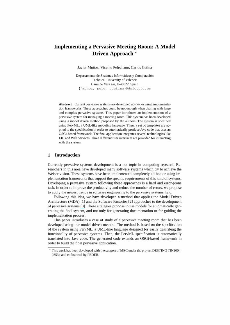
Fig. 1. Framework architecture.
The implementation framework, which is introduced in [4], has been build on topof the OSGi middleware. It provides similar abstract classes to the PervML concep-tual primitives (Service, Trigger, Interaction, etc.) in order to facilitate the translationprocess. Fig. 1 shows the overall framework architecture. This architecture has beendesigned with the aim of providing facilities for integrating several technologies (EIBnetworks, web services, etc.) and for supporting multiple user interfaces.
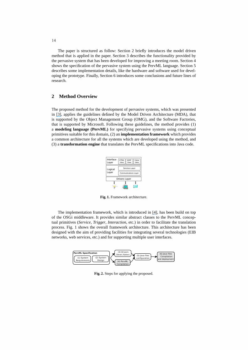
Fig. 2. Steps for applying the proposed.
14
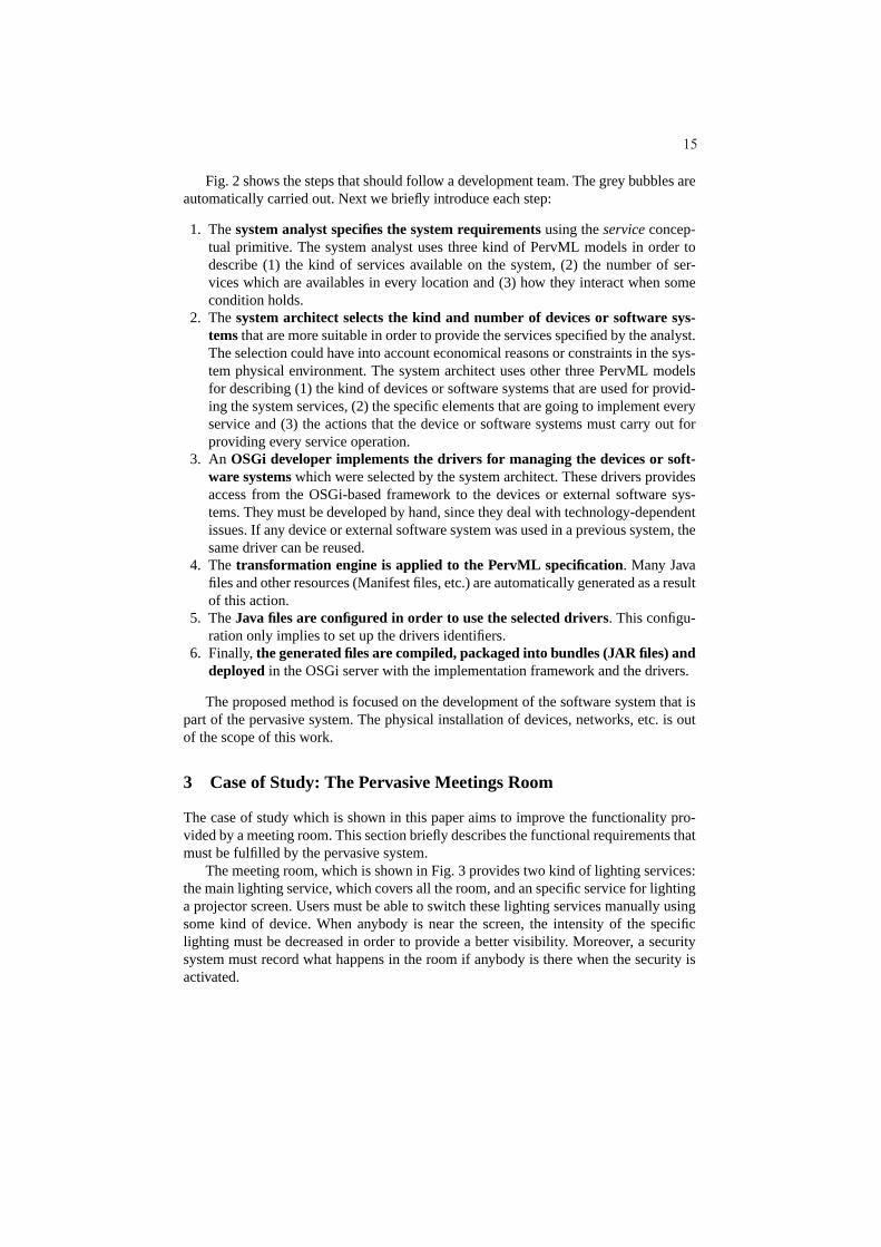
Fig. 2 shows the steps that should follow a development team.The grey bubbles areautomatically carried out. Next we briefly introduce each step:
1. Thesystem analyst specifies the system requirementsusing theservice concep-tual primitive. The system analyst uses three kind of PervMLmodels in order todescribe (1) the kind of services available on the system, (2) the number of ser-vices which are availables in every location and (3) how theyinteract when somecondition holds.
2. Thesystem architect selects the kind and number of devices or software sys-temsthat are more suitable in order to provide the services specified by the analyst.The selection could have into account economical reasons orconstraints in the sys-tem physical environment. The system architect uses other three PervML modelsfor describing (1) the kind of devices or software systems that are used for provid-ing the system services, (2) the specific elements that are going to implement everyservice and (3) the actions that the device or software systems must carry out forproviding every service operation.
3. An OSGi developer implements the drivers for managing the devices or soft-ware systemswhich were selected by the system architect. These drivers providesaccess from the OSGi-based framework to the devices or external software sys-tems. They must be developed by hand, since they deal with technology-dependentissues. If any device or external software system was used ina previous system, thesame driver can be reused.
4. Thetransformation engine is applied to the PervML specification. Many Javafiles and other resources (Manifest files, etc.) are automatically generated as a resultof this action.
5. TheJava files are configured in order to use the selected drivers. This configu-ration only implies to set up the drivers identifiers.
6. Finally,the generated files are compiled, packaged into bundles (JARfiles) anddeployedin the OSGi server with the implementation framework and thedrivers.
The proposed method is focused on the development of the software system that ispart of the pervasive system. The physical installation of devices, networks, etc. is outof the scope of this work.
3 Case of Study: The Pervasive Meetings Room
The case of study which is shown in this paper aims to improve the functionality pro-vided by a meeting room. This section briefly describes the functional requirements thatmust be fulfilled by the pervasive system.
The meeting room, which is shown in Fig. 3 provides two kind oflighting services:the main lighting service, which covers all the room, and an specific service for lightinga projector screen. Users must be able to switch these lighting services manually usingsome kind of device. When anybody is near the screen, the intensity of the specificlighting must be decreased in order to provide a better visibility. Moreover, a securitysystem must record what happens in the room if anybody is there when the security isactivated.
15
208mm0mm0mm
149m
m0mm
149m
m
208mm0mmGlobal Lighting
Screen Lighting
Player
Screen PresenceDetection
Global PresenceDetection Record
Global LightingActivation
Screen LightingActivation
Fig. 3.The meeting room plan.
4 System Description using PervML
Perv-ML is a language designed with the aim of providing to the pervasive system de-velopers with a set of constructs that allow to precisely describe the pervasive system.Perv-ML promotes the separation of roles where developers can be categorized as an-alysts and architects. Systems analysts capture system requirements and describe thepervasive system at a high level of abstraction using the service metaphor as the mainconceptual primitive. System architects specify what devices and/or existing softwaresystems realize system services. Next we give a more detailed description of the lan-guage and how it is applied to the meeting room case of study.
4.1 The Analyst View: Specifying System Requirements
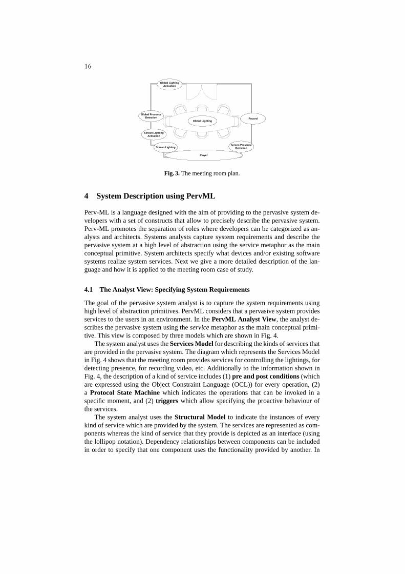
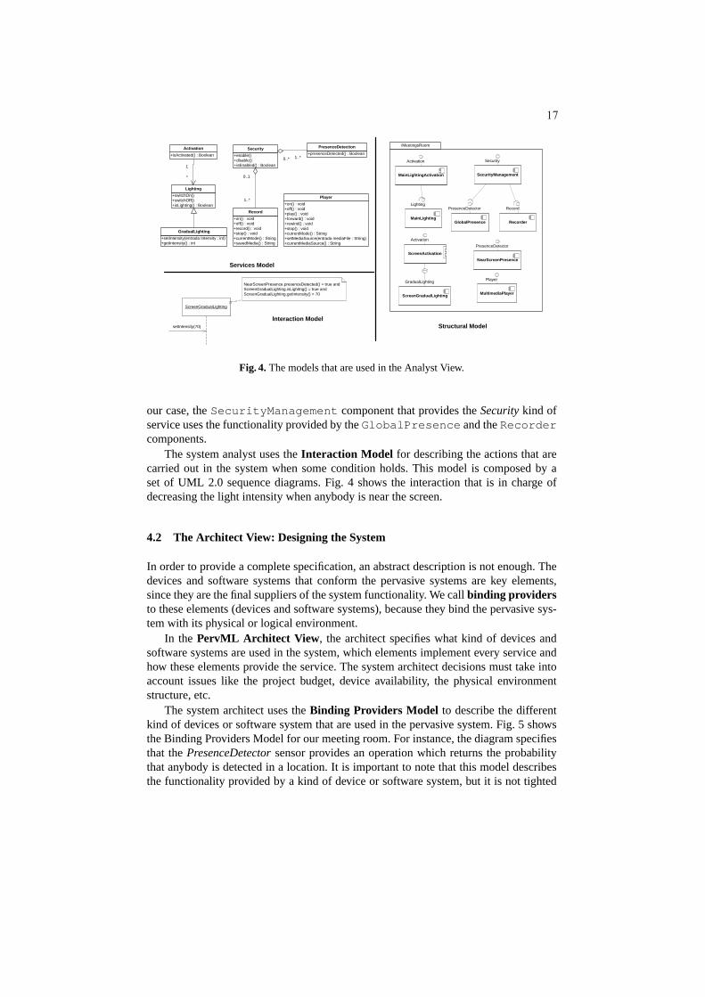
The goal of the pervasive system analyst is to capture the system requirements usinghigh level of abstraction primitives. PervML considers that a pervasive system providesservices to the users in an environment. In thePervML Analyst View , the analyst de-scribes the pervasive system using theservice metaphor as the main conceptual primi-tive. This view is composed by three models which are shown inFig. 4.
The system analyst uses theServices Modelfor describing the kinds of services thatare provided in the pervasive system. The diagram which represents the Services Modelin Fig. 4 shows that the meeting room provides services for controlling the lightings, fordetecting presence, for recording video, etc. Additionally to the information shown inFig. 4, the description of a kind of service includes (1)pre and post conditions(whichare expressed using the Object Constraint Language (OCL)) for every operation, (2)a Protocol State Machinewhich indicates the operations that can be invoked in aspecific moment, and (2)triggers which allow specifying the proactive behaviour ofthe services.
The system analyst uses theStructural Model to indicate the instances of everykind of service which are provided by the system. The services are represented as com-ponents whereas the kind of service that they provide is depicted as an interface (usingthe lollipop notation). Dependency relationships betweencomponents can be includedin order to specify that one component uses the functionality provided by another. In
16
+presenceDetected() : Boolean
PresenceDetection
+switchOn()+switchOff()+isLighting() : Boolean
Lighting
+isActivated() : Boolean
Activation
+setIntensity(entrada Intensity : int)+getIntensity() : int
GradualLighting
+on() : void+off() : void+play() : void+forward() : void+rewind() : void+stop() : void+currentMode() : String+setMediaSource(entrada mediaFile : String)+currentMediaSource() : String
Player
+enable()+disable()+isEnabled() : Boolean
Security
+on() : void+off() : void+record() : void+stop() : void+currentMode() : String+savedMedia() : String
Record
0..* 1..*
0..1
1..*
1
*
ScreenGradualLighting
GradualLighting
ScreenActivation
Activation
MultimediaPlayer
Player
NearScreenPresence
PresenceDetector
GlobalPresence
PresenceDetector
SecurityManagement
Security
Recorder
Record
MainLightingActivation
Activation
MainLighting
Lighting
/MeetingsRoom
Services Model
Structural Model
ScreenGradualLighting
NearScreenPresence.presenceDetected() = true andScreenGradualLighting.isLighitng() = true andScreenGradualLighting.getIntensity() > 70
setIntensity(70)
Interaction Model
Fig. 4.The models that are used in the Analyst View.
our case, theSecurityManagement component that provides theSecurity kind ofservice uses the functionality provided by theGlobalPresence and theRecordercomponents.
The system analyst uses theInteraction Model for describing the actions that arecarried out in the system when some condition holds. This model is composed by aset of UML 2.0 sequence diagrams. Fig. 4 shows the interaction that is in charge ofdecreasing the light intensity when anybody is near the screen.
4.2 The Architect View: Designing the System
In order to provide a complete specification, an abstract description is not enough. Thedevices and software systems that conform the pervasive systems are key elements,since they are the final suppliers of the system functionality. We callbinding providersto these elements (devices and software systems), because they bind the pervasive sys-tem with its physical or logical environment.
In the PervML Architect View , the architect specifies what kind of devices andsoftware systems are used in the system, which elements implement every service andhow these elements provide the service. The system architect decisions must take intoaccount issues like the project budget, device availability, the physical environmentstructure, etc.
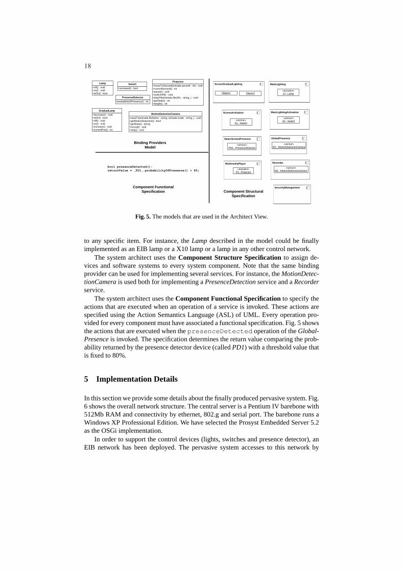
The system architect uses theBinding Providers Model to describe the differentkind of devices or software system that are used in the pervasive system. Fig. 5 showsthe Binding Providers Model for our meeting room. For instance, the diagram specifiesthat thePresenceDetector sensor provides an operation which returns the probabilitythat anybody is detected in a location. It is important to note that this model describesthe functionality provided by a kind of device or software system, but it is not tighted
17
+off() : void+on() : void+isOn() : bool
Lamp
+probabilityOfPresence() : int
PresenceDetector
+decrease() : void+isOn() : bool+off() : void+on() : void+increase() : void+currentPos() : int
GradualLamp
+activated() : bool
Switch+moveToSecond(entrada secondi : int) : void+currentSecond() : int+pause() : void+switchOff() : void+playFile(entrada fileURL : string, ) : void+getState() : int+length() : int
Projector
+saveTo(entrada fileName : string, entrada mode : string, ) : void+getMotionDetection() : bool+getState() : string+record() : void+stop() : void
MotionDetectionCamera ScreenActivation
«sensor»S1 : Switch
MainLighting
«actuator»L3 : Lamp
ScreenGradualLighting
Objeto1 Objeto2
MainLightingActivation
«sensor»S2 : Switch
GlobalPresence
«sensor»M1 : MotionDetectionCamera
SecurityManagement
NearcScreenPresence
«sensor»PD1 : PresenceDetector
Recorder
«sensor»M1 : MotionDetectionCamera
MultimediaPlayer
«actuator»P1 : Projector
Binding ProvidersModel
Component FunctionalSpecification Component Structural
Specification
bool presenceDetected():returnValue = _PD1_.probabilityOfPresence() > 80;
Fig. 5.The models that are used in the Architect View.
to any specific item. For instance, theLamp described in the model could be finallyimplemented as an EIB lamp or a X10 lamp or a lamp in any other control network.
The system architect uses theComponent Structure Specificationto assign de-vices and software systems to every system component. Note that the same bindingprovider can be used for implementing several services. Forinstance, theMotionDetec-tionCamera is used both for implementing aPresenceDetection service and aRecorderservice.
The system architect uses theComponent Functional Specificationto specify theactions that are executed when an operation of a service is invoked. These actions arespecified using the Action Semantics Language (ASL) of UML. Every operation pro-vided for every component must have associated a functionalspecification. Fig. 5 showsthe actions that are executed when thepresenceDetected operation of theGlobal-Presence is invoked. The specification determines the return value comparing the prob-ability returned by the presence detector device (calledPD1) with a threshold value thatis fixed to 80%.
5 Implementation Details
In this section we provide some details about the finally produced pervasive system. Fig.6 shows the overall network structure. The central server isa Pentium IV barebone with512Mb RAM and connectivity by ethernet, 802.g and serial port. The barebone runs aWindows XP Professional Edition. We have selected the Prosyst Embedded Server 5.2as the OSGi implementation.
In order to support the control devices (lights, switches and presence detector), anEIB network has been deployed. The pervasive system accesses to this network by
18
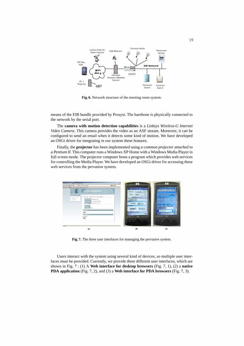
Fig. 6.Network structure of the meeting room system.
means of the EIB bundle provided by Prosyst. The barebone is physically connected tothe network by the serial port.
The camera with motion detection capabilitiesis a Linksys Wireless-G InternetVideo Camera. This camera provides the video as an ASF stream. Moreover, it can beconfigured to send an email when it detects some kind of motion. We have developedan OSGi driver for integrating in our system these features.
Finally, theprojector has been implemented usinga common projector attached toa Pentium II. This computer runs a Windows XP Home with a Windows Media Player infull screen mode. The projector computer hosts a program which provides web servicesfor controlling the Media Player. We have developed an OSGi driver for accessing theseweb services from the pervasive system.
Fig. 7.The three user interfaces for managing the pervasive system.
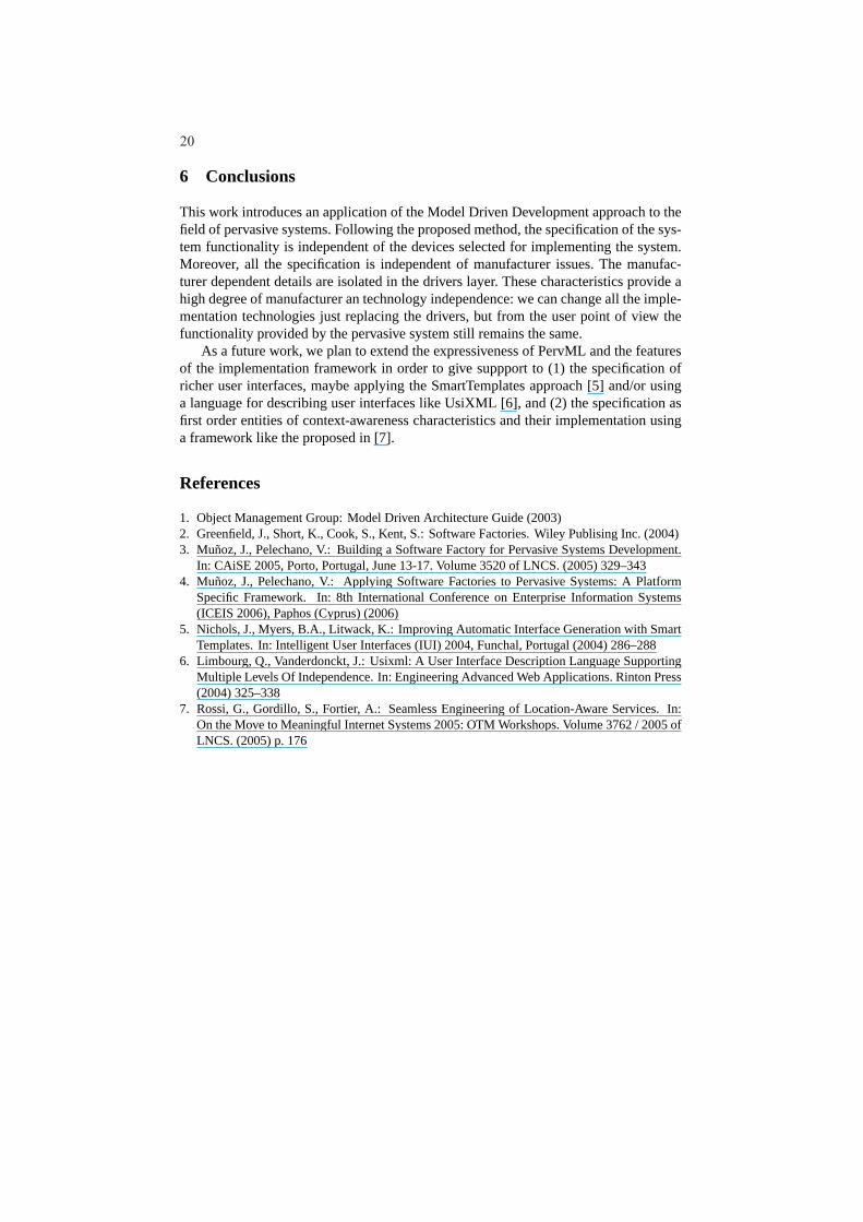
Users interact with the system using several kind of devices, so multiple user inter-faces must be provided. Currently, we provide three different user interfaces, which areshown in Fig. 7 : (1) AWeb interface for desktop browsers(Fig. 7, 1), (2) anativePDA application (Fig. 7, 2), and (3) aWeb interface for PDA browsers(Fig. 7, 3).
19
6 Conclusions
This work introduces an application of the Model Driven Development approach to thefield of pervasive systems. Following the proposed method, the specification of the sys-tem functionality is independent of the devices selected for implementing the system.Moreover, all the specification is independent of manufacturer issues. The manufac-turer dependent details are isolated in the drivers layer. These characteristics provide ahigh degree of manufacturer an technology independence: wecan change all the imple-mentation technologies just replacing the drivers, but from the user point of view thefunctionality provided by the pervasive system still remains the same.
As a future work, we plan to extend the expressiveness of PervML and the featuresof the implementation framework in order to give suppport to(1) the specification ofricher user interfaces, maybe applying the SmartTemplatesapproach [5] and/or usinga language for describing user interfaces like UsiXML [6], and (2) the specification asfirst order entities of context-awareness characteristicsand their implementation usinga framework like the proposed in [7].
References
1. Object Management Group: Model Driven Architecture Guide (2003)2. Greenfield, J., Short, K., Cook, S., Kent, S.: Software Factories. Wiley Publising Inc. (2004)3. Munoz, J., Pelechano, V.: Building a Software Factory for Pervasive Systems Development.
In: CAiSE 2005, Porto, Portugal, June 13-17. Volume 3520 of LNCS. (2005) 329–3434. Munoz, J., Pelechano, V.: Applying Software Factories to Pervasive Systems: A Platform
Specific Framework. In: 8th International Conference on EnterpriseInformation Systems(ICEIS 2006), Paphos (Cyprus) (2006)
5. Nichols, J., Myers, B.A., Litwack, K.: Improving Automatic Interface Generation with SmartTemplates. In: Intelligent User Interfaces (IUI) 2004, Funchal, Portugal (2004) 286–288
6. Limbourg, Q., Vanderdonckt, J.: Usixml: A User Interface Description Language SupportingMultiple Levels Of Independence. In: Engineering Advanced Web Applications. Rinton Press(2004) 325–338
7. Rossi, G., Gordillo, S., Fortier, A.: Seamless Engineering of Location-Aware Services. In:On the Move to Meaningful Internet Systems 2005: OTM Workshops. Volume 3762 / 2005 ofLNCS. (2005) p. 176
20