imaging in forensic radiology: an illustrated guide for postmortem computed tomography technique and...
TRANSCRIPT
REVIEW
Imaging in forensic radiology: an illustrated guide for postmortemcomputed tomography technique and protocols
Patricia M. Flach • Dominic Gascho • Wolf Schweitzer • Thomas D. Ruder •
Nicole Berger • Steffen G. Ross • Michael J. Thali • Garyfalia Ampanozi
Accepted: 10 March 2014
� Springer Science+Business Media New York 2014
Abstract Forensic radiology is a new subspecialty that
has arisen worldwide in the field of forensic medicine.
Postmortem computed tomography (PMCT) and, to a les-
ser extent, PMCT angiography (PMCTA), are established
imaging methods that have replaced dated conventional
X-ray images in morgues. However, these methods have
not been standardized for postmortem imaging. Therefore,
this article outlines the main approach for a recommended
standard protocol for postmortem cross-sectional imaging
that focuses on unenhanced PMCT and PMCTA. This
review should facilitate the implementation of a high-
quality protocol that enables standardized reporting in
morgues, associated hospitals or private practices that
perform forensic scans to provide the same quality that
clinical scans provide in court.
Keywords Virtopsy � Postmortem computed
tomography � PMCT � PMCTA � Protocol � Forensic
imaging � Virtual autopsy
Introduction
Postmortem cross-sectional imaging, including computed
tomography (CT) and magnetic resonance imaging (MR),
has been an established adjunct to forensic pathology for
approximately a decade, and the number of scientific
studies on postmortem imaging has increased significantly
over that short time span [1–4].
The first postmortem CT (PMCT) was reported in the late
1970s in a case of fatal cranial bullet wounds [5]. This report
was followed by numerous publications and even dedicated
books on forensic imaging [6–14]. At the turn of the mil-
lennium, the Virtopsy project was founded at the Institute of
Legal Medicine of the University of Berne in Switzerland.
This project aims to establish minimally invasive routine
imaging methods in the field of forensic pathology to sup-
plement, or even obviate, traditional autopsies [15]. So far,
several forensic departments worldwide have established
working relationships with clinical CT or MR suites, where
after-hours scans can be acquired, or they can even have
dedicated CT and/or MR devices placed in their institutes to
supplement, substitute or triage the daily forensic workflow
[16–36]. Postmortem imaging is a new radiological sub-
specialty, and unlike diagnostic radiology, it does not yet
have established standards.
Clinical and postmortem radiology differ significantly in
several aspects [37, 38]. First, radiation is not an issue for
the deceased. The imaging parameters can be adjusted to
maximize image quality without safety considerations for
the subject, such as the ALARA (as low as reasonably
achievable) principle. Also, a body does not have motion
artifacts or circulation, the latter of which is accompanied
by typical postmortem sedimentation effects within the
vessels or hypostasis of the lungs (inner livor mortis),
sometimes obscuring image reading or even mimicking
P. M. Flach (&) � D. Gascho � W. Schweitzer �T. D. Ruder � N. Berger � S. G. Ross � M. J. Thali �G. Ampanozi
Institute of Forensic Medicine, University of Zurich,
Winterthurerstrasse 190/52, 8057 Zurich, Switzerland
e-mail: [email protected]
P. M. Flach � N. Berger
Institute of Diagnostic and Interventional Radiology, University
Hospital Zurich, Raemistrasse 100, 8091 Zurich, Switzerland
P. M. Flach
Institute of Forensic Medicine, University of Bern, Buehlstrasse
20, 3012 Bern, Switzerland
123
Forensic Sci Med Pathol
DOI 10.1007/s12024-014-9555-6
real pathologies [37, 38] (Fig. 1). Second, the indications
in forensic medicine are typically different from those in
clinical radiology [39]. In antemortem imaging, usually
specific pathologies must be ruled out or confirmed using a
focused clinical protocol for a specific anatomical region.
For example, chest pain indicates imaging of the thorax.
Thus, clinical protocols lead to a specific diagnosis with a
subsequent therapy, whereas forensic radiology’s goals are
to detect the cause of death and to generate insights into the
deceased’s mortal circumstances. However, clinical emer-
gency or trauma scans can show the greatest resemblance
to postmortem imaging, in which the investigator has only
a rough idea of the suspected pathology (e.g., a traffic
accident with trauma) and the imaging should detect life-
threatening lesions, such as hemorrhage, internal paren-
chymal organ laceration and osseous or thoracic trauma,
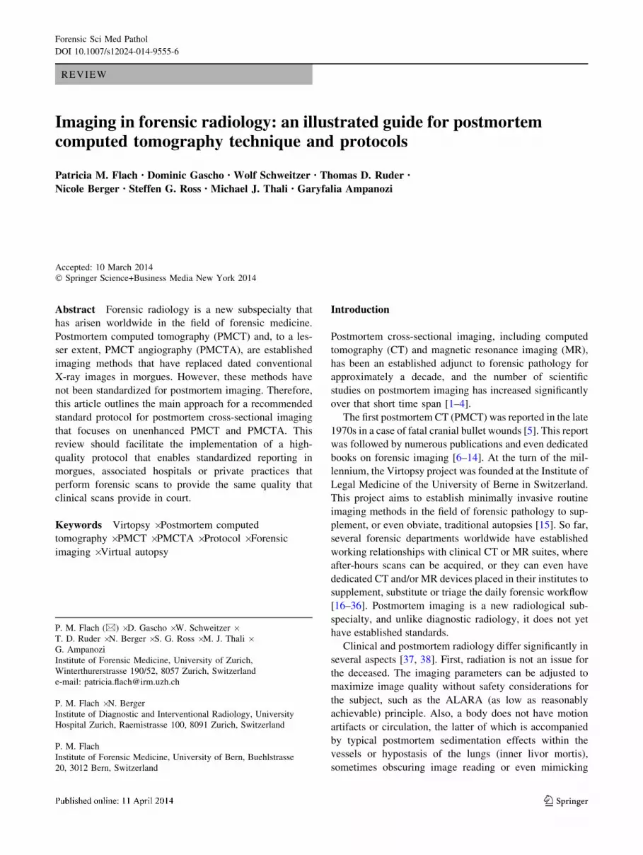
Fig. 1 a Axial PMCT at the tracheal bifurcation. There is no fluid in
the airways indicating aspiration. Note the diffuse ground-glass
opacities in the right lung and in the dorsal parts of the left lung,
corresponding to the inner livor mortis (position-dependent hypostasis
in the lungs). This finding is typical of PMCT. The inner livor mortis
marks depend on the position in which the person died, and the body
remained. These marks provide clues as to whether the body has been
moved. This body was found lying face down on the right (see
Fig. 1d). The PMCT scan, however, was taken after he was already
transported and stored for a while in the supine position. Therefore,
there is the major settling of the hypostasis in the right (dependent)
portion of the lung (due to original position) and, to a lesser degree, in
the dorsal parts of the lung (due to later supine positioning). b Coronal
MinIP (minimum intensity projection) of the airways and the lungs.
The dotted lines indicate the predominantly right-sided, position-
dependent inner livor mortis. c Volume rendering technique (VRT) of
the lung displaying the opacified parts of the lungs due to position-
dependent inner livor mortis. d Photograph documenting an overview
of the external inspection. Note the ventral settling of the blood as a
function of the body position, causing a reddish discoloration of the
skin: livor mortis. The contact area of the body with the ground (or
another object) on the right is spared due to the compression of the
capillaries and a lack of settling of the blood. The dorsal body parts
are not discolored due to the ventral and right-sided body position
Forensic Sci Med Pathol
123
from the brain to the pelvis. These techniques are similar to
those in postmortem imaging for determining the cause of
death [40–44].
Forensic pathology and imaging both play roles in docu-
menting anatomy and pathology for forensic purposes. At
trial, forensic imaging must sustain a technically impeccable
image quality for the attorney representing the defense/vic-
tims or for the court to verify, confirm or exclude inquiries.
Therefore, a technically impeccable forensic imaging proto-
col must be as maximally comprehensive as possible. This
goal contrasts with clinical protocols, in which full or overly
extensive documentation for deferred or later analysis is
typically not intended, although it might be desired. Third,
specific forensic considerations for postmortem imaging are
different from those for clinical inquiries and include multiple
objectives, such as dental identification, medical malpractice,
accident reconstruction, air embolisms, reconstruction of
inflicted wounds due to blunt or sharp force (Figs. 2, 3, 4),
signs of intoxication, natural cause of death, identification of
foreign material (Fig. 4) and homicide, to name only a few [8,
39]. Finally, forensic considerations are paramount, while
postmortem imaging allows for re-evaluation, provides
objective counter-expertise and serves as evidence in court.
Thus, postmortem imaging must be performed using at least
the same standards as clinical scans.
PMCT [and postmortem MR (PMMR)] should also
include the extremities and is predominantly unenhanced,
in contrast to clinical radiology. If postmortem imaging is
taken a step further, the lack of cardiovascular circulation
can be overcome by administering additional intravascular
contrast media mixture using a roller-pump or modified
heart–lung machine [45–52]. Recently described PMCT
angiography (PMCTA) procedures allow for precise vas-
cular and parenchymal localization of pathologies, which
can substantially aid in forensic diagnoses. Current
research on PMMR angiography (PMMRA) is scarce [53].
However, PMCTA and PMMR/PMMRA both add crucial
diagnostic value to forensic imaging, although they are
time-consuming and therefore have not yet been widely
adopted worldwide in forensic institutions. Specific PMMR
and PMMRA scanning parameters are clearly beyond the
scope of this review [53–57].
In this article, we outline the main approach for a recom-
mended standard protocol for postmortem cross-sectional
imaging, focusing on unenhanced PMCT and PMCTA.
The forensic role of PMCT
Forensic indications for postmortem cross-sectional imag-
ing can vary from institution to institution and from
country to country. At our forensic institution, we use
PMCT as a baseline exam, which each body delivered to
the morgue undergoes, regardless of a subsequent state-
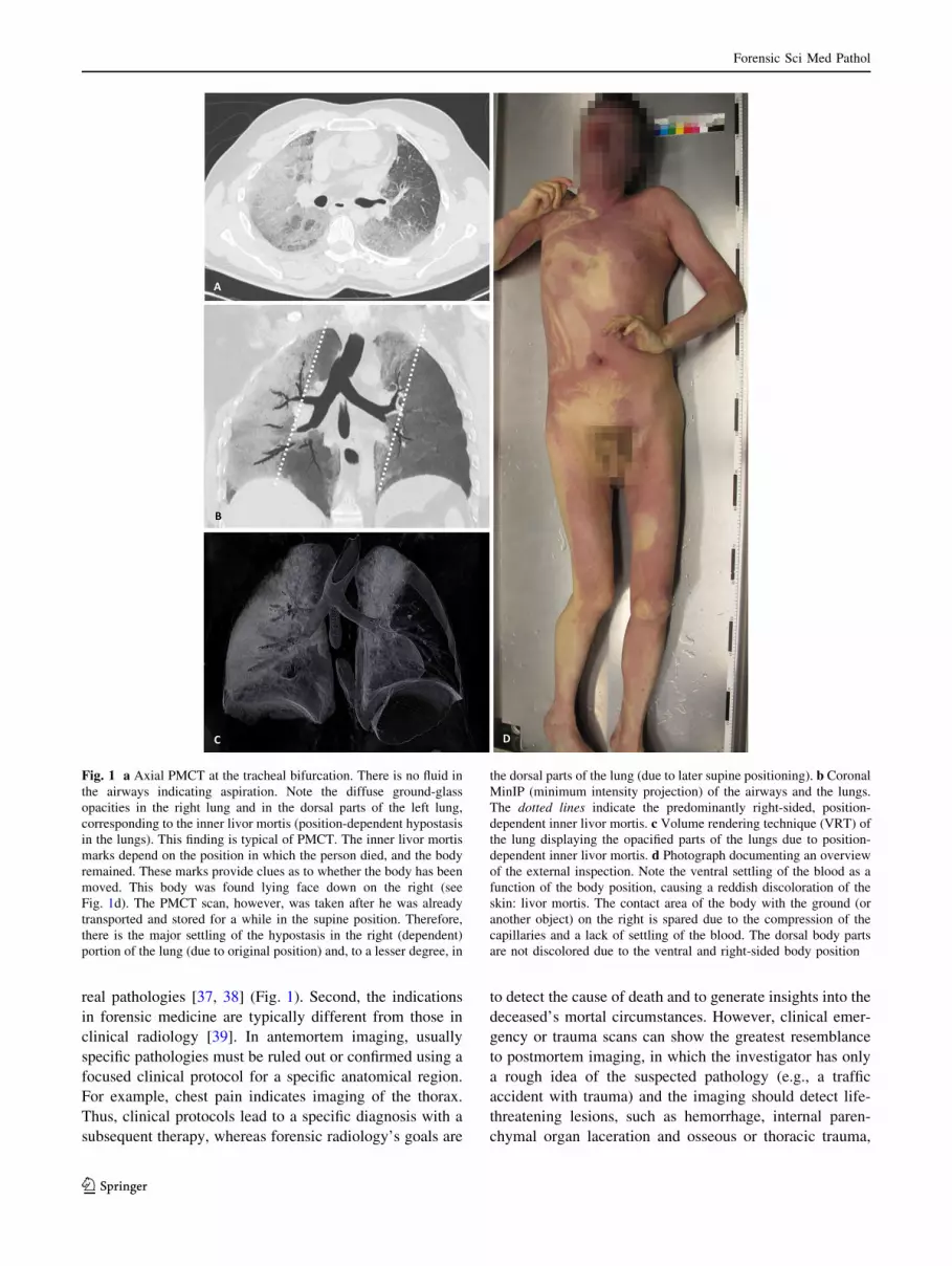
Fig. 2 a VRT, latero-ventral
view of the proximal femur.
b VRT, latero-dorsal view of the
proximal femur. Both images, a,
b, display a classic Messerer’s
wedge (butterfly wedge) of the
fractured proximal diaphysis of
the left femur (bold red arrows).
This finding is forensically
relevant, as it allows for the
determination of the side of
direct trauma (e.g., in a case of
traffic accident reconstruction).
Hence, the apex of the wedge
points in the direction of force,
and the base represents the
impact site
Forensic Sci Med Pathol
123
ordered autopsy, toxicological analysis or legal (external)
inspection only. Supplementary exams, such as whole-
body PMMR or focused PMMR, PMCTA or PMMRA, are
based on the results of the diagnosis of the initial unen-
hanced PMCT, on the findings of the external inspection
and on the deceased’s history, in consensus between the
forensic radiologist and the forensic pathologist. Addi-
tionally, all imaging is performed under a general agree-
ment with the district attorney’s office.
In other institutions, PMCT might be the only imaging
modality. In these institutions, it might be used for triage
purposes to reduce the sheer number of daily forensic
autopsies by identifying the cases with potential unnatural
causes of death for subsequent autopsy, thus obviating
autopsy for natural causes of death [3, 4]. In other parts of
the world, surviving family members might object to
postmortem investigations, such as autopsies, out of reli-
gious or cultural motivations. In these places, the use of
postmortem imaging, including PMMR, as a potential
substitute to autopsy is a new approach for overcoming
these problems [26, 27]. Moreover, at some institutions
every fatality returning from war undergoes PMCT at a
military facility to add efficiency and accuracy to the
subsequent autopsy process, rather than to replace it [22–
24]. Currently, some institutions primarily use postmortem
imaging for scientific research purposes and not for pre-
autopsy planning [58–60].
PMCT allows forensic pathologists to dissect cumber-
some body parts or areas that are not routinely dissected
during a standard autopsy (opening of the 3 body cavities:
skull, thorax and abdomen), directed by the findings of the
cross-sectional data set. These areas include the viscero-
cranium, shoulder girdle, extremities, outer pelvis, cranio-
cervical junction, larynx and soft tissue of the back.
Due to this heterogeneity of imaging purposes within the
domain of forensic PMCT alone, a standardized imaging
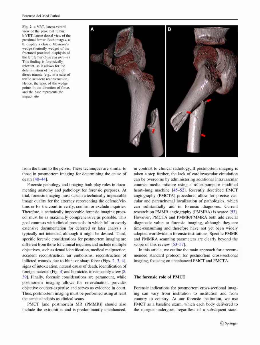
Fig. 3 a Coronal maximum intensity projection (MIP) of the lower
airways and the lungs. Note the mal-positioned endotracheal tube in
the right main bronchus. The cuff is blocked at the level of the
bifurcation. These findings would have been missed during autopsy as
medical devices are removed for dissection. b Volume rendering
technique (VRT) of the air-filled structures, such as the blocked cuff
of the tube, the left bronchus and the stomach (colored in green). The
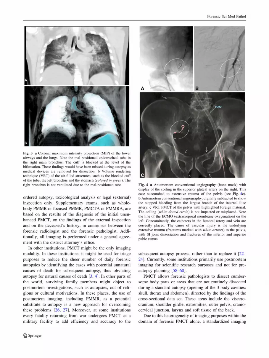
right bronchus is not ventilated due to the mal-positioned tube Fig. 4 a Antemortem conventional angiography (bone mask) with
display of the coiling in the superior gluteal artery on the right. This
case succumbed to extensive trauma of the pelvis (see Fig. 4c).
b Antemortem conventional angiography, digitally subtracted to show
the stopped bleeding from the largest branch of the internal iliac
artery. c VRT PMCT of the pelvis with highlighted foreign material.
The coiling (white dotted circle) is not impacted or misplaced. Note
the line of the ECMO (extracorporal membrane oxygenation) on the
left. Concomitantly, the catheters in the femoral artery and vein are
correctly placed. The cause of vascular injury is the underlying
extensive trauma (fractures marked with white arrows) to the pelvis,
with SI joint dissociation and fractures of the inferior and superior
pubic ramus
Forensic Sci Med Pathol
123
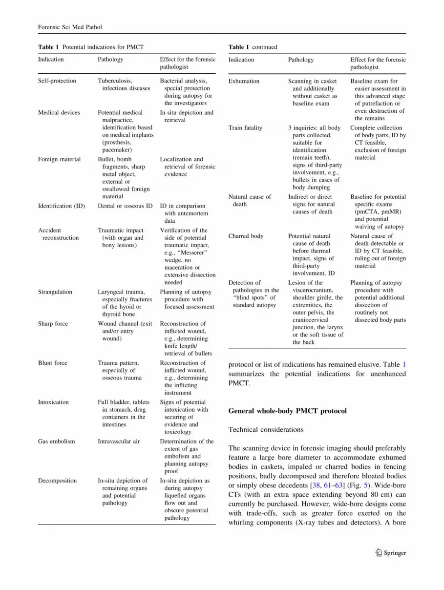
protocol or list of indications has remained elusive. Table 1
summarizes the potential indications for unenhanced
PMCT.
General whole-body PMCT protocol
Technical considerations
The scanning device in forensic imaging should preferably
feature a large bore diameter to accommodate exhumed
bodies in caskets, impaled or charred bodies in fencing
positions, badly decomposed and therefore bloated bodies
or simply obese decedents [38, 61–63] (Fig. 5). Wide-bore
CTs (with an extra space extending beyond 80 cm) can
currently be purchased. However, wide-bore designs come
with trade-offs, such as greater force exerted on the
whirling components (X-ray tubes and detectors). A bore
Table 1 Potential indications for PMCT
Indication Pathology Effect for the forensic
pathologist
Self-protection Tuberculosis,
infectious diseases
Bacterial analysis,
special protection
during autopsy for
the investigators
Medical devices Potential medical
malpractice,
identification based
on medical implants
(prosthesis,
pacemaker)
In-situ depiction and
retrieval
Foreign material Bullet, bomb
fragments, sharp
metal object,
external or
swallowed foreign
material
Localization and
retrieval of forensic
evidence
Identification (ID) Dental or osseous ID ID in comparison
with antemortem
data
Accident
reconstruction
Traumatic impact
(with organ and
bony lesions)
Verification of the
side of potential
traumatic impact,
e.g., ‘‘Messerer’’
wedge, no
maceration or
extensive dissection
needed
Strangulation Laryngeal trauma,
especially fractures
of the hyoid or
thyroid bone
Planning of autopsy
procedure with
focused assessment
Sharp force Wound channel (exit
and/or entry
wound)
Reconstruction of
inflicted wound,
e.g., determining
knife length/
retrieval of bullets
Blunt force Trauma pattern,
especially of
osseous trauma
Reconstruction of
inflicted wound,
e.g., determining
the inflicting
instrument
Intoxication Full bladder, tablets
in stomach, drug
containers in the
intestines
Signs of potential
intoxication with
securing of
evidence and
toxicology
Gas embolism Intravascular air Determination of the
extent of gas
embolism and
planning autopsy
proof
Decomposition In-situ depiction of
remaining organs
and potential
pathology
In-situ depiction as
during autopsy
liquefied organs
flow out and
obscure potential
pathology
Table 1 continued
Indication Pathology Effect for the forensic
pathologist
Exhumation Scanning in casket
and additionally
without casket as
baseline exam
Baseline exam for
easier assessment in
this advanced stage
of putrefaction or
even destruction of
the remains
Train fatality 3 inquiries: all body
parts collected,
suitable for
identification
(remain teeth),
signs of third-party
involvement, e.g.,
bullets in cases of
body dumping
Complete collection
of body parts, ID by
CT feasible,
exclusion of foreign
material
Natural cause of
death
Indirect or direct
signs for natural
causes of death
Baseline for potential
specific exams
(pmCTA, pmMR)
and potential
waiving of autopsy
Charred body Potential natural
cause of death
before thermal
impact, signs of
third-party
involvement, ID
Natural cause of
death detectable or
ID by CT feasible,
ruling out of foreign
material
Detection of
pathologies in the
‘‘blind spots’’ of
standard autopsy
Lesion of the
viscerocranium,
shoulder girdle, the
extremities, the
outer pelvis, the
craniocervical
junction, the larynx
or the soft tissue of
the back
Planning of autopsy
procedure with
potential additional
dissection of
routinely not
dissected body parts
Forensic Sci Med Pathol
123
size of 85 cm is favorable for postmortem forensic imag-
ing. However, working with an average bore size of 78 cm
is sufficient in most cases.
Body preparation
The body should be in the supine position for whole-body
PMCT and should be wrapped in an artifact-free body bag
(or at least in plastic foil) to diminish contamination of the
CT couch. Positioning of the head with the median location
of the nose is feasible to some extent by palpating the nasal
bone through the body bag and repositioning the head in an
orthograde position. This process clearly depends on the
extent of rigor mortis. Doing so facilitates later image
reconstruction and avoids the potential pitfall of mistaking
the sides while reconstructing the head. The medical
investigator or radiological technologist, or even the mor-
gue technologist in charge of the PMCT scan, must ensure
that the complete body is included in the scan range of the
whole-body PMCT, from the vertex and the galeal soft
tissue to the tips of the toes. Newer scanners allow for a
scan range of up to 200 cm, and most of the deceased’s
body will fit. If the scan range is too short, e.g., if the
decedent is taller than 2 m, bending the knees will facilitate
inclusion of the whole body in one scan range. However, a
drawback of this approach is that artifacts at the knees
might extend the field of view (eFoV) on the data set.
Alternatively, the operator can simply split the scan into 2
scan ranges and adjust the body position accordingly.
The initial whole-body PMCT should be performed
without any alterations of the body; i.e., everything should
be left untouched for the baseline scan, and medical
devices or foreign material should not be removed (Figs. 3,
4). In high-profile cases, such as homicides, the radiolog-
ical investigator must ensure that the DNA tests and
criminal investigations have already been completed prior
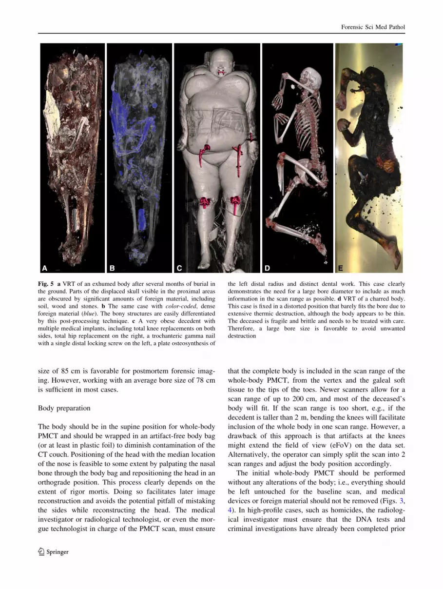
Fig. 5 a VRT of an exhumed body after several months of burial in
the ground. Parts of the displaced skull visible in the proximal areas
are obscured by significant amounts of foreign material, including
soil, wood and stones. b The same case with color-coded, dense
foreign material (blue). The bony structures are easily differentiated
by this post-processing technique. c A very obese decedent with
multiple medical implants, including total knee replacements on both
sides, total hip replacement on the right, a trochanteric gamma nail
with a single distal locking screw on the left, a plate osteosynthesis of
the left distal radius and distinct dental work. This case clearly
demonstrates the need for a large bore diameter to include as much
information in the scan range as possible. d VRT of a charred body.
This case is fixed in a distorted position that barely fits the bore due to
extensive thermic destruction, although the body appears to be thin.
The deceased is fragile and brittle and needs to be treated with care.
Therefore, a large bore size is favorable to avoid unwanted
destruction
Forensic Sci Med Pathol
123
to the scan to avoid altering any forensic evidence from the
body. When imaging dedicated body areas, external for-
eign material (e.g., stones, zippers, etc., but not medical
devices) should be removed after the baseline scan [38].
The image quality of the torso improves, even with
newer scanners, when elevating the upper extremities and
fixating the wrists using a hook-and-pile fastener or simply
loosely wrapping the extremities in duct tape (Fig. 6).
Doing so diminishes streak artifacts in the upper abdomen,
which impairs image quality and therefore poses a risk to
the reporting of findings. To elevate the arms, the body bag
must be opened, and rigor mortis, if present, must be
broken without blunt force.
In cases of exhumation, the body should first be scanned
within the casket if it fits the bore size [38] to obtain a true
in situ depiction. Clearly, exhumed bodys usually show vast
signs of decomposition and, therefore, potential displacement
of body parts after removal from the casket. Second, a scan
without the casket should follow to eliminate the artifacts
from soil or stones that usually accompany exhumed coffins.
Clearly, there are cases in which the operator must
abstain from elevating the arms at the expense of image
quality of the torso, due to physical limitations and
potential postmortem alteration of the body. The operator
should avoid elevation of the upper extremities in the fol-
lowing scenarios (Fig. 7): (1) Decomposition: Potential
detachment of the skin due to elevation of the arms, con-
tamination of the CT couch caused by insect infestation or
bodily fluids or molestation by odor (especially in clinical
suites); (2) A charred body: Frequently, no alterations are
feasible without concomitant destruction of the body; (3) A
frozen body: The image quality will change to more hyp-
odense parenchyma if frozen. If the body does not fit in the
bore, the operator should wait until the body has defrosted;
(4). Isolated trauma to the proximal upper extremity:
Bending of the arms can aggravate potential fracture of the
humerus or glenohumeral dislocation and create false-
positive postmortem findings; (5) Vast traumatic destruc-
tion of the body (including transsection of the limbs, train
fatalities or massive open trauma): Potential alteration of
postmortem findings or contamination of the CT couch by
bodily fluids (however, a second PMCT in ordered ana-
tomical position of all body parts is suggested); and (6) An
exhumed body: Usually adipocere and decomposition are
present; therefore, the arms cannot be elevated.
Pitfalls
Postmortem fractures of the body can occur due to acci-
dentally sloppy transfer from the gurney to the CT couch
and vice versa. This pitfall is especially relevant with
charred bodies. In these cases, communication with the
forensic pathologist regarding the initial external inspec-
tion or later inspection during autopsy (if performed) is
crucial to avoid mistaking postmortem fractures for ante-
mortem findings. However, indirect signs of antemortem
fractures, such as hematoma on PMCT or bone bruises on
PMMR, might be present. Nevertheless, bone marrow
edema can also occur as a result of heat-related bone
changes due to thermal impact.
Postmortem fractures of the upper proximal extremity or
the shoulder girdle rarely occur due to elevation of the
arms. The initial whole-body PMCT without elevated arms
should serve as the baseline in the latter case.
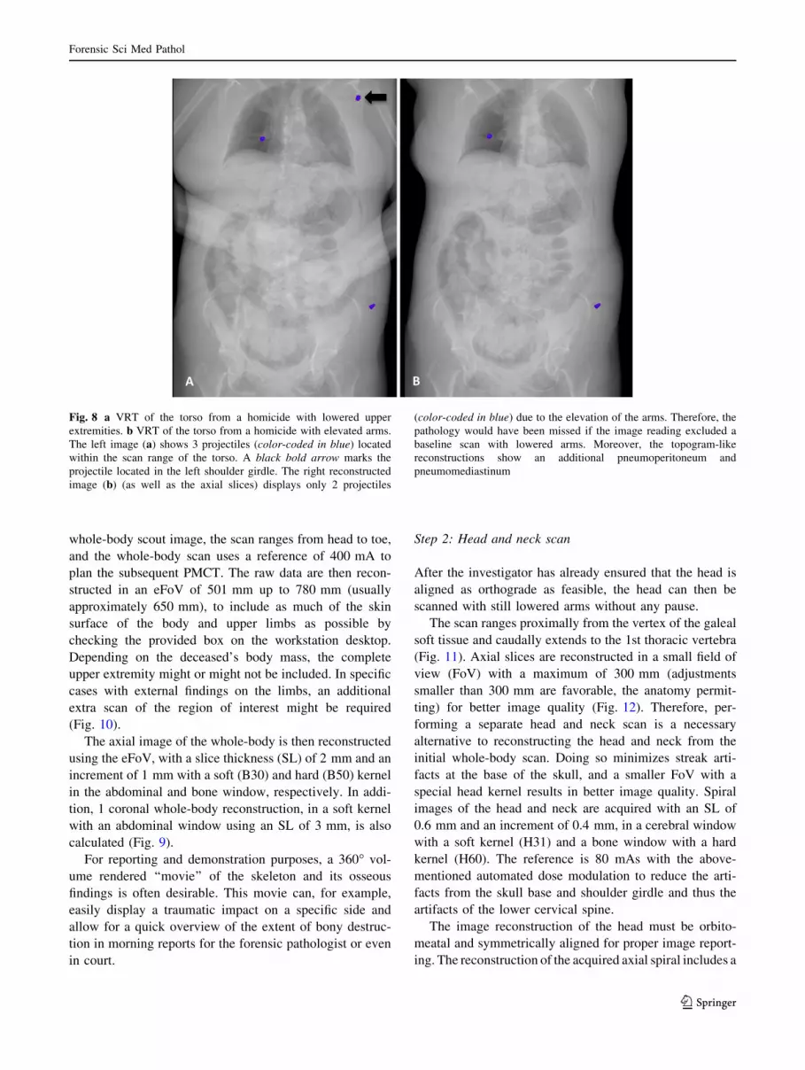
Elevation of the arms can also exclude pathologies from
the scan range when the thorax and abdomen are scanned
(Fig. 8) [38]. Therefore, the shoulder girdle in particular
should be read on the whole-body scan (with lowered
arms), and the dedicated torso scan should be read with
better image quality (with elevated arms).
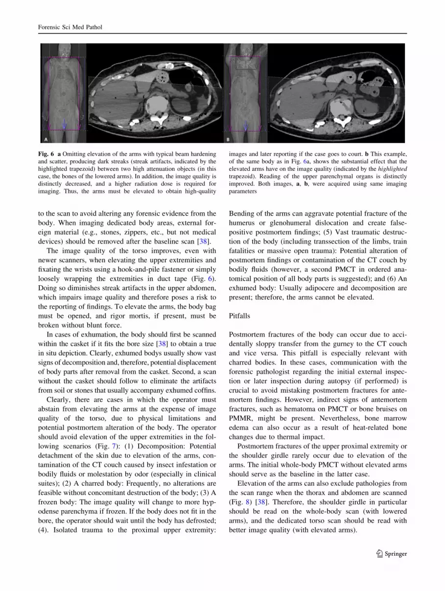
Fig. 6 a Omitting elevation of the arms with typical beam hardening
and scatter, producing dark streaks (streak artifacts, indicated by the
highlighted trapezoid) between two high attenuation objects (in this
case, the bones of the lowered arms). In addition, the image quality is
distinctly decreased, and a higher radiation dose is required for
imaging. Thus, the arms must be elevated to obtain high-quality
images and later reporting if the case goes to court. b This example,
of the same body as in Fig. 6a, shows the substantial effect that the
elevated arms have on the image quality (indicated by the highlighted
trapezoid). Reading of the upper parenchymal organs is distinctly
improved. Both images, a, b, were acquired using same imaging
parameters
Forensic Sci Med Pathol
123
Whole-body PMCT ([16 multidetector CT)
Newer scanners feature longer scan ranges of almost
200 cm, and they allow for complete whole-body scans
without repositioning the body. Our experience regarding
the following whole-body PMCT protocol is based on a
dual-source CT scanner (SOMATOM Flash Definition,
Siemens, Forchheim, Germany) with 2 9 128 slices.
Automated dose modulation (CARE Dose4DTM, Siemens,
Forchheim, Germany) was used for all of the scans to
reduce streak artifacts. The tube voltage was 120 kV for all
of the performed exams (unless otherwise stated), as the
dose savings were inconsequential. The pitch factor was
0.35, and the rotation time was 0.5 s. The complete 3-step-
scanning protocol is described step by step in the following
section and is summarized in Table 2.
Step 1: Whole-body scan: ‘‘The Baseline’’
The body is positioned using laser cross hairs to determine
the exact height of the CT couch, and a line is projected
onto the table, so the body is positioned exactly in the
middle of the table. Small aligning lasers are also used to
determine the starting point for the scout view. Folding the
body bag and palpating the vertex through the body bag
usually support this approach. Positioning of the head with
the median location of the nose is favorable, as mentioned
above. The body should be scanned head first in the supine
position, with the arms at the sides or slightly crossed over
the torso (‘‘praying position’’) to include as much of the
upper extremities in the scan field as possible.
The topogram is obtained at 120 kV and 35 mA in the
anterior-posterior and lateral orientations (Fig. 9). On the
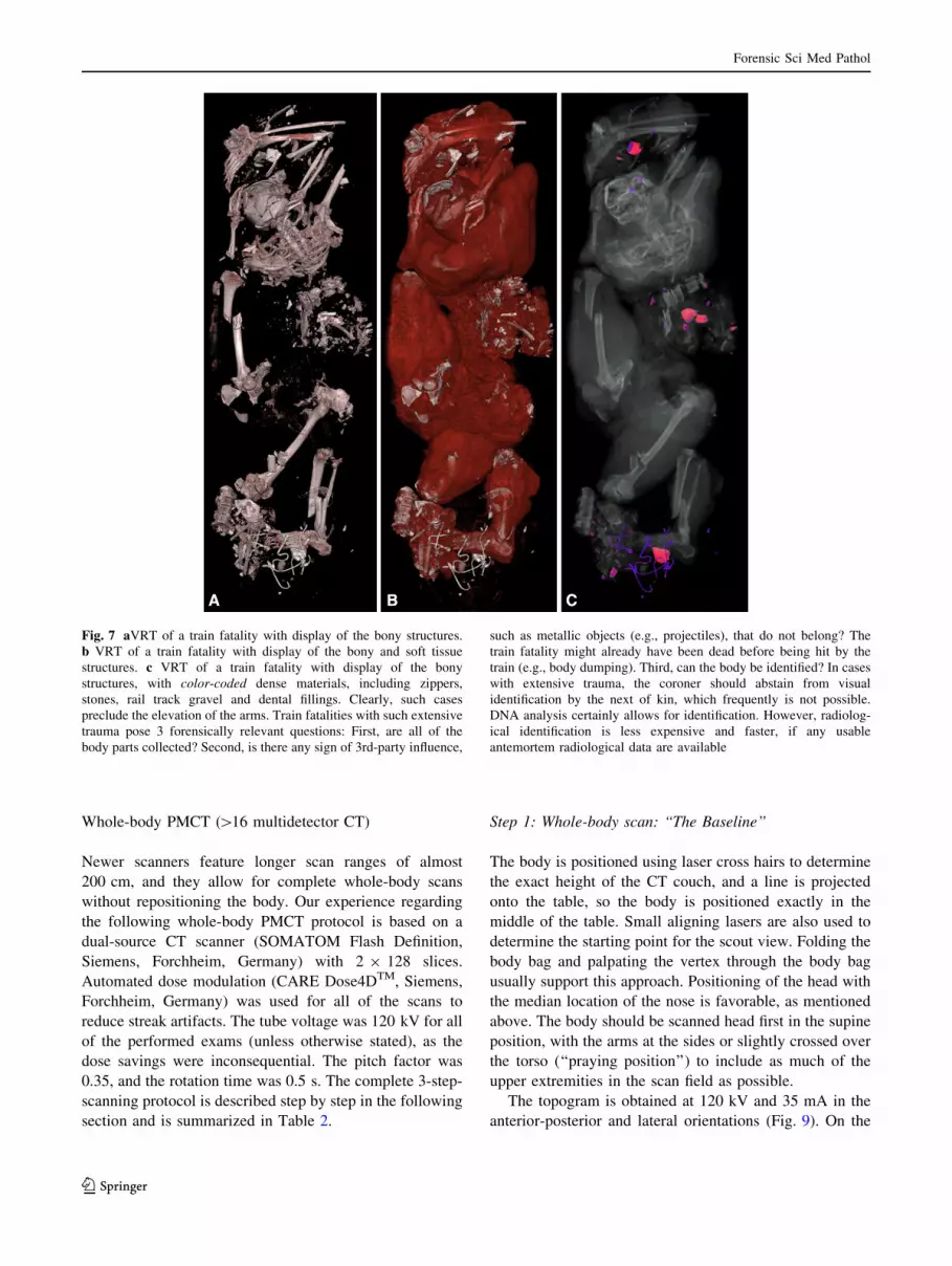
Fig. 7 aVRT of a train fatality with display of the bony structures.
b VRT of a train fatality with display of the bony and soft tissue
structures. c VRT of a train fatality with display of the bony
structures, with color-coded dense materials, including zippers,
stones, rail track gravel and dental fillings. Clearly, such cases
preclude the elevation of the arms. Train fatalities with such extensive
trauma pose 3 forensically relevant questions: First, are all of the
body parts collected? Second, is there any sign of 3rd-party influence,
such as metallic objects (e.g., projectiles), that do not belong? The
train fatality might already have been dead before being hit by the
train (e.g., body dumping). Third, can the body be identified? In cases
with extensive trauma, the coroner should abstain from visual
identification by the next of kin, which frequently is not possible.
DNA analysis certainly allows for identification. However, radiolog-
ical identification is less expensive and faster, if any usable
antemortem radiological data are available
Forensic Sci Med Pathol
123
whole-body scout image, the scan ranges from head to toe,
and the whole-body scan uses a reference of 400 mA to
plan the subsequent PMCT. The raw data are then recon-
structed in an eFoV of 501 mm up to 780 mm (usually
approximately 650 mm), to include as much of the skin
surface of the body and upper limbs as possible by
checking the provided box on the workstation desktop.
Depending on the deceased’s body mass, the complete
upper extremity might or might not be included. In specific
cases with external findings on the limbs, an additional
extra scan of the region of interest might be required
(Fig. 10).
The axial image of the whole-body is then reconstructed
using the eFoV, with a slice thickness (SL) of 2 mm and an
increment of 1 mm with a soft (B30) and hard (B50) kernel
in the abdominal and bone window, respectively. In addi-
tion, 1 coronal whole-body reconstruction, in a soft kernel
with an abdominal window using an SL of 3 mm, is also
calculated (Fig. 9).
For reporting and demonstration purposes, a 360� vol-
ume rendered ‘‘movie’’ of the skeleton and its osseous
findings is often desirable. This movie can, for example,
easily display a traumatic impact on a specific side and
allow for a quick overview of the extent of bony destruc-
tion in morning reports for the forensic pathologist or even
in court.
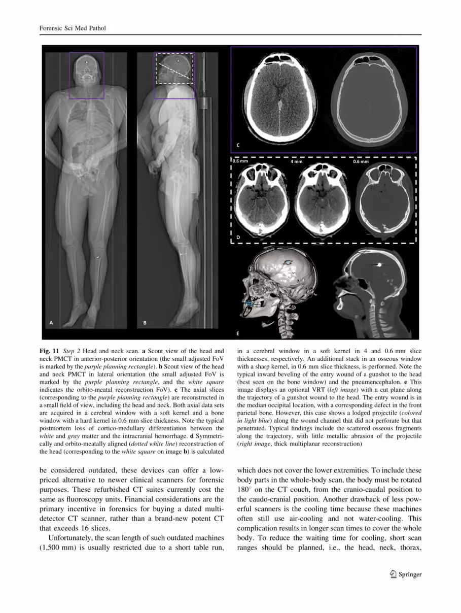
Step 2: Head and neck scan
After the investigator has already ensured that the head is
aligned as orthograde as feasible, the head can then be
scanned with still lowered arms without any pause.
The scan ranges proximally from the vertex of the galeal
soft tissue and caudally extends to the 1st thoracic vertebra
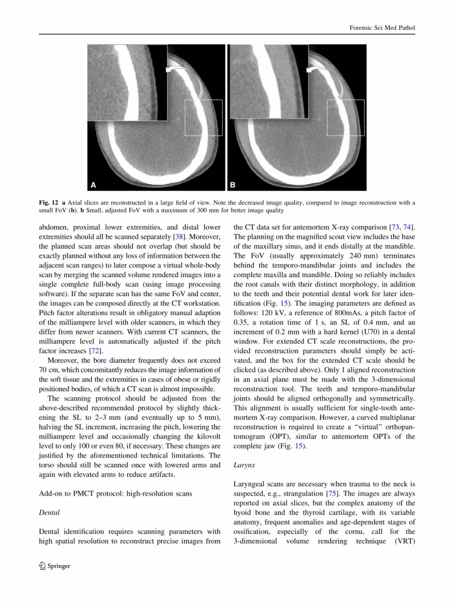
(Fig. 11). Axial slices are reconstructed in a small field of
view (FoV) with a maximum of 300 mm (adjustments
smaller than 300 mm are favorable, the anatomy permit-
ting) for better image quality (Fig. 12). Therefore, per-
forming a separate head and neck scan is a necessary
alternative to reconstructing the head and neck from the
initial whole-body scan. Doing so minimizes streak arti-
facts at the base of the skull, and a smaller FoV with a
special head kernel results in better image quality. Spiral
images of the head and neck are acquired with an SL of
0.6 mm and an increment of 0.4 mm, in a cerebral window
with a soft kernel (H31) and a bone window with a hard
kernel (H60). The reference is 80 mAs with the above-
mentioned automated dose modulation to reduce the arti-
facts from the skull base and shoulder girdle and thus the
artifacts of the lower cervical spine.
The image reconstruction of the head must be orbito-
meatal and symmetrically aligned for proper image report-
ing. The reconstruction of the acquired axial spiral includes a
Fig. 8 a VRT of the torso from a homicide with lowered upper
extremities. b VRT of the torso from a homicide with elevated arms.
The left image (a) shows 3 projectiles (color-coded in blue) located
within the scan range of the torso. A black bold arrow marks the
projectile located in the left shoulder girdle. The right reconstructed
image (b) (as well as the axial slices) displays only 2 projectiles
(color-coded in blue) due to the elevation of the arms. Therefore, the
pathology would have been missed if the image reading excluded a
baseline scan with lowered arms. Moreover, the topogram-like
reconstructions show an additional pneumoperitoneum and
pneumomediastinum
Forensic Sci Med Pathol
123
thick-sliced (4 mm, increment 3 mm) stack with a cerebral
window in a soft kernel (H31) via a 3-dimensional recon-
struction tool for multiplanar reconstruction, which usually
comes with the operating controls of the CT scanner. In
addition, the thin slices of the head (SL 0.6 mm, increment
0.4 mm) are aligned with the same parameters used for the
thick slices, with an osseous window in a sharp kernel (H60).
The reconstruction of the head images includes the soft tissue
from the vertex down to the chin (Fig. 11).
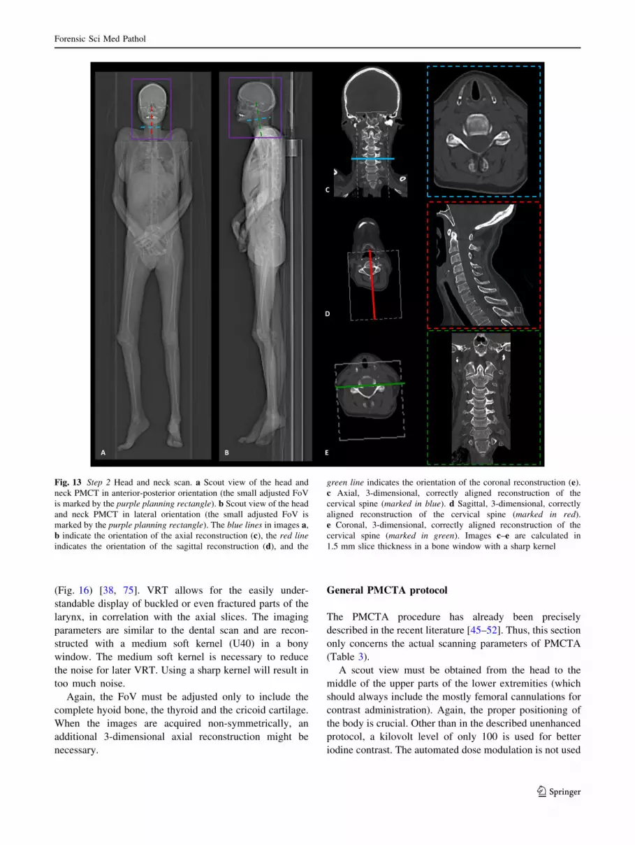
The neck reconstruction parameters are calculated in the
3-dimensional application as follows: for the axial images of
the cervical spine, the FoV is minimized and properly
aligned to the facet joint on both sides and to the interver-
tebral disk. The axial, sagittal, and coronal images of the
cervical spine are all obtained with an SL of 1.5 mm and
increment of 1 mm, with a bone window in a sharp kernel
(H60). The reconstruction includes the occipital condyles
proximally and distally the 1st thoracic vertebra (Fig. 13).
The sagittal image reconstruction is centered and
aligned to the dens, and it includes the very tips of the
transverse processes on both sides. The coronal images are
aligned with the facet joints/dens and include the complete
vertebrae on the anterior and the complete spinous process
on the posterior (Fig. 13).
Step 3: Thorax and abdomen scan
According to the above-mentioned protocol, the arms are
then elevated to ensure proper image quality of the torso. The
FoV is usually adjusted to a width of 300–400 mm,
according to the decedent’s habitus; the maximum FoV
should not exceed 500 mm. The scan range includes the
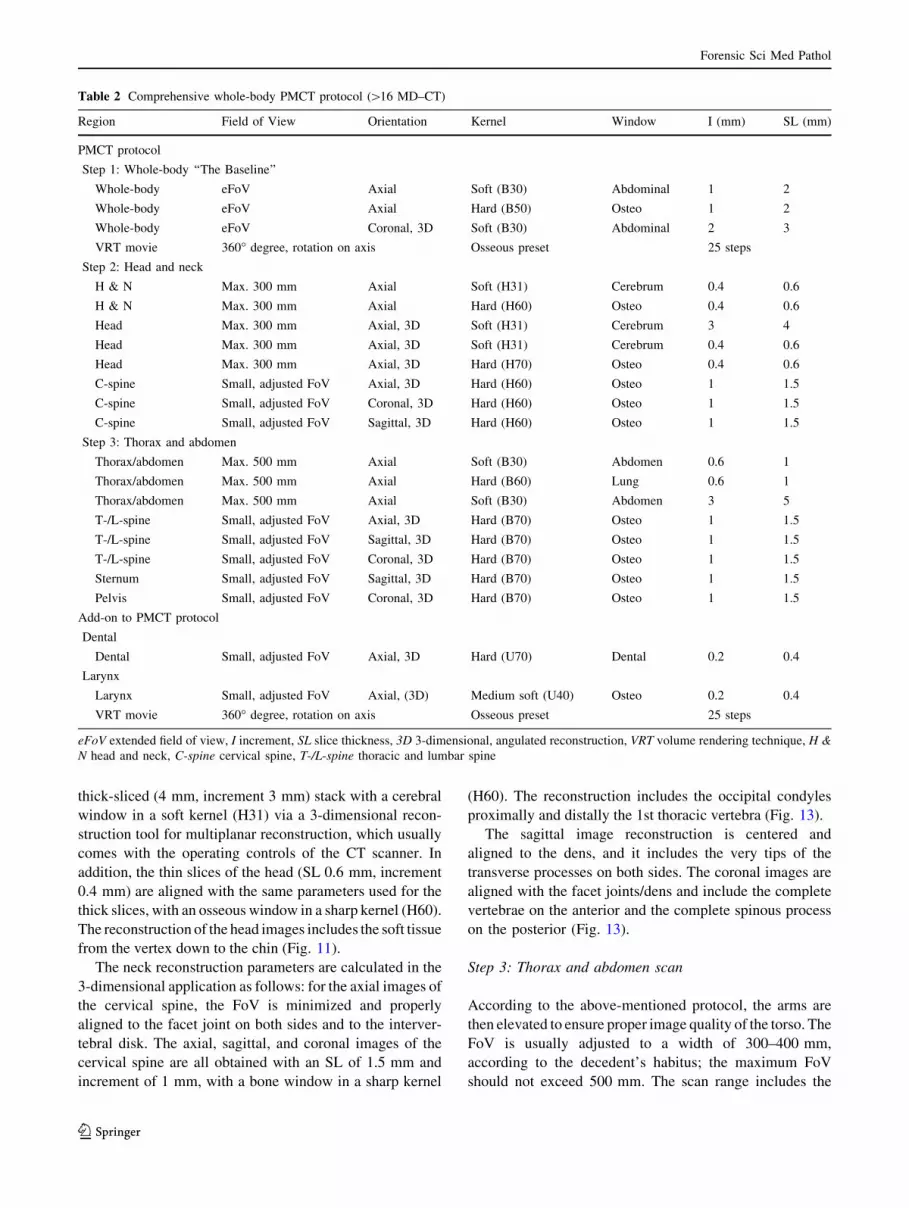
Table 2 Comprehensive whole-body PMCT protocol ([16 MD–CT)
Region Field of View Orientation Kernel Window I (mm) SL (mm)
PMCT protocol
Step 1: Whole-body ‘‘The Baseline’’
Whole-body eFoV Axial Soft (B30) Abdominal 1 2
Whole-body eFoV Axial Hard (B50) Osteo 1 2
Whole-body eFoV Coronal, 3D Soft (B30) Abdominal 2 3
VRT movie 360� degree, rotation on axis Osseous preset 25 steps
Step 2: Head and neck
H & N Max. 300 mm Axial Soft (H31) Cerebrum 0.4 0.6
H & N Max. 300 mm Axial Hard (H60) Osteo 0.4 0.6
Head Max. 300 mm Axial, 3D Soft (H31) Cerebrum 3 4
Head Max. 300 mm Axial, 3D Soft (H31) Cerebrum 0.4 0.6
Head Max. 300 mm Axial, 3D Hard (H70) Osteo 0.4 0.6
C-spine Small, adjusted FoV Axial, 3D Hard (H60) Osteo 1 1.5
C-spine Small, adjusted FoV Coronal, 3D Hard (H60) Osteo 1 1.5
C-spine Small, adjusted FoV Sagittal, 3D Hard (H60) Osteo 1 1.5
Step 3: Thorax and abdomen
Thorax/abdomen Max. 500 mm Axial Soft (B30) Abdomen 0.6 1
Thorax/abdomen Max. 500 mm Axial Hard (B60) Lung 0.6 1
Thorax/abdomen Max. 500 mm Axial Soft (B30) Abdomen 3 5
T-/L-spine Small, adjusted FoV Axial, 3D Hard (B70) Osteo 1 1.5
T-/L-spine Small, adjusted FoV Sagittal, 3D Hard (B70) Osteo 1 1.5
T-/L-spine Small, adjusted FoV Coronal, 3D Hard (B70) Osteo 1 1.5
Sternum Small, adjusted FoV Sagittal, 3D Hard (B70) Osteo 1 1.5
Pelvis Small, adjusted FoV Coronal, 3D Hard (B70) Osteo 1 1.5
Add-on to PMCT protocol
Dental
Dental Small, adjusted FoV Axial, 3D Hard (U70) Dental 0.2 0.4
Larynx
Larynx Small, adjusted FoV Axial, (3D) Medium soft (U40) Osteo 0.2 0.4
VRT movie 360� degree, rotation on axis Osseous preset 25 steps
eFoV extended field of view, I increment, SL slice thickness, 3D 3-dimensional, angulated reconstruction, VRT volume rendering technique, H &
N head and neck, C-spine cervical spine, T-/L-spine thoracic and lumbar spine
Forensic Sci Med Pathol
123
shoulder girdle with the soft tissue above the AC joints
(acromio-clavicular joints; to depict pathologies, such as
hematomas, along the vascular sheaths of the supra-aortal
branches and the clavicle). Distally, the scan range should be
terminated below the pubic bone. The reference is 400mAs
with automated dose modulation. The imaging parameters
for the 2 axial stacks are defined as follows: an SL of 1 mm;
and an increment of 0.6 mm, in a pulmonary window with a
sharp kernel (B60) and in an abdominal window with a soft
kernel (B30). The osseous findings should be read out in the
sharp kernel while switching from the pulmonary window to
the bone window, to avoid overlooking subtle findings, such
as buckle-rib fractures [64].
The torso requires the most extensive reconstructions: an
axial stack is first calculated with thick slices in an abdominal
window with a soft kernel (B30) (SL 5 mm, increment
3 mm) for a fast work-up and a better signal-to-noise ratio. If
elevation of the arms is not feasible, separate reconstructions
of the torso should still be performed after scanning, using
the same parameters but an increased dose (Fig. 14).
All of the following image reconstructions are calculated
with an SL of 1.5 mm and an increment of 1 mm in a sharp
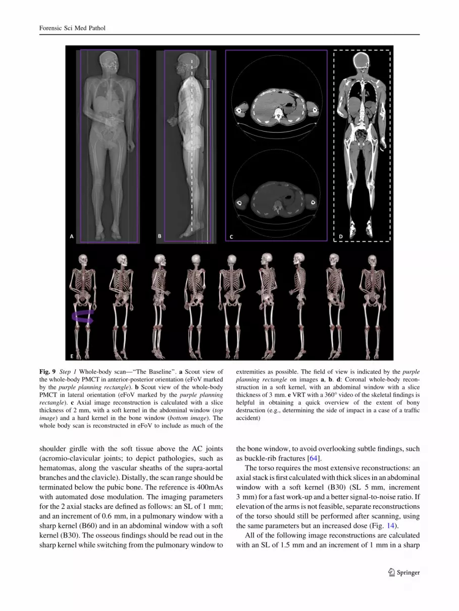
Fig. 9 Step 1 Whole-body scan—‘‘The Baseline’’. a Scout view of
the whole-body PMCT in anterior-posterior orientation (eFoV marked
by the purple planning rectangle). b Scout view of the whole-body
PMCT in lateral orientation (eFoV marked by the purple planning
rectangle). c Axial image reconstruction is calculated with a slice
thickness of 2 mm, with a soft kernel in the abdominal window (top
image) and a hard kernel in the bone window (bottom image). The
whole body scan is reconstructed in eFoV to include as much of the
extremities as possible. The field of view is indicated by the purple
planning rectangle on images a, b. d: Coronal whole-body recon-
struction in a soft kernel, with an abdominal window with a slice
thickness of 3 mm. e VRT with a 360� video of the skeletal findings is
helpful in obtaining a quick overview of the extent of bony
destruction (e.g., determining the side of impact in a case of a traffic
accident)
Forensic Sci Med Pathol
123
kernel (B70) with a bone window. Again, similar to the axial
3-dimensional reconstructed images of the cervical spine, a
small FoV is applied to the thoracic and lumbar spine. The
axial slices are aligned symmetrically to the intervertebral
disks, and they include the transverse process on both sides.
The sagittally aligned reconstruction is orthogradely centered
to the middle of the vertebrae and is aligned with the course of
the thoracic and lumbar spine, including the sacrum and os
coccygis. In cases of extensive scoliosis or vertebral disso-
ciation due to trauma, the thoracic spine and an extra lumbar
sagittal stack might require splitting. The coronal images
include the thoracic and lumbar spine and are centered sym-
metrically on the middle of the vertebra, including the com-
plete vertebral body with the spinous process. The sacrum and
os coccygis are included in the pelvic reconstruction. Thus, an
additional coronal reconstruction, with a small FoV of the
pelvis, is added. The FoV encompasses the complete, sym-
metrically aligned pelvis: the sacrum, the os coccygis, the
symphysis, the iliac and pubic bones and both femoral heads.
For a precise report of resuscitation-related injuries to the
sternum, a sagittal reconstruction is calculated, with a small
FoV centered on the middle of the manubrium, including both
lateral sides of the costosternal transition to the ribs that
proximally extends to the sternoclavicular joints (Fig. 14).
Special reconstruction parameters
For cases that feature dense foreign material, such as
projectiles, general metallic fragments, prostheses, and
osteosyntheses or even dental fillings (gold, amalgam), an
extended CT scale (not to be confused with an extended
FoV) is advisable to facilitate material differentiation. The
maximum width of the HU scale in a standard setting is -
1,024 to ?3,071 HU, which is usually sufficient for clinical
cases. In a forensic setting, a larger, extended HU width is
favorable and be obtained by multiplying the HU incre-
ment by a factor of 10 (-10,240 to ?30,710). However,
not every CT scanner is equipped with this unique feature
(activated simply by checking the dedicated box on the CT
reconstruction control panel under the reconstruction sec-
tion), and this fact should be taken into account when
considering the purchase of a new or used device for
forensic-radiological purposes [65–68].
In addition, badly decomposed bodies can present with
vast gas accumulations that are distributed depending on
the position in the whole body [38]. The window might
need to be adjusted for proper image analysis, and using a
medium soft kernel for image reconstruction might be
indicated for a better reporting [37, 38, 69–71].
Whole-body PMCT (\16 multidetector CT)
With dated scanners, the whole body often cannot be
scanned in a single pass because the radiation source,
namely the X-ray tube, was not designed to cover whole-
body scans, especially not repeatedly. However, so-called
outdated scanners are not necessarily precluded from
forensic use. For example, although a 6-slice scanner might
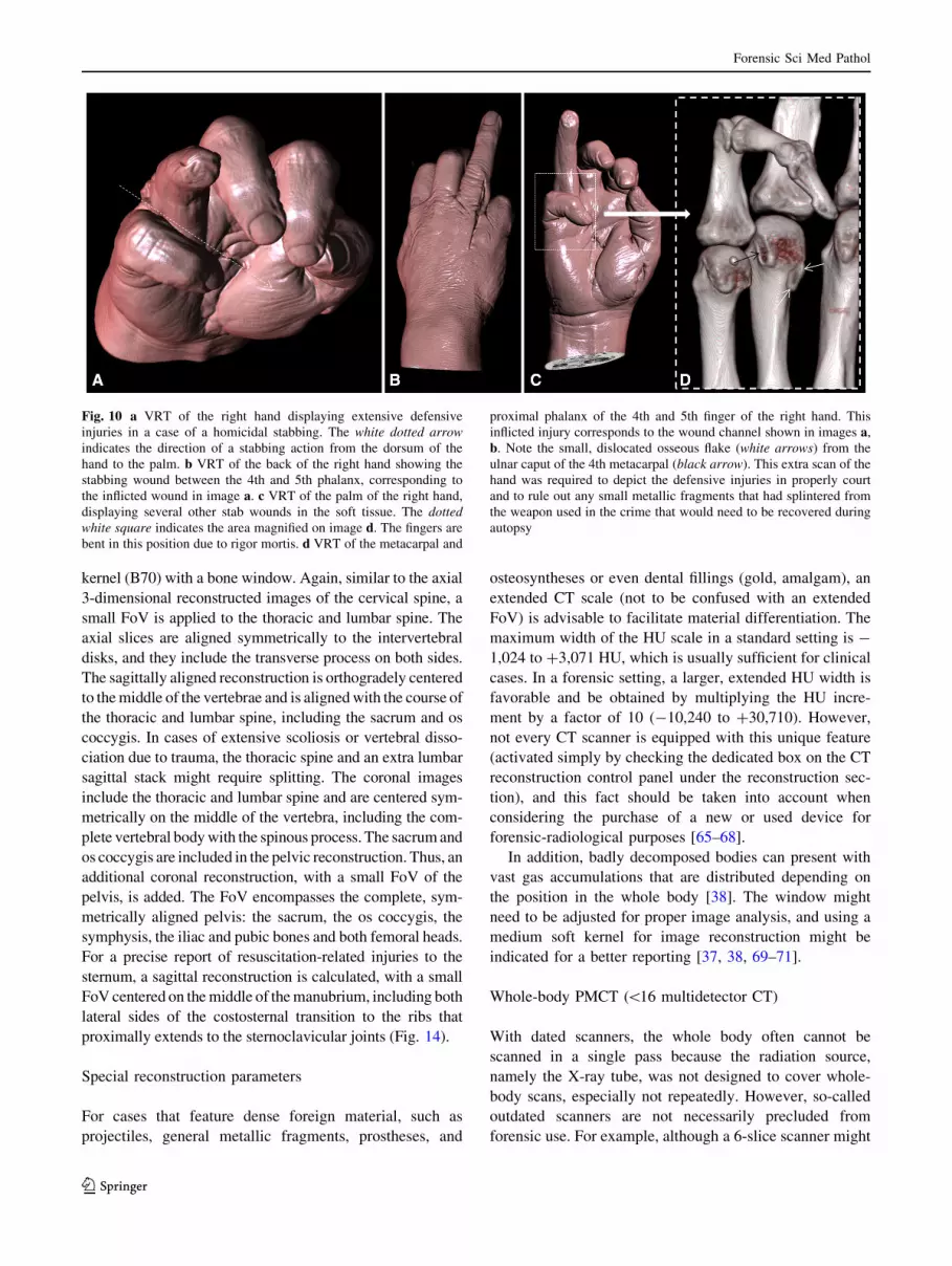
Fig. 10 a VRT of the right hand displaying extensive defensive
injuries in a case of a homicidal stabbing. The white dotted arrow
indicates the direction of a stabbing action from the dorsum of the
hand to the palm. b VRT of the back of the right hand showing the
stabbing wound between the 4th and 5th phalanx, corresponding to
the inflicted wound in image a. c VRT of the palm of the right hand,
displaying several other stab wounds in the soft tissue. The dotted
white square indicates the area magnified on image d. The fingers are
bent in this position due to rigor mortis. d VRT of the metacarpal and
proximal phalanx of the 4th and 5th finger of the right hand. This
inflicted injury corresponds to the wound channel shown in images a,
b. Note the small, dislocated osseous flake (white arrows) from the
ulnar caput of the 4th metacarpal (black arrow). This extra scan of the
hand was required to depict the defensive injuries in properly court
and to rule out any small metallic fragments that had splintered from
the weapon used in the crime that would need to be recovered during
autopsy
Forensic Sci Med Pathol
123
be considered outdated, these devices can offer a low-
priced alternative to newer clinical scanners for forensic
purposes. These refurbished CT suites currently cost the
same as fluoroscopy units. Financial considerations are the
primary incentive in forensics for buying a dated multi-
detector CT scanner, rather than a brand-new potent CT
that exceeds 16 slices.
Unfortunately, the scan length of such outdated machines
(1,500 mm) is usually restricted due to a short table run,
which does not cover the lower extremities. To include these
body parts in the whole-body scan, the body must be rotated
1808 on the CT couch, from the cranio-caudal position to
the caudo-cranial position. Another drawback of less pow-
erful scanners is the cooling time because these machines
often still use air-cooling and not water-cooling. This
complication results in longer scan times to cover the whole
body. To reduce the waiting time for cooling, short scan
ranges should be planned, i.e., the head, neck, thorax,
Fig. 11 Step 2 Head and neck scan. a Scout view of the head and
neck PMCT in anterior-posterior orientation (the small adjusted FoV
is marked by the purple planning rectangle). b Scout view of the head
and neck PMCT in lateral orientation (the small adjusted FoV is
marked by the purple planning rectangle, and the white square
indicates the orbito-meatal reconstruction FoV). c The axial slices
(corresponding to the purple planning rectangle) are reconstructed in
a small field of view, including the head and neck. Both axial data sets
are acquired in a cerebral window with a soft kernel and a bone
window with a hard kernel in 0.6 mm slice thickness. Note the typical
postmortem loss of cortico-medullary differentiation between the
white and gray matter and the intracranial hemorrhage. d Symmetri-
cally and orbito-meatally aligned (dotted white line) reconstruction of
the head (corresponding to the white square on image b) is calculated
in a cerebral window in a soft kernel in 4 and 0.6 mm slice
thicknesses, respectively. An additional stack in an osseous window
with a sharp kernel, in 0.6 mm slice thickness, is performed. Note the
typical inward beveling of the entry wound of a gunshot to the head
(best seen on the bone window) and the pneumencephalon. e This
image displays an optional VRT (left image) with a cut plane along
the trajectory of a gunshot wound to the head. The entry wound is in
the median occipital location, with a corresponding defect in the front
parietal bone. However, this case shows a lodged projectile (colored
in light blue) along the wound channel that did not perforate but that
penetrated. Typical findings include the scattered osseous fragments
along the trajectory, with little metallic abrasion of the projectile
(right image, thick multiplanar reconstruction)
Forensic Sci Med Pathol
123
abdomen, proximal lower extremities, and distal lower
extremities should all be scanned separately [38]. Moreover,
the planned scan areas should not overlap (but should be
exactly planned without any loss of information between the
adjacent scan ranges) to later compose a virtual whole-body
scan by merging the scanned volume rendered images into a
single complete full-body scan (using image processing
software). If the separate scan has the same FoV and center,
the images can be composed directly at the CT workstation.
Pitch factor alterations result in obligatory manual adaption
of the milliampere level with older scanners, in which they
differ from newer scanners. With current CT scanners, the
milliampere level is automatically adjusted if the pitch
factor increases [72].
Moreover, the bore diameter frequently does not exceed
70 cm, which concomitantly reduces the image information of
the soft tissue and the extremities in cases of obese or rigidly
positioned bodies, of which a CT scan is almost impossible.
The scanning protocol should be adjusted from the
above-described recommended protocol by slightly thick-
ening the SL to 2–3 mm (and eventually up to 5 mm),
halving the SL increment, increasing the pitch, lowering the
milliampere level and occasionally changing the kilovolt
level to only 100 or even 80, if necessary. These changes are
justified by the aforementioned technical limitations. The
torso should still be scanned once with lowered arms and
again with elevated arms to reduce artifacts.
Add-on to PMCT protocol: high-resolution scans
Dental
Dental identification requires scanning parameters with
high spatial resolution to reconstruct precise images from
the CT data set for antemortem X-ray comparison [73, 74].
The planning on the magnified scout view includes the base
of the maxillary sinus, and it ends distally at the mandible.
The FoV (usually approximately 240 mm) terminates
behind the temporo-mandibular joints and includes the
complete maxilla and mandible. Doing so reliably includes
the root canals with their distinct morphology, in addition
to the teeth and their potential dental work for later iden-
tification (Fig. 15). The imaging parameters are defined as
follows: 120 kV, a reference of 800mAs, a pitch factor of
0.35, a rotation time of 1 s, an SL of 0.4 mm, and an
increment of 0.2 mm with a hard kernel (U70) in a dental
window. For extended CT scale reconstructions, the pro-
vided reconstruction parameters should simply be acti-
vated, and the box for the extended CT scale should be
clicked (as described above). Only 1 aligned reconstruction
in an axial plane must be made with the 3-dimensional
reconstruction tool. The teeth and temporo-mandibular
joints should be aligned orthogonally and symmetrically.
This alignment is usually sufficient for single-tooth ante-
mortem X-ray comparison. However, a curved multiplanar
reconstruction is required to create a ‘‘virtual’’ orthopan-
tomogram (OPT), similar to antemortem OPTs of the
complete jaw (Fig. 15).
Larynx
Laryngeal scans are necessary when trauma to the neck is
suspected, e.g., strangulation [75]. The images are always
reported on axial slices, but the complex anatomy of the
hyoid bone and the thyroid cartilage, with its variable
anatomy, frequent anomalies and age-dependent stages of
ossification, especially of the cornu, call for the
3-dimensional volume rendering technique (VRT)
Fig. 12 a Axial slices are reconstructed in a large field of view. Note the decreased image quality, compared to image reconstruction with a
small FoV (b). b Small, adjusted FoV with a maximum of 300 mm for better image quality
Forensic Sci Med Pathol
123
(Fig. 16) [38, 75]. VRT allows for the easily under-
standable display of buckled or even fractured parts of the
larynx, in correlation with the axial slices. The imaging
parameters are similar to the dental scan and are recon-
structed with a medium soft kernel (U40) in a bony
window. The medium soft kernel is necessary to reduce
the noise for later VRT. Using a sharp kernel will result in
too much noise.
Again, the FoV must be adjusted only to include the
complete hyoid bone, the thyroid and the cricoid cartilage.
When the images are acquired non-symmetrically, an
additional 3-dimensional axial reconstruction might be
necessary.
General PMCTA protocol
The PMCTA procedure has already been precisely
described in the recent literature [45–52]. Thus, this section
only concerns the actual scanning parameters of PMCTA
(Table 3).
A scout view must be obtained from the head to the
middle of the upper parts of the lower extremities (which
should always include the mostly femoral cannulations for
contrast administration). Again, the proper positioning of
the body is crucial. Other than in the described unenhanced
protocol, a kilovolt level of only 100 is used for better
iodine contrast. The automated dose modulation is not used
Fig. 13 Step 2 Head and neck scan. a Scout view of the head and
neck PMCT in anterior-posterior orientation (the small adjusted FoV
is marked by the purple planning rectangle). b Scout view of the head
and neck PMCT in lateral orientation (the small adjusted FoV is
marked by the purple planning rectangle). The blue lines in images a,
b indicate the orientation of the axial reconstruction (c), the red line
indicates the orientation of the sagittal reconstruction (d), and the
green line indicates the orientation of the coronal reconstruction (e).
c Axial, 3-dimensional, correctly aligned reconstruction of the
cervical spine (marked in blue). d Sagittal, 3-dimensional, correctly
aligned reconstruction of the cervical spine (marked in red).
e Coronal, 3-dimensional, correctly aligned reconstruction of the
cervical spine (marked in green). Images c–e are calculated in
1.5 mm slice thickness in a bone window with a sharp kernel
Forensic Sci Med Pathol
123
Forensic Sci Med Pathol
123
for PMCTA. The following settings are effective: 350mAs;
a pitch factor of 0.35; and a rotation time of 0.5 s.
Usually, arterial injection is the first ‘‘contrast phase’’
that should be scanned after administration, except when
venous pathologies (e.g., laceration of the caval vein) or
pulmonary thrombembolisms are strongly suspected. In
these cases, venous injection should precede arterial
injection to display the pulmonary trunk better. After the
required contrast volume is administered, the scan should
be performed as quickly as possible, while still slowly
injecting small volumes during the scans to maintain the
distension of the vascular lumen.
If the planning of the scan or adjustments of the arms takes
too long, more contrast media mixture (between 500 ml and
1000 ml) can be injected according to the habitus.
Step 1: Arterial PMCTA
A spiral is scanned from the head to the thighs (including
the femoral accesses) with lowered arms. The head and
neck are then separately axially reconstructed (using the
3-dimensional reconstruction tool with correct alignments)
from the raw data, with an SL of 1 mm and an increment
of 0.5 mm in a medium soft kernel (B26) in an angio
window. The complete data set of the head and neck,
thorax and abdomen (including the upper extremities) is
reconstructed in a medium soft (B26) and sharp heart
view (B46) kernel, with both a CT angio window with the
same parameters as the head and neck in an eFoV
(Fig. 17).
Step 2: Arterial PMCTA
The upper extremities then must be elevated immediately
to improve the image quality of the torso. This scan only
includes the thorax and abdomen, with the same imaging
and reconstruction parameters as mentioned above
(Fig. 17). If the right coronary artery or the heart chambers
are insufficiently filled, the body should be turned to a
prone position to be re-injected prior to scanning. In this
manner, the problem of gravity can be overcome, and even
the right coronary artery should be nicely distended with
contrast media mixture (if no pathology or cruor is
present).
Step 3: Venous PMCTA
The arms should remain elevated, and the cannulation
connection should be changed from the arterial to the
venous injection site. The next scan is performed directly
after injection of the contrast media mixture. The param-
eters are similar to those of step 2 (Fig. 17).
Step 4: Venous PMCTA
The upper extremities should now be lowered again for a
scan similar to step 1, to obtain proper images of the head
(Fig. 17).
Clearly, additional separate scans can be supplemented,
e.g., focused scanning of the hand and wrist in the case of
an inflicted wound to the radial arteries with extravasation
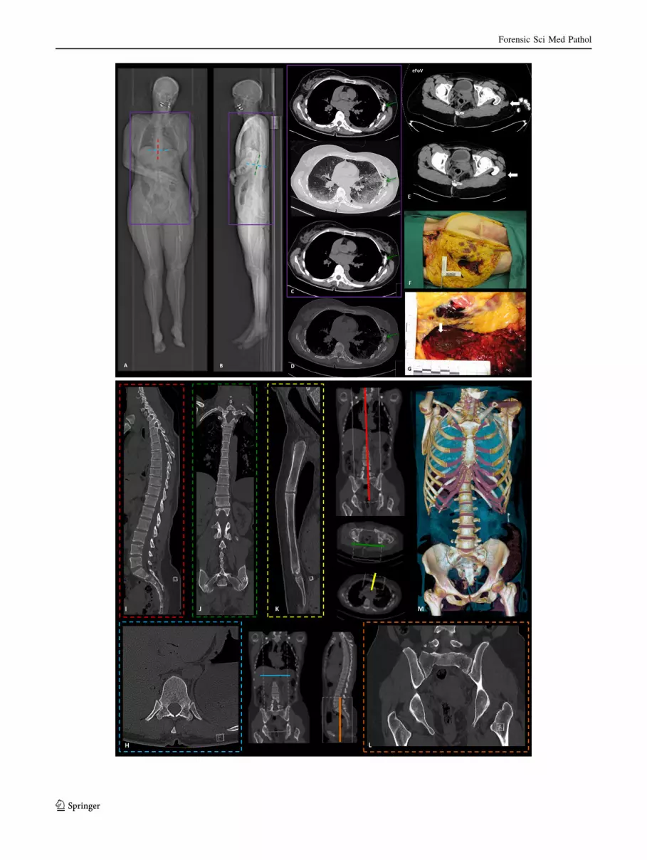
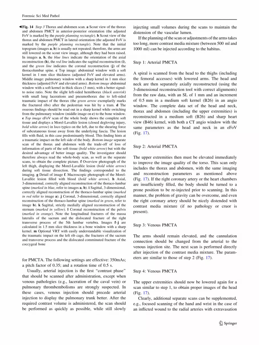
b Fig. 14 Step 3 Thorax and abdomen scan. a Scout view of the thorax
and abdomen PMCT in anterior-posterior orientation (the adjusted
FoV is marked by the purple planning rectangle). b Scout view of the
thorax and abdomen PMCT in lateral orientation (the adjusted FoV is
marked by the purple planning rectangle). Note that the initial
topogram (images a, b) is usually not repeated; therefore, the arms are
still lowered on the scout view image, although they had been raised.
In images a, b, the blue lines indicate the orientation of the axial
reconstruction (h), the red line indicates the sagittal reconstruction (i),and the green line indicates the coronal reconstruction (j) of the
thoracolumbar spine. c Top image: abdominal window with a soft
kernel in 1 mm slice thickness (adjusted FoV and elevated arms).
Middle image: pulmonary window with a sharp kernel in 1 mm slice
thickness (adjusted FoV and elevated arms). Bottom image abdominal
window with a soft kernel in thick slices (3 mm), with a better signal-
to noise ratio. Note the slight left-sided hemithorax (black asterisk)
with small lung lacerations and pneumothorax due to left-sided
traumatic impact of the thorax (the green arrow exemplarily marks
the fractured ribs) after the pedestrian was hit by a tram. d The
osseous findings should be read out in a sharp kernel while switching
from the pulmonary window (middle image on c) to the bone window.
e Top image eFoV scan of the whole body shows the complete soft
tissue and displays a Morel-Lavallee lesion (closed degloving injury,
bold white arrow) in loco typico on the left, due to the shearing force
of subcutaneous tissue away from the underlying fascia. The lesion
fills with fluid, in this case predominantly blood. This finding hints at
a traumatic impact on the left side of the body. Bottom image separate
scan of the thorax and abdomen with the trade-off of loss of
information of parts of the soft tissue (bold white arrow) but with the
desired advantage of better image quality. The investigator should
therefore always read the whole-body scan, as well as the separate
scans, to obtain the complete picture. f Overview photograph of the
left thigh, displaying the Morel-Lavallee lesion (bold white arrow)
during soft tissue dissection. The findings corresponded to the
imaging. g Detail of image f. Macroscopic photograph of the Morel-
Lavallee lesion filled with blood (bold white arrow). h Axial,
3-dimensional, correctly aligned reconstruction of the thoraco-lumbar
spine (marked in blue, refer to images a, b). i Sagittal, 3-dimensional,
correctly aligned reconstruction of the thoraco-lumbar spine (marked
in red refer to image a). j Coronal, 3-dimensional, correctly aligned
reconstruction of the thoraco-lumbar spine (marked in green, refer to
image b). k Sagittal, strictly medially aligned reconstruction of the
sternum (marked in yellow). l Coronal reconstruction of the pelvis
(marked in orange). Note the longitudinal fractures of the massa
lateralis of the sacrum and the dislocated fracture of the right
transverse process of the 5th lumbar vertebra. Images f–j are
calculated in 1.5 mm slice thickness in a bone window with a sharp
kernel. m Optional VRT with easily understandable visualization of
the traumatic impact on the left rib cage, the fractures of the sacrum
and transverse process and the dislocated comminuted fracture of the
coccygeal bone
Forensic Sci Med Pathol
123
from the vascular injury or focused scanning of the lower
extremities in cases such as a shot through the femoral
bone and adjacent vasculature.
General pediatric PMCT protocol
Imaging of a pediatric collective requires an adjusted
protocol due to the smaller scanning subject and can be
adjusted as follows [76, 77]: the body preparation and scout
view are similar to the adult protocol, employing a whole-
body scan with lowered upper extremities. Table 4 sum-
marizes the comprehensive pediatric PMCT protocol.
Step 1: Whole-body scan
In infants and neonates, the tube voltage in all scans is
120 kV (can be increased to 140 kV in neonates) with
automated dose modulation (the reference is 1000mAs for
the whole-body scan). If the scanner does not allow for
such a high reference level, or if it is not equipped with
automated dose modulation, the protocol should be tailored
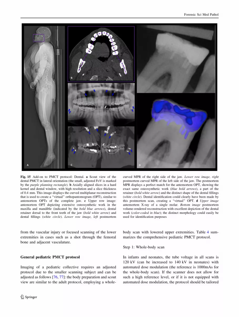
Fig. 15 Add-on to PMCT protocol: Dental. a Scout view of the
dental PMCT in lateral orientation (the small, adjusted FoV is marked
by the purple planning rectangle). b Axially aligned slices in a hard
kernel and dental window, with high resolution and a slice thickness
of 0.4 mm. This image displays the curved multiplanar reconstruction
that is used to create a ‘‘virtual’’ orthopantomogram (OPT), similar to
antemortem OPTs of the complete jaw. c Upper row image:
antemortem OPT depicting extensive osteosynthetic work in the
maxilla and mandible (indicated by the bold blue arrows), dental
retainer dorsal to the front teeth of the jaw (bold white arrow) and
dental fillings (white circle). Lower row image, left postmortem
curved MPR of the right side of the jaw. Lower row image, right
postmortem curved MPR of the left side of the jaw. The postmortem
MPR displays a perfect match for the antemortem OPT, showing the
exact same osteosynthetic work (blue bold arrows), a part of the
retainer (bold white arrow) and the distinct shape of the dental fillings
(white circle). Dental identification could clearly have been made by
this postmortem scan, creating a ‘‘virtual’’ OPT. d Upper image
antemortem X-ray of a single molar. Bottom image postmortem
volume-rendered reconstruction with excellent depiction of the dental
work (color-coded in blue); the distinct morphology could easily be
used for identification purposes
Forensic Sci Med Pathol
123
to 120 kV and 250mAs. The rotation time is 0.5 s with a
pitch of 0.6. The scan range should include the whole body,
from the vertex to the toes.
The axial images are reconstructed with a SL of 0.6 mm
(increment 0.4 mm) in a medium soft kernel (B25) with a
baby abdominal window and in a medium sharp kernel
(B50) in a bony window. The FoV must be adjusted
(neonates, e.g., 240 mm) to include the extremities.
Step 2: Head and neck
The whole-body scan is then followed by a separate head
and neck scan. The tube voltage remains unchanged, but
the reference is increased to 2,000mAs to obtain quality
images of the head. The rotation time, SL and increment
are the same as in step 1. The pitch factor is changed to
0.35. Axial images (including the head and the neck, as
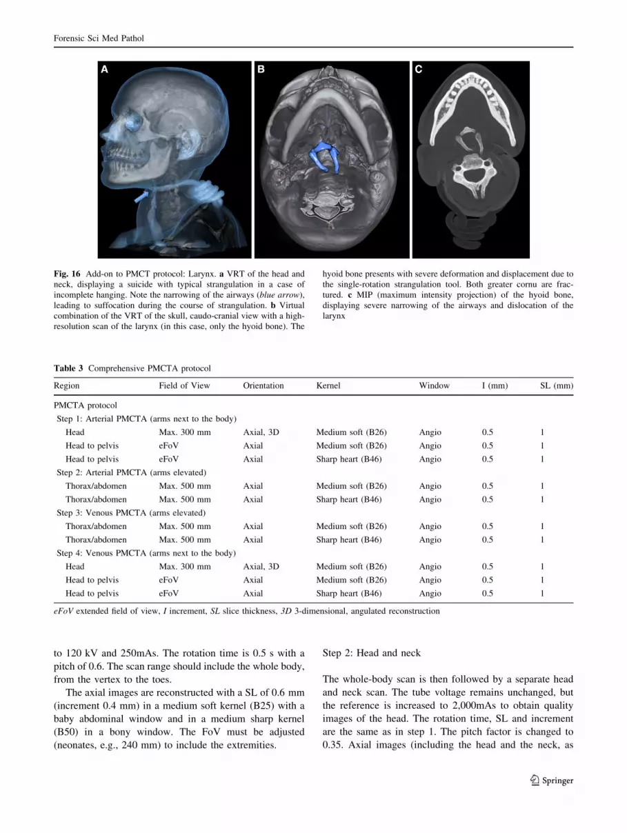
Fig. 16 Add-on to PMCT protocol: Larynx. a VRT of the head and
neck, displaying a suicide with typical strangulation in a case of
incomplete hanging. Note the narrowing of the airways (blue arrow),
leading to suffocation during the course of strangulation. b Virtual
combination of the VRT of the skull, caudo-cranial view with a high-
resolution scan of the larynx (in this case, only the hyoid bone). The
hyoid bone presents with severe deformation and displacement due to
the single-rotation strangulation tool. Both greater cornu are frac-
tured. c MIP (maximum intensity projection) of the hyoid bone,
displaying severe narrowing of the airways and dislocation of the
larynx
Table 3 Comprehensive PMCTA protocol
Region Field of View Orientation Kernel Window I (mm) SL (mm)
PMCTA protocol
Step 1: Arterial PMCTA (arms next to the body)
Head Max. 300 mm Axial, 3D Medium soft (B26) Angio 0.5 1
Head to pelvis eFoV Axial Medium soft (B26) Angio 0.5 1
Head to pelvis eFoV Axial Sharp heart (B46) Angio 0.5 1
Step 2: Arterial PMCTA (arms elevated)
Thorax/abdomen Max. 500 mm Axial Medium soft (B26) Angio 0.5 1
Thorax/abdomen Max. 500 mm Axial Sharp heart (B46) Angio 0.5 1
Step 3: Venous PMCTA (arms elevated)
Thorax/abdomen Max. 500 mm Axial Medium soft (B26) Angio 0.5 1
Thorax/abdomen Max. 500 mm Axial Sharp heart (B46) Angio 0.5 1
Step 4: Venous PMCTA (arms next to the body)
Head Max. 300 mm Axial, 3D Medium soft (B26) Angio 0.5 1
Head to pelvis eFoV Axial Medium soft (B26) Angio 0.5 1
Head to pelvis eFoV Axial Sharp heart (B46) Angio 0.5 1
eFoV extended field of view, I increment, SL slice thickness, 3D 3-dimensional, angulated reconstruction
Forensic Sci Med Pathol
123
well as the 1st thoracic vertebra) are reconstructed in a
medium soft (H31) kernel with a baby brain window and a
medium sharp (H50) kernel with a bony window. Both of
these spirals are also calculated using the 3-dimensional
multiplanar reconstruction tool with proper symmetric
alignment and orbitomeatal orientation. For noise
reduction, an additional similarly aligned 3-dimensional
stack of the head should be calculated with a 2 mm SL and
an increment of 1 mm, in a medium soft kernel (H31) with
a baby brain window. The cervical spine is again calculated
(similar to the adult PMCT protocol) in a small, adjusted
FoV (e.g., 50 9 50 mm), with an orientation aligned to the
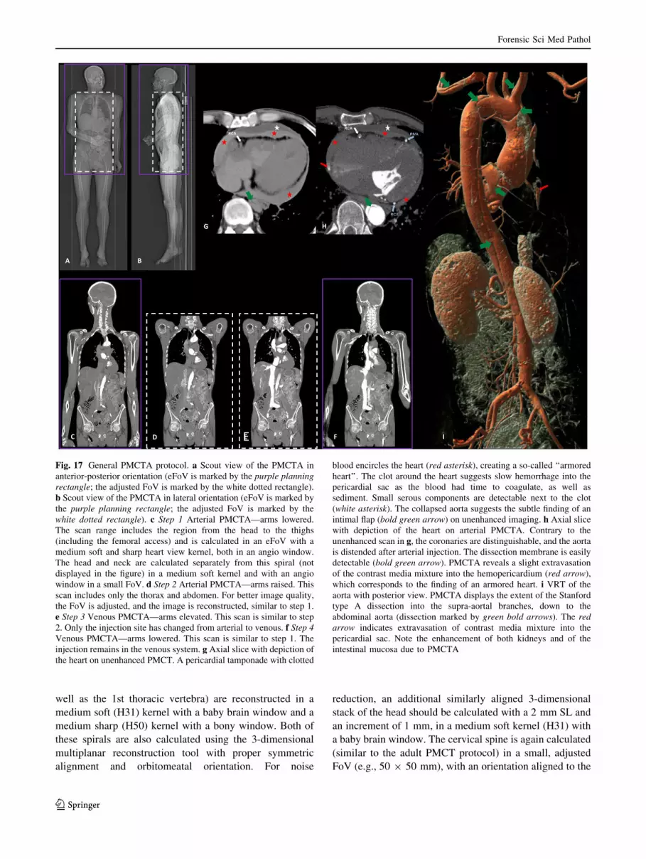
Fig. 17 General PMCTA protocol. a Scout view of the PMCTA in
anterior-posterior orientation (eFoV is marked by the purple planning
rectangle; the adjusted FoV is marked by the white dotted rectangle).
b Scout view of the PMCTA in lateral orientation (eFoV is marked by
the purple planning rectangle; the adjusted FoV is marked by the
white dotted rectangle). c Step 1 Arterial PMCTA—arms lowered.
The scan range includes the region from the head to the thighs
(including the femoral access) and is calculated in an eFoV with a
medium soft and sharp heart view kernel, both in an angio window.
The head and neck are calculated separately from this spiral (not
displayed in the figure) in a medium soft kernel and with an angio
window in a small FoV. d Step 2 Arterial PMCTA—arms raised. This
scan includes only the thorax and abdomen. For better image quality,
the FoV is adjusted, and the image is reconstructed, similar to step 1.
e Step 3 Venous PMCTA—arms elevated. This scan is similar to step
2. Only the injection site has changed from arterial to venous. f Step 4
Venous PMCTA—arms lowered. This scan is similar to step 1. The
injection remains in the venous system. g Axial slice with depiction of
the heart on unenhanced PMCT. A pericardial tamponade with clotted
blood encircles the heart (red asterisk), creating a so-called ‘‘armored
heart’’. The clot around the heart suggests slow hemorrhage into the
pericardial sac as the blood had time to coagulate, as well as
sediment. Small serous components are detectable next to the clot
(white asterisk). The collapsed aorta suggests the subtle finding of an
intimal flap (bold green arrow) on unenhanced imaging. h Axial slice
with depiction of the heart on arterial PMCTA. Contrary to the
unenhanced scan in g, the coronaries are distinguishable, and the aorta
is distended after arterial injection. The dissection membrane is easily
detectable (bold green arrow). PMCTA reveals a slight extravasation
of the contrast media mixture into the hemopericardium (red arrow),
which corresponds to the finding of an armored heart. i VRT of the
aorta with posterior view. PMCTA displays the extent of the Stanford
type A dissection into the supra-aortal branches, down to the
abdominal aorta (dissection marked by green bold arrows). The red
arrow indicates extravasation of contrast media mixture into the
pericardial sac. Note the enhancement of both kidneys and of the
intestinal mucosa due to PMCTA
Forensic Sci Med Pathol
123
facet joints on the axial plane. This FoV is centered on the
ossification center of the dens and the middle of the ver-
tebral column (FoV, e.g., 50 9 73 mm) on the sagittal
plane; with coronal orientation (FoV, e.g., 50 9 63 mm),
including the foramen magnum on the proximal side and
the 1st thoracic vertebra on the distal side, as well as both
sides of the transverse and spinous process on the posterior
side. The images are reconstructed with a medium sharp
kernel (H50) in a bony window with a SL of 0.6 mm and
an increment of 0.4 mm.
Step 3: Thorax and abdomen
The arms should now be elevated, if possible. The rotation
time and pitch remain unchanged from step 2. The refer-
ence for the torso is 800mAs. An axial spiral in a medium
soft kernel (B25), with an abdomen window and a sharp
kernel (B60) with a lung window, is calculated using a
0.6 mm SL and an increment of 0.4 mm. According to the
reconstructions of the adult thoracic and lumbar spine, a
small adjusted FoV, with symmetric orientation to the facet
joints, is reconstructed in the 3-dimensional multiplanar
reconstruction tool, in a medium sharp (B50) kernel with a
bony window. The same settings apply for the thoracic and
lumbar spine (including the os coccigys) in the coronal and
sagittal orientation. The last reconstruction includes the
pelvis (according to the borders of the FoV as described in
the adult PMCT protocol). These images are reconstructed
with a SL of 0.6 mm, an increment of 0.4 mm, and an
adjusted FoV with a sharp kernel (B60) in a bony window.
The lower limbs are already included in the whole-body
scanning protocol and are usually not reconstructed sepa-
rately, except for special requests. Children with an
approximate age older than 6 years old might already
undergo the adult PMCT protocol, according to the habitus.
General pediatric PMCTA protocol
The technical settings of the pediatric PMCTA protocol are
similar to those of the adult PMCTA protocol. However,
cannulation of the vessels is more cumbersome, and a
smaller diameter of vascular access is needed. In addition,
the volume of injected contrast media mixture clearly must
be adapted to the habitus of the child.
Conclusion and future directions
PMCT and even PMCTA are radiological modalities that
have been adopted in morgues worldwide recently and that
will certainly increase over the coming years [12–36]. In
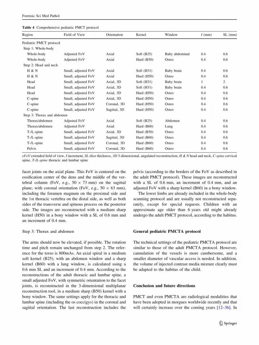
Table 4 Comprehensive pediatric PMCT protocol
Region Field of View Orientation Kernel Window I (mm) SL (mm)
Pediatric PMCT protocol
Step 1: Whole-body
Whole-body Adjusted FoV Axial Soft (B25) Baby abdominal 0.4 0.6
Whole-body Adjusted FoV Axial Hard (B50) Osteo 0.4 0.6
Step 2: Head and neck
H & N Small, adjusted FoV Axial Soft (H31) Baby brain 0.4 0.6
H & N Small, adjusted FoV Axial Hard (H50) Osteo 0.4 0.6
Head Small, adjusted FoV Axial, 3D Soft (H31) Baby brain 1 2
Head Small, adjusted FoV Axial, 3D Soft (H31) Baby brain 0.4 0.6
Head Small, adjusted FoV Axial, 3D Hard (H50) Osteo 0.4 0.6
C-spine Small, adjusted FoV Axial, 3D Hard (H50) Osteo 0.4 0.6
C-spine Small, adjusted FoV Coronal, 3D Hard (H50) Osteo 0.4 0.6
C-spine Small, adjusted FoV Sagittal, 3D Hard (H50) Osteo 0.4 0.6
Step 3: Thorax and abdomen
Thorax/abdomen Adjusted FoV Axial Soft (B25) Abdomen 0.4 0.6
Thorax/abdomen Adjusted FoV Axial Hard (B60) Lung 0.4 0.6
T-/L-spine Small, adjusted FoV Axial, 3D Hard (B50) Osteo 0.4 0.6
T-/L-spine Small, adjusted FoV Sagittal, 3D Hard (B60) Osteo 0.4 0.6
T-/L-spine Small, adjusted FoV Coronal, 3D Hard (B60) Osteo 0.4 0.6
Pelvis Small, adjusted FoV Coronal, 3D Hard (B60) Osteo 0.4 0.6
eFoV extended field of view, I increment, SL slice thickness, 3D 3-dimensional, angulated reconstruction, H & N head and neck, C-spine cervical
spine, T-/L-spine thoracic and lumbar spine
Forensic Sci Med Pathol
123
addition, the cross-sectional method of CT will certainly
supersede X-ray imaging of the deceased, which is still in
use in other institutions, e.g., for the localization of bullets
or the imaging of fracture patterns, which are usually
performed by preparers or morgue technicians [24]. As the
field of radiology continues to develop, other modalities,
such as PMMR and PMMRA, will find their way into
standard procedures in more than a few forensic institu-
tions, and these modalities will require trained personnel,
including radiological technicians, radiologists or radio-
logical trained forensic pathologists. These new technolo-
gies should not be left in the hands of poorly radiological
trained staff, not only with regard to image quality and
standards but also regarding medico-legal requirements.
Therefore, standards must be established for postmortem
imaging. A new society that was recently formed (ISFRI,
the International Society of Forensic Radiology and
Imaging) addresses this issue as one of its goals and to
generate quality standards and curricula for forensic radi-
ology [78]. In the future, such societies will hopefully act
as a base for the further international implementation of
guidelines and standards in forensic imaging.
Future directions in forensic radiology will clearly adopt
even more sophisticated and interdisciplinary approaches as
standard procedures in selected cases, such as molecular
imaging (spectroscopy, diffusion weighted imaging), micro-
CT/MR, image-guided biopsy, robot-guided biopsy, photo-
grammetry, and surface scanning [13, 14, 79–87]. Such pro-
cedures will intensify the need for high-quality standards. In
addition, other medical disciplines, such as pathology, with
clinical autopsies could even adopt imaging into their work-
flow to improve pathological diagnoses. This approach might
even improve the quality of clinical treatment [17, 18, 88].
This article should facilitate the implementation of high-
quality protocols in morgues, associated hospitals or pri-
vate practices that perform forensic scans. This protocol
could also facilitate proper reporting and standards similar
to those for clinical scans used in courts.
Key points
1. Postmortem imaging is a new radiological subspe-
cialty, and unlike diagnostic radiology, it does not yet
have established standards.
2. Clinical and postmortem radiology differ significantly
in several aspects: imaging parameters can be adjusted
to maximize image quality and the indications in
forensic medicine are typically different from those in
clinical radiology.
3. Forensic radiology’s goals are to detect the cause of
death and to generate insights into the deceased’s
mortal circumstances.
4. This article outlines the main approach for a recom-
mended standard protocol for postmortem cross-sec-
tional imaging, focusing on unenhanced PMCT and
PMCTA.
References
1. Baglivo M, Winklhofer S, Hatch GM, Ampanozi G, Thali MJ,
Ruder TD. The rise of forensic and post-mortem radiology—
analysis of the literature between the year 2000 and 2011. JOFRI.
2013;1:3–9.
2. Brogdon BG. Forensic radiology in historical perspective. In:
Thali MJ, Viner M, Brogdon BG, editors. Brogdon’s forensic
radiology. 2nd ed. Boca Raton: CRC Press; 2010. p. 3–7.
3. O’Donnell C, Woodford N. Post-mortem radiology—a new sub-
speciality? Clin Radiol. 2008;63:1189–94.
4. Rutty GN, Morgan B, O’Donnell C, Leth PM, Thali M. Forensic
institutes across the world place CT or MRI scanners or both into
their mortuaries. J Trauma. 2008;65:493–4.
5. Wullenweber R, Schneider V, Grumme T. A computer-tomo-
graphical examination of cranial bullet wounds (author’s transl).
Z Rechtsmed. 1977;80(3):227–46.
6. Levy AD, Harcke TH. Essentials of forensic imaging: a text-atlas.
1st ed. Boca Raton: CRC Press; 2010.
7. Brogdon BG, editor. Forensic radiology. 1st ed. Boca Raton:
CRC Press LCC; 1998.
8. Thali MJ, Viner MD, Brogdon BG. Brogdon’s forensic radiology.
2nd ed. Boca Raton: CRC Press; 2010.
9. Folio LR. Combat radiology: diagnostic imaging of blast and
ballistic injuries. 1st ed. New York: Springer; 2010.
10. Burke MP. Forensic pathology of fractures and mechanisms of
injury: postmortem CT scanning. 1st ed. Boca Raton: CRC Press;
2011.
11. Brogdon BG, Vogel H, McDowell JDA. Radiologic atlas of
abuse, torture, terrorism, and inflicted Trauma. 1st ed. Boca
Raton: CRC Press; 2003.
12. Thali MJ, Dirnhofer R, Vock P. The virtopsy approach: 3D
optical and radiological scanning and reconstruction in forensic
medicine. 1st ed. Boca Raton: CRC Press; 2009.
13. Thali MJ, Jackowski C, Oesterhelweg L, Ross SG, Dirnhofer R.
VIRTOPSY—the Swiss virtual autopsy approach. Leg Med
(Tokyo). 2007;9(2):100–4.
14. Thali MJ, Yen K, Schweitzer W, Boesch C, Ozdoba C, Schroth
G, Ith M, Sonnenschein M, Doernhoefer T, Scheurer E, Plattner
T, Dirnhofer R. Virtopsy a new imaging horizon in forensic
pathology: virtual autopsy by postmortem multislice computed
tomography (MSCT) and magnetic resonance imaging (MRI)—a
feasibility study. J Forensic Sci. 2003;48:386–403.
15. The Virtopsy Project. http://www.virtopsy.com. Accessed 1 June
2013.
16. Pollanen MS, Woodford N. Virtual autopsy: time for a clinical
trial. Forensic Sci Med Pathol. 2013;9(3):427–8.
17. Wichmann D, Obbelode F, Vogel H, Hoepker WW, Nierhaus A,
Braune S, Sauter G, Pueschel K, Kluge S. Virtual autopsy as an
alternative to traditional medical autopsy in the intensive care unit:
a prospective cohort study. Ann Intern Med. 2012;156(2):123–30.
18. Westphal SE, Apitzsch J, Penzkofer T, Mahnken AH, Knuchel R.
Virtual CT autopsy in clinical pathology: feasibility in clinical
autopsies. Virchows Arch. 2012;461(2):211–9.
19. Scandurra I, Forsell C, Ynnerman A, Ljung P, Lundstrom C,
Persson A. Advancing the state-of-the-art for Virtual Autopsies–
initial forensic workflow study. Stud Health Technol Inform.
2010;160(Pt 1):639–43.
Forensic Sci Med Pathol
123
20. Blaauwgeers JL, van Rijn RR. Virtual autopsy–why not? Ned
Tijdschr Geneeskd. 2012;156(19):A4786.
21. Persson A, Lindblom M, Jackowski C. A state-of-the-art pipeline
for postmortem CT and MRI visualization: from data acquisition
to interactive image interpretation at autopsy. Acta Radiol.
2011;52(5):522–36.
22. Levy AD, Abbott RM, Mallak CT, Getz JM, Harcke HT,
Champion HR, Pearse LA. Virtual autopsy: preliminary experi-
ence in high-velocity gunshot wound victims. Radiology.
2006;240(2):522–8.
23. Levy AD, Harcke HT, Getz JM, Mallak CT, Caruso JL, Pearse L,
Frazier AA, Galvin JR. Virtual autopsy: two- and three-dimen-
sional multidetector CT findings in drowning with autopsy
comparison. Radiology. 2007;243(3):862–8.
24. Harcke HT, Levy AD, Abbott RM, Mallak CT, Getz JM,
Champion HR, Pearse L. Autopsy radiography: digital radio-
graphs (DR) vs multidetector computed tomography (MDCT) in
high-velocity gunshot-wound victims. Am J Forensic Med
Pathol. 2007;28(1):13–9.
25. Daly B, Abboud S, Ali Z, Sliker C, Fowler D. Comparison of
whole-body post mortem 3D CT and autopsy evaluation in
accidental blunt force traumatic death using the abbreviated
injury scale classification. Forensic Sci Int. 2013;225(1–3):20–6.
26. Takahashi N, Higuchi T, Shiotani M, Hirose Y, Shibuya H,
Yamanouchi H, Hashidate H, Funayama K. The effectiveness of
postmortem multidetector computed tomography in the detection
of fatal findings related to cause of non-traumatic death in the
emergency department. Eur Radiol. 2012;22(1):152–60.
27. Shiotani S, Kobayashi T, Hayakawa H, Kikuchi K, Kohno M.
Postmortem pulmonary edema: a comparison between immediate
and delayed postmortem computed tomography. Leg Med
(Tokyo). 2011;13(3):151–5.
28. Roberts IS, Benamore RE, Benbow EW, Lee SH, Harris JN,
Jackson A, Mallett S, Patankar T, Peebles C, Roobottom C, Traill
ZC. Post-mortem imaging as an alternative to autopsy in the
diagnosis of adult deaths: a validation study. Lancet. 2012;379:
136–42.
29. O’Donnell CJ, Woodford N. Imaging the dead. Can supplement
but not replace autopsy in medicolegal death investigation. BMJ.
2010;341:c7415.
30. Capuani C, Guilbeau-Frugier C, Dedouit F, Rouge D, Delisle
MB, Telmon N. Forensic scientist’s implication regarding med-
ical autopsies: experience in a French university hospital (CHU
Toulouse). Ann Pathol. 2013;33(2):87–92.
31. Leth PM. Computerized tomography used as a routine procedure
at postmortem investigations. Am J Forensic Med Pathol.
2009;30(3):219–22.
32. Wozniak K, Gross A, Konopka T, Pohl J, Kłys M. Report from
the medico-legal autopsy of the exhumed corpse of general
Władysław Sikorski. Arch Med Sadowej Kryminol. 2009;59(1):
15–21.
33. Bedford PJ, Oesterhelweg L. Different conditions and strategies
to utilize forensic radiology in the cities of Melbourne, Australia
and Berlin, Germany. Forensic Sci Med Pathol. 2013;9(3):321–6.
34. Thomsen AH, Jurik AG, Uhrenholt L, Vesterby A. An alternative
approach to computerized tomography (CT) in forensic pathol-
ogy. Forensic Sci Int. 2009;183(1–3):87–90.
35. Rutty GN, Brogdon G, Dedouit F, Grabherr S, Hatch GM, Jac-
kowski C, Leth P, Persson A, Ruder TD, Shiotani S, Takahashi N,
Thali MJ, Wozniak K, Yen K, Morgan B. Terminology used in
publications for post-mortem cross-sectional imaging. Int J Legal
Med. 2013;127(2):465–6.
36. Burton EC, Mossa-Basha M. To image or to autopsy? Ann Intern
Med. 2012;156(2):158–9.
37. Christe A, Flach P, Ross S, Spendlove D, Bolliger S, Vock P,
Thali MJ. Clinical radiology and postmortem imaging (Virtopsy)
are not the same: specific and unspecific postmortem signs. Leg
Med (Tokyo). 2010;12(5):215–22.
38. Flach PM, Ross SG, Thali MJ. Clinical and Forensic Radiology
are not the same. In: Thali MJ, Viner MD, Brogdon BG, editors.
Brogdon’s forensic radiology. 2nd ed. Boca Raton, London, New
York, Washington, DC: CRC Press, Taylor & Francis Group;
2010. p. 409–440.
39. Saukko P, Knight B, editors. Knight’s forensic pathology. 3rd ed.
London: Edward Arnold; 2004.
40. Gralla J, Spycher F, Pignolet C, Ozdoba C, Vock P, Hoppe H.
Evaluation of a 16-MDCT scanner in an emergency department:
initial clinical experience and workflow analysis. AJR. 2005;
185:232–8.
41. Novelline RA, Rhea JT, Rao PM, Stuk JL. Helical CT in emer-
gency radiology. Radiology. 1999;213:321–39.
42. Linsenmaier U, Krotz M, Hauser H, Rock C, Rieger J, Bohndorf
K, Pfeifer KJ, Reiser M. Whole-body computed tomography in
polytrauma: techniques and management. Eur Radiol. 2002;12:
1728–40.
43. Computed Tomography (CT) Guidelines. http://www.acr.org/
Quality-Safety/Standards-Guidelines/Practice-Guidelines-by-Mod
ality/CT. Accessed 19 Apr 2013.
44. Karlo C, Gnannt R, Frauenfelder T, Leschka S, Bruesch M,
Wanner GA, Alkadhi H. Whole-body CT in polytrauma patients:
effect of arm positioning on thoracic and abdominal image
quality. Emerg Radiol. 2011;18:285–93.
45. Ross SG, Flach PM, Thali MJ. Postmortem Angiography. In:
Thali MJ, Viner MD, Brogdon BG, editors. Brogdon’s forensic
radiology. 2nd ed. Boca Raton, London, New York, Washington,
DC: CRC Press, Taylor & Francis Group; 2010. p. 449–460.
46. Ross SG, Thali MJ, Bolliger S, Germerott T, Ruder TD, Flach
PM. Sudden death after chest pain: feasibility of virtual autopsy
with postmortem CT angiography and biopsy. Radiology.
2012;264(1):250–9.
47. Flach PM, Ross SG, Bolliger SA, Preiss US, Thali MJ, Spendlove
D. Postmortem whole-body computed tomography angiography
visualizing vascular rupture in a case of fatal car crash. Arch
Pathol Lab Med. 2010;134(1):115–9.
48. Grabherr S, Djonov V, Yen K, Thali MJ, Dirnhofer R. Post-
mortem angiography: review of former and current methods.
AJR. 2007;188:832–8.
49. Ross S, Spendlove D, Bolliger S, Christe A, Oesterhelweg L,
Grabherr S, Thali MJ, Gygax E. Postmortem whole-body CT
angiography: evaluation of two contrast media solutions. AJR.
2008;190(5):1380–9.
50. Jackowski C, Persson A, Thali MJ. Whole body postmortem
angiography with a high viscosity contrast agent solution using
poly ethylene glycol as contrast agent dissolver. J Forensic Sci.
2008;53:465–8.
51. Grabherr S, Doenz F, Steger B, Dirnhofer R, Dominguez A,
Sollberger B, Gygax E, Rizzo E, Chevallier C, Meuli R, Mangin
P. Multi-phase post-mortem CT angiography: development of a
standardized protocol. Int J Legal Med. 2011;125(6):791–802.
52. Saunders SL, Morgan B, Raj V, Rutty GN. Post-mortem com-
puted tomography angiography: past, present and future. Forensic
Sci Med Pathol. 2011;7:271–7.
53. Ruder TD, Hatch GM, Ebert LC, Flach PM, Ross S, Ampanozi G,
Thali MJ. Whole body postmortem magnetic resonance angiog-
raphy. J Forensic Sci. 2012;57(3):778–82.
54. Aghayev E, Christe A, Sonnenschein M, Yen K, Jackowski C,
Thali MJ, Dirnhofer R, Vock P. Postmortem imaging of blunt
chest trauma using CT and MRI: comparison with autopsy.
J Thorac Imaging. 2008;23(1):20–7.
55. Yen K, Lovblad KO, Scheurer E, Ozdoba C, Thali MJ, Aghayev
E, Jackowski C, Anon J, Frickey N, Zwygart K, Weis J, Dir-
nhofer R. Post-mortem forensic neuroimaging: correlation of
Forensic Sci Med Pathol
123
MSCT and MRI findings with autopsy results. Forensic Sci Int.
2007;173(1):21–35.
56. Patriquin L, Kassarjian A, Barish M, Casserley L, O’Brien M,
Andry C, Eustace S. Postmortem whole-body magnetic resonance
imaging as an adjunct to autopsy: preliminary clinical experience.
J Magn Reson Imaging. 2001;13(2):277–87. Erratum in: J Magn
Reson Imaging 2001 May;13(5):818.
57. Ross S, Ebner L, Flach P, Brodhage R, Bolliger SA, Christe A,
Thali MJ. Postmortem whole-body MRI in traumatic causes of
death. AJR. 2012;199(6):1186–92.
58. Langkammer C, Krebs N, Goessler W, Scheurer E, Ebner F, Yen
K, Fazekas F, Ropele S. Quantitative MR imaging of brain iron: a
postmortem validation study. Radiology. 2010;257(2):455–62.
Erratum in: Radiology. 2011;258(3):962.
59. Langkammer C, Schweser F, Krebs N, Deistung A, Goessler W,
Scheurer E, Sommer K, Reishofer G, Yen K, Fazekas F, Ropele
S, Reichenbach JR. Quantitative susceptibility mapping (QSM)
as a means to measure brain iron? A post mortem validation
study. Neuroimage. 2012;62(3):1593–9.
60. Scandurra I, Forsell C, Ynnerman A, Ljung P, Lundstrom C,
Persson A. Advancing the state-of-the-art for virtual autopsies–
initial forensic workflow study. Stud Health Technol Inform.
2010;160(Pt 1):639–43.
61. Germerott T, Flach PM, Furter M, Ampanozi G, Ruder TD, Thali
MJ. Fatal thoracic impalement on postmortem imaging. Leg Med
(Tokyo). 2011;13(2):83–6.
62. Dedouit F, Piercecchi-Marti MD, Leonetti G, Rouge D, Telmon
N. Cause of internal hemorrhage determined after exhumation:
report of one case. Forensic Sci Int. 2011;204(1–3):e20–3.
63. Levy AD, Harcke HT, Getz JM, Mallak CT. Multidetector
computed tomography findings in deaths with severe burns. Am J
Forensic Med Pathol. 2009;30(2):137–41.
64. Yang KM, Lynch M, O’Donnell C. ‘‘Buckle’’ rib fracture: an
artifact following cardio-pulmonary resuscitation detected on
postmortem CT. Leg Med (Tokyo). 2011;13(5):233–9.
65. Link TM, Berning W, Scherf S, Joosten U, Joist A, Engelke K,
Daldrup-Link HE. CT of metal implants: reduction of artifacts
using an extended CT scale technique. J Comput Assist Tomogr.
2000;24(1):165–72.
66. Lee MJ, Kim S, Lee SA, Song HT, Huh YM, Kim DH, Han SH,
Suh JS. Overcoming artifacts from metallic orthopedic implants
at high-field-strength MR imaging and multi-detector CT. Ra-
dioGraphics. 2007;27(3):791–803.
67. Bolliger SA, Oesterhelweg L, Spendlove D, Ross S, Thali MJ. Is
differentiation of frequently encountered foreign bodies in corp-
ses possible by Hounsfield density measurement? J Forensic Sci.
2009;54(5):1119–22.
68. Jackowski C, Lussi A, Classens M, Kilchoer T, Bolliger S, Ag-
hayev E, Criste A, Dirnhofer R, Thali MJ. Extended CT scale
overcomes restoration caused streak artifacts for dental identifi-
cation in CT–3D color encoded automatic discrimination of
dental restorations. J Comput Assist Tomogr. 2006;30(3):510–3.
69. Charlier P, Carlier R, Roffi F, Ezra J, Chaillot PF, Duchat F,
Huynh-Charlier I, Lorin de la Grandmaison G. Postmortem
abdominal CT: assessing normal cadaveric modifications and
pathological processes. Eur J Radiol. 2012;81(4):639–47.
70. Fischer F, Grimm J, Kirchhoff C, Reiser MF, Graw M, Kirchhoff
S. Postmortem 24-h interval computed tomography findings on
intrahepatic gas development and changes of liver parenchyma
radiopacity. Forensic Sci Int. 2012;214(1–3):118–23.
71. Singh MK, O’Donnell C, Woodford NW. Progressive gas for-
mation in a deceased person during mortuary storage
demonstrated on computed tomography. Forensic Sci Med
Pathol. 2009;5(3):236–42.
72. Alkadhi H, Leschka S, Stolzmann P, Scheffel H. Wie funktioniert
CT?. 1st ed. Berlin: Springer; 2011.
73. Thali MJ, Markwalder T, Jackowski C, Sonnenschein M, Dir-
nhofer R. Dental CT imaging as a screening tool for dental
profiling: advantages and limitations. J Forensic Sci. 2006;51(1):
113–9.
74. Dedouit F, Telmon N, Costagliola R, Otal P, Florence LL, Joffre
F, Rouge D. New identification possibilities with postmortem
multislice computed tomography. Int J Leg Med. 2007;121(6):
507–10.
75. Kempter M, Ross S, Spendlove D, Flach PM, Preiss U, Thali MJ,
Bolliger SA. Post-mortem imaging of laryngohyoid fractures in
strangulation incidents: first results. Leg Med (Tokyo). 2009;
11(6):267–71.
76. Sieswerda-Hoogendoorn T, van Rijn RR. Current techniques in
postmortem imaging with specific attention to paediatric appli-
cations. Pediatr Radiol. 2010;40(2):141–52; quiz 259.
77. Fayad LM, Corl F, Fishman EK. Pediatric skeletal trauma: use of
multiplanar reformatted and three-dimensional 64-Row multide-
tector CT in the emergency department. RadioGraphics. 2009;29:
135–50.
78. International Society of Forensic Radiology and Imaging (ISFRI).
http://www.isfri.com. Accessed 1 June 2013.
79. Ebert LC, Ptacek W, Naether S, Furst M, Ross S, Buck U, Weber
S, Thali M. Virtobot–a multi-functional robotic system for 3D
surface scanning and automatic post mortem biopsy. Int J Med
Robot. 2010;6(1):18–27.
80. Ebert LC, Thali MJ, Ross S. Getting in touch–3D printing in
forensic imaging. Forensic Sci Int. 2011;211(1–3):e1–6.
81. Ebert LC, Hatch G, Ampanozi G, Thali MJ, Ross S. You can’t
touch this: touch-free navigation through radiological images.
Surg Innov. 2012;19(3):301–7.
82. Scheurer E, Lovblad KO, Kreis R, Maier SE, Boesch C, Dir-
nhofer R, Yen K. Forensic application of postmortem diffusion-
weighted and diffusion tensor MR imaging of the human brain
in situ. AJNR. 2011;32(8):1518–24.
83. Germerott T, Preiss US, Ebert LC, Ruder TD, Ross S, Flach PM,
Ampanozi G, Filograna L, Thali MJ. A new approach in virtopsy:
postmortem ventilation in multislice computed tomography. Leg
Med (Tokyo). 2010;12(6):276–9.
84. Germerott T, Flach PM, Preiss US, Ross SG, Thali MJ. Post-
mortem ventilation: a new method for improved detection of
pulmonary pathologies in forensic imaging. Leg Med (Tokyo).
2012;14(5):223–8.
85. Buck U, Nather S, Braun M, Thali MJ. Virtopsy as a multi-tool
approach. In: Thali MJ, Dirnhofer R, Vock P, editors. The vir-
topsy approach: 3D optical and radiological scanning and
reconstruction in forensic medicine. 1st ed. Boca Raton: CRC
Press; 2009. p. 389–432.
86. Ith M, Scheurer E, Kreis R, Thali M, Dirnhofer R, Boesch C.
Estimation of the postmortem interval by means of 1H MRS of
decomposing brain tissue: influence of ambient temperature.
NMR Biomed. 2011;24(7):791–8.
87. Scheurer E, Ith M, Dietrich D, Kreis R, Husler J, Dirnhofer R,
Boesch C. Statistical evaluation of time-dependent metabolite
concentrations: estimation of post-mortem intervals based on
in situ 1H-MRS of the brain. NMR Biomed. 2005;18(3):163–72.
88. Fryer EP, Traill ZC, Benamore RE, Roberts IS. High risk med-
icolegal autopsies: is a full postmortem examination necessary?
J Clin Pathol. 2013;66(1):1–7.
Forensic Sci Med Pathol
123