imacor zura-evo™ - service manual
TRANSCRIPT
ImaCor Zura-Evo™Service Manual
ImaCor Incorporated839 Stewart AvenueSuite #3Garden City, New York 11530
TABLE OF CONTENTS
General Information . . . . . . . . . . . . . . . . . . . . . . . . . . . . . . . . . . . . . . . . . . . . . . . . . . . . . . . . . . . . . . . . . . . 1-1Audience. . . . . . . . . . . . . . . . . . . . . . . . . . . . . . . . . . . . . . . . . . . . . . . . . . . . . . . . . . . . . . . . . . . . . . . . . . . . . . . . . . . . . . . . . . . . . . 1-1
Prescription Device . . . . . . . . . . . . . . . . . . . . . . . . . . . . . . . . . . . . . . . . . . . . . . . . . . . . . . . . . . . . . . . . . . . . . . . . . . . . . . . 1-1
Voltage Disclaimer. . . . . . . . . . . . . . . . . . . . . . . . . . . . . . . . . . . . . . . . . . . . . . . . . . . . . . . . . . . . . . . . . . . . . . . . . . . . . . . . . . . . . 1-1
Connectivity Disclaimer. . . . . . . . . . . . . . . . . . . . . . . . . . . . . . . . . . . . . . . . . . . . . . . . . . . . . . . . . . . . . . . . . . . . . . . . . . . . . . . . 1-1
Privacy Disclaimer . . . . . . . . . . . . . . . . . . . . . . . . . . . . . . . . . . . . . . . . . . . . . . . . . . . . . . . . . . . . . . . . . . . . . . . . . . . . . . . . . . . . . 1-1
Service Disclaimer . . . . . . . . . . . . . . . . . . . . . . . . . . . . . . . . . . . . . . . . . . . . . . . . . . . . . . . . . . . . . . . . . . . . . . . . . . . . . . . . . . . . . 1-2
System Handling. . . . . . . . . . . . . . . . . . . . . . . . . . . . . . . . . . . . . . . . . . . . . . . . . . . . . . . . . . . . . . . . . . . . . . . . . . . . . . . . . . . . . . 1-2
License Agreement . . . . . . . . . . . . . . . . . . . . . . . . . . . . . . . . . . . . . . . . . . . . . . . . . . . . . . . . . . . . . . . . . . . . . . . . . . . . . . . . . . . . 1-2
Trademarks and Patents . . . . . . . . . . . . . . . . . . . . . . . . . . . . . . . . . . . . . . . . . . . . . . . . . . . . . . . . . . . . . . . . . . . . . . . . . . . . . . . 1-2
System Overview . . . . . . . . . . . . . . . . . . . . . . . . . . . . . . . . . . . . . . . . . . . . . . . . . . . . . . . . . . . . . . . . . . . . . . . . . . . . . . . . . . . . . . 1-2
Physical Description . . . . . . . . . . . . . . . . . . . . . . . . . . . . . . . . . . . . . . . . . . . . . . . . . . . . . . . . . . . . . . . . . . . . . . . . . . . . . . . . . . . 1-3
LCD Display/Touch Screen . . . . . . . . . . . . . . . . . . . . . . . . . . . . . . . . . . . . . . . . . . . . . . . . . . . . . . . . . . . . . . . . . . . . . . . . 1-3
Operator Console . . . . . . . . . . . . . . . . . . . . . . . . . . . . . . . . . . . . . . . . . . . . . . . . . . . . . . . . . . . . . . . . . . . . . . . . . . . . . . . . . 1-3
Modulo. . . . . . . . . . . . . . . . . . . . . . . . . . . . . . . . . . . . . . . . . . . . . . . . . . . . . . . . . . . . . . . . . . . . . . . . . . . . . . . . . . . . . . . . . . . 1-3
Transducers . . . . . . . . . . . . . . . . . . . . . . . . . . . . . . . . . . . . . . . . . . . . . . . . . . . . . . . . . . . . . . . . . . . . . . . . . . . . . . . . . . . . . . 1-4
System Specifications . . . . . . . . . . . . . . . . . . . . . . . . . . . . . . . . . . . . . . . . . . . . . . . . . . . . . . . . . . . . . . . . . . 2-1Dimensions . . . . . . . . . . . . . . . . . . . . . . . . . . . . . . . . . . . . . . . . . . . . . . . . . . . . . . . . . . . . . . . . . . . . . . . . . . . . . . . . . . . . . . . . . . . 2-1
Electrical Ratings . . . . . . . . . . . . . . . . . . . . . . . . . . . . . . . . . . . . . . . . . . . . . . . . . . . . . . . . . . . . . . . . . . . . . . . . . . . . . . . . . . . . . . 2-1
Voltage Adjustment . . . . . . . . . . . . . . . . . . . . . . . . . . . . . . . . . . . . . . . . . . . . . . . . . . . . . . . . . . . . . . . . . . . . . . . . . . . . . . . . . . . 2-1
System Installation. . . . . . . . . . . . . . . . . . . . . . . . . . . . . . . . . . . . . . . . . . . . . . . . . . . . . . . . . . . . . . . . . . . . . 3-1Installation Issues and Requirements . . . . . . . . . . . . . . . . . . . . . . . . . . . . . . . . . . . . . . . . . . . . . . . . . . . . . . . . . . . . . . . . . . . 3-1
Environmental Requirements . . . . . . . . . . . . . . . . . . . . . . . . . . . . . . . . . . . . . . . . . . . . . . . . . . . . . . . . . . . . . . . . . . . . . 3-1
Electrical Requirements . . . . . . . . . . . . . . . . . . . . . . . . . . . . . . . . . . . . . . . . . . . . . . . . . . . . . . . . . . . . . . . . . . . . . . . . . . . 3-1
Instrument Input Power Rating . . . . . . . . . . . . . . . . . . . . . . . . . . . . . . . . . . . . . . . . . . . . . . . . . . . . . . . . . . . . . . . 3-1
Electrostatic Discharge. . . . . . . . . . . . . . . . . . . . . . . . . . . . . . . . . . . . . . . . . . . . . . . . . . . . . . . . . . . . . . . . . . . . . . . . . . . . 3-2
Electromagnetic and Radio Frequency Interference . . . . . . . . . . . . . . . . . . . . . . . . . . . . . . . . . . . . . . . . . . . . . . . . 3-2
Wiring Requirements . . . . . . . . . . . . . . . . . . . . . . . . . . . . . . . . . . . . . . . . . . . . . . . . . . . . . . . . . . . . . . . . . . . . . . . . . . . . . 3-3
Main AC Connection . . . . . . . . . . . . . . . . . . . . . . . . . . . . . . . . . . . . . . . . . . . . . . . . . . . . . . . . . . . . . . . . . . . . . . . . . 3-3
Ethernet (Hard-Wired) Network Connection. . . . . . . . . . . . . . . . . . . . . . . . . . . . . . . . . . . . . . . . . . . . . . . . . . . 3-3
Image Management Network . . . . . . . . . . . . . . . . . . . . . . . . . . . . . . . . . . . . . . . . . . . . . . . . . . . . . . . . . . . . . . . . 3-3
Pre-Installation . . . . . . . . . . . . . . . . . . . . . . . . . . . . . . . . . . . . . . . . . . . . . . . . . . . . . . . . . . . . . . . . . . . . . . . . . . . . . . . . . . . . . . . . 3-3
Preliminary Inspection . . . . . . . . . . . . . . . . . . . . . . . . . . . . . . . . . . . . . . . . . . . . . . . . . . . . . . . . . . . . . . . . . . . . . . . . . . . . 3-3
Zura-Evo Unpacking Instructions . . . . . . . . . . . . . . . . . . . . . . . . . . . . . . . . . . . . . . . . . . . . . . . . . . . . . . . . . . . . . . . . . . 3-3
To Unpack the System . . . . . . . . . . . . . . . . . . . . . . . . . . . . . . . . . . . . . . . . . . . . . . . . . . . . . . . . . . . . . . . . . . . . . . . 3-4
Installation . . . . . . . . . . . . . . . . . . . . . . . . . . . . . . . . . . . . . . . . . . . . . . . . . . . . . . . . . . . . . . . . . . . . . . . . . . . . . . . . . . . . . . . . . . . . 3-6
EMI Filter and Power Pack . . . . . . . . . . . . . . . . . . . . . . . . . . . . . . . . . . . . . . . . . . . . . . . . . . . . . . . . . . . . . . . . . . . . . . . . . 3-6
Voltage Configuration. . . . . . . . . . . . . . . . . . . . . . . . . . . . . . . . . . . . . . . . . . . . . . . . . . . . . . . . . . . . . . . . . . . . . . . . 3-6
To Change Voltage Settings: . . . . . . . . . . . . . . . . . . . . . . . . . . . . . . . . . . . . . . . . . . . . . . . . . . . . . . . . . . . . . . . . . 3-6
Powering the System . . . . . . . . . . . . . . . . . . . . . . . . . . . . . . . . . . . . . . . . . . . . . . . . . . . . . . . . . . . . . . . . . . . . . . . . . . . . . 3-8
To Connect the Power Cords . . . . . . . . . . . . . . . . . . . . . . . . . . . . . . . . . . . . . . . . . . . . . . . . . . . . . . . . . . . . . . . . . 3-8
Turning on Main Power Switch . . . . . . . . . . . . . . . . . . . . . . . . . . . . . . . . . . . . . . . . . . . . . . . . . . . . . . . . . . . . . . . 3-8
Changing Fuses . . . . . . . . . . . . . . . . . . . . . . . . . . . . . . . . . . . . . . . . . . . . . . . . . . . . . . . . . . . . . . . . . . . . . . . . . . . . . . 3-9
System Initialization . . . . . . . . . . . . . . . . . . . . . . . . . . . . . . . . . . . . . . . . . . . . . . . . . . . . . . . . . . . . . . . . . . . . . . . . . . . . .3-10
Peripherals . . . . . . . . . . . . . . . . . . . . . . . . . . . . . . . . . . . . . . . . . . . . . . . . . . . . . . . . . . . . . . . . . . . . . . . . . . . . . . . . . . . . . .3-11
Software Test . . . . . . . . . . . . . . . . . . . . . . . . . . . . . . . . . . . . . . . . . . . . . . . . . . . . . . . . . . . . . . . . . . . . . . . . . . 4-1
Software Update . . . . . . . . . . . . . . . . . . . . . . . . . . . . . . . . . . . . . . . . . . . . . . . . . . . . . . . . . . . . . . . . . . . . . . . 5-1Download the Software Upgrade and Request a License File . . . . . . . . . . . . . . . . . . . . . . . . . . . . . . . . . . . . . . . 5-1
Upgrade the Zura-Evo Software . . . . . . . . . . . . . . . . . . . . . . . . . . . . . . . . . . . . . . . . . . . . . . . . . . . . . . . . . . . . . . . . . . . 5-1
Transducers . . . . . . . . . . . . . . . . . . . . . . . . . . . . . . . . . . . . . . . . . . . . . . . . . . . . . . . . . . . . . . . . . . . . . . . . . . . 6-1
ImaCor Zura-Evo v2.2 Service Manual i
Field Service Components . . . . . . . . . . . . . . . . . . . . . . . . . . . . . . . . . . . . . . . . . . . . . . . . . . . . . . . . . . . . . . 7-1Protecting Patient Data . . . . . . . . . . . . . . . . . . . . . . . . . . . . . . . . . . . . . . . . . . . . . . . . . . . . . . . . . . . . . . . . . . . . . . . . . . . . . . . . 7-1
Exporting User Data (As Required). . . . . . . . . . . . . . . . . . . . . . . . . . . . . . . . . . . . . . . . . . . . . . . . . . . . . . . . . . . . . . . . . 7-1
Export a Patient Record to a Data Transfer Module (DTM) . . . . . . . . . . . . . . . . . . . . . . . . . . . . . . . . . . . . . . . . . . 7-1
DICOM Patient Export Options . . . . . . . . . . . . . . . . . . . . . . . . . . . . . . . . . . . . . . . . . . . . . . . . . . . . . . . . . . . . . . . . . . . . 7-1
Importing User Data (As Required) . . . . . . . . . . . . . . . . . . . . . . . . . . . . . . . . . . . . . . . . . . . . . . . . . . . . . . . . . . . . . . . . 7-2
Import a Patient Record from a Remote Zura-Evo System . . . . . . . . . . . . . . . . . . . . . . . . . . . . . . . . . . . . . . . . . . 7-2
Connectivity . . . . . . . . . . . . . . . . . . . . . . . . . . . . . . . . . . . . . . . . . . . . . . . . . . . . . . . . . . . . . . . . . . . . . . . . . . . . . . . . . . . . . . 7-2
Side Connectivity Panel . . . . . . . . . . . . . . . . . . . . . . . . . . . . . . . . . . . . . . . . . . . . . . . . . . . . . . . . . . . . . . . . . . . . . . 7-3
Internal Component Replacement . . . . . . . . . . . . . . . . . . . . . . . . . . . . . . . . . . . . . . . . . . . . . . . . . . . . . . . . . . . . . . . . . . . . . 7-3
Removing the Hard Drives . . . . . . . . . . . . . . . . . . . . . . . . . . . . . . . . . . . . . . . . . . . . . . . . . . . . . . . . . . . . . . . . . . . . . . . . 7-3
Replacing the Hard Drives. . . . . . . . . . . . . . . . . . . . . . . . . . . . . . . . . . . . . . . . . . . . . . . . . . . . . . . . . . . . . . . . . . . . . . . . . 7-5
Miscellaneous Parts. . . . . . . . . . . . . . . . . . . . . . . . . . . . . . . . . . . . . . . . . . . . . . . . . . . . . . . . . . . . . . . . . . . . . . . . . . . . . . . . . . . . 7-6
Transducers Holders and Cable Hooks . . . . . . . . . . . . . . . . . . . . . . . . . . . . . . . . . . . . . . . . . . . . . . . . . . . . . . . . . . . . . 7-6
Returning Parts for Service/Repair/Replacement . . . . . . . . . . . . . . . . . . . . . . . . . . . . . . . . . . . . . . . . . . . . . . . . . . . . . . . . 7-6
Transducers . . . . . . . . . . . . . . . . . . . . . . . . . . . . . . . . . . . . . . . . . . . . . . . . . . . . . . . . . . . . . . . . . . . . . . . . . . . . . . . . . . . . . . 7-7
DICOM . . . . . . . . . . . . . . . . . . . . . . . . . . . . . . . . . . . . . . . . . . . . . . . . . . . . . . . . . . . . . . . . . . . . . . . . . . . . . . . . 8-1Patient Export Options . . . . . . . . . . . . . . . . . . . . . . . . . . . . . . . . . . . . . . . . . . . . . . . . . . . . . . . . . . . . . . . . . . . . . . . . . . . . 8-2
Archiving Server Configuration. . . . . . . . . . . . . . . . . . . . . . . . . . . . . . . . . . . . . . . . . . . . . . . . . . . . . . . . . . . . . . . . . . . . 8-2
Custom Synchronization Rules . . . . . . . . . . . . . . . . . . . . . . . . . . . . . . . . . . . . . . . . . . . . . . . . . . . . . . . . . . . . . . . . . . . . 8-2
Modality Worklist (MWL) Server Configuration . . . . . . . . . . . . . . . . . . . . . . . . . . . . . . . . . . . . . . . . . . . . . . . . . . . . . 8-3
Compression . . . . . . . . . . . . . . . . . . . . . . . . . . . . . . . . . . . . . . . . . . . . . . . . . . . . . . . . . . . . . . . . . . . . . . . . . . . . . . . . . . . . . 8-3
DICOM Synchronization Feature . . . . . . . . . . . . . . . . . . . . . . . . . . . . . . . . . . . . . . . . . . . . . . . . . . . . . . . . . . . . . . . . . . . . . . . 8-3
Querying a Modality Worklist (MWL) Server . . . . . . . . . . . . . . . . . . . . . . . . . . . . . . . . . . . . . . . . . . . . . . . . . . . . . . . . 8-3
Synchronizing with a DICOM Archiving Server . . . . . . . . . . . . . . . . . . . . . . . . . . . . . . . . . . . . . . . . . . . . . . . . . . . . . 8-4
Viewing the Sync Log . . . . . . . . . . . . . . . . . . . . . . . . . . . . . . . . . . . . . . . . . . . . . . . . . . . . . . . . . . . . . . . . . . . . . . . . 8-4
Network Configuration . . . . . . . . . . . . . . . . . . . . . . . . . . . . . . . . . . . . . . . . . . . . . . . . . . . . . . . . . . . . . . . . . 9-1Remote Assistance. . . . . . . . . . . . . . . . . . . . . . . . . . . . . . . . . . . . . . . . . . . . . . . . . . . . . . . . . . . . . . . . . . . . . . . . . . . . . . . . 9-1
Analysis Package . . . . . . . . . . . . . . . . . . . . . . . . . . . . . . . . . . . . . . . . . . . . . . . . . . . . . . . . . . . . . . . . . . . . . . . . . . . . . . . . . 9-1
Software Update . . . . . . . . . . . . . . . . . . . . . . . . . . . . . . . . . . . . . . . . . . . . . . . . . . . . . . . . . . . . . . . . . . . . . . 10-1Software Update . . . . . . . . . . . . . . . . . . . . . . . . . . . . . . . . . . . . . . . . . . . . . . . . . . . . . . . . . . . . . . . . . . . . . . . . . . . . . . . . . . . . .10-1
Download the Software Upgrade and Request a License File . . . . . . . . . . . . . . . . . . . . . . . . . . . . . . . . . . . . . .10-1
Upgrade the Zura-Evo Software . . . . . . . . . . . . . . . . . . . . . . . . . . . . . . . . . . . . . . . . . . . . . . . . . . . . . . . . . . . . . . . . . .10-1
Maintenance. . . . . . . . . . . . . . . . . . . . . . . . . . . . . . . . . . . . . . . . . . . . . . . . . . . . . . . . . . . . . . . . . . . . . . . . . . 11-1Recommended Frequency of Maintenance
Procedures. . . . . . . . . . . . . . . . . . . . . . . . . . . . . . . . . . . . . . . . . . . . . . . . . . . . . . . . . . . . . . . . . . . . . . . . . . . . . . . . . . . . . . . . . . . . . . . .11-1
System Cleaning. . . . . . . . . . . . . . . . . . . . . . . . . . . . . . . . . . . . . . . . . . . . . . . . . . . . . . . . . . . . . . . . . . . . . . . . . . . . . . . . . . . . . .11-1
LCD Display/Touch Screen and Cabinet. . . . . . . . . . . . . . . . . . . . . . . . . . . . . . . . . . . . . . . . . . . . . . . . . . . . . . . . . . .11-1
LCD Display Cabinet . . . . . . . . . . . . . . . . . . . . . . . . . . . . . . . . . . . . . . . . . . . . . . . . . . . . . . . . . . . . . . . . . . . . . . . .11-1
LCD Display/Touch Screen . . . . . . . . . . . . . . . . . . . . . . . . . . . . . . . . . . . . . . . . . . . . . . . . . . . . . . . . . . . . . . . . . .11-2
Power Pack . . . . . . . . . . . . . . . . . . . . . . . . . . . . . . . . . . . . . . . . . . . . . . . . . . . . . . . . . . . . . . . . . . . . . . . . . . . . . . . . . . . . . .11-2
Power Cord(s) . . . . . . . . . . . . . . . . . . . . . . . . . . . . . . . . . . . . . . . . . . . . . . . . . . . . . . . . . . . . . . . . . . . . . . . . . . . . . . . . . . .11-2
Transducer Holders and Cable Hooks . . . . . . . . . . . . . . . . . . . . . . . . . . . . . . . . . . . . . . . . . . . . . . . . . . . . . . . . . . . . .11-2
System Filter. . . . . . . . . . . . . . . . . . . . . . . . . . . . . . . . . . . . . . . . . . . . . . . . . . . . . . . . . . . . . . . . . . . . . . . . . . . . . . . . . . . . .11-3
Cleaning the System Filter. . . . . . . . . . . . . . . . . . . . . . . . . . . . . . . . . . . . . . . . . . . . . . . . . . . . . . . . . . . . . . . . . . .11-3
Shipping Transducers for Service or Return . . . . . . . . . . . . . . . . . . . . . . . . . . . . . . . . . . . . . . . . . . . . . . . . . . . . . . . . . . . .11-4
ImaCor Zura-Evo v2.2 Service Manual ii
Troubleshooting Issues. . . . . . . . . . . . . . . . . . . . . . . . . . . . . . . . . . . . . . . . . . . . . . . . . . . . . . . . . . . . . . . . 12-1System Not Powering Up . . . . . . . . . . . . . . . . . . . . . . . . . . . . . . . . . . . . . . . . . . . . . . . . . . . . . . . . . . . . . . . . . . . . . . . . . . . . .12-1
System has Power but is Not Powering Up. . . . . . . . . . . . . . . . . . . . . . . . . . . . . . . . . . . . . . . . . . . . . . . . . . . . . . . . . . . . .12-1
No Primary Hard Drive Detected . . . . . . . . . . . . . . . . . . . . . . . . . . . . . . . . . . . . . . . . . . . . . . . . . . . . . . . . . . . . . . . . . . . . . .12-1
System Seems Slow. . . . . . . . . . . . . . . . . . . . . . . . . . . . . . . . . . . . . . . . . . . . . . . . . . . . . . . . . . . . . . . . . . . . . . . . . . . . . . . . . . .12-1
System Freezes during Use. . . . . . . . . . . . . . . . . . . . . . . . . . . . . . . . . . . . . . . . . . . . . . . . . . . . . . . . . . . . . . . . . . . . . . . . . . . .12-1
Initialization Failures. . . . . . . . . . . . . . . . . . . . . . . . . . . . . . . . . . . . . . . . . . . . . . . . . . . . . . . . . . . . . . . . . . . . . . . . . . . . . . . . . .12-1
System Initialization . . . . . . . . . . . . . . . . . . . . . . . . . . . . . . . . . . . . . . . . . . . . . . . . . . . . . . . . . . . . . . . . . . . . . . . . . . . . .12-1
No Network Connection via Ethernet Cable . . . . . . . . . . . . . . . . . . . . . . . . . . . . . . . . . . . . . . . . . . . . . . . . . . . . . . . . . . .12-2
Transducer Connection Port not Functioning. . . . . . . . . . . . . . . . . . . . . . . . . . . . . . . . . . . . . . . . . . . . . . . . . . . . . . . . . .12-2
Troubleshooting . . . . . . . . . . . . . . . . . . . . . . . . . . . . . . . . . . . . . . . . . . . . . . . . . . . . . . . . . . . . . . . . . . . . . . . A-1
Electromagnetic Immunity Tables . . . . . . . . . . . . . . . . . . . . . . . . . . . . . . . . . . . . . . . . . . . . . . . . . . . . . . . B-1
ImaCor Limited Warranty . . . . . . . . . . . . . . . . . . . . . . . . . . . . . . . . . . . . . . . . . . . . . . . . . . . . . . . . . . . . . . . C-1
Service Drawings . . . . . . . . . . . . . . . . . . . . . . . . . . . . . . . . . . . . . . . . . . . . . . . . . . . . . . . . . . . . . . . . . . . . . . D-1
ImaCor Zura-Evo v2.2 Service Manual iii
GENERAL INFORMATION
Chapter 1: General Information
1.1 Audience
The intended audience of this service manual is properly trained field and in-house service personnel.
This system is a medical device containing several circuit boards, extensive service diagnostics, and com-
plex operating software. For these reasons, ImaCor recommends that only trained, certified technical
support representatives service this ultrasound system.
1.1.1 Prescription Device
1.2 Voltage Disclaimer
The system voltage setting is configured in the factory.
It is the user’s responsibility to ensure the system is used only under the electrical conditions dictated by
ImaCor Corp. Failure to comply with these conditions may result in damage to the system which is not
covered by the ImaCor warranty.
1.3 Connectivity Disclaimer
1.4 Privacy Disclaimer
To protect patient data, ImaCor strongly recommends regular patient/image file back-up and purging of
older patient files stored on the system. Refer to Chapter 9 in the relevant user manual for details on
transferring patient data.
Caution: United States law restricts this device to sale or use by, or on the order of a Physician.
Caution: For users running the 100V–120V system, always ensure the utility supply voltage is 100V–
120V @ 50/60 Hz. For users running the 200V–240V system, always ensure the utility supply voltage is
200V-240V @ 50/60 Hz.
Caution: For users running the 100V-120V system, always ensure the utility supply voltage is 100V–
120V @ 50/60 Hz. For users running the 200V–240V system, always ensure the utility supply voltage is
200V-240V @ 50/60 Hz.
Caution: For details on FCC regulations as they apply to the wireless adapter, please refer to the
manufacturer's User Guide included with the system.
IMPORTANT: The contents of the system hard drive may include Personal Health Information that
must be protected as dictated by local or state laws (for example, Federal Privacy Act or the Health
Insurance Portability & Accountability Act (HIPAA)). In order to ensure regulatory compliance, ImaCor
will not remove the system hard drive – and the patient data it contains – from the customer site.
In the event the hard drive must be removed from the system, it will be returned to the customer. Final
disposition of the hard drive and its data will remain the customer’s responsibility.
Ver. 2.2 1-1
GENERAL INFORMATION
1.5 Service Disclaimer
ImaCor systems are configured with a variety of options that may not be available on all platforms.
Therefore, some service instructions will apply only to specific models/configurations.
1.6 System Handling
1.7 License Agreement
Portions of the ImaCor Zura-Evo computer programs have been patented by ImaCor or are patent pend-
ing, and are licensed under the following software license agreement:
ImaCor, or its suppliers, retain(s) ownership of and title to any computer program supplied with the
Equipment and to the trade secrets embodied in such computer programs. Subject to the Buyer’s accep-
tance and fulfillment of the obligations in this paragraph, ImaCor grants the Buyer a personal, non-trans-
ferable, perpetual, non-exclusive license to use any computer program supplied with the Equipment that
is necessary to operate the Equipment solely on the medium in which such program is delivered for the
purpose of operating the Equipment in accordance with the instructions set forth in the operator’s man-
uals supplied with the Equipment and for no other purpose whatsoever. Buyer may not reverse – assem-
ble, reverse – compile or otherwise reverse – engineer such computer programs nor may Buyer make a
copy of such program or apply any techniques to derive the trade secrets embodied therein. In the event
of a failure by Buyer to comply with the terms of this license, the license granted by this paragraph shall
terminate. Further, because unauthorized use of such computer programs will leave ImaCor without an
adequate remedy at law, Buyer agrees that injunctive or other equitable relief will be appropriate to
restrain such use, threatened or actual. Buyer further agrees that (i) any of the ImaCor suppliers of soft-
ware is a direct and intended beneficiary of this end-user sublicense and may enforce it directly against
Buyer with respect to software supplied by such supplier, and (ii) NO SUPPLIER OF IMACOR SHALL BE LIA-
BLE TO BUYER FOR ANY GENERAL, SPECIAL, DIRECT, INDIRECT, CONSEQUENTIAL INCIDENTAL OR OTHER
DAMAGES ARISING OUT OF THE SUBLICENSE OF THE COMPUTER PROGRAMS SUPPLIED WITH THE
EQUIPMENT.
1.8 Trademarks and Patents
ImaCor Zura-Evos systems are protected under U.S. and International Patents.
Windows© is a trademark of Microsoft Corporation.
DICOM® (Digital Imaging and Communications in Medicine) is the registered trademark of the National
Electrical Manufacturers Association (NEMA) for its standards publications relating to digital communica-
tions of medical information.
All other products and brand names mentioned in this document are trademarks of their respective
companies.
1.9 System Overview
The ImaCor Zura-Evo is a software driven, ergonomic, diagnostic medical device. It uses state of the art
technologies to acquire, process and display ultrasound data (Figure 1-1).
Warning: Although the ImaCor Zura-Evo is portable, it weighs more than 30 lbs (13+ kg). To avoid
injury, be sure to follow proper workplace/ergonomic lifting techniques when transporting the system.
Ver. 2.2 1-2
GENERAL INFORMATION
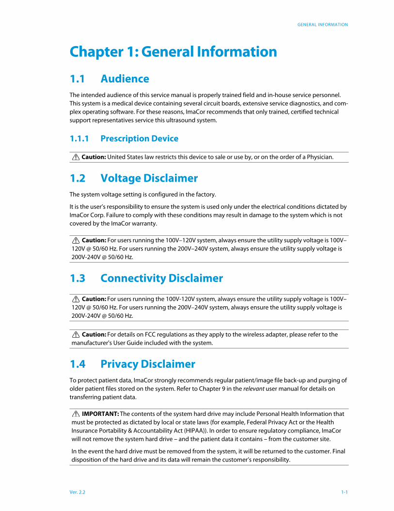
The system has several major field serviceable components including: LCD display with built-in speakers
and a multi-position, articulated lift system, operator console, modulo, transducers and UPS.
Figure 1-1: ImaCor Zura-Evo
1.10 Physical Description
1.10.1 LCD Display/Touch Screen
The monitor is a Liquid Crystal Display (LCD display) with an operating resolution of 1152x864 pixels @
60Hz (Hertz) and a built-in speaker. The monitor is a Liquid Crystal Display (LCD display) with an operat-
ing resolution of 1024x768 pixels @ 60Hz (Hertz) and built-in speakers.
1.10.2 Operator Console
All system controls are touch screen-based. Optional USB mouse and keyboard can be provided.
1.10.3 Modulo
The modulo, which is the heart of the system, is enclosed in the case with the LCD display/touch screen.
The modulo is the heart of the system. The system CPU as well as the ultrasound module – in the form of
Table 1-1: ImaCor Zura-Evo1 LCD Display/Touch Screen
2 Folding Carry Handle (top)
3 Side Connectivity Panel (power and Network connections, USB and sound ports) and Hard Drive access
4 Speaker
Warning: Do not place the device on any surface that blocks/restricts ventilation (e.g., do not set
the device on a soft surface such as a bed). Failure to comply with this directive could inhibit system air-
flow and cause the system to overheat, which is not covered by the system warranty.
Ver. 2.2 1-3
GENERAL INFORMATION
system boards and electronics – are encased in an aircraft grade aluminum composite case for ease of
service.
1.10.4 Transducers
Refer to Table 6-1: Transducer for a complete list of transducers available with the system.
Ver. 2.2 1-4
SYSTEM SPECIFICATIONS
Chapter 2: System Specifications
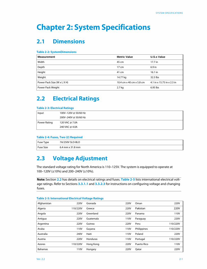
2.1 Dimensions
2.2 Electrical Ratings
2.3 Voltage Adjustment
The standard voltage rating for North America is 110–125V. The system is equipped to operate at
100–120V (±10%) and 200–240V (±10%).
Table 2-2: SystemDimensions
Measurement Metric Value U.S.s Value
Width 45 cm 17.7 in
Depth 17 cm 6.9 in
Height 41 cm 16.1 in
Weight 14.77 kg 32.5 lbs
Power Pack Size (W x L X H) 10.4 cm x 40 cm x 5.8 cm 4.1 in x 15.75 in x 2.3 in
Power Pack Weight 2.7 kg 6.95 lbs
Table 2-3: Electrical Ratings
Input 100V–120V @ 50/60 Hz
200V–240V @ 50/60 Hz
Power Rating 120 VAC @ 7.0A
240 VAC @ 4.0A
Table 2-4: Fuses, Two (2) Required
Fuse Type 7A/250V SLO-BLO
Fuse Size 6.4 mm x 31.8 mm
Note: Section 2.2 has details on electrical ratings and fuses. Table 2-5 lists international electrical volt-
age ratings. Refer to Sections 3.3.1.1 and 3.3.2.3 for instructions on configuring voltage and changing
fuses.
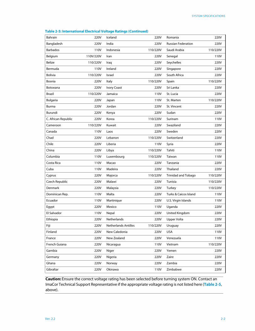
Table 2-5: International Electrical Voltage Ratings
Afghanistan 220V Granada 220V Oman 220V
Algeria 110/220V Greece 220V Pakistan 220V
Angola 220V Greenland 220V Panama 110V
Antigua 220V Guatemala 110V Paraguay 220V
Argentina 220V Guinea 220V Peru 110/220V
Aruba 110V Guyana 110V Philippines 110/220V
Australia 240V Haiti 110V Poland 220V
Austria 220V Honduras 110V Portugal 110/220V
Azores 110/220V Hong Kong 220V Puerto Rico 110V
Bahamas 110V Hungary 220V Qatar 220V
Ver. 2.2 2-1
SYSTEM SPECIFICATIONS
Bahrain 220V Iceland 220V Romania 220V
Bangladesh 220V India 220V Russian Federation 220V
Barbados 110V Indonesia 110/220V Saudi Arabia 110/220V
Belgium 110V/220V Iran 220V Senegal 110V
Belize 110/220V Iraq 220V Seychelles 220V
Bermuda 110V Ireland 220V Singapore 220V
Bolivia 110/220V Israel 220V South Africa 220V
Bosnia 220V Italy 110/220V Spain 110/220V
Botswana 220V Ivory Coast 220V Sri Lanka 220V
Brazil 110/220V Jamaica 110V St. Lucia 220V
Bulgaria 220V Japan 110V St. Marten 110/220V
Burma 220V Jordan 220V St. Vincent 220V
Burundi 220V Kenya 220V Sudan 220V
C. African Republic 220V Korea 110/220V Surinam 110V
Cameroon 110/220V Kuwait 220V Swaziland 220V
Canada 110V Laos 220V Sweden 220V
Chad 220V Lebanon 110/220V Switzerland 220V
Chile 220V Liberia 110V Syria 220V
China 220V Libya 110/220V Tahiti 110V
Columbia 110V Luxembourg 110/220V Taiwan 110V
Costa Rica 110V Macao 220V Tanzania 220V
Cuba 110V Madeira 220V Thailand 220V
Cyprus 220V Majorca 110/220V Trinidad and Tobago 110/220V
Czech Republic 220V Malawi 220V Tunisia 110/220V
Denmark 220V Malaysia 220V Turkey 110/220V
Dominican Rep. 110V Malta 220V Turks & Caicos Island 110V
Ecuador 110V Martinique 220V U.S. Virgin Islands 110V
Egypt 220V Mexico 110V Uganda 220V
El Salvador 110V Nepal 220V United Kingdom 220V
Ethiopia 220V Netherlands 220V Upper Volta 220V
Fiji 220V Netherlands Antilles 110/220V Uruguay 220V
Finland 220V New Caledonia 220V USA 110V
France 220V New Zealand 220V Venezuela 110V
French Guiana 220V Nicaragua 110V Vietnam 110/220V
Gambia 220V Niger 220V Yemen 220V
Germany 220V Nigeria 220V Zaire 220V
Ghana 220V Norway 220V Zambia 220V
Gibraltar 220V Okinawa 110V Zimbabwe 220V
Caution: Ensure the correct voltage rating has been selected before turning system ON. Contact an
ImaCor Technical Support Representative if the appropriate voltage rating is not listed here (Table 2-5,
above).
Table 2-5: International Electrical Voltage Ratings (Continued)
Ver. 2.2 2-2
SYSTEM INSTALLATION
Chapter 3: System Installation
3.1 Installation Issues and Requirements
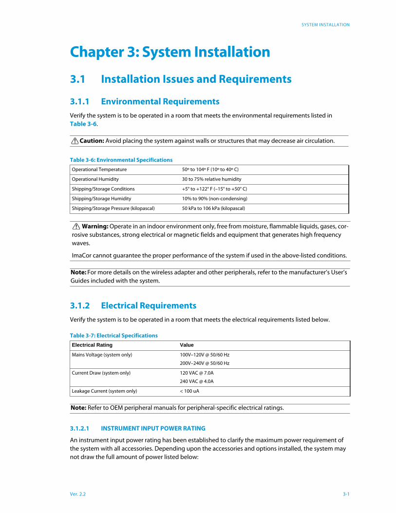
3.1.1 Environmental Requirements
Verify the system is to be operated in a room that meets the environmental requirements listed in
Table 3-6.
3.1.2 Electrical Requirements
Verify the system is to be operated in a room that meets the electrical requirements listed below.
3.1.2.1 INSTRUMENT INPUT POWER RATING
An instrument input power rating has been established to clarify the maximum power requirement of
the system with all accessories. Depending upon the accessories and options installed, the system may
not draw the full amount of power listed below:
Caution: Avoid placing the system against walls or structures that may decrease air circulation.
Table 3-6: Environmental Specifications
Operational Temperature 50º to 104º F (10º to 40º C)
Operational Humidity 30 to 75% relative humidity
Shipping/Storage Conditions +5° to +122° F (–15° to +50° C)
Shipping/Storage Humidity 10% to 90% (non-condensing)
Shipping/Storage Pressure (kilopascal) 50 kPa to 106 kPa (kilopascal)
Warning: Operate in an indoor environment only, free from moisture, flammable liquids, gases, cor-
rosive substances, strong electrical or magnetic fields and equipment that generates high frequency
waves.
ImaCor cannot guarantee the proper performance of the system if used in the above-listed conditions.
Note: For more details on the wireless adapter and other peripherals, refer to the manufacturer’s User’s
Guides included with the system.
Table 3-7: Electrical Specifications
Electrical Rating Value
Mains Voltage (system only) 100V–120V @ 50/60 Hz
200V–240V @ 50/60 Hz
Current Draw (system only) 120 VAC @ 7.0A
240 VAC @ 4.0A
Leakage Current (system only) < 100 uA
Note: Refer to OEM peripheral manuals for peripheral-specific electrical ratings.
Ver. 2.2 3-1

SYSTEM INSTALLATION
For optimal system performance, use a dedicated, interference-free, isolated, grounded wall outlet. To
ensure grounding reliability, use a hospital-grade power cord and connect it only to an equivalent hospi-
tal-grade socket. The specifications of the hospital-grade power cord as follows:
3.1.3 Electrostatic Discharge
During normal operation, the presence of electrostatic discharge (ESD) can cause system reliability
issues. The following are the most common causes for ESD:
• moving people
• low humidity
• improper grounding
• unshielded cable
• poor connection
• moving machines
ESD is most likely to occur during periods of low humidity. If the relative humidity is below 50%, static
charges can easily accumulate. ESD generally does not occur when the humidity is above 50%. Any time
the charge reaches approximately 10,000 volts, it is likely to discharge to grounded metal parts.
Although ESD will not hurt humans, it can damage certain electronic devices. The high-voltage pulse can
burn out the inputs of many integrated circuit (IC) devices. This damage might not appear instantly, but
it can build up over time, eventually causing the device to fail.
To prevent damage to the system, use ESD minimizing devices where needed. These devices include:
anti-static mats, humidifiers, and spray. Proper discharge is required before handling any electronic
device such as an ESD strap.
3.1.4 Electromagnetic and Radio Frequency Interference
This equipment has been tested and found to comply with the EMC limits for EN 55011, Group 1, Class A
and EN 60601-1-2. These limits are designed to provide reasonable protection against harmful interfer-
ence in a typical medical installation. The equipment generates, uses and can radiate radio frequency
(RF) energy and if not installed and used in accordance with these instructions, may cause harmful inter-
ference to other devices in the vicinity. However, there is no guarantee that interference will not occur in
a particular installation. If this equipment does cause harmful interference with other devices (which can
be determined by turning the equipment off and on) the user is encouraged to try to correct the interfer-
ence with one or more of the following measures:
• reorient or relocate the receiving device
• increase separation distance between equipment
Table 3-8: Instrument Power Input Rating
System voltage, VAC Nominal system power usage, including isolated accessory power System power usage
Isolated accessory power available
120V 3.75A Max 3.75A Max Not applicable
240V 1.8A Max 1.8A Max @120V Not applicable
Table 3-9: Hospital-Grade Power Cord SpecificationsInput voltage Hospital grade power cord specifications
100-120V ~, 50/60Hz 125Vac, 15A, 3 wire, 18 AWG, grounding type, 5-15P Hospital Grade plug cap, less than 6 m long, CSA &
UL approved
200-240V~, 50/60Hz 250Vac, 15A, 3 wire, 18 AWG, grounding type, 6-15P Hospital Grade plug cap, less than 6 m long, CSA &
UL approved
Ver. 2.2 3-2

SYSTEM INSTALLATION
• connect the equipment to an outlet on a circuit different to that which the other device(s) is con-
nected
• consult the manufacturer or field service technician for help
3.1.5 Wiring Requirements
3.1.5.1 MAIN AC CONNECTION
The electrical feed to the system should be a dedicated/isolated line (no other equipment on the same
line) with a third-wire ground. Ensure a low impedance path for current to return to the source.
3.1.5.2 ETHERNET (HARD-WIRED) NETWORK CONNECTION
It is the user’s responsibility to provide an Ethernet connection to the system and to install the correct
type of cable in accordance with the building's applicable standards. The commonly used cable is CAT5
(Category 5, 10 Base-T, unshielded twisted pair).
3.1.5.3 IMAGE MANAGEMENT NETWORK
Obtain the following information from the system administrator:
• list of all equipment that is part of the Image Management network
• logical diagram of the network showing topology, subnets, etc.
• location of all equipment
• location of all LAN (Local Area Network) attachment points
• locations of all power outlets and connector types
• location of any dedicated analog phone line
• all necessary Internet Protocol (IP) addresses and subnet information.
3.2 Pre-Installation
3.2.1 Preliminary Inspection
To Inspect the Shipping Crate and Box Upon Arrival
1 Examine the shipping container(s) for any damage that may have occurred during transport.
2 Look for evidence to ensure that the carton has not been opened.
3 Report any damage to both the carrier and ImaCor.
3.2.2 Zura-Evo Unpacking Instructions
Equipment/tools required: scissors or utility knife
Warning: The system should not be used adjacent to or stacked with other equipment. If adjacent
or stacked use is necessary, the system should be observed in order to verify normal operation in the
configuration in which it will be used.
Caution: System networking options are intended for use inside your organization’s firewall. Orga-
nizations that elect to configure/use the networking functionality provided by ImaCor are assuming all
liabilities and risks associated with that decision.
Ver. 2.2 3-3
SYSTEM INSTALLATION
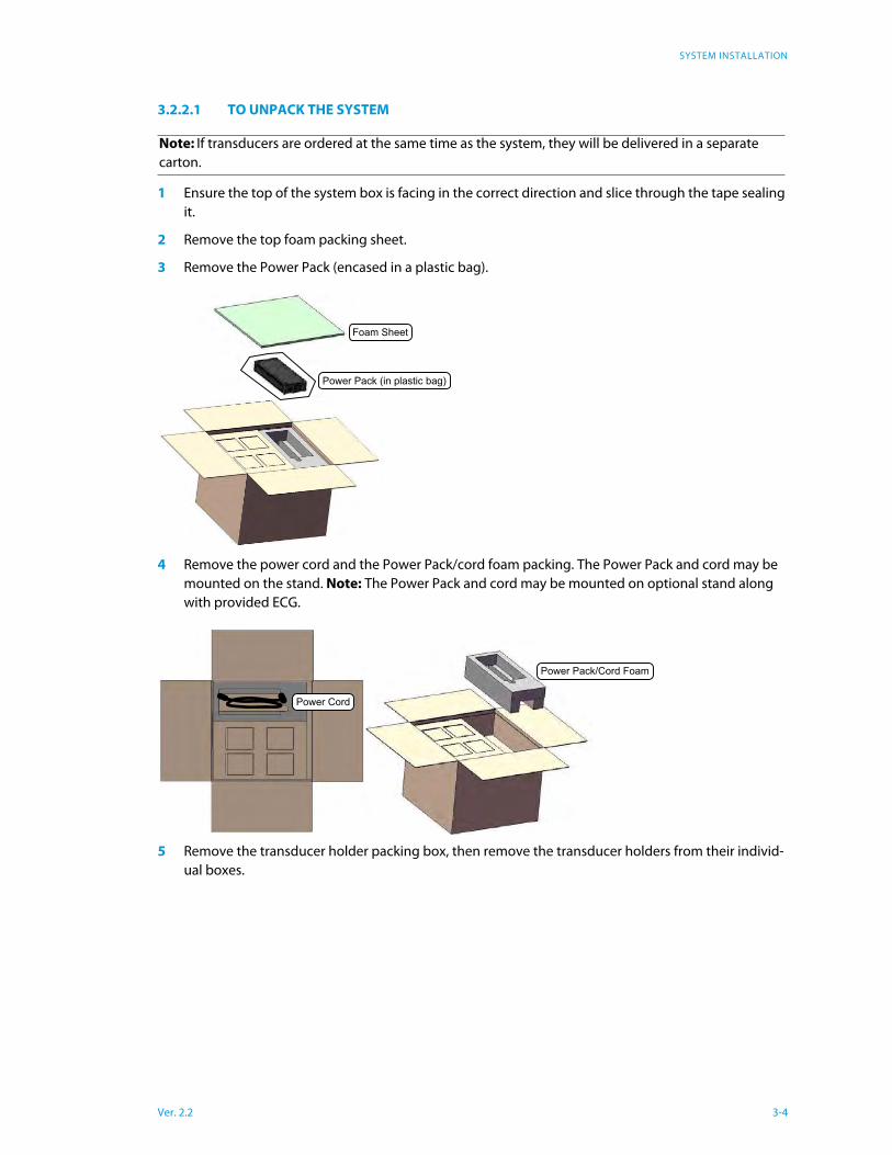
3.2.2.1 TO UNPACK THE SYSTEM
1 Ensure the top of the system box is facing in the correct direction and slice through the tape sealing
it.
2 Remove the top foam packing sheet.
3 Remove the Power Pack (encased in a plastic bag).
4 Remove the power cord and the Power Pack/cord foam packing. The Power Pack and cord may be
mounted on the stand. Note: The Power Pack and cord may be mounted on optional stand along
with provided ECG.
5 Remove the transducer holder packing box, then remove the transducer holders from their individ-
ual boxes.
Note: If transducers are ordered at the same time as the system, they will be delivered in a separate
carton.
Power Pack (in plastic bag)
Foam Sheet
Power Pack/Cord Foam
Power Cord
Ver. 2.2 3-4
SYSTEM INSTALLATION
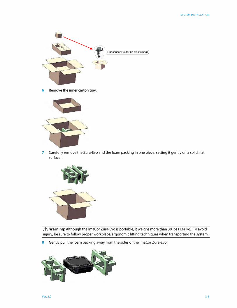
6 Remove the inner carton tray.
7 Carefully remove the Zura-Evo and the foam packing in one piece, setting it gently on a solid, flat
surface.
8 Gently pull the foam packing away from the sides of the ImaCor Zura-Evo.
Warning: Although the ImaCor Zura-Evo is portable, it weighs more than 30 lbs (13+ kg). To avoid
injury, be sure to follow proper workplace/ergonomic lifting techniques when transporting the system.
Transducer Holder (in plastic bag)
Ver. 2.2 3-5
SYSTEM INSTALLATION
9 Remove the system from the plastic bag.
10 Set the system upright on the table surface.
3.3 Installation
3.3.1 EMI Filter and Power Pack
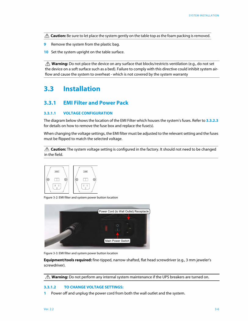
3.3.1.1 VOLTAGE CONFIGURATION
The diagram below shows the location of the EMI Filter which houses the system's fuses. Refer to 3.3.2.3
for details on how to remove the fuse box and replace the fuse(s).
When changing the voltage settings, the EMI filter must be adjusted to the relevant setting and the fuses
must be flipped to match the selected voltage.
Figure 3-2: EMI filter and system power button location
Figure 3-3: EMI filter and system power button location
Equipment/tools required: fine-tipped, narrow-shafted, flat head screwdriver (e.g., 3 mm jeweler's
screwdriver).
3.3.1.2 TO CHANGE VOLTAGE SETTINGS:
1 Power off and unplug the power cord from both the wall outlet and the system.
Caution: Be sure to let place the system gently on the table top as the foam packing is removed.
Warning: Do not place the device on any surface that blocks/restricts ventilation (e.g., do not set
the device on a soft surface such as a bed). Failure to comply with this directive could inhibit system air-
flow and cause the system to overheat - which is not covered by the system warranty
Caution: The system voltage setting is configured in the factory. It should not need to be changed
in the field.
Warning: Do not perform any internal system maintenance if the UPS breakers are turned on.
Main Power Switch
Power Cord (to Wall Outlet) Receptacle
Ver. 2.2 3-6
SYSTEM INSTALLATION
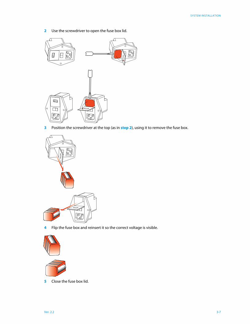
2 Use the screwdriver to open the fuse box lid.
3 Position the screwdriver at the top (as in step 2), using it to remove the fuse box.
4 Flip the fuse box and reinsert it so the correct voltage is visible.
5 Close the fuse box lid.
Ver. 2.2 3-7
SYSTEM INSTALLATION
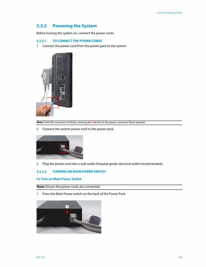
3.3.2 Powering the System
Before turning the system on, connect the power cords.
3.3.2.1 TO CONNECT THE POWER CORDS
1 Connect the power cord from the power pack to the system.
2 Connect the system power cord to the power pack.
3 Plug the power cord into a wall outlet (hospital-grade electrical outlet recommended).
3.3.2.2 TURNING ON MAIN POWER SWITCH
To Turn on Main Power Switch
1 Press the Main Power switch on the back of the Power Pack.
Note: Push the connector on firmly, ensuring the red dot on the power connector faces upwards.
Note: Ensure the power cords are connected.
1
Ver. 2.2 3-8
SYSTEM INSTALLATION
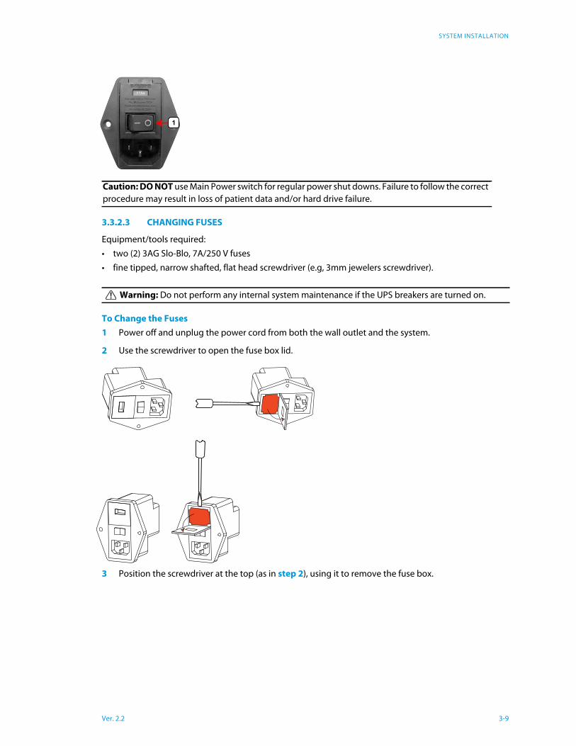
3.3.2.3 CHANGING FUSES
Equipment/tools required:
• two (2) 3AG Slo-Blo, 7A/250 V fuses
• fine tipped, narrow shafted, flat head screwdriver (e.g, 3mm jewelers screwdriver).
To Change the Fuses
1 Power off and unplug the power cord from both the wall outlet and the system.
2 Use the screwdriver to open the fuse box lid.
3 Position the screwdriver at the top (as in step 2), using it to remove the fuse box.
Caution: DO NOT use Main Power switch for regular power shut downs. Failure to follow the correct
procedure may result in loss of patient data and/or hard drive failure.
Warning: Do not perform any internal system maintenance if the UPS breakers are turned on.
1
Ver. 2.2 3-9
SYSTEM INSTALLATION
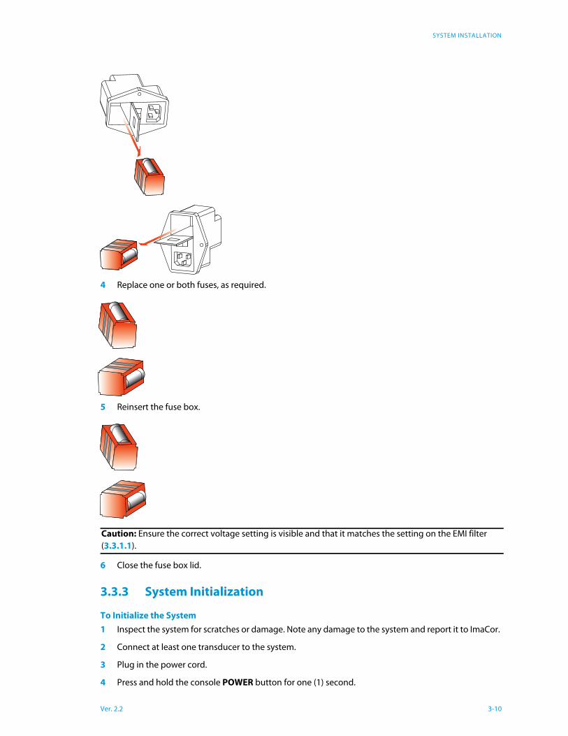
4 Replace one or both fuses, as required.
5 Reinsert the fuse box.
6 Close the fuse box lid.
3.3.3 System Initialization
To Initialize the System
1 Inspect the system for scratches or damage. Note any damage to the system and report it to ImaCor.
2 Connect at least one transducer to the system.
3 Plug in the power cord.
4 Press and hold the console POWER button for one (1) second.
Caution: Ensure the correct voltage setting is visible and that it matches the setting on the EMI filter
(3.3.1.1).
Ver. 2.2 3-10
SYSTEM INSTALLATION
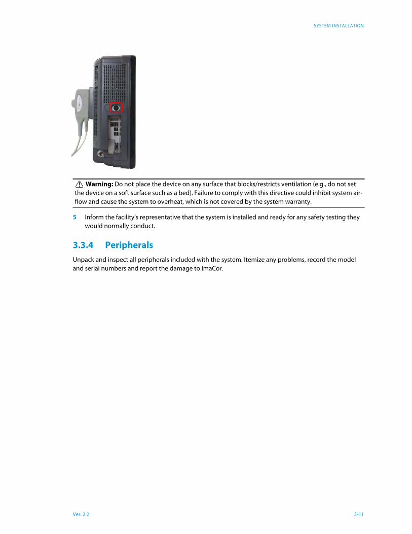
5 Inform the facility’s representative that the system is installed and ready for any safety testing they
would normally conduct.
3.3.4 Peripherals
Unpack and inspect all peripherals included with the system. Itemize any problems, record the model
and serial numbers and report the damage to ImaCor.
Warning: Do not place the device on any surface that blocks/restricts ventilation (e.g., do not set
the device on a soft surface such as a bed). Failure to comply with this directive could inhibit system air-
flow and cause the system to overheat, which is not covered by the system warranty.
Ver. 2.2 3-11
SOFTWARE TEST
Ver. 2.2 4-1
Chapter 4: Software Test
Contact ImaCor for Software Smoke test procedure, if desired. In the overwhelming majority of cases,
software can be adequately verified by starting up and proceeding to the patient screen.
SOFTWARE UPDATE
Ver. 2.2 5-1
Chapter 5: Software Update
Upgrade packages are machine-specific and require a registration code that is displayed in the Configu-
ration Dialog >Version tab.
Download the Software Upgrade and Request a License File
1 Log into the ImaCor support web page: http://www.imacorinc.com/support.html
2 Tap or click on the software upgrade you wish to download.
3 Enter the Zura-Evo machine registration code, which can found on the Version tab of the Zura-Evo
Configuration window.
4 Tap or click on the Go button. A license request is automatically sent to the ImaCor support team.
5 Tap or click on the “Download File” option.
6 Navigate to the location on your computer where you wish the file saved.
Upgrade the Zura-Evo Software
1 Save the .icm file that was emailed to you onto a USB thumb drive. For example, if your thumb drive
is the F: drive, save the .icm file to F:
2 Unzip the software downloaded upgrade and move the .exe file inside the zip folder to your USB
thumb drive. The .icm and .exe files must be placed at the same location.
3 Plug your USB key into the Zura-Evo system you are upgrading.
4 Go to Configuration > Version tab and tap or click the Update button. You can accomplish this from
either the Patient Information screen or the Imaging screen.
5 Select the .icm file on your thumb drive and tap or click “OK.”
6 When the Upgrade Wizard appears (it may take up to 5 seconds), follow the instructions.
7 Do not disconnect the USB thumb drive until a message is displayed instructing you to reboot the
system.
8 After the system reboots you will be prompted by the Upgrade Wizard to tap or click on “Finish.”
Once you’ve clicked Finish, the upgrade is complete.
TRANSDUCERS
Ver. 2.2 6-1
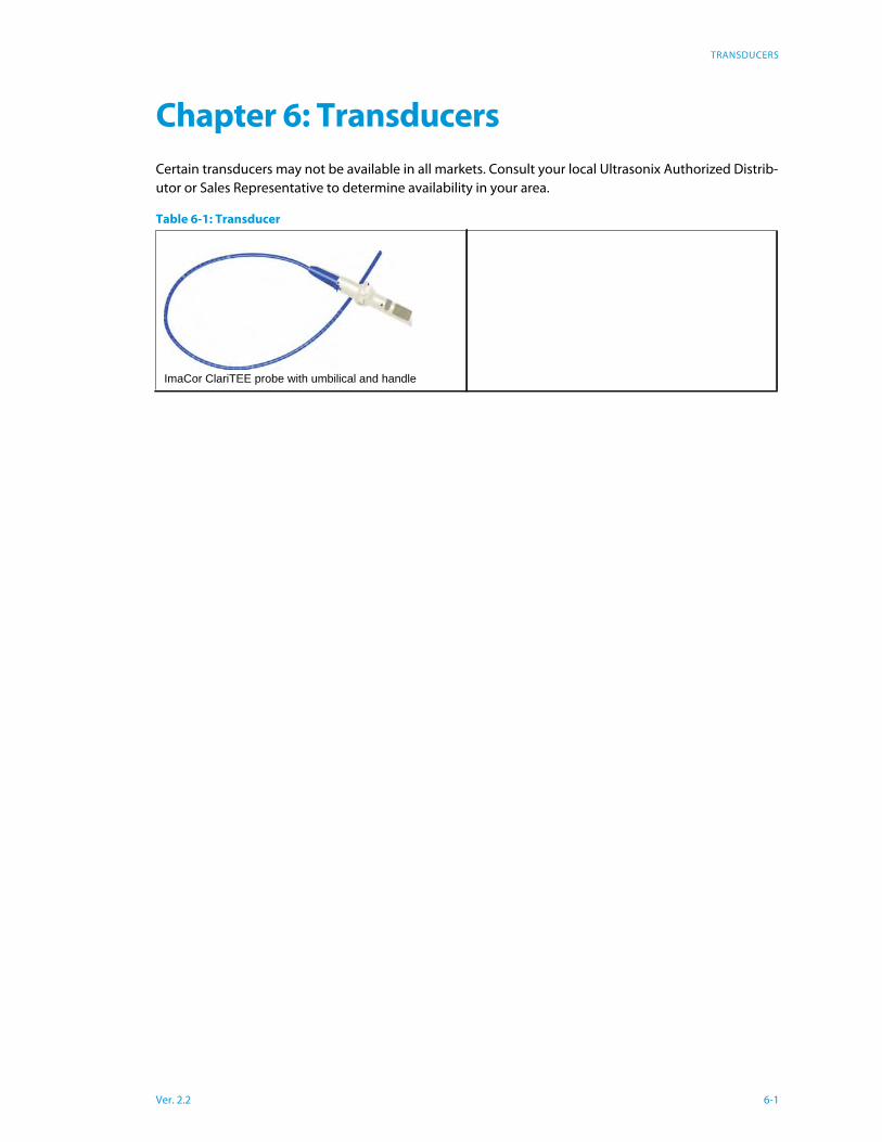
Chapter 6: Transducers
Certain transducers may not be available in all markets. Consult your local Ultrasonix Authorized Distrib-
utor or Sales Representative to determine availability in your area.
Table 6-1: Transducer
ImaCor ClariTEE probe with umbilical and handle
FIELD SERVICE COMPONENTS
Chapter 7: Field Service Components
This section describes how to handle all field serviceable components, including the modulo, LCD dis-
play, speakers, UPS, battery and transducers.
7.1 Protecting Patient Data
Before doing any work with the modulo, be sure to complete section 7.1.1 in order to the export/backup
and therefore protect the integrity of each client’s data.
Once all work has been completed, refer to section 7.1.2 to import/restore the client's settings and data.
7.1.1 Exporting User Data (As Required)
Before servicing the modulo, export User Data to a Data Transfer Module (DTM). This will ensure access to
this data if either the modulo or hard drive needs replaced during servicing.
The following options are available for export
Export a Patient Record to a Data Transfer Module (DTM)
1 Access the Patient Information screen.
– After starting the ImaCor Zura-Evo system, the Patient Information screen is the first interactive
window displayed.
– If you are in the imaging environment, tap or click the Patient button.
2 Insert the DTM into one of the USB ports on the left side of the Zura-Evo. The DTM Patients dialog
box is displayed.
3 Tap or click the name of the patient whose records you wish to export. Check the GUID to make cer-
tain you are selecting the correct patient.
4 Tap or click the Export button.
DICOM Patient Export Options
If the Export DICOM option is selected, DICOM files are automatically created as cineloops are exported
to the DTM. If Color Flow images are available, they are embedded in the DICOM file.
If the Overwrite DICOMDIR when Exporting option is checked, the DICOMDIR file is overwritten with
each patient export.
Note: When creating a backup prior to servicing or replacing the modulo, ImaCor recommends select-
ing all options for Export.
Notes:
• If the “Export DICOM Images” option is enabled in the Configuration window, the operation will
export ImaCor cine files as well as DICOM multiframe images.
• The ImaCor decryption utility must be used before DICOM images can be imported and viewed on a
DICOM workstation. The decryption utility is available to registered customers for download from
the ImaCor support web page: http://www.imacorinc.com/support.html
Ver. 2.2 7-1
FIELD SERVICE COMPONENTS
Notes:
• If multiple patient records are selected for export and the Overwrite DICOMDIR when Exporting
option is checked, only the last record selected will appear on the DICOMDIR.
• DICOMDIR and DICOM files are encrypted before they are saved onto a DTM. An ImaCor decryption
application is provided to import DTM data into a DICOM workstation.
7.1.2 Importing User Data (As Required)
Once the modulo has been installed, if required, import (restore) the previously-saved user data from the
removable disk to this system.
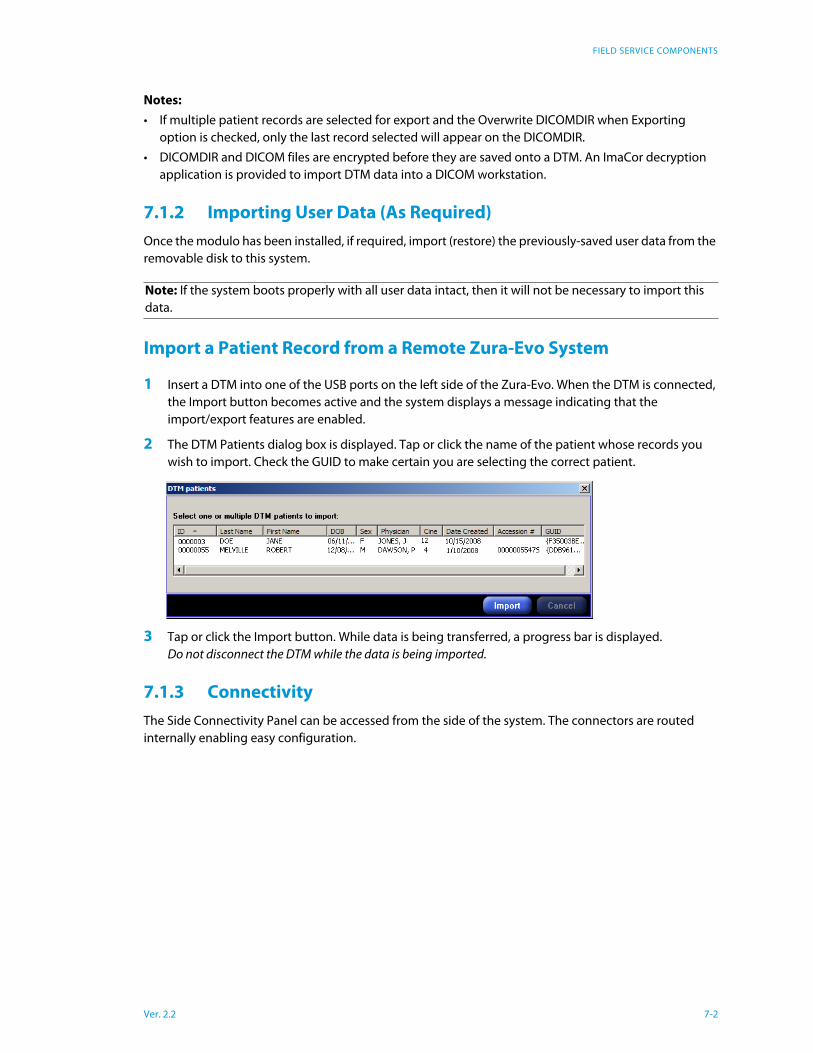
Import a Patient Record from a Remote Zura-Evo System
1 Insert a DTM into one of the USB ports on the left side of the Zura-Evo. When the DTM is connected,
the Import button becomes active and the system displays a message indicating that the
import/export features are enabled.
2 The DTM Patients dialog box is displayed. Tap or click the name of the patient whose records you
wish to import. Check the GUID to make certain you are selecting the correct patient.
3 Tap or click the Import button. While data is being transferred, a progress bar is displayed.
Do not disconnect the DTM while the data is being imported.
7.1.3 Connectivity
The Side Connectivity Panel can be accessed from the side of the system. The connectors are routed
internally enabling easy configuration.
Note: If the system boots properly with all user data intact, then it will not be necessary to import this
data.
Ver. 2.2 7-2
FIELD SERVICE COMPONENTS
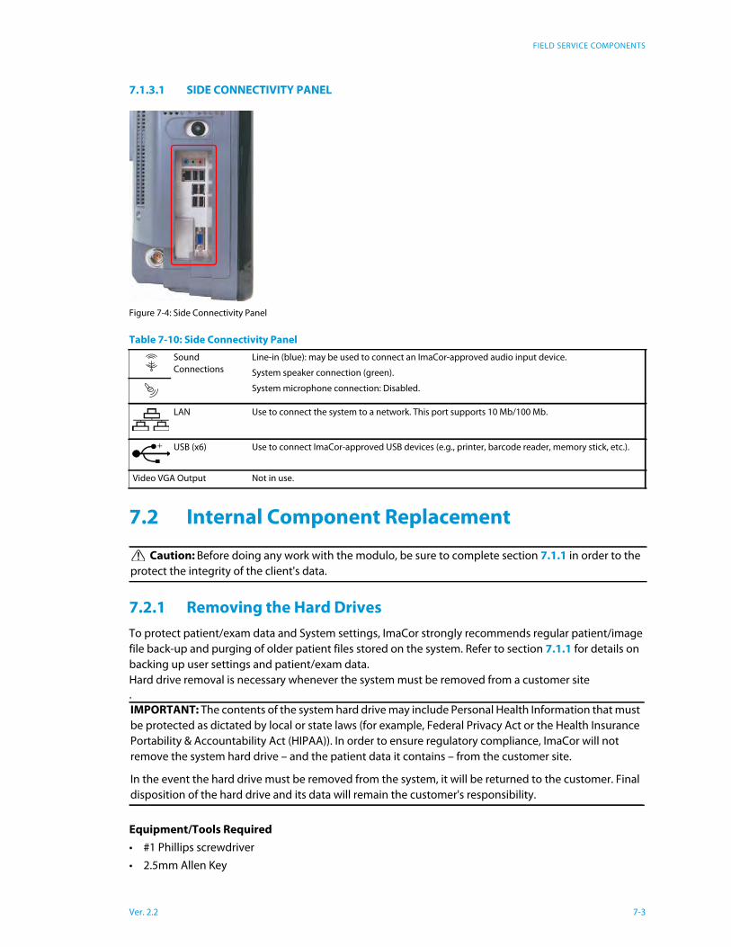
7.1.3.1 SIDE CONNECTIVITY PANEL
Figure 7-4: Side Connectivity Panel
7.2 Internal Component Replacement
7.2.1 Removing the Hard Drives
To protect patient/exam data and System settings, ImaCor strongly recommends regular patient/image
file back-up and purging of older patient files stored on the system. Refer to section 7.1.1 for details on
backing up user settings and patient/exam data.
Hard drive removal is necessary whenever the system must be removed from a customer site
.
Equipment/Tools Required
• #1 Phillips screwdriver
• 2.5mm Allen Key
Table 7-10: Side Connectivity Panel
Sound
Connections
Line-in (blue): may be used to connect an ImaCor-approved audio input device.
System speaker connection (green).
System microphone connection: Disabled.
LAN Use to connect the system to a network. This port supports 10 Mb/100 Mb.
USB (x6) Use to connect ImaCor-approved USB devices (e.g., printer, barcode reader, memory stick, etc.).
Video VGA Output Not in use.
Caution: Before doing any work with the modulo, be sure to complete section 7.1.1 in order to the
protect the integrity of the client's data.
IMPORTANT: The contents of the system hard drive may include Personal Health Information that must
be protected as dictated by local or state laws (for example, Federal Privacy Act or the Health Insurance
Portability & Accountability Act (HIPAA)). In order to ensure regulatory compliance, ImaCor will not
remove the system hard drive – and the patient data it contains – from the customer site.
In the event the hard drive must be removed from the system, it will be returned to the customer. Final
disposition of the hard drive and its data will remain the customer's responsibility.
Ver. 2.2 7-3
FIELD SERVICE COMPONENTS
• anti-static bag
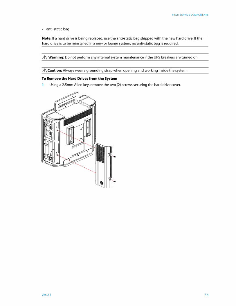
To Remove the Hard Drives from the System
1 Using a 2.5mm Allen key, remove the two (2) screws securing the hard drive cover.
Note: If a hard drive is being replaced, use the anti-static bag shipped with the new hard drive. If the
hard drive is to be reinstalled in a new or loaner system, no anti-static bag is required.
Warning: Do not perform any internal system maintenance if the UPS breakers are turned on.
Caution: Always wear a grounding strap when opening and working inside the system.
Ver. 2.2 7-4
FIELD SERVICE COMPONENTS
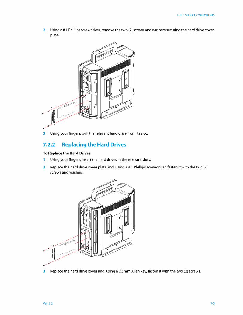
2 Using a # 1 Phillips screwdriver, remove the two (2) screws and washers securing the hard drive cover
plate.
3 Using your fingers, pull the relevant hard drive from its slot.
7.2.2 Replacing the Hard Drives
To Replace the Hard Drives
1 Using your fingers, insert the hard drives in the relevant slots.
2 Replace the hard drive cover plate and, using a # 1 Phillips screwdriver, fasten it with the two (2)
screws and washers.
3 Replace the hard drive cover and, using a 2.5mm Allen key, fasten it with the two (2) screws.
Ver. 2.2 7-5

FIELD SERVICE COMPONENTS
7.3 Miscellaneous Parts
7.3.1 Transducers Holders and Cable Hooks
The transducer holder with integrated cable hook mounts to a table edge with a simple screw clamp. The
transducer holders are connected with a simple thumbscrew that is hand-tightened. No tools are
required.
Figure 7-5: Transducer holder with integrated cable hook
7.4 Returning Parts for Service/Repair/Replacement
Once any part is determined to be defective, the Return Merchandise Authorization (RMA) process must
be initiated.
Note: If there is any doubt about the image, contact ImaCor Technical Support and forward them a digi-
tal copy of the image in question for verification of the diagnosis.
Note: For best results, ImaCor recommends removing the transducer holders before cleaning (11.2.4).
This will allow the operator to clean all the various curves and folds in a more effective manner.
Ver. 2.2 7-6
FIELD SERVICE COMPONENTS
Contact ImaCor Technical Support for the RMA number
• labeling instructions
• appropriate shipping method, instructions and destination.
ImaCor Technical Support:
Toll Free: 1-877-244-0657
E-mail: [email protected]
7.4.1 Transducers
When shipping transducers for service/repair/replacement, it is the customer's responsibility to ensure
that each transducer meets the requirements laid out in 11.3 Shipping Transducers for Service or
Return.
Note: For specific details on the transducers, refer to 7.4.1.
Note: The RMA number must always be clearly written on the outside of the packaging.
Ver. 2.2 7-7
DICOM
Chapter 8: DICOM
The system uses the Digital Imaging and Communications in Medicine (DICOM) standard to share medi-
cal information with other digital imaging systems. The system, by means of the DICOM protocol, com-
municates with Storage, Print and Modality Worklist Service Class Providers. DICOM setup/configuration
is an Administrator Settings option.
Refer to Chapter 9: Network Configuration to configure the system for network connectivity.
Digital Imaging and Communications in Medicine (DICOM) is the standard format for distributing and
viewing all types of medical images. DICOM files contain the following information:
• Patient information
• Cineloop
• ECG
• hTEE measurements, if present
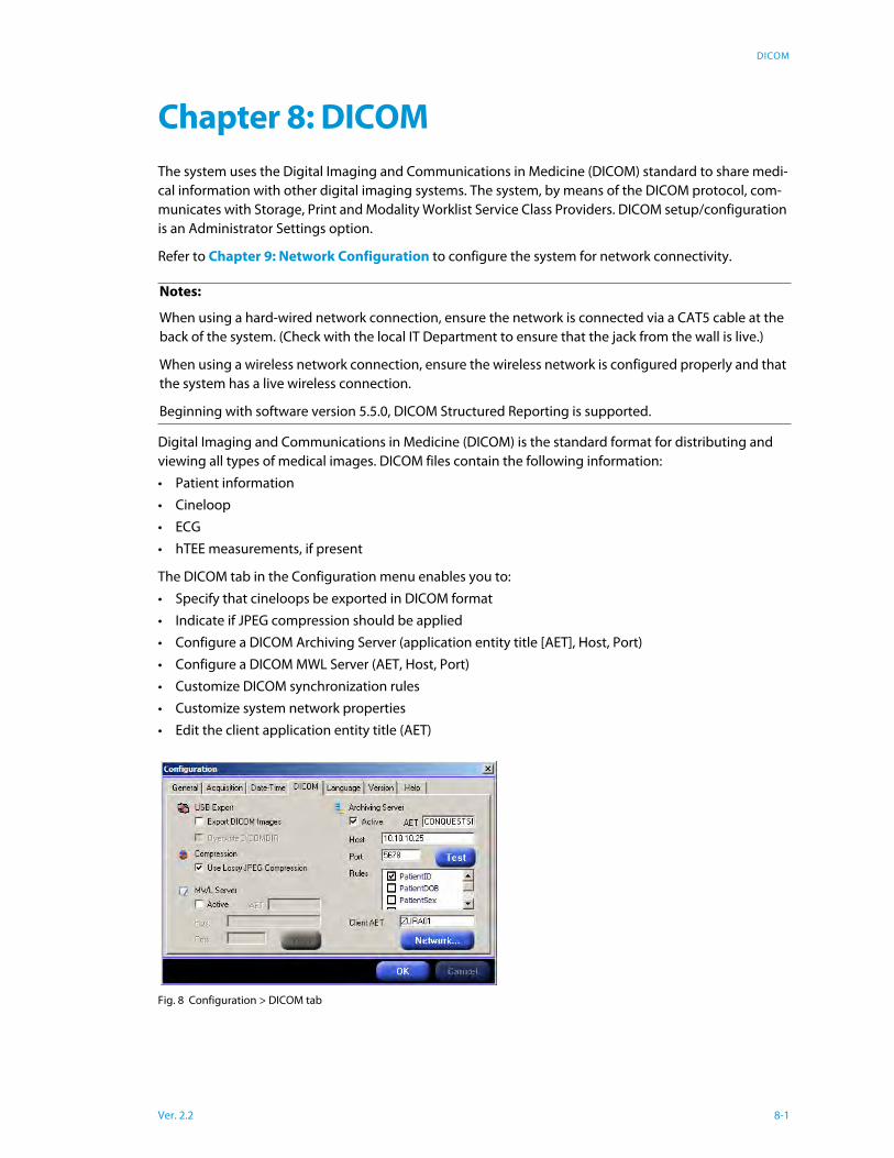
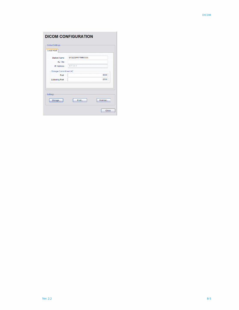
The DICOM tab in the Configuration menu enables you to:
• Specify that cineloops be exported in DICOM format
• Indicate if JPEG compression should be applied
• Configure a DICOM Archiving Server (application entity title [AET], Host, Port)
• Configure a DICOM MWL Server (AET, Host, Port)
• Customize DICOM synchronization rules
• Customize system network properties
• Edit the client application entity title (AET)
Fig. 8 Configuration > DICOM tab
Notes:
When using a hard-wired network connection, ensure the network is connected via a CAT5 cable at the
back of the system. (Check with the local IT Department to ensure that the jack from the wall is live.)
When using a wireless network connection, ensure the wireless network is configured properly and that
the system has a live wireless connection.
Beginning with software version 5.5.0, DICOM Structured Reporting is supported.
Ver. 2.2 8-1
DICOM
Patient Export Options
If the Export DICOM option is selected, DICOM files are automatically created as cineloops are exported
to the DTM. If Color Flow images are available, they are embedded in the DICOM file.
If the Overwrite DICOMDIR when Exporting option is checked, the DICOMDIR file is overwritten with
each patient export.
Notes:
• If multiple patient records are selected for export and the Overwrite DICOMDIR when Exporting
option is checked, only the last record selected will appear on the DICOMDIR.
• DICOMDIR and DICOM files are encrypted before they are saved onto a DTM. An ImaCor decryption
application is provided to import DTM data into a DICOM workstation.
Archiving Server Configuration
To configure the Archiving Server, the “Active” box must be checked. The server configuration parame-
ters are:
• Target AET
• Host name / IP Address
• Port number
By default the client AET for Zura-Evo is ZURA. It can be changed by entering an appropriate name in the
Client AET field.
The Network configuration parameters are those exposed by the Windows XP operating system and will
require an ImaCor technician (locally or with remote access) to set up.
Once the server has been configured the user can click on the Test button to check communication with
the server.
Checking the Archiving Server “Active” checkbox will enable the Sync button on the Patient Information
screen.
Custom Synchronization Rules
The Zura-Evo System provides six basic rules that can be turned ON or OFF independently to customize
the synchronization process. These rules are:
1. Require Cineloop Comment
2. Require Patient ID
3. Require Patient DOB
4. Require Patient Accession Number
5. Require Patient Sex
6. Max Daily Cine
For example if rules (1) and (2) are turned ON, only cineloops that have a comment and are for a patient
whose ID is not empty will be sent to the Archiving Server. The rules can only be turned ON/OFF by an
ImaCor technician.
If the Require Patient Accession Number rule is ON, cineloops are sent to the server only if the accession
number field in the Patient Information screen is completed for the corresponding patient.
The Max Daily Cine rule enables you to specify the maximum number of cineloops in a daily folder that
may be sent to the archiving server.
Ver. 2.2 8-2
DICOM
Synchronization operations occur when the Sync button is clicked. A synchronization log provides infor-
mation about the last Synchronization operation that was performed. To view the Log, simply right-click
on the “Sync” button and choose “Show Synchronization Log.”
Modality Worklist (MWL) Server Configuration
To configure the MWL Server, the “Active” box must be checked. The MWL Server configuration parame-
ters are similar to those required by an Archiving Server.
Once the server has been configured the user can click on the Test button to check communication with
the server.
Checking the MWL Server “Active” checkbox will enable the Check Worklist menu in the Patient list.
Compression
If the Compression option is selected, JPEG compression is automatically applied to the DICOM files. The
compression option applies to both exported data and data sent to the DICOM Archiving Server (if con-
figured).
DICOM Synchronization Feature
The atomic DICOM synchronization feature permits you to send selected patient records to the archiving
server.
Querying a Modality Worklist (MWL) Server
If an MWL server is configured and networked to a Zura-Evo system, you can query the server for a
selected patient. Data elements that are already present on the Zura-Evo system are not imported from
the MWL server. For example, if the date of birth for a selected patient is already recorded on the Zura-
Evo system, the birthdate will not be imported.
Table 8 Patient Information Screen Buttons and Function
Number Button Function
1 Import Import patient information. Enabled only when an ImaCor
Data Transfer Module (DTM) is inserted in a USB port.
2 Export Export patient information. Enabled only when an ImaCor
Data Transfer Module (DTM) is connected and a patient
record is selected from the Patient List.
3 Sync The Sync button is enabled when a DICOM Archiving
Server is active (see “Archiving Server Configuration‚”
page 2). The Sync button allows you to send cineloops as
DICOM files to a DICOM server via a network connection.
The server synchronization log can be viewed by tapping
or right-clicking the Sync button.
4 New Patient Clears the Patient Information screen, including the GUID,
enabling the user to create a new patient record. The New
Patient button is the only way to clear the GUID.
5 Next Advances to the single-view imaging environment. The
mandatory first and last name fields must have been com-
pleted.
6 Configure Accesses the Configuration screens.
7 Shutdown Shuts down the system.
Ver. 2.2 8-3
DICOM
Touch Screen
1 Select a patient from the Patient List.
2 Tap anywhere on the screen and hold.
3 Select the “Check MWL Server...” option.
Zura-Evo Mouse
1 Select a patient from the Patient List.
2 Right-click and select the “Check MWL Server...” option.
If the MWL server query returns at least one item, you can import the information from a selected MWL
item into the local patient record. See the DICOM Conformance Statement for details of imported fields.
The DICOM Conformance Statement is available to registered customers for download from the ImaCor
support web page: http://www.imacorinc.com/support.html
Synchronizing with a DICOM Archiving Server
If a DICOM archiving server is configured and networked to a Zura-Evo system, you can send acquired
cineloops to it as multiframe DICOM files.
To transmit cineloops to the server, tap or click the Sync button in the Patient Information screen.
After communication with the server is verified, the Zura-Evo system sends cineloops that do not yet
reside on the server and that satisfy user-defined Sync rules, if any. Examples of user-defined rules follow:
• Cineloop comment required
• Patient ID required
• Patient DOB required
• Accession number required
• Patient sex required; (“unknown” not acceptable)
VIEWING THE SYNC LOG
The Sync Log feature enables you to check the status of the last synchronization operation, displaying
transmission errors and the count of cineloops not transmitted because of rule noncompliance.
To view the Sync Log, tap or right-click the Sync button, which displays the Show Synchronization Log
menu.
Note: The accession number can be imported from the MWL server.
Note: Cineloops imported from another Zura-Evo system will not be sent to the archiving server.
Cineloops can be transmitted to an archiving server only by the Zura-Evo system that acquired them.
Ver. 2.2 8-4
DICOM
Ver. 2.2 8-5

NETWORK CONFIGURATION
Chapter 9: Network Configuration
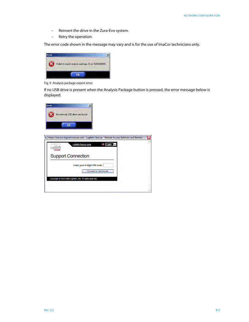
Remote Assistance
The Remote Assistance button enables you to establish a link with an ImaCor technician who can access
the Zura-Evo system remotely for troubleshooting.
Once the Remote Assistance button is clicked, the Support Internet Explorer window is displayed.
1 Enter the 6-digit PIN code provided by ImaCor tech support.
2 Tap or click the “Connect to technician” option to establish a secure connection with a technician’s
console.
Configuration > Support tab
Analysis Package
The support technician may request an analysis package, which is a file that provides information about
your system and assists in troubleshooting.
To create an analysis package:
1 Select Configuration > Help
2 Insert an external USB drive into the USB port in the Zura-Evo system. You need not use the special
ImaCor data transfer module; any operational USB drive will work.
3 Tap or click the Analysis Package button
4 Email the analysis package (ZuraPkg.zip) to [email protected].
If there is insufficient free space on the USB drive to accommodate the analysis package, or if the USB
drive is removed prematurely, the error message shown in Figure 9 is displayed.
• In the case of insufficient free space on the USB drive, you may:
– Remove the drive from the Zura-Evo system.
– Insert the drive in any personal computer with a USB port.
– Delete unnecessary files. Files may not be deleted from the Zura-Evo system.
– Retry the operation
• If the USB drive was removed prematurely — i.e., before the analysis package is completely written to
the drive — you may:
Ver. 2.2 9-1
NETWORK CONFIGURATION
– Reinsert the drive in the Zura-Evo system.
– Retry the operation.
The error code shown in the message may vary and is for the use of ImaCor technicians only.
Fig. 9 Analysis package export error
If no USB drive is present when the Analysis Package button is pressed, the error message below is
displayed.
Ver. 2.2 9-2
SOFTWARE UPDATE
Ver. 2.2 10-1
Chapter 10: Software Update
Software Update
Upgrade packages are machine-specific and require a registration code that is displayed in the Configu-
ration Dialog >Version tab.
Download the Software Upgrade and Request a License File
1 Log into the ImaCor support web page: http://www.imacorinc.com/support.html
2 Tap or click on the software upgrade you wish to download.
3 Enter the Zura-Evo machine registration code, which can found on the Version tab of the Zura-Evo
Configuration window.
4 Tap or click on the Go button. A license request is automatically sent to the ImaCor support team.
5 Tap or click on the “Download File” option.
6 Navigate to the location on your computer where you wish the file saved.
Upgrade the Zura-Evo Software
1 Save the .icm file that was emailed to you onto a USB thumb drive. For example, if your thumb drive
is the F: drive, save the .icm file to F:
2 Unzip the software downloaded upgrade and move the .exe file inside the zip folder to your USB
thumb drive. The .icm and .exe files must be placed at the same location.
3 Plug your USB key into the Zura-Evo system you are upgrading.
4 Go to Configuration > Version tab and tap or click the Update button. You can accomplish this from
either the Patient Information screen or the Imaging screen.
5 Select the .icm file on your thumb drive and tap or click “OK.”
6 When the Upgrade Wizard appears (it may take up to 5 seconds), follow the instructions.
7 Do not disconnect the USB thumb drive until a message is displayed instructing you to reboot the
system.
8 After the system reboots you will be prompted by the Upgrade Wizard to tap or click on “Finish.”
Once you’ve clicked Finish, the upgrade is complete.

MAINTENANCE
Chapter 11: Maintenance
This section is intended to assist in the effective care, cleaning and disinfection of the system. It is also
intended to protect the system and transducers against damage during cleaning/disinfection.
Be sure to carefully follow all recommendations in this section to maintain the highest standard of clean-
liness/disinfection, while at the same time ensuring the operational safety of all equipment.
11.1 Recommended Frequency of Maintenance
Procedures
The frequency of preventive maintenance performed on the system plays a key role in eliminating or
extending the periods between downtime due to poor performance or unexpected breakdown. The fol-
lowing table offers recommendations that must be weighed by factors like frequency of use and envi-
ronmental conditions. In every case, frequent checks of safety related items are highly recommended.
11.2 System Cleaning
ImaCor recommends the following cleaning instructions for all external surfaces, including the cart,
cables and connectors.
11.2.1 LCD Display/Touch Screen and Cabinet
11.2.1.1 LCD DISPLAY CABINET
Apply a small amount of one of the following recommended cleaning solutions to a soft, non-abrasive
cloth and wipe down the cabinet:
Table 11-1: Maintenance Procedure Frequency
Test/Clean Frequency Interval Task
Transducers Six (6) months Check for cracks or bent pins.
Safety Six (6) months Ground impedance/leakage test.
System Filter Four (4) months
or as required
Check for good air flow without excessive noise.
Remove and vacuum.
Note: Filter cleaning frequency is dependant upon usage location. If the system is
used in a high traffic area (such as an Emergency Room) filters may require more fre-
quent cleaning.
System Fans Six (6) months Check for good air flow without excessive noise.
Periodic
Maintenance (PM)
As prescribed by
ImaCor procedures
To be performed only by qualified service personnel.
Cautions:
Power off and unplug the system before cleaning.
Do not spill or spray water on the controls, transducer connection receptacle, or transducer ports.
Cautions:
Power off and unplug the system prior to cleaning the LCD display/touch screen.
DO NOT apply cleaning solutions directly to any surface of the system.
Ver. 2.2 11-1
MAINTENANCE
• water
• mild detergent (PH level at or near 7) and water solution.
11.2.1.2 LCD DISPLAY/TOUCH SCREEN
Apply a small amount of one of the following recommended cleaning solutions to a soft, non-abrasive
cloth and wipe down the display:
• Steriplex SD for high-level disinfection
• 50:50 isopropyl alcohol and water
• any proprietary glass cleaning solution
• water
• mild detergent (PH level at or near 7) and water solution
11.2.2 Power Pack
Apply a small amount of one of the following recommended cleaning solutions to a soft, non-abrasive
cloth and wipe the power pack:
• water
• mild detergent (PH level at or near 7) and water solution.
11.2.3 Power Cord(s)
Apply a small amount of one of the following recommended cleaning solutions to a soft, non-abrasive
cloth and wipe the power cord:
• water
• mild detergent (PH level at or near 7) and water solution.
11.2.4 Transducer Holders and Cable Hooks
Apply a small amount of one of the following recommended cleaning solutions to a soft, non-abrasive
cloth and wipe off the transducer holders and cable hooks:
• water
Cautions:
Power off and unplug the system prior to cleaning.
DO NOT apply cleaning solutions directly to the power pack.
Cautions:
Power off and unplug the system prior to cleaning.
DO NOT apply cleaning solutions directly to the power cord.
Cautions:
Power off and unplug the system prior to cleaning.
For best results, ImaCor recommends removing the transducer holders and cable hooks before cleaning
(7.3.1). This will allow the operator to clean all the various curves and folds in a more effective manner.
For best results, ImaCor recommends removing the transducer holders and cable hooks before cleaning
(7.3.1). This will allow the operator to clean all the various curves and folds in a more effective manner.
DO NOT apply cleaning solutions directly to the transducer holders and cable hooks.
Ver. 2.2 11-2
MAINTENANCE
• mild detergent (PH level at or near 7) and water solution.
11.2.5 System Filter
This filter should be cleaned approximately every three (3) to six (6) months.
The Zura-Evo comes equipped with a double layer filtering system. The first layer, or system filter, is
accessible without removing anything from the system – the filter can simply be pulled out. The second
layer (fan filtering) is attached to the modulo and necessitates modulo removal.
Cleaning the system filter every three (3) to six (6) months helps to safely prolong the modulo fan filter
cleaning interval (refer to Table 11-1 for the various maintenance procedure frequencies).
Use a vacuum cleaner to remove the dust from the system exhaust filters or vents. If a vacuum cleaner is
not available, dust off by hand or with an anti-static brush.
11.2.5.1 CLEANING THE SYSTEM FILTER
To Clean the System Filter
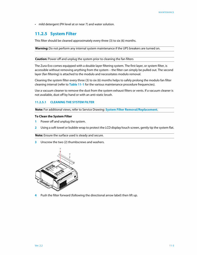
1 Power off and unplug the system.
2 Using a soft towel or bubble wrap to protect the LCD display/touch screen, gently tip the system flat.
3 Unscrew the two (2) thumbscrews and washers.
4 Push the filter forward (following the directional arrow label) then lift up.
Warning: Do not perform any internal system maintenance if the UPS breakers are turned on.
Caution: Power off and unplug the system prior to cleaning the fan filters
Note: For additional views, refer to Service Drawing: System Filter Removal/Replacement.
Note: Ensure the surface used is steady and secure.
Ver. 2.2 11-3

MAINTENANCE
5 Vacuum thoroughly and gently reinstall the filter.
6 Plug in and power on the system.
11.3 Shipping Transducers for Service or Return
It is the customer's responsibility to ensure:
• each transducer is disinfected prior to shipping
• the transducer is properly packaged for shipment
• all shipping waybills/paperwork is completed as per the relevant regulations and laws.
Refer to 7.4 Returning Parts for Service/Repair/Replacement for more details on transducer return or
replacement.
Slide
Ver. 2.2 11-4
TROUBLESHOOTING ISSUES
Chapter 12: Troubleshooting Issues
12.1 System Not Powering Up
Using a volt meter, ensure there is power to the wall outlet.
Test system power:
• Table 1 Troubleshooting Matrix
Check the AC power cable connection:
• Figure 3-2
Check fuses and voltage selection:
• 3.3.2.3 Changing Fuses
• 3.3.1.1 Voltage Configuration.
If the system still does not power on, contact ImaCor Technical Support.
12.2 System has Power but is Not Powering Up
The system has power if, when plugged in, the LCD display shows the message Digital/Analog No Signal.
Check the AC power cable connection:
• Figure 3-2
If the system still does not power on, contact ImaCor Technical Support.
12.3 No Primary Hard Drive Detected
Remove and reseat the hard drives (7.2.1).
12.4 System Seems Slow
System may be overheating:
• Check the CPU fan to ensure that it is working properly. If it is not, it will have to be replaced by a qual-
ified ImaCor Service Technician.
12.5 System Freezes during Use
If the system freezes during use and there is no discernible pattern to this behavior, contact ImaCor Tech-
nical Support.
12.6 Initialization Failures
12.6.1 System Initialization
The first screen displayed is the system initialization screen. During initialization, configuration files are
loaded into memory and the system software conducts a diagnostic self-test. Informational messages
are displayed if a problem is detected.
Ver. 2.2 12-1

TROUBLESHOOTING ISSUES
A full-power test is run after a patient examination ends abruptly; i.e., when an exam is ends without the
user pressing the End Exam button. Causes for an abrupt exam termination include a power outage, a
system powered down during an exam, and a software malfunction. The full-power test adds about 40
seconds to the initialization sequence.
The failure of one of the following
initialization steps failed:
Click the OK button and restart
the system.
If the error persists, contact tech-
nical support.
Review the Initialization screen
for the specific error.
Click the OK button and restart
the system.
If the problems persists, contact
ImaCor technical support.
12.7 No Network Connection via Ethernet Cable
If the system is connected to the network via an Ethernet cable but a network connection cannot be
established, there may be an issue with the network cable connection or with the BIOS. Contact ImaCor
Technical Support.
12.8 Transducer Connection Port not Functioning If a transducer connection port is not functioning, the MUX board may need to be replaced. Contact ImaCor Technical Support.
• Loading configuration
• Loading ultrasound definitions
• Loading ECG definitions
• Loading probe settings
• Loading ultrasound software
module
• Loading ECG software module
• Connecting to the patient data-
base server
Ver. 2.2 12-2
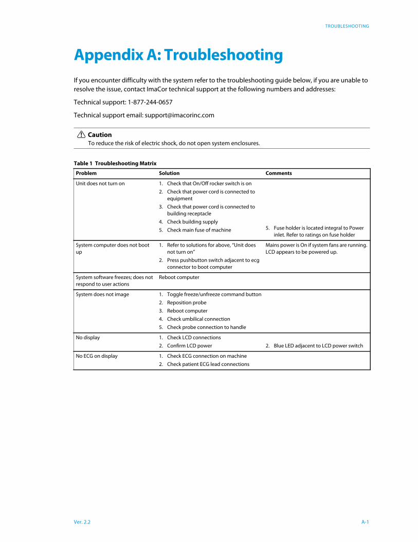
TROUBLESHOOTING
Ver. 2.2 A-1
Appendix A: Troubleshooting
If you encounter difficulty with the system refer to the troubleshooting guide below, if you are unable to
resolve the issue, contact ImaCor technical support at the following numbers and addresses:
Technical support: 1-877-244-0657
Technical support email: [email protected]
Unit does not turn on
5. Fuse holder is located integral to Power
inlet. Refer to ratings on fuse holder
System computer does not boot
up
Mains power is On if system fans are running.
LCD appears to be powered up.
System software freezes; does not
respond to user actions
Reboot computer
System does not image
No display
2. Blue LED adjacent to LCD power switch
No ECG on display
Caution
To reduce the risk of electric shock, do not open system enclosures.
Table 1 Troubleshooting Matrix
Problem Solution Comments
1. Check that On/Off rocker switch is on
2. Check that power cord is connected to
equipment
3. Check that power cord is connected to
building receptacle
4. Check building supply
5. Check main fuse of machine
1. Refer to solutions for above, “Unit does
not turn on”
2. Press pushbutton switch adjacent to ecg
connector to boot computer
1. Toggle freeze/unfreeze command button
2. Reposition probe
3. Reboot computer
4. Check umbilical connection
5. Check probe connection to handle
1. Check LCD connections
2. Confirm LCD power
1. Check ECG connection on machine
2. Check patient ECG lead connections
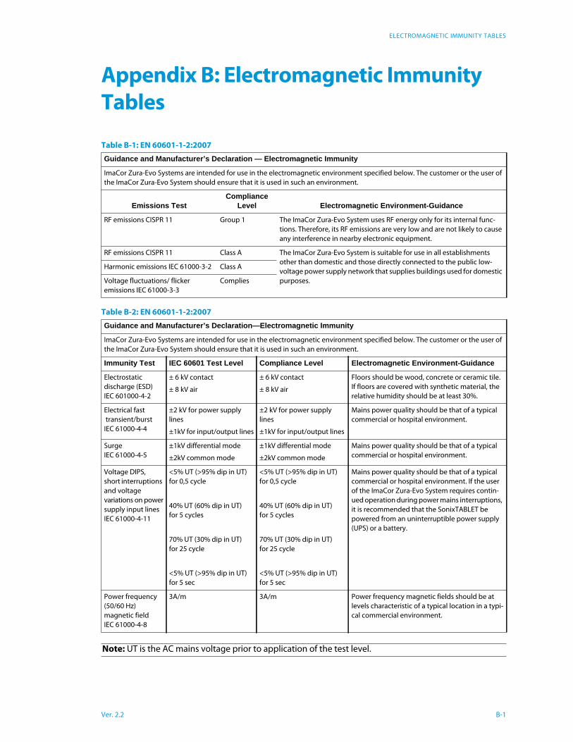
ELECTROMAGNETIC IMMUNITY TABLES
Appendix B: Electromagnetic Immunity
Tables
Table B-1: EN 60601-1-2:2007
Guidance and Manufacturer’s Declaration — Electromagnetic Immunity
ImaCor Zura-Evo Systems are intended for use in the electromagnetic environment specified below. The customer or the user of
the ImaCor Zura-Evo System should ensure that it is used in such an environment.
Emissions TestCompliance
Level Electromagnetic Environment-Guidance
RF emissions CISPR 11 Group 1 The ImaCor Zura-Evo System uses RF energy only for its internal func-
tions. Therefore, its RF emissions are very low and are not likely to cause
any interference in nearby electronic equipment.
RF emissions CISPR 11 Class A The ImaCor Zura-Evo System is suitable for use in all establishments
other than domestic and those directly connected to the public low-
voltage power supply network that supplies buildings used for domestic
purposes.
Harmonic emissions IEC 61000-3-2 Class A
Voltage fluctuations/ flicker
emissions IEC 61000-3-3
Complies
Table B-2: EN 60601-1-2:2007
Guidance and Manufacturer’s Declaration—Electromagnetic Immunity
ImaCor Zura-Evo Systems are intended for use in the electromagnetic environment specified below. The customer or the user of
the ImaCor Zura-Evo System should ensure that it is used in such an environment.
Immunity Test IEC 60601 Test Level Compliance Level Electromagnetic Environment-Guidance
Electrostatic
discharge (ESD)
IEC 601000-4-2
± 6 kV contact
± 8 kV air
± 6 kV contact
± 8 kV air
Floors should be wood, concrete or ceramic tile.
If floors are covered with synthetic material, the
relative humidity should be at least 30%.
Electrical fast
transient/burst
IEC 61000-4-4
±2 kV for power supply
lines
±1kV for input/output lines
±2 kV for power supply
lines
±1kV for input/output lines
Mains power quality should be that of a typical
commercial or hospital environment.
Surge
IEC 61000-4-5
±1kV differential mode
±2kV common mode
±1kV differential mode
±2kV common mode
Mains power quality should be that of a typical
commercial or hospital environment.
Voltage DIPS,
short interruptions
and voltage
variations on power
supply input lines
IEC 61000-4-11
<5% UT (>95% dip in UT)
for 0,5 cycle
40% UT (60% dip in UT)
for 5 cycles
70% UT (30% dip in UT)
for 25 cycle
<5% UT (>95% dip in UT)
for 5 sec
<5% UT (>95% dip in UT)
for 0,5 cycle
40% UT (60% dip in UT)
for 5 cycles
70% UT (30% dip in UT)
for 25 cycle
<5% UT (>95% dip in UT)
for 5 sec
Mains power quality should be that of a typical
commercial or hospital environment. If the user
of the ImaCor Zura-Evo System requires contin-
ued operation during power mains interruptions,
it is recommended that the SonixTABLET be
powered from an uninterruptible power supply
(UPS) or a battery.
Power frequency
(50/60 Hz)
magnetic field
IEC 61000-4-8
3A/m 3A/m Power frequency magnetic fields should be at
levels characteristic of a typical location in a typi-
cal commercial environment.
Note: UT is the AC mains voltage prior to application of the test level.
Ver. 2.2 B-1
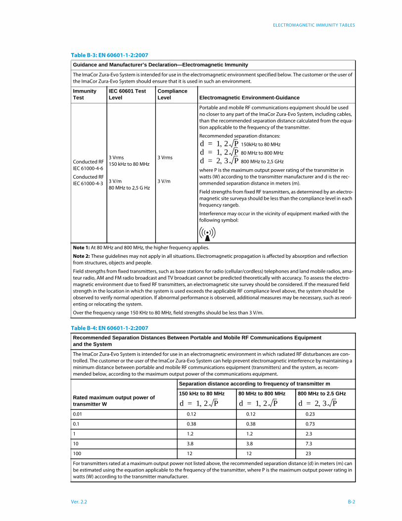
ELECTROMAGNETIC IMMUNITY TABLES
Table B-3: EN 60601-1-2:2007
Guidance and Manufacturer’s Declaration—Electromagnetic Immunity
The ImaCor Zura-Evo System is intended for use in the electromagnetic environment specified below. The customer or the user of
the ImaCor Zura-Evo System should ensure that it is used in such an environment.
Immunity Test
IEC 60601 Test Level
Compliance Level Electromagnetic Environment-Guidance
Conducted RF
IEC 61000-4-6
Conducted RF
IEC 61000-4-3
3 Vrms
150 kHz to 80 MHz
3 V/m
80 MHz to 2,5 G Hz
3 Vrms
3 V/m
Portable and mobile RF communications equipment should be used
no closer to any part of the ImaCor Zura-Evo System, including cables,
than the recommended separation distance calculated from the equa-
tion applicable to the frequency of the transmitter.
Recommended separation distances:
150kHz to 80 MHz
80 MHz to 800 MHz
800 MHz to 2,5 GHz
where P is the maximum output power rating of the transmitter in
watts (W) according to the transmitter manufacturer and d is the rec-
ommended separation distance in meters (m).
Field strengths from fixed RF transmitters, as determined by an electro-
magnetic site surveya should be less than the compliance level in each
frequency rangeb.
Interference may occur in the vicinity of equipment marked with the
following symbol:
Note 1: At 80 MHz and 800 MHz, the higher frequency applies.
Note 2: These guidelines may not apply in all situations. Electromagnetic propagation is affected by absorption and reflection
from structures, objects and people.
Field strengths from fixed transmitters, such as base stations for radio (cellular/cordless) telephones and land mobile radios, ama-
teur radio, AM and FM radio broadcast and TV broadcast cannot be predicted theoretically with accuracy. To assess the electro-
magnetic environment due to fixed RF transmitters, an electromagnetic site survey should be considered. If the measured field
strength in the location in which the system is used exceeds the applicable RF compliance level above, the system should be
observed to verify normal operation. If abnormal performance is observed, additional measures may be necessary, such as reori-
enting or relocating the system.
Over the frequency range 150 KHz to 80 MHz, field strengths should be less than 3 V/m.
Table B-4: EN 60601-1-2:2007
Recommended Separation Distances Between Portable and Mobile RF Communications Equipment and the System
The ImaCor Zura-Evo System is intended for use in an electromagnetic environment in which radiated RF disturbances are con-
trolled. The customer or the user of the ImaCor Zura-Evo System can help prevent electromagnetic interference by maintaining a
minimum distance between portable and mobile RF communications equipment (transmitters) and the system, as recom-
mended below, according to the maximum output power of the communications equipment.
Rated maximum output power of transmitter W
Separation distance according to frequency of transmitter m
150 kHz to 80 MHz 80 MHz to 800 MHz 800 MHz to 2.5 GHz
0.01 0.12 0.12 0.23
0.1 0.38 0.38 0.73
1 1.2 1.2 2.3
10 3.8 3.8 7.3
100 12 12 23
For transmitters rated at a maximum output power not listed above, the recommended separation distance (d) in meters (m) can
be estimated using the equation applicable to the frequency of the transmitter, where P is the maximum output power rating in
watts (W) according to the transmitter manufacturer.
d 1 2 P=d 1 2 P=d 2 3 P=
d 1 2 P= d 1 2 P= d 2 3 P=
Ver. 2.2 B-2
ELECTROMAGNETIC IMMUNITY TABLES
Note 1: At 80 MHz and 800 MHz, the separation distance for the higher frequency range applies.
Note 2: These guidelines may not apply in all situations. Electromagnetic propagation is affected by absorption and reflection
from structures, objects and people.
Table B-4: EN 60601-1-2:2007
Ver. 2.2 B-3
IMACOR LIMITED WARRANTY
Appendix C: ImaCor Limited Warranty
8 LIMITED WARRANTY AND REMEDY
8.1 LIMITED WARRANTY
ImaCor offers a limited warranty as per the terms and conditions of sale between the
parties that the Product as delivered to the Customer shall be free from defects in
materials and workmanship for no less than twelve (12) months (except where Customer
purchases a refurbished or reconditioned Product in which case it shall be six (6) months)
from date of delivery within North America, or from date of shipment for orders shipped
outside of North America, subject to the following limitations as well as those limitations
set out in Sections (8.2 SOLE REMEDY) and (8.3 EXCLUSIONS) below:
8.1.1 During the first twelve (12) months from delivery of the Product to the Customer,
the warranty and ImaCor’s obligations under this Section 1.1 shall be limited to
the following: provision by ImaCor of all replacement device parts, software
updates and upgrades (excluding new features) which ImaCor regularly makes
available to its customers of such Products at no additional fee, next Business Day
response to warranty repair requests received by ImaCor before 13:00 Eastern
Time on the prior Business Day, and shipping costs as per the terms and condi-
tions of sale for replacement parts. As used in this Agreement “Business Day”
means any day other than a Saturday, Sunday or statutory holiday in the United
States or install locality.
8.1.2 Notwithstanding the foregoing, for refurbished or reconditioned Products pur-
chased by the Customer, the Limited Warranty shall expire entirely six (6) months
from the date of delivery. ImaCor shall have no responsibility for defects in materi-
als or workmanship of any Product after the expiry of the applicable period for
each aspect of the Limited Warranty. In the event that ImaCor provides replace-
ment parts or components in support of a warranty claim, the warranty is not
renewed or extended, but will continue from the original date of purchase. The
Limited Warranty shall not cover, and ImaCor shall not have any responsibility for,
any defects in the Products unless the Customer gives ImaCor notice of the defect
prior to the end of the applicable warranty period.
8.2 SOLE REMEDY
ImaCor’s obligation and liability under the Limited Warranty is limited solely, at ImaCor’s
option, to repair or replace the Products, or repayment or reduction of a reasonable
portion of the purchase price for the Products, as determined by ImaCor in its sole
discretion. The Customer must obtain a “Return Materials Authorization number” from
ImaCor prior to returning any defective Product and follow all reasonable instructions of
ImaCor with respect to such return.
Ver. 2.2 C-1
IMACOR LIMITED WARRANTY
8.3 EXCLUSIONS
The Limited Warranty provided hereunder does not include the following: a) any work
external to the Product; b) maintenance, connection or removal of any device not
furnished by ImaCor; c) repair of damage by any cause beyond ImaCor’s reasonable
control, including resulting from accident, neglect, misuse, failure of recommended or
customary environmental conditions to be met, or from repairs performed by persons
other than approved repairs by ImaCor’s authorized service representatives; d) relocating
the Product or damage caused by relocation; e) upgrades to or other modifications of the
Product not approved or authorized by ImaCor, including without limitation, any
software or hardware modifications thereto, or the use of any Product with any other
hardware or software not supplied by ImaCor pursuant to a Purchase Order or written
agreement; f) any work for cosmetic purposes; g) consumable items and parts, including
batteries, h) repair of damage resulting from the use of the Product in a manner or
configuration other than as specified in the Product operation manual and other
documentation provided by ImaCor.
Ver. 2.2 C-2

SERVICE DRAWINGS
Ver. 2.2 D-1
Appendix D: Service Drawings
Contact ImaCor Technical Support