ignition management - meeknet
TRANSCRIPT
Initial Print Date: 03/11
Table of Contents
Subject Page
Ignition Management . . . . . . . . . . . . . . . . . . . . . . . . . . . . . . . . . . . . . .3Principle of Operation . . . . . . . . . . . . . . . . . . . . . . . . . . . . . . . . . . . . . . . . . . .3Ignition System Inputs . . . . . . . . . . . . . . . . . . . . . . . . . . . . . . . . . . . . . . . . . .4Ignition Coils . . . . . . . . . . . . . . . . . . . . . . . . . . . . . . . . . . . . . . . . . . . . . . . . . . .4Spark Plugs . . . . . . . . . . . . . . . . . . . . . . . . . . . . . . . . . . . . . . . . . . . . . . . . . . . .6Knock Sensors . . . . . . . . . . . . . . . . . . . . . . . . . . . . . . . . . . . . . . . . . . . . . . . . .7
Superknocking . . . . . . . . . . . . . . . . . . . . . . . . . . . . . . . . . . . . . . . . . . . . . . .8Multiple Ignition Pulses . . . . . . . . . . . . . . . . . . . . . . . . . . . . . . . . . . . . . . .9
Crankshaft Position/RPM Sensor (Hall Effect) . . . . . . . . . . . . . . . . . . . . .10Crankshaft Sensor (N55) . . . . . . . . . . . . . . . . . . . . . . . . . . . . . . . . . . . .11
Service Information . . . . . . . . . . . . . . . . . . . . . . . . . . . . . . . . . . . . . . .13Ignition Coils . . . . . . . . . . . . . . . . . . . . . . . . . . . . . . . . . . . . . . . . . . . . . . . . . .17Knock Control . . . . . . . . . . . . . . . . . . . . . . . . . . . . . . . . . . . . . . . . . . . . . . . .18Spark Plugs . . . . . . . . . . . . . . . . . . . . . . . . . . . . . . . . . . . . . . . . . . . . . . . . . . .20
Spark Plug Diagnosis (HPI engines) . . . . . . . . . . . . . . . . . . . . . . . . . . .21Engine Misfire Diagnosis . . . . . . . . . . . . . . . . . . . . . . . . . . . . . . . . . . . . . . .22
SI B 12 06 10 N54 -Misfire Faults, Diagnosis with ISTA . . . . . . . . . . . . . . . . . . . . . . . . . . .25SI B 12 11 10 N54, N54T, N55 -Diagnosis for HDP High-pressure Faults . . . . . . . . . . . . . . . . . . . . . .33
Ignition Management
Revision Date:
meeknet.co.uk/e64
2Ignition Management
Ignition Management
Model: All
Production: All
After completion of this module you will be able to:
• Understand how spark is formed and used in BMW engines
• Perform an ignition primary scope measurement
• Perform an ignition secondary scope measurement
• Interpret the spark measurements and relate them to diagnosis
• Understand optimized emission
• Describe how the ignition system is monitored
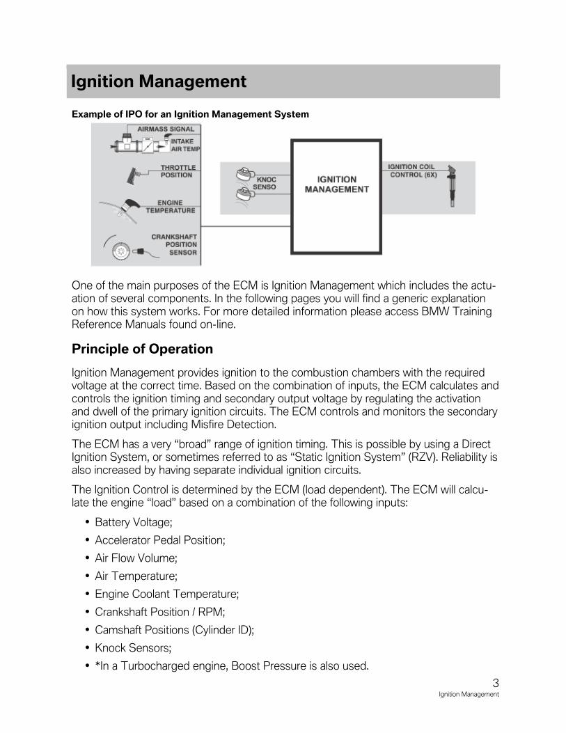
Example of IPO for an Ignition Management System
One of the main purposes of the ECM is Ignition Management which includes the actu-ation of several components. In the following pages you will find a generic explanationon how this system works. For more detailed information please access BMW TrainingReference Manuals found on-line.
Principle of Operation
Ignition Management provides ignition to the combustion chambers with the requiredvoltage at the correct time. Based on the combination of inputs, the ECM calculates andcontrols the ignition timing and secondary output voltage by regulating the activationand dwell of the primary ignition circuits. The ECM controls and monitors the secondaryignition output including Misfire Detection.
The ECM has a very “broad” range of ignition timing. This is possible by using a DirectIgnition System, or sometimes referred to as “Static Ignition System” (RZV). Reliability isalso increased by having separate individual ignition circuits.
The Ignition Control is determined by the ECM (load dependent). The ECM will calcu-late the engine “load” based on a combination of the following inputs:
• Battery Voltage;
• Accelerator Pedal Position;
• Air Flow Volume;
• Air Temperature;
• Engine Coolant Temperature;
• Crankshaft Position / RPM;
• Camshaft Positions (Cylinder ID);
• Knock Sensors;
• *In a Turbocharged engine, Boost Pressure is also used.
3Ignition Management
Ignition Management
The dwell time will be regulated based on battery voltage. When cranking, the voltage islow and the ECM will increase the dwell to compensate for saturation “lag time”. Whenthe engine is running and the battery voltage is higher, the ECM will decrease the dwelldue to faster saturation time.
The Crankshaft Position/RPM signals the ECM to start ignition in firing order as wellas providing information about the engine operation. This input is used in combinationwith other inputs to determine engine load which advances/retards the ignition tim-ing. Without this input, the ECM will not activate the ignition.
Cold start is determined by the ECM based on the engine coolant temperature and rpmduring start up. A cold engine will crank over slower than a warm engine, the ignition tim-ing will range between top dead center to slightly retarded providing optimum starting.
When starting a warm engine, the rpm is higher which results in slightly advanced timing.
If the engine coolant and intake air temperature is hot, the ignition timing will not beadvanced reducing starter motor “load”.
Ignition System Inputs
The ignition system on the engine management system uses several inputs to controlignition functions. Proper ignition timing control is dependent upon inputs such as RPM,throttle position, crankshaft position, air mass and temperature (coolant and intake air)and in our turbocharged engines, intake boost pressure.
Most of the ignition system components have remained the same for all NG6 engines.There are some minor changes to the ignition coils that apply to all versions. The coilshave been optimized for more durability.
Ignition Coils
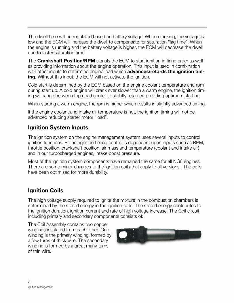
The high voltage supply required to ignite the mixture in the combustion chambers isdetermined by the stored energy in the ignition coils. The stored energy contributes tothe ignition duration, ignition current and rate of high voltage increase. The Coil circuitincluding primary and secondary components consists of:
The Coil Assembly contains two copperwindings insulated from each other. Onewinding is the primary winding, formed bya few turns of thick wire. The secondarywinding is formed by a great many turnsof thin wire.
4Ignition Management
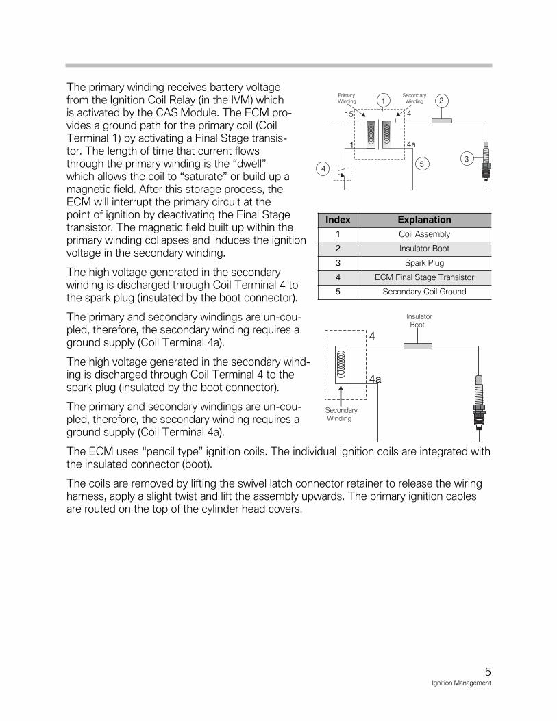
The primary winding receives battery voltagefrom the Ignition Coil Relay (in the IVM) whichis activated by the CAS Module. The ECM pro-vides a ground path for the primary coil (CoilTerminal 1) by activating a Final Stage transis-tor. The length of time that current flowsthrough the primary winding is the “dwell”which allows the coil to “saturate” or build up amagnetic field. After this storage process, theECM will interrupt the primary circuit at thepoint of ignition by deactivating the Final Stagetransistor. The magnetic field built up within theprimary winding collapses and induces the ignitionvoltage in the secondary winding.
The high voltage generated in the secondarywinding is discharged through Coil Terminal 4 tothe spark plug (insulated by the boot connector).
The primary and secondary windings are un-cou-pled, therefore, the secondary winding requires aground supply (Coil Terminal 4a).
The high voltage generated in the secondary wind-ing is discharged through Coil Terminal 4 to thespark plug (insulated by the boot connector).
The primary and secondary windings are un-cou-pled, therefore, the secondary winding requires aground supply (Coil Terminal 4a).
The ECM uses “pencil type” ignition coils. The individual ignition coils are integrated withthe insulated connector (boot).
The coils are removed by lifting the swivel latch connector retainer to release the wiringharness, apply a slight twist and lift the assembly upwards. The primary ignition cablesare routed on the top of the cylinder head covers.
5Ignition Management
Insulator Boot
Secondary Winding
Index Explanation
1 Coil Assembly
2 Insulator Boot
3 Spark Plug
4 ECM Final Stage Transistor
5 Secondary Coil Ground
Spark Plugs
The spark plugs introduce the ignition energy into the combustionchamber. The high voltage “arcs” across the air gap in the sparkplug from the positive electrode to the negative electrodes. Thiscreates a spark which ignites the combustible air/fuel mixture.
The spark plugs are located in the center of the combustion area(on the top of the cylinder heads) which is the most suitable pointfor igniting the compressed air/fuel mixture.
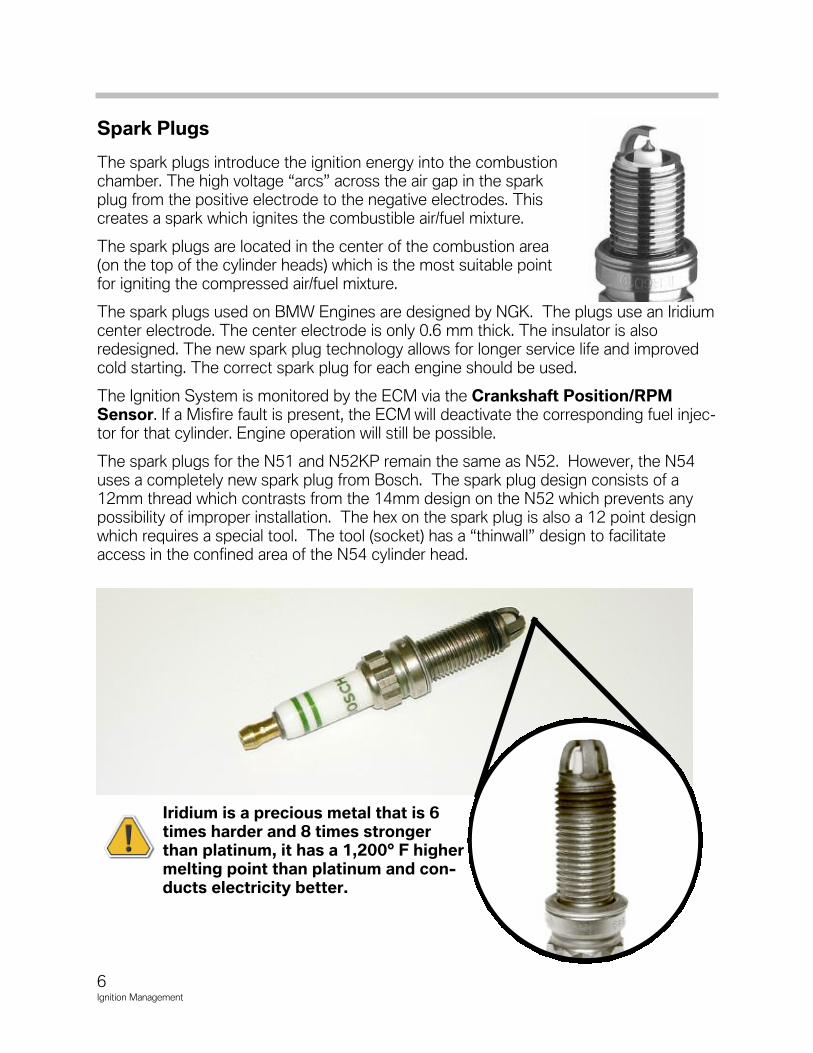
The spark plugs used on BMW Engines are designed by NGK. The plugs use an Iridiumcenter electrode. The center electrode is only 0.6 mm thick. The insulator is alsoredesigned. The new spark plug technology allows for longer service life and improvedcold starting. The correct spark plug for each engine should be used.
The Ignition System is monitored by the ECM via the Crankshaft Position/RPMSensor. If a Misfire fault is present, the ECM will deactivate the corresponding fuel injec-tor for that cylinder. Engine operation will still be possible.
The spark plugs for the N51 and N52KP remain the same as N52. However, the N54uses a completely new spark plug from Bosch. The spark plug design consists of a12mm thread which contrasts from the 14mm design on the N52 which prevents anypossibility of improper installation. The hex on the spark plug is also a 12 point designwhich requires a special tool. The tool (socket) has a “thinwall” design to facilitateaccess in the confined area of the N54 cylinder head.
Iridium is a precious metal that is 6times harder and 8 times strongerthan platinum, it has a 1,200° F highermelting point than platinum and con-ducts electricity better.
6Ignition Management
Knock Sensors
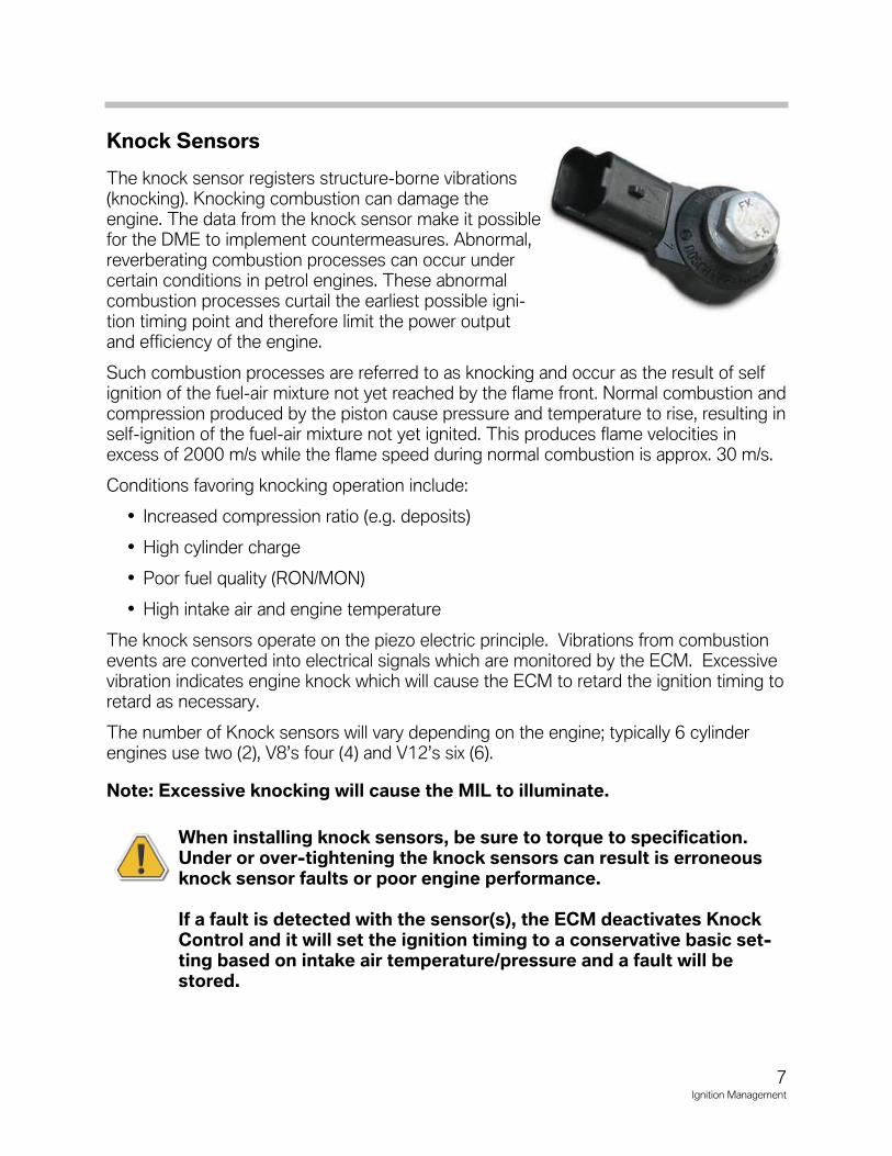
The knock sensor registers structure-borne vibrations(knocking). Knocking combustion can damage theengine. The data from the knock sensor make it possiblefor the DME to implement countermeasures. Abnormal,reverberating combustion processes can occur undercertain conditions in petrol engines. These abnormalcombustion processes curtail the earliest possible igni-tion timing point and therefore limit the power outputand efficiency of the engine.
Such combustion processes are referred to as knocking and occur as the result of selfignition of the fuel-air mixture not yet reached by the flame front. Normal combustion andcompression produced by the piston cause pressure and temperature to rise, resulting inself-ignition of the fuel-air mixture not yet ignited. This produces flame velocities inexcess of 2000 m/s while the flame speed during normal combustion is approx. 30 m/s.
Conditions favoring knocking operation include:
• Increased compression ratio (e.g. deposits)
• High cylinder charge
• Poor fuel quality (RON/MON)
• High intake air and engine temperature
The knock sensors operate on the piezo electric principle. Vibrations from combustionevents are converted into electrical signals which are monitored by the ECM. Excessivevibration indicates engine knock which will cause the ECM to retard the ignition timing toretard as necessary.
The number of Knock sensors will vary depending on the engine; typically 6 cylinderengines use two (2), V8’s four (4) and V12’s six (6).
Note: Excessive knocking will cause the MIL to illuminate.
When installing knock sensors, be sure to torque to specification.Under or over-tightening the knock sensors can result is erroneousknock sensor faults or poor engine performance.
If a fault is detected with the sensor(s), the ECM deactivates KnockControl and it will set the ignition timing to a conservative basic set-ting based on intake air temperature/pressure and a fault will bestored.
7Ignition Management
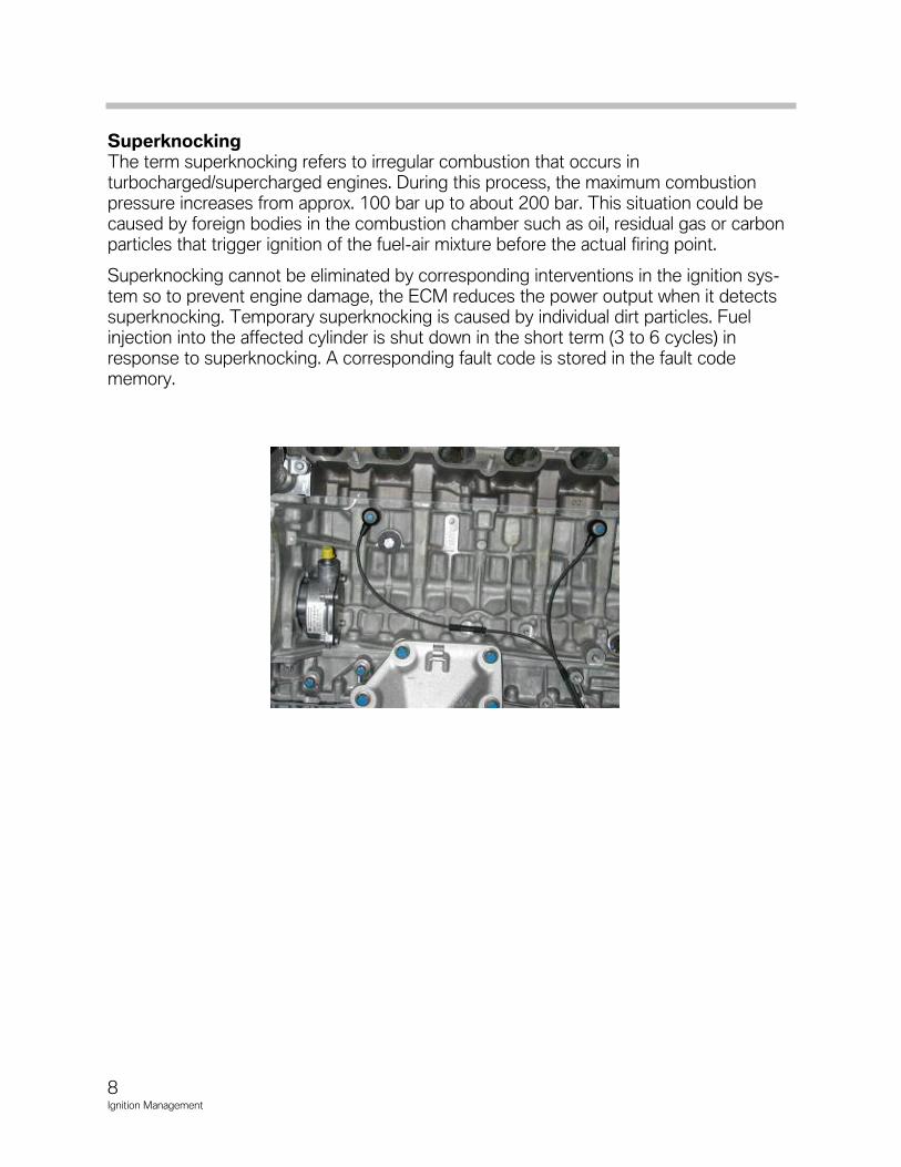
SuperknockingThe term superknocking refers to irregular combustion that occurs inturbocharged/supercharged engines. During this process, the maximum combustionpressure increases from approx. 100 bar up to about 200 bar. This situation could becaused by foreign bodies in the combustion chamber such as oil, residual gas or carbonparticles that trigger ignition of the fuel-air mixture before the actual firing point.
Superknocking cannot be eliminated by corresponding interventions in the ignition sys-tem so to prevent engine damage, the ECM reduces the power output when it detectssuperknocking. Temporary superknocking is caused by individual dirt particles. Fuelinjection into the affected cylinder is shut down in the short term (3 to 6 cycles) inresponse to superknocking. A corresponding fault code is stored in the fault codememory.
8Ignition Management
9Ignition Management
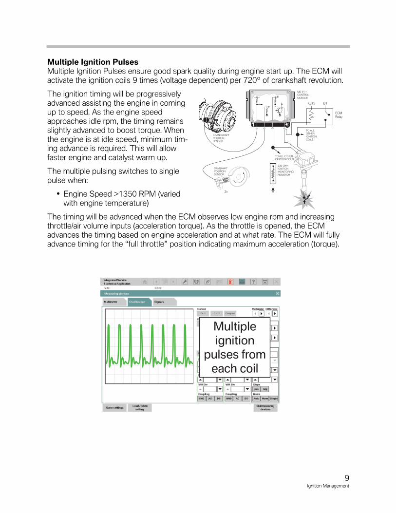
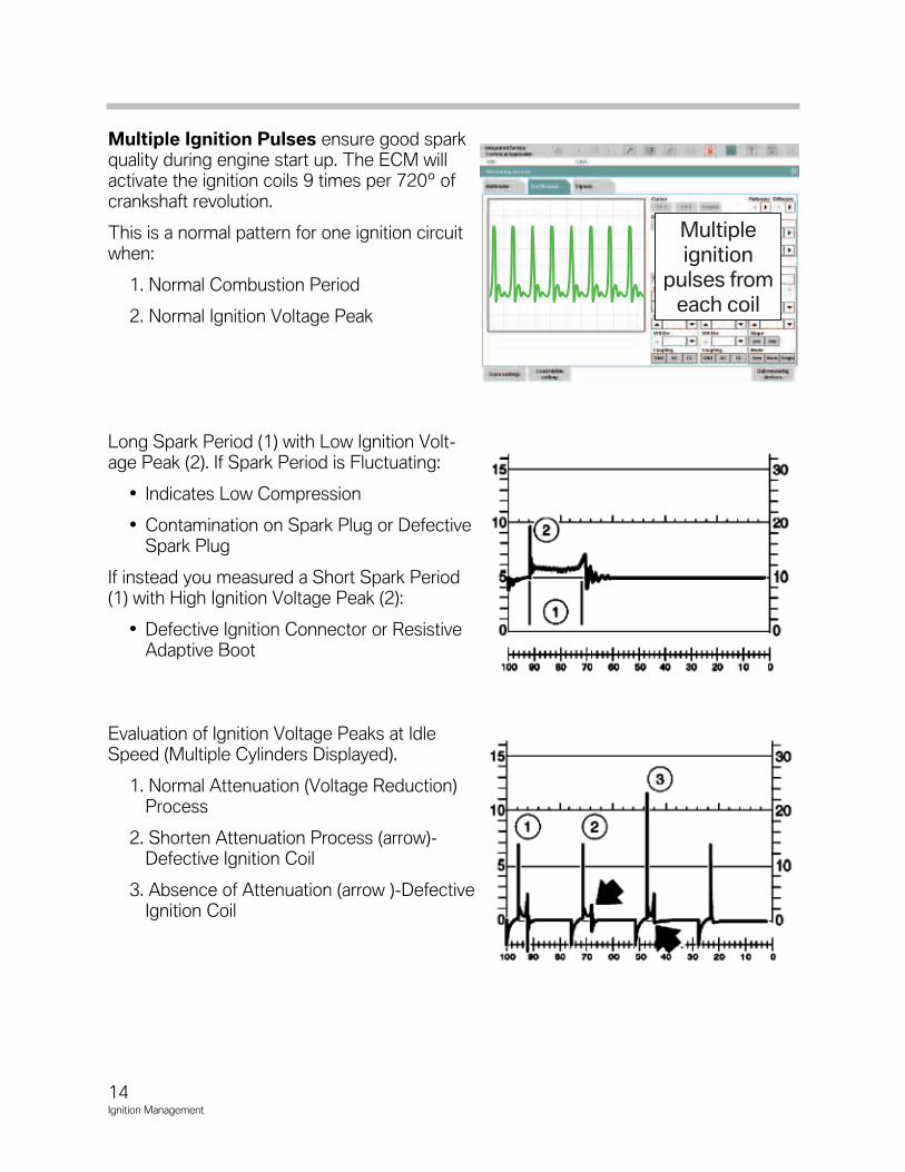
Multiple Ignition PulsesMultiple Ignition Pulses ensure good spark quality during engine start up. The ECM willactivate the ignition coils 9 times (voltage dependent) per 720º of crankshaft revolution.
The ignition timing will be progressivelyadvanced assisting the engine in comingup to speed. As the engine speedapproaches idle rpm, the timing remainsslightly advanced to boost torque. Whenthe engine is at idle speed, minimum tim-ing advance is required. This will allowfaster engine and catalyst warm up.
The multiple pulsing switches to singlepulse when:
• Engine Speed >1350 RPM (variedwith engine temperature)
The timing will be advanced when the ECM observes low engine rpm and increasingthrottle/air volume inputs (acceleration torque). As the throttle is opened, the ECMadvances the timing based on engine acceleration and at what rate. The ECM will fullyadvance timing for the “full throttle” position indicating maximum acceleration (torque).
Multipleignition
pulses fromeach coil
10Ignition Management
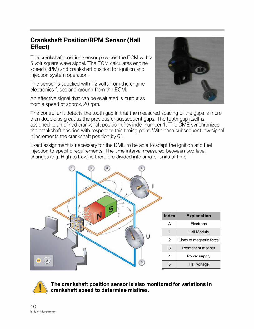
Crankshaft Position/RPM Sensor (HallEffect)
The crankshaft position sensor provides the ECM with a5 volt square wave signal. The ECM calculates enginespeed (RPM) and crankshaft position for ignition andinjection system operation.
The sensor is supplied with 12 volts from the engineelectronics fuses and ground from the ECM.
An effective signal that can be evaluated is output asfrom a speed of approx. 20 rpm.
The control unit detects the tooth gap in that the measured spacing of the gaps is morethan double as great as the previous or subsequent gaps. The tooth gap itself isassigned to a defined crankshaft position of cylinder number 1. The DME synchronizesthe crankshaft position with respect to this timing point. With each subsequent low signalit increments the crankshaft position by 6°.
Exact assignment is necessary for the DME to be able to adapt the ignition and fuelinjection to specific requirements. The time interval measured between two levelchanges (e.g. High to Low) is therefore divided into smaller units of time.
The crankshaft position sensor is also monitored for variations incrankshaft speed to determine misfires.
Index Explanation
A Electrons
1 Hall Module
2 Lines of magnetic force
3 Permanent magnet
4 Power supply
5 Hall voltage
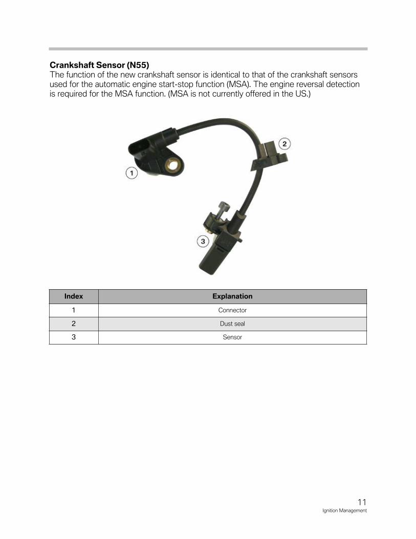
Crankshaft Sensor (N55)The function of the new crankshaft sensor is identical to that of the crankshaft sensorsused for the automatic engine startstop function (MSA). The engine reversal detectionis required for the MSA function. (MSA is not currently offered in the US.)
11Ignition Management
Index Explanation
1 Connector
2 Dust seal
3 Sensor

12Ignition Management
NOTESPAGE
13Ignition Management
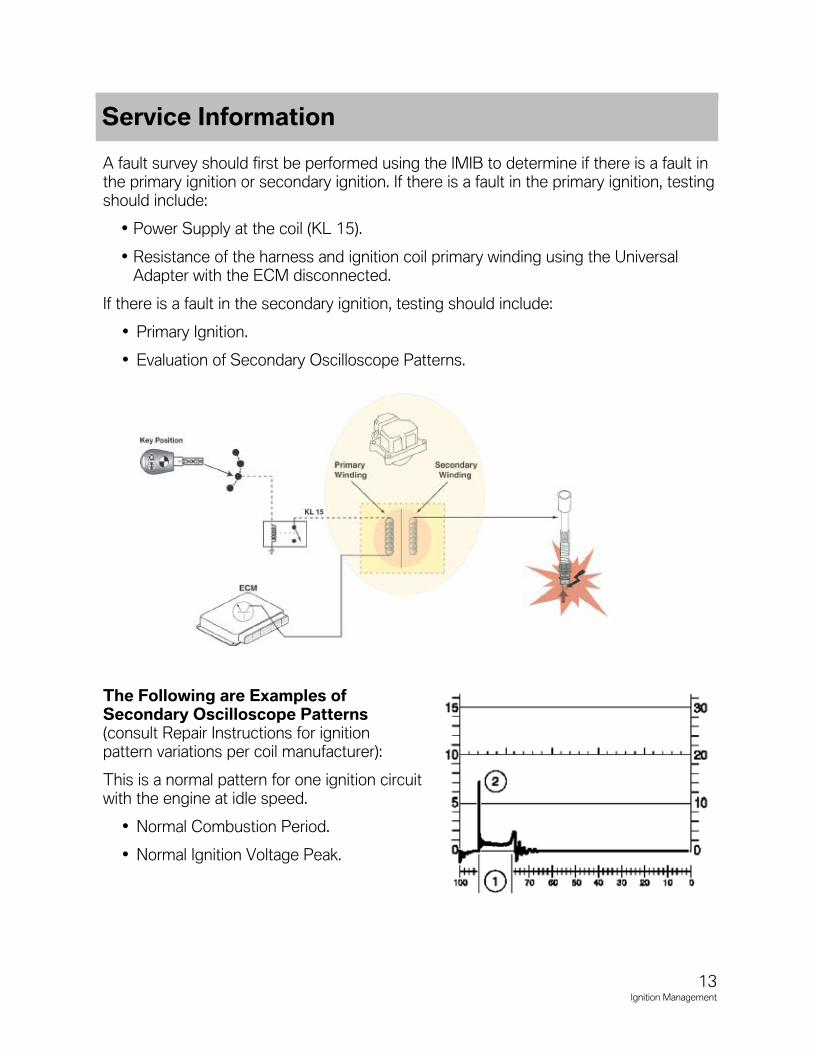
A fault survey should first be performed using the IMIB to determine if there is a fault inthe primary ignition or secondary ignition. If there is a fault in the primary ignition, testingshould include:
• Power Supply at the coil (KL 15).
• Resistance of the harness and ignition coil primary winding using the UniversalAdapter with the ECM disconnected.
If there is a fault in the secondary ignition, testing should include:
• Primary Ignition.
• Evaluation of Secondary Oscilloscope Patterns.
The Following are Examples ofSecondary Oscilloscope Patterns(consult Repair Instructions for ignitionpattern variations per coil manufacturer):
This is a normal pattern for one ignition circuitwith the engine at idle speed.
• Normal Combustion Period.
• Normal Ignition Voltage Peak.
Service Information
14Ignition Management
Multiple Ignition Pulses ensure good sparkquality during engine start up. The ECM willactivate the ignition coils 9 times per 720º ofcrankshaft revolution.
This is a normal pattern for one ignition circuitwhen:
1. Normal Combustion Period
2. Normal Ignition Voltage Peak
Long Spark Period (1) with Low Ignition Volt-age Peak (2). If Spark Period is Fluctuating:
• Indicates Low Compression
• Contamination on Spark Plug or DefectiveSpark Plug
If instead you measured a Short Spark Period(1) with High Ignition Voltage Peak (2):
• Defective Ignition Connector or ResistiveAdaptive Boot
Evaluation of Ignition Voltage Peaks at IdleSpeed (Multiple Cylinders Displayed).
1. Normal Attenuation (Voltage Reduction)Process
2. Shorten Attenuation Process (arrow)-Defective Ignition Coil
3. Absence of Attenuation (arrow )-DefectiveIgnition Coil
Multipleignition
pulses fromeach coil
15Ignition Management
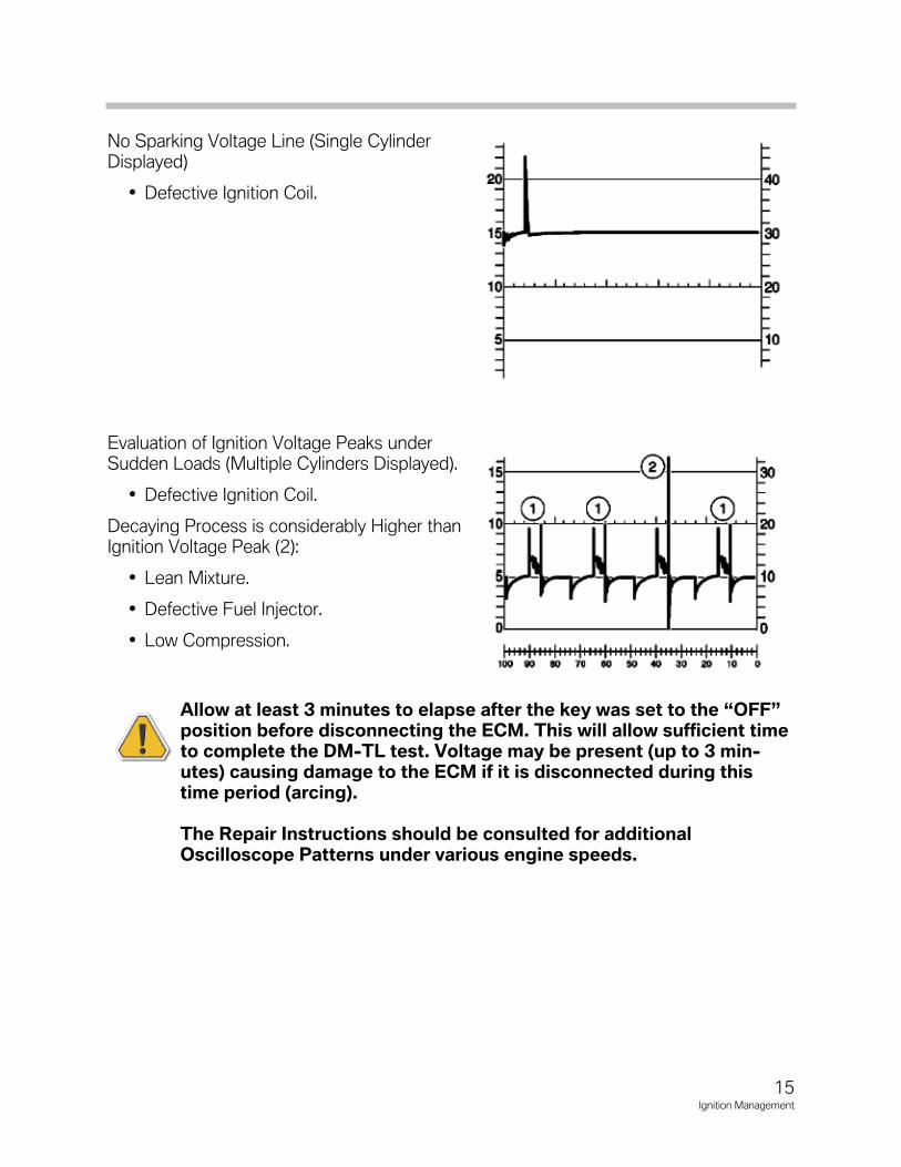
No Sparking Voltage Line (Single CylinderDisplayed)
• Defective Ignition Coil.
Evaluation of Ignition Voltage Peaks underSudden Loads (Multiple Cylinders Displayed).
• Defective Ignition Coil.
Decaying Process is considerably Higher thanIgnition Voltage Peak (2):
• Lean Mixture.
• Defective Fuel Injector.
• Low Compression.
Allow at least 3 minutes to elapse after the key was set to the “OFF”position before disconnecting the ECM. This will allow sufficient timeto complete the DM-TL test. Voltage may be present (up to 3 min-utes) causing damage to the ECM if it is disconnected during thistime period (arcing).
The Repair Instructions should be consulted for additionalOscilloscope Patterns under various engine speeds.
16Ignition Management
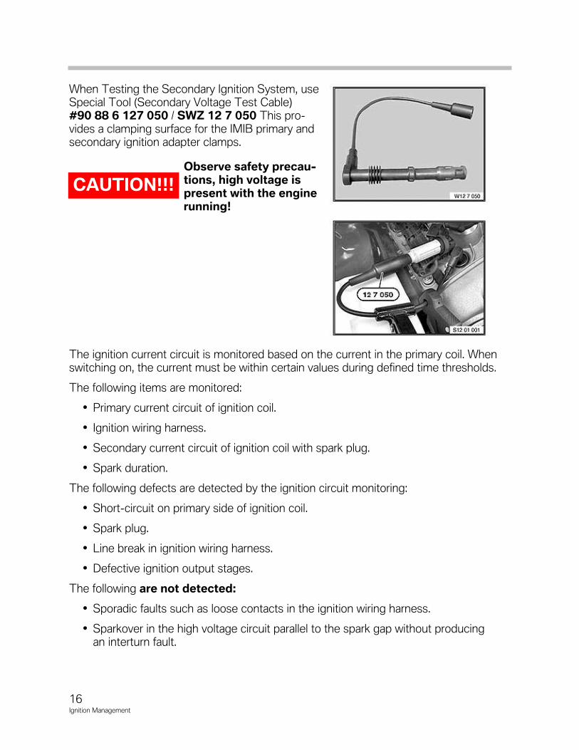
When Testing the Secondary Ignition System, useSpecial Tool (Secondary Voltage Test Cable) #90 88 6 127 050 / SWZ 12 7 050 This pro-vides a clamping surface for the IMIB primary andsecondary ignition adapter clamps.
Observe safety precau-tions, high voltage ispresent with the enginerunning!
The ignition current circuit is monitored based on the current in the primary coil. Whenswitching on, the current must be within certain values during defined time thresholds.
The following items are monitored:
• Primary current circuit of ignition coil.
• Ignition wiring harness.
• Secondary current circuit of ignition coil with spark plug.
• Spark duration.
The following defects are detected by the ignition circuit monitoring:
• Short-circuit on primary side of ignition coil.
• Spark plug.
• Line break in ignition wiring harness.
• Defective ignition output stages.
The following are not detected:
• Sporadic faults such as loose contacts in the ignition wiring harness.
• Sparkover in the high voltage circuit parallel to the spark gap without producingan interturn fault.
CAUTION!!!
17Ignition Management
In Summary,
If the Secondary Ignition Voltage is Too High (Excessive Resistance for Ignition):
• Spark Plug Gap is to Large (Worn or Burned).
• Incorrect Heat Range Spark Plug.
• Compression is too High (Carbon, etc.).
• Interruption in the Secondary Ignition Connector or Resistive Adapter Boot.
If the Secondary Ignition Voltage is Too Low (Low Resistance for Ignition):
• Spark Plug Gap is Too Small (Mishandled on Installation).
• Incorrect Heat Range Spark Plug.
• Compression is Too Low.
• Voltage Leak in the Secondary Ignition Connector or Resistive Boot to Ground.
Ignition Coils
The ignition coils of BMW enignes have been redesigned for better rigidity and durability.Particular care must be taken when working on the fuel system to ensure that the igni-tion coils are not wet with fuel. The resistance of the silicone material is greatly reducedby contact with fuel. This could compromise the coils insulation and result in arcking atthe top of the spark plug causing a misfire.
• The ignition coils must be removed before working on the fuel system.
• When installing new solenoid valve fuel injectors utmost cleanliness must beobserved.
• After removing the ignition coils use a rag to prevent fuel from entering the sparkplug well.
• Ignition coils that have been saturated with fuel must be replaced.
18Ignition Management
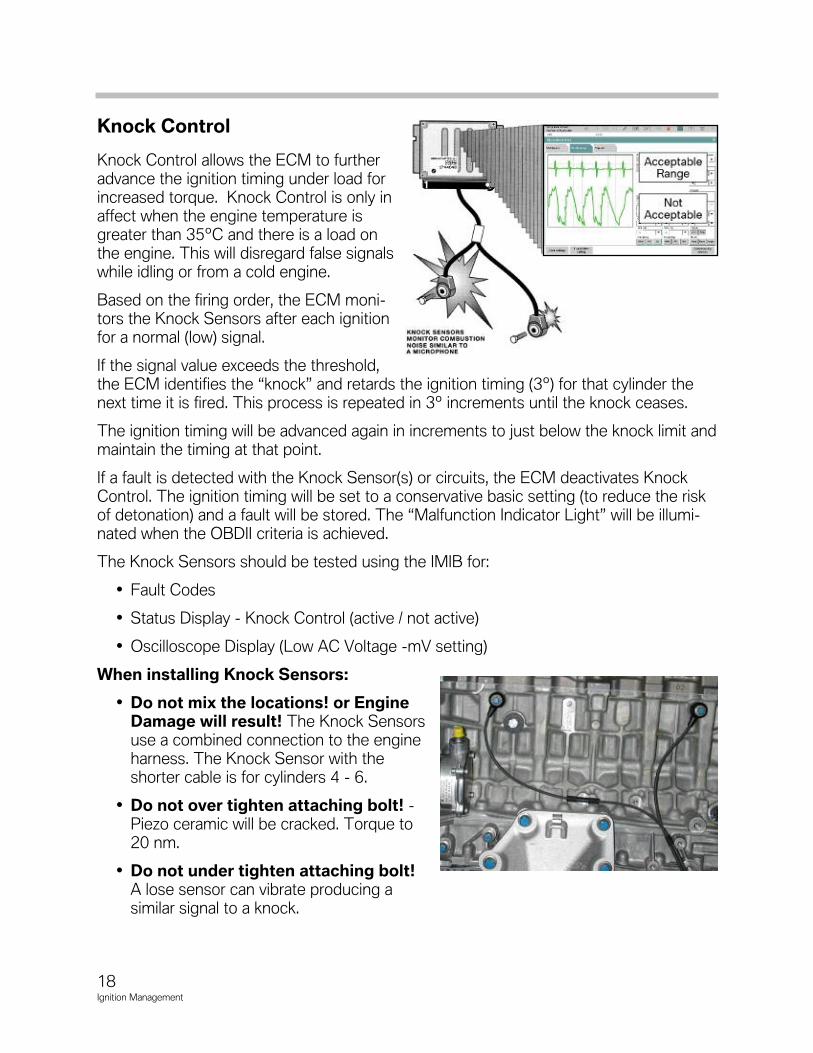
Knock Control
Knock Control allows the ECM to furtheradvance the ignition timing under load forincreased torque. Knock Control is only inaffect when the engine temperature isgreater than 35ºC and there is a load onthe engine. This will disregard false signalswhile idling or from a cold engine.
Based on the firing order, the ECM moni-tors the Knock Sensors after each ignitionfor a normal (low) signal.
If the signal value exceeds the threshold,the ECM identifies the “knock” and retards the ignition timing (3º) for that cylinder thenext time it is fired. This process is repeated in 3º increments until the knock ceases.
The ignition timing will be advanced again in increments to just below the knock limit andmaintain the timing at that point.
If a fault is detected with the Knock Sensor(s) or circuits, the ECM deactivates KnockControl. The ignition timing will be set to a conservative basic setting (to reduce the riskof detonation) and a fault will be stored. The “Malfunction Indicator Light” will be illumi-nated when the OBDII criteria is achieved.
The Knock Sensors should be tested using the IMIB for:
• Fault Codes
• Status Display - Knock Control (active / not active)
• Oscilloscope Display (Low AC Voltage -mV setting)
When installing Knock Sensors:
• Do not mix the locations! or EngineDamage will result! The Knock Sensorsuse a combined connection to the engineharness. The Knock Sensor with theshorter cable is for cylinders 4 - 6.
• Do not over tighten attaching bolt! -Piezo ceramic will be cracked. Torque to20 nm.
• Do not under tighten attaching bolt!A lose sensor can vibrate producing asimilar signal to a knock.
19Ignition Management
Conditions favoring knocking operation include:
• Elevated compression ratio.
• High cylinder charge.
• Poor fuel quality (RON/MON).
• High intake air and engine temperature.
Self-diagnosis of the knock control system comprises the following checks:
• Check for signal error, e.g. line break or plug connection defective.
• Self-test of evaluator circuit.
• Check of noise level registered by the knock sensor for the engine.
Knock control is switched off if an error is determined in one of these checks. In thiscase, an emergency program controls the ignition timing. At the same time, a corre-sponding fault code is entered in the fault code memory. The emergency programensures safe, damage-free operation. The emergency program depends on the load,engine speed and engine temperature.
20Ignition Management
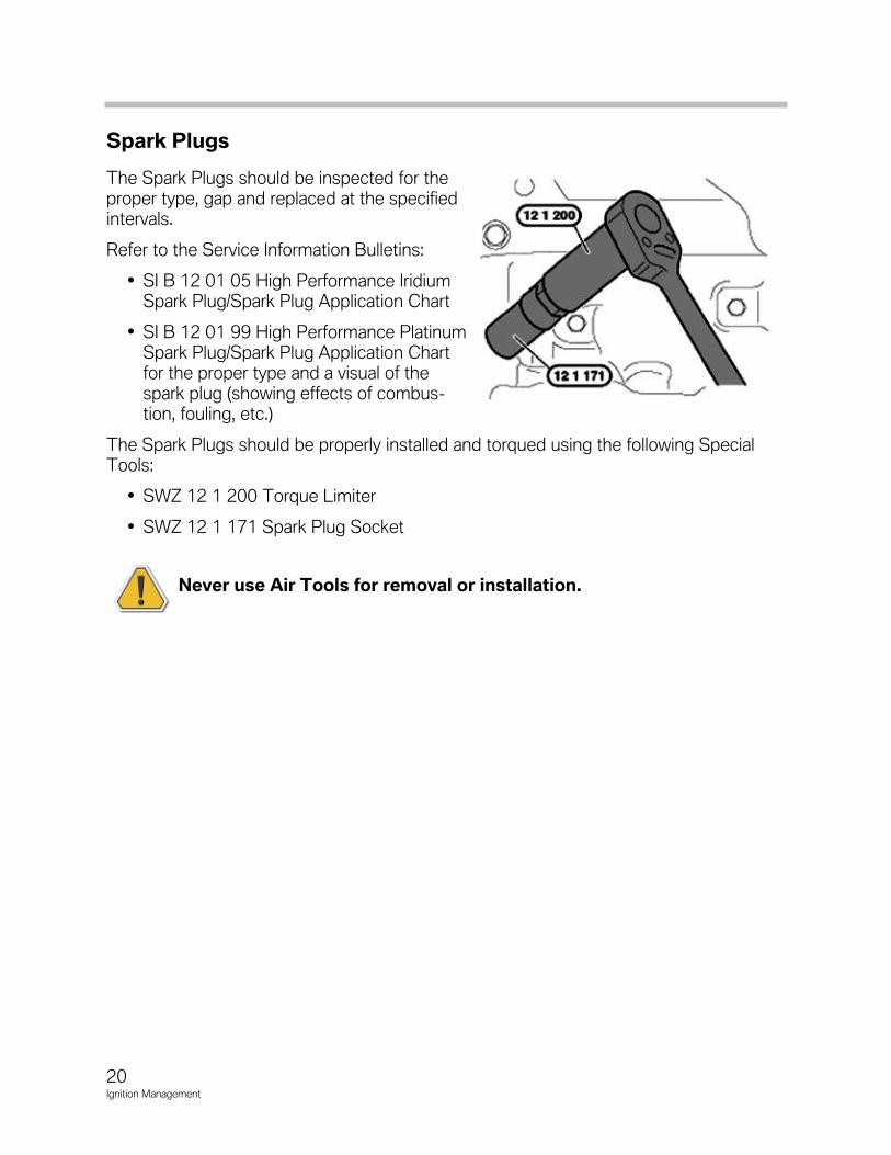
Spark Plugs
The Spark Plugs should be inspected for theproper type, gap and replaced at the specifiedintervals.
Refer to the Service Information Bulletins:
• SI B 12 01 05 High Performance IridiumSpark Plug/Spark Plug Application Chart
• SI B 12 01 99 High Performance PlatinumSpark Plug/Spark Plug Application Chartfor the proper type and a visual of thespark plug (showing effects of combus-tion, fouling, etc.)
The Spark Plugs should be properly installed and torqued using the following SpecialTools:
• SWZ 12 1 200 Torque Limiter
• SWZ 12 1 171 Spark Plug Socket
Never use Air Tools for removal or installation.
21Ignition Management
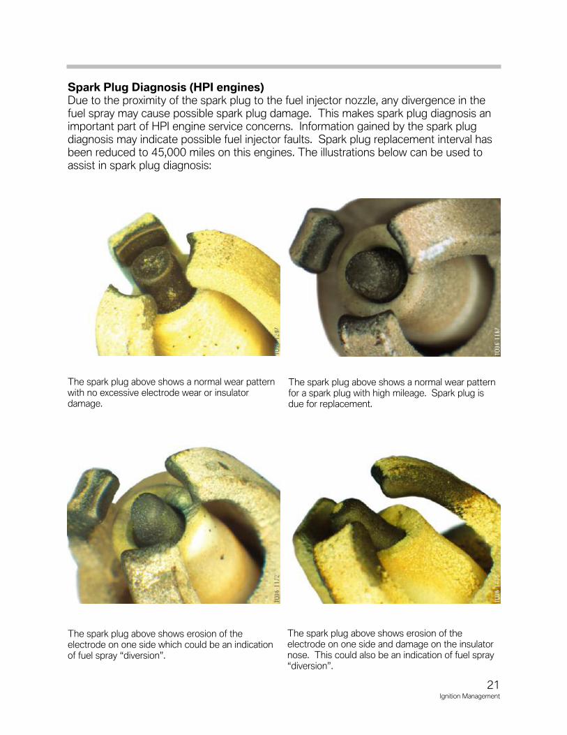
Spark Plug Diagnosis (HPI engines)Due to the proximity of the spark plug to the fuel injector nozzle, any divergence in thefuel spray may cause possible spark plug damage. This makes spark plug diagnosis animportant part of HPI engine service concerns. Information gained by the spark plugdiagnosis may indicate possible fuel injector faults. Spark plug replacement interval hasbeen reduced to 45,000 miles on this engines. The illustrations below can be used toassist in spark plug diagnosis:
The spark plug above shows a normal wear patternwith no excessive electrode wear or insulator damage.
The spark plug above shows a normal wear patternfor a spark plug with high mileage. Spark plug isdue for replacement.
The spark plug above shows erosion of the electrode on one side which could be an indicationof fuel spray “diversion”.
The spark plug above shows erosion of the electrode on one side and damage on the insulatornose. This could also be an indication of fuel spray“diversion”.
22Ignition Management
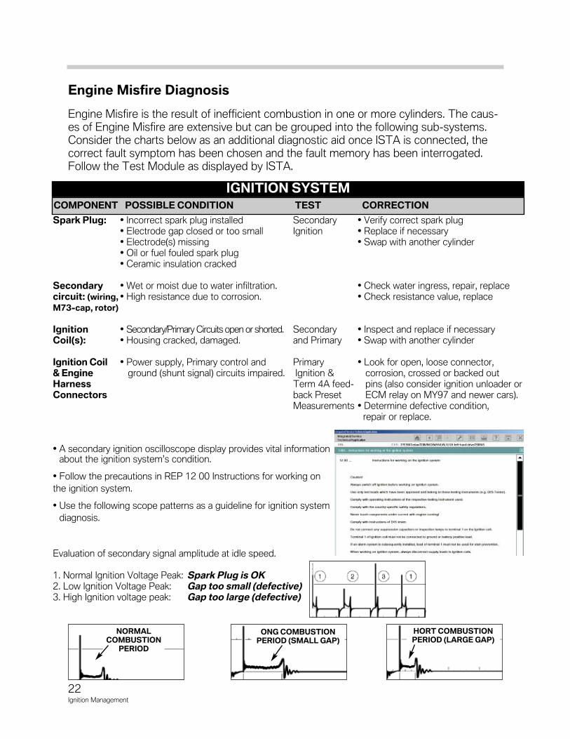
Engine Misfire Diagnosis
Engine Misfire is the result of inefficient combustion in one or more cylinders. The caus-es of Engine Misfire are extensive but can be grouped into the following sub-systems.Consider the charts below as an additional diagnostic aid once ISTA is connected, thecorrect fault symptom has been chosen and the fault memory has been interrogated.Follow the Test Module as displayed by ISTA.
IGNITION SySTEMCOMPONENT POSSIBLE CONDITION TEST CORRECTION
Spark Plug: • Incorrect spark plug installed Secondary • Verify correct spark plug• Electrode gap closed or too small Ignition • Replace if necessary• Electrode(s) missing • Swap with another cylinder• Oil or fuel fouled spark plug• Ceramic insulation cracked
Secondary • Wet or moist due to water infiltration. • Check water ingress, repair, replacecircuit: (wiring, • High resistance due to corrosion. • Check resistance value, replaceM73-cap, rotor)
Ignition • Secondary/Primary Circuits open or shorted. Secondary • Inspect and replace if necessaryCoil(s): • Housing cracked, damaged. and Primary • Swap with another cylinder
Ignition Coil • Power supply, Primary control and Primary • Look for open, loose connector, & Engine ground (shunt signal) circuits impaired. Ignition & corrosion, crossed or backed out Harness Term 4A feed pins (also consider ignition unloader or Connectors back Preset ECM relay on MY97 and newer cars).
Measurements • Determine defective condition, repair or replace.
• A secondary ignition oscilloscope display provides vital informationabout the ignition system’s condition.
• Follow the precautions in REP 12 00 Instructions for working on
the ignition system.
• Use the following scope patterns as a guideline for ignition system
diagnosis.
Evaluation of secondary signal amplitude at idle speed.
1. Normal Ignition Voltage Peak: Spark Plug is OK2. Low Ignition Voltage Peak: Gap too small (defective)3. High Ignition voltage peak: Gap too large (defective)
NORMALCOMBUSTION
PERIOD
ONG COMBUSTIONPERIOD (SMALL GAP)
HORT COMBUSTIONPERIOD (LARGE GAP)
23Ignition Management
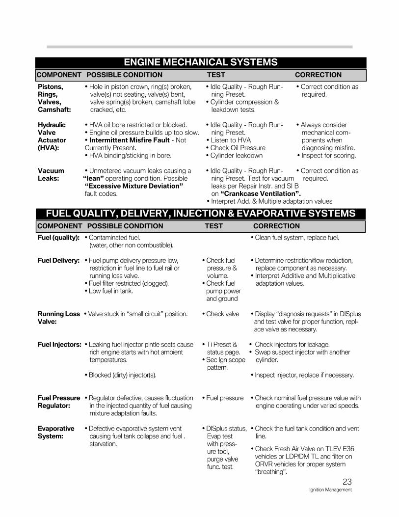
ENGINE MECHANICAL SySTEMS
COMPONENT POSSIBLE CONDITION TEST CORRECTION
Pistons, • Hole in piston crown, ring(s) broken, • Idle Quality Rough Run • Correct condition as Rings, valve(s) not seating, valve(s) bent, ning Preset. required.Valves, valve spring(s) broken, camshaft lobe • Cylinder compression & Camshaft: cracked, etc. leakdown tests.
Hydraulic • HVA oil bore restricted or blocked. • Idle Quality Rough Run • Always consider Valve • Engine oil pressure builds up too slow. ning Preset. mechanical comActuator • Intermittent Misfire Fault Not • Listen to HVA ponents when (HVA): Currently Present. • Check Oil Pressure diagnosing misfire.
• HVA binding/sticking in bore. • Cylinder leakdown • Inspect for scoring.
Vacuum • Unmetered vacuum leaks causing a • Idle Quality Rough Run • Correct condition asLeaks: “lean” operating condition. Possible ning Preset. Test for vacuum required.
“Excessive Mixture Deviation” leaks per Repair Instr. and SI B fault codes. on “Crankcase Ventilation”.
• Interpret Add. & Multiple adaptation values
FUEL QUALITy, DELIVERy, INjECTION & EVAPORATIVE SySTEMS
COMPONENT POSSIBLE CONDITION TEST CORRECTION
Fuel (quality): • Contaminated fuel. • Clean fuel system, replace fuel.(water, other non combustible).
Fuel Delivery: • Fuel pump delivery pressure low, • Check fuel • Determine restriction/flow reduction,restriction in fuel line to fuel rail or pressure & replace component as necessary.running loss valve. volume. • Interpret Additive and Multiplicative
• Fuel filter restricted (clogged). • Check fuel adaptation values.• Low fuel in tank. pump power
and ground
Running Loss • Valve stuck in “small circuit” position. • Check valve • Display “diagnosis requests” in DISplus Valve: and test valve for proper function, repl
ace valve as necessary.
Fuel Injectors: • Leaking fuel injector pintle seats cause • Ti Preset & • Check injectors for leakage.rich engine starts with hot ambient status page. • Swap suspect injector with another temperatures. • Sec Ign scope cylinder.
pattern.• Blocked (dirty) injector(s). • Inspect injector, replace if necessary.
Fuel Pressure • Regulator defective, causes fluctuation • Fuel pressure • Check nominal fuel pressure value with Regulator: in the injected quantity of fuel causing engine operating under varied speeds.
mixture adaptation faults.
Evaporative • Defective evaporative system vent • DISplus status, • Check the fuel tank condition and vent System: causing fuel tank collapse and fuel . Evap test line.
starvation. with pressure tool, purge valvefunc. test.
• Check Fresh Air Valve on TLEV E36vehicles or LDP/DM TL and filter onORVR vehicles for proper system“breathing”.
24Ignition Management
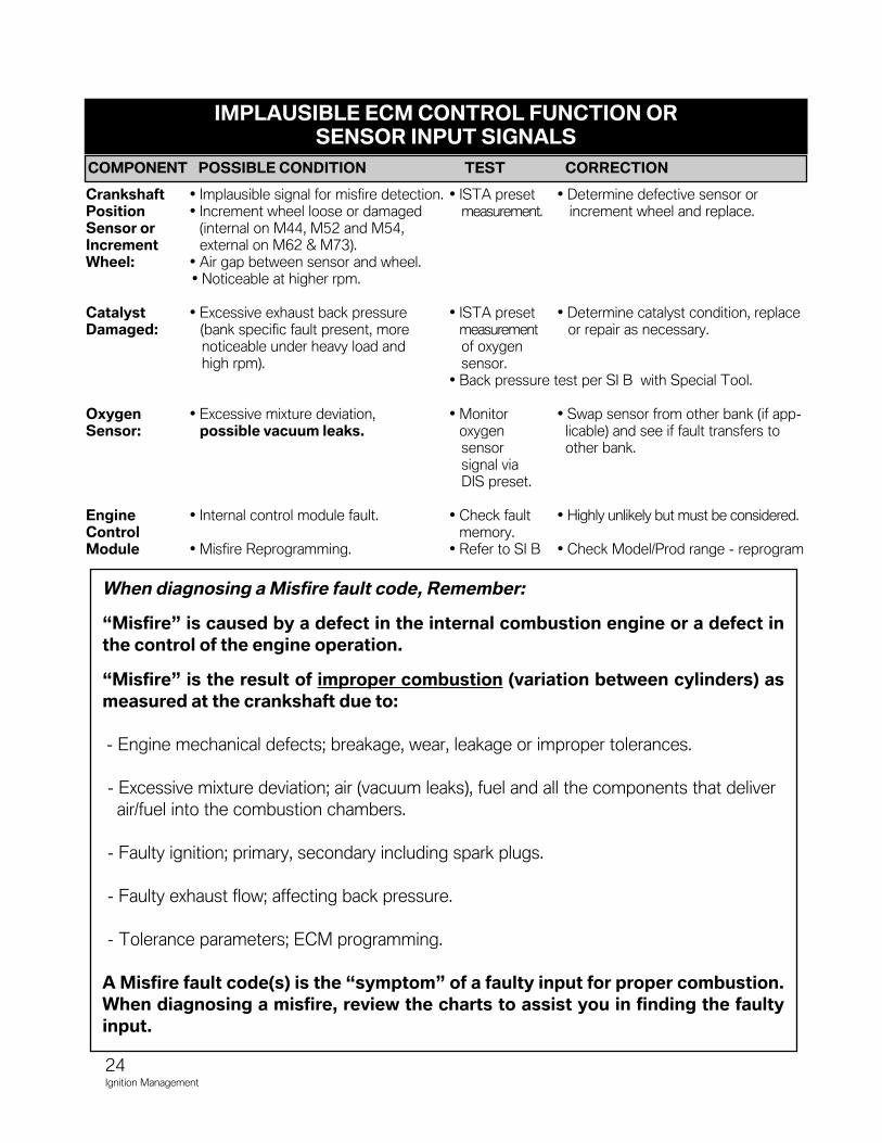
IMPLAUSIBLE ECM CONTROL FUNCTION OR SENSOR INPUT SIGNALS
COMPONENT POSSIBLE CONDITION TEST CORRECTION
Crankshaft • Implausible signal for misfire detection. • ISTA preset • Determine defective sensor or Position • Increment wheel loose or damaged measurement. increment wheel and replace.Sensor or (internal on M44, M52 and M54, Increment external on M62 & M73).Wheel: • Air gap between sensor and wheel.
• Noticeable at higher rpm.
Catalyst • Excessive exhaust back pressure • ISTA preset • Determine catalyst condition, replaceDamaged: (bank specific fault present, more measurement or repair as necessary.
noticeable under heavy load and of oxygenhigh rpm). sensor.
• Back pressure test per SI B with Special Tool.
Oxygen • Excessive mixture deviation, • Monitor • Swap sensor from other bank (if appSensor: possible vacuum leaks. oxygen licable) and see if fault transfers to
sensor other bank.signal viaDIS preset.
Engine • Internal control module fault. • Check fault • Highly unlikely but must be considered.Control memory.Module • Misfire Reprogramming. • Refer to SI B • Check Model/Prod range reprogram
When diagnosing a Misfire fault code, Remember:
“Misfire” is caused by a defect in the internal combustion engine or a defect inthe control of the engine operation.
“Misfire” is the result of improper combustion (variation between cylinders) asmeasured at the crankshaft due to:
Engine mechanical defects; breakage, wear, leakage or improper tolerances.
Excessive mixture deviation; air (vacuum leaks), fuel and all the components that deliver
air/fuel into the combustion chambers.
Faulty ignition; primary, secondary including spark plugs.
Faulty exhaust flow; affecting back pressure.
Tolerance parameters; ECM programming.
A Misfire fault code(s) is the “symptom” of a faulty input for proper combustion.When diagnosing a misfire, review the charts to assist you in finding the faultyinput.
Ve
rsio
n 0
6_
04
_1
0
*TC
-Auth
orization is n
eeded
for
repla
cem
ents
of all
part
s
liste
d b
elo
wR
ail
Pre
ssure
Fuel S
ensor
Hig
h P
ressure
Fuel P
um
p
Fuel In
jecto
r
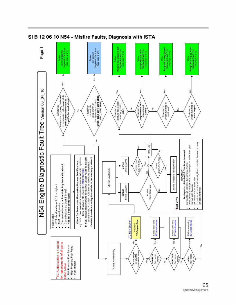
First S
teps
IST
A s
hort
test (u
se 2
.19
or
hig
her)
PM
P q
uestionnaire
Ca
r serv
ice h
isto
ry
Po
ssib
le b
uy-b
ack s
itu
ati
on
?
Co
me b
ack m
ore
than 2
tim
es?
Ha
s R
TE
be
en
co
nta
cte
d?
Che
ck F
ault M
em
ory
IGN
ITIO
N
fault c
odes
sto
red
INJ
EC
TO
R
fault c
odes
sto
red
oth
er
fault c
odes
sto
red
Follo
w a
ccord
ing
IST
A test m
odule
Follo
w a
ccord
ing
IST
A test m
odule
Follo
w a
ccord
ing
IST
A test m
odule
No
Yes
Yes
Yes
No
Ch
eck I-L
evel (D
ME
)
MS
D80
befo
re 0
3/2
008
MS
D8
1sin
ce 0
3/2
008
I-L
eve
l
=E
xxx-0
8-x
x-x
xx
veh
icle
type
E6
0 o
r E
61?
I-Level
<E
06
0-0
9-0
3-5
00
I-Level U
pdate
to n
ew
est vers
ion
DM
E O
K
Ye
s
Ye
s
Yes
No
No
No
No
No
No
Ch
eck f
or
Po
wert
rain
Aft
erm
ark
et
Devic
es /
Mo
dif
ica
tio
ns,
e.g
. tu
rbo b
oo
st contr
olle
rs,
com
ple
te e
xh
aust
or
induction s
yste
ms,
blo
w o
ff v
alv
es, etc
. (s
ee
SIB
121
008/1
22
008
);
IF Y
ES
: conta
ct
custo
mer
an
d a
dvis
e t
hat vehic
le h
as t
o b
e b
rought
back t
o S
TO
CK
CO
ND
ITIO
N p
rior
to c
ontinu
ing d
iagno
sis
;
Co
nta
ct
Are
a-T
eam
to
fla
g t
he
ve
hic
le i
n t
he
wa
rran
ty s
yste
m!!
Page 1
Tu
rbo
ch
arg
er
or
VA
NO
S
fau
lt c
od
es s
tore
d
Subm
it a
TC
-En
gin
e C
ase
Ye
s
IMP
OR
TA
NT
:R
ead
ap
tati
on
of
the D
ME
T
est
Dri
ve
is n
eed
ed
!C
ar
must b
e a
t op
era
ting
tem
pera
ture
/ w
arm
Drive v
eh
icle
50-6
0m
ph
with
20
00-2
50
0rp
m f
or
abo
ut
3m
in(u
se
manual shift, if needed)
Let veh
icle
idle
for
abo
ut 5
min
If p
ossib
le:
let
veh
icle
sit o
ve
r nig
ht
and
co
ld s
tart
the
ne
xt m
orn
ing
(let it id
le f
or
5m
in)
Sym
pto
m is
„mix
ture
ad
ap
tati
on
fa
ult
“ (e
.g.
29E
0,
29
E1)
Sym
pto
m is
„ro
ug
h r
un
nin
g a
t co
ld s
tart
“
Sym
pto
m is
„ro
ug
h r
un
nin
g a
t
warm
en
gin
e“
Follo
w
Mix
ture
Ad
ap
tati
on
Fau
lt
Dia
gnostic F
au
lt T
ree
(see p
ag
e 4
of
7)
Follo
w
Ro
ug
h R
un
nin
g @
co
ld
Dia
gnostic F
au
lt T
ree
(see p
ag
e 6
of
7)
Follo
w
Ro
ug
h R
un
nin
g @
warm
D
iag
nostic F
au
lt T
ree
(see p
ag
e 7
of
7)
Yes
No
Yes
No
Yes
Sym
pto
m is
exh
aust
has a
„str
on
g f
uel sm
ell
“
in c
om
bin
ation
with „
den
se
wh
ite
sm
oke u
po
n w
arm
sta
rt u
p“
or
„wet/
fou
led
sp
ark
plu
gs
“
Follo
w
Leakin
g I
nje
cto
r D
iag
no
stic F
ault T
ree
(see
pag
e 2
of
7)
Ye
s
If c
usto
mer
com
pla
int is
„lo
ng
cra
nk“
or
fuel syste
m f
ault c
ode
s?
(29D
C, 2
9E
2,
29
F1, 2
9F
2, 2B
2C
,2F
BC
, 2F
BE
, 2F
BF
)
Follo
w
Fu
el S
yste
m
Dia
gno
stic F
ault T
ree
(see
pag
e 3
of
7)
Yes
No
„TC
N54
Engin
e“
Sym
pto
m is
„sin
gle
mis
fire
fau
lt
co
de s
tore
d
in D
ME
“
Follo
w
Sin
gle
Mis
fire
Fau
ltD
iag
nostic F
au
lt T
ree
(see p
ag
e 5
of
7)
Yes
No
*Test
Dri
ve
25Ignition Management
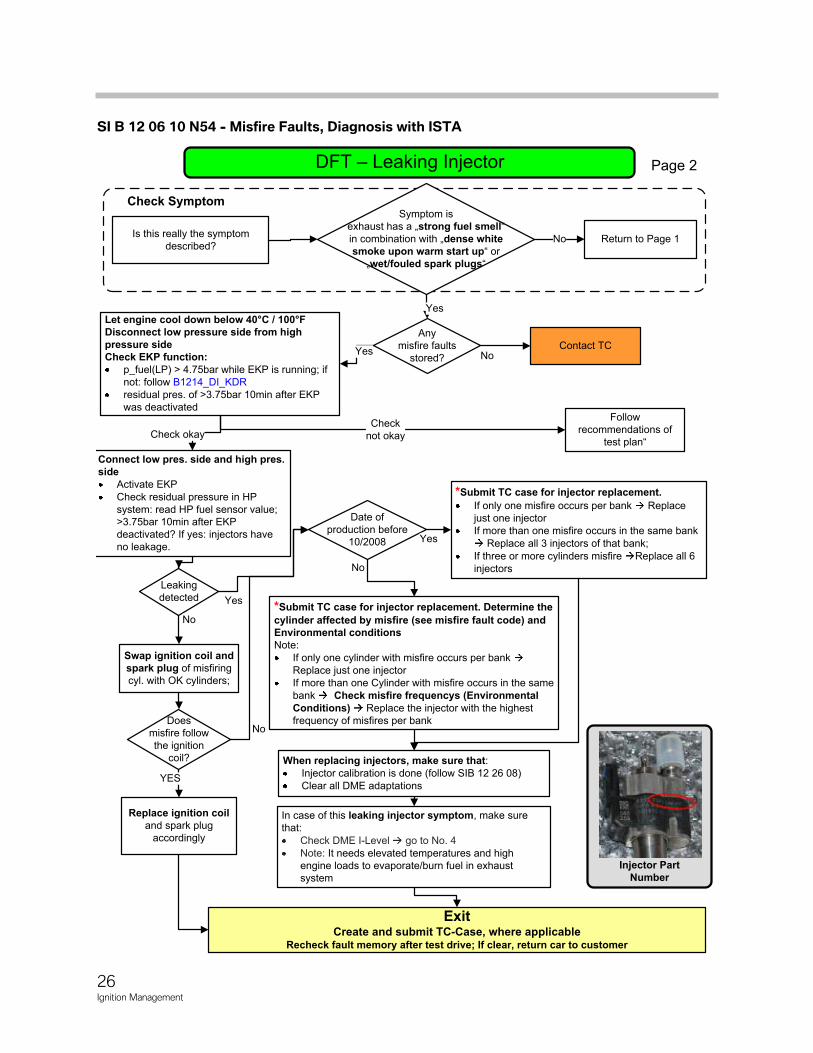
SI B 12 06 10 N54 - Misfire Faults, Diagnosis with ISTA
Page 2
ExitCreate and submit TC-Case, where applicable
Recheck fault memory after test drive; If clear, return car to customer
Any
misfire faults
stored?
Is this really the symptom
described?
Contact TC
No
Yes
Check Symptom
Return to Page 1
NoYes
Leaking
detected
In case of this leaking injector symptom, make sure
that:
Check DME I-Level go to No. 4
Note: It needs elevated temperatures and high
engine loads to evaporate/burn fuel in exhaust
system
*Submit TC case for injector replacement. Determine the
cylinder affected by misfire (see misfire fault code) and Environmental conditions Note:
If only one cylinder with misfire occurs per bank
Replace just one injector
If more than one Cylinder with misfire occurs in the same
bank Check misfire frequencys (Environmental Conditions) Replace the injector with the highest
frequency of misfires per bank
When replacing injectors, make sure that:Injector calibration is done (follow SIB 12 26 08)
Clear all DME adaptations
Swap ignition coil and spark plug of misfiring
cyl. with OK cylinders;
Does
misfire follow
the ignition
coil?
No
Injector Part Number
Let engine cool down below 40°C / 100°FDisconnect low pressure side from high pressure sideCheck EKP function:
p_fuel(LP) > 4.75bar while EKP is running; if
not: follow B1214_DI_KDR
residual pres. of >3.75bar 10min after EKP
was deactivated
Connect low pres. side and high pres. side
Activate EKP
Check residual pressure in HP
system: read HP fuel sensor value;
>3.75bar 10min after EKP
deactivated? If yes: injectors have
no leakage.
Check okayCheck
not okay
No
Follow
recommendations of
test plan“
YES
Yes
Date of
production before
10/2008
No
Yes
*Submit TC case for injector replacement.
If only one misfire occurs per bank Replace
just one injector
If more than one misfire occurs in the same bank
Replace all 3 injectors of that bank;
If three or more cylinders misfire Replace all 6
injectors
Symptom is
exhaust has a „strong fuel smell“ in combination with „dense white smoke upon warm start up“ or
„wet/fouled spark plugs“
Replace ignition coiland spark plug
accordingly
26Ignition Management
SI B 12 06 10 N54 - Misfire Faults, Diagnosis with ISTA
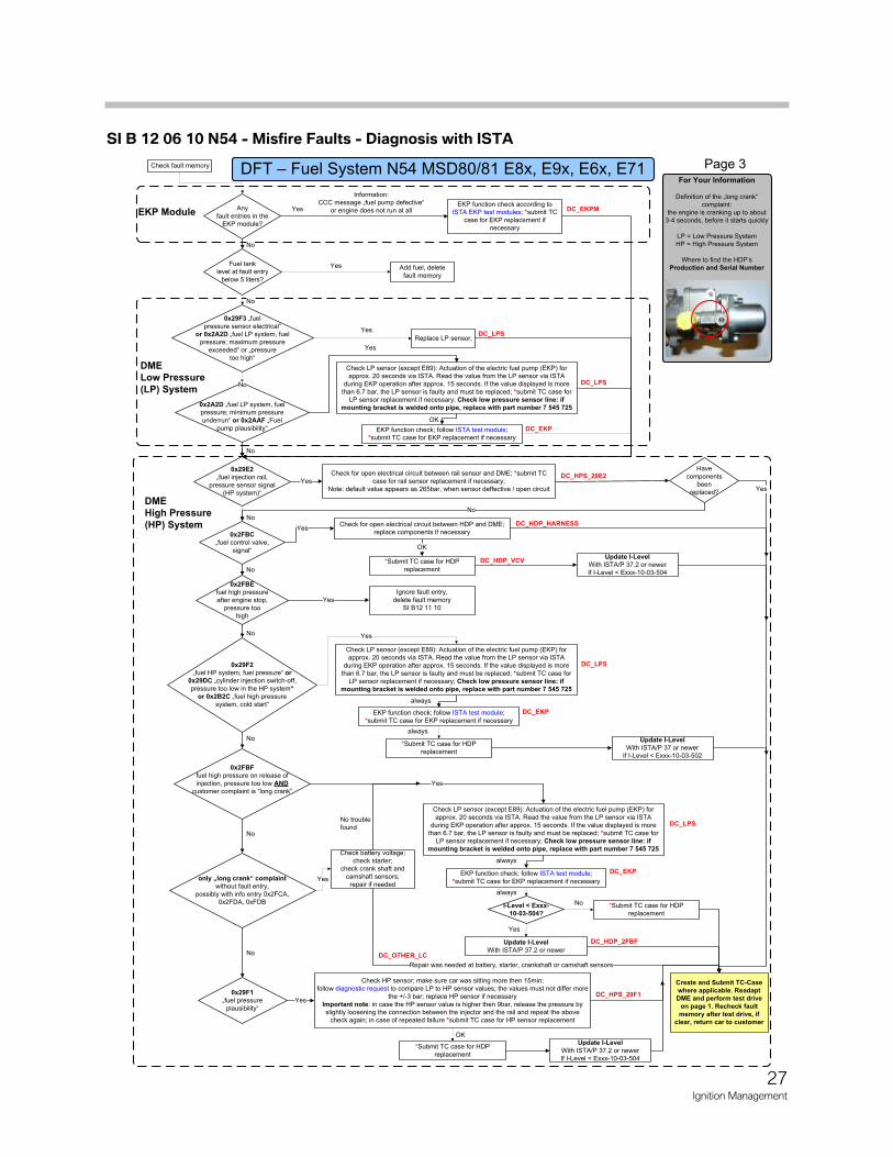
Any fault entries in the
EKP module?
EKP function check according to ISTA EKP test modules; *submit TC
case for EKP replacement if necessary
EKP function check; follow ISTA test module; *submit TC case for EKP replacement if necessary
Check LP sensor (except E89): Actuation of the electric fuel pump (EKP) for approx. 20 seconds via ISTA. Read the value from the LP sensor via ISTA
during EKP operation after approx. 15 seconds. If the value displayed is more than 6.7 bar, the LP sensor is faulty and must be replaced; *submit TC case for
LP sensor replacement if necessary; Check low pressure sensor line: if
mounting bracket is welded onto pipe, replace with part number 7 545 725
Check for open electrical circuit between rail sensor and DME; *submit TC case for rail sensor replacement if necessary;
Note: default value appears as 265bar, when sensor deffective / open circuit
0x29F1
„fuel pressure
plausibility“
Check HP sensor; make sure car was sitting more then 15min;follow diagnostic request to compare LP to HP sensor values; the values must not differ more
the +/-3 bar; replace HP sensor if necessary
Important note: in case the HP sensor value is higher then 9bar, release the pressure by slightly loosening the connection between the injector and the rail and repeat the above
check again; in case of repeated failure *submit TC case for HP sensor replacement
0x29F2
„fuel HP system, fuel pressure“ or
0x29DC „cylinder injection switch-off,
pressure too low in the HP system“
or 0x2B2C „fuel high pressure system, cold start“
0x2FBF
fuel high pressure on release of
injection, pressure too low AND
customer complaint is “long crank”
Yes
No
Yes
Yes
No
Have components
been replaced?
No
No
0x29E2
„fuel injection rail, pressure sensor signal
(HP system)“
DME
Low Pressure
(LP) System
EKP Module
DME
High Pressure
(HP) System
Yes
only „long crank“ complaint
without fault entry,
possibly with info entry 0x2FCA,0x2FDA, 0xFDB
Check battery voltage;check starter;
check crank shaft and camshaft sensors;
repair if needed
No
Repair was needed at battery, starter, crankshaft or camshaft sensors
DC_HDP_2FBF
DC_OTHER_LC
DC_EKPM
DC_HPS_29E2
DC_HPS_29F1
DC_HDP_VCV
Update I-Level
With ISTA/P 37.2 or newer
For Your Information
Definition of the „long crank“ complaint:
the engine is cranking up to about 3-4 seconds, before it starts quickly
LP = Low Pressure SystemHP = High Pressure System
Where to find the HDP’sProduction and Serial Number
Page 3
Information: CCC message „fuel pump defective“
or engine does not run at all
0x2A2D „fuel LP system, fuel pressure; minimum pressure underrun“ or 0x2AAF „Fuel
pump plausibility“
Yes
OK
No
0x2FBC
„fuel control valve,
signal“
Check for open electrical circuit between HDP and DME;replace components if necessary
*Submit TC case for HDP
replacement
Yes
0x2FBE
fuel high pressure
after engine stop, pressure too
high
OK
Yes
DC_HDP_HARNESS
No
No
No troublefound
DC_LPS
DC_EKP
Yes
Create and Submit TC-Case
where applicable. Readapt
DME and perform test drive
on page 1. Recheck fault
memory after test drive, if
clear, return car to customer
Fuel tank level at fault entry
below 5 liters?
No
Add fuel, delete fault memory
Yes
Check fault memory
0x29F3 „fuel pressure sensor electrical“
or 0x2A2D „fuel LP system, fuelpressure; maximum pressure
exceeded“ or „pressure too high“
No
Replace LP sensor,
YesDC_LPS
No
Ignore fault entry, delete fault memory
SI B12 11 10
EKP function check; follow ISTA test module;
*submit TC case for EKP replacement if necessary
always
DC_LPS
DC_EKP
*Submit TC case for HDP replacement
always
Yes
EKP function check; follow ISTA test module;
*submit TC case for EKP replacement if necessary
always
always
DC_LPS
DC_EKPYes
*Submit TC case for HDP
replacement
OK
Check LP sensor (except E89): Actuation of the electric fuel pump (EKP) for approx. 20 seconds via ISTA. Read the value from the LP sensor via ISTA
during EKP operation after approx. 15 seconds. If the value displayed is more
than 6.7 bar, the LP sensor is faulty and must be replaced; *submit TC case for LP sensor replacement if necessary; Check low pressure sensor line: if
mounting bracket is welded onto pipe, replace with part number 7 545 725
I-Level < Exxx-
10-03-504?
Yes
*Submit TC case for HDP
replacement
No
Update I-Level
With ISTA/P 37.2 or newerIf I-Level < Exxx-10-03-504
Update I-Level
With ISTA/P 37 or newerIf I-Level < Exxx-10-03-502
Update I-Level
With ISTA/P 37.2 or newerIf I-Level < Exxx-10-03-504
27Ignition Management
SI B 12 06 10 N54 - Misfire Faults - Diagnosis with ISTA
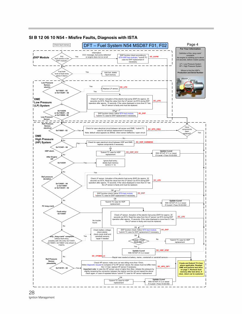
Any
fault entries in the
EKP module?
EKP function check according to
ISTA EKP test modules; *submit TC
case for EKP replacement if
necessary
EKP function check; follow ISTA test module;
*submit TC case for EKP replacement if necessary
Check LP sensor. Actuation of the electric fuel pump (EKP) for approx. 20
seconds via ISTA. Read the value from the LP sensor via ISTA during EKP
operation after approx. 15 seconds. If the value displayed is more than 6.7 bar,
the LP sensor is faulty and must be replaced.
Check for open electrical circuit between rail sensor and DME; *submit TC
case for rail sensor replacement if necessary;
Note: default value appears as 265bar, when sensor deffective / open circuit
0x11A701 - 02
Check HP sensor; make sure car was sitting more then 15min;
follow diagnostic request to compare LP to HP sensor values; the values must not differ more
the +/-3 bar; replace HP sensor if necessary
Important note: in case the HP sensor value is higher then 9bar, release the pressure by
slightly loosening the connection between the injector and the rail and repeat the above
check again; in case of repeated failure *submit TC case for HP sensor replacement
0x11A901 - 04
or 0x110001
or 0x11AC01 - 02
Fault entry:
0x11A401
Yes
No
Yes
Yes
No
Have
components
been
replaced?
No
No
0x119001 - 02
DME
Low Pressure
(LP) System
EKP Module
DME
High Pressure
(HP) System
Yes
only „long crank“ complaint
without fault entry,
possibly with info entry 0x11A401,
0x11B401, 0x11B501 only shown in
FASTA.
Check battery voltage;
check starter;
check crank shaft and
camshaft sensors;
repair if needed
No Repair was needed at battery, starter, crankshaft or camshaft sensors
DC_HDP_2FBF
DC_OTHER_LC
DC_EKPM
DC_HPS_29E2
DC_HPS_29F1
DC_HDP_VCV
Update I-Level
With ISTA/P 37.2 or newer
For Your Information
Definition of the „long crank“
complaint:
the engine is cranking up to about
3-4 seconds, before it starts quickly
LP = Low Pressure System
HP = High Pressure System
Where to find the HDP’s
Production and Serial Number
Page 4
Information:
CCC message „fuel pump defective“
or engine does not run at all
0x11A204
or 0x11B201 – 04
or 0x110002 - 08
Yes
OK
No
0x11C401 - 04
Check for open electrical circuit between HDP and DME;
replace components if necessary
*Submit TC case for HDP
replacement
Yes
0x11A301
OK
Yes
DC_HDP_HARNESS
No
No
No trouble
found
DC_LPS
DC_EKP
Create and Submit TC-Case
where applicable. Readapt
DME and perform test drive
on page 1. Recheck fault
memory after test drive, if
clear, return car to customer
Fuel tank
level at fault entry
below 5 liters?
No
Add fuel, delete
fault memory
Yes
Check fault memory
0x119201 - 02
or 0x11A201 - 02
No
Replace LP sensor,
Yes DC_LPS
No
Ignore fault entry,
delete fault memory
SI B12 11 10
EKP function check; follow ISTA test module;
*submit TC case for EKP replacement if necessary
OK
DC_LPS
DC_EKP
*Submit TC case for HDP
replacement
OK
Yes
EKP function check; follow ISTA test module;
*submit TC case for EKP replacement if necessary
OK
DC_LPS
DC_EKP
Yes
*Submit TC case for HDP
replacement
OK
Check LP sensor. Actuation of the electric fuel pump (EKP) for approx. 20
seconds via ISTA. Read the value from the LP sensor via ISTA during EKP
operation after approx. 15 seconds. If the value displayed is more than 6.7 bar,
the LP sensor is faulty and must be replaced.
Check LP sensor. Actuation of the electric fuel pump (EKP) for approx. 20
seconds via ISTA. Read the value from the LP sensor via ISTA during EKP
operation after approx. 15 seconds. If the value displayed is more than 6.7 bar,
the LP sensor is faulty and must be replaced;
Update I-Level
With ISTA/P 37.2 or newer
If I-Level < Fxxx-10-03-502
Update I-Level
With ISTA/P 37.2 or newer
If I-Level < Fxxx-10-03-502
Update I-Level
With ISTA/P 37.2 or newer
If I-Level < Fxxx-10-03-502
*Submit TC case for HDP
replacement
I-Level < Fxxx-
10-03-502 ?
Yes
No
OK
Low Pressure
Sensor,
electric
Low Prsssure
Sensor
Rail Pressure
Sensor,
electrical
HDP electr.
After Engine
Off
Rail pressure
deviation
FC long crank
Rail Pressure
Sensor
plausibility
28Ignition Management
SI B 12 06 10 N54 - Misfire Faults, Diagnosis with ISTA
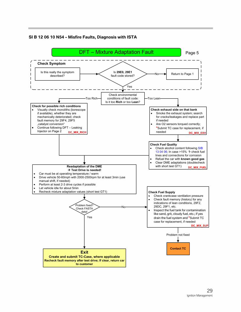
Page 5
ExitCreate and submit TC-Case, where applicable
Recheck fault memory after test drive; If clear, return car to customer
Is this really the symptom
described?
Is 29E0, 29E1fault code stored?
Contact TC
No
Yes
Check environmental
conditions of fault code:
Is it too Rich or too Lean?
Too Rich Too Lean
Readaptation of the DME Test Drive is needed!
Car must be at operating temperature / warm
Drive vehicle 50-60mph with 2000-2500rpm for at least 3min (use
manual shift, if needed)
Perform at least 2-3 drive cycles if possible
Let vehicle idle for about 5min
Recheck mixture adaptation values (short test GT1)
Check Fuel QualityCheck alcohol content following SIB
13 04 06; In case >15% check fuel
lines and connections for corrosion
Refuel the car with known good gasClear DME adaptations (doublecheck
with short test GT1)
Check Fuel SupplyCheck crankcase ventilation pressure
Check fault memory (history) for any
indications of lean conditions, 29F2,
29DC, 29F1, etc.
Inspect the fuel tank for contamination like sand, grit, cloudy fuel, etc.; if yes drain the fuel system and *Submit TC
case for replacement, if needed
Yes
DC_MIX_FUEL
Check Symptom
Check for possible rich conditionsVisually check monoliths (borescope
if available), whether they are
mechanically deteriorated; check
fault memory for 29F4, 29F5
„catalyst conversion“
Continue following DFT – Leaking
Injector on Page 2
No
Problem not fixed
DC_MIX_RICH
Return to Page 1
DC_MIX_SUP
Check exhaust side on that bankSmoke the exhaust system; search
for cracks/leakages and replace part
if needed
Are O2 sensors torqued correctly;
*Submit TC case for replacement, if
needed
Problem fixed?
Check FASTA
data!
DC_MIX_EXH
29Ignition Management
SI B 12 06 10 N54 - Misfire Faults, Diagnosis with ISTA
Page 6
ExitRecheck fault memory after test drive; If clear, return car
to customer
Is this really the symptom
described?No
Yes
Check Symptom
Return to Page 1
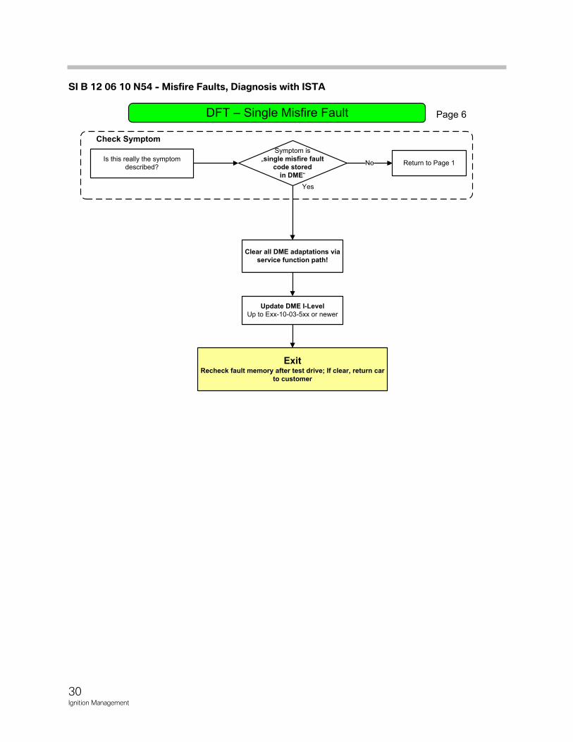
Symptom is
„single misfire fault code stored
in DME“
Clear all DME adaptations via service function path!
Update DME I-LevelUp to Exx-10-03-5xx or newer
30Ignition Management
SI B 12 06 10 N54 - Misfire Faults, Diagnosis with ISTA
Page 7
ExitCreate and submit TC-Case, where
applicableRecheck Fault Memory after cold start;
If clear, return car to customer
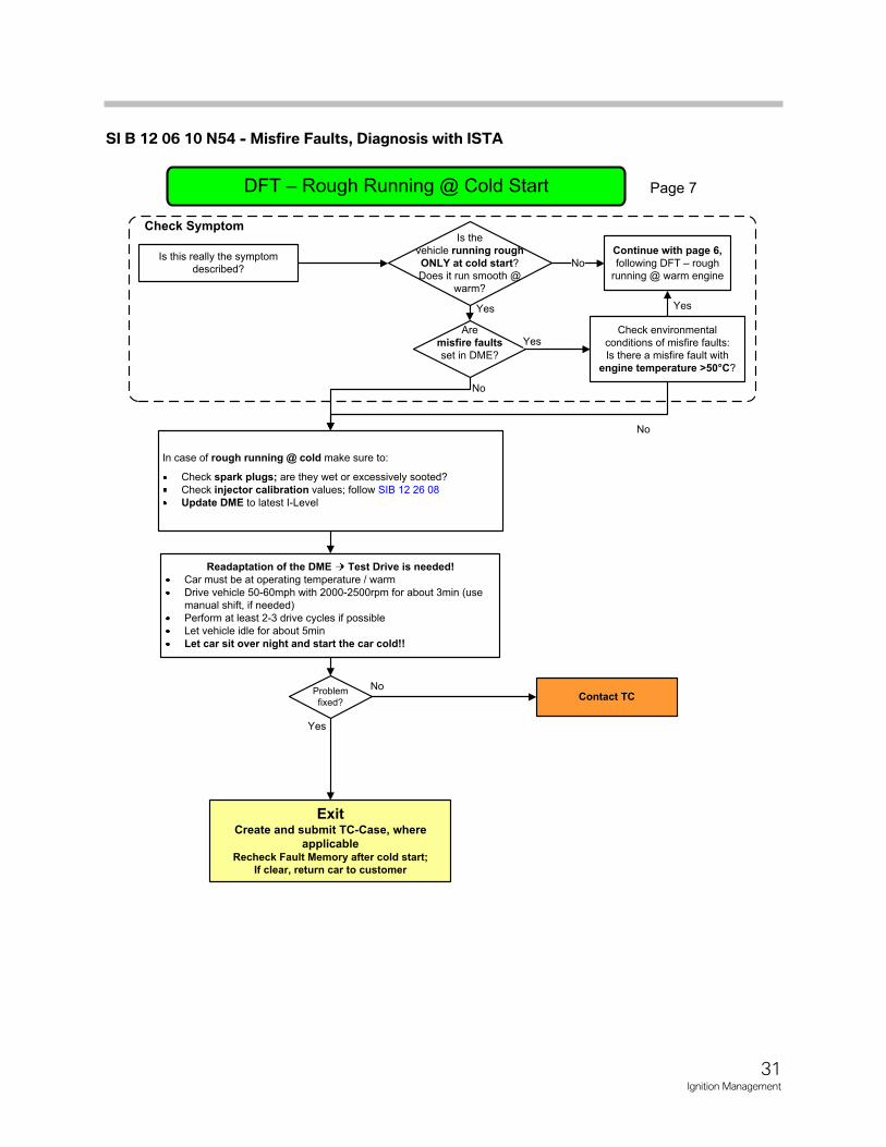
In case of rough running @ cold make sure to:
Check spark plugs; are they wet or excessively sooted?
Check injector calibration values; follow SIB 12 26 08
Update DME to latest I-Level
Is this really the symptom
described?
Is the
vehicle running rough ONLY at cold start?
Does it run smooth @
warm?
No
Are
misfire faultsset in DME?
Yes
No
Readaptation of the DME Test Drive is needed!Car must be at operating temperature / warm
Drive vehicle 50-60mph with 2000-2500rpm for about 3min (use
manual shift, if needed)
Perform at least 2-3 drive cycles if possible
Let vehicle idle for about 5min
Let car sit over night and start the car cold!!
Check Symptom
Check environmental
conditions of misfire faults:
Is there a misfire fault with
engine temperature >50°C?
No
YesYes
Problem
fixed?
No
Yes
Continue with page 6,following DFT – rough
running @ warm engine
Contact TC
31Ignition Management
SI B 12 06 10 N54 - Misfire Faults, Diagnosis with ISTA
Pa
ge
8
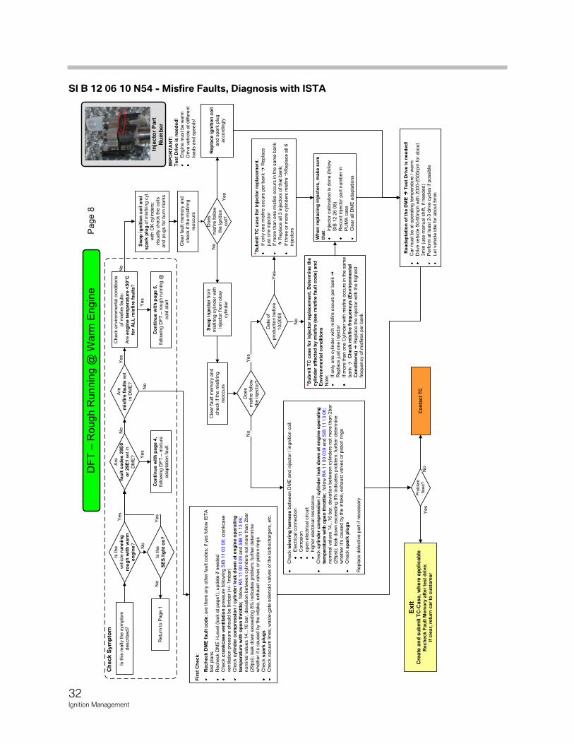
Is t
his
really
the s
ym
pto
m
describ
ed
?
Is t
he
ve
hic
le r
un
nin
g
rou
gh
wit
h w
arm
en
gin
e?
Are
mis
fire
fau
lts
se
t
in D
ME
?
Ch
eck S
ym
pto
m
Yes
Sw
ap
ig
nit
ion
co
il a
nd
sp
ark
plu
gof m
isfirin
g c
yl.
with O
K c
ylin
ders
;
vis
ually
che
ck t
he
coils
and p
lugs f
or
burn
mark
s
Do
es
mis
fire
fo
llow
the ignitio
n
co
il?
Rep
lace i
gn
itio
n c
oil
and s
pa
rk p
lug
accord
ing
ly
No
Yes
Che
ck e
nvir
onm
enta
l con
ditio
ns
of m
isfire
faults:
Are
en
gin
e t
em
pera
ture
<50°C
fo
r A
LL
mis
fire
fa
ult
s?
Inje
cto
r P
art
N
um
ber
No
Yes
Yes
Yes
Is the
SE
S l
igh
t o
n?
Retu
rn to P
age 1
No
Yes
No
Fir
st
Ch
eck:
Rech
eck D
ME
fau
lt c
od
e; are
the
re a
ny o
ther
fault c
od
es; if y
es fo
llow
IS
TA
test pla
ns
Rech
eck D
ME
I-L
evel (loo
k a
t p
age
1),
upd
ate
if n
eed
ed
Check c
ran
kcas
e v
en
tila
tio
np
ressure
follo
win
g S
IB 1
1 0
3 0
8;
cra
nkcase
ve
ntila
tion p
ressu
re s
hou
ld b
e 9
mb
ar
(+/-
1m
ba
r)
Check
cyli
nd
er
co
mp
ressio
n /
cylin
der
leak d
ow
n a
t en
gin
e o
pera
tin
g
tem
pera
ture
wit
h o
pen
th
rott
le;
follo
w R
A 1
1 0
0 0
39 a
nd
SIB
11 1
3 0
6;
nom
inal valu
es 1
4...1
6 b
ar,
devia
tion b
etw
een c
ylin
ders
no
t m
ore
th
an
2b
ar
(29p
si)
; le
ak d
ow
n e
xcee
din
g 8
% indic
ate
s p
rob
lem
; fu
rthe
r de
term
ine
wheth
er
it’s
ca
use
d b
y t
he inta
ke
, exha
ust
va
lve
s o
r pis
ton r
ings
Check s
pa
rk p
lug
sC
heck v
acuu
m lin
es, w
aste
-gate
so
len
oid
valv
es o
f th
e t
urb
och
arg
ers
, e
tc.
Co
nta
ct
TCN
o
Co
nti
nu
e w
ith
pag
e 5
,fo
llow
ing
DF
T –
roug
h r
unnin
g @
cold
sta
rt
Ex
itC
rea
te a
nd
su
bm
it T
C-C
ase, w
here
ap
plicab
leR
ech
eck F
au
lt M
em
ory
aft
er
test
dri
ve;
If c
lea
r, r
etu
rn c
ar
to c
us
tom
er
Read
ap
tati
on
of
the D
ME
T
est
Dri
ve is
nee
ded
!C
ar
must be
at o
pe
ratin
g t
em
pera
ture
/ w
arm
Drive v
ehic
le 5
0-6
0m
ph
with 2
00
0-2
500
rpm
for
ab
ou
t
3m
in(u
se m
anual shift, if needed)
Perf
orm
at le
ast 2-3
drive c
ycle
s if po
ssib
le
Le
t vehic
le id
le f
or
abou
t 5m
in
IMP
OR
TA
NT
: T
es
t D
riv
e is
ne
ed
ed
!E
ngin
em
ust be
warm
Drive v
eh
icle
at diffe
rent
loa
ds a
nd
sp
ee
ds!
Pro
ble
m
fixed
?
Ye
sN
o
Are
fau
lt c
od
es 2
9E
0
or
29E
1se
t in
DM
E?
Co
nti
nu
e w
ith
pag
e 4
,fo
llow
ing D
FT
–m
ixtu
re
ad
ap
tation f
ault
No
Sw
ap
in
jecto
rfr
om
mis
firin
g c
ylin
der
with
inje
cto
r fr
om
okay
cylin
de
r
Does
mis
fire
follo
w
the in
jecto
r?
Check w
ireri
ng
harn
ess
betw
een
DM
E a
nd inje
cto
r / in
gn
itio
n c
oil:
Ele
ctr
ical con
ne
ctio
n
Co
rrosio
n
ope
n e
lectr
ical circuit
hig
her
ele
ctr
ical re
sis
tance
Check
cyli
nd
er
co
mp
ressio
n /
cylin
der
leak d
ow
n a
t en
gin
e o
pera
tin
g
tem
pera
ture
wit
h o
pen
th
rott
le;
follo
w R
A 1
1 0
0 0
39 a
nd
SIB
11 1
3 0
6;
nom
inal valu
es 1
4...1
6 b
ar,
devia
tion b
etw
een c
ylin
ders
not m
ore
than 2
bar
(29
psi)
; le
ak d
ow
n e
xce
edin
g 8
% ind
ica
tes p
roble
m; fu
rthe
r de
term
ine
wheth
er
it’s
ca
used b
y t
he inta
ke
, exha
ust va
lves o
r pis
ton r
ings
Check s
park
plu
gs
Repla
ce d
efe
ctive p
art
if ne
ce
ssary
Cle
ar
fault m
em
ory
and
check if th
e m
isfiring
reoccurs
Cle
ar
fault m
em
ory
an
d
che
ck if th
e m
isfirin
g
reoccurs
No
Yes
*Su
bm
it T
C c
ase
fo
rin
jecto
rre
pla
ce
men
t. D
ete
rmin
e t
he
cy
lin
de
r aff
ec
ted
by
mis
fire
(s
ee m
isfi
re f
au
lt c
od
e)
an
d
En
vir
on
men
tal co
nd
itio
ns
No
te: If o
nly
one
cylin
der
with m
isfire
occurs
per
ban
k
Rep
lace just on
e inje
cto
r
If m
ore
than o
ne C
ylin
der
with m
isfire
occurs
in
the
sa
me
bank
Ch
ec
k m
isfi
re f
req
uen
cys (
En
vir
on
men
tal
Co
nd
itio
ns)
Repla
ce th
e inje
cto
r w
ith t
he
hig
he
st
fre
que
ncy o
f m
isfire
s p
er
ban
k
Wh
en
rep
lacin
g i
nje
cto
rs, m
ake s
ure
th
at: In
jecto
r calib
ration
is d
one (
follo
w
SIB
12 2
6 0
8)
Record
inje
cto
r pa
rt n
um
ber
in
PU
MA
case
Cle
ar
all
DM
E a
da
pta
tion
s
Date
of
pro
ductio
n b
efo
re
10
/20
08
*Su
bm
it T
C c
ase f
or
inje
cto
rre
pla
cem
en
t.
If o
nly
one
mis
fire
occu
rs p
er
bank
Repla
ce
just on
e in
jecto
r
If m
ore
th
an o
ne
mis
fire
occu
rs in th
e s
am
e b
ank
Rep
lace a
ll 3 inje
cto
rs o
f th
at
bank;
If thre
e o
r m
ore
cylin
de
rs m
isfire
Rep
lace a
ll 6
inje
cto
rs
Ye
s
No
32Ignition Management
SI B 12 06 10 N54 - Misfire Faults, Diagnosis with ISTA
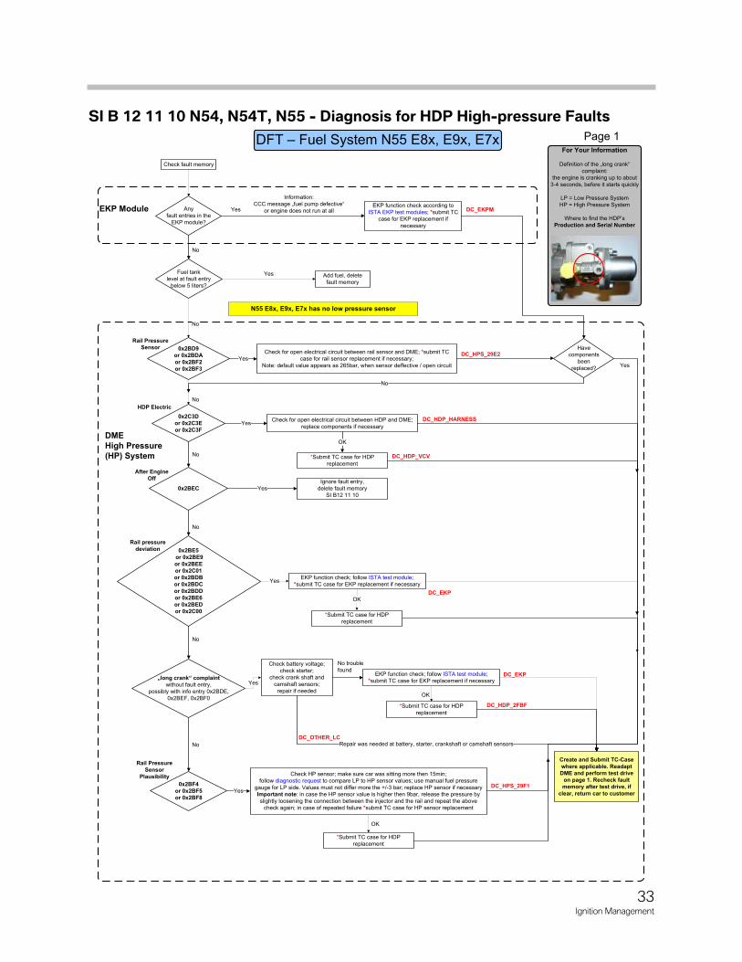
Any
fault entries in the
EKP module?
EKP function check according to
ISTA EKP test modules; *submit TC
case for EKP replacement if
necessary
Check for open electrical circuit between rail sensor and DME; *submit TC
case for rail sensor replacement if necessary;
Note: default value appears as 265bar, when sensor deffective / open circuit
0x2BF4
or 0x2BF5
or 0x2BF8
Check HP sensor; make sure car was sitting more then 15min;
follow diagnostic request to compare LP to HP sensor values; use manual fuel pressure
gauge for LP side. Values must not differ more the +/-3 bar; replace HP sensor if necessary
Important note: in case the HP sensor value is higher then 9bar, release the pressure by
slightly loosening the connection between the injector and the rail and repeat the above
check again; in case of repeated failure *submit TC case for HP sensor replacement
0x2BE5
or 0x2BE9
or 0x2BEE
or 0x2C01
or 0x2BDB
or 0x2BDC
or 0x2BDD
or 0x2BE6
or 0x2BED
or 0x2C00
Yes
No
Yes
Yes
No
Have
components
been
replaced?
No
0x2BD9
or 0x2BDA
or 0x2BF2
or 0x2BF3
EKP Module
DME
High Pressure
(HP) System
Yes
„long crank“ complaint
without fault entry,
possibly with info entry 0x2BDE,
0x2BEF, 0x2BF0
Check battery voltage;
check starter;
check crank shaft and
camshaft sensors;
repair if needed
No Repair was needed at battery, starter, crankshaft or camshaft sensors
DC_HDP_2FBF
DC_OTHER_LC
DC_EKPM
DC_HPS_29E2
DC_HPS_29F1
DC_HDP_VCV
For Your Information
Definition of the „long crank“
complaint:
the engine is cranking up to about
3-4 seconds, before it starts quickly
LP = Low Pressure System
HP = High Pressure System
Where to find the HDP’s
Production and Serial Number
Page 1
Information:
CCC message „fuel pump defective“
or engine does not run at all
0x2C3D
or 0x2C3E
or 0x2C3F
Check for open electrical circuit between HDP and DME;
replace components if necessary
*Submit TC case for HDP
replacement
Yes
0x2BEC
OK
Yes
DC_HDP_HARNESS
No
No
No trouble
found
Create and Submit TC-Case
where applicable. Readapt
DME and perform test drive
on page 1. Recheck fault
memory after test drive, if
clear, return car to customer
Fuel tank
level at fault entry
below 5 liters?
No
Add fuel, delete
fault memory
Yes
Check fault memory
No
Ignore fault entry,
delete fault memory
SI B12 11 10
EKP function check; follow ISTA test module;
*submit TC case for EKP replacement if necessary
DC_EKP
*Submit TC case for HDP
replacement
OK
Yes
EKP function check; follow ISTA test module;
*submit TC case for EKP replacement if necessary
OK
DC_EKP
Yes
*Submit TC case for HDP
replacement
OK
*Submit TC case for HDP
replacement
N55 E8x, E9x, E7x has no low pressure sensor
Rail Pressure
Sensor
HDP Electric
After Engine
Off
Rail pressure
deviation
Rail Pressure
Sensor
Plausibility
33Ignition Management
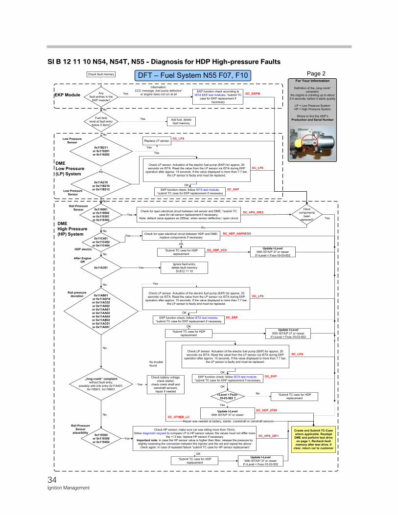
SI B 12 11 10 N54, N54T, N55 - Diagnosis for HDP High-pressure Faults
34Ignition Management
Any
fault entries in the
EKP module?
EKP function check according to
ISTA EKP test modules; *submit TC
case for EKP replacement if
necessary
EKP function check; follow ISTA test module;
*submit TC case for EKP replacement if necessary
Check LP sensor. Actuation of the electric fuel pump (EKP) for approx. 20
seconds via ISTA. Read the value from the LP sensor via ISTA during EKP
operation after approx. 15 seconds. If the value displayed is more than 7.7 bar,
the LP sensor is faulty and must be replaced.
Check for open electrical circuit between rail sensor and DME; *submit TC
case for rail sensor replacement if necessary;
Note: default value appears as 265bar, when sensor deffective / open circuit
0x119304
or 0x119308
or 0x119404
Check HP sensor; make sure car was sitting more then 15min;
follow diagnostic request to compare LP to HP sensor values; the values must not differ more
the +/-3 bar; replace HP sensor if necessary
Important note: in case the HP sensor value is higher then 9bar, release the pressure by
slightly loosening the connection between the injector and the rail and repeat the above
check again; in case of repeated failure *submit TC case for HP sensor replacement
0x11AB01
or 0x11AD10
or 0x11AC02
or 0x11A002
or 0x11AA01
or 0x11AA02
or 0x11AA04
or 0x11AB02
or 0x11AC01
or 0x11A001
Yes
No
Yes
Yes
No
Have
components
been
replaced?
No
0x119001
or 0x119002
or 0x119301
or 0x119302
DME
Low Pressure
(LP) System
EKP Module
DME
High Pressure
(HP) System
Yes
„long crank“ complaint
without fault entry,
possibly with info entry 0x11A401,
0x11B501, 0x11B601
Check battery voltage;
check starter;
check crank shaft and
camshaft sensors;
repair if needed
No
Repair was needed at battery, starter, crankshaft or camshaft sensors
DC_HDP_2FBF
DC_OTHER_LC
DC_EKPM
DC_HPS_29E2
DC_HPS_29F1
DC_HDP_VCV
Update I-Level
With ISTA/P 37 or newer
For Your Information
Definition of the „long crank“
complaint:
the engine is cranking up to about
3-4 seconds, before it starts quickly
LP = Low Pressure System
HP = High Pressure System
Where to find the HDP’s
Production and Serial Number
Page 2
Information:
CCC message „fuel pump defective“
or engine does not run at all
0x11A210
or 0x11B210
or 0x11B212
Yes
OK
No
0x11C401
or 0x11C402
or 0x11C404
Check for open electrical circuit between HDP and DME;
replace components if necessary
*Submit TC case for HDP
replacement
Yes
0x11A301
OK
Yes
DC_HDP_HARNESS
No
No
No trouble
found
DC_LPS
DC_EKP
Create and Submit TC-Case
where applicable. Readapt
DME and perform test drive
on page 1. Recheck fault
memory after test drive, if
clear, return car to customer
Fuel tank
level at fault entry
below 5 liters?
No
Add fuel, delete
fault memory
Yes
Check fault memory
0x11B211
or 0x119201
or 0x119202
No
Replace LP sensor,
Yes
DC_LPS
No
Ignore fault entry,
delete fault memory
SI B12 11 10
EKP function check; follow ISTA test module;
*submit TC case for EKP replacement if necessary
OK
DC_LPS
DC_EKP
*Submit TC case for HDP
replacement
OK
Yes
EKP function check; follow ISTA test module;
*submit TC case for EKP replacement if necessary
OK
DC_LPS
DC_EKP
Yes
*Submit TC case for HDP
replacement
OK
Check LP sensor. Actuation of the electric fuel pump (EKP) for approx. 20
seconds via ISTA. Read the value from the LP sensor via ISTA during EKP
operation after approx. 15 seconds. If the value displayed is more than 7.7 bar,
the LP sensor is faulty and must be replaced.
Check LP sensor. Actuation of the electric fuel pump (EKP) for approx. 20
seconds via ISTA. Read the value from the LP sensor via ISTA during EKP
operation after approx. 15 seconds. If the value displayed is more than 7.7 bar,
the LP sensor is faulty and must be replaced.
Update I-Level
With ISTA/P 37 or newer
If I-Level < Fxxx-10-03-502
*Submit TC case for HDP
replacement
I-Level < Fxxx-
10-03-502 ?
Yes
No
OK
Update I-Level
With ISTA/P 37 or newer
If I-Level < Fxxx-10-03-502
Update I-Level
With ISTA/P 37 or newer
If I-Level < Fxxx-10-03-502
Low Pressure
Sensor
Low Pressure
Sensor
Rail Pressure
Sensor
HDP electric
After Engine
Off
Rail pressure
deviation
Rail Pressure
Sensor
plausibility
SI B 12 11 10 N54, N54T, N55 - Diagnosis for HDP High-pressure Faults