ieee-t-bc_atsc30_phy_overview_vauthor.pdf - riunet
TRANSCRIPT
Document downloaded from:
This paper must be cited as:
The final publication is available at
Copyright
Additional Information
"(c) 2016 IEEE. Personal use of this material is permitted. Permission from IEEE must beobtained for all other users, including reprinting/ republishing this material for advertising orpromotional purposes, creating new collective works for resale or redistribution to servers orlists, or reuse of any copyrighted components of this work in other works.")
http://dx.doi.org/10.1109/TBC.2015.2505417
http://hdl.handle.net/10251/82083
Institute of Electrical and Electronics Engineers (IEEE)
Fay, L.; Michael, L.; Gómez Barquero, D.; Ammar, N.; Caldwell, MW. (2016). An Overview ofthe ATSC 3.0 Physical Layer Specification. IEEE Transactions on Broadcasting. 62(1):159-171. doi:10.1109/TBC.2015.2505417.

Submitted to the IEEE Transactions on Broadcasting
1
Abstract— This paper provides an overview of the physical
layer specification of ATSC 3.0, the next-generation digital terrestrial broadcasting standard. ATSC 3.0 does not have any backwards-compatibility constraint with existing ATSC standards, and it uses OFDM-based waveforms along with powerful LDPC forward error correction codes similar to existing state-of-the art. However, it introduces many new technological features such as two-dimensional non-uniform constellations, improved and ultra-robust LDPC codes, power-based layered division multiplexing to efficiently provide mobile and fixed services in the same radio frequency (RF) channel, as well as a novel frequency pre-distortion MISO antenna scheme. ATSC 3.0 also allows bonding of two RF channels to increase the service peak data rate and to exploit inter-RF channel frequency diversity, and to employ dual-polarized MIMO antenna system. Furthermore, ATSC 3.0 provides great flexibility in terms of configuration parameters (e.g., 12 coding rates, 6 modulation orders, 16 pilot patterns, 12 guard intervals, and 2 time interleavers), and also a very flexible data multiplexing scheme using time, frequency and power dimensions. As a consequence, ATSC 3.0 not only improves the spectral efficiency and robustness well beyond the first generation ATSC broadcast television standard, but it also is positioned to become the reference terrestrial broadcasting technology worldwide due to its unprecedented performance and flexibility. Another key aspect of ATSC 3.0 is its extensible signaling, which will allow including new technologies in the future without disrupting ATSC 3.0 services. This paper provides an overview of the physical layer technologies of ATSC 3.0, covering the ATSC A/321 standard that describes the so-called bootstrap, which is the universal entry point to an ATSC 3.0 signal, and the ATSC A/322 standard that describes the physical layer downlink signals after the bootstrap. A summary comparison between ATSC 3.0 and DVB-T2 is also provided.
Index Terms—ATSC 3.0, channel bonding, digital terrestrial broadcasting, interleaving, LDM, LDPCs, non-uniform constellations, OFDM, physical layer, MIMO, MISO.
Manuscript received August 7, 2015; revised October 13, 2015. L. Fay is with Sony Electronics, San Diego, CA 92131, USA (e-mail:
[email protected]). L. Michael is with the Digital Analog System Development Department,
Research & Development Division, Device Solutions Business Group, Sony Corporation, Atsugi-shi 243-0021 Japan (e-mail: [email protected]).
D. Gómez-Barquero is with the Institute of Telecommunications and Multimedia Applications (iTEAM), Universitat Politecnica de Valencia, Valencia 46022, Spain (e-mail: [email protected]).
N. Ammar is with Zenith Electronics, Lincolnshire, IL 60069 USA (e-mail: [email protected]).
M. W. Caldwell is with the Fox Networks Group, 21st Century Fox, Los Angeles, CA 90064 USA (e-mail: [email protected]).
I. INTRODUCTION
HE Advanced Television Systems Committee (ATSC) is a Standards Development Organization (SDO) that is
currently developing its next-generation Digital Terrestrial Television (DTT) standard, known as “ATSC 3.0”, which does not have any backwards-compatibility constraint with existing ATSC standards. The overall ATSC 3.0 project will provide a complete technical standard for broadcast, including physical, management and transport protocol as well as application layers. However the physical layer is the foundation on which ATSC 3.0 is built.
The ATSC 3.0 physical layer specification was prepared by the ATSC Technology and Standards Group 3 (TG3) Specialist Group on Physical Layer. The ATSC’s Call for Proposals (CfP) for physical layer technologies was issued in March 2013. The CfP was distributed to various groups including other SDO’s, broadcast industry organizations and universities around the world. Twelve proposals with technology elements or full physical layer system descriptions were received in October 2013. The ATSC participants began the physical layer standardization process by selecting the best technology pieces from all submitted responses, and then determined how to combine the best pieces into a coherent whole. The ATSC 3.0 physical layer specification passed TG3 Candidate Standard ballot in September 2015, and it is expected to become a published ATSC standard by the middle of 2016.
Compared to the first-generation ATSC A/53 DTT standard [1], ATSC 3.0 is required to provide at least a 30% capacity increase at the same A/53 signal-to-noise ratio (SNR) operating point or, equivalently, to be significantly more robust while providing the same capacity as A/53 [2]. However, ATSC 3.0 aims to become the reference terrestrial broadcasting technology worldwide, outperforming existing terrestrial broadcast standards [3], [4], and leveraging recent research into next-generation digital terrestrial broadcasting [5], [6]. ATSC 3.0 must provide improvements in performance, functionality, flexibility and efficiency which are significant enough to warrant the challenges of a transition to a new system. The ATSC 3.0 physical layer system requirements included, among others, higher system capacity to efficiently deliver emerging ultra-high-definition (UHD) TV services and robust indoor reception [7]. A primary goal was to provide TV services simultaneously to fixed and mobile receivers, including traditional living room and
An Overview of the ATSC 3.0 Physical Layer Specification
Luke Fay, Lachlan Michael, David Gómez-Barquero, Nejib Ammar, and M. Winston Caldwell
T
Submitted to the IEEE Transactions on Broadcasting
2
bedroom TV sets, handheld devices, vehicular screens and portable receivers. Spectrum efficiency, robustness and flexibility were key areas of evaluation so that the system can be optimized for environments both before and after the upcoming broadcast TV spectrum incentive auction in the U.S. when there might be a reduced spectrum allocation for DTT [8].
The ATSC 3.0 physical layer system offers the latest technology with the flexibility to choose many different operating modes depending on the desired trade-off between robustness (coverage) and throughput (capacity). It offers a wide range of tools for broadcasters to choose the operating modes that best fit the needs of the market and the devices being targeted. This toolbox of technology is expected to grow over time and the ability to upgrade or swap out new technologies in the future is enabled with extensible signaling. This future extensibility will allow broadcasters to try new technologies without breaking existing ATSC 3.0 service operations.
The ATSC 3.0 physical layer is built on the foundation of OFDM (Orthogonal Frequency Division Multiplexing) modulation with powerful LDPC (Low-Density Parity Check) forward error correction codes, with two code lengths (16200 and 64800 bits) and twelve code rates (from 2/15 up to 13/15). There is support for six modulation orders from QPSK up to 4096QAM. There is support for three multiplexing modes for data physical layer pipes (PLP): time, frequency and power (with two layers, known as Layered Division Multiplexing LDM), which can be combined, along with three frame types of SISO (Single-Input Single-Output), MISO (Multiple-Input Single-Output) and MIMO (Multiple-Input Multiple-Output). The physical layer supports twelve selectable guard interval (GI) lengths (cyclic prefixes) from ~27 µs up to ~700 µs, and 3 FFT sizes of 8K, 16K and 32K, which offer strong echo protection in a 6 MHz channel. Channel estimation performance can be controlled with 16 scattered pilot patterns and 5 different boosting powers.
ATSC 3.0 allows parallel decoding of up to four PLP per service to enable separate components, such as video, audio, and metadata to be sent with different robustness settings, for example. The maximum number of PLPs in one RF channel (6, 7 or 8 MHz) is 64. Supported bit rates in a single 6 MHz channel range from less than 1 Mbps with QPSK modulation, 2/15 code rate, 8K FFT and 300 µs GI, up to over 57 Mbps with 4096QAM modulation, 13/15 code rate, 32K FFT and 55 µs GI. The physical layer operates in SNR ranges from -5.7 dB to 36 dB in Rayleigh channel (from -6.2 to 32 dB in AWGN).
The maximum data rates can be doubled using channel bonding or cross-polarized MIMO. Channel bonding combines two RF channels to achieve greater service data rates than can be achieved in one channel. It also allows exploiting the additional inter-RF channel frequency diversity, and improved statistical multiplexing. MIMO allows transmitting two independent data streams using dual polarization (i.e., horizontal and vertical) in the same RF channel.
This paper provides an overview of the physical layer specification of ATSC 3.0. The physical layer specifications includes the ATSC A/321 standard that describes the so-called bootstrap [9], which is the universal entry point to an ATSC 3.0 signal, and the ATSC A/322 standard that describes the physical layer downlink signals after the bootstrap.
The rest of the paper is structured as follows: Section II provides a description of the physical layer architecture. Section III describes the input formatting module. Section IV introduces the bit interleaved and coded modulation module, and Section V the layered division multiplexing module. Section VI explains the framing and interleaving module. Section VII addresses the waveform generation module, including the bootstrap signal. Section VIII summarizes the optional channel bonding and MIMO technologies. Section IX provides some considerations about the future evolution of the standard. Finally, the paper is concluded with Section X.
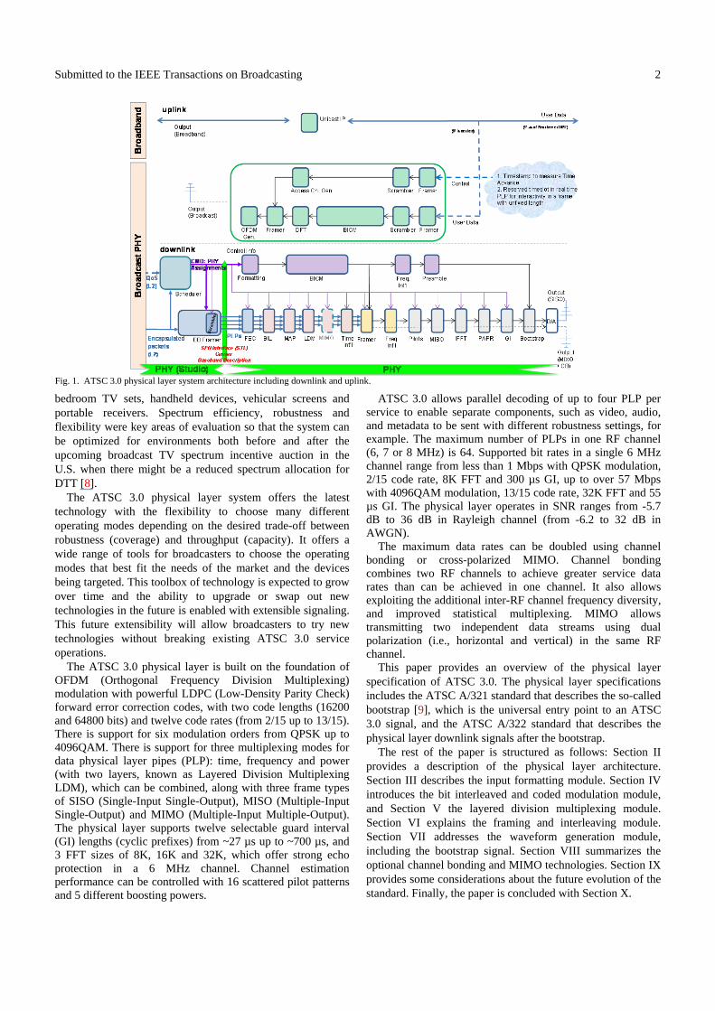
Fig. 1. ATSC 3.0 physical layer system architecture including downlink and uplink.
Submitted to the IEEE Transactions on Broadcasting
3
II. PHYSICAL LAYER ARCHITECTURE
Fig. 1 shows the skeleton of the ATSC 3.0 physical layer architecture, comprised of two main pieces, an uplink and a downlink.
A. Uplink
ATSC 3.0 will include a dedicated wireless return link as an optional connection for interactive services. The uplink may be especially suitable in emerging markets or areas without a proper Internet service framework and where there is plentiful available spectrum (e.g., rural areas in China). The uplink specification allows constituting a bi-directional wireless broadcasting system without dependence on separate from the broadcasting network. This uplink standard is in draft form at the time of this paper publication and is expected to be completed in 2016.
The ATSC 3.0 uplink will be built upon the ATSC 3.0 downlink specification [10], re-using as many functional elements and technologies as possible. It employs single-carrier frequency division multiple access (FDMA) introducing new features such as the use of adaptive modulation and hybrid automatic repeat request (ARQ).
Regarding the implications of the use of the uplink with the downlink, only a few hooks are required for synchronization, in particular, a time stamp must be delivered such that receivers can measure time in advance and timeslots must be reserved in real time for interactivity.
B. Downlink
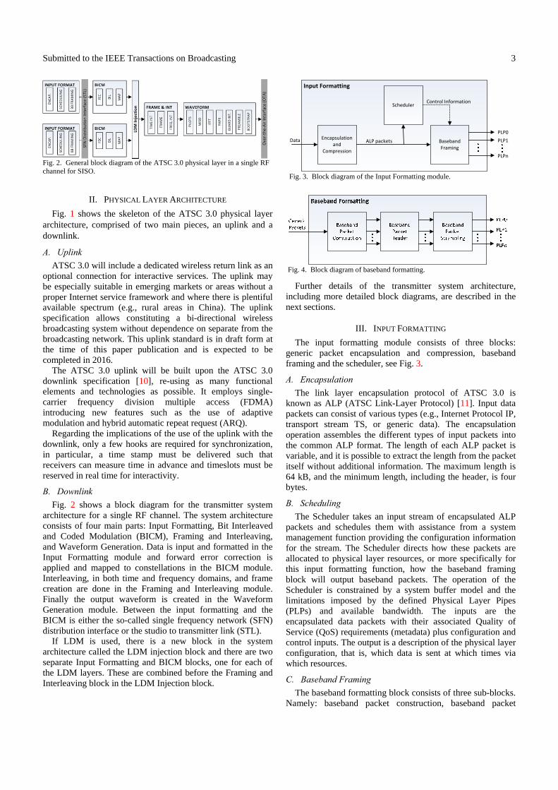
Fig. 2 shows a block diagram for the transmitter system architecture for a single RF channel. The system architecture consists of four main parts: Input Formatting, Bit Interleaved and Coded Modulation (BICM), Framing and Interleaving, and Waveform Generation. Data is input and formatted in the Input Formatting module and forward error correction is applied and mapped to constellations in the BICM module. Interleaving, in both time and frequency domains, and frame creation are done in the Framing and Interleaving module. Finally the output waveform is created in the Waveform Generation module. Between the input formatting and the BICM is either the so-called single frequency network (SFN) distribution interface or the studio to transmitter link (STL).
If LDM is used, there is a new block in the system architecture called the LDM injection block and there are two separate Input Formatting and BICM blocks, one for each of the LDM layers. These are combined before the Framing and Interleaving block in the LDM Injection block.
Further details of the transmitter system architecture, including more detailed block diagrams, are described in the next sections.
III. INPUT FORMATTING
The input formatting module consists of three blocks: generic packet encapsulation and compression, baseband framing and the scheduler, see Fig. 3.
A. Encapsulation
The link layer encapsulation protocol of ATSC 3.0 is known as ALP (ATSC Link-Layer Protocol) [11]. Input data packets can consist of various types (e.g., Internet Protocol IP, transport stream TS, or generic data). The encapsulation operation assembles the different types of input packets into the common ALP format. The length of each ALP packet is variable, and it is possible to extract the length from the packet itself without additional information. The maximum length is 64 kB, and the minimum length, including the header, is four bytes.
B. Scheduling
The Scheduler takes an input stream of encapsulated ALP packets and schedules them with assistance from a system management function providing the configuration information for the stream. The Scheduler directs how these packets are allocated to physical layer resources, or more specifically for this input formatting function, how the baseband framing block will output baseband packets. The operation of the Scheduler is constrained by a system buffer model and the limitations imposed by the defined Physical Layer Pipes (PLPs) and available bandwidth. The inputs are the encapsulated data packets with their associated Quality of Service (QoS) requirements (metadata) plus configuration and control inputs. The output is a description of the physical layer configuration, that is, which data is sent at which times via which resources.
C. Baseband Framing
The baseband formatting block consists of three sub-blocks. Namely: baseband packet construction, baseband packet
Fig. 2. General block diagram of the ATSC 3.0 physical layer in a single RFchannel for SISO. Fig. 3. Block diagram of the Input Formatting module.
Input Formatting
Scheduler
Baseband Framing
Encapsulation and
Compression
Data
PLP0
PLP1
PLPn
Control Information
ALP packets
Fig. 4. Block diagram of baseband formatting.
Submitted to the IEEE Transactions on Broadcasting
4
header construction, and baseband packet scrambling, see Fig. 4. In multiple PLP operation, the baseband formatting block creates multiple PLPs as necessary.
Each baseband packet is composed of a header and a payload consisting of ALP packets and/or padding. Baseband packets have fixed length. The length is determined by the FEC code rate and the code length chosen for that PLP. ALP packets are mapped in the same order they are received, such that the order of the ALP packets in the link layer is maintained in the physical layer.
The baseband packet header is composed of three parts, as illustrated in Fig. 5. The first part is called the base field and appears in every packet. The second part is called the optional field which may be used for padding and/or to provide signaling regarding the following extension field. The third part is called the extension field. Optional and extension fields may only be present in some baseband packets. They are not required to appear in every packet.
The baseband packet scrambler ensures that the data mapped to constellations are not assigned to the same points in an undesirable manner (which might occur, for example, when the payload consists of a repetitive sequence). The entire baseband packet, consisting of both the header and payload, is always scrambled before forward error correction encoding.
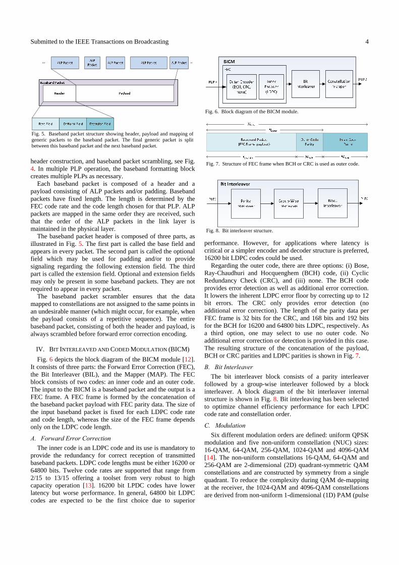
IV. BIT INTERLEAVED AND CODED MODULATION (BICM)
Fig. 6 depicts the block diagram of the BICM module [12]. It consists of three parts: the Forward Error Correction (FEC), the Bit Interleaver (BIL), and the Mapper (MAP). The FEC block consists of two codes: an inner code and an outer code. The input to the BICM is a baseband packet and the output is a FEC frame. A FEC frame is formed by the concatenation of the baseband packet payload with FEC parity data. The size of the input baseband packet is fixed for each LDPC code rate and code length, whereas the size of the FEC frame depends only on the LDPC code length.
A. Forward Error Correction
The inner code is an LDPC code and its use is mandatory to provide the redundancy for correct reception of transmitted baseband packets. LDPC code lengths must be either 16200 or 64800 bits. Twelve code rates are supported that range from 2/15 to 13/15 offering a toolset from very robust to high capacity operation [13]. 16200 bit LPDC codes have lower latency but worse performance. In general, 64800 bit LDPC codes are expected to be the first choice due to superior
performance. However, for applications where latency is critical or a simpler encoder and decoder structure is preferred, 16200 bit LDPC codes could be used.
Regarding the outer code, there are three options: (i) Bose, Ray-Chaudhuri and Hocquenghem (BCH) code, (ii) Cyclic Redundancy Check (CRC), and (iii) none. The BCH code provides error detection as well as additional error correction. It lowers the inherent LDPC error floor by correcting up to 12 bit errors. The CRC only provides error detection (no additional error correction). The length of the parity data per FEC frame is 32 bits for the CRC, and 168 bits and 192 bits for the BCH for 16200 and 64800 bits LDPC, respectively. As a third option, one may select to use no outer code. No additional error correction or detection is provided in this case. The resulting structure of the concatenation of the payload, BCH or CRC parities and LDPC parities is shown in Fig. 7.
B. Bit Interleaver
The bit interleaver block consists of a parity interleaver followed by a group-wise interleaver followed by a block interleaver. A block diagram of the bit interleaver internal structure is shown in Fig. 8. Bit interleaving has been selected to optimize channel efficiency performance for each LPDC code rate and constellation order.
C. Modulation
Six different modulation orders are defined: uniform QPSK modulation and five non-uniform constellation (NUC) sizes: 16-QAM, 64-QAM, 256-QAM, 1024-QAM and 4096-QAM [14]. The non-uniform constellations 16-QAM, 64-QAM and 256-QAM are 2-dimensional (2D) quadrant-symmetric QAM constellations and are constructed by symmetry from a single quadrant. To reduce the complexity during QAM de-mapping at the receiver, the 1024-QAM and 4096-QAM constellations are derived from non-uniform 1-dimensional (1D) PAM (pulse
Fig. 5. Baseband packet structure showing header, payload and mapping ofgeneric packets to the baseband packet. The final generic packet is splitbetween this baseband packet and the next baseband packet.
Fig. 6. Block diagram of the BICM module.
Fig. 7. Structure of FEC frame when BCH or CRC is used as outer code.
Fig. 8. Bit interleaver structure.
Submitted to the IEEE Transactions on Broadcasting
5
amplitude modulation) constellations for both in-phase (I) and quadrature (Q) components.
For each combination of NUC modulation order and LDPC code rate a different constellation exists (except for QPSK where the same constellation is used for all code rates). However, the constellation does not vary with the LPDC code length (i.e., the same constellation is used for both 64800 and 16200 bits LPDC codes).
D. Performance
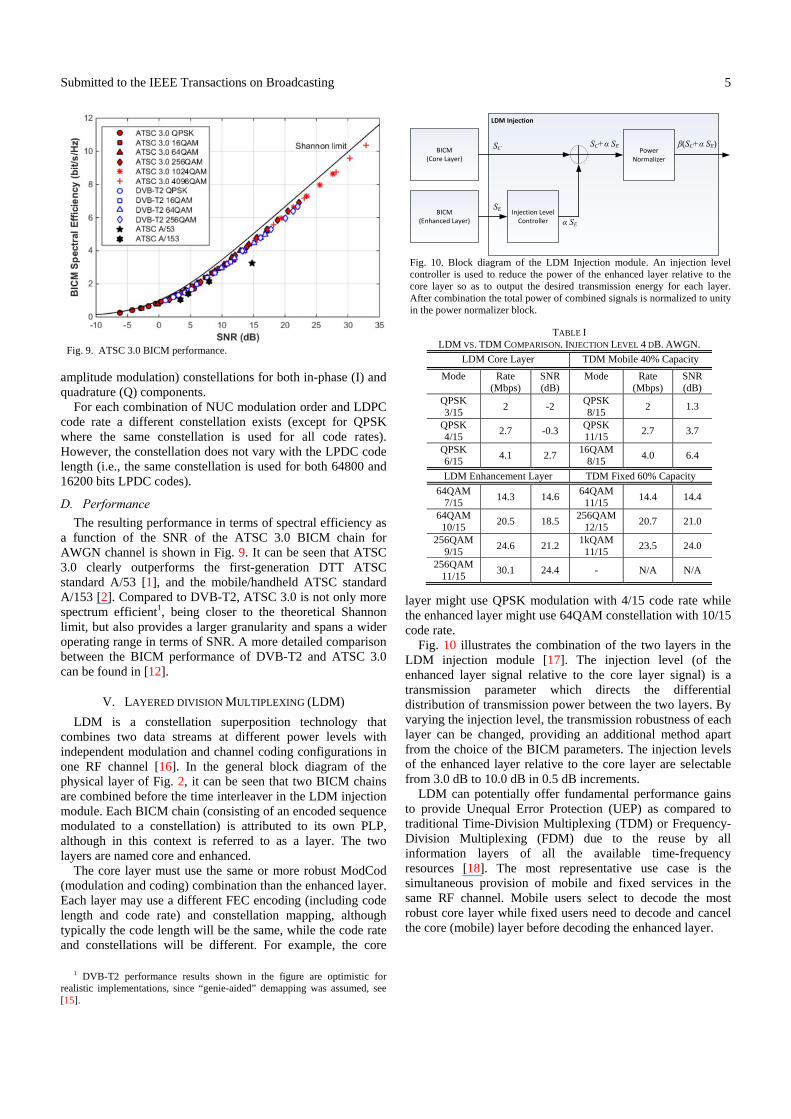
The resulting performance in terms of spectral efficiency as a function of the SNR of the ATSC 3.0 BICM chain for AWGN channel is shown in Fig. 9. It can be seen that ATSC 3.0 clearly outperforms the first-generation DTT ATSC standard A/53 [1], and the mobile/handheld ATSC standard A/153 [2]. Compared to DVB-T2, ATSC 3.0 is not only more spectrum efficient1, being closer to the theoretical Shannon limit, but also provides a larger granularity and spans a wider operating range in terms of SNR. A more detailed comparison between the BICM performance of DVB-T2 and ATSC 3.0 can be found in [12].
V. LAYERED DIVISION MULTIPLEXING (LDM)
LDM is a constellation superposition technology that combines two data streams at different power levels with independent modulation and channel coding configurations in one RF channel [16]. In the general block diagram of the physical layer of Fig. 2, it can be seen that two BICM chains are combined before the time interleaver in the LDM injection module. Each BICM chain (consisting of an encoded sequence modulated to a constellation) is attributed to its own PLP, although in this context is referred to as a layer. The two layers are named core and enhanced.
The core layer must use the same or more robust ModCod (modulation and coding) combination than the enhanced layer. Each layer may use a different FEC encoding (including code length and code rate) and constellation mapping, although typically the code length will be the same, while the code rate and constellations will be different. For example, the core
1 DVB-T2 performance results shown in the figure are optimistic for
realistic implementations, since “genie-aided” demapping was assumed, see [15].
layer might use QPSK modulation with 4/15 code rate while the enhanced layer might use 64QAM constellation with 10/15 code rate.
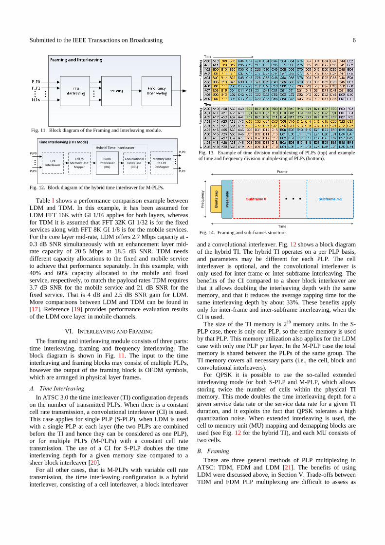
Fig. 10 illustrates the combination of the two layers in the LDM injection module [17]. The injection level (of the enhanced layer signal relative to the core layer signal) is a transmission parameter which directs the differential distribution of transmission power between the two layers. By varying the injection level, the transmission robustness of each layer can be changed, providing an additional method apart from the choice of the BICM parameters. The injection levels of the enhanced layer relative to the core layer are selectable from 3.0 dB to 10.0 dB in 0.5 dB increments.
LDM can potentially offer fundamental performance gains to provide Unequal Error Protection (UEP) as compared to traditional Time-Division Multiplexing (TDM) or Frequency-Division Multiplexing (FDM) due to the reuse by all information layers of all the available time-frequency resources [18]. The most representative use case is the simultaneous provision of mobile and fixed services in the same RF channel. Mobile users select to decode the most robust core layer while fixed users need to decode and cancel the core (mobile) layer before decoding the enhanced layer.
Fig. 9. ATSC 3.0 BICM performance.
Fig. 10. Block diagram of the LDM Injection module. An injection level controller is used to reduce the power of the enhanced layer relative to the core layer so as to output the desired transmission energy for each layer.After combination the total power of combined signals is normalized to unity in the power normalizer block.
LDM Injection
Power Normalizer
BICM(Core Layer)
BICM(Enhanced Layer)
Injection Level Controller
SC
SE
α SE
SC+α SE β(SC+α SE)
TABLE I LDM VS. TDM COMPARISON. INJECTION LEVEL 4 DB. AWGN.
LDM Core Layer TDM Mobile 40% Capacity
Mode Rate (Mbps)
SNR (dB)
Mode Rate (Mbps)
SNR (dB)
QPSK 3/15
2 -2 QPSK 8/15
2 1.3
QPSK 4/15
2.7 -0.3 QPSK 11/15
2.7 3.7
QPSK 6/15
4.1 2.7 16QAM
8/15 4.0 6.4
LDM Enhancement Layer TDM Fixed 60% Capacity
64QAM 7/15
14.3 14.6 64QAM
11/15 14.4 14.4
64QAM 10/15
20.5 18.5 256QAM
12/15 20.7 21.0
256QAM 9/15
24.6 21.2 1kQAM
11/15 23.5 24.0
256QAM 11/15
30.1 24.4 - N/A N/A
Submitted to the IEEE Transactions on Broadcasting
6
Table I shows a performance comparison example between LDM and TDM. In this example, it has been assumed for LDM FFT 16K with GI 1/16 applies for both layers, whereas for TDM it is assumed that FFT 32K GI 1/32 is for the fixed services along with FFT 8K GI 1/8 is for the mobile services. For the core layer mid-rate, LDM offers 2.7 Mbps capacity at -0.3 dB SNR simultaneously with an enhancement layer mid-rate capacity of 20.5 Mbps at 18.5 dB SNR. TDM needs different capacity allocations to the fixed and mobile service to achieve that performance separately. In this example, with 40% and 60% capacity allocated to the mobile and fixed service, respectively, to match the payload rates TDM requires 3.7 dB SNR for the mobile service and 21 dB SNR for the fixed service. That is 4 dB and 2.5 dB SNR gain for LDM. More comparisons between LDM and TDM can be found in [17]. Reference [19] provides performance evaluation results of the LDM core layer in mobile channels.
VI. INTERLEAVING AND FRAMING
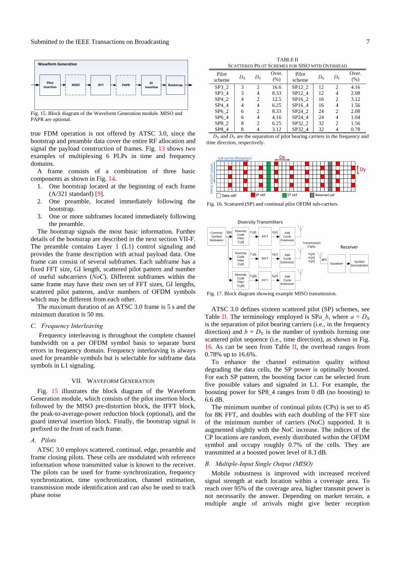
The framing and interleaving module consists of three parts: time interleaving, framing and frequency interleaving. The block diagram is shown in Fig. 11. The input to the time interleaving and framing blocks may consist of multiple PLPs, however the output of the framing block is OFDM symbols, which are arranged in physical layer frames.
A. Time Interleaving
In ATSC 3.0 the time interleaver (TI) configuration depends on the number of transmitted PLPs. When there is a constant cell rate transmission, a convolutional interleaver (CI) is used. This case applies for single PLP (S-PLP), when LDM is used with a single PLP at each layer (the two PLPs are combined before the TI and hence they can be considered as one PLP), or for multiple PLPs (M-PLPs) with a constant cell rate transmission. The use of a CI for S-PLP doubles the time interleaving depth for a given memory size compared to a sheer block interleaver [20].
For all other cases, that is M-PLPs with variable cell rate transmission, the time interleaving configuration is a hybrid interleaver, consisting of a cell interleaver, a block interleaver
and a convolutional interleaver. Fig. 12 shows a block diagram of the hybrid TI. The hybrid TI operates on a per PLP basis, and parameters may be different for each PLP. The cell interleaver is optional, and the convolutional interleaver is only used for inter-frame or inter-subframe interleaving. The benefits of the CI compared to a sheer block interleaver are that it allows doubling the interleaving depth with the same memory, and that it reduces the average zapping time for the same interleaving depth by about 33%. These benefits apply only for inter-frame and inter-subframe interleaving, when the CI is used.
The size of the TI memory is 219 memory units. In the S-PLP case, there is only one PLP, so the entire memory is used by that PLP. This memory utilization also applies for the LDM case with only one PLP per layer. In the M-PLP case the total memory is shared between the PLPs of the same group. The TI memory covers all necessary parts (i.e., the cell, block and convolutional interleavers).
For QPSK it is possible to use the so-called extended interleaving mode for both S-PLP and M-PLP, which allows storing twice the number of cells within the physical TI memory. This mode doubles the time interleaving depth for a given service data rate or the service data rate for a given TI duration, and it exploits the fact that QPSK tolerates a high quantization noise. When extended interleaving is used, the cell to memory unit (MU) mapping and demapping blocks are used (see Fig. 12 for the hybrid TI), and each MU consists of two cells.
B. Framing
There are three general methods of PLP multiplexing in ATSC: TDM, FDM and LDM [21]. The benefits of using LDM were discussed above, in Section V. Trade-offs between TDM and FDM PLP multiplexing are difficult to assess as
Fig. 13. Example of time division multiplexing of PLPs (top) and example of time and frequency division multiplexing of PLPs (bottom).
Freq
ue
nc
yF
requ
en
cy
Fig. 14. Framing and sub-frames structure.
Boo
tstr
ap
Pre
am
ble
Time
Fre
qu
enc
y
Frame
Subframe 0 Subframe n-1. . .
Fig. 11. Block diagram of the Framing and Interleaving module.
Fig. 12. Block diagram of the hybrid time interleaver for M-PLPs.
Time Interleaving (HTI Mode)
CellInterleaver
BlockInterleaver
(BIL)
Convolutional Delay Line
(CDL)
Cell to Memory Unit
Mapper
Memory Unit to Cell
DeMapper
PLP0
PLPn
PLP0
PLPn
Hybrid Time Interleaver
Submitted to the IEEE Transactions on Broadcasting
7
true FDM operation is not offered by ATSC 3.0, since the bootstrap and preamble data cover the entire RF allocation and signal the payload construction of frames. Fig. 13 shows two examples of multiplexing 6 PLPs in time and frequency domains.
A frame consists of a combination of three basic components as shown in Fig. 14.
1. One bootstrap located at the beginning of each frame (A/321 standard) [9].
2. One preamble, located immediately following the bootstrap.
3. One or more subframes located immediately following the preamble.
The bootstrap signals the most basic information. Further details of the bootstrap are described in the next section VII-F. The preamble contains Layer 1 (L1) control signaling and provides the frame description with actual payload data. One frame can consist of several subframes. Each subframe has a fixed FFT size, GI length, scattered pilot pattern and number of useful subcarriers (NoC). Different subframes within the same frame may have their own set of FFT sizes, GI lengths, scattered pilot patterns, and/or numbers of OFDM symbols which may be different from each other.
The maximum duration of an ATSC 3.0 frame is 5 s and the minimum duration is 50 ms.
C. Frequency Interleaving
Frequency interleaving is throughout the complete channel bandwidth on a per OFDM symbol basis to separate burst errors in frequency domain. Frequency interleaving is always used for preamble symbols but is selectable for subframe data symbols in L1 signaling.
VII. WAVEFORM GENERATION
Fig. 15 illustrates the block diagram of the Waveform Generation module, which consists of the pilot insertion block, followed by the MISO pre-distortion block, the IFFT block, the peak-to-average-power reduction block (optional), and the guard interval insertion block. Finally, the bootstrap signal is prefixed to the front of each frame.
A. Pilots
ATSC 3.0 employs scattered, continual, edge, preamble and frame closing pilots. These cells are modulated with reference information whose transmitted value is known to the receiver. The pilots can be used for frame synchronization, frequency synchronization, time synchronization, channel estimation, transmission mode identification and can also be used to track phase noise
ATSC 3.0 defines sixteen scattered pilot (SP) schemes, see Table II. The terminology employed is SPa_b, where a = DX is the separation of pilot bearing carriers (i.e., in the frequency direction) and b = DY is the number of symbols forming one scattered pilot sequence (i.e., time direction), as shown in Fig. 16. As can be seen from Table II, the overhead ranges from 0.78% up to 16.6%.
To enhance the channel estimation quality without degrading the data cells, the SP power is optimally boosted. For each SP pattern, the boosting factor can be selected from five possible values and signaled in L1. For example, the boosting power for SP8_4 ranges from 0 dB (no boosting) to 6.6 dB.
The minimum number of continual pilots (CPs) is set to 45 for 8K FFT, and doubles with each doubling of the FFT size of the minimum number of carriers (NoC) supported. It is augmented slightly with the NoC increase. The indices of the CP locations are random, evenly distributed within the OFDM symbol and occupy roughly 0.7% of the cells. They are transmitted at a boosted power level of 8.3 dB.
B. Multiple-Input Single Output (MISO)
Mobile robustness is improved with increased received signal strength at each location within a coverage area. To reach over 95% of the coverage area, higher transmit power is not necessarily the answer. Depending on market terrain, a multiple angle of arrivals might give better reception
TABLE II SCATTERED PILOT SCHEMES FOR SISO WITH OVERHEAD
Pilot scheme
DX DY Over. (%)
Pilot scheme
DX DY Over. (%)
SP3_2 3 2 16.6 SP12_2 12 2 4.16 SP3_4 3 4 8.33 SP12_4 12 4 2.08 SP4_2 4 2 12.5 SP16_2 16 2 3.12 SP4_4 4 4 6.25 SP16_4 16 4 1.56 SP6_2 6 2 8.33 SP24_2 24 2 2.08 SP6_4 6 4 4.16 SP24_4 24 4 1.04 SP8_2 8 2 6.25 SP32_2 32 2 1.56 SP8_4 8 4 3.12 SP32_4 32 4 0.78
DX and DY are the separation of pilot bearing carriers in the frequency and time direction, respectively.
Fig. 15. Block diagram of the Waveform Generation module. MISO and PAPR are optional.
Waveform Generation
MISO IFFTPilot
InsertionGI
InsertionBootstrapPAPR
Fig. 17. Block diagram showing example MISO transmission.
Diversity Code Filter C1[k]
Diversity CodeFilterC2[k]
Diversity CodeFilterCM[k]
CommonSymbol
Modulator
S[k]IFFT
Add Cyclic
Extension
f1[n]
IFFTAdd
Cyclic Extension
IFFTAdd
Cyclic Extension
f2[n]
fM[n]
F1[k]
F2[k]
FM[k]
Equalizerg[n]
Receiver
Symbol Demodulator
Diversity Transmitters
Transmission Paths
h1[n]h2[n]h3[n]
Fig. 16. Scattared (SP) and continual pilot OFDM sub-carriers.
Submitted to the IEEE Transactions on Broadcasting
8
percentage. OFDM offers the advantage of easy echo cancellation with the inclusion of a guard interval (GI). However, potential destructive interference may appear at the receiver if two or more multipath echoes are received with a similar power level outside of the configured GI duration. ATSC 3.0 has adopted a MISO pre-distortion technique known as Transmit Diversity Code Filter Set (TDCFS) that artificially decorrelates signals from multiple transmitters in a Single Frequency Network (SFN) in order to minimize potential destructive interference [22].
Fig 17 shows a multi-transmitter SFN system where the TDCFS filters are implemented in the frequency domain before the IFFT. Linear frequency domain filters are used so that the compensation in the receiver can be implemented as part of the equalizer process. The filter design is based on creating all-pass filters with minimized cross-correlation over all filter pairs under the constraints of the number of transmitters (2, 3 or 4) and the time domain span of the filters (64 or 256 samples). The longer time domain span filters increase the decorrelation level, but the effective guard interval length is decreased by the filter time domain span and this should be taken into consideration when choosing a filter set for a particular network topology. It should be pointed out that TDCFS does not need to double the pilot density as must be done with the Alamouti-based MISO scheme of DVB-T2 [23]. Further details of TDCFS together with some illustrative performance results can be found in [22].
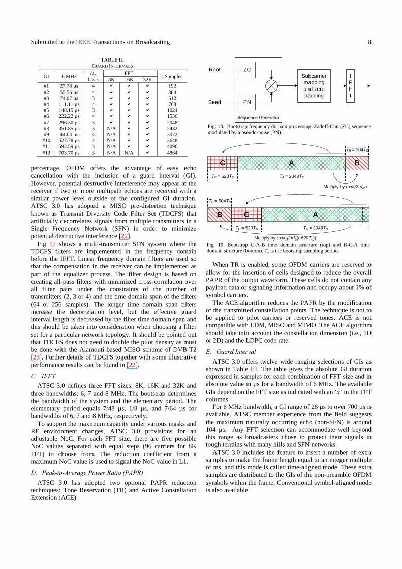
C. IFFT
ATSC 3.0 defines three FFT sizes: 8K, 16K and 32K and three bandwidths: 6, 7 and 8 MHz. The bootstrap determines the bandwidth of the system and the elementary period. The elementary period equals 7/48 µs, 1/8 µs, and 7/64 µs for bandwidths of 6, 7 and 8 MHz, respectively.
To support the maximum capacity under various masks and RF environment changes, ATSC 3.0 provisions for an adjustable NoC. For each FFT size, there are five possible NoC values separated with equal steps (96 carriers for 8K FFT) to choose from. The reduction coefficient from a maximum NoC value is used to signal the NoC value in L1.
D. Peak-to-Average Power Ratio (PAPR)
ATSC 3.0 has adopted two optional PAPR reduction techniques: Tone Reservation (TR) and Active Constellation Extension (ACE).
When TR is enabled, some OFDM carriers are reserved to allow for the insertion of cells designed to reduce the overall PAPR of the output waveform. These cells do not contain any payload data or signaling information and occupy about 1% of symbol carriers.
The ACE algorithm reduces the PAPR by the modification of the transmitted constellation points. The technique is not to be applied to pilot carriers or reserved tones. ACE is not compatible with LDM, MISO and MIMO. The ACE algorithm should take into account the constellation dimension (i.e., 1D or 2D) and the LDPC code rate.
E. Guard Interval
ATSC 3.0 offers twelve wide ranging selections of GIs as shown in Table III. The table gives the absolute GI duration expressed in samples for each combination of FFT size and in absolute value in µs for a bandwidth of 6 MHz. The available GIs depend on the FFT size as indicated with an ‘x’ in the FFT columns.
For 6 MHz bandwidth, a GI range of 28 µs to over 700 µs is available. ATSC member experience from the field suggests the maximum naturally occurring echo (non-SFN) is around 104 µs. Any FFT selection can accommodate well beyond this range as broadcasters chose to protect their signals in tough terrains with many hills and SFN networks.
ATSC 3.0 includes the feature to insert a number of extra samples to make the frame length equal to an integer multiple of ms, and this mode is called time-aligned mode. These extra samples are distributed to the GIs of the non-preamble OFDM symbols within the frame. Conventional symbol-aligned mode is also available.
Fig. 19. Bootstrap C-A-B time domain structure (top) and B-C-A timedomain structure (bottom). TS is the bootstrap sampling period.
TA = 2048TS
C A B
TB = 504TS
TC = 520TS
Multiply by exp(j2πf∆t)
TA = 2048TS
C AB
TB = 504TS
TC = 520TS
Multiply by exp(-j2πf∆(t-520TS))
TABLE III GUARD INTERVALS
GI 6 MHz DX
basis FFT
#Samples 8K 16K 32K
#1 27.78 µs 4 192 #2 55.56 µs 4 384 #3 74.07 µs 3 512 #4 111.11 µs 4 768 #5 148.15 µs 3 1024 #6 222.22 µs 4 1536 #7 296.30 µs 3 2048 #8 351.85 µs 3 N/A 2432 #9 444.4 µs 4 N/A 3072
#10 527.78 µs 4 N/A 3648 #11 592.59 µs 3 N/A 4096 #12 703.70 µs 3 N/A N/A 4864
Fig. 18. Bootstrap frequency domain processing. Zadoff-Chu (ZC) sequence modulated by a pseudo-noise (PN).
ZC
PN
Subcarrier mapping and zero padding
IFFT
Root
Seed
Sequence Generator
Submitted to the IEEE Transactions on Broadcasting
9
F. Bootstrap
Digital communication receiver devices need some a-priori information about incoming signals so they know where to start demodulating. In ATSC 3.0, that first piece of information is at the beginning of a frame. It is called a bootstrap and it signals the most basic information [24]. The bootstrap is extremely robust because it has to be received by all devices. It is intended that receivers be able to synchronize with it and track it even in bad channel conditions. It can be received below -6 dB SNR even in very difficult channels such as 0 dB echos or typical urban channels. In AWGN the SNR threshold is around -9.5 dB. The bootstrap consists of a series of OFDM symbols. The first symbol is for synchronization. The following symbols carry additional information. The bootstrap symbols have a sampling frequency of 6.144 Msymbols/s in an effective bandwidth of 4.5 MHz, centered within the RF channel. The symbols are first created in the frequency domain using a 2048 point FFT with 3 kHz carrier spacing of information coming from a Zadoff-Chu (ZC) sequence modulated by a pseudo-noise (PN) cover sequence, as shown in Fig. 18. Then, in the time domain, each bootstrap symbol consists of three parts, labeled A, B, C. The larger portion, denoted A, is a 2048 point inverse FFT of the frequency domain symbol. Parts B and C are samples of A that are frequency shifted as shown in Fig. 19. Part B has 504 samples of Part A, and Part C has 520 samples of Part A. The combined structure in time has 3072 samples giving a 500 µs length period for one bootstrap symbol.
The first version of ATSC 3.0 will have 4 bootstrap symbols. The first synchronization symbol will follow the C-A-B structure and the three subsequent symbols will have the B-C-A structure carrying bits of information, giving the total length of a bootstrap sequence of 2 ms.
The first signaled information is the version of the ATSC 3.0 standard. The version will be signaled in the first bootstrap symbol with two parts, major and minor. Major version changes will have a different ZC root while minor versions will have a different PN seed. There are 8 PN seeds listed currently but there is possibility for expansion [9].
The second bootstrap symbol carries the Emergency Alert Service (EAS) wake up bit (on/off), system bandwidth (6, 7, 8 and >8 MHz options), and the time to the next frame of similar service (i.e., same major and minor version numbers, with a range of 50 ms to 5.7 s).
The third bootstrap symbol carries the sampling rate indications of the current frame, following the equation: SampleRate ( 16) 0.384MHzN (1)
where N can take values of 0 to 80, inclusive. This initial bootstrap sampling frequency has N = 16. The value of N for 6, 7 and 8 MHz channels is 18, 21, and 24, respectively. The fourth bootstrap symbol carries the preamble structure, and signals the parameters needed to start demodulation and decoding of the preamble symbols.
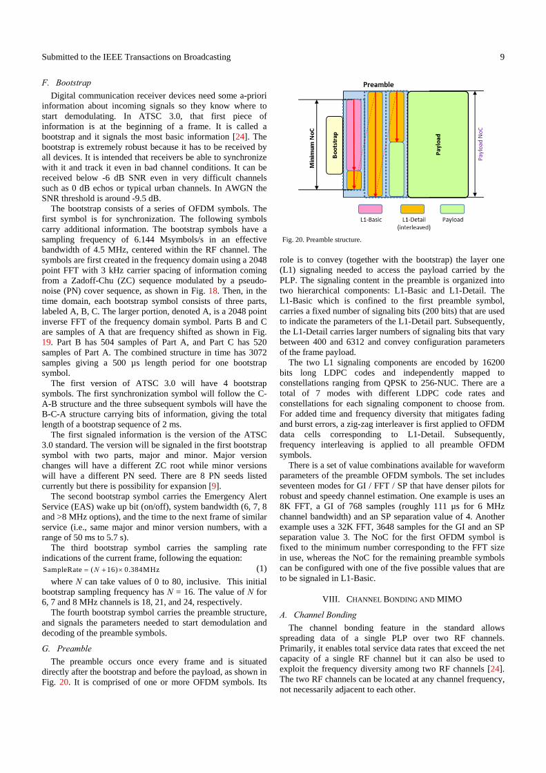
G. Preamble
The preamble occurs once every frame and is situated directly after the bootstrap and before the payload, as shown in Fig. 20. It is comprised of one or more OFDM symbols. Its
role is to convey (together with the bootstrap) the layer one (L1) signaling needed to access the payload carried by the PLP. The signaling content in the preamble is organized into two hierarchical components: L1-Basic and L1-Detail. The L1-Basic which is confined to the first preamble symbol, carries a fixed number of signaling bits (200 bits) that are used to indicate the parameters of the L1-Detail part. Subsequently, the L1-Detail carries larger numbers of signaling bits that vary between 400 and 6312 and convey configuration parameters of the frame payload.
The two L1 signaling components are encoded by 16200 bits long LDPC codes and independently mapped to constellations ranging from QPSK to 256-NUC. There are a total of 7 modes with different LDPC code rates and constellations for each signaling component to choose from. For added time and frequency diversity that mitigates fading and burst errors, a zig-zag interleaver is first applied to OFDM data cells corresponding to L1-Detail. Subsequently, frequency interleaving is applied to all preamble OFDM symbols.
There is a set of value combinations available for waveform parameters of the preamble OFDM symbols. The set includes seventeen modes for GI / FFT / SP that have denser pilots for robust and speedy channel estimation. One example is uses an 8K FFT, a GI of 768 samples (roughly 111 µs for 6 MHz channel bandwidth) and an SP separation value of 4. Another example uses a 32K FFT, 3648 samples for the GI and an SP separation value 3. The NoC for the first OFDM symbol is fixed to the minimum number corresponding to the FFT size in use, whereas the NoC for the remaining preamble symbols can be configured with one of the five possible values that are to be signaled in L1-Basic.
VIII. CHANNEL BONDING AND MIMO
A. Channel Bonding
The channel bonding feature in the standard allows spreading data of a single PLP over two RF channels. Primarily, it enables total service data rates that exceed the net capacity of a single RF channel but it can also be used to exploit the frequency diversity among two RF channels [24]. The two RF channels can be located at any channel frequency, not necessarily adjacent to each other.
Fig. 20. Preamble structure.
Submitted to the IEEE Transactions on Broadcasting
10
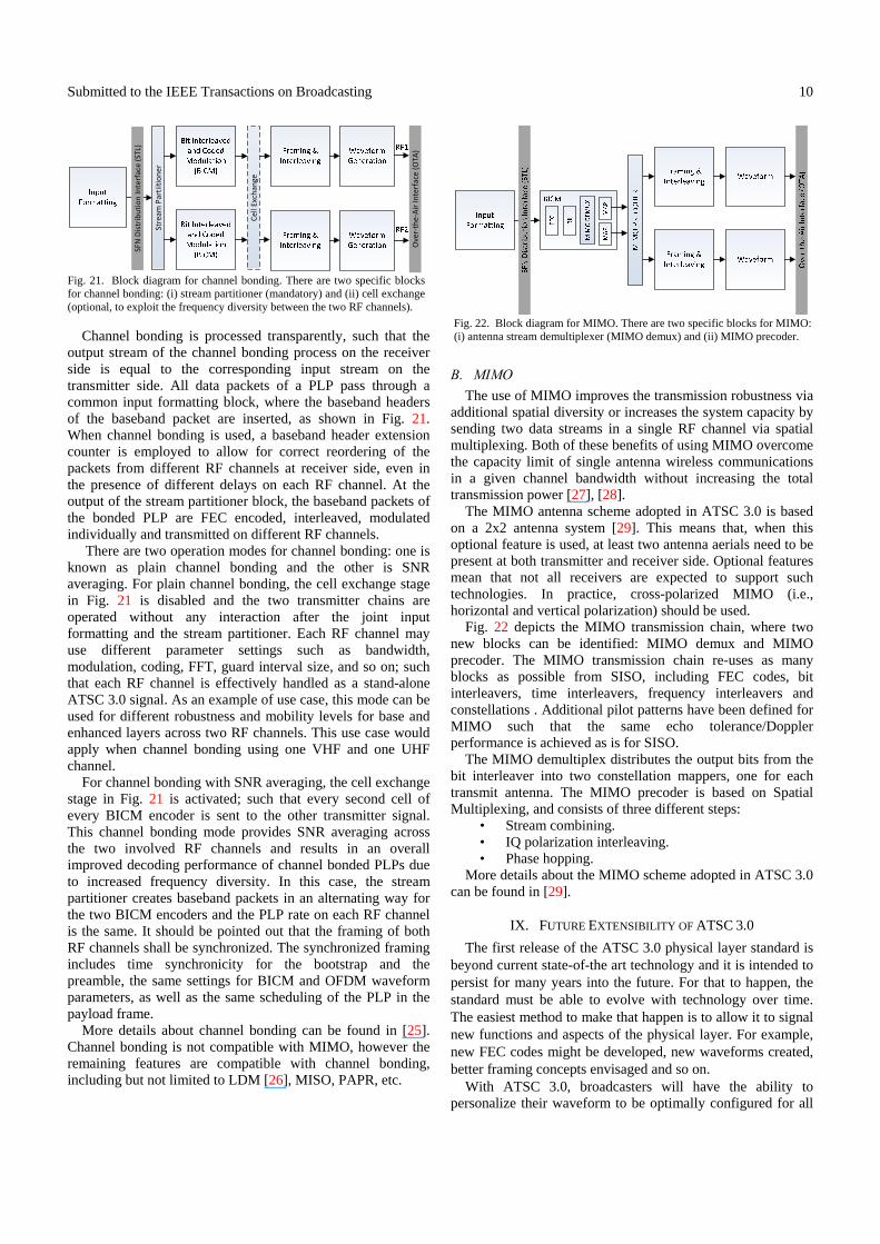
Channel bonding is processed transparently, such that the output stream of the channel bonding process on the receiver side is equal to the corresponding input stream on the transmitter side. All data packets of a PLP pass through a common input formatting block, where the baseband headers of the baseband packet are inserted, as shown in Fig. 21. When channel bonding is used, a baseband header extension counter is employed to allow for correct reordering of the packets from different RF channels at receiver side, even in the presence of different delays on each RF channel. At the output of the stream partitioner block, the baseband packets of the bonded PLP are FEC encoded, interleaved, modulated individually and transmitted on different RF channels.
There are two operation modes for channel bonding: one is known as plain channel bonding and the other is SNR averaging. For plain channel bonding, the cell exchange stage in Fig. 21 is disabled and the two transmitter chains are operated without any interaction after the joint input formatting and the stream partitioner. Each RF channel may use different parameter settings such as bandwidth, modulation, coding, FFT, guard interval size, and so on; such that each RF channel is effectively handled as a stand-alone ATSC 3.0 signal. As an example of use case, this mode can be used for different robustness and mobility levels for base and enhanced layers across two RF channels. This use case would apply when channel bonding using one VHF and one UHF channel.
For channel bonding with SNR averaging, the cell exchange stage in Fig. 21 is activated; such that every second cell of every BICM encoder is sent to the other transmitter signal. This channel bonding mode provides SNR averaging across the two involved RF channels and results in an overall improved decoding performance of channel bonded PLPs due to increased frequency diversity. In this case, the stream partitioner creates baseband packets in an alternating way for the two BICM encoders and the PLP rate on each RF channel is the same. It should be pointed out that the framing of both RF channels shall be synchronized. The synchronized framing includes time synchronicity for the bootstrap and the preamble, the same settings for BICM and OFDM waveform parameters, as well as the same scheduling of the PLP in the payload frame.
More details about channel bonding can be found in [25]. Channel bonding is not compatible with MIMO, however the remaining features are compatible with channel bonding, including but not limited to LDM [26], MISO, PAPR, etc.
B. MIMO
The use of MIMO improves the transmission robustness via additional spatial diversity or increases the system capacity by sending two data streams in a single RF channel via spatial multiplexing. Both of these benefits of using MIMO overcome the capacity limit of single antenna wireless communications in a given channel bandwidth without increasing the total transmission power [27], [28].
The MIMO antenna scheme adopted in ATSC 3.0 is based on a 2x2 antenna system [29]. This means that, when this optional feature is used, at least two antenna aerials need to be present at both transmitter and receiver side. Optional features mean that not all receivers are expected to support such technologies. In practice, cross-polarized MIMO (i.e., horizontal and vertical polarization) should be used.
Fig. 22 depicts the MIMO transmission chain, where two new blocks can be identified: MIMO demux and MIMO precoder. The MIMO transmission chain re-uses as many blocks as possible from SISO, including FEC codes, bit interleavers, time interleavers, frequency interleavers and constellations . Additional pilot patterns have been defined for MIMO such that the same echo tolerance/Doppler performance is achieved as is for SISO.
The MIMO demultiplex distributes the output bits from the bit interleaver into two constellation mappers, one for each transmit antenna. The MIMO precoder is based on Spatial Multiplexing, and consists of three different steps:
• Stream combining. • IQ polarization interleaving. • Phase hopping.
More details about the MIMO scheme adopted in ATSC 3.0 can be found in [29].
IX. FUTURE EXTENSIBILITY OF ATSC 3.0
The first release of the ATSC 3.0 physical layer standard is beyond current state-of-the art technology and it is intended to persist for many years into the future. For that to happen, the standard must be able to evolve with technology over time. The easiest method to make that happen is to allow it to signal new functions and aspects of the physical layer. For example, new FEC codes might be developed, new waveforms created, better framing concepts envisaged and so on. With ATSC 3.0, broadcasters will have the ability to personalize their waveform to be optimally configured for all
Fig. 22. Block diagram for MIMO. There are two specific blocks for MIMO: (i) antenna stream demultiplexer (MIMO demux) and (ii) MIMO precoder.
Fig. 21. Block diagram for channel bonding. There are two specific blocksfor channel bonding: (i) stream partitioner (mandatory) and (ii) cell exchange(optional, to exploit the frequency diversity between the two RF channels).
Ove
r-th
e-A
ir In
terf
ace
(O
TA)
SFN
Dis
trib
uti
on
Inte
rfac
e (S
TL)
Stre
am P
arti
itio
ne
r
Cel
l Exc
han
ge

Submitted to the IEEE Transactions on Broadcasting
11
the services they want to deliver. Having a bootstrap available as the universal entry point for waveform signaling allows for such physical layer personalization. The bootstrap is robust enough to be buried well within the noise and still allow receive devices to synchronize and provide key bits of information to start demodulating. Digital communications must start with some a-priori information. That could be sampling frequency or channel bandwidth or some other key information. Television signals have traditionally had a known channel bandwidth through which a sampling frequency can be inferred. For ATSC 3.0, both the sampling frequency and channel bandwidth are signaled. This signaling removes many constraints of using future systems that are yet to be developed and allows broadcasters to evolve over time without having to develop a new standard every time some new technology piece becomes available.
X. CONCLUSION
This paper has provided an overview of the physical layer specification of the ATSC 3.0 system. ATSC 3.0 aims to redefine over-the-air TV broadcasting for decades to come and to become the reference terrestrial broadcasting standard worldwide. The ATSC 3.0 physical layer represents an important achievement, which goes well beyond the current state-of-the art in terrestrial broadcasting. It offers the most robust, most spectrum efficient, and most flexible transmission options for broadcasters and the services that they provide. Several novel transmission techniques have been adopted into the standard, such as new LPDCs, two-dimensional non-uniform constellations, (power-based) layered division multiplexing, transmit diversity code filter set MISO, channel bonding and MIMO. A summary comparison between DVB-T2 and ATSC 3.0 can be found in Table IV. Furthermore, the signaling in the physical layer has been devised to ensure flexibility and extensibility for future technology advances for many years to come.
ACKNOWLEDGMENT AND NOTE
The authors would like to thank all the colleagues from the ATSC TG3/S32 Specialist Group on Physical Layer that contributed to the development of the ATSC 3.0 physical layer specification.
It is noted that that the ATSC 3.0 physical layer specification (A/322 standard) is in the candidate standard phase at the time of writing this paper, and therefore the reader should be aware that some details may change before the ATSC A/322 standard is finalized.
REFERENCES [1] ATSC A/53, “ATSC Digital Television Standard,” parts 1-6, Jan. 2007. [2] M. Simon and M. A. Aitken, “An Overview of the North American
ATSC M/H Mobile Broadcasting System and its Next-Generation ATSC 3.0,” in Next Generation Mobile Broadcasting, pp. 91-121, CRC Press, 2013.
[3] I. Eizmendi, et al., “DVB-T2: The Second Generation of Terrestrial Digital Video Broadcasting System,” IEEE Trans. Broadcast, vol. 60, no. 2, pp. 258-271, June 2014.
[4] D. Gomez-Barquero, C. Douillard, P. Moss, and V. Mignone, “DVB-NGH: The Next Generation of Digital Broadcast Services to Handheld Devices,” IEEE Trans. Broadcast, vol. 60, no. 2, pp. 246-257, June 2014.
[5] D. Gomez-Barquero (Ed.), “Next Generation Mobile Broadcasting,” Boca Raton, FL, USA: CRC Press, 2013.
[6] W. Zhang, Y. Wu, N. Hur, T. Ikeda, and P. Xia, “FOBTV: Worldwide Efforts in Developing Next-Generation Broadcasting System,” IEEE Trans. Broadcast, vol. 60, no. 2, pp. 154-159, 2014.
[7] ATSC, Technical Document TG3-S31087r7, “System Requirements for ATSC 3.0,” Nov. 2013.
[8] D. Gomez-Barquero and M. W. Caldwell, “Broadcast Television Spectrum Incentive Auctions in the U.S.: Trends, Challenges and Opportunities,” IEEE Commun. Mag., vol. 53, no. 7, pp. 50-56, July 2015.
[9] ATSC 3.0 System Discovery and Signaling, ATSC A/321 Part 1, May 2015.
TABLE IV COMPARISON OVERVIEW BETWEEN ATSC 3.0 AND DVB-T2 IN 6 MHZ
Parameter DVB-T2 ATSC 3.0
Outer code BCH BCH, CRC, none LDPC size 16200 and 64800 bits 16200 and 64800 bits
LPDC code rate
1/2, 3/5, 2/3, 3/4, 4/5, 5/6 {2, 3, 4, 5, 6, 7, 8, 9, 10, 11, 12, 13}/15
Modulation QPSK, 16QAM,
64QAM, 256QAM
QPSK, 2D-16NUC, 2D-64NUC, 2D-256NUC,
1D-1024NUC, 1D-4098NUC
Rotated Constellation
Yes (optional) No
Time Interleaver
Block interleaver CI (S-PLP)
Hybrid BI+CI (M-PLP) TI size (cells)
219 + 215 219
220 (QPSK) Multiplexing TDM LDM, FDM, TDM Max. Frame
size 250 ms 5 s
Pilot Patterns
PP1 – PP8 (x8) 1.04%-8.33% overhead
SP3_2 – SP32_2 (x16) 0.78%-16.6% overhead
MISO Alamouti
(twice pilot overhead) TDCFS
(same pilot overhead) PAPR TR and ACE TR and ACE
FFT size 1K, 2K, 4K, 8K,
16K, 32K 8K, 16K, 32K
Extended Mode
8KE, 16KE, 32KE Number of active carriers
configurable
GI 1/128, 1/32, 1/16, 19/256,
1/8, 19/128, 1/4
3/512, 3/256, 1/64, 3/128, 1/32, 3/64, 1/16, 19/256, 3/32, 57,512, 3/16, 1/8, 19/128, 1/4 (symbol and
time-aligned frames) Multiple PLPs
per service No (1 common PLP) Yes (up to 4)
Link Layer Encapsulation
MPEG-2 TS ALP
Main transport protocol
TS IP
Min-Max. Data Rate
6 MHz 5.6 Mbps, 38 Mbps 1 Mbps, 57 Mbps
SNR operating
range AWGN +1 dB, +22 dB -6.2 dB, +32 dB
Entry point to the system
P1 (7 bits, -5 dB SNR @AWGN)
Bootstrap (24 bits, -9.5 dB SNR @AWGN)
Channel Bonding
No Yes (two RFs)
MIMO No Yes (not mandatory for the receivers)
Submitted to the IEEE Transactions on Broadcasting
12
[10] D. He, W. Zhang, Y. Wang, L. Ding, and F, Yang, “Dedicated Return Channel in ATSC 3.0,” IEEE Trans. Broadcast, vol. 62, no. 1, 2016.
[11] W. Kwon, et al., “The ATSC Link-layer Protocol (ALP): Design and Efficiency Evaluation,” IEEE Trans. Broadcast, vol. 62, no. 1, 2016.
[12] L. Michael and D. Gomez-Barquero, “Bit Interleaved Coding and Modulation for ATSC 3.0,” IEEE Trans. Broadcast, vol. 62, no. 1, 2016.
[13] K,-J. Kim, et al., “Low Density Parity Check Codes (LDPC) for ATSC 3.0,”IEEE Trans. Broadcast, vol. 62, no. 1, 2016.
[14] N. Loghin, et al., “Non-Uniform Constellations for ATSC 3.0,” IEEE Trans. Broadcast, vol. 62, no. 1, 2016.
[15] ETSI TS 102 831 v1.2.1, “Digital Video Broadcasting (DVB); Implementation guidelines for a second generation broadcasting system (DVB-T2)” Aug. 2012.
[16] L. Zhang, et al., “Layered Division Multiplexing: Theory and Practice,” IEEE Trans. Broadcast, vol. 62, no. 1, 2016.
[17] S.-I. Park, et al., “Low Complexity Layered Division Multiplexing System for ATSC 3.0,” IEEE Trans. Broadcast, vol. 62, no. 1, 2016.
[18] D. Gomez-Barquero and O. Simeone, “LDM vs. FDM/TDM for Unequal Error Protection in Terrestrial Broadcasting Systems: An Information-Theoretic View,” IEEE Trans. Broadcast, vol. 61, no. 4, 2015.
[19] C. Rigueiro, et al., “LDM Core Services: Indoor and Mobile Performance in ATSC 3.0” IEEE Trans. Broadcast., vol. 62, no. 1, 2016.
[20] P. Klenner, et al., “Physical Layer Time Interleaver for the ATSC 3.0 System,” IEEE Trans. Broadcast, vol. 62, no. 1, 2016.
[21] M. Earnshaw, K. Shelby, H. Lee, Y, Oh, and M. Simon, “Physical Layer Framing for ATSC 3.0,” IEEE Trans. Broadcast, vol. 62, no. 1, 2016.
[22] S. Lopresto, R. Citta, D. Vargas, and D. Gomez-Barquero, “Transmit Diversity Code Filter Sets (TDCFS), a MISO Antenna Frequency Pre-Distortion Scheme for ATSC 3.0,” IEEE Trans. Broadcast, vol. 62, no. 1, 2016.
[23] J. Qi, J. Robert, K. L. Chee, M. Slimani, and J. Zöllner, “DVB-T2 MISO Field Measurements and a Calibrated Coverage Gain Predictor,” Proc. IEEE BMSB, Seoul, Korea, 2012.
[24] D. He, H. Xu, G. Huang, K. Shelby, and M. Earnshaw, “An Introduction on the Bootstrap Signal in ATSC 3.0,” IEEE Trans. Broadcast, vol. 62, no. 1, 2016.
[25] L. Stadelmeier, D. Schneider, J. Zollner, and J. J. Gimenez, “Channel Bonding for ATSC 3.0,” IEEE Trans. Broadcast, vol. 62, no. 1, 2016.
[26] E. Garro, J. J. Gimenez, D. Gomez-Barquero, and S.-I. Park, “Layer Division Multiplexing (LDM) with Multi Radio-Frequency Channel Technologies,” IEEE Trans. Broadcast, vol. 61, no. 4, 2015.
[27] D. Vargas, D. Gozalvez, D. Gomez-Barquero, and N. Cardona, “MIMO for DVB-NGH, the Next Generation Mobile TV Broadcasting,” IEEE Commun. Mag., vol. 51, no. 7, pp. 130-137, July 2013.
[28] S. Saito, et al., “8K Terrestrial Transmission Field Tests Using Dual-polarized MIMO and Higher-order Modulation OFDM,” IEEE Trans. Broadcast., vol. 62, no. 1, 2016.
[29] D. Gomez-Barquero, et al., “MIMO for ATSC 3.0,” IEEE Trans. Broadcast, vol. 62, no. 1, 2016.
Luke Fay received an M.Sc. degree in electrical engineering from National Technological University. He is a Senior Staff SW Systems Engineer for Sony Semiconductor’s Component Solutions Business Division with over 16 years of experience in digital communications systems engineering and receiver design. Currently he is involved with ATSC and its efforts toward developing the next generation TV broadcast standards. He is vice-chair of the Advanced Television Systems Committee (ATSC) Technology Group 3 (TG3), and also chair of ATSC TG3 Specialist Group on Physical Layer for ATSC 3.0, which focuses on the physical layer of the next generation digital TV standard. He is the recipient of the ATSC Bernard J. Lechner 2015 outstanding contributor award. Lachlan Michael received B.Eng (Hons) and B.A. (Japanese) from the University of Queensland, Australia in 1994, M.Eng from Keio University, Japan in 1997 and Ph.D. degree in
Electrical Engineering from Keio University in 2000. He joined Sony Computer Science Laboratories in 2000 and moved to Sony Corporation in 2002.
Dr. Michael has been actively involved in both broadcast receiver development and broadcast standardization, having participated in DVB-T2/T2-Lite, DVB-C2, DVB-NGH and DVB-S2x activities. In DVB-T2 he led the V&V (Verification and Validation) group concluding three successful plug-fests. He has participated in ATSC 3.0 standardization from the beginning, notably as the Chairman of the Modulation and Coding Ad-Hoc Group and editor of the A/322 specification. David Gómez-Barquero received the double M.Sc. degrees in telecommunications engineering from the Universitat Politecnica de Valencia (UPV), Spain, and the University of Gävle, Sweden, in 2004, the Ph.D. degree in telecommunications from the UPV in 2009; and he carried out a 2-year post-doc at the Fraunhofer Heinrich Hertz Institute, Germany. He is a Senior Researcher (Ramon & Cajal Fellow) with the Institute of Telecommunications and Multimedia Applications, UPV, where he leads a research group working on next generation broadcasting technologies. He has hold visiting research appointments at Ericsson Eurolab, Germany, the Royal Institute of Technology, Sweden, the University of Turku, Finland, the Technical University of Braunschweig, Germany, the University Sergio Arboleda of Bogota, Colombia, and the New Jersey Institute of Technology, USA.
Dr. Gómez-Barquero has been since 2008 actively participating in the European digital television standardization forum DVB in different topics such as upper layer forward error correction, DVB-T2, T2-Lite, and DVB-NGH. In 2013, he joined the U.S. digital television standardization forum ATSC to work on ATSC 3.0, acting as Vice-Chairman of the Modulation and Coding Ad-Hoc Group. He is the Editor of the book entitled Next Generation Mobile Broadcasting (CRC Press, 2013). Nejib Ammar received the B.Sc and M.Sc degrees in electrical engineering from Bilkent University, Turkey in 1997 and 2000 respectively, and the Ph. D. in electrical and computer engineering from the University of California at Davis in 2005. Since 2004, he has been working as an electrical engineer in the areas of video compression and wireless communications. He joined the Zenith R&D team in 2012 and has been working on ATSC 3.0 TV broadcast standards. He serves as the chairman of ATSC Waveform Ad-Hoc Group. M. Winston Caldwell, P.E. received his Bachelor of Engineering degree in electrical engineering from Vanderbilt University and his Master of Science degree in electrical engineering from the University of Southern California. He is a licensed Professional Engineer in the state of California with over twenty years of electrical engineering experience, specializing in RF propagation, wireless communications, and antenna design. He is currently Vice President, Spectrum Engineering and Advanced Engineering, for 21st Century Fox’s Fox Networks Group, where he is involved with the exploration of new broadcasting opportunities including development work on the ATSC 3.0 next-generation TV
Submitted to the IEEE Transactions on Broadcasting
13
broadcast standard, acting as vice-chairman of the Waveform Ad-Hoc Group. He is an active participant in the ITU, IEEE, NAB, NABA and SMPTE, where he has provided technical expertise in the determination of compatibility requirements between the established broadcasting services and unlicensed TV band, ultra-wideband, power-line transmission and IMT-Advanced devices.