how to use this book
TRANSCRIPT


How to Use This Book
This book will teach you how to do physics problems. The explanation of not only how to do a problem butwhy we do it a certain way teaches you not just a collection of solved problems, but a collection of methods thatcan be used, modified, and built upon to do other physics problems. As researchers and teachers, we know thatthe key to solving new and challenging problems is contained within the collection of techniques alreadylearned for solving simpler problems. Seeing a problem solved and knowing why it was done in a certainmanner is the best way to learn how to solve related, more difficult problems.
This book is not a presentation of every problem you are going to encounter on a test. It is a presentation of themethods that we have found to work for large groups of problems. If you develop the techniques we describefor solving problems then you will know how to successfully attack the problems you will encounter on thetests. This is the book you should have as a reference when you are doing your homework problems. It willshow you how to work the problems and explain why they are being done the way they are.
The topics in this book are in the order of most physics texts. Each chapter begins with a theoretical discussion.Problems are mixed in with the discussion as soon as possible. These problems follow the development of thetheory. In this way you do not have to assimilate a large amount of conceptual material before begining to workproblems.
A “standard” route is followed for problems wherever possible. In this way you will learn that broad categoriesof problems worked in a standard “logical” way always produce correct solutions. Our emphasis is on logic andorder in solving problems. We avoid methods that may be quick and have limited application to problemsolving in favor of possibly longer solutions that have broad applications and always work. We believe that a lotof good physics can be taught in problems so we use problems to illustrate and expand a topic and sometimesintroduce new concepts. For this reason problems and text are integrated with a minimum of artificial barriersbetween them.
The book is intended as a complement to either the calculus-based or the non-calculus-based elementaryphysics course. It has been our experience that calculus concepts can be introduced into the traditional non-calculus course and used in the development of concepts. Conceptually, calculus is not difficult and when it isintroduced in the context of a physics problem it is even easier. We use calculus concepts to explain theory, butcalculus is rarely used in problems. Even those students who are taking calculus concurrent with their physicscourse usually learn calculus concepts in physics before they see them in their calculus course.
In those instances where calculus is needed, the problems and paragraphs are marked with a calculus icon. Eventhe student without formal calculus training should read these sections. They are often explained in a simplemanner so that the calculus does not present a problem.
The chapters on electricity and magnetism are also excellent background chapters for someone taking anundergraduate course in Electricity and Magnetism.
We have used two significant figures for the physical constants and most of the numbers in the problems.Results are given to two, and occasionally three, significant figures. Using two significant figures cuts down onthe clutter in the problems, allowing the technique to receive greater exposure. Do not be concerned in workingthrough the problems if your answers do not agree exactly with ours. This is no doubt due to when, or if,intermediate calculations were rounded off. SI units are used nearly universally throughout the book.

How to Excel in Your Physics Course
Most students realize that putting off studying until the day before the exam and then cramming at the lastminute is not efficient. Some students do this anyway, because so far they have gotten away with it. Perhapsmost of the other students you previously competed with had poor study skills. This may have allowed you toadopt poor or non-existent study habits and still keep up, or even get good grades if you are naturally a betterstudent. Now that you are in college, the courses will be more difficult and it is to your advantage to develop amore organized approach to handling your course work.
Successful people generally have three things in common. They make effective use of their time, they set goalsfor themselves, and they have a positive attitude. Physics is a challenging course for most students. It will take awell-organized consistent effort to do well in this course, but success in a challenging area is a worthwhile goal.
General Approach for Studying Physics
Many people believe the following: more work and more study results in higher grades. This is not necessarilyso. You certainly must be willing to make a certain commitment of time and energy to this course, but the keyto academic success is concentrating your efforts on the right things at the right times. You may have noticedthat those students who receive the highest grades are not necessarily the ones who work the greatest number ofhours. Some students may boast that they have studied all night for an exam, but don't be impressed by thishabit. “Allnighters” and the like are almost always the result of procrastination and bad study habits. Getting nosleep before an exam is foolish and it usually takes several days to recover from this kind of activity. By takingadvantage of the study techniques that follow you can achieve higher grades with less effort.
The most efficient way of learning Physics by attending lectures, problem solving sessions, and performingsupplementary readings is to:
1. Do a quick reading on the topics to be covered in the lecture before attending class. Ten or fifteen minutesmay be sufficient for a one hour lecture. The purpose here is to generally familiarize yourself with the topics tobe discussed. Perhaps you can identify one or two questions or key points to listen for during the lecture.
2. Attend class and take notes. Attend all of the classes. Someone is paying for these classes so BE THERE! Beon the alert for any indication by the instructor of possible test questions. If the professor says something like“This is very important, you may be seeing this again,” make a special note of this in your notebook.
3. Review your lecture notes. Don't save this step until a few days before the exam. It is far more efficient toreview your notes a little bit at a time during the semester than to try and do it all at once. At this point youshould also do a more detailed reading of the text to fill in any gaps in your class notes.
4. This may be the most important step. Do the homework problems regularly. In other courses it may besufficient to read the text and review your notes, but in Physics you must be able to work the problems. Youdon't learn problem solving skills by just reading examples of solved problems, you must do the problemsyourself. By doing the homework problems on a regular basis you will be able to identify areas that you needmore work on well in advance of the test. Physics problems can be difficult. Therefore, when you set out towork problems do not set yourself the task of working a certain number of problems, but rather set out a certainamount of time to work on problems.

5. Compile a formal set of notes and prepare a detailed outline. The general strategy here is that a number ofshort exposures to manageable pieces of the course is more efficient than one long exposure to a large amountof material. As you progress through the course, you first get your information in an initial reading of thematerial, then again in the lecture, then again in a second reading, and yet again in an organizing session whereyou prepare a detailed outline. The detailed outline is essential to success on the exams. It contains theexamination questions. Your main preparation for the exam will be to extract the questions and prepare toanswer them. Notice we did not say “study for the exam;” the studying for the exam has been going on allalong. That is what you have been doing as you make up your formal notes, outline, etc. What you have donewith this systematic approach is to reproduce the notes and outline that the instructor is using. If you arereasonably good at it, you will have as good a source of exam questions as the instructor.
How to Prepare for a Physics Test
Examine the shelves of any bookstore catering to career oriented students and you will find books with titlessuch as: How to Pass the Real Estate Licensing Exam, or How to Succeed on the S.A.T. Examining these bookswill help you to develop your personal exam-taking program. One common thread in all books on how to passparticular exams is to know the questions in advance. Most writers of these types of books are in the business oftraining people in their particular areas, so they are close to the people who are making up the exams. This givesthem a ready source of test questions, and knowing the questions (or at least the type of questions) is half wayto knowing the answers. Therefore we make the following suggestions:
1. Almost all instructors in physics will place some problems on the test that are very similar to examples thatthey have done in class. Many times you may encounter the same problem with different numbers. This makesit very important to attend every class so as not to miss the opportunity to see possible test questions. If you domiss class, always get the notes from a friend.
2. Another frequent occurrence is for slight modifications of homework problems to appear on the test. Join astudy group that does homework problems together. This can be more efficient than grinding away on yourown. Don't waste too much time with a study group unless it is productive. Your final preparations for a testshould be done privately so that you can concentrate on developing a plan for taking the test.
3. Find sample physics tests given by your instructor for the past few years. It is a good bet that most of thequestions for the exams in the near future will be very much like those of the immediate past.
4. Some physics problems involve mathematics that can be deceptively easy. For example, if you expectproblems involving the manipulation of logarithms or exponents be sure you practice the mathematicaloperations and entering the numbers into your calculator so you don't have to stop and figure out how to takeexponents during the test. Practice any unfamiliar mathematical operations before the test.
Timing and the Use of the Subconscious.
Have you ever experienced the frustration of having a conversation with someone and forgetting momentarily aname or fact that is very familiar to you? Usually, shortly after such an experience, the name or fact will cometo you when you are not consciously trying to recall it. Another variation of this same phenomenon is when aperson doesn't feel right about making a decision immediately upon receiving or defining a problem. They liketo “sleep on it.” Both of these situations have a common characteristic - the use of the subconscious. The factthat solutions are often presented to us in the absence of active work on the problem at the moment we receivethe solution indicates that another part of the brain was analyzing the pertinent information and providing asolution. We call this part of the brain the subconscious, and this part of the brain is very effective at solvingproblems.

Here are some tips for effectively using the subconscious:
1. Your subconscious will not work without information. You must consciously sort out all of the facts orinformation for a particular problem. If you are having difficulty with a problem, try to get straight in your mindwhat you do know about the problem. Then also define in your mind what specifically you don't know or don'tunderstand about the problem.
2. Put conscious effort into the problem up to the point of confusion. Many people grind and grind on a problemafter this point and accomplish very little. It is more efficient for you to plan your study time so that you do notput yourself in a situation where your only choice is to grind on a problem.
3. After you have done all you can consciously on the problem, “Put it in the back of your mind.” Don't keepworrying about it. It is important that you clear your mind so that you can accept the solution when it comes.
4. Be sure you have a deadline for the solution.
5. When a solution comes, be sure to act on it quickly, so you can go on to something else. Sometimes insteadof a solution to the problem you will receive a request for more information. The problem may still beunanswered, but will be clearer to you. What could be happening here is that your subconscious has analyzedthe problem and found an essential piece of information missing and is asking you for it.
The study program that we have outlined, consisting of regular review of lecture notes, frequent working ofhomework problems, and periodic updates of your formal notes and outline, makes maximum use of yoursubconscious. The periodic intake of new material and the required conscious review serves to keep yousubconsciously analyzing and fitting new information into the body of knowledge you are accumulating.
Here would be a good approach to practicing for a Physics test:
ED - 4: (Exam day minus four) Prepare a sample exam from your outline.This may consist of questions from previous exams given by theinstructor and variations of homework problems or examplesdone in class. Keep in mind that this is probably the same waythat the professor is making up your exam.
ED - 3: Study for your first sample exam. Go over your notes, text, andhomework problems.
ED - 2: Take your first sample exam. As soon as possible after the exam,do a detailed review concentrating on the weaker areas. Make upyour final sample exam.
ED - 1: Take your final sample exam. Again review the difficult points ofthis sample exam. Get a good night's sleep tonight.
ED: Do as little as possible on the day of the exam. You may want toquickly review your outline or a couple of difficult points.

You will notice that the bulk of the work in preparing for a test this way consists of writing and taking sampletests. It is planned that way. One of the common fallacies in preparing for exams is to prepare for the wrongthing. Many students will prepare for a Physics exam by reading the text or by reading solutions to problems. APhysics exam, however, is not a reading exam but a writing and problem-solving exam. If you have notpracticed writing solutions to typical problems, you have not prepared as well as you might for the exam.
The second advantage to taking sample tests is that it increases your speed in writing solutions to types ofproblems that are likely to be on the test. This will allow you more time during the test to spend on unexpectedor more troublesome problems.
Strategies to Use During a Physics Test
You are now entering the test room. You are well prepared to take the test. You have taken practice tests andknow what to expect on the exam. You have gotten a good night's sleep the night before and eaten a healthybreakfast that will provide you with the energy needed for good concentration. You have a positive attitude. Atthis point worrying about how you will do on the exam is useless. Study time is over. You now need toconcentrate on the strategies that will get you the highest possible score on the test. Here are some suggestions:
1. It is usually a good idea to take a minute or two at the beginning of the exam to look over all the questions.Look for the type of questions that you expected and have practiced and do these first. Save the hardestquestions for last. It can be very frustrating to run out of time working on question # 4 only to realize that youdidn't even get a chance to start question #5 that was much easier.
2. Have a rough idea of how much time you should be spending on each question. Sometimes certain questionswill count for more points than others and the instructor should provide that information on the test.
3. If you are required to memorize a lot of formulas you may want to take the time at the beginning of the test towrite down a few of the more complicated ones next to problems that involve those formulas as you areglancing over the test. Later during the test, your mind may be cluttered with formulas and it may be harder tocorrectly recall one of the more complicated ones.
4. Always include the units of your answer (miles per hour if the answer is a velocity for example). Don't makethe mistake of not including units. This is very important to almost all physics teachers.
5. Write your work clearly when you are solving a problem. It is easier for the professor to give you partialcredit if he can clearly see that you did the problem correctly and just made a minor computational error.
6. Think about your answer to a problem. Does the answer make sense? For example, if you are solving for thelength of one side of a right triangle and you are given the hypotenuse, your answer better not be a lengthgreater than the hypotenuse. It is very important to be able to think like this on a test. This will help you to catcha lot of mistakes like missing a minus sign.
7. Unfortunately some instructors give tests that are much too long for a given period of time. It seems as if theyare more interested in measuring how fast you can do physics than how well you can do physics. Try to find outin advance of the test if your professor's tests are like this. If the cutoff for an A is usually 75% instead of 90%then you need to be aware of this. This will save you from panicking as you run out of time on the test.Remember that you may be able to work for partial credit on that last answer. On these kinds of tests it is veryimportant to keep your cool and try to get as many points as you possibly can. Stay positive all the way throughand give it your best shot!
8. Make sure you know the difference between radian mode and degree mode on your calculator when taking atest that includes trigonometry (See the Mathematical Background Section).
9. Avoid prolonged contact with other students immediately before the exam. Many times the nervous tension,frustration, defeatism, and perhaps wrong information expressed by fellow students can be harmful to yourperformance.
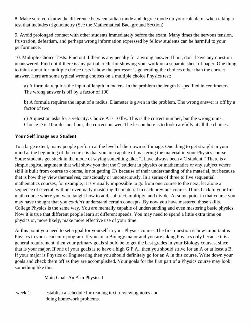
10. Multiple Choice Tests: Find out if there is any penalty for a wrong answer. If not, don't leave any questionunanswered. Find out if there is any partial credit for showing your work on a separate sheet of paper. One thingto think about for multiple choice tests is how the professor is generating the choices other than the correctanswer. Here are some typical wrong choices on a multiple choice Physics test:
a) A formula requires the input of length in meters. In the problem the length is specified in centimeters.The wrong answer is off by a factor of 100.
b) A formula requires the input of a radius. Diameter is given in the problem. The wrong answer is off by afactor of two.
c) A question asks for a velocity. Choice A is 10 lbs. This is the correct number, but the wrong units.Choice D is 10 miles per hour, the correct answer. The lesson here is to look carefully at all the choices.
Your Self Image as a Student
To a large extent, many people perform at the level of their own self image. One thing to get straight in yourmind at the beginning of the course is that you are capable of mastering the material in your Physics course.Some students get stuck in the mode of saying something like, “I have always been a C student.” There is asimple logical argument that will show you that the C student in physics or mathematics or any subject whereskill is built from course to course, is not getting C's because of their understanding of the material, but becausethat is how they view themselves, consciously or unconsciously. In a series of three to five sequentialmathematics courses, for example, it is virtually impossible to go from one course to the next, let alone asequence of several, without eventually mastering the material in each previous course. Think back to your firstmath course where you were taught how to add, subtract, multiply, and divide. At some point in that course youmay have thought that you couldn't understand certain concepts. By now you have mastered those skills.College Physics is the same way. You are mentally capable of understanding and even mastering basic physics.Now it is true that different people learn at different speeds. You may need to spend a little extra time onphysics or, more likely, make more effective use of your time.
At this point you need to set a goal for yourself in your Physics course. The first question is how important isPhysics in your academic program. If you are a Biology major and you are taking Physics only because it is ageneral requirement, then your primary goals should be to get the best grades in your Biology courses, sincethat is your major. If one of your goals is to have a high G.P.A., then you should strive for an A or at least a B.If your major is Physics or Engineering then you should definitely go for an A in this course. Write down yourgoals and check them off as they are accomplished. Your goals for the first part of a Physics course may looksomething like this:
Main Goal: An A in Physics I
week 1: establish a schedule for reading text, reviewing notes anddoing homework problems.

week 2: investigate the possibility of joining a study group
week 3: find out if past exams from this professor are available: findout how many points it will take to make an A on the first test
week 4: prepare and take sample exams for first test
The purpose of writing down your goals is not to create more work, but to keep you focused on the mostimportant things that you need to accomplish as the semester progresses. Please remember that all of the studytechniques outlined in this chapter are designed to make achieving higher grades easier for you. The sooner youbecome more organized and focused on your goals, the sooner you will begin to realize that you are capable ofimpressive accomplishments with a reasonable amount of effort.
Perhaps Physics is a favorite area of study that you may wish to pursue in the future or perhaps you areprimarily interested in the most efficient way to make it through this course. Whatever you choose for yourmajor area of study, find something you enjoy and pursue excellence. Give it your best today, and bettertomorrow. We wish you success.
Preface
The purpose of this book is to show you how to do physics problems. It is only through application of conceptsto solving problems that we can know for certain that we understand something. Nowhere is this more true thanin a physics course where performance is measured almost exclusively by your ability to do problems.
This book is not a collection of problems. Neither is it a text. It is an attempt to strike a balance between theoryand problem solving with heavy emphasis on the problem solving. As such it is intended to complement yourcourse text. Generations of physics students, the authors included, have often lamented, concerning theirphysics courses, “I understood everything in lecture and the text but I can't do the problems.” This book willhelp you do the problems.
Learning physics is different from most other disciplines. Most disciplines can be learned by reading andlistening, with mastery demonstrated by writing. Physics is not like that. Reading and listening are the first step,but mastery is demonstrated by doing problems. Writing comes easy to most people. Working problems inmathematical symbolism is not so easy to most, and it is not something we do regularly. Learning physicsrequires learning to do the problems of physics not by writing about them but by manipulating mathematicalsymbols in the correct manner.
The book was started around 1980 (by RMO) and was provided in rough form to his students in the elementaryphysics sequence to help them understand concepts and give them practice and confidence in workingproblems. The favorable response from those students provided motivation to continue to expand the numberand extent of the topics. In 1984 the problems were used (by DMO) as an aid in the elementary physics courseshe was taking. Since then the collection of problems and text has been expanded by both authors and refinedthrough further use by their students.
It is the sincere desire of the authors that this book help you to better understand physical concepts and work theassociated problems. We would like to thank the many students who have contributed to this work by using thematerial and offering their suggestions. Also the fine staff at McGraw-Hill, especially our editor, ArthurBiderman, have contributed greatly to the clarity of presentation.
ROBERT M OMANST.PETERSBURG, FLORIDA
DANIEL M.OMANORLANDO,FLORIDA

IntroductionMathematical Background
The purpose of this chapter is to provide you with a review of and reference for the mathematical techniquesyou will need in working the physics problems in this book. Some topics may be familiar to you while othersmay not. Depending on the mathematical level of your physics course, some topics may not be of interest toyou. Each topic is covered in sufficient depth to allow you to perform the mathematical manipulationsnecessary for a particular problem without getting bogged down in lengthy derivations. It is not our intention toteach mathematics, but to show you how to apply specific mathematical procedures to physics problems.
The most efficient use of this chapter is for you to do a brief review of the chapter, spending time on thosesections that are unfamiliar to you and that you know you will need in your course, then refer to specific topicsas they are encountered in the solution to problems. With this reference you should be able to perform all themathematical operations necessary to complete the problems in your physics course. If you need or desire moredepth in a particular topic go to an algebra or calculus text.
Solving Equations
The simplest equations to solve are the linear equations of the form ax + b = 0 which have as solution x = -b /a. You should be very familiar with these.
The next most complicated equations are the quadratics. The simplest quadratic is the type that can be solved bytaking square roots directly, without any other manipulations.
An example is 4x2 = 36, which is first divided by 4 to read x2 = 9 and square roots taken to produce x = ±3. Bothplus and minus values are legitimate solutions. The reality of the physical problem producing the equation maydictate that one of the solutions be discarded.
The next complication in quadratic equations is the factorable equations such as x2 - x - 6 = 0, which can befactored to (x - 3)(x + 2) = 0. The solutions, the values of x that make each parentheses equal to zero and satisfythe factored equation, are x = 3 and x = -2.
If the quadratic cannot be solved by factoring, the most convenient solution is by quadratic formula, a generalformula for solution of any quadratic equation in the form ax2 + bx + c = 0.
The solution according to the quadratic formula is
See any algebra book for a derivation of this formula.
The physics problems you are doing should not produce square roots of negative numbers. If your solution to aquadratic produces any square roots of negative numbers, you are probably doing something wrong in theproblem.
Certain cubic equations such as x3 = 8 can be solved directly producing the single answer x = 2. Cubicequations with quadratic (x2) and linear (x) terms can be solved by factoring (if possible) or approximated usinggraphical techniques. You most likely will not encounter cubic equations in your early physics courses.

Another category of equations you will encounter is simultaneous equations: two independent equations in twounknowns and later three equations in three unknowns. We'll start with two equations in two unknowns. Taketwo equations
The most direct way of solving these equations is by substitution, solving one equation for one unknown andsubstituting in the other equation. Looking at these two equations the easiest variable to solve for is x in thesecond equation
Now substitute equation 2) in equation 1) and solve
Now put this value of y in either original equation and solve for x
These answers can be checked by substituting into both the original equations.
Another method, often involving less manipulation, is addition and subtraction where the equations aremultiplied in such a way that upon addition or subtraction one of the variables adds away leaving one equationin one unknown. Start with the equations used previously and write equation 1) and -2 times equation 2), andadd
This is the same value obtained above and by substitution in either original equation will produce the value forx. The equations could be handled differently by making the y terms add away. Multiply equation 1) by 4 andequation 2) by 3, and add
The use of determinants in solving simultaneous equations is discussed in the next section.
Determinants

A determinant is a square array of numbers. Determinants are very convenient for solving two equations intwo unknowns and three equations in three unknowns. The determinant technique for solving equations, calledCramers Rule, can be derived from the addition and subtraction method of solving simultaneous equations. Useas an example the equations of the previous section.
For the master, or main, determinant the array is the coefficients of the variables.
The numeric equivalent of the determinant is found by multiplying 2 times -4 and subtracting the multiplicationof 3 times 1. The numeric equivalence of a 2 by 2 determinant is this first diagonal multiplication minus thesecond diagonal multiplication. With a little practice this goes very quickly.
Now form the x associated determinant by replacing the x coefficients with the constants.
Perform the same diagonal multiplication minus diagonal multiplication operation: multiply 7 times -4 andsubtract the multiplication of 3 times -3.
The y associated determinant is formed by replacing the y associated coefficients with the constants andmultiplying and subtracting.
The solutions are
and
If you need practice with determinants write down some sets of equations and solve them by substitution anddeterminants. After a few manipulations with determinants you will be able to solve simultaneous equationsvery quickly. Some calculators that solve systems of equations with Cramers Rule ask you to enter the numbersin a determinant format.
Three by three determinants require a little more manipulation. Consider three equations with the masterdeterminant

There are several ways to find the values of this determinant. We'll look at one simple method called expandingthe determinant, using the first row and the associated determinants obtained by crossing off the rows andcolumns associated with each number in the top row. This is easier to see than explain.
Look at the top row of (the 3 by 3) D and write each term times the determinant obtained by blocking off therow and column associated with that term. Also, alternate the signs of the three 2 by 2 determinants so thesecond number, 1, is changed to -1. The two by two determinants are evaluated as before.
The x associated determinant is (again replacing the x coefficients with the constants)
The y associated determinant is
so
As an exercise find the z associated determinant and calculate z. The value of z = 3 can be verified from any ofthe original equations.
With a little practice determinants can be a very quick way of solving multiple equations in multiple unknowns.
Determinants as applied to vector products are discussed in the chapter on vectors.
Binomial Expansions.
Squaring (a + b) is done so often that most would immediately write a2 + 2ab + b2.
Cubing (a + b) is not so familiar but easily accomplished by multiplying (a2 + 2ab + b2) by (a + b) to obtain a3
+ 3a2b + 3ab2 + b3.

There is a simple procedure for finding the nth power of (a + b). Envision a string of (a + b)'s multipliedtogether, (a + b)n. Notice that the first term has coefficient 1 with a raised to the nth power, and the last term hascoefficient 1 with b raised to the nth power. The terms in between contain a to progressively decreasing powers,n, n - 1, n - 2, …, and b to progressively increasing powers. The coefficients can be obtained from an array ofnumbers or more conveniently from the binomial expansion or binomial theorem
The factorial notation may be new to you. The definitions are
As an exercise use the binomial expansion formula to verify (a + b)3.
The real utility of the binomial expansion in physics problems is in finding approximations to expressionswhere a is equal to 1 and b is less than 1. For this case the expansion looks like
The terms of the series decrease depending on the value of b. Two or three terms is usually a goodapproximation. Also the “next” term in the expansion is a good measure of the error in using a fixed number ofterms of the binomial expansion.
The classic use of this expansion is in special relativity where the expression regularly occurs.
In special relativity v c is always less than one so this approximation. whether used algebraically or withnumbers, is very convenient.
Coordinate Systems
The standard two dimensional coordinate system works well for most physics problems. In working problems intwo dimensions do not hesitate to arrange the coordinate system for your convenience in doing a problem. If amotion is constrained to move up an incline, it may be more convenient to place one axis in the direction of themotion rather than in the traditional horizontal direction. If a projectile is dropped from an airplane, it may bemore convenient to place the origin of the coordinate system at the place where the projectile was dropped andhave the positive directions down, since the projectile and possibly the distances in the problem are given inreference to the airplane.

Fig. I-1
Positions in the standard right angle coordinate system are given with two numbers. In a polar coordinatesystem positions are given by a number and an angle. In the accompanying diagram it is clear that any point(x,y) can also be specified by (r, θ). Rather than moving distances in mutually perpendicular directions, the r andθ locate points by moving a distance r from the origin along what would be the +x direction, then rotatingthrough an angle θ. The relationship between rectangular and polar coordinates is also shown in Fig. I-1.
Three dimensional coordinate systems are usually right-handed. In Fig. I-2 imagine your right hand positionedwith fingers extended in the +x direction closing naturally so that your fingers rotate into the direction of the +yaxis while your thumb points in the direction of the +z axis. It is this rotation of x into y to produce z with theright hand that specifies a right-handed coordinate system. Points in the three dimensional system are specifiedwith three numbers (x,y,z).
Fig. I-2
For certain types of problems, locating a point in space is more convenient with a cylindrical coordinate system.Construct a cylinder with the central axis on the z-axis of a right-handed coordinate system.
A point is located by specifying a radius measured out from the origin in the +x direction, an angle in the x-yplane measured from the x-axis, and a height above the x-y plane. Thus the coordinates in the cylindrical systemare (r,θ,z). The relation of these coordinates to x,y,z is given in Fig. I-3.

Fig. I-3
Spherical coordinates are also convenient in some problems. As the name suggests, points are located on asphere centered on the origin of an (x,y,z) system. The radius of the sphere is the distance from the origin (to thesphere). The angle between this radius and the z-axis is one angle, and the angle between the x-axis and theprojection of r on the x-y plane is the other angle. Thus, the coordinates in the spherical system are (r,θ,φ). Therelation of these coordinates to x,y,z is given in Fig. I-4.
Fig. I-4
Trigonometry
The trigonometric relations can be defined in terms of right angle trigonometry or through their functions. Thebasic trigonometric relations, as they relate to right triangles, are shown in the box.

Graphs of the trigonometric relations are shown in the Fig. I-5.
Fig. I-5
Angles are measured in radians. Radian measure is a pure number, the ratio of are length to radius to producethe desired angle. Figure I-6 shows the relationship of are length to radius to define the angle.
Fig. I-6
The s = rθ is the basic relation in rotational motion.
The relation between radians and degrees is 2πrad = 360°
The sine of small angles can be approximated with the radian measurement of angles. Figure I-7 shows the sineof a very small angle and the radian measure of the angle. Take the two sides of the triangle as equal to r. Forsmall angles this is nearly an isosceles triangle. The sine of the angle is
Fig. I-7
For small angles s is approximately h and the sine of the angle is nearly equal to the angle (measured inradians). Take a small angle, π/30, which is equal to 6 degrees, and as an exercise find the sin 6° and π/30 andverify that the error in using the radian rather than the sine is 2 parts in 1000 or 0.2%.
There are a large number of trigonometric identities that can be derived using geometry and algebra. Several ofthe more common are in the box below.

Functions
It is helpful in visualizing problems to know what certain functions look like. The linear algebraic function (seeFig. I-8 ) is y = mx + b, where m is the slope of the straight line and b is the intercept, the point where the linecrosses the x-axis.
Fig. I-8
The next most complicated function is the quadratic (see Fig. I-9), and the simplest quadratic is y = x2, a curveof increasing slope symmetric about the y-axis. Quadratics are also called parabolas. Adding a constant a infront of the x2 either sharpens (a > 1) or flattens (a < 1) the graph. Adding a constant to obtain y = ax2 + c servesto move the curve up or down the y-axis. Adding a linear term, producing the most complicated quadratic,moves the curve up and down and sideways. If a quadratic is factorable then the places where it crosses the x-axis are obtained directly in factorable form. This discussion of parabolas is continued in the chapter onprojectile motion.
Fig. I-9
With a little experience you should be able to look at a function y = x2 + 2x - 8 (see Fig. I-9) and say that the x2
means it is a parabola, the coefficient of 1 means it has standard shape, and the other two terms mean that it ismoved up and down and sideways. Factor to y = (x + 4)(x - 2), and the curve crosses the x-axis at x = 2 and x = -4. Because it is a parabola the curve is symmetric about x = -1.
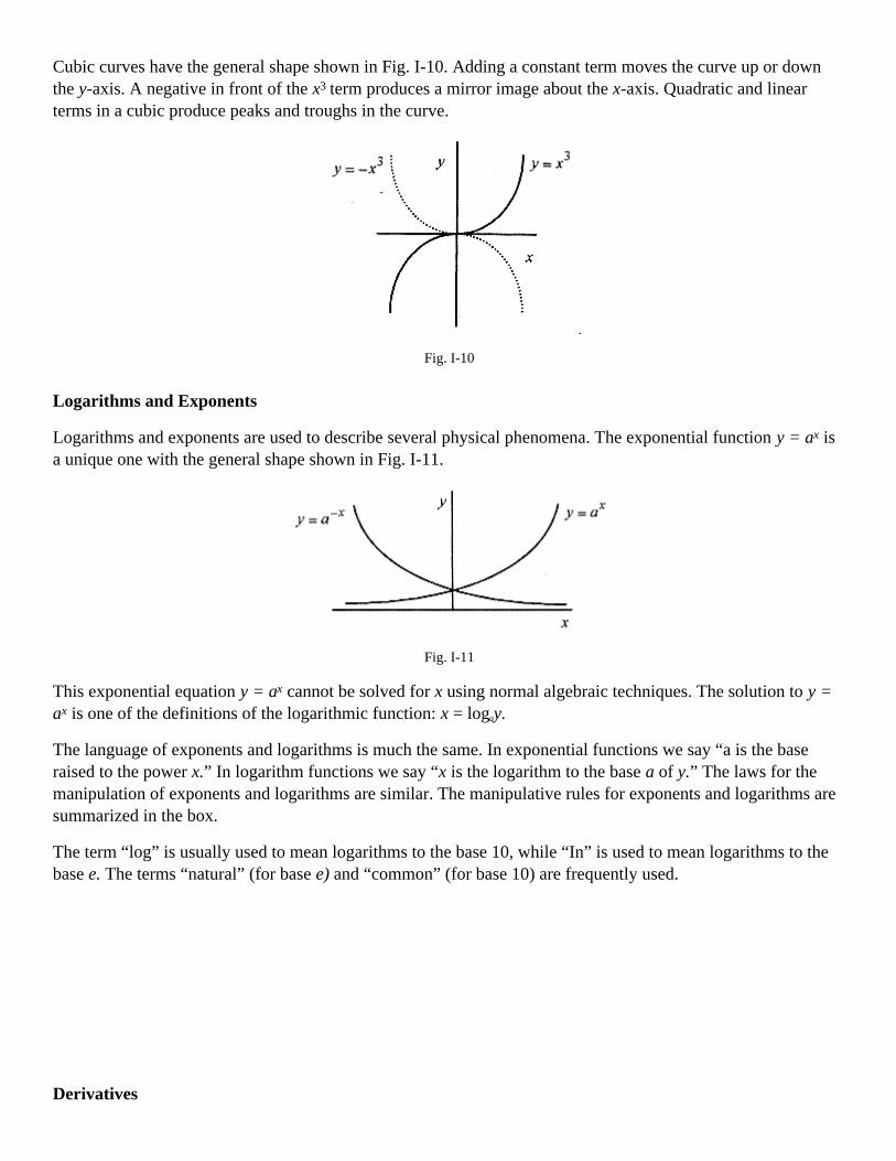
Cubic curves have the general shape shown in Fig. I-10. Adding a constant term moves the curve up or downthe y-axis. A negative in front of the x3 term produces a mirror image about the x-axis. Quadratic and linearterms in a cubic produce peaks and troughs in the curve.
Fig. I-10
Logarithms and Exponents
Logarithms and exponents are used to describe several physical phenomena. The exponential function y = ax isa unique one with the general shape shown in Fig. I-11.
Fig. I-11
This exponential equation y = ax cannot be solved for x using normal algebraic techniques. The solution to y =ax is one of the definitions of the logarithmic function: x = logay.
The language of exponents and logarithms is much the same. In exponential functions we say “a is the baseraised to the power x.” In logarithm functions we say “x is the logarithm to the base a of y.” The laws for themanipulation of exponents and logarithms are similar. The manipulative rules for exponents and logarithms aresummarized in the box.
The term “log” is usually used to mean logarithms to the base 10, while “In” is used to mean logarithms to thebase e. The terms “natural” (for base e) and “common” (for base 10) are frequently used.
Derivatives

There are numerous definitions of the derivative, but the one that fits most physics problems best is that thederivative of a function is another function that gives the slope of the original function at any point. Consider afunction f(x), often written as y = f(x), over an interval δx. The notation y = f(x) is mathematical symbolism thatsays “a variable y is going to be described by certain operations on another variable x.”
Using the δ notation the general expression for slope is
This equation says that the slope of a function is the value of the function at a point x + δx minus the value ofthe function at x all divided by the δx. This assumes the function is linear between x and x + δx; anapproximation that gets better as δx gets smaller. The slope defined this way is an average slope between x andx + δx. The derivative is the general expression for the slope at any point, thus, it is a function that gives theslope of another function at every point. The derivative, df/dx or f' is the limiting case of the slope where δx → 0
Fig. I-12
Now apply this procedure to several functions.
Fig. I-13
The function is a constant so f(x + δx) = f(x) and the slope is zero as is evident from the graph.
Fig. I-14

<><><><><><><><><><><><>
Fig. I-15
The slope of the curve y = x2 - 5 is 2x. Just pick a value of x, and the slope is two times this value.
<><><><><><><><><><><><>
As an exercise verify that the derivative of y = x3 is 3x2.
The derivative of power law functions is very easy with the procedure described above. After performing a fewof these, we can come to the conclusion that for any power law y = cvn, the general expression for the slope(derivative) is y' = cnvn-1. Listed below are the derivatives for power laws as well as some trigonometric,exponential, and logarithmic functions. All of these can be derived using the procedures employed above.
DERIVATIVES
Function Derivative
xn nxn-1
sinαx αcosαx
cosαx -αsinαx
tanαx αsec2 αx = α / cos2 αx
eαt αeαt
In αx 1/x
One other useful rule of differentiation is the chain rule. If y is written in terms of x and x is written terms of t,it is possible to write dy/dt through the simple expediency of a chain derivative.

and since x is written in terms of t, the derivative dy/dt can be written in terms of x or t.
Integrals
Integrals can be viewed two ways, as the area under a curve or as the inverse operation to the derivative. Lookupon the derivative as an operation performed on a function. If y = 3x2 + 2x - 1 is the function, then thederivative is d by dx of y or
The inverse of this operation is called integration. The actual operation of integration is seen by writing the d/dxoperation as a total derivative dy = (6x + 2)dx, and the integral is
so =6x/2+2x+const=3x+2+const the original function plus a constant.
Just as the derivative of a power function y = cvn is dy = cnvn-1dv the integral of
The constant is necessary because constants are lost in differentiation! Evaluating the constant requires someknowledge of the physical problem.
The other definition of the integral is as the area under a curve. This definition is most convenient in manyphysical problems, especially those involving work. The integrals of several curves are done below. Theintegrals are represented by the area under the curves between two specific values.
Fig. I-16
The area under the curve is A quick glance at the graph of y = 3 confirms thiscalculation.

Fig. I-17
The area under the curve is
The shaded area consisting of a rectangle and triangle is equal to 6.
Fig. I-16
As an exercise approximate the area under the curve. The area between x = 3 and x = 4 can be approximatedwith a rectangle and triangle. Find the value of y at x = 3 and the area of the rectangle. Find the value of y at x =4 and find the approximate area of the triangle. These two areas are very close to the area found from theintegral.
<><><><><><><><><><><><>
The integrals of these three curves are what is known as definite integrals, ones that have specific limits. Assuch they do not need constants. The indefinite integrals, those without limits, need the constant. Listed beloware the integrals of some common functions.

INTEGRALS
Function Integral
xn (n = -1) (n + 1)-1xn+1
1/x Inx
sinαx -α-1cosαx
cosαx α-1sinαx
tanαx α-1 In&bbar;cosαx&bbar;
eαx α-1eαx
Inαx xInαx - x
Average Value of a Function.
In Fig.I-18 the shaded area is the value of the integral. This area could be represented by a rectangle with oneside of the rectangle equal to 1, the length of the integral, from 3 to 4, and the other side, the average height ofthe function between 3 and 4. This average height is the average value of the function over the interval from 3to 4. From the geometry then we can say that the average value of the function times the length of the integralequals the area or value of the integral. Rearranging then, the average value of a function over a particular rangeis the value of
the integral over the range divided by the range. Applying this to the function y = x2 - 5 the average value of thefunction between 3 and 4 is
At x = 3 the function has value 4, and at x = 4 it has value 11, so 22/3 is a reasonable value for the average.
Likewise, the average value of the function y = x3 - 3 between 1 and 3 is

Chapter 1Vectors
This chapter serves a dual purpose. First, it will help you to do the addition and subtraction of vectors in thechapter in your text on vectors and the vector problems in the chapters on motion and forces. Second, it willserve as a reference for those topics involving vector products, especially the definitions of work and torqueencountered in mechanics.
Certain physical quantities such as mass or temperature are described with a number called a scalar. Otherquantities, such as displacement, velocity, or force, have a direction associated with them and are calledvectors. Operationally, a vector is an arrow oriented in space with the length (of the arrow) representing thenumber and the orientation, the direction. Vectors can be placed anywhere on a coordinate system so long asthey maintain their required length and orientation.
Number Plus Angle and Components
A vector can be described with a number and an angle as A = 23<37°. In performing the basic mathematicaloperations of addition, subtraction, multiplication, and division, it is more convenient to write vectors incomponent form. If A were placed with the tail (of the vector) at the origin of a coordinate system, then the xand y components could be written as shown in Fig. 1-1.
Fig. 1-1
It is very important in the use of vectors to be able to go from the number plus angle format to componentformat quickly and accurately. Before going any further in this chapter review the basic trigonometric relationsand the formulas for going from number plus angle to components and vice versa (Fig. 1–2). And if you are atall unsure of yourself make up a 3 × 5 card with figure and formulas and review it several times a day until youcan perform the operations without hesitation.
A vector A = A <0 has components as shown in Fig. 1–2. (The bold type represents the vector, and the normaltype represents the number associated with that vector.) If the components, ax and ay, are given, then the numberplus angle form can be obtained with the trigonometric relations on the left side of Fig. 1–2.
Fig. 1–2

The vector A (see Fig. 1-1) can be reconstructed from the components ax = 18.4 and ay = 13.8.
and
1-1 Diagram the vector C = 47<193° and write the components.
Solution: The components are cx = 47 cos193° = -45.8 and cy = 47 sin 193° = -10.6.
Fig. 1–3
Taking the sine or cosine of the 193° angle will produce the appropriate negative numbers, but drawing a figureand using the principle angle is a better procedure. Less mistakes are made from figures than from the readoutof calculators. When the vector and its components are drawn on the coordinate system there can be no mistakethat 45.8 and 10.6 are both negative.
Unit Vectors in Two Dimensions
The use of unit vectors simplifies the mathematical operations on vectors. In two dimensions unit vectors arevectors of unit value directed in the +x and +y directions.
Fig. 1–4
The vector A (Fig. 1-1) would be written as A = 18.4i + 13.8j and C (problem 1-1) would be written as C = -45.8i - 10.6j
1–2 Add the vectors A and C.
Solution: The addition of A and C is now accomplished by adding the components
<><><><><><><><><><><><>
1–3 Subtract C from A.
Solution:

<><><><><><><><><><><><>
1–4 Diagram T = A–C and write in number plus angle form.
Solution: The diagram is started by drawing the components on the coordinate system. With the componentsthe magnitude and angle can be calculated T = 68.7<20.8°.
Fig. 1–5
1–5 Add the vectors A = 13<50°, B = 15< -60°, and C = 17<20°.
Solution: Diagram each vector along with the components.
Fig. 1–6
The sum of these vectors R = A + B + C is R = 1.2i–11.5j. This resultant vector is diagrammed in Fig. 1–7along with the magnitude and angle.
Fig. 1–7
The vector is R = 11.6< -84°
The key to getting vector addition problems correct is to use multiple diagrams. Most mistakes in vectorproblems are sign mistakes. And the way to avoid sign mistakes is to use diagrams extensively.
1–6 Find the resultant of the two forces F1 = 800N<47° and F2 = 600N<140°.
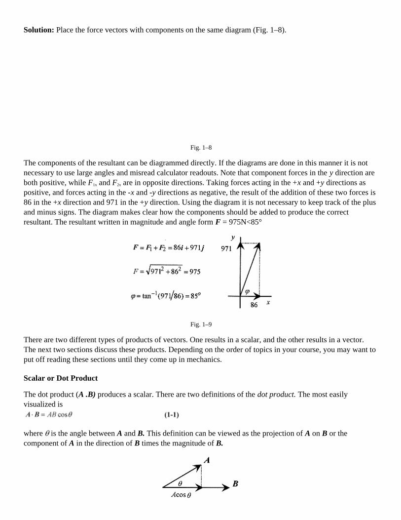
Solution: Place the force vectors with components on the same diagram (Fig. 1–8).
Fig. 1–8
The components of the resultant can be diagrammed directly. If the diagrams are done in this manner it is notnecessary to use large angles and misread calculator readouts. Note that component forces in the y direction areboth positive, while F1x and F2x are in opposite directions. Taking forces acting in the +x and +y directions aspositive, and forces acting in the -x and -y directions as negative, the result of the addition of these two forces is86 in the +x direction and 971 in the +y direction. Using the diagram it is not necessary to keep track of the plusand minus signs. The diagram makes clear how the components should be added to produce the correctresultant. The resultant written in magnitude and angle form F = 975N<85°
Fig. 1–9
There are two different types of products of vectors. One results in a scalar, and the other results in a vector.The next two sections discuss these products. Depending on the order of topics in your course, you may want toput off reading these sections until they come up in mechanics.
Scalar or Dot Product
The dot product (A .B) produces a scalar. There are two definitions of the dot product. The most easilyvisualized is
where θ is the angle between A and B. This definition can be viewed as the projection of A on B or thecomponent of A in the direction of B times the magnitude of B.

Fig. 1–10
The second definition fits with the unit vector notation
Following A.B = AB cosθ, i.i = 1.1 cos0=1° = 1, and i.j = 1.1cos90° = 0.
Following A.B = axbx + ayby, i.i = 1.1, and i.j = 0.
1–7 Form the dot product of A = 23<37° and B = 14< - 35°.
Solution: Using the first definition A . B = A . B cosθ= 23.14 cos72° = 100.
The second definition of the dot product requires the components of the vectors. The components of A (fromFig. 1-1) are ax = 18.4 and ay = 13.8. The components of B are in Fig. 1–11.
Fig. 1–11
The dot product is
More dot product problems will be done in the chapters where dot products are used in the calculation of work.Work, as defined in mechanics, is the product of the component of an applied force in the direction of adisplacement and that displacement. W = F.s
The cross product (A × B) produces a vector. As with the dot product there are two definitions of the crossproduct. The simplest definition to understand is that the cross product of A and B produces a vector ofmagnitude AB sin φ in a direction normal (perpendicular) to the plane of A and B with φ the angle between Aand B. The specific direction is obtained by rotating A into B (crossing A into B or A cross B) again using thefingers of the right hand naturally curling (closing) from A to B with the thumb pointing in the direction of thenew (product) vector. This is the same procedure as for finding the z direction in an x-y-z right-handedcoordinate system. A right-handed coordinate system with the three unit vectors is shown in Fig. 1–12.
Practice visualizing i × j to produce k and j × k to produce i. The angle between the unit vectors is 90°, and theirmagnitude is 1; so the resultant vector has magnitude 1 and is in the direction given by this “vector crossed intoanother vector” procedure. Practice pointing your fingers in the direction of the first vector, curling them intothe second vector with your thumb pointing in the direction of the result of this “cross” product until you canquickly see that i × k = -j and k × i = +j.

Fig. 1–12
The definition of torque in mechanics is lever arm times force times the sine of the angle between them.Another way of saying this is that torque is lever arm times the component of the force at right angles to thelever arm. In mathematical terms
Fig. 1–13
with the magnitude of the torque given by T = rF sin θ and the direction of the vector given by the r × F role.The F sin θ term can be viewed as the component of F perpendicular to r.
In Fig. 1–13 the vectors are arranged as the sides of a parallelogram with F sin θ the height of theparallelogram. The product rF sin θ is the magnitude of r × F and is also the area of the parallelogram (a basetimes the height) formed by r and F.
The second definition of the cross product is mathematically easier but harder to relate to physical problems.This definition is expressed as a determinant.
1–8 Form the cross product of A = 23<37° and C = 47 <193°.
Solution: The vectors and their components are shown in Fig. 1–14. Crossing A into C defines the angle as156° so that AC sin 156° = 440 with the direction out of the paper as give by the right-hand rule.

Fig. 1–14
Doing the same problem with determinants
The numeric difference, 440 versus 437, is due to rounding the components to three significant figures.
In simple problems it is easier to find the cross product from the geometric definition. In more complicatedproblems, or where it is difficult to be sure of the direction of the vector product, the determinant form is moreconvenient.
Chapter 2Motion in One Dimension
The motion of a particle (ballistic missiles, golf balls, and gas molecules are all examples of particles) isdescribed by giving position, velocity, and acceleration usually as a function of time. For convenience in gettingstarted we confine the discussion to one dimension. We also need to differentiate between distance anddisplacement, and speed and velocity.
If a dog fetching a stick runs in a straight line (the +x direction) 30m to pick up the stick and returns (the -xdirection) 26m then the total distance traveled is 56m but the displacement is +4m. Distance generally meanstotal distance traveled while displacement is the actual difference between end point and beginning.
If the dog were to execute the fetching in 8s then the speed of the dog would be the total distance traveleddivided by the time or 7m/s while the velocity, defined as the displacement divided by the time, would be0.5m/s.
In a word equation form this is
The “δ” notation is read as “a change in” or “a small change in.”
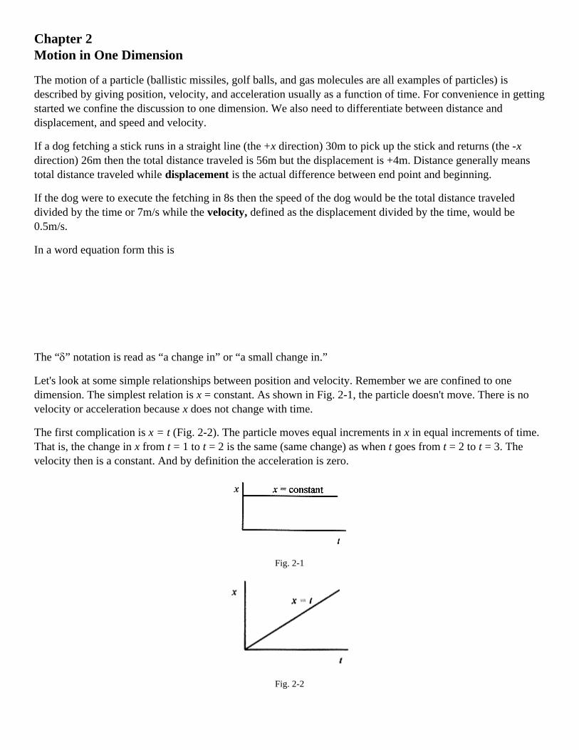
Let's look at some simple relationships between position and velocity. Remember we are confined to onedimension. The simplest relation is x = constant. As shown in Fig. 2-1, the particle doesn't move. There is novelocity or acceleration because x does not change with time.
The first complication is x = t (Fig. 2-2). The particle moves equal increments in x in equal increments of time.That is, the change in x from t = 1 to t = 2 is the same (same change) as when t goes from t = 2 to t = 3. Thevelocity then is a constant. And by definition the acceleration is zero.
Fig. 2-1
Fig. 2-2

The next complication is x = t2. This graph is shown in Fig. 2–3. In this quadratic relationship, the simpledefinition of velocity begins to break down. Between t = 0 and t = 1 the velocity is (1-0)/(1-0) = 1. Between t =1 and t = 2 the velocity is (4-1)/(2-1) = 3 and on and on with the velocity changing depending on the timeinterval chosen. Clearly the acceleration is not a constant. This velocity calculation fits our present definitionand is equivalent to drawing a straight line between points on the smooth curve of x versus t.
Fig. 2–3
Fig. 2–4
Calculating velocity this way presents a problem because depending on the interval we will get differentanswers for the velocity. To find the velocity at t = 1, we found x at t = 1 and x at t = 2 and performed thevelocity calculation. This is not a good approximation to the velocity at t = 1 because the average is between t =1 and t = 2. A better approximation would be to take values of x between t = 1 and t = 1.1. Even better would beto take values between t = 0.99 and t = 1.01. And for even better approximations just shorten the time intervalcentered about t = 1. As the interval gets smaller we will get a better and better measure of velocity. In Fig. 2–4the slope of the straight line from x = 1 to x = 4 represents the average velocity between x = 1 and x = 4. Theslope of the straight line tangent to the curve at x = 1 represents the velocity at x = 1.
Instantaneous Velocity and Acceleration

A more versatile definition of velocity is δx/δt, where the interval δt is very small and centered about the timewhere the velocity is desired. This approach leads to a general method for obtaining an expression for velocitythat can be evaluated at any point rather than going through the numeric calculation whenever we want avelocity.
In words, this definition is stated as the instantaneous velocity which is the value of δx/δt as δt approacheszero. In equation form this is written as
This definition of the derivative as the limit of δx/δt as δt approaches zero is the slope of the tangent to thecurve evaluated at the point in question. Thus if we want to find the velocity of any particle traveling accordingto a polynomial relation between x and t all we need is a general technique for finding the slope of the tangent tothe polynomial at any point.
The instantaneous acceleration is defined as the value of δv/δt as δt approaches zero. In equation form this is
The instantaneous acceleration is the slope of the tangent to the curve of v versus t.
The general expression for the slope of any polynomial is discussed in the Introduction, MathematicalBackground. For a polynomial of the form x = ctn the expression for the slope at any point is cntn-1. Stating thisin calculus terms; for any function x = ctn, the derivative of the function is cntn-1. This can be verified in thecase of the parabola by taking successively smaller intervals of δt and δx at any point t to verify that the slope atany point is 2t.
Kinematic Equations of Motion.
The kinematic equations of motion are derived under the assumption of constant acceleration. While this may atfirst seem to be a restriction, there are a large number of problems where the acceleration is a constant. Thesimplest and most obvious are falling body problems, that is, problems involving bodies falling on (or near) thesurface of the earth where the acceleration due to gravity is a constant. Falling body problems are taken up in aseparate chapter. In the derivation of the kinematic equations of motion a good image to keep in mind is that offalling bodies.
Starting with the assumption of constant acceleration we can write
which can be rearranged to vf = v0 - at.
Usually the f subscript is dropped to read v = v0 + at.
Now defining the average velocity as

and the displacement as
and substituting for vavg with the previous equation
and further substituting for v = v0 + at. we arrive at x = x0 + v0t + (1/2)at2.
And if is solved for t and substituted into
then we get
and upon rearranging
Summarizing, these four kinematic equations of motion are written as
The first three equations relate displacement, velocity, and acceleration in terms of time while the fourthequation does not contain the time.
Now let's apply these four equations to some typical problems. Remember that the kinematic equations ofmotion allow us to describe the position, velocity, and acceleration of a mass point.
2-1 A train starts from rest (at position zero) and moves with constant acceleration. On first observation thevelocity is 20m/s and 80s later the velocity is 60m/s. At 80s, calculate the position, average velocity, and theconstant acceleration over the interval.Solution: Diagram the problem.
Fig. 2–5
Calculate the acceleration:
Calculate the distance traveled over this 80s:

The average velocity is
If the acceleration is constant then the average velocity is the average of 20m/s and 60m/s, or 40m/s, and at anaverage velocity of 40m/s and 80s, the distance traveled is 3200m.
<><><><><><><><><><><><>
2-2 For the situation of problem 2-1, calculate the position of the train at 20s.
Solution:
<><><><><><><><><><><><>
2–3 For the situation of problem 2-1 find the time required for the train to reach 100m
Solution: so
This is a quadratic equation in t. Without units the equation is
and has solutions
The negative answer is inappropriate for this problem so take t = 4.5s.
<><><><><><><><><><><><>
2–4 For the situation of problem 2-1 find the velocity of the train at 120m.
Solution:
<><><><><><><><><><><><>
2–5 Two vehicles are at position x = 0 at t = 0. Vehicle 1 is moving at constant velocity of 30m/s. Vehicle 2,starting from rest, has acceleration of 10m/s2. A typical question of this situation is “Where do they pass?”
Solution: First diagram the situation.

Fig. 2–6
The question “Where do they pass?” translated into algebra means “What is the value of x when they pass?”This can be determined by writing equations for the position of each vehicle and
equating and
Setting x1 = x2 gives the time when they pass as 30t = 5t(t-6) = 0; so the vehicles pass at t = 0 and t = 6. Puttingt = 6s in either equation for x (x1 or x2) gives 180m as the distance.
<><><><><><><><><><><><>
2–6 For the situation in problem 2–5, when do the vehicles have the same velocity?
Solution: In algebra this means to set the equations for velocity equal (v1 = v2) and solve for the time.Remember that three of the four equations of motion are functions of time so most question are answered byfirst calculating the time for a certain condition to occur.
Now that we know when, we can calculate where they have the same velocity. Use either equation for positionand t = 3.0s
<><><><><><><><><><><><>
2–7 For the situation of problem 2–5. what is the position, velocity, and acceleration of each vehicle whenvehicle 2 has traveled twice the distance of vehicle 1?
Solution: The time when this occurs is when x2 = 2x1: 5t2 = 60t or 5t(t - 12) = 0
This gives times of t = 0 and t = 12. The time t = 0 is correct, though uninteresting. The time t = 12 is thephysically interesting answer.
At t = 12:
From the original statement of the problem, v1 = v10 = 30m/s and a1 = 0.
Now solve for the remaining variables for the second vehicle by substitution

From the original statement of the problem a2 = 10m/s.
<><><><><><><><><><><><>
2–8 Two trains are traveling along a straight track, one behind the other. The first train is traveling at 12m/s.The second train, approaching from the rear, is traveling at 20m/s. When the second train is 200m behind thefirst, the operator applies the brakes producing a constant deceleration of 0.20m/s2. Will the trains collide, and ifso where and when?
Solution: First, diagram the situation. Our strategy will be to write down the equations for each train usingequations (2-1) through (2–6) and the information provided in the problem. Take t = 0 when the brakes areapplied and the first train is 200m ahead of the second. This makes the position of the first train 200m at t = 0(x10 in equation 2-2).
Fig. 2–7
The question as to whether the trains collide means: “Is there a real (time) solution to the equation resultingfrom setting x1 = x2.
If there are no real solutions to this equation then the trains do not collide. Drop the units and write 0.10t2 - 8t +200 = 0 which is solved by quadratic formula
Since there are no real solutions to this equation there are no times when the trains collide.
<><><><><><><><><><><><>
2–9 Change problem 2–8 by giving the second train an initial velocity of 25m/s. This will give a real time forthe collision. Find the collision time.
Solution: The situation is now as shown in the Fig. 2–8.

Again setting the expressions for x1 and x2 equal and dropping the units produces 200 + 12t = 25t - 0.10t2 or0.10t2 - 13t + 200 = 0 with solutions
Fig. 2–8
The two times correspond to when x1 = x2. The earliest time is the first coincidence and the end of the (physical)problem. The position at this time can be obtained from either expression for x.
Verify this distance by using x2.
The velocity of the second train at collision is
The relative velocity (between the two trains) is v = 1.4m/s.
The two times are the result of the quadratic in t. The two solutions occur when the curves cross. The equationfor x1 = 200 + 12t is a straight line of slope 12 starting at 200. The equation for x2 = 25t - 0.10t2 is a parabola thatopens down. Figure 2–9 (not to scale) shows the two curves.
While the “mathematics” produces two times, the reality of the problem dictates the earlier time as the one forthe “collision.”
Fig. 2–9

Chapter 3Falling Body Problems
The kinematic equations of motion for constant acceleration, equation 2-1 and equations 2–3 through 2–6 of theprevious chapter. can be applied to a large collection of problems known as “falling body problems,” problemswhere the constant acceleration is the acceleration due to gravity on the surface of the earth. These equationsfrom the previous chapter are rewritten here for your convenience.
3-1 Consider a ball dropped from the top of a 40m tall building. Calculate everything possible.
Solution: “Calculate everything possible” is an unusual request. Usually early in your study of falling bodyproblems, there is a problem that asks for something that does not at all seem like it has anything to do with theinformation given. It's almost like asking “What color is the building?” When this happens, and it probably will,the way to do the problem is to calculate what you can and let the information you generate lead you throughthe problem. Let's apply this approach to this problem. First, diagram the problem as shown in Fig. 3-1. Placethe origin at the top of the building with displacement, velocity, and acceleration (g) all positive down.
Fig. 3-1
Since most of the kinematic equations contain the time, this is usually one of the first things to calculate. Useequation 3–4 to find the time for the ball to strike the ground.
Knowing the time we can calculate the velocity from equation 3-2.
Alternatively we can use equation 3–4.

NOTE: This last equation is a better one to use because it relies on original data rather than calculated data. Ifthere had been an error in the time calculation it would have been repeated in the v = v0 + gt equation. Alsoround off errors are eliminated by using equations that rely on original data.
<><><><><><><><><><><><>
3-2 Now add a complication to problem 3-1 by throwing the ball down with an initial velocity of 8.0m/s. Findthe time for the ball to reach the ground and the velocity on impact.
Solution: Again diagram the problem as in Fig. 3-2. Note that in this problem the displacement and velocity arepositive down.
Fig. 3-2
The time of flight is from 40m = (8.0m/s)tn + (1/2)(9.8m/s2)t2,
which rearranged and without units is 4.9t2 + 8.0t - 40 = 0,
with solution by formula of
The positive time is the obvious choice.
The velocity at the ground level is from
<><><><><><><><><><><><>
3-3 Add a different complication to problem 3-1. Throw the ball up from the top of the building with a velocityof 8.0m/s. Find the time for the ball to reach the ground and the velocity on impact
Solution: Diagram the problem as in Fig. 3-3. Take x the displacement as positive down and the velocity asnegative up. It is important to remember that the sign of the velocity is opposite that of the displacement. Itdoesn't matter whether the velocity is negative and the distance down positive or vice versa. It does matter thatthe signs be opposite! Getting a sign wrong is the source of many, possibly most, errors in falling bodyproblems.

Fig. 3-3
Calculate the time of flight and note the signs:
Rearranging and without units, this equation is 4.9t2 -8.0t -40 = 0,
with solution
The positive time is the obvious choice. Note the numbers used for the solutions to the quadratics in time forthis and problem 3-2.
The velocity when the ball strikes the ground is
Notice that whether the v term is a positive or negative number, the result is the same. If the ball is thrown upwith a certain velocity or down with the same velocity, the velocity at impact is the same. This is to be expectedfrom the symmetry of the equations. If the ball is thrown up with a certain velocity, then on the way down itpasses the same level (from which it was thrown) with (numerically) that same velocity.
3–4 For the situation of problem 3-3 calculate the maximum height above the top of the building and the timefor the ball to reach maximum height.
Solution: The time for the ball to reach maximum height is from equation 3-2. Note that at maximum height thevelocity must be zero. Again watch the signs closely. It doesn't matter how you choose the signs, but theacceleration has to be opposite the velocity. The equations
yield the same result, t = 0.82s. Because of symmetry, it takes the ball the same amount of time to reachmaximum height as it does for the ball to return to the original level.
Calculate the height above the top of the building from equation 3–5.
A thorough understanding of these four problems will keep you from making sign mistakes in problems likethese.

<><><><><><><><><><><><>
3–5 A bottle of champagne is dropped by a balloonist. The balloon is rising at a constant velocity of 3.0m/s. Ittakes 8.0s for the bottle of champagne to reach the ground. Find the height of the balloon when the bottle wasdropped, the height of the balloon when the bottle reached the ground, and the velocity with which the bottlestrikes the ground.
Solution: Diagram the situation as shown in Fig. 3–4 being especially careful about the relative orientation(algebraic signs) of displacement, velocity, and acceleration. There are several possibilities as regards the originand direction of the coordinate system. Take the origin at the height of the balloon when the bottle is dropped;the position of the balloon at t = 0. Take the displacement as positive down. The main reason for taking thedisplacement as positive down is that the acceleration is down and the initial velocity up making two positivesand one negative. As time goes on, however, displacement, velocity, and acceleration will be positive. Thischoice seems to make for fewer minus signs and less chance for error with an algebraic sign.
Fig. 3–4
Write the equation for the height of the balloon (when the bottle was dropped) counting time from when thebottle was dropped
The height of the balloon when the bottle reached the ground would be the height when the bottle was droppedplus the amount the balloon rose in the 8.0s it took the bottle to reach the ground, or
290m + (3.0m/s)8.0s = 314m
The velocity on impact v = v0 + at = -3.0m/s + (9.8m/s2)8.0s = 75m/s.
This velocity could also be calculated using
<><><><><><><><><><><><>

3–6 A parachutist descending at a constant rate of 2.0m/s drops a smoke canister at a height of 300m. Find thetime for the smoke canister to reach the ground and its velocity when it strikes the ground. Then find the timefor the parachutist to reach the ground, the position of the parachutist when the smoke canister strikes theground, and an expression for the distance between the smoke canister and the parachutist.
Solution: Diagram the system as shown in Fig. 3–5 taking displacement, velocity, and acceleration as positivedown with the origin at the point where the canister is dropped.
The time for the smoke canister to reach the ground is from equation 3–4.
Fig. 3–5
Without units the equation is 4.9t2 + 2.0t - 300 = 0 with solutions
The time for the canister to reach the ground is 7.6s.
The velocity when it strikes the ground is
The time for the parachutist to reach the ground is from equation 3-2.
When the canister strikes the ground the parachutist has dropped (2.0m/s)7.6s = 15m and is 285m above theground.
The expression for the distance between the canister and the parachutist is

<><><><><><><><><><><><>
3–7 A coconut is dropped from a height of 60m. One second later a second coconut is thrown down with aninitial velocity. Both coconuts reach the ground at the same time. What was the initial velocity of the secondcoconut?
Solution: In problems where there is a time delay it is usually best to calculate the position, velocity, andacceleration of the first particle at the time when the second particle starts to move. In the train problem in theprevious chapter there was a position difference between the two trains at t = 0 that was easily translated intothe equations. It is possible to do time delay problems with a time differential in one set of equations. Thedifficulty with this approach is that it is easy to get an algebraic sign wrong. If you say that the time for thesecond particle is the time for the first plus the difference between them, then it is essential that the algebraicsign of the difference be correct. It is much easier, especially when you are learning how to do problems with atime delay, to do them in this slower, but inherently more accurate, method. First, calculate the state of the firstparticle when the second one begins moving. Then, write the two sets of equations describing the motion withthis instant as t = 0.
Calculate the position and velocity of the first coconut at the end of one second, the time when the second onestarts.
Since everything (position, velocity, and acceleration) is positive down, orient the coordinate system forpositive down with the origin at the top. Now diagram the problem as in Fig. 3–6. At the instant the secondcoconut is thrown down, the first coconut has position 4.9m, velocity 9.8m/s and acceleration 9.8m s2.
Fig. 3–6
Since both coconuts strike the ground at the same time use the conditions of the first coconut to find the totaltime.
First calculate the velocity at impact of the first coconut.

The time for the second coconut to reach the ground is the same as the time for the first coconut to go from4.9m to 60m or the time for the first coconut to go from 9.8m/s to 34.3m/s.
This comes from v = v0 + at. where v0 is v10, the velocity of the first coconut when the second one is throwndown, and v is the velocity of the first coconut at the ground.
Now that we have the time for the second coconut to travel the 60m we can find its initial velocity from x - x0 =v20t + (1/2) at2 where t is the total time for the second coconut.
Review this problem until all the different times and velocities are clear in your mind. Set up the problem anddo it yourself without reference and you will know you understand it.
3–8 A boat is passing under a bridge. The deck of the boat is 15m below the bridge. A small package is to bedropped from the bridge onto the deck of the boat when the boat is 25m from just below the drop point. What(boat) speed is necessary to have the package land in the boat?
Solution: Calculate the time for the package to fall the 15.0m using
The boat must move at 25m/1.7s = 14m/s
<><><><><><><><><><><><>
3–9 You are observing steel balls falling at a constant velocity in a liquid-filled tank. The window you are usingis one meter high and the bottom of the window is twelve meters from the bottom of the tank. You observe aball falling past the window taking 3.0s to pass the window. Calculate the time required to reach the bottom ofthe tank, after the ball has reached the bottom of the window.
Solution: The situation is diagrammed in Fig. 3–7.
The observed velocity is 1.0m/3.0s so 12m = (1.0m/3.0s)t or t = 36s
Fig. 3–7

<><><><><><><><><><><><>
3–10 In a situation similar to problem 3–9, the tank is filled with a different liquid causing the acceleration inthe tank to be 6.0m/s2 and the time to traverse the window, 0.40s. Calculate the height of the liquid above thewindow, the time to reach the bottom of the tank, and the velocity of the ball when it reaches the bottom of thetank.
Solution: Diagram the problem as in Fig. 3–8.
Fig. 3–8
From the data about the window, calculate the velocity of the ball at the top of the window.
The velocity at the bottom of the window is from
The time to reach the bottom of the tank is from x - x0 = vbt + (1/2)at2
and eliminating the units
so
This (positive) time is for the ball to travel from the bottom of the window to the bottom of the tank.
Assuming the ball started at zero velocity the distance from the top of the liquid to the top of the window, xt,
will come from

Solution: Diagram the problem as in Fig. 3–9. This is another example of a question that seems totallyunrelated to the information in the problem. When you don't know where to start, and you do not see a clearpath to the desired answer, simply start where you can, calculating what you can and hopefully learning enoughto answer the specific question.
Fig. 3–9
One of the first things we can calculate in this problem is the average velocity at the middle of the window.
This average velocity is the velocity of the ball on the way up (and on the way down) at the middle of the
window. Add this feature to the problem. With this information we can use to find the distancethe ball rises above the midpoint of the window.
So the ball rises 2.5-0.7 = 1.8m above the top of the window.
Second Solution: View the ball as decelerating as it goes up past the window and find vb at the bottom of the
window from
Velocity and displacement are taken as positive so acceleration is negative.
Now the distance to maximum height (velocity zero) is
Again the maximum height of the ball above the top of the window is 3.2m - 1.4m = 1.8m.
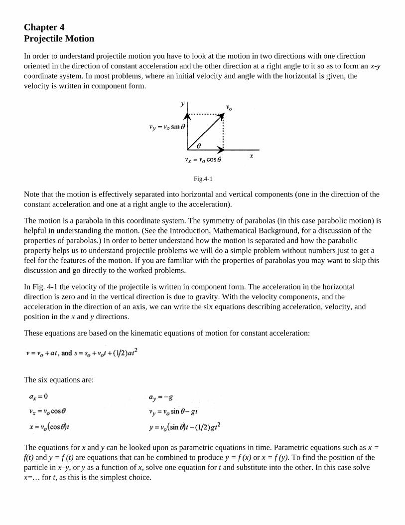
Chapter 4Projectile Motion
In order to understand projectile motion you have to look at the motion in two directions with one directionoriented in the direction of constant acceleration and the other direction at a right angle to it so as to form an x-ycoordinate system. In most problems, where an initial velocity and angle with the horizontal is given, thevelocity is written in component form.
Fig.4-1
Note that the motion is effectively separated into horizontal and vertical components (one in the direction of theconstant acceleration and one at a right angle to the acceleration).
The motion is a parabola in this coordinate system. The symmetry of parabolas (in this case parabolic motion) ishelpful in understanding the motion. (See the Introduction, Mathematical Background, for a discussion of theproperties of parabolas.) In order to better understand how the motion is separated and how the parabolicproperty helps us to understand projectile problems we will do a simple problem without numbers just to get afeel for the features of the motion. If you are familiar with the properties of parabolas you may want to skip thisdiscussion and go directly to the worked problems.
In Fig. 4-1 the velocity of the projectile is written in component form. The acceleration in the horizontaldirection is zero and in the vertical direction is due to gravity. With the velocity components, and theacceleration in the direction of an axis, we can write the six equations describing acceleration, velocity, andposition in the x and y directions.
These equations are based on the kinematic equations of motion for constant acceleration:
The six equations are:
The equations for x and y can be looked upon as parametric equations in time. Parametric equations such as x =f(t) and y = f (t) are equations that can be combined to produce y = f (x) or x = f (y). To find the position of theparticle in x–y, or y as a function of x, solve one equation for t and substitute into the other. In this case solvex=… for t, as this is the simplest choice.

Substitute into y = … to obtain
This is of the form y = -ax2 + bx = x(-ax+b), which is a parabola that opens down and intercepts the y-axis(makes y = 0) at x = b/a.
The range, or value of xwhen y = 0, can be determined from the factored form of this equation
which tells us that y = 0 at x = 0 and
or using the trigonometric identity 2sinθcosθ=sin2θ
The maximum range occurs for an angle of 45°, corresponding to sin 2θ= 1.
The main point of this discussion is that the motion is a parabola, and the properties of parabolas can be used insolving problems in projectile motion. That the maximum range occurs at 45° is not surprising, and is generallynot of interest in problems. The expression for maximum range is only of passing interest, since the range is oneof the easier things to calculate in any problem.
Do not consume precious memory space memorizing formulas for the range or time of flight. If you work theproblems by first writing down the six equations describing the motion, then the time of flight, range, and manyother things are easily calculated.
In order to set up a problem in projectile motion, first orient one axis of a right angle (x–y) coordinate system inthe direction of constant acceleration. Remember to place the origin of the coordinate system and the positivedirection for x and y for (your) convenience in solving the problems. Then write equations for acceleration,velocity, and position for each direction. Along with the symmetry of the motion, these equations can be used tofind the characteristics (position, velocity, and acceleration) of the projectile at any point in space or time. Theprocedure is illustrated with a simple problem.
4-1 A soccer player kicks a ball at an initial velocity of 18m/s at an angle of 36° to the horizontal. Find the timeof flight, range, maximum height, and velocity components at t = 0, mid-range, and at impact.
Solution: The acceleration is down so set up the coordinate system with x horizontal (along the ground ) and yvertical, and place v0 on the graph. Write the velocity in component form, and calculate vx0 and vy0.

Fig.4-2
Now, and this and this is the key to getting the problem right, write down the six equations governing themotion starting with the accelerations (the accelerations are the easiest to write).
Now look at the motion, which is parabolic in x–y, keeping in mind the properties of parabolas.
Fig.4-3
The ball is on the ground at t = 0 and t = τ, the time of flight. To find these times, set y = 0 and obtain (withoutunits)
which gives t = 0 and t = 10.6/4.9 = 2.16s, the time of flight.
The range is the value of x at 2.16s:
The maximum height, and vy = 0, occur at 1.08s (one-half the time of flight). Therefore the maximum height isy at t = 1.08s
The velocity components are:

The procedure for doing the problem is to write the initial velocity in component form, write the six equationsfor acceleration, velocity, and position, and then perform the mathematical operations answering questionsabout the problem.
4-2 For the situation of problem 4-1 suppose the field is covered with fog down to 3.0m above the ground. Whatare the times for the ball's entry into and exit out of the fog?
Solution: The times are found from the equation for y as a function of time with y set equal to 3.0m.
This is a quadratic and removing the units it reads 4.9t2 - 10.6t + 3.0 = 0
and is solved with the quadratic formula.
As an exercise find the x positions for these times.
<><><><><><><><><><><><>
4-3 An airplane traveling at 100m/s drops a bomb from a height of 1500m. Find the time of flight, distancetraveled, and the velocity components as the bomb strikes the ground.
Solution: Start by placing the origin of the coordinate system at the point where the bomb is released. And takethe direction the bomb falls due to gravity as positive x and the horizontal position as y. This is different fromthe conventional orientation, but it is convenient in this problem because the six equations all come outpositive!
Fig.4-4
Now write down the six equations governing the motion.

With these six equations we can answer all the questions in the problem. We need only to “translate” the wordquestions into algebra questions.
a) The time for the bomb to reach the earth means: Find the time when x = 1500m?
b) How far does the bomb travel horizontally means: Find the value of y when t = 17 s?
c) Find the velocity components at impact means: Find vx and vy at t = 17s?
d) Where is the airplane when the bomb strikes the earth means: What is y and t = 17 s?
Remember that the plane and the bomb have the same velocity in the horizontal direction.
<><><><><><><><><><><><>
4-4 A baseball is hit at a 45° angle and a height of 0.90m. The ball travels a total distance of 120m. What is theinitial velocity of the ball? What is the height of the ball above a 3.0m fence 100m from where the ball is hit?
Solution: This problem is unique in that it requests the initial velocity, a number usually given in the problem.Also note that the angle is 45°, the angle for maximum range. The other interesting feature of the problem is thequestion concerning the height at some specific point down range. Set up the problem in the conventional wayassigning v0 to the initial velocity.
Fig.4–5

The next question is how to handle the ball being hit at 0.90m above the ground. Since v0 is specified at thepoint where the ball is hit, and this is where we start counting time, then the origin for the coordinate systemshould be put here. We just need to keep in mind that this origin is 0.90m above the ground level.
Fig. 4–6
Now write the six equations.
The first question reduces to finding vo for the 120m hit. Algebraically this means that when y = -0.9m, x =120m, so write the two equations (for x and y) with these conditions
Note that so write
This is the time of flight, so put this time into the equation for x.
The next part of the problem asks for the height above the fence at 100m. Again we need to find the time for xto be 100m down range and substitute this value of t into the y equation
This is the time for the ball to go 100m. The height of the ball at this time is

Remember that this is 15.6m above the zero of the coordinate system which is 0.90m above the ground. So theball is 16.5m above the ground at this point and for a 3.0m high fence is 13.5m above the fence.
<><><><><><><><><><><><>
4–5 A physicist turned motorcycle stunt rider will jump a 20m wide row of cars. The launch ramp is 30° and9.0m high. The land ramp is also 30° and is 6.0m high. Find the minimum speed for the launch.
Solution:
Fig. 4–7
First write down the six equations of motion.
The minimum v0 is dictated by the condition that the rider be at x = 20m and y = -3.0m. So put these conditionsinto the equations for x and y.
At this point we can solve for v0 by substituting from the first equation into the second equation.
This is the minimum velocity to make the jump.
As a follow on to this problem calculate the velocity to just hit the end of the ramp. This velocity gives an upperlimit to the jump velocity.
<><><><><><><><><><><><>
Go back through the problems and notice the common approach:

1) orient a coordinate system,
2) write the six equations of motion, and
3) translate the word questions into algebra.
In these problems we have not always used each of the six equations to answer the question. Few problemsrequire the detailed description of the motion available in the six equations. If, however, each problem isdescribed by these six equations you will always have all the information to answer any possible question aboutthe motion.

Chapters 5Forces (including friction)
In the development of mechanics, the first thing to learn is the interrelation of position, velocity, andacceleration (for constant acceleration). These interrelations are described with the four kinematic equations ofmotion and discussed in earlier chapters.
In this chapter we relate constant force to constant acceleration and then to all of kinematics. Operationally,force can be defined as what makes masses accelerate. Actually it is the unbalanced force on a mass that makesit accelerate. Simply: Unbalanced forces make masses accelerate.
Force, acceleration, and mass are related by Newton's second law as F = ma.
5-1 A 40-N force is applied to a 20kg block resting on a horizontal frictionless table. Find the acceleration?
Solution: The acceleration is
Fig. 5-1
Once the acceleration is known, the kinematic equations of motion can be applied to find position, velocity, andacceleration as a function of time.
<><><><><><><><><><><><>
5-2 Now place the 20kg mass (with no external force applied) on a frictionless 50° incline plane. What is theacceleration of the mass?
Solution: The force acting on the mass is due to gravity so set up a vector diagram (some authors call this aforce diagram or free body diagram) starting with this 196N force acting down. The mass is constrained tomove down the plane, so the force we want is the component of this gravitational force acting down the plane.In Fig. 5-2 the gravitational force is shown with components down the plane, Fp, and normal, Fn, to the plane.Notice the geometry of the situation where the 50° angle of the plane is the same as the angle between thegravitational force and the normal (force).
Fig. 5-2

The 150N force acting down the plane causes the 20kg mass to accelerate at
5-3 Place a 10kg mass on a frictionless 35° incline plane, and attach a second 20kg mass via a cord to hangvertically as shown in Fig. 5-3. Calculate the acceleration of the system.
Solution:
Fig. 5-3
This problem introduces the concept of the tension in the connecting cord. The most convenient way tovisualize this tension is that if the cord were cut and a force meter inserted it would read a certain tension(force). This tension acts, as shown, on each mass. Notice the 35° angle of the plane and the 35° angle betweenthe normal and the direction of mg.
We'll do the problem first with the tension and later without the tension.
To write equations relating the unbalanced force to the acceleration, we need to make an assumption as towhich way the masses move. Assume that the system (of masses) moves to the right or clockwise.
Start by writing equations relating the unbalanced force on each mass. On m1 the unbalanced force is T - 56N,and this force makes the 10kg accelerate.
Likewise on m2, the unbalanced force to make the mass accelerate is
The assumption that the system accelerates clockwise dictates the directions of the forces in these twoequations. Look again at these equations and notice that if we had assumed the acceleration werecounterclockwise then the signs would be different. In frictionless problems it is all right to have a negativeacceleration. The negative sign means that you guessed wrong in assuming the acceleration direction. This isnot true with friction problems.
Add the two equations and take the accelerations the same. The accelerations are the same because the massesare linked together with the cord.

Now the tension in the cord is easily calculated from the equation for m1.
Another way to view this problem is to say that the unbalanced force on m1 and m2 is (196-56)N = 140N. Thisforce makes the total mass of 30kg accelerate, so
This is a very quick way to find the acceleration of the system, but it is inconvenient to find the tension in thecord.
5-4 The next complication in force problems with incline planes is a double-incline plane as shown in Fig. 5-4.
Fig. 5-4
Solution: The vector diagram for these masses is shown in Fig. 5-5. Assume the system moves clockwise.
Fig. 5-5
The equation for m1 is T - 76N = 12kg.a
The equation for m2 is 83N - T = 20kg.a
Adding the two equations 7.0N = 32kg.a or a = 0.22m/s2
The tension in the cord is T = 76N + 12kg.0.22m/s2 = 79N
<><><><><><><><><><><><>
5-5 Another popular problem is the Atwood machine. A simple example is shown in Fig. 5–6. Find theacceleration of the system.

Solution: Assume the system moves counterclockwise.
The equation for m1 is 98N–T = 10kg.a
The equation for m2 is T - 147N = 15 kg.a
Add the equations -49N = 25kg.a or a = -2.0m/s2
Fig. 5–6
The system accelerates clockwise! The tension in the cord is from the equation for m1.
Friction
A good first problem in friction is the arrangement shown in Fig. 5–7 where the problem is first done withoutfriction and then with friction.
For the purposes of doing problems there are two important properties of frictional forces:
· they oppose the motion, and
· they are less than or equal to a constant (the coefficient of friction) times the normal force, the force atthe frictioning surface. (f < µN)
5–6 Two masses are arranged with one, of 50kg, on a frictionless table and the other, of 30kg, attached by acord and hanging, over a frictionless pulley, off the edge of the table. Find the acceleration of the system.
Solution: Assume the system moves clockwise.
The equation for m1 is
The equation for m2 is
Adding the two equations

Fig. 5–7
<><><><><><><><><><><><>
5–7 For the situation of problem 5–6 add a coefficient of friction µ = 0.20 between the block and table.
Solution: This makes the vector diagram look like Fig. 5–8. Notice that the only addition is the frictionalretarding force µN = 98N.
Fig. 5–8
The equation for m1 is T - 98N = 50kg.a
The equation for m2 is 294N - T = 30kg.a
Add the equations to obtain 196N = 80kg.a or a = 2.4 m/s2
<><><><><><><><><><><><>
5–8 For the situation of problem 5–7 increase the coefficient of friction to 0.80. What is the acceleration of thesystem?
Solution: This makes the vector diagram look like Fig. 5–9.

The equation for m2 is T - 392N = 50 kg.a
The quation for m2 is 294 - T = 30kg.a
Adding the tow equations -98N = 80kg.a or a = -1.2m/s2
Clearly the system does not accelerate counterclockwise! This is an illustration of the second property offrictional forces: the frictional force is less than or equal to µN. In this case the frictional force just balances thetension in the cord. The frictional force, as calculated, can be up to 392N. In order for m2 not to move, thetension in the cord must be 294N. (If m2 is not moving, the forces must be in balance.) Therefore the forces onm1 must be 294N due to the tension in the cord and 294N due to friction.
Another important point with frictional forces is the normal force as illustrated by this next problem.
<><><><><><><><><><><><>
5–9 A 50kg sled is pulled along a level surface at constant velocity by a constant force of 200N at an angle of30°. What is the coefficient of friction between the sled and the surface?
Solution: The first step in this problem is to find the components of the applied force and the mg of the sled.These are shown on the vector diagram. Notice that the normal force, the actual force between the sled and thefriction surface is mg minus the component of the applied force lifting up on the sled. Sometimes it is easy tomiss this vertical component of the applied force. This is the major mistake in this type of problem. To helpvisualize this vertical component of force try placing the origin for the vectors in the middle of the sled ratherthan at one end where a rope would be attached.
Fig. 5–10
The normal force is mg(=490N) minus the vertical component of the applied force, 100N, or 390N. Since thesled is moving at constant velocity the forces must be in equilibrium. The horizontal component of the appliedforce must equal the frictional retarding force, the coefficient of friction times the normal force.

<><><><><><><><><><><><>
5–10 A 65° -incline plane has a mass of 20kg on the plane where the coefficient of friction is 0.40 and a mass of50kg hanging free. Calculate the acceleration of the system.
Solution: Set up the vector diagram assuming motion counterclockwise. In the diagram the frictional force iscalculated as a maximum of 33N.
The equation for m2 is 490N - T = 50kg.a
The equation for m1 is T - 178N - 33N = 20 kg.a
Adding the equations 279N = 70kg.a or a = 4.0m/s2
Fig. 5–11
In doing friction problems like this, you have to be careful with the frictional force. If the forces up and downthe plane are nearly balanced, it is important to remember that the frictional force is not 33N but that it can beup to 33N. In a problem similar to this, it could easily happen that the blocks would not move.
<><><><><><><><><><><><>
5–11 Consider a double-incline plane with angles, masses, and coefficients of friction as shown in Fig. 5–12.Calculate the acceleration of the system.
Fig. 5–12
Solution: Assume the system moves counterclockwise and set up the vector diagram.

The equation for m1 is (30 - 15 - TN = 6.0kg.a
The equation for m2 is (T - 62 - 10)N = 9.0kg.a
Adding the equations -57N = 15kg.a
Fig. 5–13
This is a negative acceleration. We cannot simply reverse the sign of a to find the correct answer since if thesystem were moving the other way the frictional forces would have to be reversed. Further analysis requires usto consider another vector diagram assuming the system moves in a clockwise direction.
The numbers have all been calculated so the vector diagram can be written down easily and is shown in Fig.5–14
Fig. 5–14
The new equations are: (T - 30 - 15)N = 6.0kg.a
(62 - T - 10)N = 9.0kg.a
Adding the equations yields 7.0N = 15kg.a or a = 0.54 m/s2
The tension in the cord is from the first equation: T = 45N + 6.0kg(0.54m/s2) = 48N
If the acceleration of the system were negative for both the clockwise and counterclockwise calculations thenwe would conclude that the system would not move.

The final complication in these incline plane problems is the introduction of three masses and two connectingcords.
<><><><><><><><><><><><>
5–12 Consider a flat surface with a coefficient of friction of 0.20 with a 2.0kg mass and a 3.0kg mass connectedtogether with a 6.0kg mass along a slant as shown in Fig. 5–15. The coefficient of friction on the slant is zero.Calculate the acceleration of the system.
Fig. 5–15
Solution: In this problem note that the tensions are different leading to three unknowns, T1, T2, and a. Thesolution will require three equations from three vector diagrams as shown in Fig. 5–16. Assume the accelerationof the system is clockwise.
The frictional retarding force on the 2.0kg block is f = µN = 0.20(19.6N) = 3.92N.
The frictional retarding force on the 3.0kg block is f = µN = 0.20(29.4N) = 5.88N.
Fig. 5–16
The equations for the masses are: T2 = 3.92N = 2.0kg.a
T1 - T2 - 5.88N = 3.0kg.a
24.8N - T1 = 6.0kg.a
The last two equations added together are: 18.9N - T2 =9.0kg.a
and adding this to the first equation yields 15.0N = 11 kg.a or a = 1.36 m/s2
The tensions come from the first and third equations for the masses.

Circular Motion
A particle moving at constant speed in a circle is moving in Uniform circular motion. There is an accelerationand a force associated with such a particle. Figure 5–17 shows the velocity vectors associated with a particle inuniform circular motion.
Fig. 5–17
While the length of the velocity vector remains the same, the direction changes continually. The diagram on theleft of Fig. 5–17 shows vi and vf, with the tail of the vectors at the same point, and ∆v. Looking at the limitingcase where ∆ θ 0 the ratio
is valid because of similar triangles. With this statement write
which in the limiting situation when ∆θ 0 or ∆ t 0 (same criterion) is
The “rad” subscript is a reminder that the acceleration points radially inward. The direction of arad is also clearfrom the limiting situation. As ∆ t 0 the angle between v and ∆ v 90°, so the acceleration is directedradially inward.
5–13 A certain car driven in a circle can exert a maximum side force of 0.95g. What is the maximum speed forthis car driven in a circle of 160m radius?
Solution: An 0.95g means a side force or acceleration directed at right angles to the direction of travel of0.95(9.8m/s2) = 9.3m/s2. Using arad = v2/r
At a speed greater than 38.6m/s the car will “slide out of the circle.”

<><><><><><><><><><><><>
The acceleration directed toward the center of the circle for a mass in unifom circular motion is called thecentripetal acceleration. The force associated with moving a mass in a circle is marad and is called the centripetalforce.
5–14 What is the (centripetal) force produced by the tires acting on the pavement for the car of problem 5–13 ifthe car is 1200kg of mass?
Solution:
<><><><><><><><><><><><>
5–15 An 0.60kg rubber stopper is whirled in a horizontal circle of 0.80m radius at a rate of 3.0 revolutions persecond. What is the tension in the string?
Solution: Three revolutions per second means three 2 πr's (circumferences) per second so
The tension in the string, which is providing the centripetal force, is
<><><><><><><><><><><><>
5–16 A 1-oz gold coin is placed on a turntable turning at 33-1/3 RPM (revolutions per minute). What is thecoefficient of friction between the coin and the turntable if the maximum radius, before the coin slips, is 0.14m?
Solution: The frictional force between the coin and turntable provides the center-directed force to keep the coinon the turntable (see Fig. 5–18). This center-directed force must equal my2 / r.
Fig. 5–18
This is a force-balance problem. In equation form: frictional force = centripetal force, or
The velocity is 2πr times the number of 2 πr's per minute, 100 / 3, or

Therefore,
<><><><><><><><><><><><>
5–17 A conical pendulum is a mass on the end of a cord, where the mass moves at constant speed in a circlewith the cord tracing out a cone. A conical pendulum of length 1.2m moves in a circle of radius 0.20m. What isthe period of the pendulum?
Solution: Note that the mass is not given. Start with a vector diagram of the forces on the mass as shown in Fig.5–19.
The mg must equal the vertical component of the tension in the string T cosθ = mg.
The horizontal component is due to the centripetal force so T sin θ = mv2/r.
Dividing the second equation by the first eliminates T and m or tan θ = v2/rg.
The angle is from sin θ = r/L making tan θ = 0.17 and
Fig. 5–19
The period is from 2πr/T = v or
5–18 What is the speed, at which no side force due to friction is required, for a car traveling at a radius of 240mon a 20° banked road?
Solution: Figure 5–20 shows a profile of the car on the banking and the vector diagram.

Fig. 5–20
Start with mg acting down. The normal force (between the car and road) is normal to the surface with thevertical component equal to mg and the horizontal component equal to mv2/r.
And again,
so,
Notice that in this problem the mass of the car does not enter into the calculation.
<><><><><><><><><><><><>
Go back over problems 5–13 through 5–18 and notice how each problem could be written asking for a differentvariable. For example in problem 5–13 give the side force and the velocity and ask for the radius. In problem5–16 give the speed and the coefficient of friction and ask for the radius. Changing the problems like this is anexcellent way to generate practice (for the test) problems.

Chapter 6Apparent Weight
Apparent weight problems usually are encountered in the discussion of force. Though relatively easy, theycause problems for some people. This short chapter should give you enough background and examples to showyou how to do apparent weight problems.
One of the first points to get straight is the difference between mass and weight. Mass is that property thatmakes different objects accelerate differently when equal forces are applied. Operationally mass is the m in theequation F=ma. Mass is measured in kilograms or slugs. Weight in equation form is
and is the force something exerts. Weight is measured in Newtons or pounds. Popular usage scrambles weightand mass. Gold and silver are usually sold by the gram or kilogram while nails and chicken feed are sold by thepound.
The first step in keeping this all straight is to remember that weight is force. A scale that measures weight inpounds or Newtons is just a force meter. Tension in a rope is a force.
A person of 80kg mass standing on the surface of the earth is subject to the force of gravity that acts betweenthe 80kg person and the mass of the earth. This force is expressed as an acceleration due to gravity. On theearth, this acceleration is 9.8m/s2. The force on the person, also called weight is
A force meter placed between the person and the earth would read 784 N.
To understand apparent weight take a “thought trip” (based on experience) on an elevator. Imagine a forcemeter between you and the floor of the elevator. As you step on the elevator the force meter reads the same aswhen you are standing on the ground. As the elevator accelerates upward, the force meter registers higher,reading maximum at maximum acceleration. As the acceleration decreases and the elevator assumes a constantvelocity (upward) the force meter reads the same as when the elevator was not moving. This constant velocitycondition is equivalent to forces in equilibrium, so that the only thing contributing to the reading of your forcemeter is the mg due to the earth. As the elevator slows, by decelerating, the force meter reads less than the forcefor constant velocity. As the elevator comes to rest at a higher level, the force meter again-reads the same aswhen you were at ground level.
Let's go back over this elevator ride and put in some numbers. At zero or constant velocity the force meter reads784 N. If the elevator were accelerating upward at 2.0 m/s2, then the force meter would read
If the elevator were accelerating downward (or decelerating near the top of its trip up) at 3.0m/s2, then the forcemeter would read
If the elevator were in free fall, then the force meter would read zero. The acceleration acting on the elevator isthe same as on the person.

6-1 A 12 kg flower pot is hanging by a cord from the roof of an elevator. What is the tension in the cord whenthe elevator is stationary and when it is accelerating upward at 3.0m/s2?
Solution: When the elevator is stationary the tension in the cord is
When the elevator is accelerating upward the tension in the cord is increased by an amount equal to ma
Second Solution: Now take another, more analytical, look at the problem. When the elevator is at rest thetension in the cord equals mg, so writing a force statement, T - mg = ma where a is zero, produces T = mg.
Fig. 6-1
When the elevator is accelerating upward at 3.0m/s2 the T - mg = ma equation has an acceleration. The hardpart of doing the problem this way is keeping the algebraic sign of the acceleration correct. Looking at Fig. 6-1,T and a have the same sign so write
If you use this vector approach to doing apparent weight problems be especially careful of the signs. Howeveryou do the problems, go through a little thought experiment to make sure you have the signs right.
Another difficulty with the vector approach to apparent weight has to do with the interpretation of the vectordiagram (on the right in Fig. 6-1). If you are an observer outside the elevator you observe an acceleration of theflower pot, as the analysis indicates. If, however, you are riding in the elevator you observe no acceleration ofthe flower pot because you are riding in the accelerating reference frame.
<><><><><><><><><><><><>
6-2 A rope (fastened at the top) is hanging over a cliff. What is the tension in the rope with a 70kg mountainclimber sliding down the rope at a constant acceleration of 6.0m/s2.
Solution: Performing a little “thought experiment,” the tension in the rope is less than if he were at zerovelocity or sliding at constant velocity. In this instance the 6.0m/s2 must be subtracted from the 9.8 m/s2.

When in doubt as to whether to add or subtract the acceleration from g, look to the extreme situation. In thisproblem the person sliding down the rope at constant velocity would produce (9.8m/ s2)70kg=686N of tensionin the rope. If the person were in “free fall,” that is accelerating at 9.8m/s2. he would produce no tension in therope. Thus, any acceleration down the rope should be subtracted from the 9.8m/s2.
6-3 What is the tension in a rope with the 70kg mountain climber of problem 6-3 accelerating (climbing) up therope at a constant acceleration of 1.0m/s2.
Solution: In this case the tension in the rope is increased by ma.
6-4 A 100kg astronaut produces a force (weight) on the surface of the earth of 980 N. What force (weight)would the astronaut produce on the surface of the moon where the “g” is about one-sixth of the g on earth?
Solution: The force or weight would be
<><><><><><><><><><><><>
6-5 A 16kg monkey wishes to raise a 20kg mass by climbing (accelerating) up a rope that passes over a pulleyattached to the mass. How much must the monkey accelerate up the rope in order to raise the mass?
Fig. 6-2
Solution: The mass produces a force or tension in the rope of
The mass of the monkey hanging on the rope produces a force of
To just balance the mass the monkey must accelerate up the rope to produce a force of (196-157) N = 39 N.
At this acceleration, the tension in the rope is 196N.
To raise the mass, the monkey must accelerate at a rate greater than 2.4 m/s2.

Any acceleration greater than 2.4 m/s2 will increase the tension in the rope by an amount equal to the“additional” acceleration times the mass of the monkey.

Chapter 7Work and the Definite Integral.
Work is defined as the force, in the direction of a displacement, times that displacement. Consider theapplication of a constant force, F, applied over a distance, x, as depicted in Fig. 7-1.
Fig. 7-1
According to the definition, the work is
which is seen as the shaded rectangular area in Fig. 7-1. In calculus terminology the work is the area under thecurve. The area under this curve is the area of the rectangle, Foxo. The unit of work is the Joule. (J = N.m)
7-1 Calculate the work performed by a constant force of 60N acting in the direction of a displacement of 3.0m.
Solution:
Fig. 7-2
The force is acting in the direction of the displacement, so the work is the product of force times displacement.

In problem 7-1 the force is in the direction of the displacement, and the work is simply the product of force anddisplacement. In this next problem the force is not in the direction of the displacement. The simplest way toobtain the component of the force in the direction of the displacement is to form the dot product of force anddisplacement. Using s as a general symbol for displacement, work is defined as the dot product of the forcevector times the displacement vector.
Work is a scalar, the dot product of force and displacement. See the Introduction, Mathematical Background,for a discussion of the dot product.
7-2 Calculate the work performed by a constant force of 40N pushing a block a distance of 3.0m along ahorizontal surface at an angle of 20° with the horizontal as shown in Fig. 7-3.
Fig. 7-3
Solution: The work performed is calculated with equation 7-2.
<><><><><><><><><><><><>
7-3 Calculate the work done by the force of gravity acting on a 70kg student sliding down a 30° inclined slide aslant distance of 10m.
Solution: The first thing to calculate is the force due to gravity, mg, which is 70kg.9.8m/ s2 = 686 N. Place thisvector on Fig. 7-4 pointing down.
Fig. 7-4
Calculate the force in the direction of the incline F = 686N cos60° = 343N
The work performed by the gravitational force is W = F.s = 343N.10m = 3430J

<><><><><><><><><><><><>
Now consider variable forces and look first at a force that is proportional to x, the displacement, or F =kx wherek is a constant. This form of force is encountered in springs where one unit of force compresses (or elongates)the spring a certain distance and the next unit of force doubles the compression, and so on. The graph of forceversus displacement is shown in Fig. 7-5.
Fig. 7-5
The area under any curve of force versus distance can be approximated by taking a sum of forces timesincrements of distances over the curve. In this instance take each increment as ∆x and the associated forces asF1,F2,F3… up to N forces and increments as in Fig. 7-6. In mathematical language this sum of the forces wouldbe written as
where F represents the N discrete forces measured at intervals of ∆x from 0 to x0. This sum is a collection ofrectangles of height F1, F2,…FN and width ∆x.
Fig. 7-6
Better approximations are obtained by increasing the number of intervals (decreasing the width of each one). Inthe limiting case the area would be written as
which is a statement that says as ∆x 0 the rectangles become progressively narrower.
Geometrically this limit of the sum represents the “area under the curve” between x = 0 and x = xo andphysically represents the work performed by this linear force over x. For a linear spring then the workperformed is the shaded triangular area in Fig. 7-5 (1/2 base × height) or

7-4 Calculate the work performed in compressing a spring with a force constant of 200 N/m the first 3.0cm.
Solution: The work performed is calculated with equation 7-5 as
<><><><><><><><><><><><>
7-5 Calculate the work performed in compressing the spring of problem 7-4 the next 3.0cm.
Solution: The general expression for the work performed is kx2 /2. The work to compress the spring from 3.0cmto 6.0cm is the work to compress it 6.0cm less the work necessary to compress it 3.0cm.
<><><><><><><><><><><><>
This process of taking an infinite number of sums of infinitesimally small increments as described in equation7-4 and Fig. 7-6 defines an integral.
For the linear or Hooke's law spring where F = kx the integral becomes
which corresponds to the area under the curve of kx in the interval from 0 to xo.
The area is the area of the triangle and is equal to kx2o/2. We will not develop the general technique forobtaining integrals of power law functions. We will, however, present a justification for the general formula forpower law integrals. Consider the following table.

The first two entries in the table are based on the area of a rectangle and a triangle, easy examples done above.The third entry, for the quadratic, follows the pattern of the previous two and can be verified by “numerically”integrating the quadratic, that is, by taking small increments and calculating the associated force andmultiplying to find the area of each little approximating rectangle. See the section on integrals in theIntroduction. Mathematical Background, for more on this technique. This process also can be done for higherpower curves to come to the conclusion shown in the last entry in the table, the one for the general power lawcurve.
We come now to another definition of work as the integral of the dot product of force and differential distance.
Most of the situations encountered in the elementary course are for constant or linear forces. The linear force isencountered in springs. Linear springs are characterized by the constant, k. The k in the equation F = kx has theunits N/m. The work performed in compressing a “kx” spring is kx2 /2. As a final problem consider the workperformed in compressing a “quadratic” spring.
7-6 What is the work performed in compressing a quadratic spring, F = kx2, with k = 2000N/m2, from 0.30m to0.40m?
Solution: The force is in the direction of the displacement so equation 7–8 reduces to
<><><><><><><><><><><><>

Go back through this chapter and notice the development of the definition of work. The first definition was theproduct of the force in the direction of displacement times displacement (equation 7-1). In order to handleforces not in the direction of the displacement the dot product was introduced (equation7-2). Finally, fornonconstant forces the integral was introduced giving the last definition (equation 7–8).

Chapter 8Work-Energy Problems
Work-energy analysis is a very powerful tool for solving problems. Force analysis works well in problemswhere there is a constant force or where there is a balance of forces. But when the force acts over a distance,especially when that force is not constant, then work-energy analysis is the appropriate analytic tool. To handlethe transformation of force over a distance (or work performed) to energy, we first need to define the conceptsof kinetic and potential energy.
Kinetic Energy
A constant force applied to a mass over a distance produces an acceleration according to F = ma. Thisacceleration over a distance changes the velocity of the mass in accord with the kinematic equation
. If a in this equation is replaced with F/m then . If the constantforce over a distance is identified as the work then
This simple derivation suggests a more formal look at the work performed on a mass by a force.
The work performed on a mass by a force is defined as the integral of the force times the distance over a
specific distance. Mathematically this is If the force is replaced by ma and the distance taken in onedimension, for convenience, then the work integral becomes
The acceleration can be written as a chain derivative (see the Introduction, Mathematical Background).
which makes the integral read
When a force is applied to a mass over a distance and that mass accelerates, then there is a difference in velocityof the mass between before and after the application of the force. The work performed is manifest in thisvelocity and the mv2/2 form is called kinetic energy. Work is transformed into kinetic energy.
Gravitational Potential Energy

Gravitational potential energy comes from the acceleration due to gravity and the accompanying force on amass on the surface of the earth. If a mass is raised from a height y1 to a height y2, directly opposite theacceleration due to gravity, then the work performed appears as gravitational potential energy.
Fig. 8-1
This mgy term is the gravitational potential. In mechanical systems the total energy of the system is the sum ofthe kinetic plus potential energies.
In a mechanical system on the surface of the earth, work performed on the system (mass) can appear as kineticor potential energy.
A convenient way of understanding this is to say that work “goes into” kinetic or potential energy. Goes intomay be shortened to the one very descriptive word “Goesinto.” As the problems get more complicated you willfind this “Goesinto” concept more and more useful.
Look first at a block sliding down a frictionless incline plane as shown in Fig. 8-2. The velocity at the bottom ofthe plane is related to the height, h, from which the block “fell”.
Fig. 8-2
The kinetic energy at the bottom of the plane is mv2 /2, and this must equal mgh, the potential energy at the topof the plane. The gravitational potential energy Goesinto kinetic energy.

For the geometric situation shown in Fig. 8-2, h is 3.4m so
If the block were to continue to slide horizontally along a frictionless surface it would maintain this 8.2m/svelocity.
Frictional Forces
Frictional forces are proportional to the normal force (the force between the two surfaces) and a constantcharacteristic of the interface (the surfaces involved). They also act to oppose the motion. Frictional forcesacting over a distance result in energy lost due to friction. In the example shown in Fig. 8-2, a coefficient offriction between the block and a flat surface at the bottom of the plane would result in energy lost to friction andthe block eventually coming to rest. In this problem, potential energy at the top of the incline plane Goesintokinetic energy at the bottom of the plane, and this energy Goesinto work to overcome friction.
Give the flat surface (Fig. 8-2) a coefficient of 0.20 and the frictional retarding force is
To find the distance the block slides, we can go back to the kinetic energy at the bottom of the plane or thepotential energy at the top of the plane. Since there are no losses these numbers must be the same. Take thepotential energy at the top of the plane because it is easier to calculate and is original data in the problem. Thisenergy must equal the work due to friction fL or
8-1 Place a 3.0kg block at the top of a 3.4m high frictionless incline. At the bottom of the incline the blockencounters a spring with a constant of 400 N/m on a horizontal surface. No energy is lost to friction. How far isthe spring compressed?
Solution: The energy at the top of the plane, which is the same as the energy at the bottom of the plane,Goesinto compressing the spring. The energy at the top of the plane is, from the example problem, 100Jso

Fig. 8-3
<><><><><><><><><><><><>
8-2 Now complicate problem 8-1 by adding a coefficient of friction of 0.20 for the horizontal surface. How fardoes the block slide while compressing the spring?
Solution: Now the potential energy Goesinto compressing the spring and overcoming friction. This statementis very helpful in writing the equation. In words, the potential energy, mgh, equals the energy to compress thespring, kx2 /2 plus the work to overcome friction, µmgx, or
or
Eliminating the units, which are correct, the equation becomes
with solutions
The negative root is inappropriate for this problem. The block compresses the spring 0.70m while sliding onthis frictional surface.
<><><><><><><><><><><><>
It is instructive to do a problem first with force analysis and then with work-energy analysis. Consider the caseof a block sliding down an incline plane with a coefficient of friction. As will become evident, it is possible todo this problem with force analysis techniques. Work-energy analysis is, however, conceptually andcomputationally easier. The force analysis follows the procedures in the chapter on forces.
8-3 Consider the incline plane with friction shown in Fig. 8-4 and calculate the velocity of the block at thebottom of the plane using force analysis, then work-energy analysis.
Solution: The vector diagram is also shown in Fig. 8-4. The unbalanced force of 20 N acts on the 5.0kg blockcausing it to accelerate at 4.0m/ s2 down the plane.
The slant height of the plane is 6.0m / sin 35° = 10.5m.

Fig. 8-4
This acceleration over the 10.5 m results in a velocity
Second Solution: Now do the same problem using work-energy analysis. When the block is at the top of theplane, the energy is
At the bottom of the plane all of this (potential) energy has gone into kinetic energy (velocity of the block)except for the amount used to do work against the frictional force. The work (against the frictional force) is
The energy “left” after the block has slid down the plane is the 294 J at the top of the plane minus the 84 J lostdue to friction, and this energy (= 210J) is manifest in the velocity of the block (kinetic energy). This “energy”is equal to the mv2/2, the kinetic energy of the block at the bottom of the plane.
<><><><><><><><><><><><>
8-4 A 5.0kg block sliding at 12 m/s along a frictionless surface encounters a spring of force constant of 500N/m resting on a surface with coefficient of friction 0.25. The friction surface is only under the spring. What isthe maximum compression of the spring?
Solution: Before looking at Fig. 8-5 try drawing the diagram yourself. On exams you sometimes have to work aproblem from only a word description. As you are working through these problems practice drawing thediagrams, and do not be hesitant in using several diagrams. Notice the previous problem where the system wasdepicted with the vector diagram beside it. Sketching the system and all the vectors on a single diagram isunnecessary confusion. Use multiple diagrams and reduce the clutter.

Fig. 8-5
When the block encounters the spring and the friction surface all the energy is kinetic, mv2 /2. This energyGoesinto compressing the spring and sliding along the friction surface. In equation form
Be careful in writing this statement. Many people write the kinetic energy correctly, the energy to compress thespring correctly, and then write the force to slide along the friction surface. Be aware of this mistake and checkthe units to be sure the units on one side of the equation are the same as the units on the other side of theequation. You may have noticed that in all problems the first equation is written with units just as a reminderthat checking units will reduce the number of errors. It is very frustrating to make a simple mistake that couldhave been avoided had units been checked in the problem before proceeding with the numerical calculations.
Putting in numbers
The units are correct so without units the equation is
and
This is the amount the spring is compressed as the block comes to a stop.
<><><><><><><><><><><><>
8-5 For the situation described in problem 8-4, find the velocity with which the block leaves the spring.
Solution: Start this problem with the spring compressed the 0.91m. At this point the potential energy stored inthe spring is used to push the block 0.91m back across the friction surface. The energy remaining as the blockleaves the spring is the original kinetic energy less the energy expended in two 0.91m trips across this frictionsurface. In word-equation form this is

This is a Goesinto problem. Initial KE Goesinto two trips across the friction surface plus the final KE.
The total work performed in the block moving across this surface is
The velocity of the block as it flies off the spring is
8-6 Go back to an incline plane problem (similar to problem 8-3) but with the addition of a spring with a forceconstant of 300 N/m placed at the bottom of the incline, as shown in Fig. 8-6. Calculate the compression of thespring when the block slides down the plane.
Solution: An approximate answer can be obtained by setting mgh, where h is the vertical distance from theblock to the spring, equal to kx2 /2, the compression of the spring.
Fig. 8-6
The compression of the spring gives the block a little more potential energy so a more correct statement wouldtake into account this “additional height,” h.
Eliminating the units and cleaning up the numbers yields a quadratic
with solution

This value is somewhat larger than calculated above as expected, due to the “additional height.”
The procedure of finding an approximate solution and then refining it to the exact solution is very helpful inattacking problems. First you get an approximate solution that is close to the exact one, and second you educateyourself as to how to proceed to the exact solution. This procedure is used in the last problem in this chapter.
8-7 Place a mass on a track made up of a flat section, L, with coefficient of friction, µ, and two frictionlesssemicircular surfaces of radius R. Let the mass start from the top of one of the semicircles and calculate where itcomes to rest.
Solution:
Fig. 8-7
The initial potential energy is mgR. When the mass encounters the friction surface, this (potential) energy isdissipated in doing work to overcome friction. Assuming the energy lost due to friction in one traverse is lessthan the initial potential energy, the mass will rise to a height (on the opposite semicircle) R' dictated by theenergy statement
After another traverse of the flat portion of the track the height will be dictated by
and so on until all the original potential energy is dissipated.
<><><><><><><><><><><><>
8-8 For the track shown in problem 8-7 take µ = 0.10, R = 1.0m, and L = 2.0m and find where the mass stops.
Solution: The only way the mass loses energy is by sliding along the flat “friction” part of the track. The initialpotential energy Goesinto frictional work.
The mass crosses the friction area 5 times and ends up at the edge of the friction surface opposite from where itstarted.

<><><><><><><><><><><><>
8–9 Consider a 10gm bullet passing through a 3.0kg block resting on a table. The velocity of the bullet is 400m/s on entering the block and 250 m/s on exit. Calculate the energy lost by the bullet in passing through theblock.
Solution: The energy is all kinetic, so calculating before and after
The kinetic energy lost or ∆KE = 488J.
<><><><><><><><><><><><>
8–10 If 30% of the energy lost in problem 8–9 is available to move the block along a surface with coefficient offriction 0.80, how far will it move?
Solution: Equate the energy available to the work performed
8–11 Consider an elevator weighing 4000N held 5.0m above a spring with a force constant of 8000 N/m. Theelevator falls onto the spring while subject to a frictional retarding force (brake) of 1000 N. Describe the motionof the elevator.
Solution:
Fig. 8-8
The potential energy of the elevator with respect to the top of the spring is
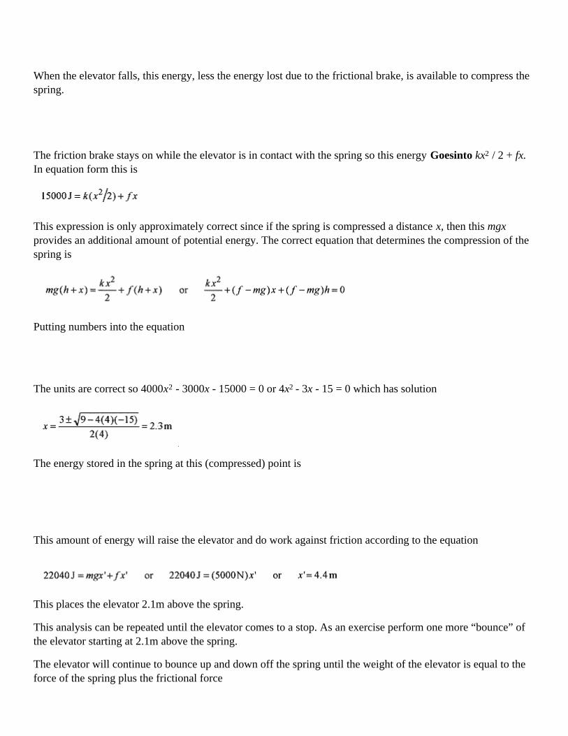
When the elevator falls, this energy, less the energy lost due to the frictional brake, is available to compress thespring.
The friction brake stays on while the elevator is in contact with the spring so this energy Goesinto kx2 / 2 + fx.In equation form this is
This expression is only approximately correct since if the spring is compressed a distance x, then this mgxprovides an additional amount of potential energy. The correct equation that determines the compression of thespring is
Putting numbers into the equation
The units are correct so 4000x2 - 3000x - 15000 = 0 or 4x2 - 3x - 15 = 0 which has solution
The energy stored in the spring at this (compressed) point is
This amount of energy will raise the elevator and do work against friction according to the equation
This places the elevator 2.1m above the spring.
This analysis can be repeated until the elevator comes to a stop. As an exercise perform one more “bounce” ofthe elevator starting at 2.1m above the spring.
The elevator will continue to bounce up and down off the spring until the weight of the elevator is equal to theforce of the spring plus the frictional force

so the elevator comes to rest with the spring compressed 0.38m.

Chapter 9Momentum Analysis
A discussion of the application of the law of conservation of momentum starts with a consideration of the centerof mass of a collection of particles. For discrete mass points the center of mass is defined as
and likewise for y and z if the masses are distributed in two or three dimensions. A more powerful vectornotation is
9-1 Calculate the center of mass for a distribution of mass points as shown in Fig. 9-1.
Solution:
Fig. 9-1
The rcm form indicates that the calculation is to be done in vector notation, so (The units are often left our ofcalculations involving unit vectors and added at the end.)

These mass points act as if all of their mass (50kg) were at the point (0.72,0.24). If these three masses wereplaced on a plate of negligible mass, the balance point would be at (0.72,0.24).
The law of conservation of momentum can be viewed as a consequence of the statement: The total mass of acollection of particles times the acceleration of the center of mass equals the applied, or external, force, that is,the sum of the forces on all the individual component masses. This is of course a vector equation.
9-2 For the same collection of masses at the same points, as in problem 9-1, add forces as shown in Fig. 9-2 toeach mass and find the resultant acceleration of the center of mass.
Fig. 9-2
Solution: Remember: the acceleration of the center of mass is the total mass times the vector sum of all theseforces. Applying equation 9-3
so

If the previous statement Fext = macm is viewed as then if Fext = 0, mvcm must be a constant. (Thederivative of a constant is zero; or viewed graphically, if the curve of mv versus time is a constant then the slopeis zero.)
Stated another way: For a system with no external forces the sum of the momentum vectors m1v1+m2v2+…,which add to mvcm, must all add to zero.
<><><><><><><><><><><><>
9-3 A 5.0g pellet is compressed against a spring in a gun of mass 300g. The spring is released and the gunallowed to recoil with no friction as the pellet leaves the gun. If the speed of the recoiling gun is 8.0m/s, what isthe speed of the pellet?
Solution: This problem is solved by application of the law of conservation of momentum. This law can beapplied because there is a no external force. Since there is no external force, all the mv's must add to zero.
Fig. 9-3
The conservation of momentum statement on the left is based on the simple observation “bullet go one way,gun go the other,” while the formal statement that the mv's add to zero is on the right. With a well-labeleddiagram of the situation, the statement on the left is probably easier to visualize, that is, the momenta are equaland opposite. Putting in the numbers
As a check, not that the momentum of the gun pg = mgvg = 2.4kg.m/s and the momentum of the pellet pp = mpvp =2.4kg.m/s are numerically equal and since they are in opposite directions add to zero.
The energy of each is mv2/2 or p2/2m. So for the gun
Performing the same calculation for the pellet

The total energy stored in the spring is the sum of these energies or 298J.
<><><><><><><><><><><><>
9-4 Make the pellet gun of problem 9-3 fully automatic and capable of firing 10 pellets per second. Calculatethe force these pellets make on a target where the pellets do not bounce.
solution: This problem is solved by calculating the average momentum transferred to the target per unit of time.The momentum of each pellet is 2.4kg.m/s. The force on the target is calculated from the simple expression
The total momentum transferred each second is 10 individual momenta of each pellet.
<><><><><><><><><><><><>
9-5 A 75kg hockey player traveling at 12m/s collides with a 90kg player traveling, at right angles to the first, at15m/s . The players stick together. Find their resultant velocity and direction. Assume the ice surface to befrictionless.
Solution: This problem can be analyzed by conservation of momentum. Calculate the momenta and draw avector diagram.
Fig. 9-4
The angle of the two hockey players is from or θ=56°,
and the resulting momentum is

The players move off with velocity at an angle of 56° to the original direction of the 75kgplayer.
Second Solution: A more formal approach is to write a conservation of momentum statement equating the total(vector) momentum before the collision to the total (vector) momentum after the collision. Take the plus idirection as the initial direction of the first player and the plus j direction as the original direction of the secondplayer. Using the numbers already calculated
As an exercise verify the final velocity of 9.83m/s at the 56° angle.
<><><><><><><><><><><><>
9-6 James Bond is skiing along being pursued by Goldfinger, also on skis. Assume no friction. Mr. Bond, at100kg, fires backward a 40g bullet at 800m/s. Goldfinger, at 120kg, fires forward at Bond with a similarweapon. What is the relative velocity change after the exchange of 6 shots each? No bullets hit Bond orGoldfinger.
Solution: The problem is analyzed with conservation of momentum. The mbvb of the bullet fired by Bondincreases his momentum by mBδvB. Remember that each bullet Bond fires increase his velocity. Set mbvb = mBδvB
and solve for δvB
The 40 × 10-3kg bullet is small compared to the 100kg of Bond, and it would not affect the calculation. The δvB
notation is used to indicate that each bullet fired by Bond causes a change in his velocity.
Goldfinger, on the other hand, has his momentum decreased. In his case, mbvb = mGδvG.
Putting in the numbers
Bond goes faster and Goldfinger goes slower with the total change in velocity 0.58m/s for each pair of shotsfired. For six shots this amounts to a difference of 3.48m/s. If Bond and Goldfinger had been traveling at thesame speeds, then after this exchange Bond would have a relative speed advantage of 3.48m/s.
<><><><><><><><><><><><>
9-7 A 3000kg closed boxcar traveling at 3.0m/s is overtaken by a 1000kg open boxcar traveling at 5.0m/s. Thecars couple together. Find the resultant speed of the combination.
Solution: The momentum before coupling is the same as the momentum after coupling (no external forces).

<><><><><><><><><><><><>
9-8 Continuing problem 9-7, rain falls into the open boxcar so that the mass increases at 1.0kg/s. What is thevelocity of the boxcars at 500s?
Solution: The total momentum of the boxcars is 4000kg(3.5m/s=14000kg.m/s. Assume there is no horizontalcomponent of the rain to change the momentum in the direction of motion of the boxcars. The mass increasesby (1.10kg/s)3.5m/s=500kg. The momentum is a constant, so the new velocity is
<><><><><><><><><><><><>
9-9 For the situation described in problems 9-7 and 9-8, what is the rate of change in velocity for the boxcars?
Solution: This is a very interesting calculus problem that involves taking the total derivative. Since there are noexternal forces, the total change in mv must equal zero so
Now write m as a function of timem = mo + rt=4000kg + (1.0kg/s)t.
The derivative of m is dm = rdt.
Using the previous two equations and rearranging
Introduce a change of variable
Integrating, 1n v=-1nu + 1n K. Use 1n K because it is a convenient form for the constant.
Now rearrange: 1nv + 1nu=1nK and 1nuv=1n K or uv=K
change the variable back to t so (mo + rt) v =K.
Evaluate the constant from the condition that at

The relation between
The velocity at
Conservation of momentum and a little calculus produce the v versus t relation.
<><><><><><><><><><><><>
9-10 A 3.0kg cat is in a 24kg boat. The cat is 10m from the shore. The cat walks 3.0m toward the shore. Howfar is the cat from the shore? Assume no friction between boat and water.
Solution: There are no external forces so the center of mass of the cat-boat system is constant. Knowing that thecenter of mass doesn't move is all that is necessary to do this problem.
Fig. 9-5
Referring to Fig. 9-5, write the center of mass of the cat-boat system before the cat walks. (M is the mass of theboat and m the cat.) Then write the center of mass of the cat-boat system after the cat walks.
Because there are no external forces the centers of mass are the same so
Watch the algebra and solve for xc. Use a word statement before writing the algebra statement. “The finaldistance of the cat from the shore is equal to the original distance of the cat from the shore plus thedisplacement of the cat relative to the boat and the displacement of the boat relative to the shore.” Read thesentence, look at the diagram, and write
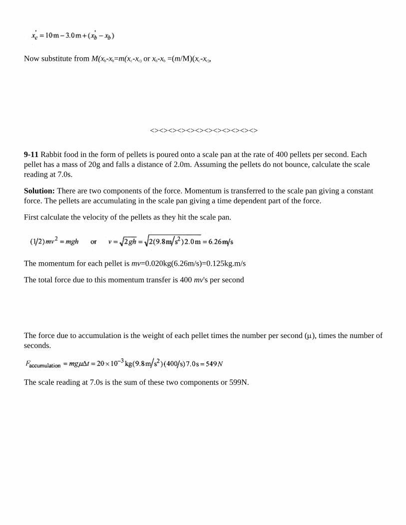
Now substitute from M(xb-xb=m(xc-xc) or xb-xb =(m/M)(xc-xc),
<><><><><><><><><><><><>
9-11 Rabbit food in the form of pellets is poured onto a scale pan at the rate of 400 pellets per second. Eachpellet has a mass of 20g and falls a distance of 2.0m. Assuming the pellets do not bounce, calculate the scalereading at 7.0s.
Solution: There are two components of the force. Momentum is transferred to the scale pan giving a constantforce. The pellets are accumulating in the scale pan giving a time dependent part of the force.
First calculate the velocity of the pellets as they hit the scale pan.
The momentum for each pellet is mv=0.020kg(6.26m/s)=0.125kg.m/s
The total force due to this momentum transfer is 400 mv's per second
The force due to accumulation is the weight of each pellet times the number per second (µ), times the number ofseconds.
The scale reading at 7.0s is the sum of these two components or 599N.

Chapter 10Collision and Impulse
Momentum provides a new analysis technique. With force analysis and work-energy analysis, application of theappropriate analysis technique to “the problems at the end of the chapter” was reasonably straight forward. Atthe end of the chapter on forces use force analysis. At the end of the chapter on work-energy use work-energyanalysis. However, at the end of the chapter on momentum we need to use momentum and work-energyanalysis. Knowing when to use work-energy analysis and when to sue momentum analysis adds a whole newdimension to problem solving.
As will become evident in this chapter, there are certain types of collision problems where conservation ofmomentum and conservation of energy can be applied and certain problems where only conservation ofmomentum can be applied. This is no where better illustrated than in the ballistic pendulum problem (presentedlater), where conservation of momentum is applied in one part of the problem and conservation of energy inanother part of the problem. Learning where to apply these two conservation laws is difficult. As the problemsin this chapter are presented, be aware of which law is being applied and why.
Before doing problems take a general look at collisions in one dimension. Throughout the discussion A and Bwill designate the two particles, and 1 and 2 will designate before and after the collision.
There are two types of collisions:
In elastic collisions both momentum and energy are conserved. Examples of elastic collisions are billiard ballsor any collision where the participants bounce.
In inelastic collisions only momentum is conserved. Examples of inelastic collisions are railroad cars couplingor a steel ball thrown into a piece of clay or any collision where the participants stick together.
It is this sticking or nonsticking that determines if energy is conserved or not. When we say that energy is notconserved in a collision where the participants stick together, we mean only that mechanical energy, (1/2)mv2,is not conserved.
Inelastic Collisions.
Consider first inelastic collisions. Where the particles stick together. Using the notation described above
Fig. 10-1
This equation states that after the collision, the velocity of the A particle is the same as the velocity of the Bparticle. Applying in the law of conservation of momentum and this condition
The left side of the equation is the momentum before collision, and the right side is the momentum of the twomasses stuck together traveling at the same velocity after the collision.

Fig. 10-2
Take the special case where the B particle is initially stationary. While mechanical energy is not conserved inthe collision the kinetic energies can be written as
and
K2 can be rewritten using the conservation of momentum statement
Comparing these two equations gives a relationship for the energy before and after collision.
10-1 A ballistic pendulum, a device for measuring the speed of a bullet, consists of a block of wood suspendedby cord. When the bullet is fired into the block, the block is free to rise. How high does a 5.0kg block rise whena 12g bullet traveling at 350m/s is fired into it?
Fig. 10-3
Solution: This is a most interesting and instructive problem. The collision between the bullet and the block isclearly inelastic (the bullet comes to rest in the block). Part of the kinetic energy of the bullet Goesinto frictionas the bullet burrows its way into the block. Therefore mechanical energy is not conserved.
Because the collision is inelastic, apply conservation of momentum of the collision. Before the collision, all themomentum is in the mv of the bullet. After the collision, the momentum is in the (m+M)V of the block andbullet. We assume that the bullet comes to rest (transfer all its momentum) before there is appreciable motion ofthe bullet-block combination.

After the collision, the rise of the block is determined by energy analysis. The kinetic energy of the blockGoesinto potential energy.
or
Substituting for V from mv = (m+M)V
so or
giving the relation between the velocity of the bullet and the height the block and bullet rise. For this problem
In this problem the 0.012 can be neglected in comparison to 5.0. This is not always the case so we write m + Mas 5.012 as a reminder to include both m +M in the calculation.
<><><><><><><><><><><><>
10-2 A 6.0g bullet is fired horizontally into a 2.8kg block resting on a horizontal surface with coefficient offriction 0.30. The bullet comes to rest in the block, and the block slides 0.65m before coming to a stop. What isthe velocity of the bullet?
Solution:
Fig. 10-4
Assume the bullet comes to rest in the block before the block moves appreciably and that all the momentum inthe bullet is transferred to the bullet-block combination.
Once the bullet-block combination is moving at V, the kinetic energy, (1/2)(m+M)V2, Goesinto work toovercome friction µ(m + M)gx
Substituting
or

Elastic Collisions
Now look at elastic collisions, where the particles bounce. In elastic collisions no energy is lost to permanentdeformation of the particles. Write a conservation of momentum statement for the collision diagrammed in Fig.10-5.
Fig. 10-5
Now write a conservation of energy statement.
These two statements can be written as
and
Now divide the (rewritten) conservation of energy statement by the conservation of momentum statement tofind
or
The term vA1 – vB1 is the speed of approach, the speed of A relative to B measured by an observer on B. The termvA2 – vA2 is the speed of departure. So in an elastic collision the speed of approach is equal to the speed ofdeparture.
Now find expressions for the velocities after the collision in terms of the masses and the velocities before thecollision. From the velocity statement (above)
From the conservation of momentum statement (above), substitute the equation for vB2.
and with a little algebra
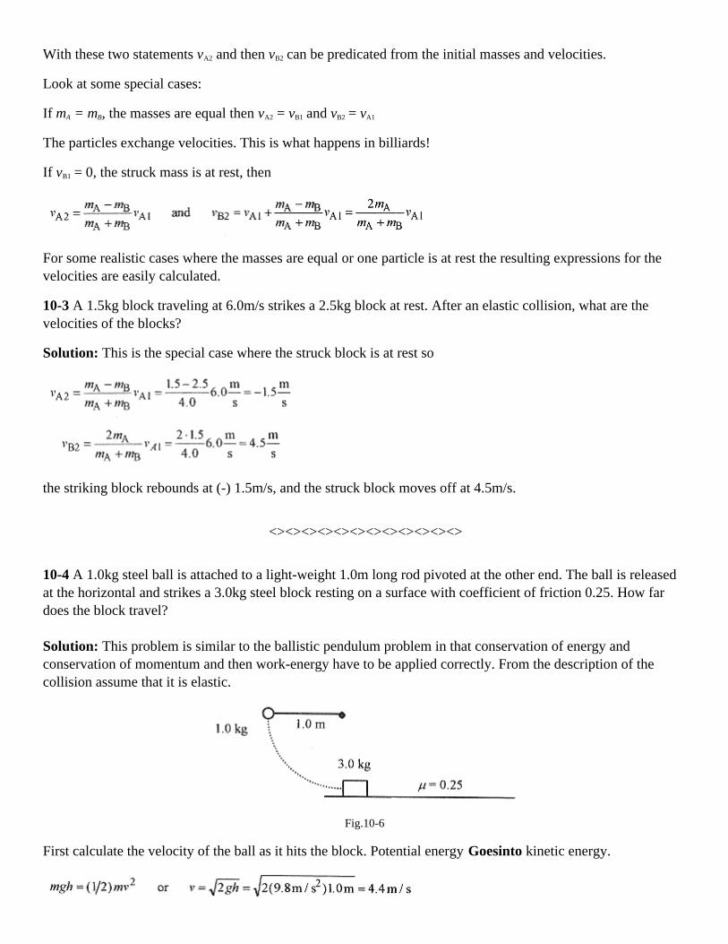
With these two statements vA2 and then vB2 can be predicated from the initial masses and velocities.
Look at some special cases:
If mA = mB, the masses are equal then vA2 = vB1 and vB2 = vA1
The particles exchange velocities. This is what happens in billiards!
If vB1 = 0, the struck mass is at rest, then
For some realistic cases where the masses are equal or one particle is at rest the resulting expressions for thevelocities are easily calculated.
10-3 A 1.5kg block traveling at 6.0m/s strikes a 2.5kg block at rest. After an elastic collision, what are thevelocities of the blocks?
Solution: This is the special case where the struck block is at rest so
the striking block rebounds at (-) 1.5m/s, and the struck block moves off at 4.5m/s.
<><><><><><><><><><><><>
10-4 A 1.0kg steel ball is attached to a light-weight 1.0m long rod pivoted at the other end. The ball is releasedat the horizontal and strikes a 3.0kg steel block resting on a surface with coefficient of friction 0.25. How fardoes the block travel?
Solution: This problem is similar to the ballistic pendulum problem in that conservation of energy andconservation of momentum and then work-energy have to be applied correctly. From the description of thecollision assume that it is elastic.
Fig.10-6
First calculate the velocity of the ball as it hits the block. Potential energy Goesinto kinetic energy.

The collision is elastic and vB1 = 0, so
The gives the initial velocity of the struck block. The kinetic energy Goesinto work against friction.
Go back over this problem and see where energy analysis is applied, conservation of momentum is applied, andwork-energy analysis applied. Knowing what laws to apply where in the problems is the hard part of collisionproblems.
Impulse
Impulse is the name given to a force that acts for a very short period of time. A struck baseball, golf ball, ortennis ball are examples of impulses or impulse forces. In most impulses, it is impossible to graph force versustime; though we can often estimate how the force varies with time.
Force is defined terms of change in momentum as
If the force is time dependent, F(t), then rewriting, ∆(mv) = F (t)∆t
With calculus notation this statement would be written as
The left side is the change in momentum, and the right side is the area under the F(t) versus t curve. Thisintegral is called the impulse or impulse integral. If the curve of F(t) versus t were a parabola (reasonable foran impulse), then the right side of the equation would be the area under the curve in Fig. 10-7.
Fig. 10-7
10–5 A 1.2kg croquet ball moving at 2.0m/s struck from behind by the impulse force shown in Fig. 10-8. Whatis the final velocity of the croquet ball?
Solution: The initial momentum is
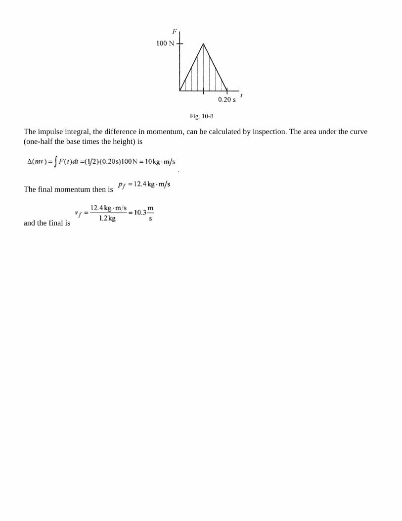
Fig. 10-8
The impulse integral, the difference in momentum, can be calculated by inspection. The area under the curve(one-half the base times the height) is
The final momentum then is
and the final is

Chapter 11Rotational Motion
The study of rotational motion begins with the kinematics of the motion, that is, the relation between angle, θ,angular velocity, ω, and angular acceleration, α. Start with a point rotating about the origin of a coordinatesystem, usually an x - y system, with r - θ superimposed.
Begin with the definition of radian measure as angle equals arc length over radius. This gives the angle as apure number, or radians. Radian is a phantom unit, sometimes it is used and sometimes not. For example, for anarc length of 4m on a circle of radius 2m the angle in radians is 4 m / 2 m=2. This is usually written as 2 rad. Ina problem involving canceling units this can add confusion because rad is length over length or unity and doesnot cancel with anything. So rad may appear in a problem, then disappear in the answer, or vice versa, thusfitting the description “phantom.” When radian is used in a problem, the unit is for clarity and will notnecessarily be in the final answer.
Fig. 11-1
The kinematic angular equations can be written as direct analogs to the linear ones.
Another set of relationships in rotational motion is the one between linear motion and angular motion. Theserelate the motion of a particle, or point, along a circular path to the angular motion. Position along the circularpath is called the linear position or rim position. These relationships come out of the definition of radianmeasure, θ=s / r or s=rθ. For constant r, a small change in s is related to a small change in θ by ∆s=r∆θ; and ifthe change is over time, then ∆s/∆t=r(∆θ/∆t) or v=rω, relating the linear velocity, the velocity of a point on therim, to the angular velocity. For a small change in linear velocity ∆v=r∆ω; and if this occurs over time∆v/∆t=r(∆ω/∆t) or a=rα, relating the linear acceleration, the acceleration of a point on the rim, to the angularacceleration. Formal definitions of angular velocity and angular acceleration are in the next chapter.
There is one more relationship in angular motion. If a point is rotating on a circle with constant angular velocityω, the linear velocity is numerically constant. But velocity is a vector; and while the number associated with thelinear velocity is not changing, the direction is changing. Refer to Fig. 11-2.

Fig. 11-2
The vectors v and v' are separated by an angle θ. The acceleration is the difference between the vectors.Remember, the vectors v and v' are at right angles to the radius, so the angle between v and v' is the same as theangle between the r's. Drawing the figure for the r's and another figure for the v's, with the v's placed tail to tail,we have similar triangles (isosceles triangles with the same angles). For small angles, ∆s approaches a straightline so comparing the similar triangles write
and form this relation write
In the limit ∆s / ∆t is v and ∆v / ∆t is a, so the acceleration is
The acceleration vector points inward along r. Refer to Fig. 11-2 and note that in the limit as ∆t 0, ∆s 0,and ∆v 0, ∆v and a point toward the center of the circle. These are all the relations necessary to do problemsin rotational motion.
Use this sample problem to become familiar with manipulating revolutions, revolutions per minute, and radians.A wheel is rotating on its axis at 100 revolutions per minute. This is usually written as 100 rev / min. The angleturned through in each minute is 100 times 2π (radians). This little calculation is often missed in rotationproblems. Each revolution represents an angle of 2ω measured in radians.
The angular speed is θ=2π.100rad/min,
Converting to seconds ω=(2π.100rad/min)(1 min/60s)=(10π/3)(rad/s).
Assume the wheel slows, under constant acceleration, to zero in 3.0 minutes.
Calculate the acceleration as
Angular velocity is usually written with the units (rad/s) or (1/s) and angular acceleration as (rad/s2) or (1/s2),which is why radian is called a phantom unit. Radians and revolutions are usually introduced as units forconvenience in understanding a problem and not as units to be carried and manipulated, as is the case with kg,m, s, etc. Be very careful on this point. It can cause you trouble!
The angle turned through is the average angular velocity times the time.

or
<><><><><><><><><><><><>
11-1 An automobile is traveling at 60km/hr. Calculate the angular velocity of the 0.35m radius wheels.
Solution: The linear velocity of the (contact) point on the wheel is
The linear velocity of the contact point on the wheel is the same as the velocity of the axle.
The angular velocity is
Adding radians in the units makes the meaning clearer.
<><><><><><><><><><><><>
11-2 If the automobile of problem 11-1 accelerates uniformly from 60km/hr to 80km/hr in 3.0s, what is theangular acceleration?
Solution: This acceleration is the acceleration of the point where the wheel meets the road. First calculate thechange in velocity.
This is the change in velocity of the point on the wheel. The linear acceleration, is
The angular acceleration is

<><><><><><><><><><><><>
11-3 A disk rotating at 30rad/s slows to 20rad/s while turning through 60 revolutions. How long does this take?
Solution: Since the acceleration is constant we can use
<><><><><><><><><><><><>
11-4 For the acceleration of the disk in problem 11-3, how many revolutions does it take for the disk to stop?
Solution: First, calculate
Now use ω2=ω02+2αθ with ω=0 and ω0=30 rad/s to find θ:
Applications
From kinematics we can go to some more complicated rotational problems.
11-5 Consider a space station in the form of a donut with a rectangular cross section connected by spokes to acentral axis. The “floor” is the inside of the outer wall. How fast would a 300 m radius station have to rotate toduplicate the “acceleration due to gravity” on the surface of the earth?
Fig. 11-3
Solution: The required acceleration is the v2/r acceleration associated with rotational motion. Since v is relatedto ω by v=rω, then the required acceleration a=v2/r=rω2. Set this acceleration equal to 9.8m / s2 and solve forω.

The frequency in revolutions per minute is
Notice that in this last calculation “rev” was introduced for clarity.
<><><><><><><><><><><><>
11-6 If someone of weight 800N (on earth) living in the space station described in problem 11-5 were to moveone-half the radius in toward the axis of rotation, what would be their weight at this radius?
Solution: Their weight, what a force meter placed between them and a “floor” would read, in this environmentwould be
If the person in the space station were placed in a “black box” where they were unaware of their surroundings,there is no experiment they could perform to determine whether their weight were produced by the mv2 / r ofthe space station or mg of the earth or any other planet.
Consider astronauts in earth orbit. From the reference frame of the astronauts the mv2 / r force is balanced bythe gravitational force of the earth. This lack of force, or weightlessness, has a dramatic effect on the bodies ofearth orbiters who typically “grow” 2 to 3cm in earth orbit.
Many physics textbooks treat all problems involving centripetal force from an external reference point. Thismay sometimes be confusing. Keep this clear in your mind; from the reference point of the external observerthere is no “centrifugal” force, or force that acts radially out. However, in many instances the most practicalway of solving uniform circular motion problems is from the point of view of the object being rotated.Operationally this means to treat them as force balance problems in which mv2/r acts radially out. Look back toproblem 5–16 where the coin is rotating on the turntable. If you were riding on the coin at constant angularvelocity you would say there is no unbalanced force in the radial direction; the mv2/r force acting out isbalanced by the µN force acting in.
<><><><><><><><><><><><>
11-7 Consider a mass of 2.0kg being whirled in a sling in a horizontal circle. The period of rotation is 1.0s, andthe radius 1.0m. What is the tension in the cord?

Solution: The force that makes the mass travel in a circle must be equal to mv2/r. The velocity of the mass isthe distance traveled (one circumference) divided by the time to travel one circumference (the period)
The force (or tension) in the cord is
Be aware of how tension in the cord is interpreted. If you are whirling the cord, the tension, from your point ofview, is radially out. From the point of view of the mass in the sling, however, the tension is pointing in. This issimilar to force problems with blocks where the tension in the connecting string acts one way on one block andthe other way on another block. See for example problem 5–7 in Chapter 5, Force.
In linear motion, something moving at constant velocity is not acted on by an unbalanced force. In circularmotion, something moving in uniform circular motion is subject to a force; the mv2/r force to produce theacceleration necessary to make it move in a circle.
To help keep this straight in your mind take a “thought trip” in an airplane flying in a vertical bank (wingsvertical) in a horizontal circle. A force meter between you and the seat of the airplane would read a numberequal to your m times v2/r. The force acting on you is toward the center of the circle, but you exert an equal (inmagnitude) force on the seat that is radially out of the circle. In some airplanes the force can be so great as tocause the blood in the pilot to remain in the lower part of his body resulting in loss of oxygen (carried by theblood) to the brain and “blackout.”
Make a slight variation in this “thought trip” by having the airplane move in a vertical circle. Now the forcemeter between you and the seat reads mg more or less than mv2/r depending on whether you are on the top orthe bottom of the loop.
<><><><><><><><><><><><>
11-8 Take the same mass, radius, and period as in problem 11-7 but with the rotation in a vertical circle. What isthe force between the mass and the sling?
Solution: In this case gravity has to be taken into account. The mass exerts a force on the sling radially out andequal to mv2/r. Gravity exerts a force mg down. Figure 11-4 shows the relative direction of these forces at fourpoints on the circle.
The gravitational force is mg=(2.0kg)9.8m/s2=19.6N
The force between the mass and the sling as shown in Fig. 11-4 is 79.0+19.6=98.6N at the bottom of the circleand 79.0-19.6=59.4N at the top of the circle.

Fig. 11-4
<><><><><><><><><><><><>
11-9 For the situation in problem 11-8 calculate the minimum velocity and period of rotation to keep the massfrom “falling out” at the top of the circle.
Solution: Zero tension in the cord occurs (at the top) when
Notice that the mass drops out of the equation. Using the 1.0m radius
The period is calculated by replacing the velocity by 2πr / T
This result can be checked by whirling a mass in a vertical circle and observing that the mass “falls out” of thecircle at a period of over 2.0s. (The length from shoulder to ground is a little over 1.0m for most people so thisis an easy experiment to perform. For a little adventure try it with a container of liquid!)
11-10 A glider pilot wishing to fly in a vertical loop dives to attain a speed sufficient to keep the glider from“falling out” of the top of the loop. What is the minimum entry speed for a 200m radius loop?
Solution: This problem is solved with energy analysis. At the bottom of the loop the glider must have sufficientkinetic energy to climb the diameter of the loop and have enough left to satisfy the mv2 / r = mg condition.Refer to Fig. 11-5 to write the energy balance statement and the criteria for the glider not “falling out” of theloop.

Fig. 11-5
The energy statement is in word form: Kinetic energy at entry equals the potential energy to reach the top of theloop plus the kinetic energy at the top of the loop
The minimum velocity condition is
Substituting for vt the minimum energy statement is yielding a minimum entry
speed of
For a 200m radius loop (very large) the minimum ve for the glider is
For a 100m radius loop ve = 70m/s = 252km / hr
11-11 A grinding wheel of 30cm diameter is rotating with angular velocity of 3.0(rad / s) and slowing underconstant acceleration of -3.0(rad / s2 ). Calculate everything possible about the motion at several differenttimes.
Solution: Circular motion problems even more than linear motion problems, often present a challenge as to howto proceed from the data to the specific question. When confused about the specific route to follow in aproblem, the best thing to do is calculate something simple and let this first calculation lead you to others andultimately the answer. After doing the problem once the “hard way” you will learn more direct routes throughthe problem. Given the data in this problem start calculating some simple things.
What is the angular velocity at 0.40s? Use
What angle has been turned through in this 0.40s? Use

What is the velocity of a point on the rim at 0.20s? First find the angular velocity.
And then find the linear velocity from v=rω=15 × 10-2m.2.4(rad/s)=0.36m/s.
With this acceleration, how long does it take for the wheel to come to rest? Use
How much angle is turned through in this time? Use
How far does a spot on the rim travel in this time? Use

Chapter 12Rotational Dynamics
Because we take another view of rotational motion in the beginning of this chapter, you may find it helpful tofirst review the discussion of rotational motion in the previous chapter.
Consider the rotation of a solid about some point in a plane. The rotation is counterclockwise in conformitywith trigonometry. The angle is again defined as arc length over radius, the standard definition appropriate toradian measure θ= s / r.
Fig. 12-1
The average angular speed is defined as
with the instantaneous angular speed defined by
Similarly, the average angular acceleration is defined as
with the instantaneous acceleration defined as
The relationships between the point and the angle all start with s=rθ; then with successive derivatives comes
Remember that the radial, or center-directed, acceleration is arad=v2/r = rw2.
A force has to be associated with the angular acceleration. Force, however, does not lend itself well to motionof a particle constrained to move in a circle, because most forces are not tangent to a circle. Torque works muchbetter. Torque is defined in a rather unusual manner. Unusual, that is, until its utility is seen through experiencein rotational dynamics.

Torque is the vector product of r, the vector from the axis of rotation to the rotating point, and F, the forceapplied at that point.
You may want to review the definitions of the cross product in the Introduction, Mathematical Background,before continuing. Most problems in torque can be done with the geometric interpretation of the cross product.Torque, r × F, is the product of r and the component of F perpendicular to r or \r\\F\ sin θ as shown on the leftin Fig. 12-2.
Fig. 12-2
The torque vector is perpendicular to the plane of r and F and follows the right-hand rule of rotating r into F. Inthis case the torque is out of the paper.
12-1 Calculate the torque on a 2.5kg mass constrained to rotate in a 1.6m radius circle with a 250N forceapplied at a (constant) angle of 35° between r and F.
Solution: The problem is depicted in Fig. 12-2. The definition of r × F. gives the direction of the torque as outof the paper. Application of the crossing of r into F is similar to generating a righthanded coordinate system byrotating x into y with the right hand with the thumb giving the direction of z. The magnitude of the torque is
Torque is r cross force, and similarly, angular momentum is r cross momentum or
Angular momentum is a vector in a direction perpendicular to the plane of r and p and magnitude equal to theproduct of r and the component of p perpendicular to r.
12-2 For the situation of problem 12-1 add that the linear velocity is 2.8m / s and find the angular momentum.
Solution: The linear momentum is mv = 2.5kg(2.8m/s)=7.0kg.m/s. The linear velocity is the tangential velocity,which is always at right angles to the radius; so the direction of the angular momentum vector is out of thepaper, and the magnitude of the cross product is simplified because the sine of 90° is one.
<><><><><><><><><><><><>

With these definitions for torque and momentum, several relationships can be derived. Start with
Torque is the time derivative of angular momentum as force is the time derivative of linear momentum. Now,by analog, several things follow.
The total angular momentum of a system is the sum of the angular momentum of the individual pieces. Internaltorques are equal and opposite, so only external torques change the angular momentum of the system. Thestatement
If the derivative of the total angular momentum is zero, the condition for no external torques, then the angularmomentum is a constant.
Now look to the kinetic energy associated with rotating particles. Each particle, or piece, of a rotating mass hasa linear speed v = rw, and the KE for each piece is a sum
This sum of the mr2's for the collection of pieces is called the rotational inertia, I, so that the KE can be writtencompactly as
The rotational inertia, I, is easy to calculate for individual particles and has been calculated for many shapes.Tabulations are found in most physics books and some mathematical tables.
12-3 Calculate the rotational inertia for one 2.0kg mass at the end of a 3.0m rod of negligible mass and then therotational inertia of a dumbbell consisting of two 2.0kg masses on the ends of a 6.0m long rod of negligiblemass pivoted about the center of the rod.
Solution: For the one mass, the sum of the mr2's is just 2.0kg(9.0m2)=18kg.m2.
For the dumbbell, there are two masses, and the rotational inertia would be 36kg.m2.
Notice that if the dumbbell were rotated about one mass then the rotational inertia would be

2.0kg(36m2 = 72kg.m2. This is of course neglecting the extent of the mass close around the rotating axis.
<><><><><><><><><><><><>
The total momentum of a rotating mass (point) is mvr. If the mass is rotating, then v is perpendicular to rleading to a simple statement of angular momentum.
Angular momentum is L = mvr = mr2 w = IW.
By definition
The power is
Conservation of Angular Momentum
Angular momentum, as a property of the motion, is conserved and is a powerful tool in solving certain problemsin rotational motion. First, calculate a torque using the vector form for position and force and the determinantfor the cross product. See the Introduction, Mathematical Background for a review of this definition of crossproducts.
Most problems do not require as extensive a calculation as this equation would indicate. For a position andforce vector in the x-y plane the torque reduces to a single z component.
12-4 Calculate the angular momentum of a 3.0kg mass at 3.0m in the x-direction and -2.0m in the y-directionand with velocity components of 20m/s in the x-direction and
-30m / s in the y-direction?
Fig. 12-3
Solution: Write r and p in vector form: r=(3.0i-2.0j)m p=(60i-90j)kg.m/s The angular momentum is

The angular momentum vector is 150kg.m2 / s pointed into the paper.
Second Solution: Now redo the problem with angle and magnitude. The angle between r and p is -22.6°. Figure12-3 shows the trigonometric relations. Note that the angle between r and p is negative. The fact that the angleis negative can be easily missed. Rather than rely on the sign of the angle, the better way to determine thedirection of the angular momentum vector is to use the right-hand rule and cross r into p with the thumb givingthe direction of L. The magnitude of L is
Applications.
Now to a few problems with rotating hoops and cylinders using rotational dynamics, conservation of energy,and conservation of angular momentum.
12-5 A hoop of mass 1.0kg and radius 0.25m is rotating in a horizontal plane with angular momentum 4.0kg.m2
/ s. A lump of clay of mass 0.20kg is placed (gently) on the hoop. What happens to the angular velocity of thehoop?
Solution: The moment of inertia for a hoop (from the table in your text) is I = mr2.
The angular momentum, L, is Iw,, so the initial angular velocity can be calculated from L = Iwi
Since the lump of clay is placed (gently) on the hoop (The hoop is rotating in the horizontal plane, and the clayis placed on the hoop vertically.), placing the clay only adds mass to the hoop. This additional mass adds
“another” moment of inertia mr2, so with the angular momentum the same (no external torque has acted tochange it)
<><><><><><><><><><><><>

12-6 An amusement park game consists of a paddle wheel arrangement where you shoot at the paddles with apellet gun, thereby turning the wheel. The paddle wheel is set in motion with an initial angular momentum of200kg.m2 / s and angular frequency of 4.0rad / s. You shoot eight 40g pellets at a speed of 200m/s at thepaddles. The pellets hit the paddles at 0.80m radius, stick, and impart all their momentum to the wheel. Find thenew angular momentum and the new angular frequency.
Solution: First calculate the initial moment of inertia of the paddle wheel from L = Iw.
Fig. 12-4
Now calculate the w after the wheel has absorbed the (momentum in the) eight pellets. The angular momentumof each pellet is the linear momentum times the 0.80m radius.
For eight pellets the “absorbed” angular momentum is Lall pellets = 51.2 kg.m2/ 2
The new angular momentum is the original plus this, or 251.2 kg.m2 / s.
The I also has increased because of the additional mass at the 0.80m radius. This “additional” / is
The equation for calculating the new angular velocity
(L = Iw) is
<><><><><><><><><><><><>
12-7 Now consider a 10kg solid cylindrical drum with radius 1.0m rotating about its cylindrical axis under theinfluence of a force produced by a 30kg mass attached to a cord wound around the drum. What is the torque,moment of inertia, and angular acceleration?

Fig 12-5
Solution: The moment of inertia for a solid drum rotating about its axis is mr2 / 2.
The torque on the drum is the tension in the cable times the radius of the drum. This tension is much like thetension encountered in the problems of multiple blocks sliding on tables as found in Chapter 5, Force. Thesystem accelerates clockwise, so the unbalanced force on M makes it accelerate according to
The torque on the drum makes it angularly accelerate according to rF =lα
The acceleration of M is the same as the tangential acceleration, a=rτ so
Evaluating
The angular acceleration is
The torque is
12-8 When the 30kg mass in problem 12-7 has fallen (starting from rest) through 4.0m, what is the linearvelocity, angular velocity of the drum, and the time for this to occur?
Solution: This part of the problem is approached from an energy point of view. The 30kg mass falls through adistance of 4.0m. The work performed by gravity Goesinto translational
KE of the 30kg mass and rotational KE of the cylinder. The main difficulty in problems like this is rememberingthat some of the work performed results in rotational KE and some in translational KE.

Putting in the numbers
Fromv = rω angular velocity is
The time for this system to reach this velocity is from ω=ωo+τ1.
<><><><><><><><><><><><>
12-9 A solid sphere is constrained to rotate about a vertical axis passing through the center of the sphere. A cordis wrapped around what would be the equator, passes over a pulley of negligible mass, and is attached to a massthat is allowed to fall under the influence of gravity. Write a conservation of energy statement for the system.
Fig. 12-6
Solution: If the mass falls a distance h, then the energy gained by the system is Mgh. This energy Goesintotranslational kinetic energy of the mass and rotational kinetic energy of the sphere. A conservation of energystatement is
The velocity of a point on the string and the velocity of the mass are the same and are related to the angularvelocity through v = rω, so the energy statement can be written in terms ofv.
Additionally, the formula for I=2mr2/5 can be substituted so

Note that the energy statement could have been written in terms of ω rather than v.
12-10 For problem 12-9 take the mass of the sphere as m=2.0kg,r=0.30m, the hanging mass as M= 0.80 kg, andthe height the mass falls through as h=1.5m. Find the velocity of the hanging mass, and the angular momentumof the sphere.
Solution: The velocity of the mass, the rope, and a point on the equator of the sphere (all the same velocity) is
from the energy statement
The angular velocity of the sphere is
The angular momentum of the sphere is
As an added exercise give the pulley in this problem a mass and a radius and go through the problem again.Remember that I and ω will be different for the pulley.

Chapter 13Equilibrium
The only difficulty you will encounter in doing equilibrium problems is lack of familiarity with the mechanicsof doing the problems. This is overcome by doing problems. The theory is simple. If something is not moving,that is, it is in equilibrium, then the sum of the forces on it must be zero. Likewise if it is not rotating, then thesum of the torques must be zero.
For problems in two dimensions these laws are stated very simply:
We start off with some simple problems requiring force analysis only and progress to problems involvingtorques.
13-1 Hang a 50kg mass with ropes making angles of 30° and 45° as shown in Fig. 13-1. Calculate the tension inthe ropes.
Fig. 13-1
Solution: Note that all the forces come together at the knot in the rope so draw a force diagram about this point.The only laws to apply are for equilibrium in the x and y directions.
This provides two equations in two unknowns. Because sin45° = cos45° rewrite
and
As an exercise work through this problem with different angles.
<><><><><><><><><><><><>

13-2 In the arrangement shown in Fig. 13-2, what is the minimum coefficient of friction to prevent the 8.0kgmass from sliding?
Fig. 13-2
Solution: The forces come together where the cords come together. This point is not moving so apply theequilibrium conditions here. The vector diagram at this point is also in Fig. 13-2.
The equilibrium conditions are:
Solving for T1:
The force is: F=45N cos60° = 22.5N
This force is supplied by the frictional force µmg, so
This is the minimum coefficient of friction that will prevent me system from moving.
13-3 A 500 N diver is on the end of a 4.0m diving board of negligible mass. The board is on pedestals as shownin Fig. 13-3. What are the forces that each pedestal exerts on the diving board?
Solutions: There are no forces in the x-direction, but in the y-direction the pedestal at A and the diver are actingdown while the force at pedestal B is acting up. Pedestal B is in compression while pedestal A is in tension.Draw the vector diagram and write the equations.

Fig. 13-3
In this problem apply about pedestal A. Taking the rotation point at pedestal A, the diver produces aclockwise torque, and pedestal B an anti-clockwise torque that are in equilibrium. Note that this is not the onlypossible rotation point.
Solve for FB:
Solve for
As an exercise write the about pedestal B and the diver.
<><><><><><><><><><><><>
13-4 Place a 7.0m uniform, 150N ladder against a frictionless wall at an angle of 75°. What are the reactionforces at the ground and wall and the minimum coefficient of friction of the ground?
Solution: Figure 13-4 shows the ladder with the 150N acting down at the center of the ladder and the sides ofthe triangle formed by the ladder, wall, and ground. The vector portion of the figure shows the two componentsof the reaction force at the ground. The reaction force at the ground is not necessarily in the direction of theladder. This (vector) force can be written in terms of a force (magnitude) at an angle (with horizontal andvertical components) or directly in component form as done here. Writing the force in component force helps toavoid the temptation to place the force at the same angle as the ladder. Either way requires two variables. Sincethe wall is frictionless, the reaction at the wall is entirely horizontal. Refer to Fig. 13-4 and write theequilibrium conditions.
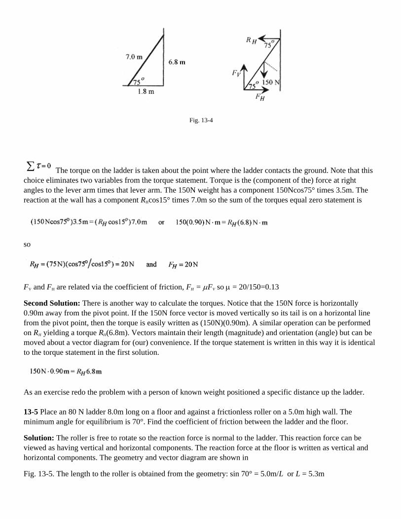
Fig. 13-4
The torque on the ladder is taken about the point where the ladder contacts the ground. Note that thischoice eliminates two variables from the torque statement. Torque is the (component of the) force at rightangles to the lever arm times that lever arm. The 150N weight has a component 150Ncos75° times 3.5m. Thereaction at the wall has a component RHcos15° times 7.0m so the sum of the torques equal zero statement is
so
FV and FH are related via the coefficient of friction, FH = µFV so µ = 20/150=0.13
Second Solution: There is another way to calculate the torques. Notice that the 150N force is horizontally0.90m away from the pivot point. If the 150N force vector is moved vertically so its tail is on a horizontal linefrom the pivot point, then the torque is easily written as (150N)(0.90m). A similar operation can be performedon RH yielding a torque RH(6.8m). Vectors maintain their length (magnitude) and orientation (angle) but can bemoved about a vector diagram for (our) convenience. If the torque statement is written in this way it is identicalto the torque statement in the first solution.
As an exercise redo the problem with a person of known weight positioned a specific distance up the ladder.
13-5 Place an 80 N ladder 8.0m long on a floor and against a frictionless roller on a 5.0m high wall. Theminimum angle for equilibrium is 70°. Find the coefficient of friction between the ladder and the floor.
Solution: The roller is free to rotate so the reaction force is normal to the ladder. This reaction force can beviewed as having vertical and horizontal components. The reaction force at the floor is written as vertical andhorizontal components. The geometry and vector diagram are shown in
Fig. 13-5. The length to the roller is obtained from the geometry: sin 70° = 5.0m/L or L = 5.3m

Fig. 13-5
Write the force equilibrium equations.
The torque about the point on the floor is produced by the reaction force at the roller and the weight of theladder taken at its midpoint.
Rewriting with f = µN
Solve these equations from last to first to obtain
<><><><><><><><><><><><>
13-6 A 20kg beam 4.0m long is pivoted at a wall and supported by a cable as shown in Fig. 13-6. What is theforce at the wall and the tension in the cable?
Solution: There are two points of possible confusion in this problem. First, the mass of the beam is taken asdown at the center of the beam. Second, the reaction of the wall, at the pivot, has two components, one up thewall (holding the end of the beam up) and one out of the wall (keeping the beam from sinking into the wall).

Fig. 13-6
Set up the vector diagram at the pivot and the point where the cable is attached. The reaction at the wall isshown with components up the wall and normal to the wall. The weight of the beam is shown as down and fromthe center of the beam with a component at a right angle to the beam. The tension in the cable is broken up intovertical and horizontal components (for the sum of the forces laws) and a component at right angles to the beam(for the sum of the torques laws). Applying the sum of the forces laws means looking at the vector diagram andadding up all the vectors in the horizontal or vertical directions.
In applying the sum of the torques, it is convenient to take the pivot point at the wall. Since the angle θ isunknown, the least complicated sum of the torques statement will come from the tension in the cable and theweight of the beam.
Using the components at right angles 4.0m = 160N. 2.0m
Solve the last equation for the tension in the cable
Use this value to solve for
Now divide these two equations
and finally, R is obtained from one of the original equations
The main points in this problem are the detailed vector diagram and the choice of the wall as the pivot point incalculating the torques.

<><><><><><><><><><><><>
In the early problems, construction of the vector diagram was confined to one point where the forces all “cametogether.” In problems where there is a strut or ladder or some other extended object the common mistake is tomiss a force or torque and have an incomplete vector diagram.
13-7 Set up a 300N strut 14m long with a cable as shown in Fig. 13-7. Find the tension in the cable and thereaction force at the pivot.
Solution: The reaction force at the pivot is set up with vertical and horizontal components. The weight of thestrut is taken at the center of the strut with the 2000 N weight at the end. The tension is written along with allthe components needed to write the force and torque equations.
Fig. 13-7
Apply the sum of the forces laws.
Apply the sum of the torques law about the pivot point.
Note that the length of the strut does not influence the calculation.
Solve the torque equation for T.
Use this value to find FH and FV.
The reaction at the floor can be written in terms of magnitude and angle.

<><><><><><><><><><><><>
Another feature of equilibrium problems is that an object hung by two cords has its center of mass along avertical line determined by the (extension of) intersection of those cords. The argument is based on the fact thata body hung by a cord has its center of mass along the extension of that cord. If the center of mass were not onthis line, a torque would exist and the body would move. Likewise if the center of mass were not on theintersection of the two cords, a torque would exist and the body would move.
13-8 Consider a non-uniform bar of 200N weight and 4.0m length suspended horizontally between two wallswhere the angles between the walls and cables are 37° and 50°. What are the tensions in the cables?
Solution The extensions of the cables specify the center of mass. Looking just to the center of mass and usingthe common side of the triangle write
Fig. 13-8
Solve for C and set equal
and 4.0 tan tan° - x tan 37° = x tan 50° or
Draw a vector diagram at the center of mass line. Write the equilibrium conditions as
Rewriting
Multiplying and adding

and
A sum of two angles trigonometric identity (see the Introduction, Mathematical Background) was used in thedenominator.

Chapter 14Gravity
The basic law of gravity describes the force of one mass on another
where G is a constant that depends on the units of the m's, the masses, and r, the distance between centers. In SIunits the gravitational constant is G = 6.7 × 10⁻¹¹ N.m2/kg2. The gravitational force acts along the line of centersand is an action-reaction pair. (The force on both masses is the same.) Gravitational forces are vectors andsuperpose (add) as vectors.
The gravitational force of attraction for a mass of small (compared to the earth) radius on the surface of theearth is known as the weight of that mass on the earth and is
with being called the acceleration due to gravity. Weight then is the familiar W = mg.Acceleration units (the units ofg) times mass produce force or weight units. Also, “g” is a vector that pointsbetween the center line of the masses involved.
14-1 What is the gravitational force of attraction between two 7.5kg bowling balls with 0.50m between centers?
Solution Use the gravitational force equation
Each ball is attracted to the other on a line between their centers.
Gravitational Potential
Following the general form for potential energy, the gravitational potential is defined as the work performed bythe gravitational force when r increases from r1 to r2.
The minus sign is in the integral because the force points opposite to the direction of increasing r. The forcedecreases as r increases. The integral definition is necessary because the force depends on r. Performing theintegration

Look at the signs in this expression. If r1 is taken at the surface of the earth and r2 above the earth then thegravitational potential at r2 is positive (less negative) with respect to the earth.
Notice that the general expression for gravitational potential is
The zero of gravitational potential is at r = ∞ The gravitational potential is negative at the surface of the earthand becomes more negative as we go in toward the center of the earth.
With the gravitational potential energy and the conservation of energy we can calculate the escape velocity.This is the velocity with which we would have to shoot something vertically up to completely remove it fromthe earth's gravitational pull.
14-2 Calculate the escape velocity on the surface of the earth.
Solution: The escape velocity is the minimum velocity for a mass to escape the gravitational attraction of theearth. Envision a mass being shot vertically up from the surface of the earth and write the energy statement forit at two levels, the surface of the earth and some height r further out from the center of the earth. Theconservation of energy statement will read: The kinetic plus potential energy on the surface of the earth equalsthe kinetic plus potential energy at some point r.
The escape velocity is that velocity that will produce zero velocity (v2 = 0) when the mass is infinitely far away(when r = ∞, GmmE / r = 0). This reduces the equation to
The mass and radius of the earth are on the constants page of your text so
As an exercise calculate the escape velocity for the moon of radius 1.7 × 10⁶ m and mass 7.4 × 10²²kg.
<><><><><><><><><><><><>
14-3 What initial vertical speed is necessary to shoot a satellite to 300km above the earth?

Solution: Use energy analysis and the same energy-balance equation as in the previous problem with thevelocity at 300km equal to zero.
Putting in the numbers
or
Satellites
A satellite, whether artificial or moon, moves in a circular orbit about a larger planet. The gravitational forcesupplies the center-directed acceleration necessary to make the satellite move in a circular orbit. Mathematicallystated the force balance is
which reduces to v2r = Gm1 with the right hand side a constant.
The orbit radius, period, and velocity are related through
14-4 Calculate the speed, period, and radial acceleration of a satellite placed in orbit 400km above the earth.
Solution: The orbit radius is 6.4 × 10⁶m+0.4 × 10⁶ m = 6.8 × 10⁶m
The velocity is
The period is
The radial acceleration is
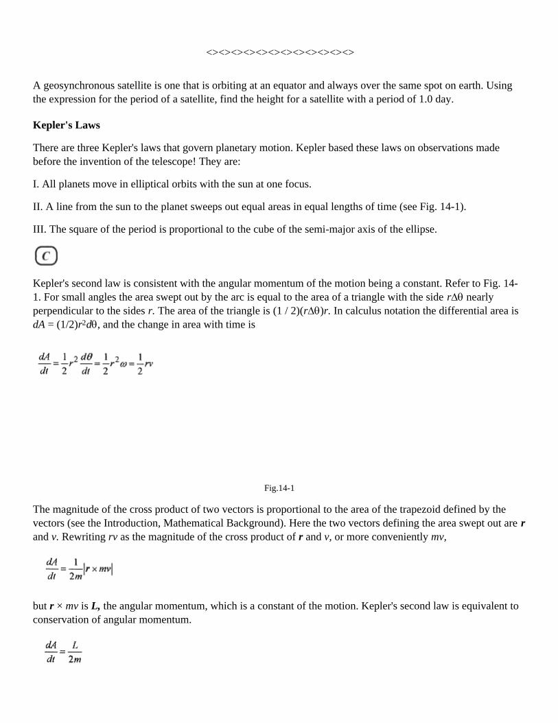
<><><><><><><><><><><><>
A geosynchronous satellite is one that is orbiting at an equator and always over the same spot on earth. Usingthe expression for the period of a satellite, find the height for a satellite with a period of 1.0 day.
Kepler's Laws
There are three Kepler's laws that govern planetary motion. Kepler based these laws on observations madebefore the invention of the telescope! They are:
I. All planets move in elliptical orbits with the sun at one focus.
II. A line from the sun to the planet sweeps out equal areas in equal lengths of time (see Fig. 14-1).
III. The square of the period is proportional to the cube of the semi-major axis of the ellipse.
Kepler's second law is consistent with the angular momentum of the motion being a constant. Refer to Fig. 14-1. For small angles the area swept out by the arc is equal to the area of a triangle with the side r∆θ nearlyperpendicular to the sides r. The area of the triangle is (1 / 2)(r∆θ)r. In calculus notation the differential area isdA = (1/2)r2dθ, and the change in area with time is
Fig.14-1
The magnitude of the cross product of two vectors is proportional to the area of the trapezoid defined by thevectors (see the Introduction, Mathematical Background). Here the two vectors defining the area swept out are rand v. Rewriting rv as the magnitude of the cross product of r and v, or more conveniently mv,
but r × mv is L, the angular momentum, which is a constant of the motion. Kepler's second law is equivalent toconservation of angular momentum.

Going back to rotational dynamics, dL / dt = r × F, and in planetary motion the force is gravitational and actsalong r, so r × F must equal zero, and if the derivative of the angular momentum is zero then the angularmomentum is a constant.
Equation 14-6 is based on conservation of energy and shows T as proportional to the 3/2 power of r. This isverification of Kepler's third law for the case of circular orbits.
14-5 The orbit radius of the satellite of problem 14-4 is 6.8 × 10⁶ m, and the period is 93 min. The orbit radiusof the moon is 3.8 × 10⁸ m, and the period is 27.3 days. Is this consistent with Kepler's third law?
Solution: Kepler's third law states that T is a constant times the 3/2 power of the radius, so
If the constant is the same then
Putting in the numbers
The satellite and moon orbits verify Kepler's third law for circular orbits.

Chapter 15Simple Harmonic Motion
Simple harmonic motion is the phrase used to describe a repetitive harmonic motion such as the motion of amass oscillating up and down on the end of a spring, the rotation of a point moving at constant speed along acircle, or a pendulum in small (amplitude) oscillation. The most convenient visualization of an oscillatingsystem is the mass-spring system. This is also the one most analyzed. Simple harmonic motion is oftencharacterized by the period, the time for one oscillation, and the amplitude, the maximum excursion fromequilibrium. (Period is the time for one repetition and is measured in seconds, while the frequency is thereciprocal of the period and is measured in Hertz or 1/s.) More complete analysis usually involves writingstatements about the total energy of the system.
Fig. 15-1
For a first look at simple harmonic motion consider the analysis of a mass-spring system. The kinetic energy is(1/2)mv2, the energy associated with the moving mass, and the potential energy of the system is (1/2)kx2, theenergy associated with the elongation and compression of the spring. Here we assume the spring is a Hook's lawspring obeying F = -kx. You may want to review the discussion of the energy stored in a Hooke's law spring inChapters 7 and 8.
To describe the motion of the mass from a force point of view, take the force as -kx and equate that to ma with awritten as the second derivative of position.
-
If you don't have much experience in calculus, this may look like a formidable equation. It is not. It has a verysimple and obvious (once you've seen it) solution. Acceleration is the time derivative of velocity (a=dv/dt), andvelocity is the time derivative of displacement (v=dx/dt) as defined in Chapter 1. Acceleration, then, can bewritten as the second derivative of the displacement.

The solution to this equation requires that the second derivative of a function of x with respect to time beproportional to the negative of the function. This reduces to the question: What function differentiated twiceyields the negative of itself? The answer is a sine or cosine function or a linear combination of both. If you havenot encountered this yet, see the table of derivatives in the Introduction, Mathematical Background.
The derivative of the sine function is the cosine function and the derivative of the cosine function is the negativeof the sine function. Two derivatives of the sine function yield the negative of itself. This is also true of thecosine function. The solution can also be written as the sine or cosine of a constant times t plus a phase angle.Acosωt + Bsinωt and C(cosorsin)(ωt + θ) are equivalent solutions.
Take as a general solution x = Acosωt + Bsinωt
If the starting position (t = 0) is taken as an extreme of the motion, corresponding to maximum compression ofthe spring, then B = 0, and A is the amplitude of the motion. If the starting position were taken at the midpointof the motion, then at t=0 the amplitude would have to be zero; therefore, A = 0 and B would be the amplitude.(Remember sin0 = 0 and cos0=1.) The choice of initial condition determines whether the motion is described bya sine or cosine function.
Use as a solution x=Bsinωt. Take two time derivatives to obtain
and substitute in the force law statement, -kx=-m(d2x/dt2)
In the statement x=Bsinωt, ω is 2π/T. The 2π effectively scales the sine function, and the ratio t/T determinesthe fraction of 2π required for determining the value of the function. For example, at t=T (one period) the sinefunction has gone through one cycle. At t=T/2 (one- half period) the sine function has gone through one-halfcycle. Because of the 2π factor, ω is called the angular frequency. The term frequency applies to f in the relation
In solving problems be careful to differentiate between frequency, f, and angular frequency, ω.
15-1 A mass-spring system has mass 2.0kg, spring with constant 3.0N/m, and amplitude of vibration 0.10m.Calculate the angular frequency and frequency. Write expressions for the position, velocity, and acceleration asa function of time. Take t=0 at the equilibrium position. Graph position, velocity, and acceleration as a functionof time.
Solution: The angular frequency is
The frequency is

If t=0 at the equilibrium position, then the displacement must be given by x=Bsinωt.
At t=0 the sine function is zero, so this is the appropriate function to describe the motion. For an amplitude of0.10m this expression should read
The velocity is the time derivative of x or
At t=0 the velocity, as the mass passes through the equilibrium position, is a maximum. The acceleration isanother time derivative of the velocity or
At t=0 the acceleration is zero; the spring is neither elongated nor compressed (at the equilibrium position), sothe force (and acceleration) of the mass is zero.
Fig. 15-2
These three curves graphed one under the other in Fig. 15-2 give a good picture of the motion from the position,velocity, and acceleration point of view.

Look at these graphs and visualize the motion. At the equilibrium position, displacement is zero, the velocity isa maximum, and acceleration is zero. As the mass moves to the positive maximum displacement, the velocitydecreases to zero and the acceleration (down) increases to a maximum. At the maximum displacement, thevelocity is zero and the acceleration is a maximum. As the mass starts down, the velocity is negative reachingmaximum again as the mass passes through equilibrium. Go over this picture of the motion until the relationshipbetween position, velocity, and acceleration is clear in your mind.
<><><><><><><><><><><><>
15-2 A piece of metal rests on top of a piston executing simple harmonic motion in the vertical plane with anamplitude of 0.20m. At what frequency will the piece of metal “float” at the top of the cycle?
Solution: Take the motion to be described by y=(0.20m)cosωt.
Two derivatives produces the acceleration a=-(0.20m)ω2cosωt.
The maximum acceleration, which is the constant (0.20m)ω2, is at the extreme of the motion where the cosineterm is one. At the bottom of the cycle, the piece of metal will experience an acceleration greater than g and atthe top an acceleration less than g. The piece will “float” when that acceleration is greater than g.
Fig. 15-3
<><><><><><><><><><><><>
15-3 A mass-spring system has a mass of 0.50kg and period of 1.0s. The maximum velocity is 0.20m/s. Find thefrequency, angular frequency, constant of the spring, and displacement for this velocity and period.
Solution: The frequency is the reciprocal of the period or f=1.0(1/s), and the angular frequency is 2πf or2π(1/s). The spring constant comes from the relation

The general expression for velocity is v=Aωcosωt where Aω is the maximum velocity. It makes no differencewhether the function is a sine or cosine. The maximum velocity is still Aω. The amplitude for this particularmotion then is
<><><><><><><><><><><><>
15-4 An 0.80kg mass hangs from a spring. When an additional 0.20kg mass is added the spring elongatesanother 3.0cm What is the period of oscillation of the spring?
Solution: First determine the force constant of the spring from F=-kx
The period is the reciprocal of the frequency
so
<><><><><><><><><><><><>
15-5 An oscillating mass-spring system has displacement 10cm, velocity -12m/s, and acceleration -20m/s2.What is the period of the system?
Solution: Since the displacement is not zero at t=0, the motion cannot be described with a sinωt function. Sincethe velocity is not zero at t=0, the motion in not at an extreme, and cannot be described with a cosωt function.Because of the initial conditions, a sine or cosine function of ωt plus a phase angle must be used. It makes nodifference whether a sine or cosine function is used since the phase angle can absorb the 90° difference betweena sine and a cosine function. Look at Fig. 15-4 and go over the logic in this paragraph until it is clear in yourmind.
Take x=Acos(ωt+θ) then v=-Aωsin(ωt+θ) and a=-Aω2cos(ωt+θ)
Using the equations for x and a, at t=0,
The period is from

The phase angle comes from v(0) and a(0).
The specific functional relations are
Fig. 15-4
Look at these relations and relate them to what the system is doing at t=0. The amplitude is past its maximumpositive excursion and on the way down corresponding to the cosine function at 83° The velocity is negativeand heading toward its most negative value as is the negative sine function at 83°. The acceleration is negativeand tending toward zero just as is the negative cosine function at 83°.
Energy Analysis.
Simple harmonic motion can be analyzed from an energy point of view. The energy stored in a spring is kx2/2,and the energy stored in the mass by virtue of its velocity is mv2/2. A total energy statement for the system thenis
which is most easily evaluated by looking at the extrema of the motion,
15-6 Find the maximum velocity of a mass-spring system with mass 2.0kg, spring constant 0.80N /m, andamplitude of oscillation 0.36m.

Solution: All the energy of the system is stored in the spring at maximum displacement so the total energy is
This is the total energy in the system, and at zero displacement all this energy is in kinetic energy so
It is relatively easy, and quite instructive, to show that the total energy of an oscillating system is a constant.Take an oscillating system with x=Asinωt and velocity v=Aωcosωt. Now place these expressions for x and vinto the total energy statement
But from the previous analysis ω2=k/m so the statement reads
and since
which shows that the total energy does not vary over time. The energy does not vary over one cycle, it goesback and forth from kinetic to potential in a manner such that the total (energy) remains a constant.
<><><><><><><><><><><><>
15-7 Find the amplitude, angular frequency, and frequency for a mass-spring system with mass 2.0kg that isoscillating according to x=(2.0m)cos(6πt/s). Write and graph the expressions for position, velocity, andacceleration. Finally, calculate the total energy of the system.
Solution: The amplitude, angular frequency, and frequency are determined by comparing x=(2.0m)cos(6πt/s) tothe standard form x=Acosωt=Acos2πft.
The amplitude is 2.0m. The angular frequency is 6π(1/s). The frequency is 3(1/s).
The expressions for position, velocity (first derivative), and acceleration (second derivative) are
shown in Fig. 15-5 associated with the graphs.
In Fig. 15-5, the units are dropped in the argument of trigonometric functions, and the maximum values for thevelocity and acceleration are placed on the graphs.

Fig. 15-5
The conservation of energy statement is For a 2.0kg mass the total energy can be evaluatedwhen x is zero and the velocity maximum.
<><><><><><><><><><><><>
15-8 For a 3.0kg mass-spring system executing simple harmonic motion according to y=(4.0cm)cos(πt/4-π/6),what is the total energy and the y position for equal division of the energy between kinetic and potential?
Solution: The general expression for displacement is y=Acos(ωt+θ). Looking at the two expressions,
Knowing k, the total energy is
The potential energy due to position is ky2/2 and y=Acos(ωt+θ) so that the energy due to position iskA2cos2(ωt+θ)/2. The energy due to position is 1/2 the total when the factor
.

For this particular system, the time for equal division of the energy is when
The position of the mass for equal division of the energy is
As an exercise, calculate the velocity at this time.
<><><><><><><><><><><><>
15-9 A 0.20kg block traveling at 20m/ s slides into and sticks to an 0.80kg block resting on a frictionlesssurface and connected to a spring with force constant 80N/m. What is the angular frequency, frequency, anddisplacement as a function of time? Also what fraction of the original energy in the moving block appears in thesystem?
Solution: The collision is inelastic; the blocks stick together, so applying conservation of momentum0.20kg(20m/s)=(1.0kg)V. The velocity of the 1.0kg combination is V=4.0m/s. This is the velocity of the systemat zero displacement. The analysis of this collision is similar to the ballistic pendulum problem in the chapter oncollisions.
The total energy of the oscillating system is
Fig. 15-6
The angular frequency is
The frequency is from ω=2πf or f=ω/2π=1.4(1/s)
The general expression for the displacement is y=Asinωt. The sine function without a phase angle completelydescribes the motion because it starts (t=0) at the equilibrium position with maximum velocity. The amplitudeof the motion is obtained from

so the specific expression for the displacement is y=(45cm)sin(1.4t/s)
The initial energy is all in the small block
The energy in the oscillating system is 8.0J, so the fraction of the original energy that appears in the oscillatingsystem is F=8.0J/40J=0.20
Applications
The oscillating simple pendulum can be analyzed in terms of force. For small oscillations the tension in thecable can be written in components; one vertical and the other the “restoring force,” the force that returns themass to equilibrium. For small θ, cosθ≅1 and sinθ≅x/l, with x being the displacement, approximately equal tothe arc length.
Fig. 15-7
For small angle oscillations Fcosθ≅F and Fsinθ≅-mgx/l=-(mg/l)x. Notice that in this equation mg/l plays thesame role as k in the mass-spring systems.
By analog then The most important point to note is that the period is independent of the mass. Historically this was one of thefirst instruments to measure “g,” the gravitational constant.
<><><><><><><><><><><><>
The torsional pendulum, a disk suspended by a thin rod, can be analyzed using torque. The disk is rotated byapplying a torque. Torque is proportional to the angle in the same manner as force is proportional tocompression (or elongation) in a spring. The torque is written in terms of the moment of inertia and the angularacceleration [ ] which is set equal to the total torque, -kθ the torsional constant times theangle, yielding the equation

which is the same form as the force equation for the oscillating mass-spring system. By analogthen θ=θmaxsinωt where
Fig. 15-8
15-10 What is the restoring constant (torsional constant) for a disk of mass 3.0kg and radius 0.20m oscillatingwith a period of 2.0s?
Solution: The moment of inertia for a disk is
The restoring constant is
Note that these are the correct units since torque has the dimensions N.m, and in Torque=-kθ the angle is in(dimensionless) radians.
Damped Mass-Spring System
The system is usually depicted as a mass-spring with a dashpot, a piston in a thick liquid. In the case of thespring, the restoring force is proportional to displacement, compression or elongation of the spring. With thepiston in the fluid, however, the retarding force is proportional to velocity, not position. Move your handthrough water and notice that the retarding force (the force on your hand) is proportional to velocity! Thevelocity-dependent force component of a typical automobile suspension is called a shock absorber. It is usuallya piston in a cylinder of oil. Since the retardation force is velocity dependent the differential equation governingthe motion is

Notice that the velocity-dependent term has the same sign as the displacement-dependent term. It too opposesthe motion.
Fig. 15-9
This differential equation is solved with sophisticated techniques. Here we give an intuitive solution.
This second order differential equation is solved as a product of solutions, the position-dependent part and thevelocity-dependent part. The position-dependent part is a sine or cosine function with a phase angle. Thevelocity-dependent part is from the velocity-dependent part of the equation
The solution to this part of the equation is one which when differentiated once produces the negative of itself.The function that does this is an exponent to the negative power. The particular solution that satisfies thisdifferential equation is
where ω' is slightly different from ω. The damping of the exponential does exactly as we know fromexperience. Oscillations subject to velocity damping (a velocity-dependent restoring force) eventually die out.

Chapter 16Fluids
There are several definitions and concepts that are unique to the study of fluids. Let's review these basicdefinitions and concepts working some problems along the way.
Density is simply mass per unit volume, or symbolically ρ = m/V. The density that is most useful in problems isthe density of water, which is 1g / cm 3 or 1000kg / m3.
The ratio called specific gravity is better called the specific density since it is the ratio of the density of anothersubstance to the density of water. Aluminum has a specific gravity of 2.7, which means that for the samevolumes, aluminum has 2.7 times the mass of water. Relative density or specific gravity is used to measure therelative amount of sulfuric acid (compared to water) in a storage battery or the relative amount of ethyleneglycol (compared to water) in an automotive cooling system.
Pressure
The pressure in a fluid is defined as the force per unit area, ρ = F / A. And the units of pressure are N / m2 ,also called a Pascal or Pa. Atmospheric pressure, the force per unit area exerted by the air, is 1.0 ×10⁵Pa=151b/in2 =1atm.
To determine the pressure at any depth in a liquid consider the differential change in force due to a column ofliquid of cross section A. The increase in force between the top and bottom of this differential piece is equal tothe weight of the piece.
It is convenient to write the mass of this little piece as ρ∆V so that the force (difference) is
Now ∆V for this piece is A ∆y so ∆F=ρgA∆y. The pressure is the force per unit area so rewriting
Dropping the differential notation

Fig. 16-1
Ify is measured from the bottom of the liquid then insert a negative sign on the right side of the equation. Thisdiscussion of pressure leading up to equation 16-3 is equally valid whether the delta or differential notation isused. This is true of most of the discussion of fluids. We start with delta notation and switch to differentialnotation in some later development.
16-1 Calculate the pressure at the bottom of a 3.0m deep pool.
Solution:
Notice that this pressure is the difference between the top and the bottom. This difference is known as thegauge pressure. Adding the atmospheric pressure at the top surface of the pool gives the absolute pressure atthe bottom of the pool.
<><><><><><><><><><><><>
The typical automobile tire pressure is the gauge pressure. With the tire inflated the pressure might read 30 1b /in 2. If the tire were “flat” the pressure would read zero. The gauge pressure for the “flat” tire would be zero butthe absolute pressure would be 15 1b / in2. Likewise the tire with gauge pressure of 301b / in 2 would have anabsolute pressure of (30+15) Ib / in2. The gauge that measures the tire pressure is measuring the difference inpressure between inside and outside the tire.
Pressure exerted on a liquid in a closed container is transmitted throughout the liquid. The pressure is the samein every direction varying only with height as described by equation 16-3. In most devices using fluids totransfer forces, the fluid is nearly incompressible and height variations are insignificant.
16-2 Consider the classic problem of a hydraulic lift. In a typical service station 12 atm is applied to the smallarea with the lifting column 9.0cm in radius. Find the force transferred to the large area and the mass of vehiclethat can be lifted.
Fig. 16-2
Solution: The hydraulic fluid is at the same level so ρ1 = ρ2. or
A force F1 applied at A1 is multiplied by the ratio of the areas so F2=(A2/A1)F1
The lifting force F2 can also be rewritten as F2= A2(F1/A1=A2ρ1, and putting in the numbers

And the equivalent mass (from F=mg) is 3.1× 10³ kg. This number is somewhat larger than the mass of typicalcars.
Barometer and Manometer
A simple atmospheric air pressure gauge is the mercury barometer. A closed tube is filled with mercury andthen inverted in a beaker of mercury. The pressure at the top of the mercury column is zero. And the column isheld up by the (atmospheric) pressure on the surface of the mercury. Looking to Fig. 16-3, the pressure at thebottom of the column is ρgh. This experiment was first done by Torricelli, and the pressure was given as thepressure associated with the column of mercury. Pressures are often measured in mm of Hg or Torr. and referback to this experiment.
Pressure exerted on a liquid in a closed container is transmitted throughout the liquid. The pressure is the samein every direction varying only with height as described by equation 16-3. In most devices using fluids totransfer forces, the fluid is nearly incompressible and height variations are insignificant.
16-2 Consider the classic problem of a hydraulic lift. In a typical service station 12 atm is applied to the smallarea with the lifting column 9.0cm in radius. Find the force transferred to the large area and the mass of vehiclethat can be lifted.
Fig. 16-2
Solution: The hydraulic fluid is at the same level so ρ1 = ρ2. or
A force F1 applied at A1 is multiplied by the ratio of the areas so F2=(A2/A1)F1
The lifting force F2 can also be rewritten as F2= A2(F1/A1=A2ρ1, and putting in the numbers
And the equivalent mass (from F=mg) is 3.1× 10³ kg. This number is somewhat larger than the mass of typicalcars.
Barometer and Manometer

A simple atmospheric air pressure gauge is the mercury barometer. A closed tube is filled with mercury andthen inverted in a beaker of mercury. The pressure at the top of the mercury column is zero. And the column isheld up by the (atmospheric) pressure on the surface of the mercury. Looking to Fig. 16-3, the pressure at thebottom of the column is ρgh. This experiment was first done by Torricelli, and the pressure was given as thepressure associated with the column of mercury. Pressures are often measured in mm of Hg or Torr. and referback to this experiment.
Fig. 16-3
An open tube manometer as depicted in Fig. 16-3 can be used to measure pressure. The force exerted by thegas is ρA, and this force raises the column of (usually) mercury by exerting a force equal to ρgV, the weight ofthe column. The volume of the column. V is Ah so equating forces.
The manometer measures the difference in pressure between two points and as such measures gauge pressure.The open tube manometer is equally valuable as a vacuum gauge. The difference in column height (the heightof the mercury in the open tube is now lower than in the tube connected to the vacuum chamber) is a measureof the vacuum.
Buoyancy
Material objects appear to weigh less when partially or completely submerged in liquids. This apparent loss inweight is due to the buoyant force of the liquid. This buoyant force is expressed by Archimedes' principle: Abody partially or completely immersed in a liquid is buoyed up by a force equal to the weight of the liquiddisplaced.
16-3 The classic problem in buoyancy is to determine if a “gold” statue is really gold by measuring its weightin and out of water. A certain “gold” statue weighs 70N when out of water and 64N when immersed in water.
Solution: With the statue suspended from a scale the weight is mg, or density times g, times the volume of thestatue. In equation form mg=ρ?gV = 70N.
In water the statue weighs less because of the buoyant force: ρ?gV - ρwgV = 64 N
Subtracting one equation from the other we can determine the volume from

With this value for V, calculate the unknown density from the first equation
This density is much less than the density of gold ρgold =19×103kg/m3) and closer to the density of lead (ρlead =11× 103 kg/m3) suggesting that the statue is lead with a thin covering of gold.
This same experiment can be conducted by lowering the statue into a beaker of water on a scale. The volume isdetermined by the increase in the level of water in the beaker. The drop in tension in the cord is offset by theincrease in the scale reading when the statue is lowered into the beaker and the calculations proceed as before.
<><><><><><><><><><><><>
16-4 A U-tube originally containing mercury has water added to one arm to a depth of 20cm. What is thepressure at the water-mercury interface? What is the height of the mercury column as measured from the water-mercury level?
Solution: Assume that the difference in air pressure can be neglected. The pressure at the watermercuryinterface is due to the column of water plus the atmospheric pressure ρo, or p=po+pwg. 20cm . Neglecting po
gives the gauge pressure as
Fig. 16-4
At this level (the level of the interface) the pressure on the mercury arm must be the same. (If it were not theliquids would move!) The height of the mercury level is
As we expect, the same pressure is produced by a much shorter column of mercury.
Second Solution:Analytically the problem can be approached by writing expressions for the pressure at thelevel of the water-mercury interface.

In the left arm pW = po + pWghW, where the subscript W refers to the water column.
In the right arm the pressure is pM = po + pMghM, where the subscript M refers to the mercury column.
Since these pressures must be equal at the water-mercury interface
For this problem
Practice variations of this problem with different liquids (different densities).
<><><><><><><><><><><><>
16-5 A rectangular-shaped, open-top steel barge is 10m by 3.0m and has sides 1.0m high. The mass of the bargeis 8.0 × 10³kg. How much mass can the barge hold if it can safely sink 0.75m?
Solution: The volume of water displaced is length times width times allowed depth,10m×3.0m×0.75m=22.5m3. The buoyant force is the weight of the water displaced (Archimedes' principle)
Fig. 16-5
This buoyant force must support the barge (mB) plus the load (mL.
As an additional exercise calculate how deep the unloaded barge will sink in the water.
16-6 An iceberg floats in seawater. What percentage of the iceberg is submerged?
Solution: Assume a cubical iceberg of side s. You can assume any shape you wish. Cubical, however, seemsconvenient. The mass of the cubical iceberg is pices3 , and the weight is pices3g. Since the density of the icebergis less than the density of the seawater the iceberg will float. The buoyant force of the seawater is pSWg timesthe volume submerged. Since the iceberg is cubical the submerged volume must be s2 , the area of the bottom ofthe iceberg, times a fraction of the side k times s.

This buoyant force must equal the weight of the iceberg. pices3g = pSwgs2(Ks).
So K, the fraction of the iceberg submerged is
Thus 92% of the iceberg is submerged.
Fluid Flow.
The last, and possibly most important, of the fluid laws are associated with the flow of liquids through tubes ofvarying cross section. The best place to start on this is with a simple statement of mass flow in a pipe ofvariable thickness.
Fig. 16-6
Mass flow requires p1A1v1dt = p2A2v2dt
Density is mass per unit volume, and Avdt = Adx is a differential volume, so that the above equation is astatement that there is the same mass of fluid in the two differential volumes shown. Since in most fluids p1 = p2,the mass flow (also called the continuity equation) statement reduces to
Now look to the Bernouli equation, which takes account of changes in the gravitational potential and pressure.The law is understood from a work-energy point of view. If liquid is flowing through a tube as shown in Fig.16-7, then the work done on the fluid in pushing it through the tube must be manifest as increased potential andkinetic energy.
Fig. 16-7

Consider a mass of fluid moving through this tube. The volume of this mass of fluid is
where the ds's are the respective distances along the tube necessary to make up the same mass of fluid. Thework performed on this mass of fluid is (note that the work is force, pA, times distance,ds).t
The change in kinetic energy, basically (1/2)mv2 , is
And the change in potential energy (analogous to mgh) is dU = pgdV (y2-y1).
Equating the work performed to the energy change yields the Bernoulli equation
This is all the information necessary to do fluid problems as found in most physics texts. Buoyancy andpressure problems do not usually present a problem. Calculating pressures is sometimes encountered in thecontext of a flow problem, In flow problems the usual procedure is to first apply the mass flow statement,equation 16-5. Then apply the Bernoulli equation. In the application of this equation it is often necessary to takesome of the terms as zero. The ability to know when to take a term as zero comes from experience.
Venturi Tube
The venturi tube is used as a siphon or speed indicator. The tube is constructed as shown in Fig. 16-8. Apply theBernoulli equation without the gravitational term (most venturi tubes are mounted horizontally).
Fig.16-8
From the mass flow equation, equation 16-5, A1v1 = A2v2 so

Since A1 is larger than A2, p1-p2 is positive. The pressure is reduced in the smaller section, or throat, of theventuri. A side tube connected to the narrow region will siphon liquid or gas. The side tube also can beconnected to a pressure gauge to measure velocity, which is proportional to the square root of pressure.
16-7 Calculate the speed at which liquid flows out a small hole in the bottom of a large tank containing liquid toa depth of 1.0m.
Fig. 16-9
Solution: Apply the Bernoulli equation
Note that p1 = p2, so remove these terms from the equation. Because A1 >> A2,v1 is very small and is taken aszero. Take y1 = 0, so y2 is the depth of the liquid. The Bernoulli equation for this case reduces to
The velocity of liquid from a small hole in a container depends only on the height of the column of liquid.
For a liquid height of 1.0m,
Go back through this problem and note how the terms of the Bernoulli equation were handled, the pressurebeing the same, and the logic leading to the v1 term being taken as zero. This is the hard part of this problem. If,in doing a problem like this, you do not see that v1 can be taken as zero you will be stuck. You can move nofurther on the problem because there is not enough data to calculav1.
<><><><><><><><><><><><>
16-8 For the situation of problem 16-7, find the volume flow rate, that is dV/dt, for a hole of radius 3.0mm.

Solution: The flow rate is the instantaneous rate of liquid flowing out of the container. This is most easilyobtained from the statement of the differential volume.
For a hole of radius 3.0mm and liquid depth 1.0m
<><><><><><><><><><><><>
16-9 A cylindrical container of radius 20cm contains water to a height of 3.0m. Two meters down from thewater level there is a hole 0.50cm in radius. Find the velocity and volume flow rate of water leaving the hole.What is the shape of the stream, and where does it strike the ground?
Solution: Apply the Bernoulli equation
The pressure is the same: p1 = p2. The velocity v1 is so small compared to v2 that it can be neglected: set v1 = 0.The distance from the top of the water to the hole is 2.0m.
Fig. 16-10
The differential volume of liquid flowing out of the hole is dV = A2v2dt
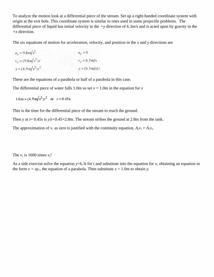
To analyze the motion look at a differential piece of the stream. Set up a right-handed coordinate system withorigin at the exit hole. This coordinate system is similar to ones used in some projectile problems. Thedifferential piece of liquid has initial velocity in the +y direction of 6.3m/s and is acted upon by gravity in the+x direction.
The six equations of motion for acceleration, velocity, and position in the x and y directions are
These are the equations of a parabola or half of a parabola in this case.
The differential piece of water falls 1.0m so set x = 1.0m in the equation for x
This is the time for the differential piece of the stream to reach the ground.
Then y at t= 0.45s is y|t=0.45=2.8m. The stream strikes the ground at 2.8m from the tank.
The approximation of v1 as zero is justified with the continuity equation, A1v1 = A2v2.
The v2 is 1600 times v1!
As a side exercise solve the equation y=6.3t for t and substitute into the equation for x, obtaining an equation inthe form x = ay2, the equation of a parabola. Then substitute x = 1.0m to obtain y.
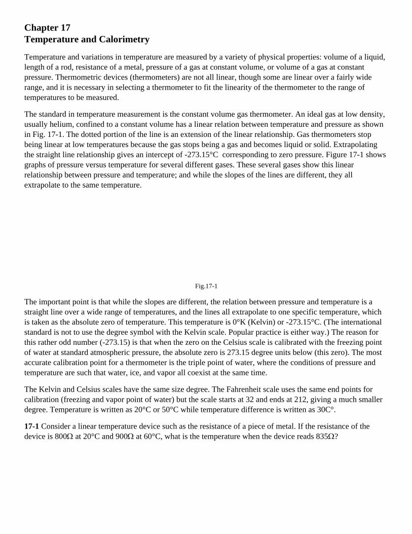
Chapter 17Temperature and Calorimetry
Temperature and variations in temperature are measured by a variety of physical properties: volume of a liquid,length of a rod, resistance of a metal, pressure of a gas at constant volume, or volume of a gas at constantpressure. Thermometric devices (thermometers) are not all linear, though some are linear over a fairly widerange, and it is necessary in selecting a thermometer to fit the linearity of the thermometer to the range oftemperatures to be measured.
The standard in temperature measurement is the constant volume gas thermometer. An ideal gas at low density,usually helium, confined to a constant volume has a linear relation between temperature and pressure as shownin Fig. 17-1. The dotted portion of the line is an extension of the linear relationship. Gas thermometers stopbeing linear at low temperatures because the gas stops being a gas and becomes liquid or solid. Extrapolatingthe straight line relationship gives an intercept of -273.15°C corresponding to zero pressure. Figure 17-1 showsgraphs of pressure versus temperature for several different gases. These several gases show this linearrelationship between pressure and temperature; and while the slopes of the lines are different, they allextrapolate to the same temperature.
Fig.17-1
The important point is that while the slopes are different, the relation between pressure and temperature is astraight line over a wide range of temperatures, and the lines all extrapolate to one specific temperature, whichis taken as the absolute zero of temperature. This temperature is 0°K (Kelvin) or -273.15°C. (The internationalstandard is not to use the degree symbol with the Kelvin scale. Popular practice is either way.) The reason forthis rather odd number (-273.15) is that when the zero on the Celsius scale is calibrated with the freezing pointof water at standard atmospheric pressure, the absolute zero is 273.15 degree units below (this zero). The mostaccurate calibration point for a thermometer is the triple point of water, where the conditions of pressure andtemperature are such that water, ice, and vapor all coexist at the same time.
The Kelvin and Celsius scales have the same size degree. The Fahrenheit scale uses the same end points forcalibration (freezing and vapor point of water) but the scale starts at 32 and ends at 212, giving a much smallerdegree. Temperature is written as 20°C or 50°C while temperature difference is written as 30C°.
17-1 Consider a linear temperature device such as the resistance of a piece of metal. If the resistance of thedevice is 800Ω at 20°C and 900Ω at 60°C, what is the temperature when the device reads 835Ω?

Fig. 17-2
Solution: Figure 17-2 shows the linear relationship of the device. Since the slope is a constant, the slope of thegraph on the right is equal to the slope of the graph on the left (similar triangles).
So or ∆T=14°C and the measured temperature is 34°C.
<><><><><><><><><><><><>
Hot objects placed in contact with cold objects cool and warm (respectively) according to a constant thatdepends on the conditions of contact and the difference in temperature. This heating or cooling is mostconveniently expressed as a differential equation
In words this differential equation states that the change over time of the difference in temperature isproportional to the difference in temperature. The rate at which something cools is directly proportional to thedifference in temperature with its surroundings. The negative sign is a reminder that the change in ∆T is such asto reduce ∆T. The equation is solved by separating
The constant can be evaluated by taking an initial temperature difference ∆T0. Substituting into this equation fort=0 and ∆T0 yields In ∆T0 = const and the equation reads In ∆T = In ∆T0 - kt or In and switching to exponentialformat
This equation states that the difference in temperature between a hot body and a cold body in contact isproportional to the initial difference and a decaying exponential. This is very much what we expect fromexperience. Note that this equation is in the same form as other decay equations that describe, for example, therate of radioactive decay as proportional to the amount of decaying product remaining.

17-2 Two objects have an initial temperature difference of 20C°. In two minutes the temperature difference is18C°. Calculate the time for the temperature difference to be 10C°.
Solution: This is a classic type of problem where the physical law is known, data is given to calculate thespecific relationship, and this relationship is used to predict something. Keep this process in mind as you gothrough this problem. It is used in the solution of many problems in physics.
The basic law is ∆T=∆T0e-kt
Now, use the given data to determine k. Units are left off in the exponent to avoid clutter, but keep in mind thatthe 2.0 is in minutes, so k will be in reciprocal minutes.
This gives k for this specific situation, and the law for this specific situation is
Now ask, what time is required for the temperature difference to decline to 10°C, ∆T=10°C for an initialdifference of 20°C.
10 = 20e -0.053t and switching to logarithms
Go back over this problem and be sure you understand the procedure and how to manipulate the exponents andlogarithms. Practice performing these operations on your calculator so you will be able to do them rapidly andaccurately on a test.
<><><><><><><><><><><><>
Solids expand and contract with their change in length proportional to their length and change in temperature
The α's of various materials are tabulated in most physics texts.
17-3 A steel bridge is set in concrete pillars on opposite sides of a river. The bridge is 300m long, and the workis performed on a day when the temperature is 18°C. What clearance is required for the bridge not to buckle at45°C? (αsteel=11×10-6/C°)
Solution: The change in length is
A minimum of 8.9cm would be required for expansion.
<><><><><><><><><><><><>

For flat objects the change in length is isotropic (the same in all directions) so that the diagonal of a plate, thediameter or circumference of a hole punched in the plate, or any length changes according to ∆l=αl∆T; so thatfor areas
17-4 Calculate the change in volume of a brass sphere of 8.0cm in radius on going from 0°C to 100°C.(αbrass=19×10-6/C°)
Solution: The change in volume is
The fractional change in volume ∆V/V is
The percentage change in volume is 0.57%.
<><><><><><><><><><><><>
Consider the effect of temperature on the period of a pendulum clock. The period of a pendulum is
Taking the differential with respect to l, the variable that depends on temperature
Now the ∆l can be written in terms of change in temperature as ∆l=αl∆T, so
A more interesting formula is one for the fractional change in period ∆t/t
17-5 Calculate the fractional change in period for a brass pendulum going through a 5C° change from summerto winter (not unusual).

Solution:
As the temperature increases, the length of the pendulum gets longer, and the time for one oscillation getslonger. Pendulum clocks run slower in the summer.
Calorimetry
Heat is a form of energy. The unit of heat is the calorie, the heat to raise 1.0g of water from 14.5°C to 15.5°C.The kilocalorie or kcal is also popular. Food calories are actually kilocalories.
The British heat unit is the British Thermal Unit (BTU), the heat to raise 1.0 pound of water from 63°F to64°F. The joule equivalence is 1cal=4.2J.
The quantity of heat necessary to raise the temperature of a mass of material is
where c, the specific heat, is the amount of heat per g.C° for the material. The specific heat for water is1.0cal/g.C°. Tables of specific heats are in most physics texts.
17-6 How much heat is required to raise a 1.8kg copper tea kettle containing 2.0kg of water from 20°C to100°C? The specific heat of copper is 0.092cal/g.C°.
Solution: The total heat is
The specific heat is sometimes expressed in J/kg.K rather than cal/g.C°. For the previous problem thecalculations would read
Use the calorie to joule equivalence to verify the numbers in this problem.
The quantity of material is sometimes given in moles, n. The total mass is related to the number of moles viam=nM where M is the mass per mole of the material. Measuring the mass in number of moles, heat capacitywould be calculated with the molar heat capacity, the heat in joules per mole.C° or mole.K. (Remember, theCelsius and Kelvin degrees are the same size.)
The equilibrium temperature of a mixture can be determined by knowing the quantity of heat necessary to affecta change in temperature
17-7 A 150g cup of coffee (water) at 80°C has added to it 20g of sugar (carbon) at 25°C. What is the finaltemperature of the insulated mixture? (cc=0.12cal/g.C°)

Solution: In this problem heat from the water raises the temperature of the carbon until they are both at thesame temperature. Saying it simply, this is a Goesinto problem. The heat in the water Goesinto heating thecarbon until they both reach an equilibrium temperature, T.
The heat leaving the water is 150g(1.0cal/g.C°)(80-T°C.
The final temperature is between 80 and 25, so writing the temperature difference as 80-T produces a positivenumber (of calories).
This heat goes to raise the temperature of the carbon 20g(0.12cal/g.C°)(T-25)°C.
Notice that the temperature difference in parentheses is written so as to produce a positive number.
The equation will read: The heat from the water Goesinto heating the carbon.
or
These problems can be complicated with three or more components at different temperatures. If you guesswrong as to where the equilibrium temperature lies, the calculations will produce a temperature higher or lowerthan the original temperatures. If this occurs you know that the initial assumption was wrong, so go back withanother (better) assumption of the equilibrium temperature and do the problem over again. The main problemwith calorimetry problems is keeping the algebraic signs correct. These problems can be done with a positiveheat minus negative heat approach, but the Goesinto approach cuts down on the number of negative signs andreduces the possible number of places where you can get a sign wrong.
Phase Change
If water is heated from room temperature to the vapor point it takes 1 calorie of heat (energy) to raise each gram1K degree. When the vapor point is reached a discrete amount of energy is required to convert each gram (orkilogram) of water at 100°C to vapor without raising its temperature. This amount of energy is called the heatof vaporization and for water is 2.3×10⁶J/kg.
A similar phenomenon is observed when a solid is taken to the liquid phase. The heat of fusion, the heat tochange 1.0kg of solid (water) to liquid at 0°C is 3.3×10⁵J/kg. Tables of heats of fusion and vaporization are inmost physics texts. Problems involving heat of fusion or heat of vaporization must be done carefully, becausethe energy requirements for these changes of state are very large. Converting a small amount of ice to waterconsumes a large amount of energy compared to raising the temperature of the water. It takes 4.2×10³J per kgfor each degree of temperature while it takes 3.3×10⁵J per kg to convert ice to water with no temperature rise!
17-8 An insulated container holds 3.0kg of water at 25°C. One kilogram of ice at 0°C is added to the mixture.What is the final temperature and composition (ice and water) of the mixture?
Solution: First calculate the energy to bring all the water to 0°C.
Now ask how much ice could be melted with this amount of energy.
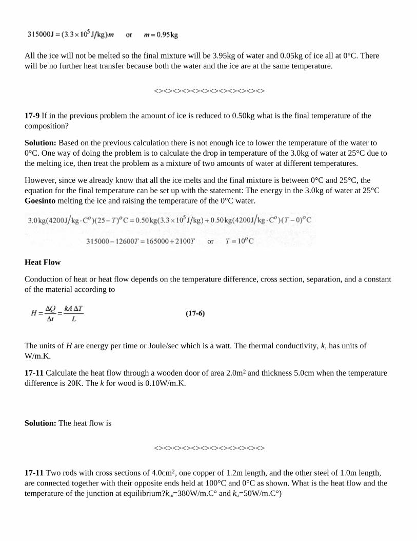
All the ice will not be melted so the final mixture will be 3.95kg of water and 0.05kg of ice all at 0°C. Therewill be no further heat transfer because both the water and the ice are at the same temperature.
<><><><><><><><><><><><>
17-9 If in the previous problem the amount of ice is reduced to 0.50kg what is the final temperature of thecomposition?
Solution: Based on the previous calculation there is not enough ice to lower the temperature of the water to0°C. One way of doing the problem is to calculate the drop in temperature of the 3.0kg of water at 25°C due tothe melting ice, then treat the problem as a mixture of two amounts of water at different temperatures.
However, since we already know that all the ice melts and the final mixture is between 0°C and 25°C, theequation for the final temperature can be set up with the statement: The energy in the 3.0kg of water at 25°CGoesinto melting the ice and raising the temperature of the 0°C water.
Heat Flow
Conduction of heat or heat flow depends on the temperature difference, cross section, separation, and a constantof the material according to
The units of H are energy per time or Joule/sec which is a watt. The thermal conductivity, k, has units ofW/m.K.
17-11 Calculate the heat flow through a wooden door of area 2.0m2 and thickness 5.0cm when the temperaturedifference is 20K. The k for wood is 0.10W/m.K.
Solution: The heat flow is
<><><><><><><><><><><><>
17-11 Two rods with cross sections of 4.0cm2, one copper of 1.2m length, and the other steel of 1.0m length,are connected together with their opposite ends held at 100°C and 0°C as shown. What is the heat flow and thetemperature of the junction at equilibrium?kcu=380W/m.C° and kst=50W/m.C°)

Solution: The key to this problem is that the heat flow in the two rods must be the same. If the heat flow in thecopper is greater than the heat flow in the steel then the joint will get hot. This does not happen so the heat flowmust be the same.
Fig.17-3
Take the temperature of the junction as Tj, and set the heat flows equal
Putting in the numbers
The heat flow is from either formula
Calorimetry combined with other energy analysis techniques can be used to solve other types of problems.
17-12 A block of ice initially at 50kg and traveling at 5.4m/s slides along a horizontal surface until it comes torest. Assume all the heat generated due to friction is used to melt the ice. How much ice is melted?
Solution: All the kinetic energy in the block Goesinto work expended to overcome friction, and all this energyGoesinto melting the ice. The initial kinetic energy is
All this energy is used to melt the ice.
<><><><><><><><><><><><>
17-13 A 5.0kg bullet traveling 800m/s passes through a 5.0kg copper block at rest on a frictionless table.Twenty percent of the kinetic energy of the bullet goes into heating the block. Thirty percent goes into kineticenergy of the block. Fifty percent remains with the bullet. The block and bullet are initially at 25°C. What is thetemperature and speed of the block and the speed of the bullet? (ccu=390J/kg.C°)

Solution: First find the initial kinetic energy of the bullet.
Twenty percent of this, or 320J, goes to heating the copper block.
Thirty percent, or 480J, goes to kinetic energy of the block.
Fifty percent, or 800J, stays with the bullet.

Chapter 18Kinetics and The Gas Laws
A complete description of a gas is given by the pressure, volume, temperature, and amount (total mass ornumber of moles) of the gas. What is called the equation of state (equation 18-1) describes the relationbetween p, V, T and m or n. These four properties completely describe a gas just as position, velocity, andacceleration completely describe the motion of a particle.
Early experiments on gases produced Boyle's law, pV = constant (at constant temperature), Charles' law, p =constant . T (at constant volume), and finally, the ideal gas equation of state pV = nRT with n the number ofmoles and R the gas constant equal to 2.0cal / mol.K or 8.3 J / mol.K. A mole of a gas contains a specificnumber of molecules. The number of molecules per mole is Avogadro's number, NA = 6.0×10²³ molecule /mole. The mass of a mole of gas depends on the atomic weight of the gas. The mole and Avogadro's number aredefined as the number of carbon 12 atoms in 12g of carbon 12. For helium (atomic weight 4.0) one mole of thegas contains Avogadro's number of helium atoms and has mass of 4.0g.
The ideal gas law not only describes the p, V, T relationship but allows that for the same amount of gas therelationship between two different states is
allowing a large number of problems to be solved. In applying this formula, Kelvin temperatures must be usedthroughout, and the pressure and volume must be written in the same units.
18-1 What is the volume of a mole of ideal gas at standard temperature and pressure (STP)?
Solution: Standard temperature is 0°C = 273K. Standard pressure is latm = 1.0 × 10⁵ Pa. From the ideal gas law
This is a 23 liter container or a box 0.28m on a side Remember that a Pascal is a N/m2.
<><><><><><><><><><><><>
18-2 An air bubble at the bottom of a lake has a volume of 20cm3, pressure of 4.9Pa, and temperature 4°C. Thebubble rises to the surface where the temperature is 20°C and the pressure 1.0 Pa. Find the volume as thebubble reaches the surface. Also find the number of moles of the gas.

Fig. 18-1
Solution: remembering that T is written in kelvin.
or
To find the number of moles use pV/T = nR and the given conditions at the bottom of the lake.
<><><><><><><><><><><><>
18-3 A weather balloon is inflated with helium at just over atmospheric pressure of 1.2×10⁵ Pa, temperature20°C, and volume 2.5m3. When the balloon rises to where the pressure is 0.50×10⁵ Pa and temperature is -58°C, what is the volume?
Solution: Using
or
As an exercise find the number of moles of this gas.
Variation of Pressure with Elevation.
Consider a slab of air in a column of air and note that the increase in force between the top and bottom of theslab is due to the weight of the slab. Envision this as holding your hand horizontally at two different heights.Higher up in the column of air there is less air above your hand and thus a lower pressure.

Fig. 18-2
Writing this difference with differentials, F2 = F1 + dW
Since p = F / A and dW = pgAdy = pgdV, this statement can be written as
where dp is the difference, top to bottom, of the slab. The minus sign serves to remind us that as we go up inthe atmosphere (column) the pressure goes down (there is less air in the column).
Going back to pV = nRT and the relation mass equals moles times molecular mass (m = nM) (remember thateach mole of Helium is 4.0g)
, or using density , so equation 18-3 can be written as
which integrates to ln with ln A the constant of integration.
At y = 0 (on the ground), p = po, ln po = ln A, and
or switching to exponents
Note that in this derivation the temperature is assumed constant. The density of the air is not assumed constantbecause V in the density relation ρ = (m/V) was replaced with nRT / p.
18-4 What is the pressure at 3000m elevation above the earth?
Solution: Assume T = 0°C = 273K. T decreases with height because the air is heated, primarily by radiationfrom the earth, so consider this an average temperature over the 3000m. Air is mostly oxygen and nitrogen andhas an average molecular weight of 28.8g/mole or 28.8×10⁻³ kg / mole. The gravitational constant varies onlyslightly over this distance.
First calculate the exponent
then the pressure p = poe-0.374 = 1.0atm(0.69) = 0.69atm
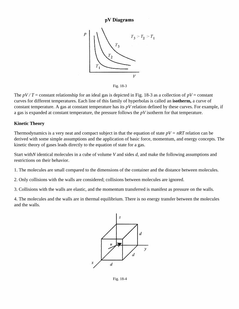
Fig. 18-3
The pV / T = constant relationship for an ideal gas is depicted in Fig. 18-3 as a collection of pV = constantcurves for different temperatures. Each line of this family of hyperbolas is called an isotherm, a curve ofconstant temperature. A gas at constant temperature has its pV relation defined by these curves. For example, ifa gas is expanded at constant temperature, the pressure follows the pV isotherm for that temperature.
Kinetic Theory
Thermodynamics is a very neat and compact subject in that the equation of state pV = nRT relation can bederived with some simple assumptions and the application of basic force, momentum, and energy concepts. Thekinetic theory of gases leads directly to the equation of state for a gas.
Start withN identical molecules in a cube of volume V and sides d, and make the following assumptions andrestrictions on their behavior.
1. The molecules are small compared to the dimensions of the container and the distance between molecules.
2. Only collisions with the walls are considered; collisions between molecules are ignored.
3. Collisions with the walls are elastic, and the momentum transferred is manifest as pressure on the walls.
4. The molecules and the walls are in thermal equilibrium. There is no energy transfer between the moleculesand the walls.
Fig. 18-4

A molecule with velocity v and components vx, vy, vz makes an elastic collision (momentum conserved) with thex-wall. The change in momentum of the molecule is numerically equal to the momentum imparted to the wall(∆p)mom = 2mvx.
This is the same expression you would write for a tennis ball bouncing off a wall. The subscript identifies thisas momentum and not pressure. The time between collisions with the same wall is the time for the molecule togo to the opposite wall and return, or 2d/vx = ∆t. Therefore the average force exerted on the wall by thismolecule is
To find the force over the entire area of the wall, we need to sum all the molecular velocities.
The symbolism for this summation is . The means sum the velocities, and the index, i, means totake that sum over all the molecules. The average value of the velocity in the x-direction then is
The total force on the wall due to all the molecules is
The velocity is the same in all three directions so is one-third (v2) avg.
Again, the total force on the wall is
The pressure is the force per unit area, d2 in this case, so
Adding a factor 2 over 2, the pressure can be written with familiar terms
where the expression m(v2)avg/2 is identified as the average translational kinetic energy of the molecule.Writing equation 18-6 another way
where (KE)tr is the total translational kinetic energy of all N molecules.

Equation 18-7 can be compared to pV = nRT, the equation of state for the gas. However, it is more instructive torework the equation of state. The expression nR is the product of the number of moles of the gas and the gasconstant, in joule per mole-kelvin. The number of moles times the gas constant per mole is the same as numberof molecules times a gas constant per molecule. Specifically nR = Nk, where k is the gas constant per moleculeas opposed to R which is the gas constant per mole. For one mole N is NA in nR = Nk and k is easily calculated.The k is the Boltzmann constant of value 1.4×10⁻²³ J / K. Writing the equation of state with Nk rather than nRproduces
Comparing equations 18-6 and 18-8
This identification shows that the temperature of the gas is directly proportional to the kinetic energy of themolecules. If a container of gas is heated, the pressure increases due to the molecules moving faster!
Rearrange this equation to read
A gas molecule acting as a mass point confined to a box is viewed as being able to move in three mutuallyperpendicular directions. In the language of kinetic theory the molecule has three degrees of freedom. Lookingat this equation then (1/2)kT of energy is associated with each degree of freedom.
The root-mean-square speed is defined as the square root of (v2)avg, which is
Look back to equation 18-6 and note that for the specific conditions that the gas and the walls be in thermalequilibrium, pV is a constant. This is Boyle's law.
Again looking to equation 18-6, the pressure for constant volume is proportional to (v2)avg and in equation 18-9(v2)avg is proportional to temperature. Pressure being proportional to temperature at constant volume is Charles'law.
18-5 Two moles of helium are in a tank at 25°C. Find the total translational kinetic energy, the kinetic energyper molecule, and the rms speed of the atoms.
Solution: The total translational kinetic energy is

The energy per molecule is
The rms speed is
<><><><><><><><><><><><>
18-6 Isotopes of uranium are sometimes separated by gaseous diffusion. The lighter isotope, having a higherspeed diffuses more rapidly than the heavier isotope. What is the ratio of the rms speeds of U 235 and U 238?
Solution: The rms speed is . The ratio of these speeds is
Heat Capacity of Gases
In the previous section we took the energy in the gas as the translational motion, with kT / 2 or nRT / 2 theamount of energy associated with each degree of freedom. For a container where the gas has three degrees offreedom, then the energy associated with the motion of the molecules is
and the change in energy with temperature is ∆KEtr = (3/2) nR∆T
The quantity of heat associated with a rise in temperature for n moles of a gas is
where CV is the molar heat capacity, the heat to raise one mole of the gas one kelvin. The units of CV are J / moleK. It is important to differentiate between the heat capacity for constant volume and for constant pressure. Moreheat is required to raise the temperature of a gas one kelvin at constant pressure than at constant volume becausethe change in volume requires (additional) work to be performed in the expansion. Associating ∆KEtr with ∆Q,CV should equal 3R/2. Measurements on monatomic gases verify this relation.
Fig. 18-5

The diatomic gases have additional degrees of freedom. Figure 18-5 illustrates a diatomic molecule intranslation, then in rotation, first in the x-y plane and then in the x-z plane, and finally with the molecule invibration. The rotation adds two new degrees of freedom and the vibration adds another two degrees offreedom.
Experimental measurements on diatomic molecules show that for low temperatures (three translational degreesof freedom only) CV = 3R / 2. As the temperature of the gas is increased the diatomic molecule begins to rotate(adding two more degrees of freedom) and the CV climbs to 5R / 2. At even higher temperatures the moleculebegins to vibrate (adding another two degrees of freedom) and the CVreaches 7 R / 2. This is shown in Fig. 18-6.
Fig. 18-6
At sufficiently high temperatures diatomic molecules require more heat to raise their temperatures one kelvinthan do monatomic molecules because diatomic molecules are not only translators but rotators and possiblyvibrators. Most diatomic molecules are rotators at room temperature.
18-7 How much heat is required to raise the temperature of 2.0 mole of monatomic gas 25K starting at roomtemperature.
Solution: Use ∆Q = nCV∆T with CV for a diatomic gas as 3 R / 2 so
<><><><><><><><><><><><>
18-8 For the previous problem find the heat required if the gas were diatomic.
Solution: Assume that at room temperature the diatomic molecule is a translator and rotator (see Fig. 18-6) sothat CV = 5 R / 2. Then

Chapter 19First Law of Thermodynamics
The first law of thermodynamics is a conservation of energy statement for thermodynamic systems thatexchange energy with their surroundings. It states that energy cannot be created or destroyed, but may only bechanged from one form to another. The discussion is restricted to ideal gases and systems with constant mass.The quantity of heat, Q, added to the system and the work performed by the system, W, are taken as positive.
Work During Volume Change
Place a gas in a cylinder with a moveable piston. If the gas is allowed to expand at constant temperature, there isa force on the piston F = pA, and this force acting over a distance ∆x is the work performed by the system.
Fig. 19-1
Figure 19-1 shows the cylinder with moveable piston and a p-V diagram. The single (p-V) curve is an isotherm,a constant temperature curve.
In differential notation
The total work in expanding from V1 to V2 is the area under the p-V curve from V1 to V2. This is analogous to aspring where the work to compress the spring is the area under the curve of F vs x (see Chapter 7, Work and theDefinite Integral).
The pressure depends on p through pV = nRT. At constant temperature the system follows the curve in Fig. 19-1. Writing p in terms of V

Since the gas is expanding at constant temperature, it is moving along an isotherm (T = const) line so p1V1 =p2V2, and another expression for work is
19-1 Two moles of an ideal gas maintained at 20° C expand until the pressure is one-half the original. Howmuch work is done by the gas?
Solution: Since the gas remains at constant temperature, it goes from one state to the other along an isotherm(see Fig. 19-1).
<><><><><><><><><><><><>
19-2 A gas at constant pressure of 4.0 × 10⁵ Pa is cooled so that its volume decreases from 1.6m3 to 1.2m3.What work is performed by the gas?
Solution: Since pressure is a constant the work performed is from equation 19-1.
The negative sign indicates that work was done on the system by an outside agent.
Internal Energy and the First Law
In going from state (p, V, T) to state (another p, V, T) a gas goes through a set of intermediary states. Thesestates are called the path the system takes. On the p-V diagram in Fig. 19-2 the point p1V1 represents the initialpoint and p2V2 the final point.
Fig. 19-2
If the gas were taken along the isothermal line, then the work performed would be the area under the p-V curveas shown earlier. Consider, however, two different paths. First, the path from 1-3-2 could be accomplished byexpanding the gas at constant pressure (1-3) then reducing the pressure to reach p2. In this case the workperformed would be the area under the 1-3 line.

A second path from 1-4-2 is accomplished by reducing the pressure to p2 then expanding the gas to V2. In thiscase the work performed would be the area under the 4-2 line.
The work performed by the system in going from state 1 to state 2 via the 1-3-2 route is different from the workperformed via the 1-4-2 route. Since there are an infinite number of possible routes from state 1 to state 2, theamount of work performed in going from state 1 to state 2 depends on the path.
Now consider an ideal gas in a container with a moveable piston and heat source (Fig. 19-3).
The gas atp1V1T1 is heated to a state p2V2T1. Heat is added from the reservoir to change p and V but not T.
The same amount of gas is placed in another container of volume V2, but the gas is confined to V1 with abreakable partition and the space above V1 is evacuated. If the partition is broken, the gas expands to V2 withouta change in temperature and sufficiently rapidly so there is no heat transferred in the process. This rapidexpansion of a gas into a vacuum is called free expansion. These two extreme routes are illustrative of theinfinite number of possible routes, each requiring a different amount of heat, from p1V1T1 to p2V2T1. Therefore,the amount of heat necessary to go from one state to another depends on the path.
Fig. 19-3
While the amount of heat to go from one state to another depends on the path and the amount of work to gobetween these two states depends on the path, the difference, heat minus work, is independent of the path andalways appears as a change in internal energy of the gas. In equation form this is
This last statement is the first law of thermodynamics and in words states that heat into a system appearseither as an addition to the total internal energy or work performed by the system. Going from one state toanother where the temperature of the state is the same, the heat in equals the work performed. Going from onestate to another where the temperature of the state is not the same the heat equals the increase in internal energyplus the work performed.
19-3 You eat 100 food calories worth of nuts. How high would you, at 65kg, have to climb to “work off” these100 calories?
Solution: The 100 food calories is 100kcal into your (thermodynamic) system. The work to reduce your totalinternal energy back to what it was before eating the nuts is

<><><><><><><><><><><><>
19-4 In a certain process 1.5×10⁵ J of heat is added to an ideal gas to keep the pressure at 2.0×10⁵ Pa while thevolume expands from 6.3m3 to 7.1m3. What is the change in internal energy for the gas?
Solution: Apply the first law ∆U = ∆Q - ∆W. Since the pressure is constant
The internal energy of the gas has been decreased by 1.0×10⁴ J.
<><><><><><><><><><><><>
19-5 An ideal gas initially at 3.0×10⁵ Pa, volume of 0.030m3, and temperature 20°C is heated at constantpressure to a volume of 0.120m3. How much work was performed by the gas? If 80KJ of heat energy wassupplied to the gas, what was the change in internal energy?
Solution: The work performed is
The increase in internal energy is
<><><><><><><><><><><><>
There are several different thermodynamic processes that occur often enough to warrant definition.
An isothermal process occurs at constant temperature.
An adiabatic process is one where no heat is transfered in or out of the system (∆Q = 0).
An isobaric process occurs at constant pressure (W = p∆V).
An isochoric process occurs at constant volume (W = 0).
Heat Capacities of Ideal Gases
The heat capacity of an ideal gas depends on whether the measurement is made at constant volume, CV, orconstant pressure, Cp.
At constant volume (∆V = 0) no work is performed by the system, so according to the first law ∆Q = ∆U. For nmoles requiring CV amount of heat per mole

At constant pressure work is performed. Defining the heat capacity at constant pressure as the heat to raise onemole of a gas one degree,
Since the gas expands in this process, work, ∆W = p∆V is performed. From the ideal gas law p∆V = nR∆T so∆W = nR∆T. Substituting in the first law in the form ∆Q = ∆U + ∆W, nCp∆T = ∆U + nR∆T. Since the internalenergy depends only on temperature ∆U = nCV∆T and
Measurements on gases confirm this relationship.
19-6 What is the total internal energy of 10 moles of an ideal monatomic gas at 20° C?
Solution: A monatomic gas is composed of single atoms that behave as mass points, and as such, they can onlytranslate. They cannot rotate or vibrate. See problem 18-5 and the associated discussion to confirm that theinternal energy is (3/2)nRT.
<><><><><><><><><><><><>
19-7 The heat necessary to raise the temperature of 10 moles of an ideal gas at a constant pressure of 1.0 × 10⁵
Pa 10 degrees is 2100J. What is the volume change and the heat capacity at constant pressure and constantvolume?
Solution: The work performed in the volume change is ∆W = p∆V = nR∆T so
Starting with the basic statement ∆Q = nCp∆T the heat capacity at constant pressure is
The gas constant R is 8.3 J / mol . K so

19-8 Two moles of an ideal gas at a pressure of 1.0atm has 400 J of heat added in expanding from a volume of4.7 × 10-3 m3 to 7.0 × 10⁻³ m3. What is the change in internal energy and temperature? What are the specificheats?
Solution: The work performed is W = p∆V = 1.0 × 10⁵ N / m2 (2.3 × 10⁻³m3) = 230J.
The change in internal energy is from the first law ∆U = ∆Q - W = 400 J - 230J = 170J.
The change in temperature is from ∆U = (3 / 2)nR∆T, or
The heat capacity at constant pressure is from ∆Q = nCp∆T, or
The heat capacity at constant volume is
Adiabatic Processes.
Adiabatic processes are ones where there is no heat transfer between the system and its surroundings. Rapidvolume changes where there is no time for heat transfer are characteristic of adiabatic processes.
Fig. 19-4
A model adiabatic process is shown in Fig. 19-4. An ideal gas in an insulated container with a moveableweighted piston rapidly expands when the weight is removed. The volume increases, and the pressure andtemperature drop with no heat in or out.
From the first law ∆U = -W and ∆U = nCv∆T and W = p∆V. Writing the first law with p replaced from the idealgas law pV = nRT

Switching to differential format
The factor R / CV is usually written in the form
Rewriting, is integrated directly as a logarithm
In T + (γ - 1) InV = In (const), and applying the laws of logarithms TVγ-1 = const
Again applying the gas law pV = nRT, or pVγ = (another) const.
For a monatomic gas γ = 1.40. For adiabatic expansions there are two relationships
The p-V curves for the pVγ = const are a lot like pV = const curves. The pVγ = const curves are called adiabatsand are shown in Fig. 19-4 along with (for comparison) some isotherms.
19-9 Two moles of an ideal gas expand isothermally at 295K from 0.60m3 to 0.80m3. What would be thetemperature of the gas if the same expansion were adiabatic?
Solution: The temperature is from equation 19-7.
19-10 Air and fuel at 300K and 1.0atm is compressed in an automobile engine with a compression ratio of 8 to1. Take γ = 1.40 and calculate the final pressure and temperature of the mixture.
Solution: The pressure is from or
The temperature is from or

<><><><><><><><><><><><>
19-11 An ideal gas at 3.0 × 10⁵ Pa and 0.080m3 is compressed adiabatically to 0.020m3. What is the finalpressure and the work performed?
Solution: The final pressure is from , or
The work performed is from -W = nCv∆T = nCv(T2 - T1). Substituting from the ideal gas law pV = nRT and R/Cv= γ-1
Work is performed on the gas in the amount of 4.5 × 10⁴J.
<><><><><><><><><><><><>
19-12 An ideal monatomic gas at pa = 3.0 × 10⁵ N/m2, Va = 0.060m3, and T = 27°C expands adiabatically to pb= 2.0 × 10⁵ N/m2, Vb = 0.085m3 and then isothermally to Vc = 0.100m3. What is the final temperature, pressure,and work performed by the gas? Show these paths on a p-V diagram.
Solution: First calculate the temperature at the end of the adiabatic expansion using the ideal gas law
The gas has moved along an adiabat from the 300 K isotherm to the 140K isotherm (point a to point b on Fig.19-5).
The pressure at the end of the isothermal expansion can be calculated from the ideal gas law with thetemperature a constant, PbVb = PcVc, or
The temperature of the gas at point c is 140K, and the pressure is 1.7 × 10⁵ Pa.
The work performed is positive in both parts of the expansion. During the adiabatic portion of the expansion,the work is the area under the a-b portion of the curve (see problem 19-11).

Fig. 19-5
In the isothermal portion of the expansion the work is the area under the b-c curve (equation 19-3).
The nRT is equal to pbVb, so
This is the work performed in the isothermal expansion. Along the isotherm pbVb / Tb = pcVc / Tc reduces topbVb = pcVc because Tb = Tc.
The total work performed by the gas is 5260J.
Look over this problem again. It is probably the most difficult one you will encounter, and if you understand allthe steps and can do them on your own, you understand the first law of thermodynamics very well.

Chapter 20Second Law of Thermodynamics
The first law of thermodynamics deals with heat, work, and internal energy. The second law deals with thedirection and efficiencies of thermodynamic processes. Many thermodynamic processes proceed in onedirection but not the reverse. Applying the brakes to stop a car is an excellent example of a thermodynamicprocess (the conversion of mechanical energy to heat) that is not reversible.
It is possible to convert mechanical energy into heat with 100% efficiency. It is not possible to convert heat intomechanical energy with 100% efficiency.
Heat Engines
A heat engine is a device that converts thermal energy to other (usually mechanical or electrical) forms ofenergy. The engine takes a working substance through a cycle where heat is absorbed from a hot source andexpelled to a cold source. The cycle may involve taking on or expelling heat, expansion, compression, or aphase change. Figure 20-1 depicts a heat engine extracting heat from a hot source, performing work, andexpelling heat to the cold source, In this engine the working substance goes through a cycle so that over onecycle ∆U = 0. In real engines, such as the typical automobile engine, the working substance is the air-fuelmixture continuously supplied to the engine. In this case the working substance is not physically the same buthas the same characteristics. According to the first law
The thermal efficiency of an engine is defined as the ratio of the work performed to the heat taken in, or
Fig. 20-1
To avoid the confusion of determining the algebraic sign of heat entry or exit of the system, the thermalefficiency, e, is defined with absolute value signs. According to this definition an engine that converted all theheat taken in to work would be 100% efficient.
One way of stating the second law of thermodynamics is to say that: A heat engine cannot have an efficiencyof 100%. In terms of the engine, all the heat taken in cannot be converted to work. The first law ofthermodynamics says that we cannot get more energy out of a thermodynamic system than we put in, and thesecond law says we cannot hope to break even in extracting energy (mechanical or electrical) from heat.

20-1 What is the efficiency of an engine that takes in 300J and expels 100J over each cycle?
Solution:
<><><><><><><><><><><><>
20-2 If an (gasoline) automobile engine performs 10kW of work and is 28% efficient, what is the rate at whichheat is taken in and expelled?
Solution: It doesn't matter whether we take the heat in and the work performed for one cycle or the rates forheat in and work performed. The efficiency is e = W/ QH so the rate of heat in is
From the efficiency equation 20-2, so the heat expelled is
Carnot Cycle
The Carnot cycle or engine operates in an ideal reversible cycle between two temperatures. Figure 20-2 showsthe two isothermal and two adiabatic paths for the working substance. For the cycle to be reversible the pathshave to be reversible. A reversible path or process is one that can be made to go backwards or forward. Theworking substance following these isotherms and adiabats can be taken in either direction by changing theconditions. For example, along the isotherm from A to B changing the volume slowly (in either direction) willmake the system move up or down the isotherm.
A similar argument holds for the adiabats.
Fig. 20-2
Take an ideal gas as the working substance through a complete cycle.
Path A → B is an isothermal expansion at TH. The gas is placed in contact with a heat reservoir that provides QH
while the gas does work in expanding from VA to VB.

This work according to equation 19-3 is
Path B → C is an adiabatic expansion.
Path C → D is an isothermal compression at TC. The gas is placed in contact with a heat reservoir that removesQC while work is done on the gas compressing it from VC to VD.
This work according to equation 19-3 is
Path D → A is an adiabatic compression.
In this (cyclic) process the working substance has been taken from TH to TC and back to TH. The area bounded bythese four curves is a visual measure of the inefficiency of the Carnot engine.
The efficiency of the Carnot engine is 1 - ¦QC¦/¦QH¦ so form
The logarithmic part of this expression can be simplified by looking at the adiabatic relations. The adiabaticprocesses follow
and
Dividing, or making
and ¦QC/QH¦ reduces to TC/TH and the efficiency is
20-3 A steam engine is operated with steam at atmospheric pressure and 100°C. Steam leaves the engine atslightly above outside temperature, 35°C. What is the efficiency of the engine?
Solution: e = 1 - 308/373 = 0.17 ⇒ 17%
<><><><><><><><><><><><>
20-4 For the situation of problem 20-3 increase the pressure in the boiler so that the temperature of the steam is450K. What is the efficiency of the engine?
Solution: e = 1 - (308/450) = 0.32 ⇒ 32%

<><><><><><><><><><><><>
20-5 A heat engine takes in 2000J of heat and performs 400J of work each cycle. What is the efficiency, amountof heat rejected, and the power output for a cycle rate of 100cycles/s?
Solution: The amount of heat rejected in each cycle is 2000J - 400J = 1600J.
The efficiency is
The power output for the engine is
<><><><><><><><><><><><>
20-6 An electric generating plant has an output of 50MW. Steam enters the turbines at 550°C and exits at110°C. The efficiency of the plant is 80% of the theoretical Carnot efficiency. What is the rate of heatconsumption and heat rejection?
Solution: The Carnot efficiency is e = 1 - TC/TH = 1 - 383K/823K = 0.53
Eighty percent of this is 43% efficiency. This means that 43% of the input is equal to the 50MW output, givingan input requirement of 116MW. The rate of heat rejection is 57% of the 116MW input or 66MW (rejected).
Refrigerators and Heat Pumps
Refrigerators and heat pumps perform the same function, they supply mechanical energy (work) to an enginethat moves heat from a cold place to a hot place.
A heat pump has as its purpose to heat. The measure of efficiency is called the coefficient of performance and isthe ratio of heat transferred to mechanical work input. Heat engines take in heat in order to perform mechanicalwork. Refrigerators and heat pumps take in mechanical energy in order to move heat from a cold to a hot place(opposite to the normal direction of the process).
Remember that for a Carnot engine W = QH -QC and that QH/QC = TH/TC. For a Carnot engine run as a heat pumpthe coefficient of performance is

Fig. 20-3
A refrigerator has as its purpose to cool. The coefficient of performance is
For the Carnot engine run as a refrigerator
20-7 What is the coefficient of performance of a refrigerator operating as a Carnot engine between 5°C and25°C?
Solution: COPC(refrigerator) = 278/20 = 14
Most refrigerators run at 1/2 or less of their Carnot efficiencies.
<><><><><><><><><><><><>
20-8 Assuming Carnot efficiency calculate the coefficient of performance of a heat pump operating between20°C and 12°C. Find the minimum power requirements to move thermal energy from the 12°C area to the 20°Carea at the rate of 20kW.
Solution: The coefficient of performance for a heat pump is
The coefficient of performance is the ratio QH/W so QH/W = 37, or

The theoretical minimum power to move the 20kW (from cold to hot) is 0.54kW. Real heat pumps requireabout twice this theoretical minimum power. Notice, however, that it takes much less power to “move” heatthan it does to heat directly. In this case about one kW moves 20kW. Heat pumps are most efficient in mildclimates. As the temperature difference increases the coefficient of performance decreases.
Entropy
Entropy is a measure of disorder. Since perfect order or perfect disorder is hard to define, the definition ofentropy is given in terms of the change in entropy. If a system can be taken over a reversible path at constanttemperature then the change in entropy is the heat necessary to traverse this path divided by the temperature,regardless of the path actually taken
The subscript r is a reminder that the heat transfer is to be measured over a reversible path even though thesystem may have been taken over an irreversible path.
20-9 What is the change in entropy for 50kg of water going from liquid to vapor at 100°C?
Solution: The conversion of water from liquid to vapor is reversible, and the heat required is the heat ofvaporization of water (3.3×10⁵J / kg), so
Water vapor has more disorder than water (liquid).
<><><><><><><><><><><><>
20-10 Calculate the change in entropy for 200kg of water slowly heated from 20°C to 80°C.
Solution: The basic definition of entropy is ∆S = ∆Qr / T. The heating process is surely reversible. Switching toa calculus definition
and integrating over the temperature range
<><><><><><><><><><><><>

Consider the change in entropy during one Carnot cycle. Refer to Fig. 20-2 and the associated discussion of thecycle. Along the isotherm A → B an amount of heat QH is absorbed at TH. Path B → C is adiabatic as is path D→ A, so no heat is absorbed or rejected in these paths. Along path C → D an amount of heat QC is expelled atTC so
Recalling that QC/QH = TC/TH
The total entropy change for one Carnot cycle is zero. This is also true for any reversible cycle.

Chapter 21Mechanical Waves
Mechanical waves travel in a medium. The medium and the mechanism for producing the wave determine itsproperties. There are two types of mechanical waves.
Transverse waves are those where the mechanical motion is perpendicular to the direction of the wave. A wavesnapped on a rope in tension is a transverse wave: pieces of the rope go up and down, and the wave travelsalong the rope. Waves on water are transverse: the water goes up and down, and the wave travels along thesurface of the water.
Longitudinal waves are waves in the direction of the motion. An audio loudspeaker creates a varying pressurewave by physically moving the (column of) air between the speaker and your ear.
Waves move with a speed determined primarily by the medium. Waves also transport energy.
Transverse Waves on a String.
First consider the periodic sinusoidal waves that propagate on a stretched string. If we took a “snapshot” (Fig.21-1) of the wave we would see a sine wave with amplitude, the maximum displacement from equilibrium, andwavelength, the length for one complete cycle, or from crest to crest or trough to trough. The velocity of thewave is the wavelength divided by the time for the wave to pass a point on the string.
Fig. 21-1
This time for the wave to pass a point on the string, or for a piece of the string to execute one sine wave, iscalled the period. The reciprocal of the period is called the frequency.
21-1 The end of a stretched rope is being vibrated up and down at 120Hz. A “snapshot” of the wave indicates awavelength of 0.50m. What is the speed of the wave?
Solution: The wave has velocity given by ν = λƒ = 0.50m(120Hz) = 60m/s.
<><><><><><><><><><><><>
Take a stretched string being vibrated with an amplitude A at a frequency of 10 Hz, or period 0.10s. In thisdiscussion do not be concerned with how the stretched string is terminated. The displacement of the end of thestring is

The displacement is a sine function, and sine functions are periodic in 2π, so when t has gone from zero to0.10s, the time for one period, the oscillation has gone through one (2π) cycle. One In cycle is shown in Fig. 21-1. Writing the argument of the sine function as 2πƒt is more compact, and replacing 2πƒ by ω is even moreconvenient.
From the basic definition of ν = x/t, the time for a wave to move a distance is x/v.
The displacement of a piece of the rope at any distance along the rope and at any time is
The velocity ν is also equal to λƒ so another often convenient form is
In many problems the wave number, k = 2π/λ, is often used and combining with ω = 2 πf
This equation describes the wave on the string at any particular time. It also describes the motion of a piece ofthe string at any position on the string. The minus sign is for a wave moving in the positive direction. A plussign would be for a wave moving in the negative direction.
21-2 A sinusoidal wave is propagated on a string with amplitude 0.050m, wavelength 0.20m,
and frequency of 40 Hz. Write an expression for the displacement of the string as a function of the time andposition on the string.
Solution: The period of the wave is 1/40 s= 0.025s. The displacement is according to equation 21-2
<><><><><><><><><><><><>
21-3 For the situation described in problem 21-2, what is the expression for the time variation of a point on thestring at x = 0.010m?
Solution: The expression for y with x = 0.10m is

If at t = 0, a wave is initiated from the point x = 0 in the positive direction, then according to this expression, ittakes t =(0.025s)(0.50)= 0.0125s for the wave to reach 0.010m. After this 0.0125s time interval, the point x =0.010m oscillates in a sinusoidal manner. Look back at the numbers for wavelength and period in problem 21-2and notice that it takes 1/2 of a period for the wave to travel 1/2 of a wavelength.
<><><><><><><><><><><><>
21-4 For the situation of problem 21-2, what is the expression for the space variation of the wave at t = 0.25s?
Solution:
<><><><><><><><><><><><>
There are two speeds associated with this description of a wave on a string. The speed that the wave movesalong the string is called the phase velocity. This is thevelocity of a crest of the wave as it moves in the positivedirection.
For a wave traveling at constant speed, the displacement must be a constant as a function of space and time, sosin(ωt-kx) must equal a constant, and therefore ωt-kx must equal a constant. Taking the total derivative of ωt-kxyields the phase velocity dx/dt.
or
The speed of the wave along the string is the length of the wave divided by the time for one oscillation.
The transverse velocity is the up and down velocity of a piece of the string. This is ∂y/∂t. We use the ∂notation rather than the d because it is possible to take derivatives of y with respect to both x and t. For asinusoidal wave described by equation 21-3

This derivative shows that the up and down motion of a piece of the string is sinusoidal. The maximum velocity(of a piece of the string) occurs at its equilibrium position, where
cos(ω kx) = 1, and is equal to Aω.
Wave Equation
If the equation for the wave y = Asin(ωt-kx) is differentiated twice with respect to t and twice with respect to x avery interesting result is obtained:
and
Now 27
But ω/k is ν, the velocity, so
which is called the wave equation, a most important equation in physics. Any function of x and t that satisfiesthis relation propagates in the positive x direction with velocity v. This analysis is equally valid withlongitudinal waves (sound) with the added complication that y describes the displacement of the particle fromits equilibrium but in the direction of the wave.
Transverse Wave Speed
The speed of a transverse wave on a string depends on the tension and the mass per unit length. Commonexperience is that a wave “snapped” on a string moves faster when the string is under greater tension and slowerwhen a heavier (mass per unit length) string is used.
Look at the crest of the wave as forming part of a circle and follow this crest as it propagates along the string.Take the arc of the circle as length ∆l and the string of mass per unit length µ. Thus the mass of the length ∆l isµ∆l. Next look at the forces on thispiece of string. The tension in the string, F, has the components as shown inFig. 21-2.

Fig. 21-2
The force, on the piece of string ∆l, directed toward the center of the circle is 2Fsin θ.
At small angles , so
This center-directed force is the centripetal force
Set this center-directed force equal to , or
21-5 What is the speed and wavelength of a 20Hz frequency wave on a string of 0.20kg/m under tension of 80N?
Solution: The velocity of the wave is
Use the basic relation ν = λƒ to find
Power
When a stretched string is displaced (plucked), a pulse travels along the string. There is a force associated withthis displacement. This force acting on an element of the string to produce the displacement and return toequilibrium is the work performed on the element of string or the energy associated with the pulse. This energyper time is the power transported along the string.
Fig. 21-3

In a stretched string the tension, or force, has longitudinal and transverse components. The components of theforce are proportional to the slope as shown in Fig. 21-3. The slope is written in the partial derivative notation.(Remember y is a function of both x and t.)
For small displacements the longitudinal component of the tension is the static tension in the string
(Flong, = F, or small displacements). While the pulse is moving along the string the transverse force is alwaysopposite the slope of the pulse. The transverse force that moves the pulse is opposite (in sign) to thedisplacement.
The power, again from mechanics, is this transverse force times the transverse velocity, or
Take a pulse described by with
and so
The average value of the cos2 function is 1/2, w=νk, and ν= F/µ, so
21-6 A steel wire of length 1.0m and mass 4.0gm is stretched with a force of 50N. Waves of
amplitude 1.2 x 10⁻³ m and frequency 1000 Hz are traveling on the wire. What is the average power of thesewaves?
Solution: Use the formula
<><><><><><><><><><><><>
21-7 What happens to the power if the frequency is increased by a factor of 10?
Solution: Since the frequency appears in the formula as the square, the power increases by a factor of onehundred.
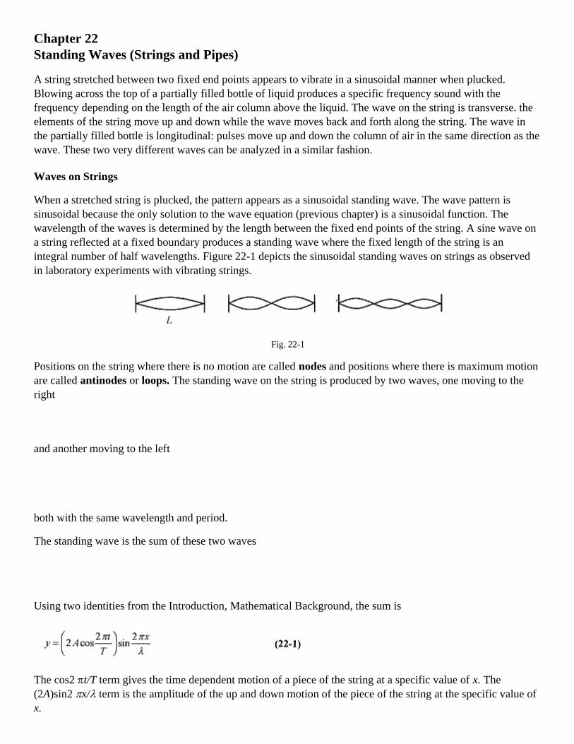
Chapter 22Standing Waves (Strings and Pipes)
A string stretched between two fixed end points appears to vibrate in a sinusoidal manner when plucked.Blowing across the top of a partially filled bottle of liquid produces a specific frequency sound with thefrequency depending on the length of the air column above the liquid. The wave on the string is transverse. theelements of the string move up and down while the wave moves back and forth along the string. The wave inthe partially filled bottle is longitudinal: pulses move up and down the column of air in the same direction as thewave. These two very different waves can be analyzed in a similar fashion.
Waves on Strings
When a stretched string is plucked, the pattern appears as a sinusoidal standing wave. The wave pattern issinusoidal because the only solution to the wave equation (previous chapter) is a sinusoidal function. Thewavelength of the waves is determined by the length between the fixed end points of the string. A sine wave ona string reflected at a fixed boundary produces a standing wave where the fixed length of the string is anintegral number of half wavelengths. Figure 22-1 depicts the sinusoidal standing waves on strings as observedin laboratory experiments with vibrating strings.
Fig. 22-1
Positions on the string where there is no motion are called nodes and positions where there is maximum motionare called antinodes or loops. The standing wave on the string is produced by two waves, one moving to theright
and another moving to the left
both with the same wavelength and period.
The standing wave is the sum of these two waves
Using two identities from the Introduction, Mathematical Background, the sum is
The cos2 πt/T term gives the time dependent motion of a piece of the string at a specific value of x. The(2A)sin2 πx/λ term is the amplitude of the up and down motion of the piece of the string at the specific value ofx.

Where x is equal to 0 and λ/2, the sin 2 πx/λ term is zero, and the string doesn't move. The allowed wavelengthsare determined by requiring x/λ to equal 1/2, 1, 3/2 …, that is, where the sine function is equal to zero. Thiscorresponds to x = λ/2, λ, 3λ/2 ….
For a string fixed at end points L distance apart, the allowed wavelengths are then L = nλ/2(n = 1,2,3 …).Indexing λ for the allowed wavelengths
The allowed frequencies for this stretched string are from v = λf or v = λnfn, so
Remember that for the stretched string, v is a constant equal to . The first frequency (longestwavelength) is called the fundamental and the next frequency the second harmonic or first overtone withsubsequent frequencies labeled in a similar manner.
When a stringed musical instrument is plucked, all of these allowed frequencies are prevalent though theovertones are of successively lower amplitude. The difference in sound of stringed instruments plucked at thesame fundamental frequency is due to the design of the instrument to enhance or suppress certain of theseovertones.
22-1 The third harmonic is excited on a 2.4m length of stretched string. What are the positions of the loops andnodes?
Solution: To produce the third harmonic there are two nodes at 0.80 and 1.6m so as to divide the string intothree segments. The loops are half way between the nodes at 0.40, 1.2, and 2.0m.
Fig. 22-2
<><><><><><><><><><><><>
22-2 An 0.040kg string 0.80m long is stretched and vibrated in a fundamental mode with a frequency of 40 Hz.What is the speed (of propagation) of the wave and the tension in the string?
Solution: The relationship v = λƒf is used to calculate the speed of the wave. Since the string is vibrating infundamental mode, the wavelength is 1.6m (see Fig. 22-1), so

Having determined the velocity from this basic relation, the tension can be determined from . Thelinear density of the string is µ = 0.040 kg/0.80m = 0.050 kg/m so
<><><><><><><><><><><><>
22-3 For the situation described in problem 22-2, add that the amplitude (maximum displacement from thecenter line of the string) is 2.0mm. What is the displacement at 0.20, 0.40, and 0.60mm, and the time for one ofthese oscillations?
Solution: The oscillation is described in both space and time by equation 22-1 at x = 0.20m. The equation is
The sin π/4= 0.71 term specifies the fraction of the 2.0mm (amplitude) of the oscillation at
x = 0.20m. This maximum displacement is 1.4mm. This is the displacement measured from the center line ofthe string. The height of the envelope or total (up and down) excursion of the piece of string is 2.8mm.
At x = 0.40mm the sine term becomes sin π/2 = 1 and the total excursion is 4.0mm.
Because of symmetry the maximum excursion at 0.60m is the same as at 0.20m.
The stretched string goes up and down together, that is, all points on the string are vibrating with the samefrequency of 40 Hz, so the time for one oscillation is 1/40s= 0.025s.
<><><><><><><><><><><><>
22-4 One string on a cello is tightened to produce concert A (440 Hz) when the string is not touched (shortenedby placing a finger on it). The length of the vibrating string is 60cm and mass is 2.0gm. How much must theplayer shorten the string to play a 660 Hz note?
Solution: The tension (velocity) is adjusted so that the frequency is 440 Hz for a wavelength of 1.2m. Thevelocity is
If the tension is not changed, the velocity is not changed so the wavelength to produce 660 Hz is
or
The length of the string to produce this frequency is one-half of a wavelength or 40cm. The player needs toshorten the string by 20cm (from 60cm to 40cm). This is done by pressing the string onto the fingerboard.

Waves in Pipes
If a longitudinal wave is propagated down a gas-filled tube, the wave will be reflected at a closed end in muchthe same manner as the wave on a string is reflected at a rigid boundary thereby setting up standing waves in thetube. Reflection at this end implies no motion and a displacement node. If the end of the pipe is open, then thisend is a displacement antinode. The air is free to move at an open end. Similarly a string with an end free tovibrate has an antinode at the free end.
The simplest example of a standing wave in a tube is an organ pipe. Air is blown across the open end of theorgan pipe. The opposite end can be closed or open.
Look first at a closed (at one end) pipe. The open end is a loop (displacement antinode)
Fig 22-3
and the closed end a displacement node, so the first fundamental frequency has wavelength 4L (see Fig. 22-3)The next allowed wave, the second harmonic, as shown in Fig. 22-3, is 4L/3. The general expression for thewavelengths is
and
Next look at an open (both ends) pipe. Both ends have to be loops (displacement
Fig. 22-4
antinodes), and the simplest situation is shown in Fig. 22-4. The second harmonic is the next simplest situation(also Fig. 22-4) with the general expression for the wavelength
and frequency

22-5 Standing waves are excited in a 1.0m long pipe open at one end, closed at the other. Take the speed of thewaves as 340 m/s and calculate the frequency for the fundamental and the first harmonic.
Solution: The wavelength is determined by the geometry, so look to Fig. 22-3 where the left diagram shows thefundamental wave. If the pipe is 1.0m then the wavelength is 4.0m and the frequency is
The next wavelength is shown in the right diagram and requires a π = (4/3) m and
<><><><><><><><><><><><>
22-6 What is the lowest possible frequency of a 5.0m long organ pipe?
Solution: The lowest frequency corresponds to the longest wavelength, and the longest wavelength is for aclosed at one end open at the other pipe (see Figs. 22-3 and 22-4). In this situation the wavelength is 20mcorresponding to a frequency of
This frequency is below what most people can hear.
<><><><><><><><><><><><>
22-7 An open at both ends organ pipe has two successive harmonics of 567 Hz and 850 Hz. What is the lengthof the pipe? Take the speed as 340m/s.
Solution: For an open at both ends pipe the wavelengths are given by equation 22-6. For successive harmonics(n and n +1) two equations can be written in the form v = λf.
and
or
Refer to Fig. 22-4. These frequencies correspond to the second and third harmonics. The lowest frequency (567Hz) corresponds to the longest wavelength and using v =λf
The pipe then is 0.60m long.

Chapter 23Sound.
Longitudinal waves in air is called sound. The simplest physical picture of sound is a thin membrane vibrating(being driven) sinusoidally with the vibrations being transmitted through the air to another membrane that is setinto sinusoidal motion.
Fig. 23-1
Picture the source as an electrically driven speaker and the detector as your ear that detects the vibrations andtransmits their frequency and intensity to your brain.
If the sending membrane executes one sinusoidal oscillation, a region of high pressure followed by a region oflow pressure, is propagated through the air to the sensor which executes a similar sinusoidal oscillation as thevariations in pressure pass by. (Regions of low pressure are called rarefactions.) Remember that the individualair molecules or slices of air between source and detector move only about an equilibrium position while thepressure-rarefaction pulse moves from source to detector.
Take the source as vibrating according to
Remember that y is in the same direction as x, and y represents the displacement of a narrow slice of air while xrepresents the motion of the pulse from source to detector. Go over the picture of sound in your mind as apressure-rarefaction pulse traveling from source to detector (see Fig. 231) until this last sentence becomes clearto you. When you understand this statement you have a good physical image of sound.
The pressure maximum is coincident with the maximum rate of change of y with respect to x.
The pressure variation, which is proportional to (∂y / ∂x), is a cosine function. The slope of y versus x is amaximum (positive) at x = 0, and maximum (negative) at π/2 . Pressure, (∂y / ∂x) is 90° out of phase withdisplacement.
The ear is very sensitive to pressure variations, capable of detecting pressures of 10-5 Pa which is 10-10 of anatmosphere!
23-1 At some arbitrary position x graph displacement and pressure as a function of time on the same axis andexplain the relationship.
Solution:

Fig. 23-2
Pick a point x where the displacement versus time is a sine curve (equation 23-1). The pressure curve (equation23-2) is a cosine curve. Maximum pressure occurs when y is moving to the right with maximum speed. Thiscorresponds to maximum positive slope or the point t = 0 on the graph. Minimum pressure (a rarefaction)occurs 180° later where the slope of y versus t has its largest negative value.
Intensity and the Inverse Square Law
Sound waves transport energy. Most sound sources radiate spherically symmetric patterns while most detectorsintercept only a certain portion (solid angle) of the radiated energy. Therefore in sound measurements it isconvenient to specify intensity, the power per unit area, rather than total power.
The power transmitted by a wave on a string is proportional to the square of the amplitude. With techniquessimilar to those used to determine the power transmitted by a wave on a string, the intensity of a sound wave is
where p is the density of air.
For a source of sound, the total power is the intensity times the spherical area corresponding to the point (at aradius out from the source) where the intensity is measured.
23-2 What is the total power output of a source with intensity 0.050W/m2 at a distance of 3.0m from the source?
Solution: The total power is the intensity times the area of the sphere with radius 3.0m.
Fig. 23-3
<><><><><><><><><><><><>

23-3 What is the intensity of a 4.0W source at 2.0m?
Solution: The power is P = 4 π2 I so
<><><><><><><><><><><><>
Consider a spherically symmetric source and intensity measurements on two different concentric spheres. Thetotal power is the same so the power collected over one sphere is the same as the power collected over any othersphere. In equation form this statement is
leading to
which is the inverse square law.
23-4 If the intensity from a source is 4.0 × 10⁻³ W/m2 at 12m, what will the intensity be at 4.0m?
Solution: Assume a spherically symmetric radiator and equate the powers at the two radii.
P1 = P2 requires
Be careful on problems like this that you don't get the ratio upside down. Develop the habit of checking for theobvious. When you get closer to a source the intensity increases and vice versa.
<><><><><><><><><><><><>
23-5 How far away can a 50 W tornado siren be heard? Assume the minimum detectable intensity is 5.0 × 10⁻⁶
W/m2
Solution: The power is P = 4π2 I so
The Decibel

The human ear is responsive to sound intensities over a wide dynamic range, 1010 or more in intensity levels. Aperson's perception of “loudness” is that increasing intensity by a factor of 10 approximately doubles theperceived “loudness.” This property of the human ear suggests that sound intensity, or level, should bemeasured with a logarithmic scale. The logarithmic decibel scale for measuring loudness is defined as
where Io = 1.0 × 10⁻¹² W/m2 is the approximate threshold for human hearing.
23-6 Most people experience pain at sound levels above 100dB. What is the intensity associated with 100dB?
Solution: Equation 23-6 needs to be solved for I, and this requires switching from a logarithmic to anexponential equation. See the Introduction, Mathematical Background for a review of logarithmic andexponential equations.
First write β/10=log(I/Io) and remember that x=logy has the solution y=10x. The use of “log” implies base 10.
Switch from a logarithmic equation to an exponential one and write I/Io = 10β/10.
For β = 100,
Practice switching logarithmic equations to exponential equations and vice versa and solving for the variousvariables. This is not a common algebraic operation, and you need sufficient practice to develop proficiencywith exponents and logarithms.
<><><><><><><><><><><><>
23-7 What is the dB loss when you double your distance from a spherically symmetric constantoutput powersource?
Solution: Since the source is constant power output and spherically symmetric the inverse square law applies.Take r1 and r2 = 2r1 and apply power equals power.
and
The dB levels at r1 and r2 are
and
and the difference is
Doubling the distance from the source results in a 6.0 dB loss.
The Doppler Effect

The Doppler effect is the apparent increase or decrease in frequency of a source when the source and observerare moving toward or away from one other.
Fig. 23-4
First consider a stationary source and a moving observer. In Fig. 23-4 pressure pulses are depicted as equallyspaced and moving radially out from the source. An observer at rest would observe vt/λ waves passing in a timet (vt is the length of the collection of waves or “wave train” traveling from source to observer and λ is thewavelength, so the quotient is the number of waves). The number of waves divided by the time is the frequencyf = vt/µt resulting in v = µf.
If the observer is moving toward the source with a velocity vo he will intercept vot/µ more waves, and theapparent frequency is
If the observer is moving away from the source, the sign of vot/µ is negative. The apparent frequency thencorresponds to the negative sign in equation (23-8).
23-8 What is the apparent frequency of a siren emitting a 300 Hz sinusoidal signal that you are approaching at30m/s?
Solution: Use equation 23-8 with the plus sign because you are approaching the source and intercepting morewaves than if you were stationary.
<><><><><><><><><><><><>
23-9 What is the apparent frequency of the siren in problem 23-8 after you have passed it and are moving away?
Solution: When you are moving away the frequency is lower because you are intercepting fewer wave frontsthan if you were stationary so use the minus sign in equation 23-7.
<><><><><><><><><><><><>
Now consider a moving source and a stationary observer. Figure 23-5 depicts the pressure pulses as packedcloser together in the direction the source is moving. This effectively shortens the wavelength to a stationaryobserver.

Fig. 23-5
The effective wavelength is λ'= (v - vs)/f, and the apparent frequency is
For a source moving away from an observer the effective wavelength is (v + vs)/f, so combining
The two expressions for source and observer moving (equations 23-7 and 23-8) can be combined
The way to keep the signs straight is to remember that on approach the frequency is increased and on departurethe frequency is decreased.
23-10 A railroad train traveling at 30m/s emits a note at 400 Hz. What frequency is heard by an observer a) onthe train, b) standing beside the track, and c) on another train approaching at 35m/s?
Solution: a) On the train the observer hears the 400 Hz.
b) Beside the track with the train approaching the observer hears a higher frequency
And with the train moving away the observer hears a lower frequency
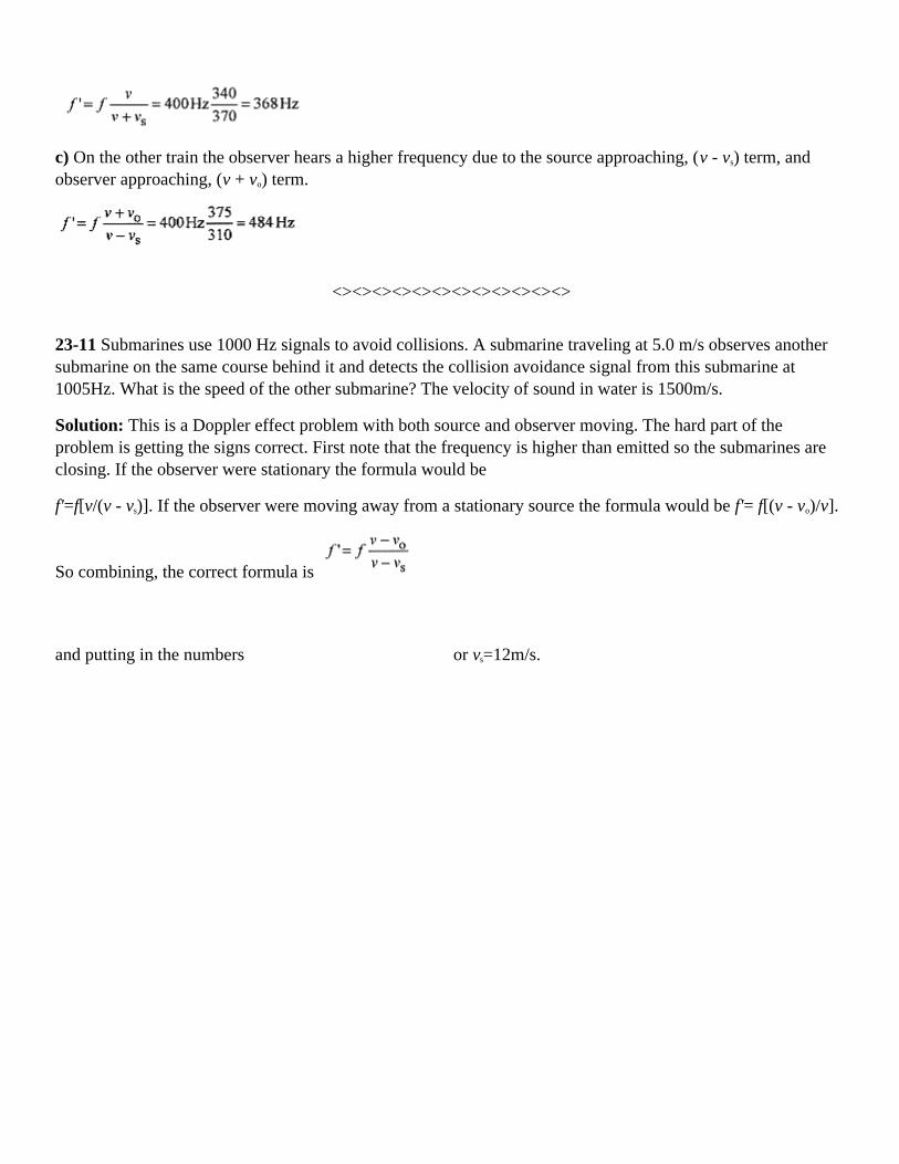
c) On the other train the observer hears a higher frequency due to the source approaching, (v - vs) term, andobserver approaching, (v + vo) term.
<><><><><><><><><><><><>
23-11 Submarines use 1000 Hz signals to avoid collisions. A submarine traveling at 5.0 m/s observes anothersubmarine on the same course behind it and detects the collision avoidance signal from this submarine at1005Hz. What is the speed of the other submarine? The velocity of sound in water is 1500m/s.
Solution: This is a Doppler effect problem with both source and observer moving. The hard part of theproblem is getting the signs correct. First note that the frequency is higher than emitted so the submarines areclosing. If the observer were stationary the formula would be
f'=f[v/(v - vs)]. If the observer were moving away from a stationary source the formula would be f'= f[(v - vo)/v].
So combining, the correct formula is
and putting in the numbers or vs=12m/s.

Chapter 24Charge and Coulomb's Law
Coulomb's law is the basic force relationship between two charges. This force acts along the line connectingthe charges and is repulsive for like charges and attractive for unlike charges.
where εo = 8.9 × 10⁻¹² C2/Nm2 , and
The proportionality constant can, for the moment, be thought of as a constant that makes the force Newtonswhen the charges are measured in Coulombs and the separation in meters.
24-1 Two charges, q1= 3.0×10⁻⁸C and q2 = -4.0×10⁻⁸ C, are separated by 6.0×10⁻³ m as shown in Fig 24-1. Whatis the force of one on the other?
Solution:
Fig. 24-1
This is the force each charge experiences due to the other. The fact that q1 is positive and q2 is negative meansthat the force is directed from one to the other along the line joining their centers.
<><><><><><><><><><><><>
24-2 Consider a line of charges, q1 = 8.0µC at the origin, q2 = -12µC at 2.0 cm, and q3 = 10µC at 4.0cm, asshown in Fig. 24-2. What is the force on q3 due to the other two charges?
Solution: The force on q3 due to q1 is repulsive as shown in Fig. 24-2. The magnitude of F31 is

Fig. 24-2
It is not necessary to be overly concerned about the sign of the force. The vector makes the direction clear.Drawing a vector diagram is a more sure way of getting the final direction correct than using algebraic signs inthe force calculations.
The force on q3 due to q2 is attractive, and the magnitude is
The resultant force is 2250N toward q1 and q2.
<><><><><><><><><><><><>
24-3 Arrange three charges in the form of an equilateral triangle as shown in Fig. 24-3 and find the force on q3
due to the other two.
Fig. 24-3
Solution: This is a more complicated vector problem. First calculate the force on q3 due to q1 and then due toq2. Adding these vector forces is called superposition. The forces can be added as vectors as long as the forcedue to one charge does not affect the force due to another charge. In this case the force on q3 due to q1 does notinfluence the force on q3 due to q2.
The force on q3 due to q1 is
and is directed as shown in Fig. 24-3. Likewise the force on q3 due to q2 is

and is directed as shown. Referring to Fig. 24-3, the x and y components of the resultant force can be written.The x-component of these two forces is
The y-component of these two forces is
Second Solution: Using unit vector notation the forces are written as
and combine to
Rather than worry about the algebraic signs of angles other than 0° to 90° draw the picture and keep the anglesunder 90°. This way it is easy to “see” the sign of the various components. Most mistakes in problems like thisare algebraic sign mistakes. The way to avoid these mistakes is to draw and label a vector diagram, more thanone if necessary.
As an exercise find the magnitude and direction of the resultant.
<><><><><><><><><><><><>
A classic charge problem is one where charged balls are hung by strings from a common point with the questionbeing how far apart the balls separate for a given equal charge.
24-4 Consider two conducting balls both of mass m and equal charge q suspended by nonconducting cords ofequal length, l as shown in Fig 24-4. How does the separation of the balls depend on charge, mass, and length?
Fig. 24-4

Solution: The arrangement is shown in the accompanying drawing along with the vector diagram. This is aforce balance problem. The mechanical force is due to gravity and is directed down. The electrical force is theCoulomb force and is directed along the line of centers of the conducting balls, which for this geometry ishorizontal.
On the vector diagram the mg force is balanced by the vertical component of the tension in the cord, or Tcosθ=mg. The horizontal component of the tension is T sinθ, and replacing T with mg/cosθ the horizontalcomponent is
But tanθ can be written in terms of the geometry as and
The horizontal component of the tension in the cord is balanced by the Coulomb force of
repulsion
or
<><><><><><><><><><><><>
24-5 What is the force of attraction between sodium and chlorine ions in salt molecules if each ion carries oneelectronic charge and the separation is 2.8 × 10⁻¹⁰ m?
Solution:

Chapter 25The Electric Field
The electric field is defined as the force per unit charge E = F/qo and as such is a vector. Electric fields can besuperposed - added as vectors. The units of the electric field are N/C or Volt/meter. In terms of charges theelectric field has magnitude
and direction, the direction of a unit positive charge placed at r.
Discrete Charges
A classic problem that illustrates the vector nature of electric fields is the calculation of the E field on the axisof a dipole.
25-1 An electric dipole is depicted as equal and opposite charges separated by a distance 2a as shown in Fig.25-1. Find the electric field at a distance r along the bisector of the center line of the charges.
Fig. 25-1
Solution: First draw the diagram and note the direction of the electric field vectors. The horizontal componentsof E1 and E2 add to zero. The vertical component is made up of two vectors of equal magnitude, E1cosθ. Themagnitude of the vertical vector is 2E1cosθ.
From the geometry, and so
This is the magnitude of the electric vector. The direction of the vector is down or parallel to a line drawn from+q to -q. If r is large compared to a (often the case) then
and for large distances the field falls off as 1/r3. The product 2aq is called the dipole moment p = 2aq. It isinteresting to note that for a point charge the E field is radial (in or out) and falls off as 1/r2 while for the dipoleE is tangential to the radius and falls off as 1/r3.

<><><><><><><><><><><><>
25-2 Calculate the electric field due to two charges, q1 = 4.0 × 10⁻⁶C and q2 = -3.0 × 10⁻⁶C, separated by 3.0 mand at a point 3.0 m opposite q2 as shown in Fig. 25-2.
Fig. 25-2
Solution: The electric field due to the first charge is
The electric field due to the second charge is
The direction of the fields due to these two charges is shown on the diagram. The vectors are written incomponent form
with resultant ER = (1.4 × 10³i+-1.6 ×10³j)N/C
As an exercise verify that in number plus angle form this vector is .
<><><><><><><><><><><><>
25-3 Find an expression for the electric field due to a collection of charges of equal magnitude all placed in aline and separated by a distance d. The charges have alternate signs, and the field to be calculated is the field ona line normal to the line of charges and opposite the central positive charge. Additionally, look for approximateexpressions for long distances away from the line of charges.

Fig. 25-3
Solution: The electric fields are labeled to correspond with the charges. The fields at a point r distance awayfrom the line of charge are:
Look at the geometry associated with E2 and notice that this vector can be written in terms of a horizontal and avertical component. The vector E4 also has vertical and horizontal components.
The vertical components of E2 and E4 add to zero while the horizontal components add along r. The same is trueof vectors E3 and E5. The horizontal component of E2 is E2 times the cosine of the angle θ, thus the contributionof E2 and E4 is two times the magnitude of E2 times the cosine of the angle θ
E2 and E4 contribute pointed in along r.
Similarly E3 and E5 contribute also pointed out along r
Combining the contributions from all the charges
If r is comparable to d then this formula is appropriate. However if r is large compared to d, then the r termspredominate in the denominators and the expression is approximately
This formula shows that at long distances the array looks like one positive charge.

Linear Charge.
So far we have looked at the electric fields that result from discrete charges. If the charges are spread out, suchas over a surface, then the definition of electric field has to be modified to a calculus definition where thecontribution of each element of charge to the total field is summed.
25-4 A problem that illustrates this is the calculation of the electric field on the axis of a ring of positive charge.Set up the problem as shown in Fig. 25-4.
Solution: Each element of charge dq produces an element of electric field dE at a point on the bisector of adiameter of the ring. This dE has components dE cosθ along the direction of the bisector and dE sin θperpendicular to the bisector. An element of dq at one spot on the ring produces dE sin θ, and across thediameter of the ring a similar element (of dq) produces a dE sin θ component that cancels this one. Because ofthis symmetry the dE sin θ components add to zero.
Fig. 25-4
The magnitude of the electric field due to each element of charge can be written as
but it is dE cosθ which ultimately produces the field pointing outward from the center of the ring.
From the geometry , so the differential electric field component is
This expression can be summed (integrated) without the need for formal integration. The left side is just thetotal electric field, the sum of the dE cosθ contributions. The right side is the sum of all the elements of dq,which is just q, so

Notice that at x = 0, E = 0, as it should and that for , again as it should. Far away the ringof charge should look like a point.
Surface Charge
25-5 Calculate the electric field vertically out from a uniformly charged disk of radius R and charge density(charge/area) σ.
Solution: The calculus definition of the electric field is that each element of charge produces an element ofelectric field according to equation 25-4 where r is the distance from the element to the point where dE iscalculated. Because of the symmetry of the problem the dE is produced by a dq in the form of a ring of chargeof radius r and width dr. Refer to Fig. 25-5 and note that the dE produced by this ring of charge is a cone withhorizontal components adding to zero. A piece of the ring producing a piece of dE has a corresponding pieceacross a diameter. The horizontal components of these corresponding pieces add to zero. The vertical
component is dE cosθ with cosθ determined from the geometry as Summing thecontributions over r produces the electric field pointing away (and perpendicular to) the charged disk. Thedifferential element of charge is dq = (2πrdr)σ (2πrdr is the differential element of area), thus
Fig. 25-5
Remember the integral is over r and not x. Make a change of variable with u = x2 + r2 and du = 2rdr. Theintegral transforms according to
Changing the sign and switching the limits

When R is large compared to x, the bracket approaches one and the electric field is
Applications
25-6 Consider an electron ballistics problem where an electron is projected between two plates (as shown inFig. 25-6) at an initial velocity of 6.0 × 10⁶ m/s and angle of 45°. The electric field is 2.0 × 10³N/C and directedup. The length of the plates is 10 cm and separation 2.0 cm. Will the electron strike the plates? And if so,where?
Fig. 25-6
Solution: This is a projectile problem. Look through Chapter 4, Projectile Motion, and refresh your memory onthe general approach to projectile motion problems before continuing with this problem. The electronic chargeand mass are given on the constants page.
First calculate the acceleration. The force on the electron comes from the electric field, F = eE, and this forcemakes the electron accelerate leading to a = eE/m. Using the values for e and m for the electron
The electric field is directed up, which would be the direction of acceleration of a positive charge. For thenegatively charged electron the acceleration is down. Using this logic argument to determine the direction of theacceleration is easier than carrying minus signs throughout the problem.
The most convenient origin for the coordinate system is the edge of the plate where the initial velocity anddirection are known with x positive to the right and y positive up. Now write the six equations describing themotion.

To determine if the electron hits the upper plate, set y = 2.0 × 10⁻² m and solve for t. Without units
and
The smallest time is taken as this corresponds to the electron striking the top plate. If the solution for t hadcontained an imaginary number, this would have indicated that the electron would never reach the top plate.
Now with this time calculate the position in x where the electron strikes the plate.
Another way to solve the problem is to go back to the six equations describing the motion and solve for y as afunction of x. First solve the x equation for t and substitute this expression for t into the y equation to obtain
When y = 0.020 this equation becomes 10x2 -x + 0.020 = 0 with solution
Here again be sure to take the value of x corresponding to the smallest positive time.
Dipoles
A dipole placed in an electric field experiences a torque. The dipole moment, defined earlier as p = 2aq, can beexpanded to define the dipole moment vector of magnitude 2aq pointing from -q to +q. The force on eachcharge is qE, and they add to zero so the dipole does not translate.

Fig. 25-7
It does, however, rotate due to the torque of magnitude 2aF sin θ. When θ= 0 and the dipole is lined up withthe field, the torque is zero. But when θ= 90° the torque is 2aF. Multiply the torque by q/q to obtain
which is a cross product, or
25-7 A dipole with charge 6.0 × 10⁻⁶C and separation 4.0 × 10⁻³ m is immersed in an E-field of 3.0 × 10⁶N/C.Calculate the maximum torque.
Solution:
<><><><><><><><><><><><>
If a dipole is subjected to an E-field and the dipole is rotated by that electric field, then work is done on thedipole. The work done by the field must be
Be careful with the signs and angles.
25-8 Take the original position θ0 = 70°, and the final position θ1 = 20° and calculate the work performed on thedipole and the energy stored in the system.
Solution:
The electric field has done 0.086J of work on the dipole, and this is the amount of energy stored in the dipole-field system.

Chapter 26Gauss' Law
Gauss' law can be tricky. The concepts expressed in mathematical terms often imply considerable mathematicalsophistication to work the problems. This is almost always not the case. In general; if you are involved inexcessive mathematical manipulations you are doing the problem wrong or do not see an easy way to applyGauss' law. Remember that Gauss' law represents the density of flux lines through an area. Remember also thatmost of the difficult looking integrals never occur.
Start with a definition of flux as
This states that the flux is the sum of the vector (dot) product of electric field over a surface times the area. Erepresents the electric field, and ds is a vector normal to the surface representing a differential element ofsurface. The dot product is the component of E parallel to ds, that is, normal to the surface, times ds. If E is aconstant (most often the case) then the sum of (integral
of) E.ds over the surface is the component of E normal to the surface area, times the total surface area.
26-1 Calculate the flux through a square plate 1.0m on a side inclined at 120° with respect to a constant electricfield of 100N/C. You may at this point want to review the definition of dot product in Chapter 1, Vectors, andthe concept of the integral in the Introduction, Mathematical Background.
Fig. 26-1
Solution: The surface area ds is represented by a vector normal to the surface. The vector product E.ds isEds(cos30°). Integrating this product
This represents the flux through the surface.
<><><><><><><><><><><><>
The construct (concept) “flux” can be thought of as a collection of lines intercepting this square plate. If theelectric field is increased, then there are more “flux lines” per square meter and, if the angle is changed, more orless flux lines are intercepted as the angle is changed.
This integral of a vector product that sounds like a very difficult problem is performed rather easily with anunderstanding of dot products and integrals.

Electric field lines are a convenient concept or construct to help us visualize the electric field. The electric fieldlines are envisioned as vectors going from positive charges to negative charges, the direction a unit positivecharge would move. The electric field lines between two oppositely charged plates are just lines going from oneplate to another. Higher fields would be envisioned as more lines or more lines per cross-sectional area.
In the case of a sphere surrounding a unit positive charge the field lines would be pointing radially out, thedirection a unit positive charge would move. On spheres with different radii the electric field would bedifferent; the field line density (number per square meter) would be different. However if we could sum all theelectric field lines over the different spheres we would find the same number of lines. Their number densitywould decrease as the radii were increased but the total number over a sphere would remain the same.
The formal Gauss' law connects flux to the charge contained again via an integral
The charge q is the net charge enclosed by the integral. The εo can, for the moment, be thought of as a constantthat makes the units come out right.
Place a charge q at the center of a sphere and apply Gauss' law
Fig. 26-2
The little circle on the integral sign serves as a reminder to integrate over an enclosed surface. The sphere weare integrating over in this instance, not a physical sphere, is known as a Gaussian surface - a surface where theintegral is taken when applying Gauss' law. Now E is a constant over the surface (symmetry) so the integralbecomes
and is just the surface area of the sphere or
and (26-3)
which is just the statement we have from Coulomb's law and the definition of the electric field.
26-2 The electric field at the surface of the earth is approximately 150N/C directed down. Calculate the sign andmagnitude of the charge on the earth.
Solution: Gauss' law states that E.ds = q enclosed

Construct a spherical Gaussian surface just outside the physical surface of the earth where E is everywherenormal and of value 150N/C. The integral of E.ds is the sum of this field over the Gaussian surface. E and dsare 180° so their dot product is negative.
Fig. 26-3
The field pointing down indicates that the charge is negative as does the dot product being negative. Againnotice that this integral over the Gaussian surface is quite easy. These past two problems are very illustrative ofthe “integration by inspection” approach to problems involving Gauss' law.
<><><><><><><><><><><><>
26-3 Calculate the sign and magnitude of the charge contained in a cube 10 cm on a side oriented as shownwhere the E-field is given by
Fig. 26-4
Solution: First calculate the E-fields entering and exiting the cube. Watch the algebraic signs carefully.
There is more flux leaving the cube than there is entering it, so the net charge inside the cube must be positive.On the left side E is to the right and the vector representing ds is to the left, so

Remember that the direction of ds is always outward from the enclosed volume. On the right side E is to theright and the vector representing ds is to the right so
The integrals over y and z are zero and the integrals over x add to 1.05 Nm2/C. Now q can be calculated
<><><><><><><><><><><><>
26-4 The total charge (charge density) contained in an electron stream can be calculated with Gauss' law. If thefield at the edges of a stream of square cross section 1.0cm on a side is
1.0 × 10³ N/C, calculate the charge density in the stream. Assume that the E-field in the direction of the streamis constant.
Fig. 26-5
Solution: The field is directed in, so the charge is negative and reduces to calculating four
identical integrals.
The charge in a cube 1.0 cm on a side is now
The charge density is
For the electron charge density we need to introduce the charge of the electron.

<><><><><><><><><><><><>
26-5 A planetary probe is traveling radially inward toward the center of the planet. At 600 m above the surfacethe field is directed up and has value 180 N/C. At 500 m it is still directed up but has value 125 N/C. Find thesign and density of the charge (density) in this region.
Solution: The radius of the planet is sufficiently large so that we can take the region as a cube 100 m on a side.The electric fields are as shown in Fig. 26-6. Gauss' law can be written as
Fig. 26-6
The electric field at the sides is zero. At the top, the electric field and the vector representing ds point in thesame direction so the dot product has a plus sign. On the bottom, the electric field vector points up while thevector representing ds points down giving the dot product a minus sign. Putting in the values for the integrals.
the total charge enclosed within the volume is
The charge density then is 4.9 × 10⁻¹² C/m3.
<><><><><><><><><><><><>
26-6 Calculate the electric field between cylinders carrying charges as shown. The +q is on the inner conductorand -q on the inside of the outer conductor with another -q on the outside of the outer conductor.

Solution: On a surface between the conductors, applies to the charge contained
and with 2πrl the surface area of the Gaussian cylinder, corresponding to the point wherethe field is required, so in this region E points inward and has value E=q/2πεorl.
Note that the electric field at a point between the cylinders is only due to the charge enclosed by the Gaussiansurface. Because of the symmetry of the problem, the charge on the outer cylinder produces no net electric fieldat any point inside the outer cylinder.
Fig. 26-7
Outside the outer cylinder the E field points inward because the net charge contained is negative, and at anypoint r (outside the outer cylinder) measured from the center line of the two cylinders E=q/2πεorl.
With this particular arrangement of charge, the field has the same algebraic form between the cylinders andoutside the outer cylinder but points outward between the cylinders and inward outside the outer cylinder.

Chapter 27Electric Potential
In mechanics the use of force to analyze problems works well when the force is a constant. When the forcedepends on position, then the concepts of work and energy are introduced with work defined as the summation,or integral, of force over distance.
In electricity, potential is introduced for similar reasons. While the electric field is a constant in many problems,it is not a constant, say, in the vicinity of a point charge except on a sphere surrounding that (central) charge.Any motion of charges due to electric force that is not on the surface of the sphere surrounding a central chargehas to take account of this non-constancy of the field, or force (field is force per charge).
The electric potential or potential difference between two points A and B is defined as the work per unitcharge necessary to move the unit charge from A to B
The units of potential are Joule/Coulomb or volt. Usually one point (A) is taken at infinity where VA=0. This isconvenient and correct since the force on the unit charge at infinity (see Coulomb's law) is zero.
Look at the integral (same definition of work as in mechanics) involved in calculating WAB for a charge qo beingbrought from infinity to the vicinity of q. This integral is
Fig. 27-1
Be careful of the signs here; If q and qo are positive, the force is repulsive; and if qo is coming from infinity torB, then F.dr is negative. With this definition the potential, or work per unit charge, at any point r radially outfrom q is
a most convenient definition.
For a constant electric field, such as between two parallel plates, WAB=Fd=qoEd and VB-VA=WAB/qo=Ed, where dis the distance moved (in the direction of the field).
27-1 In a certain experiment an electric field of 2.0×10⁵ N/C is required for parallel plates separated by0.0020m. What voltage will produce this field?
Solution: For a constant field, V = Ed so

<><><><><><><><><><><><>
27-2 An electron placed between two charged parallel plates separated by 2.0×10⁻²m is observed to accelerate at5.0×1014m/s2. What is the voltage on the plates?
Solution: First calculate the force on the electron as
The electric field required to move this electron is
The voltage for this separation is
<><><><><><><><><><><><>
27-3 What is the electric potential 0.20m away from a charge of 1.0 × 10⁻⁶C?
Solution:
27-4 Calculate the electric potential for the same charge but at 0.50m away.
Solution:
The potential difference between these two positions is 2.7 × 10⁴V
<><><><><><><><><><><><>
27-5 Use the situation (charge and potential calculations) of problems 27-3 and 27-4. If a charge of 5.0×10⁻⁶Cwere moved from a radius of 0.50m to a radius of 0.20m, how much work would be performed?
Solution: The work performed is the potential difference in Joule/Coulomb (or volt) times the charge inCoulomb (observe the units carefully).
The work is independent of the path between these radii. This is the great value of potential calculations.

<><><><><><><><><><><><>
27-6 A 5.0g conducting sphere with charge of 20 µC hangs by a non-conducting thread in an electric fieldproduced by two plates separated by 8.0cm. What potential will cause the ball to hang at 25° to the vertical?
Fig. 27-2
Solution: This is a force-balance problem, the electric force is balanced by the horizontal component of thetension in the thread. Refer to Fig. 27-2 and write the force statements.
Divide one by the other to arrive at
The potential is from E = V/d or V = Ed
<><><><><><><><><><><><>
27-7 Calculate the electric potential of a spherical (conducting) shell of radius 0.10m carrying a charge of5.0×10-4C.
Solution: In calculating the potential on the spherical shell the charge acts as if it were at the center of thesphere.
<><><><><><><><><><><><>
27-8 Now calculate the electric field just outside this surface.

Solution:
As an exercise show that the unit V/m is equal to N/C.
<><><><><><><><><><><><>
The electric potential due to an array of charges can be calculated by superposing the solutions for each charge.Because the electric potential is not a vector this is usually an easy calculation.
27-9 For the array shown in Fig. 27-3 calculate the potential mid-way between q1 and q2.
Solution: First calculate the distance from this midpoint to q3
Fig. 27-3
The potential at the point P is the sum of the contributions from each of the charges.
if a is measured in meters.
<><><><><><><><><><><><>
27-10 Calculate the electric potential along the x-axis for the triangular array of charges shown.

Fig. 27-4
Solution:
for which is what we would expect.
A long way away from the collection of charges the collection looks like one positive charge.A classic problem is the calculation of the potential at a point a distance r and at an angle θ from the center of adipole. The potential is written by summing the potential from the two charges and using the approximatetrigonometric relation between r, r1, and r2.
Fig. 27-5
If r>>a then r1r2 ≈ r2 and also θ1 ≈ θ2 ≈ so r2-r1 ≈ 2a cosθ and using the dipole definition p=2aq
27-11 The water molecule H2O has an asymmetric charge distribution leading to a dipole moment p of 6.2×10-
30C.m. Calculate the electric potential 1.0nm a) at right angles to the direction of the dipole moment and b) at45° to the direction of the dipole moment. (1.0 nm is approximately 10 hydrogen atom diameters)

Fig. 27-6
Solution: The approximate expression for the electric potential is
and the electric potentials at Pa and Pb are
ccap
27-12 A positron (positively charged electron) traveling at 3.0×10⁷ m/s is projected directly at a stationaryproton. What is the distance of closest approach?
Solution: The positron will approach the proton until the energy of the positron is expended in doing workagainst the Coulomb repulsive force. The positron will stop, then exit the vicinity of the proton having avelocity profile on exit the same as, but in the opposite direction, to the entrance.
This work is set equal to the kinetic energy and solved for
This is a very close approach being two orders of magnitude smaller than the distance from the nucleus to thefirst electron orbit radius in the hydrogen atom.
Second Solution: This problem can be done using the concept of the electron-volt (eV) unit of energy. Anelectron accelerated through one volt has an amount of work performed on it equal to one volt (the work perunit charge) times the charge on the electron.

This equation defines the Joule-eV equivalence. An electron accelerated through a potential difference of onevolt is said to gain one electron volt in energy. An electron accelerated through 1000 volts would gain 1000 eVin energy. An alpha particle (two positive electronic charges) accelerated through 1000 volts would gain 2000eV in energy.
In this particular problem the positron with a velocity of 3.0 × 10⁷ m/s has a kinetic energy of
This means that the positron has been accelerated through 2600 V.
A positron with this energy could approach a proton to a radius equivalent to 2600 volt potential.
Set equal to 2600V and solve for rc
<><><><><><><><><><><><>
Another application of the concept of potential is to calculate the amount of work required to place charges inan array.
27-13 Calculate the work required to arrange the charges as shown in Fig. 27-7. In this problem the subscriptson the q's represent the position of the charges
Fig. 27-7
Solution: To make this calculation place q0 in position (corresponding to the origin of a coordinate system) andcalculate the work necessary to place q1 in position. This is
Since the charges are opposite, the electric force is attractive and the work to put this charge in position isnegative (this charge has to be restrained as it approaches q0). Now with these charges in place, add -2q2 with anamount of work

There are two components to this work calculation, the work to bring -2q2 to within of -q0 and the work tobring -2q2 to within a of +q1. Adding the third charge means taking into account the three charges already inplace
The total work is the sum of these, or
ccap
27-14 Another classic problem has to do with the calculation of the electric potential due to charge on a surfacealong a line from the center of a disk and perpendicular to the disk.
Fig. 27-8
Solution: The potential is
In this problem dq will have to be written in terms of charge per unit area times (differential) area. Start bywriting the differential voltage in terms of the differential element of charge, dq, or
The charge on the surface is assumed uniform with surface charge density σ (charge per unit area). Take thecharge contained in the circular strip, σ(2πy)dy (2 πy is the length of the strip and dy is the width). The r is
, so the contribution of this strip to the electric potential is
The integration is to be performed in y from zero to b, the radius of the disk

Make a change of variable. Let u = a2 + y2 and du = 2ydy so the integral becomes (and we look at the integralonly without the limits)
This integral is in the Introduction, MathematicalBackground.
Therefore
Now look at the limiting case where b/a <<1, which is often the case. This is most conveniently done by firstrewriting the expression in brackets as
and then writing the square root as a binomial expansion remembering that b/a <<1. The binomial expansion(see the Introduction, Mathematical Background for the binomial expansion) is
This is expected since σπb2 is the total charge and a is the distance from that charge. A long way away a disk ofcharge “looks like” a point charge. The use of the binomial expansion is helpful in two ways. First, it allows aconvenient calculation for the situation where b/a <<1; and second, the limiting case reduces to the simpleexpression for the potential due to a point charge, in effect verifying the calculation.

Chapter 28Capacitance
A capacitor is a geometric arrangement of conducting plates where charge can be stored. The capacitance is ameasure of the charge that can be stored per volt. The unit of capacitance, the farad, is defined as aCoulomb/Volt. The defining equation
for capacitance is C =q/V.
The simplest capacitor is two parallel plates of area A and separation d.
Fig. 28-1
The capacitance of a parallel plate capacitor determines the amount of charge that can be stored on the plates. Abattery connected to the plates will place charge on the plates. For this discussion the battery can be viewed as asource of charge (or charge pump) with the amount of charge delivered to the plates determined by the voltageof the battery. Remember that the voltage of the battery is a measure of the amount of work that can beperformed on a unit of charge.
When the battery is connected to the plates, we say that positive charge begins to flow onto the positive plateand negative charge onto the negative plate. The first “piece of charge” distributes uniformly over the plate. Thepositive and negative charges arrange themselves on the plates opposite one another. As more charge is pumpedonto the plates the work necessary to place each new “piece of charge” on the plate increases because of themutual repulsion of the charges already on the plate. Thus the capacity of the device to store charge is directlyproportional to the plate area.
The limitation on capacity imposed by the mutual repulsion of like charges on one plate is offset by oppositecharges on the other plate. As the distance between the plates is reduced, the attraction between unlike chargesmakes it easier, in terms of work performed by the battery, to place charge on the plates and the capacity of thedevice is increased. Thus capacitance is inversely proportional to the separation of the plates.
The capacitance of a parallel plate capacitor is directly proportional to the plate area and inversely proportionalto the separation, with a constant added to make the units work out correctly.
This very simple view of a parallel plate capacitor produces the correct functional relationship as seen in theformal derivation in the following paragraph.
The formal procedure for determining capacitance is to:

1) calculate E using Gauss' law, then
2) calculate V from and finally
3) calculate C from the definition
For the parallel plate capacitor, charge the plates with a battery so that one plate contains positive charge andthe other negative charge. The charges will arrange themselves so they are on the insides of the plates oppositeone other (unlike charges attract). Construct a Gaussian surface surrounding one plate. The E-field exists onlybetween the plates and is constant over the Gaussian surface. Applying Gauss' law
E is a constant over the Gaussian surface so the integral ofE over this surface is just E times A, the surface area.This is another case of an integral that can be evaluated by looking at it and writing down the answer. In thisgeometry the relationship between voltage and field is simple, V=Ed, so εoVA/d =q and the capacitance, whichis defined as
The capacitance is entirely geometry dependent. One thing to notice here is εo, which can be expressed in thenew units of Farad/meter or F/m.
28-1 A capacitor with circular plates of 0.20m radius separated by 0.0010m is connected to a 100V battery.After a long time the battery is disconnected. What is the charge stored on the plates?
Solution: The capacitance of the arrangement is
The charge is obtained from the definition of capacitance, equation 28-1
<><><><><><><><><><><><>
28-2 Calculate the capacitance of a cylindrical capacitor of inner radius a, outer radius b, and length l.
Solution: Set up a cylindrical Gaussian surface symmetrical about the inner cylinder and of length l.

Fig. 28-2
E is constant over this surface and so that
Continuing with the procedure, calculate V.
and by definition , so
<><><><><><><><><><><><>
28-3 Calculate the capacitance of a spherical capacitor with inner radius a and outer radius b.
Fig.28-3
Solution: Set up the Gaussian surface symmetric about the inner sphere. E is a constant over this surface and
or εoE(4πr2) = q, so
Now calculate V from

and by definition so
Capacitors as Lumped Circuit Elements.
Capacitors are used in electric circuits, so it is necessary to know how capacitors add when used in series andparallel. First look at three capacitors placed in series.
Fig.28-4
The applied voltage is distributed between the three capacitors so V=V1+V2+V3. Since there is no way to addcharge except to the end plates, those connected directly to the battery, then the charge contained within theGaussian surface must total zero.
The right plate of C1 has equal but opposite charge to the left plate of C2. Another Gaussian surface surroundingC1 also must have total charge zero, so the charge on the plates of C1 are equal and opposite. Proceeding in thismanner the magnitude of the charge on all the plates is the same. Rewriting the equation for the voltage usingthe definition of capacitance
Therefore can be replaced by an equivalent capacitance
Capacitors placed in series add in a reciprocal manner.
Capacitors placed in parallel add linearly. Look at the expression for C for a parallel plate capacitor: C = εoA/d.Adding another parallel capacitor just adds more εoA/d to the capacitor. Therefore, capacitors placed in paralleladd linearly.

28-4 A 6.0 µF capacitor and an 8.0 µF capacitor are connected in series. A potential of 200V is placed acrossthem. Find the charge and potential on each.
Fig. 28-5
Solution: The circuit is as shown. Since the capacitors are in series the charge on each capacitor is the same.The equivalent capacitance is found from
so the equivalent capacitance is (24/7) µF, and the equivalent circuit is as shown.
The charge is easily calculated from q = CV = (24/7) µF. 200 V = 686 µC. The voltage on each capacitor is
These voltages add to the 200V applied to the combination.
<><><><><><><><><><><><>
NOTE: This general approach of reducing circuits to simpler equivalents by applying the rules for lumpedcircuit elements is at the heart of circuit analysis.
28-5 A 12 µF capacitor and a 10 µF capacitor are connected in parallel across a 100V battery. Find the chargeand potential on each capacitor.
Fig. 28-6
Solution: The circuit is as shown. The voltage across each capacitor is the same, 100 V. The charge, however,depends on the capacitance.
Look at the equivalence. Take this total charge and the applied voltage and find an equivalent capacitance.

This is the sum of the capacitances as expected in a parallel arrangement.
28-6 The analysis of multiple capacitor combinations is done with (sometimes several) equivalent circuits.Consider the circuit shown that has parallel and series combinations.
Fig. 28-7
Solution: The first equivalent circuit comes from the combination of C1 and C2.
Now combine C3 and C4 to C5=C3+C4 =4.4 µF + 6.0 µF = 10.4 µF allowing construction of the final (simplest)equivalent circuit
Fig. 28-8
Now calculate the total charge qt = C5V = 10.4 µF.300 V=3.1 × 10⁻³ C.
The charge on C3 is q3 =C3V = 6.0µF.300 V= 1.8 × 10⁻³ C.
The remaining charge is 1.3 ×10⁻³ C, and this is the charge on each of the other capacitors, C1 and C2. Rememberthat the charge on capacitors in series is the same. The voltage on each of these capacitors is
The error here of these voltages not adding up to 300V is about 2%, which is expected from round off.
28-7 Charge a 12µF capacitor with a 200V source, then place this capacitor in parallel with an uncharged 7.0µFcapacitor and calculate the “new” voltage.
Fig. 28-9

Solution: The 12 µF capacitor initially placed on the 200V source has a charge of
When connected to the 7.0µF capacitor the charge distributes so that the total charge remains the same and the“new” voltages are equal as they must be for capacitors in parallel. Take Q as the amount of charge that movesfrom the 12µF capacitor to the 7.0µF capacitor. The voltages as expressed by the ratio of q to C must be equal,so write
The voltage on each of the capacitors is
Energy Storage
If the potential of a capacitor is defined as the work required to move an amount of charge from one plate to theother, then in differential form
and the integral of this expression to find the total work to move an amount of charge q is
This work is equal to the energy stored in the capacitor, U. Another quantity of interest is the energy that can bestored per unit volume. For a parallel plate capacitor, where C =εoA/d
28-8 Go back to the previous problem of the 12µF capacitor charged to 200V and then connected to the 7.0µFcapacitor and look at the question of energy.
Solution: The 12µF capacitor at 200V has a stored energy of
NOTE: The units of energy are [FV2]=[(C/V)(J/C)2]=[J].
After the capacitors are connected, the voltage drops to 126V and the energy stored in the two capacitors is

Where did the energy go? The difference between the 0.24J and the 0.15J is the kinetic energy needed totransport the charge or the work to move the charge.
Capacitors and Dielectrics
Dielectrics are most conveniently thought of as materials containing dipoles that are “loose” and can line upwith an applied electric field. The easiest way to understand dielectrics is to approach them experimentally.Using a parallel plate capacitor as a model observe experimentally that the amount of charge per unit voltageincreases with the insertion of various dielectric materials. The easiest way to explain this is to
say that C = εoA/d is changed by a factor kgr;, so C = κεoA/d with this κ called the dielectric constant, ameasure of the amount by which the capacity of a capacitor is increased due to a particular dielectric.
The mechanism of increasing the capacitance can be thought of as the dipoles lining up across the separation dwith the positive end of the string effectively neutralizing some of the negative charge on the plate and thenegative end of the string doing the same to the other plate. The effect of these positive charges in the vicinityof the negative plate allows the negative plate to be negatively charged more easily (with less work) leading to agreater capacity of the device in the presence of the dielectric.
Fig. 28-10
Consider another experiment with dielectrics. Connect a battery in parallel with identical sized parallel platecapacitors except one has a dielectric and the other does not. For the one without the dielectric C = εoA/d. Andfor the one with the dielectric C=κεoA/d. Since q=CV, to carry the same charge the capacitor with the dielectricwould have to have V reduced to Vo/κ and likewise E to Eo/κ. Finally looking at the energy density forcapacitors with dielectrics
28-9 A parallel plate capacitor of 2.0 × 10⁻⁹ F and plate area 0.50 m2 is connected to 3000V. Calculate the storedenergy.
Solution:
<><><><><><><><><><><><>
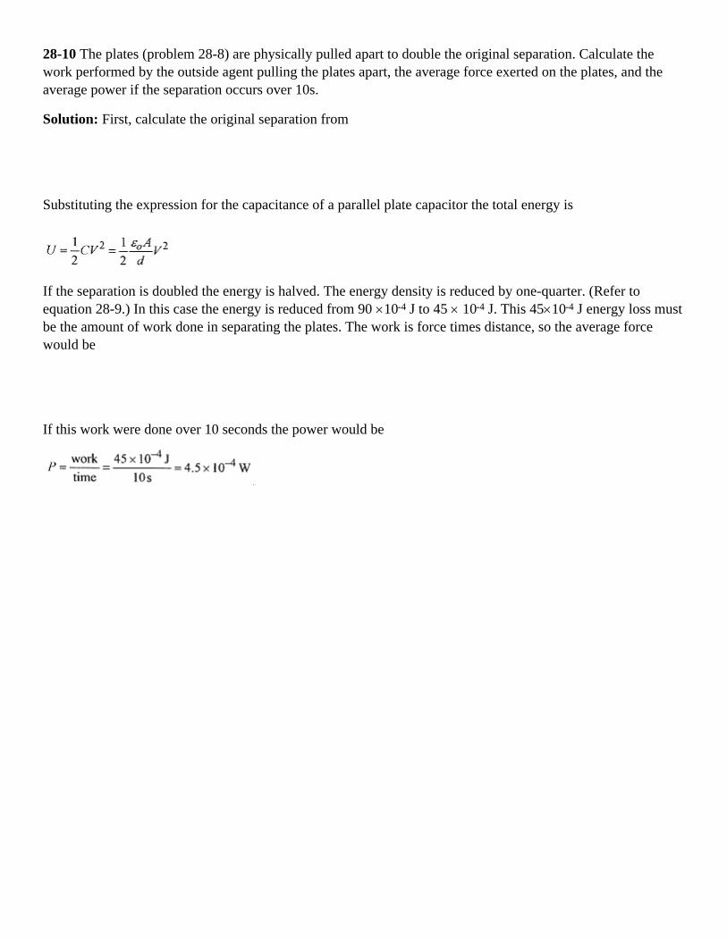
28-10 The plates (problem 28-8) are physically pulled apart to double the original separation. Calculate thework performed by the outside agent pulling the plates apart, the average force exerted on the plates, and theaverage power if the separation occurs over 10s.
Solution: First, calculate the original separation from
Substituting the expression for the capacitance of a parallel plate capacitor the total energy is
If the separation is doubled the energy is halved. The energy density is reduced by one-quarter. (Refer toequation 28-9.) In this case the energy is reduced from 90 ×10-4 J to 45 × 10-4 J. This 45×10-4 J energy loss mustbe the amount of work done in separating the plates. The work is force times distance, so the average forcewould be
If this work were done over 10 seconds the power would be

Chapter 29Conductivity
Electric conductivity is most conveniently thought of as motion by essentially “free” electrons; electrons notbound to atoms. The actual mechanism is more complicated but this simple view is sufficient to understandconductivity in metals. In the absence of an electric field, these free electrons are moving in random patternswith a mean free speed v. They regularly crash into ion cores (metal ions with the conduction electron(s)missing), then move off again with this same mean free speed.
Electric conduction comes about because an electric field is impressed on the metal which slightly modifies thisrandom motion of the electrons giving them a drift velocity in the direction opposite to the field. Theaccompanying diagram shows the effect of an electric field (dashed lines) on the random motion of aconduction electron in a metal subject to an electric field.
Fig. 29-1
The mean free speed is the speed of the electrons as determined by the temperature of the metal, and the driftvelocity is due to the electric field. This drift velocity is small compared to the mean free speed. The motion ofthe electron charge carriers is characterized by the drift-velocity, the mean free path (the distance betweencollisions), and the relaxation time (the time between collisions). The drift velocity depends on the appliedfield. The mean free path and the relaxation time are characteristics of the metal and the physical condition ofthe metal (temperature, pressure, etc.).
Current
Consider a wire, containing charge, under the influence of an electric field. On a plane through the wire(perpendicular to the charge motion) an amount of charge will pass per unit of time. This is called the current
with unit of ampere = coulomb/second or A = C/s.
Fig. 29-2
The current density is defined as the current per cross-sectional area.
The current direction is direction a unit positive charge would move in the field. Despite the charge beingcarried by electrons, current is viewed as the motion of positive charge. This definition fits with the previouswork in potential.

29-1 A current of 5.0 A exists in a wire of 0.50cm diameter. Calculate the current density.
Solution:
<><><><><><><><><><><><>
29-2 Calculate the amount of charge that passes a cross section each second.
Solution: 5.0 A = 5.0C/s, so 5.0C passes a cross second each second.
<><><><><><><><><><><><>
29-3 Calculate the number of electrons per second.
Solut ion:
Notice that a current on the order of 10-15 A would amount to 104 electrons per second.
<><><><><><><><><><><><>
29-4 What is the current and current density in a 1.2cm diameter gas discharge tube if 3.0×10¹⁷ electrons and2.0×1016 positive ions pass a cross section of the tube each second?
Solution: The current is due to electrons going one way and positive ions going the other way.
The current density is
The amount of charge in a length of wire is the product of number density of charge carriers (number/volume),cross-sectional area, and length (the volume), and the charge per carrier, or
In the presence of an electric field the time for this charge to traverse the length, l, of this volume is the lengthdivided by the drift velocity, t=l/vd. The current is the charge contained in the volume divided by the time forthe charges to move the length of the volume. The current is
and the current density is

29-5 A metal conductor with 2.0×1025 charge carriers/m3 and cross-sectional area 1.0×10⁻⁴ m2 has a current of4.0×10-2 A. What is the drift velocity of the charge carriers?
Solution:
Resistance
The resistance of a conductor is defined as the voltage divided by the current, R = V/i and has a special unit,the ohm = volt/amp, or in symbol form Ω = V/A. The resistivity of a material is defined as the electric fielddivided by the current density
which gives resistivity the units of Ω.m. The resistivity of most metals is the order of 10-8 Ω.m.
The instantaneous relationship between voltage, current, and resistance is
and is known as Ohm's law. Many metals over a wide range of voltage and current obey Ohm's law.
29-6 The resistivity of copper is 1.7×10⁻⁸ Ω.m. What current flows through a 2.0m long copper conductor of1.0×10-4 m2 cross section when 20V is applied?
Solution: First calculate the resistance:
Now the current:
<><><><><><><><><><><><>
The “free” charge carriers in a conductor experience an electric field when a voltage is applied and this fieldproduces an acceleration a = eE/m, the electric force divided by the mass. The charge carriers accelerate untilthey crash into an ion core, then the process of accelerate and crash begins again. The characteristic timebetween collisions, which is dictated by the mean free speed, is called the relaxation time. The accelerationtimes the relaxation time produces the drift velocity.
This expression for resistivity is consistent with Ohm's law. Resistance (and resistivity) is a constant providedthe applied field does not change the time between collisions. Remember, the time between collisions is aproperty of the material and is not appreciably affected by the applied electric field.

29-7 Take a rectangular block of metal 1.0×10⁻⁴ m2 in cross section, 50cm in length with a relaxation time of3.0×10-14s. Apply 4.0V for a current of 3.0A. Calculate resistivity, electrons/sec. passing a cross section, currentdensity, the acceleration of the electrons, and the drift velocity.
Solution: The resistivity is
The number of e-/s passing a cross section is
Calculate the current density.
Calculate the acceleration of the electrons.
Calculate the drift velocity. vd = aτ=(1.4 × 10¹² m/s2)(3.0×10-14 s) = 4.2 × 10⁻² m/s
NOTE: The mean free speed, the speed of the electrons before the application of the field, is the order of 106
m/s .
Power
In electric circuits, energy is transferred when charge moves under the influence of voltage. Since voltage iswork/charge, then the energy involved in moving an amount of charge under the influence of voltage is thevoltage times the charge. In differential form
Power (work/time) dU/dt is P = Vi
In a circuit where V, i, and R are related by V = iR this power can be written
In the case of electrons passing through a metal this energy is manifest as heat in the conductor. The energytransfer is known as Joule's law of heating. The units are VA = (J/C)(C/s) = J/s= W.
29-8 A 1000W electric heater operates at 115V. Calculate the current, resistance, and energy generated in onehour.
Solution: The current in the heater is
The resistance is

The energy generated in one hour is U = Pt = (1000J/s) (3600s) = 3.6×10⁶ J.
29-9 For the situation of problem 29-8, if the voltage is reduced to 110V (assume no change in resistance) howdoes the heat output change?
Solution: This is best handled with a variational equation. In this case start with P = V2/R and ask how does Pchange with V, while R remains constant. The left side becomes ∆P, and the right side becomes (1/R) times thedifferential of V2. Writing in delta format
The 2V∆V is the difference between (V + ∆V)2 and V2.
The ∆V2 term is dropped because it is small compared with 2V∆V. For this case them
What is the fractional change in power output, ∆ P/P?
NOTE: The fractional change is the change divided by the original amount.
There is an 8.7% decline in power for a 4.35% decline in voltage.
Temperature Dependence of Resistivity.
The resistance or resistivity of a metal depends on temperature according to
where α is the temperature coefficient of resistance. This increase in resistance is consistent with our view ofelectric conductivity as charge carriers moving under the influence of an electric field until they crash into muchlarger ion cores.
As a metal is heated, energy goes into vibration of the ion cores. Charge carriers moving through the metal havea greater chance of intercepting an ion core as the amplitude of the oscillations increases. More collisions meansgreater resistance.

As an analog, consider the problem of walking blindfolded across a room with all the same size people standingin a random pattern in the room. The number of times you collide with another person depends on the relativecross sections (areas) of you and the people standing in the room. If the people are put into oscillation,perpendicular to your direction of motion, the probability of collision becomes greater. In the time it takes foryou to move past each person, they move, increasing the probability of collision. They have a greater effectivecross section, with respect to your walking across the room, because of their motion.
29-10 Calculate the resistance of an iron bar when the temperature is raised from 0°C to 100°C.
The initial resistance is 1.43Ω, and the temperature coefficient of resistivity is 0.00501/C°.
Solution:
Batteries and emf
Batteries can be viewed (loosely) as charge pumps. Work is performed on charge as it moves through thebattery effectively raising its potential (energy). This potential energy is expended when a path (circuit) isprovided for the charge to travel outside the battery. The ability of the battery to do work on the charge passingthrough it is called the electromotive force (emf). The electromotive force is measured in volts. A 10 voltbattery can perform 10 Joules of work on each coulomb of charge passing through it and is said to have an emfof 10 V.
A battery connected to a load with resistance, R, causes current to flow in the load according to the V = iRrelation. For an amount of charge flowing through the load, the drop in potential (voltage) is the same as thegain in potential (voltage) in the battery. This is a conservation of energy statement: the charge does not gofaster and faster as it moves around the circuit; neither does it go slower and slower; it moves at a rate dictatedby V = iR.
Real batteries have internal resistance. Batteries viewed as charge pumps have resistance associated withmoving the charge through the battery. The no load (no current) voltage at the terminals of the battery is the emfof the battery. As current is supplied by the battery, the internal resistance lowers the voltage at the terminals. Incircuits, batteries are usually depicted as a voltage source in series with a resistor.
29-11 A battery with an emf of 10 V has internal resistance of 0.70Ω. What is the voltage at the terminals of thebattery when 1.0 A is being drawn by an external load?
Fig. 29-3
Solution: The voltage drop inside the battery is i ri = 1.0A .0.70Ω = 0.70V, so the output voltage is reduced to9.30 V.
<><><><><><><><><><><><>
When batteries with internal resistance are connected to external loads, the battery plus internal resistance isusually shown enclosed either by a dashed line or shading and the emf specified by the symbol emf.

29-12 A battery of 12 V emf has internal resistance of 0.50Ω and is connected to a 6.0Ω load. What is theterminal voltage of the battery under these conditions and the power dissipated in the external resistor?
Solution: The total current comes from emf = i(ri + R) or
At this current the voltage drop due to the internal resistor is 1.85A.0.50Ω = 0.92 V, so the output voltage orvoltage applied to the 6.0Ω resistor is 11.08V.
Fig. 29-4
The power dissipated in the external resistor is P=Vi=11.08V.1.85A = 20.5W.
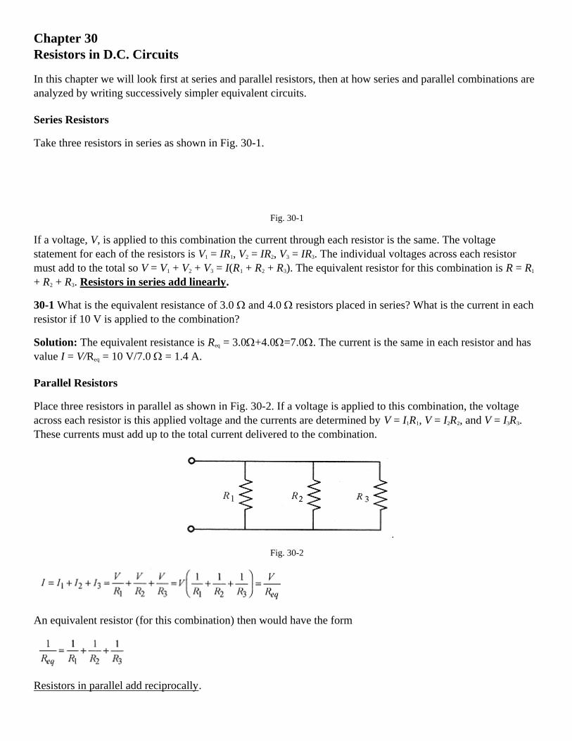
Chapter 30Resistors in D.C. Circuits
In this chapter we will look first at series and parallel resistors, then at how series and parallel combinations areanalyzed by writing successively simpler equivalent circuits.
Series Resistors
Take three resistors in series as shown in Fig. 30-1.
Fig. 30-1
If a voltage, V, is applied to this combination the current through each resistor is the same. The voltagestatement for each of the resistors is V1 = IR1, V2 = IR2, V3 = IR3. The individual voltages across each resistormust add to the total so V = V1 + V2 + V3 = I(R1 + R2 + R3). The equivalent resistor for this combination is R = R1
+ R2 + R3. Resistors in series add linearly.
30-1 What is the equivalent resistance of 3.0 Ω and 4.0 Ω resistors placed in series? What is the current in eachresistor if 10 V is applied to the combination?
Solution: The equivalent resistance is Req = 3.0Ω+4.0Ω=7.0Ω. The current is the same in each resistor and hasvalue I = V/Req = 10 V/7.0 Ω = 1.4 A.
Parallel Resistors
Place three resistors in parallel as shown in Fig. 30-2. If a voltage is applied to this combination, the voltageacross each resistor is this applied voltage and the currents are determined by V = I1R1, V = I2R2, and V = I3R3.These currents must add up to the total current delivered to the combination.
Fig. 30-2
An equivalent resistor (for this combination) then would have the form
Resistors in parallel add reciprocally.

30-2 What is the current in each resistor for a parallel combination of 3.0 Ω, 3.5 Ω, and 4.0 Ω resistors with8.0V?
Fig. 30-3
Solution:
The total current delivered by the power source is I = 2.7A + 2.3A + 2.0A = 7.0A. Now check the total by usingthe equivalence
Using the equivalent resistance (1.15Ω) the total current is I = V/Req = 8.0 V/1.15Ω = 7.0A.
Series-Parallel Combinations
30-3 Calculate the equivalent resistance of the series-parallel combination shown in Fig. 30-4.
Fig. 30-4
Solution: The first step in this circuit analysis is to find the equivalent of the parallel combination.
The circuit then becomes two series resistors and they add to a single resistor.
NOTE: The equivalent resistance of any two resistors is lower than either of the two alone.
Fig. 30-5

<><><><><><><><><><><><>
30-4 Apply 20 V across this network and find the voltage across and current through each resistor.
Solution: In order to find the current in a resistor in the original network, it is necessary to work back throughthe equivalent circuits. Start with the last circuit. Apply 20V to a 14.5Ω resistor for a current of I = V/R = 20V/14.5Ω = 1.4 A. Working backwards, this current through R1 produces a voltage across this resistor ofV1=(1.4A)R1=(1.4A)(8.0Ω)=11V. This current passes through the equivalent resistor R4 producing a voltageacross it of V4=(1.4A)R4=(1.4 A)(6.5Ω) = 9.1 V. V1 and V4 add to 20 V, the total applied, to within round offerror range. The 1.4A divides between R2 and R3. The voltage across R2 and R3 is V4 = 9.1 V so
Again this total adds to 1.4A, within round off error. This analysis produces the voltage across and currentthrough each resistor in the network. The numbers are internally consistent (the currents through R2 and R3 addup to the current through their equivalence) giving confidence in the calculation.
<><><><><><><><><><><><>
30-5 In the circuit of Fig. 30-6 calculate the voltage across, current through, and power requirements of the8.0Ω resistor when 15V is applied to the network.
Fig. 30-6
Solution: The first step in the analysis is to find the equivalent of R2 and R3.
A similar analysis on R4 and R5 yields
Now the equivalent can be drawn.

Fig. 30-7
The parallel combination of R6 and R7 produces another equivalent.
Fig. 30-8
The total current is I =V/R9 = 15V/6.1Ω=2.46A.
This current through the 2.1Ω resistor produces V8=(2.46A)R8=(2.46A)(2.1Ω)=5.16V.
Look back through the equivalent circuits and notice that this voltage is across R8, R6, and R2.
The current through R2 then is I2=V8/R2=V2/R2=5.16V/8.0Ω=0.64A.
The power dissipated in this resistor is I2R=(0.64A)2(8.0Ω)=3.3W.
<><><><><><><><><><><><>
The general procedure for circuit analysis is to look at the circuit and find parts of it that can be replaced withsimpler equivalents and just keep applying the process until the circuit is reduced to one resistor, perform V =IR on that resistor, and move back through the equivalents to obtain the desired information.

Chapter 31Kirchoff's Laws
Kirchhoff's laws applied to circuits containing multiple branches, voltage sources, and resistors allowcalculation of currents in each branch of the circuit. Start with a very simple circuit consisting of a battery andresistor. The battery polarity is taken as indicated with positive charge
Fig. 31-1
leaving the positive plate. The current is as indicated by the arrow. An amount of charge or current over timestarting at the negative plate of the battery is viewed as gaining energy in passing through the battery and losingthis same amount of energy in the resistor. The equation for this circuit is shown in Fig. 31-1.
Kirchhoff Voltage Loop Equations.
The V - IR equation for this simple circuit illustrates the first Kirchhoff law: The algebraic sum of the changesin potential (energy) encountered in a complete traverse of a path is zero. This is analogous to a conservation ofenergy statement.
The only difficulty in applying Kirchhoff's laws is keeping the algebraic signs correct. When confused, go backto this simple diagram of a battery and resistor and the current flowing (in the external circuit) from the positiveside of the battery through the resistor to the negative side of the battery. Write the V - IR = 0 statementestablishing that when a battery is traversed in a positive direction, there is a gain in energy giving V a plussign; and when a resistor is traversed in the direction of the current arrow, there is a loss in energy giving IR anegative sign. Every Kirchhoff law problem you do should have this little circuit drawn in a corner of the paperto remind you of the algebraic signs and their importance.
Think of a “piece of charge” traversing the circuit gaining energy as it passes through the battery and losingenergy as it passes through the resistor. In this simple circuit the direction of the current is clear. In multiplebranch circuits it is not possible to “guess” the correct directions for the currents. Make the best educated guessthat you can and let the mathematics tell you whether the currents are positive or negative.

Fig. 31-2
Consider the three branch circuit of Fig. 31-2. Make your best estimate of the current direction for each resistorand draw and label the current arrows. It is not necessary to have the direction correct, it is only necessary to beconsistent in applying the sign convention. Now make two loops around this circuit, one around the left andone around the right as indicated by the closed loops. Remember, when traversing a battery from minus topositive write +V and when traversing the resistor in the direction of the current arrow write -IR. Around thefirst loop
In traversing this loop start at the low, or negative, side of the 6V battery and proceed around the loop:
6 is positive
4I1 is negative because the resistor is traversed in the direction of the current arrow.
3I2 is positive because the resistor is traversed in the direction opposite to the current arrow.
7 is negative because the battery is traversed from plus to minus.
Around the second loop
Rewrite these two equations
Writing the equations this way illustrates very clearly that they cannot be solved. In mathematical languagethey are two equations in three unknowns. The third equation necessary to solve for the three currents comesfrom the next Kirchhoff law.
Kirchhoff Current Junction Equations
The second Kirchhoff law deals with the currents: the sum of the currents to any junction must add to zero.This law is often forgotten. It is, however, easily remembered via a whimsical law called the “fat wire law.” Thefat wire law is very simple. The sum of the currents to any junction must equal zero, otherwise the wire will getfat. Applying this second Kirchhoff law to the junction just above the 3Ω resistor

Now we have three independent equations in three unknowns.
NOTE: For convenience in the discussion, individual equations in a set of equations will be designated byletter symbols. The number of significant figures used in the calculations will be kept to a minimum so as not toobscure the mathematical procedure with numbers. Likewise, units will not be used. Several techniques forsolving multiple equations in multiple unknowns will be presented. It is not necessary to know all thesetechniques. Pick a technique that you feel comfortable with and learn it well.
At this point you may be asking why we did not take another loop to obtain a third equation. Taking anotherloop in the circuit will only serve to generate another equation which is a linear combination of the first twoloop equations. Take a loop around the outside of the circuit and write:
This equation is just the difference of the first two loop equations and is not a linearly independent thirdequation. Therefore it cannot be used to solve for the three currents. As an exercise take a figure eight patharound the circuit and prove that this statement is also a linear combination of the first two loop equations.
Solving by Adding and Subtracting
Now to the solution of these three equations. The most popular and direct approach is to add and subtractequations to produce two equations in two unknowns and then further add and subtract to solve for one currentand work backwards to find all the currents.
14I1+4I2+4I3=0
add (b) -4I1+3I2
=1
to obtain(α)
7I2-4I3=1
Combine equation (α) with 2/3 of equation (c) and write (α) and (β)
Place I2 = 1/3 into (c). 3(1/3)+6I3=3 or I3 = 1/3
Now place I2 = 1/3 and I3 = 1/3 into (a). I1+(1/3)-(1/3)=0 or I1=0
Check these current values in each of the original equations to verify that they are correct.

Solving by Determinants
Another method of solving these equations is with determinants. Using determinants to solve three equations inthree unknowns is explained in the Introduction, Mathematical Background. Your calculator may have analgorithm for solving simultaneous equations using determinants (sometimes called Cramer's rule), so this maybe your method of choice.
Going back to the equations marked (a), (b), (c) set up the master determinant and expand along the firstcolumn. Equation (c) is divided by 3 to reduce the numbers.
The determinant for I1 is expanded along the top row
The value of
The determinant for I2 is expanded about the top row
The value for
As an exercise set up the determinant for I3, expand along the top row, and verify the value of I3 obtainedpreviously.
Solving by Augmented Matrix
A third method of solving three equations in three unknowns is with an augmented matrix. Many calculatorsthat have internal programs for solving simultaneous equations require data to be input in a manner similar tothe augmented matrix form. The manipulations of the augmented matrix are similar to adding and subtractingequations to find a solution. Before applying this method to the equations for this problem look at a general setof three equations in three unknowns.
If the first equation were multiplied by -(k/a) and added to the third equation these three equations would read

What this accomplishes is to make the coefficient of x zero in the third equation. Now multiply the firstequation by -k/e and add to the second equation making the coefficient of x zero in the second equation. Afterthis, the second equation can be multiplied by a constant and added to the third equation with the constantchosen so as to make the coefficient of y in the third equation zero. Once this is accomplished the solutions areeasily written down. The procedure is better illustrated with a specific case, the previous problem. Theseequations already have some coefficients equal to zero making the process easier. This is usually the case withKirchhoff law analysis
Multiply the first equation by 4 and add to the second equation generating a new second equation.
This makes the coefficient of I1 equal to zero in the second and third equation producing two equations in twounknowns. Now multiply the second equation by -1/7 and add to the third equation generating a new thirdequation.
Now solve directly with I3=1/3. Substituting this into the second equation I2=1/3. Putting these two values intothe first equation obtains I1=0.
The augmented matrix method uses the coefficients from the equations. The adding and subtracting of equationsto generate other equations is done by multiplying and adding different rows of the matrix just as if they wereequations. As we go through the process imagine that the operations are being performed on equations.Working with the coefficients arranged in an orderly array is easier. Working the matrix so as to produce zerosstarting in the lower left hand corner and then moving diagonally across the matrix is easier than working theequations. Start with

There is already a zero in the lower left corner so we need to create a zero in the -4 position. Multiply the firstrow by 4 and add to the second row generating a new second row. This is equivalent to multiplying the firstequation by 4 and adding it to the second equation generating a new second equation, which is a linearcombination of the first two. This is exactly what is done in solving simultaneous equations by adding andsubtracting.
Now multiply the third row by -7 and add to the second row generating a new third row.
Now go back to the equations where 18I3 = 6 or I3=1/3.
Put I3=1/3 into 7I2-4I3=1 to obtain I2=1/3.
Put I2=1/3 and I3=1/3 to obtain I1=0.
These methods of solving multiple equations in multiple unknowns require considerable number manipulationwith the attendant chance for error. The augmented matrix method has the least number manipulation whileadding and subtracting may be more familiar to you. All of the techniques work. Pick the one that fits you, andthe set of equations you are solving, best and proceed carefully.
Applications
The procedure for solving Kirchhoffs laws problems is the following:
1. Draw the battery and resistor circuit in the corner of your paper to remind you of the sign convention.
2. Place current arrows next to each resistor and label them.
3. Pick a junction and write the current statement.
4. Draw loops and write the loop equations.
5. Solve for the currents and check them in the original equations.
31-1 Solve for the current in each of the resistors in the circuit shown in Fig. 31-3.
Fig. 31-3

Solution: Follow the procedure for Kirchhoff problems. This is a subject that is conceptually easy but becauseof the large number of manipulations often hard to actually do. Work this problem as you are following along inthe book. Draw the circuit and begin.
Draw the single battery and single resistor with current arrow and V - IR=0 equation.
Place and label the current arrows.
Write the statement of the “fat wire law” for the top center of the circuit.
Write a loop statement for the left side of the circuit.
Write a loop statement for the right side of the circuit.
Now write these three equations in a convenient form for solution.
As an exercise solve these equations and verify that the solutions are I1 = 17/47 = 0.36, I2=24/47 = 0.51, andI3=7/47=0.15. Check these answers in the original equations.
31-2 Consider a more complicated problem as shown in Fig. 31-4 and calculate the currents in the resistors.
Fig. 31-4
Solution: Draw the battery and resistor circuit and V - IR equation to remind you of the algebraic signconvention.
Note the current arrows. Remember that if one of the currents comes out negative it means only that the currentis opposite to the direction of your arrow.

Apply the “fat wire law” to the line across the top of the three resistors.
The loop around the top branch of the circuit is 6-8I1=0.
A loop around the lower left branch is 10-10I4-5I3-3=0.
A loop around the lower right branch is 3+5I3+6I2-6=0.
Rewrite the equations in convenient form for solving.
Immediately I1=3/4=0.75. Work the problem and verify that the other currents are I2=-0.20, I3=0.84, and I4=0.28.
31-3 Calculate the currents in the resistors of the circuit shown in Fig. 31-5.
Fig. 31-5
Solution: Draw the battery and resistor circuit and V - IR equation to remind you of the algebraic signconvention. Apply the “fat wire law” to the line across the top of the circuit.
The loop around the left branch is 4 - 6I1 - 3I2 + 2 - 4I2 = 0.
The middle loop is 4I2 - 2 + 3I2 - 8I3 = 0.
The loop around the right branch is -3 + 5I4 + 8I3 = 0.
Rewriting the equations in convenient form for solving

Work the problem and verify that the currents are I1=0.41, I2=0.51, I3=0.19, and I4=0.29.
Hint: First solve for I3 using determinants, then the rest of the currents by algebra.

Chapter 32R-C Circuits
Our first look at R-C circuits is with a simple word description of the charging phenomenon. The circuit shownin Fig. 32-1 is appropriate for the study of charging and discharging. After giving a general description of howthe circuit works, we will take a closer look at the mathematical description. Throughout the discussion, unlessthe context and notation indicate otherwise, lower case letters mean time varying quantities and upper caseletters constants. For example, q is the symbol for time varying charge on the capacitor while Q is the totalcharge.
Fig. 32-1
Charging.
Assume the capacitor has zero charge and voltage, and place the switch (S) in the charging position (up). Whenthe battery voltage is applied to the R and C in series, current begins to flow. Current through the resistor causesa voltage drop across the resistor. Because of this voltage drop, less than the battery voltage is applied to thecapacitor. As current flows, the capacitor charges and less and less current flows until there is no current, novoltage across the resistor and the capacitor is charged to the battery voltage (Q=CV).
The charge on the capacitor increases with time starting with zero charge and eventually reaching maximumcharge of CV following an exponential function.
This function fits our understanding of how the circuit operates since when t = 0, q is zero, and when t is verylarge, q=CV, the capacitor is totally charged.
The voltage on the capacitor is
Here the notation VC denotes the time varying voltage on the capacitor.
The current in the circuit declines exponentially according to i=(V/R)e-t/RC
With this description of the operation of the charging circuit, we can proceed to a more detailed (mathematical)analysis of the charging situation.

When the battery voltage is applied to R and C, voltages across these components vary with time. We can,however, write a Kirchhoff-type voltage statement that is correct for the entire time the circuit is charging. Thisis called an instantaneous voltage statement; it is true at any instant of time. Following Kirchhoff's law
This equation can be integrated with a change of variable. Replace q-CV with x so dq = dx.
Then The integral of the left side is In(x)=In(q-CV), so
Choosing the constant as InK1 is very convenient, allowing further simplification.
Notice that the logarithm equation goes into an exponential equation. This is not an every day mathematicaloperation. Review the Introduction, Mathematical Background, and be sure you understand how to go from alogarithmic equation to an exponential one. Rewrite the equation
and apply the condition that at t=0, q=0, or 0 = CV + K1, or K1 = -CV, so finally
Obtaining this expression for q looks easy, and it is if you remember to choose the constant for convenience insolving the equation, remember how to switch from a logarithmic equation to an exponential equation, andapply the initial conditions correctly.
The voltage across the capacitor is
The current in the resistor is
The voltage across the resistor is

Two graphs are particularly helpful in understanding the situation; one of q versus t, and the other of i versus t.
Fig. 32-2
Notice in the curve of q versus t, that at t = 0, q = 0, and as t → ∞, q → CV.
In the curve of i versus t, at t=0, i=V/R, and as t → ∞, i → 0.
At t = 0, the charge on the capacitor is zero and the current is maximum; and as t goes to infinity, the currentgoes to zero and the charge reaches its maximum of CV.
The Time Constant
In biological systems that grow exponentially the systems are often characterized by giving the doubling time,the time for the system to double in number, size, or mass. In electrical systems that grow exponentially thesystems are characterized by a time constant, the time to make the exponent of e equal to 1. The time constantfor this circuit is RC (see equation 32-1). As an exercise verify that the units of RC are seconds.
Look at equation 32-1 and the q versus t graph. When t=RC, 1-e-1=0.63 and the charge on the capacitor hasrisen to 0.63 of its final value. A similar statement can be made about the voltage on the capacitor. After onetime constant, the voltage on the capacitor is 0.63 of the battery voltage.
The current, meanwhile, has in one time constant dropped to e-1 = 0.37 of its initial value.
32-1 A 10kΩ resistor and a 20µF capacitor are placed in series with a 12V battery. Find the charge on thecapacitor, the current, and the voltages on the capacitor and resistor at the instant the switch is closed, t = 0.
Solution: At t = 0 the charge on the capacitor is zero.
At t=0, the current is i=V/R=12V/10×103Ω=1.2×10-3A.
At t=0, the voltage on the capacitor is zero (it has no charge) and the entire battery voltage of 12V is across theresistor.
<><><><><><><><><><><><>
32-2 For the circuit of problem 32-1, find the time constant, and the charge, current, and VR, and VC at a timeequal to one time constant.
Solution: The time constant is RC=10×103Ω.20×10-6F = 0.20s.
The charge on the capacitor at t = 0.20s is
The current at t= 0.20s is
The voltage across the capacitor is VC=V(1-e-1)=12V.0.63=7.6V.
The voltage across the resistor is 12V-7.6V=4.4 V.
These problems can be deceptively easy. Be sure you know how to manipulate the exponents on yourcalculator. Don't get a test problem wrong because you did not practice all the steps in the problem and wereunfamiliar with manipulating exponents on your calculator.
<><><><><><><><><><><><>
32-3 For the circuit of problem 32-1, how long does it take for the capacitor to reach 80% of its final charge?
Solution: This problem is similar to radioactive decay problems where we want to know the time for half thematerial to decay. There is a fair amount of algebraic manipulation that is easier to follow without numbers, sothe problem will be worked as far as possible with symbols.
Start with q=CV(1-e-t/RC) and note that the final (fully charged) q is equal to CV.
Mathematically, when t → ∞, e-t/RC → 1 so q → CV.
To find the time for 80% charge set q equal to 80% of the final charge, or q=0.80CV, and solve for t.
For convenience switch to positive exponents so 1/e-t/RC=0.20 or e-t/RC=1/0.20=5
In order to solve for t, switch the exponential equation to a logarithmic equation. One of the functions oflogarithms is to solve for variables in exponents.
Now put in the values for R and C.
As a check note that 1-e-t/RC=1-e-0.32/0.20=0.80
Discharging
After the capacitor is left to charge for a long time (many time constants) the charge is CV. Move the switch tothe discharge position (down in Fig. 32-1) where R and C are in series. When the charged capacitor and resistorare placed in series the charged capacitor acts as a battery. The voltage on the capacitor is q/C, and this voltageappears across the resistor as iR. As time goes on, the charge on the capacitor is depleted and the current drops(eventually) to zero. The charge decays according to

and the current according to
The negative sign indicates that the current in the resistor is in the opposite direction from the chargingsituation, which must be the case.
Mathematical analysis of the discharge circuit starts with a Kirchhoffs law loop type of statement.
and solving
Again notice that the choice of constant is very convenient because
Now impose the initial condition, At t=0, q=CV, so K2=CV and
The charge on the capacitor decays with the same time constant, RC.
32-4 For the circuit described in problem 32-1 placed in the discharge mode, how long does it take for thecircuit to discharge to 50% of its original (total) charge?
Solution: Solve equation 32-5 for t when q=0.50CV
It is more convenient to write 0.50 as 1/2, so when the statement is converted to logarithms,
In terms of time constants this would be 1n2 time constants, or 0.69 of a time constant.

It makes sense that our answer is less than one time constant since it takes less time for the charge to decline to50% of its initial value than to 37% (1/e) of its initial value.
32-5 An RC circuit is observed during discharge to have an initial capacitor potential of 100V and after 3.0s tohave a potential of 20V. How long will it take for the capacitor to discharge to 1.0V.
Solution: The voltage across the capacitor at any time is determined by equation 32-5 rewritten as q/C, orVC=Voe-t/RC, where Vo is the voltage at t = 0.
Take Vo=100, VC = 20V, and t = 3.0s and write
Switching to logarithms
Knowing this number, the specific decay law for this circuit can be written V = 100Ve-t/1.9.
Now calculate the time for the voltage to drop to 1.0V.
Switching to logarithms
Go back over this problem and note the procedure.
1. After reading the problem, the general law (equation) was written down, VC=Voe-t/RC.
2. Next the data from the problem (100V going to 20V in 3.0s) was used to find RC.
3. With RC the specific law for this problem was written, V=100Ve-t/1.9.
4. Finally, with this specific law the predictive calculation was performed to find the time for the 100V to decayto 1.0V.
This analysis procedure is typical of growth and decay problems in general. Be familiar with the steps in thisprocedure. It will keep you from getting lost and not knowing how to proceed in problems like this.

Chapter 33Magnetic Fields
The magnetic field or B field is a field that produces a force on a moving charge. This is not the onlydefinition, but it is a good operational definition to start with. The force is given by the vector relation
Cross products are discussed in detail in the Introduction, Mathematical Background. In a coordinate system therelation is shown in the accompanying figure.
Fig. 33-1
To fix the direction of the force on a positive charge, place the right hand with fingers pointing in the directionof v, and a line normal to the palm of the hand pointing in the direction of B. Curl the fingers naturally into B.The thumb points in the direction of F. For a negative charge the force is in the opposite direction. The force isa right angles to the plane of v and B.
Since this is a vector it can be expressed as a cross product in determinant form,
or in magnitude and direction form, F = vB sin φ, where φ is the angle between v and B and F points in adirection normal to the plane of v and B as determined by the right-hand rule.
Most problems involve v and B at right angles, so the magnitude of the force reduces to the product of q, v, andB with the direction of F determined by the right-hand rule.
The units of B are (from the force equation 33-1) N.s/C.m or N/A.m, which is called a Tesla (T). The Tesla isrelated to the smaller and widely used unit the gauss (1 Tesla = 104 gauss).
33-1 Calculate the deflection of the electrons in a typical video display tube due to the earth's magnetic field.Take the electrons with 10KeV energy. Orient the tube north to south and with the electron beam at right anglesto the earth's B field of 0.40 gauss.
Solution: First calculate the velocity of the electrons using an energy relation eV = (1/2)mv2.

Convert gauss to Tesla: 0.40 gauss(1T/104 gauss) = 4.0 × 10⁻⁵ T.
The force on the electron is
Fig. 33-2
Now for the direction. Place the right hand in the direction of v (out of the paper) and curl the fingers into B(down) so the thumb points to the right (looking at the paper). Because this is a negative charge, the force is tothe left.
The electron is deflected in a horizontal plane. B in the vertical direction always produces a force in thehorizontal plane and at right angles to the velocity causing the electron to move along a circular path. A masswhirled on the end of a string moves in a circle because the (centerdirected) force is at right angles to thevelocity throughout the motion.
This last problem is typical of many problems with charged particle trajectories in magnetic fields where the Bfield is always at right angles to the motion so the vector problem reduces to one of finding the magnitude of theforce and then determining the direction via the right-hand rule. This next problem is illustrative of a moredifficult problem where the velocity vector has two components. Be sure you have mastered the calculation inproblem 33-1, and above all the direction, before moving on to this more difficult problem.
33-2 Take an electron with velocity (components) v = 2.0 × 10⁶ i-3.0 × 10⁶ j m/s and a B field of B = 4.0 × 10⁻³
K T.
Solution: The force vector in component form is

It is a bit hard to envision, but a velocity vector in the x-y plane curled into a B-field vector in the z-directionproduces a force vector in the x-y plane. Figure 33-3 shows the orientations.
Fig. 33-3
There are several classic phenomena, experiments, and equipment associated with moving charges in B-fields.These are both interesting and instructive. You will probably use one or more of these instruments in yourwork.
The Cyclotron
If a particle with negative charge, mass, and velocity is injected into a B field in a plane normal to the field theforce is at right angles to the velocity and remains at right angles to the velocity throughout the motion causingthe charged particle to go in a circle as shown in Fig. 33-4. A positively charged particle would move in a circlein the opposite direction.
Fig. 33-4
The force is at right angles to the velocity. Apply the v × B law for a negative charge. The magnitude of thisforce is qvB, and it is always at right angles to the velocity. From mechanics, a motion produced by a force atright angles to the velocity is circular, thus the charged particles move in circular orbits. This qvB forceprovides the (mechanical force)mv2/r, so equating these forces
There are several relations that follow from this statement, but for the cyclotron the most important is one forthe orbit radius
and the one for the angular frequency

33-3 An electron of energy 4.0 KeV is circulating in a plane at right angles to a magnetic field of 3.0T. What isthe radius of the orbit?
Solution: The geometry is the same as in Fig. 33-4. First, calculate the velocity from the energy.
Now calculate r
33-4 An α-particle moves in a circle of radius 5.0 × 10⁻² m in a magnetic field of 2.0 T. Find the speed of the α-particle and the frequency and period of the motion.
Solution: An α-particle is a helium nucleus, which has two protons and two neutrons. The speed of the α-particle is from the defining equation for the cyclotron.
The angular velocity is (analogous to mechanics)
The frequency, or what is called the cyclotron frequency, is f = w/2π = 1.5× 10⁷ 1/s.
The period, or time for one transit of the circle is T = 1/f = 6.7 × 10⁻⁸ s.
<><><><><><><><><><><><>
A cyclotron is a device for accelerating charged particles while they are being forced to travel in a circular pathby a magnetic field. A source of, say, deuterons is placed at the center of the device. A deuteron is a proton andneutron combination with one electronic charge and 2 amu. An amu (atomic mass unit) is the average mass of anuclear resident (neutron or proton). The deuterons exit the source with a small velocity to the right. The radiusof the circular orbit is given by r = mv/qB and is quite small. The particle enters a semicircular open areabetween “D” shaped plates and travels in a circular orbit until it exits the “D” area. The voltage between theDees, as they are called, is alternated sinusoidally so that on leaving the right Dee the particle is accelerated andassumes a new (larger) orbit in the left Dee. When the particle leaves the left Dee the voltage is again switchedso that acceleration is accomplished across the Dees. Remember that the angular frequency is qB/m, and is notdependent on velocity!

Fig. 33-5
33-5 Calculate the frequency of oscillation of the Dee voltage for a deuteron in a 2.0T magnetic field.
Solution:
<><><><><><><><><><><><>
33-6 What is the maximum energy of a deuteron in this cyclotron with maximum available radius of 1.5m?
Solution: The kinetic energy is (1/2) mv2, but v can be written in terms of the r, q, B, and m according to thebasic equation defining the cyclotron orbits.
The deuteron gained this large amount of energy by making many traverses of the distance between the Dees asthe voltage was alternating at the cyclotron frequency.
The Mass Spectrometer
Another application of the circular orbits in a magnetic field is in the mass spectrometer. Ionized atoms areinjected into a magnetic field at a known energy (velocity). They take up circular orbits with radii determinedby their mass. The ions are detected with a photographic plate or traveling collector.
The ions are accelerated (by a voltage) to a particular energy before they enter the magnetic field region. Theirenergy is their charge times this accelerating voltage. This is the energy the ions have while orbiting in themagnetic field. (See the previous problem.)
Fig. 33-6

The ions strike the photographic plate a diameter x = 2r from the injection point, so
33-7 Calculate the mass of a singly charged ion accelerated through 4120V and striking the collection area at7.0 × 10-2 m from the entrance point in a 1.0T field.
Solution:
The ion is carbon 14, an isotope of carbon 12.
<><><><><><><><><><><><>
Another function of this type of mass spectrometer is to separate out isotopes, atoms with the same nuclearcharge and number of electrons but with different nuclear mass. The sensitivity of the spectrometer can befound by looking at the variation of x with m. Start with
and ask how m varies with x:
The sensitivity is measured by the ratio of ∆m tom.
33-8 Calculate the resolution required of the photographic plate to differentiate between carbon 12 and carbon14.
Solution: Use the diameter from the previous problem, 7.0 × 10⁻² m, and m as 12 amu with ∆m as 2 amu.
This value is easily obtained on a photographic plate.
The J. J. Thomson Experiment

The J. J. Thomson experiment uses crossed electric and magnetic fields to measure the charge to mass ratio forthe electron. This was a classic turn-of-the-century experiment.
Fig. 33-7
The force equation for moving electrons subject to both electric and magnetic fields is
The electric and magnetic fields are arranged as shown. Verify that a negatively charged particle willexperience a “down” force due to the magnetic field and an “up” force due to the electric field. In the tube, thevoltage V accelerates the electrons from the hot filament and the electrons enter a field-free region between theaccelerating grid, shown as the dotted line, and the video screen.
In the experiment, a deflecting electric field is applied and the spot on the screen is observed to move up on thescreen. The B field is added to bring the spot back to zero deflection. In this situation the net force is zero andbecause of the directions of E, v, and B, E = vB.
33-9 An electric field of 1.0 × 10³ V/m and a magnetic field of 0.35T act on a stream of electrons so as toproduce zero net force. What is the speed of the electrons?
Solution:
<><><><><><><><><><><><>
The velocity of the electrons is determined by the accelerating voltage in the tube. The electrons are acceleratedbefore they enter the region of crossed E and B fields and travel through this region and to the screen withoutfurther acceleration axially down the tube. The kinetic energy of these electrons is eV, the electronic chargetimes the accelerating voltage. For zero deflection an energy statement can be made replacing v with E/B.
from which

The charge to mass ratio for the electron can be determined by the applied voltage and fields in the tube.
33-10 Calculate the charge to mass ratio for charged particles in a J. J. Thomson tube with accelerating voltageof 3000V and crossed fields of E = 6.5 × 10⁴ V/m and B = 2.0 × 10⁻³T.
Solution:
Verify that this is the correct charge to mass ratio for electrons.
The Hall Effect.
The Hall effect is used to determine the algebraic sign and number density, n, of charge carriers in a conductor.Set up a slab of unknown material in a magnetic field as shown. In one sample (left
Fig.33-8
side of Fig. 33-8) assume the current is due to charge carriers that are positive, and, in the other, negative.Apply the v × B force on each, with the B field directed into the page, and notice that despite the sign of thecarriers they will be deflected to the right. This accumulation of carriers will create a “transverse” or Hallvoltage, which has a different direction depending on the sign of the charge carriers. In the sample on the left(positive charge carriers) point b is at a higher potential than point a. In the sample on the right (negative chargecarriers) point b is at a lower potential than point a. The sign of the voltage produced in the Hall experimentgives the sign of the charge carriers. Charges build up to produce an electric field (the transverse Hall field) thatjust balances the magnetic force on the charge carriers.
This Hall field is EH = VHd.
The Hall field is also the E in the statement for zero force, 0 = qE + qv × B.
This produces a Hall field of EH = vdB.
The current density in the sample is j = nevd.
Combining, from which the charge carrier density is

33-11 In a Hall experiment the current is 2.0 × 10⁻³ A when 2.0V is applied to a semiconductor of length 6.0cm,width 3.0cm, and depth 0.20cm. A magnetic field of 2.0 T produces a Hall voltage of 2.0×10⁻⁴ V. Find the signof the charge carriers, their number density, and the resistivity of the material.
Fig. 33-9
Solution: The sign of the Hall voltage indicates negative charge carriers. Now calculate the current density.
The Hall field is EH = VH/d = 2.0 × 10⁻⁴ V/3.0 × 10-2 m = 6.7 × 10⁻³ V/m.
The number density of charge carriers is
The resistivity of the sample is easily calculated from the defining statement E=ρj and remember that this E isnot the Hall field but the field driving the current through the sample.
These measurements of the sign of the charge carriers, their number density, and the resistivity are veryimportant in the characterization of semiconductor material.

Chapter 34Magnetic Forces
Magnetic fields exert forces on moving charges. If these charges are confined to wires then the fields can bethought of as exerting forces on current-carrying wires. The vector equation for the force is
where l is the length of the wire taken in the direction of the current. In most instances it is not necessary to do aformal vector cross product because the direction of the current and the magnetic field are perpendicular. Theone instance where this becomes important is in considering the torque on a current-carrying wire. This problemis central to several topics and is taken up as a separate exercise.
34-1 A typical problem illustrating the force on a current-carrying wire is the problem of a wire of 0.010kg and1.0m in length suspended by springs in a B field of strength 30T directed out of the page. What current willcause zero tension in the springs?
Fig. 34-1
Solution: First consider the direction of the current. The force due to the magnetic field has to be up so thecurrent has to be from right to left. With the right hand, form I × B with i in both directions to verify thisconclusion. The value of the current that makes for zero tension in the springs occurs when the force due to themagnetic field balances gravity. This is a force-balance problem.
34-2 Another problem illustrating this force is a rod or bar resting on current-carrying rails with a perpendicularmagnetic field. Take the field as 0.50 gauss (approximately the earth's field) and the separation as 3.0m andcalculate the current needed through the bar of mass 0.20kg with coefficient of friction 0.070 to make it slidealong the rails.
Fig. 34-2

Solution: The orientation of current (either direction in the bar) and magnetic field is such that the forceproduced by the il × B will slide the bar along the rails. Verify this with the right-hand rule. The force opposingthis sliding is µmg so this is a force-balance problem.
A Current-Carrying Loop in a B Field
The study of torque on a current-carrying loop leads to the definition of the magnetic moment of a circulatingcurrent, the understanding of the meter movement (voltmeter and current meter), and electric motors andgenerators. A loop of wire placed in a magnetic field and oriented as shown in Fig. 34-3 will have no torque ormaximum torque, depending on the orientation (rotation) of the loop with respect to the magnetic field.
Fig. 34-3
As shown in the middle diagram the piece of wire on the right carrying a current, i, represented by the tail of thecurrent arrow, has a force to the right (l × B) producing no torque. The piece of wire on the left produces a forceto the left also producing no torque. In the diagram on the right the forces are in the same direction but for thisorientation of the coil the torque is a maximum.
Figure 34-4 shows the torque for angles other than for zero or maximum torque. The torque is the component ofthis force at right angles to the line connecting the two sides of the coil times b/2 (the lever arm) times 2 (twowires).
Fig. 34-4
The appropriate component of the force is F sinα. The vector, m, the magnetic moment, is normal to the planeof the coil and points in the direction of the thumb when the fingers are curled naturally in the direction of thecurrent in the coil. The angle between m and B is the same as the angle between force and lever arm.

The product ab is the area,A, of the loop. The sin α term implies a cross product and if iA is taken as themagnitude of m, the magnetic moment, with the direction as defined in Fig. 34-4 then the vector equation forthe torque is
34-3 Find an expression for the torque on a circular coil of radius α carrying a current I placed at an angle to amagnetic field.
Fig. 34-5
Solution: The definition of the magnetic moment and the expression for the torque based on the magneticmoment is most convenient. The magnetic moment is m = I A = πa2I. The magnitude of the torque is T = mBsinα = πa2 IBsin α and the direction is the direction determined by m × B.
<><><><><><><><><><><><>
34-4 Find the maximum torque on a circular coil of 0.050m radius with current of 0.50A and in a magnetic fieldof 0.0050T.
Solution The maximum torque is
<><><><><><><><><><><><>
34-5 The plane of a 10 turn rectangular loop of wire 3.0cm by 4.0cm carrying 2.0A is at an angle of 60° withrespect to a magnetic field of 20 T. What is the torque on the loop in this position?
Solution: First calculate the magnetic moment noting that the current is not due to one loop but ten loops. m =IA = 10.2.0A.12×10-4 m2 = 2.4×10⁻² A.m2. Refer to Fig. 34-5 and note that if the angle between the plane of thecoil and the magnetic field is 60°, then the angle between m and B is 30°, so the torque is

<><><><><><><><><><><><>
34-6 An interesting problem is to ask the question, “What dimensions of rectangle will produce maximumtorque for the same length of wire?”
Solution: Take a rectangle with length l, width w,2 and perimeter equal to p=2l+2w. The perimeter relating l tow is the constraint in the problem. The torque is T = mB = I AB = IlwB. Before looking for a maximum we needto write l or w in terms of the constraint p.
Now take two derivatives of T with respect to w
The first derivative is zero (indicating a maximum or minimum) when p = 4w and putting this requirement infor p in the constraint equation (2l + 2w = 4w) requires that l = w. The rectangle must be a square. The secondderivative is always negative indicating that the curve is everywhere concave down and that this point is amaximum.
d'Arsonval Meter Movement
A schematic of a d'Arsonval galvanometer is shown in Fig. 34-6. The torque on a loop in a magnetic field offsetby the torque of a spiral spring as shown here is the basis for mechanical meter movements. Galvanometers aremid-reading meters. Current meters use parallel (with the coil) resistors to change the scale of the meter.Voltmeters use large series resistors to take the small currents necessary to activate the meter to measurevoltage.
Fig. 34-6

The plane of the coil is parallel to the magnetic field so that a small current in the coil produces a torque on thecoil which is offset by the torque of the spiral spring. With this arrangement, the rotation of the coil isproportional to the current. The external magnetic field (supplied by the permanent magnet) is curved (shaped)so the field is parallel to the plane of the coil through an angle of typically sixty degrees. Meter movements arerated as to how much current causes full scale deflection. A movement with a full scale deflectioncorresponding to 1.0µA is typical.
Energy Storage in Magnetic Materials
Magnetic dipoles placed in a magnetic field experience a torque. A simple model of a magnetic dipole is amolecule with a circulating current. These dipoles are rotated depending on the restoring torque of the material(structure). Picture a collection of magnetic dipolar molecules in a crystalline structure rotated by an externalmagnetic field thus stressing the structure. Consider the work done on a magnetic dipole by the application ofan external magnetic field. This work is equivalent to the energy stored in the dipole-field combination.
The energy of the system is taken as zero when m and B are at right angles (α= 90°). The energy at a position α,analogous to both the electrical and mechanical relationship between torque, angle, and energy, is
In vector notation
34-7 A coil of 5.0 × 8.0 cm dimensions and carrying a current of 0.0020A is rotated 45° by a 20T magnetic fieldfrom parallel to the plane of the field to an angle of 45° with respect to the field (see Fig. 34-5). Calculate theenergy of the system.
Solution: The energy of the system is
This is the energy stored in the system. An external agent would have to perform this amount of work to movethe dipole (coil) back to parallel with the external magnetic field.

Chapter 35Ampere's Law
Ampere's law describes the magnetic field produced by a current-carrying wire. Two statements give acomplete description of the magnetic field around a wire. The strength of the field is given by
where µo = 4π×10-7 Wb/A.m is the (magnetic) permeability. The direction of the field is (a vector) tangent to acircle about the current-carrying wire normal to the plane of the current. With the thumb of the right hand in thedirection of the current the fingers naturally curl in the direction of the B fields tangent to concentric circles.The drawing on the left side of Fig. 35-1 is a view of a current coming out of the paper showing the field as avector tangent to the circle and the drop off of the magnetic field with radius. The diagram on the right side is athree dimensional view of the magnetic field around a current-carrying wire.
Fig. 35-1
Ampere's law is written in the form of an integral
where i is the current contained within the path of the integral. This integral sign with a circle means that theintegral is to be performed over a closed path. In this case the path is a circle in a plane normal to the current(see Fig. 35-1). The circular path is centered about the wire where the magnetic field is a constant. Over thiscircular path the magnetic field vector and dl, the vector representing an element of length of the circle areparallel so the sum of (integral of) their dot product, B. dl, is the constant B times the circumference of thecircle or B(2πr). Remember that the dot product is the product of the projection of one vector onto another.
35-1 Calculate the magnetic field 7.0m below a power line carrying 12000A of current.
Solution:

This is comparable to the earth's magnetic field. Assuming the power line is parallel to the surface of the earththen the magnetic field produced by this power line is also parallel to the surface of the earth.
<><><><><><><><><><><><>
35-2 Two long parallel wires separated by 0.60m carry antiparallel currents (the currents are physically parallelbut in opposite directions) of 7.0 A each. What is the resulting field along the line between the wires and 0.40mfrom the lower wire?
Fig. 35-2
Solution: At the specified position the magnetic field due to wire 1 is
and directed as shown (right thumb in direction of current with fingers curled). The magnetic field due to wire 2is
and directed as shown. The total magnetic field is 10.5×10⁻⁶T.
The Force on Current Carrying Wires
Parallel wires carrying currents I1 and I2 produce a force on one other. Take the currents as parallel as shown inFig. 35-3. The current in wire 1 produces a magnetic field at wire 2 of magnitude B1 = µoII/2πd. This field isdirected down as shown and produces a force on wire 2 of magnitude F2=B1I2l. These forces are usually writtenin terms of force per unit length and this is most convenient in this problem. The force per unit length on wire 2produced by the magnetic field associated with I1 is

The force on wire 2 due to the magnetic field produced by wire 1 is toward wire 1. Go through the v × Boperation until this is clear in your mind. If you encounter a test problem concerning forces on wires inevitablyone part of the question will concern the direction and you don't want to get something this simple wrongbecause you didn't practice the v × B operation.
Fig. 35-3
This is the experimental setup that is used to define the ampere. A current produces a magnetic field thatproduces a force on another current. Using Ampere's law and this setup current can be related directly tomechanical force.
<><><><><><><><><><><><>
35-3 Consider two wires coming out of the page carrying equal, and oppositely directed, currents as shown inFig. 35-4. The wires are suspended from a common point with 0.40m long cords. The wires have a mass perunit length of 30 × 10-3 kg/m. Calculate the current to produce an angle of 6°.
Solution: This is a force-balance problem. The horizontal component of the tension (force) in the cord mustequal the force due to the currents. Look at 1.0m of the wire. The mass of 1.0m of wire is 30 × 10-3 kg, and theforce due to gravity mg = 0.29N. This must equal the vertical component of the tension in the cord. From thegeometry,
Fig. 35-4
In Fig. 35-4 the separation of the wires is 2s where s is defined in the figure through sin6° = s/0.40m or s =0.40m.sin6°. The electric force produced by the current in one wire producing a magnetic field that acts on thecurrent in the other wire is

and this force must equal the mechanical force, or tension, in the cord so
and solving for I
<><><><><><><><><><><><>
35-4 Calculate the magnetic field 10cm perpendicular to the bisector of the line connecting two wires 2.0cmapart and carrying antiparallel currents of 100 A each as shown in Fig. 35-5.
Fig. 35-5
Solution: The magnitude of the magnetic field from each wire is µoI / 2πd. Because of the geometry the verticalcomponents of B1 and B2 add to zero. The horizontal components add to a vector pointing toward the centerline
of the wires with magnitude B = 2B1sin θ. The dimension . The sin Themagnitude of the resultant field is
Concentric Currents.
In the statement of Ampere's law, the i is the current contained within the path of the integral. Thisis illustrated in the following problem. Take a cylindrical conducting wire of radius 4a and total current I out ofthe plane of the page. The current is uniformly distributed over the cross-sectional area of the wire.

Fig. 35-6
First calculate the magnetic field at r = 6a using B = µoI/2πr: B = µoI/12πa.
Now calculate the magnetic field within the wire at a radius of 3a.
The I in this case is the fractional part of I contained within the 3a radius or
Applying Ampere's law
Another variation of this problem is concentric conductors with equal and opposite currents as shown in Fig.35-7. Remember, the magnetic field over a circular path (Ampere's law) is related to the net current within thepath.
The inner conductor is solid and has radius a. The outer conductor is hollow, having an inner radius b and anouter radius c. The currents are numerically equal but in opposite directions. Look at the magnetic field overseveral regions.
Fig. 35-7

Average Field Outside a Wire
Another application of Ampere's law involves the calculus concept of average value of a function.
35-5 Calculate the average value of the magnetic field from 0.50 to 0.10m radially out from a long wire carrying100 A.
Solution: The magnetic field falls off radially according to B = µ0I/2Πr. The average value of the function overthis interval is the integral of the function (the area under the curve of B vs r) divided by the radial distance. Seethe Introduction, Mathematical Background, for the definition of the average value of a function.
Fig. 35-8
The Solenoid
A popular device that is based on the application of Ampere's law is the solenoid, a tightly wound coilproducing a nearly uniform magnetic field along the axis of the coil. The coil is shown in Fig. 35-9.
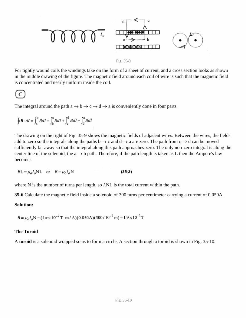
Fig. 35-9
For tightly wound coils the windings take on the form of a sheet of current, and a cross section looks as shownin the middle drawing of the figure. The magnetic field around each coil of wire is such that the magnetic fieldis concentrated and nearly uniform inside the coil.
The integral around the path a → b → c → d → a is conveniently done in four parts.
The drawing on the right of Fig. 35-9 shows the magnetic fields of adjacent wires. Between the wires, the fieldsadd to zero so the integrals along the paths b → c and d → a are zero. The path from c → d can be movedsufficiently far away so that the integral along this path approaches zero. The only non-zero integral is along thecenter line of the solenoid, the a → b path. Therefore, if the path length is taken as L then the Ampere's lawbecomes
where N is the number of turns per length, so IoNL is the total current within the path.
35-6 Calculate the magnetic field inside a solenoid of 300 turns per centimeter carrying a current of 0.050A.
Solution:
The Toroid
A toroid is a solenoid wrapped so as to form a circle. A section through a toroid is shown in Fig. 35-10.
Fig. 35-10

The application of Ampere's law is very straight forward. The path for the integral is along the center line of thetoroid where the magnetic field is constant, so
reduces to
where n is the total number of turns in the toroid. But n/2πr is the turns per unit length. Call this N, as before, sothe field in a toroid is
35-7 Calculate the magnetic field in a toroid of 600 turns, current of 0.76A and center line radius 0.50m.
Solution:

Chapter 36Biot-Savart Law
Ampere's law allows convenient calculation of the magnetic field surrounding a straight current-carrying wire.While the law is written in calculus terms the application is quite easy and involves little formal calculus formost problems. The Biot-Savart law is more general than Ampere's law and allows calculation of the magneticfield in the vicinity of curved wires. Application of the Biot-Savart law involves considerable calculus. If youare interested only in the application of the formula for the magnetic field on the axis of a current carrying coilyou may want to skip directly to the problems involved with these calculations. For the physics student with areasonable background in calculus the Biot-Savart law is very good for learning how to interpret a differentiallaw written in vector format.
The magnetic field due to a moving charge or a current is given by the Biot-Savart law.
These are vector equations. They allow calculation of the magnitude of the magnetic field and show thedirection of that field. The equation on the left applies to moving charges and states that the magnetic field at arhas magnitude µoqv/4πr2 and direction determined by the cross product of v and the unit vector . Theequation on the right applies to currents in wires and states that the contribution of a length of wire dlto themagnetic field is µoIdl/4Πr2 and the direction is the direction determined by the cross product of dl and the unitvector . The following problem will help in visualizing the cross product.
36-1 Calculate the magnetic field a distance x radially out from a wire carrying a current I.
Solution: Figure 36-1 shows the geometry for calculating the magnetic field due to an element of current in thewire. Use the differential form of the Biot-Savart law
and integrate. The vector dl is in the direction of 1, and the angle θ is the angle between the vectors dl and r.Cross dl (in the direction of I) with r to see thatB, at the point P, is into the paper.
Fig. 36-1

Integrate from -a to a and then let a go to infinity to find the expression for the magnetic field due to a longstraight wire. This specific integral was done in problem 25-5 in Chapter 25, Electric Field. Follow along thesteps in problem 25-5 and work through this problem to confirm that the magnetic field outside a long current-carrying wire is µoI/2πr, in conformity to Ampere's law.
<><><><><><><><><><><><>
36-2 Calculate the magnetic field on the axis of a circular loop of current.
Fig. 36-2
Solution: The Biot-Savart law is most convenient for solving this problem. The cross product of dl and givesthe direction of the field along the axis as being at right angles to rand in the plane defined by x and r. The loopof current and dl are in the y-z plane. Start with the law in differential form (equation 36-1) and write the x andy components of the field.
For every differential increment of length on the loop there is another differential increment of length across adiameter also producing a contribution to the field. Looking at the components of these fields, the x componentsadd while the y components add to zero leaving only the x component that contributes to the resultant field. Thefield then reduces to the integral of the x component.
At the center of the loop, x = 0 and the expression for the field reduces to

For a coil of N loops the current is multiplied by N.
<><><><><><><><><><><><>
36-3 What is the magnetic field at the center of a circular coil of radius 5.0 × 10⁻²m carrying a current of 0.25 Aand having 40 turns?
Solution: The field is perpendicular to the plane of the loop at the center and has value
<><><><><><><><><><><><>
36-4 For problem 36-3, what is the field 5.0 × 10⁻¹m distance along the axis?
36-5 A 3.0µC charge at x = 0, y = 1.0m has a velocity vx = 5.0 × 10⁷ m/s. A -4.0µC charge at x = 2.0m, y = 0 hasa velocity vy = 8.0 × 10⁷ m/s. What is the magnetic field at the origin due to the motion of these charges?
Solution: For the first charge the vector points down (from the charge to the origin) and v × shows themagnetic field at the origin as into the page. The magnitude of this field is
Fig. 36-3
For the second charge the vector points to the left (from the charge toward the origin) and v × is a vectorpointing out of the page, but the negative charge makes the field point into the page. This magnetic field hasmagnitude

The total magnetic field is 2.1 × 10⁻⁵ T directed into the page.
<><><><><><><><><><><><>
36-6 What is the magnetic field at the center of a semicircular piece of wire with radius 0.20m and carrying150A of current?
Solution: Start with equation 36-1 in differential form, and referring to Fig. 36-4, form dl× that shows B intothe page at the center of the semicircle. Integrating equation 36-1 produces
Fig. 36-
The connecting wires are on radii out from the center of the semicircle, so dl× = 0 and they contribute nomagnetic field at the center of the semicircle

Chapter 37Faraday's Law
There are two basic experiments demonstrating Faraday's law. The first experiment involves passing a magnetthrough a loop of wire. If a magnet is passed through a loop of wire connected to a galvanometer as shown inFig. 37-1 then three things are observed:
Fig. 37-1
1) a current is observed in the loop when the magnet is moving,
2) the direction of the current depends on the direction of the magnet,
3) the magnitude of the deflection (current) is proportional to the strength of the magnet and its velocity.
The second Faraday experiment involves two loops of wire. If the current in the primary loop (the one with thebattery) is changed, then there is a current in the secondary loop (the one with the galvanometer).
Fig. 37-2
If the switch connecting the battery to the loop is opened and closed three things are observed:
1) a current in the galvanometer loop is observed when the switch is closed,
2) a current in the opposite direction is observed when the switch is opened,
3) no current in the galvanometer loop is observed when there is steady or zero current in the battery loop.
These two experiments are the basis for a statement of Faraday's law. An emf and current is induced in a loopwhen there is a change in magnetic field in the loop. The magnitude of the induced emf is proportional to therate of change in magnetism.
The amount of magnetism is conveniently envisioned as lines of flux φ. For a constant magnetic field, and areanormal to the field, flux is related to magnetic field through
The magnetic field can be envisioned as a collection of (magnetic) lines (of flux) with a higher magnetic fieldbeing associated with a higher density of flux lines (more lines of flux per square meter). Picture a square frameone meter on a side oriented normal to the direction of a magnetic field. A stronger (higher Tesla) field isviewed as one with more lines passing through this frame. There are no physical lines of flux. This is aconvenient construct that allows us to visualize magnetic fields.
The formal definition of flux involves an integral that looks difficult, but in concept it is relatively easy tounderstand and in practice is often done by inspection.
The vector ds is a vector normal to a surface. B is the vector representing the field passing through this surface.If B and ds are pointing in the same direction the integral reduces to equation 37-1. Even when an integral isrequired most of the time B is at a fixed angle with respect to ds so the integral involves the area and an anglewithout any formal integration.
The unit of flux is Tesla-meter square which has a special name, Weber. One Weber's worth of flux passingthrough a square meter produces a field strength of one Tesla.
The Faraday's law specifically states that the emf induced in a closed loop is the change in flux per time.
The delta form of this statement implies that the emf is the average emf over the time interval. The minus signis a reminder of the convention for determining the direction of the emf. For multiple turns of a coil the emf isjust the number of turns times this change in flux over time. The direction of the induced emf is such as toproduce a magnetic field in opposition to the field that created the emf. This will be discussed in detail in thecontext of a problem. Now look at several means for generating emf's in wires.
This induced emf is different from the emf produced by a battery. In the case of a battery, a terminal voltage canbe measured and the emf of the battery can be associated with the battery raising the potential of chargespassing through it. In the case of a loop of wire there are no terminals, yet there is a current so we say that thiscurrent must be due to an electromotive force, a force that makes electric charges move. While there are noterminals to measure voltage in the loop, the current in the loop due to magnetic induction is just as real as thecurrent produced by a battery.
37-1 Place a 20 turn coil of radius 0.050m inside a solenoid where the magnetic field is changed from 40 × 10-3
Tin one direction to 40 × 10-3T in the other direction in 60 × 10-3s. Find the induced emf.
Fig. 37-3
Solution: Inside the coil the flux is Φ= BA = 40 × 10-3 Tπ(0.05m)2=3.1 × 10⁻⁴ Wb.

The change in flux is ∆Φ = 6.2 × 10⁻⁴ Wb, and this occurs over 60 × 10-3 s in the coil of 20 turns so the inducedemf is
Lenz's Law
To determine the direction of the induced current look at the coil and the direction of the initial and finalmagnetic fields through the coil. The field originally pointing to the right collapses to zero and then grows tothe left to its final value. The current is physically constrained by the wire to go only in one of two directions. Ifthe current in the coil were such that the field produced by this current grew in the same direction as the fieldthat initiated the current then the current would continue to grow (because the field would continue to change inthe same direction). This would mean that any time a field changed in a loop of wire the current in the loopwould grow without limit. This is clearly contrary to nature. Lenz's law, applied to this situation, states that aninduced current is in a direction so as to produce a field that opposes the changing field that initiated thecurrent. This will be shown in subsequent problems.
37-2 A circular loop 0.040m in radius is perpendicular to a magnetic field of 0.50T. The loop is stretched,across a diameter, so that its area goes to zero in 0.20s. What is the induced voltage and direction of the currentthrough the resistor?
Solution: The flux through the loop is Φ=BA=0.50T.∆(0.04m)2 =2.5×10⁻³Wb.
The emf is
Fig. 37-4
The current is such as to produce a magnetic field out of the page (or in opposition to the collapsing magneticfield). The current is counterclockwise in the stretched loop and up on the resistor.
<><><><><><><><><><><><>
37-3 Take a 50 turn rectangular coil of dimensions 0.10m by 0.20m and rotate it from a position perpendicularto a field of 0.50T to parallel to the field in 0.10s and calculate the induced emf.

Fig. 37-5
Solution: The flux Φ=BA. In addition, ∆Φ=BA since the flux goes from maximum to zero.
The coil is 50 turns, so the induced emf is
37-4 Now instead of flipping the coil from perpendicular to parallel, rotate it with uniform angular velocity.
Solution: The expression for the flux, assuming the rotation is clockwise is
The coil rotates through an angle of ∆/2 in 0.10s so φ=0.50T.2.0 × 10-2 m2 cos(∆t/0.20s)
The instantaneous emf is
The units in this calculation are helpful in understanding the emf generated in a loop. A T.m2 is a Weber, ameasure of the number of lines of flux. Webers per second is the number of flux lines per second that arechanged within a loop. One Weber's worth of flux lines per second generates an emf of one Volt in the loop.
<><><><><><><><><><><><>
37-5 Now find the average emf induced over this time. This is the average value of the instantaneous emffunction over this one-quarter cycle.
Solution: This requires the concept of the average value of a function from integral calculus. Review thisprocedure in the Introduction, Mathematical Background, if necessary. This integral is

The integral is done over θ for convenience rather than over ωt and a time interval. The average value of thefirst quarter cycle of the sine function is the same as the average value for the first half cycle of the sinefunction and the same as the absolute value of the average value of the entire sine function. This is an excellentexample of a problem where the average emf can be calculated using either ∆Φ/∆t (problem 37-3) or theaverage value of the function for emf.
<><><><><><><><><><><><>
37-6 For the coil and magnetic field situation of Fig. 37-5 consider continuous rotation at some angular velocityω. The maximum flux through the coil is Φ0.
Solution: The flux is Φ=Φ0cosωt.
The time rate of change of flux is
The instantaneous emf is
These three quantities are shown in Fig. 37-6.
Fig. 37-6
<><><><><><><><><><><><>
Consider a rectangular loop of wire being pulled through a magnetic field. The field is strength B, width of theloop L, length of the loop in the field x, and velocity with which the loop is being pulled through the field v.

Fig. 37-7
The total flux within the loop is Φ=BLx
The induced emf is
As the loop is being pulled through the field there is a decrease in the number of lines of magnetic flux pointingout of the page. Therefore the induced current will be in a direction so as to create more flux out of the page.This requires a counterclockwise current around the loop. Interestingly this current produces forces on the sidesof the loop. Apply the right-hand rule to the forces and note that the force on the bottom section of the wire isdown, while the force on the top section of the wire is up. These two forces are equal and opposite and so add tozero. The force on the vertical section of the wire is to the left in opposition to the force producing the velocity.The force on the wire due to the induced current is BiL. The work performed by this force is (in analog withmechanics) force times distance or F.x=BiLx.
The power (again in analog with mechanics) is force times velocity or P=F.v=BiLv.
37-7 Pull a loop of width 0.20m, length 0.80m, and resistance 200Ωthrough a magnetic field of 0.40T at0.20m/s. First find the induced emf and current. Then find the force necessary to pull the loop, the workperformed, and the power, the rate of doing the work.
Solution: The induced emf is emf=-BLv =-0.40T.0.20m.0.20m/s=-1.6× 10-2 V.
The induced current (in the direction shown on Fig. 37-7) is
The force necessary to pull the wire out of the field is
The work performed in completely removing the loop is this force times the length of the loop.
The power delivered to the loop is P=F.v=6.4× 10⁻⁶ N.0.20m/s=1.3 × 10-6 W.
<><><><><><><><><><><><>
37-8 A variation of the problem done above is one where the loop is replaced by a “U”-shaped piece of wirewith a sliding piece along the arms of the “U.” Take a 0.60T field and a “U”shaped piece with width 0.30 m.The entire circuit has resistance of 20 Ω and the sliding bar is moving to the right at 6.0m/s.
Solution: The emf generated in the wire and moving rod is

The current in the loop is i = emf/R=1.1 V/20 Ω=0.054 A.
Fig. 37-8
When the bar is moving to the right, the number of lines of flux (amount) is increasing out of the page, so thecurrent is clockwise so as to produce a field pointing into the page, i.e., a field opposing the increasing field,within the “loop” causing the current.
The work performed in moving the bar is
Compare this with the Joule heat production H = i2R = (0.054 A)2 (20Ω)=0.058J.
<><><><><><><><><><><><>
Calculation of the total flux through a rectangular frame placed with its long side parallel to a current-carryingwire is very helpful in understanding how to apply calculus to a physics problem.
Fig. 37-9
The geometry is shown in Fig. 37-9. What is desired is the total flux in the rectangle of width b-a and height L.The magnetic field at any point, x, a radial distance away from the current, is B=µ0I/2πx.
The incremental flux over the strip of width dx is the flux at the point x times the incremental area
The total flux over the frame is the integral of dφ from a to b.

37-9 For the situation described above the current in the wire increases from zero to 20 A in 0.10s. Find theinduced emf over a rectangle with a = 0.20cm, b = 0.60 cm, and L = 1.0 cm.
Solution: emf = ∆Φ/∆t and ∆Φ is the total flux, so
Time Varying Magnetic Fields.
There is another aspect of Faraday's law associated with time varying magnetic fields. Place a conducting loopof wire in a magnetic field that varies with time and make the field increase out of the page so that the fluxcontained within the loop increases as shown in Fig. 37-10.
The emf generated in the loop is dΦB/dt. In the wire there must be an electric field. In equations involving timevarying magnetic fields the magnetic flux is often indicated with φB to avoid possible confusion with electric
flux. Because of the symmetry
Fig. 37-10
In this instance potential has no meaning (cannot be defined). Further, a physical wire is not necessary for theexistence of the electric field caused by this changing flux. With the emf defined by the changing flux and theintegral of the electric field, we can make the identification
and remembering that ΦB = BA we have as a solution
37-10 Calculate how an electron placed at 0.30m radius would be accelerated in a changing magnetic field of 50× 10-6 T/s.
Solution: The force on the electron would be eE = ma so

Accelerating devices using this principle are called synchrotrons.

Chapter 38Inductance
If two coils are placed nearby, the current in one sets up a magnetic field or flux through the other. If the currentin the one is changing, then there is a changing magnetic field and flux in the other producing an induced emfand current. In equation-like statements:
Current in one produces fluxin the other.
Changing current in oneproduces an emf in the other.
Self Inductance
Further, a changing current in an isolated coil produces an emf in itself. This is called a self-induced emf. Thedirection of the self-induced emf is so as to produce a current that opposes the current that set it up.
Calculation of the self-induced emf follows from a consideration of the geometry of the coil. Consider a closepacked coil with a flux, Φ, passing through each of N turns of the coil. The number of turns times the flux iscalled the flux linkages, NΦ. The self-induced emf is proportional to the time rate of change of these fluxlinkages. In the language of calculus, the selfinduced emf is proportional to d/dt of NΦ, so
The quantity NΦ, the flux linkages, is proportional to the current, so make NΦ= Li where L is a constant thatdepends on how much flux is linked to the coil. Rewriting equation 38-1 with the defined constant L
The unit of inductance is the Henry which, from equation 38-2, must have units of V.s/A.
The self inductance, or inductance as it is often called, can be calculated for a solenoid. Consider a solenoid oflength l having N turns or n turns per unit length. Inside the solenoid the flux is BA, so the number of fluxlinkages is NΦ=(nl)BA. For a solenoid the magnetic field is µoni, so
The quantity NΦ is equal to the constant L times i so
The inductance of a solenoid is entirely geometry dependent. Adding a magnetic material to enhance the fluxlinkages only makes the inductance also dependent on material.
38-1 Calculate the inductance of a solenoid of radius 0.0040m, length 0.015m, and 1.0 × 10⁴ turns per meter.
Solution:

<><><><><><><><><><><><>
The geometric factors n, l, and A (equation 38-3) are difficult to calculate in a closely wound coil, so themeasurement of inductance is often done operationally using emf = L(di/dt). Most inductors, or choke coils asthey are sometimes called, are not solenoids but short (in length) tightly wound coils. In this geometry it is verydifficult to calculate the inductance based on geometry, so this operational method is employed.
38-2 For a coil of 300 turns and inductance 12 × 10-3 H, find the flux through the coil when the current is 5.0 ×10⁻³ A.
Solution: Use the relationship between flux linkages and inductance NΦ= Li.
Mutual Inductance
If there are coils within, or adjacent to, other coils, then we can define mutual inductance, the linking of one coilwith another via the flux. If the flux is changing, then the current in the one coil is linked to the current in theother coil.
The simplest case to consider is one solenoid-like coil inside another solenoid-like coil. The voltage induced inthe second coil is proportional, via the flux linkage, to the changing current in the first coil. The mathematicalstatement is
The reverse is also true. The voltage induced in the first coil is proportional to the changing current in thesecond coil.
The constants are the same. The geometry is the same. These“geometric coupling constants” are again labeledL, the inductance.
38-3 Consider a coil within a coil. The larger coil is 3.0cm in radius, 10cm in length with 1200 turns. Thesmaller coil is 2.0cm in radius, 4.0cm in length with 50 turns. Calculate the inductance.

Fig. 38-1
Solution: The current in the large solenoid sets up a magnetic field within the coil of B = µoNi/l. Assume theflux is uniform across the inside of the large coil so that the flux through the small coil is this B times the areaof the small coil Φ2 = BA2. The 1 subscript refers to the large coil and 2 refers to the smaller coil. The mutualinductance, in accord with the definition of self inductance is the number of flux linkages divided by the current
The inductance is totally geometry dependent. For this particular combination of coils
38-4 For the situation of problem 38-3 find the voltage induced in the second coil as a result of a steady changein current of 0.50 A/s.
Solution:
<><><><><><><><><><><><>
38-5 Two coils wound together as a single package have an inductance of 6.0×10⁻³ H. Find the voltage inducedin the second coil when the current is changing in the first at the instantaneous rate of 20 × 10-3 A/s.
Solution:
Power and Energy Storage
If the emf generated in an inductor is L(di/dt) and the power in an electric circuit is voltage times current, thenthe general expression for the power in an inductor is

The energy stored in a conductor is the integral over time of the power (remember power is work over time), orin differential form dU = Lidi, so the total energy stored in a coil (the energy is actually stored in the magneticfield) when the current goes from zero to some value i is the integral of this expression
See Chapter 39, R-L Circuits, for another discussion on this topic.
The energy density in a solenoid is the total energy stored in the solenoid divided by the volume.
Using L = µon2lA,
Or using B = µoni.
Compare this with the expression for the energy density in an electric field
38-6 Calculate the energy density in the large coil of problem 38-3 for a current of 0.10 A.
Solution:

Chapter 39R-L Circuits
Our first look at R-L circuits is with a simple word description of the behavior of the current in the circuit ofFig. 39-1. After this general description of how the circuit behaves, we will take a closer look at themathematical description. The important point to keep in mind in this discussion is that the voltage across aninductor is proportional to the rate of change in current.
Increasing Current
Fig. 39-1
When the switch is closed to place the resistor and inductor in series with the battery, current begins to flow inthe circuit. Because of the self-induced emƒf in the inductor, that is proportional to the rate of change of current,all of the battery voltage does not instantaneously appear across the resistor. The current in the circuit rises in anexponential manner to (its final value of) V/R according to equation 39-1.
This function is consistent with our understanding of inductors: as time goes on the current rises to V/R.
When the battery voltage is applied to R and L in series, voltages across these components vary with time. Wecan, however, write a Kirchhoff-type voltage statement that is valid for all time.
which can be solved for i. The solution is similar to the one for the R-C circuit done in an earlier chapter. Areview of that more detailed analysis may be helpful before continuing. Rewrite this equation as
Switching to a more convenient form for integration
Integrating with a change of variable as before

Switching to exponentials
The constant, K, can be evaluated in either of these equations by imposing the initial condition that at t = 0, i =0, so K = -V/R and
The time constant in the circuit is L/R. The rate of change of current in the circuit is
There are three graphs (Fig. 39-2) that describe how the voltage and current vary in the circuit.
The graph of i = (V/R)(1-e-Rt/L) versus t shows how the current in the circuit varies with time.
The graph of vR = iR = V(1-e-Rt/L) versus t shows the exponential rise of voltage across R.
The graph of vL = L(di/dt) = Ve-Rt/L versus t shows the exponential decay of voltage across L.
Fig. 39-2
As an exercise show that the Kirchhoff equation V = iR + L(di/dt) is satisfied by substituting the expressions fori and di/dt. The analysis is also verified by the graphs: the voltage across the resistor is growing in a one minusexponential manner while the voltage across the inductor is decaying in an exponential manner.
39-1 Place a 60V battery in series with an inductor of 50×10-3H and a resistor of 180Ω. What is the current andthe rate of change of current at t = 0?
Solution: Using and it is clear that at t =0, i = 0,
but

<><><><><><><><><><><><>
39-2 For the same circuit, what is the time constant?
Solution: The time constant
<><><><><><><><><><><><>
39-3 For the same circuit, what is the rate of current increase at t = 1.0×10⁻⁴ s?
Solution: Using
<><><><><><><><><><><><>
39-4 For the same circuit described in problem 39-3, what is the rate of current increase when i has reached90% of its final value?
Solution: Translated into mathematics, the question reads, “Find di/dt when i =0.90(V/R).” First find t when i =0.90(V/R). Set i = 0.90V/R in equation 39-1 and solve for t.
Solve for t by switching to logarithms: t = 2.8×10⁻⁴ 1n10 = 6.4×10⁻⁴ s
This is not a common type of problem, so go back over these equations and be sure you know how tomanipulate the exponents and logarithms.
Now place this time in equation 39-2.
<><><><><><><><><><><><>
39-5 Construct the circuit of Fig. 39-1 with an inductor of 10 H, a resistor of 12 Ω, and a 10 V battery. Calculatethe time constant, the rate of change of current, and the voltages across the resistor and inductor at one timeconstant.

Solution: The time constant is
The rate of change of current is
The voltage across the resistor is vR = iR = V(1-e-t/0.83s) = 10(1-e-1)V = 6.3 V.
The voltage across the inductor is
Decreasing Current.
Referring back to Fig. 39-1, suppose that the current has reached the steady state condition, the R and L areplaced in series, and the battery removed. At the instant the battery is removed there is no voltage across theinductor. The circuit has reached steady state and (di/dt) = 0 so L(di/dt) = vL is zero. There is, however, fullbattery voltage across the resistor. This voltage drops as the current in the circuit drops in an exponentialmanner according to equation 39-3.
In this situation the loop equation is
which has solution
The constant can be obtained by imposing the initial conditions. At t = 0 (in decay mode), i = io. The io has thevalue V/R (initially all the battery voltage is across the resistor). With the constant evaluated
and
The voltage across the resistor is vR = iR=Ve-Rt/L.

The voltage across the inductor is
Graphs of i,vR, and vL are shown in Fig. 39-3.
Fig. 39-3
39-6 For the circuit described in problem 39-5 operating in decreasing current mode, calculate the time for thevoltage to decay to one-half the steady state value. Then find the voltages across R and L at this time.
Solution: The time constant, calculated earlier, is 0.83s. The time for the current to drop to onehalf the steadystate value is found by replacing i in equation 39-3 with 0.50io/sub>.
A more convenient form for logarithms is
Taking logarithms and remembering that 1n(1/2)= 1n1 - 1n2 = 0-1n2 = -1n2,
The voltage across the inductor is
The voltage across the resistor is
The voltages vR + vL add to zero as they must since they are the entire circuit!
Energy Storage
The energy stored in an inductor is, from Chapter 38, Inductance,

In this circuit in the increasing current mode, energy is being stored in the magnetic field associated with thecurrent in the coil. In the decreasing current mode the energy stored in the magnetic field of the coil leaves asthe magnetic field and current collapse. This energy is dissipated as heat in the resistor.
39-7 In the circuit described in problem 39-5, what is the maximum energy stored in the (magnetic field of the)coil?
Solution:

Chapter 40Oscillating L-C Circuits
In the next two chapters we will look at L-C and R-L-C circuits from two different points of view. Our view inthis chapter is concerned with the transient response of the circuit, that is how the circuit responds to an initiallycharged capacitor. In the next chapter we will look at how the circuit behaves when it is driven by a sinusoidalvoltage source.
L-C Circuits
Charge a capacitor and place it in series with an inductor as shown in Fig. 40-1.
Fig.40-1
When the charged capacitor is connected to the inductor, the maximum possible voltage is applied across theinductor. This maximum voltage results in the maximum rate of increase in current in the circuit, vL = L(di/dt).As time goes on, the voltage drops, the rate of change in current drops, but the current increases. Maximumcurrent and zero voltage across the capacitor are coincident. The current continues in the same direction untilthe capacitor is fully charged in the opposite (from original) direction. In the absence of energy-consumingresistance the voltage (across the capacitor) and current (in the circuit) continue to vary sinusoidally 90° out ofphase.
This circuit behaves analogous to the mechanical mass-spring system with the capacitor playing the role of thespring and the inductor playing the role of the mass. Voltage is analogous to the compression of the spring.Energy stored in the spring is equal to kx2/2, and energy stored in the capacitor is equal to CV2/2. Current isanalogous to the velocity of the mass. Energy stored in the velocity of the mass is equal to mv2/2, and energystored in the inductor is equal to Li2/2. Zero spring displacement is coincident with maximum velocity of themass, as zero voltage is coincident with maximum current.
The Kirchhoff loop statement for this circuit is
This equation can be rewritten with q the only time dependent variable as
This equation has the same form as the one for the simple harmonic oscillator. (See Chapter 15, SimpleHarmonic Motion.) It is solved by asking the question, “What function differentiated twice produces a negativeconstant times itself?” A sine or cosine function is the obvious answer, so “guess” q = qo cosωt with

and putting this into the Kirchhoff equation , we see immediately that thefrequency is
The circuit oscillates between maximum electric field in the capacitor and zero current in the circuit, andmaximum current in the circuit and zero charge (and field) in the capacitor.
40-1 An L-C circuit consists of a 50mH inductor and a 40 µF capacitor. What is the frequency of oscillation ofthis circuit? If the maximum charge on the capacitor is 100 µC, what is the maximum voltage on thecomponents?
Solution: The frequency
The maximum voltage on either component is the same as the maximum voltage on the capacitor, which comesfrom the basic definition of capacitance
In an ideal circuit with no resistance, there is no way for energy to enter or leave the system, and the totalenergy must be passed back and forth between capacitor and inductor. Energy is stored in the electric field ofthe capacitor and the magnetic field of the inductor. The maximum energy in each component is equal, so
40-2 For the circuit described in problem 40-1, what is the maximum energy and the maximum current in thecircuit?
Solution: Maximum energy is
The maximum current is from ,so
R-L-C Circuits
The introduction of series resistance produces the circuit of Fig. 40-2.
Fig. 40-2
If the capacitor is initially charged (before it is placed in the circuit), oscillation will occur. The total energy inthe circuit, however, will not remain constant but decrease at the rate of i2R, the power dissipated in the resistoras heat.
A Kirchhoff-type voltage equation for the circuit can be written
Again, rewriting with q
The introduction of the iR term makes the equation much more difficult to solve. It is, however, identical inform to the equation for the damped harmonic oscillator found in Chapter 15, Simple Harmonic Motion. Theaddition of the iR term produces an exponential envelope to the oscillations. The specific solution is
where
This exponential envelope of a sinusoidal oscillation is what we would expect from this circuit; oscillations thatdecrease exponentially. While this equation hasn't been derived, it can be justified by taking the appropriatederivatives and substituting back into equation 40-6.
40-3 An R-L-C circuit consists of a 10Ω resistor, 200mH inductor, and a 10µF capacitor. The capacitor isinitially charged to 10µC. What is the maximum possible voltage on the capacitor (as dictated by theexponential envelope) at 0.10s?
Solution: The voltage on the capacitor is proportional to the charge. The value of the exponential function atany time is determined by taking the cosine function as 1. Using equation 40-6 the charge is

The notation for e has been switched to exp for convenience.
The voltage at this time is

Chapter 41Series R-L-C Circuits and Phasors
The previous chapter was concerned with the natural oscillations of L-C circuits. This chapter is devoted to thestudy of R's, L's and C's, individually and in combination, in response to sinusoidal voltages.
Alternating Currents
Problems 37-3 through 37-6 in Chapter 37, Faraday's Law, describe how a loop rotated in a magnetic fieldproduces a sinusoidal voltage and current. This is the basis of alternating current generators. An external agent,such as falling water or steam, is used to rotate the loop of wire in a magnetic field thus generating a sinusoidal,or alternating, voltage and current. This alternating current, ac for short, has two basic advantages over directcurrent. First, it is easy to increase the voltage for transmission over long distances and later decrease thevoltage for distribution to individual users or for specific applications. (See the “Transformers” section in thischapter.) Second, an alternating current in a loop placed in a magnetic field rotates, providing rotational powerfor all sorts of machines. See the “A Current-Carrying Loop in a B Field” section in Chapter 34, MagneticForces. The basic circuit for the study of alternating current in R-L-C circuits is shown in Fig. 41-1.
Fig 41-1
The circuit is driven by the ac source. This is in contrast with the circuit of Fig. 40-2 where the capacitor ischarged, placed in the circuit, and the transient response studied. The Kirchhoff voltage differential equation forthis circuit is like equation 40-5 except that the right-hand side contains a driving voltage Vocosω. Thisdramatically complicates the mathematics beyond the level for most people taking their first physics course. Forthis reason we take another, less mathematical, view of this circuit but one that is very helpful in understandinghow the circuit operates.
The Resistive Circuit.
The simplest way to start the study of ac circuits is with a resistor and ac source as shown in Fig. 41-2. The timevarying voltage is v = VRcosωt.
Fig. 41-2
The current tracks (is in phase with) the voltage and is i = (VR/R)cosωt = IR cosωt.
Fig. 41-3 shows the voltage and current as a function of time and (on the right) what is known as a phasordiagram, an important analysis tool in the study of R-L-C circuits.

Fig. 41-3
The individual vector-like arrows are called phasors. The diagram is started by drawing a phasor IR at somearbitrary angle ωt. The phasor rotates counterclockwise with the length proportional to IR, and the projection onthe horizontal axis proportional to the instantaneous current. An increase in ωt toward the right on the graphcorresponds to an increase in ωt in the counterclockwise direction on the phasor diagram. When an entire cycleof a sine wave is complete the phasor will have rotated through 360°. Next the phasor representing the voltageis drawn at the same arbitrary angle ωt. In a resistor the instantaneous voltage and current are in phase. Thelength is proportional to VR, and the projection along the horizontal axis is proportional to the instantaneousvoltage across R.
The Capacitive Circuit
Figure 41-4 shows a capacitive circuit driven by an ac source.
Fig. 41-4
The time varying voltage is v = VC cosωt. The phase relation between this v and iC is different than for a resistor.When an alternating voltage is applied to a capacitor the current alternates (flows in one direction, then in theopposite direction) but does not track with (is not in phase with) the voltage across the capacitor. When thevoltage reaches a maximum the capacitor is fully charged and the current is zero! When the voltage reaches amaximum in the other direction the capacitor is again fully, but oppositely, charged and the current is againzero. The current then must be a maximum when the (alternating) voltage is passing through zero.
The charge is in phase with the voltage q = Cv = CVC cosωt.
The current is iC = (dq/dt) = -ωCVC sinωt
The voltage and current are plotted as a function of time in Fig. 41-5 along with the phasor diagram.
Fig. 41-5

The phasor diagram is drawn starting with VC at an arbitrary angle ωt. (Starting with IC produces the sameresult.) The hard part in drawing the IC phasor is to figure out how to orient it with respect to VC. The easiest wayto do this is to look at the graph of v and i versus time and ask the question, “Which quantity leads the other andby how much?” By looking at adjacent peaks note that i reaches its maximum 90° before v. Therefore we say “ileads v by 90° in a capacitive circuit.” The IC phasor is 90° ahead (rotated 90° further counterclockwise) of VC.
The maximum current is IC = ωCVC or VC = IC(1/ωC) = ICXC.
The 1/ωC term plays the role of resistance and is called capacitive reactance XC.
41-1 A 20µF capacitor is connected to a variable frequency ac source with maximum voltage 30V. What is thecapacitive reactance at 60 Hz, 600 Hz, and 60 kHz?
Solution:
The Inductive Circuit
Figure 41-6 shows an inductor driven by an ac source. The time varying voltage is v = VLcosωt.
Again the phase relationship between v and iL is different from either the resistor or capacitor. The maximumvoltage across an inductor is proportional to the rate of change of current. Therefore the maximum voltagecorresponds not to maximum current but to maximum rate of change of current. A quick look at a sine curveindicates that the maximum rate of change (slope) is when the curve crosses the axis, so we expect the currentto be 90° out of phase with the voltage.
Fig 41-6
The Kirchhoff-type voltage statement for this circuit is V cosωt = L(di/dt)
This statement is easily integrated
The voltage and current are plotted as a function of time in Fig. 41-7 along with the phasor diagram.
Fig. 41-7

The phasor diagram is drawn by starting with VL. Now look at the adjacent peaks in the graph of v and i versusωt and note that v reaches its peak earlier in time than iL. Therefore we say “v leads i by 90° in an inductivecircuit.” Notice how, as the phasors rotate at this fixed 90° difference, the voltage phasor traces out the cosinefunction on the horizontal axis and the current phasor traces out the sine function.
The maximum current is IL = VL/ωL = VL/XL or VL = ILXL.
The ωL term plays the role of resistance and is called inductive reactance XL.
41-2 A 120mH inductor is connected to a variable frequency ac source with maximum voltage 10V. What is theinductive reactance at 100 Hz, and 1.0 MHz?
Solution:
The basic relation v = L(di/dt) shows that [H = V .s/A] making XL have the units of Ω.
<><><><><><><><><><><><>
41-3 At what frequency do a 65mH inductor and a 20µF capacitor have the same reactance?
Solution: When XL = XC, or The frequency then is
This is the condition for resonance or oscillation in the L-C circuit!
<><><><><><><><><><><><>
41-4 An ac source of 100Hz and maximum voltage of 20V is connected to a 70mH inductor. What is themaximum current? When the current is maximum, what is the voltage of the source?
Solution: First calculate the inductive reactance
XL = ωL = 2π.100Hz.0.070H = 44Ω
The maximum current is
Look at the graphs in Fig. 41-7 and note that when the current is a maximum, the voltage is zero.

<><><><><><><><><><><><>
41-5 For the circuit described in problem 41-4, what is the current when the source voltage is 12 andincreasing?
Solution: Look at the graphs of voltage and current, and voltage versus time as shown in Fig. 41-8 and notewhere on the graph the voltage is 12 V and increasing. This point (12 V and increasing) is between 270° and360°.
The curve between 270° and 360° is a sine curve so the angle β = sin-1 (12/20) = 37°.
Therefore the point where the voltage is 12 V and increasing is 270° + 37° = 307°.
Fig. 41-8
The current at this point is
This solution using the graphs may appear a bit cumbersome to you. The visual aspect of using the graphs,however, is a considerable help in keeping track of where you are as you proceed through the problem. It iseasy to make the mistake of finding the arcsin of 12/20 and putting 37° into the current equation, completelymissing that this is the point where i is decreasing, not increasing. After you have done a few problems like thisyou may be able to shorten the procedure.
The R-L-C Circuit
The phasor diagrams are most helpful in understanding R-L-C circuits as shown in Fig. 41-1. There are twoimportant points to keep in mind in the analysis of these circuits. First, the sum of the instantaneous voltagesmust equal the source voltage V cosωt = vR + vL + vC. Second, since there is only one current path, the current iseverywhere the same. Voltages on the various components have different phase relationships, but the current isthe same everywhere in the circuit. The phasor diagram for a typical R-L-C circuit is shown in Fig. 41-9. Do nottry to take this in all at once. Follow along the steps in the construction of the diagram.

Fig. 41-9
Place the I phasor at the arbitrary angle ωt
Place the VR phasor over l. The voltage and current in the resistor are in phase.
Add VL = l XL leading VR by 90°.
Add VC = l XC lagging VR by 90°.
On an axis perpendicular to VR and I, VL and VC, add in a vector manner to produce VL - VC. In this example VL >VC.
If the load is resistive, voltage is in phase with current. If the load is entirely inductive or entirely capacitive thevoltage is 90° out of phase with current. In this situation, with all elements present, the voltage is the vector-likesum of VR and VL - VC.
In equation form
or
This suggests another resistance-like expression
which is called impedance. We now have the numeric relations between voltage, current, and the vaues of R, L,and C.
The phase relation between V and I is seen from the phasor diagram as
To obtain a better picture of what is going on here imagine measuring the ac voltages of the source, resistor,capacitor, and inductor, and the current in the circuit. The voltages across the resistor, capacitor, and inductordo not add up to the source voltage! They are not in phase! These voltages will satisfy equation 41-2. Thesource voltage divided by the impedance, equation 41-3, will equal the current. Finally the phase angle betweenthe source voltage and current comes from equation 41-4.
41-6 An R-L-C circuit with R = 200Ω, L = 0.40H, and C = 3.0µF is driven by an ac source of 20 V maximumand frequency 100 Hz. Find the reactances, impedance, and maximum current and voltages across each of thecomponents.

Solution: R-L-C circuit problems can be confusing. The key to successfully solving them is to follow a logicalpath through the problem. The current is everywhere the same and is determined by the source voltage and theimpedance. The impedance is determined by the resistance and the reactances, and the reactances are frequencydependent. As you proceed through this problem be aware of the logic in the calculations. The schematic of thecircuit is shown in Fig. 41-1.
41-7 For the circuit described in problem 41-6 construct the phasor diagram and find the angle of the sourcevoltage with respect to the current.
Solution: The phasor diagram is shown in Fig. 41-10. Again, follow the logic in the construction
Fig 41-10
of the diagram. Draw the phasor representing I = 0.058A. at an arbitrary angle ωt. Draw the phasor representingVR = 11.6 V in the same direction as I. Draw VL = 14.6 V leading VR by 90°. Add VC = 30.7 V lagging VR by 90°.Complete the rectangle with side VL - VC and VR. Since VC > VL, this vector points in the same direction as VC.The source voltage V is the diagonal of this rectangle. The phase angle is determined from equation 41-4.

The load is resistive and capacitive and (from the diagram) the source voltage lags the current by 54°.
After you are clear on the calculations go back over these last two problems and concentrate on the logic. Thebiggest pitfall in R-L-C circuit problems is losing your way!
<><><><><><><><><><><><>
41-8 An R-L-C circuit consists of a 300Ω resistor, 0.15H inductor, and 4.5 µF capacitor driven by an ac sourceof 800 rad/s. Find the phase angle of the source voltage with respect to the current.
Solution: Notice that the maximum voltage is not given in the problem, yet a phase diagram is to be drawn. Theproblem is written this way to emphasize that it is not necessary to know the maximum source voltage to findthe phase angle. The phase diagrams so far have used voltage.
The voltage across each component is the resistance or reactance times a constant, the current. Thus the diagramcould as well be drawn with resistance and reactances as well as voltage.
Calculate the reactances:
Now draw the phasor diagram as shown in Fig. 41-11. Draw I at some arbitrary angle ωt.
Fig. 41-11
Draw R along I proportional to 300 Ω. Draw XL leading R by 90° proportional to 120 Ω. Draw XC lagging R by90° proportional to 278 Ω. Draw XL - XC = -158 Ω. Complete the rectangle formed by R and XL - XC and draw thediagonal, which is proportional to Z. The phase angle is

The load is resistive and capacitive, and the phase angle is -28° with the source voltage lagging the current.
Power in ac Circuits
The instantaneous power in the resistive circuit of Fig. 41-2 is
The average power is the average value of the cos2 function over one cycle. The sin2 function and cos2
functions have the same shape (area under the curve), and sin2 θ+cos2 θ= 1. The only way for sin2 θ to equalcos2 θ and their sum to equal 1 is for cos2 θ to equal 1/2. Therefore the average value of the cosine squaredfunction over one cycle is 1/2, and the average power is
The most convenient associations are shown as and
These values of and used to compute the average power are equivalent to V and I used tocompute power in a dc circuit. DC voltmeters and ammeters measure V and I with the product being power, P =
VI AC voltmeters and ammeters must measure and , the time average of these quantities, so
power calculations in ac and dc will be the same. The and measurements are called the rms (rootmean square) values of voltage and current.
41-9 For the circuit described in problem 41-6 calculate the power loss in each of the components.
Solution: There is no energy loss in an inductor. Energy goes in to build up the magnetic field and is released inthe collapse of the magnetic field. Look at the curves of Fig. 41-7. The product vi averaged over one cycle addsto zero. A similar argument can be made for a capacitor.
For the resistor the voltage is v = (11.6V)cosωt and the current is i = (0.058A)cosωt, so the power is p =11.6.0.058Wcos2ωt. The average power is
Using the rms voltages and currents
Transformers

A transformer consists of two coils (called primary and secondary) wound one over the other with usually a softiron core to enhance the magnetic field or an arrangement with two coils wound on a soft iron core as illustratedin Fig. 41-12. Based on Faraday's law the voltage induced in a coil is proportional to the number of windings.
Fig. 41-12
By varying the relative number of windings we can make either a step-up or step-down (voltage) transformer.The relative currents in the primary and secondary are determined with a simple statement that the power inequals the power out.
41-10 A power distribution transformer steps voltage down from 8.5 kV to 120V (both rms values). If the 120Vside of the transformer supplies 500A to a resistive load, what current is taken from the primary (high) side ofthe transformer and what is the turns ratio?
Solution: First find the turns ratio
The current is

Chapter 42Maxwell's Equations
The discussion of Maxwell's equations starts with four basic laws of electromagnetism, each of which has beendescribed in a previous chapter. These laws can be described in words, but a full appreciation of them requires agood calculus background. Whether you have sufficient calculus background to fully appreciate the scope ofthese equations or not, our discussion, which will use both words and equations, should be helpful to you.
Four Basic Laws of Electromagnetism.
The first basic law is Gauss' law for electricity.
This law states that the summation of the electric vector over a closed surface times the vector representing thatsurface must add up to the total charge contained. Visualize a sphere, or irregular volume if you like, containingcharge. On each element of this surface there is an electric field vector and a vector ds normal to the surfacerepresenting the element of surface. The dot product of these two vectors summed over the surface must equalthe charge contained.
The second basic law is Gauss' law for magnetism.
The integral in this law is the same form as Gauss' law for electricity. Again visualize a surface but with Brepresenting the magnetic field on the surface with the dot product of B and ds being summed over the surface.In this case, however, the summation (integral) is equal to zero!
The third basic law is Faraday's law of induction.
This law states that magnetic flux, this construct visualized as magnetic field lines, changing with time througha closed area equals the sum of the dot product of the electric field and the vector representing the loop (aroundthe area). Visualize a loop of wire normal to a changing magnetic field. An emf and current is induced in thewire when the flux (of magnetic field) through the loop changes.
The fourth basic law is Ampere's law.
The sum of the dot product of the magnetic field and a vector representing an element of a loop around thecurrent is equal to the current contained. A simple visual picture is a wire carrying a current with a circlesymmetric about the wire and in a plane normal to the current. The field is constant on the circle, so this integralreduces to the constant field times the length of the circle. This integral is proportional to the current.
These four equations are the basic laws of electromagnetism. They are unique among electric laws in that theyare valid for both stationary and rapidly moving charges. Now let's take a look at these equations from asymmetry point of view remembering that εo and µo operationally serve only to define a system of units.

Notice that equations 42-1 and 42-2 are symmetric in that they are surface integrals, but the first is equal tocharge and the second to zero. This difference implies that there are discrete charges but no discrete magneticpoles. Equation 42-4 describes a current of charges, but there is no corresponding current of magneticmonopoles evident in equation 42-3. This is as we would expect, since based on equation 42-2 there are nomagnetic monopoles.
Looking at equations 42-3 and 42-4 another asymmetry is the lack of a time varying electric field term inequation 42-4. If there are no magnetic monopoles then we expect no term corresponding to a flow ofmonopoles in equation 42-3, but the question of a time varying electric field term in equation 42-4 is not soeasily dismissed. Time varying electric fields do exist.
Look at the consequence of a d ΦE/dt term in equation 42-4. To be dimensionally correct dΦE/dt) would have tobe multiplied by a constant with the same units as µoεo. Note that εo(dΦE/dt) has the units of current. Adding theterm µoεo(dΦE/dt) produces Ampere's law as modified by Maxwell.
This completes our discussion leading to Maxwell's equations as summarized below.
The Displacement Current
The most convenient way to study the time varying electric field term is with a parallel plate capacitor. Figure42-1 shows a parallel plate capacitor with current to the plate and a growing electric field producing a magneticfield. Note the direction of the magnetic field for the displacement current is the same as for the physical (orreal) current.
Fig. 42-1
For the connecting wire. Ampere's law is valid,

For the space between the parallel plates the physical current is zero, so the Maxwell added term in Ampere's
law is valid and
Both integrals can be evaluated over a circular path with radius equal to the radius of the parallel plates.
The electric flux is simply EA, so and equating the physical currentto the displacement current
This is the magnetic field at the edge of the capacitor. This is a small field and a transient one. The dE/dt cannotbe increased rapidly for a long time! A magnetic field due to this “additional term” in Ampere's law wasdiscovered over 60 years after it was first predicted by Maxwell.
The quantity is known as the displacement current and the Ampere-Maxwell equationis sometimes written as
In the case of the parallel plate capacitor the displacement current is equal to the physical current to the plates.
42-1 Find the displacement current and the magnetic field in a parallel plate capacitor with circular plates ofradius 5.0 cm at an instant when E is changing at 1.0×10¹² V/m.s.
Solution: The displacement current is
The magnetic field is
<><><><><><><><><><><><>
42-2 Find the maximum magnetic field at the edge of a parallel plate capacitor with radius 6.0cm and separation2.0cm connected to a sinusoidal voltage source of 1000 Hz and 200V maximum.
Solution: The basic equation is but for this case so

The voltage is ν=Vo sinωt and and

Chapter 43Electromagnetic Waves
This chapter, especially in the middle part, is very calculus intensive. Depending on your course you may wantto be selective of the sections you read. If your course does not deal with the derivations of the speed andenergy transport in an electromagnetic wave, you may want to pass over or skim the sections on “The Speed ofthe Wave” and “Energy Transport in Electromagnetic Waves.” While the understanding of how electromagneticwaves are propagated is fairly complicated, many of the problems are quite simple. Because the understandingof how waves propagate is so important, and fairly difficult to understand, we will develop the ideasunderpinning electromagnetic wave propagation in some detail.
Generating Waves
There is a broad spectrum of electromagnetic waves generated in a variety of ways. For convenience indiscussion we will, however, concentrate on waves generated from an oscillating L-C circuit. The circuit shownin Fig. 43-1 is an L-C circuit with some additions.
Fig. 43-1
The L-C circuit has components that produce resonance with a frequency suitable for a radio transmitter (atypical radio frequency of 300 kHz corresponds to a wavelength of 1.0 m). The energy source keeps the circuitoscillating. The inductor consists of a primary and secondary, with the secondary connected to a resistor. At thenatural resonance frequency of the L-C circuit, the voltage across the resistor is sinusoidal. If a wire (antenna) issubstituted for this resistor, then a sinusoidal voltage appears across the antenna. This is not a completedescription of a radio transmitter; it is intended only to illustrate that it is possible to generate a sinusoidalvoltage and current in a wire (antenna) of finite resistance.
“Can the oscillating electric field and current be detected a distance away from the antenna?” “Of course theycan.” A current in a wire produces a magnetic field, and a changing current produces a changing magnetic field(Ampere's law). A changing magnetic field means flux is changing in space, and according to Faraday's law,changing magnetic flux produces an electric field.
“Do these oscillating fields proceed out as waves?” “Yes, they do.” If you were floating on an inflatable raft ina pool and you sensed a sinusoidal up and down motion of the raft, you would say a (water) wave passed by. Ifyou were viewing a small length of stretched rope and the small segment you were viewing executed asinusoidal up and down motion, you would say a sine wave traveled down the rope.
Likewise if you observed a sinusoidally varying electric field accompanied at right angles by a sinusoidallyvarying magnetic field, you would say an electromagnetic wave passed by.
Electromagnetic waves are on firm theoretical ground. The above discussion presents only a plausible argumentfor the existence of electromagnetic waves.
The Speed of the Waves
Start with an antenna with oscillating current. Any wave that propagates out from the antenna has velocity c.
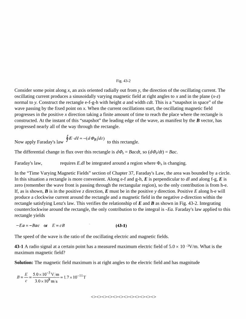
Fig. 43-2
Consider some point along x, an axis oriented radially out from y, the direction of the oscillating current. Theoscillating current produces a sinusoidally varying magnetic field at right angles to x and in the plane (x-z)normal to y. Construct the rectangle e-f-g-h with height a and width cdt. This is a “snapshot in space” of thewave passing by the fixed point on x. When the current oscillations start, the oscillating magnetic fieldprogresses in the positive x direction taking a finite amount of time to reach the place where the rectangle isconstructed. At the instant of this “snapshot” the leading edge of the wave, as manifest by the B vector, hasprogressed nearly all of the way through the rectangle.
Now apply Faraday's law to this rectangle.
The differential change in flux over this rectangle is dΦB = Bacdt, so (dΦB/dt) = Bac.
Faraday's law, requires E.dl be integrated around a region where ΦB is changing.
In the “Time Varying Magnetic Fields” section of Chapter 37, Faraday's Law, the area was bounded by a circle.In this situation a rectangle is more convenient. Along e-f and g-h, E is perpendicular to dl and along f-g, E iszero (remember the wave front is passing through the rectangular region), so the only contribution is from h-e.If, as is shown, B is in the positive z direction, E must be in the positive y direction. Positive E along h-e willproduce a clockwise current around the rectangle and a magnetic field in the negative z-direction within therectangle satisfying Lenz's law. This verifies the relationship of E and B as shown in Fig. 43-2. Integratingcounterclockwise around the rectangle, the only contribution to the integral is -Ea. Faraday's law applied to thisrectangle yields
The speed of the wave is the ratio of the oscillating electric and magnetic fields.
43-1 A radio signal at a certain point has a measured maximum electric field of 5.0 × 10 -3V/m. What is themaximum magnetic field?
Solution: The magnetic field maximum is at right angles to the electric field and has magnitude
<><><><><><><><><><><><>

Now apply Ampere's law using only the displacement term.
Fig. 43-3
Figure 43-3 shows the relationship of E and B. The procedure is much the same as before. The onlycontribution to the integral is along one side of the rectangle, so the integral becomes Ba (again integratingcounterclockwise).
The differential flux is dΦE = Eacdt.
Ampere's law then is Ba = µoεoEac, or B = µoεoEc.
Substituting E = cB, B = µoεoc2B, so µoεo = 1/c2, or
The velocity of electromagnetic waves (including light) is derivable from static constants!
There are three conclusions to this short discussion.
1. The electric and magnetic fields are related by the velocity; E = cB.
2. The velocity is
3. The wave moves in a direction determined by E × B.
43-2 How long does it take for an electromagnetic wave to travel to the moon, 3.8 × 10⁸ m away?
Solution:
<><><><><><><><><><><><>
43-3 How far does light travel in 1.0ns (1.0 × 10⁻⁹ s)?

Solution:
Energy Transport in Electromagnetic Waves
When electric and magnetic fields are absorbed in material objects, energy is transferred from the wave to thematerial. This is true for radio waves impinging on antennas, infrared waves absorbed in water molecules, ormicrowaves into your lunch.
The discussion of energy transport starts with the energy density expressions from static electric and magneticfields. (See the “Energy Storage” section in Chapter 28, Capacitance, and the “Power and Energy Storage”section in Chapter 38, Inductance.) The total energy density for a region of space where E and B fields arepresent is
In the electromagnetic wave E = cB and E2 = c2B2 so B2 = µoεoE2 allowing rewriting
This last expression shows that while the B field is numerically smaller than the E field, the energy densityassociated with both fields is the same.
Referring to Fig. 43-4, the differential amount of energy in the volume with cross-sectional area A and lengthcdt is
Fig. 43-4
the expression dU/dt is the energy transported per time over the area A. The more useful expression is theenergy flowing across an area per unit of time
The alternative forms come from E = cB and The units of S are energy per unit time per unit areaor power per unit area.
The Poynting Vector
The magnitude and direction of the energy flow rate is defined by the Poynting Vector.
This vector, like the flow rate, varies with time. The average value of the magnitude of the Poynting vector isthe intensity. The average value of the magnitude of S is
The average value of sin2 ωt is 1/2, so
43-4 Take the intensity of sunlight at the earth's surface as 600W/m2. Assuming 100% collection efficiency,how much energy is collected on a 1.0m2 panel exposed to this amount of sunlight for 10 hours?
Solution: The key to getting problems involving energy, power, and intensity correct is to watch the unitsclosely. In this case notice how the units dictate how to make the calculation.
Another way to do this problem is to find the energy in W.hr rather than Joules.
This is a strange looking unit, but it gives us a feel for the amount of energy that can be collected this way. This6000 W.hr would light sixty 100W light bulbs for an hour or run a 1.0kW microwave oven for 6 hours.
<><><><><><><><><><><><>
43-5 The maximum value of electric field 2.0m away from a spherically symmetric source is 1.8 V/m. Find themaximum value of magnetic field, average intensity, and power output of the source.
Solution: The magnetic field is from
The average intensity is from

As an exercise work through the units in this problem.
The total power is the power per unit area at 2.0 m radius times the total area.
Fig. 43-5
<><><><><><><><><><><><>
43-6 What is the maximum electric field strength and intensity of a 500W spherically symmetric light source at10m radius?
Solution: The area of a sphere 10m in radius is A = 4π(10m)2 = 1.2×10³ m2. The entire 500W is delivered tothis area. The power, intensity, and area are related by
The electric field intensity comes from
Radiation Pressure.
When an electromagnetic wave is absorbed by a material, charges are accelerated by the electric field transverseto the direction of the wave. The electric and magnetic field vectors are shown in Fig. 43-4. The electric fieldvector is pointing in the +y direction, and this is the direction a positive charge would accelerate. A chargemoving in the +y direction acted on by a magnetic field in the +z direction has a (v × B) force in the +xdirection, the direction of the wave. The Poynting vector always points in the direction the wave is traveling, sothe net force on any charges in the material is in the direction of the wave.
This force can be associated with a momentum. This momentum is

This is the momentum absorbed by a non-reflecting surface. For a completely reflecting surface the momentumtransfer is twice this value. Think of a tennis ball striking a surface and sticking or striking a surface andrebounding with the incident velocity.
43-7 A light beam with energy flux 20W/cm2 falls normal onto a completely reflecting surface of 2.0cm2. Whatis the force on this reflector?
Solution: The average force is F = ∆p/∆t and ∆p = 2∆U/c, but ∆U = S A∆t, so

Chapter 44Reflection, Refraction, and Polarization
In the study of reflection and refraction it is very convenient to depict light as rays. A light ray represents thepath of a thin beam (ray) of light. This ray construct is very convenient in understanding reflection andrefraction as well as images formed by mirrors and lenses.
Reflection and Refraction
When light strikes a surface such as an air-glass or air-water interface, part of the incident light is reflected andpart is refracted. Reflection of light at any interface follows a very simple law. The angle of incidence equalsthe angel of reflection with these angles measured from the normal to the surface. Incident and reflected raysare shown in Fig. 44-1.
Fig. 44-1
44-1 A ray of light is incident on a reflecting surface at 70° with respect to the surface. What is the angle of thereflected ray?
Solution: The 70° with respect to the surface is 20° with respect to the normal so the reflected beam is 20° fromthe normal.
The refracted (or bent) ray is the one that enters the new medium. The angular relationship between the incidentand refracted ray is given by Snell's law
where the n1 and n2 are the indexes of refraction of the two media. The index of refraction is a property of thematerial. Figure 44-1 contains some index of refraction values.
In addition to describing refraction, the index of refraction is also the ratio of the velocity of light in vacuum tothe velocity of light in the indexed medium.
44-2 What are the angles of reflection and refraction for a light ray in air incident on glass at an angle of 35°?
Solution: The angle of incidence is measured from the normal so the angle of reflection is 35° The angle ofrefraction is from Snell's law n1 sin θ1 = n2 sin θ2

<><><><><><><><><><><><>
In passing from a medium of lower index of refraction to one with higher index of refraction the light bendstoward the normal and vice versa. This is best illustrated in problem 44-3.
44-3 A light ray in water is incident on the water-air interface at an angle of 45°. What is the angle of reflectionin the water and refraction into the air?
Fig 44-2
Solution: The problem is diagrammed in Fig. 44-2. The incident angle equals the reflected angle, so θ1 = 45°The refracted angle is from Snell's law
This last problem suggests that there is an angle of incidence where there is no refracted ray; the refracted rayfollows the surface. Beyond this critical angle, as it is called, all light will be reflected back into the water.Fiber-optic cable is made of light transmitting material with an index greater than one, so that light injected atthe end of the cable will be internally reflected many times over its entire length.
44-4 Find the critical angle for a fiber optic material with index 1.50.
Fig 44-3
Solution: The critical angle is the one where the angle of refraction is 90°. Applying Snell's law
Any beam that strikes the fiber-air interface at an angle greater than 42° will be internally reflected down thefiber.
<><><><><><><><><><><><>

Figure 44-4 shows a ray of light incident on a equilateral triangular glass prism at an angle of 54°.
Fig. 44-4
Applying Snell's law to find the refracted ray angle yields 1.00 sin 54° = 1.62 sin θr, or θr = 30°. This means thatthe ray travels parallel to the base inside the prism and is refracted at 54° on exit.
Now change the problem slightly by having the ray incident parallel to the base of a prism with the base angles70°.
Fig. 44-5
From the geometry the angle of incidence for the ray entering the prism is 20°, and applying Snell's law1.00sin20° = 1.62sinθr, θr = 12°. Again from the geometry, the angle of incidence for the ray leaving the prismis 28°, and applying Snell's law 1.62sin28° = 1.00sinθr, θr = 50°. A prism bends light incident parallel to its basetoward the base.
If a collection of parallel rays were incident on the face of this prism they would all be refracted toward a lineextending from the base. Further, if the incident and exit faces were curved, all parallel rays could be focused atone point. Two curved-face prisms placed base-to-base are a lens of sorts focusing parallel rays to a singlepoint.
The index of refraction, or wave speed, depends slightly on the wavelength of the light. A ray of sunlightpassing through a prism exhibits the dispersion effect, whereby different wavelength components of thesunlight are refracted at different angles producing a rainbow of colors from red to violet.
44-5 Light is incident at an angle of 35° on a slab of glass 2.0cm thick. Part of the light travels through the glassand part along its original direction beside the glass. Find the path of the two rays, the velocity of the ray in theglass, and the time difference between the two when they emerge from the opposite side of the glass. Thegeometry is shown in Fig. 44-6.

Fig 44-6
Solution: Apply Snell's law to find the path through the slab. 1.00sin 35° = 1.62sinθr, or θr=21°. Because ofsymmetry, the ray through the slab exits parallel to the original ray. The velocity of the ray in the glass is fromn = c/v, or v = c/n=3.0 × 108 m/s/1.62=1.85×108 m/s. Now that the velocities are known the time differencerequires finding the distance the rays travel.
The distance a (the path through the slab) comes from cos21° = 2.0cm/a, or a = 2.14 cm. Construct a lineperpendicular to the two rays at the point where the refracted one leaves the slab.
The distance b in the original ray direction comes from cos14° = b/2.14cm, or b = 2.08cm.
The time for the refracted beam is τr = 0.0214m/1.85 × 108 m/s = 11.6 × 10⁻¹¹S.
The time for the unaltered beam is τ=0.0208m/3.0 × 108 m/s = 6.9 × 10⁻¹¹S.
The time delay is 4.7 × 10⁻¹¹ S.
Polarization
Light from a light bulb or the sun is circularly polarized. This means that if you could look at the electricvectors there would be no preferred direction. The electric vectors would be randomly oriented in space.Polarization is described in terms of electric vectors rather than magnetic vectors. A radio transmitting antennathat is vertical produces waves with vertical electric vectors, and the radiation from this antenna is verticallypolarized.
Polarization is usually studied in the context of light. There are two ways to polarize light. It can be polarizedby passing through a material that contains molecules all oriented in the same direction that absorb the electricvector (in this one direction) in the light. These materials are called polaroids. Polaroid sun glasses are made ofa polaroid that absorbs the electric vector in one direction.
Light, and other electromagnetic waves are more or less polarized by reflection, depending on the angle ofincidence and the index of refraction. When unpolarized or circularly polarized light is incident from air ontowater the reflected beam is of lowered intensity and polarized with the electric vector parallel to the reflectingsurface. The refracted beam is transmitted with a diminished intensity and is partially polarized by the reductionof the electric vector in the plane of the reflecting surface. The angle of incidence for complete polarizationoccurs when the angle between the reflected and refracted beams is 90°. The geometry of the situation is shownin Fig. 44-7.
The criterion for complete polarization is that θr + θp = 90°. Snell's law requires that ninc sin θp = nrefr sinθr, but θr
= 90° - θp and sin θr = sin(90° - θp) = cosθp, so nincsinθp = nrefr cosθp or

Fig. 44-7
This polarization law is known as Brewster's law, and the angle of polarization is called the Brewster angle.In working problems be careful not to invert the fraction of the indexes of refraction.
44-6 What is the polarization angle for light reflected from water?
Solution:
<><><><><><><><><><><><>
44-7 A beam of unpolarized light in water is incident on what is reported to be diamond. By means of polaroidsthe angle (of incidence) for complete polarization is determined to be 61°. Is this diamond?
Solution: For light in water reflected from diamond the Brewster angle should be
From the indexes of refraction given in Fig. 44-1 we conclude that this is diamond.

Chapter 45Mirrors and Lenses
The subject of mirrors and lenses is difficult to treat briefly first because for a thorough discussion there needsto be considerable attention to sign convention and second because different instructors and authors approachthe subject with slight, but very significant differences that impact the working of problems.
The only way to become proficient in working with lenses and mirrors is to place the sign conventionsappropriate to your course on a card in front of you and do problems drawing the rays and working thecalculations. Be sure that you know the sign conventions and practice doing sample problems before taking anytests on mirrors or lenses. Signs will be your major (perhaps only) source of error. Sample sign conventions formirrors and lenses are given below.
Sign Conventions for Mirrors
o is positive if object is in front of the mirroro is negative if object is in back of the mirror
i is positive if the image is in front of the mirrori is negative if the image is in back of the mirror
f is positive if the center of curvature is in front of the mirrorf is negative if the center of curvature is in back of the mirror
Sign Conventions for Lenses
o is positive if the object is in front of the lenso is negative if the object is in back of the lens
i is positive if the image is in back of the lensi is negative if the image is in front of the lens
f is positive for a converging lensf is negative for a diverging lens
Mirrors.
An object placed in front of a plane mirror appears to an observer to be behind the mirror.
Fig. 45-1

Because of the law of reflection, divergent rays intercepted by the observer on reflection from the mirror appearto come from behind the mirror. The object distance, p, is numerically equal to the image distance, q. Theimage is called a virtual image because the light does not physically come from the image. A real image is onewhere the light comes from or passes through the image.
45-1 A light source is 4.0cm in front of a plane mirror. Where does an observer looking into the mirror see theimage and is it real or virtual?
Solution: The image is 4.0cm behind the mirror. It is a virtual image because light does not pass through thisimage point.
A concave (converging) spherical mirror as shown in Fig. 45-2 can be analyzed by rays.
Fig 45-2
An object of height h placed at o, the object distance from the concave mirror, will produce a smaller image, h'at i, the image distance, according to the formula
where R is the radius of curvature and f(= R/2) is the focal length. The magnification is
The minus sign in the definition indicates that the image is inverted.
Draw a ray from the top of the object through the center of curvature (C in Fig. 45-2). Next draw a ray to thepoint where the principal axis (the horizontal line through C) intersects the mirror reflecting this ray back tointersect the one drawn previously. The intersection of these rays defines the top of the object. Drawing theserays requires experience. Set up several situations and draw the ray diagrams to become familiar with theprocedure.
45-2 For a spherical concave mirror of 12cm radius of curvature describe the image of a 2.0cm height objectplaced 20cm on the center line of the mirror according to Fig. 45-2.
Solution: The image is inverted. The ray diagrams show this. Using the radius of curvature and the objectdistance find the image distance from

The magnification is from
The height of the image is from or h'=-0.86cm.
The image is 8.6cm from the mirror, inverted (minus sign) and real (rays pass through image).
<><><><><><><><><><><><>
When the object is at infinity (very far away) the mirror equation reduces to 1/i = 2/R, and we can say that therays from infinity are focused at R/2. This defines the focal length as f = R/2.
A convex (diverging) spherical mirror is illustrated in Fig. 45-3.
Fig. 45-3
Objects placed in front of a convex mirror appear to come from behind the mirror, and they are smaller. Firstdraw a ray from the top of the object parallel to the principal axis and reflect it from the mirror. This ray appearsto come from the focus (behind the mirror). Next draw a ray so as to produce a reflected ray parallel to theprincipal axis of the mirror. The extension of this ray intersects the extension of the first one locating the top ofthe image.
The equations for concave mirrors also work for convex mirrors if a sign convention is adopted. Lengths wherethe light moves (to the left of the mirrors in Figs. 45-2 and 45-3) are positive, and lengths on the other side ofthe mirror (to the right of the mirror in Fig. 45-3) are negative. Lengths are measured (positive and negative)from the intersection of the principal axis and the mirror. These positive and negative regions are often referredto as the front and the back sides of the mirrors.
45-3 For a spherical convex mirror of 14cm radius of curvature, describe the image of a 2.5cm object placed30cm out on the principal axis of the mirror.
Solution: Here is where we get into the signs. The focus and the image are on one side of the mirror and theobject is on the other side. Therefore we take the focus as negative and expect the image distance to benegative. The image distance comes from equation 45-1
The magnification comes from equation 45-2

The height of the image is from
The minus sign for the image distance indicates that the image is behind the mirror, or on the same side as allthe other minus signs. The plus sign for the magnification indicates that the image is erect (not inverted). Theimage is virtual.
Lenses
There are two types of thin lenses, converging and diverging, as shown in Fig. 45-4.
Fig 45-4
The converging lens converges parallel rays to a point called the focus while a diverging lens refracts rays tomake them appear as to come from a focus. The sign conventions become more involved for lenses than formirrors. Rather than set out a sign convention, we will handle the signs in the context of each problem. Therelationship between image distance, object distance and focal length is the same as for mirrors (equation 45-1).
45-4 A converging lens of focal length 8.0cm forms an image of an object placed 20cm in front of the lens.Describe the image.
Fig. 45-5
Solution: Draw a ray from the top of the object parallel to the axis then through the focus. Next draw a ray fromthe top of the object through the center of the lens to intersect the first ray. This locates the top of the object.Use equation 45-1 to find the image distance.
The magnification is (-) image distance over object distance or
The image is located 13cm on the side of the lens opposite the object with magnification 0.67. It is inverted(minus sign) and real (rays pass through image).
45-5 A diverging lens has a 14cm focal length. Describe the image of a 4.0cm object placed 40cm from the lens.

Fig. 45-6
Solution: Draw a ray from the top of the object to the lens parallel to the principal axis and refract it back to thefocus. Next draw a line from the top of the object through the center of the lens. The intersection of these rayslocates the top of the object. The image distance is from equation 45-1.
The negative sign for the focal length is because this is a diverging lens. The image distance is negative becauseit is on the same side of the lens as the object (opposite to the converging lens). The magnification is 10/40 =0.25.
The image is 0.25×4.0cm=1.0cm high, erect, virtual, and appears to come from a point 10cm from the lens onthe same side as the object.
Go back over the problems in this chapter paying particular attention to the signs. As an exercise change thenumbers in these problems and work them through until the sign conventions are clear in your mind. As you domore problems the logic of the sign convention listed on the first page of this chapter will become clear.

Chapter 46Diffraction and Interference
The wave nature of light is used to explain the several diffraction and interference phenomena discussed in thischapter.
Double Slit Diffraction
Figure 46-1 shows the setup for the classic Young's double slit experiment first performed around 1800.
Fig. 46-1
Monochromatic light passes through a sufficiently narrow slit to produce a coherent source for the double slits.The coherent (in phase) light spreads out from each of the slits creating an interference pattern on the screen.The geometry for the interference is shown in Fig. 46-1. Destructive interference occurs when the path lengthdiffers by one-half wavelength and constructive interference occurs when the path length is an integral numberof wavelengths. From the figure we can write the criteria for constructive interference as
The distance from the central maxima (opposite the center of the two slits) to the first bright fringe on thescreen is related to the angle via tan θ = ym/R. For small angles, which is the case with the Young's experiment,sinθ ≈ tanθ = θ, so equation 46-1 can be rewritten as
Historically this experiment was used to measure the wavelength of light.
46-1 A Young's experiment is set up with slit separation 2.0 × 10⁻⁴ m, screen distance 0.80m, and distance fromcentral maxima to second bright fringe 3.9 × 10⁻³ m. What is the wavelength of the source?
Solution:
<><><><><><><><><><><><>
46-2 In a different Young's experiment with 488nm light the second dark fringe is 1.2 × 10⁻³ m away from thecenter of the central bright fringe. The screen is 1.2m from the slits. What is the separation of the slits?

Solution: This second dark fringe corresponds to 3/2 of a wavelength in path difference. One wavelength pathdifference is 2/3 of the 1.2 × 10⁻³ m or 8.0 × 10⁻⁴ m. This number now fits with equation 46-2 (one wavelengthpath difference), and solving for d
Single Slit Diffraction
The intensity distribution pattern for single slit diffraction is similar to the pattern for double slit diffraction.The geometry and analysis, however, are quite different. Coherent light incident on a narrow slit (100 to 1000wavelengths wide) produces a fringe pattern as shown in Fig. 46-2.
Fig. 46-2
In the analysis of single slit, or Fraunhofer, diffraction we will use the dark fringes. The slit of width a isviewed as a region where interference occurs between light at the top of the slit and the middle of the slit. Theparticular situation for the first dark fringe obtains for corresponding pairs of source points separated by a/2across the width of the slit. The criterion for dark fringes is
Again sinθ is approximately the same as tanθ, which is approximately the same as θ. So rewrite equation 46-3with this approximation as
where m corresponds to the number of the dark fringes away from the central maxima.
46-3 Monochromatic light is incident on a 4.0 × 10⁻⁴ m wide slit producing a Fraunhofer diffraction pattern on ascreen 1.5m away. The distance from the central maxima to the second dark fringe is 3.4 × 10⁻³ m. What is thewavelength of the light?
Solution: Reworking equation 46-4 yields
<><><><><><><><><><><><>

46-4 Light from a He-Ne laser of 633nm is incident on a 2.0 × 10⁻⁴ m wide slit. What is the width of the centralmaxima (the distance between the dark fringes on either side of the central maxima) on a screen 2.0m away.
Solution: Rearranging equation 46-4, the distance to the first dark fringe is
The width of the central maxima is two times this value or 1.3 × 10⁻² m.
The Diffraction Grating
A diffraction grating consists of multiple slits as shown in Fig. 46-3. When light is incident on this arrangementconstructive interference occurs when the path difference between adjacent slits is mλ. Increasing the number ofslits produces two effects: the intensity of each interference maximum increases, and the width of eachinterference maximum decreases. This makes the grating a very convenient tool for the study of the variouscomponent wavelengths (spectra) of gases.
Fig. 46-3
46-5 A grating with 2000 lines per cm is illuminated with a hydrogen gas discharge tube. Two of the hydrogenlines are at 410 and 434 nm. What is the first order spacing of these lines on a screen 1.0 m from the grating.The experimental arrangement is shown in Fig. 46-4.
Fig. 46-4
Solution: The phrase “first order” refers to the first maxima.
First find the spacing 1.0 × 10⁻² m/2000 lines = 5.0 × 10⁻⁶ m.
For the 410 nm line
For the 434 nm line

The lines are separated by 5 mm on the screen.

Chapter 47Special Relativity
The special theory of relativity is based on two postulates.
1. The laws of physics are the same in all inertial reference frames.
Inertial frames are reference (coordinate) frames moving at constant velocity with respect to one another; thatis, they are not accelerating.
2. The speed of light is the same in all inertial frames.
These two postulates lead to very interesting and highly significant conclusions concerning simultaneity andhow we measure the fundamental quantities of length, mass, and time. These discussions, though veryinteresting, are inappropriate for a problems book, so we will go directly to the consequences of specialrelativity as it impacts our understanding of physics.
The concepts and calculations of special relativity require a change in how we view the world. Many of thethings we study in special relativity may go against our intuition, but remember, intuition is often wrong andeven if it were correct we have no experience to base our intuition on when dealing with particles approachingthe speed of light where relativistic effects are observable. How many of Galileo's colleagues intuitively “knew”that when he dropped those two different sized balls from the Tower at Pisa the heavier one would reach theground first? Success in understanding Special Relativity requires first that you rid your mind of intuitiveknowledge based on what could be called “low velocity experience.” As you study Special Relativity you willencounter situations where you will be challenged to look at the postulates and change your view of the world.
Time Dilation.
Time intervals are different in different (moving) inertial frames. Place a light source, mirror, and detector in amoving vehicle as shown in Fig. 47-1. An observer in the moving vehicle measures the time for a light pulse tomove from the source to the mirror and back to the detector as the distance traveled divided by the velocity oflight, so ∆t0 = 2d/c. The zero subscript indicates that this time is measured by an observer in the same framewhere the event is taking place. This is also called the proper time.
Fig 47-1
An observer in another inertial frame observes the vehicle moving at a velocity v (see Fig. 47-2) and over thetime interval of the event observes that the detector has traveled a distance v∆t.
Fig. 47-2

The total distance the light has traveled is
The time interval is
Remember, c is the same to all observers regardless of inertial frame. The two times can be related with d =c∆to/2 so that
The external observer of an event taking place in a moving reference frame, the one who measures ∆t, alwayssees an event as taking longer than the stationary observer, the one who measures ∆to, in the frame moving withthe event.
47-1 You are in a railroad car moving at constant velocity of zero with respect to the surface of the earth. Whatdo you measure as the time it takes for a coin to drop 1.0m to the floor of the railroad car? What does anobserver in another railroad car traveling at a constant 25m/s measure for this time?
Solution: You apply and observe
The moving observer measures a time given by equation 47-1. For small v/c the best way to make thiscalculation is to use a binomial expansion of the radical (see, the Introduction, Mathematical Background).
The first, and largest, relativistic correction term is
This means that the correction is ∆t = ∆to(1+3.5 × 10⁻¹⁵)s. Time measurement this precise is beyond thecapability of the cesium clocks. This is an unobservable effect.
<><><><><><><><><><><><>
47-2 For the situation of the previous problem take the moving observer from the train to a 2500m/s jet planeand then to a rocket ship traveling at 0.90c. (It is common, and very convenient in relativistic calculations, toexpress velocity as a fraction or decimal times c.)
Solution: Again using the binomial expansion and looking at the first term
This small a time difference is observable but it is a difficult experiment.

For the rocket ship traveling at 0.90c, use equation 47-1 directly.
The observer in the rocket ship measures the time for the falling coin as 1.0s, over twice what the stationaryobserver sees. These two problems illustrate how relativistic effects are observable only as relative velocitiesapproach c.
47-3 A “strange particle” is observed to move at 0.96c and have a lifetime of 2.0 × 10⁻⁸ s. What is the lifetime ofthe particle in its own reference frame?
Solution: In equation 47-1 ∆to is the (proper) time an observer traveling with the “strange particle” wouldmeasure so find
Length Contraction
The time dilation leads to a length contraction with velocity. Consider a vehicle moving at velocity v betweentwo stars with one observer in the vehicle and another at a fixed (with respect to the stars) point. The externalobserver measures the (proper) distance between the stars as Lo, observes the velocity of the vehicle as v, andwrites the time interval as ∆t = Lo/v. The time interval ∆t is not a proper time because measurement of ∆t wouldrequired synchronized clocks at both stars. The observer in the vehicle sees the stars moving at t and measures a(proper) time interval ∆to. This observer determines the distance between the stars as L = v∆to. Write these twoequations as a fraction
and with
The length measured by a moving observer is contracted by a factor equal to
47-4 In a soaring space ship (a vehicle capable of both space flight and conventional aircraft flight) you returnfrom a space journey to find a new landing runway. Passing over this runway at 0.92c you measure its length as1960m. What is its length at your landing speed of 200 m/s?
Solution: At 200 m/s there is no observable relativistic effect. Use equation 47-3 to find the length of therunway at your landing speed.
47-5 How fast must a meter stick be traveling relative to your reference frame for you to observe a 2%contraction?
Solution: Use equation 47-3 with L = 0.98Lo

Relativistic Momentum
At “low velocities” a force applied to a particle produces an acceleration according to the familiar F = d/dt (mv)= m(dv/dt). As the velocity of the particle approaches c, the momentum becomes velocity dependent with theforce statement taking on the form
The most convenient interpretation is to associate the with the mass and say that the effective massof a moving particle is
where mo is the rest mass, measured with the mass not moving in the inertial frame where the measurements aremade.
47-6 What is the effective mass of an electron moving at 0.80c?
Solution:
<><><><><><><><><><><><>
47-7 Intergalactic space travelers need to know the relative velocities and masses of their space ships. Eachship, therefore, has a 1.0m long bar painted on the side of the ship alongside their rest mass. As you pass by aship you measure this 1.0m bar as 0.93m. What is your relative velocity? You also observe their rest massprinted as 365,000kg. What is their mass relative to you? What does an observer in the other ship measure foryour 1.0m bar?
Solution: The length you observe is where Lo is the 1.0m, the length an observer at rest withrespect to the vehicle would measure, and L is the length you measure so
The relativistic mass you observe is
Observers in the other space ship measure your bar as 0.93m and relative speed as 0.37c.

<><><><><><><><><><><><>
As an exercise find the effective mass of an electron at 0.999c and at 0.99999c. As the velocity approaches c,the effective mass approaches infinity implying the necessity of an infinite force to reach c. This shows thetheoretical impossibility of material objects traveling at c or beyond.
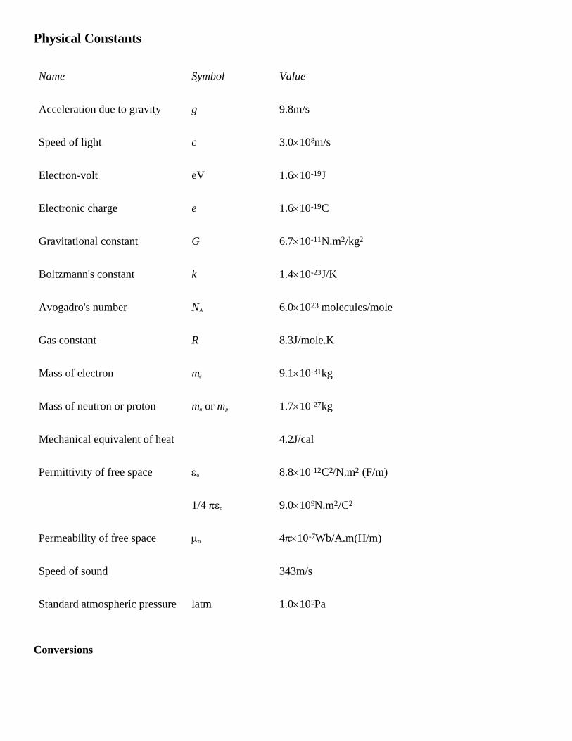
Physical Constants
Name Symbol Value
Acceleration due to gravity g 9.8m/s
Speed of light c 3.0×10⁸m/s
Electron-volt eV 1.6×10⁻¹⁹J
Electronic charge e 1.6×10⁻¹⁹C
Gravitational constant G 6.7×10⁻¹¹N.m2/kg2
Boltzmann's constant k 1.4×10⁻²³J/K
Avogadro's number NA 6.0×10²³ molecules/mole
Gas constant R 8.3J/mole.K
Mass of electron me 9.1×10⁻³¹kg
Mass of neutron or proton mn or mp 1.7×10⁻²⁷kg
Mechanical equivalent of heat 4.2J/cal
Permittivity of free space εo 8.8×10⁻¹²C2/N.m2 (F/m)
1/4 πεo 9.0×10⁹N.m2/C2
Permeability of free space µo 4π×10-7Wb/A.m(H/m)
Speed of sound 343m/s
Standard atmospheric pressure latm 1.0×10⁵Pa
Conversions

1kg=1000g=0.068slug 1m=100cm=3.3ft 1nm=10-9m=10Å
1m/s=3.3ft/s 1rad=57.3° πrad=180°
1N=105dyne=0.221b 1cal=4.2J leV=1.6×10⁻¹⁹J
1hp=750W=550ft.lb/s 1J=107 erg=0.24cal=0.74ft.lb