how to make injection molds - iran mavad
TRANSCRIPT


Georg MengesWalter MichaeliPaul Mohren
How to MakeInjection MoldsThird Edition
HANSERHanser Publishers, Munich
Hanser Gardner Publications, Inc., Cincinnatiwww.iran-mavad.com
مرجع تخصصی مهندسی مواد و متالورژی
Translated and revised edition of"Anleitung zum Bau von SpritzgieBwerkzeugen", 5th Edition, 1999by Prof. Dr.-Ing. Georg Menges, Prof. Dr.-Ing. Walter Michaeli and Ing. Paul Mohren,Institut fur Kunststoffverarbeitung in Industrie und Handwerkan der Rhein.-Westf. Technischen Hochschule Aachen(Institute for Plastics Processing, Technical University of Aachen)
Translated by Rolf J. Kahl and Raymond Brown
Distributed in the USA and in Canada byHanser Gardner Publications, Inc.6915 Valley Ave.Cincinnati, OH 45244, USAFax:+1 (513)527 8950http://www.hansergardner.com
Distributed in all other countries byCarl Hanser VerlagPostfach 86 04 20, 81631 Munchen, GermanyFax: +49 (89) 99 830-269http://hanser.de
Library of Congress Cataloging-in-Publication Data
Menges, Georg, 1923-[Anleitung zum Bau von Spritzgiesswerkzeugen. English]How to make injection molds. - 3rd ed. / Georg Menges, Walter Michaeli, Paul Mohren;[translated by Rolf J. Kahl and Raymond Brown].
p. cmIncludes bibliographical references and index.ISBN: 1-56990-282-81. Injection molding of plastics. I. Michaeli, Walter. II. Mohren, Paul. III. Title.
TP1150.M3813 2000668.4'12-dc21 00-046238
Die Deutsche Bibliothek — CIP-Einheitsaufnahme
Menges, Georg:How to make injection molds / Georg Menges ; Walter Michaeli; Paul Mohren. [Transl. by Rolf J. Kahland Raymond Brown]. - 3. ed.. - Munich : Hanser; Cincinnati : Hanser Gardner, 2000Einheitssacht.: Anleitung fur den Bau von SpritzgieBwerkzeugen <engl.>ISBN: 3-446-21256-6
The use of general descriptive names, trademarks, etc. in this publication, even if the former are notespecially identified, is not to be taken as a sign that such names, as understood by the Trade Marks andMerchandise Marks Act, may accordingly be used freely by anyone.While the advice and information in this book are believed to be true and accurate at the date of goingto press, neither the authors nor the editors nor the publisher can accept any legal responsibility for anyerrors or omissions that may be made. The publisher makes no warranty, express or implied, with respectto the material contained herein.
All right reserved. No part of this book may be reproduced or transmitted in any form or by any means,electronic or mechanical, including photocopying or by any information storage and retrieval system,without permission in writing from the publisher.Copyright © Carl Hanser Verlag, Munich, 2001Typesetting by Cicero Lasersatz, GermanyPrinted in Germany by Kosel
www.iran-mavad.com
مرجع تخصصی مهندسی مواد و متالورژی

P r e f a c e t o t h e 3 r d E d i t i o n
Injection molds are high-precision tools whose smooth-operation on a day-to-day basisis vital to the economic success of many plastics processors. Consequently, errors indesign and construction of molds can have grave consequences.
That is where this book comes in. Building on the earlier editions, it draws extensi-vely both on the literature and on the development work carried out at the Institute forPlastics Processing in the Technical University of Aachen with the aid of substantial pri-vate and public research funding.
We are especially grateful to those who participated in this edition and to those wholaid the foundations for it in earlier editions, namely Dr. H. Bangert, Dr. P. Barth, Dr. W.Hoven-Nievelstein, Dr. O. Kretschmar, Dr. M. Paar, Dr. G. Potsch, Dr. Th. W. Schmidt.,Dr. Ch. Schneider, Prof. E. Schiirmann and Prof. S. Stitz.
We are indebted to the co-workers and students in the institute who contributed to thesuccess of this book through their unstinting work and their personal commitment. Asthey are too numerous to mention, we trust that Ms. G. Nelissen, Ms. I. Zekorn and Mr.W. Okon will accept our thanks on their behalf. Finally, we extend our appreciation toCarl Hanser Verlag, and especially to Dr. W. Glenz and Mr. O. Immel, for taking themanuscript and turning it into such a distinctive and attractive book.
G. MengesW. MichaeliP. Mohren
www.iran-mavad.com
مرجع تخصصی مهندسی مواد و متالورژی

T h e f o l l o w i n g c o n t r i b u t o r s h e l p e d
t o r e v i s e a n d u p d a t e t h i s n e w e d i t i o n :
Chapter 1 Prof. Dr. F. KlockeA. Karden
Chapter 2 Prof. Dr. A. Biihrig PolaczekProf. Dr. F. KlockeA. KardenDr. M. LangenProf. Dr. E. SchmachtenbergDr. M. Polifke
Chapter 3 Prof. Dr. H. Schluter
Dr. V. Romberg-Forkert
Chapter 4 P. Niggemeier
Chapter 5 Dr. F. EhrigChapter 6 J. Berthold
Dr. C. BrockmannC. P. CuttatDr. F. EhrigC. HopmannC. Ronnewinkel
Chapter 7 Dr. A. Rogalla
Chapter 8 Dr. F. EhrigA. SpennemannDr. J. Zachert
Chapter 9 P. Niggemeier
Chapter 11 Dr. F. Ehrig
Chapter 12 Dr. M. Stommel
Chapter 13 Dr. N. Kudlik
Chapter 14 Dr. P. FiIzH. GenoskeDr. A. BiswasDr. K. Schlesinger
Chapter 15 Dr. A. Feldhaus
Chapter 16 Dr. H. ReckerDr. O. Schnerr-Haselbarth
Chapter 18 R Gorbach
Chapter 20 Dr. A. RogallaC. BrockmannE. Henze
www.iran-mavad.com
مرجع تخصصی مهندسی مواد و متالورژی
vii This page has been reformatted by Knovel to provide easier navigation.
Contents
Preface to the 3rd Edition .......................................................... v
The Following Contributors Helped to Revise and Update This New Edition ............................................................. vi
1. Materials for Injection Molds ........................................ 1 1.1 Steels ........................................................................................ 2
1.1.1 Summary ..................................................................... 2 1.1.2 Case-Hardening Steels ............................................... 6 1.1.3 Nitriding Steels ............................................................ 7 1.1.4 Through-Hardening Steels .......................................... 7 1.1.5 Heat-Treated Steels .................................................... 9 1.1.6 Martensitic Steels ........................................................ 10 1.1.7 Hard Mold Alloys ......................................................... 10 1.1.8 Corrosion-Resistant Steels .......................................... 10 1.1.9 Refined Steels ............................................................. 11
1.2 Cast Steel ................................................................................. 12 1.3 Nonferrous Metallics ................................................................. 12
1.3.1 Copper Alloys .............................................................. 12 1.3.1.1 Beryllium-Copper Alloys .............................. 13
1.3.2 Zinc and Its Alloys ....................................................... 14 1.3.3 Aluminum Alloys .......................................................... 16 1.3.4 Bismuth-Tin Alloys ....................................................... 18
1.4 Materials for Electrolytic Deposition ......................................... 19 1.5 Surface Treatment of Steels for Injection Molds ....................... 20
1.5.1 General Information ..................................................... 20 1.5.2 Heat Treatment of Steels ............................................ 21
www.iran-mavad.com
مرجع تخصصی مهندسی مواد و متالورژی
viii Contents
This page has been reformatted by Knovel to provide easier navigation.
1.5.3 Thermochemical Treatment Methods .......................... 21 1.5.3.1 Carburizing .................................................. 21 1.5.3.2 Nitriding ....................................................... 22 1.5.3.3 Bonding ....................................................... 22
1.5.4 Electrochemical Treatments ........................................ 23 1.5.4.1 Chrome Plating ........................................... 23 1.5.4.2 Nickel Plating .............................................. 23 1.5.4.3 NYE-CARD Process ................................... 24 1.5.4.4 Hard Alloy Coating ...................................... 24
1.5.5 Coating at Reduced Pressure ..................................... 24 1.5.5.1 CVD Process ............................................... 24 1.5.5.2 PVD Process ............................................... 25
1.6 Laser Surface Treatment .......................................................... 26 1.6.1 Laser Hardening and Re-Melting ................................ 27 1.6.2 Laser Alloying, Dispersing, and Coating ..................... 27
1.7 Electron Beam Hardening ........................................................ 28 1.8 Lamcoat Coating ...................................................................... 28 References ......................................................................................... 28
2. Mold Making Techniques ............................................. 31 2.1 Production of Metallic Injection Molds and Mold Inserts by
Casting ..................................................................................... 32 2.1.1 Casting Methods and Cast Alloys ............................... 32 2.1.2 Sand Casting ............................................................... 33 2.1.3 Precision Casting Techniques ..................................... 35
2.2 Rapid Tooling for Injection Molds ............................................. 35 2.2.1 State of the Art ............................................................ 37 2.2.2 Direct Rapid Tooling .................................................... 39
2.2.2.1 Direct Fabrication of Metallic Molds ............ 39 2.2.2.1.1 Generative Methods ................. 39 2.2.2.1.2 Direct Fabrication of
Nonmetallic Molds .................... 42
www.iran-mavad.com
مرجع تخصصی مهندسی مواد و متالورژی
Contents ix
This page has been reformatted by Knovel to provide easier navigation.
2.2.3 Indirect Rapid Tooling (Multistage Process Chains) ... 43 2.2.3.1 Process Chains Involving a Positive
Pattern ......................................................... 44 2.2.3.2 Process Chains Involving a Negative
Pattern ......................................................... 46 2.2.4 Outlook ........................................................................ 50
2.3 Hobbing .................................................................................... 50 2.4 Machining and Other Material Removing Operations ............... 54
2.4.1 Machining Production Methods ................................... 54 2.4.2 Surface Treatment (Finishing) ..................................... 55
2.4.2.1 Grinding and Polishing (Manual or Assisted) ..................................................... 55
2.4.2.2 Vibratory Grinding ....................................... 56 2.4.2.3 Sand Blasting (Jet Lapping) ........................ 56 2.4.2.4 Pressure Lapping ........................................ 57 2.4.2.5 Electrochemical Polishing ........................... 57 2.4.2.6 Electric-Discharge Polishing ....................... 57
2.5 Electric-Discharge Forming Processes .................................... 59 2.5.1 Electric-Discharge Machining (EDM) .......................... 59 2.5.2 Cutting by Spark Erosion with Traveling-Wire
Electrodes ................................................................... 62 2.6 Electrochemical Machining (ECM) ........................................... 63 2.7 Electrochemical Material Removal-Etching .............................. 63 2.8 Surfaces Processed by Spark Erosion or Chemical
Dissolution (Etching) ................................................................. 65 2.9 Laser Carving ........................................................................... 67
2.9.1 Rapid Tooling with LASERCAV ................................... 68 2.10 Molds for the Fusible-Core Technique ..................................... 68
2.10.1 Molds for Sheathing the Fusible Cores ....................... 71 2.10.1.1 Gating the Molding ...................................... 74 2.10.1.2 Thermal Considerations Concerning
Mold Design ................................................ 74 2.10.1.3 Core Shifting ............................................... 75 2.10.1.4 Venting ........................................................ 75
www.iran-mavad.com
مرجع تخصصی مهندسی مواد و متالورژی
x Contents
This page has been reformatted by Knovel to provide easier navigation.
2.10.2 Molds for Making the Fusible Cores ............................ 77 2.10.2.1 Core Material ............................................... 78 2.10.2.2 Construction of a Casting Mold ................... 78 2.10.2.3 Gating Systems ........................................... 78 2.10.2.4 Thermal Considerations Concerning
the Core-Casting Mold ................................ 80 2.10.2.5 Demolding Cast Fusible Cores ................... 81
References ......................................................................................... 81
3. Procedure for Estimating Mold Costs ......................... 85 3.1 General Outline ........................................................................ 85 3.2 Procedures for Estimating Mold Costs ..................................... 85 3.3 Cost Group I: Cavity ................................................................. 88
3.3.1 Computation of Working Hours for Cavities ................ 89 3.3.2 Time Factor for Machining Procedure ......................... 90 3.3.3 Machine Time for Cavity Depth ................................... 90 3.3.4 Time Consumption for Cavity Surface ......................... 91 3.3.5 Time Factor for Parting Line ........................................ 92 3.3.6 Time Factor for Surface Quality .................................. 92 3.3.7 Machining Time for Fixed Cores ................................. 92 3.3.8 Time Factor for Tolerances ......................................... 93 3.3.9 Time Factor for Degree of Difficulty and
Multifariousness .......................................................... 93 3.3.10 Time Factor for Number of Cavities ............................ 94 3.3.11 Computation of Working Hours for EDM
Electrodes ................................................................... 94 3.4 Cost Group II: Basic Molds ....................................................... 95 3.5 Cost Group III: Basic Functional Components ......................... 96
3.5.1 Sprue and Runner System .......................................... 96 3.5.2 Runner System ........................................................... 98 3.5.3 Hot-Runner Systems ................................................... 98 3.5.4 Heat-Exchange System ............................................... 98 3.5.5 Ejector System ............................................................ 99
www.iran-mavad.com
مرجع تخصصی مهندسی مواد و متالورژی
Contents xi
This page has been reformatted by Knovel to provide easier navigation.
3.6 Cost Group IV: Special Functions ............................................ 99 3.7 Other Cost Calculation Methods ............................................... 100
3.7.1 Costs Based on Similarity Considerations .................. 100 3.7.2 The Principle behind Hierarchical Similarity
Searching .................................................................... 103 References ......................................................................................... 103
4. The Injection Molding Process .................................... 105 4.1 Cycle Sequence in Injection Molding ........................................ 105
4.1.1 Injection Molding of Thermoplastics ............................ 107 4.1.2 Injection Molding of Crosslinkable Plastics ................. 107
4.1.2.1 Injection Molding of Elastomers .................. 108 4.1.2.2 Injection Molding of Thermosets ................. 108
4.2 Terms Used in Connection with Injection Molds ....................... 109 4.3 Classification of Molds .............................................................. 109 4.4 Functions of the Injection Mold ................................................. 110
4.4.1 Criteria for Classification of Molds ............................... 111 4.4.2 Basic Procedure for Mold Design ................................ 115 4.4.3 Determination of Mold Size ......................................... 115
4.4.3.1 Maximum Number of Cavities ..................... 115 4.4.3.2 Clamping Force ........................................... 121 4.4.3.3 Maximum Clamping Area ............................ 121 4.4.3.4 Required Opening Stroke ............................ 121
4.4.4 The Flow Length/Wall Thickness Ratio ....................... 122 4.4.5 Computation of Number of Cavities ............................ 123
4.4.5.1 Algorithm for the Determination of the Technically and Economically Optimum Number of Cavities ...................... 127
4.4.5.2 Costs for Sampling, Setup, and Maintenance ................................................ 136
4.5 Cavity Layouts .......................................................................... 138 4.5.1 General Requirements ................................................ 138 4.5.2 Presentation of Possible Solutions .............................. 139
www.iran-mavad.com
مرجع تخصصی مهندسی مواد و متالورژی
xii Contents
This page has been reformatted by Knovel to provide easier navigation.
4.5.3 Equilibrium of Forces in a Mold During Injection ......... 139 4.5.4 Number of Parting Lines .............................................. 140
References ......................................................................................... 141
5. Design of Runner Systems .......................................... 143 5.1 Characterization of the Complete Runner System ................... 143 5.2 Concept and Definition of Various Types of Runners ............... 144
5.2.1 Standard Runner Systems .......................................... 144 5.2.2 Hot-Runner Systems ................................................... 144 5.2.3 Cold-Runner Systems ................................................. 144
5.3 Demands on the Runner System ............................................. 145 5.4 Classification of Runner Systems ............................................. 146 5.5 The Sprue ................................................................................. 146 5.6 Design of Runners .................................................................... 151 5.7 Design of Gates ........................................................................ 152
5.7.1 Position of the Gate at the Part ................................... 156 5.8 Runners and Gates for Reactive Materials ............................... 161
5.8.1 Elastomers .................................................................. 161 5.8.2 Thermosets ................................................................. 162 5.8.3 Effect of Gate Position for Elastomers ........................ 162 5.8.4 Runners for Highly-Filled Melts ................................... 163
5.9 Qualitative (Flow Pattern) and Quantitative Computation of the Filling Process of a Mold (Simulation Models) ................ 164 5.9.1 Introduction ................................................................. 164 5.9.2 The Flow Pattern and Its Significance ......................... 165 5.9.3 Using the Flow Pattern for Preparing a
Simulation of the Filling Process ................................. 166 5.9.4 Theoretical Basis for Producing a Flow Pattern .......... 168 5.9.5 Practical Procedure for Graphically Producing a
Flow Pattern ................................................................ 169 5.9.5.1 Drawing the Flow Fronts ............................. 169 5.9.5.2 Radius Vectors for the Presentation of
Shadow Regions ......................................... 169
www.iran-mavad.com
مرجع تخصصی مهندسی مواد و متالورژی
Contents xiii
This page has been reformatted by Knovel to provide easier navigation.
5.9.5.3 Areas with Differences in Thickness ........... 172 5.9.5.4 Flow Patterns of Ribs .................................. 175 5.9.5.5 Flow Patterns of Box-Shaped
Moldings ...................................................... 176 5.9.5.6 Analysis of Critical Areas ............................ 176 5.9.5.7 Final Comments .......................................... 179
5.9.6 Quantitative Analysis of Filling .................................... 179 5.9.7 Analytical Design of Runners and Gates ..................... 180
5.9.7.1 Rheological Principles ................................. 180 5.9.7.2 Determining Viscous Flow Behavior
under Shear with the Aid of a Capillary Viscometer .................................................. 186
5.9.7.3 Elongational Viscosity ................................. 189 5.9.7.4 Simple Equations for Calculating Loss
of Pressure in Gates and Runners .............. 189 5.10 Special Phenomena Associated with Multiple Gating .............. 192 5.11 Design of Gates and Runners for Crosslinking
Compounds .............................................................................. 194 5.11.1 Elastomers .................................................................. 194
5.11.1.1 Calculation of Filling Process ...................... 194 5.11.1.2 Effect of Processing Characteristics on
the Basis of Processing Windows ............... 195 5.11.1.3 Criticism and Examples Concerning
the Processing-Window Model .................... 196 5.11.2 Thermosets ................................................................. 198
5.11.2.1 Flow-Curing Behavior of Thermosets .......... 198 References ......................................................................................... 200
6. Design of Gates ............................................................. 205 6.1 The Sprue Gate ........................................................................ 205 6.2 The Edge or Fan Gate .............................................................. 206 6.3 The Disk Gate ........................................................................... 208 6.4 The Ring Gate .......................................................................... 208 6.5 The Tunnel Gate (Submarine Gate) ......................................... 210
www.iran-mavad.com
مرجع تخصصی مهندسی مواد و متالورژی
xiv Contents
This page has been reformatted by Knovel to provide easier navigation.
6.6 The Pinpoint Gate in Three-Platen Molds ................................ 212 6.7 Reversed Sprue with Pinpoint Gate ......................................... 214 6.8 Runnerless Molding .................................................................. 215 6.9 Molds with Insulated Runners .................................................. 217 6.10 Temperature-Controlled Runner Systems – Hot
Runners .................................................................................... 220 6.10.1 Hot-Runner Systems ................................................... 221
6.10.1.1 Economic Advantages and Disadvantages of Hot-Runner Systems ............................... 221
6.10.1.2 Hot Runners for Various Applications and New Possibilities ......................................... 222
6.10.1.3 Design of a Hot-Runner System and Its Components ........................................... 223 6.10.1.3.1 Sprue Bushing ......................... 227 6.10.1.3.2 Melt Filters ............................... 228 6.10.1.3.3 Manifold Blocks ........................ 228 6.10.1.3.4 Manifold Beams ....................... 229
6.10.1.4 Nozzles for Hot-Runner Molds .................... 231 6.10.1.5 Data Concerning the Design of Hot
Runner Manifolds ........................................ 234 6.10.1.5.1 Manifold Beams ....................... 234 6.10.1.5.2 Nozzle Design .......................... 237 6.10.1.5.3 Notes on Operating Hot
Runners ................................... 238 6.10.1.6 Heating of Hot Runner Systems .................. 238
6.10.1.6.1 Heating of Nozzles ................... 238 6.10.1.6.2 Heating of Manifolds ................ 239 6.10.1.6.3 Computing of Power Output ..... 240 6.10.1.6.4 Temperature Control in Hot
Manifolds .................................. 241 6.10.1.6.5 Placement of Thermocouples .. 241
6.10.2 Cold Runners .............................................................. 242 6.10.2.1 Cold-Runner Systems for Elastomer
Injection Molds ............................................ 242
www.iran-mavad.com
مرجع تخصصی مهندسی مواد و متالورژی
Contents xv
This page has been reformatted by Knovel to provide easier navigation.
6.10.2.2 Cold-Runner Molds for Thermosets ............ 248 6.11 Special Mold Concepts ............................................................. 249
6.11.1 Stack Molds ................................................................. 249 6.11.2 Molds for Multicomponent Injection Molding ............... 252
6.11.2.1 Combination Molds ..................................... 253 6.11.2.2 Two-Component Sandwich Injection
Molds ........................................................... 256 6.11.2.3 Bi-Injection Molds ........................................ 256
References ......................................................................................... 256
7. Venting of Molds ........................................................... 259 7.1 Passive Venting ........................................................................ 260 7.2 Active Venting ........................................................................... 265 7.3 Venting of Gas Counter-Pressure Injection Molds ................... 266 References ......................................................................................... 268
8. The Heat Exchange System ......................................... 271 8.1 Cooling Time ............................................................................ 272 8.2 Thermal Diffusivity of Several Important Materials ................... 275
8.2.1 Thermal Diffusivity of Elastomers ................................ 276 8.2.2 Thermal Diffusivity of Thermosets ............................... 276
8.3 Computation of Cooling Time of Thermoplastics ...................... 277 8.3.1 Estimation ................................................................... 277 8.3.2 Computation of Cooling Time with Nomograms .......... 277 8.3.3 Cooling Time with Asymmetrical Wall
Temperatures .............................................................. 279 8.3.4 Cooling Time for Other Geometries ............................ 280
8.4 Heat Flux and Heat-Exchange Capacity .................................. 283 8.4.1 Heat Flux ..................................................................... 283
8.4.1.1 Thermoplastics ............................................ 283 8.4.1.2 Reactive Materials ....................................... 287
8.4.1.2.1 Thermosets .............................. 287
www.iran-mavad.com
مرجع تخصصی مهندسی مواد و متالورژی
xvi Contents
This page has been reformatted by Knovel to provide easier navigation.
8.5 Analytical, Thermal Calculation of the Heat-Exchange System Based on the Specific Heat Flux (Overall Design) ..................................................................................... 293 8.5.1 Analytical Thermal Calculation .................................... 294
8.5.1.1 Calculating the Cooling Time ...................... 296 8.5.1.2 Heat Flux Balance ....................................... 296 8.5.1.3 Coolant Throughput .................................... 298 8.5.1.4 Temperature of the Cooling Channel .......... 300 8.5.1.5 Position of the Cooling Channels ................ 302 8.5.1.6 Design of Cooling Circuit ............................. 307
8.5.1.6.1 Flow Rate of Coolant ............... 307 8.5.1.6.2 Pressure Drop .......................... 308
8.6 Numerical Computation for Thermal Design of Molded Parts ......................................................................................... 308 8.6.1 Two-Dimensional Computation ................................... 309 8.6.2 Three-Dimensional Computation ................................. 309 8.6.3 Simple Estimation of the Heat Flow at Critical
Points .......................................................................... 310 8.6.4 Empirical Correction for Cooling a Corner ................... 311
8.7 Practical Design of Cooling Systems ........................................ 312 8.7.1 Heat-Exchange Systems for Cores and Parts
with Circular Cross-Section ......................................... 312 8.7.2 Cooling Systems for Flat Parts .................................... 316 8.7.3 Sealing of Cooling Systems ........................................ 318 8.7.4 Dynamic Mold Cooling ................................................ 320 8.7.5 Empirical Compensation of Corner Distortion in
Thermoplastic Parts from Heat-Flux Differences ........ 322 8.7.5.1 Cold Core and Warm Cavity ....................... 323 8.7.5.2 Modification of Corner Configuration ........... 323 8.7.5.3 Local Adjustment of Heat Fluxes ................ 324
8.8 Calculation for Heated Molds for Reactive Materials ................ 325 8.9 Heat Exchange in Molds for Reactive Materials ....................... 325
8.9.1 Heat Balance ............................................................... 325 8.9.2 Temperature Distribution ............................................. 328
www.iran-mavad.com
مرجع تخصصی مهندسی مواد و متالورژی
Contents xvii
This page has been reformatted by Knovel to provide easier navigation.
8.10 Practical Design of the Electric Heating for Thermoset Molds ........................................................................................ 329
References ......................................................................................... 331
9. Shrinkage ....................................................................... 335 9.1 Introduction ............................................................................... 335 9.2 Definition of Shrinkage ............................................................. 335 9.3 Tolerances ................................................................................ 337 9.4 Causes of Shrinkage ................................................................ 342 9.5 Causes of Anisotropic Shrinkage ............................................. 343 9.6 Causes of Distortion ................................................................. 345 9.7 Effect of Processing on Shrinkage ........................................... 346 9.8 Supplementary Means for Predicting Shrinkage ...................... 348 References ......................................................................................... 349
10. Mechanical Design of Injection Molds ........................ 351 10.1 Mold Deformation ..................................................................... 351 10.2 Analysis and Evaluation of Loads and Deformations ............... 351
10.2.1 Evaluation of the Acting Forces ................................... 352 10.3 Basis for Describing the Deformation ....................................... 353
10.3.1 Simple Calculation for Estimating Gap Formation .................................................................... 353
10.3.2 More Accurate Calculation for Estimating Gap Formation and Preventing Flash ................................. 354
10.4 The Superimposition Procedure ............................................... 356 10.4.1 Coupled Springs as Equivalent Elements ................... 356
10.4.1.1 Parallel Coupling of Elements ..................... 357 10.4.1.2 Elements Coupled in Series ........................ 358
10.5 Computation of the Wall Thickness of Cavities and Their Deformation .............................................................................. 358 10.5.1 Presentation of Individual Cases of Loading and
the Resulting Deformations ......................................... 359 10.5.2 Computing the Dimensions of Cylindrical Cavities ...... 360
www.iran-mavad.com
مرجع تخصصی مهندسی مواد و متالورژی

xviii Contents
This page has been reformatted by Knovel to provide easier navigation.
10.5.3 Computing the Dimensions of Non-Circular Cavity Contours ........................................................... 362
10.5.4 Computing the Dimensions of Mold Plates ................. 363 10.6 Procedure for Computing Dimensions of Cavity Walls
under Internal Pressure ............................................................ 364 10.7 Deformation of Splits and Slides under Cavity Pressure .......... 364
10.7.1 Split Molds ................................................................... 364 10.8 Preparing for the Deformation Calculations .............................. 370
10.8.1 Geometrical Simplifications ......................................... 372 10.8.2 Tips on Choosing Boundary Conditions ...................... 374
10.9 Sample Calculations ................................................................. 376 10.10 Other Loads .............................................................................. 385
10.10.1 Estimating Additional Loading ..................................... 385 References ......................................................................................... 386
11. Shifting of Cores ........................................................... 387 11.1 Estimating the Maximum Shifting of a Core ............................. 387 11.2 Shifting of Circular Cores with Lateral Pinpoint Gate at
the Base (Rigid Mount) ............................................................. 388 11.3 Shifting of Circular Cores with Disk Gates (Rigid Mount) ......... 390
11.3.1 Basic Examination of the Problem .............................. 391 11.3.2 Results of the Calculations .......................................... 392
11.4 Shifting of Cores with Various Types of Gating (Rigid Mount) ...................................................................................... 394
11.5 Shifting of Inserts ...................................................................... 395 11.5.1 Analytical Calculation of Deformation of Metal
Inserts Using a Cylindrical Roll Shell as an Example ...................................................................... 395 11.5.1.1 Evaluation of the Deflection Line for
Different Part Geometries ........................... 396 11.6 Design Examples for Core Mounting and Alignment of
Deep Cavities ........................................................................... 399 References ......................................................................................... 400
www.iran-mavad.com
مرجع تخصصی مهندسی مواد و متالورژی
Contents xix
This page has been reformatted by Knovel to provide easier navigation.
12. Ejection .......................................................................... 401 12.1 Summary of Ejection Systems .................................................. 401 12.2 Design of the Ejection System – Ejection and Opening
Forces ....................................................................................... 405 12.2.1 General Discussion ..................................................... 405 12.2.2 Methods for Computing the Release Forces ............... 407
12.2.2.1 Coefficients of Static Friction for Determining Demolding and Opening Forces ......................................................... 407
12.2.2.2 The Estimation Method for Cylindrical Sleeves ....................................................... 410
12.2.2.3 Rectangular Sleeves ................................... 413 12.2.2.4 Tapered Sleeves ......................................... 413 12.2.2.5 Summary of Some Basic Cases ................. 413
12.2.3 The Release Forces for Complex Parts Exemplified with a Fan ................................................ 414
12.2.4 Numerical Computation of Demolding Processes (for Elastomer Parts) ................................................... 420
12.2.5 Estimating the Opening Forces ................................... 424 12.2.5.1 Changes of State in a p-v-T Diagram
for Molds with Different Rigidities ................ 425 12.2.5.2 Indirect Opening Forces .............................. 426 12.2.5.3 Total Opening Force ................................... 426
12.3 Types of Ejectors ...................................................................... 426 12.3.1 Design and Dimensions of Ejector Pins ...................... 426 12.3.2 Points of Action of Ejector Pins and Other
Elements of Demolding ............................................... 429 12.3.3 Ejector Assembly ......................................................... 433
12.4 Actuation of the Ejector Assembly ............................................ 434 12.4.1 Means of Actuation and Selection of Places of
Action .......................................................................... 434 12.4.2 Means of Actuation ...................................................... 434
12.5 Special Release Systems ......................................................... 437 12.5.1 Double-Stage Ejection ................................................. 437
www.iran-mavad.com
مرجع تخصصی مهندسی مواد و متالورژی

xx Contents
This page has been reformatted by Knovel to provide easier navigation.
12.5.2 Combined Ejection ...................................................... 437 12.5.3 Three-Plate Molds ....................................................... 440
12.5.3.1 Ejector Movement by Stripper Bolt .............. 440 12.5.3.2 Ejector Movement by Latch ......................... 440 12.5.3.3 Reversed Ejection from the Stationary
Side ............................................................. 441 12.6 Ejector Return ........................................................................... 443 12.7 Ejection of Parts with Undercuts ............................................... 446
12.7.1 Demolding of Parts with Undercuts by Pushing Them Off ..................................................................... 446
12.7.2 Permissible Depth of Undercuts for Snap Fits ............ 447 12.8 Demolding of Threads .............................................................. 449
12.8.1 Demolding of Parts with Internal Threads ................... 449 12.8.1.1 Stripper Molds ............................................. 449 12.8.1.2 Collapsible Cores ........................................ 449 12.8.1.3 Molds with Interchangeable Cores .............. 450
12.8.2 Molds with Unscrewing Equipment ............................. 451 12.8.2.1 Semiautomatic Molds .................................. 452 12.8.2.2 Fully Automatic Molds ................................. 453
12.8.3 Demolding of Parts with External Threads .................. 460 12.9 Undercuts in Noncylindrical Parts ............................................. 461
12.9.1 Internal Undercuts ....................................................... 461 12.9.2 External Undercuts ...................................................... 461
12.9.2.1 Slide Molds .................................................. 462 12.9.2.2 Split-Cavity Molds ....................................... 467
12.9.3 Molds with Core-Pulling Devices ................................. 471 References ......................................................................................... 472
13. Alignment and Changing of Molds .............................. 475 13.1 Function of Alignment ............................................................... 475 13.2 Alignment with the Axis of the Plasticating Unit ........................ 475 13.3 Internal Alignment and Interlocking .......................................... 476 13.4 Alignment of Large Molds ......................................................... 480
www.iran-mavad.com
مرجع تخصصی مهندسی مواد و متالورژی
Contents xxi
This page has been reformatted by Knovel to provide easier navigation.
13.5 Changing Molds ........................................................................ 482 13.5.1 Systems for a Quick Change of Molds for
Thermoplastics ............................................................ 482 13.5.2 Mold Exchanger for Elastomer Molds ......................... 489
References ......................................................................................... 490
14. Computer-Aided Mold Design and the Use of CAD in Mold Construction ........................................... 493
14.1 Introduction ............................................................................... 493 14.1.1 The Flow Pattern Method Pointed the Way
Forward ....................................................................... 493 14.1.2 Geometry Processing Marks the Key to
Success ....................................................................... 494 14.1.3 Complex Algorithms Mastered .................................... 495 14.1.4 Simulation Techniques Still Used Too
Infrequently ................................................................. 495 14.1.5 Simpler and Less Expensive ....................................... 495 14.1.6 The Next Steps Already Carved Out ........................... 496
14.2 CAD Use in Mold Design .......................................................... 498 14.2.1 Introduction ................................................................. 498 14.2.2 Principles of CAD ........................................................ 498
14.2.2.1 2D/3D Model Representation ...................... 498 14.2.2.2 Enhancing the Performance of CAD
Models by Associativity, Parametrics, and Features ...................................................... 501
14.2.2.3 Interfaces and Use of Integrated CAD ........ 502 14.2.2.4 Data Administration and Flow of
Information .................................................. 506 14.2.3 CAD Application in Mold-Making ................................. 507
14.2.3.1 Modeling ...................................................... 507 14.2.3.2 Integrated Functions for Mold-Making ......... 511 14.2.3.3 Application-Specific Function Extension ..... 514 14.2.3.4 Possibilities Afforded to Concurrent
Engineering through the Use of CAD .......... 515
www.iran-mavad.com
مرجع تخصصی مهندسی مواد و متالورژی
xxii Contents
This page has been reformatted by Knovel to provide easier navigation.
14.2.4 Selection and Introduction of CAD Systems ............... 517 14.2.4.1 Phases in System Selection ........................ 518 14.2.4.2 Formulating the CAD Concept .................... 520 14.2.4.3 Benchmarking ............................................. 521 14.2.4.4 CAD Introduction ......................................... 522
References ......................................................................................... 523
15. Maintenance of Injection Molds ................................... 527 15.1 Advantages of Maintenance Schedules ................................... 529 15.2 Scheduling Mold Maintenance ................................................. 530
15.2.1 Data Acquisition .......................................................... 530 15.2.2 Data Evaluation and Weak-Point Analysis .................. 532 15.2.3 Computer-Based Support ............................................ 534
15.3 Storage and Care of Injection Molds ........................................ 534 15.4 Repairs and Alterations of Injection Molds ............................... 538 References ......................................................................................... 541
16. Measuring in Injection Molds ....................................... 543 16.1 Sensors in Molds ...................................................................... 543 16.2 Temperature Measurement ...................................................... 543
16.2.1 Measuring Melt Temperatures in Molds Using IR Sensors ....................................................................... 543
16.3 Pressure Measurement ............................................................ 544 16.3.1 Purpose of Pressure Measurement ............................. 544 16.3.2 Sensors for Measuring Melt Pressures in Molds ......... 544
16.3.2.1 Direct Pressure Measurement .................... 545 16.3.2.2 Indirect Pressure Measurement .................. 546
16.4 Use of Sensor-Transducer Probes ........................................... 547 16.5 Process Optimization ................................................................ 547 16.6 Monitoring Quality ..................................................................... 548 References ......................................................................................... 550
www.iran-mavad.com
مرجع تخصصی مهندسی مواد و متالورژی

Contents xxiii
This page has been reformatted by Knovel to provide easier navigation.
17. Mold Standards ............................................................. 553 References ......................................................................................... 559
18. Temperature Controllers for Injection and Compression Molds ...................................................... 561
18.1 Function, Method, Classification ............................................... 561 18.2 Control ...................................................................................... 563
18.2.1 Control Methods .......................................................... 563 18.2.2 Preconditions for Good Control Results ...................... 565
18.2.2.1 Controllers ................................................... 565 18.2.2.2 Heating, Cooling, and Pump Capacity ........ 565 18.2.2.3 Temperature Sensors ................................. 566 18.2.2.4 Installation of Temperature Sensors in
the Mold ...................................................... 566 18.2.2.5 Heat-Exchange System in the Mold ............ 567 18.2.2.6 Keeping the Temperature as Stable as
Possible ....................................................... 568 18.3 Selection of Equipment ............................................................. 569 18.4 Connection of Mold and Equipment – Safety Measures .......... 569 18.5 Heat Carrier .............................................................................. 570 18.6 Maintenance and Cleaning ....................................................... 571 References ......................................................................................... 571
19. Steps for the Correction of Molding Defects during Injection Molding .............................................. 573
References ......................................................................................... 576
20. Special Processes – Special Molds ............................. 577 20.1 Injection Molding of Microstructures ......................................... 577
20.1.1 Molding Technology and Process Control ................... 577 20.1.2 Production Processes for Microcavities ...................... 579
20.1.2.1 Silicon Technology ...................................... 581 20.1.2.2 The LiGA Technique ................................... 583 20.1.2.3 Laser LiGA .................................................. 584
www.iran-mavad.com
مرجع تخصصی مهندسی مواد و متالورژی

xxiv Contents
This page has been reformatted by Knovel to provide easier navigation.
20.1.2.4 Laser Removal ............................................ 584 20.1.2.5 Electric-Discharge Removal ........................ 585 20.1.2.6 Micromachining ........................................... 587
20.2 In-Mold Decoration ................................................................... 587 20.3 Processing of Liquid Silicone .................................................... 591
20.3.1 Evacuation .................................................................. 591 20.3.2 Gate ............................................................................ 592 20.3.3 Demolding ................................................................... 592 20.3.4 Temperature Control ................................................... 592 20.3.5 Cold-Runner Technique .............................................. 593
20.4 Injection-Compression Molding ................................................ 593 References ......................................................................................... 596
Index ........................................................................................ 601
www.iran-mavad.com
مرجع تخصصی مهندسی مواد و متالورژی

1 M a t e r i a l s f o r I n j e c t i o n M o l d s
The injection molding technique has to meet the ever increasing demand for a highquality product (in terms of both consumption properties and geometry) that is stilleconomically priced. This is feasible only if the molder can adequately control themolding process, if the configuration of the part is adapted to the characteristics of themolding material and the respective conversion technique, and a mold is available whichsatisfies the requirements for reproducible dimensional accuracy and surface quality.Therefore injection molds have to be made with the highest precision. They are expectedto provide reliable and fully repeatable function in spite of being under extreme loadsduring the molding process, and a long service life to offset the high capital investment.Besides initial design and maintenance while in service, reliability and service life areprimarily determined by the mold material used, its heat treatment and the machiningoperations during mold making [1.1, 1.2].
Injection molding uses almost exclusively high-strength molds made of metals,primarily steel. While the frames are almost always made of steel, the cavitiesare frequently made of other high-quality materials - metals or nonmetals - andinserted into the cavity retainer plate. Inserts made of materials other than steel arepreferably used for cavities that are difficult to shape. They are often made byelectrodeposition.
Recently, nonmetallic materials have been growing in importance in moldconstruction. This is due on the one hand to the use of new technologies, some of whichare familiar from prototype production, and especially to the fact that users wish toobtain moldings as quickly and inexpensively as possible that have been produced inrealistic series production, so that they can inspect them to rule out weaknesses in theproduct and problems during later production. The production of such prototype molds,which may also be used for small and medium-sized series, as well as the materialsemployed, will be discussed later.
An injection mold is generally assembled from a number of single components (seeFigure 4.3). Their functions within the mold call for specific properties and thereforeappropriate selection of the right material. The forming parts, the cavity in connectionwith the core, provide configuration and surface texture. It stands to reason that theseparts demand particular attention to material selection and handling.
Several factors determine the selection of materials for cavity and core. They resultfrom economic considerations, nature and shape of the molding and its application, andfrom specific properties of the mold material. Details about the molded part shouldprovide information concerning the plastic material to be employed (e.g. reinforced orunreinforced, tendency to decompose, etc.). They determine minimum cavitydimensions, wear of the mold under production conditions, and the quality demands onthe molding with respect to dimensions and surface appearance. The market placedetermines the quantity of parts to be produced and thus the necessary service life as wellas justifiable expenses for making the mold. The demands on the mold material, on its
www.iran-mavad.com
مرجع تخصصی مهندسی مواد و متالورژی
thermal, mechanical, and metallurgical properties are derived from these requirements.Frequently a compromise must be made between conflicting demands.
1.1 S t e e l s
1.1.1 Summary
Normally, steel is the only material that guarantees reliably functioning molds with longservice lives, provided that a suitable steel grade has been selected from the assortmentoffered by steel manufacturers and this grade has been treated so as to develop a structurethat produces the properties required in use. This necessitates first of all a suitablechemical composition. The individual alloying elements, according to their amount,have positive as well as negative effects on the desired characteristics. Generally severalalloying elements will be present, which can also mutually affect one another(Table 1.1). The requirements result from the demands of the molder and the moldmaker. The following properties are expected from steels:
- characteristics permitting economical workability (machining, electric dischargemachining, polishing, etching, possibly cold hobbing),
- capacity for heat treatment without problems,- sufficient toughness and strength,- resistance to heat and wear,- high thermal conductivity, and- corrosion resistance.
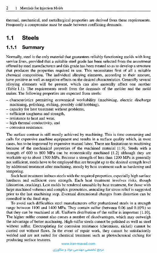
The surface contour is still mostly achieved by machining. This is time consuming andcalls for expensive machine equipment and results in a surface quality which, in mostcases, has to be improved by expensive manual labor. There are limitations to machiningbecause of the mechanical properties of the machined material [1.9]. Steels with astrength of 600 to 800 MPa can be economically machined [1.2] although they areworkable up to about 1500 MPa. Because a strength of less than 1200 MPa is generallynot sufficient, steels have to be employed that are brought up to the desired strength levelby additional treatment after machining, mostly by heat treatment such as hardening andtempering.
Such heat treatment imbues steels with the required properties, especially high surfacehardness and sufficient core strength. Each heat treatment involves risks, though(distortion, cracking). Lest molds be rendered unusable by heat treatment, for those withlarge machined volumes and complex geometries, annealing for stress relief is suggestedprior to the last machining step. Eventual dimensional changes from distortion can beremedied in the final step.
To avoid such difficulties steel manufacturers offer prehardened steels in a strengthrange between 1100 and 1400 MPa. They contain sulfur (between 0.06 and 0.10%) sothat they can be machined at all. Uniform distribution of the sulfur is important [1.10].The higher sulfur content also causes a number of disadvantages, which may outweighthe advantage of better machining. High-sulfur steels cannot be polished as well as steelwithout sulfur. Electroplating for corrosion resistance (chromium, nickel) cannot becarried out without flaws. In the event of repair work, they cannot be satisfactorilywelded and are not suited for chemical treatment such as photochemical etching forproducing surface textures.
www.iran-mavad.com
مرجع تخصصی مهندسی مواد و متالورژی
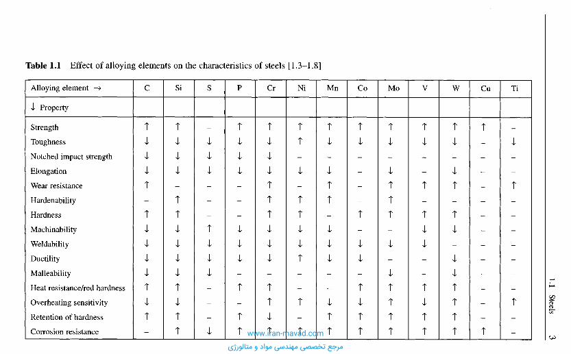
Table 1.1 Effect of alloying elements on the characteristics of steels [1.3-1.8]
Alloying element —>
•I Property
Strength
Toughness
Notched impact strength
Elongation
Wear resistance
Hardenability
Hardness
Machinability
Weldability
Ductility
Malleability
Heat resistance/red hardness
Overheating sensitivity
Retention of hardness
Corrosion resistance
TiCuWVMoCoMnNiCrPSSiC
www.iran-mavad.com
مرجع تخصصی مهندسی مواد و متالورژی
In recent years, electric-discharge machining, including spark erosion with travelingwire electrodes, has become a very important method of machine operations forheattreated steel without sulfur.
If a series of equal cavities of small size has to be made (e.g. typewriter keys),coldhobbing is an economical process. Steels suitable for this process should have goodplasticity for cold working after annealing. Therefore soft steel with a carbon content ofless than 0.2% is utilized.
After forming, they receive adequate surface hardness through heat treatment. Suchhardening is made possible by carburizing. These case-hardening steels are an importantgroup of materials for mold cavities.
Distortion and dimensional changes often occur as a side effect of heat treatment.Dimensional changes are caused by thermal stresses and changes in volume resultingfrom transformations within the steel. They are unavoidable. Distortion, on the otherhand, is caused by incompetent execution of heat treatment before, during, or after theforming process, or by faulty mold design (sharp corners and edges, large differences incross sections etc.). Deviation from the accurate shape as a consequence of heattreatment is always the sum of distortion and dimensional change. The two cannot bestrictly separated. Figure 1.1 points out the various effects which cause configurationalchanges. Use of steels with a low tendency to dimensional changes reduces such effectsto a minimum [1.11, 1.12].
Prehardened, martensitic hardenable, and through-hardening steels should bepreferred in order to avoid distortion. Pretreated steels do not need any appreciable heattreatment after forming. The required wear resistance of these steel grades is achievedby a chemical process (e.g. chrome plating) or a diffusion process (e.g. nitriding attemperatures between 450 and 600 0C). Because of the low treatment temperature of 400to 500 0C for martensitic steels, only small transformation and thermal stresses occur inthese steels, and the risks generally associated with heat treatment are slight [1.13]. Inthrough-hardening steels, the heat treatment causes a uniform structure throughout thecross section and thus no appreciable stresses occur.
The range of applications for through-hardening steels is limited, however, since thedanger of cracking under bending forces is high, especially in the case of molds withlarge cavities. Demands for molds with a tough core and a wear-resistant, hardenedsurface are best met with case-hardening steels (e.g. for long cores or similar items).
High wear in use is most effectively countered with high surface hardness. The besthardening results and a uniform surface quality can be achieved with steels that are freefrom surface imperfections, are of the highest purity and have a uniform structure.Completely pure steels are the precondition for the impeccably polishable, i.e. flawless,mold surface required for processing clear plastics for optical articles. A high degree ofpurity is obtained only with steels that are refined once or more. Remelting improves themechanical properties, too. These steels have gained special importance in mold makingfor producing cavity inserts.
The maximum abrasive strength is obtained with steels produced by powdermetallurgy (hard-material alloys).
Mold temperature and heat exchange in the mold are determined by the plasticmaterial and the respective molding technique. The thermal effect of the moldtemperature during the processing of the majority of thermoplastics (usually below120 0C) is practically insignificant for the selection of the mold material. There are,however, an increasing number of thermoplastics with melt temperatures up to 400 0Cthat require a constant mold temperature of more than 200 0C during processing. Mold
www.iran-mavad.com
مرجع تخصصی مهندسی مواد و متالورژی
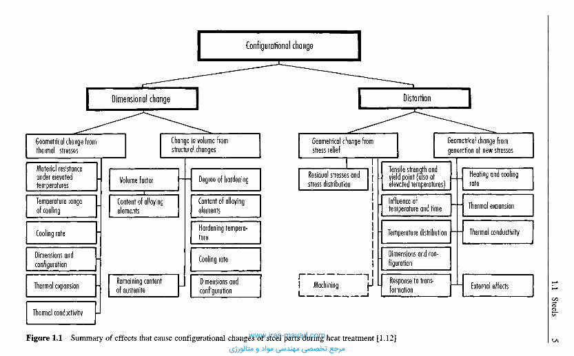
Figure 1.1 Summary of effects that cause configurational changes of steel parts during heat treatment [1.12]
Geometrical change fromgeneration of new stresses
Heating and coolingrate
Thermal expansion
Thermal conductivity
External effectsResponse to trans-formation
Dimensions and con-figuration
j Temperature distribution
Influence oftemperature and time
Tensile strength andyield point (also atelevated temperatures)
Distortion
Geometrical change fromstress relief
Residual stresses andstress distribution
Machining
Configurational change
Change in volume fromstructural changes
Degree of hardening
Content of alloyingelements
Hardening tempera-ture
Cooling rate
Dimensions andconfiguration
Dimensional change
Volume factor
Content of alloyingelements
Remaining contentof austenite
I Geometrical change fromthermal stresses
Material resistanceunder elevatedtemperatures
Temperature rangeof cooling
Cooling rate
Dimensions andconfiguration
Thermal expansion
Thermal conductivity
www.iran-mavad.com
مرجع تخصصی مهندسی مواد و متالورژی
temperatures for thermosets are also between 150 and 250 0C. At this point, themechanical properties of the mold material are affected. Wear and tendency to distortionincrease, creep to rupture data and fatigue resistance decrease [1.14]. This has to be takeninto account through selecting the most suitable material. A heat-treatment diagram(hardness versus temperature) can indicate the permissible temperature of use if the latteris taken as 30 to 50 0C below the tempering temperature.
Heat exchange between the solidifying molding and the mold has a substantial effecton the cost of a part. This heat exchange is considerably influenced by the thermalconductivity of the mold material which again is affected by its alloying components.Their different structures give rise to varying thermal conductivity. Notch sensitivity canbe countered to a certain degree with case hardening or nitriding because such treatmentcauses compressive stresses in the surface [1.15]. Nevertheless, attention should be paidto avoiding notches during the design and manufacturing stages.
Some plastics release chemically aggressive substances during processing, such ashydrochloric acid, acetic acid or formaldehyde. They attack the mold surface if it is notprotected with a deposit of hard chromium or nickel.
Since such deposits have a tendency to peel off if the molds are improperly designed(e.g., shape, sharp corners) or handled, corrosion resistant steels should be used formaking molds which are employed under such conditions. Then no further precautionsagainst possible corrosion from humidity or coolant are necessary.
The demands listed so far are partially contradictory. Therefore the mold designer andmold maker have to select that steel grade which is best suited for a particular job.
The following steel grades are presently offered for producing cavity inserts:
- case hardening steels,- nitriding steels,- through-hardening steels,- tempered steels for use as supplied,- martensitic-hardening steels,- hard-material alloys,- corrosion-resistant steels,- refined steels.
The most important steels for mold making are shown in Table 1.2, along with theircomposition, heat treatment and application areas. A more detailed characterization ofthese groups of steels is provided below.
1.1.2 Case-Hardening Steels
Case-hardening steels best meet the qualifications for mold making. They are notexpensive, and it should not come as a surprise that their share is about 80% of the totalsteel consumed in mold making [1.16] (This figure includes consumption for base andclamp plates). Unalloyed or low-alloyed steels offer a special advantage. Through casehardening, carburization or cementization (so-called because cementite is formed duringsubsequent hardening), a mold surface as hard as glass is generated and, at the sametime, a tough, ductile core. The hard surface renders the mold wear resistant and thetough core confers resistance to shock and alternate loading [1.17].
There are other criteria favoring the application of case-hardening steels overhighcarbon and through-hardening steels. Easy machining and, if properly produced and
www.iran-mavad.com
مرجع تخصصی مهندسی مواد و متالورژی
treated, very good polishing are especially worth mentioning. In carburization, there isthe possibility of performing local hardening by covering certain areas. However, theextensive heat-treatment procedure required for carburization cannot preventdimensional changes from occurring, with the result that additional outlay is requiredbefore the molds can be used [1.18]. Another advantage over the other steel groups is thelow strength after low-temperature annealing. Case-hardening steels are thereforesuitable for hobbing (see Section 2.3). This process is particularly suitable for smallcavities and multi-cavity molds with a large number of equal cavities.
1.1.3 Nitriding Steels
Basically all steels which contain nitride-forming alloying elements can be nitrided.Such alloying elements are chromium, molybdenum, vanadium and preferablyaluminum, which especially favors formation of nitrides. These steels absorb nitrogenfrom the surrounding medium by diffusion into their outer layer. This process can takeplace in a salt bath, in gas, powder or in the plasma of a strong corona discharge(ionitriding) at temperatures between 350 and 580 0C. Temperature and time aredetermined by the individual medium. This procedure causes the above mentionedalloying elements to form nitrides. They provide the steel with an extraordinarily hardand wear-resistant surface with a Brinell hardness between 600 and 800, the valuedepending on steel grade and process. The greatest hardness is not at the immediatesurface but a few hundredths of a millimeter deeper. Therefore the mold should beappropriately larger and the dimensions corrected by grinding after nitriding [1.19].Ionitrided molds do not need this posttreatment, and it should not be done, which is aspecial advantage of this process.
Nitriding has the following advantages:
- After nitriding, there is no need for heating, quenching or annealing since nitridingbestows the hardness direct.
- Nitrided parts are free from distortion because they are heated only to about 550 0C.- The hardness of the nitrided layer is not affected by heating up to 500 0C (retention of
hardness).- Nitrided molds are thus suitable for processing thermosets and such thermoplastics
that are shaped at high mold temperatures.- Nitriding steels yield an extremely hard and at the same time wear-resistant outer layer
having good surface slip.
Disadvantageous is the low extent to which the nitrided layer is anchored to the basematerial as the hard layer can peel off under high surface pressure [1.20].
1.1.4 Through-Hardening Steels
Through-hardening steels increase their hardness by the formation of martensite, whichresults from rapid quenching. The mechanical properties depend on the quenchingmedium and the cooling rate. Quenching media are water, oil or air. Water works fastestand has the most drastic effect, while oil and air are milder. Thermal conduction, amongother factors, determines the cooling rate, too. The heat conduction depends on the
www.iran-mavad.com
مرجع تخصصی مهندسی مواد و متالورژی
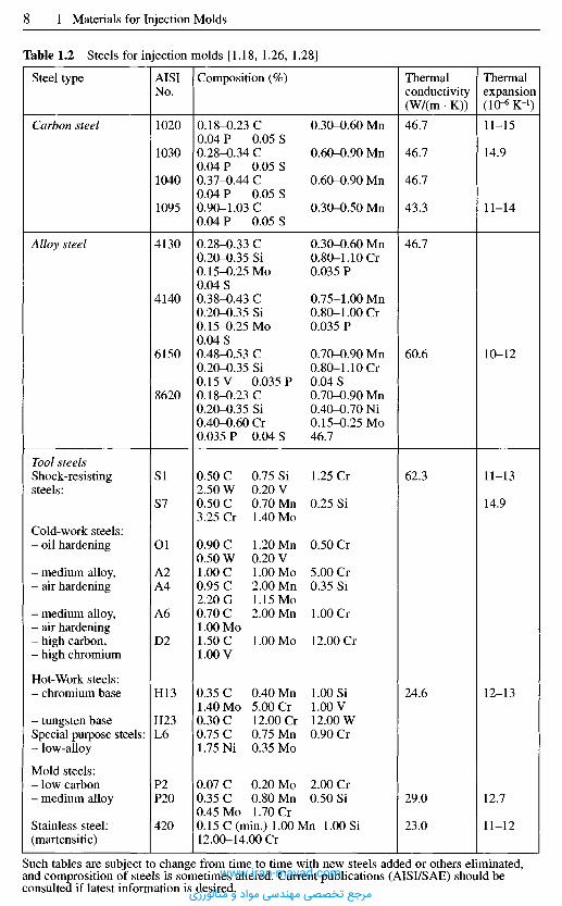
Steel type
Carbon steel
Alloy steel
Tool steelsShock-resistingsteels:
Cold-work steels:- oil hardening
- medium alloy,- air hardening
- medium alloy,- air hardening- high carbon,- high chromium
Hot-Work steels:- chromium base
- tungsten baseSpecial purpose steels:- low-alloy
Mold steels:- low carbon- medium alloy
Stainless steel:(martensitic)
AISINo.
1020
1030
1040
1095
4130
4140
6150
8620
Sl
S7
Ol
A2A4
A6
D2
H13
H23L6
P2P20
420
Composition (%)
0.18-0.23 C 0.30-0.60 Mn0.04 P 0.05 S0.28-0.34 C 0.60-0.90 Mn0.04 P 0.05 S0.37-0.44 C 0.60-0.90 Mn0.04 P 0.05 S0.90-1.03 C 0.30-0.50Mn0.04 P 0.05 S
0.28-0.33 C 0.30-0.60 Mn0.20-0.35Si 0.80-1.10 Cr0.15-0.25Mo 0.035 P0.04 S0.38-0.43 C 0.75-1.00 Mn0.20-0.35Si 0.80-1.00 Cr0.15-0.25Mo 0.035 P0.04 S0.48-0.53 C 0.70-0.90 Mn0.20-0.35Si 0.80-1.10 Cr0.15 V 0.035 P 0.04 S0.18-0.23 C 0.70-0.90Mn0.20-0.35 Si 0.40-0.70 Ni0.40-0.60Cr 0.15-0.25 Mo0.035 P 0.04 S 46.7
0.50C 0.75Si 1.25Cr2.50 W 0.20 V0.50 C 0.70 Mn 0.25 Si3.25Cr 1.40Mo
0.90C 1.20Mn 0.50 Cr0.50 W 0.20 V1.00 C 1.00 Mo 5.00Cr0.95 C 2.00 Mn 0.35 Si2.20G 1.15Mo0.70C 2.00Mn 1.00 Cr1.00 Mo1.50C 1.00 Mo 12.00Cr1.00 V
0.35 C 0.40Mn 1.00 Si1.40Mo 5.00Cr 1.00 V0.30 C 12.00 Cr 12.00 W0.75 C 0.75 Mn 0.90 Cr1.75 Ni 0.35 Mo
0.07 C 0.20 Mo 2.00Cr0.35 C 0.80 Mn 0.50 Si0.45Mo 1.70Cr0.15 C (min.) 1.00 Mn 1.00 Si12.00-14.00 Cr
Thermalconductivity(W/(m • K))
46.7
46.7
46.7
43.3
46.7
60.6
62.3
24.6
29.0
23.0
Thermalexpansion(IO"6 K-1)
11-15
14.9
11-14
10-12
11-13
14.9
12-13
12.7
11-12
Such tables are subject to change from time to time with new steels added or others eliminated,and comprosition of steels is sometimes altered. Current publications (AISI/SAE) should beconsulted if latest information is desired.
Table 1.2 Steels for injection molds [1.18, 1.26, 1.28]
www.iran-mavad.com
مرجع تخصصی مهندسی مواد و متالورژی

surface-to-volume ratio of the mold and the alloying elements added to the steel. Ni, Mn,Cr, Si and other elements lower the critical cooling rate and, therefore, permitthroughhardening of larger cross sections [1.17].
The hardening process consists in preheating, heating to prescribed temperature,quenching with formation of a hard martensitic structure and then normalizing toimprove toughness. Because of the low toughness of through-hardening steels, moldswith deep cavities have a higher risk of cracking.
Unlike tempering, normalizing reduces the hardness only slightly. The temperaturesfor normalizing are between 160 and 250 0C. Besides improving toughness, normalizinghas the effect of reducing stresses. (Occasionally this treatment is, therefore, called stressrelieving but it should not be confused with stress-relieving annealing.)
Through-hardening steels exhibit very good dimensional stability when heat-treated.Because of their natural hardening capacity they have high compressive strength and areespecially suitable for molds with shallow cavities where high pressure peaks may beexpected. They can also be recommended in molds for insert molding (with possiblehigh edge pressure) and, due to good wear resistance and high normalizing temperatures,for processing thermosets [1.20, 1.21].
As far as the mechanical properties are concerned, through-hardening steels have ahomogeneous structure. Major postmachining does not remove outer layers havingspecial strength as is the case with case-hardening steels. Since the introduction ofelectrical discharge machining (EDM), the use of through-hardening steels has beensteadily gaining in importance.
1.1.5 Heat-Treated Steels
These steels are tempered by the manufacturer and can therefore be used as suppliedwithout the need for further heat treatment.
After hardening, these steels are submitted to a tempering process. At temperaturesabove 500 0C, the martensite decomposes into carbide and alpha iron. This causes areduction in hardness and strength of these steels and, at the same time, an increase intoughness. Ductility and toughness increase with rising tempering temperatures;hardness and strength, however, decrease.
Through judicious choice of temperature (usually constant) and duration of tempering(1 to 2 hours), it is possible to obtain a certain degree of toughness, the exact valuedepending on the strength. 1200 to 1400 MPa yield strength can be assumed as the upperlimit. Steels of higher strength can no longer be economically machined [1.22].
To improve the machining properties, sulfur (0.06%) is added to the heat-treatedsteels. However, this reduces the scope for electroplating the mold surfaces, such as byhard chroming. Similarly, photo-etchability is severely restricted by the manganesesulfides emitted at the surface.
These disadvantages are compensated by treating the steels in some cases withcalcium as they are being made. The sulfur content can thereby be reduced (< 0.005%;these steels are said to be highly desulfurized) and the machinability and etchabilityimproved simultaneously [1.18, 1.23].
Heat-treated steels are preferably employed for medium-sized and large molds. Theyhave the additional advantage that corrections are more easily accomplished if deemednecessary after a first trial run [1.2, 1.25].
www.iran-mavad.com
مرجع تخصصی مهندسی مواد و متالورژی

1.1.6 Martensit ic Steels
Martensitic steels combine extreme strength and hardness with the advantage of simpleheat treatment. They are supplied in an annealed state. Their structure consists of toughnickel martensite with a strength of 1000-1150 MPa. To an extent depending on theirstrength, their machinability is comparable to that of tempered steel. It takes about 10 to20% more machine time than with mild steels.
After machining, molds are subjected to a simple heat treatment that harbors no risks.They are heated up to temperatures between 480 and 500 0C, kept at this temperature for3 to 5 hours and slowly cooled in still air. No normalizing is done.
Due to the low hardening temperature, no distortion is to be expected. There is onlya slight dimensional change from a shrinkage of 0.05 to 0.1% on all sides. The wearresistance of the mold surface can be improved even further by a diffusion process suchas nitriding. Care should be taken not to exceed 480 to 500 0C when doing this. Thepreceding hardening step can be omitted if diffusion treatment occurs. The extraordinarytoughness of martensitic steel at the high hardness of 530 to 600 Brinell is remarkable[1.2, 1.13, 1.20, 1.25].
The use of martensitic steels is recommended for smaller cavity inserts with complexcontours that exhibit large differences in cross sections and detached thin flanges.
The use of other steel grades for such molds would definitely result in distortion.It should be noted that hardened martensitic steels can be easily welded using materialsof the same kind without the need for preheating.
1.1.7 Hard Mold Alloys
Hard mold alloys are steels produced by a powder-metallurgical process that have a highproportion of small carbides which are uniformly embedded in a steel matrix of differentcomposition, primarily a chromium-molybdenum-carbon matrix with added cobalt andnickel [1.18, 1.26-1.28]. These practically isotropic steels are produced in a diffusionprocess under pressure and temperature from homogeneous alloying powders ofmaximum purity. To an extent depending on the steel grade and manufacturer, thesesteels have a titanium carbide content of 50 vol.%. This high carbide content renders thesteels extremely wear resistant. They are thus particularly suitable for processingwearpromoting compounds (thermosets and reinforced thermoplastics) and for varioustool parts subjected to increased wear, such as nozzles, gate systems, etc.
Hard mold alloys are supplied in a soft-annealed state and may be machined. Afterheat treatment (6-8 hours storage at 480 0C), the hardness increases to 60-62 Rc. Toincrease the hardness further, storage may be combined with a nitriding treatment. Thesurface hardness increases as a result to 72-74 Rc [1.27].
Due to their isotropic structure and low coefficient of thermal expansion, hard moldalloys undergo extremely little distortion during heat treatment.
1.1.8 Corrosion-Resistant Steels
Some polymeric materials release chemically aggressive substances during processingthat attack steel and harm the surface, e.g. by causing rusting. One way of protectingmolds against corrosion is afforded by applying a protective electroplating coat (chrom-
www.iran-mavad.com
مرجع تخصصی مهندسی مواد و متالورژی
nickel plating). Complicated geometries make it difficult, however to apply uniformcoatings, particularly on the corners and edges. It is therefore possible that the shape ofthe moldings will change as a result. In addition, protective electroplating coats tend topeel off very easily. If the molds are likely to be used in a corrosive setting, it is advisableto use corrosion-resistant steel.
The corrosion resistance of such steels is due to their having been alloyed withchromium. Given a chromium content of at least 12%, very dense, strongly adhering,invisible layers of chromium oxide are formed in contact with atmospheric oxygen orother oxygen-providing media. They protect the steel against corrosion. In this case thecrystalline structure is a solid solution of iron and chromium. Adding other alloyingelements to steel, especially carbon, may partially reduce the corrosion resistance.Carbon has the tendency to react with chromium and form ineffective chromium carbide.Only in the hardened state does carbon remain bound to the iron atoms or in solution,thereby allowing the chromium to fully play its anti-corrosive function. Through heattreatment above ca. 400 0C, part of the carbon escapes from the solution and can formchromium carbide. Thus, carbon binds part of the chromium, preventing it fromperforming its protective role. Because of the required mechanical properties, however,carbon cannot be dispensed with mold in stainless steels for mold making [1.28].Therefore hardened chrome steel is always the best choice.
The corrosion resistance also depends on the quality of the mold surface. A roughsurface presents a larger area for attack than a smooth, highly polished one. Chrome steelwith only 13% chromium, for instance, is corrosion resistant only if the surface is highlypolished. In addition, the plastics processor himself should make every effort to protecthis molds from corrosion by cleaning them before storage.
Steels with 17% chromium and martensitic structure have better corrosion resistancebut tend to coarseness and formation of soft ferritic parts in their crystalline structure.Only the hard material alloys (tool steels with the maximum carbide content producedby powder metallurgical processes) are not susceptible to these problems (see alsoSection 1.1.7).
1.1.9 Refined Steels
The cosmetic appearance of a plastic molding depends largely on the mold's surfacequality. Particular attention to this fact should be paid when selecting a steel for moldinserts that will be employed for molding transparent articles such as lenses etc.
The better the steel can be polished, the higher is the surface quality of the mold. Howwell steels can be polished is determined by their degree of purity. This degree dependson the amount of nonmetallic inclusions in the steel, such as oxides, sulfides and silicates[1.19]. These inclusions, unavoidable in an open-hearth steel, can be eliminated byremelting. In modern practice three methods with self-consuming electrodes are applied:melting in an electric-arc vacuum oven, in an electron beam oven or by electro-slagrefining.
For refining in an electric-arc vacuum oven, a normally produced steel rod as self-consuming electrode is burnt off in a cooled copper die under high vacuum (IO"1 or 10~3 Pa).
In an electron beam oven, the rod is melted in an ingot mold by an electron beam.Electro-slag refining has gained greatest importance in recent years. In this process,
the electrode, which is in the form of a completely alloyed block, dips into electricallyconductive liquid slag in a water-cooled mold and is melted [1.29]. The melt dripping
www.iran-mavad.com
مرجع تخصصی مهندسی مواد و متالورژی
from the electrode passes through the liquid slag and is purified by respectivemetallurgical reactions [1.30, 1.31].
Refined steels have the following advantages over those conventionally produced:
- more homogeneous primary structure and extensive freedom from ingot liquation andinternal defects from solidification,
- less crystal liquation and therefore more homogeneous microstructure,- reduced quantity and size and a more favorable distribution of nonmetallic inclusions,
such as oxides, sulfides and silicates [1.32].
Remelted and refined steels are the purest steels presently on the market. Therefore theycan be very well polished.
1.2 C a s t S t e e l
The production of molds from forged or rolled steel is relatively expensive because ofthe high labor costs for machining and the expenses for the necessary equipment whichis partly special machinery. In addition, there are high material losses from cuttingoperations, which can amount to 30 to 50% for large cavities [1.19]. Besides this, stylistsand consumers demand a molding whose surface quality or texture cannot be producedin a cavity by conventional cutting operations. Solutions can be found in physical orchemical procedures or precision casting.
The most common casting steel grades and casting processes are discussed in detailin Sections 2.1.1-2.1.3. A summary of cast steel alloys is shown in Table 1.3.
1.3 N o n f e r r o u s M e t a l l i c s
The best known nonferrous metals employed in mold making are:
- copper alloys,- zinc alloys,- aluminum alloys,- bismuth-tin alloys.
1.3.1 Copper Alloys
The importance of copper alloys as materials for mold making is based on their highthermal conductivity and ductility, which equalizes stresses from nonuniform heatingquickly and safely. The mechanical properties of pure copper are moderate. Althoughthey can be improved by cold rolling or forming, they generally do not meet the demandson a mold material.
Therefore, copper serves in mold making at best as an auxiliary material, for instance,as components of heat exchangers in molds cast from low melting alloys. Beryllium-copper-cobalt alloys, however, are important materials for mold cavities.
www.iran-mavad.com
مرجع تخصصی مهندسی مواد و متالورژی
1.3.1.1 Beryllium-Copper Alloys
As with other alloys, the mechanical and thermal properties depend on the chemicalcomposition of the alloy. With increasing beryllium content, the mechanical propertiesimprove while the thermal properties deteriorate. Beryllium-copper alloys with morethan 1.7% beryllium have prevailed in mold making. They have a tensile strength of upto 1200 MPa and can be hardened up to 440 Brinell. Hardening up to 330 to 360 Brinellis generally sufficient for practical purposes. In this range the material is very ductile,has no tendency to fragility at the edges, and is readily polishable [1.39].
Table 1.3 Cast steels for injection molds; composition - treatment - properties [1.38]
Carbon steels
Alloy steels
Heat-resistantsteel
AISI 1020
AISI 1040
AISI 1330
AISI 4130
AISI 4340
AISI 8630
AISI 501
0.18-0.23% C 0.30-0.60% Mn 0.04% P 0.05% Sannealed BH 122, normalized BH 134Welding is readily done by most arc and gas processes.Preheating unnecessary unless parts are very heavy
0.37-0.44% C 0.60-0.90% Mn 0.04% P 0.05% Snormalized and annealed BH 175normalized and oil quenched BH 225Welding can be done by arc, resistance and gas processes. Todecrease cooling rate and subsequently hardness preheating toabove 150 preferably 260 0C. Final heating to 600-650 0Crestores ductility and relieves stress
0.28-0.33% C 1.60-1.90% Mn 0.20-0.35% Si0.035% P 0.04% Snormalized BH 187, normalized and tempered BH 160Can be relatively easily welded with mild-steel filler metal
0.28-0.33% C 0.40-0.60% Mn 0.20-0.35% Si0.80-1.10% Cr 0.15-0.25% Mo 0.035% P 0.04% Sannealed BH 175Welding same as 1330
0.38-0.43% C 0.60-0.80% Mn 0.20-0.35% Si1.65-2.00% Ni 0.70-0.90% Cr 0.20-0.30% Mo0.035% P 0.04% Snormalized and annealed BH 200quenched and tempered BH 300Welding calls for pre- and postheating and filler metals of thesame mechanical properties as the base metal. Stress relieving isdesirable especially in repair work
0.28-0.30% C 0.70-0.90% Mn 0.20-0.35% Si0.40-0.70% Ni 0.40-0.60% Cr 0.15-0.25% Monormalized BH 240, annealed BH 175Welding preferably with filler metal of the same chemicalanalysis. No preheating needed for sections up to 0.5 in. butstress relieving after welding
0.10% C 1.00% Mn 1.00% Si 4.00-4.00% Cr0.40-0.65% MoWelding similar to 8630
www.iran-mavad.com
مرجع تخصصی مهندسی مواد و متالورژی
Tempering, which provides a homogeneous hardness, can be done in a simple oven [1.40].Alloys with a beryllium content below 1.7% are only used for functional components,
such as heat conductors in heat exchangers, because of their diminished strength.Table 1.4 summarizes the technical data of some beryllium-copper alloys.
Molds made of beryllium copper are sufficiently corrosion resistant and can bechrome or nickel plated if needed. Protective coating is mainly done by electroless nickelplating today. It has the advantage of a more even deposit and a hardenability of up to780 Brinell with an appropriate heat treatment at about 400 0C. Besides this, a nickelcoating is less prone to cracking than a hard chrome coating [1.40]. In contrast to caststeel, beryllium-copper alloys are practically insensitive to thermal shock.
Mechanical damage can be repaired by brazing or welding. Beryllium-copper rodswith about 2% beryllium are preferably used for welding with 250 Amps [1.39, 1.40].The molds are appropriately preheated to 300 0C [1.40].
Molds of beryllium copper can be made by machining or casting. Cold-hobbing isonly conditionally suitable for shallow cavities. The alloy can be better formed byhothobbing in a temperature range of 600 to 800 0C followed by solution annealing.
Beryllium-copper alloys are employed as materials for molds or functionalcomponents wherever high heat conductivity is important either for the whole mold orpart of it. The temperature differential between cavity wall and cooling channel isreduced. This results in higher output with the same, or often better, quality with thesame cooling capacity. These alloys also offer an advantage if high demands on surfaceaccuracy have to be met. They are well suited for casting with patterns having astructured surface such as wood, leather or fabric grain.
1.3.2 Zinc and its Alloys
High-grade zinc alloys for casting are used in mold making only for prototype molds ormolds for small production runs because of their inferior mechanical properties. They aremore frequently utilized for blow molding or vacuum forming where molds are notunder high mechanical loads. Zinc alloys, like copper alloys, are characterized by highthermal conductivity of about 100 W/(m • K).
Molds of zinc alloys are mostly cast. The low casting temperature (melting point ca.390 0C, casting temperature 410 to 450 0C) is a special advantage. It allows patterns tobe made of wood, plaster, or even plastics, in addition to steel. Patterns of plaster andplastics can be made especially easily and fast. High-grade zinc alloys can also be castin sand and ceramic molds. Die casting, although possible, is used only rarely.
The excellent behavior of zinc alloys during casting produces smooth and nonporoussurfaces of intricate and structured surfaces [1.39]. Molds, especially plaster molds, mustbe adequately dried before use (plaster for several days at 220 0C), since otherwise aporous and rough cavity surface results from the generation of steam [1.21].
Molds of high-grade zinc alloys can also be made by cold-hobbing. The blank ispreheated to 200 to 250 0C before hobbing. Even deep cavities are produced in one stepwithout intermediate annealing. Hobs with a Brinell hardness of 430 are employed.Vertical motion is sometimes combined with rotation. With such hobs cavity inserts formolding helical gears can be made [1.21].
Another process using high-grade zinc alloys is metal spraying (Section 2.2).Because of low mechanical strength only cavity inserts are made of high-grade zinc
alloys. These inserts are fitted into steel bases, which have to resist the forces fromwww.iran-mavad.com
مرجع تخصصی مهندسی مواد و متالورژی

Designation
Composition
Density kg/m3
Therm, conductivityW/(m • K)
Therm, expansion10* K-1
Specifie heat capacityJ/(kg • K)
Electric resistivity10-8H-m
Modulus of elasticity GPa
Tensile strength [MPa]
Yield strength [MPa]
Elongation [%]
Rockwell hardness
C 17 200Be1.80-2.00%Co/Ni0.20% min.Co/Ni/Fe0.6% max.,Cu balance
C 17 300Be1.80-2.00%,Co/Ni0.20% min.,Co/Ni/Fe0.6% max.,Pb0.20-0.6%,Cu balance
8250
130
17.5
420
7.7
131
I 415-585H 620-895HI 1140-1310IV 1275-1480
I 140-415H 515-725m 1000-1200IV 1140-1380
I 35-60H 10-20m 3-ioIV 2-5
I B45-80H B88-103m C36-41IV C39-44
C17 000Be1.60-1.79%Co/Ni0.20% min.,Co/Ni/Fe0.6% max.,Cu balance
8415
130
17.5
420
7.7
128
I 415-585H 620-895m 1035-1310IV 1170-1450
I 140-205H 515-725m 860-1070IV 930-1140
I 35-60H 10-20m4~ioIV 2-5
I B45-85H B91-103m C32-39IVC35-41
C 17 510Be0.20-0.60%Ni1.40-2.20%Cu balance
8610
260
17.6
420
3.8
138
I 240-380E 450-550m 690-830IV 760-900
I 140-310H 340-515m 550-690IV 690-830
I 20-35n 10-15m 10-25IV 10-20
I B25-50H B60-75m B92-100IV B95-102
C 17 500Be0.40-0.75%Co2.40-2.70%Cu balance
8775
260
18
420
3.8
138
Notes: I: Solution heat treatedII: Cold drawnIII: Solution heat treated and age hardenedIV: Cold drawn and age hardened
Table 1.4 Technical data of beryllium-copper [1.41]
www.iran-mavad.com
مرجع تخصصی مهندسی مواد و متالورژی
clamping and injection pressure during the molding process. The most commonhighgrade zinc alloys, known under their trade names Zamak or Kirksite, aresummarized in Table 1.5.
1.3.3 Aluminum Alloys
For a long time, aluminum was not used to any major extent for making injection molds.However, extensive improvements in properties, particularly mechanical properties,have led to this material being used more and more often in recent times. The mainproperties in favor of using aluminum for mold making are:
- low density,- good machinability,- high thermal conductivity, and- corrosion resistance.
Aluminum alloys are available as casting and forging alloys. The casting alloys are notof much significance. Casting is difficult. Perfect molds presuppose correct choice ofalloy, the appropriate melting and casting technique and a mold design amenable tocasting. It is therefore advisable to collaborate with the manufacturer at the designstage.
More important for mold making are the forging alloys which, in the form ofheathardening, high-strength aluminum-zinc-magnesium-copper alloys, have alreadyshown their mettle in aircraft construction. These are now available commercially in theform of complete mold structures as well as plates that have been machined on all sidesand as blanks [1.44]. The chemical composition and physical properties of a typicalaluminum alloy used in mold making are shown in Table 1.6.
Aluminum molds weigh less than steel molds due to their specific weights (between2.7 and 2.85 g/cm3, depending on alloying additives). Unfortunately this "positivecharacteristic" is not fully recognized because the individual plates, which arecomponents of a mold, have to be about 40% thicker than steel plates because of theirlower mechanical strength (modulus of elasticity is only roughly 30% that of steel; Table1.6). In spite of this, aluminum molds weigh about 50% less than steel molds. This is aconsiderable advantage during mold making and assembly as well as later on duringsetup in the molding shop. With smaller molds, it is frequently possible to do withoutexpensive lifting devices such as cranes and lift trucks.
Additional advantages result from good machinability, which can allow cuttingspeeds five times as fast as those for steel [1.44]. This holds particularly true if therecommendations of the producer are taken into account and those tools are used whichare especially suited for aluminum. Distortion from machining is not to be expectedbecause aluminum has very little residual stresses due to special heat treatment duringproduction (the wrought products are hot-rolled, then heat-treated and stretched untilstress-free). Aluminum can be worked with cutting tools as well as shaped by means ofEDM.
Electrode material made of electrolytic copper or copper containing alloys areprimarily used for this procedure. Here, too, the high eroding speed (6 to 8 times that ofsteel) is economically significant. Cut or eroded surfaces can be polished with standardmachines and wheels and made wear resistant by chrome plating or anodizing. Servicelives of up to 200,000 shots per mold have been achieved with aluminum molds, the
www.iran-mavad.com
مرجع تخصصی مهندسی مواد و متالورژی
Shearstrength(MPa)
300246
Compressivestrength(MPa)
600-700420-527793685
BrinellhardnessBH
1000100010901450-1500
Elongation(% in 50 mm)
1-2
1.25Very low
Tensilestrength(MPa)
220-240226236149
Thermalexpansion(10-6/K)
272728
Shrinkage
1.10.7-1.21.11.1
Meltingpoint(0C)
390380380358
Density(kg/m3)
6700670067006600
Designation
ZamakKirksite AKayemKayem 2
Table 1.5 High-grade zinc alloys for injection molds [1.42, 1.43]
Table 1.6 Chemical composition and physical properties of a typical heat-hardening aluminum forging alloy used for mold making [1.44, 1.45, 1.47]
Others
Ti + Zr = 0.25
Zn
5.1-6.1
Ti
0.2
Si
0.4
Mn
0.3
Mg
2.1-2.9
Fe
0.5
Chemical composition
Composition (wt. -%)
Cs
0.18-0.28
Cu
1.2-2.0
A.A.No.
3.4365
Thermalconductivity
W/(K • m)
153(0-1000C)
Coefficient ofthermal expansion
W/(m 0C)
23.7
Modulus ofelasticity
MPa
72000
Ultimate tensilestrength
N/mm2
480-610
Yield strength
N/mm2
410-530
Physical properties
Density
kg/dm3
2.82
A.A.No.
3.4365 www.iran-mavad.com
مرجع تخصصی مهندسی مواد و متالورژی
Due to the positive aspects for mold making described above, mold plates already milledand surface-ground to finished dimensions, with the corresponding bores for guidesystems right through to complete mold structures, are now commercially available.
Designs combining aluminum with steel have yielded good results. This constructionhas the advantage of allowing the more resistant steels to be used for areas subject tohigh wear and abrasion. It therefore combines the advantages of both materials.
The service life of aluminum molds depends on the plastic to be processed (reinforcedor unreinforced), its processing conditions (injection pressure, temperature) and thegeometry of the molding. The literature contains reports of molds that have produced15,000-200,000 moldings. Aluminum is of little or no suitability for processingthermosets on account of the high processing temperatures and the associated thermalstress [1.45, 1.49].
1.3.4 Bismuth-Tin Alloys
Bismuth-tin alloys are marketed under the trade name Cerro alloys. They are relativelysoft, heavy metals, which generally react to shock in a brittle manner but exhibit plasticityunder constant loading. The strength of these alloys increases with aging [1.51].
number depending on the application [1.48, 1.49]. Surface treatment will be discussedlater.
The thermal conductivity of the materials used for the molds is critical to injectionmolding. When aluminum alloys are used, it ensures good, rapid heat distribution anddissipation. This shortens cycle times and may lead to enhanced quality of moldings.
In the presence of atmospheric oxygen, a dense, strongly adhering oxide layer about0.001 um thick forms on the surface of the aluminum [1.44, 1.46]. This layer protects theunderlying materials, particularly in dry environments, against atmospheric attack. If itis destroyed or removed during machining, it re-forms anew spontaneously. It isdamaged by acids formed from salts and gases in contact with moisture (water ofcondensation). If this kind of stress is expected during operation, surface treatment isadvisable. Good results in this connection have been produced by
- chrome plating,- nickel plating,- anodizing, and- PVD coating.
Surface treatment enhances not only corrosion resistance but also wear and abrasionresistance and sometimes facilitates demolding. Layer thicknesses and hardnessesobtained with the aforementioned coating methods are summarized in Table 1.7.
Table 1.7 Coating processes for aluminum and properties obtained [1.45, 1.47]
Process
Chrome platingNickel platingAnodizingPVD coating
Layer thickness
20-200 um35-50 um30-60 um
5-10 um
Hardness
900-1100 HV500-600 HV350-150 HV
www.iran-mavad.com
مرجع تخصصی مهندسی مواد و متالورژی
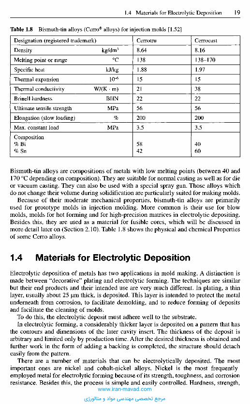
Bismuth-tin alloys are compositions of metals with low melting points (between 40 and170 0C depending on composition). They are suitable for normal casting as well as for dieor vacuum casting. They can also be used with a special spray gun. Those alloys whichdo not change their volume during solidification are particularly suited for making molds.
Because of their moderate mechanical properties, bismuth-tin alloys are primarilyused for prototype molds in injection molding. More common is their use for blowmolds, molds for hot forming and for high-precision matrices in electrolytic depositing.Besides this, they are used as a material for fusible cores, which will be discussed inmore detail later on (Section 2.10). Table 1.8 shows the physical and chemical Propertiesof some Cerro alloys.
1.4 M a t e r i a l s f o r E l e c t r o l y t i c D e p o s i t i o n
Electrolytic deposition of metals has two applications in mold making. A distinction ismade between "decorative" plating and electrolytic forming. The techniques are similarbut their end products and their intended use are very much different. In plating, a thinlayer, usually about 25 urn thick, is deposited. This layer is intended to protect the metalunderneath from corrosion, to facilitate demolding, and to reduce forming of depositsand facilitate the cleaning of molds.
To do this, the electrolytic deposit must adhere well to the substrate.In electrolytic forming, a considerably thicker layer is deposited on a pattern that has
the contours and dimensions of the later cavity insert. The thickness of the deposit isarbitrary and limited only by production time. After the desired thickness is obtained andfurther work in the form of adding a backing is completed, the structure should detacheasily from the pattern.
There are a number of materials that can be electrolytically deposited. The mostimportant ones are nickel and cobalt-nickel alloys. Nickel is the most frequentlyemployed metal for electrolytic forming because of its strength, toughness, and corrosionresistance. Besides this, the process is simple and easily controlled. Hardness, strength,
Table 1.8 Bismuth-tin alloys (Cerro® alloys) for injection molds [1.52]
Designation (registered trademark)
Density
Melting point or range
Specific heat
Thermal expansion
Thermal conductivity
Brinell hardness
Ultimate tensile strength
Elongation (slow loading)
Max. constant load
Composition%Bi%Sn
kg/dm3
0C
kJ/kg
io-6
W/(K • m)
BHN
MPa
%
MPa
Cerrotru
8.64
138
1.88
15
21
22
56
200
3.5
5842
Cerrocast
8.16
138-170
1.97
15
38
22
56
200
3.5
4060
www.iran-mavad.com
مرجع تخصصی مهندسی مواد و متالورژی

ductility, and residual stresses can be varied within a broad range by selecting certainelectrolytic solutions and process conditions [1.53, 1.54].
Even the hardest forms of electrolytically deposited copper and iron are too soft forcavity walls. Copper is primarily used for backing an already formed nickel shell. Therate at which copper can be deposited is a very desirable feature of this procedure.
By contrast, electrolytically deposited chromium is so hard that postoperations suchas drilling holes for ejector pins are impractical. In addition chromium exhibits highresidual stresses, which can easily lead to cracks in the chrome layer. Thereforechromium is used only for protective coatings in mold making.
1.5 S u r f a c e T r e a t m e n t o f S t e e l s f o r I n j e c t i o n M o l d s
1.5.1 Genera l I n f o r m a t i o n
As already explained in Section 1.1, materials for mold making have to exhibitdistinctive properties. Frequently, a compromise becomes necessary because theproperties of steels depend largely on their chemical composition and the alloyingcomponents affect each other.
Therefore it is reasonable that steel producers and users, together with plasticsprocessors, keep looking for suitable processes to improve the quality and particularlythe service life of injection molds. This can be done by numerous surface treatments. Thegoal of all these processes is to improve
- surface quality,- fatigue and wear resistance,- corrosion resistance,- sliding ability, and- to reduce the tendency to form material residues and deposits in the mold.
The surface properties of components of injection molds can be considerably modifiedby suitable machining, controlled heat treatment or a change in the alloying elements inthe surface layers, by diffusion or build-up. Special demands can thus be met.
Before the details of some selected procedures are discussed below, it must be pointedout that the application of the various processes calls for specialist knowledge and, insome cases, considerable technical resources. Therefore such work is ordinarily done byspecialists. Steel producers also provide advice in this respect.
Table 1.9 Characteristics of electro-deposited nickel [1.53, 1.55]
HardnessTensile strengthTyp. strength for moldsYield strengthTyp. strength for moldsElongationTyp. elongation for moldsTemperature resistanceCorrosion and wear resistantFine, ductile grain
4500-5400 MPa360-1510MPa1400 MPa230-640 MPa460 MPa2-37%10%max. 300 0C
www.iran-mavad.com
مرجع تخصصی مهندسی مواد و متالورژی

Currently, the most common surface treatments for mold steels are shown in Figure 1.2.Some are presented in more detail below.
1.5.2 Heat Treatment of Steels
In traditional heat-treatment processes changes in the crystalline structure are caused bysimple heating and cooling. This confers distinct properties on the steel. To this end, thesteel producers provide special heat-treatment information showing the feasibility oftreatments and the resulting properties. Such "simple" treatments do not require - aslong as small dimensions are considered - a great amount of technique. They onlyassume a theoretical understanding of the reactions occurring during heat treatment.Annealing, hardening and tempering are considered "simple" treatments.
1.5.3 Thermochemical Treatment Methods
Unlike their thermal counterparts, thermochemical methods utilize chemical elementsthat diffuse from a gaseous, liquid or solid state into the material surface to produce ahard, wear-resistant layer [1.56]. A distinction is drawn between
- carburizing,- nitriding, and- bonding.
1.5.3.1 Carburizing
In carburizing, the carbon content of layers close to the surface of steel, having a lowcarbon content of ordinarily less than 0.25%, and therefore not soluble is increased to as
Figure 1.2 Techniques of surfacetreatment [1.56, 1.57]
ThermalInduction hardeningFlame hardening
Electron beam hardeningImpulse hardening,Deposit by welding.
Armor platingCementationNitriding
CarbonizingBonding
SulfidizationOxidizing
Chemical vapordeposition
Physical vapordeposition Techniques
of surfacetreatment
Hard-chromium platingNickel platingFlame spraying
Explosion coating
Jet lappingPressure polishing
Rolling
Mechanical
www.iran-mavad.com
مرجع تخصصی مهندسی مواد و متالورژی
much as 0.9% at temperatures between 850 and 980 0C. If quenching is doneimmediately from the carburizing temperature, this process is called direct hardening[1.58]. Carburizing produces a hard surface, which is supported by a soft, tough interiorcore [1.58].
After hardening the steel is tempered. The tempering temperature is determined bylater application or temperature at which the mold is used [1.56] and determines thehardness of the surface. Tempering at temperatures between 100 and 300 0C yields ahardness of 600 to 700 Brinell.
1.5.3.2 Nitriding
Nitriding (see also Section 1.1.3) can be done in a salt bath, in gas, or powder. Themedium determines the temperature and duration of the process. The aim of all processesis to saturate the outer layer of the workpiece by diffusion of nitrogen so as to increasehardness, wear resistance or corrosion resistance.
In nitriding in a bath, the molds are preheated to 400 0C. The nitriding itself is doneat 580 0C. The nitriding time depends on the desired depth of nitriding, but two hours aregenerally sufficient. A special form of nitriding in a bath is the Tenifer treatment, whichis characterized by an aerated nitriding bath of special composition. The required surfacehardness for injection molds is likewise achieved after two hours at a temperature of5700C [1.59].
Much longer nitriding times are necessary for gas nitriding. The desired surfacehardness takes at least 15 to 30 hours treatment, the exact time depending on the steelgrade. The treatment is performed at temperatures between 500 and 550 0C. It is possibleto selectively nitride certain areas by partially covering the surface with a coating ofcopper or nickel or with a special paste [1.59].
When nitro-carburizing in gas, a reaction component that provides carbon is used inaddition to ammonia. This enriches the connecting zone with carbon. Applicablecomponents are endogas, exogas or combinations thereof as well as natural gas or liquidsthat contain carbon dioxide. The treatment temperatures are about 570 0C, and the timeis 2 to 6 hours.
Activator content, nitriding time and temperature determine the quality of the resultsof powder nitriding for a particular steel grade. It is carried out at temperatures between450 and 570 0C [1.59].
Ionitriding is nitriding in the plasma of a high-amperage corona discharge. It causesnitrogen to be deposited on the mold surface. The hardening depth can range from a fewmicrometers to 1 mm. The greatest hardness is achieved here immediately at the surface,reaching 800 Brinell for some steel grades. Posttreatment of the surface is, therefore,unnecessary. The treatment is done in the temperature range between 350 and 580 0C.Treatment times start at a few minutes and are practically unlimited (20 min to 36 h) [1.60].
Distortion of molds through nitriding or ionitriding does not normally occur. Afterheat treatment, molds are obtained which are tough and free of stresses, have highsurface hardness and improved corrosion resistance.
Nitriding steels are annealed before delivery and can be machined without difficulties.
1.5.3.3 Bonding
In bonding, layers close to the surface are enriched with boron. The result is a very thinbut extremely hard (1800 to 2100 HV 0.025 [1.56]) and wear-resistant layer of iron
www.iran-mavad.com
مرجع تخصصی مهندسی مواد و متالورژی
boride, which is interlocked with the base metal. Bonding can be effected in a solidcompound, through treatment in gas or in borax-based melts, both with and withoutelectrolyte.
Bonding is carried out in a temperature range of 800 to 1050 0C. The usual durationis between 15 minutes and 30 hours. Treatment time, temperature and base materialdetermine the thickness of the layer. Thicknesses of up to 600 |im can be achieved.Partial bonding is feasible.
After bonding, workpieces can be heat-treated to confer a higher "load capacity" on thebase material. The use of a heat-treated steel is a precondition for this. The temperaturedepends on the base material. This treatment should be limited to workpieces with amedium layer of boride (100 to 120 urn). Thicker layers are liable to crack [1.61].
Borided surfaces usually have a dull-gray appearance, and build-up of the boride layeron the surface is possible, the extent depending on the processing conditions. Therefore,a finishing operation in the form of grinding, polishing, lapping or honing is oftennecessary.
1.5.4 Electrochemical Treatments
During processing, some polymeric materials release chemically aggressive substances,mostly hydrochloric or acetic acid. In such cases, the molds are frequently protected byelectrolytic plating with chromium or nickel.
Not only is corrosion resistance enhanced, but also the antifriction properties and, inthe case of chromium, the wear resistance as well.
This plating is permanently effective only if the thickness of the deposit is uniformand sharp edges in the mold are avoided. Nonuniform thickness and sharp edges causestresses in the protective layer, which can lead to peeling off under loads. The risk of anonuniform deposit is particularly great in molds with intricate contours (undercuts etc.).Plated thin flanges subject to bending stresses are very susceptible to cracking.
Before protective plating by electrolytic depositing can be performed, the molds haveto be finished accordingly. Build-up and surface quality of the deposit depend on thequality of the base material. Ground, or even better, polished and compacted surfacesgive the best results.
1.5.4.1 Chrome Plating
The thickness of electrolytically deposited layers of chromium depends on the currentdensity and the temperature of the electrolyte. Their hardness also depends on thetemperature of the heat treatment after plating. Common thicknesses lie between 5 and200 urn, in special cases between 0.5 and 1 mm [1.56]. A surface hardness of 900 HV0.2 is obtained. Because the chrome layer is deposited electrolytically, it builds up inlumps and needs to be reground to the requirements imposed on the quality of the coatedworkpiece.
1.5.4.2 Nickel Plating
A distinction is drawn between electrolytic and chemical nickel plating. The propertiesof the deposits also depend on the processing parameters. Nickel deposits are relativelysoft and therefore not wear resistant.
www.iran-mavad.com
مرجع تخصصی مهندسی مواد و متالورژی
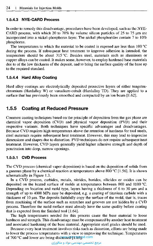
1.5A3 NYE-CARD Process
In order to remedy this disadvantage, procedures have been developed, such as the NYE-CARD process, with which 20 to 70% by volume silicon particles of 25 to 75 um areincorporated into a nickel-phosphorus layer. The nickel phosphorides contain 7 to 10%phosphorus.
The temperatures to which the material to be coated is exposed are less than 100 0Cduring the process. If subsequent heat treatment to improve adhesion is intended, thetemperature should be about 315 0C. Besides steel, materials such as aluminum orcopper alloys can be coated. It makes sense, however, to employ hardened base materialsdue to of the low thickness of the deposit, and to bring the surface quality of the base upto the required standard.
1.5.4.4 Hard Alloy Coating
Hard alloy coatings are electrolytically deposited protective layers of either tungsten-chromium (Hardalloy W) or vanadium-cobalt (Hardalloy TD). They are applied to asurface that has previously been smoothed and compacted by an ion beam [1.62].
1.5.5 Coating at Reduced Pressure
Common coating techniques based on the principle of deposition from the gas phase arechemical vapor deposition (CVD) and physical vapor deposition (PVD) and theirrespective variants. Both techniques have specific advantages and disadvantages.Because CVD requires high temperatures above the retention of hardness for tool steels,steel materials require subsequent heat treatment. However, this may lead to imprecisedimensions and shapes due to distortion. PVD techniques do not require subsequent heattreatment. However, CVD layers generally yield higher adhesive strength and depth ofpenetration into deep, narrow openings.
1.5.5.1 CVD Process
The CVD process (chemical vapor deposition) is based on the deposition of solids froma gaseous phase by a chemical reaction at temperatures above 800 0C [1.56]. It is shownschematically in Figure 1.3.
In a CVD process, carbides, metals, nitrides, borides, silicides or oxides can bedeposited on the heated surface of molds at temperatures between 800 and 11000C.Depending on location and mold type, layers having a thickness of 6 to 30 um and astrength of up to 4000 MPa may be deposited, e.g. a coating of titanium carbide with athickness of 10 um. The deposits faithfully copy the surface of the mold, that is, tracesfrom machining of the surface such as scratches and grooves are not hidden by a CVDprocess. Therefore the mold surface must already have the same quality before coatingthat is expected from the finished tool [1.64].
The high temperatures needed for this process cause the base material to loosehardness and strength. This disadvantage must be compensated by another heat treatmentand associated hardening of the base material. Appropriate steel grades should be used.
Because every heat treatment involves risks such as distortion, efforts are being madeto lower the process temperatures with a view to improving the technique. Temperaturesof 700 0C and lower are being discussed [1.65].www.iran-mavad.com
مرجع تخصصی مهندسی مواد و متالورژی
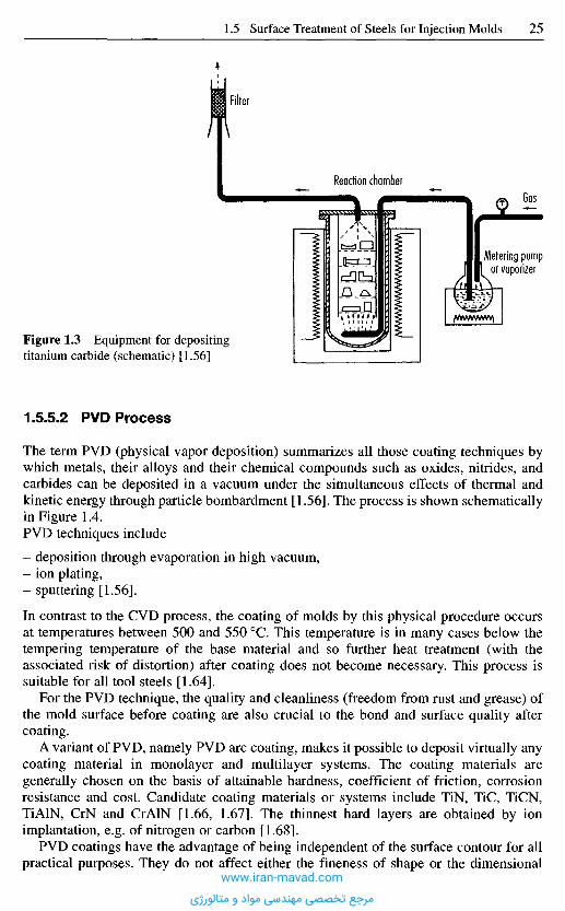
1.5.5.2 PVD Process
The term PVD (physical vapor deposition) summarizes all those coating techniques bywhich metals, their alloys and their chemical compounds such as oxides, nitrides, andcarbides can be deposited in a vacuum under the simultaneous effects of thermal andkinetic energy through particle bombardment [1.56]. The process is shown schematicallyin Figure 1.4.PVD techniques include
- deposition through evaporation in high vacuum,- ion plating,- sputtering [1.56].
In contrast to the CVD process, the coating of molds by this physical procedure occursat temperatures between 500 and 550 0C. This temperature is in many cases below thetempering temperature of the base material and so further heat treatment (with theassociated risk of distortion) after coating does not become necessary. This process issuitable for all tool steels [1.64].
For the PVD technique, the quality and cleanliness (freedom from rust and grease) ofthe mold surface before coating are also crucial to the bond and surface quality aftercoating.
A variant of PVD, namely PVD arc coating, makes it possible to deposit virtually anycoating material in monolayer and multilayer systems. The coating materials aregenerally chosen on the basis of attainable hardness, coefficient of friction, corrosionresistance and cost. Candidate coating materials or systems include TiN, TiC, TiCN,TiAlN, CrN and CrAlN [1.66, 1.67]. The thinnest hard layers are obtained by ionimplantation, e.g. of nitrogen or carbon [1.68].
PVD coatings have the advantage of being independent of the surface contour for allpractical purposes. They do not affect either the fineness of shape or the dimensional
Figure 1.3 Equipment for depositingtitanium carbide (schematic) [1.56]
Filter
Reaction chamberGas
Metering pumpor vaporizer
www.iran-mavad.com
مرجع تخصصی مهندسی مواد و متالورژی
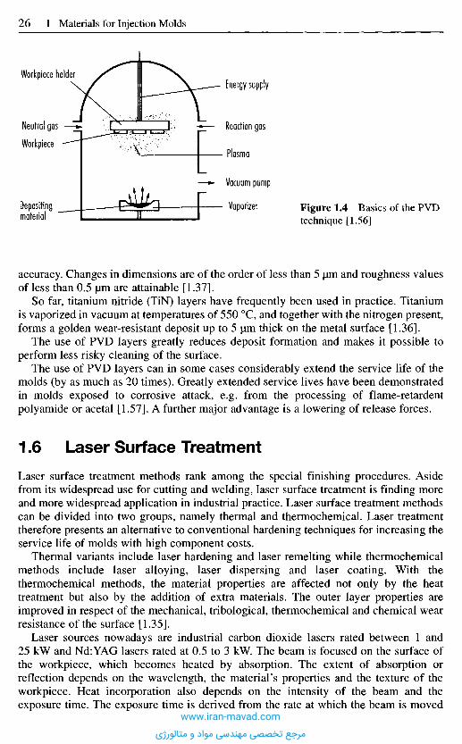
accuracy. Changes in dimensions are of the order of less than 5 urn and roughness valuesof less than 0.5 |im are attainable [1.37].
So far, titanium nitride (TiN) layers have frequently been used in practice. Titaniumis vaporized in vacuum at temperatures of 550 0C, and together with the nitrogen present,forms a golden wear-resistant deposit up to 5 um thick on the metal surface [1.36].
The use of PVD layers greatly reduces deposit formation and makes it possible toperform less risky cleaning of the surface.
The use of PVD layers can in some cases considerably extend the service life of themolds (by as much as 20 times). Greatly extended service lives have been demonstratedin molds exposed to corrosive attack, e.g. from the processing of flame-retardentpolyamide or acetal [1.57]. A further major advantage is a lowering of release forces.
1.6 L a s e r S u r f a c e T r e a t m e n t
Laser surface treatment methods rank among the special finishing procedures. Asidefrom its widespread use for cutting and welding, laser surface treatment is finding moreand more widespread application in industrial practice. Laser surface treatment methodscan be divided into two groups, namely thermal and thermochemical. Laser treatmenttherefore presents an alternative to conventional hardening techniques for increasing theservice life of molds with high component costs.
Thermal variants include laser hardening and laser remelting while thermochemicalmethods include laser alloying, laser dispersing and laser coating. With thethermochemical methods, the material properties are affected not only by the heattreatment but also by the addition of extra materials. The outer layer properties areimproved in respect of the mechanical, tribological, thermochemical and chemical wearresistance of the surface [1.35].
Laser sources nowadays are industrial carbon dioxide lasers rated between 1 and25 kW and Nd:YAG lasers rated at 0.5 to 3 kW. The beam is focused on the surface ofthe workpiece, which becomes heated by absorption. The extent of absorption orreflection depends on the wavelength, the material's properties and the texture of theworkpiece. Heat incorporation also depends on the intensity of the beam and theexposure time. The exposure time is derived from the rate at which the beam is moved
Figure 1.4 Basics of the PVDtechnique [1.56]
Energy supply
Reaction gas
Plasma
Vacuum pump
Vaporizer
Workpiece holder
Neutral gas
Workpiece
Depositingmaterial
www.iran-mavad.com
مرجع تخصصی مهندسی مواد و متالورژی
across the surface of the workpiece. Processing usually occurs in adjacent tracks thatmay or may not overlap. It is thus possible to perform large-scale and partial surfacecoating [1.35].
1.6.1 Laser Hardening and Re-Melt ing
All steel and cast-iron materials with a carbon content exceeding 3% can be laserhardened since they harden martensitically. In laser hardening, the workpiece is heatedto temperatures above the austenitizing temperature; at the surface, heating is due toabsorption of the infrared laser beam and down to a certain depth in the lower zones, dueto heat conduction. This heating process occurs so quickly that the cooling which occursimmediately afterwards creates an extremely steep temperature gradient between theworkpiece surface and the rest of the workpiece. As the laser beam is moved on, theabsorbed quantity of heat is dissipated so quickly inside the workpiece that the criticalcooling rate for martensite formation is exceeded (self-quenching) [1.34].
Laser hardening is a partial hardening process in which the focused beam is guidedback and forth across the area to be hardened. The advantage of this is that selectivehardening can be performed at points where increased wear is expected. As a result,hardening can be performed with very little distortion, zones of partial hardening can bereproducibly created and the workpiece suffers only minor thermal stress. However, thedisadvantage is that large areas have to be hardened in several steps.
Laser re-melting is primarily used for cast materials. The heating and subsequent -self quenching generate supersaturated solutions, metastable phases and amorphousstructures. Re-melting generates homogeneous, extremely fine-grained structures in theouter layer of the component. These structures are notable for their high strength and, atthe same time, high toughness [1.35].
1.6.2 Laser Alloying, Dispersing, and Coating
Laser alloying is used for completely dissolving additional materials into the basematerial. Convection and diffusion processes in the melting bath lead to homogeneousmixing of the base and additional materials. The high cooling rates ensure that theadditives stay in solution even after cooling. The additive elements and compoundsprimarily increase the wear and corrosion resistance.
By contrast, laser dispersing does not dissolve the additive but rather keeps it finelydispersed in the base structure. Standard high-melting or dissolving-resistant additivesfor laser alloying are SiC, TaC, TiC, VC and WC.
Finally, the aim of laser coating is not to cause any mingling of the base and additivematerials. A homogeneous, strongly adhering layer is generated on the substratematerial. The additive material is completely melted on top and the base structure is onlymelted in the narrow edge zone to create a metallurgical bond. The most commonadditive materials are usually low-melting Ni or Co alloys.
www.iran-mavad.com
مرجع تخصصی مهندسی مواد و متالورژی
1.7 E l e c t r o n B e a m H a r d e n i n g
In principle, electron beams may be used instead of laser beams. Consequently, electronbeam hardening works on the same principle as laser hardening. Bombardment by theelectron beam causes rapid heating up and subsequent self-quenching of the outer layerof the workpiece. Since an electron beam is extremely diffuse under ambient conditionsand the necessary intensity cannot be attained, processing can only be carried out inhigh-vacuum chambers. This restriction increases the processing time because a highvacuum has to be produced after the vacuum chamber has been set up. In addition, thecramped conditions of the electron beam equipment restricts the size of the componentsthat can be processed. For these reasons, this process has so far found little industrial use.
1 . 8 L a m c o a t C o a t i n g
The Lamcoat process was developed in the USA for smooth, sliding surfaces. In it, a softlayer based on tungsten disulfide is applied mechanically to the mold surface at roomtemperature. To this end, the mold is first thoroughly cleaned in an alcoholic ultrasonicdegreasing bath by means of special high-pressure micro-sprays (no material ablationoccurs). Then the tungsten disulfide is applied manually in a spray booth with the aid ofdry, purified compressed air at high pressure. The coating material does not accumulateon the surface, however, but penetrates extensively into it to form molecular bonds withthe base material. Excess material does not material. As a result, a very thin layermeasuring 0.5-1.5 jum is formed that cannot be made any thicker.
Studies in the USA have shown that a Lamcoat coating reduces friction by up to 70%.This leads to lower injection pressures and increases flow paths by up to 10%. Furtherpositive results are shorter cycle times and a 30-70% increase in mold service life [1.33].This coating technology is currently offered by two companies in Germany.
R e f e r e n c e s
[1.1] Becker, H. J.: Herstellung und Warmebehandlung von Werkzeugen fur die Kunst-stoffverarbeitung. VDI-Z, 114 (1972), 7, pp. 527-532.
[1.2] Krumpholz, R.; Meilgen, R.: ZweckmaBige Stahlauswahl beim Verarbeiten vonKunststoffen. Kunststoffe, 63 (1973), 5, pp. 286-291.
[1.3] Kuhlmann, E.: Die Werkstoffe der metallverarbeitenden Berufe. Girardet, Essen, 1954.[1.4] Fachkunde Metall. 50th Ed., Verlag Europe-Lehrmittel Nourney, Vollmer GmbH & Co.,
Haan Gruiten, 1990.[1.5] Werkstoffkunde fur Praktiker. 3rd Ed., Verlag Europe-Lehrmittel Nourney, Vollmer
GmbH & Co., Haan Gruiten, 1989.[1.6] Werkstofftechnik fur Metallberufe. Verlag Europe-Lehrmittel Nourney, Vollmer GmbH
& Co., Haan Gruiten.[1.7] Das ist Edelstahl. Thyssen Edelstahl Werke AG. Publication, 1980, 2, Krefeld.[1.8] Werkstoff + Werkzeug. Thyssen Edelstahl Werke AG. Publication, 1984, 3, Krefeld.[1.9] Konig, W.: Neuartige Bearbeitungsverfahren. Lecture, Production techniques, 11, Tech.
University Aachen, Laboratory for Machine Tools and Plant Management.[1.10] Auswahl und Warmebehandlung von Stahl fur Kunststoff-Formen. Arburg heute, 5
(1974), 7, pp. 16-18.[1.11] Dember, G.: Stahle zum Herstellen von Werkzeugen fur die Kunststoffverarbeitung,
Kunststoff-Formenbau, Werkstoffe und Verarbeitungsverfahren. VDI-Verlag, Diissel-dorf, 1976.
www.iran-mavad.com
مرجع تخصصی مهندسی مواد و متالورژی
[1.12] MaBanderungsarme Stahle. Company brochure, Boehler.[1.13] Becker, H. J.: Werkzeugstahle fur die Kunststoffverarbeitung im PreB- und SpritzgieB-
verfahren. VDI-Z, 113 (1971), 5, pp. 385-390.[1.14] Catic, L: Kriterien zur Auswahl der Formnestwerkstoffe. Plastverarbeiter, 26 (1975), 11,
pp. 633-637.[1.15] Werkstoffe fur den Formenbau. Technical information, 4.6, BASF, Ludwigshafen/Rh.,
1969.[1.16] Treml, K: Stahle fur die Kunststoffverarbeitung. Paper given at the IKV Aachen,
November 15, 1969.[1.17] Malmberg, W.: Gliihen, Harten und Vergtiten des Stahls. Springer Verlag, Berlin,
Gottingen, Heidelberg, 1961.[1.18] Mennig, G.: Mold Making Handbook, 2nd ed., Carl Hanser Verlag, Munich, 1998.[1.19] Stoeckhert, K.: Werkzeugbau fiir die Kunststoffverarbeitung. 3rd Ed., Carl Hanser
Verlag, Munich, Vienna, 1979.[1.20] Weckener, H. D.; Hapken, H.; Dorlam, H.: Werkzeugstahle fiir die Kunststoff-
verarbeitung. Stahlwerke Siidwestfalen AG. Information, 15/75, Hiittental-Geisweid,1975, pp. 31-40.
[1.21] SpritzgieBen von Thermoplasten. Company brochure, Farbwerke Hoechst AG.,Frankfurt, 1971.
[1.22] Illgner, K. H.: Gesichtspunkte zur Auswahl von Vergutungs- und Einsatzstahlen.Metalloberflache, 22 (1968), 11, pp. 321-330.
[1.23] Bauer, M.: Kunstofformenstahlen - Moderne Werkzeugstahle. Paper presented at the 8thTechnical Conference on Plastic, Wiirzburg, September 24-25, 1997.
[1.24] Auswahl und Warmebehandlung von Stahl fiir Kunststoff-Formen, Arburg heute, 5(1974), 8, pp. 23-25.
[1.25] Auswahl und Warmebehandlung von Stahl fiir Kunststoff-Formen, Arburg heute, 5(1974), 7, pp. 16-18.
[1.26] Dittrich, A.; Kortmann, W.: Werkstoffauswahl und Obernachenbearbeitung vonKunststoffstahlen. Thyssen Edelst. Technical Report, 7 (1981), 2, pp. 190-192.
[1.27] Frehn, F.: Hochst-Carbidhaltige. Werkzeugstahle fiir die Kunststoff-Verarbeitung.Kunststoffe, 66 (1976), 4, pp. 220-226.
[1.28] Boehler Company. Publication, Dusseldorf, 1997.[1.29] Becker, H. J.; Haberling, E.; Rascher, K.: Herstellung von Werkzeugstahlen durch das
Electro-Schlacke-Umschmelz-(ESU)-Verfahren. Thyssen Edelst. Technical Report, 15(1989), 2, pp. 138-146.
[1.30] Weckener, H. D.; Dorlatu, H.: Neuere Entwicklungen auf dem Gebiet der Werkzeug-stahle fiir die Kunststoffverarbeitung. Publication, 57/67, Stahlwerke Siidwestfalen AG,Hiittental-Geisweid, 1967.
[1.31] Stahle und Superlegierungen. Elektroschlacke umgeschmolzen. WF Informations MBB,5 (1972), pp. 140-143.
[1.32] Verderber, W; Leidel, B.: Besondere MaBnahmen bei der Herstellung von Werkzeug-stahlen fiir die Kunststoffverarbeitung. Information, 15/75, Stahlwerke SiidwestfalenAG, Hiittental-Geisweid (1975), pp. 22-27.
[1.33] Mikroschicht stoppt teueren VerschleiB. VDI-Nachrichten, 7. 8. 1998.[1.34] Meis, F. U.; Schmitz-Justen, C : Gezieltes Harten durch Laser-Licht. Industrie-Anzeiger,
105(1983), 56/57, pp. 28-31.[1.35] Konig, W.; Klocke, R: Fertigungsverfahren. Vol. 3: Abtragen und Generieren. Springer
Verlag, Berlin, 1997.[1.36] Wild, R.: PVD-Hartstoffbeschichtung - Was Werkzeugbauer und Verarbeiter beachten
sollten. Plastverarbeiter, 39 (1988), 4, pp. 14-28.[1.37] Bennighoff, H.: Beschichten von Werkzeugen. K. Plast. Kautsch. Z., 373 (1988), p. 13.[1.38] Spezialgegossene Werkzeuge. Information Stahlwerke Carp & Hones, Ennepetal,
1156/4, 1973.[1.39] Merten, H.: Gegossene NE-Metallformen. Angewandte NE-Metalle - Angewandte
GieBverfahren. VDI-Bildungswerk, BW 2197. VDI-Verlag, Dusseldorf.[1.40] Beck, G.: Kupfer Beryllium, Kunststoff-Formenbau, Werkstoffe und Verarbeitungs-
verfahren. VDI-Verlag, Dusseldorf, 1976.[1.41] Gegossene Formen. Company brochure, BECU, Hemer-Westig.
www.iran-mavad.com
مرجع تخصصی مهندسی مواد و متالورژی
[1.42] Richter, F. H.: GieBen von SpritzguB- und Tiefziehformen aus Feinzinklegierungen.Kunststoffe, 50 (1960), 12, pp. 723-727.
[1.43] Wolf, W.: Tiehzieh-, Prage- und Stanzwerkzeuge aus Zinklegierungen. Z. Metall furTechnik, Industrie und Handel, 6 (1952), 9/10, pp. 240-243.
[1.44] Erstling, A.: Erfolge mit Aluminium im Werkzeug- und Formenbau. Werkstoff undInnovation, 11/12/1990, pp. 31-34.
[1.45] Menning, G.: Mold Making Handbook, 2nd ed., Carl Hanser Verlag, Munich, 1998.[1.46] Erstling, A.: Aluminium fur Blasform Werkzeuge. Reprint of Plastverarbeiter. Vol. 1,
1995, pp. 76-80.[1.47] Prospectus, Almet, Fellbach.[1.48] Erstling, A.: Aluminium im SpritzgieBwerkzeugbau. Kunststoffe, 78 (1988), 7,
pp. 596-598.[1.49] Ziirb, G.: Vorteilhafter Aluminium-Einsatz im Werkzeug und Formenbau. Stahlbauer.
Vol. 4, 1986.[1.50] Erstling, A.: Sparen mit AIu. Form und Werkzeug. November 1997, pp. 40-51.[1.51] Cerro-Legierungen fur schnellen Werkzeugbau. Plastverarbeiter, 25 (1974), 3,
pp. 175-176.[1.52] Eigenschaften und Anwendungen der Cerro-Legierungen. Prospectus, Hek GmbH,
Liibeck.[1.53] Winkler, L.: Galvanoformung - ein modernes Fertigungsverfahren. Vol. 1 and 11.
Metalloberflache, 21 (1967), 8, 9, 11.[1.54] Watson, S. A.: Taschenbuch der Galvanoformung mit Nickel. Lenze, Saulgau/Wiirtt.,
1976.[1.55] Galvanoeinsatze fur Klein- und GroBwerkzeuge. Prospectus, Gesellschaft fur Galvano-
plastik mbH, Lahr.[1.56] Kortmann, W.: Vergleichende Betrachtungen der gebrauchlichsten Oberflachen-
behandlungsverfahren. Thyssen Edelstahl. Technical report, 11 (1985), 2, pp. 163-199.[1.57] Walkenhorst, U.: Uberblick iiber verschiedene SchutzmaBnahmen gegen VerschleiB und
Korrosion in SpritzgieBmaschinen und -werkzeugen. Reprint of 2nd Tooling Conferenceat Wiirzburg, October 4-5, 1988.
[1.58] Rationalisierung im Formenbau. Symposium report, 1981, VKI. Kunstst. Plast., 29(1982), 172, pp. 25-28.
[1.59] Werkzeugstahle fur die Kunststoffverarbeitung. Publication, 0122/1A. EdelstahlwerkeWittenAG,Witten, 1973.
[1.60] Ionitrieren ist mehr als Harten. Publication, Kloeckner Ionen GmbH, KoIn.[1.61] Publication. Elektroschmelzwerk Kempten GmbH, Munich, 1974.[1.62] Publication. Hardalloy W. and T. D., IEPCO, Zurich, 1979.[1.63] Piwowarski, E.: Herstellen von SpritzgieBwerkzeugen. Kunststoffe, 78 (1988), 12,
pp. 1137-1146.[1.64] Ludwig, J. H.: Werkzeugwerkstoffe, ihre Oberflachenbehandlung, Verschmutzung und
Reinigung. Gummi Asbest Kunstst., 35 (1982), 2, pp. 72-78.[1.65] Ruminski, L.: Harte Haut aus Titancarbid. BiId der Wissenschaft, 2 (1984), p. 28.[1.66] Miiller, D.; Harlen, U.: VerschleiBschutz an Werkzeugen fur die Blechbearbeitung.
In: Leistungssteigerung in der Stanztechnik, VDI Bildungswerk, Diisseldorf, 1996.[1.67] Leistungsfahige Fertigungsprozesse - Losungen fur den Werkzeugbau. In: Produktions-
technik: Aachener Perspektiven, VDI-Verlag, Dusseldorf, 1996.[1.68] Frey, H.: MaBgeschneiderte Oberflachen. VDI-Nachrichten-Magazin, 1988, 2, pp. 7-11.
www.iran-mavad.com
مرجع تخصصی مهندسی مواد و متالورژی

Figure 2.1 Comparison of costs: production methods in mold making [2.1]
Cavities made by electrolytic deposition as well as other procedures, which cannot bedone in-house, call for additional working hours until the mold is finally available. Thismay be rather inconvenient. The making of an electrolytically deposited insert takesweeks or even months. A cavity made of heat-treated steel can be used for samplingwithout problems and still be finished afterwards. The high production costs also justifythe application of a superior material because its costs are generally only 10 to 20% ofthe total mold costs.
In spite of all the modern procedures in planning, design, and production, moldmaking calls for highly qualified and trained craftsmen and such personnel are in shortsupply nowadays. Thus, the production of molds always poses a bottleneck.
2 M o l d M a k i n g T e c h n i q u e s
Injection molds are made by a highly varied number of processes and combinationsthereof.
Figure 2.1 demonstrates the relative costs for cavities made from various materials.Accordingly, steel cavities appear to be many times more expensive than those made ofother materials. In spite of this, a cavity made of steel is normally the preferred choice.This apparent contradiction is explained with the consideration that the service life of asteel mold is the longest, and the additional costs for a cavity represent only a fractionof those for the whole mold.
Miscellaneous
Manual labor
Machining costs
Material costs
100
90
80
70
60
50
40
30
20
10
0
Machinedsteel
Zinccasting
Electrolyticdepositionof nickel
Syntheticresin casting
Metal-sprayingprocess: MCP alloy
www.iran-mavad.com
مرجع تخصصی مهندسی مواد و متالورژی
It is clear, therefore, that only up-to-date equipment is found in modern mold-makingfacilities such as numerically-controlled machine tools. With their help one tries toreduce the chances of rejects or to automate the working process without human operator(e.g. EDM).
2 . 1 P r o d u c t i o n o f M e t a l l i c I n j e c t i o n M o l d s
a n d M o l d I n s e r t s b y C a s t i n g
The production of mold inserts, or whole mold halves by casting, attained a certainpreeminence in some application areas for a time. The reason was that the castingprocess offers suitable alloys for nearly every type of application and that there arehardly any limits concerning geometry. Molds requiring extensive machining couldtherefore be made economically by casting. Another application area is the simple, morecost effective production of injection molds for low production runs and samples,particularly of non-ferrous metals. Only a brief account of the casting methods forproducing mold inserts is provided below. Readers requiring more detailed informationare referred to the literature at the end of the chapter.
2.1.1 Cas t i ng M e t h o d s a n d C a s t A l l oys
Of the numerous casting methods available [2.2, 2.3], variants of sand casting andprecision casting are used to make mold inserts. The choice of casting method dependson the dimensions of the mold, the specified dimensional tolerances, the desiredfaithfulness of reproduction and the requisite surface quality.
After casting, the mold essentially has the contours necessary for producing themolding. For large molds cast in one piece, the heat-exchange system can be integrateddirectly by casting a tubing system or by means of a special arrangement of recesses atthe rear through which the temperature-control medium can flow freely.
Generally, the inner contours of the mold (the mold recesses) are cast slightly largerand so require only a minimal amount of additional machining. Another critical factor isthe requirements imposed on the surface quality of the molding. Any posttreatment ofthe surfaces (e.g. polishing) that may be necessary is performed by the same methods asin conventional mold making. Grained and textured surfaces such as can be produced byprecision casting mostly do not require posttreatment. With cast molds, just as inconventional mold making, incorporation of holes for ejector pins, sprue bushings andinserts as well as the fitting of slide bars and the application of wear-resistant protectivelayers are all performed on the cast blank.
The metallic casting materials suitable for mold making fall into two groups:
- ferrous materials (cast steel alloys, cast iron materials), and- non-ferrous materials (aluminum, copper, zinc and tin-bismuth alloys).
Only cast steel will generally satisfy the mechanical demands of mold inserts that arerequired for more than just experimental and low-production runs. Furthermore, onlysteel has an adequate degree of polishability. Many of the steel grades successfullyemployed in mold making are amenable to casting. However, it must be borne in mindthat castings always have a coarse structure that is not comparable to the transformationstructure of forged or rolled steels. At the macroscopic level, castings have different
www.iran-mavad.com
مرجع تخصصی مهندسی مواد و متالورژی
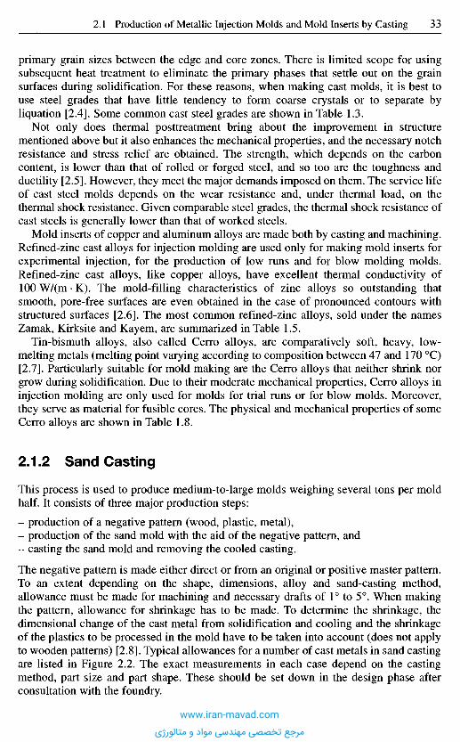
primary grain sizes between the edge and core zones. There is limited scope for usingsubsequent heat treatment to eliminate the primary phases that settle out on the grainsurfaces during solidification. For these reasons, when making cast molds, it is best touse steel grades that have little tendency to form coarse crystals or to separate byliquation [2.4]. Some common cast steel grades are shown in Table 1.3.
Not only does thermal posttreatment bring about the improvement in structurementioned above but it also enhances the mechanical properties, and the necessary notchresistance and stress relief are obtained. The strength, which depends on the carboncontent, is lower than that of rolled or forged steel, and so too are the toughness andductility [2.5]. However, they meet the major demands imposed on them. The service lifeof cast steel molds depends on the wear resistance and, under thermal load, on thethermal shock resistance. Given comparable steel grades, the thermal shock resistance ofcast steels is generally lower than that of worked steels.
Mold inserts of copper and aluminum alloys are made both by casting and machining.Refined-zinc cast alloys for injection molding are used only for making mold inserts forexperimental injection, for the production of low runs and for blow molding molds.Refined-zinc cast alloys, like copper alloys, have excellent thermal conductivity of100 W/(m • K). The mold-filling characteristics of zinc alloys so outstanding thatsmooth, pore-free surfaces are even obtained in the case of pronounced contours withstructured surfaces [2.6]. The most common refined-zinc alloys, sold under the namesZamak, Kirksite and Kay em, are summarized in Table 1.5.
Tin-bismuth alloys, also called Cerro alloys, are comparatively soft, heavy, low-melting metals (melting point varying according to composition between 47 and 170 0C)[2.7]. Particularly suitable for mold making are the Cerro alloys that neither shrink norgrow during solidification. Due to their moderate mechanical properties, Cerro alloys ininjection molding are only used for molds for trial runs or for blow molds. Moreover,they serve as material for fusible cores. The physical and mechanical properties of someCerro alloys are shown in Table 1.8.
2.1.2 Sand Casting
This process is used to produce medium-to-large molds weighing several tons per moldhalf. It consists of three major production steps:
- production of a negative pattern (wood, plastic, metal),- production of the sand mold with the aid of the negative pattern, and- casting the sand mold and removing the cooled casting.
The negative pattern is made either direct or from an original or positive master pattern.To an extent depending on the shape, dimensions, alloy and sand-casting method,allowance must be made for machining and necessary drafts of 1° to 5°. When makingthe pattern, allowance for shrinkage has to be made. To determine the shrinkage, thedimensional change of the cast metal from solidification and cooling and the shrinkageof the plastics to be processed in the mold have to be taken into account (does not applyto wooden patterns) [2.8]. Typical allowances for a number of cast metals in sand castingare listed in Figure 2.2. The exact measurements in each case depend on the castingmethod, part size and part shape. These should be set down in the design phase afterconsultation with the foundry.
www.iran-mavad.com
مرجع تخصصی مهندسی مواد و متالورژی
The casting mold is made by applying the mold material to the pattern and solidifying iteither by compaction (physically) or by hardening (chemically).
A wide range of synthetic mold materials of varied composition is available [2.2].Washed, classified quartz sand is the predominant refractory base substance. For specialneeds, e.g. to prevent high-alloy casting materials (cast-steel alloys) from reacting withthe melt, chromite, zirconium or olivine sand may be used. The binders used for moldsands are organic and inorganic. The inorganic binders may be divided into natural andsynthetic types. Natural inorganic binders are clays such as montmorillonite, glauconite,kaolinite and illite. Synthetic, inorganic binders include waterglass, cement and gypsum.
Organic binders are synthetic resins such as phenol, urea, furan and epoxy resins. Inpractice, the molds are made predominantly of bentonite-bound (a natural inorganicbinder) mold materials (classified quartz sand) that have to be mechanically compactedin order that adequate sag resistance may be obtained.
After the mold has been produced, the pattern is removed. To an extent depending onthe requirements imposed on surface texture and alloy, the finished sand mold may ormay not be smoothed with a facing. After casting, the finished mold is more or lessready. The sand mold is destroyed when the mold is removed.
Ts = Solidus temperatureTL = Liquidus temperature
Liquid shrinkage
Solidification shrinkage
Solid shrinkage
Temperature [0C]
Volum
eCo
mpen
satio
nthr
ough
feede
r
Comp
ensa
tion
throu
gh d
egree
of sh
rinka
ge
Figure 2.2 Shrinkageon solidification andshrinkage for differentcasting alloys
Material
Cast iron:With lamellar graphiteWith spheroidal graphite
Malleable cast ironCast steelAluminum baseCopper base
Solidificationshrinkage in %
-1 to 41 to 65.5 to 65 to 65 to 64 to 8
Shrinkage in %
0.9 to 1.10.8 to 0.90.5 to 1.91.5 to 2.80.9 to 1.40.8 to 2.4
www.iran-mavad.com
مرجع تخصصی مهندسی مواد و متالورژی
A somewhat different procedure is employed in the lost foam method. In this, apolystyrene foam pattern is embedded in sand, remains in the casting mold, and isgasified by the casting heat only when the liquid metal is poured into the casting mold.Polystyrene patterns may be milled from slab material (once-off production) or foamedin mold devices (mass production). Since the pattern is generally only used a few timesto make inserts for injection molds, the use of CAD interfaces can allow a polystyrenepattern to be milled quickly and cost effectively.
The major advantage of cast molds is the fact that the mold is ready for use almostimmediately after casting. Posttreatment is limited, especially if a heat-exchange systemhas already been integrated by embedding a prefabricated tubing system before casting.
2.1.3 Prec is ion C as t i ng Techn iques
Precision casting is used for mold inserts that must satisfy particularly high demands onreproducibility. The techniques are eminently suitable for fine contours and, owing to thevery high reproducibility, for the faithful reproduction of surface structures, such as thatof wood, leather, fabrics, etc.
A number of different types of precision casting process exist [2.9] that vary in thesequence of processes, the ceramic molding material and the binders employed. Moldinserts are usually made by the Shaw process (Figure 2.3) or variants thereof. Formolding, a pattern is required that already contains the shrinkage allowance (see alsoSection 2.1.2). The patterns are reusable and so further castings can be made forreplacement parts. This pattern forms the basis for producing the ceramic casting mold(entailing one, two or more intermediate steps, depending on method chosen). The liquidceramic molding compound usually consists of very finely ground zirconium sand mixedwith a liquid binder. After the mold has been produced, it is baked for several hours atelevated temperatures. It is then ready to be used for casting. After casting, the ceramicmold is broken and the part removed.
Precision-cast parts may be made from the same molding steels employed for makinginjection molds, but all other casting alloys may also be used. Posttreatment of precision-cast parts is generally restricted to the mounting and mating surfaces, as well as allregions that comprise the mold parting surface.
2 . 2 R a p i d T o o l i n g f o r I n j e c t i o n M o l d s
Time and costs are becoming more and more important factors in the development ofnew products. It is therefore extremely important for the injection molding industry toproduce prototypes that can go into production as quickly as possible. To be sure, rapidprototyping is being employed more and more often but such prototypes frequentlycannot fully match the imposed requirements. Where there is a need for molds that areas close to going into production as possible, rapid tooling (RT) is the only process bywhich the molds can be made that will enable the production of injection moldedprototypes from the same material that will eventually be used for the mass-producedpart. Rapid tooling allows properties such as orientation, distortion, strength and long-term characteristics to be determined at an early stage in product development. Suchproximity to series production, however, also entails greater outlay on time and costs.For this reason, RT will only be used where the specifications require it.
www.iran-mavad.com
مرجع تخصصی مهندسی مواد و متالورژی
1 2
Mount top box Pour in slurry Slurry sets
3
6 5 4
Remove modelDry (Skin-dry)Assemble
mold halves
7 8 9
Knock outCastFire
10
Figure 2.3 Steps in the Shaw process Cleanwww.iran-mavad.com
مرجع تخصصی مهندسی مواد و متالورژی
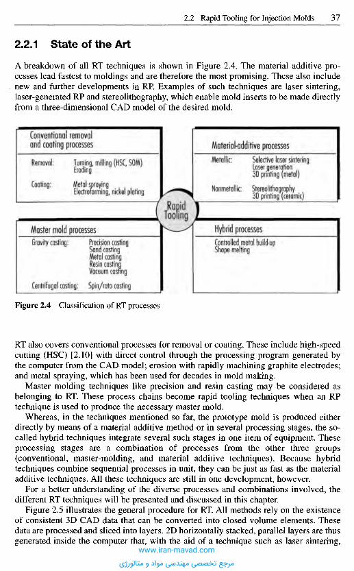
RT also covers conventional processes for removal or coating. These include high-speedcutting (HSC) [2.10] with direct control through the processing program generated bythe computer from the CAD model; erosion with rapidly machining graphite electrodes;and metal spraying, which has been used for decades in mold making.
Master molding techniques like precision and resin casting may be considered asbelonging to RT. These process chains become rapid tooling techniques when an RPtechnique is used to produce the necessary master mold.
Whereas, in the techniques mentioned so far, the prototype mold is produced eitherdirectly by means of a material additive method or in several processing stages, the so-called hybrid techniques integrate several such stages in one item of equipment. Theseprocessing stages are a combination of processes from the other three groups(conventional, master-molding, and material additive techniques). Because hybridtechniques combine sequential processes in unit, they can be just as fast as the materialadditive techniques. All these techniques are still in one development, however.
For a better understanding of the diverse processes and combinations involved, thedifferent RT techniques will be presented and discussed in this chapter.
Figure 2.5 illustrates the general procedure for RT. All methods rely on the existenceof consistent 3D CAD data that can be converted into closed volume elements. Thesedata are processed and sliced into layers. 2D horizontally stacked, parallel layers are thusgenerated inside the computer that, with the aid of a technique such as laser sintering,
Figure 2.4 Classification of RT processes
2.2.1 State of the Art
A breakdown of all RT techniques is shown in Figure 2.4. The material additive pro-cesses lead fastest to moldings and are therefore the most promising. These also includenew and further developments in RP. Examples of such techniques are laser sintering,laser-generated RP and stereolithography, which enable mold inserts to be made directlyfrom a three-dimensional CAD model of the desired mold.
Conventional removaland coating processes
Removal:
Coating:
Turning, milling (HSC, SOM)Eroding
Metal sprayingElectroforming, nickel plating
Material-additive processes
Metallic:
Nonmetallic:
Selective laser sinteringLaser generation3D printing (metal)
Stereolithography3D printing (ceramic)
RapidTooling
Master mold processesGravity casting:
Centrifugal casting:
Precision castingSand castingMetal castingResin castingVacuum casting
Spin/roto casting
Hybrid processesControlled metal build-upShape melting
www.iran-mavad.com
مرجع تخصصی مهندسی مواد و متالورژی
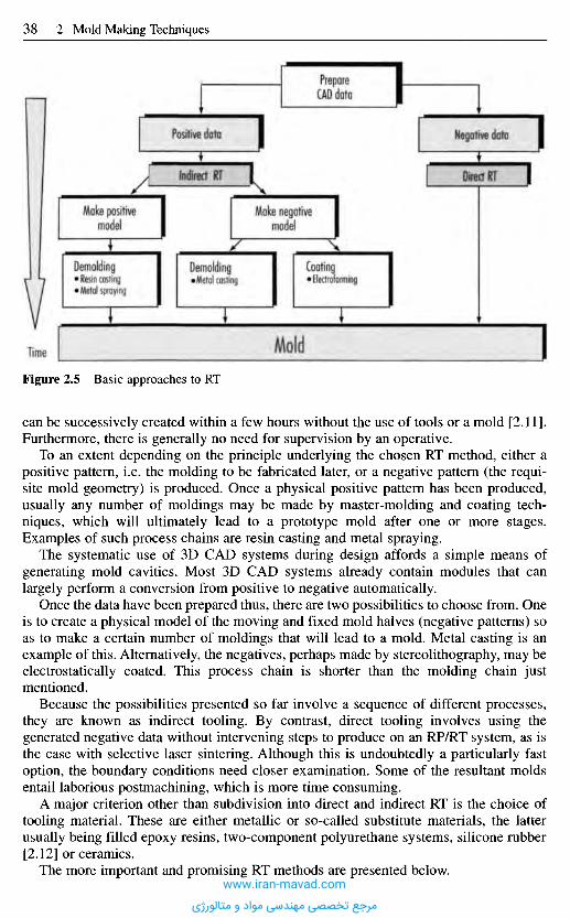
Figure 2.5 Basic approaches to RT
can be successively created within a few hours without the use of tools or a mold [2.11].Furthermore, there is generally no need for supervision by an operative.
To an extent depending on the principle underlying the chosen RT method, either apositive pattern, i.e. the molding to be fabricated later, or a negative pattern (the requi-site mold geometry) is produced. Once a physical positive pattern has been produced,usually any number of moldings may be made by master-molding and coating tech-niques, which will ultimately lead to a prototype mold after one or more stages.Examples of such process chains are resin casting and metal spraying.
The systematic use of 3D CAD systems during design affords a simple means ofgenerating mold cavities. Most 3D CAD systems already contain modules that canlargely perform a conversion from positive to negative automatically.
Once the data have been prepared thus, there are two possibilities to choose from. Oneis to create a physical model of the moving and fixed mold halves (negative patterns) soas to make a certain number of moldings that will lead to a mold. Metal casting is anexample of this. Alternatively, the negatives, perhaps made by stereolithography, may beelectrostatically coated. This process chain is shorter than the molding chain justmentioned.
Because the possibilities presented so far involve a sequence of different processes,they are known as indirect tooling. By contrast, direct tooling involves using thegenerated negative data without intervening steps to produce on an RP/RT system, as isthe case with selective laser sintering. Although this is undoubtedly a particularly fastoption, the boundary conditions need closer examination. Some of the resultant moldsentail laborious postmachining, which is more time consuming.
A major criterion other than subdivision into direct and indirect RT is the choice oftooling material. These are either metallic or so-called substitute materials, the latterusually being filled epoxy resins, two-component polyurethane systems, silicone rubber[2.12] or ceramics.
The more important and promising RT methods are presented below.
MoldTime
PrepareCAD data
Negative dataPositive data
Make negativemodel
indirect RTMake positive
model
Demolding• Resin casting• Metal spraying Demolding•Metal casting
Coating• Electroforming
Direct RT
www.iran-mavad.com
مرجع تخصصی مهندسی مواد و متالورژی
2.2.2 Direct Rapid Tooling
The goal of all developments in the field of RT is automated, direct fabrication ofprototype molds, whose properties approach those of production parts, from 3D CADdata describing the mold geometry. This data set must already allow for technical aspectsof molds, such as drafts, allowance for dimensional shrinkage and shrinkage parametersfor the RT process.
Processes for the direct fabrication of metallic and nonmetallic molds are presentedbelow. In either case, the mold may be made from the CAD data direct.
2.2.2.1 Direct Fabrication of Metallic Molds
Direct fabrication of prototype molds encompasses conventional methods that allowrapid processing (machining) of, e.g. aluminum.
2.2.2.Ll Generative MethodsA common feature of generative methods for making metallic molds is that theworkpiece is formed by addition of material or the transition of a material from the liquidor powder state into the solid state, and not by removal of material as is the case withconventional production methods.
All the processes involved here have been developed out of RP methods (e.g. selectivelaser sintering, 3D printing, metal LOM (Laminated Object Manufacturing), shapemelting, and multiphase jet solidification) or utilize conventional techniques augmentedby layered structuring (laser-generated RP, controlled metal build-up).
In selective laser sintering (SLS) of metals, a laser beam melts powder startingmaterials layer by layer, with the layer thickness varying from 0.1 to 0.4 mm in line withthe particle size of the metal powder [2.13, 2.14]. The mold is thus generated layer bylayer.
Sintering may be performed indirectly and directly. In the indirect method (DTMprocess), metal powder coated with binder is sintered in an inert work chamber (e.g.flooded with nitrogen). Heated to a temperature just below the melting point of thebinder, the powder is applied thinly by a roller and melted at selected sites. The geometryof the desired mold inserts is thus obtained by melting the polymer coating. The resultantgreen part, which has low mechanical strength, is then heat-treated. The polymer binderis burned out at elevated temperatures to produce the brown part, which is then sinteredat a higher temperature. At an even higher temperature again, the brown part is infiltratedwith copper (at approx. 1120 0C), solder alloy or epoxy resin [2.15], this serving to sealthe open pores that were formed when the polymer binder was removed (Figure 2.6).
In direct laser sintering manufacture, metals are sintered in the absence of binder(EOS process). The advantage of not using coated powders is that the laborious removalof binder, and the possibility of introducing inaccuracies into the processing stage, canbe dispensed with. Nevertheless, the part must be infiltrated since it has only provedpossible so far to sinter parts to 70% of the theoretical density [2.16]. After infiltration,posttreatment is necessary and generally takes the form of polishing.
Aside from pure metal powders and powders treated with binder, multicomponentmetallic powders are used. These consist of a powder mixture containing at least twometals that can also be used in the direct sintering process. The lower-meltingcomponent provides the cohesion in the SLS preform and the higher-melting componentmelts in the furnace to imbue the mold with its ultimate strength. Candidate metals and
www.iran-mavad.com
مرجع تخصصی مهندسی مواد و متالورژی
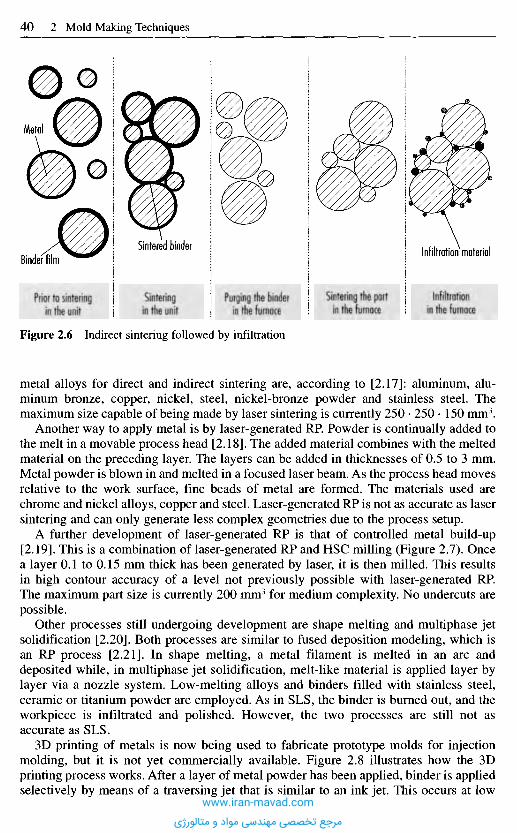
Figure 2.6 Indirect sintering followed by infiltration
metal alloys for direct and indirect sintering are, according to [2.17]: aluminum, alu-minum bronze, copper, nickel, steel, nickel-bronze powder and stainless steel. Themaximum size capable of being made by laser sintering is currently 250 • 250 • 150 mm3.
Another way to apply metal is by laser-generated RP. Powder is continually added tothe melt in a movable process head [2.18]. The added material combines with the meltedmaterial on the preceding layer. The layers can be added in thicknesses of 0.5 to 3 mm.Metal powder is blown in and melted in a focused laser beam. As the process head movesrelative to the work surface, fine beads of metal are formed. The materials used arechrome and nickel alloys, copper and steel. Laser-generated RP is not as accurate as lasersintering and can only generate less complex geometries due to the process setup.
A further development of laser-generated RP is that of controlled metal build-up[2.19]. This is a combination of laser-generated RP and HSC milling (Figure 2.7). Oncea layer 0.1 to 0.15 mm thick has been generated by laser, it is then milled. This resultsin high contour accuracy of a level not previously possible with laser-generated RRThe maximum part size is currently 200 mm3 for medium complexity. No undercuts arepossible.
Other processes still undergoing development are shape melting and multiphase jetsolidification [2.20]. Both processes are similar to fused deposition modeling, which isan RP process [2.21]. In shape melting, a metal filament is melted in an arc anddeposited while, in multiphase jet solidification, melt-like material is applied layer bylayer via a nozzle system. Low-melting alloys and binders filled with stainless steel,ceramic or titanium powder are employed. As in SLS, the binder is burned out, and theworkpiece is infiltrated and polished. However, the two processes are still not asaccurate as SLS.
3D printing of metals is now being used to fabricate prototype molds for injectionmolding, but it is not yet commercially available. Figure 2.8 illustrates how the 3Dprinting process works. After a layer of metal powder has been applied, binder is appliedselectively by means of a traversing jet that is similar to an ink jet. This occurs at low
Prior to sinteringin the unit
Sinteringin the unit
Purging the binderin the furnace
Sintering the partin the furnace
Infiltrationin the furnace
Infiltration materialSintered binderBinder film
Metal
www.iran-mavad.com
مرجع تخصصی مهندسی مواد و متالورژی
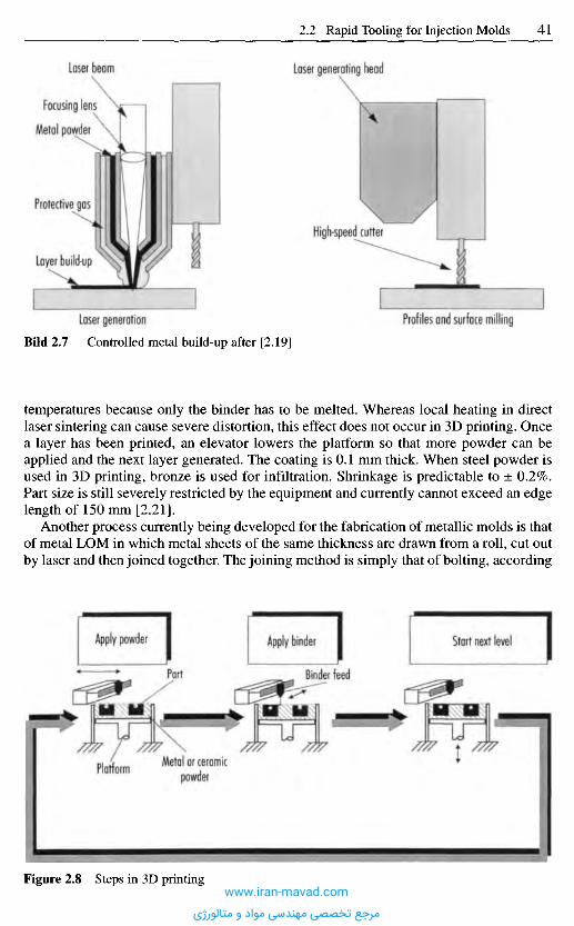
temperatures because only the binder has to be melted. Whereas local heating in directlaser sintering can cause severe distortion, this effect does not occur in 3D printing. Oncea layer has been printed, an elevator lowers the platform so that more powder can beapplied and the next layer generated. The coating is 0.1 mm thick. When steel powder isused in 3D printing, bronze is used for infiltration. Shrinkage is predictable to ± 0.2%.Part size is still severely restricted by the equipment and currently cannot exceed an edgelength of 150 mm [2.21].
Another process currently being developed for the fabrication of metallic molds is thatof metal LOM in which metal sheets of the same thickness are drawn from a roll, cut outby laser and then joined together. The joining method is simply that of bolting, according
Profiles and surface millingLaser generation
BiId 2.7 Controlled metal build-up after [2.19]
High-speed cutter
Laser generating headLaser beam
Focusing lens
Metal powdei
Protective gas
Layer build-up
Apply powder Apply binder Start next level
Part Binder feed
PlatformMetal or ceramic
powder
Figure 2.8 Steps in 3D printingwww.iran-mavad.com
مرجع تخصصی مهندسی مواد و متالورژی
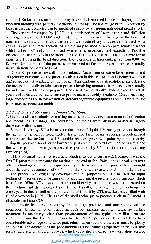
to [2.22]. So far, molds made in this way have only been used for metal shaping and forinjection molding wax patterns for precision casting. The advantage of molds joined bybolts is that the geometry can be modified simply by swapping individual metal sheets.
The variant developed by [2.23] is a combination of laser cutting and diffusionwelding. Unlike metal LOM and most other RT processes, which grow the layers atconstant thickness, this process variant allows sheets of any thickness to be used. As aresult, simple geometric sections of a mold may be used as a compact segment, a factwhich allows RT only to be used where it is necessary and expedient. Possibledimensional accuracy is in the order of 0.1%. Due to the process itself, it is never lowerthan ±0.1 mm in the build direction. The tolerances of laser cutting are from 0.001 to0.1 mm. Unlike most of the processes mentioned so far, this process imposes virtuallyno restrictions on part size [2.24].
Direct RT processes are still in their infancy. Apart from selective laser sintering and3D printing of metals, all the processes discussed in this section are still being developedand so are not yet available on the market. This explains why stereolithography, despitethe fact that it is a direct fabrication process involving nonmetallic materials, is virtuallythe only one used for these purposes. Because it has constantly evolved over the last 10years and is offered by many service providers, it is readily available. Moreover, manylarge companies are in possession of stereolithographic equipment and still elect to useit for making prototype molds.
2.2.2.7.2 Direct Fabrication of Nonmetallic MoldsWhile most direct methods for making metallic molds require posttreatment (infiltrationand mechanical finishing), the production of molds from auxiliary materials largelydispenses with this need.
Stereolithography (STL) is based on the curing of liquid, UV-curing polymers throughthe action of a computer-controlled laser. The laser beam traverses predeterminedcontours on the surface of a UV-curable photopolymer bath point by point, therebycuring the polymer. An elevator lowers the part so that the next layer can be cured. Oncethe whole part has been generated, it is postcured by UV radiation in a postcuringfurnace [2.24].
STL's potential lies in its accuracy, which is as yet unsurpassed. Because it was thefirst RP process to come onto the market, at the end of the 1980s, it has a head-start overother technologies. Ongoing improvements to the resins and the process have broughtabout the current accuracies of 0.04 mm in the x- and y-axes and 0.05 mm in the z-axis.
The process was originally developed for RP purposes but is also used for rapidtooling of injection molds because of its accuracy and the resultant good surfaces whichit produces. When STL is used to make a mold cavity, the mold halves are generated onthe machine and then mounted in a frame. Usually, however, the shell technique isemployed. In this, a shell of the mold contour is built by STL and then back-filled withfilled epoxy resin [2.25]. The use of the shell technique to produce such an RT mold isillustrated in Figure 2.9.
Parts made by stereolithography feature high precision and outstanding surfaceproperties. Unlike all other direct methods for making metallic molds, no furthertreatment is necessary other than posttreatment of the typical step-like structurestemming from the layered build-up by the RP/RT processes. This translates to aconsiderable advantage time-wise, particularly when the mold surfaces must be glossyand planar. The downside is the poor thermal and mechanical properties of the availableresins (acrylate, vinyl ether, epoxy), which cause the molds to have very short service
www.iran-mavad.com
مرجع تخصصی مهندسی مواد و متالورژی
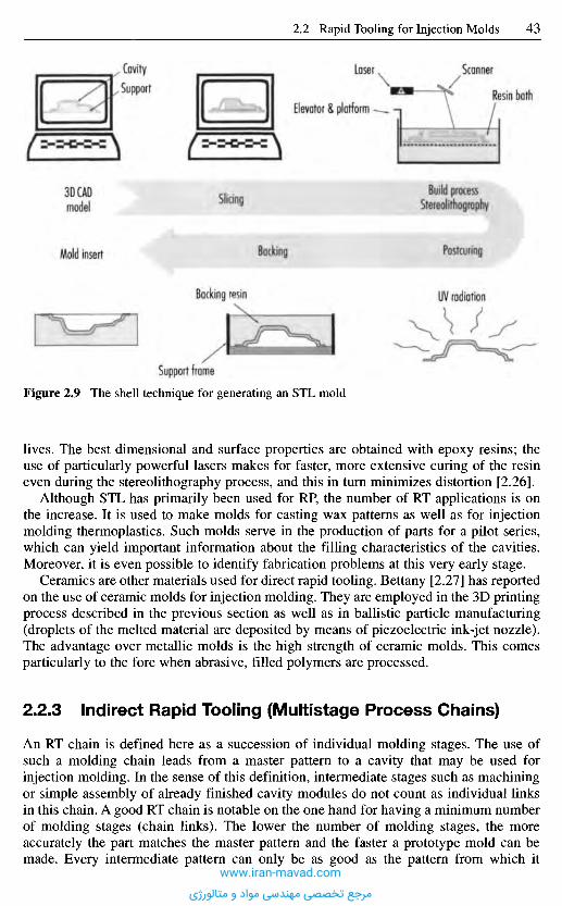
Figure 2.9 The shell technique for generating an STL mold
lives. The best dimensional and surface properties are obtained with epoxy resins; theuse of particularly powerful lasers makes for faster, more extensive curing of the resineven during the stereolithography process, and this in turn minimizes distortion [2.26].
Although STL has primarily been used for RP, the number of RT applications is onthe increase. It is used to make molds for casting wax patterns as well as for injectionmolding thermoplastics. Such molds serve in the production of parts for a pilot series,which can yield important information about the filling characteristics of the cavities.Moreover, it is even possible to identify fabrication problems at this very early stage.
Ceramics are other materials used for direct rapid tooling. Bettany [2.27] has reportedon the use of ceramic molds for injection molding. They are employed in the 3D printingprocess described in the previous section as well as in ballistic particle manufacturing(droplets of the melted material are deposited by means of piezoelectric ink-jet nozzle).The advantage over metallic molds is the high strength of ceramic molds. This comesparticularly to the fore when abrasive, filled polymers are processed.
2.2.3 Indirect Rapid Tooling (Multistage Process Chains)
An RT chain is defined here as a succession of individual molding stages. The use ofsuch a molding chain leads from a master pattern to a cavity that may be used forinjection molding. In the sense of this definition, intermediate stages such as machiningor simple assembly of already finished cavity modules do not count as individual linksin this chain. A good RT chain is notable on the one hand for having a minimum numberof molding stages (chain links). The lower the number of molding stages, the moreaccurately the part matches the master pattern and the faster a prototype mold can bemade. Every intermediate pattern can only be as good as the pattern from which it
Support frame
Mold insert
3D CADmodel Slicing
Backing
Build processStereolithography
Rosfcyring
UV radiationBacking resin
CavitySupport
Elevator & platform
Laser Scanner
Resin bath
www.iran-mavad.com
مرجع تخصصی مهندسی مواد و متالورژی

proceeds. Consequently, the attainable tolerances become greater and the surface qualitydiminishes from casting to casting. On the other hand, each RT chain must finish with acavity that withstands the high mechanical and thermal loads that occur in the injectionmolding process. The bottom line for all RT molding chains is therefore to have as fewlinks as possible so as to end up with an injection mold whose strength and qualitysomewhat exceed requirements.
Indirect rapid tooling may be effected with a positive or a negative pattern. Whilethese patterns serve as the master patterns for casting processes, using the virtualnegative pattern and new RT process chains can dispense with the master pattern andenable a cavity to be made directly in sand or ceramic slip for casting metals.
2.2.3.1 Process Chains Involving a Positive Pattern
Rapid manufacture of prototype molds using the shortest possible process chainfrequently involves using RP to make a positive pattern. These patterns can be made byany means, i.e. also conventionally.
Casting is frequently employed in the production of prototype molds. This master-pattern process entails observing the ground rules for designing cast parts. These include:
- avoidance of accumulation of material,- avoidance of major changes in cross-section, of thin flanges (1.5 mm minimum) and
of sharp edges (minimum radius of 0.5),- avoidance of vertical walls (1% min. conicity) [2.28].
The simplest, and at the same time a very common process, is that of making a siliconerubber mold, starting from an RP pattern. The pattern is equipped with gate and risersand fixed in a frame. Once the parting line has been prepared, liquid silicone resin ispoured over the pattern in a vacuum chamber. It is not possible to use this type of moldto injection mold prototypes in production material. This process is known as soft toolingsince prototypes with certain heat or mechanical resistance can be cast in two-componentpolyurethane resins [2.24]. Not only can the Shore A hardness be adjusted to the range47-90, heat resistance of up to 140 0C and resin strengths of up to 85 Shore D arepossible. This is the only casting method in which the ground rules mentioned above canbe largely ignored, due to the use of yielding silicone rubber. Nor is any shrinkageallowance required (1:1 reproduction).
Resin casting is illustrated in Figure 2.10. The RP pattern is embedded as far as theparting line and fixed in a frame. After delineating, a thixotropic surface resin (gelcoat)is usually applied and cooling coils are incorporated. An aluminum-filled epoxy mold-casting resin is then used for back-filling. When the molds are being designed, allowancemust be made not only for a design suitable for plastics but particularly for shrinkage bythe resin (range: 0.5-1.5%).
The service life of the mold depends greatly on the injected material and theprocessing parameters during injection molding.
The process allows metal inserts and slide bars to be embedded (Figure 2.11).The coating processes employed are familiar from conventional mold making. They
include flame spraying, arc spraying, laser coating, and plasma and metal spraying.Because both flame spraying and plasma spraying entail temperatures of 3,000 0C andabove, it is necessary to create a heat-resistant positive pattern. For this reason, we shallin the context of rapid production only discuss metal spraying with a metal-sprayingpistol. In this process, two spray wires are melted in an arc and atomized into small
www.iran-mavad.com
مرجع تخصصی مهندسی مواد و متالورژی
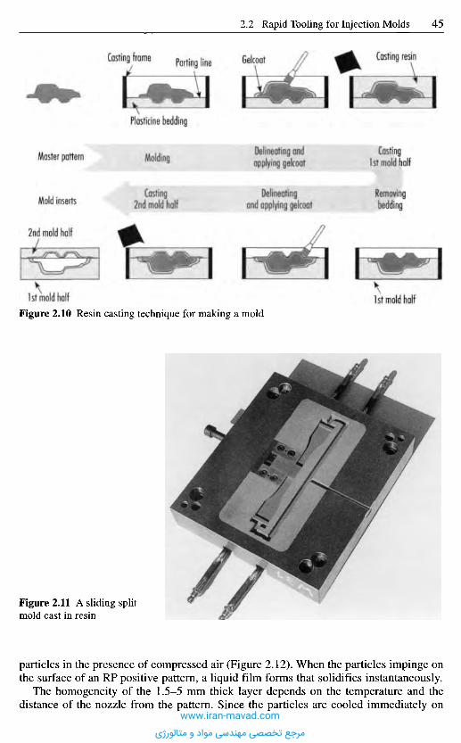
particles in the presence of compressed air (Figure 2.12). When the particles impinge onthe surface of an RP positive pattern, a liquid film forms that solidifies instantaneously.
The homogeneity of the 1.5-5 mm thick layer depends on the temperature and thedistance of the nozzle from the pattern. Since the particles are cooled immediately on
Figure 2.11 A sliding splitmold cast in resin
Figure 2.10 Resin casting technique for making a mold1st mold half1st mold half
2nd mold half
Mold inserts
Master pattern Molding
Casting2nd mold half
Delineating andapplying gelcoaf
Delineatingand applying gelcoat
Casting1st mold half
Removingbedding
Casting resinGelcoatParting lineCasting frame
Plasticine bedding
www.iran-mavad.com
مرجع تخصصی مهندسی مواد و متالورژی
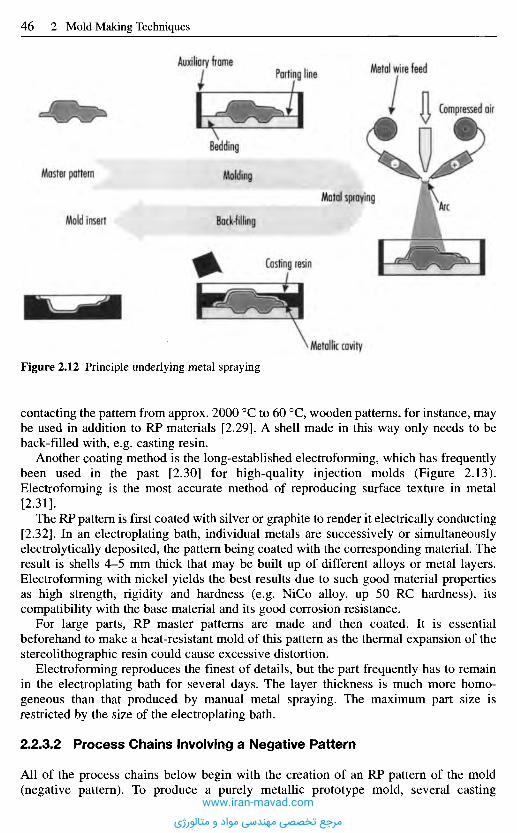
Figure 2.12 Principle underlying metal spraying
contacting the pattern from approx. 2000 0C to 60 0C, wooden patterns, for instance, maybe used in addition to RP materials [2.29]. A shell made in this way only needs to beback-filled with, e.g. casting resin.
Another coating method is the long-established electroforming, which has frequentlybeen used in the past [2.30] for high-quality injection molds (Figure 2.13).Electroforming is the most accurate method of reproducing surface texture in metal[2.31].
The RP pattern is first coated with silver or graphite to render it electrically conducting[2.32]. In an electroplating bath, individual metals are successively or simultaneouslyelectrolytically deposited, the pattern being coated with the corresponding material. Theresult is shells 4-5 mm thick that may be built up of different alloys or metal layers.Electroforming with nickel yields the best results due to such good material propertiesas high strength, rigidity and hardness (e.g. NiCo alloy, up 50 RC hardness), itscompatibility with the base material and its good corrosion resistance.
For large parts, RP master patterns are made and then coated. It is essentialbeforehand to make a heat-resistant mold of this pattern as the thermal expansion of thestereolithographic resin could cause excessive distortion.
Electroforming reproduces the finest of details, but the part frequently has to remainin the electroplating bath for several days. The layer thickness is much more homo-geneous than that produced by manual metal spraying. The maximum part size isrestricted by the size of the electroplating bath.
2.2.3.2 Process Chains Involving a Negative Pattern
All of the process chains below begin with the creation of an RP pattern of the mold(negative pattern). To produce a purely metallic prototype mold, several casting
Metallic cavity
Casting resin
Master pattern
Mold insert
Molding
Bock-filling
Matat spraying
Bedding
Auxiliary frameParting line Metal wire feed
Compressed air
kArc
www.iran-mavad.com
مرجع تخصصی مهندسی مواد و متالورژی
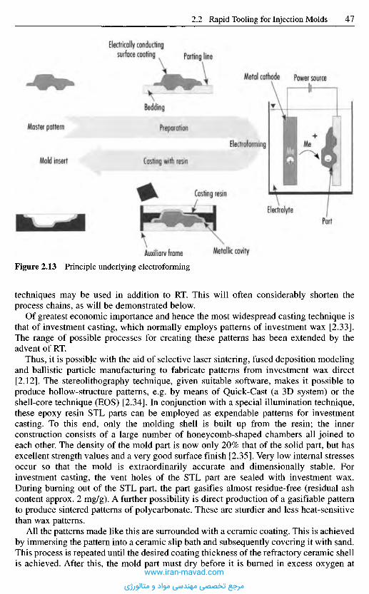
Figure 2.13 Principle underlying electroforming
techniques may be used in addition to RT. This will often considerably shorten theprocess chains, as will be demonstrated below.
Of greatest economic importance and hence the most widespread casting technique isthat of investment casting, which normally employs patterns of investment wax [2.33].The range of possible processes for creating these patterns has been extended by theadvent of RT.
Thus, it is possible with the aid of selective laser sintering, fused deposition modelingand ballistic particle manufacturing to fabricate patterns from investment wax direct[2.12]. The stereolithography technique, given suitable software, makes it possible toproduce hollow-structure patterns, e.g. by means of Quick-Cast (a 3D system) or theshell-core technique (EOS) [2.34]. In conjunction with a special illumination technique,these epoxy resin STL parts can be employed as expendable patterns for investmentcasting. To this end, only the molding shell is built up from the resin; the innerconstruction consists of a large number of honeycomb-shaped chambers all joined toeach other. The density of the mold part is now only 20% that of the solid part, but hasexcellent strength values and a very good surface finish [2.35]. Very low internal stressesoccur so that the mold is extraordinarily accurate and dimensionally stable. Forinvestment casting, the vent holes of the STL part are sealed with investment wax.During burning out of the STL part, the part gasifies almost residue-free (residual ashcontent approx. 2 mg/g). A further possibility is direct production of a gasifiable patternto produce sintered patterns of polycarbonate. These are sturdier and less heat-sensitivethan wax patterns.
All the patterns made like this are surrounded with a ceramic coating. This is achievedby immersing the pattern into a ceramic slip bath and subsequently covering it with sand.This process is repeated until the desired coating thickness of the refractory ceramic shellis achieved. After this, the mold part must dry before it is burned in excess oxygen at
Metallic cavityAuxiliary frame
Casting resin
ElectrolytePart
Master pattern
Mold insert
Preparation
Casting with resin
Electroforming Me
Power sourceMetal cathode
Bedding
Parting lineElectrically conducting
surface coating
www.iran-mavad.com
مرجع تخصصی مهندسی مواد و متالورژی
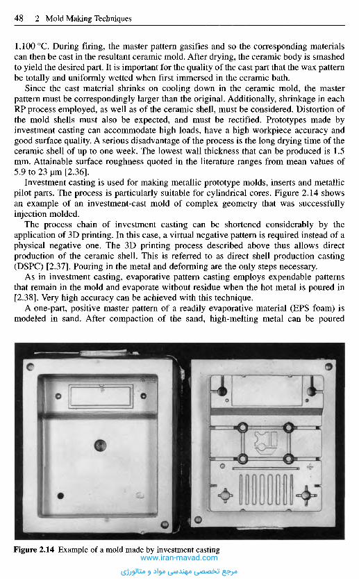
1,100 0C. During firing, the master pattern gasifies and so the corresponding materialscan then be cast in the resultant ceramic mold. After drying, the ceramic body is smashedto yield the desired part. It is important for the quality of the cast part that the wax patternbe totally and uniformly wetted when first immersed in the ceramic bath.
Since the cast material shrinks on cooling down in the ceramic mold, the masterpattern must be correspondingly larger than the original. Additionally, shrinkage in eachRP process employed, as well as of the ceramic shell, must be considered. Distortion ofthe mold shells must also be expected, and must be rectified. Prototypes made byinvestment casting can accommodate high loads, have a high workpiece accuracy andgood surface quality. A serious disadvantage of the process is the long drying time of theceramic shell of up to one week. The lowest wall thickness that can be produced is 1.5mm. Attainable surface roughness quoted in the literature ranges from mean values of5.9 to 23 urn [2.36].
Investment casting is used for making metallic prototype molds, inserts and metallicpilot parts. The process is particularly suitable for cylindrical cores. Figure 2.14 showsan example of an investment-cast mold of complex geometry that was successfullyinjection molded.
The process chain of investment casting can be shortened considerably by theapplication of 3D printing. In this case, a virtual negative pattern is required instead of aphysical negative one. The 3D printing process described above thus allows directproduction of the ceramic shell. This is referred to as direct shell production casting(DSPC) [2.37]. Pouring in the metal and deforming are the only steps necessary.
As in investment casting, evaporative pattern casting employs expendable patternsthat remain in the mold and evaporate without residue when the hot metal is poured in[2.38]. Very high accuracy can be achieved with this technique.
A one-part, positive master pattern of a readily evaporative material (EPS foam) ismodeled in sand. After compaction of the sand, high-melting metal can be poured
Figure 2.14 Example of a mold made by investment castingwww.iran-mavad.com
مرجع تخصصی مهندسی مواد و متالورژی
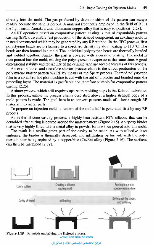
directly into the mold. The gas produced by decomposition of the pattern can escapereadily because the sand is porous. A material frequently employed in the field of RT isthe light metal Zamak, a zinc-aluminum-copper alloy that is easy to posttreat [2.28].
An RT operation based on evaporative pattern casting is that of expandable patterncasting (EPC). To enable fast production of the desired component, an auxiliary mold isinstead constructed which may be generated by any RP method. In the EPC process, firstpolystyrene beads are prefoamed to a specified density by slow heating to 110 0C. Thebeads are then foamed in a mold. The individual polystyrene beads are thermally bondedand welded together. Finally, the part is covered with a ceramic coating. Hot metal isthen poured into the mold, causing the polystyrene to evaporate at the same time. A gooddimensional stability and reusability of the ceramic sand are notable features of this process.
An even simpler and therefore shorter process chain is the direct production of thepolystyrene master pattern via RP by means of the Sparx process. Foamed polystyrenefilm in a so-called hot-plot machine is cut with the aid of a plotter and bonded onto thepreceding layer/The material is gasifiable and therefore suitable for evaporative patterncasting [2.25].
A sinter process which still requires upstream molding steps is the Keltool technique.In this process, unlike the process chains described above, a higher strength copy of amold pattern is made. The goal here is to convert patterns made of a low-strength RPmaterial into metal parts.
To prepare an injection mold, a pattern of the mold half is generated first by any RPprocess.
As in the silicone casting process, a highly heat-resistant RTV silicone that can bedemolded after curing is poured around the master pattern (Figure 2.15). An epoxy binderthat is very highly filled with a metal alloy in powder form is then poured into this mold.
The result is a stellite green part of the cavity to be made. As with selective lasersintering, the binder is thermally desorbed, and infiltration performed, with the poly-meric binder being replaced by a copper/zinc (Cu/Zn) alloy (Figure 2.16). The surfacescan then be machined [2.39].
Cavity pattern
Cavity of metal
Creating a siliconecasting mold
Infiltrating
Pouring in a metalpowder-resin mixture
Driving out the binder,and sintering
Figure 2.15 Principle underlying the Keltool processwww.iran-mavad.com
مرجع تخصصی مهندسی مواد و متالورژی

Figure 2.16 Processes occurring in the Keltool process
2.2.4 Outlook
Many of the direct RT operations proposed here are still in development and are subjectto size limitations, for example. Nevertheless, all process chains presented here aregenerally available on the market and may be used for rapid prototyping of molds.
Finally, an overview of all the processes discussed here is presented for comparisonpurposes (Figure 2.17). Many of the metallic processes are not yet commerciallyavailable on the market. Only selective laser sintering, metal spraying andelectroforming are available. The Keltool process is also available but it is onlywidespread in the American market at this time. Aside from complexity and stability,however, major criteria are attainable surface quality, the availability and the price,which can vary extensively according to geometry.
Therefore, despite their speed, when using all these operations, it is always best toestimate whether it is more economical to avail of RT or whether it might not be betterto employ a conventional process instead.
2 . 3 H o b b i n g
Robbing is used for producing accurate hollow molds. It comes in two variants, cold-hobbing, the more common, and hot-hobbing.
Cold-hobbing is a technique for producing molds or cavities without removingmaterial. A hardened and polished hob, which has the external contour of the molding,is forced into a blank of soft-annealed steel at a low speed (between 0.1 and 10 mm/min).The hob is reproduced as a negative pattern in the blank. Figure 2.18 demonstrates theprocess schematically. The technique is limited by the maximum permissible pressure onthe hob of ca. 3,000 MPa and the yield strength of the blank material after annealing. The
Infiltratingin the furnace
Infiltration material
Sintering the partin the furnace
Driving out the binderin the furnaceAfter casting
Binder
Metal
www.iran-mavad.com
مرجع تخصصی مهندسی مواد و متالورژی
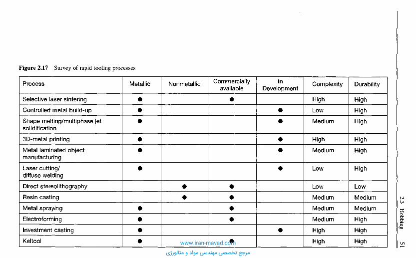
Durability
High
High
High
High
High
High
Low
Medium
Medium
High
High
High
Complexity
High
Low
Medium
High
Medium
Low
Low
Medium
Medium
Medium
High
High
InDevelopment
Commerciallyavailable
NonmetallicMetallicProcess
Selective laser sintering
Controlled metal build-up
Shape melting/multiphase jetsolidification
3D-metal printing
Metal laminated objectmanufacturing
Laser cutting/diffuse welding
Direct stereolithography
Resin casting
Metal spraying
Electroforming
Investment casting
Keltool
Figure 2.17 Survey of rapid tooling processes
www.iran-mavad.com
مرجع تخصصی مهندسی مواد و متالورژی
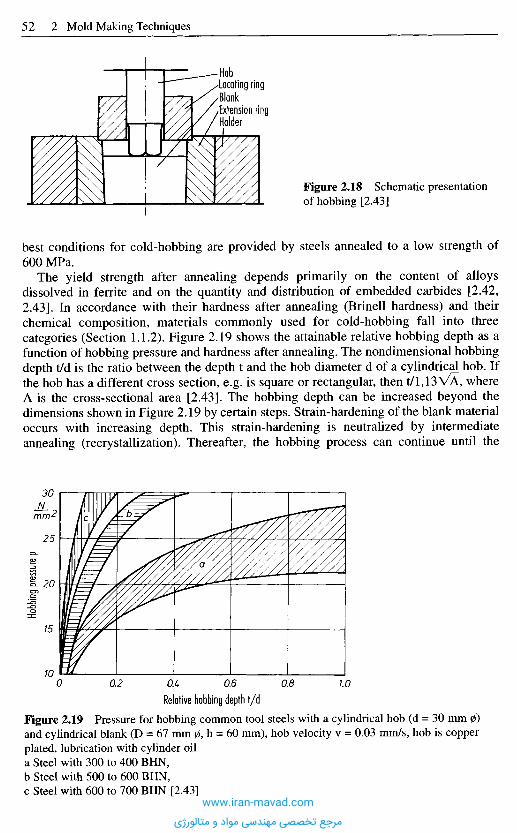
best conditions for cold-hobbing are provided by steels annealed to a low strength of600 MPa.
The yield strength after annealing depends primarily on the content of alloysdissolved in ferrite and on the quantity and distribution of embedded carbides [2.42,2.43]. In accordance with their hardness after annealing (Brinell hardness) and theirchemical composition, materials commonly used for cold-hobbing fall into threecategories (Section 1.1.2). Figure 2.19 shows the attainable relative hobbing depth as afunction of hobbing pressure and hardness after annealing. The nondimensional hobbingdepth t/d is the ratio between the depth t and the hob diameter d of a cylindrical hob. Ifthe hob has a different cross section, e.g. is square or rectangular, then t/l,13VA, whereA is the cross-sectional area [2.43]. The hobbing depth can be increased beyond thedimensions shown in Figure 2.19 by certain steps. Strain-hardening of the blank materialoccurs with increasing depth. This strain-hardening is neutralized by intermediateannealing (recrystallization). Thereafter, the hobbing process can continue until the
Figure 2.18 Schematic presentationof hobbing [2.43]
Hob•Locating ring•Blank-Extension ringHolder
Relative hobbing depth t/d
Figure 2.19 Pressure for hobbing common tool steels with a cylindrical hob (d = 30 mm jzand cylindrical blank (D = 67 mm 0, h = 60 mm), hob velocity v = 0.03 mm/s, hob is coppeplated, lubrication with cylinder oila Steel with 300 to 400 BHN,b Steel with 500 to 600 BHN,c Steel with 600 to 700 BHN [2.43]
-^2
Hobb
ing p
ressur
e p
bc
a
www.iran-mavad.com
مرجع تخصصی مهندسی مواد و متالورژی
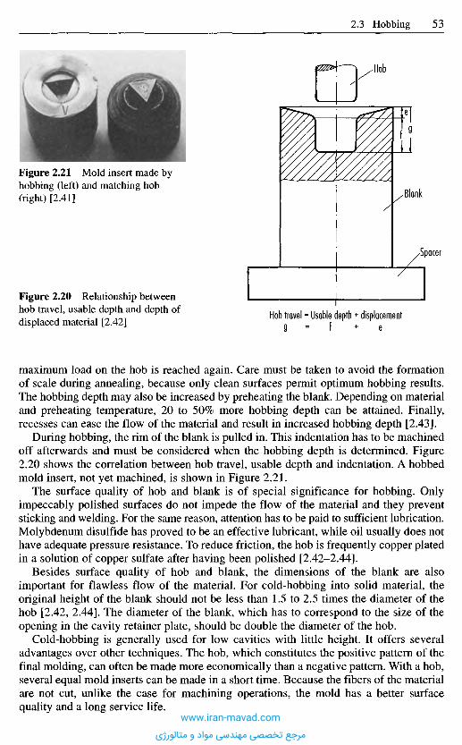
maximum load on the hob is reached again. Care must be taken to avoid the formationof scale during annealing, because only clean surfaces permit optimum hobbing results.The hobbing depth may also be increased by preheating the blank. Depending on materialand preheating temperature, 20 to 50% more hobbing depth can be attained. Finally,recesses can ease the flow of the material and result in increased hobbing depth [2.43].
During hobbing, the rim of the blank is pulled in. This indentation has to be machinedoff afterwards and must be considered when the hobbing depth is determined. Figure2.20 shows the correlation between hob travel, usable depth and indentation. A hobbedmold insert, not yet machined, is shown in Figure 2.21.
The surface quality of hob and blank is of special significance for hobbing. Onlyimpeccably polished surfaces do not impede the flow of the material and they preventsticking and welding. For the same reason, attention has to be paid to sufficient lubrication.Molybdenum disulfide has proved to be an effective lubricant, while oil usually does nothave adequate pressure resistance. To reduce friction, the hob is frequently copper platedin a solution of copper sulfate after having been polished [2.42-2.44].
Besides surface quality of hob and blank, the dimensions of the blank are alsoimportant for flawless flow of the material. For cold-hobbing into solid material, theoriginal height of the blank should not be less than 1.5 to 2.5 times the diameter of thehob [2.42, 2.44]. The diameter of the blank, which has to correspond to the size of theopening in the cavity retainer plate, should be double the diameter of the hob.
Cold-hobbing is generally used for low cavities with little height. It offers severaladvantages over other techniques. The hob, which constitutes the positive pattern of thefinal molding, can often be made more economically than a negative pattern. With a hob,several equal mold inserts can be made in a short time. Because the fibers of the materialare not cut, unlike the case for machining operations, the mold has a better surfacequality and a long service life.
Figure 2.20 Relationship betweenhob travel, usable depth and depth ofdisplaced material [2.42]
Figure 2.21 Mold insert made byhobbing (left) and matching hob(right) [2.41]
Hob travel = Usable depth + displacement9 = f + e
Spacer
Blank
Hob
www.iran-mavad.com
مرجع تخصصی مهندسی مواد و متالورژی
Limitations on cold-hobbing result from the mechanical properties of hob and blankand therefore the size of a cavity.
2 . 4 M a c h i n i n g a n d O t h e r M a t e r i a l R e m o v i n g
O p e r a t i o n s
2.4.1 M a c h i n i n g P r o d u c t i o n M e t h o d s
Machining production methods may be divided into processes with geometricallydefined cutter (turning, milling, drilling, sawing) and geometrically undefined cutter(grinding, honing, lapping). The machinery, frequently special equipment, has to finishthe object to the extent that only little postoperation, mostly manual in nature (polishing,lapping, and finishing), is left.
Modern tooling machines for mold making generally feature multiaxial CNC controlsand highly accurate positioning systems. The result is higher accuracy and greaterefficiency against rejects. The result of a survey [2.45] shows NC machining as havingjust a 25% share compared to 75% for the copying technique, but this does not hold truefor modern tool shops and the fabrication of large molds.
Nowadays, heat-treated workpieces may be finished to final strength by milling (e.g.Rm up to 2000 MPa). Various operations, e.g. cavity sinking by EDM, can be replacedby complete milling operations and the process chain thus shortened. Furthermore, thethermal damage to the outer zone that would otherwise result from erosion does notoccur. Hard milling can be used both with conventional cutting-tool materials, such ashard metals, and with cubic boron nitride (CBN). For plastic injection molds, hardmetals or coated hard metals should prove to be optimum cutting-tool materials.
Machining frees existing residual stresses. This can cause distortion eitherimmediately or during later heat treatment. It is advisable, therefore, to relieve stressesby annealing after roughing. Any occurring distortion can be compensated by ensuingfinishing, which usually does not generate any further stresses.
After heat treatment, the machined inserts are smoothed, ground and polished toobtain a good surface quality, because the surface conditions of a cavity are, in the end,responsible for the surface quality of a molding and its ease of release.
Defects in the surface of the cavity are reproduced to different extents depending onthe molding material and processing conditions. Deviations from the ideal geometricalcontour of the cavity surface, such as ripples and roughness, diminish the appearance inparticular and form "undercuts", which increase the necessary release forces.
There are three milling variants:
- three-axis milling,- three-plus-two-axis milling and- five-axis milling (simultaneous).
Competition has recently developed between high-speed cutting (HSC) andsimultaneous five-axis milling. HSC is characterized by high cutting speeds and highspindle rotation speeds. Steel materials with hardness values of up to 62 HRC can alsobe machined with contemporary standard HSC millers [2.46]. HSC machining can becarried out as a complete machining so that the process steps of electrode manufacturing
Next Page
www.iran-mavad.com
مرجع تخصصی مهندسی مواد و متالورژی
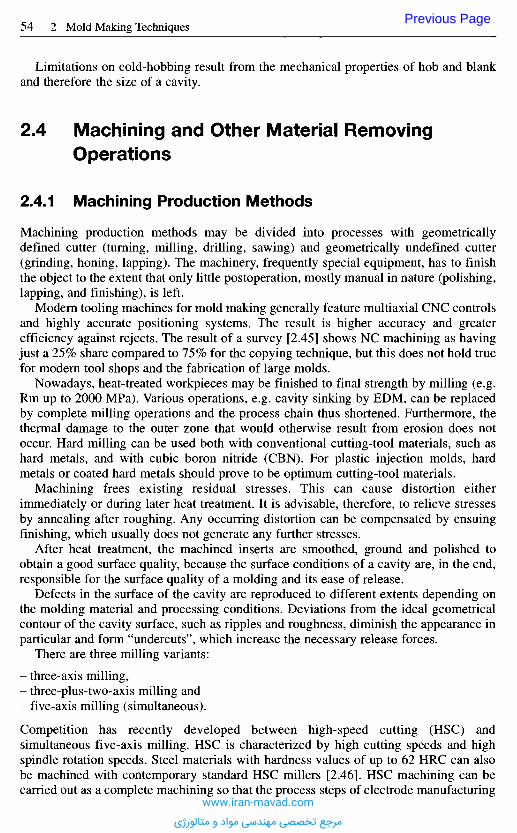
Limitations on cold-hobbing result from the mechanical properties of hob and blankand therefore the size of a cavity.
2 . 4 M a c h i n i n g a n d O t h e r M a t e r i a l R e m o v i n g
O p e r a t i o n s
2.4.1 M a c h i n i n g P r o d u c t i o n M e t h o d s
Machining production methods may be divided into processes with geometricallydefined cutter (turning, milling, drilling, sawing) and geometrically undefined cutter(grinding, honing, lapping). The machinery, frequently special equipment, has to finishthe object to the extent that only little postoperation, mostly manual in nature (polishing,lapping, and finishing), is left.
Modern tooling machines for mold making generally feature multiaxial CNC controlsand highly accurate positioning systems. The result is higher accuracy and greaterefficiency against rejects. The result of a survey [2.45] shows NC machining as havingjust a 25% share compared to 75% for the copying technique, but this does not hold truefor modern tool shops and the fabrication of large molds.
Nowadays, heat-treated workpieces may be finished to final strength by milling (e.g.Rm up to 2000 MPa). Various operations, e.g. cavity sinking by EDM, can be replacedby complete milling operations and the process chain thus shortened. Furthermore, thethermal damage to the outer zone that would otherwise result from erosion does notoccur. Hard milling can be used both with conventional cutting-tool materials, such ashard metals, and with cubic boron nitride (CBN). For plastic injection molds, hardmetals or coated hard metals should prove to be optimum cutting-tool materials.
Machining frees existing residual stresses. This can cause distortion eitherimmediately or during later heat treatment. It is advisable, therefore, to relieve stressesby annealing after roughing. Any occurring distortion can be compensated by ensuingfinishing, which usually does not generate any further stresses.
After heat treatment, the machined inserts are smoothed, ground and polished toobtain a good surface quality, because the surface conditions of a cavity are, in the end,responsible for the surface quality of a molding and its ease of release.
Defects in the surface of the cavity are reproduced to different extents depending onthe molding material and processing conditions. Deviations from the ideal geometricalcontour of the cavity surface, such as ripples and roughness, diminish the appearance inparticular and form "undercuts", which increase the necessary release forces.
There are three milling variants:
- three-axis milling,- three-plus-two-axis milling and- five-axis milling (simultaneous).
Competition has recently developed between high-speed cutting (HSC) andsimultaneous five-axis milling. HSC is characterized by high cutting speeds and highspindle rotation speeds. Steel materials with hardness values of up to 62 HRC can alsobe machined with contemporary standard HSC millers [2.46]. HSC machining can becarried out as a complete machining so that the process steps of electrode manufacturing
Previous Page
www.iran-mavad.com
مرجع تخصصی مهندسی مواد و متالورژی
and eroding can be dispensed with completely. In addition, better surface quality is oftenachieved, and this allows drastic reduction in manual postmachining [2.47].
For the production of injection and die-casting molds, a combination of milling anderoding may also be performed. The amount of milling should be maximized since themachining times are shorter on account of higher removal capability. However, verycomplex contours, filigree geometries and deep cavities can be produced by subsequentspark-erosive machining. Often, field electrodes are used [2.48]. The electrode can, inturn, be made from graphite or copper by HSC (for details of the production method formicro cavities, see Sections 20.1.2-20.1.2.6).
2.4.2 Surface Treatment (Finishing)
In many cases, and by no means exclusively for the production of optical articles, thecondition of the cavity surface (porosity, ripples, roughness) is crucial to the quality ofthe final product. This has a decisive effect on the time needed for mold making and thuson the costs of the mold. Moreover, the ease with which the molding can be released anddeposits from thermosets and rubber are affected.
Mirror-finish surfaces require the greatest amount of polishing and facilitate demolding.As opposed to these are untreated cavity surfaces for the production of moldings which donot have to meet optical requirements. Here release properties are the criterion governingthe condition of the cavity surface. This also applies to textured surfaces.
The texture determines the ease of demolding and calls for more draft than forpolished molds if the texture forms "undercuts", as when grooves run across thedirection of demolding. Some polishing procedures will now be presented below.
2.4.2.1 Grinding and Polishing (Manual or Assisted)
After the cavity has been completed by turning, milling, EDM, etc., the surfacesgenerally have to be smoothened by grinding and polishing until the desired surfacequality of the moldings is obtained and release is easy. Even nowadays, this is stillmainly done manually, supported by electrically or pneumatically powered equipment orwith ultrasonics [2.49-2.51].
The sequence of operations, coarse and precision grinding and polishing, arepresented in detail in Figure 2.22.
Coarse grinding produces a blank-metal, geometrically correct surface with aroughness of Ra < 1 um, which can be finished in precision-grinding step or immediatepolishing [2.52].
Careful work and observance of some basic rules can yield a surface quality withroughness heights of 0.001 to 0.01 um (see Table 2.1) after polishing. A precondition forthis, of course, is steels that are free from inclusions and have a uniform fine-grainedstructure, such as remelted steels (Section 1.1.9).
A disadvantage of manual finishing processes is that they are personnel-intensive andthat they do not guarantee reproducible removal. Machine-assisted removal withgeometric undefined cutter (grinding, honing, lapping) has nonetheless been unable tomake a breakthrough. These techniques have major kinematic and technologicialrestrictions in the case of complex, 3D contours.
Some of the fully-automatic polishing processes presented here have also exhibitedconsiderable shortcomings. For this reason, they are almost exclusively used in
www.iran-mavad.com
مرجع تخصصی مهندسی مواد و متالورژی
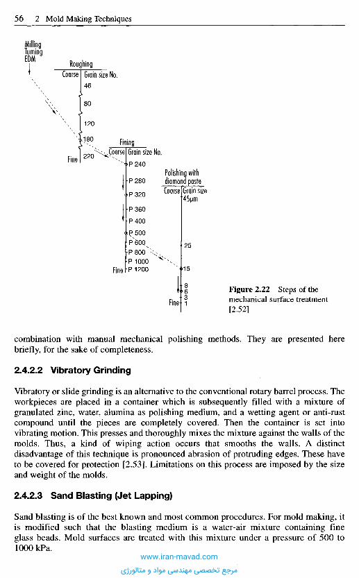
combination with manual mechanical polishing methods. They are presented herebriefly, for the sake of completeness.
2.4.2.2 Vibratory Grinding
Vibratory or slide grinding is an alternative to the conventional rotary barrel process. Theworkpieces are placed in a container which is subsequently filled with a mixture ofgranulated zinc, water, alumina as polishing medium, and a wetting agent or anti-rustcompound until the pieces are completely covered. Then the container is set intovibrating motion. This presses and thoroughly mixes the mixture against the walls of themolds. Thus, a kind of wiping action occurs that smooths the walls. A distinctdisadvantage of this technique is pronounced abrasion of protruding edges. These haveto be covered for protection [2.53]. Limitations on this process are imposed by the sizeand weight of the molds.
2.4.2.3 Sand Blasting (Jet Lapping)
Sand blasting is of the best known and most common procedures. For mold making, itis modified such that the blasting medium is a water-air mixture containing fineglass beads. Mold surfaces are treated with this mixture under a pressure of 500 to1000 kPa.
Figure 2.22 Steps of themechanical surface treatment[2.52]
Fine
Fine
Coarse Grain size45jjm
Polishing withdiamona paste
Fine
Fining.Coarse Grain size No.
RoughingGrain size No.Coarse
MillingTurningEDM
www.iran-mavad.com
مرجع تخصصی مهندسی مواد و متالورژی
This levels out any unevenness, such as grooves. The attainable surface quality is notcomparable to that of surfaces treated mechanically. The roughness height is about 5 um[2.53]. The application of this technique appears to make sense only for flat parts.Disadvantages are non-reproducible removal and relatively low dimensional stability.
2.4.2.4 Pressure Lapping
This process is a variant of jet lapping and also known as "extrude-honing". It is limitedto the treatment of openings. As the name indicates, it has found special significance inthe fabrication of profile-extrusion tools where arbitrarily shaped openings with thelowest of cross sections have to be polished.
The procedure uses applications a pasty polishing compound of variable viscosity thatcontains silicon carbide, boron carbide or diamond grits of various sizes depending onthe dimension of the opening. The compound is moved back and forth and averageroughness heights of Ra = 0.05 um are achieved in no time [2.54 to 2.56]. The process isdone automatically and requires only a short set-up time.
2.4.2.5 Electrochemical Polishing
With electrochemical polishing, or electro-polishing in short, the top layers of aworkpiece are removed [2.57]. The process is based on anodic metal machining andtherefore qualifies as a "cold" process. Thus, the workpiece does not become thermallystressed; see also Section 2.6. The process works without contact between workpiece andmold, so no mechanical loading occurs. Since removal only occurs at the workpiece, theworkpiece is subjected to virtually no abrasion [2.58].
Through the removal of material, leveling of the surface of the workpiece occurs. Highdimensional and molding accuracies, as well as good surface properties, can be achievedby electrochemical polishing. The aim is often to remove impurities introduced into theouter surface layer during preceding machining processes. Further advantages of theoperation are reproducible removal and the resultant high degree of automatability [2.58].
Defects in the steel, such as inclusions and pores, are exposed. Therefore, thematerials to be electrochemically polished must be of high purity. Various steels,especially the usual carbon steels, cannot be optimally electrochemically polished [2.53].
2.4.2.6 Electric-Discharge Polishing
Electric-discharge polishing is not essentially a new or independent procedure. It is anextension of electric-discharge machining (Section 2.5.1) and immediately followserosive fine finishing. Thus, erosion and polishing are done on the same equipment usingthe set-up. Consequently, to an extent depending on the level of surface finish required,it can replace time-consuming and costly manual postmachining.
In electric-discharge polishing, the discharge energies are very much reduced, e.g.through lower discharge currents, relative to electric-discharge fine finishing. As a result,removal rates are low and so electric-discharge polishing is also a time-consumingfinishing process. Because electric discharge polishing works on the principle ofremoval by heat, thermal damage is done to the outer zone. The outer zone can beminimized but it can never be removed completely.
The structure of surfaces after electric-discharge polishing characterized is by rows ofadjoining and superimposed discharge craters similar to that of electric-discharge
www.iran-mavad.com
مرجع تخصصی مهندسی مواد و متالورژی
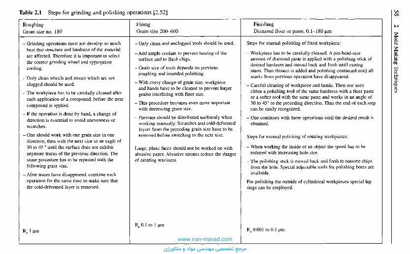
FinishingDiamond flour or paste, 0.1-180 jum
Steps for manual polishing of fixed workpiece:
- Workpiece has to be carefully cleaned. A pin-head-sizeamount of diamond paste is applied with a polishing stick ofdesired hardness and moved back and forth until cuttingstarts. Then thinner is added and polishing continued until allmarks from previous operation have disappeared.
- Careful cleaning of workpiece and hands. Then one useseither a polishing tool of the same hardness with a finer pasteor a softer tool with the same paste and works in an angle of30 to 45° to the preceding direction. Thus the end of each stepcan be easily recognized.
- One continues with these operations until the desired result isobtained.
Steps for manual polishing of rotating workpieces:
- When working the inside of an object the speed has to bereduced with increasing hole size.
- The polishing stick is moved back and forth to remove chipsfrom the hole. Special adjustable tools for polishing bores areavailable.
For polishing the outside of cylindrical workpieces special laprings can be employed.
Ra 0.001 to 0.1 urn
FiningGrain size 200-600
- Only clean and unclogged tools should be used.
- Add ample coolant to prevent heating of thesurface and to flush chips.
- Grain size of tools depends on previousroughing and intended polishing.
- With every change of grain size, workpieceand hands have to be cleaned to prevent largergrains interfering with finer size.
- This procedure becomes even more importantwith decreasing grain size.
- Pressure should be distributed uniformly whenworking manually. Scratches and cold-deformedlayers from the preceding grain size have to beremoved before switching to the next size.
Large, plane faces should not be worked on withabrasive paper. Abrasive strones reduce the dangerof creating waviness.
Ra0.1 to 1 urn
RoughingGrain size no. 180
- Grinding operations must not develop so muchheat that structure and hardness of the materialare affected. Therefore it is important to selectthe correct grinding wheel and appropriatecooling.
- Only clean wheels and stones which are notclogged should be used.
- The workpiece has to be carefully cleaned aftereach application of a compound, before the nextcompound is applied.
- If the operation is done by hand, a change ofdirection is essential to avoid unevenness orscratches.
- One should work with one grain size in onedirection, then with the next size in an angle of30 to 45 ° until the surface does not exhibitanymore traces of the previous direction. Thesame procedure has to be repeated with thefollowing grain size.
- After traces have disappeared, continue eachoperation for the same time to make sure thatthe cold-deformed layer is removed.
Ra 1 urn
Table 2.1 Steps for grinding and polishing operations [2.52]
www.iran-mavad.com
مرجع تخصصی مهندسی مواد و متالورژی
machining. Here, however, they are shallow, largely circular and all of about equal size.The surface roughness of so polished molds is about Ra = 0.1 to 0.3 um with a diameterof the discharge craters of about 10 um. These patterns are in the range of finely groundsurfaces and meet the requirements of mold making in many cases. Thus, it is possibleto forgo manual polishing, which is difficult with complex geometries [2.57, 2.60]. Thenecessary time is 15 to 30 min/cm2, the exact pattern depending on shape and size.
Hence, electric-discharge machining allows molds to be machined completely in oneset-up by means of roughing, prefinishing, fine finishing and polishing. However, theworkable area is limited in this process. Furthermore, electric-discharge polishing is verytime-consuming. On account of the thermal removal principle of electric-dischargemachining, a thermally damaged outer zone always remains on the workpiece. This canbe minimized by electric-discharge polishing, but can never be removed completely.
2 . 5 E l e c t r i c - D i s c h a r g e F o r m i n g P r o c e s s e s
Modern mold making would be inconceivable without electric-discharge equipment.With its help, complicated geometric shapes, the smallest of internal radii and deepgrooves can be achieved in one working step in annealed, tempered and hardened steelwith virtually no distortion [2.58, 2.61]. The process is contactless, i.e. there is a gapbetween the tool and the workpiece. Material removal is heat-based, requiring electricdischarges to occur between tool and workpiece electrode [2.58]. (For method ofproducing microcavities, see Section 20.1.2-20.1.2.6).
2.5.1 Electric-Discharge Machining (EDM)
Electric-discharge machining is a reproducing forming process, which uses the materialremoving effect of short, successive electric discharges in a dielectric fluid. Hydro-carbons are the standard dielectric, although water-based media containing dissolvedorganic compounds may be used. The tool electrode is generally produced as the shapingelectrode and is hobbed into the workpiece, to reproduce the contour [2.58].
With each consecutive impulse, a low volume of material of the workpiece and theelectrode is heated up to the melting or evaporation temperature and blasted from theworking area by electrical and mechanical forces. Through judicious selection of theprocess parameters, far greater removal can be made to occur at the workpiece than atthe tool, allowing the process to be economically viable. The relative abrasion, i.e.,removal at the tool in relation to removal at the workpiece, can be reduced to valuesbelow 0.1% [2.48,2.58].
This creates craters in both electrodes, the size of which are related to the energy ofthe spark. Thus, a distinction is drawn between roughing (high impulse energy) andplaning. The multitude of discharge craters gives the surface a distinctive structure, acertain roughness and a characteristic mat appearance without directed marks frommachining. The debris is flushed out of the spark gap and deposited in the container.Flushing can be designed as a purely movement-related operation. This type of flushingis very easy to realize since only the tool electrode, together with the sleeve, has to liftup a short distance. This lifting movement causes the dielectric in the gap to be changed.Admittedly, this variant is only really adequate for flat cavities. For complex contours,pressure or suction flushing by the workpiece or tool electrodes would need to be
www.iran-mavad.com
مرجع تخصصی مهندسی مواد و متالورژی
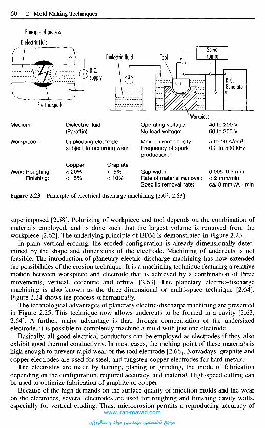
Figure 2.23 Principle of electrical discharge machining [2.62, 2.63]
superimposed [2.58], Polarizing of workpiece and tool depends on the combination ofmaterials employed, and is done such that the largest volume is removed from theworkpiece [2.62]. The underlying principle of EDM is demonstrated in Figure 2.23.
In plain vertical eroding, the eroded configuration is already dimensionally deter-mined by the shape and dimensions of the electrode. Machining of undercuts is notfeasible. The introduction of planetary electric-discharge machining has now extendedthe possibilities of the erosion technique. It is a machining technique featuring a relativemotion between workpiece and electrode that is achieved by a combination of threemovements, vertical, eccentric and orbital [2.63]. The planetary electric-dischargemachining is also known as the three-dimensional or multi-space technique [2.64].Figure 2.24 shows the process schematically.
The technological advantages of planetary electric-discharge machining are presentedin Figure 2.25. This technique now allows undercuts to be formed in a cavity [2.63,2.64]. A further, major advantage is that, through compensation of the undersizedelectrode, it is possible to completely machine a mold with just one electrode.
Basically, all good electrical conductors can be employed as electrodes if they alsoexhibit good thermal conductivity. In most cases, the melting point of these materials ishigh enough to prevent rapid wear of the tool electrode [2.66]. Nowadays, graphite andcopper electrodes are used for steel, and tungsten-copper electrodes for hard metals.
The electrodes are made by turning, planing or grinding, the mode of fabricationdepending on the configuration, required accuracy, and material. High-speed cutting canbe used to optimize fabrication of graphite or copper
Because of the high demands on the surface quality of injection molds and the wearon the electrodes, several electrodes are used for roughing and finishing cavity walls,especially for vertical eroding. Thus, microerosion permits a reproducing accuracy of
Medium:
Workpiece:
Wear: Roughing:Finishing:
Dielectric fluid(Paraffin)
Duplicating electrodesubject to occurring wear
Copper<20%< 5%
Graphite< 5%<10%
Operating voltage:No-load voltage:
Max. current density:Frequency of sparkproduction:
Gap width:Rate of material removal:Specific removal rate:
40 to 200 V60 to 300 V
5 to 10 A/cm2
0.2 to 500 kHz
0.005-0.5 mm< 2 mm/minca. 8 mmVA • min
Workpiece
Electric spark
Principle of process
Dielectric fluid
supply
Dielectric fluid ToolServocontrol
D. C.Generator
www.iran-mavad.com
مرجع تخصصی مهندسی مواد و متالورژی
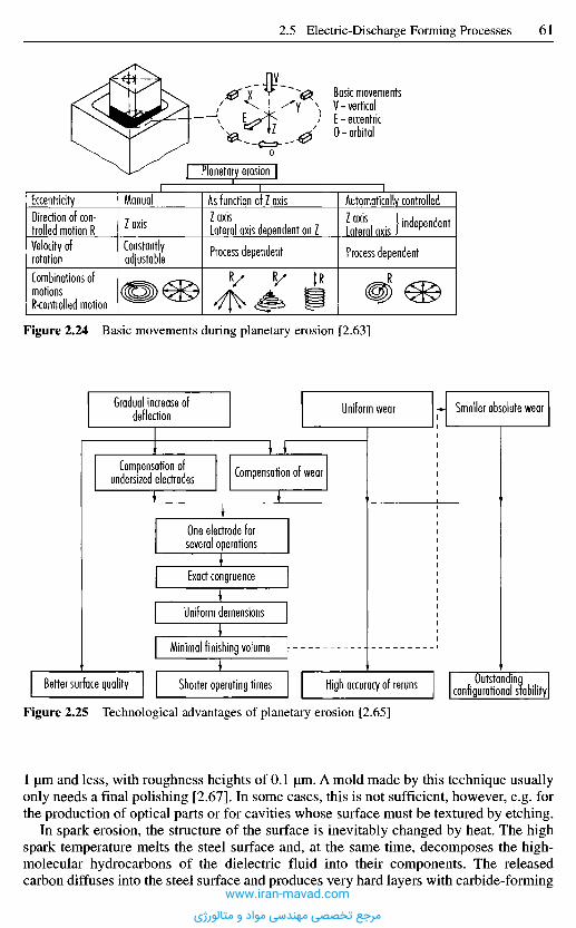
Figure 2.25 Technological advantages of planetary erosion [2.65]
1 jum and less, with roughness heights of 0.1 jiim. A mold made by this technique usuallyonly needs a final polishing [2.67]. In some cases, this is not sufficient, however, e.g. forthe production of optical parts or for cavities whose surface must be textured by etching.
In spark erosion, the structure of the surface is inevitably changed by heat. The highspark temperature melts the steel surface and, at the same time, decomposes the high-molecular hydrocarbons of the dielectric fluid into their components. The releasedcarbon diffuses into the steel surface and produces very hard layers with carbide-forming
Basic movementsV - verticalE - eccentric0-orbital
Planetary erosion
EccentricityDirection of con-trolled motion RVelocity ofrotationCombinations ofmotionsR-controlled motion
ManualZ axis
Constantlyadjustable
As function of Z axisZ axisLateral axis dependent on ZProcess dependent
Automatically controlled?°xis, . !independentLateral axis J
Process dependent
Figure 2.24 Basic movements during planetary erosion [2.63]
Gradual increase ofdeflection Uniform wear Smaller absolute wear
Compensation ofundersized electrodes Compensation of wear
One electrode forseveral operations
Exact congruence
Uniform demensions
Minimal finishing volume
Better surface quality Shorter operating times High accuracy of reruns Outstandingconfigurational stability
www.iran-mavad.com
مرجع تخصصی مهندسی مواد و متالورژی

elements. Their thickness depends on the energy of the spark [2.61]. Moreover, aconcentration of the electrode material can be detected in the melted region [2.63].Between the hardened top layer and the basic structure there is a transition layer [2.66].The consequences of this change in structure are high residual tensile stresses [2.68] inthe outer layers that can result in cracking and may sometimes impede necessaryposttreatment, e.g. photochemical etching.
Nevertheless, the EDM process has found a permanent place in mold makingnowadays. Some molds could not be made without it. Crucial advantages of it are thatmaterials of any hardness can be processed and that it lends itself to the fabrication ofcomplex, filigree contours.
A further advantage is that it works automatically and without supervision and is veryprecise and troublefree. Therefore modern electric-discharge machines are numericallycontrolled with four-axial screen control by dialogue. To better automate the process, themachinery is sometimes equipped with automatic tool and/or workpiece changingdevices. Thus, pallet loading and pallet displacement can be arranged such that it ispossible to handle pallet in several coordinates in the fluid. Startup and exact machiningcan be done without supervision and the work can continue on several workpieceswithout operator.
2.5.2 Cutting by Spark Erosion with Traveling-Wire
Electrodes
This is a very economical process for cutting through-holes of arbitrary geometry inworkpieces. The walls of the openings may be inclined to the plate surface. Thanks tothe considerable efficiency of this process, low cavities are increasingly being cutdirectly into mold plates.
Cutting by spark erosion is based on the same principle of thermal erosion that hasbeen used in EDM for some time (see Section 2.5.1). The metal is removed by anelectrical discharge without contact or mechanical action between the workpiece and athin wire electrode [2.69]. The electrode is numerically controlled and moved throughthe metal like a jig or band saw. Deionized water is the dielectric fluid, and is fed to thecutting area through coaxial nozzles. It is subsequently cleaned and regenerated inseparate equipment. Modern equipment has 5-axis CNC controls with high-precisionpositioning systems [2.48].
Deionized water has several advantages over hydrocarbons. It creates a wider sparkgap, which improves flushing and the whole process; the debris is lower, there are nosolid decomposition products and no arc is generated that would inevitably result in awire break [2.70]. In addition, there is a lower risk of emissions.
Figure 2.26 depicts the principle of cutting by spark erosion.Standard equipment can handle complicated openings and difficult contours with
cutting heights up to 600 mm. The width of the gap depends on the diameter of the wireelectrode and is determined by the task at hand. It is common practice to use wire witha diameter of 0.03 to 0.3 mm [2.69]. The wire is constantly replaced by winding from areel. Abrasion and tension would otherwise cause the wire to break. Furthermore, thecuts would not be accurate as the wire diameter would become progressively shorter.
The maximum cutting speed of modern machines is roughly 350 mm2/min. With theaid of so-called multi-cut technology (principal cut and several follow-up cuts), surfaceswith a roughness height of Ra= 0.15 um can be achieved [2.48].
www.iran-mavad.com
مرجع تخصصی مهندسی مواد و متالورژی
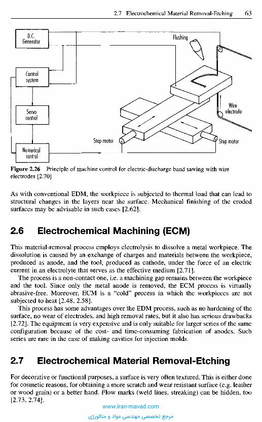
Figure 2.26 Principle of machine control for electric-discharge band sawing with wireelectrodes [2.70]
As with conventional EDM, the workpiece is subjected to thermal load that can lead tostructural changes in the layers near the surface. Mechanical finishing of the erodedsurfaces may be advisable in such cases [2.62].
2 . 6 E l e c t r o c h e m i c a l M a c h i n i n g ( E C M )
This material-removal process employs electrolysis to dissolve a metal workpiece. Thedissolution is caused by an exchange of charges and materials between the workpiece,produced as anode, and the tool, produced as cathode, under the force of an electriccurrent in an electrolyte that serves as the effective medium [2.71].
The process is a non-contact one, i.e. a machining gap remains between the workpieceand the tool. Since only the metal anode is removed, the ECM process is virtuallyabrasive-free. Moreover, ECM is a "cold" process in which the workpieces are notsubjected to heat [2.48, 2.58].
This process has some advantages over the EDM process, such as no hardening of thesurface, no wear of electrodes, and high removal rates, but it also has serious drawbacks[2.72]. The equipment is very expensive and is only suitable for larger series of the sameconfiguration because of the cost- and time-consuming fabrication of anodes. Suchseries are rare in the case of making cavities for injection molds.
2 . 7 E l e c t r o c h e m i c a l M a t e r i a l R e m o v a l - E t c h i n g
For decorative or functional purposes, a surface is very often textured. This is either donefor cosmetic reasons, for obtaining a more scratch and wear resistant surface (e.g. leatheror wood grain) or a better hand. Flow marks (weld lines, streaking) can be hidden, too[2.73, 2.74].
D.C.Generator
Controlsystem
Servocontrol
Numericalcontrol
Step motor
Flushing
Wireelectrode
Step motor
www.iran-mavad.com
مرجع تخصصی مهندسی مواد و متالورژی
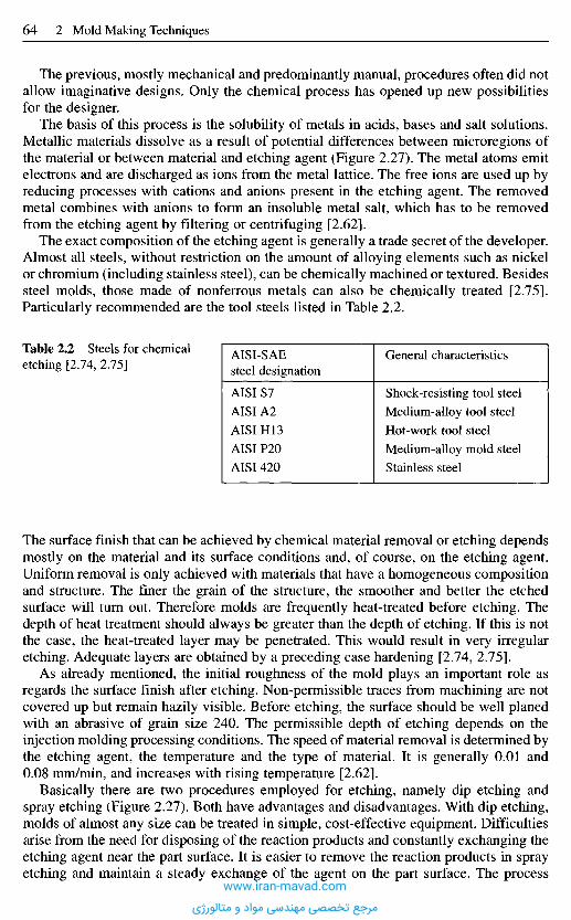
The surface finish that can be achieved by chemical material removal or etching dependsmostly on the material and its surface conditions and, of course, on the etching agent.Uniform removal is only achieved with materials that have a homogeneous compositionand structure. The finer the grain of the structure, the smoother and better the etchedsurface will turn out. Therefore molds are frequently heat-treated before etching. Thedepth of heat treatment should always be greater than the depth of etching. If this is notthe case, the heat-treated layer may be penetrated. This would result in very irregularetching. Adequate layers are obtained by a preceding case hardening [2.74, 2.75].
As already mentioned, the initial roughness of the mold plays an important role asregards the surface finish after etching. Non-permissible traces from machining are notcovered up but remain hazily visible. Before etching, the surface should be well planedwith an abrasive of grain size 240. The permissible depth of etching depends on theinjection molding processing conditions. The speed of material removal is determined bythe etching agent, the temperature and the type of material. It is generally 0.01 and0.08 mm/min, and increases with rising temperature [2.62].
Basically there are two procedures employed for etching, namely dip etching andspray etching (Figure 2.27). Both have advantages and disadvantages. With dip etching,molds of almost any size can be treated in simple, cost-effective equipment. Difficultiesarise from the need for disposing of the reaction products and constantly exchanging theetching agent near the part surface. It is easier to remove the reaction products in sprayetching and maintain a steady exchange of the agent on the part surface. The process
The previous, mostly mechanical and predominantly manual, procedures often did notallow imaginative designs. Only the chemical process has opened up new possibilitiesfor the designer.
The basis of this process is the solubility of metals in acids, bases and salt solutions.Metallic materials dissolve as a result of potential differences between microregions ofthe material or between material and etching agent (Figure 2.27). The metal atoms emitelectrons and are discharged as ions from the metal lattice. The free ions are used up byreducing processes with cations and anions present in the etching agent. The removedmetal combines with anions to form an insoluble metal salt, which has to be removedfrom the etching agent by filtering or centrifuging [2.62].
The exact composition of the etching agent is generally a trade secret of the developer.Almost all steels, without restriction on the amount of alloying elements such as nickelor chromium (including stainless steel), can be chemically machined or textured. Besidessteel molds, those made of nonferrous metals can also be chemically treated [2.75].Particularly recommended are the tool steels listed in Table 2.2.
Table 2.2 Steels for chemicaletching [2.74, 2.75]
AISI-SAEsteel designation
AISI S7
AISIA2
AISI H13
AISI P20
AISI420
General characteristics
Shock-resisting tool steel
Medium-alloy tool steel
Hot-work tool steel
Medium-alloy mold steel
Stainless steel
www.iran-mavad.com
مرجع تخصصی مهندسی مواد و متالورژی
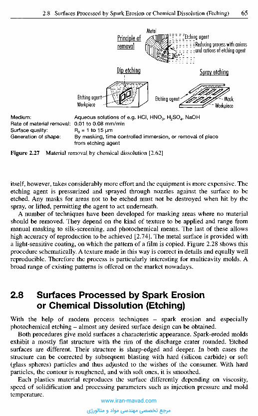
Figure 2.27 Material removal by chemical dissolution [2.62]
itself, however, takes considerably more effort and the equipment is more expensive. Theetching agent is pressurized and sprayed through nozzles against the surface to beetched. Any masks for areas not to be etched must not be destroyed when hit by thespray, or lifted, permitting the agent to act underneath.
A number of techniques have been developed for masking areas where no materialshould be removed. They depend on the kind of texture to be applied and range frommanual masking to silk-screening, and photochemical means. The last of these allowshigh accuracy of reproduction to be achieved [2.74]. The metal surface is provided witha light-sensitive coating, on which the pattern of a film is copied. Figure 2.28 shows thisprocedure schematically. A texture made in this way is correct in details and equally wellreproducible. Therefore the process is particularly interesting for multicavity molds. Abroad range of existing patterns is offered on the market nowadays.
2 . 8 S u r f a c e s P r o c e s s e d b y S p a r k E r o s i o n
o r C h e m i c a l D i s s o l u t i o n ( E t c h i n g )
With the help of modern process techniques - spark erosion and especiallyphotochemical etching - almost any desired surface design can be obtained.
Both procedures give mold surfaces a characteristic appearance. Spark-eroded moldsexhibit a mostly flat structure with the rim of the discharge crater rounded. Etchedsurfaces are different. Their structure is sharp-edged and deeper. In both cases thestructure can be corrected by subsequent blasting with hard (silicon carbide) or soft(glass spheres) particles and thus adjusted to the wishes of the consumer. With hardparticles, the contour is roughened, and with soft ones, it is smoothed.
Each plastics material reproduces the surface differently depending on viscosity,speed of solidification and processing parameters such as injection pressure and moldtemperature.
Medium:Rate of material removal:Surface quality:Generation of shape:
Aqueous solutions of e.g. HCI, HNO3, H2SO4, NaOH0.01 to 0.08 mm/minR0 = 1 to 15 urnBy masking, time controlled immersion, or removal of piecefrom etching agent
Etching agentWorkpiece
Etching agentWorkpiece
Mask
Spray etchingDip etching
Reducing process with anionsand cations of etching agentremoval
Principle ofMetal
Etching agent
www.iran-mavad.com
مرجع تخصصی مهندسی مواد و متالورژی
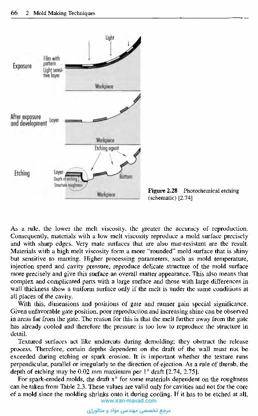
As a rule, the lower the melt viscosity, the greater the accuracy of reproduction.Consequently, materials with a low melt viscosity reproduce a mold surface preciselyand with sharp edges. Very mate surfaces that are also mar-resistant are the result.Materials with a high melt viscosity form a more "rounded" mold surface that is shinybut sensitive to marring. Higher processing parameters, such as mold temperature,injection speed and cavity pressure, reproduce delicate structure of the mold surfacemore precisely and give this surface an overall matter appearance. This also means thatcomplex and complicated parts with a large surface and those with large differences inwall thickness show a uniform surface only if the melt is under the same conditions atall places of the cavity.
With this, dimensions and positions of gate and runner gain special significance.Given unfavorable gate position, poor reproduction and increasing shine can be observedin areas far from the gate. The reason for this is that the melt further away from the gatehas already cooled and therefore the pressure is too low to reproduce the structure indetail.
Textured surfaces act like undercuts during demolding; they obstruct the releaseprocess. Therefore, certain depths dependent on the draft of the wall must not beexceeded during etching or spark erosion. It is important whether the texture runsperpendicular, parallel or irregularly to the direction of ejection. As a rule of thumb, thedepth of etching may be 0.02 mm maximum per 1° draft [2.74, 2.75].
For spark-eroded molds, the draft x° for some materials dependent on the roughnesscan be taken from Table 2.3. These values are valid only for cavities and not for the coreof a mold since the molding shrinks onto it during cooling. If it has to be etched at all,
Figure 2.28 Photochemical etching(schematic) [2.74]Workpiece
BottomEtching LayerDepth of etchingStructure roughness
Etching agentWorkpiece
After exposureand development
Layer
Workpiece
Film withpatternLight sensi-tive layer
Exposure
Light
www.iran-mavad.com
مرجع تخصصی مهندسی مواد و متالورژی
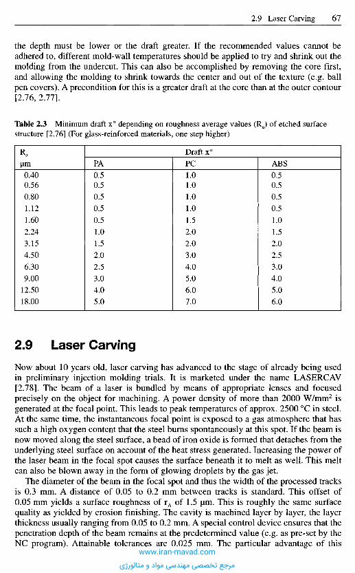
2 . 9 L a s e r C a r v i n g
Now about 10 years old, laser carving has advanced to the stage of already being usedin preliminary injection molding trials. It is marketed under the name LASERCAV[2.78]. The beam of a laser is bundled by means of appropriate lenses and focusedprecisely on the object for machining. A power density of more than 2000 W/mm2 isgenerated at the focal point. This leads to peak temperatures of approx. 2500 0C in steel.At the same time, the instantaneous focal point is exposed to a gas atmosphere that hassuch a high oxygen content that the steel burns spontaneously at this spot. If the beam isnow moved along the steel surface, a bead of iron oxide is formed that detaches from theunderlying steel surface on account of the heat stress generated. Increasing the power ofthe laser beam in the focal spot causes the surface beneath it to melt as well. This meltcan also be blown away in the form of glowing droplets by the gas jet.
The diameter of the beam in the focal spot and thus the width of the processed tracksis 0.3 mm. A distance of 0.05 to 0.2 mm between tracks is standard. This offset of0.05 mm yields a surface roughness of rA of 1.5 urn. This is roughly the same surfacequality as yielded by erosion finishing. The cavity is machined layer by layer, the layerthickness usually ranging from 0.05 to 0.2 mm. A special control device ensures that thepenetration depth of the beam remains at the predetermined value (e.g. as pre-set by theNC program). Attainable tolerances are 0.025 mm. The particular advantage of this
the depth must be lower or the draft greater. If the recommended values cannot beadhered to, different mold-wall temperatures should be applied to try and shrink out themolding from the undercut. This can also be accomplished by removing the core first,and allowing the molding to shrink towards the center and out of the texture (e.g. ballpen covers). A precondition for this is a greater draft at the core than at the outer contour[2.76, 2.77].
Table 2.3 Minimum draft x° depending on roughness average values (Ra) of etched surfacestructure [2.76] (For glass-reinforced materials, one step higher)
Ra
urn
0.40
0.56
0.80
1.12
1.60
2.24
3.15
4.50
6.30
9.00
12.50
18.00
Draft x°
PA
0.5
0.5
0.5
0.5
0.5
1.0
1.5
2.0
2.5
3.0
4.0
5.0
PC
1.01.01.01.01.52.02.03.04.05.06.07.0
ABS
0.50.50.50.51.01.52.02.53.04.05.06.0
www.iran-mavad.com
مرجع تخصصی مهندسی مواد و متالورژی
technique is that the NC program for guiding the laser beam is obtained directly from thevirtual image of a molding or cavity that has been generated by a CAD program andtransferred via the stereolithography interface of the CAD system (for processes forproducing microcavities, see Sections 20.1.2-20.1.2.6).
2.9.1 Rapid Tooling with LASERCAV
This direct way of programming straight from the computer offers for the first time thepossibility of taking tool materials, any kind of alloyed steel of any hardness, othermetals or ceramics and working up the desired shape directly, without interveningmaterial steps. Consequently, this process can be expected to supersede most of the rapidtooling processes developed in recent years. Although the surface quality and the size ofthe possible die and cavities do not yet satisfy all demands, it may be expected that thisprocess, when combined with other machining processes such as grinding, eroding, ormilling, will satisfy all requirements. The advantages that accrue thereby extend farbeyond merely speeding up the process, because it is possible for the first time to use thesame material that will be used to mass produce the tool later. Moreover, in manyinstances, it will likely also be used in mass production if design changes are not needed.The next few years will show just how much the relatively expensive investment willpay off and how competitive the process will be.
2 . 1 0 M o l d s f o r t h e F u s i b l e - C o r e T e c h n i q u e
In the injection molding of technical plastics parts, the mold parts designer is continuallyfaced with the problem of incorporating undercuts into the part such that they willdemold properly. Growing technical and design requirements make the problem ofdemolding a major part of the design phase. Often, the desire for optimum design has togive way to demoldability. Moldings that feature complex undercuts, or that represent a3D hollow body, can be made by 2 different fabrication techniques: the shell techniqueor the fusible-core technique. In the shell technique, the molding is built up from two ormore parts, known as shells. The shells are made by means of conventional tooling andmachine technology, either in the same mold or in two different molds. The shells arethen joined by means of screws, snap-on connections, bonding or welding in a furtherstep to form a mold part. Another method of joining is to mold material around a flange.
The housing for a water pump is shown in Figure 2.29. This is notable for the fact thatit is designed as a single part and thus has a conventionally non-demoldable internalgeometry. The inside surface of the part is indistinguishable from the outside one.
The production of a part like this requires a method that allows the demolding ofinternal geometries that cannot be conventionally demolded. The fusible-core techniqueis one such method. The various stages are shown in Figure 2.30.
A metal core consisting of a low-melting metal alloy is inserted into an injection moldand plastic material is molded around it. The surface of the core forms the internalcontour of the mold part. The mold part is demolded with the core inside it andtransferred to a heated melting medium. The core melts completely and runs out of themold part, without causing damage. The liquid core material can then be used to makeanother core. The cores are made with the aid of a core-casting machine in what is knownas the lowpressure casting process.
www.iran-mavad.com
مرجع تخصصی مهندسی مواد و متالورژی
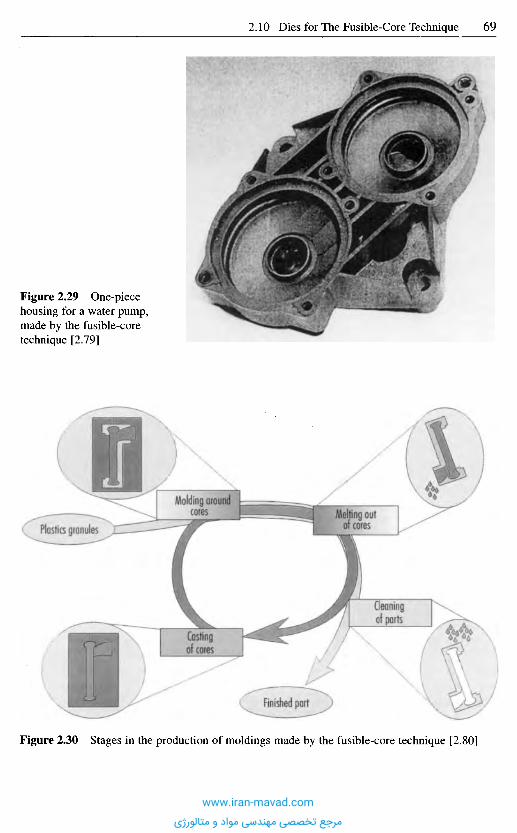
Figure 2.30 Stages in the production of moldings made by the fusible-core technique [2.80]
Figure 2.29 One-piecehousing for a water pump,made by the fusible-coretechnique [2.79]
Plastics granulesMailing out
of cores
Molding aroiwtlcores .-I
Cleaningof parts
Finished part
Castingof cores
www.iran-mavad.com
مرجع تخصصی مهندسی مواد و متالورژی
Because the production process involves several stages, the plastic and the corematerial must satisfy a large number of requirements. Apart from withstanding the highpressures acting on it when the plastic is injected, the core must resist the temperaturestresses involved when material is molded around it. Premature melting of the coreduring this process causes flaws in the molding. If the core material is too soft, the coremight be shifted and the walls of the molding may vary in thickness. If the core materialis too brittle, it might fail when the mold is closed or when material is molded around it,thereby making reliable production difficult.
The need to melt the core imposes further requirements. For one thing, the corematerial must not be damaged during melting in order that continuous reuse in the cyclemay be ensured. Also, the mold and the plastic must not be damaged by the melting-outstep.
Throughout the production cycle, the various materials, plastic, core material, meltingmedium and also the mold materials are in constant interaction. This interaction isinfluenced by such process parameters as temperature, pressure and speed. A furtherinfluence that must be mentioned is the geometry of the part and of the core. It istherefore evident that the fusible-core technique is an elaborate, complex productionmethod.
The great advantage of making moldings by the fusible-core technique as opposed tothat of multiple shells is that production occurs "in cast". As a result, the part is morehomogeneous, has a more accurate contour and does not have any weak zones caused byjoints. Further advantages are:
- greater design scope,- complex geometries can be realized as a single part,- dimensionally stable internal and external contours, with high surface finish- more simple mold design, and- increased parts functionality through integration of insert parts (part-in-part technique).
These production methods are thus particularly suitable where high demands areimposed on the strength, level of seal, and dimensional accuracy of the part.Disadvantages are the apparent high costs of manufacture due to the necessity of makingand removing the core.
However, it is precisely the use of a core that remains in the molded part duringdemolding that gives the designer much more freedom when designing parts. Further, thefusible-core technique affords a means of simplifying mold designs for complexcontours. Whereas to demold these complex contours by the traditional mold-makingmethod would necessitate a large number of highly elaborate, perhaps interpenetrating,ejectors and cores, the use of fusible cores can simplify mold design.
Different variants of this production process have been developed since the start of the1980s that permit mold parts featuring complex, smooth internal geometries to beproduced with high dimensional stability. All these processes have the same basic idea:the manufacture of injection-molded parts with lost cores, comparable with sand castingof metallic materials. These processes are:
- the fusible-core technique,- the dissolved core technique, and- the salt core technique.
From today's point of view, the fusible-core technique has become the established mass-production method. The reasons for this are the superior mechanical properties of the
www.iran-mavad.com
مرجع تخصصی مهندسی مواد و متالورژی
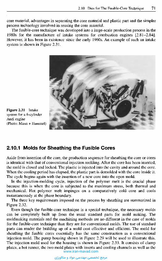
2.10.1 Molds for Sheathing the Fusible Cores
Aside from insertion of the core, the production sequence for sheathing the core or coresis identical with that of conventional injection molding. After the core has been inserted,the mold is closed and locked. The plastic is injected into the cavity and around the core.When the cooling period has elapsed, the plastic part is demolded with the core inside it.The cycle begins again with the insertion of a new core into the open mold.
In the injection-molding cycle, injection of the polymer melt is the crucial phasebecause this is when the core is subjected to the maximum stress, both thermal andmechanical. Hot polymer melt impinges on a comparatively cold core and coolsinstantaneously at the phase boundary.
The three key requirements imposed on the process by sheathing are summarized inFigure 2.32.
Even though the fusible-core technique is a special technique, the necessary moldscan be completely built up from the usual standard parts for mold making. Themoldmaking materials and the machining methods are no different in the case of moldsfor the fusible-core technique than they are for conventional molds. The use of standardparts can render the building up of a mold cost effective and efficient. The mold forsheathing the fusible cores essentially has the same construction as a conventionalinjection mold. The pump housing shown in Figure 2.29 will be used to illustrate this.The injection mold used for the housing is shown in Figure 2.33. It consists of clampplates, a hot runner, the two mold plates with inserts and cooling channels as well as the
Figure 2.31 Intakesystem for a 6-cyUnderAudi engine(Photo: Mann + Hummel)
core material, advantages in separating the core material and plastic part and the simplerprocess technology involved in reusing the core material.
The fusible-core technique was developed into a large-scale production process in the1980s for the manufacture of intake systems for combustion engines [2.81-2.84].However, it has been in existence since the early 1960s. An example of such an intakesystem is shown in Figure 2.31.
www.iran-mavad.com
مرجع تخصصی مهندسی مواد و متالورژی
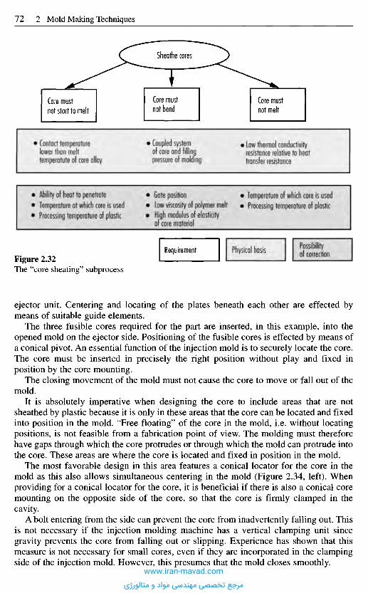
ejector unit. Centering and locating of the plates beneath each other are effected bymeans of suitable guide elements.
The three fusible cores required for the part are inserted, in this example, into theopened mold on the ejector side. Positioning of the fusible cores is effected by means ofa conical pivot. An essential function of the injection mold is to securely locate the core.The core must be inserted in precisely the right position without play and fixed inposition by the core mounting.
The closing movement of the mold must not cause the core to move or fall out of themold.
It is absolutely imperative when designing the core to include areas that are notsheathed by plastic because it is only in these areas that the core can be located and fixedinto position in the mold. "Free floating" of the core in the mold, i.e. without locatingpositions, is not feasible from a fabrication point of view. The molding must thereforehave gaps through which the core protrudes or through which the mold can protrude intothe core. These areas are where the core is located and fixed in position in the mold.
The most favorable design in this area features a conical locator for the core in themold as this also allows simultaneous centering in the mold (Figure 2.34, left). Whenproviding for a conical locator for the core, it is beneficial if there is also a conical coremounting on the opposite side of the core, so that the core is firmly clamped in thecavity.
A bolt entering from the side can prevent the core from inadvertently falling out. Thisis not necessary if the injection molding machine has a vertical clamping unit sincegravity prevents the core from falling out or slipping. Experience has shown that thismeasure is not necessary for small cores, even if they are incorporated in the clampingside of the injection mold. However, this presumes that the mold closes smoothly.
Figure 2.32The "core shearing" subprocess
Requirement Physical basis Possibilityof correction
Ability of heat to penetrateTemperature at which core is usedProcessing temperature of plastic
Gate positionLow viscosity of polymer meltHigh modulus of elasticityof core material
Temperature of which core is usedProcessing temperature of plastic
Contact temperaturelower than melttemperatute of core olloy
Coupled systemof core and fillingpressure of molding
Low thermal conductivityresistance relative to heattransfer resistance
Core mustnot melt
Core mustnot bend
Core mustnot start to melt
Sheathe cores
www.iran-mavad.com
مرجع تخصصی مهندسی مواد و متالورژی
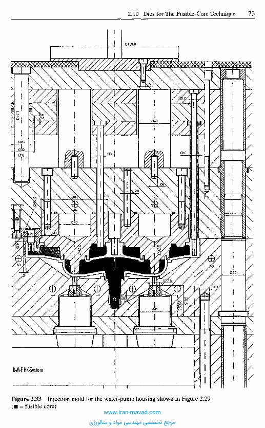
D-M-E HK-System
Figure 2.33 Injection mold for the water-pump housing shown in Figure 2.29( • = fusible core)
www.iran-mavad.com
مرجع تخصصی مهندسی مواد و متالورژی
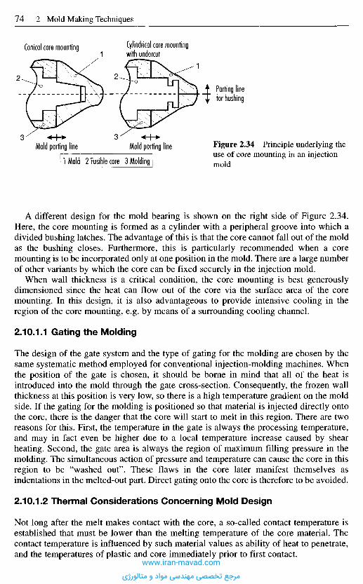
A different design for the mold bearing is shown on the right side of Figure 2.34.Here, the core mounting is formed as a cylinder with a peripheral groove into which adivided bushing latches. The advantage of this is that the core cannot fall out of the moldas the bushing closes. Furthermore, this is particularly recommended when a coremounting is to be incorporated only at one position in the mold. There are a large numberof other variants by which the core can be fixed securely in the injection mold.
When wall thickness is a critical condition, the core mounting is best generouslydimensioned since the heat can flow out of the core via the surface area of the coremounting. In this design, it is also advantageous to provide intensive cooling in theregion of the core mounting, e.g. by means of a surrounding cooling channel.
2.10.1.1 Gating the Molding
The design of the gate system and the type of gating for the molding are chosen by thesame systematic method employed for conventional injection-molding machines. Whenthe position of the gate is chosen, it should be borne in mind that all of the heat isintroduced into the mold through the gate cross-section. Consequently, the frozen wallthickness at this position is very low, so there is a high temperature gradient on the moldside. If the gating for the molding is positioned so that material is injected directly ontothe core, there is the danger that the core will start to melt in this region. There are tworeasons for this. First, the temperature in the gate is always the processing temperature,and may in fact even be higher due to a local temperature increase caused by shearheating. Second, the gate area is always the region of maximum filling pressure in themolding. The simultaneous action of pressure and temperature can cause the core in thisregion to be "washed out". These flaws in the core later manifest themselves asindentations in the melted-out part. Direct gating onto the core is therefore to be avoided.
2.10.1.2 Thermal Considerations Concerning Mold Design
Not long after the melt makes contact with the core, a so-called contact temperature isestablished that must be lower than the melting temperature of the core material. Thecontact temperature is influenced by such material values as ability of heat to penetrate,and the temperatures of plastic and core immediately prior to first contact.
Figure 2.34 Principle underlying theuse of core mounting in an injectionmoldIMoId 2 Fusible core3 Molding
Mold parting line Mold parting line33
Parting linefor bushing
12
1Cylindrical core mountingwith undercut
Conical core mounting
2
www.iran-mavad.com
مرجع تخصصی مهندسی مواد و متالورژی
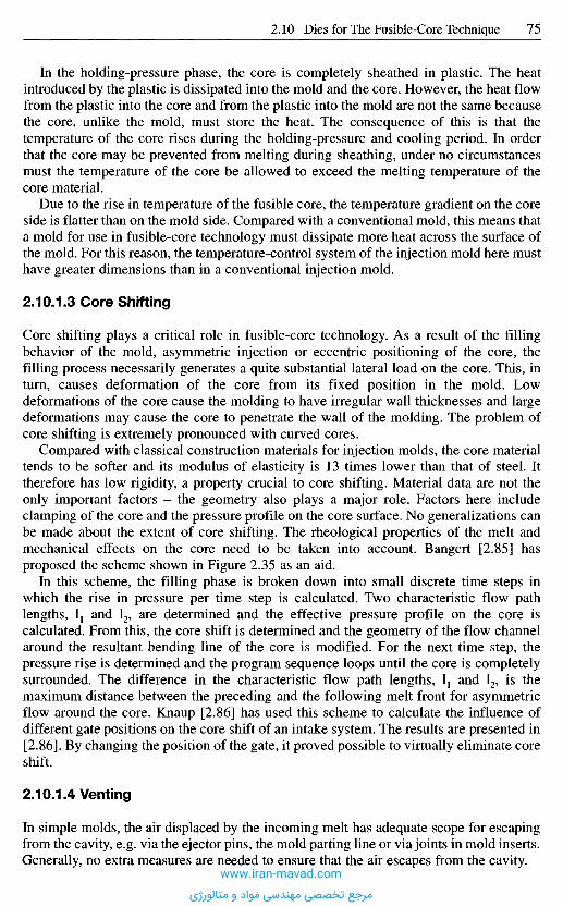
In the holding-pressure phase, the core is completely sheathed in plastic. The heatintroduced by the plastic is dissipated into the mold and the core. However, the heat flowfrom the plastic into the core and from the plastic into the mold are not the same becausethe core, unlike the mold, must store the heat. The consequence of this is that thetemperature of the core rises during the holding-pressure and cooling period. In orderthat the core may be prevented from melting during sheathing, under no circumstancesmust the temperature of the core be allowed to exceed the melting temperature of thecore material.
Due to the rise in temperature of the fusible core, the temperature gradient on the coreside is flatter than on the mold side. Compared with a conventional mold, this means thata mold for use in fusible-core technology must dissipate more heat across the surface ofthe mold. For this reason, the temperature-control system of the injection mold here musthave greater dimensions than in a conventional injection mold.
2.10.1.3 Core Shifting
Core shifting plays a critical role in fusible-core technology. As a result of the fillingbehavior of the mold, asymmetric injection or eccentric positioning of the core, thefilling process necessarily generates a quite substantial lateral load on the core. This, inturn, causes deformation of the core from its fixed position in the mold. Lowdeformations of the core cause the molding to have irregular wall thicknesses and largedeformations may cause the core to penetrate the wall of the molding. The problem ofcore shifting is extremely pronounced with curved cores.
Compared with classical construction materials for injection molds, the core materialtends to be softer and its modulus of elasticity is 13 times lower than that of steel. Ittherefore has low rigidity, a property crucial to core shifting. Material data are not theonly important factors - the geometry also plays a major role. Factors here includeclamping of the core and the pressure profile on the core surface. No generalizations canbe made about the extent of core shifting. The rheological properties of the melt andmechanical effects on the core need to be taken into account. Bangert [2.85] hasproposed the scheme shown in Figure 2.35 as an aid.
In this scheme, the filling phase is broken down into small discrete time steps inwhich the rise in pressure per time step is calculated. Two characteristic flow pathlengths, I1 and I2, are determined and the effective pressure profile on the core iscalculated. From this, the core shift is determined and the geometry of the flow channelaround the resultant bending line of the core is modified. For the next time step, thepressure rise is determined and the program sequence loops until the core is completelysurrounded. The difference in the characteristic flow path lengths, I1 and I2, is themaximum distance between the preceding and the following melt front for asymmetricflow around the core. Knaup [2.86] has used this scheme to calculate the influence ofdifferent gate positions on the core shift of an intake system. The results are presented in[2.86]. By changing the position of the gate, it proved possible to virtually eliminate coreshift.
2.10.1.4 Venting
In simple molds, the air displaced by the incoming melt has adequate scope for escapingfrom the cavity, e.g. via the ejector pins, the mold parting line or via joints in mold inserts.Generally, no extra measures are needed to ensure that the air escapes from the cavity.
www.iran-mavad.com
مرجع تخصصی مهندسی مواد و متالورژی
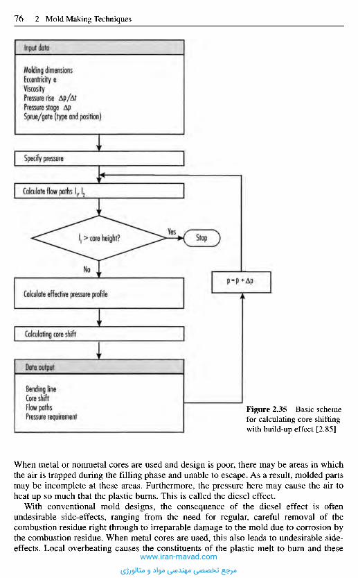
When metal or nonmetal cores are used and design is poor, there may be areas in whichthe air is trapped during the filling phase and unable to escape. As a result, molded partsmay be incomplete at these areas. Furthermore, the pressure here may cause the air toheat up so much that the plastic burns. This is called the diesel effect.
With conventional mold designs, the consequence of the diesel effect is oftenundesirable side-effects, ranging from the need for regular, careful removal of thecombustion residue right through to irreparable damage to the mold due to corrosion bythe combustion residue. When metal cores are used, this also leads to undesirable side-effects. Local overheating causes the constituents of the plastic melt to burn and these
Figure 2.35 Basic schemefor calculating core shiftingwith build-up effect [2.85]
Bending lineCore shiftFlow pathsPressure requirement
Data output
Calculating core shift
Calculate effective pressure profile
P=P+Ap
StopI1 > core height?
No
Yes
Calculate flow paths I1,12
Specify pressure
Molding dimensionsEccentricity eViscosityPressure rise Ap/AtPressure stage ApSprue/gate (type and position)
Input data
www.iran-mavad.com
مرجع تخصصی مهندسی مواد و متالورژی
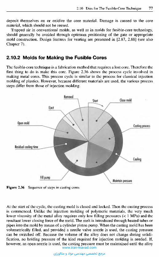
deposit themselves on or oxidize the core material. Damage is caused to the corematerial, which should not be reused.
Trapped air in conventional molds, as well as in molds for fusible-core technology,should generally be avoided through optimum positioning of the gate or appropriatemold construction. Design features for venting are presented in [2.87, 2.88] (see alsoChapter 7).
2.10.2 Molds for Making the Fusible Cores
The fusible-core technique is a fabrication method that requires a lost core. Therefore thefirst thing to do is make this core. Figure 2.36 shows the process cycle involved inmaking metal cores. This process cycle is similar to the process for classical injectionmolding of plastics. However, because different materials are used, the various processsteps differ from those of injection molding.
RemovalStart Close mold
Casting process
Cooling
Eject
Open mold
Residual cooling time
Fill pump
Figure 2.36 Sequence of steps in casting cores
At the start of the cycle, the casting mold is closed and locked. Then the casting processis commenced. Unlike the injection molding of polymeric materials, the very muchlower viscosity of the metal alloy requires only low filling pressures (< 1 MPa) and theresultant lower closing force of the mold. The melt is introduced through heated tubes orpipes into the mold by means of a cylinder piston pump. When the casting mold has beenvolumetrically filled, and provided a needle valve nozzle is used, the casting pressurecan be switched off. Because the volume of the alloy does not change during solidi-fication, no holding pressure of the kind required for injection molding is needed. If,however, an open nozzle is used, the casting pressure must be maintained until the alloy
Maintain pressure
www.iran-mavad.com
مرجع تخصصی مهندسی مواد و متالورژی
2.10.2.2 Construction of a Casting Mold
The construction of a casting mold for fusible cores is essentially the same as that of aninjection mold. By way of example, Figure 2.37 shows the casting mold used for thefusible cores for the water-pump housing. The mold also comprises clamp plates, the twomold plates with mold inserts and cooling channels, as well as the ejector unit.Alignment and location of the plates beneath each other are effected by means of suitableguide elements, which are not shown in this cross-section.
Casting molds for the fusible-mold technique impose high requirements on the gapdimensions of the cavity. The reason for this is the low viscosity of the metallic melt,which is comparable to that of water. To use an analogy, the casting mold is to be filledwith water without the water running out of the gaps in the parting line or the inserts andejector pins.
2.10.2.3 Gating Systems
Since the casting molds are maintained at a temperature between 30 and 80 0C, thecontact temperature for first contact between the hot metal melt and the cold mold wallis always lower than the melting temperature of the core material. Through the lowcontact temperature, and the allowance made for the forces of inertia and gravity, thefirst requirement concerning the filling phase of the casting mold presents itself. The gate
in the gate area is cold. If the pressure is released too soon, unfrozen core material flowsback into the conveying system and the core might possibly be partially hollow. After thegate has been closed or has frozen, the pressure on the casting system is released and theconveying pump is filled again. After the residual cooling time, the casting mold is open-ed and the core is demolded and removed from the casting mold by robot or manually.
2.10.2.1 Core Material
Nowadays, the core material is usually an eutectic alloy of tin and bismuth. The specialattraction of the tin/bismuth eutectic alloy is that solidification is virtually shrinkage-free. Tin contracts, whereas bismuth expands in volume by 3.3% [2.89]. The internaldimensions of the casting mold or so-called metal mold are thus almost identical with theouter dimensions of the casting after demolding. Table 2.4 shows selected properties ofan eutectic alloy of tin and bismuth.
Table 2.4 Selected properties of a eutectic alloy of tin and bismuth
Property
Density at 20 0C
Specific heat capacity
Melt enthalpy
Thermal conductivity at 20 0C
Viscosity
SolidLiquid
Unit
g/cm3
kJ/(kg K)
kJ/kg
W/(m K)
mPa s
Value
8.58
0.167
0.201
44.8
18.5
2.1
www.iran-mavad.com
مرجع تخصصی مهندسی مواد و متالورژی
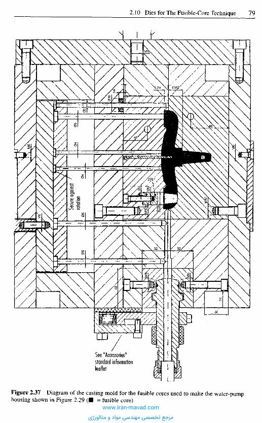
Figure 2.37 Diagram of the casting mold for the fusible cores used to make the water-pumphousing shown in Figure 2.29 ( • = fusible core)
See "Accessories"standard informationleaflet
www.iran-mavad.com
مرجع تخصصی مهندسی مواد و متالورژی
must be positioned at the lowest point of the cavity. Further, it is crucial that the geo-metry inside the core is arranged so that casting is always effected against gravity. A cast"dropping" onto the mold wall will freeze immediately and manifests itself as anundesirable mark on the surface of the core. A high-quality surface therefore requiresslow, steady casting.
As in the injection molding of polymeric materials, hot-runner systems are used incore-casting molds. A distinction is made between open nozzles and needle valvesystems. The casting mold shown in Figure 2.37 has an open hot runner, and a manifoldin the form of a cold runner. The disadvantage of this design is that the fusible cores mustbe machined mechanically in the gate region of the cold runner after demolding. This isboth time-consuming and the dust from grinding represents a loss of core material.
Casting molds in a modern production system for exhaust equipment feature needlevalve nozzles whose geometry matches that of the fused core and are designed as a hotrunner. The gate does not have to be posttreated, a fact that considerably facilitates fullyautomated production.
2.10.2.4 Thermal Considerations Concerning the Core-Casting Mold
Particularly with voluminous fusible cores of the kind used for intake systems, the cycletimes for core casting are much longer than those for injection molding. Therefore, inthis application, two core-casting machines feed one injection-molding machine. Thereason for the long cooling times is the thermal design of the core-casting molds and thematerial employed.
The casting mold is usually made of steel. The tool steels usually employed have athermal conductivity in the range 20 to 30 W/(m • K). Case-hardened steels and severalannealed steels are notable for having a higher thermal conductivity of ranging from 40to 46 W/(m • K). Even for these steels, the thermal diffusivity is roughly in the range of thetin/bismuth alloy. The thermal diffusivity, as a measure of the speed at which a temperaturejump is introduced into a material, is shown in Figure 2.38 for a range of materials.
It can be seen that the thermal diffusivity of a case-hardened steel is roughly in therange of an alloy of tin and bismuth. To shorten the cooling time during core manufacture,it would therefore be sensible to use a material for the metal mold that has a much greaterthermal diffusivity. Copper is renowned for its excellent thermal properties and would intheory be an ideal candidate. However, the use of copper as a mold material is ruled outbecause the liquid tin penetrates into the copper at the grain boundaries, forming an alloythrough the creation of an intercrystalline phase. This causes the copper to physicallydissolve [2.90] and visible damage in the form of washout is caused to the mold.
A suitable coating process, such as electrolytic nickel plating or chrome plating, maybe used to apply a thin passive layer that suppresses alloy formation and hence greatlyreduces the rate of corrosion. The reason for this is a very thin but dense semiconductingfilm of oxide on the metal surface that displaces the electron potential extensively in thepositive direction. This property, which is known as chemical passivity, is possessedmainly by the transition metals, whose principle characteristic is that their electronconfiguration has vacant d orbitals. They include the metals in the iron and platinumgroup, chromium, molybdenum, tungsten, titanium and zirconium. Some other metals,such as aluminum, also exhibit chemical passivity [2.91]. For this reason, and becauseof its thermal conductivity, aluminum is also a very interesting mold material. So far, noexperience has been gained of the compatibility of these materials in various combi-nations.
www.iran-mavad.com
مرجع تخصصی مهندسی مواد و متالورژی
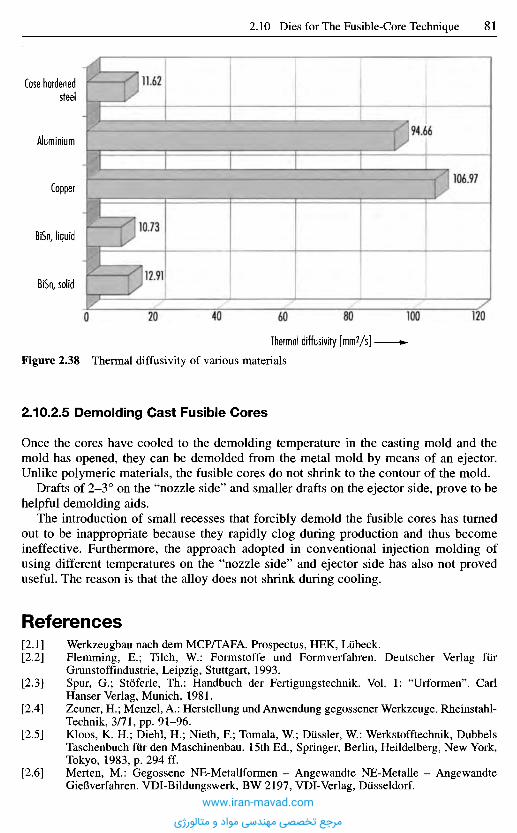
Figure 2.38 Thermal diffusivity of various materials
2.10.2.5 Demolding Cast Fusible Cores
Once the cores have cooled to the demolding temperature in the casting mold and themold has opened, they can be demolded from the metal mold by means of an ejector.Unlike polymeric materials, the fusible cores do not shrink to the contour of the mold.
Drafts of 2-3° on the "nozzle side" and smaller drafts on the ejector side, prove to behelpful demolding aids.
The introduction of small recesses that forcibly demold the fusible cores has turnedout to be inappropriate because they rapidly clog during production and thus becomeineffective. Furthermore, the approach adopted in conventional injection molding ofusing different temperatures on the "nozzle side" and ejector side has also not proveduseful. The reason is that the alloy does not shrink during cooling.
R e f e r e n c e s
[2.1] Werkzeugbau nach dem MCP/TAFA. Prospectus, HEK, Liibeck.[2.2] Flemming, E.; Tilch, W.: Formstoffe und Formverfahren. Deutscher Verlag fiir
Grunstoffindustrie, Leipzig, Stuttgart, 1993.[2.3] Spur, G.; Stoferle, Th.: Handbuch der Fertigungstechnik. Vol. 1: "Urformen". Carl
Hanser Verlag, Munich, 1981.[2.4] Zeuner, H.; Menzel, A.: Herstellung und Anwendung gegossener Werkzeuge. Rheinstahl-
Technik, 3/71, pp. 91-96.[2.5] Kloos, K. H.; Diehl, H.; Nieth, R; Tomala, W.; DUssler, W.: Werkstofftechnik, Dubbels
Taschenbuch fiir den Maschinenbau. 15th Ed., Springer, Berlin, Heildelberg, New York,Tokyo, 1983, p. 294 ff.
[2.6] Merten, M.: Gegossene NE-Metallformen - Angewandte NE-Metalle - AngewandteGieBverfahren. VDI-Bildungswerk, BW 2197, VDI-Verlag, Dusseldorf.
Thermal diffusivity [mm2/s]
Case hardenedsteel
Aluminium
Copper
BiSn, liquid
BiSn, solid
11.62
94.66
106.97
10.73
12.91
www.iran-mavad.com
مرجع تخصصی مهندسی مواد و متالورژی

[2.7] Cerro-Legierungen fiir schnellen Werkzeugbau. Plastverarbeiter, 25 (1974), 3,pp. 175-176.
[2.8] Menden, A.: GieBerei Molellbau. Giesserei-Verlag GmbH, Dusseldorf, 1991.[2.9] Clegg, A. J.: Precision Casting Process. Pergamon Press, Oxford, New York, Frankfurt,
1991.[2.10] Chock, J.: Zauberformel HSC. Maschine + Werkzeug, 3/97, pp. 10-12.[2.11] Duretek, L; Santek, D.: Der schnelle Weg. Plastverarbeiter, 47 (1996), 11, pp. 44-56.[2.12] Dusel, K. H.; Eyerer, P.: Materialien fur Rapid Tooling Technologien. User Meeting,
Report 4, Dresden, 1996, pp. 246-256.[2.13] Santek, D.; Duretek, L: Materialien fiir Rapid Prototyping - schneller Modellbau aus
CAD-Daten. Osterreichische Kunstoffzeitschrift, 27 (1996), pp. 82-85.[2.14] Haferkamp, H.; Bach, F. W.; Gerken, J.: Rapid Manufacturing of Metal Parts by Laser
Sintering. 28th International Symposium on Automotive Technology and Automation,ISATA; Stuttgart, 1995, pp. 459-474.
[2.15] Eckstein, M.: Rapid Metal Prototyping. 41st International Colloquium, TU, Ilmenau,September 23-26, 1996, pp. 383-386.
[2.16] Lorenzen, J.; Breitinger, E.: Rapid Tooling - Verfahren zur schnellen Herstellung vonPrototypenwerkzeugen (Chapter 8). Paper presented at the Conference on: Verkiirzungvon Entwicklungszeiten durch Rapid Prototyping, EUROFORUM, KoIn, October 24-25,1996.
[2.17] Shellabear, M.: Bindemittel ade - Neue Wege beim Lasersintern. Laser Praxis, June1995, p. 48.
[2.18] Klocke, E.; Noken, S.: Verfahren und ProzeBketten zur Fertigung metallischer Bauteileund Werkzeuge. Spektrum der Wissenschaft, April 1995, pp. 97-99.
[2.19] Klocke, E.; Clemens, U.: An RP network for product development Prototyping.Technology International Annual Review, UK & International Press, Surrey, UK, 1997.
[2.20] Gasser, A.: Herstellung metallischer Bauteile durch Selektives. Lasersintern undLasergenerieren. NCG-Conference. Arbeitskreis Rapid Prototyping, LBBZ, Aachen,December 1995.
[2.21] Sachs, E.; Cima, M.; Allen, S.: Tooling by Three Dimensional Printing - A DesktopManufacturing Process. 28th International Symposium on Automotive Technology andAutomation, ISATA, 1995, Stuttgart, pp. 405-420.
[2.22] Thomson, G. A.; Pridham, M. S.: RP and Tooling with a high powered laser. 1st NationalConference on Rapid Prototyping and Tooling, Buckinghamshire College, UK,November 6-7, 1995.
[2.23] Wiesner, R.; Eckstein, M. et al.: Rapid Prototyping durch Laserschneiden undDiffusionsschweiBen. Proceedings of the 6th European Conference on Laser Treatmentof Materials, ECLAT. Vol. 2, September 16-18, 1996.
[2.24] Gebhardt, A.: Rapid Prototyping - Werkzeuge fiir die schnelle Produktentwicklung. CarlHanser Verlag, Munich, 1996, pp. 23-26.
[2.25] Langen, M.: Einsatz der Stereolithographie fiir das Rapid Tooling in derSpritzgieBverarbeitung. 3rd User Meeting: Intelligente Produktionssysteme - SolidFreeform Manufacturing, Dresden, September 1995, pp. 255-265.
[2.26] Schulthess, A.: Future Developments in Cibatool SL-Resins. 6th EuropeanStereolithography User Meeting, Strasbourg, France, November 7-8, 1994.
[2.27] Bettany, S.; Cobb, R. C : A Rapid Ceramic Tooling System for Prototype Plastic InjectionMoldings. 1st National Conference on Rapid Prototyping and Tooling, BuckinghamshireCollege, UK, November 6-7, 1995.
[2.28] Auf dem Weg zum Serienteil. Werkzeug & Formenbau, November 1995, pp. 44-48.[2.291 Gernot, T. H. C : Beitrage zum Simultaneous Engineering bei der Produkt- und
ProzeBplanung fiir die SpritzgieBfertigung. Dissertation, RWTH, Aachen, 1994.[2.30] Bocking, C. E.; Dover, S. J.: Rapid Tooling Using Electroforming. European Action on
Rapid Prototyping, EARP, No. 6, August 1996, pp. 8-9.[2.31] Prospectus. Galvanoform Company. Gesellschaft fiir Galvanoplastik mbH, Lahr, 1996.[2.32] Greul, M.: Prototype Moulds by using FDM and Electroplating. European Action on
Rapid Prototyping, EARP, No. 6, July 1995, pp. 1-2.[2.33] Flimm, J.: Spanlose Formgebung. 6th Ed., Carl Hanser Verlag, Munich, 1996, pp. 20-35.
www.iran-mavad.com
مرجع تخصصی مهندسی مواد و متالورژی
[2.34] Andre, L.: Investment Casting and Ceramic Moulds. Using the Quick Cast Process. 6thEuropean Stereolithography User Meeting, Strasbourg, France, November 7-8, 1994.
[2.35] Tsang, H.; Bennet, G.: Rapid Tooling-direct use of SLA moulds for investment easting.First National Conference on Rapid Prototyping and Tooling, Buckinghamshire College,UK, November 6-7, 1995.
[2.36] Sprunk, J.: FeinguB fur alle Industriebetriebe. 2nd Ed., Industrie-Werkstatten GmbH,Bochum, 1987.
[2.37] Evans, B.: Production Outsourcing in Metal Casting. Rapid Prototyping &Manufacturing. Conference, Dearborn, MI, USA, April 22-24, 1997, pp. 177-205.
[2.38] Clerico, M.; Lanzoni, C ; Minks, H.: Ort an Expandable Pattern Casting. 3rd UserMeeting: Intelligente Produktionssysteme - Solid Freeform Manufacturing, Dresden,September 1995, pp. 307-316.
[2.39] Connelly, R.: Verbal information. Becton Dickinson, Raleigh, USA, May 1997.[2.40] Langen, M.: Einsatz des Rapid Prototyping und Rapid Tooling im Rahmen eines
Simultaneous Engineering in der SpritzgieBverarbeitung. Dissertation, RWTH, Aachen,1998.
[2.41] Galvanisiergerechtes Gestalten von Werkstiicken. Report. International Nickel,Dusseldorf, 1968.
[2.42] Kalteinsenken von Werkzeugen. VDI-Richtlinie, 3170, 1961.[2.43] Hoischen, H.: Werkzeugformgebung durch Kalteinsenken. Werkstatt und Betrieb, 104
(1971), 4, pp. 275-282.[2.44] Stoeckhert, K.: Formenbau fur die Kunststoffverarbeitung. 3rd Ed., Carl Hanser Verlag,
Munich, 1979.[2.45] Piwowarski, E.: Erstellen von SpritzgieBwerkzeugen. Kunststoffe, 78 (1988), 12,
pp. 1137-1146.[2.46] HSC-Fraszentrum bearbeitet Stahl bis 62 HRC. In: Maschinenmarkt, Wurzburg, 102
(1996), 36.[2.47] Malle, K.: Von der HSC-Produktidee zum Bearbeitungszentrum. VDI-Z, 138 (1996), 6.[2.48] Eversheim, W.; Klocke, E: Werkzeugbau mit Zukunft - Strategic und Technologic
Springer Verlag, Berlin, 1997.[2.49] Prospectus. Joisten und Kettenbaurn, Berg.-Gladbach.[2.50] Prospectus. Novapax, Berlin.[2.51] Ultraschall-Lapp- und Poliergerat. Kunststoffe, 68 (1978), 12, p. 818.[2.52] Polieren von Werkzeugstahlen. Prospectus. Uddeholm, Hilden.[2.53] Schmidt, P.: Verfahren zum Polieren von SpritzgieBformen. Paper presented at the 3rd
Plastics Conference at Leoben, 1975.[2.54] PreBlappen - ein Verfahren zur Erzielung glatter Oberflachen in Werkzeugen fur die
Kunststoffverarbeitung. Kunststoffe, 73 (1983), 10, p. 567.[2.55] Prospectus. Deploeg, Technik BV, Helmond, Holland.[2.56] Extrude-Hone - ein PreBlappverfahren zum wirtschaftlichen Polieren, Entgraten und
Abrunden. Betrieb + Meister, 4 (1985), p. 16.[2.57] Hornisch, R.: Alternative zur mechanischen Oberflachenbearbeitung. Oberflache + Jot.
1982, 2, pp. 24-29.[2.58] Konig, W; Klocke, E.: Fertigungsverfahren. Vol. 3: Abtragen und Generieren, Springer
Verlag, Berlin, 1997.[2.59] Jutzler, W. I.: Das funkenerosive Polieren. Ind.-Anz., 105 (1983), 56/57, pp. 17-19.[2.60] Verbal information. Laboratorium fur Werkzeugmaschinen und Betriebslehre. RWTH,
Aachen.[2.61] Steiner, J.: Senkerodieren von Stahl im Werkzeubau. Kunststoffe, 76 (1986), 12,
pp. 1193-1194.[2.62] Konig, W: Neuartige Bearbeitungsverfahren. Laboratorium fur Werkzeugmaschinen und
Betriebstehre. Lecture, RWTH, Aachen.[2.63] Kortmann, W.; Walkenhorst, U.: Funkenerosion von Werkzeugstahlen und Hartstoffen.
Thyssen Edelstahl. Technical Report, 7 (1981), 2, pp. 200-201.[2.64] Schekulin, K.: Rationalisierung des Kunststoff-Forinenbaus durch neue Erodier-
Technologien. Kunststoffberater, 27 (1982), 11, pp. 22-29.[2.65] Schaede, J.: Planetar-Erodieren. VDI-Bildungswerk, BW 4409, VDI-Verlag, Dusseldorf.
www.iran-mavad.com
مرجع تخصصی مهندسی مواد و متالورژی
[2.66] Hermes, J.: Funkenerosion - ein Verfahren zum Herstellen von Raumformen. VDI-Z, 112(1970), 17, pp. 1188-1192.
[2.67] Genath, B.: Die Mikroerosion erzielt hohe Genauigkeiten. VDI-Nachr., No. 6, 7.2.1973.[2.68] Hopken, H.: Extreme Oberflachentemperaturen bei der Funkenerosion und ihre Folgen.
Information, Stahlwerke Siidwestfalen, 13/1974, p. 16.[2.69] CNC Feinschneiderodieren fur den Miniaturbereich, 116 (1983), 6, pp. 64-66.[2.70] Week, M.; Konig, W.: Abtragende Bearbeitungsverfahren. Laboratory for Machine Tools
and Plant Management, RWTH, Aachen.[2.71] Elektrochemische Bearbeitung - Anodisches Abtragen mit auBerer Stromquelle. VDI-
Richtlinie, 3401, 1, 1970 and 2, 1972.[2.72] Pielorz, E.: Elektrochemisches Senken (ECM). Paper given in Haus der Technik in
Essen, 1984 (available from Koppern Company, 4320 Hattrigen/Ruhr).[2.73] Wagner, U.: Strukturierte Formoberflachen im SpritzguB, Plastverarbeiter, 24 (1973), 6,
pp. 1-3.[2.74] Fotostrukturen als Oberflachedessin. Prospectus. Wagner Graviertechnik, Ohringer,
1975.[2.75] Ludemann, D.: Oberflachen-Strukturieren, Kunststoff-Forinenbau, Werkstoffe und
Verarbeitungsverfahren. VDI-Verlag, Dusseldorf, 1976.[2.76] Schauf, D.: Die Abbildung strukturierter Formnestoberflachen durch Thermoplaste.
Paper and reprint, 2nd Tooling Conference at Wiirzburg, October 4 and 5, 1988.[2.77] Schauf, D.: Die Formnestoberflache. Technical Information, Bayer AG, Leverkusen,
1983.[2.78] Beruhrungsloses Frasen mit Hilfe eines Lasers. LCTec GmbH, Laser und Computer-
technik, Tirolerstr. 85, D-87459, Pfronten.[2.79] Schmachtenberg, E.; Polifke, M.: Vom Saugrohr zum Pumpengehause. Kunststoffe, 86
(1996), 3, pp. 323-326.[2.80] Schmachtenberg, E.; Polifke, M.: Schmelzkerntechnik - Ein Sonderverfahren des
SpritzgieGens. Contribution on occasion of the honory colloquium for Dr. F. Johannaber,Essen, 26. 1. 1996.
[2.81] Altmann, O.; Jeschonnek, P.: Entwicklung neuer Technologien fiir hochbeanspruchteHohlkorper aus Kunststoff im Motorenbereich. Kunststoffe im Fahrzeugbau - Technikund Wirtschaftlichkeit, VDI-Verlag, Dusseldorf, 1988, pp. 245-281.
[2.82] Haldenwanger, H.-G.; Mineif, R.; Arnegger, K.; Schuler, S.: Kunststoff-Motorbauteile inAusschmelzkerntechnik am Beispiel eines Saugrohres. Kunststoffberater, 9/1987.
[2.83] Jeschonnek, P.: Von der Bauteilentwicklung bis zur GroBserienfertigung (Vol. 1).Plastverarbeiter, 42 (1991), 9, pp. 166-173.
[2.84] Jeschonnek, P.: Von der Bauteilentwicklung bis zur GroBserienfertigung (Vol. 2).Plastverarbeiter, 42 (1991), 10, pp. 64-67.
[2.85] Bangert, H.: Systematische Konstruktion von SpritzgieBwerkzeugen und Rechnereinsatz.Dissertation, RWTH, Aachen, 1981.
[2.86] Knaup, J.: Werkzeugverformung beim Fiillvorgang vorausberechnen. Carl HanserVerlag, CAD CAM CIM, May 1994, pp. CA 64-CA 68.
[2.87] Hartmann, W: Entliiften des Formenhohlraumes. SpritzgieBwerkzeuge. Verein deutscherIngenieure VDI-Ges. Kunststofftechnik (ed.), VDI-Verlag, 1990.
[2.88] Menges, G.; Mohren, P.: SpritzgieBwerkzeuge, 3rd Ed., Carl Hanser Verlag, Munich,Vienna, 1991.
[2.89] Eigenschaften und Anwendungen von niedrigschmelzenden MCP-Legierungen. Infor-mation, HEK, Liibeck, May 1995.
[2.90] Bergmann, W: Werkstofftechnik. Vol. 1: Grundlagen. Carl Hanser Verlag, Munich, 1984.[2.91] Wranglen, G.: Korrosion und Korrosionsschutz - Grundlagen, Vorgange, SchutzmaB-
nahmen, Priifung. Springer-Verlag, Berlin, 1985.
www.iran-mavad.com
مرجع تخصصی مهندسی مواد و متالورژی
3 P r o c e d u r e f o r E s t i m a t i n g
M o l d C o s t s
3 . 1 G e n e r a l O u t l i n e
Injection molds are made with the highest precision because they have to meet a varietyof requirements and are generally unique or made as very few pieces.
They are to some extent produced by very time- and cost-consuming procedures andare therefore a decisive factor in calculating the costs of a molded product. The moldcosts for small series often affect the introduction of a new product as a decidingcriterion [3.1]. In spite of this, in many shops, calculation not have the place to which itshould be entitled.
The respective mold costs are often not computed at all but estimated based onexperience or in comparison with molds made in the past. This is also a consequence ofthe fact that the number of orders is only 5% of the number of quotations. Thenecessarily resulting uncertainties in such a situation are compensated by an extra chargefor safety, which is determined by subjective criteria [3.2]. This leads to differences inquotations which render the customer uncertain.
Therefore the goal of a procedure to estimate mold costs must
- raise the certainty and accuracy of a cost calculation,- reduce the time consumption for the calculation,- make it possible to calculate costs of molds for which there is not yet any experience,- ensure a reliable cost calculation even without many years of experience [3.3].
Extreme caution is in order if molds are quoted considerably less expensive than theresult of such a calculation would call for. Crucial working steps may have been omitted,which would result in irreparable shortcomings in use.
3 . 2 P r o c e d u r e s f o r E s t i m a t i n g M o l d C o s t s
Mold cost can be computed in two different ways, either on the basis of the data ofproduction planning or based on a forecast procedure.
The first procedure assigns costs to each working step and to the used material. Thehigh accuracy of this procedure is opposed by many disadvantages and difficulties. Themethod is time consuming and requires from the accountant detailed knowledge ofworking hours and costs in mold making. Besides this, it can be applied only after themold design has been finalized.
A basis for estimating the costs of injection molds was worked out by theFachverband Technische Teile im Gesamtverband Kunststoffverarbeitende Industrie(GKV) (Professional Association Technical Parts in General Association of the PlasticsProcessing Industry) [3.4]. This should facilitate estimating the costs of molds. It isbased on practical experience, e.g. working time for runners (Figure 3.1). If such costs
www.iran-mavad.com
مرجع تخصصی مهندسی مواد و متالورژی
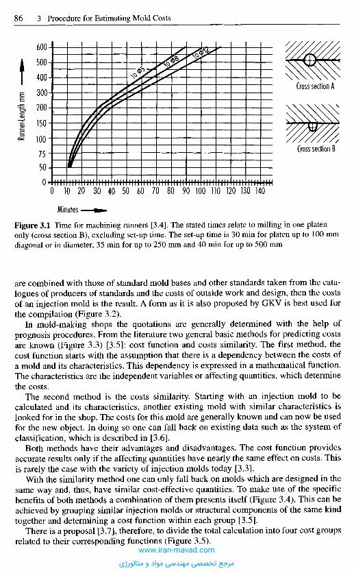
Figure 3.1 Time for machining runners [3.4]. The stated times relate to milling in one platenonly (cross section B), excluding set-up time. The set-up time is 30 min for platen up to 100 mmdiagonal or in diameter, 35 min for up to 250 mm and 40 min for up to 500 mm
are combined with those of standard mold bases and other standards taken from the cata-logues of producers of standards and the costs of outside work and design, then the costsof an injection mold is the result. A form as it is also proposed by GKV is best used forthe compilation (Figure 3.2).
In mold-making shops the quotations are generally determined with the help ofprognosis procedures. From the literature two general basic methods for predicting costsare known (Figure 3.3) [3.5]: cost function and costs similarity. The first method, thecost function starts with the assumption that there is a dependency between the costs ofa mold and its characteristics. This dependency is expressed in a mathematical function.The characteristics are the independent variables or affecting quantities, which determinethe costs.
The second method is the costs similarity. Starting with an injection mold to becalculated and its characteristics, another existing mold with similar characteristics islooked for in the shop. The costs for this mold are generally known and can now be usedfor the new object. In doing so one can fall back on existing data such as the system ofclassification, which is described in [3.6].
Both methods have their advantages and disadvantages. The cost function providesaccurate results only if the affecting quantities have nearly the same effect on costs. Thisis rarely the case with the variety of injection molds today [3.3].
With the similarity method one can only fall back on molds which are designed in thesame way and, thus, have similar cost-effective quantities. To make use of the specificbenefits of both methods a combination of them presents itself (Figure 3.4). This can beachieved by grouping similar injection molds or structural components of the same kindtogether and determining a cost function within each group [3.5].
There is a proposal [3.7], therefore, to divide the total calculation into four cost groupsrelated to their corresponding functions (Figure 3.5).
Minutes
Runn
er-Le
ngth
mm
Cross section A
Cross section B
www.iran-mavad.com
مرجع تخصصی مهندسی مواد و متالورژی

Figure 3.2 Blank form for computing mold costs as suggested by IKV (Institute for PlasticsProcessing) [3.4]
EDM
Grind
ingTu
rning,
copyin
g,eng
raving
Milling
Drillin
gSm
oothin
g, pla
ning,
polish
ing,
fitting
, blas
ting,
genera
lben
ch wo
rk
Machi
ne gro
upPa
ttern
Templa
teAu
xiliary
equi
pment
_Hob Electr
odes
Inserts
, stat
ionary
side
Mold
insert
s a b c
Cavi
tyIn
serts
, m
ovab
le sid
e a b_ c_
Cavi
ty
Slid
esIn
terlo
cks
Ejec
tors
Latc
hes
Cooli
ng,
heat
ingIn
stal
ling
hydr
aulic
sIn
stal
ling
elec
trics
Safe
ty me
chan
ismSt
anda
rd r
unne
r sy
stem
s
Asse
mbly
Tota
l wo
rkin
g ho
urs
• =
inje
ctio
n mo
ld **
= c
ompr
essio
n m
old
••*
= in
ject
ion-
com
pres
sion
mold
Offe
r No
.of Na
me
Custo
mer
Cust
omer
_No. Draw
ing N
oInd
exIn
quiry
No.
_of Mo
ld No
.
Orde
r No
.
Date kg
, ea
chkg
, ea
chkg
, ea
ch
Edge
gat
e
Cav.
Mach
ine t
ype
Tunn
elPi
npoin
tmo
nths
inj.co
m. m
d.
week
s
autom
atic
Spru
e
Mold
class
: se
mia
utom
atic
Mold
cost
s (E
stim
ated
/Fin
al)
Prod
uct
Comm
ents
Mat
erial
com.
md.
inj. m
d.:
Deliv
ery
time:
Gatin
g:
Hot
runn
erot
hers
Mold
base
des
igna
tion
Mat
eria
la_ b_ c_
Acce
ssor
ies
Q_ b_ c_ e_
Outsi
de l
abor
(Har
denin
g, Et
eciro
lyt.
proc
, Su
rface
tre
atm
.) a
b_ chr
s. ea
ch
hrs. ea
chhr
s. e
ach
hrs. ea
chhr
s. ea
chhr
s. ea
chhr
s. ea
chhr
s.
1 to
tal
2 to
tal
3 to
tal
4 to
tal
5 to
tal
Mold
makin
gSu
btot
alMa
chine
gr
oup
Mach
ine
grou
pMa
chine
gro
upMa
chine
gro
upMa
chine
gro
upAd
ditio
nal
set-u
p tim
eTo
tal
hour
sSu
mTo
tal
Retu
rn%
Addi
tiona
l cha
rges
: Ov
erhe
ad
%Ch
arge
for
ris
ksCo
sts o
f sa
mplin
gTo
tal c
osts
Net
sales
pric
e
www.iran-mavad.com
مرجع تخصصی مهندسی مواد و متالورژی
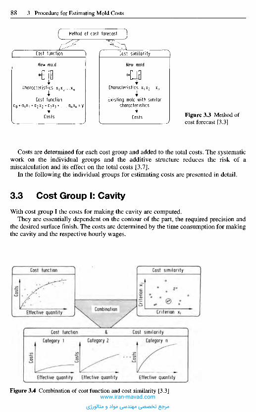
Costs
Crite
rion
Xj
Costs
Costs
Costs
Cost function Cost similarity
CombinationEffective quantity Criterion x.
Cost function Cost similarityCategory 1 Category 2 Category n
Effective quantity Effective quantity Effective quantity
Figure 3.4 Combination of cost function and cost similarity [3.3]
Costs are determined for each cost group and added to the total costs. The systematicwork on the individual groups and the additive structure reduces the risk of amiscalculation and its effect on the total costs [3.7].
In the following the individual groups for estimating costs are presented in detail.
3 . 3 C o s t G r o u p I: C a v i t y
With cost group I the costs for making the cavity are computed.They are essentially dependent on the contour of the part, the required precision and
the desired surface finish. The costs are determined by the time consumption for makingthe cavity and the respective hourly wages.
Figure 3.3 Method ofcost forecast [3.3]
Method of cost forecast
Cost function Cost similarity
New mold
Characteristics X1X2^xn
Existing mold with similarcharacteristics
Costs
New mold
Characteristics X1X2^xn
Cost function
Costs
www.iran-mavad.com
مرجع تخصصی مهندسی مواد و متالورژی
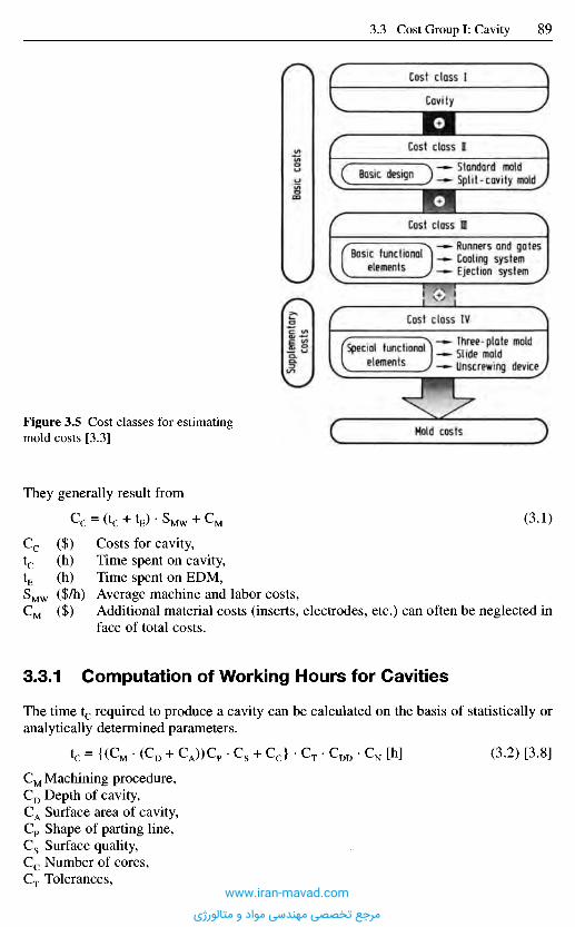
They generally result from
(3.1)
Costs for cavity,Time spent on cavity,Time spent on EDM,Average machine and labor costs,Additional material costs (inserts, electrodes, etc.) can often be neglected inface of total costs.
3.3.1 Computat ion of Working Hours for Cavities
The time tc required to produce a cavity can be calculated on the basis of statistically oranalytically determined parameters.
(3.2) [3.8]
Machining procedure,Depth of cavity,Surface area of cavity,Shape of parting line,Surface quality,Number of cores,Tolerances,
Figure 3.5 Cost classes for estimatingmold costs [3.3]
Supp
leme
ntar
yco
sts
Basi
c co
sts
Cost class I
Cavity
Cost class n
Basic designStandard moldSplit-cavity mold
Cost class I
Basic functiontelements
Runners and gatesCooling systemEjection system
Cost class IV
Special functionalelements
Three-plate moldSlide moldUnscrewing device
Mold costs
www.iran-mavad.com
مرجع تخصصی مهندسی مواد و متالورژی

CDD Degree of difficulty,C N Number of cavities.CD, CA, Cc are real working hours, the remainders are time factors.
The following correlations are used to determine the individual times or time factors.
3.3.2 T ime Factor for Machining Procedure
The shares of individual kinds of machining for making the male and the female half ofa cavity are identified as a percentage and multiplied by the machining factor fM(Table 3.1). This factor has been found in practice and is a quantity for the speeddifferences of various techniques in machining the contours of cavities.
(3.3)
(3.4)
CM Time factor machining procedure,fMi Machining factor (Table 3.1),a{ Percentage of the respective machining procedure,nM Number of machining procedures.
Table 3.1 Machining factor fMi
Milling EDM Duplicate milling Turning Grinding Manual labor
0.85 1.35 1.0 to 1.35 0.4 0.8 to 1.2 0.8
3.3.3 Machine T ime for Cavity Depth
If one looks at a molding above and below a suitably selected parting line, one has todistinguish between elevations (E) and depressions (D).
The time consumption resulting from the depth of the cavity is determined by themean of elevations and depressions above (1) and below (2) the parting line. In doing soit seems practical to establish the elevations as their projected area on the plane throughthe parting line. If the core is not machined from the solid material but made as an insert,the result for one cavity half is
Elevation with depression;core machinedfrom solid
Herein is
www.iran-mavad.com
مرجع تخصصی مهندسی مواد و متالورژی
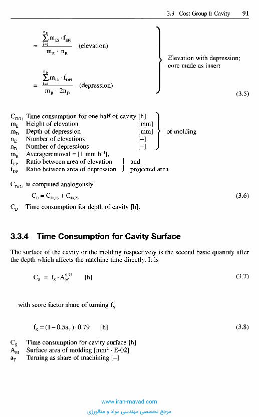
Elevation with depression;core made as insert
(3.5)
CD(1) Time consumption for one half of cavity [h]m E Height of elevation [mm]m D Depth of depression [mm] > of moldingnE Number of elevations [-]nD Number of depressions [-] ^mR Averageremoval = [1 m m I r 1 ] ,fEP Ratio between area of elevation 1 andfDP Ratio between area of depression J projected area
CD(2) is computed analogously
(3.6)
C D Time consumption for depth of cavity [h].
3.3.4 T ime Consumption for Cavity Surface
The surface of the cavity or the molding respectively is the second basic quantity afterthe depth which affects the machine time directly. It is
(3.7)
with score factor share of turning fs
(3.8)
Cs Time consumption for cavity surface [h]AM Surface area of molding [mm2 • E-02]&j Turning as share of machining [-]
(elevation)
(depression)
www.iran-mavad.com
مرجع تخصصی مهندسی مواد و متالورژی
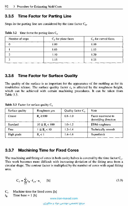
3.3.5 T ime Factor for Parting Line
Steps in the parting line are considered by the time factor Cp.
Table 3.2 Time factor for parting lines Cp
Number of steps Cp for plane faces Cp for curved faces
0 1.00 1.10
1 1.05 1.15
2 1.10 1.20
3 1.15 1.25
3 .3 .6 T i m e F a c t o r f o r S u r f a c e Q u a l i t y
The quality of the surface is as important for the appearance of the molding as for itstroublefree release. The surface quality factor cs is affected by the roughness height,which can be achieved with certain machining procedures. It can be taken fromTable 3.3.
Table 3.3 Factor for surface quality Cs
Surface quality Roughness um Quality factor Cs Note
Coarse Ra ^ 100 0.8-1.0 Faces transverse to
demolding direction
Standard 10 ^ Ra< 100 1.0-1.2 EDM roughness
Fine 1 Ra< 10 1.2-1.4 Technically smooth
High grade Ra< 1 1.4-1.6 Superfinish
3 .3 .7 M a c h i n i n g T i m e f o r F i x e d C o r e s
The machining and fitting of cores in both cavity halves is covered by the time factor Cc.This work becomes more difficult with increasing deviation of the fitting area from acircular shape. The contour factor is multiplied by the number of cores with equal fittingarea.
Cc Machine time for fixed cores [h]tB Time base = 1 [h]
(3.9)
www.iran-mavad.com
مرجع تخصصی مهندسی مواد و متالورژی
Figure 3.6 Time valuation for tolerancePercentage of medium fine tolerances requirements [3.7]
Close tolerances as well as critical tolerances for bearings (centricity, accuracy ofangle, parallelism, flatness, freedom from displacement) considerably increase the timeneeded for producing the cavity.
3.3.9 T ime Factor for Degree of Difficultyand Multifariousness
A departure from an average degree of difficulty (CDD = 1) is considered the specialeffort for an extreme length/diameter ratio of cores, their large number in a small areaand complex surfaces. For large plane parts without openings the time factor is reduced(CDD < 1). Table 3.5 shows relevant criteria with their corresponding factor.
Score
facto
r CT
fCF Contour factor (Table 3.4) [-]n Number of cores with equal fitting area [-]j Number of different fitting areas [-]
Table 3.4 Contour factor for cores fCF
Contour factor fCF Fitting area
1 Circular o
2 Angular D
4 Circular, large O
8 Angular, large D
10 Curved contour g
3 .3 .8 T i m e F a c t o r f o r T o l e r a n c e s
Close tolerances raise costs. To produce moldings economically no closer tolerancesshould be considered than necessary for the technical function.
A standard for making precision molds implies that mold tolerances should not exceedabout 10% of those of the finished molding. The factor for dimensional tolerances CT
comprises the expected expenditure for required accuracy and posttreatment(Figure 3.6).
www.iran-mavad.com
مرجع تخصصی مهندسی مواد و متالورژی
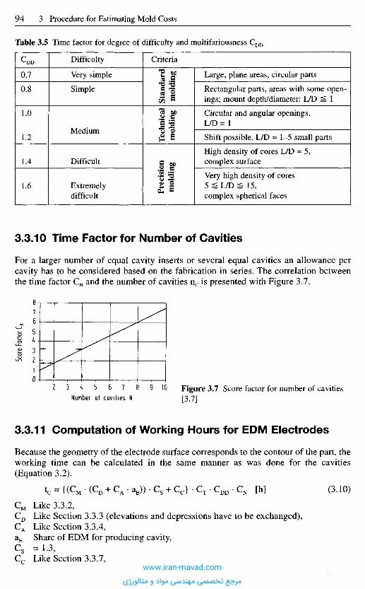
3.3.11 Computat ion of Working Hours for E D M Electrodes
Because the geometry of the electrode surface corresponds to the contour of the part, theworking time can be calculated in the same manner as was done for the cavities(Equation 3.2).
(3.10)
CM Like 3.3.2,CD Like Section 3.3.3 (elevations and depressions have to be exchanged),CA Like Section 3.3.4,aE Share of EDM for producing cavity,C s = 1 . 3 ,C c Like Section 3.3.7,
Table 3.5 Time factor for degree of difficulty and multifariousness CDD
C-DD
0.7
0.8
1.0
1.2
1.4
1.6
Difficulty
Very simple
Simple
Medium
Difficult
Extremelydifficult
Criteria
Stan
dard
mol
ding
Tec
hnic
alm
oldi
ngP
reci
sion
mol
ding
Large, plane areas, circular parts
Rectangular parts, areas with some open-ings; mount depth/diameter: L/D 1
Circular and angular openings,LZD=I
Shift possible, L/D « 1 - 5 small parts
High density of cores L/D « 5,complex surface
Very high density of cores5 ^ L/D ^ 15,complex spherical faces
3 .3 -10 T i m e F a c t o r f o r N u m b e r o f C a v i t i e s
For a larger number of equal cavity inserts or several equal cavities an allowance percavity has to be considered based on the fabrication in series. The correlation betweenthe time factor CN and the number of cavities nc is presented with Figure 3.7.
Figure 3.7 Score factor for number of cavities[3.7]
Score
Fac
tor C
N
Number of cavities N
www.iran-mavad.com
مرجع تخصصی مهندسی مواد و متالورژی

CT Like Section 3.3.8,CDD Like Section 3.3.9,C N Like Section 3.3.10.
3 . 4 C o s t G r o u p I I : B a s i c M o l d s
The basic mold retains the cavities, the basic functional components (runner, heat-exchange and ejector system) and any necessary special functional elements (three-platemold, slides, unscrewing unit). As far as self-made basic molds are concerned, it ispractical to distinguish different quality grades.
A basic mold of grade I is for a small number of moldings with little precision, for testseries etc. It is not hardened.
A basic mold grade II has case-hardened plates, additional alignment, heat insulationon the stationary half and, if of round design, is equipped with three leader pins. It isassumed to produce technical parts and medium-sized quantities.
A basic mold grade III is largely hardened and made with large quantities, highprecision and reliability in mind [3.7].
However, injection molds are largely built with mold standards. Thus the total costsof the basic mold are primarily the costs for the readily usable standards, expenses forspecific machining operations not included (Figure 3.8). It is suggested, though, toconsult the catalogs of suppliers for up-to-date prices and the availability of mold basesof a different design like such with floating plates, etc.
Standard basic molds are all of the highest quality and differ only in the steel gradebeing employed, which affects the service life of the mold, its polishability or itscorrosion resistance. The costs presented in Figure 3.9 are based on the use of AISI4130type steel. The bases are supplied preheat-treated and precision ground.
Figure 3.8 Total basic costs [3.3]
Mold standards
Treatment of standards
Drilling
Heat treatment
Coordinate-table grinding
Assembly
Basic costs
www.iran-mavad.com
مرجع تخصصی مهندسی مواد و متالورژی
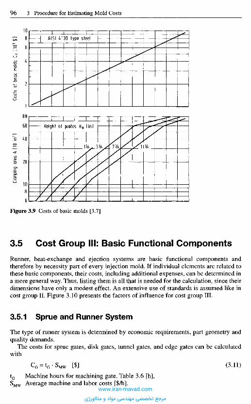
Figure 3.9 Costs of basic molds [3.7]
3 . 5 C o s t G r o u p I I I : B a s i c F u n c t i o n a l C o m p o n e n t s
Runner, heat-exchange and ejection systems are basic functional components andtherefore by necessity part of every injection mold. If individual elements are related tothese basic components, their costs, including additional expenses, can be determined ina more general way. Thus, listing them is all that is needed for the calculation, since theirdimensions have only a modest effect. An extensive use of standards is assumed like incost group II. Figure 3.10 presents the factors of influence for cost group III.
3.5.1 Sprue and Runner System
The type of runner system is determined by economic requirements, part geometry andquality demands.
The costs for sprue gates, disk gates, tunnel gates, and edge gates can be calculatedwith
CG = tG -SM W [$] (3.11)
tG Machine hours for machining gate, Table 3.6 [h],SMW Average machine and labor costs [$/h].
Clamp
ing a
rea A
[10
in2]Co
sts o
f bas
ic mo
lds C
B MO
3 $]
AISI 4130 type steel
Height of plates HM (in)
www.iran-mavad.com
مرجع تخصصی مهندسی مواد و متالورژی
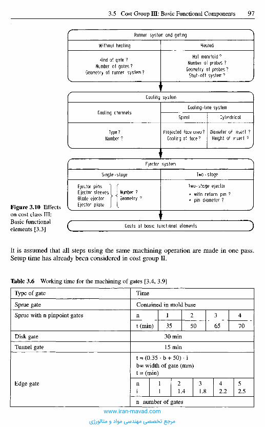
Runner system and gating
Without heating Heated
Kind of gate ?Number of gates?
Geometry of runner system ?
Hot manifold ?Number of probes ?
Geometry of probes7
Shut-off system?
Cooling system
Cooling channelsCooling-line system
Spiral Cylindrical
Type?Number ?
Projected face area?Cooling of face?
Diameter of insert ?Height of insert ?
Ejector system
Single-stage Two-stage
Ejector pinsEjector sleevesBlade ejectorEjector plate
Number ?Geometry ?
Two-stage ejectorwith return pin ?pin diameter ?
Costs of basic functional elements
Figure 3.10 Effectson cost class III:Basic functionalelements [3.3]
It is assumed that all steps using the same machining operation are made in one pass.Setup time has already been considered in cost group II.
Table 3.6 Working time for the machining of gates [3.4, 3.9]
Type of gate
Sprue gate
Sprue with n pinpoint gates
Disk gate
Tunnel gate
Edge gate
Time
Contained in mold base
n
t (min)
1
35
2
50
3
65
4
70
30min
15 min
t = (0.35 • b + 50) • ib= width of gate (mm)t = (min)
ni
11
21.4
31.8
42.2
52.5
n number of gates
www.iran-mavad.com
مرجع تخصصی مهندسی مواد و متالورژی
3.5.2 Runner System
Cost for runners are largely determined by their necessary length [3.4]:
CR = gR- lR-SM W[$] (3.12)
CR Costs of runners [$],SMW Average machine and labor costs [$/h],1R Length of runner [mm],gR Correction factor for diameter of runner,
0.14 min/mm for dR = 5 mm0.16 min/mm for dR =8 mm0.18 min/mm for dR = 12 mm,
dR Diameter of runner [mm].
If runners are machined into both mold plates, the costs can be doubled. The setup timecan also be neglected (Section 3.5.1).
3.5.3 Hot-Runner Systems
The total costs of a hot-runner manifold can be determined with Equation (3.13):
CHR = {(CBHR + gA • A) + nN • ( C N + 225 $ + CNS)} • gG [$] (3.13)
CHR Total costs of hot runner and assembly [$],CBHR basic costs for hot runner [$],gA Area coefficient [8 • E-03 $/mm2],A Clamping area,nN Number of nozzles [-],C N Cost of one nozzle [$],CNS Cost of a shut-off nozzle [$],gG 1.1 to 1.2 for molding glass-reinforced plastics,
1.0 for molding unreinforced plastics.
Hot-runner systems are mainly made with standards today. Therefore basic hot-runnercosts and the costs for nozzles can be taken from catalogs of the producers of standards.Added to the basic costs are the costs for floating plates, the manifold (I-, X-orH-shaped), the material for assembly and sealing as well as assembly and machining.
Because of the variety of systems and their related demands, it is not possible to breakdown all the costs here in detail.
3.5.4 Heat -Exchange System
For a given number of cooling lines the costs of the system CH can be calculated with
CH = k D -n-S M W [$] (3.14)
kD Factor for degree of difficulty allows for mold size, shape of channel (Table 3.7),n Number of cooling lines (without connection).
www.iran-mavad.com
مرجع تخصصی مهندسی مواد و متالورژی
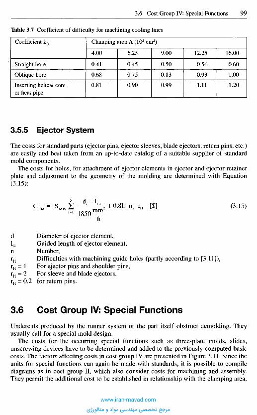
3.5.5 Ejector System
The costs for standard parts (ejector pins, ejector sleeves, blade ejectors, return pins, etc.)are easily and best taken from an up-to-date catalog of a suitable supplier of standardmold components.
The costs for holes, for attachment of ejector elements in ejector and ejector retainerplate and adjustment to the geometry of the molding are determined with Equation(3.15):
C E M = S M W t d - " ^ m 2 + Q . 8 h . n r r H [$] (3.15)
h
d Diameter of ejector element,1G Guided length of ejector element,n Number,rH Difficulties with machining guide holes (partly according to [3.11]),rH = 1 For ejector pins and shoulder pins,rH = 2 For sleeve and blade ejectors,rH = 0.2 for return pins.
3 . 6 C o s t G r o u p IV: S p e c i a l F u n c t i o n s
Undercuts produced by the runner system or the part itself obstruct demolding. Theyusually call for a special mold design.
The costs for the occurring special functions such as three-plate molds, slides,unscrewing devices have to be determined and added to the previously computed basiccosts. The factors affecting costs in cost group IV are presented in Figure 3.11. Since theunits for special functions can again be made with standards, it is possible to compilediagrams as in cost group II, which also consider costs for machining and assembly.They permit the additional cost to be established in relationship with the clamping area.
Table 3.7 Coefficient of difficulty for machining cooling lines
Coefficient kD
Straight bore
Oblique bore
Inserting helical coreor heat pipe
Clamping area A (102 cm2)
4.00
0.41
0.68
0.81
6.25
0.45
0.75
0.90
9.00
0.50
0.83
0.99
12.25
0.56
0.93
1.11
16.00
0.60
1.00
1.20
www.iran-mavad.com
مرجع تخصصی مهندسی مواد و متالورژی
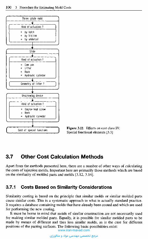
3 . 7 O t h e r C o s t C a l c u l a t i o n M e t h o d s
Apart from the methods presented here, there are a number of other ways of calculatingthe costs of injection molds. Important here are primarily those methods which are basedon the similarity of molded parts and molds [3.12, 3.14].
3.7.1 Costs Based on Similarity Considerations
Similarity costing is based on the principle that similar molds or similar molded partscause similar costs. This is a systematic approach to what is actually standard practice.It requires a database containing molds that have already been costed and which are usedfor performing the new costing.
It must be borne in mind that molds of similar construction are not necessarily usedfor making similar molded parts. Equally, it is possible for similar molded parts to bemade by means of different and thus less similar molds, as is the case for differentpositions of the parting surfaces. The following basic possibilities exist:
Figure 3.11 Effects on cost class IV:Special functional elements [3.3]Cost of special functions
Three-plate mold
Kind of actuation ?by latchby frictionby undercut
Slide
Kind of actuation ?
Cam pinLifterRackHydraulic cylinder
Geometry of lifter ?
Unscrewing device
Kind of actuation ?
Coarse lead screwRackHydraulic cylinder
www.iran-mavad.com
مرجع تخصصی مهندسی مواد و متالورژی
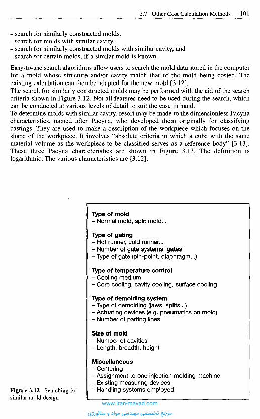
- search for similarly constructed molds,- search for molds with similar cavity,- search for similarly constructed molds with similar cavity, and- search for certain molds, if a similar mold is known.
Easy-to-use search algorithms allow users to search the mold data stored in the computerfor a mold whose structure and/or cavity match that of the mold being costed. Theexisting calculation can then be adapted for the new mold [3.12].The search for similarly constructed molds may be performed with the aid of the searchcriteria shown in Figure 3.12. Not all features need to be used during the search, whichcan be conducted at various levels of detail to suit the case in hand.To determine molds with similar cavity, resort may be made to the dimensionless Pacynacharacteristics, named after Pacyna, who developed them originally for classifyingcastings. They are used to make a description of the workpiece which focuses on theshape of the workpiece. It involves "absolute criteria in which a cube with the samematerial volume as the workpiece to be classified serves as a reference body" [3.13].These three Pacyna characteristics are shown in Figure 3.13. The definition islogarithmic. The various characteristics are [3.12]:
Type of mold- Normal mold, split mold...
Type of gating- Hot runner, cold runner...- Number of gate systems, gates- Type of gate (pin-point, diaphragm...)
Type of temperature control- Cooling medium- Core cooling, cavity cooling, surface cooling
Type of demolding system- Type of demolding (jaws, splits...)- Actuating devices (e.g. pneumatics on mold)- Number of parting lines
Size of mold- Number of cavities- Length, breadth, height
Miscellaneous- Centering- Assignment to one injection molding machine- Existing measuring devices- Handling systems employedFigure 3.12 Searching for
similar mold designwww.iran-mavad.com
مرجع تخصصی مهندسی مواد و متالورژی
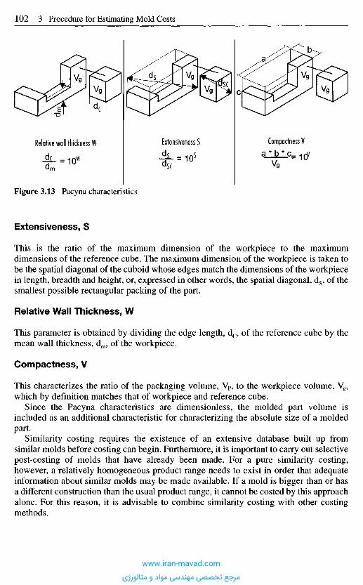
Extensiveness, S
This is the ratio of the maximum dimension of the workpiece to the maximumdimensions of the reference cube. The maximum dimension of the workpiece is taken tobe the spatial diagonal of the cuboid whose edges match the dimensions of the workpiecein length, breadth and height, or, expressed in other words, the spatial diagonal, ds, of thesmallest possible rectangular packing of the part.
Relative Wall Thickness, W
This parameter is obtained by dividing the edge length, dc, of the reference cube by themean wall thickness, dm, of the workpiece.
Compactness, V
This characterizes the ratio of the packaging volume, VP, to the workpiece volume, Vg,which by definition matches that of workpiece and reference cube.
Since the Pacyna characteristics are dimensionless, the molded part volume isincluded as an additional characteristic for characterizing the absolute size of a moldedpart.
Similarity costing requires the existence of an extensive database built up fromsimilar molds before costing can begin. Furthermore, it is important to carry out selectivepost-costing of molds that have already been made. For a pure similarity costing,however, a relatively homogeneous product range needs to exist in order that adequateinformation about similar molds may be made available. If a mold is bigger than or hasa different construction than the usual product range, it cannot be costed by this approachalone. For this reason, it is advisable to combine similarity costing with other costingmethods.
Figure 3.13 Pacyna characteristics
Relative wall thickness W
dm
Extensiveness S
| L = 10sdsc
Compactness Va * b * c_ ^ QV
Vg
www.iran-mavad.com
مرجع تخصصی مهندسی مواد و متالورژی
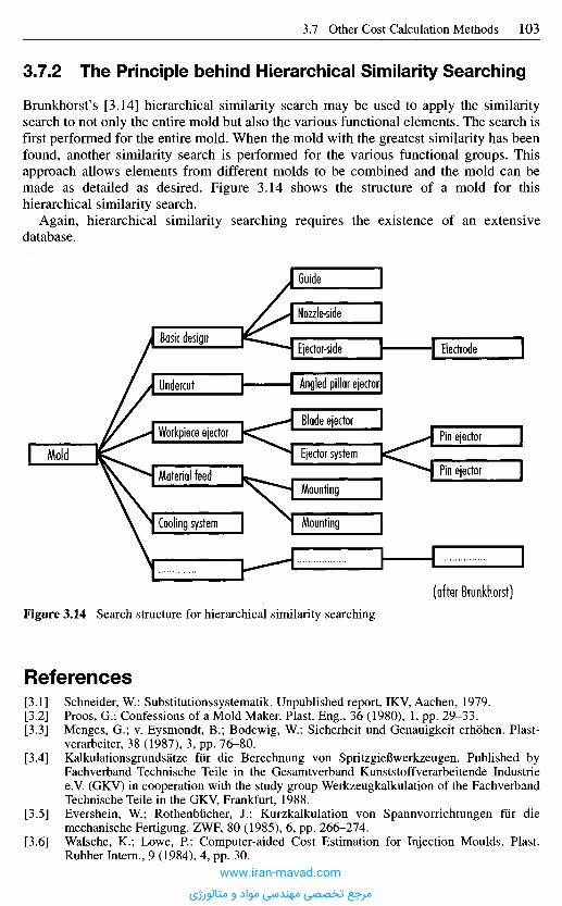
Figure 3.14 Search structure for hierarchical similarity searching
R e f e r e n c e s
[3.1] Schneider, W.: Substitutionssystematik. Unpublished report, IKV, Aachen, 1979.[3.2] Proos, G.: Confessions of a Mold Maker. Plast. Eng., 36 (1980), 1, pp. 29-33.[3.3] Menges, G.; v. Eysmondt, B.; Bodewig, W.: Sicherheit und Genauigkeit erhohen. Plast-
verarbeiter, 38 (1987), 3, pp. 76-80.[3.4] Kalkulationsgrundsatze fur die Berechnung von SpritzgieBwerkzeugen. Published by
Fachverband Technische Teile in the Gesamtverband Kunststoffverarbeitende Industriee.V. (GKV) in cooperation with the study group Werkzeugkalkulation of the FachverbandTechnische Teile in the GKV, Frankfurt, 1988.
[3.5] Evershein, W.; Rothenbucher, J.: Kurzkalkulation von Spannvorrichtungen fiir diemechanische Fertigung. ZWF, 80 (1985), 6, pp. 266-274.
[3.6] Walsche, K.; Lowe, P.: Computer-aided Cost Estimation for Injection Moulds. Plast.Rubber Intern., 9 (1984), 4, pp. 30.
(after Brunkhorst)
Mold
Workpiece ejector
Material feed
Cooling system Mounting
Mounting
Ejector system
Blade ejectorPin ejector
Pin ejector
Basic design
Undercut
Guide
Nozzle-side
Ejector-side
Angled pillar ejector
Electrode
3 .7 .2 T h e P r i n c i p l e b e h i n d H i e r a r c h i c a l S i m i l a r i t y S e a r c h i n g
Brunkhorst's [3.14] hierarchical similarity search may be used to apply the similaritysearch to not only the entire mold but also the various functional elements. The search isfirst performed for the entire mold. When the mold with the greatest similarity has beenfound, another similarity search is performed for the various functional groups. Thisapproach allows elements from different molds to be combined and the mold can bemade as detailed as desired. Figure 3.14 shows the structure of a mold for thishierarchical similarity search.
Again, hierarchical similarity searching requires the existence of an extensivedatabase.
www.iran-mavad.com
مرجع تخصصی مهندسی مواد و متالورژی

[3.7] Schluter, H.: Verfahren zur Abschatzung der Werkzeugkosten bei der Konstruktion vonSpritzguBteilen. Dissertation, Tech. University, Aachen, 1982.
[3.8] Formberechnungsbogen, Anlage 1 zu Kalkulations-Grundsatze fur die Berechnung vonSpritzgieBwerkzeugen. Fachverband Technische Teile im Gesamtverband Kunststoff-verarbeitende Industrie e.V. (GKV) in cooperation with the study group Werkzeugkalku-lation of the Fachverband Technische Teile in the KGV, Frankfurt/M., February 1980.
[3.9] Informations from misc. mold makers.[3.10] Catalogs and informations from misc. producers of standards.[3.11] Ufrecht, M.: Die Werkzeugbelastung beim Uberspritzen. Unpublished report, IKV,
Aachen, 1978.[3.12] Grundmann, M.: Entwicklung eines Kalkulationsinstrumentariums fur SpritzgieBbetriebe
auf der Basis von Ahnlichkeitsbetrachtungen, Dissertation, RWTH, Aachen, 1993.[3.13] Pacyna, H.: Die Klassifikation von GuBstucken, GieBerei-Verlag GmbH, Diisseldorf,
1969.[3.14] Brunkhorst, U.: Angebots- und Auftragsplanung im Werkzeug- und Formenbau, Arbeits-
kreis Technische Informationssysteme im Werkzeug und Formenbau, IPH, Hannover,September 21, 1995.
www.iran-mavad.com
مرجع تخصصی مهندسی مواد و متالورژی

The injection molding process is one of the key production methods for processingplastics. It is used to produce molded parts of almost any complexity that are to be madein medium to large numbers in the same design. There are major restrictions on wallthickness, which generally should not exceed a few millimeters, and on shape - it mustbe possible to demold the part. This will be discussed later.
The advantages of this process are:
- direct route from raw material to finished part,- very little finishing, or none at all, of molded parts,- full automatability,- high reproducibility,- low piece costs for large volumes.
4 . 1 C y c l e S e q u e n c e in I n j e c t i o n M o l d i n g
The molded parts are produced discontinuously in cycles. The sequence of one cycle isshown schematically in Figure 4.1.
The raw material, usually in the form of pellets, is fed into the plasticating unit whereit will be melted. The plasticating unit is generally a single-screw extruder in which thescrew reciprocates coaxially against a hydraulically actuated cylinder. The continuallyrotating screw plasticates the pellets to form a melt that is transported forward by therotation. Because the injection nozzle is still closed during plastication, the melt ispushed to the front of the screw. As a result, the screw is pushed to the right against theresistance of the barrel, which is called the back pressure.
At the start of the cycle, the mold is closed by actuating the press, which on aninjection molding machine is called the clamping unit. Before the melt, which isgenerated in and supplied by the plasticating unit (in a precise, metered quantity), isinjected into the closed mold, the plasticating unit traverses against the mold, causing theinjection nozzle of the plasticating unit to press against the sprue bushing of the mold.The pressure with which the nozzle is pressed against the sprue bushing must be adjustedin such a way that the joint remains sealed when the melt is injected afterwards. At thesame time, the nozzle is opened and the melt can be pushed from the front of the barrelinto the cavity of the mold.
As the cavity is filled, pressure builds up inside. This is counteracted by pressing theclamping unit against the mold under as much clamping force as possible to prevent meltfrom escaping out of the cavity through the mold parting lines.
The connection between the mold and plasticating unit is maintained until the fillingprocess is complete. Generally, however, filling of the cavity does not mean the end ofthe process because the melt changes its volume on solidifying (freezing). In order that
4 T h e I n j e c t i o n M o l d i n g P r o c e s s
www.iran-mavad.com
مرجع تخصصی مهندسی مواد و متالورژی
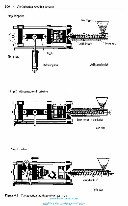
Stage 1: InjectionFeed hopper
Tie bar nutsToggle
Hydraulic piston
Mold clamped Heater band
Mold partially filled
Stage 2: Holding pressure and plastication
Screw rotates for plastication
Mold filled
Stage 3: Ejection
Nozzle breaks off
Mold open
Figure 4.1 The injection molding cycle [4.1-4.3]www.iran-mavad.com
مرجع تخصصی مهندسی مواد و متالورژی
either more melt may be forced in to make up the difference in volume or to preventthe melt from running out of the mold, the connection must be maintained until themelt has frozen in the gate. The connection is broken by screwing back the plasticatingunit, and closing the injection nozzle. Detaching of the nozzle causes thermal isolationbetween mold and plasticating unit because these are at totally different temperatures.
Since the plasticating process requires a certain amount of time, as soon as the nozzleis detached and closed, the plasticating unit usually starts rotating, drawing in -metering - more material, melting it and moving it to the front.
When the molding (molded part) has solidified to the extent that it can retain its shapewithout external support, the clamping unit opens the mold and the molding is pushedout of the cavity by ejectors.
The cycle then repeats. Figure 4.1 shows the order in which the processes occur. Thebasic cycle described here may vary for other materials and processes.
4.1.1 Injection Molding of Thermoplast ics
When thermoplastics are heated, they experience a change of state; they turn soft andmelt, becoming flowable. When cooled down, they solidify again. This is the reason thatplasticating units are operated hot and molds are operated cold when working withthermoplastics. Generally, the temperature difference is more than 100 0C. Thethermoplastic materials developed for injection molding generally constitute relativelylow-viscosity melts with the result that injection times are short and low clamping forcesare needed.
The injection mold should remove the heat from the material fast and steadily.Therefore, the cooling system has to be carefully designed. The coolant - usually water,provided the mold temperature is below 100 0C - flows through channels around thecavity. For reasons of economics, such as the quality of the molded parts, which dependsheavily on uniform heat flow in the mold, the cooling circuit is monitored very preciselyand cooling equipment is used to ensure that the coolant is always at the sametemperature.
Molded parts requiring no machining can only be produced if all joints and moldparting lines are so well sealed that melt is unable to penetrate and harden there.Otherwise, flash would be formed and machining become necessary. To this end, all jointgaps must remain smaller than 0.03 mm even during full injection pressure, until themelt has solidified. These requirements are particularly demanding where large moldedparts and large injection molding machines are involved as the molds must be extremelyrigid and the clamping units must function very precisely; the rigidity of the clamp platesis particularly critical.
4.1.2 Injection Molding of Crosslinkable Plastics
These plastics only attain their final molecular structure by crosslinking under heat. Forthis reason, they must be kept at as low a warm temperature as possible in the plasti-cating unit, i.e. the viscosity must be just low enough that the cavity is filled. Thisprevents premature crosslinking from interfering with complete formation of the moldedpart. The plasticating unit is therefore usually kept below 100 0C and frictional heat isminimized through the use of compressionless screws.
www.iran-mavad.com
مرجع تخصصی مهندسی مواد و متالورژی
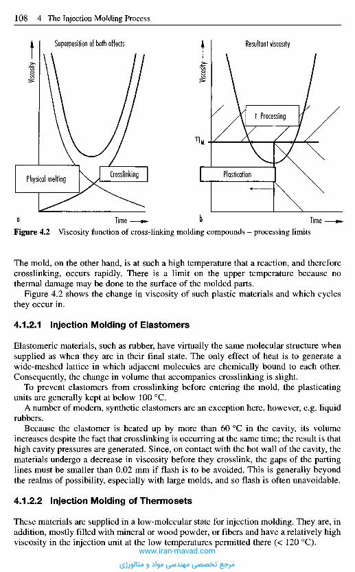
Figure 4.2 Viscosity function of cross-linking molding compounds - processing limits
The mold, on the other hand, is at such a high temperature that a reaction, and thereforecrosslinking, occurs rapidly. There is a limit on the upper temperature because nothermal damage may be done to the surface of the molded parts.
Figure 4.2 shows the change in viscosity of such plastic materials and which cyclesthey occur in.
4.1.2.1 Injection Molding of Elastomers
Elastomeric materials, such as rubber, have virtually the same molecular structure whensupplied as when they are in their final state. The only effect of heat is to generate awide-meshed lattice in which adjacent molecules are chemically bound to each other.Consequently, the change in volume that accompanies crosslinking is slight.
To prevent elastomers from crosslinking before entering the mold, the plasticatingunits are generally kept at below 100 0C.
A number of modern, synthetic elastomers are an exception here, however, e.g. liquidrubbers.
Because the elastomer is heated up by more than 60 0C in the cavity, its volumeincreases despite the fact that crosslinking is occurring at the same time; the result is thathigh cavity pressures are generated. Since, on contact with the hot wall of the cavity, thematerials undergo a decrease in viscosity before they crosslink, the gaps of the partinglines must be smaller than 0.02 mm if flash is to be avoided. This is generally beyondthe realms of possibility, especially with large molds, and so flash is often unavoidable.
4.1.2.2 Injection Molding of Thermosets
These materials are supplied in a low-molecular state for injection molding. They are, inaddition, mostly filled with mineral or wood powder, or fibers and have a relatively highviscosity in the injection unit at the low temperatures permitted there (< 120 0C).
Visco
sity
Visco
sity
Superposition of both effects Resultant viscosity
t Processing
Physical melting Crosslinking Plastication
Q Time b Time
www.iran-mavad.com
مرجع تخصصی مهندسی مواد و متالورژی
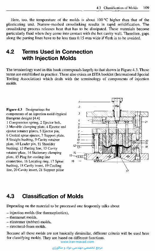
Here, too, the temperature of the molds is about 100 0C higher than that of theplasticating unit. Narrow-meshed crosslinking results in rapid solidification. Thecrosslinking process releases heat that has to be dissipated. These materials becomeparticularly fluid when they come into contact with the hot cavity wall. Therefore, gapsalong the parting lines have to be less than 0.15 mm wide if flash is to be avoided.
4 . 2 T e r m s U s e d in C o n n e c t i o n
w i t h I n j e c t i o n M o l d s
The terminology used in this book corresponds largely to that shown in Figure 4.3. Theseterms are established in practice. There also exists an ISTA booklet (International SpecialTooling Association) which deals with the terminology of components of injectionmolds.
Figure 4.3 Designations forcomponents of an injection mold (typicalEuropean design) [4.4]1 Compression spring, 2 Ejector bolt,3 Movable clamping plate, 4 Ejector andejector retainer plates, 5 Ejector pin,6 Central sprue ejector, 7 Support plate,8 Straight bushing, 9 Cavity retainerplate, 10 Leader pin, 11 Shoulderbushing, 12 Parting line, 13 Cavityretainer plate, 14 Stationary clampingplate, 15 Plug for cooling lineconnection, 16 Locating ring, 17 Spruebushing, 18 Cavity insert, 19 Coolingline, 20 Cavity insert, 21 Support pillar
4 . 3 C l a s s i f i c a t i o n o f M o l d s
Depending on the material to be processed one frequently talks about
- injection molds (for thermoplastics),- thermoset molds,- elastomer (rubber) molds,- structural-foam molds.
Because all these molds are not basically dissimilar, different criteria will be used herefor classifying molds. They are based on different functions.
www.iran-mavad.com
مرجع تخصصی مهندسی مواد و متالورژی
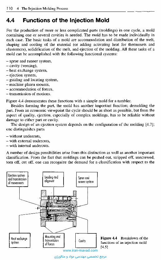
4 . 4 F u n c t i o n s o f t h e I n j e c t i o n M o l d
For the production of more or less complicated parts (moldings) in one cycle, a moldcontaining one or several cavities is needed. The mold has to be made individually ineach case. The basic tasks of a mold are accommodation and distribution of the melt,shaping and cooling of the material (or adding activating heat for thermosets andelastomers), solidification of the melt, and ejection of the molding. All these tasks of amold can be accomplished with the following functional systems:
- sprue and runner system,- cavity (venting),- heat exchange system,- ejection system,- guiding and locating system,- machine platen mounts,- accommodation of forces,- transmission of motions.
Figure 4.4 demonstrates these functions with a simple mold for a tumbler.Besides forming the part, the mold has another important function; demolding the
part. From an economic viewpoint the cycle should be as short as possible, but from theaspect of quality, ejection, especially of complex moldings, has to be reliable withoutdamage to either part or cavity.
The design of an ejection system depends on the configuration of the molding [4.7];one distinguishes parts
- without undercuts,- with external undercuts,- with internal undercuts.
A number of design possibilities arise from this distinction as well as another importantclassification. From the fact that moldings can be pushed out, stripped off, unscrewed,torn off, cut off, one can recognize the demand for a classification with respect to the
Figure 4.4 Breakdown of thefunctions of an injection mold[4.5]
Ejection systemand transmissionof movements
Leading andaligment
Sprue andrunner system
Heat exchangesystem
Mounting andtransmissionof forces
Cavity
www.iran-mavad.com
مرجع تخصصی مهندسی مواد و متالورژی
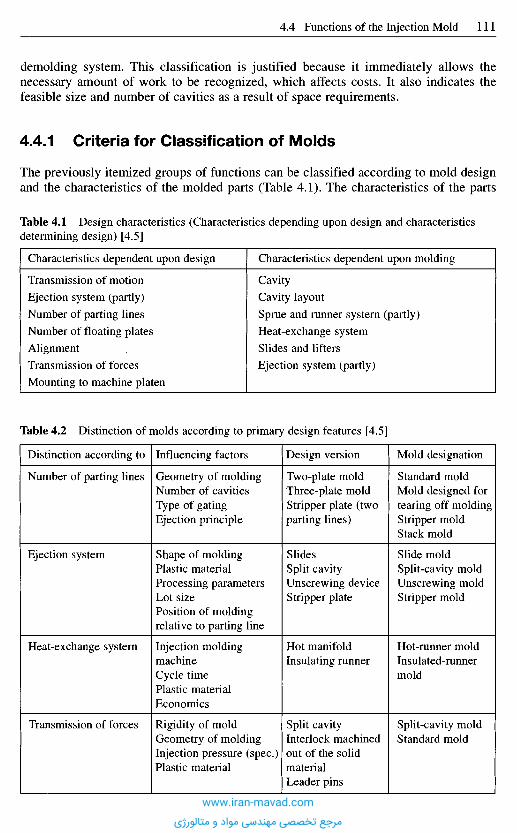
demolding system. This classification is justified because it immediately allows thenecessary amount of work to be recognized, which affects costs. It also indicates thefeasible size and number of cavities as a result of space requirements.
4 .4 .1 C r i t e r i a f o r C l a s s i f i c a t i o n of M o l d s
The previously itemized groups of functions can be classified according to mold designand the characteristics of the molded parts (Table 4.1). The characteristics of the parts
Table 4.1 Design characteristics (Characteristics depending upon design and characteristicsdetermining design) [4.5]
Characteristics dependent upon design Characteristics dependent upon molding
Transmission of motion Cavity
Ejection system (partly) Cavity layout
Number of parting lines Sprue and runner system (partly)
Number of floating plates Heat-exchange system
Alignment . Slides and lifters
Transmission of forces Ejection system (partly)
Mounting to machine platen
Table 4.2 Distinction of molds according to primary design features [4.5]
Distinction according to
Number of parting lines
Ejection system
Heat-exchange system
Transmission of forces
Influencing factors
Geometry of moldingNumber of cavitiesType of gatingEjection principle
Shape of moldingPlastic materialProcessing parametersLot sizePosition of moldingrelative to parting line
Injection moldingmachineCycle timePlastic materialEconomics
Rigidity of moldGeometry of moldingInjection pressure (spec.)Plastic material
Design version
Two-plate moldThree-plate moldStripper plate (twoparting lines)
SlidesSplit cavityUnscrewing deviceStripper plate
Hot manifoldInsulating runner
Split cavityInterlock machinedout of the solidmaterialLeader pins
Mold designation
Standard moldMold designed fortearing off moldingStripper moldStack mold
Slide moldSplit-cavity moldUnscrewing moldStripper mold
Hot-runner moldInsulated-runnermold
Split-cavity moldStandard mold
www.iran-mavad.com
مرجع تخصصی مهندسی مواد و متالورژی
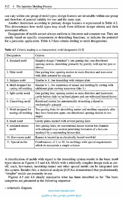
can vary within one group of mold types; design features are invariable within one groupand therefore of general validity for one and the same type.
Another distinction according to primary design features is represented in Table 4.2.This demonstrates how mold types may result from different design criteria and theirassociated effects.
Designations of molds are not always uniform in literature and common use. They aremostly based on specific components or demolding functions, or indicate the potentialfor a particular application. Table 4.3 lists criteria leading to mold designations.
Table 4.3 Criteria leading to a characteristic mold designation [4.5]
A classification of molds with regard to the demolding system results in the basic moldtypes shown in Figures 4.5 and 4.6. Molds with a relatively complex design such as cut-off, stack, hot-runner, insulating-runner and other special molds can be integrated intothis system. Besides this, a statistical analysis [4.8] has demonstrated that predominantly"simpler" molds are presently in use.
Figures 4.5 and 4.6 clearly summarize what has been described so far. The basiccategories are presented in the following sequence:
- schematic diagram,
Designation
1. Standard mold
2. Slide mold
3. Stripper mold
4. Mold designed forcutting off molding
5. Split-cavity mold
6. Unscrewing mold
7. Mold designed fortearing off molding
8. Stack mold
9. Insulated-runnermold
10. Hot-runner mold
11. Special molds
Criteria
Simplest design ("standard"): one parting line; one-directionalopening motion, demolding primarily by gravity, with ejector pins orsleeves
One parting line; opening motion in main direction and transversewith slide actuated by cam pin
Similar to 1., but demolding with stripper plate
Similar to 1., but separation of runner and molding by cutting withadditional plate moving transverse (like 3.)
One parting line; opening motion in main direction and transverse;cavity halves slide on inclined planes and can withstand lateral forces
Rotational motion for automatically demolding a thread ismechanically actuated
Two parting lines for demolding runner and molding separately afterthey have been torn apart; one-directional opening motion in twostages
Cavity plates stacked with several parting lines
Two parting lines; no conventional runner system but channelswith enlarged cross section permitting formation of a hot coreinsulated by a surrounding frozen skin
Runner is located in an electrically heated manifold
Combinations of 2. to 10. for moldings with special requirementswhich do not permit a simple solution
www.iran-mavad.com
مرجع تخصصی مهندسی مواد و متالورژی
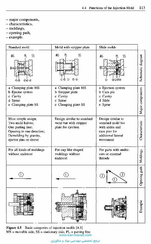
major components,characteristics,moldings,opening path,example.
Standard mold Mold with stripper plate Slide molds
Sche
mat
ic d
iagr
amM
ajor
com
pone
nts
Cha
ract
eris
ticM
oldi
ngs
Ope
ning
pat
hE
xam
ple
a Clamping plate MSb Ejector systemc Cavityd Spruee Clamping plate SS
Most simple sesign;Two mold halves;One parting line;Opening in one direction;Demolding by gravity,ejector pins or sleeve
For all kinds of moldingswithout undercut
a Clamping plate MSb Stripper platec Cavityc Spruee Clamping plate SS
Design similar to standardmold but with stripperplate for ejection
For cup like shapedmoldings withoutundercut
a Ejection systemb Cam pinc Cavityd Slidee Sprue
Design similar tostandard mold butwith slides andcam pins foradditional lateralmovement
For parts with under-cuts or externalthreads
Figure 4.5 Basic categories of injection molds [4.5]MS = movable side, SS = stationary side, PL = parting line
www.iran-mavad.com
مرجع تخصصی مهندسی مواد و متالورژی
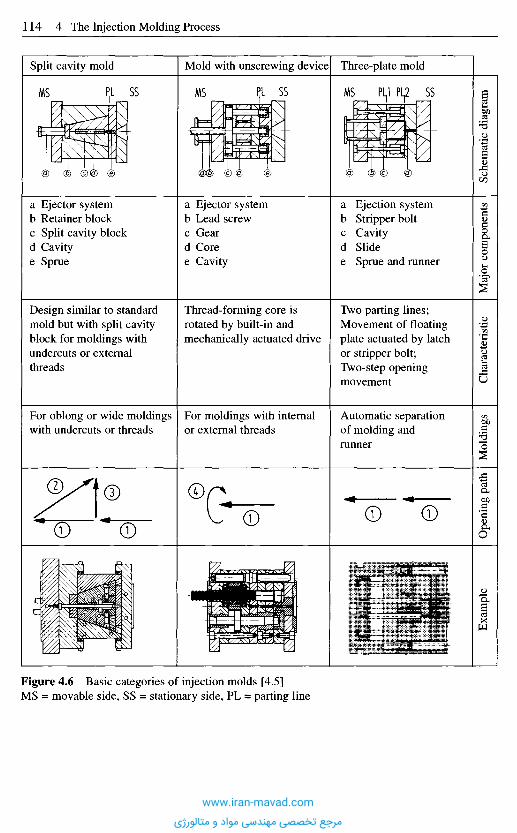
Sche
mat
ic d
iagr
amM
ajor
com
pone
nts
Cha
ract
eris
ticM
oldi
ngs
Ope
ning
pat
hE
xam
ple
Split cavity mold Mold with unscrewing device Three-plate mold
a Ejector systemb Retainer blockc Split cavity blockd Cavitye Sprue
Design similar to standardmold but with split cavityblock for moldings withundercuts or externalthreads
For oblong or wide moldingswith undercuts or threads
a Ejector systemb Lead screwc Geard Coree Cavity
Thread-forming core isrotated by built-in andmechanically actuated drive
For moldings with internalor external threads
a Ejection systemb Stripper boltc Cavityd Slidee Sprue and runner
Two parting lines;Movement of floatingplate actuated by latchor stripper bolt;Two-step openingmovement
Automatic separationof molding andrunner
Figure 4.6 Basic categories of injection molds [4.5]MS = movable side, SS = stationary side, PL = parting line
www.iran-mavad.com
مرجع تخصصی مهندسی مواد و متالورژی
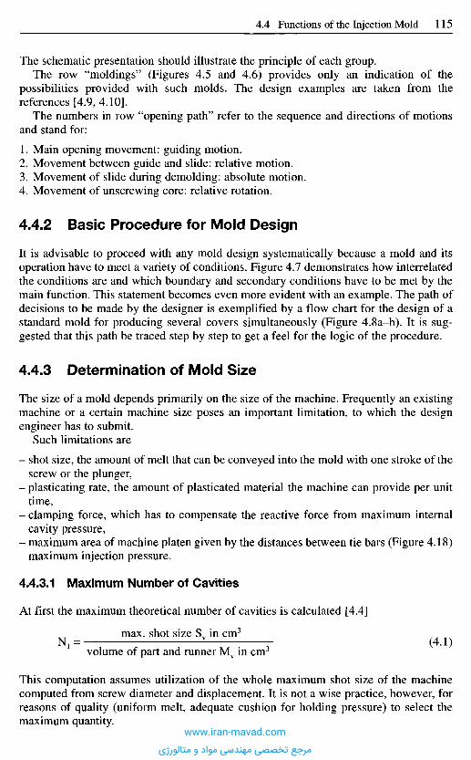
The schematic presentation should illustrate the principle of each group.The row "moldings" (Figures 4.5 and 4.6) provides only an indication of the
possibilities provided with such molds. The design examples are taken from thereferences [4.9, 4.10].
The numbers in row "opening path" refer to the sequence and directions of motionsand stand for:
1. Main opening movement: guiding motion.2. Movement between guide and slide: relative motion.3. Movement of slide during demolding: absolute motion.4. Movement of unscrewing core: relative rotation.
4.4.2 Basic Procedure for Mold Design
It is advisable to proceed with any mold design systematically because a mold and itsoperation have to meet a variety of conditions. Figure 4.7 demonstrates how interrelatedthe conditions are and which boundary and secondary conditions have to be met by themain function. This statement becomes even more evident with an example. The path ofdecisions to be made by the designer is exemplified by a flow chart for the design of astandard mold for producing several covers simultaneously (Figure 4.8a-h). It is sug-gested that this path be traced step by step to get a feel for the logic of the procedure.
4.4.3 Determination of Mold Size
The size of a mold depends primarily on the size of the machine. Frequently an existingmachine or a certain machine size poses an important limitation, to which the designengineer has to submit.
Such limitations are
- shot size, the amount of melt that can be conveyed into the mold with one stroke of thescrew or the plunger,
- plasticating rate, the amount of plasticated material the machine can provide per unittime,
- clamping force, which has to compensate the reactive force from maximum internalcavity pressure,
- maximum area of machine platen given by the distances between tie bars (Figure 4.18)maximum injection pressure.
4.4.3.1 Maximum Number of Cavities
At first the maximum theoretical number of cavities is calculated [4.4]
max. shot size Sv in cm3
N1 = (4.1)volume of part and runner Mv in cm3
This computation assumes utilization of the whole maximum shot size of the machinecomputed from screw diameter and displacement. It is not a wise practice, however, forreasons of quality (uniform melt, adequate cushion for holding pressure) to select themaximum quantity.
www.iran-mavad.com
مرجع تخصصی مهندسی مواد و متالورژی
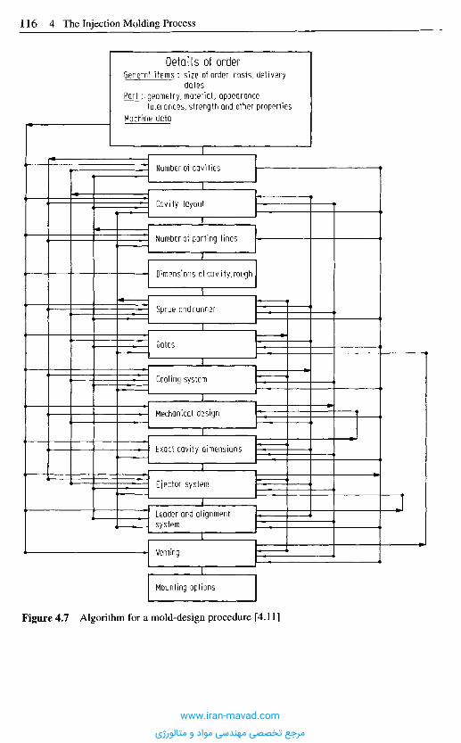
Details of orderGeneral items : size of order, costs, delivery
datesPort : geometry, material, appearance
tolerances, strength and other propertiesMachine data
Number of cavities
Cavity layout
Number of parting lines
Dimensions of cavity,rough
Sprue and runner
Gates
Cooling system
Mechanical design
Exact cavity dimensions
Ejector system
Leader and alignmentsystem
Venting
Mounting options
Figure 4.7 Algorithm for a mold-design procedure [4.11]
www.iran-mavad.com
مرجع تخصصی مهندسی مواد و متالورژی

Dimensions: R = 20 mmh = 8 mms= 2 mm
Material: PS
Machine : Type...Injection pressure...Cycle time...
Molding: Cover
Parting line
Cavity insert Mold core
Start
Molding :Dimensions,material,description
Has machinebeen decidedupon?
no 1
yesCharacteristicmachine data
Position ot moldingrelative to partingline
Shape of cavityinsert
Shape of moldcore
a
a
Undercuts ?yes
no 2
Number of cavities
Cavitylayout
Mold dimensionsrelative to cavityinsert
Mold dimensionsrelative to moldcore
Slides? k y« 3
no(3.
b
No undercuts 1
Number of cavities n = f (plastication rate, clamping force,shot weight, economy, deliverydates)
Selected: n=4
Figure 4.8a-b Design example: Standard mold [4.5]MS = movable side, SS = stationary side(Continued on next page)
www.iran-mavad.com
مرجع تخصصی مهندسی مواد و متالورژی
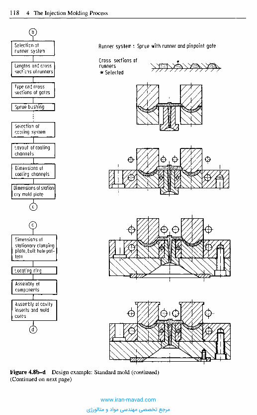
Runner system : Sprue with runner and pinpoint gate
Cross sections ofrunners* Selected
Figure 4.8b-d Design example: Standard mold (continued)(Continued on next page)
b
Selection ofrunner system
Lengths and crosssections of runners
Type and crosssections of gates
Sprue bushing
Selection ofcooling system
Layout of coolingchannels
Dimensions ofcooling channels
Dimensions of station-ary mold plate
c
Dimensions ofstationary clampingplate, bolt hole pat-tern
Locating ring
Assembly ofcomponents
Assembly of cavityinserts and moldcores
d
www.iran-mavad.com
مرجع تخصصی مهندسی مواد و متالورژی

Figure 4.8d-f Design example: Standard mold (continued)(Continued on next page)
d
Selection of ejectorlayout
Selection of ejectorsystem
Stripper plate? yes 4
noEj e_c]or_ co m£qnen ts:forms, position
>. J
Lea_der_pins_: type,position, number
Leader bushings
Dimensions of mo-vable mold plate
e
e
Dimensions of baseplate, bolt hole pat-tern
Stripper plate ? yes
noMultisectionalejector housing i
7
yes6
no
Supports
6
Mounting of ejector
housing
f
www.iran-mavad.com
مرجع تخصصی مهندسی مواد و متالورژی
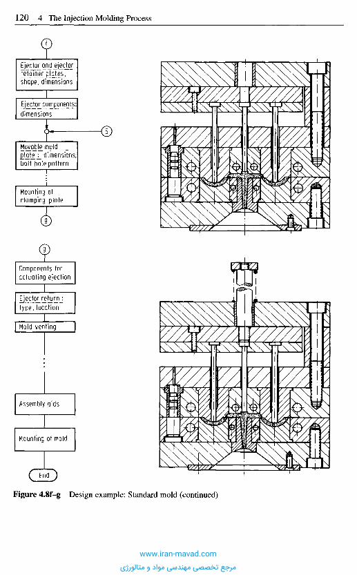
Figure 4.8f-g Design example: Standard mold (continued)
f
Ejector and_e[e_ctorr§Tgi_n_e££latGs_,shape, dimensions
Ejector components:dimensions
5,
Movable _m old])late j_ dimensions,bolt hole pattern
Mounting ofclamping plate
9
9
Components foractuating ejection
Ejector returnjtype, location
Mold venting
Assembly aids
Mounting of mold
End
www.iran-mavad.com
مرجع تخصصی مهندسی مواد و متالورژی

The number of cavities for thin-walled parts can furthermore be determined by theplasticating rate of the machine
plasticating rate R in cmVminN2= (4.1a)
number of shots Z/min • (part + runner volume in cm3)
Modern reciprocating-screw injection molding machines have such a high plasticatingrate that the number of cavities N2 should only be checked for thin-walled parts withlarge shot size. An empirical rule states
0.4 N1 ^ N2 ^ 0.8 N1 (4.2)
4.4.3.2 Clamping Force
The minimum clamping force is derived from the reactive force of the cavity, whichresults from the projected area of all cavities and runners and the maximum cavitypressure:
F = A - p (4.3)
Herein F is the reactive force, A the projected areas of cavities and runner system and pthe cavity pressure. Depending on material and part the cavity pressure is between 20 and100 MPa, proper processing assumed. Faulty operation can rise this pressure up to the fullinjection pressure. It is advisable, therefore, to calculate with the maximum injectionpressure of the machine and the total projected area that can be covered with melt.
**max = ^max ' Pinj ^ ^clamp ( 4 - 4 )
4 . 4 . 3 . 3 M a x i m u m C l a m p i n g A r e a
This area is determined by the distances between the tie bars (Figure 4.18). Generally oneavoids the additional trouble of pulling tie bars. Therefore between the largest molddimension should be about 10 mm smaller than the distance the corresponding tie bars.Clamping units are built to withstand the maximum cavity pressure that can be expected.Machines for processing foam with low pressure can have light-duty clamping units orlarger clamping platens and wider distances between tie bars. Care should be taken thatthe plates do not bend more under loads than several micrometers. Otherwise theadmissible gap width of the parting line cannot be maintained even if the molds themselvesare sufficiently rigid. In this respect today's machinery is frequently undersized.
4.4.3.4 Required Opening Stroke
The opening stroke has to be adequately long to permit troublefree ejection from moldswith very long cores (example: mold for bucket). Minimum requirement is a stroke ofmore than twice the length of the core.
On the other hand, a stroke that is longer than needed uses up cycle time, which hasto be kept short for reasons of costs.
The opening stroke can certainly be adjusted but the investment for a more thannormal stroke is high. Therefore, one has proposed [4.12] to tilt the mold during theopening stroke with an auxiliary equipment and to demold then (Figure 4.9).
www.iran-mavad.com
مرجع تخصصی مهندسی مواد و متالورژی
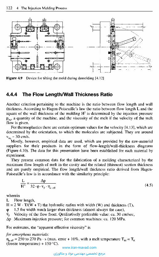
Figure 4.9 Device for tilting the mold during demolding [4.12]
4.4.4 The Flow Length/Wall Thickness Ratio
Another criterion pertaining to the machine is the ratio between flow length and wallthickness. According to Hagen-Poiseuille's law the ratio between flow length L and thesquare of the wall thickness of the molding H2 is determined by the injection pressurepinj, a quantity of the machine, and the viscosity of the melt if the velocity of the meltflow is given.
For thermoplastics there are certain optimum values for the velocity [4.13], which aredetermined by the orientation, to which the molecules are subjected. They are aroundvinj - 3 0 cm/s.
Mostly, however, empirical data are used, which are provided by the raw-materialsuppliers for their products in the form of flow-length/wall-thickness diagrams(Figure 4.10). The data for this presentation have been established for each material byexperiment.
They present common data for the fabrication of a molding characterized by themaximum flow length of melt in the cavity and the related (thinnest) section thicknessand are purely empirical. The flow length/wall thickness ratio derived from Hagen-Poiseuille's law is in accordance with the similarity principle:
L _ Ap
H 2 ~32(pv F .T i a e f f (45>
whereinL Flow length,H = 2 W • T/(W + T) the hydraulic radius with width (W) and thickness (T),(p 1.5 for width much larger than thickness (almost always the case),vF Velocity of the flow front. Qualitatively preferable value: ca. 30 cm/sec,Ap Maximum injection pressure; for common machines: ca. 120 MPa.
For estimates, the "apparent effective viscosity" is
for amorphous materials:qaeff = 250 to 270 Pa • s (max. error + 10%, with a melt temperature TM = TE
(freeze temperature) + 150 0C).www.iran-mavad.com
مرجع تخصصی مهندسی مواد و متالورژی

for crystalline materials:T eff
= 170 Pa • s (max. error ±5%, with a melt temperature TM = TE
(freeze temperature) + 250 to 375 0C).
With the flow length for common molds and machines (120 MPa injection pressure) canbe estimated
for amorphous materials
106- H2
L = = 325 • H2 (cm) (4.6)12-260
for crystalline materials
L = 1Q > H = 500 • H2 (cm) (4.7)12-170
(L and H are in cm)If the material is filled with short glass fibers or powder, 30% by volume, one can
assume a reduction factor of 2, that is the flow length is reduced to one half.
4.4.5 Computat ion of Number of Cavities
The first design step is to determine the number of cavities. Technical (in form of theavailable machine equipment and the required quality and costs) as well as economic (inform of the delivery date) criteria are considered. To facilitate this multi-level decision aflow chart (Figure 4.11) is proposed, which exemplifies a suitable procedure [4.6, 4.16].
Beginning with the assumption that the cost price of an article is closely related to themethod by which it is manufactured, one can conversely conclude that cost calculation
Wall thicknessmm
Figure 4.10 Relationshipbetween wall thickness andflow length for a number ofPMMA molding resins(Degussa Corporation) [4.14]They meet the requirements ofDIN 7745.There are two series of grades:Standard grades 6, 7 and 8, andE-grades with higher molecularweight.
Flow lengthmm
www.iran-mavad.com
مرجع تخصصی مهندسی مواد و متالورژی
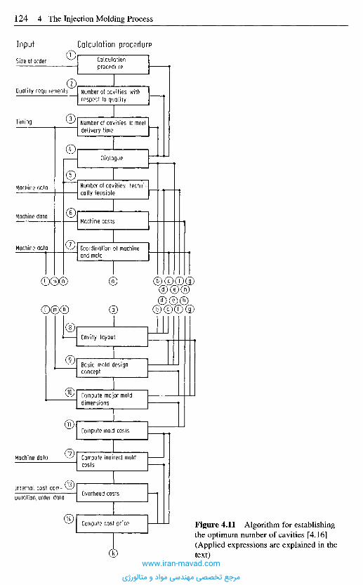
Figure 4.11 Algorithm for establishingthe optimum number of cavities [4.16](Applied expressions are explained in thetext)
Input Calculation procedure
Calculationprocedure
Number of cavities withrespect to quality
Quality requirements2
Size of order
Number of cavities to meetdelivery time
Timing
Dialogue4
Number of cavities techni-cally feasible
5
Machine costs6
Machine data
Machine data
Machine data 7 Coordination of machineand mold
Cavity layout8
a
Basic mold designconcept
9
Compute major molddimensions
3°;
Compute mold costs11,
Compute indirect moldcosts
12Machine data
Overhead costs13Internal cost com-
putation, order data
Compute cost price.14
kwww.iran-mavad.com
مرجع تخصصی مهندسی مواد و متالورژی
should already start at the design stage, especially in mold design, in order to find anoptimal solution. It is practical to break down the whole procedure into several knownpartial or elementary functions [4.17], which can replace the overall function withrespect to cause and effect. Then these partial functions have to be evaluated with thehelp of a value analysis. An important point is the source of costs. Figure 4.12 shows thecosts to be considered here allocated to cost groups.
Summation of all individual costs or cost groups as demonstrated in Figure 4.12results in the cost price. The trend of these costs is schematically shown in Figure 4.13[4.3,4.18-4.21].
Since it is not known in advance which combination of numbers of cavities, moldsystem and injection molding machine results in the lowest costs, these three quantitieshave to be varied within certain limits, which have to be determined.
First the number of cavities has to be narrowed down. This is done with the first 5steps of the algorithm in Figure 4.11, which because of their significance will bediscussed in more detail later. If there is no information concerning quality demands(step 2) or delivery time (step 3), one can commence with a practically sound number ofcavities in step 1 [4.20], which only depends on the order size (Figure 4.14). One can seethat the curve does not begin below n = 10,000 parts. In fact, smaller numbers are notprofitable because the expenses for the mold would result in a high amortization charge.This charge increases with decreasing lot size and can render the article uneconomic.
According to this experience [4.20], a single cavity mold is the most economicsolution for lot sizes up to 100,000 parts as long as the required delivery date does notcommand otherwise. If best quality and positive availability is kept in mind, then one cangenerally only agree with this rule. This diagram [4.20] counts even more, the moreproblematic processing of a material becomes.
Figure 4.12 Summaryof costs - optimumnumber of cavities [4.16]
Group of costs
Machine costs
Cost related to product
Mold costs
Indirect mold costs
Overhead
Costs
Depreciation and amortizationInterestMaintenanceBuildingWagesEnergyCooling water
MaterialPostoperation
Mold materialMachiningDesignOutside labor
SetupSamplingMaintenance
ProductionMold makingDesignMaterialAdministration and sales
www.iran-mavad.com
مرجع تخصصی مهندسی مواد و متالورژی
Numb
er ot
cavit
iesCo
st of
produ
ction
Order size
Figure 4.14 Correlation betweennumber of cavities and order size[4.20]
Figure 4.13 Costs related to numberof cavities [4.16]
OverheadsDirect costs
Number of cavities
Mold costs
Mold making overheadsDesignDesign overheads
Machine costs and wagesAdministration and sales overheadProduction overheadsMaterialMaterial overheads
Cost price (sum ofindividual costs)
Economically interestingrange
www.iran-mavad.com
مرجع تخصصی مهندسی مواد و متالورژی

If there are additional requirements, a further examination is worthwhile. A proposalfrom [4.6] is presented with Figure 4.15, which can be followed.
4.4.5,1 Algorithm for the Determination of the Technically andEconomically Optimum Number of Cavities
If the optimum number of cavities is determined from a technical and economic point of view,the most favorable combination of mold and machine is found at the same time, because arealistic definition of this number can only be made with regard to the characteristics of themolding machine and a suitable mold principle for the part in mind [4.16].
Starting with an inquiry for the production of injection molded parts, which containsin essence
- part geometry,- molding material,- demands on the part,- lot size,- delivery date.
At least the following parameters have to be laid down by the molder and mold makerin their quotations:
- number of cavities n,- mold principle W,- major mold dimensions,- number m and types M of molding machines,- mold costs,- costs of parts S (n, W, m, M).
Figure 4.15 Algorithm for determining theoptimum number of cavities (Combination:Mold-Machine) - abridged [4.6]
Stage 1
Stage 2
Stage 3
Stage 4
Stage 5
Mold criteria andpreliminary machineselection
1. Limitation of rangefor number ofcavities (general)
2. Limitation of rangefor number ofcavities (specificmachine and mold
Major dimensions of mold
Cost of part= f(M, W, n)
Result matrix
www.iran-mavad.com
مرجع تخصصی مهندسی مواد و متالورژی
The listed parameters can only be established together because they are mutuallyinterdependent. For instance, there is a connection between the number of cavities n andthe number m as well as the type of molding machine M. This dependency is a resultfrom the lot size and the delivery date on one side and the technical necessities ofprocessing (plasticating rate, shot size, etc.) and the machine data on the other side.
Depending on the kind of gating and its location the mold principle also depends onthe number of cavities, for instance with a change from a single-cavity to a two-cavitymold. The major mold dimensions depend on the number of cavities, the mold conceptand the machine type. Conversely there may be a dependency of the mold concept on themajor mold dimensions, if e.g., because of high lateral opening forces, a thick leader pinfor a slide mold should become necessary, which cannot be realized any more afterdimensioning. Thus, the use of a split-cavity mold would make more sense.
Mold and part costs are directly or indirectly dependent on the remaining parameterslaid down in the quotation.
In order to find the most favorable number of cavities (mold-machine combination)with justifiable effort, the following course of action is proposed. Figure 4.15 shows anabridged version of the flow chart of an algorithm, with which one can determine thetechnically and economically best combination of mold and machine for the part to beproduced. In step 1, the part is analyzed and all feasible mold conceptions are procured.Furthermore a preliminary selection of machines is made, that is those moldingmachines are considered among which the finally selected one will be found.Subsequently, in step 2, the first limitation of the scope of cavity numbers isaccomplished based on criteria, which depend on part data in the first place. After this,in step 3, further narrowing down of the number of cavities follows after a review of theessential technical criteria. In step 4, the part costs can be calculated after the major molddimensions have been computed. In doing this the number of cavities is modified for acertain machine and certain mold and after this, machine and mold are likewisemodified. By this variation, in step 5, matrix of results is obtained for the part costs. Itshould make visible the most economical, although not necessarily the technically bestcombination of machine, mold principle, and number of cavities.
Figure 4.16 presents the flow chart of the algorithm in more detail. In step 1, allfeasible mold design modes are determined according to an analysis of the part (Section4.4.1 to 4.4.3). The most important angles for this are the creation of the system andlocation of gating as well as the way of demolding. It is the goal of this stage to specifyall feasible alternative mold principles. Restrictions to the number of cavities for designreasons have to be noted for the respective principle.
Subsequently, in step 2, those machines are singled out from the whole machineequipment, from which one is later selected to do the job. Narrowing down the wholespectrum of machinery to those machines which may be considered, is done by scheduleor from experience. This considerably reduces the total effort in finding the mostfavorable combination of machine and mold in the following steps.
In step 3, practical number of cavities is established from experience with similarparts.
To increase the significance of such a statement it makes sense to carry out an analysisconcerning the dependence of the number of cavities on the lot size for a certain familyof moldings subdivided in to groups of similar size as the molding. Such data can beentered in diagrams and, thus, expressed mathematically. With this, a preliminaryestimate of the number of cavities is available. Step 4 deals with the qualitative numberof cavities. With more than one cavity in a mold there are no suitable processing
www.iran-mavad.com
مرجع تخصصی مهندسی مواد و متالورژی
Figure 4.16 Algorithm for determining the optimum number of cavities (Combination: Mold-Machine) [4.6] (continued on next page)
Stage
1Sta
ge 2
Stage
3
Mold type feasible for differentnumbers of cavities
Available machines to beconsidered suitable
n-number from experience (nP)
n-number with regard toquality (nQ)
n-number to meet delivery date(nT.nTopt)
Scopestage 2
Number of cavities
Machine M
Mold criterion T
Cavity layout and nt1
Number of cavities technicallyfeasible n,2
Number of cavities allowed by ma-chine parameters nt3.nu,nt5,nt6
Is Tstill feasiblefor all nt ?
Limitation of n,no
yes
"tmin * n t *n tmox
Scope
stage 3
Number of cavities
valid for 1 machine Mand 1 mold criterion Tin each case
next moldcriterion T
nextmachine M
6
7
8
9
10)
Il
12
13.
KJ
15
1
2
3
4
5
www.iran-mavad.com
مرجع تخصصی مهندسی مواد و متالورژی
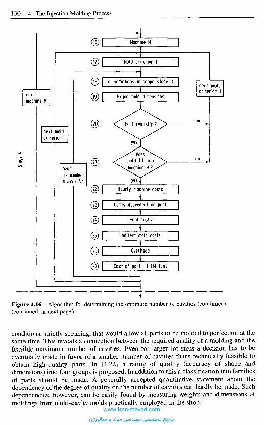
Figure 4.16 Algorithm for determining the optimum number of cavities (continued)(continued on next page)
conditions, strictly speaking, that would allow all parts to be molded to perfection at thesame time. This reveals a connection between the required quality of a molding and thefeasible maximum number of cavities. Even for larger lot sizes a decision has to beeventually made in favor of a smaller number of cavities thans technically feasible toobtain high-quality parts. In [4.22] a rating of quality (accuracy of shape anddimensions) into four groups is proposed. In addition to this a classification into familiesof parts should be made. A generally accepted quantitative statement about thedependency of the degree of quality on the number of cavities can hardly be made. Suchdependencies, however, can be easily found by measuring weights and dimensions ofmoldings from multi-cavity molds practically employed in the shop.
nextmachine M
Stag
e 4
next moldcriterion T
nextn-number:n = n + An
Machine M
Mold criterion T
n-variations in scope stage 3
Major mold dimensions
Is T realistic ?
yes
no
next moldcriterion T
noDoes
mold fit intomachine M ?
yesHourly machine costs
Costs dependent on part
Mold costs
Indirect mold costs
Overhead
Cost of part = f (M,T,n)
16
17
18
19,
20
21
22
23,
X
25
26)
27
www.iran-mavad.com
مرجع تخصصی مهندسی مواد و متالورژی
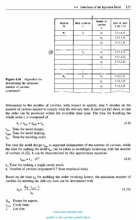
Subsequent to the number of cavities, with respect to quality, step 5 decides on thenumber of cavities needed to comply with the delivery date. It must not fall short, so thatthe order can be produced within the available time span. The time for handling thewhole order t, is composed of
*U = toes + *MM + 1M ( 4 ' 8 )
tDes Time for mold design,tMM, Time for mold making,tM Time for molding order.
The time for mold design tDes is regarded independent of the number of cavities, whilethe time for making the mold tM, can be taken as recedingly increasing with the numberof cavities [4.22]. It can be characterized by this approximate equation:
t«M = tci • n0 '7 (4.9)
tcl Time for making a single cavity mold,n Number of cavities (exponent 0.7 from empirical data).
Based on the time tM for molding the order (working hours), the minimum number ofcavities for meeting the delivery date can be determined with
nD= K R ' t c y c l ' L (4.10)
KR Factor for rejects,tcyd Cycle time,L Lot size.
Figure 4.16 Algorithm fordetermining the optimumnumber of cavities(continued)
MachineM
Mi
M2
Mold criterionT
Ti
T2
T1
Number ofcavities
n
ninzn3
"in2
n3
nin2
n3
Cost of part5 (MJ,n)
S (1.1.1)S (1.1.2)S (1.1.3)
5 (1.2.1)S (1,2,2)S (1.2,3)
S (2,1.1)S (2.1,2)S (2,1,3)
.28
www.iran-mavad.com
مرجع تخصصی مهندسی مواد و متالورژی
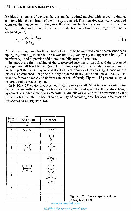
Besides this number of cavities there is another optimal number with respect to timing,ntopt for which the minimum of the time tU5 is entered. This time depends with tMM(n) andtM(n) on the number of cavities, too. By equating the first derivative of the functionty = f(n) with zero the number of cavities which is an optimum with regard to time isobtained [4.22]
ntopt= *£^* (4-11)U. / l c l
A first operating range for the number of cavities to be expected can be established withnp, nQ, nD, and ntopt in step 6. The lower limit is given by nD, the upper one by nQ. Thenumbers ntopt and np provide additional nonobligatory information.
In stage 3 the first machine of the preselected machinery (step 2) and the first moldconcept from all feasible ones (step 1) is brought up for further study by steps 7 and 8.With step 9 the cavity layout and the technical number of cavities ntl, (space on theplaten) is established. On principle, only a symmetrical layout should be allowed, other-wise the forces on mold and tie bars cannot act uniformly. Figure 4.17 presents a layoutin series and a circular layout.
In [4.16, 4.23] cavity layout is dealt with in more detail. Most important criteria forthe layout are sufficient rigidity between the cavities and space for the heat-exchangesystem. The available clamping area with the dimensions Wv and Wh is determined by thedistances between the tie bars. The possibility of removing a tie bar should be reservedfor special cases (Figure 4.18).
Number ofcavities Layout in series Circular layout
Figure 4.17 Cavity layouts with oneparting line [4.18]
1
2
3
4
5
6
7
www.iran-mavad.com
مرجع تخصصی مهندسی مواد و متالورژی
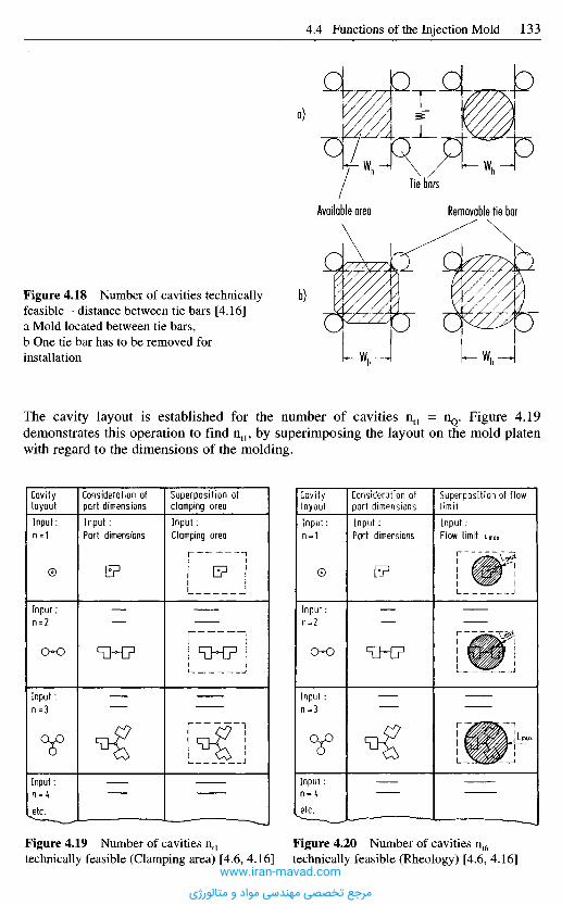
a)
b)
Tie bars
Available area Removable tie bar
Figure 4.18 Number of cavities technicallyfeasible - distance between tie bars [4.16]a Mold located between tie bars,b One tie bar has to be removed forinstallation
The cavity layout is established for the number of cavities ntl = nQ. Figure 4.19demonstrates this operation to find ntl, by superimposing the layout on the mold platenwith regard to the dimensions of the molding.
CavitylayoutInput:n = 1
Consideration ofpart dimensionsInput :Part dimensions
Superposition ofclamping areaInput :Clamping area
CavitylayoutInput:n = 1
Consideration ofpart dimensionsInput :Part dimensions
Superposition of flowlimitInput:Flow limit LmQX
Input :n = 2
Input :n=3
Input:n = 4etc.
Input:n = 2
Input :n=3
Input:n = 4etc.
Figure 4.19 Number of cavities ntl
technically feasible (Clamping area) [4.6, 4.16]Figure 4.20 Number of cavities nt6
technically feasible (Rheology) [4.6, 4.16]www.iran-mavad.com
مرجع تخصصی مهندسی مواد و متالورژی
If there is sufficient space on the mold platen for the cavity number nQ then ntl = nQ;if not then the next lower number is selected and the layout determined again. Thewanted number is found when the available space is just enough for all cavities.
With step 10 the number of cavities nt2 is established with respect to the availableinjection pressure. The previously determined cavity number ntl is taken and examinedwhether for nt2 = ntl, the maximum injection pressure of the machine is sufficient to fillthe cavities. If this is not so, then nt2, is reduced so long until it meets the demand.
One possible way to examine the requirement is an estimation of the pressure demandof cavity and gate, and deducting this from the maximum injection pressure of themachine. The remaining pressure is available for nozzle and runner system. Thispressure allows to compute the maximum length Lmax of the runners, which can beentered into the plane of the parting line (Figure 4.20).
Besides this optical check there is a second more general possibility of establishingthe pressure demand of the whole system with separate programs [4.22, 4.24].
With step 11, the technical cavity numbers nt3 to nt6 are determined.
nt3 is based on clamping force,nt4 is based on minimum shot capacity,nt5 is based on maximum shot capacity,nt6 is based on plasticating rate.
The numbers nt3, nt5 and nt6 are determined in a similar way as n12 in step 10, alwaysbeginning with the largest number so far, while the cavity number nt4 is raised step bystep, starting with nD (step 6), until the actual shot capacity is larger than the minimalone.
With step 12 and 13, the numbers of cavities within the range established so far aretested as to whether or not they can be attained with the mold concept M of step 8. Basedon the completed steps 1 to 13, a range of cavity numbers ntmin to ntmax can be specifiedwith steps 14 and 15, which meet the demands on quality and timely delivery on one sideand can, on the other side, be technically realized with the mold concept W and themachine M. With this in stage 4 of the flow chart, a field of operation has becomeavailable, in which the number of cavities can be modified and a calculation of theeconomics is carried out, that is, the costs for producing the part can be computed.
For the same machine M and the same mold concept W (steps 16 and 17), the majormold dimensions are determined before the economics are calculated (steps 22 to 27). Itshould be understood that not only those data and dimensions are meant which can affectthe mold concept, but also all important external geometry data such as dimensions ofplates and height of the mold.
With the cavity number ntmin the major mold dimensions are established in step 19. Ifthese dimensions are defined, one has to examine the concept with regard to itsfeasibility of realization (e.g. can part dimensions be achieved? - can demolding forceswith ejection system be accomplished?).
Subsequently, one checks with step 21 whether the mold still fits the machine. Moldheight, opening and ejection stroke are compared for the first time and the dimensionsof the mold platen with the machine data for the second time.
Figure 4.21 presents the system of calculating costs on which steps 22 to 27 are based.The hourly machine costs (step 22) include:
- depreciation,- interest,
www.iran-mavad.com
مرجع تخصصی مهندسی مواد و متالورژی
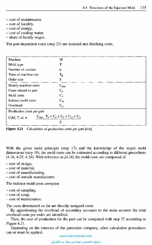
Figure 4.21 Calculation of production costs per part [4.6]
With the given mold principle (step 17) and the knowledge of the major molddimensions (step 19), the mold costs can be estimated according to different procedures[4.16, 4.25, 4.26]. With reference to [4.16] the mold costs are composed of
- cost of design,- cost of material,- cost of manufacturing,- cost of outside manufacturer.
The indirect mold costs comprise
- cost of sampling,- cost of setup,- cost of maintenance.
The costs determined so far are directly assigned costs.By apportioning the overhead of secondary accounts to the main account the total
overhead costs per order are identified.Then, the cost of production for the part can be computed with step 27 according to
Figure 4.21.Depending on the interests of the particular company, other calculation procedures
can or must be applied.
- cost of maintenance,- cost of locality,- cost of energy,- cost of cooling water,- share of hourly wages.
The part-dependent costs (step 23) are material and finishing costs.
Machine
Mold type
Number of cavities
Time of machine run
Order size
Hourly machine costs
Costs related to part
Mold costs
Indirect mold costs
Overhead
M
T
n
TR
S
cCp
CT
Cn
C0
Production costs per part
CCM. T. n) = ^MH • TF + Cp + CT + CTI + C0
S
www.iran-mavad.com
مرجع تخصصی مهندسی مواد و متالورژی
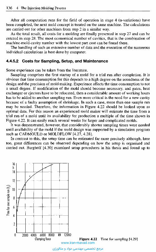
After all computation runs for the field of operation in stage 4 (n-variations) havebeen completed, the next mold concept is treated on the same machine. The calculationsare carried out for other machines from step 2 in a similar way.
As the total result, all costs for a molding are finally presented in step 27 and can beentered in step 28. The most economical number of cavities, that is the combination ofmachine-mold-cavity number with the lowest part cost can be found there.
The handling of such an extensive number of data and the execution of the numerousindividual calculations is best done by computer.
4.4.5.2 Costs for Sampling, Setup, and Maintenance
Some experience can be taken from the literature.Sampling comprises the first startup of a mold for a trial run after completion. It is
obvious that time consumption for this depends to a high degree on the soundness of thedesign and the precision of mold making. Experience affects the time consumption to nota small degree. If modification of the mold should become necessary, and gates, heatexchanger or ejectors have to be relocated, then a considerable amount of working hourshas to be added to another sampling run. Even more critical is the need for a new cavitybecause of a faulty assumption of shrinkage. In such a case, more than one sample runmay be needed. Therefore, the information in Figure 4.22 should be looked upon asoptimal data. For this reason an experienced mold maker will estimate the time from atrial run of a mold until its availability for production a multiple of the time shown inFigure 4.22. It can easily reach several weeks for larger and complicated molds.
It was demonstrated, however, that considerably shorter sampling times were neededuntil availability of the mold if the mold design was supported by a simulation programsuch as CADMOULD or MOLDFLOW [4.27, 4.28].
In contrast to this, the setup time can be estimated far more precisely although, heretoo, great differences can be observed depending on how the setup is organized andcarried out. Burgholf [4.30] examined setup procedures in his thesis and found up to
Time f
or on
e sam
ple ru
n (t s)
Clamping force
h
kNFigure 4.22 Time for sampling [4.29]
www.iran-mavad.com
مرجع تخصصی مهندسی مواد و متالورژی
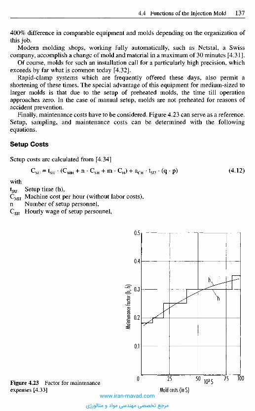
400% difference in comparable equipment and molds depending on the organization ofthis job.
Modern molding shops, working fully automatically, such as Netstal, a Swisscompany, accomplish a change of mold and material in a maximum of 30 minutes [4.31].
Of course, molds for such an installation call for a particularly high precision, whichexceeds by far what is common today [4.32].
Rapid-clamp systems which are frequently offered these days, also permit ashortening of these times. The special advantage of this equipment for medium-sized tolarger molds is that due to the setup of preheated molds, the time till operationapproaches zero. In the case of manual setup, molds are not preheated for reasons ofaccident prevention.
Finally, maintenance costs have to be considered. Figure 4.23 can serve as a reference.Setup, sampling, and maintenance costs can be determined with the followingequations.
Setup Costs
Setup costs are calculated from [4.34]
(4.12)
withtsu Setup time (h),CMH Machine cost per hour (without labor costs),n Number of setup personnel,CSH Hourly wage of setup personnel,
Maint
enan
ce fa
ctor (
h, h)
Mold costs (in $)103$Figure 4.23 Factor for maintenance
expenses [4.33]www.iran-mavad.com
مرجع تخصصی مهندسی مواد و متالورژی

m N u m b e r of auxiliary personnel ,C H Hour ly wages for auxiliary personnel ,q Plastificating rate,p Cost of the fol low-up material ,aCH Addit ional t ime for material change .
Costs of Sampling
C 8 = tP • (C M H + C n ) + c ^ ^ • (VP + VR) • p M • Pr (4.13)
withtp T ime for sampling (h),C M H Mach ine costs per hour (without labor costs),C H Hourly wages for sampling,c Time effectiveness,
Vp Volume of molding (dm3) ,V R Volume of runners (dm3) ,p M Specific weight of material (kg/dm 3) ,Pr Price of material ($/kg).
Maintenance Costs
CMT = h . C w (4.14)withh Maintenance factor,Cw Mold costs.
4 . 5 C a v i t y L a y o u t s
4.5.1 General Requirements
After the number of cavities has been established, the cavities have to be placed in themold as ingeniously as possible.
In modern injection molding machines the barrel is usually positioned in the centralaxis of the stationary platen. This establishes the position of the sprue. The cavities haveto be arranged relative to the central sprue in such a way that the following conditionsare met:
- All cavities should be filled at the same time with melt of the same temperature.- The flow length should be short to keep scrap to a minimum.- The distance from one cavity to another has to be sufficiently large to provide space
for cooling lines and ejector pins and leave an adequate cross section to withstand theforces from injection pressure.
- The sum of all reactive forces should be in the center of gravity of the platen.www.iran-mavad.com
مرجع تخصصی مهندسی مواد و متالورژی
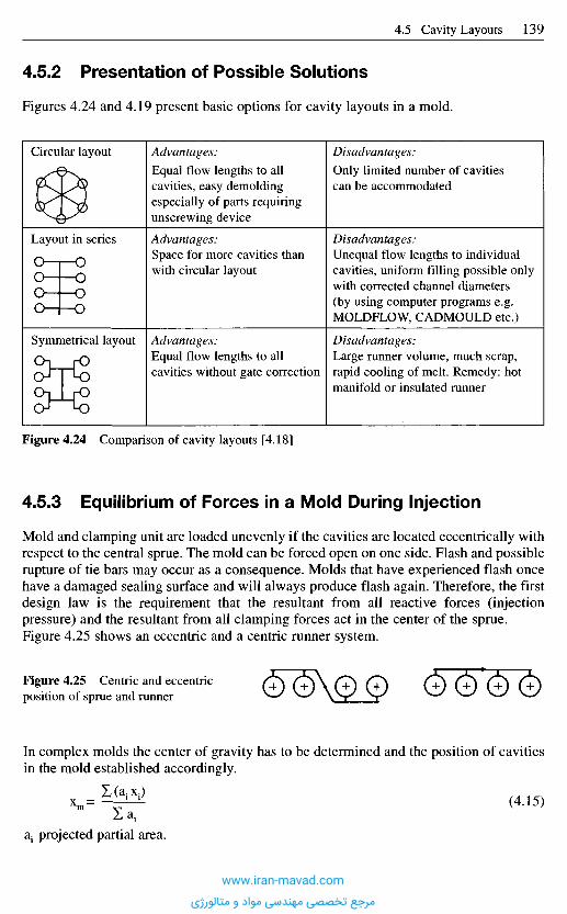
Figure 4.24 Comparison of cavity layouts [4.18]
4.5.3 Equilibrium of Forces in a Mold During Injection
Mold and clamping unit are loaded unevenly if the cavities are located eccentrically withrespect to the central sprue. The mold can be forced open on one side. Flash and possiblerupture of tie bars may occur as a consequence. Molds that have experienced flash oncehave a damaged sealing surface and will always produce flash again. Therefore, the firstdesign law is the requirement that the resultant from all reactive forces (injectionpressure) and the resultant from all clamping forces act in the center of the sprue.Figure 4.25 shows an eccentric and a centric runner system.
Figure 4.25 Centric and eccentricposition of sprue and runner
In complex molds the center of gravity has to be determined and the position of cavitiesin the mold established accordingly.
xm= ^ (4.15)
Z1 projected partial area.
Advantages:Equal flow lengths to allcavities, easy demoldingespecially of parts requiringunscrewing device
Advantages:Space for more cavities thanwith circular layout
Advantages:Equal flow lengths to allcavities without gate correction
Disadvantages:Only limited number of cavitiescan be accommodated
Disadvantages:Unequal flow lengths to individualcavities, uniform filling possible onlywith corrected channel diameters(by using computer programs e.g.MOLDFLOW, CADMOULD etc.)
Disadvantages:Large runner volume, much scrap,rapid cooling of melt. Remedy: hotmanifold or insulated runner
4 .5 .2 P r e s e n t a t i o n of P o s s i b l e S o l u t i o n s
Figures 4.24 and 4.19 present basic options for cavity layouts in a mold.
Circular layout
Layout in series
Symmetrical layout
www.iran-mavad.com
مرجع تخصصی مهندسی مواد و متالورژی
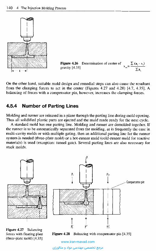
On the other hand, suitable mold design and remedial steps can also cause the resultantfrom the clamping forces to act in the center (Figures 4.27 and 4.28) [4.7, 4.35]. Abalancing of forces with a compensator pin, however, increases the clamping forces.
4.5.4 Number of Parting Lines
Molding and runner are released in a plane through the parting line during mold opening.Thus all solidified plastic parts are ejected and the mold made ready for the next cycle.
A standard mold has one parting line. Molding and runner are demolded together. Ifthe runner is to be automatically separated from the molding, as is frequently the case inmulti-cavity molds or with multiple gating, then an additional parting line for the runnersystem is needed (three-plate mold) or a hot-runner mold (cold-runner mold for reactivematerials) is used (exception: tunnel gate). Several parting lines are also necessary forstack molds.
Figure 4.27 Balancingforces with floating plate(three-plate mold) [4.35]
Figure 4.28 Balancing with compensator pin [4.35]
Compensator pin
Figure 4.26 Determination of center ofgravity [4.35]
www.iran-mavad.com
مرجع تخصصی مهندسی مواد و متالورژی
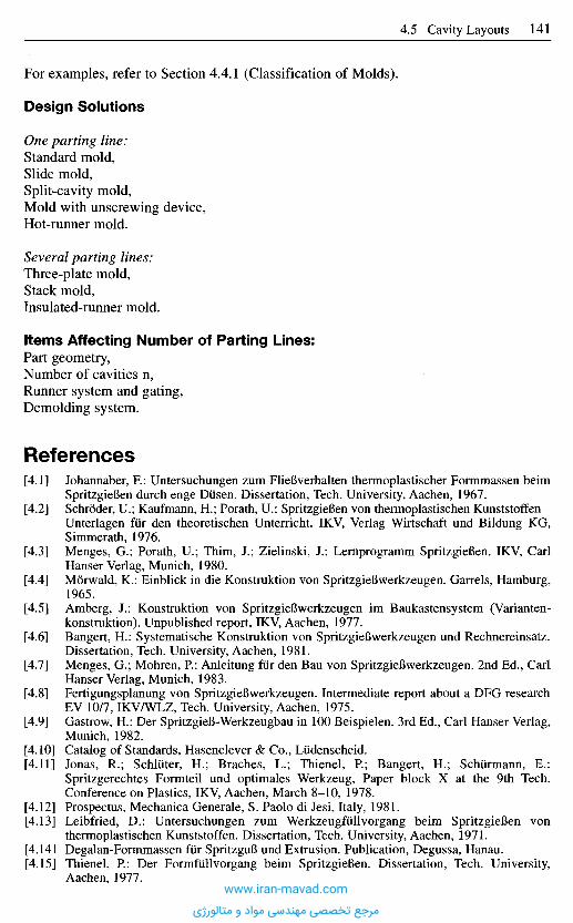
For examples, refer to Section 4.4.1 (Classification of Molds).
Design Solutions
One parting line:Standard mold,Slide mold,Split-cavity mold,Mold with unscrewing device,Hot-runner mold.
Several parting lines:Three-plate mold,Stack mold,Insulated-runner mold.
I tems Affect ing Number of Part ing Lines:Part geometry,Number of cavities n,Runner system and gating,Demolding system.
R e f e r e n c e s
[4.1] Johannaber, R: Untersuchungen zum FlieBverhalten thermoplastischer Formmassen beimSpritzgieBen durch enge Diisen. Dissertation, Tech. University, Aachen, 1967.
[4.2] Schroder, U.; Kaufmann, H.; Porath, U.: SpritzgieBen von thermoplastischen Kunststoffen -Unterlagen fur den theoretischen Unterricht. IKV, Verlag Wirtschaft und Bildung KG,Simmerath, 1976.
[4.3] Menges, G.; Porath, U.; Thim, J.; Zielinski, J.: Lernprogramm SpritzgieBen. IKV, CarlHanser Verlag, Munich, 1980.
[4.4] Morwald, K.: Einblick in die Konstruktion von SpritzgieBwerkzeugen. Garrels, Hamburg,1965.
[4.5] Amberg, J.: Konstruktion von SpritzgieBwerkzeugen im Baukastensystem (Varianten-konstruktion). Unpublished report, IKV, Aachen, 1977.
[4.6] Bangert, H.: Systematische Konstruktion von SpritzgieBwerkzeugen und Rechnereinsatz.Dissertation, Tech. University, Aachen, 1981.
[4.7] Menges, G.; Mohren, P.: Anleitung fur den Bau von SpritzgieBwerkzeugen. 2nd Ed., CarlHanser Verlag, Munich, 1983.
[4.8] Fertigungsplanung von SpritzgieBwerkzeugen. Intermediate report about a DFG researchEV 10/7, IKVAVLZ, Tech. University, Aachen, 1975.
[4.9] Gastrow, H.: Der SpritzgieB-Werkzeugbau in 100 Beispielen. 3rd Ed., Carl Hanser Verlag,Munich, 1982.
[4.10] Catalog of Standards, Hasenclever & Co., Ludenscheid.[4.11] Jonas, R.; Schliiter, H.; Braches, L.; Thienel, P.; Bangert, H.; Schurmann, E.:
Spritzgerechtes Formteil und optimales Werkzeug, Paper block X at the 9th Tech.Conference on Plastics, IKV, Aachen, March 8-10, 1978.
[4.12] Prospectus, Mechanica Generale, S. Paolo di Jesi, Italy, 1981.[4.13] Leibfried, D.: Untersuchungen zum Werkzeugfiillvorgang beim SpritzgieBen von
thermoplastischen Kunststoffen. Dissertation, Tech. University, Aachen, 1971.[4.141 Degalan-Formmassen fiir SpritzguB und Extrusion. Publication, Degussa, Hanau.[4.15] Thienel, P.: Der Formfullvorgang beim SpritzgieBen. Dissertation, Tech. University,
Aachen, 1977.www.iran-mavad.com
مرجع تخصصی مهندسی مواد و متالورژی

[4.16] Gohing, U.: Ermittlung eines Algorithmus zur Bestimmung der techn.-wirtschaftlichoptimalen Formnestzahl bei ThermoplastspritzgieBwerkzeugen. Unpublished report, IKV,Aachen, 1976.
[4.17] Koller, R.: Konstruktionsmethode fur den Maschinen-, Gerate- und Apparatebau. Springer,Heidelberg, Berlin, New York, 1976.
[4.18] Szibalski, M.; Meier, E.: Entwicklung einer qualitativen Methode fiir den Konstruktions-ablauf bei SpritzgieBwerkzeugen. Unpublished report, IKV, Aachen, 1976.
[4.19] Drall, L.; Gemmer, H.: Berechnung der wirtschaftlichsten Formnestzahl bei SpritzgieB-werkzeugen. Kunststoffe, 62 (1972), 3, pp. 158-165.
[4.20] Gemmer, H.; Prols, J.: Berechenbarkeit von SpritzgieBwerkzeugen. VDI-Verlag, Diissel-dorf, 1974.
[4.21] Custodis, Th.: Auswahl der kostengiinstigsten SpritzgieBmaschinen fur die Fertigungvorgegebener Produkte. Dissertation, Tech. University, Aachen, 1975.
[4.22] Lichius, U.: Erarbeitung von Konzepten zur rechnerunterstutzten Konstruktion vonSpritzgieBwerkzeugen und Erstellung einiger hierzu einsetzbarer Rechenprogramme.Unpublished report, IKV, Aachen, 1978.
[4.23] Benfer, W.: Aufstellung eines Rechenprogrammes zur Ermittlung aller Hauptabmessungeneines SpritzgieBwerkzeuges. Unpublished report, IKV, Aachen, 1977.
[4.24] Schmidt, L.: Auslegung von SpritzgieBwerkzeugen unter flieBtechnischen Gesichts-punkten. Dissertation, Tech. University, Aachen, 1981.
[4.25] Schlater, H.: Verfahren zur Abschatzung der Werkzeugkosten bei der Konstruktion vonSpritzgieBwerkzeugen. Dissertation, Tech. University, Aachen, 1981.
[4.26] Krawanja, A.: Zeit- und Kostenplanung fiir die Herstellung von SpritzgieBwerkzeugen.Unpublished graduation thesis at the Montan University, Leoben, Austria, 1976.
[4.27] Haldenwanger, H. G.; Schaper, S.: Erfahrungen in der Rheologievorausberechnung vonKunststofformteilen. Paper, Annual VDI Conference: Plastics in the Automotive Industry,Mannheim, 1986.
[4.28] Engelen, P.: Formteilauslegung mit CAD/CAM aufgezeigt an einem praktischen Beispiel.Lecture, VDI, Baden-Baden, Februar 1985.
[4.29] Rehmert, W.: Behandlung von Umriist- und Bemusterungskosten. Kunststoffe, 61 (1971),6, pp. 441-443.
[4.30] Burghoff, G.: Riistzeitreduzierung in SpritzgieBbetrieben. Dissertation, Tech. University,Aachen, 1983.
[4.31] Verbal information from Re visa, Haggingen.[4.32] Verbal information from Netstal, Nafels.[4.33] Kalkulationsgrundsatze fiir die Berechnung von SpritzgieBwerkzeugen. Fachverband
Technische Teile in the GKV, Frankfurt.[4.34] Hiittner. H.-J.; Pistorius, D.; Riihmann, H.; Schiirmann, E.: Kostensenkung durch
Riistzeitverkurzung beim SpritzgieBen. Paper block XIII at the 9th Tech. Conference onPlastics, IKV, Aachen, March 8-10, 1978.
[4.35] Morgue, M.: Modules d'injection pour Thermoplastiques. Officiel des Activites desPlastiques et du Caoutchouc, 14 (1967), pp. 269-276 and pp. 620-628.
www.iran-mavad.com
مرجع تخصصی مهندسی مواد و متالورژی
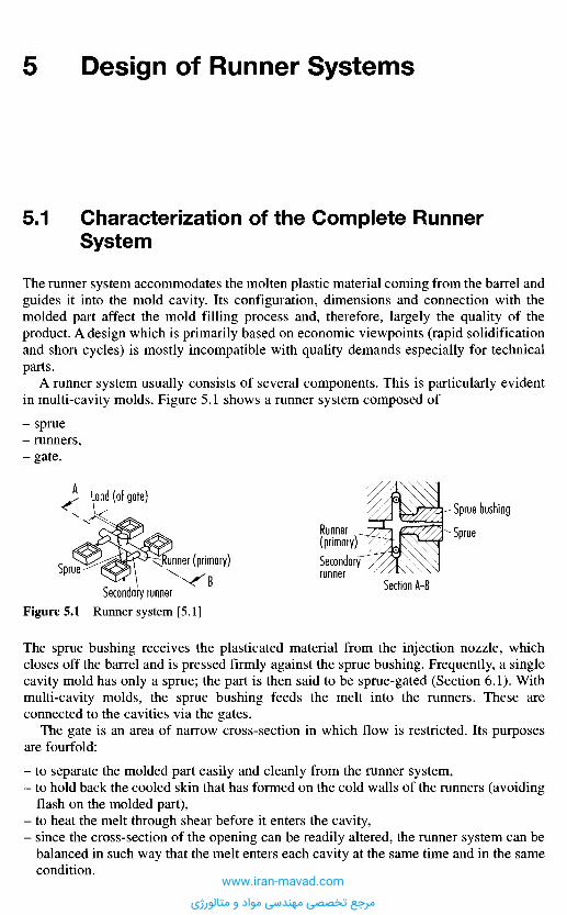
The sprue bushing receives the plasticated material from the injection nozzle, whichcloses off the barrel and is pressed firmly against the sprue bushing. Frequently, a singlecavity mold has only a sprue; the part is then said to be sprue-gated (Section 6.1). Withmulti-cavity molds, the sprue bushing feeds the melt into the runners. These areconnected to the cavities via the gates.
The gate is an area of narrow cross-section in which flow is restricted. Its purposesare fourfold:
- to separate the molded part easily and cleanly from the runner system,- to hold back the cooled skin that has formed on the cold walls of the runners (avoiding
flash on the molded part),- to heat the melt through shear before it enters the cavity,- since the cross-section of the opening can be readily altered, the runner system can be
balanced in such way that the melt enters each cavity at the same time and in the samecondition.
5 D e s i g n o f R u n n e r S y s t e m s
5.1 C h a r a c t e r i z a t i o n o f t h e C o m p l e t e R u n n e r
S y s t e m
The runner system accommodates the molten plastic material coming from the barrel andguides it into the mold cavity. Its configuration, dimensions and connection with themolded part affect the mold filling process and, therefore, largely the quality of theproduct. A design which is primarily based on economic viewpoints (rapid solidificationand short cycles) is mostly incompatible with quality demands especially for technicalparts.
A runner system usually consists of several components. This is particularly evidentin multi-cavity molds. Figure 5.1 shows a runner system composed of
spruerunners,gate.
Runner(primary)Secondaryrunner
Section A-B
Sprue bushing
Sprue
Land (of gate)A
Sprue
Secondary runner
[Runner primary)B
Figure 5.1 Runner system [5.1]
www.iran-mavad.com
مرجع تخصصی مهندسی مواد و متالورژی
5 . 2 C o n c e p t a n d D e f i n i t i o n o f V a r i o u s T y p e s
o f R u n n e r s
Depending on the temperature control, different types of runners may be distinguished:
- standard runner systems,- hot-runner systems,- cold-runner systems.
5.2.1 S t a n d a r d Runne r S y s t e m s
Standard runners are directly machined into the mold plates, which form the mainparting line. The temperature is therefore the temperature of the mold. The meltremaining in the runner freezes and has to be demolded along with the molded part aftereach shot. In the case of thermoplastics, the frozen material can generally be recycled asregrind, whereas in the case of thermosets, it has limited scope for reuse and isunrecoverable material.
5.2.2 H o t - R u n n e r S y s t e m s
Hot runners may be viewed as extended injection nozzles in the form of a block. Heatbarriers isolate it from the cold mold. It contains the runner system consisting of centralsprue bush, runners and gates or nozzles. The temperature of this block lies in themelting range of the thermoplastic melts. Hot-runners offer the following advantages:
- no loss of melt and thus less energy and work input,- easier fully automatic operation,- superior quality because melt can be transferred into the cavity at the optimum sites.
The disadvantages are:
- high costs,- the risk of decomposition and production stoppages in the case of materials with low
thermal resistance,- thermal isolation from the hot-runner manifold block is problematic.
5.2.3 C o l d - R u n n e r S y s t e m s
Just as hot runners are used in molds for thermoplastics, cold runners are used in moldsfor reactive materials such as thermosets and rubber. Unlike the hot mold, which is keptat 160-180 0C, the cold runner must be kept at 80-120 0C in order that the material maynot react prematurely in the runner. The advantages are the same as for thermoplastics,but there are additional difficulties:
- pressure consumption in cold runners is very high, a fact which makes the design moreexpensive,
- since the slightest temperature differences cause very large differences in viscosity, itis practically impossible to fulfill the requirement of introducing "the material intoevery cavity at the same time in the same condition".
www.iran-mavad.com
مرجع تخصصی مهندسی مواد و متالورژی
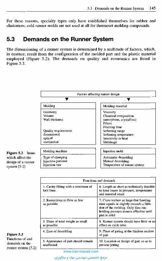
For these reasons, specialty types only have established themselves for rubber andelastomers; cold runner molds are not used at all for thermoset molding compounds.
5 . 3 D e m a n d s o n t h e R u n n e r S y s t e m
The dimensioning of a runner system is determined by a multitude of factors, which,in essence, result from the configuration of the molded part and the plastic materialemployed (Figure 5.2). The demands on quality and economics are listed inFigure 5.3.
Factors affecting runner design
Molding
GeometryVolumeWall thickness
Quality requirementsdimensionalopticalmechanical
Molding material
ViscosityChemical composition(amorphous, crystalline)FillersFreezing timeSoftening rangeSoftening temperatureSensitivity to heatShrinkage
Molding machine
Type of clampingInjection pressureInjection rate
Injection mold
Automatic demoldingManual demoldingTemperature of runner system
Functions and demands
1. Cavity filling with a minimum ofknit lines
2. Restrictions to flow as fewas possible
3. Share of total weight as smallas possible
4. Ease of demolding
5. Appearance of part should remainunaffected
6. Length as short as technically feasibleto keep losses in pressure, temperatureand material small
7. Cross section so large that freezingtime equals or slightly exceeds a littlethat of the molding. Only then canholding pressure remain effective untilpart is solid
8. Runner system should have little or noeffect on cycle time
9. Place of gating at the thickest sectionof part
10. Location or design of gate so as toprevent jetting
Figure 5.2 Itemswhich affect thedesign of a runnersystem [5.2]
Figure 5.3Functions of anddemands on therunner system [5.2]
www.iran-mavad.com
مرجع تخصصی مهندسی مواد و متالورژی
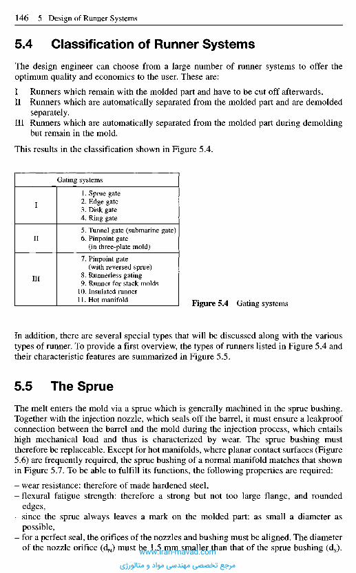
In addition, there are several special types that will be discussed along with the varioustypes of runner. To provide a first overview, the types of runners listed in Figure 5.4 andtheir characteristic features are summarized in Figure 5.5.
5 . 5 T h e S p r u e
The melt enters the mold via a sprue which is generally machined in the sprue bushing.Together with the injection nozzle, which seals off the barrel, it must ensure a leakproofconnection between the barrel and the mold during the injection process, which entailshigh mechanical load and thus is characterized by wear. The sprue bushing musttherefore be replaceable. Except for hot manifolds, where planar contact surfaces (Figure5.6) are frequently required, the sprue bushing of a normal manifold matches that shownin Figure 5.7. To be able to fulfill its functions, the following properties are required:
- wear resistance: therefore of made hardened steel,- flexural fatigue strength: therefore a strong but not too large flange, and rounded
edges,- since the sprue always leaves a mark on the molded part: as small a diameter as
possible,- for a perfect seal, the orifices of the nozzles and bushing must be aligned. The diameter
of the nozzle orifice (dN) must be 1.5 mm smaller than that of the sprue bushing (ds).
Figure 5.4 Gating systems
5 . 4 C l a s s i f i c a t i o n o f R u n n e r S y s t e m s
The design engineer can choose from a large number of runner systems to offer theoptimum quality and economics to the user. These are:
I Runners which remain with the molded part and have to be cut off afterwards.II Runners which are automatically separated from the molded part and are demolded
separately.III Runners which are automatically separated from the molded part during demolding
but remain in the mold.
This results in the classification shown in Figure 5.4.
Gating systems
1. Sprue gate2. Edge gate3. Disk gate4. Ring gate
5. Tunnel gate (submarine gate)6. Pinpoint gate
(in three-plate mold)
7. Pinpoint gate(with reversed sprue)
8. Runnerless gating9. Runner for stack molds
10. Insulated runner11. Hot manifold
I
II
III
www.iran-mavad.com
مرجع تخصصی مهندسی مواد و متالورژی
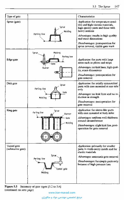
Characteristics
Application: for temperature-sensi-tive and high-viscous materials,high-quality parts and those withheavy sections
Advantages: results in high qualityand exact dimensions
Disadvantages: postoperation forsprue removal, visible gate mark
Application: for parts with largeareas such as plates and strips
Advantages: no knit lines, high qual-ity, exact dimensions
Disadvantages: postoperation forgate removal
Application: for axially symmetricalparts with core mounted at one sideonly
Advantages: no knit lines and no re-duction in strength
Disadvantages: postoperation forgate removal
Application: for sleeve-like partswith core mounted at both sides
Advantages: uniform wall thicknessaround circumference
Disadvantages: slight knit line, post-operation for gate removal
Application: primarily for smallerparts in multi-cavity molds and forelastic materials
Advantages: automatic gate removal
Disadvantages.for simple parts onlybecause of high pressure loss
Type of gate
Sprue (gate)
Edge gate
Disk gate
Ring gate
Tunnel gate(submarine gate)
Figure 5.5 Summary of gate types [5.2 to 5.6](continued on next page)
Sprue
MoldingParting line
MoldingParting line
Sprue
Gate
Runner
SprueParting line
Molding
Gate
SprueRunnerParting line
Gate
Molding
Sprue
Tunnel gateMolding
Parting line
www.iran-mavad.com
مرجع تخصصی مهندسی مواد و متالورژی
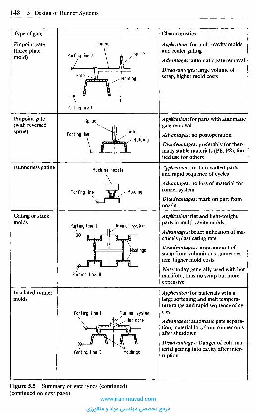
Characteristics
Application: for multi-cavity moldsand center gating
Advantages: automatic gate removal
Disadvantages: large volume ofscrap, higher mold costs
Application:for parts with automaticgate removal
Advantages: no postoperation
Disadvantages: preferably for ther-mally stable materials (PE, PS), lim-ited use for others
Application: for thin-walled partsand rapid sequence of cycles
Advantages: no loss of material forrunner system
Disadvantages: mark on part fromnozzle
Application .flat and light-weightparts in multi-cavity molds
Advantages: better utilization of ma-chine's plasticating rate
Disadvantages:large amount ofscrap from voluminous runner sys-tem, higher mold costs
Note: today generally used with hotmanifold, thus no scrap but moreexpensive
Application: for materials with alarge softening and melt tempera-ture range and rapid sequence of cy-cles
Advantages: automatic gate separa-tion, material loss from runner onlyafter shutdown
Disadvantages: Danger of cold ma-terial getting into cavity after inter-ruption
Type of gate
Pinpoint gate(three-platemold)
Pinpoint gate(with reversedsprue)
Runnerless gating
Gating of stackmolds
Insulated runnermolds
Figure 5.5 Summary of gate types (continued)(continued on next page)
Sprue
Runner
Parting line 2
MoldingGate
Parting line 1
Gate
Molding
Sprue
Parting line
Machine nozzle
MoldingParting line
Runner systemParting line I
Moldings
Parting line n
Parting line I Runner systemHot core
MoldingsParting line II
www.iran-mavad.com
مرجع تخصصی مهندسی مواد و متالورژی
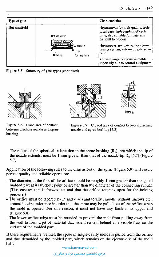
The radius of the spherical indentation in the sprue bushing (Rs) into which the tip ofthe nozzle extends, must be 1 mm greater than that of the nozzle tip RN [5.7] (Figure5.7).
Application of the following rules to the dimensions of the sprue (Figure 5.9) will ensureperfect quality and reliable operation:
- The diameter at the foot of the orifice should be roughly 1 mm greater than the gatedmolded part at its thickest point or greater than the diameter of the connecting runner.(This ensures that it freezes last and that the orifice remains open for the holdingpressure.)
- The orifice must be tapered (> 1° and < 4°) and totally smooth, without furrows etc.,around its circumference in order that the sprue may be pulled out of the orifice whenthe mold is opened. For this reason, it must not have any flash at its upper end(Figure 5.8).
- The lower orifice edge must be rounded to prevent the melt from pulling away fromthe wall to form a jet of material that would remain behind as a visible flaw on thesurface of the molded part.
If these requirements are met, the sprue in single-cavity molds is pulled from the orificeand thus demolded by the molded part, which remains on the ejector-side of the moldhalf.
Figure 5.6 Plane area of contactbetween machine nozzle and spruebushing
Figure 5.7 Curved area of contact between machinenozzle and sprue bushing [5.3]
Detail A
Figure 5.5 Summary of gate types (continued)
Characteristics
Applications: for high-quality, tech-nical parts, independent of cycletime, also suitable for materialsdifficult to process
Advantages: no material loss fromrunner system, automatic gate sepa-ration
Disadvantages: expensive moldsespecially due to control equipment
Type of gate
Hot manifold
Hot manifold
Molding
Nozzle
Parting line
www.iran-mavad.com
مرجع تخصصی مهندسی مواد و متالورژی
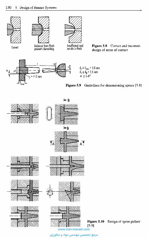
Correct Undercut from flashprevents demolding
Insufficient sealresults in flash
Figure 5.8 Correct and incorrectdesign of areas of contact
Figure 5.9 Guidelines for dimensioning sprues [5.8]
Figure 5.10 Design of sprue pullers[5.9]
www.iran-mavad.com
مرجع تخصصی مهندسی مواد و متالورژی
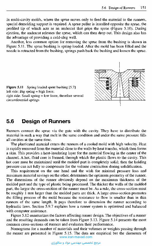
In multi-cavity molds, where the sprue serves only to feed the material to the runners,special demolding support is required. A sprue puller is installed opposite the sprue, theprofiled tip of which acts as an undercut that grips the sprue (Figure 5.10). Duringejection, the undercut releases the sprue, which can then drop out. This design also hasthe advantage of providing a cold-slug well.
Another, less common option for removing the sprue from the bushing is shown inFigure 5.11. The sprue bushing is spring-loaded. After the mold has been filled and thenozzle is retracted from the bushing, springs push back the bushing and loosen the sprue.
Figure 5.11 Spring loaded sprue bushing [5.7]left side: Big spring = high force;right side: Small spring = low force, therefore severalcircumferential springs
5 . 6 D e s i g n o f R u n n e r s
Runners connect the sprue via the gate with the cavity. They have to distribute thematerial in such a way that melt in the same condition and under the same pressure fillsall cavities at the same time.
The plasticated material enters the runners of a cooled mold with high velocity. Heatis rapidly removed from the material close to the walls by heat transfer, which then formsa skin. This provides a heat-insulating layer for the material flowing in the center of thechannel. A hot, fluid core is formed, through which the plastic flows to the cavity. Thishot core must be maintained until the molded part is completely solid; then the holdingpressure can act fully to compensate for the volume contraction during solidification.
This requirement on the one hand and the wish for minimal pressure loss andmaximum material savings on the other, determines the optimum geometry of the runner.The dimensions of the runner obviously depend on the maximum thickness of themolded part and the type of plastic being processed. The thicker the walls of the moldedpart, the larger the cross-section of the runner must be. As a rule, the cross-section mustbe roughly 1 mm larger than the molded parts are thick. A large cross-section promotesthe filling process of the mold because the resistance to flow is smaller than in thinrunners of the same length. It pays therefore to dimension the runner according tohydraulic laws. Section 5.9.7 explains how a runner system is optimized and balancedwith computer assistance.
Figure 5.12 summarizes the factors affecting runner design. The objectives of a runnerand the resulting demands can be taken from Figure 5.13. Figure 5.14 presents the mostcommon cross-sections of runners and evaluates their performance.
Nomograms for a number of materials and their volumes or weights passing throughthe runner are presented in Figure 5.15. The data are empirical but the diameters of
www.iran-mavad.com
مرجع تخصصی مهندسی مواد و متالورژی
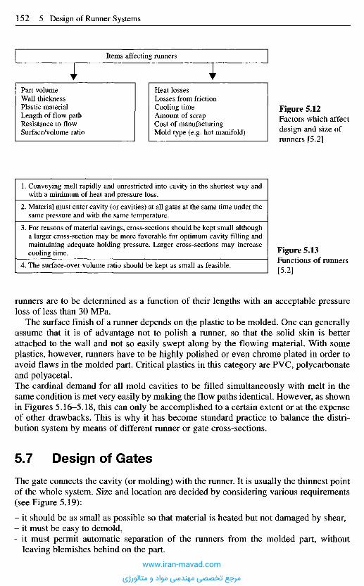
runners are to be determined as a function of their lengths with an acceptable pressureloss of less than 30 MPa.
The surface finish of a runner depends on the plastic to be molded. One can generallyassume that it is of advantage not to polish a runner, so that the solid skin is betterattached to the wall and not so easily swept along by the flowing material. With someplastics, however, runners have to be highly polished or even chrome plated in order toavoid flaws in the molded part. Critical plastics in this category are PVC, polycarbonateand polyacetal.The cardinal demand for all mold cavities to be filled simultaneously with melt in thesame condition is met very easily by making the flow paths identical. However, as shownin Figures 5.16-5.18, this can only be accomplished to a certain extent or at the expenseof other drawbacks. This is why it has become standard practice to balance the distri-bution system by means of different runner or gate cross-sections.
5 . 7 D e s i g n o f G a t e s
The gate connects the cavity (or molding) with the runner. It is usually the thinnest pointof the whole system. Size and location are decided by considering various requirements(see Figure 5.19):
- it should be as small as possible so that material is heated but not damaged by shear,- it must be easy to demold,- it must permit automatic separation of the runners from the molded part, without
leaving blemishes behind on the part.
Figure 5.13Functions of runners[5.2]
1. Conveying melt rapidly and unrestricted into cavity in the shortest way andwith a minimum of heat and pressure loss.
2. Material must enter cavity (or cavities) at all gates at the same time under thesame pressure and with the same temperature.
3. For reasons of material savings, cross-sections should be kept small althougha larger cross-section may be more favorable for optimum cavity filling andmaintaining adequate holding pressure. Larger cross-sections may increasecooling time.
4. The surface-over-volume ratio should be kept as small as feasible.
Items affecting runners
Part volumeWall thicknessPlastic materialLength of flow pathResistance to flowSurface/volume ratio
Heat lossesLosses from frictionCooling timeAmount of scrapCost of manufacturingMold type (e.g. hot manifold)
Figure 5.12Factors which affectdesign and size ofrunners [5.2]
www.iran-mavad.com
مرجع تخصصی مهندسی مواد و متالورژی
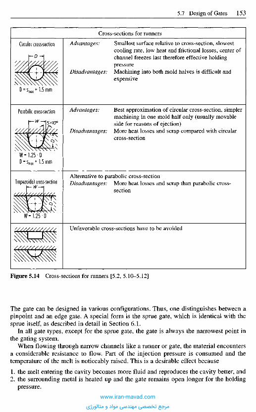
Figure 5.14 Cross-sections for runners [5.2, 5.10-5.12]
The gate can be designed in various configurations. Thus, one distinguishes between apinpoint and an edge gate. A special form is the sprue gate, which is identical with thesprue itself, as described in detail in Section 6.1.
In all gate types, except for the sprue gate, the gate is always the narrowest point inthe gating system.
When flowing through narrow channels like a runner or gate, the material encountersa considerable resistance to flow. Part of the injection pressure is consumed and thetemperature of the melt is noticeably raised. This is a desirable effect because
1. the melt entering the cavity becomes more fluid and reproduces the cavity better, and2. the surrounding metal is heated up and the gate remains open longer for the holding
pressure.
Cross-sections for runners
Advantages: Smallest surface relative to cross-section, slowestcooling rate, low heat and frictional losses, center ofchannel freezes last therefore effective holdingpressure
Disadvantages: Machining into both mold halves is difficult andexpensive
Advantages: Best approximation of circular cross-section, simplermachining in one mold half only (usually movableside for reasons of ejection)
Disadvantages: More heat losses and scrap compared with circularcross-section
Alternative to parabolic cross-sectionDisadvantages: More heat losses and scrap than parabolic cross-
section
Unfavorable cross-sections have to be avoided
Circular cross-section
Parabilic cross-section
Trapezoidal cross-section
www.iran-mavad.com
مرجع تخصصی مهندسی مواد و متالورژی

G(g
)
Gig
)
L
Diagram 1 Diagram 2
D'(mm)D' (mm)
Figure 5.15 Guide lines for dimensioning cross-sections of runners [5.13]Diagram 1 Applicable for PS, ABS, SAN, CAB.Diagram 2 Applicable for PE, PP, PA, PC, POM.Symbols:S: Wall thickness of part (mm),D': Diameter of sprue at its end (mm),G: Weight of part (g),L: Length of runner to one cavity (mm),LF: Correction factor.Procedure (Diagram 3):1. Determine G and S,2. Take D' from diagram for material considered,3. Determine L,4. Take LF from diagram 3,5. Correct diameter or runner: D = D' x LF.
Diagram 3
V
The optimum gate size that will not cause
1. thermal damage to the plastic or2. too high a pressure loss
has to be determined by computation or experiment during a sample run. The runners canbe balanced at the same time.
This is done in practice - this is generally necessary even if the design has beencomputed beforehand - as follows. The employee inspecting the mold changes the gatesmechanically such that every cavity is filled uniformly at the same time with melt. Thiscan be readily determined with consecutive short shots (Figures 5.20 and 5.21). In practice,it is accomplished by making the gates considerably smaller than necessary at first.
www.iran-mavad.com
مرجع تخصصی مهندسی مواد و متالورژی
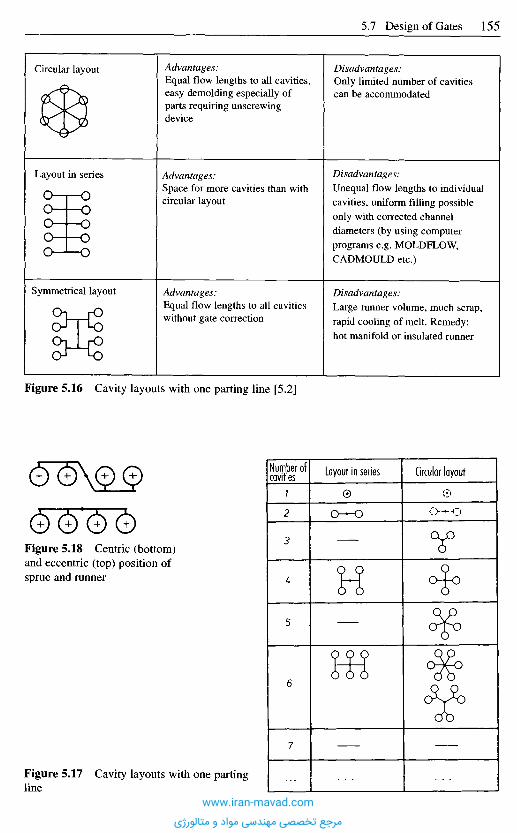
Advantages:Equal flow lengths to all cavities,easy demolding especially ofparts requiring unscrewingdevice
Advantages:Space for more cavities than withcircular layout
Advantages:Equal flow lengths to all cavitieswithout gate correction
Disadvantages:Only limited number of cavitiescan be accommodated
Disadvantages:Unequal flow lengths to individualcavities, uniform filling possibleonly with corrected channeldiameters (by using computerprograms e.g. MOLDFLOW,CADMOULD etc.)
Disadvantages:Large runner volume, much scrap,rapid cooling of melt. Remedy:hot manifold or insulated runner
Circular layout
Layout in series
Symmetrical layout
Figure 5.16 Cavity layouts with one parting line [5.2]
Number ofcavities Layout in series Circular layout
7
2
3
L
5
6
7
Figure 5.18 Centric (bottom)and eccentric (top) position ofsprue and runner
Figure 5.17 Cavity layouts with one partingline
www.iran-mavad.com
مرجع تخصصی مهندسی مواد و متالورژی
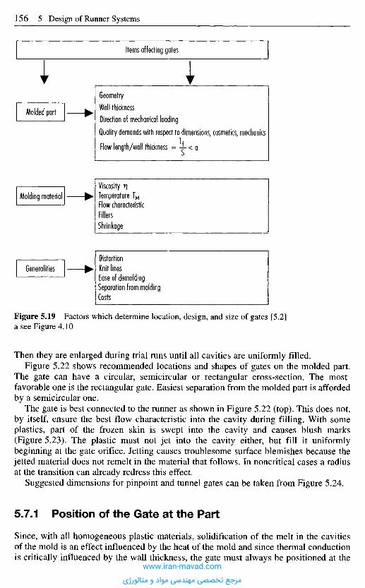
Figure 5.19 Factors which determine location, design, and size of gates [5.2]a see Figure 4.10
Then they are enlarged during trial runs until all cavities are uniformly filled.Figure 5.22 shows recommended locations and shapes of gates on the molded part.
The gate can have a circular, semicircular or rectangular cross-section. The mostfavorable one is the rectangular gate. Easiest separation from the molded part is affordedby a semicircular one.
The gate is best connected to the runner as shown in Figure 5.22 (top). This does not,by itself, ensure the best flow characteristic into the cavity during filling. With someplastics, part of the frozen skin is swept into the cavity and causes blush marks(Figure 5.23). The plastic must not jet into the cavity either, but fill it uniformlybeginning at the gate orifice. Jetting causes troublesome surface blemishes because thejetted material does not remelt in the material that follows. In noncritical cases a radiusat the transition can already redress this effect.
Suggested dimensions for pinpoint and tunnel gates can be taken from Figure 5.24.
5,7.1 Position of the Gate at the Part
Since, with all homogeneous plastic materials, solidification of the melt in the cavitiesof the mold is an effect influenced by the heat of the mold and since thermal conductionis critically influenced by the wall thickness, the gate must always be positioned at the
Items affecting gates
GeometryWall thicknessDirection of mechanical loadingQuality demands with respect to dimensions, cosmetics, mechanics
Flow length/wall thickness = -i-< a
Molded part
Molding materialViscosity v)Temperature TMFlow characteristicFillersShrinkage
GeneralitiesDistortionKnit linesEase of demoldingSeparation from moldingCosts
www.iran-mavad.com
مرجع تخصصی مهندسی مواد و متالورژی
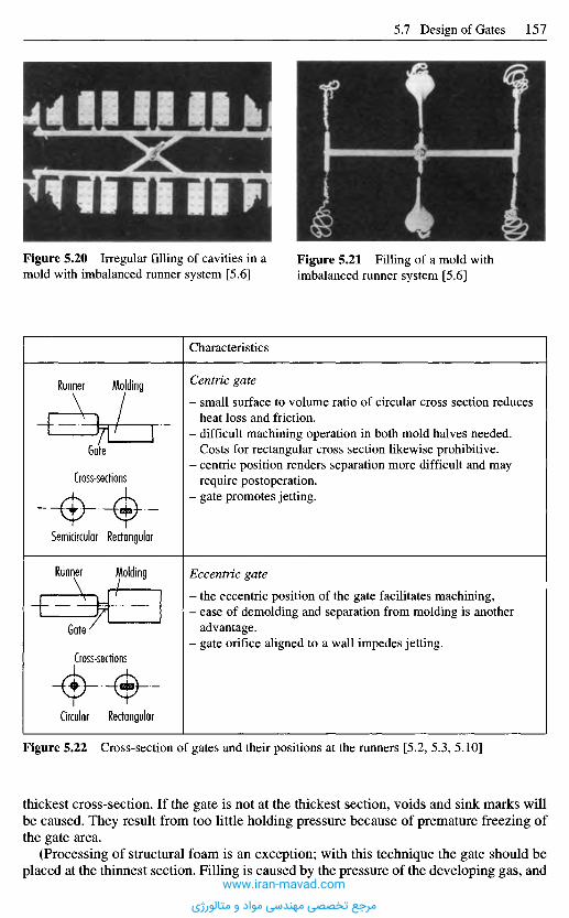
Figure 5.20 Irregular filling of cavities in amold with imbalanced runner system [5.6]
Figure 5.21 Filling of a mold withimbalanced runner system [5.6]
Characteristics
Centric gate
- small surface to volume ratio of circular cross section reducesheat loss and friction.
- difficult machining operation in both mold halves needed.Costs for rectangular cross section likewise prohibitive.
- centric position renders separation more difficult and mayrequire postoperation.
- gate promotes jetting.
Eccentric gate
- the eccentric position of the gate facilitates machining,- ease of demolding and separation from molding is another
advantage.- gate orifice aligned to a wall impedes jetting.
Runner Molding
Gate
Cross-sections
Semicircular Rectangular
MoldingRunner
Gate
Cross-sections
RectangularCircular
Figure 5.22 Cross-section of gates and their positions at the runners [5.2, 5.3, 5.10]
thickest cross-section. If the gate is not at the thickest section, voids and sink marks willbe caused. They result from too little holding pressure because of premature freezing ofthe gate area.
(Processing of structural foam is an exception; with this technique the gate should beplaced at the thinnest section. Filling is caused by the pressure of the developing gas, and
www.iran-mavad.com
مرجع تخصصی مهندسی مواد و متالورژی
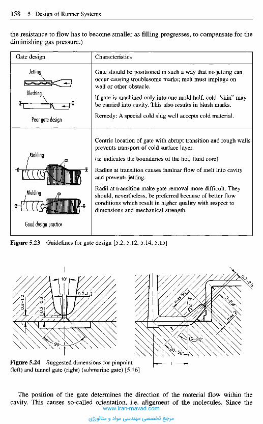
the resistance to flow has to become smaller as filling progresses, to compensate for thediminishing gas pressure.)
Characteristics
Gate should be positioned in such a way that no jetting canoccur causing troublesome marks; melt must impinge onwall or other obstacle.
If gate is machined only into one mold half, cold "skin" maybe carried into cavity. This also results in blush marks.
Remedy: A special cold slug well accepts cold material.
Centric location of gate with abrupt transition and rough wallsprevents transport of cold surface layer.
(a: indicates the boundaries of the hot, fluid core)
Radius at transition causes laminar flow of melt into cavityand prevents jetting.
Radii at transition make gate removal more difficult. Theyshould, nevertheless, be preferred because of better flowconditions which result in higher quality with respect todimensions and mechanical strength.
Figure 5.23 Guidelines for gate design [5.2, 5.12, 5.14, 5.15]
Good design practice
Molding
Molding
Gate design
Jetting
Blushing
Poor gate design
Figure 5.24 Suggested dimensions for pinpoint(left) and tunnel gate (right) (submarine gate) [5.16]
The position of the gate determines the direction of the material flow within thecavity. This causes so-called orientation, i.e. alignment of the molecules. Since the
www.iran-mavad.com
مرجع تخصصی مهندسی مواد و متالورژی
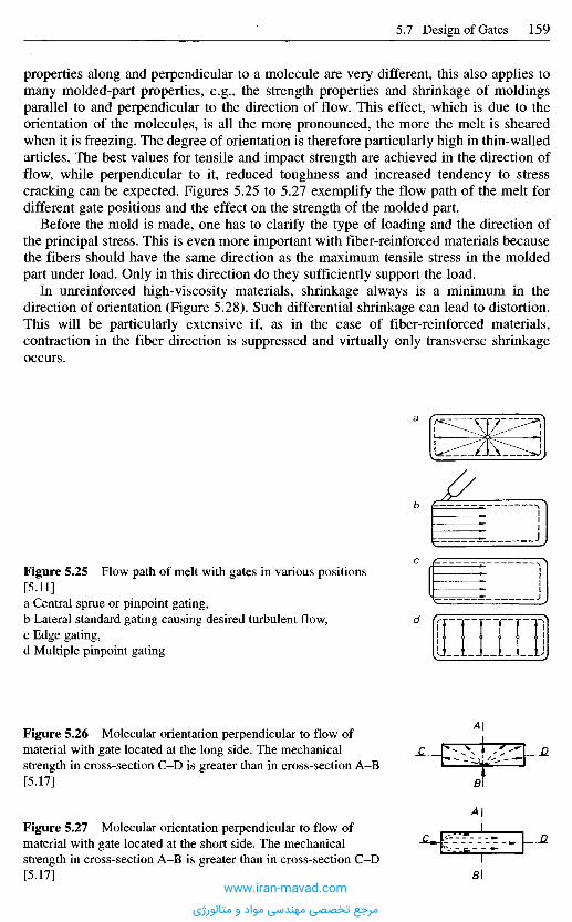
properties along and perpendicular to a molecule are very different, this also applies tomany molded-part properties, e.g., the strength properties and shrinkage of moldingsparallel to and perpendicular to the direction of flow. This effect, which is due to theorientation of the molecules, is all the more pronounced, the more the melt is shearedwhen it is freezing. The degree of orientation is therefore particularly high in thin-walledarticles. The best values for tensile and impact strength are achieved in the direction offlow, while perpendicular to it, reduced toughness and increased tendency to stresscracking can be expected. Figures 5.25 to 5.27 exemplify the flow path of the melt fordifferent gate positions and the effect on the strength of the molded part.
Before the mold is made, one has to clarify the type of loading and the direction ofthe principal stress. This is even more important with fiber-reinforced materials becausethe fibers should have the same direction as the maximum tensile stress in the moldedpart under load. Only in this direction do they sufficiently support the load.
In unreinforced high-viscosity materials, shrinkage always is a minimum in thedirection of orientation (Figure 5.28). Such differential shrinkage can lead to distortion.This will be particularly extensive if, as in the case of fiber-reinforced materials,contraction in the fiber direction is suppressed and virtually only transverse shrinkageoccurs.
Figure 5.25 Flow path of melt with gates in various positions[5.11]a Central sprue or pinpoint gating,b Lateral standard gating causing desired turbulent flow,c Edge gating,d Multiple pinpoint gating
Figure 5.26 Molecular orientation perpendicular to flow ofmaterial with gate located at the long side. The mechanicalstrength in cross-section C-D is greater than in cross-section A-B[5.17]
Figure 5.27 Molecular orientation perpendicular to flow ofmaterial with gate located at the short side. The mechanicalstrength in cross-section A-B is greater than in cross-section C-D[5.17]
a
b
c
d
www.iran-mavad.com
مرجع تخصصی مهندسی مواد و متالورژی
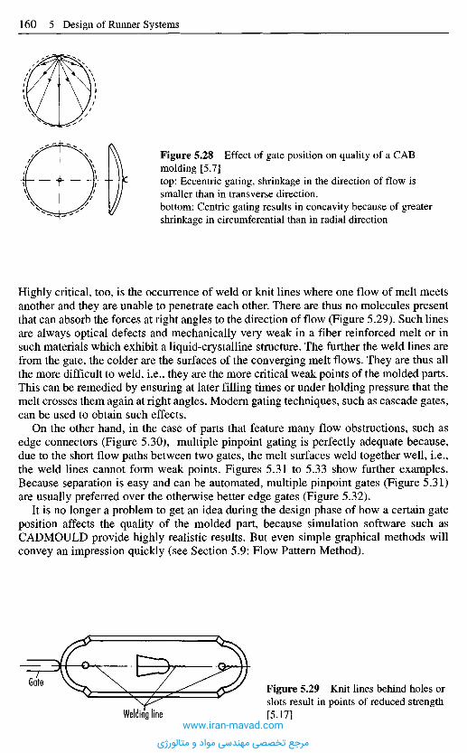
Highly critical, too, is the occurrence of weld or knit lines where one flow of melt meetsanother and they are unable to penetrate each other. There are thus no molecules presentthat can absorb the forces at right angles to the direction of flow (Figure 5.29). Such linesare always optical defects and mechanically very weak in a fiber reinforced melt or insuch materials which exhibit a liquid-crystalline structure. The further the weld lines arefrom the gate, the colder are the surfaces of the converging melt flows. They are thus allthe more difficult to weld, i.e., they are the more critical weak points of the molded parts.This can be remedied by ensuring at later filling times or under holding pressure that themelt crosses them again at right angles. Modern gating techniques, such as cascade gates,can be used to obtain such effects.
On the other hand, in the case of parts that feature many flow obstructions, such asedge connectors (Figure 5.30), multiple pinpoint gating is perfectly adequate because,due to the short flow paths between two gates, the melt surfaces weld together well, i.e.,the weld lines cannot form weak points. Figures 5.31 to 5.33 show further examples.Because separation is easy and can be automated, multiple pinpoint gates (Figure 5.31)are usually preferred over the otherwise better edge gates (Figure 5.32).
It is no longer a problem to get an idea during the design phase of how a certain gateposition affects the quality of the molded part, because simulation software such asCADMOULD provide highly realistic results. But even simple graphical methods willconvey an impression quickly (see Section 5.9: Flow Pattern Method).
Figure 5.28 Effect of gate position on quality of a CABmolding [5.7]top: Eccentric gating, shrinkage in the direction of flow issmaller than in transverse direction.bottom: Centric gating results in concavity because of greatershrinkage in circumferential than in radial direction
Figure 5.29 Knit lines behind holes orslots result in points of reduced strength[5.17]Welding line
Gate
www.iran-mavad.com
مرجع تخصصی مهندسی مواد و متالورژی

5 . 8 R u n n e r s a n d G a t e s f o r R e a c t i v e M a t e r i a l s
Minimizing the volume of the runners is particularly important for both elastomers andthermosets because this fraction of the material can only be recycled to a certain extentand generally needs to be disposed of. For economic reasons, however, multi-cavitymolds with extensive runner systems are used on a large scale, with the result that cold-runner systems are gaining in importance as a means of reducing the material costsincurred. The design of the runner systems is basically the same as that of thermoplasticmaterials.
5.8.1 Elastomers
These materials are usually filled and so are highly viscous. They therefore use up almostall the injection pressure to overcome the resistance of the runner systems. Filling of thecavities, which often have large cross-sections, requires hardly any pressure. However,there is a risk of jetting. It is frequently thought that filling the mold by jetting rather thanby frontal flow does not pose a problem since the curing process will largely eliminatethe weakness of the weld lines. This is not correct. From a processing point of view,jetting is unfavorable because the molded part is not filled in a defined manner. Forexample, air can be introduced during injection and this will lower the quality (e.g., inburners). Furthermore, the stream of material formed can start to crosslink and this willlower the strength.
The high pressure consumption in the runner system mostly results in an opening ofthe mold in the parting line with extensive flashing (Figure 5.34). This creates verydifferent filling conditions in the individual cavities that result in varying orientation andonly partly filled, faulty molded parts. Furthermore, this flashing requires costly
Figure 5.31 Multiplepinpoint gating
Figure 5.32 Edge gating Figure 5.33 Principle of equalflow lengths
Figure 5.30 Edge connector
Gates
www.iran-mavad.com
مرجع تخصصی مهندسی مواد و متالورژی
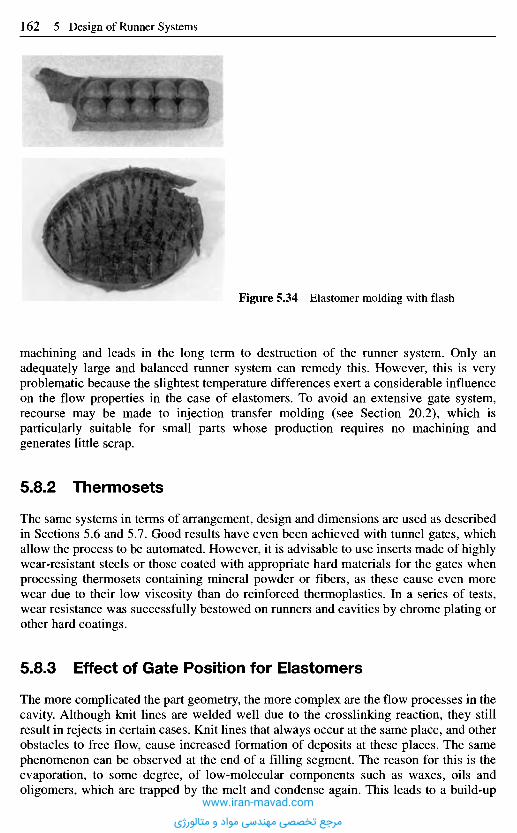
machining and leads in the long term to destruction of the runner system. Only anadequately large and balanced runner system can remedy this. However, this is veryproblematic because the slightest temperature differences exert a considerable influenceon the flow properties in the case of elastomers. To avoid an extensive gate system,recourse may be made to injection transfer molding (see Section 20.2), which isparticularly suitable for small parts whose production requires no machining andgenerates little scrap.
5.8.2 Thermosets
The same systems in terms of arrangement, design and dimensions are used as describedin Sections 5.6 and 5.7. Good results have even been achieved with tunnel gates, whichallow the process to be automated. However, it is advisable to use inserts made of highlywear-resistant steels or those coated with appropriate hard materials for the gates whenprocessing thermosets containing mineral powder or fibers, as these cause even morewear due to their low viscosity than do reinforced thermoplastics. In a series of tests,wear resistance was successfully bestowed on runners and cavities by chrome plating orother hard coatings.
5.8.3 Effect of Gate Position for Elastomers
The more complicated the part geometry, the more complex are the flow processes in thecavity. Although knit lines are welded well due to the crosslinking reaction, they stillresult in rejects in certain cases. Knit lines that always occur at the same place, and otherobstacles to free flow, cause increased formation of deposits at these places. The samephenomenon can be observed at the end of a filling segment. The reason for this is theevaporation, to some degree, of low-molecular components such as waxes, oils andoligomers, which are trapped by the melt and condense again. This leads to a build-up
Figure 5.34 Elastomer molding with flash
www.iran-mavad.com
مرجع تخصصی مهندسی مواد و متالورژی
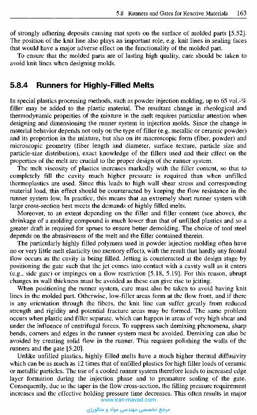
of strongly adhering deposits causing mat spots on the surface of molded parts [5.52].The position of the knit line also plays an important role, e.g. knit lines in sealing facesthat would have a major adverse effect on the functionality of the molded part.
To ensure that the molded parts are of lasting high quality, care should be taken toavoid knit lines when designing molds.
5.8.4 Runners for Highly-Filled Melts
In special plastics processing methods, such as powder injection molding, up to 65 vol.-%filler may be added to the plastic material. The resultant change in rheological andthermodynamic properties of the mixture in the melt requires particular attention whendesigning and dimensioning the runner system in injection molds. Since the change inmaterial behavior depends not only on the type of filler (e.g. metallic or ceramic powder)and its proportion in the mixture, but also on its macroscopic form (fiber, powder) andmicroscopic geometry (fiber length and diameter, surface texture, particle size andparticle-size distribution), exact knowledge of the fillers used and their effect on theproperties of the melt are crucial to the proper design of the runner system.
The melt viscosity of plastics increases markedly with the filler content, so that tocompletely fill the cavity much higher pressure is required than when unfilledthermoplastics are used. Since this leads to high wall shear stress and correspondingmaterial load, this effect should be counteracted by keeping the flow resistance in therunner system low. In practice, this means that an extremely short runner system withlarge cross-section best meets the demands of highly filled melts.
Moreover, to an extent depending on the filler and filler content (see above), theshrinkage of a molding compound is much lower than that of unfilled plastics and so agreater draft is required for sprues to ensure better demolding. The choice of tool steeldepends on the abrasiveness of the melt and the filler contained therein.
The particularly highly filled polymers used in powder injection molding often haveno or very little melt elasticity (no memory effect), with the result that hardly any frontalflow occurs as the cavity is being filled. Jetting is counteracted at the design stage bypositioning the gate such that the jet comes into contact with a cavity wall as it enters(e.g., side gate) or impinges on a flow restriction [5.18, 5.19]. For this reason, abruptchanges in wall thickness must be avoided as these can give rise to jetting.
When positioning the runner system, care must also be taken to avoid having knitlines in the molded part. Otherwise, low-filler areas form at the flow front, and if thereis any orientation through the fibers, the knit line can suffer greatly from reducedstrength and rigidity and potential fracture areas may be formed. The same problemoccurs when plastic and filler separate, which can happen in areas of very high shear andunder the influence of centrifugal forces. To suppress such demixing phenomena, sharpbends, corners and edges in the runner system must be avoided. Demixing can also beavoided by creating solid flow in the runner. This requires polishing the walls of therunners and the gate [5.20].
Unlike unfilled plastics, highly filled melts have a much higher thermal diffusivitywhich can be as much as 12 times that of unfilled plastics for high filler loads of ceramicor metallic particles. The use of a cooled runner system therefore leads to increased edgelayer formation during the injection phase and to premature sealing of the gate.Consequently, due to the taper in the flow cross-section, the filling pressure requirementincreases and the effective holding pressure time decreases. This often results in major
www.iran-mavad.com
مرجع تخصصی مهندسی مواد و متالورژی

quality problems for injection-molded parts because, on the one hand, a high fillingpressure causes pronounced orientation in the molded part that in this form - andespecially with filled materials - is often undesirable and troublesome. On the otherhand, the maximum attainable flow-path lengths and the minimum part wall thicknessare restricted by this. The gates and runners for molds that are intended for processinghighly-filled polymers should therefore, also for these thermodynamic reasons, have alarger cross-section than is usual for thermoplastic molds.
An alternative to large-dimensioned gates, that also serves to counteract freezingeffects, is hot-runner systems. These permit much longer, more selective influence to beexerted on the molded-part-formation process in the holding-pressure phase [5.21].Since the formation of a frozen edge layer in the runner is suppressed, pressure lossesare reduced. The disadvantage of this is the need for elaborate, thermal insulation of thehot-runner system toward the cavity with the risk of high orientation near the gate, wherethe material remains molten for a long time. This problem has been successfullyeliminated in powder injection molding by using combinations of hot runners with short,freezing gates [5.22, 5.23]. The effect is that the areas of high orientation are pushed intothe gate area to be later removed and therefore do not have any effect on the quality ofthe molded part.
5 . 9 Q u a l i t a t i v e ( F l o w P a t t e r n ) a n d Q u a n t i t a t i v e
C o m p u t a t i o n o f t h e F i l l ing P r o c e s s o f a M o l d
( S i m u l a t i o n M o d e l s ) [5 .24]
5.9.1 Introduction
It is often necessary to study the filling process of a finished mold in advance, that isduring the conception of mold and molding. Examinations of this kind are generallysummarized under the generic expression "rheological design" [5.25, 5.28] and make aqualitative and quantitative analysis of the later flow process possible. Qualitativeanalysis here is the composition of a flow pattern, which provides informationconcerning
- effective kind and position of gates,- ease of filling individual sections,- location of weld lines,- location of likely air traps and- directions of principal orientation.
Aids for theoretically composing a flow-pattern are the flow-pattern method [5.27 to5.29] and calculation software for computers capable of graphics [5.29, 5.30].
The second step is the quantitative analysis. This is a series of calculations, whichinclude the behavior of the material and assumed processing parameters. They determinemold filling data such as
- pressures,- temperatures,- shear rate,- shear stresses, etc.
Next Page
www.iran-mavad.com
مرجع تخصصی مهندسی مواد و متالورژی

quality problems for injection-molded parts because, on the one hand, a high fillingpressure causes pronounced orientation in the molded part that in this form - andespecially with filled materials - is often undesirable and troublesome. On the otherhand, the maximum attainable flow-path lengths and the minimum part wall thicknessare restricted by this. The gates and runners for molds that are intended for processinghighly-filled polymers should therefore, also for these thermodynamic reasons, have alarger cross-section than is usual for thermoplastic molds.
An alternative to large-dimensioned gates, that also serves to counteract freezingeffects, is hot-runner systems. These permit much longer, more selective influence to beexerted on the molded-part-formation process in the holding-pressure phase [5.21].Since the formation of a frozen edge layer in the runner is suppressed, pressure lossesare reduced. The disadvantage of this is the need for elaborate, thermal insulation of thehot-runner system toward the cavity with the risk of high orientation near the gate, wherethe material remains molten for a long time. This problem has been successfullyeliminated in powder injection molding by using combinations of hot runners with short,freezing gates [5.22, 5.23]. The effect is that the areas of high orientation are pushed intothe gate area to be later removed and therefore do not have any effect on the quality ofthe molded part.
5 . 9 Q u a l i t a t i v e ( F l o w P a t t e r n ) a n d Q u a n t i t a t i v e
C o m p u t a t i o n o f t h e F i l l ing P r o c e s s o f a M o l d
( S i m u l a t i o n M o d e l s ) [5 .24]
5.9.1 Introduction
It is often necessary to study the filling process of a finished mold in advance, that isduring the conception of mold and molding. Examinations of this kind are generallysummarized under the generic expression "rheological design" [5.25, 5.28] and make aqualitative and quantitative analysis of the later flow process possible. Qualitativeanalysis here is the composition of a flow pattern, which provides informationconcerning
- effective kind and position of gates,- ease of filling individual sections,- location of weld lines,- location of likely air traps and- directions of principal orientation.
Aids for theoretically composing a flow-pattern are the flow-pattern method [5.27 to5.29] and calculation software for computers capable of graphics [5.29, 5.30].
The second step is the quantitative analysis. This is a series of calculations, whichinclude the behavior of the material and assumed processing parameters. They determinemold filling data such as
- pressures,- temperatures,- shear rate,- shear stresses, etc.
Previous Page
www.iran-mavad.com
مرجع تخصصی مهندسی مواد و متالورژی
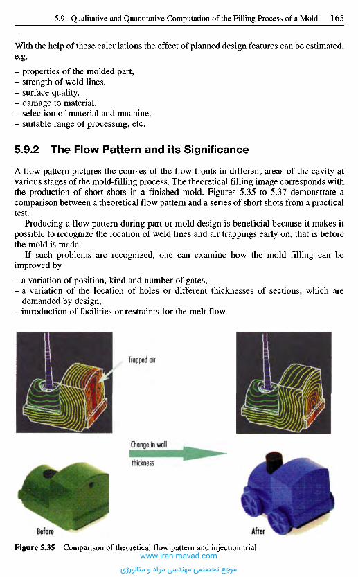
With the help of these calculations the effect of planned design features can be estimated,e-g.
- properties of the molded part,- strength of weld lines,- surface quality,- damage to material,- selection of material and machine,- suitable range of processing, etc.
5.9.2 The Flow Pattern and its Significance
A flow pattern pictures the courses of the flow fronts in different areas of the cavity atvarious stages of the mold-filling process. The theoretical filling image corresponds withthe production of short shots in a finished mold. Figures 5.35 to 5.37 demonstrate acomparison between a theoretical flow pattern and a series of short shots from a practicaltest.
Producing a flow pattern during part or mold design is beneficial because it makes itpossible to recognize the location of weld lines and air trappings early on, that is beforethe mold is made.
If such problems are recognized, one can examine how the mold filling can beimproved by
- a variation of position, kind and number of gates,- a variation of the location of holes or different thicknesses of sections, which are
demanded by design,- introduction of facilities or restraints for the melt flow.
Trapped air
Change in wall
After
thickness
Before
Figure 5.35 Comparison of theoretical flow pattern and injection trialwww.iran-mavad.com
مرجع تخصصی مهندسی مواد و متالورژی
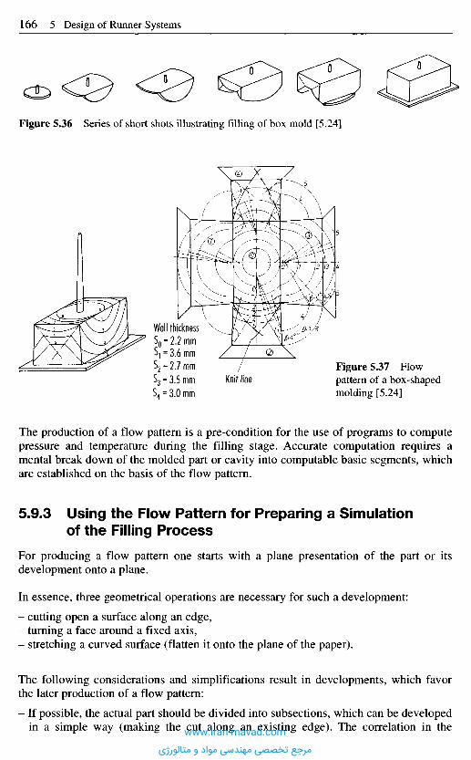
The production of a flow pattern is a pre-condition for the use of programs to computepressure and temperature during the filling stage. Accurate computation requires amental break down of the molded part or cavity into computable basic segments, whichare established on the basis of the flow pattern.
5.9.3 Using the Flow Pattern for Preparing a Simulationof the Filling Process
For producing a flow pattern one starts with a plane presentation of the part or itsdevelopment onto a plane.
In essence, three geometrical operations are necessary for such a development:
- cutting open a surface along an edge,- turning a face around a fixed axis,- stretching a curved surface (flatten it onto the plane of the paper).
The following considerations and simplifications result in developments, which favorthe later production of a flow pattern:
- If possible, the actual part should be divided into subsections, which can be developedin a simple way (making the cut along an existing edge). The correlation in the
Figure 5.37 Flowpattern of a box-shapedmolding [5.24]
Knit line
Wall thickness
Figure 5.36 Series of short shots illustrating filling of box mold [5.24]
www.iran-mavad.com
مرجع تخصصی مهندسی مواد و متالورژی
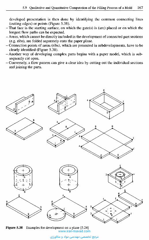
developed presentation is then done by identifying the common connecting lines(cutting edges) or points (Figure 5.38).
- That face is the starting surface, on which the gate(s) is (are) placed or on which thelongest flow paths can be expected.
- Areas, which cannot be directly included in the development of connected part sections(e.g. ribs), are folded separately onto the paper plane.
- Connection points of areas (ribs), which are presented in subdevelopments, have to beclearly identified (Figure 5.38).
- Another way of developing complex parts begins with a paper model, which is sub-sequently cut open.
- Conversely, a flow pattern can give a clear idea by cutting out the individual sectionsand joining the parts.
Figure 5.38 Examples for development on a plane [5.24]www.iran-mavad.com
مرجع تخصصی مهندسی مواد و متالورژی
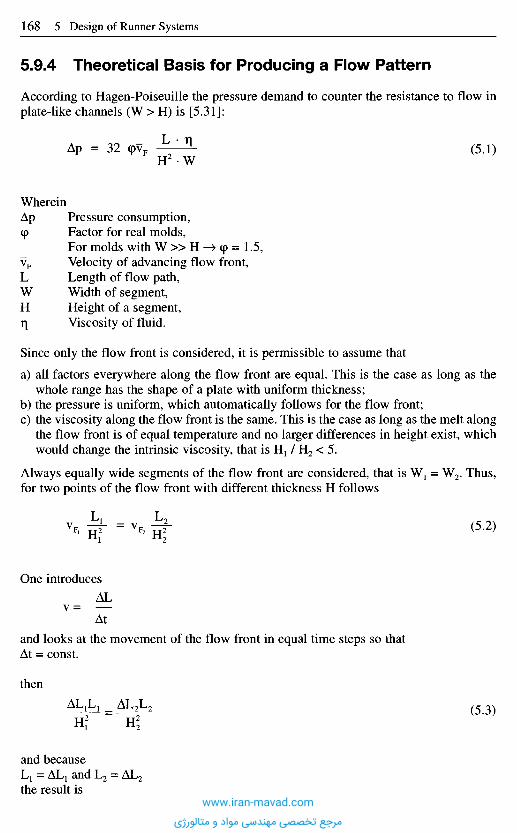
5.9.4 Theoretical Basis for Producing a Flow Pattern
According to Hagen-Poiseuille the pressure demand to counter the resistance to flow inplate-like channels (W > H) is [5.31]:
(5.1)
WhereinAp Pressure consumption,(p Factor for real molds,
For molds with W » H -^ <p = 1.5,vF Velocity of advancing flow front,L Length of flow path,W Width of segment,H Height of a segment,q Viscosity of fluid.
Since only the flow front is considered, it is permissible to assume that
a) all factors everywhere along the flow front are equal. This is the case as long as thewhole range has the shape of a plate with uniform thickness;
b) the pressure is uniform, which automatically follows for the flow front;c) the viscosity along the flow front is the same. This is the case as long as the melt along
the flow front is of equal temperature and no larger differences in height exist, whichwould change the intrinsic viscosity, that is H1 / H2 < 5.
Always equally wide segments of the flow front are considered, that is W1 = W2. Thus,for two points of the flow front with different thickness H follows
(5.2)
One introduces
and looks at the movement of the flow front in equal time steps so thatAt = const.
then
(5.3)
and becauseL1 = AL1 and L2 = AL2
the result iswww.iran-mavad.com
مرجع تخصصی مهندسی مواد و متالورژی

The advance of the flow front in equal time intervals corresponds with the ratio ofthicknesses at the points considered.
Present experience demonstrates a very good agreement between flow pattern andpractical results as long as one can assume that the flow front is uniformly supplied withmelt. This holds true in all cases even for very different materials from very fluidreactive polyurethanes or caprolactams to elastomers and filled thermosets. If,however, narrow cross-sections, such as a living hinge, restrict the filling, then adeviation from the location of weld lines in the following area can be noticed. This,however, has never really interfered with the qualitative prediction of the location ofweld lines. If this method, however, should serve to compute pressure and temperaturein a simulation program (CADMOULD or MOLDFLOW) then the result has aconsiderable error in such cases.
5.9.5 Practical Procedure for Graphically Producinga Flow Pattern
5.9.5.1 Drawing the Flow Fronts
The model on which the method of the flow pattern is based, relies on the theory of wavepropagation according to Huygens. It implies that every point of an "old" wave front(flow front) can be considered the starting point (center) of a so-called elementarywavelet (circular wave). The envelope of the new elementary wavelets is the new (next)wave front (flow front). The "new" flow front is the envelope of the new elementarywavelets, which expand in circular form from every point of the last flow front. Theradius of every elementary wavelet is equal to the advance of the flow front Al (Figures5.39 and 5.40).
5.9.5.2 Radius Vectors for the Presentation of Shadow Regions
Areas of a part which are located in the "shadow" of openings cannot be directly reachedby parallel or swelling flow from the gate. They are filled beginning from a flow front(Figure 5.41).
Vectors starting at the gate indicate these regions and offer points of support forproducing the flow front (Figure 5.42).
The points P, where the vectors are tangent to the opening, are, as points of an "old"flow front, the origins of new elementary wavelets. They start the filling of the shadowregions (Figure 5.43 to 5.45).
With complex shapes of openings or barriers to flow it may be necessary to introducemore vectors during the process to completely cover the flow around them (Figure 5.46).
(5.4)
www.iran-mavad.com
مرجع تخصصی مهندسی مواد و متالورژی
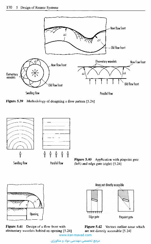
New flow front
Old flow front
Elementary wavelets New flow frontNew flow front
Old flow front
Parallel flow
Old flow front
Elementarywavelets
Swelling flow
Figure 5.39 Methodology of designing a flow pattern [5.24]
Swelling flow Parallel flowFigure 5.40 Application with pinpoint gate(left) and edge gate (right) [5.24]
Areas not directly accessible
Edge gate Pinpoint gate
Figure 5.42 Vectors outline areas whichare not directly accessible [5.24]
Figure 5.41 Design of a flow front withelementary wavelets behind an opening [5.24]
Opening
www.iran-mavad.com
مرجع تخصصی مهندسی مواد و متالورژی
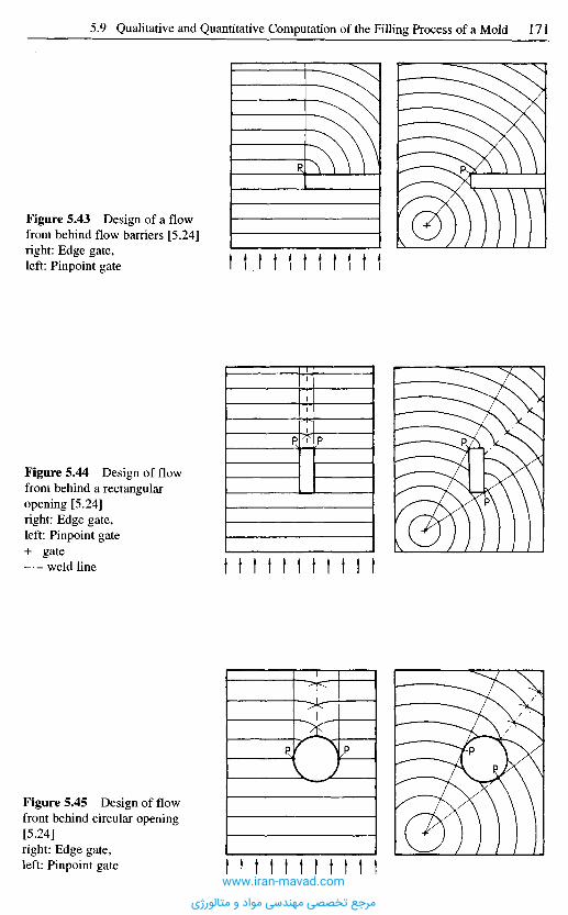
Figure 5.43 Design of a flowfront behind flow barriers [5.24]right: Edge gate,left: Pinpoint gate
Figure 5.44 Design of flowfront behind a rectangularopening [5.24]right: Edge gate,left: Pinpoint gate+ gate
weld line
Figure 5.45 Design of flowfront behind circular opening[5.24]right: Edge gate,left: Pinpoint gate
www.iran-mavad.com
مرجع تخصصی مهندسی مواد و متالورژی
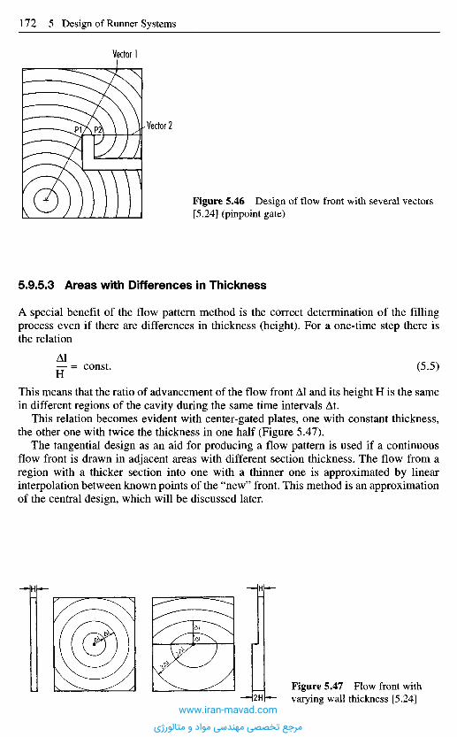
5.9.5.3 Areas with Differences in Thickness
A special benefit of the flow pattern method is the correct determination of the fillingprocess even if there are differences in thickness (height). For a one-time step there isthe relation
Al— = const. (5.5)H
This means that the ratio of advancement of the flow front Al and its height H is the samein different regions of the cavity during the same time intervals At.
This relation becomes evident with center-gated plates, one with constant thickness,the other one with twice the thickness in one half (Figure 5.47).
The tangential design as an aid for producing a flow pattern is used if a continuousflow front is drawn in adjacent areas with different section thickness. The flow from aregion with a thicker section into one with a thinner one is approximated by linearinterpolation between known points of the "new" front. This method is an approximationof the central design, which will be discussed later.
Figure 5.47 Flow front withvarying wall thickness [5.24]
Figure 5.46 Design of flow front with several vectors[5.24] (pinpoint gate)
Vector 1
Vector 2
www.iran-mavad.com
مرجع تخصصی مهندسی مواد و متالورژی
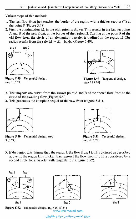
Various steps of this method:
1. The last flow front just touches the border of the region with a thicker section (II) atthe point P (Figure 5.48).
2. First the continuation Al1 in the old region is drawn. This results in the known pointsA and B of the new front, at the border of the region II. Starting at the point P of theold flow front the circle of an elementary wavelet is outlined in the region II. Theradius results from the rule Aln = Al1 Hn/Hj (Figure 5.49).
Figure 5.48 Tangential design,step 1 [5.24]
Figure 5.49 Tangential design,step 2 [5.24]
Area Il Area 2
3. The tangents are drawn from the known point A and B of the "new" flow front to thecircle of the swelling flow (Figure 5.50).
4. This generates the complete sequel of the new front (Figure 5.51).
Figure 5.50 Tangential design, step3 [5.24]
Figure 5.51 Tangential design,step 4 [5.24]
5. If the region II is thinner than the region I, the flow from I to II is pictured as describedabove. If the region II is thicker than region I the flow from I to II is considered by asecond circle for a wavelet with tangents to it (Figure 5.52).
Area Il Area I
Figure 5.52 Tangential design, H11 > H1 [5.24]
Step] Step 2 Step 3
www.iran-mavad.com
مرجع تخصصی مهندسی مواد و متالورژی
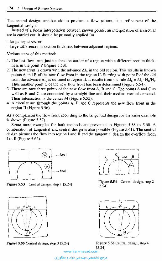
The central design, another aid to produce a flow pattern, is a refinement of thetangential design.
Instead of a linear interpolation between known points, an interpolation of a circulararc is carried out. It should be primarily applied for
- large step sizes, or- large differences in section thickness between adjacent regions.
Various steps of this method:
1. The last flow front just touches the border of a region with a different section thick-ness in the point P (Figure 5.53).
2. The new front is drawn with the advance Al1, in the old region. This results in knownpoints A and B of the new flow front in the region II. Starting with point P of the oldfront the advance Aln is outlined in region II. It results from the rule Aln = Al1 • HnZH1.Thus another point C of the new flow front has been determined (Figure 5.54).
3. There are now three points of the new flow front A, B and C. The points A and C aswell as B and C are connected by a straight line and their median verticals erected.Their intersection is the center M (Figure 5.55).
4. A circular arc through the points A, B and C represents the new flow front in theregion II (Figure 5.56).
As a comparison the flow front according to the tangential design for the same exampleis shown (Figure 5.57).
Some more examples for both methods are presented in Figures 5.58 to 5.60. Acombination of tangential and central design is also possible (Figure 5.61). The centraldesign pictures the flow into region I and II and the tangential design the overflow fromI to II (Figure 5.62).
Figure 5.53 Central design, step 1 [5.24]Figure 5.54 Central design, step 2[5.24]
Figure 5.55 Central design, step 3 [5.24] Figure 5.56 Central design, step 4[5.24]
Area Il
Area I
www.iran-mavad.com
مرجع تخصصی مهندسی مواد و متالورژی

Here, tangential and central design can also be combined (Figure 5.63). The first onepictures the overflow from region II to I and the second one the flow into regions I andII.
5.9.5.4 Flow Patterns of Ribs
First, ribs are looked at which are thinner than the base (Figure 5.64). They are filledfrom the base and do not affect the flow pattern of the main body.
In Figure 5.64 venting should be provided in the corner C; the rib should not bemachined as a closed pocket.
Figure 5.60 Determination of flowpattern with tangential design [5.24]
Figure 5.61Determination offlow pattern withtangential and centraldesign [5.24]
•Weld lineDirection of flow
Figure 5.58 Determination of flowpattern with central design [5.24]
Figure 5.59 Determination of flowpattern with tangential design [5.24]
Area Il Area I
Figure 5.57 Flow front based ontangential design [5.24]
www.iran-mavad.com
مرجع تخصصی مهندسی مواد و متالورژی
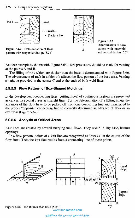
Another example is shown with Figure 5.65. Here provisions should be made for ventingat the points A and B.
The filling of ribs which are thicker than the base is demonstrated with Figure 5.66.The advancement of melt in a thick rib affects the flow pattern of the base area. Ventingshould be provided in the corner C and at the ends of both weld lines.
5.9.5.5 Flow Pattern of Box-Shaped Moldings
In the development, connecting lines (cutting lines) of continuous regions are presentedas curves, in special cases as straight lines. For the determination of a filling image theadvances of the flow have to be picked off from one connecting line and transferred tothe proper "opposite" connecting line to correctly determine an advance of flow or anoverflow (Figure 5.67).
5.9.5.6 Analysis of Critical Areas
Knit lines are created by several merging melt flows. They occur, in any case, behindopenings.
In a flow pattern, points of a knit line are recognized as "breaks" in the course of theflow front. Then the knit line results from a connecting line of these points.
Figure 5.64 Rib thinner than base [5.24]
Centraldesign
Tangentialdesign
Figure 5.62 Determination of flowpattern with tangential design [5.24]
Figure 5.63Determination of flowpattern with tangentialand central design [5.24]
Weld lineDirection of flow
Area IArea Il
www.iran-mavad.com
مرجع تخصصی مهندسی مواد و متالورژی
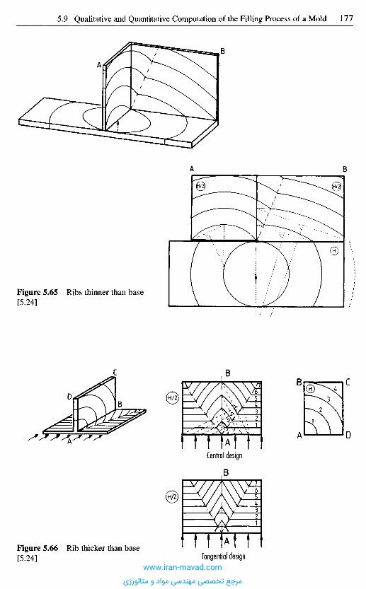
Figure 5.65 Ribs thinner than base[5.24]
Central design
Tangential designFigure 5.66 Rib thicker than base[5.24]
www.iran-mavad.com
مرجع تخصصی مهندسی مواد و متالورژی
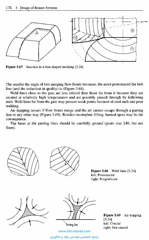
Figure 5.67 Junction in a box-shaped molding [5.24]
The smaller the angle of two merging flow fronts becomes, the more pronounced the knitline (and the reduction in quality) is (Figure 5.68).
Weld lines close to the gate are less critical than those far from it because they arecreated at relatively high temperatures and are possibly passed through by followingmelt. Weld lines far from the gate may present weak points because of cool melt and poorwelding.
Air trapping occurs if flow fronts merge and the air cannot escape through a partingline or any other way (Figure 5.69). Besides incomplete filling, burned spots may be theconsequence.
The faces at the parting lines should be carefully ground (grain size 240, but notfiner).
Figure 5.68 Weld lines [5.24]left: Pronouncedright: Insignificant
Figure 5.69 Air trapping[5.24]left: Crucialright: Not crucial
Parting line
www.iran-mavad.com
مرجع تخصصی مهندسی مواد و متالورژی
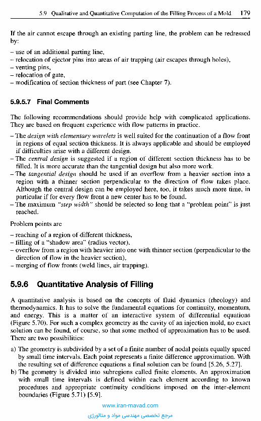
If the air cannot escape through an existing parting line, the problem can be redressedby:
- use of an additional parting line,- relocation of ejector pins into areas of air trapping (air escapes through holes),- venting pins,- relocation of gate,- modification of section thickness of part (see Chapter 7).
5,9.5-7 Final Comments
The following recommendations should provide help with complicated applications.They are based on frequent experience with flow patterns in practice.
- The design with elementary wavelets is well suited for the continuation of a flow frontin regions of equal section thickness. It is always applicable and should be employedif difficulties arise with a different design.
- The central design is suggested if a region of different section thickness has to befilled. It is more accurate than the tangential design but also more work.
- The tangential design should be used if an overflow from a heavier section into aregion with a thinner section perpendicular to the direction of flow takes place.Although the central design can be employed here, too, it takes much more time, inparticular if for every flow front a new center has to be found.
- The maximum "step width" should be selected so long that a "problem point" is justreached.
Problem points are
- reaching of a region of different thickness,- filling of a "shadow area" (radius vector),- overflow from a region with heavier into one with thinner section (perpendicular to the
direction of flow in the heavier section),- merging of flow fronts (weld lines, air trapping).
5.9.6 Quantitative Analysis of Filling
A quantitative analysis is based on the concepts of fluid dynamics (rheology) andthermodynamics. It has to solve the fundamental equations for continuity, momentum,and energy. This is a matter of an interactive system of differential equations(Figure 5.70). For such a complex geometry as the cavity of an injection mold, no exactsolution can be found, of course, so that some method of approximation has to be used.There are two possibilities:
a) The geometry is subdivided by a set of a finite number of nodal points equally spacedby small time intervals. Each point represents a finite difference approximation. Withthe resulting set of difference equations a final solution can be found [5.26, 5.27].
b) The geometry is divided into subregions called finite elements. An approximationwith small time intervals is defined within each element according to knownprocedures and appropriate continuity conditions imposed on the inter-elementboundaries (Figure 5.71) [5.9].
www.iran-mavad.com
مرجع تخصصی مهندسی مواد و متالورژی
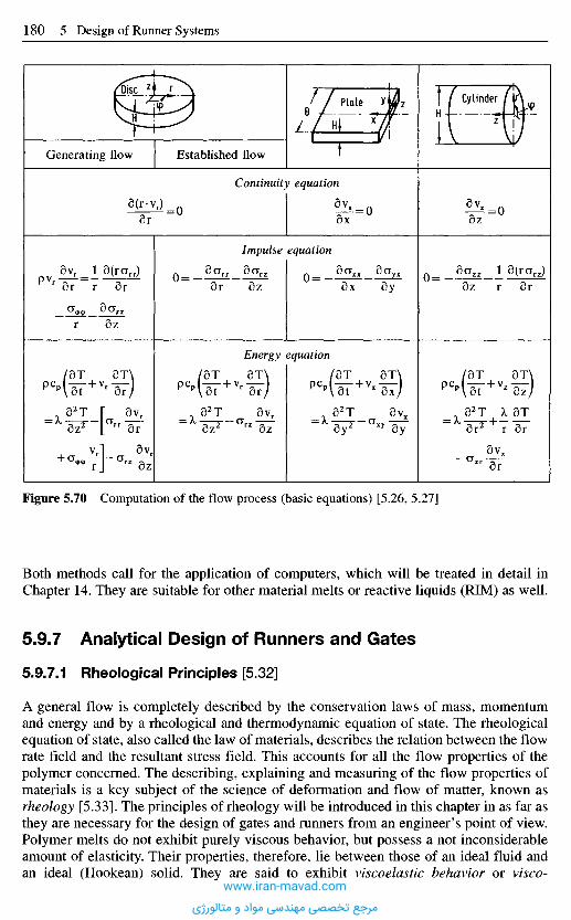
Figure 5.70 Computation of the flow process (basic equations) [5.26, 5.27]
Both methods call for the application of computers, which will be treated in detail inChapter 14. They are suitable for other material melts or reactive liquids (RIM) as well.
5.9.7 Analytical Design of Runners and Gates
5.9,7,1 Rheological Principles [5.32]
A general flow is completely described by the conservation laws of mass, momentumand energy and by a rheological and thermodynamic equation of state. The rheologicalequation of state, also called the law of materials, describes the relation between the flowrate field and the resultant stress field. This accounts for all the flow properties of thepolymer concerned. The describing, explaining and measuring of the flow properties ofmaterials is a key subject of the science of deformation and flow of matter, known asrheology [5.33]. The principles of rheology will be introduced in this chapter in as far asthey are necessary for the design of gates and runners from an engineer's point of view.Polymer melts do not exhibit purely viscous behavior, but possess a not inconsiderableamount of elasticity. Their properties, therefore, lie between those of an ideal fluid andan ideal (Hookean) solid. They are said to exhibit viscoelastic behavior or visco-
Generating flow Established flow
Continuity equation
Impulse equation
Energy equation
Plate CylinderDisc
www.iran-mavad.com
مرجع تخصصی مهندسی مواد و متالورژی
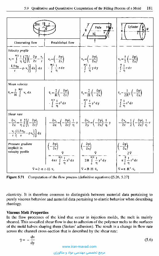
Figure 5.71 Computation of the flow process (definitive equations) [5.26, 5.27]
elasticity. It is therefore common to distinguish between material data pertaining topurely viscous behavior and material data pertaining to elastic behavior when describingrheology.
Viscous Melt PropertiesIn the flow processes of the kind that occur in injection molds, the melt is mainlysheared. This so-called shear flow is due to adhesion of the polymer melts to the surfacesof the mold halves shaping them (Stokes' adhesion). The result is a change in flow rateacross the channel cross-section that is described by the shear rate:
(5.6)
Generating flow Established flow
DiscPlate Cylinder
Velocity profile
Mean velocity
Shear rate
Pressure gradientimplicit invelocity profile
www.iran-mavad.com
مرجع تخصصی مهندسی مواد و متالورژی
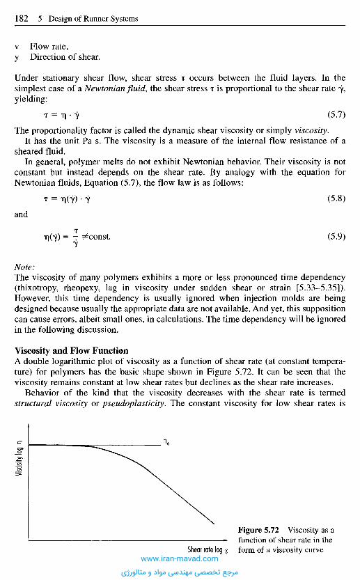
v Flow rate,y Direction of shear.
Under stationary shear flow, shear stress T occurs between the fluid layers. In thesimplest case of a Newtonian fluid, the shear stress T is proportional to the shear rate 7,yielding:
T = T] • 7 (5-7)
The proportionality factor is called the dynamic shear viscosity or simply viscosity.It has the unit Pa s. The viscosity is a measure of the internal flow resistance of a
sheared fluid.In general, polymer melts do not exhibit Newtonian behavior. Their viscosity is not
constant but instead depends on the shear rate. By analogy with the equation forNewtonian fluids, Equation (5.7), the flow law is as follows:
T = T](7) • 7 (5-8)
and
T1(ZY) = T T^const. (5.9)
Note:The viscosity of many polymers exhibits a more or less pronounced time dependency(thixotropy, rheopexy, lag in viscosity under sudden shear or strain [5.33-5.35]).However, this time dependency is usually ignored when injection molds are beingdesigned because usually the appropriate data are not available. And yet, this suppositioncan cause errors, albeit small ones, in calculations. The time dependency will be ignoredin the following discussion.
Viscosity and Flow FunctionA double logarithmic plot of viscosity as a function of shear rate (at constant tempera-ture) for polymers has the basic shape shown in Figure 5.72. It can be seen that theviscosity remains constant at low shear rates but declines as the shear rate increases.
Behavior of the kind that the viscosity decreases with the shear rate is termedstructural viscosity or pseudoplasticity. The constant viscosity for low shear rates is
Viscis
ity log
n
Figure 5.72 Viscosity as afunction of shear rate in theform of a viscosity curveShear rate log •%
www.iran-mavad.com
مرجع تخصصی مهندسی مواد و متالورژی

called the Newtonian viscosity, lower Newtonian intrinsic viscosity or when 7= 0 aszero viscosity 0.
Not only can the viscosity be plotted as a function of the shear rate to yield a viscositycurve, but the shear stress can be plotted against the shear rate (also on a doublelogarithmic scale) to yield a flow curve (Figure 5.73).
In a Newtonian fluid, the shear rate is proportional to the shear stress. A doublelogarithmic plot of the pairs of values yields a straight line with a slope of 1, i.e., theangle between the abscissa and the flow curve is 45°. Any deviation by the flow curvefrom this slope is therefore a direct indicator of non-Newtonian flow behavior.
A pseudoplastic fluid would have a slope greater than 1 on this plot, i.e., the shear rateincreases progressively with increase in shear stress.
Mathematical Description of Pseudoplastic Melt BehaviorVarious mathematical models have been developed to describe the viscosity and flowcurves; they differ in the amount of mathematics involved on the one hand and in theiradaptability to concrete experimental data and thus accuracy on the other. Overviews areprovided in [5.33, 5.36]. The models most commonly employed for thermoplastics andelastomers are briefly discussed below. In the following chapters, reference will be madeexclusively to the models described here.
Power Law ofOstwald and de Waele [5.37, 5.38]When the flow curves of different polymers are plotted on a double logarithmic scale,the resultant curves have two approximately linear ranges separated by a transition range(Figure 5.74). In many cases, we are often only dealing with one of the two ranges andso we only need one function, namely
i> = 3>-Tm (5.10)
to describe it mathematically. Equation (5.10) is called the power law of Ostwald and deWaele, where the exponent m is the flow exponential and O is the fluidity. The flowexponent m characterizes the flow capability of a material and its deviation from non-Newtonian behavior. The following applies:
Figure 5.73 Shear rate as a function of shearstress in the form of a flow curve Shear stress log x
Shea
r rate
log
Newtonian fluid
Non-Newtonian fluid
www.iran-mavad.com
مرجع تخصصی مهندسی مواد و متالورژی
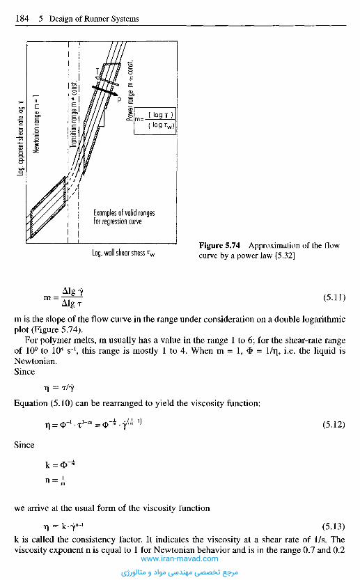
m is the slope of the flow curve in the range under consideration on a double logarithmicplot (Figure 5.74).
For polymer melts, m usually has a value in the range 1 to 6; for the shear-rate rangeof 10° to 104 S"1, this range is mostly 1 to 4. When m = 1, <I> = l/r|, i.e. the liquid isNewtonian.Since
Equation (5.10) can be rearranged to yield the viscosity function:
(5.12)
we arrive at the usual form of the viscosity function
(5.13)k is called the consistency factor. It indicates the viscosity at a shear rate of 1/s. Theviscosity exponent n is equal to 1 for Newtonian behavior and is in the range 0.7 and 0.2
Since
Figure 5.74 Approximation of the flowcurve by a power law [5.32]
(5.11)
Log. wall shear stress TW
Examples of valid rangesfor regression curve
Log.
appa
rent s
hear
rate l
og K
Newt
onian
rang
e m
= 1
Trans
ition r
ange
m *
cons
t.
Powe
r ran
ge m
^ co
nst.
www.iran-mavad.com
مرجع تخصصی مهندسی مواد و متالورژی

for most polymers. It describes the slope of the viscosity curves in the range underconsideration (Figure 5.74).
The power law has a very simple mathematical construction and therefore allowsalmost all simple flow problems to be analyzed that can be resolved by the Newtonianmodel. The disadvantage of this approach is that, on vanishing shear rate, the viscosityvalue becomes infinitely large when the power law of Ostwald and de Waele is used,with the result that the roughly shear-rate-independent Newtonian range is not described.A further disadvantage is that the flow exponent m is included in the dimension of thefluidity.
In general, the power model is only accurate enough to describe a flow or viscositycurve over a certain shear-rate range. For a given accuracy, the size of this range dependson the curvature of the curve.
Where the power law is to be used to describe a large range of a flow curve, the curvecan be divided into segments. 3> and m have to be determined for each segment [5.39].
Standard collections of rheological data [5.40, 5.41] are available that list values for3> and m for various shear-rate ranges.
Carreau Model [5.41-5.43]A model that is increasingly being used in practical injection-mold design is the tripleparameter model of Carreau:
^ = ^ d W ( 5 - i 4 )
[A] = Pa s, [B] = s and [C] = -
Here, A is the zero viscosity, B is the so-called reciprocal transition rate and C is theslope of the viscosity curves in the pseudoplastic range for 7 —> 00 (Figure 5.75).
This Carreau model has the advantage that it correctly reflects the actual materialbehavior over a broader shear-rate range than that afforded by the power law, and that italso yields meaningful viscosity values for 7 —> 0.
Moreover the dependency of the pressure loss on the volumetric flow rate can becalculated for a cylindrical gate and a plane-parallel gap in analytically closed form[5.41, 5.43]. This model can therefore also be used for making rough calculations with acalculator. This applies particularly when easier-to-handle approximate solutions are tobe used instead of the analytically correct solution [5.41, 5.43].
Figure 5.75 Approximationof the viscosity curve by theCarreau law [5.32]
Ig n
Ig twww.iran-mavad.com
مرجع تخصصی مهندسی مواد و متالورژی
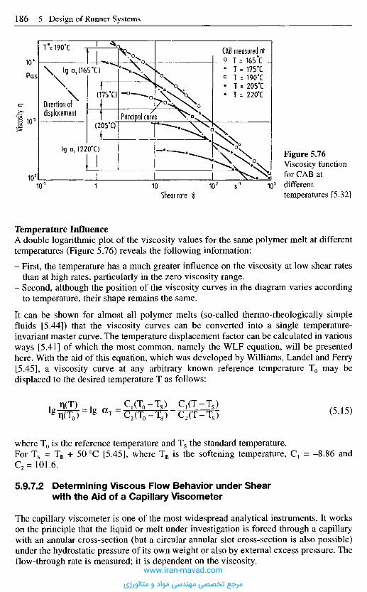
Temperature InfluenceA double logarithmic plot of the viscosity values for the same polymer melt at differenttemperatures (Figure 5.76) reveals the following information:
- First, the temperature has a much greater influence on the viscosity at low shear ratesthan at high rates, particularly in the zero viscosity range.
- Second, although the position of the viscosity curves in the diagram varies accordingto temperature, their shape remains the same.
It can be shown for almost all polymer melts (so-called thermo-rheologically simplefluids [5.44]) that the viscosity curves can be converted into a single temperature-invariant master curve. The temperature displacement factor can be calculated in variousways [5.41] of which the most common, namely the WLF equation, will be presentedhere. With the aid of this equation, which was developed by Williams, Landel and Ferry[5.45], a viscosity curve at any arbitrary known reference temperature T0 may bedisplaced to the desired temperature T as follows:
(5.15)
where T0 is the reference temperature and Ts the standard temperature.For Ts s TE + 500C [5.45], where TE is the softening temperature, C1 = -8.86 andC2=101.6.
5.9.7.2 Determining Viscous Flow Behavior under Shearwith the Aid of a Capillary Viscometer
The capillary viscometer is one of the most widespread analytical instruments. It workson the principle that the liquid or melt under investigation is forced through a capillarywith an annular cross-section (but a circular annular slot cross-section is also possible)under the hydrostatic pressure of its own weight or also by external excess pressure. Theflow-through rate is measured; it is dependent on the viscosity.
Figure 5.76Viscosity functionfor CAB atdifferenttemperatures [5.32]Shear rate if
Visco
sity n
Pas
s-1
CAB measured atT = 165*CT = 175'CT = 190#CT = 205*CT = 220'C
Principal curve
Direction ofdisplacement
T-=190*C
www.iran-mavad.com
مرجع تخصصی مهندسی مواد و متالورژی

The isothermal flow of Newtonian liquids in capillaries is described by the Hagen-Poiseuille law. This assumes that the flow is laminar and stationary, and that adhesion towalls occurs.
This yields a flow-through of
(5.16)
and a wall shear stress of
(5.17)
Since these relations only hold for Newtonian liquids, a flow test performed on non-Newtonian materials yields an apparent shear rate Ds, which is lower at the wall(Figure 5.78) than the true shear rate.
To obtain the true shear rate for non-Newtonian liquids, a correction called theRabinowitsch correction, is applied. This correction is based on the assumption that apower law, such as that of Ostwald and de Waele, describes the flow behavior of themelt.
If the throughput Q is known, the apparent shear rate Ds and the wall shear xw can bedetermined. Since the desired flow function must be fulfilled both at the tube wall andin the interior, the apparent shear rate can be linked to the true rate to yield the followingrelationship for the annular capillary:
(5.18)
(5.19)
And for the slot capillary:
Figure 5.77 Principle of the capillary rheometer [5.32]
www.iran-mavad.com
مرجع تخصصی مهندسی مواد و متالورژی

Figure 5.78 Shear rate distribution for a Newtonian and a non-Newtonian substance in laminarpipe flow [5.32]
Another possibility for pseudoplastic substances consists in determining so-called"representative variables". The aim here is no longer to look at the wall but rather toconsider the point at which the two shear rate profiles overlap (Figure 5.78). Forcapillaries, this representative spot is always given with sufficient accuracy by rs = R • e0,where e0 ~ 0.815. For a slot-shaped geometry, rs = R • en, where en ~ 0.772. It is thuspossible to describe the flow condition of non-Newtonian materials by the laws forNewtonian behavior. Given the same throughput Q, it is easy to calculate therepresentative shear rate.
Figure 5.79 shows the basic structure of a capillary viscometer. The material to beinvestigated is melted in a heated cylinder and forced through a nozzle at a defined rateby a piston to produce the measurement. The measured loss in pressure and the presetvolumetric flow rate are used for calculating the viscosity. Performing the measurementon different nozzle lengths allows the flow-in pressure loss in the dead-water area at thenozzle inlet to be eliminated with the aid of the Bagley correction.
Figure 5.79 Principle of the capillaryviscometer1 Piston, 2 Cylinder, 3 Pressure sensor bore,4 Capillary [5.32]
!± = Representative radius in a capillaryt = Representative shear rateT = Representative shear stress
i Wall Newt<j> Wall non-Newt.
.i(r) Non-Newt.Vr const.
www.iran-mavad.com
مرجع تخصصی مهندسی مواد و متالورژی
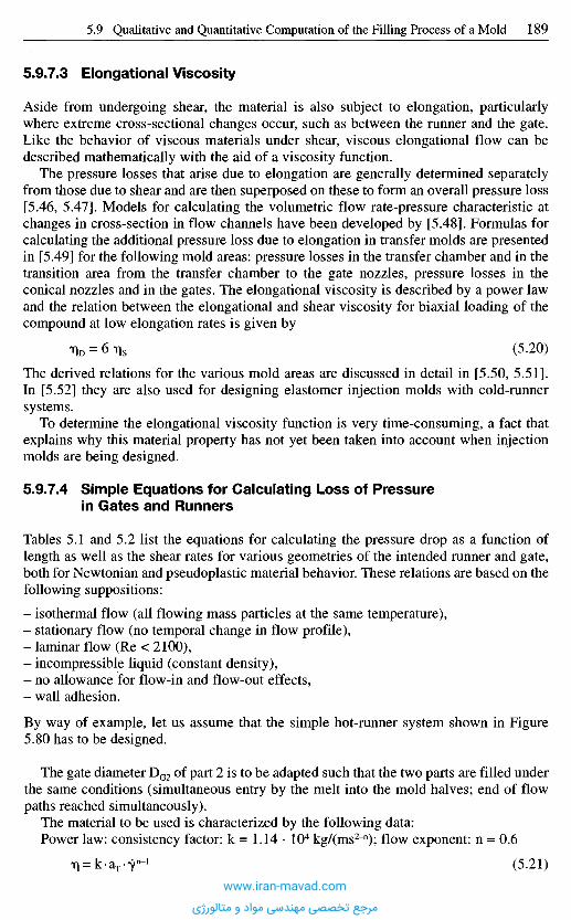
5.9.7.3 Elongational Viscosity
Aside from undergoing shear, the material is also subject to elongation, particularlywhere extreme cross-sectional changes occur, such as between the runner and the gate.Like the behavior of viscous materials under shear, viscous elongational flow can bedescribed mathematically with the aid of a viscosity function.
The pressure losses that arise due to elongation are generally determined separatelyfrom those due to shear and are then superposed on these to form an overall pressure loss[5.46, 5.47]. Models for calculating the volumetric flow rate-pressure characteristic atchanges in cross-section in flow channels have been developed by [5.48]. Formulas forcalculating the additional pressure loss due to elongation in transfer molds are presentedin [5.49] for the following mold areas: pressure losses in the transfer chamber and in thetransition area from the transfer chamber to the gate nozzles, pressure losses in theconical nozzles and in the gates. The elongational viscosity is described by a power lawand the relation between the elongational and shear viscosity for biaxial loading of thecompound at low elongation rates is given by
TID = 6 % (5.20)
The derived relations for the various mold areas are discussed in detail in [5.50, 5.51].In [5.52] they are also used for designing elastomer injection molds with cold-runnersystems.
To determine the elongational viscosity function is very time-consuming, a fact thatexplains why this material property has not yet been taken into account when injectionmolds are being designed.
5.9.7.4 Simple Equations for Calculating Loss of Pressurein Gates and Runners
Tables 5.1 and 5.2 list the equations for calculating the pressure drop as a function oflength as well as the shear rates for various geometries of the intended runner and gate,both for Newtonian and pseudoplastic material behavior. These relations are based on thefollowing suppositions:
- isothermal flow (all flowing mass particles at the same temperature),- stationary flow (no temporal change in flow profile),- laminar flow (Re < 2100),- incompressible liquid (constant density),- no allowance for flow-in and flow-out effects,- wall adhesion.
By way of example, let us assume that the simple hot-runner system shown in Figure5.80 has to be designed.
The gate diameter DG2 of part 2 is to be adapted such that the two parts are filled underthe same conditions (simultaneous entry by the melt into the mold halves; end of flowpaths reached simultaneously).
The material to be used is characterized by the following data:Power law: consistency factor: k = 1.14 • 104 kg/(ms2~n); flow exponent: n = 0.6
(5.21)
www.iran-mavad.com
مرجع تخصصی مهندسی مواد و متالورژی
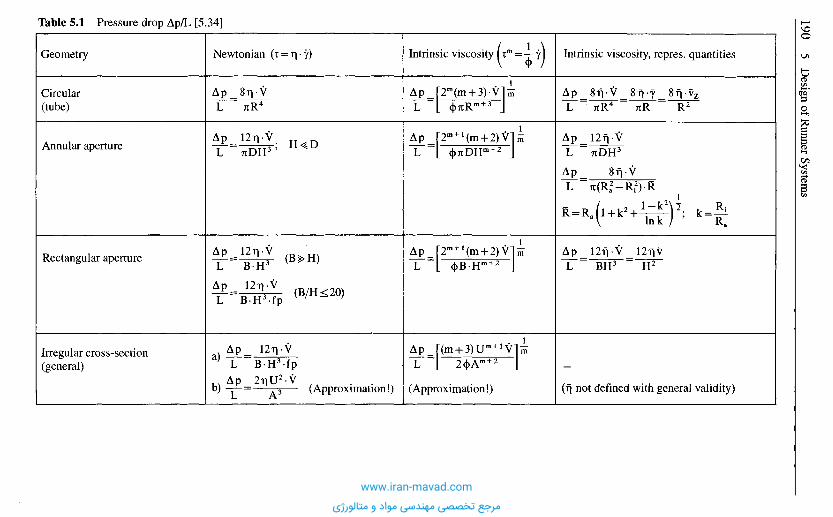
Table 5.1 Pressure drop Ap/L [5.34]
Newtonian
(Approximation!) (Approximation!)
Intrinsic viscosity Intrinsic viscosity, repres. quantities
(r| not defined with general validity)
www.iran-mavad.com
مرجع تخصصی مهندسی مواد و متالورژی
Figure 5.80 Simple hot runner system
Molded part 1 Molded part 2
Hot runner
(Approximation)
Geometry
Circular(tube)
Annularaperture
Rectangularaperture
Conical aperture
Irregularcross-section
Newtonian Non-Newtonian
Table 5.2 Shear rates 7 Shear rate or the mold wall7w [5.32]
www.iran-mavad.com
مرجع تخصصی مهندسی مواد و متالورژی
This is substituted into equation (5.21) to solve for DG2. When the numerical values havebeen inserted, DG2 computes to 2.61 mm. This is a plausible result since the much greaterresistance generated in this gate, which has a smaller diameter than gate 1, compensatesthe shorter flow path to molded part 2.
5 . 1 0 S p e c i a l P h e n o m e n a A s s o c i a t e d
w i t h M u l t i p l e G a t i n g
To discover particular phenomena of materials, a mold was developed [5.52] based onthe theoretical considerations above that would demonstrate dependency on an operatinglevel. The runner system shown in Figure 5.81 was chosen. It has equal flow paths andequal gate cross-sections that would guarantee simultaneous onset of filling and auniform filling pattern.
Trials on various materials (HDPE, LDPE, POM) confirmed the assumptions again.Very different pictures of the filling process were obtained with PA 6 and even more sowith glass-reinforced nylon 12. A difference in the onset of filling could not be noticedbut the throughput through the outside gates was considerably larger than through theinside gates (Figure 5.81). This phenomenon was more pronounced at lower materialtemperatures (< 2500C) and at high injection speeds. However, at high materialtemperatures (approx. 300 0C) and extremely low injection speeds, no advancing in thesense just described was noticeable. This effect is best illustrated by a change of colorsduring molding to observe the origin of the melt in the individual cavities. It can beclearly seen, as the low Reynolds numbers (Re < 20) would suggest, that completelylaminar flow is maintained even in the gate. This means that, above all, a flow path closeto the wall remains there. At the point of branching, the core material penetrates againstthe opposite wall and lingers there afterwards (Figure 5.82) [5.53].
(5.22)
(5.23)
(5.24)
(5.25)
equation 5.22 becomes:
Given the representative shear rate:
For the various viscosities, the following applies:
Dimensions of the hot-runner system:Hot runner as far as molded part 2: LHR2 = 50 mm; DHR = 10 mm; L02 = 5 mm; D02 = ?Hot runner as far as molded part 1: LHR1 = 120 mm; DHR =10 mm; L01 = 5mm; D01 = 3 mm
For simultaneous filling of the parts, the pressure on both flow paths must be equal:
www.iran-mavad.com
مرجع تخصصی مهندسی مواد و متالورژی

The reason for the advancing of melt could therefore be due to the dependency of meltviscosity on shearing time in the various zones. Those portions of melt which are closeto the runner wall during the filling process (melt for the outside cavities) haveexperienced a larger shearing time integral than the melt which fills the inside cavities.This is confirmed by the simultaneous onset of filling already mentioned because thegate-filling phase differs from the mold-filling phase. A considerable part of the meltwhich is sheared in the runner during gate filling remains in the runner to fill the gatenext to the runner wall. As a result, the design of a runner system demands that:
- The flow of melt must be divided up symmetrically (Figure 5.82).- Two branches must not be placed in the same plane.
From this example (glass-reinforced nylon 12), it is evident that the initially derivedmethods of estimation are sufficient if the consequences of the flow path study are takeninto consideration.
Figure 5.81 Runner system [5.25]
Figure 5.82 Melt distribution in a runner system [5.25]www.iran-mavad.com
مرجع تخصصی مهندسی مواد و متالورژی
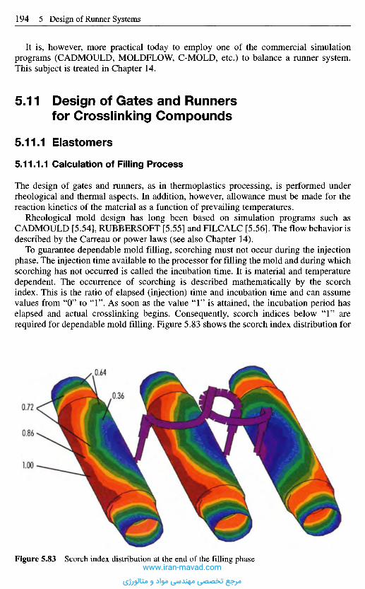
It is, however, more practical today to employ one of the commercial simulationprograms (CADMOULD, MOLDFLOW, C-MOLD, etc.) to balance a runner system.This subject is treated in Chapter 14.
5 . 1 1 D e s i g n o f G a t e s a n d R u n n e r s
f o r C r o s s l i n k i n g C o m p o u n d s
5.11.1 E las tomers
5.11.1.1 Calculation of Filling Process
The design of gates and runners, as in thermoplastics processing, is performed underrheological and thermal aspects. In addition, however, allowance must be made for thereaction kinetics of the material as a function of prevailing temperatures.
Rheological mold design has long been based on simulation programs such asCADMOULD [5.54], RUBBERSOFT [5.55] and FILCALC [5.56]. The flow behavior isdescribed by the Carreau or power laws (see also Chapter 14).
To guarantee dependable mold filling, scorching must not occur during the injectionphase. The injection time available to the processor for filling the mold and during whichscorching has not occurred is called the incubation time. It is material and temperaturedependent. The occurrence of scorching is described mathematically by the scorchindex. This is the ratio of elapsed (injection) time and incubation time and can assumevalues from "O" to " 1 " . As soon as the value " 1 " is attained, the incubation period haselapsed and actual crosslinking begins. Consequently, scorch indices below " 1 " arerequired for dependable mold filling. Figure 5.83 shows the scorch index distribution for
Figure 5.83 Scorch index distribution at the end of the filling phasewww.iran-mavad.com
مرجع تخصصی مهندسی مواد و متالورژی
a 3-cavity mold for a medium-voltage bushing at the end of the filling phase. Scorchingcan therefore be expected during the injection phase for the chosen parameter setting.
It is suggested in [5.57] that so-called processing windows be established forfrequently used materials. These windows are based on tests performed on plate moldsand results from rheometers and plastometers. With this, scorch is also registered, whichplays an important part in the case of elastomers. However, creating them involves arelatively high input.
The following section explains how different materials and mold geometries influenceprocessing window qualitatively. After this, several calculated processing windows arediscussed.
5.11.1.2 Effect of Processing Characteristics on the Basisof Processing Windows
The processing properties of an elastomer may be characterized by its
- viscosity,- incubation time (t{ time) and- curing velocity (difference between t90 and t{).
Of greatest interest during processing is the question of how different material types ordifferent lots in the process behave and how potential processing problems can beeliminated. These questions can be discussed with the aid of a processing window.Figure 5.84 demonstrates how the position of the
- injection-time line,- injection limit,- holding-time line, and- heating-time line
vary according to material (or lot).
Higher viscosity causes higher pressure losses in the mold. Higher pressure losses leadto very different effects [5.58] depending on the injection-speed control of the injection-molding machine. With a closed-loop control, the injection speed is decreasedcontinuously. With an open-loop control, in contrast, the speed is decreased more or lessirregularly. How low the speed may become depends on the dimension of the hydraulicdrive. If the machine reaches its pressure limit (maximum injection pressure) aninjection speed results which corresponds with the equilibrium between injectionpressure and pressure loss [5.58].
Therefore higher pressure losses (due to a higher viscosity) have a very different effect.If there is still an adequate pressure reserve, the injection time remains constant (closed-loop control) or becomes a little longer (open-loop control). At this time, however, theinjection pressure rises. This means another, higher injection pressure counts for theinjection-time line. Because of the higher pressure loss, more energy is dissipated duringinjection and the temperature of the material increases. The curing process proceeds morerapidly and the incubation phase is shortened. This shifts the injection limit to smallertime periods (Figure 5.84, effect a). Consequently, increasing viscosity narrows thepossible filling-time range (distance between injection-time line and injection limit).
If the machine is operated at its pressure limit, the injection time is increased by amaterial with higher viscosity. This means that the injection-time line is shifted to the
www.iran-mavad.com
مرجع تخصصی مهندسی مواد و متالورژی
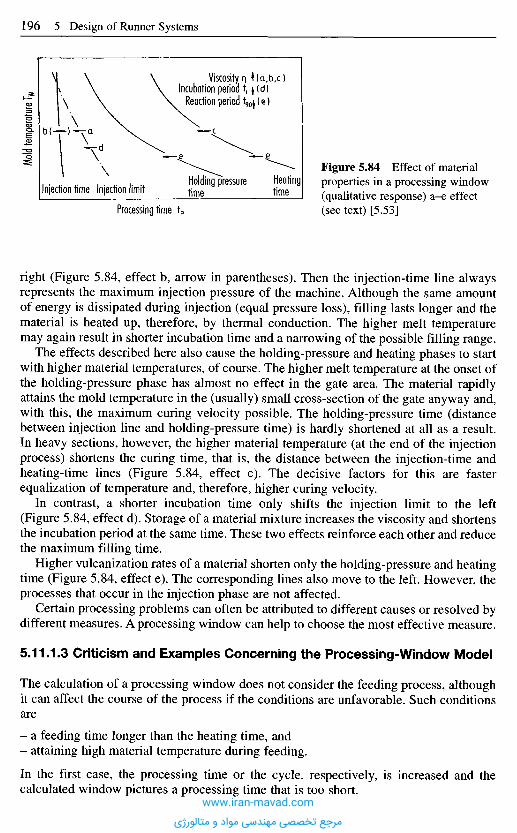
right (Figure 5.84, effect b, arrow in parentheses). Then the injection-time line alwaysrepresents the maximum injection pressure of the machine. Although the same amountof energy is dissipated during injection (equal pressure loss), filling lasts longer and thematerial is heated up, therefore, by thermal conduction. The higher melt temperaturemay again result in shorter incubation time and a narrowing of the possible filling range.
The effects described here also cause the holding-pressure and heating phases to startwith higher material temperatures, of course. The higher melt temperature at the onset ofthe holding-pressure phase has almost no effect in the gate area. The material rapidlyattains the mold temperature in the (usually) small cross-section of the gate anyway and,with this, the maximum curing velocity possible. The holding-pressure time (distancebetween injection line and holding-pressure time) is hardly shortened at all as a result.In heavy sections, however, the higher material temperature (at the end of the injectionprocess) shortens the curing time, that is, the distance between the injection-time andheating-time lines (Figure 5.84, effect c). The decisive factors for this are fasterequalization of temperature and, therefore, higher curing velocity.
In contrast, a shorter incubation time only shifts the injection limit to the left(Figure 5.84, effect d). Storage of a material mixture increases the viscosity and shortensthe incubation period at the same time. These two effects reinforce each other and reducethe maximum filling time.
Higher vulcanization rates of a material shorten only the holding-pressure and heatingtime (Figure 5.84, effect e). The corresponding lines also move to the left. However, theprocesses that occur in the injection phase are not affected.
Certain processing problems can often be attributed to different causes or resolved bydifferent measures. A processing window can help to choose the most effective measure.
5.11.1.3 Criticism and Examples Concerning the Processing-Window Model
The calculation of a processing window does not consider the feeding process, althoughit can affect the course of the process if the conditions are unfavorable. Such conditionsare
- a feeding time longer than the heating time, and- attaining high material temperature during feeding.
In the first case, the processing time or the cycle, respectively, is increased and thecalculated window pictures a processing time that is too short.
Mold
tempe
rature
T w
Injection time Injection limitHolding pressuretimfi
Heatingtime
Figure 5.84 Effect of materialproperties in a processing window(qualitative response) a-e effect(see text) [5.53]Processing time tp
Viscosityn t(a,b,c)Incubation period tf (d)
Reaction period t9Oj(e)
www.iran-mavad.com
مرجع تخصصی مهندسی مواد و متالورژی
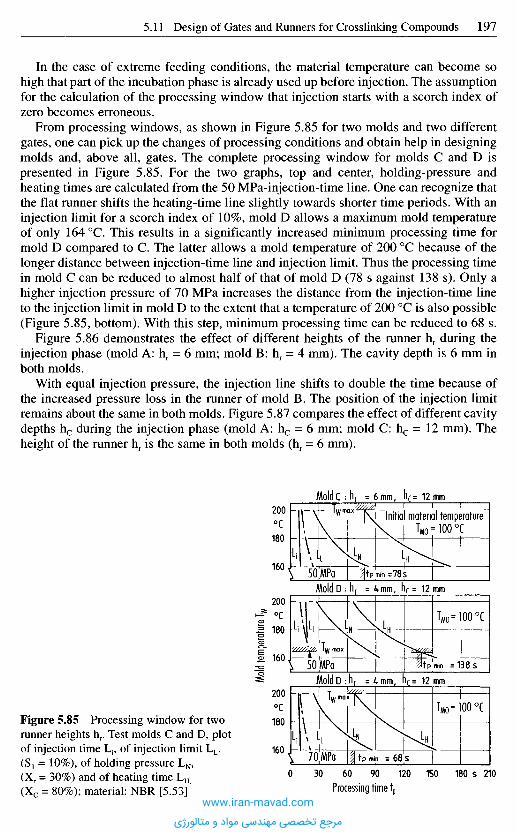
In the case of extreme feeding conditions, the material temperature can become sohigh that part of the incubation phase is already used up before injection. The assumptionfor the calculation of the processing window that injection starts with a scorch index ofzero becomes erroneous.
From processing windows, as shown in Figure 5.85 for two molds and two differentgates, one can pick up the changes of processing conditions and obtain help in designingmolds and, above all, gates. The complete processing window for molds C and D ispresented in Figure 5.85. For the two graphs, top and center, holding-pressure andheating times are calculated from the 50 MPa-injection-time line. One can recognize thatthe flat runner shifts the heating-time line slightly towards shorter time periods. With aninjection limit for a scorch index of 10%, mold D allows a maximum mold temperatureof only 164 0C. This results in a significantly increased minimum processing time formold D compared to C. The latter allows a mold temperature of 200 0C because of thelonger distance between injection-time line and injection limit. Thus the processing timein mold C can be reduced to almost half of that of mold D (78 s against 138 s). Only ahigher injection pressure of 70 MPa increases the distance from the injection-time lineto the injection limit in mold D to the extent that a temperature of 200 0C is also possible(Figure 5.85, bottom). With this step, minimum processing time can be reduced to 68 s.
Figure 5.86 demonstrates the effect of different heights of the runner hr during theinjection phase (mold A: hr = 6 mm; mold B: hr = 4 mm). The cavity depth is 6 mm inboth molds.
With equal injection pressure, the injection line shifts to double the time because ofthe increased pressure loss in the runner of mold B. The position of the injection limitremains about the same in both molds. Figure 5.87 compares the effect of different cavitydepths hc during the injection phase (mold A: hc = 6 mm; mold C: hc = 12 mm). Theheight of the runner hr is the same in both molds (hr = 6 mm).
Figure 5.85 Processing window for tworunner heights hr. Test molds C and D, plotof injection time L1, of injection limit LL.(S1 = 10%), of holding pressure LN ,(Xr = 30%) and of heating time LH
(Xc = 80%); material: NBR [5.53]
Mold
tempe
rature
T w
°c
°c
0C
Processing time tp
MoIdD
MoIdD
MoIdC
Initial material temperature
www.iran-mavad.com
مرجع تخصصی مهندسی مواد و متالورژی
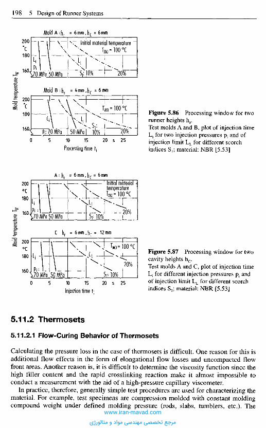
5,11.2 Thermosets
5.11.2,1 Flow-Curing Behavior of Thermosets
Calculating the pressure loss in the case of thermosets is difficult. One reason for this isadditional flow effects in the form of elongational flow losses and uncompacted flowfront areas. Another reason is, it is difficult to determine the viscosity function since thehigh filler content and the rapid crosslinking reaction make it almost impossible toconduct a measurement with the aid of a high-pressure capillary viscometer.
In practice, therefore, generally simple test procedures are used for characterizing thematerial. For example, test specimens are compression molded with constant moldingcompound weight under defined molding pressure (rods, slabs, tumblers, etc.). The
Mold
tempe
rature
Tw
°c
'C
MoIdA
MoIdB
Initial material temperature
Processing time t,
0C
0C
Injection time tj
Initial materialtemperature
Figure 5.86 Processing window for tworunner heights hr.Test molds A and B, plot of injection timeLj for two injection pressures P1 and ofinjection limit LL for different scorchindices S1; material: NBR [5.53]
Figure 5.87 Processing window for twocavity heights hc.Test molds A and C, plot of injection timeL1 for different injection pressures P1 andof injection limit LL for different scorchindices S1; material: NBR [5.53]
www.iran-mavad.com
مرجع تخصصی مهندسی مواد و متالورژی
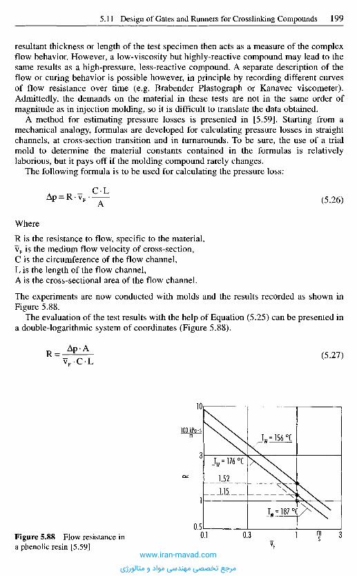
resultant thickness or length of the test specimen then acts as a measure of the complexflow behavior. However, a low-viscosity but highly-reactive compound may lead to thesame results as a high-pressure, less-reactive compound. A separate description of theflow or curing behavior is possible however, in principle by recording different curvesof flow resistance over time (e.g. Brabender Plastograph or Kanavec viscometer).Admittedly, the demands on the material in these tests are not in the same order ofmagnitude as in injection molding, so it is difficult to translate the data obtained.
A method for estimating pressure losses is presented in [5.59]. Starting from amechanical analogy, formulas are developed for calculating pressure losses in straightchannels, at cross-section transition and in turnarounds. To be sure, the use of a trialmold to determine the material constants contained in the formulas is relativelylaborious, but it pays off if the molding compound rarely changes.
The following formula is to be used for calculating the pressure loss:
(5.26)
Where
R is the resistance to flow, specific to the material,vF is the medium flow velocity of cross-section,C is the circumference of the flow channel,L is the length of the flow channel,A is the cross-sectional area of the flow channel.
The experiments are now conducted with molds and the results recorded as shown inFigure 5.88.
The evaluation of the test results with the help of Equation (5.25) can be presented ina double-logarithmic system of coordinates (Figure 5.88).
(5.27)
Figure 5.88 Flow resistance ina phenolic resin [5.59]
R
vF
www.iran-mavad.com
مرجع تخصصی مهندسی مواد و متالورژی

There is a clear connection with the resistance to flow R. An effect of the channelgeometry cannot be seen anymore. It is completely included in the geometry coefficientCL/A.
The function R is a function of the velocity and invariant with respect to geometry.According to these preconditions a computation of arbitrary channel geometries ispossible. The mathematical relations for different geometric shapes are summarized inTable 5.3. More detailed information is to be found in [5.26, 5.59-5.63].
Table 5.3 Pressure calculation
R e f e r e n c e s
[5.1] Pye, R.G.E.: Injection Mould Design (for Thermoplastics). Ilitte Books Ltd., London,1968.
[5.2] Szibalski, M.; Meier, E.: Entwicklung einer quantitativen Methode fur den Konstruk-tionsablauf bei SpritzgieBwerkzeugen. Unpublished report, IKV, Aachen, 1976.
[5.3] Mohrwald, K.: Einblick in die Konstruktion von SpritzgieBwerzeugen. Verlag BrunkeGarrels, Hamburg, 1965.
Geometry
Straight channels
Pressure drop Characteristics
= 1 m/s= tan a, Slope of the curves inthe double-logarithmic plotR = f(vF)= f(V0)
Elbows
Cross-sectionaltransitions
= rK/B, Geometry function= 1= tan p, Slope of the curves inthe double-logarithmic plotRE = fW= fWo)
= A1ZA2 -1, Cross-sectionalratio= 1= f(v0,<|>0)= tan 7, Slope of the curves inthe double-logarithmic plotApA0 = f(v)= tan 8, Slope of the curves inthe double-logarithmic plot
www.iran-mavad.com
مرجع تخصصی مهندسی مواد و متالورژی

[5.4] SpritzgieBtechnik von Vestolen. Publication, Chemische Werke Htils AG, Marl.[5.5] Christoffers, K.-E.: Formteilauslegung, verarbeitungsgerecht. Das SpritzguBteil. VDI-
Verlag, Dusseldorf, 1980.[5.6] Kunststoff-Verarbeitung im Gesprach, 1: SpritzgieBen. Publication, BASF, Ludwigshafen,
1979.[5.7] Morgue, M.: Moules d'injection pour Thermoplastiques. Officiel des Activities des
Plastiques et du Caoutchouc, 14 (1967), pp. 269-276 and 14 (1967), pp. 620-628.[5.8] KegelanguB, SchirmanguB, BandanguB. Technical Information, 4.2.1, BASF, Ludwigs-
hafen/Rh., 1985.[5.9] Zawistowski, H.; Frenkler D.: Konstrukcja form wtryskowych do tworzyw
termoplastycznych. Wydawnictwo Naukowo-Techniczne, Warszawa, 1984.[5.10] Menges, G.; Mohren, P.: Anleitung fur den Bau von SpritzgieBwerkzeugen. Carl Hanser
Verlag, Munich, 1974.[5.11] SpritzgieBen von Thermoplasten. Publication, Farbwerke Hoechst AG, Frankfurt/M.,
1971.[5.12] Schmid, A.: Leitsatze, Angiisse, Anschnitte, Lehrgangshandbuch SpritzgieBwerkzeuge.
VDI-Bildungswerk, Dusseldorf, December 1971.[5.13] Stank, H.-D.: Anforderungen an den AnguB, seine Aufgaben, Anordnung am SpritzguBteil.
AnguB- und Anschnittprobleme beim SpritzgieBen. Ingenieurwissen, VDI-Verlag,Dusseldorf, 1975.
[5.14] Speil, Th.: Fertigungsgenauigkeit und Herstellung von Kunststoffprazisionsteilen,Lehrgangshandbuch SpritzgieBwerkzeuge. VDI-Bildungswerk, Dusseldorf, December1977.
[5.15] Cechacek, J.: Problematik der Werkzeugkonstruktion. Plaste und Kautschuk, 22 (1975), 2,p. 183.
[5.16] Crastin-Sortiment, Eigenschaften, Verarbeitung. Company brochure, Ciba-Geigy AG,Basel, August 1977.
[5.17] Gestaltung von SpritzguBteilen aus thermoplastischen Kunststoffen. VDI-Richtlinie, 2006,VDI-Verlag GmbH, Dusseldorf, 1970.
[5.18] Appel, O.: Ubertragbarkeit von Auslegungsregeln fur SpritzgieBwerkzeuge auf Werkzeugefur die Pulvermetall SpritzgieBtechnik, Unpublished report, IKV, RWTH, Aachen, 1988.
[5.19] German, R. M.: Powder Injection Molding, Metal Powder Industries Federation,Princeton, New Jersey, 1990.
[5.20] Greim, J.: Keramische Formmassen - Anwendungen und Verarbeiten durch SpritzgieBen,Neue Werkstoffe und Verfahren beim SpritzgieBen, VDI-Verlag, Dusseldorf, 1990.
[5.21] Bielzer, R.: Ermittlung von Kriterien zur systematischen Binderauswahl beimPulverspritzgieBen und Ubertragung des Verfahrens auf PTFE, Dissertation, RWTH,Aachen, 1992.
[5.22] Ricking, T.: Analyse der thermischen Vorgange in einem HeiBkanalwerkzeug zurHerstellung keramischer Bauteile, Unpublished report, IKV, RWTH, Aachen, 1996.
[5.23] Konig, K.: Entwicklung statistischer ProzeBmodelle fiir den KeramikspritzguB,Unpublished report, IKV, RWTH, Aachen, 1997.
[5.24] Menges, G.; Schmidt, Th. W; Hoven-Nievelstein, W. B.: Handbuch zur Berechnung vonSpritzgieBwerk zeugen. Verlag Kunststoff-Information, Bad Homburg, 1985.
[5.25] Schurmann, E.: Abschatzmethoden fiir die Auslegung von SpritzgieBwerkzeugen.Dissertation, RWTH, Aachen, 1979.
[5.26] Schmidt, L.: Auslegung von SpritzgieBwerkzeugen unter flieBtechnischen Gesichts-punkten. Dissertation, RWTH, Aachen, 1981.
[5.27] Lichius, U.: Rechnerunterstutzte Konstruktion von Werkzeugen zum SpritzgieBen vonthermoplastischen Kunststoffen. Dissertation, RWTH, Aachen, 1983.
[5.28] Bangert, H.: Systematische Konstruktion von SpritzgieBwerkzeugen und Rechnereinsatz.Dissertation, RWTH, Aachen, 1981.
[5.29] Lichius, U.; Bangert, H.: Eine einfache Methode zur Vorausbestimmung des FlieBfrontver-laufs beim SpritzgieBen von Thermoplasten. Plastverarbeiter, 31 (1980), 11, pp. 671-676.
[5.30] Schacht, Th.: Unpublished report, IKV, Aachen, 1984.[5.31] Thienel, P.: Der Formfiillvorgang beim SpritzgieBen von Thermoplasten. Dissertation,
RWTH, Aachen, 1977.
www.iran-mavad.com
مرجع تخصصی مهندسی مواد و متالورژی

[5.32] Michaeli, W.: Extrusionswerkzeuge fur Kunststoffe und Kautschuk. Carl Hanser Verlag,Munich, 1991.
[5.33] Pahl, M.: Praktische Rheologie der Kunststoffschmelzen und Losungen. VDI-Verlag,Dusseldorf, 1982.
[5.34] Meissner, J.: Rheologisches Verhalten von Kunststoffschmelzen und Losungen. In:Praktische Rheologie der Kunststoffe. VDI-Verlag, Dusseldorf, 1978.
[5.35] GleiBle, W.: Kurzzeitmessungen zur Ermittlung der FlieBeigenschaften von Kunststoffenbis zu hochsten Schergeschwindigkeiten. In: Praktische Rheologie der Kunststoffe. VDI-Verlag, Dusseldorf, 1978.
[5.36] Bird, R. B.; Armstrong, R. C ; Hassager, 0.: Dynamics of Polymeric Liquids. Vol. 1: FluidMechanics. Wiley, New York, 1977.
[5.37] Ostwald, W.: Uber die Geschwindigkeitsfunktion der Viskositat disperser Systeme.Kolloid-Z., 36 (1925), pp. 99-117.
[5.38] Waele, A. de: J. Oil Colour Chem. Assoc, 6 (1923), p. 33.[5.39] Schulze-Kadelbach, R.; Thienel, E.; Michaeli, W.; Haberstroh, E.; Dierkes, A.; Wortberg,
J.; Wabken, G.: Praktische Stoffdaten fur die Verarbeitung von Plastomeren. Conferencevolume. Plastics Conference, IKV, Aachen, 1978.
[5.40] Kenndaten fiir die Verarbeitung thermoplastischer Kunststoffe. VDMA (ed.). Vol. 2:Rheologie, Carl Hanser Verlag, Munich, 1982.
[5.41] Kenndaten fiir die Verarbeitung thermoplastischer Kunststoffe. VDMA (ed.). Vol. 4:Rheologie, Carl Hanser Verlag, Munich, 1986.
[5.42] Carreau, P. J.: Rheological equations from Molecular Network Theories. Ph. D. Thesis.University of Wisconsin, 1968.
[5.43] Geiger, K.; Ktihnle, H.: Analytische Berechnung einfacher Scherstromungen aufgrundeines FlieBgesetzes vom Carreauschen Typ. Rheol. Acta, 23 (1984), pp. 355-367.
[5.44] Laun, H. M.: Rheologie von Kunststoffschmelzen mit unterschiedlichem molekularemAufbau. Kautschuk, Gummi, Kunststoffe, 40 (1987), 6, pp. 554-562.
[5.45] Williams, M. L. et. al.: The Temperature Dependence of Relaxation Mechanism inAmorphous Polymers and other Glassforming Liquids. J. Am. Chem. Soc, 77 (1955), 7,pp. 3701-3706.
[5.46] Cogswell, F. N.: Polymer Melt Rheology. A Guide for Industrial Practice. George GodwinLtd. Halted Press, 1981.
[5.47] Kemper, W: Kriterien und Systematik fiir die theologische Auslegung von SpritzgieB-werkzeugen. Dissertation, RWTH, Aachen, 1982.
[5.48] Benfer, W: Rechnergestutzte Auslegung von Werkzeugen fiir Elastomere. Dissertation,RWTH, Aachen, 1986.
[5.49] Schneider, W: Spritzpressen technischer Gummiformteile. Dissertation, RWTH, Aachen,1985.
[5.50] Potsch, G.: Berechnungsverfahren zur Abschatzung der Druckverluste von Transfer-moldingwerkzeugen. Unpublished report, IKV, Aachen, 1985.
[5.51] Potsch, G.: Dehndruckverluste in Transfermoldingwerkzeugen. Unpublished report, IKV,Aachen, 1986.
[5.52] MaaB, R.: Die Anwendung der statistischen Versuchsmethodik zur Auslegung vonSpritzgieBwerkzeugen mit Kaltkanalsystern. Dissertation, RWTH, Aachen, 1995.
[5.53] Hengesbach, H. A.; EgIi, L.; Schiirmann, E.; Neuenschwander, S.: Injection tests at Biihler,Uzwil, 1978.
[5.54] Programmsystem CADMOULD. IKV, Aachen, 1996.[5.55] Krehwinkel, T; Schneider, C : RUBBERSOFT - ein Programmsystem fur Elastome-
rverarbeiter. Kautschuk, Gummi, Kunststoffe, 41 (1988), p. 953 ff.[5.56] Usermanual FILCALC, Version 5.0. RAPRA Technology Ltd., Shawbury, 1997.[5.57] Schneider, Ch.: Das Verarbeitungsverhalten von Elastomeren im SpritzgieBprozeB.
Dissertation, RWTH, Aachen, 1986.[5.58] Rorick, W.: ProzeBregelung im Thermoplast-SpritzgieBbetrieb. Dissertation, RWTH,
Aachen, 1979.[5.59] Paar, M.: Auslegung von SpritzgieBwerkzeugen fiir vernetzende Formmassen.
Dissertation, RWTH, Aachen, 1984.[5.60] Kemper, W.: Kriterien und Systematik fiir die theologische Auslegung von
SpritzgieBwerkzeugen. Dissertation, RWTH, Aachen, 1982.www.iran-mavad.com
مرجع تخصصی مهندسی مواد و متالورژی

[5.61] Feichtenbeiner, H.: Auslegung eines SpritzgieBwerzeuges mit 4fach Kaltkanalverteiler furElastomerformteile. Unpublished report, IKV, Aachen, 1983.
[5.62] Busch, E.: FlieBtechnische Auslegung von SprtzgieGwerkzeugen fur Duromere.Unpublished report, IKV, Aachen, 1983.
[5.63] Andermann, H.: Abschatzmethode fur Druckverluste an Querschnittsiibergangen inAnguBsystemen. Unpublished report, IKV, Aachen, 1983.
www.iran-mavad.com
مرجع تخصصی مهندسی مواد و متالورژی
6 . 1 T h e S p r u e G a t e
The sprue gate is the simplest and oldest kind of gate. It has a circular cross-section, isslightly tapered, and merges with its largest cross-section into the part.
The sprue gate should always be placed at the thickest section of the molded part.Provided proper size, the holding pressure can thus remain effective during the entiretime the molded part solidifies, and the volume contraction during cooling iscompensated by additional material forced into the cavity. No formation of voids or sinkmarks can occur. The diameter of the sprue gate depends on the location at the moldedpart. It has to be a little larger than the section thickness of the molded part so that themelt in the sprue solidifies last. The following holds (Figure 5.9):
d F ^S m a x +1.0(mm). (6.1)
It should not be thicker, though, because it then the melt solidifies too late and extendsthe cooling time unnecessarily.
To demold the sprue without trouble it should taper off towards the orifice on the sideof the nozzle. The taper is
a ^ 1-4°. (6.2)
American standard sprue bushings have a uniform taper of 1/2 inch per foot, which isequivalent to about 2.4°.
The orifice towards the nozzle has to be wider than the corresponding orifice of thenozzle. Therefore
d A ^ d D + 1 . 5 m m (6.3)
(Refer to Figure 5.9 for explanation of symbols)If these requirements are not met, undercuts at the upper end are formed (Figure 5.8).Very long sprues, that is if the mold platens are very thick, call for a check on the
taper. Possibly another nozzle has to be used in the injection molding machine.To a large degree the release properties of the sprue also depend on the surface finish
of the tapered hole. Scores from grinding or finishing perpendicular to the direction ofdemolding have to be avoided by all means. Material would stick in such scores andprevent the demolding. As a rule the interior of sprue bushings is highly polished.
A radius r2 (Figure 5.9) at the base of the sprue is recommended to create a sharp notchbetween sprue and molding and to permit the material to swell into the mold duringinjection.
To its disadvantage, the sprue always has to be machined off. Even with the mostcareful postoperation, this spot remains visible. This is annoying in some cases, and onecould try to position the sprue at a location that will be covered after assembly of thearticle. Since this is often impractical, the sprue can be provided with a turnaround so
6 D e s i g n o f G a t e s
www.iran-mavad.com
مرجع تخصصی مهندسی مواد و متالورژی
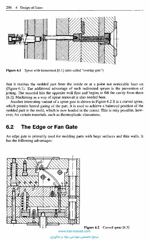
Figure 6.1 Sprue with turnaround [6.1] (also called "overlap gate")
that it reaches the molded part from the inside or at a point not noticeable later on(Figure 6.1). The additional advantage of such redirected sprues is the prevention ofjetting. The material hits the opposite wall first and begins to fill the cavity from there[6.2]. Machining as a way of sprue removal is also needed here.
Another interesting variant of a sprue gate is shown in Figure 6.2 It is a curved sprue,which permits lateral gating of the part. It is used to achieve a balanced position of themolded part in the mold, which is now loaded in the center. This is only possible, how-ever, for certain materials, such as thermoplastic elastomers.
6 . 2 T h e E d g e o r F a n G a t e
An edge gate is primarily used for molding parts with large surfaces and thin walls. Ithas the following advantages:
Figure 6.2 Curved sprue [6.3]www.iran-mavad.com
مرجع تخصصی مهندسی مواد و متالورژی

- parallel orientation across the whole width (important for optical parts),- in each case uniform shrinkage in the direction of flow and transverse (important for
crystalline materials),- no inconvenient gate mark on the surface.
The material leaving the sprue first enters an extended distributor channel, whichconnects the cavity through a narrow land with the runner system (Figure 6.3). Thenarrow cross-section of the land acts as a throttle during mold filling. Thus, the channelis filled with melt before the material can enter the cavity through the land. Such athrottle has to be modified in its width if the viscosity changes considerably.
The distributor channel has usually a circular cross-section. The relationship of Figure6.3 generally determines its dimensions. They are comparable with the correspondingdimensions of a ring gate, of which it may be considered a variant.
Besides the circular channel, a fishtail-shaped channel is sometimes met (Figure 6.4).This shape requires more work and consumes more material, but it results in excellentpart quality due to a parallel flow of the plastic into the cavity.
Dimensioning was mostly done empirically so far. Today it can be accomplished withthe help of rheological software packages such as CADMOULD, MOLDFLOW, etc.(see Chapter 14).
Figure 6.3 Edge gate with circular distributor channel[6.1, 6.4]D = s to 4/3 s + k,k = 2 mm for short flow lengths and thick sections,k = 4 mm for long flow lengths and thin sections,L = (0.5 to 2.0) mm,H = (0.2 to 0.7) s.
Figure 6.4 Edge gate withadjusted cross section resulting inuniform speed of flow front [6.5] Section A-B
www.iran-mavad.com
مرجع تخصصی مهندسی مواد و متالورژی
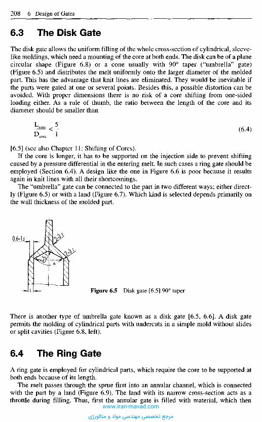
6 . 3 T h e D i s k G a t e
The disk gate allows the uniform filling of the whole cross-section of cylindrical, sleeve-like moldings, which need a mounting of the core at both ends. The disk can be of a planecircular shape (Figure 6.8) or a cone usually with 90° taper ("umbrella" gate)(Figure 6.5) and distributes the melt uniformly onto the larger diameter of the moldedpart. This has the advantage that knit lines are eliminated. They would be inevitable ifthe parts were gated at one or several points. Besides this, a possible distortion can beavoided. With proper dimensions there is no risk of a core shifting from one-sidedloading either. As a rule of thumb, the ratio between the length of the core and itsdiameter should be smaller than
(6.4)
[6.5] (see also Chapter 11: Shifting of Cores).If the core is longer, it has to be supported on the injection side to prevent shifting
caused by a pressure differential in the entering melt. In such cases a ring gate should beemployed (Section 6.4). A design like the one in Figure 6.6 is poor because it resultsagain in knit lines with all their shortcomings.
The "umbrella" gate can be connected to the part in two different ways; either direct-ly (Figure 6.5) or with a land (Figure 6.7). Which kind is selected depends primarily onthe wall thickness of the molded part.
Figure 6.5 Disk gate [6.5] 90° taper
There is another type of umbrella gate known as a disk gate [6.5, 6.6]. A disk gatepermits the molding of cylindrical parts with undercuts in a simple mold without slidesor split cavities (Figure 6.8, left).
6 . 4 T h e R i n g G a t e
A ring gate is employed for cylindrical parts, which require the core to be supported atboth ends because of its length.
The melt passes through the sprue first into an annular channel, which is connectedwith the part by a land (Figure 6.9). The land with its narrow cross-section acts as athrottle during filling. Thus, first the annular gate is filled with material, which then
www.iran-mavad.com
مرجع تخصصی مهندسی مواد و متالورژی
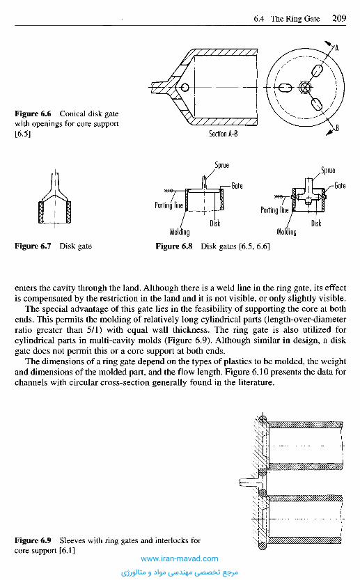
enters the cavity through the land. Although there is a weld line in the ring gate, its effectis compensated by the restriction in the land and it is not visible, or only slightly visible.
The special advantage of this gate lies in the feasibility of supporting the core at bothends. This permits the molding of relatively long cylindrical parts (length-over-diameterratio greater than 5/1) with equal wall thickness. The ring gate is also utilized forcylindrical parts in multi-cavity molds (Figure 6.9). Although similar in design, a diskgate does not permit this or a core support at both ends.
The dimensions of a ring gate depend on the types of plastics to be molded, the weightand dimensions of the molded part, and the flow length. Figure 6.10 presents the data forchannels with circular cross-section generally found in the literature.
Figure 6.7 Disk gate Figure 6.8 Disk gates [6.5, 6.6]
MoldingDiskDisk
Molding
Parting line
Sprue
Gate
Sprue
Parting line
Gate
Section A-B
Figure 6.6 Conical disk gatewith openings for core support[6.5]
Figure 6.9 Sleeves with ring gates and interlocks forcore support [6.1]
www.iran-mavad.com
مرجع تخصصی مهندسی مواد و متالورژی
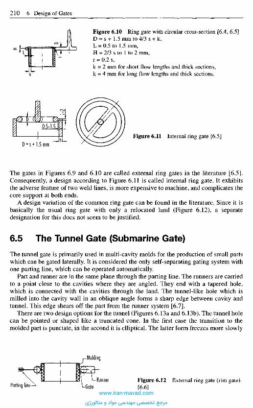
The gates in Figures 6.9 and 6.10 are called external ring gates in the literature [6.5].Consequently, a design according to Figure 6.11 is called internal ring gate. It exhibitsthe adverse feature of two weld lines, is more expensive to machine, and complicates thecore support at both ends.
A design variation of the common ring gate can be found in the literature. Since it isbasically the usual ring gate with only a relocated land (Figure 6.12), a separatedesignation for this does not seem to be justified.
6 . 5 T h e T u n n e l G a t e ( S u b m a r i n e G a t e )
The tunnel gate is primarily used in multi-cavity molds for the production of small partswhich can be gated laterally. It is considered the only self-separating gating system withone parting line, which can be operated automatically.
Part and runner are in the same plane through the parting line. The runners are carriedto a point close to the cavities where they are angled. They end with a tapered hole,which is connected with the cavities through the land. The tunnel-like hole which ismilled into the cavity wall in an oblique angle forms a sharp edge between cavity andtunnel. This edge shears off the part from the runner system [6.7].
There are two design options for the tunnel (Figures 6.13a and 6.13b). The tunnel holecan be pointed or shaped like a truncated cone. In the first case the transition to themolded part is punctate, in the second it is elliptical. The latter form freezes more slowly
Figure 6.10 Ring gate with circular cross-section [6.4, 6.5]D = s+ 1.5 mm to 4/3 s + k,L = 0.5 to 1.5 mm,H = 2/3 s to 1 to 2 mm,r = 0.2 s,k = 2 mm for short flow lengths and thick sections,k = 4 mm for long flow lengths and thick sections.
Figure 6.11 Internal ring gate [6.5]
Figure 6.12 External ring gate (rim gate)[6.6]
Molding
Runner-GateParting line
www.iran-mavad.com
مرجع تخصصی مهندسی مواد و متالورژی
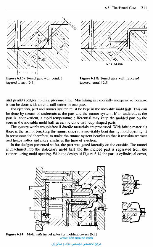
and permits longer holding pressure time. Machining is especially inexpensive becauseit can be done with an end-mill cutter in one pass.
For ejection, part and runner system must be kept in the movable mold half. This canbe done by means of undercuts at the part and the runner system. If an undercut at thepart is inconvenient, a mold temperature differential may keep the molded part on thecore in the movable mold half as can be done with cup-shaped parts.
The system works troublefree if ductile materials are processed. With brittle materialsthere is the risk of breaking the runner since it is inevitably bent during mold opening. Itis recommended therefore, to make the runner system heavier so that it remains warmerand hence softer and more elastic at the time of ejection.
In the designs presented so far, the part was gated laterally on the outside. The tunnelis machined into the stationary mold half and the molded part is separated from therunner during mold opening. With the design of Figure 6.14 the part, a cylindrical cover,
Figure 6.14 Mold with tunnel gates for molding covers [6.8]
Figure 6.13a Tunnel gate with pointedtapered tunnel [6.5]
Figure 6.13b Tunnel gate with truncatedtapered tunnel [6.5]
www.iran-mavad.com
مرجع تخصصی مهندسی مواد و متالورژی
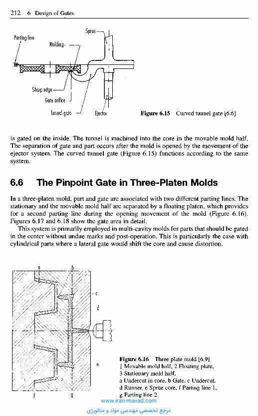
is gated on the inside. The tunnel is machined into the core in the movable mold half.The separation of gate and part occurs after the mold is opened by the movement of theejector system. The curved tunnel gate (Figure 6.15) functions according to the samesystem.
6 . 6 T h e P i n p o i n t G a t e in T h r e e - P l a t e n M o l d s
In a three-platen mold, part and gate are associated with two different parting lines. Thestationary and the movable mold half are separated by a floating platen, which providesfor a second parting line during the opening movement of the mold (Figure 6.16).Figures 6.17 and 6.18 show the gate area in detail.
This system is primarily employed in multi-cavity molds for parts that should be gatedin the center without undue marks and post-operation. This is particularly the case withcylindrical parts where a lateral gate would shift the core and cause distortion.
Figure 6.16 Three plate mold [6.9]1 Movable mold half, 2 Floating plate,3 Stationary mold half,a Undercut in core, b Gate, c Undercut,d Runner, e Sprue core, f Parting line 1,g Parting line 2.
Figure 6.15 Curved tunnel gate [6.6]EjectorTunnel gate -
Gate orifice
Sharp edge
Sprue
MoldingParting line
www.iran-mavad.com
مرجع تخصصی مهندسی مواد و متالورژی
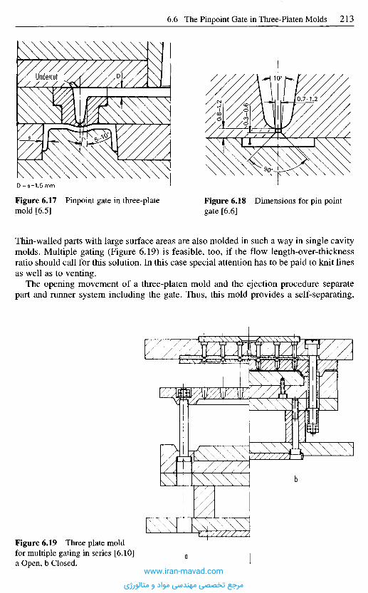
Figure 6.17 Pinpoint gate in three-platemold [6.5]
Figure 6.18 Dimensions for pin pointgate [6.6]
Thin-walled parts with large surface areas are also molded in such a way in single cavitymolds. Multiple gating (Figure 6.19) is feasible, too, if the flow length-over-thicknessratio should call for this solution. In this case special attention has to be paid to knit linesas well as to venting.
The opening movement of a three-platen mold and the ejection procedure separatepart and runner system including the gate. Thus, this mold provides a self-separating,
Figure 6.19 Three plate moldfor multiple gating in series [6.10]a Open, b Closed.
a
b
Undercut
www.iran-mavad.com
مرجع تخصصی مهندسی مواد و متالورژی
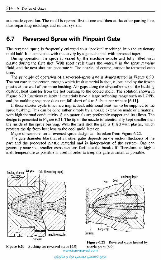
automatic operation. The mold is opened first at one and then at the other parting line,thus separating moldings and runner system.
6 . 7 R e v e r s e d S p r u e w i t h P i n p o i n t G a t e
The reversed sprue is frequently enlarged to a "pocket" machined into the stationarymold half. It is connected with the cavity by a gate channel with reversed taper.
During operation the sprue is sealed by the machine nozzle and fully filled withplastic during the first shot. With short cycle times the material in the sprue remainsfluid, and the next shot can penetrate it. The nozzle, of course, cannot be retracted eachtime.
The principle of operation of a reversed-sprue gate is demonstrated in Figure 6.20.The hot core in the center, through which fresh material is shot, is insulated by the frozenplastic at the wall of the sprue bushing. Air gaps along the circumference of the bushingobstruct heat transfer from the hot bushing to the cooled mold. The solution shown inFigure 6.20 functions reliably if materials have a large softening range such as LDPE,and the molding sequence does not fall short of 4 to 5 shots per minute [6.11].
If these shorter cycle times are impractical, additional heat has to be supplied to thesprue bushing. This can be done rather simply by a nozzle extension made of a materialwith high thermal conductivity. Such materials are preferably copper and its alloys. Thedesign is presented in Figure 6.21. The tip of the nozzle is intentionally kept smaller thanthe inside of the sprue bushing. With the first shot the gap is filled with plastic, whichprotects the tip from heat loss to the cool mold later on.
Major dimensions for a reversed-sprue design can be taken from Figure 6.22.The gate diameter like that of all other gates depends on the section thickness of the
part and the processed plastic material and is independent of the system. One cangenerally state that smaller cross-sections facilitate the break-off. Therefore, as high amelt temperature as possible is used in order to keep the gate as small as possible.
Figure 6.20 Bushing for reversed sprue [6.9]Figure 6.21 Reversed sprue heated bynozzle point [6.9]
BushingCooper tip
Hot ColdInsulating layer
Cold (insulating layer)Air gapCooling channel
Hot coreMachine nozzle
www.iran-mavad.com
مرجع تخصصی مهندسی مواد و متالورژی
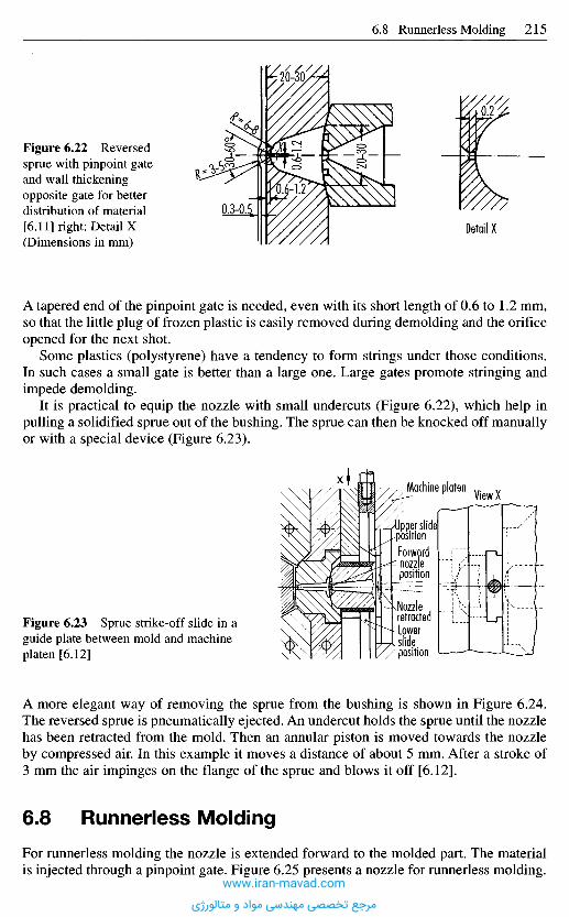
A more elegant way of removing the sprue from the bushing is shown in Figure 6.24.The reversed sprue is pneumatically ejected. An undercut holds the sprue until the nozzlehas been retracted from the mold. Then an annular piston is moved towards the nozzleby compressed air. In this example it moves a distance of about 5 mm. After a stroke of3 mm the air impinges on the flange of the sprue and blows it off [6.12].
6 . 8 R u n n e r l e s s M o l d i n g
For runnerless molding the nozzle is extended forward to the molded part. The materialis injected through a pinpoint gate. Figure 6.25 presents a nozzle for runnerless molding.
Figure 6.23 Sprue strike-off slide in aguide plate between mold and machineplaten [6.12]
NozzleretractedLowerslideposition
'Upper slidepositionForward
'- nozzleposition
Machine platenView X
x
A tapered end of the pinpoint gate is needed, even with its short length of 0.6 to 1.2 mm,so that the little plug of frozen plastic is easily removed during demolding and the orificeopened for the next shot.
Some plastics (polystyrene) have a tendency to form strings under those conditions.In such cases a small gate is better than a large one. Large gates promote stringing andimpede demolding.
It is practical to equip the nozzle with small undercuts (Figure 6.22), which help inpulling a solidified sprue out of the bushing. The sprue can then be knocked off manuallyor with a special device (Figure 6.23).
Figure 6.22 Reversedsprue with pinpoint gateand wall thickeningopposite gate for betterdistribution of material[6.11] right: Detail X(Dimensions in mm)
Detail X
www.iran-mavad.com
مرجع تخصصی مهندسی مواد و متالورژی
The face of the nozzle is part of the cavity surface. This causes pronounced gate marks(mat appearance and rippled surface) of course. Therefore, one has to keep the nozzle assmall as possible. It is suggested that a diameter of 6 to 12 mm not be exceeded. Becausethe nozzle is in contact with the cooler mold during injection- and holding-pressure time,this process is applicable only for producing thin-walled parts with a rapid sequence ofcycles. This sequence should not be less than 3 shots per minute to avoid a freezing ofthe nozzle, which is only heated by conduction. The applicability of this procedure islimited and it is used for inexpensive packaging items.
Figure 6.25 Sprueless gatingWall thickening forbetter melt distribution Core
Stripper ring
Stationary mold half
Nozzle
Air gap forthermalinsulation
Figure 6.24 Reversed sprue with pinpoint gate and pneumatic sprue ejector [6.12] Dimensionsin mm
Undercut 0.2-0.5
Compressedair
Annular pistonStroke 5 mm
O-ring 50 X 3
www.iran-mavad.com
مرجع تخصصی مهندسی مواد و متالورژی

The principle is successfully employed when the material is further distributedthrough runners as in a three-platen mold.
6 . 9 M o l d s w i t h I n s u l a t e d R u n n e r s
Properly designed insulated runners, i.e., with thermally controlled gate, offer severaladvantages over hot runners. These are:
- Thanks to the lack of dead spots and to the smooth channel, insulated runners aredependable, provided that fairly well stabilized materials are used. But all commonthermoplastic materials nowadays meet this condition.
- Since the thermal insulation arises itself through melt deposited at the wall, thetemperature distribution of the melt will always be very uniform.
- Insulated runners are always economical if constant operation with uniform cycles isguaranteed. It is not suitable, however, for extended interruptions.
- The higher the throughput, i.e., the greater the shot weight at normal wall thickness,the more dependable are insulated runners.
- Because insulated runners are very easy and quick to clean, they are particularlyrecommended when frequent color changes have to be made or when recycled materialis used for which it cannot be guaranted that entrained impurities will not lead toblockage or unclean, patchy surfaces.
- Properly designed insulated runners are both cheaper to buy and to maintain than hotrunners.
A distinguishing feature of a well designed insulated runner is that it has minimal heatloss. This means that thermal equilibrium will be reached pretty quickly with low energyinput on startup or after interruptions. Good design requires the following measures:
- good insulation effect through thick, outer insulation (generous channel cross-section),- an isolated air gap (a chimney effect must not occur in the air gap),- minimal contact areas between channel block and mold,- carefully calculated installation of cartridge heaters in the channel block to compensate
for losses at critical points during long cycle times.
It is always advisable - and absolutely vital for heat-sensitive plastics such as POM, PC,PBT, etc. - that the gate area be carefully designed. Neither the critical shear rate maybe exceeded nor may material that is too cold be transported into the mold. Furthermore,material that is too hot must not remain there to decompose. The following measures willproduce an ideal temperature profile in the gate area:
An internally heated needle (Figure 6.26) serving as the energy supply element in thetransition area to the cavity must have a temperature profile well adjusted to the plastic forprocessing. This means that the tip of the needle must keep the melt precisely at its idealprocessing temperature, while it must not overheat the melt along its shaft, and in the areaof the guide bushing the temperature of the plastic should just about be that of freezing.
For some years now, three standard types of tried and proven modules have beenavailable in two sizes for materials such as PS, ABS, PC, PE, PP, PA, POM and PBT (seeFigures 6.27 and 6.28) (e.g., supplied by KBC System, Bellanger, 1271 Givirns,Switzerland):
- for gate diameters in the range: 0.6 to 2.5 mm: MIDI,- for gate diameters in the range 2.0 to 5 mm: MAXI.
www.iran-mavad.com
مرجع تخصصی مهندسی مواد و متالورژی
Stage 2 = Sprue removed from thermally conductive tip
Figure 6.26 Insulated runner mold with internally heated needle
Application AreasPE moldings weighing 0.15 g can still be produced at a rate of 8 shots/minute withinsulated runners, although the heat input into the system is correspondingly low forsmall shot weights. In these cases, more energy must be fed to the runner by means ofcartridge heaters. Nevertheless, the insulated runners require barely one fourth of the
Temp
eratur
e prof
ile
Shoulder of dowel screw
www.iran-mavad.com
مرجع تخصصی مهندسی مواد و متالورژی
electric energy required by hot runners. It may generally be assumed that the size andweight of the producible molded parts are governed only by the rheological limits of theplastic melts used, i.e. the shear rate at the gate.
Figure 6.28 Internallyheated needles
Mold
heigh
t 130
mm
(MID
I)Mo
ld he
ight 1
99 m
m (M
AXI)
Figure 6.27 Internallyheated needles
Mold
heigh
t 108
mm
(MID
I)Mo
ld he
ight 1
63 m
m (M
AXI)
www.iran-mavad.com
مرجع تخصصی مهندسی مواد و متالورژی

Practical Experience Gained with Insulated RunnersThanks to its simple construction, clear functionality and self-sealing capability, theinsulated runner is easy to operate. There are few practiced operatives who consider thefreezing of the insulated runner during protracted production breaks to be a seriousdisadvantage. Quite the opposite is true. They appreciate the fact that the second partingline is easy and quick to open by simply moving two retaining clamps and that the frozenmaterial can be removed in one movement (Figure 6.29). The mold is then ready forproduction again after two to three cycles. This is quite advantageous because, whendisruptions occur in the case of hot runners, these are by far more complicated todismantle and clean. Furthermore, protracted disruptions with hot runners causeproblems because the material degrades if the heating is not turned off. An insulatedrunner can be completely cleaned within a few minutes, whereas production has to bestopped for hours when this happens to hot runners.
6 . 1 0 T e m p e r a t u r e - C o n t r o l l e d R u n n e r S y s t e m s -
H o t R u n n e r s
Runner systems in conventional molds have the same temperature level as the rest of themold because they are in the same mold block. If, however, the runner system is locatedin a special manifold that is heated to the temperature of the melt, all the advantageslisted below accrue. Runner manifolds heated to melt temperature have the task ofdistributing the melt as far as the gates without damage. They are used for all injection-molded thermoplastics as well as for crosslinking plastics, such as elastomers andthermosets.
In the case of thermoplastics, these manifolds are usually referred to as the hot-runnersystem, the hot manifold, or simply as hot runners. For crosslinking plastics, they areknown as cold runners.
Retaining clampAperture 2
Retaining clampAperture I
Figure 6.29 Retaining clamps make insulated runners easier to clean
Parting line I Parting line 2
Next Page
www.iran-mavad.com
مرجع تخصصی مهندسی مواد و متالورژی
Practical Experience Gained with Insulated RunnersThanks to its simple construction, clear functionality and self-sealing capability, theinsulated runner is easy to operate. There are few practiced operatives who consider thefreezing of the insulated runner during protracted production breaks to be a seriousdisadvantage. Quite the opposite is true. They appreciate the fact that the second partingline is easy and quick to open by simply moving two retaining clamps and that the frozenmaterial can be removed in one movement (Figure 6.29). The mold is then ready forproduction again after two to three cycles. This is quite advantageous because, whendisruptions occur in the case of hot runners, these are by far more complicated todismantle and clean. Furthermore, protracted disruptions with hot runners causeproblems because the material degrades if the heating is not turned off. An insulatedrunner can be completely cleaned within a few minutes, whereas production has to bestopped for hours when this happens to hot runners.
6 . 1 0 T e m p e r a t u r e - C o n t r o l l e d R u n n e r S y s t e m s -
H o t R u n n e r s
Runner systems in conventional molds have the same temperature level as the rest of themold because they are in the same mold block. If, however, the runner system is locatedin a special manifold that is heated to the temperature of the melt, all the advantageslisted below accrue. Runner manifolds heated to melt temperature have the task ofdistributing the melt as far as the gates without damage. They are used for all injection-molded thermoplastics as well as for crosslinking plastics, such as elastomers andthermosets.
In the case of thermoplastics, these manifolds are usually referred to as the hot-runnersystem, the hot manifold, or simply as hot runners. For crosslinking plastics, they areknown as cold runners.
Retaining clampAperture 2
Retaining clampAperture I
Figure 6.29 Retaining clamps make insulated runners easier to clean
Parting line I Parting line 2
Previous Page
www.iran-mavad.com
مرجع تخصصی مهندسی مواد و متالورژی

6.10.1 Hot-Runner Systems
Hot-runner systems have more or less become established for highly-automatedproduction of molded thermoplastic parts that are produced in large numbers. Thedecision to use them is almost always based on economics, i.e. production size. Qualityconsiderations, which played a major role in the past, are very rare now becausethermoplastics employed today are almost all so stable that they can be processedwithout difficulty with hot-runner systems that have been adapted accordingly.
Hot-runner systems are available as standard units and it is hardly worthwhile havingthem made. The relevant suppliers offer not only proven parts but also complete systemstailored to specific needs. The choice of individual parts is large.
Table 6.1 Hot runner systems suppliers in North America (selection) (see also Table 17.2)
D-M-E Company Madison Heights, MIAJSADynisco HotRunners Gloucester, MA/USAEurotool Gloucester, MA/USAEwicon Hotrunner Systems East Dundee, ILAJSAGunther Hot Runner Systems Buffalo Grove, ILAJSAHasco-Internorm Chatsworth, CAAJSAHusky Bolton, Ontario/CanadaIncoe Troy, MIAJSAManner International Tucker, GAAJSAMold-Masters Georgetown, Ontario/CanadaThermodyne HotRunner Systems Beverly, MAAJSA
6.10.1.1 Economic Advantages and Disadvantages of Hot-Runner Systems
Economic Advantages:- Savings in materials and costs for regrind.- Shorter cycles; cooling time no longer determined by the slowly solidifying runners;
no nozzle retraction required.- Machines can be smaller because the shot volume - around the runners - is reduced,
and the clamping forces are smaller because the runners do not generate reactive forcessince the blocks and the manifold block are closed.
Economic Disadvantages:- Much more complicated and considerably more expensive.- More work involved in running the mold for the first time.- More susceptible to breakdowns, higher maintenance costs (leakage, failure of heating
elements, and wear caused by filled materials).Technological Advantages:- Process can be automated (demolding) because runners do not need to be demolded.- Gates at the best position; thanks to uniform, precisely controlled cooling of the gate
system, long flow paths are possible.- Pressure losses minimized, since the diameter of the runners is not restricted.- Artificial balancing of the gate system; balancing can be performed during running
production by means of temperature control or special mechanical system (e.g.adjustment of the gap in a ring-shaped die or use of plates in flow channel).(Natural balancing is better!)
www.iran-mavad.com
مرجع تخصصی مهندسی مواد و متالورژی
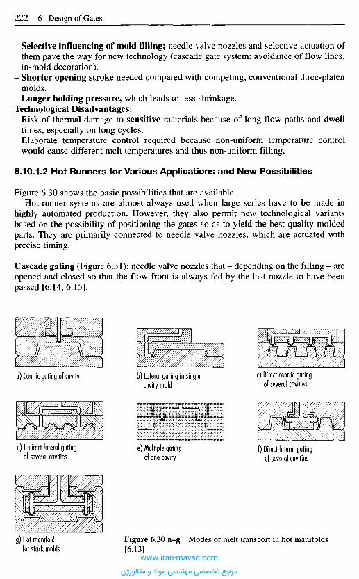
- Selective influencing of mold filling; needle valve nozzles and selective actuation ofthem pave the way for new technology (cascade gate system: avoidance of flow lines,in-mold decoration).
- Shorter opening stroke needed compared with competing, conventional three-platenmolds.
- Longer holding pressure, which leads to less shrinkage.Technological Disadvantages:- Risk of thermal damage to sensitive materials because of long flow paths and dwell
times, especially on long cycles.- Elaborate temperature control required because non-uniform temperature control
would cause different melt temperatures and thus non-uniform filling.
6.10.1.2 Hot Runners for Various Applications and New Possibilities
Figure 6.30 shows the basic possibilities that are available.Hot-runner systems are almost always used when large series have to be made in
highly automated production. However, they also permit new technological variantsbased on the possibility of positioning the gates so as to yield the best quality moldedparts. They are primarily connected to needle valve nozzles, which are actuated withprecise timing.
Cascade gating (Figure 6.31): needle valve nozzles that - depending on the filling - areopened and closed so that the flow front is always fed by the last nozzle to have beenpassed [6.14, 6.15].
a) Centric gating of cavity b) Lateral gating in singlecavity mold
c) Direct centric gatingof several cavities
d) Indirect lateral gatingof several cavities
e) Multiple gatingof one cavity
f) Direct lateral gatingof several cavities
g) Hot manifoldfor stack molds
Figure 6.30 a-g Modes of melt transport in hot manifolds[6.13]
www.iran-mavad.com
مرجع تخصصی مهندسی مواد و متالورژی
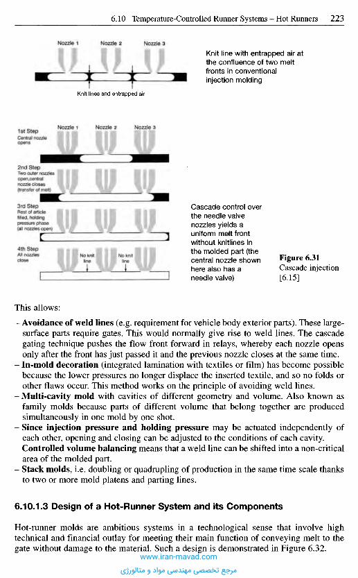
This allows:
- Avoidance of weld lines (e.g. requirement for vehicle body exterior parts). These large-surface parts require gates. This would normally give rise to weld lines. The cascadegating technique pushes the flow front forward in relays, whereby each nozzle opensonly after the front has just passed it and the previous nozzle closes at the same time.
- In-mold decoration (integrated lamination with textiles or film) has become possiblebecause the lower pressures no longer displace the inserted textile, and so no folds orother flaws occur. This method works on the principle of avoiding weld lines.
- Multi-cavity mold with cavities of different geometry and volume. Also known asfamily molds because parts of different volume that belong together are producedsimultaneously in one mold by one shot.
- Since injection pressure and holding pressure may be actuated independently ofeach other, opening and closing can be adjusted to the conditions of each cavity.
- Controlled volume balancing means that a weld line can be shifted into a non-criticalarea of the molded part.
- Stack molds, i.e. doubling or quadrupling of production in the same time scale thanksto two or more mold platens and parting lines.
6.10.1.3 Design of a Hot-Runner System and its Components
Hot-runner molds are ambitious systems in a technological sense that involve hightechnical and financial outlay for meeting their main function of conveying melt to thegate without damage to the material. Such a design is demonstrated in Figure 6.32.
Figure 6.31Cascade injection[6.15]
Cascade control overthe needle valvenozzles yields auniform melt frontwithout knitlines inthe molded part (thecentral nozzle shownhere also has aneedle valve)
Knit line with entrapped air atthe confluence of two meltfronts in conventionalinjection molding
Nozzle 1 Nozzle 2 Nozzle 3
Knit lines and entrapped air
1st StepCentral nozzleopens
Nozzle 1 Nozzle 2 Nozzle 3
2nd StepTwo outer nozzlesopen,centralnozzle closes(transfer of melt)
3rd StepRest of articlefilled, holdingpressure phase(all nozzles open)
4th StepAll nozzlesclose No knit
lineNo knit Iline i
www.iran-mavad.com
مرجع تخصصی مهندسی مواد و متالورژی
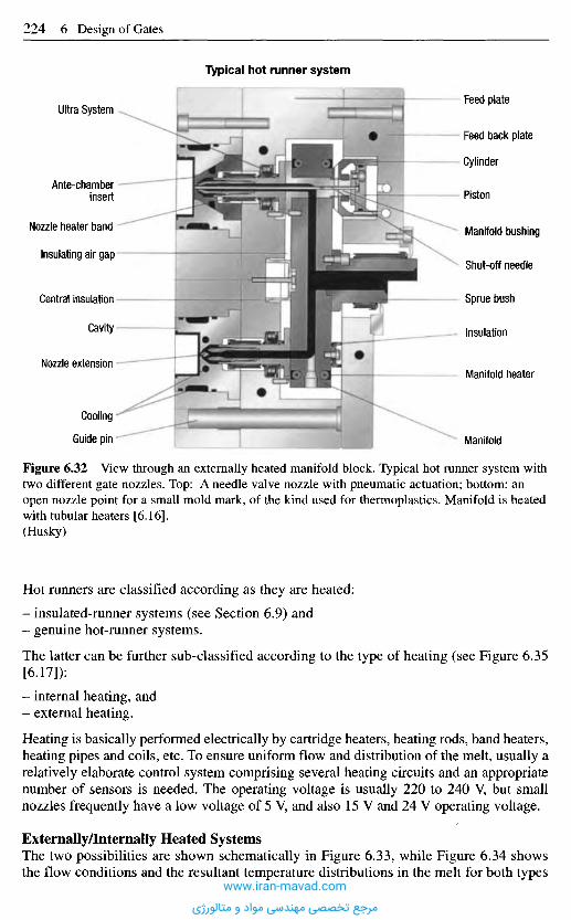
Figure 6.32 View through an externally heated manifold block. Typical hot runner system withtwo different gate nozzles. Top: A needle valve nozzle with pneumatic actuation; bottom: anopen nozzle point for a small mold mark, of the kind used for thermoplastics. Manifold is heatedwith tubular heaters [6.16].(Husky)
Hot runners are classified according as they are heated:
- insulated-runner systems (see Section 6.9) and- genuine hot-runner systems.
The latter can be further sub-classified according to the type of heating (see Figure 6.35[6.17]):
- internal heating, and- external heating.
Heating is basically performed electrically by cartridge heaters, heating rods, band heaters,heating pipes and coils, etc. To ensure uniform flow and distribution of the melt, usually arelatively elaborate control system comprising several heating circuits and an appropriatenumber of sensors is needed. The operating voltage is usually 220 to 240 V, but smallnozzles frequently have a low voltage of 5 V, and also 15 V and 24 V operating voltage.
Externally/Internally Heated SystemsThe two possibilities are shown schematically in Figure 6.33, while Figure 6.34 showsthe flow conditions and the resultant temperature distributions in the melt for both types
Feed plate
Feed back plate
Cylinder
Piston
Manifold bushing
Shut-off needle
Sprue bush
Insulation
Manifold heater
Manifold
Ultra System
Ante-chamberinsert
Nozzle heater band
Insulating air gap
Central insulation •
Cavity
Nozzle extension -
Cooling -
Guide pin •
Typical hot runner system
www.iran-mavad.com
مرجع تخصصی مهندسی مواد و متالورژی
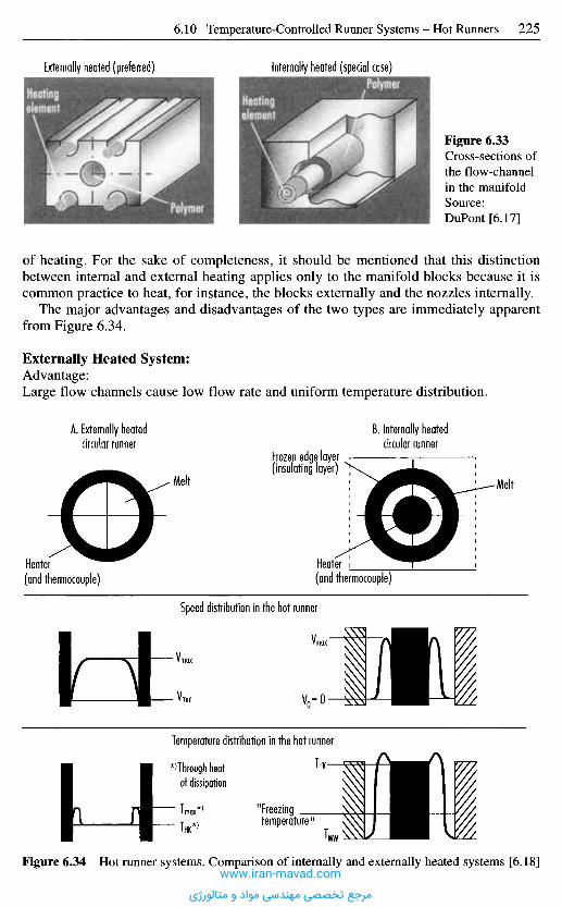
Externally heated (preferred) Infernally heated (special case)
Figure 6.33Cross-sections ofthe flow-channelin the manifoldSource:DuPont [6.17]
of heating. For the sake of completeness, it should be mentioned that this distinctionbetween internal and external heating applies only to the manifold blocks because it iscommon practice to heat, for instance, the blocks externally and the nozzles internally.
The major advantages and disadvantages of the two types are immediately apparentfrom Figure 6.34.
Externally Heated System:Advantage:Large flow channels cause low flow rate and uniform temperature distribution.
A. Externally heatedcircular runner
B. Internally heatedcircular runner
Melt
Frozen edge layer(insulating layer)
Heater(and thermocouple)
Heater(and thermocouple)
Melt
Speed distribution in the hot runner
Temperature distribution in the hot runner
'Through heatof dissipation
"Freezingtemperature"
Figure 6.34 Hot runner systems. Comparison of internally and externally heated systems [6.18]www.iran-mavad.com
مرجع تخصصی مهندسی مواد و متالورژی
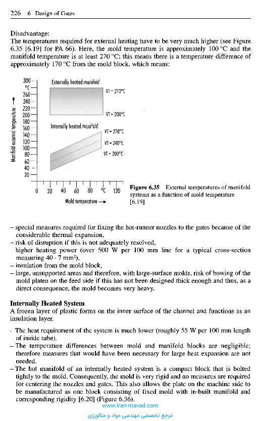
- special measures required for fixing the hot-runner nozzles to the gates because of theconsiderable thermal expansion,
- risk of disruption if this is not adequately resolved,- higher heating power (over 500 W per 100 mm line for a typical cross-section
measuring 40 • 7 mm2),- insulation from the mold block,- large, unsupported areas and therefore, with large-surface molds, risk of bowing of the
mold platen on the feed side if this has not been designed thick enough and thus, as adirect consequence, the mold becomes very heavy.
Internally Heated SystemA frozen layer of plastic forms on the inner surface of the channel and functions as aninsulation layer.
- The heat requirement of the system is much lower (roughly 55 W per 100 mm lengthof inside tube).
-The temperature differences between mold and manifold blocks are negligible;therefore measures that would have been necessary for large heat expansion are notneeded.
- The hot manifold of an internally heated system is a compact block that is boltedtightly to the mold. Consequently, the mold is very rigid and no measures are requiredfor centering the nozzles and gates. This also allows the plate on the machine side tobe manufactured as one block consisting of fixed mold with in-built manifold andcorresponding rigidity [6.20] (Figure 6.36).
Figure 6.35 External temperatures of manifoldsystems as a function of mold temperature[6.19]Mold temperature
Manif
old e
xterna
l temp
eratur
e
Disadvantage:The temperatures required for external heating have to be very much higher (see Figure6.35 [6.19] for PA 66). Here, the mold temperature is approximately 1000C and themanifold temperature is at least 270 0C; this means there is a temperature difference ofapproximately 170 0C from the mold block, which means:
0CExternally heated manifold
Internally heated manifold
www.iran-mavad.com
مرجع تخصصی مهندسی مواد و متالورژی
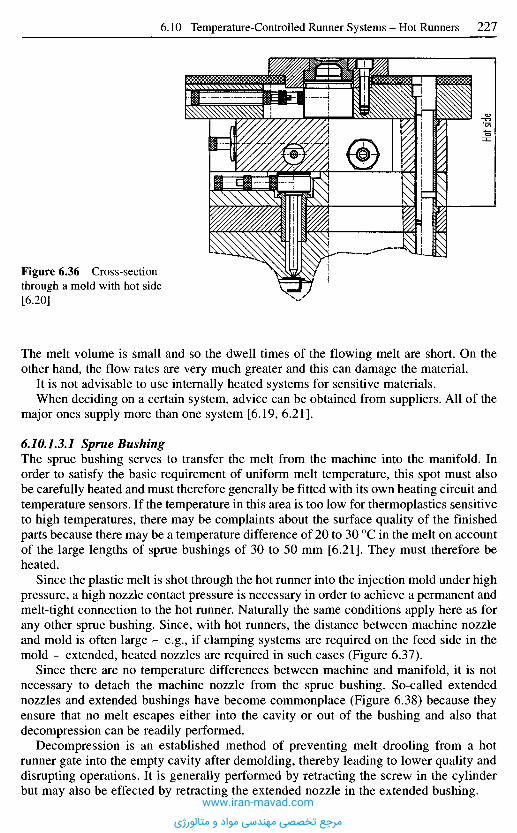
The melt volume is small and so the dwell times of the flowing melt are short. On theother hand, the flow rates are very much greater and this can damage the material.
It is not advisable to use internally heated systems for sensitive materials.When deciding on a certain system, advice can be obtained from suppliers. All of the
major ones supply more than one system [6.19, 6.21].
6.10.1.3J Sprue BushingThe sprue bushing serves to transfer the melt from the machine into the manifold. Inorder to satisfy the basic requirement of uniform melt temperature, this spot must alsobe carefully heated and must therefore generally be fitted with its own heating circuit andtemperature sensors. If the temperature in this area is too low for thermoplastics sensitiveto high temperatures, there may be complaints about the surface quality of the finishedparts because there may be a temperature difference of 20 to 30 0C in the melt on accountof the large lengths of sprue bushings of 30 to 50 mm [6.21]. They must therefore beheated.
Since the plastic melt is shot through the hot runner into the injection mold under highpressure, a high nozzle contact pressure is necessary in order to achieve a permanent andmelt-tight connection to the hot runner. Naturally the same conditions apply here as forany other sprue bushing. Since, with hot runners, the distance between machine nozzleand mold is often large - e.g., if clamping systems are required on the feed side in themold - extended, heated nozzles are required in such cases (Figure 6.37).
Since there are no temperature differences between machine and manifold, it is notnecessary to detach the machine nozzle from the sprue bushing. So-called extendednozzles and extended bushings have become commonplace (Figure 6.38) because theyensure that no melt escapes either into the cavity or out of the bushing and also thatdecompression can be readily performed.
Decompression is an established method of preventing melt drooling from a hotrunner gate into the empty cavity after demolding, thereby leading to lower quality anddisrupting operations. It is generally performed by retracting the screw in the cylinderbut may also be effected by retracting the extended nozzle in the extended bushing.
Figure 6.36 Cross-sectionthrough a mold with hot side[6.20]
Hot s
ide
www.iran-mavad.com
مرجع تخصصی مهندسی مواد و متالورژی
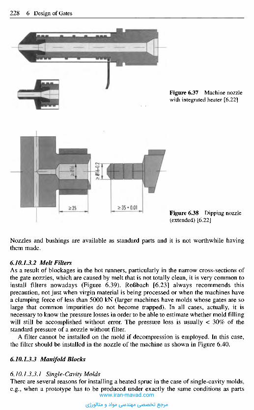
Nozzles and bushings are available as standard parts and it is not worthwhile havingthem made.
6.10.1.3.2 Melt FiltersAs a result of blockages in the hot runners, particularly in the narrow cross-sections ofthe gate nozzles, which are caused by melt that is not totally clean, it is very common toinstall filters nowadays (Figure 6.39). RoBbach [6.23] always recommends thisprecaution, not just when virgin material is being processed or when the machines havea clamping force of less than 5000 kN (larger machines have molds whose gates are solarge that common impurities do not become trapped). In all cases, actually, it isnecessary to know the pressure losses in order to be able to estimate whether mold fillingwill still be accomplished without error. The pressure loss is usually < 30% of thestandard pressure of a nozzle without filter.
A filter cannot be installed on the mold if decompression is employed. In this case,the filter should be installed in the nozzle of the machine as shown in Figure 6.40.
6 JO.1.3.3 Manifold Blocks
6.10.133.1 Single-Cavity MoldsThere are several reasons for installing a heated sprue in the case of single-cavity molds,e.g., when a prototype has to be produced under exactly the same conditions as parts
Figure 6.38 Dipping nozzle(extended) [6.22]
Figure 6.37 Machine nozzlewith integrated heater [6.22]
www.iran-mavad.com
مرجع تخصصی مهندسی مواد و متالورژی
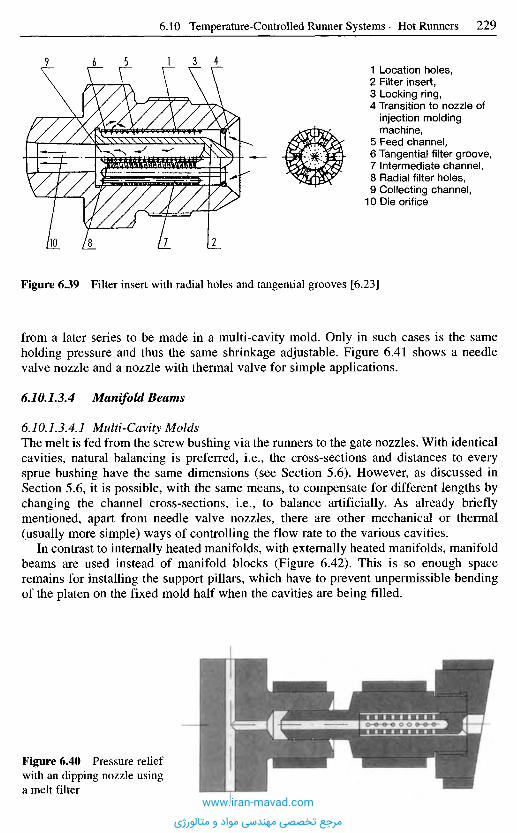
Figure 6.39 Filter insert with radial holes and tangential grooves [6.23]
from a later series to be made in a multi-cavity mold. Only in such cases is the sameholding pressure and thus the same shrinkage adjustable. Figure 6.41 shows a needlevalve nozzle and a nozzle with thermal valve for simple applications.
6.10.1.3.4 Manifold Beams
6.10.1.3.4.1 Multi-Cavity MoldsThe melt is fed from the screw bushing via the runners to the gate nozzles. With identicalcavities, natural balancing is preferred, i.e., the cross-sections and distances to everysprue bushing have the same dimensions (see Section 5.6). However, as discussed inSection 5.6, it is possible, with the same means, to compensate for different lengths bychanging the channel cross-sections, i.e., to balance artificially. As already brieflymentioned, apart from needle valve nozzles, there are other mechanical or thermal(usually more simple) ways of controlling the flow rate to the various cavities.
In contrast to internally heated manifolds, with externally heated manifolds, manifoldbeams are used instead of manifold blocks (Figure 6Al). This is so enough spaceremains for installing the support pillars, which have to prevent unpermissible bendingof the platen on the fixed mold half when the cavities are being filled.
1 Location holes,2 Filter insert,3 Locking ring,4 Transition to nozzle of
injection moldingmachine,
5 Feed channel,6 Tangential filter groove,7 Intermediate channel,8 Radial filter holes,9 Collecting channel,
10 Die orifice
Figure 6.40 Pressure reliefwith an dipping nozzle usinga melt filter
www.iran-mavad.com
مرجع تخصصی مهندسی مواد و متالورژی
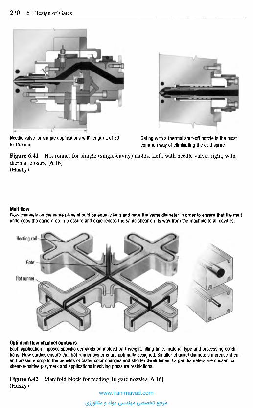
Needle valve for simple applications with length L of 80to 155 mm
Gating with a thermal shut-off nozzle is the mostcommon way of eliminating the cold sprue
Figure 6.41 Hot runner for simple (single-cavity) molds. Left, with needle valve; right, withthermal closure [6.16](Husky)
Melt flowFlow channels on the same plane should be equally long and have the same diameter in order to ensure that the meltundergoes the same drop in pressure and experiences the same shear on its way from the machine to all cavities.
Heating coil
Gate
Hot runner
Optimum flow channel contoursEach application imposes specific demands on molded part weight, filling time, material type and processing condi-tions. Flow studies ensure that hot runner systems are optimally designed. Smaller channel diameters increase shearand pressure drop to the benefits of faster color changes and shorter dwell times. Larger diameters are chosen forshear-sensitive polymers and applications involving pressure restrictions.
Figure 6.42 Manifold block for feeding 16 gate nozzles [6.16](Husky)
www.iran-mavad.com
مرجع تخصصی مهندسی مواد و متالورژی
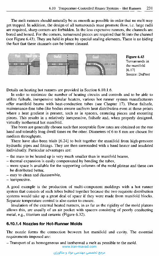
The melt runners should naturally be as smooth as possible in order that no melt mayget trapped. In addition, the design of all turnarounds must promote flow, i.e. large radiiare required, sharp corners are forbidden. In the less expensive runners, the channels arebored and honed. For the corners, turnaround pieces are required that fit into the channel(see Figure 6.43). They are held in place by special sealing elements. There is no hidingthe fact that these channels can be better cleaned.
Figure 6.43Turnarounds inthe manifold[6.17]Source: DuPont
Details on heating hot runners are provided in Section 6.10.1.6.In order to minimize the number of heating circuits and controls and to be able to
utilize failsafe, inexpensive tubular heaters, various hot runner system manufacturersoffer manifold beams with heat-conduction tubes (see Chapter 17). These failsafe,maintenance-free tube-like bodies ensure uniform heat distribution even at those pointswhere a heat gradient is present, such as in spacers, centering pieces and mountingpieces. This results in a relatively inexpensive, failsafe and, when properly designed,virtually isothermal hot manifold.
The bores are generally chosen such that acceptable flow rates are obtained on the onehand and tolerably long dwell times on the other. Diameters of 6 to 8 mm are chosen formedium throughputs.
There have also been trials [6.24] to bolt together the manifold from high-pressurehydraulic pipes and fittings. They are then surrounded with a band heater and insulatedindividually. Particular advantages are:
- the mass to be heated up is very much smaller than in manifold beams,- thermal expansion is easily compensated by bending the tubes,- more space is available for the supporting columns of the mold platens and these can
be distributed better,- easy to clean and disassemble,- inexpensive.
A good example is the production of multi-component moldings with a hot runnersystem that consists of such tubes bolted together because the two requisite distributionsystems would take up a great deal of space if they were made from manifold blocks.Separate temperature control is also easier to ensure.
Insulation of the external heated runners, in as far as the rigidity of the mold platensallows this, are usually of an air pocket with spacers consisting of poorly conductingmetal, e.g., titanium and ceramic (Figure 6.32).
6.10.1.4 Nozzles for Hot-Runner Molds
The nozzle forms the connection between hot manifold and cavity. The essentialrequirements imposed are:
- Transport of as homogeneous and isothermal a melt as possible to the mold.www.iran-mavad.com
مرجع تخصصی مهندسی مواد و متالورژی
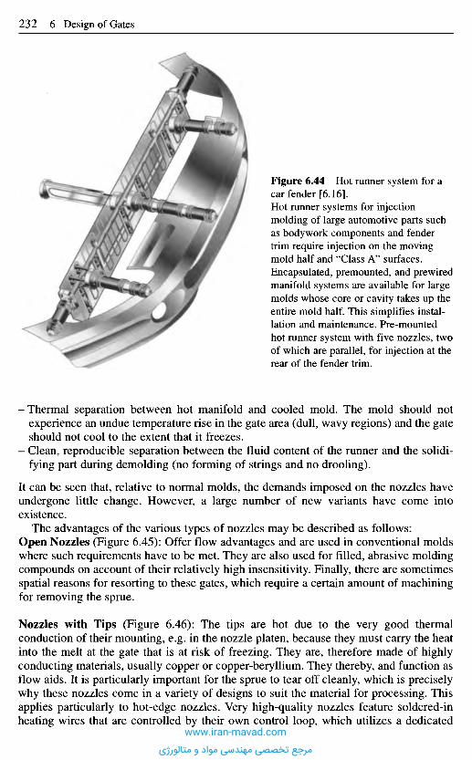
-Thermal separation between hot manifold and cooled mold. The mold should notexperience an undue temperature rise in the gate area (dull, wavy regions) and the gateshould not cool to the extent that it freezes.
- Clean, reproducible separation between the fluid content of the runner and the solidi-fying part during demolding (no forming of strings and no drooling).
It can be seen that, relative to normal molds, the demands imposed on the nozzles haveundergone little change. However, a large number of new variants have come intoexistence.
The advantages of the various types of nozzles may be described as follows:Open Nozzles (Figure 6.45): Offer flow advantages and are used in conventional moldswhere such requirements have to be met. They are also used for filled, abrasive moldingcompounds on account of their relatively high insensitivity. Finally, there are sometimesspatial reasons for resorting to these gates, which require a certain amount of machiningfor removing the sprue.
Nozzles with Tips (Figure 6.46): The tips are hot due to the very good thermalconduction of their mounting, e.g. in the nozzle platen, because they must carry the heatinto the melt at the gate that is at risk of freezing. They are, therefore made of highlyconducting materials, usually copper or copper-beryllium. They thereby, and function asflow aids. It is particularly important for the sprue to tear off cleanly, which is preciselywhy these nozzles come in a variety of designs to suit the material for processing. Thisapplies particularly to hot-edge nozzles. Very high-quality nozzles feature soldered-inheating wires that are controlled by their own control loop, which utilizes a dedicated
Figure 6.44 Hot runner system for acar fender [6.16].Hot runner systems for injectionmolding of large automotive parts suchas bodywork components and fendertrim require injection on the movingmold half and "Class A" surfaces.Encapsulated, premounted, and prewiredmanifold systems are available for largemolds whose core or cavity takes up theentire mold half. This simplifies instal-lation and maintenance. Pre-mountedhot runner system with five nozzles, twoof which are parallel, for injection at therear of the fender trim.
www.iran-mavad.com
مرجع تخصصی مهندسی مواد و متالورژی
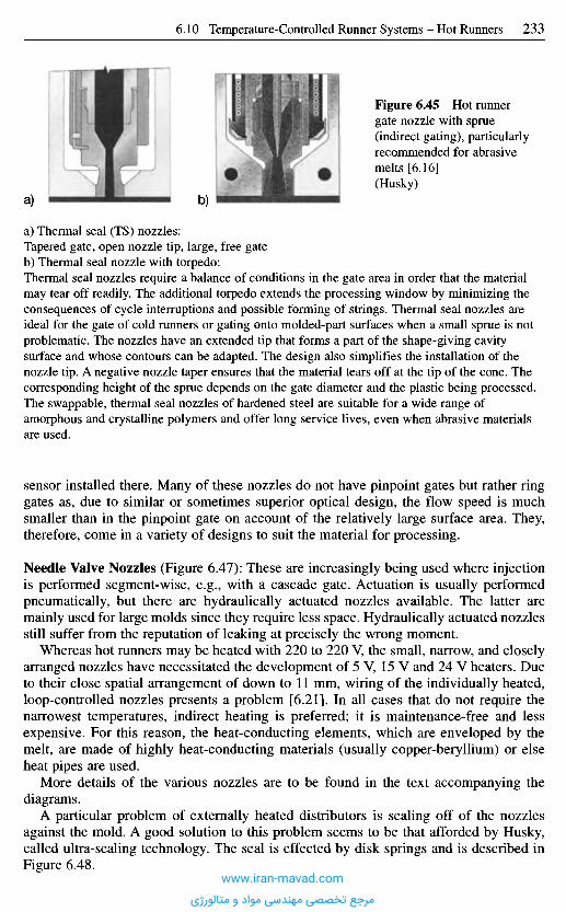
a) Thermal seal (TS) nozzles:Tapered gate, open nozzle tip, large, free gateb) Thermal seal nozzle with torpedo:Thermal seal nozzles require a balance of conditions in the gate area in order that the materialmay tear off readily. The additional torpedo extends the processing window by minimizing theconsequences of cycle interruptions and possible forming of strings. Thermal seal nozzles areideal for the gate of cold runners or gating onto molded-part surfaces when a small sprue is notproblematic. The nozzles have an extended tip that forms a part of the shape-giving cavitysurface and whose contours can be adapted. The design also simplifies the installation of thenozzle tip. A negative nozzle taper ensures that the material tears off at the tip of the cone. Thecorresponding height of the sprue depends on the gate diameter and the plastic being processed.The swappable, thermal seal nozzles of hardened steel are suitable for a wide range ofamorphous and crystalline polymers and offer long service lives, even when abrasive materialsare used.
sensor installed there. Many of these nozzles do not have pinpoint gates but rather ringgates as, due to similar or sometimes superior optical design, the flow speed is muchsmaller than in the pinpoint gate on account of the relatively large surface area. They,therefore, come in a variety of designs to suit the material for processing.
Needle Valve Nozzles (Figure 6.47): These are increasingly being used where injectionis performed segment-wise, e.g., with a cascade gate. Actuation is usually performedpneumatically, but there are hydraulically actuated nozzles available. The latter aremainly used for large molds since they require less space. Hydraulically actuated nozzlesstill suffer from the reputation of leaking at precisely the wrong moment.
Whereas hot runners may be heated with 220 to 220 V, the small, narrow, and closelyarranged nozzles have necessitated the development of 5 V, 15 V and 24 V heaters. Dueto their close spatial arrangement of down to 11 mm, wiring of the individually heated,loop-controlled nozzles presents a problem [6.21]. In all cases that do not require thenarrowest temperatures, indirect heating is preferred; it is maintenance-free and lessexpensive. For this reason, the heat-conducting elements, which are enveloped by themelt, are made of highly heat-conducting materials (usually copper-beryllium) or elseheat pipes are used.
More details of the various nozzles are to be found in the text accompanying thediagrams.
A particular problem of externally heated distributors is sealing off of the nozzlesagainst the mold. A good solution to this problem seems to be that afforded by Husky,called ultra-sealing technology. The seal is effected by disk springs and is described inFigure 6.48.
Figure 6.45 Hot runnergate nozzle with sprue(indirect gating), particularlyrecommended for abrasivemelts [6.16](Husky)
b)a)
www.iran-mavad.com
مرجع تخصصی مهندسی مواد و متالورژی
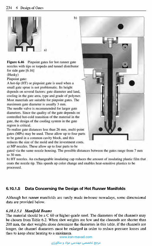
Figure 6.46 Pinpoint gates for hot runner gatenozzles with tips or torpedo and tunnel distributorfor side gate [6.16](Husky)Pinpoint gate:A hot-tip (HT) or pinpoint gate is used when asmall gate sprue is not problematic. Its heightdepends on several factors: gate diameter and land,cooling in the gate area, type and grade of polymer.Most materials are suitable for pinpoint gates. Themaximum gate diameter is usually 3 mm.The needle valve is recommended for larger gatediameters. Since the quality of the gate depends oncontrolled hot-cold transition of the material in thegate, the design of the cooling system in the gateregion is critical.To realize gate distances less than 26 mm, multi-pointgates (MPs) may be used. These allow up to four partsto be gated in a common cavity block, and thisreduces the size of the mold and the investment costs.a) MP nozzles. These allow up to four parts to begated via the same nozzle housing. The possible distances between the gates range from 7 mmto 30 mm.b) HT nozzles. An exchangeable insulating cap reduces the amount of insulating plastic film thatcoats the nozzle tip. This speeds up color change and enables heat-sensitive plastics to beprocessed.
6.10.1.5 Data Concerning the Design of Hot Runner Manifolds
Although hot runner manifolds are rarely made in-house nowadays, some dimensionaldata are provided below.
6.10.1.5.1 Manifold BeamsThe material should be a C 60 or higher-grade steel. The diameters of the channels maybe chosen from Table 6.2. When shot weights are low and the channels are shorter than200 mm, the shot weights alone determine the diameters in this table. If the channels arelonger, the channel diameters must be enlarged in order to reduce pressure losses andthus to keep shear heating to a minimum.
a)
b)
www.iran-mavad.com
مرجع تخصصی مهندسی مواد و متالورژی
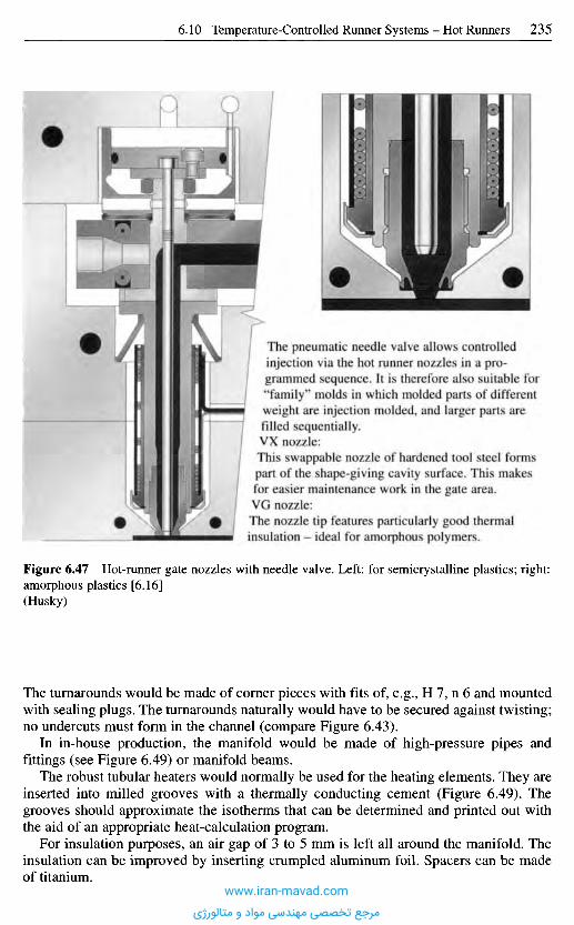
Figure 6.47 Hot-runner gate nozzles with needle valve. Left: for semicrystalline plastics; right:amorphous plastics [6.16](Husky)
The turnarounds would be made of corner pieces with fits of, e.g., H 7, n 6 and mountedwith sealing plugs. The turnarounds naturally would have to be secured against twisting;no undercuts must form in the channel (compare Figure 6.43).
In in-house production, the manifold would be made of high-pressure pipes andfittings (see Figure 6.49) or manifold beams.
The robust tubular heaters would normally be used for the heating elements. They areinserted into milled grooves with a thermally conducting cement (Figure 6.49). Thegrooves should approximate the isotherms that can be determined and printed out withthe aid of an appropriate heat-calculation program.
For insulation purposes, an air gap of 3 to 5 mm is left all around the manifold. Theinsulation can be improved by inserting crumpled aluminum foil. Spacers can be madeof titanium.
The pneumatic needle valve allows controlledinjection via the hot runner nozzles in a pro-grammed sequence. It is therefore also suitable for"family" molds in which molded parts of differentweight are injection molded, and larger parts arefilled sequentially.VX nozzle:This swappable nozzle of hardened tool steel formspart of the shape-giving cavity surface. This makesfor easier maintenance work in the gate area.VG nozzle:The nozzle tip features particularly good thermalinsulation - ideal for amorphous polymers.
www.iran-mavad.com
مرجع تخصصی مهندسی مواد و متالورژی
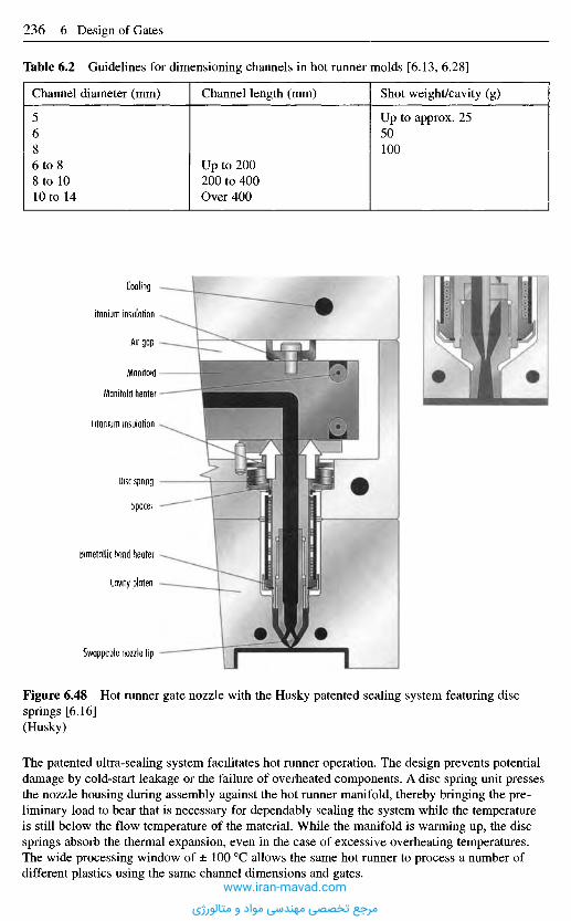
Figure 6.48 Hot runner gate nozzle with the Husky patented sealing system featuring discsprings [6.16](Husky)
The patented ultra-sealing system facilitates hot runner operation. The design prevents potentialdamage by cold-start leakage or the failure of overheated components. A disc spring unit pressesthe nozzle housing during assembly against the hot runner manifold, thereby bringing the pre-liminary load to bear that is necessary for dependably sealing the system while the temperatureis still below the flow temperature of the material. While the manifold is warming up, the discsprings absorb the thermal expansion, even in the case of excessive overheating temperatures.The wide processing window of ± 100 0C allows the same hot runner to process a number ofdifferent plastics using the same channel dimensions and gates.
Cooling
I Itanium insulation
Air gap
Manitoid
Manifold heater
I Itanium insulation
Uisc spring
bpacer
bimetallic band heater
Cavity platen
Swappable nozzle tip
Table 6.2 Guidelines for dimensioning channels in hot runner molds [6.13, 6.28]
Channel diameter (mm) Channel length (mm) Shot weight/cavity (g)
5 Up to approx. 256 508 1006 to 8 Up to 2008 to 10 200 to 40010 to 14 Over 400
www.iran-mavad.com
مرجع تخصصی مهندسی مواد و متالورژی
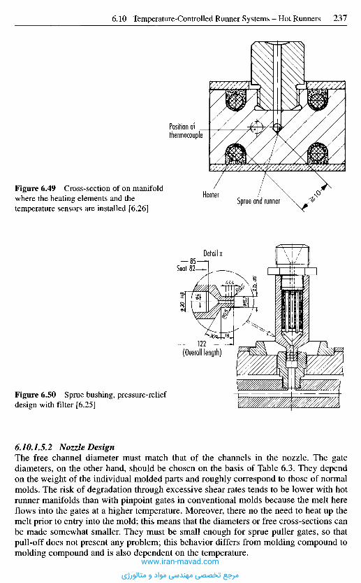
6.10.1.5.2 Nozzle DesignThe free channel diameter must match that of the channels in the nozzle. The gatediameters, on the other hand, should be chosen on the basis of Table 6.3. They dependon the weight of the individual molded parts and roughly correspond to those of normalmolds. The risk of degradation through excessive shear rates tends to be lower with hotrunner manifolds than with pinpoint gates in conventional molds because the melt hereflows into the gates at a higher temperature. Moreover, there no the need to heat up themelt prior to entry into the mold; this means that the diameters or free cross-sections canbe made somewhat smaller. They must be small enough for sprue puller gates, so thatpull-off does not present any problem; this behavior differs from molding compound tomolding compound and is also dependent on the temperature.
Figure 6.50 Sprue bushing, pressure-reliefdesign with filter [6.25]
Figure 6.49 Cross-section of on manifoldwhere the heating elements and thetemperature sensors are installed [6.26]
Position of _thermocouple
HeaterSprue and runner
Detail x
Seat
(Overall length)
www.iran-mavad.com
مرجع تخصصی مهندسی مواد و متالورژی
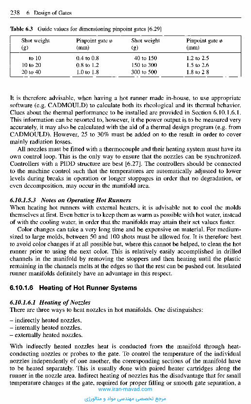
It is therefore advisable, when having a hot runner made in-house, to use appropriatesoftware (e.g. CADMOULD) to calculate both its rheological and its thermal behavior.Clues about the thermal performance to be installed are provided in Section 6.10.1.6.1.This information can be resorted to, however, it the power output is to be measured veryaccurately, it may also be calculated with the aid of a thermal design program (e.g. fromCADMOULD). However, 25 to 30% must be added on to the result in order to covermainly radiation losses.
All nozzles must be fitted with a thermocouple and their heating system must have itsown control loop. This is the only way to ensure that the nozzles can be synchronized.Controllers with a PIDD structure are best [6.27]. The controllers should be connectedto the machine control such that the temperatures are automatically adjusted to lowerlevels during breaks in operation or longer stoppages in order that no degradation, oreven decomposition, may occur in the manifold area.
6.10.1.5.3 Notes on Operating Hot RunnersWhen heating hot runners with external heaters, it is advisable not to cool the moldsthemselves at first. Even better is to keep them as warm as possible with hot water, insteadof with the cooling water, in order that the manifolds may attain their set values faster.
Color changes can take a very long time and be expensive on material. For medium-sized to large molds, between 50 and 100 shots must be allowed for. It is therefore bestto avoid color changes if at all possible but, where this cannot be helped, to clean the hotrunner prior to using the next color. This is relatively easily accomplished in drilledchannels in the manifold by removing the stoppers and then heating until the plasticremaining in the channels melts at the edges so that the rest can be pushed out. Insulatedrunner manifolds definitely have an advantage in this respect.
6.10.1.6 Heating of Hot Runner Systems
6.10.1.6.1 Heating of NozzlesThere are three ways to heat nozzles in hot manifolds. One distinguishes:
- indirectly heated nozzles,- internally heated nozzles,- externally heated nozzles.
With indirectly heated nozzles heat is conducted from the manifold through heat-conducting nozzles or probes to the gate. To control the temperature of the individualnozzles independently of one another, the corresponding sections of the manifold haveto be heated separately. This is usually done with paired heater cartridges along therunner in the nozzle area. Indirect heating of nozzles has the disadvantage that for smalltemperature changes at the gate, required for proper filling or smooth gate separation, a
Table 6.3 Guide values for dimensioning pinpoint gates [6.29]
Shot weight
(g)
to 1010 to 2020 to 40
Pinpoint gate 0(mm)
0.4 to 0.80.8 to 1.21.0 to 1.8
Shot weight
(g)
40 to 150150 to 300300 to 500
Pinpoint gate 0(mm)
1.2 to 2.51.5 to 2.61.8 to 2 8
www.iran-mavad.com
مرجع تخصصی مهندسی مواد و متالورژی
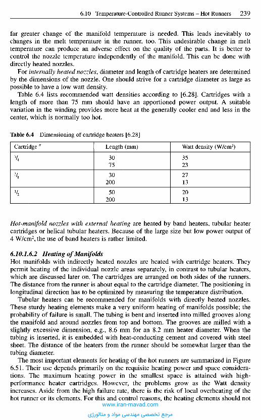
Hot-manifold nozzles with external heating are heated by band heaters, tubular heatercartridges or helical tubular heaters. Because of the large size but low power output of4 W/cm2, the use of band heaters is rather limited.
6.10.1.6.2 Heating of ManifoldsHot manifolds with indirectly heated nozzles are heated with cartridge heaters. Theypermit heating of the individual nozzle areas separately, in contrast to tubular heaters,which are discussed later on. The cartridges are arranged on both sides of the runners.The distance from the runner is about equal to the cartridge diameter. The positioning inlongitudinal direction has to be optimized by measuring the temperature distribution.
Tubular heaters can be recommended for manifolds with directly heated nozzles.These sturdy heating elements make a very uniform heating of manifolds possible; theprobability of failure is small. The tubing is bent and inserted into milled grooves alongthe manifold and around nozzles from top and bottom. The grooves are milled with aslightly excessive dimension, e.g., 8.6 mm for an 8.2 mm heater diameter. When thetubing is inserted, it is embedded with heat-conducting cement and covered with steelsheet. The distance of the heaters from the runner should be somewhat larger than thetubing diameter.
The most important elements for heating of the hot runners are summarized in Figure6.51. Their use depends primarily on the requisite heating power and space considera-tions. The maximum heating power in the smallest space is attained with high-performance heater cartridges. However, the problems grow as the Watt densityincreases. Aside from the high failure rate, there is the risk of local overheating of thehot runner or its elements. For this and control reasons, the heating elements should not
far greater change of the manifold temperature is needed. This leads inevitably tochanges in the melt temperature in the runner, too. This undesirable change in melttemperature can produce an adverse effect on the quality of the parts. It is better tocontrol the nozzle temperature independently of the manifold. This can be done withdirectly heated nozzles.
For internally heated nozzles, diameter and length of cartridge heaters are determinedby the dimensions of the nozzle. One should strive for a cartridge diameter as large aspossible to have a low watt density.
Table 6.4 lists recommended watt densities according to [6.28]. Cartridges with alength of more than 75 mm should have an apportioned power output. A suitablevariation in the winding provides more heat at the generally cooler end and less in thecenter, which is normally too hot.
Table 6.4 Dimensioning of cartridge heaters [6.28]
Length (mm)
3075
30200
50200
Watt density (W/cm2)
3523
2713
2013
Cartridge "
www.iran-mavad.com
مرجع تخصصی مهندسی مواد و متالورژی
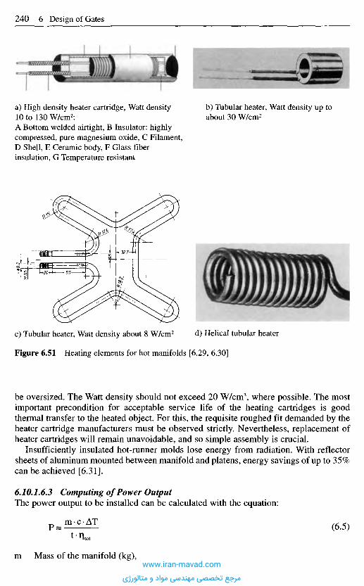
Figure 6.51 Heating elements for hot manifolds [6.29, 6.30]
be oversized. The Watt density should not exceed 20 W/cm3, where possible. The mostimportant precondition for acceptable service life of the heating cartridges is goodthermal transfer to the heated object. For this, the requisite roughed fit demanded by theheater cartridge manufacturers must be observed strictly. Nevertheless, replacement ofheater cartridges will remain unavoidable, and so simple assembly is crucial.
Insufficiently insulated hot-runner molds lose energy from radiation. With reflectorsheets of aluminum mounted between manifold and platens, energy savings of up to 35%can be achieved [6.31].
6.10.1.6.3 Computing of Power OutputThe power output to be installed can be calculated with the equation:
P =m c A T (6.5)
m Mass of the manifold (kg),
c) Tubular heater, Watt density about 8 W/cm2 d) Helical tubular heater
a) High density heater cartridge, Watt density10 to 130 W/cm2:A Bottom welded airtight, B Insulator: highlycompressed, pure magnesium oxide, C Filament,D Shell, E Ceramic body, F Glass fiberinsulation, G Temperature resistant
b) Tubular heater, Watt density up toabout 30 W/cm2
www.iran-mavad.com
مرجع تخصصی مهندسی مواد و متالورژی
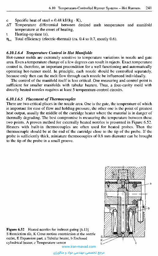
c Specific heat of steel = 0.48 kJ/(kg • K),AT Temperature differential between desired melt temperature and manifold
temperature at the onset of heating,t Heating-up time (s),T)tot Total efficiency (electric-thermal) (ca. 0.4 to 0.7, mostly 0.6).
6.10.1.6.4 Temperature Control in Hot ManifoldsHot-runner molds are extremely sensitive to temperature variations in nozzle and gatearea. Even a temperature change of a few degrees can result in rejects. Exact temperaturecontrol is, therefore, an important precondition for a well functioning and automaticallyoperating hot-runner mold. In principle, each nozzle should be controlled separately,because only then can the melt flow through each nozzle be influenced individually.
The control of the manifold itself is less critical. One measuring and control point issufficient for smaller manifolds with tubular heaters. Thus, a four-cavity mold withdirectly heated nozzles requires at least 5 temperature-control circuits.
6.10.1.6.5 Placement of ThermocouplesThere are two critical places in the nozzle area. One is the gate, the temperature of whichis important for ease of flow and holding pressure; the other one is the point of greatestheat output, usually the middle of the cartridge heater where the material is in danger ofthermally degrading. The best compromise is measuring the temperature between thesetwo points. A proven method for externally heated nozzles is presented in Figure 6.52.Heaters with built-in thermocouples are often used for heated probes. Then thethermocouple should be at the end of the cartridge close to the tip of the probe. If theprobe is sufficiently thick, miniature thermocouples of 0.8 mm diameter can be broughtto the tip of the probe in a small groove.
Figure 6.52 Heated nozzles for indirect gating [6.13]S Restriction slit, K Cross section constriction at the nozzleoutlet, E Expansion part, a Tubular heater, b Enclosedcylindrical heater, c Temperature sensor
www.iran-mavad.com
مرجع تخصصی مهندسی مواد و متالورژی
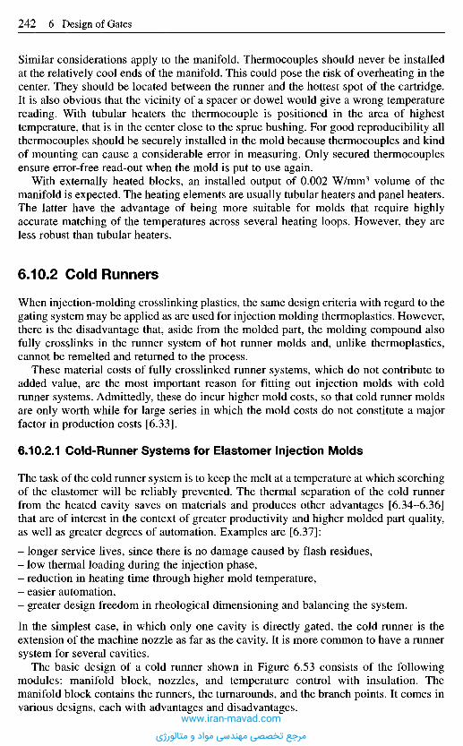
Similar considerations apply to the manifold. Thermocouples should never be installedat the relatively cool ends of the manifold. This could pose the risk of overheating in thecenter. They should be located between the runner and the hottest spot of the cartridge.It is also obvious that the vicinity of a spacer or dowel would give a wrong temperaturereading. With tubular heaters the thermocouple is positioned in the area of highesttemperature, that is in the center close to the sprue bushing. For good reproducibility allthermocouples should be securely installed in the mold because thermocouples and kindof mounting can cause a considerable error in measuring. Only secured thermocouplesensure error-free read-out when the mold is put to use again.
With externally heated blocks, an installed output of 0.002 W/mm3 volume of themanifold is expected. The heating elements are usually tubular heaters and panel heaters.The latter have the advantage of being more suitable for molds that require highlyaccurate matching of the temperatures across several heating loops. However, they areless robust than tubular heaters.
6.10.2 Cold Runners
When injection-molding crosslinking plastics, the same design criteria with regard to thegating system may be applied as are used for injection molding thermoplastics. However,there is the disadvantage that, aside from the molded part, the molding compound alsofully crosslinks in the runner system of hot runner molds and, unlike thermoplastics,cannot be remelted and returned to the process.
These material costs of fully crosslinked runner systems, which do not contribute toadded value, are the most important reason for fitting out injection molds with coldrunner systems. Admittedly, these do incur higher mold costs, so that cold runner moldsare only worth while for large series in which the mold costs do not constitute a majorfactor in production costs [6.33].
6.10.2.1 Cold-Runner Systems for Elastomer Injection Molds
The task of the cold runner system is to keep the melt at a temperature at which scorchingof the elastomer will be reliably prevented. The thermal separation of the cold runnerfrom the heated cavity saves on materials and produces other advantages [6.34-6.36]that are of interest in the context of greater productivity and higher molded part quality,as well as greater degrees of automation. Examples are [6.37]:
- longer service lives, since there is no damage caused by flash residues,- low thermal loading during the injection phase,- reduction in heating time through higher mold temperature,- easier automation,- greater design freedom in rheological dimensioning and balancing the system.
In the simplest case, in which only one cavity is directly gated, the cold runner is theextension of the machine nozzle as far as the cavity. It is more common to have a runnersystem for several cavities.
The basic design of a cold runner shown in Figure 6.53 consists of the followingmodules: manifold block, nozzles, and temperature control with insulation. Themanifold block contains the runners, the turnarounds, and the branch points. It comes invarious designs, each with advantages and disadvantages.
www.iran-mavad.com
مرجع تخصصی مهندسی مواد و متالورژی
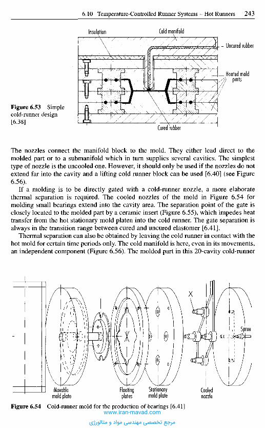
The nozzles connect the manifold block to the mold. They either lead direct to themolded part or to a submanifold which in turn supplies several cavities. The simplesttype of nozzle is the uncooled one. However, it should only be used if the nozzles do notextend far into the cavity and a lifting cold runner block can be used [6.40] (see Figure6.56).
If a molding is to be directly gated with a cold-runner nozzle, a more elaboratethermal separation is required. The cooled nozzles of the mold in Figure 6.54 formolding small bearings extend into the cavity area. The separation point of the gate isclosely located to the molded part by a ceramic insert (Figure 6.55), which impedes heattransfer from the hot stationary mold platen into the cold runner. The gate separation isalways in the transition range between cured and uncured elastomer [6.41].
Thermal separation can also be obtained by leaving the cold runner in contact with thehot mold for certain time periods only. The cold manifold is here, even in its movements,an independent component (Figure 6.56). The molded part in this 20-cavity cold-runner
Figure 6.54 Cold-runner mold for the production of bearings [6.41]
Coolednozzle
Stationarymold plate
Floatingplates
Movablemold plate
Sprue
Figure 6.53 Simplecold-runner design[6.38]
Insulation Cold manifold
Uncured rubber
Heated moldparts
Cured rubber
www.iran-mavad.com
مرجع تخصصی مهندسی مواد و متالورژی
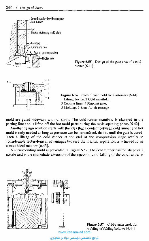
mold are gated sideways without scrap. The cold-runner manifold is clamped in theparting line and is lifted off the hot mold parts during the mold-opening phase [6.42].
Another design solution starts with the idea that a contact between cold runner and hotmold is only needed as long as pressure can be transmitted, that is, until the gate is cured.Then a lifting of the cold runner at the end of the compression stage results inconsiderable technological advantages because the thermal separation is achieved in analmost ideal manner [6.43].
A corresponding mold is presented in Figure 6.57. The cold runner has the shape of anozzle and is the immediate extension of the injection unit. Lifting of the cold runner is
Figure 6.57 Cold-runner mold formolding of folding bellows [6.44]
Figure 6.55 Design of the gate area of a coldrunner [6.41]
Figure 6.56 Cold-runner mold for elastomers [6.44]1 Lifting device, 2 Cold manifold,3 Cooling lines, 4 Pinpoint gate,5 Molding, 6 Slots for air passage
Cooled nozzle beryllium-copperCold runner
Heated stationary mold plate
CeramicsChromium steel
Area of gate separation
Heated core
Cavity
www.iran-mavad.com
مرجع تخصصی مهندسی مواد و متالورژی
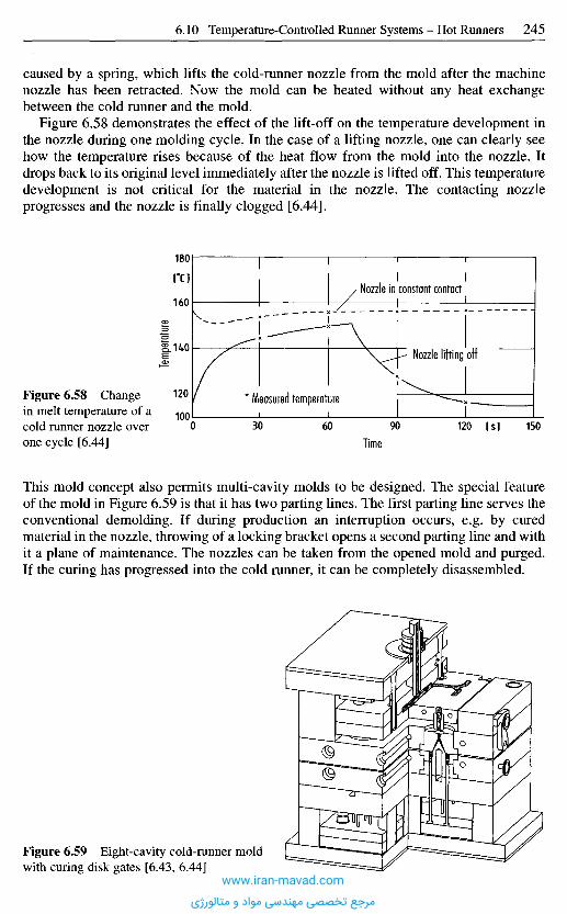
This mold concept also permits multi-cavity molds to be designed. The special featureof the mold in Figure 6.59 is that it has two parting lines. The first parting line serves theconventional demolding. If during production an interruption occurs, e.g. by curedmaterial in the nozzle, throwing of a locking bracket opens a second parting line and withit a plane of maintenance. The nozzles can be taken from the opened mold and purged.If the curing has progressed into the cold runner, it can be completely disassembled.
Temp
eratur
e
Figure 6.58 Changein melt temperature of acold runner nozzle overone cycle [6.44]
m
TimeIs]
Measured temperature
Nozzle lifting off
Nozzle in constant contact
Figure 6.59 Eight-cavity cold-runner moldwith curing disk gates [6.43, 6.44]
caused by a spring, which lifts the cold-runner nozzle from the mold after the machinenozzle has been retracted. Now the mold can be heated without any heat exchangebetween the cold runner and the mold.
Figure 6.58 demonstrates the effect of the lift-off on the temperature development inthe nozzle during one molding cycle. In the case of a lifting nozzle, one can clearly seehow the temperature rises because of the heat flow from the mold into the nozzle. Itdrops back to its original level immediately after the nozzle is lifted off. This temperaturedevelopment is not critical for the material in the nozzle. The contacting nozzleprogresses and the nozzle is finally clogged [6.44].
www.iran-mavad.com
مرجع تخصصی مهندسی مواد و متالورژی
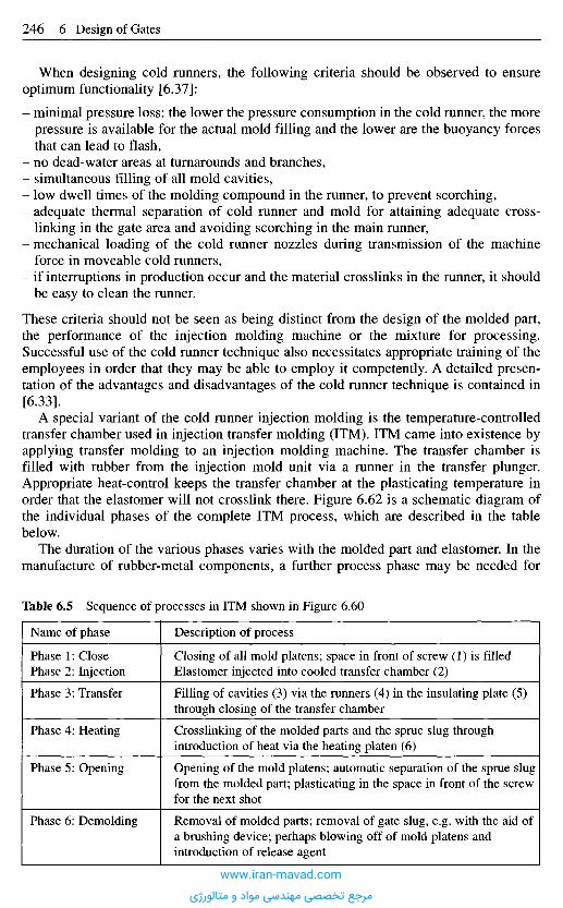
When designing cold runners, the following criteria should be observed to ensureoptimum functionality [6.37]:
- minimal pressure loss: the lower the pressure consumption in the cold runner, the morepressure is available for the actual mold filling and the lower are the buoyancy forcesthat can lead to flash,
- no dead-water areas at turnarounds and branches,- simultaneous filling of all mold cavities,- low dwell times of the molding compound in the runner, to prevent scorching,- adequate thermal separation of cold runner and mold for attaining adequate cross-
linking in the gate area and avoiding scorching in the main runner,- mechanical loading of the cold runner nozzles during transmission of the machine
force in moveable cold runners,- if interruptions in production occur and the material crosslinks in the runner, it should
be easy to clean the runner.
These criteria should not be seen as being distinct from the design of the molded part,the performance of the injection molding machine or the mixture for processing.Successful use of the cold runner technique also necessitates appropriate training of theemployees in order that they may be able to employ it competently. A detailed presen-tation of the advantages and disadvantages of the cold runner technique is contained in[6.33].
A special variant of the cold runner injection molding is the temperature-controlledtransfer chamber used in injection transfer molding (ITM). ITM came into existence byapplying transfer molding to an injection molding machine. The transfer chamber isfilled with rubber from the injection mold unit via a runner in the transfer plunger.Appropriate heat-control keeps the transfer chamber at the plasticating temperature inorder that the elastomer will not crosslink there. Figure 6.62 is a schematic diagram ofthe individual phases of the complete ITM process, which are described in the tablebelow.
The duration of the various phases varies with the molded part and elastomer. In themanufacture of rubber-metal components, a further process phase may be needed for
Table 6.5 Sequence of processes in ITM shown in Figure 6.60
Name of phase
Phase 1: ClosePhase 2: Injection
Phase 3: Transfer
Phase 4: Heating
Phase 5: Opening
Phase 6: Demolding
Description of process
Closing of all mold platens; space in front of screw (1) is filledElastomer injected into cooled transfer chamber (2)
Filling of cavities (3) via the runners (4) in the insulating plate (5)through closing of the transfer chamber
Crosslinking of the molded parts and the sprue slug throughintroduction of heat via the heating platen (6)
Opening of the mold platens; automatic separation of the sprue slugfrom the molded part; plasticating in the space in front of the screwfor the next shot
Removal of molded parts; removal of gate slug, e.g. with the aid ofa brushing device; perhaps blowing off of mold platens andintroduction of release agent
www.iran-mavad.com
مرجع تخصصی مهندسی مواد و متالورژی

installing the inserts. The use of a transfer chamber heated to the plasticating temperatureresults in virtually scrap-free production, since only the sprue slugs in the short runnersbetween the transfer chamber and the cavity area crosslink. The process is mainly usedto manufacture a high number of small molded elastomer parts in one mold.
Injection phase
1 2.
Transfer phase Heating phase
43
Mold opening Demolding
5 6
Figure 6.60 Schematic representation of phases in the ITM processwww.iran-mavad.com
مرجع تخصصی مهندسی مواد و متالورژی
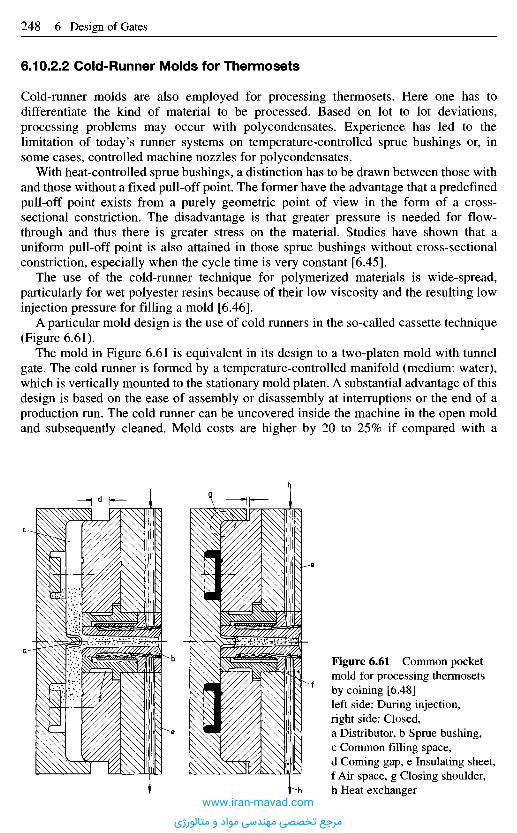
6.10.2.2 Cold-Runner Molds for Thermosets
Cold-runner molds are also employed for processing thermosets. Here one has todifferentiate the kind of material to be processed. Based on lot to lot deviations,processing problems may occur with poly condensates. Experience has led to thelimitation of today's runner systems on temperature-controlled sprue bushings or, insome cases, controlled machine nozzles for polycondensates.
With heat-controlled sprue bushings, a distinction has to be drawn between those withand those without a fixed pull-off point. The former have the advantage that a predefinedpull-off point exists from a purely geometric point of view in the form of a cross-sectional constriction. The disadvantage is that greater pressure is needed for flow-through and thus there is greater stress on the material. Studies have shown that auniform pull-off point is also attained in those sprue bushings without cross-sectionalconstriction, especially when the cycle time is very constant [6.45].
The use of the cold-runner technique for polymerized materials is wide-spread,particularly for wet polyester resins because of their low viscosity and the resulting lowinjection pressure for filling a mold [6.46].
A particular mold design is the use of cold runners in the so-called cassette technique(Figure 6.61).
The mold in Figure 6.61 is equivalent in its design to a two-platen mold with tunnelgate. The cold runner is formed by a temperature-controlled manifold (medium: water),which is vertically mounted to the stationary mold platen. A substantial advantage of thisdesign is based on the ease of assembly or disassembly at interruptions or the end of aproduction run. The cold runner can be uncovered inside the machine in the open moldand subsequently cleaned. Mold costs are higher by 20 to 25% if compared with a
Figure 6.61 Common pocketmold for processing thermosetsby coining [6.48]left side: During injection,right side: Closed,a Distributor, b Sprue bushing,c Common filling space,d Coming gap, e Insulating sheet,f Air space, g Closing shoulder,h Heat exchanger
www.iran-mavad.com
مرجع تخصصی مهندسی مواد و متالورژی

6 . 1 1 S p e c i a l M o l d C o n c e p t s
6.11.1 Stack Molds
A special mold design has come into use, the stack mold, for molding shallow, smallparts in large quantities such as tape cassettes. Here, cavities are located in two or moreplanes corresponding to two parting lines and are filled at the same time (Figure 6.63).A molding machine with an exceptionally long opening stroke is needed. An increase inproductivity of 100% as one might expect from doubling the number of cavities cannotbe realized because of the time needed for the longer opening and closing strokes. Theincrease in productivity is about 80% [6.49]. The clamping force should be 15% higherthan for a standard mold [6.49].
Hot manifolds are now employed exclusively. A stack mold with two parting lines hasthree main components, a stationary and a movable mold half, and a middle section. Itcontains the runner system (Figure 6.64).
Figure 6.62 Cold runner moldBucher/Mueller system with tunnel gate[6.47]
conventional mold and have to be compensated by material savings. Thus, materiallosses in a corresponding eight-cavity mold could be reduced from 12 to 3% [6.47].
In cases where multiple gating is needed for certain moldings (e.g. headlampreflectors), production without cold-runner cassettes is often not conceivable [6.46].
Cold-runner technique for thermosets is also used in the so-called common-pocketprocess (Figure 6.62). A combination with this process is the RIC technique (RunnerlessInjection Compression), which reduces scrap to a minimum in a simple way. At the sametime flashing is diminished. The plasticated material flows through a temperature-controlled runner into the slightly opened mold and is distributed there. The material ispushed into the cavities and formed by the clamping motion of the mold. The materialdistributor penetrates the tapered sprue bushing and closes it against the parting line.Temperature control keeps the material in the runner fluid and ready for the next shot[6.48].
Next Page
www.iran-mavad.com
مرجع تخصصی مهندسی مواد و متالورژی
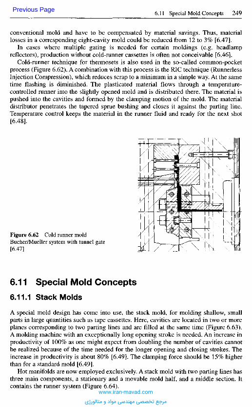
6 . 1 1 S p e c i a l M o l d C o n c e p t s
6.11.1 Stack Molds
A special mold design has come into use, the stack mold, for molding shallow, smallparts in large quantities such as tape cassettes. Here, cavities are located in two or moreplanes corresponding to two parting lines and are filled at the same time (Figure 6.63).A molding machine with an exceptionally long opening stroke is needed. An increase inproductivity of 100% as one might expect from doubling the number of cavities cannotbe realized because of the time needed for the longer opening and closing strokes. Theincrease in productivity is about 80% [6.49]. The clamping force should be 15% higherthan for a standard mold [6.49].
Hot manifolds are now employed exclusively. A stack mold with two parting lines hasthree main components, a stationary and a movable mold half, and a middle section. Itcontains the runner system (Figure 6.64).
Figure 6.62 Cold runner moldBucher/Mueller system with tunnel gate[6.47]
conventional mold and have to be compensated by material savings. Thus, materiallosses in a corresponding eight-cavity mold could be reduced from 12 to 3% [6.47].
In cases where multiple gating is needed for certain moldings (e.g. headlampreflectors), production without cold-runner cassettes is often not conceivable [6.46].
Cold-runner technique for thermosets is also used in the so-called common-pocketprocess (Figure 6.62). A combination with this process is the RIC technique (RunnerlessInjection Compression), which reduces scrap to a minimum in a simple way. At the sametime flashing is diminished. The plasticated material flows through a temperature-controlled runner into the slightly opened mold and is distributed there. The material ispushed into the cavities and formed by the clamping motion of the mold. The materialdistributor penetrates the tapered sprue bushing and closes it against the parting line.Temperature control keeps the material in the runner fluid and ready for the next shot[6.48].
Previous Page
www.iran-mavad.com
مرجع تخصصی مهندسی مواد و متالورژی
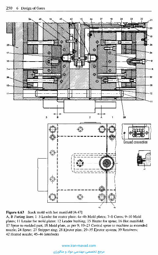
Figure 6.63 Stack mold with hot manifold [6.47]A, B Parting lines; 1-3 Leader for center plate; 4a-4b Mold plates; 7-8 Cores; 9-10 Moldplates; 11 Leader for mold plates; 12 Leader bushing; 15 Heater for sprue; 16 Hot manifold;17 Sprue to molded part; 18 Mold plate, as per 9; 19-23 Central sprue to machine as extendednozzle; 24 Sprue; 27 Stripper ring; 28 Ejector pins; 29-35 Ejector system; 39 Retainers;42 Heated nozzle; 4 5 ^ 6 Interlocks
Ground connection
www.iran-mavad.com
مرجع تخصصی مهندسی مواد و متالورژی
The mold section mounted on the movable platen and the center section are moved in thedirection of the machine axis during demolding. With this, the extension is removedfrom the nozzle. The extension has to be sufficiently long that no leakage material candrop onto the leader pins and stick there during mold opening. This would impede theirproper functioning [6.53, 6.54]. For this reason many stack molds are operated todaywith telescopic extensions and without nozzle retraction. While the outer section on theclamping side is mounted on the movable machine platen and moves positively with itduring mold opening and closing, special elements are necessary to guide and control themovement of the center section. Because of the frequently large size of the moldsutilizing the whole platen area, center sections are attached to the tie bars or are guidedby means of guide bars with guide shoes [6.53, 6.54] (see Figure 6.64).
Today the motion is primarily produced by toggles or sometimes by racks(Figure 6.65). Previously systems were employed which used separate hydrauliccylinders for moving the center section.
Toggle and rack control open at both parting lines smoothly and simultaneously.Toggle controls also offers the option of using, within a certain range, opening strokesof different lengths. This allows the molding of parts with one height in one stack andparts with a different height in the other one. The curves of the opening path can be
Sprue
Figure 6.64 Stack mold [6.16]Hot runner system for stack mold manifold and sprues and gates molds. The sprue is normallymounted at the level of the mold center and feeds the melt into the middle of the hot runnermanifold. From there, the melt is distributed uniformly to all cavities of both mold daylights.
www.iran-mavad.com
مرجع تخصصی مهندسی مواد و متالورژی
Figure 6.67 Ejector drive for stack molds [6.55]
adjusted within a wide range depending on pivotal point and toggle geometry. At thesame time ejection is actuated by the same elements that move the center section.Various kinds of toggle control are shown with Figure 6.66. The rack control in Figure6.67 is less rigid and permits a gentle start and build-up of demolding forces because ofsprings in the pulling rods connected to the crank drive.
6.11.2 Molds for Mult icomponent Injection Molding
There are a large number of multicomponent injection molding techniques, in terms ofprocesses and of names, which are explained in Table 6.6 [6.56, 6.57].
Rack or lever systemStripper plateClamp ram
Clamping unit
Movableclamping platen Stripper ring
Stationaryclamping platen
Figure 6.66Toggle mechanismfor stack molds[6.55]
Figure 6.65 Methods of moving center section of stack molds [6.55]
Movement with racksMovement with toggleMovement with hydraulic cylinder
www.iran-mavad.com
مرجع تخصصی مهندسی مواد و متالورژی
This separation has allowed the development of two-component combination injection-molded parts, such as housings with integrated seals.
The separation may be effected in either of two ways: by the rotating mold systemsshown in Figure 6.68 and by the non-rotating core-back technique shown in Figure 6.69[6.57-6.59].
Molds with Rotating Mold Platen or Rotating Mold HalfA rotating mold has several gating stations and different cavities. For a two-colored part,the first colored section is created by injection at the first mold position. After sufficienttime has elapsed for the melt to cool, the mold opens and the mold-part section turns180° into the second position. The mold closes to form the second cavity into which thesecond color or another material is injected via a second injection position. In the firstmold position, meanwhile, the first molded-part section is being created again. In asimilar fashion, three-colored parts can be made using three injection and mold positionsand rotations of 120°. The mold is rotated either by means of a standard rotary platformthat can be attached to the machine, irrespective of the mold, or by means of a rotarydevice integrated into the mold that allows a rotary plate to operate. The advantage ofthe standard rotary platform is its universal method of use, and in the smaller and lessexpensive design of the molds used. Usually the mold platen on the ejector side isdesigned to be the rotating side since rotation of the nozzle-side mold platen is morecomplicated in terms of gating system and rotating system. These molds require highprecision mold making but are dependable in operation and do not require any elaboratemelt feed [6.57, 6.60]. Typical applications are car tail light covers [6.60], three-coloredkeyboards [6.61], and the vent flaps of the Golf motorcar [6.62].
6.11.2.1 Combination Molds
Two-component combination injection molding in which two melts are introduced intothe cavity in succession via separate gating systems requires special mold techniquessince those areas of the mold that become filled by the second melt must be blocked offwhen the first material is injected, in order that it does not penetrate into those areas.
Table 6.6 Definition of several multicomponent injection molding processes
Process name
Multicomponent injection molding
Composite injection molding
2-Color injection molding
Multicolor injection molding
2-Component sandwich injectionmolding
Bi-injection
Definition
All injection molding methods in which two or morematerials are processedSeveral melts are injected via several gate systems intothe cavity in succession
As above, but using one material in different colors
Same as 2-color injection molding, but using more than2 colors
Two melts are injected in succession through a gatesystem, to form a core and outer layer
Two melts are injected simultaneously via two gatingsystems into the cavity
www.iran-mavad.com
مرجع تخصصی مهندسی مواد و متالورژی
Molds with Rotary Cores or SpidersIn this technique, only part of the ejector- or nozzle-side cavity with injected pre-molding is rotated (Figure 6.70). Both mold platens remain in position.
Molds with Transfer or Insert TechniqueAfter the pre-molding is made in the first cavity, it is transferred by a handling device orby hand into the second cavity and molded to produce the final part with a secondmaterial. The term transfer technique is also used to describe using a different machinefor molding to produce the final part. Generally, these molds are preferred to rotarymolds for economic reasons because the complicated rotary device can be dispensedwith, and usually more cavities can be accommodated on the mold platen. Furthermore,thermal separation of the pre-molding and final-molding positions is easier toaccomplish (particularly important for thermoplastic-thermoset laminates). Dis-advantages are the need for precise centering of the pre-moldings [6.57].
Molds with Retractable Slides and Cores (Core-Back Molds)With comparatively low mold costs, it is possible to produce multicolor or multi-component injection molded parts in one mold without the need for opening the machinein between and further transport of a molded part by means of the core-back technique.The cavity spaces for the second material are first closed by movable inserts or cores andare opened only after the first material has been injected. The components can bearranged beside, above, or inside each other. This method does not suit material pairs thatwill not join or bond to each other since it is not possible to produce effective undercutsfor interlocking with the injection partner. Furthermore, injection in these molds can onlybe carried out sequentially and not in parallel as in other methods. This results in longer
Figure 6.68 Rotary mold systems forcomposite injection molding
Figure 6.69 Core-back technique
Rotary mold systems
Rotary platformRotary moldSpiders or coresTransfer technique
Non-rotary mold system
Core/back technique
www.iran-mavad.com
مرجع تخصصی مهندسی مواد و متالورژی
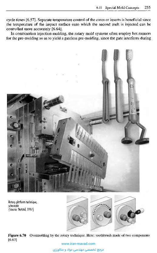
cycle times [6.57]. Separate temperature control of the cores or inserts is beneficial sincethe temperature of the impact surface onto which the second melt is injected can becontrolled more accurately [6.64].
In combination injection molding, the rotary mold systems often employ hot runnersfor the pre-molding so as to yield a gateless pre-molding, since the gate interferes during
Figure 6.70 Overmolding by the rotary technique. Here: toothbrush made of two components[6.63]
Rotary platform technique,schematic[Source: Nefctal, 1997]
www.iran-mavad.com
مرجع تخصصی مهندسی مواد و متالورژی
rotation or transfer [6.64, 6.65] and would otherwise have to be removed prior totransfer.
The choice of method for a particular molded part must be established individuallyfrom technical and, economic aspects for every application. It must be remembered,however, that rotary mold systems are generally more expensive because of the need fortwo cavities and from the machine point of view, need a large distance between tie barsin order to be rotatable. Rotary molds do, however, offer greater design freedom and thepossibility of thermal separation of the kind required for the manufacture of rubber-thermoplastic combinations (e.g. PA/SLR).
6.11.2.2 Two-Component Sandwich Inject ion Molds
In contrast to combination injection molding, sandwich molding theoretically does notrequire a special mold technology and may be performed with standard injection molds.Two melts are injected through a joint gating system into the cavity, to form a core andan outer skin. The melts meet in an adapter between the nozzle peaks of the injectionunits and the sprue bushing of the mold. It should be noted that all deviations fromrotationally symmetrical molded-part geometry with central gating cause non-uniformcore material distribution.
6.11.2.3 Bi- ln ject ion Molds
In this injection molding method, two different melt components are fed into the cavitysimultaneously through different gating systems. The weld line is affected by the posi-tions of injection and wall thicknesses in the mold as well as by the injection parametersof the two components [6.68].
R e f e r e n c e s
[6.1] KegelanguB, SchirmanguB, RinganguB, BandanguB. Technical Information, 4.2.1, BASF,Ludwigshafen/Rh., 1969.
[6.2] SpritzgieBen von Thermoplasten. Publication, Farbwerke Hoechst AG, Frankfurt/M.,1971.
[6.3] Sowa, H.: Wirtschaftlicher fertigen durch verbesserte AnguBsysteme. Plastverarbeiter, 29(1978), 11, pp. 587-590.
[6.4] Kohlhepp, K. G.; Mohnberg, J.: SpritzgieBen von Formteilen hoher Prazision, dargestelltam Beispiel von Polyacetal. Kunststoff-Berater, 10 (1974), pp. 577-584.
[6.5] Crastin-Sortiment, Eigenschaften, Verarbeitung. Publication, Ciba-Geigy, Basel, August1977.
[6.6] Christoffers, K. E.: Formteilgestaltung, verarbeitungsgerecht. Das SpritzguBteil. VDI-Verlag, Dusseldorf, 1980.
[6.7] TunnelanguB, AbreiB-Punkt-AnguB. Technical Information, 4.2.3, BASF, Ludwigs-hafen/Rh., 1969.
[6.8] Thonemann, O. E.: AnguB- und Anschnitt-Technik fur die wirtschaftliche Herstellung vonSpritzguBteilen aus Makrolon. Plastverarbeiter, 14 (1963), 9, pp. 509-524.
[6.9] Kunststoffverarbeitung im Gesprach, 1: SpritzgieBen. Publication, BASF, Ludwigs-hafen/Rh., 1979.
[6.10] SpritzguB-Hostalen PP. Handbook. Farbwerke Hoechst AG, Frankfurt/M., 1980.[6.11] Vorkammer-PunktanguB-Isolierverteiler. Technical Information, 4.2.4, BASF, Ludwigs-
hafen/Rh., 1969.
www.iran-mavad.com
مرجع تخصصی مهندسی مواد و متالورژی
[6.12] Durethan BK. Tech. Ringbuch der Farbenfabriken, Bayer AG, Leverkusen, 1967.[6.13] Goldbach, H.: HeiBkanal-Werkzeuge fur die Verarbeitung technischer Thermoplaste (ABS,
PA, PBT, PC). Plastverarbeiter, 29 (1978), pp. 677-682, and 30 (1979), pp. 591-598.[6.14] Gauler, K.: HeiBkanalsysteme mit Ventilanschnitten. Kunsstoffe, 87 (1997), 3, pp. 338-340.[6.15] Homes, W.: KaskadenspritzgieBen vermeidet Bindenahte. Kunststoffe, 86 (1996), 9,
pp. 1269-1272.[6.16] Husky: Husky-HeiBkanalsysteme. Werkschrift der Husky Injection Moulding Systems
Ltd., Bolton, Canada, D-62507 Wiesbaden-Igstadt, Phone: +49 611 950 850.[6.17] Leidig, K.; Poppe, E. A.; Schinner, K.: Technische Kunststoffe: Die Top Ten der Spritz-
gieBprobleme. Schwierigkeiten mit HeiBkanalen (8), DuPont de Nemours GmbH,D-61343, Bad Homburg.
[6.18] Eiden, G.: Werkzeuge fiir die Herstellung von Prazisionsteilen aus technischenThermoplasten. Reprint of 8th Tooling Conference at Wiirzburg: Der SpritzgieBformenbauim internationalen Wettbewerb. September 24-25, 1997.
[6.19] Braun, P.: Innenbeheizte HeiBkanalsysteme. Kunststoffe, 87 (1997), 9, pp. 1184-1886.[6.20] HeiBe Seiten. Plastverarbeiter, 48 (1997), 10, pp. 96-98.[6.21] Braun, P.: Universelles HeiBkanalsystem. Osterr. Kunststoffzeitschrift, 28 (1997), 5/6,
pp. 98-102.[6.22] Sander, W.: Homogene Schmelze-Temperaturverteilung mit Standard-Elementen. Plast-
verarbeiter, 42 (1991), 12, pp. 55-59.[6.23] RoBbach, R.: Schmelzefilter fur den SpritzgieBer. Kunststoffe, 85 (1995), 2, pp. 193-195.[6.24] Zimmermann, W.; Hack, K.: Einfaches HeiBkanal Schmelzeleitsystem fiir SpritzgieB-
werkzeuge. Plastverarbeiter, 44 (1993), 4, pp. 18-22.[6.25] Konstruktionszeichnung. H. Weidmann AG, Raperswil/Schweiz.[6.26] HeiBkanalsystem - Indirekt beheitzter Warmeleittorpedo C.2.1. Technische Kunststoffe,
Berechnen - Gestalten - Anwenden. Publication, Hoechst AG, Frankfurt/M., October1979.
[6.27] Mit Microelektronik Temperaturen genau regeln. Plastverarbeiter, 41 (1990), 5, pp. 78-80.[6.28] Der HeiBkanal. Publication, Plastic Service GmbH, Mannheim.[6.29] Catalog. Firma Hotset, Ludenscheid.[6.30] Publication. Tiirk und Hillinger, Zuttlingen.[6.31] Warmeverluste an HeiBkanalblocken - Reflektorbleche schaffen Abhilfe. Plastverarbeiter,
37 (1986), 4, pp. 122-123.[6.32] Schauf, D.: AnguBloses Entformen von SpritzguBteilen. In: Das SpritzgieBwerkzeug. VDI-
Verlag, Dusseldorf, 1980.[6.33] Krehwinkel, T.; Schneider, Ch.: Kaltkanaltechnik-pro und contra. In: SpritzgieBen und
Extrudieren von Elastomeren, VDI-Gesellschaft Kunststofftechnik, VDI-Verlag, Dussel-dorf, 1996.
[6.34] Cottancin, G.: Gummispritzformen mit dem Kaltkanalverfahren. Kautschuk GummiKunststoffe, 33 (1980), 10, pp. 839-841.
[6.35] Kaltkanaltechnologie beim ElastomerspritzgieBen. Publication, Klockner FerromaticDesma, Werk Achim, 1983.
[6.36] Schneider, Ch.: Das Verarbeitungsverhalten von Elastomeren im SpritzgieBprozeB.Dissertation, RWTH, Aachen, 1987.
[6.37] MaaB, R.: Die Anwendung der statistischen Versuchsmethodik zur Auslegung vonSpritzgieBwerkzeugen mit Kaltkanalsystem. Dissertation, RWTH, Aachen, 1995.
[6.38] Cottancin, G.: Gummispritzformen fiir das Kaltkanalverfahren. Gummi, Asbest, Kunst-stoffe, 33 (1980), 9, pp. 624-633.
[6.39] Bode, M.: SpritzgieBen von Gummiformteilen. In: SpritzgieBen von Gummiformteilen.VDI-Verlag, Dusseldorf, 1988, pp. 1-33.
[6.40] Cottancin, G.: Gummispritzpressen mit dem Kaltkanalverfahren. Gummi, Asbest, Kunst-stoffe, 33 (1980), 9, pp. 624-633.
[6.41] Lommel, H.: Einfliisse der ProzeBgroBenverlaufe un der Werkzeuggestaltung auf dieQualitat von Elastomerformteilen. Unpublished report, IKV, 1984.
[6.42] Holm, D.: Aufbau von Werkzeugen fiir SpritzgieBmaschinen. In: SpritzgieBen vonElastomeren. VDI-Verlag, Dusseldorf, 1978.
[6.43] Benfer, W.: Rechnergestiitzte Auslegung von SpritzgieBwerkzeugen fiir Elastomere.Dissertation, RWTH Aachen, 1985.
www.iran-mavad.com
مرجع تخصصی مهندسی مواد و متالورژی

[6.44] Menges, G.; Barth, R: Erarbeitung systematischer Konstruktionshilfen zur Auslegung vonKaltkanalwerkzeugen. AIF-AbschluBbericht, IKV, Aachen, 1987.
[6.45] Kloubert, T.: Reduzierung von ausgehartetem AnguBmaterial beim SpritzgieBen vonrieselfahigen Duroplasten - Kaltkanaleinsatz und Partikelrecycling. Dissertation, RWTH,Aachen, 1996.
[6.46] Niemann, K.: Kaltkanaltechnik-Stand und Einsatzmoglichkeiten bei Duroplasten.AnguBminimiertes SpritzgieBen, SKZ, Wiirzburg, June 23-24, 1987.
[6.47] Gluckau, K.: Wirtschaftliche Verarbeitung von Duroplasten auf SpritzgieBmaschinen inKaltkanalwerkzeugen. Plastverarbeiter, 31 (1980), 8, pp. 467^69.
[6.48] Braun, U.; Danne, W.; Schonthaler, W.: AnguBloses Spritzpragen in der Duro-plastverarbeitung. Kunststoffe, 77 (1987), 1, pp. 27-29.
[6.49] Hotz, A.: Mehr-Etagen-SpritzgieBwerkzeuge. Plastverarbeiter, 29 (1978), 4, pp. 185-188.[6.50] Hartmann, W.: SpritzgieBwerkzeuge in Etagenbauweise mit "Thermoplay"-
HeiBkanaldiisen fur Verpackungs-Unterteile aus Polystyrol. Plastverarbeiter, 32 (1981), 5,pp. 600-605.
[6.51] Moslo, E. R: Runnerless-Moulding. SPE-Journal, 11 (1955), pp. 26-36.[6.521 Moslo, E. R: Runnerless-Moulding. New York, 1960.[6.531 Lindner E.; Hartmann, W.: SpritzgieBwerkzeuge in Etagenbauweise. Plastverarbeiter, 28
(1977), 7, pp. 351-353.[6.54] Schwaninger, W.: Etagenwerkzeuge insbesondere als Alternative zum Schnellaufer. Der
SpritzgieBprozeB, Ingenieurwissen, VDI-Verlag, Dusseldorf, 1979.[6.55] Publication, Husky.[6.56] Eckardt, H.: MehrkomponentenspritzgieBen - Neue Werkstoffe und Verfahren beim
SpritzgieBen. VDI-Verlag, Dusseldorf, 1990, pp. 149-194.[6.57] Langenfeld, M.: Werkzeugtechnik zur Herstellung von Mehrkomponenten-SpritzgieB-
teilen. Mehr Farben - Mehr Materialien - Mehr Komponenten - SpritzgieBtechnik, SKZ,Wurzburg, May 1992, pp. 83-102.
[6.58] Eckardt, H.: Verarbeitung von TPE auf SpritzgieBmaschinen und Moglichkeiten derAnwendung des Mehrkomponenten-SpritzgieBens. Thermoplastische Elastomere imAufwartstrend, SKZ, Wurzburg, October 1989, pp. 95-123.
[6.59] Kraft, H.: "Erweiterte Anwendungsbereiche fur das Mehrkomponenten-SpritzgieBen". In:Kunststoffe, 83 (1993), 6, pp. 429-433.
[6.60] Bodeving, C : "Horizontalmaschine mit Drehtisch". In: Kunststoffe, 85 (1995), 9,pp. 1244-1254.
[6.61] "Beweglich aus dem SpritzgieBwerkzeug". In: Plastverarbeiter, 36 (1985), 4.[6.62] "Vollbewegliche Lufterklappen bei jedem Spritzzyklus". In: Plastverarbeiter, 44 (1993), 2.[6.63] Netstal News. No. 31, Netstal-Maschinen AG, Nafels/Schweiz, April 1997.[6.64] "HeiBkanaltechnik beim Mehrkomponenten-SpritzgieBen". In: Plastverarbeiter, 45 (1994),
10.[6.65] Krauss, R.: SpritzgieBtechnik fur die Mehrfarbentechnik. In: Konstruieren von SpritzgieB-
werkzeugen, VDI-Verlag, Dusseldorf, 1987, pp. 6.1-6.18.[6.66] Mehr-Rohstoff-Technologie. Publication. Battenfeld, Meinerzhagen, September 1996.[6.67] "Combimelt-Technologie fur Mehrfarben und MehrkomponentenspritzguB". In: KGK
Kautschuk, Gummi, Kunststoffe, 49 (1996), 7-8.[6.68] Johannaber E; Konejung, K.: Mehrkomponenten-Technik beim SpritzgieBen. Mehr
Farben - Mehr Materialien - Mehr Komponenten - SpritzgieBtechnik, SKZ, Wurzburg,May 1992, pp. 7-20.
www.iran-mavad.com
مرجع تخصصی مهندسی مواد و متالورژی

During mold filling the melt has to displace the air which is contained in the cavity. Ifthis cannot be done, the air can prevent a complete filling of the cavity. Besides this theair may become so hot from compression that it burns the surrounding material. Themolding compounds may decompose, outgas or form a corrosive residue on cavity walls.This effect can occasionally be noticed in poorly vented molds at knit lines or in cornersor flanges opposite the gate.
Burns usually appear as dark discolorations in the molded part and render it useless.If this residue is not carefully removed again and again, it may cause irreparable damageto the mold from corrosion and abrasion. Table 7.1 [7.1] summarizes the majorconsequences of inadequate mold venting.
Table 7.1 Consequences of inadequate mold venting [7.1]
7 V e n t i n g o f M o l d s
For the molded part
Burn marks due todiesel effect
Structural defects/surfacedefects through detachmentof the polymer from astructured mold wall
Overpacking due toinjection pressure set toohigh when vents clogged
Displacement of weld linesdue to changes in vents (e.g.through increasing cloggingof venting elements)
Entrapped air (voids)
Incomplete mold filling
Reduction in strength,especially at weld lines
For the mold
Abrasion (leaching) throughcombustion residues in thecombustion gas —> diesel effect
Corrosion by aggressive gases—> diesel effect
Mold coated by combustionresidues in the combustion gas-> diesel effect
Mold exposed to direct heatdue to strong air heatingduring compression(diesel effect)=> hardening of outer layer(varying with steel grade)
Increased cleaning of ventingelements
Higher repair and mainte-nance costs
For injection molding
Irregular processes throughblockage of venting channels
Longer cycle times due toincreased back pressure inthe cavity
Short service life of machinedue to higher loading
Escaping gases duringcompusting of the polymer(diesel effect), may beharmful to health, dependingon material
Longer setup time throughhigher scrap rate
Greater need for pressuredue to increased back pressurein the cavity
Injection molding machinehas higher energyrequirements
www.iran-mavad.com
مرجع تخصصی مهندسی مواد و متالورژی
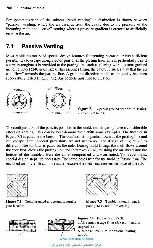
For systematization of the subject "mold venting", a distinction is drawn between"passive" venting, where the air escapes from the cavity due to the pressure of theincoming melt, and "active" venting where a pressure gradient is created to artificiallyremove the air.
7.1 P a s s i v e V e n t i n g
Most molds do not need special design features for venting because air has sufficientpossibilities to escape along ejector pins or at the parting line. This is particularly true ifa certain roughness is provided at the parting line such as planing with a coarse-grainedgrinding wheel (240 grain size). This assumes filling the cavity in such a way that the aircan "flow" towards the parting line. A grinding direction radial to the cavity has beensuccessfully tested (Figure 7.1). Air pockets must not be created.
Figure 7.1 Special ground sections in sealingsurface [7.2 to 7.4]
The configuration of the part, its position in the mold, and its gating have a considerableeffect on venting. This can be best demonstrated with some examples. The tumbler inFigure 7.2 is gated at the bottom. The confined air is pushed towards the parting line andcan escape there. Special provisions are not necessary. The design of Figure 7.3 isdifferent. The tumbler is gated on the side. During mold filling, the melt flows aroundthe core first, closes the parting line and then rises slowly pushing the air ahead into thebottom of the tumbler. Here the air is compressed and overheated. To prevent this,special design steps are necessary. The same holds true for the mold in Figure 7.4a. Theenclosed air in the rib cannot escape because the melt first crosses the base of the rib.
Figure 7.2 Tumbler gated at bottom, favorablegate location
Figure 7.3 Tumbler laterally gated,poor gate location for venting
Figure 7.4 Part with rib [7.3]:a Air cannot escape from rib section and istrapped (1),b Remedial measure: Additional partingline (2)
www.iran-mavad.com
مرجع تخصصی مهندسی مواد و متالورژی

In both cases adding a joint can provide venting of the cavity. The tumbler mold(Figure 7.3) can obtain an additional joint if the bottom piece is made separately (Figure7.5) or a cylindrical insert is used, which lets the air escape. A mark on the bottom of thetumbler, of course, cannot be avoided. If it is a nuisance, it can be converted into adecorative line [7.5].
Figure 7.5 Laterally gated cup. Mold with additionalparting line: Venting through parting line (left) orventing pin (right)
In the case of a rib (Figure 7.4a), an additional joint for venting is obtained by dividingthe forming inserts into two pieces (Figure 7.4b).
For the presented solution it was assumed that the air can escape through joiningfaces, but this is feasible only if the faces have sufficient roughness and the injectionprocess is adequately slow to allow the air to escape. This solution fails for molding thin-walled parts with very short injection times. Here, special venting channels becomenecessary.
In the case of the center-gated tumbler (Figure 7.2), a solution is found by machiningan annular channel into the parting-line plane into which the air can escape via one ormore venting gaps during injection, and then from the mold through a venting channel.Dimensions for these channels can be taken from Figures 7.6 and 7.7.
A logical development of this approach is that of continuous venting [7.6, 7.8] orperipheral venting [7.9]. The annular gap is not interrupted by flanges but is continuous.Penetration by the melt is prevented by adjusting the gap width so as to just preventingress of melt. Usual gap widths vary from 10 urn to 20 urn in accordance with thepolymer employed [7.8].
Figure 7.6 Cup mold withannular channel for venting [7.6] Detail X
Detail Z
Figure 7.7 Mold venting through venting gaps and annular channel [7.7]www.iran-mavad.com
مرجع تخصصی مهندسی مواد و متالورژی
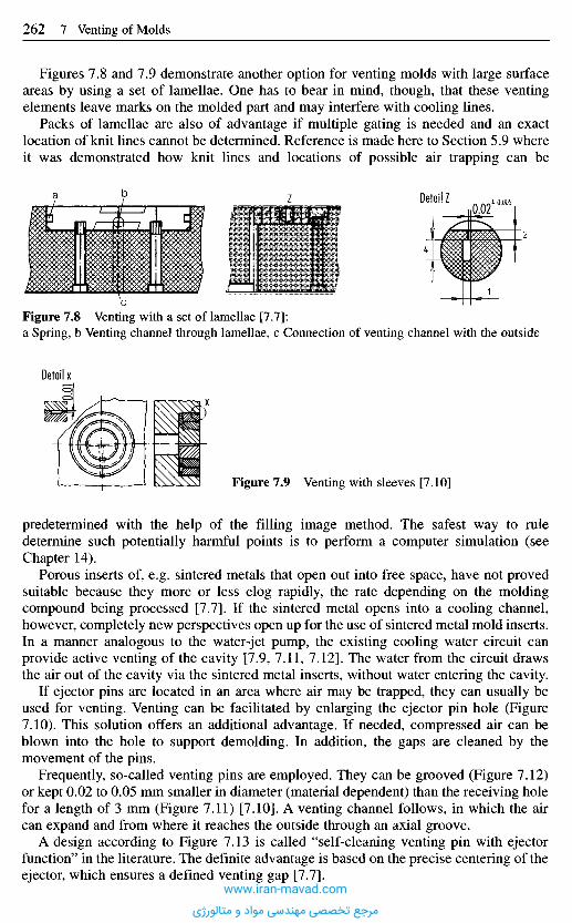
predetermined with the help of the filling image method. The safest way to ruledetermine such potentially harmful points is to perform a computer simulation (seeChapter 14).
Porous inserts of, e.g. sintered metals that open out into free space, have not provedsuitable because they more or less clog rapidly, the rate depending on the moldingcompound being processed [7.7]. If the sintered metal opens into a cooling channel,however, completely new perspectives open up for the use of sintered metal mold inserts.In a manner analogous to the water-jet pump, the existing cooling water circuit canprovide active venting of the cavity [7.9, 7.11, 7.12]. The water from the circuit drawsthe air out of the cavity via the sintered metal inserts, without water entering the cavity.
If ejector pins are located in an area where air may be trapped, they can usually beused for venting. Venting can be facilitated by enlarging the ejector pin hole (Figure7.10). This solution offers an additional advantage. If needed, compressed air can beblown into the hole to support demolding. In addition, the gaps are cleaned by themovement of the pins.
Frequently, so-called venting pins are employed. They can be grooved (Figure 7.12)or kept 0.02 to 0.05 mm smaller in diameter (material dependent) than the receiving holefor a length of 3 mm (Figure 7.11) [7.10]. A venting channel follows, in which the aircan expand and from where it reaches the outside through an axial groove.
A design according to Figure 7.13 is called "self-cleaning venting pin with ejectorfunction" in the literature. The definite advantage is based on the precise centering of theejector, which ensures a defined venting gap [7.7].
Figures 7.8 and 7.9 demonstrate another option for venting molds with large surfaceareas by using a set of lamellae. One has to bear in mind, though, that these ventingelements leave marks on the molded part and may interfere with cooling lines.
Packs of lamellae are also of advantage if multiple gating is needed and an exactlocation of knit lines cannot be determined. Reference is made here to Section 5.9 whereit was demonstrated how knit lines and locations of possible air trapping can be
Detail Z
Figure 7.8 Venting with a set of lamellae [7.7]:a Spring, b Venting channel through lamellae, c Connection of venting channel with the outside
Detail x
Figure 7.9 Venting with sleeves [7.10]
www.iran-mavad.com
مرجع تخصصی مهندسی مواد و متالورژی
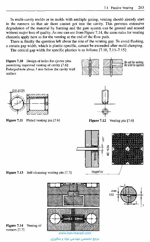
In multi-cavity molds or in molds with multiple gating, venting should already startin the runners so that air there cannot get into the cavity. This prevents extensivedegradation of the material by burning and the gate system can be ground and reusedwithout major loss of quality. As one can see from Figure 7.14, the same rules for ventingchannels apply here as for the venting at the end of the flow path.
There is finally the question left about the size of the venting gap. To avoid flashing,a certain gap width, which is plastic-specific, cannot be exceeded after mold clamping.
The critical gap width for specific plastics is as follows [7.10, 7.13-7.15]:
Figure 7.10 Design of holes for ejector pinspermitting improved venting of cavity [7.6]:Enlarged hole about 3 mm below the cavity wallsurface
Air exit for ventingAir inlet for ejection
Figure 7.11 Fluted venting pin [7.6] Figure 7.12 Venting pin [7.6]
Figure 7.13 S elf-cleansing venting pin [7.7] Trapped air
Figure 7.14 Venting ofrunners [7.7]
www.iran-mavad.com
مرجع تخصصی مهندسی مواد و متالورژی
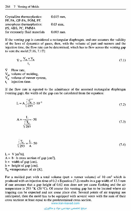
Crystalline thermoplastics: 0.015 mm,PP, PA, GF-PA, POM, PEamorphous thermoplastics: 0.03 mm,PS, ABS, PC, PMMAfor extremely fluid materials 0.003 mm.
If the venting gap is considered a rectangular diaphragm, and one assumes the validityof the laws of dynamics of gases, then, with the volume of part and runners and theinjection time, the flow rate can be determined, which has to flow across the venting gapto vent the mold [7.16, 7.17]:
(7.1)
V Flow rate,VM volume of molding,VR volume of runner system,tj injection time.
If the flow rate is equated to the admittance of the assumed rectangular diaphragm(venting gap), the width of the gap can be calculated from the equation:
(7.2)
(7.3)
(7.4)
L= V[m3/s],A = b • h cross section of gap [cm2],b = width of gap [cm],h = height of gap [cm],TK =temperature of air [K].
For a molded part with a total volume (part + runner volume) of 10 cm3 which isproduced with an injection time of 0.2 s Equation (7.2) results in a gap width of 12.5 mmif one assumes that a gap height of 0.02 mm does not yet cause flashing and the airtemperature is 293 0K (20 0C). Of course this venting gap has to be located where airtrapping can be expected and not some place else. Several points of air trapping areanticipated, then the mold has to be equipped with several vents with the sum of theircross sections at least equal to the predetermined cross section.
www.iran-mavad.com
مرجع تخصصی مهندسی مواد و متالورژی
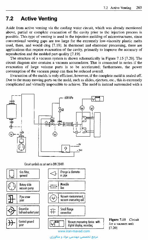
7 . 2 A c t i v e V e n t i n g
Aside from active venting via the cooling water circuit, which was already mentionedabove, partial or complete evacuation of the cavity prior to the injection process ispossible. This type of venting is used in the injection molding of microstructures, sinceconventional venting gaps are too large for the extremely low-viscosity plastic meltsused, there, and would clog [7.18]. In thermoset and elastomer processing, there areapplications that require evacuation of the cavity, primarily to improve the accuracy ofreproduction and the molded part quality [7.19].
The structure of a vacuum system is shown schematically in Figure 7.15 [7.20]. Thecircuit diagram also contains a vacuum accumulator. This is connected in series if theevacuation of large volume parts is to be accelerated; furthermore, the powerconsumption of the vacuum pump can then be reduced overall.
Evacuation of the molds is only efficient, however, if the complete mold is sealed off.Due to the many moving parts on the mold, such as slides, ejectors, etc., this is extremelycomplicated and virtually impossible to achieve. The mold is instead surrounded with a
Circuit symbols as set out in DIN 28401
Gas filter,general
Change in diameteror pipe
Rotary slidevacuum pump
Movableline
Pipe screwjoint
Vacuum measurement,vacuum measuring cell
Ground-inball-and-socket joint
Small flangeconnection
Figure 7.15 Circuitfor a vacuum unit[7.20]
Conical groundjoint
Vacuum measuring device withdigital display, recording
www.iran-mavad.com
مرجع تخصصی مهندسی مواد و متالورژی
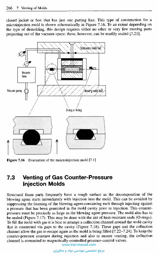
Figure 7.16 Evacuation of the mincroinjection mold [7.1]
7 . 3 V e n t i n g o f G a s C o u n t e r - P r e s s u r e
I n j e c t i o n M o l d s
Structural foam parts frequently have a rough surface as the decomposition of theblowing agent starts immediately with injection into the mold. This can be avoided bysuppressing the foaming of the blowing-agent-containing melt through injecting againsta pressure that has been generated in the mold cavity prior to injection. This counter-pressure must be precisely as large as the blowing agent pressure. The mold also has tobe sealed (Figure 7.17). This may be done with the aid of heat-resistant seals (O-rings).To fill the mold with gas it is best to arrange a collection channel around the mold cavitythat is connected via gaps to the cavity (Figure 7.18). These gaps and the collectionchannel allow the gas to escape again as the mold is being filled [7.22-7.24]. To keep thecounter-pressure constant during injection and also to ensure venting, the collectionchannel is connected to magnetically-controlled pressure-control valves.
O-ring or V-ring
Vacuum pump WomymldMll
Vacuumtank
xStdtiq nbfv mdd fm|f
closed jacket or box that has just one parting line. This type of construction for amicroinjection mold is shown schematically in Figure 7.16. To an extent depending onthe type of demolding, this design requires either no other or very few moving partsprojecting out of the vacuum space; these, however, can be readily sealed [7.21].
www.iran-mavad.com
مرجع تخصصی مهندسی مواد و متالورژی
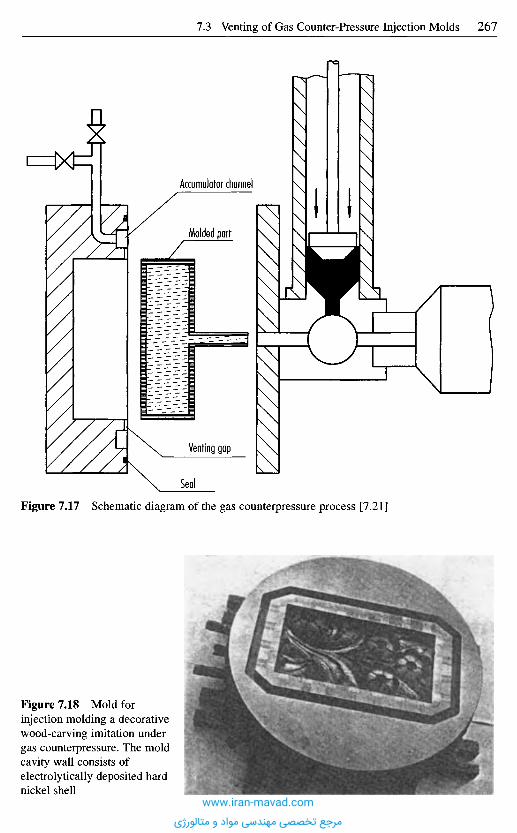
Figure 7.18 Mold forinjection molding a decorativewood-carving imitation undergas counterpressure. The moldcavity wall consists ofelectrolytically deposited hardnickel shell
Figure 7.17 Schematic diagram of the gas counterpressure process [7.21]
Seal
Venting gap
Accumulator channel
Molded part
www.iran-mavad.com
مرجع تخصصی مهندسی مواد و متالورژی
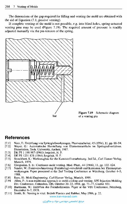
R e f e r e n c e s
[7.1] Notz, K: Entliiftung von SpritzgieBwerkzeugen. Plastverarbeiter, 45 (1994), 11, pp. 88-94.[7.2] Weyer, G.: Automatische Herstellung von Elastomerartikeln im SpritzgieBverfahren.
Dissertation, Tech. University, Aachen, 1987.[7.3] DE PS 1 198 987 (1961) Jurgeleit, H. F.[7.4] DE PS 1231 878 (1964) Jurgeleit, H. F.[7.5] Stoeckhert, K.: Werkzeugbau fur die Kunststoffverarbeitung. 3rd Ed., Carl Hanser Verlag,
Munich, 1979.[7.6] Giragosian, S. E.: Continous mold venting. Mod. Plast, 44 (1966), 11, pp. 122-124.[7.7] Sander, W.: Formverschmutzung (Formbelag)-verschleiB und Korrosion bei Thermoplast-
werkzeugen. Paper presented at the 2nd Tooling Conference at Wurzburg, October 4-5,1988.
[7.8] Rees, H.: Mold Engineering. Carl Hanser Verlag, Munich, 1995.[7.91 Allen, P.: A non-traditional approach to mold cooling and venting. SPE Injection Molding
Div. Conference, Columbus, OH, Oktober 20-22, 1981, pp. 71-77, Confer. 831.[7.10] Hartmann, W.: Entliiften des Formhohlraums. Paper at the VDI Conference, Niirnberg,
December 6-7, 1978.[7.11] Smith, B.: Venting is vital. British Plastics and Rubber, May 1986, p. 22.
Figure 7.19 Schematic diagramof a venting pin
The dimensions of the gap required for filling and venting the mold are obtained withthe aid of Equation (7.1, passive venting).
If complete venting of the mold is not possible, e.g. into blind holes, spring-actuatedventing pins may be used (Figure 7.19). The required amount of pressure is readilyadjusted manually via the pre-tension of the spring.
www.iran-mavad.com
مرجع تخصصی مهندسی مواد و متالورژی

[7.12] Water-line venting saves the job. Plastics World, 46 (1988), 3, pp. 27-28.[7.13] Ufrecht, M.: Die Werkzeugbelastung beim Uberspritzen. Unpublished report, IKV,
Aachen, 1978.[7.14] Huyjmans, H.; Packbier, K.; Schurmann, E.: Trial run with a two-cavity mold with 12 gates
at NWM, s'Hertogenbosch, 1978.[7.15] Stitz, S.; Schiirmann, E.: Measurements of deformations of injection molds at H.
Weidmann, Switzerland, 1976.[7.16] Wutz, M.; Hermann, A.; Walcher, W: Theorie und Praxis der Vakuumtechnik. Vieweg,
Braunschweig, Wiesbaden, 1986.[7.17] Speuser, G.: Evakuierung von SpritzgieBwerkzeugen fur die Elastomerverarbeitung.
Unpublished report, IKV, Aachen 1987.[7.18] Rogalla, A.: Analyse des SpritzgieBens mikrostrukturierter Bauteile aus Thermoplasten.
Dissertation, RWTH, Aachen, 1997.[7.19] Meiertoberens, U.; Herschbach, Ch.; MaaB, R.: Verbesserte Technologien fur die
Elastomerverarbeitung. Gummi, Fasern, Kunststoffe, 47 (1994), 10, pp. 642-649.[7.20] Michaeli, W; Weyer G.; Speuser G.; Kretzschmar, G.: Entliiftung von Formnestern beim
SpritzgieBen von Elastomeren. Kautschuk + Gummi, Kunststoffe, 44 (1991), 12,pp. 1146-1153.
[7.21] Winterkemper, A.: Entwicklung eines Werkzeugkonzeptes ftir das SpritzgieBen vonMikrostrukturen. Unpublished report, IKV, Aachen.
[7.22] Semerdjiev, S.; Popov, N.: Probleme des Gasgegendruck-SpritzgieBens von thermo-plastischen Strukturschaumstoffen. Kunststoffberater, 4/1978, pp. 198-201.
[7.23] Eckardt, E.: SchaumspritzgieBverfahren - Theorie und Praxis. Kunststoffberater, 1983,1/2, pp. 26-32.
[7.24] Semerdjiev, S.; Piperov, N.; Popov, N.; Mateev, E.: Das Gasgegendruck-SpritzgieB-verfahren zum Herstellen von thermoplastischen Strukturschaumteilen. Kunststoffe,64 (1974), 1, pp. 13-15.
www.iran-mavad.com
مرجع تخصصی مهندسی مواد و متالورژی
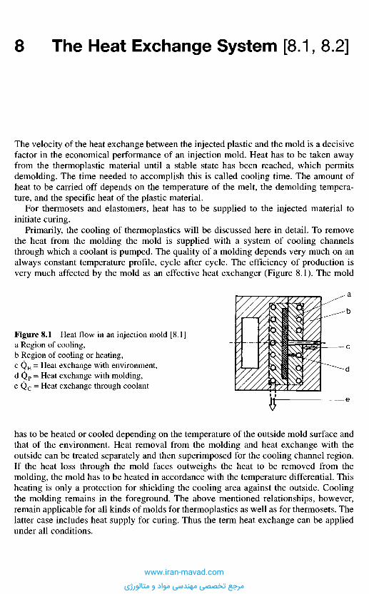
The velocity of the heat exchange between the injected plastic and the mold is a decisivefactor in the economical performance of an injection mold. Heat has to be taken awayfrom the thermoplastic material until a stable state has been reached, which permitsdemolding. The time needed to accomplish this is called cooling time. The amount ofheat to be carried off depends on the temperature of the melt, the demolding tempera-ture, and the specific heat of the plastic material.
For thermosets and elastomers, heat has to be supplied to the injected material toinitiate curing.
Primarily, the cooling of thermoplastics will be discussed here in detail. To removethe heat from the molding the mold is supplied with a system of cooling channelsthrough which a coolant is pumped. The quality of a molding depends very much on analways constant temperature profile, cycle after cycle. The efficiency of production isvery much affected by the mold as an effective heat exchanger (Figure 8.1). The mold
8 T h e H e a t E x c h a n g e S y s t e m [ 8 . 1 , 8 . 2 ]
Figure 8.1 Heat flow in an injection mold [8.1]a Region of cooling,b Region of cooling or heating,c QE = Heat exchange with environment,d Qp = Heat exchange with molding,e Q c = Heat exchange through coolant
has to be heated or cooled depending on the temperature of the outside mold surface andthat of the environment. Heat removal from the molding and heat exchange with theoutside can be treated separately and then superimposed for the cooling channel region.If the heat loss through the mold faces outweighs the heat to be removed from themolding, the mold has to be heated in accordance with the temperature differential. Thisheating is only a protection for shielding the cooling area against the outside. Coolingthe molding remains in the foreground. The above mentioned relationships, however,remain applicable for all kinds of molds for thermoplastics as well as for thermosets. Thelatter case includes heat supply for curing. Thus the term heat exchange can be appliedunder all conditions.
www.iran-mavad.com
مرجع تخصصی مهندسی مواد و متالورژی
8 .1 C o o l i n g T i m e
Cooling begins with the mold filling, which occurs during the time tP The major amountof heat, however, is exchanged during the cooling time tc. This is the time until the moldopens and the molding is ejected. The design of the cooling system must depend on thatsection of the part that has to be cooled for the longest time period, until it has reachedthe permissible demolding temperature TE.
The heat exchange between plastic and coolant takes place through thermalconduction in the mold. Thermal conduction is described by the Fourier differentialequation. Because moldings are primarily of a two-dimensional nature and heat is onlyremoved in one direction, the direction of their thickness, a one-dimensionalcomputation is sufficient. (Solutions for one dimensional heat exchange in the form ofapproximations have been compiled by [8.3, 8.4] for a length-over-wall-thickness ratioL/s > 10.) Elastomers, however, may have very different shapes and Figure 8.14presents, therefore, all conceivable geometries.
In the case of one-dimensional heat flow, the Fourier differential equation can bereduced to:
(8.1)
with a = = thermal diffusivity.
In these and the following equations:a Thermal diffusivity,aeff Effective thermal diffusivity,t Time,tc Cooling time,s Wall thickness,x Distance,p Density,k Thermal conductivity,Cp Specific heat capacity,TE Demolding temperature,TE Mean demolding temperature,TE Maximum demolding temperature,TM Melt temperature,Tw Cavity-wall temperature,Tw Average cavity-wall temperature,0 Cooling rate,Fo Fourier number.
Assuming that, immediately after injection, the melt temperature in the cavity has auniform constant value of TM ^ f(x), the temperature of the cavity wall jumps abruptlyto the constant value Tw ^ f(tc) and remains constant, then according to [8.3]
www.iran-mavad.com
مرجع تخصصی مهندسی مواد و متالورژی
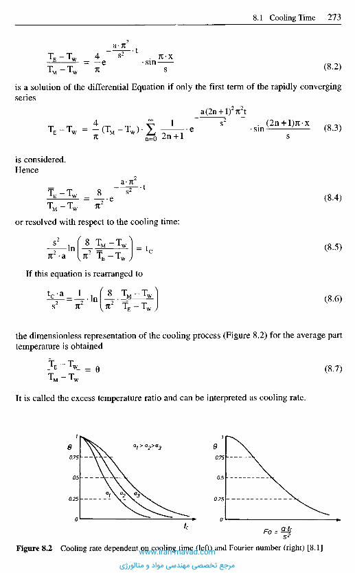
is a solution of the differential Equation if only the first term of the rapidly convergingseries
(8.2)
(8.3)
(8.4)
(8.5)
(8.6)
is considered.Hence
or resolved with respect to the cooling time:
If this equation is rearranged to
the dimensionless representation of the cooling process (Figure 8.2) for the average parttemperature is obtained
It is called the excess temperature ratio and can be interpreted as cooling rate.
(8.7)
Figure 8.2 Cooling rate dependent on cooling time (left) and Fourier number (right) [8.1]www.iran-mavad.com
مرجع تخصصی مهندسی مواد و متالورژی
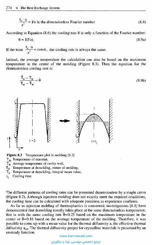
Figure 8.3 Temperature plot in molding [8.2]TM Temperature of material,T w Average temperature of cavity wall,TE Temperature at demolding, center of molding,TE Temperature at demolding, integral mean value,tc Cooling time
The different patterns of cooling rates can be presented dimensionless by a single curve(Figure 8.2). Although injection molding does not exactly meet the required conditions,the cooling time can be calculated with adequate precision as experience confirms.
As far as injection molding of thermoplastics is concerned, investigations [8.5] havedemonstrated that demolding usually takes place at the same dimensionless temperature,that is with the same cooling rate S=0.25 based on the maximum temperature in thecenter or 6=0.16 based on the average temperature of the molding. Therefore, it waspossible to come up with a mean value for the thermal diffusivity a, the effective thermaldiffusivity aeff. The thermal diffusivity proper for crystalline materials is presented by anunsteady function.
Fo is the dimensionless Fourier number (8.8)
According to Equation (8.6) the cooling rate 6 is only a function of the Fourier number:
(8.9a)
t • 2iIf the term c
2 = const., the cooling rate is always the same.s
Instead, the average temperature the calculation can also be based on the maximumtemperature in the center of the molding (Figure 8.3). Then the equation for thedimensionless cooling rate is:
(8.9b)
www.iran-mavad.com
مرجع تخصصی مهندسی مواد و متالورژی
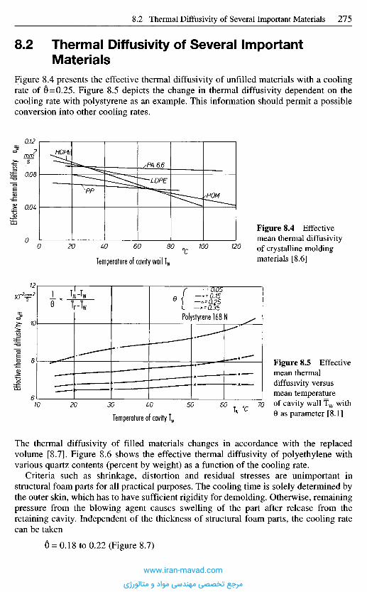
The thermal diffusivity of filled materials changes in accordance with the replacedvolume [8.7]. Figure 8.6 shows the effective thermal diffusivity of polyethylene withvarious quartz contents (percent by weight) as a function of the cooling rate.
Criteria such as shrinkage, distortion and residual stresses are unimportant instructural foam parts for all practical purposes. The cooling time is solely determined bythe outer skin, which has to have sufficient rigidity for demolding. Otherwise, remainingpressure from the blowing agent causes swelling of the part after release from theretaining cavity. Independent of the thickness of structural foam parts, the cooling ratecan be taken
6 = 0.18 to 0.22 (Figure 8.7)
Temperature of cavity Tw
Figure 8.5 Effectivemean thermaldiffusivity versusmean temperatureof cavity wall Tw with9 as parameter [8.1]
Effec
tive th
ermal
diffus
ivity
a eff
Temperature of cavity wall Tw
Figure 8.4 Effectivemean thermal diffusivityof crystalline moldingmaterials [8.6]
Polystyrene 168 N
Tw °C
10-2rmn2
0C
mm5
8 . 2 T h e r m a l D i f f u s i v i t y o f S e v e r a l I m p o r t a n t
M a t e r i a l s
Figure 8.4 presents the effective thermal diffusivity of unfilled materials with a coolingrate of S=0.25. Figure 8.5 depicts the change in thermal diffusivity dependent on thecooling rate with polystyrene as an example. This information should permit a possibleconversion into other cooling rates.
www.iran-mavad.com
مرجع تخصصی مهندسی مواد و متالورژی

8.2.1 Thermal Diffusivity of Elastomers
For elastomers, the heat of reaction can be neglected because of its small magnitude. Onecan calculate and proceed like one does with thermoplastics.
Due to a high content of carbon black the thermal diffusivity is shifted to highervalues similar to filled polyethylene (Figure 8.6):
aeff ~ 1 to 2 mm2/s
8.2.2 Thermal Diffusivity of Thermosets
Thermosets can develop a considerable higher heat of reaction. The amount of releasedheat depends on the degree of cross-linking and the percentage of reacting volume of the
Figure 8.7 Effective thermal diffusivitydependent on density of structural foam[8.1](Styrofoam parts 4-8 mm thick, coolingrate 0 = 0.2)
Effe
ctive
ther
mal
diff
usivi
ty a
eff
Density gs
Effec
tive t
herm
al dif
fusivi
ty cy
]Q-2mm2
PE1800MQuartz powderTw = 30 0C
Percentage of filler
Cooling gradient
Figure 8.6 Effective thermal diffusivityof polyethylene filled with quartz powder[8.1]
g/cm3
mm2
s
www.iran-mavad.com
مرجع تخصصی مهندسی مواد و متالورژی
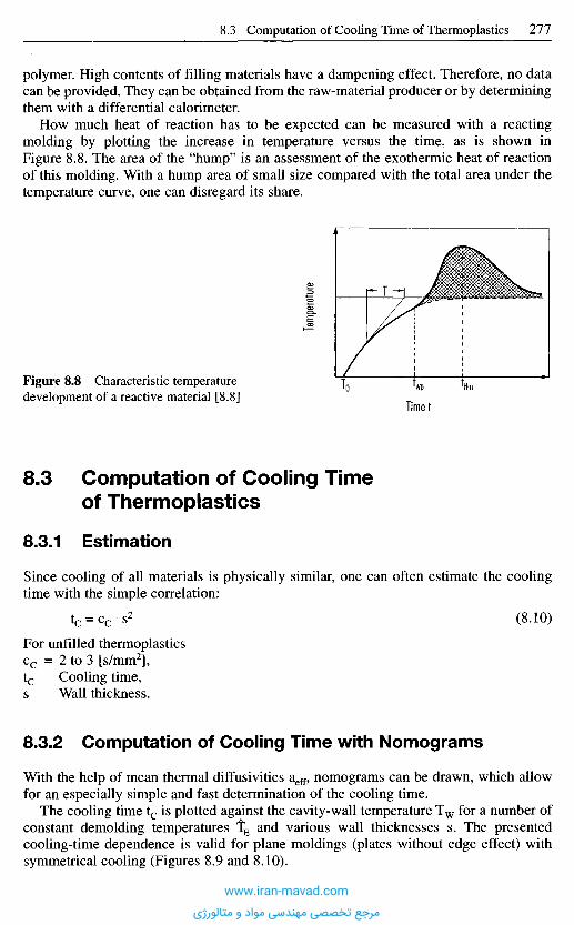
8 . 3 C o m p u t a t i o n o f C o o l i n g T i m e
o f T h e r m o p l a s t i c s
8.3.1 Es t ima t i on
Since cooling of all materials is physically similar, one can often estimate the coolingtime with the simple correlation:
tc = cc s2 (8.10)
For unfilled thermoplasticscc = 2 to 3 [s/mm2],tc Cooling time,s Wall thickness.
8.3.2 C o m p u t a t i o n o f C o o l i n g T i m e w i t h N o m o g r a m s
With the help of mean thermal diffusivities aeff, nomograms can be drawn, which allowfor an especially simple and fast determination of the cooling time.
The cooling time tc is plotted against the cavity-wall temperature Tw for a number ofconstant demolding temperatures tE and various wall thicknesses s. The presentedcooling-time dependence is valid for plane moldings (plates without edge effect) withsymmetrical cooling (Figures 8.9 and 8.10).
Figure 8.8 Characteristic temperaturedevelopment of a reactive material [8.8]
Timet
Temp
eratur
e
polymer. High contents of filling materials have a dampening effect. Therefore, no datacan be provided. They can be obtained from the raw-material producer or by determiningthem with a differential calorimeter.
How much heat of reaction has to be expected can be measured with a reactingmolding by plotting the increase in temperature versus the time, as is shown inFigure 8.8. The area of the "hump" is an assessment of the exothermic heat of reactionof this molding. With a hump area of small size compared with the total area under thetemperature curve, one can disregard its share.
www.iran-mavad.com
مرجع تخصصی مهندسی مواد و متالورژی
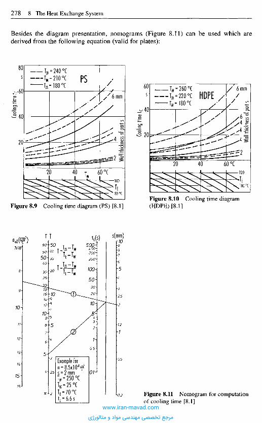
Besides the diagram presentation, nomograms (Figure 8.11) can be used which arederived from the following equation (valid for plates):
Figure 8.11 Nomogram for computationof cooling time [8.1]
Figure 8.9 Cooling time diagram (PS) [8.1]Figure 8.10 Cooling time diagram(HDPE) [8.1]
Coolin
g tim
e t c
Wall t
hickn
ess o
f part
s
Coolin
g tim
e t c
Wall t
hickn
ess o
f part
s
PS
HDPE
Example for
s(mm)t«(s)aeff(f2)
www.iran-mavad.com
مرجع تخصصی مهندسی مواد و متالورژی
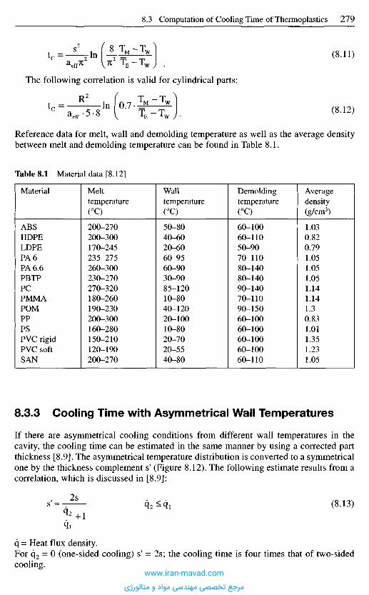
8.3.3 Cooling Time with Asymmetr ical Wall Temperatures
If there are asymmetrical cooling conditions from different wall temperatures in thecavity, the cooling time can be estimated in the same manner by using a corrected partthickness [8.9]. The asymmetrical temperature distribution is converted to a symmetricalone by the thickness complement s' (Figure 8.12). The following estimate results from acorrelation, which is discussed in [8.9]:
(8.13)
q = Heat flux density.For q2 = 0 (one-sided cooling) s1 = 2s; the cooling time is four times that of two-sidedcooling.
The following correlation is valid for cylindrical parts:
(8.11)
(8.12)
Reference data for melt, wall and demolding temperature as well as the average densitybetween melt and demolding temperature can be found in Table 8.1.
Table 8.1 Material data [8.12]
Material
ABSHDPELDPEPA 6PA 6.6PBTPPCPMMAPOMPPPSPVC rigidPVC softSAN
Melttemperature(0C)
200-270200-300170-245235-275260-300230-270270-320180-260190-230200-300160-280150-210120-190200-270
Walltemperature(°C)
50-8040-6020-6060-9560-9030-9085-12010-8040-12020-10010-8020-7020-5540-80
Demoldingtemperature(0C)
60-10060-11050-9070-11080-14080-14090-14070-11090-15060-10060-10060-10060-10060-110
Averagedensity(g/cm3)
1.030.820.791.051.051.051.141.141.30.831.011.351.231.05
www.iran-mavad.com
مرجع تخصصی مهندسی مواد و متالورژی
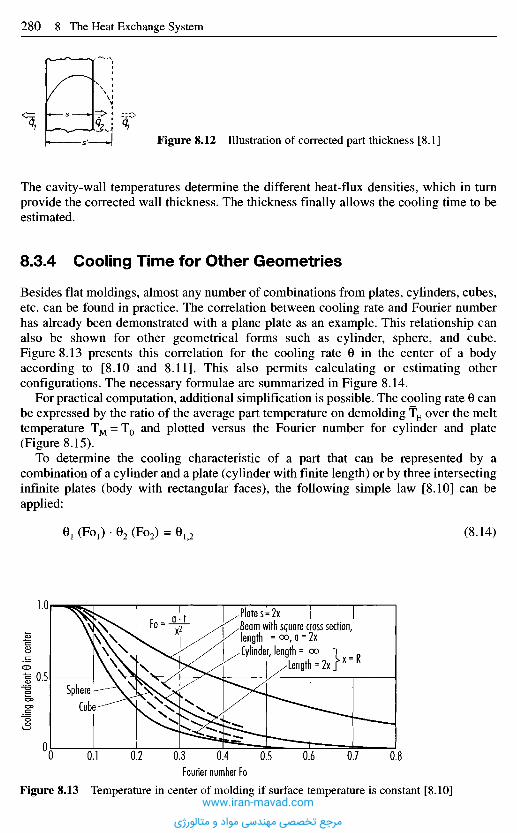
The cavity-wall temperatures determine the different heat-flux densities, which in turnprovide the corrected wall thickness. The thickness finally allows the cooling time to beestimated.
8.3.4 Cooling T ime for Other Geometr ies
Besides flat moldings, almost any number of combinations from plates, cylinders, cubes,etc. can be found in practice. The correlation between cooling rate and Fourier numberhas already been demonstrated with a plane plate as an example. This relationship canalso be shown for other geometrical forms such as cylinder, sphere, and cube.Figure 8.13 presents this correlation for the cooling rate 0 in the center of a bodyaccording to [8.10 and 8.11]. This also permits calculating or estimating otherconfigurations. The necessary formulae are summarized in Figure 8.14.
For practical computation, additional simplification is possible. The cooling rate 0 canbe expressed by the ratio of the average part temperature on demolding TE over the melttemperature TM = T0 and plotted versus the Fourier number for cylinder and plate(Figure 8.15).
To determine the cooling characteristic of a part that can be represented by acombination of a cylinder and a plate (cylinder with finite length) or by three intersectinginfinite plates (body with rectangular faces), the following simple law [8.10] can beapplied:
Figure 8.12 Illustration of corrected part thickness [8.1]
(8.14)
c5§CDCDECD
v >
Fourier number FoFigure 8.13 Temperature in center of molding if surface temperature is constant [8.10]
SphereCube
Plate s=2xBeam with square cross section,length = °o, a = 2xCylinder, length = oo 1 „
Length = 2xJx = K
www.iran-mavad.com
مرجع تخصصی مهندسی مواد و متالورژی
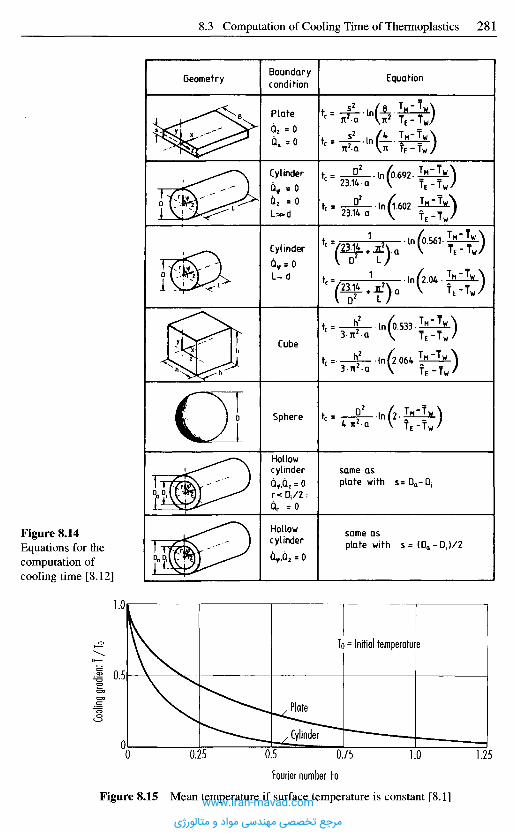
GeometryBoundarycondition Equation
Figure 8.14Equations for thecomputation ofcooling time [8.12]
Plate
Cylinder
Cylinder
Cube
Sphere
Hollowcylinder same as
plate with
Hollowcylinder same as
plate with
To = Initial temperature
Cooli
ng g
radi
entT
/To
Plate
Cylinder
Fourier number Fo
Figure 8.15 Mean temperature if surface temperature is constant [8.1]www.iran-mavad.com
مرجع تخصصی مهندسی مواد و متالورژی
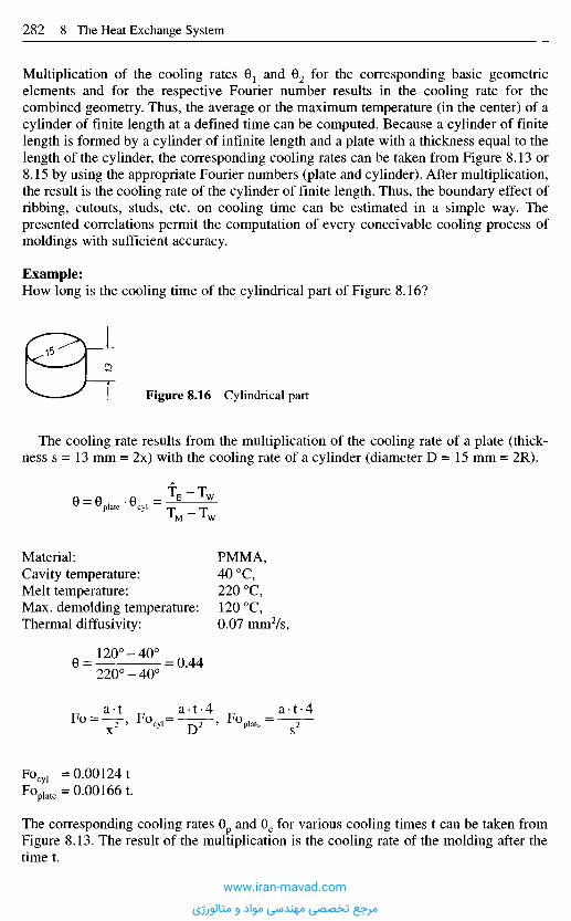
Multiplication of the cooling rates B1 and G2 for the corresponding basic geometricelements and for the respective Fourier number results in the cooling rate for thecombined geometry. Thus, the average or the maximum temperature (in the center) of acylinder of finite length at a defined time can be computed. Because a cylinder of finitelength is formed by a cylinder of infinite length and a plate with a thickness equal to thelength of the cylinder, the corresponding cooling rates can be taken from Figure 8.13 or8.15 by using the appropriate Fourier numbers (plate and cylinder). After multiplication,the result is the cooling rate of the cylinder of finite length. Thus, the boundary effect ofribbing, cutouts, studs, etc. on cooling time can be estimated in a simple way. Thepresented correlations permit the computation of every conceivable cooling process ofmoldings with sufficient accuracy.
Example:How long is the cooling time of the cylindrical part of Figure 8.16?
The cooling rate results from the multiplication of the cooling rate of a plate (thick-ness s = 13 mm = 2x) with the cooling rate of a cylinder (diameter D = 15 mm = 2R).
Figure 8.16 Cylindrical part
Material: PMMA,Cavity temperature: 40 0C,Melt temperature: 220 0C,Max. demolding temperature: 120 0C,Thermal diffusivity: 0.07 mm2/s,
The corresponding cooling rates 0p and 6C for various cooling times t can be taken fromFigure 8.13. The result of the multiplication is the cooling rate of the molding after thetime t.
www.iran-mavad.com
مرجع تخصصی مهندسی مواد و متالورژی
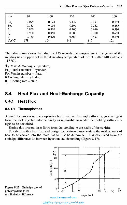
The table above shows that after ca. 135 seconds the temperature in the center of themolding has dropped below the demolding temperature of 120 0C (after 140 s already117 0C).
TE Max. demolding temperature,Foc Fourier number - cylinder,Fop Fourier number - plate,0CCooling rate - cylinder,0p Cooling rate - plate.
8 . 4 H e a t F l u x a n d H e a t - E x c h a n g e C a p a c i t y
8.4.1 Heat Flux
8.4.1.1 Thermoplastics
A mold for processing thermoplastics has to extract fast and uniformly, so much heatfrom the melt injected into the cavity as is possible to render the molding sufficientlyrigid to be demolded.
During this process, heat flows from the molding to the walls of the cavities.To calculate this heat flux and design the heat-exchange system the total amount of
heat to be carried into the mold has to first be determined. It is calculated from theenthalpy difference Ah between injection and demolding (Figure 8.17).
Figure 8.17 Enthalpy plot ofpolypropylene [8.2]A h Enthalpy difference
Speci
fic en
thalpy
h
Temperature T
is!kg
0C
t(s)
F O P
e,0PeTE(°C)
80
0.0990.1330.8600.9000.770
178
100
0.1240.1660.8100.8500.690
164
120
0.1490.1990.7000.8000.560
141
140
0.1730.2320.6100.7000.427
117
160
0.1980.2650.5100.6700.340
101
www.iran-mavad.com
مرجع تخصصی مهندسی مواد و متالورژی
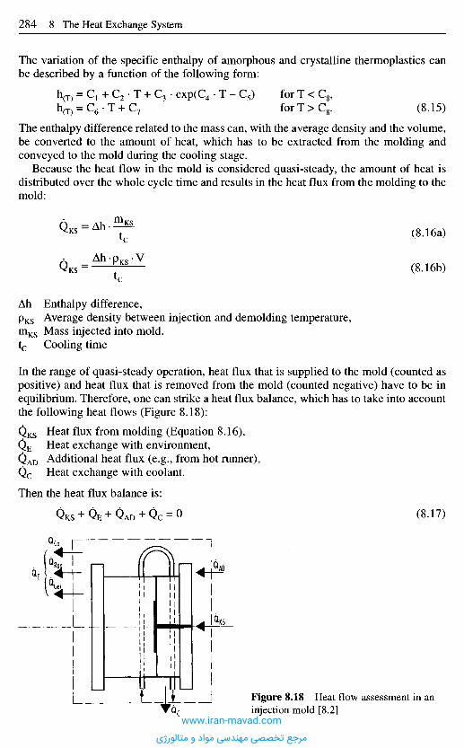
The variation of the specific enthalpy of amorphous and crystalline thermoplastics canbe described by a function of the following form:
(8.15)
The enthalpy difference related to the mass can, with the average density and the volume,be converted to the amount of heat, which has to be extracted from the molding andconveyed to the mold during the cooling stage.
Because the heat flow in the mold is considered quasi-steady, the amount of heat isdistributed over the whole cycle time and results in the heat flux from the molding to themold:
(8.16a)
(8.16b)
Ah Enthalpy difference,pKS Average density between injection and demolding temperature,mKS Mass injected into mold.tc Cooling time
In the range of quasi-steady operation, heat flux that is supplied to the mold (counted aspositive) and heat flux that is removed from the mold (counted negative) have to be inequilibrium. Therefore, one can strike a heat flux balance, which has to take into accountthe following heat flows (Figure 8.18):
Heat flux from molding (Equation 8.16),Heat exchange with environment,Additional heat flux (e.g., from hot runner),Heat exchange with coolant.
Then the heat flux balance is:
(8.17)
Figure 8.18 Heat flow assessment in aninjection mold [8.2]
www.iran-mavad.com
مرجع تخصصی مهندسی مواد و متالورژی
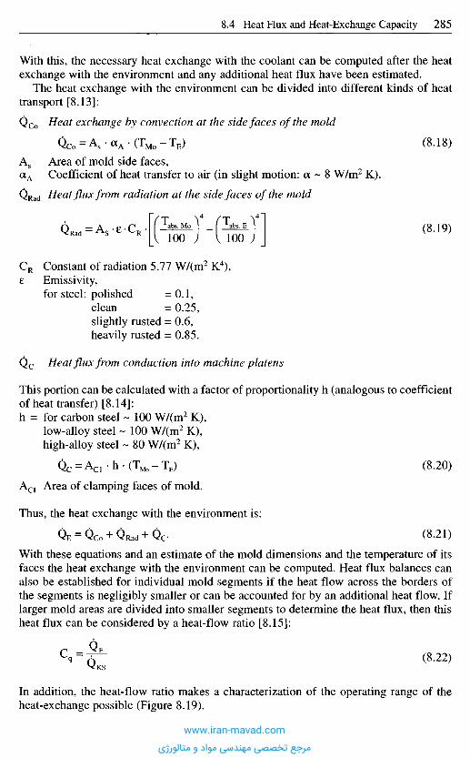
With this, the necessary heat exchange with the coolant can be computed after the heatexchange with the environment and any additional heat flux have been estimated.
The heat exchange with the environment can be divided into different kinds of heattransport [8.13]:
QCo Heat exchange by convection at the side faces of the mold
(8.18)
As Area of mold side faces,aA Coefficient of heat transfer to air (in slight motion: a ~ 8 W/m2 K).
QRad Heat flux from radiation at the side faces of the mold
(8.19)
CR Constant of radiation 5.77 W/(m2 K4),e Emissivity,
for steel: polished =0.1,clean = 0.25,slightly rusted = 0.6,heavily rusted = 0.85.
Q c Heat flux from conduction into machine platens
This portion can be calculated with a factor of proportionality h (analogous to coefficientof heat transfer) [8.14]:h = for carbon steel ~ 100 W/(m2 K),
low-alloy steel ~ 100 W/(m2 K),
high-alloy steel ~ 80 W/(m2 K),
(8.20)
ACI Area of clamping faces of mold.
Thus, the heat exchange with the environment is:
(8.21)
With these equations and an estimate of the mold dimensions and the temperature of itsfaces the heat exchange with the environment can be computed. Heat flux balances canalso be established for individual mold segments if the heat flow across the borders ofthe segments is negligibly smaller or can be accounted for by an additional heat flow. Iflarger mold areas are divided into smaller segments to determine the heat flux, then thisheat flux can be considered by a heat-flow ratio [8.15]:
(8.22)
In addition, the heat-flow ratio makes a characterization of the operating range of theheat-exchange possible (Figure 8.19).
www.iran-mavad.com
مرجع تخصصی مهندسی مواد و متالورژی
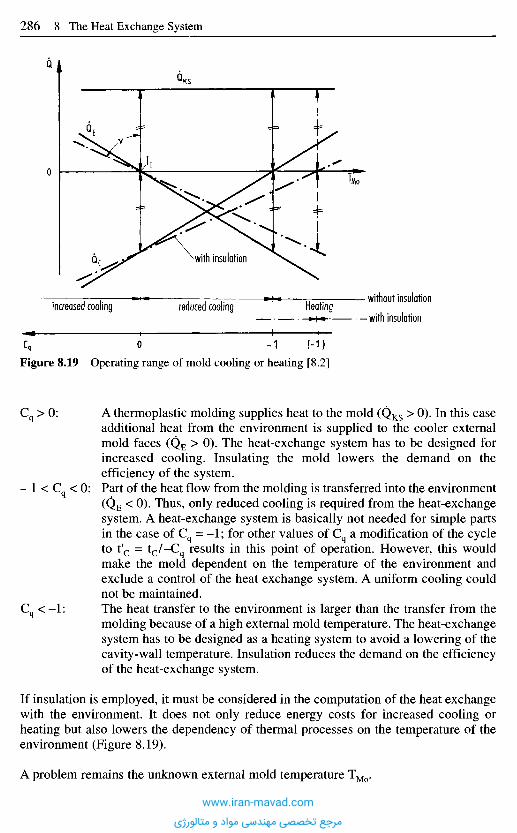
A thermoplastic molding supplies heat to the mold (QKS > 0). In this caseadditional heat from the environment is supplied to the cooler externalmold faces (QE > 0). The heat-exchange system has to be designed forincreased cooling. Insulating the mold lowers the demand on theefficiency of the system.Part of the heat flow from the molding is transferred into the environment(QE < O)- Thus, only reduced cooling is required from the heat-exchangesystem. A heat-exchange system is basically not needed for simple partsin the case of Cq = - 1 ; for other values of Cq a modification of the cycleto t'c = t c / -C q results in this point of operation. However, this wouldmake the mold dependent on the temperature of the environment andexclude a control of the heat exchange system. A uniform cooling couldnot be maintained.The heat transfer to the environment is larger than the transfer from themolding because of a high external mold temperature. The heat-exchangesystem has to be designed as a heating system to avoid a lowering of thecavity-wall temperature. Insulation reduces the demand on the efficiencyof the heat-exchange system.
If insulation is employed, it must be considered in the computation of the heat exchangewith the environment. It does not only reduce energy costs for increased cooling orheating but also lowers the dependency of thermal processes on the temperature of theenvironment (Figure 8.19).
A problem remains the unknown external mold temperature TMo.
Figure 8.19 Operating range of mold cooling or heating [8.2]
* with insulation
without insulation
• with insulationHeatingreduced coolingincreased cooling
www.iran-mavad.com
مرجع تخصصی مهندسی مواد و متالورژی
It can be estimated or determined by iteration as follows:That is, the heat exchange with the environment is neglected (permissibleonly with small unheated molds).(Temperature of coolant). Results in highest heat flux into the environment.(Temperature of cooling channel). Transpires in the course of the compu-tation.
With, the average distance I cooling channel and external mold surface one can calculate
(8.23)
Area of external mold surface,Clamping area of mold,Thermal conductivity of mold materialDistance between cooling channel and external mold surface.
Since T c c is still unknown, one estimates the heat flow in a first step with 2 (temperatureof coolant). When in the course of further calculation the temperature of the coolingchannel has been found, it can be inserted to improve the accuracy of the calculation.
8.4.1.2 Reactive Materials [8.16]
8.4.1.2.1 ThermosetsThermosets set free considerable amounts of heat from reaction. They cannot be dis-regarded. The simplest way to determine them is a DSC analysis (Figure 8.20).
This analysis provides the possibility of quantitatively correlating heat of reactionwith temperature and time. The relationship can be clearly demonstrated withexothermic reactions (phenolic resin). The presented graph shows the energy needed toraise the temperature with the desired speed (constant heating rate of 10 0C if not notedother-wise). The integral under the curve (shown dark in Figure 8.20) is a good approxi-mation of the heat of reaction, the distance between the two curves, and the heat effect.If sufficiently high temperatures are attained, there is no heat effect any more, and onecan assume a complete curing. Then the total heat of reaction corresponds to a degree ofcross-linking of 100%. This method is so reliable that different degrees of pre-curing canbe determined with phenolic resin [8.17]. If a specimen presents incomplete curing eitherby too short a testing time or too low a temperature, a second pass shows a clearlysmaller peak, ands its area corresponds with the residual curing. For this reason, the DSCanalysis is a suitable procedure for the thermal characterization of a reactive material andits kinetics of reaction.
The dashed line in Figure 8.20 is, strictly taken, a curved line as it would be obtainedwith a completely cured material. The used plotter programs, however, depend onstraight base lines. The considered temperature range has been determined by pre-liminary testing.
www.iran-mavad.com
مرجع تخصصی مهندسی مواد و متالورژی
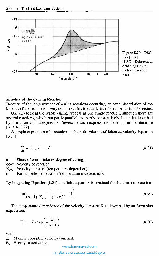
Kinetics of the Curing ReactionBecause of the large number of curing reactions occurring, an exact description of thekinetics of the reactions is very complex. This is equally true for rubber as it is for resins.
One can look at the whole curing process as one single reaction, although there areseveral reactions, which run partly parallel and partly consecutively. It can be describedby a reaction-kinetic expression. Several of such expressions are found in the literature[8.18 to 8.22].
A simple expression of a reaction of the n-th order is sufficient as velocity Equation[8.17].
(8.24)
Share of cross-links (= degree of curing),Velocity of reaction,Velocity constant (temperature dependent),Formal order of reaction (temperature independent).
By integrating Equation (8.24) a definite equation is obtained for the time t of reaction
(8.25)
The temperature dependence of the velocity constant K is described by an Arrheniusexpression:
(8.26)
withMaximal possible velocity constant,Energy of activation,
Figure 8.20 DSCplot [8.16](DSC = DifferentialScanning Calori-metry); phenolicresin
Heat
flow
mW
Temperature T
0C
www.iran-mavad.com
مرجع تخصصی مهندسی مواد و متالورژی
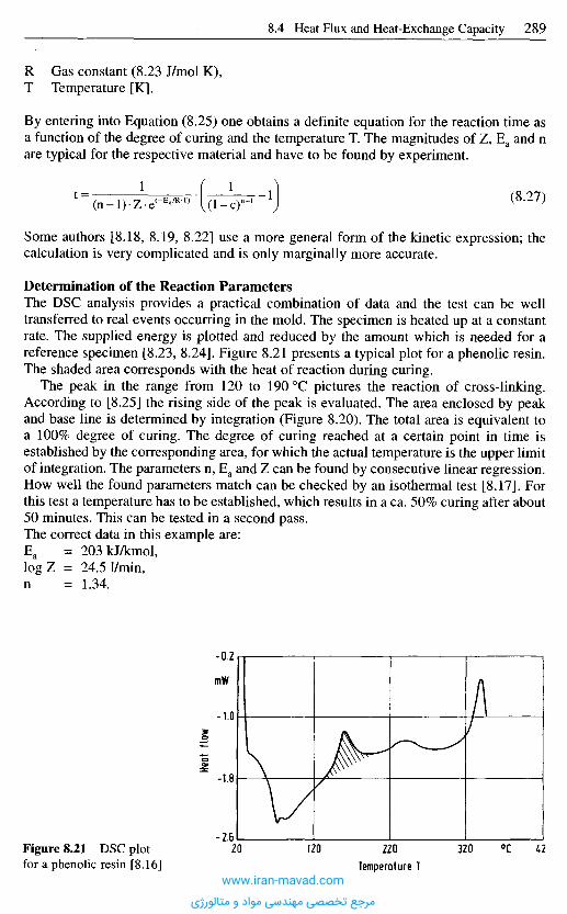
R Gas constant (8.23 J/mol K),T Temperature [K].
By entering into Equation (8.25) one obtains a definite equation for the reaction time asa function of the degree of curing and the temperature T. The magnitudes of Z, Ea and nare typical for the respective material and have to be found by experiment.
(8.27)
Some authors [8.18, 8.19, 8.22] use a more general form of the kinetic expression; thecalculation is very complicated and is only marginally more accurate.
Determination of the Reaction ParametersThe DSC analysis provides a practical combination of data and the test can be welltransferred to real events occurring in the mold. The specimen is heated up at a constantrate. The supplied energy is plotted and reduced by the amount which is needed for areference specimen [8.23, 8.24]. Figure 8.21 presents a typical plot for a phenolic resin.The shaded area corresponds with the heat of reaction during curing.
The peak in the range from 120 to 190 0C pictures the reaction of cross-linking.According to [8.25] the rising side of the peak is evaluated. The area enclosed by peakand base line is determined by integration (Figure 8.20). The total area is equivalent toa 100% degree of curing. The degree of curing reached at a certain point in time isestablished by the corresponding area, for which the actual temperature is the upper limitof integration. The parameters n, Ea and Z can be found by consecutive linear regression.How well the found parameters match can be checked by an isothermal test [8.17]. Forthis test a temperature has to be established, which results in a ca. 50% curing after about50 minutes. This can be tested in a second pass.The correct data in this example are:Ea = 203kJ/kmol,log Z = 24.51/min,n = 1.34.
Heat
flow
Temperature T
mW
0CFigure 8.21 DSC plotfor a phenolic resin [8.16]
www.iran-mavad.com
مرجع تخصصی مهندسی مواد و متالورژی
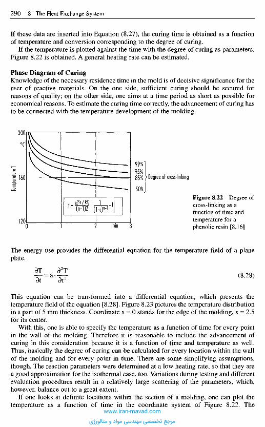
This equation can be transformed into a differential equation, which presents thetemperature field of the equation [8.28]. Figure 8.23 pictures the temperature distributionin a part of 5 mm thickness. Coordinate x = 0 stands for the edge of the molding, x = 2.5for its center.
With this, one is able to specify the temperature as a function of time for every pointin the wall of the molding. Therefore it is reasonable to include the advancement ofcuring in this consideration because it is a function of time and temperature as well.Thus, basically the degree of curing can be calculated for every location within the wallof the molding and for every point in time. There are some simplifying assumptions,though. The reaction parameters were determined at a low heating rate, so that they area good approximation for the isothermal case, too. Variations during testing and differentevaluation procedures result in a relatively large scattering of the parameters, which,however, balance out to a great extent.
If one looks at definite locations within the section of a molding, one can plot thetemperature as a function of time in the coordinate system of Figure 8.22. The
If these data are inserted into Equation (8.27), the curing time is obtained as a functionof temperature and conversion corresponding to the degree of curing.
If the temperature is plotted against the time with the degree of curing as parameters,Figure 8.22 is obtained. A general heating rate can be estimated.
Phase Diagram of CuringKnowledge of the necessary residence time in the mold is of decisive significance for theuser of reactive materials. On the one side, sufficient curing should be secured forreasons of quality; on the other side, one aims at a time period as short as possible foreconomical reasons. To estimate the curing time correctly, the advancement of curing hasto be connected with the temperature development of the molding.
Temp
eratur
e T
Figure 8.22 Degree ofcross-linking as afunction of time andtemperature for aphenolic resin [8.16]
0C
mm
Degree of cross-linking
The energy use provides the differential equation for the temperature field of a planeplate.
(8.28)
www.iran-mavad.com
مرجع تخصصی مهندسی مواد و متالورژی
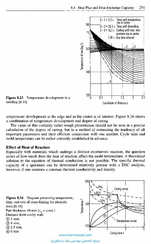
temperature development at the edge and in the center is of interest. Figure 8.24 showsa combination of temperature development and degree of curing.
The value of this certainly rather rough presentation should not be seen in a precisecalculation of the degree of curing, but in a method of estimating the tendency of allimportant parameters and their efficient connection with one another. Cycle time andmold temperature can be rather correctly established in advance.
Effect of Heat of ReactionEspecially with materials which undergo a distinct exothermic reaction, the questionarises of how much does the heat of reaction affect the mold temperature. A theoreticalsolution to the equation of thermal conduction is not possible. The specific thermalcapacity of a specimen can be determined relatively precise with a DSC analysis,however, if one assumes a constant thermal conductivity and density.
Figure 8.23 Temperature development in amolding [8.16] Coordinate of distance x
Temp
eratur
e of m
olding
T P
Time until temperaturerise in centerTime until demoldingCooling until max. tem-perature rise in centerOne time interval
0C
Figure 8.24 Diagram presenting temperature,time, and rate of cross-linking for phenolicresin [8.16]Part thickness 10 mm (cp = const.)Distance from cavity wall:® 5 mm,© 4 mm,(3) 2.5 mm,® 0 mm
Temp
eratur
e T
Curing curves
Temperature curves
Curing time twww.iran-mavad.com
مرجع تخصصی مهندسی مواد و متالورژی
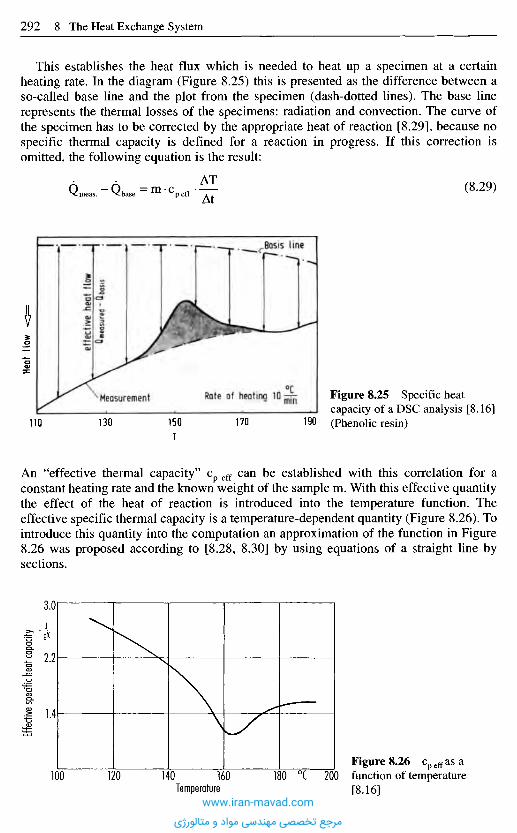
An "effective thermal capacity" cp eff can be established with this correlation for aconstant heating rate and the known weight of the sample m. With this effective quantitythe effect of the heat of reaction is introduced into the temperature function. Theeffective specific thermal capacity is a temperature-dependent quantity (Figure 8.26). Tointroduce this quantity into the computation an approximation of the function in Figure8.26 was proposed according to [8.28, 8.30] by using equations of a straight line bysections.
Effec
tive s
pecifi
c hea
t cap
acity
Heat
tlow
effe
ctive
hea
t flow
^mea
sured
- Qbos
is
This establishes the heat flux which is needed to heat up a specimen at a certainheating rate. In the diagram (Figure 8.25) this is presented as the difference between aso-called base line and the plot from the specimen (dash-dotted lines). The base linerepresents the thermal losses of the specimens: radiation and convection. The curve ofthe specimen has to be corrected by the appropriate heat of reaction [8.29], because nospecific thermal capacity is defined for a reaction in progress. If this correction isomitted, the following equation is the result:
(8.29)
Basis line
Measurement0CRate of heating 10^ Figure 8.25 Specific heat
capacity of a DSC analysis [8.16](Phenolic resin)
9K
Temperature
0CFigure 8.26 cp eff as afunction of temperature[8.16]
www.iran-mavad.com
مرجع تخصصی مهندسی مواد و متالورژی
In practice, however, pinpoint gates in multi-cavity molds are frequently employed.Then precuring (also called scorching) may occur. To consider this phenomenon it issuggested to establish so-called windows of operation [8.32, 8.33].
8 . 5 A n a l y t i c a l , T h e r m a l C a l c u l a t i o n o f t h e H e a t -
E x c h a n g e S y s t e m B a s e d o n t h e S p e c i f i c H e a t
F l u x ( O v e r a l l D e s i g n )
A simple analytical calculation (rough design) can be used as a first approximate valuefor thermal design of the cooling system if one does not wish to rely totally onexperience. The molded part is simply regarded as a slab. Short calculation timesproduce results for temperatures, heat fluxes, and cooling geometry that form a goodstarting value for the numerical calculation.
In practical cases, it has been shown for molds up to approximately 100 0C that theerrors are negligible in the case of just two-dimensional calculation. There are goodreasons for this since one is on the safe side with a two-dimensional calculation and thecalculation necessarily contains a series of further assumptions, such as coolanttemperature, heat-transfer coefficient in the cooling channels, which, unfortunately, lieon the more unreliable side. It may therefore be assumed that the error given by two-dimensional calculation compensate for the other errors in terms of providing a morereliable design.
These principles may be used to design the cooling system. It must be borne in mindthat: the calculation is based on a two-dimensional viewpoint. This simplification cannaturally lead to errors of the outer edges and corners of the mold, if for example noinsulation is present at high mold temperatures.
If this effect is taken into account, the result is a more rapid temperature rise, whichis especially noticeable in heavy sections. The temperature function attains highertemperatures for the center of the part faster with this more accurate description. Thenecessary degree of curing is reached sooner. The residence time in the mold is estimatedmore accurate and can be set shorter. Similar results are reported by [8.31].
ElastomersThe calculation corresponds to that for thermosets, however, when designing the moldone can neglect the reaction heat for noncritical materials. The thermal diffusivities ofsome typical elastomers are listed in Table 8.2.
Table 8.2 Thermal diffusivity a ofsome elastomers [8.32]
Material
NBR-INBR-2NR-INR-2ACMCR
HardnessShore A
407045607568
Thermal-diffusivity amm2/s
0.1470.1450.0930.1220.2180.188
www.iran-mavad.com
مرجع تخصصی مهندسی مواد و متالورژی

8.5.1 Analytical Thermal Calculation
The analytical thermal calculation can be subdivided into separate steps (Figure 8.27).The necessary time to cool down a molding from melt to demolding temperature with agiven cavity-wall temperature is established in the cooling-time computation. This canbe done with equations for a variety of configurations (Section 8.3.4) for differentsections of moldings, which have to be rigid enough to be demolded and ejected at theend of the cooling time. The longest time found with this calculation is decisive forfurther proceedings.
Design steps Criteria
Minimum cooling timedown to demoldingtemperature
Required heat flow throughcoolant
Uniform temperature alongcooling line
Turbulent flow
Heat flowuniformity
Selection of heat exchangerModification of diameter orflow rate
1 Computationof cooling time
2 Balance ofheat flow
3 Flow rate ofcoolant
4 Diameter ofcooling line
5 Position ofcooling line
6 Computation ofpressure drop
Figure 8.27 Analytic computation of the cooling system [8.2]www.iran-mavad.com
مرجع تخصصی مهندسی مواد و متالورژی
With the heat-flux balance, which has to be taken in by the coolant is computed. Thiscalls for consideration of additional heat input, heat exchange with the environment, andeventual insulation. The heat exchange with the environment is found with the estimatedoutside dimensions of the mold and the temperature of the mold surface. Anapproximation for the latter is the temperature of the coolant, which is assumed for thetime being.
The heat-flux balance does not only provide information about the operating range ofthe heat-exchange system, but also indicates design problems along the way. High heatflux, which has to be carried away by the coolant and which occurs particularly withthin, large moldings of crystalline material, requires a high flow rate of the coolant andresults in a high pressure drop in the cooling system. Then the use of several coolingcircuits can offer an advantage. A low heat flux to be taken up by the coolant may resultin a small flow rate of the coolant in channels with common diameter and with this in alaminar flow. For this reason, a higher flow rate should be accomplished than thatresulting from the criterion of temperature difference between coolant entrance and exit.After the flow rate of the coolant has been calculated, the requirement of a turbulent flowsets an upper limit for the diameter.
The position of the cooling channels to one another as well as their distance from thesurface of the molding result from the calculated heat flux including compliance with thelimits of homogeneity (Figure 8.28). The calculation can be done with a number ofpreconditions:
- specification of cooling error and computation of distances,- specification of distance from molding surface,- specification of distances among cooling channels,- specification of whole length of cooling line,- specification of both channel distances and computation of required flow rate of
coolant. In this case another heat-flux balance becomes necessary.
Tabulating the points of the functions presented with Figure 8.28 is an additionalbeneficial option. Such a table makes it possible to fit the position of individual coolingchannels into the mold design without relocating parting lines or ejector pins.
For the analytical calculation, the configuration of the molding is simplified by a platewith the same volume and surface as the molding. This allows segmenting the internal
Figure 8.28 Position ofcooling line andtemperature uniformity [8.2]
Distan
ce fr
om su
rface
I mm
Distance between channels bmm
Nonuniform
www.iran-mavad.com
مرجع تخصصی مهندسی مواد و متالورژی

area of the mold with each segment having a width equal to the calculated distancebetween the cooling channels.
With the position of the cooling channels one can determine the whole length of thecooling system, the length of supply lines, the number of corners, elbows and connectorsand enter them into the drawing. This information permits the computation of thepressure loss and the necessary capacity of heat exchangers. In the same way one cancalculate the minimum diameter of the cooling channel or the maximum flow rate of thecoolant for a given permissible pressure drop.
One has to consider that a large part of the pressure drop does not occur solely in thecooling line in the mold, but also in connecting lines, connectors and turns, which mustalso be taken into account.
8.5.1.1 Calculating the Cooling Time
With the aid of the equations presented in Section 8.3.4 (Figure 8.14), it is possible tocalculate the necessary cooling time. To ensure a dependable design, it is always betterto use the critical (i.e., thickest) cross-section of the part for the calculation.
8.5.1.2 Heat Flux Balance
The efficiency of the heat-exchange system of a mold depends on the amount of heat thatcan be extracted from the plastic material in the cavity at a certain cavi ty-walltemperature in the shortest t ime span possible. Therefore it is the task of the heat-exchange system to ensure the desired temperature of the cavity wall (see also Section8.4).
In contrast to [8.34, 8.35] one can apparently do without a transfer coefficient be tweencavity wall and material if the wall temperature is defined as the contact temperaturebetween plastic and cavity wall , which, as shown below, has to be calculated. This holdsfor as long as the molded part is still lying against the cavity wall .
The contact temperature is the m a x i m u m temperature during the cycle that establishesitself when the molding compound is in contact with the wall . It is expressed as:
(8.30)
T c Contact temperature,Tp
max Material temperature before contact,T w Cavity-wall temperature before contact,b Heat penetrability,k Thermal conductivity,p Density,c Specific heat capacity.
Depending on time and cycle, the temperature of the cavity surface varies be tweencontact and min imum temperature , which is determined by the temperature of thecoolant. The average of both provides sufficient accuracy for calculating cooling t imeand necessary heat-exchange capacity. Therefore this average temperature represents thecavity-wall temperature T w .
www.iran-mavad.com
مرجع تخصصی مهندسی مواد و متالورژی
In a steady state the cavity surface with the temperature T w acts as a heat sink for themolding and a heat source for the mold. The resulting heat flux can be determined asfollows:
Quantity of heat from the molding:
(8.32)
Heat flux from the molding into each mold half:
(8.33)
Ah Enthalpy difference (Figure 8.17),p Density of melt,QM Heat flux from melt,s Wall thickness,AM Surface area of molding,t c Cooling time = C c • s2,tc Cycle time t c + tn (tn is the nonproductive time for opening, closing and ejecting).
with
(8.34)
Heat-flux density from molding:
(8.35)
For the first estimate, the nonproductive time (the period of time during which nomolding compound is in the cavity) is ignored initially.
When the nonproductive time is ignored, the equation can be simplified further:
If one now combines ^- = K into a single material constant, thenK
(8.37)
Within the usual range of processing temperature the heat-flux density only depends onthe material. It is obvious that it has to increase with decreasing wall thickness to ensurethe required cavity temperature. Besides this, the heat-flux density, in future calledspecific heat flux, represents a specific material characterization if the generally small
(8.31)
(8.36)
www.iran-mavad.com
مرجع تخصصی مهندسی مواد و متالورژی
8.5.1.3 Coolant Throughput
For the determination of the coolant throughput, the specific heat flux q (Figures 8.31and 8.32) is the central design parameter. Multiplying the specific heat flux by thecorresponding surface area of the molding AM results in the amount of heat which has tobe removed by the coolant during one cycle, which belongs to AM. The necessary flowrate of the coolant Vc is determined by the permissible rise in coolant temperature ATC.
The difference in coolant temperature AT should not exceed 3 to 5 0C in order toensure adequate homogeneous cooling along the cooling circuit. The maximum per-missible temperature difference may be used to calculate the minimum necessary coolantthroughput ATmax.
Figure 8.29 Specific heat flux q PS as afunction of wall thickness [8.1]
Figure 8.30 Specific heat flux q HDPE asa function of wall thickness [8.1]
Wall thickness of part smm
Wall thickness of part smm
Spec
ific he
at flu
x q
Spec
ific h
eat fl
ux q
machine effect is neglected. The machine effect becomes apparent by the extra timeneeded for the completion of movements (ejection, etc.). The heat flow from the moldingto the mold is interrupted with the demolding process; the coolant, however, continuesto cool the mold during this secondary time, which reduces the specific heat fluxaccordingly.
Figures 8.29 and 8.30 present the specific heat flux for PS and HDPE as a function ofsecondary machine time. The maximum occurs with a wall thickness for which coolingand secondary time are equal. The specific heat flux as a function of cavity temperatureis shown in Figures 8.31 and 8.32 for a number of wall thicknesses. The specific heatflux can facilitate the selection of the right mold concept already in the planning stageand also presents a basis for the design of the heat-exchange system of the mold.
JLcm2
JLcm2
HDPEPSIdle time tn Idle time tn
www.iran-mavad.com
مرجع تخصصی مهندسی مواد و متالورژی

Figure 8.33 Computation offlow rate of cooling water(molding surface = 100 cm2) [8.1]
Density of coolant,Specific heat of coolant.
Specific heat flux q
W/cm2
(8.39)
Flow
rate
(wate
r) V
Spec
ific he
at flu
x q
Spec
ific h
eat fl
ux q
JLCm2
WCm2
Wall thickness of partsin mm
PS
Wall thickness of partsin mmTM = 220 0ClE = 100°C
TN= 5s
Figure 8.31 Specific heat flux q PS as afunction of temperature of cavity wall [8.1]
Temperature of cavity wall Tw
0C
Temperature of cavity wall Tw
Figure 8.32 Specific heat flux q HDPE asa function of temperature of cavity wall [8.1]
0C
TM = 220 0CTE = 90 0CTN = 5s
HDPE
www.iran-mavad.com
مرجع تخصصی مهندسی مواد و متالورژی
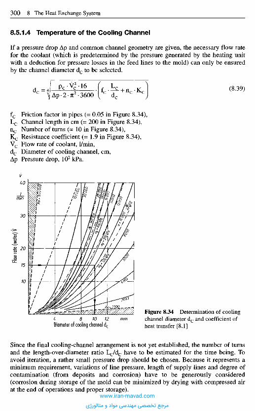
8.5.1.4 Temperature of the Cooling Channel
If a pressure drop Ap and common channel geometry are given, the necessary flow ratefor the coolant (which is predetermined by the pressure generated by the heating unitwith a deduction for pressure losses in the feed lines to the mold) can only be ensuredby the channel diameter dc to be selected.
(8.39)
fc Friction factor in pipes (= 0.05 in Figure 8.34),Lc Channel length in cm (= 200 in Figure 8.34),nc Number of turns (= 10 in Figure 8.34),Kc Resistance coefficient (= 1.9 in Figure 8.34),Vc Flow rate of coolant, 1/min,dc Diameter of cooling channel, cm,Ap Pressure drop, 102 kPa.
Since the final cooling-channel arrangement is not yet established, the number of turnsand the length-over-diameter ratio Lc/dc have to be estimated for the time being. Toavoid iteration, a rather small pressure drop should be chosen. Because it represents aminimum requirement, variations of line pressure, length of supply lines and degree ofcontamination (from deposits and corrosion) have to be generously considered(corrosion during storage of the mold can be minimized by drying with compressed airat the end of operations and proper storage).
Figure 8.34 Determination of coolingchannel diameter dc and coefficient ofheat transfer [8.1]
Flow
rate (
water
) V
Diameter of cooling channel dc
mm
Imin
www.iran-mavad.com
مرجع تخصصی مهندسی مواد و متالورژی
Measurements on molds have demonstrated [8.9] that the friction factor in pipes withoutdeposits can be described according to Blasius' law:
(8.40)
With few deposits (after about 100 working hours = usual operating range) one canestimate fc ~ 0.04 [8.9].Resistance coefficients for sharp and rounded bends were reported as follows:90° sharp bend K = 1.9 [8.9],90° round bend K = 0.4 [8.9].
(Literature [8.36, 8.37] contains values for the 90° sharp bend of between 1.13 and 1.9and for the 90° round bend of between 0.4 and 0.9).
The coefficient of heat transfer can be calculated in combination with Nusselt,Reynolds and Prandtl numbers [8.38]:
(8.41)
dh Hydraulic diameter (4 x cross section/circumference),kc Thermal conductivity of coolant,Kf Correction factor.
The dimensionless parameters compute to:
(8.42)
(8.43)
The equation for the heat transfer coefficient a applies to the range of turbulent flowwith a considerably better heat transfer than with laminar flow (Re < 2300). Anotherdisadvantage of the range of laminar flow is the transition into turbulent flow behindcorners and changes in cross-sectional areas, which causes a better heat transfer for acertain length. The demand for a turbulent flow results in an upper limit for the diameter:
(8.44)
Common diameters for cooling channels in most applications are far below this limit.Arrival of laminar flow in water of 20 0C can only be assumed with a flow rate of lessthan 2 1/min.
With the channel diameter determined, the coefficient of heat transfer can becomputed with the flow rate of the coolant for 2300 < Re < 106, 0.7 < Pr < 500, and
www.iran-mavad.com
مرجع تخصصی مهندسی مواد و متالورژی

Kinematic viscosity of coolant [cm2/s],Cooling channel diameter [cm],Prandtl number = v/a,Thermal conductivity of coolant [W/cm K].
The dependency of the coefficient of heat transfer on flow rates (expressed inFigure 8.34 by Ap), temperature and channel diameter is demonstrated for severalcoolants in Figures 8.36, 8.37 and 8.38. It is evident that water is the most effectivecoolant.
8.5.1.5 Position of the Cooling Channels
The distance between two cooling channels in a mold is based on the relationship givenin Figure 8.39.
For the dimensions Figure 8.40 can be used. The example is based on an averagetemperature of coolant of Tc = 20 0C and an average mold temperature of Tw = 62 0C.
The ratio AC/AM is presented with Figure 8.41 as a function of the distance of thechannels between each other and their diameters.
Figure 8.35 Cooling elements [8.2]
(8.45)
Simplechannel
Channelinsertedcylinder
Bubbler Channel withbaffle
Channelwithtwistedbuffle
Single-threadedspiralbubbler
Double-threadedspiralbubbler
www.iran-mavad.com
مرجع تخصصی مهندسی مواد و متالورژی

Coeff
icient
of he
at tra
nsfer
a
Line p
ressur
e p
Coeff
icient
of he
at tra
nsfer
a
Line p
ressur
e p
Coeff
icien
t of h
eat t
rans
fer a
Line
press
ure p
Figure 8.38 Coefficient of heat transfer a,coolant: oil (Marlotherm S) [8.1]
Diameter of cooling channel dc
xlO3[ J L lm2oCi
Diameter of cooling channel dc
Figure 8.37 Coefficient of heat transfera, coolant: brine (20%) [8.1]
Diameter of cooling channel dc
Figure 8.36 Coefficient of heat transfer a,coolant: water [8.1]
fegrd^Lo W }
x 10*
www.iran-mavad.com
مرجع تخصصی مهندسی مواد و متالورژی
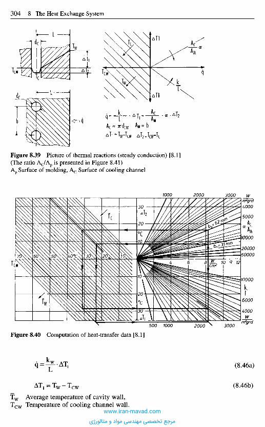
Figure 8.40 Computation of heat-transfer data [8.1]
Average temperature of cavity wall,Temperature of cooling channel wall.
(8.46a)
(8.46b)
Figure 8.39 Picture of thermal reactions (steady conduction) [8.1](The ratio Ac/Ap is presented in Figure 8.41)Ap Surface of molding, Ac Surface of cooling channel
www.iran-mavad.com
مرجع تخصصی مهندسی مواد و متالورژی
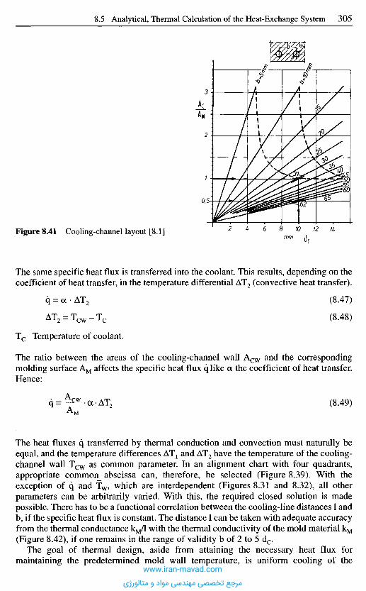
The same specific heat flux is transferred into the coolant. This results, depending on thecoefficient of heat transfer, in the temperature differential AT2 (convective heat transfer).
(8.47)
(8.48)
T c Temperature of coolant.
The ratio between the areas of the cooling-channel wall A c w and the correspondingmolding surface AM affects the specific heat flux qlike a the coefficient of heat transfer.Hence:
(8.49)
The heat fluxes q transferred by thermal conduction and convection must naturally beequal, and the temperature differences AT1 and AT2 have the temperature of the cooling-channel wall T c w as common parameter. In an alignment chart with four quadrants,appropriate common abscissa can, therefore, be selected (Figure 8.39). With theexception of q and Tw, which are interdependent (Figures 8.31 and 8.32), all otherparameters can be arbitrarily varied. With this, the required closed solution is madepossible. There has to be a functional correlation between the cooling-line distances 1 andb, if the specific heat flux is constant. The distance 1 can be taken with adequate accuracyfrom the thermal conductance kM/l with the thermal conductivity of the mold material kM
(Figure 8.42), if one remains in the range of validity b of 2 to 5 dc.The goal of thermal design, aside from attaining the necessary heat flux for
maintaining the predetermined mold wall temperature, is uniform cooling of the
Figure 8.41 Cooling-channel layout [8.1]
AM
dcmm
www.iran-mavad.com
مرجع تخصصی مهندسی مواد و متالورژی
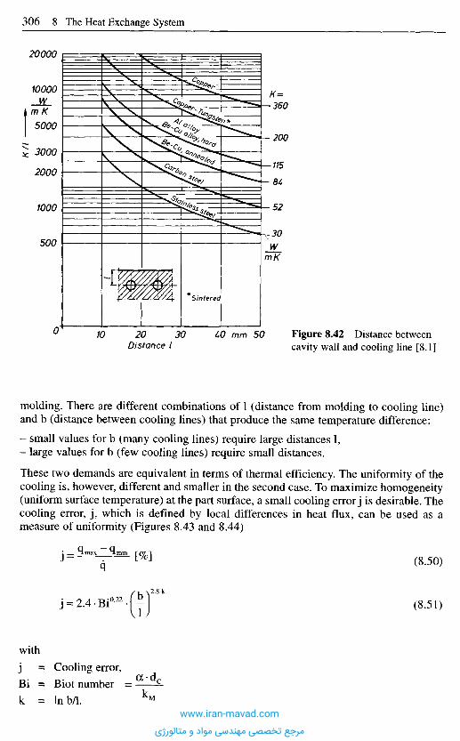
molding. There are different combinations of 1 (distance from molding to cooling line)and b (distance between cooling lines) that produce the same temperature difference:
- small values for b (many cooling lines) require large distances 1,- large values for b (few cooling lines) require small distances.
These two demands are equivalent in terms of thermal efficiency. The uniformity of thecooling is, however, different and smaller in the second case. To maximize homogeneity(uniform surface temperature) at the part surface, a small cooling error j is desirable. Thecooling error, j , which is defined by local differences in heat flux, can be used as ameasure of uniformity (Figures 8.43 and 8.44)
(8.50)
(8.51)
with
= Cooling error,
= Biot number
= lnb/1.
Figure 8.42 Distance betweencavity wall and cooling line [8.1]Distance I
mm
Sintered
K/I
m K
WmK
www.iran-mavad.com
مرجع تخصصی مهندسی مواد و متالورژی
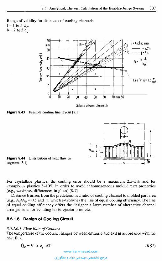
For crystalline plastics, the cooling error should be a maximum 2.5-5% and foramorphous plastics 5-10% in order to avoid inhomogeneous molded part properties(e.g., waviness, differences in gloss) [8.1].
Distance b arises from the predetermined ratio of cooling channel to molded part area(e.g., AC/AM = 0.5 and 1), which establishes the line of equal cooling efficiency. The lineof equal cooling efficiency offers the designer a large number of alternative channelarrangements for avoiding bolts, ejector pins, etc.
8.5.1.6 Design of Cooling Circuit
8.5.1.6.1 Flow Rate of CoolantThe temperature of the coolant changes between entrance and exit in accordance with theheat flux.
(8.52)
Figure 8.44 Distribution of heat flow insegment [8.1]
Distan
ce fr
om ca
vity w
all L
Figure 8.43 Feasible cooling line layout [8.1]
Distance between channels b
mm
mmj = Cooling error
Line for
Range of validity for distances of cooling channels:1 = 1 to 5 dc,b = 2 to 5 dc.
www.iran-mavad.com
مرجع تخصصی مهندسی مواد و متالورژی
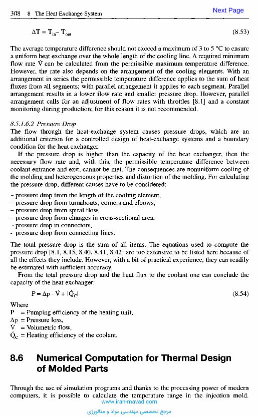
The average temperature difference should not exceed a maximum of 3 to 5 0C to ensurea uniform heat exchange over the whole length of the cooling line. A required minimumflow rate V can be calculated from the permissible maximum temperature difference.However, the rate also depends on the arrangement of the cooling elements. With anarrangement in series the permissible temperature difference applies to the sum of heatfluxes from all segments; with parallel arrangement it applies to each segment. Parallelarrangement results in a lower flow rate and smaller pressure drop. However, parallelarrangement calls for an adjustment of flow rates with throttles [8.1] and a constantmonitoring during production; for this reason it is not recommended.
8.5.1.6.2 Pressure DropThe flow through the heat-exchange system causes pressure drops, which are anadditional criterion for a controlled design of heat-exchange systems and a boundarycondition for the heat exchanger.
If the pressure drop is higher than the capacity of the heat exchanger, then thenecessary flow rate and, with this, the permissible temperature difference betweencoolant entrance and exit, cannot be met. The consequences are nonuniform cooling ofthe molding and heterogeneous properties and distortion of the molding. For calculatingthe pressure drop, different causes have to be considered:
- pressure drop from the length of the cooling element,- pressure drop from turnabouts, corners and elbows,- pressure drop from spiral flow,- pressure drop from changes in cross-sectional area,- pressure drop in connectors,- pressure drop from connecting lines.
The total pressure drop is the sum of all items. The equations used to compute thepressure drop [8.1, 8.15, 8.40, 8.41, 8.42] are too extensive to be listed here because ofall the effects they include. However, with a bit of practical experience, they can readilybe estimated with sufficient accuracy.
From the total pressure drop and the heat flux to the coolant one can conclude thecapacity of the heat exchanger:
(8.54)
Where= Pumping efficiency of the heating unit,= Pressure loss,= Volumetric flow,= Heating efficiency of the coolant.
8 . 6 N u m e r i c a l C o m p u t a t i o n f o r T h e r m a l D e s i g n
o f M o l d e d P a r t s
Through the use of simulation programs and thanks to the processing power of moderncomputers, it is possible to calculate the temperature range in the injection mold.
(8.53)
Next Page
www.iran-mavad.com
مرجع تخصصی مهندسی مواد و متالورژی
The average temperature difference should not exceed a maximum of 3 to 5 0C to ensurea uniform heat exchange over the whole length of the cooling line. A required minimumflow rate V can be calculated from the permissible maximum temperature difference.However, the rate also depends on the arrangement of the cooling elements. With anarrangement in series the permissible temperature difference applies to the sum of heatfluxes from all segments; with parallel arrangement it applies to each segment. Parallelarrangement results in a lower flow rate and smaller pressure drop. However, parallelarrangement calls for an adjustment of flow rates with throttles [8.1] and a constantmonitoring during production; for this reason it is not recommended.
8.5.1.6.2 Pressure DropThe flow through the heat-exchange system causes pressure drops, which are anadditional criterion for a controlled design of heat-exchange systems and a boundarycondition for the heat exchanger.
If the pressure drop is higher than the capacity of the heat exchanger, then thenecessary flow rate and, with this, the permissible temperature difference betweencoolant entrance and exit, cannot be met. The consequences are nonuniform cooling ofthe molding and heterogeneous properties and distortion of the molding. For calculatingthe pressure drop, different causes have to be considered:
- pressure drop from the length of the cooling element,- pressure drop from turnabouts, corners and elbows,- pressure drop from spiral flow,- pressure drop from changes in cross-sectional area,- pressure drop in connectors,- pressure drop from connecting lines.
The total pressure drop is the sum of all items. The equations used to compute thepressure drop [8.1, 8.15, 8.40, 8.41, 8.42] are too extensive to be listed here because ofall the effects they include. However, with a bit of practical experience, they can readilybe estimated with sufficient accuracy.
From the total pressure drop and the heat flux to the coolant one can conclude thecapacity of the heat exchanger:
(8.54)
Where= Pumping efficiency of the heating unit,= Pressure loss,= Volumetric flow,= Heating efficiency of the coolant.
8 . 6 N u m e r i c a l C o m p u t a t i o n f o r T h e r m a l D e s i g n
o f M o l d e d P a r t s
Through the use of simulation programs and thanks to the processing power of moderncomputers, it is possible to calculate the temperature range in the injection mold.
(8.53)
Previous Page
www.iran-mavad.com
مرجع تخصصی مهندسی مواد و متالورژی
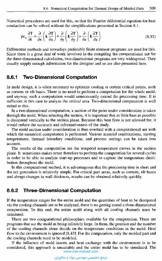
Numerical procedures are used for this, so that the Fourier differential equation for heatconduction can be solved without the simplifications presented in Section 8.1.
(8.55)
Differential methods and nowadays preferably finite element programs are used for this.Since there is a great deal of work involved in the compiling the computational net forthe three-dimensional calculation, two-dimensional programs are very widespread. Theyusually supply enough information for the designer and so are also presented here.
8.6.1 Two-Dimensional Computat ion
In mold design, it is often necessary to optimize cooling at certain critical points, suchas corners or rib bases. There is no need to perform a computation for the whole mold,and anyway, such a computation would unnecessarily extend the processing time. It issufficient in this case to analyze the critical area. Two-dimensional computation is wellsuited to this.
In a two-dimensional computation, a section of the point under consideration is takenthrough the mold. When selecting the section, it is important that as little heat as possibleis dissipated vertically to the section plane. Because this heat flow is not allowed for, itwould reduce the accuracy and informativeness of the study.
The mold section under consideration is then overlaid with a computational net withwhich the numerical computation is performed. Various material combinations, startingtemperatures, thermal boundary conditions, and process settings can be taken intoaccount.
The results of the computation are the temporal temperature curves in the sectionplane. It sometimes makes sense therefore to perform the computation for several cyclesin order to be able to analyze start-up processes and to capture the temperature distri-bution throughout the mold.
In this computational method, it is advantageous that the processing time is short andthe net generation is relatively simple. For critical part areas, such as corners, rib basesand abrupt changes in wall thickness, results can be obtained relatively quickly.
8.6.2 Three-Dimensional Computat ion
If the temperature ranges for the entire mold and the quantities of heat to be dissipatedvia the cooling channels are to be analyzed, there is no getting round a three-dimensionalcomputation. To this end, the entire mold along with all cooling channels must besimulated.
There are two computational philosophies available for the computation. There areprograms that see the mold as being infinitely large. In them, the position and the numberof the cooling channels alone decide on the temperature conditions in the mold. Heatflow to the environment is ignored [8.43]. For the computation, only the molded part andthe cooling channels need to be modeled.
If the influence of mold inserts and heat exchange with the environment is to beconsidered, this approach is unsuitable and the entire mold has to be simulated. The
www.iran-mavad.com
مرجع تخصصی مهندسی مواد و متالورژی
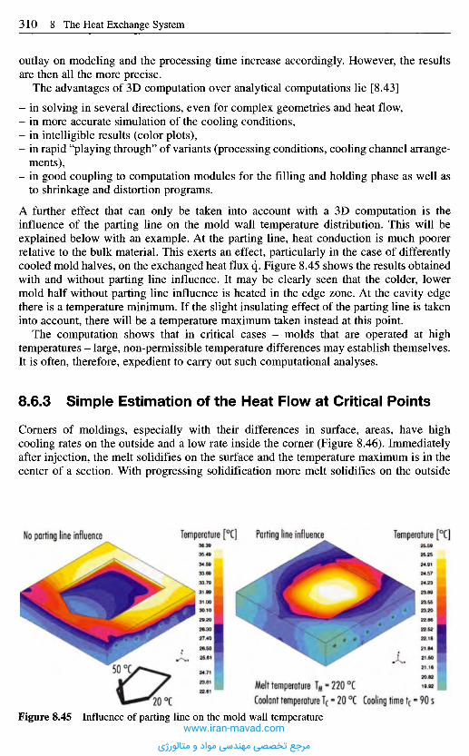
outlay on modeling and the processing time increase accordingly. However, the resultsare then all the more precise.
The advantages of 3D computation over analytical computations lie [8.43]
- in solving in several directions, even for complex geometries and heat flow,- in more accurate simulation of the cooling conditions,- in intelligible results (color plots),- in rapid "playing through" of variants (processing conditions, cooling channel arrange-
ments),- in good coupling to computation modules for the filling and holding phase as well as
to shrinkage and distortion programs.
A further effect that can only be taken into account with a 3D computation is theinfluence of the parting line on the mold wall temperature distribution. This will beexplained below with an example. At the parting line, heat conduction is much poorerrelative to the bulk material. This exerts an effect, particularly in the case of differentlycooled mold halves, on the exchanged heat flux q. Figure 8.45 shows the results obtainedwith and without parting line influence. It may be clearly seen that the colder, lowermold half without parting line influence is heated in the edge zone. At the cavity edgethere is a temperature minimum. If the slight insulating effect of the parting line is takeninto account, there will be a temperature maximum taken instead at this point.
The computation shows that in critical cases - molds that are operated at hightemperatures - large, non-permissible temperature differences may establish themselves.It is often, therefore, expedient to carry out such computational analyses.
8.6.3 Simple Estimation of the Heat Flow at Critical Points
Corners of moldings, especially with their differences in surface, areas, have highcooling rates on the outside and a low rate inside the corner (Figure 8.46). Immediatelyafter injection, the melt solidifies on the surface and the temperature maximum is in thecenter of a section. With progressing solidification more melt solidifies on the outside
No parting line influence Temperature [0C] Parting line influence Temperature [0C]
Melt temperature TM - 220 0CCoolant temperature Tc * 20
0C Cooling time t( * 90 sFigure 8.45 Influence of parting line on the mold wall temperature
www.iran-mavad.com
مرجع تخصصی مهندسی مواد و متالورژی
A material deficit during solidification of the last melt is generated because the shrinkagecannot be compensated by melt supplied by the holding pressure. Tensile stresses arecreated accordingly. These stresses are counterbalanced by the rigidity of the mold. Afterdemolding, the external forces have ceased and the formation of a stress equilibrium inthe part causes warpage or deformation. Besides this, voids and sink marks and evenspontaneous cracking may occur. Deformation can be eliminated, however, if theremaining melt, and with it the forces of shrinkage, are kept in the plane of symmetry.Then an equilibrium of forces through-out the cross section is generated if the lastmaterial solidifies in the center.
8.6.4 Empirical Correction for Cooling a Corner
One draws the corner of the part and the planned cooling channels on an enlarged scale.Then the cross section of the corner is divided into rectangles of equal size with one sideequal to half the thickness of the section (s/2); the other one equal to the distancebetween two cooling channels. Thus, the area is pictured, which is cooled by one coolingchannel (cooling segment). By comparing areas and adjustment, one hole at the corneris either eliminated or the holes are shifted in such a way that equal cooling surfaces(ratio of holes to rectangles) are generated (Figure 8.46).
Figure 8.46 Freezing of melt in a corner[8.1]The drawing at the top shows that the farthestsquare a on the convex side is affected bytwo cooling channels d. On the concave sidethree squares b are affected by only onecooling channel c. Consequently melt closeto the concave side will solidify last
Last melt
Cooling channels
than on the inside of the corner because the heat-exchange areas are of different size andmore heat is dissipated on the outside than on the inside. Figure 8.46 demonstrates thatthe remaining melt moves from the center towards the inside. At the end of the coolingtime, the melt which solidifies last is close to the internal surface.
www.iran-mavad.com
مرجع تخصصی مهندسی مواد و متالورژی
8 . 7 P r a c t i c a l D e s i g n o f C o o l i n g S y s t e m s
8.7.1 H e a t - E x c h a n g e S y s t e m s f o r C o r e s a n d Par ts w i t hC i rcu la r C r o s s - S e c t i o n
Adapting the specific heat flux to requirements and ensuring it in all areas of a molding,particularly in critical sections, may cause considerable difficulties.
A slender core is a characteristic example for mold parts which are accessible onlywith difficulties. Because of unawareness of the serious consequences (increased coolingtime) or for reasons of manufacturing, such cores are often left without any particularcooling. Cooling occurs only from the mold base through the core mount. Withdecreasing secondary time and, consequently, reduced time for core cooling betweenejection and injection, heating-up of cores without separate cooling is unavoidable. Coretemperatures of the magnitude of the demolding temperature are definitely possible. Ifintense cooling of the core base is feasible, then an undesirable temperature gradientfrom the tip of the core to the base is the result. A high temperature differential betweencore wall and coolant impairs the dynamic characteristics, which are important forstart-up and leads to high time constants, this means a long time until the temperaturesof the mold level out to a constant value. (The basic correlations for describing thedynamics are presented in [8.44 to 8.46].)
Because of the already mentioned increase in cycle time, an uncooled core can resultin parts of inferior quality and even fully interrupt a production. This becomesparticularly apparent with cores having a square or rectangular cross section. Withuncooled cores, sink marks or distorted sides can hardly be avoided. Therefore,provisions for cooling of cores should always be made. To do so, the following optionsare available dependent on the diameter or width of the core (Figure 8.47).
If diameter or width are minor, only air cooling is feasible most of the time. Air isblown from the outside during mold opening or flows through a central hole from theinside. This procedure, of course, does not permit maintaining exact mold temperatures(Figure 8.47a).
A better cooling of slender cores is accomplished by using inserts made of materialswith high thermal conductivity, such as copper, beryllium-copper, or high-strengthsintered copper-tungsten materials (Figure 8.47b). Such inserts are press-fitted into thecore and extend with their base, which has a cross section as large as it is feasible, intoa cooling channel.
The most effective cooling of slender cores is achieved with bubblers. An inlet tubeconveys the coolant into a blind hole in the core. The diameters of both have to beadjusted in such a way that the resistance to flow in both cross sections is equal. Thecondition for this is ID/OD = 0.5. The smallest realizable tubing so far are hypodermicneedles with an OD of 1.5 mm. To guarantee flawless operation in this case, the purityof the coolant has to meet special demands. Bubblers are commercially available and areusually screwed into the core (Figure 8.47d). Up to a diameter of 4 mm the tubing shouldbe beveled at the end to enlarge the cross section of the outlet (Figure 8.47c).
Bubblers can be used not only for core cooling but also for flat mold sections, whichcannot be equipped with drilled or milled channels.
A special bubbler has been developed for cooling rotating cores in unscrewing molds(Figure 8.47e).
It is frequently suggested to separate inlet and return flow in a core hole with a baffle(Figure 8.47f). This method provides maximum cross sections for the coolant but it is
www.iran-mavad.com
مرجع تخصصی مهندسی مواد و متالورژی
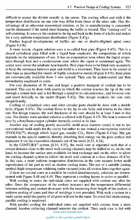
difficult to mount the divider exactly in the center. The cooling effect and with it thetemperature distribution on one side may differ from those of the other side. This dis-advantage of an otherwise economical solution, as far as manufacturing is concerned,can be eliminated if the metal sheet forming the baffle is twisted. This "cooling coil" isself-centering. It conveys the coolant to the tip and back in the form of a helix and makesfor a very uniform temperature distribution (Figure SAIg).
Further logical developments of baffles are one or double-flighted spiral cores(Figure 8.47h).
A more recent, elegant solution uses a so-called heat pipe (Figure 8.47i). This is aclosed cylindrical pipe filled with a liquid heat conductor, the composition of whichdepends on the temperature of use. It has an evaporation zone where the liquid evapo-rates through heat and a condensation zone where the vapor is condensed again. Thecenter zone serves the adiabatic heat transfer. Heat pipes have to be fitted very accuratelyto keep the resistance between pipe and mold to a minimum. They have to be cooled attheir base as described for inserts of highly conductive metals (Figure 8.47b). Heat pipesare commercially available from 3 mm upward. They can be nickel-coated and thenimmediately employed as cores.
For core diameters of 40 mm and larger a positive transport of coolant has to beensured. This can be done with inserts in which the coolant reaches the tip of the corethrough a central hole and is led through a spiral to its circumference, and between coreand insert helically to the outlet (Figure 8.47j). This design weakens the core onlyinsignificantly.
Cooling of cylindrical cores and other circular parts should be done with a doublehelix (Figure 8.47k). The coolant flows to the tip in one helix and returns in the otherone. For design reasons, the wall thickness of the core should be at least 3 mm in thiscase. For thinner walls another solution is offered with Figure 8.471. The heat is removedhere by a beryllium-copper cylinder intensely cooled at its base.
Another way of cooling poorly accessible mold areas (narrow cores) is not to useconventional mold steels for the cavity but rather to use instead a microporous material(TOOLVAC®), through which liquid gas, usually CO2, flows (Figure 8.47m). The gasexpands in the special material, thereby absorbing heat energy via the pore surface andtransports it via the evacuation channels out of the mold [8.53, 8.54].
In the CONTURA® system [8.54, 8.55], the mold core is separated such that at acertain distance close to the mold wall cooling channels may be milled so as, on the onehand, to increase the surface area available for heat exchange and, on the other, to allowthe cooling channel system to follow the mold wall contour at a close distance (8.47n).In this case, a more uniform temperature distribution in the core ensures better moldreproduction of the part as well as shorter cooling times. The use of a suitable joiningmethod (high-temperature soldering under vacuum) joins all section lines together again.
If there are several cores in a mold to be cooled simultaneously, solutions are demon-strated with Figure 8.48 and 8.49. They represent a cooling layout in series or parallel.
With cooling in series the individual cores are supplied with coolant one after theother. Since the temperature of the coolant increases and the temperature differentialbetween molding and coolant decreases with the increasing flow length of the coolant, auniform cooling of cores and thus of moldings is not provided. With such a system in amulti-cavity mold the quality of all parts will not be the same. To avoid this shortcoming,parallel cooling is employed.
With parallel cooling the individual cores are supplied with coolant from a mainchannel. Another collecting channel removes the coolant. Thus, each core is fed with
www.iran-mavad.com
مرجع تخصصی مهندسی مواد و متالورژی

Figure
a
b
C
d
e
f
Diameter orwidth of core
= 3 mm
^ 5 mm
^ 8 mm
Characteristic
Heat removal by air from theoutside when mold is open;continuous cooling onlyfeasible if part has openings.Cooling of closed moldachieved with sucked-in water
Heat-conducting copper isconnected to cooling line.Base of insert should be enlarged
Bubbler with beveled tip(4 mm)
ID/OD = 0.5
Bubbler for rotating cores
Baffle
Design
Monel sleeve
Ball bearingSeal
Out
In
Water in
Figure 8.47 Core cooling techniques [8.47 to 8.55] (continued on next page)
Air
Cu
www.iran-mavad.com
مرجع تخصصی مهندسی مواد و متالورژی
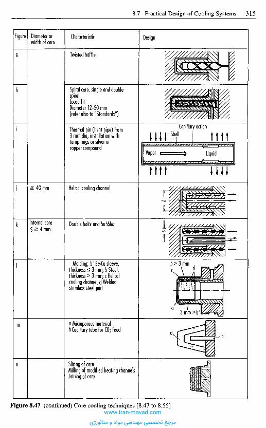
Figure
g
h
i
i
k
I
m
n
Diameter orwidth of core
= 40 mm
Internal coreS = 4 mm
Characteristic
Twisted baffle
Spiral core, single and doublespiralLoose fitDiameter 12-50 mm(refer also to "Standards")
Thermal pin (heat pipe) from3 mm dia, installation withtamp rings or silver orcopper compound
Helical cooling channel
Double helix and bubbler
Molding; b+ Be-Cu sleeve,thickness £ 3 mm; b Steel,thickness > 3 mm; c Helicalcooling channel, d Weldedstainless steel part
a Microporous materialb Capillary tube for CO2 feed
Slicing of coreMilling of modified heating channelsJoining of core
Figure 8.47 (continued) Core cooling techniques [8.47 to 8.55]
Design
Capillary actionShell
Vapor Liquid
www.iran-mavad.com
مرجع تخصصی مهندسی مواد و متالورژی
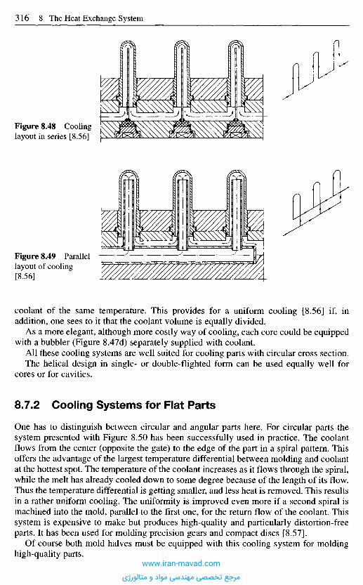
coolant of the same temperature. This provides for a uniform cooling [8.56] if, inaddition, one sees to it that the coolant volume is equally divided.
As a more elegant, although more costly way of cooling, each core could be equippedwith a bubbler (Figure SAId) separately supplied with coolant.
All these cooling systems are well suited for cooling parts with circular cross section.The helical design in single- or double-flighted form can be used equally well for
cores or for cavities.
8.7.2 Cooling Systems for Flat Parts
One has to distinguish between circular and angular parts here. For circular parts thesystem presented with Figure 8.50 has been successfully used in practice. The coolantflows from the center (opposite the gate) to the edge of the part in a spiral pattern. Thisoffers the advantage of the largest temperature differential between molding and coolantat the hottest spot. The temperature of the coolant increases as it flows through the spiral,while the melt has already cooled down to some degree because of the length of its flow.Thus the temperature differential is getting smaller, and less heat is removed. This resultsin a rather uniform cooling. The uniformity is improved even more if a second spiral ismachined into the mold, parallel to the first one, for the return flow of the coolant. Thissystem is expensive to make but produces high-quality and particularly distortion-freeparts. It has been used for molding precision gears and compact discs [8.57].
Of course both mold halves must be equipped with this cooling system for moldinghigh-quality parts.
Figure 8.49 Parallellayout of cooling[8.56]
Figure 8.48 Coolinglayout in series [8.56]
www.iran-mavad.com
مرجع تخصصی مهندسی مواد و متالورژی
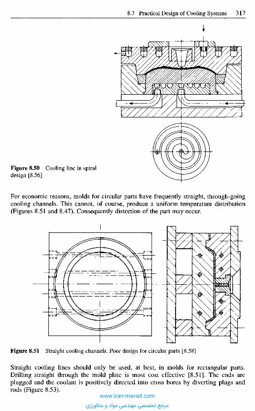
Figure 8.51 Straight cooling channels. Poor design for circular parts [8.58]
Straight cooling lines should only be used, at best, in molds for rectangular parts.Drilling straight through the mold plate is most cost effective [8.51]. The ends areplugged and the coolant is positively directed into cross bores by diverting plugs androds (Figure 8.53).
Figure 8.50 Cooling line in spiraldesign [8.56]
For economic reasons, molds for circular parts have frequently straight, through-goingcooling channels. This cannot, of course, produce a uniform temperature distribution(Figures 8.51 and 8.47). Consequently distortion of the part may occur.
www.iran-mavad.com
مرجع تخصصی مهندسی مواد و متالورژی
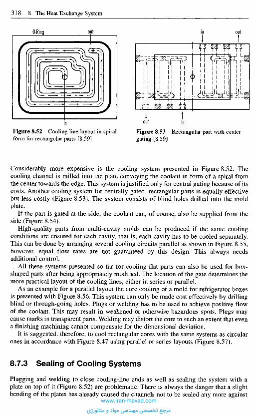
Considerably more expensive is the cooling system presented in Figure 8.52. Thecooling channel is milled into the plate conveying the coolant in form of a spiral fromthe center towards the edge. This system is justified only for central gating because of itscosts. Another cooling system for centrally gated, rectangular parts is equally effectivebut less costly (Figure 8.53). The system consists of blind holes drilled into the moldplate.
If the part is gated at the side, the coolant can, of course, also be supplied from theside (Figure 8.54).
High-quality parts from multi-cavity molds can be produced if the same coolingconditions are ensured for each cavity, that is, each cavity has to be cooled separately.This can be done by arranging several cooling circuits parallel as shown in Figure 8.55,however, equal flow rates are not guaranteed by this design. This always needsadditional control.
All these systems presented so far for cooling flat parts can also be used for box-shaped parts after being appropriately modified. The location of the gate determines themore practical layout of the cooling lines, either in series or parallel.
As an example for a parallel layout the core cooling of a mold for refrigerator boxesis presented with Figure 8.56. This system can only be made cost effectively by drillingblind or through-going holes. Plugs or welding has to be used to achieve positive flowof the coolant. This may result in weakened or otherwise hazardous spots. Plugs maycause marks in transparent parts. Welding may distort the core to such an extent that evena finishing machining cannot compensate for the dimensional deviation.
It is suggested, therefore, to cool rectangular cores with the same systems as circularones in accordance with Figure 8.47 using parallel or series layouts (Figure 8.57).
8.7.3 Sealing of Cooling Systems
Plugging and welding to close cooling-line ends as well as sealing the system with aplate on top of it (Figure 8.52) are problematic. There is always the danger that a slightbending of the plates has already caused the channels not to be sealed any more against
Figure 8.52 Cooling line layout in spiralform for rectangular parts [8.59]
Figure 8.53 Rectangular part with centergating [8.59]
in out in
O-Ring out in out
www.iran-mavad.com
مرجع تخصصی مهندسی مواد و متالورژی
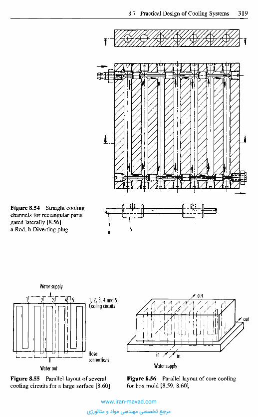
Figure 8.54 Straight coolingchannels for rectangular partsgated laterally [8.56]a Rod, b Diverting plug
Water supply
Figure 8.55 Parallel layout of severalcooling circuits for a large surface [8.60]
Figure 8.56 Parallel layout of core coolingfor box mold [8.59, 8.60]
Water supplyWater out
Hoseconnections
1,2,3,4 and 5Cooling circuits
out
out
inin
www.iran-mavad.com
مرجع تخصصی مهندسی مواد و متالورژی
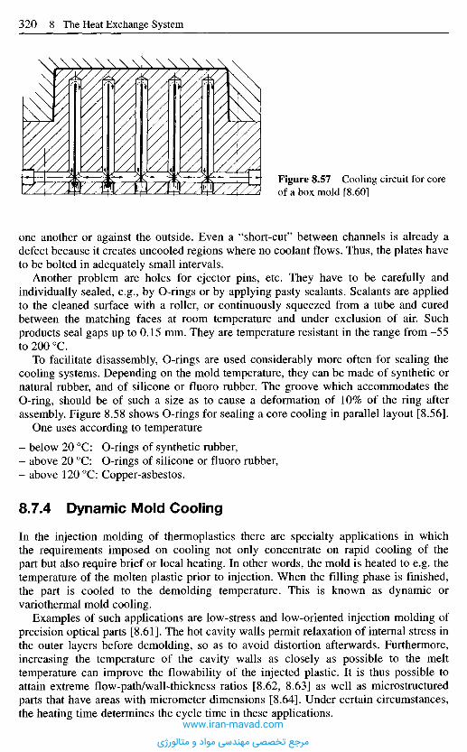
one another or against the outside. Even a "short-cut" between channels is already adefect because it creates uncooled regions where no coolant flows. Thus, the plates haveto be bolted in adequately small intervals.
Another problem are holes for ejector pins, etc. They have to be carefully andindividually sealed, e.g., by O-rings or by applying pasty sealants. Sealants are appliedto the cleaned surface with a roller, or continuously squeezed from a tube and curedbetween the matching faces at room temperature and under exclusion of air. Suchproducts seal gaps up to 0.15 mm. They are temperature resistant in the range from -55to 200 0C.
To facilitate disassembly, O-rings are used considerably more often for sealing thecooling systems. Depending on the mold temperature, they can be made of synthetic ornatural rubber, and of silicone or fluoro rubber. The groove which accommodates theO-ring, should be of such a size as to cause a deformation of 10% of the ring afterassembly. Figure 8.58 shows O-rings for sealing a core cooling in parallel layout [8.56].
One uses according to temperature
- below 20 0C: O-rings of synthetic rubber,- above 20 0C: O-rings of silicone or fluoro rubber,- above 120 0C: Copper-asbestos.
8.7.4 Dynamic Mold Cooling
In the injection molding of thermoplastics there are specialty applications in whichthe requirements imposed on cooling not only concentrate on rapid cooling of thepart but also require brief or local heating. In other words, the mold is heated to e.g. thetemperature of the molten plastic prior to injection. When the filling phase is finished,the part is cooled to the demolding temperature. This is known as dynamic orvariothermal mold cooling.
Examples of such applications are low-stress and low-oriented injection molding ofprecision optical parts [8.61]. The hot cavity walls permit relaxation of internal stress inthe outer layers before demolding, so as to avoid distortion afterwards. Furthermore,increasing the temperature of the cavity walls as closely as possible to the melttemperature can improve the flowability of the injected plastic. It is thus possible toattain extreme flow-path/wall-thickness ratios [8.62, 8.63] as well as microstructuredparts that have areas with micrometer dimensions [8.64]. Under certain circumstances,the heating time determines the cycle time in these applications.
Figure 8.57 Cooling circuit for coreof a box mold [8.60]
www.iran-mavad.com
مرجع تخصصی مهندسی مواد و متالورژی
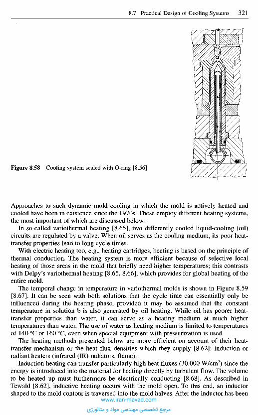
Approaches to such dynamic mold cooling in which the mold is actively heated andcooled have been in existence since the 1970s. These employ different heating systems,the most important of which are discussed below.
In so-called variothermal heating [8.65], two differently cooled liquid-cooling (oil)circuits are regulated by a valve. When oil serves as the cooling medium, its poor heat-transfer properties lead to long cycle times.
With electric heating too, e.g., heating cartridges, heating is based on the principle ofthermal conduction. The heating system is more efficient because of selective localheating of those areas in the mold that briefly need higher temperatures; this contrastswith Delpy's variothermal heating [8.65, 8.66], which provides for global heating of theentire mold.
The temporal change in temperature in variothermal molds is shown in Figure 8.59[8.67]. It can be seen with both solutions that the cycle time can essentially only beinfluenced during the heating phase, provided it may be assumed that the constanttemperature in solution b is also generated by oil heating. While oil has poorer heat-transfer properties than water, it can serve as a heating medium at much highertemperatures than water. The use of water as heating medium is limited to temperaturesof 140 0C or 160 0C, even when special equipment with pressurization is used.
The heating methods presented below are more efficient on account of their heat-transfer mechanism or the heat flux densities which they supply [8.62]: induction orradiant heaters (infrared (IR) radiators, flame).
Induction heating can transfer particularly high heat fluxes (30,000 W/cm2) since theenergy is introduced into the material for heating directly by turbulent flow. The volumeto be heated up must furthermore be electrically conducting [8.68]. As described inTewald [8.62], inductive heating occurs with the mold open. To this end, an inductorshaped to the mold contour is traversed into the mold halves. After the inductor has been
Figure 8.58 Cooling system sealed with O-ring [8.56]
www.iran-mavad.com
مرجع تخصصی مهندسی مواد و متالورژی

removed, the mold closes and the plastic is injected into the cavity, whose surface is hot[8.62, 8.63].
Radiant heating using IR (ceramic or vitreous quartz radiators) or halogen radiatorshave so far predominantly been used as heating systems for thermoforming, but alsohave a high potential for providing additional heating for a dynamic system.
A look at the theoretically transferable heating efficiency (Figure 8.60) reveals thatshorter heating times may be expected with these other mechanisms of heat transfer thanwith thermal conduction.
The advantage, therefore, of induction and radiant heating lies particularly in the factthat the mold surface can be selectively heated up for a brief period. The heat does notpenetrate deep into the mold platens and so the cooling time is not essentially prolonged.
8.7.5 Empirical Compensat ion of Corner Distortion inThermoplastic Parts f rom Heat-Flux Differences
It is known from experience that distortion of box-shaped moldings can be avoided if thetemperature of the core is lower than that of the cavity. This method tries to compensate
Solution a: Pure oil temperature controlSolution b: Oil temperature controlwith additional electric heater
Temp
eratur
e
Temp
eratur
e
Figure 8.59 Temperature changes in variotherm molds as a function of time [8.67]
Temperature control medium 1Heating phase
Temperature control medium 2Cooling phase Heating phase Cooling phase
Time I in out Time
Toemold TDemold
tal
-'Additional heater
TGOQI
IncreaseAdditional heater
Table 8.3 Transferable heating efficiency of different types of heating [8.68]
Type of heating
ConvectionRadiationThermal conductionInduction
Example
Hot air deviceInfrared heaterBurnerInductor
Possible transferable heatingefficiency [W/cm2]
0.581,00030,000
www.iran-mavad.com
مرجع تخصصی مهندسی مواد و متالورژی
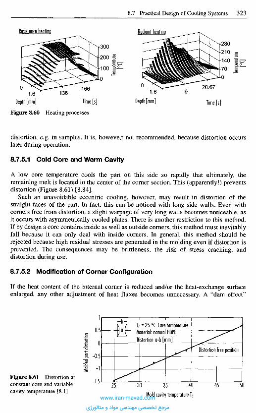
distortion, e.g. in samples. It is, howeve,r not recommended, because distortion occurslater during operation.
8.7.5.1 Cold Core and Warm Cavity
A low core temperature cools the part on this side so rapidly that ultimately, theremaining melt is located in the center of the corner section. This (apparently!) preventsdistortion (Figure 8.61) [8.84].
Such an unavoidable eccentric cooling, however, may result in distortion of thestraight faces of the part. In fact, this can be noticed with long side walls. Even withcorners free from distortion, a slight warpage of very long walls becomes noticeable, asit occurs with asymmetrically cooled plates. There is another restriction to this method.If by design a core contains inside as well as outside corners, this method must inevitablyfall because it can only deal with inside corners. In general, this method should berejected because high residual stresses are generated in the molding even if distortion isprevented. The consequences may be brittleness, the risk of stress cracking, anddistortion during use.
8.7.5.2 Modification of Corner Configuration
If the heat content of the internal corner is reduced and/or the heat-exchange surfaceenlarged, any other adjustment of heat fluxes becomes unnecessary. A "dam effect"
Figure 8.60 Heating processes
Resistance heating Radiant heating
Temp
eratur
e[°C
]
Temp
eratur
e[°C
]
Molde
d pa
rt dis
tortio
n
Time [s]Depth [mm]Time [s]Depth [mm]
Figure 8.61 Distortion atconstant core and variablecavity temperature [8.1] Mold cavity temperature Tf
Distortion free position
Tc = 25 0C Core temperatureMaterial: natural HDPEDistortion a-b [mm]
www.iran-mavad.com
مرجع تخصصی مهندسی مواد و متالورژی
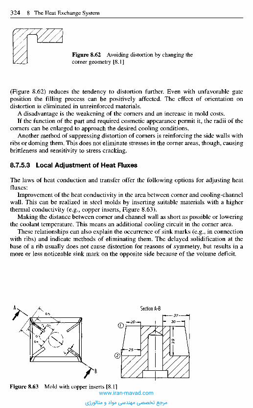
(Figure 8.62) reduces the tendency to distortion further. Even with unfavorable gateposition the filling process can be positively affected. The effect of orientation ondistortion is eliminated in unreinforced materials.
A disadvantage is the weakening of the corners and an increase in mold costs.If the function of the part and required cosmetic appearance permit it, the radii of the
corners can be enlarged to approach the desired cooling conditions.Another method of suppressing distortion of corners is reinforcing the side walls with
ribs or doming them. This does not eliminate stresses in the corner areas, though, causingbrittleness and sensitivity to stress cracking.
8.7.5.3 Local Adjustment of Heat Fluxes
The laws of heat conduction and transfer offer the following options for adjusting heatfluxes:
Improvement of the heat conductivity in the area between corner and cooling-channelwall. This can be realized in steel molds by inserting suitable materials with a higherthermal conductivity (e.g., copper inserts, Figure 8.63).
Making the distance between corner and channel wall as short as possible or loweringthe coolant temperature. This means an additional cooling circuit in the corner area.
These relationships can also explain the occurrence of sink marks (e.g., in connectionwith ribs) and indicate methods of eliminating them. The delayed solidification at thebase of a rib usually does not cause distortion for reasons of symmetry, but results in amore or less noticeable sink mark on the opposite side because of the volume deficit.
Figure 8.62 Avoiding distortion by changing thecorner geometry [8.1]
Figure 8.63 Mold with copper inserts [8.1]
Section A-B
www.iran-mavad.com
مرجع تخصصی مهندسی مواد و متالورژی
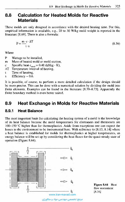
8 . 8 C a l c u l a t i o n f o r H e a t e d M o l d s f o r R e a c t i v e
M a t e r i a l s
These molds are only designed in accordance with the desired heating time. For this,empirical information is available, e.g., 20 to 30 W/kg mold weight is reported in theliterature [8.69]. There is also a formula:
(8.56)
Where
Wattage to be installed,Mass of heated mold or mold section,Specific heat csteel = 0.48 (kJ/kg • K),Temperature interval of heating,Time of heating,Efficiency ~ 0.6.
It is possible, of course, to perform a more detailed calculation if the design shouldbe more precise. This can be done with a numerical solution by dividing the mold intofinite elements. Examples can be found in the literature [8.70-8.73]. Apparently thefinite boundary method is even better suited.
8 . 9 H e a t E x c h a n g e in M o l d s f o r R e a c t i v e M a t e r i a l s
8.9.1 Heat Balance
The most important basis for calculating the heating system of a mold is the knowledgeof its heat balance because the mold temperatures for elastomers and thermosets are100-150 0C higher than for thermoplastics. Aside from exceptions one can expect thelosses to the environment to be instrumental here. With reference to [8.13, 8.14] wherea heat balance is established for molds for thermoplastics at higher temperatures, anenergy balance will be set up by considering the heat fluxes for the quasi-steady state ofoperation (Figure 8.64).
Figure 8.64 Heatflow assessment[8.16]
www.iran-mavad.com
مرجع تخصصی مهندسی مواد و متالورژی
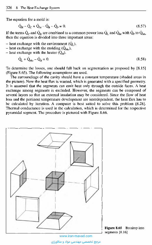
If the terms Qc and QR are combined to a common power loss QL and QM with QP to QMo
then the equation is divided into three important areas:
- heat exchange with the environment (QL),- heat exchange with the molding (QMo),- heat exchange with the heater (QH).
(8.58)
To determine the losses, one should fall back on segmentation as proposed by [8.15](Figure 8.65). The following assumptions are used.
The surroundings of the cavity should have a constant temperature (shaded areas inthe picture). Now the heat flux is wanted, which is generated with a specified geometry.It is assumed that the segments can emit heat only through the outside faces. A heatexchange among segments is excluded. However, the segments can be composed ofseveral layers so that an external insulation may be considered. Since the flow of heatloss and the pertinent temperature development are interdependent, the heat flux has tobe calculated by iteration. A computer is best suited to solve this problem [8.28].Thermal conductance is used in the calculation, which is determined for the respectivepyramidal segment. The procedure is pictured with Figure 8.66.
The equation for a mold is:
(8.57)
Figure 8.65 Breakup intosegments [8.16]
www.iran-mavad.com
مرجع تخصصی مهندسی مواد و متالورژی
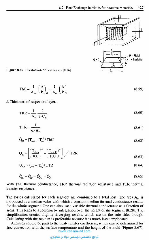
With ThC thermal conductance, TRR thermal radiation resistance and TTR thermaltransfer resistance.
The losses calculated for each segment are combined to a total loss. The area Am isintroduced as a median value with which a constant median thermal conductance resultsfor the whole segment. One can also use a variable thermal conductance as a function ofareas. This leads to a solution by integration over the height of the segment [8.28]. Thesimplification creates slightly diverging results, which are on the safe side, though.Calculating with the median is preferable because it is much less complicated.
Attention should be paid to the heat-transfer coefficient, which can be determined forfree convection with the surface temperature and the height of the mold (Figure 8.67).
Figure 8.66 Evaluation of heat losses [8.16]
Thickness of respective layer.
(8.59)
M = MetalI - Insulation
(8.60)
(8.61)
(8.62)
(8.63)
(8.64)
(8.65)
www.iran-mavad.com
مرجع تخصصی مهندسی مواد و متالورژی
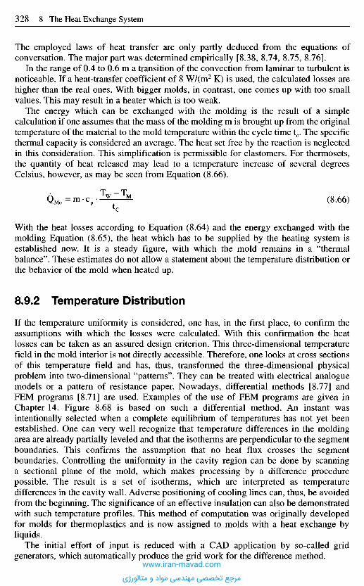
The employed laws of heat transfer are only partly deduced from the equations ofconversation. The major part was determined empirically [8.38, 8.74, 8.75, 8.76].
In the range of 0.4 to 0.6 m a transition of the convection from laminar to turbulent isnoticeable. If a heat-transfer coefficient of 8 W/(m2 K) is used, the calculated losses arehigher than the real ones. With bigger molds, in contrast, one comes up with too smallvalues. This may result in a heater which is too weak.
The energy which can be exchanged with the molding is the result of a simplecalculation if one assumes that the mass of the molding m is brought up from the originaltemperature of the material to the mold temperature within the cycle time tc. The specificthermal capacity is considered an average. The heat set free by the reaction is neglectedin this consideration. This simplification is permissible for elastomers. For thermosets,the quantity of heat released may lead to a temperature increase of several degreesCelsius, however, as may be seen from Equation (8.66).
(8.66)
With the heat losses according to Equation (8.64) and the energy exchanged with themolding Equation (8.65), the heat which has to be supplied by the heating system isestablished now. It is a steady figure, with which the mold remains in a "thermalbalance". These estimates do not allow a statement about the temperature distribution orthe behavior of the mold when heated up.
8.9.2 Temperature Distribution
If the temperature uniformity is considered, one has, in the first place, to confirm theassumptions with which the losses were calculated. With this confirmation the heatlosses can be taken as an assured design criterion. This three-dimensional temperaturefield in the mold interior is not directly accessible. Therefore, one looks at cross sectionsof this temperature field and has, thus, transformed the three-dimensional physicalproblem into two-dimensional "patterns". They can be treated with electrical analoguemodels or a pattern of resistance paper. Nowadays, differential methods [8.77] andFEM programs [8.71] are used. Examples of the use of FEM programs are given inChapter 14. Figure 8.68 is based on such a differential method. An instant wasintentionally selected when a complete equilibrium of temperatures has not yet beenestablished. One can very well recognize that temperature differences in the moldingarea are already partially leveled and that the isotherms are perpendicular to the segmentboundaries. This confirms the assumption that no heat flux crosses the segmentboundaries. Controlling the uniformity in the cavity region can be done by scanninga sectional plane of the mold, which makes processing by a difference procedurepossible. The result is a set of isotherms, which are interpreted as temperaturedifferences in the cavity wall. Adverse positioning of cooling lines can, thus, be avoidedfrom the beginning. The significance of an effective insulation can also be demonstratedwith such temperature profiles. This method of computation was originally developedfor molds for thermoplastics and is now assigned to molds with a heat exchange byliquids.
The initial effort of input is reduced with a CAD application by so-called gridgenerators, which automatically produce the grid work for the difference method.
www.iran-mavad.com
مرجع تخصصی مهندسی مواد و متالورژی
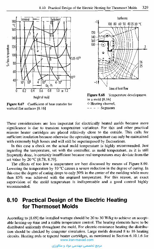
These considerations are less important for electrically heated molds because moresignificance is due to transient temperature variations. For this and other practicalreasons heater cartridges are placed relatively close to the outside. This calls forsufficient insulation because otherwise the operating temperature can only be maintainedwith extremely high losses and will still be superimposed by fluctuations.
In this case a check on the actual mold temperature is highly recommended. Justregarding the temperature, set with the controller, as mold temperature, as it is stillfrequently done, is certainly insufficient because real temperatures may deviate from theset value by 20 0C [8.78, 8.79].
The effects of too low a temperature are best discussed by means of Figure 8.69.Lowering the temperature by 10 0C causes a severe reduction in the degree of curing. Inthis case the degree of curing drops to only 50% in the center of the molding while morethan 85% was achieved with the required temperature. For this reason, an exactsupervision of the mold temperature is indispensable and a good control highlyrecommended.
8 . 1 0 P r a c t i c a l D e s i g n o f t h e E l e c t r i c H e a t i n g
f o r T h e r m o s e t M o l d s
According to [8.69] the installed wattage should be 20 to 30 W/kg to achieve an accept-able heating-up time and a stable temperature control. The heating elements have to bedistributed uniformly throughout the mold. For electric-resistance heating the distribu-tion should be checked by computer simulation. Large molds demand 8 to 16 heatingcircuits. Heating rods or tapered heater cartridges, as mentioned in Section 6.10.1.6 for
Figure 8.67 Coefficient of heat transfer forvertical flat surfaces [8.16]
Figure 8.68 Temperature developmentin a mold [8.16]
Heating channel,Segments
Lines of heat flow
Height of mold
m
Surfa
ce tem
perat
ure
0C
Isotherms0C
Laminar Turbulent
www.iran-mavad.com
مرجع تخصصی مهندسی مواد و متالورژی
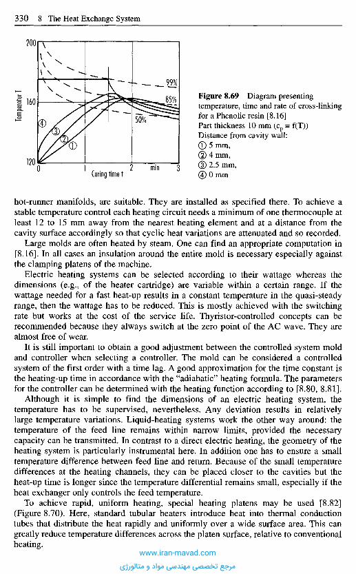
hot-runner manifolds, are suitable. They are installed as specified there. To achieve astable temperature control each heating circuit needs a minimum of one thermocouple atleast 12 to 15 mm away from the nearest heating element and at a distance from thecavity surface accordingly so that cyclic heat variations are attenuated and so recorded.
Large molds are often heated by steam. One can find an appropriate computation in[8.16]. In all cases an insulation around the entire mold is necessary especially againstthe clamping platens of the machine.
Electric heating systems can be selected according to their wattage whereas thedimensions (e.g., of the heater cartridge) are variable within a certain range. If thewattage needed for a fast heat-up results in a constant temperature in the quasi-steadyrange, then the wattage has to be reduced. This is mostly achieved with the switchingrate but works at the cost of the service life. Thyristor-controlled concepts can berecommended because they always switch at the zero point of the AC wave. They arealmost free of wear.
It is still important to obtain a good adjustment between the controlled system moldand controller when selecting a controller. The mold can be considered a controlledsystem of the first order with a time lag. A good approximation for the time constant isthe heating-up time in accordance with the "adiabatic" heating formula. The parametersfor the controller can be determined with the heating function according to [8.80, 8.81].
Although it is simple to find the dimensions of an electric heating system, thetemperature has to be supervised, nevertheless. Any deviation results in relativelylarge temperature variations. Liquid-heating systems work the other way around: thetemperature of the feed line remains within narrow limits, provided the necessarycapacity can be transmitted. In contrast to a direct electric heating, the geometry of theheating system is particularly instrumental here. In addition one has to ensure a smalltemperature difference between feed line and return. Because of the small temperaturedifferences at the heating channels, they can be placed closer to the cavities but theheat-up time is longer since the temperature differential remains small, especially if theheat exchanger only controls the feed temperature.
To achieve rapid, uniform heating, special heating platens may be used [8.82](Figure 8.70). Here, standard tubular heaters introduce heat into thermal conductiontubes that distribute the heat rapidly and uniformly over a wide surface area. This cangreatly reduce temperature differences across the platen surface, relative to conventionalheating.
Figure 8.69 Diagram presentingtemperature, time and rate of cross-linkingfor a Phenolic resin [8.16]Part thickness 10 mm (cp = f(T))Distance from cavity wall:(T) 5 mm,(2) 4 mm,(3) 2.5 mm,(4) 0 mm
Temp
eratur
T
Curing time tmin
www.iran-mavad.com
مرجع تخصصی مهندسی مواد و متالورژی
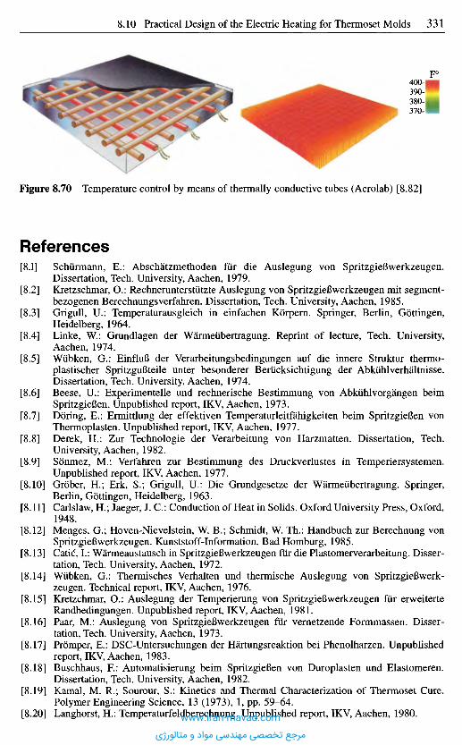
Figure 8.70 Temperature control by means of thermally conductive tubes (Acrolab) [8.82]
R e f e r e n c e s
[8.1] Schurmann, E.: Abschatzmethoden fur die Auslegung von SpritzgieBwerkzeugen.Dissertation, Tech. University, Aachen, 1979.
[8.2] Kretzschmar, 0.: Rechnerunterstiitzte Auslegung von SpritzgieBwerkzeugen mit segment-bezogenen Berechnungsverfahren. Dissertation, Tech. University, Aachen, 1985.
[8.3] Grigull, U.: Temperaturausgleich in einfachen Korpern. Springer, Berlin, Gottingen,Heidelberg, 1964.
[8.4] Linke, W.: Grundlagen der Warmeubertragung. Reprint of lecture, Tech. University,Aachen, 1974.
[8.5] Wubken, G.: EinfluB der Verarbeitungsbedingungen auf die innere Struktur thermo-plastischer SpritzguBteile unter besonderer Beriicksichtigung der Abkiihlverhaltnisse.Dissertation, Tech. University, Aachen, 1974.
[8.6] Beese, U.: Experimentelle und rechnerische Bestimmung von Abkuhlvorgangen beimSpritzgieBen. Unpublished report, IKV, Aachen, 1973.
[8.7] Doring, E.: Ermittlung der effektiven Temperaturleitfahigkeiten beim SpritzgieBen vonThermoplasten. Unpublished report, IKV, Aachen, 1977.
[8.8] Derek, H.: Zur Technologie der Verarbeitung von Harzmatten. Dissertation, Tech.University, Aachen, 1982.
[8.9] Sonmez, M.: Verfahren zur Bestimmung des Druckverlustes in Temperiersystemen.Unpublished report, IKV, Aachen, 1977.
[8.10] Grober, H.; Erk, S.; Grigull, U.: Die Grundgesetze der Warmeubertragung. Springer,Berlin, Gottingen, Heidelberg, 1963.
[8.11] Carlslaw, H.; Jaeger, J. C : Conduction of Heat in Solids. Oxford University Press, Oxford,1948.
[8.12] Menges, G.; Hoven-Nievelstein, W. B.; Schmidt, W. Th.: Handbuch zur Berechnung vonSpritzgieBwerkzeugen. Kunststoff-Information, Bad Homburg, 1985.
[8.13] Catic, I.: Warmeaustausch in SpritzgieBwerkzeugen fur die Plastomerverarbeitung. Disser-tation, Tech. University, Aachen, 1972.
[8.14] Wubken, G.: Thermisches Verhalten und thermische Auslegung von SpritzgieBwerk-zeugen. Technical report, IKV, Aachen, 1976.
[8.15] Kretzchmar, 0.: Auslegung der Temperierung von SpritzgieBwerkzeugen fur erweiterteRandbedingungen. Unpublished report, IKV, Aachen, 1981.
[8.16] Paar, M.: Auslegung von SpritzgieBwerkzeugen fur vernetzende Formmassen. Disser-tation, Tech. University, Aachen, 1973.
[8.17] Promper, E.: DSC-Untersuchungen der Hartungsreaktion bei Phenolharzen. Unpublishedreport, IKV, Aachen, 1983.
[8.18] Buschhaus, R: Automatisierung beim SpritzgieBen von Duroplasten und Elastomeren.Dissertation, Tech. University, Aachen, 1982.
[8.19] Kamal, M. R.; Sourour, S.: Kinetics and Thermal Characterization of Thermoset Cure.Polymer Engineering Science, 13 (1973), 1, pp. 59-64.
[8.20] Langhorst, H.: Temperaturfeldberechnung. Unpublished report, IKV, Aachen, 1980.www.iran-mavad.com
مرجع تخصصی مهندسی مواد و متالورژی

[8.21] Murray, P.; White, J.: Kinetics of the Thermal Decomposition of Clay. Trans. Brit. Ceram.Soc, 48, pp. 187-206.
[8.22] Nicolay, A.: Untersuchung zur Blasenbildung in Kunststoffen unter besonderer Beriick-sichtigung der RiBbildung, Dissertation, Tech. University, Aachen, 1976.
[8.23] Heide, K.: Dynamische thermische Analysemethoden. Deutscher Verlag fur die Grund-stoffindustrie, Leipzig, 1979.
[8.24] Differential Scanning Calorimetry (DSC). Publication, DuPont, Bad Homburg, 1988.[8.25] Borchert and Daniels Kinetics. Publication, DuPont, Bad Homburg, 1982.[8.26] Standard Test Method for Arrhenius Kinetic Constants for Thermally Unstable Materials.
ASTM E 698-79.[8.27] Piloyan, Y. 0.; Ryabchikow, J. B.; Novikova, O. S.: Determination of Activation Energies
of Chemical Reactions bei Differential Thermal Analysis. Nature, 212 (1966), p. 1229.[8.28] Feichtenbeiner, H.: Berechnungsgrundlagen zur thermischen Auslegung von Duroplast-
und Elastomerwerkzeugen. Unpublished report, IKV, Aachen, 1982.[8.29] Kamal, M. R.; Ryan, M. E.: The Behaviour of Thermosetting Compounds in Injection
Moulding Cavities. Polymer Engineering and Science, 20 (1980), 13, pp. 859-867.[8.30] Feichtenbeiner, H.: Auslegung eines SpritzgieBwerkzeuges mit 4fach Kaltkanalverteiler
fur Elastomerforrnteile. Unpublished report, IKV, Aachen, 1983.[8.31] Lee, J.: Curing of Compression Moulded Sheet Moulding Compound. Polymer Engineer-
ing and Science, 1981, 8, pp. 483-^92.[8.32] Schneider, Ch.: Das Verarbeitungsverhalten von Elastomeren im SpritzgieBprozeB. Disser-
tation, Tech. University, Aachen, 1986.[8.33] Baldt, V; Kramer, H.; Koopmann, R.: Temperaturleitzahl von Kautschukmischungen -
Bedeutung, MeBmethoden und Ergebnisse. Bayer Information for the Rubber Industry, 50(1978), pp. 50-57.
[8.34] Kenig, S.; Kamal, M. R.: Cooling Molded Parts - a rigorous analysis. SPE-Journal, 26(1970), 7, pp. 50-57.
[8.35] Sors, L.: Kiihlen von SpritzgieBwerkzeugen. Kunststoffe, 64 (1974), 2, pp. 117-122.[8.36] Bird, R.; Stewart, W. E.: Transport Phenomena. John Wiley and Sons, New York, 1962.[8.37] Eck, B.: Stromungslehre. In: Dubbels Taschenbuch fiir Maschinenbau. Vol. 1. Springer,
Berlin, Heidelberg, New York, 1970.[8.38] Renz, U.: Grundlagen der Warmeubertragung. Lecture, Tech. University, Aachen, 1984.[8.39] Hausen, H.: Neue Gleichungen fiir die Warmeubertragung bei freier und erzwungener
Stromung. AlIg. Warmetechnik, 9 (1959).[8.40] Weinand, D.: Berechnung der Temperaturverteilung in SpritzgieBwerkzeugen. Unpub-
lished report, IKV, Aachen, 1982.[8.41] Kretzschmar, O.: Thermische Auslegung von SpritzgieBwerkzeugen. VDI-IKV Seminar
"Computer Assisted Design of Injection Molds", Minister, 1984.[8.42] Ott, S.: Aufbau von Programmen zur segmentierten Temperierungsauslegung. Unpub-
lished report, IKV, Aachen, 1985.[8.43] Thermische Werkzeugauslegung. Anwendungstechnische Information ATI, 892, Bayer
AG.[8.44] Wiibken, G.: Thermisches Verhalten und thermische Auslegung von SpritzgieBwerk-
zeugen. Dissertation, Tech. University, Aachen, 1976.[8.45] Hengesbach, H. A.: Verbesserung der ProzeBfiihrung beim SpritzgieBen durch ProzeB-
uberwachung. Dissertation, Tech. University, Aachen, 1976.[8.46] Mohren, P.; Schiirmann, E.: Die thermische und mechanische Auslegung von SpritzgieB-
werkzeugen. Seminar material, IKV, Aachen, 1976.[8.47] Temperiersysteme als Teil der Werkzeugkonstruktion. Publication, Arburg heute, 10 (1979),
pp. 28-34.[8.48] Rotary-Kupplung. Prospectus, Gebr. Heyne GmbH, Offenbach/M.[8.49] Das Warmerohr. Prospectus, Mechanique de File de France.[8.50] Temesvary, L.: Mold Cooling: Key to Fast Molding. Modern Plastics, 44 (1966), 12,
pp. 125-128 and pp. 196-198.[8.51] Stockert, K.: Formenbau fiir die Kunststoffverarbeitung. Carl Hanser Verlag, Munich,
1969.[8.52] SpritzgieBen von Thermoplasten. Publication, Farbwerke Hoechst AG, Frankfurt, 1971.[8.53] Publication. AGA Gas GmbH, Hamburg, 1996.
www.iran-mavad.com
مرجع تخصصی مهندسی مواد و متالورژی
[8.54] Westhoff, R.: Innovative Techniken der Werkzeugtemperierung - Hilfe bei der Senkungvon Stiickkosten. In: Kostenreduktion durch innovatives SpritzgieBen. VDI-Verlag,Diisseldorf, 1997.
[8.55] System CONTURA - Publication. Innova Engineering GmbH, Menden, 1997.[8.56] Morwald, K.: Einblick in die Konstruktion von SpritzgieBwerkzeugen. Brunke Garrels,
Hamburg, 1965.[8.57] Joisten, S.: Ein Formwerkzeug fur Zahnrader. Die Maschine, 10 (1969).[8.58] SpritzguB Hostalen PP. Handbook, Farbwerke Hoechst AG, Frankfurt/M., 1965.[8.59] Temperieren von SpritzgieBwerkzeugen. Information, Netstal-Maschinen AG, Nafels/
Switzerland, No. 12, June 1979, pp. 1-11.[8.60] Friel, P.; Hartmann, W.: Beitrag zum Temperieren von Spritzwerkzeugen. Plastverarbeiter,
26 (1975), 9, pp. 491^98.[8.61] Michaeli, W.; Kudlik, N.; Vaculik, R.: Qualitatssicherung bei optischen Bauteilen.
Kunststoffe, 86 (1996), 4, pp. 478^80.[8.62] Tewald, A.; Jung, A.: Dynamische Werkzeugtemperierung beim SpritzgieBen. F & M, 102
(1994), 9, pp. 395^00.[8.63] Tewald, A.; Thissen, U.: AnguBloses SpritzgieBen dunnwandiger Mikrohulsen. Reprint of
lecture. Congres Europeen Chronometrie Biel/Bienne, October 1996, pp. 109-114.[8.64] Michaeli, W.; Rogalla, A.: Kunststoffe fur die Mikrosystemtechnik. Ingenieur-Werkstoffe,
6(1997), 1, pp. 50-53.[8.65] Delpy, U.: EinfluB variabler Formtemperaturen auf die Eigenschaften von Spritzlingen aus
amorphen Thermoplasten. Dissertation, Univ. Stuttgart, 1971.[8.66] Delpy, U.; Wintergerst, S.: SpritzgieBen mit veranderlicher Werkzeugtemperatur. Lecture,
2nd Plastics Conference at Stuttgart, September 30, 1971.[8.67] Rogalla, A.: Analyse des SpritzgieBens mikrostrukturierter Bauteile aus Thermoplasten.
Dissertation, RWTH, Aachen, 1998.[8.68] Benkowsky, G.: Induktionserwarmung. Verlag Technik, Berlin, 1990.[8.69] Keller, W: Spezielle Anforderungen an Werkzeuge fur die Duroplastverarbeitung. Kunst-
stoffe, 78 (1988), 10, pp. 978-983.[8.70] Weyer, G.: Automatische Herstellung von Elastomerartikeln im SpritzgieBverfahren.
Dissertation, Tech. University, Aachen, 1987.[8.71] Ehrig, E.: Moglichkeiten der thermischen Auslegung von Duroplastwerkzeugen am
Beispiel eines Kaltkanalverteilers. 8th International Symposium on Thermoset, Wiirzburg,1996.
[8.72] MaaB, R.: Die Anwendung der statistischen Versuchsmethodik zur Auslegung von Spritz-gieBwerkzeugen mit Kaltkanalsystem. Dissertation, RWTH, Aachen, 1995.
[8.73] Diemert, J.: Einsatz physikalisch gestutzter ProzeBmodelle zur Verbesserung der Qualitats-iiberwachung beim ElastomerspritzgieBen. Unpublished report, IKV, Aachen.
[8.74] Grober, H.; Erk, S.; Grigull, U.: Die Grundgesetze der Warmeubertragung. 3rd Ed., Sauer-lander, Aaran, Frankfurt/M., 1980.
[8.75] Holman, J. P.: Heat Transfer. McGraw Hill Koga Kusha, Ltd. 4th Ed., 1976.[8.76] VDI-Warmeatlas. VDI, Fachgruppe Verfahrenstechnik (ed.), VDI-Verlag, Diisseldorf,
1957.[8.77] Lichius, U.: Rechnerunterstutzte Konstruktion von Werkzeugen zum SpritzgieBen von
thermoplastischen Kunststoffen. Dissertation, Tech. University, Aachen, 1983.[8.78] Rauscher, W.: Praktische Uberpriifung von Rechenmodellen zur thermischen Auslegung
von Elastomerwerkzeugen. Unpublished report, IKV, Aachen, 1984.[8.79] Rellmann, J.: Inbetriebnahme eines DuroplastspritzgieBwerkzeugs. Unpublished report,
IKV, Aachen, 1984.[8.80] Recker, H.: Regler und Regelstrecken. In: Messen und Regeln beim Extrudieren. VDI-
Gesellschaft Kunststofftechnik (ed.), VDI-Verlag, Diisseldorf, 1982.[8.81] Wiegand, G.: Messen, Steuern, Regeln in der Kunststoffverarbeitung. Lecture material,
Tech. University, Aachen, 1970.[8.82] Publication. ACROLAB Engineering, Windsor, Ontario, Kanada, 1996.[8.83] For QMC New Cooling Software. Plastics Technology, 30 (1984), 9, pp. 19-20.[8.84] Simsir, E.: Vermeidung von Formteilverzug. Unpublished report, IKV, Aachen, 1977.[8.85] Leibfried, D.: Untersuchungen zum Werkzeugfiillvorgang beim SpritzgieBen von
thermoplastischen Kunststoffen. Dissertation, Tech. University, Aachen, 1970.www.iran-mavad.com
مرجع تخصصی مهندسی مواد و متالورژی
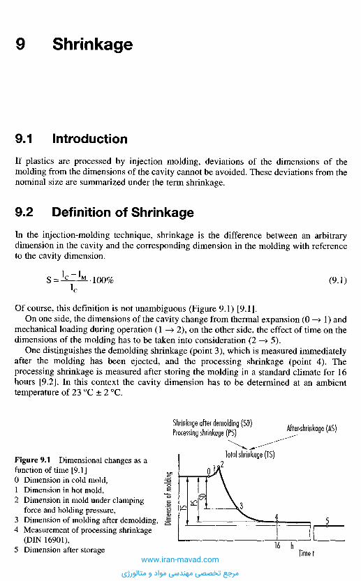
9 .1 I n t r o d u c t i o n
If plastics are processed by injection molding, deviations of the dimensions of themolding from the dimensions of the cavity cannot be avoided. These deviations from thenominal size are summarized under the term shrinkage.
9 . 2 D e f i n i t i o n o f S h r i n k a g e
In the injection-molding technique, shrinkage is the difference between an arbitrarydimension in the cavity and the corresponding dimension in the molding with referenceto the cavity dimension.
S = 1 C ~ 1 M 100% (9.1)c
Of course, this definition is not unambiguous (Figure 9.1) [9.1].On one side, the dimensions of the cavity change from thermal expansion (0 —> 1) and
mechanical loading during operation (1 —> 2), on the other side, the effect of time on thedimensions of the molding has to be taken into consideration (2 -^ 5).
One distinguishes the demolding shrinkage (point 3), which is measured immediatelyafter the molding has been ejected, and the processing shrinkage (point 4). Theprocessing shrinkage is measured after storing the molding in a standard climate for 16hours [9.2]. In this context the cavity dimension has to be determined at an ambienttemperature of 23 0C ± 2 0C.
9 S h r i n k a g e
Dimen
sion
of mo
lding
Figure 9.1 Dimensional changes as afunction of time [9.1]0 Dimension in cold mold,1 Dimension in hot mold,2 Dimension in mold under clamping
force and holding pressure,3 Dimension of molding after demolding,4 Measurement of processing shrinkage
(DIN 16901),5 Dimension after storage
After-shrinkage (AS)Shrinkage after demolding (SD)Processing shrinkage (PS)
Total shrinkage (TS)
Timetwww.iran-mavad.com
مرجع تخصصی مهندسی مواد و متالورژی

After extended storage another dimensional change may occur from the effect oftemperature changes and especially from post-conditioning. It is called post-shrinkage(4 —> 5). This change is caused by relaxation of residual stresses, re-orientation andpost-crystallization in crystalline materials. Except in crystalline materials, it isnegligibly small, though. The sum of processing shrinkage and post-shrinkage is calledtotal shrinkage. If additional dimensional deviations from moisture absorption orhigher temperatures of use have to be taken into account at the time of acceptance,post-treatment and conditions of measurement have to be negotiated between molderand customer. In addition, one can distinguish shrinkage in dependence on the directionof flow (Figure 9.2). Radial processing shrinkage is shrinkage in the direction of flow,tangential shrinkage is that perpendicular to the direction of flow.
The difference in processing shrinkage is the difference between radial and tangentialshrinkage and is a measurement of the anisotropy of the shrinkage. The shrinkage inthickness is measured as section thickness, but it is usually not of interest in practice. Formeasuring, any kind of mechanical or optical instrument can be used, but a possible errorfrom the measuring force should be taken into account for soft materials.
If the dimensions in Equation (9.1) are replaced by the volumes of cavity andmolding, one talks about volume shrinkage [9.3].
Figure 9.2 Frozen model [9.7]
Contour shrunkMold contour
Plastic core
Frozen frameBoundlength
Figure 9.3 Magnitude of shrinkagedepending on direction of flowSR Radial shrinkage,ST Tangential shrinkage,S Shrinkage difference
(9-2)
V = Specific volume of the material (Figure 9.7)
Longitudinal and volume shrinkage are related to one another but because of anisotropy(dependency of shrinkage on direction), linear shrinkage cannot be calculated fromvolume shrinkage. Another problem is the impossibility to measure volume shrinkage.
www.iran-mavad.com
مرجع تخصصی مهندسی مواد و متالورژی
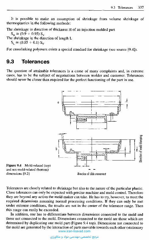
Tolerances are closely related to shrinkage but also to the nature of the particular plastic.Close tolerances can only be expected with precise machine and mold control. Thereforethey are beyond any action the mold maker can take. He has to try, however, to meet therequired dimensions assuming normal processing conditions. If they can only be metunder extreme conditions, the results are not in the center of the tolerance range. Thenthis range can easily be exceeded.
In addition, one has to differentiate between dimensions connected to the mold andthose not connected to the mold. Dimensions connected to the mold are those which aredetermined by duplicating one mold part (Figure 9.4 top). Dimensions not connected tothe mold are generated by the interaction of parts movable towards each other (stationary
Figure 9.4 Mold-related (top)and not-mold-related (bottom)dimensions [9.2] Direction of slide movement
Direc
tion o
f mold
clam
ping
It is possible to make an assumption of shrinkage from volume shrinkage ofthermoplastics in the following methode:
The shrinkage in direction of thickness H of an injection molded partSH = (0.9 - 0.95) Sv
The shrinkage in the direction of length LSL = (0.05 - 0 . 1 ) S v
For crosslinking polymers exists a special standard for shrinkage (see source [9.4]).
9 . 3 T o l e r a n c e s
The question of attainable tolerances is a cause of many complaints and, in extremecases, has to be the subject of negotiations between molder and customer. Tolerancesshould never be closer than required for the perfect functioning of the part in use.
www.iran-mavad.com
مرجع تخصصی مهندسی مواد و متالورژی
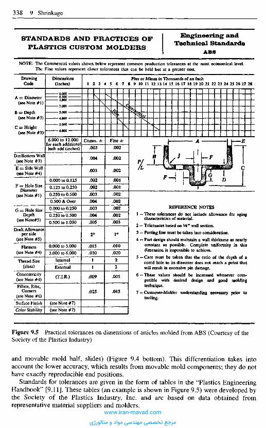
Figure 9.5 Practical tolerances on dimensions of articles molded from ABS (Courtesy of theSociety of the Plastics Industry)
and movable mold half, slides) (Figure 9.4 bottom). This differentiation takes intoaccount the lower accuracy, which results from movable mold components; they do nothave exactly reproducible end positions.
Standards for tolerances are given in the form of tables in the "Plastics EngineeringHandbook" [9.11]. These tables (an example is shown in Figure 9.5) were developed bythe Society of the Plastics Industry, Inc. and are based on data obtained fromrepresentative material suppliers and molders.
STANDARDS AND PRACTICES OPPLASTICS CUSTOM MOLDERS
Engineering andTechnical Standards
ABS
NOTE: The Commercial values shown below represent common production tolerances at the most economical level.The Fine values represent closer tolerances that can be held but at a greater cost.
Plus or Minus in Thousands of an InchDimensions(Inches)
DrawingCode
A = Diameter(see Note #1)
B = Depth(see Note #3)
C = Height(sec Note #3)
D=BottomWall(see Note #3)
E = Side Wall(see Note #4)
F = Hole SizeDiameter
(see Note #1)
G = Hole SizeDepth
(seeNote#5)
Draft Allowanceper side
(see Note #5)
Flatness(see Note #4)
Thread Size(class)
Concentricity(sec Note #4)
"Fillets, Ribs,Corners
(see Note #6)Surface FinishColor Stability
6.000 to 12.000for each additionalinch add (inches)
0.000 to 0.125
0.125 to 0.250
0.250 to 0.500
0.500 & Over
0.000 to 0.250
0.250 to 0.500
0.500 to 1.000
0.000 to 3.000
3.000 to 6.000
Internal
External
(T.I.R.)
(see Note #7)(see Note #7)
Comm. ±
.003
.004
.003
.002
.002
.003
.004
.003
.004
.005
2°
.015
.030
1
1
.009
.025
Finc±
.002
.002
.002
.001
.001
.002
.002
.002
.002
.003
1°
.010
.020
2
2
.005
.015
REFERENCE NOTES1 — These tolerances do not include allowance for aging
characteristics of material.
2 - Tolerances based on W wall section.
3 — Parting line must be taken into consideration.4 — Part design should maintain a wall thickness as nearly
constant as possible. Complete uniformity in thisdimension is impossible to achieve.
5 — Care must be taken that the ratio of the depth of acored hole to its diameter docs not reach a point thatwill result in excessive pin damage.
6 —These values should be increased whenever com-patible with desired design and good moldingtechnique.
7 — Customer-Molder understanding necessary prior totooling.
www.iran-mavad.com
مرجع تخصصی مهندسی مواد و متالورژی

1 Take next higher tolerance group for unfilled, crystalline thermoplastics and wall thicknesses more than 4 mm.
Pertinent information concerning tolerances may also be received from the BritishStandard BS 4042. The following data are provided with reference to the GermanStandard DIN 16 901.
Depending on the molding material one can determine several tolerance groups(Table 9.1). Within each group a distinction is made between two grades of accuracy forentered allowances above and below nominal sizes. For each tolerance group allowancesdepending on nominal sizes can be taken from a second table (Table 9.2). In this table a
Table 9.1 Coordination of tolerance groups with molding materials [9.2]
Moldings made of:
Acetal (polyoxyrnethylene)1 (unfilled), part length: < 150 mm
Acetal (polyoxymethylene)1 (unfilled), part length: >150 mm
Acetal (polyoxymethylene)1 (filled)
Acrylic
Diallyl phthalate compounds (with inorganic filler)
Polyethersulfone (unfilled)
Polyethylene1 (unfilled)
Polyethylene terephthalate (amorphous)
Polyethylene terephthalate (crystalline)
Polyethylene terephthalate (filled)
Polyphenylene oxide
Polyphenylene oxide-styrene mixture (filled, unfilled)
Polyphenylene sulfide (filled)
Polypropylene1 (unfilled)
Polypropylene1 (filled with glass ribers or talc)
Polypropylene impact copolymer (unfilled)
Polystyrene
Polysulfone (filled, unfilled)
Polyvinyl chloride (without plasticizer)
Poly vinyl chloride (with plasticizer)
Styrene-acrylonitrile (filled, unfilled)
Styrene-butadiene copolymers
Fluorinated ethylene propylene
Thermoplastic polyurethanes (hardness 70-90 Shore A)
Thermoplastic polyurethanes (hardness > 50 Shore D)
Tolerance groups
Forcommontolerances
140
150
130
130
130
130
150
130
140
130
130
130
130
150
140
140
130
130
130
For dimensionswith allowancesentered in thedrawing
Grade 1
130
140
120
120
120
120
140
120
130
120
120
120
120
140
130
130
120
120
120
Grade 2
120
130
110
110
110
110
130
110
120
110
110
110
110
130
120
120
110
110
110
No information at present
130
130
150
150
140
120
120
140
140
130
110
110
130
130
120
www.iran-mavad.com
مرجع تخصصی مهندسی مواد و متالورژی
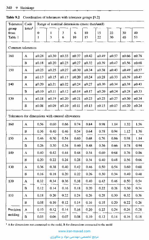
Table 9.2 Coordination of tolerances with tolerance groups [9.2]
TolerancegroupfromTable 1
Codeletter1
Range of nominal dimensions (more than/until)
01
13
36
610
1015
1522
2230
3040
4053
Common tolerances
160
150
140
130
A
B
A
B
A
B
A
B
±0.28
±0.18
±0.23
±0.13
±0.20
±0.10
±0.18
±0.08
±0.30
±0.20
±0.25
±0.15
±0.21
±0.11
±0.19
±0.09
±0.33
±0.23
±0.27
±0.17
±0.22
±0.12
±0.20
±0.10
±0.37
±0.27
±0.30
±0.20
±0.24
±0.14
±0.21
±0.11
±0.42
±0.32
±0.34
±0.24
±0.27
±0.17
±0.23
±0.13
±0.49
±0.39
±0.38
±0.28
±0.30
±0.20
±0.25
±0.15
±0.57
±0.47
±0.43
±0.33
±0.34
±0.24
±0.27
±0.17
±0.66
±0.56
±0.49
±0.39
±0.38
±0.28
±0.30
±0.20
±0.78
±0.68
±0.57
±0.47
±0.43
±0.33
±0.34
±0.24
Tolerances for dimensions with entered allowances
160
150
140
130
120
110
Precision
molding
A
B
A
B
A
B
A
B
A
B
A
B
A
B
0.56
0.36
0.46
0.26
0.40
0.20
0.36
0.16
0.32
0.12
0.18
0.08
0.10
0.05
0.60
0.40
0.50
0.30
0.42
0.22
0.38
0.18
0.34
0.14
0.20
0.10
0.12
0.06
0.66
0.46
0.54
0.34
0.44
0.24
0.40
0.20
0.36
•0.16
0.22
0.12
0.14
0.07
0.74
0.54
0.60
0.40
0.48
0.28
0.42
0.22
0.38
0.18
0.24
0.14
0.16
0.08
0.84
0.64
0.68
0.48
0.54
0.34
0.46
0.26
0.40
0.20
0.26
0.16
0.20
0.10
0.98
0.78
0.76
0.56
0.60
0.40
0.50
0.30
0.42
0.22
0.28
0.18
0.22
0.12
1.14
0.94
0.86
0.66
0.68
0.48
0.54
0.34
0.46
0.26
0.30
0.20
0.24
0.14
1.32
1.12
0.98
0.78
0.76
0.56
0.60
0.40
0.50
0.30
0.32
0.22
0.26
0.16
1.56
1.36
1.14
0.94
0.86
0.66
0.68
0.48
0.54
0.34
0.36
0.26
0.28
0.18
1 A for dimensions not connected to the mold, B for dimensions connected to the mold
www.iran-mavad.com
مرجع تخصصی مهندسی مواد و متالورژی
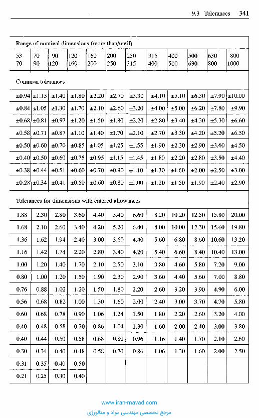
Range of nominal dimensions (more than/until)
5370
7090
90120
120160
160200
200250
250315
315400
400500
500630
630800
8001000
Common tolerances
±0.94
±0.84
±0.68
±0.58
±0.50
±0.40
±0.38
±0.28
±1.15
±1.05
±0.81
±0.71
±0.60
±0.50
±0.44
±0.34
±1.40
±1.30
±0.97
±0.87
±0.70
±0.60
±0.51
±0.41
±1.80
±1.70
±1.20
±1.10
±0.85
±0.75
±0.60
±0.50
±2.20
±2.10
±1.50
±1.40
±1.05
±0.95
±0.70
±0.60
±2.70
±2.60
±1.80
±1.70
±1.25
±1.15
±0.90
±0.80
±3.30
±3.20
±2.20
±2.10
±1.55
±1.45
±1.10
±1.00
±4.10
±4.00
±2.80
±2.70
±1.90
±1.80
±1.30
±1.20
±5.10
±5.00
±3.40
±3.30
±2.30
±2.20
±1.60
±1.50
±6.30
±6.20
±4.30
±4.20
±2.90
±2.80
±2.00
±1.90
±7.90
±7.80
±5.30
±5.20
±3.60
±3.50
±2.50
±2.40
±10.00
±9.90
±6.60
±6.50
±4.50
±4.40
±3.00
±2.90
Tolerances for dimensions with entered allowances
1.88
1.68
1.36
1.16
1.00
0.80
0.76
0.56
0.60
0.40
0.40
0.30
0.31
0.21
2.30
2.10
1.62
1.42
1.20
1.00
0.88
0.68
0.68
0.48
0.44
0.34
0.35
0.25
2.80
2.60
1.94
1.74
1.40
1.20
1.02
0.82
0.78
0.58
0.50
0.40
0.40
0.30
3.60
3.40
2.40
2.20
1.70
1.50
1.20
1.00
0.90
0.70
0.58
0.48
0.50
0.40
4.40
4.20
3.00
2.80
2.10
1.90
1.50
1.30
1.06
0.86
0.68
0.58
5.40
5.20
3.60
3.40
2.50
2.30
1.80
1.60
1.24
1.04
0.80
0.70
6.60
6.40
4.40
4.20
3.10
2.90
2.20
2.00
1.50
1.30
0.96
0.86
8.20
8.00
5.60
5.40
3.80
3.60
2.60
2.40
1.80
1.60
1.16
1.06
10.20
10.00
6.80
6.60
4.60
4.40
3.20
3.00
2.20
2.00
1.40
1.30
12.50
12.30
8.60
8.40
5.80
5.60
3.90
3.70
2.60
2.40
1.70
1.60
15.80
15.60
10.60
10.40
7.20
7.00
4.90
4.70
3.20
3.00
2.10
2.00
20.00
19.80
13.20
13.00
9.00
8.80
6.00
5.80
4.00
3.80
2.60
2.50
www.iran-mavad.com
مرجع تخصصی مهندسی مواد و متالورژی
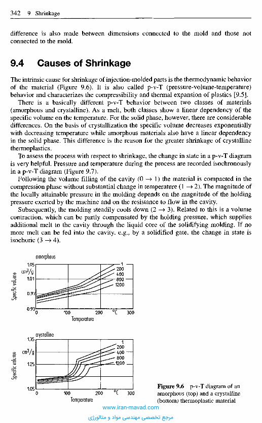
difference is also made between dimensions connected to the mold and those notconnected to the mold.
9 . 4 C a u s e s o f S h r i n k a g e
The intrinsic cause for shrinkage of injection-molded parts is the thermodynamic behaviorof the material (Figure 9.6). It is also called p-v-T (pressure-volume-temperature)behavior and characterizes the compressibility and thermal expansion of plastics [9.5].
There is a basically different p-v-T behavior between two classes of materials(amorphous and crystalline). As a melt, both classes show a linear dependency of thespecific volume on the temperature. For the solid phase, however, there are considerabledifferences. On the basis of crystallization the specific volume decreases exponentiallywith decreasing temperature while amorphous materials also have a linear dependencyin the solid phase. This difference is the reason for the greater shrinkage of crystallinethermoplastics.
To assess the process with respect to shrinkage, the change in state in a p-v-T diagramis very helpful. Pressure and temperature during the process are recorded isochronouslyin a p-v-T diagram (Figure 9.7).
Following the volume filling of the cavity (0 —» 1) the material is compacted in thecompression phase without substantial change in temperature (1 —» 2). The magnitude ofthe locally attainable pressure in the molding depends on the magnitude of the holdingpressure exerted by the machine and on the resistance to flow in the cavity.
Subsequently, the molding steadily cools down (2 —» 3). Related to this is a volumecontraction, which can be partly compensated by the holding pressure, which suppliesadditional melt to the cavity through the liquid core of the solidifying molding. If nomore melt can be fed into the cavity, e.g., by a solidified gate, the change in state isisochoric (3 —» 4).
Spec
ific vo
lume
Spec
ific vo
lume
amorphous
crystalline
cm3/g
Temperature
0C
cmfyg
Temperature
0CFigure 9.6 p-v-T diagram of anamorphous (top) and a crystalline(bottom) thermoplastic material
www.iran-mavad.com
مرجع تخصصی مهندسی مواد و متالورژی

The point where the 100-kPa line is met (point 4) establishes the local volume shrinkage.A higher volume shrinkage occurs if this point is in the range of larger volumes. Sincethe volume shrinkage is equivalent to the shrinkage potential, a larger volume shrinkagealso results in a higher longitudinal shrinkage.
After the 100-kPa line has been reached, any further change of state is isobaric. At thetime the molding is ejected (point 5) and constraints from the surrounding cavity cease.
9 . 5 C a u s e s o f A n i s o t r o p i c S h r i n k a g e
Dimensional changes of a molding in the mold are restricted or prevented by a force-locking clamping of the mold halves [9.6] and shrinkage is non-uniform (anisotropic). Adistinction must be drawn between internal and external constraints of contraction.
External restriction of shrinkage is a mechanical restriction against a change of shapeby the surrounding mold. The restriction of shrinkage and the related stress relaxationresult in a lower level of shrinkage. The shrinkage of a restricted part is less than thatof a restricted one and there is, moreover, less dependence on the process parameters(Figure 9.8).
The mechanical restriction, of course, is effective only as long as the molding is stillin the mold. After ejection, restricted dimensions can also shrink freely. Therefore thetemperature of demolding is a characteristic for the change in mechanical boundaryconditions and for the shrinkage and distortion behavior.
Internal restriction of shrinkage is due to both cooling-related internal stresses and toorientation.
Molecule orientations affect shrinkage in two ways. On the one hand, the coefficientsof linear expansion dependent on orientation cause a difference in shrinkage. On theother, re-orientation (contraction) in the direction of orientation contributes to anincrease in shrinkage. The molecular orientation is determined by the processparameters, and primarily by the type and location of gating, but exerts much less of aninfluence than does, e.g., fiber orientation in fiber-filled molding compounds.
Figure 9.7 Change of state in the p-v-Tdiagram [9.3]0 —> 1 Volumetric filling,1 —> 2 Compression,2 —> 3 Effect of holding pressure,3 —> 4 Isochoric pressure drop down to
temperature T100 kPa
4 —> 5 Cooling to demolding temperature TE
5 —> 6 Cooling to room temperature TR
4 -* 6 Volume shrinkage.
Spec
ific vo
lume
vPre
ssure
p
Temp
eratur
e T
Timet Timet
Pressure
Temperature
www.iran-mavad.com
مرجع تخصصی مهندسی مواد و متالورژی

Oriented by the flow processes, the fibers hinder shrinkage primarily in the direction oforientation because they have a lower thermal expansion and greater stiffness relative tothe matrix material (Figure 9.9) [9.8]. Through the use of fibers, shrinkage may bereduced by up to 80%. However, no further reductions in shrinkage behavior areobserved at additions of more than 20% fiberglass.
Incorporation of fillers such as glass beads and mineral powder leads to isotropicshrinkage. The reduction in overall shrinkage that occurs is due to the lowercompressibility of the material as a whole.
Aside from fiber orientation, molecular orientation in the direction of flow leads toanisotropic shrinkage.
Holding pressure PH
MPaMPaHolding pressure PH
Figure 9.8 Shrinkage of a free (left) and a confined (right) circular plate
Shrin
kage
S|
Shrin
kage
Si
near gatein centerfar trom gate
near gatein centerfar from gate
Long
itudin
al sh
rinka
ge S
|
Temperature of cavity wall %
0C
Figure 9.9 Effect ofglass fibers and spheres onshrinkagePart: bushing,Material: PBPT unreinforced(X),30% glass spheres (O),30% glass fibers (D),TM = 251°C,Pw = 33 MPa.
www.iran-mavad.com
مرجع تخصصی مهندسی مواد و متالورژی
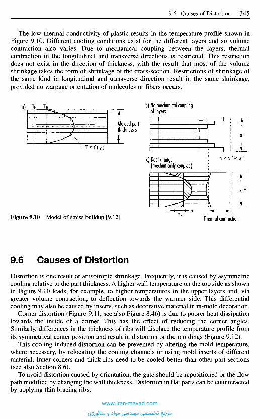
9 . 6 C a u s e s o f D i s t o r t i o n
Distortion is one result of anisotropic shrinkage. Frequently, it is caused by asymmetriccooling relative to the part thickness. A higher wall temperature on the top side as shownin Figure 9.10 leads, for example, to higher temperatures in the upper layers and, viagreater volume contraction, to deflection towards the warmer side. This differentialcooling may also be caused by inserts, such as decorative material in in-mold decoration.
Corner distortion (Figure 9.11; see also Figure 8.46) is due to poorer heat dissipationtowards the inside of a corner. This has the effect of reducing the corner angles.Similarly, differences in the thickness of ribs will displace the temperature profile fromits symmetrical center position and result in distortion of the moldings (Figure 9.12).
This cooling-induced distortion can be prevented by altering the mold temperature,where necessary, by relocating the cooling channels or using mold inserts of differentmaterial. Inner corners and thick ribs need to be cooled better than other part sections(see also Section 8.6).
To avoid distortion caused by orientation, the gate should be repositioned or the flowpath modified by changing the wall thickness. Distortion in flat parts can be counteractedby applying thin bracing ribs.
The low thermal conductivity of plastic results in the temperature profile shown inFigure 9.10. Different cooling conditions exist for the different layers and so volumecontraction also varies. Due to mechanical coupling between the layers, thermalcontraction in the longitudinal and transverse directions is restricted. This restrictiondoes not exist in the direction of thickness, with the result that most of the volumeshrinkage takes the form of shrinkage of the cross-section. Restrictions of shrinkage ofthe same kind in longitudinal and transverse direction result in the same shrinkage,provided no warpage orientation of molecules or fibers occurs.
o)
Molded partthickness s
b) No mechanical couplingof layers
c) Real change(mechanically coupled)
Thermal contractionFigure 9.10 Model of stress buildup [9.12]
www.iran-mavad.com
مرجع تخصصی مهندسی مواد و متالورژی
9 . 7 E f f e c t o f P r o c e s s i n g o n S h r i n k a g e
Other than by modifications to the mold and a change of material, the molder can onlyinfluence shrinkage and distortion by making changes to the process. From the p-v-Tdiagram, it can be seen that pressure and temperature are the main factors affectingshrinkage. Design changes will affect these parameters and thus also the shrinkage. Asurvey of the influences exerted by various parameters is shown in Figure 9.13 [9.11].
With amorphous as well as with crystalline thermoplastics, the holding pressure exertsthe greatest effect on shrinkage (Figure 9.8).
Under holding pressure, the material in the cavity is compressed and the volumecontraction from cooling is compensated by additional melt supply. The influence of theholding pressure is shown in the p-v-T diagram charting the progress of the process(see Figure 9.7). If the holding pressure is increased, the process is shifted to lowerspecific volumes, reaching at lower specific volumes the 100-kPa line at which the partundergoes lower shrinkage. The influence of the holding pressure is degressive,however; in other words, the reduction in shrinkage decreases with increase in holdingpressure.
Figure 9.12 Distortion causedby differences in wall thickness
Figure 9.11 Corner distortion through poorer heatdissipation in internal corners
Shrin
kage
Shrin
kage
Shrin
kage
Shrin
kage
Shrin
kage
Shrin
kage
Shrin
kage
Shrin
kage
Shrin
kage
Shrin
kage
Shrin
kage
Shrin
kage
Wall thickness Flow restriction Runner profilecross-section
Runner length Holding pressuretime
Holdingpressure
Flow path/wall thickness ratio Gate size Moldtemperature
Melttemperature
Injectionspeed
Figure 9.13 Relationships between shrinkage and characteristic parameters [9.11]
In directionof flow
Perpendicular todirection of flow
www.iran-mavad.com
مرجع تخصصی مهندسی مواد و متالورژی
With an increase in holding pressure, a reduction in shrinkage of up to 0.5% can beobtained in crystalline materials. With amorphous materials, a reduction of just 0.2%max. is feasible because of their overall lower level of shrinkage.
The second major influence on shrinkage is the temperature of the material.Theoretically, a higher injection temperature has two opposing effects on shrinkage:
on the one hand, a higher temperature results in a higher thermal contraction potential ofthe material (see also Figure 9.7 and [9.7]) and, on the other, the decrease in meltviscosity causes a better transfer of pressure and with this a reduction in shrinkage.Given sufficiently long holding-pressure stages, the effect of improved cavity pressurepredominates in the case of crystalline materials (Figure 9.14).
Shrin
kage
S|
Shrin
kage
S(
Melt temperature TMFigure 9.14 Effect of melt temperature on shrinkage (top: Crystalline, bottom: Amorphousmaterial)
Melt temperature TM
near gate :'in center :far from gate"
near gatein centerfar from gate~
0C
0C
www.iran-mavad.com
مرجع تخصصی مهندسی مواد و متالورژی
With crystalline materials, a reduction in shrinkage can be obtained of up to 0.5%; withamorphous plastics, the figure is up to 0.15%. All other parameters determine theshrinkage behavior via the pressure and temperature. While a greater wall thicknessleads to better pressure transfer, the poor thermal conductivity of plastics makes volumecontraction more noticeable at high temperatures and increases the shrinkage.Restrictions to flow impair pressure transfer and so increase shrinkage. In contrast, largerrunner profile cross-sections and thicker gates make for better pressure transfer. A largerunner length leads, just as does a large flow path to wall thickness ratio, to a drop inpressure and thus to greater shrinkage. Hot runners, however, reduce shrinkage.
The influences of the holding pressure time can be used to again illustrate the mostimportant criterion concerning shrinkage. As the holding pressure time increases, theforcing of additional material into the cavity reduces shrinkage. This can only happen,however, as long as the melt, particularly the gate and sprue, has not frozen. Prolongingthe holding pressure time beyond that has no further effect. For this reason, a part forhomogeneous molding materials should always be gated at the thickest point and thewall thicknesses should be such that holding pressure can take effect even in those areasfurthest away from the sprue.
With glass-reinforced materials, there are some particularities (Figure 9.15). In thedirection of fiber orientation, it is not possible to affect shrinkage by modifying pro-cessing parameters, as the rigidity of the fibers exerts an extremely strong influence. Theeffect perpendicular to the direction of fibers is approximately the same as it is with thematrix material only.
9 . 8 S u p p l e m e n t a r y M e a n s f o r P r e d i c t i n g S h r i n k a g e
The simplest way to estimate shrinkage for dimensioning a mold is to consult tables(Table 9.3). They are provided by the raw-material suppliers in the data sheets for theirrespective materials.
However, the partly wide range of listed data is problematic because it does not allowa sufficiently accurate prediction of shrinkage; nor are pertinent process parametersknown or configurations of moldings from which the shrinkage was obtained. Transferto other configurations is, therefore, difficult.
Long
itudin
al sh
rinka
ge
Cavity pressure pc max
Figure 9.15 Effect on shrinkage of glass fiber reinforced materials
10OkPa
Molding: plateMaterial: Nylon 6,
30% glassreinforced
Thickness: 3 mm
Relation to directionof flow:
www.iran-mavad.com
مرجع تخصصی مهندسی مواد و متالورژی
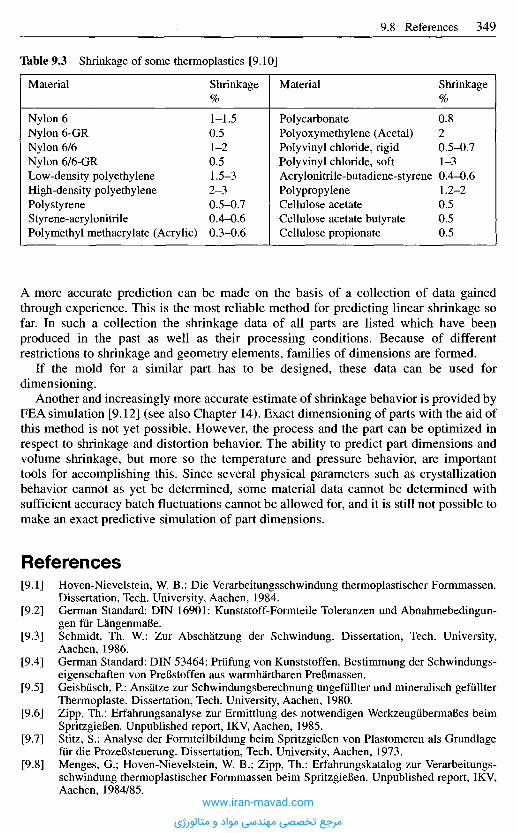
A more accurate prediction can be made on the basis of a collection of data gainedthrough experience. This is the most reliable method for predicting linear shrinkage sofar. In such a collection the shrinkage data of all parts are listed which have beenproduced in the past as well as their processing conditions. Because of differentrestrictions to shrinkage and geometry elements, families of dimensions are formed.
If the mold for a similar part has to be designed, these data can be used fordimensioning.
Another and increasingly more accurate estimate of shrinkage behavior is provided byFEA simulation [9.12] (see also Chapter 14). Exact dimensioning of parts with the aid ofthis method is not yet possible. However, the process and the part can be optimized inrespect to shrinkage and distortion behavior. The ability to predict part dimensions andvolume shrinkage, but more so the temperature and pressure behavior, are importanttools for accomplishing this. Since several physical parameters such as crystallizationbehavior cannot as yet be determined, some material data cannot be determined withsufficient accuracy batch fluctuations cannot be allowed for, and it is still not possible tomake an exact predictive simulation of part dimensions.
R e f e r e n c e s
[9.1] Hoven-Nievelstein, W. B.: Die Verarbeitungsschwindung thermoplastischer Formmassen.Dissertation, Tech. University, Aachen, 1984.
[9.2] German Standard: DIN 16901: Kunststoff-Formteile Toleranzen und Abnahmebedingun-gen fiir LangenmaBe.
[9.3] Schmidt, Th. W.: Zur Abschatzung der Schwindung. Dissertation, Tech. University,Aachen, 1986.
[9.4] German Standard: DIN 53464: Prufung von Kunststoffen. Bestimmung der Schwindungs-eigenschaften von PreBstoffen aus warmhartbaren PreBmassen.
[9.5] Geisbiisch, P.: Ansatze zur Schwindungsberechnung ungefiillter und mineralisch gefullterThermoplaste. Dissertation, Tech. University, Aachen, 1980.
[9.6] Zipp, Th.: Erfahrungsanalyse zur Ermittlung des notwendigen WerkzeugiibermaBes beimSpritzgieBen. Unpublished report, IKV, Aachen, 1985.
[9.7] Stitz, S.: Analyse der Forrnteilbildung beim SpritzgieBen von Plastomeren als Grundlagefiir die ProzeBsteuerung. Dissertation, Tech. University, Aachen, 1973.
[9.8] Menges, G.; Hoven-Nievelstein, W. B.; Zipp, Th.: Erfahrungskatalog zur Verarbeitungs-schwindung thermoplastischer Formmassen beim SpritzgieBen. Unpublished report, IKV,Aachen, 1984/85.
Table 9.3 Shrinkage of some thermoplastics [9.10]
Material
Nylon 6Nylon 6-GRNylon 6/6Nylon 6/6-GRLow-density polyethyleneHigh-density polyethylenePolystyreneStyrene-acrylonitrilePolymethyl methacrylate (Acrylic)
Shrinkage%
1-1.50.51-20.51.5-32-30.5-0.70.4-0.60.3-0.6
Material
PolycarbonatePolyoxymethylene (Acetal)Polyvinyl chloride, rigidPolyvinyl chloride, softAcrylonitrile-butadiene-styrenePolypropyleneCellulose acetateCellulose acetate butyrateCellulose propionate
Shrinkage%
0.820.5-0.71-30.4-0.61.2-20.50.50.5
www.iran-mavad.com
مرجع تخصصی مهندسی مواد و متالورژی

[9.9] Baur, E.; Schleede, K.; Lessenich, V.; Ort, St.; FiIz, P.; Potsch, G.; Groth, S.; Greif, H.:Formteil- und Werkzeugkonstruktion aus einer Hand - Die modernen Hilfsmittel fur denKonstrukteur. Contribution to 14th Technical Conference on Plastics, Aachen, 1988.
[9.10] Strack Normalien fur Formwerkzeuge. Handbook, Strack-Norma GmbH, Wuppertal.[9.11] Frados, J.: Plastics Engineering Handbook. Van Nostrand Reinhold, New York, 1976.[9.12] Potsch, M. G.: Prozessimulation zur Abschatzung von Schwindung und Verzug thermo-
plastischer Spritzgussteile. Dissertation, RWTM, Aachen, 1991.
www.iran-mavad.com
مرجع تخصصی مهندسی مواد و متالورژی
1 0 . 1 M o l d D e f o r m a t i o n
Injection molds are exposed to a very high mechanical loading but they are only allowedelastic deformation. Since these molds are expected to produce parts that meet thedemands for high precision, it is evident, therefore, that any deformation of the moldaffects the final dimensions of a part as well as the shrinkage of the plastic materialduring the cooling stage. Besides this, undue deformation of a mold can result inundesirable interference with the molding process or actuation of the mold.
Effects on the quality of the molding:
- Mold deformation results in dimensional deviations and possible flashing.
Effects on the function of the mold:
- Deformation of the mold, especially transverse to the direction of demolding and largerthan the corresponding shrinkage of the molding, results in problems in mold-openingor ejection from jamming.
- Thus, the rigidity of a mold determines the quality of the moldings as well as reliableoperation of the mold.
- Common molds are assembled from a number of components, which as a wholeprovide rigidity to the mold by their interaction. The components of a mold arecompact bodies and both bending and shear strains have to be considered in design.They are still sufficiently slender, though, that, with some exceptions, permissiblestresses need not be taken into account because of their small permissible deformation.
1 0 . 2 A n a l y s i s a n d E v a l u a t i o n o f L o a d s
a n d D e f o r m a t i o n s
a) As a general principle, molds have to be designed with their permissible deformationin mind.
b) Dynamic deformations do not occur, which is why a large number of equations areused for working out the static load and deformation behavior.
c) Complex configurations make injection molds statically indeterminate systems. Forcalculating the expected deformation one can either use a finite-element method fora closed approximation or - much simpler and sufficiently exact - divide the moldsinto separate elements [10.1, 10.2]. Since only elastic deformations are admitted, theindividual elements can be considered springs and the whole system computed as aset of springs. The individual "springs" are then added up to yield the overalldeformation (cf. Sections 10.4 to 10.6).
1 0 M e c h a n i c a l D e s i g n o f I n j e c t i o n
M o l d s [ 1 0 . 1 ]
www.iran-mavad.com
مرجع تخصصی مهندسی مواد و متالورژی
10.2.1 Evaluation of the Acting Forces
The acting forces are:
a) Closing and clamping forces exerted by the machine.b) The maximum cavity pressure. It acts via the molding compound in the mold cavities
and the runner system on the mold, which may deform mainly by bending.
Two problems may arise:
1. The part is jammed in the mold when cavity pressure forces, acting perpendicularlyto the mold axis, bend the walls further than the molding compound at these pointsshrinks in thickness after cooling to demolding temperature.
2. Under the effect of the cavity pressure forces in the direction of the mold axis,unpermissibly large gaps in the mold parting line could occur into which melt couldpenetrate and flash could form.The maximum cavity pressure in thermoplastics and normal operating conditions isalways the maximum injection pressure.With elastomers and thermosets, the maximum cavity pressure usually only occursafter filling because now the molding compound is heated further both by the hottermold wall and by the liberated heat of reaction, and it expands more. Only whencross-linking progresses further does a more or less large reduction in volume occur.This volume expansion due to heating is also the reason that these moldingcompounds almost always leave behind flash on the parts. While there are suitableappropriate controls for preventing this, they are rarely used. Many molders stillafford themselves the luxury of expensive, very often manual finishing of every partproduced.To calculate the formation of such gaps more accurately, it is not sufficient to use thesimple calculations employing spring stiffness for the molds alone because thedeformations of the press (clamping unit) contribute considerably to overalldeformation.A great deal of work has been done in recent years that allows the formation of gapsin mold parting lines to be calculated very accurately [10.3, 10.4]. They alwaysconsist in adding up the deformations of the molds in the axial direction and those ofthe entire clamping unit. These calculations are admittedly much more complicatedthan the simple calculation that will be described below. An accurate calculationmoreover requires that the molder determines the deformation of the clamping unit,including all its elements. To date, this deformation is usually not quoted by themachine manufacturers. The method of measuring and calculating the deformation ofthe clamping unit is described in [10.4]. There is, however, a relatively simple methodthat will be explained later. This method yields results that lie on the safe side.
c) Mold opening and ejection forces:These forces are usually much smaller. They only need to be considered whendesigning the ejection system. If present, however, the ejector pins must also beallowed for, as there are two frequently ignored dangers here:
- the pins can buckle outwards and be destroyed,- the pins can punch through the molded part.
Calculations for these are provided in Chapter 12.www.iran-mavad.com
مرجع تخصصی مهندسی مواد و متالورژی
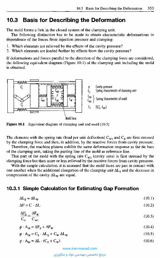
1 0 . 3 B a s i s f o r D e s c r i b i n g t h e D e f o r m a t i o n
The mold forms a link in the closed system of the clamping unit.The following distinction has to be made to obtain characteristic deformations in
dependence of the forces from injection pressure and clamping:
1. Which elements are relieved by the effects of the cavity pressure?2. Which elements are loaded further by effects from the cavity pressure?
If deformations and forces parallel to the direction of the clamping force are considered,the following equivalent diagram (Figure 10.1) of the clamping unit including the moldis obtained.
Cavity pressureSpring characteristic of clamping unit
Spring characteristic of mold
Figure 10.1 Equivalent diagram of clamping unit and mold [10.5]
The elements with the spring rate (load per unit deflection) CW1 and Cs are first stressedby the clamping force and then, in addition, by the reactive forces from cavity pressure.
Therefore, the machine platens exhibit the same deformation response as the tie barsof the clamping unit, taking the parting line of the mold as reference line.
That part of the mold with the spring rate CW2 (cavity area) is first stressed by theclamping force but then more or less relieved by the reactive forces from cavity pressure.
With the simple calculation, it is assumed that the mold faces are just in contact withone another when the additional elongation of the clamping unit AL8 and the decrease incompression of the cavity ALW are equal.
10.3.1 Simple Calculation for Estimating Gap Formation
(10.1)
(10.2)
(10.3)
(10.4)
(10.5)
(10.6)
Mold face
www.iran-mavad.com
مرجع تخصصی مهندسی مواد و متالورژی
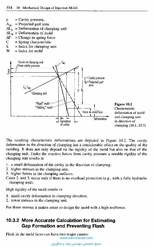
The resulting characteristic deformations are depicted in Figure 10.2. The cavitydeformation in the direction of clamping has a considerable effect on the quality of themolding. It does not only depend on the rigidity of the mold but also on that of theclamping unit. Under the reactive forces from cavity pressure a notable rigidity of theclamping unit results in
1. a small deformation of the cavity in the direction of clamping,2. higher stresses in the clamping unit,3. higher forces in the clamping surfaces.Cases 2. and 3. occur only if there is no overload protection (e.g., with a fully hydraulic
clamping unit).
High rigidity of the mold results in
1. small cavity deformation in clamping direction,2. lower stresses in the clamping unit.
For these reasons it makes sense to design the mold with a high resilience.
10.3.2 More Accurate Calculation for EstimatingGap Formation and Preventing Flash
Flash in the mold faces can have two major causes:
Figure 10.2Characteristicdeformation of moldand clamping unitin direction ofclamping [10.1, 10.5]
= Cavity pressure,= Projected part area.= Deformation of clamping unit= Deformation of mold= Change in spring force= Spring characteristic= Index for clamping unit= Index for mold
Force
Forces on clamping unitfrom cavity pressure
Cavity pressureProjected partarea
Clamping unit
"Rigid" mold"Yielding" mold
Force on mold face
De-formationof cavity
Deformation
www.iran-mavad.com
مرجع تخصصی مهندسی مواد و متالورژی
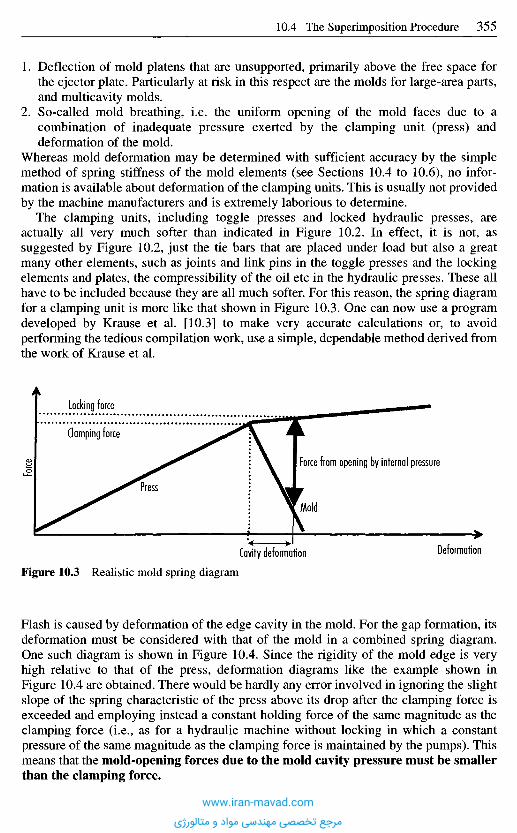
1. Deflection of mold platens that are unsupported, primarily above the free space forthe ejector plate. Particularly at risk in this respect are the molds for large-area parts,and multicavity molds.
2. So-called mold breathing, i.e. the uniform opening of the mold faces due to acombination of inadequate pressure exerted by the clamping unit (press) anddeformation of the mold.
Whereas mold deformation may be determined with sufficient accuracy by the simplemethod of spring stiffness of the mold elements (see Sections 10.4 to 10.6), no infor-mation is available about deformation of the clamping units. This is usually not providedby the machine manufacturers and is extremely laborious to determine.
The clamping units, including toggle presses and locked hydraulic presses, areactually all very much softer than indicated in Figure 10.2. In effect, it is not, assuggested by Figure 10.2, just the tie bars that are placed under load but also a greatmany other elements, such as joints and link pins in the toggle presses and the lockingelements and plates, the compressibility of the oil etc in the hydraulic presses. These allhave to be included because they are all much softer. For this reason, the spring diagramfor a clamping unit is more like that shown in Figure 10.3. One can now use a programdeveloped by Krause et al. [10.3] to make very accurate calculations or, to avoidperforming the tedious compilation work, use a simple, dependable method derived fromthe work of Krause et al.
Flash is caused by deformation of the edge cavity in the mold. For the gap formation, itsdeformation must be considered with that of the mold in a combined spring diagram.One such diagram is shown in Figure 10.4. Since the rigidity of the mold edge is veryhigh relative to that of the press, deformation diagrams like the example shown inFigure 10.4 are obtained. There would be hardly any error involved in ignoring the slightslope of the spring characteristic of the press above its drop after the clamping force isexceeded and employing instead a constant holding force of the same magnitude as theclamping force (i.e., as for a hydraulic machine without locking in which a constantpressure of the same magnitude as the clamping force is maintained by the pumps). Thismeans that the mold-opening forces due to the mold cavity pressure must be smallerthan the clamping force.
Figure 10.3 Realistic mold spring diagram
Cavity deformation Deformation
Force from opening by internal pressure
Mold
Press
Force
Locking force
Clamping force
www.iran-mavad.com
مرجع تخصصی مهندسی مواد و متالورژی
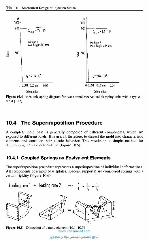
Figure 10.4 Realistic spring diagram for two normal mechanical clamping units with a typicalmold [10.3]
1 0 . 4 T h e S u p e r i m p o s i t i o n P r o c e d u r e
A complete mold base is generally composed of different components, which areexposed to different loads. It is useful, therefore, to dissect the mold into characteristicelements and consider their elastic behavior. This results in a simple method fordetermining the total deformation (Figure 10.5).
10.4.1 Coupled Springs as Equivalent Elements
The superimposition procedure represents a superimposition of individual deformations.All components of a mold base (plates, spacers, supports) are considered springs with acertain rigidity (Figure 10.6).
Deformation Deformationmm mm
Force
Force
kN kN
Machine 1Mold height 310 mm
Machine 2Mold height 336 mm
Loading case 1 Loading case 2
Figure 10.5 Dissection of a mold element [10.1, 10.5]www.iran-mavad.com
مرجع تخصصی مهندسی مواد و متالورژی
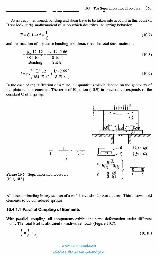
All cases of loading in any section of a mold have similar correlations. This allows moldelements to be considered springs.
10.4.1.1 Parallel Coupling of Elements
With parallel, coupling, all components exhibit the same deformation under differentloads. The total load is allocated to individual loads (Figure 10.7):
(10.10)
Figure 10.6 Superimposition procedure[10.1, 10.5]
In the case of the deflection of a plate, all quantities which depend on the geometry ofthe plate remain constant. The term of Equation (10.9) in brackets corresponds to theconstant C of a spring.
and the reaction of a plate to bending and shear, then the total deformation is
Bending Shear
As already mentioned, bending and shear have to be taken into account in this context.If we look at the mathematical relation which describes the spring behavior
(10.7)
(10.8)
(10.9)
a)
b)
www.iran-mavad.com
مرجع تخصصی مهندسی مواد و متالورژی

10.4.1.2 Elements Coupled in Series
All components are deformed by the same loads (Figure 10.8).
(10.11)
Hence, all springs are loaded by the full magnitude of the acting force and not pro-portionately. The resulting spring travel is
(10.12)
The total deformation is the sum of the individual deformations.Thus, the possible number of loading cases can be reduced to three basic cases:
1. single load,2. parallel coupling (Figure 10.7),3. coupling in series (Figure 10.8).
Figure 10.8 System of elements in series [10.5]
Figures 10.5 and 10.6 demonstrate how the total deformation can be determined bycombining the basic cases.
1 0 . 5 C o m p u t a t i o n o f t h e W a l l T h i c k n e s s o f C a v i t i e s
a n d T h e i r D e f o r m a t i o n
The configuration of all parts can be reduced to simple shapes. If all possible cavity andcore configurations are analyzed with this assumption in mind, we can select thefollowing typical geometries with the goal of obtaining a method for estimatingdimensions:
1. circular cavities and cores,2. cavities and cores with plane faces as boundaries.
If the existing loading cases are analyzed, the causes of deformations can be reduced toa few cases. The basis for this simplified calculation is the dissection of the moldcomponent to be dimensioned into two characteristic equivalent beams as is done with a
Figure 10.7 Parallel system of elements [10.5]
www.iran-mavad.com
مرجع تخصصی مهندسی مواد و متالورژی
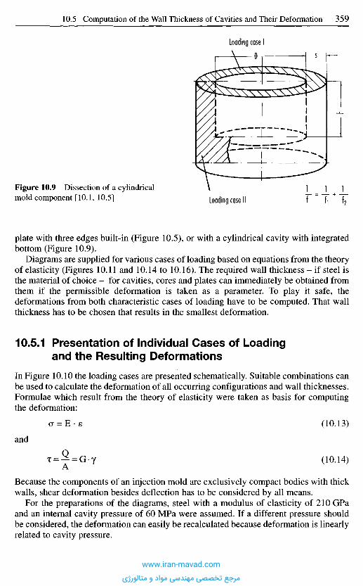
plate with three edges built-in (Figure 10.5), or with a cylindrical cavity with integratedbottom (Figure 10.9).
Diagrams are supplied for various cases of loading based on equations from the theoryof elasticity (Figures 10.11 and 10.14 to 10.16). The required wall thickness - if steel isthe material of choice - for cavities, cores and plates can immediately be obtained fromthem if the permissible deformation is taken as a parameter. To play it safe, thedeformations from both characteristic cases of loading have to be computed. That wallthickness has to be chosen that results in the smallest deformation.
10.5.1 Presentation of Individual Cases of Loadingand the Resulting Deformations
In Figure 10.10 the loading cases are presented schematically. Suitable combinations canbe used to calculate the deformation of all occurring configurations and wall thicknesses.Formulae which result from the theory of elasticity were taken as basis for computingthe deformation:
(10.13)
(10.14)
Because the components of an injection mold are exclusively compact bodies with thickwalls, shear deformation besides deflection has to be considered by all means.
For the preparations of the diagrams, steel with a modulus of elasticity of 210 GPaand an internal cavity pressure of 60 MPa were assumed. If a different pressure shouldbe considered, the deformation can easily be recalculated because deformation is linearlyrelated to cavity pressure.
Figure 10.9 Dissection of a cylindricalmold component [10.1, 10.5] Loading case Il
Loading case I
and
www.iran-mavad.com
مرجع تخصصی مهندسی مواد و متالورژی
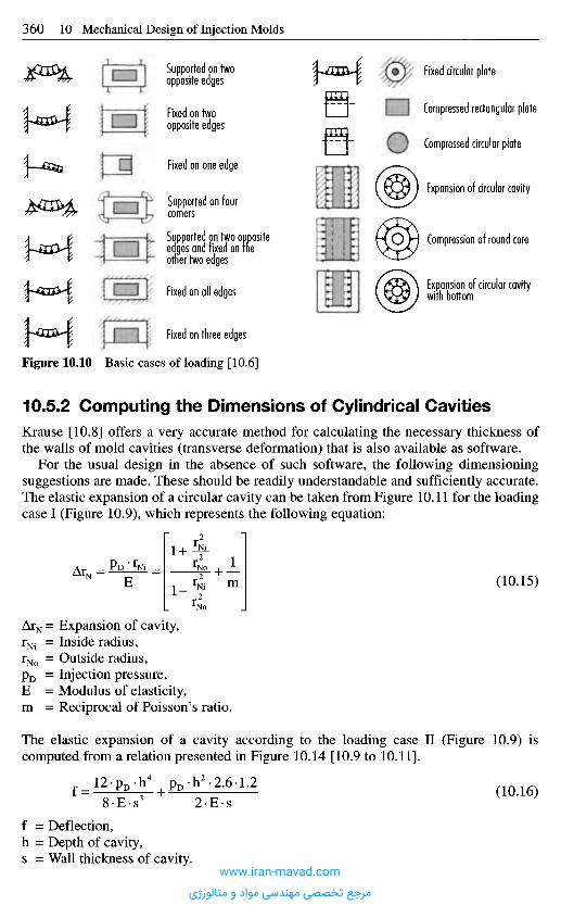
Supported on twoopposite edges
Fixed on twoopposite edges
Fixed on one edge
Supported on fourcorners
Supported on two oppositeedges and fixed on theother two edges
Fixed on all edges
Fixed on three edges
Fixed circular plate
Compressed rectangular plate
Compressed circular plate
Expansion of circular cavity
Compression of round core
Expansion of circular cavitywith bottom
Figure 10.10 Basic cases of loading [10.6]
10.5.2 Computing the Dimensions of Cylindrical Cavities
Krause [10.8] offers a very accurate method for calculating the necessary thickness ofthe walls of mold cavities (transverse deformation) that is also available as software.
For the usual design in the absence of such software, the following dimensioningsuggestions are made. These should be readily understandable and sufficiently accurate.The elastic expansion of a circular cavity can be taken from Figure 10.11 for the loadingcase I (Figure 10.9), which represents the following equation:
(10.15)
ATN = Expansion of cavity,rNi = Inside radius,rNo = Outside radius,pD = Injection pressure,E = Modulus of elasticity,m = Reciprocal of Poisson's ratio.
The elastic expansion of a cavity according to the loading case II (Figure 10.9) iscomputed from a relation presented in Figure 10.14 [10.9 to 10.11].
(10.16)
f = Deflection,h = Depth of cavity,s = Wall thickness of cavity.
www.iran-mavad.com
مرجع تخصصی مهندسی مواد و متالورژی
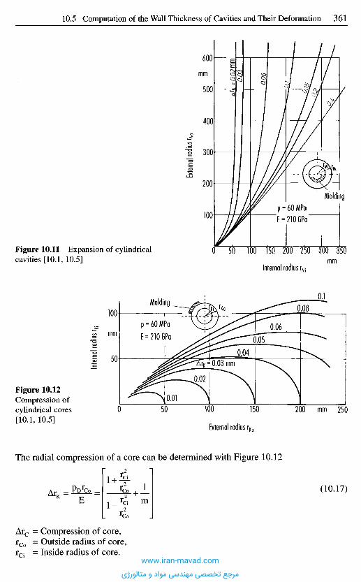
Exter
nal r
adius
r No
Intern
al rad
ius r K
i
mm
Molding
Internal radius rNjmm
Figure 10.11 Expansion of cylindricalcavities [10.1, 10.5]
Molding
mm
mm
External radius rKa
Figure 10.12Compression ofcylindrical cores[10.1, 10.5]
The radial compression of a core can be determined with Figure 10.12
(10.17)
Arc = Compression of core,rCo = Outside radius of core,rCi = Inside radius of core.
www.iran-mavad.com
مرجع تخصصی مهندسی مواد و متالورژی
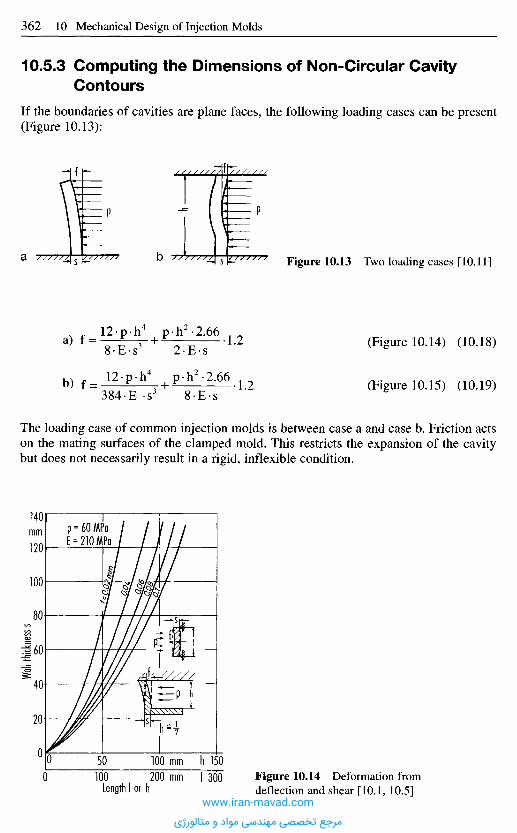
Wall t
hickn
ess s
10.5.3 Computing the Dimensions of Non-Circular Cavity
Contours
If the boundaries of cavities are plane faces, the following loading cases can be present(Figure 10.13):
Figure 10.13 Two loading cases [10.11]a b
(Figure 10.14) (10.18)
The loading case of common injection molds is between case a and case b. Friction actson the mating surfaces of the clamped mold. This restricts the expansion of the cavitybut does not necessarily result in a rigid, inflexible condition.
mm
Figure 10.14 Deformation fromdeflection and shear [10.1, 10.5]Length I or h
mmmm
hI
(Figure 10.15) (10.19)
a)
b)
www.iran-mavad.com
مرجع تخصصی مهندسی مواد و متالورژی
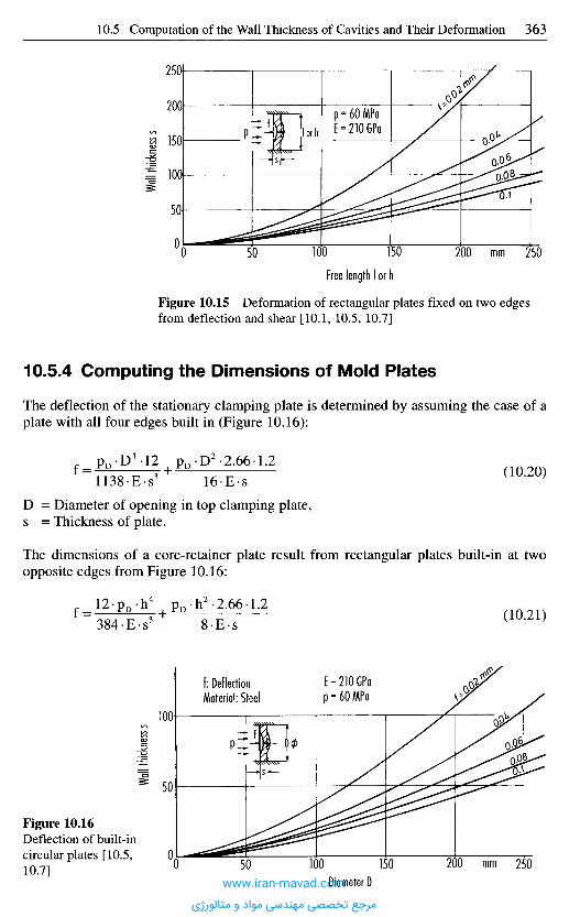
Wall t
hickn
ess s
Wall t
hickn
ess s
mmFree length I or h
Figure 10.15 Deformation of rectangular plates fixed on two edgesfrom deflection and shear [10.1, 10.5, 10.7]
10 .5 .4 C o m p u t i n g t h e D i m e n s i o n s of M o l d P l a t e s
The deflection of the stationary clamping plate is determined by assuming the case of aplate with all four edges built in (Figure 10.16):
D = Diameter of opening in top clamping plate,s = Thickness of plate.
The dimensions of a core-retainer plate result from rectangular plates built-in at twoopposite edges from Figure 10.16:
(10.20)
(10.21)
mmDiameter D
f: DeflectionMaterial: Steel
Figure 10.16Deflection of built-incircular plates [10.5,10.7]
www.iran-mavad.com
مرجع تخصصی مهندسی مواد و متالورژی
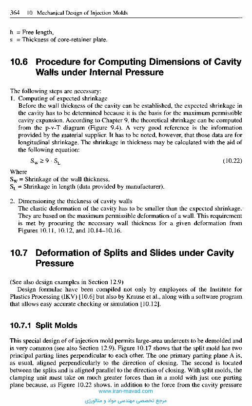
h = Free length,s = Thickness of core-retainer plate.
1 0 . 6 P r o c e d u r e f o r C o m p u t i n g D i m e n s i o n s o f C a v i t y
W a l l s u n d e r I n t e r n a l P r e s s u r e
The following steps are necessary:1. Computing of expected shrinkage
Before the wall thickness of the cavity can be established, the expected shrinkage inthe cavity has to be determined because it is the basis for the maximum permissiblecavity expansion. According to Chapter 9, the theoretical shrinkage can be computedfrom the p-v-T diagram (Figure 9.4). A very good reference is the informationprovided by the material supplier. It has to be noted, however, that those data are forlongitudinal shrinkage. The shrinkage in thickness may be calculated with the aid ofthe following equation:
Sw > 9 • SL (10.22)
WhereSw = Shrinkage of the wall thickness,SL = Shrinkage in length (data provided by manufacturer).
2. Dimensioning the thickness of cavity wallsThe elastic deformation of the cavity has to be smaller than the expected shrinkage.They are based on the maximum permissible deformation of a wall. This requirementis met by procuring the necessary wall thickness for a given deformation fromFigures 10.11, 10.12, and 10.14-10.16.
1 0 . 7 D e f o r m a t i o n o f S p l i t s a n d S l i d e s u n d e r C a v i t y
P r e s s u r e
(See also design examples in Section 12.9)Design formulae have been compiled not only by employees of the Institute for
Plastics Processing (IKV) [10.6] but also by Krause et al., along with a software programthat allows easy accurate checking or simulation [10.12].
10.7.1 Split Molds
This special design of of injection mold permits large-area undercuts to be demolded andis very common (see also Section 12.9). Figure 10.17 shows that the split mold has twoprincipal parting lines perpendicular to each other. The one primary parting plane A is,as usual, aligned perpendicularly to the direction of closing. The second is locatedbetween the splits and is aligned parallel to the direction of closing. With split molds, theclamping unit must take on much greater forces than in a mold with just one partingplane because, as Figure 10.22 shows, in addition to the force from the cavity pressure
www.iran-mavad.com
مرجع تخصصی مهندسی مواد و متالورژی
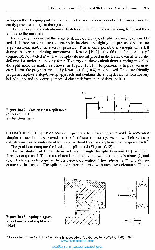
acting on the clamping parting line there is the vertical component of the forces from thecavity pressure acting on the splits.
The first step in the calculation is to determine the minimum clamping force and thento choose the machine.
It is already necessary at this stage to decide on the type of splits because functionalityand flash-free parts require that the splits be closed so tightly and pre-stressed that nogaps can form under the internal pressure. This is only possible if enough air is leftduring the vertical closing movement - Krause [10.2] calls this a "functional gap"(Figure 10.17, labeled a) - that the splits do not sit proud in the frame even after elasticdeformation under the locking force. To carry out these calculations, a spring model ofthe split mold is made, as shown in Figure 10.21. (To perform a highly accuratecalculation, the program created by Krause et al. [10.8] may be used. This user friendlyprogram employs a step-by-step approach and contains the strength calculations for anybolted joints and the consequences of elastic deformation of these bolts.)
Figure 10.17 Section from a split mold(principle) [10.6]a = Functional gap
CADMOULD [10.13] which contains a program for designing split molds is somewhatsimpler to use but has proved to be of sufficient accuracy. As shown below, thesecalculations can be understood by users, without their having to use the program itself*.
The goal is to compute the load on a split mold (Figure 10.18).The distribution of forces flows entirely through the split (element (I)), which is
thereby compressed. The counterforce is applied by the two locking mechanisms (2) and(3), which are both subjected to the same deformation. Thus, elements (2) and (3) areconnected in parallel. The split is connected in series with these two elements. This is
Figure 10.18 Spring diagramfor deformation of a split mold[10.6]
Extract from "Handbook for Computing Injection Molds", published by Kl-Verlag, 1985 [10.6]
1 2 3
X
Y
www.iran-mavad.com
مرجع تخصصی مهندسی مواد و متالورژی
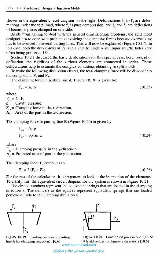
shown in the equivalent circuit diagram on the right. Deformations f{ to f3 are defor-mations under the total load, where fY is pure compression, and f2 and f3 are deflectionsof beams or plates clamped on one side.
Aside from having to deal with the general dimensioning problems, the split molddesigner has to cope with problems involving the clamping forces because overpackinghas to be avoided in several parting lines. This will now be explained (Figure 10.17). Inthis case, both the dimensions of the gap a and the angle a are important, the latter veryoften being pre-set at 18°.
Section 10.2.1 discussed the basic deliberations for this special case; here, instead ofdeflection, the rigidities of the various elements are connected in series. Thesedeliberations help to estimate the complex conditions obtaining in split molds.
To make the following discussion clearer, the total clamping force will be divided intothe components F1 and F2.
The clamping force in parting line A (Figure 10.19) is given by:
(10.23)
whereFcx = 2 - F 2
p = Cavity pressure,Fcx = Clamping force in the x-direction,Ax = Area of the part in the x-direction.
The clamping force in parting line B (Figure 10.20) is given by:
(10.24)
whereFcy = Clamping pressure in the y-direction,Ay = Projected area of part in the y-direction.
The clamping force Fc computes to
(10.25)
For the rest of the calculation, it is important to look at the interaction of the elements.To clarify this, the equivalent circuit diagram for the system is shown in Figure 10.21.
The circled numbers represent the equivalent springs that are loaded in the clampingdirection x. The numbers in the squares represent equivalent springs that are loadedperpendicularly to the clamping direction y.
Figure 10.19 Loading on jaws in partingline A (in clamping direction) [10.6]
Figure 10.20 Loading on jaws in parting lineB (right angles to clamping direction) [10.6]
www.iran-mavad.com
مرجع تخصصی مهندسی مواد و متالورژی
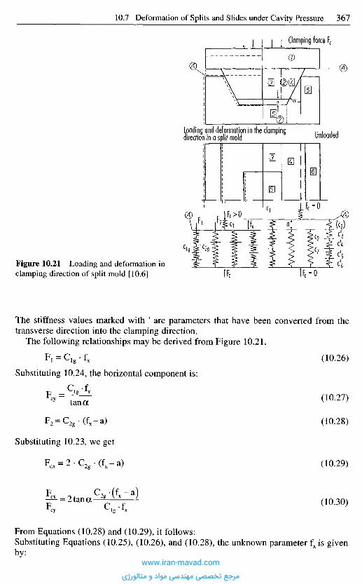
Clamping force Fc
UnloadedLoading and deformation in the clampingdirection in a split mold
Figure 10.21 Loading and deformation inclamping direction of split mold [10.6]
The stiffness values marked with ' are parameters that have been converted from thetransverse direction into the clamping direction.
The following relationships may be derived from Figure 10.21.
(10.26)
(10.27)
(10.28)
(10.29)
(10.30)
Substituting 10.24, the horizontal component is:
Substituting 10.23, we get
From Equations (10.28) and (10.29), it follows:Substituting Equations (10.25), (10.26), and (10.28), the unknown parameter fx is givenby:
www.iran-mavad.com
مرجع تخصصی مهندسی مواد و متالورژی

(10.31)
(10.32)
We now need to determine the individual stiffness values Clg and C2g.Figure 10.22 shows the deformation of the system in the y-direction (fy) on closing of
the mold over the distance fx.
Figure 10.22 Deformation at rightangles to clamping direction [10.6]
The spring constant that occurs in the y-direction is C. This can be normalized by theconstant factor tan2 a to the x-direction.
Thus:
(10.33)
Forces onelement 1
Forces onelement 2
not deformeddeformed
www.iran-mavad.com
مرجع تخصصی مهندسی مواد و متالورژی
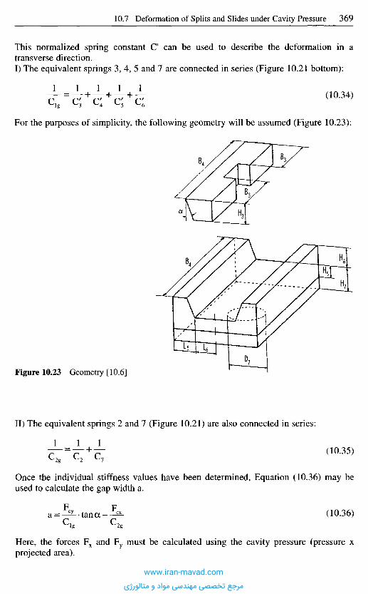
This normalized spring constant C can be used to describe the deformation in atransverse direction.I) The equivalent springs 3, 4, 5 and 7 are connected in series (Figure 10.21 bottom):
(10.34)
For the purposes of simplicity, the following geometry will be assumed (Figure 10.23):
Figure 10.23 Geometry [10.6]
II) The equivalent springs 2 and 7 (Figure 10.21) are also connected in series:
(10.35)
Once the individual stiffness values have been determined, Equation (10.36) may beused to calculate the gap width a.
(10.36)
Here, the forces Fx and Fy must be calculated using the cavity pressure (pressure xprojected area).
www.iran-mavad.com
مرجع تخصصی مهندسی مواد و متالورژی

1 0 . 8 P r e p a r i n g f o r t h e D e f o r m a t i o n C a l c u l a t i o n s
ExamplesWhen the simple computational premises such as those described above are used fordimensioning injection molds, it must be borne in mind from the outset that certainsimplifications have to be made with respect to description of geometry and load.Ultimately, the designer must use his engineering knowledge to decide himself on suchsimplifications. Some examples will serve to illustrate this.
If we consider the case of two bolted mold plates (Figure 10.24), we have to decidewhether these two plates are to be regarded as one plate with the sum of the individualthicknesses or if this loading instance has to be defined as a parallel circuit of theindividual plates.
Figure 10.24 Simplified view of loads using bolted plates; connected in parallel [10.6]
This depends most definitely on the number of bolts or shear pins or guide pins, i.e., thequestion is whether the plates can still be displaced to a certain extent. The final decisioncan therefore only be reached in practice.
Calculations of the two loading cases can prove of great assistance to the designerwhen deciding on the design. The results of one example are shown in Figure 10.25.
Case A clearly shows that the deformation in a parallel circuit (two plates loosely ontop of each other) is twice as high, so the designer should consider the use of supports.
Figure 10.25 Comparison of different loads [10.6]
Case A Case B
Pressure p = 50 MPa
Real load: Substitution: Spring model:
www.iran-mavad.com
مرجع تخصصی مهندسی مواد و متالورژی
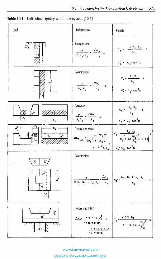
Table 10.1 Individual rigidity within the system [10.6]
Load Deformation Rigidity
Compression
Compression
Extension
Flexure and thrust
Compression
Flexure and thrust
www.iran-mavad.com
مرجع تخصصی مهندسی مواد و متالورژی

The comparison of the two possibilities quickly shows up the limits that deformationvalues impose.
Since the choice obviously requires a certain amount of experience, a few tips willnow be given concerning the simplified approach. Figure 10.27 shows schematicsimplifications for frequently recurrent loading cases. The table is by no means com-plete.
If a definitive determination of the load proves to be difficult, the system should becalculated under minimal and maximal load to establish precise limits.
10.8.1 Geometr ical Simplifications [10.15]
Often, mold cavities have really complicated contours. One such example is provided inFigure 10.28.
In this case, too, comparative computation of the deformations using two differentequivalent wall thicknesses yields sufficient information to help the designer reach adecision.
The same approach is used in the example shown in Figure 10.29. In this case, thesimplification is a plate clamped on one side with equivalent thickness.
A further problem is posed by the weakening of the mold plates brought about bydrilled cooling channels; only FEA can take this into account. Again, mold elements withdifferent equivalent wall thicknesses may be used (Figure 10.30).
To summarize the approach, a geometric simplification of the real loading case mustbe made and then the equivalent spring system for this chosen system has to be decidedon.
In many instances, an equivalent loading that is covered by computationalpossibilities first has to be found for the actual loading.
This can be a problem even in very simple cases, as shown in Figure 10.26 for a platewith a sprue gate.
Mold and moldedpart
Pressure loading(filling phase)
Possible approximations
Molded partwith sprue gate
Figure 10.26 Plate with sprue gate [10.6]
Pmax
P*= Pmax/2
www.iran-mavad.com
مرجع تخصصی مهندسی مواد و متالورژی

LoadMost favorable scenario(pressure convertedfor same force)
Least favorable scenario(pmQX across entire area)Approximation Slicing
Central gate Addition of bending lines
Subtraction of bending linesDouble hot runner(central)
Side gating
Dual side Subtraction of bending lines
Figure 10.27 Compilation of simplified load scenarios [10.6]
Molded part contour
Mold
Simplification
Plate with substitute thicknesses sf, sf
Figure 10.28 Simplification ofcomplicated mold contours [10.6]
Pmax Pmax/2 Pmax
Pmax
•Pmax
PmaxPmaxPmax/3Pmax
Pmax Pmax/2Pmax
Pmax Pmax/3 Pmax Pmax Pmax
www.iran-mavad.com
مرجع تخصصی مهندسی مواد و متالورژی
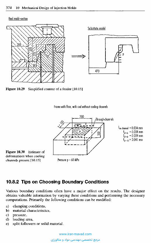
10.8.2 Tips on Choosing Boundary Conditions
Various boundary conditions often have a major effect on the results. The designerobtains valuable information by varying these conditions and performing the necessarycomputations. Primarily the following conditions can be modified:
a) clamping conditions,b) material characteristics,c) pressure,d) loading area,e) split followers or solid material.
Figure 10.30 Estimate ofdeformations when coolingchannels present [10.15] Pressure p = 60 MPa
Real mold-section
Substitute model
Figure 10.29 Simplified contour of a fender [10.15]
Frame with floor, with and without cooling channels
Through-channels
U channel = 0.034 mm
www.iran-mavad.com
مرجع تخصصی مهندسی مواد و متالورژی
Practitioners very often over-estimate the influence of hardened tool steel versusunhardened tool steel with regard to deflection and compression behavior. While normalsteel has a modulus of elasticity of 210,000 N/mm2, the modulus of elasticity ofhardened steel is 215,000 N/mm2 or roughly 7% higher. Accordingly, the deformationbehavior changes only slightly.
The situation is totally different, however, when, e.g., beryllium-copper is used. Themodulus of elasticity decreases to 130,000 N/mm2. This is a change of approx. 40% andwill naturally have a corresponding influence on the deformation behavior.
As the calculations have just shown, the pressure is directly proportional to thedeflection, i.e. a doubling of pressure leads to a doubling of deflection.
The influence of the loaded area is not as strong. Table 10.3 shows the differentrelations for a given geometry.
Table 10.3 Varying the loaded area [10.6]
If pressure (load) and geometry have been established for a mold element, a comparisonof different clamping conditions reveals that deformations can change by orders ofmagnitude (Table 10.2).
Table 10.2 Varying the clamping conditions [10.6]
FlexureBilaterallymounted plate
LengthBreadthPressurized lengthPressurized breadthPressureThicknessX-coordinateDeflection
596 mm446 mm596 mm446 mm25MPa116 mm298 mm
1.51051 mm
FlexureBilaterallyclamped plate
LengthBreadthPressurized lengthPressurized breadthPressureThicknessX-coordinateDeflection
596 mm446 mm596 mm446 mm25MPa116 mm298 mm.415842 mm
FlexurePlate clampedon all sides
LengthBreadthPressurized lengthPressurized breadthPressureThicknessX-coordinateDeflection
596 mm446 mm596 mm446 mm25MPa116 mm298 mm
.11835 mm
FlexureBilaterallymounted plate
LengthBreadthPressurized lengthPressurized breadthPressureThicknessX-coordinateY-coordinateDeflection
596 mm446 mm596 mm446 mm50MPa116 mm298 mm223 mm
.2367 mm
FlexureBilaterallyclamped plate
LengthBreadthPressurized lengthPressurized breadthPressureThicknessX-coordinateY-coordinateDeflection
596 mm446 mm446 mm298 mm50MPa116 mm298 mm223 mm
.159065 mm
FlexurePlate clampedon all sites
LengthBreadthPressurized lengthPressurized breadthPressureThicknessX-coordinateY-coordinateDeflection
596 mm446 mm298 mm223 mm50MPa116 mm298 mm223 mm
9.28907E-02 mm
www.iran-mavad.com
مرجع تخصصی مهندسی مواد و متالورژی
If the loading area is reduced by a factor of 2, the deflection is roughly 2:1.34; for anarea ratio of 4:1, the deformation is reduced by a factor of roughly 4:1.56.
Often the designer is faced with the problem of either not being able to work out thecontour of the molded part from the solid material or, for economic or technologicalreasons, not wanting to do so, and instead he resorts to a split follower. In such cases, heweakens the mold and the geometry of the split follower has to be optimized. Figure10.31 provides an example of one way of performing the calculation in such a case.
Figure 10.31 Mold with and without insert [10.6]
1 0 . 9 S a m p l e C a l c u l a t i o n s
While sample calculations were provided in the previous section, for the sake of clarity,the process will be repeated here for several components.
The following numerical figures can be reproduced with the aid of the equationsquoted*.
Figure 10.18 showed a spring equivalent model of a split mold. We will now calcu-late the opening for the simplified geometry of the split locking mechanism sketched inFigure 10.32.
Figure 10.32 Simplified geometry of a splitlocking mechanism [10.6]
The expressions used stem from the use of the program PLASTISOFT-POLI-M, but another program (e.g.,CADMOULD) could equally be used.
Pressure p = 60 MPa
Frame compact(large side length)
Frame with insert
www.iran-mavad.com
مرجع تخصصی مهندسی مواد و متالورژی
It will be assumed that the split is 60 mm broad and the mold is 200 mm long.
Compression of element (1)The pressure of the split face can be used to calculate a compressive loading force.F = p-A,F = 30 MPa • 85 mm • 70 mm,Input/output (Table 10.4, left).(2) For element (2), the load is a plate clamped on one side. For simplicity, it will beassumed that the pressure is uniform.Input/output (Table 10.4, center).(3) For element (3), the conditions are the same as those for (2).Input/output (Table 10.4, right).
Table 10.4 Input/output data for calculating the expansion of a split locking mechanism [10.6]
Flexural modulus of elasticity210000 N/mm2
Poisson's ratio |i = 0.3
CompressionForceSide length ASide length BHeightCompression
178500 N70 mm85 mm80 mm
1.14286E-02mm
FlexureUnilaterally clamped plateLengthBreadthPressurized lengthPressurized breadthPressureThicknessX-coordinateDeflection
85 mm200 mm
85 mm70 mm30MPa60 mm85 mm
2.58864E-02 mm
FlexureUnilaterally clamped plateLengthBreadthPressurized lengthPressurized breadthPressureThicknessX-coordinateDeflection
60 mm200 mm60 mm70 mm30MPa40 mm60 mm
2.08406E-02 mm
With this information, the total deformation
can be determined quantitatively:
f = 0.023 mm
As a second example, consider the mold half shown in Figure 10.33.The given geometry of the mold chassis is as follows:Plate (1) 246 • 190 • 36,Support (2) = (3) 190 • 38 • 56,Plate (4) 254 • 190 • 22.
www.iran-mavad.com
مرجع تخصصی مهندسی مواد و متالورژی
Let the diameter of the aperture beneath plate (4) be: d = 125 mm.
Let the cavity pressure be: p = 50 MPaand let it act along the entire length between the supports; in the other direction, theloaded length is 100 mm.
Figure 10.33 Principle structure of mold [10.6]
a) Determination of individual deformations(1) Plate clamped on two sides.
This type of loading is assumed because, in the closed condition, the plate is clampedunder the clamping force (effectively, the load is intermediate between resting on top andclamped).Input/output (Table 10.5, left).
(2) Compression of the supports.The total force acting on the mold isF = p A ,F = 60 MPa • 170 • 100 mm2,
Table 10.5 Input/output data for calculating the deformation of the example in Figure 10.35[10.6]
Flexural modulus of elasticity210000 N/mm2
Poisson's ratio u = 0.3
FlexureBilaterally clamped plateLengthBreadthPressurized lengthPressurized breadthPressureThicknesscoordinateDeflection
170 mm190 mm170 mm100 mm50MPa36 mm85 mm.103027 mm
Compression
ForceSide length ASide length BHeightCompression
1.02E+06190 mm38 mm56 mm
3.76731E-02 mm
FlexureCircular plateDiameterLoad diameterPressureThicknessRadius
125 mm125 mm50MPa22 mm0 mm
Deflection . 105776 mm
www.iran-mavad.com
مرجع تخصصی مهندسی مواد و متالورژی

F = 1020 kN,Input/output (Table 10.5, center).
(3) Compression of the central support.
f3 = f2,
(4) Deflection of the plate above the aperture,Input/output (Table 10.5, right).
b) Total deformationWith the aid of the individual deformations, the total deformation can now be determined(see Superimposition of Mold Elements).
The value of the deformation is:f = 0.0659 mm.This calculation shows that the third support (3) can reduce the deflection of plate (1) by0.077 mm.
Calculation of the plate thickness for the same deflection leads to a value of approx.45 mm. The designer can now decide which solution he prefers.
As another example, let us determine the gap width of a split mold.The objective is to design a split mold for the molded part shown in Figure 10.34. The
pressure on the mold is 60 MPa.
Figure 10.34 Example: molded part box [10.6]www.iran-mavad.com
مرجع تخصصی مهندسی مواد و متالورژی
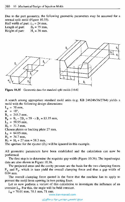
A search among appropriate standard mold units (e.g. KB 246246/36/2764) yields amold with the following design dimensions:LB = 70 mm,a = 18°,B4 = 245.7 mm,BF = B4 - 2B3 = 79 -> B3 = 83.35 mm,L5 = 58.95 mm,H5 = 31.3 mm,Chosen platen or backing plate 27 mm,L6 = 64.05 mm,H6 = 34.7 mm,H7 = H5 + 27 mm = 58.3 mm,The aperture for the ejector (D7) will be ignored in this example.
All geometric parameters have been established and the calculation can now beperformed.
The first step is to determine the requisite gap width (Figure 10.36). The input/outputdata are also shown in Figure 10.36.
The projected areas and the cavity pressure are the basis for the two clamping forcesF x and FY, which in turn yield the overall clamping force and thus a gap width of0.04 mm.
The overall clamping force quoted is the force that the machine has to apply toprevent the mold from opening in two parting lines.
Let us now perform a variant of this calculation to investigate the influence of anoversize LB. For this, the angle will be held constant.
LB = 70.01 mm, 70.1 mm, 71 mm.
Figure 10.35 Geometric data for standard split molds [10.6]
Due to the part geometry, the following geometric parameters may be assumed for anormal split mold (Figure 10.35).Half width of part: L3 = 24 mm,Length of part: BF = 79 mm,Height of part: H3 = 36 mm.
www.iran-mavad.com
مرجع تخصصی مهندسی مواد و متالورژی
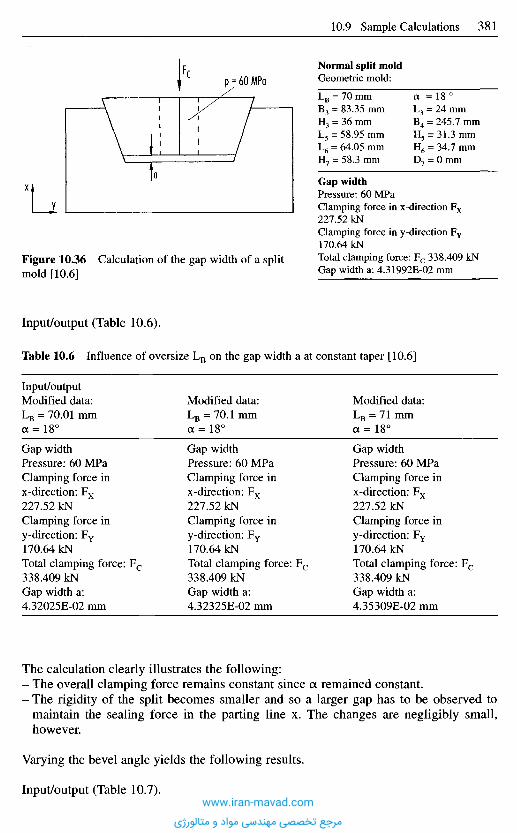
The calculation clearly illustrates the following:- The overall clamping force remains constant since a remained constant.- The rigidity of the split becomes smaller and so a larger gap has to be observed to
maintain the sealing force in the parting line x. The changes are negligibly small,however.
Varying the bevel angle yields the following results.
Input/output (Table 10.7).
Normal split moldGeometric mold:
LB = 70 mm a = 18 °B3 = 83.35 mm L3 = 24 mmH3 = 36 mm B4 = 245.7 mmL5 = 58.95 mm H5 = 31.3 mmL6 = 64.05 mm H6 = 34.7 mmH7 = 58.3 mm D7 = 0 mm
Gap widthPressure: 60 MPaClamping force in x-direction F x
227.52 kNClamping force in y-direction FY
170.64 kNTotal clamping force: F c 338.409 kNGap width a: 4.31992E-02 mm
Figure 10.36 Calculation of the gap width of a splitmold [10.6]
Input/output (Table 10.6).
Table 10.6 Influence of oversize LB on the gap width a at constant taper [10.6]
Input/outputModified data:LB = 70.01 mma =18°
Gap widthPressure: 60 MPaClamping force inx-direction: F x
227.52 kNClamping force iny-direction: FY
170.64 kNTotal clamping force: F c
338.409 kNGap width a:4.32025E-02 mm
Modified data:LB = 70.1 mma =18°
Gap widthPressure: 60 MPaClamping force inx-direction: F x
227.52 kNClamping force iny-direction: FY
170.64 kNTotal clamping force: F c
338.409 kNGap width a:4.32325E-02 mm
Modified data:LB = 71 mma =18°
Gap widthPressure: 60 MPaClamping force inx-direction: F x
227.52 kNClamping force iny-direction: FY
170.64 kNTotal clamping force: F c
338.409 kNGap width a:4.35309E-02 mm
www.iran-mavad.com
مرجع تخصصی مهندسی مواد و متالورژی
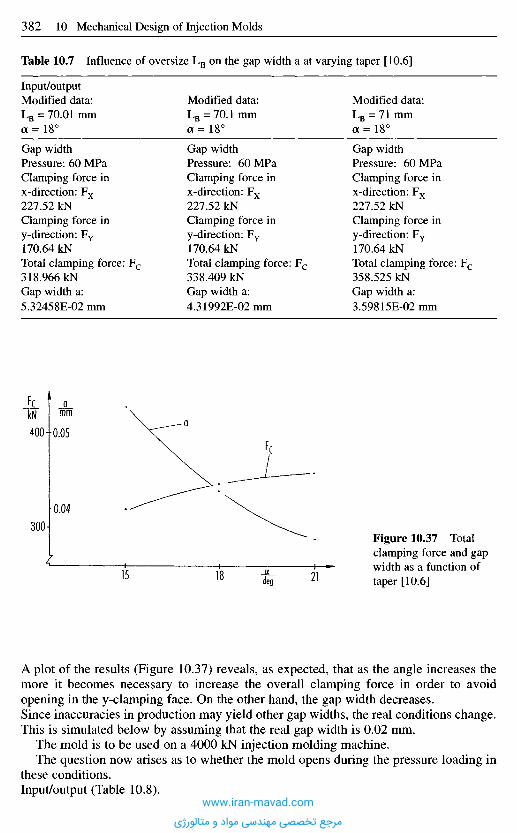
A plot of the results (Figure 10.37) reveals, as expected, that as the angle increases themore it becomes necessary to increase the overall clamping force in order to avoidopening in the y-clamping face. On the other hand, the gap width decreases.Since inaccuracies in production may yield other gap widths, the real conditions change.This is simulated below by assuming that the real gap width is 0.02 mm.
The mold is to be used on a 4000 kN injection molding machine.The question now arises as to whether the mold opens during the pressure loading in
these conditions.Input/output (Table 10.8).
Figure 10.37 Totalclamping force and gapwidth as a function oftaper [10.6]
_QL_deg
kNa
mm
Table 10.7 Influence of oversize LB on the gap width a at varying taper [10.6]
Input/outputModified data:LB = 70.01 mma =18°
Gap widthPressure: 60 MPaClamping force inx-direction: F x
227.52 kNClamping force iny-direction: FY
170.64 kNTotal clamping force: F c
318.966 kNGap width a:5.32458E-02 mm
Modified data:LB = 70.1 mma = 18°
Gap widthPressure: 60 MPaClamping force inx-direction: F x
227.52 kNClamping force iny-direction: FY
170.64 kNTotal clamping force: F c
338.409 kNGap width a:4.31992E-02mm
Modified data:LB = 71 mma =18°
Gap widthPressure: 60 MPaClamping force inx-direction: F x
227.52 kNClamping force iny-direction: FY
170.64 kNTotal clamping force: F c
358.525 kNGap width a:3.59815E-02 mm
www.iran-mavad.com
مرجع تخصصی مهندسی مواد و متالورژی
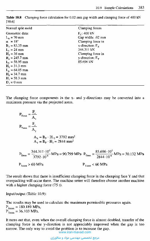
The result shows that there is insufficient clamping force in the clamping face Y and thatoverpacking will occur there. The machine setter will therefore choose another machinewith a higher clamping force (75 t).
Input/output (Table 10.9):
The results may be used to calculate the maximum permissible pressures again.Pxmax= 180.189 MPa,PYmax = 36.103 MPa.
It turns out that, even when the overall clamping force is almost doubled, transfer of theclamping force in the y-direction is not appreciably improved when the gap is toonarrow. The only way to avoid the problem is to increase the gap.
Table 10.8 Clamping force calculation for 0.02 mm gap width and clamping force of 400 kN[10.6]
Normal split mold Clamping forces
Geometric data: Fc: 400 kNLB = 70 mm Gap width: .02 mma =18° Clamping force inB3 = 83.35 mm x-direction: F x
L3 =24 mm 344.31IkNH3 = 36 mm Clamping force inB4 = 245.7 mm y-direction: FY
L5 = 58.95 mm 85.696 kNH5 = 31.3 mmL6 = 64.05 mmH6 = 34.7 mmH7 = 58.3 mmD7 = 0 mm
The clamping force components in the x- and y-directions may be converted into amaximum pressure via the projected areas.
www.iran-mavad.com
مرجع تخصصی مهندسی مواد و متالورژی
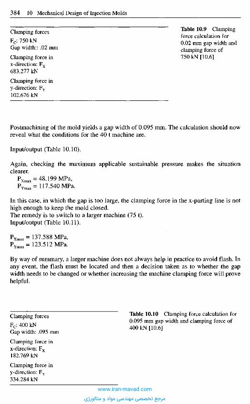
Postmachining of the mold yields a gap width of 0.095 mm. The calculation should nowreveal what the conditions for the 40 t machine are.
Input/output (Table 10.10).
Again, checking the maximum applicable sustainable pressure makes the situationclearer.
PXmax = 48.199 MPa,PYmax=117.540MPa.
In this case, in which the gap is too large, the clamping force in the x-parting line is nothigh enough to keep the mold closed,The remedy is to switch to a larger machine (75 t).Input/output (Table 10.11).
PXmax= 137.588 MPa,P Y m a x = 123.512 MPa.
By way of summary, a larger machine does not always help in practice to avoid flash. Inany event, the flash must be located and then a decision taken as to whether the gapwidth needs to be changed or whether increasing the machine clamping force will provehelpful.
Table 10.9 Clampingforce calculation for0.02 mm gap width andclamping force of750 kN [10.6]
Clamping forces
Fc: 750 kNGap width:: .02 mm
Clamping force inx-direction: F x
683.277 kN
Clamping force iny-direction: FY
102.676 kN
Table 10.10 Clamping force calculation for0.095 mm gap width and clamping force of400 kN [10.6]
Clamping forces
Fc: 400 kNGap width: .095 mm
Clamping force inx-direction: F x
182.769 kN
Clamping force iny-direction: FY
334.284 kN
www.iran-mavad.com
مرجع تخصصی مهندسی مواد و متالورژی
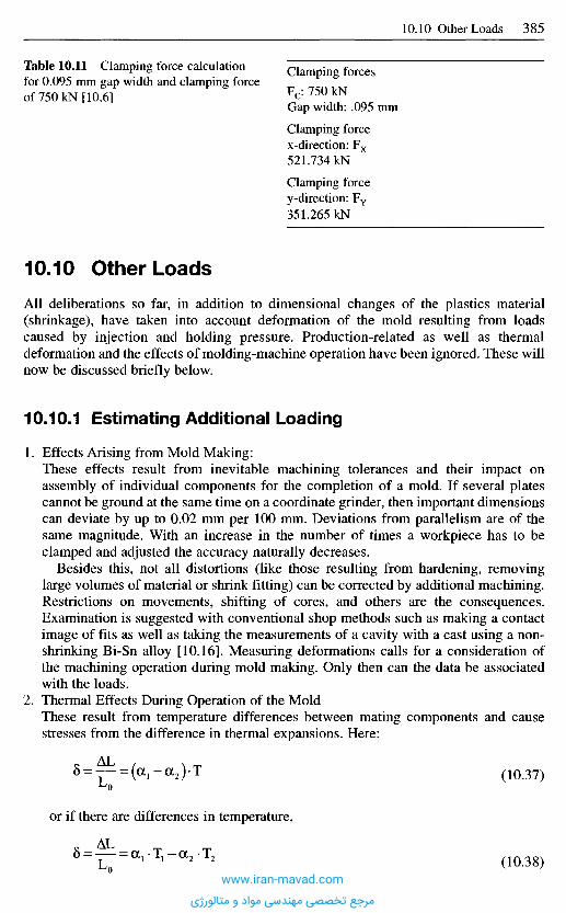
1 0 . 1 0 O t h e r L o a d s
All deliberations so far, in addition to dimensional changes of the plastics material(shrinkage), have taken into account deformation of the mold resulting from loadscaused by injection and holding pressure. Production-related as well as thermaldeformation and the effects of molding-machine operation have been ignored. These willnow be discussed briefly below.
10.10.1 Estimating Additional Loading
1. Effects Arising from Mold Making:These effects result from inevitable machining tolerances and their impact onassembly of individual components for the completion of a mold. If several platescannot be ground at the same time on a coordinate grinder, then important dimensionscan deviate by up to 0.02 mm per 100 mm. Deviations from parallelism are of thesame magnitude. With an increase in the number of times a workpiece has to beclamped and adjusted the accuracy naturally decreases.
Besides this, not all distortions (like those resulting from hardening, removinglarge volumes of material or shrink fitting) can be corrected by additional machining.Restrictions on movements, shifting of cores, and others are the consequences.Examination is suggested with conventional shop methods such as making a contactimage of fits as well as taking the measurements of a cavity with a cast using a non-shrinking Bi-Sn alloy [10.16]. Measuring deformations calls for a consideration ofthe machining operation during mold making. Only then can the data be associatedwith the loads.
2. Thermal Effects During Operation of the MoldThese result from temperature differences between mating components and causestresses from the difference in thermal expansions. Here:
(10.37)
(10.38)
Table 10.11 Clamping force calculationfor 0.095 mm gap width and clamping forceof 75OkN [10.6]
Clamping forcesFc: 750 kNGap width: .095 mm
Clamping forcex-direction: Fx
521.734 kN
Clamping forcey-direction: FY
351.265 kN
or if there are differences in temperature,
www.iran-mavad.com
مرجع تخصصی مهندسی مواد و متالورژی
If this deformation is restricted, stresses are generated, which can be calculated fromthe equilibrium of forces.
A typical example is the manifold of a hot-runner mold, for which the dislocation hasto be computed at least for the position of the gates.3. Effects Arising from Molding Machines:
Since injection molds are usually compact bodies, machine effects can usually beomitted from the computation. It is difficult to measure them anyway because theyvary from machine to machine.
R e f e r e n c e s
[10.1] Schurmann, E.: Abschatzmethoden fur die Auslegung von SpritzgieBwerkzeugen.Dissertation, Tech. Univ., Aachen, 1979.
[10.2] Kretzschmar, 0.: Rechnergestiitzte Auslegung von SpritzgieBwerkzeugen mit Segment-bezogenen Berechnungsverfahren. Dissertation, RWTH, Aachen, 1985.
[10.3] Krause, H.; Starke, B.: Gratbildung durch Plattenverformung rechnerisch ermitteln.Plastverarbeiter, 43, 10, pp. 133-141 and 11, pp. 90-94.
[10.4] Krause, H.: Modellbetrachtungen zur Werkzeugatmung beim SpritzgieBen. Plastver-arbeiter, 44, 8, pp. 58-64 and 9, pp. 82-90.
[10.5] Doring, E.; Schurmann, E.: Thermische und mechanische Auslegung von SpritzgieB-werkzeugen. Internal report, IKV, Aachen, 1979.
[10.6] Menges, G.; Hoven-Nievelstein, W. B.; Kretzschmar, O.; Schmidt, Th. W.: Handbuch zurBerechnung von SpritzgieBwerkzeugen. Verlag Kunststoff-Information, Bad Homburg,1985.
[10.7] Zawistowski, M.; Frenkler, D.: Konstrukcja form wtryskowych do tworzywtermoplastycznych (Design of injection molds for thermoplastics). WydawnictwoNaukowo-Techniczne, Warszawa, 1984.
[10.8] Krause, H.: Programm zur Berechnung der Querverformung. Plastverarbeiter 42 (1991),3, pp. 126-132 and 4, pp. 103-107.
[10.9] Barp; Freimann: Kreisformige Platten. Escher Wyss AG, Zurich.[10.10] Timoschenko, S.: Strength of Materials, 1 and 11. Van Nostrand, London, 1955/56.[10.11] Bangert, H.; Mohren, P.; Schurmann, E.; Wiibken, G.: Konstruktionshilfen fur den
Werkzeugbau. Lecture at the 8. Kunststofftechnisches Kolloquium, IKV Aachen;Industrie Anzeiger, 98 (1976), pp. 678-681 and pp. 706-710.
[10.12] Arndt, St.; Krause, H.: SpritzgieB-Backenwerkzeuge. Berechnungsprogramin zumKonstruieren und Betreiben. Plastverarbeiter, 41 (1990), 11, p. 144ff and 12, p. 52f.
[10.13] Rechenprogramm, Kunststofftechnische Software GmbH., Kaiserstr. 100, 52134Herzogenrath, Phone: 02407 5088.
[10.14] Henkel, W.: Untersuchung der Steifigkeit verschiedener Backenverriegelungen. IKV,1982.
[10.15] Bangert, H.: Mechanische Auslegung fur komplizierte Anwendungsfalle. VDI-IKV-Seminar "Rechnerunterstiitztes Konstruieren von SpritzgieBwerkzeugen", Miinster,1984.
[10.16] Dick, H.: Ubersicht iiber einfache Verfahren zur Herstellung von Prototypenwerkzeugenfur die Kunststoffverarbeitung. Unpublished report, IKV, Aachen, 1976.
www.iran-mavad.com
مرجع تخصصی مهندسی مواد و متالورژی
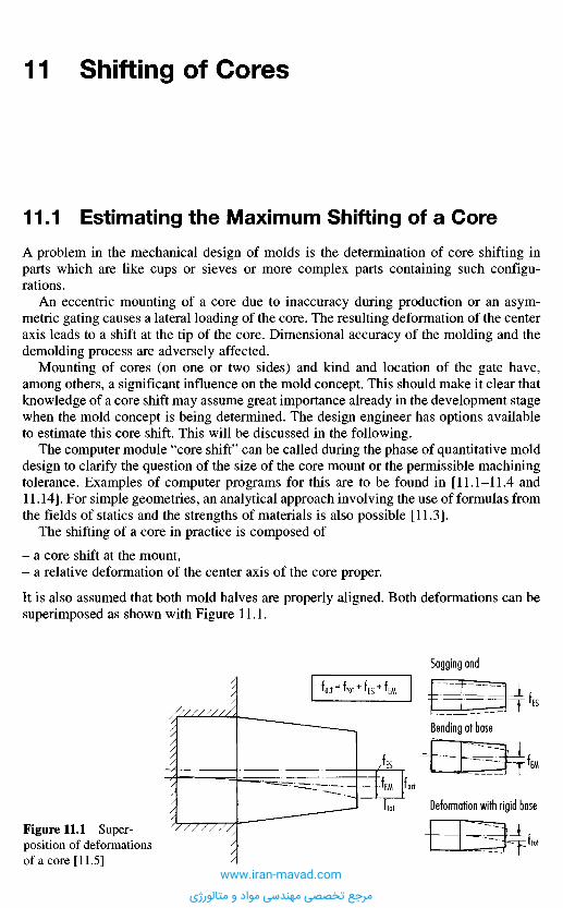
1 1 . 1 E s t i m a t i n g t h e M a x i m u m S h i f t i n g o f a C o r e
A problem in the mechanical design of molds is the determination of core shifting inparts which are like cups or sieves or more complex parts containing such configu-rations.
An eccentric mounting of a core due to inaccuracy during production or an asym-metric gating causes a lateral loading of the core. The resulting deformation of the centeraxis leads to a shift at the tip of the core. Dimensional accuracy of the molding and thedemolding process are adversely affected.
Mounting of cores (on one or two sides) and kind and location of the gate have,among others, a significant influence on the mold concept. This should make it clear thatknowledge of a core shift may assume great importance already in the development stagewhen the mold concept is being determined. The design engineer has options availableto estimate this core shift. This will be discussed in the following.
The computer module "core shift" can be called during the phase of quantitative molddesign to clarify the question of the size of the core mount or the permissible machiningtolerance. Examples of computer programs for this are to be found in [11.1-11.4 and11.14]. For simple geometries, an analytical approach involving the use of formulas fromthe fields of statics and the strengths of materials is also possible [11.3].
The shifting of a core in practice is composed of
- a core shift at the mount,- a relative deformation of the center axis of the core proper.
It is also assumed that both mold halves are properly aligned. Both deformations can besuperimposed as shown with Figure 11.1.
1 1 S h i f t i n g o f C o r e s
Figure 11.1 Super-position of deformationsof a core [11.5]
Sagging and
Bending at base
Deformation with rigid base
www.iran-mavad.com
مرجع تخصصی مهندسی مواد و متالورژی
Part of the shifting of a core generated during mold filling can recover after the fillingprocess during the cooling stage. The magnitude of this recovery depends on processingparameters, material characteristics and geometrical conditions. One can only expect aminor recovery with thin sections, slender cores, low injection speeds (quick freezing)and materials with a high modulus of elasticity. Therefore the maximum shift of coresduring injection is considered in the following.
For a variety of core configurations (circular and rectangular, with or without coolingline) and cases of loading (kind and location of gates) computing modules have beengenerated [11.5-11.7], which are employed in Software such as CADMOULD. Some ofthese cases will be presented.
Theoretically computed data for core shifting or limits for the height-to-diameter ratioof cores are in good agreement with results from practical experience. Another verifi-cation of theoretical data could be indirectly made by comparing the description of theflow pattern and the pressure consumption with actual measurements [11.8, 11.9].
By way of example, core shifting of circular cores with lateral pinpoint gate at thebase (rigid mount) will be calculated below.
1 1 . 2 S h i f t i n g o f C i r c u l a r C o r e s w i t h L a t e r a l P i n p o i n t
G a t e a t t h e B a s e ( R i g i d M o u n t )
The computation is based on a number of assumptions [11.6]:1. The pressure profile declines linearly along the length Hc of the core (Figure 11.3).2. A slightly tapered shape of the core is substituted by a cylindrical one.3. A core cooling is substituted by a through hole. The stabilizing effect of the section
without hole is neglected.4. In cores with an inserted cooling line, the insert is not considered load-supporting.5. The weight of the core is not taken into account.6. Mounting of the core is assumed rigid for the time being.7. A building-up effect remains neglected at present. The effect of the core shift on the
filling pattern during injection is not considered. Comments on assumptions 1 and 7are given in [11.6, 11.7].
The basic procedure for determining the core shift is illustrated with Figure 11.2.
- The core shift fv 10 at the tip of the core is computed for a reference pressure p* =10 MPa at the gate and a linear pressure profile along the core.
- To consider the supporting effect on the core by the melt from the base up, the shapefactor K1 is introduced. This coefficient includes the various height-to-diameter ratios.
- Establishing the pressure factor K2 considers the real pressure for filling the mold.- Computing the whole deflection with
fv = K rK2.fV5l0 (11.1)
Based on this procedure, computer programs were assembled, which provided the core-shift data presented in the following pictures [11.6].
Figures 11.3 and 11.4 demonstrate the core shift for polystyrene dependent on the corediameter and various core lengths. If the diameter remains below certain values, theshifting increases rather rapidly (refer to design limits in Section 11.4).
www.iran-mavad.com
مرجع تخصصی مهندسی مواد و متالورژی
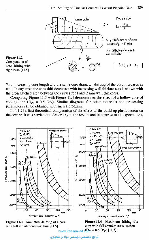
Preal
Pressure profile Pressure factor
fv 10 = Deflection at referencepressure of p* = 10 MPa
Total deflection of core withone end built-in
With increasing core length and the same core diameter shifting of the core increases aswell. In any case, the core shift decreases with increasing wall thickness as is shown withthe crosshatched area between the curves for 1 and 2 mm wall thickness.
Comparing Figure 11.3 with Figure 11.4 demonstrates the effect of a hollow core ofcooling line (DCi = 0.6 D*c). Similar diagrams for other materials and processingparameters can be obtained with such a program.
In [11.7] a first theoretical computation of the effect of the build-up phenomenon onthe core shift was carried out. According to the results and in contrast to all expectations,
Maxim
um c
ore s
hift /
5
Maxim
um c
ore s
hift f
s
Figure 11.3 Maximum shifting of a corewith full circular cross-section [11.5]
Figure 11.4 Maximum shifting of acore with full annular cross-section(Dci = 0.6 D*c) [11.5]
Average core diameter Dc*mm
Average core diameter Dc*mm
mm mm
Pressure profile
Pressure profile
Figure 11.2Computation ofcore shifting withrigid base [11.5]
www.iran-mavad.com
مرجع تخصصی مهندسی مواد و متالورژی

it does not add to the shifting of cores. The core-shifting data are even somewhat smallerthan without regarding this effect. A first explanation is given by two kinds of opposingeffects from the core shift during injection and its consequences on the rheologicalconditions. First the melt flows into the nonuniform cavity. From this, a higher load onone side of the core can be expected, but then the melt can flow more easily into theenlarged gap. This means less total pressure demand and relief for the core. Both effectsalmost cancel one another out. The effect of a build-up cannot be measured by itselfbecause it is present at all measurements.
The theoretical computation of a core shift with a build-up taken into account for thecase of a laterally gated core was carried out - similar to Section 11.3.1 (Figure 11.6) -by a step wise computation of the filling process.
For estimating the maximum core shift in design the presented results (without build-up effect) are sufficient, especially since these results are even somewhat higher.
In [11.5], a calculation of core shifting for further core geometries, mounting andloading types is presented. These are:
- Core shifting of circular cores with lateral pinpoint gate at the core tip (rigid mount).- Core shifting of rectangular with lateral pinpoint gate at the base (rigid mount).- Shifting of cores related to mounting (exemplified by a circular core laterally gated at
the base).
1 1 . 3 S h i f t i n g o f C i r c u l a r C o r e s w i t h D i s k G a t e s
( R i g i d M o u n t )
In [11.7] the shifting of circular cores without cooling line but with build-up effect iscomputed for
- cores with disk gate,- cores with lateral pinpoint gate at the base,- cores with lateral pinpoint gate at the tip.
Now the case "core with disk gate" will be discussed (Figure 11.5). Compared withpreviously treated cases, estimating the core shift calls for a different procedure here.The reason for this is an eccentric core mount linked to the machining process. Thiscauses the initial core shift. It is assumed, of course, that temperature, pressure, andvelocity (viscosity) are the same in the whole gate region.
Figure 11.5 Core with disk gate [11.5]www.iran-mavad.com
مرجع تخصصی مهندسی مواد و متالورژی
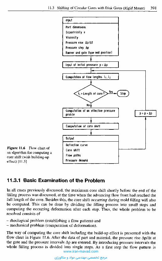
11.3.1 Basic Examination of the Problem
In all cases previously discussed, the maximum core shift shortly before the end of thefilling process was discussed, at the time when the advancing flow front had reached thefull length of the core. Besides this, the core shift occurring during mold filling will alsobe computed. This can be done by dividing the filling process into small steps andcomputing the occurring deformation after each step. Thus, the whole problem to beresolved consists of
- rheological problem (establishing a flow pattern) and- mechanical problem (computation of deformation).
The way of computing the core shift including the build-up effect is presented with theflow chart in Figure 11.6. After the data of part and material, the pressure rise Ap/At atthe gate and the pressure intervals Ap are entered. By introducing pressure intervals thewhole filling process is divided into single steps. As a first step the flow pattern is
Figure 11.6 Flow chart ofan algorithm for computing acore shift (with building-upeffect) [11.5]
Input
Part dimensionsEccentricity eViscosityPressure rise Ap/AtPressure step ApRunner and gate (type and position)
Input of initial pressure p = Ap
Computation of flow lengths i^Ai
StopYesI1 >Length of core?
No
Computation of an effective pressureprofile p = p • Ap
Computation of core shift
Output
Deflection curveCore shiftFlow pathsPressure demand
www.iran-mavad.com
مرجع تخصصی مهندسی مواد و متالورژی
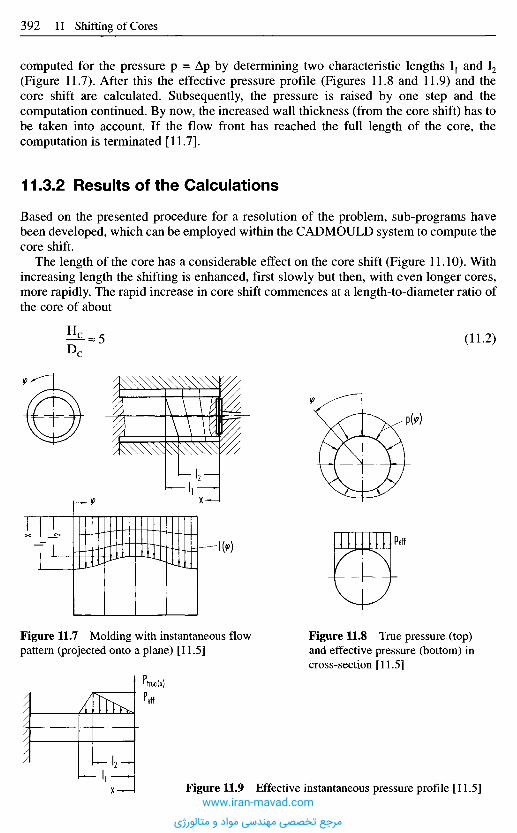
computed for the pressure p = Ap by determining two characteristic lengths I1 and I2
(Figure 11.7). After this the effective pressure profile (Figures 11.8 and 11.9) and thecore shift are calculated. Subsequently, the pressure is raised by one step and thecomputation continued. By now, the increased wall thickness (from the core shift) has tobe taken into account. If the flow front has reached the full length of the core, thecomputation is terminated [11.7].
11.3.2 Results of the Calculations
Based on the presented procedure for a resolution of the problem, sub-programs havebeen developed, which can be employed within the CADMOULD system to compute thecore shift.
The length of the core has a considerable effect on the core shift (Figure 11.10). Withincreasing length the shifting is enhanced, first slowly but then, with even longer cores,more rapidly. The rapid increase in core shift commences at a length-to-diameter ratio ofthe core of about
(11.2)
Figure 11.7 Molding with instantaneous flowpattern (projected onto a plane) [11.5]
Figure 11.8 True pressure (top)and effective pressure (bottom) incross-section [11.5]
Figure 11.9 Effective instantaneous pressure profile [11.5]www.iran-mavad.com
مرجع تخصصی مهندسی مواد و متالورژی

This ratio is largely independent from any eccentricity because the latter affects coreshifting linearly. The limit ratio also retains its validity with different wall thicknesses.Even with adhering to this ratio, the resulting core shift may already be too much.Similar limits are also published in [11.10].
Thin sections in a part promote an asymmetrical flow into the cavity and producelarger deformations (Figure 11.11).
If, however, the mentioned length-to-diameter ratio is observed, wall thickness haslittle effect.
The influence of eccentricity can be recognized in Figure 11.12. In a normal case thiseccentricity is the deviation of the center axis of the core from the center axis of thecavity caused by inaccurate machining.
Figure 11.10 Maximum shifting of cores with varying diameters depending on core length(disk gate) [11.5]
Length of core Hc
mm
Maxim
um c
ore
shift
f s
Wall thickness smm
Figure 11.11 Maximum shifting of cores depending on wall thickness (disk gate) [11.5]
Smm1.5
PS-e
urn100
143EAp/AtkPa/s100
ApkPa1200
12J456
Hcmm8080UU
100100100
eurn50
100IbU50
100150
ApkPa1800150012UU180015001200
pm
urn
PS-K3EDc = 15 mmAp/At =100MPa/s
www.iran-mavad.com
مرجع تخصصی مهندسی مواد و متالورژی
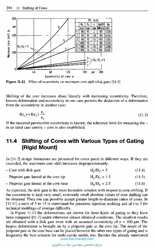
If the maximal permissible eccentricity is known, the tolerance limit for mounting the -in an ideal case centric - core is also established.
1 1 . 4 S h i f t i n g o f C o r e s w i t h V a r i o u s T y p e s o f G a t i n g
( R i g i d M o u n t )
In [11.7] design limitations are presented for cores gated in different ways. If they areexceeded, the maximum core shift increases disproportionately.
- Core with disk gate H c / D c « 5 (11.4)
- Pinpoint gate lateral at the core tip Hc/Dc - 1 . 5 (115)
- Pinpoint gate lateral at the core base Hc/Dc = 2.5 (116)
As expected, the disk gate is the most favorable solution with respect to core shifting. Ifthe eccentricity is kept very small, extremely small absolute values of core shifting canbe obtained. Then one can possibly accept greater length-to-diameter ratios of cores. In[11.11] a ratio of 5 to 15 is mentioned for precision injection molding and of 1 to 5 fortechnical moldings of average difficulty.
In Figure 11.13 the deformations are shown for three kinds of gating as they havebeen computed [11.7] under otherwise almost identical conditions. The smallest resultsare obtained with a disk gate even with an assumed eccentricity of e = 100 urn. Thelargest deformation is brought on by a pinpoint gate at the core tip. The result of thepinpoint gate at the core base can be placed between the other two types of gating and isfrequently the best solution for multi-cavity molds, too. Besides the already mentioned
Eccentricity ot core e
Figure 11.12 Effect of eccentricity on maximum core shift (disk gate) [11.5]
Shifting of the core increases about linearly with increasing eccentricity. Therefore,known deformation and eccentricity in one case permits the deduction of a deformationfrom the eccentricity in another case:
(11.3)
pm
Maxim
um c
ore
shift
fs
pm
PS-U3E
K2
rr
JL6
Hcmm808080
100100100
Ocmm151515151515
Smm21.81.621.81.6
Ap/AtMPa/s80801008080
100
ApkPa120012001200120012001200
www.iran-mavad.com
مرجع تخصصی مهندسی مواد و متالورژی
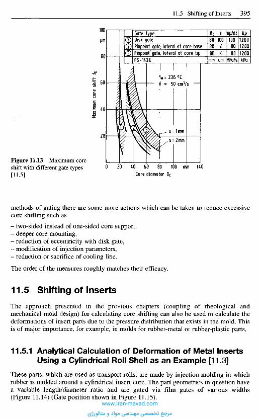
methods of gating there are some more actions which can be taken to reduce excessivecore shifting such as
- two-sided instead of one-sided core support,- deeper core mounting,- reduction of eccentricity with disk gate,- modification of injection parameters,- reduction or sacrifice of cooling line.
The order of the measures roughly matches their efficacy.
1 1 . 5 S h i f t i n g o f I n s e r t s
The approach presented in the previous chapters (coupling of rheological andmechanical mold design) for calculating core shifting can also be used to calculate thedeformations of insert parts due to the pressure distribution that exists in the mold. Thisis of major importance, for example, in molds for rubber-metal or rubber-plastic parts.
11.5.1 Ana l y t i ca l Ca l cu la t i on o f D e f o r m a t i o n of Me ta l Inser tsUs ing a Cy l i nd r i ca l Rol l She l l as a n E x a m p l e [11.3]
These parts, which are used as transport rolls, are made by injection molding in whichrubber is molded around a cylindrical insert core. The part geometries in question havea variable length/diameter ratio and are gated via film gates of various widths(Figure 11.14) (Gate position shown in Figure 11.15).
Figure 11.13 Maximum coreshift with different gate types[11.5] Core diameter Dc
mm
Maxim
um c
ore
shift
f$
\im
Gate typeDisk gatePinpoint gate, lateral at core basePinpoint gate, lateral at core tipP5-143E
Hc808080
mm
e100/Zurn
Ap/At1008080
MPa/s
Ap120012001200kPa
www.iran-mavad.com
مرجع تخصصی مهندسی مواد و متالورژی

As already explained in the previous section, a rheological mold design is performedfirst, to determine the filling pressure distribution in the cavity. The boundary conditionsof the simulation calculation arise essentially through the given material-specificcoefficients of the material models and the processing parameters of the injectionmolding process.
As an example, Figure 11.15 shows the finite element net used for a part geometryand Figure 11.16 shows the corresponding computed filling pressure distribution from asimulation. The pressure distribution of a number of part geometries was calculated atdifferent filling levels.
Then, the deformation calculation was performed analytically for this part with the aidof the formulae provided by statics and the strengths of materials.
11.5.1.1 Evaluation of the Deflection Line for Different Part Geometries
Figure 11.17 shows the maximum mold insert deflection against filling level for thesample calculation. It can be seen that the deflection of the mold core rises until thefilling level is roughly 50%. At around 50%, the flow fronts converge in the areaopposite the gate. As the mold continues to fill up, the pressure difference between thecore upper surface or gate side and the core lower surface decreases, as a result of whichthe deflection of the mold core decreases towards the end of filling. It can generally besaid that the narrower the film gate, the higher is the deflection on account of the higherpressure losses.
Figure 11.14 Dimensionsand gating arrangement formolded parts [11.14]
Figure 11.15Structured geometry ofmolded part Ic withnetwork refinement inthe gate area [11.3]
s fabric
^elasto
mer
Film gatePinpoint gate
Ring gate
I core
d core
www.iran-mavad.com
مرجع تخصصی مهندسی مواد و متالورژی
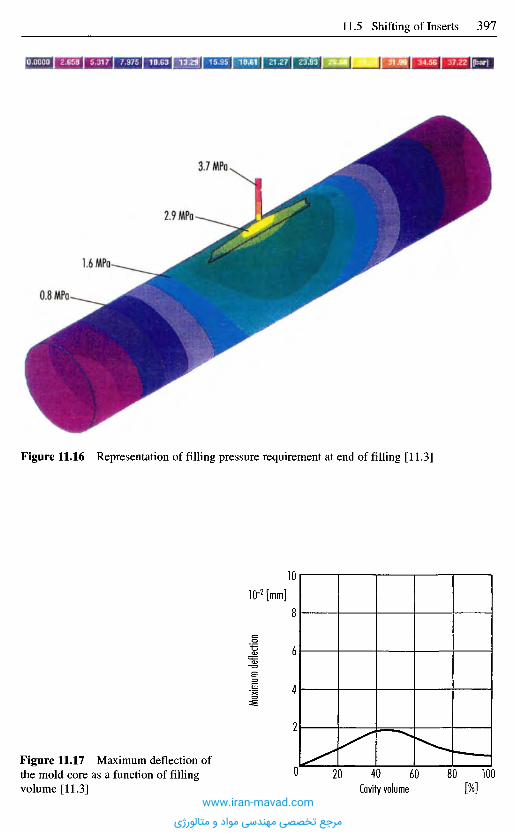
Figure 11.16 Representation of filling pressure requirement at end of filling [11.3]
Maxim
um de
flecti
on
IO"2 [mm]
Cavity volume [%]
Figure 11.17 Maximum deflection ofthe mold core as a function of fillingvolume [11.3]
www.iran-mavad.com
مرجع تخصصی مهندسی مواد و متالورژی

In the case of a diameter/length ratio d/1 of approx. 0.2, once the flow fronts haveconverged, further filling of the cavity is accompanied by a reduction in the pressuredifference between part upper face or gate side and part lower face, as a result of whichdeflection of the mold core decreases again towards the end of filling.
Molded part geometries with a d/1 ratio less than 0.1 pass through a deflectionminimum and then undergo a renewed rise in deflection that may be attributed to othercomponents of the pressure difference between the sprue side and the mold clampinghalf. The temporary maximum deflection on convergence of the flow fronts can beexceeded at the end of filling.
These studies show the deflection that may be expected for a given pressure distri-bution and the influence that the part geometry has on the maximum deflection and thecourse of deflection.
However, due to multiple integration of the pressure function, this analytical approachcan only be applied to parts whose geometry comprises simple basic bodies (cylinders,plates) and whose pressure load can be described by simple mathematics.
The use of an FE analysis program is advisable for more complex geometries orloading.
The qualitative change in deflection of the mold geometries at different diameter/lengthratios is shown in Figure 11.18. From the function curves, it can be seen that thedeflection of the mold cores increases until that filling level is reached whichcorresponds with the converging of the flow fronts in the area opposite the gate. Afterfilling of the cavity just after convergence of the flow fronts is complete (diameter/lengthratio of approx. 0.5), the maximum deflection is attained at the end of filling.
Core
defle
ction
Core
defle
ction
Core
defle
ction
Cavity volume Cavity volume
Cavity volume
d/1 = 0.5 d/1 = 0.2
d/1 = 0.1
[%]
[%][%]
Figure 11.18 Change in deflection fordifferent geometries [11.3]
www.iran-mavad.com
مرجع تخصصی مهندسی مواد و متالورژی
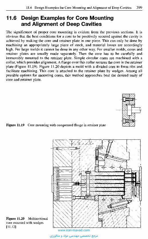
1 1 . 6 D e s i g n E x a m p l e s f o r C o r e M o u n t i n g
a n d A l i g n m e n t o f D e e p C a v i t i e s
The significance of proper core mounting is evident from the previous sections. It isobvious that the best conditions for a core to be positively secured against the cavity isachieved by making the core and retainer plate in one piece. This can only be done bymachining an appropriately large piece of stock, and material losses are accordinglyhigh. For large molds it cannot be done in any other way. For smaller molds, cores andretainer plates are usually made separately. Then the core has to be carefully andimmovably mounted to the retainer plate. Simple circular cores are machined with acollar, which provides alignment. A flange over this collar secures the core in the retainerplate (Figure 11.19). Figure 11.20 depicts a mold with a divided core to form ribs andfacilitate machining. This core is attached to the retainer plate by wedges. Among allpossible options for mounting cores, this method approaches best the desired unity ofcore and retainer plate.
Figure 11.19 Core mounting with compressed flange in retainer plate
Figure 11.20 Multisectionalcore mounted with wedges[11.12]
www.iran-mavad.com
مرجع تخصصی مهندسی مواد و متالورژی
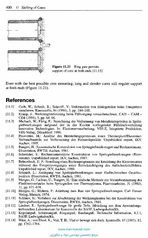
Even with the best possible core mounting, long and slender cores still require supportat both ends (Figure 11.21).
R e f e r e n c e s
[11.1] Guth, W.; Schenk, R.; Schroiff, V.: Deformation von Einlegeteilen beim Umspritzensimulieren. Kunststoffe, 84 (1994), 3, pp. 244-248.
[11.2] Knaup, J.: Werkzeugverformung beim Fullvorgang vorausberechnen. CAD - CAM -CIM (1994), 5, pp. 64-68.
[11.3] Michaeli, W.; Ehrig, E.: Berechnung der Verformung von Metalleinlegeteilen in Spritz-gieBwerkzeugen aufgrund der in der Kavitat vorliegenden FulldruckverteilungInnovative Technologien. In: Elastomerverarbeitung, VDI-Z, Integrierte Produktion,VDI-Verlag, Diisseldorf, 1996.
[11.4] Pesavento, M.: Analyse des Herstellungsprozesses eines Thermoplast/Elastomer-Verbundbauteils zur Verbesserung der Formteilqualitat. Unpublished report, IKV,Aachen, 1995.
[11.5] Bangert, H.: Systematische Konstruktion von Spritzgiefiwerkzeugen und Rechnereinsatz.Dissertation, RWTH, Aachen, 1981.
[11.6] Schreuder, S.: Rechnerunterstiitzte Konstruktion von SpritzgieBwerkzeugen (Kern-versatz). Unpublished report, IKV, Aachen, 1987.
[11.7] Behrenbeck, U. P.: Erstellung eines Rechenprogramms zur Ermittlung des Kernversatzeswahrend des Einspritzvorganges unter Beriicksichtigung des Aufschaukeleffektes.Unpublished report, IKV, Aachen, 1980.
[11.8] Schmidt, L.: Auslegung von SpritzgieBwerkzeugen unter flieBtechnischen Gesichts-punkten. Dissertation, RWTH, Aachen, 1981.
[11.9] Menges, G.; Lichius, U.; Bangert, H.: Eine einfache Methode zur Vorausbestimmung desFlieBfrontverlaufes beim SpritzgieBen von Thermoplasten. Plastverarbeiter, 31 (1980),11, pp. 671-676.
[11.10] Menges, G.; Mohren, P.: Anleitung zum Bau von SpritzgieBwerkzeugen. Carl HanserVerlag, Munich, 1974.
[11.11] Schluter, H.: Verfahren zur Abschatzung der Werkzeugkosten bei der Konstruktion vonSpritzgieBwerkzeugen. Dissertation, RWTH, Aachen, 1981.
[11.12] Lindner, E.: SpritzgieBwerkzeuge fiir groBe Teile. Mitteilung aus dem Anwendungs-technischen Laboratorium fur Kunststoffe der BASF, Ludwigshafen/Rh.
[11.13] KegelanguB, SchirmanguB, RinganguB, BandanguB. Technische Information, 4.2.1,BASF, Ludwigshafen/Rh.
[11.14] Wust, A.; von Diest, K.; Voit, T. H.: Und er bewegt sich doch. Kuststoffe, 87 (1997), 12,pp. 1762-1764.
Figure 11.21 Ring gate permitssupport of core at both ends [11.13]
www.iran-mavad.com
مرجع تخصصی مهندسی مواد و متالورژی
1 2 . 1 S u m m a r y o f E j e c t i o n S y s t e m s
After the molding has solidified and cooled down, it has to be removed from the mold.It would be ideal if gravity could separate the part from cavity or core after moldopening. The molding is kept in place, however, by undercuts, adhesion and, internalstresses and, therefore, has to be separated and removed from the mold by specialmeans.
Ejection equipment is usually actuated mechanically by the opening stroke of themolding machine. If this simple arrangement effected by the movement of the clampingunit is not sufficient, ejection can be performed pneumatically or hydraulically [12.1 to12.3]. Manually actuated ejection can only be found in very small or prototype moldsand for small series if little force suffices for actuating ejection and an exact cycle is ofno concern.
The ejector system is normally housed in the movable mold half. Mold openingcauses the mechanically actuated ejector system to be moved towards the parting lineand to eject the molding. Precondition for this procedure is, of course, that the moldingstays on or in the movable mold half. This can be achieved by undercuts or by letting themolding shrink onto a core. Taper and surface treatment should prevent too muchadhesion, however.
Retaining the molding on the movable half becomes a problem if the core is on thestationary side. This should be avoided or more elaborate demolding systems are needed.Figure 12. IB is an example.
Figure 12.1 summarizes the usual ejector systems, as they are used for smallermoldings:
A Standard system for small parts.B Direction of ejection towards movable side. Stripping is used but usually for circular
parts only.C Demolding at two parting lines for automatic operation including separation of gate.D Demolding of parts with local undercuts (slide mold).E Demolding of large, full-side undercut (split-cavity mold).F Unscrewing molds for threads.G Air ejectors usually provide support. Breaking is done mechanically.
Finally, one has to take into account that larger moldings are demolded by pushing themout, but they must not be ejected. They are removed manually or by robot after beingloosened.
1 2 E j e c t i o n
www.iran-mavad.com
مرجع تخصصی مهندسی مواد و متالورژی
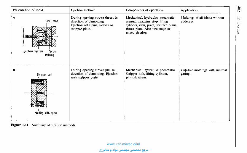
Application
Moldings of all kinds withoutundercut.
Cup-like moldings with internalgating.
Components of operation
Mechanical, hydraulic, pneumatic,manual, machine stop, liftingcylinder, cam, pivot, inclined plane,thrust plate. Also two-stage ormixed ejection.
Mechanical, hydraulic, pneumatic.Stripper bolt, lifting cylinder,pin-link chain.
Ejection method
During opening stroke thrust indirection of demolding.Ejection with pins, sleeves orstripper plate.
During opening stroke pull indirection of demolding. Ejectionwith stripper plate.
Presentation of mold
A
B
Figure 12.1 Summary of ejection methods
Molding with sprue
Stripper bolt
SprueMolding
Ejection system
Limit stop
www.iran-mavad.com
مرجع تخصصی مهندسی مواد و متالورژی
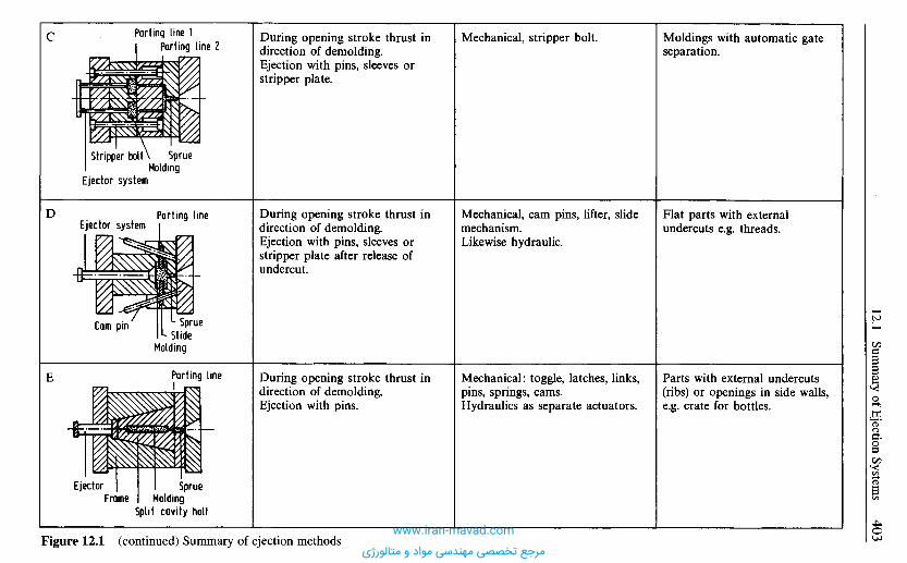
Moldings with automatic gateseparation.
Flat parts with externalundercuts e.g. threads.
Parts with external undercuts(ribs) or openings in side walls,e.g. crate for bottles.
Mechanical, stripper bolt.
Mechanical, cam pins, lifter, slidemechanism.Likewise hydraulic.
Mechanical: toggle, latches, links,pins, springs, cams.Hydraulics as separate actuators.
During opening stroke thrust indirection of demolding.Ejection with pins, sleeves orstripper plate.
During opening stroke thrust indirection of demolding.Ejection with pins, sleeves orstripper plate after release ofundercut.
During opening stroke thrust indirection of demolding.Ejection with pins.
Figure 12.1 (continued) Summary of ejection methods
Parting line
SprueMolding
Split cavity halfFrame
Ejector
E
SprueSlide
Molding
Cam pin
Parting lineEjector system
D
SprueMolding
Ejector system
Stripper bolt
Parting line 1Parting line 2
C
www.iran-mavad.com
مرجع تخصصی مهندسی مواد و متالورژی
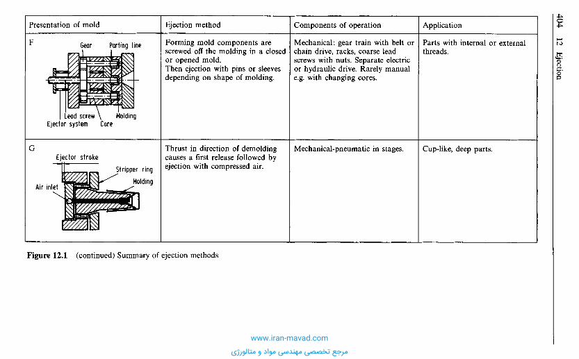
Application
Parts with internal or externalthreads.
Cup-like, deep parts.
Components of operation
Mechanical: gear train with belt orchain drive, racks, coarse leadscrews with nuts. Separate electricor hydraulic drive. Rarely manuale.g. with changing cores.
Mechanical-pneumatic in stages.
Ejection method
Forming mold components arescrewed off the molding in a closedor opened mold.Then ejection with pins or sleevesdepending on shape of molding.
Thrust in direction of demoldingcauses a first release followed byejection with compressed air.
Figure 12.1 (continued) Summary of ejection methods
Presentation of mold
Molding
Stripper ring
Ejector stroke
Air inlet
G
MoldingCore
Lead screwEjector system
Parting lineGearF
www.iran-mavad.com
مرجع تخصصی مهندسی مواد و متالورژی
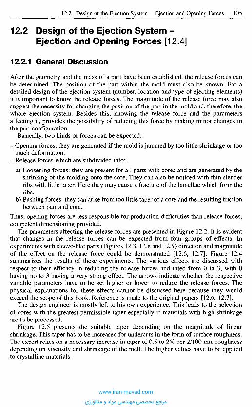
1 2 . 2 D e s i g n o f t h e E j e c t i o n S y s t e m -
E j e c t i o n a n d O p e n i n g F o r c e s [ 1 2 . 4 ]
12.2.1 Genera l D i s c u s s i o n
After the geometry and the mass of a part have been established, the release forces canbe determined. The position of the part within the mold must also be known. For adetailed design of the ejection system (number, location and type of ejecting elements)it is important to know the release forces. The magnitude of the release force may alsosuggest the necessity for changing the position of the part in the mold and, therefore, thewhole ejection system. Besides this, knowing the release force and the parametersaffecting it, provides the possibility of reducing this force by making minor changes inthe part configuration.
Basically, two kinds of forces can be expected:
- Opening forces: they are generated if the mold is jammed by too little shrinkage or toomuch deformation.
- Release forces which are subdivided into:
a) Loosening forces: they are present for all parts with cores and are generated by theshrinking of the molding onto the core. They can also be noticed with thin slenderribs with little taper. Here they may cause a fracture of the lamellae which form theribs.
b) Pushing forces: they can arise from too little taper of a core and the resulting frictionbetween part and core.
Thus, opening forces are less responsible for production difficulties than release forces,competent dimensioning provided.
The parameters affecting the release forces are presented in Figure 12.2. It is evidentthat changes in the release forces can be expected from four groups of effects. Inexperiments with sleeve-like parts (Figures 12.3, 12.8 and 12.9) direction and magnitudeof the effect on the release force could be demonstrated [12.6, 12.7]. Figure 12.4summarizes the results of these experiments. The various effects are discussed withrespect to their efficacy in reducing the release forces and rated from 0 to 3, with 0having no to 3 having a very strong effect. The arrows indicate whether the respectivevariable parameters have to be set higher or lower to reduce the release forces. Thephysical explanations for these effects cannot be discussed here because they wouldexceed the scope of this book. Reference is made to the original papers [12.6, 12.7].
The design engineer is mostly left to his own experience. This leads to the selectionof cores with the greatest permissible taper especially if materials with high shrinkageare to be processed.
Figure 12.5 presents the suitable taper depending on the magnitude of linearshrinkage. This taper has to be increased for undercuts in the form of surface roughness.The expert relies on a necessary increase in taper of 0.5 to 2% per 2/100 mm roughnessdepending on viscosity and shrinkage of the melt. The higher values have to be appliedto crystalline materials.
www.iran-mavad.com
مرجع تخصصی مهندسی مواد و متالورژی
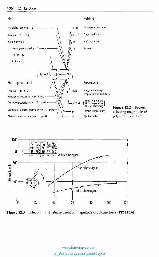
Figure 12.3 Effect of mold release agent on magnitude of release force (PP) [12.6]
Relea
se for
ce F E
N
with release agent
no release agent
with release agent
Figure 12.2 Factorsaffecting magnitude ofrelease forces [12.5]
Processing
Pressure build-upTemperature of molding T£
Melt temperatureMold temperatureTime of demolding
Contact temperature
Ejection rate
Molding material
Friction = f (T) ji
Modulus of elasticity
Therm, characteristics
Coefficient of therm, expansion
Thermodynamics (shrinkage)
Molding
Thickness of sections
Cross sections
Projected area
Undercuts
Mold
Rigidity (design) p
Cooling T
Mold material:
Therm, characteristics T
Friction \i
Surface fi
itmm38
TMSV0C280
TWK0C40
TWN0C32
PW1 maxMPa760
www.iran-mavad.com
مرجع تخصصی مهندسی مواد و متالورژی
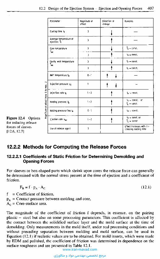
12.2.2 Methods for Comput ing the Release Forces
12.2.2.1 Coefficients of Static Friction for Determining Demolding andOpening Forces
For sleeves or box-shaped parts which shrink upon cores the release force can generallybe determined with the normal stress present at the time of ejection and a coefficient offriction.
FR = f - p A - A c (12.1)
f = Coefficient of friction,pA = Contact pressure between molding and core,Ac = Core-surface area.
The magnitude of the coefficient of friction f depends, in essence, on the pairingplastic - steel but also on some processing parameters. This coefficient is affected bythe contact between the solidified surface layer and the mold surface at the time ofdemolding. Only measurements in the mold itself, under real processing conditions andwithout preceding separation between molding and mold surface, can be used inEquation (12.1) if realistic values are to be obtained. For mold inserts, which were madeby EDM and polished, the coefficient of friction was determined in dependence on thesurface roughness and are presented in Table 12.1.
Figure 12.4 Optionsfor reducing releaseforces of sleeves[12.6, 12.7]
Magn
itude o
f effe
ct fro
m 0 t
o max.
3
Parameter
Cooling time tE
Average temperature atejection TE
Core temperatureTWK
Cavity wall temperatureTWH
Melt temperature TM
Injection pressure pE
Injection rate vE
Holding pressure PN
Holding pressure time tN
Ejection rate vOu,
Use of release agent
Magnitude ofeffect
3
3
3
3
3
3
0-1
1
1-2
1-2
0-1
1 -2
3
Direction ofchange
Remarks
tK = const.
tn = const, orTE = const.
tK = const.
tK = const, orTE = const.
Effect increases with in-creasing cooling time
TE = const.
tK = const.
TE = const.
tK = const.
www.iran-mavad.com
مرجع تخصصی مهندسی مواد و متالورژی
The static friction coefficients in Table 12.1 were determined from the breaking forcesthat occurred immediately at the start of the demolding process for the part in theinjection mold [12.9, 12.10].
The values in Table 12.1 are the maximum values for the friction coefficientdetermined using various process parameters. Since the process parameters are notknown exactly at the start of the mold design and cannot always be reliably observedduring operation when known and since, moreover, the f values show scatter, therespective value in the Table should be multiplied by a factor of 1.5 to 2.
Figure 12.5 Diagram fortapers [12.8]Taper in degrees
Taper in mm
Length in mm
www.iran-mavad.com
مرجع تخصصی مهندسی مواد و متالورژی
The scope for influencing the f value is shown in Figure 12.6, taking PE as an example.The extent of the influence is divided into 4 steps, 0-3, where
0: No influence,1: Slight influence,2: Moderate influence,3: Strong influence.
The direction of the arrow in the column "Direction of change" denotes whether thepertinent influential parameter has to be increased (T) or decreased (4,) in order to obtainlower f values. The dependency shown here for PE apply in the main to PP, PS, ABS andPC as well [12.9, 12.10].
Aside from the coefficient of friction, the surface pressure between core and moldedpart must be determined. It may be calculated theoretically [12.11-12.13] or with the aidof a very simple method based on experience (shrinkage values).
Table 12.1 Coefficient of staticfriction dependent on roughnessheight [12.9, 12.10]
Material
PEPPPSABSPC
Coefficient of friction for roughness height
1 um
0.380.470.370.350.47
6 um
0.520.500.520.460.68
20 um
0.700.841.821.331.60
Factor
Contact pressure
Ejection rate
Cooling time
Average cavity-wall temperature
Melt temperature
Holding pressure
Release agent
Surface finish
Magnitudeof effect
0-1 (2)
0-1 (2)
(0) 1-2
2-3
0-1 (2)
0-1 (2, 3)
1-3
1-3
Direction of change Remarks
More notable effect (2) is theexception with Ra = 35 um
Considerable effect with veryrough surfaces
(0) with release agent
No definite statement possible
Considerable effect with roughsurface and with increasingholding pressure raising pwmax
Deviations possible in rarecases
Figure 12.6 Options for reducing the coefficient of static friction of polyethylene (PE)www.iran-mavad.com
مرجع تخصصی مهندسی مواد و متالورژی
12.2.2.2 The Estimation Method for Cylindrical Sleeves
For practical purposes another method has been developed to quickly estimate therelease forces. They can be determined with sufficient accuracy, e.g., for sleeves[12.6, 12.12], which demand high release forces by their nature.
The assumption is made that the design engineer has to be able to establish anappropriate core diameter, which corresponds to the final internal diameter of the part.From the resulting diameter differential an absolute upper limit for the release force canalready be estimated by means of an equilibrium of forces. This will be explained witha thin-walled sleeve as an example [12.6] (see flow chart in Figure 12.10).
The shrinkage of the molding is restricted by the core. This causes a build-up ofstresses in the cross-sections of the part, which results in forces normal to the surfacesrestrained from shrinking. The stored energy-elastic forces can recover spontaneouslywith demolding. The resulting contraction of circumference or diameter causes ameasurable decrease in the inside diameter of the sleeve. The relative decrease of thepart's diameter or circumference is:
(12.2)
Wherein
ACr Relative change in circumference,dc Core diameter,di(tE) ID of sleeve immediately after demolding.
The circumferential reduction, measured immediately after demolding is directlyassociated with the tensile stress in the cross-section of the part as long as the moldingwas still on the core. Its computation is simple; the thin-walled sleeve does not requirePoisson's ratio to be applied (Figure 12.7):
(12.3)
(12.4)
(12.5)
(12.6)
(12.7)
(12.8)
(Hooke's law)
or in this case (Figure 12.7):
Hence
withwww.iran-mavad.com
مرجع تخصصی مهندسی مواد و متالورژی
FE is always the breaking force which is necessary to initiate the ejection movement andis related to static friction. This release force takes only the force for demolding the partinto account regardless of the friction of the ejector system.
Depending on mold size and the kind of ejector system, the forces from friction in thesystem ZF8, which vary in magnitude, have to be added to the release forces if the totalpower demand for demolding has to be computed (selection of a machine with adequateejection force).
The demand on ejection force for n cavities results from
(12.11)
This method was used for a sleeve made of ABS (dc =38 mm, do = 46 mm, L = 30 mm)and compared with measurements of the release force. The results were satisfactory asdemonstrated in Figure 12.8 [12.6].
Because the design engineer usually does not know in advance which change indiameter he can expect, he can calculate this change with the information of linearshrinkage (raw-material supplier) and use it as a starting point for his calculation(Figure 12.9) as follows:
Point A shows the mold open with the molding still on the core producing contactpressure from cooling. B represents the state immediately after ejection. A decrease indiameter results from the spontaneous energy-elastic deformation:
(12.12)
Stages A and B correspond to one and the same point for TE on the 100 kPa-line in ap-v-T diagram because they do not differ thermodynamically from one another. Coolingdown to room temperature results in the stage C, for which a corresponding volume
With the coefficient of friction f, the necessary release force is obtained from
(12.9)
(12.10)
sM Wall thickness of part,rc Radius of core.
Figure 12.7 Computationof release forces for sleeves[12.6]
www.iran-mavad.com
مرجع تخصصی مهندسی مواد و متالورژی
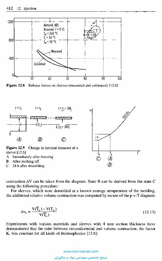
contraction AV can be taken from the diagram. State B can be derived from the state Cusing the following procedure:
For sleeves, which were demolded at a known average temperature of the molding,the additional relative volume contraction was computed by means of the p-v-T diagram:
(12.13)
Experiments with various materials and sleeves with 4 mm section thickness havedemonstrated that the ratio between circumferential and volume contraction, the factorK, was constant for all kinds of thermoplastics [12.6]:
Figure 12.9 Change in internal diameter of asleeve [12.6]A Immediately after freezingB After pushing offC 24 h after demolding
Figure 12.8 Release forces on sleeves (measured and estimated) [12.6]
Measured
Calculated
Material: ABSAssumed: f = 0.15TM = 260 0CTc = 54 0CTw = 50 0C
www.iran-mavad.com
مرجع تخصصی مهندسی مواد و متالورژی
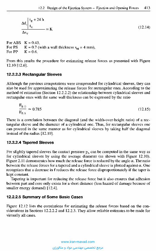
For ABS K - 0 . 4 3 ,For PS K - 0.7 (with a wall thickness sM = 4 mm),For PP K - 0.6.
From this results the procedure for estimating release forces as presented with Figure12.10 [12.6].
12.2.2.3 Rectangular Sleeves
Although the previous computations were compounded for cylindrical sleeves, they canalso be used for approximating the release forces for rectangular ones. According to themethod of estimation (Section 12.2.2.2) the relationship between cylindrical sleeves andrectangular ones with the same wall thickness can be expressed by the ratio
- 0.785 (12.15)FED
There is a correlation between the diagonal (and the width-over-height ratio) of a rec-tangular sleeve and the diameter of a cylindrical one. Thus, for rectangular sleeves onecan proceed in the same manner as for cylindrical sleeves by taking half the diagonalinstead of the radius [12.11].
12.2.2.4 Tapered Sleeves
For slightly tapered sleeves the contact pressure pA can be computed in the same way asfor cylindrical sleeves by using the average diameter (as shown with Figure 12.10).Figure 2.11 demonstrates how much the release force is reduced by the angle a. The ratiobetween the release forces for a tapered and a cylindrical sleeve is plotted against a. Onerecognizes that a decrease in f reduces the release force disproportionately if the taper iskept constant.
Tapering is important for reducing the release force but it also ensures that adhesionbetween part and core only exists for a short distance (less hazard of damage because ofsmaller energy demand) [12.4].
12.2.2.5 Summary of Some Basic Cases
Figure 12.12 lists the correlations for estimating the release forces based on the con-siderations in Sections 12.2.2.2 and 12.2.3. They allow reliable estimates to be made forvirtually all cases.
(12.14)
www.iran-mavad.com
مرجع تخصصی مهندسی مواد و متالورژی
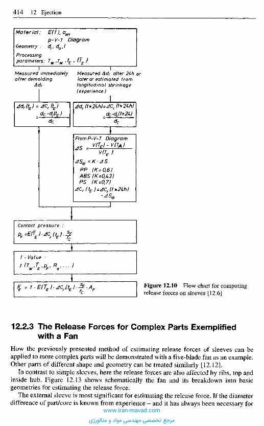
12.2.3 The Release Forces for Complex Parts Exemplifiedwith a Fan
How the previously presented method of estimating release forces of sleeves can beapplied to more complex parts will be demonstrated with a five-blade fan as an example.Other parts of different shape and geometry can be treated similarly [12.121.
In contrast to simple sleeves, here the release forces are also affected by ribs, top andinside hub. Figure 12.13 shows schematically the fan and its breakdown into basicgeometries for estimating the release force.
The external sleeve is most significant for estimating the release force. If the diameterdifference of part/core is known from experience - and it has always been necessary for
Figure 12.10 Flow chart for computingrelease forces on sleeves [12.6]
Material: E(T). aeff
p-V-T DiagramGeometry : djf da,lProcessing _parameters: TW>TM >*£ > (?E )
Measured immediatelyafter demolding
Ad r
Measured Adr after 24h orlater or estimated fromlongitudinal shrinkage(experience)
FromP-V-T Diagram
Contact pressure :
f -Value :
www.iran-mavad.com
مرجع تخصصی مهندسی مواد و متالورژی
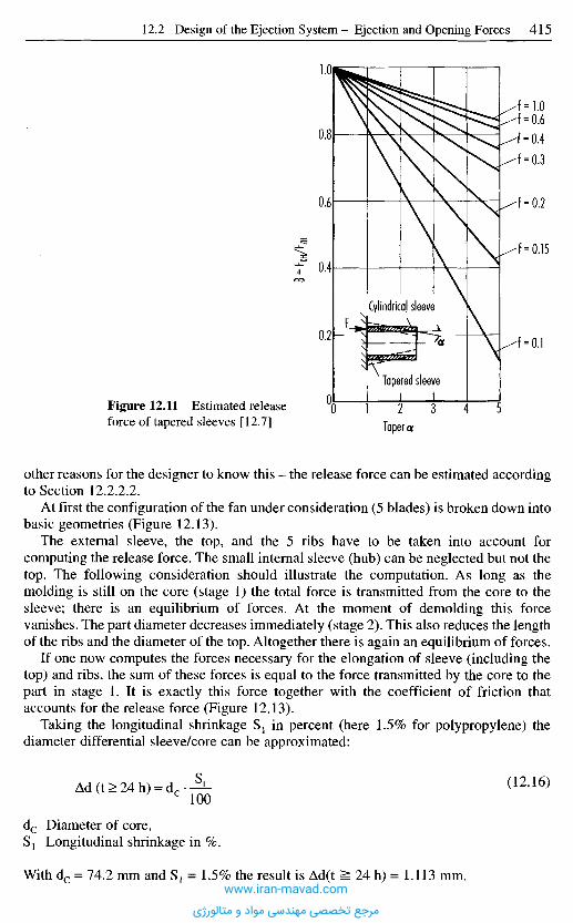
other reasons for the designer to know this - the release force can be estimated accordingto Section 12.2.2.2.
At first the configuration of the fan under consideration (5 blades) is broken down intobasic geometries (Figure 12.13).
The external sleeve, the top, and the 5 ribs have to be taken into account forcomputing the release force. The small internal sleeve (hub) can be neglected but not thetop. The following consideration should illustrate the computation. As long as themolding is still on the core (stage 1) the total force is transmitted from the core to thesleeve; there is an equilibrium of forces. At the moment of demolding this forcevanishes. The part diameter decreases immediately (stage 2). This also reduces the lengthof the ribs and the diameter of the top. Altogether there is again an equilibrium of forces.
If one now computes the forces necessary for the elongation of sleeve (including thetop) and ribs, the sum of these forces is equal to the force transmitted by the core to thepart in stage 1. It is exactly this force together with the coefficient of friction thataccounts for the release force (Figure 12.13).
Taking the longitudinal shrinkage S1 in percent (here 1.5% for polypropylene) thediameter differential sleeve/core can be approximated:
Ad(t>24h) = d c - ^ - ( 1 2 ' 1 6 )
dc Diameter of core,S1 Longitudinal shrinkage in %.
With dc = 74.2 mm and S1 = 1.5% the result is Ad(t ^ 24 h) = 1.113 mm.
Figure 12.11 Estimated releaseforce of tapered sleeves [12.7] Taper a
B"
^KHA
ZHCylindrical sleeve
Tapered sleeve
www.iran-mavad.com
مرجع تخصصی مهندسی مواد و متالورژی
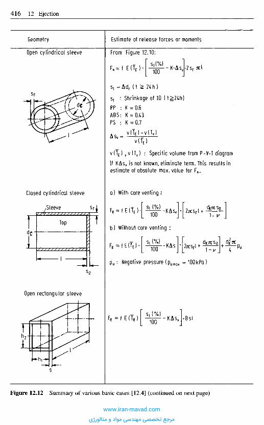
Geometry
Open cylindrical sleeve
Estimate of release forces or moments
From Figure 12.10:
Si : Shrinkage of ID (t^24h)
v (TE) 7 v (Tv) : Specific volume from P-V-T diagram
If KAsv is not known, eliminate term. This results inestimate of absolute max. value for FR.
Closed cylindrical sleeve a) With core venting :
b) Without core venting :
,Sleeve
Top
Open rectangular sleeve
Pu: Negative pressure (pumQX = 10OkPa )
Figure 12.12 Summary of various basic cases [12.4] (continued on next page)
www.iran-mavad.com
مرجع تخصصی مهندسی مواد و متالورژی

Geometry Estimate of release forces or moments
Closed rectangular sleeve a) With core venting :
b) Without core venting :
hi see previous figure
Threaded sleeveSaw-toothed thread
Direction of demolding
pu = Negative pressure (pumQX = 100 kPa)
Two different cases of shrinkage are considered. Thehighest torque is taken for design purposes
Root rests upon crest
Internal thread
External threadStatic torque :
Sliding torque :
fo. Coeff.of static friction; f Coeff.of sliding friction
Case 2 :Internal thread rests uniformly upon external thread.
Internal thread
External thread
Static torque :
Sliding torque :Same as above with fo replacing f for sliding
Figure 12.12 (continued) Summary of various basic cases [12.4]www.iran-mavad.com
مرجع تخصصی مهندسی مواد و متالورژی
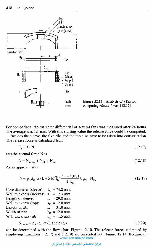
For comparison, the diameter differential of several fans was measured after 24 hours.The average was 1.1 mm. With this starting value the release force could be computed.
Besides the sleeve, the five ribs and the top also have to be taken into consideration.The release force is calculated from
(12.17)
and the normal force N is
(12.18)
As an approximation
(12.19)
Core diameter (sleeve): dc = 74.2 mm,Wall thickness (sleeve): s = 2.3 mm,Length of sleeve: L =29.8 mm,Wall thickness (top): sT = 2.0 mm,Length of rib: LR = 31.0 mm,Width of rib: bR = 12.0 mm,Wall thickness (rib): sR = 1.5 mm,
(12.20)
can be determined with the flow chart Figure 12.10. The release forces estimated byemploying Equations (12.17) and (12.19) are presented with Figure 12.14. Because of
Figure 12.13 Analysis of a fan forcomputing release forces [12.12]
Top
Hub(sleeve)Stage 1Stage 2
Rib
Insidesleeve
Dissection into:
TopRibInside sleeve,Hub (sleeve)
www.iran-mavad.com
مرجع تخصصی مهندسی مواد و متالورژی
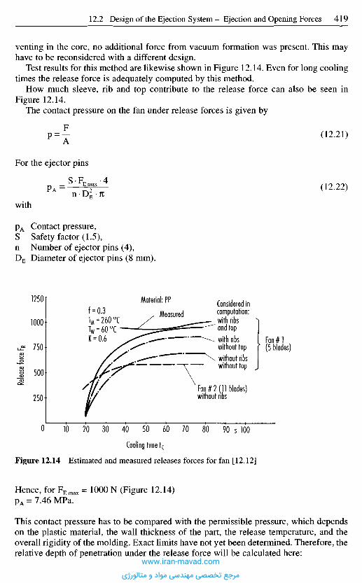
venting in the core, no additional force from vacuum formation was present. This mayhave to be reconsidered with a different design.
Test results for this method are likewise shown in Figure 12.14. Even for long coolingtimes the release force is adequately computed by this method.
How much sleeve, rib and top contribute to the release force can also be seen inFigure 12.14.
The contact pressure on the fan under release forces is given by
(12.21)
(12.22)
For the ejector pins
with
pA Contact pressure,S Safety factor (1.5),n Number of ejector pins (4),DE Diameter of ejector pins (8 mm).
Relea
se for
ce F R
Cooling time tc
Figure 12.14 Estimated and measured releases forces for fan [12.12]
Hence, for F E m a x = 1000 N (Figure 12.14)pA = 7.46 MPa.
This contact pressure has to be compared with the permissible pressure, which dependson the plastic material, the wall thickness of the part, the release temperature, and theoverall rigidity of the molding. Exact limits have not yet been determined. Therefore, therelative depth of penetration under the release force will be calculated here:
s
Material: PP
MeasuredConsidered incomputation:with ribsand topwith ribswithout topwithout ribswithout top
Fan#l(5 blades)
Fan #2 (11 blades)without ribs
f = 0.3TM = 260 0CTw = 60 0C "K = 0.6
www.iran-mavad.com
مرجع تخصصی مهندسی مواد و متالورژی
The small values of As and e indicate that no problems need be expected.Finally, there is the buckling of the ejector pins under cavity pressure to be con-
sidered.According to Figure 12.27, and assuming
PW max =100 MPa,DE = 8 mm,
the critical length is 280 mm. This dimension must not be exceeded.
12.2.4 Numerical Computat ion of Demolding Processes(for Elastomer Parts)
For the mechanical design and dimensioning of injection molded parts, the finiteelements method (FEA) has proved to be a powerful tool for the designer [12.14].However, FEA is rarely used for the numerical computation of demolding processes ofthermoplastic injection-molded parts. The major reason for this is that the frictionalrelationships between mold wall and part surface, as described in Section 12.2.2.1, areinfluenced by a large number of factors. For this reason, the friction conditions duringpart design can often only be estimated, with the result that FEA can only yield roughcomputations. The outlay involved in FEA calculations is not always offset by thebenefit gained.
With elastomer parts, however, FEA can be a useful tool for assessing demoldingprocesses. Unlike thermoplastics, elastomers are noted for their high elasticity. Thisspecial material property is not only exploited in the technical applications for which the
(12.23)
(12.24)
From
and
the approximate result is
As Depth of penetration,sw Wall thickness (2 mm).
Hence
or
www.iran-mavad.com
مرجع تخصصی مهندسی مواد و متالورژی
parts are used. When rubber parts are made with undercuts by the master mold method(e.g., injection molding, transfer molding), often demolding occurs without the undercutof the mold being eliminated, i.e., without the undercut being exposed by slides or splits.This type of demolding is possible due to the high deformation capability of elastomers.The resulting cost-efficient production of parts with undercuts opens up greater designscope than is actually used in practice. A large number of rubber parts with undercutsfind technical application (e.g. rotary shaft seals, spring elements of car engine bearings,expansion bellows).
Nevertheless, for elastomers, the demoldability of undercuts is limited by themaximum sustainable material load. The local stresses and strains that actually occur inthe part during the demolding process are dependent on the following parameters:
- undercut geometry,- elastomer material,- frictional conditions between part and mold wall,- processing parameters,- nature and mode of action of the force exerted by the demolding device on the part
(e.g., by ejector system or handling device).
If the elastomer material is over-stressed during demolding, this may cause the part tofail immediately (e.g., the part may tear in the undercut area) or it may suffer damagethat makes the part no longer adequate in terms of service life or maximum sustainableload. The design of rubber parts can therefore not just proceed on the basis of loads inpractical use alone. Demoldability of undercuts must also be assessed at the design stage.At this stage, the loads are generally completely different from those which affect thepart in practical use.
At the moment, dimensioning of the undercuts is usually carried out on the basis ofthe designer's experience or that of trial and error. Often, this fails to fully exploit thepotential of rubber as a material, or damage is sometimes introduced unnoticed into thepart during demolding. With the aid of FEA calculations, however, the designer is put inthe position of being able to estimate the maximum possible undercut as a function ofthe geometry, the material, and the demolding kinematics. A motivation for applyingFEA to this problem is that FEA can already be applied to complex geometries duringthe design stage and that local peak loads in the part can be simulated under majordeformation, frictional contact and non-linear material behavior.
The potential and advantages of using FEA to simulate demolding will be illustratedin the following example in which the dimensions of a rotary shaft seal have to bedetermined, whose geometry is shown in Figure 12.15. For a certain type of rotary shaftring demolding, local crack formation was discovered in a large number of parts (up to30%). They are labeled in the part geometry shown in Figure 12.15.
The rotary shaft seal is made in an automated injection process. The mold employedis shown in Figure 12.16 (starting situation). It consists of four parts: the upper part(item 1), the middle part (item 3, the lower part (item 2b), and the mandrel (item 2a).Demolding is initiated by raising the upper part. Then the lower part with mandrel islowered. The traverse speed of the mold parts is roughly 0.02 m/s. The rotary shaft sealremains during both stages in position on the middle part. This is now swiveled into themanipulating area of the machine, where the seal is pushed out of the mold by a slidebar.
This demolding process was simulated with the aid of FEA [12.15], Figure 12.17shows, by way of example, the results of the deformation simulation for traversing of the
www.iran-mavad.com
مرجع تخصصی مهندسی مواد و متالورژی

Reinforcing ring
•Elastomer part
Figure 12.15 Cross-section of a radial shaft seal showing damage that occurred duringdemolding: 1—4 (in order of damage frequency)
Protective lip
•Spring
a-area
P-area
Starting situation Step 2Stepl
Gate
Upper part
Lower part with mandrel
Middle part
Figure 12.16 Demolding process for the radial shaft sealwww.iran-mavad.com
مرجع تخصصی مهندسی مواد و متالورژی

Demolding step 2
Demolding stroke
Figure 12.17 Calculated deformation of the part cross-section during demolding of the uppermold part (see mold part in Figure 12.13)
lower mold and the mandrel with protective lip as undercut. Other results of the FEAanalysis are the stress and strain distributions in the part. The locations of the calculatedpeak loads are found to coincide with crack formation zones observed in practice (innerside of the annular spring seat and protective lip connection; Figure 12.15). Thecalculated maximum stresses and maximum strains match or exceed the strength limitsfor the elastomer material that were determined in the rapid tearing test. FEA analysiscan therefore help to predict failure of the part during demolding.
The demolding forces which the part exerts on the mold wall can also be calculated,provided that the value of the coefficient of sliding friction is known with sufficient
Demolding force atUpper mold partLower mold part
Demolding distance y [mm]
Figure 12.18 Calculated demolding forces at the upper and lower mold parts for part shown inFigure 12.13
www.iran-mavad.com
مرجع تخصصی مهندسی مواد و متالورژی

Figure 12.19 Reduction in material stress during demolding as a result of design optimization(see mold part in Figure 12.13)
12.2.5 Estimating the Opening Forces
Only a completely accurate design ensures adequately small opening forces, which donot cause interruptions of the production or damage to molds and moldings. Becauseconsiderable opening forces should not occur, methods of their computation as proposedin the literature are dispensed with. If required, they can be taken from this literature[12.4].Should there, nevertheless, be a problem of this kind at the start-up of a new mold, tryingthe following measures is recommended:1. Reducing the injection pressure to the level required to just fill the cavity. If the part
can now be demolded perfectly, then increase the injection pressure to the level justbeneath where the problems occur again.
2. If method 1 fails, the mold is too weak and must be strengthened or modified. To thisend, the necessary dimensions for the critical areas are calculated with the aid of theformulae quoted in Chapter 10.
accuracy. Figure 12.18 shows the change in reaction forces for the simulated demoldingprocess. The demolding stage at which the reaction force is a maximum correlates withthe point in time at which there is maximum internal stress in the part. It is thus possibleto identify the most critical phase of the demolding process.
To avoid part failure during demolding, process and geometry variants are calculatedwith the aid of FEA. Reversing the sequences of the mold (demolding of the lower partfollowed by demolding of the upper part) does not lead to any improvement (this wasconfirmed in practice). In contrast, slight changes to the undercut geometry bring aboutmajor reductions in peak loads. If the undercut of the protective lip is reduced by 20%,without the lip being shortened, the stress peaks are below the value of the yield stress(Figure 12.19).
Protective lip
Stress [MPa]
www.iran-mavad.com
مرجع تخصصی مهندسی مواد و متالورژی
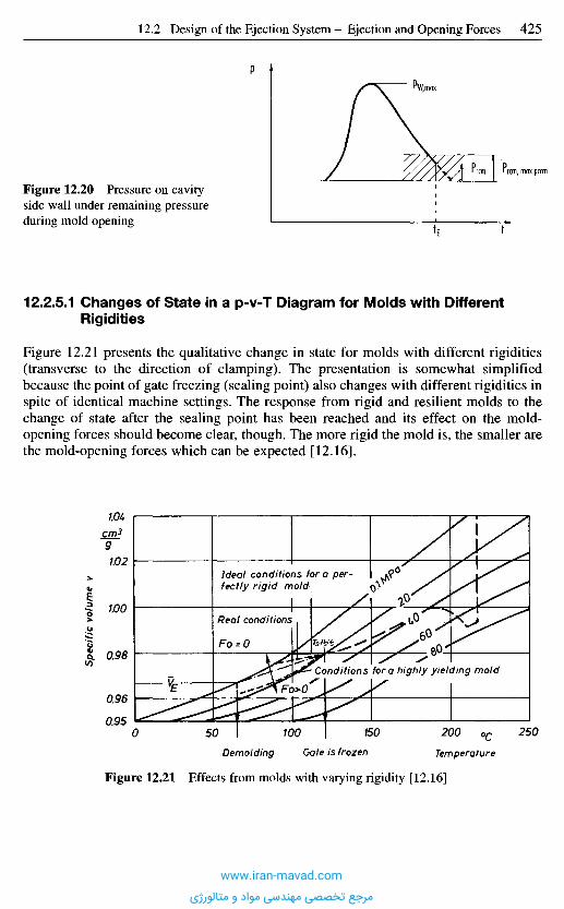
Spec
ific v
olum
e v
crr>39
Figure 12.21 Effects from molds with varying rigidity [12.16]
Demolding Gate is frozen Temperature
0C
Ideal conditions fora per-fectly rigid mold
Real conditions
Fo = O
Conditions fora highly yielding mold
12.2.5.1 Changes of State in a p-v-T Diagram for Molds with DifferentRigidities
Figure 12.21 presents the qualitative change in state for molds with different rigidities(transverse to the direction of clamping). The presentation is somewhat simplifiedbecause the point of gate freezing (sealing point) also changes with different rigidities inspite of identical machine settings. The response from rigid and resilient molds to thechange of state after the sealing point has been reached and its effect on the mold-opening forces should become clear, though. The more rigid the mold is, the smaller arethe mold-opening forces which can be expected [12.16].
Figure 12.20 Pressure on cavityside wall under remaining pressureduring mold opening
I rcm, max pccm
P
t
P'W,max
www.iran-mavad.com
مرجع تخصصی مهندسی مواد و متالورژی

12.2.5.2 Indirect Opening Forces
The release force in slide molds, acting perpendicular to the direction of mold opening,is generated by the opening force through the cam pins (Figure 12.83).
Estimating the release force Q (e.g., for a sleeve positioned accordingly) can be donewith the Equations in the Chapter "Slide Molds". Using the relationships shown inFigure 12.83 the necessary opening force can then be computed.
12.2.5.3 Total Opening Force
The total opening force is composed of
- Forces from friction in the mold Fof,- Forces from acceleration Foa,- Direct opening forces Fod,- Indirect opening forces Foi
Fo, machine/mold = Fof + Foa + Fod + Foi (12.25)
1 2 . 3 T y p e s o f E j e c t o r s
1 2 . 3 . 1 D e s i g n a n d D i m e n s i o n s o f E j e c t o r P i n s
To demold a molding, ejector pins are the most frequently employed elements. They areon the market as standards in many variations and dimensions [12.17 to 12.21]. Ejectorpins are mostly made of hotwork die steel (AISI H-13 type) and hardened or gas nitridedto achieve a high surface hardness of about 70 Rc. Adequate hardening and good surfacequality prevent seizing in the mold and ensure long service life. Molybdenum disulfideshould be applied to the pin surface during maintenance work to improve function underadverse conditions.
Nitrided ejector pins are primarily used in molds for thermosets and for lengths ofmore than 200 mm.
For shorter lengths (under 200 mm) and low operating temperatures, ejector pins ofannealed tool steel are also in use. Their hardness is 60 to 62 Rc at the shaft and 45 Rcat the head.
The heads of ejector pins are hot-forged. This produces a uniform grain flow andavoids sharp corners, which would weaken the pin by a notch effect.
There are two basic types of ejector pins according to their intended use(Figure 12.22):a) Straight cylindrical pins are the most common for all ejection forces. The cylindrical
head reduces the hazard of being pressed into the ejector plate. They are usually avail-able in diameters from 1.5 to 25 mm or 3/64 to 1 in. and in lengths up to 635 mm or25 in.
b) Shoulder-type or stepped ejector pins are employed if only a small area of themolding is available for ejection and little force is needed. The stepped shaft raisesthe buckling strength. Common diameters are from 1.5 to 3.0 mm or 3/64 to 7/64 in.
www.iran-mavad.com
مرجع تخصصی مهندسی مواد و متالورژی
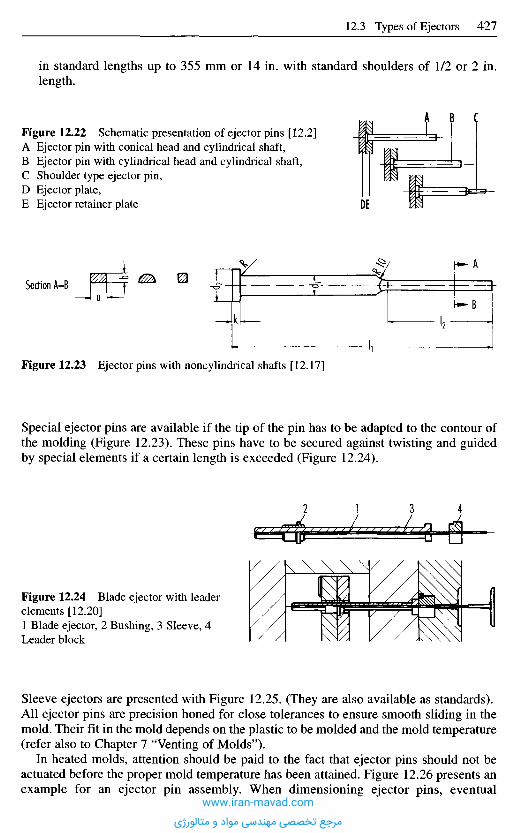
Sleeve ejectors are presented with Figure 12.25. (They are also available as standards).AU ejector pins are precision honed for close tolerances to ensure smooth sliding in themold. Their fit in the mold depends on the plastic to be molded and the mold temperature(refer also to Chapter 7 "Venting of Molds").
In heated molds, attention should be paid to the fact that ejector pins should not beactuated before the proper mold temperature has been attained. Figure 12.26 presents anexample for an ejector pin assembly. When dimensioning ejector pins, eventual
Figure 12.24 Blade ejector with leaderelements [12.20]1 Blade ejector, 2 Bushing, 3 Sleeve, 4Leader block
Special ejector pins are available if the tip of the pin has to be adapted to the contour ofthe molding (Figure 12.23). These pins have to be secured against twisting and guidedby special elements if a certain length is exceeded (Figure 12.24).
Figure 12.23 Ejector pins with noncylindrical shafts [12.17]
Section A-B
Figure 12.22 Schematic presentation of ejector pins [12.2]A Ejector pin with conical head and cylindrical shaft,B Ejector pin with cylindrical head and cylindrical shaft,C Shoulder type ejector pin,D Ejector plate,E Ejector retainer plate
in standard lengths up to 355 mm or 14 in. with standard shoulders of 1/2 or 2 in.length.
www.iran-mavad.com
مرجع تخصصی مهندسی مواد و متالورژی
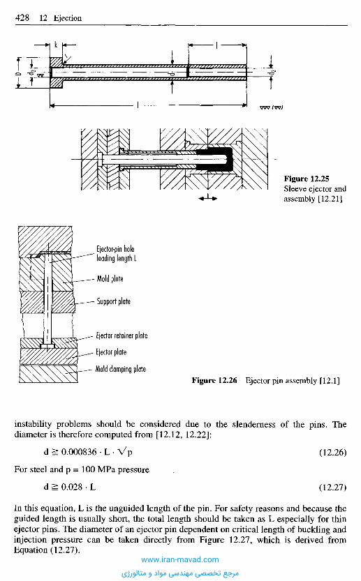
instability problems should be considered due to the slenderness of the pins. Thediameter is therefore computed from [12.12, 12.22]:
d ^ 0.000836 • L • Vrj (12.26)
For steel and p = 100 MPa pressure
d ^ 0.028 • L (12.27)
In this equation, L is the unguided length of the pin. For safety reasons and because theguided length is usually short, the total length should be taken as L especially for thinejector pins. The diameter of an ejector pin dependent on critical length of buckling andinjection pressure can be taken directly from Figure 12.27, which is derived fromEquation (12.27).
Figure 12.26 Ejector pin assembly [12.1]
Ejector-pin holeleading length L
- Mold plate
- Support plate
- Ejector retainer plate
Ejector plate
Mold clamping plate
Figure 12.25Sleeve ejector andassembly [12.21]
www.iran-mavad.com
مرجع تخصصی مهندسی مواد و متالورژی
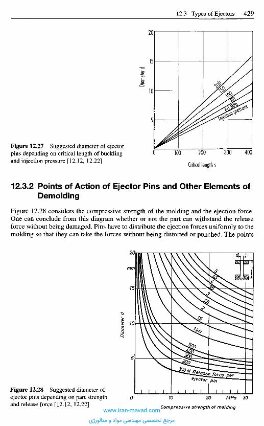
12.3.2 Points of Action of Ejector Pins and Other Elements ofDemolding
Figure 12.28 considers the compressive strength of the molding and the ejection force.One can conclude from this diagram whether or not the part can withstand the releaseforce without being damaged. Pins have to distribute the ejection forces uniformly to themolding so that they can take the forces without being distorted or punched. The points
Figure 12.27 Suggested diameter of ejectorpins depending on critical length of bucklingand injection pressure [12.12, 12.22]
Diame
ter d
Diam
eter
d
Critical length s
Compressive strength of molding
Figure 12.28 Suggested diameter ofejector pins depending on part strengthand release force [12.12, 12.22]
www.iran-mavad.com
مرجع تخصصی مهندسی مواد و متالورژی
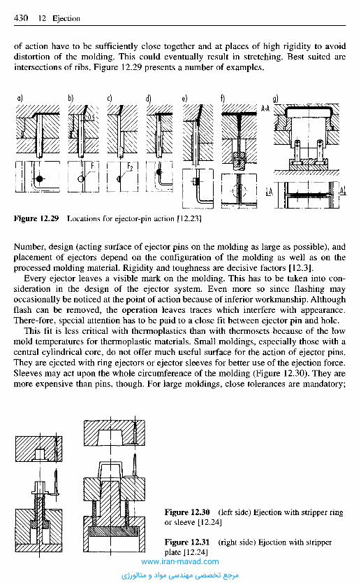
Number, design (acting surface of ejector pins on the molding as large as possible), andplacement of ejectors depend on the configuration of the molding as well as on theprocessed molding material. Rigidity and toughness are decisive factors [12.3].
Every ejector leaves a visible mark on the molding. This has to be taken into con-sideration in the design of the ejector system. Even more so since flashing mayoccasionally be noticed at the point of action because of inferior workmanship. Althoughflash can be removed, the operation leaves traces which interfere with appearance.There-fore, special attention has to be paid to a close fit between ejector pin and hole.
This fit is less critical with thermoplastics than with thermosets because of the lowmold temperatures for thermoplastic materials. Small moldings, especially those with acentral cylindrical core, do not offer much useful surface for the action of ejector pins.They are ejected with ring ejectors or ejector sleeves for better use of the ejection force.Sleeves may act upon the whole circumference of the molding (Figure 12.30). They aremore expensive than pins, though. For large moldings, close tolerances are mandatory;
Figure 12.29 Locations for ejector-pin action [12.23]
Figure 12.30 (left side) Ejection with stripper ringor sleeve [12.24]
Figure 12.31 (right side) Ejection with stripperplate [12.24]
of action have to be sufficiently close together and at places of high rigidity to avoiddistortion of the molding. This could eventually result in stretching. Best suited areintersections of ribs. Figure 12.29 presents a number of examples.
a) b) c) i) e) f) g)
www.iran-mavad.com
مرجع تخصصی مهندسی مواد و متالورژی

otherwise flashing occurs between sleeve and pin, which impedes demolding and callsfor expensive postoperation to remove flash.
Another option for letting the ejection force act along the whole circumference isprovided by a stripper plate (Figure 12.31). It is useful for stripping off circular as wellas differently shaped moldings. Because of the expensive fitting work required, ringejectors, ejector sleeves and stripper plates are primarily used for cylindrical parts.
The mating surfaces between core and stripping device are usually tapered inaccordance with the configuration of the part to achieve good sealing in the closed moldand reduce wear of these surfaces (Figure 12.32). Tapered faces also facilitate the returnmovement. A small step (Figure 12.33) prevents damage to the polished core surfaceduring ejection or return [12.3].
Figure 12.34 demonstrates an ejector system that acts upon the molding in severalplanes simultaneously. This system is particularly useful for ejecting deep moldings of
Tapered seat
Figure 12.34 Simultaneousejection in more than one plane[12.24]Figure 12.33 Mold core and stripper ring [12.3]
Figure 12.32 Tumbler moldwith stripper ring [12.3]
www.iran-mavad.com
مرجع تخصصی مهندسی مواد و متالورژی
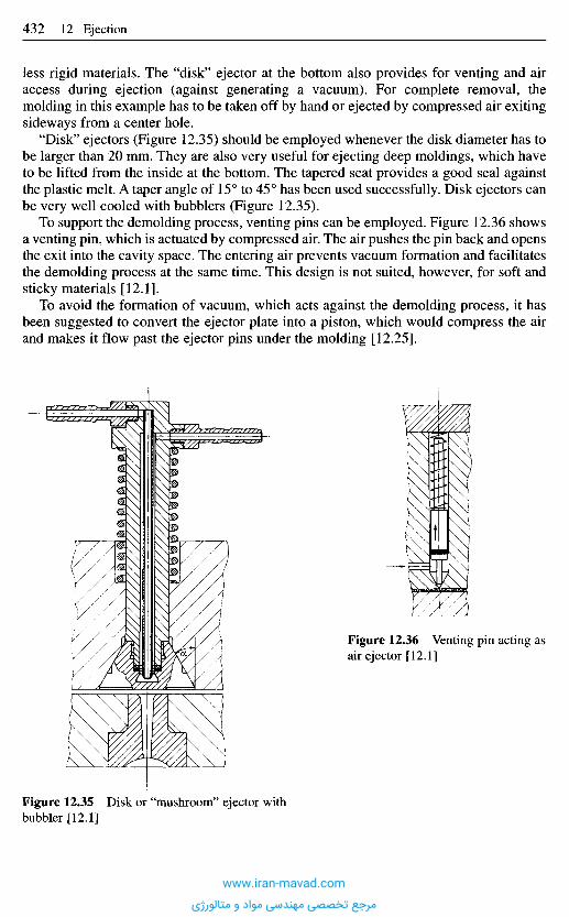
less rigid materials. The "disk" ejector at the bottom also provides for venting and airaccess during ejection (against generating a vacuum). For complete removal, themolding in this example has to be taken off by hand or ejected by compressed air exitingsideways from a center hole.
"Disk" ejectors (Figure 12.35) should be employed whenever the disk diameter has tobe larger than 20 mm. They are also very useful for ejecting deep moldings, which haveto be lifted from the inside at the bottom. The tapered seat provides a good seal againstthe plastic melt. A taper angle of 15° to 45° has been used successfully. Disk ejectors canbe very well cooled with bubblers (Figure 12.35).
To support the demolding process, venting pins can be employed. Figure 12.36 showsa venting pin, which is actuated by compressed air. The air pushes the pin back and opensthe exit into the cavity space. The entering air prevents vacuum formation and facilitatesthe demolding process at the same time. This design is not suited, however, for soft andsticky materials [12.1].
To avoid the formation of vacuum, which acts against the demolding process, it hasbeen suggested to convert the ejector plate into a piston, which would compress the airand makes it flow past the ejector pins under the molding [12.25].
Figure 12.35 Disk or "mushroom" ejector withbubbler [12.1]
Figure 12.36 Venting pin acting asair ejector [12.1]
www.iran-mavad.com
مرجع تخصصی مهندسی مواد و متالورژی
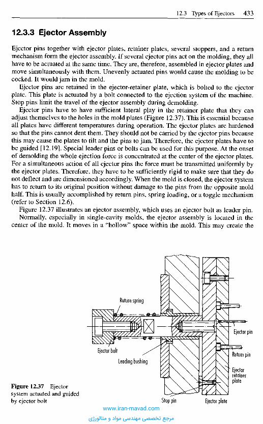
12.3.3 Ejector Assembly
Ejector pins together with ejector plates, retainer plates, several stoppers, and a returnmechanism form the ejector assembly. If several ejector pins act on the molding, they allhave to be actuated at the same time. They are, therefore, assembled in ejector plates andmove simultaneously with them. Unevenly actuated pins would cause the molding to becocked. It would jam in the mold.
Ejector pins are retained in the ejector-retainer plate, which is bolted to the ejectorplate. This plate is actuated by a bolt connected to the ejection system of the machine.Stop pins limit the travel of the ejector assembly during demolding.
Ejector pins have to have sufficient lateral play in the retainer plate that they canadjust themselves to the holes in the mold plates (Figure 12.37). This is essential becauseall plates have different temperatures during operation. The ejector plates are hardenedso that the pins cannot dent them. They should not be carried by the ejector pins becausethis may cause the plates to tilt and the pins to jam. Therefore, the ejector plates have tobe guided [12.19]. Special leader pins or bolts can be used for this purpose. At the onsetof demolding the whole ejection force is concentrated at the center of the ejector plates.For a simultaneous action of all ejector pins the force must be transmitted uniformly bythe ejector plates. Therefore, they have to be sufficiently rigid to make sure that they donot deflect and are dimensioned accordingly. When the mold is closed, the ejector systemhas to return to its original position without damage to the pins from the opposite moldhalf. This is usually accomplished by return pins, spring loading, or a toggle mechanism(refer to Section 12.6).
Figure 12.37 illustrates an ejector assembly, which uses an ejector bolt as leader pin.Normally, especially in single-cavity molds, the ejector assembly is located in the
center of the mold. It moves in a "hollow" space within the mold. This may create the
Figure 12.37 Ejectorsystem actuated and guidedby ejector bolt
Ejector pin
Return pin
Ejectorretainerplate
Leading bushing
Stop pin Ejector plate
Return spring
Ejector bolt
www.iran-mavad.com
مرجع تخصصی مهندسی مواد و متالورژی
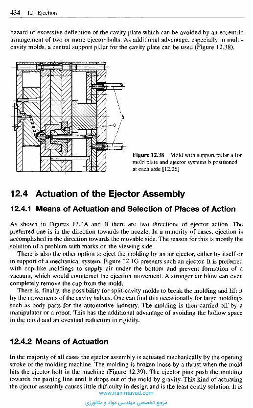
1 2 . 4 A c t u a t i o n o f t h e E j e c t o r A s s e m b l y
12.4.1 M e a n s o f A c t u a t i o n a n d Se lec t i on o f P laces o f A c t i o n
As shown in Figures 12. IA and B there are two directions of ejector action. Thepreferred one is in the direction towards the nozzle. In a minority of cases, ejection isaccomplished in the direction towards the movable side. The reason for this is mostly thesolution of a problem with marks on the viewing side.
There is also the other option to eject the molding by an air ejector, either by itself orin support of a mechanical system. Figure 12. IG presents such an ejector. It is preferredwith cup-like moldings to supply air under the bottom and prevent formation of avacuum, which would counteract the ejection movement. A stronger air blow can evencompletely remove the cup from the mold.
There is, finally, the possibility for split-cavity molds to break the molding and lift itby the movements of the cavity halves. One can find this occasionally for large moldingssuch as body parts for the automotive industry. The molding is then carried off by amanipulator or a robot. This has the additional advantage of avoiding the hollow spacein the mold and an eventual reduction in rigidity.
12.4.2 M e a n s o f A c t u a t i o n
In the majority of all cases the ejector assembly is actuated mechanically by the openingstroke of the molding machine. The molding is broken loose by a thrust when the moldhits the ejector bolt in the machine (Figure 12.39). The ejector pins push the moldingtowards the parting line until it drops out of the mold by gravity. This kind of actuatingthe ejector assembly causes little difficulty in design and is the least costly solution. It is
Figure 12.38 Mold with support pillar a formold plate and ejector systems b positionedat each side [12.26]
hazard of excessive deflection of the cavity plate which can be avoided by an eccentricarrangement of two or more ejector bolts. As additional advantage, especially in multi-cavity molds, a central support pillar for the cavity plate can be used (Figure 12.38).
www.iran-mavad.com
مرجع تخصصی مهندسی مواد و متالورژی
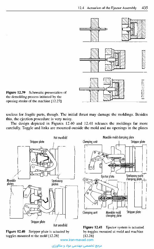
Figure 12.39 Schematic presentation ofthe demolding process initiated by theopening stroke of the machine [12.27]
useless for fragile parts, though. The initial thrust may damage the moldings. Besidesthis, the ejection procedure is very noisy.
The design depicted in Figures 12.40 and 12.41 releases the moldings far morecarefully. Toggle and links are mounted outside the mold and no openings in the plates
Figure 12.40 Stripper plate is actuated bytoggles mounted at the mold [12.28]
Figure 12.41 Ejector system is actuatedby toggles mounted at mold and machine[12.28]
Hot manifoldStripper plate
Clamping unit Movable moldclamping plate
Stripper plate
Ejector plate Stationary moldclamping plateStationary
platenMovableplaten
Stripper plateHot manifold
Clamping unitMovable mold clamping plate
Stripper plate
www.iran-mavad.com
مرجع تخصصی مهندسی مواد و متالورژی
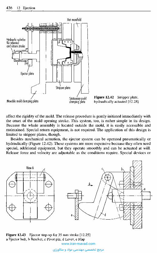
affect the rigidity of the mold. The release procedure is gently initiated immediately withthe onset of the mold opening stroke. This system, too, is rather simple in its design.Because the whole assembly is located outside the mold, it is easily accessible andmaintained. Special return equipment, is not required. The application of this design islimited to stripper plates, though.
Besides mechanical actuation, the ejector system can be operated pneumatically orhydraulically (Figure 12.42). These systems are more expensive because they often needspecial, additional equipment, but they operate smoothly and can be actuated at will.Release force and velocity are adjustable as the conditions require. Special devices or
Figure 12.42 Stripper plate,hydraulically actuated [12.28]
Stationary moldclamping plateMovable mold clamping plate
Stripper plate
Ejector plate
Hydraulic cylinderfor advanceand return stroke
Hot manifold
View A
Figure 12.43 Ejector step-up for 35 mm stroke [12.25]a Ejector bolt, b Bracket, c Pivot pin, d Lever, e Flap
www.iran-mavad.com
مرجع تخصصی مهندسی مواد و متالورژی

safeguards for returning the ejector assembly with mold closing is not needed if double-acting cylinders are employed.
For proper functioning of all systems, an ample stroke of the ejector plates is required.The plates have to advance the ejector pins (or other means of ejection) sufficiently fartowards the parting line that gravity can act on the molding. Only then is a fullyautomatic operation possible.
In very deep molds (buckets) the ejector stroke may not be sufficient to completelyrelease the molding. Then a combined release method is often employed. The part is firstpartially released by mechanical operation of the ejector assembly and then blown off thecore by compressed air. If no compressed air is available, the part has to be removedmanually after breaking.
A combined, stepwise release method is also used if especially high breaking forcesare needed. The step-up ejector in Figure 12.43 increases the ejection force two to threetimes [12.25]. After loosening the molding, it is advanced in a second step or taken offby hand.
1 2 . 5 S p e c i a l R e l e a s e S y s t e m s
12.5.1 D o u b l e - S t a g e E jec t i on
Large but thin-walled parts often have to be demolded in several stages. This isespecially the case if ejector pins cannot act at places where the moldings cannotwithstand the forces without damage. An example is presented with Figure 12.44. At firstthe molding is broken loose by the stripper ring. To prevent formation of a vacuum underthe bottom, the ejectors are moved likewise and support the bottom. The element that isused for double ejection is introduced in the literature as ball notch [12.1]. During,demolding the ejector bolt a moves against a fixed stop and so actuates the ejectorsystem f. At the same time the ejector system g is taken along by means of the engagedballs e. Thus, stripper plate and ejector pins simultaneously remove the part from thecore. By now both ejector plates have advanced so far towards the parting line that thefixed bolt c has become too short to keep the balls apart. They drop out of the recess andonly the ejector plate f is actuated further. Its ejector pins finally release the part.
Because of high wear, the balls (ball bearings), the bushing, and the bolt c have to behardened. To ensure proper function of the mold, attention has to be paid to thedimensions and the arrangement of the individual elements so that the balls are forcedinto a rolling motion. The diameter of the balls has to be larger than the diameter of thebolt [12.1].
Figure 12.45 presents a typical two-stage ejector for separating tunnel gates from themolding.
12.5.2 C o m b i n e d E jec t i on
Another version of double-stage ejection is the possibility shown with Figure 12.46.During mold opening the part is first stripped off the core mechanically. Final ejection isdone with compressed air. This system has the advantage of lower mold costs compared
Next Page
www.iran-mavad.com
مرجع تخصصی مهندسی مواد و متالورژی
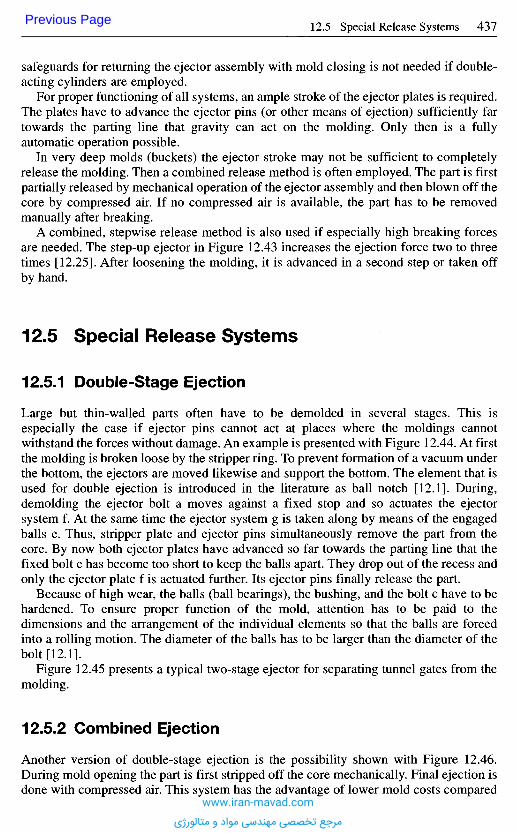
safeguards for returning the ejector assembly with mold closing is not needed if double-acting cylinders are employed.
For proper functioning of all systems, an ample stroke of the ejector plates is required.The plates have to advance the ejector pins (or other means of ejection) sufficiently fartowards the parting line that gravity can act on the molding. Only then is a fullyautomatic operation possible.
In very deep molds (buckets) the ejector stroke may not be sufficient to completelyrelease the molding. Then a combined release method is often employed. The part is firstpartially released by mechanical operation of the ejector assembly and then blown off thecore by compressed air. If no compressed air is available, the part has to be removedmanually after breaking.
A combined, stepwise release method is also used if especially high breaking forcesare needed. The step-up ejector in Figure 12.43 increases the ejection force two to threetimes [12.25]. After loosening the molding, it is advanced in a second step or taken offby hand.
1 2 . 5 S p e c i a l R e l e a s e S y s t e m s
12.5.1 D o u b l e - S t a g e E jec t i on
Large but thin-walled parts often have to be demolded in several stages. This isespecially the case if ejector pins cannot act at places where the moldings cannotwithstand the forces without damage. An example is presented with Figure 12.44. At firstthe molding is broken loose by the stripper ring. To prevent formation of a vacuum underthe bottom, the ejectors are moved likewise and support the bottom. The element that isused for double ejection is introduced in the literature as ball notch [12.1]. During,demolding the ejector bolt a moves against a fixed stop and so actuates the ejectorsystem f. At the same time the ejector system g is taken along by means of the engagedballs e. Thus, stripper plate and ejector pins simultaneously remove the part from thecore. By now both ejector plates have advanced so far towards the parting line that thefixed bolt c has become too short to keep the balls apart. They drop out of the recess andonly the ejector plate f is actuated further. Its ejector pins finally release the part.
Because of high wear, the balls (ball bearings), the bushing, and the bolt c have to behardened. To ensure proper function of the mold, attention has to be paid to thedimensions and the arrangement of the individual elements so that the balls are forcedinto a rolling motion. The diameter of the balls has to be larger than the diameter of thebolt [12.1].
Figure 12.45 presents a typical two-stage ejector for separating tunnel gates from themolding.
12.5.2 C o m b i n e d E jec t i on
Another version of double-stage ejection is the possibility shown with Figure 12.46.During mold opening the part is first stripped off the core mechanically. Final ejection isdone with compressed air. This system has the advantage of lower mold costs compared
Previous Page
www.iran-mavad.com
مرجع تخصصی مهندسی مواد و متالورژی
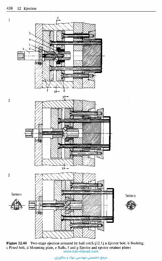
1
2
3
Figure 12.44 Two-stage ejection actuated by ball catch [12.1] a Ejector bolt, b Bushing,c Fixed bolt, d Mounting plate, e Balls, f and g Ejector and ejector retainer plates
Section ySection x
www.iran-mavad.com
مرجع تخصصی مهندسی مواد و متالورژی
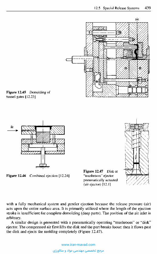
with a fully mechanical system and gentler ejection because the release pressure (air)acts upon the entire surface area. It is primarily utilized where the length of the ejectionstroke is insufficient for complete demolding (deep parts). The position of the air inlet isarbitrary.
A similar design is presented with a pneumatically operating "mushroom" or "disk"ejector. The compressed air first lifts the disk and the part breaks loose; then it flows pastthe disk and ejects the molding completely (Figure 12.47).
Figure 12.46 Combined ejection [12.24]Figure 12.47 Disk or"mushroom" ejectorpneumatically actuated(air ejector) [12.1]
Air
Figure 12.45 Demolding oftunnel gates [12.23]
www.iran-mavad.com
مرجع تخصصی مهندسی مواد و متالورژی
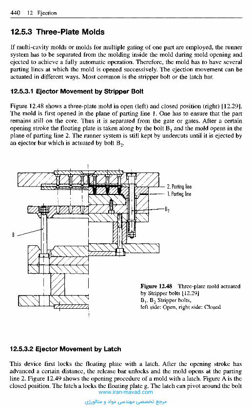
12.5.3 Three-Plate Molds
If multi-cavity molds or molds for multiple gating of one part are employed, the runnersystem has to be separated from the molding inside the mold during mold opening andejected to achieve a fully automatic operation. Therefore, the mold has to have severalparting lines at which the mold is opened successively. The ejection movement can beactuated in different ways. Most common is the stripper bolt or the latch bar.
12.5.3.1 Ejector Movement by Stripper Bolt
Figure 12.48 shows a three-plate mold in open (left) and closed position (right) [12.29].The mold is first opened in the plane of parting line 1. One has to ensure that the partremains still on the core. Thus it is separated from the gate or gates. After a certainopening stroke the floating plate is taken along by the bolt B1 and the mold opens in theplane of parting line 2. The runner system is still kept by undercuts until it is ejected byan ejector bar which is actuated by bolt B2.
2. Parting line1. Parting line
Figure 12.48 Three-plate mold actuatedby Stripper bolts [12.29]B1, B2 Stripper bolts,left side: Open, right side: Closed
12.5.3.2 Ejector Movement by Latch
This device first locks the floating plate with a latch. After the opening stroke hasadvanced a certain distance, the release bar unlocks and the mold opens at the partingline 2. Figure 12.49 shows the opening procedure of a mold with a latch. Figure A is theclosed position. The latch a locks the floating plate g. The latch can pivot around the bolt
B2
B,
www.iran-mavad.com
مرجع تخصصی مهندسی مواد و متالورژی
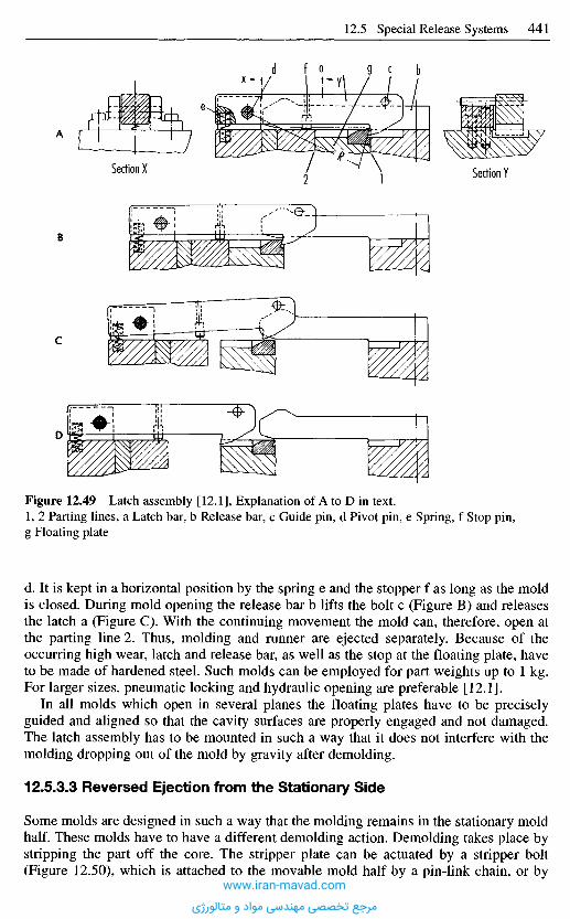
Figure 12.49 Latch assembly [12.1], Explanation of A to D in text.1, 2 Parting lines, a Latch bar, b Release bar, c Guide pin, d Pivot pin, e Spring, f Stop pin,g Floating plate
d. It is kept in a horizontal position by the spring e and the stopper f as long as the moldis closed. During mold opening the release bar b lifts the bolt c (Figure B) and releasesthe latch a (Figure C). With the continuing movement the mold can, therefore, open atthe parting line 2. Thus, molding and runner are ejected separately. Because of theoccurring high wear, latch and release bar, as well as the stop at the floating plate, haveto be made of hardened steel. Such molds can be employed for part weights up to 1 kg.For larger sizes, pneumatic locking and hydraulic opening are preferable [12.1].
In all molds which open in several planes the floating plates have to be preciselyguided and aligned so that the cavity surfaces are properly engaged and not damaged.The latch assembly has to be mounted in such a way that it does not interfere with themolding dropping out of the mold by gravity after demolding.
12.5.3.3 Reversed Ejection from the Stationary Side
Some molds are designed in such a way that the molding remains in the stationary moldhalf. These molds have to have a different demolding action. Demolding takes place bystripping the part off the core. The stripper plate can be actuated by a stripper bolt(Figure 12.50), which is attached to the movable mold half by a pin-link chain, or by
Section YSection X
A
B
C
D
www.iran-mavad.com
مرجع تخصصی مهندسی مواد و متالورژی
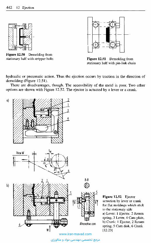
hydraulic or pneumatic action. Thus the ejection occurs by traction in the direction ofdemolding (Figure 12.51).
There are disadvantages, though. The accessibility of the mold is poor. Two otheroptions are shown with Figure 12.52. The ejector is actuated by a lever or a crank.
Figure 12.52 Ejectoractuation by lever or crankfor flat moldings which stickto the stationary sidea) Lever: 1 Ejector, 2 Returnspring, 3 Lever, 4 Cam plate,b) Crank: 1 Ejector, 2 Returnspring, 5 Cam disk, 6 Crank[12.23]
Alternative cam
b)
View W
a)
Figure 12.51 Demolding fromstationary half with pin-link chain
Figure 12.50 Demolding fromstationary half with stripper bolts
www.iran-mavad.com
مرجع تخصصی مهندسی مواد و متالورژی
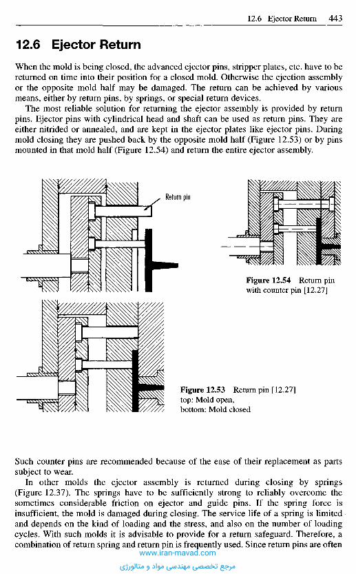
1 2 . 6 E j e c t o r R e t u r n
When the mold is being closed, the advanced ejector pins, stripper plates, etc. have to bereturned on time into their position for a closed mold. Otherwise the ejection assemblyor the opposite mold half may be damaged. The return can be achieved by variousmeans, either by return pins, by springs, or special return devices.
The most reliable solution for returning the ejector assembly is provided by returnpins. Ejector pins with cylindrical head and shaft can be used as return pins. They areeither nitrided or annealed, and are kept in the ejector plates like ejector pins. Duringmold closing they are pushed back by the opposite mold half (Figure 12.53) or by pinsmounted in that mold half (Figure 12.54) and return the entire ejector assembly.
Figure 12.53 Return pin [12.27]top: Mold open,bottom: Mold closed
Such counter pins are recommended because of the ease of their replacement as partssubject to wear.
In other molds the ejector assembly is returned during closing by springs(Figure 12.37). The springs have to be sufficiently strong to reliably overcome thesometimes considerable friction on ejector and guide pins. If the spring force isinsufficient, the mold is damaged during closing. The service life of a spring is limitedand depends on the kind of loading and the stress, and also on the number of loadingcycles. With such molds it is advisable to provide for a return safeguard. Therefore, acombination of return spring and return pin is frequently used. Since return pins are often
Return pin
Figure 12.54 Return pinwith counter pin [12.27]
www.iran-mavad.com
مرجع تخصصی مهندسی مواد و متالورژی

Figure 12.55 Pawl pin [12.30]1) Mold is closed. Slides are returned. Ejector system A is in returned position.2) Mold is open. Slide travel is complete. Return bolt R has been inserted in catch F, has
actuated ejector system A and ejected moldings. Fingers of catch have locked behind bolthead.
3) Closing mold has positively returned ejector system after having moved the distance B(ejector travel + 5 mm). Slides can be moved now without restriction.
obstructive, electric limit switches are also employed as safeguards. They shut themachine down if the ejector assembly is not completely returned. Besides this,mechanically operating return devices have been developed, which are presented inFigures 12.55 and 12.56.
www.iran-mavad.com
مرجع تخصصی مهندسی مواد و متالورژی

In the slide mold in Figure 12.55 a pawl pin b is screwed into the ejector plates a insteadof an ejector bolt [12.30]. This pin is surrounded by a clamping sleeve c, which isconnected to the ejector housing by a fine thread and secured by a slotted nut d. Whenthe mold opens, the pawl pin hits the profiled tip of the knockout bolt e in the machine,which spreads the catches of the pawl pin. As soon as the machine bolt has dipped intothe hollow pawl pin, the catches snap back behind its collar. This creates a positiveconnection between pin and machine bolt. The machine bolt can now return the ejectorassembly while the mold is being closed. At the end of the return stroke the catches freethe machine bolt. The length of the stroke can be accurately determined by adjusting thebushing. This system works very reliably.
The return system in Figure 12.56 operates with a ball notch [12.1]. The machine doesnot carry a knockout bolt but the bushing a, which accommodates the balls b. The smallbolt c with a profiled surface can slide in this bushing. A spring d keeps the bolt undertension and the set screw e stops it at the foremost position. In this position the ballscatch a recess in the bolt. During mold opening the bushing a enters the sleeve f, whichis attached to the movable plate. The bolt c hits an ejector bolt. The engaged balls
Figure 12.56 Return System withball catch [12.1]a Bushing, b Balls, c Sleeve,d Spring, e Set screw, f Lockingsleeve, g Spring
www.iran-mavad.com
مرجع تخصصی مهندسی مواد و متالورژی
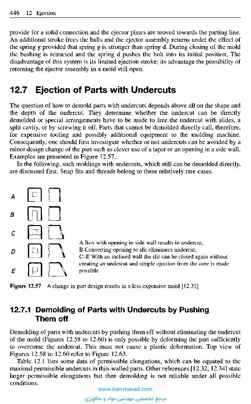
provide for a solid connection and the ejector plates are moved towards the parting line.An additional stroke frees the balls and the ejector assembly returns under the effect ofthe spring g provided that spring g is stronger than spring d. During closing of the moldthe bushing is retracted and the spring d pushes the bolt into its initial position, Thedisadvantage of this system is its limited ejection stroke; its advantage the possibility ofreturning the ejector assembly in a mold still open.
1 2 . 7 E j e c t i o n o f P a r t s w i t h U n d e r c u t s
The question of how to demold parts with undercuts depends above all on the shape andthe depth of the undercut. They determine whether the undercut can be directlydemolded or special arrangements have to be made to free the undercut with slides, asplit cavity, or by screwing it off. Parts that cannot be demolded directly call, therefore,for expensive tooling and possibly additional equipment to the molding machine.Consequently, one should first investigate whether or not undercuts can be avoided by aminor design change of the part such as clever use of a taper or an opening in a side wall.Examples are presented in Figure 12.57.
In the following, such moldings with undercuts, which still can be demolded directly,are discussed first. Snap fits and threads belong to these relatively rare cases.
A Box with opening in side wall results in undercut,B Converting opening to slit eliminates undercut,C-E With an inclined wall the slit can be closed again withoutcreating an undercut and simple ejection from the core is madepossible
Figure 12.57 A change in part design results in a less expensive mold [12.31]
12 .7 .1 D e m o l d i n g o f P a r t s w i t h U n d e r c u t s b y P u s h i n g
T h e m o f f
Demolding of parts with undercuts by pushing them off without eliminating the undercutof the mold (Figures 12.58 to 12.60) is only possible by deforming the part sufficientlyto overcome the undercut. This must not cause a plastic deformation. Top view ofFigures 12.58 to 12.60 refer to Figure 12.63.
Table 12.1 lists some data of permissible elongations, which can be equated to themaximal permissible undercuts in thin-walled parts. Other references [12.32, 12.34] statelarger permissible elongations but then demolding is not reliable under all possibleconditions.
A
B
C
D
E
www.iran-mavad.com
مرجع تخصصی مهندسی مواد و متالورژی
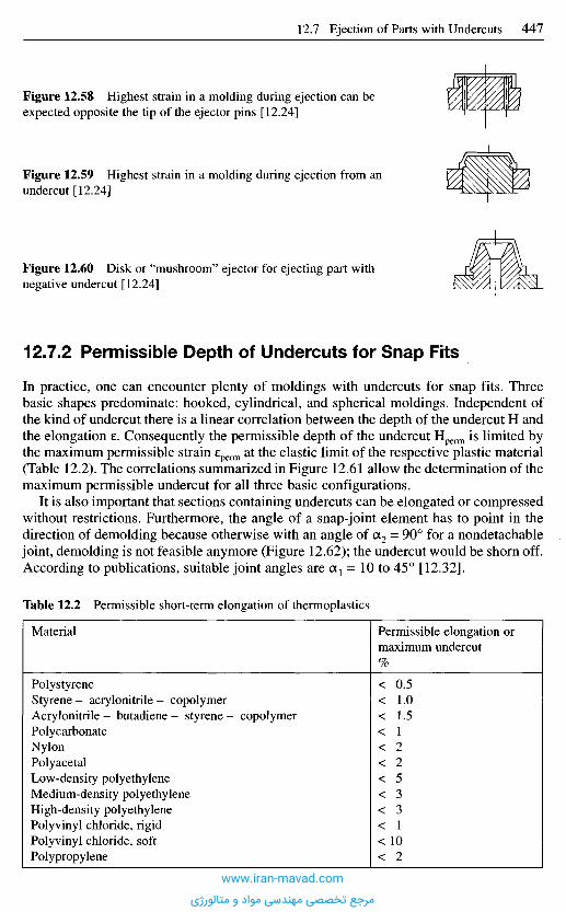
Figure 12.58 Highest strain in a molding during ejection can beexpected opposite the tip of the ejector pins [12.24]
Figure 12.59 Highest strain in a molding during ejection from anundercut [12.24]
Figure 12.60 Disk or "mushroom" ejector for ejecting part withnegative undercut [12.24]
1 2 . 7 . 2 P e r m i s s i b l e D e p t h of U n d e r c u t s f o r S n a p F i ts
In practice, one can encounter plenty of moldings with undercuts for snap fits. Threebasic shapes predominate: hooked, cylindrical, and spherical moldings. Independent ofthe kind of undercut there is a linear correlation between the depth of the undercut H andthe elongation e. Consequently the permissible depth of the undercut Hperm is limited bythe maximum permissible strain eperm at the elastic limit of the respective plastic material(Table 12.2). The correlations summarized in Figure 12.61 allow the determination of themaximum permissible undercut for all three basic configurations.
It is also important that sections containing undercuts can be elongated or compressedwithout restrictions. Furthermore, the angle of a snap-joint element has to point in thedirection of demolding because otherwise with an angle of Ot2 = 90° for a nondetachablejoint, demolding is not feasible anymore (Figure 12.62); the undercut would be shorn off.According to publications, suitable joint angles are Ct1 = 10 to 45° [12.32].
Table 12.2 Permissible short-term elongation of thermoplastics
Material
PolystyreneStyrene - acrylonitrile - copolymerAcrylonitrile - butadiene - styrene - copolymerPolycarbonateNylonPolyacetalLow-density polyethyleneMedium-density polyethyleneHigh-density polyethylenePolyvinyl chloride, rigidPolyvinyl chloride, softPolypropylene
Permissible elongation ormaximum undercut%
< 0.5< 1.0< 1.5< 1< 2< 2< 5< 3< 3< 1< 10< 2
www.iran-mavad.com
مرجع تخصصی مهندسی مواد و متالورژی
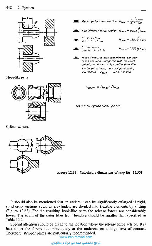
It should also be mentioned that an undercut can be significantly enlarged if rigid,solid cross-sections such, as a cylinder, are divided into flexible elements by slitting(Figure 12.63). For the resulting hook-like parts the release forces are considerablylower. The strain of the outer fiber from bending should be smaller than specified inTable 12.2.
Special attention should be given to the location where the release force acts on. It isbest to let the forces act immediately at the undercut on a large area of contact.Therefore, stripper plates are particularly recommended.
Figure 12.61 Calculating dimensions of snap fits [12.35]
Refer to cylindrical parts
Hperm — Dmax ^min
Hook-like parts
>Dma
xDm
in
Rectangular cross-section
Semicircular cross-section
Cross-section;third of a circle
Cross-section :quarter of a circle
These formulae also approximate annularcross-sections. Compared with the exactcalculation the error is smaller than 10%.I = Length of hook, h = Height of hook ,r = Radius , eperm = Elongation (%)
Cylindrical parts
Dm
in
u _ J? ^ £perm"perm- / / , " 700
Hperm — 0.578 —^perm
(2Ii perm — 0.580~£perm
/2Hperm — 0.555 — £perm
www.iran-mavad.com
مرجع تخصصی مهندسی مواد و متالورژی
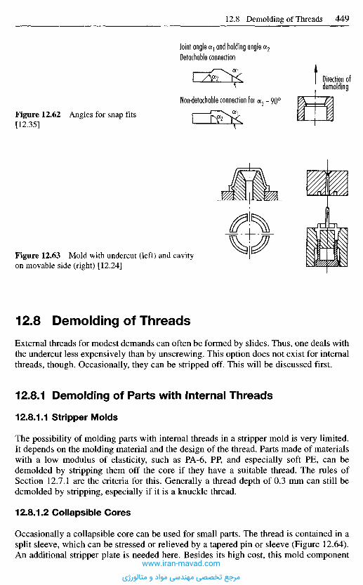
1 2 . 8 D e m o l d i n g o f T h r e a d s
External threads for modest demands can often be formed by slides. Thus, one deals withthe undercut less expensively than by unscrewing. This option does not exist for internalthreads, though. Occasionally, they can be stripped off. This will be discussed first.
12.8.1 Demolding of Parts with Internal Threads
12.8.1.1 Stripper Molds
The possibility of molding parts with internal threads in a stripper mold is very limited.It depends on the molding material and the design of the thread. Parts made of materialswith a low modulus of elasticity, such as PA-6, PP, and especially soft PE, can bedemolded by stripping them off the core if they have a suitable thread. The rules ofSection 12.7.1 are the criteria for this. Generally a thread depth of 0.3 mm can still bedemolded by stripping, especially if it is a knuckle thread.
12.8.1.2 Collapsible Cores
Occasionally a collapsible core can be used for small parts. The thread is contained in asplit sleeve, which can be stressed or relieved by a tapered pin or sleeve (Figure 12.64).An additional stripper plate is needed here. Besides its high cost, this mold component
Figure 12.63 Mold with undercut (left) and cavityon movable side (right) [12.24]
Figure 12.62 Angles for snap fits[12.35]
Joint angle a} and holding angle a2
Detachable connection
Direction ofdemolding
Non-detachable connection for a2 = 90°
www.iran-mavad.com
مرجع تخصصی مهندسی مواد و متالورژی
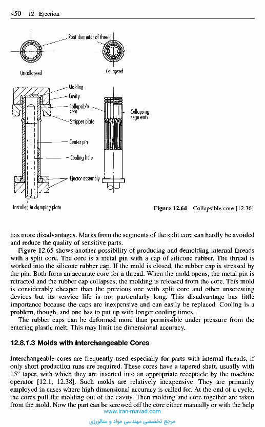
has more disadvantages. Marks from the segments of the split core can hardly be avoidedand reduce the quality of sensitive parts.
Figure 12.65 shows another possibility of producing and demolding internal threadswith a split core. The core is a metal pin with a cap of silicone rubber. The thread isworked into the silicone rubber cap. If the mold is closed, the rubber cap is stressed bythe pin. Both form an accurate core for a thread. When the mold opens, the metal pin isretracted and the rubber cap collapses; the molding is released from the core. This moldis considerably cheaper than the previous one with split core and other unscrewingdevices but its service life is not particularly long. This disadvantage has littleimportance because the caps are inexpensive and can easily be replaced. Cooling is aproblem, though, and one has to put up with longer cooling times.
The rubber caps can be deformed more than permissible under pressure from theentering plastic melt. This may limit the dimensional accuracy.
12.8.1.3 Molds with Interchangeable Cores
Interchangeable cores are frequently used especially for parts with internal threads, ifonly short production runs are required. These cores have a tapered shaft, usually with15° taper, with which they are inserted into an appropriate receptacle by the machineoperator [12.1, 12.38]. Such molds are relatively inexpensive. They are primarilyemployed in cases where high dimensional accuracy is called for. At the end of a cycle,the cores pull the molding out of the cavity. Then molding and core together are takenfrom the mold. Now the part can be screwed off the core either manually or with the help
Figure 12.64 Collapsible core [12.36]Installed in clamping plate
Molding
Cavity
Collapsiblecore
• Stripper plate
Center pin
- Cooling hole
Ejector assembly
Collapsingsegments
Uncollapsed
Root diameter of thread
Collapsed
www.iran-mavad.com
مرجع تخصصی مهندسی مواد و متالورژی
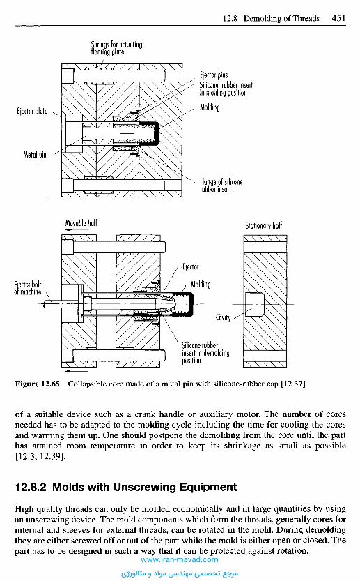
Figure 12.65 Collapsible core made of a metal pin with silicone-rubber cap [12.37]
of a suitable device such as a crank handle or auxiliary motor. The number of coresneeded has to be adapted to the molding cycle including the time for cooling the coresand warming them up. One should postpone the demolding from the core until the parthas attained room temperature in order to keep its shrinkage as small as possible[12.3, 12.39].
12.8.2 Molds with Unscrewing Equipment
High quality threads can only be molded economically and in large quantities by usingan unscrewing device. The mold components which form the threads, generally cores forinternal and sleeves for external threads, can be rotated in the mold. During demoldingthey are either screwed off or out of the part while the mold is either open or closed. Thepart has to be designed in such a way that it can be protected against rotation.
Springs for actuatingfloating plate
Ejector pinsSilicone rubber insertin molding position
Molding
Flange of siliconerubber insert
Ejector plate
Metal pin
Movable half Stationary half
Ejector
Molding
Cavity
Silicone rubberinsert in demoldingposition
Ejector boltof machine
www.iran-mavad.com
مرجع تخصصی مهندسی مواد و متالورژی

In all such molds attention has to be paid to an exact mounting and alignment of coresand drive units. Insufficiently supported cores, particularly slender ones, can be shiftedfrom their center position by the entering plastic material more easily than rigidlymounted cores. This would impede or even prevent the unscrewing process because thedriving torque becomes insufficient for breaking off the core from the deformed molding.There is also a deviation from the desired geometry of the part. One distinguishes betweensemi- and fully automatic molds, which will now be discussed in greater detail.
12.8.2.1 Semiautomatic Molds
In semiautomatic molds, the part is demolded by manually operated unscrewing devices.The rotation is transmitted to the thread forming core by a gear drive, a V-belt, or a chain.The mold can be a single or multi-cavity one. Care should be taken, though, that theforce at the crank shaft does not exceed 150 N [12.1]. Among the multitude of possibledesign features, a mold with chain drive is depicted in Figure 12.66. At present, thissystem is only met here and there.
Figure 12.66 Mold withunscrewing device manuallyoperated by crank and chain[12.27]
Bearing
Set screw
Crank
Drive sprocketwheel
Drive shaft
Bushing
Chain-
Base plate
Shaft
Driven sprocketwheel
Core
Sprue puller Cavity insertwww.iran-mavad.com
مرجع تخصصی مهندسی مواد و متالورژی
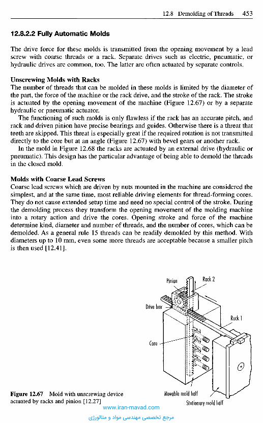
12.8.2.2 Fully Automatic Molds
The drive force for these molds is transmitted from the opening movement by a leadscrew with coarse threads or a rack. Separate drives such as electric, pneumatic, orhydraulic drives are common, too. The latter are often actuated by separate controls.
Unscrewing Molds with RacksThe number of threads that can be molded in these molds is limited by the diameter ofthe part, the force of the machine or the rack drive, and the stroke of the rack. The strokeis actuated by the opening movement of the machine (Figure 12.67) or by a separatehydraulic or pneumatic actuator.
The functioning of such molds is only flawless if the rack has an accurate pitch, andrack and driven pinion have precise bearings and guides. Otherwise there is a threat thatteeth are skipped. This threat is especially great if the required rotation is not transmitteddirectly to the core but at an angle (Figure 12.67) with bevel gears or another rack.
In the mold in Figure 12.68 the racks are actuated by an external drive (hydraulic orpneumatic). This design has the particular advantage of being able to demold the threadsin the closed mold.
Molds with Coarse Lead ScrewsCoarse lead screws which are driven by nuts mounted in the machine are considered thesimplest, and at the same time, most reliable driving elements for thread-forming cores.They do not cause extended setup time and need no special control of the stroke. Duringthe demolding process they transform the opening movement of the molding machineinto a rotary action and drive the cores. Opening stroke and force of the machinedetermine kind, diameter and number of threads, and the number of cores, which can bedemolded. As a general rule 15 threads can be readily demolded by this method. Withdiameters up to 10 mm, even some more threads are acceptable because a smaller pitchis then used [12.41].
Figure 12.67 Mold with unscrewing deviceactuated by racks and pinion [12.27]
Rack 2Pinion
Drive box
Rack 1
Core
Movable mold half
Stationary mold halfwww.iran-mavad.com
مرجع تخصصی مهندسی مواد و متالورژی
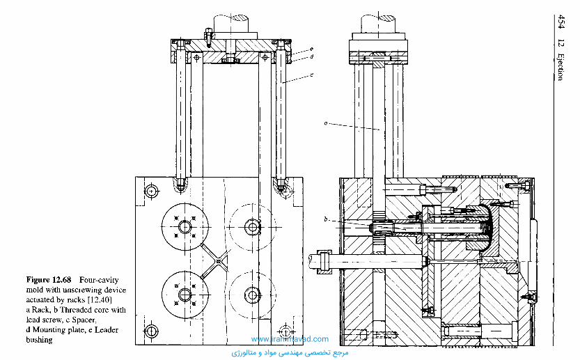
Figure 12.68 Four-cavitymold with unscrewing deviceactuated by racks [12.40]a Rack, b Threaded core withlead screw, c Spacer,d Mounting plate, e Leaderbushing www.iran-mavad.com
مرجع تخصصی مهندسی مواد و متالورژی
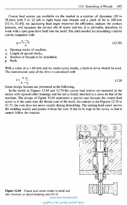
Coarse lead screws are available on the market in a number of diameters (20 to38 mm) with 5 to 12 left or right hand stub threads and a pitch of 80 to 200 mm[12.41, 12.43]. An increasing lead angle improves the efficiency, reduces the contactpressure, and increases the service life of screw and nut. It is advisable, therefore, towork with a spur-gear drive built into the mold. The pitch needed for demolding a threadcan be computed with
p = ^ ^ (12.28)n
51 Opening stroke of machine,52 Length of ejector stroke,n N u m b e r of threads to be demolded ,p Pitch.
With a value of p < 60 m m and for mult i -cavi ty molds , a buil t- in dr ive should be used.The transmission ratio of the drive is calculated with
n pi = ^ : i 2 - 2 9
Some design features are presented in the following.In the molds in Figures 12.69 and 12.70 the coarse lead screws are mounted in the
molds with tapered-roller bearings and the nut is firmly attached to a cross-tie bar of themachine. The design of Figure 12.69 represents a special case because the coarse leadscrew is at the same time the thread core of the mold. In contrast to the Figures 12.70 to12.72, the core does not move axially during demolding. The turning lead screw movesthe molding axially and pushes it from the core. It has to be kept in the cavity so that itcannot follow the rotation.
Figure 12.69 Coarse lead screw rotates in mold andalso functions as thread-forming core [12.1]
www.iran-mavad.com
مرجع تخصصی مهندسی مواد و متالورژی
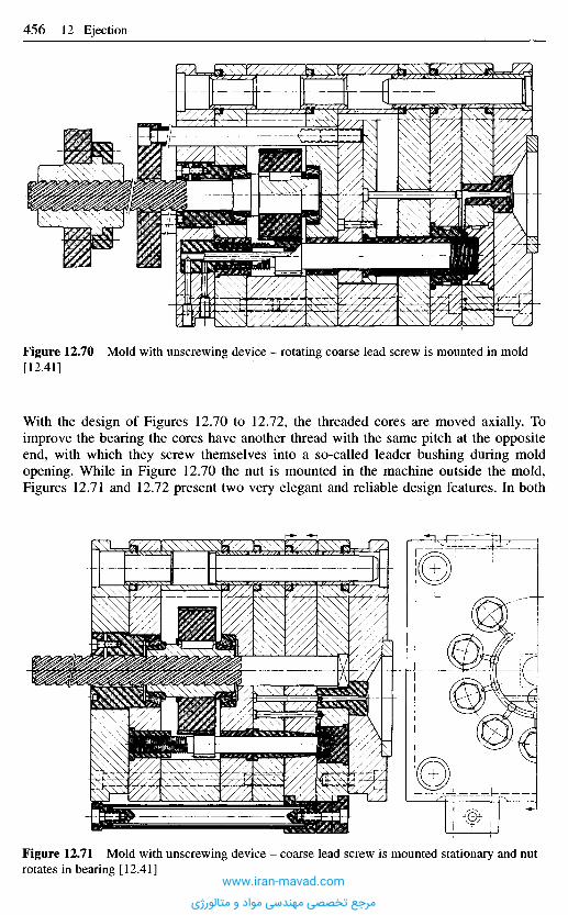
Figure 12.70 Mold with unscrewing device - rotating coarse lead screw is mounted in mold[12.41]
With the design of Figures 12.70 to 12.72, the threaded cores are moved axially. Toimprove the bearing the cores have another thread with the same pitch at the oppositeend, with which they screw themselves into a so-called leader bushing during moldopening. While in Figure 12.70 the nut is mounted in the machine outside the mold,Figures 12.71 and 12.72 present two very elegant and reliable design features. In both
Figure 12.71 Mold with unscrewing device - coarse lead screw is mounted stationary and nutrotates in bearing [12.41]
www.iran-mavad.com
مرجع تخصصی مهندسی مواد و متالورژی
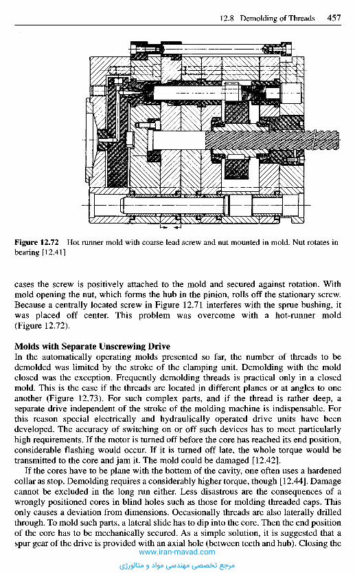
Figure 12.72 Hot runner mold with coarse lead screw and nut mounted in mold. Nut rotates inbearing [12.41]
cases the screw is positively attached to the mold and secured against rotation. Withmold opening the nut, which forms the hub in the pinion, rolls off the stationary screw.Because a centrally located screw in Figure 12.71 interferes with the sprue bushing, itwas placed off center. This problem was overcome with a hot-runner mold(Figure 12.72).
Molds with Separate Unscrewing DriveIn the automatically operating molds presented so far, the number of threads to bedemolded was limited by the stroke of the clamping unit. Demolding with the moldclosed was the exception. Frequently demolding threads is practical only in a closedmold. This is the case if the threads are located in different planes or at angles to oneanother (Figure 12.73). For such complex parts, and if the thread is rather deep, aseparate drive independent of the stroke of the molding machine is indispensable. Forthis reason special electrically and hydraulically operated drive units have beendeveloped. The accuracy of switching on or off such devices has to meet particularlyhigh requirements. If the motor is turned off before the core has reached its end position,considerable flashing would occur. If it is turned off late, the whole torque would betransmitted to the core and jam it. The mold could be damaged [12.42].
If the cores have to be plane with the bottom of the cavity, one often uses a hardenedcollar as stop. Demolding requires a considerably higher torque, though [12.44]. Damagecannot be excluded in the long run either. Less disastrous are the consequences of awrongly positioned cores in blind holes such as those for molding threaded caps. Thisonly causes a deviation from dimensions. Occasionally threads are also laterally drilledthrough. To mold such parts, a lateral slide has to dip into the core. Then the end positionof the core has to be mechanically secured. As a simple solution, it is suggested that aspur gear of the drive is provided with an axial hole (between teeth and hub). Closing the
www.iran-mavad.com
مرجع تخصصی مهندسی مواد و متالورژی
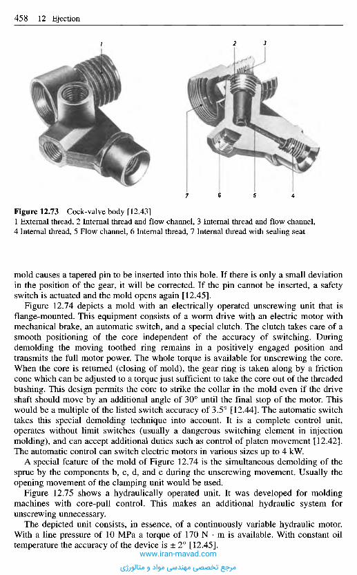
Figure 12.73 Cock-valve body [12.43]1 External thread, 2 Internal thread and flow channel, 3 Internal thread and flow channel,4 Internal thread, 5 Flow channel, 6 Internal thread, 7 Internal thread with sealing seat
mold causes a tapered pin to be inserted into this hole. If there is only a small deviationin the position of the gear, it will be corrected. If the pin cannot be inserted, a safetyswitch is actuated and the mold opens again [12.45].
Figure 12.74 depicts a mold with an electrically operated unscrewing unit that isflange-mounted. This equipment consists of a worm drive with an electric motor withmechanical brake, an automatic switch, and a special clutch. The clutch takes care of asmooth positioning of the core independent of the accuracy of switching. Duringdemolding the moving toothed ring remains in a positively engaged position andtransmits the full motor power. The whole torque is available for unscrewing the core.When the core is returned (closing of mold), the gear ring is taken along by a frictioncone which can be adjusted to a torque just sufficient to take the core out of the threadedbushing. This design permits the core to strike the collar in the mold even if the driveshaft should move by an additional angle of 30° until the final stop of the motor. Thiswould be a multiple of the listed switch accuracy of 3.5° [12.44]. The automatic switchtakes this special demolding technique into account. It is a complete control unit,operates without limit switches (usually a dangerous switching element in injectionmolding), and can accept additional duties such as control of platen movement [12.42].The automatic control can switch electric motors in various sizes up to 4 kW.
A special feature of the mold of Figure 12.74 is the simultaneous demolding of thesprue by the components b, c, d, and e during the unscrewing movement. Usually theopening movement of the clamping unit would be used.
Figure 12.75 shows a hydraulically operated unit. It was developed for moldingmachines with core-pull control. This makes an additional hydraulic system forunscrewing unnecessary.
The depicted unit consists, in essence, of a continuously variable hydraulic motor.With a line pressure of 10 MPa a torque of 170 N • m is available. With constant oiltemperature the accuracy of the device is ± 2° [12.45].
www.iran-mavad.com
مرجع تخصصی مهندسی مواد و متالورژی
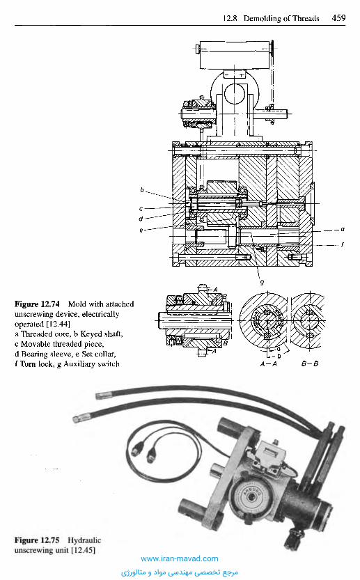
Figure 12.75 Hydraulicunscrewing unit [12.45]
Figure 12.74 Mold with attachedunscrewing device, electricallyoperated [12.44]a Threaded core, b Keyed shaft,c Movable threaded piece,d Bearing sleeve, e Set collar,f Turn lock, g Auxiliary switch A-A B-B
www.iran-mavad.com
مرجع تخصصی مهندسی مواد و متالورژی
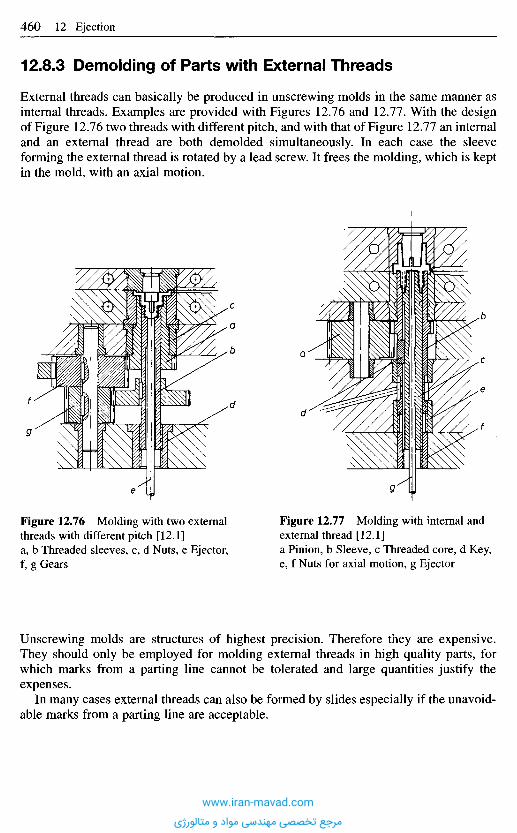
12.8.3 Demolding of Parts with External Threads
External threads can basically be produced in unscrewing molds in the same manner asinternal threads. Examples are provided with Figures 12.76 and 12.77. With the designof Figure 12.76 two threads with different pitch, and with that of Figure 12.77 an internaland an external thread are both demolded simultaneously. In each case the sleeveforming the external thread is rotated by a lead screw. It frees the molding, which is keptin the mold, with an axial motion.
Figure 12.76 Molding with two externalthreads with different pitch [12.1]a, b Threaded sleeves, c, d Nuts, e Ejector,f, g Gears
Figure 12.77 Molding with internal andexternal thread [12.1]a Pinion, b Sleeve, c Threaded core, d Key,e, f Nuts for axial motion, g Ejector
Unscrewing molds are structures of highest precision. Therefore they are expensive.They should only be employed for molding external threads in high quality parts, forwhich marks from a parting line cannot be tolerated and large quantities justify theexpenses.
In many cases external threads can also be formed by slides especially if the unavoid-able marks from a parting line are acceptable.
www.iran-mavad.com
مرجع تخصصی مهندسی مواد و متالورژی
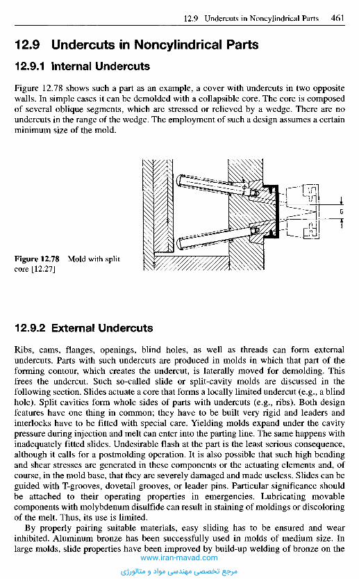
12.9.2 Ex te rna l U n d e r c u t s
Ribs, cams, flanges, openings, blind holes, as well as threads can form externalundercuts. Parts with such undercuts are produced in molds in which that part of theforming contour, which creates the undercut, is laterally moved for demolding. Thisfrees the undercut. Such so-called slide or split-cavity molds are discussed in thefollowing section. Slides actuate a core that forms a locally limited undercut (e.g., a blindhole). Split cavities form whole sides of parts with undercuts (e.g., ribs). Both designfeatures have one thing in common; they have to be built very rigid and leaders andinterlocks have to be fitted with special care. Yielding molds expand under the cavitypressure during injection and melt can enter into the parting line. The same happens withinadequately fitted slides. Undesirable flash at the part is the least serious consequence,although it calls for a postmolding operation. It is also possible that such high bendingand shear stresses are generated in these components or the actuating elements and, ofcourse, in the mold base, that they are severely damaged and made useless. Slides can beguided with T-grooves, dovetail grooves, or leader pins. Particular significance shouldbe attached to their operating properties in emergencies. Lubricating movablecomponents with molybdenum disulfide can result in staining of moldings or discoloringof the melt. Thus, its use is limited.
By properly pairing suitable materials, easy sliding has to be ensured and wearinhibited. Aluminum bronze has been successfully used in molds of medium size. Inlarge molds, slide properties have been improved by build-up welding of bronze on the
Figure 12.78 Mold with splitcore [12.27]
1 2 . 9 U n d e r c u t s in N o n c y l i n d r i c a l P a r t s
12.9.1 In te rna l U n d e r c u t s
Figure 12.78 shows such a part as an example, a cover with undercuts in two oppositewalls. In simple cases it can be demolded with a collapsible core. The core is composedof several oblique segments, which are stressed or relieved by a wedge. There are noundercuts in the range of the wedge. The employment of such a design assumes a certainminimum size of the mold.
www.iran-mavad.com
مرجع تخصصی مهندسی مواد و متالورژی
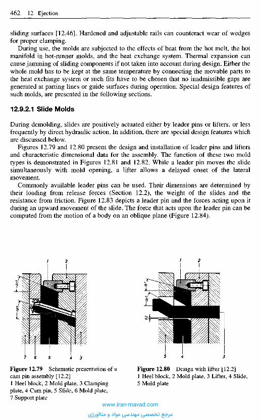
sliding surfaces [12.46]. Hardened and adjustable rails can counteract wear of wedgesfor proper clamping.
During use, the molds are subjected to the effects of heat from the hot melt, the hotmanifold in hot-runner molds, and the heat exchange system. Thermal expansion cancause jamming of sliding components if not taken into account during design. Either thewhole mold has to be kept at the same temperature by connecting the movable parts tothe heat exchange system or such fits have to be chosen that no inadmissible gaps aregenerated at parting lines or guide surfaces during operation. Special design features ofsuch molds, are presented in the following sections.
12.9.2.1 Slide Molds
During demolding, slides are positively actuated either by leader pins or lifters, or lessfrequently by direct hydraulic action. In addition, there are special design features whichare discussed below.
Figures 12.79 and 12.80 present the design and installation of leader pins and liftersand characteristic dimensional data for the assembly. The function of these two moldtypes is demonstrated in Figures 12.81 and 12.82. While a leader pin moves the slidesimultaneously with mold opening, a lifter allows a delayed onset of the lateralmovement.
Commonly available leader pins can be used. Their dimensions are determined bytheir loading from release forces (Section 12.2), the weight of the slides and theresistance from friction. Figure 12.83 depicts a leader pin and the forces acting upon itduring an upward movement of the slide. The force that acts upon the leader pin can becomputed from the motion of a body on an oblique plane (Figure 12.84).
Figure 12.79 Schematic presentation of acam pin assembly [12.2]1 Heel block, 2 Mold plate, 3 Clampingplate, 4 Cam pin, 5 Slide, 6 Mold plate,7 Support plate
Figure 12.80 Design with lifter [12.2]1 Heel block, 2 Mold plate, 3 Lifter, 4 Slide,5 Mold plate
www.iran-mavad.com
مرجع تخصصی مهندسی مواد و متالورژی
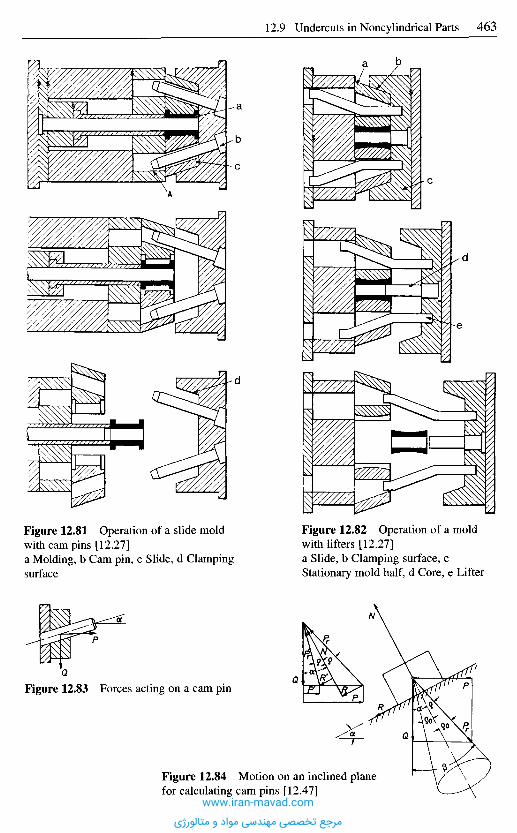
Figure 12.81 Operation of a slide moldwith cam pins [12.27]a Molding, b Cam pin, c Slide, d Clampingsurface
Figure 12.82 Operation of a moldwith lifters [12.27]a Slide, b Clamping surface, cStationary mold half, d Core, e Lifter
Figure 12.83 Forces acting on a cam pin
Figure 12.84 Motion on an inclined planefor calculating cam pins [12.47]
www.iran-mavad.com
مرجع تخصصی مهندسی مواد و متالورژی
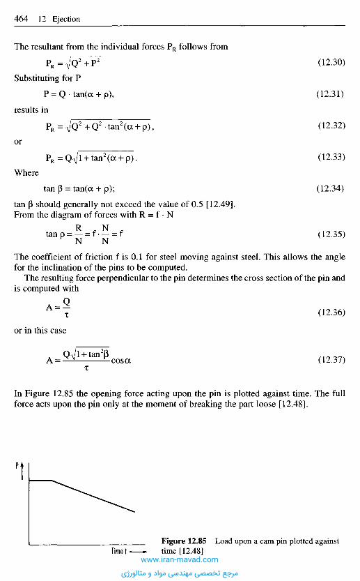
P
Time tFigure 12.85 Load upon a cam pin plotted againsttime [12.48]
In Figure 12.85 the opening force acting upon the pin is plotted against time. The fullforce acts upon the pin only at the moment of breaking the part loose [12.48].
(12.36)
(12.37)
The coefficient of friction f is 0.1 for steel moving against steel. This allows the anglefor the inclination of the pins to be computed.
The resulting force perpendicular to the pin determines the cross section of the pin andis computed with
or in this case
(12.30)
(12.31)
(12.32)
(12.33)
(12.34)
(12.35)
The resultant from the individual forces PR follows from
Substituting for P
results in
or
Where
tan P should generally not exceed the value of 0.5 [12.49].From the diagram of forces with R = f • N
www.iran-mavad.com
مرجع تخصصی مهندسی مواد و متالورژی

In order to evade overloading the cam pins, one has found out that the most favorablerange for the inclination of cam pins is between 15 and 25 0C. Larger angles facilitatemold opening while smaller ones provide higher clamping forces. One has to make acompromise, which is determined by the mold size and the clamping and opening forces.
The method of securing the slide with an inserted heel block against shifting underinjection pressure is sufficient in most cases (Figure 12.79). The advantage of this designis its simplicity compared with machining a solid plate (Figure 12.81) and fasterinterchangeability after it is worn out. The angle of the face should be kept 2 to 3° steeperthan the corresponding angle of the cam pin to compensate for a possible play betweenpin and hole [12.1, 12.2, 12.46] and to cause clamping in the closed state and with thisa firm seat of the slide.
During mold closing the slides have to be returned to their original position. This isaccomplished either by the cam pin (Figure 12.86) or with the face of the mold. The lastmethod is used if only very short cam pins are acceptable for design reasons. This designcalls for means to keep the slide in place (with a ball notch in Figure 12.87) so that thepin accurately enters the hole in the slide when the mold is closed.
Clampingsurface
Cam pin
Slide
Figure 12.86 Return of slides with campins [12.1]a and Ot1 Inclination of cam pin andclamping surface, H Undercut, H1 Openingstroke of slide
Figure 12.87 Return of slides withclamping surface [12.1]a and Ot1 Inclination of cam pin andclamping surface, H Undercut, H1 Openingstroke of slide
The length of the cam pin depends on the required opening stroke. Figure 12.87 showsa short pin. A long stroke requires an appropriately long pin. Then, as Figure 12.86demonstrates, the pin has to enter deep into the movable mold half and an opening hasto be provided accordingly.
To obtain longer slide travel with a shorter lead, the angle of inclination has to beincreased. Since an angle of 25° should not be exceeded (increased wear, poor forcetransmission), another design has to be found. Figure 12.88 presents a slide mold inwhich rollers c are attached to the slide a. They are guided in oblique grooves b. It is theadvantage of this design that the angle of the oblique grooves can be increased to more
www.iran-mavad.com
مرجع تخصصی مهندسی مواد و متالورژی
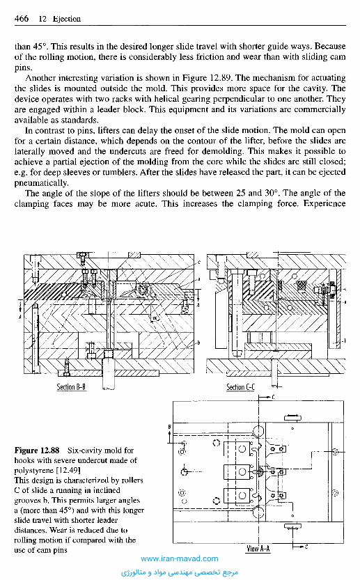
than 45°. This results in the desired longer slide travel with shorter guide ways. Becauseof the rolling motion, there is considerably less friction and wear than with sliding campins.
Another interesting variation is shown in Figure 12.89. The mechanism for actuatingthe slides is mounted outside the mold. This provides more space for the cavity. Thedevice operates with two racks with helical gearing perpendicular to one another. Theyare engaged within a leader block. This equipment and its variations are commerciallyavailable as standards.
In contrast to pins, lifters can delay the onset of the slide motion. The mold can openfor a certain distance, which depends on the contour of the lifter, before the slides arelaterally moved and the undercuts are freed for demolding. This makes it possible toachieve a partial ejection of the molding from the core while the slides are still closed;e.g. for deep sleeves or tumblers. After the slides have released the part, it can be ejectedpneumatically.
The angle of the slope of the lifters should be between 25 and 30°. The angle of theclamping faces may be more acute. This increases the clamping force. Experience
Figure 12.88 Six-cavity mold forhooks with severe undercut made ofpolystyrene [12.49]This design is characterized by rollersC of slide a running in inclinedgrooves b. This permits larger anglesa (more than 45°) and with this longerslide travel with shorter leaderdistances. Wear is reduced due torolling motion if compared with theuse of cam pins
Section B-B Section C-C
View A-Awww.iran-mavad.com
مرجع تخصصی مهندسی مواد و متالورژی
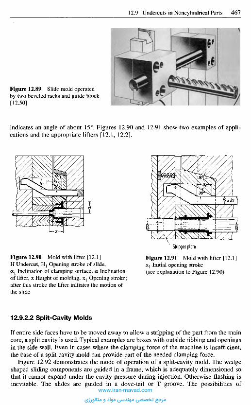
12.9.2.2 Split-Cavity Molds
If entire side faces have to be moved away to allow a stripping of the part from the maincore, a split cavity is used. Typical examples are boxes with outside ribbing and openingsin the side wall. Even in cases where the clamping force of the machine is insufficient,the base of a split cavity mold can provide part of the needed clamping force.
Figure 12.92 demonstrates the mode of operation of a split-cavity mold. The wedgeshaped sliding components are guided in a frame, which is adequately dimensioned sothat it cannot expand under the cavity pressure during injection. Otherwise flashing isinevitable. The slides are guided in a dove-tail or T groove. The possibilities of
Figure 12.90 Mold with lifter [12.1]H Undercut, H1 Opening stroke of slide,aj Inclination of clamping surface, a Inclinationof lifter, x Height of molding, X1 Opening stroke;after this stroke the lifter initiates the motion ofthe slide
Figure 12.91 Mold with lifter [12.1]X1 Initial opening stroke(see explanation to Figure 12.90)
Stripper plate
indicates an angle of about 15°. Figures 12.90 and 12.91 show two examples of appli-cations and the appropriate lifters [12.1, 12.2].
Figure 12.89 Slide mold operatedby two beveled racks and guide block[12.50]
www.iran-mavad.com
مرجع تخصصی مهندسی مواد و متالورژی
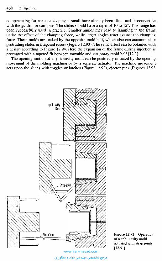
compensating for wear or keeping it small have already been discussed in connectionwith the guides for cam pins. The slides should have a taper of 10 to 15°. This range hasbeen successfully used in practice. Smaller angles may lead to jamming in the frameunder the effect of the clamping force, while larger angles react against the clampingforce. These molds are locked by the opposite mold half, which also can accommodateprotruding slides in a tapered recess (Figure 12.93). The same effect can be obtained witha design according to Figure 12.94. Here the expansion of the frame during injection isprevented with a tapered fit between movable and stationary mold half [12.1].
The opening motion of a split-cavity mold can be positively initiated by the openingmovement of the molding machine or by a separate actuator. The machine movementacts upon the slides with toggles or latches (Figure 12.92), ejector pins (Figures 12.93
Figure 12.92 Operationof a split-cavity moldactuated with strap joints[12.51]
Strap joint
Strap joint
Split cavityRibs
www.iran-mavad.com
مرجع تخصصی مهندسی مواد و متالورژی
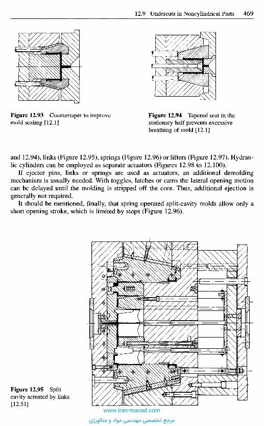
Figure 12.93 Countertaper to improvemold sealing [12.1]
Figure 12.94 Tapered seat in thestationary half prevents excessivebreathing of mold [12.1]
and 12.94), links (Figure 12.95), springs (Figure 12.96) or lifters (Figure 12.97). Hydrau-lic cylinders can be employed as separate actuators (Figures 12.98 to 12.100).
If ejector pins, links or springs are used as actuators, an additional demoldingmechanism is usually needed. With toggles, latches or cams the lateral opening motioncan be delayed until the molding is stripped off the core. Thus, additional ejection isgenerally not required.
It should be mentioned, finally, that spring operated split-cavity molds allow only ashort opening stroke, which is limited by stops (Figure 12.96).
Figure 12.95 Splitcavity actuated by links[12.51]
www.iran-mavad.com
مرجع تخصصی مهندسی مواد و متالورژی
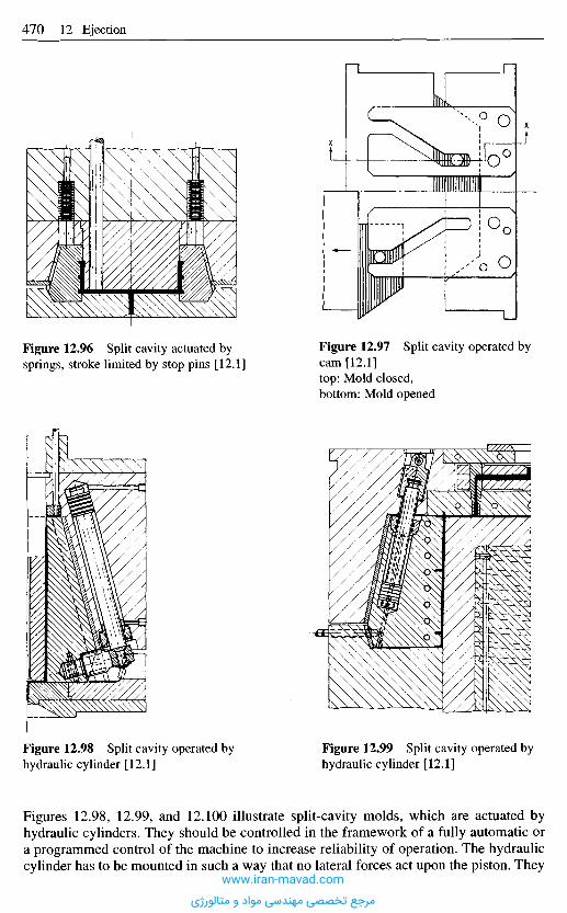
Figure 12.96 Split cavity actuated bysprings, stroke limited by stop pins [12.1]
Figure 12.97 Split cavity operated bycam [12.1]top: Mold closed,bottom: Mold opened
Figure 12.98 Split cavity operated byhydraulic cylinder [12.1]
Figure 12.99 Split cavity operated byhydraulic cylinder [12.1]
Figures 12.98, 12.99, and 12.100 illustrate split-cavity molds, which are actuated byhydraulic cylinders. They should be controlled in the framework of a fully automatic ora programmed control of the machine to increase reliability of operation. The hydrauliccylinder has to be mounted in such a way that no lateral forces act upon the piston. They
www.iran-mavad.com
مرجع تخصصی مهندسی مواد و متالورژی
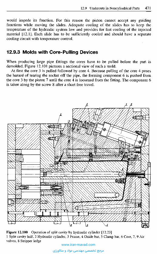
would impede its function. For this reason the piston cannot accept any guidingfunctions while moving the slides. Adequate cooling of the slides has to keep thetemperature of the hydraulic system low and provides for fast cooling of the injectedmaterial [12.1]. Each slide has to be sufficiently cooled and should have a separatecooling circuit with temperature control.
12.9.3 Molds with Core-Pull ing Devices
When producing large pipe fittings the cores have to be pulled before the part isdemolded. Figure 12.101 pictures a sectional view of such a mold.
At first the core 3 is pulled followed by core 4. Because pulling of the core 4 posesthe hazard of tearing the socket off the pipe, the forming component 6 is pushed fromthe core 3 by the piston 7 until the core 4 is loosened from the fitting. The component 6is taken along by the screw 8 after a short free travel.
Figure 12.100 Operation of split cavity by hydraulic cylinder [12.23]1 Split cavity half, 2 Hydraulic cylinder, 3 Frame, 4 Guide bar, 5 Clamp bar, 6 Core, 7, 9 Airvalves, 8 Stripper ledge
www.iran-mavad.com
مرجع تخصصی مهندسی مواد و متالورژی
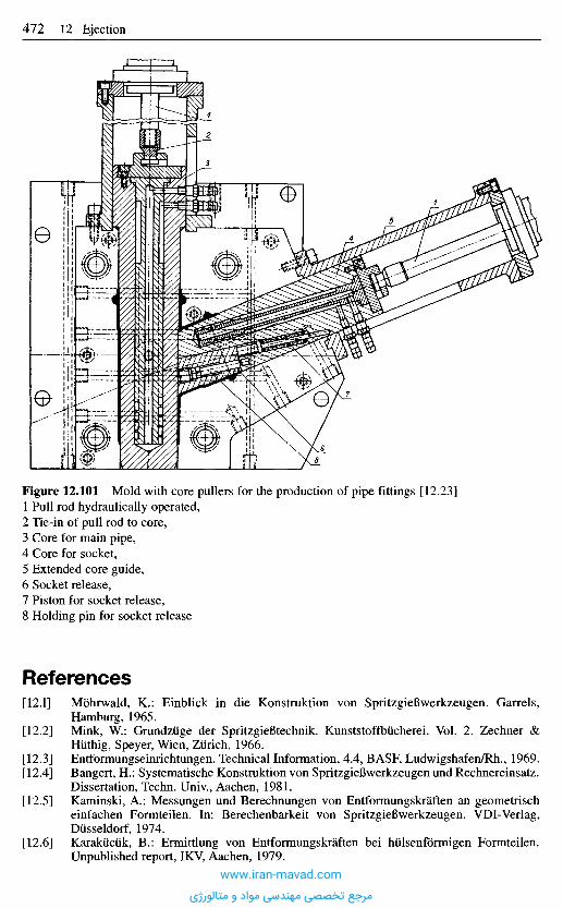
Figure 12.101 Mold with core pullers for the production of pipe fittings [12.23]1 Pull rod hydraulically operated,2 Tie-in of pull rod to core,3 Core for main pipe,4 Core for socket,5 Extended core guide,6 Socket release,7 Piston for socket release,8 Holding pin for socket release
R e f e r e n c e s
[12.1] Mohrwald, K.: Einblick in die Konstruktion von SpritzgieBwerkzeugen. Garrels,Hamburg, 1965.
[12.2] Mink, W.: Grundzuge der Spritzgiefitechnik. Kunststoffbucherei. Vol. 2. Zechner &Hiithig, Speyer, Wien, Zurich, 1966.
[12.3] Entformungseinrichtungen. Technical Information, 4.4, BASF, Ludwigshafen/Rh., 1969.[12.4] Bangert, H.: Systematische Konstruktion von SpritzgieBwerkzeugen und Rechnereinsatz.
Dissertation, Techn. Univ., Aachen, 1981.[12.5] Kaminski, A.: Messungen und Berechnungen von Entformungskraften an geometrisch
einfachen Formteilen. In: Berechenbarkeit von SpritzgieBwerkzeugen. VDI-Verlag,Diisseldorf, 1974.
[12.6] Karakiiciik, B.: Ermittlung von Entformungskraften bei hulsenformigen Formteilen.Unpublished report, IKV, Aachen, 1979.
www.iran-mavad.com
مرجع تخصصی مهندسی مواد و متالورژی

[12.7] Schlattmann, M.: Messung von Entformungskraften. Unpublished report, IKV, Aachen,1978.
[12.8] SpritzgieBtechnik. Publication, Chemische Werke HuIs AG, Marl, 1979.[12.9] Yorgancioglu, Y. Z.: Ermittlung von Entformungsbeiwerten beim SpritzgieBen von
Thermoplasten (PS, ABS, PC). Unpublished report, IKV, Aachen, 1979.[12.10] Ribbert, E. J.: Ermittlung von Entformungsbeiwerten beim SpritzgieBen von Thermo-
plasten (PP, PE). Unpublished report, IKV, Aachen, 1979.[12.11] Schrender, S.: Ermittlung von Entformungskraften beim SpritzgieBen von Thermo-
plasten. Unpublished report, IKV, Aachen, 1979.[12.12] Bangert, H.; Doring, E.; Lichius, U.; Kemper, W; Schumann, E.: Bessere Wirtschaft-
lichkeit beim SpritzgieBen durch optimale Werkzeugauslegung. Paper block VII at the10th Tech. Conference on Plastics, IKV, Aachen, March 12-14, 1980.
[12.13] Cordes, H.: Theoretische Ermittlung von Entformungskraften. Unpublished report, IKV,Aachen, 1975.
[12.14] Aengenheyster, G.: Gestaltung und Dimensionierung von Verbundkonstruktionen mitThermoplast- und Elastomerkomponente. Dissertation, RWTH, Aachen 1997.
[12.15] Koos, W.: Finite - Elemente - Berechnung der inneren mechanischen Beanspruchungenin einem Radialwellendichtring bei der Entformung. Unpublished report, IKV, Aachen,1993.
[12.16] Benfer, W.: Algorithmus zur rechneruntersttitzten mechanischen Auslegung einesSpritzgieBwerkzeuges. Unpublished report, IKV, Aachen, 1980.
[12.17] Prazisions-Schleifteile. Catalog, Drei-S-Werk, Schwabach.[12.18] Handbook of Standards, Sustau, Frankfurt.[12.19] Entformungseinrichtungen. Technical Information, 4.4, BASF, Ludwigshafen, 1969.[12.20] Catalog of Standards, Hasco, Ludenscheid.[12.21] Handbook of Standards, Strack-Norma GmbH, Wuppertal.[ 12.22] Schiirmann, E.: Abschatzmethoden fur die Auslegung von SpritzgieBwerkzeugen. Disser-
tation, Tech. Univ., Aachen, 1979.[12.23] Zawistowski, H.; Frenkler, D.: Konstrukcja form wtryskowych do tworzyw
termoplastycznych (Design of injection molds for thermoplastics), WydawnictwoNaukowo-Techniczne, Warszawa, 1984.
[12.24] Morgue, M.: Moules d'injection pour Thermoplastiques. Officiel des Activites desPlastiques et du Caoutchoucs, 14 (1967), pp. 269-276 and pp. 620-628.
[12.25] Gastrow, H.: Der SpritzgieBwerkzeugbau in 100 Beispielen. 3rd Ed., Carl Hanser Verlag,Munich, 1966.
[12.26] Lohmann, A.: Auswerfereinrichtungen an SpritzgieBmaschinen. Kunststoffe, 59 (1969),3, pp. 137-139.
[12.27] Pye, R. G. E.: Injection Mould Design (for Thermoplastics). Iliffe Books, London, 1968.[12.28] Actuation Methods for Part Ejection. Prospectus, Husky GmbH, Hilchenbach/Dahlbruch,
1973.[12.29] SpritzguB-Hostalen PP. Handbook, Farbwerke Hoechst AG, Frankfurt.[12.30] Automatische Auswerfer-Ruckzug-Einrichtung. Prospectus, Zimmermann, Lahr/Schwarz-
wald.[12.31] Kuroda, J.: Mold Designing and Construction for Automation and High Cycle
Molding (1). Jpn. Plast. Age, 11 (1973), pp. 39-44.[12.32] Schnappverbindungen. Material sheet 3101.1, BASF, Ludwigshafen, 1973.[12.33] Halbzeugverarbeitung. Information for Tech. Application, Farbwerke Hoechst AG,
Frankfurt, 1975.[12.34] Erhard, G.: Schnappverbindungen bei Kunststoffteilen. Kunststoffe, 58 (1968), 2,
pp. 131-133.[12.35] Berechnen von Schnappverbindungen mit Kunststoffteilen. Information for Tech.
Application, Farbwerke Hoechst AG, Frankfurt, 1978.[12.36] Collapsible Core. Prospectus DME Madison Heights (Detroit), USA, 1970.[12.37] New Collapsible - Core Tooling System. Br. Plast., 44 (1971), 9, pp. 195-196.[12.38] SpritzgieBwerkzeuge. Information, H. Weidmann, Rapperswil AG, Switzerland, 1972.[12.39] Stoeckkert, K.: Werkzeugbau fur die Kunststoffverarbeitung. 3rd Ed., Carl Hanser
Verlag, Munich, 1979.
www.iran-mavad.com
مرجع تخصصی مهندسی مواد و متالورژی

[12.40] Muller, M.: Vierfach - Abspindel-Werkzeug mit Zahnstangen. Kunststoffe, 66 (1976), 4,p. 201.
[12.41] Steilgewindespindeln mit Muttern. Prospectus, Zimmermann, Mahlberg.[12.42] Entformung von Spritzteilen mit Gewinden. Plastverarbeiter, 30 (1979), 4, pp. 189-192.[12.43] Mink, W.: Grundzuge der SpritzgieBtechnik. 5th Ed., Zechner & Hiithig, Speyer, 1979.[12.44] Schneckengetriebe mit Bremsmotor, Schaltautomat und Spezialkupplung. Prospectus,
Zimmermann, Mahlberg.[12.45] Hydraulische Ausschraubeinheit zum Entformen von Gewindeteilen. Arburg heute, 5
(1974), 7, pp. 31-37.[12.46] Reimer, V. v.: Konstruktionselemente der SpritzgieBformen. Ind. Anz., 93 (1971), 104,
pp. 2657-2659.[12.47] Sass, R; Bouche, Ch.: Dubbels Taschenbuch fur den Maschinenbau. Vol. 1. Springer,
Berlin, Gottingen, Heidelberg, 1958.[12.48] Catic, L: Calcul dimensionnel rapide des broches inclinees. Plast. Mod. Elastomeres, 17
(1965), pp. 99-105.[12.49] Trapp, M.: Bewegungselemente fur SpritzgieBwerkzeuge mit langen Schieberteilwegen.
Kunststoffe, 63 (1973), 2, pp. 86-87.[12.50] Schiebermechanik. Prospectus Hasco, Liidenscheid.[12.51] Kunststoffverarbeitung im Gesprach, 1: SpritzgieBen. Publication, BASF, Ludwigs-
hafen/Rh., 1979.[12.52] Lindner, E.: SpritzgieBwerkzeuge fur groBe Teile. Information from the Laboratory for
Tech. Application of Plastics, BASF, Ludwigshafen/Rh.
www.iran-mavad.com
مرجع تخصصی مهندسی مواد و متالورژی
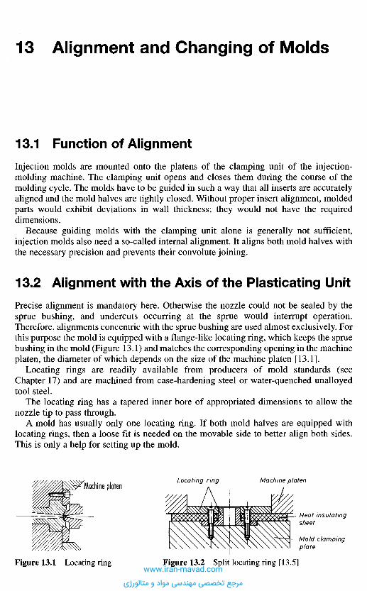
1 3 . 1 F u n c t i o n o f A l i g n m e n t
Injection molds are mounted onto the platens of the clamping unit of the injection-molding machine. The clamping unit opens and closes them during the course of themolding cycle. The molds have to be guided in such a way that all inserts are accuratelyaligned and the mold halves are tightly closed. Without proper insert alignment, moldedparts would exhibit deviations in wall thickness; they would not have the requireddimensions.
Because guiding molds with the clamping unit alone is generally not sufficient,injection molds also need a so-called internal alignment. It aligns both mold halves withthe necessary precision and prevents their convolute joining.
1 3 . 2 A l i g n m e n t w i t h t h e A x i s o f t h e P l a s t i c a t i n g U n i t
Precise alignment is mandatory here. Otherwise the nozzle could not be sealed by thesprue bushing, and undercuts occurring at the sprue would interrupt operation.Therefore, alignments concentric with the sprue bushing are used almost exclusively. Forthis purpose the mold is equipped with a flange-like locating ring, which keeps the spruebushing in the mold (Figure 13.1) and matches the corresponding opening in the machineplaten, the diameter of which depends on the size of the machine platen [13.1].
Locating rings are readily available from producers of mold standards (seeChapter 17) and are machined from case-hardening steel or water-quenched unalloyedtool steel.
The locating ring has a tapered inner bore of appropriated dimensions to allow thenozzle tip to pass through.
A mold has usually only one locating ring. If both mold halves are equipped withlocating rings, then a loose fit is needed on the movable side to better align both sides.This is only a help for setting up the mold.
1 3 A l i g n m e n t a n d C h a n g i n g o f M o l d s
Figure 13.1 Locating ring Figure 13.2 Split locating ring [13.5]
Machine platenLocating ring Machine platen
Heat insulatingsheet
Mold clampingplate
www.iran-mavad.com
مرجع تخصصی مهندسی مواد و متالورژی
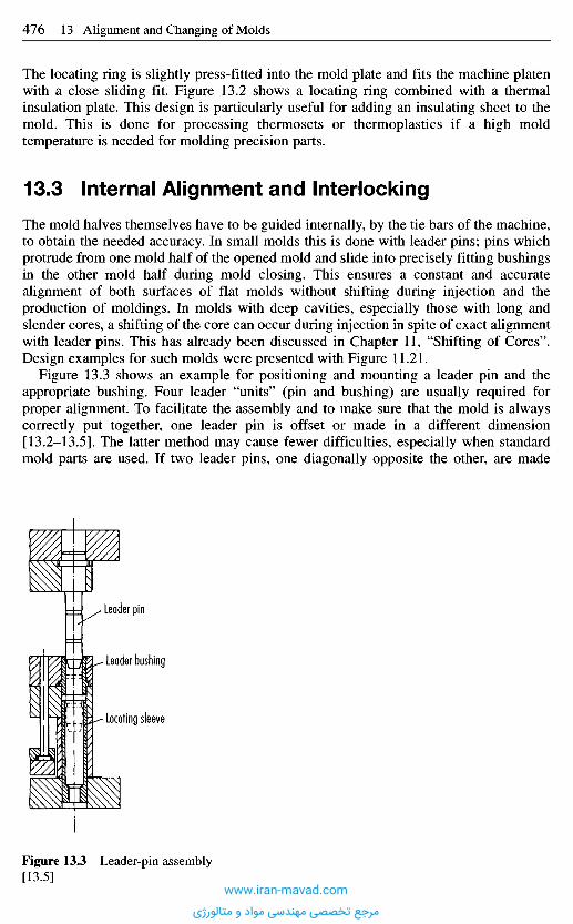
The locating ring is slightly press-fitted into the mold plate and fits the machine platenwith a close sliding fit. Figure 13.2 shows a locating ring combined with a thermalinsulation plate. This design is particularly useful for adding an insulating sheet to themold. This is done for processing thermosets or thermoplastics if a high moldtemperature is needed for molding precision parts.
1 3 . 3 I n t e r n a l A l i g n m e n t a n d I n t e r l o c k i n g
The mold halves themselves have to be guided internally, by the tie bars of the machine,to obtain the needed accuracy. In small molds this is done with leader pins; pins whichprotrude from one mold half of the opened mold and slide into precisely fitting bushingsin the other mold half during mold closing. This ensures a constant and accuratealignment of both surfaces of flat molds without shifting during injection and theproduction of moldings. In molds with deep cavities, especially those with long andslender cores, a shifting of the core can occur during injection in spite of exact alignmentwith leader pins. This has already been discussed in Chapter 11, "Shifting of Cores".Design examples for such molds were presented with Figure 11.21.
Figure 13.3 shows an example for positioning and mounting a leader pin and theappropriate bushing. Four leader "units" (pin and bushing) are usually required forproper alignment. To facilitate the assembly and to make sure that the mold is alwayscorrectly put together, one leader pin is offset or made in a different dimension[13.2-13.5]. The latter method may cause fewer difficulties, especially when standardmold parts are used. If two leader pins, one diagonally opposite the other, are made
Leader pin
Leader bushing
Locating sleeve
Figure 13.3 Leader-pin assembly[13.5]
www.iran-mavad.com
مرجع تخصصی مهندسی مواد و متالورژی

The length of leader bushings depends on their diameter. It should be 1.5- to 3-times theinside diameter (Figure 13.6). The corresponding holes in the mold plate have to bedrilled according to instructions. Figures 13.7 and 13.8 demonstrate the assembly ofleader pins and bushings [13.4].
Figure 13.7 shows the system for the design of simple molds and for leading slides.A jig drill is needed for proper alignment of the holes in the various plates.
Figure 13.8 represents a system with shoulder leader pins. Bores for pin and bushingcan be drilled in a single operation (equal diameters).
The system of Figure 13.9 is not used very often. It is carefree and ensures a preciseand low-friction movement, but at additional expenses.
With leader sleeves, mold plates can be aligned and connected with one another whichwould otherwise not be engaged by leader pin or bushing (Figure 13.10). The diameterof the sleeve is kept the same as that of the bushing or the shoulder of a shoulder leaderpin. Therefore, all holes can be machined in one pass. The internal diameter isadequately large to permit unrestricted entering of pins. The removal of the locatingsleeves can be readily effected through the tapped hole at the end by means of anextractor, e.g., leader pin in Figure 13.11.
longer, it is easier to slide the two halves together while placing the mold into themachine or during assembly. The leader pins are positioned as close to the edge aspossible to gain space for the cavity and an adequate number of cooling lines.
Effective alignment is possible only if close tolerances are kept between leader pinsand corresponding holes. This, however, causes considerable wear. Therefore it is notprudent to let the pins slide directly into the respective holes of the mold plates. As amatter of principle, leader bushings should be used to counteract wear and to enableworn-out parts to be exchanged easily. Leader bushings, like leader pins, are made ofcase-hardened steel with a hardness of 60 to 62 Rc. They are commercially available invarious sizes and shapes. Wear can furthermore be reduced by lubricating the pins withmolybdenum disulfide. For this purpose pins or bushings have oil grooves. Leader pinswithout lubrication (Figure 13.7) should only be used for rather small molds or specialapplications in slides or with ball bushings (Figure 13.9) Low-maintenance operation isachieved through the use of leader bushings with solid lubricant depots [13.2-13.4].
Leader pins and bushings are commercially available in various designs (Figure 13.5).Attention should be paid to the recommended fits (Figure 13.4). The length of leaderpins depends on the depth of the cavity.
Leading has to begin before the mold halves are engaged. Therefore, a sufficientlength must be selected. Shoulder leader pins (Figure 13.5) can, at the same time, pinmold plates together. Commercial availability is treated in Chapter 17.
Figure 13.4 Tolerances for leaderpins Figure 13.5 Common design of leader pins
www.iran-mavad.com
مرجع تخصصی مهندسی مواد و متالورژی

Among the multitude of leader-pin systems, those shown in Figures 13.11 and 13.12should also be mentioned. Both are based on components already described: leader pin,bushing and sleeve. The system of Figure 13.11 has pins and bushings with threadedholes and tightening screws, which are propped on the opposite side by head supports.Plates not engaged by pin and bushing are lead by sleeves. This design is moreexpensive, however, than the one shown in Figure 13.3 but has some decisiveadvantages. The assembly of the individual plates is not done with screws, and additionaldrilling of holes is unnecessary. The plates are kept together with the tightening screws.At the same time, the mold plate can be utilized better for accommodating cavity andcooling lines [13.3, 13.5].
The system in Figure 13.12 shows a very different design of leader bushings andsleeves and their assembly in the mold. The bushings consist of three parts: the bushingproper, a retainer ring, and a ring nut. There are two locations for the retainer ring. Thebushings can be mounted flush with the plate surface or protruding by 5 mm and
Figure 13.6 Shoulder bushings withcommon tolerances
Figure 13.8 Shoulder leader pin[13.4]
Figure 13.7 Leader pin withoutoil grooves [13.4]
Vent
Figure 13.9 Leader pin assemblywith ball bushing [13.4]
Figure 13.10 Locating sleeve [13.4]
www.iran-mavad.com
مرجع تخصصی مهندسی مواد و متالورژی
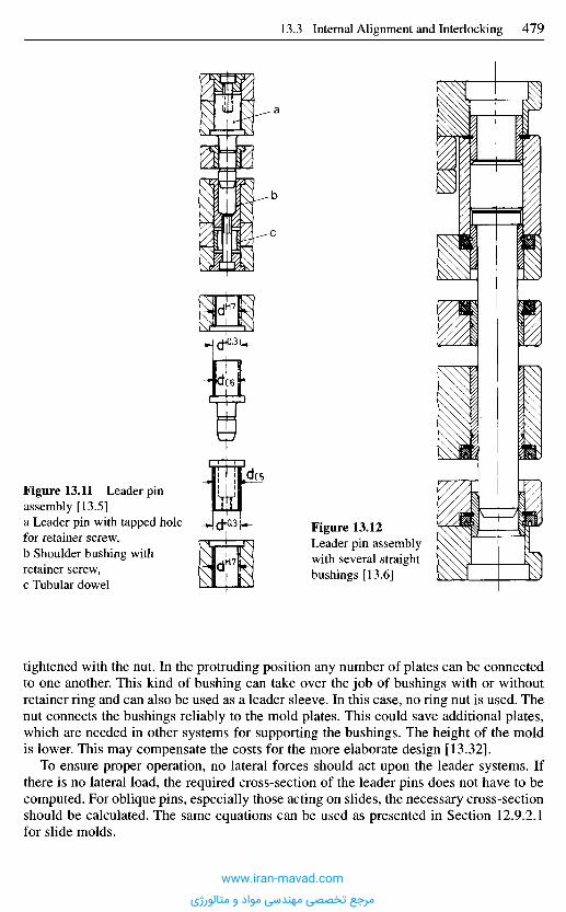
tightened with the nut. In the protruding position any number of plates can be connectedto one another. This kind of bushing can take over the job of bushings with or withoutretainer ring and can also be used as a leader sleeve. In this case, no ring nut is used. Thenut connects the bushings reliably to the mold plates. This could save additional plates,which are needed in other systems for supporting the bushings. The height of the moldis lower. This may compensate the costs for the more elaborate design [13.32].
To ensure proper operation, no lateral forces should act upon the leader systems. Ifthere is no lateral load, the required cross-section of the leader pins does not have to becomputed. For oblique pins, especially those acting on slides, the necessary cross-sectionshould be calculated. The same equations can be used as presented in Section 12.9.2.1for slide molds.
Figure 13.12Leader pin assemblywith several straightbushings [13.6]
Figure 13.11 Leader pinassembly [13.5]a Leader pin with tapped holefor retainer screw,b Shoulder bushing withretainer screw,c Tubular dowel
www.iran-mavad.com
مرجع تخصصی مهندسی مواد و متالورژی
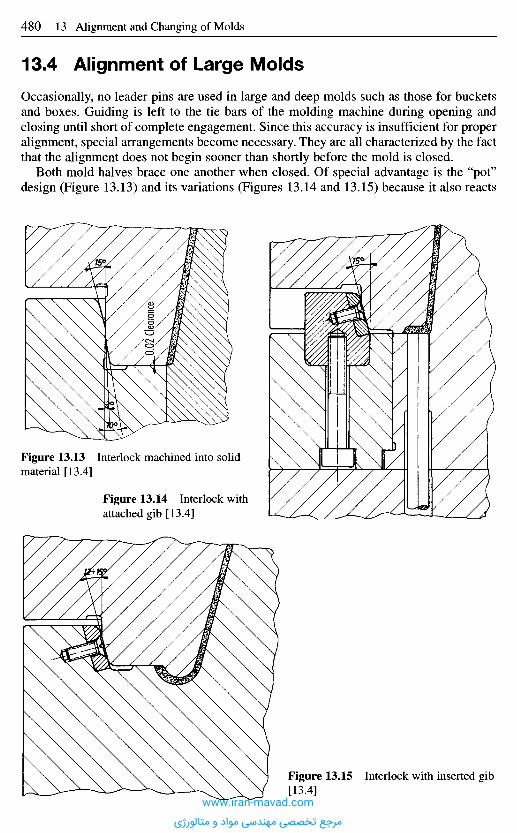
1 3 . 4 A l i g n m e n t o f L a r g e M o l d s
Occasionally, no leader pins are used in large and deep molds such as those for bucketsand boxes. Guiding is left to the tie bars of the molding machine during opening andclosing until short of complete engagement. Since this accuracy is insufficient for properalignment, special arrangements become necessary. They are all characterized by the factthat the alignment does not begin sooner than shortly before the mold is closed.
Both mold halves brace one another when closed. Of special advantage is the "pot"design (Figure 13.13) and its variations (Figures 13.14 and 13.15) because it also reacts
Figure 13.13 Interlock machined into solidmaterial [13.4]
Figure 13.14 Interlock withattached gib [13.4]
.0.02
Clea
rance
Figure 13.15 Interlock with inserted gib[13.4]
www.iran-mavad.com
مرجع تخصصی مهندسی مواد و متالورژی
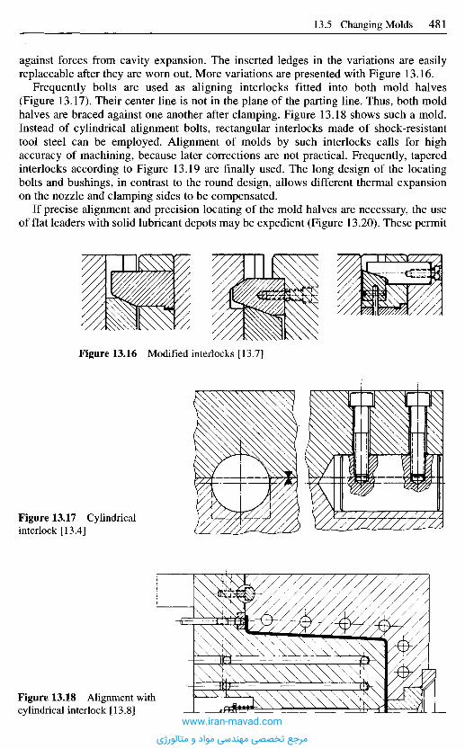
against forces from cavity expansion. The inserted ledges in the variations are easilyreplaceable after they are worn out. More variations are presented with Figure 13.16.
Frequently bolts are used as aligning interlocks fitted into both mold halves(Figure 13.17). Their center line is not in the plane of the parting line. Thus, both moldhalves are braced against one another after clamping. Figure 13.18 shows such a mold.Instead of cylindrical alignment bolts, rectangular interlocks made of shock-resistanttool steel can be employed. Alignment of molds by such interlocks calls for highaccuracy of machining, because later corrections are not practical. Frequently, taperedinterlocks according to Figure 13.19 are finally used. The long design of the locatingbolts and bushings, in contrast to the round design, allows different thermal expansionon the nozzle and clamping sides to be compensated.
If precise alignment and precision locating of the mold halves are necessary, the useof flat leaders with solid lubricant depots may be expedient (Figure 13.20). These permit
Figure 13.16 Modified interlocks [13.7]
Figure 13.17 Cylindricalinterlock [13.4]
Figure 13.18 Alignment withcylindrical interlock [13.8]
www.iran-mavad.com
مرجع تخصصی مهندسی مواد و متالورژی
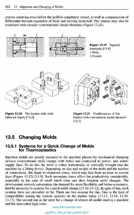
1 3 . 5 C h a n g i n g M o l d s
13.5.1 S y s t e m s f o r a Q u i c k C h a n g e of M o l d sf o r T h e r m o p l a s t i c s
Injection molds are usually mounted to the machine platens by mechanical clampingdevices (conventional mold clamps with bolts) and connected to power- and water-supply lines. To do this the mold is either horizontally or vertically brought into themachine by a lifting device. Depending on size and weight of the mold and the numberof connections, this leads to shutdown times, which may last from an hour to severaldays (Figure 13.22) [13.9]. Such secondary times affect the productivity considerably,especially in the case of small batch sizes and thus frequent mold changes. Thedevelopment towards automation, the demand for more flexibility and better economics,lead by necessity to systems for a quick mold change [13.10-13.12]. In spite of this, suchsystems have not prevailed so far. There are two reasons for this. One is the lack ofcompatibility among the various systems on the market today [13.13, 13.14, 13.16,13.17]. The second one is the need for a change of almost all molds used in a machineand the associated high costs.
Figure 13.20 Flat leaders with solidlubricant depots [13.2]
Figure 13.21 Combinations of flatleaders with conventional leader elements[13.2]
Figure 13.19 Taperedinterlocks [13.8]1 Male,2 Female
precise centering even before the mold is completely closed, as well as compensation ofdifferential thermal expansion of fixed and moving mold half. Flat leaders may also becombined with circular (conventional) leader elements (Figure 13.21).
www.iran-mavad.com
مرجع تخصصی مهندسی مواد و متالورژی
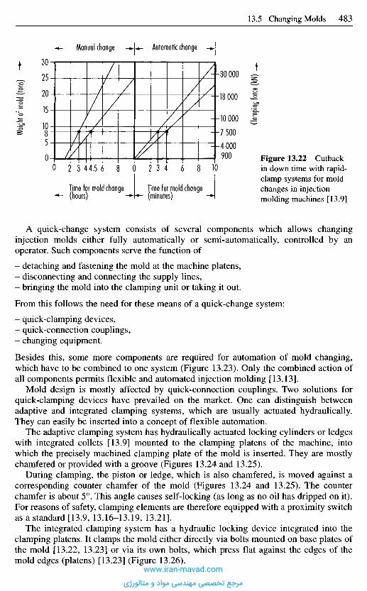
A quick-change system consists of several components which allows changinginjection molds either fully automatically or semi-automatically, controlled by anoperator. Such components serve the function of
- detaching and fastening the mold at the machine platens,- disconnecting and connecting the supply lines,- bringing the mold into the clamping unit or taking it out.
From this follows the need for these means of a quick-change system:
- quick-clamping devices,- quick-connection couplings,- changing equipment.
Besides this, some more components are required for automation of mold changing,which have to be combined to one system (Figure 13.23). Only the combined action ofall components permits flexible and automated injection molding [13.13].
Mold design is mostly affected by quick-connection couplings. Two solutions forquick-clamping devices have prevailed on the market. One can distinguish betweenadaptive and integrated clamping systems, which are usually actuated hydraulically.They can easily be inserted into a concept of flexible automation.
The adaptive clamping system has hydraulically actuated locking cylinders or ledgeswith integrated collets [13.9] mounted to the clamping platens of the machine, intowhich the precisely machined clamping plate of the mold is inserted. They are mostlychamfered or provided with a groove (Figures 13.24 and 13.25).
During clamping, the piston or ledge, which is also chamfered, is moved against acorresponding counter chamfer of the mold (Figures 13.24 and 13.25). The counterchamfer is about 5°. This angle causes self-locking (as long as no oil has dripped on it).For reasons of safety, clamping elements are therefore equipped with a proximity switchas a standard [13.9, 13.16-13.19, 13.21].
The integrated clamping system has a hydraulic locking device integrated into theclamping platens. It clamps the mold either directly via bolts mounted on base plates ofthe mold [13.22, 13.23] or via its own bolts, which press flat against the edges of themold edges (platens) [13.23] (Figure 13.26).
Weigh
t of m
old (t
ons)
Clamp
ing fo
rce (Ic
N)
Manual change Automatic change
Time for mold change(hours)
Time for mold change(minutes)
Figure 13.22 Cutbackin down time with rapid-clamp systems for moldchanges in injectionmolding machines [13.9]
www.iran-mavad.com
مرجع تخصصی مهندسی مواد و متالورژی
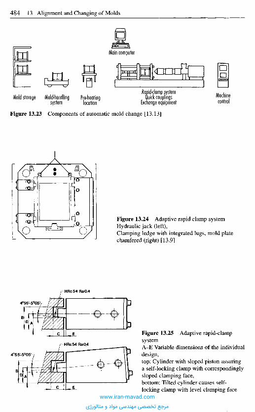
Main computer
Machinecontrol
Rapid-clamp systemQuick couplings
Exchange equipmentPre-heatinglocation
Mold-handlingsystem
Mold storage
Figure 13.23 Components of automatic mold change [13.13]
Figure 13.24 Adaptive rapid clamp systemHydraulic jack (left),Clamping ledge with integrated lugs, mold platechamfered (right) [13.9]
Figure 13.25 Adaptive rapid-clampsystemA-E Variable dimensions of the individualdesign,top: Cylinder with sloped piston assuringa self-locking clamp with correspondinglysloped clamping face,bottom: Tilted cylinder causes self-locking clamp with level clamping face
www.iran-mavad.com
مرجع تخصصی مهندسی مواد و متالورژی
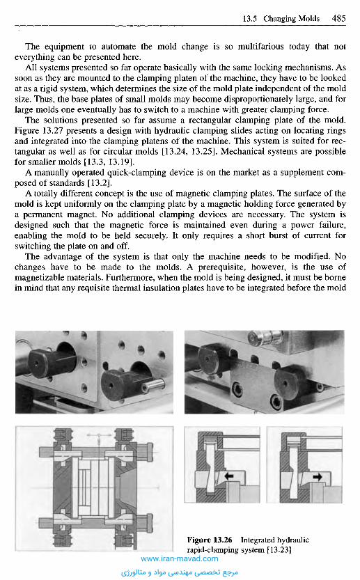
The equipment to automate the mold change is so multifarious today that noteverything can be presented here.
All systems presented so far operate basically with the same locking mechanisms. Assoon as they are mounted to the clamping platen of the machine, they have to be lookedat as a rigid system, which determines the size of the mold plate independent of the moldsize. Thus, the base plates of small molds may become disproportionately large, and forlarge molds one eventually has to switch to a machine with greater clamping force.
The solutions presented so far assume a rectangular clamping plate of the mold.Figure 13.27 presents a design with hydraulic clamping slides acting on locating ringsand integrated into the clamping platens of the machine. This system is suited for rec-tangular as well as for circular molds [13.24, 13.25]. Mechanical systems are possiblefor smaller molds [13.3, 13.19].
A manually operated quick-clamping device is on the market as a supplement com-posed of standards [13.2].
A totally different concept is the use of magnetic clamping plates. The surface of themold is kept uniformly on the clamping plate by a magnetic holding force generated bya permanent magnet. No additional clamping devices are necessary. The system isdesigned such that the magnetic force is maintained even during a power failure,enabling the mold to be held securely. It only requires a short burst of current forswitching the plate on and off.
The advantage of the system is that only the machine needs to be modified. Nochanges have to be made to the molds. A prerequisite, however, is the use ofmagnetizable materials. Furthermore, when the mold is being designed, it must be bornein mind that any requisite thermal insulation plates have to be integrated before the mold
Figure 13.26 Integrated hydraulicrapid-clamping system [13.23]
www.iran-mavad.com
مرجع تخصصی مهندسی مواد و متالورژی
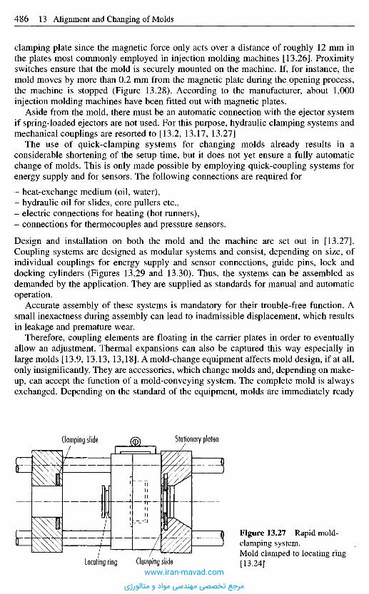
clamping plate since the magnetic force only acts over a distance of roughly 12 mm inthe plates most commonly employed in injection molding machines [13.26]. Proximityswitches ensure that the mold is securely mounted on the machine. If, for instance, themold moves by more than 0.2 mm from the magnetic plate during the opening process,the machine is stopped (Figure 13.28). According to the manufacturer, about 1,000injection molding machines have been fitted out with magnetic plates.
Aside from the mold, there must be an automatic connection with the ejector systemif spring-loaded ejectors are not used. For this purpose, hydraulic clamping systems andmechanical couplings are resorted to [13.2, 13.17, 13.27]
The use of quick-clamping systems for changing molds already results in aconsiderable shortening of the setup time, but it does not yet ensure a fully automaticchange of molds. This is only made possible by employing quick-coupling systems forenergy supply and for sensors. The following connections are required for
- heat-exchange medium (oil, water),- hydraulic oil for slides, core pullers etc.,- electric connections for heating (hot runners),- connections for thermocouples and pressure sensors.
Design and installation on both the mold and the machine are set out in [13.27].Coupling systems are designed as modular systems and consist, depending on size, ofindividual couplings for energy supply and sensor connections, guide pins, lock anddocking cylinders (Figures 13.29 and 13.30). Thus, the systems can be assembled asdemanded by the application. They are supplied as standards for manual and automaticoperation.
Accurate assembly of these systems is mandatory for their trouble-free function. Asmall inexactness during assembly can lead to inadmissible displacement, which resultsin leakage and premature wear.
Therefore, coupling elements are floating in the carrier plates in order to eventuallyallow an adjustment. Thermal expansions can also be captured this way especially inlarge molds [13.9, 13.13, 13,18]. Arnold-change equipment affects mold design, if at all,only insignificantly. They are accessories, which change molds and, depending on make-up, can accept the function of a mold-conveying system. The complete mold is alwaysexchanged. Depending on the standard of the equipment, molds are immediately ready
Figure 13.27 Rapid mold-clamping system.Mold clamped to locating ring[13.24]
Stationary platenClamping slide
Locating ring Clamping slidewww.iran-mavad.com
مرجع تخصصی مهندسی مواد و متالورژی
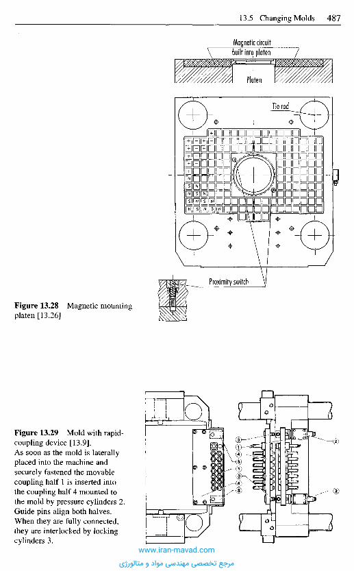
Magnetic circuitbuilt into platen
Platen
Tie rod
Proximity switch
Figure 13.28 Magnetic mountingplaten [13.26]
Figure 13.29 Mold with rapid-coupling device [13.9].As soon as the mold is laterallyplaced into the machine andsecurely fastened the movablecoupling half 1 is inserted intothe coupling half 4 mounted tothe mold by pressure cylinders 2.Guide pins align both halves.When they are fully connected,they are interlocked by lockingcylinders 3.
www.iran-mavad.com
مرجع تخصصی مهندسی مواد و متالورژی
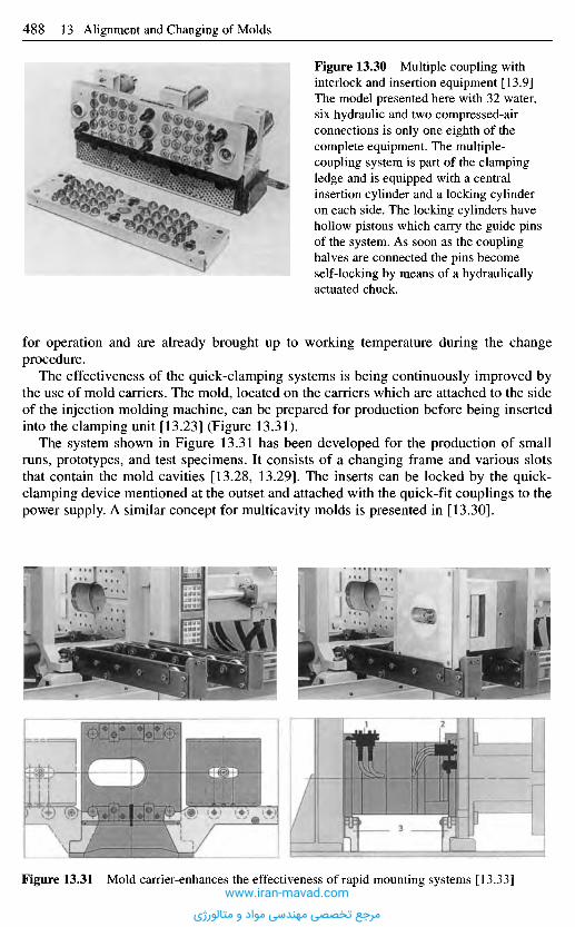
for operation and are already brought up to working temperature during the changeprocedure.
The effectiveness of the quick-clamping systems is being continuously improved bythe use of mold carriers. The mold, located on the carriers which are attached to the sideof the injection molding machine, can be prepared for production before being insertedinto the clamping unit [13.23] (Figure 13.31).
The system shown in Figure 13.31 has been developed for the production of smallruns, prototypes, and test specimens. It consists of a changing frame and various slotsthat contain the mold cavities [13.28, 13.29]. The inserts can be locked by the quick-clamping device mentioned at the outset and attached with the quick-fit couplings to thepower supply. A similar concept for multicavity molds is presented in [13.30].
Figure 13.30 Multiple coupling withinterlock and insertion equipment [13.9]The model presented here with 32 water,six hydraulic and two compressed-airconnections is only one eighth of thecomplete equipment. The multiple-coupling system is part of the clampingledge and is equipped with a centralinsertion cylinder and a locking cylinderon each side. The locking cylinders havehollow pistons which carry the guide pinsof the system. As soon as the couplinghalves are connected the pins becomeself-locking by means of a hydraulicallyactuated chuck.
Figure 13.31 Mold carrier-enhances the effectiveness of rapid mounting systems [13.33]www.iran-mavad.com
مرجع تخصصی مهندسی مواد و متالورژی
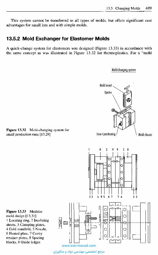
This system cannot be transferred to all types of molds, but offers significant costadvantages for small lots and with simple molds.
13.5.2 Mold Exchanger for Elastomer Molds
A quick-change system for elastomers was designed (Figure 13.33) in accordance withthe same concept as was illustrated in Figure 13.32 for thermoplastics. For a "mold
Mold-changing system
Mold insert-
Ejector
Insert positioning Mold chassisFigure 13.32 Mold-changing system forsmall production runs [13.29]
Figure 13.33 Modularmold design [13.31]1 Locating ring, 2 Insulatingsheets, 3 Clamping plates,4 Cold manifold, 5 Nozzle,6 Heated plate, 7 Cavityretainer plates, 8 Spacingblocks, 9 Guide ledges
www.iran-mavad.com
مرجع تخصصی مهندسی مواد و متالورژی
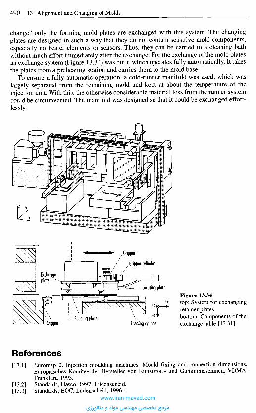
change" only the forming mold plates are exchanged with this system. The changingplates are designed in such a way that they do not contain sensitive mold components,especially no heater elements or sensors. Thus, they can be carried to a cleaning bathwithout much effort immediately after the exchange. For the exchange of the mold platesan exchange system (Figure 13.34) was built, which operates fully automatically. It takesthe plates from a preheating station and carries them to the mold base.
To ensure a fully automatic operation, a cold-runner manifold was used, which waslargely separated from the remaining mold and kept at about the temperature of theinjection unit. With this, the otherwise considerable material loss from the runner systemcould be circumvented. The manifold was designed so that it could be exchanged effort-lessly.
Figure 13.34top: System for exchangingretainer platesbottom: Components of theexchange table [13.31]
R e f e r e n c e s
[13.1] Euromap 2. Injection moulding machines. Mould fixing and connection dimensions.Europaisches Komitee der Hersteller von Kunststoff- und Gummimaschinen, VDMA,Frankfurt, 1995.
[13.2] Standards, Hasco, 1997, Liidenscheid.[13.3] Standards, EOC, Liidenscheid, 1996.
Exchangeplate
SupportFeeding plate
Feeding cylinder
Locating plate
Gripper
Gripper cylinder
www.iran-mavad.com
مرجع تخصصی مهندسی مواد و متالورژی
[13.4] Mohrwald, K.: Einblick in die Konstruktion von SpritzgieBwerkzeugen. Garrels, Ham-burg, 1965.
[13.5] Handbook of Standards, Sustan, Frankfurt, 1966.[13.6] Standards, Prospectus, Zimmermann, Lahr/Schwarzwald.[13.7] Zawistowski, H.; Frenkler, D.: Konstrukcja form wtryskowych do tworzyw termo-
plastycznych (Design of injection molds for thermoplastics). Wydawnictwo Naukowo-Techniczne, Warszawa, 1984.
[13.8] Lindner, E.: SpritzgieBwerkzeuge fiir groBe Teile, Information from the Laboratory forTech. Application of Plastics, BASF, Ludwigshafen/Rh.
[13.9] Handbuch fiir den Einsatz von Werkzeugschnellwechselsystemen in SpritzgieBbetrieben.Prospectus, Enerpac, Diisseldorf, 1987.
[13.10] CIM im SpritzgieBbetrieb. Carl Hanser Verlag, Miinchen, 1992.[13.11] Fernengel, R.: Konzept einer modernen SpritzgieBfertigung. Kunststoffe, 84 (1994), 10,
pp. 1361-1362 and pp. 1364-1367.[13.12] Rationeller fertigen mit Werkzeugwechselsystemen Plastverarbeiter, 45 (1994), 2,
pp. 87-89.[13.13] Benfer, W.: Werkzeugwechselsysteme an SpritzgieBmaschinen. Kunststoffe, 77 (1987),
2, pp. 139-149.[13.14] Heuel, 0.: Losen Schnellwechsel-Systeme fiir SpritzgieBformen alle Probleme? Kunst-
stoffberater, 32 (1987), 11, pp. 22-25.[13.15] Spannen der Werkzeuge vereinheitlicht. Plastverarbeiter, 38 (1987), 2, pp. 82-84.[13.16] Bourdon, K.: Zufiihrungs- und Entnahmetechniken an der SpritzgieBmaschine. SKZ-
Conference, Wurzburg, June 19-20, 1991, pp. 83-101.[13.17] Schultheis, M.: Der SpritzgieBbetrieb und seine Wettbewerbsfahigkeit. VDI-K,
Dusseldorf(1992), pp. 113-131.[13.18] Handbuch fiir den Einsatz von Werkzeugwechselsystemen in SpritzgieBbetrieben.
Prospectus, Enerpac, Veenendaal, NL.[13.19] Prospectus. Staubli AG, SeestraBe 250, CH-8810, Horgen/Ziirich.[13.20] Thoma, H.: Rechnereinsatz und flexible Maschinenkonzepte. Kunststoffe, 75 (1985), 9,
pp. 568-572.[13.21] Schneller Werkzeugwechsel moglich. Plastverarbeiter, 37 (1986), 8, pp. 56-57.[13.22] Prospectus. Engel, Schwertberg, Osterreich, 1995.[13.23] Prospectus. Arburg, LoBburg, 1996.[13.24] DE PS 2938665 C2, Krauss-Maffei, 1984.[13.25] Prospectus. Netstal AG, Nafels, Schweiz, 1996.[13.26] Prospectus. Giihring. Spanntechnik, Komwestheim, 1997.[13.27] Euromap 11. Automatic mould changing on injection moulding machines. Europaisches
Komitee der Hersteller von Kunststoff- und Gummimaschinen, VDMA, Frankfurt, 1993.[13.28] Backhoff, W.; Lemmen, E.: Stammwerkzeug mit wechselbaren Einsatzen. Information
for Tech. Applications, 259/79, Bayer AG, Leverkusen, 1979.[13.29] Spanner, P. et al.: Flexibles Fertigungszentrum fiir das SpritzgieBen kleiner Serien.
Kunststoffe, 74 (1984), 9, pp. 489-490.[13.30] Vollaustauschbares Werkzeug-Wechselsystem. Plastverarbeiter, 45 (1994), 2, pp. 42-43.[13.31] Weyer, G.: Automatische Herstellung von Elastomerartikeln im SpritzgieBverfahren.
Dissertation, Tech. University, Aachen, 1987.[13.32] Formenwechsel leichtgemacht. Kunstst. Plast., 32 (1985), 11, pp. 12-13.[13.33] Halbwerkzeugverarbeitung. Technical Information. Farbwerke Hoechst AG, Frankfurt,
1975.
www.iran-mavad.com
مرجع تخصصی مهندسی مواد و متالورژی
1 4 C o m p u t e r - A i d e d M o l d D e s i g n
a n d t h e U s e o f C A D i n M o l d
C o n s t r u c t i o n
1 4 . 1 I n t r o d u c t i o n
Development work on the simulation of the injection molding process started in themid-1970s when the first simple programs for programmable pocket calculators becameavailable for calculating the pressure loss in specified flow channels. The geometryoptions then available were cylinders for the gate system and plates and circularsegments for the molded part, depending on whether the melt flowed through a constantor a divergent channel (Figure 14.1).
Figure 14.1 Differentlysegmented geometries forcalculating the pressureloss in the flow channel
14,1.1 The F low Pa t t e rn M e t h o d Po in ted t h e Way F o r w a r d
Even 20 years ago, injection molders and mold builders were already confronted withthe same problems as today, namely: where should the gates be located, how many gatesshould there be, and where can weld lines or even entrapped air occur. At that time, theso-called flow pattern method had been developed by the IKV Plastics ProcessingInstitute of the Technical University of Aachen, which made it possible to simulatecavity filling with a compass and pencil on the basis of a developed view of the moldedpart. Once the flow pattern had been compiled, the developed view was cut out and gluedto give the 3D molded part (Figure 14.2). A new flow pattern had to be compiled for eachnew gate position and this was naturally very time-consuming.
Working on from this, a joint research project was set up with industry under the nameCADMOULD with the aim of developing a calculation model for use in the rheological,thermal, and mechanical layout of an injection mold. Those involved in the project wereraw materials producers, machine producers, injection molders and producers ofstandard mold components. At the same time, MOLDFLOW in Australia also developeda system for rheological simulation. These initial programs simply produced tablesshowing the prevailing pressure losses, viscosities, shear rates and temperatures, by wayof a result. This nonetheless marked the start of computer-aided simulation for injectionmolding.
www.iran-mavad.com
مرجع تخصصی مهندسی مواد و متالورژی
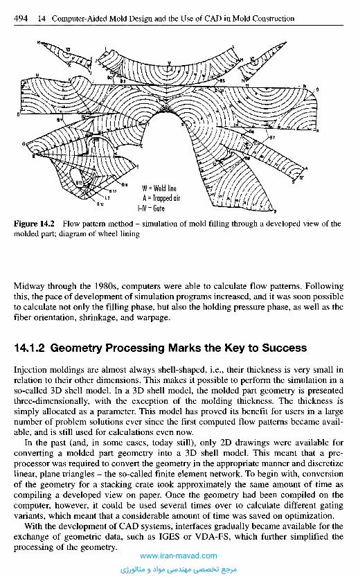
Figure 14.2 Flow pattern method - simulation of mold filling through a developed view of themolded part; diagram of wheel lining
Midway through the 1980s, computers were able to calculate flow patterns. Followingthis, the pace of development of simulation programs increased, and it was soon possibleto calculate not only the filling phase, but also the holding pressure phase, as well as thefiber orientation, shrinkage, and warpage.
14,1.2 Geometry Processing Marks the Key to Success
Injection moldings are almost always shell-shaped, i.e., their thickness is very small inrelation to their other dimensions. This makes it possible to perform the simulation in aso-called 3D shell model. In a 3D shell model, the molded part geometry is presentedthree-dimensionally, with the exception of the molding thickness. The thickness issimply allocated as a parameter. This model has proved its benefit for users in a largenumber of problem solutions ever since the first computed flow patterns became avail-able, and is still used for calculations even now.
In the past (and, in some cases, today still), only 2D drawings were available forconverting a molded part geometry into a 3D shell model. This meant that a pre-processor was required to convert the geometry in the appropriate manner and discretizelinear, plane triangles - the so-called finite element network. To begin with, conversionof the geometry for a stacking crate took approximately the same amount of time ascompiling a developed view on paper. Once the geometry had been compiled on thecomputer, however, it could be used several times over to calculate different gatingvariants, which meant that a considerable amount of time was saved on optimization.
With the development of CAD systems, interfaces gradually became available for theexchange of geometric data, such as IGES or VDA-FS, which further simplified theprocessing of the geometry.
W = Weld lineA = Trapped air
HV = Gate
www.iran-mavad.com
مرجع تخصصی مهندسی مواد و متالورژی
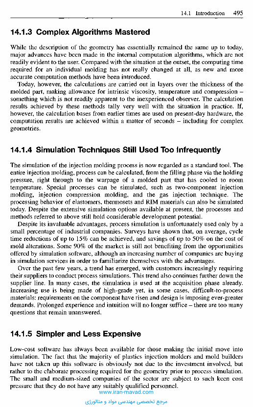
14.1.3 Complex Algorithms Mastered
While the description of the geometry has essentially remained the same up to today,major advances have been made in the internal computation algorithms, which are notreadily evident to the user. Compared with the situation at the outset, the computing timerequired for an individual molding has not really changed at all, as new and moreaccurate computation methods have been introduced.
Today, however, the calculations are carried out in layers over the thickness of themolded part, making allowance for intrinsic viscosity, temperature and compression -something which is not readily apparent to the inexperienced observer. The calculationresults achieved by these methods tally very well with the situation in practice. If,however, the calculation bases from earlier times are used on present-day hardware, thecomputation results are achieved within a matter of seconds - including for complexgeometries.
14.1.4 Simulation Techniques Still Used Too Infrequently
The simulation of the injection molding process is now regarded as a standard tool. Theentire injection molding, process can be calculated, from the filling phase via the holdingpressure, right through to the warpage of a molded part that has cooled to roomtemperature. Special processes can be simulated, such as two-component injectionmolding, injection compression molding, and the gas injection technique. Theprocessing behavior of elastomers, thermosets and RIM materials can also be simulatedtoday. Despite the extensive simulation options available at present, the processes andmethods referred to above still hold considerable development potential.
Despite its invaluable advantages, process simulation is unfortunately used only by asmall percentage of industrial companies. Surveys have shown that, on average, cycletime reductions of up to 15% can be achieved, and savings of up to 50% on the cost ofmold alterations. Some 90% of the market is still not benefiting from the opportunitiesoffered by simulation software, although an increasing number of companies are buyingin simulation services in order to familiarize themselves with the advantages.
Over the past few years, a trend has emerged, with customers increasingly requiringtheir suppliers to conduct process simulations. This trend also continues further down thesupplier line. In many cases, the simulation is used at the acquisition phase already.Increasing use is being made of high-grade yet, in some cases, difficult-to-processmaterials: requirements on the component have risen and design is imposing ever-greaterdemands. Prolonged experience and intuition will no longer suffice - there are too manyquestions that remain unanswered.
14.1.5 Simpler and Less Expensive
Low-cost software has always been available for those making the initial move intosimulation. The fact that the majority of plastics injection molders and mold buildershave not taken up this software is obviously not due to the investment involved, butrather to the elaborate processing required for the geometry prior to process simulation.The small and medium-sized companies of the sector are subject to such keen costpressure that they do not have any suitably qualified personnel.
www.iran-mavad.com
مرجع تخصصی مهندسی مواد و متالورژی
This has been made possible through a different type of geometry description, takenfrom the field of rapid prototyping (STL file). A file of this type can be output from most3D-CAD systems at the push of a button. With an STL file, these starter packages willautomatically process the geometry and select the gate positions; they will calculate theflow pattern, the filling pressure and the residual cooling time and also establish theclamping force from the filling pressure. The simulation based on this model will onlypermit the filling phase to be calculated as yet, however.
14.1.6 The Next Steps already Carved out
The possibilities that exist for simulating the injection molding process in a 3D volumemodel have been described several times already (Figure 14.4). This technology is stillright at its initial stage of development, at least as far as plastics are concerned. Theadvantage of this model is that no essential simplifications have to be made for thegeometry model and hence the full range of physical effects can be described. Examplesinclude the possibility of making allowance for gravitational and inertia effects(development of free jetting). Thick components and components with thick points canbe correctly described with this process. A further advantage of the use of the CV-FDM(Control Volume - Finite Difference Method) is the problem-free adoption of CADgeometries and their fully automatic conversion into networks in a matter of minutes.Over and above this, the model always contains the entire shape, ensuring that fullconsideration is always given to the influence of the mold (e.g. cooling, corner warpage).
Figure 14.3 Filling patternsimulation for a bottlecrate, designed with theprogram CADMOULDCadmoM®
hmmuxm mmmW
Starter packages from different software companies, such as CADMOULDRAPIDMESH (Figure 14.3) have been available for about a year now. These are not onlyinexpensive, but also considerably simplify geometry processing. Almost anyone canperform a simulation with a starter package.
www.iran-mavad.com
مرجع تخصصی مهندسی مواد و متالورژی

Figure 14.4 3D simulation (volume model); shrinkage and distortion of a lamp socket made ofplastic.Photo: Magma, Aachen
It can be assumed that injection molding simulation will be employed on an increasinglywidespread basis in future. A prerequisite for this is a maximum of user friendliness, i.e.,a geometry model that is compiled at the press of a button. An appropriate computationprocess must be available for each individual problem, giving a rapid overview orpermitting a specific problem to be calculated as accurately as possible. At the sametime, software of this type should offer support in the interpretation of the results, andalso automatic optimization strategies.
A comprehensive simulation must cover the low-end ranges (e.g., Rapidmesh), themid-range with simulations in a shell model, and the high-end, with volume-orientedsoftware. It would be conceivable for the low-end installation to be installed at severalpoints within the company (purchasing, development, marketing) and the other systemsin the classical engineering departments.
The injection molding simulation software must additionally be optimally integratedin the company's environment. This means that fully automatic geometry and resultsinterfaces need to be available to other development tools, such as structural and modalanalysis systems, and also production, planning, and control, production data collectingsystem, quality assurance, and quality optimization systems.
www.iran-mavad.com
مرجع تخصصی مهندسی مواد و متالورژی
1 4 . 2 C A D U s e in M o l d D e s i g n
14.2.1 Introduction
Through the consistent use of modern information systems, many companies haveincreased their competitiveness considerably in recent years. The success brought aboutby the introduction of a CAD system or the change-over to a more powerful one isfrequently measured in terms of the savings made on time and costs during the designprocess. According to the trade literature, these amount to as much as 75% (e.g.[14.1-14.3]). Similarly, a marked, although less quantifiable improvement in productquality is reported.
While CAD systems were initially aimed at superseding the drawing board, thecurrent trend is towards obtaining an exact copy of the product in the form of a three-dimensional model as early as possible during development and thus to generate a virtualprototype in order that this may be used, with the aid of computers, for furtherdevelopment stages. Necessary geometric models, e.g., for FEA simulation or rapidprototyping/rapid tooling, can be derived with little effort, in some cases, from the solidmodel. The borders between CAD and CAE in the conventional sense are thereforebecoming very fluid.
A study commissioned in 1996 by the CAD CIRCLE [14.4] showed that only two outof every three companies use CAD systems. Mostly only 2D functions are employed andrelatively little use is made of generated CAD data for other development stages, e.g.,for technical documentation, quality assurance or NC processing. Thus, data that definea product are having to be generated repeatedly. This is expensive in terms of time anderrors. Only a small fraction of the enormous potential inherent in CAD systems iscurrently being exploited.
14.2.2 Principles of CAD
14.2.2.1 2D/3D Model Representation
Compared with molded-part design and its sometimes complex description of freeformsurfaces, mold design commands a much greater proportion of CAD activities in thefield of classical drawing since the mold is largely made up of relatively simple geo-metric objects (rectangular, cylindrical, prismatic).
The CAD model of a design is a representation of the geometry in the computer. Thetype of internal representation leads to models with different information contents.
A basic distinction may be drawn between:
- 2D graphics systems,- 2V2D graphics systems,- 3D graphics systems.
The use of 2D systems is restricted to drafting at the screen level. The informationalcontent is only slightly higher than that of a drawing. It is the task of the user to drawall necessary views and cross-sections one by one. The various views are independentof each other, with the result that they are not automatically self-consistent. Theadvantage of the 2D CAD drawing over a sketch is primarily that a major change doesnot entail having to do another complete drawing. Individual geometry elements
www.iran-mavad.com
مرجع تخصصی مهندسی مواد و متالورژی
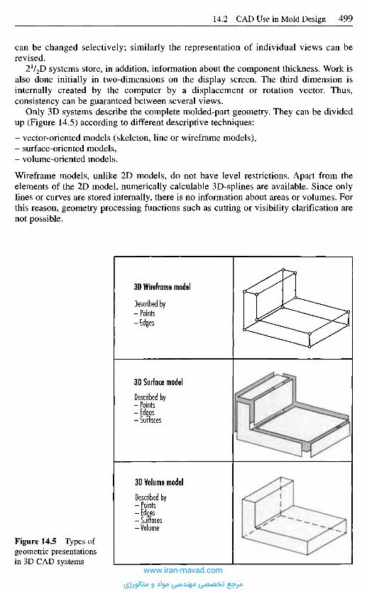
can be changed selectively; similarly the representation of individual views can berevised.
2V2D systems store, in addition, information about the component thickness. Work isalso done initially in two-dimensions on the display screen. The third dimension isinternally created by the computer by a displacement or rotation vector. Thus,consistency can be guaranteed between several views.
Only 3D systems describe the complete molded-part geometry. They can be dividedup (Figure 14.5) according to different descriptive techniques:
- vector-oriented models (skeleton, line or wireframe models),- surface-oriented models,- volume-oriented models.
Wireframe models, unlike 2D models, do not have level restrictions. Apart from theelements of the 2D model, numerically calculable 3D-splines are available. Since onlylines or curves are stored internally, there is no information about areas or volumes. Forthis reason, geometry processing functions such as cutting or visibility clarification arenot possible.
3D Wireframe model
Described by- Points- Edges
3D Surface model
Described by- Points-Edges- Surfaces
3D Volume model
Described by- Points-Edges- Surfaces-Volume
Figure 14.5 Types ofgeometric presentationsin 3D CAD systems
www.iran-mavad.com
مرجع تخصصی مهندسی مواد و متالورژی

With surface models, it is possible to describe arbitrary entities by means of theboundary areas. Interpolating, approximative, and analytical procedures are used for thearea description. Apart from the surfaces that are analytically easy to capture, such asplane, cylinder, cone, sphere, pyramid, and toroid, the user frequently employs thefollowing types:
- surface of rotation (rotation of a contour about a line),- translation or profile surface (translation of a contour along a guideline),- ruled surface (linking of two contours by curves),
The differences in the performance of 3D surface models come primarily to the forewhen it is a matter of describing freeform surfaces (mathematically indeterminate areas;areas that have a different curvature in every point). In the past, it was usual to apply themethods of Coons and Bezier [14.6, 14.7] or B(ase) splines [14.8]. Newer CAD systemsuse more powerful algorithms for the surface description. In this connection, mentionshould be made of NURBS (Non-Uniform Rational B-Splines), a surface descriptionmethod that allows both analytical and nonanalytical curves and surfaces to bedescribed, with the result that all geometric operations may be performed with a uniformalgorithm [14.9, 14.10].
The surfaces of arbitrary molded parts can thus be described with these functions.Information on which side of the area the volume (material) is located, however, ismissing. Section operations can only yield intersection lines and do not generate thehatching of the sectioned volume automatically. Furthermore, only with the aid of thisadditional information would a visibility clarification be possible.
The solid model delivers the most complete parts description. Purely volume-orientedoperations, like the determination of solid volumes, center of gravity, or moment ofinertia, as well as the derivation of arbitrary section views, become possible. Dependingon the type of geometry representation, the solid models can in turn be classified invarious ways. The best known are the CSG, the B-REP, the FEA and hybrid models(Figure 14.6).
B-REP model CSG model HYBRID model FEA model
Figure 14.6 Describing parts by volume models
Part volume
I Inner contouTSurface I
Outer contour |
EdgeI Point I
Booleanoperations
Cylinder
CuboidCuboid nexahedm
Booleanoperations Nodes
Elements
www.iran-mavad.com
مرجع تخصصی مهندسی مواد و متالورژی
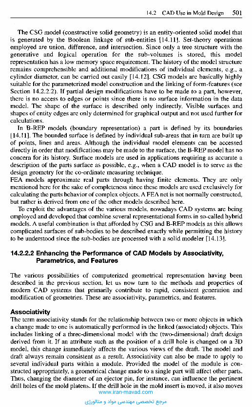
The CSG model (constructive solid geometry) is an entity-oriented solid model thatis generated by the Boolean linkage of sub-entities [14.11]. Set-theory operationsemployed are union, difference, and intersection. Since only a tree structure with thegenerative and logical operation for the sub-volumes is stored, this modelrepresentation has a low memory space requirement. The history of the model structureremains comprehensible and additional modifications of individual elements, e.g., acylinder diameter, can be carried out easily [14.12]. CSG models are basically highlysuitable for the parameterized model construction and the linking of form-features (seeSection 14.2.2.2). If partial design modifications have to be made to a part, however,there is no access to edges or points since there is no surface information in the datamodel. The shape of the surface is described only indirectly. Visible surfaces andshapes of entity edges are only determined for graphical output and not used further forcalculations.
In B-REP models (boundary representation) a part is defined by its boundaries[14.11]. The bounded surface is defined by individual sub-areas that in turn are built upof points, lines and areas. Although the individual model elements can be accesseddirectly in order that modifications may be made to the surface, the B-REP model has noconcern for its history. Surface models are used in applications requiring as accurate adescription of the parts surface as possible, e.g., when a CAD model is to serve as thedesign geometry for the co-ordinate measuring technique.FEA models approximate real parts through having finite elements. They are onlymentioned here for the sake of completeness since these models are used exclusively forcalculating the parts behavior of complex objects. A FEA net is not normally constructed,but rather is derived from one of the other models described here.
To exploit the advantages of the various models, nowadays CAD systems are beingemployed and developed that combine several representational forms in so-called hybridmodels. A useful combination is that afforded by CSG and B-REP models as this allowscomplicated surfaces of sub-bodies to be described exactly while permitting the historyto be understood since the sub-bodies are processed with a solid modeler [14.13].
14.2.2.2 Enhancing the Performance of CAD Models by Associativity,Parametrics, and Features
The various possibilities of computerized geometrical representation having beendescribed in the previous section, let us now turn to the methods and properties ofmodern CAD systems that primarily contribute to rapid, consistent generation andmodification of geometries. These are associativity, parametrics, and features.
AssociativityThe term associativity stands for the relationship between two or more objects in whicha change made to one is automatically performed in the linked (associated) objects. Thisincludes linking of a three-dimensional model with the (two-dimensional) draft designderived from it. If an attribute such as the position of a drill hole is changed on a 3Dmodel, this change immediately affects the various views of the draft. The model anddraft always remain consistent as a result. Associativity can also be made to apply toseveral individual parts within a module. Provided the model of the module is con-structed appropriately, a geometrical change made to a single part will affect other parts.Thus, changing the diameter of an ejector pin, for instance, can influence the pertinentdrill holes of the mold platens. If the drill hole in the mold insert is moved, it also moves
www.iran-mavad.com
مرجع تخصصی مهندسی مواد و متالورژی
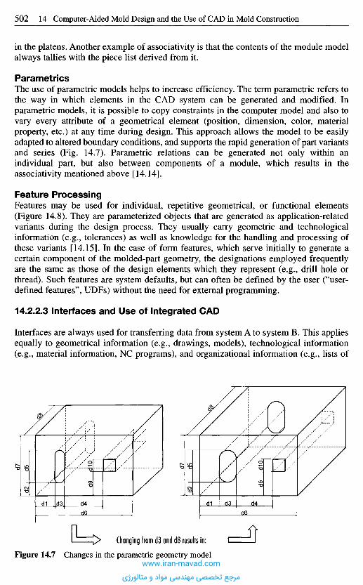
in the platens. Another example of associativity is that the contents of the module modelalways tallies with the piece list derived from it.
ParametricsThe use of parametric models helps to increase efficiency. The term parametric refers tothe way in which elements in the CAD system can be generated and modified. Inparametric models, it is possible to copy constraints in the computer model and also tovary every attribute of a geometrical element (position, dimension, color, materialproperty, etc.) at any time during design. This approach allows the model to be easilyadapted to altered boundary conditions, and supports the rapid generation of part variantsand series (Fig. 14.7). Parametric relations can be generated not only within anindividual part, but also between components of a module, which results in theassociativity mentioned above [14.14].
Feature ProcessingFeatures may be used for individual, repetitive geometrical, or functional elements(Figure 14.8). They are parameterized objects that are generated as application-relatedvariants during the design process. They usually carry geometric and technologicalinformation (e.g., tolerances) as well as knowledge for the handling and processing ofthese variants [14.15]. In the case of form features, which serve initially to generate acertain component of the molded-part geometry, the designations employed frequentlyare the same as those of the design elements which they represent (e.g., drill hole orthread). Such features are system defaults, but can often be defined by the user ("user-defined features", UDFs) without the need for external programming.
14.2.2.3 Interfaces and Use of Integrated CAD
Interfaces are always used for transferring data from system A to system B. This appliesequally to geometrical information (e.g., drawings, models), technological information(e.g., material information, NC programs), and organizational information (e.g., lists of
Figure 14.7 Changes in the parametric geometry model
Changing from d3 and d8 results in:
www.iran-mavad.com
مرجع تخصصی مهندسی مواد و متالورژی
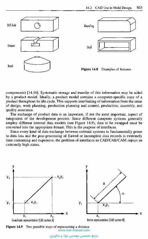
components) [14.16]. Systematic storage and transfer of this information may be aidedby a product model. Ideally, a product model contains a computer-specific copy of aproduct throughout its life cycle. This supports interlinking of information from the areasof design, work planning, production planning and control, production, assembly, andquality assurance.
The exchange of product data is an important, if not the most important, aspect ofintegration of the development process. Since different computer systems generallyemploy different internal data models (see Figure 14.9), data to be swapped must beconverted into the appropriate format. This is the purpose of interfaces.
Since every kind of data exchange between external systems is fundamentally proneto data loss and the post-processing of flawed or incomplete data records is extremelytime consuming and expensive, the problem of interfaces in CAD/CAE/CAM enjoys anextremely high status.
Drill hole
Groove
Bezel
Rounding
Shell
Figure 14.8 Examples of features
Figure 14.9 Two possible ways of representing a distance
Coordinate representation (CAD system A) Vector representation (CAD system B)
y y
X X
www.iran-mavad.com
مرجع تخصصی مهندسی مواد و متالورژی

IGESIGES (Initial Graphics Exchange Specification) was originally conceived fortransferring drawings [14.17] and was later augmented with the description of spatialgeometrical information (surfaces) [14.18]. Aside from geometrical data, text anddimensions can also be exchanged. The scope for copying freeform curves and surfacesis limited since only polynomials as far as the 3rd degree can be classified. Later versionsof IGES permit, in principle, the exchange of solid models, texts and symbols,measurements, and drawing views. IGES is the most widespread standard in the world.The main criticism is its large size and the extent of interpretation needed for theinterface specification which leads to a situation where hardly any processor offers total,generally compatible support. Frequent problems encountered with this interface arereproduced in e.g. [14.19]. The possibility of exchanging solids is rarely used in practicedue to a lack of processors.
VDA-FSThe VDA surface interface was developed by the German automobile association (VDA)to bridge the weaknesses of the IGES interface. VDA-FS is used primarily forexchanging area-related data [14.16], is used on a large scale for data exchange by
Figure 14.10 Reducing complexity through standardized interfaces
Number of processors:2 • n = 10
Number of processors:n - (n-1) = 20
Processor
Standardizedinterface J
CADB
CADE
CADD
CADC
CADA
CADA
CADB
CADE
CADC
CADD
Information exchange without standardized interface Information exchange with standardized interface
Interfaces for data exchange may be system-specific ("native"), specific for severalsystems (e.g., DXF), standardized at national level (e.g., VDA-FS in Germany), or atinternational level (e.g., IGES, STEP). The data from system A are converted during dataexchange into the interface format by a preprocessor. The postprocessor reads these datainto system B. Figure 14.10 shows that native solutions require many more processorsthan is the case when standardized interfaces are used. For this reason, there have beenmany attempts in the past to develop neutral data exchange forms in the form of inter-face standards.
www.iran-mavad.com
مرجع تخصصی مهندسی مواد و متالورژی

automotive manufacturers and their suppliers, and is primarily employed in Germany.Drawing information cannot be exchanged with VDA-FS.
VDA-ISVDA-IS is a more precise subset of IGES (IS stands for IGES subset) defined by theVDA for the needs of the German automotive industry. The interface supports theexchange of geometrical and measurement elements as well as freeform surfaces. Theimplementation of accompanying convertors is thereby restricted to selected, essentialfunctions, a fact which should increase the quality of the exchanged data.
VDA-PSA programming interface developed by DIN and the VDA, VDA-PS in Germany is usedfor providing standardized and repetitive parts. VDA-PS contains the generative logicfor the standardized parts.
SETSET (Standard d'Exchange et de Transfert) was developed by the French as animprovement on IGES. More detailed data descriptive of the product can be copied,especially those required by the aerospace industry. SET is primarily used in France.
STEPSeveral years ago under the auspices of ISO (ISO 10303) and drawing on the collectiveexperiences of other interface concepts, development was begun on a universal dataexchange format [14.20, 14.21]. STEP (STandard for the Exchange of Product modeldata) lays claim to being the sole all-embracing standard of the future and to supersedingIGES and other formats. Aside from geometrical data, information from the entireproduct life cycle will be transferred in the long term by STEP. In particular, this willinclude organizational data. Through division into so-called partial models and throughtheir application to individual application areas in the form of application protocols,STEP can be used to describe all kinds of product information. For example, ApplicationProtocol AP 214 of the automotive industry will not only exchange geometrical data butalso product structure data, kinematic data, NC data, material information, and surfaceproperties [14.22]. Although not yet realized, it is conceivable for parametric models andform features to be exchanged on the basis of SET [14.23]. STEP has been used since1996 for the productive exchange of solid models at international level. Furthermore,surface models, module structures, and organizational data can be transferred.
DXFWhile DXF (draft exchange format) from the company AutoDesk is not an attempt by astandards committee to produce a standard, it has become the most important format forthe 2D sector.
Native FormatsDespite all attempts to exchange geometric data between different systems via neutralinterfaces, many sectors operate with "native" data so as to minimize possible sources oferror. This means that the recipient of geometric data uses the same CAD system (andsame version) as the transmitter. This situation necessitates high outlay on costs andpersonnel particularly for subcontractors working for different clients because of thelarge number of CAD systems employed.
www.iran-mavad.com
مرجع تخصصی مهندسی مواد و متالورژی

Direct InterfaceAn alternative is the direct interface, which converts the model generated on CADsystem A into that of system B. Since direct converters are developed especially for onesystem combination, the amount of information transferred is often high. Thedisadvantage is the usually high costs required for each individual interface (seeFigure 14.10).
SATThe ACIS solid modeler from the company Spatial Technologies is the core of a numberof CAD systems. ACIS processes different geometric objects, such as wireframe,freeform, and solid models in a uniform data structure. The systems on top of this corepermit direct data exchange via the internal SAT (Save ACIS Text) interface of the ACISmodels [14.24]
Interfaces nowadays are indispensable to communications between the countlesssystems on the market and they are the most common means of data transfer [14.25].Nevertheless, there has been a clear tendency developing in recent years to integrateCAE/CAM systems, that until now were stand-alone programs receiving their CAD datavia interfaces, into comprehensive CAD packages. The purpose is to avoid thosedisadvantages associated with interfaces:
- It is not always possible to transfer all the required information (restrictions on theperformance capability of the interfaces, and transfer losses).
- Data exist in various, redundant representations because they are duplicated.Considerable amounts of work are needed before all data have the same, up-to-datestatus.
In general, the aim should be to use as few different software systems and thus dataformats as possible. Ideally, there would be one database which is accessed by allprograms in the process chain. The CAD model thus consists no longer of purelygeometric data, but instead is expanded by more detailed information. Integratedpackages have the goal of supporting the entire product development cycle and offer theadvantage of just one user interface with consistent handling.
14.2.2.4 Data Administration and Flow of Information
The areas of data administration and integration are very closely linked to each other andmust always be considered in conjunction with the respective CAD system. This isparticularly true of modern 3D CAD systems. As soon as the information for describinga mold no longer is restricted to conventional drawings, data administration becomesvery important. It is not only the actual data administration but also the work processes,which so far have been directed at conventional drawings, that have to be rethought andadapted. Such deliberations yield a range of not immediately apparent consequences thatare discussed below. The following points usually have to be considered:
- authoritativeness of information,- data dependencies,- archiving of information,- job processes (e.g., approval procedures and modification documentation).
Whereas drawings used to be the authority for the definition of a product, nowadays theyare usually derived from the mainly superordinate CAD model. The creation of such a
www.iran-mavad.com
مرجع تخصصی مهندسی مواد و متالورژی
2D drawing simply requires information as to which 3D model is to be represented inwhich orientation and with which section view in the layer. The geometrical information(lines, hatching, etc.), which ultimately make up a view, no longer need to be created andstored explicitly, but instead are computed from the 3D geometry. Often, information isalso taken directly from the CAD model without its being documented on a drawing,e.g., for NC programming. The CAD model is authoritative in this case. This does notmean, however, that drawings no longer play a role. If NC machines are not used forproduction, for example, classical drawings are required. To an extent depending on thecompany and the economics, working practice will be a mixture of direct productionbased on CAD data records and conventional production from drawings.
It must always be ensured that drawings and CAD models reflect the same stage ofmodification or development. This applies not just to CAD model and drawing, but alsoto all data (e.g., NC programs, computational models, etc.). All these dependent datamust be updated when modifications are made. Since the CAD model containsauthoritative information on the definition of the mold, there must be a process forapproving the CAD models. Aside from approval, there is the question of documentingmodifications to approved data to be considered.
In connection with modifications, the distribution of information plays an importantrole. Since interdependent data may in certain circumstance be used for different tasks atdifferent places, not only must the corresponding data be available there, but alsoinformation concerning the development and approval stages. When modificationsoccur, those places with dependent data that are affected by the modifications, must beinformed accordingly. This is vitally important when various development stages forshortening development times are performed in parallel.
The actual solution to data administration, archiving and modification processes isextremely dependent on company vagaries, the CAD system employed and the entirecomputer environment. The quality of the solution is crucial to the efficiency of the useof CAD and thus ultimately to product development. Most systems manufacturers offerdata administration software tailored to the CAD system that takes account of generateddata dependencies. Furthermore, there are powerful, adaptable engineering and productdata management systems (EDM and PDM) available on the market that provide back-up for this problem area.
14.2.3 C A D Application in Mold-Mak ing
CAD systems, especially the modern parametric solid modelers, offer numerouspossibilities for an efficient, accelerated approach in the construction of mold-makingand tool-making.
14.2.3.1 Modeling
As far as the use of CAD is concerned, there are generally three possible ways toconstruct a mold:
- 2D construction,- hybrid construction,- 3D construction.
www.iran-mavad.com
مرجع تخصصی مهندسی مواد و متالورژی
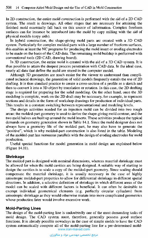
In 2D construction, the entire mold construction is performed with the aid of a 2D CADsystem. The result is drawings. All other stages that are necessary for attaining thefinished mold essentially fall back on this source of information. Complex freeformsurfaces can for instance be introduced into the mold by copy milling with the aid ofphysical models (copy aids).
In hybrid construction, the shape-giving mold parts are created with a 3D CADsystem. Particularly for complex molded parts with a large number of freeform surfaces,this enables at least the NC programs for producing the mold insert or eroding electrodesto be made on the basis of the CAD data. The remaining mold buildup is performed withconventional tools (2D CAD, drawing board).
In 3D construction, the entire mold is created with the aid of a 3D CAD system. It isthus possible to attain the deepest process penetration with CAD data. In the ideal case,nearly all data that define the mold are stored in the computer model.
Although 3D geometries are much easier for the viewer to understand than compli-cated technical drawings, the generation of solid models frequently entails the use of 2Ddrafting. It is thus standard practice to create a cross-section of a profile as a sketch andthen to convert it into a 3D object by translation or rotation. In this case, the 2D draftingstage is required for preparing for the solid modeling. On the other hand, once the 3Dmodeling is complete, work on the 2D draft may be necessary, for example, to representsections and details in the form of workshop drawings for production of individual parts.This results in a constant switching between representational and modeling levels.
The design activities needed for an injection mold can be divided into two roughareas: the molded-part geometry is used to derive the shape-giving mold contour, and thetwo mold halves are built up around the mold inserts. These activities produce the typicaldemands on geometry generation shown in Table 14.1. Since the mold designer does notalways have a geometry file of the molded part, he may also have to generate the"positive", which is why molded-part construction is also listed in the table. Modelingof the molded-part has numerous parallels with the design of eroding electrodes for moldproduction.
Useful special functions for model generation in mold design are explained below(Figure 14.11).
ShrinkageThe molded part is designed with nominal dimensions, whereas material shrinkage mustbe allowed for when the mold cavities are being designed. A suitable way of starting todesign the cavities is to scale a copy of the molded-part geometry. Since scaling shouldcompensate the material shrinkage, it is usually necessary in the case of highlyanisotropic molded-part properties to allow for differential shrinkage in different spatialdirections. In addition, a selective definition of shrinkage in which different areas of themodel can be scaled with different factors is beneficial. It can often be desirable toexempt individual geometrical elements (e.g. perfectly circular cylinders) fromanisotropic shrinkage as they would otherwise mutate into more complicated geometrieswhose production later would involve excessive work.
Mold-Parting LinesThe design of the mold-parting line is undoubtedly one of the most demanding tasks ofmold design. The CAD system must, therefore, generally possess good surfacefunctions. It is already possible nowadays in the case of simple molds to have the CADsystem automatically compute all of the mold-parting line for a pre-determined mold-
www.iran-mavad.com
مرجع تخصصی مهندسی مواد و متالورژی
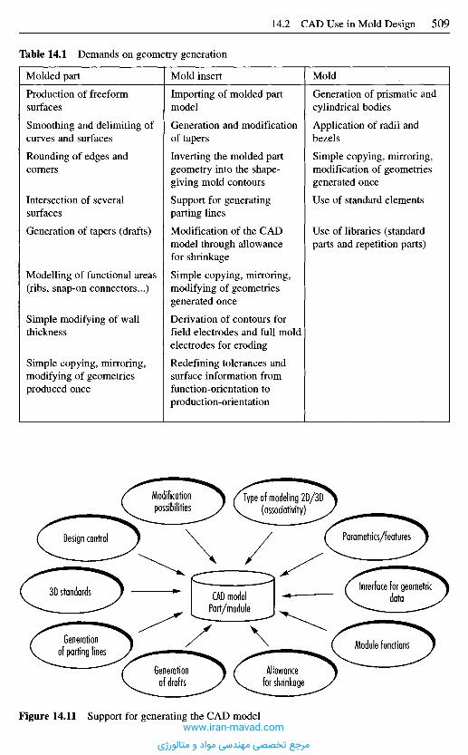
Table 14.1 Demands on geometry generation
Molded part
Production of freeformsurfaces
Smoothing and delimiting ofcurves and surfaces
Rounding of edges andcorners
Intersection of several
surfaces
Generation of tapers (drafts)
Modelling of functional areas(ribs, snap-on connectors...)
Simple modifying of wallthickness
Simple copying, mirroring,modifying of geometriesproduced once
Mold insert
Importing of molded partmodel
Generation and modificationof tapers
Inverting the molded partgeometry into the shape-giving mold contours
Support for generatingparting lines
Modification of the CADmodel through allowancefor shrinkage
Simple copying, mirroring,modifying of geometriesgenerated once
Derivation of contours forfield electrodes and full moldelectrodes for eroding
Redefining tolerances andsurface information fromfunction-orientation toproduction-orientation
Mold
Generation of prismatic andcylindrical bodies
Application of radii andbezels
Simple copying, mirroring,modification of geometriesgenerated once
Use of standard elements
Use of libraries (standardparts and repetition parts)
Modificationpossibilities
Type of modeling 2D/3D(associativity)
Parametrics/featuresDesign control
CAD modelPart/module
3D standards
Generationof parting lines
Generationof drafts
Allowancefor shrinkage
Module functions
lnrerface for geometricdata
Figure 14.11 Support for generating the CAD modelwww.iran-mavad.com
مرجع تخصصی مهندسی مواد و متالورژی
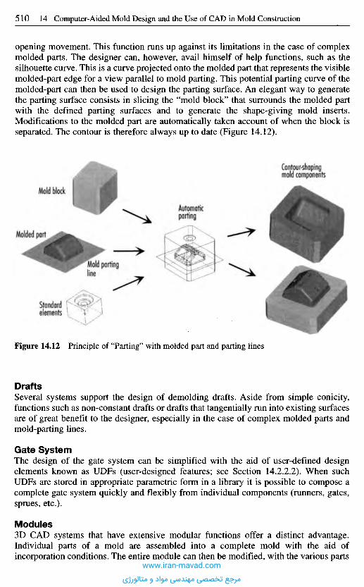
DraftsSeveral systems support the design of demolding drafts. Aside from simple conicity,functions such as non-constant drafts or drafts that tangentially run into existing surfacesare of great benefit to the designer, especially in the case of complex molded parts andmold-parting lines.
Gate SystemThe design of the gate system can be simplified with the aid of user-defined designelements known as UDFs (user-designed features; see Section 14.2.2.2). When suchUDFs are stored in appropriate parametric form in a library it is possible to compose acomplete gate system quickly and flexibly from individual components (runners, gates,sprues, etc.).
Modules3D CAD systems that have extensive modular functions offer a distinct advantage.Individual parts of a mold are assembled into a complete mold with the aid ofincorporation conditions. The entire module can then be modified, with the various parts
Figure 14.12 Principle of "Parting" with molded part and parting lines
Standardelements
Mold partingline
Molded part
Mold block
Automaticparting
Contour-shapingmold components
opening movement. This function runs up against its limitations in the case of complexmolded parts. The designer can, however, avail himself of help functions, such as thesilhouette curve. This is a curve projected onto the molded part that represents the visiblemolded-part edge for a view parallel to mold parting. This potential parting curve of themolded-part can then be used to design the parting surface. An elegant way to generatethe parting surface consists in slicing the "mold block" that surrounds the molded partwith the defined parting surfaces and to generate the shape-giving mold inserts.Modifications to the molded part are automatically taken account of when the block isseparated. The contour is therefore always up to date (Figure 14.12).
www.iran-mavad.com
مرجع تخصصی مهندسی مواد و متالورژی
behaving associatively. For example, drill holes for ejector pins in the module can be"drilled" through several mold platens. By means of definable relationships, diameterand positions of the ejector pins, for instance, may be set in relation to the pertinent drillholes. This ensures that the drill holes are always aligned in all mold platens and that thesize and position are adapted to the pins employed. Displacement of the ejector pinsautomatically leads to displacement of the ejector holes. If the CAD system is alsocapable of variant design and handling, exchanging the ejector pins automatically causesthe drill holes to be adapted.
Standard UnitsFor many molds, it is possible to revert to standard structures contained in libraries ofstandard parts. Such a case would be a fully assembled mold to which only the gate,mold inserts, and ejector pins have to be added. But even molds that are not predefinedas standards can be built up simply and used again as the basis for similar designs.
Design ControlDiverse design control functions make it possible to check if the design has beenperformed logically in terms of geometry on the one hand and plastics on the other. It isthus possible to test radii and demolding drafts as well as undercuts on the molded-partmodel and the mold insert.
Aside from the basic capability of generating and modifying geometric objects, CADsystems must also support manipulation by the user in a dependable manner and yieldthe expected results. For complex three-dimensional models, there are design aids avail-able that support spatial movement and positioning and identification of salient points asreference points. Object snap with adjustable sensitivity is especially helpful in thisregard.
Due to different demands imposed on design support in various development areas,molded-part geometries in practice are frequently generated on CAD systems other thanthose used for the pertinent molds. This raises the problem of data transfer with possibleloss of data (see Section 14.2.2.3) that makes it necessary to repair the swapped models.Repairing of CAD models, also known as CAD finishing, necessitates the availability ofdiagnostic functions that can detect damaged or incomplete part surfaces as well as easy-to-use manipulation tools, such as dragging together of individual surfaces and insertionof surface sections to bridge gaps.
Data transfer over standard interfaces causes parametric information to be lost. If thegeometric model has to subsequently be scalable or even to be used for making anefficient design variant, it is necessary to parameterize the imported data afterwards.Precisely in the case of complicated models, this may prove so difficult as to make a newdesign preferable. Furthermore, in many instances it can be better to de-parameterize themodel so as to emphasize other geometric relations or constraints.
14.2.3.2 Integrated Functions for Mold-Making
When the fully described solid models of the molded part and corresponding mold areavailable, there are numerous ways of using the model information of the entireCAD/CAM process chain, as Figure 14.13 shows. Not only are classical areas such asthe derivation of NC data or preprocessing for simulation computations supported, butdifferent forms of representation can be chosen leading to marked increases in efficiencyin the fields of preparatory work, quality control, technical documentation, right through
www.iran-mavad.com
مرجع تخصصی مهندسی مواد و متالورژی
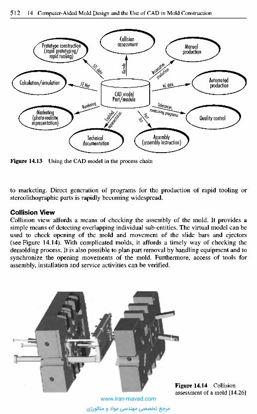
Figure 14.14 Collisionassessment of a mold [14.26]
to marketing. Direct generation of programs for the production of rapid tooling orstereolithographic parts is rapidly becoming widespread.
Collision ViewCollision view affords a means of checking the assembly of the mold. It provides asimple means of detecting overlapping individual sub-entities. The virtual model can beused to check opening of the mold and movement of the slide bars and ejectors(see Figure 14.14). With complicated molds, it affords a timely way of checking thedemolding process. It is also possible to plan part removal by handling equipment and tosynchronize the opening movements of the mold. Furthermore, access of tools forassembly, installation and service activities can be verified.
Figure 14.13 Using the CAD model in the process chain
Technicaldocumentation
Assembly(assembly instruction)
Quality controlMarketing
(photo-realisticrepresentation)
Calculation/simulation
Collisionassessment Manual
production
Automatedproduction
Prototype construction"(rapid prototyping/
rapid tooling)
CAD modelPart/module
Modul
e
www.iran-mavad.com
مرجع تخصصی مهندسی مواد و متالورژی
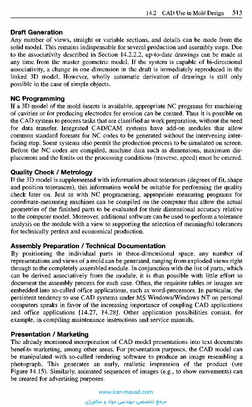
Draft GenerationAny number of views, straight or variable sections, and details can be made from thesolid model. This remains indispensable for several production and assembly steps. Dueto the associativity described in Section 14.2.2.2, up-to-date drawings can be made atany time from the master geometric model. If the system is capable of bi-directionalassociativity, a change in one dimension in the draft is immediately reproduced in thelinked 3D model. However, wholly automatic derivation of drawings is still onlypossible in the case of simple objects.
NC ProgrammingIf a 3D model of the mold inserts is available, appropriate NC programs for machiningof cavities or for producing electrodes for erosion can be created. Thus it is possible onthe CAD system to process tasks that are classified as work preparation, without the needfor data transfer. Integrated CAD/CAM systems have add-on modules that allowcommon standard formats for NC codes to be generated without the intervening inter-facing step. Some systems also permit the production process to be simulated on screen.Before the NC codes are compiled, machine data such as dimensions, maximum dis-placement and the limits on the processing conditions (traverse, speed) must be entered.
Quality Check / MetrologyIf the 3D model is supplemented with information about tolerances (degrees of fit, shapeand position tolerances), this information would be suitable for performing the qualitycheck later on. Just as with NC programming, appropriate measuring programs forcoordinate-measuring machines can be compiled on the computer that allow the actualgeometries of the finished parts to be evaluated for their dimensional accuracy relativeto the computer model. Moreover, additional software can be used to perform a toleranceanalysis on the module with a view to supporting the selection of meaningful tolerancesfor technically perfect and economical production.
Assembly Preparation / Technical DocumentationBy positioning the individual parts in three-dimensional space, any number ofrepresentations and views of a mold can be generated, ranging from exploded views rightthrough to the completely assembled module. In conjunction with the list of parts, whichcan be derived associatively from the module, it is thus possible with little effort todocument the assembly process for each case. Often, the requisite tables or images areembedded into so-called office applications, such as word-processors. In particular, thepersistent tendency to use CAD systems under MS Windows/Windows NT on personalcomputers speaks in favor of the increasing importance of coupling CAD applicationsand office applications [14.27, 14.28]. Other application possibilities consist, forexample, in compiling maintenance instructions and service manuals.
Presentation / MarketingThe already mentioned incorporation of CAD model presentations into text documentsbenefits marketing, among other areas. For presentation purposes, the CAD model canbe manipulated with so-called rendering software to produce an image resembling aphotograph. This generates an early, realistic impression of the product (seeFigure 14.15). Similarly, animated sequences of images (e.g., to show movements) canbe created for advertising purposes.
www.iran-mavad.com
مرجع تخصصی مهندسی مواد و متالورژی

FE SimulationSeveral CAD systems offer the designer the possibility of preparing geometric modelsfor further use in external simulation programs for thermal-rheological mold design.This occurs through the generation of a finite element net based on a CAD model. Sincecommon FE programs for ambitious process simulations (e.g., CADMOULD, C-MOLD,MOLDFLOW) exclusively compute in 2D at the moment, there is no getting round acentral layer model of the molded part or the cavity. The automatic generation of centrallayer models remains a problem to be adequately resolved [14.29]. Algorithms forautomatically deriving the central layer, fail at the very latest in the case of complexgeometries involving frequent abrupt changes in wall thickness and freeform surfaces.The experts still have to convert the model manually and perform the simplifications forthe simulation. There are now CAD systems on the market that have integratedsimulation programs. Some of these programs utilize STL data of the complete 3Dgeometry by way of geometry specification. This affords a means of finding the endpositions of weld lines and occluded air in the mold. These modules are withoutexception designed as tools for rough assessments and they are directed more atdesigners to help them perform a preliminary estimate than at simulation experts, whoare more interested in the most realistic prediction possible of the process behavior[14.30].
PrototypingNow that rapid prototyping has largely become established in product development inrecent years, rapid tooling is starting to grow in importance. Only with the advent of thisprocess has it proved possible to produce close-to-series prototypes while makingallowances for process influences and using the material that will later be employed.Most CAD models have the capability of converting a CAD model into an STL model.The STL format has now become the standard format in the field of rapid prototyping(rapid tooling).
14.2.3.3 Application-Specific Function Extension
The CAD systems currently on the market are generally universal types that can be usedin a number of branches. To ensure that CAD is used efficiently for a specific application(e.g., the development of plastic parts of a certain product range), functional capabilitiescan be added to the CAD systems. This is achieved by integrating or expanding themwith product-specific or company-specific application software. A prerequisite for thecompilation and incorporation of such program modules is the presence of suitable dataand program interfaces (e.g., FORTRAN or C) in the CAD system.
Adaptation of the performance capability of the CAD system to factory requirementsincludes the provision of macros (drafting and design macros), character sets, standardparts, the programming of standard procedures and of requisite variant parts [14.3].
Nowadays, plastic parts are often offered not just once on the market but as a wholerange of parts that differ only in size and not in function. Successful parts are not justmade once; it is standard practice to make generations of parts that appear at intervalswith slight modifications. For such parts and the pertinent molds, plastics convertershave a considerable amount of factory-specific know-how gained from computations,experiments, and practical experience of series production. This knowledge has to berendered computer-readable and made available to the designer, e.g., in the form ofmenus of features for his CAD workstation.
www.iran-mavad.com
مرجع تخصصی مهندسی مواد و متالورژی
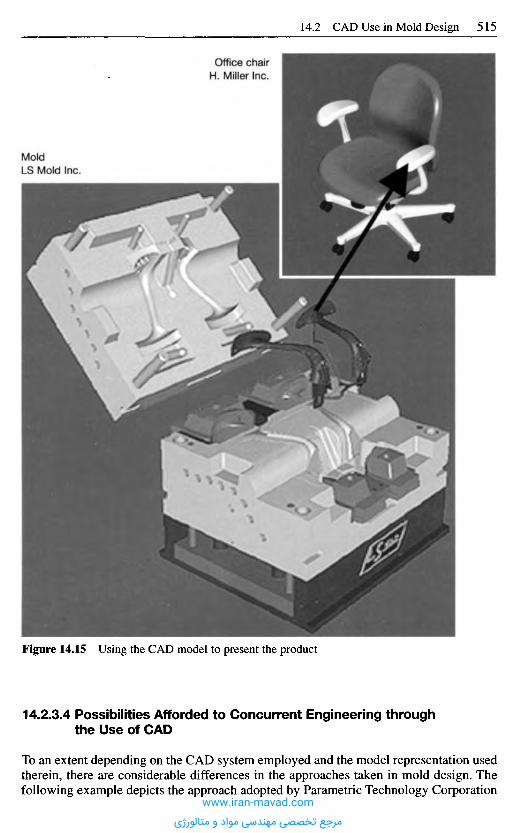
Figure 14.15 Using the CAD model to present the product
14.2.3.4 Possibilities Afforded to Concurrent Engineering throughthe Use of CAD
To an extent depending on the CAD system employed and the model representation usedtherein, there are considerable differences in the approaches taken in mold design. Thefollowing example depicts the approach adopted by Parametric Technology Corporation
MoldLS Mold Inc.
Office chairH. Miller Inc.
www.iran-mavad.com
مرجع تخصصی مهندسی مواد و متالورژی
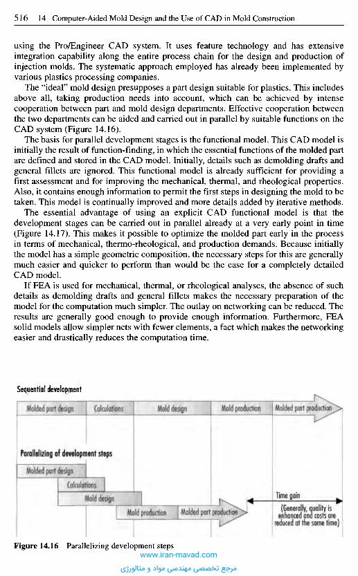
using the Pro/Engineer CAD system. It uses feature technology and has extensiveintegration capability along the entire process chain for the design and production ofinjection molds. The systematic approach employed has already been implemented byvarious plastics processing companies.
The "ideal" mold design presupposes a part design suitable for plastics. This includesabove all, taking production needs into account, which can be achieved by intensecooperation between part and mold design departments. Effective cooperation betweenthe two departments can be aided and carried out in parallel by suitable functions on theCAD system (Figure 14.16).
The basis for parallel development stages is the functional model. This CAD model isinitially the result of function-finding, in which the essential functions of the molded partare defined and stored in the CAD model. Initially, details such as demolding drafts andgeneral fillets are ignored. This functional model is already sufficient for providing afirst assessment and for improving the mechanical, thermal, and rheological properties.Also, it contains enough information to permit the first steps in designing the mold to betaken. This model is continually improved and more details added by iterative methods.
The essential advantage of using an explicit CAD functional model is that thedevelopment stages can be carried out in parallel already at a very early point in time(Figure 14.17). This makes it possible to optimize the molded part early in the processin terms of mechanical, thermo-rheological, and production demands. Because initiallythe model has a simple geometric composition, the necessary steps for this are generallymuch easier and quicker to perform than would be the case for a completely detailedCAD model.
If FEA is used for mechanical, thermal, or rheological analyses, the absence of suchdetails as demolding drafts and general fillets makes the necessary preparation of themodel for the computation much simpler. The outlay on networking can be reduced. Theresults are generally good enough to provide enough information. Furthermore, FEAsolid models allow simpler nets with fewer elements, a fact which makes the networkingeasier and drastically reduces the computation time.
Sequential development
Molded part design Calculations Mold design Mold production Molded part production
i Parallelizing of development steps
Molded part design
Calculations
Mold design
Mold production Molded part production
Figure 14.16 Parallelizing development steps
I Time gainI (Generally, quality is |I enhanced and costs are |I reduced at the same time) I
www.iran-mavad.com
مرجع تخصصی مهندسی مواد و متالورژی
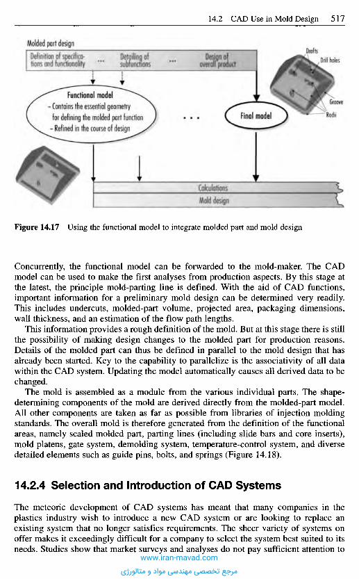
Figure 14.17 Using the functional model to integrate molded part and mold design
Concurrently, the functional model can be forwarded to the mold-maker. The CADmodel can be used to make the first analyses from production aspects. By this stage atthe latest, the principle mold-parting line is defined. With the aid of CAD functions,important information for a preliminary mold design can be determined very readily.This includes undercuts, molded-part volume, projected area, packaging dimensions,wall thickness, and an estimation of the flow path lengths.
This information provides a rough definition of the mold. But at this stage there is stillthe possibility of making design changes to the molded part for production reasons.Details of the molded part can thus be defined in parallel to the mold design that hasalready been started. Key to the capability to parallelize is the associativity of all datawithin the CAD system. Updating the model automatically causes all derived data to bechanged.
The mold is assembled as a module from the various individual parts. The shape-determining components of the mold are derived directly from the molded-part model.All other components are taken as far as possible from libraries of injection moldingstandards. The overall mold is therefore generated from the definition of the functionalareas, namely scaled molded part, parting lines (including slide bars and core inserts),mold platens, gate system, demolding system, temperature-control system, and diversedetailed elements such as guide pins, bolts, and springs (Figure 14.18).
14.2.4 Selection and Introduction of CAD Systems
The meteoric development of CAD systems has meant that many companies in theplastics industry wish to introduce a new CAD system or are looking to replace anexisting system that no longer satisfies requirements. The sheer variety of systems onoffer makes it exceedingly difficult for a company to select the system best suited to itsneeds. Studies show that market surveys and analyses do not pay sufficient attention to
Molded part designDefinition of specifica-tions and functionality
Detailing ofsubfunctions
Design ofoverall product
functional model- Contains the essential geometryfor defining the molded part function- Refined in the course of design
Final model
CalculationsMold design
DraftsDrill holes
Groove
Radii
www.iran-mavad.com
مرجع تخصصی مهندسی مواد و متالورژی
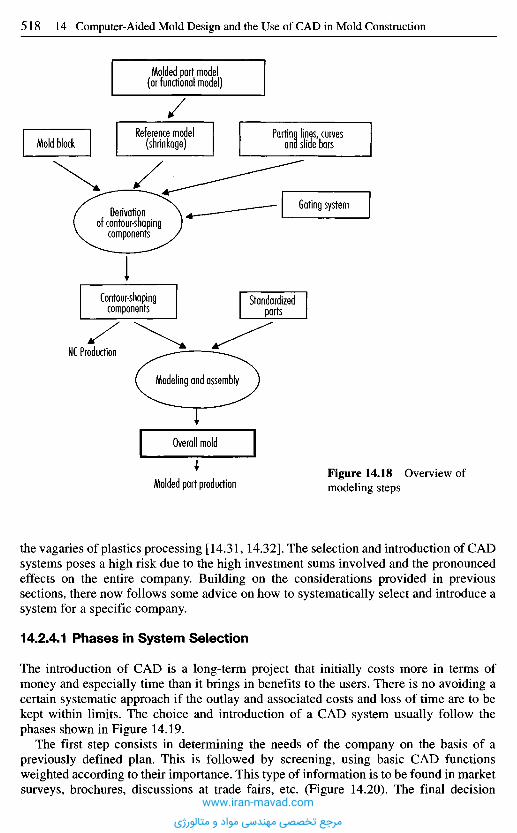
the vagaries of plastics processing [14.31,14.32]. The selection and introduction of CADsystems poses a high risk due to the high investment sums involved and the pronouncedeffects on the entire company. Building on the considerations provided in previoussections, there now follows some advice on how to systematically select and introduce asystem for a specific company.
14.2.4.1 Phases in System Selection
The introduction of CAD is a long-term project that initially costs more in terms ofmoney and especially time than it brings in benefits to the users. There is no avoiding acertain systematic approach if the outlay and associated costs and loss of time are to bekept within limits. The choice and introduction of a CAD system usually follow thephases shown in Figure 14.19.
The first step consists in determining the needs of the company on the basis of apreviously defined plan. This is followed by screening, using basic CAD functionsweighted according to their importance. This type of information is to be found in marketsurveys, brochures, discussions at trade fairs, etc. (Figure 14.20). The final decision
Figure 14.18 Overview ofmodeling stepsMolded part production
Overall mold
Modeling and assembly
Standardizedparts
NC Production
Contour-shapingcomponents
Derivationof contour-shaping
components
Mold blockReference model
(shrinkage)Parting lines, curves
ana slide bars
Gating system
Molded part model(or functional model)
www.iran-mavad.com
مرجع تخصصی مهندسی مواد و متالورژی
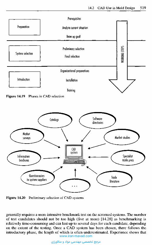
Preparation
System selection
Introduction
Figure 14.19 Phases in CAD selection
Prerequisites
Analyze current situation
Draw up goal
Preliminary selection
Final selection
Organizational preparations
Installation
Training
WORK
ING ST
EPS
Catalogs Softwaredirectories
Marketsurveys
Informationbrochures
CADsystem
Market studies
Specialisttrade press
Questionnairesto system suppliers Trade
literature
Figure 14.20 Preliminary selection of CAD systems
generally requires a more intensive benchmark test on the screened systems. The numberof test candidates should not be too high (five at most) [14.28] as benchmarking isrelatively time-consuming and can last up to several days for each candidate, dependingon the extent of the testing. Once a CAD system has been chosen, there follows theintroductory phase, the length of which is often underestimated. Experience shows that
www.iran-mavad.com
مرجع تخصصی مهندسی مواد و متالورژی

it can take up to several months, since exchanging the CAD program triggers a series offurther changes, e.g., new hardware and network components, a new solution for datastorage, linking of proven modules from the old system and, of course, employeetraining.
14.2.4.2 Formulating the CAD Concept
Planning the use of CAD entails systematically analyzing the factory and non-factorysituation at the outset; a thorough stocktaking of the existing situation and a carefuldetermination of the needs are crucial to selecting a system [14.33]. The analysis usuallyembraces the organizational structure, range of parts, and the way in which the pro-cessing of tasks is organized, including interfaces to other companies [14.34].
Even as the plan is being devised, as many persons as possible from those affected bythe introduction of CAD should be included in the project. This ensures on the one handthat the needs of the various company divisions are taken into account. On the other, itbrings about early contact with the new program and increases acceptance, defusing thechange-over phase. The basic questions that the project team should ask of every indi-vidual system are [14.33]:
- How easy is it to change plans?- What interfaces are needed to other systems?- What is the development potential of the software?
In the past, the process of arriving at a concept for the intended use of CAD has beenaided with checklists and lists of criteria (e.g., [14.3, 14.35-14.37]) whose purpose is toensure that every major aspect of planning the introduction of CAD are covered. Theseaids are employed in discussions with all those affected to establish a specificationsprofile for the system to be chosen, which include these problem areas:
- computer plan, data storage,- hardware, operating system,- compatibility with existing system,- interfaces to other applications and company divisions,- interfaces to other companies (e.g., suppliers),- system add-ons, additional functions,- programming environment, expandability,- design activities, compilation of drawings, model generation,- geometry model in computer, accuracy,- parametrics, variant design,- features, macros,- ergonomics, input and output devices,- introductory phase, extent of training, user-friendliness,- customer service, updates,- long-term planned development processes and production technologies.
The formulated demands imposed on the future CAD system can then be assigned tovarious categories (essential, minimal, desirable requirements) of the specification listshown in Figure 14.21. An essential requirement would be, for instance, that the CADsystem is fitted out with an IGES interface. A minimal (or maximal) requirement, bycontrast, would be information on the permissible amount of time for the introductoryphase, whereas the existence of an STL interface (for mold-making, an STL interface is
www.iran-mavad.com
مرجع تخصصی مهندسی مواد و متالورژی
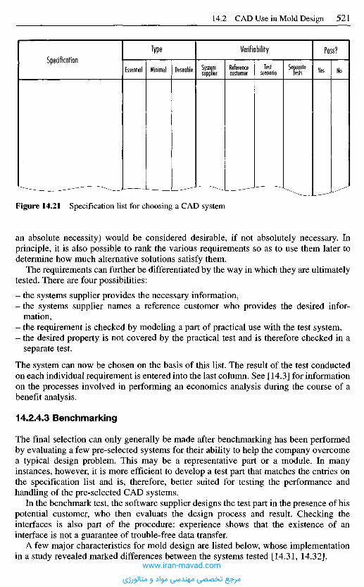
Figure 14.21 Specification list for choosing a CAD system
an absolute necessity) would be considered desirable, if not absolutely necessary. Inprinciple, it is also possible to rank the various requirements so as to use them later todetermine how much alternative solutions satisfy them.
The requirements can further be differentiated by the way in which they are ultimatelytested. There are four possibilities:
- the systems supplier provides the necessary information,- the systems supplier names a reference customer who provides the desired infor-
mation,- the requirement is checked by modeling a part of practical use with the test system,- the desired property is not covered by the practical test and is therefore checked in a
separate test.
The system can now be chosen on the basis of this list. The result of the test conductedon each individual requirement is entered into the last column. See [14.3] for informationon the processes involved in performing an economics analysis during the course of abenefit analysis.
14.2.4.3 Benchmarking
The final selection can only generally be made after benchmarking has been performedby evaluating a few pre-selected systems for their ability to help the company overcomea typical design problem. This may be a representative part or a module. In manyinstances, however, it is more efficient to develop a test part that matches the entries onthe specification list and is, therefore, better suited for testing the performance andhandling of the pre-selected CAD systems.
In the benchmark test, the software supplier designs the test part in the presence of hispotential customer, who then evaluats the design process and result. Checking theinterfaces is also part of the procedure: experience shows that the existence of aninterface is not a guarantee of trouble-free data transfer.
A few major characteristics for mold design are listed below, whose implementationin a study revealed marked differences between the systems tested [14.31, 14.32].
SpecificationType
Essential Minimal Desirable
Verifiability
Systemsupplier
Referencecustomer
Testscenario
Separatetests
Pass?
Yes No
www.iran-mavad.com
مرجع تخصصی مهندسی مواد و متالورژی

- Fillet problems: The generation and representation of merging radii causes difficultiesfor some systems.
- Duplication of an element: it should be possible to duplicate a geometry element thathas been generated (e.g. drill hole). In some systems, it is not possible to break the linkbetween the original and the duplicated elements. This may be necessary forcompensating e.g., differential shrinkage.
- Identification of changes: when changes are made to a model or drawing, it is oftendesirable to automatically emphasize the modified areas so that the differences fromthe previous version may be seen more easily.
- Working in two-dimensional views and sections: many systems do not allow sectionwork. The sections can be generated at will, but modifications made therein do notaffect the 3D geometry, i.e., there is no bidirectional associativity.
- Transposing the tolerance field from function-oriented to production-oriented: for NCproduction, it is often necessary to dimension according to tolerance field centers.
- Representation of standard parts: care should be taken to ensure that standard partssuch as threads are depicted in compliance with the standard when the drawing iscompiled.
- Demolding drafts: the attaching of demolding drafts is absolutely indispensable formold-making. Many systems offer very good tools here. Often, the behavior of thebordering areas and radii poses a problem during automatic generation.
- Changing the radius of a bezel: the production of an injection mold often requires abezel to be used instead of a radius, or vice versa. This presents difficulties for manysystems.
- Scaling: to compensate the expected processing shrinkage, it is often necessary to scalewith different factors in the x-, y- and z-axes. This is not supported by many systems.It must also be remembered, however, that with such scaling it is possible that radiiturn into more complex freeform surfaces, which is not always desirable due to higherproduction costs.
- Hardware: when CAD benchmarking is performed at a systems supplier's, usually thebest computer systems are used. The actual configuration should be borne in mind inorder that comparisons may be made.
14.2.4.4 CAD Introduction
The work involved in introducing a new CAD system is often underestimated. Modernpowerful CAD systems not only bring about a change in the designer's work practices,but also introduce incisive changes into factory procedures and organizational forms.
The success of introducing such a system depends heavily on a positive attitude onthe part of the employees at all company levels, i.e., from users through to management[14.33]. At least in the initial phase, it is a good idea to form individual project teams toget the employees involved. Active collaboration during the change-over promotesmotivation and increases the level of acceptance towards the new system.
The following stages are part of the introductory phase:
Planning of the IntroductionWithout detailed planning, it is not possible to switch over to the new CAD systemefficiently. Assessable milestones need to be incorporated into planning as a way ofmeasuring the success of the introductory phase. This may help to identify problems atan early stage and perhaps allow countermeasures to be implemented.
www.iran-mavad.com
مرجع تخصصی مهندسی مواد و متالورژی
Process Re-EngineeringThe introduction of a new CAD system provides an opportunity to take a fresh look atthe entire development process and to render it more efficient. Only the plannedincorporation of the manifold possibilities offered by modern CAD systems can fullyunlock the vast potential that they offer for shortening development time, improvingquality and reducing development and downstream costs.
TrainingAll employees must be familiarized with the new system before they can use it safelyand productively on a daily basis. Although in-house training can be performed, coursesheld outside the familiar environment prove to be more effective. There, the employeesare not distracted by their daily working environment and are able to fully concentrateon the new system.
CoachingIn order to be able to work as efficiently as possible, it is often helpful to integratesocalled coaching phases into the employees' training plan. During pilot applications,these phases can be used very effectively to demonstrate new approaches in working anddeveloping with the CAD system. There is also the opportunity to examine and improvethe re-engineering.
Data AdministrationThe modified data administration has to be implemented concurrently with systemintroduction. Interfaces to other company areas must be installed and checked.
Allowance for Company SpecificsThe further use or transfer of existing design data must be initiated. It is not uncommonfor this to necessitate the development of a special interface for reading in existing data.Furthermore, company-specific solutions must be incorporated into the new designenvironment by, for instance, taking add-in programs from the old system that weredeveloped in-house and adapting them to the new CAD system.
The company's expertise in handling the new CAD system must be built up step by step.It is, therefore, beneficial to bring in experts during the introductory phase. Such servicesare offered by most CAD systems producers. Consultation provided by the systemsmanufacturer during the introductory phase has proven to speed up the introduction. Inparticular, process re-engineering with the aid of specialists supplied by the systemsmanufacturer is more reliable and more comprehensive as they are better able to assessthe possibilities which the system offers. Additionally, they have experience of previousprojects with other customers that will help to reduce the risk of errors or judgment.
R e f e r e n c e s
[14.1] Sendler, U.: Varianten aus dem 3D-Baukasten. CAD/CAM, 1997, No. 2, pp. 94-96.[14.2] Weule, H.; Krause, R-L.; Kind, C ; Ulbig, S.: Nutzeffekte rechnerunterstutzter
Werkzeuge in der Produktentwicklung. ZWF, 92 (1997), 3, pp. 81-85.[14.3] Einfuhrungsstrategien und Wirtschaftlichkeit von CAD-Systemen. VDI-Richtlinie, 2216,
VDI-Verlag, Dtisseldorf, 1994.
www.iran-mavad.com
مرجع تخصصی مهندسی مواد و متالورژی

[14.4] Stand der C-Technik-Anwendung in Deutschland. Studie des Instituts fur Management-Praxis im Auftrag des CAD-CIRCLE, Winterthur, 1996.
[14.5] Rooney, J.; Steadman, P.: CAD-Grundlagen von Computer Aided Design. R.Ouldenbourg-Verlag, Munich, Vienna, 1990.
[14.6] Grieger, L.: Graphische Datenverarbeitung - mathematische Methoden. Springer, Berlin,Heidelberg, New York, 1987.
[14.7] Piegl, L.: Hermite- and Coons-like Interpolation Using. Bezier approximation forminfinite control points. Computer-aided Design. Vol. 20. No. 1, 1988, pp. 2-10.
[14.8] Piegl, L.; Tiller W.: Curve and surface constructions using rational B-Splines. Computer-aided Design. Vol. 19. No. 9, 1987, pp. 485^98.
[14.9] Walter, U.: Was sind NURBS ? Eine kleine Einfiihrung CAD/CAM, 3 (1989), pp. 96-98.[14.10] Farin, G.: From Conies to NURBS: A tutorial and survey. IEEE Graphies & Applications,
September 1992, pp. 78-86.[14.11] Pahl, G.: Konstruieren mit 31-CAD-Systemen - Grundlagen, Arbeitstechnik, Anwendun-
gen. Springer-Verlag, Berlin, Heidelberg, New York, 1990.[14.12] Mortenson, M. E.: Geometrie Modeling. Wiley, New York, Chichester, Brisbane,
Toronto, 1985.[14.13] Casale, M. S.: Free-form Solid Modeling with Trimmed Surface Patches. IEEE Computer
Graphics and Applications. Vol. 7. No. 1, 1987, pp. 3 3 ^ 3 .[14.14] Parametrik. CAD/CAM, 1996, 6, pp. 73-76.[14.15] Features verbessern die Produktentwicklung: Integration von ProzeBketten. (VDI-
Berichte, 1322). VDI-Verlag, Dusseldorf, 1997.[14.16] Scholz-Reiter, B.; von Issendorf C : CAD-Schnittstellen in der Praxis. CIM
Management, 10 (1992), 2, pp. 23-30.[14.17] Jager, K.-W: Schnittstellen bei CAD/CAE-Systemen - Grundlagen,
Anwendungsbeispiele, Problematik, Losungsansatze, VDI-Verlag, Dusseldorf, 1991.[14.18] Mattei, D.: New Version of IGES Supports B-REP Solids. Mechanical Engineering,
January 1993, pp. 50-52.[14.19] Kiesel, R.; Rheinbay, J.; Leber, M.: Optimierung des CAD-Datenaustausches durch
firmentibergreifende Zusammenarbeit. Konstruktion. 45, 1993, pp. 217-220.[14.20] Anderl, R.: STEP - Schritte zum Produktmodell. CAD-CAM-Report, No. 8, 1992,
pp. 48-57.[14.21] Grabowski, H.: Das Produktmodellkonzept von STER, VDI-Z, 131, No. 12, 1989,
pp. 84-96.[14.22] ISOAVD 10303-214 - Core Data for Automotive Mechanical Design Processes. Septem-
ber 1994.[14.23] Grabowski, H.; Anderl, R.; Polly, A.: Integriertes Produktmodell. Beuth Verlag, Berlin,
Wien, Zurich, 1993.[14.24] Scharf, A.: 3D-CAD beschleunigt die Konstruktion. VDI-N, 1996, No. 20, p. 11.[14.25] Anderl, R.: CAD-Schnittstellen. Carl Hanser Verlag, Munich, Vienna, 1993.[14.26] Ziebeil, E.: Produkt- und Werkzeugentwicklung - Der Weg zum Kunststoffteil. Braun
AG, Kronberg, December 1997.[14.27] Dressier, E.: Computer - Graphik - Markt 1996/97 - Ein systematischer Leitfaden durch
die Branche. Dressier Verlag, Heidelberg, 1996.[14.28] Vajna, S.; Weber, C : CAD/CAM-Systemwechsel - Chancen, Risiken, Strategien und
Erfahrungen. Springer, VDI-Verlag, Dusseldorf, 1997.[14.29] Boshoff, E.: Integration von FEM - Berechnungen in den CAD-gestutzten
KonstruktionsprozeB durch bidirektionalen automatischen Geometrieaustausch.Dissertation, Aachen, 1997.
[14.30] Lynen, W.: Partner fur die Gerateentwicklung. F&M, 105 (1997), 6, pp. 424-427.[14.31] Michaeli, W; Menzenbach, D.; Muller D.: CAD-Systerne in SpritzgieBbetrieben. Plast-
verarbeiter, 46 (1995), No. 11, pp. 48-55.[14.32] Michaeli, W; Menzenbach, D.; Schlesinger, K.: Beurteilung und Erweiterung von CAD-
Systemen fur den Einsatz in KunststoffspritzgieBbetrieben. AbschluBbericht zu einemAiF-Forschungsvorhaben. IKV, Aachen, 1996.
[14.33] Bittermann, H.-J.: CAD ist zu einem Wettbewerbsfaktor geworden. PROCESS, 3, 1996,pp. 38-39.
www.iran-mavad.com
مرجع تخصصی مهندسی مواد و متالورژی

[14.34] Sammet, R: Einfiihrung von CAD-Systemen. CIM Management, 10 (1994), 2,pp. 21-24.
[14.35] CEFE-Kriterienkatalog fur CIM-Bausteine. IKO Softwareservice, Stuttgart, 1987.[14.36] Reisbeck, C: CAD/CAM - Einfuhrung, Praxis, Auswahl. Hoppenstedt-Technik Tabellen
Verlag, Darmstadt, 1990.[14.37] Eversheim, W.; Dahl, B.; Spenrath, K.: CAD/CAM-Einfuhrung. RKW-Verlag, TUV-
Rheinland, 1989.
www.iran-mavad.com
مرجع تخصصی مهندسی مواد و متالورژی
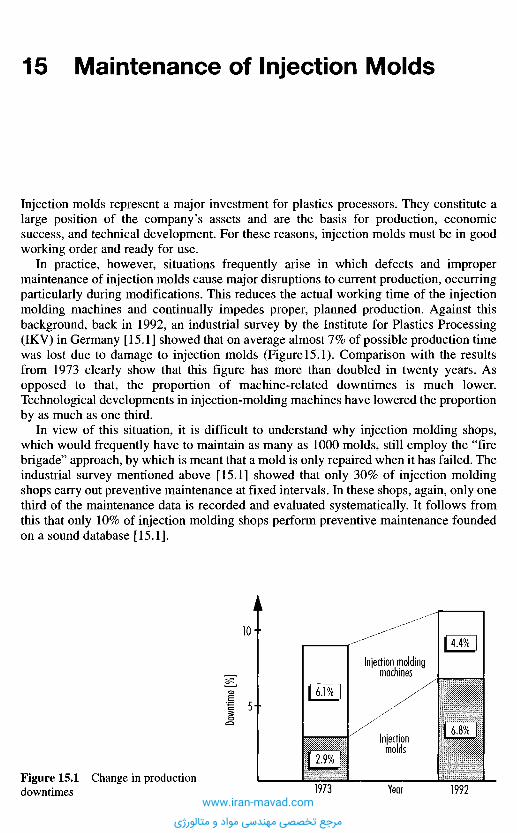
Injection molds represent a major investment for plastics processors. They constitute alarge position of the company's assets and are the basis for production, economicsuccess, and technical development. For these reasons, injection molds must be in goodworking order and ready for use.
In practice, however, situations frequently arise in which defects and impropermaintenance of injection molds cause major disruptions to current production, occurringparticularly during modifications. This reduces the actual working time of the injectionmolding machines and continually impedes proper, planned production. Against thisbackground, back in 1992, an industrial survey by the Institute for Plastics Processing(IKV) in Germany [15.1] showed that on average almost 7% of possible production timewas lost due to damage to injection molds (Figure 15.1). Comparison with the resultsfrom 1973 clearly show that this figure has more than doubled in twenty years. Asopposed to that, the proportion of machine-related downtimes is much lower.Technological developments in injection-molding machines have lowered the proportionby as much as one third.
In view of this situation, it is difficult to understand why injection molding shops,which would frequently have to maintain as many as 1000 molds, still employ the "firebrigade" approach, by which is meant that a mold is only repaired when it has failed. Theindustrial survey mentioned above [15.1] showed that only 30% of injection moldingshops carry out preventive maintenance at fixed intervals. In these shops, again, only onethird of the maintenance data is recorded and evaluated systematically. It follows fromthis that only 10% of injection molding shops perform preventive maintenance foundedon a sound database [15.1].
1 5 M a i n t e n a n c e o f I n j e c t i o n M o l d s
Figure 15.1 Change in productiondowntimes
Down
time
[%]
Injection moldingmachines
Injectionmolds
Year1973 1992
6.1%
2.9%
4.4%
6.8%
www.iran-mavad.com
مرجع تخصصی مهندسی مواد و متالورژی
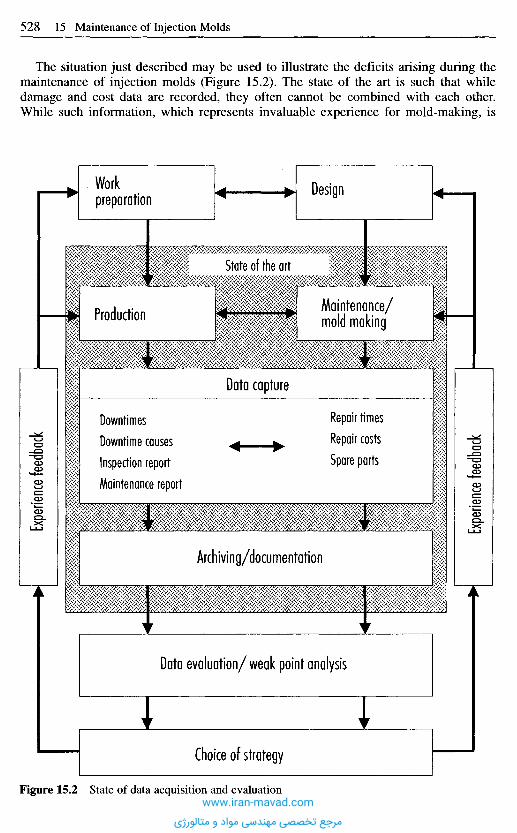
The situation just described may be used to illustrate the deficits arising during themaintenance of injection molds (Figure 15.2). The state of the art is such that whiledamage and cost data are recorded, they often cannot be combined with each other.While such information, which represents invaluable experience for mold-making, is
Workpreparation
Design
State of the art
Maintenance/mold makingProduction
Data capture
Downtimes
Downtime causes
Inspection report
Maintenance report
Repair times
Repair costs
Spare parts
Expe
rienc
e fe
edba
ck
Expe
rienc
e fe
edba
ck
Archiving/documentation
Data evaluation/weak point analysis
Choice of strategy
Figure 15.2 State of data acquisition and evaluationwww.iran-mavad.com
مرجع تخصصی مهندسی مواد و متالورژی
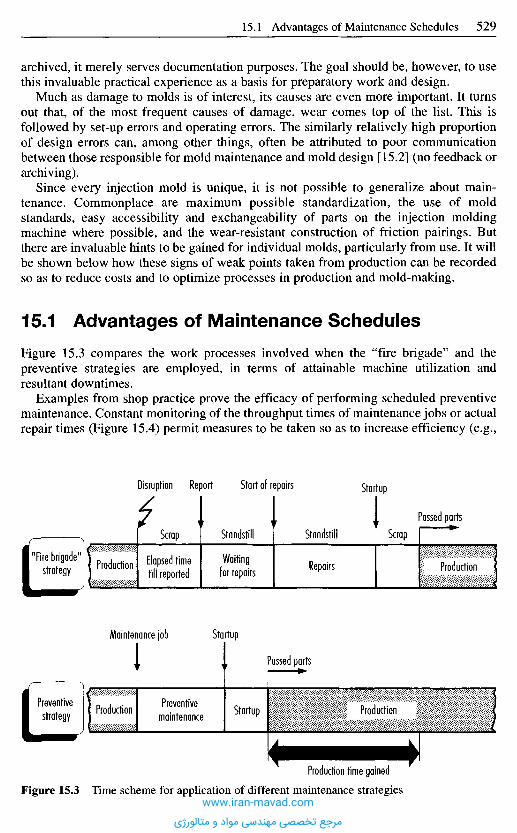
archived, it merely serves documentation purposes. The goal should be, however, to usethis invaluable practical experience as a basis for preparatory work and design.
Much as damage to molds is of interest, its causes are even more important. It turnsout that, of the most frequent causes of damage, wear comes top of the list. This isfollowed by set-up errors and operating errors. The similarly relatively high proportionof design errors can, among other things, often be attributed to poor communicationbetween those responsible for mold maintenance and mold design [15.2] (no feedback orarchiving).
Since every injection mold is unique, it is not possible to generalize about main-tenance. Commonplace are maximum possible standardization, the use of moldstandards, easy accessibility and exchangeability of parts on the injection moldingmachine where possible, and the wear-resistant construction of friction pairings. Butthere are invaluable hints to be gained for individual molds, particularly from use. It willbe shown below how these signs of weak points taken from production can be recordedso as to reduce costs and to optimize processes in production and mold-making.
1 5 . 1 A d v a n t a g e s o f M a i n t e n a n c e S c h e d u l e s
Figure 15.3 compares the work processes involved when the "fire brigade" and thepreventive strategies are employed, in terms of attainable machine utilization andresultant downtimes.
Examples from shop practice prove the efficacy of performing scheduled preventivemaintenance. Constant monitoring of the throughput times of maintenance jobs or actualrepair times (Figure 15.4) permit measures to be taken so as to increase efficiency (e.g.,
Disruption Report Start of repairs Startup
Scrap Standstill Standstill ScrapPassed parts
"Fire brigade"strategy Production Elapsed time
till reportedWaitingfor repairs Repairs Production
Maintenance job Startup
Passed parts
Preventivestrategy Production Preventive
maintenance Startup Production
Figure 15.3 Time scheme for application of different maintenance strategies
Production time gained
www.iran-mavad.com
مرجع تخصصی مهندسی مواد و متالورژی

investment in new machining equipment) and decrease the throughput times formaintenance and for production through reducing downtimes. This effect is reinforcedby purposeful preparation of the measures to be implemented (e.g., provision ofequipment and spare parts), much as when set-up preparations are made when molds arechanged. As may be seen in Figure 15.4, the proportion of quick repairs has increased inour example while the proportion of longer-lasting ones has receded over the years, as aresult. This clearly illustrates the success of the measures implemented.
1 5 . 2 S c h e d u l i n g M o l d M a i n t e n a n c e
15.2.1 Data Acquisition
The choice of molds to examine first necessitates the acquisition of detailed data. Sincevarious factory studies revealed that a great deal of acquired data are not used, particularvalue should be attached to goal-oriented or need-oriented data acquisition. The goal ofdata acquisition must be the provision of informative maintenance data in the form offeedback to staff in design, work preparation and mold making (Figure 15.2).
Data on mold maintenance is essentially required in two areas. The first is the controland monitoring of the direct and indirect costs that arise. It should be possible to reporton all molds, a particular class of molds, an individual mold, or a functional group. Thesecond is selective weak-point analysis, which requires detailed data acquisition. Here,a distinction needs to be made between the damage that occurs and its actual cause[15.4].
The mold data can be stored in a type of lifetime. As shown in Figure 15.5, the datafor each individual mold should be recorded in the form of a lifetime data record. Item1 is the mold identification number. To be able to schedule maintenance measures orintervals, the number of cycles needs to be known as it is a wear-determining factor (item2). It is also important to establish if the maintenance measure is scheduled or non-scheduled (item 3). For referencing purposes, the functional system where the damageoccurred must be noted (item 4). Description of the damage (item 5) and, where possible,
Figure 15.4 Decreasingrepairs over the yearsRepair times [hours]
Up to 5 Up to 10 Up to 15 Up to 20 Over 20
Fractio
n [0A]
1989
1990
1991
www.iran-mavad.com
مرجع تخصصی مهندسی مواد و متالورژی
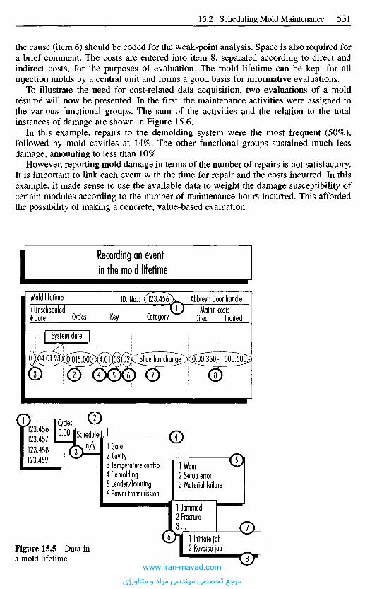
the cause (item 6) should be coded for the weak-point analysis. Space is also required fora brief comment. The costs are entered into item 8, separated according to direct andindirect costs, for the purposes of evaluation. The mold lifetime can be kept for allinjection molds by a central unit and forms a good basis for informative evaluations.
To illustrate the need for cost-related data acquisition, two evaluations of a moldresume will now be presented. In the first, the maintenance activities were assigned tothe various functional groups. The sum of the activities and the relation to the totalinstances of damage are shown in Figure 15.6.
In this example, repairs to the demolding system were the most frequent (50%),followed by mold cavities at 14%. The other functional groups sustained much lessdamage, amounting to less than 10%.
However, reporting mold damage in terms of the number of repairs is not satisfactory.It is important to link each event with the time for repair and the costs incurred. In thisexample, it made sense to use the available data to weight the damage susceptibility ofcertain modules according to the number of maintenance hours incurred. This affordedthe possibility of making a concrete, value-based evaluation.
Recording an event
in the mold lifetime
Mold lifetimeUnscheduledDate Cycles
ID. No.:
Key Category
Abbrev.: Door handleMa int. costs
Direct Indirect
System date
Cycles:ISchedulec
1 Gate2 Cavity3 Temperature control4 Demolding5 Leader/locating6 Power transmission
lWear2 Setup error3 Material failure
1 Jammed2 Fracture3...
1 Initiate job2 Reverse jobFigure 15.5 Data in
a mold lifetime
n/y
123.456123.457123.458123.459
www.iran-mavad.com
مرجع تخصصی مهندسی مواد و متالورژی
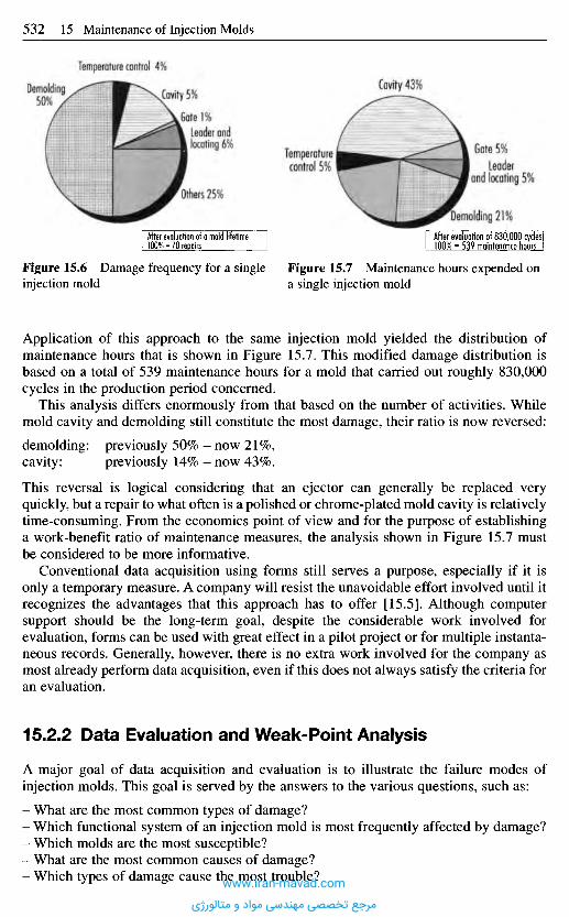
Application of this approach to the same injection mold yielded the distribution ofmaintenance hours that is shown in Figure 15.7. This modified damage distribution isbased on a total of 539 maintenance hours for a mold that carried out roughly 830,000cycles in the production period concerned.
This analysis differs enormously from that based on the number of activities. Whilemold cavity and demolding still constitute the most damage, their ratio is now reversed:
demolding: previously 50% - now 21%,cavity: previously 14% - now 43%.
This reversal is logical considering that an ejector can generally be replaced veryquickly, but a repair to what often is a polished or chrome-plated mold cavity is relativelytime-consuming. From the economics point of view and for the purpose of establishinga work-benefit ratio of maintenance measures, the analysis shown in Figure 15.7 mustbe considered to be more informative.
Conventional data acquisition using forms still serves a purpose, especially if it isonly a temporary measure. A company will resist the unavoidable effort involved until itrecognizes the advantages that this approach has to offer [15.5]. Although computersupport should be the long-term goal, despite the considerable work involved forevaluation, forms can be used with great effect in a pilot project or for multiple instanta-neous records. Generally, however, there is no extra work involved for the company asmost already perform data acquisition, even if this does not always satisfy the criteria foran evaluation.
15.2.2 Data Evaluation and Weak-Point Analysis
A major goal of data acquisition and evaluation is to illustrate the failure modes ofinjection molds. This goal is served by the answers to the various questions, such as:
- What are the most common types of damage?- Which functional system of an injection mold is most frequently affected by damage?- Which molds are the most susceptible?- What are the most common causes of damage?- Which types of damage cause the most trouble?
Figure 15.6 Damage frequency for a singleinjection mold
Figure 15.7 Maintenance hours expended ona single injection mold
After evaluation of 830,000 cycles100% = 539 maintenance hours
Demolding 21%After evaluation of a mold lifetime I100% = 70 repairs
Others 25%
Temperaturecontrol 5%
Leader andlocating 6%
Cavity 5%
.Gate 1%
Temperature control 4%
Demolding50%
Cavity 43%
Gate 5%Leader
and locating 5%
www.iran-mavad.com
مرجع تخصصی مهندسی مواد و متالورژی
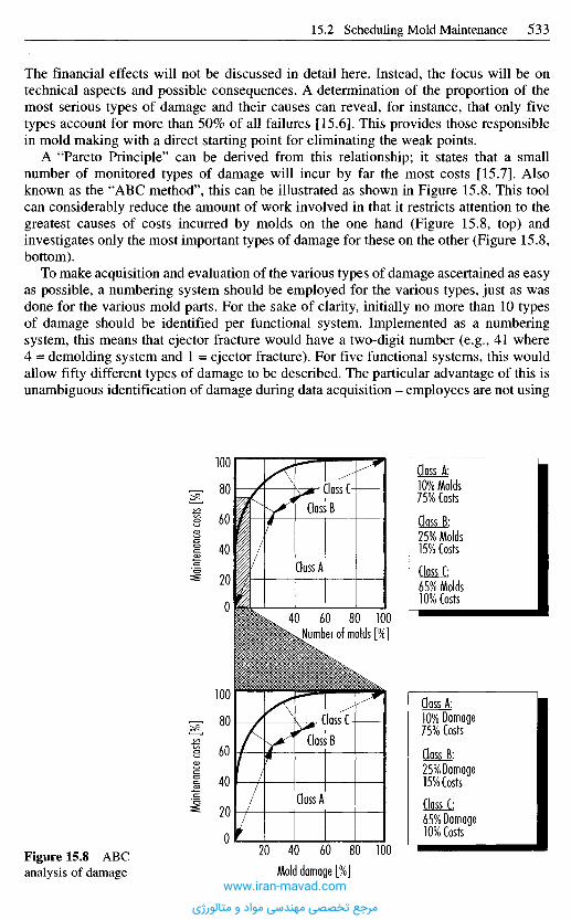
The financial effects will not be discussed in detail here. Instead, the focus will be ontechnical aspects and possible consequences. A determination of the proportion of themost serious types of damage and their causes can reveal, for instance, that only fivetypes account for more than 50% of all failures [15.6]. This provides those responsiblein mold making with a direct starting point for eliminating the weak points.
A "Pareto Principle" can be derived from this relationship; it states that a smallnumber of monitored types of damage will incur by far the most costs [15.7]. Alsoknown as the "ABC method", this can be illustrated as shown in Figure 15.8. This toolcan considerably reduce the amount of work involved in that it restricts attention to thegreatest causes of costs incurred by molds on the one hand (Figure 15.8, top) andinvestigates only the most important types of damage for these on the other (Figure 15.8,bottom).
To make acquisition and evaluation of the various types of damage ascertained as easyas possible, a numbering system should be employed for the various types, just as wasdone for the various mold parts. For the sake of clarity, initially no more than 10 typesof damage should be identified per functional system. Implemented as a numberingsystem, this means that ejector fracture would have a two-digit number (e.g., 41 where4 = demolding system and 1 = ejector fracture). For five functional systems, this wouldallow fifty different types of damage to be described. The particular advantage of this isunambiguous identification of damage during data acquisition - employees are not using
Maint
enan
ce co
sts [%
]Ma
inten
ance
costs
[%]
Class C-
Class B
Class A
Number of molds [%]
Class A:10% Molds75% Costs
Class B:25% Molds15% Costs
Class C:65% Molds10% Costs
Class C-Class B
Class A
Mold damage [%]
Class A:10% Damage75% Costs
Class B:25% Damage15% Costs
Class C:65% Damage10% Costs
Figure 15.8 ABCanalysis of damage
www.iran-mavad.com
مرجع تخصصی مهندسی مواد و متالورژی

their own descriptions for the same type of damage. Furthermore, the numbering systemallows direct classification and access to the corresponding work plan. It also helps tosmooth the transition to a computer-based support system.
15.2.3 C o m p u t e r - B a s e d S u p p o r t
Crucial to the use of a computer system are the functions provided for data evaluation,which must suit the case at hand. A peculiarity arises from the fact that injection moldsare not fixed permanently in one place, but rather have to be tracked as movableinventory. A computer system must therefore be able to accommodate the respectivestatus with more detailed information (e.g., in the mold department for repair untilapprox. ...) This information serves production control for planning subsequentproduction orders as well as maintenance in the planning of preventive measures.
From the point of view of the prime aim of a maintenance analysis, a computer systemmust be in a position to provide the following functions:
- acquisition of all relevant data in a mold lifetime,- support for ABC analyses for all molds, mold groups, functional systems, and mold
damage,- comprehensive support in the evaluation of lifetime data,- presentation of percentage types of damage for a single mold or mold group,- possibility of classifying damage within a functional system,- presentation of the proportion of a certain type of damage in a mold group,- presentation of the maintenance measures for the service life in cycles,- comparison of intervals between occurrences of a particular type of damage,- presentation of the frequency of the damage that has occurred with the goal of weak-
point analysis,- tracking of repair times, comparison of in-house/external share, etc.
The ultimate goal of the evaluations must be to eliminate primarily those weak pointsthat incur the highest costs. An example of such a presentation is shown in Figure 15.9.This allows the costs of the different functional systems of a specific mold to becompared. If a functional system becomes noticeable because of extremely highmaintenance, it must be possible to call up more detailed information on the proportionsof the various types of damage. The special advantage of this presentation comes to theforeground when an evaluation can be performed separately on the basis of direct andindirect costs. In this case, those weak points whose direct costs were not high enoughto cause concern can be uncovered if they lead to indirect costs in the form of lost profitcontributions due to equipment downtimes.
1 5 . 3 S t o r a g e a n d C a r e o f I n j e c t i o n M o l d s
Injection molds have a limited service life (Table 15.1). Appropriate measures cangreatly extend this, however. Such measures can be classified on the basis of:
- maintenance,- storage, and- care.
www.iran-mavad.com
مرجع تخصصی مهندسی مواد و متالورژی

To be able to quickly fall back on ready-to-use molds, the following demands on storageand care must be fulfilled:
- every mold must be stored along with one molded part and a mold card in its own,easily accessible space in the mold store,
- only ready-to-use, complete, clean molds may be stored. The purpose of also storing amolded part (usually the last one from previous production) and a mold card bearingthe article number and the mold number is to allow the mold to be uniquely identified.
Table 15.1 Numbers of molded parts obtainable with various mold materials [15.8]
Material
Zinc alloysAluminumAluminumCopper-berylliumSteel
CastingCastingRolledSurface hardened
Attainable number
100,000100,000100,000-200,000250,000-500,000500,000-1,000,000
Figure 15.9 Weakpoint analysis based onmold lifetime
Cycle
main
tenan
ce c
osts
y irec
t
Evaluationof a mold lifetime
Moldcycles
ID. No.: 123.456250.000-500.000
Abbrev.: Door handle
Gate Cavity Temperature control Demolding Leader and locating
Damage cause tables:
Cavity(4-cavity model)
1 Contamination2 Corrosion3...
Leader and locating
Demolding
Temperature control
Gate
www.iran-mavad.com
مرجع تخصصی مهندسی مواد و متالورژی
The mold card should also bear all the information needed for setting up the mold andstarting up the injection molding machine. Information in this category includes thefollowing:
- mold design (split, sliding split, unscrewable mold etc.),- dimensions of the mold and the molded part,- mold mounting equipment,- injection molding machine suitable for production,- shot weight (injection volume),- suitable plastic,- rules on material pretreatment,- processing temperatures,- mold temperature and heat-control medium (water, oil, etc.),- cycle times,- injection pressure, follow-up pressure, dynamic pressure,- injection speed,- screw speed,- cylinder equipment (sliding shut-off nozzle, non-return valve),- maintenance intervals,- number of pieces produced.
This list could be extended and thus matched to the special needs of a factory. Instead ofon a mold card, much of this information, such as the settings for the injection moldingmachine, could be stored on external data storage media that could be read into thecontrol unit prior to production startup.
Mold changes can only be performed quickly if the molds are ready for use when theyleave the stores and can go into production without the need for major assembly orcleaning work. Every mold must therefore be a self-contained unit, i.e., it must not bemade of parts that are required for other molds. Parts or groups of parts that are "loaned"or "borrowed" often disappear or are needed elsewhere just when the mold is scheduledfor use. The consequences are unnecessary, incalculable, and often time-consumingdowntimes.
Cleaning work also delays the start of production. It should therefore be kept to aminimum. This means that special care has to be taken of the molds (discussed later) andimposes specific demands on the store, its cleanness and particularly the ambientconditions. Damp and unheated rooms promote corrosion. Once rust has begun to attackthe mold, maintenance becomes very time consuming and very expensive. Often it isimpossible. The mold store should therefore be kept at a constant temperature wherepossible, and dehumidified. Not much equipment is required for this, and it soon paysfor itself.
Important to the accessibility of the molds is also the size of the store. It is essentiallydetermined by the vehicles available in the factory (e.g., forklift) and the maneuveringspace.
When a job is complete, the mold may only be returned to storage when its suitabilityfor future use has been checked. The last parts produced with it can provide an indicationof its condition. They must be examined for dimensional stability and closelyscrutinized. This will provide information about the state of the mold surface, the levelof seal in the mold parting line (perhaps flash formation on the molded part) and theworking order of the ejectors, ejector bushes, etc. If no deficiencies are found, themaintenance work then takes the form of the general care measures described below.
www.iran-mavad.com
مرجع تخصصی مهندسی مواد و متالورژی

Maintenance of Cooling LinesCooling lines must be cleaned thoroughly to eliminate scale, rust, sludge, and algae.
Since these deposits decrease the diameter of the channels, measuring the flow rate isa way of checking the system. A pressure-controlled valve is installed between mold andwater line and a defined pressure drop is set, which has to be the same for eachexamination. If the flow rate was measured with the new mold, a comparison with anynew measurement after a production run provides information about the degree ofclogging of the cooling channels.
For cleaning, the cooling lines are usually flushed with a detergent becausemechanical removal of the deposit is generally not feasible due to the geometry of thesystem. Detergents and special cleaning equipment are marketed by several producers[15.9, 15.10]. A solution of hydrochloric acid (20° Be) with two parts water and acorrosion inhibitor has been successfully used.
The nipples, bridges, bolts and feed lines (tubes) outside the mold are also checkedfor damage and replaced where necessary, provided they stay on the mold.
Before the mold is stored, water has to be removed with compressed air and thesystem dried with hot air.
Care and Maintenance of the Mold SurfacesAfter the end of production, the mold must be carefully cleaned of any adhering plasticresidue. The work is independent of the type and amount of molding material. It isadvisable to use soap and water for removing material remnants and other deposits. Themold then has to be dried carefully.
Rust spots from condensed water or aggressive plastics have also to be removedbefore storage. Depending on the degree of chemical attack, abrasives for grinding andpolishing (car polish) may be suitable.
Removal of residual lubricants from movable mold components is also part of thecleaning operation. Degreasing detergents for this are available on the market.
Care and Maintenance of the Heating and Control SystemThis work is particularly important for hot-runner molds. After each production run,heater cartridges, heater bands, and thermocouples should be checked with an ohmmeterand the results compared with those on the mold card. Accidental grounding should beinvestigated, too. The control circuits are easily tested with an ammeter installed in thecircuit.
A check should also be made to ensure that lines, connections, insulation, and mainlead cleats are in proper working order.
Care and Maintenance of Sliding GuidesThe guides on movable mold parts require particularly careful cleaning and must bewashed with resin-free and acid-free lubricants. Also check the level of seal in thecylinder in the case of hydraulically actuated slides and cores.
Care and Maintenance of the Gate SystemStart checking at the nozzle contact area, which is subjected to very high loads duringoperation. Check also any special nozzles belonging to the mold. In the case oftemperature-controlled gates that are not generally demolded with every shot, it isnecessary - to an extent depending on the plastic processed - to flush the gating systemuntil the end of production with a plastic that has wide processing latitude.
www.iran-mavad.com
مرجع تخصصی مهندسی مواد و متالورژی
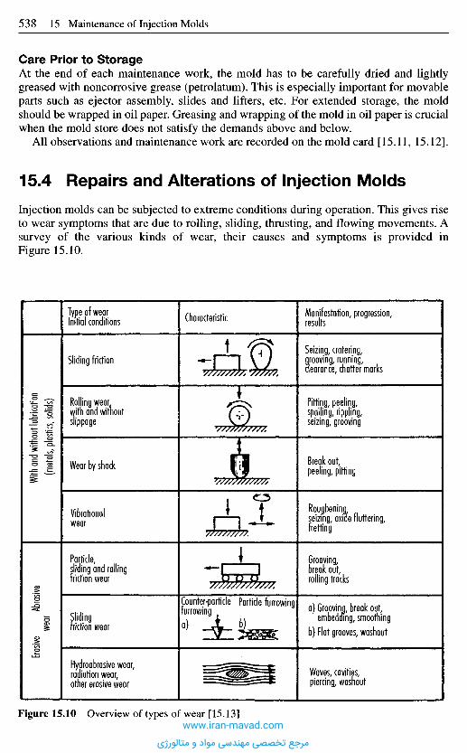
Care Prior to StorageAt the end of each maintenance work, the mold has to be carefully dried and lightlygreased with noncorrosive grease (petrolatum). This is especially important for movableparts such as ejector assembly, slides and lifters, etc. For extended storage, the moldshould be wrapped in oil paper. Greasing and wrapping of the mold in oil paper is crucialwhen the mold store does not satisfy the demands above and below.
AU observations and maintenance work are recorded on the mold card [15.11, 15.12].
1 5 . 4 R e p a i r s a n d A l t e r a t i o n s o f I n j e c t i o n M o l d s
Injection molds can be subjected to extreme conditions during operation. This gives riseto wear symptoms that are due to rolling, sliding, thrusting, and flowing movements. Asurvey of the various kinds of wear, their causes and symptoms is provided inFigure 15.10.
With
and w
ithou
t lub
ricati
on(m
etals,
plas
tics, s
olids
)Ero
sive
Abras
ivewe
ar
Type of wearInitial conditions
Sliding friction
Rolling wearwith and withoutslippage
Wear by shock
Vibrationalwear
Particle,sliding and rollingfriction wear
Slidingfriction wear
Hydroabrasive wear,radiation wear,other erosive wear
Manifestation, progression,results
Seizing, cratering,grooving, running,clearance, chatter marks
Pitting, peeling,spoiling, rippling,seizing, grooving
Break out,peeling, pitting
Rougheningseizing, oxide fluttering,fretting
Grooving,break out,rolling tracks
a) Grooving, break out,embedding, smoothing
b) Flat grooves, washout
Waves, cavities,piercing, washout
Characteristic
Counter-particlefurrowing
Particle furrowing
b)a)
Figure 15.10 Overview of types of wear [15.13]www.iran-mavad.com
مرجع تخصصی مهندسی مواد و متالورژی
The consequences of wear are dimensional inaccuracy, flawed surfaces and flash onthe molded part. Before the damage can be repaired, the cause must be determined.Remedial measures require a detailed knowledge of the cause of damage. The followingare possible:
- simple mechanical finishing,- replacement of parts or modules,- deposition of material.
Leaky parting planes are typical injection molding damage. When this is not veryextensive, it can be eliminated by grinding. However, this is limited by the tolerancesimposed on the molded-part dimensions.
Minor damage to the mold surface (pits) that can be attributed to impact can beremedied by reboring, remilling, and then setting pins or wedges. Once the flaw has beentreated, the mold is heated and the drill hole or groove closed with a cold insert (slightlyoverdimensioned). The repaired spot is then rendered flush with the mold surface bygrinding or polishing.
It is important to use the same type of material for this repair work, as the repairedarea should have the same material properties as the rest of the mold surface.
Damage to functional and mounting parts, such as guide pins and bushings, ejectors,locating flanges, nozzles, etc., should not be repaired. These are normally standard parts(see Chapter 17) available in various dimensions and can thus be replaced cheaply.Doing this means that the molds will function perfectly and avoid any major risks.
The repairs described so far will often be inadequate and material will have to bedeposited because, e.g., edges or corners have broken off. Welding is necessary in suchcases.
Repair welds to injection molds should always be preceded by heating to keep thermalstress and the formation of internal stress as low as possible.
Preheating avoids compression and shrinkage in the weld zone and, above all,prevents heat from being dissipated so quickly from the weld area that hardening sets in(as when heated parts are quenched in oil or water).
The preheating temperature (at which the workpiece must be kept during welding)depends on the material to be welded, and in particular on its chemical composition.Steel manufacturers provide details of this.
During welding, the workpiece must be kept at the preheating temperature. Whenwelding is complete, it is cooled to between 80 and 100 0C and then reheated again tothe normalizing temperature [15.14].
Welding repairs are performed by the TIG method and welding with coated electrodewires. TIG (tungsten inert gas) offers distinct advantages. The following basic rules mustbe observed for repair welding:
- The electrode wire material should be of the same composition as the mold material,or at least similar. Ensuing heat treatment of the weld results in equal hardness andstructure [15.14].
- The amperage has to be kept as low as possible to prevent reduced hardness and coarsestructure [15.14].
- The preheating temperature must be above the martensite-forming temperature. It canbe taken from the respective temperature-time phase diagram for the steel. It shouldnot be considerably higher, however, since it increases the depth of burn-in [15.14].
- During the entire welding process, the mold must be kept at the preheating tempera-ture. This is particularly the case for several deposits.www.iran-mavad.com
مرجع تخصصی مهندسی مواد و متالورژی
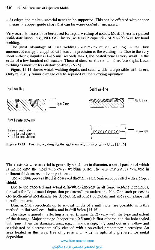
Figure 15.11 Possible welding depths and seam widths in laser welding [15.15]
The electrode wire material is generally < 0.5 mm in diameter, a small portion of whichis melted onto the mold with every welding pulse. The wire material is available indifferent thicknesses and compositions.
The welding process itself is observed through a stereomicroscope fitted with a propershield.
Due to the expected and actual difficulties inherent in all forge welding techniques,the calls for "cold metal-deposition processes" are understandable. One such process iselectrochemical metallizing for depositing all kinds of metals and alloys on almost allmetallic materials.
Dimensional corrections up to several tenths of a millimeter are possible with thismethod on flat surfaces, shafts, and in drill holes [15.16].
The steps required in effecting a repair (Figure 15.12) vary with the type and extentof the damage. Major damage (deeper than 0.5 mm) is first rebored and the hole sealedwith pins. Then the damaged area, e.g., minor damage, is ground out in a hollow andsandblasted or electrochemically cleaned with a so-called preparatory electrolyte. Anarea treated in this way, free of grease and oxide, is optimally prepared for metaldeposition.
Diameter: depth ratio= 1:3 for small diameter= 1:1 for large diameter
Spot diameter 0.2-2 mm
Spot welding
Up to 2 mm
Seam welding
Up to 2 mm
0.2-2 mm
- At edges, the molten material needs to be supported. This can be effected with copperpieces or copper guide shoes that can be water-cooled if necessary.
Very recently, lasers have been used for repair welding of molds. Mostly these are pulsedsolid-state lasers, e.g., ND-YAG lasers, with laser capacities of 50-200 Watt for handwelding.
The great advantage of laser welding over "conventional welding" is that lowamounts of energy are applied with extreme precision to the welding site. Due to the veryshort welding impulses (1-15 milliseconds max.), the heated zone is very small, in theorder of a few hundred millimeters. Thermal stress on the mold is therefore slight. Laserwelding is more or less distortion-free [15.15].
Figure 15.11 shows which welding depths and seam widths are possible with lasers.Only relatively minor damage can be repaired in one working operation.
www.iran-mavad.com
مرجع تخصصی مهندسی مواد و متالورژی
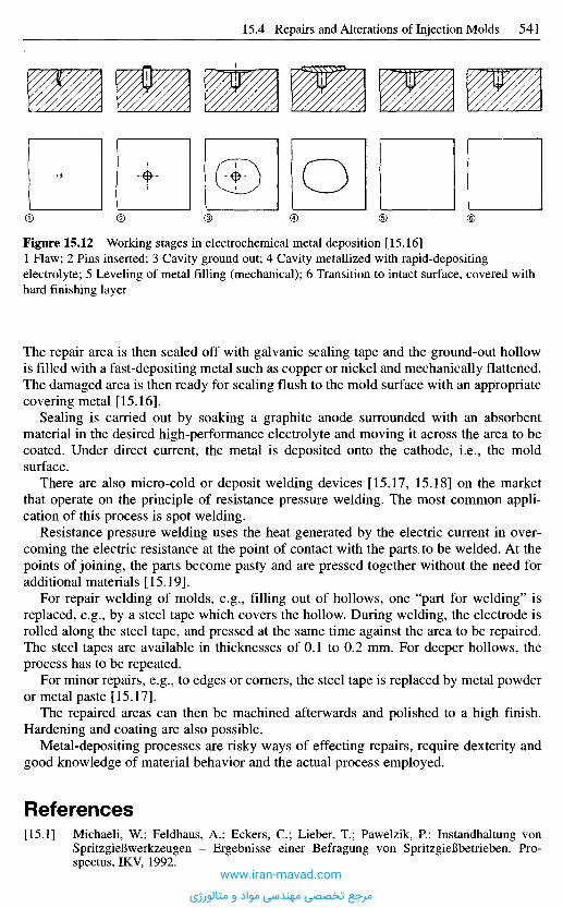
Figure 15.12 Working stages in electrochemical metal deposition [15.16]1 Flaw; 2 Pins inserted; 3 Cavity ground out; 4 Cavity metallized with rapid-depositingelectrolyte; 5 Leveling of metal filling (mechanical); 6 Transition to intact surface, covered withhard finishing layer
The repair area is then sealed off with galvanic sealing tape and the ground-out hollowis filled with a fast-depositing metal such as copper or nickel and mechanically flattened.The damaged area is then ready for sealing flush to the mold surface with an appropriatecovering metal [15.16].
Sealing is carried out by soaking a graphite anode surrounded with an absorbentmaterial in the desired high-performance electrolyte and moving it across the area to becoated. Under direct current, the metal is deposited onto the cathode, i.e., the moldsurface.
There are also micro-cold or deposit welding devices [15.17, 15.18] on the marketthat operate on the principle of resistance pressure welding. The most common appli-cation of this process is spot welding.
Resistance pressure welding uses the heat generated by the electric current in over-coming the electric resistance at the point of contact with the parts to be welded. At thepoints of joining, the parts become pasty and are pressed together without the need foradditional materials [15.19].
For repair welding of molds, e.g., filling out of hollows, one "part for welding" isreplaced, e.g., by a steel tape which covers the hollow. During welding, the electrode isrolled along the steel tape, and pressed at the same time against the area to be repaired.The steel tapes are available in thicknesses of 0.1 to 0.2 mm. For deeper hollows, theprocess has to be repeated.
For minor repairs, e.g., to edges or corners, the steel tape is replaced by metal powderor metal paste [15.17].
The repaired areas can then be machined afterwards and polished to a high finish.Hardening and coating are also possible.
Metal-depositing processes are risky ways of effecting repairs, require dexterity andgood knowledge of material behavior and the actual process employed.
R e f e r e n c e s
[15.1] Michaeli, W.; Feldhaus, A.; Eckers, C ; Lieber, T.; Pawelzik, P.: Instandhaltung vonSpritzgieBwerkzeugen - Ergebnisse einer Befragung von SpritzgieBbetrieben. Pro-spectus, IKV, 1992.
www.iran-mavad.com
مرجع تخصصی مهندسی مواد و متالورژی

[15.2] Feldhaus, A.: Instandhaltung von SpritzgieBwerkzeugen - Analyse des Ausfallverhaltensund Entwicklung angepaBter MaBnahmen zur Steigerung der Anlagenverfiigbarkeit.Dissertation, RWTH, Aachen, 1993.
[15.3] Hackstein, R.; Richter, H.: Optionale Instandhaltung - untersucht am Beispiel von Spritz-und DruckguBmaschinen. FB/IE 24 (1975), 5, pp. 267-273.
[15.4] Oltmanns, P.: EDV-Unterstutzung zur Instandhaltung von SpritzgieBwerkzeugen,Unpublished report, IKV, Aachen, 1993.
[15.5] Mexis, N. D.: Die Verfugbarkeitsanalyse in der Investitionsplanung. Verlag furFachliteratur, Heidelberg, 1991.
[15.6] Wilden, H.: Werkzeugkonzeption. In: Der SpritzgieBprozeB. VDI-Verlag, Diisseldorf,1979, pp. 87-109.
[15.7] Taubert, D.: Wirtschaftliche Bewertungskriterien fur die geplante Instandhaltung, VDI-Berichte, No. 380, 1980, S. 13-19.
[15.8] Rheinfeld, D.: Werkzeug soil in Ordnung sein. VDI-Nachrichten, 30 (1976), 31, p. 8.[15.9] Reinigungsgerate fur Kuhlkanale. Kunststoffe, 54 (1974), 3, p. 112.[15.10] SpritzgieBen-Werkzeug. Technical information, 4.3, BASF, Ludwigshafen/Rh., 1969.[15.11] Kundenzeitschrift. Arburg heute, 10 (1979), 16, June 1979.[15.12] Oebius, E.: Pflege und Instandhaltung von SpritzgieBwerkzeugen. Kunststoffe, 64
(1974), 3, pp. 123-124.[15.13] Brandis, H.; Reismann, J.; Salzmann, H.; Spyra, W; Klupsch, H.: HartschweiBlegierun-
gen. Thyssen Edelstahl, Technical report, 10 (1984), Ml, pp. 54-75.[15.14] Rasche, K.: Das SchweiBen von Werkzeugstahlen. Thyssen Edelstahl, Technical report,
7 (1981), 2, pp. 212-219.[15.15] Schmid, L.: ReparaturschweiBen mit dem Laserstrahl. Paper presented at the 8th Tooling
conference at Wlirzburg: "Der SpritzgieBformenbau im internationalen Wettbewerb",Wurzburg 24. 9. 1997-25. 9. 1997.
[15.16] Elektrochemischer Metallauftrag. Prospectus, Baltrusch und Mtitsch GmbH & Co., KG,Forchtenberg.
[15.17] Prospectus, Joisten und Kettenbaum GmbH & Co., Joke KG, Bergisch Gladbach.[15.18] Fachkunde Metall. Verlag Europa-Lehrmittel, Nourmney, Vollmer GmbH & Co., Haan-
Gruiten, 1990.[15.19] Prospectus, Schwer & Kopka GmbH, Weingarten.
www.iran-mavad.com
مرجع تخصصی مهندسی مواد و متالورژی

1 6 . 1 S e n s o r s i n M o l d s
Crucial to the quality of injection moldings is the state of the melt after plastication andhow the mold-filling process went, which is characterized by the change in pressure andtemperature.
It is therefore advisable to incorporate appropriate sensors into the molds for moni-toring and perhaps control purposes.
On the other hand, installing them incurs additional costs, could even leave marks onthe moldings to be made, and could possibly make mold changing difficult. Moreover,the cooling channels and the ejector units take up considerable space, with the result thatthere is limited choice as to the best place to install them.
For these reasons, it is not standard practice to measure melt temperature in productionmolds. However, pressure measurements in molds are being used more and more tomonitor production (for documentation and scrap monitoring) and are a prerequisite forpressure-dependent switching and for controlling the pressure in the mold [16.1].
1 6 . 2 T e m p e r a t u r e M e a s u r e m e n t
16.2.1 M e a s u r i n g Me l t T e m p e r a t u r e s in M o l d s Us ing IRS e n s o r s
The thermocouples and resistance thermometers used to measure and control mold walltemperatures are unsuitable for measuring melt temperatures (these are discussed inChapter 18: Temperature Controllers for Injection and Compression Molds).
Melt temperatures are measured by methods that detect the inherent radiation emittedby the melt in a defined wavelength range.
To this end, a bundle of optical fibers is installed inside the mold, flush with the wall.The inherent radiation emitted by the melt is fed to a radiation-sensitive detector. Theelectrical output signal from the detector then correlates with the melt temperature.
The radiation emitted to the environment by a body as a result of its temperaturedepends on its emission power. Ideal blackbody emitters emit all their heat, i.e., theyhave an emission power of 1. Real bodies have a lower emission power, the amount ofradiation emitted being reduced by the amounts lost through reflection and transmission.
Polymer melts inside a closed mold behave almost like ideal blackbodies since thereflected and transmitted radiation emitted from the cavity surfaces impinge on the IRsensor. This is why plastics that have an emission coefficient of 0.9 in air have emissioncoefficients of 0.99 in molds [16.2-16.4].
Melt temperatures inside molds can therefore be measured with high precision (±1%of the display value) and speed (response time < 10 milliseconds) and with high
1 6 M e a s u r i n g i n I n j e c t i o n M o l d s
www.iran-mavad.com
مرجع تخصصی مهندسی مواد و متالورژی
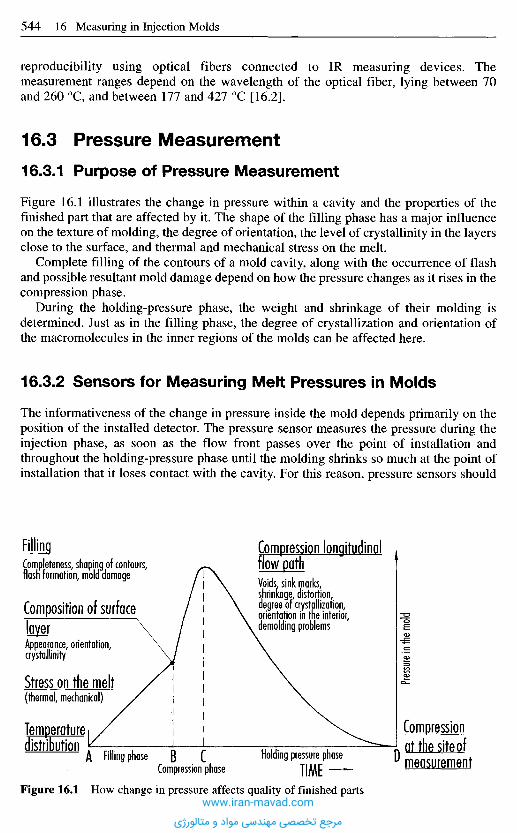
reproducibility using optical fibers connected to IR measuring devices. Themeasurement ranges depend on the wavelength of the optical fiber, lying between 70and 260 0C, and between 177 and 427 0C [16.2].
1 6 . 3 P r e s s u r e M e a s u r e m e n t
16.3.1 Purpose of Pressure Measurement
Figure 16.1 illustrates the change in pressure within a cavity and the properties of thefinished part that are affected by it. The shape of the filling phase has a major influenceon the texture of molding, the degree of orientation, the level of crystallinity in the layersclose to the surface, and thermal and mechanical stress on the melt.
Complete filling of the contours of a mold cavity, along with the occurrence of flashand possible resultant mold damage depend on how the pressure changes as it rises in thecompression phase.
During the holding-pressure phase, the weight and shrinkage of their molding isdetermined. Just as in the filling phase, the degree of crystallization and orientation ofthe macromolecules in the inner regions of the molds can be affected here.
16.3.2 Sensors for Measuring Melt Pressures in Molds
The informativeness of the change in pressure inside the mold depends primarily on theposition of the installed detector. The pressure sensor measures the pressure during theinjection phase, as soon as the flow front passes over the point of installation andthroughout the holding-pressure phase until the molding shrinks so much at the point ofinstallation that it loses contact with the cavity. For this reason, pressure sensors should
Pressu
re in
the m
old
Compression longitudinalflow pathVoids sink marks,shrinkage, distortion,degree of crystallization,orientation in the interior,demolding problems
FillingCompleteness, shaping of contours,flash formation, mold damage
Composition of surface
layerAppearance, orientation,crystallinity
Stress on the melt(thermal, mechanical)
Temperaturedistribution
A Filling phase B CCompression phase
Holding pressure phaseTIME
D
Compression
at the site ofmeasurement
Figure 16.1 How change in pressure affects quality of finished partswww.iran-mavad.com
مرجع تخصصی مهندسی مواد و متالورژی
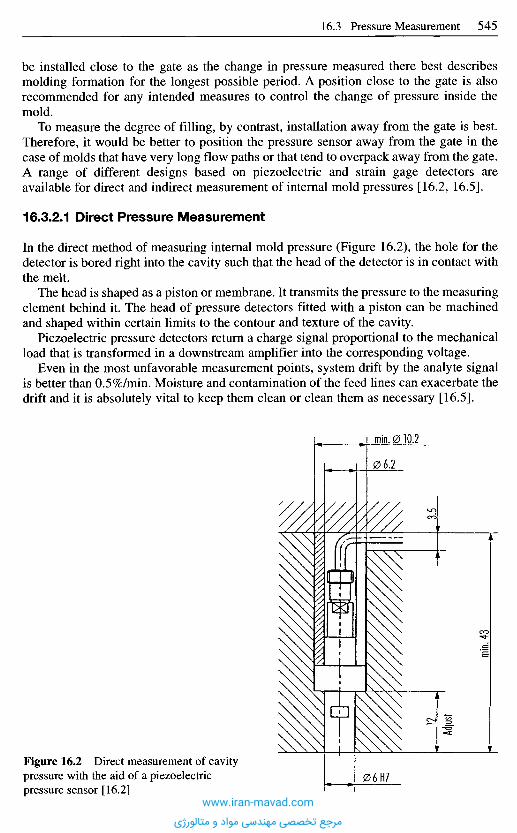
be installed close to the gate as the change in pressure measured there best describesmolding formation for the longest possible period. A position close to the gate is alsorecommended for any intended measures to control the change of pressure inside themold.
To measure the degree of filling, by contrast, installation away from the gate is best.Therefore, it would be better to position the pressure sensor away from the gate in thecase of molds that have very long flow paths or that tend to overpack away from the gate.A range of different designs based on piezoelectric and strain gage detectors areavailable for direct and indirect measurement of internal mold pressures [16.2, 16.5].
16.3.2.1 Direct Pressure Measurement
In the direct method of measuring internal mold pressure (Figure 16.2), the hole for thedetector is bored right into the cavity such that the head of the detector is in contact withthe melt.
The head is shaped as a piston or membrane. It transmits the pressure to the measuringelement behind it. The head of pressure detectors fitted with a piston can be machinedand shaped within certain limits to the contour and texture of the cavity.
Piezoelectric pressure detectors return a charge signal proportional to the mechanicalload that is transformed in a downstream amplifier into the corresponding voltage.
Even in the most unfavorable measurement points, system drift by the analyte signalis better than 0.5%/min. Moisture and contamination of the feed lines can exacerbate thedrift and it is absolutely vital to keep them clean or clean them as necessary [16.5].
Figure 16.2 Direct measurement of cavitypressure with the aid of a piezoelectricpressure sensor [16.2]
Adjus
t
www.iran-mavad.com
مرجع تخصصی مهندسی مواد و متالورژی
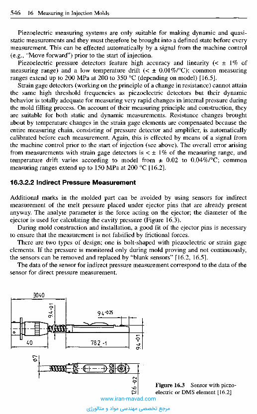
Piezoelectric measuring systems are only suitable for making dynamic and quasi-static measurements and they must therefore be brought into a defined state before everymeasurement. This can be effected automatically by a signal from the machine control(e.g., "Move forward") prior to the start of injection.
Piezoelectric pressure detectors feature high accuracy and linearity (< ± 1% ofmeasuring range) and a low temperature drift (< ± 0.01%/°C); common measuringranges extend up to 200 MPa at 200 to 350 0C (depending on model) [16.5].
Strain gage detectors (working on the principle of a change in resistance) cannot attainthe same high threshold frequencies as piezoelectric detectors but their dynamicbehavior is totally adequate for measuring very rapid changes in internal pressure duringthe mold filling process. On account of their measuring principle and construction, theyare suitable for both static and dynamic measurements. Resistance changes broughtabout by temperature changes in the strain gage elements are compensated because theentire measuring chain, consisting of pressure detector and amplifier, is automaticallycalibrated before each measurement. Again, this is effected by means of a signal fromthe machine control prior to the start of injection (see above). The overall error arisingfrom measurements with strain gage detectors is < ± 1% of the measuring range, andtemperature drift varies according to model from ± 0.02 to 0.04%/°C; commonmeasuring ranges extend up to 150 MPa at 200 0C [16.2].
16.3.2.2 Indirect Pressure Measurement
Additional marks in the molded part can be avoided by using sensors for indirectmeasurement of the melt pressure placed under ejector pins that are already presentanyway. The analyte parameter is the force acting on the ejector; the diameter of theejector is used for calculating the cavity pressure (Figure 16.3).
During mold construction and installation, a good fit of the ejector pins is necessaryto ensure that the measurement is not falsified by frictional forces.
There are two types of design; one is bolt-shaped with piezoelectric or strain gageelements. If the pressure is monitored only during mold proving and not continuously,the sensors can be removed and replaced by "blank sensors" [16.2, 16.5].
The data of the sensor for indirect pressure measurement correspond to the data of thesensor for direct pressure measurement.
Figure 16.3 Sensor with piezo-electric or DMS element [16.2]
www.iran-mavad.com
مرجع تخصصی مهندسی مواد و متالورژی
The data quoted for measuring accuracy, temperature dependency and response time,just like those concerning measuring ranges and service temperatures are guide values;the manufacturer's instructions must be observed each time.
1 6 . 4 U s e o f S e n s o r - T r a n s d u c e r P r o b e s
The sensors described can be used for various processes associated with production.These can be divided into process-optimizing and quality-monitoring mechanisms.
1 6 . 5 P r o c e s s O p t i m i z a t i o n
Optimum machine setting parameters are crucial to the quality of the molded parts.Optimum process control entails minimizing cycle times and increasing the service livesof machines and molds. It is often not enough to just consider process parameters on themachine side as a means of optimizing the injection molding process. This is becausethis approach fails to take account of the filling behavior of a mold, for instance,viscosity fluctuations of the raw material, and changes in ambient conditions such asshop temperature and humidity. The more sensors which are fitted to the mold, the moreinformation that can be gained from the production process.
The most useful information about the process of molded-part formation can beobtained from measuring the mold cavity pressure. Optimizing the shape of this processcurve can greatly influence molded-part properties such as dimensions, weight, andinternal properties, as well as cycle times and mold wear. The measurements also help tospeed set-up when molds are used on different machines. Figure 16.4 illustrates variouscavity-pressure curves. Of most interest is the linear rise in the mold cavity pressure,synonymous with virtually constant flow front speed [16.11] during injection (e), theswitch-over phase from the speed-controlled injection phase to the pressure-controlledholding-pressure phase (n) and the duration and value of the holding pressure.Figure 16.4 shows pressure curves that are obtained when the switch-over point in themold is altered. Switching too late from the injection to the holding-pressure phase (1)causes the cavity pressure to peak and may lead to overpacking of the cavity, demoldingdifficulties and damage to the mold, while switching too early may cause the cavity tobe filled under holding pressure (2). Incompletely filled molded parts and a high level oforientations are the result. The optimum cavity-pressure curve has neither peaks norpressure breaks (3). With the aid of the cavity pressure sensor, the optimum point can bedetermined rapidly. Similarly, the gate-sealing point, the point when the gate is frozenand no more material can be transported into the mold, can also be determined and theholding-pressure time adapted. The residual cooling time is the time elapsed until themolded part detaches from the mold and is equivalent to the time when the mold cavitypressure has reached the zero limit. The whole process can be recorded by placing themold-cavity pressure sensor close to the gate. The farther the sensor is located away fromthe optimum position, the less information is obtained about the process.
Aside from manual corrections to the molded-part formation processes performedwith the aid of cavity-pressure curves, modern injection-molding control units offer thepossibility of using the cavity pressure to switch over from the injection to holdingphase. Once a threshold value is exceeded, a corresponding signal is transmitted. Thisswitching process makes for greater reproducibility. Above all, it allows for fluctuations
www.iran-mavad.com
مرجع تخصصی مهندسی مواد و متالورژی
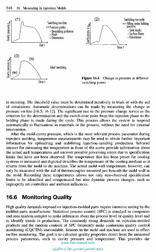
in metering. The threshold value must be determined iteratively in trials or with the aidof simulations. Automatic determinations can be made by measuring the change inpressure on-line [16.5, 16.12]. The significant rise in the pressure change serves as thecriterion for the determination and the switch-over point from the injection phase to theholding phase is made during the cycle. This process allows the system to respondautomatically to fluctuations in materials or the process, without the need for externalintervention.
After the mold-cavity pressure, which is the most relevant process parameter duringinjection molding, temperature measurements may be used to obtain further importantinformation for optimizing and stabilizing injection-molding production. Infraredsensors for measuring the temperature in front of the screw provide information aboutthe actual melt temperatures and uncover possible processing errors due to specificationlimits that have not been observed. The temperature that has been preset for coolingsystems or measured and depicted describes the temperature of the cooling medium as itreturns from the mold to the machine. The actual mold-wall temperature, however, canonly be measured with the aid of thermocouples mounted just beneath the mold wall inthe mold. Recording these temperatures allows not only non-observed specificationlimits to be identified and compensated but also dynamic process changes, such asimproperly set controllers and ambient influences.
1 6 . 6 M o n i t o r i n g Q u a l i t y
High quality demands imposed on injection-molded parts require intensive testing by themolded-parts manufacturer. Statistical process control (SPC) is standard in companiesand uses random samples to make inferences about the process level or quality level andto identify trends in production. The constantly rising demands on injection-moldedproducts and the random controls of SPC frequently make continuous quality controlmonitoring (CQCTM) unavoidable. Sensors in the mold and machine are used to effecton-line monitoring. The goal is to calculate quality properties direct from the measuredprocess parameters, such as cavity pressure and temperature. This provides the
Cavit
y pres
sure
p wi
Cavit
y pres
sure
p wj
Cavity
press
ure p
wi
(1)
(3)
(e)
(2)
Zeitt
Idea! switching
Timet
Switching too latePressure peaks- Demolding problems- Flash- Orientation
Timet
Switching too earlyFilling under holdingpressure- Sink marks- Surface flaws- Orientation
Figure 16.4 Change in pressure at differentswitching points
www.iran-mavad.com
مرجع تخصصی مهندسی مواد و متالورژی
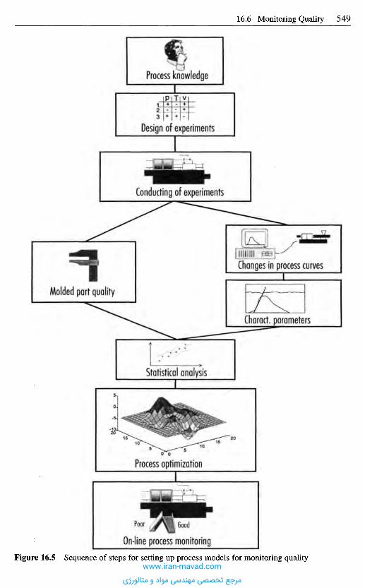
Process knowledge
Design of experiments
Conducting of experiments
Molded part quality
Changes in process curves
Charact. parameters
Statistical analysis
Process optimization
On-line process monitoring
GoodPoor
Figure 16.5 Sequence of steps for setting up process models for monitoring qualitywww.iran-mavad.com
مرجع تخصصی مهندسی مواد و متالورژی
possibility of performing a 100% quality control without the need to examine each andevery molded part.
The key to the quality calculation is a model that describes the dependencies ofmolded-part properties and process parameters. The approach for determining such amodel is illustrated in Figure 16.5. Starting from existing knowledge of the process, suchas that of a machine setter, a statistical experimental plan is drawn up in whichalterations to machine settings are set out during trials to be conducted. Statisticalexperimental design makes it possible to design trials efficiently and to gain a great dealof information from technical processes with a low number of experiments.
In injection molding, process parameters are recorded during the trial phase on themachine and the molded parts produced are removed and labeled so that clear classi-fication of trial parts and measured process parameters is ensured during the modelingphase. When the trials are over, the quality characteristics of the produced molded partsare determined.
Modeling of the interdependencies of the quality characteristics and process para-meters is performed off-line. Mostly, statistical methods are used as models. The choiceof regression to use depends on the type of quality characteristic to be evaluated.Continuous characteristics, such as weights and dimensions, are evaluated with multipleregression calculations. Logistic regression is used for describing the dependencies ofattributive characteristics. This group of quality characteristics includes those which canonly be subdivided into classes, such as "Characteristic present" and "Characteristicabsent". Burns and sink marks numbers are among these. Increasingly, statisticalmethods are being replaced by algorithms from research areas of artificial intelligence,such as neural networks. These have the advantage of being easier to apply since therelationships between process parameters and quality characteristics can be learnedindependently [16.13, 16.14].
With the aid of the models created, the quality of molded parts can be calculated on-line during injection molding from the process parameters measured during theproduction cycle. Thus, as soon as the cycle is over, information is available on theproduct just made. This can be used to aim for 100% quality documentation and establisha "reject route" for molded parts that fail to meet specifications.
R e f e r e n c e s
[16.1] Recker, H.; Spix, L.: MeB-, Steuer- und Regeleinrichtungen. In: Johannaber, F. (ed.):Kunststoffmaschinenfiihrer, 3rd Ed., Carl Hanser Verlag, Munich, Vienna, 1992,pp. 1123-1180.
[16.2] Company brochure, Dynisco Gerate GmbH, Heilbronn.[16.3] Wittemeier, R.: Temperaturmessung im Schneckenvorraum einer SpritzgieBplastifizier-
einheit mit Infrarotsensoren, Study report, Univ. GH, Paderborn, 1990.[16.4] Bluhm, R.: Methoden zur Bestimmung der Massetemperatur - Infrarotsensoren und
miniaturisierte Thermoelemente, Paper presented at the 17th Tooling Conference, IKV,Aachen, 1994.
[16.5] Company brochure, Kistler Instrumente AG, Winterthur, Schweiz.[16.6] Sarholz, R.; Beese, U.; Hengesbach, H. A.: ProzeBfiihrung beim SpritzgieBen, IKV, 1977.[16.7] Stitz, S.: Konstante Formteilqualitat beim SpritzgieBen durch Regeln des Werkzeug-
Druckverlaufs, Kunststoffe, 63 (1973), 11, pp. 777-783.[16.8] Rorick, W.: Zur Praxis der ProzeBregelung im Thermoplast-SpritzguBbetrieb,
Dissertation, RWTH, Aachen, 1979.[16.9] Sarholz, R.: Rechnerische Abschatzung des SpritzgieBprozesses als Hilfsmittel zur
Maschineneinstellung, Dissertation, RWTH, Aachen, 1980.www.iran-mavad.com
مرجع تخصصی مهندسی مواد و متالورژی

[16.10] Hellmeyer, H. 0.: Ein Beitrag zur Automatisierung des SpritzgieBprozesses, Dissertation,RWTH, Aachen, 1977.
[16.11] Lauterbach, M.: Ein Steuerungskonzept zur Flexibilisierung des Thermoplastspritz-guBprozesses, Dissertation, RWTH, Aachen, 1989.
[16.12] Bader, C : Die Bedeutung der WerkzeuginnendruckmeBtechnik beim SpritzgieBen.Reprint at the conference on: Qualitatssicherung und -optimierung beim SpritzgieBen,IKV, Aachen, 1997.
[16.13] Gierth, M. M.: Methoden und Hilfsmittel zur prozeBnahen Qualitatssicherung beimSpritzgieBen von Thermoplasten, Dissertation, RWTH, Aachen, 1992.
[16.14] Schnerr, O.; Vaculik, R.: Qualitatssicherung mit Neuronalen Netzen. Paper presented atthe 18th Tooling Conference, IKV, Aachen, 1996.
www.iran-mavad.com
مرجع تخصصی مهندسی مواد و متالورژی

Injection molds are always made in accordance with the same rules. Therefore, it shouldnot come as a surprise that their design approach is always similar. This holdsparticularly true for the basic components. A great number of companies are specializedin manufacturing such basic elements. They produce these elements on a large scale andin a variety that a detailed discussion of these products would be beyond the scope of thischapter. We emphasize, therefore, to contact a supplier of mold standards. Suppliers offerextensive and very informative catalogs. Sometimes the information is also available asa software database. Figures 17.1-17.3 and Table 17.1 show the most common moldstandards and their application areas.
Mold standards are parts or modules whose dimensions have been standardized andcharacterized. In line with the basic design of a mold, they can be classified as standardsfor the mold structure, the cavity, the gate system, the guides and centering, for heatcontrol, for demolding and for accommodating the mold in the injection moldingmachine.
The use of mold standards shortens production times and relieves the designer andmold maker of routine work. Advantages are:- For computer-assisted design, standards can be retrieved from a database, displayed on
the screen and employed in the design ("features"). The user has the option to "play"with several variants to select the solution which is the most suitable one in hisopinion. This relieves him of routine work.
- The uncertainty in a quotation is smaller because one can calculate with fixed costs forthe individual elements.
- Work input into the production of the molds can be reduced by 25-45% through theuse of standards. Extensive studies have shown that 55% of the total work is performedby the mold maker himself, 25% by the standards producer, and 20% can additionallybe delegated to the standards producer [17.2].
- The mold maker can adjust his machinery to the special requirements of mold makingsince he has to work primarily on the cavities. He saves on capital expenditure and canoperate more effectively and with lower costs.
- Supply of replacement is simplified because standards are interchangeable. There is noneed for maintaining an expensive in-house stock.
- Discarded molds can be disassembled and part of their components re-used.
1 7 M o l d S t a n d a r d s
www.iran-mavad.com
مرجع تخصصی مهندسی مواد و متالورژی
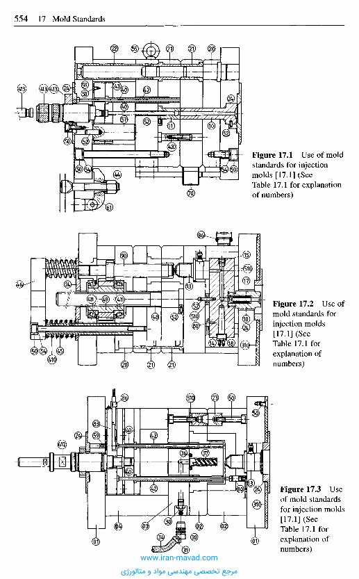
Figure 17.1 Use of moldstandards for injectionmolds [17.1] (SeeTable 17.1 for explanationof numbers)
Figure 17.2 Use ofmold standards forinjection molds[17.1] (SeeTable 17.1 forexplanation ofnumbers)
Figure 17.3 Useof mold standardsfor injection molds[17.1] (SeeTable 17.1 forexplanation ofnumbers)
www.iran-mavad.com
مرجع تخصصی مهندسی مواد و متالورژی

Table 17.1 Mold standards and their applications (see Figures 17.1-17.3 for illustrations of parts)
Module
0
1
Functional group
Mold frame
Gating systems
Part No.
1
2
3
4
10
11
13
14
15
17
18
Name
Mounting plates
Mold plate
Backing plate
Spacer strip
Sprue bushes
Sprue retaining bush
Sprue bushes withpneumatic sprueremoval and corre-sponding nozzles
Hot runner nozzles,with and withoutneedle valve
Heated manifoldblocks
Closure plug
Deflector plug
Melt filter
Filter insert
Heating elements, like:Cartridge heatersBand heaters,Flat tubular heatingelements,Spiral tube cartridges,Ring heaters withcorresponding controldevices
Application area
Circular, rectangular, drilled andundrilled plates, machined on all sides,in various dimensions.Material: steel and different aluminumgrades.Used for individual mold constructionsinto which only the cavities or moldinserts, gating system, cooling systemand drill holes for the ejector systemshave to be incorporated. The drilledplates contain drilled holes for guideelements and for bolting platestogether; these are exchangeable parts.
Accommodating the drill hole for thesprue, sealing the mold against theinjection nozzle
Demolding the gating system,
especially the sprue and the sprue gate
Fully automatic sprue removal
Single-point and multipoint gatenozzles lead the melt directly to thecavity. Runners etc are eliminated.Fully automatic production
Leading the melt in hot runner moldsfrom the injection nozzle to the hotrunner nozzles
Sealing a melt channel in hot runnerblocks
Deflecting the melt in hot runner blocks
Retaining contaminants.For injection nozzles and hot runnernozzles
Temperature control in hot runnermolds, molds with insulatedrunners and thermoset andelastomer molds
www.iran-mavad.com
مرجع تخصصی مهندسی مواد و متالورژی

Module
2
3
Functional group
Guide andlocating
elements
Temperaturecontrol system
Part No.
20
21
22
23
24
30
31
34
36
37
310
Name
Guide bolts
Guide bushes
Locating bush
Locating unit
Flat guides
Locating ring
Couplings andnipples, also assealing couplingsand nipples
Hose connectorsHose clampsPinch-off sleeves
Hoses: PVCHose with fabric insertVition hose withmetal braidingCorrugated metal hosewith metal braiding
Sealing bolt
Seals
Spiral cores, singleflighted, doubleflighted
Cooling finger
Heat pipe
Heat sink cartridge
Thermal protectionplatesInsulating plates
Heating elements(see Gating system)
Application area
Internal guiding and locating ofmold halves and lateral slide bars
Locating and guiding mold halvesand ejector assembly
Locating mold plates and stripsrelative to each other
Locating the mold plates
For individual guides with solidlubricant depots
Locating and centring mold halves onthe machine mounting plates
Connecting the mold to thetemperature control units
Depending on temperature of heatingmedium
Locking heating channel holes, e.g. atdeflectors (cross holes)
O-rings for sealing the temperaturecontrol system, Teflon® ribbon, etc.
Cooling mold cores
Spot cooling at points in barelyaccessible areas of mold
Avoiding heat dissipation into machine
mounting plates in hot runner molds,
molds with insulated runners and
thermoset and elastomer molds
See Gating system
Table 17.1 (continued) Mold standards and their applications (see Figures 17.1-17.3 forillustrations of parts)
www.iran-mavad.com
مرجع تخصصی مهندسی مواد و متالورژی
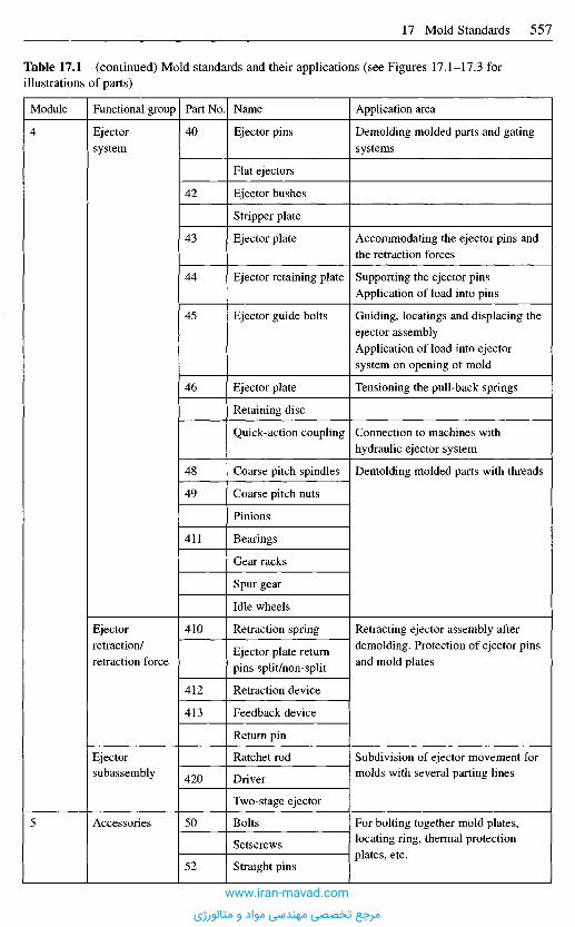
Module
4
5
Functional group
Ejectorsystem
Ejectorretraction/retraction force
Ejectorsubassembly
Accessories
Part No.
40
42
43
44
45
46
48
49
411
410
412
413
420
50
52
Name
Ejector pins
Flat ejectors
Ejector bushes
Stripper plate
Ejector plate
Ejector retaining plate
Ejector guide bolts
Ejector plate
Retaining disc
Quick-action coupling
Coarse pitch spindles
Coarse pitch nuts
Pinions
Bearings
Gear racks
Spur gear
Idle wheels
Retraction spring
Ejector plate returnpins split/non-split
Retraction device
Feedback device
Return pin
Ratchet rod
Driver
Two-stage ejector
Bolts
Setscrews
Straight pins
Application area
Demolding molded parts and gatingsystems
Accommodating the ejector pins andthe retraction forces
Supporting the ejector pinsApplication of load into pins
Guiding, locatings and displacing theejector assemblyApplication of load into ejectorsystem on opening of mold
Tensioning the pull-back springs
Connection to machines withhydraulic ejector system
Demolding molded parts with threads
Retracting ejector assembly afterdemolding. Protection of ejector pinsand mold plates
Subdivision of ejector movement formolds with several parting lines
For bolting together mold plates,locating ring, thermal protectionplates, etc.
Table 17.1 (continued) Mold standards and their applications (see Figures 17.1-17.3 forillustrations of parts)
www.iran-mavad.com
مرجع تخصصی مهندسی مواد و متالورژی

Module
6
7
8
9
Functional group
Transport aids
Spacer segments
Clampingsystems/rapidclampingsystems
Slide barmechanism
Measuring andcontrol devices
Mold inserts
Part No.
54
55
57
59
510
60
61
70
80
83
86
90
Name
Ball catch
Springs/springelements
Ring bolts
Support rolls
Support strips
Headed dowels andsupport discs
Spacing rings
Mechanical andhydraulic clampingsystems
Clamps/brackets
Mechanism com-prising tie rod andslide rod
Locking cylinders
Heat sensors
Electronic temperaturecontrollers
Pressure sensors
Sensor
Recording device
Computer
Plug-in connectors
Cores
Application area
Stopping movable mold parts, e.g.jaws
Compression and disc springs for e.g.ejector retraction, bolt security, etc.
Lowering lifting tool and securingmolds during transport
Partial support for mold plates and forbridging large distances bewteen themold plates with minimal thermalconduction
Supporting the ejector assembly
Supporting the hot runner blocksCompensating plate thicknesses
Mounting the molds on the machinemounting plates
Long slide bar distances that otherwiseare attainable only with hydraulic orpneumatic cylinders
Locking and pulling lateral slide barsand core pins
Temperature control and monitoring inhot runner molds with insulatedrunners and thermoplastics andelastomer molds
Monitoring and recording cavitypressure and pressure in the hydraulicsystem of the injection moldingmachine
Connecting sensors to measuring andrecording devices
Core pins for swappable cores, e.g.unscrewing cores
Table 17.1 (continued) Mold standards and their applications (see Figures 17.1-17.3 forillustrations of parts)
www.iran-mavad.com
مرجع تخصصی مهندسی مواد و متالورژی

Company
American MSIBohlerD-M-EDMSDyniscoEnerpacEngelEurotoolEwiconEast HeatGammafluxGuntherHasco InternormHasco Mold BasesHotsetHuskyIncoeKistlerMannerMold-MastersPlasthingStaubliThermodyneUddeholmWatlow
City, State
Moorpark, CA/USAArlington Heights, IL/USAMadison Heights, MI/USAWindsor,Ontario/CanadaGloucester, MA/USAMilwaukee, WIAJSAGuelph, Ontario/CanadaGloucester, MA/USAEast Dundee, IL/USAElmhurst, IL/USASterling, VA/USABuffalo Grove, IL/USAChatsworth, CA/USAArden, NC/USABattle Creek, MI/USABolton, Ontario/CanadaTroy, MI/USAAmherst, NY/USATucker, GA/USAGeorgetown, Ontario/CanadaMishawaka, IN/USADuncon, SC/USABeverly, MA/USAWood Dale, IL/USASt. Louis/MO/USA
Table 17.2 Selected suppliers of mold standards, hot runners and accessories, pressure andtemperature sensors as well as mold changing systems in North America. These suppliers offernot only tried and true parts but also systems tailored to specific needs.
R e f e r e n c e s
[17.1] Catalog of Standards, Hasco, Ludenscheid, Germany.[17.2] Heuel, 0.: Werkzeug - F M E A fur SpritzgieBwerkzeuge. Kunststoffberater, 1, 2 and 3,
1994.
www.iran-mavad.com
مرجع تخصصی مهندسی مواد و متالورژی
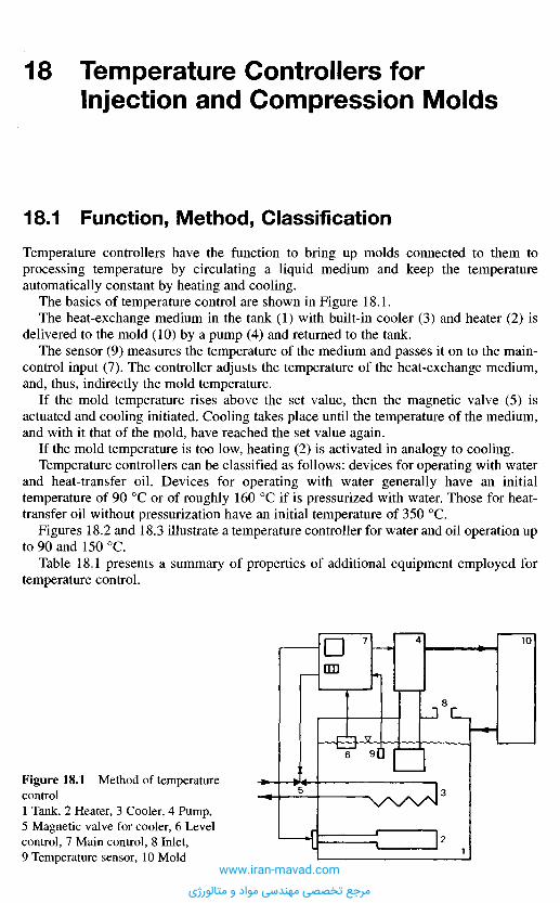
1 8 . 1 F u n c t i o n , M e t h o d , C l a s s i f i c a t i o n
Temperature controllers have the function to bring up molds connected to them toprocessing temperature by circulating a liquid medium and keep the temperatureautomatically constant by heating and cooling.
The basics of temperature control are shown in Figure 18.1.The heat-exchange medium in the tank (1) with built-in cooler (3) and heater (2) is
delivered to the mold (10) by a pump (4) and returned to the tank.The sensor (9) measures the temperature of the medium and passes it on to the main-
control input (7). The controller adjusts the temperature of the heat-exchange medium,and, thus, indirectly the mold temperature.
If the mold temperature rises above the set value, then the magnetic valve (5) isactuated and cooling initiated. Cooling takes place until the temperature of the medium,and with it that of the mold, have reached the set value again.
If the mold temperature is too low, heating (2) is activated in analogy to cooling.Temperature controllers can be classified as follows: devices for operating with water
and heat-transfer oil. Devices for operating with water generally have an initialtemperature of 90 0C or of roughly 160 0C if is pressurized with water. Those for heat-transfer oil without pressurization have an initial temperature of 350 0C.
Figures 18.2 and 18.3 illustrate a temperature controller for water and oil operation upto 90 and 150 0C.
Table 18.1 presents a summary of properties of additional equipment employed fortemperature control.
Figure 18.1 Method of temperaturecontrol1 Tank, 2 Heater, 3 Cooler, 4 Pump,5 Magnetic valve for cooler, 6 Levelcontrol, 7 Main control, 8 Inlet,9 Temperature sensor, 10 Mold
1 8 T e m p e r a t u r e C o n t r o l l e r s f o r
I n j e c t i o n a n d C o m p r e s s i o n M o l d s
www.iran-mavad.com
مرجع تخصصی مهندسی مواد و متالورژی
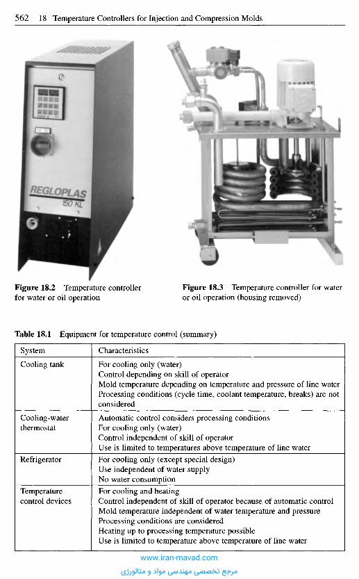
Table 18.1 Equipment for temperature control (summary)
System
Cooling tank
Cooling-waterthermostat
Refrigerator
Temperaturecontrol devices
Characteristics
For cooling only (water)Control depending on skill of operatorMold temperature depending on temperature and pressure of line waterProcessing conditions (cycle time, coolant temperature, breaks) are notconsidered
Automatic control considers processing conditionsFor cooling only (water)Control independent of skill of operatorUse is limited to temperatures above temperature of line waterFor cooling only (except special design)Use independent of water supplyNo water consumptionFor cooling and heatingControl independent of skill of operator because of automatic controlMold temperature independent of water temperature and pressureProcessing conditions are consideredHeating up to processing temperature possibleUse is limited to temperature above temperature of line water
Figure 18.2 Temperature controllerfor water or oil operation
Figure 18.3 Temperature controller for wateror oil operation (housing removed)
www.iran-mavad.com
مرجع تخصصی مهندسی مواد و متالورژی

1 8 . 2 C o n t r o l
18.2.1 Control Methods
There are three methods to control the mold temperature:
Control of the heat-exchange medium (Figures 18.4 and 18.7).The sensor measures the temperature of the medium in the equipment. Figure 18.6presents the response of this control type in various stages. The characteristics are asfollows:- The temperature set at the controller and required for reproducible production is not
measured. Therefore, depending on the disturbance variables, different temperaturescan occur in the mold, even though the same value is selected.
- Variations of the temperature in the mold may be relatively great because thedisturbance variables (9) affecting the mold are not directly considered and controlled(such as cycle time, injection, melt temperature, etc.).
Direct control of the mold temperature (Figures 18.5 and 18.8).The temperature sensor is in the mold. This results, in most cases, in a much better
stability of the mold temperature than with the control of the medium temperature.Figure 18.8 shows the response of the temperature control of the mold in various
stages. The primary characteristics of this control are:
Figure 18.4 Control of heat-exchangemedium
Figure 18.5 Control of mold temperature
1 Temperature controller, 2 Controller, maincontroller PI, master controller,3 Heating/cooling system, 4 Set value,5 Actual value, 6 Actual mold temperature,7 Temperature sensor for heat transfermedium, 8 Temperature sensor for mold,9 Auxiliary controller (PfD), 10 Correctingset value, 11 Mold (consumer)
Figure 18.6 Cascade controlwww.iran-mavad.com
مرجع تخصصی مهندسی مواد و متالورژی
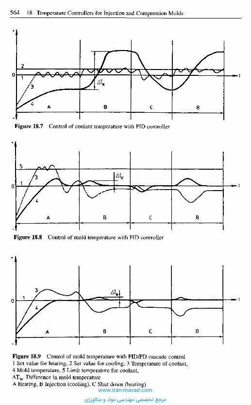
Figure 18.7 Control of coolant temperature with PID controller
A B C 8
Figure 18.8 Control of mold temperature with PID controller
A B C B
Figure 18.9 Control of mold temperature with PID/PD cascade control1 Set value for heating, 2 Set value for cooling, 3 Temperature of coolant,4 Mold temperature, 5 Limit temperature for coolant,ATW Difference in mold temperatureA Heating, B Injection (cooling), C Shut down (heating)
A B C B
www.iran-mavad.com
مرجع تخصصی مهندسی مواد و متالورژی
- The temperature set with the controller corresponds with the mold temperature.-Disturbance variables (9) affecting the mold are considered and leveled out. This
results in very small temperature variations of the mold.- Processing data are reproducible.
Cascade control(Figures 18.7 and 18.9)This is a combination of the two different types of control presented so far. By means oftwo coupled controllers (2) and (9), both the medium and the mold temperature arecontrolled. Mold temperature constancy is further improved.
18.2.2 Preconditions for Good Control Results
The following preconditions have to be met to obtain good stability of the moldtemperature:
1. Properly dimensioned channels in the consumer (arrangement, heat-exchange sur-face, diameter, circuits) (see also Chapter 8).
2. Use of temperature-controlled devices with properly dimensioned heating, cooling,and pumping capacity.
3. Correct adaptation of the controller to the controlled system (mold), i.e., actuation bymeans of control measurement.
4. Correct positioning of the temperature sensor in the mold in the case of regulation ofmold temperature and cascade control (see Section 18.2.2.4).
5. The heat carrier should have good heat-transfer properties to carry appropriatequantities of heat in a short time.
These preconditions are discussed in more detail in the following sections.
18.2.2.1 Controllers
The controllers employed in temperature-control equipment are three-point controllerswith the positions "heating - neutral - cooling" (quasi-steady controllers). For specialapplications steady controllers are used. Heating or cooling are not controlled in anin/out mode but in a "more/less" mode depending on the capacity demand.
An interface (e.g., RS 232, 485) enables software dialog with the processor of theinjection molding machine. The machine provides the data to be set, calls the parametersfor the controller, orders the mold to empty, asks for the status of equipment (e.g.,breakdown), etc.
18.2.2.2 Heating, Cooling, and Pump Capacity
Insufficient heating capacity prolongs the heating-up phase and levels out disturbancesimperfectly or too slowly. Oversizeing can make the control circuit oscillate. Duringstart-up, a temperature overshooting may occur.
The capacity of the pump determines the temperature gradient of the mold or the heat-exchange circuit. The greater the capacity, the smaller is the temperature difference ofthe heat carrier in the mold between inlet and outlet. On the other hand, a large dischargecauses a large pressure drop in the mold so that pumps with high discharge pressure are
www.iran-mavad.com
مرجع تخصصی مهندسی مواد و متالورژی
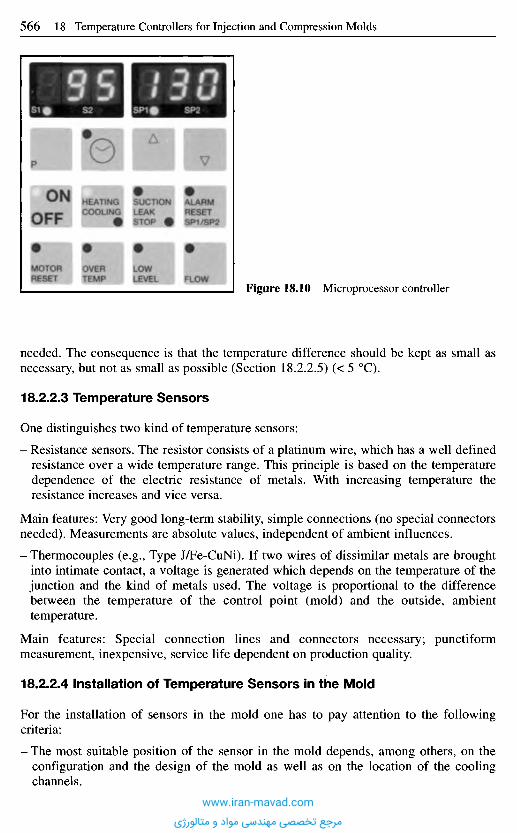
needed. The consequence is that the temperature difference should be kept as small asnecessary, but not as small as possible (Section 18.2.2.5) (< 5 0C).
18.2.2.3 Temperature Sensors
One distinguishes two kind of temperature sensors:
- Resistance sensors. The resistor consists of a platinum wire, which has a well definedresistance over a wide temperature range. This principle is based on the temperaturedependence of the electric resistance of metals. With increasing temperature theresistance increases and vice versa.
Main features: Very good long-term stability, simple connections (no special connectorsneeded). Measurements are absolute values, independent of ambient influences.
- Thermocouples (e.g., Type J/Fe-CuNi). If two wires of dissimilar metals are broughtinto intimate contact, a voltage is generated which depends on the temperature of thejunction and the kind of metals used. The voltage is proportional to the differencebetween the temperature of the control point (mold) and the outside, ambienttemperature.
Main features: Special connection lines and connectors necessary; punctiformmeasurement, inexpensive, service life dependent on production quality.
18.2.2.4 Installation of Temperature Sensors in the Mold
For the installation of sensors in the mold one has to pay attention to the followingcriteria:
- The most suitable position of the sensor in the mold depends, among others, on theconfiguration and the design of the mold as well as on the location of the coolingchannels.
Figure 18.10 Microprocessor controller
www.iran-mavad.com
مرجع تخصصی مهندسی مواد و متالورژی
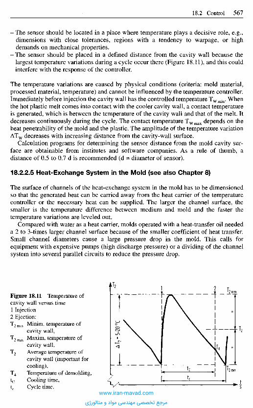
- The sensor should be located in a place where temperature plays a decisive role, e.g.,dimensions with close tolerances, regions with a tendency to warpage, or highdemands on mechanical properties.
- The sensor should be placed in a defined distance from the cavity wall because thelargest temperature variations during a cycle occur there (Figure 18.11), and this couldinterfere with the response of the controller.
The temperature variations are caused by physical conditions (criteria: mold material,processed material, temperature) and cannot be influenced by the temperature controller.Immediately before injection the cavity wall has the controlled temperature TWmin. Whenthe hot plastic melt comes into contact with the cooler cavity wall, a contact temperatureis generated, which is between the temperature of the cavity wall and that of the melt. Itdecreases continuously during the cycle. The contact temperature TWmax depends on theheat penetrability of the mold and the plastic. The amplitude of the temperature variationATW decreases with increasing distance from the cavity-wall surface.
Calculation programs for determining the sensor distance from the mold cavity sur-face are obtainable from institutes and software companies. As a rule of thumb, adistance of 0.5 to 0.7 d is recommended (d = diameter of sensor).
18.2.2.5 Heat-Exchange System in the Mold (see also Chapter 8)
The surface of channels of the heat-exchange system in the mold has to be dimensionedso that the generated heat can be carried away from the heat carrier of the temperaturecontroller or the necessary heat can be supplied. The larger the channel surface, thesmaller is the temperature difference between medium and mold and the faster thetemperature variations are leveled out.
Compared with water as a heat carrier, molds operated with a heat-transfer oil neededa 2 to 3-times larger channel surface because of the smaller coefficient of heat transfer.Small channel diameters cause a large pressure drop in the mold. This calls forequipment with expensive pumps (high discharge pressure) or a dividing of the channelsystem into several parallel circuits to reduce the pressure drop.
Figure 18.11 Temperature ofcavity wall versus time1 Injection2 Ejection:T2 min Minim, temperature of
cavity wall,T2 max Maxim, temperature of
cavity wall,T2 Average temperature of
cavity wall (important forcooling),
T4 Temperature of demolding,tc Cooling time,tc Cycle time.
J2
iSwww.iran-mavad.com
مرجع تخصصی مهندسی مواد و متالورژی
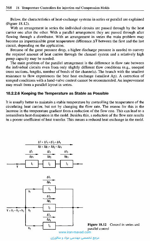
Below, the characteristics of heat-exchange systems in series or parallel are explained(Figure 18.12).
With an arrangement in series the individual circuits are passed through by the heatcarrier one after the other. With a parallel arrangement they are passed through afterflowing through a distributor. With an arrangement in series the main problem maybecome an impermissible great temperature difference AT between the first and the lastcircuit, depending on the application.
Because of the great pressure drop, a higher discharge pressure is needed to conveythe required amount of heat carrier through the channel system and a relatively highpump capacity may be needed.
The main problem of the parallel arrangement is the difference in flow rate betweenthe individual circuits even from only slightly different flow conditions (e.g., unequalcross sections, lengths, number of bends of the channels). The branch with the smallestresistance to flow experiences the best heat exchange (smallest Ap). A correction ofunequal conditions with a hand-valve control cannot be recommended. An improvementmay result from a parallel layout in series.
18.2.2.6 Keeping the Temperature as Stable as Possible
It is usually better to maintain a stable temperature by controlling the temperature of thecirculating heat carrier, but not by changing the flow rate. The reason for this is theincrease in the temperature gradient from a reduction of the flow rate. This can lead to anonuniform heat dissipation in the mold. Besides this, a reduction of the flow rate resultsin a poorer coefficient of heat transfer. This means a reduced heat exchange in the mold.
Figure 18.12 Control in series andparallel control
www.iran-mavad.com
مرجع تخصصی مهندسی مواد و متالورژی

1 8 . 3 S e l e c t i o n o f E q u i p m e n t
The selection of temperature-control equipment depends primarily on processedmaterial, the weight of the mold, the desired heat-up time, the amount of material to beprocessed per unit time (kg/h), the permissible temperature differential in the mold, aswell as pressure and flow-rate conditions in the mold (Table 18.2).
The discharge pressure of the pump can only be determined with a diagram "pressuredrop as a function of flow rate". If there is no such diagram, the pressure drop can beestimated from experience with similar molds.
As already mentioned in Section 18.2.2.5, water should be preferred as the heat carrierif possible because of its better heat-transfer properties. It should be used for mold tem-peratures up to 90 0C. Employing equipment for pressurized water allows its use up totemperatures of about 140 0C. Beyond 90 or 140 0C respectively, heat-transfer oil has tobe employed as heat carrier.
Table 18.2 Criteria for selection of equipment
Specification Objective
Processed material Mold temperatureMold temperature Heat exchange medium (water/oil)Mold weight, heating time Heating capacityAmount of processed material per unit time Cooling capacityTemperature gradient of mold Discharge of pumpPressure drop versus flow rate Discharge pressure of pump
1 8 . 4 C o n n e c t i o n o f M o l d a n d E q u i p m e n t -
S a f e t y M e a s u r e s
For reasons of safety and reliability of operation, maintenance, and avoidance of leaksthe following items should be observed:
- Only plugs with tapered pipe threads should be employed in heat-exchange circuits.- Only pressure- and heat-resistant hoses should be used. Twisting, too small bending
radii, compression, etc. have to be prevented.- Cooling should always be connected for safety reasons.- Heat-insulated lines should be employed for greater distances between equipment and
mold.- Periodic examinations of the circuit (controller, connections, mold) for leaks and
proper function.- For a change-over from water to oil in suitable equipment, one has to proceed
cautiously: hazard of an accident during heating from excessive vapor pressure ofwater remnants in the circuit.
- Periodic change of the heat carrier.- Use of synthetic heat-transfer oil because of little tendency to form deposits.
www.iran-mavad.com
مرجع تخصصی مهندسی مواد و متالورژی

- Heat exchanger or expansion tank have to be placed somewhat higher than the mold ifthe latter is very large and contains a proportional quantity of heat carrier. Thisprevents a slow return of the content of the mold into the expansion tank and over-flowing during a shutdown. A return is almost inevitable because of tiny leaks atconnections in the circuit which permit air to enter. If a higher placement is notfeasible, then there are the following options:
- Size of the expansion tank has to be adequate to accommodate all returning fluidduring the shutdown.
- Mounting shut-off valves at inlet and outlet at the mold, which can be closed duringshutdown.
- Use of magnetic valves, which close when the equipment is turned off.- Reduction of cross-sections in the circuit, only if needed, and then close to the mold.
A measure for the size of the connections are the connectors of the control equipment.This permits the full use of the pump capacity.
1 8 . 5 H e a t C a r r i e r
In the following, the characteristics of water and heat-transfer oil are compared. Wateroffers the following advantages over heat-transfer oil:
- Cheaper, cleaner, and ecologically safe. Water from leaks in the circuit can be dis-charged into the sewer system without further precautions.
- Very good thermal properties, such as heat transfer (high heat transfer coefficienta), heat capacity (high specific heat capacity c), and thermal conductivity (highthermal conductance f).
- Comparatively low channel surface area required for heat supply and dissipation.
Disadvantages are:
- low boiling point.
In the case of tap water:
- Danger of corrosion and scale development in the heat-exchange circuit leading togreater pressure drop and a deterioration of the heat exchange.
- Detrimental substances dissolved in water (nitrites, chlorides, iron, etc.) areincreasingly precipitated at elevated temperatures.
Preventive measures depending on shop conditions are:
- use closed-loop cooling circuit,- removal of solids with strainers,- periodic flushing of equipment and mold with a scale remover,- treatment of the circuit with a corrosion inhibitor,- correct water quality.
To avoid damage to the cooler of the temperature-control device and in the temperature-control circuit (device and attached consumers), the water used must meet the followingrequirements:
Hardness 10 to 45 ppm equivalent calcium carbonate,pH value at 20 0C 6.5 to 8.5,
www.iran-mavad.com
مرجع تخصصی مهندسی مواد و متالورژی
Cl-ions max. 150 mg/1,Sum of chlorides and sulfates max. 250 mg/1.
Potable water often meets these requirements. If the water is too soft (distilled water, rainwater), it can cause corrosion. Corrosion is also promoted by the prescuce of chlorides.Water that is too hard promotes scale and sludge development.
Heat-transfer oils do not exhibit the disadvantages of water. Because of their higherboiling point they can be used up to more than 350 0C, depending on the type.
Disadvantages of heat-transfer oils are:
- poorer heat-transfer characteristics. Optimum heat transfer can only be obtained underdefined flow conditions. The flow rate (1/min) has to be precisely adjusted to thespecific heating capacity (W/cm2),
- inflammable under certain conditions (there are not yet flame retardant oils),- aging (oxidation, increase in viscosity),- costs.
Synthetic heat-transfer oils exhibit better solubility of products from the aging process,which are primarily formed near the temperature limits. This reduces the danger ofundesirable deposits considerably. Of course one has to pay a higher price than for amineral oil.
1 8 . 6 M a i n t e n a n c e a n d C l e a n i n g
Maintenance and cleaning of the heat-exchange system (device, mold, connecting lines)must be performed regularly as otherwise "creeping" deterioration (slow reduction ofcross-sections of channels by scaling) may occur.
To avoid production downtimes on expensive production equipment, preventaccidents, and maintain the temperature-control device at a high level of operationalsafety, the periodic controls and maintenance work prescribed in the manufacturer'smanual must be performed.
Deposits of rust and scale adversely affect the heat exchange between mold andcirculating water, if the latter is the heat carrier.
Contamination and deposits can constrict the flow-through cross-section and result ina higher pressure drop in the mold so that, after some time, the pump capacity does notsuffice for a troublefree operation anymore. Periodic examination and cleaning istherefore indispensable. Adding a corrosion inhibitor is a commendable means ofprevention.
Deposits in the mold from heat-transfer oil can also impair heat transfer and result inhigher pressure drop. Adding a detergent before changing the oil or preventively duringthe whole time between changes is likewise suggested. The oil should be examinedperiodically. This is best done by the supplier with an analysis. Dark color is by itself noquality criterion.
R e f e r e n c e s
[18.1] Handbuch der Temperierung mittels fliissiger Medien. Regloplas AG, 5th Ed., St. Gallen,Huthig Verlag, Heidelberg, 1997.
www.iran-mavad.com
مرجع تخصصی مهندسی مواد و متالورژی
Melt leaks betweennozzle and spruebushing.
Sprue cannot bedemolded;breaks off.
Part cannot bedemolded.
a) Molding sticksin cavity.
b) Molding isdemolished duringdemolding.
Orifices of nozzle and sprue bushing are misaligned. Checklocating, ring, and alignment. Contact pressure between nozzleand sprue bushing is insufficient. Increase pressure. Checkuniform pressure with thin paper. Proper contact results inuniform indentation. Radii of nozzle and sprue bushing do notmatch. Nozzle orifice is larger than orifice of sprue bushing.
Sprue has an undercut because1. radii of nozzle and sprue bushing do not match,2. nozzle and sprue bushing are misaligned,3. nozzle orifice is larger than orifice of sprue bushing,4. sprue bushing is insufficiently polished, grooves in circum-
ferential direction. Polish mold, round sharp corners.
Sprue is not yet solidified because1. sprue bushing is too large and sprue too thick,2. area of sprue bushing is inadequately cooled, check mold
temperature.
General: cooling time too short; mold overloaded; undercuts toodeep; rough cavity surface. Reduce injection speed and holdingpressure; eliminate undercuts; repolish cavity.
Sprue or runner system has undercuts. Check radii of nozzle andsprue bushing. Check surface of cavity for imperfections.Repolish it and round sharp corners. Cavity temperature is toolow. Formation of vacuum. Check taper. Consider venting duringdemolding
Undercuts too deep. Ejectors are placed in locations which aredetrimental to proper transmission of ejection forces resultingin unacceptable pressure peaks. Check cavity surface forimperfections. Formation of vacuum. Check taper.
1 9 S t e p s f o r t h e C o r r e c t i o n o f M o l d i n g
D e f e c t s D u r i n g I n j e c t i o n M o l d i n g
In the following a number of molding defects, which are mostly caused by faulty molddesign, are listed along with steps to remedy them. A first summary is presented withFigure 19.1. It shows a point system, which has been developed to remove visible defectsfrom acrylic moldings [19.1]. However, it can also be applied to other thermoplasticmaterials.
www.iran-mavad.com
مرجع تخصصی مهندسی مواد و متالورژی
Distortion ofmolding.
Burned spots atthe molding.
Darkening at themolding.
Dark (black) specks.
Discoloration neargate.
Brittle moldings.
Molding has mator streaky surface.
Color streaks.
Bubbles, humiditystreaks.
Formation of rutsand clouds;Flaking (scaling)of molding surface.
Molding with poorsurface gloss.Incomplete moldfilling.
Poor location of gating. Poor type of gate. Nonuniform moldtemperature. Unfavorable cross-sectional transitions. Consider-able difference in wall thickness requires more than one coolingcircuit. Wrong mold temperature. Nonuniform shrinkage. Adverseswitch-over point from injection to holding pressure. Poorlocation of ejectors.
Melt temperature is too high. Material is overheated in narrowgates. Mold is insufficiently vented. Adverse flow of material.Residence time too long. Select smaller plasticating unit.
Residence time of the material in the barrel is too long. Barreltemperatures too high. Rate of screw revolutions too high. Gatestoo small.
Impurities in the material; wear in the plasticating unit. Use of acorrosion- and wear-resistant plasticating unit.
Mold temperature too high. Enlarge runners and gate. Cold-slugwell needed.
Raise mold temperature. Enlarge runners and gate. Cold-slug wellneeded. Thermally damaged or heterogeneous melt. Humid material.
Mold surface inadequately polished. Poor location of gating. Poortype of gate. Increase size of runners and gate and polish. Cold-slug well needed. Mold too cold (condensed humidity).Overheating of material from insufficient venting or unfavorableflow path. Lower rate of screw rotation; pre-dry material.
Poor mixing or separation of molding material. Raise rate ofscrew rotation, raise back pressure. Modify temperature profile ofbarrel. Reduce feed hopper cooling. Use another screw.
Material is too humid, dry sufficiently.
Poor gate position. Raise mold and melt temperature. Raiseinjection speed. Check plasticating unit for wear. Check gate.Excessive temperature differential between melt and mold. Raisemold temperature. Enlarge runners and gate. Contamination froma different material.
Check mold temperature. Enlarge runners and gate. Round sharpcorners. Repolish mold.Runners too long or too small or both. Enlarge runner system.Flow in cavity is restricted. Open gates. Core shifting. Insufficientmold venting. Mold and melt temperature too low. Raise injectionspeed and/or pressure. Insufficient feeding of material, no cushion.
www.iran-mavad.com
مرجع تخصصی مهندسی مواد و متالورژی
Molding with sinkmarks and shrinkholes.
Mold flashes.
Molding with visibleknit lines.
Cold slug
Jetting
Off-sized molding.
a) with uniformshrinkage
b) with nonuniformshrinkage
Stress cracking.
Rippled moldingsurface.
Runners and gate too small. System solidifies before holdingpressure has become effective. Check mold temperature. Raiseagainst shrink holes, lower against sink marks. Lower melttemperature. Check cushion, lengthen holding-pressure time, raiseholding pressure. Lower injection speed.
Poor fit at parting line. Matching surfaces damaged by e.g.,remnants of material or excessive pressure. Rework surfaces.Clamping force is insufficient because projected area of part is toolarge. Core shifting has caused a considerable differential in wallthickness causing flash on one side and insufficient filling on theother. Mold temperature too high. Injection speed and/or pressuretoo high. Advance switch-over point. Mold is not sufficiently"rigid". Platens of the clamping unit bend. Reinforce platens,change machine. Mold cavity is not dead center in mold.
Poor position of gating. Objectionable type of gate. Detrimentalgate and runner cross sections. Enlarge gate. Poor mold venting.Nonuniform mold cooling. Raise mold temperature. Raiseinjection speed. Wall thickness of molding too small. Choosecascade gating.
Nozzle temperature too low, retract nozzle from sprue bushingsooner. Reduce cooling of sprue bushing, enlarge nozzle bore.
Relocate gate that material is injected against a wall. Enlarge crosssection of gate.
Too high a mold and melt temperature increase shrinkage. Longercooling time; higher injection pressure and increased holding-pressure time decrease shrinkage.
Poor heat exchange, gate freezes too soon, heterogeneous melt.
Sharp corners and edges in the mold. Processing with inserts:preheat inserts, avoid sharp corners and edges.
Reduce mold temperature. [19.1 to 19.9]
www.iran-mavad.com
مرجع تخصصی مهندسی مواد و متالورژی
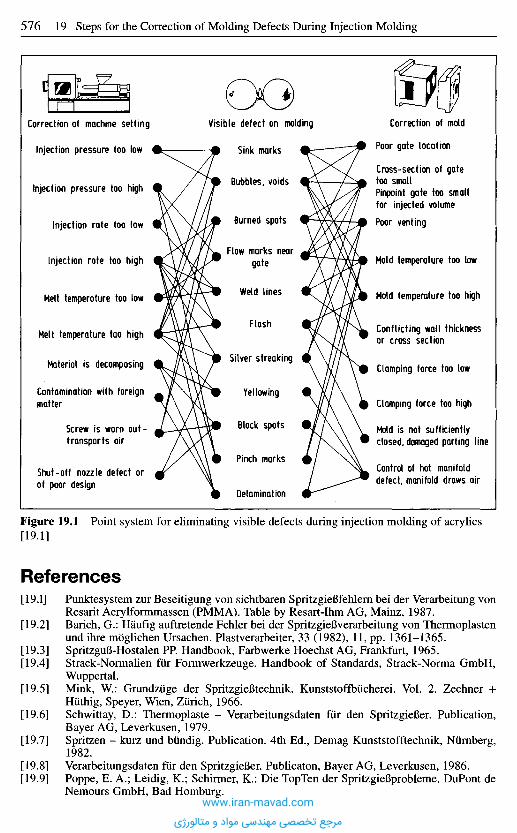
Figure 19.1 Point system for eliminating visible defects during injection molding of acrylics[19.1]
R e f e r e n c e s
[19.1] Punktesystem zur Beseitigung von sichtbaren SpritzgieBfehlern bei der Verarbeitung vonResarit Acrylformmassen (PMMA). Table by Resart-Ihm AG, Mainz, 1987.
[19.2] Barich, G.: Haufig auftretende Fehler bei der SpritzgieBverarbeitung von Thermoplastenund ihre moglichen Ursachen. Plastverarbeiter, 33 (1982), 11, pp. 1361-1365.
[19.3] SpritzguB-Hostalen PP. Handbook, Farbwerke Hoechst AG, Frankfurt, 1965.[19.4] Strack-Normalien fur Formwerkzeuge. Handbook of Standards, Strack-Norma GmbH,
Wuppertal.[19.5] Mink, W.: Grundziige der SpritzgieBtechnik. Kunststoffbucherei. Vol. 2. Zechner +
Huthig, Speyer, Wien, Zurich, 1966.[19.6] Schwittay, D.: Thermoplaste - Verarbeitungsdaten fiir den SpritzgieBer. Publication,
Bayer AG, Leverkusen, 1979.[19.7] Spritzen - kurz und biindig. Publication. 4th Ed., Demag Kunststofftechnik, Niirnberg,
1982.[19.8] Verarbeitungsdaten fiir den SpritzgieBer. Publicaton, Bayer AG, Leverkusen, 1986.[19.9] Poppe, E. A.; Leidig, K.; Schirmer, K.: Die TopTen der SpritzgieBprobleme. DuPont de
Nemours GmbH, Bad Homburg.
Correction of machine setting Visible defect on molding Correction of mold
Injection pressure too low
Injection pressure too high
Injection rate too low
Injection rate too high
Melt temperature too low
Melt temperature too high
Material is decomposing
Contamination with foreignmatter
Screw is worn out-transports air
Shut-off nozzle defect orof poor design
Sink marks
Bubbles, voids
Burned spots
Flow marks neargate
Weld lines
Flash
Silver streaking
Yellowing
Black spots
Pinch marks
Delamination
Poor gate location
Cross-section of gatetoo smallPinpoint gate too smallfor injected volume
Poor venting
Mold temperature too low
Mold temperature too high
Conflicting wall thicknessor cross section
Clamping force too low
Clamping force too high
Mold is not sufficientlyclosed, damaged parting line
Control of hot manifolddefect manifold draws air
www.iran-mavad.com
مرجع تخصصی مهندسی مواد و متالورژی

2 0 . 1 I n j e c t i o n M o l d i n g o f M i c r o s t r u c t u r e s
The injection molding process may be used to produce on the one hand extremely smallparts with molded-part weights of less than 1000th of a gram and, on the other hand,parts with structured areas each measuring just a few square micrometers. Both appli-cations enable mass production of molded parts intended specifically for microsystemstechnology.
The following description pertains to macroscopic parts with microstructured areas.This mold technology has already been used to produce structures with minimal widthof 2.5 urn and a height of 20 jam [20.1]. The so-called aspect ratio (ratio of the maximumheight to the minimum lateral dimensions of a structure) has a value of 8 in this case.This illustrates the difference from CD production, which also involves the productionof microstructures from plastic. The smallest lateral dimension occurring in theproduction of compact discs is approx. 0.6 um and the maximum structure height isapprox. 0.1 um, this giving an aspect ratio of far less than 1.
Figure 20.1 shows an injection-molded demonstration structure. The roughly 1100pillars of POM each have a width across of 80 um for a height of 200 um and are spaced8 um apart.
2 0 S p e c i a l P r o c e s s e s - S p e c i a l M o l d s
Figure 20.1 Injection molded demonstration structure
20.1.1 M o l d i n g Techno logy a n d P r o c e s s C o n t r o l
The quality of injection molded parts is critically dependent on the molding technology.Already during the design of a microinjection mold, particular attention must be paid tothe filigree structure of the cavities themselves. Additionally, the injection molding ofmicrostructured parts requires special process control (Figure 20.2).
www.iran-mavad.com
مرجع تخصصی مهندسی مواد و متالورژی
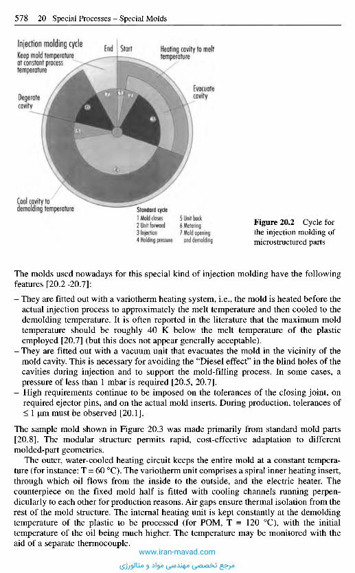
The molds used nowadays for this special kind of injection molding have the followingfeatures [20.2-20.7]:
- They are fitted out with a variotherm heating system, i.e., the mold is heated before theactual injection process to approximately the melt temperature and then cooled to thedemolding temperature. It is often reported in the literature that the maximum moldtemperature should be roughly 40 K below the melt temperature of the plasticemployed [20.7] (but this does not appear generally acceptable).
- They are fitted out with a vacuum unit that evacuates the mold in the vicinity of themold cavity. This is necessary for avoiding the "Diesel effect" in the blind holes of thecavities during injection and to support the mold-filling process. In some cases, apressure of less than 1 mbar is required [20.5, 20.7].
- High requirements continue to be imposed on the tolerances of the closing joint, onrequired ejector pins, and on the actual mold inserts. During production, tolerances of< 1 urn must be observed [20.1].
The sample mold shown in Figure 20.3 was made primarily from standard mold parts[20.8]. The modular structure permits rapid, cost-effective adaptation to differentmolded-part geometries.
The outer, water-cooled heating circuit keeps the entire mold at a constant tempera-ture (for instance: T = 60 0C). The variotherm unit comprises a spiral inner heating insert,through which oil flows from the inside to the outside, and the electric heater. Thecounterpiece on the fixed mold half is fitted with cooling channels running perpen-dicularly to each other for production reasons. Air gaps ensure thermal isolation from therest of the mold structure. The internal heating unit is kept constantly at the demoldingtemperature of the plastic to be processed (for POM, T = 120 0C), with the initialtemperature of the oil being much higher. The temperature may be monitored with theaid of a separate thermocouple.
Figure 20.2 Cycle forthe injection molding ofmicrostructured parts
Standard cycle1 Mold closes2 Unit forward3 Injection4 Holding pressure
5 Unit back6 Metering7 Mold openingand demolding
Cool cavity todemolding temperature
Injection molding cycle End Start Heating cavity to melttemperature
Evacuatecavity
Keep mold temperatureat constant processtemperature
Degeratecavity
www.iran-mavad.com
مرجع تخصصی مهندسی مواد و متالورژی
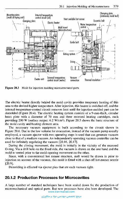
Figure 20.3 Mold for injection molding microstructured parts
The electric heater directly behind the mold cavity provides temporary heating of thisarea to the desired higher temperature. After injection, this heater is switched off, and theinternal temperature-control circuit removes heat until the injection molded part can bedemolded (Figure 20.4). The electric heating system consists of a 9-mm-thick, circularbrass plate with a diameter of 70 mm and three recessed heating cartridges, eachproviding 200 W (surface output: 6.2 W/cm2). Figure 20.5 shows the basic structure ofthe mold cavity and heating element area.
The necessary vacuum equipment is built according to the circuit shown inFigure 20.6. Due to the low volume for evacuation, instead of the vacuum pump usuallyemployed, a vacuum ejector with two operating steps is used that can generate vacuumclose to that of a medium vacuum. An independently operating vacuum controller can beused for infinitely regulating the vacuum [20.16, 20.17].
During the closing movement, the mold is initially in the vicinity of the recessedO-ring. Via a drill hole on the fixed side, the vacuum is drawn on the one hand and themold is vented prior to the mold-opening movement on the other.
Since, with a conventional hot runner structure, melt would be drawn in prior toinjection on account of the vacuum, this mold is fitted with a shut-off hot-runner nozzle[20.9].
Demolding is effected via ejector pins that are each vacuum tight.
20.1.2 Production Processes for Microcavities
A large number of standard techniques have been scaled down for the production ofmicromechanical and optical parts. But new processes have also been developed. The
Mounting plate(mold clamping unit)
Internal temperaturecontrol circuit (oil)
Clamping plate Electric heaterHeat sealable hot runner
Mold insert(Microstructure)
Water temperaturecontrol
Clamping plate(stationary mold half)
Eccentric bolt
Guide bolt
Gating system
O-ring
Ejector unit External temperaturecontrol circuit (water)
Vacuumconnection Thermal insulation
www.iran-mavad.com
مرجع تخصصی مهندسی مواد و متالورژی
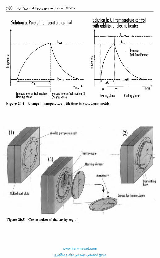
Figure 20.5 Construction of the cavity region
Molded part plate
(3)
Thermocouple
Heating element
Microcavity
,Groove for thermocouple
Dismantlingbolts
Molded part plate insert (2)O)
Figure 20.4 Change in temperature with time in variotherm molds
Temperature control medium 1Heating phase
Temperature control medium 2Cooling phase Heating phase Cooling phase
Time Timetouttin
'Demold - Toemold
Temp
eratur
e
Temp
eratur
e
"!"Goal
'Additional heater
TGOOI
IncreaseAdditional heater
Solution a: Pure oil temperature controlSolution b: Oil temperature control
with additional electric heater
www.iran-mavad.com
مرجع تخصصی مهندسی مواد و متالورژی
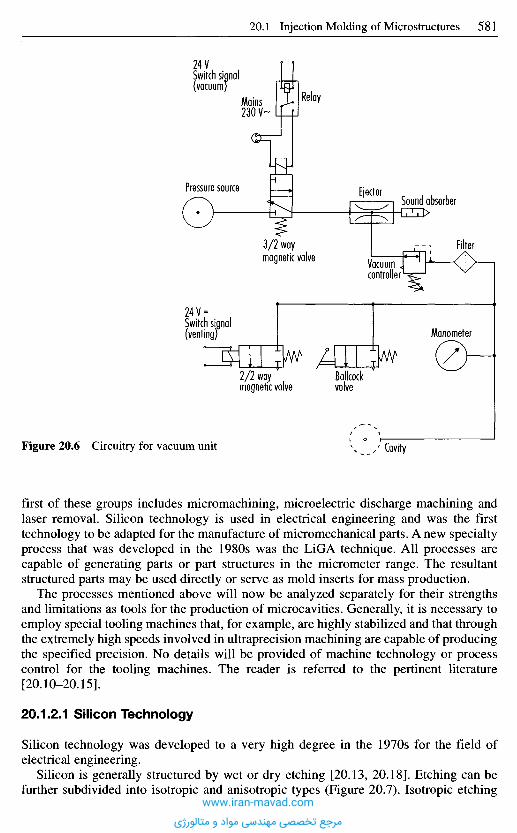
first of these groups includes micromachining, microelectric discharge machining andlaser removal. Silicon technology is used in electrical engineering and was the firsttechnology to be adapted for the manufacture of micromechanical parts. A new specialtyprocess that was developed in the 1980s was the LiGA technique. All processes arecapable of generating parts or part structures in the micrometer range. The resultantstructured parts may be used directly or serve as mold inserts for mass production.
The processes mentioned above will now be analyzed separately for their strengthsand limitations as tools for the production of microcavities. Generally, it is necessary toemploy special tooling machines that, for example, are highly stabilized and that throughthe extremely high speeds involved in ultraprecision machining are capable of producingthe specified precision. No details will be provided of machine technology or processcontrol for the tooling machines. The reader is referred to the pertinent literature[20.10-20.15].
20.1.2.1 Silicon Technology
Silicon technology was developed to a very high degree in the 1970s for the field ofelectrical engineering.
Silicon is generally structured by wet or dry etching [20.13, 20.18]. Etching can befurther subdivided into isotropic and anisotropic types (Figure 20.7). Isotropic etching
Figure 20.6 Circuitry for vacuum unit Cavity
Manometer
Ballcockvalve
2/2 waymagnetic valve
24V =Switch signal(venting)
3/2 waymagnetic valve Vacuum
controller
Filter
EjectorSound absorber
Pressure source
RelayMains230 V'
24 VSwitch signal(vacuum)
www.iran-mavad.com
مرجع تخصصی مهندسی مواد و متالورژی
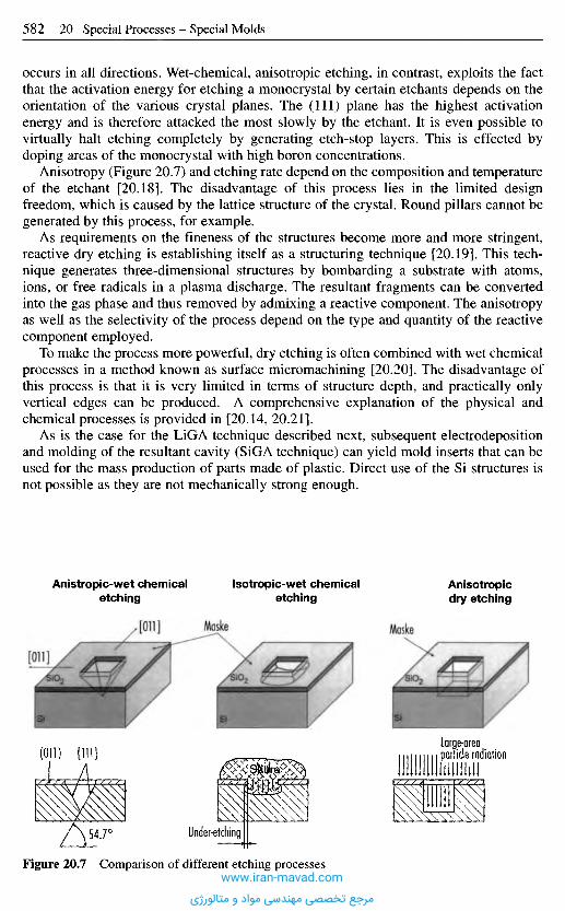
occurs in all directions. Wet-chemical, anisotropic etching, in contrast, exploits the factthat the activation energy for etching a monocrystal by certain etchants depends on theorientation of the various crystal planes. The (111) plane has the highest activationenergy and is therefore attacked the most slowly by the etchant. It is even possible tovirtually halt etching completely by generating etch-stop layers. This is effected bydoping areas of the monocrystal with high boron concentrations.
Anisotropy (Figure 20.7) and etching rate depend on the composition and temperatureof the etchant [20.18]. The disadvantage of this process lies in the limited designfreedom, which is caused by the lattice structure of the crystal. Round pillars cannot begenerated by this process, for example.
As requirements on the fineness of the structures become more and more stringent,reactive dry etching is establishing itself as a structuring technique [20.19]. This tech-nique generates three-dimensional structures by bombarding a substrate with atoms,ions, or free radicals in a plasma discharge. The resultant fragments can be convertedinto the gas phase and thus removed by admixing a reactive component. The anisotropyas well as the selectivity of the process depend on the type and quantity of the reactivecomponent employed.
To make the process more powerful, dry etching is often combined with wet chemicalprocesses in a method known as surface micromachining [20.20]. The disadvantage ofthis process is that it is very limited in terms of structure depth, and practically onlyvertical edges can be produced. A comprehensive explanation of the physical andchemical processes is provided in [20.14, 20.21].
As is the case for the LiGA technique described next, subsequent electrodepositionand molding of the resultant cavity (SiGA technique) can yield mold inserts that can beused for the mass production of parts made of plastic. Direct use of the Si structures isnot possible as they are not mechanically strong enough.
Anistropic-wet chemicaletching
Isotropic-wet chemicaletching
Anisotropicdry etching
MaskeMaske
Figure 20.7 Comparison of different etching processes
Under-etching
Large-areaparticle radiation
www.iran-mavad.com
مرجع تخصصی مهندسی مواد و متالورژی
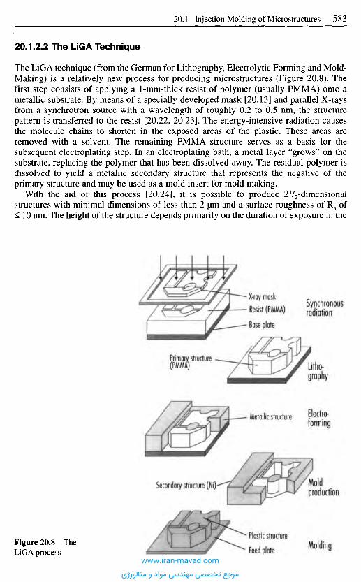
20.1.2.2 The LiGA Technique
The LiGA technique (from the German for Lithography, Electrolytic Forming and Mold-Making) is a relatively new process for producing microstructures (Figure 20.8). Thefirst step consists of applying a 1-mm-thick resist of polymer (usually PMMA) onto ametallic substrate. By means of a specially developed mask [20.13] and parallel X-raysfrom a synchrotron source with a wavelength of roughly 0.2 to 0.5 nm, the structurepattern is transferred to the resist [20.22, 20.23]. The energy-intensive radiation causesthe molecule chains to shorten in the exposed areas of the plastic. These areas areremoved with a solvent. The remaining PMMA structure serves as a basis for thesubsequent electroplating step. In an electroplating bath, a metal layer "grows" on thesubstrate, replacing the polymer that has been dissolved away. The residual polymer isdissolved to yield a metallic secondary structure that represents the negative of theprimary structure and may be used as a mold insert for mold making.
With the aid of this process [20.24], it is possible to produce 2V2-dimensionalstructures with minimal dimensions of less than 2 |im and a surface roughness of Ra of< 10 nm. The height of the structure depends primarily on the duration of exposure in the
• X-ray mask• Resist (PMMA)
• Base plate
Synchronousradiation
Primary structure(PMMAj Litho-
graphy
Metallic structure Electro-forming
Moldproduction
Secondary structure (Ni)
Plastic structure
Feed plate MoldingFigure 20.8 TheLiGA process
www.iran-mavad.com
مرجع تخصصی مهندسی مواد و متالورژی
lithographic step. This step can yield lateral accuracies of 0.2 urn at a structure height of0.5 mm.
The extensively researched steps of lithography and electroplating are not acceptablein terms of costs for large series. For example, the electroplating time for a 1-mm-thicklayer is roughly one week. Only the last step of the LiGA technique, namely molding byreaction casting, vacuum deep-drawing, or polymer injection molding makes massproduction economical [20.26, 20.27].
20.1.2.3 Laser LiGA
Laser LiGA is inexpensive relative to LiGA. It replaces the "lithography by synchrotronradiation" step with the use of an excimer laser. The two steps of "exposure anddevelopment" of the PMMA resist constitute one process stage since the primarystructure can be generated directly with the aid of the laser. However, due to the largerwavelengths of the laser, this technique can only generate smaller aspect ratios (< 10)and larger structures (> 1 um) than those of the LiGA. The surface quality cannot becompared directly with that of the LiGA technique [20.28, 20.29]. Furthermore, abso-lutely parallel side walls cannot be produced, but this, in fact, aids demolding afterinjection molding.
20.1.2.4 Laser Removal
Laser removal in the macrorange of metals is used particularly in the production offorging dies, plastic injection molds, and die cast molds as an alternative to machiningprocesses and electric discharge machining.
A knowledge of the possibilities afforded by microstructuring of metals is crucial formold-making for microstructural injection molding. There are three ways in which thesematerials can be removed by means of a laser:
- Materials such as steel can be evaporated by means of highly energetic laser pulses(Figure 20.9, left). The point of removal is flushed with inert gas to prevent the purgedmaterial from re-condensing on the surface and to retain the original surface quality[20.30-20.32].
- It is also possible to melt the material with a laser and then to blow it away, as basicallyhappens in the case of laser cutting [20.31, 20.32] (see also Section 2.9).
- The laser is used to initiate selective oxidation at the workpiece surface and thus totrigger surface erosion. Oxygen is admitted to effect local combustion, which releasesadditional energy (Figure 20.9, right). If the process parameters are properly set,thermal stresses are induced in the cooling zone, with the result that the oxidizedmaterial detaches itself from the unchanged base material. This process is highlysuitable for mold-making because the attainable surface quality is very high, just as inthe case of electric discharge finishing [20.32, 20.33].
Lasers can be used to process all materials. Radiation sources for laser removal includeCO2 lasers, Nd:YAG lasers and excimer lasers. Table 20.1 summarizes importantinformation about the scope and limits of the various instruments for themicrostructuring of metals.
Detailed information of the physical processes that occur during laser removal iscontained in Herziger [20.38].
www.iran-mavad.com
مرجع تخصصی مهندسی مواد و متالورژی
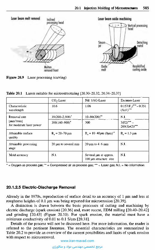
* = Oxygen as process gas; ** = Compressed air as process gas; *** = Laser gas; N.I. = No information
20.1.2.5 Electric-Discharge Removal
Already in the 1970s, reproduction of surface detail to an accuracy of 1 |um and less atroughness heights of 0.1 |im was being reported for microerosion [20.39].
A distinction is drawn between the basic processes of cutting and machining byelectric discharge (spark erosion) [20.36] and, more recent, EDM milling [20.40-20.42]and grinding [20.43] (Figure 20.10). For spark erosion, the material must have aminimum conductivity of 0.01 to 0.1 S/cm [20.31].
Details of the process will not be discussed here. For more information, the reader isreferred to the pertinent literature. The essential characteristics are summarized inTable 20.2 to provide an overview of the current possibilities and limits of spark erosionwith respect to microremoval.
Characteristicwavelength
Removal rate[mm3/min]for moderate laser power
Attainable surfacequality
Attainable processingstage
Mold accuracy
CO2-Laser
10.6
35(200-2,500)*
300(160-800)*
Ra = 20-70 urn
20 urn to several mm
Ni .
Nd: YAG-Laser
1.06
10-80(200)**
300
Ra = lO^Oum (9um)**
20 um to 4-6 mm
Several um at approx.100 um structure size
Excimer-Laser
0.157(F2)***-0.351(XeF)***
N.I.
3(F2)*** -200(XeCl)***
R a= 1.3 um
N.I.
N.I.
Table 20.1 Lasers suitable for mictrostructuring [20.30-20.32, 20.34-20.37]
Figure 20.9 Laser processing (carving)
Moltenremoval front
Oxidemelt
Laser beam melt removal Inclinedprocessing head
Laser beam oxide machining
Vertical processinghead
Detachingmetal
Steamjet
Resolidifiedcooling oxide
20.1 Injection Molding of Microstructures 585
www.iran-mavad.com
مرجع تخصصی مهندسی مواد و متالورژی
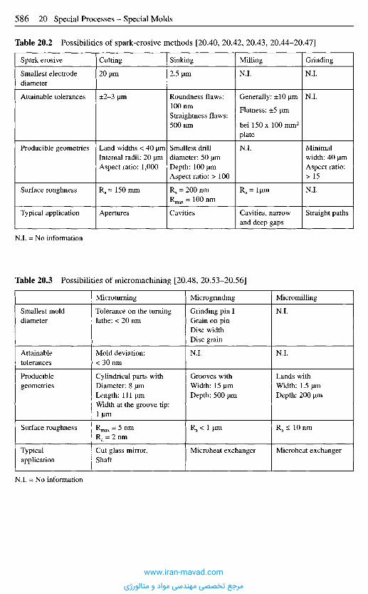
Spark erosive
Smallest electrodediameter
Attainable tolerances
Producible geometries
Surface roughness
Typical application
Cutting
20 urn
±2-3 urn
Land widths < 40 umInternal radii: 20 urnAspect ratio: 1,000
Ra= 150 mm
Apertures
Sinking
2.5 urn
Roundness flaws:100 nmStraightness flaws:500 nm
Smallest drilldiameter: 50 urnDepth: 100 umAspect ratio: > 100
Ra = 200 nmRmax = 100 nm
Cavities
Milling
N.I.
Generally: ±10 um
Flatness: ±5 um
bei 150 x 100 mm2
plate
N.I.
Ra = lum
Cavities, narrowand deep gaps
Grinding
N.I.
N.I.
Minimalwidth: 40 umAspect ratio:> 15
N.I.
Straight paths
Smallest molddiameter
Attainabletolerances
Produciblegeometries
Surface roughness
Typicalapplication
N.I. = No information
Microturning
Tolerance on the turninglathe: < 20 nm
Mold deviation:< 30 nm
Cylindrical parts withDiameter: 8 umLength: 111 umWidth at the groove tip:1 um
Rmax = 5 nmRa = 2 nm
Cut glass mirror,Shaft
Microgrinding
Grinding pin IGrain on pinDisc widthDisc grain
N.I.
Grooves withWidth: 15 umDepth: 500 um
Ra < 1 um
Microheat exchanger
Micromilling
N.I.
N.I.
Lands withWidth: 1.5 umDepth: 200 um
Ra < 10 nm
Microheat exchanger
Table 20.2 Possibilities of spark-erosive methods [20.40, 20.42, 20.43, 20.44-20.47]
N.I. = No information
Table 20.3 Possibilities of micromachining [20.48, 20.53-20.56]
www.iran-mavad.com
مرجع تخصصی مهندسی مواد و متالورژی
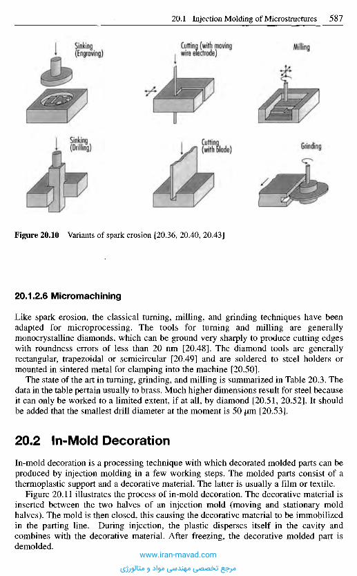
Figure 20.10 Variants of spark erosion [20.36, 20.40, 20.43]
20.1.2.6 Micromachining
Like spark erosion, the classical turning, milling, and grinding techniques have beenadapted for microprocessing. The tools for turning and milling are generallymonocrystalline diamonds, which can be ground very sharply to produce cutting edgeswith roundness errors of less than 20 nm [20.48]. The diamond tools are generallyrectangular, trapezoidal or semicircular [20.49] and are soldered to steel holders ormounted in sintered metal for clamping into the machine [20.50].
The state of the art in turning, grinding, and milling is summarized in Table 20.3. Thedata in the table pertain usually to brass. Much higher dimensions result for steel becauseit can only be worked to a limited extent, if at all, by diamond [20.51, 20.52]. It shouldbe added that the smallest drill diameter at the moment is 50 urn [20.53].
2 0 . 2 I n - M o I d D e c o r a t i o n
In-mold decoration is a processing technique with which decorated molded parts can beproduced by injection molding in a few working steps. The molded parts consist of athermoplastic support and a decorative material. The latter is usually a film or textile.
Figure 20.11 illustrates the process of in-mold decoration. The decorative material isinserted between the two halves of an injection mold (moving and stationary moldhalves). The mold is then closed, this causing the decorative material to be immobilizedin the parting line. During injection, the plastic disperses itself in the cavity andcombines with the decorative material. After freezing, the decorative molded part isdemolded.
Sinking(Engraving)
Cutting (with movingwire electrode)
Milling
Sinkinq(Drilling)
Cuffing(with Blade)
Grinding
www.iran-mavad.com
مرجع تخصصی مهندسی مواد و متالورژی
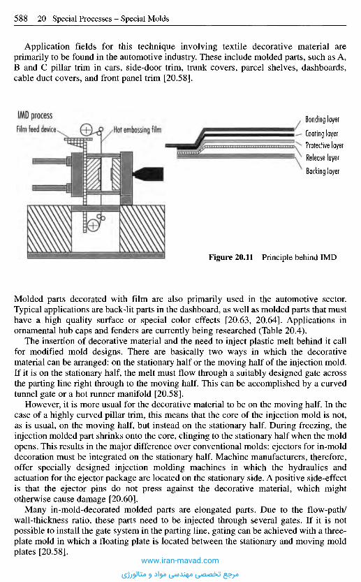
Molded parts decorated with film are also primarily used in the automotive sector.Typical applications are back-lit parts in the dashboard, as well as molded parts that musthave a high quality surface or special color effects [20.63, 20.64]. Applications inornamental hub caps and fenders are currently being researched (Table 20.4).
The insertion of decorative material and the need to inject plastic melt behind it callfor modified mold designs. There are basically two ways in which the decorativematerial can be arranged: on the stationary half or the moving half of the injection mold.If it is on the stationary half, the melt must flow through a suitably designed gate acrossthe parting line right through to the moving half. This can be accomplished by a curvedtunnel gate or a hot runner manifold [20.58].
However, it is more usual for the decorative material to be on the moving half. In thecase of a highly curved pillar trim, this means that the core of the injection mold is not,as is usual, on the moving half, but instead on the stationary half. During freezing, theinjection molded part shrinks onto the core, clinging to the stationary half when the moldopens. This results in the major difference over conventional molds: ejectors for in-molddecoration must be integrated on the stationary half. Machine manufacturers, therefore,offer specially designed injection molding machines in which the hydraulics andactuation for the ejector package are located on the stationary side. A positive side-effectis that the ejector pins do not press against the decorative material, which mightotherwise cause damage [20.60].
Many in-mold-decorated molded parts are elongated parts. Due to the flow-path/wall-thickness ratio, these parts need to be injected through several gates. If it is notpossible to install the gate system in the parting line, gating can be achieved with a three-plate mold in which a floating plate is located between the stationary and moving moldplates [20.58].
Figure 20.11 Principle behind IMD
Bonding layer
Coating layerProtective layerRelease layerBacking layer
Hot embossing filmFilm feed device
IMD process
Application fields for this technique involving textile decorative material areprimarily to be found in the automotive industry. These include molded parts, such as A,B and C pillar trim in cars, side-door trim, trunk covers, parcel shelves, dashboards,cable duct covers, and front panel trim [20.58].
www.iran-mavad.com
مرجع تخصصی مهندسی مواد و متالورژی
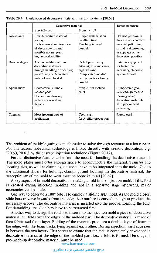
The problem of multiple gating is much easier to solve through recourse to a hot runner.For this reason, hot-runner technology is linked directly with in-mold decoration, e.g.[20.60, 20.61] by the cascade injection technique (Figure 20.12).
Further distinctive features arise from the need for handling the decorative material.The mold plates must offer enough space to accommodate the material. Transfer andlocating aids, as well as clamping elements, have to be integrated into the mold. Due tothe additional sliders for holding, clamping, and locating the decorative material, thesusceptibility of the mold to wear must be borne in mind [20.62].
A key aspect of in-mold decoration is making a fold in the injection mold. If this foldis created during injection molding and not in a separate stage afterward, majoreconomies can be made.
One way to generate a 180° fold is to employ a sliding split mold. As the mold closes,slide bars traverse inwards from the side; their surface is curved enough to produce thenecessary groove. The decorative material is inserted into the groove, forming the fold.For demolding, the slide bars have to be retracted first.
Another way to design the fold is to insert into the injection mold a piece of decorativematerial that folds over the edges of the molded part. The decorative material is made offace fabric and foam layer. Folding of the material produces a double layer of foam atthe edge, with the foam backs lying against each other. During injection, melt squeezesin between the two layers. This serves to ensure that the melt is completely enveloped indecorative material at the edge of the molded part, i.e., a fold is formed. Here, again,pre-made-up decorative material must be used.
Table 20.4 Evaluation of decorative material insertion systems [20.59]
Advantages
Disadvantages
Applications
Comment
Decorative material
Specially cut
Low decorative materialwastageParts removal and insertionof decorative materialpossible in one pass;high reproducibility
Accommodation of thindecorative materialsthrough handling difficulties;prestressing of decorativematerial complicated
Geometrically simplemolded partsDecorations showingpatterns or revealingthreads
Most frequent type ofapplication
From the roll
Simple system, shorthandling timePunching in moldpossible
Partial prestressingdifficult; in some cases,high wastageComplicated moldedpart geometries barelypossible
Simple, flat moldedparts
Used, e.g.,for A-pillar production
Tenter technique
Defined position inthe case of decorativematerial patterning,partial pretensioningor slippage of thedecoration possible
External equipmentfor tenter feednecessary, elaboratesystem overall
Complicated geo-metries/high thermo-forming ratio;decoration materialswith pronouncedpatterning
Rarely used
www.iran-mavad.com
مرجع تخصصی مهندسی مواد و متالورژی
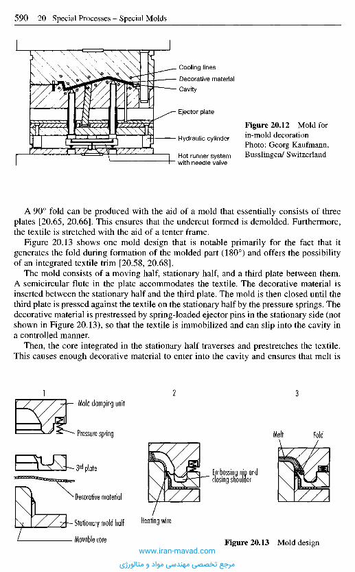
A 90° fold can be produced with the aid of a mold that essentially consists of threeplates [20.65, 20.66]. This ensures that the undercut formed is demolded. Furthermore,the textile is stretched with the aid of a tenter frame.
Figure 20.13 shows one mold design that is notable primarily for the fact that itgenerates the fold during formation of the molded part (180°) and offers the possibilityof an integrated textile trim [20.58, 20.68].
The mold consists of a moving half, stationary half, and a third plate between them.A semicircular flute in the plate accommodates the textile. The decorative material isinserted between the stationary half and the third plate. The mold is then closed until thethird plate is pressed against the textile on the stationary half by the pressure springs. Thedecorative material is prestressed by spring-loaded ejector pins in the stationary side (notshown in Figure 20.13), so that the textile is immobilized and can slip into the cavity ina controlled manner.
Then, the core integrated in the stationary half traverses and prestretches the textile.This causes enough decorative material to enter into the cavity and ensures that melt is
Figure 20.12 Mold forin-mold decorationPhoto: Georg Kaufmann,Busslingen/ Switzerland
Cooling linesDecorative materialCavity
Ejector plate
Hydraulic cylinder
Hot runner systemwith needle valve
Mold clamping unit
Pressure spring
3rd plate
Decorative material
Stationary mold half
Movable core
1 2 3
Embossing nip andclosing shoulder
Heating wire
Figure 20.13 Mold design
Melt Fold
www.iran-mavad.com
مرجع تخصصی مهندسی مواد و متالورژی
not injected through it. When the core retracts, the mold closes further. The provision ofvertical flash faces allows both conventional injection molding and injection com-pression molding to be employed. Injection compression molding also allows sensitivedecorative material to be processed.
2 0 . 3 P r o c e s s i n g o f L i q u i d S i l i c o n e
Liquid silicone rubbers (LSRs) differ considerably from conventionally crosslinkingelastomers in terms of processing and material properties. The raw material is a low-viscosity, two-pack system that is supplied in 20-liter and 200-liter containers by themanufacturer [20.69] The two components have to be mixed before the system becomesreactive, and addition-crosslink under the influence of heat without releasing by-products. The crosslinking rates of 3-7 mm/s wall thickness are much higher than thoseof conventional elastomers [20.70-20.73]. The material is processed in injectionmolding machines fitted with extra equipment for conveying the raw components.Because the material, which is kept at 20-40 0C in the plastifying section, swellsextensively in heated molds at up to 240 0C, it is necessary to underfill the mold so as toavoid flash formation.
The low viscosity during the filling process and the extremely high crosslinking ratesimpose stringent demands on the mold design. Thus, fully automatic, machining-freeproduction of LSR molded parts requires greater precision in mold making. If, duringthermoplastic processing, gap widths of 0.01 to 0.02 mm are sufficient for avoiding flashformation, the tolerable gap widths of LSR molds range from less than 0.005 to 0.01 mm[20.74-20.75]. To maintain the narrow tolerances, after every operation, the mold plateshave to be stress-free annealed and, after hardening, freed of residual stresses byrepeated normalizing [20.76]. Due to the high mold temperatures, high-temperature,hardenable steels are used for mold plates and inserts. [20.77-20.80].
To avoid flash formation, LSR molds are made to be very rigid despite the relativelylow cavity pressures of 20 MPa max. The aim is to keep the design as simple as possibleand to more or less eliminate slide bars and split molds due to the problems with sealingthem. The critical mold areas for mechanical design are in the vicinity of the locatingring aperture on the stationary half and in the vicinity of the ejector system on themoving half. Dimensioning of the mold-plate thickness is based on that of thermo-plastics molds. The high cavity pressures occurring during thermoplastics processing arecompensated by the lower gap tolerances in LSR molds [20.73].
20.3.1 Evacuation
Because LSR crosslinks so quickly, high injection speeds are necessary, especially formolds with high flow-path / wall-thickness ratio, in order that flow errors due to materialstarting to crosslink during mold filling may be avoided. However, high injection speedsreadily cause air pockets in the flow front. For this reason, and to prevent residual airbeing trapped, if the mold does not part close to the end of the flow path, the cavitieshave to be evacuated to 200-800 mbar. Evacuation takes place on the machine via a so-called intermediate stop program (also known as embossing or venting program) [20.77,20.81]. It is carried out during the closing process by closing the mold halves initially towithin a few tenths of a millimeter. Special seals recessed in the mold parting line bridge
www.iran-mavad.com
مرجع تخصصی مهندسی مواد و متالورژی
the gap and seal off the resultant mold cavity against the environment. Then the cavitiesand gates are evacuated via a drill hole in the parting plane. Only after evacuation iscomplete does the clamping mechanism of the injection molding machine build up themaximum locking force and the injection process is started.
20.3.2 Gate
The cavities are usually gated with a pin-point gate (0.1-0.8 mm diameter) or film gate(0.08-0.12 mm film thickness) unless sprueless injection is performed (see Cold RunnerTechnique). To improve the economics of injection molding, the predominantly smallLSR molded parts (part weight frequently less than 10 g), multicavity molds containingfrom 4 to 16 cavities (up to 128 for very small parts) are used. Natural, symmetricalbalancing is preferred for multiple gating, so as to avoid different degrees of fill duringpartial filling. Even minor differences in degree of fill can lead to underfilled parts orflash formation [20.73].
20.3.3 Demolding
Fully automatic demolding is hampered by the adhesive, rubber-elastic properties ofLSR. For this reason, usually several demolding systems within the mold are required,which demold the part stepwise. In some cases, external devices are used, such asbrushes and grippers [20.77, 20.82, 20.83]. Demolding systems inside the mold may beof the passive or active types. The passive type include selective setting of the roughnessof the cavity surface to exploit the adhesion of the LSR material for positioning themolded part on the desired mold half. Greater roughness, as generated by etching,sandblasting or eroding, lowers the adhesion while lower roughness increases it [20.76,20.77, 20.84]. It must be remembered that the molded parts tend to cling to the cavityand not to the core, due to the thermal expansion.
Common active demolding devices are mold wipers and mushroom ejectors withcompressed air support. The valve-like mushroom ejectors are raised by compressed air(see Figure 12.47). Air fed between the molded part and cavity surface detaches the partfrom the wall and forces it out of the cavity. The current of air, however, causes highlyconvective heat release and, in certain circumstances, may lead to unpermissibleinterference with the temperature homogeneity of the mold. Conventional, cylindricalejector pins are only used for composite parts if the force can be introduced via a rigidinsert [20.73].
20.3.4 Temperature Control
A heating capacity of roughly 50 W/kg mold weight is needed for achieving a uniformtemperature field at high mold-operating temperatures. Strip heaters and conicalcartridge heaters are preferred as they, unlike cylindrical cartridges, have a heat transferindependent of the drill hole tolerance [20.77]. This has a positive effect on thehomogeneity of the heat introduction and the cartridge life time. To reduce heat releaseto the mold platens and the surrounding air, the cavity platens need to be insulated withepoxy resin platens.
www.iran-mavad.com
مرجع تخصصی مهندسی مواد و متالورژی

20.3.5 Cold-Runner Technique
Due to high raw material costs and elaborate gate separation, the use of cold runners inLSR processing is state of the art and highly advanced [20.85]. Aside from open cold-runner systems with reduced sprue waste, mainly cold runners with needle valves fordirect gating are used, with the result that production can be sprueless and hence totallyfree of sprue waste. Cold-runner systems are either mold-dependent or machine-dependent. Machine-dependent systems with up to 8 individual nozzles serve asstandardized heads, instead of the shut-off nozzle; they are mounted on the plasticatingunit and protrude into the mold [20.86]. The advantages lie in the possibility of multipleuse for different molds and the attendant lower costs and in easy changes in the event ofdisruptions. Figure 20.14 shows a cold-runner adapter specially developed for LSRmolds that is mounted on the machine nozzle [20.87]. It protrudes with its sprues downas far as the cavities to inject into these direct.
2 0 . 4 I n j e c t i o n - C o m p r e s s i o n M o l d i n g
The injection-compression molding process can be roughly divided into two steps,namely injection and compression (Figure 20.15). During the injection phase, a preciselymetered amount of plastic melt is injected into the mold, which has been opened by acompression nip. Since at this point the volume of the cavity is greater than the volumeof the molded part later, the injected melt forms a cake. In the compression phase, thiscake is forced into the cavity by the closing moving mold half and is shaped. Thispresupposes, however, that the sprue is closed at the start of the compression phase in
Figure 20.14 4-fold cold runner head for permanent mounting on the plasticating unit [20.85]
5 Connection to temperature control6 Hydraulic connection for needle shut-off valve system7 Coupling8 Adapter for machine nozzle
1 Needle shut-off valve2 Throttle3 Exchangeable insert for nozzle4 Centering cone
8
7
6
5
3
2
4
1
www.iran-mavad.com
مرجع تخصصی مهندسی مواد و متالورژی
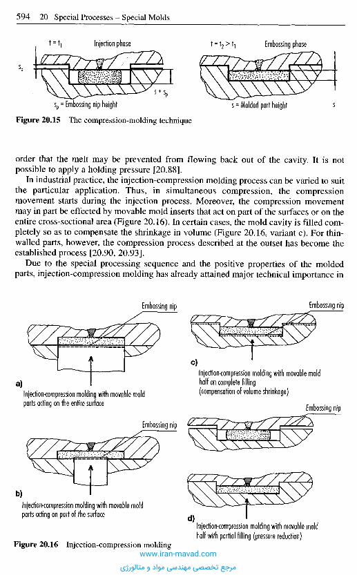
Figure 20.15 The compression-molding technique
order that the melt may be prevented from flowing back out of the cavity. It is notpossible to apply a holding pressure [20.88].
In industrial practice, the injection-compression molding process can be varied to suitthe particular application. Thus, in simultaneous compression, the compressionmovement starts during the injection process. Moreover, the compression movementmay in part be effected by movable mold inserts that act on part of the surfaces or on theentire cross-sectional area (Figure 20.16). In certain cases, the mold cavity is filled com-pletely so as to compensate the shrinkage in volume (Figure 20.16, variant c). For thin-walled parts, however, the compression process described at the outset has become theestablished process [20.90, 20.93].
Due to the special processing sequence and the positive properties of the moldedparts, injection-compression molding has already attained major technical importance in
Injection phase Embossing phase
s = Molded part heightsp = Embossing nip height
Embossing nip Embossing nip
Injection-compression molding with movable moldhalf on complete filling(compensation of volume shrinkage)
c)
Injection-compression molding with movable moldparts acting on the entire surface
a)
Embossing nip
Embossing nip
Injection-compression molding with movable moldparts acting on part of the surface
Injection-compression molding with movable moldhalf with partial filling (pressure reduction)
d)
b)
Figure 20.16 Injection-compression moldingwww.iran-mavad.com
مرجع تخصصی مهندسی مواد و متالورژی
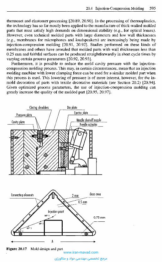
thermoset and elastomer processing [20.89, 20.90]. In the processing of thermoplastics,the technology has so far mostly been applied to the manufacture of thick-walled moldedparts that must satisfy high demands on dimensional stability (e.g., for optical lenses).However, even technical molded parts with large diameters and low wall thicknesses(e.g., membranes for microphones and loudspeakers) are increasingly being made byinjection-compression molding [20.91, 20.92]. Studies performed on these kinds ofmembranes and others have revealed that molded parts with wall thicknesses less than0.25 mm and faithful surfaces can be produced straightforwardly in short cycle times byvarying certain process parameters [20.92, 20.93].
Furthermore, it is possible to reduce the mold cavity pressure with the injection-compression molding process. This may, in certain circumstances, mean that an injectionmolding machine with lower clamping force can be used for a similar molded part whenthis process is used. This lowering of pressure is of more interest, however, for the in-mold decoration of parts with textile decorative materials (see Section 20.2) [20.94].Given optimized process parameters, the use of injection-compression molding cangreatly increase the quality of the molded part [20.95, 20.97].
Figure 20.17 Mold design and part
Connecting elements Base area
Injection point
A
Die plateEjector plate
Needle shut-off nozzleNeedle actuator
Closing shoulders
Pressure plate
Cavity plate
www.iran-mavad.com
مرجع تخصصی مهندسی مواد و متالورژی
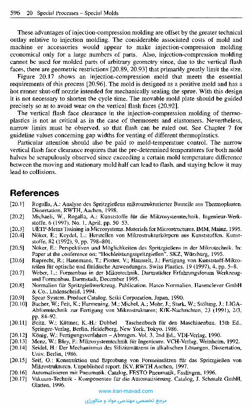
These advantages of injection-compression molding are offset by the greater technicaloutlay relative to injection molding. The considerable associated costs of mold andmachine or accessories would appear to make injection-compression moldingeconomical only for a large numbers of parts. Also, injection-compression moldingcannot be used for molded parts of arbitrary geometry since, due to the vertical flashfaces, there are geometric restrictions [20.89, 20.93] that primarily greatly limit the size.
Figure 20.17 shows an injection-compression mold that meets the essentialrequirements of this process [20.96]. The mold is designed as a positive mold and has ahot runner shut-off nozzle intended for mechanically sealing the sprue. With this designit is not necessary to shorten the cycle time. The movable mold plate should be guidedprecisely so as to avoid wear on the vertical flash faces [20.92].
The vertical flash face clearance in the injection-compression molding of thermo-plastics is not as critical as in the case of thermosets and elastomers. Nevertheless,narrow limits must be observed, so that flash can be ruled out. See Chapter 7 forguideline values concerning gap widths for venting of different thermoplastics.
Particular attention should also be paid to mold-temperature control. The narrowvertical flash face clearance requires that the pre-determined temperatures for both moldhalves be scrupulously observed since exceeding a certain mold temperature differencebetween the moving and stationary mold half can lead to flash, and staying below it maylead to collisions.
R e f e r e n c e s
[20.1] Rogalla, A.: Analyse des SpritzgieBens mikrostrukturierter Bauteile aus Thermoplasten.Dissertation, RWTH, Aachen, 1998.
[20.2] Michaeli, W., Rogalla, A.: Kunststoffe fur die Mikrosystemtechnik. Ingenieur-Werk-stoffe, 6 (1997), No. 1, April, pp. 50-53.
[20.3] UETP-Mems Training in Microsystems. Materials for Microstructures, IMM, Mainz, 1995.[20.4] Noker, E.; Key del, L.: Herstellen von Mikrostrukturkorpern aus Kunststoffen. Kunst-
stoffe, 82 (1992), 9, pp. 798-801.[20.5] Noker, E.: Perspektiven und Moglichkeiten des SpritzgieBens in der Mikrotechnik. In:
Paper at the conference on: "HochleistungsspritzgieBen". SKZ, Wiirzburg, 1995.[20.6] Ruprecht, R.; Hanemann, T; Piotter, V.; Hausselt, J.: Fertigung von Kunststoff-Mikro-
teilen fur optische und fluidische Anwendungen. Swiss Plastics, 19 (1997), 4, pp. 5-8.[20.7] Weber, L.: Formenbau in der Mikrotechnik. Darmstadter Erfahrungsforum Werkzeug-
und Formenbau, Darmstadt, December 1995.[20.8] Normalien fur SpritzgieBwerkzeug. Publication. Hasco Normalien, Hasenclever GmbH
& Co., Liidenscheid, 1994.[20.9] Spear System. Product Catalog. Seiki Corporation, Japan, 1990.[20.10] Bacher, W; Feit, K.; Harmening, M.; Michel, A.; Mohr, J.; Stark, W; Stolting, J.: LIGA-
Abformtechnik zur Fertigung von Mikrostrukturen; KfK-Nachrichten, 23 (1991), 2/3,pp. 84-92.
[20.11] Beitz, W; Kiittner, K.-H.: Dubbel - Taschenbuch fiir den Maschinenbau. 15th Ed.,Springer-Verlag, Berlin, Heidelberg, New York, Tokyo, 1986.
[20.12] Konig, W: Fertigungsverfahren - Abtragen. Vol. 3. 2nd Ed., VDI-Verlag, 1990.[20.13] Menz, W.; Bley, R: Mikrosystemtechnik fiir Ingenieure. VCH-Verlag, Weinheim, 1992.[20.14] Seidel, H.: Der Mechanismus des Siliziumatzens in alkalischen Losungen. Dissertation,
Univ. Berlin, 1986.[20.15] Seif, O.: Konstruktion und Erprobung von Formeinsatzen fiir das SpritzgieBen von
Mikrostrukturen. Unpublished report. IKV, RWTH Aachen, 1997.[20.16] Automatisieren mit Pneumatik. Catalog, FESTO Pneumatik, Esslingen, 1996.[20.17] Vakuum-Technik - Komponenten fiir die Automatisierung. Catalog, J. Schmalz GmbH,
Glatten, 1996.www.iran-mavad.com
مرجع تخصصی مهندسی مواد و متالورژی
[20.18] Biittgenbach, S.: Mikromechanik - Einfiihrung in Technologie und Anwendungen. B.G.Teubner-Verlag, Stuttgart, 1991.
[20.19] Liebel, G.: Ionenstrahlatzen. Feinwerktechnik & Mefitechnik, 95 (1987), pp. 436-441.[20.20] Kowanz, B.; Ehrfeld, W.: Systemtechnische Analyse und Entwicklung eines Ventils in
LIGA-Tech. Report No. 4886, KfK, Karlsruhe, 1991.[20.21] Seidel, H.: NaBchernisches Tiefertatzen. In: Mikromechanik. Heuberger (ed.),
A. Springer-Verlag, Berlin, 1989.[20.22] Becker, E.; Ehrfeld, W.: Das LIGA-Verfahren. Phys. BL, 44 (1988), 6, pp. 166-170.[20.23] Menz, W.: Die Mikrosysterntechnik und ihre Anwendungen. In: Spektrum der
Wissenschaften, Dossier, 4: Mikrosysterntechnik, 1996.[20.24] Becker, E. W.; Ehrfeld, W.; Munchmeyer, D.; Betz, H.; Heuberger, A.; Pongartz, S.;
Glashaziser, W.; Michel, H. J. V.; Siemens, R.: Production of Separation - NozzleSystems for Uranium. Enrichment by a Combination of X-Ray Lithography andGalvanoplastics. Naturwissenschaften, 69 (1982), pp. 520-523.
[20.25] Ehrfeld, W.; Lehr, H.: LIGA-Method - Deep. X-Ray Lithography for the Production ofThree-Dimensional Microstructures from Metals, Polymers and Ceramies RadiationPhysics and Chemistry Pergamon Press, 45 (1995), 3, pp. 349-365.
[20.26] Gotz, W.: "Mikrostrukturtechnik". In: Industrieanzeiger, 1992.[20.27] Rogner, A.; Eicher, J.; Peters, R.-R; Mohr, J.: The LiGA-Technique - what are the new
opportunities. Reprint: MME '92, Micromechanics Europe 1992, 3rd Workshop anMicromachining, Micromechanics and Microsystems, Leuven, Belgien, 01./02.06.1992.
[20.28] Arnold, J.; Dasbach, U.; Ehrfeld, W.; Hesch, K.; Lowe, H.: Combination of ExcimerLaser Micromachining and Replication Processes Suited for Large Scale Production("LaserLiGA"). Lecture. EMRD Spring Meeting, Strasbourg, France, May 23-27, 1994.
[20.29] Arnold, J., Ehrfeld, W.; Hesch, K.; Mobius, H.: Kostengiinstige Serienfertigung vonMikrobauteilen durch "Laser-LIGA". F&M, 103 (1995), 1-2, pp. 48-49.
[20.30] Brinkmann, U.; Basting, D.; Endert, H.; Pippert, K.: Licht in der Mikrofertigung Waruman Excimer-Lasern kein Weg vorbeifiihrt. F&M, 103 (1995), 6, pp. 304-308.
[20.31] Westkamper, E.; Freytag, J.: Slab im Vorteil - Laserstrahlabtragen: Leistung gesteigert.Industrie Anzeiger, 35/1992, pp. 64-66.
[20.32] Witjes, G.; Hildebrand, P.; Kuhl, M.; Wrba, P.: Der direkte Weg - Laserabtragen imWerkzeug- und Formenbau rechnet sich. Form + Werkzeug, March 1996, pp. 32-35.
[20.33] Eberl, G.; Hildebrand, P.; Kuhl, M.; Sutor, U.; Wrba, P.: Neue Entwicklungen beimLaserabtragen Laser und Optoelektronik, (1992) 4, pp. AA-A9.
[20.34] Eversheim, W.; Klocke, R; Pfeifer, T.; Week, M.: Herstellen von Mikrobauteilen.In: Aachener Werkzeugmaschinen-Kolloquium '96; Wettbewerbsfaktor Produktions-technik - Aachener. Perspektiven, VDI-Verlag, Diisseldorf, 1996, pp. 4-194.
[20.35] Jiang, C. E.; Lau, W. S.; Yue, T. M.; Chiang, L.: On the Maximum Depth and Profile ofCut in Pulsed Nd:YAG-Laser Machining, Analysis of the CIRR Vol. 42, 1993, 1,pp. 223-226.
[20.36] Konig, W.: Fertigungsverfahren. Vol. 3: Abtragen. 2nd Ed., VDI-Verlag, 1990.[20.37] Pfeufer, V: Prazise Lichtblitze - Mikrobearbeitung mit Excimerlaser. F&M, 104 (1996),
7-8, pp. 532-536.[20.38] Herziger G.; Wester R.; Petring, D.: Abtragen mit Laserstrahlung Laser und Opto-
elektronik, No. 4, 1991, pp. 64-69.[20.39] Genath, J.: Die Mikrofunkenerosion erzielt hohe Genauigkeiten. VDI-Nachrichten,
No. 6, 7.2.1973.[20.40] Bahle, W.: In den richtigen Bahnen - Elektroerosives Frasen erweitert die Erodier-
technik. Form und Werkzeug, May 1995, pp. 37-38.[20.41] Baileys, R: Steigende Bedeutung - EDM-Frasen. Schweizer Maschinenmarkt. SMM,
No. 19, 1995, pp. 36-37.[20.42] Maag, J.: Formenwerkzeuge mit Funken frasen. Industrieanzeiger, 41/1995, pp. 44-46.[20.43] Wolf, A.; Ehrfeld, W.; Lehr, H.; Michel, E.; Richter, T.; Gruber, H.; Worz, O.: Mikro-
reaktorfertigung mittels Funkenerosion - Funkenerosives, Strukturierungsverfahren furmikrofluidische Systeme. F&M, 105 (1997), 6, pp. 436-439.
[20.44] Li, H.; Masaki, T.: Micro-EDM; Society of Manufacturing Engineers SME, TechnicalPaper No. MS91-485, Grand Rapids, Michigan, USA, 1991.
www.iran-mavad.com
مرجع تخصصی مهندسی مواد و متالورژی

[20.45] Heinzelmann, E.: Funkenerosion: Neue Qualitat dank Mikrotechnik; TechnischeRundschau TR, No. 48, 1995, pp. 24-27.
[20.46] Masuzawa, T.; Fujino, M.: A Process for Manufacturing Very Fine Pin Tools. Society ofManufacturing Engineers. SME, Technical Paper No. MS90-307, Chicago, USA, 1990.
[20.47] Masuzawa, T.; Kuo, C-L.; Fujino, M.: A Combined Electrical Machining Process forMicronozzle Fabrication. Annals of CIRP. Vol. 43 (1994), 1, pp. 189-192.
[20.48] Obata, K.; Oka, K.; Chujo, T.: Development of Ultra Cutting Tool. Society ofManufacturing Engineers. SME, Conference: Superabrasives '91, Chicago, Illinois,USA, June 11-13, 1991, Paper-No. MR 91-194, pp. 12-38.
[20.49] Schubert, K.; Bier, W.; Linder, G.; Seidel, D.: Profilierte Mikrodiamanten fur die Her-stellung von Mikrostrukturen. Industrie Diamanten Rundschau. IDR, 23 (1989), No. 4.
[20.50] Klocke, E; Koch, K.-E; Zamel, S.: Technologie des Hoch- und Ultraprazisionsdrehens.Zeitschrift fur wirtschaftlichen Fabrikbetrieb, 90 (1995), 5, pp. 217-221.
[20.51] Moriwaki, T.; Shamoto, E.: Ultraprecision Diamont Turning of Stainless Steel byApplying Vibration Annals of CIRP. Vol. 49 (1991), 1, pp. 559-562.
[20.52] Week, M.; Bispink, T.: Drehmaschinen zur Herstellung hochpraziser Bauteile:Ubertragung der Erkenntnisse aus der Ultraprazisionstechnik auf die Stahlfeinst-bearbeitung; Symposium report, TH, Darmstadt 1991.
[20.53] Westkamper, E.; Hoffmeister, H.-W.; Gabler, J.: Spanende Mikrofertigung - Flexibilitydurch Schleifen, Bohren und Frasen F&M, 104 (1996), 7-8, pp. 525-530.
[20.54] Tonshoff, H.; v. Schmieden, W.; Insaki, L.; Konig, W.; Spur, G.: Abrasive Machining ofSilicon Manufacturing Technology - CIRP, Annals. Vol. 39 (1990), 2, pp. 621-635.
[20.55] Week, M.; Wieners, A.: Maschinen fiir die Hoch- und Ultraprazision. TECHNICA, 1995,13/14, pp. 14-19.
[20.56] Week, M.; Vos, M.: Gedrehte und gefraste Mikrostrukturen VDI-Z (1995), No. 7/8,pp. 33-35.
[20.57] Witjes, G.; Hildebrand, E.; Kuhl, M.; Wrba, P.: Der direkte Weg - Laserabtragen imWerkzeug- und Formenbau rechnet sich. Form + Werkzeug, March 1996, pp. 32-35.
[20.58] Galuschka, S.: Hinterspritztechnik - Herstellung von textil-kaschierten SpritzguBteilen.Dissertation, RWTH, Aachen, 1994.
[20.59] Barkle, E.; Rehm, G.; Eyerer, P.: Hinterspritzen und Hinterpressen. Kunststoffe, 86(1996), 3, pp. 298-304.
[20.60] Jaeger, A.; Fischbach, G.: Maschinentechnik und ProzeBfiihrung zum Dekorhinter-spritzen. Kunststoffe, 81 (1991), 10, pp. 869-875.
[20.61] Biirkle, E.: Hinterspritzen und Hinterpressen von Textilien beider Innenausstattung vonAutomobilen. In: Textilien im Automobil. Reprint of Conference. VDI-GesellschaftTextil und Bekleidung, Diisseldorf, 1992, pp. 37-57.
[20.62] Biirkle, E.: Hinterpressen und Hinterpragen - eine neue Oberflachentechnik. In:Innovative SpritzgieBtechnologien - ein Beitrag zur Konjunkturbelebung, Wurzburg,December 1-2, 1993, pp. 7-28.
[20.63] Manz, B.: SpritzgieBteile mit farbigem Oberflachendekor. Kunststoffe, 85 (1995),pp. 1346-1350.
[20.64] Wank, J.: SpritzgieBteile mit Oberflachen-Dekor: Vergleich der Verfahren. Plastver-arbeiter, 44 (1993), 7, pp. 70-76.
[20.65] Zwei getrennte Fertigungsschritte in einem: Textilmelttechnologie. Plastverarbeiter, 44(1993), 7, pp. 80-82.
[20.66] SpritzgieBform. Offenlegungsschrift. DE 4033297.[20.67] Verfahren zum Herstellen von kaschierten Kunststoffformteilen. Publication, DE
4114289 C2.[20.68] Becker, H.-G.: Konstruktion eines Versuchwerkzeuges fiir die Hinterspritztechnik.
Unpublished report, IKV, Aachen, 1992.[20.69] Bayer Silicone Silopren LSR. Daten - Fakten - Ratschlage zur Verarbeitung. Technical
Information, Bayer AG, Leverkusen, 1995.[20.70] Batch, G. L.; Macosko, C. W: Reaction kinetics and injection molding of liquid silicone
rubber. In: Rubber Chemistry and Technology, 64 (1991), 2, pp. 218-233.[20.71] Pradl, E: Fliissigsilikonkautschuk - Charakteristik, Verarbeitung und Anwendung.
In: Kautschuk + Gummi. Kunststoffe, 38 (1985), 8. pp. 408-409.
www.iran-mavad.com
مرجع تخصصی مهندسی مواد و متالورژی
[20.72] Steinberger, H.: Fliissiger Siliconkautschuk - eine Alternative zu festem Silikon-kautschuk. In: Paper given at the Conference: Silikonelastomere, SKZ; Wurzburg, 1993.
[20.73] Walde, H.: Beitrag zum vollautomatischen SpritzgieBen von Fliissigsilikonkautschuk.Dissertation, RWTH, Aachen, 1996.
[20.74] In der Dichtung liegt Wahrheit - PrazisionspritzgieBmaschinen verarbeiten Fliissig-silikon. In: KPZ (1991), 12, pp. 26-27.
[20.75] Elastosil, LR: Eigenschaften, Verarbeitung, Typen, Hilfsmittel und spezielleInformationen. Technical Information. Wacker Chemie GmbH, Munich, 1990.
[20.76] SpritzguBverarbeitung von Fliissigsilikonkautschuk. Technical Information. WackerChemie GmbH, Munich, 1991.
[20.77] Steinbichler, G.: SpritzgieBen von Fliissigsilikonkautschuk. In: Kunststoffe, 77 (1987),10, pp. 931-935.
[20.78] Huber, A.: Fliissigsilikonverarbeitung - Verfahrenstechnik oder Maschinentechnik - woliegt die Problematik? In: Paper given at the Conference on: "Verarbeitung von fliissigenSilikonkautschuken" im SpritzgieBverfahren, SKZ, Wurzburg, 1984.
[20.79] Engel-LIM-Verfahren. Technical Information. Engel GmbH, Schwertberg, 1990.[20.80] Steinbiehler, G.: Rationelleres SpritzgieBen von Flussigsilikon. In: Maschinenmarkt, 91
(1985), 77, pp. 1508-1511.[20.81] SpritzgieBmaschinen der Baureihe CI/C2. Technical Information. Krauss-Maffei
Kunststofftechnik GmbH, Munich.[20.82] Kaltkanalwerkzeuge fiir Babysauger aus LSR. Technical Information. Emde Industrie-
technik GmbH, Nassau, 1993.[20.83] Burstvorrichtungen fiir SpritzgieBmaschinen. In: KPZ, (1991), 3, p. 15.[20.84] Schray, J. G.: Vergleiche bei der Verarbeitung fester und fliissiger Silikonkautschuke im
SpritzgieBverfahren. In: Paper given at the Conference on: "Fester und fliissigerSilikonkautschuk", SKZ, Wurzburg, 1991.
[20.85] Masberg, U.: Die Kaltkanaltechnik in der Eiastomerverarbeitung. In: Kautschuk +Gummi. Kunststoffe, 43 (1990), 9, pp. 810-816.
[20.86] Kaltkanalsysteme, standardisiert. Technical Information. EOC Normalien GmbH & Co.KG, Liidenscheid, 1996.
[20.87] Emmerichs, H.; Giesler, D.: AnguBsysteme fiir die LSR-Verarbeitung. In: Kunststoffe, 86(1996), 11, pp. 1678-1680.
[20.88] Jiirgens, W.: Untersuchungen zur Verbesserung der Formteilqualitat beim SpritzgieBenteilkristalliner und amorpher Kunststoffe. Dissertation, RWTH, Aachen, 1968.
[20.89] Keller, W.: Vorteile in Marktnischen, SpritzgieBen-Ubersicht iiber die gangigenSpezialverfahren. Kunststoffe, Synthetics, 9/95, pp. 32-42.
[20.90] Knappe, W; Lampl, A.: Zum optimalen Zyklusverlauf beim Spritzpragen von Thermo-plasten. Kunststoffe, 74 (1984), 2, pp. 79-83.
[20.91] Friesenbichler, W.; Ebster, M.; Langecker, G.: Spritzpragewerkzeuge fiir diinnwandigeFormteile richtig auslegen. Kunststoffe, 83 (1993), 6, pp. 445-448.
[20.92] Gissing, K.: Spritzpragen von diinnwandigen technischen Formteilen aus Thermoplasten.In: Neue Werkstoffe und Verfahren beim SpritzgieBen. Paper given at the Conference:VDI Gesellschaft Kunststofftechnik, Diisseldorf, 1990, pp. 119-131.
[20.93] Friedrichs, B.; Friesenbichler, W.; Gissing, K.: Spritzpragen diinnwandigerthermoplastischer Formteile. Kunststoffe, 80 (1990), 5, pp. 583-587.
[20.94] Galuschka, S.: Hinterspritztechnik - Herstellung von textil-kaschierten SpritzguBteilen.Dissertation. RWTH, Aachen, 1994.
[20.95] Michaeli, W.; Brockmann, C: Injection Compression Moulding - A Low PressureProcess for Manufacturing Textile-Covered Mouldings. Society of Plastics Engineers,Proceedings of the Annual Technical Conference (ANTEC), Toronto/Can, 1997.
[20.96] Conze, M.: Konstruktion eines Versuchswerkzeuges zur Herstellung diinnwandigerFormteile mit Hilfe des Spritzprageverfahrens. Unpublished Report; RWTH, Aachen,1996.
[20.97] Kuckertz, M.: Vergleich zwischen SpritzgieB- und Spritzprageverfahren hinsichtlich derEignung zum integrierten Kaschieren von Dekormaterial. Unpublished Report, IKV;RWTH, Aachen, 1996.
www.iran-mavad.com
مرجع تخصصی مهندسی مواد و متالورژی
601 This page has been reformatted by Knovel to provide easier navigation.
Index
Index terms Links
2D construction 507
2D/3D model representation 498
3D-CAD 38 496
3D computation 310
3D construction 507
3D contours 55
3D hollow body 68
3D molded part 493
3D printing 37 39 40 42 48
3D shell model 494
3D-splines 499
5-axis CNC control 62
A ABC method 533
Abrasive strength 4
ACIS solid modeler 506
Activating heat 110
Actuators 469
Adhesion 401
Air 260 cooling 312 ejectors 401 434 gaps 235 578 pockets 260 591 trapping 165 178 179 262 264
AISI H-13 type 426
www.iran-mavad.com
مرجع تخصصی مهندسی مواد و متالورژی
602 Index terms Links
This page has been reformatted by Knovel to provide easier navigation.
Alloying elements 2 3 9 11 20 64
Aluminum 7 18 20 24 32 39 40 80 235
alloys 12 16 22 bronze 40 461 forging alloys 17
Amorphous plastics 307
Analysis systems, modal 497 structural 497
Anisotropic etching 582
Anisotropy 336
Annealing 54 for stress relief 2 of steels 21
Annular channels 208 261
Annular gap 261
Annular piston 215
Anodizing 18
Apparent shear rate 187
Application protocol 505
Arc spraying 44
Archiving 506
Aspect ratio 577 585
Assembly 503
Assembly preparation 513
Automatic switch 458
Auxiliary motor 451
B Backpressure 105
Back-filling 44
www.iran-mavad.com
مرجع تخصصی مهندسی مواد و متالورژی
603 Index terms Links
This page has been reformatted by Knovel to provide easier navigation.
Backing 19 20
Bagley correction 188
Balancing 221 229
Ball bushings 477
Ball notch 437 445
Band heaters 224 239
Barrel 143 146
Basic molds 95
Beams 358
Benchmarking 521
Bending 357
Beryllium-copper alloys 13 15
Beryllium-copper-cobalt alloys 12
Beryllium-copper 312 375
Bi-injection molds 256
Binders, inorganic 34
Binders, organic 34
Bismuth-tin alloys 12 18
Blackbody emitters 543
Blade ejector 427
Blank material 52
Blind holes 268
Blow molding 14
Blow molds 19 33
Blasius’ law 301
Blush marks 156
Bombarding 582
Boolean linkage 500
Bonding 21 23
Boundary representation (B-REP) models 501
Box-shaped moldings 176
www.iran-mavad.com
مرجع تخصصی مهندسی مواد و متالورژی
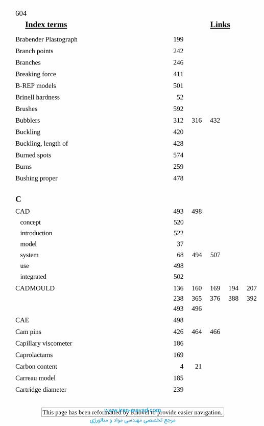
604 Index terms Links
This page has been reformatted by Knovel to provide easier navigation.
Brabender Plastograph 199
Branch points 242
Branches 246
Breaking force 411
B-REP models 501
Brinell hardness 52
Brushes 592
Bubblers 312 316 432
Buckling 420
Buckling, length of 428
Burned spots 574
Burns 259
Bushing proper 478
C CAD 493 498
concept 520 introduction 522 model 37 system 68 494 507 use 498 integrated 502
CADMOULD 136 160 169 194 207 238 365 376 388 392 493 496
CAE 498
Cam pins 426 464 466
Capillary viscometer 186
Caprolactams 169
Carbon content 4 21
Carreau model 185
Cartridge diameter 239
www.iran-mavad.com
مرجع تخصصی مهندسی مواد و متالورژی
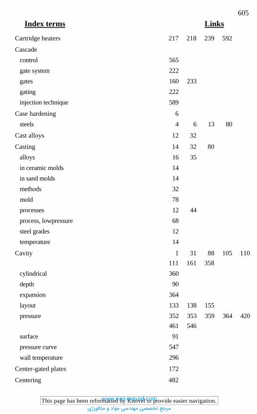
605 Index terms Links
This page has been reformatted by Knovel to provide easier navigation.
Cartridge heaters 217 218 239 592
Cascade control 565 gate system 222 gates 160 233 gating 222 injection technique 589
Case hardening 6 steels 4 6 13 80
Cast alloys 12 32
Casting 14 32 80 alloys 16 35 in ceramic molds 14 in sand molds 14 methods 32 mold 78 processes 12 44 process, lowpressure 68 steel grades 12 temperature 14
Cavity 1 31 88 105 110 111 161 358
cylindrical 360 depth 90 expansion 364 layout 133 138 155 pressure 352 353 359 364 420
461 546 surface 91 pressure curve 547 wall temperature 296
Center-gated plates 172
Centering 482
www.iran-mavad.com
مرجع تخصصی مهندسی مواد و متالورژی
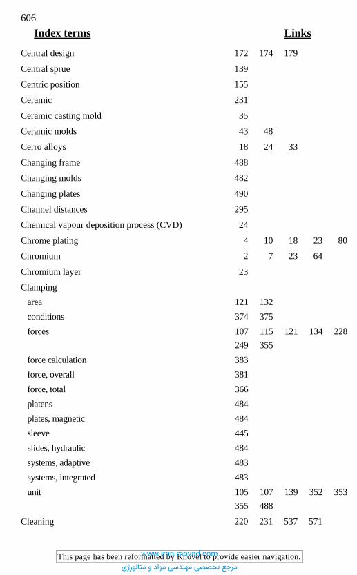
606 Index terms Links
This page has been reformatted by Knovel to provide easier navigation.
Central design 172 174 179
Central sprue 139
Centric position 155
Ceramic 231
Ceramic casting mold 35
Ceramic molds 43 48
Cerro alloys 18 24 33
Changing frame 488
Changing molds 482
Changing plates 490
Channel distances 295
Chemical vapour deposition process (CVD) 24
Chrome plating 4 10 18 23 80
Chromium 2 7 23 64
Chromium layer 23
Clamping area 121 132 conditions 374 375 forces 107 115 121 134 228
249 355 force calculation 383 force, overall 381 force, total 366 platens 484 plates, magnetic 484 sleeve 445 slides, hydraulic 484 systems, adaptive 483 systems, integrated 483 unit 105 107 139 352 353
355 488
Cleaning 220 231 537 571
www.iran-mavad.com
مرجع تخصصی مهندسی مواد و متالورژی
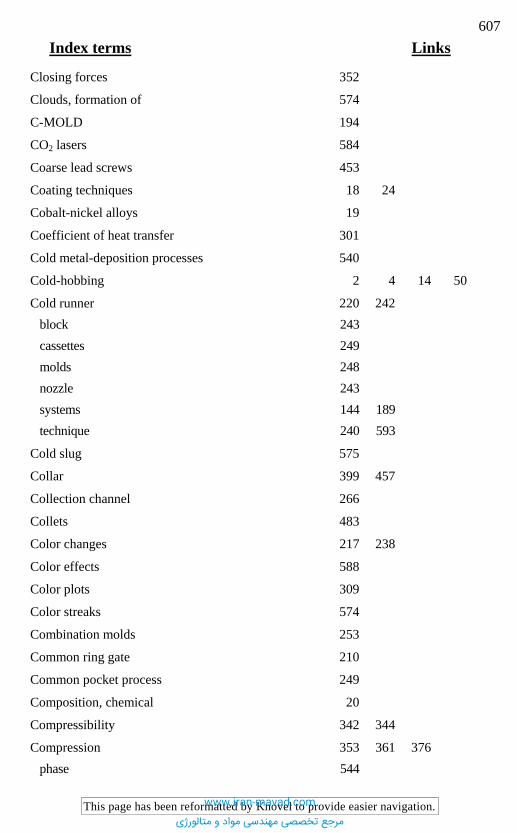
607 Index terms Links
This page has been reformatted by Knovel to provide easier navigation.
Closing forces 352
Clouds, formation of 574
C-MOLD 194
CO2 lasers 584
Coarse lead screws 453
Coating techniques 18 24
Cobalt-nickel alloys 19
Coefficient of heat transfer 301
Cold metal-deposition processes 540
Cold-hobbing 2 4 14 50
Cold runner 220 242 block 243 cassettes 249 molds 248 nozzle 243 systems 144 189 technique 240 593
Cold slug 575
Collar 399 457
Collection channel 266
Collets 483
Color changes 217 238
Color effects 588
Color plots 309
Color streaks 574
Combination molds 253
Common ring gate 210
Common pocket process 249
Composition, chemical 20
Compressibility 342 344
Compression 353 361 376 phase 544
www.iran-mavad.com
مرجع تخصصی مهندسی مواد و متالورژی
608 Index terms Links
This page has been reformatted by Knovel to provide easier navigation.
Compression (Continued) stage 244 strength 429
Computer-aided simulation 493
Conical locator 72
Conicity 510
Connecting lines 296 308
Connectors 296 308
Consistency factor 184
Constructive solid geometry (CSG) model 500
Contact pressure 413 419
Contact temperature 74 296 567
Continuous quality control monitoring (CQCTM)
Contour accuracy 40
Contour factor 93
Control volume-finite difference method (CV-FDM) 496
Contura 313
Convection 292 305 327
Coolant 307 temperature 293 throughput 298
Cooling 286 565 a corner 311 channel 74 295 300 circuits 295 coil 313 conditions 309 elements 308 lines 262 295 312 395 537 of cores 312 process 273 rate 274 280 282
www.iran-mavad.com
مرجع تخصصی مهندسی مواد و متالورژی
609 Index terms Links
This page has been reformatted by Knovel to provide easier navigation.
Cooling (Continued) stage 284 system 107 293 time 80 271 272 296 311 time, computation of 277 water 135
Copper 20 32 40 80 214 232 312 541
Copper/zinc alloy 49
Copper-asbestos 320
Copper-beryllium 232 233
Copper-tungsten materials, sintered 312
Copy aids 508
Copy milling 508
Core 1 361 base 394 cooling 312 diameter 389 length 389 material 68 71 75 78 mounting 74 387 399 pullers 472 shifting 75 strength 2 support 395 surface 75 temperatures 312 tip 394
Core-back molds 254
Core-back technique 253
Core-casting machine 68
Core-casting molds 80
Core-pulling devices 471
www.iran-mavad.com
مرجع تخصصی مهندسی مواد و متالورژی

610 Index terms Links
This page has been reformatted by Knovel to provide easier navigation.
Cores circular 388 390 collapsible 449 contour factor for 93 fusible 33 interchangeable 450 shifting of 385 387
Corrosion 9 11 19 300 536
Corrosion resistance 2 11 16 18 19 20 22 27
Cost calculation 85 100
Costs 31 100 111 121 125 135 136 138 161 528 553
Costs of parts 127
Covering metal 541
Crank 442
Crank drive 252
Crank handle 451
Craters 59
Crosslinking 107 108 194 246
Crosslinking plastics 107 194 220
Crystalline plastics 123 307 342
CSG 500
Curing 289 process 161 reaction 288 velocity 195 196
Curved sprue 206
Curved tunnel gate 212
Cushion 115
Cut-off 112
www.iran-mavad.com
مرجع تخصصی مهندسی مواد و متالورژی
611 Index terms Links
This page has been reformatted by Knovel to provide easier navigation.
Cutter 54
Cutting 26
Cutting by spark erosion 62
Cutting-tool materials 54
CVD process 24
CV-FDM 496
Cycle time 214 312 321 547
Cylindrical cavities 360
D Dam effect 323
Dark specks 574
Data acquisition 530 administration 506 507 523 administration software 507 evaluation 532 exchange 504 storage, external 536
Dead-water areas 246
Decomposition 144
Decompression 227 228
Deflection 359 line 396
Deformation 311 351 358 364 calculation 370 396 capability 421 total 379
Degree of filling 545
Demixing 163
www.iran-mavad.com
مرجع تخصصی مهندسی مواد و متالورژی

612 Index terms Links
This page has been reformatted by Knovel to provide easier navigation.
Demolding 81 110 121 128 140 205 215 227 274 401 410 449 592
action 441 process 420 435 512 shrinkage 335 support 151 system 140 temperature 271 272 277 283 352
578
Deposit formation 26
Deposit welding 541
Design 135 503 530 change 446 characteristics 111 control 510 freedom 582 with elementary wavelets 179
Diamonds 586
Die-casting molds 55
Diesel effect 76 578
Diffusion welding 42
Dimensional changes 2 336 deviations 351 shrinkage 39 stability 536 tolerances, factor for 93
Dip etching 64
Direct shell production casting (DSPC) 48
Discoloration 574
Disk 208 ejector 432 439 gate 208 390 394
www.iran-mavad.com
مرجع تخصصی مهندسی مواد و متالورژی
613 Index terms Links
This page has been reformatted by Knovel to provide easier navigation.
Disk (Continued) spring 233
Distortion 2 4 159 208 212 309 323 345
Distributor channel 207
Doping areas 582
Double stage ejection 437
Dove-tail 467
Dovetail grooves 461
Draft exchange format (DXF) 505
Drafts 33 39 66 81 163 510
Drilling 54
Driving torque 452
Drooling 232
Dry etching 581
DSC analysis 287 291
DSPC 48
DTM process 39
Dwell time 222 227 231 246
DXF 504
E Eccentricity 155 393
ECM process 63
Edge gate 153 160 170 206
EDM 16 59 60 94 407 507
EDM milling 585
Ejection 121 401 forces 352 405 426 429 methods 402
www.iran-mavad.com
مرجع تخصصی مهندسی مواد و متالورژی
614 Index terms Links
This page has been reformatted by Knovel to provide easier navigation.
Ejection (Continued) movement 411 stroke 134 system 110 352 401
Ejector 107 136 434 assembly 433 bolt 433 movement 440 pin 179 260 352 419 420
426 468 546 plate 355 426 437 return 443 sleeves 430 431 system 99 212
Ejector-retainer plate 433
Elastic deformation 351 365
Elasticity, modulus of 359
Elasticity, modulus of 375
Elasticity, theory of 359
Elastomer (rubber) molds 109 489
Elastomer injection molds 189 242
Elastomer processing 265 595
Elastomers 108 110 145 161 169 194 195 220 246 276 293 328 420
Elbows 308
Electric-arc vacuum oven 15
Electric discharge 2 finishing 584 machines 62 machining (EDM) 4 57 59 polishing 57 removal 585
www.iran-mavad.com
مرجع تخصصی مهندسی مواد و متالورژی

615 Index terms Links
This page has been reformatted by Knovel to provide easier navigation.
Electric heating 321
Electric resistance heating 329
Electrochemical machining (ECM) 63 metallizing 540 polishing 57
Electrodeposition 1
Electroforming 46
Electrolytic forming 19
Electron beam hardening 28
Electroplating 2 583 bath 46
Electro-slag refining 11
Elongational flow 198
Elongational viscosity 189
Emission power 543
Energy 135 180 balance 325 savings 240 use 290
EOS process 39
EPC 49
Equation of state 180
Eroding 68 electrodes 508 speed 16
Erosion 37
Erosive finishing 57
Etching 2 61 64 528 582
Evacuation 265 591
Evaporation 162 deposition 25 zone 313
www.iran-mavad.com
مرجع تخصصی مهندسی مواد و متالورژی
616 Index terms Links
This page has been reformatted by Knovel to provide easier navigation.
Evaporation (Continued) pattern casting 48
Excimer lasers 584
Expandable pattern casting (EPC) 49
External heating 224 239
Extrude-honing 57
F Fan gate 206
Fatigue resistance 20
FEA 372 420 421 500 517
FEA simulation 349 498 514
Feeding process 196
FEM programs 328
Fiber-reinforced materials 159
Filcalc 194
Filigree structure 577
Filled thermosets 169
Fillers 163 198
Filling 208 phase 195 544 pressure 163 pressure distribution 396 process 164 166 172 192 324 time 196
Film gates 395 592
Fine finishing 59
Finishing 54 55 105
Finite element method 179 351 396 420 494
Five-axis milling 54
Flame spraying 44
www.iran-mavad.com
مرجع تخصصی مهندسی مواد و متالورژی
617 Index terms Links
This page has been reformatted by Knovel to provide easier navigation.
Flash 107 108 109 143 149 352 354 461 539 544
Flash face clearance 596
Flash formation 591
Flashing 161 249 263 351 430 467
Flat leaders 481
Flat runner 197
Floating platen 212 440
Flow front 168 169 172 174 179
198 function 182 length 123 138 length/wall thickness ratio 122 320 348 588 paths 164 222 pattern 164 166 175 176 rate 225 229 231 264 295
307 resistance 199 restriction 163
FORTRAN 514
Four-cavity mold 241
Fourier number 273 274 280 282
Freeform surfaces 498
Freezing 220 gates 164
Friction 362 443 462 coefficient of 407 464 conditions 420 cone 458 factor 301
Frontal flow 161 163
www.iran-mavad.com
مرجع تخصصی مهندسی مواد و متالورژی
618 Index terms Links
This page has been reformatted by Knovel to provide easier navigation.
Frozen material 220
Functional gap 365
Fused deposition modeling 40 47
Fusible core 33 68 78
G Galvanic sealing tape 541
Gap 108 366 formation 353 width 121 380 591 596 width, critical 263
Gas counter-pressure injection molds 266
Gas injection technique 495
Gas nitriding 22
Gas phase deposition 24
Gate 136 143 151 152 160 161 163 164 179 180 189 194 592
area 196 cross-sections 152 192 freezing 425 marks 216 nozzles 228 229 orifice 156 position 162 -sealing point 547 size 154 system 162 510 537 thermally controlled 217
Gating 128 140
Gating systems 78 146
Gear drive 452
Gear ring 458
www.iran-mavad.com
مرجع تخصصی مهندسی مواد و متالورژی

619 Index terms Links
This page has been reformatted by Knovel to provide easier navigation.
Gelcoat 44
Geometry generation 509
Glass beads 344
Glass-reinforced materials 348
Grid generators 328
Grinding 23 54 55 68 539
Grinding direction 260
Grippers 592
Guiding molds 475
H Hagen-Poiseuille’s law 122 168 187
Hard chroming 9
Hard coatings 14 24 162
Hardening 2 6 9 21
Hardness 7 22
Heat balance 325 barriers 144 carrier 567 569 conductivity 14 dissipation 568 distribution 231 exchange 271 285 296 308 568 exchange medium 561 exchange system 98 110 132 271 295
571 exchanger 136 296 flow 283 flux 283 292 296 324 loss 217 326 penetrability 567 pipe 233 313
www.iran-mavad.com
مرجع تخصصی مهندسی مواد و متالورژی
620 Index terms Links
This page has been reformatted by Knovel to provide easier navigation.
Heat (Continued) removal 271 treatment 1 2 4 10 11
16 21 23 24 26 54 64
Heating 231 565 capacity 592 circuits 227 231 329 elements 239 329 pipes 224 platens 330 power 239 rods 224 system 537 time 195 197 325
Heat-transfer coefficient 293 301 327 568
Heel block 465
Helical tubular heaters 239
High-pressure capillary viscometer 198
High-speed cutting (HSC) 37 54 60
Hobbing 14 50 depth 52 pressure 52
Holding pressure 115 153 157 160 196 205 222 223 229 241 311 346 347 547 594
Holding time 195 211 348
Honing 23 54 55
Hooke’s law 410
Hot core 151
Hot hobbing 14 50
Hot-edge nozzles 232
Hot-manifold nozzles 239
www.iran-mavad.com
مرجع تخصصی مهندسی مواد و متالورژی
621 Index terms Links
This page has been reformatted by Knovel to provide easier navigation.
Hot-plot machine 49
Hot runner 112 164 217 220 227 233 238
manifold 144 234 mold 140 231 nozzles 226 system 80 98 144 164 192
221 223
HSC 37
Hybrid construction 507
Hybrid models 500
Hybrid techniques 37
Hydraulic clamping slides 484
Hydraulic cylinders 470
Hydraulic locking device 483
Hydraulic presses 355
Hydrochloric acid 537
I IGES 494 504 520
Incubation time 194 195
Induction heating 321
Infrared sensors 548
Initial graphics exchange specification (IGES) 504
Injection 55 205 compression molding 495 591 593 limit 195 197 molding 40 421 molding machine 105 125 195 205 246 molding process 105 molding simulation 497 molding, two-component 495
www.iran-mavad.com
مرجع تخصصی مهندسی مواد و متالورژی
622 Index terms Links
This page has been reformatted by Knovel to provide easier navigation.
Injection (Continued) molds 31 109 351 molds, metallic 32 nozzle 105 143 144 146 parameters 395 phase 544 pressure 121 122 134 138 153
161 195 197 223 352 424 428
pressure, maximum 115 speed 192 temperature 347 time 107 195 197 transfer molding 162 246
In-mold decoration 222 223 586
Insert alignment 475
Inserts 70 247 262 395
Insulating runner 112 224
Insulation 217 226 231 235 286 293 295 329 330
Interlocking 476
Internal heating 224
Internal mold pressures 545
Internal ring gates 210
Internal stresses 343
Ion plating 25
Ionitriding 22
IR sensors 543
Isothermal flow 189
Isotropic etching 581
ITM 246
www.iran-mavad.com
مرجع تخصصی مهندسی مواد و متالورژی
623 Index terms Links
This page has been reformatted by Knovel to provide easier navigation.
J Jet lapping 56
Jetting 161 163 206 575
Jig drill 477
Joint 261
K Kanavec viscometer 199
Kayem 33
Keltool process 50
Kirksite 16 33
Knit lines 160 162 163 176 178 208 259 262 575
Knockout bolt 445
Knuckle depth 449
L Lamcoat coating 28
Lamellae, packs of 262
Laminar flow 189 192 301
Land 207 208
Lapping 23 54 55
Laser 540 alloying 26 27 carving 67 coating 26 27 44 cutting 42 584 dispersing 26 27 generation 37 hardening 26 27 28 LiGA 584 re-melting 26 27
www.iran-mavad.com
مرجع تخصصی مهندسی مواد و متالورژی

624 Index terms Links
This page has been reformatted by Knovel to provide easier navigation.
Laser (Continued) removal 581 584 sintering 37 41 surface treatment 26 welding 540
Latch 440 468 bar 440
Leader bushing 456 477 elements, circular 482 pin 128 433 461 462 476 sleeve 477 479 units 476
Leakage 221 233
Lifters 469
LiGA technique 581 583
Line pressure 300
Liquid rubbers 108
Liquid silicone rubbers (LSRs) 591
Liquid-crystalline structure 160
Lithographic prouss 584
Living hinge 169
Locating rings 475
Locating system 110
Locking device 483
Locking elements 355
Locking force 365
Lost foam method 35
Lot size 127 128 131
Low pressure casting process 68
LSR 591
Lubricating 53 461 477 537
www.iran-mavad.com
مرجع تخصصی مهندسی مواد و متالورژی
625 Index terms Links
This page has been reformatted by Knovel to provide easier navigation.
M Machinability 6 9
Machining 162 206 production methods 54 properties 9 time for fixed cores 92 tolerances 385 387
Magnetic mounting platen 487
Maintenance 135 136 138 527 537 571
analysis 534 costs 221 factor 138 hours 531 schedules 528
Manifold beams 229 234
Manifold blocks 225 228 229 242
Manifolds, externally heated 229 internally heated 229
Martensite-forming temperature 539
Master mold method 421
Master mold processes 37
Master pattern 43
Melt 153 distribution 193 elasticity 163 filters 228 pressure 544 temperature 214 239 543
Memory effect 163
Metal LOM 39 41
Metal paste 541
www.iran-mavad.com
مرجع تخصصی مهندسی مواد و متالورژی
626 Index terms Links
This page has been reformatted by Knovel to provide easier navigation.
Metal powder 541
Metal spraying 14 37 38 44 50
Metrology 513
Microcavities 579
Micromachining 581
Microstructures 265 320 577
Milling 54 68
Mineral powder 344
Modal analysis systems 497
Models, parametric 505 partial 505 surface-oriented 499 vector-oriented 499 volume-oriented 499
Mold 110 base 356 block 226 breathing 355 card 535 cavity 143 cavity pressure 355 547 changes 536 costs 85 127 128 damage 534 544 deformation 351 dimensions 127 134 exchanger 489 filling 165 194 207 221 388 filling process 143 543 flashes 575 height 134 identification number 530 inserts 32
www.iran-mavad.com
مرجع تخصصی مهندسی مواد و متالورژی

627 Index terms Links
This page has been reformatted by Knovel to provide easier navigation.
Mold (Continued) lifetime 531 material 4 number 535 opening 211 212 244 352 parting line 352 508 platens 134 223 355 size 115 standards 553 555 surfaces 537 temperature 107 211 286 561 563 venting 259 wear 547
MOLDFLOW 136 169 194 207 493
Molding 140 chain 43 cycle 245 defects 573 sequence 214
Mold making 507
Molds for hot forming 19
Molds for trial runs 33
Molds, fully automatic 453
Molds, semiautomatic 452
Molybdenum 7
Molybdenum disulfide 53 426 461 477
Mounting platen, magnetic 487
Multi-cavity molds 130 140 151 161 209 210 212 223 229 245 263 394 488
Multicomponent injection molding 252
Multi-cut technology 62
Multiphase jet solidification 39 40
www.iran-mavad.com
مرجع تخصصی مهندسی مواد و متالورژی

628 Index terms Links
This page has been reformatted by Knovel to provide easier navigation.
Multiple gating 160 192
Multi-space technique 60
Mushroom ejector 439 592
N NC programming 507 513
ND:YAG lasers 584
ND-YAG lasers 540
Needle valve nozzles 222 229 233
Negative pattern 33 38 44 46 48
Neural networks 550
Newtonian viscosity 183
Nickel 2 19 20 40 64 541
coating 14 plating 11 18 23 80 electro-deposited 20
Nitrided layer 7
Nitriding 4 7 10 22 in a bath 22 steels 6 22 temperature 22 time 22 treatment 10
Nitro-carburizing 22
Nomograms 277
Nozzle 134 151 205 214 231 design 237 extension 214 orifice platen 232
www.iran-mavad.com
مرجع تخصصی مهندسی مواد و متالورژی
629 Index terms Links
This page has been reformatted by Knovel to provide easier navigation.
Nozzle (Continued) with tips 232
externally heated 238 indirectly heated 238 internally heated 238 239
Number of cavities 115 123 127 128 131 134 136 138 140
NURBS 500
Nusselt number 301
Nuts 453
O Open nozzles 232
Opening forces 128 405 424
Opening stroke 121 134 222 249 401 434 453
Optical fibers 543
Organic binders 34
Orientation 158 161 164 343
Orifice 149 205
O-rings 266 320 579
Overpacking 366 547
P Pacyna characteristics 101
Pallet loading 62
Panel heaters 242
Pareto principle 533
Part costs 128
Part geometry 127 140 396
Parting 510
www.iran-mavad.com
مرجع تخصصی مهندسی مواد و متالورژی

630 Index terms Links
This page has been reformatted by Knovel to provide easier navigation.
Parting lines 92 108 109 140 155 179 210 212 220 223 244 260 309 364 539
Part-in-part technique 70
Pawl pin 444
PDM 507
Pertinent influential parameter 409
Photochemical etching 62 65
Physical vapour deposition process (PVD) 25
PIDD structure 238
Pin-link chain 441
Pinpoint gate 150 153 170 172 212 214 215 233 237 293 394 592
Pits 539
Planetary electric-discharge machining 60
Planing 59 260
Plasticating rate 115 121 128 134
Plasma 7 44
Plasma discharge 582
Plasticating 105 543 temperature 247 unit 105 107
Plastometers 195
Plating 19
Polishability 32
Polishing 2 7 11 23 54 55 59
Post-shrinkage 336
Pot design 480
Powder injection molding 163
Powder nitriding 22
www.iran-mavad.com
مرجع تخصصی مهندسی مواد و متالورژی
631 Index terms Links
This page has been reformatted by Knovel to provide easier navigation.
Power law 183 187 194
Prandtl number 301
Precision casting 12 35 42
Precision injection molding 394
Press 352
Pressure 164 227 374 consumption 144 161 168 demand 134 distribution 396 398 drop 300 308 factor 388 function 398 lapping 57 loss 185 189 195 198 199
221 228 234 246 296 493
profile, effective 392 sensors 544
Pressure-control valves 266
Pro/Engineer CAD system 517
Probes 241
Process chain 44
Process simulation 495
Processing shrinkage 335 temperature 296 time 197 windows 195
Product data management (PDM) 507
Production planning 503
Prototypes 1 228 488
Prototype molds 1 19 39 40 401
www.iran-mavad.com
مرجع تخصصی مهندسی مواد و متالورژی
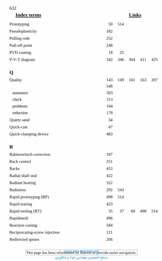
632 Index terms Links
This page has been reformatted by Knovel to provide easier navigation.
Prototyping 50 514
Pseudoplasticity 182
Pulling rods 252
Pull-off point 248
PVD coating 18 25
P-V-T diagram 342 346 364 411 425
Q Quality 143 149 161 163 207
548 assurance 503 check 513 problems 164 reduction 178
Quartz sand 34
Quick-cast 47
Quick-clamping device 483
R Rabinowitsch correction 187
Rack control 251
Racks 453
Radial shaft seal 422
Radiant heating 322
Radiation 292 543
Rapid prototyping (RP) 498 514
Rapid tearing 423
Rapid tooling (RT) 35 37 68 498 514
Rapidmesh 496
Reaction casting 584
Reciprocating-screw injection 121
Redirected sprues 206
www.iran-mavad.com
مرجع تخصصی مهندسی مواد و متالورژی
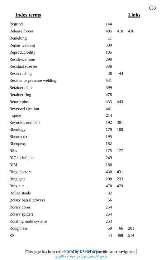
633 Index terms Links
This page has been reformatted by Knovel to provide easier navigation.
Regrind 144
Release forces 405 418 436
Remelting 11
Repair welding 539
Reproducibility 105
Residence time 290
Residual stresses 336
Resin casting 38 44
Resistance pressure welding 541
Retainer plate 399
Retainer ring 478
Return pins 433 443
Reversed ejection 441 sprue 214
Reynolds numbers 192 301
Rheology 179 180
Rheometers 195
Rheopexy 182
Ribs 175 177
RIC technique 249
RIM 180
Ring ejectors 430 431
Ring gate 208 233
Ring nut 478 479
Rolled steels 32
Rotary barrel process 56
Rotary cores 254
Rotary spiders 254
Rotating mold systems 253
Roughness 59 66 261
RP 44 498 514
www.iran-mavad.com
مرجع تخصصی مهندسی مواد و متالورژی
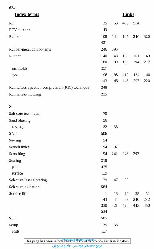
634 Index terms Links
This page has been reformatted by Knovel to provide easier navigation.
RT 35 68 498 514
RTV silicone 49
Rubber 108 144 145 246 320 421
Rubber-metal components 246 395
Runner 140 143 155 161 163 180 189 193 194 217
manifolds 237 system 96 98 110 134 140
143 145 146 207 220
Runnerless injection compression (RIC) technique 248
Runnerless molding 215
S Salt core technique 70
Sand blasting 56 casting 32 33
SAT 506
Sawing 54
Scorch index 194 197
Scorching 194 242 246 293
Sealing 318 point 425 surface 139
Selective laser sintering 39 47 50
Selective oxidation 584
Service life 1 18 26 28 31 43 44 53 240 242 330 421 426 443 450 534
SET 505
Setup 135 136 costs 137
www.iran-mavad.com
مرجع تخصصی مهندسی مواد و متالورژی
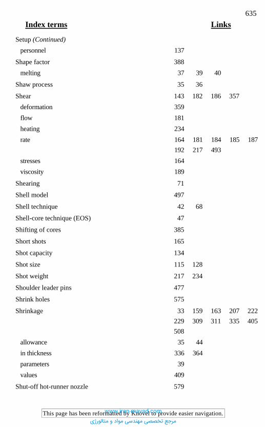
635 Index terms Links
This page has been reformatted by Knovel to provide easier navigation.
Setup (Continued) personnel 137
Shape factor 388 melting 37 39 40
Shaw process 35 36
Shear 143 182 186 357 deformation 359 flow 181 heating 234 rate 164 181 184 185 187
192 217 493 stresses 164 viscosity 189
Shearing 71
Shell model 497
Shell technique 42 68
Shell-core technique (EOS) 47
Shifting of cores 385
Short shots 165
Shot capacity 134
Shot size 115 128
Shot weight 217 234
Shoulder leader pins 477
Shrink holes 575
Shrinkage 33 159 163 207 222 229 309 311 335 405 508
allowance 35 44 in thickness 336 364 parameters 39 values 409
Shut-off hot-runner nozzle 579
www.iran-mavad.com
مرجع تخصصی مهندسی مواد و متالورژی
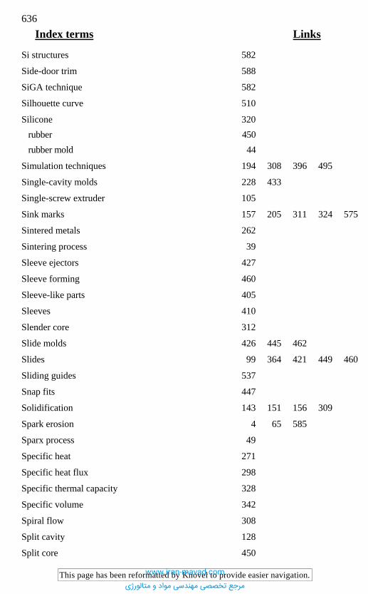
636 Index terms Links
This page has been reformatted by Knovel to provide easier navigation.
Si structures 582
Side-door trim 588
SiGA technique 582
Silhouette curve 510
Silicone 320 rubber 450 rubber mold 44
Simulation techniques 194 308 396 495
Single-cavity molds 228 433
Single-screw extruder 105
Sink marks 157 205 311 324 575
Sintered metals 262
Sintering process 39
Sleeve ejectors 427
Sleeve forming 460
Sleeve-like parts 405
Sleeves 410
Slender core 312
Slide molds 426 445 462
Slides 99 364 421 449 460
Sliding guides 537
Snap fits 447
Solidification 143 151 156 309
Spark erosion 4 65 585
Sparx process 49
Specific heat 271
Specific heat flux 298
Specific thermal capacity 328
Specific volume 342
Spiral flow 308
Split cavity 128
Split core 450
www.iran-mavad.com
مرجع تخصصی مهندسی مواد و متالورژی
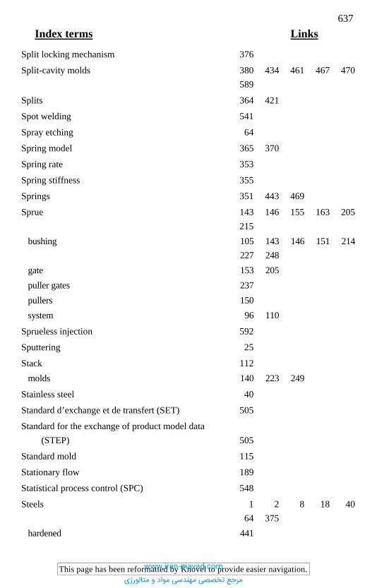
637 Index terms Links
This page has been reformatted by Knovel to provide easier navigation.
Split locking mechanism 376
Split-cavity molds 380 434 461 467 470 589
Splits 364 421
Spot welding 541
Spray etching 64
Spring model 365 370
Spring rate 353
Spring stiffness 355
Springs 351 443 469
Sprue 143 146 155 163 205 215
bushing 105 143 146 151 214 227 248
gate 153 205 puller gates 237 pullers 150 system 96 110
Sprueless injection 592
Sputtering 25
Stack 112 molds 140 223 249
Stainless steel 40
Standard d’exchange et de transfert (SET) 505
Standard for the exchange of product model data (STEP) 505
Standard mold 115
Stationary flow 189
Statistical process control (SPC) 548
Steels 1 2 8 18 40 64 375
hardened 441
www.iran-mavad.com
مرجع تخصصی مهندسی مواد و متالورژی

638 Index terms Links
This page has been reformatted by Knovel to provide easier navigation.
Steels (Continued) case-hardening 4 475 corrosion-resistant 7 10 11 forged 32 martensitic 4 10 martensitic-hardening 4 6 prehardened 2 4 pure 4 refined 6 rolled 32 tempered 6 through-hardening 4 6
STEP 504 505
Step-up ejector 437
Stereolithography 42 47 68
STL 496 514 520
Strength, abrasive 4
Stress cracking 324 575
Stress distribution 423
Stress relaxation 343
Stringing 215
Strip heaters 592
Stripper bolt 440 molds 449 plate 431 435 437 441 448 ring 437
Structural foam 157 266
Structural viscosity 182
Submarine gate 210
Surface blemishes 156 design 65
www.iran-mavad.com
مرجع تخصصی مهندسی مواد و متالورژی

639 Index terms Links
This page has been reformatted by Knovel to provide easier navigation.
Surface (Continued) finish 64 70 152 gloss 574 hardness 2 4 7 22 426 micromachining 582 models 500 pressure 409 quality 4 20 55 92 165
584 roughness 405 407 structures 35 texture 1 2 34 163 treatment 18 55
T T groove 467
Tangential design 172 173 179
Taper 205 382 401 405 446
Taper angle 432
Telescopic extension 251
Temperature control 75 144 222 241 569
592 distribution 239 328 profile 345 sensors 227 566
Tempering 2 9 of steels 21 process 13 temperature 22
Tenifer treatment 22
Tenter frame 590
Test specimens 488
www.iran-mavad.com
مرجع تخصصی مهندسی مواد و متالورژی
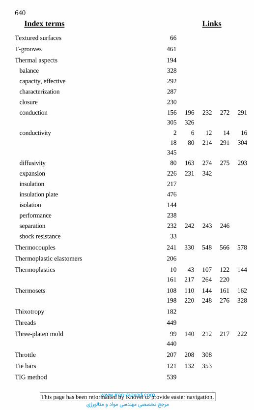
640 Index terms Links
This page has been reformatted by Knovel to provide easier navigation.
Textured surfaces 66
T-grooves 461
Thermal aspects 194 balance 328 capacity, effective 292 characterization 287 closure 230 conduction 156 196 232 272 291
305 326 conductivity 2 6 12 14 16
18 80 214 291 304 345
diffusivity 80 163 274 275 293 expansion 226 231 342 insulation 217 insulation plate 476 isolation 144 performance 238 separation 232 242 243 246 shock resistance 33
Thermocouples 241 330 548 566 578
Thermoplastic elastomers 206
Thermoplastics 10 43 107 122 144 161 217 264 220
Thermosets 108 110 144 161 162 198 220 248 276 328
Thixotropy 182
Threads 449
Three-platen mold 99 140 212 217 222 440
Throttle 207 208 308
Tie bars 121 132 353
TIG method 539
www.iran-mavad.com
مرجع تخصصی مهندسی مواد و متالورژی
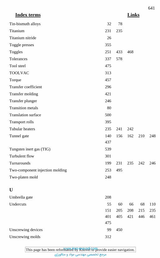
641 Index terms Links
This page has been reformatted by Knovel to provide easier navigation.
Tin-bismuth alloys 32 78
Titanium 231 235
Titanium nitride 26
Toggle presses 355
Toggles 251 433 468
Tolerances 337 578
Tool steel 475
TOOLVAC 313
Torque 457
Transfer coefficient 296
Transfer molding 421
Transfer plunger 246
Transition metals 80
Translation surface 500
Transport rolls 395
Tubular heaters 235 241 242
Tunnel gate 140 156 162 210 248 437
Tungsten inert gas (TIG) 539
Turbulent flow 301
Turnarounds 199 231 235 242 246
Two-component injection molding 253 495
Two-platen mold 248
U Umbrella gate 208
Undercuts 55 60 66 68 110 151 205 208 215 235 401 405 421 446 461 475
Unscrewing devices 99 450
Unscrewing molds 312
www.iran-mavad.com
مرجع تخصصی مهندسی مواد و متالورژی
642 Index terms Links
This page has been reformatted by Knovel to provide easier navigation.
Unsrewing devices 99
V Vacuum forming 14 584
Vacuum unit 578
Vanadium 7
Variothermal cooling 320
Variothermal heating 321 578
V-belt 452
V-chain 452
Venting 75 259 266 268 419 432 596
channels 261 262 gaps 261 262 264 pins 179 262 432
Vertical eroding 60
Vibratory grinding 56
Viscoelasticity 180
Viscosity 108 144 168 182 192 195 207 493
Viscous flow behavior 186
Voids 157 205 311
Volume 284 balancing 223 contraction 151 205 345 expansion 352 shrinkage 336 343 345 349
Vulcanization 196
W Wall adhesion 189 Wall thickness 156 164 208 209 348
358 372
www.iran-mavad.com
مرجع تخصصی مهندسی مواد و متالورژی

643 Index terms Links
This page has been reformatted by Knovel to provide easier navigation.
Warpage 311 345
Water-jet pump 262
Wear 146 162 437 441 443 528 538
Wear resistance 9 20 22 23 27 162
Weld lines 160 164 165 169 179 209 223 256
Welding 14 26 539
Welding repairs 539
Wet etching 581
Wireframe models 499
WLF equation 186
Z Zamak 16 33 49
Zero viscosity 183 185
Zinc 14 32
Zinc alloys 12 14 49
www.iran-mavad.com
مرجع تخصصی مهندسی مواد و متالورژی